DL1720/DL1740 Digital Oscilloscope User's Manual YOKOGAWA/YOKOGAWA DL1740 USER YOKOGAWA
User Manual: YOKOGAWA/YOKOGAWA DL1740 USER
Open the PDF directly: View PDF ![]() .
.
Page Count: 391 [warning: Documents this large are best viewed by clicking the View PDF Link!]
- Foreword
- Checking the Contents of the Package
- Safety Precautions
- Structure of the Manual
- Contents
- Chapter 1 Functions
- Chapter 2 Name and Use of Each Part
- Chpater 3 Precautions During Use
- Chpater 4 Common Operations
- Chpater 5 Vertical and Horizontal Axes
- 5.1 Turning Channels ON/OFF
- 5.2 Setting the Vertical Position of a Waveform
- 5.3 Selecting Input Coupling
- 5.4 Selecting Probe Attenuation
- 5.5 Setting the Offset Voltage
- 5.6 The Preset Function
- 5.7 Setting the Bandwidth
- 5.8 Setting V/div
- 5.9 Using the Linear Scaling Function
- 5.10 Selecting the Timebase
- 5.11 Setting T/div
- Chpater 6 Triggering
- 6.1 Setting the Trigger Mode
- 6.2 Setting the Trigger Delay
- 6.3 Setting the Trigger Position
- 6.4 Setting the Hold Off Time
- 6.5 Setting the Edge Trigger (SIMPLE)
- 6.6 Setting the External Trigger (SIMPLE)
- 6.7 Generating Triggers on the Power Signal (SIMPLE)
- 6.8 Setting the A->B(N) Trigger (ENHANCED)
- 6.9 Setting the A Delay B Trigger (ENHANCED)
- 6.10 Setting the Pattern Trigger (ENHANCED)
- 6.11 Setting the Width (Pulse<T, Pulse>T, T1<PLS<T2, Time Out) Trigger (ENHANCED)
- 6.12 Setting the OR Trigger
- 6.13 Setting the Window Trigger (ENHANCED)
- 6.14 Setting the TV Trigger (ENHANCED)
- 6.15 Setting the Action-On Trigger
- 6.16 Setting the Trigger Gate
- Chpater 7 Acquisition and Display
- 7.1 Setting the Record Length
- 7.2 Acquisition Mode
- 7.3 Using Sequential Store Function
- 7.4 Box Average Mode
- 7.5 Using Interleave Mode
- 7.6 Setting Repetitive Sampling Mode ON/OFF
- 7.7 Using the History Memory
- 7.8 Searching the Historical Data Using Zone (History Search Function)
- 7.9 Searching the Historical Data Using Parameters (History Search Function)
- Chpater 8 Display
- 8.1 Changing the Display Format
- 8.2 Setting the Interpolation Method
- 8.3 Changing the Graticule
- 8.4 Turning Display of the Scaling Value ON/OFF
- 8.5 Setting the Waveform Labels
- 8.6 Accumulated Waveform Display
- 8.7 Turning Translucent Mode ON/OFF
- 8.8 X-Y Waveform Display
- 8.9 Zooming the Waveform
- 8.10 Search Data Using Search and Zoom Function
- Chpater 9 Waveform Analysis
- 9.1 Measuring Waveforms Using Cursors
- 9.2 Automated Measurement of Waveform Parameters
- 9.3 Statistical Processing
- 9.4 Performing Automated Measurements of Waveform Parameters on Dual Areas
- 9.5 Adding, Subtracting, and Multiplying Waveforms
- 9.6 Binary Computation
- 9.7 Inverting the Waveform Display
- 9.8 Differentiating and Integration Waveforms
- 9.9 Displaying the Power Spectrum
- 9.10 Smoothing
- 9.11 Phase-Shifted Display
- 9.12 GO/NO-GO Determination Using the Measurement of Waveform Parameters
- 9.13 GO/NO-GO Determination Using Zones
- 9.14 Using the GO/NO-GO Signal Output Function
- Chpater 10 Outputs of Screen Data
- Chpater 11 Saving and Loading Data to and from the Storage Medium
- 11.1 Floppy Disks
- 11.2 Zip Disks
- 11.3 Connecting MO Disk Drives or Hard Disks to the SCSI Interface (Option)
- 11.4 Formatting the Storage Medium
- 11.5 Changing the SCSI ID Number
- 11.6 Saving/Loading Waveform Data
- 11.7 Saving/Loading Setup Data
- 11.8 Saving/Loading Snapshot Waveforms
- 11.9 Saving the Results of the Automated Measurement of Waveform Parameters
- 11.10 Changing the File Attributes, Deleting Files
- 11.11 Copying Files
- 11.12 Changing the Directory/File Name of the Storage Medium and Creating a Directory
- Chpater 12 Trigger Input/Trigger Output/RGB Video Signal Output
- Chpater 13 Ethernet Interface (Option)
- 13.1 Connecting the DL1720/DL1740 to a Personal Computer
- 13.2 Configuring the Ethernet Interface (TCP/IP)
- 13.3 Saving Waveform and Setting Data to a Network Drive (FTP Client Function)
- 13.4 Saving Screen Image Data to a Network Drive (FTP Client Function)
- 13.5 Sending Screen Image Data to a Network Printer (LPR Client Function)
- 13.6 Using the Mail Function (Fixed Interval)
- 13.7 Using the Mail Function (Action Mail Function)
- 13.8 Accessing DL1720/DL1740 Drives from a Network Drive (FTP Server Function)
- 13.9 Viewing the Ethernet Interface Option and MAC Address
- 13.10 Setting the FTP Passive Mode and LPR/SMTP Timeout
- Chpater 14 Other Operations
- Chpater 15 Troubleshooting, Maintenance and Inspection
- Chpater 16 Specifications
- Appendix
- Index

Digital Oscilloscope
IM 701710-01E
2nd Edition
DL1720/DL1740
Product Registration
Thank you for purchasing YOKOGAWA products.
YOKOGAWA provides registered users with a variety of information and
services.
Please allow us to serve you best by completing the product registration
form accessible from our homepage.
http://www.yokogawa.com/tm/
PIM 103-01E

i
IM 701710-01E
Foreword
Thank you for purchasing the DL1720/DL1740 Digital Oscilloscope. This user’s manual
contains useful information about the instrument’s functions and operating procedures as
well as precautions that should be observed during use, mainly DL1740. To ensure
proper use of the instrument, please read this manual thoroughly before operating it.
Keep the manual in a safe place for quick reference whenever a question arises.
Three manuals are provided with the instrument, including this user’s manual.
Manual Name Manual No. Description
DL1720/DL1740 IM 701710-01E Describes all functions (except for the
User’s Manual communications function) and their operation
procedures for the instrument.
DL1720/DL1740 IM 701710-17E Describes the communications functions of
Communication Interface the GP-IB, RS-232, USB, and network
User’s Manual interface.
DL1720/DL1740 IM 701710-02E Explaings basic operations only.
Operation Guide
Notes
• The contents of this manual are subject to change without prior notice as a result of
improvements in the instrument’s performance and functions. Display contents
illustrated in this manual may differ slightly from what actually appears on your screen.
• Every effort has been made in the preparation of this manual to ensure the accuracy
of its contents. However, should you have any questions or find any errors, please
contact your nearest YOKOGAWA representative listed on the back cover of this
manual.
• Copying or reproduction of all or any part of the contents of this manual without
YOKOGAWA’s permission is strictly prohibited.
• A guarantee card is attached to the instrument. The card will not be reissued, so
please read it carefully and keep it in a safe place.
• The TCP/IP software used in this product and the documentation for that TCP/IP
software are based in part on BSD Networking Software, Release 1 licensed from The
Regents of the University of California.
Trademarks
• Microsoft, MS-DOS, Windows, and Windows NT are either registered trademarks or
trademarks of Microsoft Corporation in the United States and/or other countries.
• Adobe, Adobe Acrobat, and PostScript are either trademarks or registered trademarks
of Adobe Systems incorporated.
• Zip is a registered trademark or trademark of Iomega corporation in the Unites States
and/or other countries.
• PC-9800 is a registered trademark of the NEC Corporation.
• UNIX is a registered trademark of The Open Group.
• For purposes of this manual, the TM and ® symbols do not accompany their
respective trademark names or registered trademark names.
• Other product names are trademarks or registered trademarks of their respective
holders.
Revisions
1st Edition: January 2001
2nd Edition: July 2001 (supports firmware version 1.30 or later)
Disk No. DL31
2nd Edition : July 2001 (YK)
All Rights Reserved, Copyright © 2001 Yokogawa Electric Corporation
ii IM 701710-01E
Checking the Contents of the Package
Unpack the box and check the contents before operating the instrument. If the wrong
instrument or accessories have been delivered, if some accessories are missing or if
they appear abnormal, contact the dealer from which you purchased them.
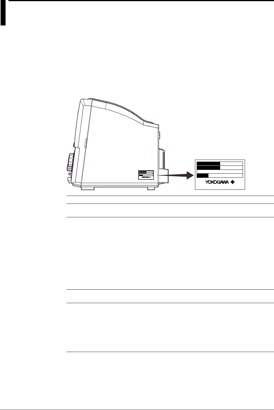
DL1720/DL1740 Main Body
Check that the model name and suffix code given on the name plate of the side panel
match those on your order. Whenever you contact the dealer from which you purchased
the instrument, tell the dealer your unit’s serial number.
MODEL
NO.
SUFFIX
Made in Japan
MODEL
NO.
SUFFIX
Made in Japan
MODEL SUFFIX SPECIFICATIONS
701705 (DL1720) 2 channels
701710 (DL1740) 4 channels
Power Cord -D UL/CSA standard power cord (A1006WD)
Maximum rated voltage: 125 V, maximum rated current: 7
A
-F VDE standard power cord (A1009WD)
Maximum rated voltage: 250 V, maximum rated current:
10 A
-Q BS standard power cord (A1054WD)
Maximum rated voltage: 250 V, maximum rated current:
10 A
-R SAA standard power cord (A1024WD)
Maximum rated voltage: 240 V, maximum rated current:
10 A
Built-in Media Drive -J1 Floppy disk drive*1
-J2 Zip disk drive*1
Options /B5 Built - in printer*2
/C7 SCSI+serial interface
/C10 Ethernet interface
/E2 Two passive probes*3
/P2 Two power output connectors for the probes (for the
DL1720)
/P4 Four power output connectors for the probes (for the
DL1740)
*1 You can select a floppy disk drive or a Zip drive for the built-in media drive.
*2 1 printer roll (B9850NX) included
*3 Two passive probes (700988) come standard with the DL1720/DL1740.
Example: UL/CSA standard power cord, and full options → 701710-D/B5/C7/C10/E2/P4
NO. (Instrument Number)
When contacting the dealer from which you purchased your instrument, please quote the
instrument number.
iii
IM 701710-01E
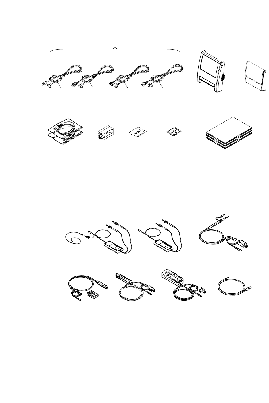
Standard Accessories
The following standard accessories are supplied with the instrument. Make sure that all
items are present and undamaged.
User’s Manual
Communication Interface
Operation Guide
Printer Roll
Chart *
B9850NX
Fuse
A1352EF
400MHz Passive
Probe (x2)
700988
UL/CSA Standard
A1006WD VDE Standard
A1009WD BS Standard
A1054WD SAA Standard
A1024WD
D F Q R
Power Cord (one of the following power cords
is supplied according to the instrument’s suffix codes)
(x1)
(x1)
(x1)
Rubber Feet
(x4)
B9989EX
Front Panel Protection
Cover (Clear) B9989FA
Probe Case
B9918EZ
* A roll chart will be supplied only when the instrument is equipped with a built-in printer.
Optional Accessories
The following optional accessories are available. On receiving these optional
accessories, make sure that all the items that you ordered have been supplied and that
they are undamaged.
If you have any questions regarding optional accessories, or if you wish to place an
order, contact the dealer from whom you purchased the instrument.
Current Probe
701930
Differential Probe
700924 Differential Probe
700925
Current Probe
700937
FET Probe
700939
GO/NO-GO Cable
366973
Differential Probe
701920
Checking the Contents of the Package

iv IM 701710-01E
Optional Spare Parts
The following optional spare parts are available. On receiving these optional spare
parts, make sure that all the items that you ordered have been supplied and that they are
undamaged.
If you have any questions regarding optional spare parts, or if you wish to place an order,
contact the dealer from whom you purchased the instrument.
Part Name Part No. Minimum Q’ty Remarks
Roll chart B9850NX 5 Thermo-sensible paper, Total
400 MHz passive probe 700988 1 Input impedance: 10 MΩ, Length:
1.5 m
Fuse A1352EF 2 4 A, 250 V
Front panel protection cover B9989FA 1
(clear)
Checking the Contents of the Package
v
IM 701710-01E
Safety Precautions
This instrument is an IEC safety class I instrument (provided with terminal for protective
grounding).
The following general safety precautions must be observed during all phases of
operation, service and repair of this instrument. If this instrument is used in a manner
not specified in this manual, the protection provided by this instrument may be impaired.
Also, Yokogawa Electric Corporation assumes no liability for the customer’s failure to
comply with these requirements.
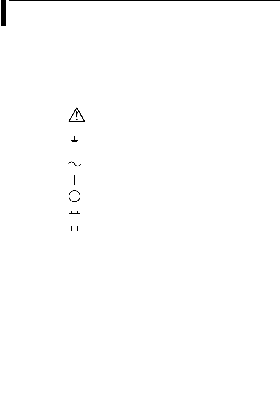
The Following Symbols are Used on this Instrument.
To avoid injury, death of personnel or damage to the instrument, the operator
must refer to an explanation in the user’s manual or service manual.
Function grounding terminal (This terminal should not be used as a “protective
grounding terminal.”)
Alternating current
ON (power)
OFF (power)
In - position of a bistable push control
Out - position of a bistable push control

vi IM 701710-01E
Make sure to comply with the following safety precautions. Not complying might
result in injury or death, or damage to the instrument.
WARNING
Power Supply
Ensure the source voltage matches the voltage of the power supply
before turning ON the power.
Power Cord and Plug
To prevent an electric shock or fire, be sure to use the power cord
supplied by YOKOGAWA. The main power plug must be plugged in an
outlet with a protective grounding terminal. Do not invalidate protection
by using an extension cord without protective grounding.
Protective Grounding
The protective grounding terminal must be connected to ground to
prevent an electric shock before turning ON the power.
Necessity of Protective Grounding
Never cut off the internal or external protective grounding wire or
disconnect the wiring of the protective grounding terminal. Doing so
poses a potential shock hazard.
Defect of Protective Grounding and Fuse
Do not operate the instrument when the protective grounding or fuse
might be defective.
Fuse
To prevent a fire, make sure to use fuses with the specified standard
(voltage, current, type). Before replacing the fuses, turn off the power
and disconnect the power source. Do not use a different fuse or short -
circuit the fuse holder.
Do Not Operate Near Flammable Materials
Do not operate the instrument in the presence of flammable liquids or
vapors. Operation of any electrical instrument in such an environment
constitutes a safety hazard.
Do Not Remove Any Covers
There are some areas inside the instrument with high voltages. Do not
remove any cover if the power supply is connected. The cover should
be removed by qualified personnel only.
External Connection
To ground securely, connect the protective grounding before
connecting to measurement or control unit. Also, when touching the
circuit, turn off the power to the circuit and check that there is no
voltage being generated.
To prevent electric shock, connect the ground terminal of the probe or
input connector to the protective ground of the object under
measurement.
Safety Precautions

vii
IM 701710-01E
Structure of the Manual
Structure of the Manual
This user’s manual consists of 16 chapters, an Appendix and an Index as described
below.
Chapter Title Content
1 Functions Introduces the unit’s features, functions, and operating
principles. Please read this information to familiarize
yourself with the unit’s capabilities. This chapter does not
present operational details.
2 Name and Use of Each Part Briefly explains the significance and use of the unit’s
controls, connectors, and screen displays. Includes page
references to help you find detailed information quickly.
3 Precautions During Use Presents safety precautions, and explains how to install,
connect up, and switch on the unit. Also explains how to
connect the probes and how to set the date.
4 Common Operations Explains basic operations, including acquisition start/stop,
automatic setup, parameter reset, snapshots, trace
clearing, and calibration.
5 Vertical and Horizontal Explains settings related to vertical (voltage) and horizontal
Axes (time) axes. Vertical-axis settings include channel on/off,
input coupling, probe attenuation, and voltage sensitivity.
6 Triggering Explains how to set up and use triggers to control timing
of waveform acquisition. Includes description of trigger
modes, trigger types, trigger source, and trigger level.
7 Acquisition and Display Explains acquisition parameters (acquisition mode,
sampling mode, record length, history), and use of
overlapping (accumulated) waveform display.
8 Display Explains display format, interpolation, zoom, X-Y display,
graticule, and other display-related parameters.
9 Waveform Analysis Explains cursor-based measurements, automatic
measurements, statistical processing, mathematical
operations, and GO/NO-GO determinations.
10 Output of Screen Data Explains how to print screen data to internal printer, or to
a printer connected through the USB interface, and how
to store screen display to the storage medium.
11 Saving and Loading Data Explains how to save and reload waveform data and
to and from the Storage Storage medium settings to floppy disk, or external SCSI
Medium device (option).
Also explains related disk operations, including disk
formatting, file copying, and file deletion.
12 Trigger Input/Trigger Output/ Explains external-trigger input, external-clock input,
RGB Video Signal Output trigger output, and RGB video output.
13 Ethernet Interface Explains saving to a network drive, getting files from a
(Option) floppy disk, Zip disk, or external SCSI device(option),
outputting to a network printer, and receiving email
transmissions.
14 Other Operations Explains how to set the display colors, display language,
click sound, and back light.
15 Troubleshooting, Gives troubleshooting advice; explains screen messages
Maintenance, and Inspection and self-test operation.
16 Specifications Lists the unit’s main specifications.
Appendix Appendix 1 shows the relationships between time axis,
sampling rate, and record length. Appendix 2 explains
waveform area calculation. Appendix 3 gives the format
for ASCII file headers. Appendix 4 presents a list of
default settings.
Index Index of contents.

viii IM 701710-01E
Conventions Used in this Manual
Units
k ............. Denotes
1000
. Example: 100 kS/s
K ............ Denotes
1024
.
Example: 720 KB (storage capacity of a floppy disk)
Bolded Items
Characters written in bold mainly refer to characters or setting values that are displayed
on the screen or panel.
Symbols
The following symbols are used in to this manual.
Affixed to the instrument. Indicates danger to personnel or
instrument and the operator must refer to the user’s manual.
The symbol is used in the user’s manual to indicate the
reference.
WARNING Describes precautions that should be observed to prevent
serious of injury or death to the user.
CAUTION Describes precautions that should be observed to prevent
minor or moderate injury, or damage to the instrument.
Note
Provides information that is important for proper operation of
the instrument.
Terms Used for Descriptions of Operations
The following terms are used in chapters 3 to 15 to distinguish certain features in
descriptions.
Relevant Keys
Indicates the relevant panel keys which are
necessary to carry out the operation.
Operating Procedure
Carry out steps in the order shown. The operating
procedures are given with the assumption that you
are not familiar with the operation. Thus, it may not
be necessary to carry out all the steps when
changing settings.
Explanation
Describes settings and restrictions relating to the
operation. A detailed description of the function is
not provided. For a detailed description of the
function, refer to Chapter 1.
Structure of the Manual

ix
IM 701710-01E
3
2
1
4
5
6
7
8
9
10
11
12
13
14
15
16
App
Index
Contents
Foreword ......................................................................................................................................... i
Checking the Contents of the Package ...........................................................................................ii
Safety Precautions ......................................................................................................................... v
Structure of the Manual ................................................................................................................. vii
Chapter 1 Functions
1.1 Block Diagram .................................................................................................................. 1-1
1.2 Setting the Vertical and Horizontal Axes .......................................................................... 1-3
1.3 Setting a Trigger ............................................................................................................... 1-8
1.4 Setting the Acquisition and Display Conditions .............................................................. 1-14
1.5 Analyzing the Waveform ................................................................................................ 1-21
1.6 Communications ............................................................................................................ 1-29
1.7 Other Useful Functions .................................................................................................. 1-31
Chapter 2 Name and Use of Each Part
2.1 Front Panel/Rear Panel .................................................................................................... 2-1
2.2 Operation Keys/Jog Shuttle/Knobs .................................................................................. 2-3
2.3 Screens ............................................................................................................................ 2-6
Chpater 3 Precautions During Use
3.1 Precautions During Use ................................................................................................... 3-1
3.2 Installation ........................................................................................................................ 3-3
3.3 Connecting the Power Cord ............................................................................................. 3-5
3.4 Connecting a Probe ......................................................................................................... 3-7
3.5 Compensating the Probe (Phase Correction) ................................................................ 3-10
3.6 Setting the Date and Time ............................................................................................. 3-12
Chpater 4 Common Operations
4.1 Entering Values and Character Strings ............................................................................ 4-1
4.2 Initializing Settings ........................................................................................................... 4-6
4.3 Performing Auto Setup ..................................................................................................... 4-8
4.4 Storing and Recalling Setting Parameters ..................................................................... 4-10
4.5 Starting/Stopping Waveform Acquisition ........................................................................ 4-12
4.6 The Snapshot and Clear Trace Functions ...................................................................... 4-13
4.7 Calibration ...................................................................................................................... 4-14
4.8 Using the Help Function................................................................................................. 4-16
Chpater 5 Vertical and Horizontal Axes
5.1 Turning Channels ON/OFF .............................................................................................. 5-1
5.2 Setting the Vertical Position of a Waveform...................................................................... 5-2
5.3 Selecting Input Coupling .................................................................................................. 5-4
5.4 Selecting Probe Attenuation ............................................................................................ 5-6
5.5 Setting the Offset Voltage ................................................................................................ 5-7
5.6 The Preset Function......................................................................................................... 5-8
5.7 Setting the Bandwidth .................................................................................................... 5-10
5.8 Setting V/div ................................................................................................................... 5-11
5.9 Using the Linear Scaling Function ................................................................................. 5-13

xIM 701710-01E
Contents
5.10 Selecting the Timebase .................................................................................................. 5-15
5.11 Setting T/div ................................................................................................................... 5-17
Chpater 6 Triggering
6.1 Setting the Trigger Mode .................................................................................................. 6-1
6.2 Setting the Trigger Delay .................................................................................................. 6-3
6.3 Setting the Trigger Position .............................................................................................. 6-4
6.4 Setting the Hold Off Time ................................................................................................. 6-6
6.5 Setting the Edge Trigger (SIMPLE) .................................................................................. 6-8
6.6 Setting the External Trigger (SIMPLE) ........................................................................... 6-11
6.7 Generating Triggers on the Power Signal (SIMPLE) ...................................................... 6-13
6.8 Setting the A→B(N) Trigger (ENHANCED) .................................................................... 6-14
6.9 Setting the A Delay B Trigger (ENHANCED).................................................................. 6-17
6.10 Setting the Pattern Trigger (ENHANCED) ...................................................................... 6-20
6.11 Setting the Width (Pulse<T, Pulse>T, T1<PLS<T2, Time Out) Trigger (ENHANCED) ... 6-24
6.12 Setting the OR Trigger .................................................................................................... 6-29
6.13 Setting the Window Trigger (ENHANCED) ..................................................................... 6-32
6.14 Setting the TV Trigger (ENHANCED) ............................................................................. 6-35
6.15 Setting the Action-On Trigger ......................................................................................... 6-38
6.16 Setting the Trigger Gate ................................................................................................. 6-40
Chpater 7 Acquisition and Display
7.1 Setting the Record Length ............................................................................................... 7-1
7.2 Acquisition Mode .............................................................................................................. 7-2
7.3 Using Sequential Store Function ..................................................................................... 7-5
7.4 Box Average Mode ........................................................................................................... 7-6
7.5 Using Interleave Mode ..................................................................................................... 7-8
7.6 Setting Repetitive Sampling Mode ON/OFF .................................................................... 7-9
7.7 Using the History Memory ............................................................................................. 7-10
7.8 Searching the Historical Data Using Zone (History Search Function) ........................... 7-13
7.9 Searching the Historical Data Using Parameters (History Search Function) ................. 7-17
Chpater 8 Display
8.1 Changing the Display Format ........................................................................................... 8-1
8.2 Setting the Interpolation Method ...................................................................................... 8-3
8.3 Changing the Graticule .................................................................................................... 8-5
8.4 Turning Display of the Scaling Value ON/OFF ................................................................. 8-6
8.5 Setting the Waveform Labels ........................................................................................... 8-7
8.6 Accumulated Waveform Display ....................................................................................... 8-9
8.7 Turning Translucent Mode ON/OFF ............................................................................... 8-11
8.8 X-Y Waveform Display ................................................................................................... 8-12
8.9 Zooming the Waveform .................................................................................................. 8-15
8.10 Search Data Using Search and Zoom Function ............................................................ 8-18
Chpater 9 Waveform Analysis
9.1 Measuring Waveforms Using Cursors .............................................................................. 9-1
9.2 Automated Measurement of Waveform Parameters ...................................................... 9-11
9.3 Statistical Processing ..................................................................................................... 9-18
9.4 Performing Automated Measurements of Waveform Parameters on Dual Areas .......... 9-25
9.5 Adding, Subtracting, and Multiplying Waveforms ........................................................... 9-32
9.6 Binary Computation ....................................................................................................... 9-36

xi
IM 701710-01E
3
2
1
4
5
6
7
8
9
10
11
12
13
14
15
16
App
Index
Contents
9.7 Inverting the Waveform Display ...................................................................................... 9-39
9.8 Differentiating and Integration Waveforms ..................................................................... 9-42
9.9 Displaying the Power Spectrum ..................................................................................... 9-45
9.10 Smoothing ...................................................................................................................... 9-48
9.11 Phase-Shifted Display .................................................................................................... 9-50
9.12 GO/NO-GO Determination Using the Measurement of Waveform Parameters ............. 9-51
9.13 GO/NO-GO Determination Using Zones........................................................................ 9-55
9.14 Using the GO/NO-GO Signal Output Function .............................................................. 9-60
Chpater 10 Outputs of Screen Data
10.1 Loading the Paper Roll into the Built-in Printer (Option) ................................................ 10-1
10.2 Outputting to the Built-in Printer (Option) ....................................................................... 10-3
10.3 Outputting Screen Images to a USB Printer .................................................................. 10-6
10.4 Storing Screen Image to the External Storage Medium............................................... 10-10
Chpater 11 Saving and Loading Data to and from the Storage Medium
11.1 Floppy Disks................................................................................................................... 11-1
11.2 Zip Disks ........................................................................................................................ 11-2
11.3 Connecting MO Disk Drives or Hard Disks to the SCSI Interface (Option) .................... 11-4
11.4 Formatting the Storage Medium .................................................................................... 11-5
11.5 Changing the SCSI ID Number ...................................................................................... 11-9
11.6 Saving/Loading Waveform Data ................................................................................... 11-10
11.7 Saving/Loading Setup Data ......................................................................................... 11-17
11.8 Saving/Loading Snapshot Waveforms ......................................................................... 11-21
11.9 Saving the Results of the Automated Measurement of Waveform Parameters ........... 11-24
11.10 Changing the File Attributes, Deleting Files ................................................................. 11-26
11.11 Copying Files ............................................................................................................... 11-30
11.12 Changing the Directory/File Name of the Storage Medium and Creating a Directory . 11-34
Chpater 12 Trigger Input/Trigger Output/RGB Video Signal Output
12.1 External Trigger Input, External Clock Input ................................................................... 12-1
12.2 Trigger Output (TRIG OUT)............................................................................................ 12-3
12.3 RGB Video Signal Output (RGB VIDEO OUT)............................................................... 12-5
Chpater 13 Ethernet Interface (Option)
13.1 Connecting the DL1720/DL1740 to a Personal Computer ............................................. 13-1
13.2 Configuring the Ethernet Interface (TCP/IP) .................................................................. 13-3
13.3 Saving Waveform and Setting Data to a Network Drive (FTP Client Function) .............. 13-8
13.4 Saving Screen Image Data to a Network Drive (FTP Client Function) ........................ 13-11
13.5 Sending Screen Image Data to a Network Printer (LPR Client Function).................... 13-14
13.6 Using the Mail Function (Fixed Interval)....................................................................... 13-16
13.7 Using the Mail Function (Action Mail Function)............................................................ 13-19
13.8 Accessing DL1720/DL1740 Drives from a Network Drive (FTP Server Function) ....... 13-21
13.9 Viewing the Ethernet Interface Option and MAC Address ........................................... 13-23
13.10 Setting the FTP Passive Mode and LPR/SMTP Timeout ............................................. 13-24
Chpater 14 Other Operations
14.1 Setting the Screen Color and Brightness ....................................................................... 14-1
14.2 Changing the Message Language and Click Sound ...................................................... 14-4
14.3 Turning OFF the Backlight and Setting the Brightness of the Backlight......................... 14-5
14.4 Canceling the Offset Voltage .......................................................................................... 14-7

xii IM 701710-01E
Contents
Chpater 15 Troubleshooting, Maintenance and Inspection
15.1 Troubleshooting .............................................................................................................. 15-1
15.2 Messages and Corrective Actions.................................................................................. 15-2
15.3 Self-Diagnostic Test (Self Test) ...................................................................................... 15-7
15.4 Checking the System Condition ................................................................................... 15-10
15.5 Replacing the Power Fuse ........................................................................................... 15-11
15.6 Recommended Replacement Parts ............................................................................. 15-12
Chpater 16 Specifications
16.1 Input Section .................................................................................................................. 16-1
16.2 Trigger Section ............................................................................................................... 16-2
16.3 Time Axis ....................................................................................................................... 16-4
16.4 Display ........................................................................................................................... 16-4
16.5 Functions ....................................................................................................................... 16-4
16.6 Built-in Printer (Option) .................................................................................................. 16-7
16.7 Storage .......................................................................................................................... 16-7
16.8 Keyboard and Printer Interface ...................................................................................... 16-7
16.9 Auxiliary Input/Output Section........................................................................................ 16-8
16.10 Computer Interface ........................................................................................................ 16-9
16.11 General ........................................................................................................................ 16-10
16.12 External Dimensions .................................................................................................... 16-12
Appendix
Appendix 1 Relationship between the Time Axis Setting, Sample Rate and Record Length .App-1
Appendix 2 How to Calculate the Area of a Waveform ........................................................... App-8
Appendix 3 ASCII Header File Format ................................................................................. App-10
Appendix 4 List of Defaults ...................................................................................................App-14
Appendix 5 Assignment of Keys on the USB Keyboard .......................................................App-15
Index
1-1
IM 701710-01E
Functions
1
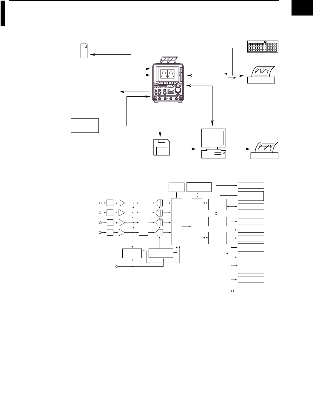
1.1 Block Diagram
System Configuration
Signal input
Personal Computer
USB printer
Printer
Floppy disk/Zip disk
USB keyboard
Built-in printer
(option)
External clock input
External trigger input
Trigger gate input
GO/NO-GO judgment output
RGB video signal output
Trigger output
SCSI Interface (option)
Saving/loading data
Screen data
Screen data
Input
Keyboard/Printer
Interface
GP-IB Interface
RS-232 Interface (option)
USB Interface
Ethernet Interface (option)
Hard copy
Object to be
measured
Waveform data
Set-up data
Screen data
External SCSI device
Block Diagram
CH1
ATT A/D
Data
processing
memory
GP-IB
SCSI
FDD/
Zip drive
CH2
CH3*1
CH4*1
Primary
memory
Display
processing
circuit
VGA video output
CPU
Serial
(RS-232)
USB
Ethernet
External clock input
External trigger input
Gate trigger input
* The DL1720 is not equipped with channels 3 and 4. Instead, an external
trigger/external clock/trigger gate multi-purpose terminal is installed in place
of the CH4 terminal.
Pre-AmpMultiplex
circuit
Primary data
processing circuit
Acquisition
memory
Display
memory
Color
LCD display
Trigger
circuit Time base
Trigger output
Keyboard/Printer
Built-in Printer (option)
(option)
Secondary data
processing circuit
(option)
(option)
Chapter 1 Functions

1-2 IM 701710-01E
Signal Flow
The signals to be measured enter at the input terminals and pass first to the attenuator
(ATT) and preamplifier. Adjusted vertical-axis characteristics (voltage and amplitude) in
accordance with the settings for input coupling, probe attenuation, V/div, and offset value
are passed to the multiplexer. The multiplexer outputs each signal to the corresponding
A/D converter in accordance with the time-axis settings.
The A/D converter converts the voltages into digital values. The Primary Processing
Circuit then writes converted values into the primary memory at the appropriate sampling
rate (as determined by the time-axis setting).
The secondary processing circuit performs averaging and other types of processing on
the data in the primary memory and writes the resultant data to the acquisition memory.
The data written in the acquisition memory is then converted to waveform display data by
the secondary processing circuit and transferred to the waveform processing circuit by
which the data are stored in the display memory. Waveforms are displayed on the
screen based on the data stored in the display memory.
1.1 Block Diagram
1-3
IM 701710-01E
Functions
1
1.2 Setting the Vertical and Horizontal Axes
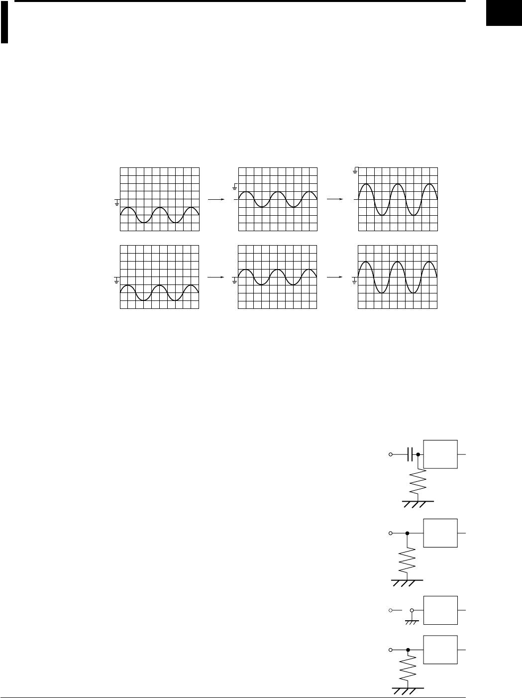
Offset Voltage <Section 5.5>
When observing a voltage riding on top of a predetermined voltage, an offset voltage can
be applied to eliminate the predetermined voltage so that only the changes in the signal
can be observed with higher voltage sensitivity.
Normally, the offset voltage does not affect the cursor measurement values, automated
measurement of waveform parameters, and computed values. However, you can turn
ON offset cancel to apply the offset voltage to them. (See section 14.4.)
1 V/div, Offset: 0 V, Position: 0 div 1 V/div, Offset: –2 V 500 mV/div, Offset: –2 V
When offset cancel is ON
When offset cancel is OFF
Input Coupling <Section 5.3>
When you only want to observe the amplitude of an alternating current signal, eliminating
the direct current components from the input signal makes observation easier. You may
also want to check the ground level or observe the input signal waveform with the offset
voltage removed. In these cases, you can change the input coupling setting. This will
switch the coupling method, which determines how the input signal is input to the vertical
control circuit (voltage axis).
The input coupling method can be chosen from the following:
AC 1 MΩ
The input signal is sent through a capacitor to the attenuator
in the vertical control circuit. This method can be used when
you just want to observe the amplitude of the alternating
current signal, eliminating the DC components from the input
signal.
DC 1 MΩ
The input signal is sent directly to the attenuator in the vertical
control circuit.
This method can be used when you want to observe both the
DC and AC components of the vertical input signal.
GND
The ground signal, not the input signal, is connected to the
attenuator in the vertical control circuit. This method enables
observation of the ground level on the screen.
DC 50 Ω
This is the same as DC 1 MΩ described above, except the
input impedance is 50 Ω. Please be aware of the maximum
input voltage.
1 MΩ
Vertical
control
circuit
Input terminal
1 MΩ
Vertical
control
circuit
Input terminal
Vertical
control
circuit
Input terminal
50 Ω
Vertical
control
circuit
Input terminal

1-4 IM 701710-01E
Probe Attenuation <Section 5.4>
A probe is usually used to connect the circuit to be measured to an input terminal. Use
of a probe provides the following advantages.
•The voltage and current of the circuit to be measured are not disturbed.
•A signal can be input without distortion.
•The measurement voltage range of the oscilloscope can be widened.
A 400 MHz passive probe is supplied with the instrument. The probe attenuates the
input signal by 1/10. When a probe is used, the probe attenuation must match the
instrument’s attenuation setting so that the input voltage can be measured directly.
DL1720/DL1740’s attenuations of 1 : 1, 10 : 1, 100 : 1 and 1000 : 1 are provided. When
you use a probe other than the one supplied with the instrument, set the instrument’s
attenuation so that it matches the probe’s attenuation.
Bandwidth Limit <Section 5.7>
High frequency noise of 20 MHz or higher, or 100 MHz or higher can be eliminated from
the input signal.
Vertical Sensitivity <Section 5.8>
The V/div (vertical sensitivity) setting is used to adjust the amplitude of the displayed
waveform so that the waveform can be observed easily.
The V/div setting is made by setting the voltage value per division on the screen grid.
The vertical sensitivity setting operates by switching to a different attenuator (attenuation
rate). The setting changes in steps (1 V/div → 2 V/div → 5 V/div ...).
In addition, by performing computations on the digital data acquired using the voltage
sensitivity above, the waveform can be displayed at a sensitivity of 0.4 (or 0.5) to 10
times the voltage sensitivity that was used to acquire the data (Variable).
1 div = 1 V 1 div = 0.50 V
When V/div is Switched from 1 V/div to 0.50 V/div
Note
Vertical Sensitivity and Measurement Resolution
To get precise readings, it is recommended that you set the vertical sensitivity so that the
waveform’s maximum and minimum amplitudes are close to the top and bottom of the screen.
Note that the instrument uses 8 - bit A/D converters. Incoming signals are sampled at a
resolution of 255 levels (LSB), or 32 levels per division.
Effective Data Range
The instrument uses 8 - bit A/D converters. Assuming that output values range from 0 to 255,
the vertical center line of the display corresponds to a value of 128. Because the A/D
converter reaches full range at 255, screen level 256 is not used.
Note also that the insturment treats an A/D output value of 0 as if it were a 1.
The screen’s effective display range extends approximately 5.29 divisions in each direction
from the screen’s center line.
However, if the vertical axis position is moved while the data acquisition is stopped, the
effective data range also moves by the same amount.
1.2 Setting the Vertical and Horizontal Axes
1-5
IM 701710-01E
Functions
1
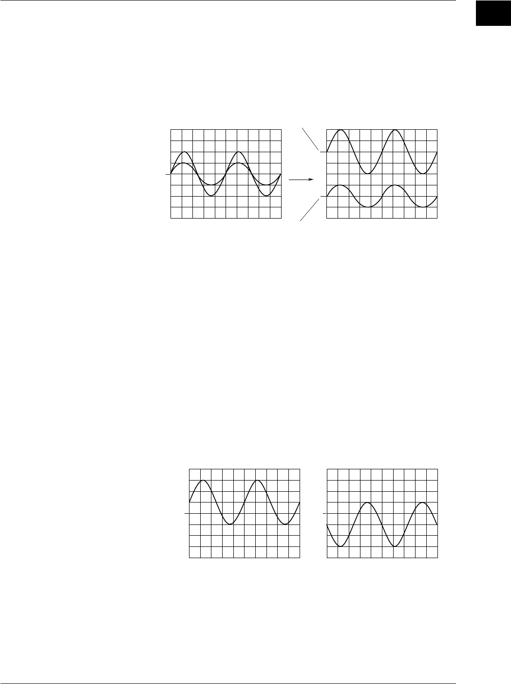
Vertical Position <Section 5.2>
Since a total of four input waveforms (or two for the DL1720) can be displayed, they may
overlap each other making observation difficult. In this case, the waveforms can be
moved in the vertical direction so that they can be observed more easily.
The vertical position mark can be set to any value in the range between ±4 div.
Changing the V/div setting, the vertical axis setting is rescaled with respect to the vertical
position.
Position: 2 div
Position: –2 div
Position: 0 div
Time Axis <Sections 5.10 and 5.11>
Selection of the Timebase
With the default settings, sampling timing is controlled by the clock signal output from the
timebase circuit of the instrument (refer to the Block Diagram, section 1.1). The
sampling timing can be controlled by an external clock signal instead of the clock signal
from the timebase circuit.
An external clock signal can be input to the EXT CLOCK IN terminal on the rear panel.
This external clock function is useful when you are observing a signal whose period
varies or when you are observing a waveform by synchronizing it with the clock signal to
be measured.
Setting the Time Axis
When using the internal clock, set the time axis scale as a time duration per division of
the grid. The setting range is 1 ns/div to 50 s/div. The time range in which waveform is
displayed is “time axis setting x 10,” as the display range along the horizontal axis is 10
divisions.
Vertical Position →→
Original Waveform (Not Inverted) Inverted Waveform
1.2 Setting the Vertical and Horizontal Axes
1-6 IM 701710-01E
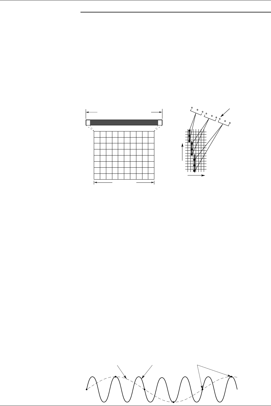
Note
Display of Time Axis Direction
The sampled data is read into the acquisition memory, and a waveform is displayed based on
this data. The number of data stored into the acquisition memory differs depending on
settings such as time axis settings, trigger mode, and acquisition mode.
The number of display lines in the time axis direction on a 10 - div screen is 500 lines.
Processing therefore varies according to record length, as described immediately below. (for
more details on the relation between time axis, acquisition mode, record length of acquisition
memory and displayed record length, refer to Appendix 1).
•If displayed record length exceeds number of screen display points, multiple data points
are connected with a line and displayed at the same time axis position.
•If displayed record length is less than number of screen display points, the oscilloscope
interpolates the data to generate the display. (See page section 1.4)
500 Lines
0 500
Display Record Length
Display Record Length
Sampling Data
Time Axis
Record Length of
Acquisition Memory
Voltage Axis
Relationship between the Time Axis Setting, Sample Rate and Record Length
Changing the time axis causes corresponding changes in the sampling rate and the
acquisition record length. For more detailed information, refer to Appendix 1.
Relationship between Time Axis Setting and Sampling Mode
The sampling method (sampling mode) for an input signal changes according to the time axis
setting as described hereafter. But note that the time - axis range over which this feature is
actually available will vary according to the maximum displayable record length, as shown in
Appendix 1.
•Real-Time Sampling Mode
Changing the time axis causes a corresponding change in the sampling rate. The
maximum sampling rate is 1 GS/s (or 500 MS/s if interleave mode is OFF. For details of
interleave mode, refer to section 7.5).
The input signal is sampled sequentially, and data is stored in the acquisition memory.
In this mode, the waveform can only be displayed correctly at frequencies up to half the
sample rate, due to Nyquist’s theorem*. Sample rate is expressed in S/s (number of
samples per second). Thus, this mode is suitable for observation of a waveform which
fluctuates more slowly than the sample rate.
* If the sample rate is higher than the frequency of the input signal, high frequency
components will be lost. In this case, a phenomenon in which high frequency components
change to lower frequency components occurs, due to Nyquist’s theorem. This
phenomenon is called aliasing. Aliasing can be avoided by setting the acquisition mode to
envelope mode and acquiring the waveform.
Aliasing Signal Input Signal Sampling Point
1.2 Setting the Vertical and Horizontal Axes
1-7
IM 701710-01E
Functions
1
•Repetitive Sampling Mode
To enable this mode, you must set the time axis so that the sampling rate is greater than
1 GS/s (interleave ON: 2 GS/s). Under this mode, the oscilloscope produces a single
waveform by taking samples over several periods of a repetitive signal, so that the
sampling rate appears higher than it actually is. An apparent sample rate of up to 100 GS/
s can be used.
Furthermore, even in the real-time sampling mode, if the sample rate exceeds 1 GS/s
(interleave ON: 2 GS/s) due to the time axis and the displayed record length settings, the
sampling mode automatically changes to repetitive sampling.
There are two repetitive sampling methods: sequential sampling, in which a signal is
sampled sequentially at a fixed interval, and random sampling, in which a signal is
sampled at random to produce a waveform. This instrument uses a random sampling
method which also enables observation of the waveform up to the trigger point.
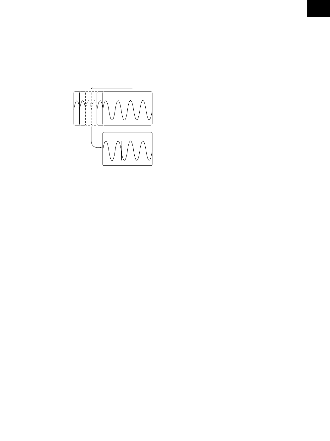
Time Axis Setting and Roll Mode Display
If the time axis is set within a certain range (refer to Appendix 1), then the display will not be
updated by trigger anymore (update mode), but the mode will switch to roll mode when new
data is acquired. In roll mode, the oldest data is deleted, and the waveform shifts from right
to left on the screen. A waveform can be observed in the same way as it is recorded on a
pen recorder. This mode is useful when you are observing a signal which repeats or which
fluctuates slowly. This mode is also useful when you want to detect glitches (fast spikes on a
waveform) which occur intermittently.
* Rolling display also operates during single - start acquisition, although trigger occurrence
causes the waveform to stop.
1.2 Setting the Vertical and Horizontal Axes
1-8 IM 701710-01E
1.3 Setting a Trigger
Trigger Type <Chapter 6>
There are two principal trigger types which you can use with the instrument.
Simple trigger
Enhanced trigger
Simple Trigger → Sections 6.5 to 6.7
This is an edge trigger and the one which is used normally.
Enhanced Trigger → Sections 6.8 to 6.14
This is a complex trigger. The following seven types of enhanced trigger are available.
A→B(N) trigger
A Delay B trigger
Pattern trigger
Width trigger
OR Trigger
Window trigger
TV trigger
Edge Trigger → Section 6.5
The edge trigger is the simplest type of trigger and uses a single trigger source to
activate a trigger. A trigger is activated when the trigger source exceeds (rises above) or
drops (falls) below the preset trigger level*.
In addition to input signals (CH1 to CH4, or CH1 and CH2 for the DL1720), the external
trigger input signal, the commercial power supply signal that is used by the instrument
can be used as a trigger source.
*“A trigger is activated” refers to the condition in which trigger conditions are satisfied and a
waveform is displayed.
Trigger Level
A trigger is activated at this point if
“Rise” ( ) is selected.
Trigger Source
A → B(N) Trigger (Enhanced Trigger) → Section 6.8
This function activates a trigger the Nth time condition B becomes true after condition A
has become true.
L
HL L H
HHHHLLL
H
CH1
CH2
CH1
CH2
When pattern A: CH1 = L, CH2 = L, Enter, When patternB: CH1 = H, CH2 = H, Enter, N = 3
L: Low level, H: High level
Trigger
LH HL L
B(1) B(2) B(3)
Pattern A is True
1-9
IM 701710-01E
Functions
1
A Delay B Trigger (Enhanced Trigger) → Section 6.9
This function activates a trigger the first time condition B becomes true after condition A
becomes true and the specified time elapses.
L
HL L H
HHHHLLL
H
CH1
CH2
CH1
CH2
Trigger
LH HLL
Pattern A is True Pattern B is True
1 µs
When pattern A: CH1 = L, CH2 = L, Enter, When patternB: CH1 = H, CH2 = H, Enter, Delay = 1 µs
Pattern Trigger → Section 6.10
Multiple trigger sources are selected, and a trigger is activated when all of the trigger
conditions set for each trigger source become true or false. Trigger conditions are
established by setting combinations of the state (High or Low) of each trigger source.
Furthermore, one of the trigger sources can be used as the clock signal, and triggering is
synchronized with this clock signal.
LH L L L
H
HHHHLLLL
L
HLLH
HLL
H
CH1
CH2
CH3
*1
CH4
*1
CH1
CH2
CH3
*1
CH4
*1
Trigger is activated.
Example: a trigger is activated
when CH1: L, CH2: L, CH3
*1
: L and CH4
*1
: L (*1 The DL1720 is not equipped
with channels 3 and 4.)
Pulse Width Trigger → Section 6.11
The time period during which the specified condition is met or not met is compared with
the specified time period. The trigger condition is set with the AND of the signal state of
each channel (High, Low, or Don’t Care) or the AND of the window conditions of each
channel (IN, OUT, or Don’t Care).
HLLH
H
H
H
LL
L
H
CH1
CH2
CH1
CH2 LH H
LL
500 ns
300 ns
400 ns
ABC
D
450 ns
1.3 Setting a Trigger
1-10 IM 701710-01E
The description of the figure above is as follows.
If CH1 = H, CH2 = L, CH3 = X, CH4 = X, Condition = True, Time = 350 ns: (The DL1720
is not equipped with channels 3 and 4.)
The trigger is activated at point B if Pulse < T.
The trigger is activated at points A and C if Pulse > T.
The trigger is activated at point C if T1 < PLS < T2 where Time1 = 350 ns, Time2 = 450
ns.
The trigger is activated at point D if “Time out” is specified where Time = 450 ns.
OR Trigger (Enhanced Trigger) → Section 6.12
A trigger is activated when any of the edge trigger conditions specified on CH1 to CH4
(or CH1 and CH2 for the DL1720) or the window condition is met. A trigger can be
activated by either the rising edge of CH1 or CH2.
When CH1 = and CH2 =
Tigger
CH1
TiggerTigger
CH2
Window Trigger (Enhanced Trigger) → Section 6.13
A certain voltage range (window) is set and a trigger is activated when the trigger source
level enters this voltage range (IN) or exits from this voltage range (OUT).
Width
trigger is activated
OUT
trigger is activated
IN
Window Window
trigger is activated
Center
Width
Center
TV Trigger (Enhanced Trigger) → Section 6.14
The TV trigger is used when you are observing a video signal, and is compatible with
NTSC and PAL broadcasting systems.
1.3 Setting a Trigger
1-11
IM 701710-01E
Functions
1
Trigger Mode <Section 6.1>
Conditions for updating displayed waveforms are set. The following five types of trigger
mode are available:
Auto Mode
Displayed waveforms are updated each time a trigger is activated within a specified time
(approximately 100 ms, referred to as the time-out period) and are updated automatically
after each time-out period.
Auto Level Mode
Waveforms are displayed in the same way as in Auto mode if a trigger is activated within
the time-out period. If no trigger is activated, the center value of the amplitude of the
trigger source (section 1.3) is detected and the trigger level is changed automatically to
this center value, then a (edge) trigger is activated to update the displayed waveforms.
Half the Amplitude
Half the Amplitude
Trigger Level Amplitude
Normal Mode
Displayed waveforms are updated only when a trigger is activated. Displayed
waveforms will not be updated if no trigger is activated.
Single Mode
When a trigger is activated, displayed waveforms are updated only once, then
acquisition stops. This mode is useful when you are observing a single-shot signal.
Single (N) Mode
This mode is useful when using the sequential store function (refer to section 7.3).
Waveforms are acquired and stored in different memory areas each time a trigger is
activated, then acquisition stops, and the waveforms are displayed. Acquisition is
performed the specified number of times. Acquired waveforms can be displayed
together, or they can be displayed individually. This mode is useful when you want to
detect a sudden abnormality in a waveform.
1st Acquisition 2nd Acquisition Nth Acquisition
Action-On Trigger <Section 6.15>
The displayed waveform can be output to the optional built-in printer, buzzer, or saved to
a floppy disk/a Zip disk each time a trigger is activated. Also sends a mail (Ethernet
interface (option)).
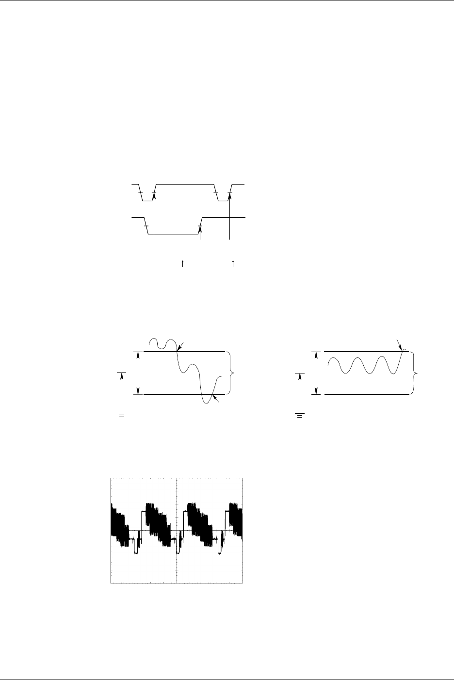
Trigger Coupling <Sections 6.5, and 6.8 to 6.13>
Input coupling can also be switched for trigger sources as it is for input signals. Select
the type of input coupling which is most suitable for the trigger source signal.
The following two types of input coupling are available for trigger source signals.
•DC: The trigger source signal is used as the trigger source without any process.
•AC: The trigger source signal is used as the trigger source after DC the content has
been removed from it. A trigger can always be activated if the trigger level is set
to 0 V as long as the signal’s amplitude is one division or more.
1.3 Setting a Trigger
1-12 IM 701710-01E
HF Rejection <Sections 6.5, and 6.8 to 6.13>
Set HF rejection to ON when you want to remove high frequencies exceeding 15 kHz or
20 MHz from the trigger source. This prevents a trigger from being activated
unexpectedly due to high frequency noise.
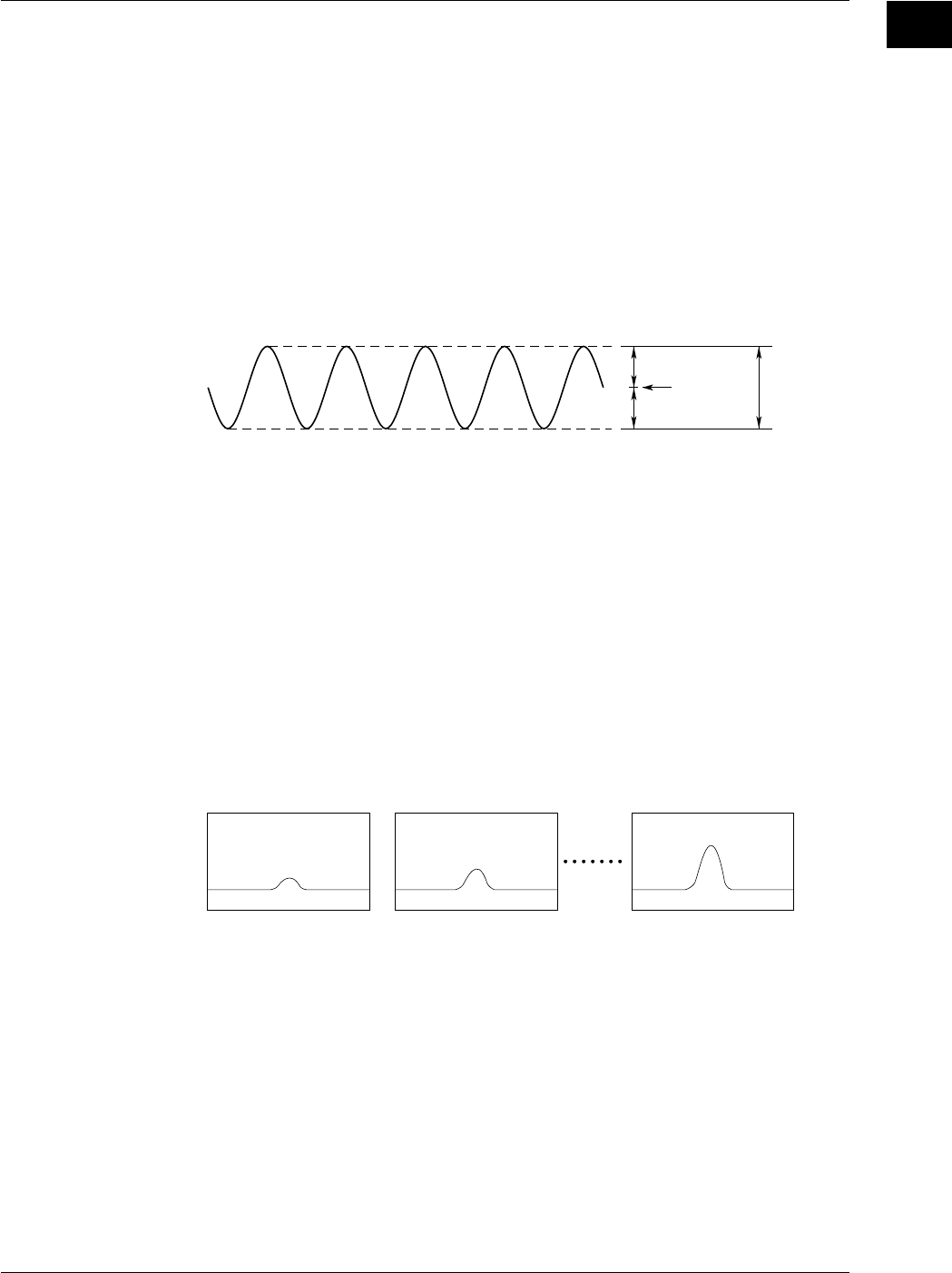
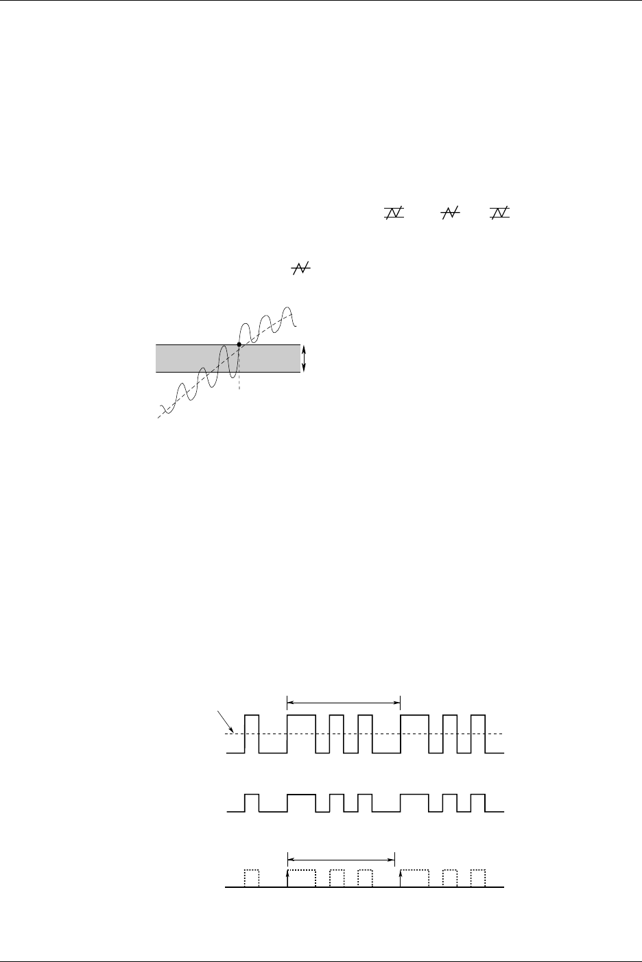
Trigger Hysteresis <Sections 6.5, and 6.8 to 6.13>
If the trigger level width is not sufficient, the trigger point fluctuates each time a trigger is
activated if noise is present in the trigger source, thereby resulting in unstable displayed
waveforms. To solve this problem, a specified margin (hysteresis) can be added to the
selected trigger level.
The hysteresis level can be chosen from “ ” and “.” If “ ” is selected, a wide
hysteresis level is provided to eliminate fluctuation in the trigger point, thereby resulting
in a stable displayed waveform. However, in this case, the trigger points become
uncertain. Thus, select “” if you want to activate a trigger to detect small fluctuations
in a waveform.
A trigger is activated.
Hysteresis Width
Trigger Source and Trigger Level <Sections 6.5 to 6.13>
Trigger Source: Selects the signal for the selected trigger type. The external trigger
signal or the commercial power supply signal can also be used a trigger
source.
Trigger Level: Sets the voltage level used to judge trigger conditions such as trigger
slope (rise/fall of a signal).
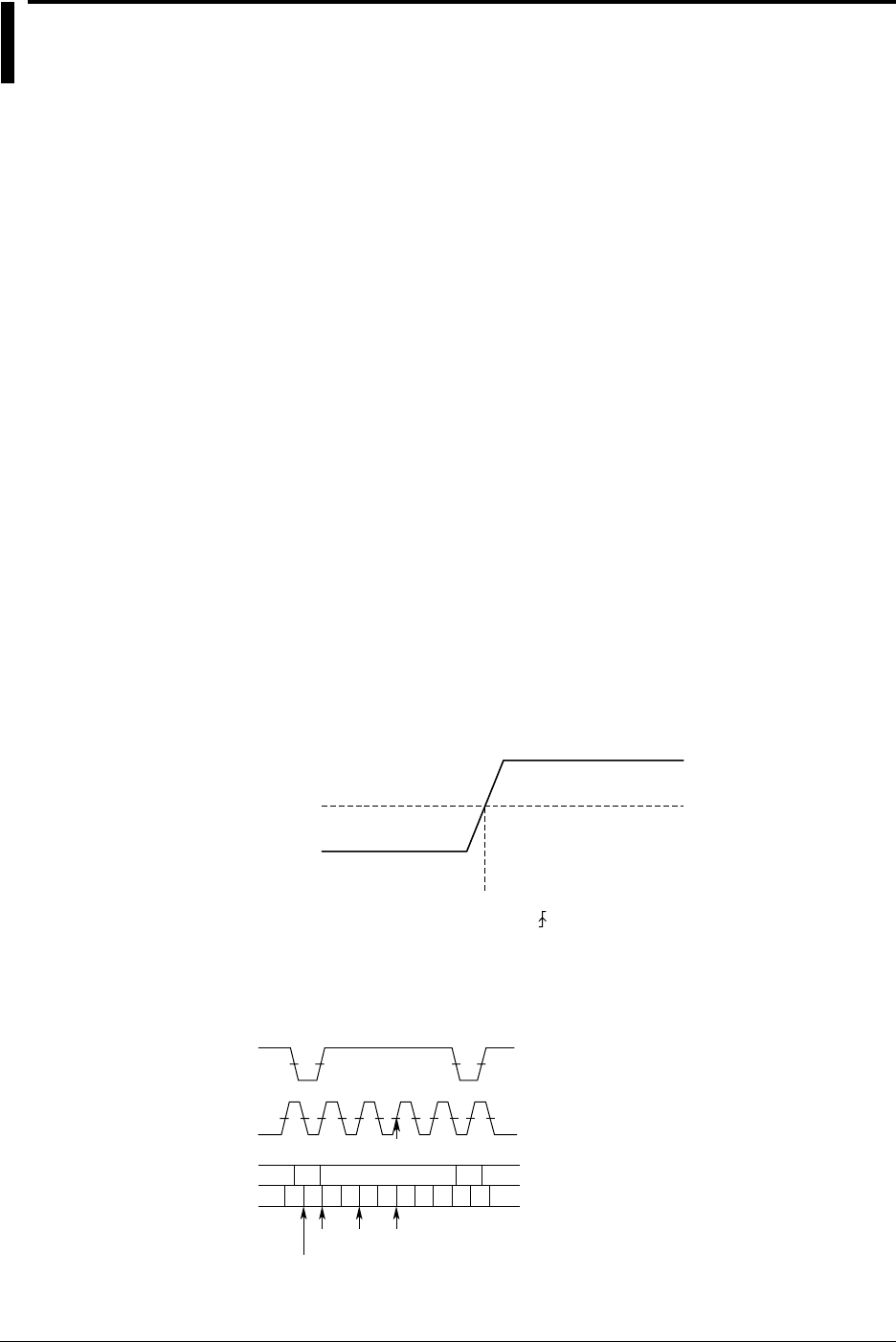
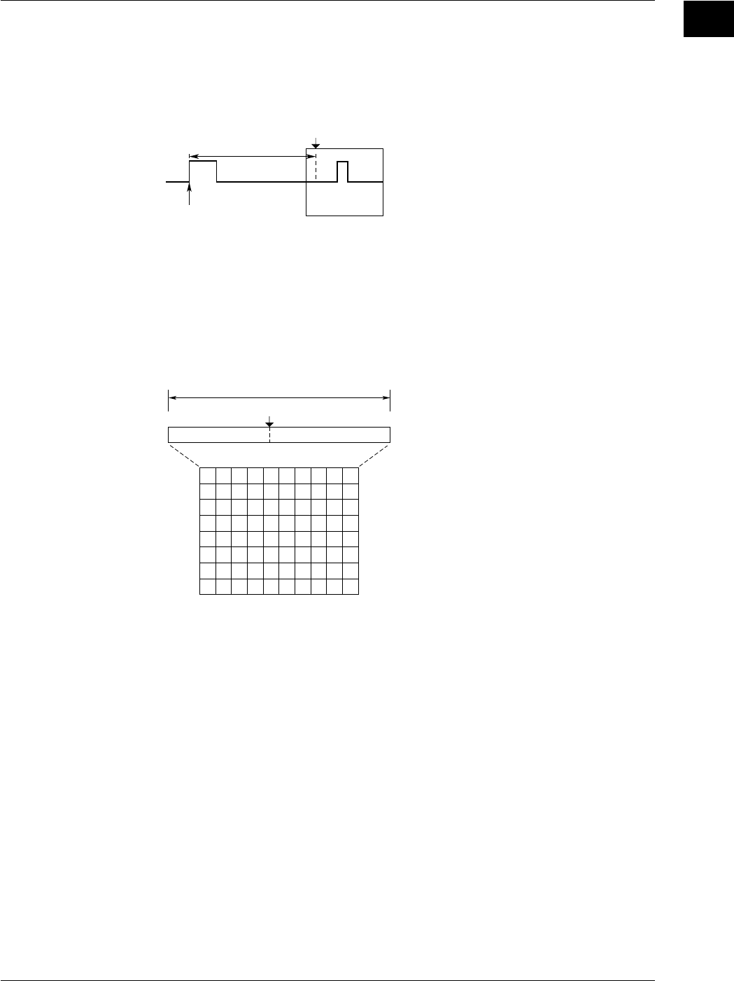
Trigger Hold-Off <Section 6.4>
The trigger hold-off function temporarily stops detection of the next trigger once a trigger
has been activated. For example, when observing a pulse train signal, such as a PCM
code, display of the waveform can be synchronized with repetitive cycles; or when using
the history memory function, you may want to change the repetitive period, as shown
below.
Input Signal
Repetitive Period: T
Trigger Level
Trigger Ssource
Signal
t
Trigger Signal Restricted by Hold-Off Time “t” (When “Rise” is selected as the trigger slope)
1.3 Setting a Trigger
1-13
IM 701710-01E
Functions
1
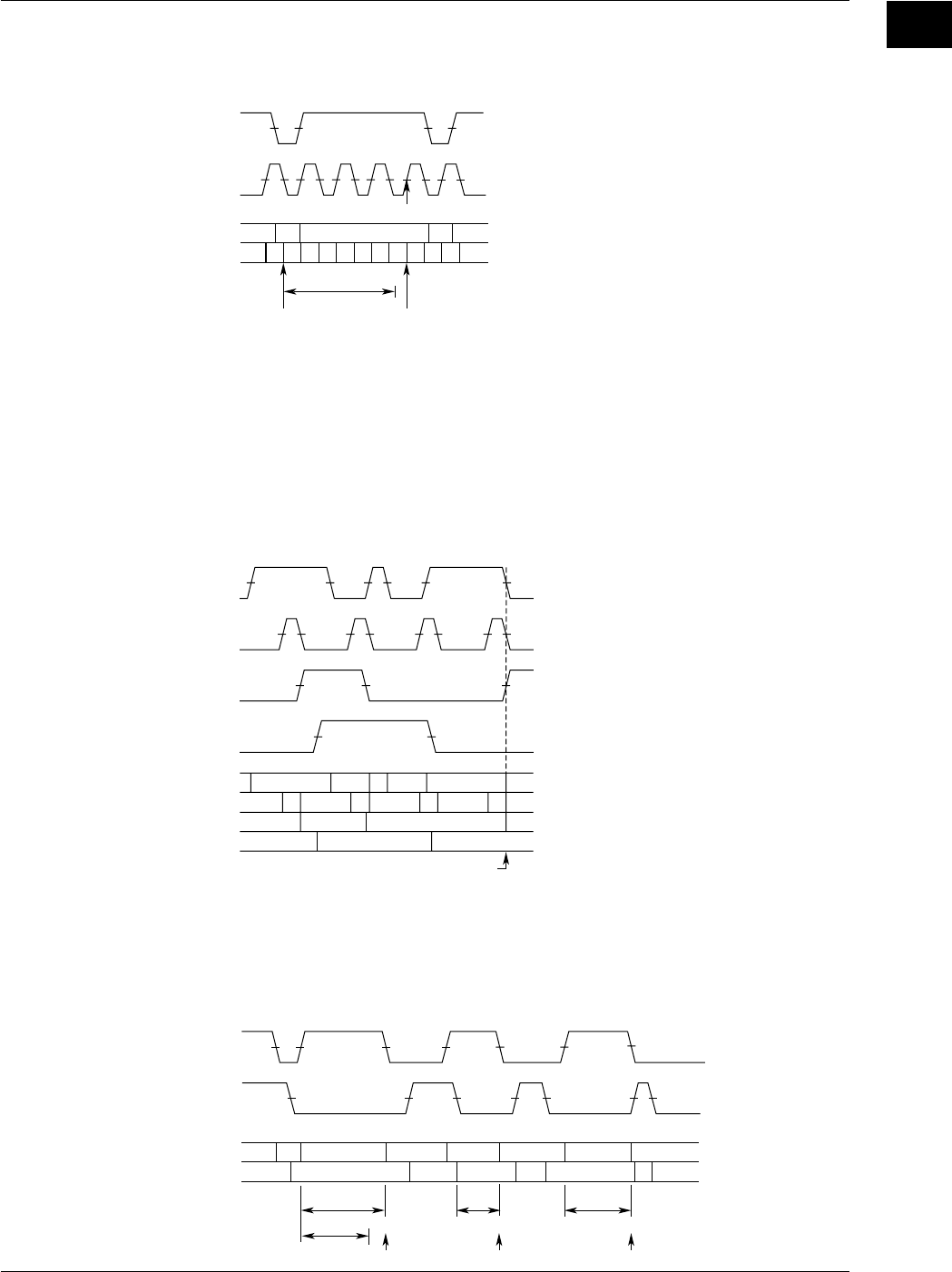
Trigger Delay <Section 6.2>
Normally, the waveform around the trigger point is displayed. However the trigger delay
function enables display of a waveform which has been acquired after a specified time
(called the delay time) has elapsed following activation of a trigger. The range for the
trigger delay setting is 0 to 4 seconds.
Delay Time
Trigger Point
T (Trigger Position)
Trigger Position <Section 6.3>
The trigger position indicates which position of the waveform in the acquisition memory
will actually be displayed on the screen. The trigger point refers to the point at which a
trigger is activated. In case the trigger delay (to be explained here after) is set to 0s, the
trigger point and the trigger position refer to the same location.
You use this setting to select how much pre-trigger area and how much post-trigger area
to show on the display.
Display Record Length
Trigger Position
Pre-Trigger Range Post-Trigger Range
0% 100%
1.3 Setting a Trigger

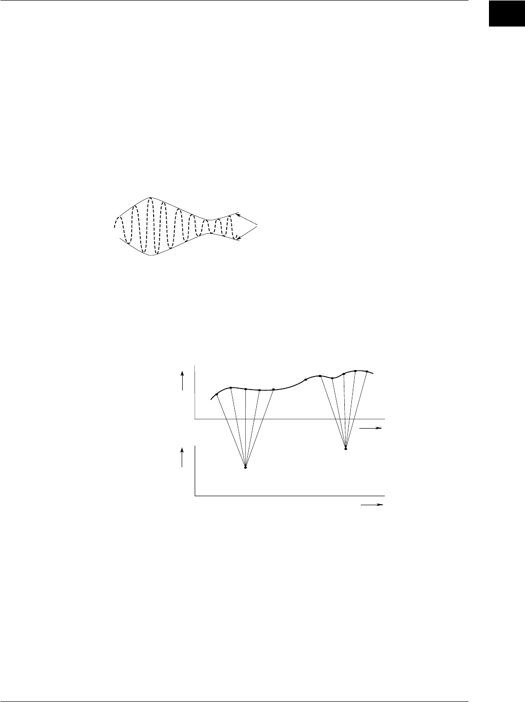
1-14 IM 701710-01E
1.4 Setting the Acquisition and Display Conditions
Record Length <Section 7.1>
The term “record length” refers to the number of data points (per channel) acquired in the
acquisition memory. “Displayed record length” refers to the number of these data points
that are actually displayed on the screen. (Note that sampling rate and record length will
vary according to the time-axis setting; see section 1.2) The DL1720/1740 lets you set
the record length to any of the following: 1 kwords, 10 kwords, 50 kwords, 100 kwords,
250 kwords, 500 kwords, 1 Mwords.
In most cases the displayed record length is identical to the (acquisition) record length.
For certain time-axis settings, however, the lengths become different. For details, refer
to Appendix 1.
Interleave Mode <Section 7.5>
This mode doubles the amount of memory per channel, while cutting the number of
channels in half. If you are using an 8 - channel model, for example, then setting this
mode ON will disable use of CH2 and CH4 (or CH2 only on the DL1720), while
reassigning the memory for those channels to CH1 and CH3 (or CH1 only on the
DL1720).
This mode doubles the maximum settings for history memory, sequential store, and
record length.
Furthermore, because the maximum sample rate can be increased by sampling the input
signal using two A/D converters, real-time sampling at a rate of 1 GS/s for the DL1720/
DL1740.
For the relationship between the interleave mode, time axis, record length, and sample
rate, see appendix 1, “Relationship between the Time Axis Setting, Sample Rate, and
Record length.”
Acquisition Modes <Section 7.2, 7.4>
When storing sampled data in the acquisition memory, it is possible to perform
processing on specified data and display the resultant waveform. The following data
processing methods are available.
Normal Mode
In this mode, sampled data are stored in the acquisition memory without processing.
Averaging Mode
Averaging is a process in which waveforms are acquired repeatedly to obtain the
average of waveform data of the same timing (the same time in relation to the trigger
point).
If this mode is active, the instrument takes the linear or exponential average of incoming
data and writes the results into acquisition memory. The averaged data is then used to
generate the display. You can set the attenuation constant to a value from 2 to 256 (in
2n steps), and the averaging count to a value from 2 to 65536 (in 2n steps).
An = {(N - 1) A
n - 1 +
X
n
}
1
N
Exponential Averaging (Count = Infinite)
A
N
=N
Linear Averaging (Count = 2 to 65536)
N
n = 1
Σ X
n
An
Xn
N
: Value Obtained After nth Averaging
: nth Measured Value
: Attenuation Constant
(2 to 256, in steps of 2
n
)
Xn
N: nth Measured Value
: Number of Averaging Times
(Acquisition Count,
in steps of 2
n
)
This averaging process is useful when you want to eliminate random noise.
1-15
IM 701710-01E
Functions
1
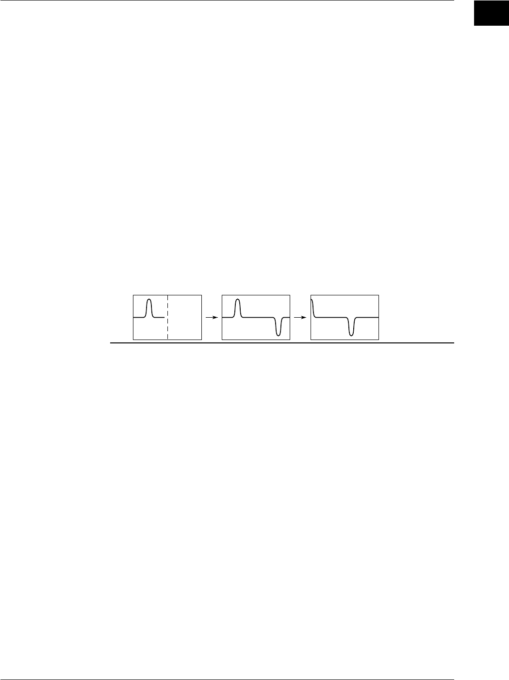
Envelope Mode
In normal mode and averaging mode, the sample rate (the number of times data is
acquired per second in the acquisition memory) drops if T/div is increased (refer to
Appendix 1 “Relationship between the time axis setting, sample rate and record length”).
However, in the envelope mode, the maximum and minimum values are determined at
every time interval from the data sampled at 400 MS/s for the DL1720/DL1740
(interleave mode: 800 MS/s or 1 GS/s). The time interval used to determine the values
is the twice sampling interval of the normal mode. The maximum and minimum values
are paired and acquired in the acquisition memory.
Envelope mode is useful when you want to avoid aliasing (section 1.2), since the sample
rate is kept high irrespective of the time axis setting (T/div). Furthermore, envelope
mode is also useful when you want to detect glitches (pulsing signals which rise very
fast) or display an envelope of a modulating signal.
Envelope
Box Average
Taking the data sampled at 400 MS/s for the DL1720/DL1740 (interleave mode: 800 MS/
s), the moving averages of certain number of data points are determined as shown in
the following figure. These data are acquired in the acquisition memory and displayed.
Box averaging is useful for eliminating the small amount of noise on the input signal. It is
also effective in removing the noise from a signal acquired only once.
Voltage
Time Axis
Time Axis
1220
a
21
Input Signal
(20 MS/s,
Interleave
Mode is OFF)
Box Averaging
Data
b
• • • • • •
36
• • • • •
• • •
Voltage
1.4 Setting the Acquisition and Display Conditions
1-16 IM 701710-01E
Sequential Store <Section 7.3>
In the real-time sampling mode, waveform data will be stored in the acquisition memory
only a set number of times, and all waveforms can be displayed. This stops
automatically after acquisition. The maximum acquisition count available with the feature
varies depending on the record length.
The range for the DL1720/DL1740 is 2 to 512 times.
Once the specified number of waveforms have been stored, you can display any of the
waveforms individually or all of them together, so that it is possible to derive a time series
of the waveform variation. The drawings below illustrate how stored data can be
displayed (assuming sequential storage of 100 waveforms).
Display Example in Case Count = 100 Times
Displaying All Waveforms
(ALL) Displaying Newest Waveform
(Selected Record No. = 0) Displaying Oldest Waveform
(Selected Record No. = –99)
Sampling Mode <Section 7.6>
As explained earlier in “Relationship between the time axis setting and sampling mode”
(section 1.2), data sampling can be performed either in real-time or in repetitive sampling
mode depending on the time axis and record length. The available time - axis range
under repetitive mode varies according to the acquisition settings. For details, refer to
Appendix 1.
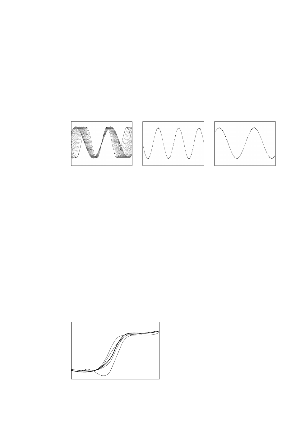
Accumulated Waveform Display <Section 8.6>
This mode holds each waveform on the screen for a time that is longer than the update
cycle, so that multiple waveforms are overlapped. The waveform age can be identified
by color.
The following two modes are available.
•Persist: Overlaps the display of waveforms using the display color of each channel.
•Color: Overlaps the display of waveforms using 8 colors which signify the
frequency of occurrence of the data values.
This function is useful when you want to observe jitters and temporary turbulence in
waveforms.
1.4 Setting the Acquisition and Display Conditions
1-17
IM 701710-01E
Functions
1
History Memory <Section 7.7>
The oscilloscope automatically retains the last N waveforms recorded. The value of N
varies in the range 2 to 2048 for the DL1720/DL1740 depending on the record length
and interleave mode. The oscilloscope retains all waveforms for the first N triggers;
then, for each subsequent trigger, the oscilloscope overwrites the oldest stored
waveform. You are free to switch the display from the current (newest) waveform to any
of other N-1 waveforms in the history. The illustration below shows how data can be
displayed, assuming N = 1024.
Saved Waveform Data of Previous 1024 Triggers
Selected Record No. 0
Selected Record No. –25
Current Waveform Display
(Select Record = 0)
Any Former Waveform Display
(Select Record is Selectable in the Range 0 to –1023)
In addition, a particular waveform can be found from the past waveforms that are held.
Display Settings <Chatpter 8>
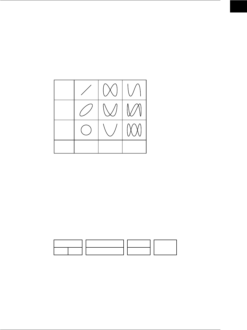
Display Format → Section 8.1
•You can display waveforms from different channels in different windows. You can
choose to use 1 window (Single), 2 windows (Dual), 3 windows (Triad), 4 windows
(Quad) or 6 windows (Hexa). (4 windows (Quad) or 6 windows (Hexa) are not
available on the DL1720.)
•You can select either of the following two methods for assigning channels to windows.
Auto: Channels that are set to ON are displayed in order of channel number, with the
lowest channel displayed in the top window.
Fixed: Channels are displayed in order of channel number, regardless of whether ON
or OFF.
User: Arbitrarily assign the channels to the split screens, regardless of wether or nor
the channel display is turn ON.
Graticule → Section 8.3
Use this feature to select use of grid, frame, or “cross” graticule.
Scale Values → Section 8.4
If the Scale Value setting is ON, the screen displays numerical values at the top and
bottom of the vertical axis and the horizontal axis.
1.4 Setting the Acquisition and Display Conditions
1-18 IM 701710-01E
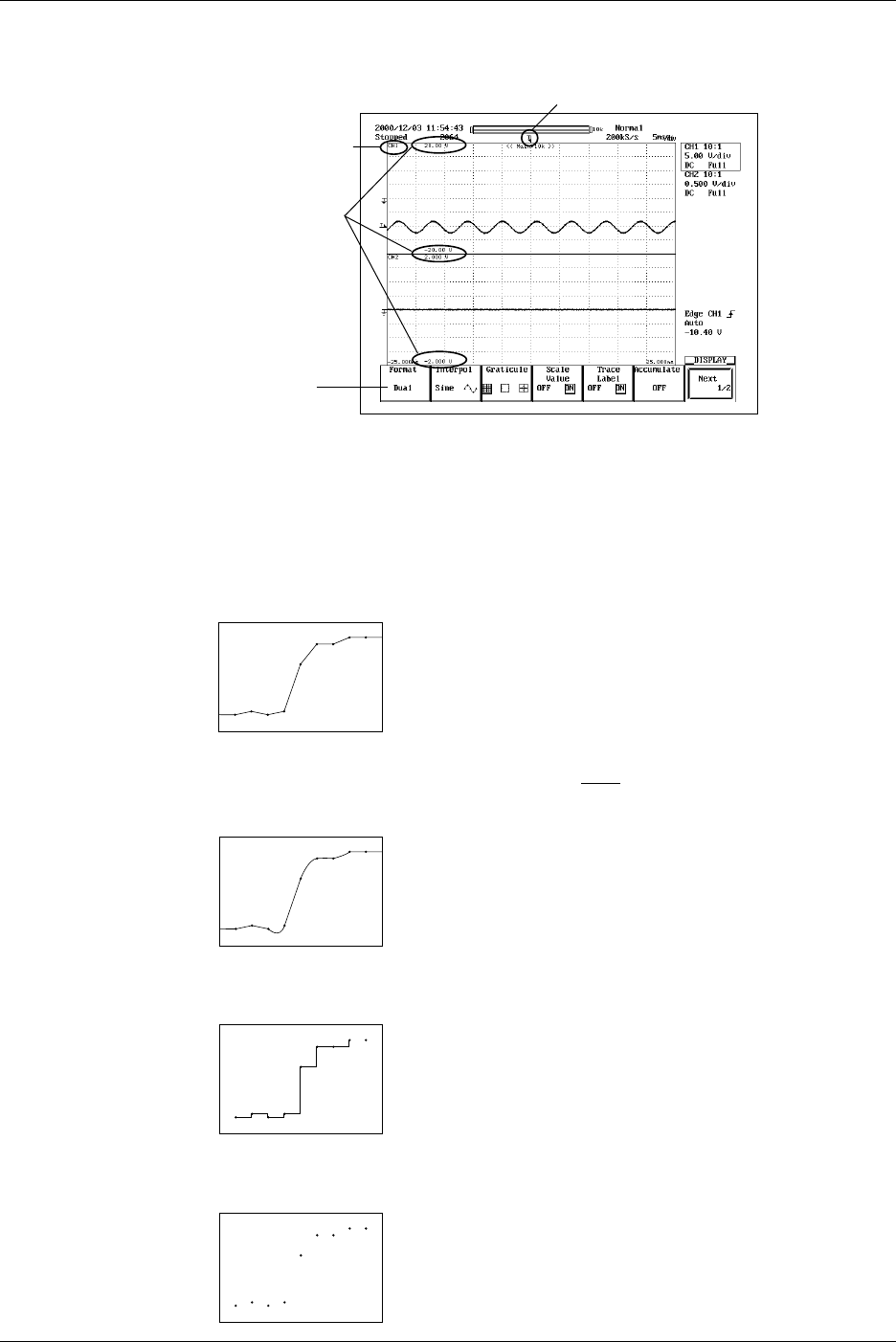
Waveform Labels → Section 8.5
You can assign an arbitrary label (up to 8 characters) to each waveform.
Waveform Label
Trigger Mark
Scale Values
Selects use of
2 waveform windows.
Display Interpolation <Section 8.2>
This feature selects the type of interpolation applied in areas where there are less than
500 sample points (Less than 250 points in the zoom window when zooming on the
waveform using Main & Z1 & Z2) per 10 time-axis divisions. (These areas are referred to
as interpolation areas.) Three settings are available.
Line Interpolation
Interpolates between two dots using a straight line.
Sine Interpolation
Generates interpolation data using the function
sin x
x
then interpolates between two dots
using resulting sine curve. Sine interpolation is suitable for observation of sine waves.
Pulse Interpolation
Interpolates between two dots using a step.
No Interpolation
Displays measurements as discrete dots, without interpolation.
1.4 Setting the Acquisition and Display Conditions
1-19
IM 701710-01E
Functions
1
X-Y Waveform Display <Section 8.8>
This feature plots the voltage values of one input waveform (on the X axis) against the
voltage values of the others (on the Y axis, which have their display turned ON). The X-
Y plot lets you view the relationship between the signal voltages. The X-Y waveforms
and normal waveforms (a waveform displayed using voltage and time axes) can be
displayed simultaneously.
Use of this X-Y waveform display function enables measurement of the phase angle
between two sine wave signals. For example, two X-Y sine waveforms are displayed to
obtain an X-Y waveform (called a Lissajous waveform), from which the phase angle can
be obtained.
Phase
Angle 0°
Phase
Angle 45°
Phase
Angle 90°
Frequency
Ratio
(X : Y) 1 : 1 1 : 2 1 : 3
Lissajous Waveform
Expanded Waveform <Section 8.9>
Waveforms can be expanded in the time axis direction. This function is useful when you
want to change the T/div setting after the waveform has been displayed in single mode
or when you want to extend the acquisition time to observe a particular part of the
waveform thoroughly.
Zooming is not available on areas with less than 11 data points.
You set the zoom position according to it’s time-axis location.
Zoom Display Arrangement
You can display one or two zoom windows on the screen. Four display arrangements
are available, as follows.
Main: Main area
Z1, Z2: Zoom area
<Main>
<Z1> or <Z2>
<Main>
<Z2><Z1>
<Z1>
<Z2>
<Z1>
or <Z2>
1.4 Setting the Acquisition and Display Conditions
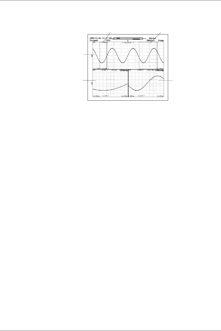
1-20 IM 701710-01E
If you display the “main” area (normal waveform display) together with one or both zoom
windows, the main area will include vertical lines (or “zoom boxes”) indicating the zoom
area (s). The center of the zoom area corresponds to the center of the zoom box.
Main Waveform
Z1 Waveform Z2 Waveform
Z2 Box
Z1 Box
1.4 Setting the Acquisition and Display Conditions
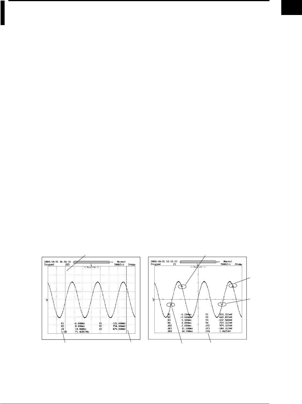
1-21
IM 701710-01E
Functions
1
1.5 Analyzing the Waveform
Linear Scaling <Section 5.9>
It is possible to append a scaling constant A, an offset value B and a unit to the
measurement value X of cursor or automated measurements. Linear scaling is useful,
when applying a voltage divider ratio to the measurement values. Linear scaling is also
handy when you want to your scope to automatically convert the measured voltage
results into the (for example, current or temperature) measurement unit of your signal
source.
Y(UNIT) = AX + B Y = result of linear scaling
Cursor Measurements <Section 9.1>
You can use the following cursor types to analyze the waveform data.
•V Cursors (Vertical)
Two vertical broken lines (V cursors) are displayed. The time from the trigger position
to each V cursor and the time difference between the V cursors are measured.
In addition, the voltage of the signal at each cursor position and the voltage difference
between the cursors are measured.
•H Cursors (Horizontal)
Two horizontal broken lines (H cursors) are displayed. The values in the vertical
direction of each H cursor and the difference between the two are measured.
•Marker Cursors (Markers)
Use this feature to place one or two markers onto the waveform. You can then read
the voltage value and time value (relative to trigger position) at each marker, and the
voltage difference and time span between the markers.
•Angle Cursors (Degree)
Set the measurement zero point and the end point and then using the angle
corresponding to the width between the two as a reference, measure the angle of the
two angle cursors.
Marker1
Marker3
Cursor2
Cursor1 Marker2
Marker4
Measurement Value
of Cursor
For Marker Cursors
For V Cursors
Measurement Value
of Cursor
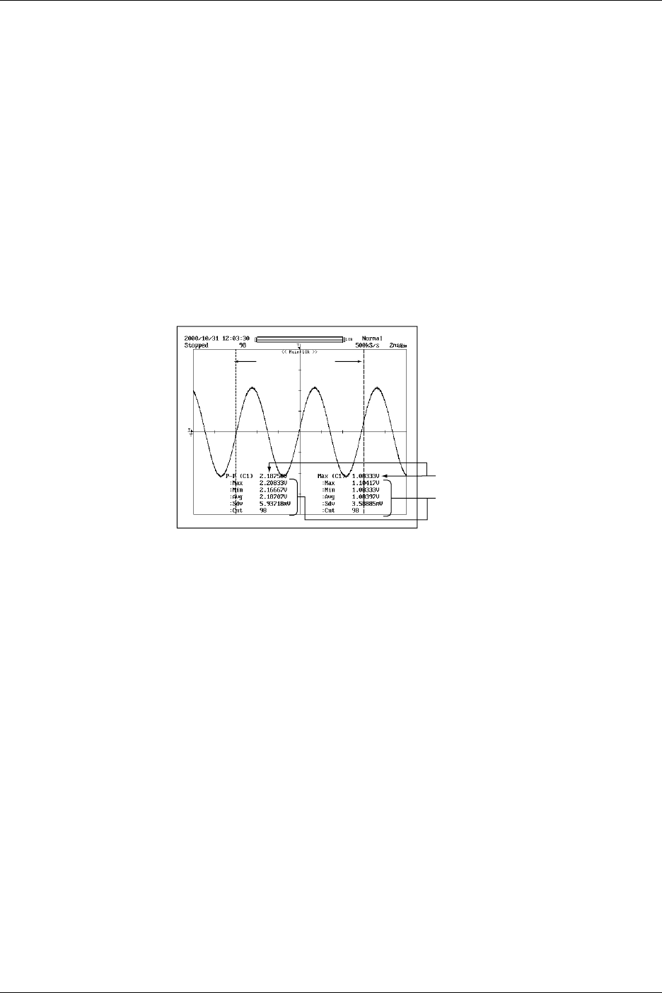
1-22 IM 701710-01E
Automated Measurements <Sections 9.2 to 9.4>
Automatic Measurement of Waveform Parameters → Section 9.2
This feature automatically measures selected waveform parameters, such as rise time
and pulse width. You can select parameters separately for each channel, although you
are limited to a total of 12 parameters to display. There are 27 parameters available for
selection.
Statistical Processing → Section 9.3
Statistical processing is performed on the automated measured values described above.
The following five statistics are determined on the two measured values of automated
measurement parameters.
•Maximum value (Max)
•Minimum value (Min)
•Average value (Avg)
•Standard deviation (Sdv)
•Number of measured values used in the statistical processing (Cnt)
Measurement
Range
Statistical Processing Results
Automatic Measurement Value of
the Statistical Processing Parameters
The following three methods are available in the statistical processing.
•Normal Statistical Processing
While acquiring waveforms, statistical processing is performed on all the waveforms
acquired up to that point.
1.5 Analyzing the Waveform
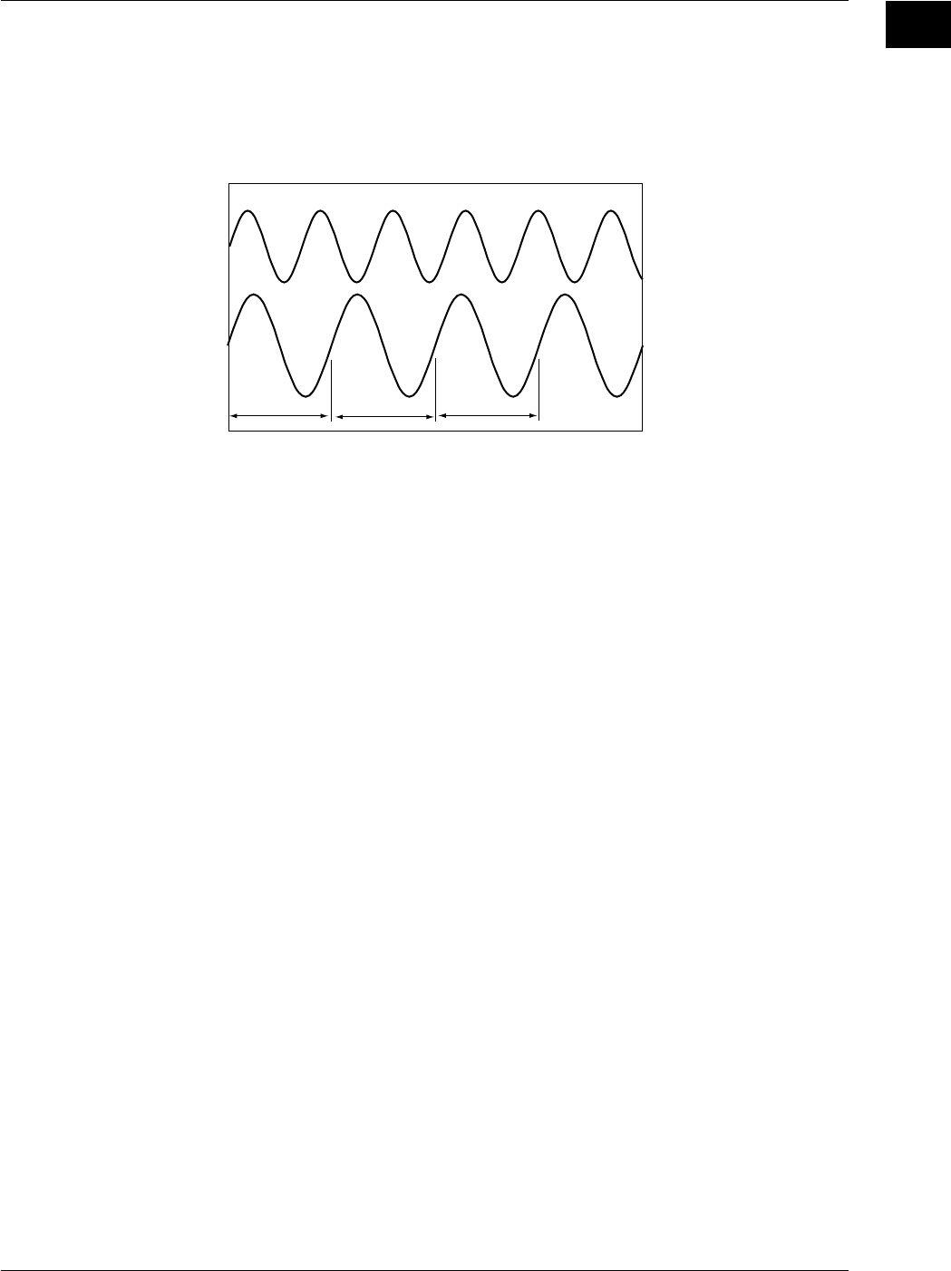
1-23
IM 701710-01E
Functions
1
•Statistical Processing for Each Period
Divides the displayed waveform using a period that is automatically calculated and
performs statistical processing on the measured values over the determined period.
Statistical processing is performed from the oldest measured data of the displayed
waveform.
CH2
CH1
abc
The parameters for automated measurement are measured in
each range a, b, and c, and statistical processing is performed
on each automated measurement parameter in the order a, b,
and c.
Automated measurement parameters of other channels are also
measured over each range a, b, and c.
Automated measurement can also be performed on the period
of each waveform.
Example in which CH1 is selected as the target waveform for determining the period
•Statistical Processing of Historical Data
Performs automated measurement of waveform parameters on the waveform that is
acquired using the history memory function and performs statistical processing.
Statistical processing is performed from the oldest waveform.
Perform Automated Measurements of Waveform Parameters on Dual Areas →
Section 9.4
You can specify two areas and perform automated measurement of waveform
parameters on each area. You can also perform computation on the parameters
determined in the two areas. Statistical processing for each period is not possible.
1.5 Analyzing the Waveform
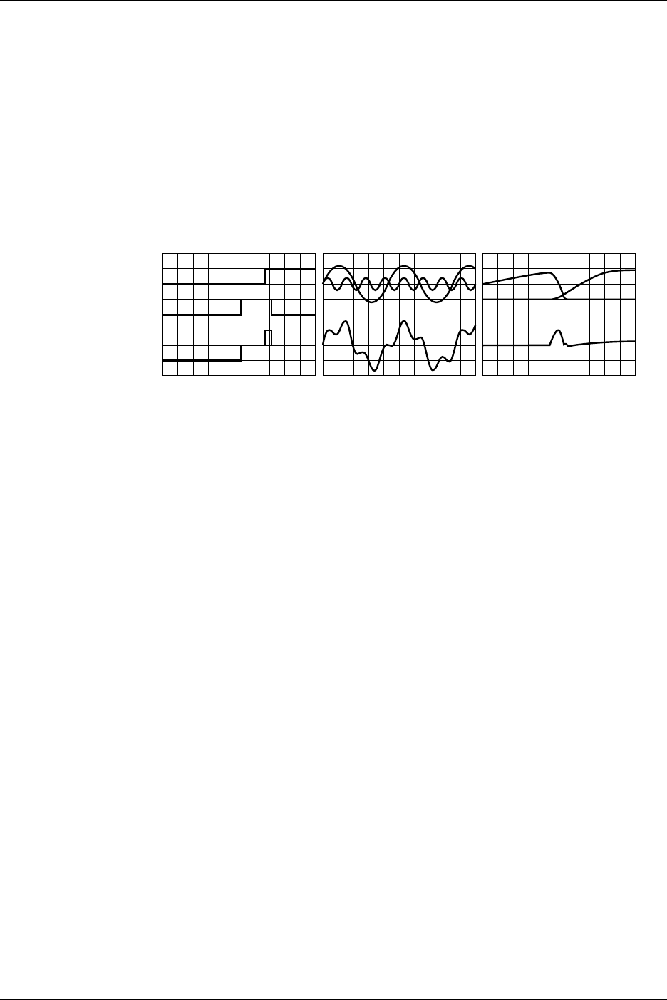
1-24 IM 701710-01E
Waveform Math <Chapter 9>
Addition, Subtraction, and Multiplication → Section 9.5
Addition, subtraction, and multiplication can be performed between CH1 and CH1 to
CH4, CH2 and CH1 to CH4, CH3 and CH1 to CH4 or Math1, and CH4 and CH1 to CH4
or Math1 (or between CH1 and CH1 to CH2, and CH2 and CH1 to CH2 for the DL1720).
The result is displayed as waveform Math1 or Math2 (or waveform Math1 on the
DL1720).
Addition and subtraction are useful for comparing signals to the standard signal,
checking the signal logic, and comparing signal phases. Multiplication is useful for
checking power signals by applying voltage and current signals.
Subtraction-
Computed Waveform
Addition-
Computed Waveform Multiplication-
Computed Waveform
Binarization → Section 9.6
Converts the selected waveform into a binarized waveform. All voltages below the
threshold become 0, while voltages above the threshold become 1. This operation is
available for CH1 to CH4, and the Math1 waveform (or CH1 to CH2 for the DL1720).
Inverted Display → Section 9.7
By multiplying the measured data by –1, the waveforms are displayed with their voltage
axes inverted. This operation can be performed on CH1 to CH4, and Math1 (or CH1 to
CH2 for the DL1720).
Differentiation and Integration → Section 9.8
Differentiates or integrates the waveform on the specified channel. This operation can
be performed on CH1 to CH4, and Math1 (or CH1 to CH2 for the DL1720).
Scaling of Math1 and Math2 Waveforms → Section 9.5 to 9.9
The instrument normally auto scales when displaying the computed waveform, but
manual scaling can also be selected.
If you select auto scaling, the upper and lower value suitable for displaying the waveform
is calculated from the voltage axis, offset voltage, type of computation, and other factors
of the waveform being computed.
If you select manual scaling, then the upper and lower limits of the computed waveform
display can be set to any desired values.
Phase-Shifted Addition, Subtraction, and Multiplication → Section 9.11
Displays the phase-shifted waveforms of CH1 to CH4 (or CH1 to CH2 for the DL1720) or
performs a computation using the phase-shifted waveforms.
1.5 Analyzing the Waveform
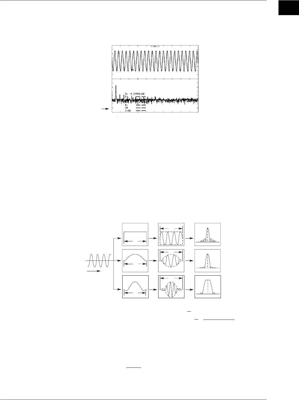
1-25
IM 701710-01E
Functions
1
Power Spectrum Display <Section 9.9>
FFT (Fast Fourier Transform) computation can be performed on the input signal to
display its power spectrum. This is useful when you want to check the frequency
distribution of the input signal.
Power Spectrum
Waveform
Three time windows are available: a Rectangular window, a Hanning window, and a
Flattop window.
The Rectangular window is effective for transient signals, such as impulse waves, which
attenuate completely within the time window. The Hanning window allows continuity of
the signal by gradually attenuating the parts of the signal located near the ends of the
time window down to the “0” level. Hence, it is effective for continuous signals. The
frequency resolution of the Hanning window is higher than that of the Flattop window.
However, the level accuracy of the spectrum of the Flattop window is higher than that of
the Hanning window. When the waveform being analyzed is a continuous-type signal,
select the appropriate window that suits the application.
FFT computation generates 1000 or 10000 measurement data points, but only half
points are displayed on the screen.
T
T
T
T
Rectangular Window
Hanning Window
Hanning Window
: W(t) = u(t)–u(t–T) U(t):
Step Function
: W(t) = 0.5–0.5cos(2π )
: W(t) = {0.54–0.46 cos(2π )}
T
T
t
Tt
Tsin{2π(1–2t/T)}
2π(1–2t/T)
Sine Wave
t
Window Integral Power Spectrum
Rectangular
Window
Hanning Window
Flattop Window
FFT Function
When the complex result of FFT computation is G = R + jI, the power spectrum can be
expressed as follows.
Power Spectrum = 10 log
R: Real Part I: Imaginaly Part
Reference (0dB) for Log Magnitude: 1Vrms
2
( )
R
2
+ I
2
2
1.5 Analyzing the Waveform
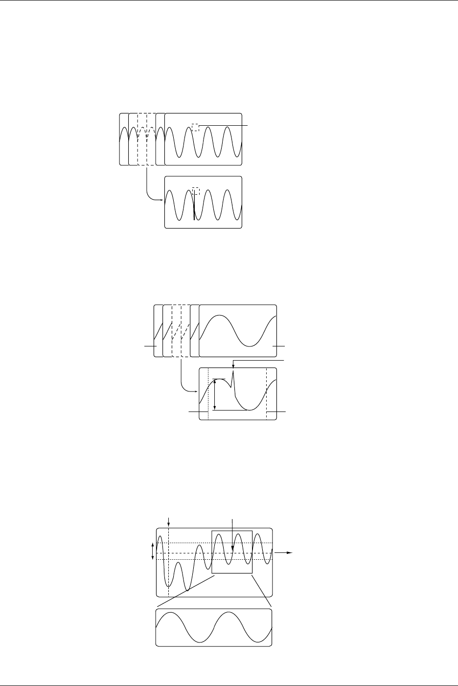
1-26 IM 701710-01E
Data Search (History Search Function) <Sections 7.8 to 7.9>
This feature can be used to search waveforms that match the specified conditions from
the history memory.
History Memory Search Using Zone → Section 7.8
Searches waveforms that did or did not pass through the specified area from the history
memory.
Waveform that was Saved Using the History Memory Function
Selected Record No. 0
Selected Record No. –25
Specified Area
Detects Waveforms that did or
did not Pass through the Specified
Area
History Memory Search Using Waveform Parameters → Section 7.9
Searches waveforms that did or did not satisfy the specified condition from the history
memory.
Waveform that was saved using the history memory function
Selected Record No. 28
Selected Record No. 0
T-Range2
Start RecEnd Rec
P-P
T-Range1
Detects position
Item Setup : P-P
Condition : OUT
Data Search (Search and Zoom Function) <Section 8.10>
Edge Search
Searches the position where the signal went above (rising) or below (falling) the
specified level the specified number of times from the search start position. Displays the
waveform expanded around the detected position in the zoom window.
Specified Level
The section that is detected is
expanded and displayed in
the zoom window
Start Point of the Dearch Detected Position
When the edge is set to rising and the count is set to 2
Hysteresis
1.5 Analyzing the Waveform
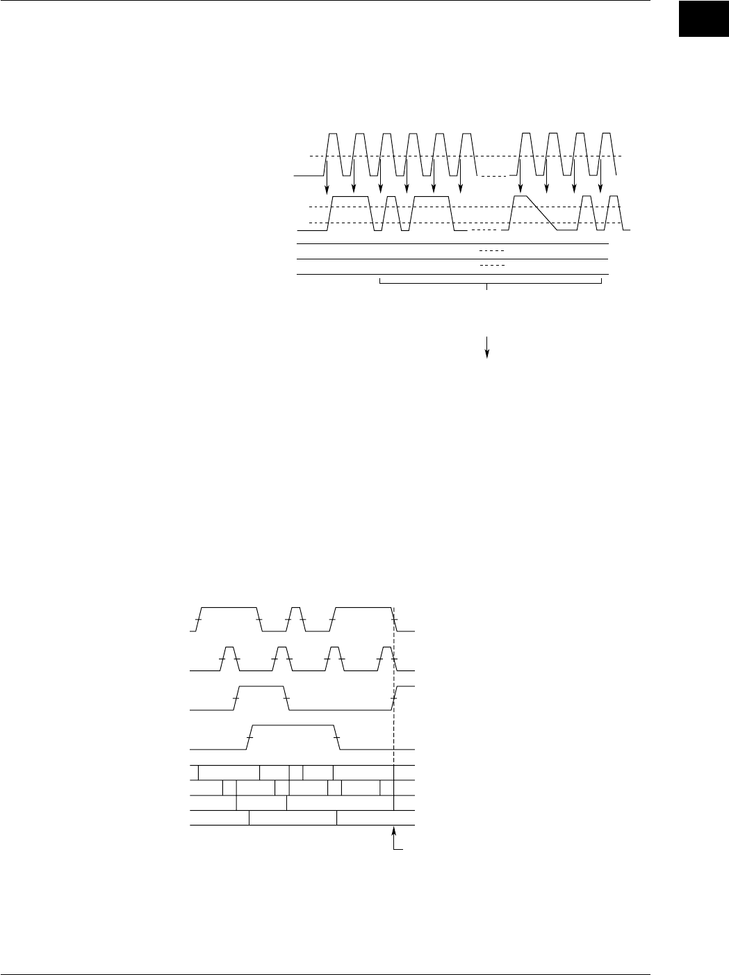
1-27
IM 701710-01E
Functions
1
Serial Pattern Search
Searches for a section of the waveform that has the same pattern as the specified
waveform pattern (specified using High or Low status or Don’t Care). The status of the
waveform (64 statuses) is detected at the rising or falling edge of the channel that is
specified as the clock channel or at a constant time interval. The matched pattern is
displayed expanded in the zoom window.
LHLL L H
H
Status (Pattern) of CH2
Specified Status (Pattern)
Conditions:
Clock Channel : CH1
Timing to Check the Status : Rising
Channel on which to Perform the Search : CH2
CH1
Level
CH2
Low Level
High Level
-LL
LL L H
HxLL
Searches Sections of the Waveform
with the Same Status (up to 64 Patterns)
as the Specified Waveform Pattern
The Section that is Detected is Expanded
and Displayed in the Zoom Window
Parallel Pattern Search
Detects a section of the waveform where the status (specified as High, Low, or Don’t
Care) of each channel, CH1 through CH4, Math1, and Math2 (or CH1, CH2, and Math1
for the DL1720), is the same as the specified status. The status is detected at the rising
or falling edge of the channel that is specified as the clock channel. If the clock channel
is set to None, detection is performed on the status of all waveforms, CH1 through CH4,
Math1, and Math2 (or CH1, CH2, and Math1 for the DL1720). The detected section is
displayed expanded in the zoom window.
LH L L L
H
HHHHLLLL
L
HLLH
HLL
• Search Example in which the Clock Channel is Set to None
and
H1: L, CH2: L, CH3
*1
: H, and CH4
*1
: L
H
CH1
CH2
CH3
*1
CH4
*1
CH1
CH2
CH3
*1
CH4
*1
L: Low Level, H: High Level Detects this Position and
Displays the Waveform
Expanded in the Zoom Windo
w
*1 The DL1720 is not equipped with channels 3 and 4.
1.5 Analyzing the Waveform
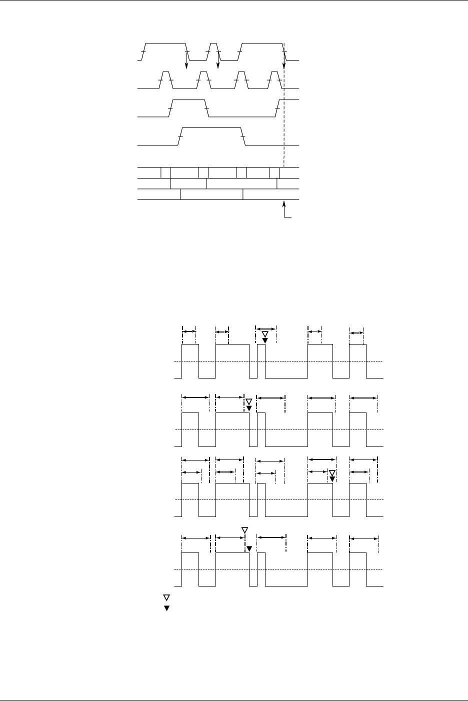
1-28 IM 701710-01E
HHHHLLLL
L
HLLH
HLL
CH1
CH2
CH3
*1
CH4
*1
CH2
CH3
*1
CH4
*1
L: Low Level, H: High Level
*1 The DL1720 is not equipped with channels 3 and 4.
Detects this Position andDisplays the
WaveformExpanded in the Zom Windo
w
• Example in which the clock channel is set to CH1
and
CH1: rising, CH2: L, CH3
*1
: H, and CH4
*1
: L
Pulse Width Search
From the search start position, search for a portion of the waveform containing a pulse
which is longer or shorter than a previously defined length of time. Expand the retrieved
portion of the waveform per the zooming factor and display it in the waveform zoom
display window.
T
T
T 1
T 2
T
Pulse > T
Pulse <T
T1 < PLS < T2
Time Out
Zoom Screen Center Position
Starting Point for Next Search
TT T
TTTT
T
T 1
T 2
T 1
T 2
T 1
T 2
T 1
T 2
TTTT
Pulse : The Length of Time a Specified Condition is Fulfilled
T : A Specified Length of Time
Auto Scroll
The zoom box scrolls automatically in a designated direction. You can stop the zoom
box while checking zoomed waveforms.
1.5 Analyzing the Waveform
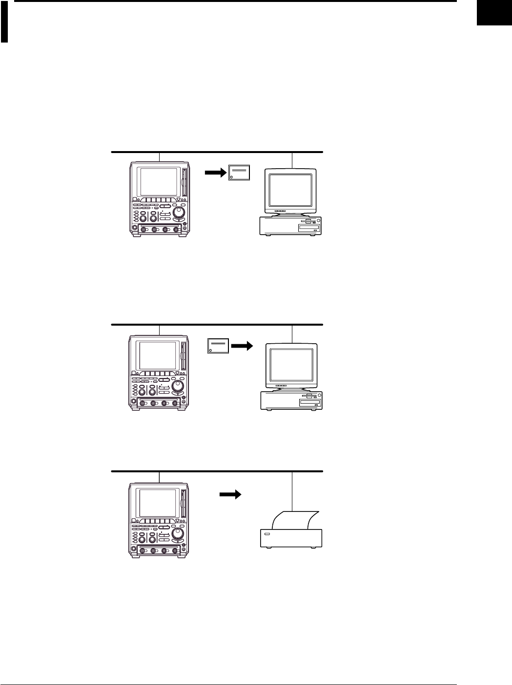
1-29
IM 701710-01E
Functions
1
1.6 Communications
Ethernet Interface (Option)
<Chapter 13 and Communication Interface User’s Manual (IM701710-17E)>
Saving to a Network Drive (FTP Client Function) → Sections 13.3, 13.4
You can save, delete, and copy waveform data, screen image data, and setting
information onto the hard drives of devices on the network such as a PC or workstation
running the FTP server function just as you would onto internal floppy disks or Zip disks
and hard disks.
Personal
Computer
File
DL1720/
DL1740
File Retrieval from the DL1720/DL1740 Floppy Disk or Zip Disk (FTP Server
Function)
→ Section 13.8
You can download files from the internal floppy disk or Zip disk of the DL1720/DL1740
using a networked PC or workstation acting as the client.
File
DL1720/
DL1740
Outputting to a Network Printer (LPR Client Function) → Section 13.5
You can print screen images to a network printer just as you would to the DL1720/
DL1740’s built-in printer, or to a printer with a USB interface.
Printer
DL1720/
DL1740
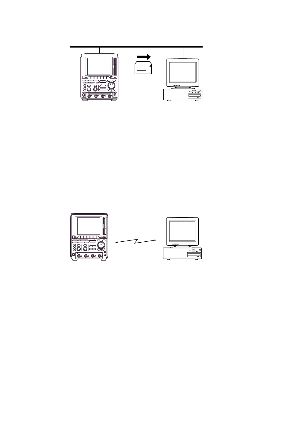
1-30 IM 701710-01E
Mail Transmission (SMTP Client Function) → Sections 13.6, 13.7
You can send transmissions to a given email address at specified intervals. Using this
function, you can periodically transmit such information as GO/NO-GO results and the
measurement rate.
Personal
Computer
Mail
DL1720/
DL1740
Network Interface → Communication Interface User’s Manual (IM701710-17E).
You can output waveform data to a PC for analysis using the Ethernet interface, or
perform waveform measurement by controlling the instrument with an external controller.
This function is available on products with firmware version 1.30 or later.
GP-IB Interface, Serial Interface (Option), and USB Interface
<The Communication Interface User’s Manual (IM701710-17E)>
A GP-IB interface and a USB interface come standard with the DL1720/DL1740. A serial
interface and a network interface are also available as an option. Through
communications functions, you can output waveform data to a PC for data analysis or
control the DL1720/DL1740 using an external controller to carry out waveform
measurements.
Communication
Interface Personal
Computer
DL1720/
DL1740
1.6 Communications
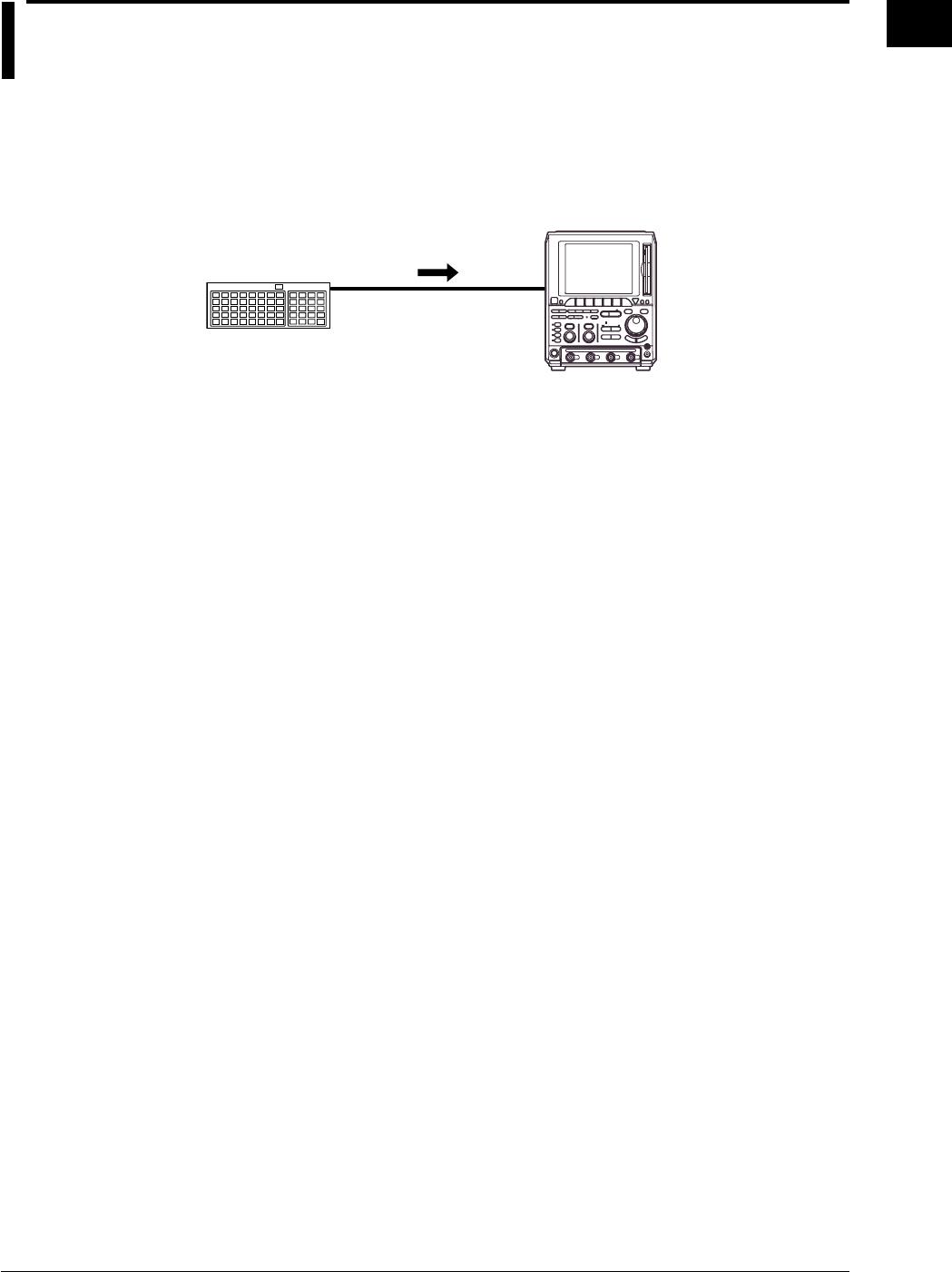
1-31
IM 701710-01E
Functions
1
1.7 Other Useful Functions
Connecting a USB Keyboard <Section 4.1>
You can connect a USB keyboard for entering file names, comments, and other
information. In addition, the keys on the keyboard are assigned to the keys on the front
panel of the DL1720/DL1740, which allows you to operate the DL1720/DL1740 in a
similar fashion. (See appendix 5.)
DL1720/
DL1740
USB Keyboard
Keyboard and Printer
Interface
Initialization <Section 4.2>
This function resets the key settings to the factory settings (default settings), and is
useful when complex settings have been made and you want to cancel all of them at
once.
However, settings related to communications, the SCSI ID, setting parameters on storing
and recalling function are not reset, and so on.
Auto Setup <Section 4.3>
This function makes settings automatically such as vertical sensitivity, time axis and
trigger settings, to suit the signal to be measured. This is useful when the signal to be
measured is unknown. However, there might be particular signals for which the auto set-
up function may not work properly.
Storing and Recalling Setting Parameters <Section 4.4>
You can store setting parameters to the internal memory. The stored parameters can
also be recalled to modify the settings on the instrument.
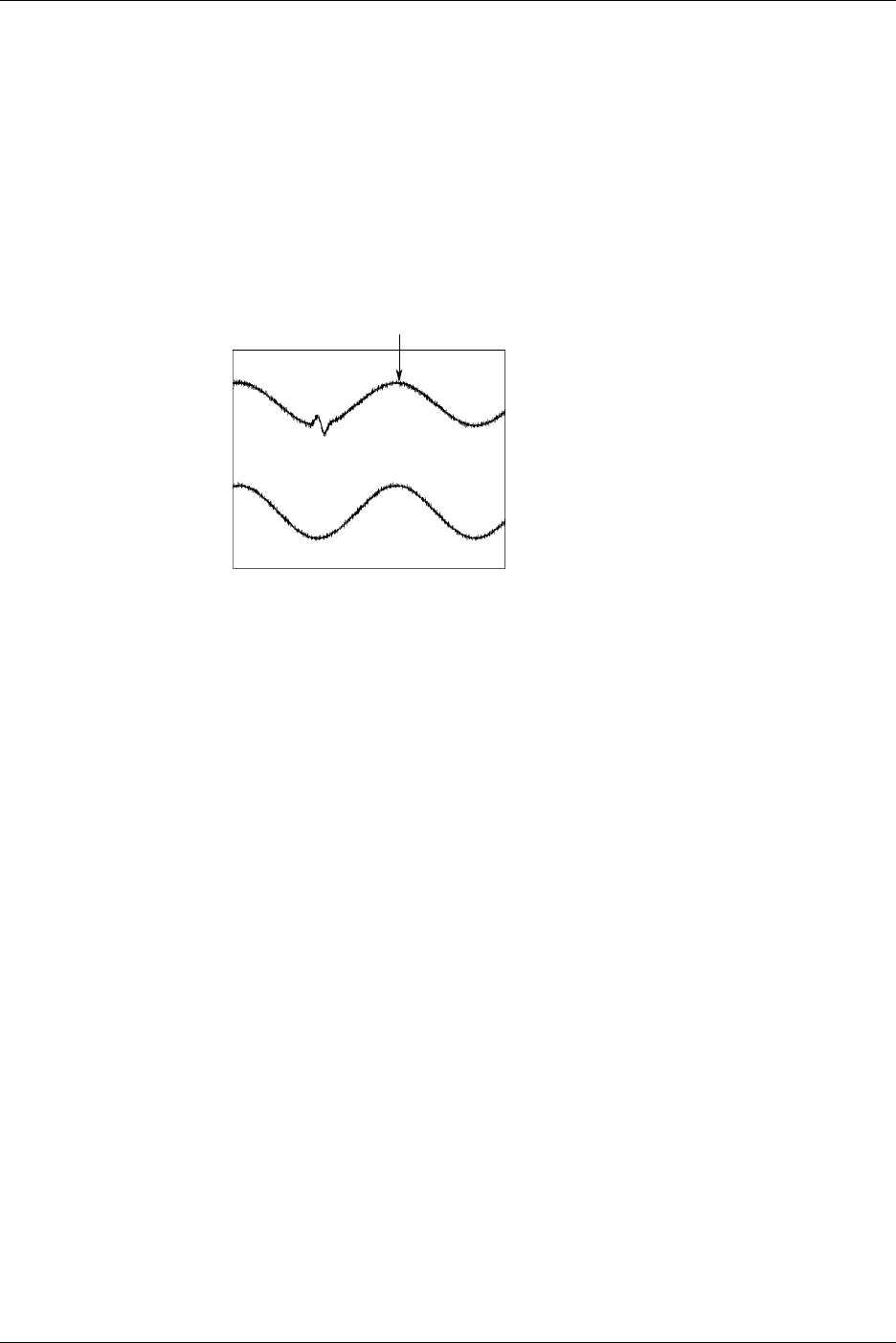
1-32 IM 701710-01E
Snapshot <Section 4.6>
If single start is not selected, a waveform is updated at the specified intervals or is
displayed in roll mode. Thus, to retain the currently displayed waveform, acquisition
must be stopped. Use of the snapshot function allows the currently displayed waveforms
to remain temporarily on the screen without acquisition being stopped. To activate this
function, just press SNAP SHOT without stopping acquisition. The currently displayed
waveform will be retained. This waveform is called a snapshot waveform. The snapshot
waveform is displayed separately in white making comparison between the two easier.
Snapshot waveforms are screen image data, so they cannot be used for cursor
measurement or automated measurement. However, screen image data output (hard
copy) is possible.
Snapshot Waveform
Clear Trace <Section 4.6>
This function clears all waveforms other than the loaded waveforms and restarts the
averaging, repetitive sampling, and accumulation in a signal operation.
Preset <Section 5.6>
This feature automatically sets the V/div, input coupling, trigger level, and other
parameters to appropriate values for TTL, ECL, or the Current probes 700937 or 701930
(Optional Accessories).
GO/NO-GO Determination <Section 9.12, 9.13>
The GO/NO-GO function is useful when you want to inspect signals and track down
abnormal symptoms on a production line making electronic equipment. Two
determinations are available: GO/NO-GO operation using the Measurement of
Waveform Parameters, and using the zone. This function detects whether an
automatically measured value falls within the specified range, and responds accordingly,
either by sounding the buzzer, saving the waveform data to internal memory or disk,
printing out the screen image (option), or sending a mail (Ethernet interface option). In
addition, the determination results can be output by an external signal.
1.7 Other Useful Functions
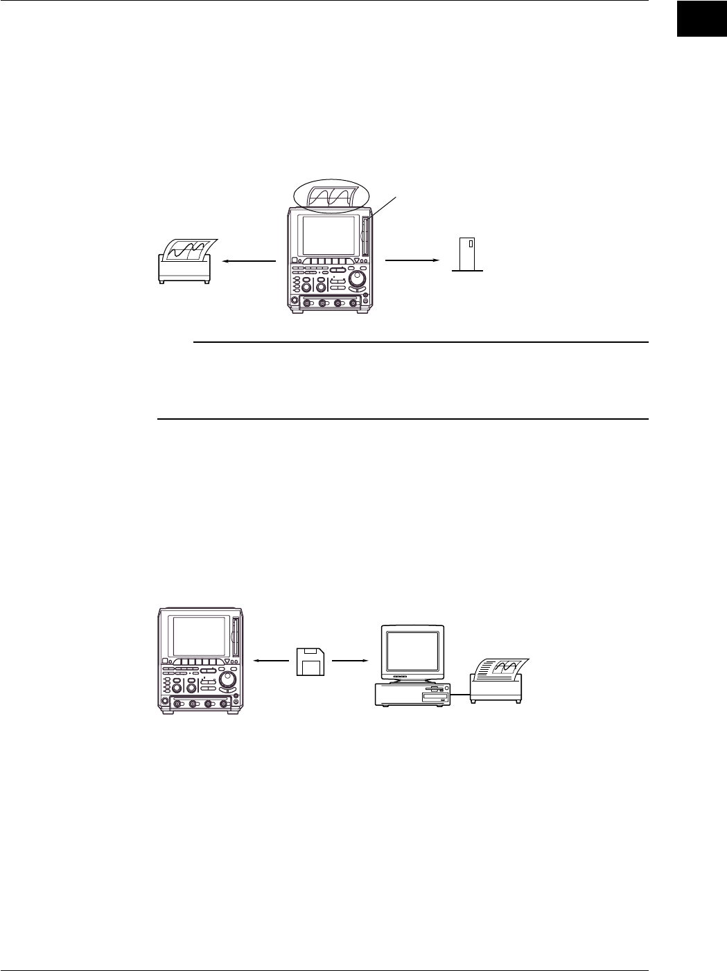
1-33
IM 701710-01E
Functions
1
Displayed Data Output Functions <Chapter 10>
You use these functions to print the screen image to the optional built-in printer, or an
exteral USB printer or a network printer, to save the image data to the storage medium
(floppy disk, Zip disk, external SCSI device (option) or network drive (Ethernet interface
option)).
Also, the instrument can display a thumbnail (miniature sample) of the screen data saved
to the storage medium. This is useful for checking the contents of saved image data
files. This function is available on products with firmware version 1.30 or later.
Printer
External SCSI Device
Floppy Disk Drive
or Zip Drive
DL1720/
DL1740
Note
The instrument provides a function which enables you to use the keyboard displayed on the
screen or the USB keyboard to enter and display a comment. If you enter a comment which
indicates the contents of the displayed waveforms before printing a hard-copy, it will help you
to distinguish between different print-outs.
Storage Medium Saves and Loads <Chapter 11>
The instrument standard configuration includes a built-in floppy disk drive or a built-in Zip
drive, and the optional configuration includes a SCSI connector and an Ethernet
conector. You can also choose to install an optional MO drive. It is also possible to save
data to an external SCSI device or network drive.
You can save data in any of the following formats: Postscript, TIFF, and BMP. This
means that you can easily insert the saved images into documents produced by
conventional DTP software packages.
Personal Computer
Floppy Disk
or Zip Disk
DL1720/
DL1740
1.7 Other Useful Functions
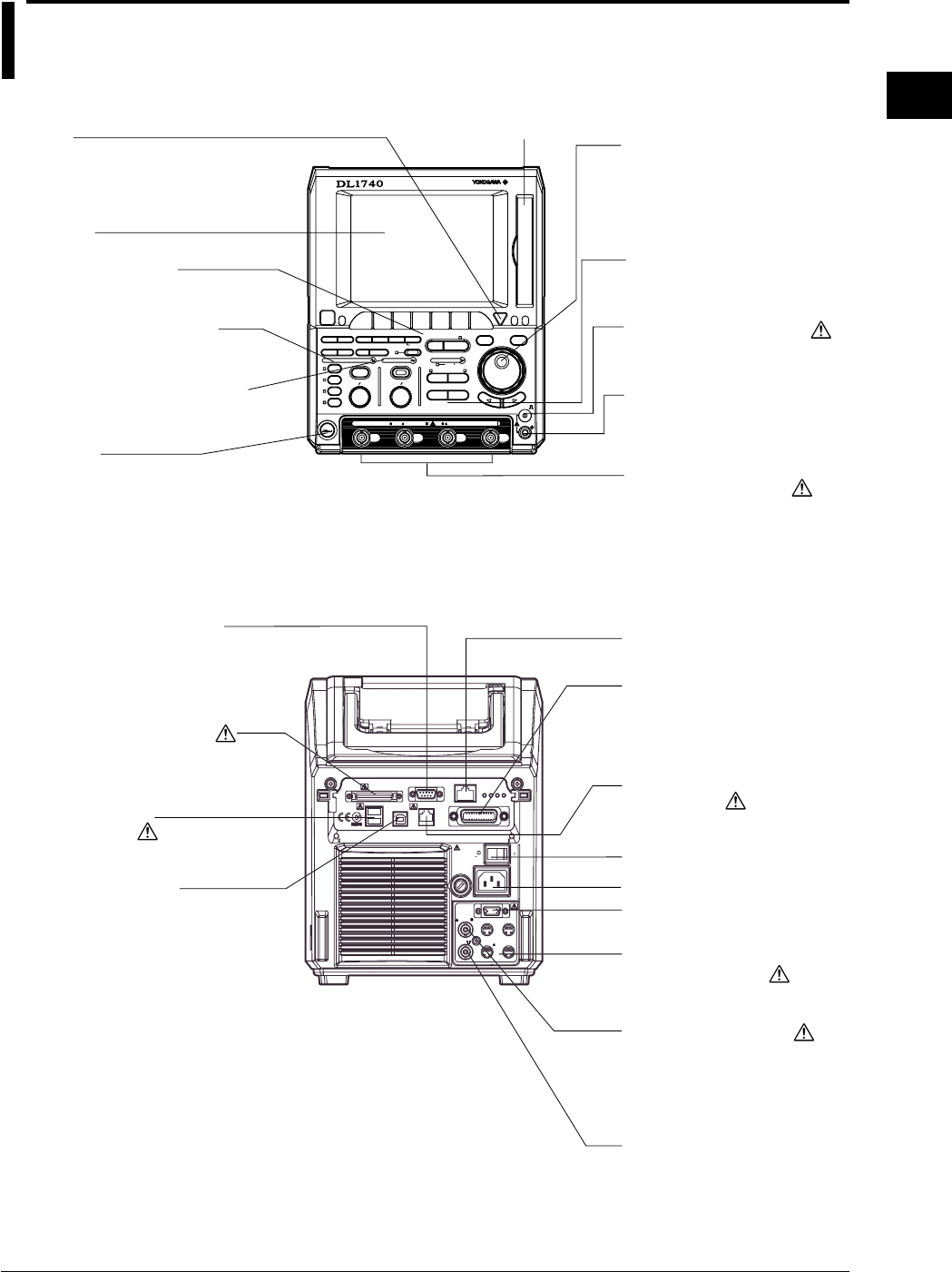
2-1
IM 701710-01E
Name and Use of Each Part
2
2.1 Front Panel/Rear Panel
Power Connectors for the
Probes (Section 3.4)
Provides power to YOKOGAWA’s
FET probes or current probes.
Ground Connector
Ground connection used for
probe calibration.
LCD Screen
Jog Shuttle
Changes the selected value or
moves the cursor. The more the
shuttle ring (outer ring) is turned,
the more the setting increment
increases.
COMP Output (Section 3.5)
Outputs probe compesation
signal.
Input Terminals (Section 3.4)
Used to connect a probe.
(The DL1720 is not equipped
with channels 3 and 4, and a
multi-purpose external
trigger/external clock/trigger gate
input terminal is provided in place
of channel 4.)
Power Switch (Section 3.3)
Ethernet Connector
(Chapter 13, Option)
Floppy Disk Drive or
Zip Drive
(Chapter 11)
VERTICAL Group (Section 2.2)
Menu group used to make settings
for the vertical axis.
HORIZONTAL Group (Section 2.2)
Menu group used to make settings for
the horizontal axis.
TRIGGER Group (Section 2.2)
Menu group used to make
trigger settings.
Menu keys (Section 2.2)
Press a key to display the
corresponding menu.
Esc Key
Closes pop-up menu or soft-
key menu.
Trigger Output Terminal
(Section 12.2)
Power Connector (Section 3.3)
GP-IB Connector
For details about communication
functions, refer to the
communication Interface Manual
(Doc. IM701710-17E).
External Trigger/Clock/
Trigger Gate Input Terminal
(Sections 5.10, 6.6, 12.1)
(On the DL1720 it is labeled as
EXT. and is located on the front
panel.)
SCSI Connector (Section 11.3)
Connects to an external hard disk,
MO disk, or other external SCSI
storage device.
Serial Port (RS-232) Connector
For details about communication
functions, refer to the instrument
Communication Interface Manual
(IM701710-17E).
USB Interface Connector
For details about
communication functions, refer
to the communication Interface
Manual (Doc. IM701710-17E).
Power Switch
(Section 3.3)
GO/NO-GO Output Terminal
(Section 9.14)
Outputs the results of the
GO/NO-GO determination.
PRN/KBD Connector
(Sections 4.1, 10.3)
Connect USB printer and
keyboard here,
RGB VIDEO OUT Terminal
(Section 12.3)
HELP
ESC
SELECTRESET
DIGITAL OSCILLOSCOPE
1GS/s 500MHz
SIMPLE
ACTION DELAY
MODE POSITION
MATHMISCFILE
CLEAR
TRACE
HISTORY
MEASURE
SETUP
PRESET
DISPLAY
CURSOR
X - Y
CH
1
CH
2
CH
3
CH
4
VDIV
POWER
CH
1
CH
2
CH
3
CH
4
TIME
1M /20pF 400Vpk CAT 50 5Vrms,10Vpk
DIV
MENU
COPY IMAGE SAVE
MENU PHASE
SHIFT
ZOOM
SEARCH
HORIZONTAL
VERTICAL
GO/NO-GO
COMP
ENHANCED
ACQ START/STOP
TRIGGER
TRIG D
SNAP
SHOT
SCSI
EXT CLOCK IN
EXT TRIG IN
TRIG GATE IN
40Vpk 1M
(VGA)
VIDEO OUT
(TTL ) PROBE POWER
TRIG OUT
( 12V)
OFF ON
250V T 4A
FUSE
250VA MAX
220-240V AC
100-120V/
50/60Hz
MAIN POWER
ETHERNET 100BASE-TX
GP-IB(IEEE488)
TX LINKFD100
GO/NO-GO
USB
PRN/KBD
SERIAL (RS-232)
ISM 1-A
Chapter 2 Name and Use of Each Part

2-2 IM 701710-01E
Top View
Built-In Printer (Option)
Handle
Use the handle to lift and carry
the unit.
2.1 Front Panel/Rear Panel
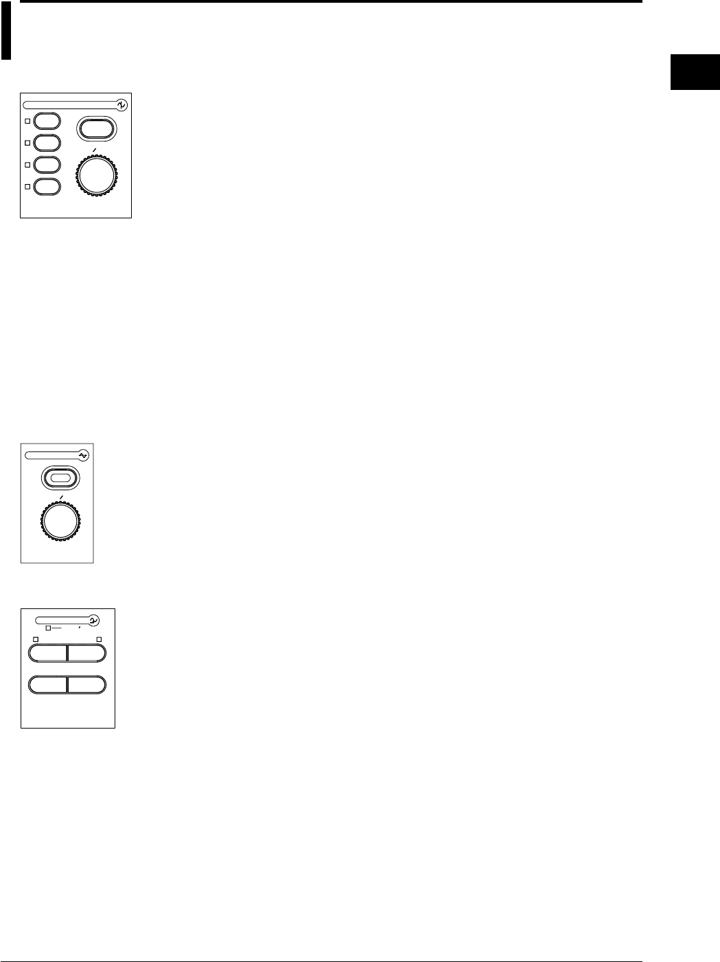
2-3
IM 701710-01E
Name and Use of Each Part
2
2.2 Operation Keys/Jog Shuttle/Knobs
VERTICAL Group
PRESET
VDIV
VERTICAL
CH
1
CH
2
CH
3
CH
4
CH1 to CH4 Keys (Sections 5.1 to 5.5, 5.7 to 5.9)
On the DL1720, the CH3 and CH4 keys are disabled.
Displays a menu used to turn ON/OFF the display on each channel, set the vertical
position, coupling, probe attenuation, offset voltage, bandwidth limit, expansion/reduction
of the vertical axis, linear scaling, and waveform labels. In addition, by pressing this key
before operating the V/DIV knob, the channel that is to be controlled by the V/DIV knob
can be selected.
PRESET Key (Section 5.6)
Displays the preset menu that sets the V/div, input coupling, probe attenuation and
trigger level to the optimum TTL level, ECL level, or the current probe (700937, 701930)
(or preset level) automatically. This preset menu allows you to set all channels or the
selected channels at once.
V/DIV Knob (Section 5.8)
Turning this knob during acquisition (i.e. while the START indicator is lit) sets the voltage
axis sensitivity. Before turning this knob, be sure to select the channel you want to
adjust by pressing the corresponding channel key (CH1 to CH4 (or CH1 to CH2 for the
DL1720)).
HORIZONTAL Group
TIME DIV
ZOOM
SEARCH
HORIZONTAL
TIME/DIV Knob (Section 5.11)
Use this knob to set the time scale. If you change the scale while acquisition is
suspended, the new value becomes effective when acquisition resumes.
(SHIFT +) ZOOM Key (Sections 8.9, 8.10)
Displays a menu related to the waveform zoom display.
Pressing the ZOOM key after pressing the SHIFT key displays a menu related to data
searching (Search and Zoom Function).
TRIGGER Group
SIMPLE
ACTION DELAY
MODE POSITION
ENHANCED
TRIGGER
TRIG D
(SHIFT +) MODE Key (Sections 6.1, 6.15, 7.3)
Displays a menu used to select the trigger mode.
Pressing the MODE key after pressing the SHIFT key displays a menu related to action-
on-trigger.
SIMPLE Key (Sections 6.4 to 6.7)
Displays the menu for the simple trigger mode, which provides normal triggers such as
the edge trigger. Simple trigger mode is selected when the indicator located above this
key is lit.
ENHANCED Key (Sections 6.4, 6.8 to 6.14)
Displays the menu for enhanced trigger mode, which provides complex triggers such as
the pattern trigger. Enhanced trigger mode is selected when the indicator located above
this key is lit.
(SHIFT +) POSITION Key (Sections 6.2, 6.3)
Used to set the trigger position.
You can set the trigger delay by pressing the POSITION key after pressing the SHIFT
key.
TRG’D Indicator
Lights up when a trigger is activated.

2-4 IM 701710-01E
Other Menus
HEL
P
ESC
SELECTRESET
MATHMISCFILE
CLEAR
TRACE
HISTORY
MEASURE
SETUP DISPLAY
CURSOR
X - Y MENU
COPY IMAGE SAVE
MENU PHASE
SHIFT
GO/NO-GO
ACQ START/STOP
SNAP
SHOT
DISPLAY Key (Sections 8.1 to 8.8)
Displays the screen display menu.
Press SHIFT + DISPLAY to produce the menu for X-Y display setup.
MISC Key (Sections 3.6, 4.7, 6.16, 11.5; Chapters 13, 14, 15; IM701710-17E)
Displays the menu for selecting GO/NO-GO judgment, communication interface, system
configuration settings, system status check, screen saver setting, and the self-diagnostic
function.
FILE Key (Sections 11.4, and 11.6 to 11.12)
Displays menu that you use to save to, load from, or execute file operations on floppy
disk, Zip disk, MO disk, or external SCSI device.
(SHIFT+) COPY Key (Sections 10.2, 10.3, 13.5)
Used for printing out hard copy of the screen data.
If you press SHIFT + COPY, the screen displays a menu that you can use to print or
save the screen image. For the save location, you can select any of the following:
internal printer (option), and USB printer.
(SHIFT+) IMAGE SAVE Key (Sections 10.4, 13.4)
You can store the screen image to an external storage medium. Press the SHIFT key
followed by the IMAGE SAVE key to display a menu used to save the screen image data
to a floppy disk, Zip disk, an external SCSI device (option), or a network drive (when the
Ethernet interface is installed).
MEASURE Key (Sections 9.2 to 9.4)
Displays the menu for performing automatic measurement of waveform parameters.
CURSOR Key (Section 9.1)
Displays the menu for cursor measurement.
(SHIFT+) MATH Key (Sections 9.5 to 9.11)
Displays the menu for waveform computation.
Pressing the MATH key after pressing the SHIFT key displays a menu used to shift the
phase.
GO/NO-GO Key (Sections 9.12, 9.13)
Displays a menu related to GO/NO-GO.
SETUP Key (Sections 4.2 to 4.4)
Displays a menu used to initialize the settings to factory defaults, perform auto setup,
which automatically sets the DL1720/DL1740 according to the input signal, store or recall
setting parameters, and so on.
SHIFT Key
Used to make the functions that are marked in purple on the panel operative. Pressing
this key activates shift mode, pressing it again releases shift mode. While the indicator
above this key is lit, shift mode is active.
2.2 Operation Keys/Jog Shuttle/Knobs

2-5
IM 701710-01E
Name and Use of Each Part
2
HISTORY Key (Sections 7.7 to 7.9)
Displays a menu used to recall data using the history memory function.
ACQ Key (Sections 5.10, 7.1, 7.2, and 7.4 to 7.6)
Displays the acquisition method menu.
START/STOP Key (Section 4.5)
Starts or stops acquisition according to the selected trigger mode. The indicator above
this key is lit during acquisition.
Jog and Shuttle Dials (“jog shuttle”)
You use these dials to set numerical values, move the measurement cursors, select
items from menus, and perform other such selection operations.
The jog dial changes the value in fixed steps as you rotate it. With the shuttle dial, the
step size increases as you turn the dial further.
RESET Key
Resets values that you have changed using the jog and shuttle dials.
SELECT Key
Activates the menu item that you have highlighted using the jog or shuttle dial.
Arrow Keys (< > keys)
Use these keys to shift the column position of the numerical value to be set by the jog or
shuttle dial.
SNAP SHOT Key (Section 4.6)
Repeats acquisition while retaining the currently displayed waveform on the screen.
CLEAR TRACE Key (Section 4.6)
Deletes the currently displayed waveform.
HELP Key (Section 4.8)
Sets help window ON or OFF.
Soft Keys
Selects the menu that is displayed at the bottom of the screen.
2.2 Operation Keys/Jog Shuttle/Knobs
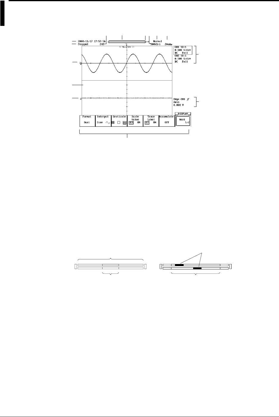
2-6 IM 701710-01E
2.3 Screens
A
B
CDEFGH
I
J
K
L
M
N
A Date and Time
For the procedures used to set the date and time, see section 3.6, “Setting the Date
and Time.”
B Operation State
Displays “Running” when data acquisition is in progress and “Stopped” when it is
stopped.
C Waveform Acquisition State and the Number of Acquisitions
Waiting for Trigger : trigger wait state
Pre... : pre-trigger
Post... : post-trigger
Value : the number of waveforms acquired
D Display Position
Record Length
Display Record Length Display Record Length
z1
z2
Zoom Position
< Zooming Waveform >
< Normal Waveform >
E Record Length
F Sample Rate
G Sampling Mode
Varies depending on the T/div and record length settings.
Normal/Env/Avg/BoxAvg Realtime sampling mode
Norm: Rep Repetitive sampling mode
Avg: Rep Repetitive sampling mode in the averaging mode
H T/div Setting that has been Changed after Waveform Acquisition
I Trigger Level
J Display Format
1, 2, 3, 4, and 6 windows are possible (or 1, 2, and 3, windows for the DL1720). (see
section 8.1)
K Ground Level
L Probe Attenuation, V/div, Input Coupling, and Bandwidth Limit Settings

2-7
IM 701710-01E
Name and Use of Each Part
2
M Soft Key Menu
N Trigger Level, Trigger Mode, Trigger Type, and Trigger Source Settings
Note
In some cases, up to 0.02% of the total number of pixels of the LCD can be defective.
2.3 Screens

3-1
IM 701710-01E
Precautions During Use
3
3.1 Precautions During Use
Safety Precautions
When you are using this instrument, read “Safety Precautions” on page v thoroughly, as
well as the following points.
Do not Remove the Cover from the Instrument
Some parts of the instrument use high voltages, which are extremely dangerous. When
the instrument needs internal inspection or adjustment, contact your dealer or nearest
YOKOGAWA representative, as listed on the back cover of this manual.
In Case of Irregularity
If you notice smoke or unusual odors coming from the instrument, immediately turn OFF
the power and unplug the power cord. If such an irregularity occurs, contact your dealer
or the nearest YOKOGAWA representative as listed on the back cover of this manual.
Power Cord
Nothing should be placed on the power cord. Also, it should be kept away from any heat
sources. When unplugging the power cord from the AC outlet, never pull the cord itself.
Always hold the plug and pull it. If the power cord is damaged, contact your dealer.
Refer to page ii for the part number to use when placing an order.
General Handling Precautions
Observe the following precautions when handling the instrument.
Never Place Anything on Top of the Instrument
Never place other equipment or objects containing water on top of the instrument,
otherwise a breakdown may occur.
Do not Cause Shock to the Input Connectors or Probes
Shock to the input connectors or probes may turn into electrical noise and enter the
instrument via the signal lines.
Do not Damage the LCD Screen
Since the LCD screen is very vulnerable and can be easily scratched, do not allow any
sharp objects near it. Also it should not be exposed to vibrations and shocks.
When the Instrument is not going to be Used for a Long Period
Unplug the power cord from the AC outlet.
Chpater 3 Precautions During Use
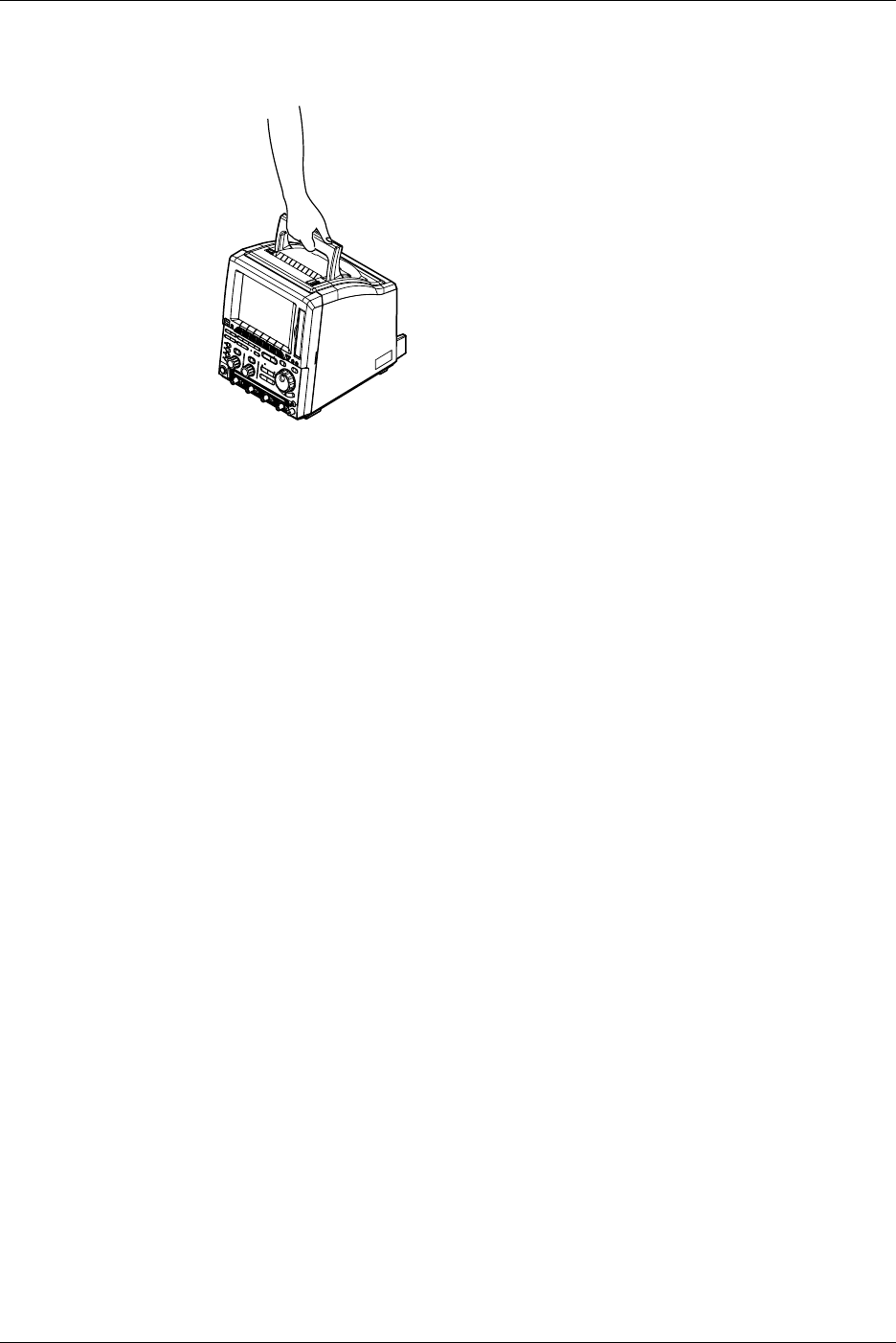
3-2 IM 701710-01E
Carrying the Instrument
Before carring the instrument remove the power cord and other cables. Always carry the
instrument by the handles or carry it with both hands (see below).
Cleaning
When cleaning the case or the operation panel, unplug the power cord from the plug
first, then wipe with a dry, soft, clean cloth. Do not use volatile chemicals such as
benzene or thinner for cleaning, as this may lead to discoloration or deformation.
3.1 Precautions During Use
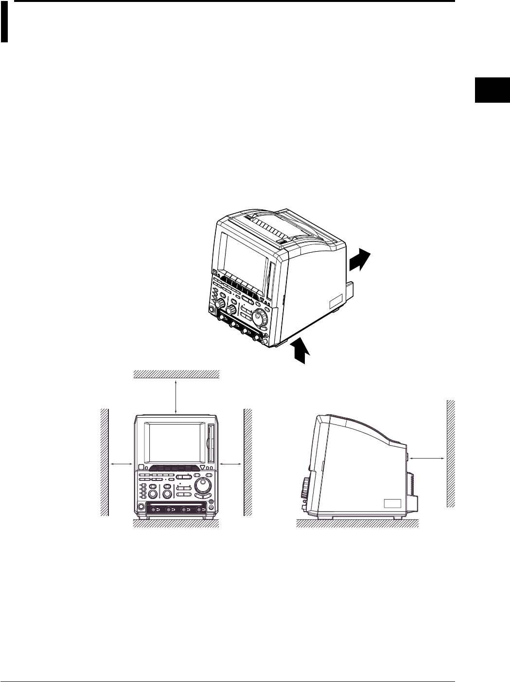
3-3
IM 701710-01E
Precautions During Use
3
3.2 Installation
Installation Conditions
The instrument must be installed in a place where the following conditions are met.
Flat Location
Set the oscilloscope in the proper direction and in a level and stable place. If placed in
an unstable place, printing quality decreases.
Well-Ventilated Location
Vent holes are situated on the bottom. In addition, vent holes for the cooling fans are
also situated in the rear sides. To prevent a rise in the internal temperature, the vent
holes should not be blocked and sufficient clearance should be maintained around them.
If a printer comes with your DL1720/DL1740, allow extra space for operation and do not
place objects on top of the printer.
5 cm or more
10 cm or more
5 cm or more
10 cm or
more
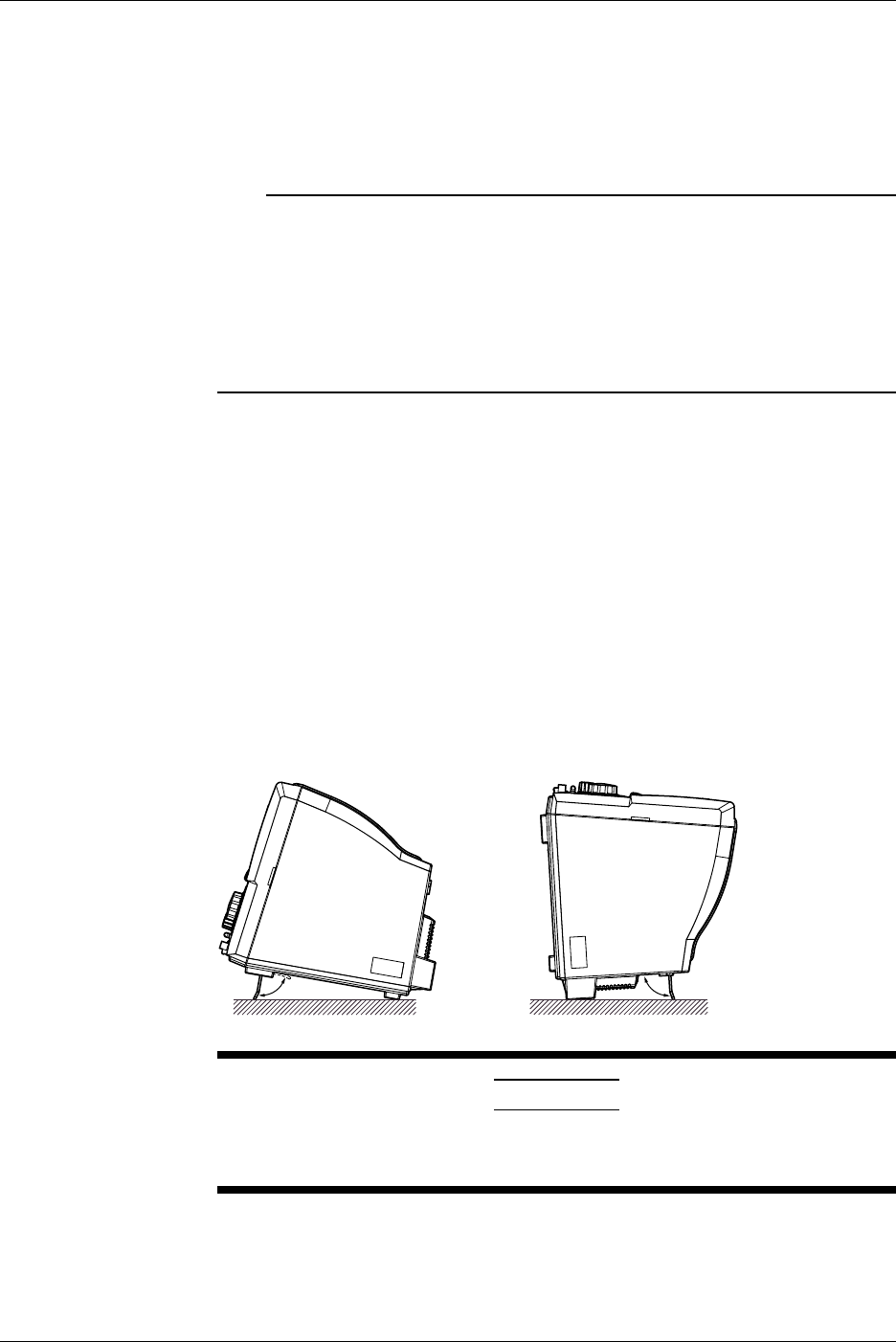
3-4 IM 701710-01E
Ambient Temperature and Humidity
Ambient Temperature : 5 to 40°C
Ambient Humidity : 20 to 80% RH (when not using the printer)
35 to 80% RH (when using the printer)
No condensation should be allowed.
Note
•To ensure high measurement accuracy, the instrument should only be used under the
following conditions.
Ambient temperature: 23 ±2°C
Ambient humidity: 55 ±10% RH
•Internal condensation may occur if the instrument is moved to another place where both the
ambient temperature and humidity are higher, or if the temperature changes rapidly. In such
cases allow the instrument to acclimatize to its new environment for at least one hour before
starting operation.
Never Install the Instrument in the Following Places
In direct sunlight or near heat sources
Where an excessive amount of soot, steam, dust or corrosive gases are present.
Near magnetic field sources
Near high voltage equipment or power lines
Where the level of mechanical vibration is high
In an unstable place
Installation Position
Place the instrument in a horizontal position or tilted using the stand, as shown below.
When you use the stand, pull it forwards until it locks. To return the stand to its original
position, push it backwards. When installing the DL1720/DL1740 with the rear panel
down, use the stand on the rear panel.
CAUTION
Do not use the Zip drive when the DL1720/DL1740 is installed with the
rear panel down.
Rubber Feet
If the instrument is installed in the tilted positon, rubber feet can be attached to prevent
slipping. Four pieces of rubber feet are included in the package.
3.2 Installation
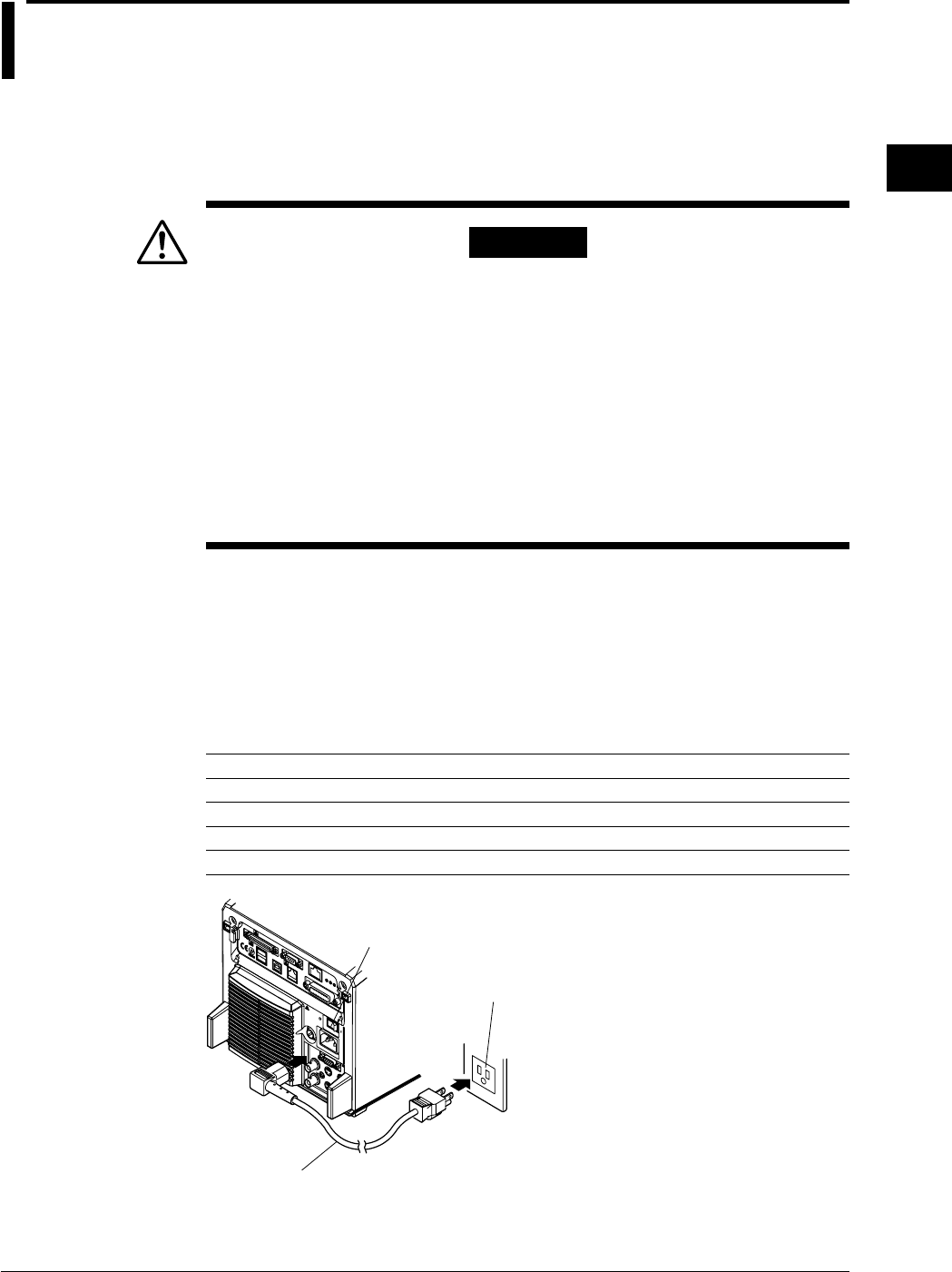
3-5
IM 701710-01E
Precautions During Use
3
3.3 Connecting the Power Cord
Before Connecting the Power
Make sure that you observe the following points before connecting the power. Failure to
do so may cause electric shock or damage to the instrument.
WARNING
•Connect the power cord after confirming that the voltage of the power
supply complies to the rated electric power voltage for the instrument.
•Connect the power cord after confirming that the instrument power
switch is OFF.
•Always use protective ground to prevent electric shock. Connect the
instrument power cord to the 3-pin power outlet with grounding
terminal.
•Do not use non-grounding extension cords or other measures that
defeat the protective grounding.
•Never use an extension cord that does not have a protective grounding,
otherwise the protection feature will be invalidated.
Connecting the Power Cord
1. Make sure that main power switch and power switch are OFF.
2. Plug the power cord into the power connector socket on the rear panel of the
instrument.
3. Plug the other end of the power cord into an AC outlet that meets the following
conditions. The AC outlet must be of 3-pin type with a protective grounding
terminal.
Rated supply voltage: 100 to 120 VAC/220 to 240 VAC
Permitted supply voltage range: 90 to 132 VAC/198 to 264 VAC
Rated supply voltage frequency: 50/60 Hz
Permitted supply voltage frequency range: 48 to 63 Hz
Maximum power consumption (when the built-in printer is used): 200 VA
3-Pin AC Outlet
Power Cord
(Supplied Wth Instrument)
Main Power Switch
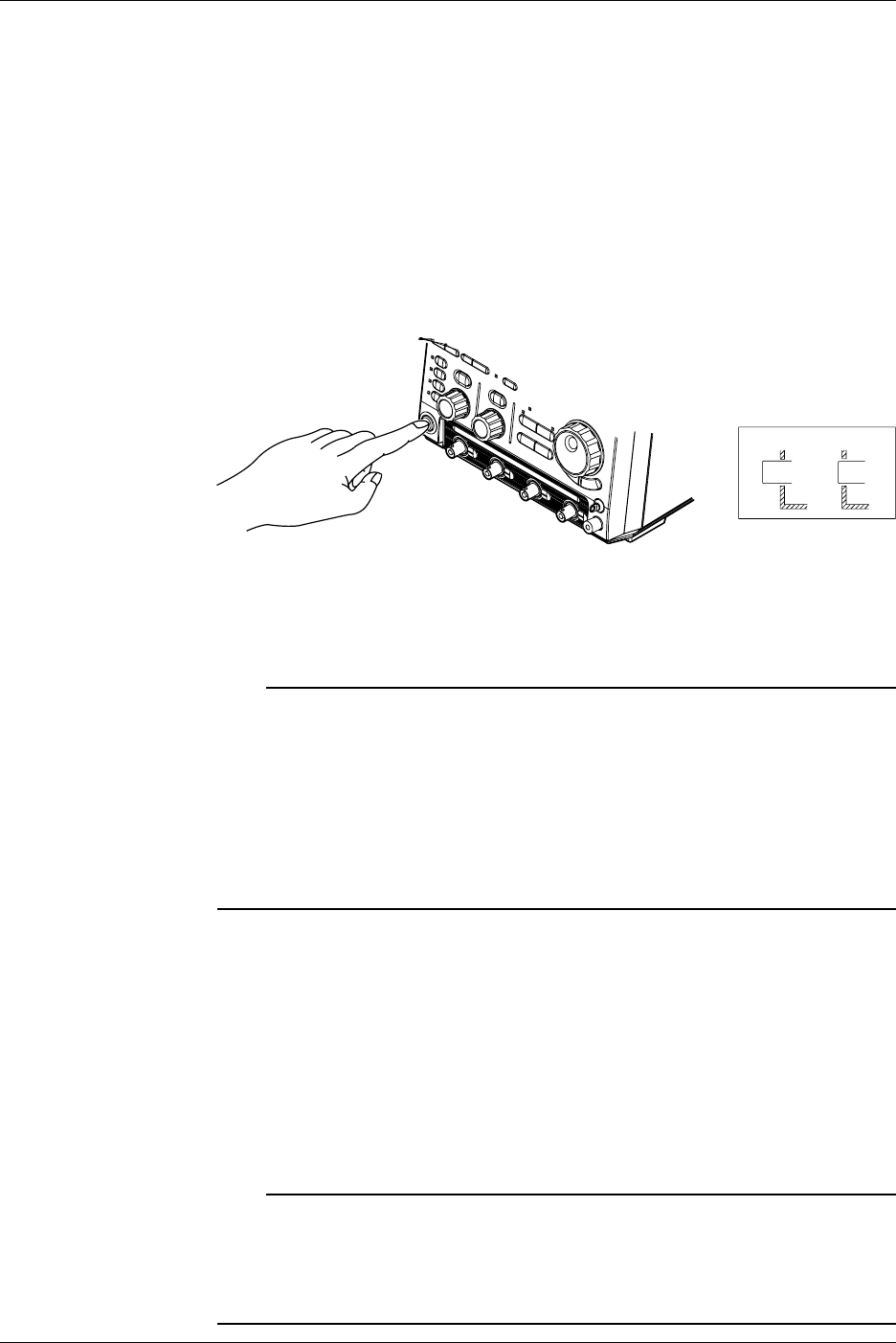
3-6 IM 701710-01E
Turning ON/OFF the Main Power Switch
Main power switch (rear panel on the right): Press the switch to the right to turn it ON;
press the switch to the left to turn it OFF.
Turning ON/OFF the Power Switch
Items to be Checked before Turning ON the Power
Check that the instrument is installed correctly as instructed in section 3.2, “Installing.”
Check that the power cord is connected correctly as sown in section 3.3, “Connecting the
Power Cord.”
Turning the Power ON/OFF
POWER switch: The power is turned ON and OFF alternately as the switch is pressed.
OFF ON
Response at Power ON
Self test and calibration start automatically when the power switch is turned ON. If the
check results are satisfactory, the normal waveform display screen will appear.
Note
•Wait at least 10 seconds after turning the power OFF before turning it back ON again.
•If calibration does not start when the power is turned ON, or if the normal waveform display
screen does not appear, check the following points.
•Check that the power cord is plugged in properly.
•Check that the main power switch is turned ON.
•Check that the correct voltage is being supplied from the AC outlet. (Refer to section 3.3)
•Check that the fuse is not blown. (Refer to section 15.5)
If there is still no power even after the above points have been checked, contact your nearest
YOKOGAWA representative as listed on the back cover of this manual.
For Accurate Measurement
Turn the power switches ON and allow the unit to warm up for at least 30 minutes.
After warm-up is complete, perform calibration. (Refer to section 4.7)
Response at Power OFF
Settings made prior to turning OFF the power are retained (even if the power cord is
removed). This allows display of waveforms using those saved settings the next time the
power is turned ON.
Note
The settings are backed up by a lithium battery. The battery lasts for approximately 5 years if
it is used at an ambient temperature of 23°C. When the battery voltage drops below the
specified level, a message will appear on the screen. In this case, the battery needs to be
replaced immediately. The battery cannot be replaced by the user, so contact the nearest
YOKOGAWA representative listed on the back cover of this manual.
3.3 Connecting the Power Cord
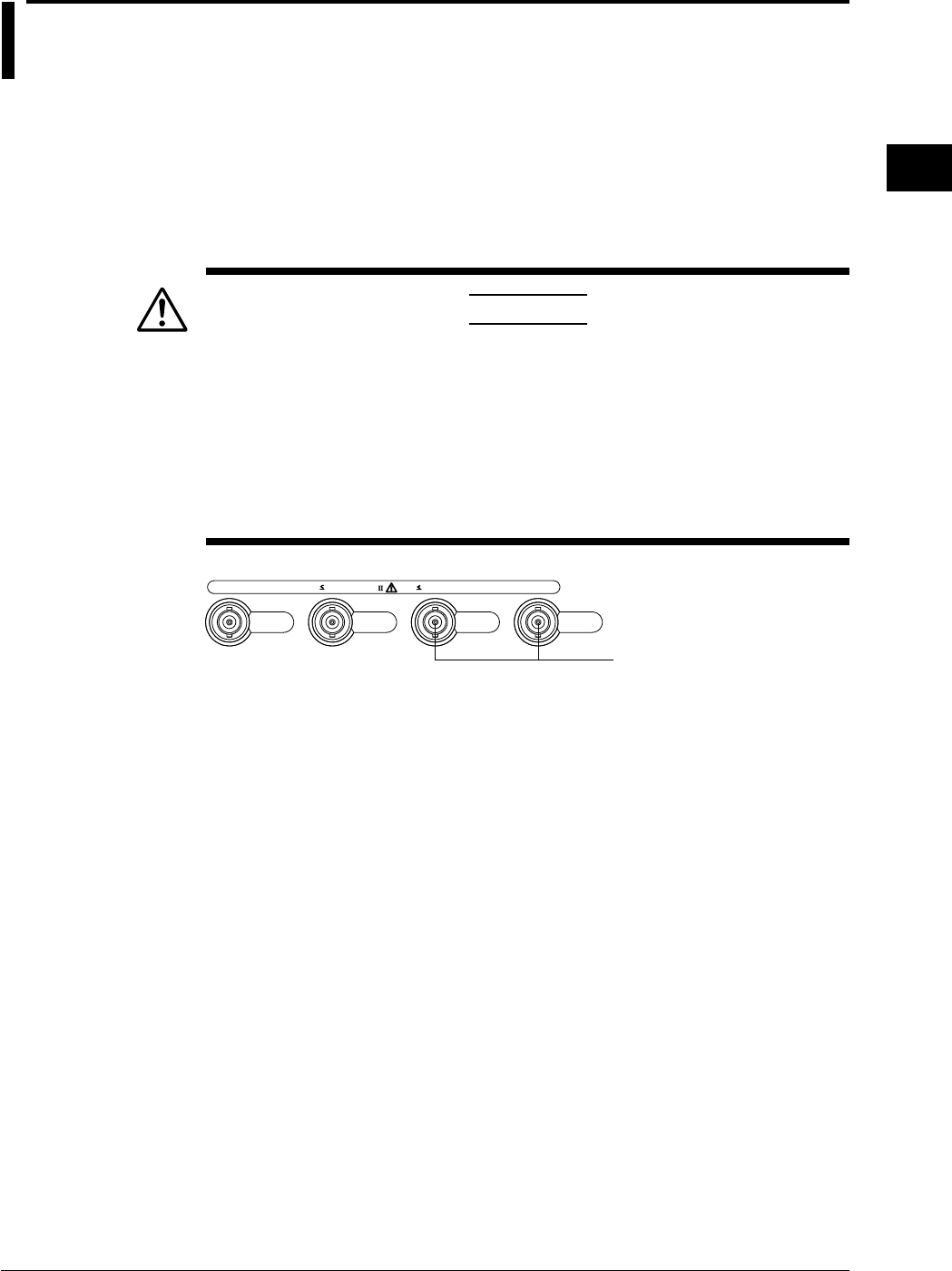
3-7
IM 701710-01E
Precautions During Use
3
3.4 Connecting a Probe
Input Terminals
A probe (or an input cable such as a BNC cable) must be connected to one of the input
terminals* (CH1 to CH4 (or CH1 and CH2 for the DL1720)) located on the lower section
of the front panel.
The input impedance is 1 MΩ ±1.0% and approximately 20 pF or 50 Ω ±1.0%.
* The number of input terminals varies according to the instrument model.
CAUTION
•The maximum allowable input voltage is 400 V (DC + AC peak) or 282
Vrms when the frequency is 1 kHz or less. Never input a voltage
exceeding this level, as it could damage the input section of the
instrument. If the frequency exceeds 1 kHz, the input section may be
damaged even when the voltage is below 400 V.
•The maximum allowable input voltage is 5 Vrms or 10 Vpeak when
using 50-Ω input. Never input voltage exceeding this level, as it could
damage the input section of this instrument.
CH
1
1MΩ 20pF 400Vpk 50Ω 5Vrms,10Vpk
CAT
CH
2
CH
3
CH
4
The DL1720 is not equipped with
channels 3 and 4, and a multi-
purpose external trigger/external
clock/trigger gate input terminal
is provided in place of channel 4.
Points to Note when Connecting a Probe
•When connecting a probe to the instrument for the first time, perform phase correction
of the probe as described in the section 3.5. Failure to do so may result in unstable
gain across different frequencies, thereby preventing correct measurement.
Calibration must be performed for each channel.
•If the object to be measured is connected to the instrument directly, without using a
probe, correct measurement cannot be performed due to the load effect.

3-8 IM 701710-01E
Probe
Specifications for the probe (700988) supplied with the instrument (after
calibration)
Item Specifications Setting 1 : 1 Conditions
Setting 10 : 1
Input impedance/ 10 MΩ ±2%,approx. 14 pF 1 MΩ ±1.0%,approx. 150 pF When used with
capacitance this instrument
Attenuation ratio 10 : 1 ±3% —When used with
this instrument
Frequency band DC to 400 MHz DC to 6 MHz When used with
this instrument
Rise time 900 ps or less 58 ns or less When used with
this instrument
Maximum 600 V (DC + AC peak)*1 —
input voltage or 424 Vrms,
Frequency is 100 kHz or lower
Connector type BNC BNC —
Total length 1.5 m 1.5 m —
*1 When the probe’s attenuation is “1 : 1,” never input voltage exceeding the maximum input
voltage of this instrument.
When Using a Probe other than the One Supplied with the Instrument
•To measure a signal which contains harmonics of approximately 500 MHz, use a
probe with a frequency band of 500 MHz or higher.
•Correct measured values cannot be displayed if the probe’s attenuation ratio is not “1
: 1,” “10 : 1,” “100 : 1” or “1000 : 1.”
Setting the Probe Attenuation
Follow the operating procedure given in section 5.4, “Selecting Probe Attenuation” so
that the probe’s attenuation matches the one displayed below Probe in the soft key
menu. If they do not match, measured values cannot be read correctly.
When Using the FET Probe (700939), the Current Probe (700937, 701930), or the
Differential Probe (701920)
When using YOKOGAWA’s FET probe (700939), current probe (700937, 701930), or
differential probe (701920) use the power supply for the probe provided on the rear panel
of the instrument.
CAUTION
Use the power connectors for the probes on the rear panel only for
powering probes 700939, 700937, 701930, or 701920. Using the
power connectors for any other purpose can damage the DL1720/
DL1740 or the device that is connected.
3.4 Connecting a Probe
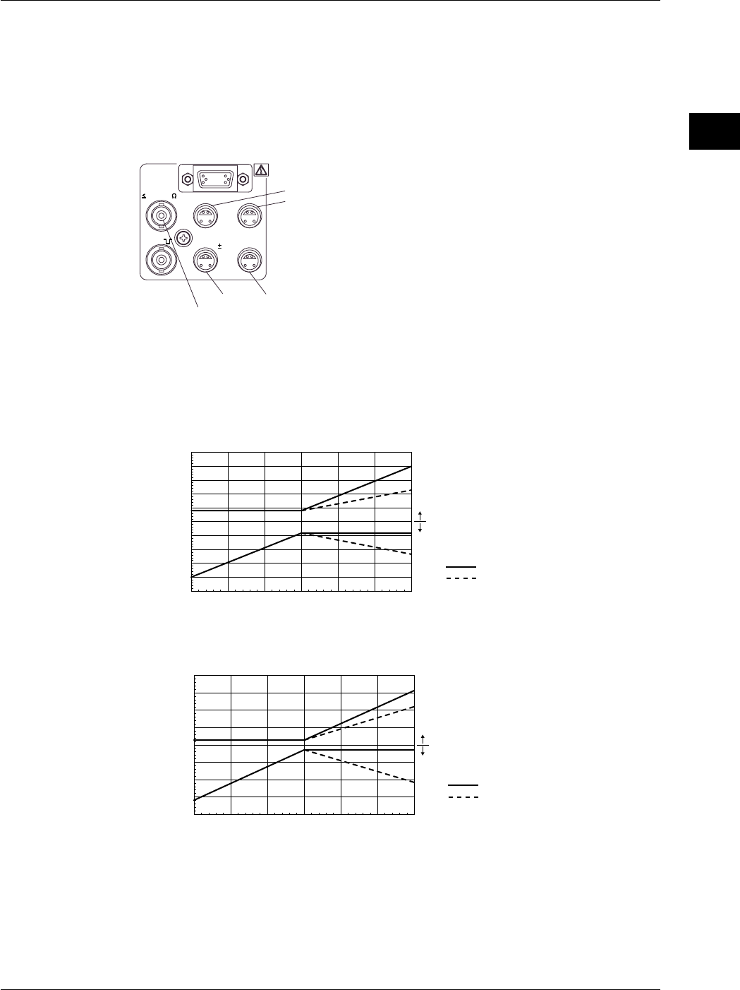
3-9
IM 701710-01E
Precautions During Use
3
3.4 Connecting a Probe
Precautions to be Taken when Using the FET Probe (700939), the Current Probe
(700937, 701930), or the Differential Probe (701920)
When connecting the FET probe (700939), the current probe (700937 or 701930), or the
differential probe (701920) to the probe power supply terminal on the rear panel, make
sure that the current does not exceed the range shown below. Otherwise, the DL1720/
DL1740 operation may become unstable due to the activation of the excessive current
protection circuit.
EXT CLOCK IN
EXT TRIG IN
TRIG GATE IN
40Vpk 1M
(TTL ) PROBE POWER
TRIG OUT
( 12V)
A
C
DB
(On the DL1720 this terminal is labeled as EXT. and is located on the front panel.)
When each terminal is assigned names A through D
(Current Consumption of A) + (Current Consumption B) ≤ 400 mA
(Current Consumption of C) + (Current Consumption D) ≤ 400 mA
(Total Current Consumption of A Through D) ≤ 600 mA
(The DL1720 is not equipped with terminals C and D.)
When using the current probe (700937 or 701930), the number of probes that can be
used is limited by the current generated by the device under measurement. Examples of
current consumption measurement using an active probe that can be connected to the
DL1720/DL1740 are shown below.
-250
-200
-150
-100
-50
-15 -10 -5 0 5 10 15
0
50
100
150
200
250
DC
Current Probe (700937)
Current Consumption [mA]
Current Generated [A]
AC (f=50 Hz)
Positive Current
Negative Current
-400
-300
-200
-100
-150 -100 -50 0 50 100 150
0
100
200
300
400
Current Probe (701930)
AC (f=50 Hz)
DC
Current Consumption [mA]
Positive Current
Negative Current
Current Generated [A]
Calculate the positive and negative current consumption of the FET probe (model
700939), or the differential probe (model 701920) at a maximum of 125 mA.
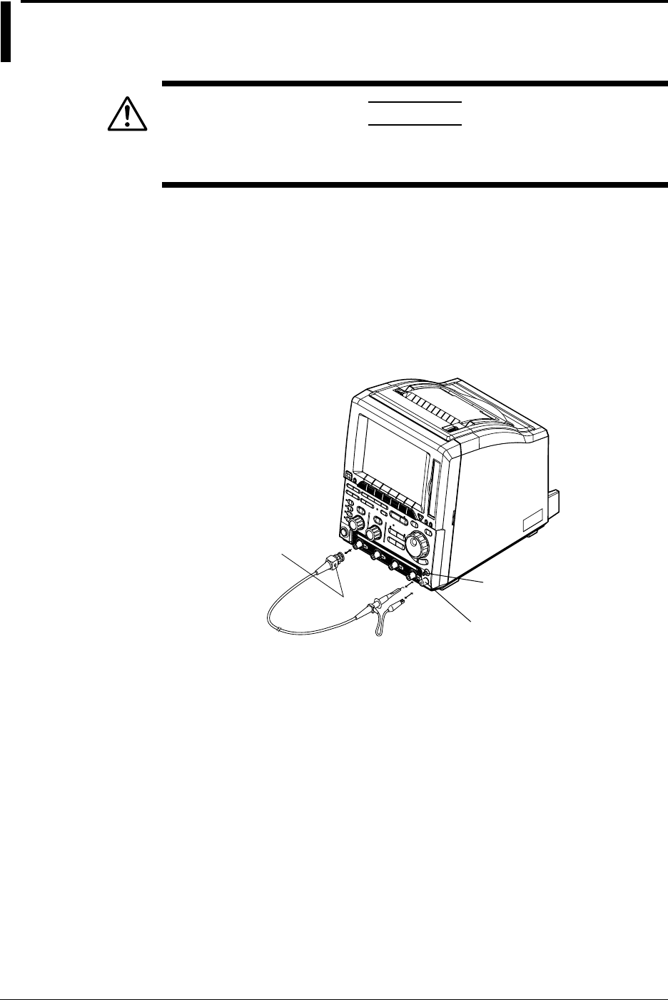
3-10 IM 701710-01E
3.5 Compensating the Probe (Phase Correction)
CAUTION
Never apply an external voltage to the COMP terminal, as damage to
the instrument may result.
Operating Procedure
1. Turn ON the power switch.
2. Connect the probe to the input terminal to which the signal is to be applied.
3. Touch the probe’s tip against the probe compensation signal output terminal and
connect the grounding wire to the functional earth terminal.
4. Perform auto setup using the procedure described in section 4.3.
5. Insert a screwdriver into the trimmer adjusting hole in the probe and turn the
trimmer so that the displayed waveform becomes square.
Functional Earth Terminal
Probe Compensation (COMP)
Phase Adjusting Hole
Signal Output Terminal
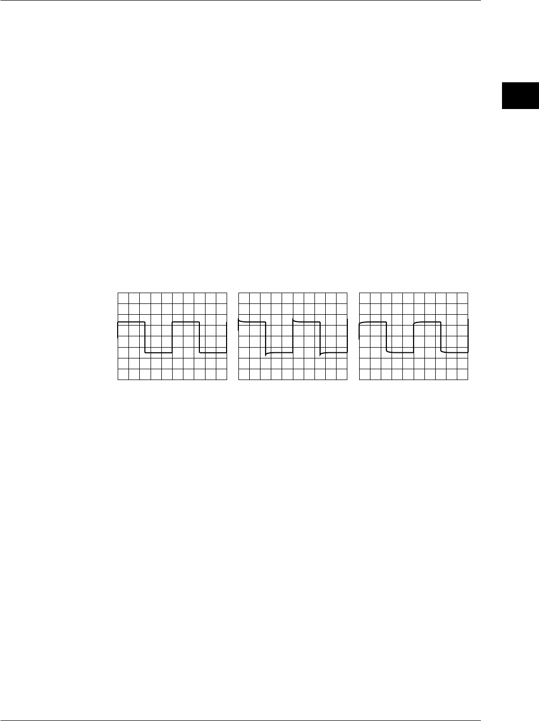
3-11
IM 701710-01E
Precautions During Use
3
Explanation
Reason for Probe Compensation
If the probe’s input capacitance is outside the specified range, the gain will not be
constant across different frequencies, preventing display of the correct waveforms. The
input capacitance varies depending on the probe used, so the variable capacitor
(trimmer) provided on the probe must be adjusted.
Probe compensation must be performed when the probe is to be used for the first time.
Moreover, the appropriate input capacitance varies according to which channel is used,
so probe compensation is required when the probe is switched from one channel to
another.
Calibration Signal
A probe compensation signal (square waveform) of the following characteristics is output
from the CAL terminal on the front panel.
Frequency: approx. 1 kHz
Amplitude: approx. 1 V
Waveform Differences
Correct Waveform Over-Compensated
(Gain is too High at High
Frequency)
Under-Compensated
(Gain is too Low at High
Frequency)
3.5 Compensating the Probe (Phase Correction)
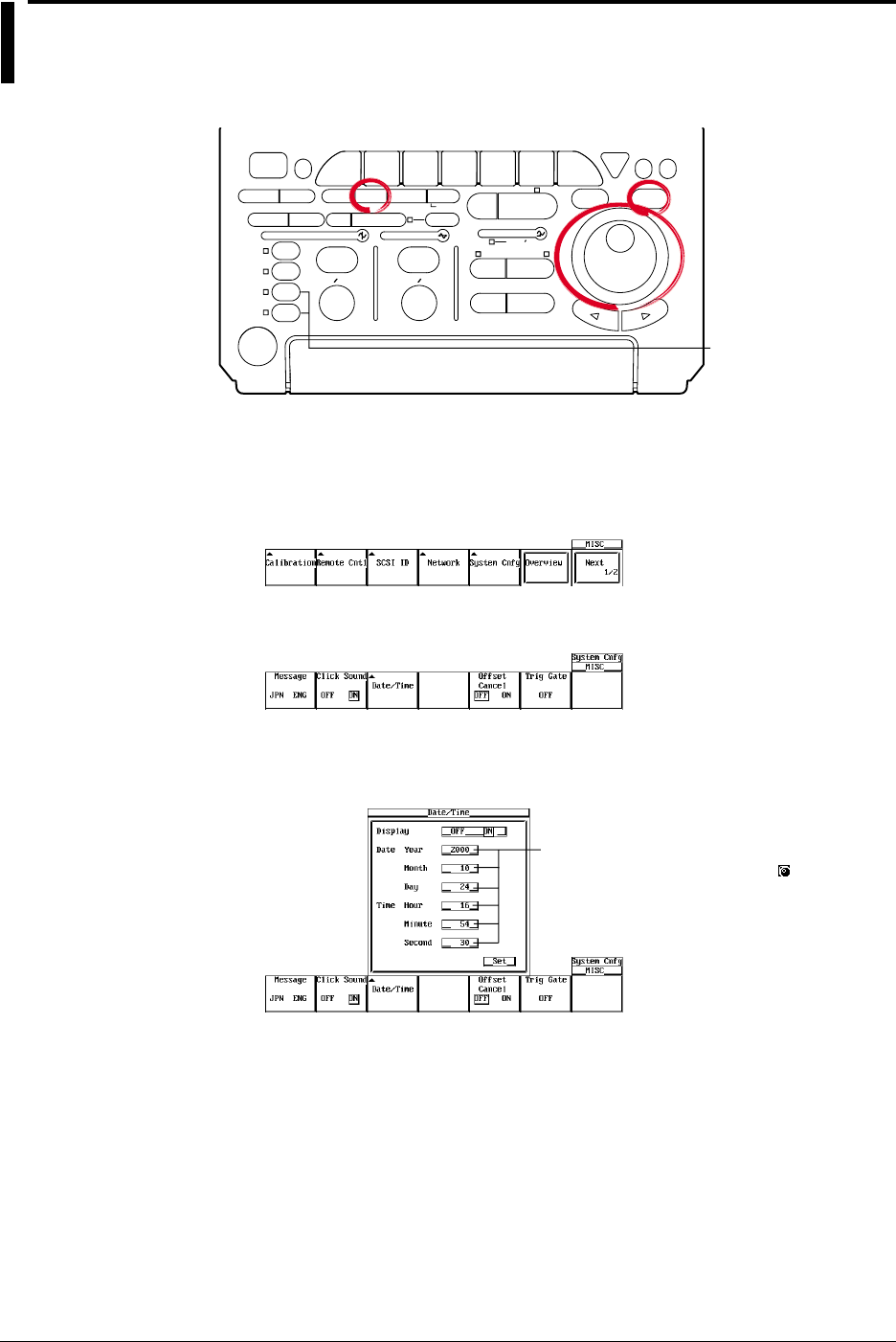
3-12 IM 701710-01E
3.6 Setting the Date and Time
Relevant Keys
ACTION DELAY
X - Y
V DIV TIME DIV
MENU MENU PHASE
SEARCH
HORIZONTAL
VERTICAL TRIGGER
TRIG D
HELP
ESC
SELECTRESET
SIMPLE
MODE POSITION
MATH
MISCFILE
CLEAR
TRACE
HISTORY
MEASURE
SETUP
PRESET
DISPLAY
CURSOR
CH
1
CH
2
CH
3
CH
4
POWER
COPY IMAGE SAVE SHIFT
ZOOM
GO/NO-GO
ENHANCED
ACQ START/STOP
SNAP
SHOT
The DL1720 is not
equipped with
an input terminal
for CH3 or CH4.
Operating Procedure
Displaying the System Configuration Menu
1. Press MISC.
2. Press the System Cnfg soft key to display the system configuration menu.
3. Press the Date/Time soft key to display the date and time display/setting menu.
Turning ON/OFF the Date and Time Display
4. Select ON or OFF by pressing SELECT.
Settings for these items can be input
directly using a USB keyboard. ( )
Setting the Date and Time
5. Turn the jog shuttle to move the cursor to Year.
6. Press SELECT to display the Year input box.
7. Set the year using the jog shuttle.
8. In a similar fashion, set the Month, Day, Hour, Minute, and Second.
9. Turn the jog shuttle to move the cursor to Set and press SELECT to confirm the
settings.

3-13
IM 701710-01E
Precautions During Use
3
Explanation
Date (YY / MM / DD)
The last two digits of the year are used to set the year (YY).
Time (HH : MM : SS)
The 24 - hour clock is used.
Note
•The date and time are backed up by the built-in lithium battery.
•Leap years are taken into account.
3.6 Setting the Date and Time
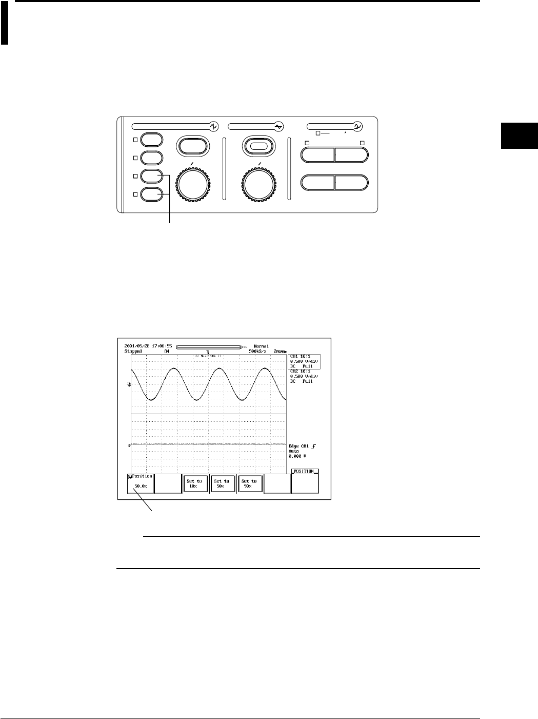
4-1
IM 701710-01E
Common Operations
4
4.1 Entering Values and Character Strings
Entering a Value
Direct Entry Using the Special Knob
The following knobs can be used to directly enter values simply by turning them.
V/DIV and TIME/DIV knobs
SIMPLE
ACTION DELAY
MODE POSITION
PRESET
V DIV TIME DIV
ZOOM
SEARCH
HORIZONTAL
VERTICAL
ENHANCED
TRIGGER
TRIG D
CH 1
CH 2
CH 3
CH 4
The DL1720 is not equipped with an input terminal for CH3 or CH4.
Entry Using the Jog Shuttle
Before using the jog shuttle to enter a value, you must select the desired parameter by
pressing the corresponding soft key. The jog shuttle ring (the outer ring of the jog
shuttle) allows you to enter values in larger steps than the jog shuttle dial. The size of
the step depends on the angle by which the shuttle ring is turned. For some parameters
you can use the arrow keys below the jog shuttle to shift from one digit to the next.
Parameter for Setting with the Jog Shuttle
Note
If you make an incorrect change with the jog shuttle, you can undo the change by pressing
RESET.
Chpater 4 Common Operations
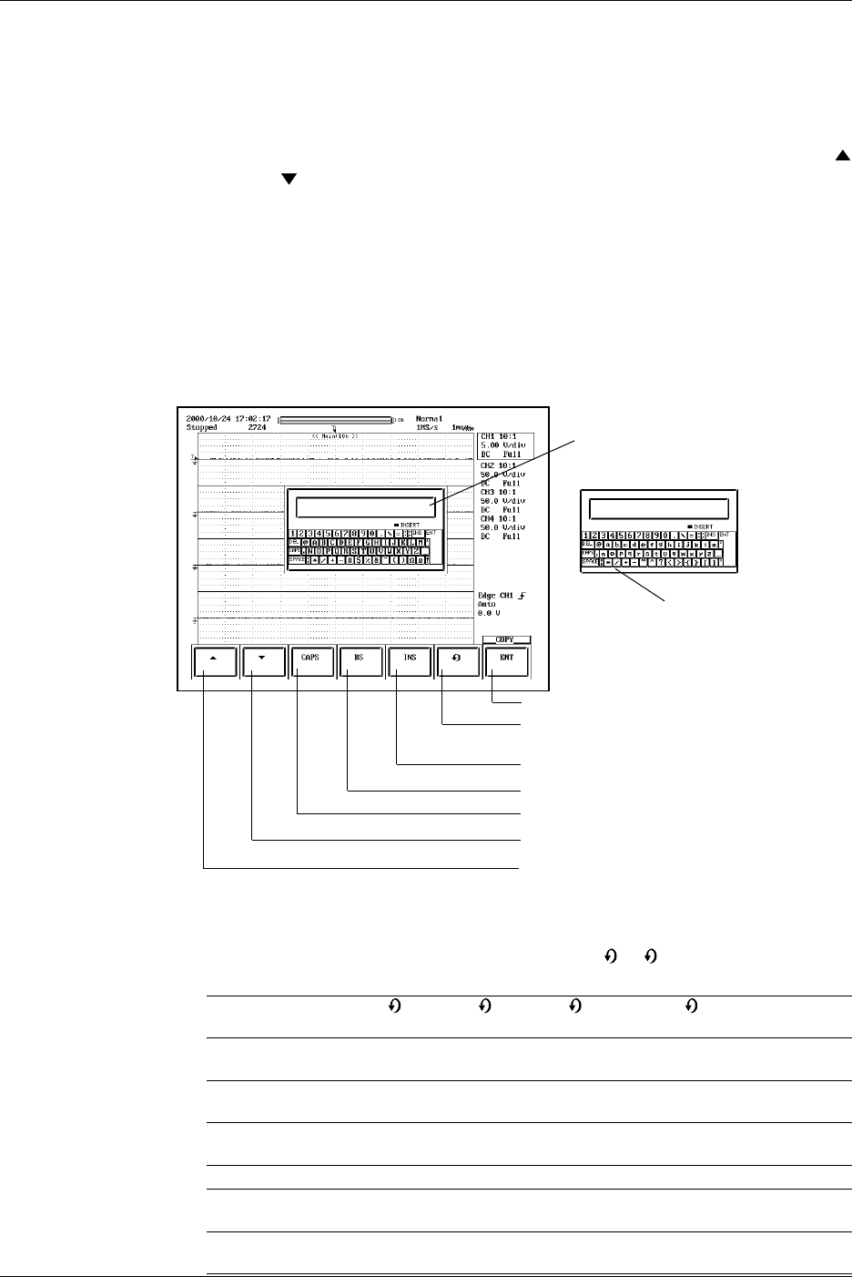
4-2 IM 701710-01E
Entering a Character String
The date/time, file name, and comment can be entered using the keyboard displayed on
the screen. Operate the keyboard using the jog shuttle, the SELECT key and arrow key
to enter a character string as follows.
Keyboard Operation
1. Turn the jog shuttle and move the cursor to the character you wish to enter. The
and soft keys can be used to move the cursor up and down.
2. Press SELECT to confirm the character entry.
If a character string is already entered, use the arrow keys to move the cursor to
the position at which you wish to enter the character.
3. Repeat steps 1 and 2 to enter all the characters.
4. ENT on the keyboard and press SELECT. The character string is confirmed and
the keyboard disappears. The ENT soft key can be used to confirm the string (and
hide the keyboard). At this point, the confirmed string is temporarily stored.)
If RESET is pressed before confirming the character string, the entire string is
cleared.
Recall the temporary stored character string.
See “Recall” below.
CAPS: a capital letter
CAPS: a small letter
Confirms the displayed characters.
Switches between insert and overwrite modes.
Deletes the character before the cursor.
Toggles uper-case and lower-case character.
Moves down the cursor.
Moves up the cursor.
•Operation to Temporarily Store Character Strings
The strings that are previously confirmed are sequentially sent to the subsequent
memories. When the number of confirmed strings exceeds eight, the strings are
deleted in order starting from the oldest string. The
0
-
7
symbols are not
displayed on the screen.
Symbol indicating the
0
1
2
...............
7
memory storing the string
When string “AA” is Stores AA
confirmed first
When string “BB” is Stores BB Moves and
confirmed next stores AA
When string “CC” is Stores CC Moves and Moves and
confirmed next stores BB stores AA
.................................................................................
When string “HH” is Stores HH Moves and Moves and ......Moves and
confirmed next stores GG stores FF stores AA
When string “JJ” is Stores JJ Moves and Moves and ......Moves and Deletes AA
confirmed next stores HH stores GG stores BB
4.1 Entering Values and Character Strings

4-3
IM 701710-01E
Common Operations
4
•Recall
(Note that the string that is displayed in the entry box of the keyboard is
overwritten when a string is recalled using the procedure in step 1 below.)
1. When you press the soft key repeatedly, the eight most recently confirmed and
stored strings are displayed one at a time from newest to oldest in the keyboard
entry box. If the soft key is pressed again after the eighth string, the display will
return to the first string.
2. Make appropriate corrections to the recalled string and confirm it according to
steps 1 to 4 that were described above in “Entering a Character String,” and
“Operation to Temporarily Store Character Strings.” At this point, the confirmed
string is temporarily stored.
Keys other than Characters
DEL: Deletes the character on the cursor.
INS: Switches between insert and overwrite modes. The indicator is lit when in
insert mode.
SPACE: Enters a space.
ENT: Confirms the displayed characters.
CAPS: Toggles uppercase and lowercase characters.
Number of Characters and Types Available
Number of Characters Available Characters
Date, time Specified number 0 to 9 ( / : )
File name 1 to 8 0 to 9, A to Z, %, _, (,)
Display image comment 0 to 20 All characters (including space)
File comment 0 to 25 All characters (including space)
Mail address 0 to 40 All ASCII characters on the keyboard
(including space)
User name/Login name 0 to 15 All ASCII characters on the keyboard
(including space)
Password 0 to 15 All ASCII characters on the keyboard
(including space)
Note
•Comments and file names can both contain both uppercase and lowercase letters. However,
file names are
not
case sensitive. The following five file names are not allowed due to MS -
DOS restrictions.
AUX, CON, PRN, NUL and CLOCK
•You cannot enter two or more atmarks (@) in succession.
Connecting a USB Keyboard
You can connect a USB keyboard for entering file names, comments, and other
information. In addition, the keys on the keyboard are assigned to the keys on the front
panel of the DL1720/DL1740, which allows you to operate the DL1720/DL1740 in a
similar fashion. (See appendix 5.)
PRN/KBD Terminal
When connecting a USB keyboard to the DL1720/DL1740, connect a USB cable to the
PRN/KBD terminal. There are two PRN/KBD terminals.
123 4
Port 1
Port 2
Pin No. Signal name
1
2
3
4
VBUS:
D–:
D+:
GND:
+5 V
–Data
+Data
Ground
4.1 Entering Values and Character Strings
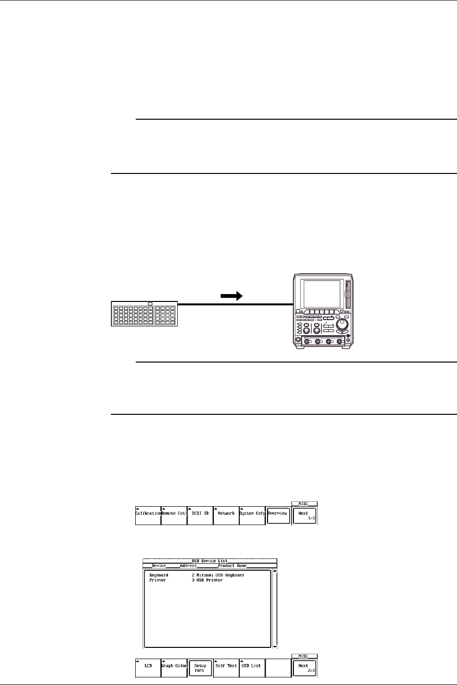
4-4 IM 701710-01E
Keyboards that can be Used
The keyboards that can be used depend on the type of message language that you
selected in section 14.2 (English or Japanese). A 104 USB keyboard (English) or a 109
USB keyboard (Japanese) that conforms to USB Human Interface Devices (HID) Class
Ver. 1.1 can be used.
•When the message language is English: 104 keyboard
•When the message language is Japanese: 109 keyboard
Note
•Connect only the keyboards that are allowed. However, operation of USB keyboards
connected to a USB hub or those that have mouse connectors is not guaranteed.
•For USB keyboards that have been tested for compatibility, contact your nearest
YOKOGAWA dealer as listed on the back cover of this manual.
Connection Procedure
When connecting a USB keyboard, directly connect the keyboard to the DL1720/DL1740
with a USB cable as shown below. You can connect the USB cable regardless of the
power ON/OFF state of the DL1720/DL1740 (supports hot-plug). Connect the type A
connector of the USB cable to the DL1720/DL1740; connect the type B connector to the
keyboard. When the power switch is ON, the keyboard is detected and enabled
approximately 6 seconds after it is connected.
DL1720/
DL1740
USB Keyboard
USB Cable
Note
•Connect the keyboard directly without going through a USB hub.
•Connect only a USB keyboard or printer to the PRN/KBD terminals.
•Do not connect multiple keyboards. You can connect a single keyboard and a single printer.
•Even if you continuously depress a key the character will not be input repeatedly.
Confirming the Type of Keyboard that is Connected
To confirm the type of keyboard that is connected to the DL1720/DL1740, carry out the
procedure below.
1. Press MISC.
2. Press the Next1/2 soft key.
3. Press the USB List soft key to display the USB Device List. Check the type of
USB keyboard that is connected.
4.1 Entering Values and Character Strings
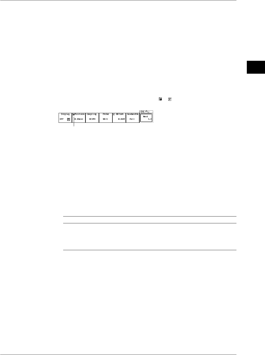
4-5
IM 701710-01E
Common Operations
4
Entering File Names, Comments, etc.
When the soft keyboard is displayed on the screen, you can enter the file name,
comment, and so on using a USB keyboard. The character that is entered through each
key of the keyboard varies depending on the keyboard type. For details, see appendix 5.
Executing Functions Corresponding to the Keys on the Front Panel of the DL1720/
DL1740
The functions corresponding to the keys on the front panel of the DL1720/DL1740 are
assigned to the keys on the USB keyboard. By pressing the keys on the keyboard, you
can operate the DL1720/DL1740 in a similar fashion. The assignment of functions varies
depending on the keyboard type. For details, see appendix 5.
Entering Numerical Values Using a USB Keyboard (This function is available on
products with firmware version 1.30 or later.)
Numerical values for menu items preceded by the or symbol can be input directly
using a USB keyboard.
Press the corresponding soft key, enter the values with the USB keyboard, then
press the Enter key. The entered values are displayed in the upper part of the screen.
•Inputting a Units Prefix
If unit prefixes are displayed (such as m for Offset in the example above), you can
input the character for the prefix as well as the numerical value using the USB
keyboard. Prefixes can be entered for units of voltage (V) and time (s). Also, the
prefixes that can be used are determined by the allowable input range.
Input Example
•If you type 1 then Enter for the Offset, this means 1 V so 1000 mV is displayed on
the screen.
•If you type 1, 0, then m, this means 10 mV so 10 mV is displayed on the screen. If
you enter a prefix for the units, it is not necessary to press the Enter key.
The available unit prefixes are as follows:
Key Prefix
K or k 103
m10
–3
U or u 10–6
N or n 10–9
P or p 10–12
4.1 Entering Values and Character Strings
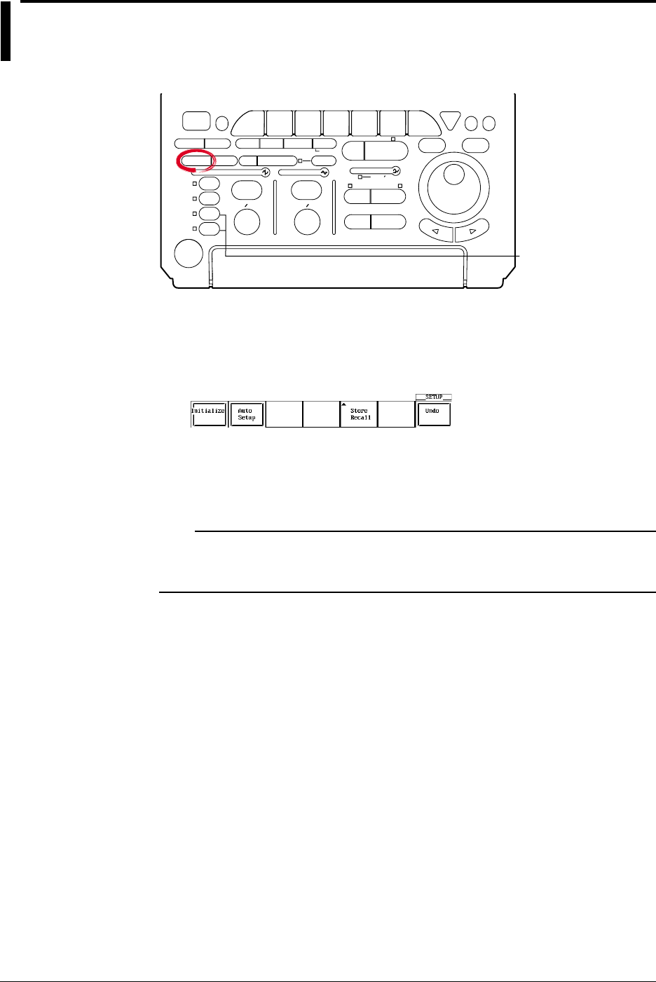
4-6 IM 701710-01E
4.2 Initializing Settings
Relevant Keys
ACTION DELAY
X - Y MENU MENU PHASE
SEARCH
HORIZONTAL
VERTICAL TRIGGER
TRIG D
HELP
ESC
SELECTRESET
SIMPLE
MODE POSITION
MATH
MISCFILE
CLEAR
TRACE
HISTORY
MEASURE
SETUP
PRESET
DISPLAY
CURSOR
CH
1
CH
2
CH
3
CH
4
POWER
COPY IMAGE SAVE SHIFT
ZOOM
GO/NO-GO
ENHANCED
ACQ START/STOP
SNAP
SHOT
V DIV TIME DIV
The DL1720 is not
equipped with
an input terminal
for CH3 or CH4.
Operating Procedure
Performing Initialization
1. Press SETUP.
2. Press the Initialize soft key to start initialization.
Canceling Initialization
3. Press the Undo soft key. This will restore the previous settings that were in effect
before initialization.
Note
The Undo operation remains available only while power stays on. The setting parameters
that existed immediately before initialization are cleared if you execute auto setup after
initialization.

4-7
IM 701710-01E
Common Operations
4
Explanation
The initialization function allows you to reset parameter values which have been set
using panel keys to the default (factory settings). This is very convenient when you have
to cancel the previous settings or when you have to restart measurement from the
beginning.
Initialization
Initialization means resetting parameters to their factory setting values. For details on
factory settings, refer to the Appendix.
Settings which cannot be Initialized
Date and time
Communication or ethernet interface related settings
SCSI ID number
Setting parameters on storing and recalling function
Setting the message language (English or Japanese)
Canceling Initialization
If you have performed initialization by mistake, press the Undo soft key. This will restore
the previous settings used before the initialization was performed.
Initializing All Settings
Turning the power switch ON while holding down RESET will start initialization. This
also initializes settings relating to the communication or ethernet interface, SCSI ID No.
setting, settings stored to the internal memory using the store/recall funcitn, and so on. If
settings are initialized using this method, you will not be able to restore the previous
settings.
4.2 Initializing Settings
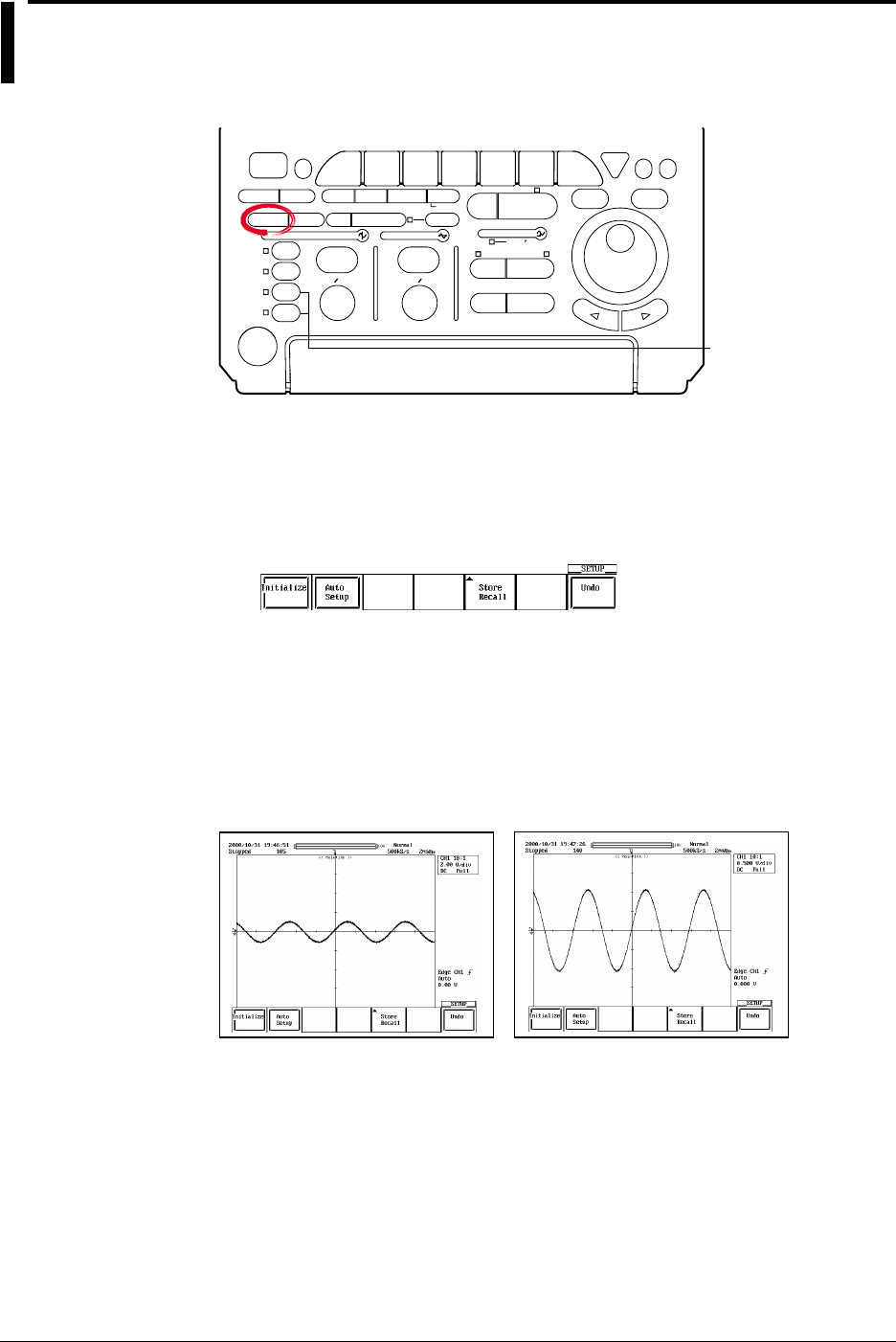
4-8 IM 701710-01E
4.3 Performing Auto Setup
Relevant Keys
ACTION DELAY
X - Y MENU MENU PHASE
SEARCH
HORIZONTAL
VERTICAL TRIGGER
TRIG D
HELP
ESC
SELECTRESET
SIMPLE
MODE POSITION
MATH
MISCFILE
CLEAR
TRACE
HISTORY
MEASURE
SETUP
PRESET
DISPLAY
CURSOR
CH
1
CH
2
CH
3
CH
4
POWER
COPY IMAGE SAVE SHIFT
ZOOM
GO/NO-GO
ENHANCED
ACQ START/STOP
SNAP
SHOT
V DIV TIME DIV
The DL1720 is not
equipped with
an input terminal
for CH3 or CH4.
Operating Procedure
Performing Auto Setup
1. Press SETUP.
2. Press the Auto Setup soft key to perform auto setup.
When auto set-up is executed, waveform acquisition starts automatically.
Canceling Auto Setup
3. Press the Undo soft key to restore the settings that existed immediately before
auto setup.
Explanation
The key settings such as V/div, T/div, and trigger levels are automatically set to optimum
values for the input signal.
Before Auto Setup After Auto Setup
Center Position
The center position after auto setup is set to 0 V.
Target Channels
Auto setup is performed on all channels.

4-9
IM 701710-01E
Common Operations
4
Canceling Auto Setup
By pressing the Undo soft key, the settings can be set back to the values that existed
immediately before auto setup was performed. However, settings which existed before
auto setup are erased when the power is turned OFF. In this case, the Undo operation
will have no effect. The setting parameters that existed immediately before auto setup
are cleared if you execute initialization after auto setup.
Waveforms that can be Automatically Setup
Frequency: Approx. 50 Hz or more
Maximum Absolute Input Value: Approx. 20 mV or more (assuming 1 : 1 probe
attenuation)
Type: Repetitive waveforms that are not complex
When the input coupling is set to “DC.”
Note
The auto setup function may not operate properly in some cases such as when the waveform
contains a large DC offset or high frequency components.
Settings Made by Auto Setup
Waveform Acquisition and Display
Acquisition Mode Normal
Acquisition Count Infinite
Record Length 10 k
Interleave Mode OFF
Timebase Int
Accumulation Mode OFF
Zoomed Waveforms Traces set ON for display
Vertical - Axis Settings
V/div Set to a value so that the absolute value of the input
waveform is between 1.6 div to 4 div. (approximately)
Offset Voltage 0 V (If Adjust Mode is 0 V)
Coupling Other than DC 50 Ω: DC 1 MΩ, DC 50 Ω: DC 50 Ω
Bandwidth FULL
Display ON/OFF Turns ON the channels of which the absolute value of the
amplitude is at least 20 mV (1 : 1)
Position 0 div
Horizontal - Axis Settings
T/div Set so that screen displays 1.6 to 4 periods of the auto -
setup waveform with the shortest period.
Trigger Settings
Trigger Mode Auto
Trigger Type Simple
Trigger Source Channel with the longest period and an amplitude of at least
1 div
Trigger Level and Slope Level is 1/2 the trigger source amplitude. Slope is “rising.”
Trigger Coupling The center level of the maximum and minimum values/
rising
HF Rejection OFF
Hysteresis
Holdoff Time 80 ns
Trigger Position 50%
Trigger Delay 0 s
Trigger Gate OFF
Math Setting
Scalling Auto
Automatic setup affects only the settings listed above. All other settings remain unchanged.
4.3 Performing Auto Setup
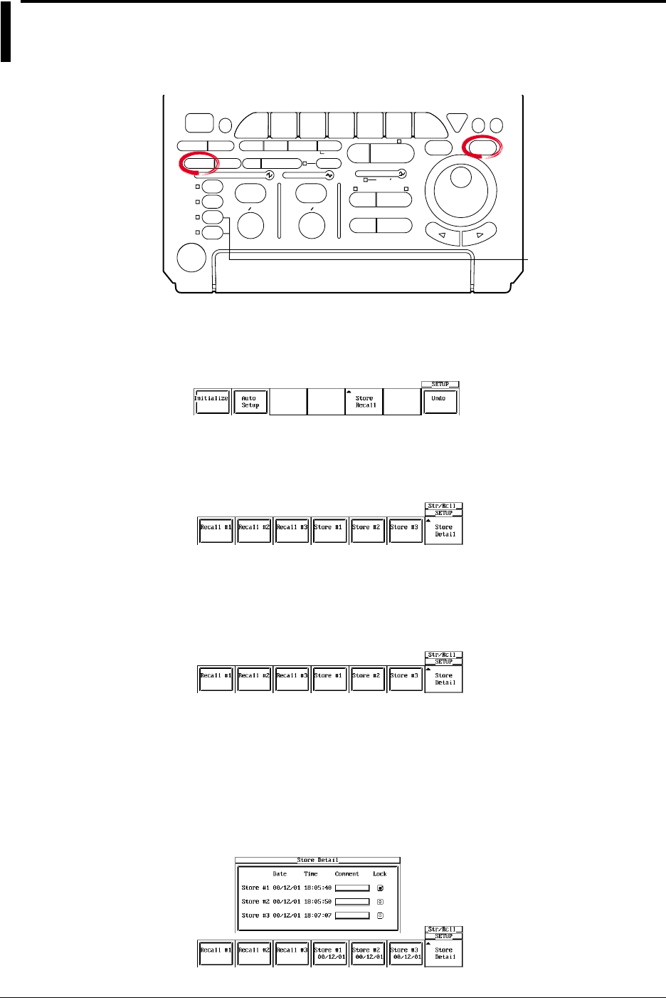
4-10 IM 701710-01E
4.4 Storing and Recalling Setting Parameters
Relevant Keys
ACTION DELAY
X - Y MENU MENU PHASE
SEARCH
HORIZONTAL
VERTICAL TRIGGER
TRIG D
HELP
ESC
SELECTRESET
SIMPLE
MODE POSITION
MATH
MISCFILE
CLEAR
TRACE
HISTORY
MEASURE
SETUP
PRESET
DISPLAY
CURSOR
CH
1
CH
2
CH
3
CH
4
POWER
COPY IMAGE SAVE SHIFT
ZOOM
GO/NO-GO
ENHANCED
ACQ START/STOP
SNAP
SHOT
V DIV TIME DIV
The DL1720 is not
equipped with
an input terminal
for CH3 or CH4.
Operating Procedure
1. Press SETUP.
2. Press the Store Recall soft key.
Recalling
3. After step 2, press the soft key corresponding to the memory number to be
retrieved (Recall #1 through Recall #3) to execute the recall operation.
Storing
3. After step 2, press the soft key corresponding to the memory number to be stored
(Store #1 through Store #3) to execute the store operation. The execution date of
the store operation is also displayed.
4. Press the Store Detail soft key to display the details of the store operation. To
enter a comment, follow the procedure described in section 4.1, “Entering a
Character String.”
There is a lock switch that you can use to prevent (lock) overwriting of the stored
data. Turn the jog shuttle to move the cursor to the lock button corresponding to
the store number that you wish to lock. Press SELECT to lock the data. Press
SELECT again to release the lock.

4-11
IM 701710-01E
Common Operations
4
4.3 Storing and Recalling Setting Parameters
Explanation
Items that are Stored
Stores all information that you entered using the soft key menu or jog shuttle menu,
START/STOP, and the ON/OFF conditions of channels.
Selecting the Storage Destination of the Setting Parameters
You can store the setting parameters to three memory locations, Store #1 through Store
#3. If the setting parameters are already stored to the selected number, the previous
data is overwritten. However, an error message is displayed if the data is locked.
Selecting the Setting Parameters to be Recalled
Select the setting parameters that are stored in the three memory locations, Recall #1
through Recall #3. You can only select memory locations that have setting parameters
stored.
Note
The stored setting parameters are not cleared even if you initialize the settings on the
DL1720/DL1740.

4-12 IM 701710-01E
4.5 Starting/Stopping Waveform Acquisition
Relevant Keys
ACTION DELAY
X - Y MENU MENU PHASE
SEARCH
HORIZONTAL
VERTICAL TRIGGER
TRIG D
HELP
ESC
SELECTRESET
SIMPLE
MODE POSITION
MATH
MISCFILE
CLEAR
TRACE
HISTORY
MEASURE
SETUP
PRESET
DISPLAY
CURSOR
CH
1
CH
2
CH
3
CH
4
POWER
COPY IMAGE SAVE SHIFT
ZOOM
GO/NO-GO
ENHANCED
ACQ START/STOP
SNAP
SHOT
V DIV TIME DIV
The DL1720 is not
equipped with
an input terminal
for CH3 or CH4.
Operating Procedure
1. Pressing START/STOP starts or stops the waveform acquisition.
Waveform acquisition is in progress when the indicator above the key is lit.
Explanation
START/STOP is pressed when starting or stopping waveform acquisition.
•When the indicator to the upper right of START/STOP is ON, waveform acquisition is
started.
•When the indicator to the upper right of START/STOP is OFF, waveform acquisition is
stopped. Stopped is displayed on the upper left corner of the screen.
Operation when the Acquisition Mode is Set to Averaging Mode
•When the waveform acquisition is stopped, the averaging process also stops.
•When the waveform acquisition is restarted, a new averaging process starts.
START/STOP Operation while Accumulation is in Progress
When the waveform acquisition is stopped, accumulation is temporarily suspended.
When the waveform acquisition is restarted, accumulation resumes.
Conditions in which the START/STOP is Disabled
•When the instrument is in the remote mode, controlled via communication.
•When the instrument is printing or auto setup is in progress.
Note
•Pressing FILE or HISTORY while the waveform acquisition is in progress stops the waveform
acquisition.
•If the waveform acquisition conditions are changed and the acquisition is restarted, previously
acquired data are cleared.
•The snapshot function can also be used to retain the waveforms that are currently displayed
on the screen. The display can be updated without having to stop the waveform acquisition
(see next section).
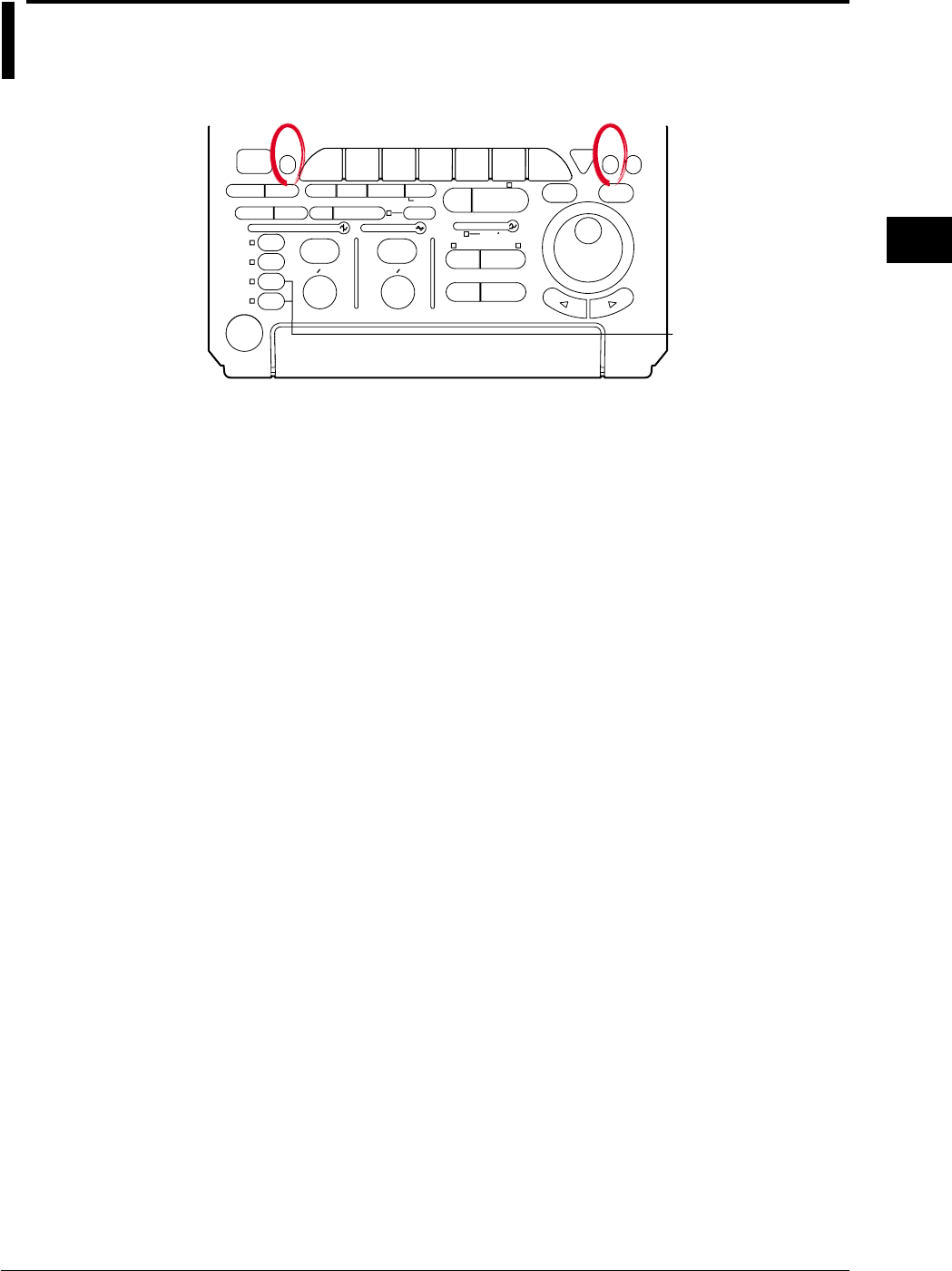
4-13
IM 701710-01E
Common Operations
4
4.6 The Snapshot and Clear Trace Functions
<For a description of this function, refer to page 1-32>
Relevant Keys
ACTION DELAY
X - Y MENU MENU PHASE
SEARCH
HORIZONTAL
VERTICAL TRIGGER
TRIG D
HELP
ESC
SELECTRESET
SIMPLE
MODE POSITION
MATH
MISCFILE
CLEAR
TRACE
HISTORY
MEASURE
SETUP
PRESET
DISPLAY
CURSOR
CH
1
CH
2
CH
3
CH
4
POWER
COPY IMAGE SAVE SHIFT
ZOOM
GO/NO-GO
ENHANCED
ACQ START/STOP
SNAP
SHOT
V DIV TIME DIV
The DL1720 is not
equipped with
an input terminal
for CH3 or CH4.
Operating Procedure
Snapshot
Press SNAP SHOT. The snapshot process will start.
Clear Trace
Press CLEAR TRACE. The clear trace process will start.
Averaging and measurement will also be started from the scratch. (The count is reset to
0.)
Explanation
Snapshot
This function retains the waveforms currently displayed on the screen. To activate this
function, just press SNAP SHOT without stopping acquisition. The currently displayed
waveform will be retained. Hence it is very useful when you want to compare
waveforms.
The following operations are not available for snapshot waveforms.
•Cursor measurements and automatic measurements
•Zoom and math operations
The snapshot waveforms can be saved or loaded.
For details, see section 11.8, “Saving Snap Shot Waveforms.”
Clear Trace
This function clears every waveform currently displayed on the screen.
If the trace is cleared while waveform acquisition is in progress, it is restarted from the
first trace.
The instrument is performing GO/NO-GO determination, action-on-trigger, or waveform
search.
The SNAP SHOT and CLEAR TRACE are not Operative in the Following Cases.
•The instrument is in remote state, controlled via the communication interface.
•The instrument is performing an operation, for example, it is in the process of printing
out or performing auto set-up, determining GO/NO-GO, performing an action on
trigger, or searching data.
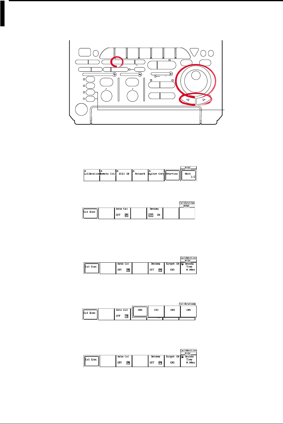
4-14 IM 701710-01E
4.7 Calibration
Relevant Keys
ACTION DELAY
X - Y MENU MENU PHASE
SEARCH
HORIZONTAL
VERTICAL TRIGGER
TRIG D
HELP
ESC
SELECTRESET
SIMPLE
MODE POSITION
MATH
MISCFILE
CLEAR
TRACE
HISTORY
MEASURE
SETUP
PRESET
DISPLAY
CURSOR
CH
1
CH
2
CH
3
CH
4
POWER
COPY IMAGE SAVE SHIFT
ZOOM
GO/NO-GO
ENHANCED
ACQ START/STOP
SNAP
SHOT
V DIV TIME DIV
The DL1720 is not
equipped with
an input terminal
for CH3 or CH4.
Operating Procedure
Performing Calibration
1. Press MISC. The MISC menu will appear.
2. Press the Calibration soft key.
3. Press the Auto Cal soft key to select either ON or OFF.
4. Press the Deskew soft key to select either ON or OFF.
5. If ON is selected in step 4, select the desired channel.
Pressing the Target CH soft key displays a menu used to select the channel.
6. Press the soft key corresponding to the desired channel to select the channel.
(CH3 and CH4 are not displayed on the DL1720.)
7. Turn the jog shuttle to set the Deskew Time.
8. Press the Cal Exec soft key to start calibration.

4-15
IM 701710-01E
Common Operations
4
Explanation
Calibration
The following parameters can be calibrated. Perform calibration when highly accurate
measurements are required.
•Ground level offset
•A/D converter gain
•Trigger threshold
•Time axis for repetitive sampling mode
•The oscillation frequency of the startup oscillator for the pulse width trigger
Points for Attention
•Always allow the instrument to warm up for at least 30 minutes after the power is
turned ON before starting calibration. If calibration is performed immediately after the
power is turned ON, the calibration may be inaccurate due to drift caused by
fluctuation in the temperature of the instrument.
•Calibration must be performed when the temperature of the instrument is stable and is
between 5°C and 40°C (preferably at 23°C ±2°C).
•When performing calibration, remove the input signals. Otherwise, proper calibration
may not result.
Note
•The above calibration is performed automatically when power is turned ON.
•If the V/div knob has been turned, perform calibration for all parameters except the time axis
for repetitive sampling mode.
Auto Calibration (Auto Cal)
Calibration is performed automatically after the times shown below elapse after turning
ON the power, when the T/div setting is changed, or when waveform acquisition is
started.
•After 3 minutes
•After 10 minutes
•After 30 minutes
•After one hour and every hour thereafter
If the DL1720/DL1740 is auto-calibrated while input takes place, it is recommended that
you disconnect the input and then repeat calibration.
Deskew
Corrects the CH1 to CH4 (or CH1 to CH2 for the DL1720) delays.
Deskew Time Setting Range
The correction time is set within the following range.
–100 ns to 100 ns
4.7 Calibration

4-16 IM 701710-01E
4.8 Using the Help Function
Relevant Keys
ACTION DELAY
X - Y MENU MENU PHASE
SEARCH
HORIZONTAL
VERTICAL TRIGGER
TRIG D
HELP
ESC
SELECTRESET
SIMPLE
MODE POSITION
MATH
MISCFILE
CLEAR
TRACE
HISTORY
MEASURE
SETUP
PRESET
DISPLAY
CURSOR
CH
1
CH
2
CH
3
CH
4
POWER
COPY IMAGE SAVE SHIFT
ZOOM
GO/NO-GO
ENHANCED
ACQ START/STOP
SNAP
SHOT
V DIV TIME DIV
The DL1720 is not
equipped with
an input terminal
for CH3 or CH4.
Operating Procedure
Displaying a Help Window
1. Press HELP.
2. Press the function key or soft key for which you want help.
Clearing the Help Window
3. Press HELP again to close the window.
Explanation
Displaying a Help Window
Pressing HELP displays the soft key menu which was in effect before HELP was
pressed, or displays a help window which contains information related to jog shuttle
menu settings.
If a key is pressed or the jog shuttle is turned while a help window is displayed, the help
window relating to the displayed soft key menu or the jog shuttle menu will appear.
Clearing the Help Window
Pressing HELP again while a help window is displayed will clear the help window.
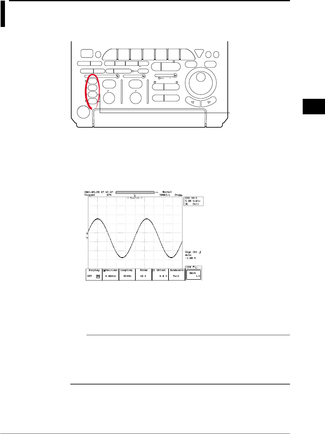
5-1
IM 701710-01E
Vertical and Horizontal Axes
5
5.1 Turning Channels ON/OFF
Relevant Keys
ACTION DELAY
X - Y MENU MENU PHASE
SEARCH
HORIZONTAL
VERTICAL TRIGGER
TRIG D
HELP
ESC
SELECTRESET
SIMPLE
MODE POSITION
MATH
MISCFILE
CLEAR
TRACE
HISTORY
MEASURE
SETUP
PRESET
DISPLAY
CURSOR
CH
1
CH
2
CH
3
CH
4
POWER
COPY IMAGE SAVE SHIFT
ZOOM
GO/NO-GO
ENHANCED
ACQ START/STOP
SNAP
SHOT
V DIV TIME DIV
The DL1720 is not
equipped with
an input terminal
for CH3 or CH4.
Operating Procedure
1. Press one of CH 1 to CH 4 (or CH 1 to CH 2 for the DL1720) to select the desired
channel.
2. Press the Display soft key to select ON or OFF.
CH 1 to CH 4 (or CH 1 to CH 2 for the DL1720) can be pressed twice to turn the
channels ON or OFF.
Explanation
The channels CH1 to CH4 (or CH1 to CH2 for the DL1720) can be displayed
simultaneously.
When turned ON, the indicators to the left of the channel keys light.
Note
•The screen can be split into up to six display areas (or 1 to 3 areas for the DL1720). (Refer to
section 8.1) A scaling value and waveform label name for each display area (refer to sections
8.4, 8.5) can also be displayed.
•If a waveform or waveforms are loaded from history memory, store memory, floppy disk or Zip
disk, the input waveform cannot be displayed. To compare waveforms, use the snapshot
function.
Chpater 5 Vertical and Horizontal Axes
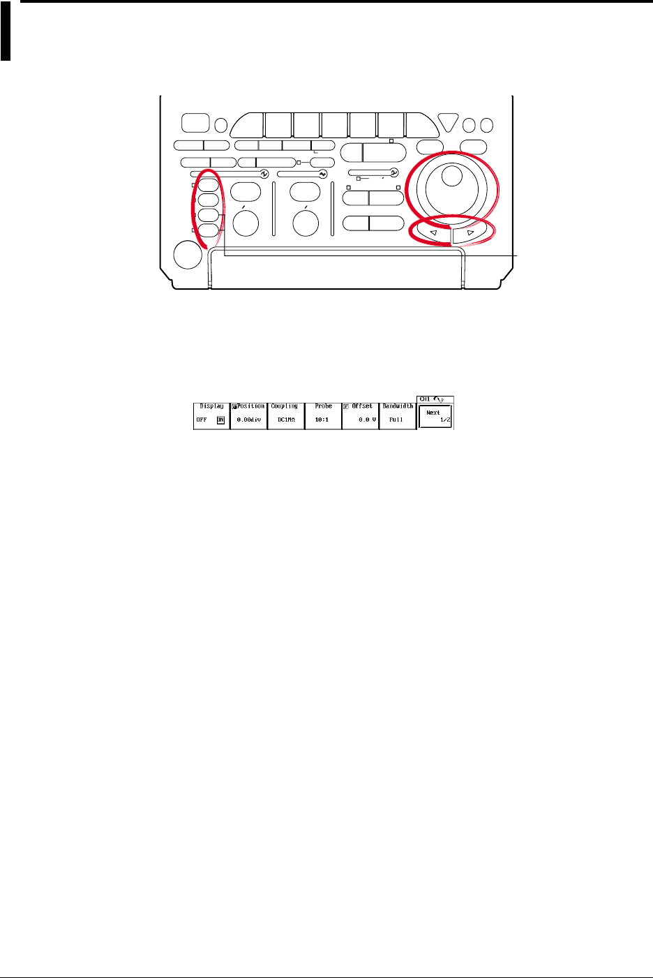
5-2 IM 701710-01E
5.2 Setting the Vertical Position of a Waveform
<For a description of this function, refer to page 1-4>
Relevant Keys
ACTION DELAY
X - Y MENU MENU PHASE
SEARCH
HORIZONTAL
VERTICAL TRIGGER
TRIG D
HELP
ESC
SELECTRESET
SIMPLE
MODE POSITION
MATH
MISCFILE
CLEAR
TRACE
HISTORY
MEASURE
SETUP
PRESET
DISPLAY
CURSOR
CH
1
CH
2
CH
3
CH
4
POWER
COPY IMAGE SAVE SHIFT
ZOOM
GO/NO-GO
ENHANCED
ACQ START/STOP
SNAP
SHOT
V DIV TIME DIV
The DL1720 is not
equipped with
an input terminal
for CH3 or CH4.
Operating Procedure
1. Press one of the keys from CH 1 to CH 4 (or CH 1 to CH 2 for the DL1720) to
select the desired channel.
2. Press the Position soft key to set the jog shuttle action to Position.
3. Turn the jog shuttle to set the vertical position.
You can change the setting a digit using the arrow keys (located below the jog
shuttle).
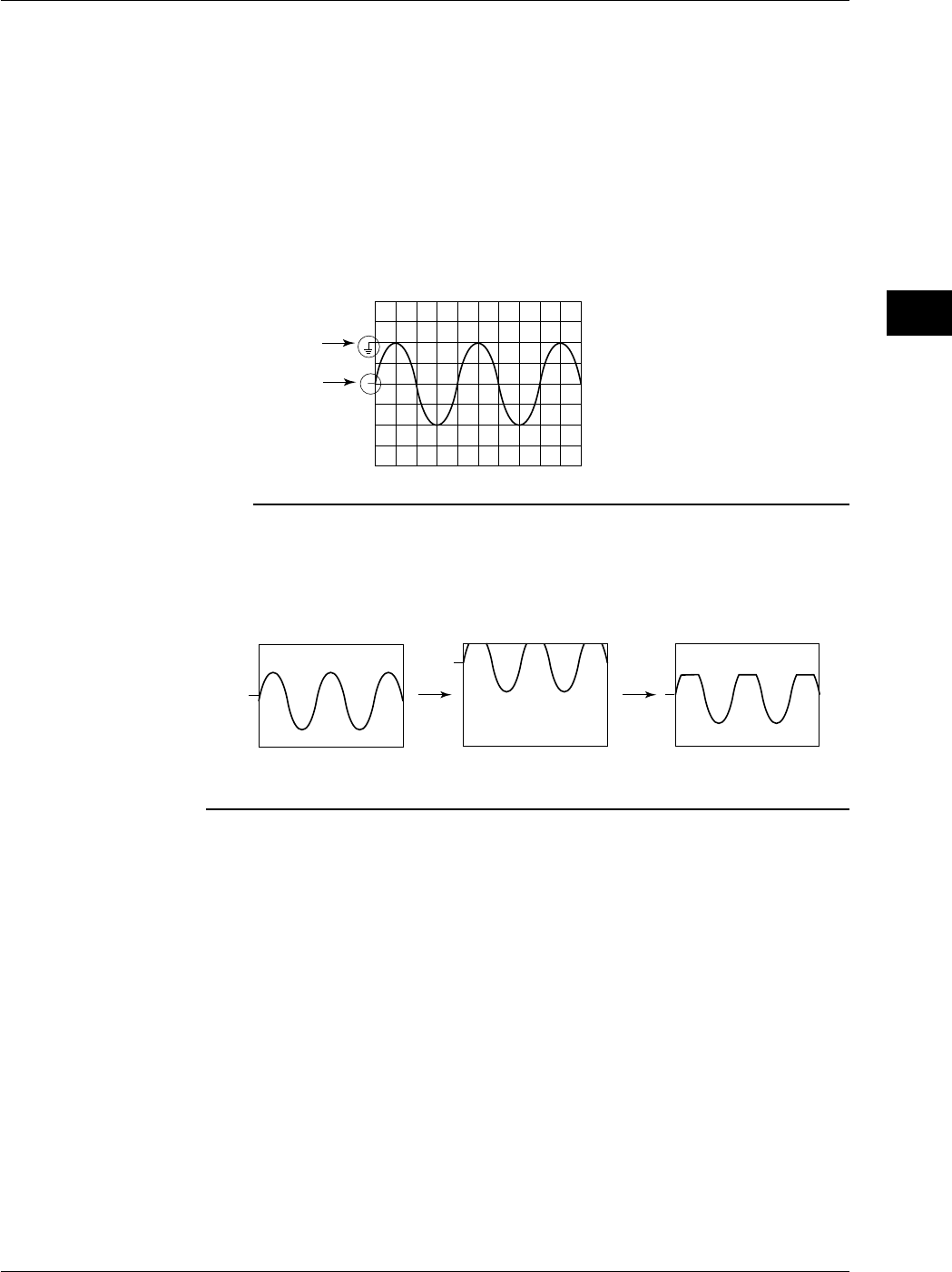
5-3
IM 701710-01E
Vertical and Horizontal Axes
5
Explanation
Range of Movement
The vertical position can be moved in the range between ±4 div from the center position
in the waveform display frame.
Setting Resolution
0.01 div
Confirming the Vertical Position
For input waveforms and computed waveforms, the ground level and vertical position are
marked on the left of the waveform display frame.
500 mV/div, Offset: –1 V, Offset Cancel: OFF, Position: 0 div
Ground Level
Mark
Vertical Position
Mark
Note
•The data which go out of the waveform display frame from moving the vertical position are
handled as overflow data.
•If the display waveform goes out of the waveform display frame from moving the vertical
position during the waveform acquisition is starting, a chopped waveform is displayed as
shown in the following figure even if the vertical position is returned to its original position
after stopping the acquisition.
•If the vertical position is moved, the effective data range also changes. For details, see
section 1.2.
5.2 Setting the Vertical Position of a Waveform
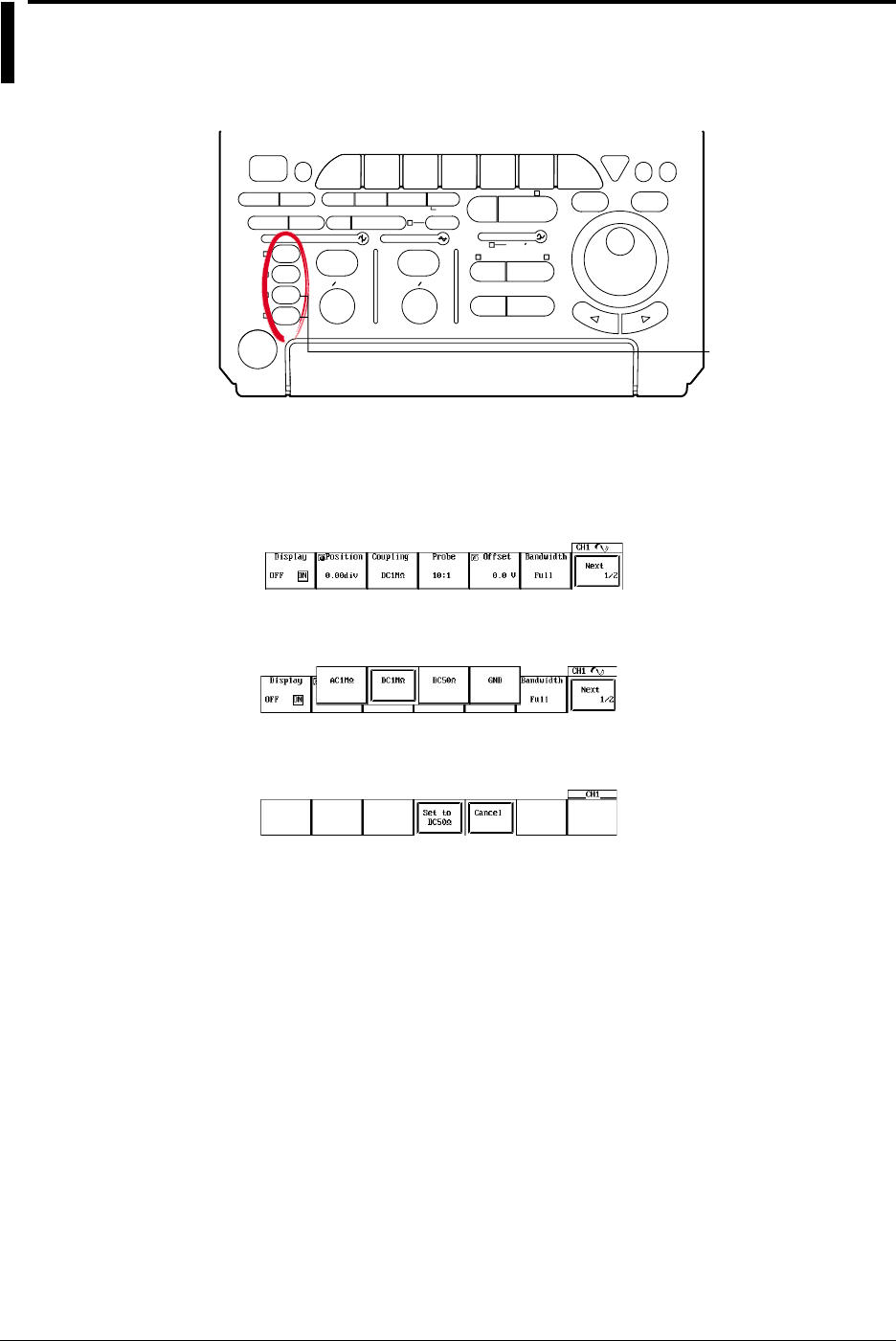
5-4 IM 701710-01E
5.3 Selecting Input Coupling
<For a description of this function, refer to page 1-2>
Relevant Keys
ACTION DELAY
X - Y MENU MENU PHASE
SEARCH
HORIZONTAL
VERTICAL TRIGGER
TRIG D
HELP
ESC
SELECTRESET
SIMPLE
MODE POSITION
MATH
MISCFILE
CLEAR
TRACE
HISTORY
MEASURE
SETUP
PRESET
DISPLAY
CURSOR
CH
1
CH
2
CH
3
CH
4
POWER
COPY IMAGE SAVE SHIFT
ZOOM
GO/NO-GO
ENHANCED
ACQ START/STOP
SNAP
SHOT
V DIV TIME DIV
The DL1720 is not
equipped with
an input terminal
for CH3 or CH4.
Operating Procedure
1. Press one of the keys from CH 1 to CH 4 (or CH 1 to CH 2 for the DL1720) to
select the channel.
2. Press the Coupling soft key to display the menu used to select the coupling.
3. Press the soft key corresponding to the desired coupling.
If DC 50 Ω is selected, a confirmation menu is displayed. Press the Set to DC 50
Ω or Cancel soft key.
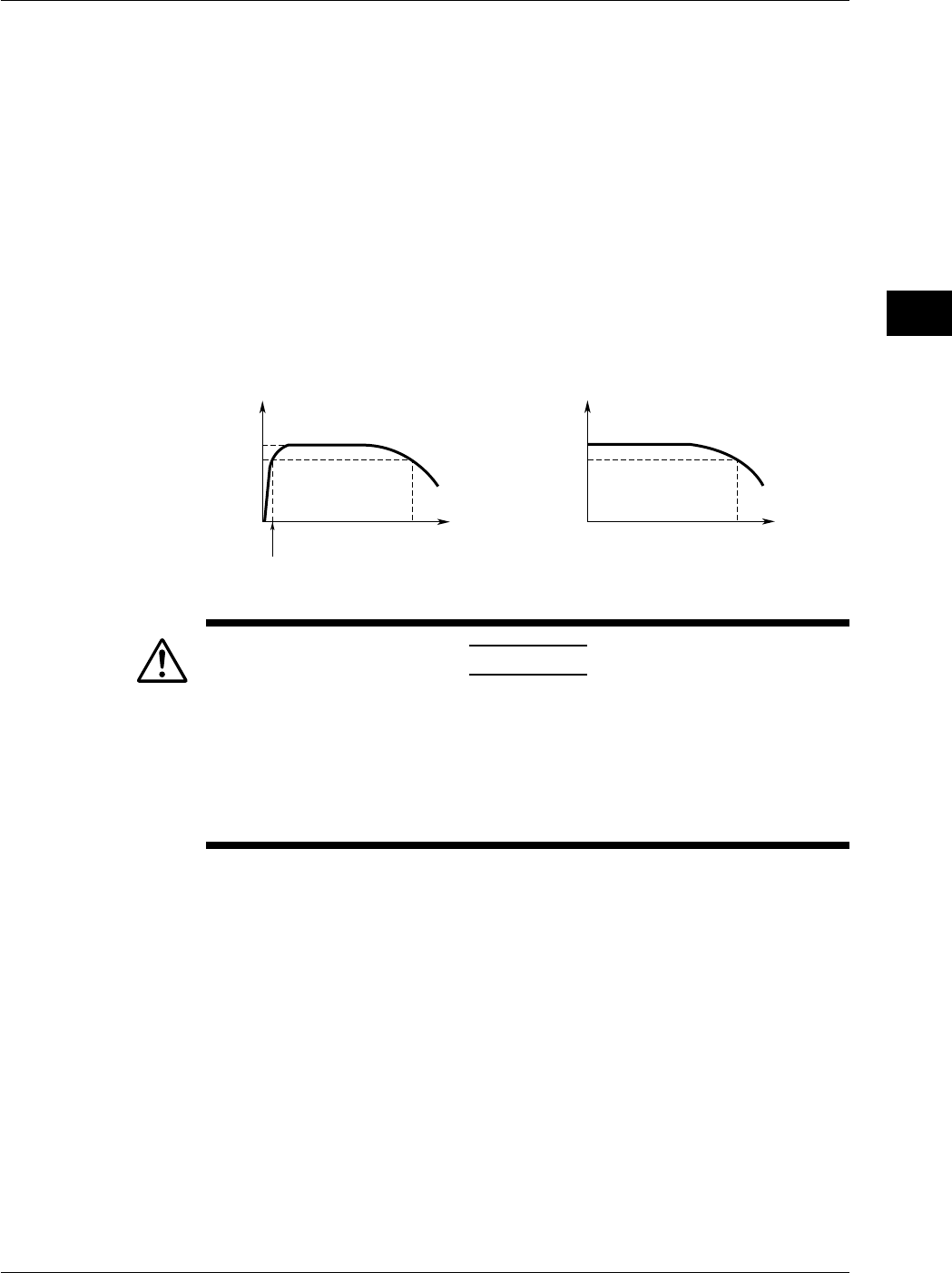
5-5
IM 701710-01E
Vertical and Horizontal Axes
5
Explanation
Input Coupling
The following three types of input coupling are available.
AC 1 MΩ: Acquires and displays only the AC content of the input signal.
DC 1 MΩ: Acquires and displays both the DC and the AC content of the input signal (1
MΩ).
DC 50 Ω: Acquires and displays both the DC and the AC content of the input signal
(50 Ω).
GND: Checks the ground level.
Input Coupling and Frequency Characteristic
The frequency characteristic when AC or DC is selected is shown below.
Note that low-frequency signals and low-frequency contents are not acquired if AC 1 MΩ
is selected.
0 dB
–3 dB
500 MHz (400 MHz)
Attenuation
0 dB
–3 dB
400 MHz
Attenuation
Less than 10 Hz when using 1 : 1 probe
Less than 1 Hz when using 10 : 1 probe
Input Frequency
When “AC” is selected When “DC 50 Ω” is selected
Input Frequency
( ): DC 1 MΩ
CAUTION
The maximum input voltage when the frequency is less than or equal to
1 kHz is 400 V (DC+ACpeak) when using 1-MΩ input and 5 Vrms or 10
Vpeak when using 50-Ω input. Applying a voltage that exceeds these
values can damage the input section. When the frequency exceeds 1
kHz, voltages below these values can also sometimes damage the
input section.
5.3 Selecting Input Coupling
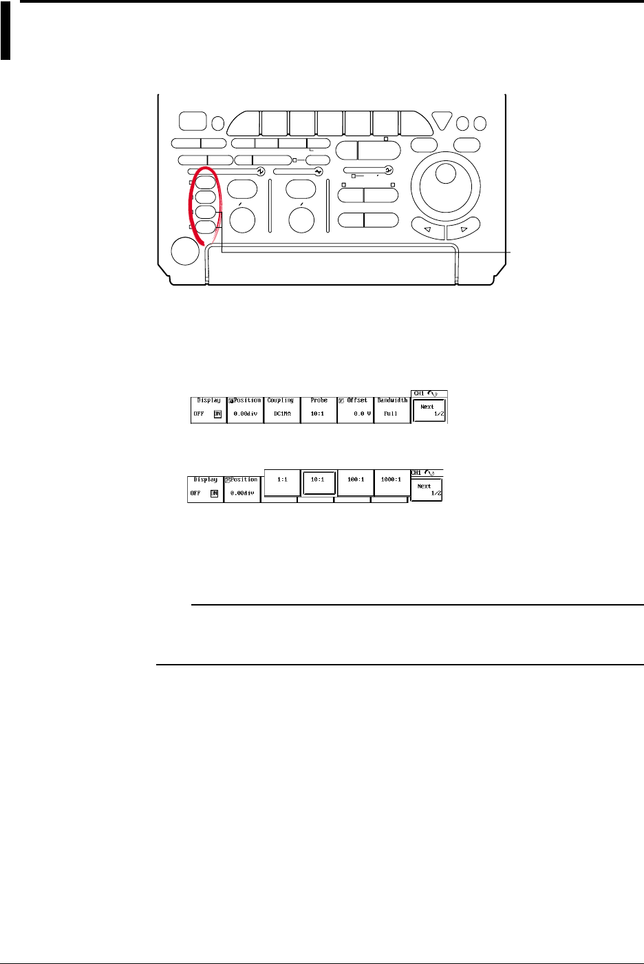
5-6 IM 701710-01E
5.4 Selecting Probe Attenuation
<For a description of this function, refer to page 1-3>
Relevant Keys
ACTION DELAY
X - Y MENU MENU PHASE
SEARCH
HORIZONTAL
VERTICAL TRIGGER
TRIG D
HELP
ESC
SELECTRESET
SIMPLE
MODE POSITION
MATH
MISCFILE
CLEAR
TRACE
HISTORY
MEASURE
SETUP
PRESET
DISPLAY
CURSOR
CH
1
CH
2
CH
3
CH
4
POWER
COPY IMAGE SAVE SHIFT
ZOOM
GO/NO-GO
ENHANCED
ACQ START/STOP
SNAP
SHOT
V DIV TIME DIV
The DL1720 is not
equipped with
an input terminal
for CH3 or CH4.
Operating Procedure
1. Press one of the keys from CH 1 to CH 4 (or CH 1 to CH 2 for the DL1720) to
select the desired channel.
2. Press the Probe soft key to display the menu used to select the attenuation.
3. Press the soft key corresponding to the desired attenuation.
Explanation
Probe attenuation for each channel can be selected from the following.
1 : 1, 10 : 1, 100 : 1, or 1000 : 1
Note
If an incorrect attenuation has been selected, V/div will also be incorrect. If you set the
attenuation to 1 : 1 when using a 10 : 1 probe, for example, the displayed value for
automatically measured amplitude will be 1/10 the true value.
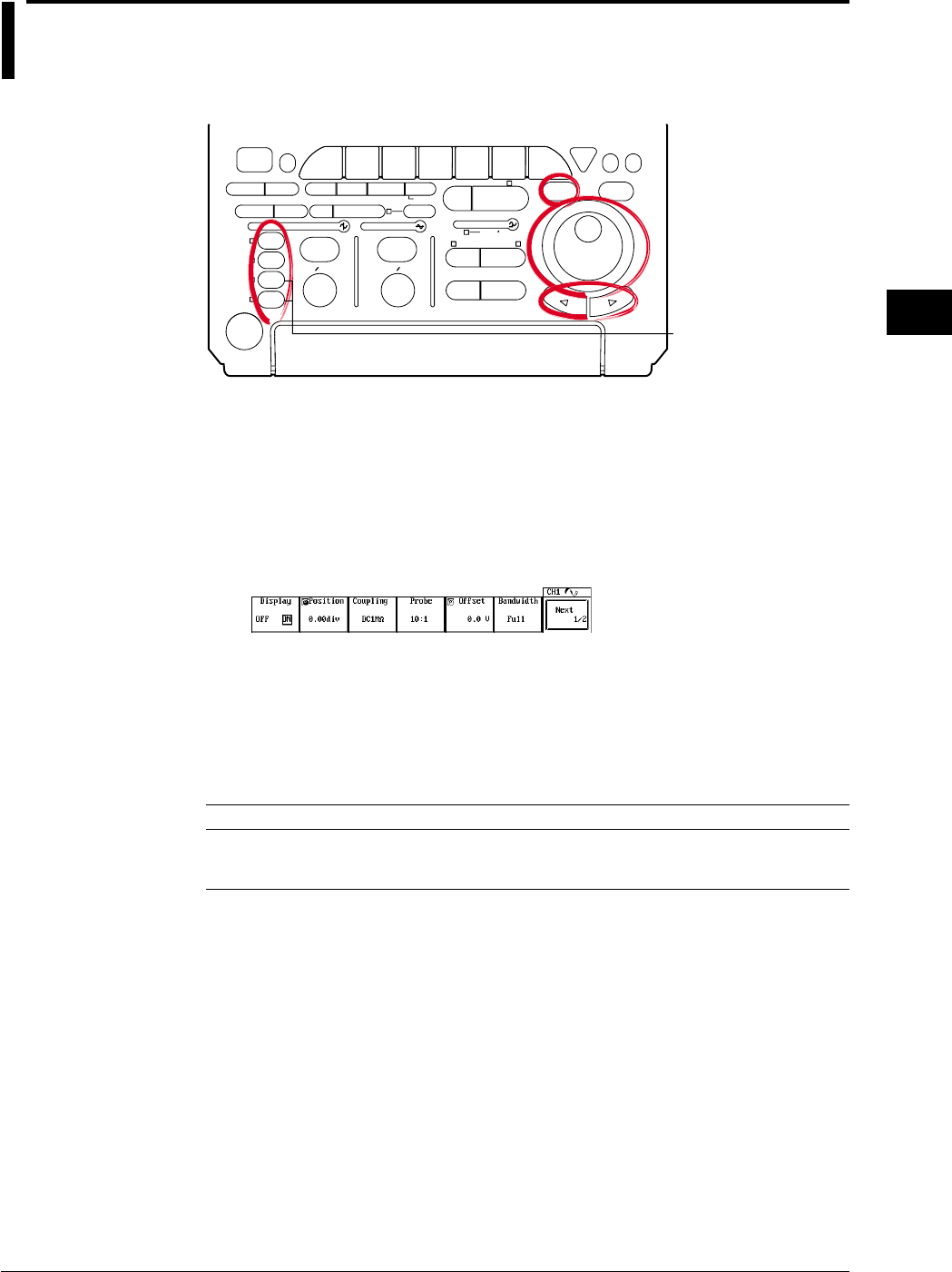
5-7
IM 701710-01E
Vertical and Horizontal Axes
5
5.5 Setting the Offset Voltage
<For a description of this function, refer to page 1-2>
Relevant Keys
ACTION DELAY
X - Y MENU MENU PHASE
SEARCH
HORIZONTAL
VERTICAL TRIGGER
TRIG D
HELP
ESC
SELECTRESET
SIMPLE
MODE POSITION
MATH
MISCFILE
CLEAR
TRACE
HISTORY
MEASURE
SETUP
PRESET
DISPLAY
CURSOR
CH
1
CH
2
CH
3
CH
4
POWER
COPY IMAGE SAVE SHIFT
ZOOM
GO/NO-GO
ENHANCED
ACQ START/STOP
SNAP
SHOT
V DIV TIME DIV
The DL1720 is not
equipped with
an input terminal
for CH3 or CH4.
Operating Procedure
Setting the Offset Value
1. Press one of the keys from CH 1 to CH 4 (or CH 1 to CH 2 for the DL1720) to
select the channel.
2. Press the Offset soft key.
3. Turn the jog shuttle to set the offset value.
You can change the setting a digit using the arrow keys (located below the jog
shuttle).
Resetting the Offset Value (Set to 0 V)
4. Press RESET to set the offset value to 0 V.
Explanation
The offset voltage setting applies to all input couplings (AC 1 MΩ, DC 1 MΩ, DC 50Ω,
and GND couplings).
Offset Voltage Setting Range
Sensitivity Range (Probe = 1 : 1) Offset Voltage Setting Range
2 mV/div to 50 mV/div –1.0 V to 1.0 V
0.1 V/div to 0.5 V/div –10.0 V to 10.0 V
1 V/div to 10 V/div –100.0 V to 100.0 V (DC 50 Ω: 1 V/div only)
The setting resolution is 0.01 div. If the voltage scale is 2 mV/div, for example, the setting resolution
will be 0.02 mV.
Resetting the Offset Voltage
You can return the offset to 0V by pressing RESET.
Important Points
•Setting the offset voltage while acquisition is stopped will change the display position
only. The newly set offset voltage will come into effect when acquisition is restarted.
•You can select whether or not the offset voltage is reflected in the results of cursor
measurements, automatic measurements, or math computations.
•If you change the probe attenuation, the offset changes proportionally to reflect the
new attenuation rate.
•Changing the voltage sensitivity does usually not affect the offset value. Only if the
change would cause the offset to go out of range, the offset moves to the nearest
range limit. If you then return to the original sensitivity, the offset returns to its original
setting as well (provided that you have not explicitly changed the value in the
meantime).
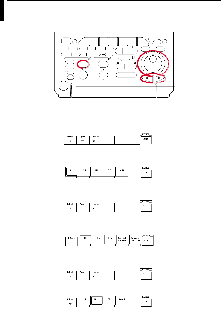
5-8 IM 701710-01E
5.6 The Preset Function
Relevant Keys
ACTION DELAY
X - Y MENU MENU PHASE
SEARCH
HORIZONTAL
VERTICAL TRIGGER
TRIG D
HELP
ESC
SELECTRESET
SIMPLE
MODE POSITION
MATH
MISCFILE
CLEAR
TRACE
HISTORY
MEASURE
SETUP
PRESET
DISPLAY
CURSOR
CH
1
CH
2
CH
3
CH
4
POWER
COPY IMAGE SAVE SHIFT
ZOOM
GO/NO-GO
ENHANCED
ACQ START/STOP
SNAP
SHOT
V DIV TIME DIV
The DL1720 is not
equipped with
an input terminal
for CH3 or CH4.
Operating Procedure
Selecting the Channel
1. Press PRESET.
2. Press the Select soft key to display the channel menu.
3. Press the soft key corresponding to the desired channel. Pressing All will select all
the channels. (CH3 and CH4 are not displayed on the DL1720.)
Selecting the Preset Type
4. Press the Type soft key to display the preset type selection menu.
5. Set the type by pressing the soft key corresponding to TTL, ECL, User, Current
(700937), or Current (701930).
Selecting the Probe Attenuation (for TTL, ECL, or User Preset)
6. Press the Probe soft key to display a menu used to select the attenuation.
7. Press the soft key corresponding to the desired attenuation.
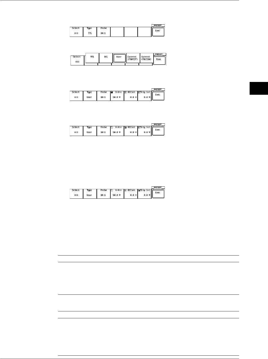
5-9
IM 701710-01E
Vertical and Horizontal Axes
5
Setting the V/div, Offset Voltage, and Trigger Level (When the Preset Type is User)
8. Press the Type soft key to display the preset type selection menu.
Press the User soft key.
9. Press the V/div soft key to highlight the jog shuttle icon.
10. Turn the jog shuttle to set the V/div value.
11. Prees the Offset soft key to select Offset, then turn the jog shuttle to set the Offset
value.
12. In a similar fashion, set the Trig Lvl.
You can change the setting a digit using the arrow keys (located below the jog
shuttle).
Executing the Preset
13. Press the Exec soft key to execute the preset.
Explanation
The preset function automatically sets each key setting, such as the V/div, input coupling
and trigger level, to the optimum value for measurement of TTL or ECL signals (or to an
arbitrary value). Also, you can automatically set the appropriate values for use with the
current probe 700937, 701930 (sold separately). This function allows you to make
settings for a selected channel or for all channels at the same time.
Settings Made by a Preset
TTL ECL User
Input Coupling DC 1 MΩDC 1 MΩDC 1 MΩ
Trigger Coupling DC DC DC
Probe 1 : 1, 10 : 1, 100 : 1 or 1000 : 1 is available.
V/div 1 V/div*1 200 mV/div*1 Arbitrary*2
Offset Voltage 2.5 V –1.3 V Arbitrary*2
Trigger Level 1.4 V –1.3 V Arbitrary*2
*1 2 V/div when probe setting is 1000 : 1.
*2 For details about the setting ranges, see Sections 5.5, 5.8, and 6.5.
Current (700937) Current (701930)
Input Copuling DC1 MΩDC1 MΩ
Probe 1 : 1 1 : 1
Linear Scaling ON ON
Linear Scaling Coefficient ValueA: +1.0000E+01 ValueA: +1.0000E+02
ValueB: 0.0000E+00 ValueB: 0.0000E+00
Units A A
Scale Value Display ON ON
5.6 The Preset Function
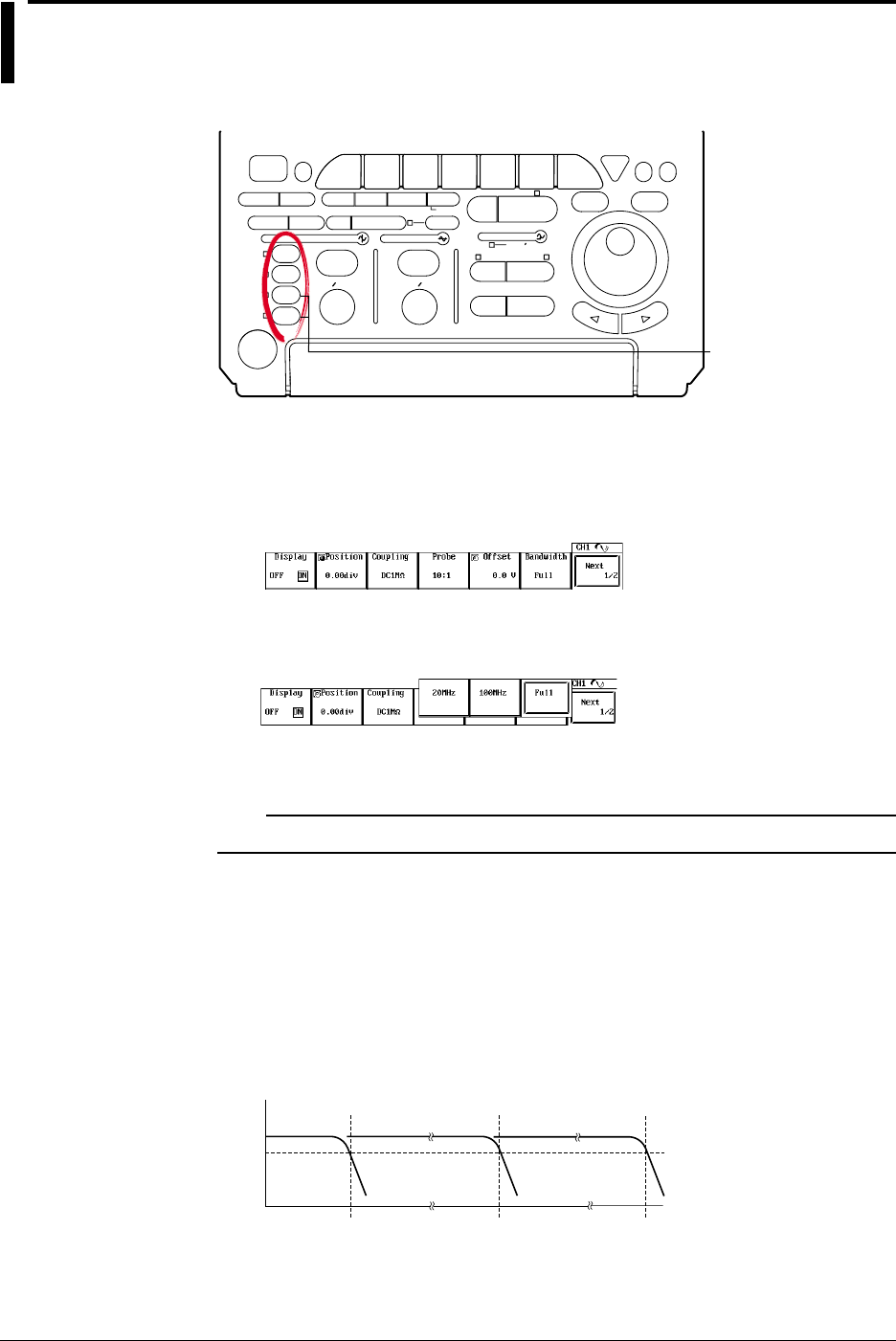
5-10 IM 701710-01E
5.7 Setting the Bandwidth
<For a description of this function, refer to page 1-3>
Relevant Keys
ACTION DELAY
X - Y MENU MENU PHASE
SEARCH
HORIZONTAL
VERTICAL TRIGGER
TRIG D
HELP
ESC
SELECTRESET
SIMPLE
MODE POSITION
MATH
MISCFILE
CLEAR
TRACE
HISTORY
MEASURE
SETUP
PRESET
DISPLAY
CURSOR
CH
1
CH
2
CH
3
CH
4
POWER
COPY IMAGE SAVE SHIFT
ZOOM
GO/NO-GO
ENHANCED
ACQ START/STOP
SNAP
SHOT
V DIV TIME DIV
The DL1720 is not
equipped with
an input terminal
for CH3 or CH4.
Operating Procedure
1. Press one of the keys from CH1 to CH4 (or CH 1 to CH 2 for the DL1720) to select
the channel.
2. Press the Bandwidth soft key to display the bandwidth menu.
3. Press a soft key corresponding to 20 MHz, 100 MHz, or Full to select the
bandwidth.
4. Repeat steps 1 to 3 as necessary to set other channels.
Note
The bandwidth is set for each channel. Set the bandwidth on all necessary channels.
Explanation
Use this function to remove high frequency components (20 MHz or more or 100 MHz or
more) from the input signal.
The bandwidth is set for each channel.
Bandwidth
Two frequency bandwidths, 20 MHz and 100 MHz are available. The following figure
shows how the bandwidth affects the frequency characteristics. When Full is selected,
the bandwidth is Max. 500 MHz (50 Ω input) or Max. 400 MHz (1 MΩ input).
–3 dB
Approx. 20 MHz FULL
Approx. 100 MHz
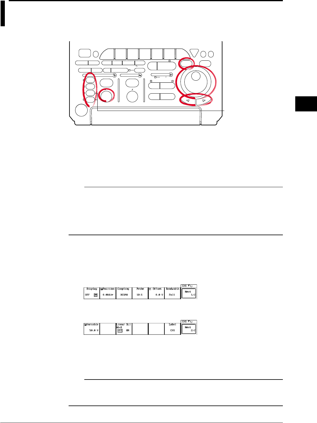
5-11
IM 701710-01E
Vertical and Horizontal Axes
5
5.8 Setting V/div
<For a description of this function, refer to page 1-4>
Relevant Keys
ACTION DELAY
X - Y MENU MENU PHASE
SEARCH
HORIZONTAL
VERTICAL TRIGGER
TRIG D
HELP
ESC
SELECTRESET
SIMPLE
MODE POSITION
MATH
MISCFILE
CLEAR
TRACE
HISTORY
MEASURE
SETUP
PRESET
DISPLAY
CURSOR
CH
1
CH
2
CH
3
CH
4
POWER
COPY IMAGE SAVE SHIFT
ZOOM
GO/NO-GO
ENHANCED
ACQ START/STOP
SNAP
SHOT
V DIV TIME DIV
The DL1720 is not
equipped with
an input terminal
for CH3 or CH4.
Operating Procedure
Setting the V/div Using the V/div Knob
1. Press one of the keys from CH 1 to CH 4 (or CH 1 to CH 2 for the DL1720) to
select the channel.
2. Turn the V/DIV knob to set the V/div value.
Note
•Changing the V/DIV setting while the waveform acquisition is stopped will not change the
displayed waveform. The new V/div value takes effect the next time waveform acquisition is
started.
•When the waveform acquisition is stopped, the cursor measurement value and automated
measurement of waveform parameters will show values using the old V/div setting even if the
V/DIV knob is turned.
Setting the V/div Using the Variable Parameter
1. Press one of the keys from CH 1 to CH 4 (or CH 1 to CH 2 for the DL1720) to
select the channel.
2. Press the Next 1/2 soft key.
3. Press the Variable soft key.
4. Turn the jog shuttle to set the V/div value.
You can change the setting a digit using the arrow keys (located below the jog
shuttle).
Note
•If the V/div setting is changed by rotating the V/DIV knob, the Variable value is set to the
modified V/div value.
•If Variable is reset with RESET, the V/div setting returns to the value set with the V/div knob.

5-12 IM 701710-01E
Explanation
The V/div (voltage axis sensitivity) setting is used to adjust the amplitude of the displayed
waveform so that the waveform can be observed easily. The V/div setting is made by
setting the voltage value per division on the screen grid.
There are two methods available in setting the V/div.
Setting the V/div Using the V/div Knob
The settings are “1 V/div,” “2 V/div,” “5 V/div,” and their tenfold multiples.
This setting will become the reference for the range that can be set using the Variable
parameter (described next) and the resolution.
•V/div Setting Range
The V/div setting range for each probe attenuation value is shown in the table below.
Probe Attenuation Setting Range (DC 1 MΩ) Setting Range (DC 50 Ω)
1 : 1 2 mV/div to 10 V/div 2 mV/div to 1 V/div
10 : 1 20 mV/div to 0.1 kV/div 20 mV/div to 10 V/div
100 : 1 0.2 V/div to 1 k V/div 0.2 V/div to 0.1 kV/div
1000 : 1 2 V/div to 10 k V/div 2 V/div to 1 kV/div
Setting the V/div Using the Variable Parameter in the CH Menu
You can set the V/div using a resolution that is finer than the resolution provided by the
V/div knob and vertically expand or reduce the displayed waveform.
The waveform acquisition can be started with the changed V/div setting.
•Range
The following table shows the range when the probe attenuation setting is 10 : 1.
V/div Setting with V/div Knob Setting Range of Variable Setting Resolution
20 mV/div 2.0 mV to 50.0 mV 0.2 mV
50 mV/div 5.0 mV to 100.0 mV 0.5 mV
100 mV/div 10 mV to 200 mV 1 mV
200 mV/div 20 mV to 500 mV 2 mV
500 mV/div 50 mV to 1000 mV 5 mV
1 V/div 0.10 V to 2.00 V 0.01 V
2 V/div 0.20 V to 5.00 V 0.02 V
5 V/div 0.50 V to 10.00 V 0.05 V
10 V/div 1.0 V to 20.0 V 0.1 V
20 V/div 2.0 V to 50.0 V 0.2 V
50 V/div 5.0 V to 100.0 V 0.5 V
100 V/div 10 V to 200 V 1 V
* When the probe attenuation is “1 : 1,” “100 : 1,” and “1000 : 1,” the values are 1/10, 10, and 100
times, respectively.
5.8 Setting V/div
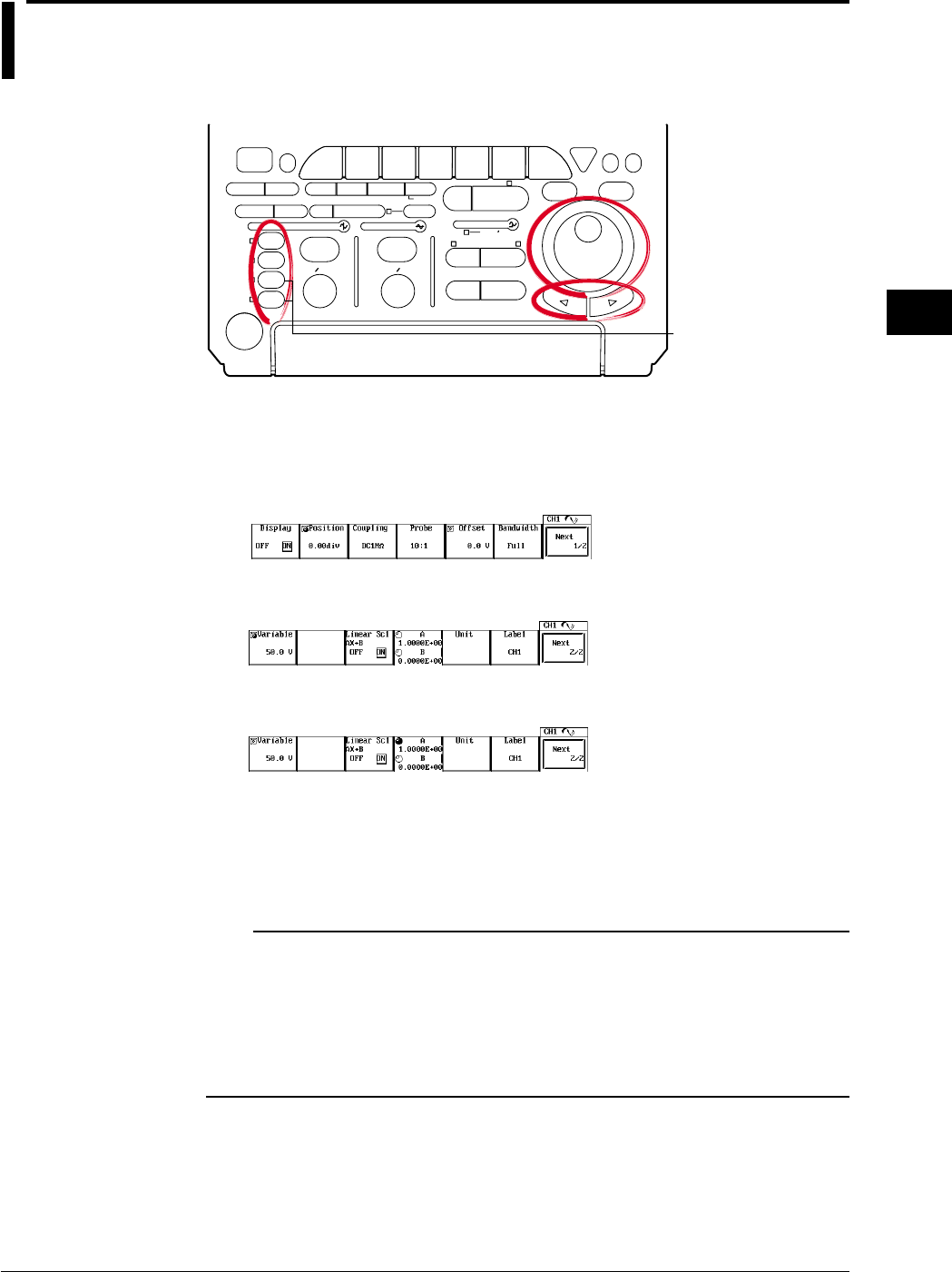
5-13
IM 701710-01E
Vertical and Horizontal Axes
5
5.9 Using the Linear Scaling Function
<For a description of this function, refer to page 1-21>
Relevant Keys
ACTION DELAY
X - Y MENU MENU PHASE
SEARCH
HORIZONTAL
VERTICAL TRIGGER
TRIG D
HELP
ESC
SELECTRESET
SIMPLE
MODE POSITION
MATH
MISCFILE
CLEAR
TRACE
HISTORY
MEASURE
SETUP
PRESET
DISPLAY
CURSOR
CH
1
CH
2
CH
3
CH
4
POWER
COPY IMAGE SAVE SHIFT
ZOOM
GO/NO-GO
ENHANCED
ACQ START/STOP
SNAP
SHOT
V DIV TIME DIV
The DL1720 is not
equipped with
an input terminal
for CH3 or CH4.
Operating Procedure
1. Press one of the keys from CH 1 to CH 4 (or CH 1 to CH 2 for the DL1720) to
select the channel.
2. Press the Next 1/2 soft key.
3. Press the Linear Scl AX+B soft key to select ON.
4. Press the A/B soft key.
5. Turn the jog shuttle to set the value of A.
You can use the arrow keys to move between the digits.
6. In a similar fashion, set the value B.
7. If necessary, press the Unit soft key to display the keyboard and enter the unit.
Note
•Linear scaling is not available for the following waveforms.
Snapshot waveforms
Accumulated waveforms (except for newest waveform)
•You can set linear scaling separately for each channel.
•The A and B values remain in memory after you switch the linear scaling function OFF, and
are restored if you switch the function back on.
•Mathematical computations operate with respect to the scaling results.

5-14 IM 701710-01E
Explanation
This function lets you apply linear scaling to the measurement values. If you set this
feature ON, the screen displays the scaled results rather than the original
measurements. The scaling relationship is
Y = AX + B
where X is the measurement value and Y is the scaled value. Note that you can select
the dimensional unit for the scaled display.
Scaling Coefficient (A) and Offset (B)
Range for A, B: –9.9999E+30 to +9.9999E+30
Default A: 1.0000E+00
B: 0.0000E+00
Dimensional Unit
Unit identifier (alphanumeric string) of up to four characters.
Displaying the Scale Value
The linearly scaled values of the upper and lower limits of the vertical axis of each
channel can be displayed. (See section 8.4, “Turning ON/OFF the Scale Value
Display.”)
5.9 Using the Linear Scaling Function
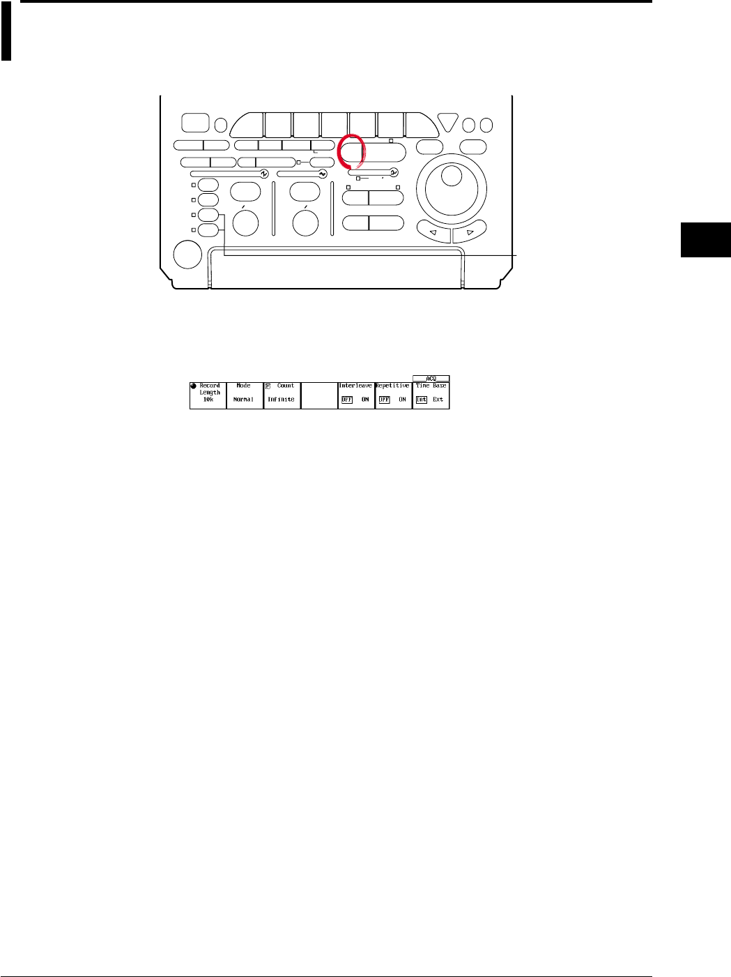
5-15
IM 701710-01E
Vertical and Horizontal Axes
5
5.10 Selecting the Timebase
<For a description of this function, refer to page 1-5>
Relevant Keys
ACTION DELAY
X - Y MENU MENU PHASE
SEARCH
HORIZONTAL
VERTICAL TRIGGER
TRIG D
HELP
ESC
SELECTRESET
SIMPLE
MODE POSITION
MATH
MISCFILE
CLEAR
TRACE
HISTORY
MEASURE
SETUP
PRESET
DISPLAY
CURSOR
CH
1
CH
2
CH
3
CH
4
POWER
COPY IMAGE SAVE SHIFT
ZOOM
GO/NO-GO
ENHANCED
ACQ START/STOP
SNAP
SHOT
V DIV TIME DIV
The DL1720 is not
equipped with
an input terminal
for CH3 or CH4.
Operating Procedure
1. Press ACQ.
2. Press the Time Base soft key to select Int or Ext.
Threshold Setting (If EXT Clock)
3. If you have selected use of an external clock, you must now set the threshold level.
This setting is identical to the trigger-level setting; refer to Section 6.5, “Setting the
Edge Trigger,” for the procedure. Note that you must set the trigger source to EXT
before setting the level.
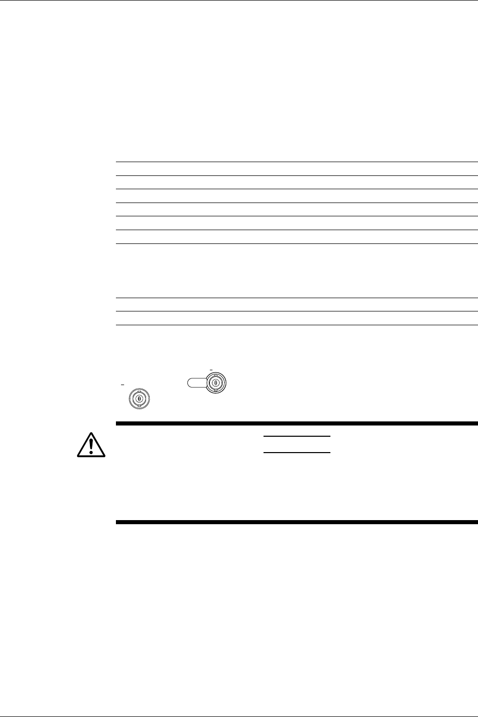
5-16 IM 701710-01E
Explanation
Selectable Timebases
Timebase can be selected from the following three types.
INT Internal clock signal
EXT IN Clock signal input to the EXT TRIG IN/EXT CLOCK IN/TRIG GATE IN
terminal
When EXT IN is Selected
Input a clock signal to the EXT CLOCK IN/EXT TRIG IN/TRIG GATE IN terminal on the
rear panel (or the terminal labeled
EXT.
on the front panel of the DL1720). The clock
signal must conform to the specifications given below.
Item Specifications
Connector Type BNC
Maximum Permissible Input Voltage ±40 V (DC + ACpeak) or 28 Vrms, 10 kHz or less
Frequency Range 40 Hz to 20 MHz (continuous clock only)
Minimum Input Level 0.1Vp-p
Input Impedance Approx. 1 MΩ and 18 pF (1 MΩ and 20 pF for the DL1720)
Threshold Level ±2 V in 5 mv resolution (for the DL1740)
±1 V in 5 mv resolution (for the DL1720 with the ±1 V range
selected)
±10 V in 50 mv resolution (for the DL1720 with the ±10 V
range selected)
Sampling Jitter 1.25 ns or less
Minimum Pulse Width 10 ns or more for both High and Low levels
[Input Terminal]
EXT CLOCK IN
<40Vpk 1MΩ
EXT TRIG IN
TRIG GATE IN
< DL1740 >
EXT.
< DL1720 >
1MΩ /20pF < 40Vpk
(On the DL1740 it is located on the rear panel,
or on the DL1720 it is located on the front panel.)
CAUTION
If a clock signal exceeding the above maximum permissible input
voltage is input to the EXT TRIG IN/EXT CLOCK IN/TRIG GATE IN
terminal (or the EXT. terminal for the DL1720), damage to the internal
circuits of the instrument may result.
Points to Note when Sampling Using an External Clock
•The clock signal must be continuous. No burst signal is allowed.
•Only real-time sampling mode is available.
•Envelope mode and Box Average mode cannot be set.
•Display of waveforms is not possible in roll mode.
•No function to divide the clock signal is available.
•Since the time axis setting cannot be changed, expand the time axis if you want to
change the display range. For a description of expanding waveforms, refer to section
8.9.
•Trigger delay cannot be set.
•Deskew function cannot be used.
•The time measured by the cursor measurement or automated measurement function
is expressed in the number of pulses of the clock signal. No unit is displayed.
5.10 Selecting the Timebase
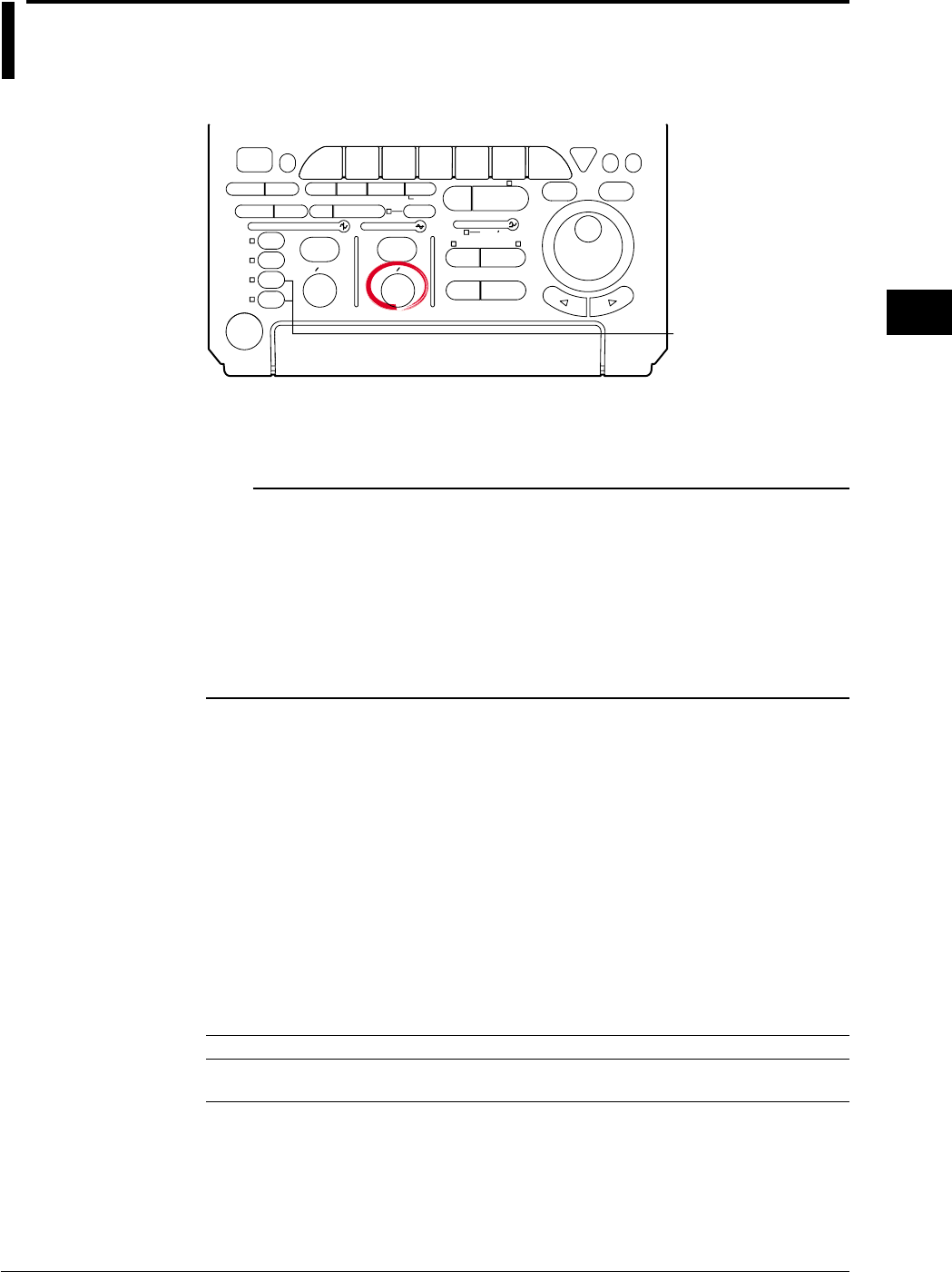
5-17
IM 701710-01E
Vertical and Horizontal Axes
5
5.11 Setting T/div
<For a description of this function, refer to page 1-5>
Relevant Keys
ACTION DELAY
X - Y MENU MENU PHASE
SEARCH
HORIZONTAL
VERTICAL TRIGGER
TRIG D
HELP
ESC
SELECTRESET
SIMPLE
MODE POSITION
MATH
MISCFILE
CLEAR
TRACE
HISTORY
MEASURE
SETUP
PRESET
DISPLAY
CURSOR
CH
1
CH
2
CH
3
CH
4
POWER
COPY IMAGE SAVE SHIFT
ZOOM
GO/NO-GO
ENHANCED
ACQ START/STOP
SNAP
SHOT
V DIV TIME DIV
The DL1720 is not
equipped with
an input terminal
for CH3 or CH4.
Operating Procedure
1. Turn the TIME/DIV knob to set the desired T/div.
Note
•Turning the TIME/DIV knob while acquisition is stopped displays the new T/div value in
parentheses on the upper right of the screen. The new setting will come into effect the next
time the acquisition is started.
•When repetieive sampling mode is OFF (see section7.6), the maximum sampling rate is 500
MS/s (or 1 GS/s when interleave mode is ON).
•Even when the repetitive sampling is turned OFF, there are cases in which the mode
automatically changes to the repetitive sampling mode when the T/div is changed. For the
relationship between the T/div setting and the sample rate, see appendix 1, “Relationship
between the Time Axis Setting, Sample Rate, and Record length.”
Explanation
The T/div setting is made by setting the time per division on the screen grid.
Setting Range
Record Length is 10 kwords or more: 1 ns/div to 50 s/div(1 - 2 - 5 steps)
Record Length is 1 kwords: 1 ns/div to 5 s/div(1 - 2 - 5 steps)
T/div and Sampling Mode
Use of repetitive sampling mode lets you get the sample rate of 1 GS/s and above (or
100 GS/s and above if interleave is also ON). But note that the allowable time-scale
settings vary according to record length. For details, see appendix 1.
T/div and Roll Mode
When acquisition count is infinite, acquisition mode is not average, or the trigger mode is
auto, auto level, or single, roll mode display is enabled at the following T/div settings.
Record Length T/div
1 kword 50 ms/div to 5 s/div
10 kword to 1 Mword 50 ms/div to 50 s/div
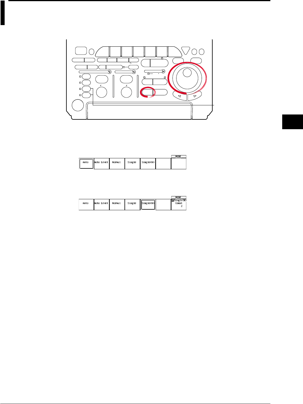
6-1
IM 701710-01E
Triggering
6
6.1 Setting the Trigger Mode
<For a description of this function, refer to page 1-11>
Relevant Keys
ACTION DELAY
X - Y MENU MENU PHASE
SEARCH
HORIZONTAL
VERTICAL TRIGGER
TRIG D
HELP
ESC
SELECTRESET
SIMPLE
MODE POSITION
MATH
MISCFILE
CLEAR
TRACE
HISTORY
MEASURE
SETUP
PRESET
DISPLAY
CURSOR
CH
1
CH
2
CH
3
CH
4
POWER
COPY IMAGE SAVE SHIFT
ZOOM
GO/NO-GO
ENHANCED
ACQ START/STOP
SNAP
SHOT
V DIV TIME DIV
The DL1720 is not
equipped with
an input terminal
for CH3 or CH4.
Operating Procedure
1. Press MODE.
2. Press the soft key corresponding to the desired mode to set the trigger mode.
3. If Single(N) is selected, turn the jog shuttle to set the number of times to acquire
the waveform.
Explanation
Auto Mode
If the trigger condition is met within the 100-ms timeout period, the waveform is updated
on each trigger occurrence. If the trigger condition is not met after the timeout period
elapses, the waveform is automatically updated. If the time axis setting is in the range in
which the display mode is set to roll mode, the display is set to roll mode.
Auto Level Mode
If a trigger occurs within the timeout period, the waveform is displayed in the same
fashion as in the auto mode. If a trigger does not occur within the timeout period, the
center value of the amplitude of the trigger source is detected, the trigger level is
automatically changed to the center value, and the trigger is generated to update the
displayed waveform. The auto-level mode is valid only if the trigger is a simple trigger
and the trigger source is CH1 to CH4 (or CH1 to CH2 for the DL1720). For all other
cases, the operation is the same as the auto mode.
If the time axis setting is in the range in which the display mode is set to roll mode, the
display is set to roll mode.
Normal Mode
The display is updated only when the trigger conditions are met. The display will not be
updated if no trigger is caused. Therefore, to check the waveform or ground level when
no trigger is detected, use auto mode.
Chpater 6 Triggering

6-2 IM 701710-01E
Single Mode
The display is updated once when the trigger conditions are met and the waveform
acquisition stops.
In the time axis setting range in which the display mode is set to roll mode, the display is
set to roll mode. When a trigger occurs, the specified record length of data is acquired
and the displayed waveform stops.
Single (N) Mode
The display is updated according to the number of times specified when the trigger
conditions are met and the waveform acquisition stops. This mode is used when
acquiring a waveform using the sequential store function. If the repetitive mode turn ON,
this mode is automatically changed to single mode.
Note
The trigger mode setting applies to both simple and enhanced triggers.
6.1 Setting the Trigger Mode
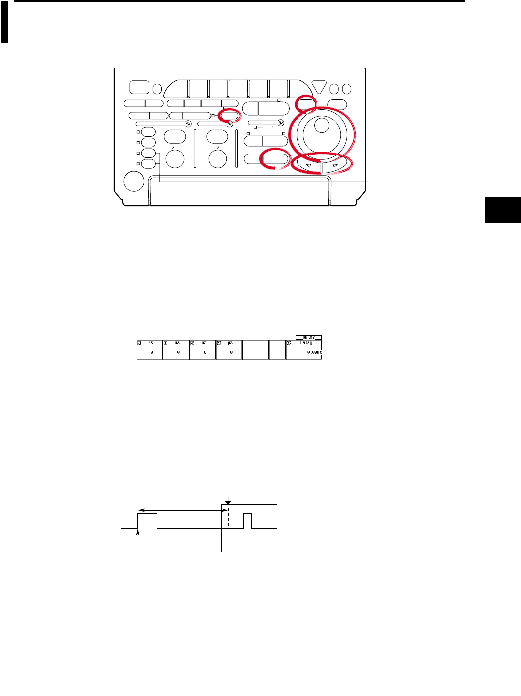
6-3
IM 701710-01E
Triggering
6
6.2 Setting the Trigger Delay
<For a description of this function, refer to page 1-13>
Relevant Keys
ACTION DELAY
X - Y MENU MENU PHASE
SEARCH
HORIZONTAL
VERTICAL TRIGGER
TRIG D
HELP
ESC
SELECTRESET
SIMPLE
MODE POSITION
MATH
MISCFILE
CLEAR
TRACE
HISTORY
MEASURE
SETUP
PRESET
DISPLAY
CURSOR
CH
1
CH
2
CH
3
CH
4
POWER
COPY IMAGE SAVE SHIFT
ZOOM
GO/NO-GO
ENHANCED
ACQ START/STOP
SNAP
SHOT
V DIV TIME DIV
The DL1720 is not
equipped with
an input terminal
for CH3 or CH4.
Operating Procedure
1. Press SHIFT to set the keys in the shifted condition.
Functions marked in purple on the panel become active.
2. Press POSITION.
3. Units, ms, us, ns, and ps are displayed on the screen. Press the soft key
corresponding to the desired unit.
Turn the jog shuttle to set the trigger delay. You can move between the digits
using the arrow keys. Pressing RESET resets delay to 0 s.
Also for instruments with firmware version 1.30 or later, you can set the trigger
delay by pressing the Delay soft key and turning the jog shuttle.
Explanation
Although the display usually shows the waveform before and after the trigger point, using
the delay function, it is possible to display the acquired waveform after a fixed time
period elapses.
Setting Range for Trigger Delay
0 to 4 s (Resolution is 1 ÷ sample rate)
Delay Time
Trigger Point
T(Trigger Position)
Points for Attention
•When T/div is changed, the trigger delay remains unchanged. However, its position in
relation to the overall record length changes.
•If the timebase is provided by an external clock, the trigger delay is fixed at 0s (no
delay).
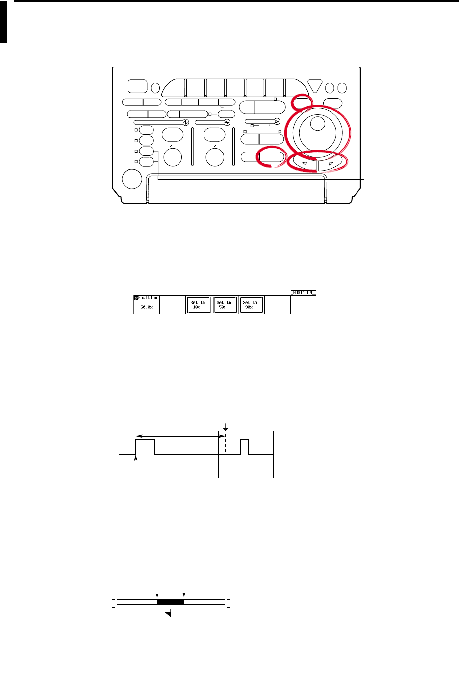
6-4 IM 701710-01E
6.3 Setting the Trigger Position
<For a description of this function, refer to page 1-13>
Relevant Keys
ACTION DELAY
X - Y MENU MENU PHASE
SEARCH
HORIZONTAL
VERTICAL TRIGGER
TRIG D
HELP
ESC
SELECTRESET
SIMPLE
MODE POSITION
MATH
MISCFILE
CLEAR
TRACE
HISTORY
MEASURE
SETUP
PRESET
DISPLAY
CURSOR
CH
1
CH
2
CH
3
CH
4
POWER
COPY IMAGE SAVE SHIFT
ZOOM
GO/NO-GO
ENHANCED
ACQ START/STOP
SNAP
SHOT
V DIV TIME DIV
The DL1720 is not
equipped with
an input terminal
for CH3 or CH4.
Operating Procedure
1. Press POSITION.
2. Turn the jog shuttle to set the trigger position.
You can use the arrow keys to move between the digits.
If you wish to select 10%, 50%, or 90%, you can press the corresponding soft key.
In addition, pressing RESET, resets the position to 50%.
Explanation
Trigger Positon
The trigger position is the waveform position that results when the trigger delay is added
to the trigger point. If the trigger delay is 0 s, therefore, the trigger position is equivalent
to the trigger point. You can select the location of the trigger position on the screen.
Delay Time
Trigger Point
T(Trigger Position)
Setting Range for Trigger Position
0 to 100% of record length, in 1% steps
Position Marker
A position marker (marker) appears above the bar at the top of the screen. The marker
indicates the trigger position with respect to the total record length. You can shift the
trigger position to the right or left on the screen.
Trigger Position
0% 100%
T

6-5
IM 701710-01E
Triggering
6
Points for Attention
•If you change the trigger position while waveform acquisition is suspended, the new
setting will not become effective until acquisition is resumed and the waveform is
updated.
•Note that cursor time measurements are with respect to the trigger position.
Changing the trigger position therefore changes the measurement values (except
during roll-mode display).
•When you change the T/div setting, the time axis setting is rescaled with respect to
the trigger position.
6.3 Setting the Trigger Position
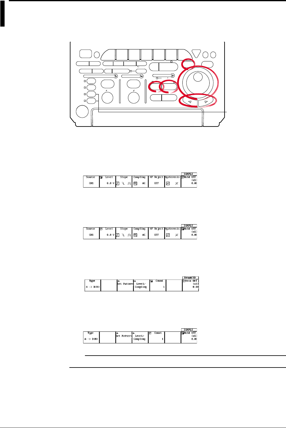
6-6 IM 701710-01E
6.4 Setting the Hold Off Time
<For a description of this function, refer to page 1-12>
Relevant Keys
ACTION DELAY
X - Y MENU MENU PHASE
SEARCH
HORIZONTAL
VERTICAL TRIGGER
TRIG D
HELP
ESC
SELECTRESET
SIMPLE
MODE POSITION
MATH
MISCFILE
CLEAR
TRACE
HISTORY
MEASURE
SETUP
PRESET
DISPLAY
CURSOR
CH
1
CH
2
CH
3
CH
4
POWER
COPY IMAGE SAVE SHIFT
ZOOM
GO/NO-GO
ENHANCED
ACQ START/STOP
SNAP
SHOT
V DIV TIME DIV
The DL1720 is not
equipped with
an input terminal
for CH3 or CH4.
Operating Procedure
During Simple Trigger
1. Press SIMPLE.
2. If the jog shuttle control is not set to Hold Off, press the Hold Off soft key.
3. Turn the jog shuttle to set the hold off period.
You can use the arrow keys to move between the digits. In addition, pressing
RESET, resets the value to 0.08 µs (0.08 µs.)
During Enhanced Trigger
1. Press ENHANCED.
2. If the jog shuttle control is not set to Hold Off, press the Hold Off soft key.
3. Turn the jog shuttle to set the hold off period.
You can use the arrow keys to move between the digits. In addition, pressing
RESET, resets the value to 0.08 µs (0.08 µs.)
Note
The hold off time setting applies to simple trigger and enhanced trigger.
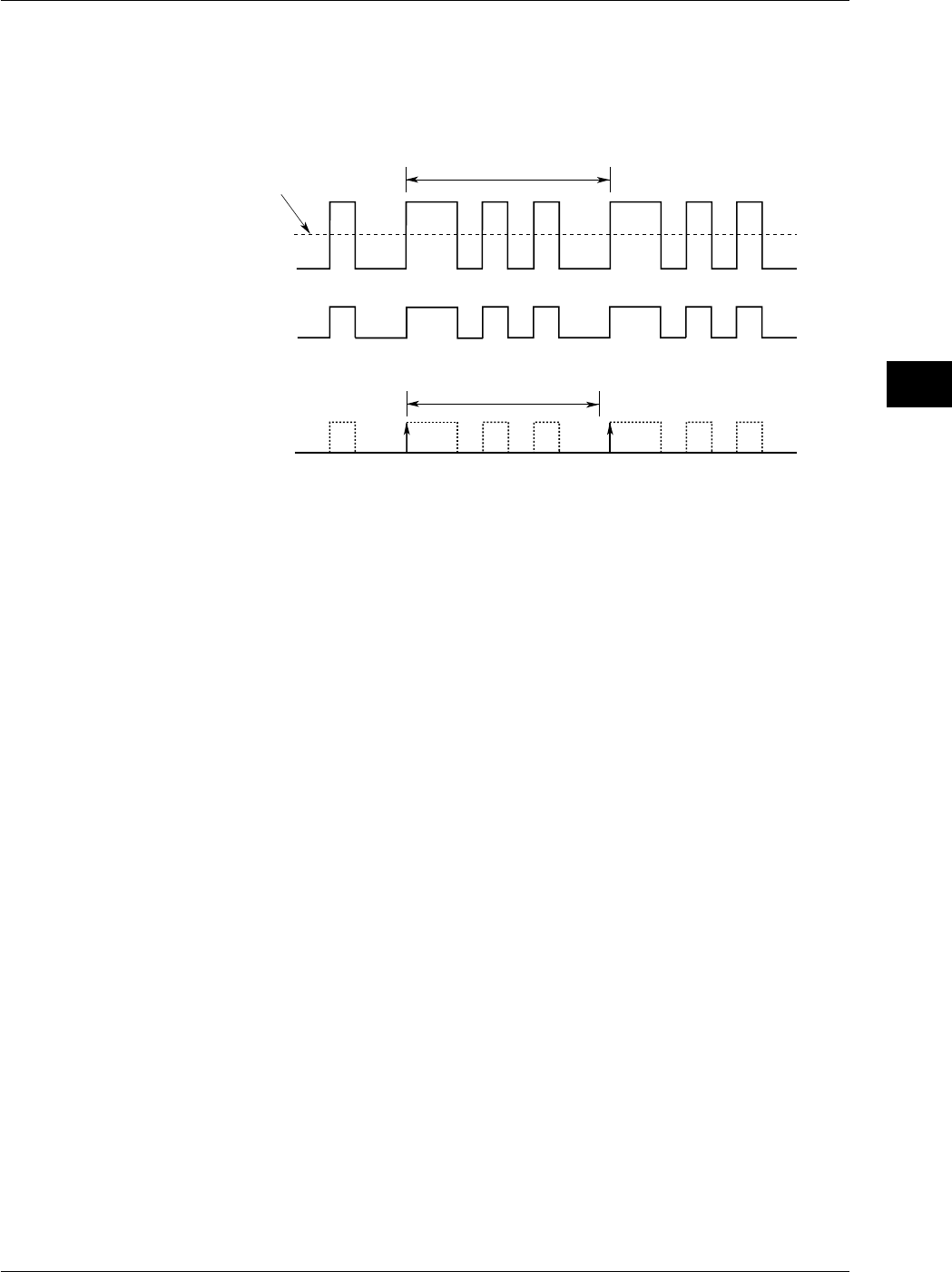
6-7
IM 701710-01E
Triggering
6
Explanation
This function prevents a trigger from being activated for a specified time, even if the
trigger conditions are met during this time. The following two methods can be used to
prevent the trigger. This is useful when you wish to activate the trigger in sync with a
signal that is periodic as shown in the figure below.
Input Signal
Repetitive Period (T)
Trigger Level
Trigger Source
Signal
t
Trigger Signal during Hold Off Period (t) (When Trigger Slope is Set to Rise)
Hold Off Time Setting Range
80 ns to 10 s (default: 80 ns).
The setting resolution is 20 ns.
Points for Attention
•Updating of the waveform may be slow in repetitive sampling mode. In this case set
the hold off time to a smaller value.
•If holdoff time is set to 100 ms or above, the trigger mode should be set to
normal
.
•When used with the A→B(N) or A Delay B trigger, the holdoff time operates with
respect to condition A only.
6.4 Setting the Hold Off Time
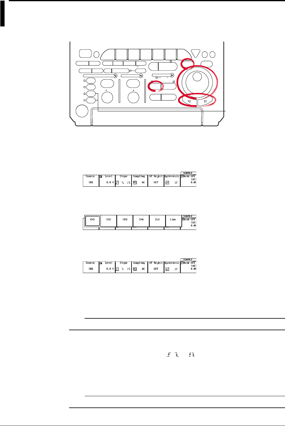
6-8 IM 701710-01E
6.5 Setting the Edge Trigger (SIMPLE)
<For a description of this function, refer to page 1-8>
Relevant Keys
ACTION DELAY
X - Y MENU MENU PHASE
SEARCH
HORIZONTAL
VERTICAL TRIGGER
TRIG D
HELP
ESC
SELECTRESET
SIMPLE
MODE POSITION
MATH
MISCFILE
CLEAR
TRACE
HISTORY
MEASURE
SETUP
PRESET
DISPLAY
CURSOR
CH
1
CH
2
CH
3
CH
4
POWER
COPY IMAGE SAVE SHIFT
ZOOM
GO/NO-GO
ENHANCED
ACQ START/STOP
SNAP
SHOT
V DIV TIME DIV
The DL1720 is not
equipped with
an input terminal
for CH3 or CH4.
Operating Procedure
Setting the Trigger Source
1. Press SIMPLE.
2. Press the Source soft key to display the trigger source menu.
3. Press the soft key corresponding to the channel to be set as the trigger source.
(CH3 and CH4 are not displayed on the DL1720.)
Setting the Trigger Level
4. If the jog shuttle control is not set to Level, press the Level soft key.
5. Turn the jog shuttle to set the trigger level.
You can use the arrow keys to move between the digits. In addition, pressing
RESET resets the trigger level to the current offset voltage value.
Note
The trigger level setting applies to simple trigger and enhanced trigger.
Setting the Trigger Slope
6. Press the Slope soft key to select , , or .
Setting the Trigger Coupling
7. Press the Coupling soft key to select DC or AC.
Note
The trigger coupling setting applies to simple trigger and enhanced trigger.
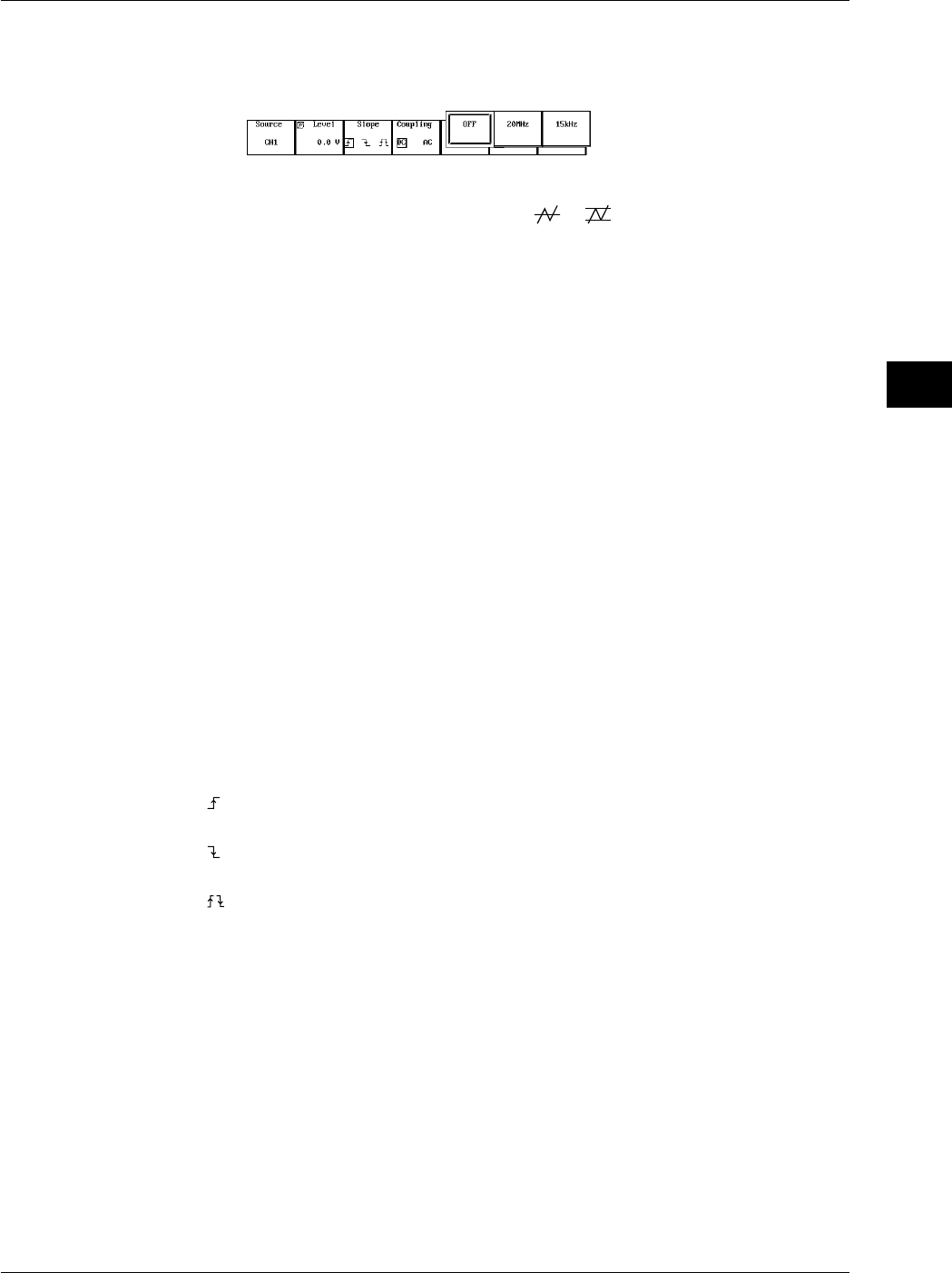
6-9
IM 701710-01E
Triggering
6
Setting the HF Rejection
8. Pressing the HF Reject soft key displays an HF rejection menu.
9. Press the soft key corresponding to the desired frequency to select HF rejection.
Setting the Hysteresis
10. Press the Hysteresis soft key to select or .
Setting the Hold Off
11. Set the hold off time according to the procedures given in 6.4, “Setting the Hold Off
Time.”
Explanation
An edge trigger is generated when the trigger source signal crosses a specified level.
Selecting the Trigger Source
Select from the following list of choices.
•CH1 to CH4 (or CH1 to CH2 for the DL1720)
•Ext (EXT TRIG IN terminal on the rear panel (or EXT. terminal on the front panel of
the D1720), see section 6.6, “Setting the External Trigger (SIMPLE)”)
•Line (power signal, see section 6.7, “Generating a Trigger Using the Power Signal
(SIMPLE)”)
Setting the Trigger Level
Range: 8 div within the screen
Resolution: 0.01 div
For example, the resolution is 0.02 mV when the V/DIV setting is 2 mV/div.
You can also reset the trigger level to the current offset voltage with one key operation.
Setting the Trigger Slope
Select the trigger activation method relative to changes in trigger source level from the
following three choices.
: Activated when the trigger source changes from below the trigger level to above the
trigger level (rising).
: Activated when the trigger source changes from above the trigger level to below the
trigger level (falling).
: Activated on either a rising edge or falling edge.
Setting the Trigger Coupling
Select from the following list of choices.
AC: Uses a signal that is obtained by removing the DC component from the trigger
source signal.
DC: Uses the trigger source signal as the trigger signal.
Setting the HF Rejection
Set 15 kHz or 20 MHz when you wish to use a signal source that is obtained by
removing the high frequency components (frequency components greater than or equal
to approximately 15 kHz or 20 MHz) from the trigger signal as the trigger source.
6.5 Setting the Edge Trigger (SIMPLE)

6-10 IM 701710-01E
Setting the Hysteresis
Sets a width to the trigger level so that the trigger is not activated by small changes in
the trigger signal.
: Approx. 0.3 div* of hysteresis around the trigger level.
: Approx. 1 div* of hysteresis around the trigger level.
*: The value above are estimated values. They are not strictly guaranteed.
Setting the Hold Off
See section 6.4, “Setting the Hold Off Time.”
6.5 Setting the Edge Trigger (SIMPLE)
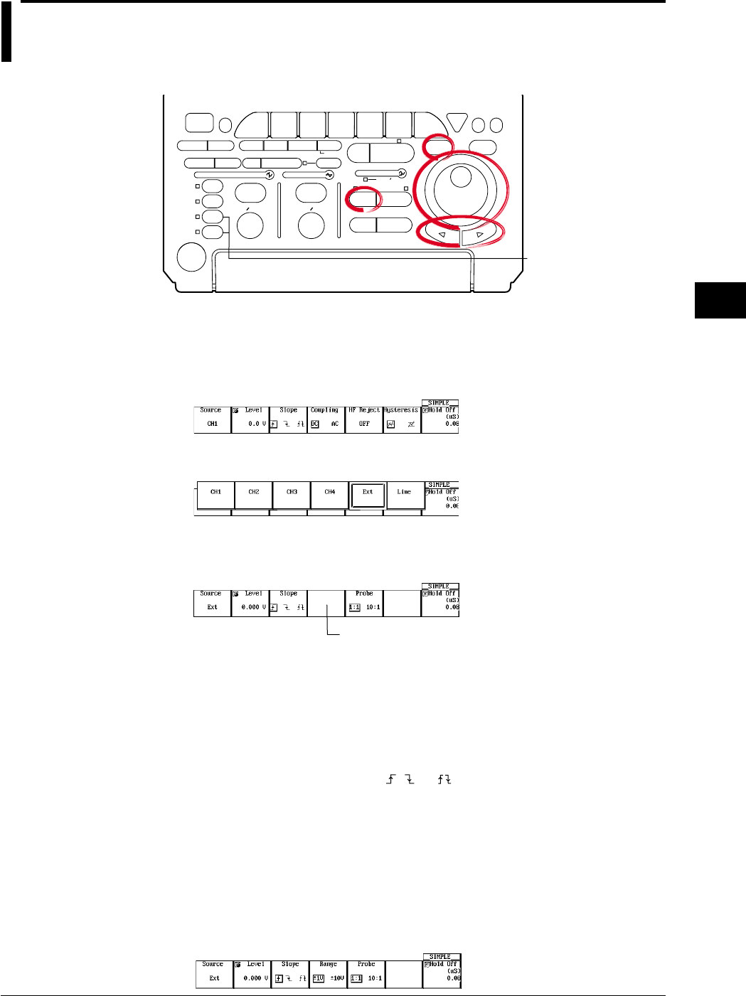
6-11
IM 701710-01E
Triggering
6
6.6 Setting the External Trigger (SIMPLE)
Relevant Keys
ACTION DELAY
X - Y MENU MENU PHASE
SEARCH
HORIZONTAL
VERTICAL TRIGGER
TRIG D
HELP
ESC
SELECTRESET
SIMPLE
MODE POSITION
MATH
MISCFILE
CLEAR
TRACE
HISTORY
MEASURE
SETUP
PRESET
DISPLAY
CURSOR
CH
1
CH
2
CH
3
CH
4
POWER
COPY IMAGE SAVE SHIFT
ZOOM
GO/NO-GO
ENHANCED
ACQ START/STOP
SNAP
SHOT
V DIV TIME DIV
The DL1720 is not
equipped with
an input terminal
for CH3 or CH4.
Operating Procedure
Setting the Trigger Source
1. Press SIMPLE.
2. Pressing the Source soft key to display the trigger source menu.
3. Press the Ext soft key. (CH3 and CH4 are not displayed on the DL1720.)
Setting the Trigger Level
4. If the jog shuttle control is not set to Level, press the Level soft key.
On the DL1720, the Range
soft key is displayed in this box.
5. Turn the jog shuttle to set the trigger level.
You can use the arrow keys to move between the digits. In addition, pressing
RESET, sets the trigger level to 0 V.
Setting the Trigger Slope
6. Press the Edge soft key to select , , or .
Setting the probe attenuation
7. Press the Probe soft key to select 1 : 1 or 10 : 1.
Setting the Range (DL1720 only)
8. Press the Range soft key, then select the range.
±1 V or ±10 V (When Probe is set to 1:1), ±10 V or ±100 V (When Probe is set to
10:1)

6-12 IM 701710-01E
Setting the Hold Off
9. Set the hold off time according to the procedures given in 6.4, “Setting the Hold Off
Time.”
Explanation
The external signal that is input through the EXT TRIG IN terminal (or the EXT. terminal
on the front panel of the DL1720) on the rear panel of this instrument can be used to
generate triggers.
Note
For details related to the specifications of the EXT TRIG IN terminal (or the EXT. terminal for
the DL1720), see section 12.1.
Selecting the Trigger Source
Select Ext.
Setting the Trigger Level
Range: ±2 V (for the DL1740)
±1 V (for the DL1720 with the ±1 V range selected)
±10 V (for the DL1720 with the ±10 V range selected)
Resolution: 5 mV (for the DL1740)
5 mV (for the DL1720 with the ±1 V range selected)
50 mV (for the DL1720 with the ±10 V range selected)
Setting the Trigger Slope
Select the trigger activation method relative to changes in trigger source level from the
following three choices.
: Activated when the trigger source changes from below the trigger level to above the
trigger level (rising).
: Activated when the trigger source changes from above the trigger level to below the
trigger level (falling).
: Activated on either a rising edge or falling edge.
Setting the Probe Attenuation
When applying a trigger input signal to the EXT TRIG IN terminal (or the EXT. terminal
on the front panel of the DL1720) via a probe, select an attenuation that matches the
probe attenuation.
1 : 1, 10 : 1
Setting the Hold Off
See section 6.4, “Setting the Hold Off Time.”
6.6 Setting the External Trigger (SIMPLE)
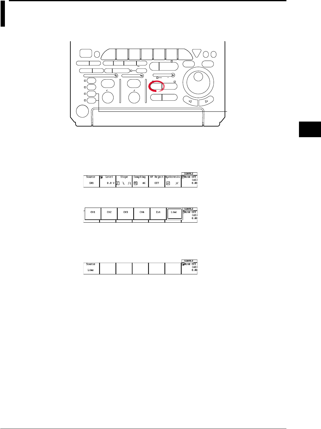
6-13
IM 701710-01E
Triggering
6
6.7 Generating Triggers on the Power Signal
(SIMPLE)
Relevant Keys
ACTION DELAY
X - Y MENU MENU PHASE
SEARCH
HORIZONTAL
VERTICAL TRIGGER
TRIG D
HELP
ESC
SELECTRESET
SIMPLE
MODE POSITION
MATH
MISCFILE
CLEAR
TRACE
HISTORY
MEASURE
SETUP
PRESET
DISPLAY
CURSOR
CH
1
CH
2
CH
3
CH
4
POWER
COPY IMAGE SAVE SHIFT
ZOOM
GO/NO-GO
ENHANCED
ACQ START/STOP
SNAP
SHOT
V DIV TIME DIV
The DL1720 is not
equipped with
an input terminal
for CH3 or CH4.
Operating Procedure
Setting the Trigger Source
1. Press SIMPLE.
2. Pressing the Source soft key displays the trigger source menu.
3. Press the Line soft key. (CH3 and CH4 are not displayed on the DL1720.)
Setting the Hold Off
4. Set the hold off time according to the procedures given in 6.4, “Setting the Hold Off
Time.”
Explanation
Triggers can be generated on the rising edge of the power signal that is being supplied
to the instrument. Waveforms can be observed in sync with the commercial power
supply frequency (50 Hz or 60 Hz).
Selecting the Trigger Source
Select Line.
Setting the Hold Off
See section 6.4, “Setting the Hold Off Time.”

6-14 IM 701710-01E
6.8 Setting the A→B(N) Trigger (ENHANCED)
<For a description of this function, refer to page 1-8>
Relevant Keys
ACTION DELAY
X - Y MENU MENU PHASE
SEARCH
HORIZONTAL
VERTICAL TRIGGER
TRIG D
HELP
ESC
SELECTRESET
SIMPLE
MODE POSITION
MATH
MISCFILE
CLEAR
TRACE
HISTORY
MEASURE
SETUP
PRESET
DISPLAY
CURSOR
CH
1
CH
2
CH
3
CH
4
POWER
COPY IMAGE SAVE SHIFT
ZOOM
GO/NO-GO
ENHANCED
ACQ START/STOP
SNAP
SHOT
V DIV TIME DIV
The DL1720 is not
equipped with
an input terminal
for CH3 or CH4.
Operating Procedure
Setting the Trigger Type
1. Press ENHANCED.
2. Pressing the Type soft key to display the trigger type menu.
3. Press the A→B(N) soft key.
Setting the Status and Condition for Conditions A and B
4. Pressing the Set Pattern soft key displays a menu used to set the status and
condition for conditions A and B. (On the DL1720, settings for CH3 and CH4 are
not displayed.)
5. Set condition A. Turn the jog shuttle to move the cursor to the channel to which the
status of condition A will be set.
6. Press SELECT to select H, L, or X.
7. Turn the jog shuttle to move the cursor to the Condition position of condition A.
8. Press SELECT to select Enter or Exit.
9. In a similar fashion, set condition B.
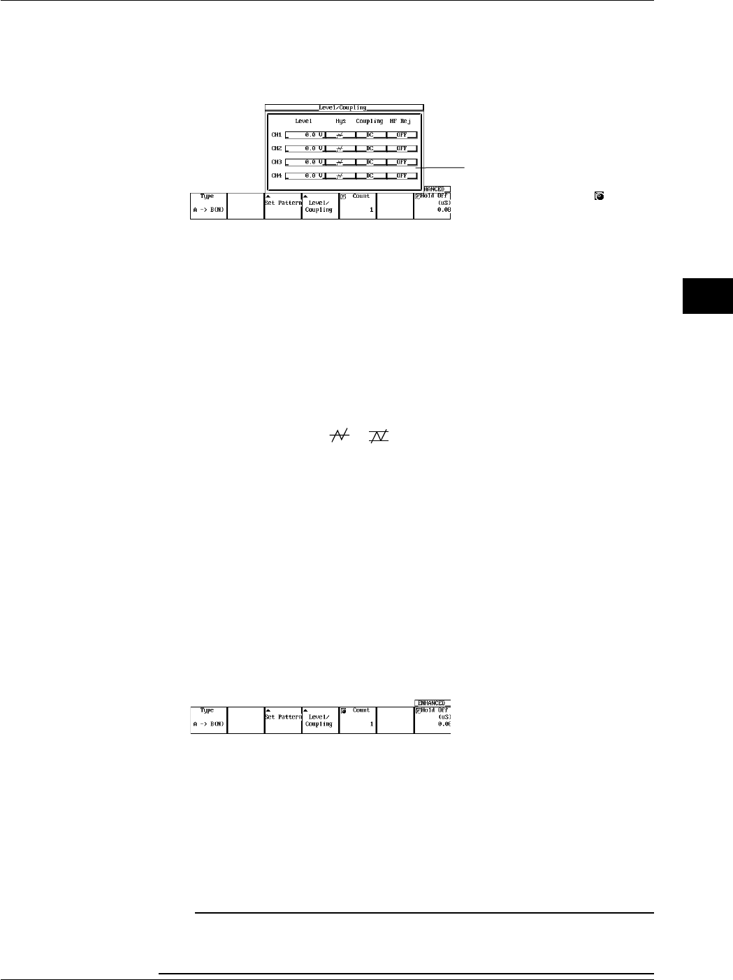
6-15
IM 701710-01E
Triggering
6
Setting the Level
10. Pressing the Level/Coupling soft key displays a menu used to set the level,
coupling, hysteresis, and HF rejection. (On the DL1720, settings for CH3 and CH4
are not displayed.)
The Level setting for each
channel can be input directly
using a USB keyboard. ( )
11. Turn the jog shuttle to move the cursor to the channel on which the level is to be
set.
12. Press SELECT to display the level setting menu.
13. Turn the jog shuttle to set the level.
You can use the arrow keys to move between the digits. In addition, pressing
RESET sets the trigger level to 0 V.
Setting the Hysteresis
14. Turn the jog shuttle to move the cursor to the channel on which hysteresis is to be
set.
15. Press SELECT to select or .
Setting the Trigger Coupling
16. Turn the jog shuttle to move the cursor to the channel on which the coupling is to
be set.
17. Press SELECT to select DC or AC.
Setting the HF Rejection
18. Turn the jog shuttle to move the cursor to the channel on which the HF rejection
(HF Rej) is to be set.
19. Press SELECT to select OFF, 20 MHz, or 15 kHz.
Setting the Number of Times Condition B is to be Met
20. If the jog shuttle control is not set to Count, press the Count soft key.
21. Turn the jog shuttle to set the count.
You can use the arrow keys to move between the digits. Pressing RESET resets
the value to 1.
Setting the Hold Off
22. Set the hold off time according to the procedures given in 6.4, “Setting the Hold Off
Time.”
Note
•The status setting of conditions A and B applies to all trigger types.
•The trigger level, hysteresis, trigger coupling, and HF rejection settings apply to simple trigger
and enhanced trigger.
6.8 Setting the A→B(N) Trigger (ENHANCED)

6-16 IM 701710-01E
Explanation
This function activates a trigger on the nth time condition B becomes true after condition
A becomes true.
Setting Conditions A and B
•Channel Status
Select the status of the channel from the following three choices.
H: Above the specified trigger level
L: Below the specified trigger level
X: Don’t care
•Condition
Select from the following two conditions.
Enter: Trigger is activated when all channels meet the specified status.
Exit: Trigger is activated when at least one channel no longer meets the specified
status.
The Number of Times Pattern B is to be Met
1 to 108 times
Setting the Trigger Level
Range: 8 div within the screen
Resolution: 0.01 div
For example, the resolution is 0.02 mV when the V/DIV setting is 2 mV/div.
Setting the Hysteresis
Sets a width to the trigger level so that the trigger is not activated on small changes.
: Approximately 0.3 div* of hysteresis around the trigger level.
: Approximately 1 div* of hysteresis around the trigger level.
*: The value above are estimated values. They are not strictly guaranteed.
Setting the Trigger Coupling
Select from the following list of choices.
AC: Uses a signal that is obtained by removing the DC component from the trigger
source signal as the trigger signal.
DC: Uses the trigger source signal as the trigger signal.
Turning ON/OFF the HF Rejection
Select 15 kHz or 20 MHz when you wish to use a signal source that is obtained by
removing the high frequency components (frequency components greater than or equal
to approximately 15 kHz or 20 MHz) from the trigger signal as the trigger source.
Setting the Hold Off
See section 6.4, “Setting the Hold Off Time.”
Note
If you wish to use only one pattern condition to activate the trigger, use the pattern trigger. If
the status for condition A and condition B are set to Xs (Don’t care), the trigger will not be
activated.
6.8 Setting the A→B(N) Trigger (ENHANCED)
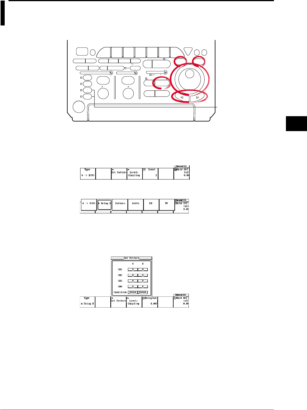
6-17
IM 701710-01E
Triggering
6
6.9 Setting the A Delay B Trigger (ENHANCED)
<For a description of this function, refer to page 1-9>
Relevant Keys
ACTION DELAY
X - Y MENU MENU PHASE
SEARCH
HORIZONTAL
VERTICAL TRIGGER
TRIG D
HELP
ESC
SELECTRESET
SIMPLE
MODE POSITION
MATH
MISCFILE
CLEAR
TRACE
HISTORY
MEASURE
SETUP
PRESET
DISPLAY
CURSOR
CH
1
CH
2
CH
3
CH
4
POWER
COPY IMAGE SAVE SHIFT
ZOOM
GO/NO-GO
ENHANCED
ACQ START/STOP
SNAP
SHOT
V DIV TIME DIV
The DL1720 is not
equipped with
an input terminal
for CH3 or CH4.
Operating Procedure
Setting the Trigger Type
1. Press ENHANCED.
2. Pressing the Type soft key to display the trigger type menu.
3. Press the A Delay B soft key.
Setting the Status and Condition for Conditions A and B
4. Pressing the Set Pattern soft key displays a menu used to set the status and
condition for conditions A and B. (On the DL1720, settings for CH3 and CH4 are
not displayed.)
5. Set condition A. Turn the jog shuttle to move the cursor to the channel to which the
status of condition A will be set.
6. Press SELECT to select H, L, or X.
7. Turn the jog shuttle to move the cursor to the Condition position of condition A.
8. Press SELECT to select Enter or Exit.
9. In a similar fashion, set condition B.
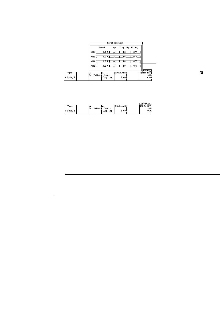
6-18 IM 701710-01E
Setting the Level, Hysteresis, Trigger Coupling, and HF Rejection
10. Pressing the Level/Coupling soft key displays a menu used to set the level,
coupling, hysteresis, and HF rejection. (On the DL1720, settings for CH3 and CH4
are not displayed.)
The setting also applies to A→B(N) trigger. See section6.8.
The Level setting for each
channel can be input directly
using a USB keyboard. ( )
Setting the Delay Time
11. If the jog shuttle control is not set to Delay, press the Delay soft key.
12. Turn the jog shuttle to set the delay time.
You can use the arrow keys to move between the digits. Pressing RESET resets
the value to 0.003 µs.
Setting the Hold Off
13. Set the hold off time according to the procedures given in 6.4, “Setting the Hold Off
Time.”
Note
•The status setting of condition A and B applies to all trigger types.
•The trigger level, hysteresis, trigger coupling, and HF rejection settings apply to simple trigger
and enhanced trigger.
6.9 Setting the A Delay B Trigger (ENHANCED)

6-19
IM 701710-01E
Triggering
6
Explanation
This function activates a trigger the first time condition B becomes true after condition A
becomes true and the specified time elapses.
Setting Conditions A and B
•Channel Status
Select the status of the channel from the following three choices.
H: Above the specified trigger level
L: Below the specified trigger level
X: Don’t care
•Condition
Enter: Trigger is activated when all channels meet the specified status.
Exit: Trigger is activated when at least one channel no longer meets the specified
status.
Delay Time
3 ns to 5 s (resolution: 1 ns)
Setting the Trigger Level
Range: 8 div within the screen
Resolution: 0.01 div
For example, the resolution is 0.02 mV when the V/DIV setting is 2 mV/div.
Setting the Hysteresis
Sets a width to the trigger level so that the trigger is not activated on small changes.
: Approximately 0.3 div* of hysteresis around the trigger level.
: Approximately 1 div* of hysteresis around the trigger level.
*: The value above are estimated values. They are not strictly guaranteed.
Setting the Trigger Coupling
Select from the following list of choices.
AC: Uses a signal that is obtained by removing the DC component from the trigger
source signal as the trigger signal.
DC: Uses the trigger source signal as the trigger signal.
Turning ON/OFF the HF Rejection
Select 15 kHz or 20 MHz when you wish to use a signal source that is obtained by
removing the high frequency components (frequency components greater than or equal
to approximately 15 kHz or 20 MHz) from the trigger signal as the trigger source.
Setting the Hold Off
See section 6.4, “Setting the Hold Off Time.”
Note
If you wish to use only one pattern condition to activate the trigger, use the pattern trigger. If
the status for condition A and condition B are set to Xs (Don’t care), the trigger will not be
activated.
6.9 Setting the A Delay B Trigger (ENHANCED)
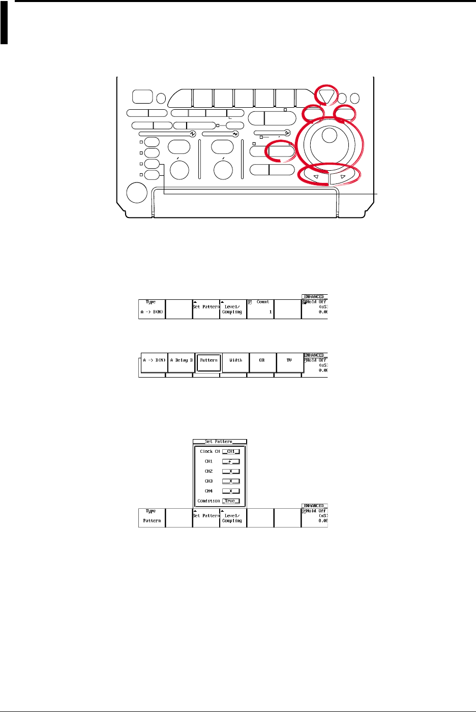
6-20 IM 701710-01E
6.10 Setting the Pattern Trigger (ENHANCED)
<For a description of this function, refer to page 1-9>
Relevant Keys
ACTION DELAY
X - Y MENU MENU PHASE
SEARCH
HORIZONTAL
VERTICAL TRIGGER
TRIG D
HELP
ESC
SELECTRESET
SIMPLE
MODE POSITION
MATH
MISCFILE
CLEAR
TRACE
HISTORY
MEASURE
SETUP
PRESET
DISPLAY
CURSOR
CH
1
CH
2
CH
3
CH
4
POWER
COPY IMAGE SAVE SHIFT
ZOOM
GO/NO-GO
ENHANCED
ACQ START/STOP
SNAP
SHOT
V DIV TIME DIV
The DL1720 is not
equipped with
an input terminal
for CH3 or CH4.
Operating Procedure
Setting the Trigger Type
1. Press ENHANCED.
2. Pressing the Type soft key displays the trigger type menu.
3. Press the Pattern soft key.
Setting the Status and Condition
4. Pressing the Set Pattern soft key displays a menu used to set the status and
condition. (On the DL1720, settings for CH3 and CH4 are not displayed.)
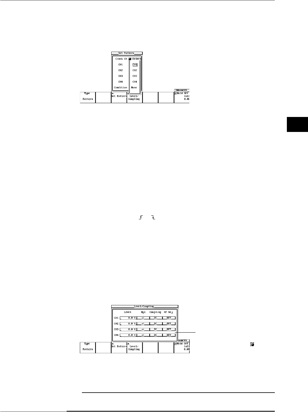
6-21
IM 701710-01E
Triggering
6
When Activating the Trigger Only on the Status Pattern
5. Turn the jog shuttle to move the cursor to Clock CH.
6. Pressing SELECT displays the clock channel setting menu.
7. Turn the jog shuttle to select None. (CH3 and CH4 are not displayed on the
DL1720.)
8. Press ESC and turn the jog shuttle to move the cursor to the channel on which the
status is to be set.
9. Press SELECT to select H, L, X.
10. Turn the jog shuttle to move the cursor to Condition.
11. Press SELECT to select Enter or Exit.
Go to step 14.
When Activating the Trigger in Sync with the Clock Channel
5. Turn the jog shuttle to move the cursor to Clock CH.
6. Pressing SELECT displays the clock channel setting menu.
7. Turn the jog shuttle to set the clock channel.
8. Press ESC and turn the jog shuttle to move the cursor to the channel that was set
as the clock channel.
9. Press SELECT to select or .
10. Turn the jog shuttle to move the cursor to the channel to which the status to be set.
11. Press SELECT to select H, L, or X.
12. Turn the jog shuttle to move the cursor to Condition.
13. Press SELECT to select True or False.
Setting the Level, Hysteresis, Trigger Coupling, and HF Rejection of the Clock CH
14. Pressing the Level/Coupling soft key displays a menu used to set the level,
coupling, hysteresis, and HF rejection. (On the DL1720, settings for CH3 and CH4
are not displayed.)
The setting also applies to the A→B(N) trigger. See section 6.8.
The Level setting for each
channel can be input directly
using a USB keyboard. ( )
Setting the Hold Off
15. Set the hold off time according to the procedures given in 6.4, “Setting the Hold Off
Time.”
Note
The trigger level, hysteresis, trigger coupling, and HF rejection settings apply to simple trigger
and enhanced trigger.
6.10 Setting the Pattern Trigger (ENHANCED)
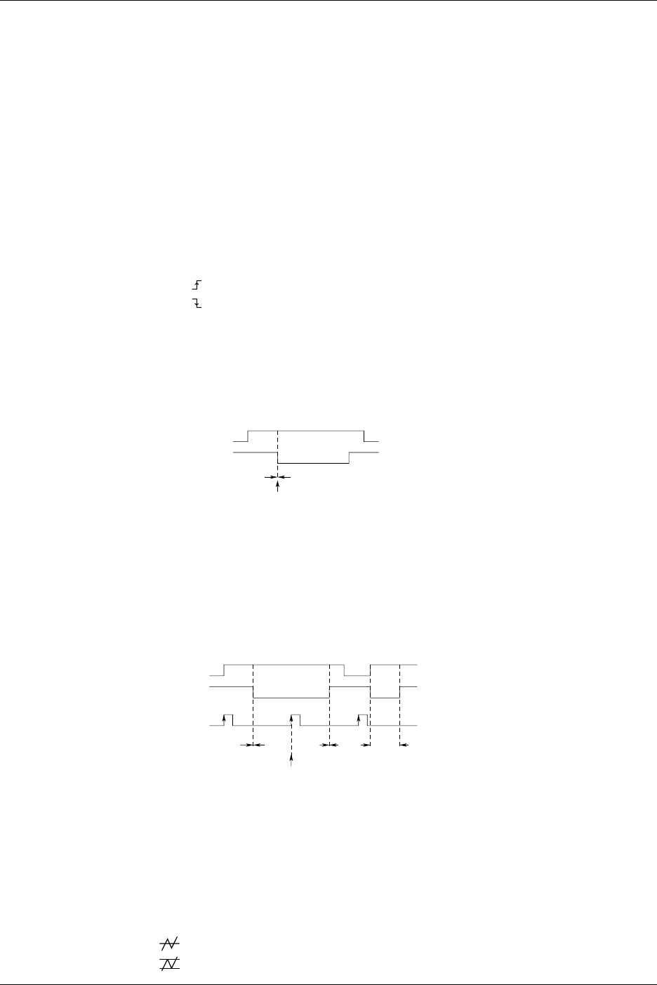
6-22 IM 701710-01E
Explanation
This function activates the trigger when all conditions set to multiple trigger sources
become true or when all conditions become false.
Setting the Trigger Source and Trigger Status
Set the trigger status of the trigger source from the following three choices.
H: The trigger source level is greater than or equal to the trigger level.
L: The trigger source level is less than or equal to the trigger level.
X: Do not set as a trigger source.
Selecting the Clock Channel: Clock CH
•Select None if the trigger is not to be activated in sync with the signal.
•Select the clock channel from CH1 to CH4 (or CH1 to CH2 for the DL1720) if the
trigger is to be activated in sync with the signal.
•Select the trigger slope from the following.
: Rising
: Falling
Selecting the Trigger Condition
•When Activating the Trigger Only on the Status Pattern
Select the trigger condition from the following list of choices.
Enter: Trigger is activated when the specified combination (pattern) is met.
Exit: Trigger is activated when the specified pattern is no longer met.
CH1 Input
CH2 Input
Pattern not Matched Pattern Matched
CH1: H CH2: L
CH3
*1
: X CH4
*1
: X
Condition: Enter
Trigger Condition Met
*1 The DL1720 is not equipped with channels 3 and 4.
•When Activating the Trigger in Sync with the Clock Channel
Set the trigger condition from the following list of choices.
True: Trigger is activated on the rising or falling edge of the clock channel while the
status pattern is being matched.
False: Trigger is activated on the rising or falling edge of the clock channel while the
status pattern match condition is not satisfied.
CH1: H CH2: L
CH4*1: X CH3*1: Clock CH
Condition: True
CH1 Input
CH2 Input
Pattern not
Matched Pattern
Matched
Trigger Condition Met
CH3
*1
Input
Pattern not
Matched Pattern
Matched
*1 The DL1720 is not equipped with channels 3 and 4.
Setting the Trigger Level
Range: 8 div within the screen
Resolution: 0.01 div
For example, the resolution is 0.02 mV when the V/DIV setting is 2 mV/div.
Setting the Hysteresis
Sets a width to the trigger level so that the trigger is not activated on small changes.
: Approximately 0.3 div* of hysteresis around the trigger level.
: Approximately 1 div* of hysteresis around the trigger level.
*: The value above are estimated values. They are not strictly guaranteed.
6.10 Setting the Pattern Trigger (ENHANCED)

6-23
IM 701710-01E
Triggering
6
Setting the Trigger Coupling
Select from the following list of choices.
AC: Uses a signal that is obtained by removing the DC component from the trigger
source signal as the trigger signal.
DC: Uses the trigger source signal as the trigger signal.
Turning the HF Rejection ON/OFF
Select 15 kHz or 20 MHz when you wish to use a signal source that is obtained by
removing the high frequency components (frequency components greater than or equal
to approximately 15 kHz or 20 MHz) from the trigger signal as the trigger source.
Setting the Hold Off
See section 6.4, “Setting the Hold Off Time.”
Precautions to be Taken when Setting the Pattern Trigger
•When the trigger type setting is changed, the pattern trigger setting is no longer valid.
However, if the pattern trigger is selected again, the previous settings are enabled.
•Even if the trigger mode is set to auto level mode, the operation will be in auto mode.
•Set the trigger status on all trigger sources. If the channel selected is a clock channel,
select the trigger slope.
•When activating the trigger in sync with the clock signal, specify at least 1 ns for the
pattern to setup and at least 1 ns for the hold time.
6.10 Setting the Pattern Trigger (ENHANCED)
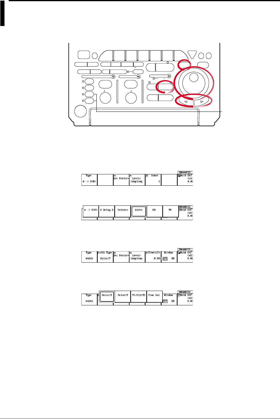
6-24 IM 701710-01E
6.11 Setting the Width (Pulse<T, Pulse>T,
T1<PLS<T2, Time Out) Trigger (ENHANCED)
<For a description of this function, refer to page 1-9>
Relevant Keys
ACTION DELAY
X - Y MENU MENU PHASE
SEARCH
HORIZONTAL
VERTICAL TRIGGER
TRIG D
HELP
ESC
SELECTRESET
SIMPLE
MODE POSITION
MATH
MISCFILE
CLEAR
TRACE
HISTORY
MEASURE
SETUP
PRESET
DISPLAY
CURSOR
CH
1
CH
2
CH
3
CH
4
POWER
COPY IMAGE SAVE SHIFT
ZOOM
GO/NO-GO
ENHANCED
ACQ START/STOP
SNAP
SHOT
V DIV TIME DIV
The DL1720 is not
equipped with
an input terminal
for CH3 or CH4.
Operating Procedure
Setting the Trigger Type
1. Press ENHANCED.
2. Pressing the Type soft key displays the trigger type menu.
3. Press the Width soft key.
Setting the Width Type
4. Pressing the Width Type soft key displays a menu used to select the width type.
5. Press the soft key corresponding to the desired type from Pulse > T, Pulse < T, T1
< PLS < T2, or Time Out.
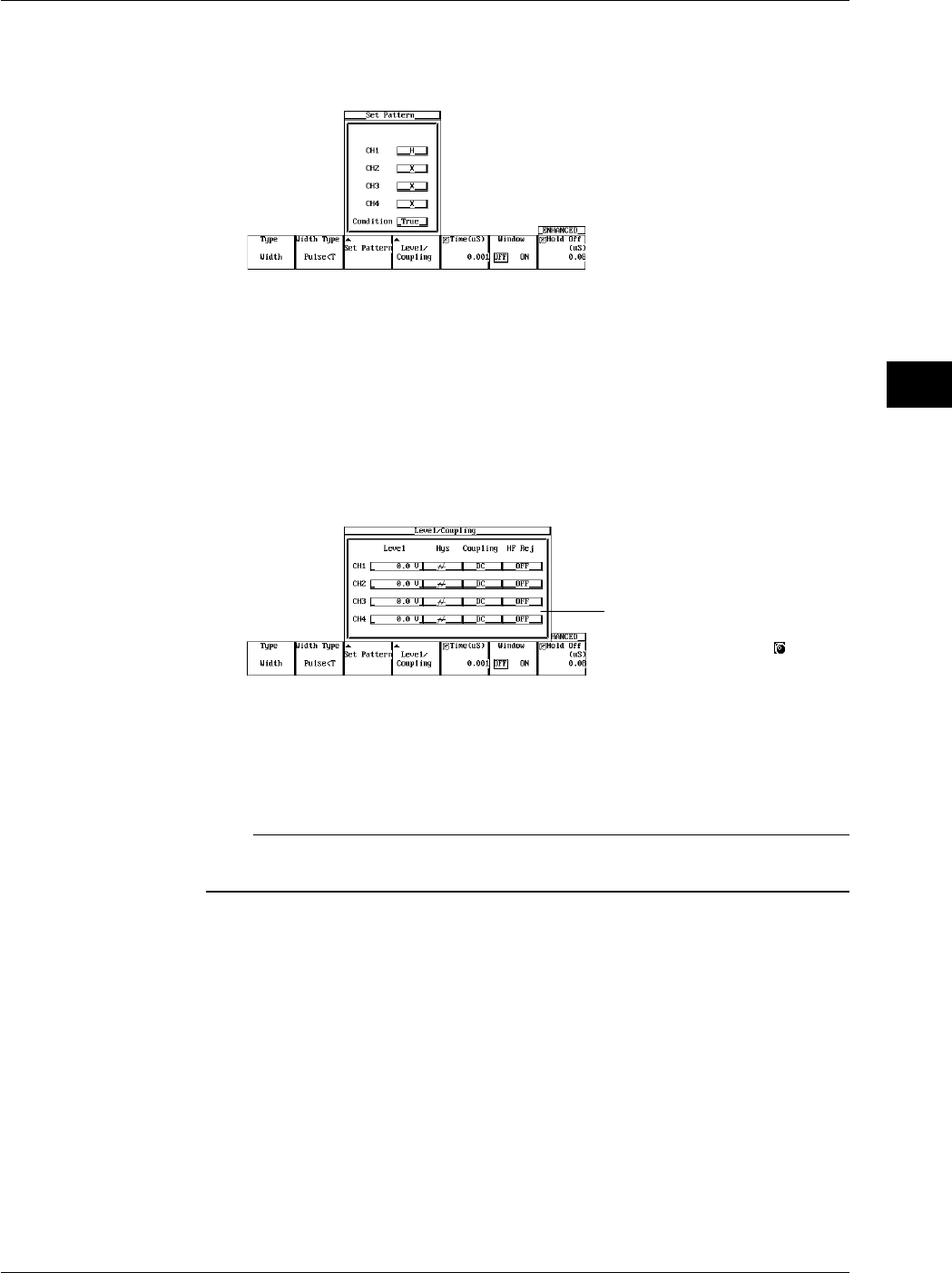
6-25
IM 701710-01E
Triggering
6
Setting the Conditions of Each Channel
6. Press the Set Pattern soft key to display the trigger setting menu. (On the DL1720,
settings for CH3 and CH4 are not displayed.)
7. Turn the jog shuttle to move the cursor to the channel to be set.
8. Press SELECT to select H, L, X (when the Window is ON, IN, OUT, or X).
9. Turn the jog shuttle to move the cursor to Condition.
10. Press SELECT to select True or False.
Setting the Level, Hysteresis, Trigger Coupling, and HF Rejection
11. Pressing the Level/Coupling soft key displays a menu used to set the level,
coupling, hysteresis, and HF rejection. (On the DL1720, settings for CH3 and CH4
are not displayed.)
The Level setting for each
channel can be input directly
using a USB keyboard. ( )
The setting also applies to A→B(N) trigger. See section 6.8.
When the Window is ON, set the window position, width, trigger coupling, and HF
rejection. The settings are the same as the window trigger. See section 6.13,
“Setting the Window Trigger.”
Note
The trigger level, hysteresis, trigger coupling, and HF rejection settings apply to simple trigger
and enhanced trigger.
6.11 Setting the Width (Pulse<T, Pulse>T, T1<PLS<T2, Time Out) Trigger (ENHANCED)
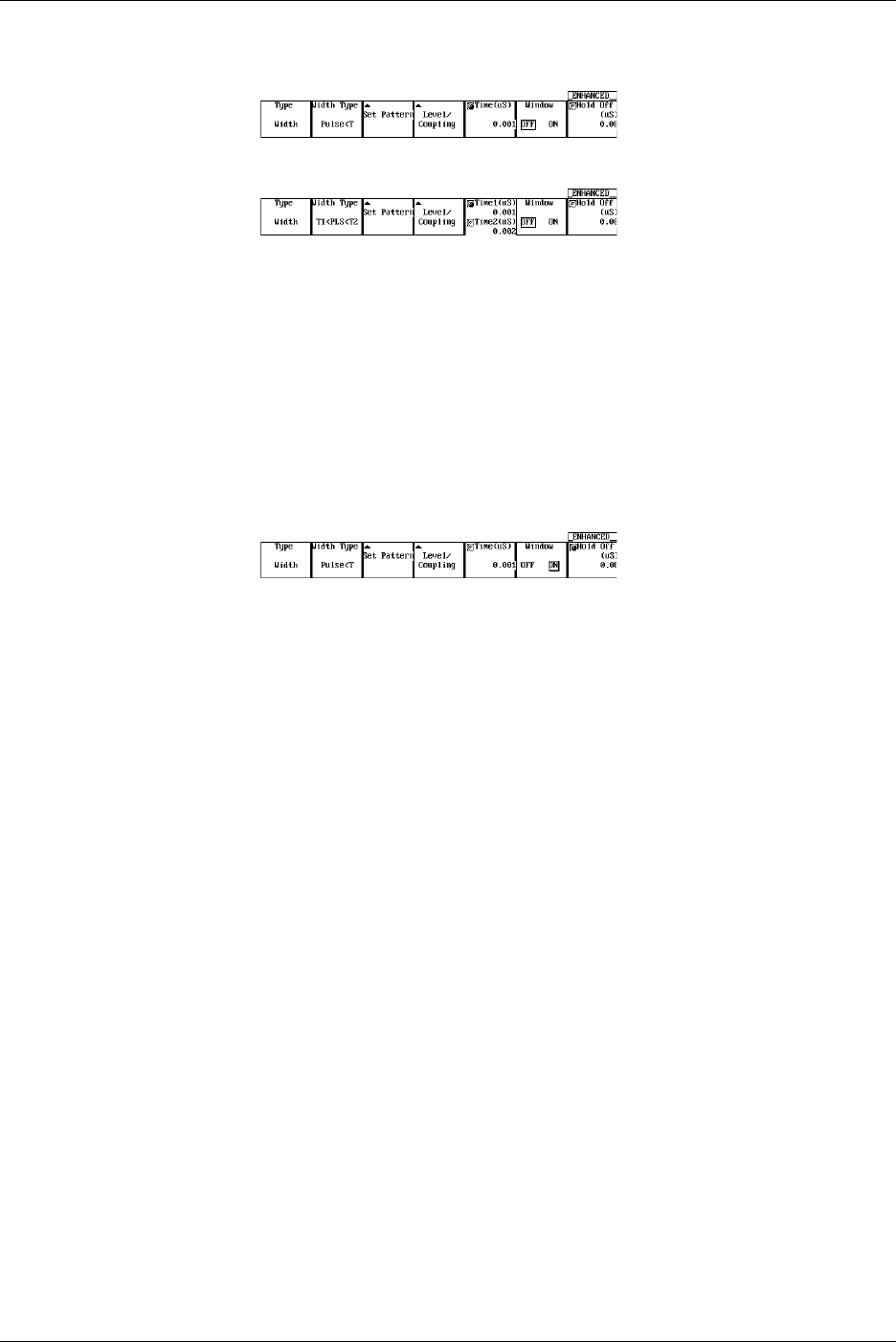
6-26 IM 701710-01E
Setting the Pulse Width
12. If the jog shuttle control is not set to Time press the Time soft key.
If the Width Type is T1 < PLS < T2, press the Time1/Time2 soft key.
13. Turn the jog shuttle to set the pulse width.
You can use the arrow keys to move between the digits. Pressing RESET resets
the pulse width to 0.001 µs (Time2 is reset to 0.002 µs).
Setting the Window
14. Press the Window soft key to select either ON or OFF.
When the Window is turned OFF, a trigger is activated on the time period over
which the parallel pattern of the channel state (H, L, and X) is met or not met.
When the Window is turned ON, a trigger is activated on the time period over which
the parallel pattern of the window condition of each channel is met or not met.
Setting the Hold Off
15. Set the hold off time according to the procedures given in 6.4, “Setting the Hold Off
Time.”
6.11 Setting the Width (Pulse<T, Pulse>T, T1<PLS<T2, Time Out) Trigger (ENHANCED)
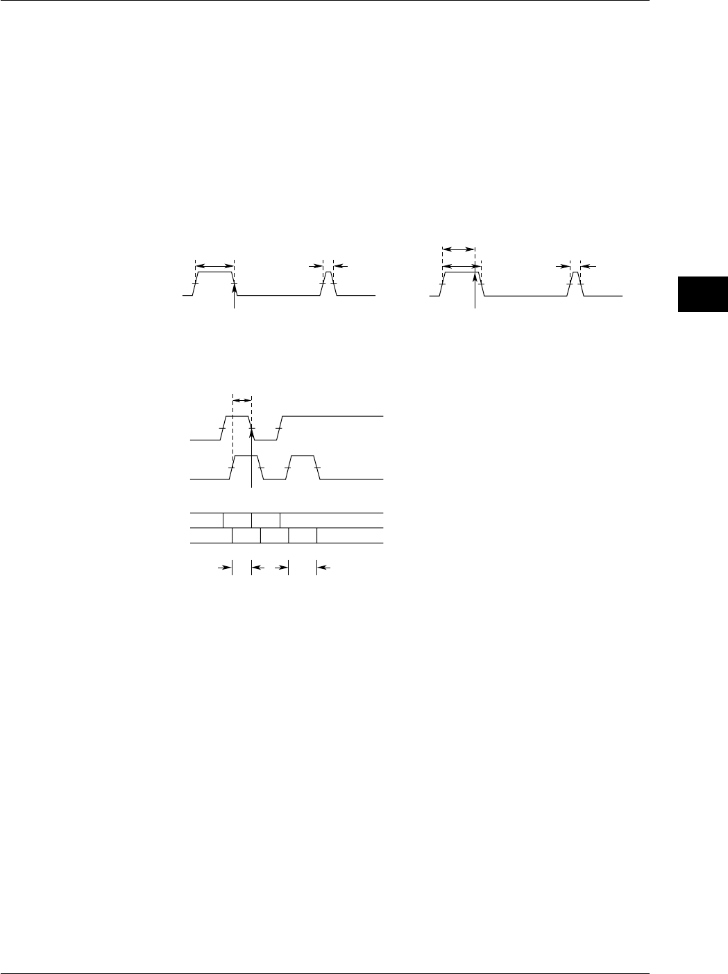
6-27
IM 701710-01E
Triggering
6
6.11 Setting the Width (Pulse<T, Pulse>T, T1<PLS<T2, Time Out) Trigger (ENHANCED)
Explanation
Pulse > T: When the time during which the status pattern is met is longer than the
specified pulse width, the trigger is activated when the condition changes.
Pulse < T: When the time during which the status pattern is met is shorter than the
specified pulse width, the trigger is activated.
T1<PLS<T2: When the time during which the status pattern is met is in between the two
specified pulse widths, the trigger is activated.
Time Out: The trigger is activated when the time during which the status pattern is
met becomes longer than the specified pulse width.
The point at which the trigger is activated differs between Pulse > T and Time Out as
indicated in the figure below.
When Pulse>T, CH1 = H, and Time = 400 ns
Trigger
500 ns 100 ns
CH1
Trigger
500 ns 100 ns
CH1
400 ns
When Pulse Time Out, CH1 = H, and Time = 400 ns
Pulse<T Setup Example
Pulse<T, Condition: CH1 = H, CH2 = H, Time = 400 ns
Trigger
LHL
HHLLL
H
CH1
CH2
CH1
CH2
300 ns 500 ns
300 ns
Conditions of Each Channel
When the window trigger turned OFF, the conditions same as the A→B(N) trigger. See
section 6.8.
Same as the window trigger when the window is ON (IN/OUT/X).
For details regarding the window trigger, see section 6.13, “Setting the Window Trigger.”
Pulse Width
1 ns to 1 s
Precautions to be Taken when Setting the Width Trigger
The trigger may not operate properly if the time between two pulses is less than 2 ns or if
the pulse width is less than 2 ns. The time accuracy of the pulse width in the standard
operating condition after calibration is ±(0.5% of the setting* + 1 ns).
*: When set to T1<PLS<T2, the value of T2.
Correlation with the Window Trigger
When the Window is turned ON, a trigger is activated based on the time period during
which the parallel pattern of the window condition of each channel is met or not met.

6-28 IM 701710-01E
Setting the Trigger Level
Range: 8 div within the screen
Resolution: 0.01 div
For example, the resolution is 0.02 mV when the V/DIV setting is 2 mV/div.
Setting the Hysteresis
Sets a width to the trigger level so that the trigger is not activated on small changes.
: Approximately 0.3 div* of hysteresis around the trigger level.
: Approximately 1 div* of hysteresis around the trigger level.
*: The value above are estimated values. They are not strictly guaranteed.
Setting the Trigger Coupling
Select from the following list of choices.
AC: Uses a signal that is obtained by removing the DC component from the trigger
source signal as the trigger signal.
DC: Uses the trigger source signal as the trigger signal.
Turning ON/OFF the HF Rejection
Select 15 kHz or 20 MHz when you wish to use a signal source that is obtained by
removing the high frequency components (frequency components greater than or equal
to approximately 15 kHz or 20 MHz) from the trigger signal as the trigger source.
Setting the Hold Off
See section 6.4, “Setting the Hold Off Time.”
6.11 Setting the Width (Pulse<T, Pulse>T, T1<PLS<T2, Time Out) Trigger (ENHANCED)
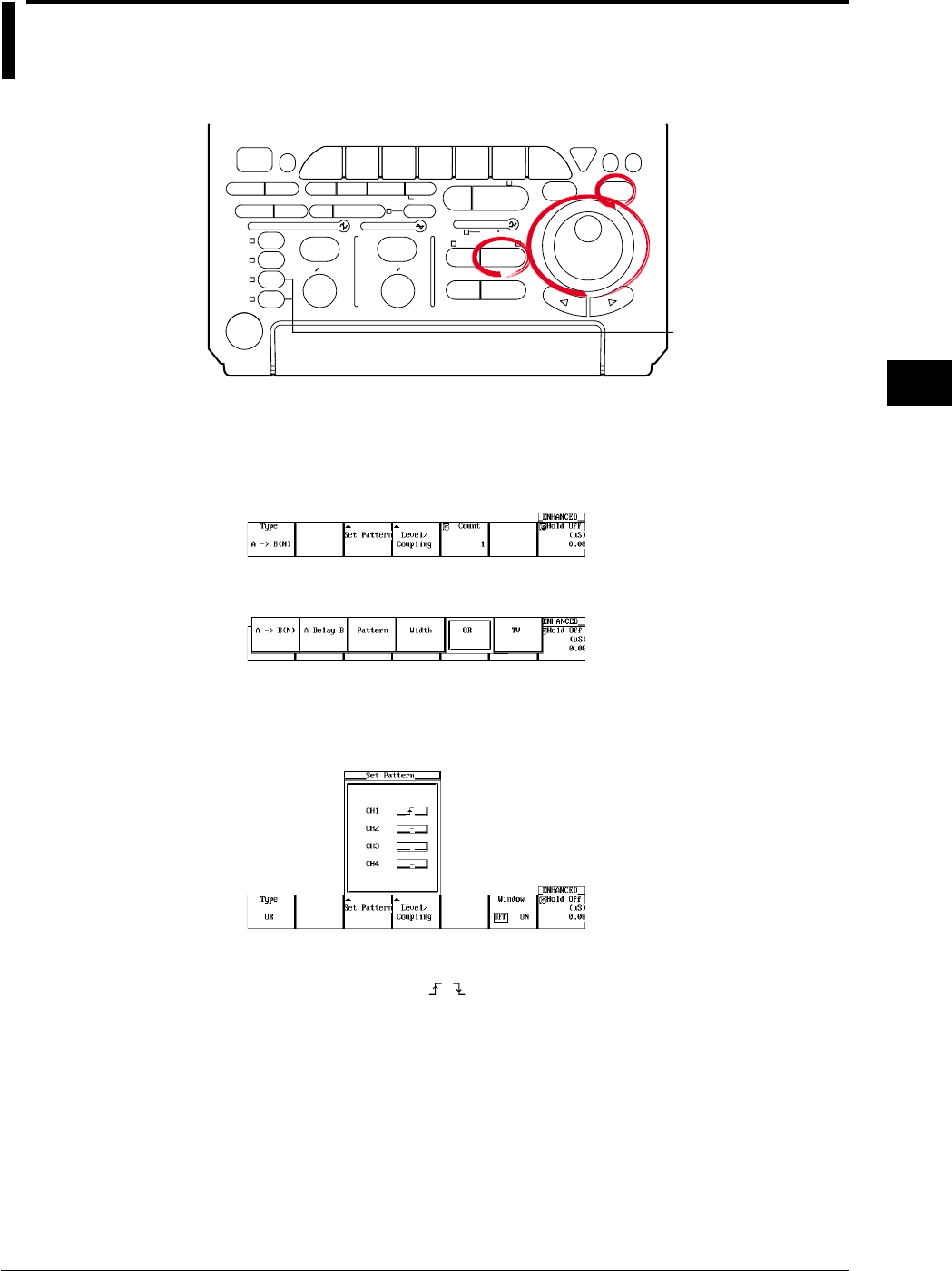
6-29
IM 701710-01E
Triggering
6
6.12 Setting the OR Trigger
<For a description of this function, refer to page 1-10>
Relevant Keys
ACTION DELAY
X - Y MENU MENU PHASE
SEARCH
HORIZONTAL
VERTICAL TRIGGER
TRIG D
HELP
ESC
SELECTRESET
SIMPLE
MODE POSITION
MATH
MISCFILE
CLEAR
TRACE
HISTORY
MEASURE
SETUP
PRESET
DISPLAY
CURSOR
CH
1
CH
2
CH
3
CH
4
POWER
COPY IMAGE SAVE SHIFT
ZOOM
GO/NO-GO
ENHANCED
ACQ START/STOP
SNAP
SHOT
V DIV TIME DIV
The DL1720 is not
equipped with
an input terminal
for CH3 or CH4.
Operating Procedure
Setting the Trigger Type
1. Press ENHANCED.
2. Pressing the Type soft key displays the trigger type menu.
3. Press the OR soft key.
Setting the Edge Trigger of Each Channel
4. Press the Set Pattern soft key to display the trigger setting menu. (On the DL1720,
settings for CH3 and CH4 are not displayed.)
5. Turn the jog shuttle to move the cursor to the channel to be set.
6. Press SELECT to select , , or — (when the Window is ON, IN, OUT, or —).
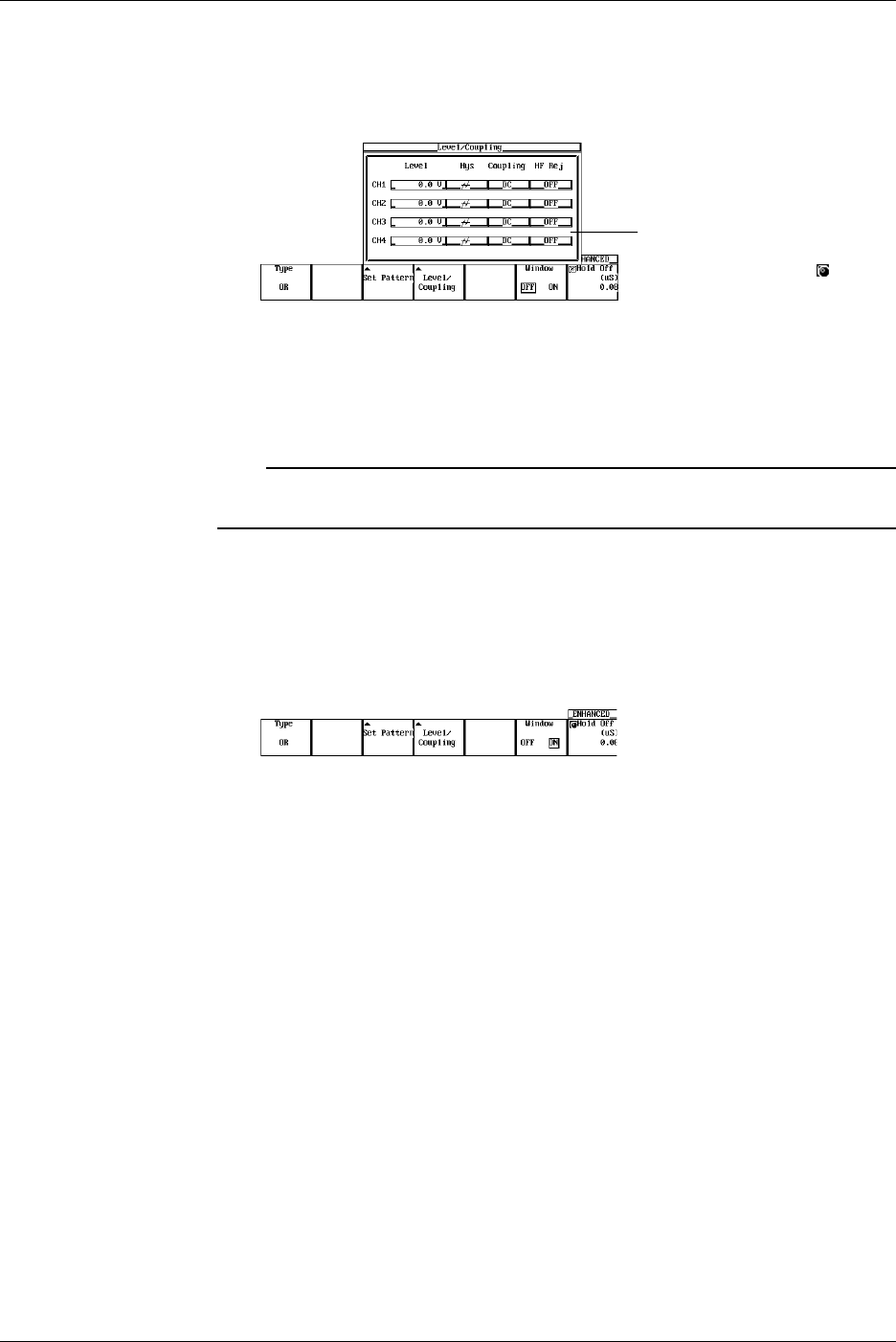
6-30 IM 701710-01E
Setting the Level, Hysteresis, Trigger Coupling, and HF Rejection
7. Pressing the Level/Coupling soft key displays a menu used to set the level,
coupling, hysteresis, and HF rejection. (On the DL1720, settings for CH3 and CH4
are not displayed.)
The Level setting for each
channel can be input directly
using a USB keyboard. ( )
The setting also applies to A→B(N) trigger. See section 6.8.
When the Window is ON, set the window position, width, trigger coupling, and HF
rejection. The settings are the same as the window trigger. See section 6.13,
“Setting the Window Trigger.”
Note
The trigger level, hysteresis, trigger coupling, and HF rejection settings apply to simple trigger
and enhanced trigger.
Setting the Window
8. Press the Window soft key to select either ON or OFF.
If OFF is selected, triggers are activated on the OR of the channel edge.
If ON is selected, triggers are activated on the OR of the channel’s window
conditions.
Setting the Hold Off
9. Set the hold off time according to the procedures given in 6.4, “Setting the Hold Off
Time.”
6.12 Setting the OR Trigger

6-31
IM 701710-01E
Triggering
6
Explanation
This function activates a trigger on the OR of each channel’s edge trigger.
Setting the Edge Trigger of Each Channel
Select from the following.
: Rising
: Falling
—: Don’t care
Setting the Trigger Level
Range: 8 div within the screen
Resolution: 0.01 div
For example, the resolution is 0.02 mV when the V/DIV setting is 2 mV/div.
Setting the Hysteresis
Sets a width to the trigger level so that the trigger is not activated on small changes.
: Approximately 0.3 div* of hysteresis around the trigger level.
: Approximately 1 div* of hysteresis around the trigger level.
*: The value above are estimated values. They are not strictly guaranteed.
Setting the Trigger Coupling
Select from the following list of choices.
AC: Uses a signal that is obtained by removing the DC component from the trigger
source signal as the trigger signal.
DC: Uses the trigger source signal as the trigger signal.
Turning ON/OFF the HF Rejection
Select 15 kHz or 20 MHz when you wish to use a signal source that is obtained by
removing the high frequency components (frequency components greater than or equal
to approximately 15 kHz or 20 MHz) from the trigger signal as the trigger source.
Setting the Hold Off
See section 6.4, “Setting the Hold Off Time.”
Correlation with the Window Trigger
If the window is turned ON, the trigger is activated when either the OR trigger or the
window trigger becomes true. For details related to window trigger, see section 6.13,
“Setting the Window Trigger.”
6.12 Setting the OR Trigger
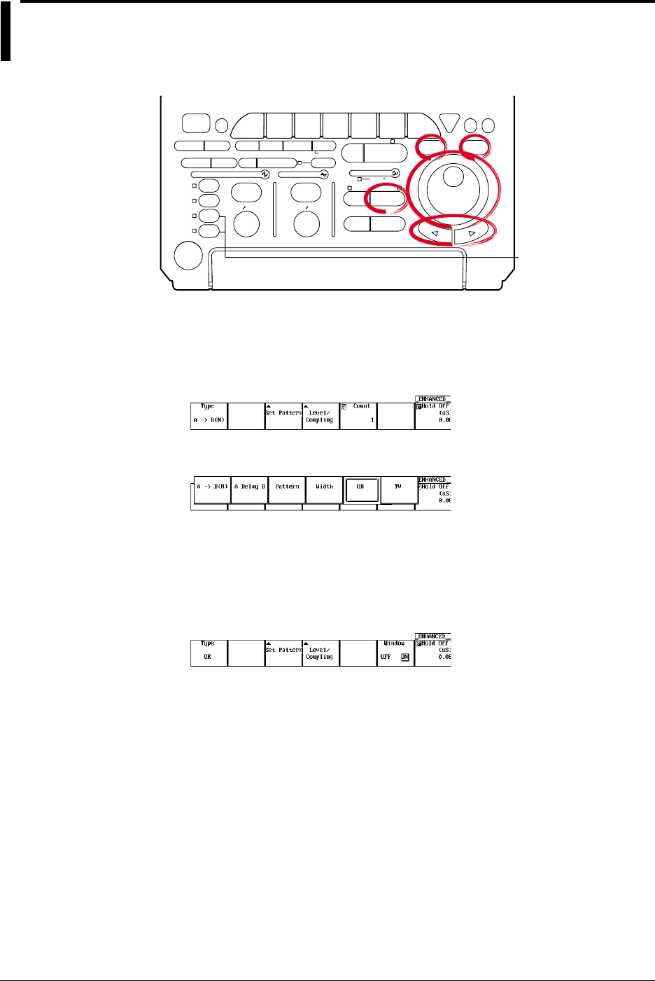
6-32 IM 701710-01E
6.13 Setting the Window Trigger (ENHANCED)
<For a description of this function, refer to page 1-10>
Relevant Keys
ACTION DELAY
X - Y MENU MENU PHASE
SEARCH
HORIZONTAL
VERTICAL TRIGGER
TRIG D
HELP
ESC
SELECTRESET
SIMPLE
MODE POSITION
MATH
MISCFILE
CLEAR
TRACE
HISTORY
MEASURE
SETUP
PRESET
DISPLAY
CURSOR
CH
1
CH
2
CH
3
CH
4
POWER
COPY IMAGE SAVE SHIFT
ZOOM
GO/NO-GO
ENHANCED
ACQ START/STOP
SNAP
SHOT
V DIV TIME DIV
The DL1720 is not
equipped with
an input terminal
for CH3 or CH4.
Operating Procedure
Setting the Trigger Type
1. Press ENHANCED.
2. Pressing the Type soft key displays the trigger type menu.
3. Press the OR or Width soft key.
Setting the Window Trigger
4. Press the Window soft key to select ON.
Set the status and trigger conditions of each channel according to the procedures
given in section 6.11, “Setting the Width (Pulse<T, Pulse>T, T1<PLS<T2, Time
Out)” or 6.12, “Setting the OR Trigger (ENHANCED).”
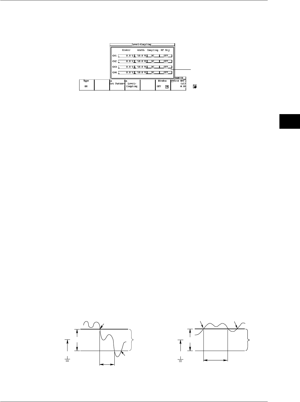
6-33
IM 701710-01E
Triggering
6
Setting the Center Level and Window Width
5. Pressing the Level/Coupling soft key displays a dialog box used to set the center
level, window width, trigger coupling, and HF rejection. (On the DL1720, settings
for CH3 and CH4 are not displayed.)
The Center and Width settings
for each channel can be input
directly using a USB keyboard.
( )
6. Turn the jog shuttle to move the cursor to the channel on which to set the window
center level (Center).
7. Press SELECT to display the center level menu.
8. Turn the jog shuttle to set the center level.
You can use the arrow keys to move between the digits. Pressing RESET sets the
window center level to 0 V.
9. Turn the jog shuttle to move the cursor to the channel on which to set the window
width.
10. Press SELECT to display the window width menu.
11. Turn the jog shuttle to set the window width.
You can use the arrow keys to move between the digits. Pressing RESET resets
the value to the initial value.
Setting the Trigger Coupling and HF Rejection
12. The coupling and HF rejection settings also apply to the A→B(N) trigger. See
section 6.8.
Explanation
This function sets up a window trigger for the CH1 to CH4 (or CH1 to CH2 for the
DL1720) input signal.
Trigger Condition
•Width trigger
IN: The time during the trigger source enters the window is trigger duration.
OUT:The time during the trigger source exits the window is trigger duration.
•OR trigger
IN: Trigger is activated when the trigger source enters the window (the area between
two preset levels).
OUT: Trigger is activated when the trigger source exits the window.
Width
Trigger is Activated (OR Trigger)
[OUT]
[IN]
Window Window
Center
Width
Center
Trigger Duration (Width Trigger)
Trigger is Activated
(OR Trigger)
Trigger is Activated (OR Trigger)
Trigger Duration (Width Trigger)
6.13 Setting the Window Trigger (ENHANCED)

6-34 IM 701710-01E
6.13 Setting the Window Trigger (ENHANCED)
Window Setting
You define the window by its center level and width.
“Center” Setting Range :Anywhere within the 8 screen divisions, in resolution of 0.01
div. (Example: If the scale is 1 V/div, resolution is 0.01 V).
“Width” Setting Range :Up to ±4 div from center, in resolution of 0.02 div.
(Example: If the scale is 1 V/div, resolution is 0.02 V).
Note
If you set the window so that the top or bottom is off the screen, the trigger will occur at the
level for the corresponding screen edge (the level at ±4 divisions from screen center) rather
than at the “missing” top or bottom. Therefore it is recommended not to exceed ±4 div when
setting the window.
Setting the Trigger Coupling
Select from the following list of choices.
AC: Uses a signal that is obtained by removing the DC component from the trigger
source signal as the trigger signal.
DC: Uses the trigger source signal as the trigger signal.
Turning ON/OFF the HF Rejection
Select 15 kHz or 20 MHz when you wish to use a signal source that is obtained by
removing the high frequency components (frequency components greater than or equal
to approximately 15 kHz or 20 MHz) from the trigger signal as the trigger source.
Setting the Hold Off
See section 6.4, “Setting the Hold Off Time.”
Correlation with the OR Trigger or Width Trigger
OR
and
Width
are the trigger types on which the window trigger can be used. When
using the window trigger of a single channel, set the window conditions of all other
channels to “–” or “x.”
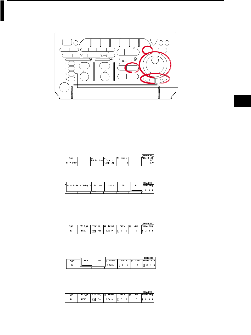
6-35
IM 701710-01E
Triggering
6
6.14 Setting the TV Trigger (ENHANCED)
<For a description of this function, refer to page 1-10>
Relevant Keys
ACTION DELAY
X - Y MENU MENU PHASE
SEARCH
HORIZONTAL
VERTICAL TRIGGER
TRIG D
HELP
ESC
SELECTRESET
SIMPLE
MODE POSITION
MATH
MISCFILE
CLEAR
TRACE
HISTORY
MEASURE
SETUP
PRESET
DISPLAY
CURSOR
CH
1
CH
2
CH
3
CH
4
POWER
COPY IMAGE SAVE SHIFT
ZOOM
GO/NO-GO
ENHANCED
ACQ START/STOP
SNAP
SHOT
V DIV TIME DIV
The DL1720 is not
equipped with
an input terminal
for CH3 or CH4.
Operating Procedure
Inputting the Video Signal
Connect the probe (cable) used to input the video signal to the CH1 input terminal.
Selecting the TV Trigger
1. Press ENHANCED.
2. Pressing the Type soft key displays the trigger type menu.
3. Press the TV soft key.
Selecting the Broadcasting System of the Video Signal to be Monitored
4. Pressing the TV Type soft key displays a menu used to select the broadcasting
system.
5. Press the soft key corresponding to the desired broadcasting system to select
NTSC or PAL.
Selecting the Polarity
6. Press the Polarity soft key to select the polarity.

6-36 IM 701710-01E
Setting the Trigger Level
7. If the jog shuttle control is not set to Level, press the Level soft key.
8. Turn the jog shuttle to set the trigger level.
You can use the arrow keys to move between the digits. Pressing RESET sets the
trigger level to 0.5 div.
Selecting the Field Number
9. Press the Field soft key to select the number.
Selecting the Line Number
10. If the jog shuttle control is not set to Line, press the Line soft key.
11. Turn the jog shuttle to set the line.
You can use the arrow keys to move between the digits. Pressing RESET sets the
line No. to 5 (NTSC) or 2 (PAL).
Selecting Frame Skip
12. Press the Frame Skip soft key repeatedly to select the frame skip.
Explanation
This function lets you set a trigger for video signal input into Channel 1. Settings and
functions are as follows.
Broadcasting Systems with which the TV Trigger can be Used
NTSC, PAL
Selecting the field No.: Field
1 Detects a field in which the vertical synchronizing pulse and the line start at the same
time.
2 Detects a field in which the vertical synchronizing pulse starts 1/2H (H: horizontal scan
time) after the line starts.
X Detects both of the above types of field.
6.14 Setting the TV Trigger (ENHANCED)
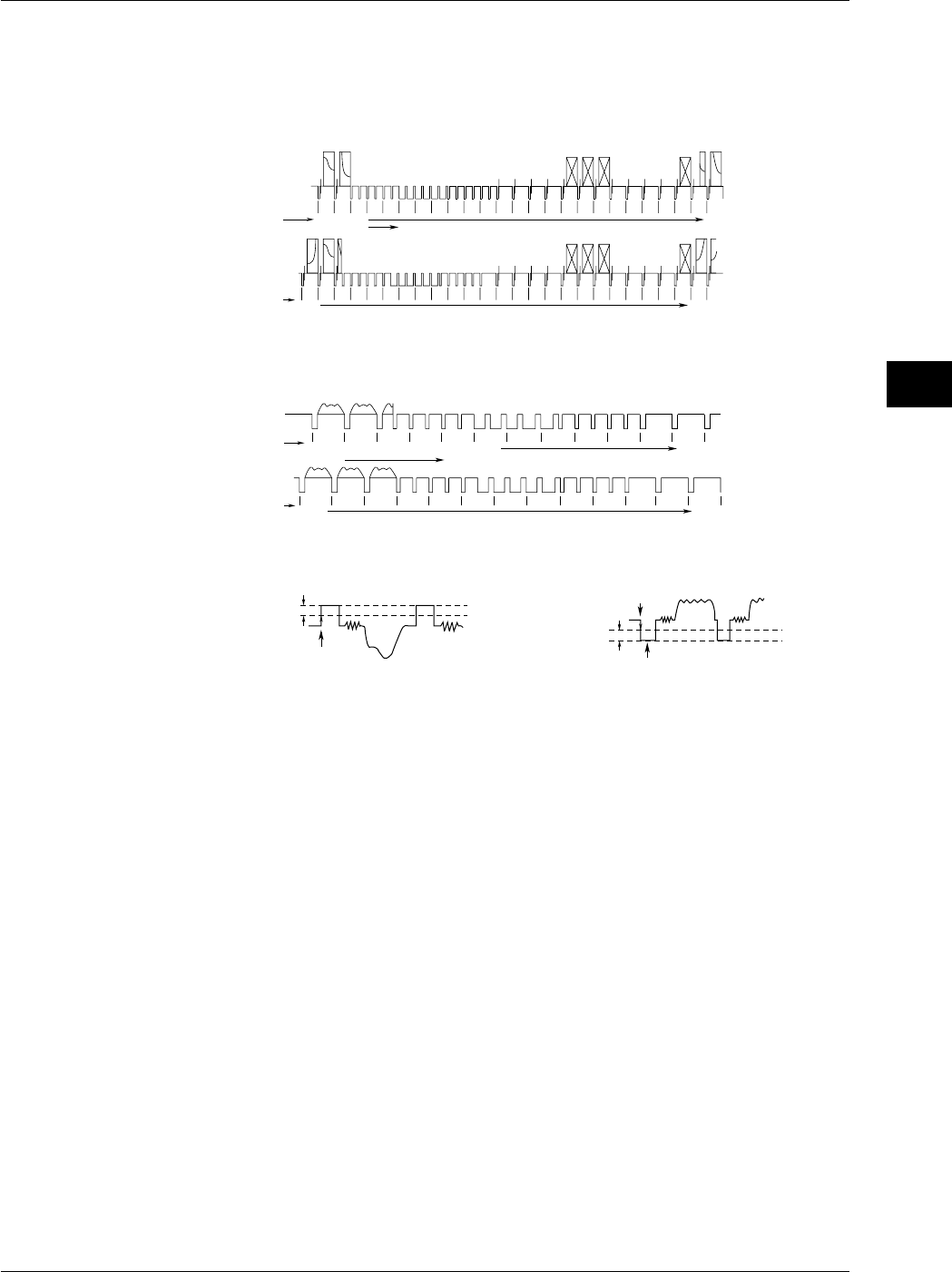
6-37
IM 701710-01E
Triggering
6
Selecting the Line No.: Line
A trigger is activated at the beginning of the selected line.
•NTSC: 5 to 1054
Field 1 starts at line No. “5.” (Field 2 starts at line No. “268.”)
524 525
(1)(2)(3)(4) 5 6 7 8 9 1011121314151617181920212223
Field 1
262 263 264 265 266 267 268 269 270 271 272 273 274 275 276 277 278 279 280 281 282 283 284 285
Filed 2
261
Line No.
Line No.
1049 1050
526 548
1051 1054
786 810
Line Nos. in ( ) cannot be set.
•PAL: 2 to 1251
Field 1 starts at line No. “2.” (Field 2 starts at line No. “315.”)
621 622 623 624 625
234567(1)
Filed 1
308 309 310 311 312 313 315314 316 318317 320319
Filed 2
Line No.
1246 1250
632626
1251
Line No.
933 945
Line Nos. in ( ) cannot be set.
Selecting the Polarity
Trigger Point
Trigger Level Trigger Point
Synchronization Pulse
Trigger Level
Polarity: NegPolarity: Pos
Setting the Trigger Level: Level
Set the difference between the beginning of the synchronization pulse and the level at
which the trigger level is judged.
The setting range is from 0.1 div to 2.0 div. The setting resolution is 0.1 div.
The default setting is 0.5 div.
Setting the Frame Skip: Frame
This is a function for skipping frames when the color burst is inverted on every frame.
You can select how many frames to skip from the following choices.
Frame1: Trigger every frame at the specified field.
Frame2: Trigger every two frames at the specified field.
Frame4: Trigger every four frames at the specified field.
Frame8: Trigger every eight frames at the specified field.
Precautions to be Taken when Setting the TV Trigger
•Video signals can only be input to CH1. All other channels do not support video
signals.
•Hold-off, trigger coupling, and HF rejection settings are ignored.
6.14 Setting the TV Trigger (ENHANCED)
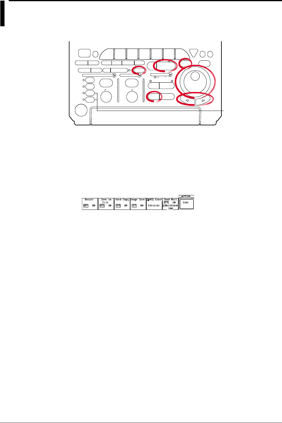
6-38 IM 701710-01E
6.15 Setting the Action-On Trigger
<For a description of this function, refer to page 1-11>
Relevant Keys
ACTION DELAY
X - Y MENU MENU PHASE
SEARCH
HORIZONTAL
VERTICAL TRIGGER
TRIG D
HELP
ESC
SELECTRESET
SIMPLE
MODE POSITION
MATH
MISCFILE
CLEAR
TRACE
HISTORY
MEASURE
SETUP
PRESET
DISPLAY
CURSOR
CH
1
CH
2
CH
3
CH
4
POWER
COPY IMAGE SAVE SHIFT
ZOOM
GO/NO-GO
ENHANCED
ACQ START/STOP
SNAP
SHOT
V DIV TIME DIV
The DL1720 is not
equipped with
an input terminal
for CH3 or CH4.
Operating Procedure
1. Press SHIFT to activat shift mode.
Functions marked in purple on the panel become active.
2. Press MODE.
Turning ON/OFF the Action
3. Press the soft key corresponding to the action you wish to enable and select ON.
Selecting the Number of Waveform Acquisitions
4. Turn the jog shuttle to set the waveform acquisition count.
You can use the arrow keys to move between the digits. In addition, pressing
RESET sets the count to Infinite.
Executing the Action-On-Trigger
5. Pressing the Exec soft key starts the waveform acquisition and executes the
action-on-trigger.
Aborting the Action-On-Trigger
6. Pressing the Abort soft key or START/STOP stops the waveform acquisition and
aborts the action-on-trigger.

6-39
IM 701710-01E
Triggering
6
Explanation
Operation to Perform when the Trigger is Activated:
The specified operation from the following list is performed every time a trigger is
activated.
Hard Copy: Outputs the screen image data to the destination (Built-in, USB, or Net
Print (Ethernet interface option)) that was specified in “Copy to” of the
Copy menu.
Image Save: Saves the screen image data to the output destination (FD, Zip disk, or
SCSI (when SCSI and serial interface option are installed) that you
specified in the Image Save menu.
Save to File: Saves the waveform data, the automated measurement value of waveform
parameters, or snapshot waveforms to the storage medium (FD, Zip disk,
or SCSI (option) and so on) specified in the File menu.
Buzzer: Sounds an alarm.
Send Mail: Sends a mail (Ethernet Interface option): For details, see section 13.7,
“Using the Mail Function (Action Mail Function).”
Note
When the action-on-trigger is started, the specified operation is performed when the trigger is
activated in the normal mode regardless of the trigger mode setting.
Number of Operations: ACQ Count
1 to 65536: Repeats the operation the specified number of times.
Infinite: Repeats the operation until the waveform acquisition is stopped.
Save to File/Hard Copy/Image Save Operation
Operates according to the settings in the FILE, COPY, or Image Save menu.
File name of Image Save or Save to File.
Saved using AUTO Name. For details, see section 10.4, “Storing Screen Image to the
Storage Medium” or section 11.6, “Saving/Loading Waveform Data.”
Send Mail Operation
Sends e-mail messages to the address specified through MISC > Network > Mail Setup
> Mail Address.
Precautions to be Taken when Setting the Action-On-Trigger
•Action-on-trigger cannot be used when the action mode is Average or Box Average.
•The settings cannot be changed during an action-on-trigger.
Trigger Mode
The trigger mode is set to Single.
6.15 Setting the Action-On Trigger
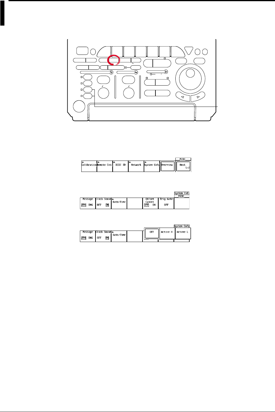
6-40 IM 701710-01E
6.16 Setting the Trigger Gate
Relevant Keys
ACTION DELAY
X - Y MENU MENU PHASE
SEARCH
HORIZONTAL
VERTICAL TRIGGER
TRIG D
HELP
ESC
SELECTRESET
SIMPLE
MODE POSITION
MATH
MISCFILE
CLEAR
TRACE
HISTORY
MEASURE
SETUP
PRESET
DISPLAY
CURSOR
CH
1
CH
2
CH
3
CH
4
POWER
COPY IMAGE SAVE SHIFT
ZOOM
GO/NO-GO
ENHANCED
ACQ START/STOP
SNAP
SHOT
V DIV TIME DIV
The DL1720 is not
equipped with
an input terminal
for CH3 or CH4.
Operating Procedure
1. Press MISC.
2. Pressing the System Cnfg soft key displays the system configuration menu.
3. Press the Trigger Gate soft key to select Active H, Active L, or OFF.
The default setting is OFF.
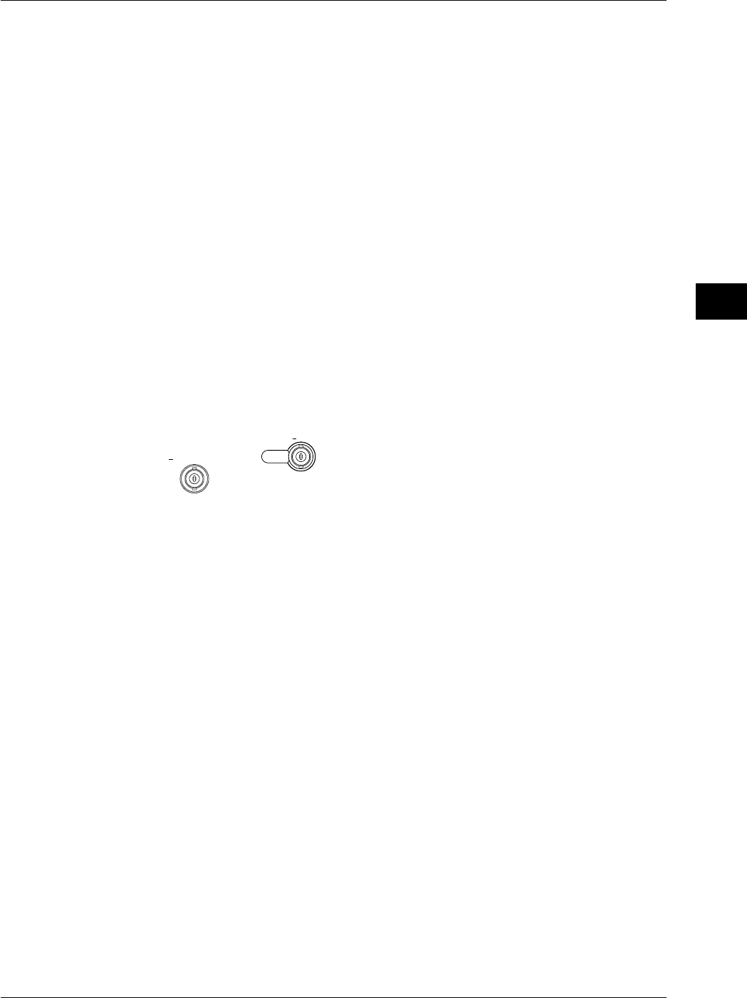
6-41
IM 701710-01E
Triggering
6
Explanation
The trigger gate is used to set the timing to enable the specified trigger conditions.
OFF: Waveforms are acquired when the trigger conditions are met.
Active High: When the external signal is Low, waveforms are not acquired even if the
trigger conditions are met. When the external signal is High, waveforms
are acquired when the trigger conditions are met.
Active Low: When the external signal is High, waveforms are not acquired even if the
trigger conditions are met. When the external signal is Low, waveforms
are acquired when the trigger conditions are met.
When trigger gate is active, A→B(N) trigger and A delay B trigger can not be specified.
Level
High and low are determined based on the external trigger level. See section 6.6.
The external signal is applied to the terminal on the rear panel (or the front panel for the
DL1720) that is shared between external triggers, external clock, and trigger gate.
Trigger Gate Input Terminal
The external trigger input terminal or external clock input terminal is also used as a
trigger gate terminal. If you wish to enable the trigger using an external signal, apply an
external signal to this terminal.
[Input Terminal]
EXT CLOCK IN
<40Vpk 1MΩ
EXT TRIG IN
TRIG GATE IN
< DL1740 >
EXT.
< DL1720 >
1MΩ /20pF < 40Vpk
(On the DL1740 it is located on the rear panel,
or on the DL1720 it is located on the front panel.)
Specifications
Connector Type: BNC
Maximum Input Voltage: ±40 V(DC + ACpeak) or 28 Vrms when the frequency is less
than or equal to 10 kHz
Frequency Range: DC to 50 MHz
Input Impedance: Approx. 1 MΩ, approx. 18 pF (1 MΩ and 20 pF for the DL1720)
Input Range: ±2 V (for the DL1740)
±1 V (for the DL1720 with the ±1 V range selected)
±10 V (for the DL1720 with the ±10 V range selected)
Minimum Input Amplitude: 0.1 Vp-p (for the DL1740)
0.1 Vp-p (for the DL1720 with the ±1 V range selected)
1 Vp-p (for the DL1720 with the ±10 V range selected)
Minimum Pulse Width: At least 10 ns for both High and Low
6.16 Setting the Trigger Gate
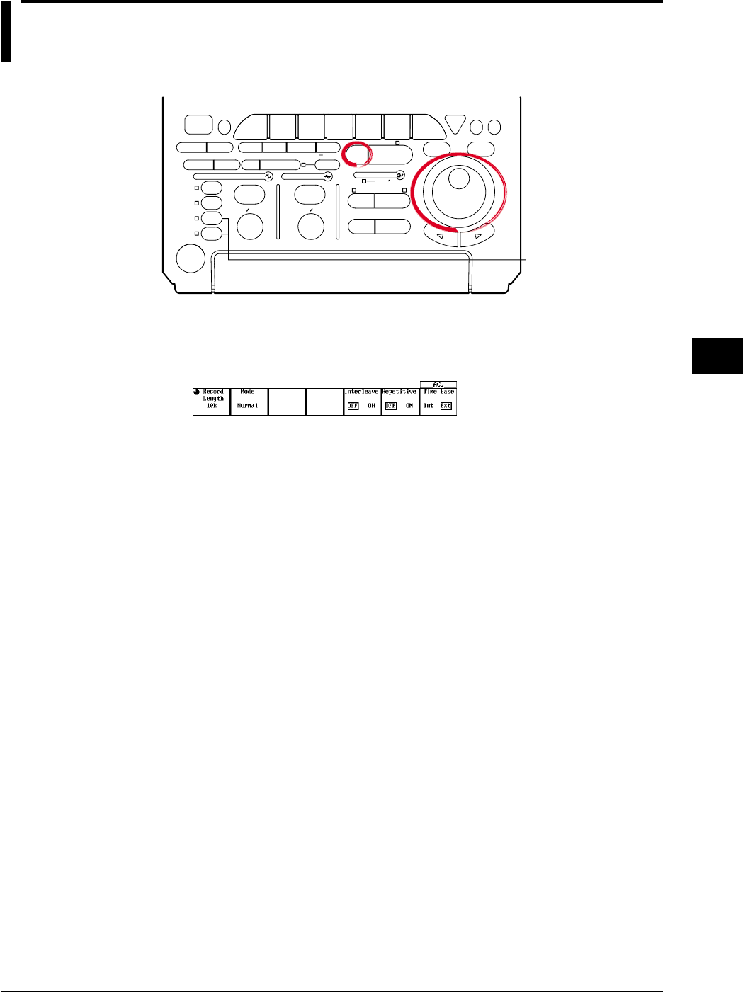
7-1
IM 701710-01E
Acquisition and Display
7
7.1 Setting the Record Length
<For a description of this function, refer to page 1-14>
Relevant Keys
ACTION DELAY
X - Y MENU MENU PHASE
SEARCH
HORIZONTAL
VERTICAL TRIGGER
TRIG D
HELP
ESC
SELECTRESET
SIMPLE
MODE POSITION
MATH
MISCFILE
CLEAR
TRACE
HISTORY
MEASURE
SETUP
PRESET
DISPLAY
CURSOR
CH
1
CH
2
CH
3
CH
4
POWER
COPY IMAGE SAVE SHIFT
ZOOM
GO/NO-GO
ENHANCED
ACQ START/STOP
SNAP
SHOT
V DIV TIME DIV
The DL1720 is not
equipped with
an input terminal
for CH3 or CH4.
Operating Procedure
1. Press ACQ.
2. Press the Record Length soft key to set the jog shuttle action to Record Length.
3. Select the length by turning the jog shuttle. choose 1 k to 1 M.
Explanation
The record length sets the amount of data to be written into the acquisition memory.
Available length settings are as follows:
1 kwords, 10 kwords, 50 kwords, 100 kwords, 250 kwords, 500 kwords, (1 Mwords)
(Value in parenthesis is available only if interleave mode is ON.)
Setting Precautions
•The sampling rate and displayed record length vary according to the T/div setting.
For details, see appendix 1.
•The maximum record length for box average is half the record length indicated above.
Chpater 7 Acquisition and Display
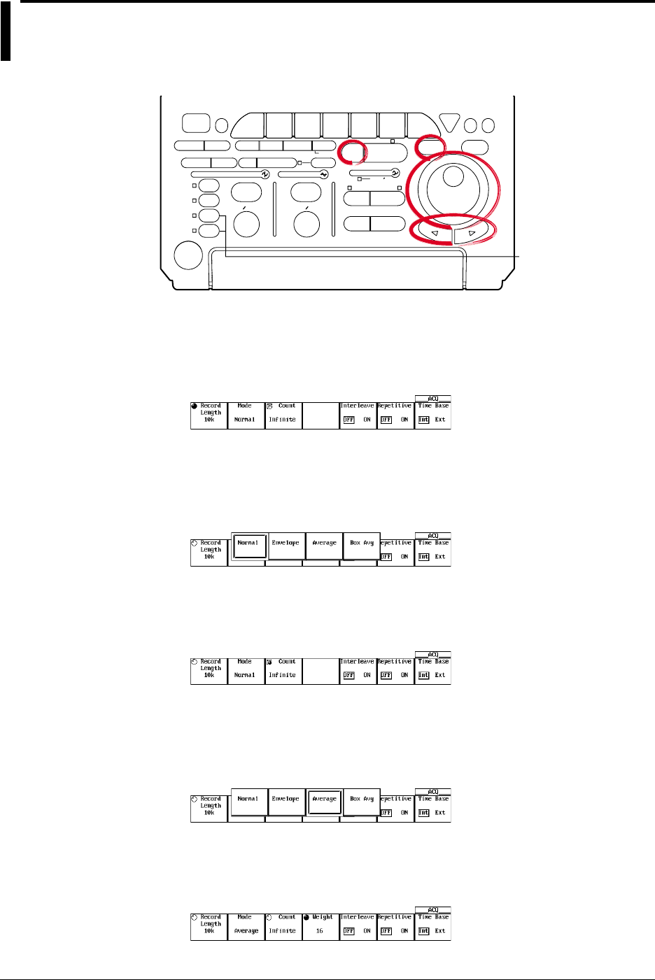
7-2 IM 701710-01E
7.2 Acquisition Mode
<For a description of this function, refer to page 1-14>
Relevant Keys
ACTION DELAY
X - Y MENU MENU PHASE
SEARCH
HORIZONTAL
VERTICAL TRIGGER
TRIG D
HELP
ESC
SELECTRESET
SIMPLE
MODE POSITION
MATH
MISCFILE
CLEAR
TRACE
HISTORY
MEASURE
SETUP
PRESET
DISPLAY
CURSOR
CH
1
CH
2
CH
3
CH
4
POWER
COPY IMAGE SAVE SHIFT
ZOOM
GO/NO-GO
ENHANCED
ACQ START/STOP
SNAP
SHOT
V DIV TIME DIV
The DL1720 is not
equipped with
an input terminal
for CH3 or CH4.
Operating Procedure
Setting the Acquisition Mode
1. Press ACQ.
2. Press the Mode soft key to display the acquisition mode menu.
3. Press the soft key corresponding to the desired mode ranging from Normal to Box
Avg.
You may not be able to select some modes depending on the record length and
sample rate settings.
Setting the Acquisition Count
4. Press the Count soft key.
This is not available when the trigger mode is Single or Single (N).
5. Turn the jog shuttle to set the acquisition count.
You can use the arrow keys to move between the digits.
In addition, pressing RESET sets the count to Infinite.
When the acquisition mode is Average and you have selected Infinite, go to step 6.
Setting the Attenuation (When the Acquisition Mode is Average and the Count is
Set to Infinite)
6. Press the Weight soft key.
7. Turn the jog shuttle to set the attenuation.

7-3
IM 701710-01E
Acquisition and Display
7
Explanation
You can select any of five acquisition modes, as follows. The default selection is
Normal.
Normal
The instrument writes sample data into acquisition memory without performing special
processing.
Envelope
The instrument finds the maximum and minimum sampled values per interval of 400 MS/
s (1 GS/s or 800 MS/s: interleave mode ON). It then writes these values into acquisition
memory, and generates an “envelope” waveform showing max/min levels for each point.
•Setting Restriction
This mode can be selected in normal mode when the time axis is 200 MS/s or lower
(500 MS/s for the interleave mode). For all other cases, the acquisition mode is set to
normal even if envelope is specified.
Average
The instrument calculates average values and writes these into the acquisition memory
If the acquisition count is set to Infinite, the instrument uses exponential averaging, and
you are required to set a Weight value. If the count is set to a numerical value (from 2 to
65536), the instrument calculates simple averages using the specified number of
readings.
An = {(N – 1)A
n-1
+ X
n
}
1
N
Exponential Averaging(Count=Infinite)
A
N
=N
Linear Averaging(Count=2 to 65536)
N
n = 1
Σ X
n
An
Xn
N
: Value Obtained after nth Averaging
: nth Measured Value
: Attenuation Constant
(2 to 256, in Steps of 2
n
)
Xn
N: nth Measured Value
: Number of Averaging Times
(Acquisition Count,
in Steps of 2
n
)
Exponential averaging cannot be used when trigger mode is single or single (N).
Simple averaging cannot be used with repetitive sampling. The maximum record length
is 500 k (1 M) Word during simple averaging. (Value in parenthesis is available only if
interleave mode is ON.)
For more information about the relationship when roll mode or repetitive samplingmode
is active or trigger mode is single or single (N), refer to appendix 1.
Box Average
For details, see section 7.4.
Acquisition Count
The available count settings are indicated below. If you set the value to Infinite,
acquisition will continue until you switch it off with START/STOP.
The default count is Infinite. You cannot change the acquisition count during
measurement. The new value is activated when the measurement is stopped.
•If Normal, Envelope, or BoxAverage mode
2 to 65536 (in steps of 1), Infinite
•If Average mode
2 to 65536 (in steps of 2n), Infinite
7.2 Acquisition Mode

7-4 IM 701710-01E
Important Information about the Averaging Mode
•Averaging mode is useful when working with repetitive waveforms.
•Correct averaging is not possible if the waveform has imperfect triggering, since
synchronization will be poor and the displayed waveform will be distorted. When
working with this type of signal, set the trigger mode to Normal, so that the waveform
display is updated only when the trigger occurs. (See section 6.1)
•Roll mode display is disabled during averaging.
•If you stop waveform acquisition by pressing START/STOP, the averaging process
also stops. Averaging restarts from the beginning when acquisition resumes.
•If you are using simple averaging, the DL1720/DL1740 terminates acquisition
automatically when it completes the specified number of acquisitions (as set by the
acquisition count).
•During repetitive sampling mode, only the exponential averaging is performed.
7.2 Acquisition Mode
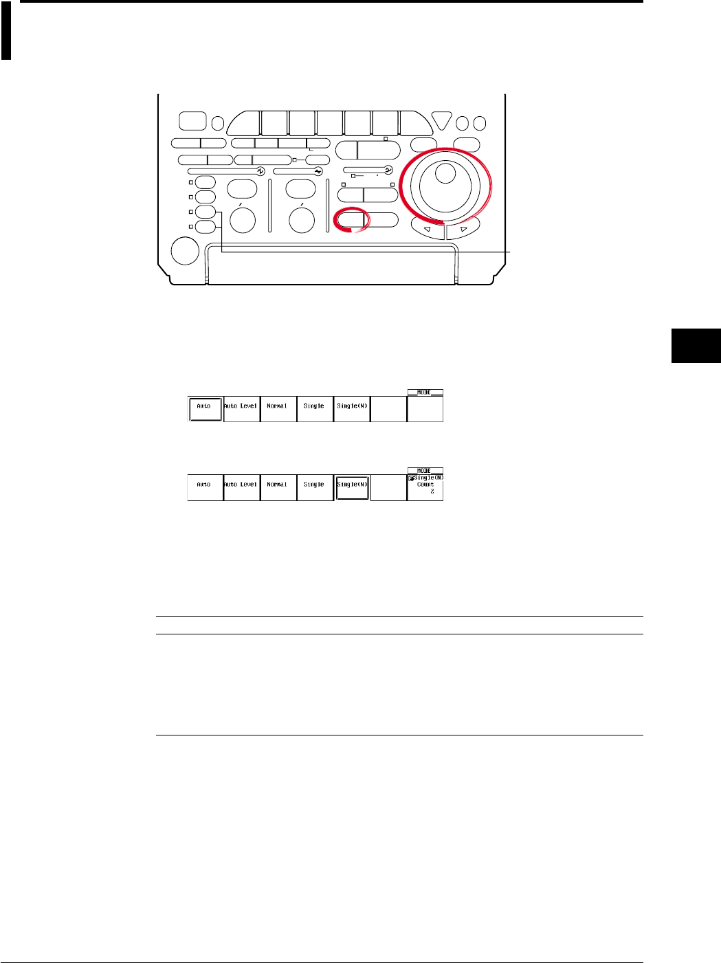
7-5
IM 701710-01E
Acquisition and Display
7
7.3 Using Sequential Store Function
<For a description of this function, refer to page 1-16>
Relevant Keys
ACTION DELAY
X - Y MENU MENU PHASE
SEARCH
HORIZONTAL
VERTICAL TRIGGER
TRIG D
HELP
ESC
SELECTRESET
SIMPLE
MODE POSITION
MATH
MISCFILE
CLEAR
TRACE
HISTORY
MEASURE
SETUP
PRESET
DISPLAY
CURSOR
CH
1
CH
2
CH
3
CH
4
POWER
COPY IMAGE SAVE SHIFT
ZOOM
GO/NO-GO
ENHANCED
ACQ START/STOP
SNAP
SHOT
V DIV TIME DIV
The DL1720 is not
equipped with
an input terminal
for CH3 or CH4.
Operating Procedure
Setting the Trigger Mode
1. Press MODE.
2. Press the Single(N) soft key to set the trigger mode to Single(N).
3. Turn the jog shuttle to set the Single(N) Count.
Explanation
By setting the trigger mode to Single(N), the sequential store function can be used.
Acquisition Count
Available numerical settings are as follows. The setting range varies according to the
record length.
Record Length Normal Mode Box Average Mode
1 kwords 1 to 256 (512) 1 to 128 (256)
10 kwords 1 to 32 (64) 1 to 16 (32)
50 kwords 1 to 8 (16) 1 to 4 (8)
100 kwords 1 to 4 (8) 1 to 2 (4)
250 kwords 1 to 2 (4) 1 to 1 (2)
500 kwords 1 (2) (1)
1 Mwords (1) –
* ( ) = This setting available only when interleave mode is ON.
Waveform Display Method
You can recall waveforms from memory in the same way as you do when working with
the history function. For details, refer to section 7.7, “Using the History Memory.”
Restrictions and Precautions
•You can not use this mode together with repetitive sampling or roll mode.
•If you stop waveform acquisition by pressing START/STOP, sequential storage also
stops. It then restarts again from the beginning when acquisition resumes.
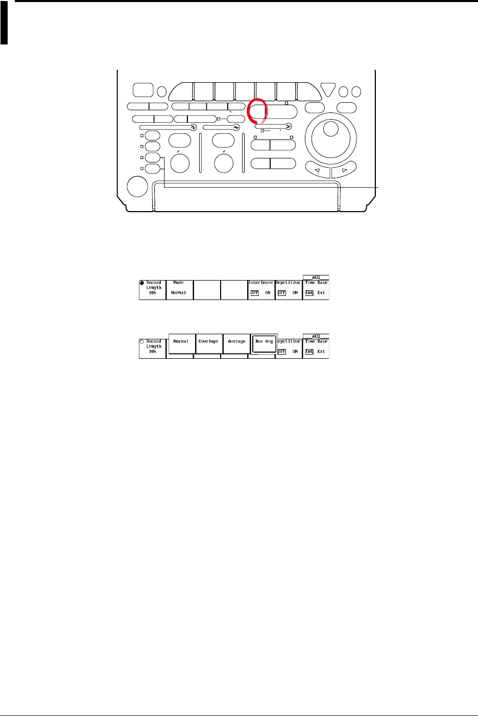
7-6 IM 701710-01E
7.4 Box Average Mode
<For a description of this function, refer to page 1-15>
Relevant Keys
ACTION DELAY
X - Y MENU MENU PHASE
SEARCH
HORIZONTAL
VERTICAL TRIGGER
TRIG D
HELP
ESC
SELECTRESET
SIMPLE
MODE POSITION
MATH
MISCFILE
CLEAR
TRACE
HISTORY
MEASURE
SETUP
PRESET
DISPLAY
CURSOR
CH
1
CH
2
CH
3
CH
4
POWER
COPY IMAGE SAVE SHIFT
ZOOM
GO/NO-GO
ENHANCED
ACQ START/STOP
SNAP
SHOT
V DIV TIME DIV
The DL1720 is not
equipped with
an input terminal
for CH3 or CH4.
Operating Procedure
1. Press ACQ.
2. Press the Mode soft key to display the acquisition mode menu.
3. Press the Box Avg soft key to select it.
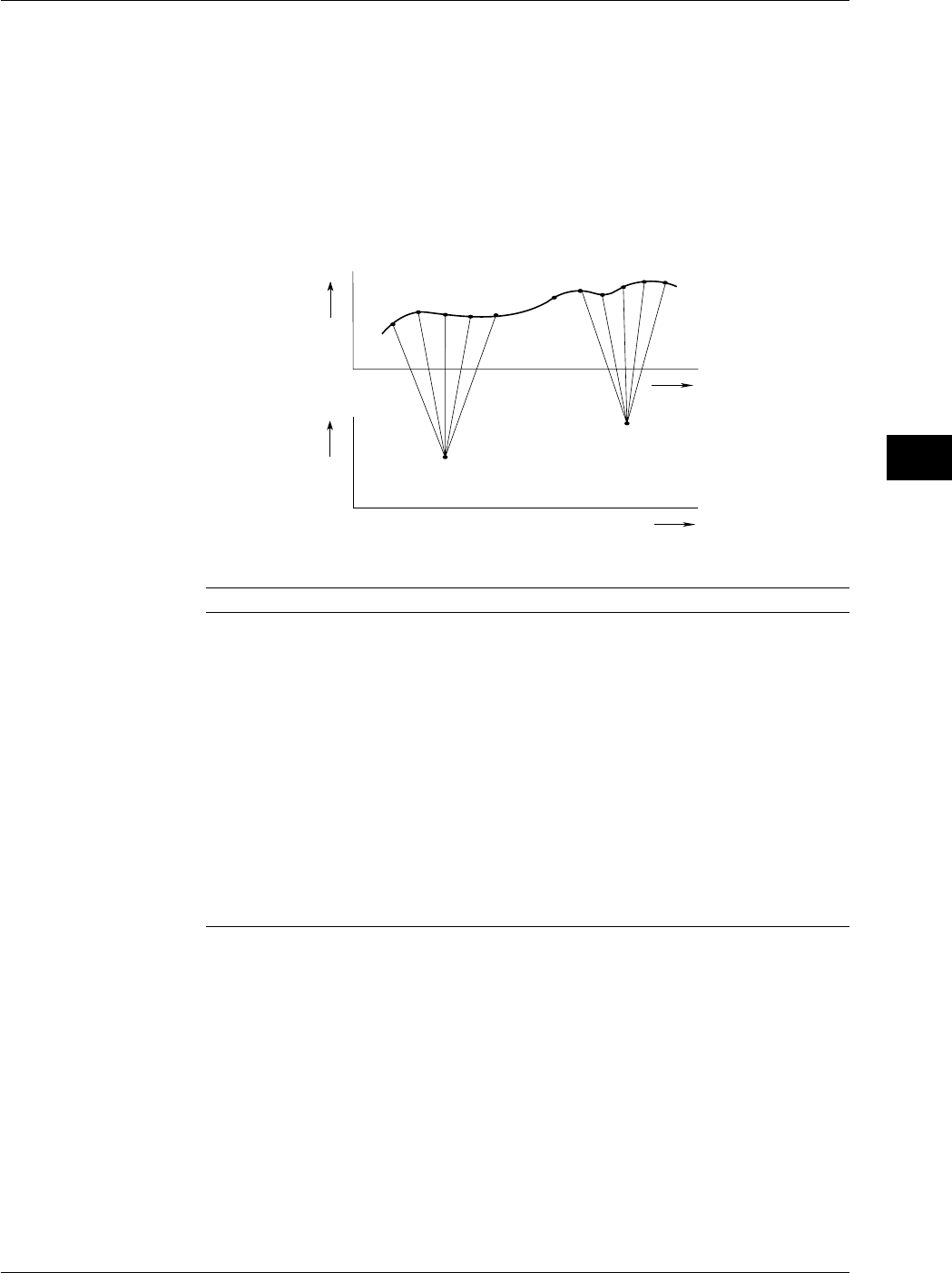
7-7
IM 701710-01E
Acquisition and Display
7
Explanation
Under most conditions the instrument samples the input signal at a true (internal)
sampling rate of 400 MS/s (1GS/s or 800 MS/s during interleave mode), extracts values
from this “sample stream” at the effective sample rate required by the T/div setting, and
writes the extracted values into the acquisition memory.
When you use box-average mode, however, the operation is different. Instead of pulling
values from the sample stream, the instrument computes average values for adjacent
groups of true sampling data, and writes the resulting averages into acquisition memory.
The following drawing illustrates the process.
Voltage
Time Axis
Time Axis
1220
a
21
Input Signal
(20 MS/s,
Interleave Mode
is OFF)
Box Averaging
Data
b
• • • • • •
36
• • • • •
• • •
Voltage
Data Samples Used for Averages
Interleave OFF Interleave ON
500 MS/s —2 points every 2 points of 1 GS/s
200 MS/s 2 points every 2 points of 400 MS/s 4 points every 4 points of 800 MS/s
100 MS/s 4 points every 4 points of 400 MS/s 8 points every 8 points of 800 MS/s
50 MS/s 8 points every 8 points of 400 MS/s 16 points every 20 points of 800
MS/s
20 MS/s 16 points every 20 points of 400 MS/s 32 points every 40 points of 800
MS/s
10 MS/s 32 points every 40 points of 400 MS/s 64 points every 80 points of 800
MS/s
5 MS/s 64 points every 80 points of 400 MS/s 128 points every 200 points of 800
MS/s
2 MS/s 128 points every 200 points of 400 MS/s 256 points every 400 points of 800
MS/s
1 MS/s 256 points every 400 points of 400 MS/s 256 points every 800 points of 800
MS/s
500 kS/s or less 256 points every 800* points of 400 MS/s 256 points every 1600* points of
800 MS/s
* Re-sampling interval is shifted by the sample rate. The maximum number of data points to
perform BoxAverage process is 256.
Record-Length Setting Limit
Not above 500 kWord (1 MWord with interleave ON)
Sampling-Rate Setting Limit
Not above 200 MS/s (or 500 MS/s with interleave ON).
If the sample rate exceeds 200 MS/s (500 MS/s when interleave is ON), the mode is set
to normal mode even if box average is specified.
7.4 Box Average Mode
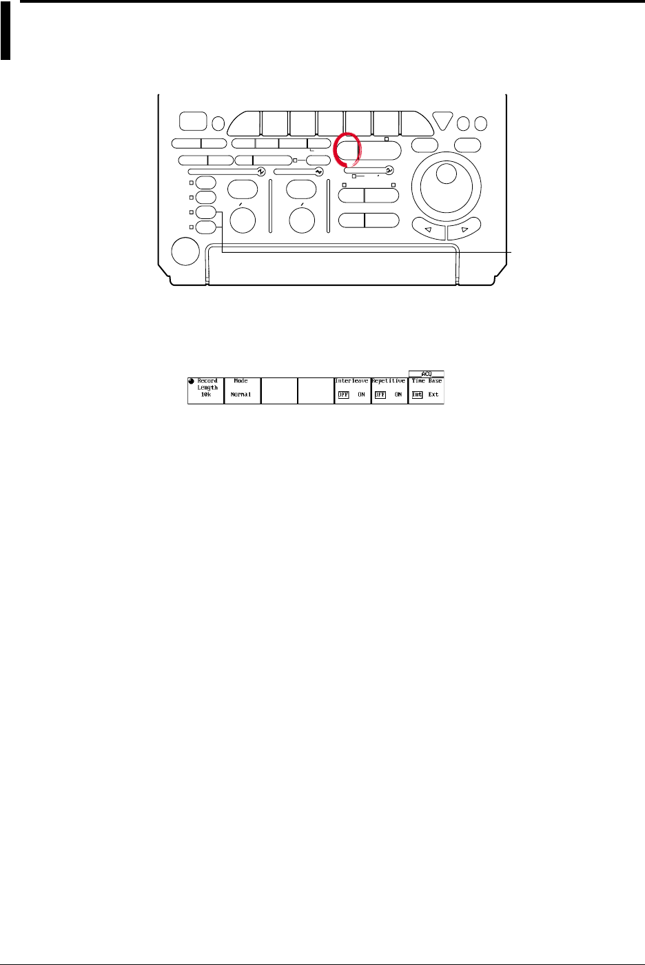
7-8 IM 701710-01E
7.5 Using Interleave Mode
<For a description of this function, refer to page 1-14>
Relevant Keys
ACTION DELAY
X - Y MENU MENU PHASE
SEARCH
HORIZONTAL
VERTICAL TRIGGER
TRIG D
HELP
ESC
SELECTRESET
SIMPLE
MODE POSITION
MATH
MISCFILE
CLEAR
TRACE
HISTORY
MEASURE
SETUP
PRESET
DISPLAY
CURSOR
CH
1
CH
2
CH
3
CH
4
POWER
COPY IMAGE SAVE SHIFT
ZOOM
GO/NO-GO
ENHANCED
ACQ START/STOP
SNAP
SHOT
V DIV TIME DIV
The DL1720 is not
equipped with
an input terminal
for CH3 or CH4.
Operating Procedure
1. Press ACQ.
2. Press the Interleave soft key to select ON or OFF.
Explanation
This mode doubles the amount of memory per channel, while cutting the number of
channels in half. In particular, this mode doubles the maximum settings for history
memory, sequential store, and record length, and allows you to set the realtime sampling
rate to 1 GS/s.
Setting interleave ON, however, disables CH2 and CH4 (or CH2 for the DL1720).
For details about restrictions on the sampling rate and record length while interleave is
ON, see appendix 1.
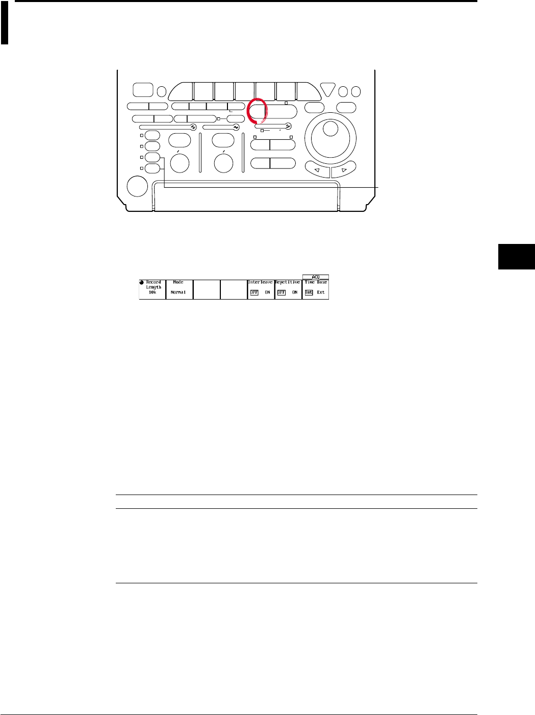
7-9
IM 701710-01E
Acquisition and Display
7
7.6 Setting Repetitive Sampling Mode ON/OFF
<For a description of this function, refer to pages 1-7 and 1-16>
Relevant Keys
ACTION DELAY
X - Y MENU MENU PHASE
SEARCH
HORIZONTAL
VERTICAL TRIGGER
TRIG D
HELP
ESC
SELECTRESET
SIMPLE
MODE POSITION
MATH
MISCFILE
CLEAR
TRACE
HISTORY
MEASURE
SETUP
PRESET
DISPLAY
CURSOR
CH
1
CH
2
CH
3
CH
4
POWER
COPY IMAGE SAVE SHIFT
ZOOM
GO/NO-GO
ENHANCED
ACQ START/STOP
SNAP
SHOT
V DIV TIME DIV
The DL1720 is not
equipped with
an input terminal
for CH3 or CH4.
Operating Procedure
1. Press ACQ.
2. Press the Repetitive soft key to select ON or OFF.
Explanation
You can select whether or not to use repetitive sampling. If the repetitive sampling mode
is ON, the sampling rate (for certain T/div settings) is set to 1 GS/s or above (2 GS/s or
above when the interleave mode is ON).
If repetitive sampling mode is OFF, the maximum available sampling rate is 500 MS/s (or
1 GS/s with interleave ON), and the instrument will add interpolation to the displayed
waveform if the number of display points is less than 500.
However, even if the repetitive sampling is turned OFF, the mode is set to repetitive
sampling depending on the time axis setting.
T/div for Repetitive Sampling
If repetitive mode is ON, the sampling mode is switched to repetitive sampling for T/div
settings as follows.
Available T/div setting varies according to the record length.
Record Length T/div
1 kwords 1 ns/div to 100 ns/div (1 ns/div to 50 ns/div)
10 kwords 1 ns/div to 1 ms/div (1 ns/div to 500 ns/div)
50 kwords 1 ns/div to 5 ms/div (1 ns/div to 2 ms/div)
100 kwords 1 ns/div to 10 ms/div (1 ns/div to 5 ms/div)
250 kwords 1 ns/div to 20 ms/div (1 ns/div to 10 ms/div)
500 kwords 1 ns/div to 50 ms/div (1 ns/div to 20 ms/div)
1 Mwords (1 ns/div to 50 ms/div)
* You cannot use repetitive sampling if the record length is set 500 kwords or above.
Values in parentheses above are available only if interleave mode is ON.
Restriction
During repetitive sampling, waveform acquisition is not possible when the trigger mode is
Single (N).
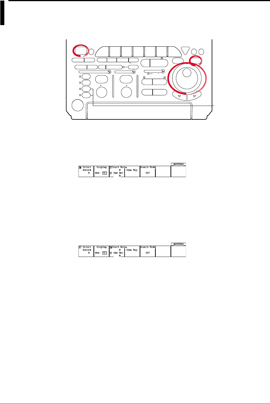
7-10 IM 701710-01E
7.7 Using the History Memory
<For a description of this function, refer to page 1-17>
Relevant Keys
ACTION DELAY
X - Y MENU MENU PHASE
SEARCH
HORIZONTAL
VERTICAL TRIGGER
TRIG D
HELP
ESC
SELECTRESET
SIMPLE
MODE POSITION
MATH
MISCFILE
CLEAR
TRACE
HISTORY
MEASURE
SETUP
PRESET
DISPLAY
CURSOR
CH
1
CH
2
CH
3
CH
4
POWER
COPY IMAGE SAVE SHIFT
ZOOM
GO/NO-GO
ENHANCED
ACQ START/STOP
SNAP
SHOT
V DIV TIME DIV
The DL1720 is not
equipped with
an input terminal
for CH3 or CH4.
Operating Procedure
Recalling Data from the History Memory
1. Press HISTORY.
2. Press the Select Record soft key.
3. Turn the jog shuttle to set the record number that you wish to recall.
Specify a record number in the range Start Rec to End Rec.
4. Press the Display Mode soft key to select One or All.
Go to step 5 if you selected All. Otherwise, go to step 8.
Setting the Accumulation Range (When Display Mode is All)
5. Press the Start Rec/End Rec soft key.
6. Turn the jog shuttle to set the first record number to be accumulated.
7. In a similar fashion, set the end record number (End Rec).
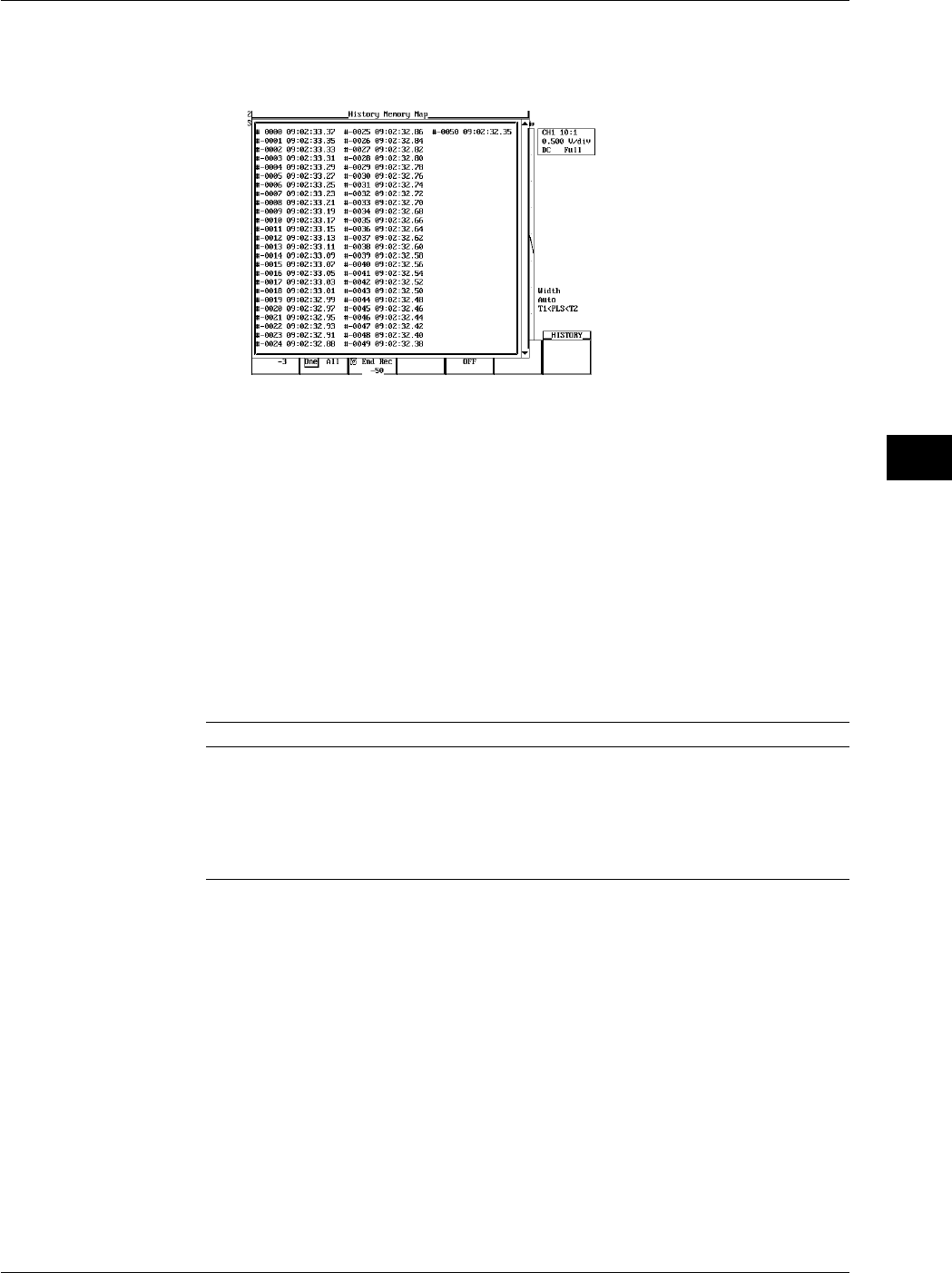
7-11
IM 701710-01E
Acquisition and Display
7
7.7 Using the History Memory
Display a List of Time Stamps
8. Pressing the Show Map soft key displays a list of acquired data numbers and the
time at acquisition end.
9. Turn the jog shuttle to select the waveform to be displayed and press SELECT.
Explanation
The acquisition memory retains waveform records generated by the most recent triggers.
If a trigger is activated beyond the number of triggers that can be held, the oldest
waveform data are cleared. Once the history becomes full, each new trigger causes loss
of the oldest waveform record in the memory.
Selected Record Number
You can display any waveform from the history by entering its record number. The
newest (current) waveform is Record 0, the immediately previous waveform is Record -1,
and so on. The range for Selected Record No. is therefore [0 to - (retained waveforms -
1)]. The number of retained waveforms (triggers) depends on the record length, as
follows.
Record Length Count
1 kwords 1 to 1024 (2048)
10 kwords 1 to 128 (256)
50 kwords 1 to 32 (64)
100 kwords 1 to 16 (32)
250 kwords 1 to 8 (16)
500 kwords 1 to 4 (8)
1 Mwords 1 to 2 (4)
* For each count of the trigger, only the displayed waveform is preserved; past waveform data is
not preserred.
( ) = The setting range when interleave mode is ON.
When performing box averaging, the available setting range is 250 kwords or less (or 500
kwords or less with interleave mode ON).
Display
•Set to One to display the selected record only.
Select the waveform to be displayed using Select Record from the specified range
between Start Rec and End Rec.
•Set to All to generate overlapped display of all history records from the Start Rec No.
to the End Rec No. The waveform corresponding to the Selected Record No. will
appear brighter than the other waveforms.

7-12 IM 701710-01E
Show Map (A List of Time Stamps)
You can list the number of the waveform data stored in the acquisition memory and the
time at acquisition end.
One screen displays 75 data points of information. You can scroll through the data by
using the jog shuttle.
Precautions and Restrictions
•You cannot use the history function while the acquisition mode is set to Average.
(Displayed history records will be meaningless.)
•The history memory function cannot be used in repetitive sampling mode.
•If you suspend waveform acquisition before the current record has been fully read, the
record will not be recorded in the history.
•You cannot use the history function while roll mode is selected.
•History records are not lost when waveform acquisition is stopped and then restarted,
provided that acquisition conditions remain unchanged.
•If you change the acquisition settings, history memory is cleared when you restart
acquisition using the new settings.
•If CLEAR TRACE is pressed during waveform acquisition or after the waveform
acquisition is stopped, data in the history memory are cleared when the data
acquisition is restarted.
Precautions to be Taken when Recalling Data from the History Memory
•Acquisition will stop when the history memory menu is displayed. It is not possible to
recall waveform data from the history memory while acquisition in progress.
•Acquisition can be restarted while the history memory menu is displayed. However, it
is not possible to change history memory settings such as Selected Record No., while
acquisition is in progress.
•Settings are restricted by the following formula.
End Rec No. ≤ Selected Record No. ≤ Start Rec No.
•If you load a waveform record from floppy disk, or external storage device, the loaded
waveform becomes Record 0. In the case of multiple records (sequential store), the
records will be loaded sequentially, with the latest record as 0.
•Computation and automatic measurement of waveform parameters are always
performed on the currently displayed waveform, i.e. the waveform identified by the
record No. designated for Selected Record No. Analysis of old data is possible as
long as the history memory content remains unchanged after acquisition is restarted.
•In roll mode only the record most recently acquired when acquisition was stopped will
be loaded into record No. 0.
•Time at acquisition end is displayed under Show map.
•Turning OFF the power will delete the entire contents of the history memory.
7.7 Using the History Memory
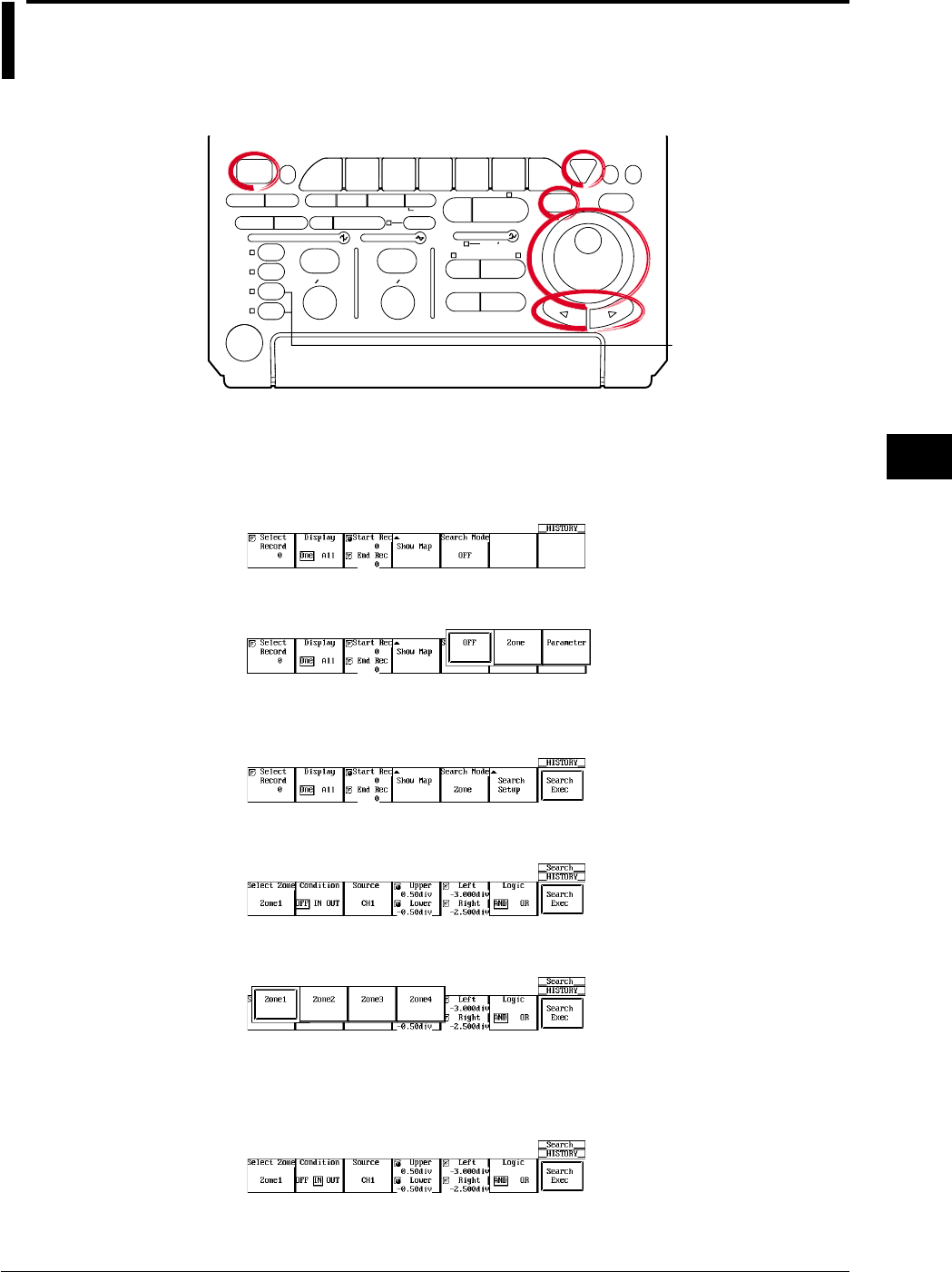
7-13
IM 701710-01E
Acquisition and Display
7
7.8 Searching the Historical Data Using Zone
(History Search Function)
<For a description of this function, refer to page 1-26>
Relevant Keys
ACTION DELAY
X - Y MENU MENU PHASE
SEARCH
HORIZONTAL
VERTICAL TRIGGER
TRIG D
HELP
ESC
SELECTRESET
SIMPLE
MODE POSITION
MATH
MISCFILE
CLEAR
TRACE
HISTORY
MEASURE
SETUP
PRESET
DISPLAY
CURSOR
CH
1
CH
2
CH
3
CH
4
POWER
COPY IMAGE SAVE SHIFT
ZOOM
GO/NO-GO
ENHANCED
ACQ START/STOP
SNAP
SHOT
V DIV TIME DIV
The DL1720 is not
equipped with
an input terminal
for CH3 or CH4.
Operating Procedure
Selecting the Search Mode
1. Press HISTORY.
2. Pressing the Search Mode soft key displays the search mode selection menu.
3. Press the Zone soft key .
Selecting the Search Zone (Select Zone)
4. Pressing the Search Setup soft key displays the search condition setting menu.
5. Press the Select Zone soft key to display the search condition selection menu.
6. Press one of the soft keys corresponding to Zone1 to Zone4.
Setting the Search Conditions (Condition)
7. Press the Condition soft key several times to select OFF, IN, or OUT. Selecting
IN or OUT displays a search window in the area displaying the Source channel.
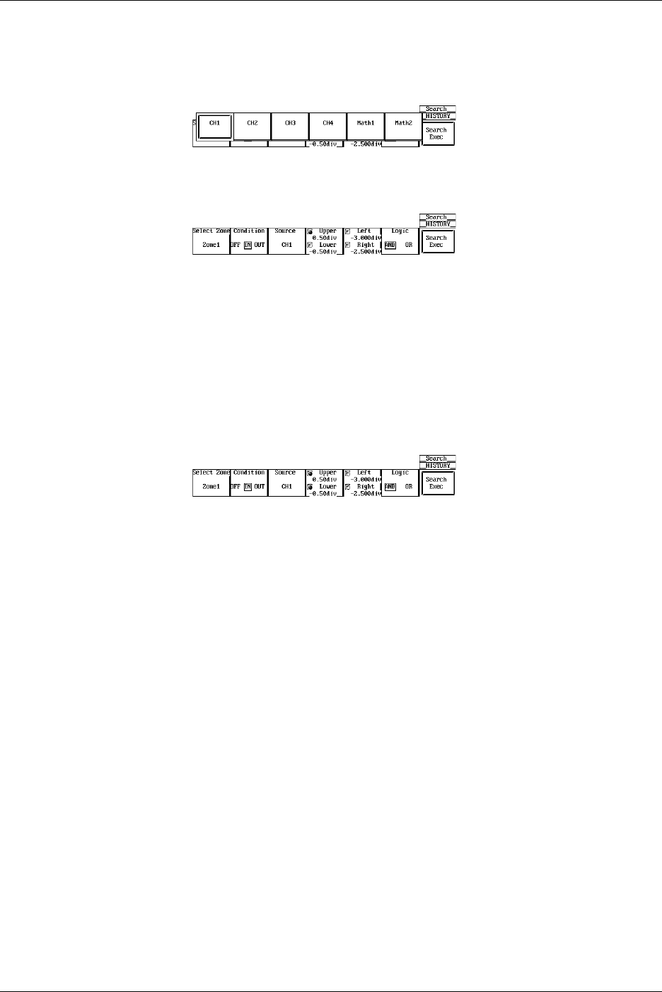
7-14 IM 701710-01E
Setting the Source Channel (Source)
8. Pressing the Source soft key displays the source channel selection menu.
9. Press the soft key corresponding to the desired channel to select the source
channel. (The CH3, CH4, and Math2 soft keys are not displayed on the DL1720.)
Setting the Search Window
10. Press the Upper Lower soft key.
11. Turn the jog shuttle to set the top of the search range.
You can use the arrow keys to move between the digits.
Pressing RESET resets the value to the default value.
12. Press the Upper Lower soft key.
13. Turn the jog shuttle to set the end of the search range.
You can use the arrow keys to move between the digits.
Pressing RESET resets the value to the default value.
14. By controlling both Upper and Lower using the jog shuttle, you can move the
search window up and down without changing the vertical width.
15. In a similar fashion, set the horizontal range of the search window.
16. Repeat steps 6 to 15 to set Zone1 to Zone4.
Setting the Logic
17. Press the Logic soft key to select AND or OR.
Executing the Search
18. Press the Search Exec soft key to execute the search.
7.8 Searching the Historical Data Using Zone (History Search Function)
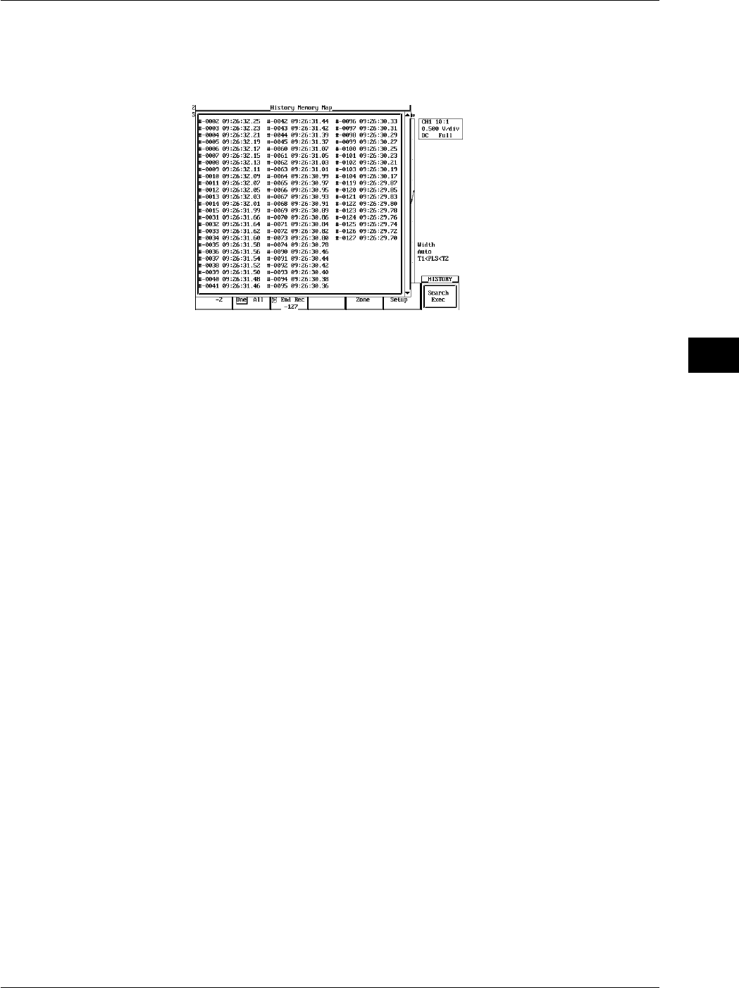
7-15
IM 701710-01E
Acquisition and Display
7
Displaying the Waveforms that are Found
19. Press ESC to return to the HISTORY menu.
20. Press the Show Map soft key to display a list of the numbers of the acquired
waveform data and time at acquisition end.
21. Turn the jog shuttle to select the waveform to be displayed and press SELECT.
Resetting the Search Results
22. Select HISTORY > Search Mode > OFF or turn OFF Zone 1 to Zone 4 and execute
the search to reset the search results.
Explanation
You can search for a waveform that matches the specified conditions from the past
waveforms in the acquisition memory and display it.
Search Parameters
Four types of search parameters can be registered in Zone1 to Zone4. You can change
the channel that is to be searched, the search condition, and the search range for each
search zone.
Search Condition: Condition
IN: Searches for waveforms that pass through the specified search window.
OUT: Searches for waveforms that do not pass through the specified window.
OFF: Do not search for waveforms.
Source Channel: Source
Search is carried out on the channel that is specified as the Source. Waveforms of other
channels are also displayed.
The Vertical Range of the Search Window (Upper/Lower)
The range is ±4 div. The resolution is 0.01 div.
Upper must always be greater than or equal to Lower.
The Horizontal Range of the Search Window (Left/Right)
The range is ±5 div. The resolution is (10 div/displayed record length).
Right must always be greater than or equal to left.
Search Logic: Logic
AND: Searches for waveforms that meet all search conditions from Zone1 to Zone4.
OR: Searches for waveforms that meet any one of the search conditions from Zone1
to Zone4.
7.8 Searching the Historical Data Using Zone (History Search Function)

7-16 IM 701710-01E
Search Range of the Historical Data
The search range is between the Start Rec and the End Rec.
Search Order
The search is carried out from the newest waveform to the oldest waveform.
Show Map (A List of Time Stamps)
Only the waveforms that are found are displayed in Show Map. If the Search Mode is
turned OFF, all waveforms are displayed.
7.8 Searching the Historical Data Using Zone (History Search Function)
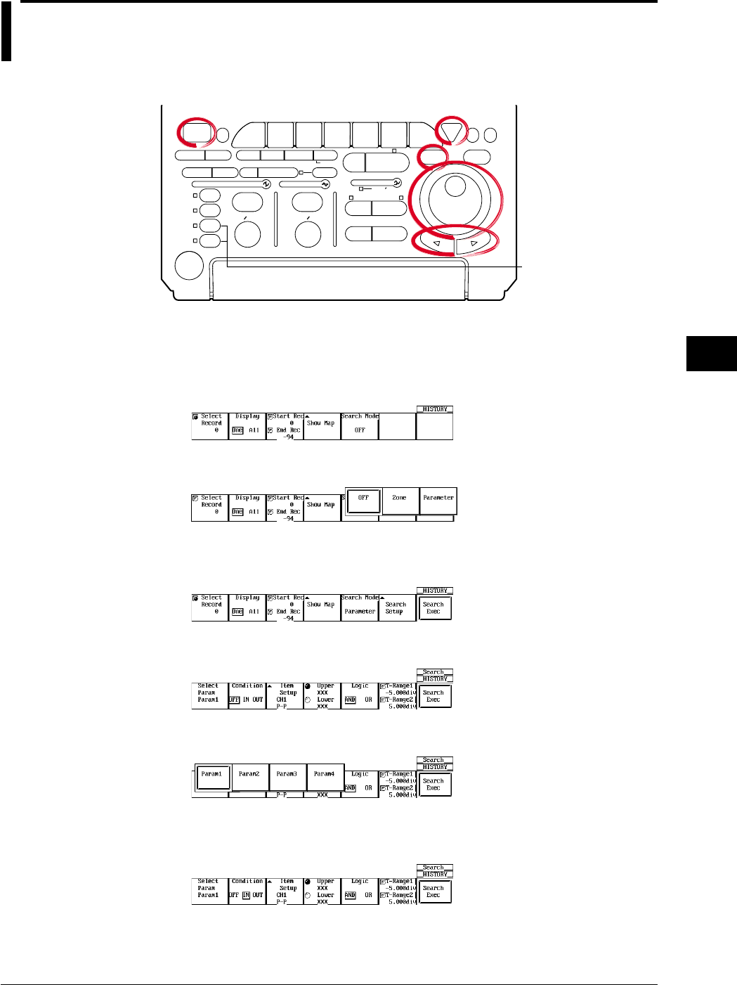
7-17
IM 701710-01E
Acquisition and Display
7
7.9 Searching the Historical Data Using
Parameters (History Search Function)
<For a description of this function, refer page 1-26>
Relevant Keys
ACTION DELAY
X - Y MENU MENU PHASE
SEARCH
HORIZONTAL
VERTICAL TRIGGER
TRIG D
HELP
ESC
SELECTRESET
SIMPLE
MODE POSITION
MATH
MISCFILE
CLEAR
TRACE
HISTORY
MEASURE
SETUP
PRESET
DISPLAY
CURSOR
CH
1
CH
2
CH
3
CH
4
POWER
COPY IMAGE SAVE SHIFT
ZOOM
GO/NO-GO
ENHANCED
ACQ START/STOP
SNAP
SHOT
V DIV TIME DIV
The DL1720 is not
equipped with
an input terminal
for CH3 or CH4.
Operating Procedure
Select the Search Mode
1. Press HISTORY.
2. Press the Search Mode soft key to display the search mode selection menu.
3. Press the Parameter soft key.
Select the Search Criteria (Select Param)
4. Press the Search Setup soft key to display the Search Criteria Setting menu.
5. Press the Select Param soft key to display the search criteria selection menu.
6. Press one of the soft keys for Param1 - Param4 to select the search criterion.
Setting the Condition
7. Press the Condition soft key to select OFF, IN, or OUT.
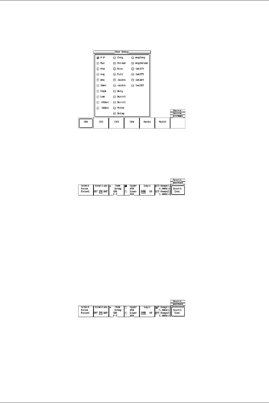
7-18 IM 701710-01E
Setting the Parameter (Item Setup)
8. Press the Item Setup soft key to display the parameter selection menu.
9. Press the soft key corresponding to the channel that you wish to set as the source
channel for the parameter search. (The CH3, CH4, and Math2 soft keys are not
displayed on the DL1720.)
10. Use the jog shuttle to highlight the parameter to be used in the search, then press
SELECT to assign the parameter to the channel.
Set the Condition Range
11. Press the Upper Lower soft key to highlight the Upper jog shuttle icon.
12. Turn the jog shuttle to set the upper edge of the condition range. Use the arrow
keys to move between the digits. Press RESET to return to the initial value (XXX).
13. Press the Upper Lower soft key to highlight the Lower jog shuttle icon.
14. Turn the jog shuttle to set the lower edge of the condition range. Use the arrow
keys to move between the digits. Press RESET to return to the initial value (XXX).
15. Repeat steps 6 - 14 to set Param1 through Param4.
Setting the Logic
16. Press the Logic soft key to select AND or OR.
Setting the Parameter Measuring Range
17. Press the T-Range1/T-Range2 soft key to highlight T-Range1.
18. Turn the jog shuttle to set the left edge of the measuring range. Use the arrow
keys to move between the digits. Press RESET to return to the initial value (XXX).
19. Press the T-Range1/T-Range2 soft key to highlight T-Range2.
20. Turn the jog shuttle to set the right edge of the measuring range. Use the arrow
keys to move between the digits. Press RESET to return to the initial value (XXX).
7.9 Searching the Historical Data Using Parameters (History Search Function)
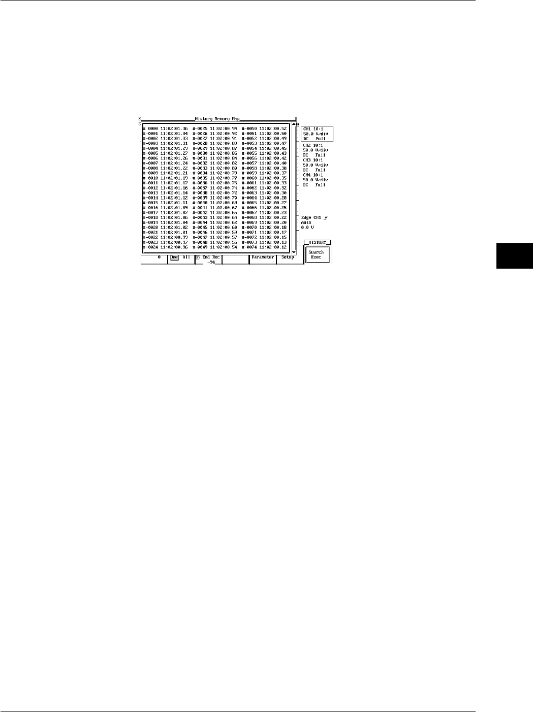
7-19
IM 701710-01E
Acquisition and Display
7
Executing the Search
21. Press the Searchexaec soft key to execute the search.
Displaying the Searched Waveform
22. Press ESC to return to the HISTORY menu.
23. Press the Show Map soft key to display a list of the numbers of the searched
waveform data and time at acquisition end.
24. Turn the jog shuttle to select the waveform to be displayed and press SELECT.
Resetting the Search Results
25. If you set the Search Mode to OFF in the HISTORY menu, or if you perform a
search with all of the parameters (Param1-Param4) set to OFF, the search results
will be reset.
Explanation
Search for waveforms from the history memory function and display only the waveforms
that fulfill specified conditions of particular parameters.
Search Criterion
You can store various kinds of search criteria in Param1-Param4. Within those four
search criteria, you can specify the channel to be searched, the search conditions, and
the searching range.
Condition
IN: Search for a waveform entering the specified range of the specified parameter.
OUT: Search for a waveform extending outside the specified range of the specified
parameter.
OFF: Do not search for a waveform.
Item Setup
Assign search parameters to each source channel. Choose (only) one of the automated
waveform measurement parameters.
Condition Range (Upper/Lower)
Set the range that defines the specified parameter’s condition.
Logic Search
AND: Search for waveforms fulfilling all of the search criterion in Param1- Param4.
OR: Search for waveforms fulfilling at least one of the search criterion in Param1-
Param4.
7.9 Searching the Historical Data Using Parameters (History Search Function)

7-20 IM 701710-01E
Parameter Measuring Range (T-Range1/T-Range2)
Set the measuring range of the specified parameter. This is the portion of the waveform
used to determine the values of the parameter.
Search Range of the Historical Data
The search range extends from the Start Rec to the End Rec.
Search Method
Search in order starting with the newest waveform.
Show Map (Timestamp List)
Only searched waveforms are displayed in Show map. When Search Mode is OFF, all
waveforms are displayed.
7.9 Searching the Historical Data Using Parameters (History Search Function)
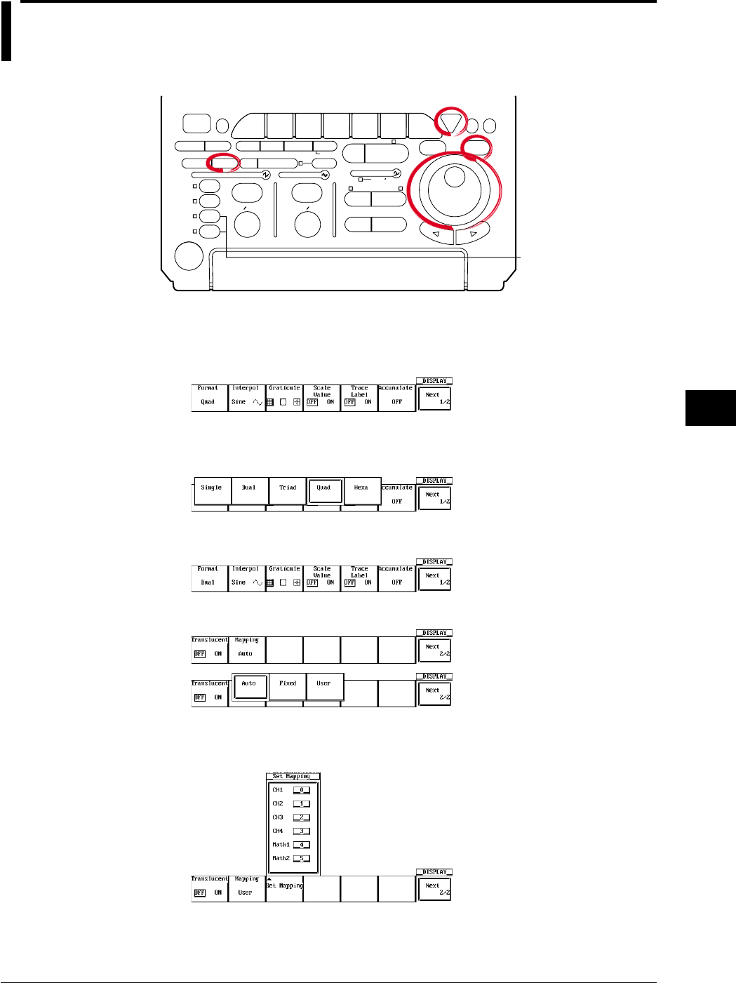
8-1
IM 701710-01E
Display
8
8.1 Changing the Display Format
<For a description of this function, refer to page 1-17>
Relevant Keys
ACTION DELAY
X - Y MENU MENU PHASE
SEARCH
HORIZONTAL
VERTICAL TRIGGER
TRIG D
HELP
ESC
SELECTRESET
SIMPLE
MODE POSITION
MATH
MISCFILE
CLEAR
TRACE
HISTORY
MEASURE
SETUP
PRESET
DISPLAY
CURSOR
CH
1
CH
2
CH
3
CH
4
POWER
COPY IMAGE SAVE SHIFT
ZOOM
GO/NO-GO
ENHANCED
ACQ START/STOP
SNAP
SHOT
V DIV TIME DIV
The DL1720 is not
equipped with
an input terminal
for CH3 or CH4.
Operating Procedure
1. Press DISPLAY.
2. Pressing the Format soft key displays the format menu.
3. Press the soft key corresponding to the desired format. (Quad and Hexa are not
displayed on the DL1720.)
4. Press the Next 1/2 soft key to display the Next 2/2 menu.
Press the Mapping soft key to select Auto, Fixed, or User.
5. Pressing the Set Mapping soft key displays a menu used to assign the waveforms.
(On the DL1720, the CH3, CH4, and Math2 settings are not displayed.)
Chpater 8 Display
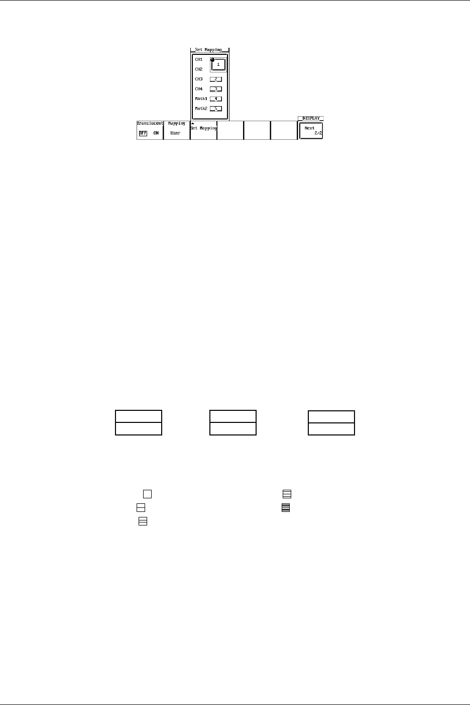
8-2 IM 701710-01E
6. Turn the jog shuttle to move the cursor to the desired channel.
7. Pressing SELECT displays a menu used to set the number.
8. Turn the jog shuttle to select a number. Pressing ESC closes the menu.
9. Repeat steps 5 to 7 as necessary.
Explanation
Main Format
Single: 1 waveform window Quad: 4 waveform windows (DL1740 only)
Dual: 2 waveform windows Hexa: 6 waveform windows (DL1740 only)
Triad: 3 waveform windows
Mapping
Auto*1: Windows are arranged from top to bottom in order: CH1, CH2,..., Math1, Math2.
But no windows are shown for channels whose display is set to OFF.
Fixed*1: Channels are displayed, regardless of whether their display setting is ON or
OFF, in order of channel number. The Math2 window is at the bottom with the
Math1 window directly above it.
User*1: Assign numbers from 0 to 5 to CH1, CH2, ..., Math1, and Math2. The display
position varies depending on the assigned numbers.
*1 The DL1720 is not equipped with channels 3, 4, or Math2.
Assignment Example when the Display Format is Set to Dual
CH1, CH4
CH2,
Auto (If CH3 = OFF)
0, 2, 4
1, 3, 5
User
CH1,
CH2, CH4
Fixed (If CH3 = OFF)
The number of points that can be displayed vertically for each channel varies as follows
according to the display format. However, the vertical resolution remains unchanged.
Single( ): 384 points Quad( ): 96 points
Dual( ): 192 points Hexa( ): 64 points
Triad( ): 128 points
8.1 Changing the Display Format
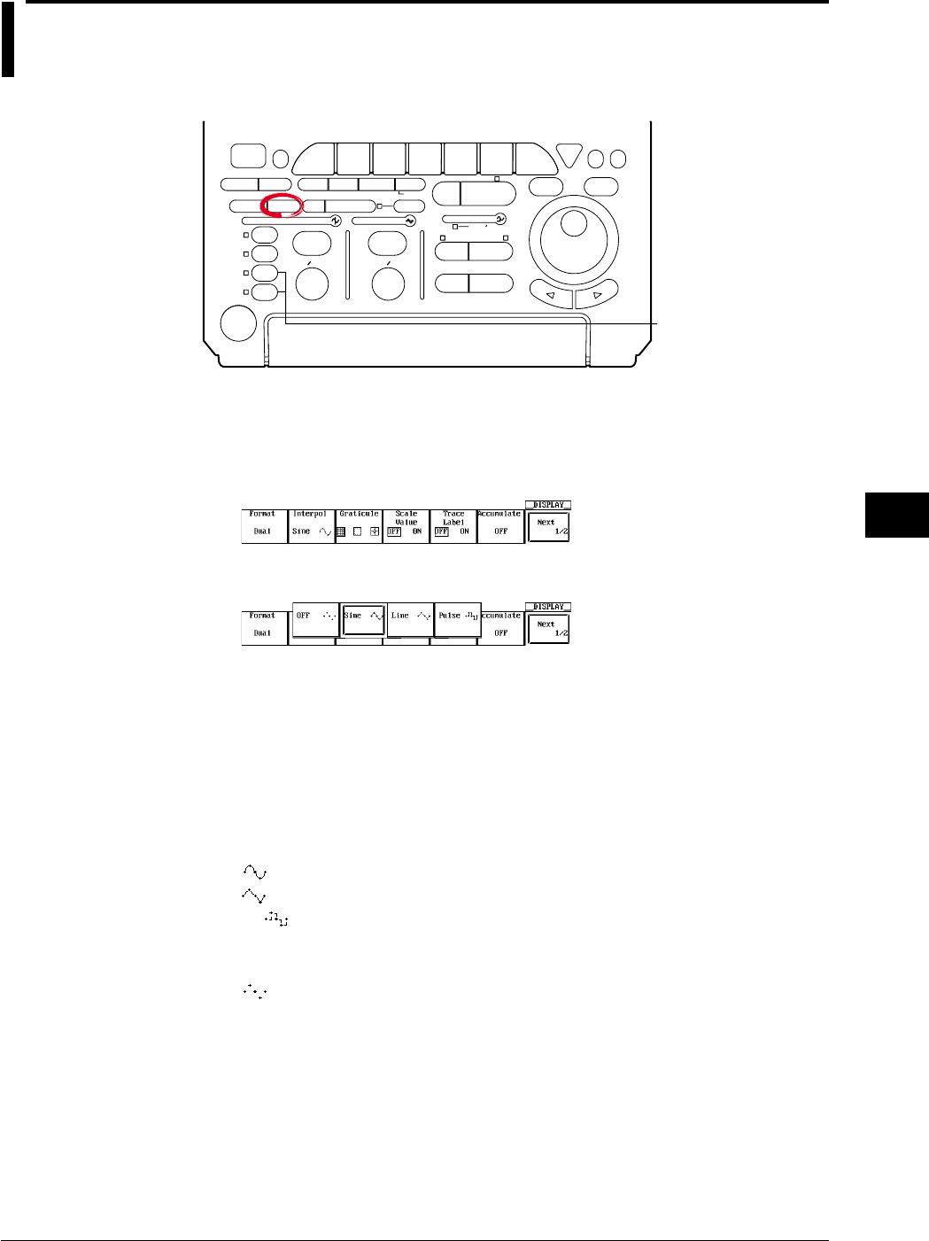
8-3
IM 701710-01E
Display
8
8.2 Setting the Interpolation Method
<For a description of this function, refer to page 1-18>
Relevant Keys
ACTION DELAY
X - Y MENU MENU PHASE
SEARCH
HORIZONTAL
VERTICAL TRIGGER
TRIG D
HELP
ESC
SELECTRESET
SIMPLE
MODE POSITION
MATH
MISCFILE
CLEAR
TRACE
HISTORY
MEASURE
SETUP
PRESET
DISPLAY
CURSOR
CH
1
CH
2
CH
3
CH
4
POWER
COPY IMAGE SAVE SHIFT
ZOOM
GO/NO-GO
ENHANCED
ACQ START/STOP
SNAP
SHOT
V DIV TIME DIV
The DL1720 is not
equipped with
an input terminal
for CH3 or CH4.
Operating Procedure
Set the Interpolation Method
1. Press DISPLAY.
2. Press the Interpol soft key to display the interpolation method menu.
3. Press the soft key corresponding to the desired interpolation method.
Explanation
Interpolate
Any area along the time axis having less than 500 points per 10 divisions (less than 250
points in the Z1 and Z2 window when displaying Main & Z1 & Z2) is recognized as an
interpolation area. If you leave interpolation off, these points will appear as discrete dots
(so that the display will show gaps between dots or vertical lines). If you set interpolation
on, however, the DL1720/DL1740 will connect the points. Three interpolation settings
are available.
Sine ( ): Interpolates between two dots using a sin x/x function.
Line ( ): Interpolates between two dots in a straight line.
PULSE ( ): Draws a horizontal line to a point directly above or below the next data
point and then interpolates using two dots so that the end of the
horizontal line is connected to the next data point by a vertical line.
OFF ( ): No interpolation
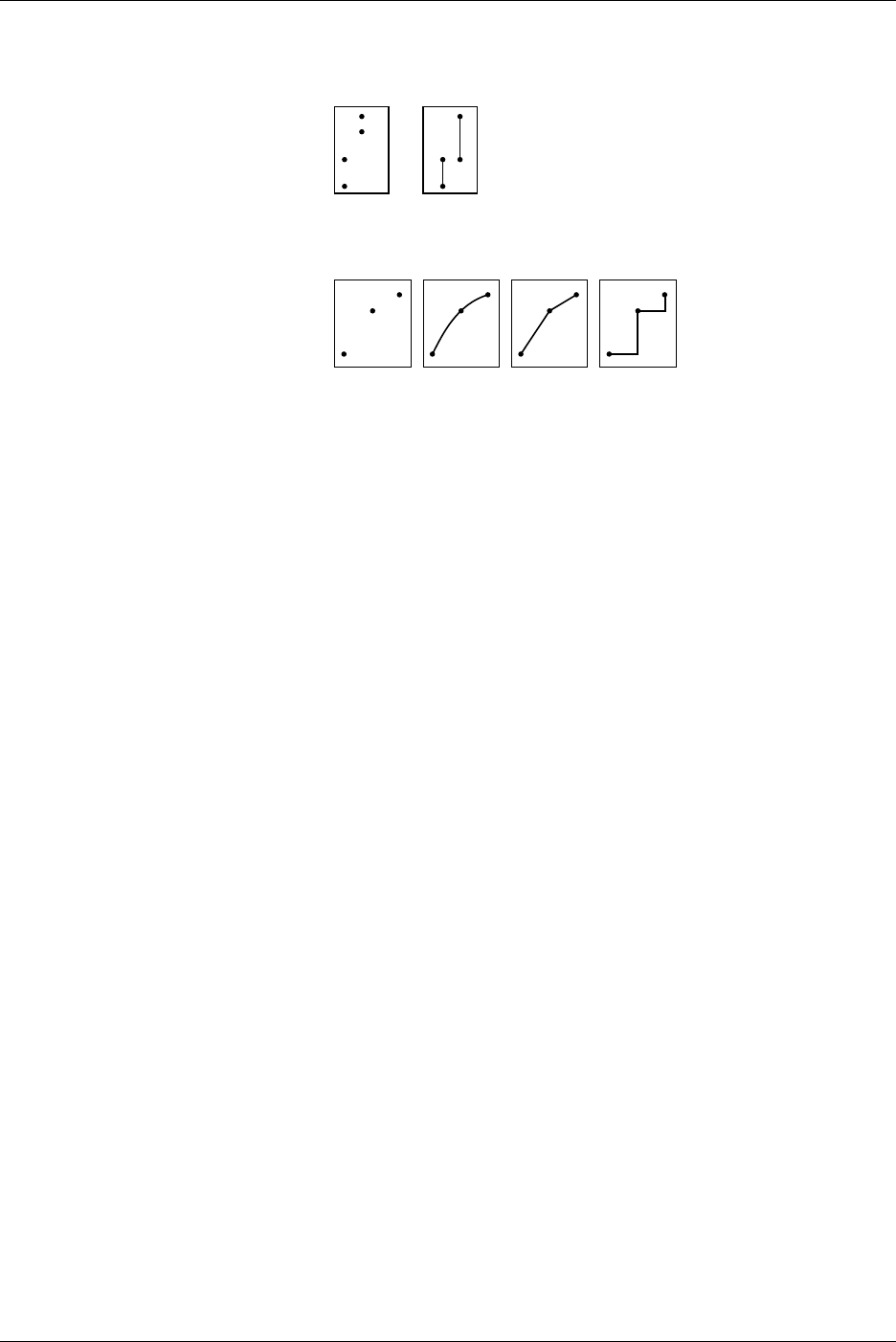
8-4 IM 701710-01E
Outside the Interpolation Area
If interpolation is set to Sine, Line, or Pulse the instrument draws lines between points
that are aligned vertically.
Interpolate OFF Sine/Line/Pulse:
Within the Interpolation Area
Interpolate OFF: Sine Line Pulse
8.2 Setting the Interpolation Method
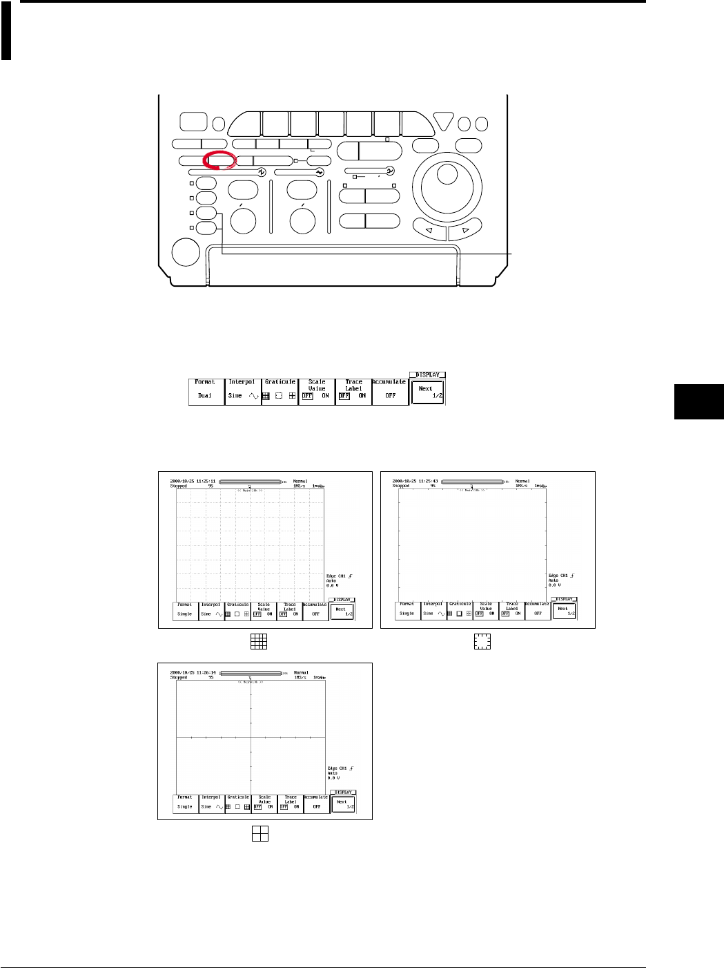
8-5
IM 701710-01E
Display
8
8.3 Changing the Graticule
<For a description of this function, refer to page 1-17>
Relevant Keys
ACTION DELAY
X - Y MENU MENU PHASE
SEARCH
HORIZONTAL
VERTICAL TRIGGER
TRIG D
HELP
ESC
SELECTRESET
SIMPLE
MODE POSITION
MATH
MISCFILE
CLEAR
TRACE
HISTORY
MEASURE
SETUP
PRESET
DISPLAY
CURSOR
CH
1
CH
2
CH
3
CH
4
POWER
COPY IMAGE SAVE SHIFT
ZOOM
GO/NO-GO
ENHANCED
ACQ START/STOP
SNAP
SHOT
V DIV TIME DIV
The DL1720 is not
equipped with
an input terminal
for CH3 or CH4.
Operating Procedure
1. Press DISPLAY.
2. Press the Graticule soft key to select one of the three graticule types.
Explanation
The graticule type can be selected from the following 3 types.
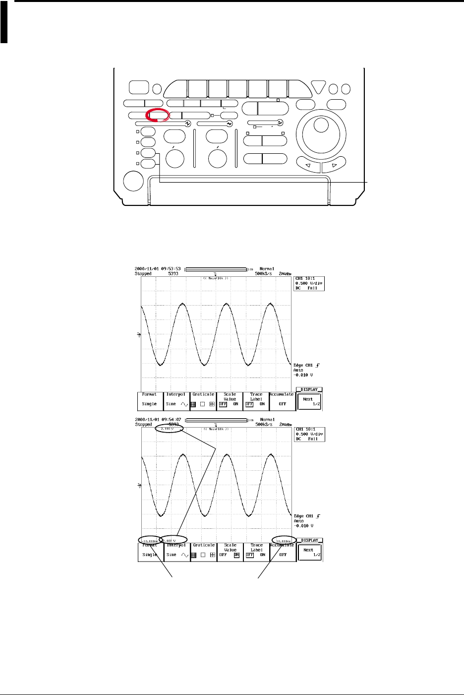
8-6 IM 701710-01E
8.4 Turning Display of the Scaling Value ON/OFF
<For a description of this function, refer to page 1-17>
Relevant Keys
ACTION DELAY
X - Y MENU MENU PHASE
SEARCH
HORIZONTAL
VERTICAL TRIGGER
TRIG D
HELP
ESC
SELECTRESET
SIMPLE
MODE POSITION
MATH
MISCFILE
CLEAR
TRACE
HISTORY
MEASURE
SETUP
PRESET
DISPLAY
CURSOR
CH
1
CH
2
CH
3
CH
4
POWER
COPY IMAGE SAVE SHIFT
ZOOM
GO/NO-GO
ENHANCED
ACQ START/STOP
SNAP
SHOT
V DIV TIME DIV
The DL1720 is not
equipped with
an input terminal
for CH3 or CH4.
Operating Procedure
1. Press DISPLAY.
2. Press the Scale Value soft key to select ON or OFF.
Scale Value of Vertical Axis
Scale Value of Time Axis
Explanation
You can display the upper and lower limits of the vertical axis or the axis horizontal of
each channel.
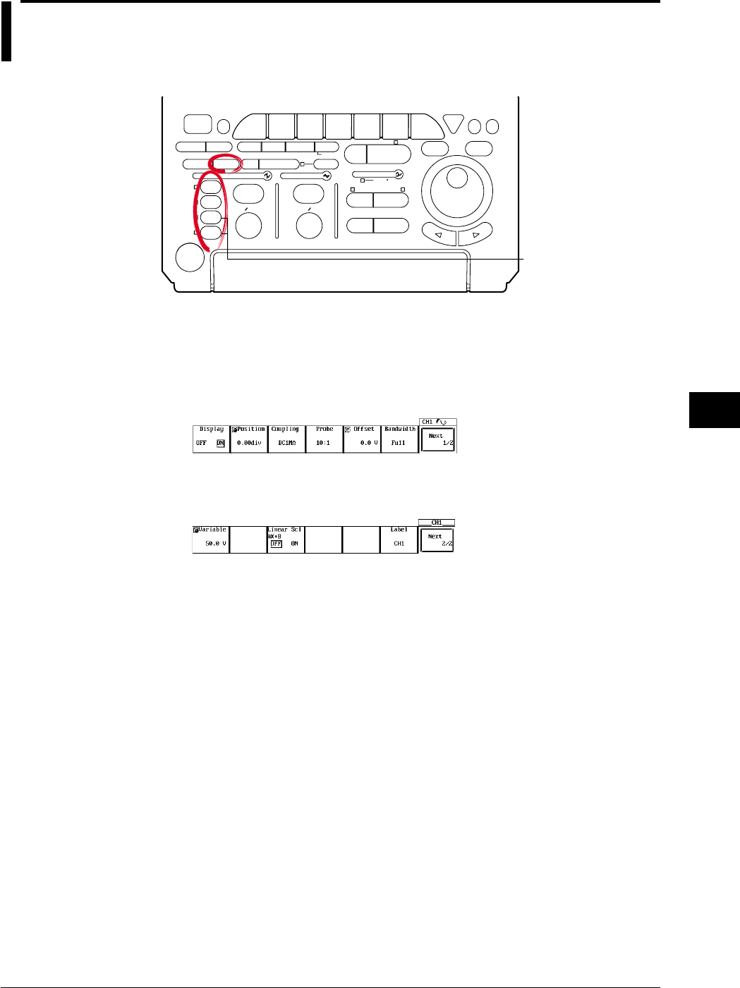
8-7
IM 701710-01E
Display
8
8.5 Setting the Waveform Labels
<For a description of this function, refer to page 1-18>
Relevant Keys
ACTION DELAY
X - Y MENU MENU PHASE
SEARCH
HORIZONTAL
VERTICAL TRIGGER
TRIG D
HELP
ESC
SELECTRESET
SIMPLE
MODE POSITION
MATH
MISCFILE
CLEAR
TRACE
HISTORY
MEASURE
SETUP
PRESET
DISPLAY
CURSOR
CH
1
CH
2
CH
3
CH
4
POWER
COPY IMAGE SAVE SHIFT
ZOOM
GO/NO-GO
ENHANCED
ACQ START/STOP
SNAP
SHOT
V DIV TIME DIV
The DL1720 is not
equipped with
an input terminal
for CH3 or CH4.
Operating Procedure
Setting the Waveform Label
1. Press one of the keys from CH 1 to CH 4 (or CH 1 to CH 2 for the DL1720) to
select the desired channel.
2. Press the Next 1/2 soft key to display the Next 2/2 menu.
3. Press the Label soft key to display a keyboard, and enter the waveform label
according to the procedures described in section 4.1.
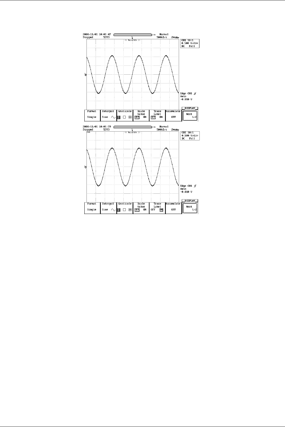
8-8 IM 701710-01E
Turning ON/OFF the Waveform Label
4. Press DISPLAY.
5. Press the Trace Label soft key to select ON or OFF.
Explanation
Label Display ON/OFF (Trace Label)
Use this parameter to select whether or not to include waveform labels (channel
identification labels) on the display.
Entering Customized Labels
You can use the Define Label feature to enter customized labels for each channel. Each
label is a character string of up to eight alphanumerics. You can set the label display
ON/OFF using the Trace Label function; the label appears in the scale-value display and
with measurement results.
8.5 Setting the Waveform Labels
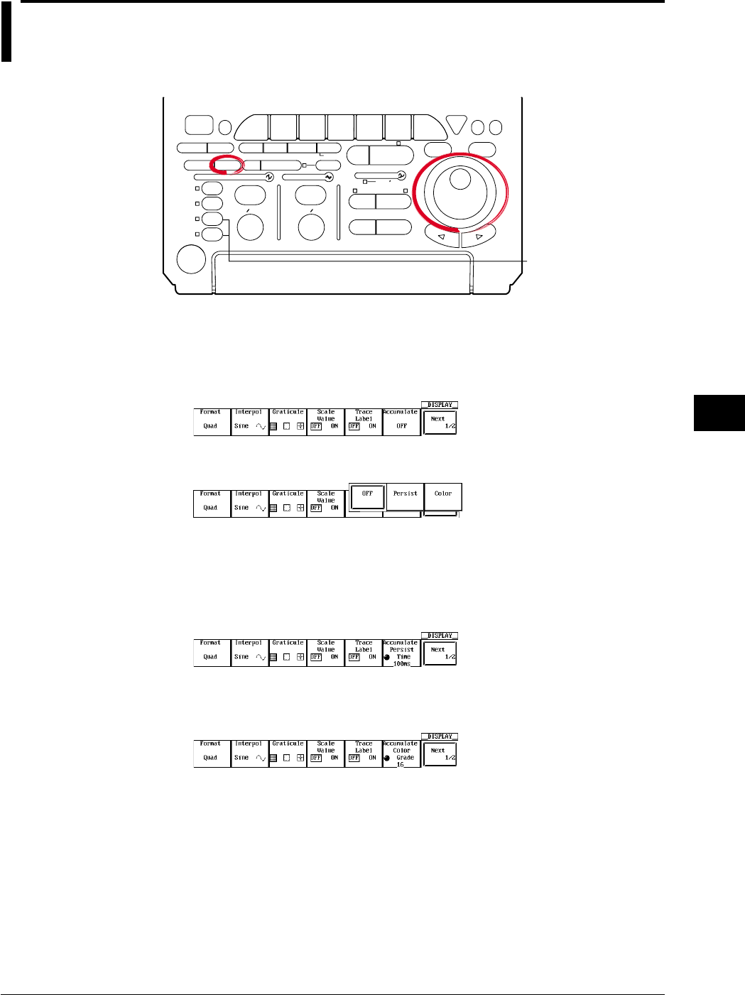
8-9
IM 701710-01E
Display
8
8.6 Accumulated Waveform Display
<For a description of this function, refer to page 1-16>
Relevant Keys
ACTION DELAY
X - Y MENU MENU PHASE
SEARCH
HORIZONTAL
VERTICAL TRIGGER
TRIG D
HELP
ESC
SELECTRESET
SIMPLE
MODE POSITION
MATH
MISCFILE
CLEAR
TRACE
HISTORY
MEASURE
SETUP
PRESET
DISPLAY
CURSOR
CH
1
CH
2
CH
3
CH
4
POWER
COPY IMAGE SAVE SHIFT
ZOOM
GO/NO-GO
ENHANCED
ACQ START/STOP
SNAP
SHOT
V DIV TIME DIV
The DL1720 is not
equipped with
an input terminal
for CH3 or CH4.
Operating Procedure
Selecting Averaging Mode
1. Press DISPLAY.
2. Press the Accumulate soft key to display the accumulate mode menu.
3. Press the corresponding to the desired accumulate mode.
Proceed to step 4 if you have selected Persist, or to step 5 if you have selected
Color.
Setting the Accumulative Time (When Persist has been Selected)
4. Turn the jog shuttle to set the desired accumulative time.
Setting the Grade Width (When Color has been Selected)
5. Turn the jog shuttle to set the desired color width.

8-10 IM 701710-01E
Explanation
During normal operation, the display is updated every time the trigger is activated
making it difficult to capture transient conditions such as sudden distortion of waveforms.
By using the accumulate function, the waveform display of the acquired data remains on
the screen for the specified time.
Accumulate Mode
Persist: Accumulate using each channel color. Displayed for the specified time period
by gradually lowering the brightness.
Color: Accumulate using eight colors that indicate the frequency of waveforms in the
data.
Accumulation Period (During Persist Mode)
When using the persistence mode, select the period over which waveforms are
accumulated from the list below. If you select infinite, the accumulation is carried out
infinitely. The default value is 100 ms.
100 ms, 200 ms, 500 ms, 1 s, 2 s, 5 s, 10 s, 20 s, 50 s, and Infinite
Grade Width (for Color Grade Mode)
In color grade mode, the frequency of data value occurrence is indicated in eight colors
as illustrated below. The grade width can be set within the range given below. The
default setting is 16.
Overlapping display is performed indefinitely in color grade mode.
2 to 2048 (steps of 2n)
Higher Frequency
Red
Pink
Orange
Yellow
White
Cyan
Green
Blue
Black
28
24
20
16
12
8
4
1
0
or more
to 27
to 23
to 19
to 15
to 11
to 7
to 3
896
768
640
512
384
256
128
1
0
or more
to 895
to 767
to 639
to 511
to 383
to 255
to 127
When Grade Width = 4 When Grade Width = 128
Red
Pink
Orange
Yellow
White
Cyan
Green
Blue
Black
For example, a dot which has appeared on the screen 100 times is displayed in red if the
grade width is 4, or in blue if the grade width is 128.
Points for Attention
•Automatic measurement of waveform parameters and GO/NO-GO judgment are
performed on the latest waveform.
•When displaying all waveforms in the history memory during accumulation, the
historical waveforms are displayed using the specified accumulation mode. However
the waveform display becomes slow.
•When printing accumulated waveforms using the optional built-in printer, they are
printed using two tones.
•Only the latest waveform can be output to an external printer.
•If the waveform acquisition is forcibly stopped by pressing START/STOP, the
accumulation is temporarily suspended. When the acquisition is restarted, the display
is cleared and accumulation continues.
Clearing Accumulated Waveforms
You can clear accumulated waveforms by pressing CLEAR TRACE.
8.6 Accumulated Waveform Display
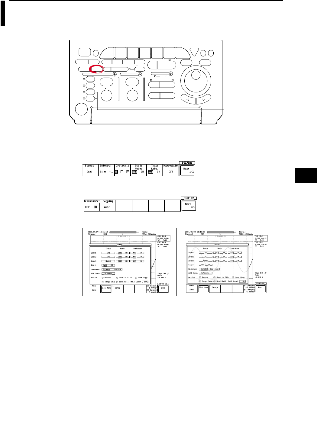
8-11
IM 701710-01E
Display
8
8.7 Turning Translucent Mode ON/OFF
Relevant Keys
ACTION DELAY
X - Y MENU MENU PHASE
SEARCH
HORIZONTAL
VERTICAL TRIGGER
TRIG D
HELP
ESC
SELECTRESET
SIMPLE
MODE POSITION
MATH
MISCFILE
CLEAR
TRACE
HISTORY
MEASURE
SETUP
PRESET
DISPLAY
CURSOR
CH
1
CH
2
CH
3
CH
4
POWER
COPY IMAGE SAVE SHIFT
ZOOM
GO/NO-GO
ENHANCED
ACQ START/STOP
SNAP
SHOT
V DIV TIME DIV
The DL1720 is not
equipped with
an input terminal
for CH3 or CH4.
Operating Procedure
1. Press DISPLAY.
2. Press the Next 1/2 soft key to display the Next 2/2 menu.
3. Press the Translucent soft key to select ON or OFF.
Translucent: OFF Translucent: ON
Explanation
When this is turned to ON, the pop-up menu becomes translucent. The contents
underneath the pop-up menu can be seen.
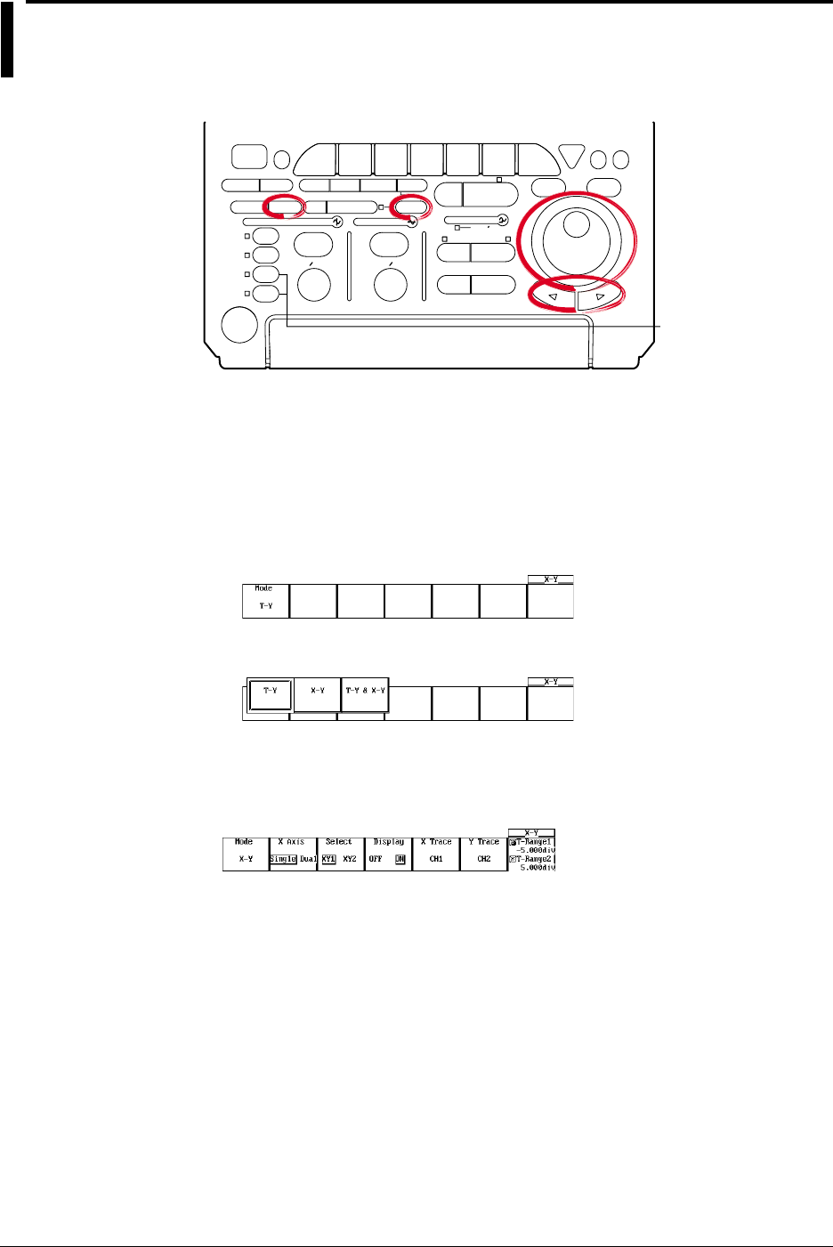
8-12 IM 701710-01E
8.8 X-Y Waveform Display
<For a description of this function, refer to page 1-19>
Relevant Keys
ACTION DELAY
X - Y MENU MENU PHASE
SEARCH
HORIZONTAL
VERTICAL TRIGGER
TRIG D
HELP
ESC
SELECTRESET
SIMPLE
MODE POSITION
MATH
MISCFILE
CLEAR
TRACE
HISTORY
MEASURE
SETUP
PRESET
DISPLAY
CURSOR
CH
1
CH
2
CH
3
CH
4
POWER
COPY IMAGE SAVE SHIFT
ZOOM
GO/NO-GO
ENHANCED
ACQ START/STOP
SNAP
SHOT
V DIV TIME DIV
The DL1720 is not
equipped with
an input terminal
for CH3 or CH4.
Operating Procedure
1. Press SHIFT to activate shift mode.
Functions marked in purple on the panel become active.
2. Press DISPLAY.
Selecting the Display Format
3. Press the Mode soft key to display the mode selection menu.
4. Prees the T-Y, X-Y, or T-Y&X-Y soft key to set the mode.
Continue with steps 5 - 12 below if you selected X-Y or T-Y&X-Y.
Selecting the X-Axis Mode (DL1740 only)
5. Press the X Axis soft key to select Single or Dual.
Selecting the X-Y Waveform (DL1740 only)
6. Press the Select soft key to select the desired X-Y waveform.
7. Press the Display soft key to select whether or not to display the X-Y waveform
that was selected in step 4.

8-13
IM 701710-01E
Display
8
Setting the X and Y Axes
8. Pressing the X Trace soft key displays the channel menu.
9. Press the soft key corresponding to the desired channel that you wish to set to the
X axis. (The CH3, CH4, and Math2 soft keys are not displayed on the DL1720.)
10. In a similar fashion, set the Y axis by pressing the Y Trace soft key.
Setting the Display Range
11. Press the T-Range1/T-Range2 soft key.
Turn the jog shuttle to set the display T-Range1.
12. In a similar fashion, press the T-Range1/T-Range2 soft key to set the display T-
Range-2.
Explanation
Selecting the X-Axis Mode (DL1740 only)
Single: Set the X-axis trace of XY1 and XY2 common.
Dual: Set the X-axis trace individually for XY1 and XY2.
Assigning X (Horizontal) and Y (Vertical) Axes
The channels that can be assigned to the X axis and Y axis depending on the X-axis
mode as follows:
DL1740
X Axis Mode X-Y X Axis Y Axis
Single XY1 CH1 to CH4, Math1, Math2 CH1, CH2, Math 1
XY2 CH1 to CH4, Math1, Math2 CH3, CH4, Math 2
Dual XY1 CH1, CH2, Math1 CH1, CH2, Math 1
XY2 CH3, CH4, Math2 CH3, CH4, Math 2
DL1720
X Axis Mode X-Y X Axis Y Axis
- XY1 CH1, CH2, Math1 CH1, CH2, Math1
Number of X-Y Waveforms that can be Displayed
The number of X-Y waveforms that can be displayed is two (XY1, XY2) (or one for the
DL1720, XY1). The display of each X-Y waveform can be turned ON/OFF.
Selecting the Display Format: Mode
You can choose from the following three display formats.
T-Y&X-Y: The top window displays normal (T-Y) waveforms. The bottom window
displays X-Y waveforms.
X-Y: Displays only X-Y waveforms.
T-Y: Displays only T-Y waveforms.
8.8 X-Y Waveform Display

8-14 IM 701710-01E
Selecting the X-Y Waveform Display Range: T-Range1/T-Range2
The X-Y display shows the range selected on the T-Y waveform.
You can set the start (fine dashed line) and end (coarse dashed line) positions in the
range -5 to +5 div from the center of the waveform display frame. The start and end
positions are not displayed on the X-Y waveform.
The resolution is as follows.
Resolution: T/div × 10/displayed record length
Precautions to be Taken when Displaying X-Y Waveforms
•The divided windows of the T-Y waveform display when using the T-Y & X-Y format
are displayed in accordance with the Format setting specified with DISPLAY.
•The zoom function applies only to T-Y waveforms. In addition, Main, Z1, or Z2 can be
selected for the T-Y waveform display.
•When expanding the X-Y waveform, change the Variable parameter of each channel.
The waveform can be expanded or reduced artificially.
8.8 X-Y Waveform Display
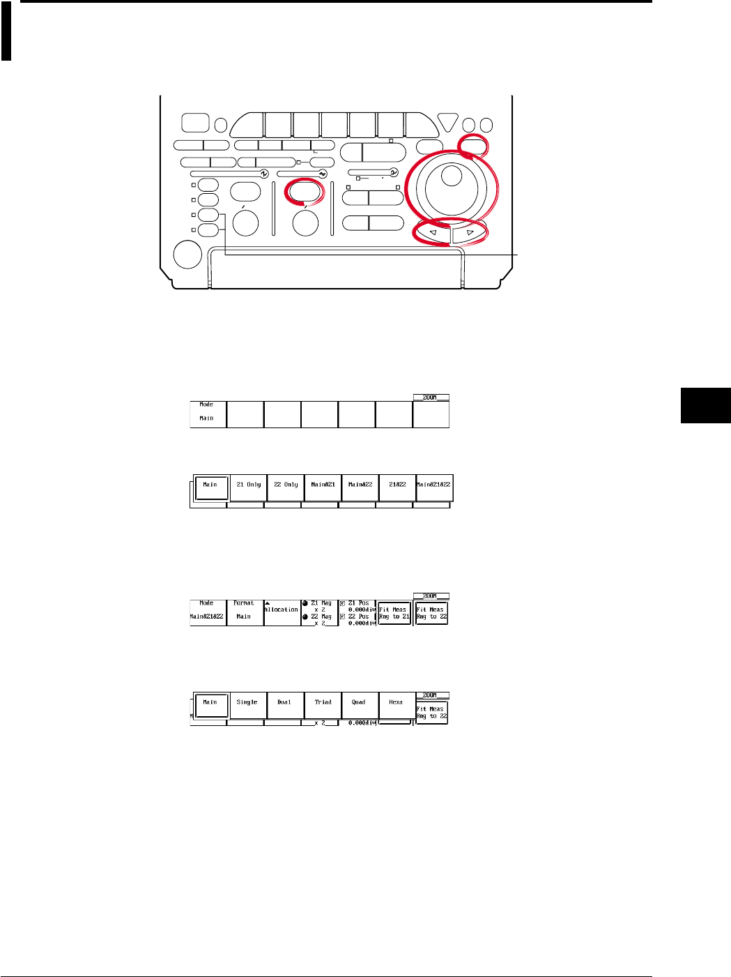
8-15
IM 701710-01E
Display
8
8.9 Zooming the Waveform
<For a description of this function, refer to page 1-19>
Relevant Keys
ACTION DELAY
X - Y MENU MENU PHASE
SEARCH
HORIZONTAL
VERTICAL TRIGGER
TRIG D
HELP
ESC
SELECTRESET
SIMPLE
MODE POSITION
MATH
MISCFILE
CLEAR
TRACE
HISTORY
MEASURE
SETUP
PRESET
DISPLAY
CURSOR
CH
1
CH
2
CH
3
CH
4
POWER
COPY IMAGE SAVE SHIFT
ZOOM
GO/NO-GO
ENHANCED
ACQ START/STOP
SNAP
SHOT
V DIV TIME DIV
The DL1720 is not
equipped with
an input terminal
for CH3 or CH4.
Operating Procedure
Selecting the Display Mode
1. Press ZOOM.
2. Pressing the Mode soft key displays the display format menu.
3. Press the soft key corresponding to the desired display format.
Selecting the Display Format of Zoomed Waveforms.
4. Pressing the Format soft key displays the format menu.
(If you set Mode to Main, the Format selection menu is not displayed.)
5. Press the soft key corresponding to the desired format. (Quad and Hexa are not
displayed on the DL1720.)
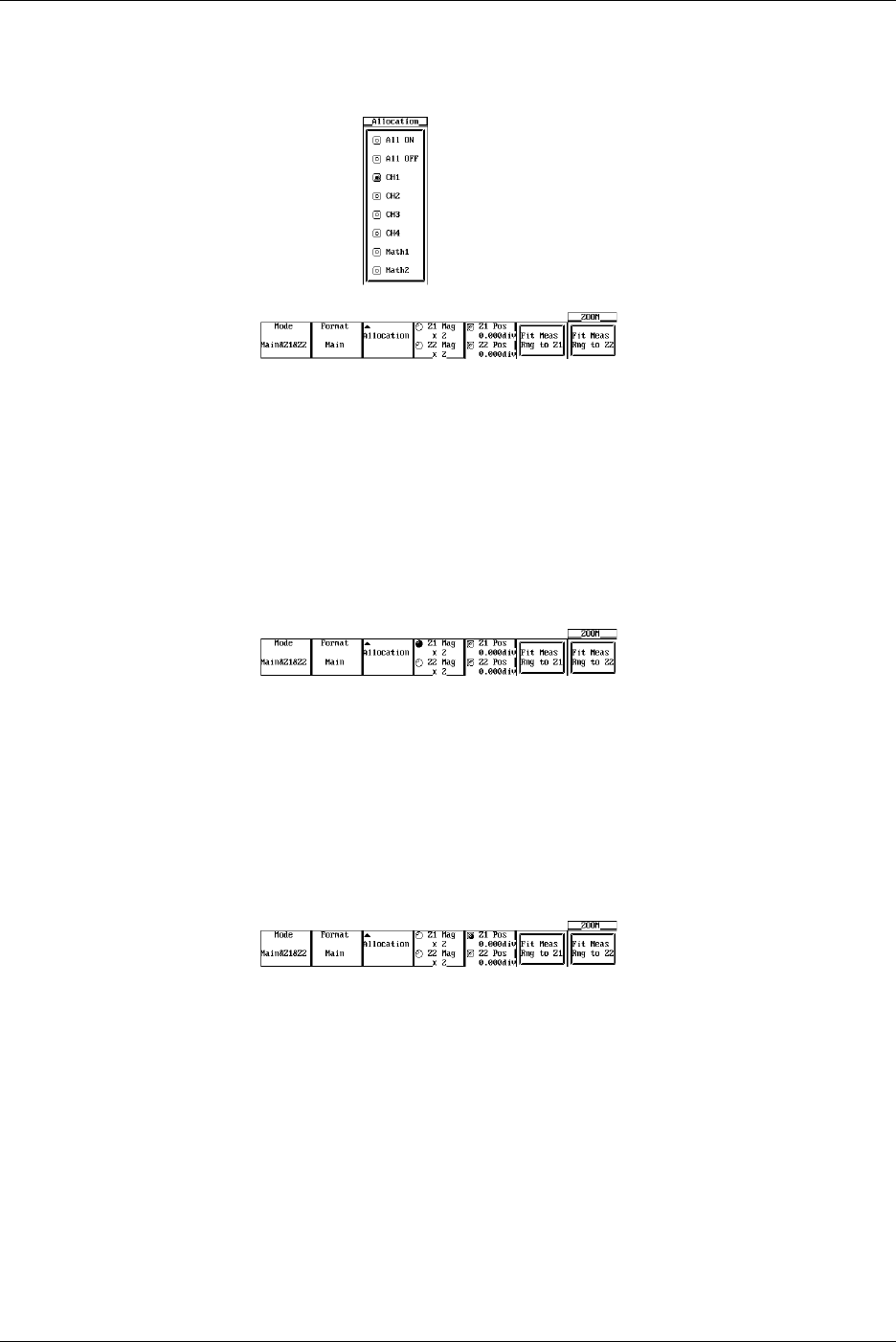
8-16 IM 701710-01E
Selecting the Zoomed Trace
6. Pressing the Allocation soft key displays the zoomed trace setting menu. (CH3,
CH4, and Math2 are not displayed on the DL1720.)
7. Turn the jog shuttle to move the cursor to the desired trace.
8. Press SELECT to select the trace.
Selecting All ON selects all traces that are currently displayed.
Setting the Zoom Rate
9. Press the Z1 Mag/Z2 Mag soft key.
Turn the jog shuttle to set the zoom rate of Z1 zoom box (If you set Mode to Z1, Z1
Mag is displayed. If you select Z2, Z2 Mag is displayed. If you select Z1 and Z2,
Z1 Mag/Z2 Mag is displayed.).
10. In a similar fashion, press the Z2 Mag soft key to set the zoom rate of Z2 zoom
box.
Selecting the Zoom Position
11. Press the Z1 Pos/Z2 Pos soft key. (If you set Mode to Z1, Z1 Pos is displayed. If
you select Z2, Z2 Pos is displayed. If you select Z1 and Z2, Z1 Pos/Z2 Pos is
displayed.)
Turn the jog shuttle to set the zoom position of the Z1 zoom box.
12. In a similar fashion, press the Z2 Pos soft key to set the zoom position of Z2 zoom
box.
By setting the jog shuttle control to both Z1 Pos and Z2 Pos, the zoom positions of
both Z1 and Z2 can be moved simultaneously.
Changing the Range of the Automated Measurement of Waveform Parameters
13. Press the Fit Meas Rng to Z1 or Fit Meas Rng to Z2 soft key (depending on the
display format of the zoom waveform) to set the range of the automated
measurement of waveform parameters to the zoom range of Z1 or Z2, respectively.
8.9 Zooming the Waveform

8-17
IM 701710-01E
Display
8
Explanation
The zoomed waveform of two locations can be displayed simultaneously (dual zoom).
You can also select which channel to zoom.
Note that if the number of displayed points is less than or equal to 50 (or 40), zooming is
not possible.
Selecting the Display Mode of Zoomed Waveforms: Mode
Main: Displays only the main (unzoomed) waveform.
Z1 Only: Displays only the zoomed waveform of zoom box Z1.
Z2 Only: Displays only the zoomed waveform of zoom box Z2.
Main&Z1: Displays the main waveform in the top window and zoomed waveform of
zoom box 1 in the bottom window.
Main&Z2: Displays the main waveform in the top window and zoomed waveform of
zoom box 2 in the bottom window.
Z1&Z2: Displays the zoomed waveform of zoom box 1 in the top window and the
zoomed waveform of zoom box 2 in the bottom window.
Main&Z1&Z2: Displays the main waveform in the top window, the zoomed waveform of
zoom box 1 in the lower left window and the zoomed waveform of zoom
box 2 in the lower right window.
Selecting the Zoomed Trace: Allocation
The traces (CH1 to CH4, Math1, Math2 (or CH1, CH2, and Math1 for the DL1720))
whose Allocation is turned ON are zoomed. If the allocation is OFF, the trace is not
zoomed.
You cannot allocate channels whose display is turned OFF.
Display Format of Zoomed Waveforms: Format
Similar to the main waveform, 6 types (or 4 types for the DL1720) of display formats are
available. You cannot set different formats for Z1 and Z2.
Main*, Single, Dual, Triad, Quad (DL1740 only), Hexa (DL1740 only)
*: Selecting Main results in the same format as when “Format” is specified for “DISPLAY.”
Zoom Rate: Z1 Mag/Z2 Mag
•The maximum zoom rate varies depending on the displayed record length.
Maximum zoom rate: (displayed record length)/50 (or 40)
Note that the displayed record length is not necessarily the same as the record length
of the acquisition memory.
For details regarding the displayed record length, see appendix 1, “Relationship
between the Time Axis Setting, Sample Rate, and Record length.”
•You can change the zoom rate for Z1 and Z2 (zoomed waveforms of two locations).
Zoom Position: Z1 Position and Z2 Position
•The zoom position can be set by specifying the center position in the range –5 to +5
div from the center of the waveform display frame.
The resolution is as follows.
Zoom position resolution: (T/div × 10)/(displayed record length)
•The zoom box enclosed by solid lines is Z1 and the one enclosed by dashed lines is
Z2. Since each box is independent, you can set the position separately.
Changing the Range of the Automated Measurement of Waveform Parameters: Fit
Meas Rng to Z1/Fit Meas Rng to Z2
Sets the range of the automated measurement of waveform parameters to the zoom
range of Z1 or Z2. This is valid even if the automated measurement of waveform
parameters is turned OFF.
8.9 Zooming the Waveform
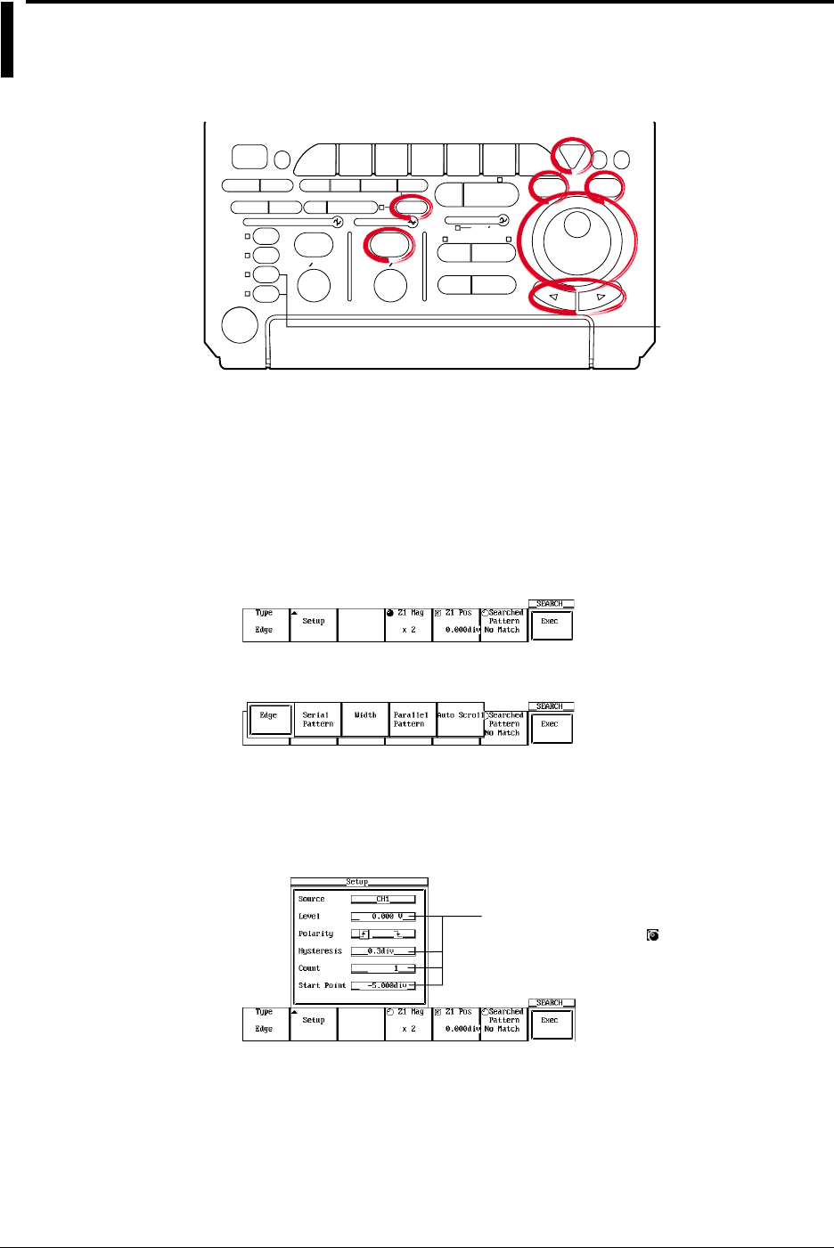
8-18 IM 701710-01E
8.10 Search Data Using Search and Zoom Function
<For a description of this function, refer to page 1-26>
Relevant Keys
ACTION DELAY
X - Y MENU MENU PHASE
SEARCH
HORIZONTAL
VERTICAL TRIGGER
TRIG D
HELP
ESC
SELECTRESET
SIMPLE
MODE POSITION
MATH
MISCFILE
CLEAR
TRACE
HISTORY
MEASURE
SETUP
PRESET
DISPLAY
CURSOR
CH
1
CH
2
CH
3
CH
4
POWER
COPY IMAGE SAVE SHIFT
ZOOM
GO/NO-GO
ENHANCED
ACQ START/STOP
SNAP
SHOT
V DIV TIME DIV
The DL1720 is not
equipped with
an input terminal
for CH3 or CH4.
Operating Procedure
When Performing a Edge Search
1. Press SHIFT to activate shift mode.
Functions marked in purple on the panel become active.
2. Press ZOOM.
Selecting the Search Method (Type)
3. Pressing the Type soft key displays the search method menu.
4. Press the Edge soft key to select the search method.
Setting the Search Condition
5. Pressing the Setup soft key displays the search condition setting dialog box. Turn
the jog shuttle to select the parameter. Pressing SELECT displays a menu used to
set the item or changes the selected item.
Settings for these items can be input directly
using a USB keyboard. ( )
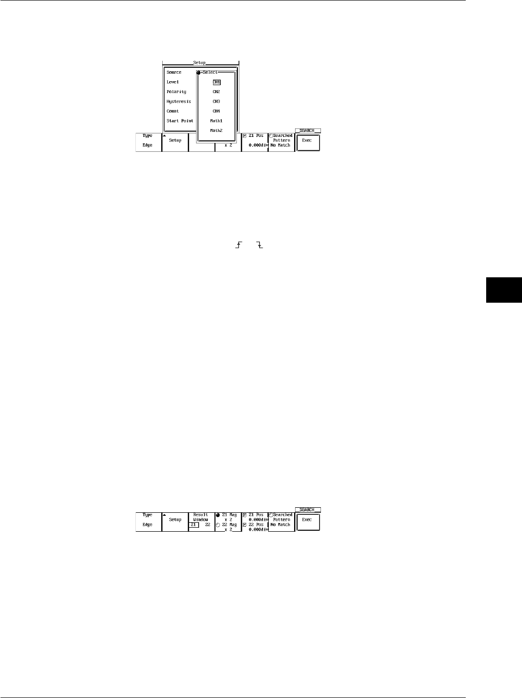
8-19
IM 701710-01E
Display
8
•Setting the Source
6. Turn the jog shuttle to move the cursor to the channel to be searched and press
SELECT. (CH3, CH4, and Math2 are not displayed on the DL1720.)
•Setting the Level
7. Turn the jog shuttle to set the level and press SELECT. You can use the arrow
keys to move between the digits.
Pressing RESET resets the level to 0 V.
•Setting the Polarity
8. Press SELECT to select or .
•Setting the Hysteresis
9. Turn the jog shuttle to set the hysteresis and press SELECT. You can use the
arrow keys to move between the digits.
Pressing RESET resets the hysteresis to 0.3 div.
•Setting the Count
10. Turn the jog shuttle to set the count and press SELECT. You can use the arrow
keys to move between the digits.
Pressing RESET resets the count to 0.
•Setting the Start Point
11. Turn the jog shuttle to set the start position of the search. Press SELECT. You
can use the arrow keys to move between the digits.
Pressing RESET sets the position to –5 div.
12. Press ESC to close the search condition setting dialog box.
Setting the Display Position of the Search Results (When Zoom Mode is Z1 & Z2 or
Main & Z1 & Z2)
13. Press the Result Window soft key to select Z1 or Z2.
Executing the Search
14. Pressing the Exec soft key starts the search. The search results are displayed in
the zoomed waveform display position selected in step 13.
You can search 1000 times using the same conditions.
Displaying the Previous Search Results
15. Press the Searched Pattern soft key.
16. Turn the jog shuttle to select the number of the search result to be displayed.
Newer search results are displayed with higher numbers (result 2 is newer than
result 1).
8.10 Search Data Using Search and Zoom Function
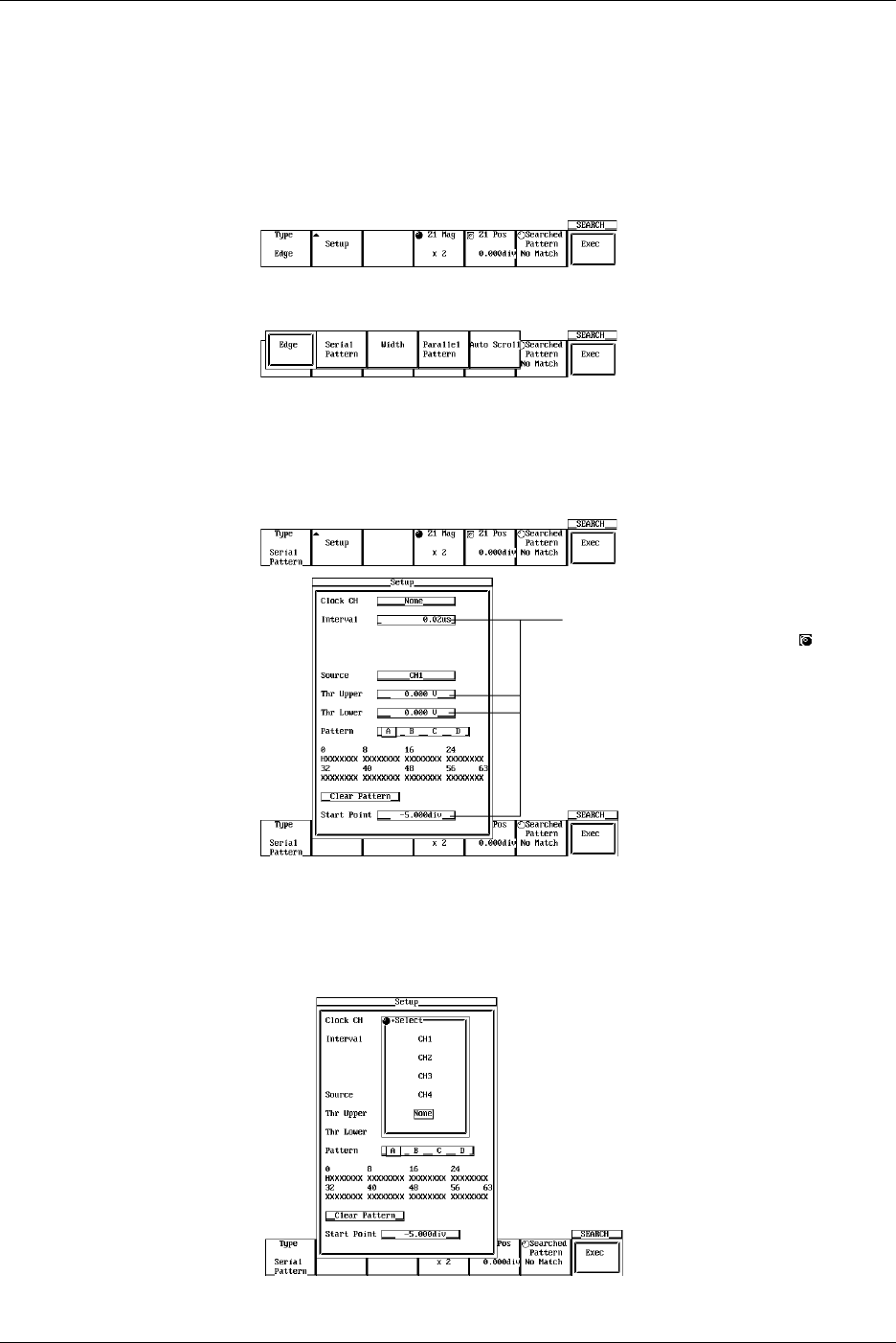
8-20 IM 701710-01E
When Performing a Serial Pattern Search
1. Press SHIFT to activate shift mode.
Functions marked in purple on the panel become active.
2. Press ZOOM.
Selecting the Search Method (Type)
3. Pressing the Type soft key displays the search method menu.
4. Press the Serial Pattern soft key to select the search method.
Setting the Search Conditions
5. Pressing the Setup soft key displays the search condition setting dialog box. Turn
the jog shuttle to select the parameter. Pressing SELECT displays a menu used to
set the item or changes the selected item.
Settings for these items can be input
directly using a USB keyboard. ( )
•Setting the Clock CH
6. Turn the jog shuttle to move the cursor to the clock channel and press SELECT. If
you selected CH1 to CH4 (or CH1 to CH2 for the DL1720), go to step 7. If you
selected None, go to step 10.
8.10 Search Data Using Search and Zoom Function
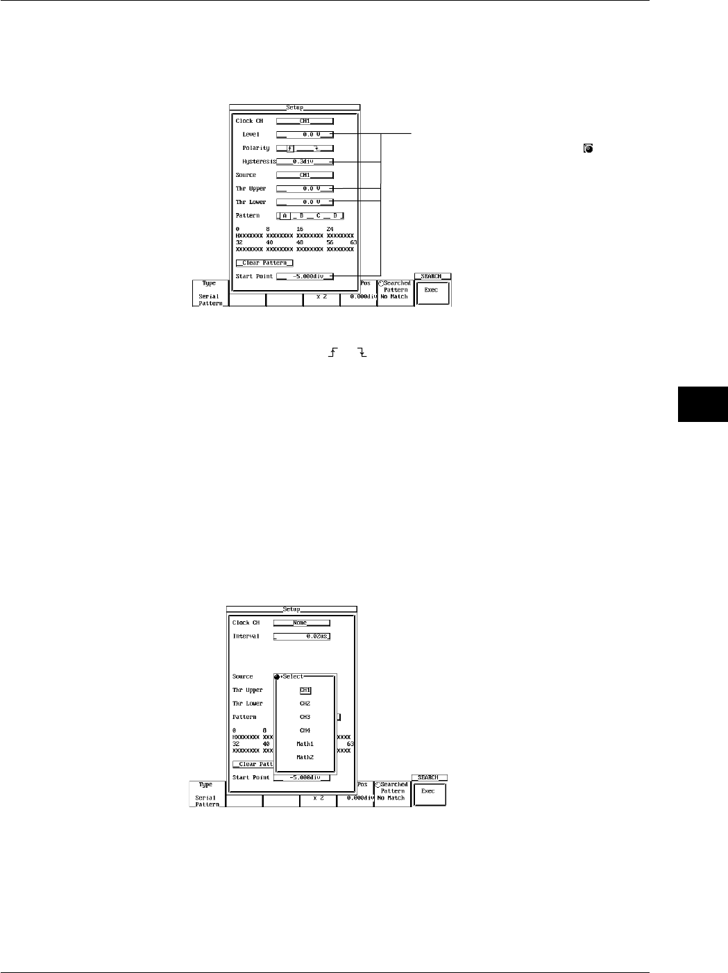
8-21
IM 701710-01E
Display
8
•Setting the Level (When Clock CH is Set to CH1-CH4)
7. Turn the jog shuttle to set the level and press SELECT. You can use the arrow
keys to move between the digits.
Pressing RESET resets the level to 0 V.
Settings for these items can be input
directly using a USB keyboard. ( )
•Setting the Polarity (When Clock CH is Set to CH1-CH4)
8. Press SELECT to select or .
•Setting the Hysteresis (When Clock CH is Set to CH1-CH4)
9. Turn the jog shuttle to set the hysteresis and press SELECT. You can use the
arrow keys to move between the digits.
Pressing RESET resets the hysteresis to 0.3 div.
•Setting the Interval (When Clock CH is Set to None)
10. Turn the jog shuttle to set the interval at which to check the pattern and press
SELECT. You can use the arrow keys to move between the digits.
Pressing RESET resets the interval to the default value.
•Setting the Source
11. Turn the jog shuttle to move the cursor to the channel to be searched and press
SELECT. (CH3, CH4, and Math2 are not displayed on the DL1720.)
•Set the Thr Upper
12. Turn the jog shuttle to set the level used to determine Low and press SELECT.
You can use the arrow keys to move between the digits.
Pressing RESET resets the level to 0 V.
•Set the Thr Lower
13. Turn the jog shuttle to set the level used to determine High and press SELECT.
You can use the arrow keys to move between the digits.
Pressing RESET resets the level to 0 V.
8.10 Search Data Using Search and Zoom Function
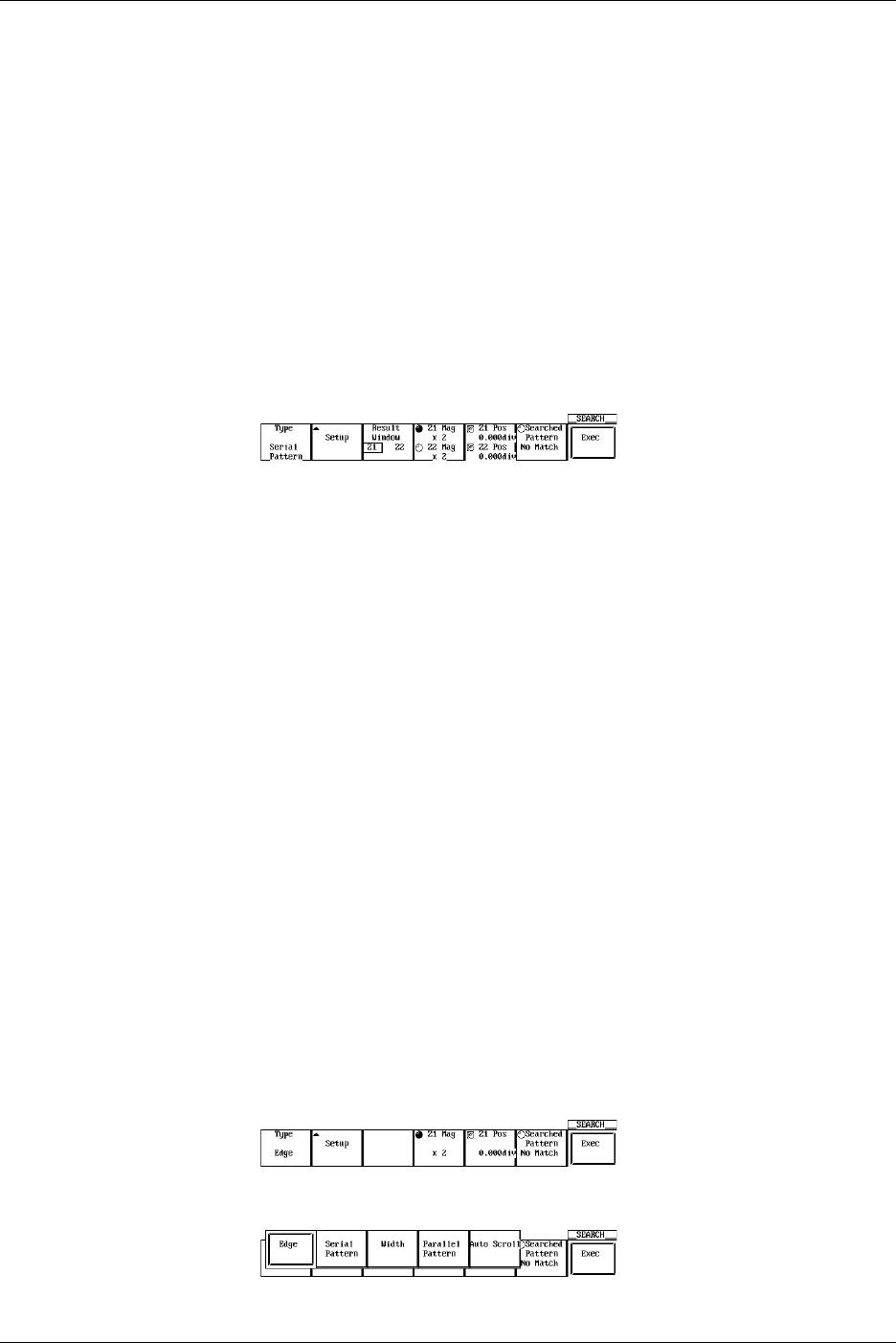
8-22 IM 701710-01E
•Set the Pattern
14. Press SELECT to select the pattern number A to D.
15. Turn the jog shuttle to move the cursor to the desired bit position.
16. Press SELECT to select H, L, or X. If you click Clear Pattern all bits are set to X.
17. Set other pattern numbers as necessary.
•Setting the Start Point
18. Turn the jog shuttle to set the start position of the search. Press SELECT. You
can use the arrow keys to move between the digits.
Pressing RESET sets the position to –5 div.
19. Press ESC close the search condition setting dialog box.
Setting the Display Position of the Search Results (When Zoom Mode is Z1 & Z2 or
Main & Z1 & Z2)
20. Press the Result Window soft key to select Z1 or Z2.
Executing the Search
21. Pressing the Exec soft key starts the search. The search results are displayed in
the zoomed waveform display position selected in step 17.
You can search 1000 times using the same conditions.
Displaying the Previous Search Results
22. Press the Searched Pattern soft key.
23. Turn the jog shuttle to select the number of the search result to be displayed.
Newer search results are displayed with higher numbers (result 2 is newer than
result 1)
Changing the Zoom Rate and Position
24. As in the zoomed waveform, you can change the zoom rate of Z1 and Z2 by
pressing the Z1 Mag/Z2 Mag soft key and turning the jog shuttle.
25. As in the zoomed waveform, you can move the section that is being zoomed by
pressing the Z1 Pos/Z2 Pos soft key and turning the jog shuttle.
When Performing a Parallel Pattern Search
1. Press SHIFT to activate shift mode.
The functions printed in purple letters on the front panel become activated.
2. Press ZOOM.
Selecting the Search Method Type
3. Press the Type soft key to display the search method selection menu.
4. Press the Parallel Pattern soft key to select the search method.
8.10 Search Data Using Search and Zoom Function
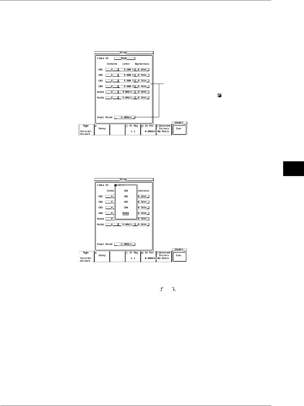
8-23
IM 701710-01E
Display
8
Setting the Search Criteria
5. Press the Setup soft key to display the search criteria settings dialog box. Turn the
jog shuttle to select the setting item. When you press SELECT, the settings menu
for the selected item is displayed, or the selected value is changed. (On the
DL1720, the CH3, CH4, and Math2 settings are not displayed.)
The Level and Hysteresis settings for each
channel or Math function can be input directly
using a USB keyboard. ( )
•Setting the Clock CH
6. Move the cursor over to the clock channel with the jog shuttle, then press SELECT.
When selecting CH1-CH4 (or CH1 to CH2 for the DL1720), proceed to step 7. If
you select None, skip to step 10.
•Setting the Clock Channel Pattern
7. Use the jog shuttle to move the cursor to the Pattern of the channel set as the clock
channel. Press SELECT to select or .
•Setting the Clock CH Level
8. Use the jog shuttle to move the cursor to the Level of the channel set as the clock
channel. Press SELECT, then use the jog shuttle to set the level, and press
SELECT again. Use the arrow keys to move between the digits. If you press
RESET, the setting will be restored to 0 V.
•Setting the Hysteresis of the Clock Channel
9. Use the jog shuttle to move the cursor to the Hysteresis of the channel set as the
clock channel. Press SELECT, use the jog shuttle to set the hysteresis, then press
SELECT again. Use the arrow keys to move between the digits. If you press
RESET, the setting will be restored to 0.3 div.
•Setting the Pattern for Each Channel
10. Use the jog shuttle to move the cursor to the Pattern of the channel you wish to set.
Press SELECT key to select H, L, or X.
8.10 Search Data Using Search and Zoom Function
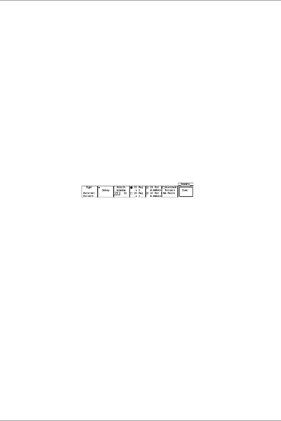
8-24 IM 701710-01E
•Setting the Level for Each Channel
11. Use the jog shuttle to move the cursor to the Level of the channel you wish to set.
Press SELECT, then use the jog shuttle to set the Level and press SELECT again.
Use the arrow keys to move between the digits. If you press RESET, the setting
will be restored to 0 V.
•Setting the Hysteresis for Each Channel
12. Use the jog shuttle to move the cursor to the Hysteresis of the channel you wish to
set. Press SELECT, then use the jog shuttle to set the hysteresis, and press
SELECT again. Use the arrow keys to move between the digits. If you press
RESET, the setting will be restored to 0.3 div.
•Setting the Start Point
13. Use the jog shuttle to move the cursor to the start point, then press SELECT. Use
the jog shuttle to select the start point, then press SELECT again. Use the arrow
keys to move between the digits. If you press RESET, the setting will be restored
to –5 div.
14. Press ESC to close the dialog box.
Setting the Display Position for the Search Results (When Zoom Mode is Z1&Z2 or
Main&Z1&Z2)
15. Press the Results Window soft key to select Z1 or Z2.
Executing the Search
16. Press the Exec soft key to perform the search. The results are displayed in the
zoom waveform display position selected in step 15. You can perform a search
using the same search criteria 1000 times.
Displaying Previous Search Results
17. Press the Searched Pattern soft key to highlight the jog shuttle icon.
18. Turn the jog shuttle to select the number of the search results to be displayed. The
most recent search has the highest number.
Changing the Zooming Factor and Position
19. As you did with the zoomed waveform, press the Z1 Mag/Z2 Mag soft key, then
turn the jog shuttle to change the zooming factor of Z1 and Z2.
20. As you did with the zoomed waveform, press the Z1 Pos/Z2 Pos soft key, then turn
the jog shuttle to change the position of the zoom box for Z1 and Z2.
8.10 Search Data Using Search and Zoom Function
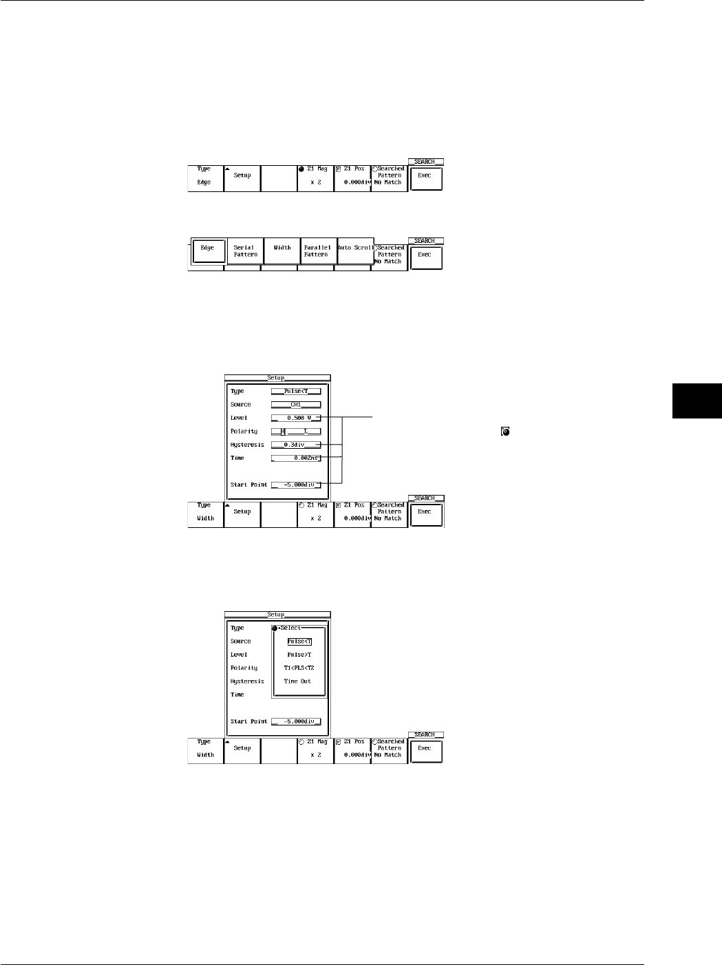
8-25
IM 701710-01E
Display
8
When Performing a Pulse Width Search
1. Press SHIFT to activate shift mode. The functions printed in purple letters on the
front panel become activated.
2. Press ZOOM.
Selecting the Search Method
3. Press the Type soft key to display the search method selection menu.
4. Press the Width soft key to select the search method.
Setting the Search Criteria
5. When you press the Setup soft key the search criteria settings dialog box is
displayed. Turn the jog shuttle to select a setting item. Press SELECT to display
the setting menu for the selected item, or change the current setting.
Settings for these items can be input directly
using a USB keyboard. ( )
•Setting the Type
6. Use the jog shuttle to choose either Pulse < T, Pulse > T, T1 < PLS < T2, or Time
Out, then press SELECT.
8.10 Search Data Using Search and Zoom Function
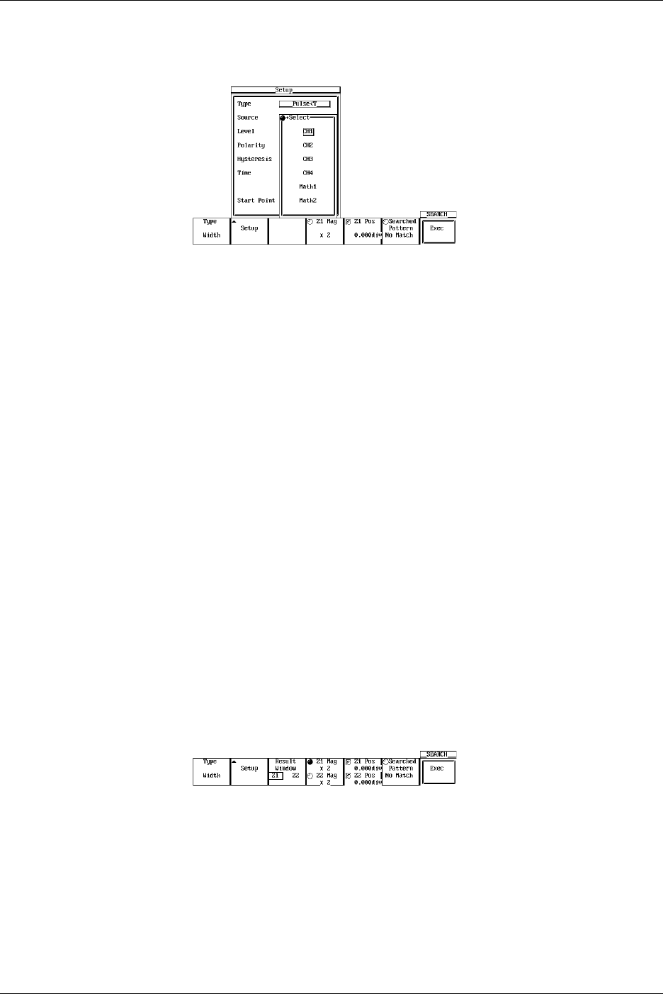
8-26 IM 701710-01E
•Setting the Source
7. Use the jog shuttle to move the cursor to the desired source channel then press
SELECT. (CH3, CH4, and Math2 are not displayed on the DL1720.)
•Setting the Level
8. Use the jog shuttle to set the level, then press SELECT. Use the arrows to move
between the digits. Pressing RESET restores the value to 0 V.
•Setting the Polarity
9. Press SELECT to select H or L.
•Setting the Hysteresis
10. Use the jog shuttle to set the hysteresis, then press SELECT. Use the arrow keys
to move the arrows between the digits. Pressing RESET restores the value to 0.3
div.
•Setting the Time
11. Use the jog shuttle to set the count, then press SELECT. Use the arrow keys to
move the arrows between the digits. Pressing RESET restores the value to
minimum resolution (1/sample rate). Set Time1 and Time2 if you selected
T1<PLS<T2 in step 6.
•Setting the Start Point
12. Use the jog shuttle to set the search start position, then press SELECT. Use the
arrow keys to move the arrows between the digits. Pressing RESET restores the
value to –5 div.
13. Press ESC to close the dialog box.
Setting the Search Results Display Position (When Zoom Mode is Z1&Z2 or
Main&Z1&Z2)
14. Press the Result Window soft key to select Z1 or Z2.
Executing the Search
15. Press the Exec soft key to perform the search. The search results are displayed in
the zoom waveform display position selected in step 14.
You can search 1000 times using the same conditions.
Displaying Previous Search Results
16. Press the Searched Pattern soft key to highlight the jog shuttle icon.
17. Turn the jog shuttle to select one of the displayed search results numbers. The
higher the number the more recent the search result.
8.10 Search Data Using Search and Zoom Function
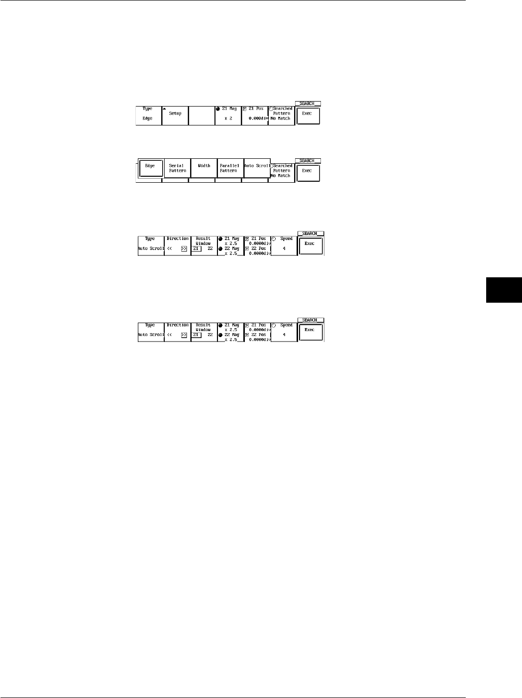
8-27
IM 701710-01E
Display
8
8.10 Search Data Using Search and Zoom Function
When Performing an Auto Scroll Search
1. Press SHIFT to activate the shift mode.
2. Press ZOOM.
Selecting the Search Method (Type)
3. Press the Type soft key to display the search method selection menu.
4. Press the Auto Scroll soft key to select the search method.
Selecting the Scroll Direction
5. Press the Direction soft key to set the scrolling direction.
Setting the Search Results Display Position (When Zoom Mode is Z1&Z2 or
Main&Z1&Z2)
6. Press the Results Window soft key to select Z1 or Z2.
Changing the Zooming Factor and Position
7. As you did with the zoomed waveform, press the Z1 Mag/Z2 Mag soft key, then
turn the jog shuttle to change the part which is expanded and displayed in Z1 and
Z2.
8. As you did with the zoomed waveform, press the Z1 Pos/Z2 Pos soft key, then turn
the jog shuttle to change the part which is expanded and displayed in Z1 and Z2.
Setting the Scroll Speed
9. Press the Speed soft key, then use the jog shuttle to set the scroll speed from 1 to
7.
Executing the Scroll
10. Press the Exec soft key to perform the Scroll. Press the key again to stop the
Scroll.

8-28 IM 701710-01E
8.10 Search Data Using Search and Zoom Function
Explanation
When the data acquisition is stopped, a section of the waveform can be searched and
displayed expanded.
Search Method: Type
The following two search methods are available.
Edge: Searches the position where the signal went above (rising) or below
(falling) the specified level the specified number of times from the
search start position.
Serial Pattern: Searches for a section of the waveform that has the same pattern as
the specified waveform pattern (High or Low status or Don’t Care).
Parallel Pattern: Searches by using a status (High, Low, or Don’t Care) of each channel,
CH1 through CH4, Math1, and Math2 (or CH1, CH2, and Math1 for the
DL1720).
Pulse Width: Searches for a particular section of the current displayed waveform.
Searches for a section of the waveform of which the pulse width is
shorter or longer than the specified time width from the search start
position.
Auto Scroll: The zoom position automatically moves (auto scroll) in the specified
direction. You can scroll through the zoomed waveform and stop the
scrolling at the desired position.
Search Condition: Setup
•When the Type is Edge
Source: Select the channel to be searched. You can also select Math1 and Math2
(or Math1 for the DL1720).
Level: Set the level used to determine the rising or falling edge. The range is 8
div within the screen. The resolution is 0.01 div.
Polarity: Select the polarity from the following list.
: Search by the number of times the waveform passes from below the
specified level to above the specified level.
: Search by the number of times the waveform passes from above the
specified level to below the specified level.
Hys: Set the hysteresis. The range is 0.3 div to 4 div.
Count: Set the number of times or is to be met. The range is 1 to 1000000.
Start Point:Set the starting position of the search. The range is from –5 to 5 div.
•When the Type is Serial Pattern
Clock CH: Select the clock channel, from CH1 to CH4 (or CH1 to CH2 for the
DL1720), that is used as a timing reference in searching the status. When
None is selected, the status is searched at a predetermined interval.
Source: Select the channel to be searched. You can also select Math1 and Math2
(or Math1 for the DL1720).
Thr Upper: Set the level used to determine Low (L).
Thr Lower: Set the level used to determine High (H).
Pattern: Four different types of patterns can be registered. Set the pattern with 64
bits of H, L, X (Don’t Care) symbols.
H: When the value is greater than or equal to Thr Lower.
L: When the value is less than or equal to Thr Upper.
X: Do not determine.
Start Point:Set the start position of the search. The range is from –5 to 5 div.

8-29
IM 701710-01E
Display
8
8.10 Search Data Using Search and Zoom Function
When CH1 to CH4 (or CH1 to CH2 for the DL1720) is Set as the Clock Channel
Level: Set the level used to determine the rising or falling edge. The range is 8
div within the screen. The resolution is 0.01 div.
Polarity: Select the polarity from the following list.
: Search the status when the waveform changes from below the
specified level to above the specified level.
: Search the status when the waveform changes from above the
specified level to below the specified level.
Hys: Set the hysteresis. The range is 0.3 div to 4 div.
When None is Set as the Clock Channel
Interval: Set the interval at which to search the status.
•When the Type is Parallel Pattern
Clock CH: Select a clock channel from CH1 to CH4 (or CH1 to CH2 for the DL1720)
that will provide the standard timing for searching the status. Select
NONE to check the sutatus of all the data.
Start Point:Set the starting position for the search. The range for this setting is –5 to 5
div.
Channels Specified as Clock Channels
Level: Set the level for determining rising and falling. The range for the setting is
an on-screen 8 div, and the resolution is 0.01 div.
Pattern: Choose from the following:
: Check the pattern when the waveform changes from above to below
the specified level.
: Checks the pattern when the waveform changes from below to above
the specified level.
Hysteresis:Set the hysteresis. The range for the setting is 0.3 to 4 div.
Channels Other than Clock Channels
Pattern: Set using the H, L, or X (Don’t Care) symbols.
H: When the value is greater than the level.
L: When the value is less than the level.
X: Do not determine.
Level: Set the levels to determine H and L.
Hysteresis:Set the hysteresis. The range for this setting is 0.3 div to 4 div.

8-30 IM 701710-01E
8.10 Search Data Using Search and Zoom Function
•When the Type is Pulse Width
Type: Select the relationship between the specified time and the measured
waveform.
Pulse < T: Detects a section of the waveform whose pulse width
(Pulse) is shorter than the specified time (T).
Pulse > T: Detects a section of the waveform whose pulse width
(Pulse) is longer than the specified time (T).
T1 < PLS < T2: Detects a section of the waveform whose pulse width
(Pulse) is within the specified times (T1 to T2).
Timeout: Detects a section of the waveform whose pulse width
(Pulse) exceeds the specified time (T). The displayed
position in the zoom display differs from the Pulse > T
case.
Source: Select the source channel for the search. You can also select Math1 and
Math2 (or Math1 for the DL1720).
Level: Set the level for determining High and Low. The setting range is an on-
screen 8 div, and the resolution is 0.01 div.
Polarity: Choose from the following:
High: When the waveform is higher than the specified level.
Low: When the waveform is lower than the specified level.
Hysteresis:Set the hysteresis. The range for this setting is 0.3 div to 4 div.
Time: Set the determination time, “T.” The range for this setting is 1/sample rate
display range.
Start Point:Set the starting position for the search. The range for this setting is –5 to 5
div.
Display Position of the Searched Waveform: Result Window
When the zoom mode is set to Z1 & Z2 or Main & Z1 & Z2, you can select whether to
display the searched waveform in the Z1 or Z2 window.
Search Count
The search can be carried out up to 1000 times. When the type is edge, the rising or
falling edge is counted from the previous search position. In addition, the past search
results can also be displayed.
Changing the Zoom Rate and Position
The search results are displayed in the zoomed waveform display area. As in the
zoomed waveform, the zoom rate and position can be changed.
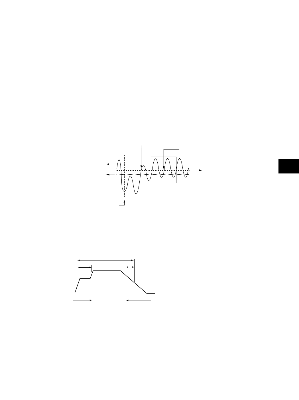
8-31
IM 701710-01E
Display
8
Precautions to be Taken when Searching
•Searching is not possible while the data acquisition is in progress.
•Searching is not possible on the computed results of the power spectrum.
•The search result is void if the following operations, are carried out:
Starting data acquisition.
Changing the Search Setup setting.
Shifting the phase of the source or the clock.
•Searching is not possible when setting CH2 or CH4 (or CH2 only for the DL1720) as
the clock channel while in interleave mode.
•Searching is not possible when all patterns are set to X.
•Patterns from undisplayed waveforms will not be referenced during searcles.
Determination when Using the Edge for the Search
When the peak immediately after the rising edge of the waveform is less than or equal to
the upper limit of the hysteresis or when the peak immediately after the falling edge is
greater than or equal to the lower limit of the hysteresis, it is determined as false (not
counted as a specified edge).
Start Point of the Search
Detected Position
The Upper Value
of Hysteresis
Determined as False
Specified Level
When the Edge is Set to Rising
and the Count is Set to 2
The Lower Value
of Hysteresis
Determination when Searching Using a Serial Pattern
The points between the Thr Upper and Thr Lower are always determined to be true
(matches the specified status). If such a point is included at the time the pattern is
checked, a message is displayed as a notification.
Thr Upper
Thr Lower
Low
Low
High
AB
A, B: Always Determined as True
8.10 Search Data Using Search and Zoom Function
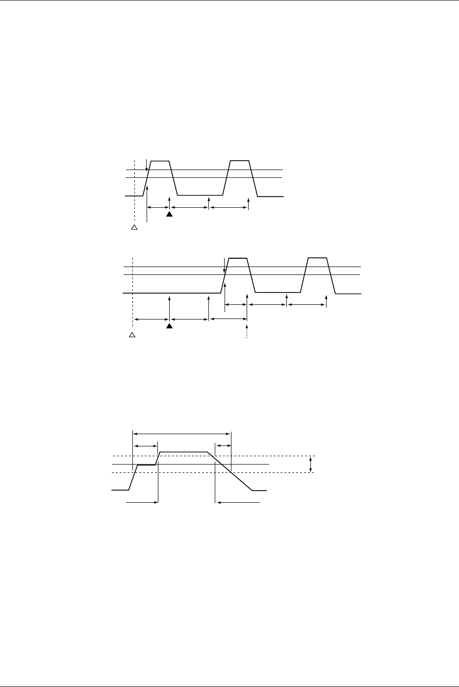
8-32 IM 701710-01E
Search Start Point when Using a Serial Pattern Search
The search start point is as follows when Clock CH is set to None.
On the screen, the first rising or falling edge to the right of the specified Start Point
becomes the reference. The search start point is set to 1/2 the specified interval right of
the reference point. However, if the Start Point and the search start point described
above are separated by an interval larger than the specified interval, the search start
point is set back in units of the specified interval to a point so that the interval between
the Start Point and the search start point is within the specified interval. (The search
start point must be to the right of the start point in this case.) Within the hysteresis range
of Clock CH, the rising or falling edge cannot be checked.
Thr Upper
Thr Lower
Detection (Reference Point)
Start Point
A: Interval
AA
B
B: Interval/2
Search Start Point
Thr Upper
Thr Lower
Detection (Reference Point)
Start Point
A: Interval
Originally, this position is the search start point.
However, the position is moved, because the interval
between the Start Point and search start point is
greater than Interval.
AA
B
B: Interval/2
C: < Interval
Search Start Point
A
A
C
Defermination During a Parallel Pattern Search
The hysteresis points are normally evaluated as true (conforming to the specified status).
Level Hysteresis
Low
Low
High
AB
A, B: Always Determined as True
8.10 Search Data Using Search and Zoom Function
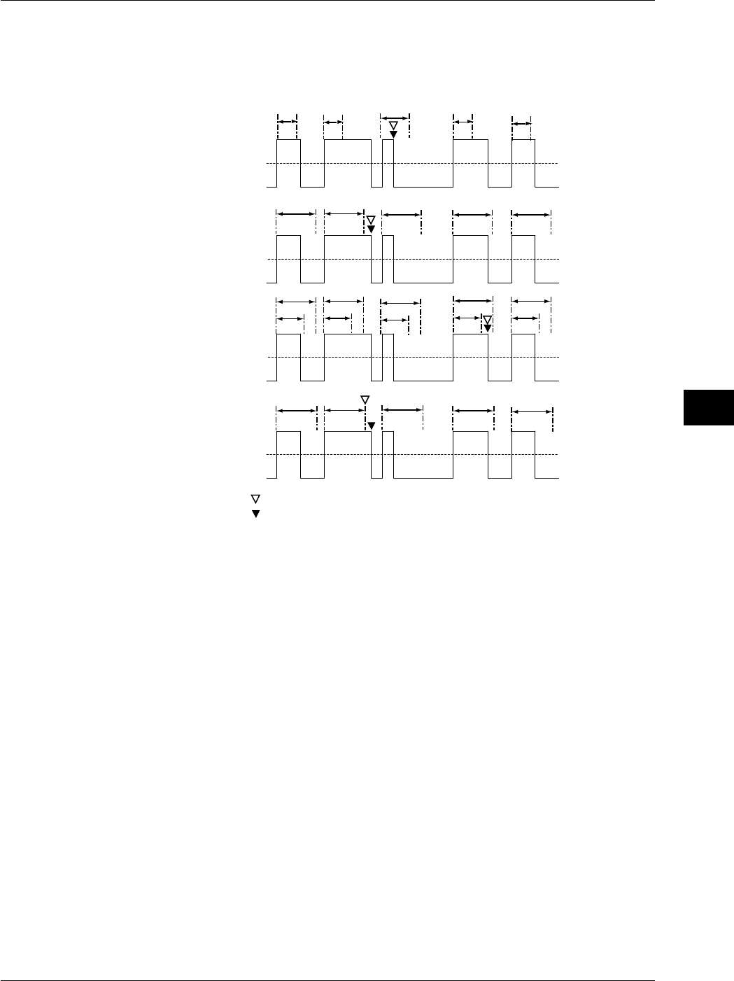
8-33
IM 701710-01E
Display
8
Display Position for Pulse Width Searches
The position of the waveform displayed in the zoom screen will change in the following
manner depending on the Type setting: An example in which the polarity is H is shown
below.
T
T
T 1
T 2
T
Pulse > T
Pulse <T
T1 < PLS < T2
Time Out
Zoom Screen Center Position
Starting Point for the Next Search
TT T
TTTT
T
T 1
T 2
T 1
T 2
T 1
T 2
T 1
T 2
TTTT
Pulse : Time Width when the Specified Condition is Met
T : Specified Time Width
The center position of the waveform displayed in the zoom screen differs
between Pulse > T and Time Out.
Auto Scroll
Set the scroll speed choosing from one of 7 steps. The higher the number, the faster the
scrolling. You cannot set any settings other than direction and speed while auto
scrolling.
8.10 Search Data Using Search and Zoom Function
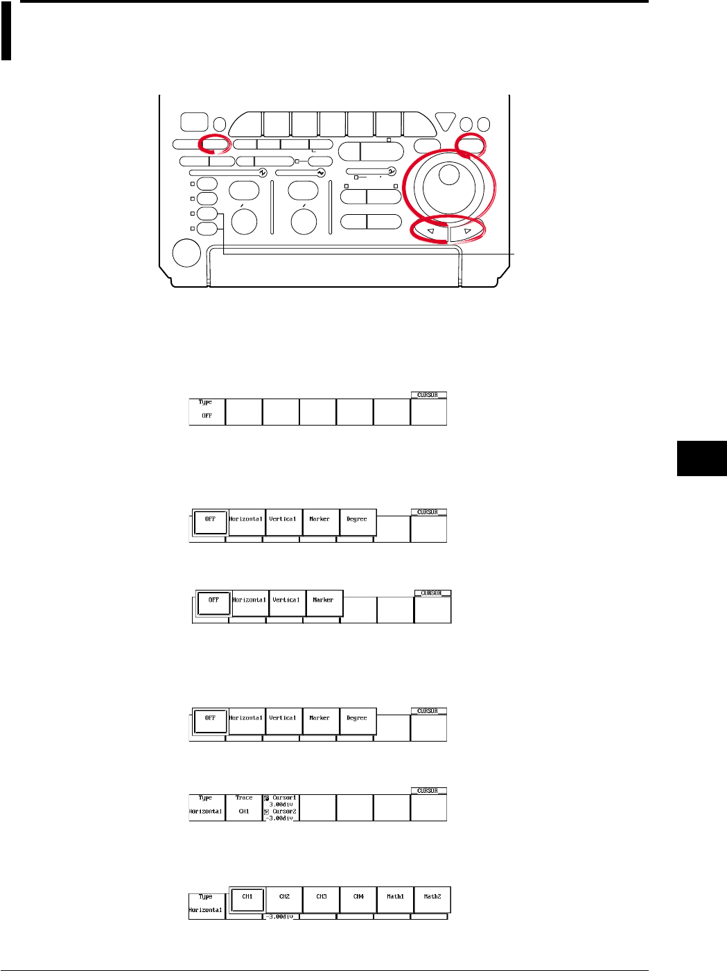
9-1
IM 701710-01E
Waveform Analysis
9
9.1 Measuring Waveforms Using Cursors
<For a description of this function, refer to page 1-21>
Relevant Keys
ACTION DELAY
X - Y MENU MENU PHASE
SEARCH
HORIZONTAL
VERTICAL TRIGGER
TRIG D
HELP
ESC
SELECTRESET
SIMPLE
MODE POSITION
MATH
MISCFILE
CLEAR
TRACE
HISTORY
MEASURE
SETUP
PRESET
DISPLAY
CURSOR
CH
1
CH
2
CH
3
CH
4
POWER
COPY IMAGE SAVE SHIFT
ZOOM
GO/NO-GO
ENHANCED
ACQ START/STOP
SNAP
SHOT
V DIV TIME DIV
The DL1720 is not
equipped with
an input terminal
for CH3 or CH4.
Operating Procedure
Selecting the Cursor Type
1. Press CURSOR.
2. Pressing the Type soft key displays the cursor type menu.
3. Press the soft key corresponding to the desired cursor type to select the cursor.
When not Displaying the X-Y Waveform
When Displaying the X-Y Waveform
For H (Horizontal) Cursors (When Not Displaying the X-Y Waveform)
Selecting the Waveform to be Measured
Refer to steps 1-3 to set the Type to Horizontal.
4. Pressing the Trace soft key displays the waveform menu.
5. Press the soft key corresponding to the desired waveform. (The CH3, CH4, and
Math2 soft keys are not displayed on the DL1720.)
Chpater 9 Waveform Analysis
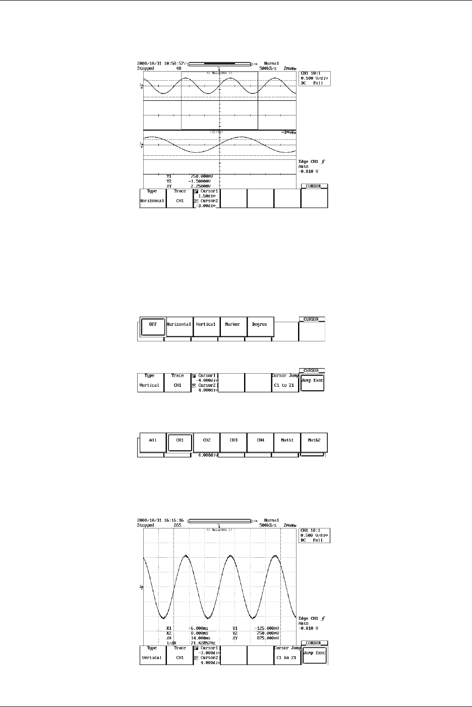
9-2 IM 701710-01E
Moving the Cursor
6. Press the Cursor1/Cursor2 soft key to set the jog shuttle control to Cursor1.
7. Turn the jog shuttle to move Cursor1.
8. Move Cursor2 in a similar fashion.
If the jog shuttle control is set to both Cursor1 and Cursor2, both cursors are
moved.
For V (Vertical) Cursors (When Not Displaying the X-Y Waveform)
Selecting the Waveform to be Measured
Refer to steps 1-3 to set the Type to Vertical.
4. Press the Trace soft key to display the waveform selection menu.
5. Press the soft key corresponding to the desired waveform to select it. (The CH3,
CH4, and Math2 soft keys are not displayed on the DL1720.)
Moving the Cursor
6. Press the Cursor1/Cursor2 soft key to highlight the jog shuttle icon for Cursor1.
7. Move Cursor1 using the jog shuttle.
8. In the same manner, move Cursor2. If you highlight the jog shuttle icon for
Cursor1 and Cursor2, you can move them at the same time.
9.1 Measuring Waveforms Using
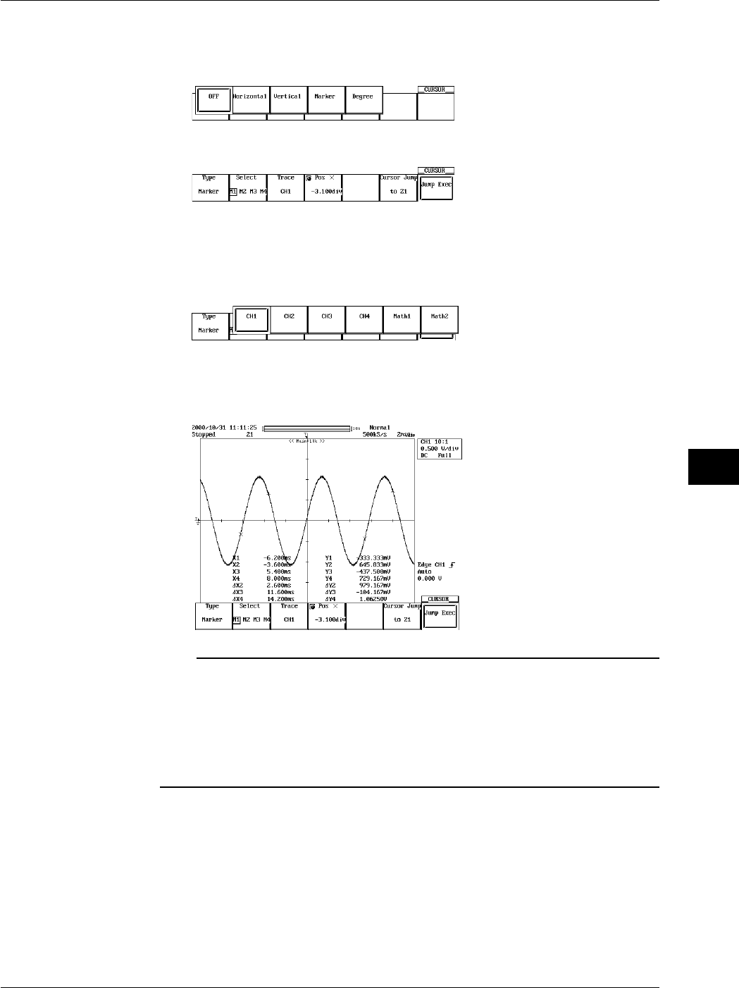
9-3
IM 701710-01E
Waveform Analysis
9
For Marker Cursors (When Not Displaying the X-Y Waveform)
Selecting the Marker
Refer steps 1-3 to set the Type to Marker.
4. Press the Select soft key to select a marker from M1 to M4.
Selecting the Waveform to be Measured
5. Pressing the Trace soft key displays the waveform menu.
6. Press the soft key corresponding to the desired waveform. (The CH3, CH4, and
Math2 soft keys are not displayed on the DL1720.)
Moving the Cursor
7. Turn the jog shuttle to move the cursor. As the cursor is moved, the displayed
value of Position changes.
Note
When the T/div is not set to repetitive sampling mode and the averaging mode is not set to
averaging mode, the sampled data may not appear on the V cursor on the interpolated
display area (when less than 500 points of data exist within 10 divisions horizontally or when
less than 250 points of data exist in the Z1Z2 display area for Main&Z1&Z2 waveform zoom).
In this case, the V cursor value indicates the value of the nearest sampled data to the right of
the cursor (for interpolated display, the sampled data is highlighted). However, the marker
cursor is always displayed over the sampled data.
9.1 Measuring Waveforms Using
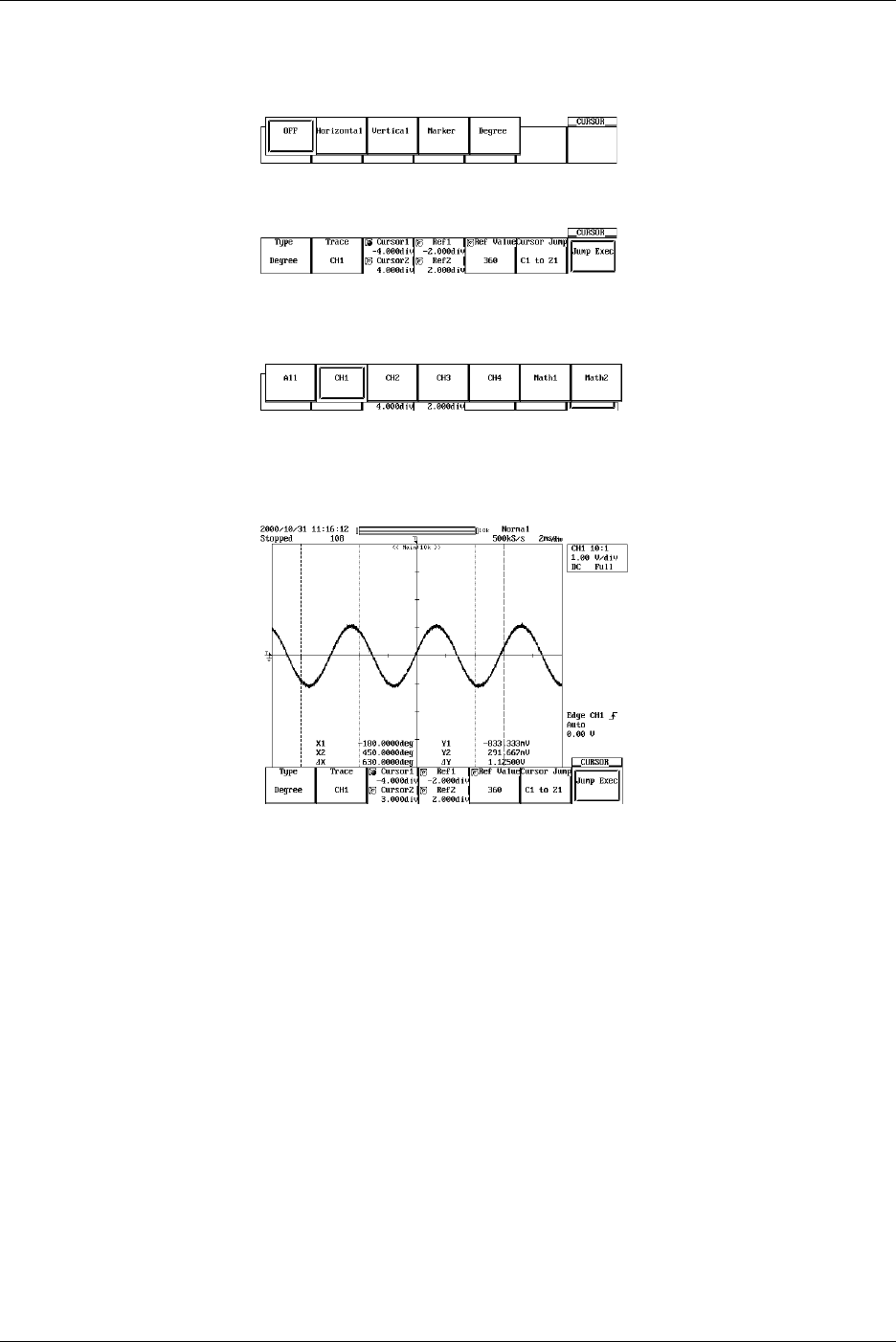
9-4 IM 701710-01E
For Angle (Degree) Cursors (When Not Displaying the X-Y Waveform)
Selecting the Waveform to be Measured
Follow steps 1-3 to set the Type to Degree.
4. Pressing the Trace soft key displays the waveform menu.
5. Press the soft key corresponding to the desired waveform. (The CH3, CH4, and
Math2 soft keys are not displayed on the DL1720.)
Moving the Cursor
6. Press the Cursor1/Cursor2 soft key to set the jog shuttle control to Cursor1.
7. Turn the jog shuttle to move Cursor1.
8. Move Cursor2 in a similar fashion.
If the jog shuttle control is set to both Cursor1 and Cursor2, both cursors are
moved.
Moving the Reference Cursor
9. Press the Ref1/Ref2 soft key to set the jog shuttle control to Ref1.
10. Turn the jog shuttle to move Ref1.
11. Move Ref2 in a similar fashion.
If the jog shuttle control is set to both Ref1 and Ref2, both cursors are moved.
Setting the Reference Angle
12. Press the Ref Value soft key.
13. Turn the jog shuttle to set the reference angle.
9.1 Measuring Waveforms Using
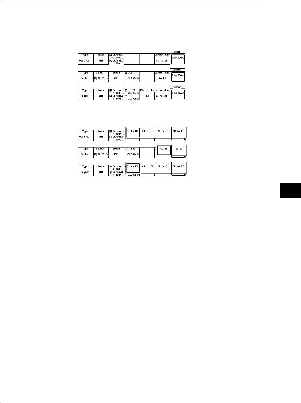
9-5
IM 701710-01E
Waveform Analysis
9
Cursor Jump (for V-Cursor, Marker Cursor, and Angle Cursor: Only when Not
Displaying the X-Y Waveform)
Follow stteps 1-3 to set the Type to Vertical, Marker, or Degree.
4. Pressing the Cursor Jump soft key displays a menu used to select the cursor you
wish to jump and the jump destination.
5. Press the soft key corresponding to the desired jump type and select the cursor to
jump and the jump destination.
6. Pressing the Jump Exec soft key moves the cursor to the jump destination.
9.1 Measuring Waveforms Using
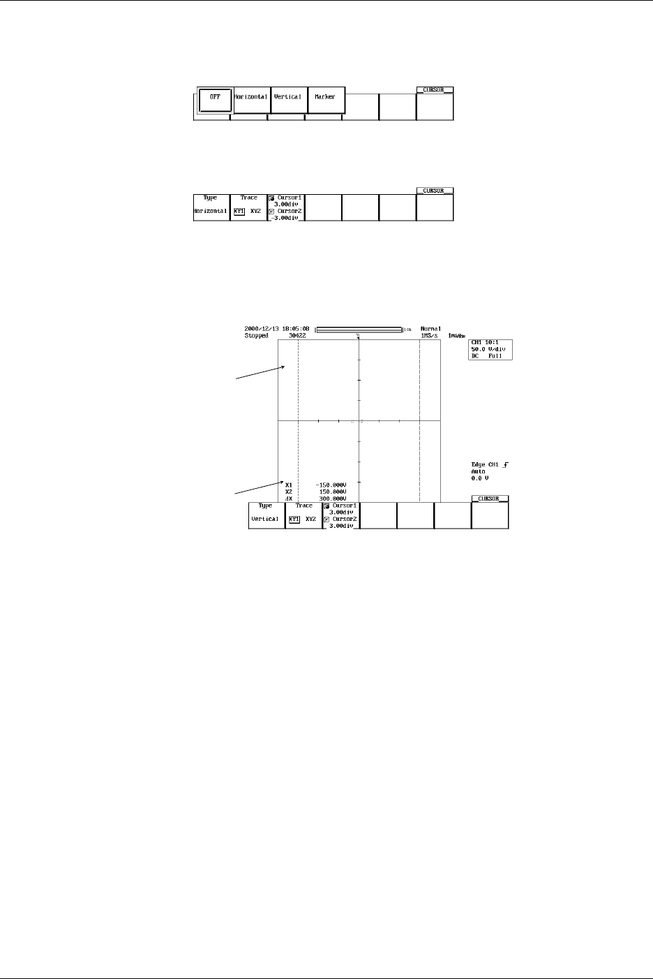
9-6 IM 701710-01E
For H (Horizontal) Cursors (When Displaying the X-Y Waveform)
Selecting the waveform to be measured
Refer to steps 1-3 to set the Type to Horizontal.
4. Press the Trace soft key to select the desired waveform. (XY2 is not available on
the DL1720, so there is no Trace setting.)
Moving the Cursor
5. Press the Cursor1/Cursor2 soft key to set the jog shuttle control to Cursor1.
6. Turn the jog shuttle to move Cursor1.
7. Move Cursor2 in a similar fashion.
Cursor1
Cursor2
If the jog shuttle control is set to both Cursor1 and Cursor2, both cursors are
moved.
9.1 Measuring Waveforms Using
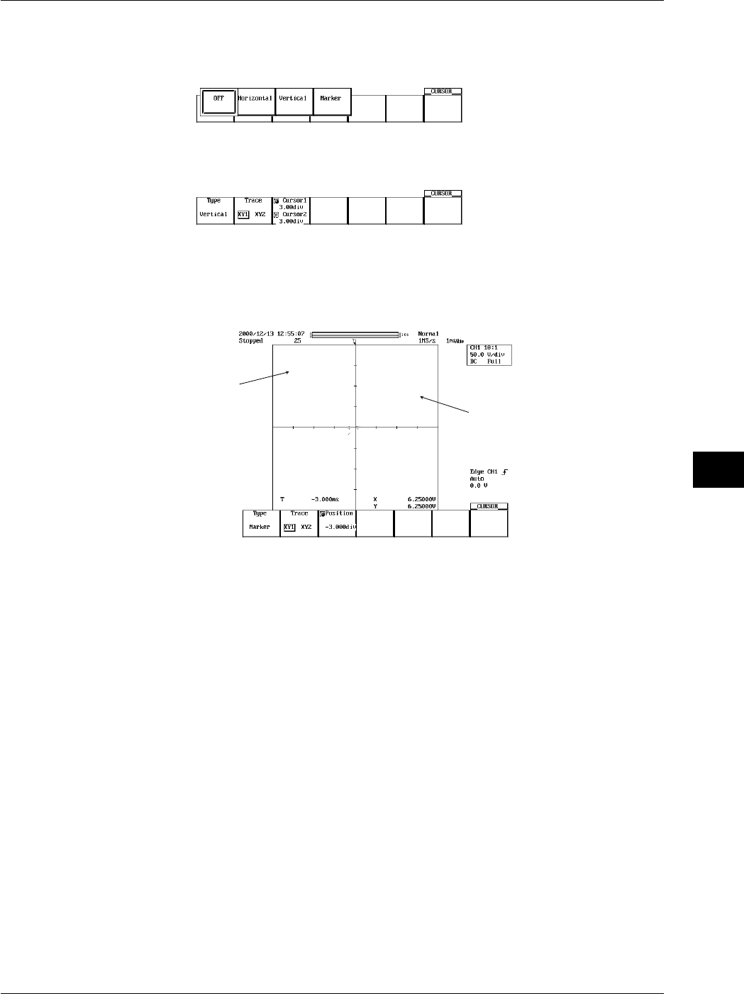
9-7
IM 701710-01E
Waveform Analysis
9
For V (Vertical) Cursors (When Displaying the X-Y Waveform)
Selecting the Waveform to be Measured
Refer to steps 1-3 to set the Type to Horizontal.
4. Press the Trace soft key to select the desired waveform. (XY2 is not available on
the DL1720, so there is no Trace setting.)
Moving the Cursor
5. Press the Cursor1/Cursor2 soft key to set the jog shuttle control to Cursor1.
6. Turn the jog shuttle to move Cursor1.
7. Move Cursor2 in a similar fashion.
Cursor1
Cursor2
If the jog shuttle control is set to both Cursor1 and Cursor2, both cursors are
moved.
9.1 Measuring Waveforms Using
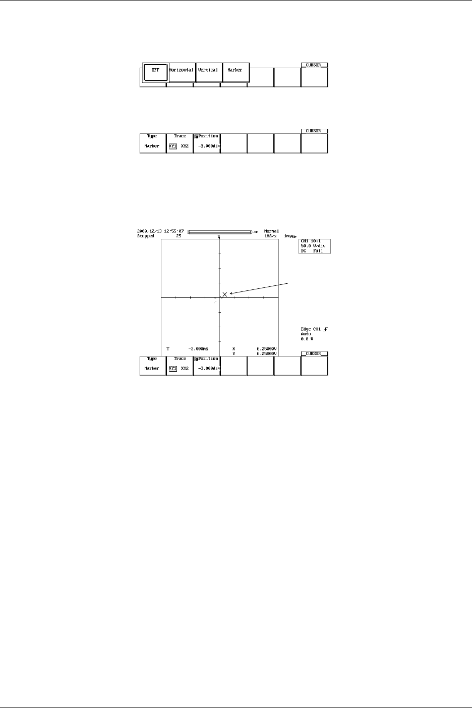
9-8 IM 701710-01E
For Marker Cursors (When Displaying the X-Y Waveform)
Selecting the Marker
Refer to steps 1-3 to set the Type to Marker.
4. Press the Trace soft key to select the desired waveform. (XY2 is not available on
the DL1720, so there is no Trace setting.)
Moving the Cursor
5. Press the Position soft key to set the jog shuttle control to Position.
6. Turn the jog shuttle to move the cursor. As the cursor is moved, the displayed
value of Position changes.
Cursor1
Explanation
Restrictions
Cursor measurements cannot be made on the following waveforms.
•Snapshot waveforms
•Accumulated waveforms other than the newest waveform
Cursor Types and Measurement Items: Type (When Not Displaying the X-Y
Waveform)
•H (Horizontal) Cursor
Measures the Y-axis value at the cursor
Y1: The Y-axis value at Cursor1
Y2: The Y-axis value at Cursor2
DY: The difference between the Y-axis values at Cursor1 and Cursor2
•V (Vertical) Cursor
Measures the X-axis value at the cursor.
Also choose the order of the data.
X1: The X-axis value at Cursor1
X2: The X-axis value at Cursor2
DX : The difference between the Y-axis values at Cursor1 and Cursor2
1/DX: The inverse or the difference between the Y-axis values ata Cursor1 and
Cursor2
Y1: The Y-axis value at Cursor1
Y2: The Y-axis value at Cursor2
DY: The difference between the Y-axis values at Cursor1 and Cursor2
9.1 Measuring Waveforms Using

9-9
IM 701710-01E
Waveform Analysis
9
•Marker Cursors
Move the cursor on the waveform data and measure the waveform data values.
M1 (Marker 1) to M4 (Marker 4) can be set on different waveforms.
Y1 to Y4: The Y-axis values of M1 to M4
DY2: The difference between the Y-axis values of M1 and M2
DY3: The difference between the Y-axis values of M1 and M3
DY4: The difference between the Y-axis values of M1 and M4
X1 to Z4: The X-axis values of M1 to M4
DX2: The difference between the X-axis values of M1 to M2
DX3: The difference between the X-axis values of M1 to M3
DX4: The difference between the X-axis values of M1 to M4
•Angle Cursor (Degree)
Set the measurement zero point (position of reference cursor Ref1) and the end point
(position of the reference cursor Ref2) on the X-axis within the screen and assign an
angle corresponding to the width of Ref1 and Ref2. Using this angle as a reference,
this function measures the angle of the two angle cursors (Cursor1 and Cursor2).
DX1: The angle of Cursor1 from Ref1
DX2: The angle of Cursor2 from Ref1
DDX: The angle difference between Cursor1 and Cursor2
DY1: The Y-axis value of Cursor1
DY2: The Y-axis value of Cursor2
DDY: The difference between the Y-axis values of Cursor1 and Cursor2
Range of reference width: 1 to 720°
Cursor types and Measurement Items: Type (When Displaying the X-Y Waveform)
•H (Horizontal) Cursor
Measures the Y-axis value at the cursor
Y1: The Y-axis value at Cursor1
Y2: The Y-axis value at Cursor2
DY: The difference between the Y-axis values at Cursor1 and Cursor2
•V (Vertical) cursor
Measures the X-axis value at the cursor
When measuring the logic waveform with the V Coursor, select a binary or 16-base
measurement value. Also choose the order of the data.
X1: The X-axis value at Cursor1
X2: The X-axis value at Cursor2
DX: The difference between the Y-axis values at Cursor1 and Cursor2
•Marker Cursors
Move the cursor on the waveform data and measure the waveform data values.
T: The time difference from the trigger point at the cursor
X: The X-axis value at Cursor
Y: The Y-axis value at Cursor
Movement Range of the Cursors (When Not Displaying the X-Y Waveform)
H Cursors can be moved in the range from –4 to +4 div from the center of the screen.
The resolution is 0.01 div.
V Cursors, marker cursors, and angle cursors can be moved in the range from –5 to +5
div from the center of the screen. The resolution is as follows:
Resolution: T/div × 10/displayed record length
9.1 Measuring Waveforms Using

9-10 IM 701710-01E
9.1 Measuring Waveforms Using
Movement Range of the Cursors (When Displaying the X-Y Waveform)
H Cursors and V Cursors can be moved in the range from –4 to +4 div from the center of
the screen. The resolution is 0.01 div.
Marker cursors can be moved in the range from –5 to +5 div from the center of the
screen. The resolution is as follows:
Resolution: T/div × 10/displayed record length
Cursor Jump (When Not Displaying the X-Y Waveform)
You can make Marker cursors, V cursors, and angle cursors jump to the center of the
zoom window. The cursors can be jumped in the following manner.
For marker cursors
to Z1: Make the selected marker jump to the Z1 window.
to Z2: Make the selected marker jump to the Z2 window.
V cursor and angle cursor
C1 to Z1: Make Cursor1 jump to the Z1 window
C1 to Z2: Make Cursor1 jump to the Z2 window
C2 to Z1: Make Cursor2 jump to the Z1 window
C2 to Z2: Make Cursor2 jump to the Z2 window
Notes when Making Cursor Measurements
•The time axis values are measured from the trigger position.
•The measured value will display “***,” if the measurement is not possible.
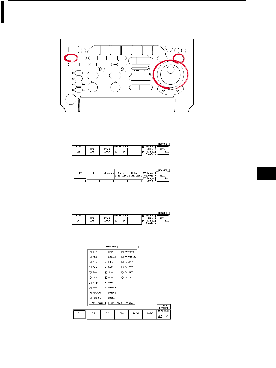
9-11
IM 701710-01E
Waveform Analysis
9
9.2 Automated Measurement of Waveform
Parameters
<For a description of this function, refer to page 1-22>
Relevant Keys
ACTION DELAY
X - Y MENU MENU PHASE
SEARCH
HORIZONTAL
VERTICAL TRIGGER
TRIG D
HELP
ESC
SELECTRESET
SIMPLE
MODE POSITION
MATH
MISCFILE
CLEAR
TRACE
HISTORY
MEASURE
SETUP
PRESET
DISPLAY
CURSOR
CH
1
CH
2
CH
3
CH
4
POWER
COPY IMAGE SAVE SHIFT
ZOOM
GO/NO-GO
ENHANCED
ACQ START/STOP
SNAP
SHOT
V DIV TIME DIV
The DL1720 is not
equipped with
an input terminal
for CH3 or CH4.
Operating Procedure
1. Press MEASURE.
2. Pressing the Mode soft key displays the automated measurement mode menu.
3. Press the ON soft key to set the automated measurement mode.
Selecting the Measurement Parameter
4. Pressing the Item Setup soft key displays the measurement parameter dialog box
and the measurement channel dialog box.
5. Press the soft key corresponding to the desired measurement channel. (The CH3,
CH4, and Math2 soft keys are not displayed on the DL1720.)
6. Turn the jog shuttle to move the cursor to the parameter you wish to turn ON.
You can turn OFF all parameters at once by selecting All Clear.
You can copy the current parameter settings to all traces by selecting Copy to All
Trace.
7. Press SELECT to turn ON the parameter
8. Repeat steps 5 to 7 as necessary.
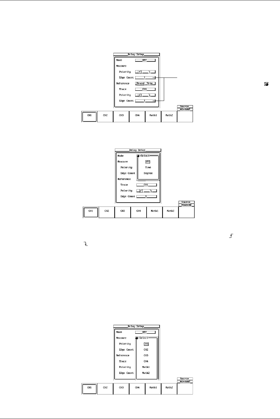
9-12 IM 701710-01E
Setting the Delay (Delay Setup)
9. Pressing the Delay Setup soft key displays the delay setting menu and the
measurement channel dialog box.
10. Press the soft key corresponding to the desired measurement channel. (The CH3,
CH4, and Math2 soft keys are not displayed on the DL1720.)
Settings for the following items can be
input directly using a USB keyboard. ( )
11. Turn the jog shuttle to move the cursor to Mode.
12. Press SELECT to select ON.
13. Turn the jog shuttle to move the cursor to Polarity under Measure.
14. Press SELECT to select whether to measure the rising edge ( ) or the falling edge
().
15. Turn the jog shuttle to move the cursor to Edge Count under Measure.
16. Press SELECT, and turn the jog shuttle to select on which rising or falling edge to
make measurements.
17. Turn the jog shuttle to move the cursor to Reference.
18. Press SELECT to select whether the trace or the trigger is to be the reference.
19. Turn the jog shuttle to move the cursor to Trace.
20. Pressing SELECT displays the reference waveform menu.
21. Turn the jog shuttle to select the reference waveform, then press SELECT. (CH3,
CH4, and Math2 are not displayed on the DL1720.)
9.2 Automated Measurement of Waveform Parameters
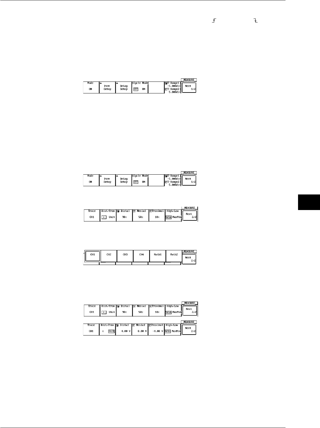
9-13
IM 701710-01E
Waveform Analysis
9
22. Turn the jog shuttle to move the cursor to Polarity under Reference.
23. Press SELECT to select whether to make the rising ( ) or the falling ( ) edge the
reference.
24. Turn the jog shuttle to move the cursor to Edge Count under Reference.
25. Press SELECT to select which rising or falling edge to make the reference.
Setting the 1 Cycle Mode
26. Press the 1 Cycle Mode soft key to select ON or OFF.
Setting the Measurement Range
27. Press the T-Range1/T-Range2 soft key to set the jog shuttle control to T-Range1.
28. Turn the jog shuttle to set the start of the measurement range.
29. Press the T-Range1/T-Range2 soft key to set the jog shuttle control to T-Range2.
30. Turn the jog shuttle to set the end of the measurement range.
Selecting the Target Waveform for Distal, Mesial, and Proximal Points
31. Press the Next 1/2 soft key to display the Next 2/2 menu.
32. Pressing the Trace soft key displays the measured waveform menu.
33. Press the soft key corresponding to the desired waveform. (The CH3, CH4, and
Math2 soft keys are not displayed on the DL1720.)
Setting the Distal, Mesial, and Proximal Unit (Dist/Prox)
34. Press the Next 1/2 soft key to display the Next 2/2 menu.
35. Press the Dist/Prox soft key to select the distal, mesial, or proximal unit.
Setting the Distal, Mesial, and Proximal Points (Distal, Mesial, Proximal)
36. Press the Next 1/2 soft key to display the Next 2/2 menu.
37. Press the Distal, Mesial, or Proximal soft key.
38. Turn the jog shuttle to set the distal, mesial, or proximal point.
Setting the High/Low Point
39. Press the Next 1/2 soft key to display the Next 2/2 menu.
40. Press the High/Low soft key to select Auto or MaxMin.
9.2 Automated Measurement of Waveform Parameters

9-14 IM 701710-01E
9.2 Automated Measurement of Waveform Parameters
Explanation
This function allows automated measurement of various parameters of the data stored in
the acquisition memory. Up to 2400 data points of the result of the automated
measurement can also be saved to a file. (See section 11.9, “Saving the Results of the
Automated Measurement of Waveform Parameters.”)
Restrictions
Automated measurement of waveform parameters cannot be performed on the following
waveforms.
•Snapshot waveforms
•Accumulated waveforms other than the newest waveform
Auto Measurement Mode
ON: Measures the specified item.
Statistic: Performs statistical computation on the measured result of the specified item.
See section 9.3, “Statistical Processing.”
Selecting the High/Low Method: High-Low
High
and
Low
correspond to the 100% level and the 0% level, respectively, that are used
to measure rise and fall times and other parameters. Select one of the two methods
used to set the High and Low levels.
•Auto
Based on the frequency of voltage levels of the waveform within the measurement
range, the higher amplitude level is set to High and the lower amplitude level is set to
Low taking into account the occurrences of ringing and spikes. This method is most
suitable for measuring square waves and pulse waves.
•MaxMin
The maximum and minimum values within the measurement range are set to High
and Low, respectively. This method is most suitable for measuring sine waves and
saw waves. It is not suited to the measurement of waveforms that have ringing and
spikes.
Setting the Distal, Proximal, and Mesial Values: Distal/Prox
Select the appropriate method to set the three levels that are to be used as reference for
such measurements as rise and fall times.
•% (Percentage)
The distal, mesial, and proximal values are set in terms of percentages when High of
any trace (CH1 to CH4, Math1, Math2 (or CH1, CH2, and Math1 for the DL1720)) and
Low are taken to be 100% and 0%, respectively.
•Unit
Set the distal, mesial, and proximal values of any trace (CH1 to CH4, Math1, Math2
(or CH1, CH2, and Math1 for the DL1720)) to arbitrary voltage values.
Setting the Measurement Range: T-Range
With the default setting, the ±5 div of the time axis display frame is the measurement
range. However, this range can be shortened. The measurement range is set using two
vertical cursors. The position of the fine dashed line is the measurement start point and
the position of the coarse dashed line is the end point.
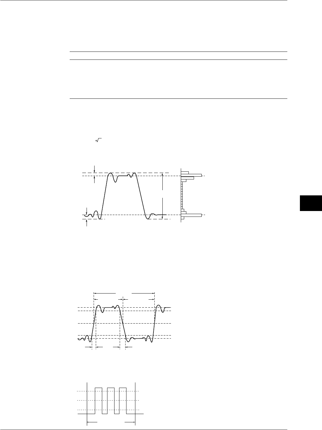
9-15
IM 701710-01E
Waveform Analysis
9
9.2 Automated Measurement of Waveform Parameters
Measurement Parameters: Items
You can select among the 26 types of measurement parameters shown below and delay
between channels. Up to 24000 combinations of parameters of all traces (CH1 to CH4,
Math1, Math2 (or CH1, CH2, and Math1 for the DL1720)) can be saved. The
parameters that can be displayed are as follows:
Auto Measurement Mode Displayed Parameters
ON Up to 12 parameters from all traces. The parameters of channels
having smaller channel numbers have precedence. The
parameters that appear higher in the parameter setting menu have
precedence.
Statistics Up to 2 parameters from all traces. Displays statistical data.
Channels having smaller channel numbers have precedence.
•Voltage-Axis Parameters
P-P
Max
Min
High
Low
+Oshot
-Oshot
: Peak to Peak Value (MAX - MIN)
[
V
]
:
Maximum Voltage [V]
:
Minimum Voltage [V]
:
Root Mean Square Value
(1/ n )(Σ(xi)2)1/2 [V]
:
Average Voltage (1/n)Σxi [V]
: Standard Deviation
(1/n(Σxi2 –(Σxi)2/n))1/2
: Undershoot Value
(LOW - MIN)/(HIGH - LOW) x 100 [%
]
: Overshoot Value
(MAX - HIGH)/(HIGH - LOW) x 100[%
]
:
High Level Voltage [V]
:
Low Level Voltage [V]
*( ) shows the corresponding name at the
measurement item setting screen.
P-P
Max
Min
Rms
Avg
Sdev
(SDv)*
–
Oshot
(
–
Ovr)*
+Oshot
(+Ovr)*
High
Low
•Time-Axis Parameters
+ Width - Width
Period
Distal Line (90%)
Mesial Line (50%)
Proximal Line (10%)
Rise Fall
High (100%)
Low(0%)
: Rise Time [s]
: Fall Time [s]
: Frequency [Hz],1/PERIOD
: Period [s]
: Mean Frequency in
Measuring Range[Hz]
: Mean Period in
Measuring Range[s]
: Width (s) Greater than the Mesial Value
: Width (s) Smaller than the Mesial Value
: Duty Ratio + Width/Period x 100[%]
*( ) shows the corresponding neme at the measurement
item setting screen.
Rise
Fall
Freq
Period
(Prod)*
Avg Freq
(FR-A)*
Avg Period
(PR-A)*
+Width
(+Wd)*
–Width
(–Wd)*
Duty
Mesurement
Range
Pulse : Pulse Count
Mesial Line (50%)
When Pulse=3
Set the measurement range
(T-Range) to match the pulse
width of the signal being measured.
(PlsN)
Distal Line (90%)
Proximal Line (10%)
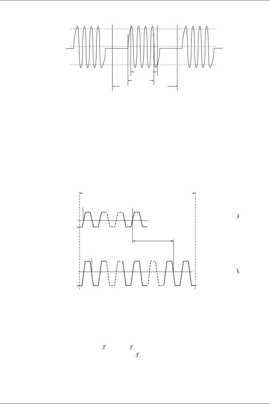
9-16 IM 701710-01E
9.2 Automated Measurement of Waveform Parameters
Burst1
Width
Distal Line (90%)
Proximal Line (10%)
Measurement Range
Set the measurement range
(T-Range) to match the burst
width of the signal being measured.
Burst1, Burst2: Burst Width
(Bst1, Bst2)
T1 cursor T2 cursor
Mesial Line (50%)
Burst2
Width
•Other Measurement Parameters
Int1TY: The area under the positive amplitude
Int2TY: (The area under the positive amplitude) - (the area under the negative
amplitude)
Int1XY: The summation of the triangular area of the X-Y waveform
Int2XY: The summation of the trapezoidal area of the X-Y waveform
* For details regarding the area calculations, see Appendix 2, “How to Calculate the Area of a
Waveform.”
Delay between Channels:
The time difference between the rising or falling edges of trace waveforms or trigger
points is called the
delay between channels
.
Reference
Waveform
Measurement
Waveform
1 count N1 count
1 count N2 count
Delay between Channels
•Edge Polarity
•Edge Count
Setting Example
Setting Example of Measurement
Waveform
Measurement Range
: (Rising)
: N1(1 to 9)
•Edge Polarity
•Edge Count : (Falling)
: N2(1 to 9)
Mesial Line
•If Mode is set to Time or Degree, measurements will be made. The default setting is
OFF.
Time: Display the delay between channels as a time
Degree: Display the delay between channels as a degree
Degree=Delay (s)/Period (s) × 360 (deg) The period is that of a standard
waveform.
•Select rising or falling for the slope of the edge to be detected in Edge Polarity.
The default setting is rising .
•Set the number of edges to detect before actually considering it a detection point in
Edge Count. The range is an integer from 1 to 9. The default setting is 1.
•The voltage level at the detection point is the mesial point.

9-17
IM 701710-01E
Waveform Analysis
9
9.2 Automated Measurement of Waveform Parameters
•The parameter name when the measured value is displayed is (Dly).
Note
If the Mode is set to Degree and the reference waveform is Trig, the measured value shows
“***.”
Setting Proximal, Mesial, and Distal: Dist/Prox
Unit: According to Dist/Prox setting.
Proximal Range: 0 to 100 (resolution: 1%) or voltage corresponding to ±8 div (resolution:
V/div × 1/100)
Mesial Range: 0 to 100 (resolution: 1%) or voltage corresponding to ±8 div (resolution:
V/div × 1/100)
Distal Range: 0 to 100 (resolution: 1%) or voltage corresponding to ±8 div (resolution:
V/div × 1/100)
Notes when Making Automated Measurement of Waveform Parameters
•The measured value will display “***,” if the measurement is not possible.
•If the waveform is of small amplitude, measurements may not produce correct results.
•If there are two or more cycles of a waveform in the measurement range, the
measurement is made on the first waveform.
1 Cycle Mode
This mode is used to compute items related to the voltage axis or the area over one
cycle after determining the cycle. This is suited to items such as Rms and Avg that
produce errors depending on the measurement range.
This does not affect the items related to the time axis or the area of the X-Y waveforms.
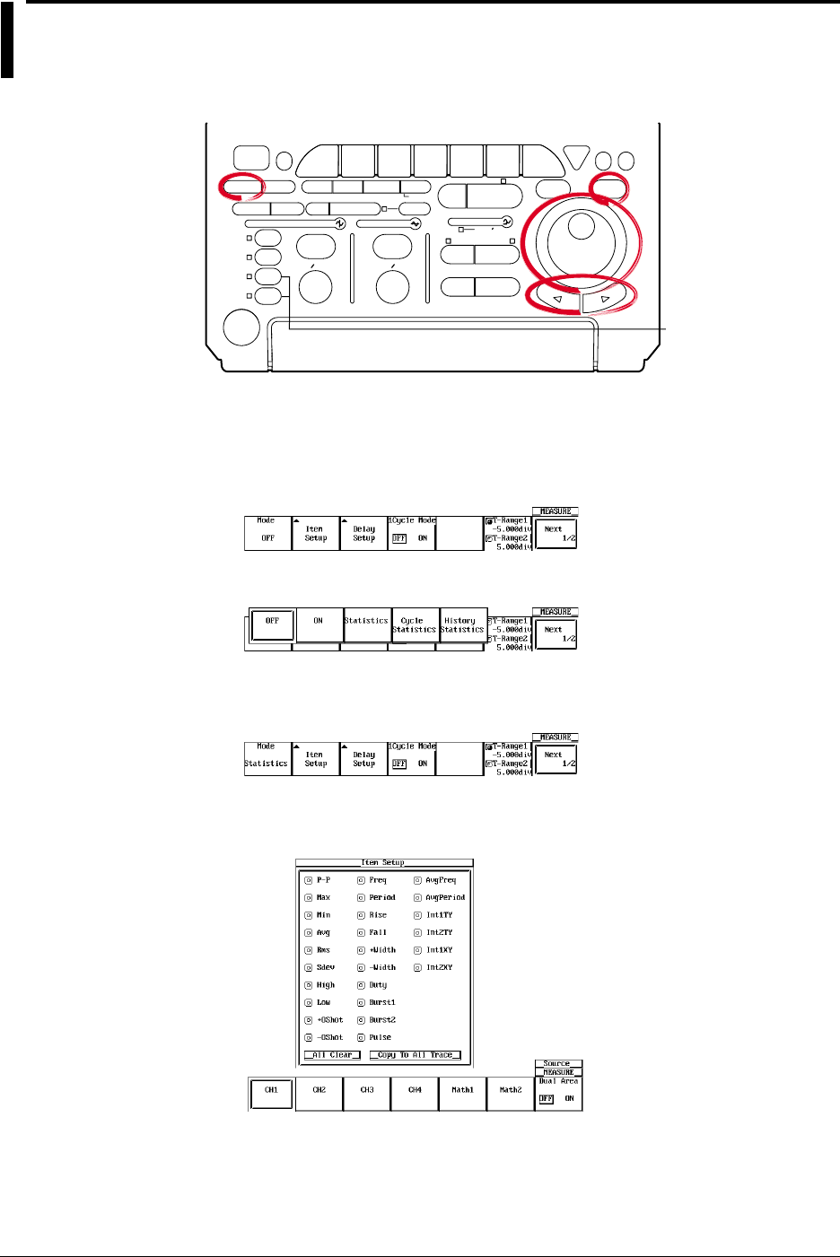
9-18 IM 701710-01E
9.3 Statistical Processing
<For a description of this function, refer to page 1-22>
Relevant Keys
ACTION DELAY
X - Y MENU MENU PHASE
SEARCH
HORIZONTAL
VERTICAL TRIGGER
TRIG D
HELP
ESC
SELECTRESET
SIMPLE
MODE POSITION
MATH
MISCFILE
CLEAR
TRACE
HISTORY
MEASURE
SETUP
PRESET
DISPLAY
CURSOR
CH
1
CH
2
CH
3
CH
4
POWER
COPY IMAGE SAVE SHIFT
ZOOM
GO/NO-GO
ENHANCED
ACQ START/STOP
SNAP
SHOT
V DIV TIME DIV
The DL1720 is not
equipped with
an input terminal
for CH3 or CH4.
Operating Procedure
Statistical Processing
1. Press MEASURE.
2. Pressing the Mod soft key displays the automated measurement mode menu.
3. Press the Statistics soft key to select the statistical processing.
4. Pressing the Item Setup soft key displays the measurement parameter menu and
the measurement channel menu.
5. Press the soft key corresponding to the desired measurement channel. (The CH3,
CH4, and Math2 soft keys are not displayed on the DL1720.)
6. Turn the jog shuttle to move the cursor to the parameter you wish to turn ON.
You can turn OFF all parameters at once by selecting All Clear.
You can copy the current parameter settings to all traces by selecting Copy to All
Trace.
7. Press SELECT to select ON.

9-19
IM 701710-01E
Waveform Analysis
9
8. Repeat steps 5 to 7 as necessary.
The setting of other parameters is the same as that of normal automated measurements
(See section 9.2).
Statistical Processing by Period
1. Press MEASURE.
2. Press the Mode soft key to display the automatic measurement mode selection
menu.
3. Press the Cycle Statistics soft key to select the statistical processing by period.
4. Press the Item Setup soft key to display the measuring item dialog box and the
measurement source channel selection menu.
5. Press the soft key corresponding to the desired measurement source channel to
select it. (The CH3, CH4, and Math2 soft keys are not displayed on the DL1720.)
6. Using the jog shuttle, move the cursor to the item that you wish to set to ON. If you
select All Clear, all items are turned OFF. If you select Copy to All Trace, you can
copy the current settings to all the traces.
7. Press SELECT to turn ON an item.
8. Repeat steps 5-7 as many times as necessary. Press ESC to return to the
automatic measurement mode selection menu.
9. Press the Cycle Trace soft key to display the period waveform selection menu.
9.3 Statistical Processing
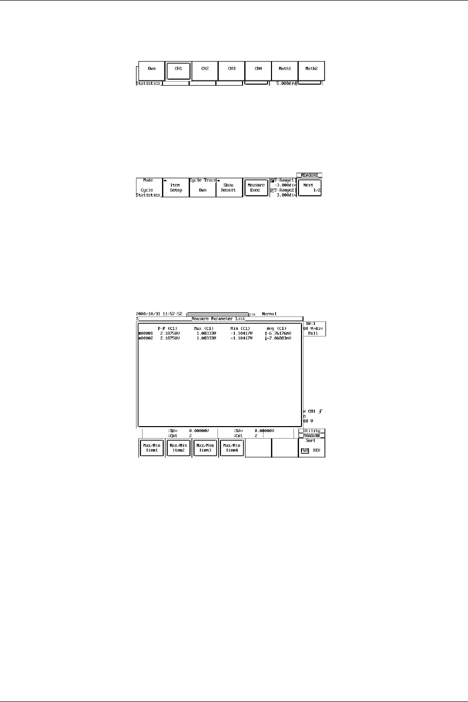
9-20 IM 701710-01E
10. Press the soft key corresponding to the source channel for the period. If Own is
selected, each waveform’s own period is used for its statistical processing. (The
CH3, CH4, and Math2 soft keys are not displayed on the DL1720.)
The other settings are the same as for normal automatic measurement (please see
section 9.2).
11. Press the Measure Exec soft key to perform the statistical processing. Press the
key again to stop statistical processing.
12. Press the Show Results soft key to display a list of the automatic measurement
results. Use the arrow keys to scroll the list horizontally, and the jog shuttle to
scroll vertically.
Press the Max/Min Item1 - Max/Min Item4 soft keys to move the cursor to the
maximum and minimum values. From the left of the displayed parameters are
Item1, Item2, Item3, and Item4. You can change the order to ascending (FWD) or
descending (REV) with the Sort soft key.
9.3 Statistical Processing
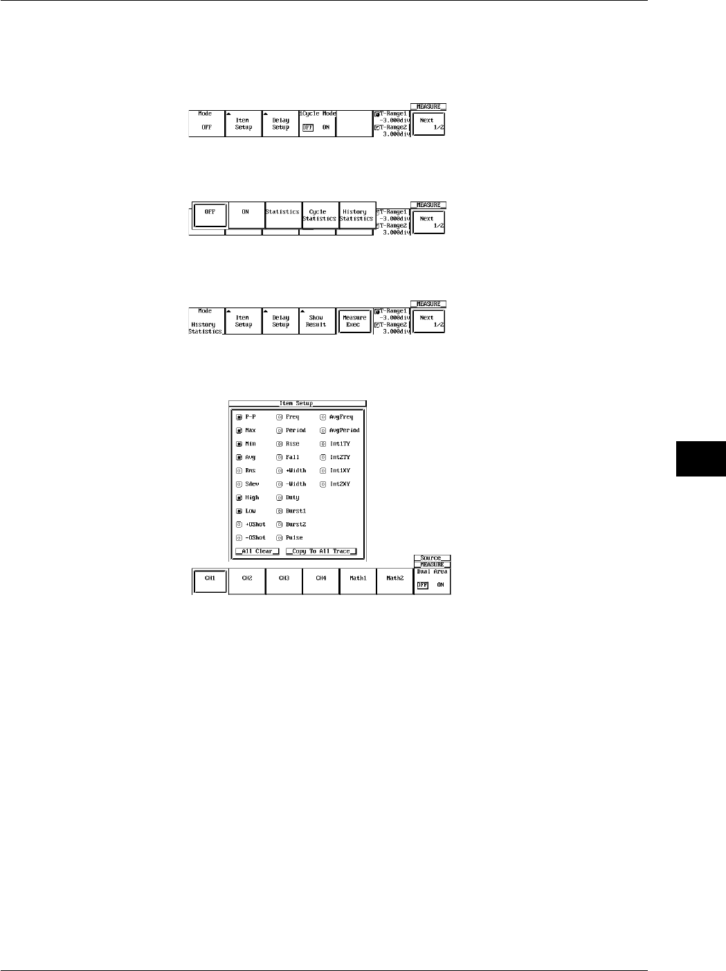
9-21
IM 701710-01E
Waveform Analysis
9
Statistical Processing with History Data
1. Press MEASURE.
2. Press the Mode soft key to display the automatic measurement mode selection
menu.
3. Press the History Statistics soft key to select the statistical processing with history
data.
4. Press the Item Setup soft key to display the measurement item dialog box and the
measuring source channel selection menu.
5. Press the soft key corresponding to the measuring source channel to select it. (The
CH3, CH4, and Math2 soft keys are not displayed on the DL1720.)
6. Using the jog shuttle, move the cursor to the item you wish to turn ON. If you
select All Clear, you can turn OFF all the items at once. If you select Copy to All
Trace, you can copy the current settings to all of the traces.
7. Press SELECT to turn ON the item.
8. Repeat steps 5-7 as many times as necessary. Press ESC to return to the
automatic measurement mode selection menu.
The other settings are the same as for normal automatic measurement.
9.3 Statistical Processing
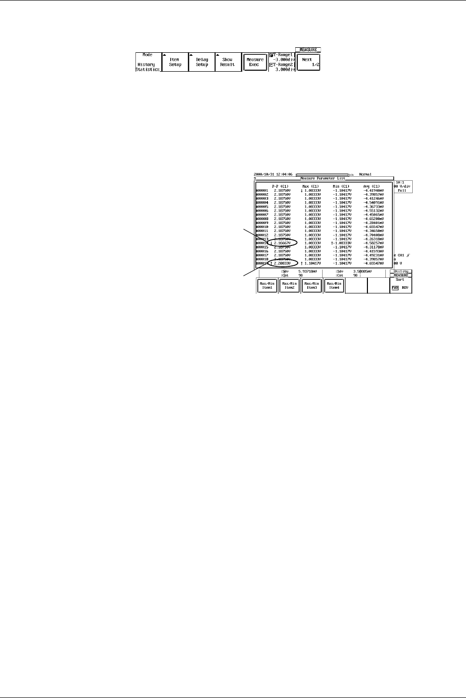
9-22 IM 701710-01E
9.3 Statistical Processing
9. Press the Measure Exec soft key to execute the statistical processing. Press the
key again to stop the statistical processing.
10. Press the Show Result soft key to list the automatic measurement results. Use
the arrow keys to scroll the list horizontally, and the jog shuttle to scroll it vertically.
Press the Max/Min Item1 - Max/Min Item4 soft keys to move the cursor to the
maximum and minimum values of each parameter. From the left side of the
displayed parameter is Item1, Item2, Item3, and Item4. Press SELECT to list the
history waveform indicated by the cursor.
Minimum Value of P-P(CH1)
Maximum Value of P-P(CH1)
Explanation
Performs statistical processing on the same measurement parameters as those of the
automated measurement of waveform parameters. The following five statistics are
determined on the two measured values of automated measurement parameters.
•Max: Maximum value
•Min: Minimum value
•Avg: Average value
•Sdv: Standard deviation
•Cnt: Number of measured values used in the statistical processing
For example, if you selected P-P of CH1 as an automated measurement parameter, the
maximum, minimum, average, standard deviation, and the number of measured values
used in the statistical processing of the P-P of CH1 are displayed.
The result of statistical processing that can be displayed is two parameters of automated
measurement. If you selected three or more parameters for automated measurement,
the first two parameters in the automated measurement parameter selection menu under
Item Setup (P-P, Max, Min,…, Init1XY, and Init2XY) are displayed starting from the
smallest-numbered channel.
For example, if you selected P-P of CH1, Min of CH2, and Max of CH3, P-P of CH1 and
Min of CH2 are displayed. The results of statistical processing that are not displayed can
be loaded into a PC using the communication function. For details, see the
communications interface user’s manual.

9-23
IM 701710-01E
Waveform Analysis
9
9.3 Statistical Processing
The following three methods of statistical processing are available:
•Normal Statistical Processing (Statistics)
Statistical processing is performed on all acquired waveforms while acquiring
waveforms. If you stop waveform acquisition and start it again, statistical processing
continues from where it left off.
Statistical processing is performed on the selected parameters for automated
measurement that are not displayed. Therefore, if you exclude statistical processing
on the automated measurement parameter that is being displayed while waveform
acquisition is in progress, the result of the statistical processing of the next selected
parameter for automated measurement is displayed. The number of measured values
used in the statistical processing (Cnt) is the number of waveforms that have been
acquired up to that point.
If you add statistical processing on a new automated measurement parameter while
waveform acquisition is in progress or when it is stopped, the number of measured
values used in the statistical processing (Cnt) is the number of waveforms that have
been acquired since the parameter was added.
•Statistical Processing for Each Period
Determines the period of the displayed waveform from the oldest data, measures the
selected parameters for automated measurement on the data within the period, and
performs statistical processing. The period is determined in the same fashion as the
period for the waveform parameter. You can select whether to apply the period of the
specified waveform to all waveforms or determine the period for each waveform.
CH1 to CH4, Math1, Math2: Apply the period of the specified waveform to all relevant
(or CH1, CH2, and Math1 waveforms and perform statistical processing.
for the DL1720)
Own: Determine the period for each relevant waveform and
perform statistical processing.
Statistical processing is performed from the oldest data of the displayed waveform in
blocks of periods.
It can not be used with the 1 cycle mode at the same time.
In addition, the following waveform parameters are not measured:
For waveforms whose period is measured:
Avg Freq (average frequency), Avg Period (average
period), PlsN (pulse count), Int1XY (area), Int2XY (area),
and Delay.
For other waveforms: Int1XY (area), Int2XY (area), and Delay.
Note
Statistical processing for each period is not possible on automated measurement of waveform
parameters on dual areas described in section 9.4.
•Statistical Processing of Historical Data
Performs automated measurement of waveform parameters on waveforms that were
acquired using the history memory function and performs statistical processing.
Statistical processing is performed from the oldest waveform. The range on which the
statistics are measured is the waveform that is displayed on Show Map.
It can be used with Delay and 1 cycle mode.

9-24 IM 701710-01E
Target Waveforms
CH1 to CH4, Math1, Math2 (or CH1, CH2, and Math1 for the DL1720)
Automated Measurement Parameters for Statistical Processing
Items of statistical processing per period are given in section 9.2. Items of other
statistical processing are indicated in section 9.2 and 9.4. The result of statistical
processing that can be displayed is only two parameters of automated measurement.
Measurement Range during Statistical Processing
The measurement range is the same as that specified for normal automated
measurement (see section 9.2 and 9.4).
Show Results
If you perform statistical processing for each period or statistical processing of historical
data, a list of measured results can be displayed for the selected automated
measurement parameters.
The waveforms are numbered from the oldest historical data, and the corresponding
results of automated measurement are displayed.
The maximum and minimum values of each waveform parameter are displayed with the
↑ (maximum) and ↓ (minimum) symbols. If there are multiple points that are of the same
value, the maximum and minimum values are marked on the oldest data.
The number of data points that can be listed is 24000. If this value is exceeded, the
most recent 24000 points of automated measurement parameters of historical
waveforms or data are displayed. In this case, the maximum and minimum values may
exist outside the displayed list. In such cases, the maximum ↑ and minimum ↓ values
outside the range are not displayed.
In the list of statistical processing of historical data, you can select a waveform using the
jog shuttle and press SELECT to display the selected historical waveform.
For the statistical processing per period, statistical processing is performed only on the
data that can be listed.
Notes when Performing Statistical Processing
All soft keys except the Measure Abort soft key are disabled while the statistical
processing is in progress.
9.3 Statistical Processing
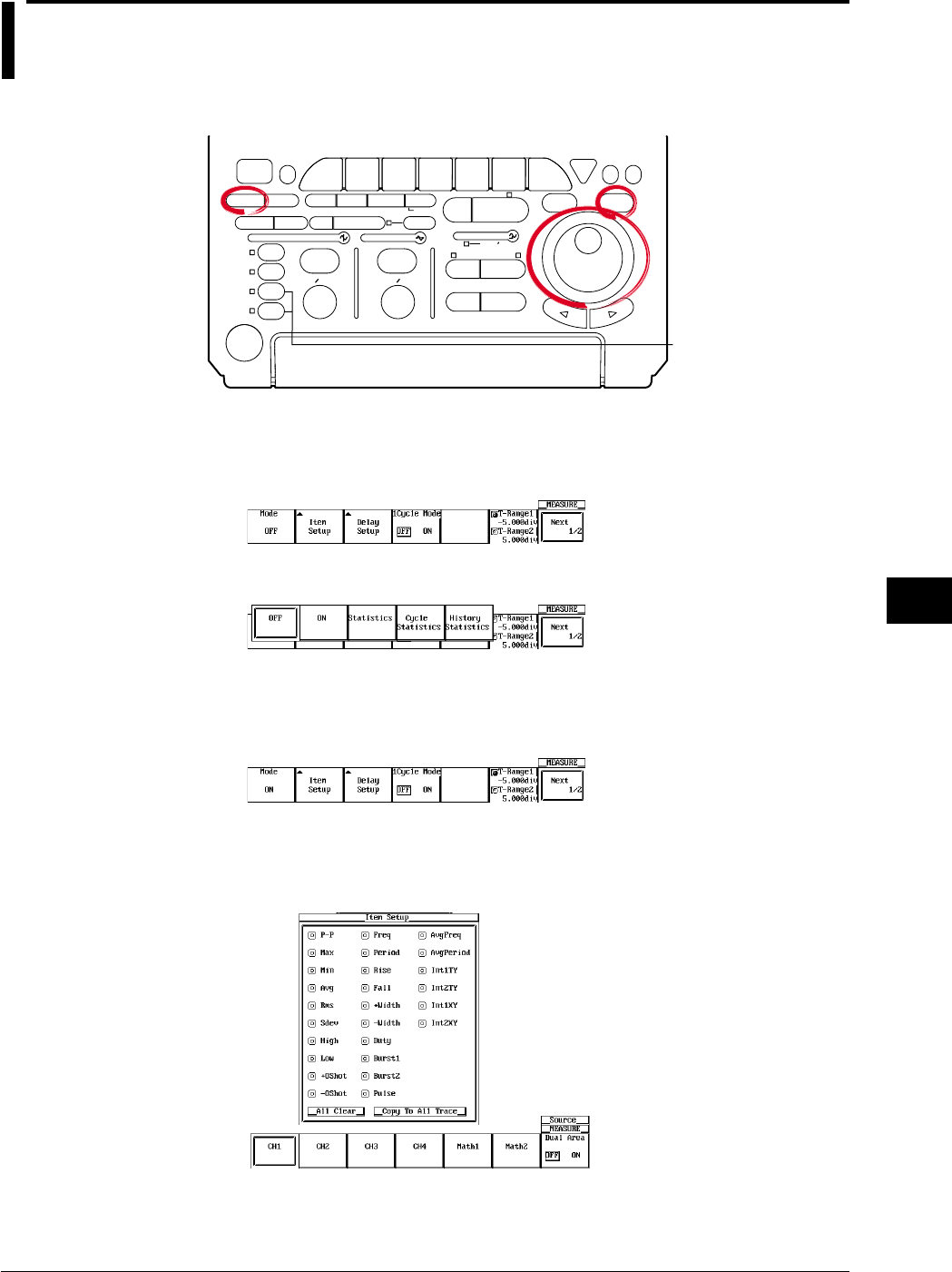
9-25
IM 701710-01E
Waveform Analysis
9
9.4 Performing Automated Measurements of
Waveform Parameters on Dual Areas
<For a description of this function, refer to page 1-23>
Relevant Keys
ACTION DELAY
X - Y MENU MENU PHASE
SEARCH
HORIZONTAL
VERTICAL TRIGGER
TRIG D
HELP
ESC
SELECTRESET
SIMPLE
MODE POSITION
MATH
MISCFILE
CLEAR
TRACE
HISTORY
MEASURE
SETUP
PRESET
DISPLAY
CURSOR
CH
1
CH
2
CH
3
CH
4
POWER
COPY IMAGE SAVE SHIFT
ZOOM
GO/NO-GO
ENHANCED
ACQ START/STOP
SNAP
SHOT
V DIV TIME DIV
The DL1720 is not
equipped with
an input terminal
for CH3 or CH4.
Operating Procedure
1. Press MEASURE.
2. Press the Mode soft key to display the automated measurement mode menu.
3. Press the ON soft key to set the automated measurement mode.
Selecting the Measurement Parameter
4. Press the Item Setup soft key. Dual Area is displayed at the right end of the soft
key menu.
5. Press the Dual Area soft key to turn it ON. (To return to the usual automated
measurement screen, press the Dual Area soft key again to turn it OFF.) (The
CH3, CH4, and Math2 soft keys are not displayed on the DL1720.)
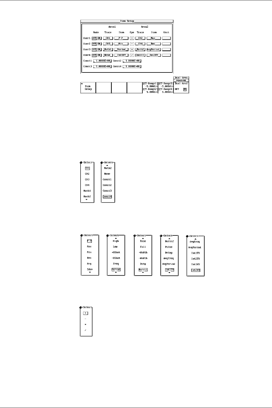
9-26 IM 701710-01E
6. Press the Item Setup soft key to display the waveform parameter dialog box.
7. Turn the jog shuttle to move the cursor to Mode of User1 and press SELECT to
turn it ON.
8. Turn the jog shuttle to move the cursor to Trace of Area1 of User1 and press
SELECT to select the trace from CH1 through CH4, Math1, Math2, None, and
Const1 through Const4 (or CH1 to CH2, Math1, None, and Const1 to Const4 for
the DL1720). If you select None or Const1 through Const4, waveform parameters
are not measured in Area1.
9. Turn the jog shuttle to move the cursor to Item of Area1 of User1 and press
SELECT to select the measurement parameter from P-P through Int2XY.
10. Turn the jog shuttle to move the cursor to Ope of User1 and press SELECT to
select the computation from +, -, *, and /.
11. Set Trace, Item, and Unit for Area2 in a similar fashion.
12. To set constants, turn the jog shuttle to move the cursor to Const1 through Const4.
13. Press SELECT, and set the constant using the jog shuttle. You can set up to four
constants.
9.4 Performing Automated Measurements of Waveform Parameters on Dual Areas
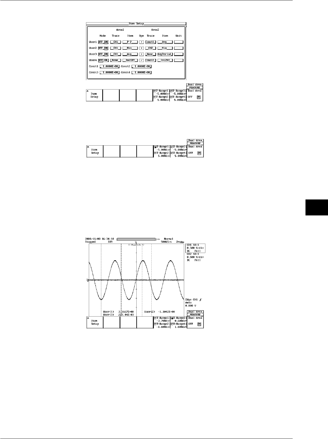
9-27
IM 701710-01E
Waveform Analysis
9
14. To set User2 through User4, repeat steps 7 through 13 as necessary.
Setting the Measurement Range
15. Press ESC.
16. To set the measurement range of Area1, press the T-Range1/T-Range2 soft key.
17. Set the measurement start point of Area1. If the jog shuttle action is not set to T-
Range1, press the T-Range1/T-Range2 soft key to set the action to T-Range1.
18. Turn the jog shuttle to set the start point of the measurement range.
19. Set the measurement end point of Area1. Press the T-Range1/T-Range2 soft key
to set the jog shuttle action to T-Range2.
20. Turn the jog shuttle to set the end point of the measurement range.
21. Set the measurement range of Area2 in a similar fashion by pressing the T-
Range3/T-Range4 soft key.
9.4 Performing Automated Measurements of Waveform Parameters on Dual Areas
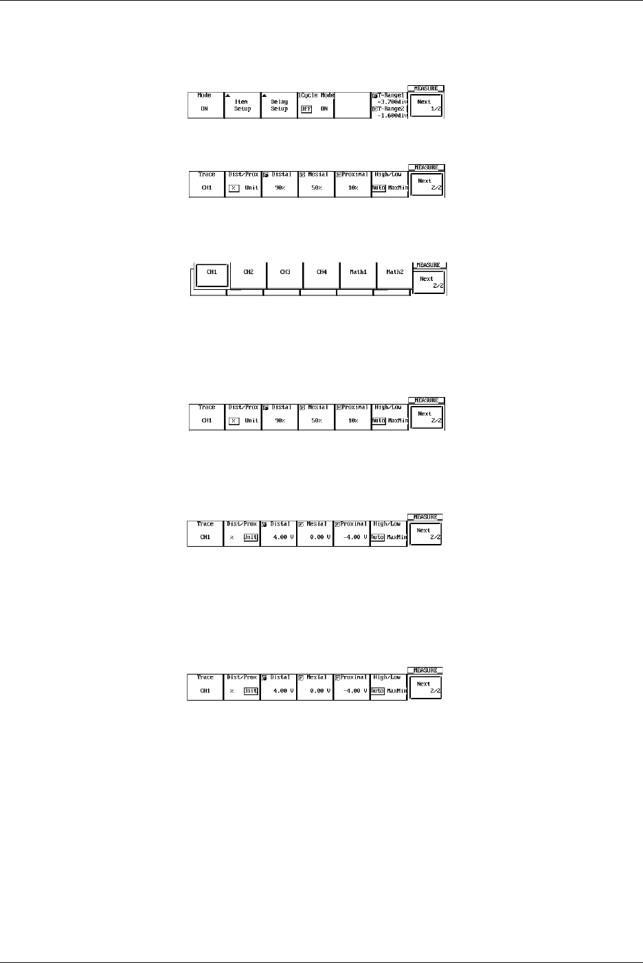
9-28 IM 701710-01E
Selecting the Target Waveform of Distal, Mesial, and Proximal Points
22. Press ESC.
23. Press the Next 1/2 soft key to display the Next 2/2 menu.
24. Press the Trace soft key to display the target waveform selection menu.
25. Press the soft key corresponding to the desired waveform to select the target
waveform. (The CH3, CH4, and Math2 soft keys are not displayed on the DL1720.)
Unit for Distal, Mesial, and Proximal Points (Dist/Prox)
26. Press the Next 1/2 soft key to display the Next 2/2 menu.
27. Press the Dist/Prox soft key to select the unit for distal, mesial, and proximal
points.
Setting the Distal, Mesial, and Proximal Points (Distal, Medial, and Proximal)
28. Press the Next 1/2 soft key to display the Next 2/2 menu.
29. Press the Distal, Mesial, or Proximal soft key.
30. Set the distal point, mesial point, and proximal point using the jog shuttle.
Setting the High and Low Points
31. Press the Next 1/2 soft key to display the Next 2/2 menu.
32. Press the High/Low soft key to select Auto or MaxMin.
9.4 Performing Automated Measurements of Waveform Parameters on Dual Areas

9-29
IM 701710-01E
Waveform Analysis
9
9.4 Performing Automated Measurements of Waveform Parameters on Dual Areas
Explanation
You can perform automated measurement of various measurement parameters
(waveform parameters) on the data retrieved in the acquisition memory over two areas.
You can also perform computation on the measurement parameter (waveform
parameter) values that are determined in the two areas.
Waveforms Excluded from Measurements
The following waveform measurements are not possible in the automated measurement
of waveform parameters.
•Snapshot waveforms
•Accumulated waveforms other than the newest waveform.
Automated Measurement Mode
ON: Performs computation between arbitrary items in Area1 and Area2.
Statistics: Performs statistical processing on the computed results between arbitrary
items in Area1 and Area2. See section 9.3, "Statistical Processing."
Note
Statistical processing for each period (Cycle Statistics) is not possible.
Selecting the High/Low Assignment Method: High-Low
High indicates the 100% level in measurements such as the rise or fall time. And, Low
indicates the 0% level. Select the assignment method of High and Low from the
following two methods.
•Auto
Sets the higher amplitude level to High and lower level to Low within the
measurement range based on the voltage level frequency of the waveform by taking
the effects of ringing, spikes, etc. into consideration. This method is best-suited when
measuring rectangular waveforms and pulse waveforms.
•MaxMin
Sets the maximum value to High and lowest value to Low in the measurement range.
This method is best-suited when measuring sine waveforms, ramp waveforms, etc. It
is not suited for measurement of waveforms with ringing and spikes.
Setting the Distal, Proximal, and Mesial Values: Distal/Prox
Select the method of assigning the three levels that are used as references in
measurements such as the rise and fall times.
•% (Percentage)
Set the distal value, mesial value, and proximal value using a percentage with respect
to an arbitrary trace (CH1 through CH4, Math1, and Math2 (or CH1, CH2, and Math1
for the DL1720)) with High set to 100% and Low set to 0%.
•Unit
Set the distal value, mesial value, and proximal value of an arbitrary trace (CH1
through CH4, Math1, and Math2 (or CH1, CH2, and Math1 for the DL1720)) to an
arbitrary voltage.
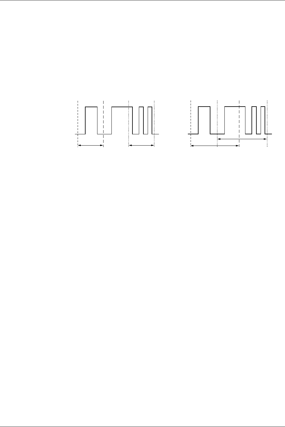
9-30 IM 701710-01E
9.4 Performing Automated Measurements of Waveform Parameters on Dual Areas
Setting the Measurement Range: T-Range
Set the measurement range of Area1 using T-Range1 and T-Range2. Set the
measurement range of Area2 using T-Range3 and T-Range4. In the initial setting, the
measurement range is ±5 divisions of the display frame on the time axis. You can limit
this range. The measurement range is specified using two vertical cursors for each area.
In Area1, the measurement start point is the position where the fine dotted line is
located, and the measurement end point is the position where the coarse dotted line is
located. In Area2, both the measurement start point and measurement end point are
where the fine dotted line is located. The measurement ranges of Area1 and Area2 can
be specified redundantly.
T-Range1
Area1 Area2
T-Range2 T-Range3 T-Range4 T-Range1
Area1
Area2
T-Range2T-Range3 T-Range4
Dual Area Measurement Mode: Mode
If you set the mode in the Item Setup menu to ON, the measurement result is displayed
in the two areas. You can select User1 through User4.
Measurement Trace: Trace
You can select the trace from 11 types (or from 8 types on the DL1720: CH1 to CH2,
Math1, None, and Const1 through Const4.): CH1 through 4, Math1, Math2, None, and
Const1 through Const4. Const1 through Const4 are constants that can be specified
arbitrarily.
Measurement Parameters: Items
Select from 27 types of measurement parameters (P-P, Max, Min, Rms, Avg, Sdev,
High, Low, +OShot, -OShot, Freq, Period, Rise, Fall, +Width, -Width, Duty, Burst1,
Burst2, Pulse, Delay, AvgFreq, AvgPeriod, Int1TY, Int2TY, Int1XY, and Int2XY). For
details on each item, see the “Measurement Parameters: Items” and “Delay between
channels: Delay Setup” sections in section 9.2. If you set the measurement trace to
None or Const1 through Const4, you cannot select the measurement parameter.
Computation: Ope
Select the computation to be performed between items of Area1 and Area2. You can
select +, -, *, or /. If you set the measurement trace to None, the computation is not
performed. In this case, the value of the measurement parameter in the other area is
displayed.
Setting Proximal, Mesial, and Distal: Dist/Prox
Unit: Dist/Prox
Selectable Range of Proximal: 0 to 100 (1% steps) or voltage corresponding to ±8
divisions (1/100 of V/div steps)
Selectable Range of Mesial: 0 to 100 (1% steps) or voltage corresponding to ±8
divisions (1/100 of V/div steps)
Selectable Range of Distal: 0 to 100 (1% steps) or voltage corresponding to ±8
divisions (1/100 of V/div steps)

9-31
IM 701710-01E
Waveform Analysis
9
9.4 Performing Automated Measurements of Waveform Parameters on Dual Areas
Precautions to be Taken when Performing Automated Measurement of Waveform
Parameters
•The measurement value displays “***” if the measurement is not possible.
•For waveforms of small amplitude, correct measurements may not be possible.
•If there are two or more periods of waveform in the measurement range, the
measurement is performed on the first period.
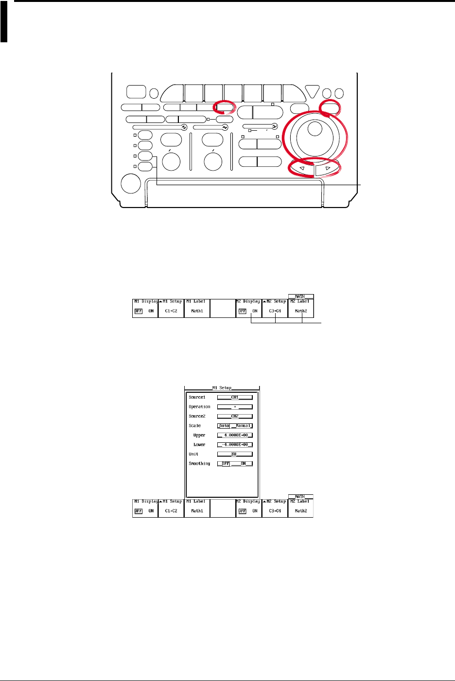
9-32 IM 701710-01E
9.5 Adding, Subtracting, and Multiplying
Waveforms
<For a description of this function, refer to page 1-24>
Relevant Keys
ACTION DELAY
X - Y MENU MENU PHASE
SEARCH
HORIZONTAL
VERTICAL TRIGGER
TRIG D
HELP
ESC
SELECTRESET
SIMPLE
MODE POSITION
MATH
MISCFILE
CLEAR
TRACE
HISTORY
MEASURE
SETUP
PRESET
DISPLAY
CURSOR
CH
1
CH
2
CH
3
CH
4
POWER
COPY IMAGE SAVE SHIFT
ZOOM
GO/NO-GO
ENHANCED
ACQ START/STOP
SNAP
SHOT
V DIV TIME DIV
The DL1720 is not
equipped with
an input terminal
for CH3 or CH4.
Operating Procedure
Turn ON/OFF the display
1. Press MATH.
2. Press the M1 Display soft key and select ON to display Math1 and OFF to not
display M1.
Math2 is not available on
the DL1720, so these soft
keys are not displayed.
Selecting the Channel on which to Perform Computation
3. Press the M1 Setup soft key to display the computation dialog box.
4. Turn the jog shuttle to move the cursor to Source1.
5. Pressing SELECT displays the channel menu.
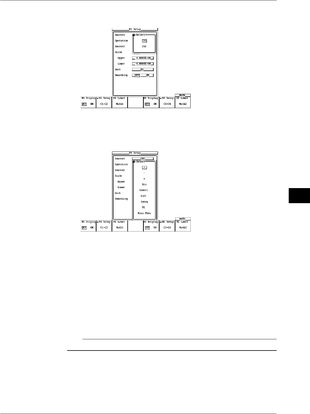
9-33
IM 701710-01E
Waveform Analysis
9
6. Turn the jog shuttle to select the channel on which to perform the computation and
press SELECT.
Setting the Operator
7. Turn the jog shuttle to move the cursor to Operation.
8. Pressing SELECT displays the operator setting menu.
9. Turn the jog shuttle to select +, –, or * and press SELECT.
Selecting the Channel on which to Perform Computation
10. Similar to steps 4 to 6, set Source2.
Scaling
11. Turn the jog shuttle to move the cursor to Scale.
12. Press SELECT to select Auto or Manual. If you select Auto, go to step 17.
13. If you selected Manual, turn the jog shuttle to move the cursor to Upper.
14. Pressing SELECT displays a menu used to set the upper limit of the waveform
display.
15. Turn the jog shuttle to set the upper limit and press SELECT.
16. Set Lower in a similar fashion.
Note
If you select Auto, you cannot set Upper and Lower.
Setting the Unit
17. Turn the jog shuttle to move the cursor to Unit.
18. Using the keyboard that appears when SELECT is pressed enter the unit using
four characters or less.
9.5 Adding, Subtracting, and Multiplying Waveforms
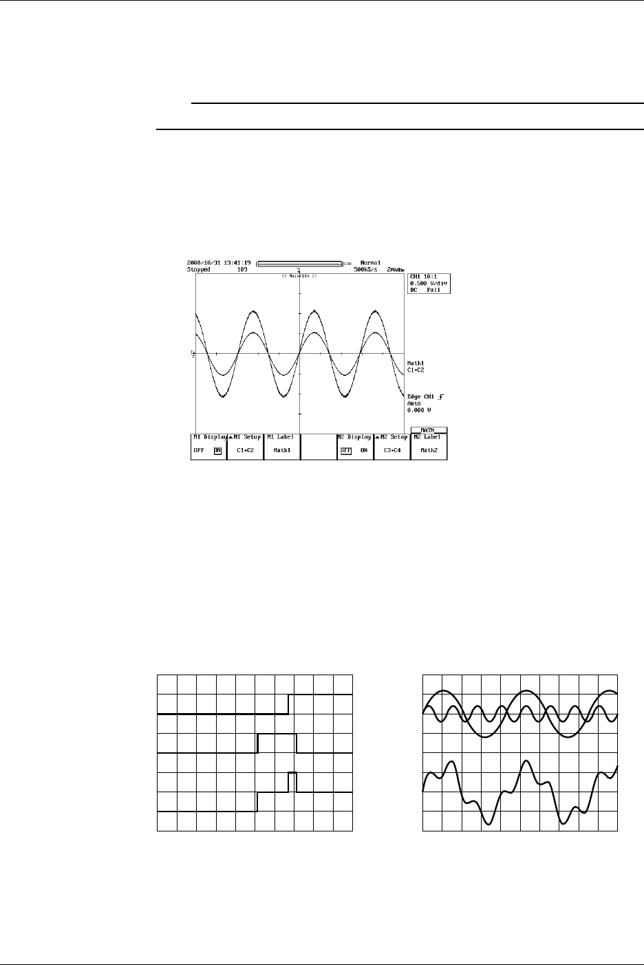
9-34 IM 701710-01E
Smoothing
19. Turn the jog shuttle to move the cursor to Smoothing.
20. Press SELECT to select ON or OFF.
Note
For details regarding smoothing, see section 9.10, “Smoothing.”
Entering Labels
21. Press the M1 Label soft key to display the keyboard, then enter a label. See
section 8.5, “Setting the Waveform Labels” for information about displaying labels.
Set Math2 in a similar manner as necessary.
Explanation
Addition, subtraction, and multiplication can be performed between the following
channels.
DL1740
Math1: CH1 + (CH1 to CH4), CH2 + (CH1 to CH4)
Math2: CH3 + (CH1 to CH4, Math1), CH4 + (CH1 to CH4, Math1)
Math1 and Math2 can be computed simultaneously.
DL1720
Math1: CH1+ (CH1 or CH2), CH2+ (CH1 or CH2)
– Computed Waveform+ Computed Waveform
Scaling
Set the upper and lower limits on computations.
Auto: The upper and lower limits are set according to the computed result.
Manual: The upper and lower limits can be set arbitrarily. The range is –9.9999E+30 to
9.9999E+30.
9.5 Adding, Subtracting, and Multiplying Waveforms

9-35
IM 701710-01E
Waveform Analysis
9
Unit
Unit can be set arbitrarily using up to four characters. The specified characters are
reflected in the scale values.
Smoothing
See section 9.10, “Smoothing.”
About Linear Scaling
When performing computation on a channel that has linear scaling set, the computation
is performed on the scaled value.
9.5 Adding, Subtracting, and Multiplying Waveforms
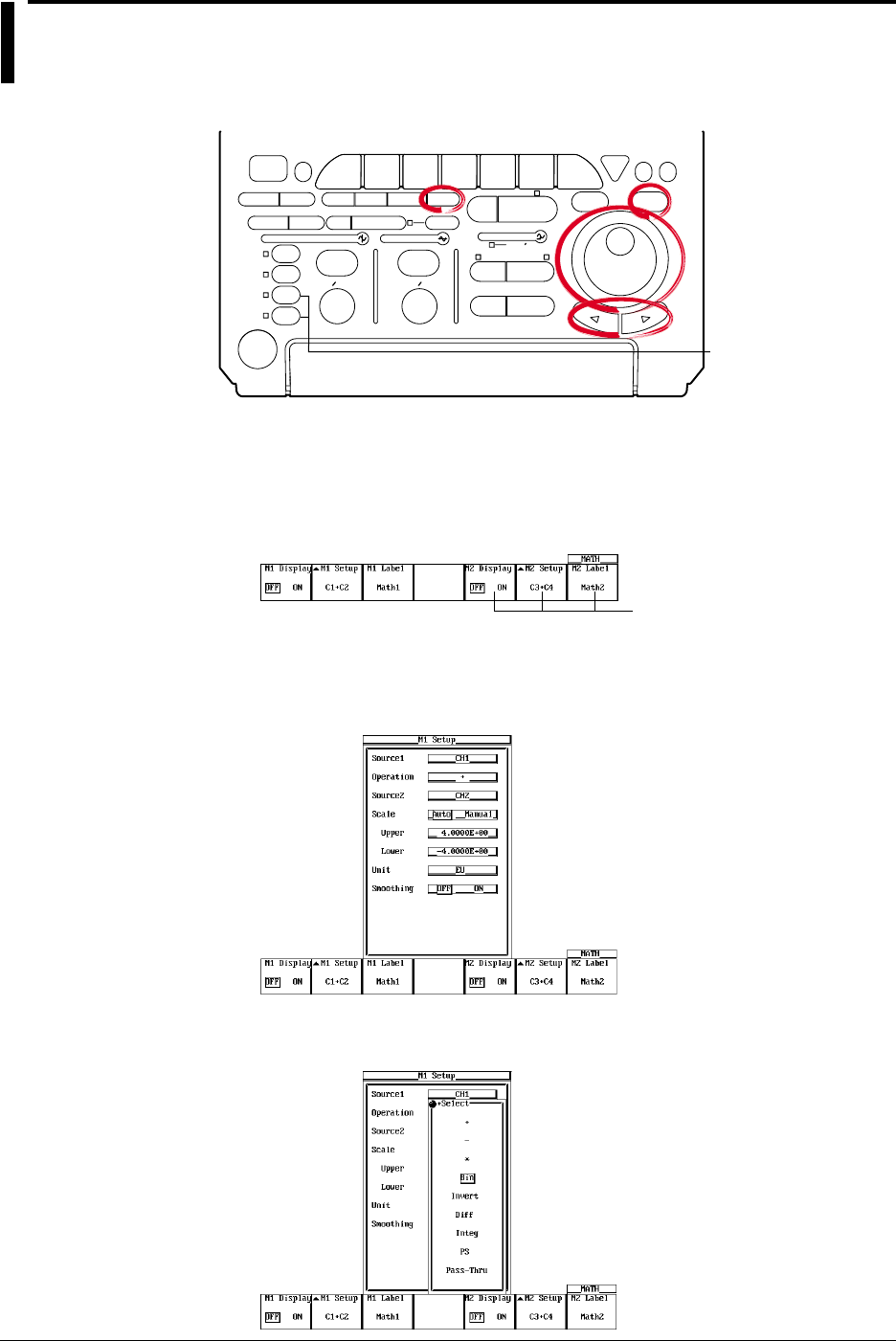
9-36 IM 701710-01E
9.6 Binary Computation
<For a description of this function, refer to page 1-24>
Relevant Keys
ACTION DELAY
X - Y MENU MENU PHASE
SEARCH
HORIZONTAL
VERTICAL TRIGGER
TRIG D
HELP
ESC
SELECTRESET
SIMPLE
MODE POSITION
MATH
MISCFILE
CLEAR
TRACE
HISTORY
MEASURE
SETUP
PRESET
DISPLAY
CURSOR
CH
1
CH
2
CH
3
CH
4
POWER
COPY IMAGE SAVE SHIFT
ZOOM
GO/NO-GO
ENHANCED
ACQ START/STOP
SNAP
SHOT
V DIV TIME DIV
The DL1720 is not
equipped with
an input terminal
for CH3 or CH4.
Operating Procedure
Turning the Display ON/OFF
1. Press MATH.
2. Press the M1 Display soft key and select ON to display Math1 and OFF to not
display Math1.
Math2 is not available on
the DL1720, so these soft
keys are not displayed.
Setting the Operator
3. Press the M1 Setup soft key to display the computation dialog box.
4. Turn the jog shuttle to move the cursor to Operation.
5. Pressing SELECT displays the operator setting menu.
6. Turn the jog shuttle to select Bin and press SELECT.
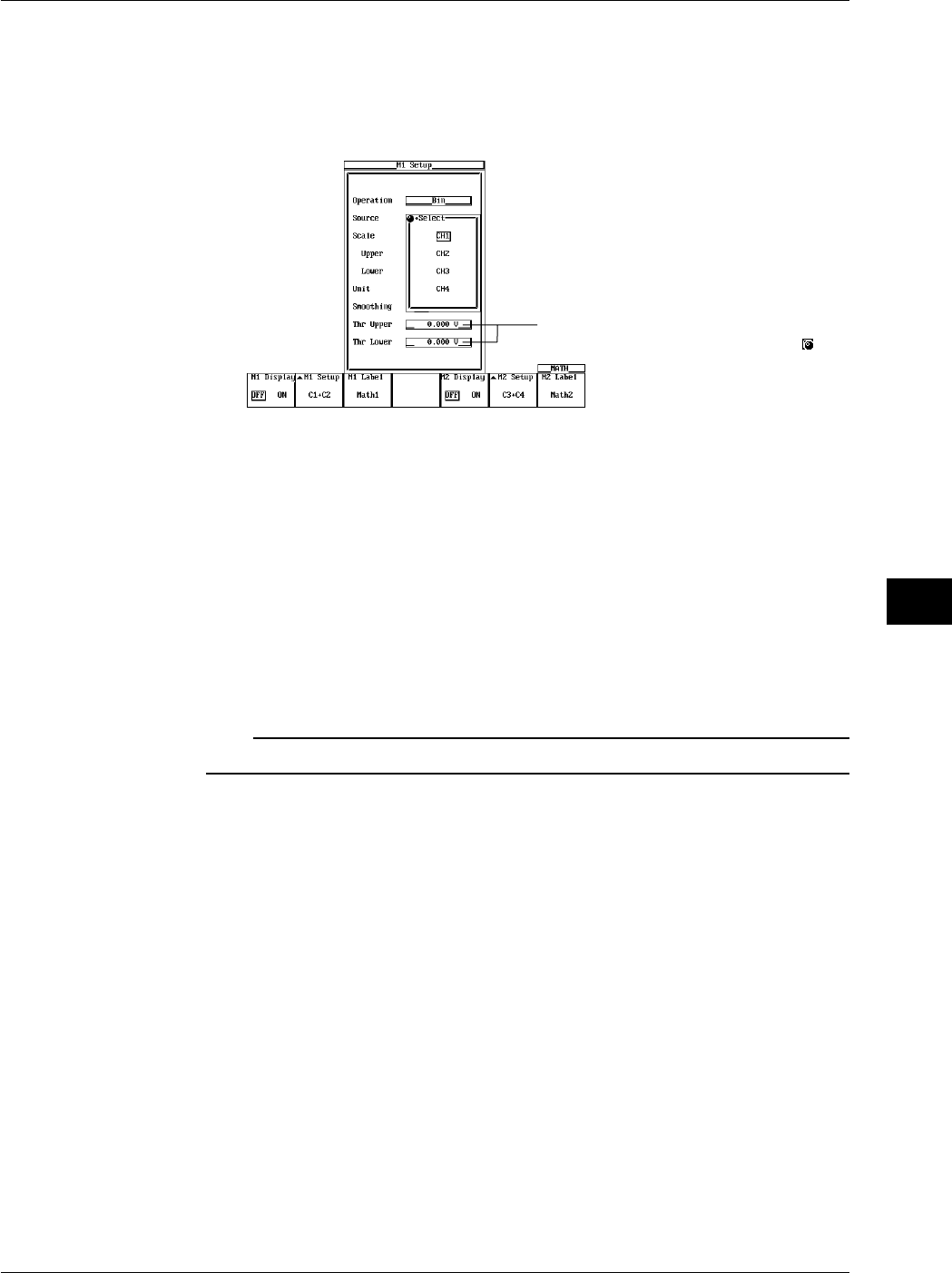
9-37
IM 701710-01E
Waveform Analysis
9
Selecting the Channel on which to Perform Computation
7. Turn the jog shuttle to move the cursor to Source.
8. Pressing SELECT displays the channel setting menu.
9. Turn the jog shuttle to select the channel on which to perform computation and
press SELECT. (CH3 and CH4 are not displayed on the DL1720.)
Settings for the following items can be
input directly using a USB keyboard. ( )
Scaling
The upper limit and lower limit of scaling are fixed to +2 and –2, respectively.
Setting the Unit
10. Turn the jog shuttle to move the cursor to Unit.
11. Using the keyboard that appears when SELECT is pressed enter the unit using
four characters or less.
Smoothing
12. Turn the jog shuttle to move the cursor to Smoothing.
13. Press SELECT to select ON or OFF.
Note
For details regarding smoothing, see section 9.10, “Smoothing.”
Entering Labels
14. Paess the M1 Label soft key to display the keyboard, then enter a label. See
section 8.5, “Setting the Waveform Labels” for in formation on displaying Labels.
9.6 Binary Computation
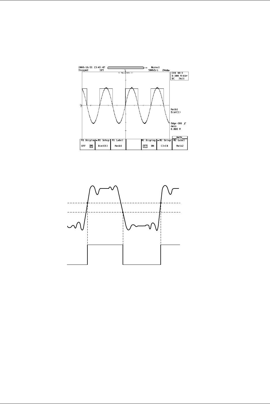
9-38 IM 701710-01E
Setting the Threshold Level
15. Turn the jog shuttle to move the cursor to Thr Upper.
16. Pressing SELECT displays the threshold level setting menu.
17. Turn the jog shuttle to set the threshold level and press SELECT.
18. Set Thr Lower in a similar fashion.
Set Math2 in a similar manner as necessary.
Explanation
This function converts CH1 to CH4 or Math1 waveform (or CH1 to CH2 waveform for the
DL1720) to a digital signal (1 s and 0 s) according to the specified threshold level.
1
0
Upper
Lower
Unit
Unit can be set arbitrarily using up to four characters. The specified characters are
reflected in the scale values.
Smoothing
See section 9.10, “Smoothing.”
9.6 Binary Computation
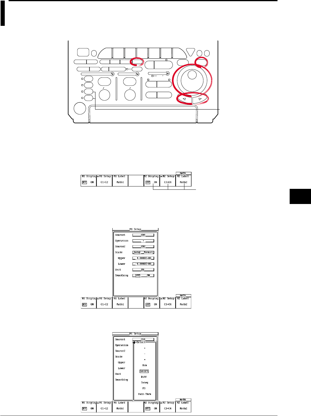
9-39
IM 701710-01E
Waveform Analysis
9
9.7 Inverting the Waveform Display
<For a discription of this function, refer to page 1-24>
Relevant Keys
ACTION DELAY
X - Y MENU MENU PHASE
SEARCH
HORIZONTAL
VERTICAL TRIGGER
TRIG D
HELP
ESC
SELECTRESET
SIMPLE
MODE POSITION
MATH
MISCFILE
CLEAR
TRACE
HISTORY
MEASURE
SETUP
PRESET
DISPLAY
CURSOR
CH
1
CH
2
CH
3
CH
4
POWER
COPY IMAGE SAVE SHIFT
ZOOM
GO/NO-GO
ENHANCED
ACQ START/STOP
SNAP
SHOT
V DIV TIME DIV
The DL1720 is not
equipped with
an input terminal
for CH3 or CH4.
Operating Procedure
Turning ON/OFF the Display
1. Press MATH.
2. Press the M1 Display soft key and select ON to display Math1 and OFF to not
display Math1.
Math2 is not available on
the DL1720, so these soft
keys are not displayed.
Setting the Operator
3. Press the M1 Setup soft key to display the computation dialog box.
4. Turn the jog shuttle to move the cursor to Operation.
5. Pressing SELECT displays the operator setting menu.
6. Turn the jog shuttle to select Invert and press SELECT.
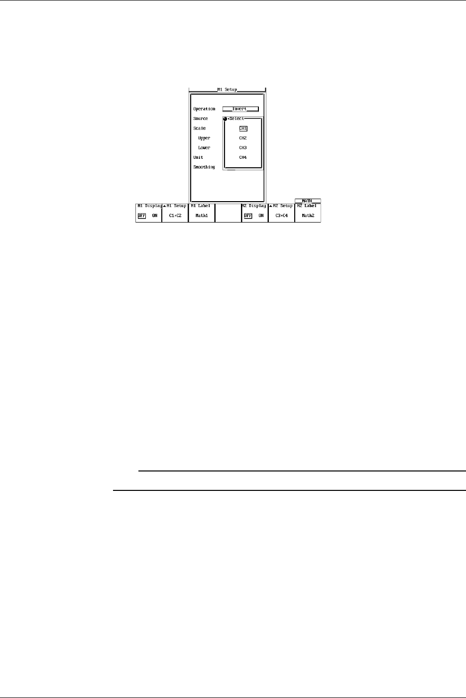
9-40 IM 701710-01E
Selecting the Waveform to be Inverted
7. Turn the jog shuttle to move the cursor to Source.
8. Pressing SELECT displays the channel setting menu.
9. Turn the jog shuttle to select the channel on which to perform computation and
press SELECT. (CH3 and CH4 are not displayed on the DL1720.)
Scaling
10. Turn the jog shuttle to move the cursor to Scale.
11. Press SELECT to select Auto or Manual.
12. If you selected Manual, turn the jog shuttle to move the cursor to Upper.
13. Pressing SELECT displays a menu used to display the upper limit of the waveform.
14. Turn the jog shuttle to set the upper limit and press SELECT.
15. Set Lower in a similar fashion.
Setting the Unit
16. Turn the jog shuttle to move the cursor to Unit.
17. Using the keyboard that appears when SELECT is pressed enter the unit using
four characters or less.
Smoothing
18. Turn the jog shuttle to move the cursor to “Smoothing.”
19. Press SELECT to select ON or OFF.
Note
For details regarding smoothing, see section 9.10, “Smoothing.”
9.7 Inverting the Waveform Display
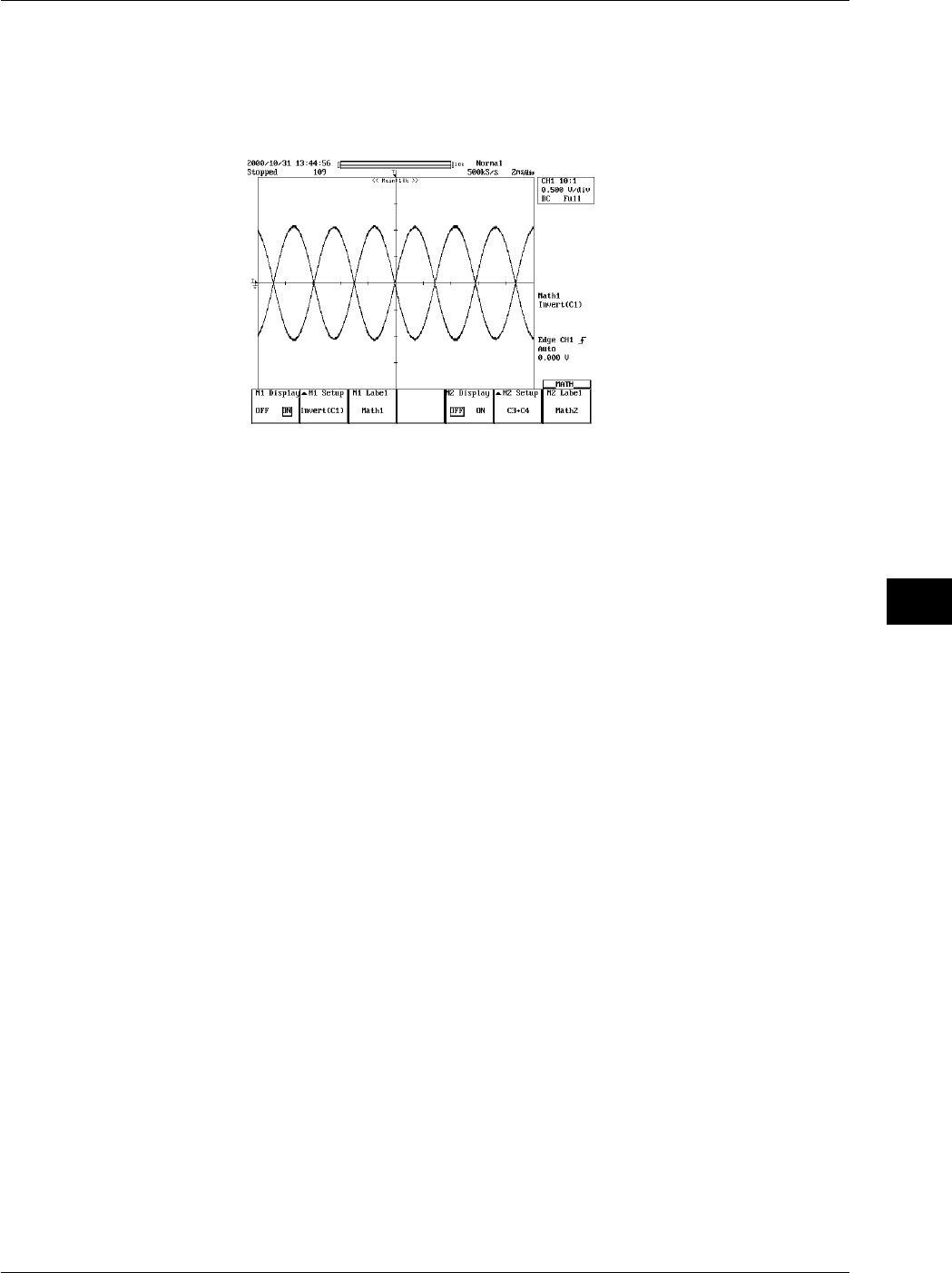
9-41
IM 701710-01E
Waveform Analysis
9
Entering Labels
20. Press the M1 Label soft key to display the keyboard. See section 8.5, “Setting
Waveform Labels” for information about displaying labels.
Set Math2 in a similar manner as necessary.
Explanation
Waveforms that can be Inverted
The waveform is inverted by multiplying CH1 to CH4 and Math1 (or CH1 to CH2 for the
DL1720) by –1.
Scaling
Set the upper and lower limits on computations.
Auto: The upper and lower limits are set according to the computed result.
Manual: The upper and lower limits can be set arbitrarily. The range is –9.9999E+30 to
9.9999E+30.
Unit
Unit can be set arbitrarily using up to four characters. The specified characters are
reflected in the scale values.
Smoothing
See section 9.10, “Smoothing.”
9.7 Inverting the Waveform Display

9-42 IM 701710-01E
9.8 Differentiating and Integration Waveforms
<For a discription of this function, refer to page 1-24>
Relevant Keys
ACTION DELAY
X - Y MENU MENU PHASE
SEARCH
HORIZONTAL
VERTICAL TRIGGER
TRIG D
HELP
ESC
SELECTRESET
SIMPLE
MODE POSITION
MATH
MISCFILE
CLEAR
TRACE
HISTORY
MEASURE
SETUP
PRESET
DISPLAY
CURSOR
CH
1
CH
2
CH
3
CH
4
POWER
COPY IMAGE SAVE SHIFT
ZOOM
GO/NO-GO
ENHANCED
ACQ START/STOP
SNAP
SHOT
V DIV TIME DIV
The DL1720 is not
equipped with
an input terminal
for CH3 or CH4.
Operating Procedure
Turning ON/OFF the Display
1. Press MATH.
2. Press the M1 Display soft key and select ON to display Math1 and OFF to not
display Math1.
Math2 is not available on
the DL1720, so these soft
keys are not displayed.
Setting the Operator
3. Press the M1 Setup soft key to display the computation dialog box.
4. Turn the jog shuttle to move the cursor to Operation.
5. Pressing SELECT displays the operator setting menu.
6. Turn the jog shuttle to select Diff (differentiation) or Integ (integration) and press
SELECT.
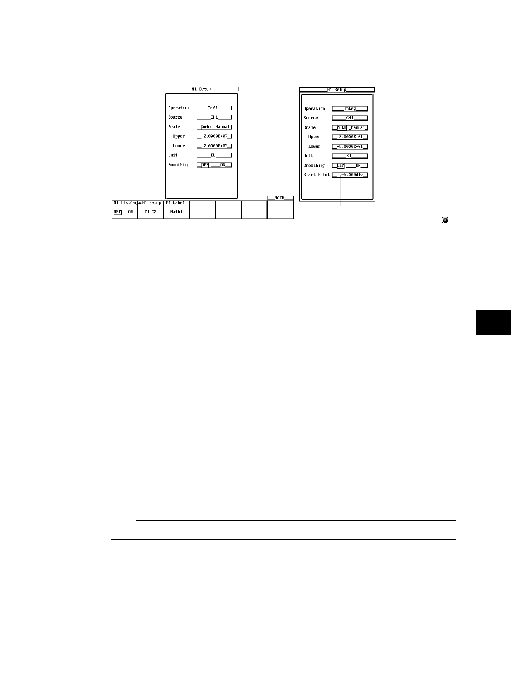
9-43
IM 701710-01E
Waveform Analysis
9
Setting the Channel on which to Perform Computation
7. Turn the jog shuttle to move the cursor to Source.
8. Pressing SELECT displays the channel setting menu.
9. Turn the jog shuttle to select the channel on which to perform computation and
press SELECT. (CH3 and CH4 are not displayed on the DL1720.)
The numerical values for this item can be
input directly using a USB keyboard. ( )
Diff Integ
Scaling
10. Turn the jog shuttle to move the cursor to Scale.
11. Press SELECT to select Auto or Manual.
12. If you selected Manual, turn the jog shuttle to move the cursor to Upper.
13. Pressing SELECT displays a menu used to set the upper limit of the waveform.
14. Turn the jog shuttle to set the upper limit and press SELECT.
15. Set Lower in a similar fashion.
Setting the Unit
16. Turn the jog shuttle to move the cursor to Unit.
17. Using the keyboard that appears when SELECT is pressed enter the unit using
four characters or less.
Smoothing
18. Turn the jog shuttle to move the cursor to Smoothing.
19. Press SELECT to select ON or OFF.
Setting the Start Point (When Integ is Selected)
20. Turn the jog shuttle to move the cursor to Start Point.
21. Press SELECT, set the start point using the jog shuttle, then press SELECT again.
Note
For details regarding smoothing, see section 9.10, “Smoothing.”
9.8 Differentiating and Integration Waveforms
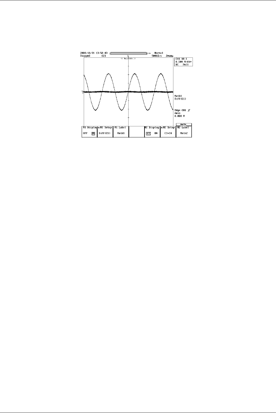
9-44 IM 701710-01E
Entering Labels
22. Press the M1 Label soft key to display the keyboard. See section 8.5, “Setting the
Waveform Labels” for information about displaying labels.
Set Math2 in a similar manner as necessary. (Math2 is not available on the DL1720.)
Explanation
Waveforms to be Differentiated or Integrated
CH1 to CH4 and Math1 waveforms (or CH1 to CH2 waveform for the DL1720) can be
differentiated or integrated.
Scaling
Set the upper and lower limits on computations.
Auto: The upper and lower limits are set according to the computed result.
Manual: The upper and lower limits can be set arbitrarily. The range is –9.9999E+30 to
9.9999E+30.
Unit
Unit can be set arbitrarily using up to four characters. The specified characters are
reflected in the scale values.
Smoothing
See section 9.10, “Smoothing.”
9.8 Differentiating and Integration Waveforms

9-45
IM 701710-01E
Waveform Analysis
9
9.9 Displaying the Power Spectrum
<For a description of this function, refer to page 1-25>
Relevant Keys
ACTION DELAY
X - Y MENU MENU PHASE
SEARCH
HORIZONTAL
VERTICAL TRIGGER
TRIG D
HELP
ESC
SELECTRESET
SIMPLE
MODE POSITION
MATH
MISCFILE
CLEAR
TRACE
HISTORY
MEASURE
SETUP
PRESET
DISPLAY
CURSOR
CH
1
CH
2
CH
3
CH
4
POWER
COPY IMAGE SAVE SHIFT
ZOOM
GO/NO-GO
ENHANCED
ACQ START/STOP
SNAP
SHOT
V DIV TIME DIV
The DL1720 is not
equipped with
an input terminal
for CH3 or CH4.
Operating Procedure
Turning ON/OFF the Display
1. Press MATH.
2. Press the M1 Display soft key and select ON to display Math1 and OFF to not
display Math1.
Math2 is not available on
the DL1720, so these soft
keys are not displayed.
Setting the Operator
3. Press the M1 Setup soft key to display the computation dialog box.
4. Turn the jog shuttle to move the cursor to Operation.
5. Pressing SELECT displays the operator setting menu.
6. Turn the jog shuttle to select PS and press SELECT.
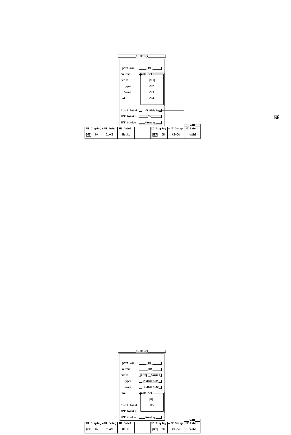
9-46 IM 701710-01E
Selecting the Channel on which to Perform Computation
7. Turn the jog shuttle to move the cursor to Source.
8. Pressing SELECT displays the channel setting menu.
9. Turn the jog shuttle to select the channel on which to perform computation and
press SELECT. (CH3 and CH4 are not displayed on the DL1720.)
The numerical values for this item can be
input directly using a USB keyboard. ( )
Scaling
10. Turn the jog shuttle to move the cursor to Scale.
11. Press SELECT to select Auto or Manual.
12. If you select Manual, turn the jog shuttle to move the cursor to Upper.
13. Pressing SELECT displays a menu used to set the upper limit of the waveform
display.
14. Turn the jog shuttle to set the upper limit and press SELECT.
15. Set Lower in a similar fashion.
Setting the Unit
16. Turn the jog shuttle to move the cursor to Unit.
17. Using the keyboard that appears when SELECT is pressed enter the unit using
four characters or less.
Setting the Start Point
18. Turn the jog shuttle to move the cursor to Start Point.
19. Pressing SELECT displays a menu used to set the FFT start point.
20. Turn the jog shuttle to set the start point and press SELECT.
Setting the Number of FFT Points
21. Turn the jog shuttle to move the cursor to FFT Points.
22. Pressing SELECT displays a menu used to select the number of points on which to
take the FFT.
23. Turn the jog shuttle to select 1 k or 10 k and press SELECT.
9.9 Displaying the Power Spectrum
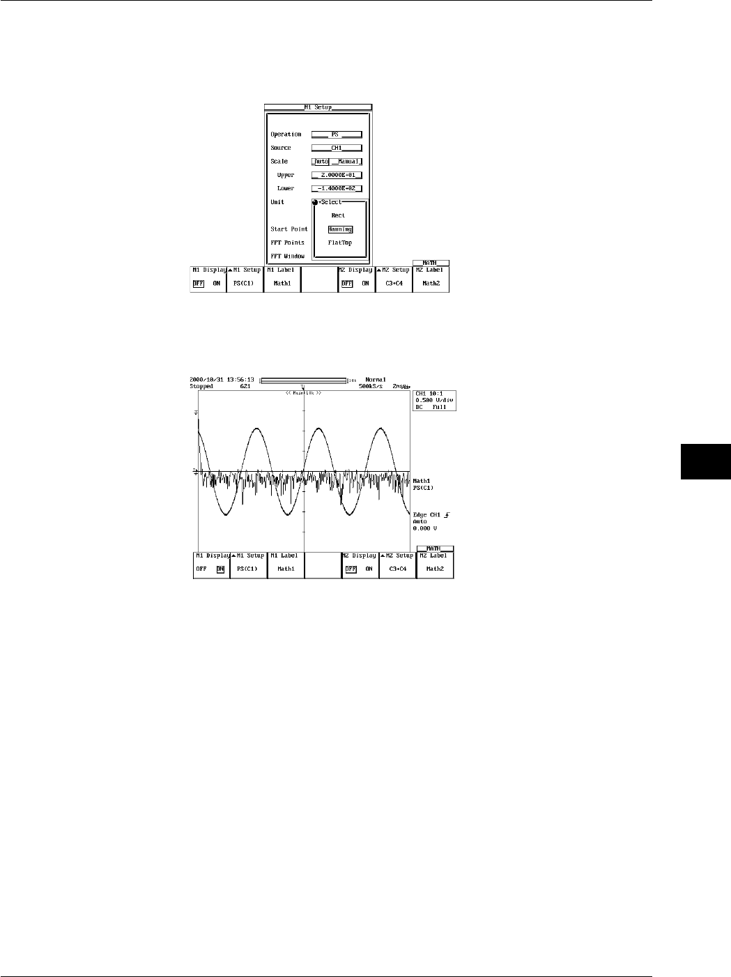
9-47
IM 701710-01E
Waveform Analysis
9
Selecting the Time Window
24. Turn the jog shuttle to move the cursor to FFT Window.
25. Pressing SELECT displays the time window menu.
26. Turn the jog shuttle to select Rect, Hanning, or FlatTop and press SELECT.
Entering Labels
27. Press the M1 Label soft key to display the keyboard. See section 8.5, “Setting the
Waveform Labels” for information about displaying labels.
Explanation
This function displays the power spectrum of CH1 to CH4 and Math1 waveforms (or CH1
to CH2 waveform for the DL1720).
Number of Computing Points: Point
Select 1000 or 10000.
Using the number of computing points from the specified Start point, an FFT is
performed and the power spectrum is displayed.
Selecting the Time Window: Window
Select from the following windows.
Rect (Rectangular): Best suited for transient signals that attenuate completely within the
time window.
Hanning (Hanning): Best suited for continuous and non-periodic signals.
Flattop (Flat Top): Best suited for improve the accuracy of the level even if the
frequency resolution is to be compromised.
Notes when Displaying Power Spectrums
•Cannot be executed if the displayed record length is less than number of computation
points (Point).
9.9 Displaying the Power Spectrum
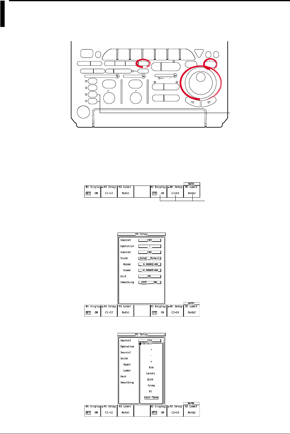
9-48 IM 701710-01E
9.10 Smoothing
Relevant Keys
ACTION DELAY
X - Y MENU MENU PHASE
SEARCH
HORIZONTAL
VERTICAL TRIGGER
TRIG D
HELP
ESC
SELECTRESET
SIMPLE
MODE POSITION
MATH
MISCFILE
CLEAR
TRACE
HISTORY
MEASURE
SETUP
PRESET
DISPLAY
CURSOR
CH
1
CH
2
CH
3
CH
4
POWER
COPY IMAGE SAVE SHIFT
ZOOM
GO/NO-GO
ENHANCED
ACQ START/STOP
SNAP
SHOT
V DIV TIME DIV
The DL1720 is not
equipped with
an input terminal
for CH3 or CH4.
Operating Procedure
Turning ON/OFF the Display
1. Press MATH.
2. Press the M1 Display soft key and select ON to display Math1 and OFF to not
display Math1.
Math2 is not available on
the DL1720, so these soft
keys are not displayed.
Setting the Operator
3. Press the M1 Setup soft key to display the computation dialog box.
To smooth the measured data, set Operation to Pass-Thru.
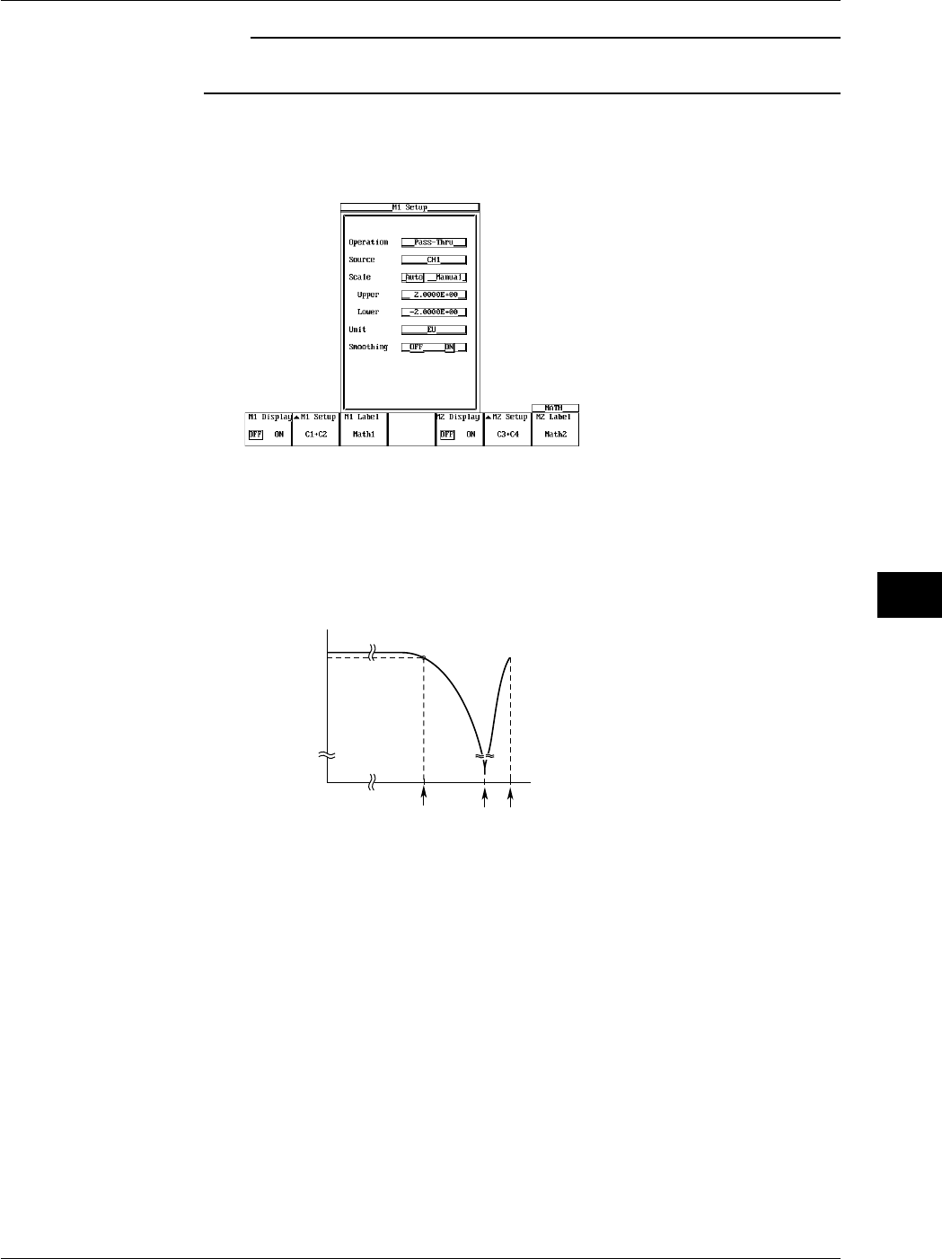
9-49
IM 701710-01E
Waveform Analysis
9
Note
If an operator other than Through is selected, the computation is performed on the smoothed
value.
Smoothing
4. Turn the jog shuttle to move the cursor to Smoothing.
5. Press SELECT to select ON.
Explanation
The moving average is determined every five data samples, and the waveform is
displayed based on the results. Since this process is performed on the data stored in the
acquisition memory, it can be executed even when the waveform acquisition is stopped.
This smoothing process has the following frequency characteristics with respect to the
sample rate. The –3dB point is at approximately 13% of the sample rate.
f0.5f0.13f
Frequency
0 dB
-3 dB
f : Sample Frequency
Attenuation
9.10 Smoothing
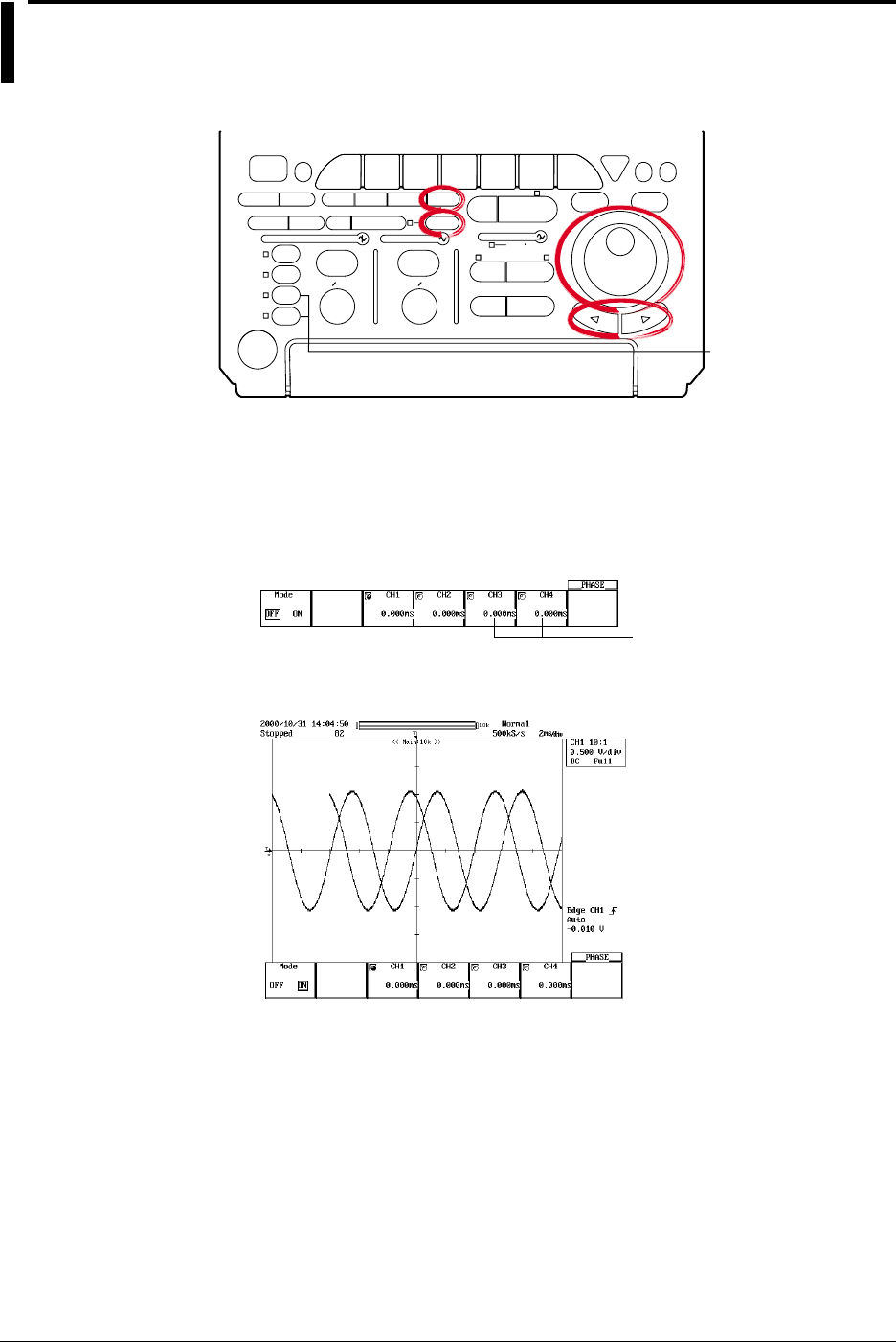
9-50 IM 701710-01E
9.11 Phase-Shifted Display
<For a discription of this function, refer to page 1-24>
Relevant Keys
ACTION DELAY
X - Y MENU MENU PHASE
SEARCH
HORIZONTAL
VERTICAL TRIGGER
TRIG D
HELP
ESC
SELECTRESET
SIMPLE
MODE POSITION
MATH
MISCFILE
CLEAR
TRACE
HISTORY
MEASURE
SETUP
PRESET
DISPLAY
CURSOR
CH
1
CH
2
CH
3
CH
4
POWER
COPY IMAGE SAVE SHIFT
ZOOM
GO/NO-GO
ENHANCED
ACQ START/STOP
SNAP
SHOT
V DIV TIME DIV
The DL1720 is not
equipped with
an input terminal
for CH3 or CH4.
Operating Procedure
Setting the Computation Mode
1. Press SHIFT to activate shift mode.
Functions marked in purple on the panel become active.
2. Press MATH.
3. Press the Mode soft key to select ON or OFF.
These soft keys are not
displayed on the DL1720.
4. Press the soft key corresponding to the channel whose phase is to be shifted.
5. Turn the jog shuttle to set the shifted time.
Explanation
The phase of CH1 to CH4 waveforms (or CH1 to CH2 waveform for the DL1720) is
shifted and the result is displayed. Computation can also be carried out on phase-shifted
waveforms.
Allowable Shift Range
The phase can be shifted in the following range.
Time value between –(record length/2) to (record length/2) (resolution: 1/sample rate)
The sample rate varies depending on the record length or T/div setting. For details, see
appendix 1, “Relationship between the Time Axis Setting, Sample Rate, and Record
Length.”
Notes when Shifting the Phase
If you change the T/div setting after shifting the phase, the shift on the screen does not
change, but the specified time value change in accordance with the T/div setting.
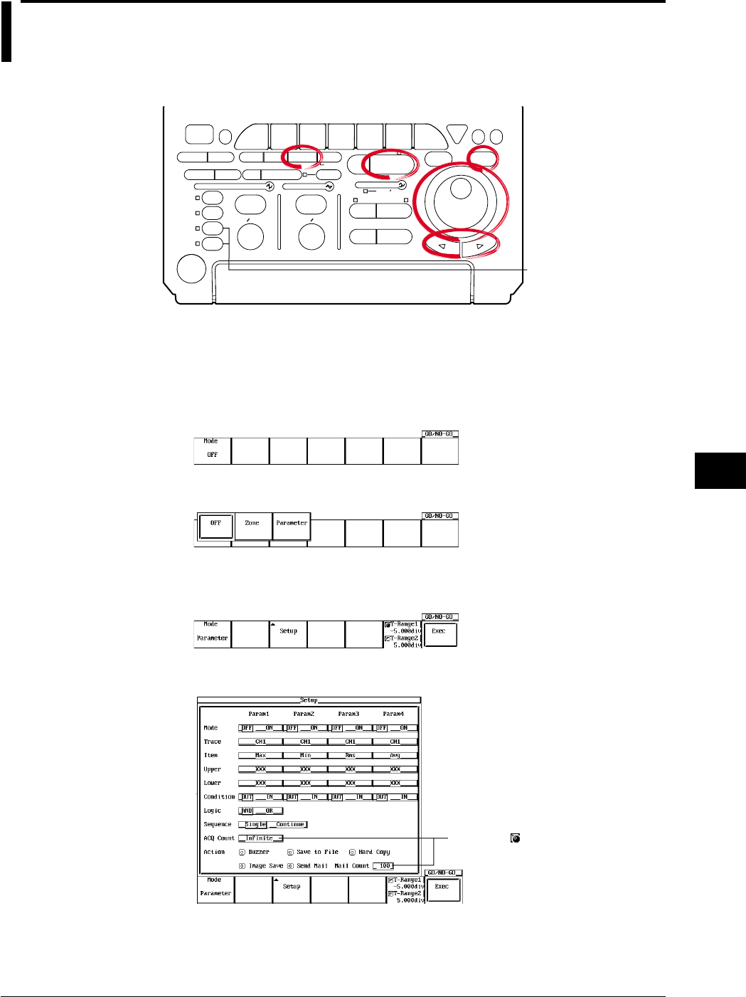
9-51
IM 701710-01E
Waveform Analysis
9
9.12 GO/NO-GO Determination Using the
Measurement of Waveform Parameters
<For a description of this function, refer to page 1-32>
Relevant Keys
ACTION DELAY
X - Y MENU MENU PHASE
SEARCH
HORIZONTAL
VERTICAL TRIGGER
TRIG D
HELP
ESC
SELECTRESET
SIMPLE
MODE POSITION
MATH
MISCFILE
CLEAR
TRACE
HISTORY
MEASURE
SETUP
PRESET
DISPLAY
CURSOR
CH
1
CH
2
CH
3
CH
4
POWER
COPY IMAGE SAVE SHIFT
ZOOM
GO/NO-GO
ENHANCED
ACQ START/STOP
SNAP
SHOT
V DIV TIME DIV
The DL1720 is not
equipped with
an input terminal
for CH3 or CH4.
Operating Procedure
Setting the Mode
1. Press GO/NO-GO.
2. Pressing the Mode soft key displays a menu used to set the GO/NO-GO
determination mode.
3. Press the Parameter soft key to set the GO/NO-GO determination mode.
Setting Param1
4. Pressing the Setup soft key displays the determination criteria menu.
5. Turn the jog shuttle to move the cursor to Mode under Param1.
Settings for the following items can
be input directly using a USB
keyboard. ( )
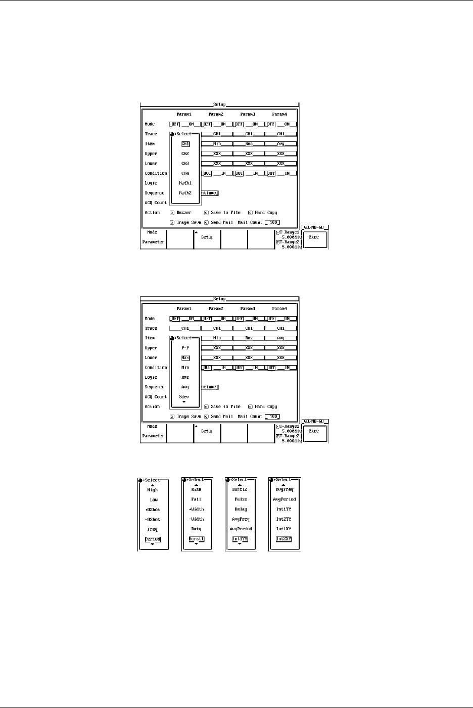
9-52 IM 701710-01E
6. Press SELECT to select ON or OFF. If OFF is selected, Param1 will be excluded
from the determination criteria.
7. Turn the jog shuttle to move the cursor to Trace.
8. Pressing SELECT displays the channel menu. (CH3, CH4, and Math2 are not
displayed on the DL1720.)
9. Turn the jog shuttle to select the channel and press SELECT.
10. Turn the jog shuttle to move the cursor to Item.
11. Pressing SELECT displays the automated measurement item menu.
12. Turn the jog shuttle to select the item and press SELECT.
13. Turn the jog shuttle to move the cursor to Upper.
14. Pressing SELECT displays the upper limit setting menu.
15. Turn the jog shuttle to select the upper limit and press SELECT.
16. Set Lower in a similar fashion.
17. Turn the jog shuttle to move the cursor to Condition.
18. Press SELECT to select IN or OUT.
19. Set Param2 to Param4 as necessary.
9.12 GO/NO-GO Determination Using the Measurement of Waveform Parameters
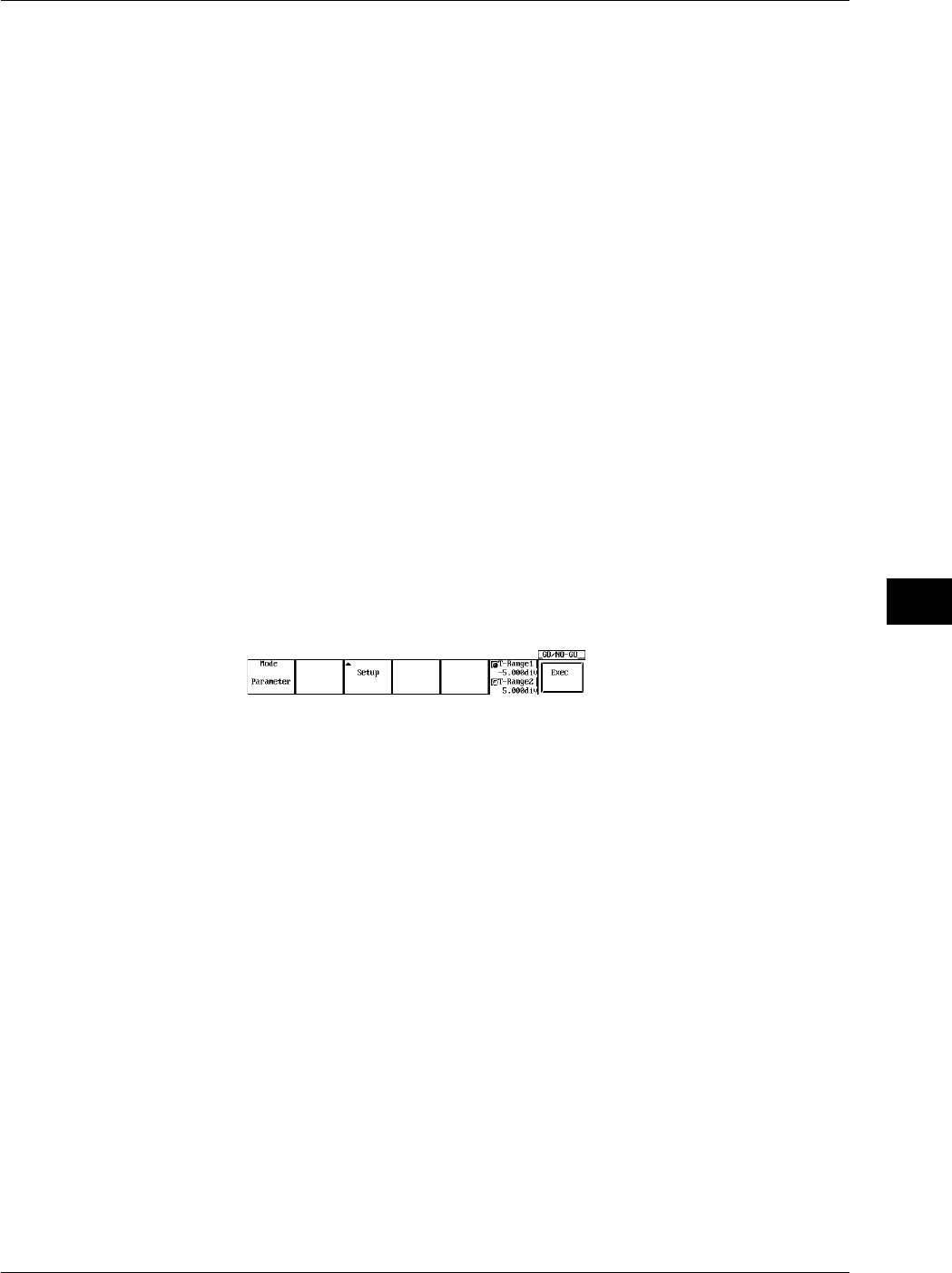
9-53
IM 701710-01E
Waveform Analysis
9
Setting the Logic
20. Turn the jog shuttle to move the cursor to Logic.
21. Press SELECT to select AND or OR.
Setting the Sequence
22. Turn the jog shuttle to move the cursor to Sequence.
23. Press SELECT to select Single or Continue.
Setting the ACQ Count
24. Turn the jog shuttle to move the cursor to ACQ Count.
25. Pressing SELECT a menu used to set the number of waveform acquisitions.
26. Turn the jog shuttle to set the number of waveform acquisitions and press
SELECT.
Selecting the Action to Take when the Condition is not Met
27. Turn the jog shuttle to move the cursor to Action.
28. Press SELECT to turn the action ON or OFF.
Setting the Determination Range
29. Press the T-Range1/T-Range2 soft key to set the jog shuttle control to T-Range1.
30. Turn the jog shuttle to set the start point of the determination range.
31. In a similar fashion, set the end point of the determination range with T-Range2.
Executing the GO/NO-GO Determination
32. Press the Exec soft key to execute the GO/NO-GO determination.
When the determination terminates, the waveform acquisition is automatically
stopped.
To forcibly stop the operation, press START/STOP or the Abort soft key to stop
the acquisition.
Explanation
Waveform Parameters that can be Determined using GO/NO-GO Operation: Item
This function is applicable to the all of waveform parameters (27 items) in section 9.2.
Up to four types of parameters can be determined simultaneously.
Mode
OFF: Does not perform GO/NO-GO determination
ON: Performs GO/NO-GO determination
Upper and Lower Limits of Parameters: Upper/Lower
The upper and lower limits depends on the parameters. They can be set in the range –
9.9999E+30 to 9.9999E+30.
Setting the Condition
IN: When the value is inside the upper and lower limits.
OUT: When the value is outside the upper or lower limits.
9.12 GO/NO-GO Determination Using the Measurement of Waveform Parameters

9-54 IM 701710-01E
Setting the Logic
AND: Executes the Action when all parameter conditions (1 to 4 types) are met.
OR: Executes the Action when any one of the parameter conditions (1 to 4 types) is
met.
Action to Take when the Condition is Met (not Met): Action
Buzzer: Sounds the buzzer.
Save to File: Saves the waveform data to the storage medium (FD, Zip disk, SCSI
(option) and so on) specified in the FILE menu.
Hard Copy: Outputs the screen image data to the destination (Built-in, USB, Net Print
(Ethernet interface option)) spcified by Copy to in the Copy setting menu.
Image Save: Saves the screen image data to the output destination (FD, Zip disk, or
SCSI (when SCSI and serial interface option are installed)) that you
specified in the Image Save menu.
Send Mail: Sends a mail (Ethernet Interface option). For details, see section 13.7,
“Using the Mail Function (Action Mail Function).”
Number of Actions: Sequence
Single: Executes the Action once and terminates.
Continue: Repeats the execution of the Action up to the number of acquisition count
specified in ACQ Count (until the acquisition is stopped if infinite is specified).
Number of Waveform Acquisitions: ACQ Count
Set the number of waveform acquisitions.
Infinite: Continues until the waveform acquisition is stopped with START/STOP.
1 to 65536: Stops when the specified number of waveforms is acquired.
Executing/Aborting GO/NO-GO Operation
The operation starts when you press the Exec soft key. Waveform acquisition is
automatically stopped when the determination is complete. To forcibly stop the
operation, press START/STOP or press the Abort soft key.
Save to File/Hard Copy/Image Save Operation
Operates according to the settings in the File menu, the Copy menu, or the Image Save
menu.
File Name when Action is Set to Save to File or Image Save
The file is saved with AutoName under the File menu or the Image Save menu. For
details, see section 10.4, “Outputting to Storage Medium” or section 11.6, “Saving/
Loading Waveform Data.”
Notes when Performing GO/NO-GO Determination
•The determination results (the number of successes and failures) are displayed.
•All keys other than START/STOP and the Abort soft key are disabled during the
determination.
•When GO/NO-GO determination is executed, the trigger mode is automatically
changed to Single.
•Determination is not possible when the acquisition mode is set to Average.
9.12 GO/NO-GO Determination Using the Measurement of Waveform Parameters
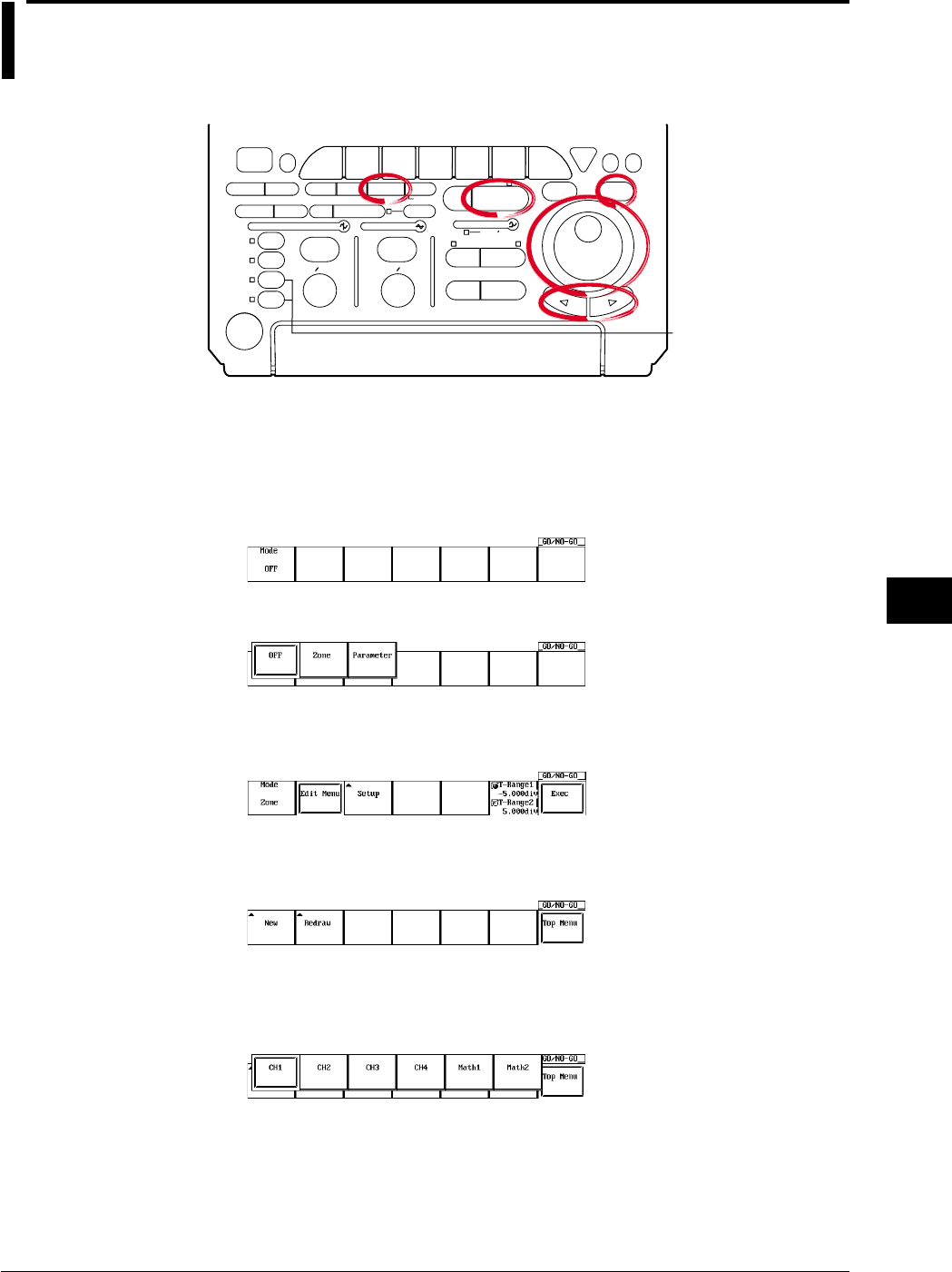
9-55
IM 701710-01E
Waveform Analysis
9
9.13 GO/NO-GO Determination Using Zones
<For a discription of this function, refer to page 1-32>
Relevant Keys
ACTION DELAY
X - Y MENU MENU PHASE
SEARCH
HORIZONTAL
VERTICAL TRIGGER
TRIG D
HELP
ESC
SELECTRESET
SIMPLE
MODE POSITION
MATH
MISCFILE
CLEAR
TRACE
HISTORY
MEASURE
SETUP
PRESET
DISPLAY
CURSOR
CH
1
CH
2
CH
3
CH
4
POWER
COPY IMAGE SAVE SHIFT
ZOOM
GO/NO-GO
ENHANCED
ACQ START/STOP
SNAP
SHOT
V DIV TIME DIV
The DL1720 is not
equipped with
an input terminal
for CH3 or CH4.
Operating Procedure
Setting the Mode
1. Press GO/NO-GO.
2. Press the Mode soft key to display the GO/NO-GO determination mode setting
menu.
3. Press the Zone soft key to set the GO/NO-GO determination mode.
Creating a Determination Zone
4. Press the Edit Menu soft key.
5. Press the New soft key to display the zone creation reference waveform selection
menu.
6. Press the soft key corresponding to the reference waveform to display the zone
editing menu. (The CH3, CH4, and Math2 soft keys are not displayed on the
DL1720.)
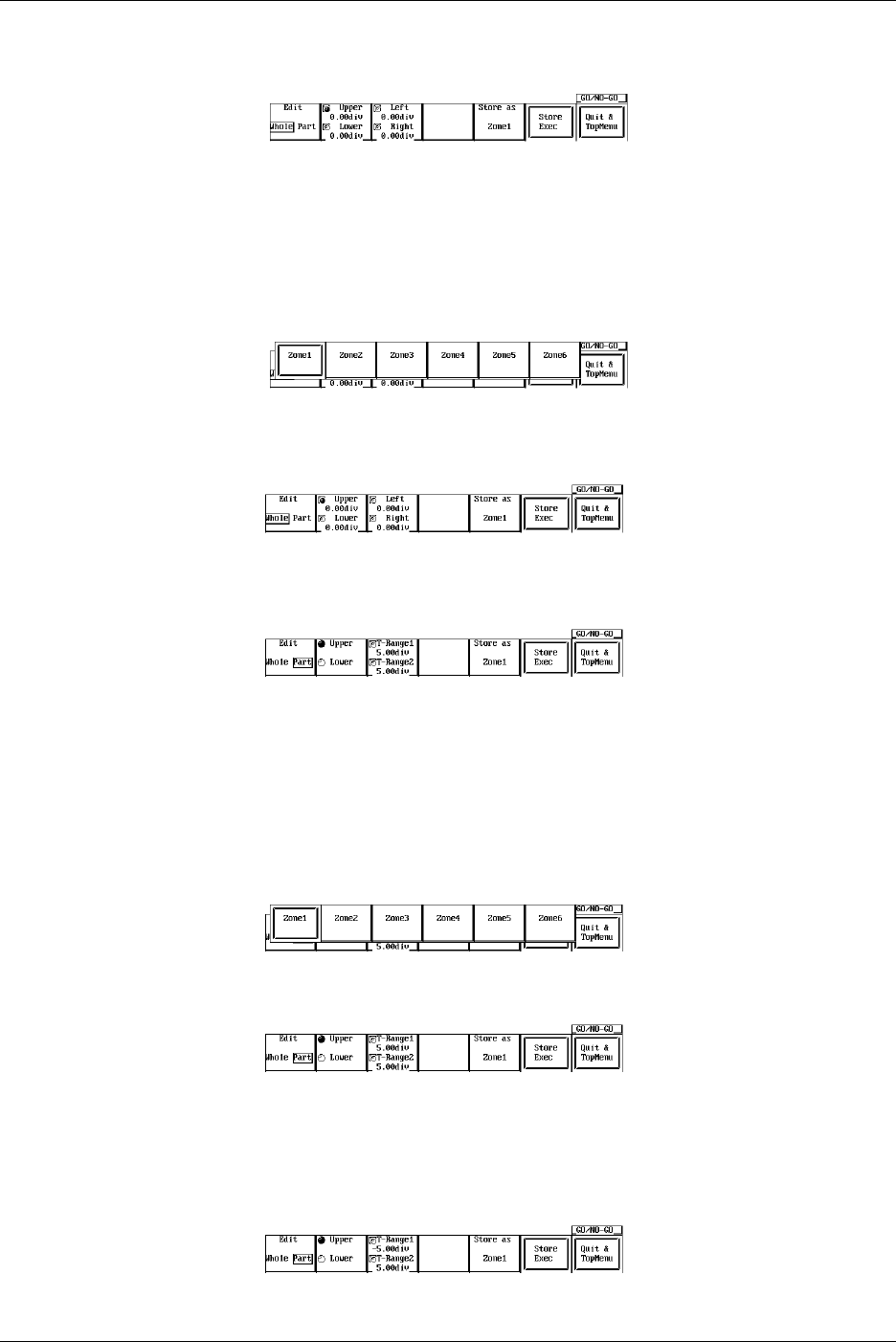
9-56 IM 701710-01E
Editing All Zones
7. When Edit is set to something other than Whole, press the Edit and select Whole.
8. Press the Upper/Lower or Left/Right soft keys to select the zone setting direction.
9. Turn the jog shuttle to create a zone.
10. Repeat steps 8 and 9 to edit the zones.
11. Press the Store as soft key to open the store as setting menu for the edited zone.
12. Press the soft key corresponding to a storage location Zone1 - Zone6 (or Zone1 -
Zone3 for the DL1720) to select it.
13. Press the Store Exec soft key to save the zone. Proceed to step 14 to edit a
partial zone, or skip to step 22 to quit.
Editing a Partial Zone
14. Press the Edit soft key to select Part.
15. Press the T-Range1/T-Range2 soft key to select the right or left cursor.
16. Turn the jog shuttle to set the right and left edges of the partial zone.
17. Press the Upper/Lower soft key to select the direction for setting the zone, then
use the jog shuttle to create the zone.
18. Repeat steps 15-17 to edit the zone.
19. Press the Store as soft key to open the store as setting menu for the edited zone.
20. Press the soft key corresponding to a storage location Zone1 - Zone6 (or Zone1 -
Zone3 for the DL1720) to select it.
21. Press the Store Exec soft key to save the zone.
Quit Zone Editing
22. Press the Quit & TopMenu soft key to return to the menu in step 3. If you press
the Quit & TopMenu soft key before pressing the Store Exec soft key, the settings
made up to that point will be inactive, and you will return to the menu in step 3.
9.13 GO/NO-GO Determination Using Zones
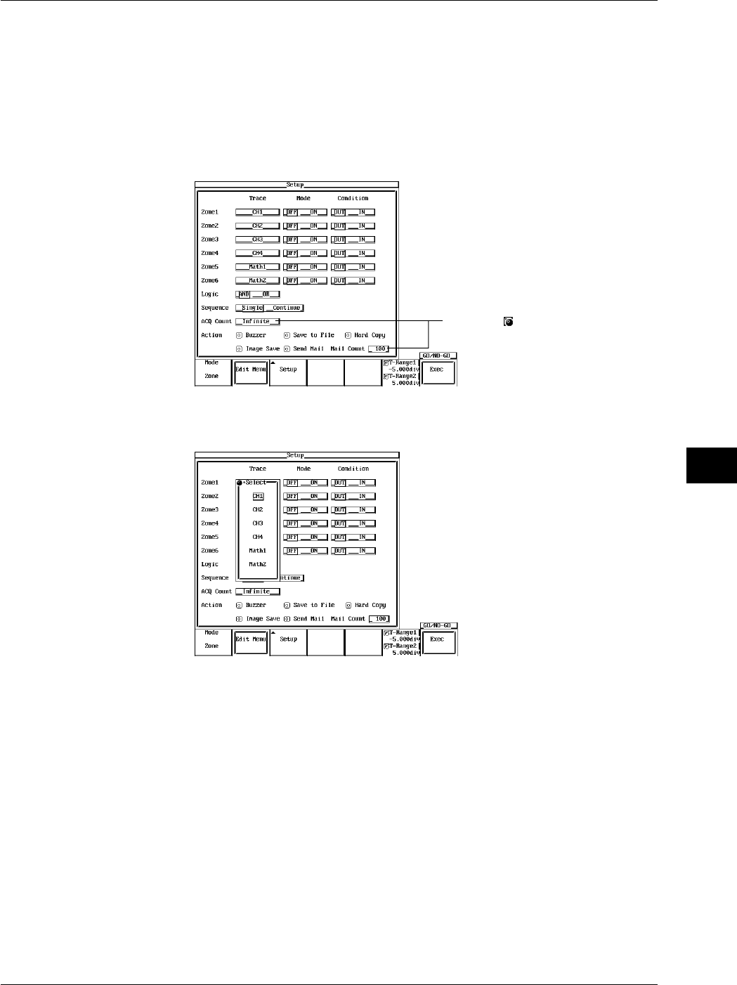
9-57
IM 701710-01E
Waveform Analysis
9
Editing Existing Zones
Edit zones that have been previously created.
23. In step 5, press the Redraw soft key.
24. Repeat steps 6-22 to edit the zones.
Selecting a Determination Waveform
25. Press the Setup soft key to display the Setup menu.
26. Turn the jog shuttle to move the cursor to Trace of Zone1.
Settings for the following items can
be input directly using a USB
keyboard. ( )
27. Press SELECT to select CH1 through CH4, MATH1, or MATH2 (or CH1, CH2, and
Math1 for the DL1720).
28. Use the jog shuttle to move the cursor to Mode under Zone1.
29. Press SELECT to select On or Off.
30. Use the jog shuttle to move the cursor to Condition under Zone1.
31. Press SELECT to select In or Out.
32. Set Zone2 - Zone6 (or Zone2 - Zone3 for the DL1720) as necessary.
Setting the Logic
33. Move the cursor to Logic with the jog shuttle.
34. Press SELECT to select AND or OR.
Setting the Sequence
35. Use the jog shuttle to move the cursor to Sequence.
36. Press SELECT to select Single, or Continue.
9.13 GO/NO-GO Determination Using Zones

9-58 IM 701710-01E
Setting the ACQ Count
37. Use the jog shuttle to move the cursor to ACQ Count.
38. Press SELECT to display the waveform acquisition count setting menu.
39. Use the jog shuttle to set the waveform acquisition count, then press SELECT.
Selecting the Action for Condition not Met
40. Use the jog shuttle to move the cursor to Action.
41. Press SELECT to turn action ON or OFF.
Setting the Determination Range
42. Press the T-Range1/T-Range2 soft key to highlight the T-Range1 jog shuttle icon.
43. Use the jog shuttle to set the head of the determination range.
44. In the same manner, set the tail of the range to T-Range2.
Executing Determination
45. Press the Exec soft key to execute the determination. The Exec changes to the
Abort soft key. When the determination is completed, acquisition automatically
stops. You can force a stop by pressing START/STOP or the Abort soft key.
Explanation
Create zones using a standard waveform as a base, and from those zones let GO/NO-
GO be determined by whether a waveform extends outside or inside of the zone.
Waveform for GO/NO-GO Determination/Determination criteria: Setup
You can select a waveform from input signals (CH1-CH4 (or CH1 to CH2 for the
DL1720)) and from math waveforms (Math1, Math2 (or Math1 only for the DL1720)).
You can use multiple waveforms for GO/NO-GO determination. Select from the
following determination standards for each waveform:
IN: When the specified waveform enters the zone.
OUT: When the specified waveform is outside the zone.
OFF: Do not determine.
Selecting the Reference Waveform: Edit Menu
Select a reference waveform for creating a zone. The basic waveform will be displayed
as a trace, and you can select from the following types.
Input signal waveform
Math waveform
Creating a Determination Zone: Redraw/New
You can set up to six (or three for the DL1720) determination zones. The following are
the setting ranges.
Up-down setting range: ±8 div from the reference waveform
Left-right setting range: ±5 div from the center of the screen
You can select input signal waveforms (CH1 through CH4 (or CH1 to CH2 for the
DL1720)) and computed waveforms (Math1 and Math2 (or Math1 only for the DL1720))
for the waveforms that are to be determined in the determination zones that are
registered in Zone1 through Zone6 (or Zone1 through Zone3 for the DL1720).
The screen displays the active zones depending on the settings in Setup.
Setting Logic
AND: when all parameter conditions 1 - 6 are met, GO/NO-GO Action is performed
OR: when at least one parameter condition from 1 - 6 are met, GO/NO-GO Action is
performed
9.13 GO/NO-GO Determination Using Zones

9-59
IM 701710-01E
Waveform Analysis
9
Action to Take when the Condition is Met (not Met): Action
Buzzer: Sounds the buzzer.
Save to File: Saves the waveform data to the storage medium (FD, Zip disk, SCSI
(option) and so on) specified in the FILE menu.
Hard Copy: Outputs the screen image data to the destination (Built-in, USB, Net Print
(Ethernet interface option)) spcified by Copy to in the Copy setting menu.
Image Save: Saves the screen image data to the output destination (FD, Zip disk, or
SCSI (when SCSI and serial interface option are installed)) that you
specified in the Image Save menu.
Send Mail: Sends a mail (Ethernet Interface option). For details, see section 13.7,
“Using the Mail Function (Action Mail Function).”
Action Count: Sequence
Single: Conclude after one instance of the Action.
Continue: Repeat the Action the number of times specified as the sampling count in
ACQ Count (if set to Infinite, Action repeats until determination stops).
Waveform Sampling Count: ACQ Count
Set the waveform sampling count.
Infinite: Sampling continues until determination stops, or until START/STOP or Abort
soft key is pressed.
1-65536: Sampling stops after the specified count has been reached.
Start/Stop GO/NO-GO Determination
Press the Exec soft key to execute the determination. Determination will stop
automatically when finished, or you can press START/STOP or Abort soft key to force a
stop.
Save to File/Hard Copy/Image Save Operation
Operates according to the settings in the File menu, the Copy menu, or the Image Save
menu.
File Name when Action is Set to Save to File or Image Save
The file is saved with AutoName under the File menu or the Image Save menu. For
details, see section 10.4, “Outputting to Storage Medium” or section 11.6, “Saving/
Loading Waveform Data.”
Notes about GO/NO-GO Determination
Determination results (number of successes, failures) are displayed on screen.
Functions other than START/STOP and Abort soft key are inactive during
determination.
When performing GO/NO-GO determination, the trigger mode is automatically set to
Single.
Determination is not possible when acquisition mode is set to Average.
Note
The zone waveform you created is stored as setting information onto the floppy disk, Zip disk,
the internal ROM and so on.
9.13 GO/NO-GO Determination Using Zones
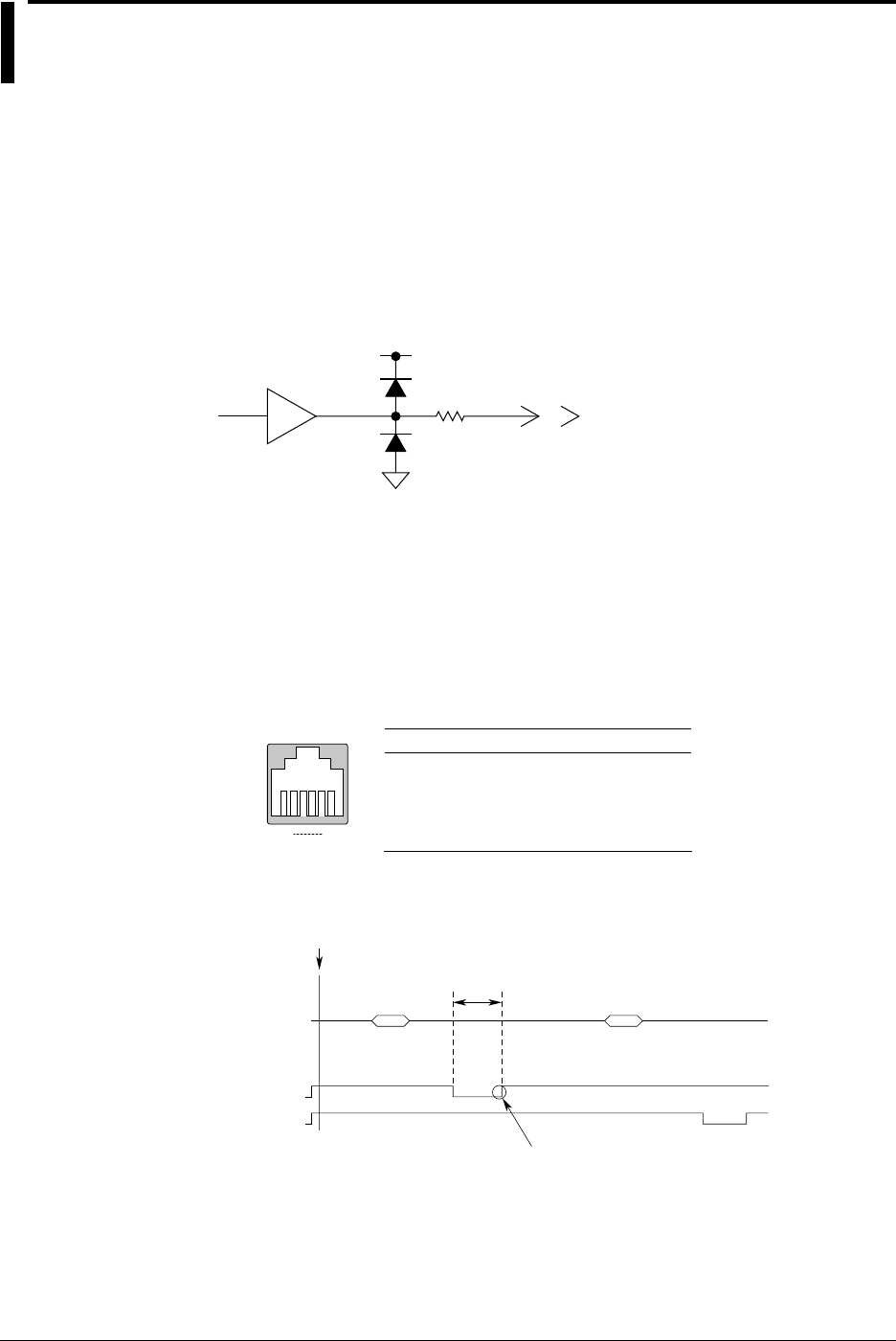
9-60 IM 701710-01E
9.14 Using the GO/NO-GO Signal Output Function
Output Signal
NO-GO OUT Signal
The output signal level (TTL level) changes from high(H) to low (L) temporarily when a
NO-GO determination is made.
GO OUT Signal
The output signal level (TTL level) changes from high (H) to low (L) temporarily when a
GO determination is made.
Signal Output Circuit Diagram
HCT04 GO OUT
NOGO OUT
5 V
100 Ω
Output Connector
The format and pin arrangement of the output connector on the DL1720/DL1740 are as
follows:
•Format
The connector uses a modular jack (RJ12). Use the optional accessory 36973 (sold
separately) for the cable. If you are using a commercially sold cable (4 contact
modular cable for telephone circuits), wire te pins according to the following figure.
•Pin Arrangement
1
6
GO/NO-GO
1
Pin Number Signal Logic
2
3
4
5
6
NC (Unconnected)
NC (Unconnected)
GO OUT
NO-GO OUT
DL Side Connector
Negative
Negative
GND
NC (Unconnected)
Output Timing
Output Timing
EXEC
10ms
or more
Acquisition Acquisition
Determination Determination
Result Result
NOGO OUT
GO OUT
Remains ‘Low’ until the system is
ready for the next judgement. If an
action is specified for when the
condition is met, the time is
prolonged until the action has
finished.
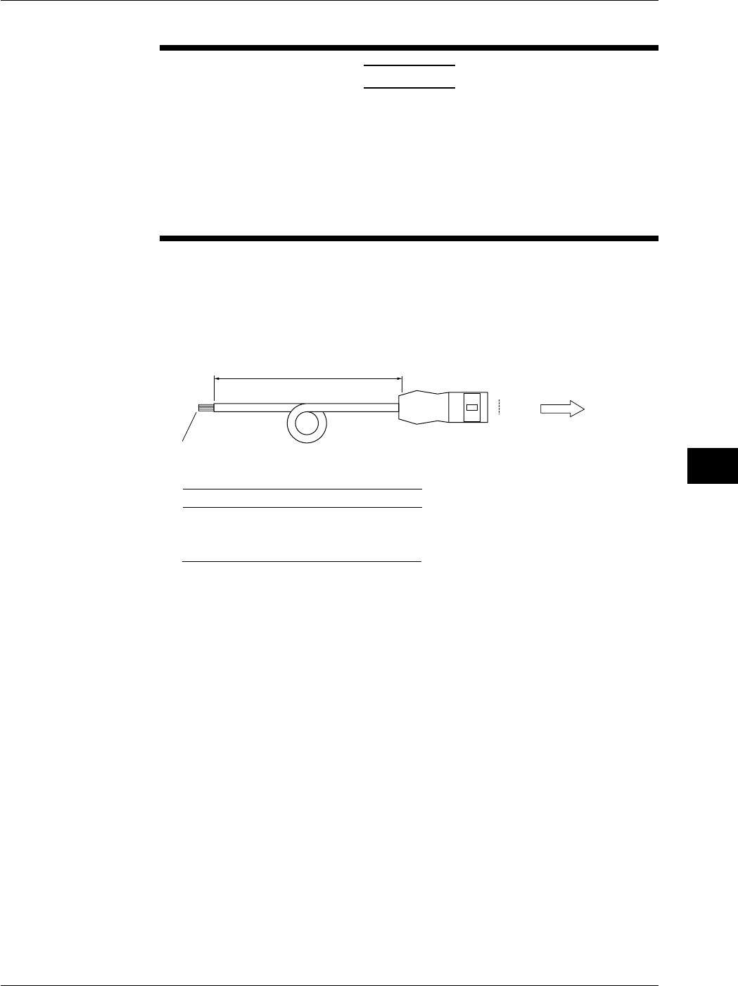
9-61
IM 701710-01E
Waveform Analysis
9
9.14 Using the GO/NO-GO Signal Output Function
Connecting to Another Instrument
CAUTION
•Never apply an external voltage to the NO-GO OUT and GO OUT
terminals, otherwise damage to the instrument may result.
•When connecting the GO/NO-GO signal output externally, make sure
not to connect other signal pins by mistake. Errors in connection may
cause damage to this instrument or to the other connected instrument.
•Do not mistakenly insert the USB cable to the GO/NO-GO output
terminal. This may cause damage to the DL1720/DL1740.
To connect the DL1720/DL1740 to external equipment, use the GO/NO-GO cable
(366973, sold separately).
Do not use the GO/NO-GO cable (366973, sold separately) for any other purpose than
for carrying out GO/NO-GO determination on the DL1720/DL1740.
•About the GO/NO-GO Cable (366973, Sold Separately)
1
6To the DL1720/DL1740
Approx. 1.5 m
RJ-12 Connector
Wires are separated.
Modify them to suit your needs.
Pin No. Signal Name Logic
3
4
5
GO OUT
NO-GO OUT Negative
Negative
GND
Color
White
Green
Blue
2NC
Yellow

10-1
IM 701710-01E
Output of Screen Data
10
10.1 Loading the Paper Roll into the Built-in Printer
(Option)
Printer Roll Chart
Use only YOKOGAWA’s roll charts. When you are using the printer for the first time, use
the roll chart supplied with the instrument. When your roll charts have run out, purchase
more from your dealer or YOKOGAWA sales offices listed on the back cover of this
manual.
Part No.: B9850NX
Specification: Thermo-sensible, 30 m
Minimum Quantity: 5 rolls
Handling the Roll Chart
Thermosensible roll charts produce color using a thermal reaction, therefore the
following precautions must be taken.
Storage Precautions
The roll chart begins to develop color at approximately 70°C. It is very sensitive to heat,
damp, light and chemicals both before and after use.
•Keep roll charts in a dry, cool and dark place.
•Once the package is opened, use the roll chart as soon as possible.
•If the roll chart is left in contact with plastic films containing plasticizer (for instance,
vinyl chloride film, cellophane tape etc.) for a long period of time, discoloration will
occur on the recording area of the chart due to the plasticizer. If you are going to
keep the roll chart in a holder, for instance, use a polypropylene holder.
•When you use adhesive on the roll chart, never use adhesive which contains an
organic solvent such as alcohol or ether, otherwise color may develop on the chart.
•When you are going to store recorded roll charts for a long period of time, we suggest
you make a copy of the charts since discoloration may occur.
Usage Precautions
•Use only YOKOGAWA’s genuine roll charts.
•Do not touch the roll chart with sweaty hands, otherwise it may become stained with
your fingerprints, and information may be lost.
•Do not rub the surface of the roll chart strongly with a firm object, color development
may occur due to frictional heat.
•Do not allow chemicals or oil to come into contact with the roll chart, otherwise color
development or loss of information may result.
Chpater 10 Outputs of Screen Data
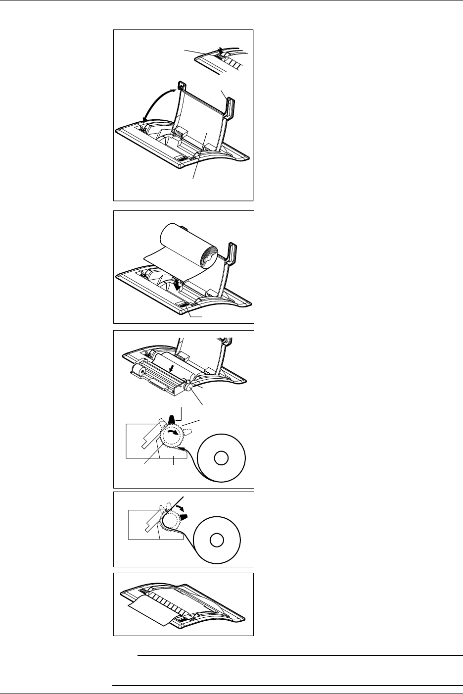
10-2 IM 701710-01E
Operating Procedure
Printer Cover
Handle
PUSH OPEN Button
Press the PUSH OPEN button, and lift the
handle on the right of the printer cover and
open the cover.
Release Arm
Move the release arm, located on the right near
the front, to the MAN FEED position.
Have the inner side of the roll paper (the side
that is not glossy) showing on top for the
following procedure. Set the core of the roll
paper to the holder on the right.
MAN FEED Rotate the Paper
Feed Knob
Roll Paper
Release Arm
Guide
Roller
Insert the edge of the roll paper evenly in the
space between the roller and the black guide,
then rotate the paper feed knob away from you
until about 10 cm of the roll sheet is showing
from the top of the roller.
FREE
HOLD
Move the release arm to the FREE position and
straighten out the roll sheet. Then, move the
release arm to the HOLD position.
The printing will fail with an error message, if
the release arm is in the FREE or MAN FEED
position during operation.
Pull the printer cover back to its original position
and close the cover. Make sure that the edge
of the roll sheet is showing from the opening of
the printer cover.
Push the printer cover down firmly until it clicks
into place.
Note
After loading the rool paper, the paper feed may be unstable. Print out 2 or 3 screen images
before using the printer in your work.
10.1 Loading the Paper Roll into the Built-in Printer (Option)
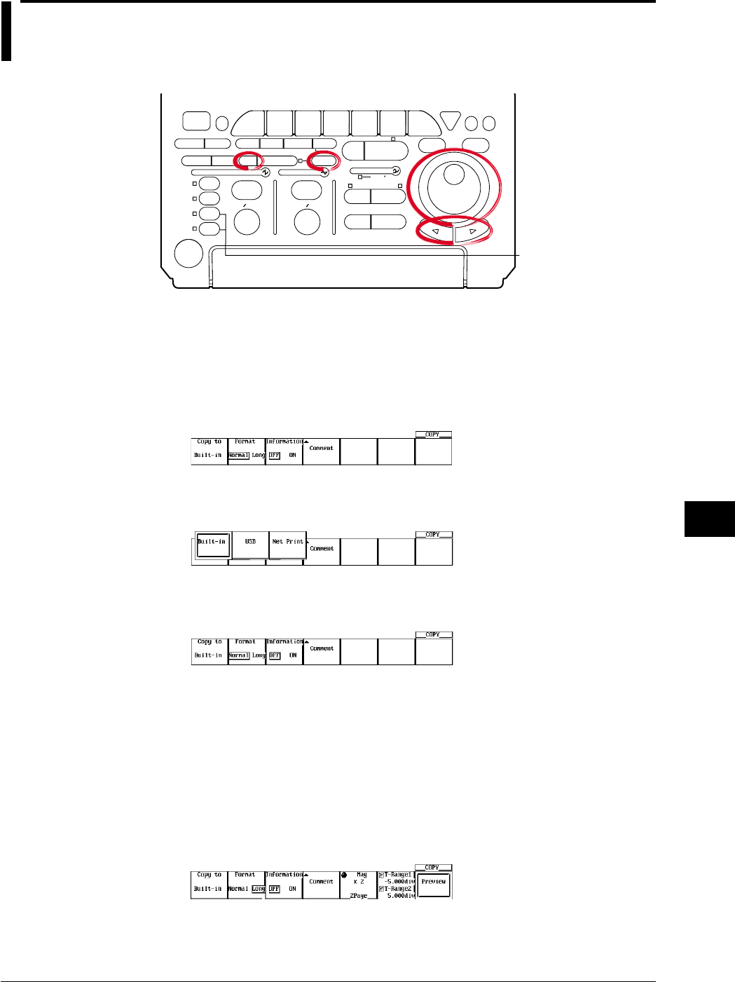
10-3
IM 701710-01E
Output of Screen Data
10
10.2 Outputting to the Built-in Printer (Option)
Relevant Keys
ACTION DELAY
X - Y MENU MENU PHASE
SEARCH
HORIZONTAL
VERTICAL TRIGGER
TRIG D
HELP
ESC
SELECTRESET
SIMPLE
MODE POSITION
MATH
MISCFILE
CLEAR
TRACE
HISTORY
MEASURE
SETUP
PRESET
DISPLAY
CURSOR
CH
1
CH
2
CH
3
CH
4
POWER
COPY IMAGE SAVE SHIFT
ZOOM
GO/NO-GO
ENHANCED
ACQ START/STOP
SNAP
SHOT
V DIV TIME DIV
The DL1720 is not
equipped with
an input terminal
for CH3 or CH4.
Operating Procedure
Selecting the Printer
1. Press SHIFT to activate shift mode.
Functions marked in purple on the panel become active.
2. Press COPY.
3. Pressing the Copy to soft key displays the output medium menu.
4. Press the Built-in soft key. (Net Print is displayed only when the Ethernet interface
option is installed.)
Setting the Output Format
5. Press the Format soft key to select Normal or Long.
6. Press the Information soft key to select ON or OFF.
Setting Comments
7. Pressing the Comment soft key displays a keyboard.
8. Enter comments according to the procedures described in section 4.1.
Setting the Magnification Ratio (When the Output Format is Set to Long)
9. If you selected Long in step 5, set the magnification ratio using the jog shuttle.
Press the Mag soft key to set the jog shuttle control to Mag.
10. Turn the jog shuttle to set the magnification ratio. The number of output pages is
displayed according to the ratio.
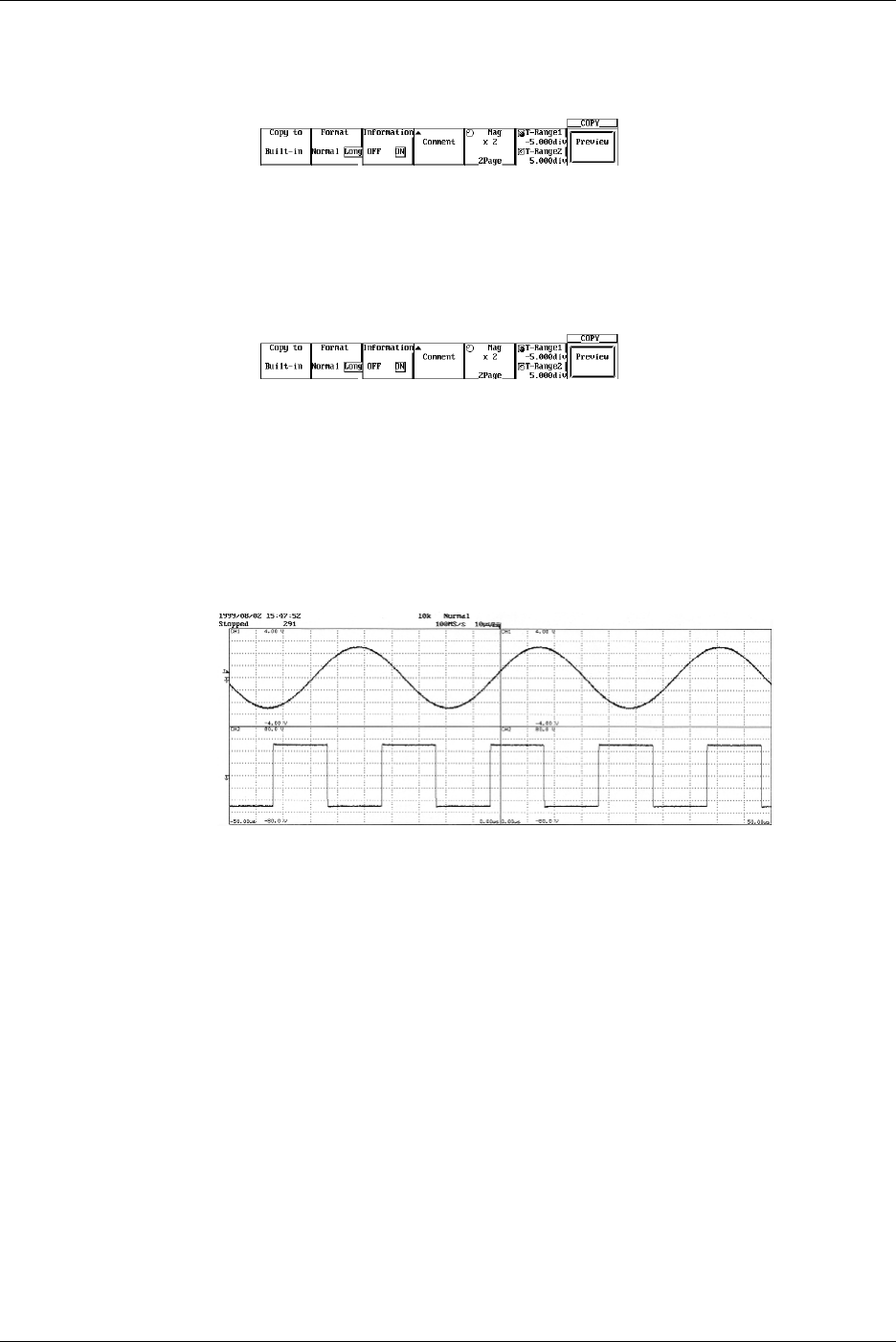
10-4 IM 701710-01E
Setting the Output Range (When the Output Format is Set to Long)
11. If you selected Long in step 5, set the output range.
Press the T-Range1/T-Range2 soft key to set the jog shuttle control to T-Range1.
12. Turn the jog shuttle to set the start point of the output range.
13. In a similar fashion, set the end point of the output range in T-Range2.
Previewing (Long Copy)
14. Pressing the Preview soft key displays the output image on the screen.
15. Turning the jog shuttle changes the displayed page.
16. Pressing the Quit soft key returns to the original screen.
Executing Print Out
17. Pressing COPY outputs a hard copy of the screen.
Pressing COPY again aborts the output.
Output Example when Mag is Set to Long
10.2 Outputting to the Built-in Printer (Option)

10-5
IM 701710-01E
Output of Screen Data
10
Explanation
Output Format
In addition to normal size, long copy is possible in which the displayed waveform is
magnified 2 to 20000 times before printing. The magnification ratio varies depending on
the T/div and record length settings.
Outputting Optional Information
Outputs the results of the setup information at the same time as the waveform.
Comments
You can output a comment string consisting of up to 20 characters in the lower section.
Print Range
Sets the range to output to the printer from –5 div to 5 div .
Preview
The output image can be previewed using the specified output format.
Precautions to be Taken when Printing with the Built-in Printer
•Printing is not possible while the waveform acquisition is in progress.
•Only the main waveform is long copied.
•When displaying a waveform using the history memory function, only the waveform
selected for Selected Record No. is long copied.
•Long copy is not possible when displaying X-Y waveforms.
•Long copy of snapshot waveforms and accumulated waveforms is not possible.
10.2 Outputting to the Built-in Printer (Option)
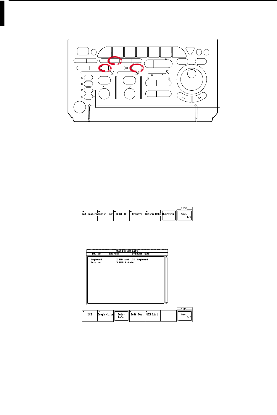
10-6 IM 701710-01E
10.3 Outputting Screen Images to a USB Printer
Relevant Keys
ACTION DELAY
X - Y MENU MENU PHASE
SEARCH
HORIZONTAL
VERTICAL TRIGGER
TRIG D
HELP
ESC
SELECTRESET
SIMPLE
MODE POSITION
MATH
MISCFILE
CLEAR
TRACE
HISTORY
MEASURE
SETUP
PRESET
DISPLAY
CURSOR
CH
1
CH
2
CH
3
CH
4
POWER
COPY IMAGE SAVE SHIFT
ZOOM
GO/NO-GO
ENHANCED
ACQ START/STOP
SNAP
SHOT
V DIV TIME DIV
The DL1720 is not
equipped with
an input terminal
for CH3 or CH4.
Operating Procedure
1. Connect the DL1720/DL1740 and a USB printer using a USB cable. For details,
see the explanation, page 10-8.
Confirming the Type of Printer that is Connected
To confirm the type of printer that is connected to the DL1720/DL1740, carry out the
procedure below.
2. Press MISC.
3. Press the Next 1/2 soft key.
4. Press the USB List soft key to display the USB Device List. Check the printer that
is connected.
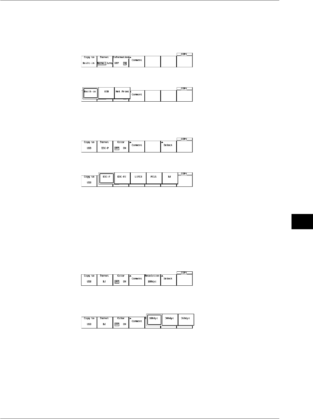
10-7
IM 701710-01E
Output of Screen Data
10
Selecting the Printer
5. Press SHIFT to activate shift mode. Functions marked in purple on the panel
become active.
6. Press COPY.
7. Press the Copy to soft key to display the output medium selection menu.
8. Press the USB soft key to select USB.
Selecting the Type
9. Press the Format soft key to display the menu used to select the output command
type.
10. Press the soft key corresponding to the desired command type.
Setting the Color
11. Press the Color soft key to select ON or OFF.
Setting Comments
12. Press the Comment soft key. A keyboard appears on the screen.
13. Enter the comment string according to the procedure given in section 4.1.
Setting the Resolution (When Format is Set to BJ)
14. Press the Resolution soft key to display the resolution menu.
15. Press one of the soft keys corresponding to 180 dpi, 300 dpi, and 360 dpi to set
the resolution.
Executing Hard Copy
16. Press COPY to output a hard copy of the screen. Press COPY again to stop the
output.
10.3 Outputting Screen Images to an USB Printer

10-8 IM 701710-01E
Explanation
On the DL1720/DL1740, you can print the screen image data to a USB printer via the
USB interface. You can also print the screen image to a network printer via the Ethernet
network (when the Ethernet interface option is installed). For details, see section 13.5,
“Printing the Screen Image to a Network Printer.”
PRN/KBD Terminal
When connecting a USB printer to the DL1720/DL1740, connect a USB cable to the
PRN/KBD terminal. There are two PRN/KBD terminals.
123 4
Port 1
Port 2
Pin No. Signal Name
1V
BUS: +5 V
2D–:–Data
3 D+: +Data
4 GND: Ground
Printers that can be Used
USB printers conforming to USB Printer Class Ver. 1.0 that support the following output
commands can be used.
Note
•Connect only the printers that are allowed.
•For USB printers that have been tested for compatibility, contact your nearest YOKOGAWA
dealer as listed on the back cover of this manual.
Format
You can select the type of command that is output to the USB printer from the following
list of choices.
•ESC-P •PCL5
•LIPS3 •ESC-P2
•BJ (can be used on models that support the BJC-35V native commands)
10.3 Outputting Screen Images to an USB Printer
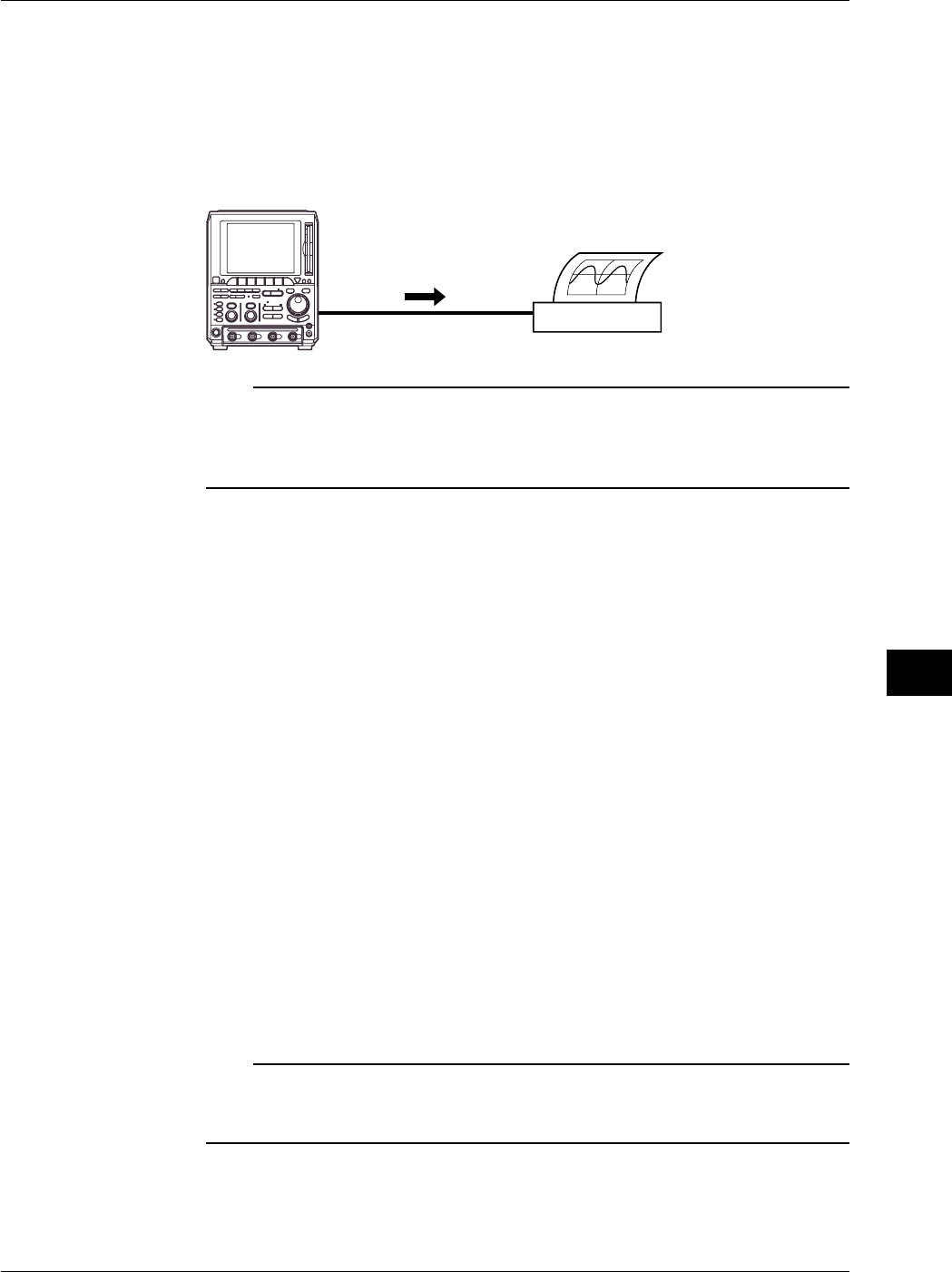
10-9
IM 701710-01E
Output of Screen Data
10
Connection Procedure
When connecting a USB printer, directly connect the keyboard to the DL1720/DL1740
with a USB cable as shown below. You can connect the USB cable regardless of the
power ON/OFF state of the DL1720/DL1740 (supports hot-plug). Connect the type A
connector of the USB cable to the DL1720/DL1740; connect the type B connector to the
printer. When the power switch is ON, the printer is detected and enabled approximately
6 seconds after it is connected.
DL1720/
DL1740
USB Printer
USB Cable
Note
•Connect the printer directly without going through a hub.
•Connect only a USB keyboard or printer to the PRN/KBD terminals.
•Do not connect multiple printers. You can connect a single printer and a single keyboard.
•Never turn OFF the printer or remove the USB cable while the printer is printing.
Output Resolution when Printing using the BJ Format
When printing the screen image data to a USB BJ printer, select the output resolution
from 180 dpi, 300 dpi, and 360 dpi.
Comments
A comment string of up to 20 characters that is displayed at the lower right corner of the
screen can be printed.
Color
Select from the following list of choices.
ON: Prints the image using the same colors as the screen (no background color, grid
printed in black).
OFF: Prints the image using the same colors as the image printed using the built-in
printer.
Precautions when Printing on a USB Printer
•Images may not print properly on some printers. Use USB printers that have been
tested for compatibility.
•You can also print to a USB printer that is connected to your PC. Save the screen
image data to a floppy disk or a Zip disk according to the procedure given in section
10.4, “Storing Screen Image to the External Storage Medium.” Then, load the data on
the PC and print it.
Note
The DL1720/DL1740 does not detect “out of paper” and printer errors on the USB printer. If
you executed printing on the DL1720/DL1740 when the USB printer is in such condition,
press COPY to stop the printing.
10.3 Outputting Screen Images to an USB Printer
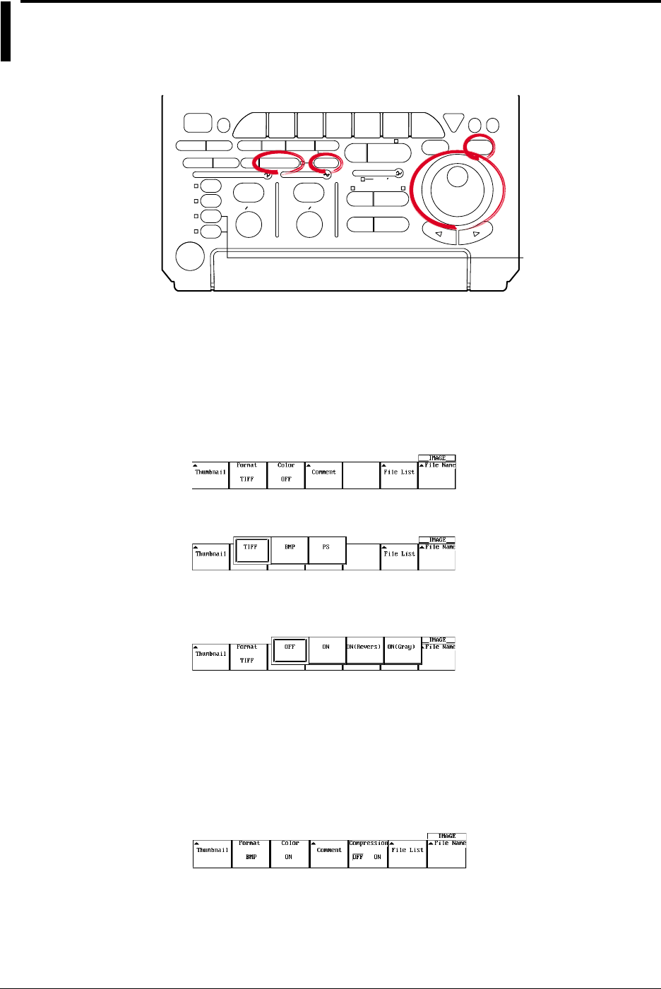
10-10 IM 701710-01E
10.4 Storing Screen Image to the External Storage
Medium
Relevant Keys
ACTION DELAY
X - Y MENU MENU PHASE
SEARCH
HORIZONTAL
VERTICAL TRIGGER
TRIG D
HELP
ESC
SELECTRESET
SIMPLE
MODE POSITION
MATH
MISCFILE
CLEAR
TRACE
HISTORY
MEASURE
SETUP
PRESET
DISPLAY
CURSOR
CH
1
CH
2
CH
3
CH
4
POWER
COPY IMAGE SAVE SHIFT
ZOOM
GO/NO-GO
ENHANCED
ACQ START/STOP
SNAP
SHOT
V DIV TIME DIV
The DL1720 is not
equipped with
an input terminal
for CH3 or CH4.
Operating Procedure
1. Press SHIFT to set the keys in the shifted condition.
Functions marked in purple on the panel become active.
2. Press IMAGE SAVE.
Selecting the Format
3. Pressing the Format soft key.
4. Press the soft key corresponding to the type of format to be selected.
Setting the Color (for TIFF and BMP)
5. Press the Color soft key to select ON, ON(Revers), ON(Gray), or OFF.
Setting Comments
6. Pressing the Comment soft key displays a keyboard.
7. Enter comments according to the procedures described in section 4.1.
Setting the Compression (for BMP (Color is ON))
8. Press the Compression soft key select ON or OFF. (When Compression is ON,
you cannot store to Network Drive.)
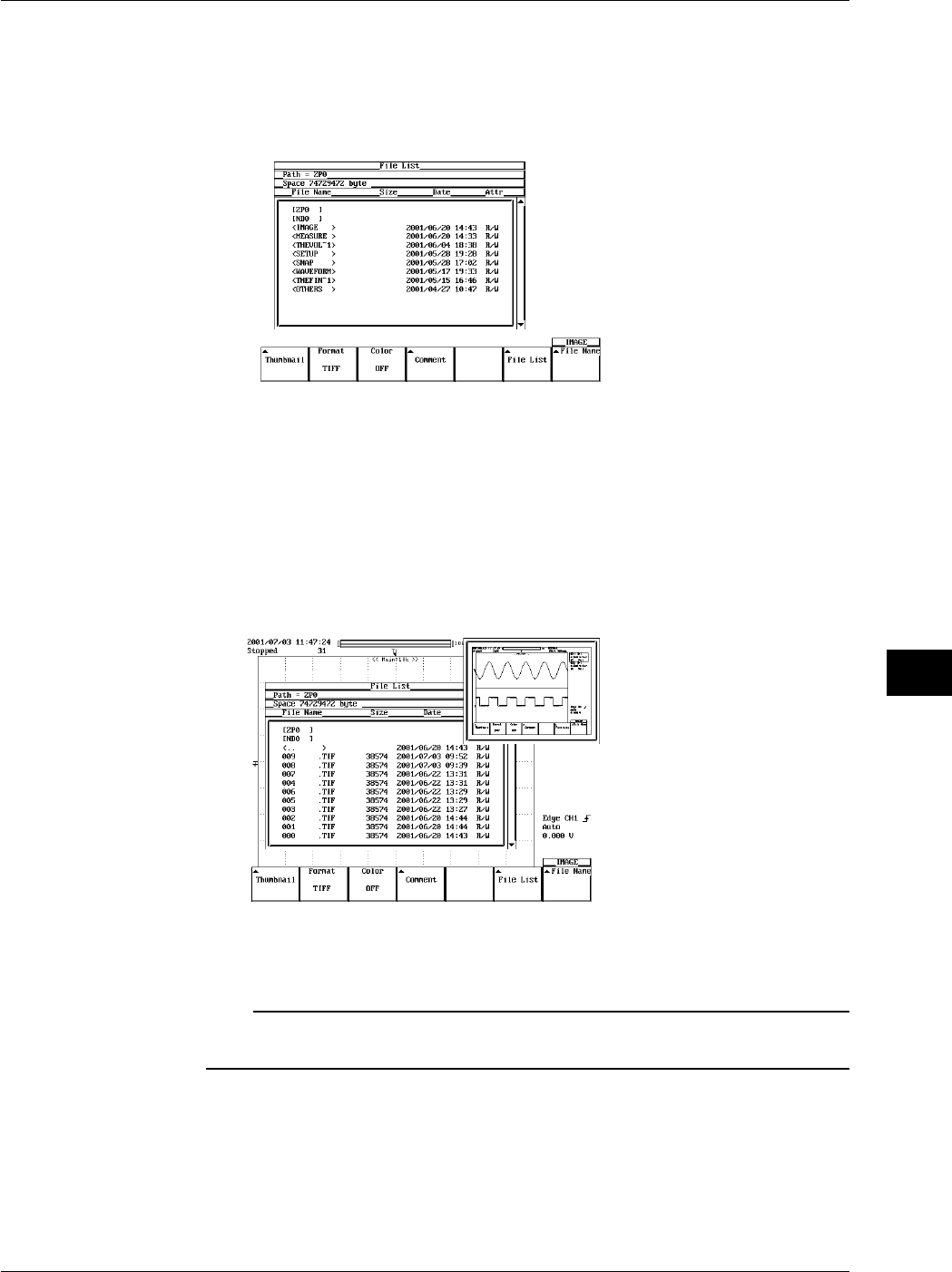
10-11
IM 701710-01E
Output of Screen Data
10
Setting the Storing Destination
9. Pressing the File List soft key displays the output destination setting menu.
10. Turn the jog shuttle to select the save destination. The floppy disk or Zip disk
inserted in the built-in drive or external SCSI devices is displayed in brackets [ ].
Directories are displayed in angle brackets < >.
11. Pressing SELECT displays the contents of the selected storage medium or the
directory.
For details related to setting the storing destination, see section 11.6.
Display of Compressed Images (Firmware Version 1.30 or Later)
12. When Image is selected under File Item, selecting a screen image data file (files
with the .tif, .bmp, or .ps extensions) in the File List window and pressing SELECT
causes the screen image file’s compressed image to appear in the upper right
portion of the file list.
If compressed image (thumbnail) data does not exist for the selected file, an error
message appears. Pressing ESC clears the error message.
Note
The following procedure clears the compressed image from the screen.
•Move the cursor using the jog shuttle.
10.4 Storing Screen Image to the External Storage Medium
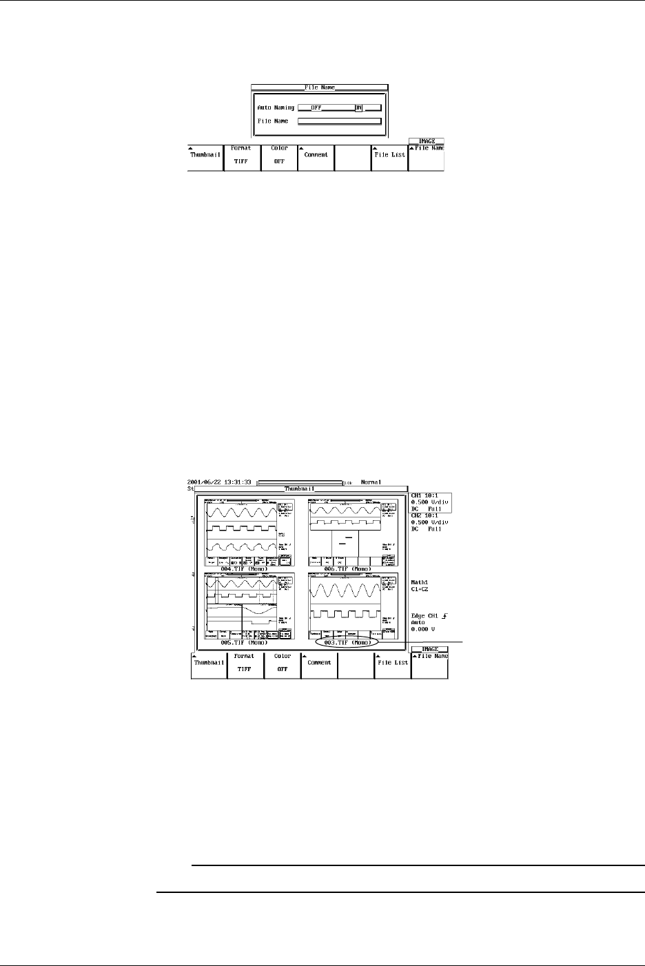
10-12 IM 701710-01E
10.4 Storing Screen Image to the External Storage Medium
Selecting the File Name
13. Pressing the File Name soft key displays the file name setting menu.
14. Turn the jog shuttle to move the cursor to Auto Naming.
15. Press SELECT to select ON or OFF.
16. Turn the jog shuttle to move the cursor to File Name.
17. Pressing SELECT displays a keyboard. Enter the file name using up to eight
characters according to the procedures given on section 4.1. If you turned ON the
auto naming function, the first five characters are valid.
Executing the Storing
18. Pressing IMAGE SAVE store the screen image.
Pressing IMAGE SAVE aborts the storing.
Displaying the Thumbnail Preview Window (This function is available on products
with firmware version 1.30 or later.)
19. Pressing the Thumbnail soft key causes a thumbnail of the screen image data
located in the output directory specified in step 10 to be displayed (four thumbnails
are displayed together). Pressing ESC closes the preview window.
File Name (Color Information)
When no files supporting the thumbnail feature are present on the storage medium,
an error message is displayed. Pressing ESC clears the error message.
Scrolling the Thumbnail Window
20. When five or more files supporting the thumbnail feature are present, you can scroll
the window using the jog shuttle. To scroll the window upwards, turn the jog
shuttle in the minus direction (counterclockwise). To scroll the window downwards,
turn the jog shuttle in the plus direction (clockwise).
Note
Files supporting the thumbnail feature are scrolled two at a time.

10-13
IM 701710-01E
Output of Screen Data
10
Explanation
The screen image can be stored to storage medium (a floppy disk, a Zip disk, an
external SCSI device (option) or Network drive (Ethernet interface option)). For details,
see Section 13.4, “Saving Screen Image Data to a Network Drive.”
Storing Data Format
You can store the output data in the following formats. The file extensions and file sizes
(reference value) that are automatically assigned are also listed.
Output Data Format Extension File Size*
TIFF *.TIF 38,574 bytes (approx. 300 Kbytes)
BMP *.BMP 38,462 bytes (approx. 300 Kbytes)
Post Script *.PS 79,061 bytes (approx. 300 Kbytes)
*: When the color is turned OFF (reference value)
The file sizes inside the parentheses are the sizes when the color is ON.
Color (for TIFF and BMP)
Select ON, ON(Revers), or OFF.
ON : Outputs in 256 colors
ON (Revers) : Background color is not output
ON (GRAY) : Outputs in 16 shade greyscale.
OFF : Outputs in Black & White
Comments
You can add a comment string consisting of up to 20 characters on the screen and save
the information.
Data Compression (for BMP Files)
BMP formats can be compressed in RLE formats, respectively, and output.
However, if color is OFF, data in BMP format cannot be compressed.
•Save Destination
A list of available storage media is displayed in the File List dialog box.
Examples
FD0 : Floppy disk
ZP0 : Zip disk
SC5 : SCSI device with an ID number of 5
SC5_1: Partition number 1 on SCSI device number 5
ND0 : Network drive (available with the Ethernet interface option)
Floppy Disk, Zip Disk and External SCSI Device (Option)
The floppy disk, the Zip disk, and external SCSI device (option) are described in chapter
11. For the procedures related to formatting, see chapter 11.
Auto Naming Function
If you use Auto Naming, files are automatically created with three digit numbers from 000
to 999 in their file name. You can place a common name in front of the numbers (up to 5
characters, specified in File Name).
Note
You can enter up to eight characters for the common name, but the last three characters are
discarded.
10.4 Storing Screen Image to the External Storage Medium

10-14 IM 701710-01E
Notes when Saving the File
•The maximum number of files that can be saved using the auto naming function is
1000.
•When the total number of files and directories in one directory exceeds 2400, the file
list will no longer be displayed.
Also, a thumbnail window for screen image data can be displayed.
Thumbnail
•Thumbnail Window
The instrument can display a thumbnail window containing screen image files (with
the .tif, .bmp, and .ps extensions) located in the directory selected from the File List
under the IMAGE SAVE menu. The data used to generate the thumbnail is separate
from the screen image data itself, but they are created at the same time. The
extension of the thumbnail data depends on the extension of the original image data,
and is shown as follows:
.tif files : .ttd
.bmp files : .btd
.ps files : .ptd
Each of these files is approx. 17 KB in size.
•Thumbnail Window Items
The following three items are displayed in the thumbnail window.
•A compressed image of the waveform
•File name
•Color information
The file name and color information appear on the bottom of the compressed
waveform image.
•Thumbnail Display Window Format
Four thumbnails can be displayed in the window. The order in which the files are
displayed is the same as that in the File List dialog box. Files are displayed from left
to right and top to bottom.
•Scrolling the Thumbnail Window
If the number of files compatible with the thumbnail feature is greater than four, you
can scroll the thumbnail window one row (2 thumbnails) at a time. To scroll the files
upwards, turn the jog shuttle in the minus direction (counterclockwise). To scroll the
files downwards, turn the jog shuttle in the plus direction (clockwise).
•Displaying Compressed Images in the File List
Selecting screen image data files from the File List causes a compressed image of the
screen data to appear in the upper right portion of the File List. Also, file name and
color information are not displayed in the compressed image.
10.4 Storing Screen Image to the External Storage Medium
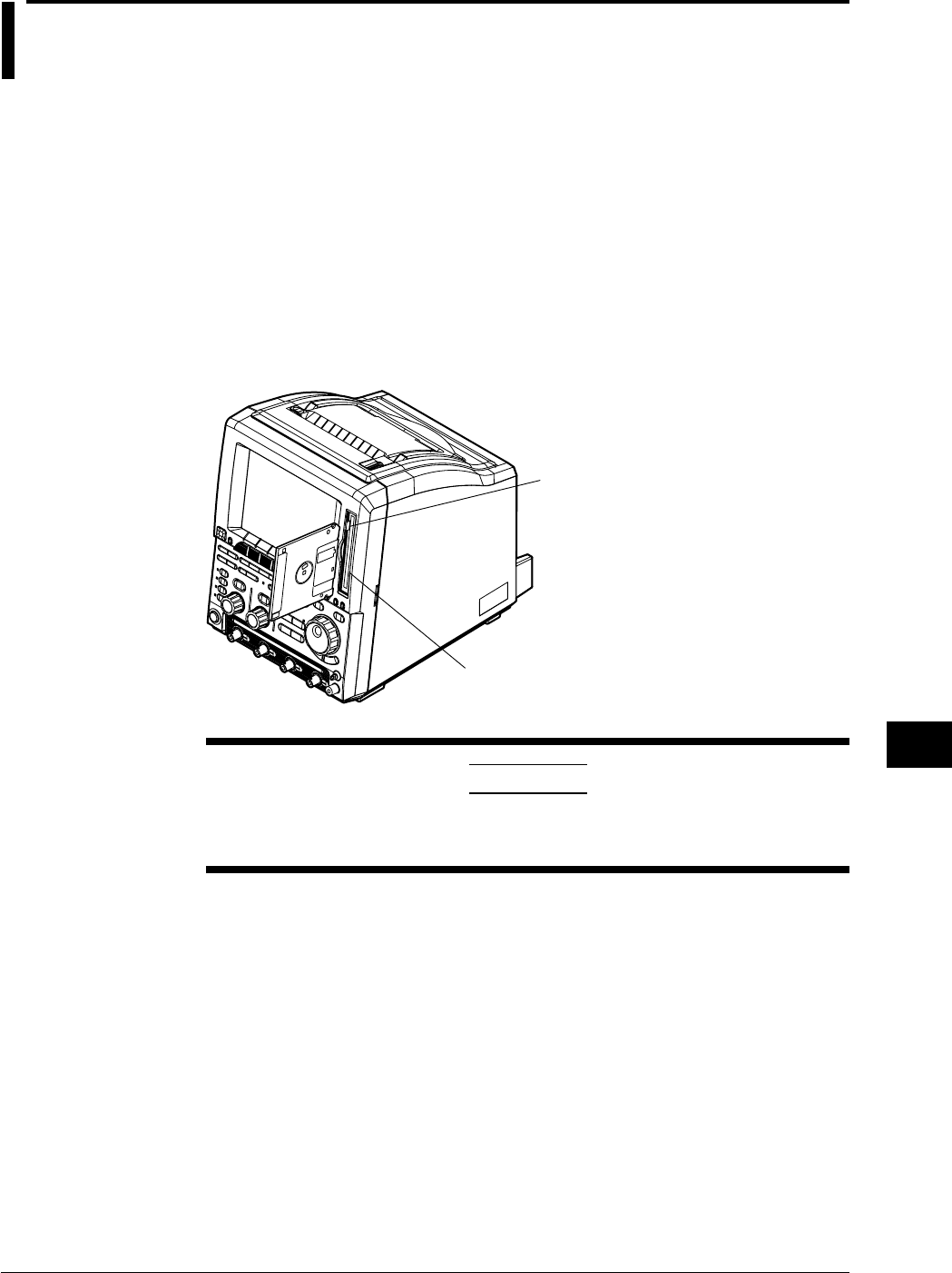
11-1
IM 701710-01E
Saving and Loading Data to and from the Storage Medium
11
11.1 Floppy Disks
Floppy Disks that can be Used
The following types of 3.5 inch floppy disk can be used. Floppy disks can be formatted
on this instrument.
2HD: 1.44 MB (MS-DOS format)
2DD: 720 KB (MS-DOS format)
Inserting a Floppy Disk into the Drive
Hold the floppy disk with the label facing left, and insert it with the shutter section facing
the drive. Insert the floppy disk until the eject button pops out.
Removing the Floppy Disk from the Drive
Check that the access indicator is not lit, then press the eject button.
Access Indicator
Eject Button
CAUTION
Removing the floppy disk while the access indicator is lit can damage
the drive’s magnetic head or destroy the data on the disk.
General Handling Precautions
For general handling precautions, see the instructions that came with the floppy disk.
Chpater 11 Saving and Loading Data to and from the Storage Medium
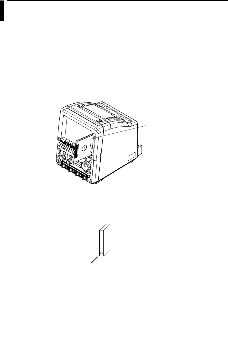
11-2 IM 701710-01E
11.2 Zip Disks
Zip Disks that can be Used
The following types can be used. You can format the zip disk on the DL1720/DL1740.
Size: 100 MB and 250 MB
Format: FDISK 1 partition (hard disk format)
Inserting the Zip Disk in the Zip Drive
With the label facing left, insert the disk from the side with the shutter.
Removing the Zip Disk from the Zip Drive
With the DL1720/DL1740 turned ON, check that the access indicator is turned OFF and
press the eject button.
Access Indicator
Eject Button
Procedure when the Zip Disk cannot be Ejected
If the Zip disk cannot be removed by performing the steps given above in “Removing the
Zip Disk from the Zip Drive”, carry out the following steps to remove it.
Insert a pin of approximately 1 mm in diameter into the eject button hole and press
slowly. This will cause the Zip disk to be ejected.
Zip Disk Eject
Button
Pin
Insert
Hole for Removing the
Zip Disk

11-3
IM 701710-01E
Saving and Loading Data to and from the Storage Medium
11
11.2 Zip Disks
CAUTION
•Removing the Zip disk while the access indicator is ON may damage
the data on the Zip disk.
•Do not use the Zip drive with the rear panel facing down. This may
damage the data on the Zip disk.
•When turning ON/OFF the DL1720/DL1740, have the Zip disk removed
from the drive.
•Immediately after inserting the Zip disk, the access indicator lights. Do
not use the instrument while the access indicator is lit as this may
cause a malfunction.
General Handling Precautions of Zip Disks
For the general handling precautions of the Zip drive, read the instruction manual that
came with the Zip disk.

11-4 IM 701710-01E
11.3 Connecting MO Disk Drives or Hard Disks to
the SCSI Interface (Option)
SCSI Specifications
Item Specification
Interface Standard SCSI (Small Computer System Interface), ANSI X3.131-1986
Connector Type 50-pin half pitch (pin type)
Connector Pin Assignments Unbalanced (single-ended), see below
1
25
26
50
2
27
3
28
24
49
23
48
Pin No.
Pin No. Signal Pin No. Signal
1 to 12 GND 38 TERMPWR
13 NC 39, 40 GND
14 to 25 GND 41 -ATN
26 -DB0 42 GND
27 -DB1 43 -BSY
28 -DB2 44 -ACK
29 -DB3 45 -RST
30 -DB4 46 -MSG
31 -DB5 47 -SEL
32 -DB6 48 -C/D
33 -DB7 49 -REQ
34 -DBP 50 -I/O
35 to 37 GND
Items Necessary for Connection
Cable
Use a commercially sold cable that is 3 m or less in length, that has a ferrite core on
each end of the cable, and that has a characteristic impedance between 90 and 132 W.
Connection Procedure
1. Connect the SCSI cable to the SCSI connector on the rear panel of the instrument.
2. Turn ON the SCSI device and the instrument (in that order).
If you need to format the medium, follow the procedures given in the next section
11.4, “Formatting the Recording Medium.”
SCSI Devices that can be Connected
Most SCSI devices (MO disk drive and hard disk) can be connected to the instrument,
but there are some exceptions.
For details on which devices can be connected, please ask your YOKOGAWA dealer.
For general handling precautions for the connected SCSI device, see the instruction
manual that is provided with the device.
Note
•When connecting multiple SCSI devices in a chain, attach a SCSI terminator to the device at
the other end of the chain.
•Hard disks (including the internal hard disk) that are formatted with the instrument cannot be
read using the NEC PC-9800 Series computers.
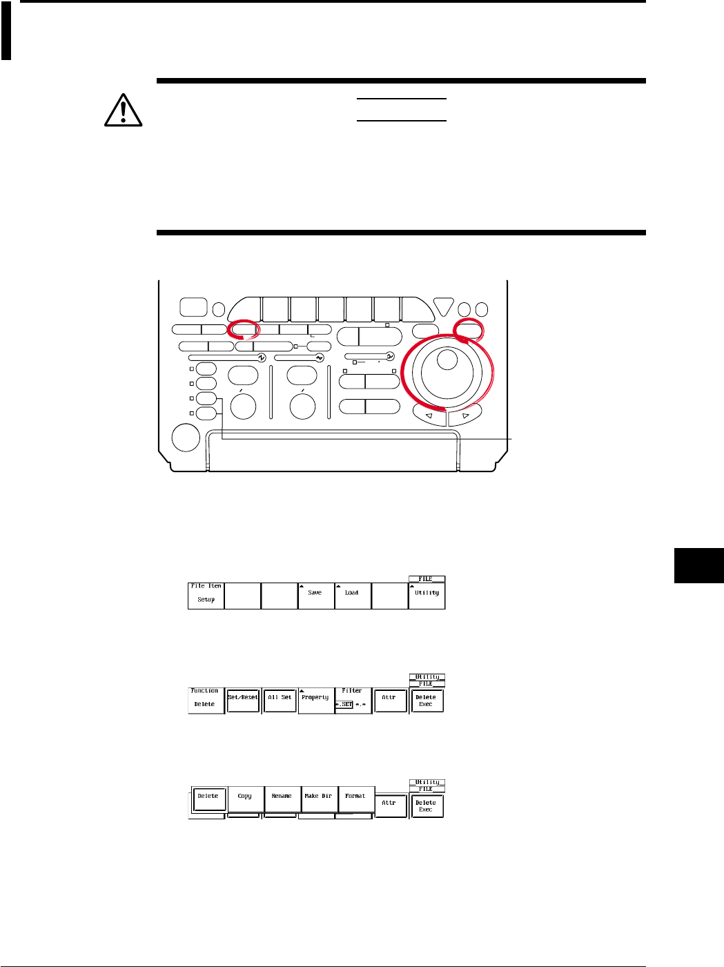
11-5
IM 701710-01E
Saving and Loading Data to and from the Storage Medium
11
11.4 Formatting the Storage Medium
CAUTION
•Never remove the medium (disk) or turn OFF the power while the
access indicator or, the floppy disk or the Zip disk icon is blinking. This
can damage the medium or destroy the data on the medium.
•When the instrument cannot read a pre-formatted medium, reformat the
formatting the medium. All data will be erased.
Relevant Keys
ACTION DELAY
X - Y MENU MENU PHASE
SEARCH
HORIZONTAL
VERTICAL TRIGGER
TRIG D
HELP
ESC
SELECTRESET
SIMPLE
MODE POSITION
MATH
MISCFILE
CLEAR
TRACE
HISTORY
MEASURE
SETUP
PRESET
DISPLAY
CURSOR
CH
1
CH
2
CH
3
CH
4
POWER
COPY IMAGE SAVE SHIFT
ZOOM
GO/NO-GO
ENHANCED
ACQ START/STOP
SNAP
SHOT
V DIV TIME DIV
The DL1720 is not
equipped with
an input terminal
for CH3 or CH4.
Operating Procedure
1. Press FILE.
2. Pressing the Utility soft key displays the utility setting menu and the file list dialog
box.
Selecting the Medium to be Formatted
3. Pressing the Function soft key displays the file function menu.
4. Pressing the Format soft key displays a list of media in the file list dialog box. (Net
Drive cannot be formatted.)
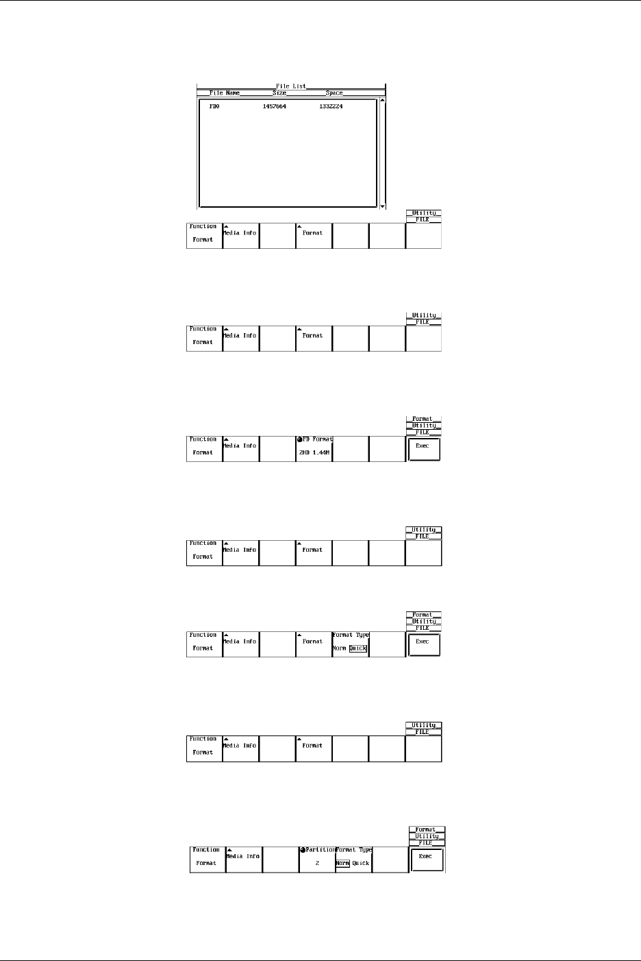
11-6 IM 701710-01E
5. Turn the jog shuttle to select the medium to be formatted.
If no external SCSI devices (option) are detected and only the floppy disk or the Zip
disk is inserted in the drive, only FD0 or ZP0 is displayed.
Selecting the FD Format
6. Pressing the Format soft key displays the format menu.
7. Turn the jog shuttle to select the format 2DD 720 K or 2HD 1.44 M.
Go to step 9.
Selecting the Format Type for the Zip Disk
6. Pressing the Format soft key displays the format menu.
7. Press the Format Type soft key to select Norm or Quick.
Selecting the Format Type for the SCSI Device (Option)
6. Pressing the Format soft key displays the format menu.
•Selecting the Number of Partitions
7. Turn the jog shuttle to select a value from 1 to 5.
•Selecting the Format Type
8. Press the Format Type soft key to select Norm or Quick.
11.4 Formatting the Storage Medium
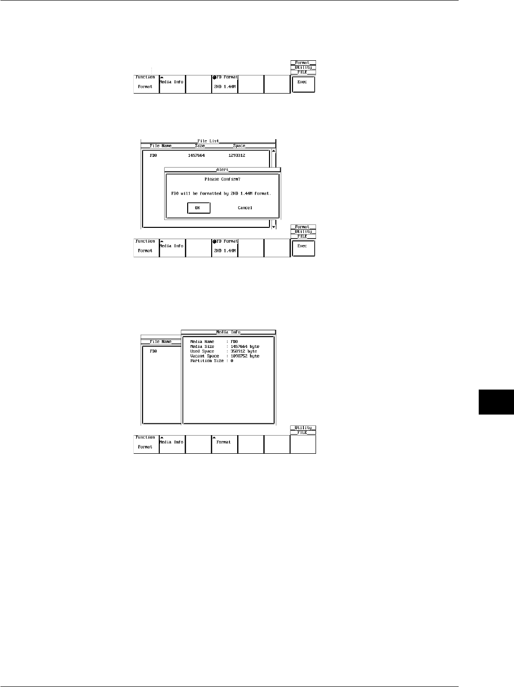
11-7
IM 701710-01E
Saving and Loading Data to and from the Storage Medium
11
•Executing/Canceling the Format Operation (OK/Cancel)
9. Pressing the Exec soft key displays the alert dialog box.
10. Turn the jog shuttle to select OK or Cancel.
11. Selecting OK and pressing SELECT starts the format operation.
Selecting Cancel and pressing SELECT cancels the format operation.
Viewing the Media Information
Follow steps 1-5 to select a media.
6. Pressing the Media Info soft key displays information about the medium that was
selected in step 5.
Explanation
Formatting a Floppy Disk
When using a new floppy disk, you must format it first. Select the appropriate format for
the floppy disk from the following choices.
2DD 720 K
Formats the 2DD floppy disk to 720 KB/9 sectors.
2HD 1.44 M
Formats the 2HD floppy disk to 1.44 MB/18 sectors.
Formatting a Zip Disk
If you are using a new Zip disk, you need to format it. The format for 250 MB and 100
MB disks is as follows:
FDISK 1 partition (hard disk format)
11.4 Formatting the Storage Medium

11-8 IM 701710-01E
Formatting a the SCSI Device
The formats of media connected via SCSI (option) are as follows.
•MO/PD
Semi-IBM format. Handled as removable disk.
•Zip/JAZ
Hard disk format. Handled as fixed disk.
•Hard Disk
IBM compatible format.
Selecting the Format Mode
When formatting a medium in a Zip disk or an external SCSI device, the following format
modes are available.
•Norm
Executes physical format and logical format. Formatting 100-MB Zip disks using this
method is not supported.
•Quick
Executes only the logical format.
Selecting the Number of Partitions
You can set partitions on the external SCSI device (option), except for removable disk.
1 to 5 partitions can be selected.
Information about the Medium
The following information is listed for the selected medium.
Media Name: Name of the medium
Media Size: Total capacity
Used Space: Used space
Vacant Space: Free space
Partition Size: Number of partitions
Note
•Formatting a medium containing data erases the data completely.
•The time it takes to format a floppy disk is approximately one and a half minutes.
•The time needed to format a 250-MB Zip disk is approximately 15 minutes for Norm,
approximately 10 s for Quick.
•A floppy disk cannot be formatted if it is write protected.
•Never format when the instrument is connected to a PC via a SCSI cable.
•Floppy disks having a format other than the ones listed in this section cannot be used.
•If an error message appears after the format operation, the floppy disk may be damaged.
•Disks formatted to MS-DOS format on a PC can also be used.
•The Quick (logical) format only clears (initializes) the directory entry and FAT information. If
you need to check for bad sectors, do a physical format (Normal).
•When data are written to an external SCSI device that has bad sectors, access error (604
Media failure) may occur in which case no more data can be written. When you are using a
medium for the first time or if the medium can no longer be read, do a “Norm” format. If you
want to format a disk that you have been using before, do a “Quick” format.
•This function can not be used in conjunction with FTP server function, FTP client function, or
LPR client function.
11.4 Formatting the Storage Medium
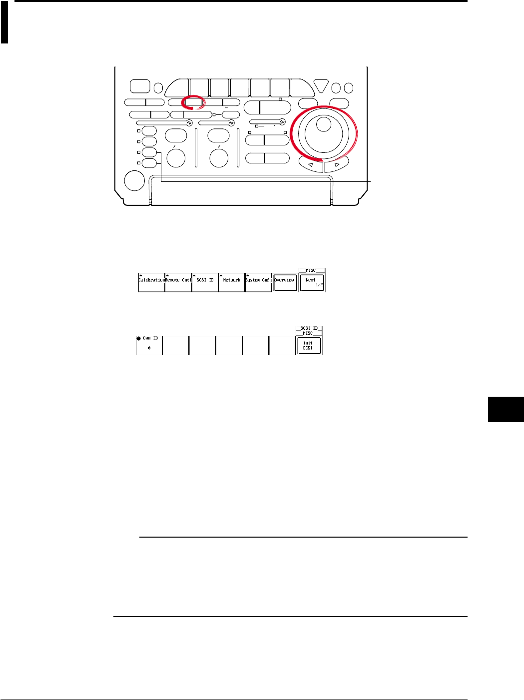
11-9
IM 701710-01E
Saving and Loading Data to and from the Storage Medium
11
11.5 Changing the SCSI ID Number
Relevant Keys
ACTION DELAY
X - Y MENU MENU PHASE
SEARCH
HORIZONTAL
VERTICAL TRIGGER
TRIG D
HELP
ESC
SELECTRESET
SIMPLE
MODE POSITION
MATH
MISCFILE
CLEAR
TRACE
HISTORY
MEASURE
SETUP
PRESET
DISPLAY
CURSOR
CH
1
CH
2
CH
3
CH
4
POWER
COPY IMAGE SAVE SHIFT
ZOOM
GO/NO-GO
ENHANCED
ACQ START/STOP
SNAP
SHOT
V DIV TIME DIV
The DL1720 is not
equipped with
an input terminal
for CH3 or CH4.
Operating Procedure
1. Press MISC.
2. Pressing the SCSI ID soft key displays the SCSI number setting menu.
3. Press the Own ID soft key.
4. Turn the jog shuttle to select a value from 0 to 7.
5. Press the Init SCSI soft key. The ID number is changed to the new number.
An icon blinks at the upper right of the screen while the change is being made.
When the change is complete, the icon disappears.
Explanation
The SCSI ID number is used to distinguish between the various devices connected to
the SCSI chain. Make sure not to use duplicate ID numbers on any of the connected
devices.
Range of Own ID Numbers
Select this instrument’s ID (Own ID) from the range 0 to 7. The default ID is 7.
Note
•When changing the Own ID number, make sure to press the “Init SCSI” soft key.
•Assign numbers that are different from the ID numbers of the external SCSI devices attached
to the instrument.
•The SCSI ID numbers of external SCSI devices are automatically detected at power up.
•If an ID number is changed, make sure to execute “Init SCSI” in order to detect the new ID
number.
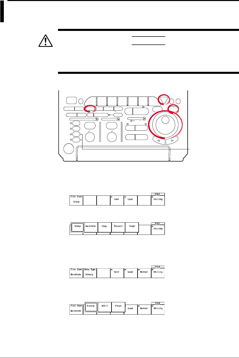
11-10 IM 701710-01E
11.6 Saving/Loading Waveform Data
CAUTION
Never remove the medium (disk) or turn OFF the power while the
access indicator or, the floppy disk or the Zip disk icon is blinking. This
can damage the medium or destroy the data on the medium.
Relevant Keys
ACTION DELAY
X - Y MENU MENU PHASE
SEARCH
HORIZONTAL
VERTICAL TRIGGER
TRIG D
HELP
ESC
SELECTRESET
SIMPLE
MODE POSITION
MATH
MISCFILE
CLEAR
TRACE
HISTORY
MEASURE
SETUP
PRESET
DISPLAY
CURSOR
CH
1
CH
2
CH
3
CH
4
POWER
COPY IMAGE SAVE SHIFT
ZOOM
GO/NO-GO
ENHANCED
ACQ START/STOP
SNAP
SHOT
V DIV TIME DIV
The DL1720 is not
equipped with
an input terminal
for CH3 or CH4.
Operating Procedure
1. Press FILE.
2. Pressing the File Item soft key displays the file time setting menu.
3. Press the soft key corresponding to Waveform.
Saving the Waveform Data
Selecting the Data Type
4. Pressing the Data Type soft key displays the data type menu.
5. Press the one of the soft keys corresponding to Binary, ASCII, or Float to select
the data type.
Data saved in Binary are only the data that can be loaded as described later in this
chapter.
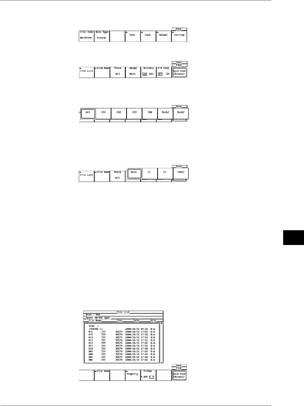
11-11
IM 701710-01E
Saving and Loading Data to and from the Storage Medium
11
Selecting the Waveform to be Saved.
6. Pressing the Save soft key displays the save setting menu.
7. Pressing the Trace soft key displays the waveform menu.
8. Press the soft key corresponding to the channel you wish to save. (CH3, CH4, and
Math2 are not displayed on the DL1720.)
Selecting the Range of the Waveform to be Saved
9. Pressing the Range soft key displays the save range selection menu.
10. Press one of the Main to Z1 & Z2 soft keys to select the range of waveforms to be
saved.
11. Press the History soft key to select whether to save all the data in the history
memory (All) or only the currently displayed waveform (One).
Compressing the Data and Saving (When Data Type is Set to Binary)
12. Press the P-P Comp soft key to select ON (compress and save) or OFF (do not
compress and save).
Compressed data cannot be loaded.
If P-P Comp is turned ON when saving waveform data, only the maximum and
minimum values of the multiple data points existing at the same time position are
saved. In this way, the file size can be reduced.
Selecting the Destination Medium/Directory
13. Pressing the File List soft key displays the file list dialog box.
14. Turn the jog shuttle to select the save destination medium (displayed with
parentheses).
15. Press SELECT to confirm the selection.
11.6 Saving/Loading Waveform Data
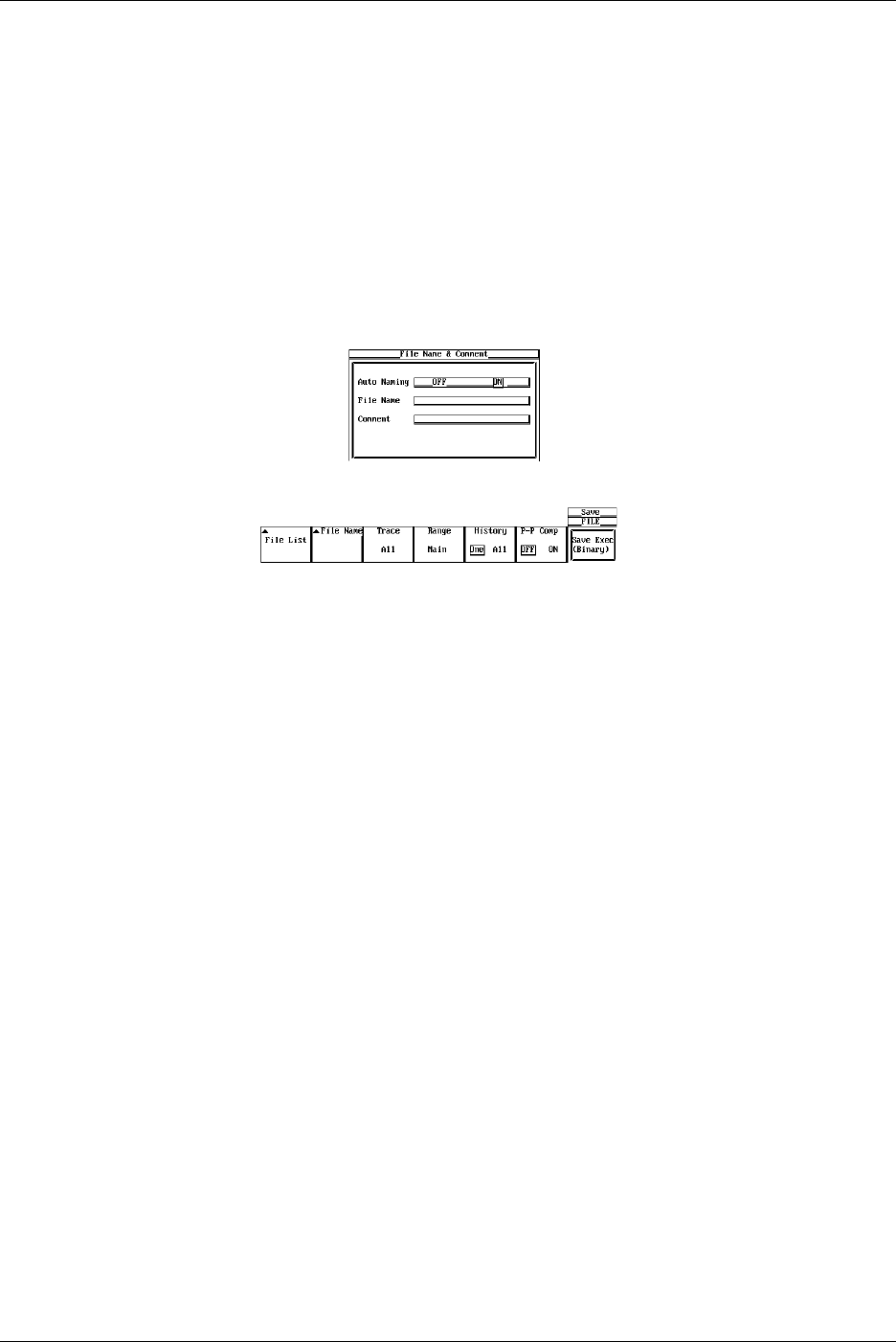
11-12 IM 701710-01E
Selecting the Destination Directory
(Use this only when there are directories on the medium.)
16. Turn the jog shuttle to select the save destination directory (displayed in angle
brackets < >).
17. Press SELECT to confirm the selection.
The Path=___ box on the top left corner of the File List dialog box displays the
selected medium/directory.
Selecting <..> moves to a higher level directory.
Setting the File Name/Comment
18. Pressing the File Name soft key displays the file name setting menu.
19. Turn the jog shuttle to select Auto Naming.
20. Press SELECT to select ON or OFF.
21. Turn the jog shuttle to select File Name.
22. Pressing SELECT displays a keyboard.
23. Enter the file name according to the procedures given in section 4.1.
24. Turn the jog shuttle to select Comment.
25. Pressing SELECT displays a keyboard.
26. Enter the file comment according to the procedures given in section 4.1.
27. Press ESC to close the file name setting dialog box.
Saving the File
28. Press the Save Exec soft key to save the file to the directory indicated in
Path=___. The name of the Save Exec soft key changes to Abort.
Canceling the Saving Operation
29. Press the Abort soft key to cancel the save operation. The name of the Abort soft
key changes to Save Exec.
Specifying the File to be Displayed in the File List Dialog Box and Viewing its
Properties
30. In the File List dialog box, press the Filter soft key to select *.extension or *.*.
31. In the File List dialog box, turn the jog shuttle to select the desired file.
32. Pressing the Property soft key displays the properties of the selected file.
33. Pressing ESC closes the window displaying the properties.
11.6 Saving/Loading Waveform Data

11-13
IM 701710-01E
Saving and Loading Data to and from the Storage Medium
11
11.6 Saving/Loading Waveform Data
Loading the Waveform Data
Set the data type to Binary. For the procedures, see steps 4 and 5 in the section “Saving
the Waveform Data” on page 11-14.
6. Pressing the Load soft key displays the load setting menu and the file list dialog
box.
Selecting the Source Medium/Directory
7. Select the directory according to steps 13 to 17.
Selecting the File to be Loaded
8. Turn the jog shuttle to select a file.
Loading the File
9. Press the Load Exec soft key to load the file from the directory indicated in
Path=___. The name of the Load Exec soft key changes to Abort.
Canceling the Loading Operation
10. Press the Abort soft key to cancel the loading operation. The name of the Abort
soft key changes to Load Exec.
Specifying the File to be Displayed in the File List Dialog Box, Viewing the
Properties
The procedures are the same as steps 30 and 31.
Unloading Waveforms
Selecting the File to be Unloaded
6. Continuing from step 5 in “Saving the waveform data,” press the Unload soft key to
display the Unload menu.
7. Pressing the Trace soft key displays a menu used to select the channels to be
unloaded.
8. Press the soft key corresponding to the desired channel to select the channel. If
All is selected, all channels are unloaded. (CH3, CH4, and Math2 are not displayed
on the DL1720.)
Unloading the File
9. Press the Unload Exec soft key.

11-14 IM 701710-01E
11.6 Saving/Loading Waveform Data
Explanation
Selecting the Data Type, File Extension
Binary
•The sampled data in the acquisition memory are saved in binary format.
•The data that are saved can be loaded to display the waveform and compute
numerical data.
•A header file is automatically created. The header file is used when analyzing the
waveform on a PC. The header file cannot be opened using this instrument. For the
header file format, see appendix 3, “ASCII Header File Format.”
•The file extension is .WVF. The file extension of the header file is .HDR.
•When saving waveform data in binary format, a header file is automatically created
with the extension .HDR. When the DL1720/DL1740 is used to copy, delete, change
filenames, or change file ownership of waveform data files (files with the extension,
.WVF), the header files are automatically updated to reflect the changes. Do not
delete the header file only or the waveform data file only as this may cause a system
malfunction.
ASCII
•The sampled data in the acquisition memory are saved in ASCII format. The data can
be used to analyze the waveform on a PC.
•Data in this format cannot be loaded on this instrument.
•The file extension is .CSV.
Float
•The sampled data in the acquisition memory are saved in 32 bit floating point format.
The data can be used to analyze the waveform on a PC.
•Data in this format cannot be loaded on this instrument.
•The file extension is .FLD.
Data Size
The following list shows the data size when the record length is set to 100 kwords,
waveform data of CH1 to CH4 are saved, and Math1 and Math2 are turned OFF
Data Type Extension Data Size (Bytes)
Binary .WVF Approx. 800 K ((100 kwords + 32) × 4 channels × number of history
waveform × 2)
.HDR Approx. 2 K (approx. 3 K if Math1 and Math2 are ON.)
ASCII .CSV Approx. 6 M (depends on the input signal condition.)
It takes more than 10 minutes to save the file.
Float .FLD Approx. 1.6 M ((100 kwords + 32) × 4 channels × number of history
waveform × 4)
Selecting the Waveform to be Saved
•You can save all waveforms or the specified waveforms from CH1 to CH4, Math1,
Math2 (or CH1, CH2, and Math1 for the DL1720).
•The vertical and horizontal axes and trigger settings of the waveform being saved are
also saved.
•For waveforms that are loaded using the history memory function, you can select
whether to save all of the history data or just the current displayed waveform on the
screen. You can also save only the search results of the data in the history memory.
For details regarding data search of the history memory, see sections 7.8 to 7.9.
•For snapshot waveforms, see section 11.8, “Saving/Loading the Snap Shot
Waveforms.”

11-15
IM 701710-01E
Saving and Loading Data to and from the Storage Medium
11
11.6 Saving/Loading Waveform Data
Selecting the Range of the Waveform to be Saved
Select the range (region) of the waveform from the following list of choices. Only the
data that have been saved by selecting Binary above in “Selecting the data type, file
extension, data size” can be loaded in this instrument.
•Main
The range of the normal (Main) waveform. It is the range defined by the displayed
record length (range displayed on the screen).
•Z1
The range of zoom waveform Z1.
•Z2
The range of zoom waveform Z2.
•Z1 & Z2
The range of zoom waveform Z1 & Z2.
Data Compression
•You can select whether or not to P-P compress the waveform data before saving.
•Power spectrum computation data cannot use P-P compression.
Selecting the Medium and Directory
The storage medium that can be used to save and load waveform data are displayed in
the File List dialog box.
Display Example of Storage Medium
FD0 : Floppy disk
ZP0 : Zip disk
SC5 : SCSI device with an ID number of 5
SC5_1 : Partition 1 of the SCSI device with an ID number of 5
ND0 : Network drive (available with the Ethernet interface option)
File Name and Comments
•You must specify a file name. Comments can be omitted.
•You cannot save to a file name that is already in use in the same directory (no
overwriting).
Number and Types of Characters that can be Used
Item Number of Characters Characters that Can be Used
File name 1 to 8 chars. 0 to 9, A to Z, %, _, ( ) (parenthesis), -(minus sign)
Comment 0 to 25 chars. All characters (including spaces),
Auto Naming Function
When Auto Naming is turned ON, files with three digit numbers from 000 to 999 are
automatically created. Specify the common name (maximum of five characters, specify
at the Filename item) that is placed before the three digit number.
Specifying the Files to Display in the File list Dialog Box
You can specify the type of files to display.
•*.WVF, *.CSV, or *.FLD
Displays only the files that have the same file format as the file being saved.
•*.*
Displays all files on the medium.
Properties
Lists the file name.extension, file size, the date it was saved, the attributes, and the
comment for the selected file.

11-16 IM 701710-01E
11.6 Saving/Loading Waveform Data
Unload
If the loaded waveform is being displayed, newly acquired waveform is not displayed
even if the data acquisition is started. In order to display the newly acquired waveforms,
loaded data must be unloaded from the appropriate channels.
Note
•If a key other than the Abort key is pressed during saving or loading, an error occurs.
•You cannot save or load while the data acquisition is in progress.
•If you change the file extension on a PC, for an example, you will not be able to load that file.
•A maximum of 36 characters can be displayed in Path.
•File names are not case sensitive. Comments are case sensitive. In addition, the following
file names cannot be used due to limitations of MS-DOS.
AUX, CON, PRN, NUL, CLOCK
•The waveform data loaded from a file overwrites the data in the acquisition memory. Once
the memory is overwritten, the old data cannot be recovered. It is recommended that the
current waveform data be saved before loading data from a file.
•Loaded waveforms are cleared only if Unload, Initialize, or Auto Setup is executed or the data
acquisition conditions are changed.
•When the total number of files and directories in one directory exceeds 2400, the file list will
no longer be displayed.
•This function can not be used in conjunction with FTP server function or LPR client function.
•Waveform (.wvf) and header (.hdr) files are saved as file pairs. If you set the filter of the files
displayed in the file list to *.* then process (Delete, Rename, Copy) each file individually, the
files become unloadable.
Data Format when Storing Multiple Records
When multiple records are stored (history memory, for example), the following data
format is used.
ASCII Format: CR+LF is inserted between records.
<Header>
Measured data 1-1 of CH1
,
Measured data 1-1 of CH2
,
Measured data 1-1 of CH3
, • • • •,,[ CR+LF]
Measured data 1-2 of CH1
,
Measured data 1-2 of CH2
,
Measured data 1-2 of CH3
, • • • •, [ CR+LF]
Measured data 1-m of CH1
,
Measured data 1-m of CH2
,
Measured data 1-m of CH3
, • • • •,[ CR+LF]
[ CR+LF]
Measured data 2-1 of CH1
,
Measured data 2-1 of CH2
,
Measured data 2-1 of CH3
, • • • •, [ CR+LF]
Measured data 2-2 of CH1
,
Measured data 2-2 of CH2
,
Measured data 2-2 of CH3
, • • • •, [ CR+LF]
Measured data 2-n of CH1
,
Measured data 2-n of CH1
,
Measured data 2-n of CH1
, • • • •, [ CR+LF]
[ CR+LF]
Record 1
Record 2
Float Format: Stored in blocks of channels.
Measured data of record 1 of CH1
Measured data of record 2of CH1
Measured data of record N of CH1
Measured data of record 1 of CH2
Measured data of record 2 of CH2
Measured data of record N of CH2
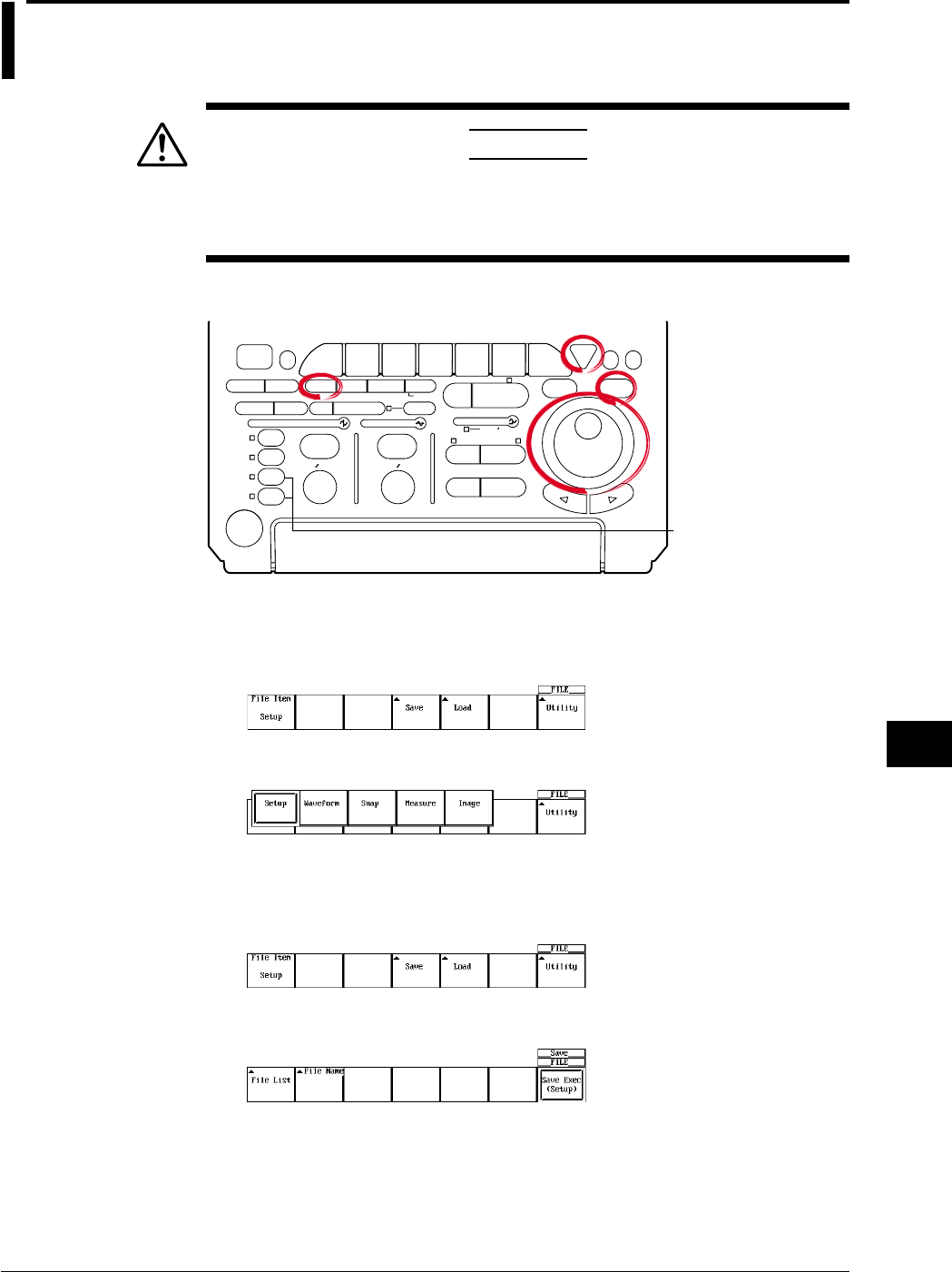
11-17
IM 701710-01E
Saving and Loading Data to and from the Storage Medium
11
11.7 Saving/Loading Setup Data
CAUTION
Never remove the medium (disk) or turn OFF the power while the
access indicator, or the floppy disk or the Zip disk icon is blinking. This
can damage the medium or destroy the data on the medium.
Relevant Keys
ACTION DELAY
X - Y MENU MENU PHASE
SEARCH
HORIZONTAL
VERTICAL TRIGGER
TRIG D
HELP
ESC
SELECTRESET
SIMPLE
MODE POSITION
MATH
MISCFILE
CLEAR
TRACE
HISTORY
MEASURE
SETUP
PRESET
DISPLAY
CURSOR
CH
1
CH
2
CH
3
CH
4
POWER
COPY IMAGE SAVE SHIFT
ZOOM
GO/NO-GO
ENHANCED
ACQ START/STOP
SNAP
SHOT
V DIV TIME DIV
The DL1720 is not
equipped with
an input terminal
for CH3 or CH4.
Operating Procedure
1. Press FILE.
2. Pressing the File Item soft key displays the file item setting menu.
3. Press the Setup soft key.
Selecting the Setup Data
Selecting the Destination Medium
4. Pressing the Save soft key displays the save setting menu.
5. Pressing the File List soft key displays the file list dialog box.
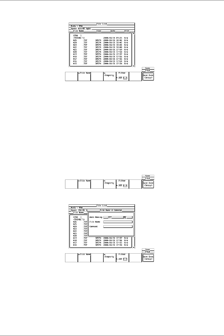
11-18 IM 701710-01E
6. Turn the jog shuttle to select the save destination medium (displayed with
parentheses).
7. Press SELECT to confirm the selection.
Selecting the Destination Directory
(Use this only when there are directories on the medium.)
8. Turn the jog shuttle to select the save destination directory (displayed in angle
brackets < >).
9. Press SELECT to confirm the selection.
The Path=___ box on the top left corner of the File List dialog box displays the
selected medium/directory.
Selecting <..> moves to a higher level directory.
Setting the File Name/Comment
10. Pressing the File Name soft key displays the file name setting menu.
11. Turn the jog shuttle to select Auto Naming.
12. Press SELECT to select ON or OFF.
13. Turn the jog shuttle to select File Name.
14. Pressing SELECT displays a keyboard.
15. Enter the file name according to the procedures given in section 4.1.
16. Turn the jog shuttle to select Comment.
17. Pressing SELECT displays a keyboard.
18. Enter the file comment according to the procedures given in section 4.1.
19. Press ESC to close the file name setting dialog box.
11.7 Saving/Loading Setup Data
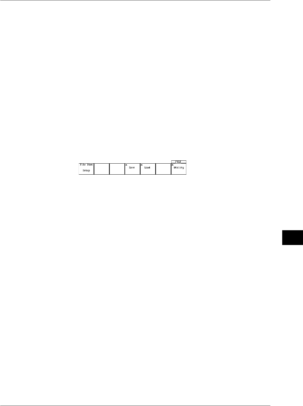
11-19
IM 701710-01E
Saving and Loading Data to and from the Storage Medium
11
Saving the File
20. Press the Save Exec soft key to save the file to the directory indicated in
Path=___. The name of the Save Exec soft key changes to Abort.
Canceling the Saving Operation
21. Press the Abort soft key to cancel the save operation. The name of the Abort soft
key changes to Save Exec.
Specifying the File to be Displayed in the File List Dialog Box, and Viewing its
Properties
22. In the File List dialog box, press the Filter soft key to select *.SET or *.*.
23. In the File List dialog box, turn the jog shuttle to select the desired file.
24. Pressing the Property soft key displays information regarding the selected file.
25. Pressing ESC closes the window displaying the information.
Loading the Setup Data
Display the menu used to save/load setup data according to steps 1 to 3.
4. Pressing the Load soft key displays the load setting menu and the file list dialog
box.
Selecting the Source Medium/Directory
5. Select the directory according to steps 13 to 17 on section 11.6.
Selecting the File to be Loaded
6. Turn the jog shuttle to select a file.
Loading the File
7. Press the Load Exec soft key to load the file from the directory indicated in
Path=___. The name of the Load Exec soft key changes to Abort.
Canceling the Loading Operation
8. Press the Abort soft key to cancel the loading operation. The name of the Abort
soft key changes to Load Exec.
Specifying the File to be Displayed in the File List Dialog Box, Viewing the
Properties
The procedures are the same as steps 22 to 25.
Explanation
Setup Data that are Saved
The setup data of each key existing at the time of the saving operation are saved.
However, date and time, communication parameters, and SCSI ID numbers are not
saved.
Number of Bytes Necessary in Saving the Setup Data
Approximately 13 Kbytes
Selecting the Medium and Directory
The storage medium that can be used to save and load waveform data are displayed in
the File List dialog box.
11.7 Saving/Loading Setup Data

11-20 IM 701710-01E
11.7 Saving/Loading Setup Data
•Display Example of Storage Medium
FD0 : Floppy disk
ZP0 : Zip disk
SC5 : SCSI device with an ID number of 5
SC5_1 : Partition 1 of the SCSI device with an ID number of 5
ND0 : Network drive (available with the Ethernet interface option)
File Name and Comments
You must specify a file name. Comments can be omitted.
You cannot save to a file name that is already in use in the same directory (no
overwriting).
•Number and Types of Characters that can be Used
Item Number of Characters Characters that can be Used
File name 1 to 8 chars. 0 to 9, A to Z, %, _, ( ) (parenthesis), -(minus sign)
Comment 0 to 25 chars. All characters (including spaces),
•Notes when Saving Setup Data
You cannot save while the data acquisition is in progress. Press START/STOP to
stop the acquisition.
When the total number of files and directories in one directory exceeds 2400, the file
list will no longer be displayed.
File Extension
The File extension .SET is automatically appended to the file.
Auto Naming Function
When Auto Naming is turned ON, files with three digit numbers from 000 to 999 are
automatically created. Specify the common name (maximum of five characters, specify
at the Filename item) that is placed before the three digit number.
Specifying the Files to Display in the File List Dialog Box
You can specify the type of files to display.
•*.SET
Displays only the setup data files.
•*.*
Displays all files on the medium.
Properties
Lists the file name.extension, file size, the date it was saved, the attributes, and the
comment for the selected file.
Note
•If a key other than the Abort key is pressed during saving or loading, an error occurs.
•You cannot save or load while the data acquisition is in progress.
•If you change the file extension on a PC, for an example, you will not be able to load that file.
•A maximum of 36 characters can be displayed in Path.
•File names are not case sensitive. Comments are case sensitive. In addition, the following
file names cannot be used due to limitations of MS-DOS.
AUX, CON, PRN, NUL, CLOCK
•When the setup parameters are loaded from a file, the setup parameters of each key are
overwritten with the loaded settings and cannot be set back to their previous settings. It is
recommended that the current setup parameters be saved before loading setup parameters
from a file.
•The date and time, communication parameters and SCSI ID numbers are not saved.
Therefore, when setup parameters are loaded from a file, these parameters do not change.
•This function can not be used in conjunction with FTP server function or LPR client function.
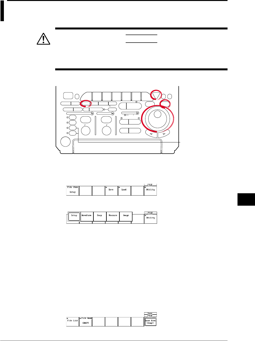
11-21
IM 701710-01E
Saving and Loading Data to and from the Storage Medium
11
11.8 Saving/Loading Snapshot Waveforms
CAUTION
Never remove the medium (disk) or turn OFF the power while the
access indicator, or the floppy disk or the Zip disk icon is blinking. This
can damage the medium or destroy the data on the medium.
Relevant Keys
ACTION DELAY
X - Y MENU MENU PHASE
SEARCH
HORIZONTAL
VERTICAL TRIGGER
TRIG D
HELP
ESC
SELECTRESET
SIMPLE
MODE POSITION
MATH
MISCFILE
CLEAR
TRACE
HISTORY
MEASURE
SETUP
PRESET
DISPLAY
CURSOR
CH
1
CH
2
CH
3
CH
4
POWER
COPY IMAGE SAVE SHIFT
ZOOM
GO/NO-GO
ENHANCED
ACQ START/STOP
SNAP
SHOT
V DIV TIME DIV
The DL1720 is not
equipped with
an input terminal
for CH3 or CH4.
Operating Procedure
1. Press FILE.
2. Pressing the File Item soft key displays the file item setting menu.
3. Press the Snap soft key.
Saving Snapshot Waveforms
Selecting the Destination Medium/Directory
The procedures are the same as steps 13 to 17 in section 11.6, “Saving/Loading
Waveform Data.”
Setting the File name/Comment
The procedures are the same as steps 18 to 27 in section 11.6, “Saving/Loading
Waveform Data.”
Saving the File
4. Press the Save Exec soft key to save the file to the directory indicated in
Path=___. The name of the Save Exec soft key changes to Abort.
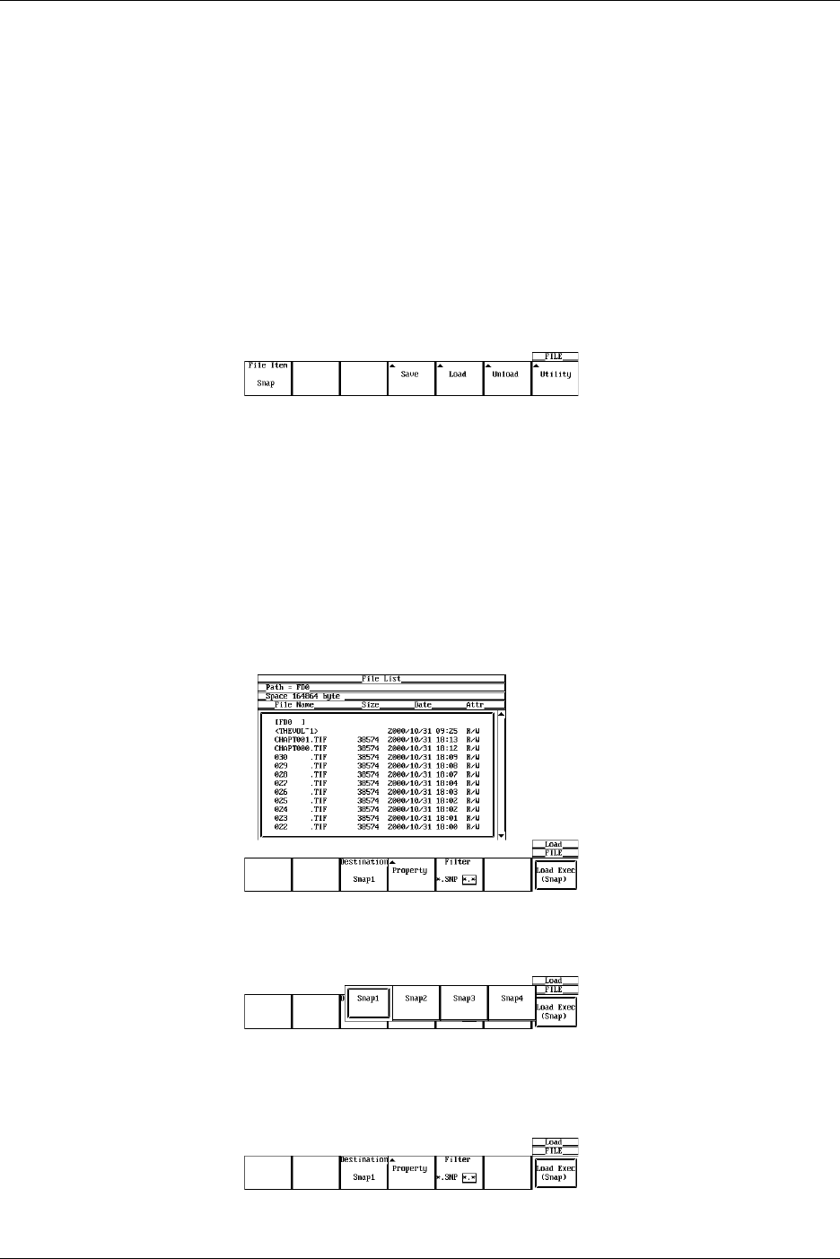
11-22 IM 701710-01E
Canceling the Saving Operation
5. Press the Abort soft key to cancel the saving operation. The name of the Abort
soft key changes to Save Exec.
Specifying the File to be Displayed in the File List Dialog Box, Viewing the
Properties
The procedures are the same as steps 30 to 33 in section 11.6, “Saving/Loading
Waveform Data.”
Loading Snapshot Waveforms
Follow steps 1-3 to select snapshot data waveforms.
4. Pressing the Load soft key displays the load setting menu and the file list dialog
box.
Selecting the Source Medium/Directory
The procedures are the same as steps 13 to 17 in section 11.6, “Saving/Loading
Waveform Data.”
Selecting the File to be Loaded
5. Turn the jog shuttle to select a file.
Selecting the Snapshot Waveform to be Loaded
6. Press the Destination soft key to display a menu used to select the snapshot
waveform.
7. Press the soft key corresponding to the desired snapshot waveform to make the
selection.
Loading the File
8. Press the Load Exec soft key to load the file from the directory indicated in
Path=___. The name of the Load Exec soft key changes to Abort.
11.8 Saving/Loading Snapshot Waveforms
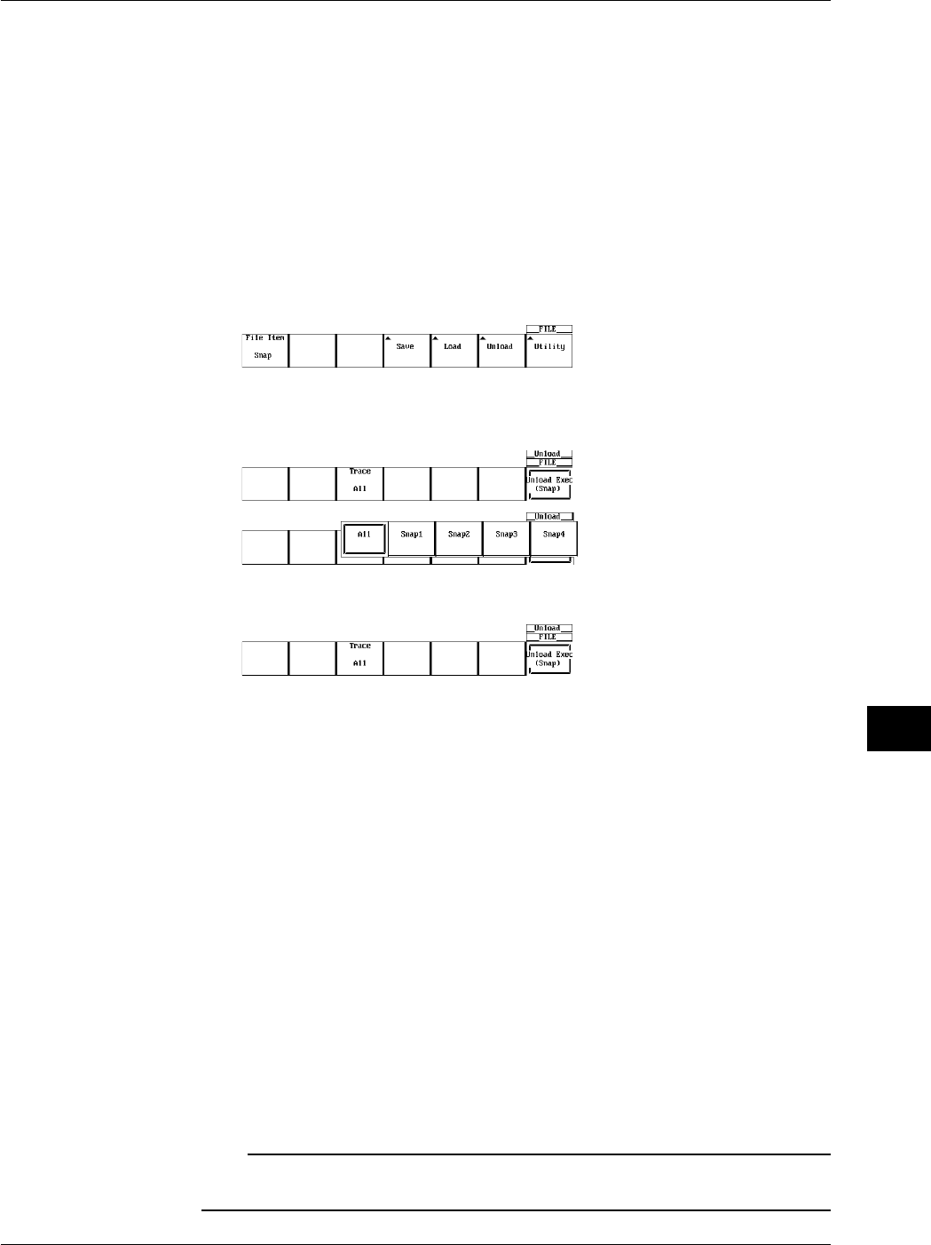
11-23
IM 701710-01E
Saving and Loading Data to and from the Storage Medium
11
Canceling the Loading Operation
9. Press the Abort soft key to cancel the loading operation. The name of the Abort
soft key changes to Load Exec.
Specifying the File to be Displayed in the File List Dialog Box, Viewing the
Properties
The procedures are the same as steps 30 to 33 in section 11.6, “Saving/Loading
Waveform Data.”
Clearing the Waveform
4. Pressing the Unload soft key displays a menu used to select the waveform to be
cleared.
5. Press the Trace soft key and press the soft key corresponding to the waveform to
be cleared.
6. Pressing the Unload Exec soft key clears the selected waveform.
Explanation
You can take snap shots of the waveform and save the image to the file. You can also
load the snapshot waveform.
Data Size
Approx. 40 K Bytes
File Extension
The file extension is .SNP.
The selection of the medium and directory, file name, comments, auto naming function,
specification of the files to be displayed in the File List dialog box, and properties are the
same as those for saving/loading normal waveform data. For explanation and
procedures, see section 11.6, “Saving/Loading Waveform Data.”
Loading the Snapshot Waveform
The snapshot waveform can be load as four waveforms, Snap1 to Snap4.
Clearing the Waveform
The loaded snapshot waveform is cleared when unload, initialize, or auto setup is
performed.
Note
•If a key other than the Abort key is pressed during saving or loading, an error occurs.
•This function can not be used in conjunction with FTP server function or LPR client function.
11.8 Saving/Loading Snapshot Waveforms

11-24 IM 701710-01E
11.9 Saving the Results of the Automated
Measurement of Waveform Parameters
CAUTION
Never remove the medium (disk) or turn OFF the power while the
access indicator, or the floppy disk or the Zip disk icon is blinking. This
can damage the medium or destroy the data on the medium.
Relevant Keys
ACTION DELAY
X - Y MENU MENU PHASE
SEARCH
HORIZONTAL
VERTICAL TRIGGER
TRIG D
HELP
ESC
SELECTRESET
SIMPLE
MODE POSITION
MATH
MISCFILE
CLEAR
TRACE
HISTORY
MEASURE
SETUP
PRESET
DISPLAY
CURSOR
CH
1
CH
2
CH
3
CH
4
POWER
COPY IMAGE SAVE SHIFT
ZOOM
GO/NO-GO
ENHANCED
ACQ START/STOP
SNAP
SHOT
V DIV TIME DIV
The DL1720 is not
equipped with
an input terminal
for CH3 or CH4.
Operating Procedure
1. Press FILE.
2. Pressing the File Item soft key displays the file item setting menu.
3. Press the soft key corresponding to Measure.
Selecting the Destination Medium/Directory
The procedures are the same as steps 13 to 17 in section 11.6, “Saving/Loading
Waveform Data.”
Setting the File Name/Comment
The procedures are the same as steps 18 to 27 in section 11.6, “Saving/Loading
Waveform Data.”
Saving the File
4. Press the Save Exec soft key to save the file to the directory indicated in
Path=___. The name of the Save Exec soft key changes to Abort.

11-25
IM 701710-01E
Saving and Loading Data to and from the Storage Medium
11
Canceling the Saving Operation
5. Press the Abort soft key to cancel the saving operation. The name of the Abort
soft key changes to Save Exec.
Specifying the File to be Displayed in the File List Dialog Box, Viewing the
Properties
The procedures are the same as steps 30 to 33 in section 11.6, “Saving/Loading
Waveform Data.”
Explanation
The results of the automated measurement of waveform parameters can be saved in
CSV format (.CSV file extension) to a floppy disk, a Zip disk, or external SCSI device
(option).
A CSV file is a comma-separated format file. The CSV file is one of the common file
formats used to exchange data between spreadsheet and database applications.
The data that are saved are the measurement results of the parameters that are
specified in the automated measurement of waveform parameters.
Notes when Saving the Results of the Automated Measurement of Waveform
Parameters
The restrictions are as follows.
•Up to (24000/the number of items that are turned ON) data points before the point at
which the save operation is executed are saved. However, the data points that are
saved are limited to those that are acquired after fixing T/div, V/div, and Measure
settings.
•Output example
CH1 P-P, CH1 Max, CH1 Min, CH2 P-P
v, v, v, v
0.199E+00, 0.199E+00, 0.000E+00, 0.02E-06 Oldest data
0.207E+00, 0.207E+00, 0.000E+00, 0.02E-06
0.377E+00, 0.152E+00, –0.125E+00, 0.02E-06
••••↓
••••
••••
••••Newest data
For information related to the automated measurement of waveform parameters, see
section 9.2, “Automated Measurement of Waveform Parameters.”
Data Size
Data size = Number of item × 15 × number of history waveform
File Extension
The file extension is .CSV.
The selection of the medium and directory, file name, comments, auto naming function,
specification of the files to be displayed in the File List dialog box, and properties are the
same as those for saving/loading normal waveform data. For explanation and
procedures, see section 11.6, “Saving/Loading Waveform Data.”
Note
•If a key other than the Abort key is pressed during saving, an error occurs.
•This function can not be used in conjunction with FTP server function or LPR client function.
11.9 Saving the Results of the Automated Measurement of Waveform Parameters
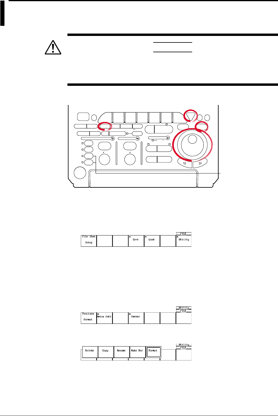
11-26 IM 701710-01E
11.10 Changing the File Attributes, Deleting Files
CAUTION
Never remove the medium (disk) or turn OFF the power while the
access indicator, or the floppy disk or the Zip disk icon is blinking. This
can damage the medium or destroy the data on the medium.
Relevant Keys
ACTION DELAY
X - Y MENU MENU PHASE
SEARCH
HORIZONTAL
VERTICAL TRIGGER
TRIG D
HELP
ESC
SELECTRESET
SIMPLE
MODE POSITION
MATH
MISCFILE
CLEAR
TRACE
HISTORY
MEASURE
SETUP
PRESET
DISPLAY
CURSOR
CH
1
CH
2
CH
3
CH
4
POWER
COPY IMAGE SAVE SHIFT
ZOOM
GO/NO-GO
ENHANCED
ACQ START/STOP
SNAP
SHOT
V DIV TIME DIV
The DL1720 is not
equipped with
an input terminal
for CH3 or CH4.
Operating Procedure
1. Press FILE.
2. Pressing the Utility soft key displays the utility setting menu and the file list dialog
box.
Selecting the Destination Medium/Directory
The procedures are the same as steps 13 to 17 in section 11.6, “Saving/Loading
Waveform Data.”
Changing the File Attributes
3. Pressing the Function soft key displays the file function menu.
4. Press the Delete soft key.
5. Turn the jog shuttle to select a file.
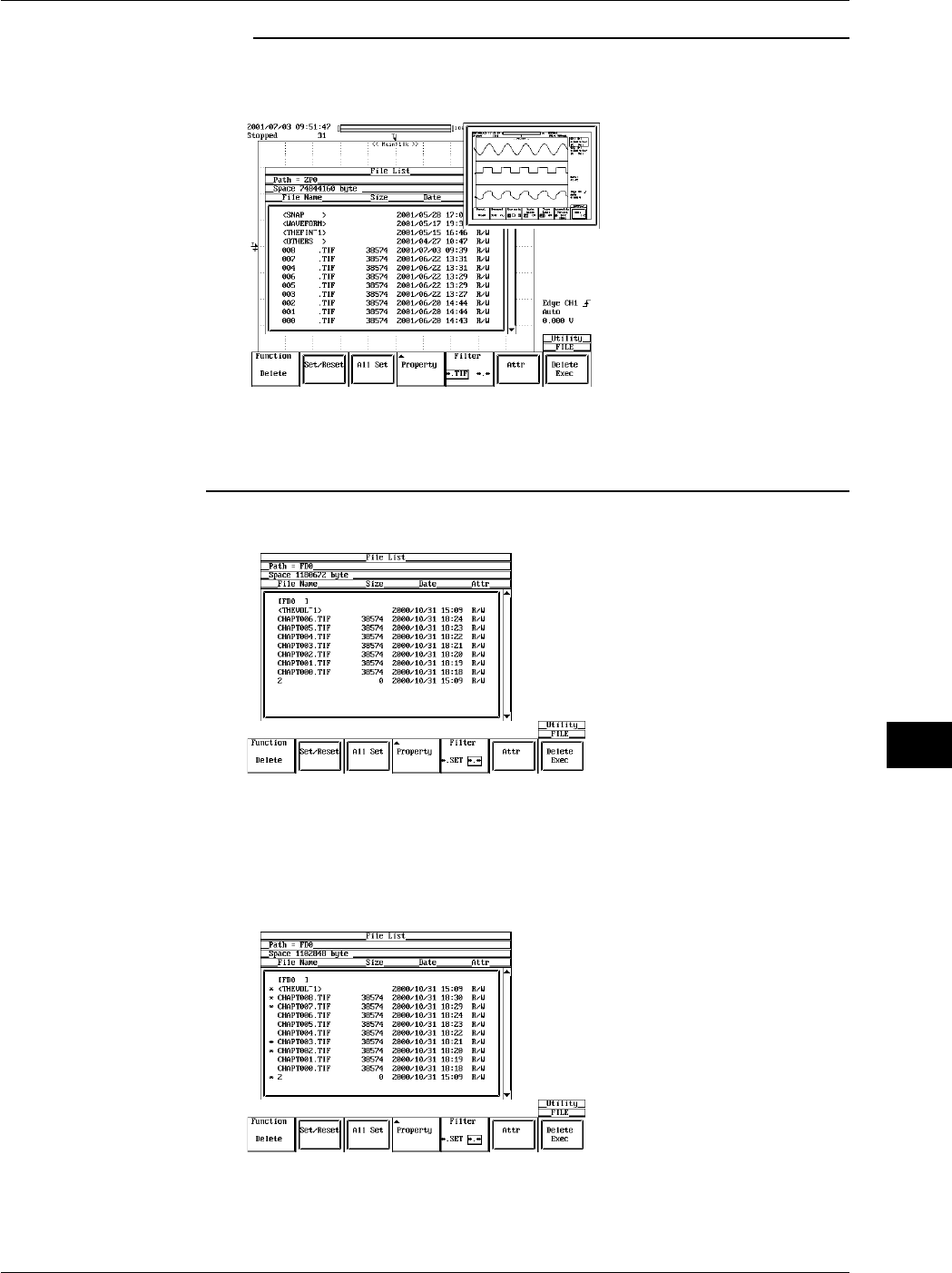
11-27
IM 701710-01E
Saving and Loading Data to and from the Storage Medium
11
Note
By selecting a screen image data file (files with the .tif, .bmp, or .ps extensions) in the File List
window and pressing SELECT, the selected screen image file's compressed image appears
in the upper right portion of the file list.
•If compressed image (thumbnail) data does not exist for the selected file, an error message
appears. Pressing ESC clears the error message.
•The following procedure clears the compressed image from the screen.
•Move the cursor using the jog shuttle.
6. Pressing the Attr soft key changes the attribution of the selected file.
Selecting the Files to be Deleted One at a Time
7. Turn the jog shuttle to select a file.
8. Pressing the Set/Reset soft key places an asterisk (*) to the left of the selected file.
The file will be deleted. Pressing the Set/Reset soft key again removes the
asterisk (*) to the left of the selected file. The file will not be deleted.
Go to step 12.
11.10 Changing the File Attributes, Deleting Files

11-28 IM 701710-01E
Selecting All Files to be Deleted
9. Turn the jog shuttle to select a file, a directory, or a medium.
10. Pressing the All Set soft key places an asterisk to the left of every file in the
directory containing the selected file or directory. These files will be deleted. The
name of the All Set soft key changes to All Reset.
11. Pressing the All Set soft key removes the asterisk to the left of every file in the
directory containing the selected file or directory. These files will not be deleted.
The name of the All Reset soft key changes to All Set.
Deleting the Files
12. Press the Delete Exec soft key. All files with the asterisks are deleted.
Specifying the File to be Displayed in the File List Dialog Box, Viewing the
Properties
The procedures are the same as steps 30 to 33 in section 11.6, “Saving/Loading
Waveform Data.”
Explanation
Selecting the Medium and Directory
The storage medium that can be used to save and load waveform data are displayed in
the File List dialog box.
•Display Example of Storage Medium
FD0 : Floppy disk
ZP0 : Zip disk
SC5 : SCSI device with an ID number of 5
SC5_1 : Partition 1 of the SCSI device with an ID number of 5
ND0 : Network drive (available with the Ethernet interface option)
Selecting the File Attributes (Excepting Net Drive)
Select the attributes for each file from the following choices.
•R/W
Read and write possible.
•R
Read only. Cannot write to the file or delete the file.
Selecting the Files to be Deleted
You can delete all files that have an asterisk to the left of the file name. There are two
methods available to select the files that are to be deleted.
•Selecting the Files One at a Time
Place an asterisk to the left of the file names one at a time, using the Set/Reset soft
key.
•Selecting All Files at Once
Selecting a file or directory and pressing the All Set soft key places an asterisk on
every file in the directory containing the selected file or directory.
11.10 Changing the File Attributes, Deleting Files

11-29
IM 701710-01E
Saving and Loading Data to and from the Storage Medium
11
Specifying the File to be Displayed in the File List Dialog Box
You can specify the type of files to display.
•*. extension
Displays only the data file that was selected in the File Item setting menu and the data
type menu.
•*.*
Displays all the files on the medium.
Properties
Lists the file name.extension, file size, the date it was saved, the attributes, and the
comment for the selected file.
Displaying Compressed Images in the File List
Selecting screen image data files from the File List causes a compressed image of the
screen data to appear in the upper right portion of the File List. Screen image data is the
only type of compressed image that is displayed. The compressed images of waveform
and setting data are not displayed. Also, file name and color information are not
displayed in the compressed image.
Note
•You cannot delete files while data acquisition is in progress
•Deleted data cannot be recovered. Make sure not to erase the wrong files.
•Directories can be deleted if there are no files in them.
•If an error occurs while deleting multiple files, the files after the error will not be deleted.
•Directory attributes cannot be changed.
•This function can not be used in conjunction with FTP server function or LPR client function.
•Screen image data and thumbnail display data is saved together as a file pairs. If you set the
designation (filter) of the files displayed in the file list to *.* then process (Delete, Rename,
Copy) each file individually, the thumbnail function becomes disabled.
11.10 Changing the File Attributes, Deleting Files

11-30 IM 701710-01E
11.11 Copying Files
CAUTION
Never remove the medium (disk) or turn OFF the power while the
access indicator, or the floppy disk or the Zip disk icon is blinking. This
can damage the medium or destroy the data on the medium.
Relevant Keys
ACTION DELAY
X - Y MENU MENU PHASE
SEARCH
HORIZONTAL
VERTICAL TRIGGER
TRIG D
HELP
ESC
SELECTRESET
SIMPLE
MODE POSITION
MATH
MISCFILE
CLEAR
TRACE
HISTORY
MEASURE
SETUP
PRESET
DISPLAY
CURSOR
CH
1
CH
2
CH
3
CH
4
POWER
COPY IMAGE SAVE SHIFT
ZOOM
GO/NO-GO
ENHANCED
ACQ START/STOP
SNAP
SHOT
V DIV TIME DIV
The DL1720 is not
equipped with
an input terminal
for CH3 or CH4.
Operating Procedure
1. Press FILE.
2. Pressing the Utility soft key displays the utility setting menu and the file list dialog
box.
3. Pressing the Function soft key displays the file function menu.
4. Press the Copy soft key.
Selecting the Source Medium/Directory
5. The procedures are the same as steps 13 to 17 in section 11.6, “Saving/Loading
Waveform Data.”

11-31
IM 701710-01E
Saving and Loading Data to and from the Storage Medium
11
Selecting the Source File One at a Time
6. Turn the jog shuttle to select a file.
Note
By selecting a screen image data file (files with the .tif, .bmp, or .ps extensions) in the File List
window and pressing SELECT, the selected screen image file's compressed image appears
in the upper right portion of the file list.
•If compressed image (thumbnail) data does not exist for the selected file, an error message
appears. Pressing ESC clears the error message.
•The following procedure clears the compressed image from the screen.
•Move the cursor using the jog shuttle.
7. Press the Set/Reset soft key. If an asterisk is displayed to the left of the file name
in the File List dialog box, the file will be copied.
If you press the Set/Reset soft key, the asterisk to the left of the file name
disappears. This file will not be copied.
Go to step 11.
Selecting All Copy Source Files at Once
8. Turn the jog shuttle to select a file, a directory, or a medium.
9. Pressing the All Set soft key places an asterisk to the left of every file in the
directory containing the selected file or directory. These directories and files will be
copied. The name of the All Set soft key changes to All Reset.
Resetting All Selected Copy Source
10. Pressing the All Set soft key removes the asterisk to the left of every file in the
directory containing the selected file or directory. The directories and files will not
be copied. The name of the All Reset soft key changes to All Set.
11.11 Copying Files
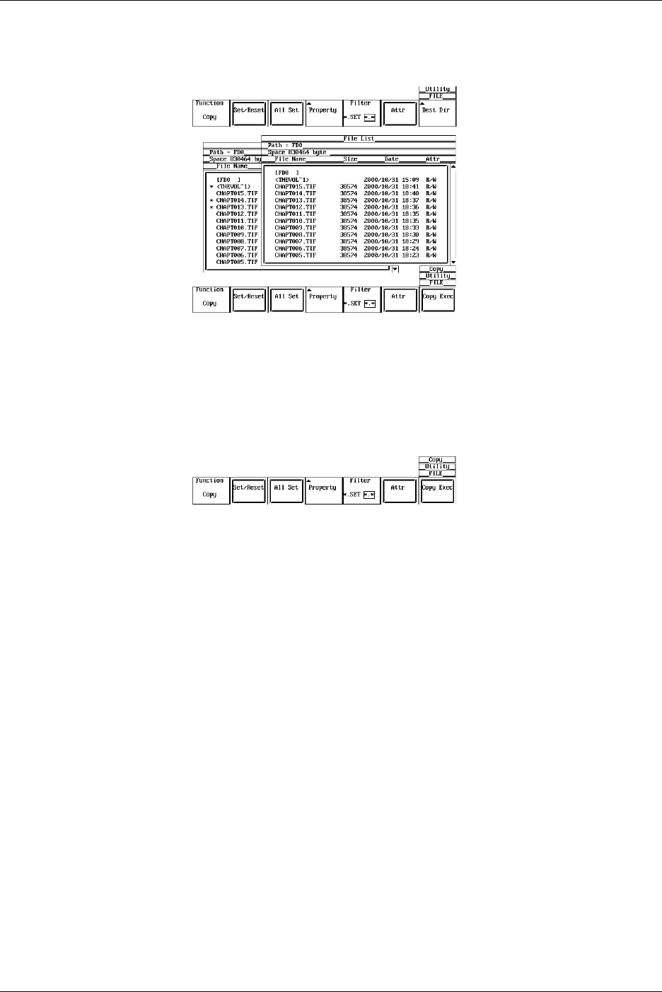
11-32 IM 701710-01E
Selecting the Copy Destination
11. Press the Dest Dir soft key. The copy execution menu and the copy destination
file list dialog box appear.
Selecting the Destination Medium/Directory
12. The procedures are the same as steps 13 to 17 in section 11.6, “Saving/Loading
Waveform Data.”
Executing the Copy Operation
13. Press the Copy Exec soft key to copy all source files that have an asterisk.
Specifying the File to be Displayed in the File List Dialog Box and Viewing its
Properties
The procedures are the same as steps 30 to 33 in section 11.6, “Saving/Loading
Waveform Data.”
Explanation
Selecting the Copy Source Files
You can copy all files that have an asterisk to the left of the file name. There are two
methods available to select the files that are to be copied.
•Selecting the Files One at a Time
Place an asterisk to the left of the file names one at a time, using the Set/Reset soft
key.
•Selecting All Files at Once
Selecting a file or directory and pressing the All Set soft key places an asterisk on
every file in the directory containing the selected file or directory.
Specifying the File to be Displayed in the File List Dialog Box
You can specify the type of files to display.
•*. extension
Displays only the data file that was selected in the File Item setting menu and the data
type menu.
•*.*
Displays all the files on the medium.
11.11 Copying Files

11-33
IM 701710-01E
Saving and Loading Data to and from the Storage Medium
11
Properties
Lists the file name.extension, file size, the date it was saved, the attributes, and the
comment for the selected file.
Displaying Compressed Images in the File List
Selecting screen image data files from the File List causes a compressed image of the
screen data to appear in the upper right portion of the File List. Screen image data is the
only type of compressed image that is displayed. The compressed images of waveform
and setting data are not displayed. Also, file name and color information are not
displayed in the compressed image.
Note
•You cannot copy files while the data acquisition is in progress.
•If an error occurs while copying multiple files, the files after the error will not be copied.
•Directory attributes cannot be changed.
•If a file with the same name exists at the destination, copying is not allowed.
•You cannot copy the same files to another directory immediately after copying those files.
You must again select the files you wish to copy.
•This function can not be used in conjunction with FTP server function or LPR client function.
•Screen image data and thumbnail display data is saved together as a file pairs. If you set the
designation (filter) of the files displayed in the file list to *.* then process (Delete, Rename,
Copy) each file individually, the thumbnail function becomes disabled.
11.11 Copying Files
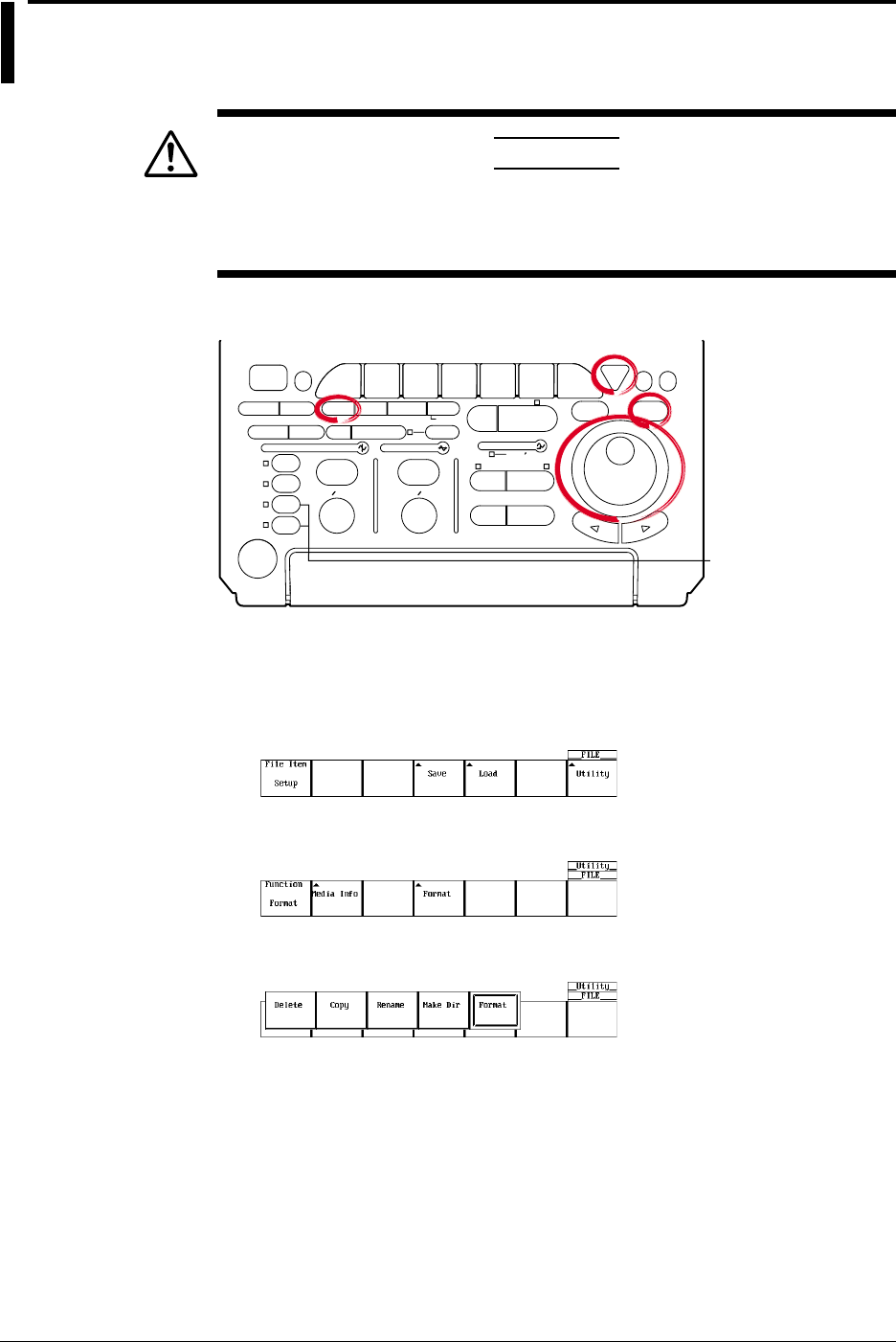
11-34 IM 701710-01E
11.12 Changing the Directory/File Name of the
Storage Medium and Creating a Directory
CAUTION
Never remove the medium (disk) or turn OFF the power while the
access indicator, or the floppy disk or the Zip disk icon is blinking. This
can damage the medium or destroy the data on the medium.
Relevant Keys
ACTION DELAY
X - Y MENU MENU PHASE
SEARCH
HORIZONTAL
VERTICAL TRIGGER
TRIG D
HELP
ESC
SELECTRESET
SIMPLE
MODE POSITION
MATH
MISCFILE
CLEAR
TRACE
HISTORY
MEASURE
SETUP
PRESET
DISPLAY
CURSOR
CH
1
CH
2
CH
3
CH
4
POWER
COPY IMAGE SAVE SHIFT
ZOOM
GO/NO-GO
ENHANCED
ACQ START/STOP
SNAP
SHOT
V DIV TIME DIV
The DL1720 is not
equipped with
an input terminal
for CH3 or CH4.
Operating Procedure
1. Press FILE.
2. Pressing the Utility soft key displays the utility setting menu and the file list dialog
box.
3. Pressing the Function soft key displays the file function menu.
4. Press the Rename soft key.
Changing the Directory/File Name of the Storage Medium
Selecting the Medium/Directory
5. The procedures are the same as steps 13 to 17 in section 11.6, “Saving/Loading
Waveform Data.”
Changing the File Attributes
6. The procedures are the same as steps 6 and 7 in section 11.10, “Changing the File
Attributes, Deleting Files.”
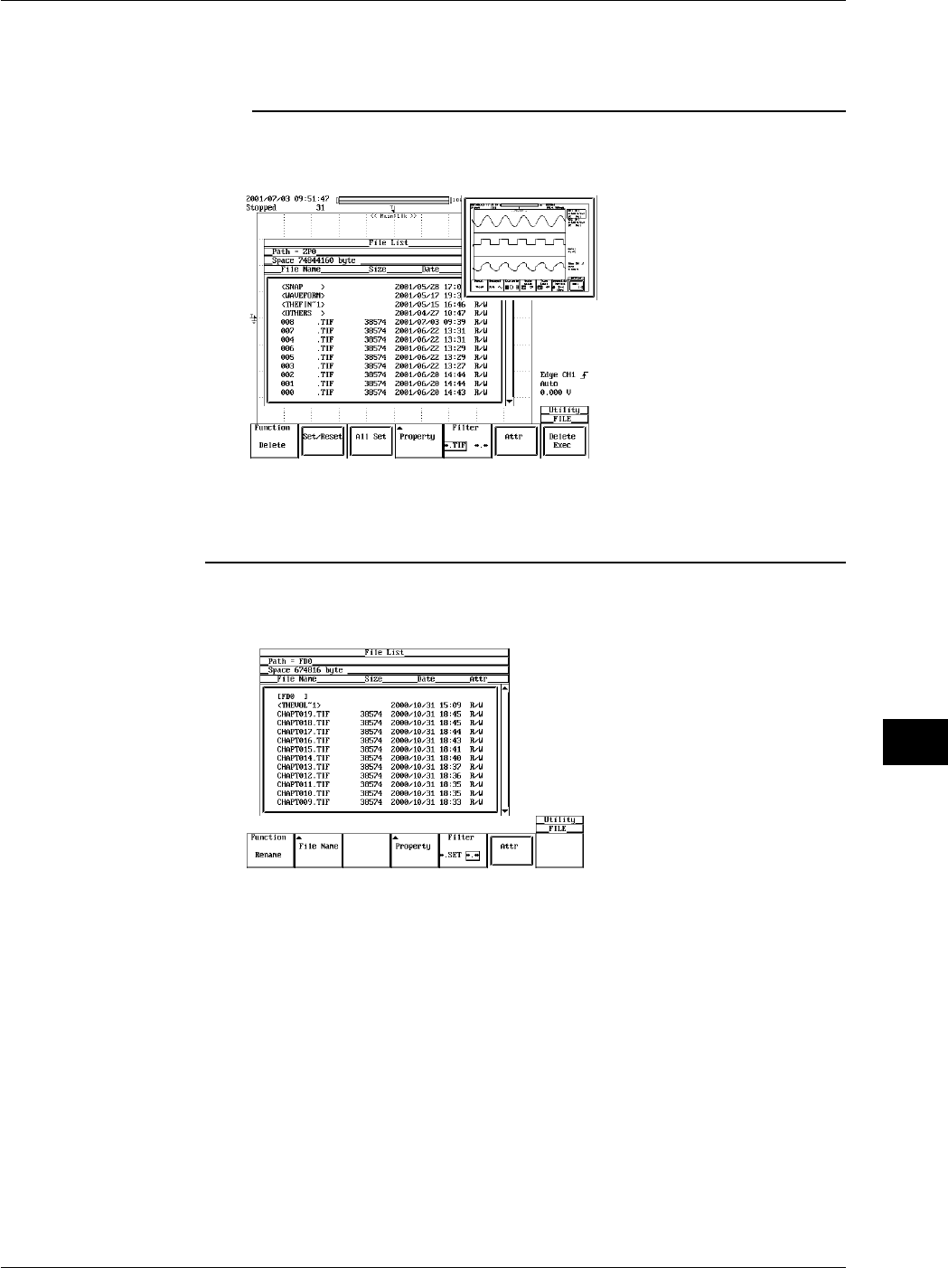
11-35
IM 701710-01E
Saving and Loading Data to and from the Storage Medium
11
Changing the directory/file name of the recording medium (excepting Net Drive)
7. Turn the jog shuttle to select directory, or file.
Note
By selecting a screen image data file (files with the .tif, .bmp, or .ps extensions) in the File List
window and pressing SELECT, the selected screen image file's compressed image appears
in the upper right portion of the file list.
•If compressed image (thumbnail) data does not exist for the selected file, an error message
appears. Pressing ESC clears the error message.
•The following procedure clears the compressed image from the screen.
•Move the cursor using the jog shuttle.
8. Pressing the File Name soft key displays a keyboard. The name of directory/file is
displayed in the entry box of the keyboard.
9. Enter the directory/file name according to the procedures given in section 4.1.
Specifying the File to be Displayed in the File List Dialog Box, Viewing the
Properties
The procedures are the same as steps 30 to 33 in section 11.6, “Saving/Loading
Waveform Data.”
11.12 Changing the Directory/File Name of the Storage Medium and Creating a Directory
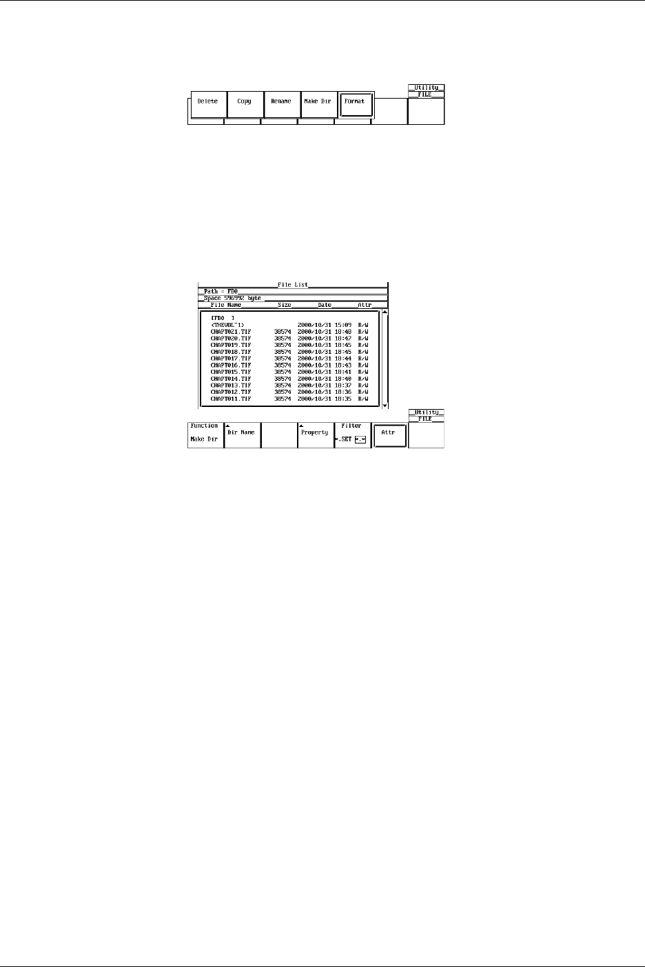
11-36 IM 701710-01E
Creating a Directory
Follow steps 1-3 to display the file function selection menu.
4. Press the soft key corresponding to Make Dir.
Selecting the Medium/Directory
5. The procedures are the same as steps 13 to 17 in section 11.6, “Saving/Loading
Waveform Data.”
Creating the Directory
6. Turn the jog shuttle to select a medium or a directory.
7. Pressing the Dir Name soft key displays a keyboard.
8. Enter the directory/file name according to the procedures given in section 4.1.
Specifying the File to be Displayed in the File List Dialog Box, Viewing the
Properties
The procedures are the same as steps 30 to 33 in section 11.6, “Saving/Loading
Waveform Data.”
Explanation
Selecting the Medium and Directory
The storage medium that can be used to save and load waveform data are displayed in
the File List dialog box.
•Display Example of Storage Medium
FD0 : Floppy disk
ZP0 : Zip disk
SC5 : SCSI device with an ID number of 5
SC5_1 : Partition 1 of the SCSI device with an ID number of 5
ND0 : Network drive (available with the Ethernet interface option)
Selecting the File Attributes
Select the attributes for each file from the following choices.
•R/W
Read and write possible.
•R
Read only. Cannot write to the file or delete the file.
11.12 Changing the Directory/File Name of the Storage Medium and Creating a Directory

11-37
IM 701710-01E
Saving and Loading Data to and from the Storage Medium
11
Changing the Directory/File Name of the storage medium
Number and types of characters that can be used
Item Number of Characters Characters that can be Used
File name 1 to 8 chars. 0 to 9, A to Z, %, _, ( ) (parenthesis), -(minus sign)
Comment 0 to 25 chars. All characters (including spaces),
Creating a Directory
A new directory can be created on a medium. See above for the assignment of the
directory name when creating a new directory.
Specifying the File to be Displayed in the File List Dialog Box
You can specify the type of files to display.
•*. extension
Displays only the data file that was selected in the File Item setting menu and the data
type menu.
•*.*
Displays all the files on the medium.
Properties
Lists the file name.extension, file size, the date it was saved, the attributes, and the
comment for the selected file.
Displaying Compressed Images in the File List
Selecting screen image data files from the File List causes a compressed image of the
screen data to appear in the upper right portion of the File List. Screen image data is the
only type of compressed image that is displayed. The compressed images of waveform
and setting data are not displayed. Also, file name and color information are not
displayed in the compressed image.
Note
•You cannot rename a directory/file or create a new directory while the data acquisition is in
progress (START/STOP indicator is ON).
•Directory attributes cannot be changed.
•If a file with the same name exists in the same directory, renaming is not allowed.
•If a directory with the same name exists in the same directory, the directory cannot be
created.
•This function can not be used in conjunction with FTP server function or LPR client function.
•Screen image data and thumbnail display data is saved together as a file pairs. If you set the
designation (filter) of the files displayed in the file list to *.* then process (Delete, Rename,
Copy) each file individually, the thumbnail function becomes disabled.
11.12 Changing the Directory/File Name of the Storage Medium and Creating a Directory

12-1
IM 701710-01E
Trigger Input/Trigger Output/
RGB Video Signal Output
12
12.1 External Trigger Input, External Clock Input
CAUTION
Never apply signals that do not meet the following specifications as this
may damage the instrument (due to overvoltage, for example).
External Trigger Input Terminal
[Input Terminal]
EXT CLOCK IN
<40Vpk 1MΩ
EXT TRIG IN
TRIG GATE IN
< DL1740 >
EXT.
< DL1720 >
1MΩ /20pF < 40Vpk
(On the DL1740 it is located on the rear panel,
or on the DL1720 it is located on the front panel.)
This terminal is used when an external signal is used as a trigger source. (See section
6.2)
Specifications
Connector Type: BNC
Maximum Input Voltage: at ±40 V (DC + AC peak) or 28 Vrms, when the frequency is
10 kHz or less.
Frequency Range: DC to 100 MHz
Input Impedance: approx. 1 MΩ and 18 pF for the DL1740
approx. 1 MΩ and 20 pF for the DL1720
Input Range: ±2 V (for the DL1740)
±1 V (for the DL1720 at the ±1 V range)
±10V (for the DL1720 at the ±10 V range)
Trigger Sensitivity: 0.1 Vp-p (for the DL1740)
0.1 Vp-p (for the DL1720 at the ±1 V range)
1 Vp-p (for the DL1720 at the ±10 V range)
Trigger Level: ±2 V in 5 mv resolution (for the DL1740)
±1 V in 5 mv resolution (for the DL1720 at the ±1 V range)
±10 V in 50 mv resolution (for the DL1720 at the ±10 V range)
Chpater 12 Trigger Input/Trigger Output/RGB Video Signal Output

12-2 IM 701710-01E
External Clock Input Terminal
[Input Terminal]
EXT CLOCK IN
<40Vpk 1MΩ
EXT TRIG IN
TRIG GATE IN
< DL1740 >
EXT.
< DL1720 >
1MΩ /20pF < 40Vpk
(On the DL1740 it is located on the rear panel,
or on the DL1720 it is located on the front panel.)
The external trigger input terminal can also be used as an external clock input terminal.
If you wish to drive the instrument with an external clock, connect a clock signal to this
terminal.
Specifications
Connector Type: BNC
Maximum Input Voltage: at ±40 V (DC + AC peak) or 28 Vrms, when the frequency is
10 kHz or less.
Frequency Range: 40 Hz to 20 MHz (continuous clock only)
Input Impedance: approx. 1 MΩ and 18 pF for the DL1740
approx. 1 MΩ and 20 pF for the DL1720
Input Range: ±2 V (for the DL1740)
±1 V (for the DL1720 at the ±1 V range)
±10V (for the DL1720 at the ±10 V range)
Threshold Level: ±2 V in 5 mv resolution (for the DL1740)
±1 V in 5 mv resolution (for the DL1720 at the ±1 V range)
±10 V in 50 mv resolution (for the DL1720 at the ±10 V
range)
Minimum Input Amplitude: 0.1 Vp-p (for the DL1740)
0.1 Vp-p (for the DL1720 at the ±1 V range)
1 Vp-p (for the DL1720 at the ±10 V range)
Minimum Pulse Width: 10 ns for both High and Low.
12.1 External Trigger Input, External Clock Input
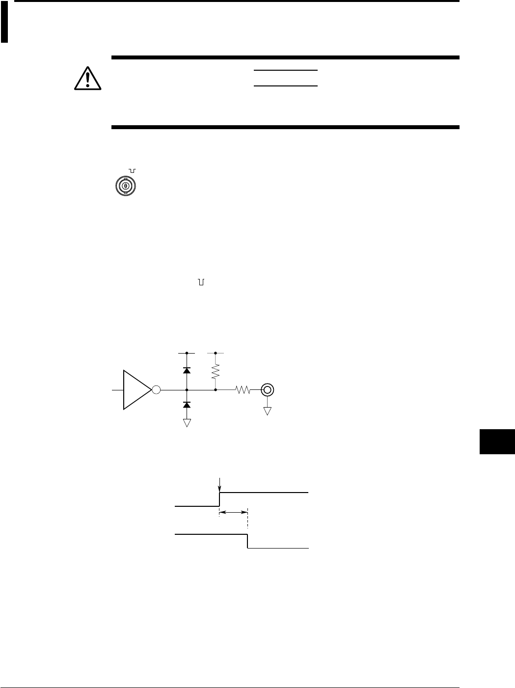
12-3
IM 701710-01E
Trigger Input/Trigger Output/
RGB Video Signal Output
12
12.2 Trigger Output (TRIG OUT)
CAUTION
Never apply an external voltage to the TRIG OUT terminal. This may
damage the instrument.
TRIG OUT Terminal
TRIG OUT
(TTL )
This trigger outputs a TTL level signal when a trigger occurs. The signal level is normally
high, but goes low when a trigger occurs.
Specifications
Connector Type: BNC
Output Level: TTL
Output Logic: (negative)
Output Delay Time: 50 ns or less
Output Hold Time: 1 µs min at low level, 100 ns min at high level
Output Circuit Diagram
47 Ω
LS06 Ω470
5 V 5 V
Timing Chart
Output Delay Time
Trigger Point
50 ns Max
H
L
Trigger Output
Trigger Signal
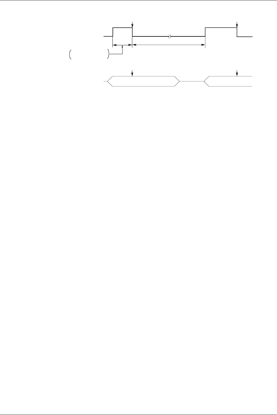
12-4 IM 701710-01E
Low Level/High Level Hold Time
H
L
Trigger Output
(Post-Trigger Time + Internal Process Time)
Trigger Occurrence
Trigger Occurrence
Pre-Trigger
Trigger Trigger
Post-TriggerPost-Trigger Pre-Trigger
Acquisition
Pre-Trigger +
Internal Process Time
*2
*1
*1: HIGH (High Level) Period
Indicates the pre-trigger and internal processing time. 100 ns minimum.
*2: LOW (Low Level) Period
Indicates the post-trigger and internal processing time. 1 µs minimum.
12.2 Trigger Output (TRIG OUT)

12-5
IM 701710-01E
Trigger Input/Trigger Output/
RGB Video Signal Output
12
12.3 RGB Video Signal Output (RGB VIDEO OUT)
CAUTION
•When making a connection, turn OFF the DL1720/DL1740 and the
monitor.
•Never short circuit the RGB VIDEO OUT terminal or apply an external
voltage. This may damage the instrument.
RGB VIDEO OUT Terminal
VIDEO OUT
(VGA)
Through RGB output, the contents displayed on the instrument can be displayed on an
external monitor. Monitors that can be connected are VGA monitors or multi-
synchronous monitors that can display VGA.
Specifications
6
11
1
5
15
10
D-Sub 15-Pin Receptacle
Pin No. Signal Specification
1 Red 0.7 Vp-p
2 Green 0.7 Vp-p
3 Blue 0.7 Vp-p
4—
5—
6 GND
7 GND
8 GND
9—
10 GND
11 —
12 —
13 Horizontal synchronous signal Approx. 31.3 kHz, TTL negative logic
14 Vertical synchronous signal Approx. 60 Hz, TTL negative logic
15 —

12-6 IM 701710-01E
Connecting the Monitor
1. Turn OFF the DL1720/DL1740 and the monitor.
2. Connect the monitor to the DL1720/DL1740 using an analog RGB cable.
3. Turn ON the DL1720/DL1740 and the monitor. The instrument’s screen is
displayed on the monitor.
Note
•The RGB VIDEO OUT terminal outputs RGB video signal at all times.
•The picture on the monitor may flicker if the DL1720/DL1740 or another instrument is brought
too close to the monitor.
•The ends of the screen may be cut off on some monitors.
12.3 RGB Video Signal Output (RGB VIDEO OUT)
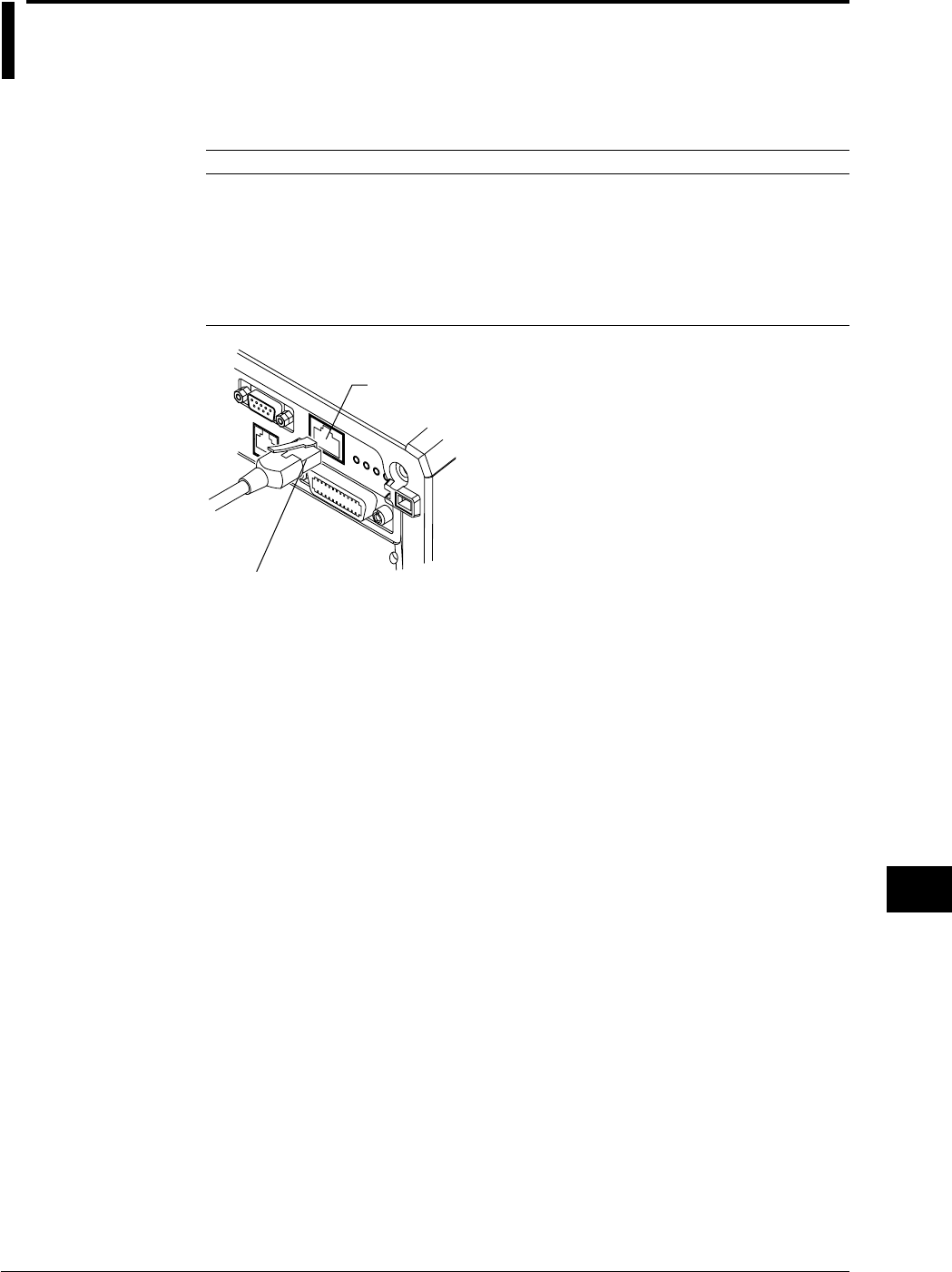
13-1
IM 701710-01E
Ethernet Interface (Option)
13
13.1 Connecting the DL1720/DL1740 to a Personal
Computer
Ethernet Interface Specifications
A 100BASE-TX port is provided on the rear panel of the DL1720/DL1740.
Item Specifications
Communication Port Number 1
Electrical-Mechanical Specifications IEEE 802.3 standards
Transmission Method Ethernet (100BASE-TX/10BASE-T)
Transmission Rate Max. 100 Mbps
Communication Protocol TCP/IP
Supported Services FTP server, FTP client (network drive), LPR client (network
printer), SMTP client (mail transmission), DHCP, DNS.
Connector Type RJ-45 connector
ETHERNET 100BASE-TX Terminal
Modular Jack (RJ-45)
Items Necessary for Connection
Cable
Use only the following cables for connection.
•UTP (unshielded twisted-pair) cable (category 5)
•STP (shielded twisted-pair) cable
Chpater 13 Ethernet Interface (Option)
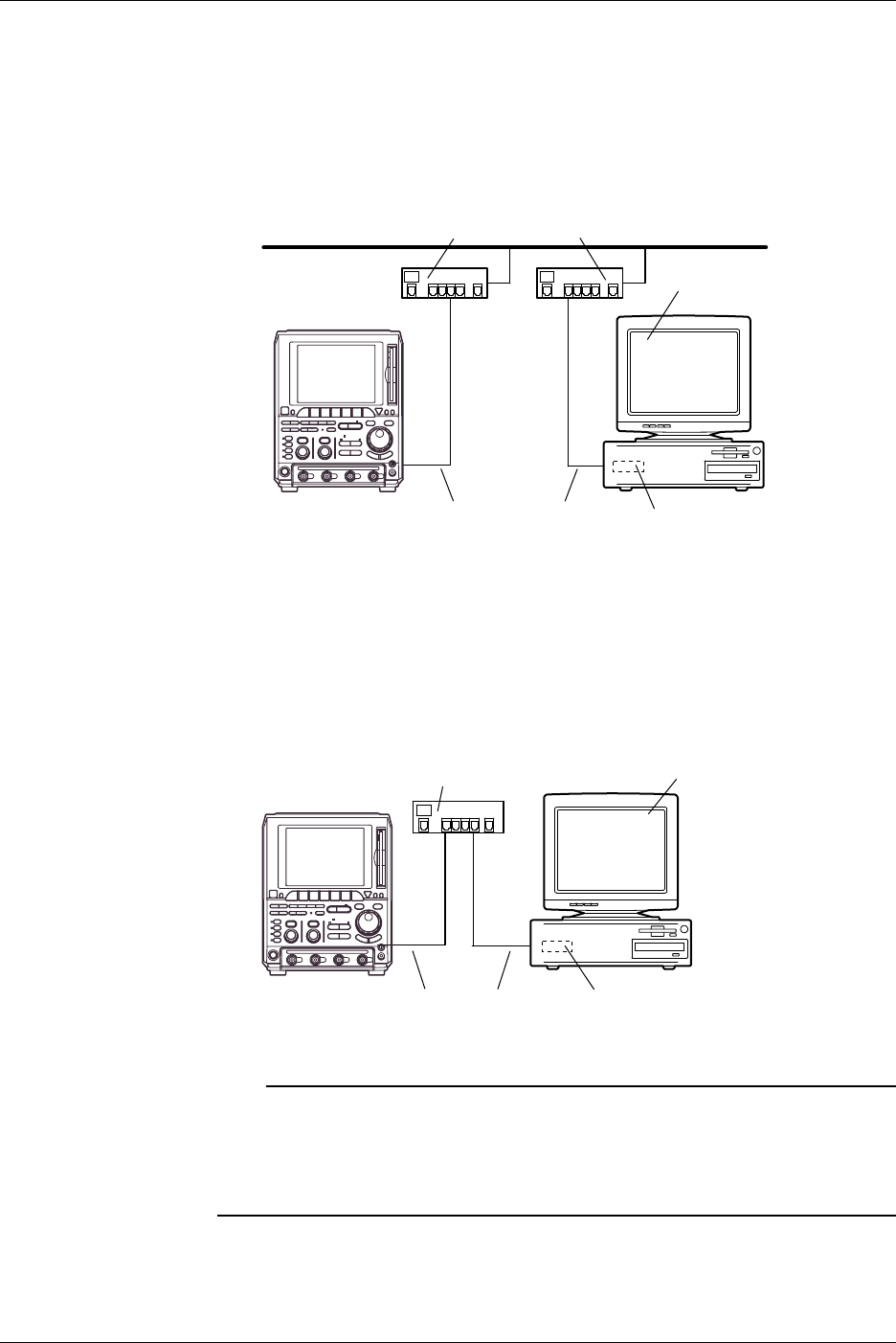
13-2 IM 701710-01E
Connection Method
When Connecting to a Network PC or Workstation
1. Turn OFF the power to the instrument.
2. Connect one side of the UTP (or STP) cable to the ETHERNET 100BASE-TX
terminal on the rear panel.
3. Connect the other end of the UTP (or STP) cable to a hub or router.
4. Turn ON the power to the instrument.
100BASE-TX Compatible Adapter (Hub or Router)
Personal Computer
or Work Station
DL1740/
DL1720
UTP Cable or STP Cable
(Straight Cable)
Network Card
When Making a One-to-One Connection to the PC or Workstation
1. Turn OFF the power to the instrument and PC or workstation.
2. Connect one side of the UTP (or STP) cable to the ETHERNET 100BASE-TX
terminal on the rear panel.
3. Connect the other end of the UTP (or STP) cable to a hub or router.
4. In the same manner, connect the PC or workstation to a hub or router.
5. Turn ON the power to the instrument.
DL1740/
DL1720
100BASE-TX Compatible Adapter (Hub or Router) Personal Computer
or Work Station
UTP Cable or STP Cable
(Straight Cable)
Network Card
Note
•When connecting the PC or workstation one-to-one, a network card (a 10BASE-T/100BASE-
TX autoswitching card) is required for the PC or workstation.
•When using a UTP cable (straight cable), be sure to use only a category 5 cable.
•Avoid connecting the PC or workstation directly to the instrument without going through the
hub or router. We cannot guarantee results using a direct connection.
13.1 Connecting the DL1720/DL1740 to a Personal Computer
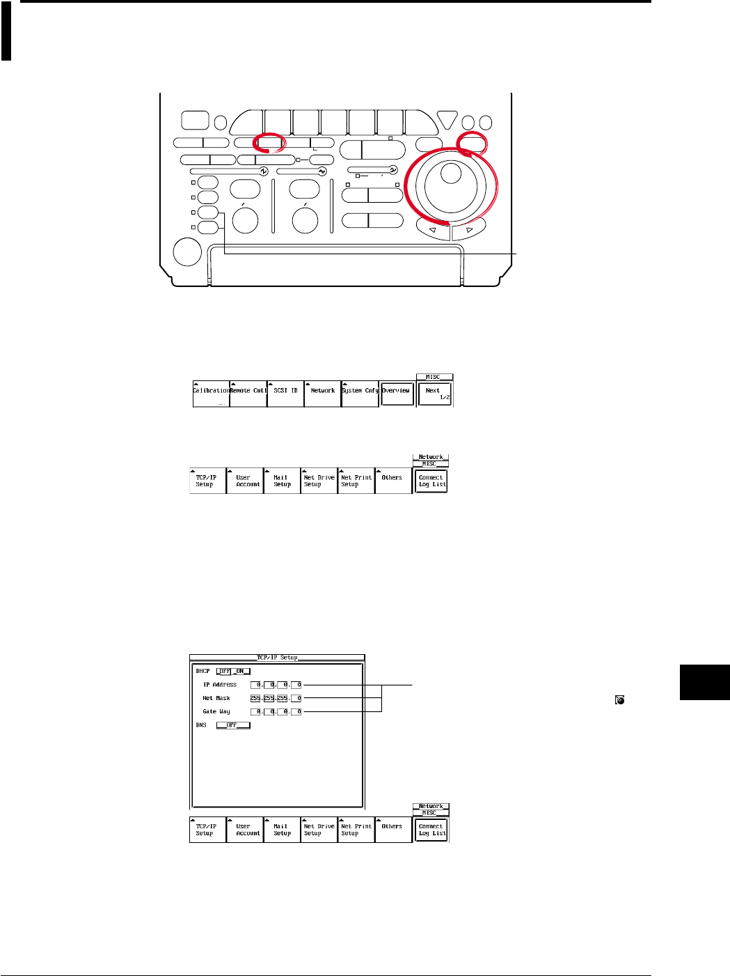
13-3
IM 701710-01E
Ethernet Interface (Option)
13
13.2 Configuring the Ethernet Interface (TCP/IP)
Relevant Keys
ACTION DELAY
X - Y MENU MENU PHASE
SEARCH
HORIZONTAL
VERTICAL TRIGGER
TRIG D
HELP
ESC
SELECTRESET
SIMPLE
MODE POSITION
MATH
MISCFILE
CLEAR
TRACE
HISTORY
MEASURE
SETUP
PRESET
DISPLAY
CURSOR
CH
1
CH
2
CH
3
CH
4
POWER
COPY IMAGE SAVE SHIFT
ZOOM
GO/NO-GO
ENHANCED
ACQ START/STOP
SNAP
SHOT
V DIV TIME DIV
The DL1720 is not
equipped with
an input terminal
for CH3 or CH4.
Operating Procedure
1. Press MISC.
2. Press the Network soft key to display the Network menu.
3. Press the TCP/IP Setup soft key to display the TCP/IP settings menu.
DHCP ON/OFF
4. Move the cursor to DHCP using the jog shuttle and press SELECT to turn DHCP
ON or OFF. If you select ON, then it is not necessary to the set the IP address,
subnet mask, and default gateway. If you wish to set up the DNS, please skip to
step 11. If you do not wish to set up the DNS, check the network cable connection
and restart the DL1720/DL1740. The IP address, subnet mask, and default
gateway are automatically set.
Settings for the following items can be
input directly using a USB keyboard. ( )
Setting the IP Address
Set the IP address if you turned DHCP OFF in step 4.
5. Move the cursor to the IP Address field with the jog shuttle, and press SELECT to
display the settings menu.
6. Enter the IP address values from 0 to 255 using the jog shuttle.
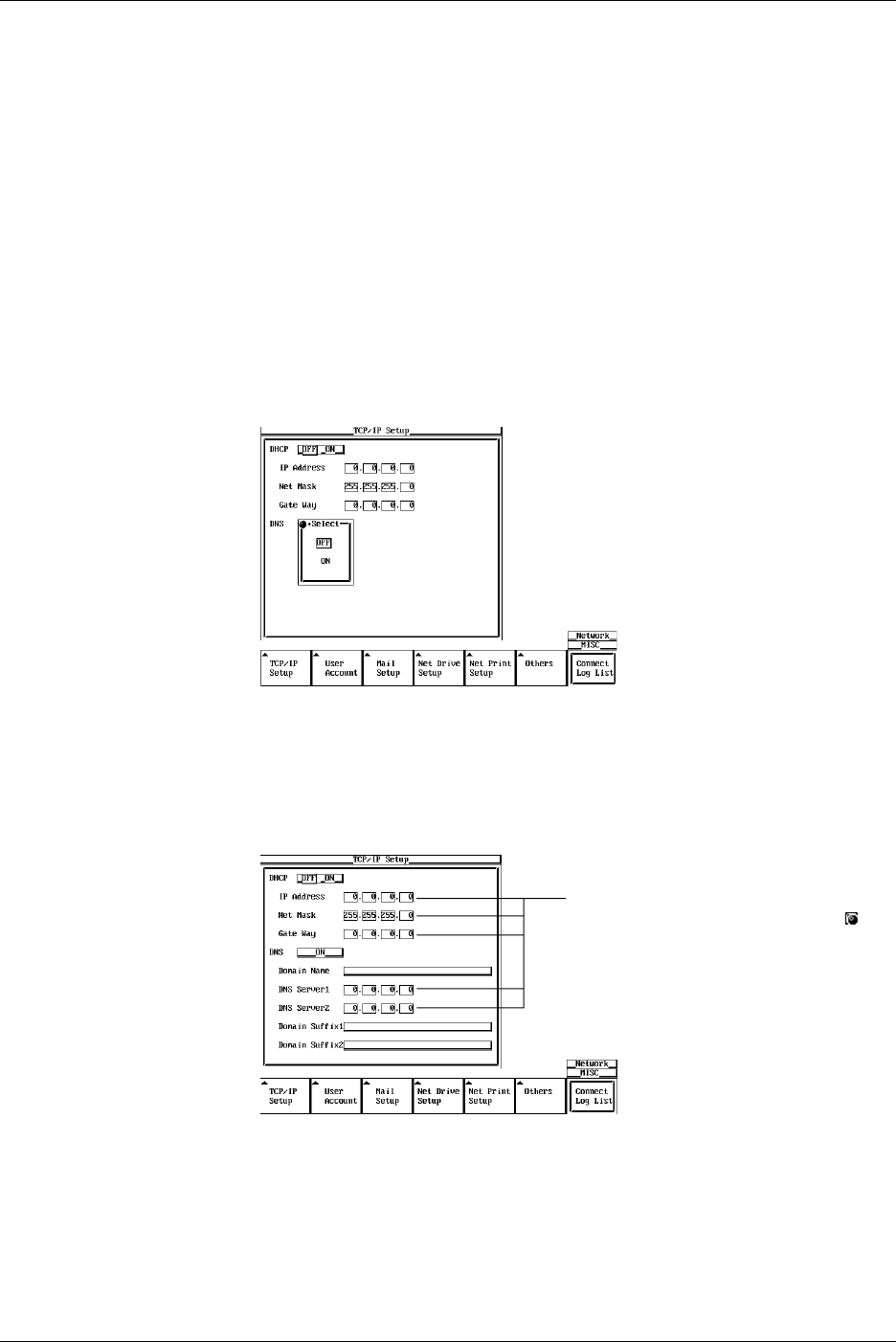
13-4 IM 701710-01E
Setting the Subnet Mask
Set the subnet mask if you turned DHCP OFF in step 4.
7. Move the cursor to the Net Mask field using the jog shuttle, and press SELECT to
display the settings menu.
8. Enter the subnet mask address values from 0 to 255 using the jog shuttle.
Setting the Default Gateway
Set the default gateway if you turned DHCP OFF in step 4.
9. Move the cursor to the Gate Way field with the jog shuttle, and press SELECT to
display the settings menu.
10. Enter the default gateway address values from 0 to 255 using the jog shuttle.
Setting the DNS
11. Move the cursor to DNS by turning the jog shuttle.
12. Press SELECT to display the DNS setting menu.
13. Press SELECT to set the DNS to ON, OFF, or AUTO (AUTO available only when
DHCP is ON). When DNS is set to AUTO, the domain name and DNS server
name are automatically set by restarting the instrument. If DNS is set to ON, the
domain name, DNS server name, and domain suffix are displayed. If DNS is set to
OFF, check the network cable connection and restart the DL1720/DL1740.
Settings for the following items can be
input directly using a USB keyboard. ( )
14. Move the cursor to Domain Name by turning the jog shuttle.
15. Press SELECT to display the keyboard.
16. Input the domain name.
17. Move the cursor with the jog shuttle to the DNS Server 1 field, and press SELECT
to display the setting menu.
18. Set the primary DNS server values from 0 to 255 using the jog shuttle.
13.2 Configuring the Ethernet Interface (TCP/IP)

13-5
IM 701710-01E
Ethernet Interface (Option)
13
19. In the same manner, set the secondary DNS server in the DNS Server 2 field.
20. Move the cursor to Domain Suffix1 by turning the jog shuttle.
21. Press SELECT to display the keyboard.
22. Input the primary domain suffix.
23. In the same manner, set the secondary domain suffix in the domain suffix 2 field.
Note
For keyboard (soft keyboard) operation see section 4.1, “Entering Values and Character
Strings.”
Turning the Power ON/OFF
24. You must restart the DL1720/DL1740 for the settings to take affect. After all the
settings are complete, turn the power to the DL1720/DL1740 OFF, then back ON
again.
Explanation
The following TCP/IP settings must be entered to use the Ethernet communications
functions on the DL1720/DL1740.
•IP Address
•Subnet Mask
•Default Gateway
IP Address (Internet Protocol Address)
Assign an IP address to the instrument. The default setting is 0.0.0.0.
A unique IP address must be assigned to each PC on an IP network such as the internet
or an intranet. The address is a 32-bit value normally expressed with four values (0-
255), each separated by a period as in 192.168.111.24.
Obtain an IP address from your network administrator. The settings are automatically
configured in environments using DHCP.
Subnet Mask
Specify the mask that is used to determine the network address from the IP address.
The default setting is 255.255.255.0.
Huge TCP/IP networks such as the internet are often divided up into smaller networks
called subunits. The subnet mask is a 32 bit value that specifies whether to use an IP
address containing some number of bits that identify the network address. The portion
other than the network address is the host address that identifies which computer on the
network the address belongs to.
Consult the network administrator for the subnet mask setting value. In some cases, this
setting may not be necessary. The settings are automatically configured in
environments using DHCP.
Default Gateway
Set the IP address of the gateway (default gateway) for communicating with machines
on different networks. The default setting is 0.0.0.0.
The default gateway has control functions that handle protocol exchanges when
communicating on multiple networks, and that smoothly carry out sending and receiving
of data.
Consult your network administrator for the default gateway setting values. In some
cases, this setting may not be necessary. The settings are automatically configured in
environments using DHCP.
13.2 Configuring the Ethernet Interface (TCP/IP)

13-6 IM 701710-01E
DHCP (Dynamic Host Configuration Protocol)
DCHP is a protocol that allocates necessary setting information to all PCs connected to
the network. When DHCP is ON, the following settings are automatically assigned.
•IP Address
•Subnet Mask
•Default Gateway
•DNS
To use DHCP, you must have a DHCP server installed on the network. Inquire with your
network administrator to find out if you can use DCHP.
When DHCP is set to ON, different settings may be assigned each time the power is
turned ON. Therefore when using the FTP server function (see section 13.8), be sure to
check the IP address and other settings of the instrument on the PC or workstation each
time you turn ON the instrument.
DNS (Domain Name System)
The DNS is a system that correlates the host name/domain name to the IP address.
(Given AAA.BBBBB.co.jp, AAA is the hostname, and BBBBB.co.jp is the domain name.)
The host/domain name can be used instead of a numeric IP address when accessing the
network.
On the DL1720/DL1740, you can specify the host by name instead of by IP address
when using the FTP client function (see sections 13.3 and 13.4) or the LPR client
function (see section 13.5).
Set the domain name, the DNS server address (default is 0.0.0.0), and the domain suffix.
In networks that support DHCP, these settings can be configured automatically. Consult
your network administrator for details on the settings.
•DNS Server
Up to two DNS servers can be specified (primary and secondary). If the primary
server is down, the secondary server is used to search the host name/domain name
and IP address.
•Domain Suffix
If the IP address corresponding to the domain name described in the previous
paragraph is not found on the DNS server, then it may be that the system is
configured to use another domain name. Set this other domain name as a domain
suffix. Up to two domain suffixes can be specified, DomainSuffix1 (primary), and
DomainSuffix2 (secondary).
Note
•To change this menu setting, you must restart the DL1720/DL1740.
•When the Ethernet cable is not connected, if you turn ON the power to the DL1720/DL1740
while DCHP is ON, there is a possiblity of malfunction in the communications or file functions.
Turn DHCP OFF and restart the instrument.
•Configuring the TCP/IP Settings of the PC
Communications parameters such as the IP address must be specified also on the PC side.
Communications parameters are specified for each Ethernet NIC that is installed in the PC.
Here, the settings of the NIC for connecting your PC and the DL1720/DL1740 are explained.
If the IP address and other parameters are to be obtained dynamically using the DHCP
server, the following settings are not necessary. In this case, select Obtain an IP address
automatically under the IP Address tab of the TCP/IP Properties dialog box.
For example, if you are connecting a PC and the DL1720/DL1740 to an independent Ethernet
network, you can specify parameters as indicated in the next table.
For details on the parameters, consult your system or network administrator.
13.2 Configuring the Ethernet Interface (TCP/IP)
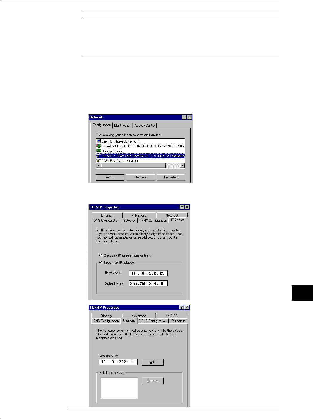
13-7
IM 701710-01E
Ethernet Interface (Option)
13
Parameter Value Note
IP Address Example: 192.168.21.128 IP address for the PC
Subnet Mask Example: 255.255.255.0 Set the same value as the subnet mask that
was specified for the DL1720/DL1740.
Gateway None
DNS Disable
WINS Disable
The following procedure describes the steps for Windows 95/98. If you are using Windows
NT/2000 Pro carry out equivalent steps according to your operating system.
1. Select Settings > Control Panel from the Start menu to open the Control Panel folder.
2. Double-click the Network icon to display the following Network dialog box.
3. Click the Configuration to select the TCP/IP connection corresponding to the Ethernet NIC
that is connected to the PC and click Properties to display the TCP/IP properties dialog
box.
4. Set the parameters such as the IP address according to the table on the previous page
and click OK.
13.2 Configuring the Ethernet Interface (TCP/IP)
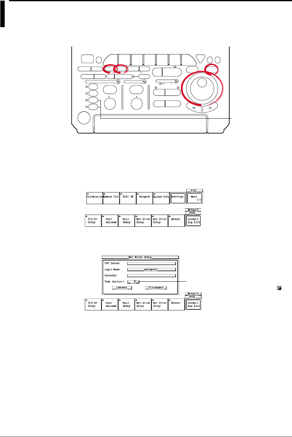
13-8 IM 701710-01E
13.3 Saving Waveform and Setting Data to a
Network Drive (FTP Client Function)
<For a description of this function, refter to page 1-29>
Relevant Keys
ACTION DELAY
X - Y MENU MENU PHASE
SEARCH
HORIZONTAL
VERTICAL TRIGGER
TRIG D
HELP
ESC
SELECTRESET
SIMPLE
MODE POSITION
MATH
MISCFILE
CLEAR
TRACE
HISTORY
MEASURE
SETUP
PRESET
DISPLAY
CURSOR
CH
1
CH
2
CH
3
CH
4
POWER
COPY IMAGE SAVE SHIFT
ZOOM
GO/NO-GO
ENHANCED
ACQ START/STOP
SNAP
SHOT
V DIV TIME DIV
The DL1720 is not
equipped with
an input terminal
for CH3 or CH4.
Operating Procedure
Entering Settings for a Network Drive
1. Press MISC.
2. Press the Network soft key and press the Net Drive Setup soft key to display the
settings menu.
3. Use the jog shuttle to move the cursor to FTP Server, then press SELECT to
display the keyboard.
The numerical values for this item can be
input directly using a USB keyboard. ( )
4. Enter the IP address of the FTP server. When using DNS, you can specify it by
name.
5. Use the jog shuttle to move the cursor to Login Name, then press SELECT to
display the keyboard.
6. Enter a login name of 15 characters or less.
7. Use the jog shuttle to move the cursor to Password, then press SELECT to display
the keyboard.
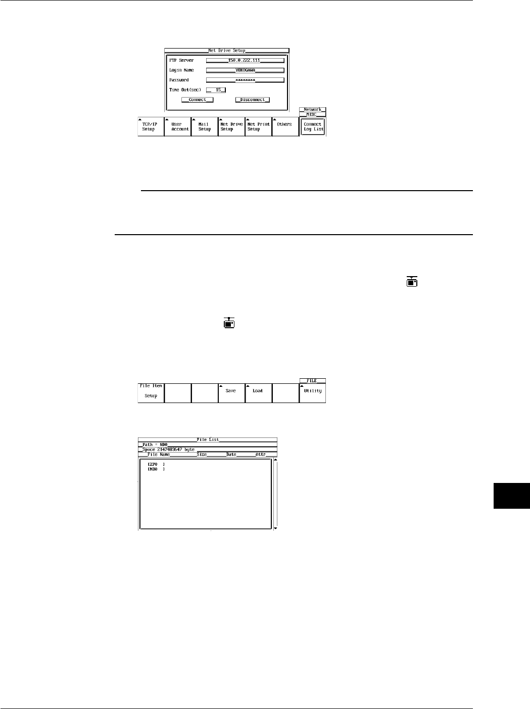
13-9
IM 701710-01E
Ethernet Interface (Option)
13
8. Enter a password of 15 characters or less for the login name. If the login name is
anonymous, you don’t need to enter a password.
9. Use the jog shuttle to move the cursor to Timeout. Press SELECT to set the
timeout time. The available setting range is 0 to 3600(s).
Note
•For keyboard (soft keyboard) operation see section 4.1, “Entering Values and Character
Strings.”
•If Login Name is set to anonymous, it is not necessary to enter a password.
Connecting/Disconnecting to a Network Drive
10. Use the jog shuttle to move the cursor to Connect, then press SELECT to make
the connection. If the connection has been made successfully the icon appears
in the upper right part of the screen.
Use the jog shuttle to move the cursor to Disconnect, then press SELECT to close
the connection. The icon in the upper right of the screen is turned off.
Saving the Waveform and the Setting Data
11. Press FILE and press the Utility soft key to display the File List.
12. Use the jog shuttle to move the cursor to ND0 (Net Drive Zero).
13. For the remaining procedures, please refer to section 11.7, “Saving/Loading Setup
Data” through section 11.12, “Changing the Storage Medium/Directory/File Name
and Creating a Directory.”
13.3 Saving Waveform and Setting Data to a Network Drive (FTP Client Function)

13-10 IM 701710-01E
Note
•You must run FTP server software on PCs and workstations that will be connected to the
network. Also, please note the following regarding the server software:
Use UNIX format for list output (character strings returned by the
dir command
).
Make the home directory and its subdirectories writable.
You can’t change to a higher directory than the home directory.
The newest file is not necessarily displayed at the top of the file list.
You cannot access files or directories having names longer than nine or more characters.
Depending on the server, the < . . > notation for the top directory may not be displayed.
•In the following cases, the time information in a file list will not be displayed accurately:
When WindowsNT uses an AM or PM timestamp.
When using a server that returns kanji or other non-ASCII character strings in a list.
•The following are not possible:
Turning file protect ON and OFF on saved files.
Formatting a network drive.
Copying between network drives.
Renaming a file on the network.
•This function can not be used in conjunction with FTP server function.
•Before saving data to a network drive, you must configure TCP/IP (see 13.2, “Configuring the
Ethernet Interface (TCP/IP)”).
•When connected to the network, you must disconnect then reconnect for settings to take
effect.
•When you are disconnected by the server when using the FTP client, you will be
automatically reconnected if you perform a file operation (save, load etc.) This is the same if
ND0 is selected for Save to File when using an action trigger or GO/NO-GO.
Explanation
You can save data such as waveform and settings data to network drives via Ethernet in
the same manner as with floppy disks or Zip disks.
Entering Settings for a Network Drive
•FTP Server
Input the IP address of the FTP server (the PC or workstation running the FTP server)
on the network to which waveform and setting data will be saved. On networks
supporting DNS, you can specify the host and domain by name instead of by IP
address.
•Login Name
Enter a login name of 15 characters or less. The default value is anonymous.
The available characters consist of all ASCII characters on the keyboard (including
space).
•Password
Enter a password corresponding to the login name using 15 characters or less.
The available characters consist of all ASCII characters on the keyboard (including
space).
•Time Out
When accessing the FTP server from this instrument, if can’t receive even after a
fixed time (the timeout time) elapses, this means that the instrument is unable to send
to or receive from the FTP server, and the connection will close. The available setting
range is 0 to 3600 s. The default setting is 15 s.
13.3 Saving Waveform and Setting Data to a Network Drive (FTP Client Function)
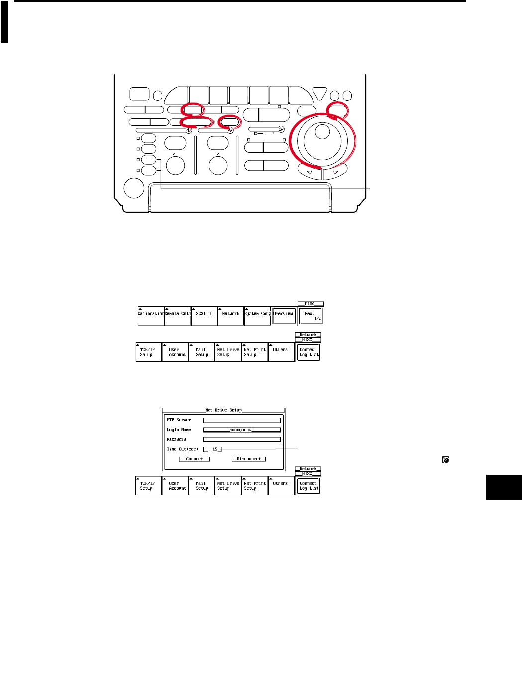
13-11
IM 701710-01E
Ethernet Interface (Option)
13
13.4 Saving Screen Image Data to a Network Drive
(FTP Client Function)
<For a description of this function, refter to page 1-29>
Relevant Keys
ACTION DELAY
X - Y MENU MENU PHASE
SEARCH
HORIZONTAL
VERTICAL TRIGGER
TRIG D
HELP
ESC
SELECTRESET
SIMPLE
MODE POSITION
MATH
MISCFILE
CLEAR
TRACE
HISTORY
MEASURE
SETUP
PRESET
DISPLAY
CURSOR
CH
1
CH
2
CH
3
CH
4
POWER
COPY IMAGE SAVE SHIFT
ZOOM
GO/NO-GO
ENHANCED
ACQ START/STOP
SNAP
SHOT
V DIV TIME DIV
The DL1720 is not
equipped with
an input terminal
for CH3 or CH4.
Operating Procedure
Entering Settings for a Network Drive
1. Press MISC.
2. Press the Network soft key and press the Net Drive Setup soft key to display the
settings menu.
3. Use the jog shuttle to move the cursor to FTP Server, then press SELECT to
display the keyboard.
The numerical values for this item can be
input directly using a USB keyboard. ( )
4. Enter the IP address of the FTP server address. If you are using DNS, you can
specify it by name.
5. Use the jog shuttle to move the cursor to Login Name, then press SELECT to
display the keyboard.
6. Enter a login name of 15 characters or less.
7. Use the jog shuttle to move the cursor to Password, then press SELECT to display
the keyboard.
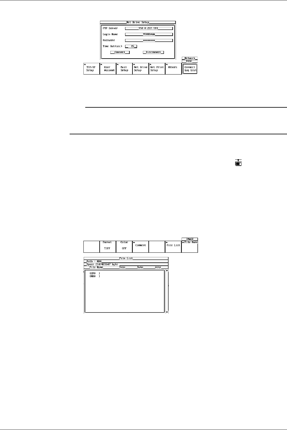
13-12 IM 701710-01E
8. Enter the password of 15 characters or less for the login name.
9. Use the jog shuttle to move the cursor to Timeout, then press SELECT to set the
timeout time. The available setting range is 0 to 3600(s).
Note
•For keyboard (soft keyboard) operation see section 4.1, “Entering Values and Character
Strings.”
•If Login Name is set to anonymous, it is not necessary to enter a password.
Connecting to a Network Drive
10. Use the jog shuttle to move the cursor to Connect, then press SELECT to make
the connection. If the connection was made successfully, the icon appears in
the upper right of the screen.
Saving the Screen Image
11. Press SHIFT to activate shift mode.
Functions marked in purple on the panel become active.
12. Press IMAGE SAVE.
13. Press the File List soft key to display the File List, and select ND0 (Net Drive
Zero).
14. For the remaining procedures, please refer to 11.7, “Saving/Loading Setup Data”
through section 11.12, “Changing the Storage Medium/Directory/File Name and
Creating a Directory.”
13.4 Saving Screen Image Data to a Network Drive

13-13
IM 701710-01E
Ethernet Interface (Option)
13
Note
•You must run FTP server software on PCs and workstations that will be connected to the
network. Also, please note the following regarding the server software:
Use UNIX format for list output (character strings returned by the
dir command
).
Make the home directory and its subdirectories writable.
You can’t change to a higher directory than the home directory.
The newest file is not necessarily displayed at the top of the file list.
You cannot access files or directories having names longer than nine or more characters.
Depending on the server, the < . . > notation for the top directory may not be displayed.
•In the following cases, the time information in a file list will not be displayed accurately:
When WindowsNT uses an AM or PM timestamp.
When using a server that returns kanji or other non-ASCII character strings in a list.
•The following are not possible:
Turning file protect ON and OFF on saved files.
Formatting a network drive.
Copying between network drives.
Renaming a file on the network.
•This function can not be used in conjunction with FTP server function.
•Before saving data to a network drive, you must configure TCP/IP (see “13.2 Configuring the
Ethernet Interface (TCP/IP)”).
•When connected to the network, you must disconnect then reconnect for settings to take
effect.
•When you are disconnected by the server when using the FTP client, you will be
automatically reconnected if you perform a file operation (save, load etc.) This is the same if
ND0 is selected for Save to File when using an action trigger or GO/NO-GO.
Explanation
You can save a screen image to a network drive via Ethernet just as you would to a
floppy disk drive or Zip drive.
Entering Settings for a Network Drive
•FTP Server
Input the IP address of the FTP server (the PC or workstation running the FTP server)
on the network to which screen image data will be saved. On networks supporting
DNS, you can specify the host and domain by name instead of by IP address.
•Login Name
Enter a login name of 15 characters or less. The default value is anonymous.
The available characters consist of all ASCII characters on the keyboard (including
space).
•Password
Enter a password corresponding to the login name using 15 characters or less.
The available characters consist of all ASCII characters on the keyboard (including
space).
•Time Out
When accessing the FTP server from this instrument, if can't receive even after a
fixed time (the timeout time) elapses, this means that the instrument is unable to send
to or receive from the FTP server, and the connection will close. The available setting
range is 0 to 3600 s. The default setting is 15 s.
13.4 Saving Screen Image Data to a Network Drive
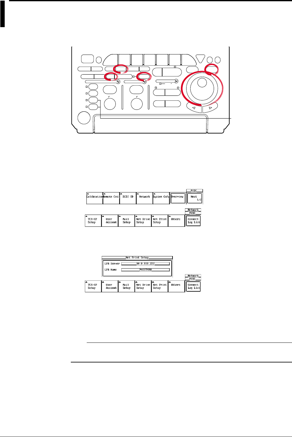
13-14 IM 701710-01E
13.5 Sending Screen Image Data to a Network
Printer (LPR Client Function)
<For a description of this function, refter to page 1-29>
Relevant Keys
ACTION DELAY
X - Y MENU MENU PHASE
SEARCH
HORIZONTAL
VERTICAL TRIGGER
TRIG D
HELP
ESC
SELECTRESET
SIMPLE
MODE POSITION
MATH
MISCFILE
CLEAR
TRACE
HISTORY
MEASURE
SETUP
PRESET
DISPLAY
CURSOR
CH
1
CH
2
CH
3
CH
4
POWER
COPY IMAGE SAVE SHIFT
ZOOM
GO/NO-GO
ENHANCED
ACQ START/STOP
SNAP
SHOT
V DIV TIME DIV
The DL1720 is not
equipped with
an input terminal
for CH3 or CH4.
Operating Procedure
Entering Settings for a Network Printer
1. Press MISC.
2. Press the Network soft key, then press the Net Print Setup soft key to display the
settings menu.
3. Use the jog shuttle to move the cursor to LPR Server, then press SELECT to
display the keyboard.
4. Enter the printer server address. If you are using a DNS, specify it by name.
5. Use the jog shuttle to move the cursor to LPR Name, then press SELECT to
display the keyboard.
6. Enter the printer name.
Note
For keyboard (soft keyboard) operation see section 4.1, “Entering Values and Character
Strings.”
Outputting the Screen Image Data
7. Press SHIFT to set the keys in the shifted condition.
Functions marked in purple on the panel become active.
8. Press COPY.
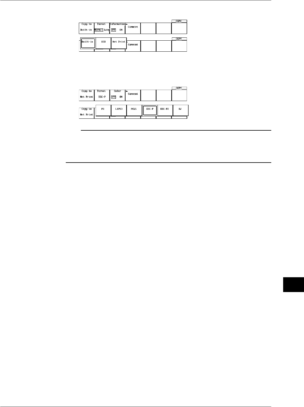
13-15
IM 701710-01E
Ethernet Interface (Option)
13
9. Press the Copy to soft key to select Net Print.
10. For the remaining procedures, please refer to 10.3, “Outputting Screen Image to an
USB Printer.”
However, when NetPrint is selected, PS is added to the Format item.
Note
•Before working with this function, enter the TCP/IP settings as described in “Configuring the
Ethernet Interface.”
•You can output to any TCP/IP compatible printer.
•This function can not be used in conjunction with FTP server function or File operation.
Explanation
You can send screen images simultaneously to a network printer via Ethernet, and the
built in printer (optional).
Entering Settings for a Network Printer
•LPR Server
Specify the IP address of the network printer server. On networks supporting DNS,
you can specify the host and domain by name instead of by IP address.
•Printer Name (LPR Name)
Specify the name of the printer to which screen images will be output.
Printer Format
The following six printer formats are supported.
•ESC-P
•ESC-P2
•LIPS3
•PCL5
•BJ
•PS (PostScript)
13.5 Sending Screen Image Data to a Network Printer
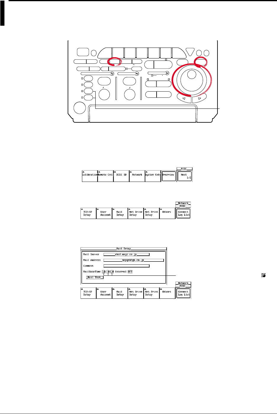
13-16 IM 701710-01E
13.6 Using the Mail Function (Fixed Interval)
<For a description of this function, refter to page 1-30>
Relevant Keys
ACTION DELAY
X - Y MENU MENU PHASE
SEARCH
HORIZONTAL
VERTICAL TRIGGER
TRIG D
HELP
ESC
SELECTRESET
SIMPLE
MODE POSITION
MATH
MISCFILE
CLEAR
TRACE
HISTORY
MEASURE
SETUP
PRESET
DISPLAY
CURSOR
CH
1
CH
2
CH
3
CH
4
POWER
COPY IMAGE SAVE SHIFT
ZOOM
GO/NO-GO
ENHANCED
ACQ START/STOP
SNAP
SHOT
V DIV TIME DIV
The DL1720 is not
equipped with
an input terminal
for CH3 or CH4.
Operating Procedure
Mail Settings
1. Press MISC.
2. Press the Network soft key to display the Network menu.
3. Press the Mail Setup soft key to display the mail settings menu.
4. Move the cursor to Mail Server using the jog shuttle, then press SELECT to display
the keyboard.
Settings for the following items can be
input directly using a USB keyboard. ( )
5. Enter the mail server name. If you are using a DNS, specify it by name.
6. Move the cursor to Mail Address using the jog shuttle, then press SELECT to
display the keyboard.
7. Enter the mail address of 40 characters or less.
8. If necessary, move the cursor to Comment using the jog shuttle, then press
SELECT to display the keyboard.
9. Enter a comment or 30 characters or less.
10. Move the cursor to Mail Base Time using the jog shuttle, then press SELECT to
display the keyboard.
11. Enter the mail transmission time.
12. Move the cursor to Interval using the jog shuttle, then press SELECT to select the
mail interval.

13-17
IM 701710-01E
Ethernet Interface (Option)
13
Sending a Test Mail Transmission
13. Move the cursor to Mail Test with the jog shuttle, then press SELECT to send a
test transmission to the specified mail recipient.
Note
•For keyboard (soft keyboard) operation see section 4.1, “Entering Values and Character
Strings.”
•For mail sent by this instrument, the sender's address will be the same as the specified
recipient address.
•When error history is included in the mail's contents, the most recent errors appear at the top.
•Before using this function, refer to section 13.2, “Configuring the Ethernet Interface (TCP/IP)”
and enter the TCP/IP settings.
•If you set [Interval] to OFF, mail is not transmitted at specified intervals.
Explanation
You can transmit DL1720/DL1710 status information to a specified email address on the
network at periodic intervals.
Mail Settings
•Mail Server
Specify the IP address of the network mail server. On networks supporting DNS, you
can specify the host and domain by name instead of by IP address.
•Mail Address
Enter the address of the mail recipient using 40 characters or less.
•Comment
The comment appears on the first line of mails that are sent. Comments are optional.
Use 30 characters or less for the comment.
•MailBaseTime
Specify the time to start transmitting the -mail messages. Set the time in units of hour
: minute : second in the following range.
0 : 0 : 0 to 23 : 59 : 59
•Interval
The allowable mail transmission intervals are as follows:
Off / 1H / 2H / 3H / 4H / 6H / 8H / 12H / 24H
When OFF is selected, transmission at specified intervals is not possible.
Sending a Test Mail
Sends a test mail to the address specified by Mail Address.
Data Sent from the DL1720/DL1740
The following four items are sent.
•Acquisition status
Start/Stop, trigger status, acquisition counter
•Error log information
Error number, and up to 16 lines of the English error message text
•GO/NO-GO success/fail information
Time of GO/NO-GO determination only (see section 9.12 and 9.13)
•Results of waveform parameter measurement
Automatic measurement of waveform parameters (see sections 9.2 and 9.4), and the
time of GO/NO-GO determination by waveform parameters only (see section 9.12)
13.6 Using the Mail Function (Fixed Interval)

13-18 IM 701710-01E
Sample Transmission:
[Comment] aaaaaa
[ACQ Status] Stopped 162
[GO/NOGO Status] Success: 140 Fail: 21
Max (C1) 4.16667V
SDv (C2) 697.941mV
Freq(C3) 500.0000kHz
+Wd (C4) 1.00us>
ErrNo 004 Exit from GO/NO-GO mode.
ErrNo 806 Cannot change settings during GO/NO-GO.
Stop the GO/NO-GO.
ErrNo 004 Exit from GO/NO-GO mode.
ErrNo 806 Cannot change settings during GO/NO-GO.
Stop the GO/NO-GO.
ErrNo 602 No SCSI device or no media inserted.
Check the SCSI device connection and
the SCSI ID, and make sure that the storage
medium is inserted (if applicable).
13.6 Using the Mail Function (Fixed Interval)
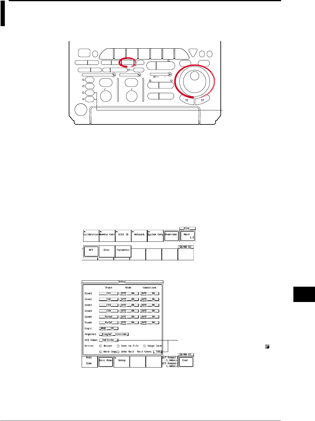
13-19
IM 701710-01E
Ethernet Interface (Option)
13
13.7 Using the Mail Function (Action Mail Function)
<For a description of this function, refter to page 1-30>
Relevant Keys
ACTION DELAY
X - Y MENU MENU PHASE
SEARCH
HORIZONTAL
VERTICAL TRIGGER
TRIG D
HELP
ESC
SELECTRESET
SIMPLE
MODE POSITION
MATH
MISCFILE
CLEAR
TRACE
HISTORY
MEASURE
SETUP
PRESET
DISPLAY
CURSOR
CH
1
CH
2
CH
3
CH
4
POWER
COPY IMAGE SAVE SHIFT
ZOOM
GO/NO-GO
ENHANCED
ACQ START/STOP
SNAP
SHOT
V DIV TIME DIV
The DL1720 is not
equipped with
an input terminal
for CH3 or CH4.
Operating Procedure
Mail Settings
1. Follow steps 1 through 9 in section 13.6, "Using the Mail Function (Fixed Interval)"
to input the MailServer, MailAddress, and a Comment if necessary.
2. It is not necessary to set the MailBaseTime and Interval using the action mail
function. However, turn Interval OFF when only using the action mail function
without using the fixed interval mail function.
Setting the Action
3. Press GO/NO-GO.
4. Press the MODE soft key then select Zone or Parameter.
5. Press the Setup soft key to display the GO/NO-GO setting menu.
Settings for the following items can be
input directly using a USB keyboard. ( )

13-20 IM 701710-01E
6. Use the jog shuttle to move the cursor to Action, and select Send Mail.
7. Select Mail Count to set a limit for the number of mails that are sent.
8. Press the Exec soft key to start GO/NO-GO.
Note
•The email destination is the Mail Address set in MISC, Network, Mail Setup.
•For mail sent by this instrument, the sender’s address will be the same as the specified
recipient address.
•This function can be used in conjunction with 13.6, “Using the Mail Function (Fixed Interval.)”
Turn the Interval OFF only when using the action mail function.
•Before uisng this function, refer to section 13.2, “Configuring the Ethernet Interface (TCP/IP)”
and enter the TCP/IP settings.
Explanation
You can send the trigger time and other information to the specified network mail
address as the action of a GO/NO-GO determination or an action trigger.
Mail Settings
For details, see section 13.6, “Using the Mail Function (Fixed Interval).”
Data Sent from the DL1720/DL1740
The following five items are sent.
•Acquisition status
Start/Stop, acquisition counter
•Trigger time
•GO/NO-GO success/fail information
Time of GO/NO-GO determination only (see section 9.12 and 9.13)
•Cause of failure
Time of GO/NO-GO determination only (see section 9.12 and 9.13)
•Results of waveform parameter measurement
Automatic measurement of waveform parameters (see sections 9.2 and 9.4), and the
time of GO/NO-GO determination by waveform parameters only (see section 9.12)
Sample Transmission Report
[Comment] aaaaaa
[ACQ Status] Stopped 1
[Trigger Date and Time] 2000/07/17 17:28:59.38
[GO/NOGO Status] Success: 9 Fail: 1
[NOGO Factor] Param4(Ch4,tWd )
Max (C1) 4.16667V
SDv (C2) 697.941mV
Freq(C3) 500.0000kHz
+Wd (C4) 1.00us>
13.7 Using the Mail Function (Action Mail Function)
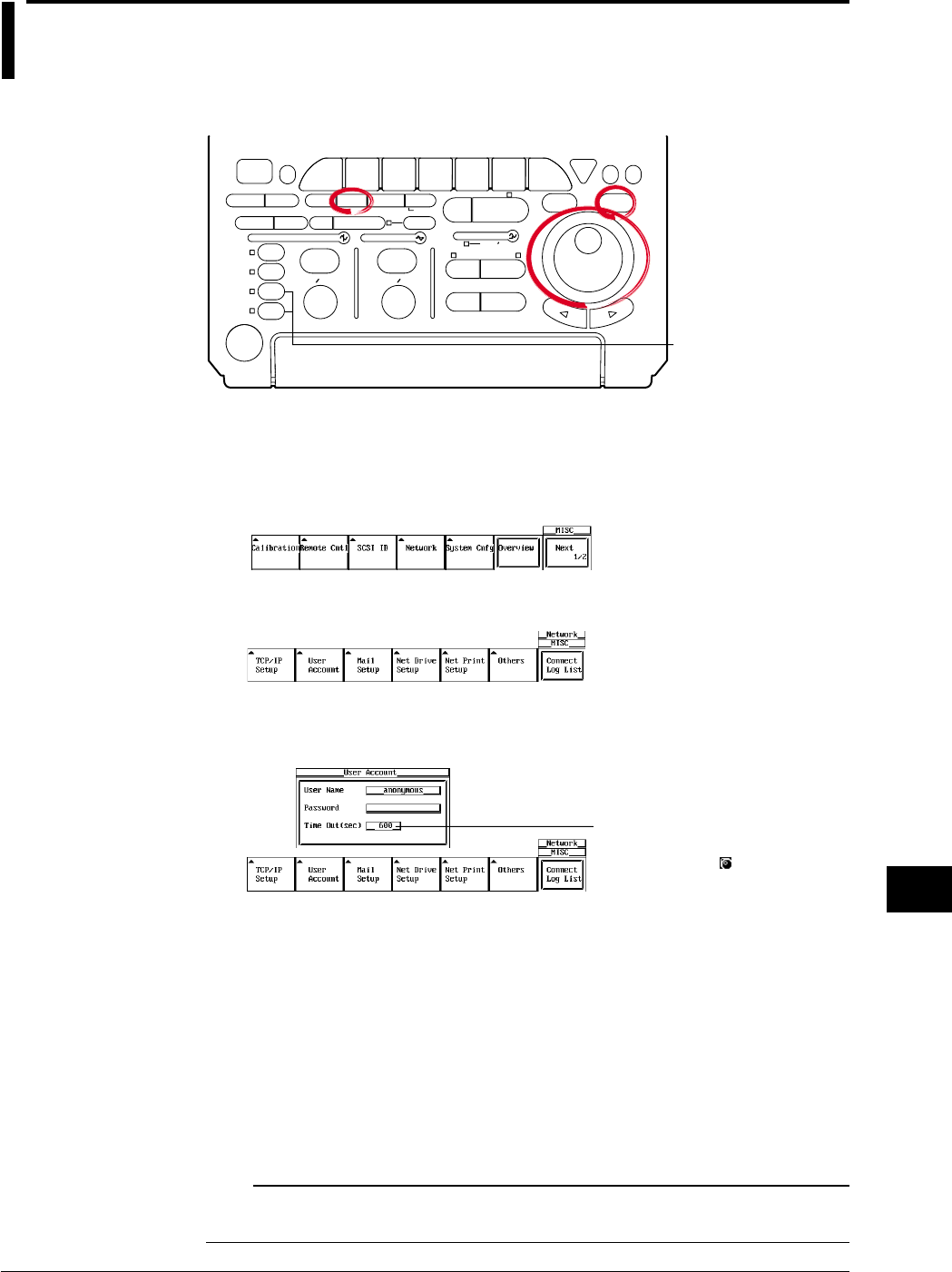
13-21
IM 701710-01E
Ethernet Interface (Option)
13
13.8 Accessing DL1720/DL1740 Drives from a
Network Drive (FTP Server Function)
<For a description of this function, refter to page 1-29>
Relevant Keys
ACTION DELAY
X - Y MENU MENU PHASE
SEARCH
HORIZONTAL
VERTICAL TRIGGER
TRIG D
HELP
ESC
SELECTRESET
SIMPLE
MODE POSITION
MATH
MISCFILE
CLEAR
TRACE
HISTORY
MEASURE
SETUP
PRESET
DISPLAY
CURSOR
CH
1
CH
2
CH
3
CH
4
POWER
COPY IMAGE SAVE SHIFT
ZOOM
GO/NO-GO
ENHANCED
ACQ START/STOP
SNAP
SHOT
V DIV TIME DIV
The DL1720 is not
equipped with
an input terminal
for CH3 or CH4.
Operating Procedure
User Account Settings
1. Press MISC.
2. Press the Network soft key to display the Network menu.
3. Press the User Account soft key to display the account settings menu.
4. Move the cursor to User Name using the jog shuttle, then press SELECT to display
the keyboard.
The numerical values for this
item can be input directly using
a USB keyboard. ( )
5. Enter the user name. If you do not wish to limit access, use the anonymous
setting. If access is to be limited, enter a user name of 15 characters or less.
6. Move the cursor to Password using the jog shuttle, then press SELECT to display
the keyboard.
7. Enter the password. Enter the same password again. If the user name is set to
anonymous, it is not necessary to enter a password.
8. Move the cursor to Timeout using the jog shuttle, then press SELECT.
9. Enter the Timeout time using the jog shuttle. If the DL1720/DL1740 is not being
accessed at the Timeout time, the connection to the network will be automatically
closed.
Note
For keyboard (soft keyboard) operation see section 4.1, “Entering Values and Character
Strings.”
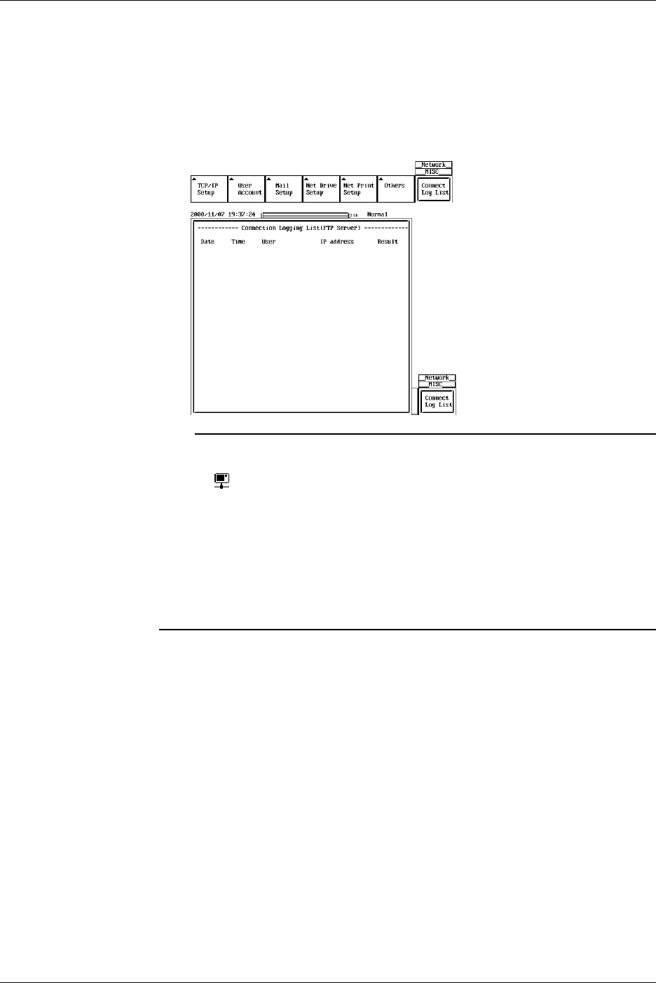
13-22 IM 701710-01E
Executing the FTP Client Software
10. Execute the FTP client software from a personal computer or workstation. Perform
file operations using the username specified in step 6.
Displaying the Connection Logging List
11. When you press the Connection Logging List soft key, the 25 most recent
access times, user names, and IP addresses are displayed.
Note
•The DL1720/DL1740 can only support one client.
•When the DL1720/DL1740 is being accessed from a PC or workstation (i.e. when it’s logged
on), is displayed in the upper right part of the screen.
•This function can not be used in conjunction with FTP client function, LPR client function, or
File operation.
•The floppy disk or the Zip disk is displayed as FD0 or ZP0 in the root directory. Other devices
connected via SCSI are displayed as SCn (where n is the SCSI ID number).
•The log is cleared when the power is turned OFF.
•Before accessing a drive, refer to 13.2, “Configuring the Ethernet Interface (TCP/IP)” and
enter the TCP/IP settings.
•You must restart the DL1720/DL1740 for the settings to take effect.
Explanation
You can access the DL1720/DL1740’s Zip drive, floppy drive, or SCSI drive (optional)
from a PC or workstation via Ethernet.
In order to access these devices, you must be running FTP client software on the PC or
workstation.
User Account Settings
•User Name
15 characters or less may be used. The default value is anonymous.
The available characters consist of all ASCII characters on the keyboard (including
space).
•Password
15 characters or less may be used.
The available characters consist of all ASCII characters on the keyboard (including
space).
•Time Out
If the instrument is not being accessed at the time specified here, the connection to
the network will be automatically closed.
13.8 Accessing DL1720/DL1740 Drives from a Network Drive (FTP Server Function)
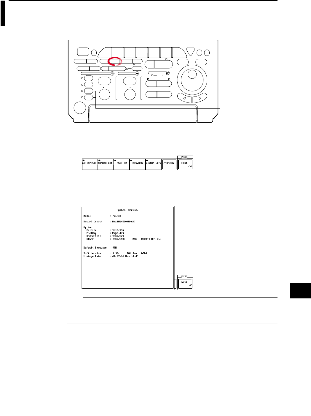
13-23
IM 701710-01E
Ethernet Interface (Option)
13
13.9 Viewing the Ethernet Interface Option and MAC
Address
Relevant Keys
ACTION DELAY
X - Y MENU MENU PHASE
SEARCH
HORIZONTAL
VERTICAL TRIGGER
TRIG D
HELP
ESC
SELECTRESET
SIMPLE
MODE POSITION
MATH
MISCFILE
CLEAR
TRACE
HISTORY
MEASURE
SETUP
PRESET
DISPLAY
CURSOR
CH
1
CH
2
CH
3
CH
4
POWER
COPY IMAGE SAVE SHIFT
ZOOM
GO/NO-GO
ENHANCED
ACQ START/STOP
SNAP
SHOT
V DIV TIME DIV
The DL1720 is not
equipped with
an input terminal
for CH3 or CH4.
Operating Procedure
1. Press MISC.
2. Press the Overview soft key.
3. When Ether:Yse(/C7) appears for the Option item in the overview screen, this
indicates that the Ethernet interface is installed.
The number on the right side is the MAC address (in the example,
MAC:000064_824_052).
Note
•Ether: Yes (/C7) is only displayed if the Ethernet interface option is installed.
•If XXXXXX_XXX_XXX is displayed for your MAC address, contact your nearest YOKOGAWA
dealer.
Explanation
Check the MAC address, and whether the Ethernet interface (optional) is installed.
The Presence of the Ethernet Interface (Option)
The presence of the Ethernet interface is displayed under Ethernet in the Information
window.
•If Yes is displayed, the Ethernet interface is installed.
•If No is displayed, the Ethernet interface is not installed.
MAC Address
The MAC address is a unique address that has already been set on the instrument, and
is necessary for transmission between nodes.
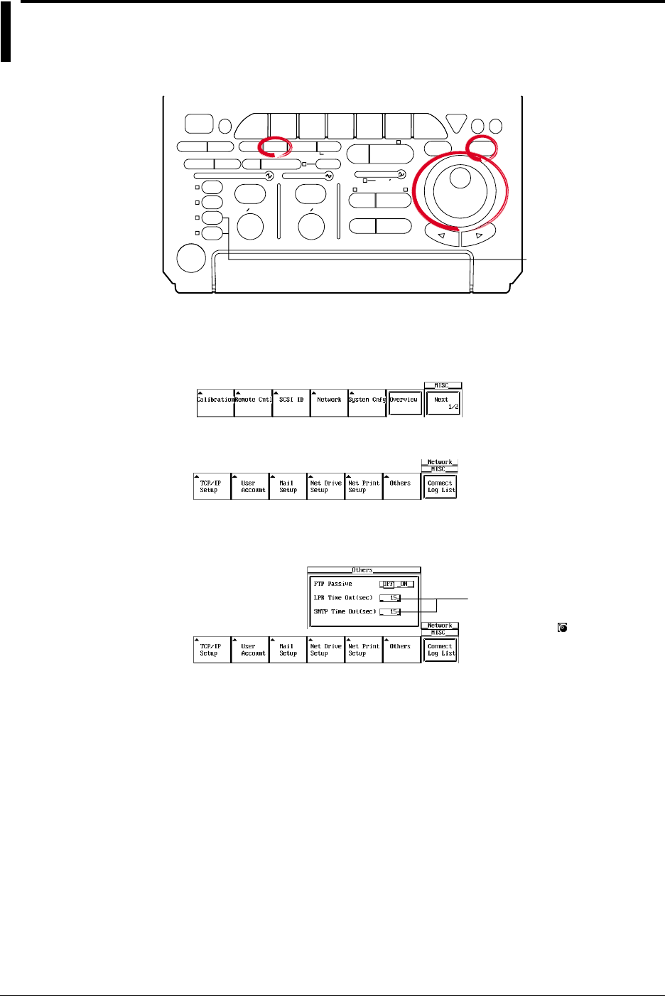
13-24 IM 701710-01E
13.10 Setting the FTP Passive Mode and LPR/SMTP
Timeout
Relevant Keys
ACTION DELAY
X - Y MENU MENU PHASE
SEARCH
HORIZONTAL
VERTICAL TRIGGER
TRIG D
HELP
ESC
SELECTRESET
SIMPLE
MODE POSITION
MATH
MISCFILE
CLEAR
TRACE
HISTORY
MEASURE
SETUP
PRESET
DISPLAY
CURSOR
CH
1
CH
2
CH
3
CH
4
POWER
COPY IMAGE SAVE SHIFT
ZOOM
GO/NO-GO
ENHANCED
ACQ START/STOP
SNAP
SHOT
V DIV TIME DIV
The DL1720 is not
equipped with
an input terminal
for CH3 or CH4.
Operating Procedure
1. Press MISC.
2. Press the Network soft key to display the Network menu.
3. Press the Others soft key to display the Others settings menu.
Turning ON/OFF the FTP Passive Mode
4. Turn the jog shuttle to select FTP Passive.
Settings for the following items
can be input directly using a
USB keyboard. ( )
5. Press SELECT to select ON or OFF.
Setting the LPR Timeout Time
4. Turn thejog shuttle to select LPR Time Out.
5. Press SELECT to display the timeout time selection box.
6. Turn thejog shuttle to set the timeout time.
7. Press SELECT or ESC to close the box.
Setting the SMPT Timeout Time
4. Turn the jog shuttle to select SMTP Time Out.
5. Press SELECT to display the timeout time selection box.
6. Turn the jog shuttle to set the timeout time.
7. Press SELECT or ESC to close the box.

13-25
IM 701710-01E
Ethernet Interface (Option)
13
13.10 Setting the FTP Passive Mode and LPR/SMTP Timeout
Explanation
Enters special settings related to the FTP client, LPR, and SMTP. Normally, these
parameters do not need to be specified.
Turning ON/OFF the FTP Passive Mode
Turn this function ON when using the DL1720/DL1740 behind a firewall that requires the
passive mode. The default setting is OFF.
(A firewall is furnished on a system that has security features. It prevents intrusion from
the outside into the network system.)
Setting the LPR Timeout Time
The DL1720/DL1740 closes the connection to the printer if there is no response from the
printer for a certain period of time (timeout time) when it accesses the printer.
Select the value in the range of 0 to 3600 s. The default value is 15 s.
Setting the SMTP Timeout Time
When a mail server is accessed from the DL1720/DL1740 and connection cannot be
established after a certain period of time (timeout time), the DL1720/DL1740 decides that
theconnection to the mail server is not possible and closes the connection.
Select the value in the range of 0 to 3600 s. The default value is 15 s.
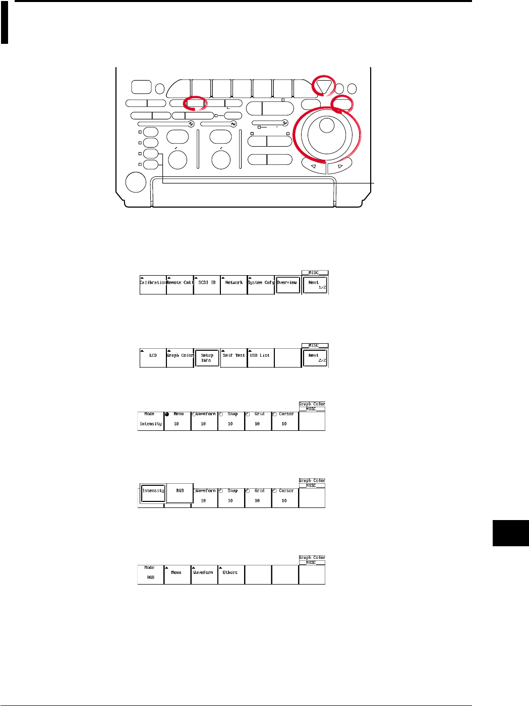
14-1
IM 701710-01E
Other Operations
14
14.1 Setting the Screen Color and Brightness
Relevant Keys
ACTION DELAY
X - Y MENU MENU PHASE
SEARCH
HORIZONTAL
VERTICAL TRIGGER
TRIG D
HELP
ESC
SELECTRESET
SIMPLE
MODE POSITION
MATH
MISCFILE
CLEAR
TRACE
HISTORY
MEASURE
SETUP
PRESET
DISPLAY
CURSOR
CH
1
CH
2
CH
3
CH
4
POWER
COPY IMAGE SAVE SHIFT
ZOOM
GO/NO-GO
ENHANCED
ACQ START/STOP
SNAP
SHOT
V DIV TIME DIV
The DL1720 is not
equipped with
an input terminal
for CH3 or CH4.
Operating Procedure
1. Press MISC.
2. Press the Next 1/2 soft key.
3. Pressing the Graphic Color soft key displays a menu used to set the display color
and brightness.
4. Pressing the Mode soft key displays a menu used to select the settings.
Setting the Color
5. Pressing the RGB soft key displays the display color setting menu.
6. Pressing the Menu soft key displays a dialog box used to set the display color of
the menu items.
Chpater 14 Other Operations
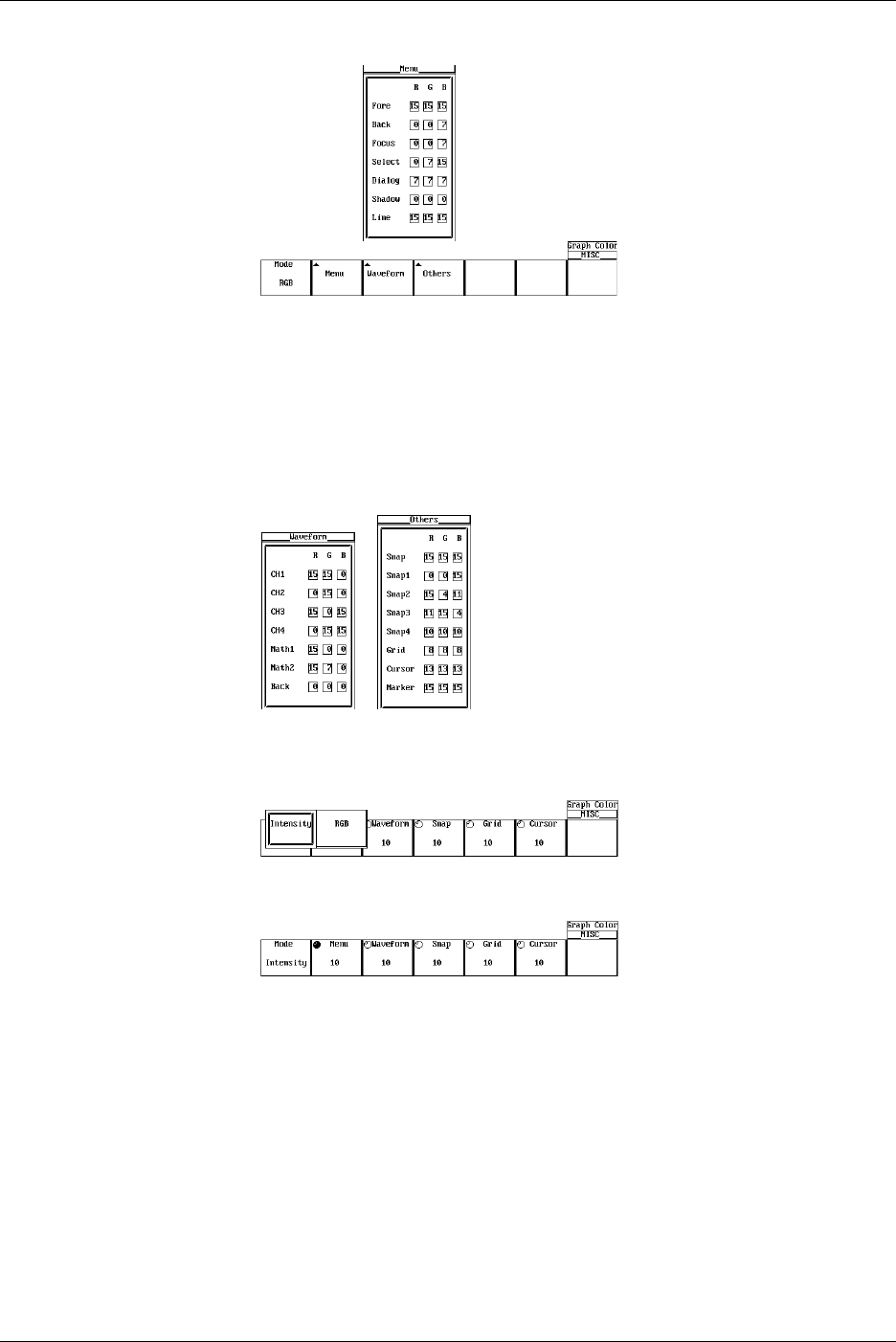
14-2 IM 701710-01E
7. Turn the jog shuttle to move the cursor to the desired item.
8. Pressing SELECT displays the color setting menu.
9. Turn the jog shuttle to set the color.
10. Pressing SELECT closes the color setting menu.
11. Pressing ESC closes the dialog box used to set the display color of the menu
items.
12. In a similar fashion, set the colors for the Waveform and Others items. (CH3, CH4,
and Math2 are not displayed on the DL1720.)
Setting the Brightness
5. Pressing the Intensity soft key displays the brightness setting menu.
6. Press the Menu soft key.
7. Turn the jog shuttle to set the brightness of the menu screen.
8. In a similar fashion, set the brightness for Waveform, Snap, Grid, and Cursor items.
14.1 Setting the Screen Color and Brightness

14-3
IM 701710-01E
Other Operations
14
Explanation
Screen Color
You can set arbitrary colors for the following items. The colors are set using R (red), G
(green), and B (blue) ratios from 0 to 15.
Menu Screen
Fore: Selected menu item
Back: Background
Focus: Selected cursor
Select : Selected menu
Dialog: Dialog box
Shadow: Background color of the selected menu
Line: Lines on the menu screen
Waveform
CH1 to CH4: Waveform (or CH1 to CH2 for the DL1720)
Back: Background color of the waveform display area
Others
Snap: Snapshot waveform
Snap1 to 4: Loaded snapshot waveforms
Grid: Grid
Cursor: Cursor
Marker: Marker
Brightness
You can set the brightness for the following items from 1 to 15 steps.
Menu: Menu screen
Waveform: Waveform
Snap: Snapshot waveform
Grid: Grid
Cursor: Cursor
14.1 Setting the Screen Color and Brightness
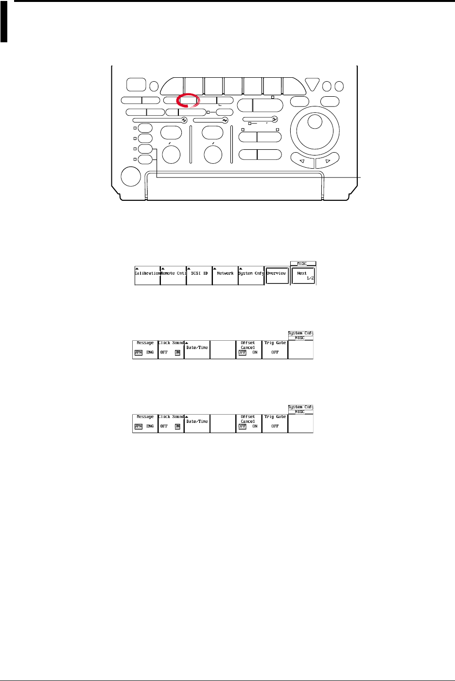
14-4 IM 701710-01E
14.2 Changing the Message Language and Click
Sound
Relevant Keys
ACTION DELAY
X - Y MENU MENU PHASE
SEARCH
HORIZONTAL
VERTICAL TRIGGER
TRIG D
HELP
ESC
SELECTRESET
SIMPLE
MODE POSITION
MATH
MISCFILE
CLEAR
TRACE
HISTORY
MEASURE
SETUP
PRESET
DISPLAY
CURSOR
CH
1
CH
2
CH
3
CH
4
POWER
COPY IMAGE SAVE SHIFT
ZOOM
GO/NO-GO
ENHANCED
ACQ START/STOP
SNAP
SHOT
V DIV TIME DIV
The DL1720 is not
equipped with
an input terminal
for CH3 or CH4.
Operating Procedure
1. Press MISC.
2. Pressing the System Cnfg soft key displays the system configuration menu.
Selecting the Message Language
3. Press the Message soft key to select ENG or JPN.
Setting the Click Sound
3. Press the Click Sound soft key to select ON or OFF.
Explanation
Selecting the Message Language
A message appears when an error occurs. You can set whether to display these
messages in English or Japanese. The message codes are the same for both
languages.
For messages, see section 15.2.
Turning ON/OFF the Click Sound
Set whether or not to make click sounds when the jog shuttle is turned. The default
setting is ON.
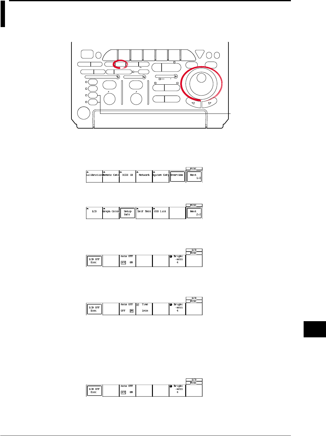
14-5
IM 701710-01E
Other Operations
14
14.3 Turning OFF the Backlight and Setting the
Brightness of the Backlight
Relevant Keys
ACTION DELAY
X - Y MENU MENU PHASE
SEARCH
HORIZONTAL
VERTICAL TRIGGER
TRIG D
HELP
ESC
SELECTRESET
SIMPLE
MODE POSITION
MATH
MISCFILE
CLEAR
TRACE
HISTORY
MEASURE
SETUP
PRESET
DISPLAY
CURSOR
CH
1
CH
2
CH
3
CH
4
POWER
COPY IMAGE SAVE SHIFT
ZOOM
GO/NO-GO
ENHANCED
ACQ START/STOP
SNAP
SHOT
V DIV TIME DIV
The DL1720 is not
equipped with
an input terminal
for CH3 or CH4.
Operating Procedure
1. Press MISC.
2. Press the Next 1/2 soft key.
3. Press the LCD soft key to display the backlight ON/OFF menu.
Setting Auto OFF
4. Press the Auto OFF soft key to select either ON or OFF.
5. If Auto OFF is turned ON, press the Time soft key. Using the jog shuttle, set the
time at which the backlight will automatically turn OFF.
Setting the Brightness of the Backlight
6. Press the Brightness soft key. Using the jog shuttle, adjust the brightness of the
backlight.
Turning ON/OFF the Backlight
7. Press the LCD OFF Exec soft key to turn OFF the backlight.
Press any key to return to the measurement screen.

14-6 IM 701710-01E
Explanation
Turning ON/OFF the backlight (LCD OFF)
Turns ON/OFF the LCD backlight. If a key is pressed when the backlight is OFF, the
screen returns to the measurement screen.
Automatically Turning OFF the Backlight (Auto OFF)
The backlight automatically turns OFF, if there is no key operation for the specified time.
Brightness of the Backlight (Brightness)
You can also change the brightness of the backlight.
The lifetime of the backlight can be prolonged by dimming the backlight or turning OFF
the backlight when it is not necessary.
14.3 Turning OFF the Backlight and Setting the Brightness of the Backlight
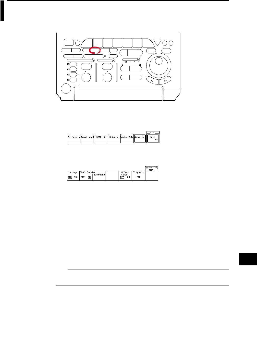
14-7
IM 701710-01E
Other Operations
14
14.4 Canceling the Offset Voltage
Relevant Keys
ACTION DELAY
X - Y MENU MENU PHASE
SEARCH
HORIZONTAL
VERTICAL TRIGGER
TRIG D
HELP
ESC
SELECTRESET
SIMPLE
MODE POSITION
MATH
MISCFILE
CLEAR
TRACE
HISTORY
MEASURE
SETUP
PRESET
DISPLAY
CURSOR
CH
1
CH
2
CH
3
CH
4
POWER
COPY IMAGE SAVE SHIFT
ZOOM
GO/NO-GO
ENHANCED
ACQ START/STOP
SNAP
SHOT
V DIV TIME DIV
The DL1720 is not
equipped with
an input terminal
for CH3 or CH4.
Operating Procedure
1. Press MISC.
2. Pressing the System Cnfg soft key displays the system configuration menu.
3. Press the Offset Cancel soft key to select ON or OFF.
The default value is OFF.
Explanation
You can select whether or not the offset voltage that is specified for each channel is
reflected in the results of computations and automated measurement of waveform
parameters.
OFF: Does not reflect the offset voltages in the results of computations and automated
measurement of waveform parameters.
The vertical position of the display screen corresponds to the offset voltage.
ON: Reflect the offset voltages in the results of computations and automated
measurement of waveform parameters.
The waveform that has offset voltage (DC voltage) removed from the input signal
can be observed. In this case, the vertical position becomes 0 V.
Note
•Offset cancel applies to all channels.
•To set whether or not to cancel the offset for each channel, use linear scaling.

15-1
IM 701710-01E
Troubleshooting, Maintenance and Inspection
15
15.1 Troubleshooting
Troubleshooting
For corrective actions when a message appears on the screen, read the following pages.
If servicing is required or if the instrument does not operate properly after taking the
following corrective actions, contact your nearest YOKOGAWA dealer.
Problem Possible Cause Corrective Action Reference Section
The power cannot be The source voltage is outside the Use a correct power supply. 3.3
turned ON. rated range.
The main power switch on the rear Turn ON the main power switch.
panel is not turned ON.
Nothing is displayed. The backlight is turned OFF. Press any key. 14.3
The screen colors are not Select appropriate colors for the screen. 13.1
appropriate.
The display is abnormal. The system is not operating Turn ON the power again. 3.3
correctly.
The waveform display is Loaded waveform data from an Unload the loaded waveform. 11.6
not updated. external storage medium.
Keys do not work. The instrument is in the remote Press SHIFT + CLEAR TRACE activate —
mode. local mode.
Other causes. Execute a key test. If the test fails, 15.3
servicing is required.
Triggering does not occur. The trigger gate is enabled. Turn OFF the trigger gate. 6.16
The trigger settings are not Set correct trigger settings. Chapter 6
appropriate.
The measured values are Did not allow adequate warm-up Allow at least 30 minutes for the —
odd. time. instrument to warm-up after turning
ON the power.
The instrument has not been Perform calibration. 4.6
calibrated.
The probe’s phase has not been Correct the phase properly. 3.5
corrected.
The probe attenuation is not Set to the correct value. 5.4
correct.
An offset voltage is added. Set the offset voltage to zero. 5.5
Other causes Perform calibration. If the measured 4.6
values are still odd, servicing is required.
Cannot output to the The printer head is damaged or Servicing is required. 15.6
internal printer. worn out.
Cannot save to the medium. The medium has not been Format the medium. 11.4
formatted.
The medium is write protected. Remove the write protection from the —
medium.
Insufficient space on the medium. Delete unnecessary files or use a new 11.10
medium.
The instrument cannot be The address used in the program Use the same address in the program Communication
configured or controlled via is different from the actual address. and the instrument. Interface User’s
the communication The GP-IB interface is not being Comply with the specifications. Manual
interface. used according to the electrical (IM701710-17E)
and mechanical specifications.
Chpater 15 Troubleshooting, Maintenance and Inspection

15-2 IM 701710-01E
15.2 Messages and Corrective Actions
Error Messages
If an error occurs during operation, an error code may appear on the screen. This
section describes the meanings of the error messages and the corrective actions which
they require. The messages can be displayed either in English or Japanese (see section
14.2). If the corrective action requires servicing, contact your nearest YOKOGAWA
dealer as listed on the back cover of this manual for repairs.
In addition to the error messages listed in this section, there are also communication
related error messages. These messages are described in the Communication Interface
User’s Manual (IM701710-17E).
Status Messages
Code Message Discription Reference Section
0 Aborted hard copy. —10.2
1 Aborted file operation. —Chapter 11
2 Completed data store. —4.4
3 Completed data recall. —4.4
4 Completed GO/NO-GO. —9,12, 9.13
10 Set to remote mode by communication Press SHIFT+ CLEAR TRACE to change to —
commands. local mode.
11 Local lockout by communication commands. To allow key operation, release the lockout —
using communication commands
13 All settings will be initialized. Power up with —4.2
the RESET key depressed.
21 Completed action-on-trigger. —6.15
22 Executed unload. —11.6, 11.8
23 Release the Preview mode. —10.2
24 Some of the channels are set to 50-Ω DC input. —5.3
To keep the settings, press the SELECT key.
Pressing any other key will change the settings
to 1 MΩ DC input.
25 Aborted the search. —7.8, 7.9, 8.9
26 Executed the search, but no record was found —7.8, 7.9
that matched the conditions.
27 Executed the search, but no pattern was found —8.9
that matched the conditions.
28 Pattern contains points that are between Thr —8.9
Lower and Thr Upper.
29 FFT will be performed on all records. ——
Abort the operation by setting the history
Display Mode to One.
30 Aborted the recalculation of the FFT. ——
32 Aborted statistical measurement processing. —9.3
36 Key invalid for this model. ——

15-3
IM 701710-01E
Troubleshooting, Maintenance and Inspection
15
Error in Execution (600 to 799)
Code Message Corrective Action Reference Section
601 Invalid file name or SCSI ID. Check the file name and the SCSI ID. 11.5 to 11.9, 11.12
602, 603 No SCSI device or no storage media inserted. Check the SCSI device connection, the SCSI 11.3, 11.5
ID number, and the existence of a medium in
the drive.
604 Storage media failure. Check the medium. —
605 File not found. Check the filename and the medium. Chapter 11
606 Storage media is protected. Set the disk’s write protect switch to OFF. —
607 Storage media failure. Check the medium. —
608 to 610 Invalid file name or SCSI ID. Check the file name and the SCSI ID. 11.5 to 11.9, 11.12
611, 612 Storage media full. Delete unnecessary files or use another disk. 11.10
The number of bytes necessary is given in
the pages indicated on the right.
613 Cannot delete a directory if there are files Delete all files in the directory before deleting 11.10
in the directory. the directory.
614 File is protected. Clear the write disable (*) mark. 11.10
615 Physical format error. Reformat the medium. If the same error 11.4
occurs, this instrument cannot format the
medium.
616 to 620 File system failure. Check using another medium. If the same —
message still appears, servicing is required.
621 File is damaged. Check the file. —
622 to 641, File system failure. Check using another medium. If the same —
656 to 663 message still appears, servicing is required.
642 No storage media exists in SCSI device. Check that the medium is correctly inserted. —
into the SCSI device
646 to 653 Storage media failure. Check the medium —
654 Storage media failure. Check the floppy disk’s format type. 11.4
665 Cannot load this file format. Files stored on other models (DL/AG series) —
cannot be loaded.
666 File is now being accessed. Wait a moment. Execute after accessing is finished. —
667 Cannot be executed while data acquisition is Press START/STOP to stop thewaveform 4.5
in progress. acquisition.
668 Cannot find ‘.HDR’ file. Check the file. 11.6
669 Cannot load the specified file on this ROM Upgrade the ROM version (upper compatible). —
version or this model.
671 Save data not found. Check the presence of data to be stored. —
673 SCSI controller failure. Servicing is required. —
676 Unknown file format. Check whether the data file in a format that 11.12
is supported. Change the file extension.
677 P-P compression cannot be used to save Turn OFF the P-P compression. 11.6
FFT waveforms.
679 Data that have been P-P compressed and ——
saved cannot be loaded.
680 Illegal printer head position. Set the release arm to the “HOLD” position. 10.1
681 Paper empty. Load a paper roll. 10.1
682 Printer overheated. Turn OFF the power immediately. —
Servicing is required.
683 Printer overheated. Turn OFF the power immediately. —
Servicing is required.
684 Printer is not installed. Check that the printer is installed. 2
685 Printer time out. Servicing is required. —
691 The printer has malfunctioned. Servicing is required. —
692 Printer error. Turn the power of the printer ——
from OFF to ON.
15.2 Messages and Corrective Actions

15-4 IM 701710-01E
Code Message Corrective Action Reference Section
693 Printer offline. ——
694 Out of paper. ——
695 Printer is in use. ——
696 Cannot detect printer. Turn ON the printer. ——
Check connectors.
697 No files supporting the thumbnail display window. —10.4
701 Cannot be executed while data acquisition is Press START/STOP to stop the waveform 4.5
in progress. acquisition.
703 There is no data to be undone. Cannot undo because the data were cleared 4.2, 4.3
during initialization or auto setup.
704 Cannot be executed while data acquisition is Press START/STOP to stop the waveform 4.5
in progress. acquisition.
705 This data cannot be backed up. ——
706 There is no data to be recalled. —4.4
707 Cannot start during data outout. Wait until data output is complete. Chapter 10
711 Cannot access file while hard-copying. Wait until the hard copy completes. 10.2
712 Cannot compress this screen image. Turn OFF the compression setting. 10.3
Turn off the compression switch.
713 Calibration failure. Servicing is required. —
Disconnect the input and execute again.
If it fails again, servicing is required.
726 Cannot start when loading waveform data Unload the files. 11.6
that has been saved in history All mode.
727 Insufficient output data. Increase Mag or widen the Time Range 10.2
Increase Mag or widen the Time Range interval.
interval.
728 Hard copying. Pressing Copy again aborts the operation. 10.2
Abort or wait until it is complete.
729 Cannot perform calibration while waveform Unload the loaded files from the FILE menu. 11.6
data is loaded.
730 Pattern is not specified. Set at least one search pattern not to X. 8.9
731 Cannot start when waveform data that has Unload the loaded files from the FILE menu. 11.6
been acquired in the linear average mode is
loaded.
732 Cannot be executed while computation is in Aborted when Math/Display is turned Off. 9.5
progress.
733 Failed to measure statistics. Check that there is at least one period of 9.3
The target waveform data exists or the waveform within the measurement range.
measured waveform data may not exist.
If Cycle Statistic is specified, the instrument
may be configured in a way that fails to detect
the cycle.
735 Cannot store because the data is locked. Release the lock through Store Detail. 4.4
Release the lock through Store Detail.
736 The File item is inappropriate. Select Waveform, Snap, or Measure. —
Select Waveform, Snap, or Measure.
737 Executing file Load, Save, or Format. ——
Abort or wait until it is complete.
738 Hard copying or saving image. ——
Abort or wait until it is complete.
750 Cannot connect to the server. Confirm the network settings and connection. Chapter 13
751 Not yet connected to the ftp server. Confirm the network settings and connection. Chapter 13
752 This ftp function in not supported. —Chapter 13
753 FTP Error: Rwd Confirm the network settings and connection. Chapter 13
754 FTP Error: Cwd Confirm the network settings and connection Chapter 13
755 FTP Error: Rm Confirm the network settings and connection. Chapter 13
15.2 Messages and Corrective Actions

15-5
IM 701710-01E
Troubleshooting, Maintenance and Inspection
15
Code Message Corrective Action Reference Section
756 FTP Error: List Confirm the network settings and connection. Chapter 13
757 FTP Error: Mkdir Confirm the network settings and connection. Chapter 13
758 FTP Error: Rmdir Confirm the network settings and connection. Chapter 13
759 FTP Error: Get Confirm the network settings and connection. Chapter 13
760 FTP Error: Put Confirm the network settings and connection. Chapter 13
761 FTP Error: GetData Confirm the network settings and connection. Chapter 13
762 FTP Error: PutData Confirm the network settings, connection, Chapter 13
and disk capacity.
763 FTP Error: AppendData Confirm the network settings, connection, Chapter 13
and disk capacity.
764 FTP Error: Client Handle Confirm the network settings and connection. Chapter 13
765 FTP Error: Others Confirm the network settings and connection. Chapter 13
785 Cannot send data to a network printer. Confirm the network settings and connection. Chapter 13
786 Cannot send the e-mail message. Confirm the network settings and connection. Chapter 13
797 Connecting to a NetDrive. —Chapter 13
Wait until connection has been established.
Error in Setting (800 to 899)
Code Message Corrective Action Reference Section
800 Illegal date/time. Set a correct date and time 3.6
801 Illegal file name. The file name contains characters that are 4.1
not allowed or the file name is restricted in
MS-DOS.
804 Cannot change this parameter while data. Press START/STOP to the waveform 4.5
acquisition is in progress. acquisition.
806 GO/NO-GO is in execution. Please press the All keys other than START/STOP are disabled 9.12, 9.13
Abort key. during GO/NO-GO determination.
814 Duplicated label. Set a different label. 8.5
819 Cannot change when Channel Display is OFF Turn ON the channel display or set Math 5.1
or Math settings are invalid. operation. Sections 9.5 to 9.10
821 Cannot change when ExtClock is active. Change the timebase to Internal. 5.10
836 Cannot change settings during Select Abort or press START/STOP. 4.5, 6.15
action-on-trigger.
840 Cannot set the acquisition mode to Average Change the acquisition mode or the trigger 6.1, 7.2
when the trigger mode is set to Single or mode.
Single(N).
841 It is not possible to make a setting that will Setting or set the trigger mode to a different 6.1
result in the repetitive mode when the trigger mode.
mode is set to Single (N).
842 Cannot specify A→B(N) and A Delay B Turn OFF the trigger gate. 6.16
when the trigger gate is active.
843 Cannot set the trigger mode to Single or Change the acquisition mode or the trigger 6.1, 7.2
Single(N) when the acquisition mode is mode.
Average.
846 Cannot set the trigger mode to Single(N) Turn OFF the repetitive sampling mode, 5.11, 7.1
during repetitive sampling mode. lower the T/div setting, or shorten the
record length.
847 Cannot set this parameter during repetitive Turn OFF the repetitive sampling mode, lower 5.11, 7.1
sampling mode. the T/div setting, or shorten the record length.
848 Not possible during the interleave mode. Turn OFF the interleave mode. 7.5
850 Not possible in the current record length. Change the record length. 7.1
851 Cannot carry out computation at the current Change the record length. 7.1
record length.
15.2 Messages and Corrective Actions

15-6 IM 701710-01E
Code Message Corrective Action Reference Section
852 The operation is not possible when Unload the files. 11.6
waveforms are loaded.
Unload the loaded files from the FILE menu.
853 Setting or executing is not possible during Abort the search. 7.8, 7.9
the search operation.
854 Search pattern does not exist. Change the search conditions. 8.9
Execute the search.
855 Settings cannot be changed or executed Abort the search. 7.8, 7.9
during the history search operation.
856 The record cannot be selected Check the record number using Show Map. 7.8, 7.9
857 History record does not exist. History record is not created in the average 7.2
mode, repetitive sampling mode, or roll mode.
858 Setting or executing is not possible during Set the history Display Mode to One. 7.7
FFT recalculation.
Abort the operation by setting the history
Display Mode to One.
860 Cannot be configured or executed while Set the history Display Mode to One. 7.7
updating the history all display.
Aborted when history display mode is set to
One.
861 Cannot output color in this format. Turn OFF the color. 10.3
862 Zones cannot be edited in the following cases: Display the main window and the target 9.12
• When the main window is not displayed. waveform.
• When the target waveform is not displayed.
863 The zone waveform does not exist. Create the zone waveform. 9.12
864 The zone is being edited. Select Quit to exit zone editing. 9.12
To perform other operations, select Quit to
exit zone editing.
865 Zones determination is not possible in the Display the main window and the target window 9.12
following cases: and create the zone waveform.
• When the main window is not displayed.
• When the target waveform is not displayed.
• When the zone waveform does not exist.
868 Processing statistics. Abort statistical processing. 9.3
To perform other operations, abort the
statistical processing.
System Operation Errors (900 to 908, 912 to 914)
Code Message Corrective Action Reference Section
901 Failed to backup setup data. Check the condition of the built-in lithium —
Will initialize. battery using the overview screen.
Servicing is required.
906 Fan stopped ; Turn OFF the power immediately. —
Turn off the power immediately Servicing is required.
907 Backup battery is flat Servicing is required to replace the battery. —
912 Fatal error in the communication driver Servicing is required. —
Note
When servicing is required, double-check by initializing the instrument.
15.2 Messages and Corrective Actions
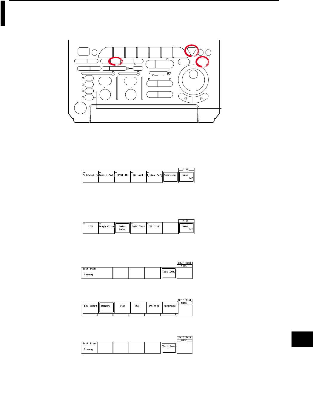
15-7
IM 701710-01E
Troubleshooting, Maintenance and Inspection
15
15.3 Self-Diagnostic Test (Self Test)
Relevant Keys
ACTION DELAY
X - Y MENU MENU PHASE
SEARCH
HORIZONTAL
VERTICAL TRIGGER
TRIG D
HELP
ESC
SELECTRESET
SIMPLE
MODE POSITION
MATH
MISCFILE
CLEAR
TRACE
HISTORY
MEASURE
SETUP
PRESET
DISPLAY
CURSOR
CH
1
CH
2
CH
3
CH
4
POWER
COPY IMAGE SAVE SHIFT
ZOOM
GO/NO-GO
ENHANCED
ACQ START/STOP
SNAP
SHOT
V DIV TIME DIV
The DL1720 is not
equipped with
an input terminal
for CH3 or CH4.
Operating Procedure
Displaying the Self Test Menu
1. Press MISC.
2. Press the Next 1/2 soft key to display the self test soft key menu.
3. Press the Self test soft key to display the self test menu.
Go to step 4 for a memory test, step 9 for a key test, step 13 for a printer test, and
step 16 for a floppy disk drive test, a SCSI test, or a accuracy test.
Execute the Memory Test
4. Pressing the Test Item soft key displays the test item menu.
5. Press the Memory soft key to be tested.
6. Pressing the Test Exec soft key executes the memory test.
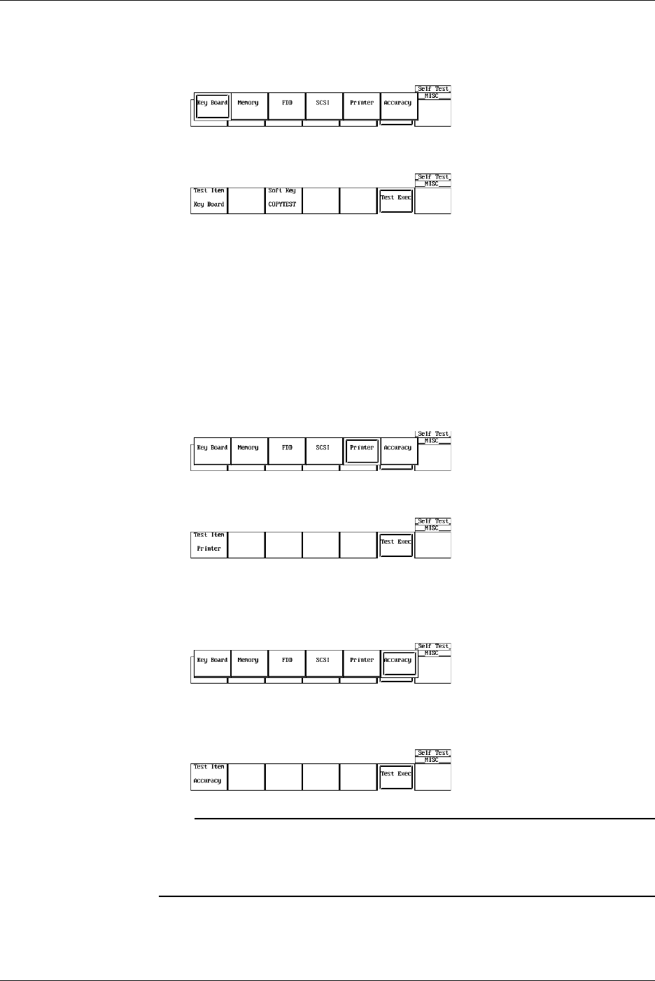
15-8 IM 701710-01E
Executing the Key Test
7. After step 3, press the Test Item soft key to display the test item menu.
8. Press the Key Board soft key to be test.
9. Pressing the Test Exec soft key executes the key test.
10. Press all the keys. To terminate the key test, press ESC twice.
Testing the Soft Keys
11. Pressing the Soft Key soft key displays a keyboard.
12. Using the jog shuttle and SELECT, check that the characters on the keyboard can
be entered correctly. Pressing ESC twice clears the keyboard.
Executing the Printer Test
13. After step 3, press the Test Item soft key to display the test item menu.
14. Press the Printer soft key to be test.
15. Pressing the Test Exec soft key executes the printer test.
Testing the FDD, Zip Drive, SCSI (Option), or Accuracy
16. After step 3, press the Test Item soft key to display the test item menu.
17. Press the soft key corresponding to the FDD, ZIP, SCSI, or Accuracy to be test.
18. Pressing the Test Exec soft key executes the floppy disk drive test, SCSI test, or
Accuracy test.
Note
•Insert a floppy disk or a Zip disk befor executing FDD or Zip test.
•Please note the following when performing the SCSI self-test:
•Only test unpartitioned SCSI devices
•Set the SCSI ID to 5
15.3 Self-Diagnostic Test (Self Test)

15-9
IM 701710-01E
Troubleshooting, Maintenance and Inspection
15
Explanation
Memory Test
This test checks the internal ROM. The ROM is functioning correctly, if Pass is
displayed. If Failed is displayed, contact your nearest YOKOGAWA dealer as listed on
the back cover of this manual.
Key Test
Tests whether or not the front panel keys are operating correctly. If the name of the key
that is pressed is highlighted, then it is operation correctly. If it does not, contact your
nearest YOKOGAWA dealer as listed on the back cover of this manual.
Floppy Disk Drive/Zip Drive Test
This test checks the floppy disk drive or the Zip drive. If Failed is displayed, contact your
nearest YOKOGAWA dealer as listed on the back cover of this manual.
SCSI Test
This test checks SCSI. If Failed is displayed, contact your nearest YOKOGAWA dealer
as listed on the back cover of this manual.
Printer Test
This test checks the optional built-in printer. The printer is functioning correctly if gray
shading is printed properly. If it is not, contact your nearest YOKOGAWA dealer as
listed on the back cover of this manual.
Accuracy Test
This test checks A/D accuracy. If Failed is displayed, contact your nearest YOKOGAWA
dealer as listed on the back cover of this manual.
15.3 Self-Diagnostic Test (Self Test)
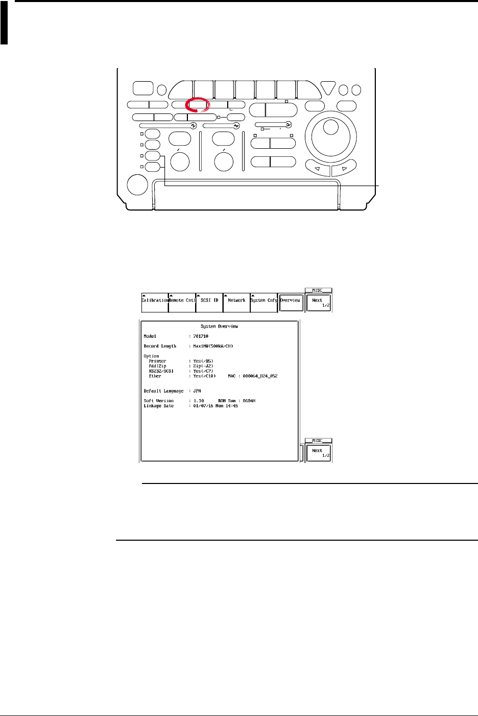
15-10 IM 701710-01E
15.4 Checking the System Condition
Relevant Keys
ACTION DELAY
X - Y MENU MENU PHASE
SEARCH
HORIZONTAL
VERTICAL TRIGGER
TRIG D
HELP
ESC
SELECTRESET
SIMPLE
MODE POSITION
MATH
MISCFILE
CLEAR
TRACE
HISTORY
MEASURE
SETUP
PRESET
DISPLAY
CURSOR
CH
1
CH
2
CH
3
CH
4
POWER
COPY IMAGE SAVE SHIFT
ZOOM
GO/NO-GO
ENHANCED
ACQ START/STOP
SNAP
SHOT
V DIV TIME DIV
The DL1720 is not
equipped with
an input terminal
for CH3 or CH4.
Operating Procedure
1. Press MISC.
2. Pressing the Overview soft key displays the overview screen.
Pressing any key clears the overview screen.
Note
•Backup battery
Displays OK if the built-in lithium battery is normal, Empty if the battery is flat. If Empty is
displayed, contact your nearest YOKOGAWA dealer as listed on the back cover of this
manual.
Explanation
This function allows you to check the ROM version, model, and installed options. The
screen is shown in the procedure.
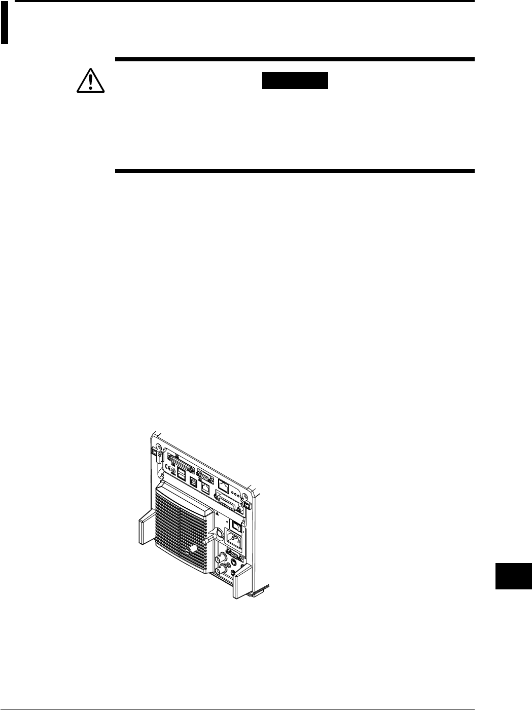
15-11
IM 701710-01E
Troubleshooting, Maintenance and Inspection
15
15.5 Replacing the Power Fuse
WARNING
•To prevent the possibility of fire, use only a fuse having the specified
rating (voltage, current, and type).
•Make sure to turn OFF the instrument and unplug the power cord
before replacing the fuse.
•Never short the fuse holder.
Specified Rating
The power fuse used on this instrument is specified as follows.
•Maximum Rated Voltage:250 V
•Maximum Rated Current: 4 A
•Type: Time lag
•Standard: VDE/SEMKO/UL/CSA/SEV certified
•Part Number: A1352EF
Replacement Procedures
Follow the procedures below to replace the power fuse.
1. Turn OFF the main power switch (rear panel on the right).
2. Unplug the power cord from the power outlet.
3. Press the dented fuse holder section of the rear panel with a Philips screwdriver,
and turn it in order to remove the fuse holder.
4. Remove the burned out fuse from the tip of the fuse holder.
5. Place a new fuse in the fuse holder, and place the fuse holder back in its original
position.

15-12 IM 701710-01E
15.6 Recommended Replacement Parts
The three-year warranty applies only to the main unit of the instrument (starting from the
day of delivery) and does not cover any other items such as expendable items (items
which wear out). Contact your nearest YOKOGAWA dealer for replacement parts.
Parts Name Limited Life
Built-In Printer Under normal usage, 120 rolls of paper (part No.: B9850NX)
LCD Back Light Approx. 25000 hours when used continuously
The following parts are wear out parts. We recommend you replace them periodically as
indicated below. Contact your nearest YOKOGAWA dealer for replacement parts.
Parts Name Recommended Replacement Period
Cooling Fan 3 years
Backup Battery (Litium Battery) 5 years

16-1
IM 701710-01E
Specifications
16
16.1 Input Section
Item Specifications
Number of Input Channels 4 (CH1 to CH4) , or 2 (CH1 to CH2) for the DL1720
Input Coupling Settings AC 1 MΩ, DC 1 MΩ, DC 50 Ω, GND
Input Connector BNC
Input Impedance 1 MΩ ±1.0%, approx. 20 pF
50 Ω ±1.0% (VSWR 1.4 or less (DC to 500 MHz))
Voltage-Axis Sensitivity Setting 1 MΩ input : 2 mV/div to 10 V/div (1-2-5 steps)
50 Ω input : 2 mV/div to 1 V/div (1-2-5 steps)
Maximum Input Voltage 1 MΩ input (at 1 kHz or less): 400 V (DC + AC peak) (282 Vrms CATII)
50 Ω input : 5 Vrms or less and 10 Vpeak or less
DC Offset Range (Max) 2 mV/div to 50 mV/div : ±1 V
(At 1 : 1 probe attenuation) 100 mV/div to 500 mV/div : ±10 V
1 V/div to 10 V/div : ±100 V
Vertical (Voltage) Axis Precision
DC Precision*1 :±(1.5% of 8 div + offset voltage precision)
Offset Axis Precision*1 2 mV/div to 50 mV/div : ±(1% of set value + 0.2 mV)
100 mV/div to 500 mV/div: ±(1% of set value + 2 mV)
1 V/div to 10 V/div : ±(1% of set value + 20 mV)
Frequency Characteristics*1*2 50 Ω input
(–3dB point when sine wave 1 V/div to 10 mV/div : DC to 500 MHz
of amplitude ±4 div is input) 5 mV/div to 2 mV/div : DC to 400 MHz
1 MΩ input (defined at the tip of the probe when using the passive probe 700988)
10 V/div to 10 mV/div: DC to 400 MHz
5 mV/div to 2 mV/div : DC to 300 MHz
–3dB Point for AC Coupling 10 Hz or less (When using the 10 : 1 probe (standard accessory), 1 Hz or less)
Used
Interchannel Skew 1 ns or less
(with identical settings)
Residual Noise*3 Larger of ±1.25 mV or ±0.15 div (typical*4)
Interchannel Isolation –34 dB (typical*4)
(at identical voltage sensitivity, DC to 500 MHz)
A/D Conversion Resolution 8 bits (24 LSB/div)
Probe Attenuation Settings 1 : 1, 10 : 1, 100 : 1, 1000 : 1
Bandwidth 100 MHz or 20 MHz band limit ON/OFF
Maximum Sample Rate Realtime sampling mode
With interleave ON : 1 GS/s
With interleave OFF : 500 MS/s
Repetitive sampling mode: 100 GS/s
Maximum Record Length With interleave ON : 1 Mwords/CH
With interleave OFF : 500 kwords/CH
*1 As measured following calibration (after 30-minute warmup), with internal-clock timebase, under standard operating
conditions as described on section 16.11.
*2 For repetitive events
The frequency region for single shot is DC to sampling frequency/2.5 or the frequency region for the repetitive event,
whichever is less.
*3 Measured under following conditions: input block shorted; 10 kWord record length; Normal acquisition mode; accumulation
OFF; 1 : 1 probe attenuation
*4 The typical value is a representative or standard velue. It is not a warranted value.
Chpater 16 Specifications

16-2 IM 701710-01E
16.2 Trigger Section
Item Specifications
Trigger Mode Auto, Auto Level, Normal, Single, Single(N)
Trigger Source CH1 to CH4 (or CH1 to CH2 for the DL1720), EXT ,LINE
Trigger Coupling CH1 to CH4 (or CH1 to CH2 for the DL1720) : DC/AC
EXT : DC
HF Rejection 20 kHz or 15 kHz band limit ON/OFF for trigger source (CH1 to CH4, or CH1 to CH2 for the
DL1720)
Trigger Hysteresis Select the trigger hysteresis width (CH1 to CH4, or CH1 to CH2 for the DL1720)
Trigger Level Setting Range CH1 to CH4 : ±4 div from screen center
(CH1 to CH2 for the DL1720)
EXT : ±2 V for the DL1740
: ±1 V for the DL1720 with the ± 1 V range selected
: ±10 V for the DL1720 with the ± 10 V range selected
Trigger Level Resolution CH1 to CH4 : 0.01 div
(CH1 to CH2 for the DL1720)
EXT : 5 mV for the DL1740
: 5 mV for the DL1720 with the ± 1 V range selected
: 50 mV for the DL1720 with the ± 10 V range selected
Trigger Level Precision*1 CH1 to CH4*1 : ±(1 div + 10% of trigger level) for the DL1740
(CH1 to CH2 for the DL1720)
EXT*2 : ±(50 mV + 10% of trigger level) for the DL1740
: ±(50 mV + 10% of trigger level)
for the DL1720 with the ± 1 V range selected
: ±(500 mV + 10% of trigger level)
for the DL1720 with the ± 10 V range selected
External-Trigger Probe 1 : 1, 10 : 1
Attenuation
Trigger Sensitivity*2 CH1 to CH4 : 1 divp-p (at DC to 500 MHz)
(CH1 to CH2 for the DL1720)
EXT : 100 mVp-p (at DC to 100 MHz) for the DL1740
: 100 mVp-p (at DC to 100 MHz)
for the DL1720 with the ± 1 V range selected
: 1 Vp-p (at DC to 100 MHz)
for the DL1720 with the ± 10 V range selected
Trigger Position Can be set in 1% increments of record length
Trigger Delay Setting Range 0 to 4 s
Hold Off Time Range 80 ns to 10 s
Trigger Slope Rise, Fall, Rise/Fall (with edge trigger)

16-3
IM 701710-01E
Specifications
16
Item Specifications
Trigger Type Edge : Activate the trigger on the edge of a single trigger source.
A → B(N) : Trigger occurs nth time condition B becomes true after condition A becomes true.
Count : 1 to 108
Condition A : Enter, Exit
Condition B : Enter, Exit
A Delay B : Trigger occurs first time condition B becomes true after specified delay following
condition A true.
Delay : 3 ns to 5 s
Condition A : Enter, Exit
Condition B : Enter, Exit, Both
OR : Trigger occurs on the OR of trigger conditions that are specified on multiple
trigger sources.
The trigger condition can either be edge or window. Rise (IN), Fall (OUT), or
Don’t Care can be specified on each channel from CH1 to CH4 (or CH1 to CH2
for the DL1720).
Pattern : Trigger occurs on the edge of the clock channel based on the True/False
condition of the parallel pattern that is specified on multiple trigger sources.
If the clock channel is set to Don’t Care, then the trigger occurs only on the
True/False condition (Enter/Exit) of the parallel pattern.
The parallel pattern is the AND of the channel states of each channel.
Pulse Width : Trigger occurs on the width of the True/False condition of the parallel pattern that
is specified on multiple trigger sources. The parallel pattern is the AND of the
channel states of each channel or the AND of the window conditions of each
channel.
Pulse>T : Triggers when the width above is greater than T.
Pulse<T : Triggers when the width above is less than T.
T1<PLS<T2 : Triggers when the width above is greater than T1 and less
than T2.
Time out : Triggers when the width above exceeds Time.
Time range : 1 ns to 1 s
Time accuracy*1 :±(0.5% of setting*3 + 1 ns)
Minimum detectable time*2 : 2 ns (typical value*4)
TV : Trigger for video signal, in NTSC or PAL format. Input channel must be CH1.
User can select field no. and line no.
•Conditions A and B are parallel pattern conditions that are set separately to High, Low, or
“Don’t Care” for each channel (CH1 to CH4 for the DL1740, or CH1 to CH2 for the DL1720)
and for EXT input.
Trigger Gate The trigger is activated only when the trigger conditions are met while the input applied to the
trigger gate input terminal (TRIG GATE IN) is active.
Select High or Low for the active level.
*1 As measured immediately after calibration, under standard operating conditions (see section 16.11), with machine warmed
up.
*2 As measured under standard operating conditions (see section 16.11) after warmed up.
*3 When set to T1<Pulse<T2, the value of T2.
*4 The typical value is a representative or standard value. It is not a warranted value.
16.2 Trigger Section

16-4 IM 701710-01E
16.3 Time Axis
Item Specifications
Time Axis Range 1 ns/div to 50 s/div (record length is 10 k words or more)
1 ns/div to 5 s/div (record length is 1 k words)
Time Base Precision*1 ±(0.005%)
Time Axis Precision*1 ±(0.005% + 50 ps + 1 digit)*2
EXT CLOCK IN*3 Connector Type BNC
Maximum Input Voltage ±40 V(DC + ACpeak) or 28Vrms, 10 kHz or less
Input Frequency Range 40 Hz to 20 MHz (continuous clock only)
Sampling Jitter not above ±1.25 ns or less
Minimum Input Level 0.1 Vp-p for the DL1740, or the DL1720 with the ±1 V range
selected
1 Vp-p for the DL1720 with the ± 10 V range selected
Threshold Level ±2 V (5 mV resolution) for the DL1740
±1 V (5 mV resolution) for the DL1720 with the ± 1 V range selected
±10 V (50 mV resolution) for the DL1720 with the ± 10 V range
selected
Input Impedance Approx. 1 MΩ, 18 pF (or Approx. 1 MΩ, 20 pF for the DL1720)
Minimum Pulse Width At least 10 ns (for both High and Low)
*1 As measured under standard operating conditions (see section 16.11) after warmed up.
*2 1 digit may be unreliabel depending on the sampling.
*3 “EXT CLOCK IN/EXT TRIG IN/TRIG GATE IN” terminal for the DL1740 or “EXT.” terminal for the DL1720
16.4 Display
Item Specifications
Display 6.4 - inch color TFT liquid crystal display
Screen Size 130.6 mm (width) × 97.0 mm (height)
Total Picture Elements*1 640 × 480 dots
Waveform Picture Elements 500 × 384 dots
*1 Liquid crystal display may include defects of about 0.02% of all picture elements.
16.5 Functions
Acquisition/Display
Item Specifications
Acquisition Mode Select from four modes: Normal, Averaging, Envelope, Box Average.
Sampling Mode Select realtime or repetitive sampling. (Availability depends on time-axis settings.)
Record Length 1 k words, 10 k words, 50 k words, 100 k words, 250 k words, 500 k words, 1 M words
Zoom Can zoom up to 2 time-axis ranges of displayed waveform(s).
Display Format 1, 2, 3, 4, or 6 waveform windows (or 1, 2, or 3 waveform windows for the DL1720)
Interpolation Display samples using dot display, “sine” interpolation, linear interpolation, or pulse
interpolation.
Graticule Select from three graticule types.
Auxiliary Display Items Select display or nondisplay of scale values, waveform labels, or trigger mark.
X - Y Display Display two X-Y waveform (XY1 or XY2) (or one X-Y waveform (XY1) for the DL1720)
Accumulation Displays multiple iterations of waveform, in either “persistence mode” or “color-grade mode.”
Snapshot Freezes the current waveform on screen. Saves or loads the snapshot waveforms.
Trace Clear Removes the currently displayed waveform.

16-5
IM 701710-01E
Specifications
16
Vertical/Horizontal Axis Setting
Item Specifications
Channel ON/OFF Independent ON/OFF for each channel (CH1 to CH4, or CH1 to CH2 for the DL1720).
Input Filter Set 20 MHz or 100 MHz band limit ON/OFF independently for each channel (CH1 to CH4, or
CH1 to CH2 for the DL1720).
Vertical Position Setting Waveforms can be moved vertically in the range ±4 div from the center of the waveform display
frame.
Linear Scaling Set scaling coefficient, offset, and unit separately for each channel (CH1 to CH4, or CH1 to CH2
for the DL1720).
Roll Mode The roll display mode is enabled when the trigger mode is auto, auto-level, or single and the
time axis is as follows.
50 ms/div to 50 s/div (except 50 ms/div to 5 s/div for 1 k words)
Analysis
Item Specifications
Search and Zoom Function Search for, then expand and display a portion of the displayed waveform. Choose from the
following five search methods.
Edge : Count the rising or falling edges, and automatically search either edge.
Serial Pattern : Automatically search a serial pattern (up to 64 bits) with a synchronized or
unsynchronized clock.
Parallel Pattern : Automatically search a parallel pattern from CH1-CH4, MATH1, MATH2 (or
CH1-CH2, MATH1 for the DL1720).
Pulse Width : Automatically search for parts where a pulse width meets specified
conditions.
Auto Scroll : Automatically scroll the zoom position.
History Search Function You can search for and display waveforms from the history memory that satisfy specified
conditions. Choose from the following two search methods.
Zone : Set an area on the screen, then extract and display only those waveforms that
pass through the area (Pass mode), or do not pass through the area (By Pass
mode).
Parameter : Extract and display only the automatic measurement results of the waveform
parameters which meet the specified conditions.
Cursor Measurement Function Allows selection of cursor type from Marker, Horiz, Vert, H&V, and Degree.
Automatic Measurement of Capable of performing automated measurement of waveform parameters.
Waveform Parameters Automated measurement of waveform parameters within one period (P-P through Int2XY),
Function statistical processing of waveform parameters, and statistical processing on the waveform
parameters of historical data.
P-P, Max, Min, Ave, Rms, Sdev, High, Low, +OShot, -OShot, Int1TY, Int2TY, Int1XY, Int2XY,
Freq, Period, Rise, Fall, +Width, -Width, Duty, Burst1, Burst2, Pulse, AvgFreq, AvgPeriod, and
Delay (between channels).
Statistical processing results.
Statistics: Min, Max, Avg, Cnt, and Sdv.
Waveform parameter computation.
Operation between waveform parameters and constants. Operators are +, -, *, and /.
Measure waveform parameters in different areas on the same channel.
Computing Functions +, –, x, binary computation, differentiation, integration, power spectrum, inversion
However, select the range for the power spectrum (1 k words/10 k words).
Phase Shift The phase of CH1 to CH4 (or CH1 to CH2 for the DL1720) can be shifted for monitoring.
Computation is performed using the phase-shifted result.
GO/NO-GO Function Judgment is made on the automatically measured value of waveform parameters and the
results are output to the printer or to a floppy disk/a Zip disk/external SCSI device, buzzer, or
send a mail.*1
*1 This function can be used when the Ethernet interface (option) is installed.
16.5 Functions

16-6 IM 701710-01E
Screen Data Output
Item Specifications
Built-in Printer (Option) Outputs hard copy of screen.
External Printer Print the screen image to an external parallel printer (via keyboard/printer interface or
Ethernet*1).
Supports ESC/P, ESC/P2, LIPS3, PCL5, BJ commands, and PostScript (Eternet interface
option*1).
Floppy Disk/Zip Disk/SCSI Output data formats : PostScript, TIFF, BMP
/Network Drive*1
*1 This function can be used when the Ethernet interface (option) is installed.
Data Storage
Item Specifications
History Memory Interleave mode ON : Retain max. 2048 waveforms recorded.
Interleave mode OFF : Retain max. 1024 waveforms recorded.
Floppy Disk/Zip Disk/SCSI Save and restore waveform data, settings, other data.
/Network Drive*1
*1 This function can be used when the Ethernet interface (option) is installed.
Other Functions
Item Specifications
Initialization Function Automatically resets key settings to the factory settings. (Excludes date/time settings, settings
related to the communication interface, SCSI ID number setting, settings stored to the internal
memory using the store/recall function, and setting the message language.)
Auto setup Function Automatically sets key settings to the optimum values for the input signals.
Store/Recall Store and recall up to three arbitrary settings.
Preset Function Sets V/div and trigger level etc. to the optimum values for TTL or ECL signal measurement, for
the user settings and the current probe 700937 or 701930 (sold separately).
Action on Trigger Hard Copy, Save to File, Buzzer and Send Mail are performed every time a trigger is activated.
Send Mail*1 Sending mails for DL1720/DL1740 condition via Ethernet interface.
Calibration Auto calibration and manual calibration are possible.
Environment Setting Function Allows setting of screen color, date/time, message language, click sound ON/OFF.
Probe Compensation Signal Outputs a square calibration waveform signal (approx. 1 Vp-p, approx. 1 kHz) from the
Output Function probe compensation signal output terminal on the front panel.
Overview Function Shows system configuration.
Self Test Function Allows memory test, key test, printer test, FDD/Zip drive test, SCSI test, or a Accuracy test.
Help Function Displays help about settings.
Thumbnail Displays the thumbnail preview window containing screen image files.
*1 This function can be used when the Ethernet interface (option) is installed.
16.5 Functions

16-7
IM 701710-01E
Specifications
16
16.6 Built-in Printer (Option)
Item Specifications
Printing System Thermal line dot method
Dot Density 8 dots/mm
Paper Width 112 mm
16.7 Storage
Built-in Storage
• Floppy Disk Drive
Item Specifications
No. of Drives 1
Drive Size 3.5 inch
Capacity 720 KB/1.44 MB
• Zip Drive
Item Specifications
No. of Drives 1
Capacity 100 MB/250 MB
External Storage Interface
• SCSI (Option)
Item Specifications
Standard SCSI (Small Computer System Interface) ANSI X3.131-1986
Connector Half - pitch 50 - pin
Connector Pin Assignments Unbalanced (single end)
16.8 Keyboard and Printer Interface
Item Specification
Connector Type Type A connector (receptacle)
Electrical and Mechanical Conforms to USB Rev.1.0
Specifications
Supported Keyboards 104 keyboard (US) and 109 keyboard (Japanese) that conform to USB HID Class Ver.1.1
Supported Printers ESC/P, ESC/P2, LIPS3, PCL5, and BJ (can be used on models that support the BJC-35V native
commands) that support USB (USB Printer Class Ver.1.0)
Power Supply 5 V, 500 mA (per port)
Number of Ports 2

16-8 IM 701710-01E
16.9 Auxiliary Input/Output Section
External Trigger Input*1 /Trigger Gate input*1
Item Specifications
Connector Type BNC
Input Bandwidth External Trigger Input : DC to 100 MHz
Trigger Gate input : DC to 50 MHz
Input Impedance Approx.1 MΩ, 18 pF (or Approx. 1 MΩ, 20 pF for the DL1720)
Maximum Input Voltage ±40 V (DC + AC peak) or 28Vrms,10 kHz or less
Trigger Level ±2 V (5 mV measurement resolution) for the DL1740
±1 V (5 mV measurement resolution) for the DL1720 with the ± 1 V range selected
±10 V (50 mV measurement resolution) for the DL1720 with the ± 10 V range selected
*1 The EXT TRIG IN terminal also operates as an EXT CLOCK IN terminal. Specifications for external - clock input appear on
section 16.3. This terminal is labeled “EXT CLOCK IN/EXT TRIG IN/TRIG GATE IN” for the DL1740 or “EXT.” for the
DL1720.
Trigger Output (TRIG OUT)
Item Specifications
Connector Type BNC
Output Level TTL
Output Logic Negative logic
Output Delay Time 50 ns max.
Output Hold Time 1 µs min. for low level, 100 ns min. for high level
RGB Video Signal Output (RGB VIDEO OUT)
Item Specifications
Connector Type D-Sub 15-pin socket
Output Type VGA compatible
GO/NO-GO Output (NO-GO OUT, GO OUT)
Connector Type RJ-12 modular jack
Output Level TTL compatible
Signal NO-GO OUT, GO OUT
Cable Four-wire modular cable
Power Connectors for the Probes (Option)
Number of Output 4 (or 2 for the DL1720)
Output Voltage ±12 V
Usable Probe FET probe 700939, Current probe 700937 and 701930, Differential probe 701920

16-9
IM 701710-01E
Specifications
16
16.10 Computer Interface
GP-IB
Item Specifications
Electrical and Mechanical Conforms to IEEE St’d 488-1978 (JIS C 1901-1987).
Specifications
Interface Functions SH1, AH1, T5, L4, SR1, RL1, PP0, DC1, DT0, C0
Protocol Conforms to IEEE St’d 488.2-1992.
Code ISO (ASCII) code
Mode Addressable mode
Address Setting Listener and talker addresses 0 to 30 are settable.
Remote Mode Clear Remote mode can be cleared by pressing the SHIFT key +the CLEAR TRACE key (except
when local lockout has been set).
For details refer to the Communication Interface User’s Manual (IM701710-17E).
Serial (RS-232, Option)
Item Specifications
Connector Type Half pitch interface cable (D-Sub 9-pin plug)
Electrical Specifications Conforms to EIA 574 Standard (EIA-232 (RS-232) Standard for 9-pin)
Connection Format Point to point
Communication Format Full duplex
Synchronizing Format Start-stop asynchronous transmission
Baud Rate 1200/2400/4800/9600/19200/38400/57600
For details refer to the Communication Interface User’s manual (IM0701710-17E).
USB
Item Specifications
Connector Type B connector (receptacle)
Electrical and Mechanical Conforms to USB Rev.1.0
Specifications
Speed Max. 12 Mbps
Number of Ports 1
Supported Systems PC system supported. Models with a standard USB port that operates on Windows 98 SE or
Windows 2000 (A separate driver is required for connecting to a PC.)
Ethernet (Option)
Item Specifications
Communication Port Number 1
Electrical-Mechanical IEEE 802.3 standards
Specifications
Transmission Method Ethernet (100BASE-TX/10BASE-T)
Transmission Rate Max. 100 Mbps
Communication Protocol TCP/IP
Supported Services FTP server, FTP client (network drive), LPR client (network printer), SMTP client (mail
transmission), DHCP, DNS.
Connector Type RJ-45 connector

16-10 IM 701710-01E
16.11 General
Item Specifications
Standard Operating Conditions Ambient Temperature : 23 ±2°C
Ambient Humidity : 55 ±10% RH
Power Voltage and Frequency : Less than 1% of the rated voltage/frequency fluctuation
Warm-up Time 30 min. or more
Storage Conditions Temperature : –20 to 60°C, –20 to 50°C (-J2 (built-in Zip drive) model)
Humidity : 20 to 80% RH (no condensation allowed)
Operating Conditions Temperature : 5 to 40°C
Humidity : 20 to 80% RH (without a printer)
35 to 80% RH (with a printer)
Storage Altitude 3000 m or below
Operating Altitude 2000 m or below
Rated supply Voltage 100 to 120 VAC/220 to 240 VAC
Permissible Supply Voltage 90 to 132 VAC/198 to 264 VAC
Range
Rated Supply Voltage 50/60 Hz
Frequency
Permissible Supply Voltage 48 to 63 Hz
Frequency
Fuse 250 V 4 A time lag; VDE/SEMKO/UL/CSA/SEV approved.
Maximum Power Consumption 200 VA (when the built-in printer is used)
Withstand Voltage 1.5 k VAC for 1 minute
(between power supply and case)
Insulation Resistance 10 MΩ or more at 500 VDC
(between power supply and case)
External Dimensions 220 (W) × 266 (H) × 306 (D) mm
(details on next page) (with printer cover closed, projections excluded)
Weight Approx. 5.5 kg
(including printer)
Cooling Method Forced air cooling, air discharged from rear
Installation Position Horizontally (the stand can be used), vertically (cannot use the Zip drive), and no stacking.
Battery Back-up Set-up data and internal clock are backed up by a built-in lithium battery.
Battery life: Approx. 5 years (at ambient temperature of 23°C)
Accessories •1 power cord
•400 MHz passive probes (2)
•Electrical fuses (1) : A1352EF
•1 roll of printer paper (Only on models with “/B5” suffix)
•4 rubber pads for bottom legs : B9989EX
•Front cover (1) : B9989FA
•User’s Manual (this manual)
•Operation Guide
•Communication Interface Manual

16-11
IM 701710-01E
Specifications
16
Item Specifications
Safety Standard Complying Standard EN61010-1
•Overvoltage category(Installation category) II*1
•Pollution degree 2*2
Emission Complying Standard •EN61326 Class A, C-Tick AS/NZS 2064 (apply for 701705, 701710, 700988,
700939)
•EN61000-3-2
•EN61000-3-3
This product is a Class A (for industrial environment)
product. Operation of this product in a domestic environment may cause
radio interference in which case the user is required to correct the
interference.
Cable Requirement •External Trigger/ External Clock/Trigger Gate Input Terminal
Use a BNC cable*3. Attach a ferrite core (TDK: ZCAT2035-0930A,
YOKOGAWA: A1190MN) to the end of the cable on the instrument side.
•Trigger Output Terminal
Same as the above external trigger input terminal.
•RGB VIDEO OUT Terminal
Use a D-Sub 15-pin VGA shielded cable*3.
•Serial(RS-232) Interface Connector
Use an RS-232 shielded cable*3 and attach a ferrite core (TDK:
ZCAT2035-0930A, YOKOGAWA: A1190MN)to the end of the cable on the
instrument side.
•SCSI Connector
Use a SCSI shielded cable*3 and attach a ferrite core (TDK: ZCAT2035-
0930A, YOKOGAWA: A1190MN) to the end of the cable on the instrument
side.
•PRN/KBD Connector
Use a USB cable*3. Attach a ferrite core (TDK: ZCAT1325-0530A,
YOKOGAWA: A1181MN) to the end of the cable on the instrument side.
•USB Interface Connector
Use a USB cable*3. Attach a ferrite core (TDK: ZCAT1325-0530A,
YOKOGAWA: A1181MN) to the end of the cable on the instrument side.
•GO/NO-GO Output Terminal
Use a GO/NOGO cable (YOKOGAWA model 366973, sold separately).
Attach a ferrite core (TDK: ZCAT1325-0530A, YOKOGAWA: A1181MN) to
the end of the cable on the instrument side.
•Ethernet Connector
Use a Ethernet cable*3. Attach a ferrite core (TDK: ZCAT1325-0530A,
YOKOGAWA: A1181MN) to the end of the cable on the instrument side.
•Power Connectors for the Probes
Attach a ferrite core (TDK: ZCAT1325-0530A, YOKOGAWA: A1181MN) to
the end of the cable on the instrument side.
Immunity*1 Complying Standard EN61326 Industrial environment(apply for 701705, 701710, 700988, 700939)
Influence in the Immunity Environment
•Noise Increase
·≤ ±80 mV, when using 700988
·≤ ±400 mV, when using 700939
•Test Condition
When using 700988
500 MS/s, envelope mode, 20 MHz BWL, input coupling: 1 MW, 20 mV/div
(probe attenuation setting: 10:1), terminate the probe at 50 MW.
When using 700939
500 MS/s, envelope mode, 20 MHz BWL, input coupling: 50 MW, 100 mV/
div (probe attenuation setting: 10:1), terminate the probe at 50 MW.
Attach a ferrite core (TDK: ZCAT2035-0930A, YOKOGAWA: A1190MN) to
each end of the signal cable.
•Cable Requirement
Same requirement as above for emission.
*1 “Overvoltage category(Installation category)” describes a number which defines a transient overvoltage condition. It implies
the regulation for impulse withstand voltage. “II” applies to electrical equipment which is supplied from the fixed installation
like distribution board.
*2 “Pollution degree” describes the degree to which a solid, liquid, or gas which deteriorates dielectric strength or surface
resistivity is adhering. “2” applies to normal indoor atmosphere. Normally, only non-conductive pollution occurs.
*3 The cable length is less than 3 m.
16.11 General
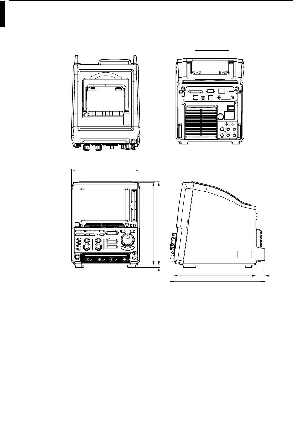
16-12 IM 701710-01E
16.12 External Dimensions
Dimensions: mm
Rear View
220
265.8
267.8
8
264.1 29
305.6
Unless othewise spcified, tolerance is ±3%.
(Tolerance is always ±0.3 mm when the dimension is under 10 mm.)
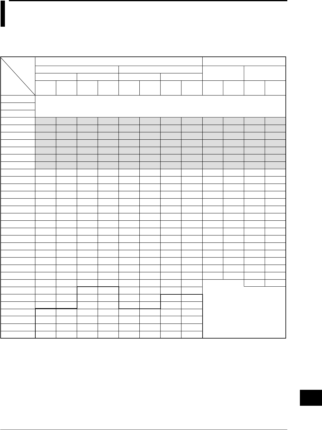
App-1
IM 701710-01E
Appendix
App
Appendix 1 Relationship between the Time Axis
Setting, Sample Rate and Record
Length
20
50
100
200
500
1 k
2 k
5 k
10 k
20 k
50 k
100 k
200 k
500 k
1 M
2 M
5 M
10 M
20 M
50 M
100 M
200 M
500 M
500 M
500 M
500 M
10 G
20 G
50 G
100 G
1 k
1 k
1 k
1 k
1 k
1 k
1 k
1 k
1 k
1 k
1 k
1 k
1 k
1 k
1 k
1 k
1 k
1 k
1 k
1 k
1 k
1 k
1 k
500
250
100
1 k
1 k
1 k
1 k
20
50
100
200
500
1 k
2 k
5 k
10 k
20 k
50 k
100 k
200 k
500 k
1 M
2 M
5 M
10 M
20 M
50 M
100 M
200 M
500 M
1 G
2 G
5 G
10 G
20 G
50 G
100 G
1 k
1 k
1 k
1 k
1 k
1 k
1 k
1 k
1 k
1 k
1 k
1 k
1 k
1 k
1 k
1 k
1 k
1 k
1 k
1 k
1 k
1 k
1 k
1 k
1 k
1 k
1 k
1 k
1 k
1 k
20
50
100
200
500
1 k
2 k
5 k
10 k
20 k
50 k
100 k
200 k
500 k
1 M
2 M
5 M
10 M
20 M
50 M
100 M
200 M
500 M
1 G
1 G
1 G
10 G
20 G
50 G
100 G
1 k
1 k
1 k
1 k
1 k
1 k
1 k
1 k
1 k
1 k
1 k
1 k
1 k
1 k
1 k
1 k
1 k
1 k
1 k
1 k
1 k
1 k
1 k
1 k
500
200
1 k
1 k
1 k
1 k
20
50
100
200
500
1 k
2 k
5 k
10 k
20 k
50 k
100 k
200 k
500 k
1 M
2 M
5 M
10 M
20 M
50 M
100 M
200 M
500 M
1 G
2 G
5 G
10 G
20 G
50 G
100 G
1 k
1 k
1 k
1 k
1 k
1 k
1 k
1 k
1 k
1 k
1 k
1 k
1 k
1 k
1 k
1 k
1 k
1 k
1 k
1 k
1 k
1 k
1 k
1 k
1 k
1 k
1 k
1 k
1 k
1 k
400 M
400 M
400 M
400 M
400 M
400 M
400 M
400 M
400 M
400 M
400 M
400 M
400 M
400 M
400 M
400 M
400 M
400 M
400 M
400 M
400 M
400 M
800 M
800 M
800 M
800 M
800 M
800 M
800 M
800 M
800 M
800 M
800 M
800 M
800 M
800 M
800 M
800 M
800 M
800 M
800 M
800 M
800 M
800 M
1 G
1 k
1 k
1 k
1 k
1 k
1 k
1 k
1 k
1 k
1 k
1 k
1 k
1 k
1 k
1 k
1 k
1 k
1 k
1 k
1 k
1 k
1 k
1 k
1 k
1 k
1 k
1 k
1 k
1 k
1 k
1 k
1 k
1 k
1 k
1 k
1 k
1 k
1 k
1 k
1 k
1 k
1 k
1 k
1 k
1 k
T/div
50 s
20 s
10 s
5 s
2 s
1 s
500 ms
200 ms
100 ms
50 ms
20 ms
10 ms
5 ms
2 ms
1 ms
500 µs
200 µs
100 µs
50 µs
20 µs
10 µs
5 µs
2 µs
1 µs
500 ns
200 ns
100 ns
50 ns
20 ns
10 ns
5 ns
2 ns
1 ns
Interleave mode OFF Interleave mode
OFF
Rep: [ON]
Rep: [OFF]Rep: [ON]
Rep: [OFF]
*1: For the setting enclosed by the bold line, repetitive sampling is active.
*2: Roll mode display is available in shaded sections.
Rep: Repetitive sampling mode
Interleave mode ON Interleave mode
ON
When Mode other than Envelope Mode is Active When Envelope Mode is Active
Record length: 1 kwords
Changes to normal mode, even
when envelope mode has been set.
*1
*2
It is not possible to set these T/div.
Sample
rate
(S/s)
Displayed
record len
gth
(word)
Displayed
record len
gth
(word)
Displayed
record len
gth
(word)
Sample
rate
(S/s)
Sample
rate
(S/s)
Displayed
record len
gth
(word)
Sample
rate
(S/s)
Displayed
record len
gth
(word)
Sample
rate
(S/s)
Sample
rate
(S/s)
Displayed
record len
gth
(word)
Setting
Appendix
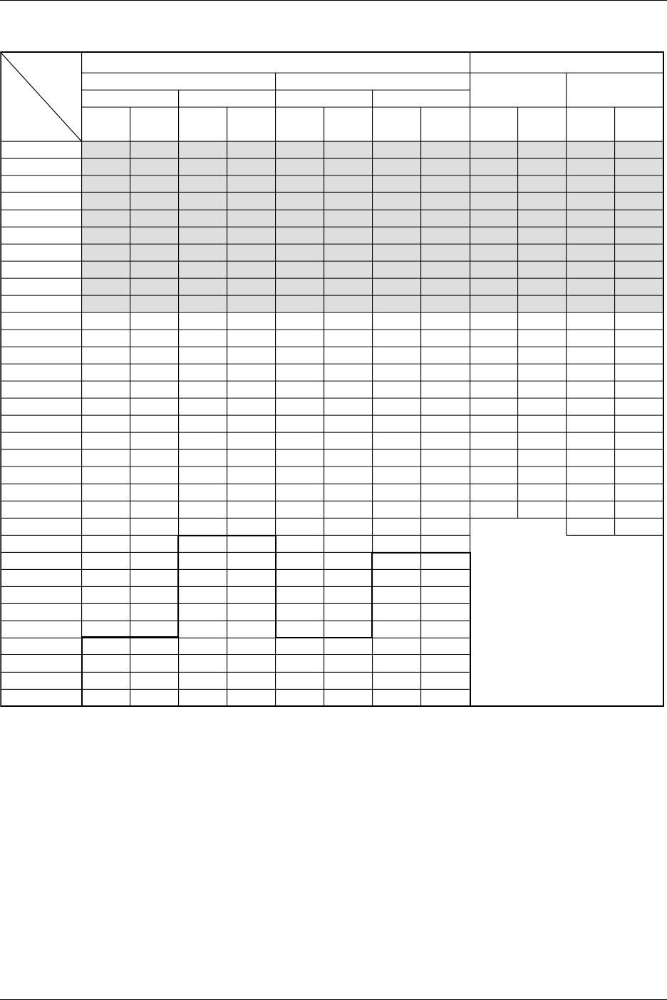
App-2 IM 701710-01E
20
50
100
200
500
1 k
2 k
5 k
10 k
20 k
50 k
100 k
200 k
500 k
1 M
2 M
5 M
10 M
20 M
50 M
100 M
200 M
500 M
500 M
500 M
500 M
500 M
500 M
500 M
100 G
100 G
100 G
100 G
10 k
10 k
10 k
10 k
10 k
10 k
10 k
10 k
10 k
10 k
10 k
10 k
10 k
10 k
10 k
10 k
10 k
10 k
10 k
10 k
10 k
10 k
10 k
5 k
2.5 k
1 k
500
250
100
10 k
5 k
2 k
1 k
20
50
100
200
500
1 k
2 k
5 k
10 k
20 k
50 k
100 k
200 k
500 k
1 M
2 M
5 M
10 M
20 M
50 M
100 M
200 M
500 M
1 G
2 G
5 G
10 G
20 G
50 G
100 G
100 G
100 G
100 G
10 k
10 k
10 k
10 k
10 k
10 k
10 k
10 k
10 k
10 k
10 k
10 k
10 k
10 k
10 k
10 k
10 k
10 k
10 k
10 k
10 k
10 k
10 k
10 k
10 k
10 k
10 k
10 k
10 k
10 k
5 k
2 k
1 k
20
50
100
200
500
1 k
2 k
5 k
10 k
20 k
50 k
100 k
200 k
500 k
1 M
2 M
5 M
10 M
20 M
50 M
100 M
200 M
500 M
1 G
1 G
1 G
1 G
1 G
1 G
100 G
100 G
100 G
100 G
10 k
10 k
10 k
10 k
10 k
10 k
10 k
10 k
10 k
10 k
10 k
10 k
10 k
10 k
10 k
10 k
10 k
10 k
10 k
10 k
10 k
10 k
10 k
10 k
5 k
2 k
1 k
500
200
10 k
5 k
2 k
1 k
20
50
100
200
500
1 k
2 k
5 k
10 k
20 k
50 k
100 k
200 k
500 k
1 M
2 M
5 M
10 M
20 M
50 M
100 M
200 M
500 M
1 G
2 G
5 G
10 G
20 G
50 G
100 G
100 G
100 G
100 G
10 k
10 k
10 k
10 k
10 k
10 k
10 k
10 k
10 k
10 k
10 k
10 k
10 k
10 k
10 k
10 k
10 k
10 k
10 k
10 k
10 k
10 k
10 k
10 k
10 k
10 k
10 k
10 k
10 k
10 k
5 k
2 k
1 k
400 M
400 M
400 M
400 M
400 M
400 M
400 M
400 M
400 M
400 M
400 M
400 M
400 M
400 M
400 M
400 M
400 M
400 M
400 M
400 M
400 M
400 M
800 M
800 M
800 M
800 M
800 M
800 M
800 M
800 M
800 M
800 M
800 M
800 M
800 M
800 M
800 M
800 M
800 M
800 M
800 M
800 M
800 M
800 M
1 G
10 k
10 k
10 k
10 k
10 k
10 k
10 k
10 k
10 k
10 k
10 k
10 k
10 k
10 k
10 k
10 k
10 k
10 k
10 k
10 k
10 k
10 k
10 k
10 k
10 k
10 k
10 k
10 k
10 k
10 k
10 k
10 k
10 k
10 k
10 k
10 k
10 k
10 k
10 k
10 k
10 k
10 k
10 k
10 k
10 k
Setting
Record length: 10 kwords
Changes to normal mode, even
when envelope mode has been set.
*1
*2
Interleave mode OFF Interleave mode
OFF
Rep: [ON]
Rep: [OFF]Rep: [ON]
Rep: [OFF]
Interleave mode ON Interleave mode
ON
When Mode other than Envelope Mode is Active When Envelope Mode is Active
Sample
rate
(S/s)
Displayed
record len
gth
(word)
Displayed
record len
gth
(word)
Displayed
record len
gth
(word)
Sample
rate
(S/s)
Sample
rate
(S/s)
Displayed
record len
gth
(word)
Sample
rate
(S/s)
Displayed
record len
gth
(word)
Sample
rate
(S/s)
Sample
rate
(S/s)
Displayed
record len
gth
(word)
T/div
50 s
20 s
10 s
5 s
2 s
1 s
500 ms
200 ms
100 ms
50 ms
20 ms
10 ms
5 ms
2 ms
1 ms
500 µs
200 µs
100 µs
50 µs
20 µs
10 µs
5 µs
2 µs
1 µs
500 ns
200 ns
100 ns
50 ns
20 ns
10 ns
5 ns
2 ns
1 ns
*1: For the setting enclosed by the bold line, repetitive sampling is active.
*2: Roll mode display is available in shaded sections.
Rep: Repetitive sampling mode
Appendix 1 Relationship between the Time Axis Setting, Sample Rate and Record Length
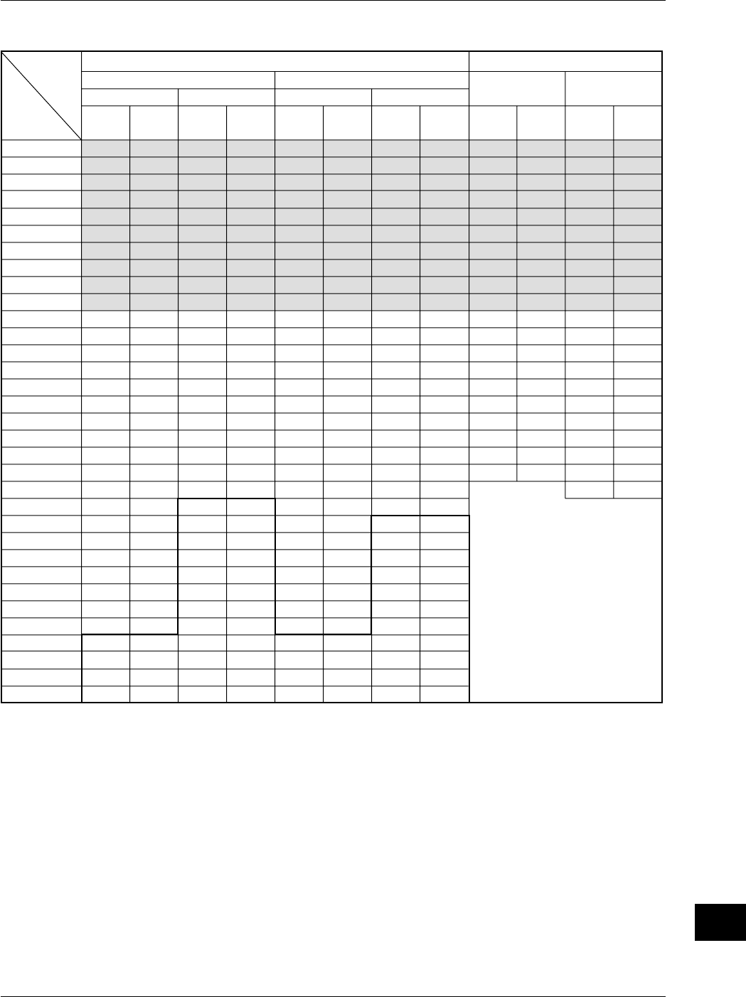
App-3
IM 701710-01E
Appendix
App
100
200
500
1 k
2 k
5 k
10 k
20 k
50 k
100 k
200 k
500 k
1 M
2 M
5 M
10 M
20 M
50 M
100 M
200 M
500 M
500 M
500 M
500 M
500 M
500 M
500 M
500 M
500 M
100 G
100 G
100 G
100 G
50 k
40 k
50 k
50 k
40 k
50 k
50 k
40 k
50 k
50 k
40 k
50 k
50 k
40 k
50 k
50 k
40 k
50 k
50 k
40 k
50 k
25 k
10 k
5 k
2.5 k
1 k
500
250
100
10 k
5 k
2 k
1 k
100
200
500
1 k
2 k
5 k
10 k
20 k
50 k
100 k
200 k
500 k
1 M
2 M
5 M
10 M
20 M
50 M
100 M
200 M
500 M
1 G
2 G
5 G
10 G
20 G
50 G
100 G
100 G
100 G
100 G
100 G
100 G
50 k
40 k
50 k
50 k
40 k
50 k
50 k
40 k
50 k
50 k
40 k
50 k
50 k
40 k
50 k
50 k
40 k
50 k
50 k
40 k
50 k
50 k
40 k
50 k
50 k
40 k
50 k
50 k
20 k
10 k
5 k
2 k
1 k
100
200
500
1 k
2 k
5 k
10 k
20 k
50 k
100 k
200 k
500 k
1 M
2 M
5 M
10 M
20 M
50 M
100 M
200 M
500 M
1 G
1 G
1 G
1 G
1 G
1 G
1 G
1 G
100 G
100 G
100 G
100 G
50 k
40 k
50 k
50 k
40 k
50 k
50 k
40 k
50 k
50 k
40 k
50 k
50 k
40 k
50 k
50 k
40 k
50 k
50 k
40 k
50 k
50 k
20 k
10 k
5 k
2 k
1 k
500
200
10 k
5 k
2 k
1 k
100
200
500
1 k
2 k
5 k
10 k
20 k
50 k
100 k
200 k
500 k
1 M
2 M
5 M
10 M
20 M
50 M
100 M
200 M
500 M
1 G
2 G
5 G
10 G
20 G
50 G
100 G
100 G
100 G
100 G
100 G
100 G
50 k
40 k
50 k
50 k
40 k
50 k
50 k
40 k
50 k
50 k
40 k
50 k
50 k
40 k
50 k
50 k
40 k
50 k
50 k
40 k
50 k
50 k
40 k
50 k
50 k
40 k
50 k
50 k
20 k
10 k
5 k
2 k
1 k
400 M
400 M
400 M
400 M
400 M
400 M
400 M
400 M
400 M
400 M
400 M
400 M
400 M
400 M
400 M
400 M
400 M
400 M
400 M
400 M
800 M
800 M
800 M
800 M
800 M
800 M
800 M
800 M
800 M
800 M
800 M
800 M
800 M
800 M
800 M
800 M
800 M
800 M
800 M
800 M
1 G
50 k
40 k
50 k
50 k
40 k
50 k
50 k
40 k
50 k
50 k
40 k
50 k
50 k
40 k
50 k
50 k
40 k
50 k
50 k
40 k
50 k
40 k
50 k
50 k
40 k
50 k
50 k
40 k
50 k
50 k
40 k
50 k
50 k
40 k
50 k
50 k
40 k
50 k
50 k
40 k
50 k
*1: For the setting enclosed by the bold line, repetitive sampling is active.
*2: Roll mode display is available in shaded sections.
Rep: Repetitive sampling mode
Setting
Record length: 50 kwords
Interleave mode OFF Interleave mode
OFF
Rep: [ON]
Rep: [OFF]Rep: [ON]
Rep: [OFF]
Interleave mode ON Interleave mode
ON
When Mode other than Envelope Mode is Active When Envelope Mode is Active
Sample
rate
(S/s)
Displayed
record len
gth
(word)
Displayed
record len
gth
(word)
Displayed
record len
gth
(word)
Sample
rate
(S/s)
Sample
rate
(S/s)
Displayed
record len
gth
(word)
Sample
rate
(S/s)
Displayed
record len
gth
(word)
Sample
rate
(S/s)
Sample
rate
(S/s)
Displayed
record len
gth
(word)
T/div
50 s
20 s
10 s
5 s
2 s
1 s
500 ms
200 ms
100 ms
50 ms
20 ms
10 ms
5 ms
2 ms
1 ms
500 µs
200 µs
100 µs
50 µs
20 µs
10 µs
5 µs
2 µs
1 µs
500 ns
200 ns
100 ns
50 ns
20 ns
10 ns
5 ns
2 ns
1 ns
Changes to normal mode, even
when envelope mode has been set.
*1
*2
Appendix 1 Relationship between the Time Axis Setting, Sample Rate and Record Length
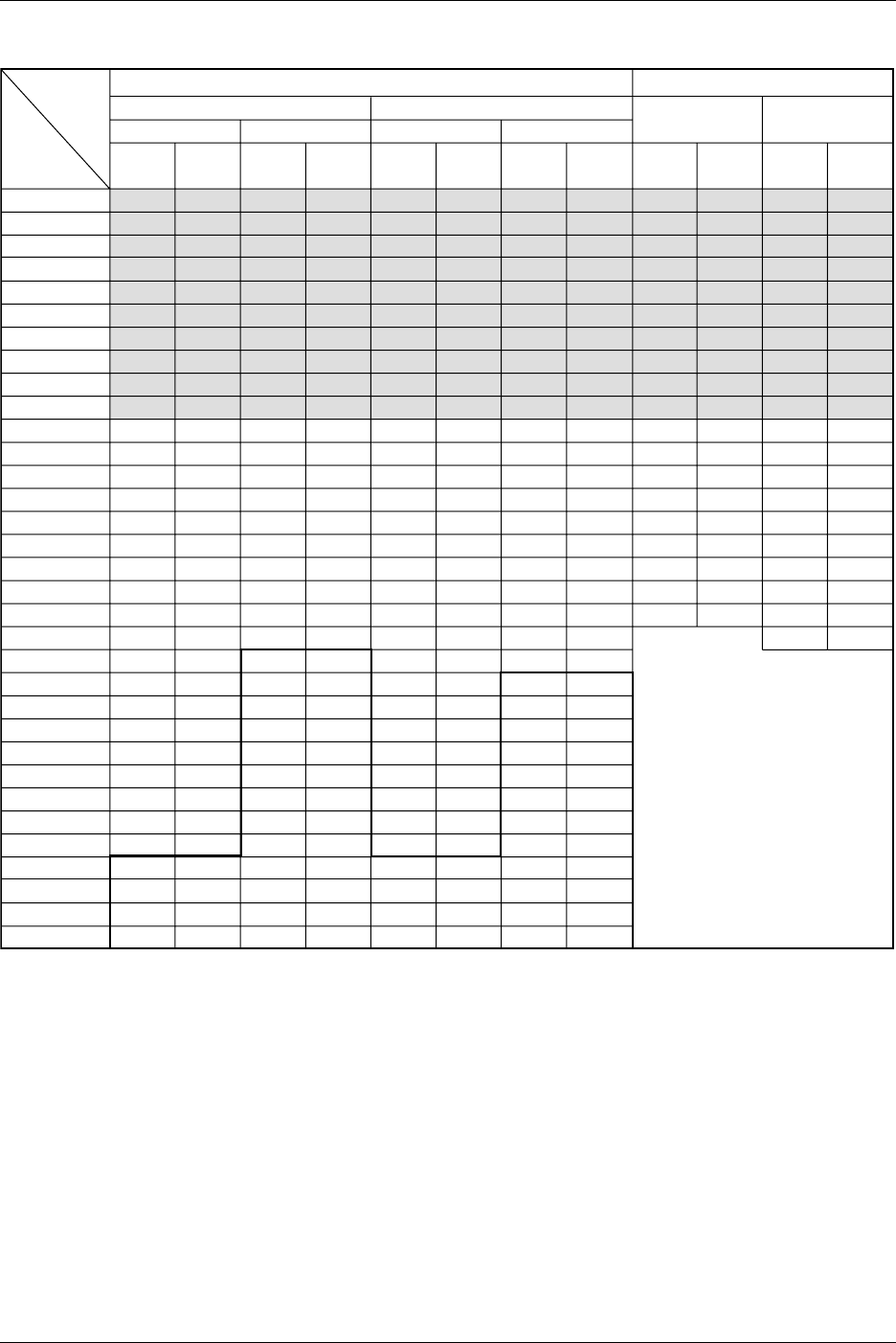
App-4 IM 701710-01E
200
500
1 k
2 k
5 k
10 k
20 k
50 k
100 k
200 k
500 k
1 M
2 M
5 M
10 M
20 M
50 M
100 M
200 M
500 M
500 M
500 M
500 M
500 M
500 M
500 M
500 M
500 M
500 M
100 G
100 G
100 G
100 G
100 k
100 k
100 k
100 k
100 k
100 k
100 k
100 k
100 k
100 k
100 k
100 k
100 k
100 k
100 k
100 k
100 k
100 k
100 k
100 k
50 k
25 k
10 k
5 k
2.5 k
1 k
500
250
100
10 k
5 k
2 k
1 k
200
500
1 k
2 k
5 k
10 k
20 k
50 k
100 k
200 k
500 k
1 M
2 M
5 M
10 M
20 M
50 M
100 M
200 M
500 M
1 G
2 G
5 G
10 G
20 G
50 G
100 G
100 G
100 G
100 G
100 G
100 G
100 G
100 k
100 k
100 k
100 k
100 k
100 k
100 k
100 k
100 k
100 k
100 k
100 k
100 k
100 k
100 k
100 k
100 k
100 k
100 k
100 k
100 k
100 k
100 k
100 k
100 k
100 k
100 k
50 k
20 k
10 k
5 k
2 k
1 k
200
500
1 k
2 k
5 k
10 k
20 k
50 k
100 k
200 k
500 k
1 M
2 M
5 M
10 M
20 M
50 M
100 M
200 M
500 M
1 G
1 G
1 G
1 G
1 G
1 G
1 G
1 G
1 G
100 G
100 G
100 G
100 G
100 k
100 k
100 k
100 k
100 k
100 k
100 k
100 k
100 k
100 k
100 k
100 k
100 k
100 k
100 k
100 k
100 k
100 k
100 k
100 k
100 k
50 k
20 k
10 k
5 k
2 k
1 k
500
200
10 k
5 k
2 k
1 k
200
500
1 k
2 k
5 k
10 k
20 k
50 k
100 k
200 k
500 k
1 M
2 M
5 M
10 M
20 M
50 M
100 M
200 M
500 M
1 G
2 G
5 G
10 G
20 G
50 G
100 G
100 G
100 G
100 G
100 G
100 G
100 G
100 k
100 k
100 k
100 k
100 k
100 k
100 k
100 k
100 k
100 k
100 k
100 k
100 k
100 k
100 k
100 k
100 k
100 k
100 k
100 k
100 k
100 k
100 k
100 k
100 k
100 k
100 k
50 k
20 k
10 k
5 k
2 k
1 k
400 M
400 M
400 M
400 M
400 M
400 M
400 M
400 M
400 M
400 M
400 M
400 M
400 M
400 M
400 M
400 M
400 M
400 M
400 M
800 M
800 M
800 M
800 M
800 M
800 M
800 M
800 M
800 M
800 M
800 M
800 M
800 M
800 M
800 M
800 M
800 M
800 M
800 M
1 G
100 k
100 k
100 k
100 k
100 k
100 k
100 k
100 k
100 k
100 k
100 k
100 k
100 k
100 k
100 k
100 k
100 k
100 k
100 k
100 k
100 k
100 k
100 k
100 k
100 k
100 k
100 k
100 k
100 k
100 k
100 k
100 k
100 k
100 k
100 k
100 k
100 k
100 k
100 k
*1: For the setting enclosed by the bold line, repetitive sampling is active.
*2: Roll mode display is available in shaded sections.
Rep: Repetitive sampling mode
Setting
Record length: 100 kwords
Changes to normal mode, even
when envelope mode has been set.
*1
*2
Interleave mode OFF Interleave mode
OFF
Rep: [ON]
Rep: [OFF]Rep: [ON]
Rep: [OFF]
Interleave mode ON Interleave mode
ON
When Mode other than Envelope Mode is Active When Envelope Mode is Active
Sample
rate
(S/s)
Displayed
record len
gth
(word)
Displayed
record len
gth
(word)
Displayed
record len
gth
(word)
Sample
rate
(S/s)
Sample
rate
(S/s)
Displayed
record len
gth (word)
Sample
rate
(S/s)
Displayed
record len
gth (word)
Sample
rate
(S/s)
Sample
rate
(S/s)
Displayed
record len
gth (word)
T/div
50 s
20 s
10 s
5 s
2 s
1 s
500 ms
200 ms
100 ms
50 ms
20 ms
10 ms
5 ms
2 ms
1 ms
500 µs
200 µs
100 µs
50 µs
20 µs
10 µs
5 µs
2 µs
1 µs
500 ns
200 ns
100 ns
50 ns
20 ns
10 ns
5 ns
2 ns
1 ns
Appendix 1 Relationship between the Time Axis Setting, Sample Rate and Record Length
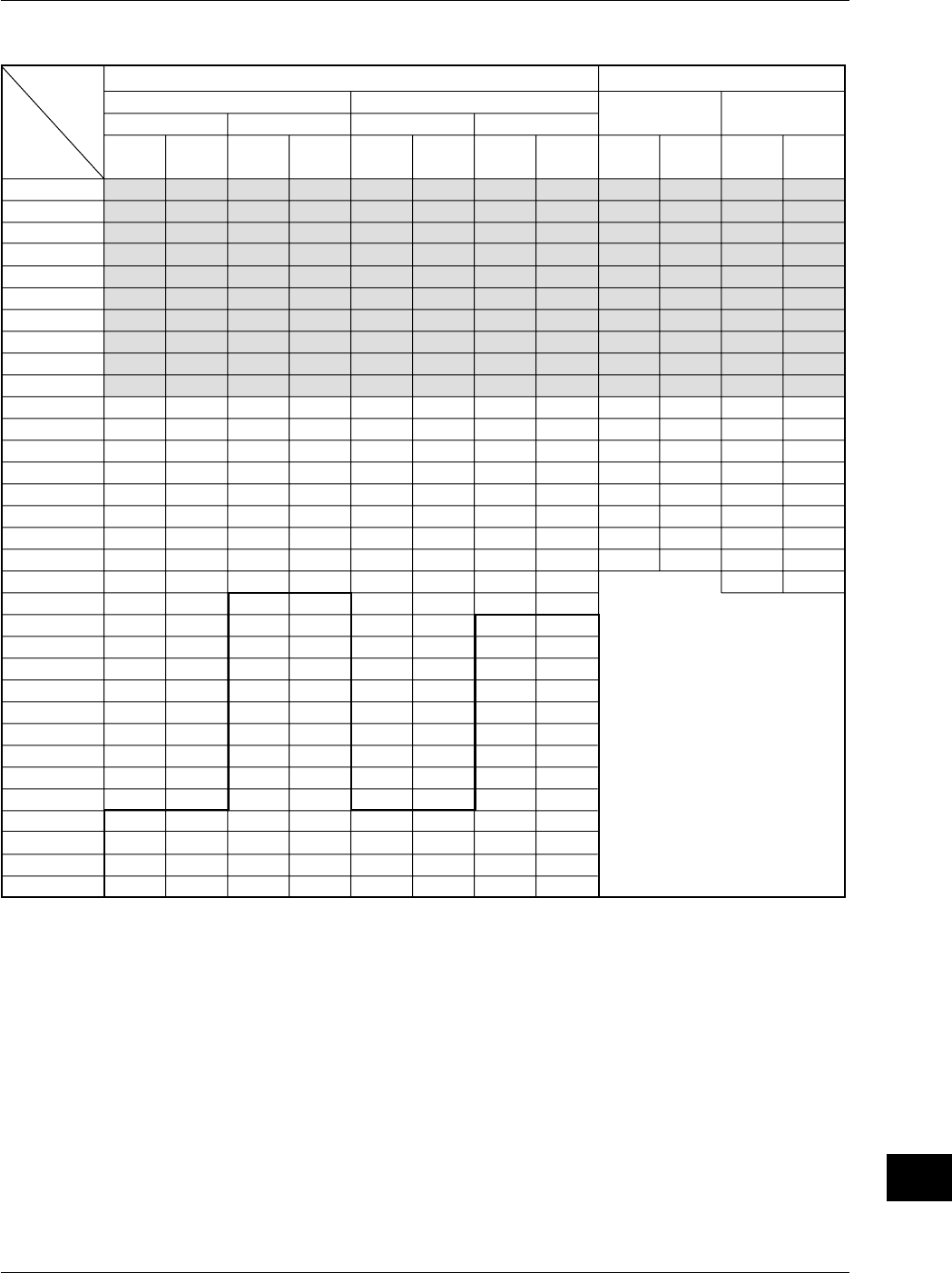
App-5
IM 701710-01E
Appendix
App
500
1 k
2 k
5 k
10 k
20 k
50 k
100 k
200 k
500 k
1 M
2 M
5 M
10 M
20 M
50 M
100 M
200 M
500 M
500 M
500 M
500 M
500 M
500 M
500 M
500 M
500 M
500 M
500 M
100 G
100 G
100 G
100 G
250 k
200 k
200 k
250 k
200 k
200 k
250 k
200 k
200 k
250 k
200 k
200 k
250 k
200 k
200 k
250 k
200 k
200 k
250 k
100 k
50 k
25 k
10 k
5 k
2.5 k
1 k
500
250
100
10 k
5 k
2 k
1 k
500
1 k
2 k
5 k
10 k
20 k
50 k
100 k
200 k
500 k
1 M
2 M
5 M
10 M
20 M
50 M
100 M
200 M
500 M
1 G
2 G
5 G
10 G
20 G
50 G
100 G
100 G
100 G
100 G
100 G
100 G
100 G
100 G
250 k
200 k
200 k
250 k
200 k
200 k
250 k
200 k
200 k
250 k
200 k
200 k
250 k
200 k
200 k
250 k
200 k
200 k
250 k
200 k
200 k
250 k
200 k
200 k
250 k
200 k
100 k
50 k
20 k
10 k
5 k
2 k
1 k
500
1 k
2 k
5 k
10 k
20 k
50 k
100 k
200 k
500 k
1 M
2 M
5 M
10 M
20 M
50 M
100 M
200 M
500 M
1 G
1 G
1 G
1 G
1 G
1 G
1 G
1 G
1 G
1 G
100 G
100 G
100 G
100 G
250 k
200 k
200 k
250 k
200 k
200 k
250 k
200 k
200 k
250 k
200 k
200 k
250 k
200 k
200 k
250 k
200 k
200 k
250 k
200 k
100 k
50 k
20 k
10 k
5 k
2 k
1 k
500
200
10 k
5 k
2 k
1 k
500
1 k
2 k
5 k
10 k
20 k
50 k
100 k
200 k
500 k
1 M
2 M
5 M
10 M
20 M
50 M
100 M
200 M
500 M
1 G
2 G
5 G
10 G
20 G
50 G
100 G
100 G
100 G
100 G
100 G
100 G
100 G
100 G
250 k
200 k
200 k
250 k
200 k
200 k
250 k
200 k
200 k
250 k
200 k
200 k
250 k
200 k
200 k
250 k
200 k
200 k
250 k
200 k
200 k
250 k
200 k
200 k
250 k
200 k
100 k
50 k
20 k
10 k
5 k
2 k
1 k
400 M
400 M
400 M
400 M
400 M
400 M
400 M
400 M
400 M
400 M
400 M
400 M
400 M
400 M
400 M
400 M
400 M
400 M
800 M
800 M
800 M
800 M
800 M
800 M
800 M
800 M
800 M
800 M
800 M
800 M
800 M
800 M
800 M
800 M
800 M
800 M
1 G
250 k
200 k
200 k
250 k
200 k
200 k
250 k
200 k
200 k
250 k
200 k
200 k
250 k
200 k
200 k
250 k
200 k
200 k
250 k
200 k
200 k
250 k
200 k
200 k
250 k
200 k
200 k
250 k
200 k
200 k
250 k
200 k
200 k
250 k
200 k
200 k
250 k
*1: For the setting enclosed by the bold line, repetitive sampling is active.
*2: Roll mode display is available in shaded sections.
Rep: Repetitive sampling mode
Setting
Record length: 250 kwords
Changes to normal mode, even
when envelope mode has been set.
*1
*2
T/div
50 s
20 s
10 s
5 s
2 s
1 s
500 ms
200 ms
100 ms
50 ms
20 ms
10 ms
5 ms
2 ms
1 ms
500 µs
200 µs
100 µs
50 µs
20 µs
10 µs
5 µs
2 µs
1 µs
500 ns
200 ns
100 ns
50 ns
20 ns
10 ns
5 ns
2 ns
1 ns
Interleave mode OFF Interleave mode
OFF
Rep: [ON]
Rep: [OFF]Rep: [ON]
Rep: [OFF]
Interleave mode ON Interleave mode
ON
When Mode other than Envelope Mode is Active When Envelope Mode is Active
Sample
rate
(S/s)
Displayed
record len
gth
(word)
Displayed
record len
gth
(word)
Displayed
record len
gth
(word)
Sample
rate
(S/s)
Sample
rate
(S/s)
Displayed
record len
gth (word)
Sample
rate
(S/s)
Displayed
record len
gth (word)
Sample
rate
(S/s)
Sample
rate
(S/s)
Displayed
record len
gth (word)
Appendix 1 Relationship between the Time Axis Setting, Sample Rate and Record Length
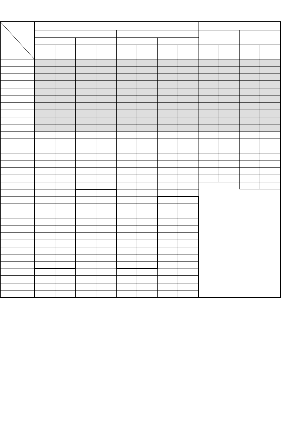
App-6 IM 701710-01E
1 k
2 k
5 k
10 k
20 k
50 k
100 k
200 k
500 k
1 M
2 M
5 M
10 M
20 M
50 M
100 M
200 M
500 M
500 M
500 M
500 M
500 M
500 M
500 M
500 M
500 M
500 M
500 M
500 M
100 G
100 G
100 G
100 G
500 k
400 k
500 k
500 k
400 k
500 k
500 k
400 k
500 k
500 k
400 k
500 k
500 k
400 k
500 k
500 k
400 k
500 k
250 k
100 k
50 k
25 k
10 k
5 k
2.5 k
1 k
500
250
100
10 k
5 k
2 k
1 k
1 k
2 k
5 k
10 k
20 k
50 k
100 k
200 k
500 k
1 M
2 M
5 M
10 M
20 M
50 M
100 M
200 M
500 M
1 G
2 G
5 G
10 G
20 G
50 G
100 G
100 G
100 G
100 G
100 G
100 G
100 G
100 G
100 G
500 k
400 k
500 k
500 k
400 k
500 k
500 k
400 k
500 k
500 k
400 k
500 k
500 k
400 k
500 k
500 k
400 k
500 k
500 k
400 k
500 k
500 k
400 k
500 k
500 k
200 k
100 k
50 k
20 k
10 k
5 k
2 k
1 k
1 k
2 k
5 k
10 k
20 k
50 k
100 k
200 k
500 k
1 M
2 M
5 M
10 M
20 M
50 M
100 M
200 M
500 M
1 G
1 G
1 G
1 G
1 G
1 G
1 G
1 G
1 G
1 G
1 G
100 G
100 G
100 G
100 G
500 k
400 k
500 k
500 k
400 k
500 k
500 k
400 k
500 k
500 k
400 k
500 k
500 k
400 k
500 k
500 k
400 k
500 k
500 k
200 k
100 k
50 k
20 k
10 k
5 k
2 k
1 k
500
200
10 k
5 k
2 k
1 k
1 k
2 k
5 k
10 k
20 k
50 k
100 k
200 k
500 k
1 M
2 M
5 M
10 M
20 M
50 M
100 M
200 M
500 M
1 G
2 G
5 G
10 G
20 G
50 G
100 G
100 G
100 G
100 G
100 G
100 G
100 G
100 G
100 G
500 k
400 k
500 k
500 k
400 k
500 k
500 k
400 k
500 k
500 k
400 k
500 k
500 k
400 k
500 k
500 k
400 k
500 k
500 k
400 k
500 k
500 k
400 k
500 k
500 k
200 k
100 k
50 k
20 k
10 k
5 k
2 k
1 k
400 M
400 M
400 M
400 M
400 M
400 M
400 M
400 M
400 M
400 M
400 M
400 M
400 M
400 M
400 M
400 M
400 M
800 M
800 M
800 M
800 M
800 M
800 M
800 M
800 M
800 M
800 M
800 M
800 M
800 M
800 M
800 M
800 M
800 M
1 G
500 k
400 k
500 k
500 k
400 k
500 k
500 k
400 k
500 k
500 k
400 k
500 k
500 k
400 k
500 k
500 k
400 k
500 k
400 k
500 k
500 k
400 k
500 k
500 k
400 k
500 k
500 k
400 k
500 k
500 k
400 k
500 k
500 k
400 k
500 k
*1: For the setting enclosed by the bold line, repetitive sampling is active.
*2: Roll mode display is available in shaded sections.
Rep: Repetitive sampling mode
Setting
Record length: 500 kwords
Changes to normal mode, even
when envelope mode has been set.
*1
*2
Interleave mode OFF Interleave mode
OFF
Rep: [ON]
Rep: [OFF]Rep: [ON]
Rep: [OFF]
Interleave mode ON Interleave mode
ON
When Mode other than Envelope Mode is Active When Envelope Mode is Active
Sample
rate
(S/s)
Displayed
record len
gth
(word)
Displayed
record len
gth
(word)
Displayed
record len
gth
(word)
Sample
rate
(S/s)
Sample
rate
(S/s)
Displayed
record len
gth
(word)
Sample
rate
(S/s)
Displayed
record len
gth
(word)
Sample
rate
(S/s)
Sample
rate
(S/s)
Displayed
record len
gth
(word)
T/div
50 s
20 s
10 s
5 s
2 s
1 s
500 ms
200 ms
100 ms
50 ms
20 ms
10 ms
5 ms
2 ms
1 ms
500 µs
200 µs
100 µs
50 µs
20 µs
10 µs
5 µs
2 µs
1 µs
500 ns
200 ns
100 ns
50 ns
20 ns
10 ns
5 ns
2 ns
1 ns
Appendix 1 Relationship between the Time Axis Setting, Sample Rate and Record Length
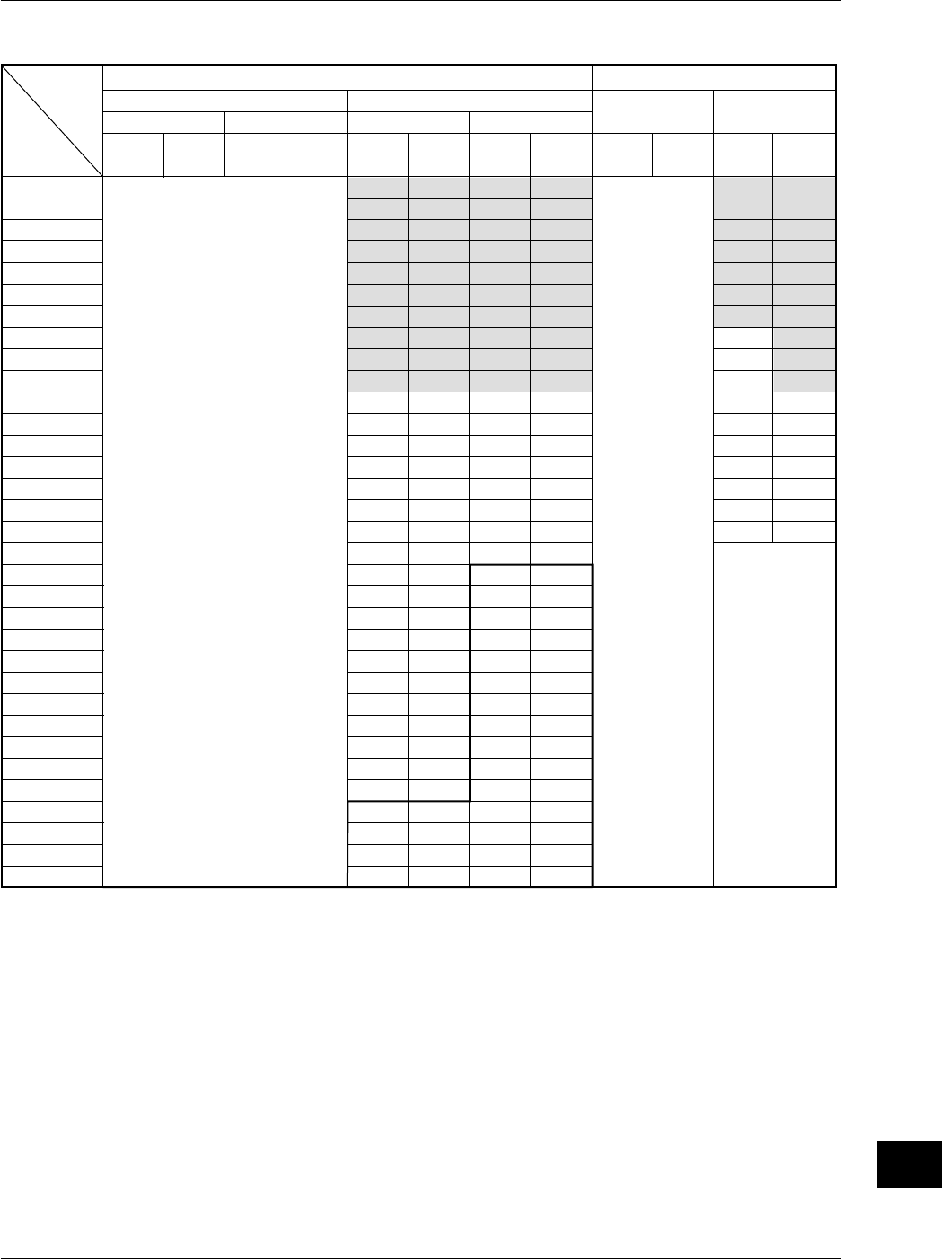
App-7
IM 701710-01E
Appendix
App
Sample
rate
(S/s)
Displayed
record len
gth (word)
Sample
rate
(S/s)
Displayed
record len
gth (word)
Sample
rate
(S/s)
2 k
5 k
10 k
20 k
50 k
100 k
200 k
500 k
1 M
2 M
5 M
10 M
20 M
50 M
100 M
200 M
500 M
1 G
1 G
1 G
1 G
1 G
1 G
1 G
1 G
1 G
1 G
1 G
1 G
100 G
100 G
100 G
100 G
Displayed
record len
gth (word)
1 M
1 M
1 M
1 M
1 M
1 M
1 M
1 M
1 M
1 M
1 M
1 M
1 M
1 M
1 M
1 M
1 M
1 M
500 k
200 k
100 k
50 k
20 k
10 k
5 k
2 k
1 k
500
200
10 k
5 k
2 k
1 k
Sample
rate
(S/s)
2 k
5 k
10 k
20 k
50 k
100 k
200 k
500 k
1 M
2 M
5 M
10 M
20 M
50 M
100 M
200 M
500 M
1 G
2 G
5 G
10 G
20 G
50 G
100 G
100 G
100 G
100 G
100 G
100 G
100 G
100 G
100 G
100 G
Displayed
record len
gth (word)
1 M
1 M
1 M
1 M
1 M
1 M
1 M
1 M
1 M
1 M
1 M
1 M
1 M
1 M
1 M
1 M
1 M
1 M
1 M
1 M
1 M
1 M
1 M
1 M
500 k
200 k
100 k
50 k
20 k
10 k
5 k
2 k
1 k
Sample
rate
(S/s)
Sample
rate
(S/s)
800 M
800 M
800 M
800 M
800 M
800 M
800 M
800 M
800 M
800 M
800 M
800 M
800 M
800 M
800 M
800 M
1 G
Displayed
record len
gth (word)
Displayed
record len
gth (word)
1 M
1 M
1 M
1 M
1 M
1 M
1 M
1 M
1 M
1 M
1 M
1 M
1 M
1 M
1 M
1 M
1 M
T/div
50 s
20 s
10 s
5 s
2 s
1 s
500 ms
200 ms
100 ms
50 ms
20 ms
10 ms
5 ms
2 ms
1 ms
500 µs
200 µs
100 µs
50 µs
20 µs
10 µs
5 µs
2 µs
1 µs
500 ns
200 ns
100 ns
50 ns
20 ns
10 ns
5 ns
2 ns
1 ns
Interleave mode OFF Interleave mode
OFF
Rep: [ON]
Rep: [OFF]Rep: [ON]
Rep: [OFF]
Rep: Repetitive sampling mode
Interleave mode ON Interleave mode
ON
When Moed other than Envelope Mode is Active When Envelope mode is Active
Setting
Record length: 1 Mwords
Changes to normal
mode, even when
envelope mode has
been set.
This record length
cannnot be used
when interleave is
OFF.
This record length cannnot be used
when interleave is OFF.
*1
*2
*1: For the setting enclosed by the bold line, repetitive sampling is active.
*2: Roll mode display is available in shaded sections.
Appendix 1 Relationship between the Time Axis Setting, Sample Rate and Record Length
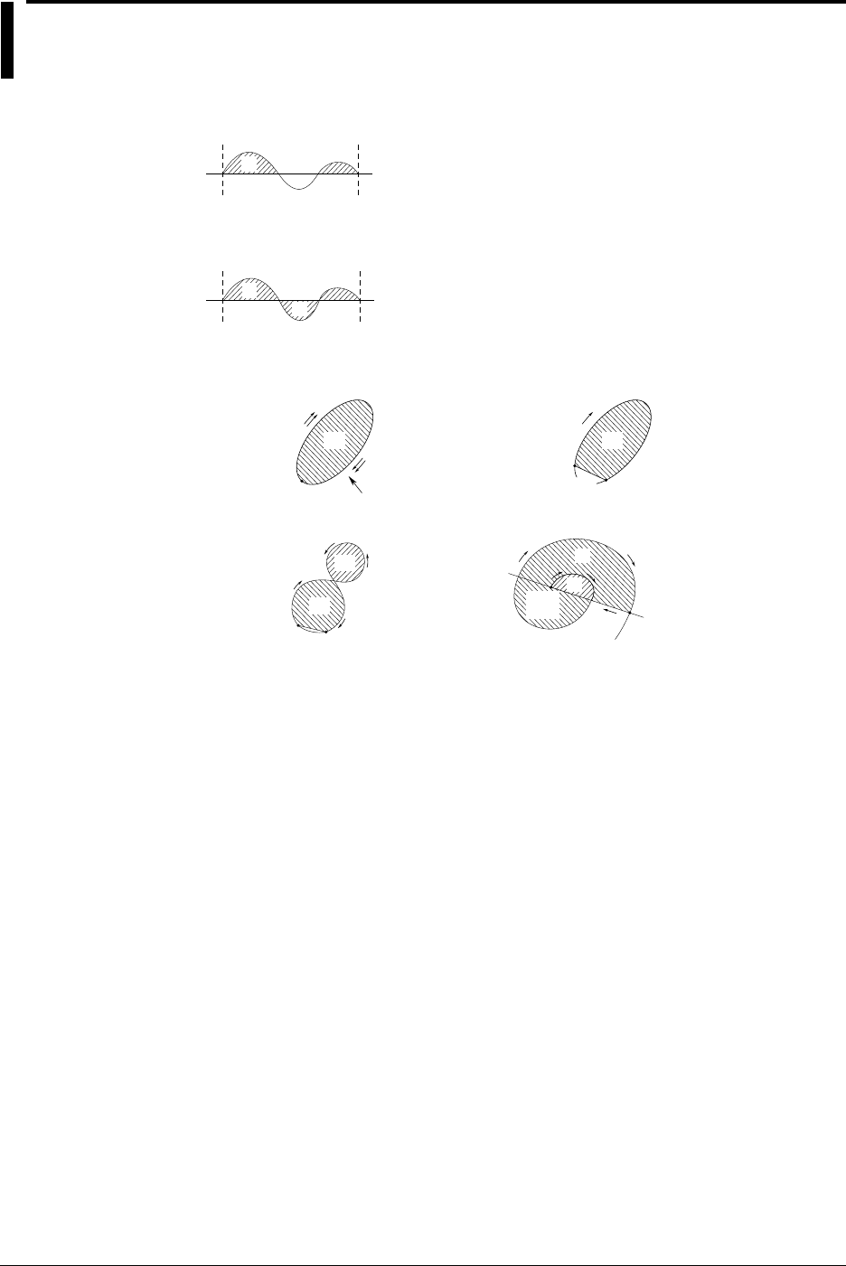
App-8 IM 701710-01E
Appendix 2 How to Calculate the Area of a
Waveform
Integ1TY
Total Area for Positive Side Only: S
1
+S
2
S
1
S
2
Integ2TY
Total Area for both Positive and Negative Sides: S1+S3–S2
S1
S3
S2
Integ1XY
(1) Multiplc Loops
S
0
Start Point,
Stop Point
Area S= n×S
0
n: Number of Loops
(2) Non-Closed Curve
S
0
Start Point
Area S= S
0
Area Enclosed by
a Curve Connecting
the Start and Stop
Points
Stop Point
(3) Loop Tracing a Figure-Eight
Area S= | S
0
– S
1
|
(4) Spiral Loop
Area S= S
0
×2+S
1
Number of Overlaps
Varies According to
the Number of Loops.
Stop Point
S
0
S
1
Start Point Stop Point
Start
Point
S
0
Waveform
S
1
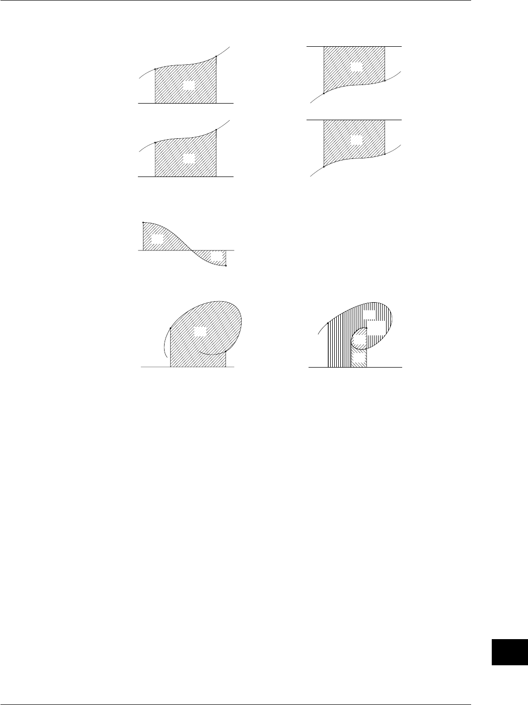
App-9
IM 701710-01E
Appendix
App
Integ2XY
(1) When Only One Y Data Corresponds to X Data
13
Start Point
Stop Point
S
0
Area S=S
0
X Axis (Y=0)
X Axis (Y=0)
Area S= –S
0
Stop Point
Start Point
S
0
24
Stop Point Start Point
S
0
Area S=S
0
–S
1
X axis (Y=0)
X Axis (Y=0)
Area S=S
0
Start Point
Stop Point
S
0
(2) When the Waveform Extends into the Negative Side
X Axis (Y=0)
S
0
S
1
Start Point
Stop Point
(2) When Two or more Y Data Correspond to X Data
X Axis (Y=0)
S
0
Start Point
Stop Point
Area S=S
0
X Axis (Y=0)
S
0
Stop
Point
Start Point
Area S=S
0
+2×S
1
+S
2
S
1
S
2
Area S= –S
0
Appendix 2 How to Calculate the Area of a Waveform

App-10 IM 701710-01E
Appendix 3 ASCII Header File Format
//YOKOGAWA ASCII FILE FORMAT
$PublicInfo
FormatVersion 1.11
Model DL1740
Endian Big
DataFormat TRACE
GroupNumber 3
TraceTotalNumber 10
DataOffset 0
$Group1
TraceNumber 4
BlockNumber 1
TraceName CH1 CH2 CH3 CH4
BlockSize 1002 1002 1002 1002
VResolution 1.5625000E+00 1.5625000E+00 1.5625000E+00 1.5625000E+00
VOffset 0.0000000E+00 0.0000000E+00 0.0000000E+00 0.0000000E+00
VDataType IS2 IS2 IS2 IS2
VUnit V V A V
VPlusOverData 32768 32768 32768 32768
VMinusOverData -32769 -32769 -32769 -32769
VIllegalData -32769 -32769 -32769 -32769
VMaxData 32767 32767 32767 32767
VMinData -32768 -32768 -32768 -32768
HResolution 5.0000000E-09 5.0000000E-09 5.0000000E-09 5.0000000E-09
HOffset -2.5000000E-06 -2.5000000E-06 -2.5000000E-06 -2.5000000E-06
HUnit s s s s
Date 2001/07/25 2001/07/25 2001/07/25 2001/07/25
Time 01:45:00 01:45:00 01:45:00 01:45:00

App-11
IM 701710-01E
Appendix
App
Appendix 3 ASCII Header File Format
$Group2
TraceNumber 2
BlockNumber 1
TraceName MATH1 MATH2
BlockSize 1002 1002
VResolution 6.1035156E-03 1.2207031E+00
VOffset -7.7000000E+01 2.0000000E+04
VDataType IS2 IS2
VUnit DB V
VPlusOverData 32768 32768
VMinusOverData -32769 -32769
VIllegalData -32769 -32769
VMaxData 32767 32767
VMinData -32768 -32768
HResolution 2.0000000E-01 5.0000000E-09
HOffset 0.0000000E+00 -2.5000000E-06
HUnit Hz s
Date 2001/07/25 2001/07/25
Time 01:45:00 01:45:00
$PrivateInfo
ModelVersion 1.02
DisplayBlockSize 10020 10020 10020 10020
DisplayPointNo. 1 1 1 1
PhaseShift 0 0 0 0
Note
•The same header file format is used by all YOKOGAWA measuring instruments, so it may
contain some data which is not necessary for the instrument.
•The DL1720 is not equipped with channels 3, 4, or Math2.

App-12 IM 701710-01E
•$Publicinfo (Common Information)
FormatVersion: Version No. of header file format
Model: Model name
Endian: Endian mode (Big/Ltl)*1
DataFormat: Storage format (Trace / Block) of binary file waveform data*2
GroupNumber: Number of the $Group
TraceTotalNumber: Total number of selected waveforms
DataOffset: Start position of binary file waveform data*3
•$Group1 (Group Information)
TraceNumber: Number of waveforms in the group
BlockNumber: Number of blocks in the group*4
TraceName: Name of each waveform
BlockSize: Data size of each block of waveform
VResolution: Resolution coefficient of Y axis conversion equation for each
waveform*5
VOffset: Offset coefficient of Y axis conversion equation for each
waveform
VDataType: Type of binary file waveform data for each waveform*6
VUnit: Units used for Y axis of each waveform (no effect on data)
VPlusOverData: Data error occurs when binary data for a waveform exceeds this
value.
VMinusOverData: Data error occurs when binary data for a waveform is below this
value.
VMaxData: Maximum value of binary data for each waveform
VMinData: Minimum value of binary data for each waveform
HResolution: Resolution coefficient of X axis conversion equation for each
waveform*7
HOffset: Offset coefficient of X axis conversion equation for each
waveform
HUnit: Units used for X axis for each waveform (no effect on data)
Date: Date when waveform acquisition was completed
Time: Time when waveform acquisition was completed
For *1 to *7, refer to the next page.
•$PrivateInfo (Information Indigenous to Model)
ModelVersion: Version No. of the model
MathBlockNo.: Block No. of block to be computed
FormMath1: Waveform for Math1 and its contents
FormMath2: Waveform for Math2 and its contents
DisplayBlockSize: Length of the data displayed on the screen (display record
length)
DisplayPointNo: Value which indicates which point of the memory is the left end
of the display record length (display offset is 1 when record
length = display record length)
PhaseShift: Phase information (lead: –, delay: +)
* Calculation of the actual display offset of the phase-shifted waveform = DisplayPointNo. –
PhaseShift
Appendix 3 ASCII Header File Format

App-13
IM 701710-01E
Appendix
App
Appendix 3 ASCII Header File Format
Creation of an ASCII Header File
When waveform data (Waveform) is stored on a floppy disk or a Zip disk, the following
files will be created automatically in the DL_WAVE directory.
•Waveform data file (*.WVF)
•ASCII header file (*.HDR)
The waveform data file can be recalled to the instrument using the file menu, but the
ASCII header file cannot; therefore it cannot be viewed on the instrument. However, it
can be used when you analyze the waveform using a personal computer.
*1: Endian Mode for Storage
Big: Data for Motorola 68000 series
Ltl: Data for Intel 86 series
*2: Binary File Storage Format
Trace: Groups into blocks, each block for a single waveform.
Block: Groups into blocks, each block for a given time interval.
*3: Binary File Start Position
Offset from the beginning of the file
*4: Maximum Number of Blocks per Group
Maximum number of blocks applies if the number of blocks varies between
waveforms.
*5: Y Axis Conversion Equation for Each Waveform
Y axis value = VResolution x Raw data + VOffset
*6: Data Type
ISn: n-byte signed integer
IUn: n-byte unsigned integer
FSn: n-byte signed real number
FUn: n-byte unsigned real number
Bm: m-byte data
*7: X Axis Conversion Equation for Each Waveform
X axis value = HResolution x (Data No. –1) + HOffset

App-14 IM 701710-01E
Appendix 4 List of Defaults
Menu Key Soft Key Default Setting
CH1 to 4 (or CH1 to 2 for the DL1720)
Display ON
Position 0 div
Cupling DC 1 MΩ
Probe 10:1
Offset 0V
Band Width Full
Variable 50 V
Linear Scale OFF
Label CH1 ....CH4
V/div
50 V
T/div
1 ms/div
PRESET
Select All
Type TTL
Prove 10 : 1
ACQ
Record Length 10 k
Mode Normal
Count Infinite
Repetitive OFF
Interleave OFF
Time Base Int
TRIGGER SIMPLE
Source CH1
Level 0V
Slope Rise
Coupling DC
HF Rejection OFF
Histeresis
Hold Off 0.08 µs
HISTORY
Select Record 0
Display Mode One
Start Record 0
End Record latest
Show Map No. 1
Search Mode OFF
FILE
File Item Set up
File Name
Auto Naming ON
COPY(MENU)
Copy to Built-in
Format Normal
Information OFF
IMAGE SAVE (MENU)
Format TIFF
Color OFF
File Name
Auto Naming ON
Menu Key Soft Key Default Setting
MEASURE
Mode OFF
Item Setup
Source CH1
Item OFF
Dual Area OFF
Delay Setup
Source CH1
Mode OFF
1 cycle mode OFF
Time Range 1 –5 div
Time Range 2 5 div
Trace CH1
Distal 90%
Mesial 50%
Proximal 10%
High/Low Mode AUTO
CURSOR
Type OFF
MATH The DL1720 is not equipped with M2
(Math2).
M1 Display OFF
M1 Setup C1+C2
M1 Label Math1
M2 Display OFF
M2 Setup C3+C4
M2 Label Math2
DISPLAY
Format Quad (or Dual for the
DL1720)
Interpolation Sin
Graticule Grid
Mapping Auto
Translucent OFF
Scale Value OFF
Trace Label OFF
Accumulate OFF
ZOOM
Mode Main
POSITON
Position 50%
DELAY
Delay 0 S
GO/NO-GO
Mode OFF
SEARCH
Type Edge
Z1 Mag ×2
Z position 0 div
ACTION
Buzzer OFF
Save to File OFF
Hard Copy OFF
Image Save OFF
ACQ Count Infinite
Send Mail OFF
Mail Count 100
App-15
IM 701710-01E
Appendix
App
Appendix 5 Assignment of Keys on the USB
Keyboard
104 Keyboard (US)
Key
When Pressed with the Control Key When the Soft Keyboard Is Displayed Other
+Shift Operation +Shift Operation +Shift Operation
a ACQ menu Same as left
MATH menu Same as left
COPY Same as left
DISPLAY menu Same as left
ENHANCED menu Same as left
FILE menu Same as left
GO/NOGO menu Same as left
HISTORY menu Same as left
IMAGE SAVE
menu Same as left
PRESET menu Same as left
MEASURE menu Same as left
POSITION menu Same as left
CLEAR TRACE Same as left
RESET Same as left
SHIFT condition Same as left
TRIGMODE menu Same as left
CURSOR menu Same as left
SIMPLE menu Same as left
ZOOM menu Same as left
CH1 menu
CH2 menu
CH3 menu
CH4 menu
Return (Enter), Select Return (Enter)Same as left Same as left
b
c
d
e
f
g
h
i
j
k
l
m
n
o
p
q
r
s
t
u
v
w
x
y
z
1
2
3
4
5
6
7
8
9
0
Enter
a
b
c
d
e
f
g
h
i
j
k
l
m
n
o
p
q
r
s
t
u
v
w
x
y
z
1
2
3
4
5
6
7
8
9
0
Escape
MISC menu HELP
EscapeSame as left
SETUP Same as left
Same as leftEsc
Tab
-
=
Space Bar
Same as left
Same as left
_
+
{
Back Space
Back Space
[
]
Space Bar
/
;
'
,
=
[
]
/
;
'
,
:
}
<
.>
/
-
.
/?
Caps Lock
Same as leftCaps Lock
A
B
C
D
E
F
G
H
I
J
K
L
M
N
O
P
Q
R
S
T
U
V
W
X
Y
Z
!
@
^
#
$
%
&
*
(
)
"
App-16 IM 701710-01E
Appendix 5 Assignment of Keys on the USB Keyboard
Escape
Select Soft key1 Same as left
Select Soft key2 Same as left
Select Soft key3 Same as left
Select Soft key4 Same as left
Select Soft key5 Same as left
Select Soft key6 Same as left
Select Soft key7
Escape
Select Soft key1
Select Soft key2
Select Soft key3
Select Soft key4
Select Soft key5
Select Soft key6
Select Soft key7
Same as left
Same as left
START/STOP Same as left START/STOP Same as left
COPY Same as left
IMAGE SAVE Same as left
SNAPSHOT Same as left
Same as left
Same as left
Same as left
Same as left
Increment V/Div
Increment T/Div
Decrement V/Div
Decrement T/Div
Increment V/Div
Increment T/Div
Decrement V/Div
Decrement T/Div
Cursor to the right Same as left
Cursor to the left Same as left
Jogshuttle down Same as left
Jogshuttle up Same as left
START/STOP Same as left
Cursor to the right Same as left
Cursor to the left Same as left
Select Soft key6
Select Soft key6
Same as left
Same as left
Cursor to the right Same as left
Cursor to the left Same as left
Jogshuttle down
Jogshuttle up
Same as left
Same as left
START/STOP Same as left
Same as left
Same as left
Same as left
Same as left
F1 Same as left
F2 Same as left
F3 Same as left
F4 Same as left
F5 Same as left
F6 Same as left
F7 Same as left
Same as left Escape
Select Soft key1
Select Soft key2
Select Soft key3
Select Soft key4
Select Soft key5
Select Soft key6
Select Soft key7
Same as left
Same as left
Same as left
Same as left
Same as left
Same as left
Same as left
Same as left
F8
F9
F10
F11 Same as leftµ
F12
Print Screen
Scroll Lock
Pause
Insert Same as left
Same as left
Insert mode
Home
Delete Delete
End
Page Down
Numeric
Num Lock
Same as left
/
Same as left
**
Same as left
-
Same as left
+
/
-
+
Same as left Same as left
Enter
CH1 menu
CH2 menu
CH3 menu
CH4 menu
Decrement V/Div
Jogshuttle down
Decrement T/Div
Increment V/Div
Jogshuttle up
Increment T/Div
DELETE
1
2
3
Cursor to the left
Cursor to the right
Decrement V/Div
Jogshuttle down
Decrement T/Div
Increment V/Div
Jogshuttle up
Increment T/Div
Cursor to the left
Cursor to the right
4
5
6
7
8
9
Insert mode
0
Return (Enter)
1
2
3
4
5
6
7
8
9
0
..
Return (Enter),Select
Page Up
Same as leftΩ

App-17
IM 701710-01E
Appendix
App
109 Keyboard (Japanese)
Key
When Pressed with the Control Key When the Soft Keyboard Is Displayed Other
+Shift Operation +Shift Operation +Shift Operation
a ACQ menu Same as left
MATH menu Same as left
COPY Same as left
DISPLAY menu Same as left
ENHANCED menu Same as left
FILE menu Same as left
GO/NOGO menu Same as left
HISTORY menu Same as left
IMAGE SAVE menu
Same as left
PRESET menu Same as left
MEASURE menu Same as left
POSITION menu Same as left
CLEAR TRACE Same as left
RESET Same as left
SHIFT condition Same as left
TRIGMODE menu Same as left
CURSOR menu Same as left
SIMPLE menu Same as left
ZOOM menu Same as left
CH1 menu
CH2 menu
CH3 menu
CH4 menu
Return (Enter), Select Return (Enter)Same as left Same as left
b
c
d
e
f
g
h
i
j
k
l
m
n
o
p
q
r
s
t
u
v
w
x
y
z
1
2
3
4
5
6
7
8
9
0
Enter
a
b
c
d
e
f
g
h
i
j
k
l
m
n
o
p
q
r
s
t
u
v
w
x
y
z
1
2
3
4
5
6
7
8
9
0
Escape
MISC menu HELP
EscapeSame as left Same as leftEsc
Tab
-
^
Space Bar
Same as left
Same as left
=
~
‘
{
Back Space
Back Space
@
[
Space Bar
;
:
]
,
+
*
}
<
.>
/
-
^
@
[
;
:
]
,
.
/?
Caps Lock
Same as leftCaps Lock
A
B
C
D
E
F
G
H
I
J
K
L
M
N
O
P
Q
R
S
T
U
V
W
X
Y
Z
!
"
#
$
%
&
’
(
)
Appendix 5 Assignment of Keys on the USB Keyboard
App-18 IM 701710-01E
Escape
Select Soft key1 Same as left
Select Soft key2 Same as left
Select Soft key3 Same as left
Select Soft key4 Same as left
Select Soft key5 Same as left
Select Soft key6 Same as left
Select Soft key7
Escape
Select Soft key1
Select Soft key2
Select Soft key3
Select Soft key4
Select Soft key5
Select Soft key6
Select Soft key7
Same as left
Same as left
START/STOP Same as left START/STOP Same as left
COPY Same as left
IMAGE SAVE Same as left
SNAPSHOT Same as left
Same as left
Same as left
Same as left
Same as left
Increment V/Div
Increment T/Div
Decrement V/Div
Decrement T/Div
Increment V/Div
Increment T/Div
Decrement V/Div
Decrement T/Div
Cursor to the right Same as left
Cursor to the left Same as left
Jogshuttle down Same as left
Jogshuttle up Same as left
Cursor to the right Same as left
Cursor to the left Same as left
Select Soft key6
Select Soft key6
Same as left
Same as left
Cursor to the right Same as left
Cursor to the left Same as left
Jogshuttle down
Jogshuttle up
Same as left
Same as left
START/STOP Same as left
Same as left
Same as left
Same as left
Same as left
SETUP menu Same as left
START/STOP Same as left
F1 Same as left
F2 Same as left
F3 Same as left
F4 Same as left
F5 Same as left
F6 Same as left
F7 Same as left
Same as left Escape
Select Soft key1
Select Soft key2
Select Soft key3
Select Soft key4
Select Soft key5
Select Soft key6
Select Soft key7
Same as left
Same as left
Same as left
Same as left
Same as left
Same as left
Same as left
Same as left
F8
F9
F10
F11 Same as leftµ
F12 Same as leftΩ
Print Screen
Scroll Lock
Pause
Insert Same as left
Same as left
Insert mode
Home
Delete Delete
End
Page Down
\\
/
/
Numeric key
Num Lock
Same as left
/
Same as left
**
Same as left
-
Same as left
+
/
-
+
Same as left Same as left
Enter
CH1 menu
CH2 menu
CH3 menu
CH4 menu
Decrement V/Div
Jogshuttle down
Decrement T/Div
Increment V/Div
Jogshuttle up
Increment T/Div
DELETE prev. char DELETE
1
2
3
Cursor to the left
Cursor to the right
Decrement V/Div
Jogshuttle down
Decrement T/Div
Increment V/Div
Jogshuttle up
Increment T/Div
Cursor to the left
Cursor to the right
4
5
6
7
8
9
Insert mode
0
Return (Enter)
1
2
3
4
5
6
7
8
9
0
..
Return (Enter), Select
Page Up
_
Appendix 5 Assignment of Keys on the USB Keyboard

Index-1
IM 701710-01E
Index
Index
Index
Binary .............................................................................. 11-14
Binary Computation .......................................................... 9-36
Binary File .................................................................... App-13
Binary Format ................................................................. 11-14
Block Diagram ..................................................................... 1-1
Box Average ....................................................... 1-15, 7-3, 7-6
Box Avg ............................................................................... 7-6
Brightness ......................................................................... 14-1
Built-in Printer ................................................ 10-1, 10-3, 16-7
Built-in Storage ................................................................. 16-7
Buzzer (Action)............................................... 6-39, 9-54, 9-59
C
Calibration ......................................................................... 4-14
Canceling the Offset Voltage ............................................. 14-7
Changing the Directory/File Name .................................. 11-34
Changing the File Attributes ............................................ 11-26
Checking the System Condition ...................................... 15-10
Clear Trace .............................................................. 1-32, 4-13
CLEAR TRACE Key ............................................................ 2-5
Click Sound ....................................................................... 14-4
Comment ........................................................................ 13-17
Compensating the Probe .................................................. 3-10
Compressed Images ................................ 11-29, 11-33, 11-37
Computer Interface ........................................................... 16-9
Connecting a Probe ............................................................ 3-7
Contents of the Package ........................................................ ii
COPY Key ........................................................................... 2-4
Copying Files .................................................................. 11-30
Coupling .............................................................................. 5-5
Creating a Directory ........................................................ 11-34
Current Probe ......................................................... iii, 3-8, 5-9
Cursor ................................................................................. 9-1
Cursor Jump ........................................................................ 9-5
CURSOR Key ..................................................................... 2-4
Cursor Measurement ........................................................ 1-21
D
Data Search ...................................................................... 1-26
Date .................................................................................. 3-12
Default Gateway ................................................................ 13-5
Degree (Cursor Measurement) ......................................... 1-21
Degree (Cursor) .................................................................. 9-4
Delay ....................................................................... 9-12, 9-16
Delay (Trigger) ................................................................... 1-13
Delay Time .............................................................. 1-13, 6-19
Deleting Files .................................................................. 11-26
Deskew ............................................................................. 4-15
DHCP ................................................................................ 13-6
Symbols
< > keys ............................................................................... 2-5
1 Cycle Mode .................................................................... 9-17
104 keyboard ...................................................................... 4-4
104 Keyboard (US) ...................................................... App-15
109 keyboard ...................................................................... 4-4
109 Keyboard (Japanese) ............................................ App-17
A
A → B(N) Trigger ....................................................... 1-8, 6-14
A Delay B Trigger ....................................................... 1-9, 6-17
Accumulate Mode ............................................................. 8-10
Accumulated Waveform Display ................................. 1-16, 8-9
Accumulation Period ......................................................... 8-10
Accuracy Test .................................................................... 15-9
ACQ Key ............................................................................. 2-5
Acquisition Mode ....................................................... 1-14, 7-2
Action Mail Function ........................................................ 13-19
Action-On Trigger .................................................... 1-11, 6-38
Adding ............................................................................... 9-32
Addition ............................................................................. 1-24
Angle Cursor ............................................................. 1-21, 9-4
Arrow Keys .......................................................................... 2-5
ASCII ............................................................................... 11-14
ASCII Format .................................................................. 11-14
ASCII Header File Format ............................................ App-10
Auto Cal ............................................................................ 4-15
Auto Calibration ................................................................. 4-15
Auto Level Mode ....................................................... 1-11, 6-1
Auto Measurement Mode .................................................. 9-14
Auto Mode .................................................................. 1-11, 6-1
Auto Naming Function.............................. 10-13, 11-15, 11-20
Auto Scroll ............................................................... 1-28, 8-28
Auto Scroll Search ............................................................ 8-27
Auto Setup ................................................................ 1-31, 4-8
Automated Measurement .................................................. 1-22
Automated Measurement Mode ........................................ 9-29
Automated Measurement of Waveform Parameters ......... 9-11
Automated Measurements ................................................ 9-25
Auxiliary Input/Output Section ........................................... 16-8
Average ............................................................................... 7-3
Averaging Mode ................................................................ 1-14
B
Backlight ............................................................................ 14-5
Bandwidth ......................................................................... 5-10
Bandwidth Limit ................................................................... 1-4
Binarization ....................................................................... 1-24

Index-2 IM 701710-01E
Differential Probe ........................................................... iii, 3-8
Differentiating .................................................................... 9-42
Differentiation .................................................................... 1-24
Display .............................................................................. 16-4
Display Format ................................................. 1-17, 8-1, 8-17
Display Interpolation ......................................................... 1-18
DISPLAY Key ...................................................................... 2-4
Display Settings ................................................................ 1-17
Displayed Data Output Functions ..................................... 1-33
Distal ....................................................................... 9-14, 9-29
DNS .................................................................................. 13-6
DNS Server ....................................................................... 13-6
Domain Suffix .................................................................... 13-6
Dual Area Measurement Mode ......................................... 9-30
Dual Areas .............................................................. 1-23, 9-25
Dual Zoom ........................................................................ 8-17
E
Edge .................................................................................. 8-28
Edge Search ........................................................... 1-26, 8-18
Edge Trigger ................................................................ 1-8, 6-8
Effective Data Range .......................................................... 1-4
ENHANCED Key ................................................................. 2-3
Enhanced Trigger ................................................................ 1-8
Entering a Character String ................................................ 4-2
Entering a Value .................................................................. 4-1
Entering Numerical Values .................................................. 4-5
Envelope ............................................................................. 7-3
Envelope Mode ................................................................. 1-15
Error in Execution .............................................................. 15-3
Error in Setting .................................................................. 15-5
Error Messages ................................................................. 15-2
Ethernet Interface .......................................... 1-29, 13-1, 16-9
Expanded Waveform ......................................................... 1-19
External Clock Input .......................................................... 12-1
External Dimensions ....................................................... 16-12
External Storage Interface ................................................ 16-7
External Trigger ................................................................. 6-11
External Trigger Input .............................................. 12-1, 16-8
F
FET Probe ...................................................................... iii, 3-8
FFT (Fast Fourier Transform) Computation ....................... 1-25
FFT Function ..................................................................... 1-25
Field No. ............................................................................ 6-36
FILE Key ............................................................................. 2-4
Fixed Interval................................................................... 13-16
Float ................................................................................ 11-14
Floating Point Format ...................................................... 11-14
Floppy Disk Drive .................................................... 1-33, 16-7
Floppy Disk Drive Test....................................................... 15-9
Floppy Disks ...................................................................... 11-1
Formatting a Floppy Disk .................................................. 11-7
Formatting a the SCSI Device ........................................... 11-8
Formatting a Zip Disk ........................................................ 11-7
Formatting the Storage Medium........................................ 11-5
Frame Skip ........................................................................ 6-37
Frequency Characteristic .................................................... 5-5
Front Panel ..........................................................................2-1
FTP Client Function ..................................... 1-29, 13-8, 13-11
FTP Passive Mode .......................................................... 13-25
FTP Server .......................................................... 13-10, 13-13
FTP Server Function ..............................................1-29, 13-21
G
Generating Triggers on the Power Signal .......................... 6-13
GO OUT ............................................................................ 16-8
GO OUT Signal ................................................................. 9-60
GO/NO-GO Determination ................................................ 1-32
GO/NO-GO Determination (Parameter) ............................ 9-51
GO/NO-GO Determination (Zone) .................................... 9-55
GO/NO-GO Key .................................................................. 2-4
GO/NO-GO Output ........................................................... 16-8
GO/NO-GO Signal Output ................................................ 9-60
GP-IB Interface ....................................................... 1-30, 16-9
Grade Width ...................................................................... 8-10
Graticule .................................................................... 1-17, 8-5
H
H Cursor ............................................................. 1-21, 9-1, 9-6
Hard Copy (Action) ......................................... 6-39, 9-54, 9-59
Help Function .................................................................... 4-16
HELP Key ............................................................................ 2-5
Help Window ..................................................................... 4-16
HF Rejection ...... 1-12, 6-9, 6-16, 6-19, 6-23, 6-28, 6-31, 6-34
High Level ......................................................................... 12-4
HISTORY Key ..................................................................... 2-5
History Memory ....................................................... 1-17, 7-10
History Memory Search Using Waveform Parameters ...... 1-26
History Memory Search Using Zone ................................. 1-26
History Search Function ................................. 1-26, 7-13, 7-17
Hold Off Time ......................................................................6-6
Horizontal (Cursor Measurement) ..................................... 1-21
Horizontal (Cursor) .......................................................9-1, 9-6
Horizontal Axes ................................................................... 1-3
HORIZONTAL Group .......................................................... 2-3
How to Calculate the Area of a Waveform ..................... App-8
Hysteresis ........................... 6-10, 6-16, 6-19, 6-22, 6-28, 6-31
I
Image Save (Action) ....................................... 6-39, 9-54, 9-59
IMAGE SAVE Key ............................................................... 2-4
Initialization ....................................................................... 1-31
Initializing ............................................................................ 4-6
Input Coupling ............................................................. 1-3, 5-4
Input Section ..................................................................... 16-1
Input Terminals .................................................................... 3-7
Index

Index-3
IM 701710-01E
Index
Index
Installation Conditions ......................................................... 3-3
Installation Position ............................................................. 3-4
Instrument Number ................................................................ ii
Integration ............................................................... 1-24, 9-42
Interleave Mode .........................................................1-14, 7-8
Interpolate ........................................................................... 8-3
Interpolation Method ........................................................... 8-3
Interval ............................................................................ 13-17
Inverted Display ................................................................ 1-24
Inverting ............................................................................ 9-39
IP Address ........................................................................ 13-5
J
Jog and Shuttle Dials .......................................................... 2-5
Jog Shuttle .......................................................................... 2-3
K
Key Test ............................................................................. 15-9
Keyboard and Printer Interface ......................................... 16-7
Keyboard Operation ............................................................ 4-2
Knobs .................................................................................. 2-3
L
Line Interpolation .............................................................. 1-18
Line No. ............................................................................. 6-37
Linear Scaling ......................................................... 1-21, 5-13
List of Defaults ............................................................. App-14
Loading Setup Data ........................................................ 11-17
Loading Snapshot Waveforms ........................................ 11-22
Loading Waveform Data .................................................. 11-10
Login Name ......................................................... 13-10, 13-13
Low Level .......................................................................... 12-4
LPR Client Function .............................................. 1-29, 13-14
LPR Server ..................................................................... 13-15
LPR Timeout ................................................................... 13-25
M
MAC Address .................................................................. 13-23
Mail Address ................................................................... 13-17
Mail Function ....................................................... 13-16, 13-19
Mail Server ...................................................................... 13-17
Mail Settings ....................................................... 13-17, 13-20
Mail Transmission .............................................................. 1-30
MailBaseTime ................................................................. 13-17
Main Power Switch .............................................................. 3-6
Mapping .............................................................................. 8-2
Marker Cursor .................................................... 1-21, 9-3, 9-8
Markers (Cursor Measurement) ........................................ 1-21
MATH Key ........................................................................... 2-4
MEASURE Key ................................................................... 2-4
Measurement Resolution .................................................... 1-4
Memory Test...................................................................... 15-9
Mesial ...................................................................... 9-14, 9-29
Message Language .......................................................... 14-4
MISC Key ............................................................................ 2-4
MODE Key .......................................................................... 2-3
MODEL .................................................................................. ii
Multiplication ..................................................................... 1-24
Multiplying ......................................................................... 9-32
N
Network Interface .............................................................. 1-30
No Interpolation................................................................. 1-18
NO-GO OUT ..................................................................... 16-8
NO-GO OUT Signal .......................................................... 9-60
Normal (Acquisition Mode).................................................. 7-3
Normal Mode ...................................................................... 6-1
Normal Mode (Acquisition Mode)...................................... 1-14
Normal Mode (Trigger Mode) ............................................ 1-11
Normal Statistical Processing ................................. 1-22, 9-23
NTSC ...................................................................... 1-10, 6-37
O
Offset ................................................................................ 5-14
Offset Voltage ...............................................................1-3, 5-7
One-to-One Connection .................................................... 13-2
Operation Keys.................................................................... 2-3
Optional Accessories ............................................................ iii
Optional Spare Parts ............................................................. iv
Options ................................................................................... ii
OR Trigger ............................................................... 1-10, 6-29
Outputting to a Network Printer ......................................... 1-29
Overview ......................................................................... 15-10
P
P-P Compression ............................................................ 11-15
PAL .......................................................................... 1-10, 6-37
Parallel Pattern .................................................................. 8-28
Parallel Pattern Search ............................................1-27, 8-22
Password.................................................. 13-10, 13-13, 13-22
Pattern Trigger ........................................................... 1-9, 6-20
Phase Correction .............................................................. 3-10
Phase-Shifted ................................................................... 1-24
Phase-Shifted Display ....................................................... 9-50
Polarity .............................................................................. 6-37
POSITION Key .................................................................... 2-3
Power Connectors for the Probes ..................................... 16-8
Power Cord ................................................................. ii, iii, 3-5
Power Fuse ..................................................................... 15-11
Power Spectrum ................................................................ 9-45
Power Spectrum Display ................................................... 1-25
Power Switch....................................................................... 3-6
Precautions During Use ...................................................... 3-1
Preset ................................................................................ 1-32
Index

Index-4 IM 701710-01E
Preset Function ................................................................... 5-8
PRESET Key....................................................................... 2-3
Preview ............................................................................. 10-5
Printer Format ................................................................. 13-15
Printer Name ................................................................... 13-15
Printer Roll Chart .............................................................. 10-1
Printer Test ........................................................................ 15-9
PRN/KBD Terminal.................................................... 4-3, 10-8
Probe .................................................................................. 3-8
Probe Attenuation .............................................. 1-4, 5-6, 6-12
Protective Grounding ............................................................ vi
Proximal .................................................................. 9-14, 9-29
Pulse Interpolation ............................................................ 1-18
Pulse Width ....................................................................... 8-28
Pulse Width Search ................................................. 1-28, 8-25
Pulse Width Trigger ............................................................. 1-9
R
Real-Time Sampling Mode ................................................. 1-6
Rear Panel .......................................................................... 2-1
Recalling ..................................................................1-31, 4-10
Recommended Replacement Parts ................................ 15-12
Record Length ........................................ 1-6, 1-14, 7-1, App-1
Repetitive Sampling Mode ...........................................1-7, 7-9
RESET Key ......................................................................... 2-5
RGB VIDEO OUT .................................................... 12-5, 16-8
RGB Video Signal Output ....................................... 12-5, 16-8
Roll Mode .......................................................................... 5-17
Roll Mode Display ............................................................... 1-7
RS-232 Interface ............................................................... 16-9
S
Sample Rate ........................................................... 1-6, App-1
Sampling Mode ................................................ 1-6, 1-16, 5-17
Save to File (Action) ....................................... 6-39, 9-54, 9-59
Saving Setup Data .......................................................... 11-17
Saving Snapshot Waveforms .......................................... 11-21
Saving the Results of the Automated Measurement ....... 11-24
Saving to a Network Drive ................................................. 1-29
Saving Waveform Data.................................................... 11-10
Scale Values ..................................................................... 1-17
Scaling ........................................................... 1-24, 9-41, 9-44
Scaling Coefficient ............................................................ 5-14
Scaling Value ...................................................................... 8-6
Screen Color ..................................................................... 14-1
Screens ............................................................................... 2-6
SCSI ID Number ............................................................... 11-9
SCSI Interface ......................................................... 11-4, 16-7
SCSI Test .......................................................................... 15-9
Search and Zoom Function ..................................... 1-26, 8-18
Searching the Historical Data Using Parameters .............. 7-17
Searching the Historical Data Using Zone ........................ 7-13
SELECT Key ....................................................................... 2-5
Self Test ............................................................................15-7
Self-Diagnostic Test .......................................................... 15-7
Send Mail (Action) .......................................... 6-39, 9-54, 9-59
Sending a Test Mail ......................................................... 13-17
Sequential Store ....................................................... 1-16, 7-5
Serial Interface .........................................................1-30, 16-9
Serial Number ........................................................................ ii
Serial Pattern .................................................................... 8-28
Serial Pattern Search .............................................. 1-27, 8-20
Settings for a Network Printer ......................................... 13-15
SETUP Key ......................................................................... 2-4
SHIFT Key ........................................................................... 2-4
Show Map ...................................................... 7-12, 7-16, 7-20
SIMPLE Key ........................................................................ 2-3
Simple Trigger ..................................................................... 1-8
Sine Interpolation .............................................................. 1-18
Single (N) Mode .........................................................1-11, 6-2
Single Mode .............................................................. 1-11, 6-2
Smoothing ......................................................................... 9-48
SMTP Client Function ....................................................... 1-30
SMTP Timeout ................................................................ 13-25
SNAP SHOT Key ................................................................ 2-5
Snapshot ...................................................... 1-32, 4-13, 11-21
Soft Keys ............................................................................. 2-5
SPECIFICATIONS ................................................................. ii
Standard Accessories ........................................................... iii
START/STOP Key ............................................................... 2-5
Statistical Processing .............................................. 1-22, 9-18
Statistical Processing for Each Period .................... 1-23, 9-23
Statistical Processing of Historical Data ................. 1-23, 9-23
Status Messages .............................................................. 15-2
Storage ............................................................................. 16-7
Storage Medium .............................................................. 10-10
Storage Medium Saves and Loads ................................... 1-33
Storing ......................................................................1-31, 4-10
STP (shielded twisted-pair) Cable..................................... 13-1
Subnet Mask ..................................................................... 13-5
Subtracting ........................................................................ 9-32
Subtraction ........................................................................ 1-24
SUFFIX .................................................................................. ii
System Configuration .......................................................... 1-1
System Operation Errors................................................... 15-6
T
T/div .................................................................................. 5-17
TCP/IP .............................................................................. 13-3
Threshold Level ....................................................... 9-38, 12-2
Threshold Setting .............................................................. 5-15
Thumbnail ....................................................................... 10-14
Thumbnail Window .......................................................... 10-14
Time .................................................................................. 3-12
Time Axis ....................................................... 1-5, 16-4, App-1
Time Out .................................................. 13-10, 13-13, 13-22
TIME/DIV Knob ................................................................... 2-3
Timebase .................................................................. 1-5, 5-15
Translucent Mode .............................................................. 8-11
TRG’D Indicator .................................................................. 2-3
Index

Index-5
IM 701710-01E
Index
Index
TRIG OUT ............................................................... 12-3, 16-8
Trigger ................................................................................. 1-8
Trigger Condition ............................................................... 6-22
Trigger Coupling
...................... 1-11, 6-9, 6-16, 6-19, 6-23, 6-28, 6-31, 6-34
Trigger Delay ............................................................. 1-13, 6-3
Trigger Gate ...................................................................... 6-40
Trigger Gate input ............................................................. 16-8
Trigger Gate Input Terminal ............................................... 6-41
TRIGGER Group ................................................................. 2-3
Trigger Hold-Off .................................................................1-12
Trigger Hysteresis ............................................................. 1-12
Trigger Level
............. 1-12, 6-9, 6-12, 6-16, 6-19, 6-22, 6-28, 6-31, 6-37
Trigger Mode ............................................................. 1-11, 6-1
Trigger Output ......................................................... 12-3, 16-8
Trigger Position ......................................................... 1-13, 6-4
Trigger Section .................................................................. 16-2
Trigger Slope ............................................................. 6-9, 6-12
Trigger Source ................................ 1-12, 6-9, 6-12, 6-13, 6-22
Trigger Type ......................................................................... 1-8
Troubleshooting ................................................................. 15-1
Turning Channels ON/OFF ................................................. 5-1
TV Trigger ................................................................ 1-10, 6-35
U
USB Interface ...........................................................1-30, 16-9
USB Keyboard ............................................. 1-31, 4-3, App-15
USB Printer ............................................................. 1-33, 10-6
User Account Settings .................................................... 13-22
User Name ...................................................................... 13-22
User Preset ......................................................................... 5-9
UTP (unshielded twisted-pair) Cable ................................ 13-1
V
V Cursor ............................................................. 1-21, 9-2, 9-7
V/div .................................................................................. 5-11
V/DIV Knob ......................................................................... 2-3
Variable Parameter............................................................ 5-12
Vertical ................................................................................ 1-3
Vertical (Cursor Measurement) ......................................... 1-21
Vertical (Cursor) ........................................................... 9-2, 9-7
Vertical Position ........................................................... 1-5, 5-2
Vertical Sensitivity ............................................................... 1-4
Video Signal ............................................................ 1-10, 6-36
W
Waveform Acquisition ........................................................ 4-12
Waveform Label ......................................................... 1-18, 8-7
Waveform Math .................................................................1-24
Width Trigger ..................................................................... 6-24
Window Trigger ....................................................... 1-10, 6-32
Index
X
X-Y Waveform ......................................................... 1-19, 8-12
Z
Zip Disks ........................................................................... 11-2
Zip Drive .................................................................. 1-33, 16-7
Zip Drive Test .................................................................... 15-9
Zoom ................................................................................. 1-19
ZOOM Key .......................................................................... 2-3
Zooming the Waveform ..................................................... 8-15
