DR232/DR242 Hybrid Recorder (Expandable Type) YOKOGAWA/YOKOGAWA DR232 And DR242 Instruction YOKOGAWA
User Manual: YOKOGAWA/YOKOGAWA DR232 and DR242 Instruction
Open the PDF directly: View PDF ![]() .
.
Page Count: 292 [warning: Documents this large are best viewed by clicking the View PDF Link!]

Instruction
Manual DR232/DR242
Hybrid Recorder
(Expandable Type)
IM DR232-01E
IM DR232-01E
8th Edition

1
IM DR232-01E
Foreword
Thank you for purchasing the YOKOGAWA Hybrid Recorder DR232 or DR242.
This User’s Manual contains useful information regarding the instrument’s functions and
operating procedures, as well as precautions that should be observed during use. To ensure proper
use of the instrument, please read this manual thoroughly before operating the instrument.
Keep the manual in a safe place for quick reference whenever a question arises.
The following manual is provided with the instrument in addition to this manual.
Manual Name Manual No.
DR231/DR232/DR241/DR242 Communication Interface IMDR231-11E
Notes
• DARWIN is a system comprising a number of data-acquisition equipment components. In the
course of system growth, new models, software, various input/output modules and optional
features are added to the family to enhance the systems expandability and flexibility. You can
check the versions of your equipment and software by referring to the style number (Sn) and
release number (Rn) respectively which are shown on the nameplate of the main unit.
When configuring a system, you must confirm that the style number of each component unit and
software meets the following requirements:
1 the style number of each input/output module must be the same as or lower than that of the
main unit or subunit to which the module is connected.
2 the release number of a dedicated software package must be the same or higher than the style
number of the main unit or subunit where the package is installed and where it performs
control.
Any equipment/software not meeting these requirements might have incompatible areas with
your system configuration.
In this manual, equipment of style S8 is explained.
For unsupported functions as classified by the style number, see the next page.
• The contents of this manual are subject to change without prior notice as a result of
improvements in the instrument’s performance and functions.
• Every effort has been made in the preparation of this manual to ensure the accuracy of its
contents. However, should you have any questions or find any errors, please contact your
nearest YOKOGAWA representative as listed on the back cover of this manual.
• Copying or reproduction of all or any part of the contents of this manual without
YOKOGAWA’s permission is strictly prohibited.
Trademarks
DOS and Windows are registered trademarks of Microsoft Corporation.
IBM is a registered trademark of International Business Machines Corporation.
Revisions
1st Edition: January 1996
2nd Edition: February 1996
3rd Edition: June 1996
4th Edition: November 1996
5th Edition: March 1997
6th Edition: November 1997
7th Edition: November 1998
8th Edition: June 2000
Disk No. RE04
8th Edition: June 2000 (YK)
All Rights Reserved, Copyright 1996 Yokogawa Electric Corporation

2IM DR232-01E
Unsupported Functions As Classified by the Style Number
The following functions are not available for style number S1
• Computation function (including remote RJC)
• Saving and reading of measured data, computated data and set-up data (FDD function)
• Summer/Winter time
• RS-422-A/RS-485 cs£munication module
• Pulse input module
• mA, Strain and AC input module
• Extender module and Extender base
• Report function
• Ethernet module
• Digital input module
• Flag and group reset functions (for /M1 option)
• The measuring of active power and apparent power on CH3 to CH6 for power monitor module.
The following functions are not available for style number S2
• Summer/Winter time
• RS-422-A/RS-485 communication module
• Pulse input nodule
• mA, Strain and AC input module
• Extender module and Extender base
• Report function
• Ethernet module
• Digital input module
• Flag and group reset functions (for /M1 option)
• The measuring of active power and apparent power on CH3 to CH6 for power monitor module.
The following functions are not available for style number S3
• Pulse input module
• mA, Strain and AC input module
• Extender module and Extender base
• Report function
• Ethernet module
• Digital input module
• Flag and group reset functions (for /M1 option)
• The measuring of active power and apparent power on CH3 to CH6 for power monitor module.
The following functions are not available for style number S4 and S5
• mA, Strain and AC input module
• Extender module and Extender base
• Report function
• Ethernet module
• Digital input module
• Flag and group reset functions (for /M1 option)
• The measuring of active power and apparent power on CH3 to CH6 for power monitor module.
Products with style number S6 is not sold.
The following functions are not available for style number S7
• Ethernet module
• Digital input module
• Flag and group reset functions (for /M1 option)
• The measuring of active power and apparent power on CH3 to CH6 for power monitor module.

3
IM DR232-01E
Checking the Contents of the Package
Unpack the box and check the contents before operating the instrument. In case the wrong
instrument or accessories have been delivered, or if some accessories are not present, or if they
seem abnormal, contact the dealer from which you purchased them. Furthermore, please contact a
Yokogawa representative to order any of parts as follows.
Main Unit DR232/DR242
Check that the model and suffix code given on the name plate are according to your order.
Model and Suffix Codes
Model Suffix Code Description
DR232 ....................... Hybrid recorder, desktop type
DR242 ....................... Hybrid recorder, panel-mount type
Memory -0 .................... No memory
-1 .................... 3.5inch Floppy disk drive
Software 0.................. Without data acquisition software
2.................. With data acquisition software
Input Type -00 ............ Always “-00”
Power Supply -1 ......... 100-240VAC
Power Cord D ......... 3-pin inlet w/UL, CSA cable* (Part No. A1006WD)
F ......... 3-pin inlet w/VDE cable* (Part No. A1009WD)
R ......... 3-pin inlet w/SAA cable* (Part No. A1024WD)
S ......... 3-pin inlet w/BS cable* (Part No. A1023WD)
W ........ 3-pin inlet with screw conversion terminal**
* For DR232 only
**For DR242 only
Options /M1 . Mathematical Func.
/M3 . Report Func.
/H1.. Internal illumination
/D2.. deg F Display
NO. (Instrument Number), Style number (equipment) and Release number
(software package)
Please refer to these numbers when contacting the dealer.
Subunit DS400/DS600
Check that the model and suffix code given on the name plate are according to your order.
Model and Suffix Codes
Model Suffix Code Description
DS400 ....................... 4-module connection subunit
DS600 ....................... 6-module connection subunit
Type 00 ................... always 00
Power Supply -1............. 100-240VAC
-2............. 12-28V DC
Power Cord D ......... 3-pin inlet w/UL, CSA cable (Part No. A1006WD)
F ......... 3-pin inlet w/VDE cable (Part No. A1009WD)
R ......... 3-pin inlet w/SAA cable (Part No. A1024WD)
S ......... 3-pin inlet w/BS cable (Part No. A1023WD)
W ........ 3-pin inlet with screw conversion terminal (when power supply suffix code is
-1)
Y ......... 2-pin inlet with round-type connector (when power supply suffix code is -2)
NO. (Instrument Number) and Style number (equipment)
Please quote these numbers when contacting the dealer.

4IM DR232-01E
Input Modules
Check that the model code given on the name plate is according to your order.
Model Codes
Model Description
DU100-11 10-channel universal input module, screw type terminal
DU100-21 20-channel universal input module, screw type terminal
DU100-31 30-channel universal input module, screw type terminal
DU100-12 10-channel universal input module, clamp type terminal
DU100-22 20-channel universal input module, clamp type terminal
DU100-32 30-channel universal input module, clamp type terminal
DU200-11 10-channel DCV/TC/DI input module, screw type terminal
DU200-21 20-channel DCV/TC/DI input module, screw type terminal
DU200-31 30-channel DCV/TC/DI input module, screw type terminal
DU200-12 10-channel DCV/TC/DI input module, clamp type terminal
DU200-22 20-channel DCV/TC/DI input module, clamp type terminal
DU200-32 30-channel DCV/TC/DI input module, clamp type terminal
DU300-11 10-channel, mA-input module with screw terminals
DU300-12 10-channel, mA-input module with clamp terminals
DU400-12 Power monitor module for single-phase use
DU400-22 Power monitor module for three-phase use
DU500-12 10-channel, strain input module with 120-Ω bridge resistors
DU500-22 10-channel, strain input module with 350-Ω bridge resistors
DU500-32 10-channel, strain input module with NDIS terminals
DU600-11 10-channel, pulse input module with screw terminals
DU700-11 10-channel, digital input module with screw terminal
NO. (Instrument Number)
Please quote this instrument number when contacting the dealer.
I/O Terminal Modules
Check that model code given on the name plate is according to your order.
Model Codes
Model Description
DT100-11 DI/DO module, screw type terminal
DT200-11 Alarm module (4 transfer contacts), screw type terminal
DT200-21 Alarm module (10 make contacts), screw type terminal
DT300-11 GP-IB module
DT300-21 RS-232-C module, D-sub terminal
DT300-31 RS-422-A/RS-485 module
DT300-41 Ethernet module
NO. (Instrument Number) and Style number (equipment)
Please quote these numbers when contacting the dealer.
Checking the Contents of the Package
5
IM DR232-01E
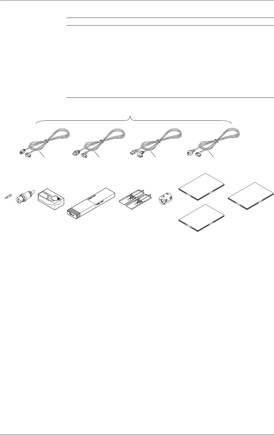
Standard Accessories
Name Part No. Q’ty Description
1. Power cord see page 2, 3 1
2. Fuse A1350EF 1 Timelag 2.5A 250V, for DR232/242, in case of
DR232 located in fuse holder
3. DC power supply A1105JC 1 Only for the subunit models whose power supply
terminal connector code is “-2”
4. Ribbon cassette B9627AZ 1 10 colors (for DR232/242)
5. Chart paper B9627AY 1 Length: 30m, 25mm grid (for DR232/DR242)
6. Mounting brackets B9900CW 1 x 2 for DR242
7. Clamp filter A1197MN 1 When power supply code is -1
8. User’s Manual IMDR232-01E 1 this manual (for DR232/242)
9. User’s Manual IMDR231-11E 1 Communication Interface manual (for DR232/242)
10.
Data acquisition software
DP120-13 Only for models whose software code is “-2”
1.One of these power cord types is supplied according
to the instrument's suffix code
F
DSR
2. 4.3. 5. 6. 7.
8.
9.
10.
Checking the Contents of the Package

6IM DR232-01E
Optional Accessories
Name Model Description
Extender module DV100-011
Extender base DV100-012
Extension cable DV200-000 Length: 0.5m
Extension cable DV200-001 Length: 1m
Extension cable DV200-002 Length: 2m
Extension cable DV200-005 Length: 5m
Extension cable DV200-010 Length: 10m
Extension cable DV200-020 Length: 20m
Extension cable DV200-050 Length: 50m
Extension cable DV200-100 Length: 100m
Extension cable DV200-200 Length: 200m
Extension cable DV200-300 Length: 300m
Extension cable DV200-400 Length: 400m
Extension cable DV200-500 Length: 500m
Shunt resistance DV300-011 10Ω, for screw
Shunt resistance DV300-012 10Ω, for clamp
Shunt resistance DV300-101 100Ω, for screw
Shunt resistance DV300-102 100Ω, for clamp
Shunt resistance DV300-251 250Ω, for screw
Shunt resistance DV300-252 250Ω, for clamp
Rack mount kit DV400-011 for DS400/600
Rack mount kit DV400-013 for DR232
Power cable DV400-051 between DR232/242 and DS400/600
Strain conversion cable DV450-001
Cable adapter DV250-001 For expanding cable
AC adapter DV500-001 2-pin inlet w/UL, CSA cable (Part No. B9988YA) for
DC100/DA100/DS400/DS600 DC power supply model
AC adapter DV500-002 2-pin inlet w/VDE cable (Part No. B9988YB) for
DC100/DA100/DS400/DS600 DC power supply model
AC adapter DV500-003 2-pin inlet w/SAA cable (Part No. B9988YC) for
DC100/DA100/DS400/DS600 DC power supply model
AC adapter DV500-004 2-pin inlet w/BS cable (Part No. B9988YD) for
DC100/DA100/DS400/DS600 DC power supply model
Optional Software
Name Model Description
DAQ 32 DP120-13 Windows 95/98 and Windows NT
DAQ 32 Plus DP320-13 Windows 95/98 and Windows NT
Spares
Name Part No. Min. Q’ty Description
Ribbon cassette B9627AZ 1 10 colors
Chart paper B9627RY 10 Length 30 m, grid 10mm
B9627AY 10 Length 30 m, grid 25mm
Checking the Contents of the Package
7
IM DR232-01E
Safety Precautions
This instrument is an IEC safety class I instrument (provided with terminal for protective
grounding).
The following general safety precautions must be observed during all phases of operation, service
and repair of this instrument. If this instrument is used in a manner not sepecified in this manual,
the protection provided by this instrument may be impaired. Also, YOKOGAWA Electric
Corporation assumes no liability for the customer’s failure to comply with these requirements.
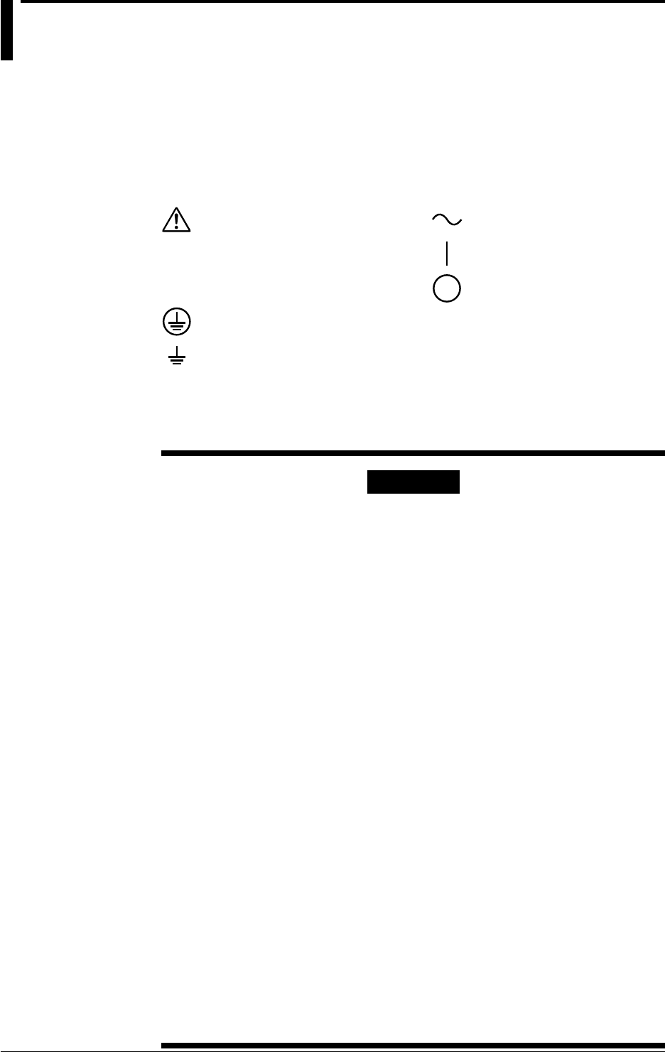
The following symbols are used on this instrument.
To avoid injury, death of personnel
or damage to the instrument, the
operator must refer to an explanation
in the User’s Manual or Service
Manual.
Protective grounding terminal.
Function grounding terminal. This
terminal should not be used as a
“Protective grounding terminal”.
Alternating current.
ON(power).
OFF(power).
Make sure to comply with the following safety precautions. Not complying might
result in injury, death of personnel or damage to the instrument.
WARNING
Power Supply
Ensure the source voltage matches the voltage of the power supply
before turning ON the power.
Power Cord and Plug
To prevent an electric shock or fire, be sure to use the power cord
supplied by YOKOGAWA. The main power plug must be plugged in an
outlet with protective grounding terminal. Do not invalidate protection by
using an extension cord without protective grounding.
Protective Grounding
Make sure to connect the protective grounding to prevent an electric
shock before turning ON the power.
Necessity of Protective Grounding
Never cut off the internal or external protective grounding wire or
disconnect the wiring of protective grounding terminal. Doing so poses a
potential shock hazard.
Defect of Protective Grounding and Fuse
Do not operate the instrument when protective grounding or fuse might be
defective.
Do not Operate in an Explosive Atmosphere
Do not operate the instrument in the presence of flammable liquids or
vapors. Operation of any electrical instrument in such an environment
constitutes a safety hazard.
Fuse
To prevent a fire, make sure to use fuses with specified standard(current,
voltage, type). Before replacing the fuse, turn OFF the power and
disconnect the power source. Do not use a different fuse or short-circuit
the fuse holder.
Do not Remove any Covers
There are some areas with high voltages. Do not remove any cover if the
power supply is connected. The cover should be removed by qualified
personnel only.
External Connection
To ground securely, connect the protective grounding before connecting
to measurement or control unit.

8IM DR232-01E
How to Use this Manual
This User’s Manual consists of the following twelve chapters and Index.
Chapter Title Description
Chapter 1 System Configuration Explains the position of the DR within DARWIN, its
configuration, etc..
Chapter 2 Functions Explains the functions of the DR. Operating
procedures are not explained here.
Chapter 3 Installation and Wiring Describes cautions for use, explains how to install and
wire the DR, the power cord, how to switch ON/OFF
the DR, how to set the date/time, explains the noise
filter, etc..
Chapter 4 Setting the Monitor Mode Explains the display in the monitor mode.
Display
Chapter 5 Setting the Input Type/ Explains the operations when setting the input type,
Recording Span/ recording span and linear scaling function.
Linear Scaling
Chapter 6 Setting the Recording Explains the operations when setting recording
Conditions conditions such as the recording mode, channels,
recording interval, chart speed, recording span, and
recording format.
Chapter 7 Executing Recording Explains how to start and stop recording.
Chapter 8 Setting, Displaying and Explains how to set an alarm and what to do when an
Recording Alarms alarm occurs.
Chapter 9 Event/Action Function and Explains how to operate the event/action function,.
Other Functions how to copy recording information, how to reset
alarms, how to reset the timer, how to use the key-
lock, and how to use the external in-/output function.
Chapter 10 Basic Settings (SET UP) Explains functions which usually do not need to be
changed, and how to set
Chapter 11 Saving/Reading Measured, Explains how to save measured data, computed data
Computed and Set-up Data and set-up data to the internal RAM disk or floppy
disk and read them into the instrument.
Chapter 12 Executing Computation Explains the computation function (optional).
(Available with the /M1 Model)
Chapter 13 Trouble-Shooting and Explains maintenance procedures, error messages and
Maintenance calibration procedures.
Chapter 14 Specifications Explains specifications for all features of DR.
Index Gives the index in main menu and alphabetic order.

9
IM DR232-01E
Conventions Used in this Manual
Used Symbols
The following symbol marks are used to attract the operator’s attention.
Affixed to the DR232/242, indicating that for safety, the operator should
refer to the appropriate User’s Manual. For a list of the User’s Manuals,
refer to page 1.
Describes precautions that should be observed to prevent the danger of
injury or death to the user.
Describes precautions that should be observed to prevent damage to the
DR232/242.
Note
Provides information that is important for proper operation of the DR232/
242.
Indicates the relevant panel keys and indicators to carry out
the operation.
The procedure is explained by a flow diagram. For the
meaning of each operation, refer to the example below. The
operating procedures are given with the assumption that you
are not familiar with the operation. Thus, it may not be
necessary to carry out all the steps when changing settings.
Describes settings and restrictions relating to the operation.

10 IM DR232-01E
Contents
Foreword ............................................................................................................................................................................. 1
Checking the Contents of the Package......................................................................................................... 3
Safety Precautions ............................................................................................................................................. 7
How to Use this Manual..................................................................................................................................... 8
Conventions Used in this Manual................................................................................................................... 9
List of Menus and Set-up Data .......................................................................................................................13
Chapter 1 System Configuration
1.1 About DARWIN ...................................................................................................................................1-1
1.2 Product Overview .................................................................................................................................1-2
1.3 Names of Parts ......................................................................................................................................1-4
1.4 Floppy Disk ........................................................................................................................................ 1-11
Chapter 2 Functions
2.1 Display Functions .................................................................................................................................2-1
2.2 Measurement Input Functions ..............................................................................................................2-3
2.3 Recording Functions ............................................................................................................................. 2-5
2.4 Alarm Function ................................................................................................................................... 2-13
2.5 Standard Computation Functions ....................................................................................................... 2-16
2.6 Other Functions .................................................................................................................................. 2-17
Chapter 3 Installation and Wiring
3.1 General Precautions for Installation .....................................................................................................3-1
3.2 How to Install .......................................................................................................................................3-2
3.3 How to Connect the Input/Output Modules ......................................................................................... 3-7
3.4 Installing the Chart and Ribbon Cassette .............................................................................................3-9
3.5 Connecting the Interface Cables .........................................................................................................3-14
3.6 Connecting the Extension Cables .......................................................................................................3-19
3.7 Connecting the Signal Lines ...............................................................................................................3-20
3.8 Connecting an Extension Module to Extension Bases ....................................................................... 3-27
3.9 Connecting the Power Cord and Turning the Power ON/OFF ........................................................... 3-29
3.10 Setting the Date and Time ..................................................................................................................3-34
3.11 Countering Noise ................................................................................................................................3-35
Chapter 4 Setting the Monitor Mode Display
4.1 Using the AUTO Display .....................................................................................................................4-1
4.2 Using the MANUAL Display ...............................................................................................................4-4
4.3 Using the PAGE Display ......................................................................................................................4-6
4.4 Using the ALARM SEARCH Display .................................................................................................4-7
4.5 Using the BARGRAPH Display........................................................................................................... 4-9
4.6 Using the ALARM STATUS Display ................................................................................................4-10
4.7 Using the RELAY STATUS Display .................................................................................................4-11
4.8 Using the CLOCK (Data & Time) Display ........................................................................................4-13
Chapter 5 Setting the Input Type/Recording Span/Linear Scaling
5.1 Setting the Type of Input and Recording Span..................................................................................... 5-1
5.2 Setting Linear Scaling and the Recording Span ...................................................................................5-4
5.3 Configuring the Input Range and Recording Span or the Linear Scaling of a Power Monitoring
Channel .................................................................................................................................................5-6
5.4 Configuring the Measuring Range and Recording Span or the Linear Scaling of a Strain Input
Channel ...............................................................................................................................................5-10

11
IM DR232-01E
5.5 Performing Initial Balancing/Initialization on a Strain Input Channel...............................................5-12
5.6 Configuring the Pulse Input Channel .................................................................................................5-13
Chapter 6 Setting the Recording Conditions
6.1 Setting the Recording Mode, Engineering Unit, Recording Channel and Recording Interval ............6-1
6.2 Setting the Chart Speed ........................................................................................................................6-4
6.3 Setting Recording Zones and Partially Expanded Recording .............................................................. 6-6
6.4 Setting Tag, Digital Printout and Manual Printout ...............................................................................6-8
6.5 Setting the Alarm Printout ..................................................................................................................6-10
6.6 Setting Scale Printout, List Printout and List Format .........................................................................6-12
6.7 Entering Messages, Headers and Title ...............................................................................................6-14
6.8 Setting Match Time, Moving Average, Interpolation and Groups .....................................................6-16
Chapter 7 Executing Recording
7.1 Starting Dot Printing, Digital Printing and Printing in Logging Mode ................................................7-1
7.2 Starting Manual Printing, List Printing and Header Printing ...............................................................7-2
7.3 Starting Message Printing .....................................................................................................................7-3
7.4 Printing Set-up Lists ............................................................................................................................. 7-4
Chapter 8 Setting, Displaying and Recording Alarms
8.1 Setting Alarms and Relays (including internal switches) .....................................................................8-1
8.2 Alarm Display and Printing .................................................................................................................. 8-4
Chapter 9 Event/Action Function and Other Functions
9.1 Setting Event/Action Functions ............................................................................................................9-1
9.2 Copying ..............................................................................................................................................9-12
9.3 Alarm Acknowledgment, Alarm Reset, Timer Reset, Keylock, and Message Printout.....................9-14
9.4 Clearing Alarm/Message Buffers, Displaying Module/Communications Information, Structuring
System Modules, and Initializing Information ...................................................................................9-16
9.5 Fail/Chart End Output, and Remote Control Signal Input .................................................................9-18
9.6 Summer/Winter Time .........................................................................................................................9-19
Chapter 10 Basic Settings (SET UP)
10.1 Selecting Adjustment of Dot-Printing Position or Scan Interval .......................................................10-1
10.2 Setting Recording Format ...................................................................................................................10-3
10.3 Select Alarm Interval/Hysteresis/Hold/A/D Converter Integration Time/Filter ................................10-7
10.4 Setting Operation Mode of Relay/Internal Switch .............................................................................10-9
10.5 Setting Burn-out/Reference Junction Compensation .......................................................................10-12
10.6 Setting Recording Colors..................................................................................................................10-14
10.7 Setting Key Lock ..............................................................................................................................10-15
10.8 Setting FUNC/FUNC3 Menu ........................................................................................................... 10-17
10.9 Setting SET/SET3 Menu ..................................................................................................................10-20
10.10 Selecting Display Update Interval, Registering Details Set/Selected with SET UP Menu, and
Terminating SET UP Menu ..............................................................................................................10-24
10.11 Selecting the temperature unit from °C or °F (option) .....................................................................10-25
10.12 Working with the Report Function ...................................................................................................10-27
Chapter 11 Saving/Reading Measured, Computed and Set-up Data
11.1 Saving Measured and Computed Data ...............................................................................................11-1
11.2 Reading Measured and Computed Data .............................................................................................11-7
11.3 Saving Set-up Data ........................................................................................................................... 11-10
11.4 Reading Set-up Data ......................................................................................................................... 11-12
11.5 Copying a Data File .......................................................................................................................... 11-15
11.6 Copying in ASCII Format ................................................................................................................11-17
Contents
1
2
3
4
5
6
7
8
9
10
11
12
13
14
Index

12 IM DR232-01E
11.7 Deleting a Data File ..........................................................................................................................11-20
11.8 Displaying RAM Disk and Floppy Disk Information ......................................................................11-21
11.9 Initializing the RAM Disk ................................................................................................................11-23
11.10 Formatting a Floppy Disk .................................................................................................................11-24
Chapter 12 Executing Computation (Available with the /M1 Model)
12.1 Overview of the Computation Function .............................................................................................12-1
12.2 Setting a Computation Equation .........................................................................................................12-4
12.3 Setting a Constant ...............................................................................................................................12-7
12.4 Starting/Stopping Computation ..........................................................................................................12-8
12.5 Setting Actions to be Carried out in Case of Computation Error and Setting the Time Axis for TLOG
SUM..................................................................................................................................................12-12
Chapter 13 Trouble-shooting and Maintenance
13.1 Periodic Maintenance and Recommended Parts Replacement Period ............................................... 13-1
13.2 Replacing the Fuse..............................................................................................................................13-2
13.3 Troubleshooting ..................................................................................................................................13-3
13.4 Error Codes .........................................................................................................................................13-4
13.5 Calibration ..........................................................................................................................................13-6
Chapter 14 Specifications
14.1 Specifications of DR232/DR242 and DS400/DS600 .........................................................................14-1
14.2 Universal Input Module and DCV/TC/DI Input Module .................................................................14-11
14.3 Specifications of mA-input Module .................................................................................................14-14
14.4 Specifications of Power Monitor Module ........................................................................................14-16
14.5 Specifications of Strain Input Module ..............................................................................................14-20
14.6 Specifications of Pulse Input Module...............................................................................................14-22
14.7 Specifications of Digital Input module.............................................................................................14-24
14.8 Alarm Module................................................................................................................................... 14-26
14.9 DI/DO Module ..................................................................................................................................14-27
14.10 Communication Interface Module ....................................................................................................14-29
14.11 Specifications of Extension Module and Extension Base ................................................................14-32
14.12 Dimensional Drawings......................................................................................................................14-33
Index
Contents

13
IM DR232-01E
List of Menus and Set-up Data
The following is a list of set-up data, procedures to switch to different setting modes, and setting
menu.
Measurement Condition Settings
Parameters Procedure Selecting menu Reference
Input type, span, linear RANGE key 001-01:VOLT/2V Chapter 5
scaling*1
Units SET key*2SET=UNIT Section 6.1
Moving average
Press the SET key for about three seconds
*2SET=MOVE AVE Section 6.8
Measurement cycle*1
Turn ON power while pressing the DISP key
SET UP= Section 10.1
SCAN INTVL
A/D integration time*1
Turn ON power while pressing the DISP key
SET UP=A/D INTG Section 10.3
Filter*1
Turn ON power while pressing the DISP key
SET UP=FILTER Section 10.3
*1: Make sure that the total number of setting changes, including calibrations and restructuring, does not
surpass 100000.
*2: Procedure varies according to the menu configuration of the SET key (see section 10.9).
Chart Speed Settings
Parameters Procedure Selecting menu Reference
Chart speed 1 CHART key CHART Section 6.2
Chart speed 2
Press the SET key for about three seconds*
SET=CHART2 Section 6.2
*: Procedure varies according to the menu configuration of the SET key (see section 10.9).
Recording Settings
Parameters Procedure Selecting menu Reference
Logging/Analog trend SET key* SET=SYSTEM Section 6.1
switch, dot-printing cycle
Recording channel SET key* SET=TREND Section 6.1
Recording zone
Press the SET key for about three seconds*
SET=ZONE Section 6.3
Partial compression
Press the SET key for about three seconds*
SET=PERTIAL Section 6.3
Tag
Press the SET key for about three seconds*
SET=TAG Section 6.4
Channel to digital print,
Press the SET key for about three seconds*
SET=DIGITAL PR Section 6.4
number of rows to print
Channel to manual print
Press the SET key for about three seconds*
SET=MANUAL PR Section 6.4
Alarm print
Press the SET key for about three seconds*
SET=ALARM PR Section 6.5
Channel to print scale
Press the SET key for about three seconds*
SET=SCALE PR Section 6.6
values
Channel to list print
Press the SET key for about three seconds*
SET=LIST PR Section 6.6
Items to list print
Press the SET key for about three seconds*
SET=LIST FMT Section 6.6
Message
Press the SET key for about three seconds*
SET=MESSAGE Section 6.7
Header
Press the SET key for about three seconds*
SET=HEADER Section 6.7
Title
Press the SET key for about three seconds*
SET=TITLE Section 6.7
Interpolation
Press the SET key for about three seconds*
SET=INTERPOL Section 6.8
Adjust dot-printing
Turn ON power while pressing the DISP key
SET UP=PRN ADJ Section 10.1
position
Recording format
Turn ON power while pressing the DISP key
SET UP=RECORD Section 10.2
Dot-print color
Turn ON power while pressing the DISP key
SET UP=COLOR Section 10.6
*: Procedure varies according to the menu configuration of the SET key (see section 10.9).
Display Settings
Parameters Procedure Selecting menu Reference
Switch display DISP key and MODE key -------- Chapter 4
Display update interval Turn ON power while pressing the SET UP=DISPLAY Section 10.10
DISP key
Alarm Settings
Parameters Procedure Selecting menu Reference
Alarm, alarm output ALARM key 001-01:1/OFF Section 8.1
relay
Alarm
Turn ON power while pressing the DISP key
SET UP=ALARM Section 10.3
interval/hysteresis/hold
Execute alarm FUNC key* ALARM ACK Section 9.3
acknowledge
Reset alarm FUNC key* ALARM RST Section 9.3
Clear alarm buffer
Press the FUNC key for about three seconds*
ALM BUF CLEAR Section 9.4
*: Procedure varies according to the menu configuration of the FUNC key (see section 10.8).

14 IM DR232-01E
List of Menus and Set-up Data
Computation Settings
Parameters Procedure Selecting menu Reference
Computation equation SET key* SET=MATH Section 12.2
Constant SET key* SET=CONST Section 12.3
Perform computation FUNC key** MATH START Section 12.4
Clear measured data and FUNC key** MATH CLR START Section 12.4
perform computation
Stop computation FUNC key** MATH STOP Section 12.4
Clear incomplete FUNC key** MATH ACK Section 12.4
measurement status
Handling of computation
Turn ON power while pressing the DISP key
SET UP=MATH Section 12.5
error/time axis setting of
TLOG SUM
*: Procedure varies according to the menu configuration of the SET key (see section 10.9).
**: Procedure varies according to the menu configuration of the FUNC key (see section 10.8).
Settings for Saving/Loading Measured/Setup Data (Floppy Disk)
Parameters Procedure Selecting menu Reference
Save/Load measured dataSET key* SET=MEMORY
Section 11.1, 11.2
Save/Load set-up data SET key* SET=FLOPPY
Section 11.2, 11.3
of SET mode
Copy measured data SET key* SET=MEMORY Section 11.5
between built-in RAM
disk and floppy disk
Convert data and copy SET key* SET=MEMORY Section 11.6
Initialize built-in RAM SET key* SET=MEMORY Section 11.9
disk
Initialize floppy disk SET key* SET=MEMORY Section 11.10
Save/Load set-up data Turn ON power while pressing the DISP SET UP=FLOPPY
Section 11.3, 11.4
of SET UP mode key
*: Procedure varies according to the menu configuration of the SET key (see section 10.9).
Perform Printing
Parameters Procedure Selecting menu Reference
Perform manual print PRINT key MAN PR START Section 7.2
Perform list print PRINT key LIST START Section 7.2
Perform header print PRINT key HEADER START Section 7.2
Perform message print FUNC key* MSG PRINT Section 7.3
Perform setup list print
Press the FUNC key for about three seconds*
S/U LIST START Section 7.4
*: Procedure varies according to the menu configuration of the FUNC key (see section 10.8).
Other Settings
Parameters Procedure Selecting menu Reference
Timer SET key* SET=TIMER Section 6.1
Event/Action SET key* SET=LOGIC Section 9.1
Copy between channels SET key* SET=COPY Section 9.2
Match time
Press the SET key for about three seconds*
SET=MATCH TIME Section 6.8
Group
Press the SET key for about three seconds*
SET=GROUP Section 6.8
Relay, internal switch
Turn ON power while pressing the DISP key
SET UP=RELAY Section 10.4
operation mode
Burnout
Turn ON power while pressing the DISP key
SET UP=BURN OUTSection 10.5
Reference junction
Turn ON power while pressing the DISP key
SET UP=RJC Section 10.5
compensation
Key lock
Turn ON power while pressing the DISP key
SET UP=LOCK Section 10.7
Menu configuration
Turn ON power while pressing the DISP key
SET UP= Section 10.8
of FUNC key FUNC PARM
Menu configuration
Turn ON power while pressing the DISP key
SET UP=SET PARM Section 10.9
of SET key
Report function
Turn ON power while pressing the DISP key
SET UP=REPORT Section 10.12
Reset timer FUNC key** TIMER RESET Section 9.3
Lock keys FUNC key** KEY LOCK ON Section 9.3
Start report FUNC key** REPORT START Section 10.12
Stop report FUNC key** REPORT STOP Section 10.12
Start report print FUNC key** REPORT RECALL Section 10.12
START
Stop report print FUNC key** REPORT PRINT Section 10.12
START
Clear message buffer
Press the FUNC key for about three seconds**
MSG BUF CLEAR Section 9.4
Display module settings
Press the FUNC key for about three seconds**
MODULE INF Section 9.4
Display communication
Press the FUNC key for about three seconds**
COMM INF Section 9.4
settings
Initialize setting
Press the FUNC key for about three seconds**
RAM INIT Section 9.4
information
*: Procedure varies according to the menu configuration of the SET key (see section 10.9).
**: Procedure varies according to the menu configuration of the FUNC key (see section 10.8).
1-1
IM DR232-01E
1
System Configuration
1.1 About DARWIN
Created from a completely new concept that is based on modular architecture, this group of next
generation data acquisition systems is called DARWIN (Data Acquistion and Recording
Windows).
Today many data acquisition networks are increasingly being linked together. More than ever
before, large volume, high speed, accurate, easy-to-use communication functions are essential in
many disciplines.
In the world of measurement and control where the number of measurement points has increased
sharply, the ability to acquire information from a large number of points easily and economically
is crucial. Interfacing to a personal computer allows simplified utilization of the information
while improving quality and efficiency.
DARWIN is based on a unique, new concept to meet these needs. The art of measurement is
revolutionized by DARWIN which integrates functions of conventional recording and data
logging.
Most existing data acquisition equipment has been the all-in-one type in which the measurement
section and display/recording section are contained in one box. While this simplifies operation on
the one hand, it is difficult to adapt to changes in the measurement environment and also makes
expansion difficult.
DARWIN uses a data acquisition engine and remote I/O modules which are completely separate
from each other. It is an entirely new product line which quickly and flexibly copes with various
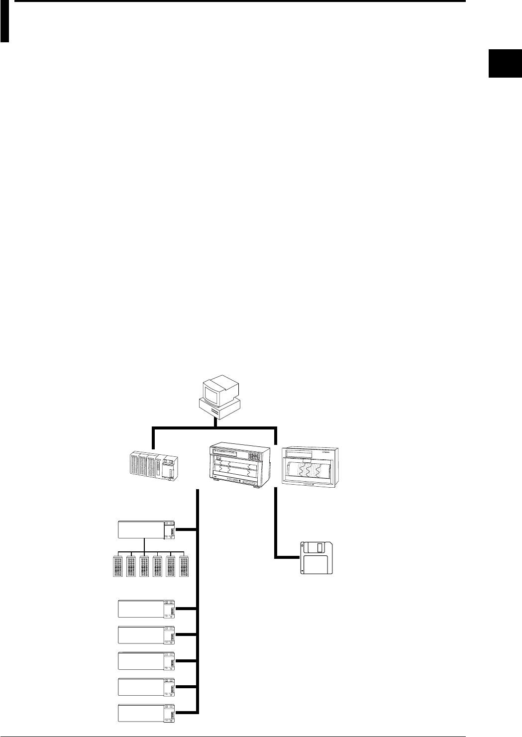
restrictive conditions and changes in specifications.
Supported by a personal computer, a whole line-up can be created starting with the data
acquisition systems DA series which performs data logging. For example, using a printer as the
output device, the equipment becomes a hybrid recorder (DR series).
Two models are available in the DR series: the DR230 and DR240. The DR 230 is a desk-top
hybrid recorder, and the DR240 is a panel-mount hybrid recorder (component type).
FD
Extension cables
(max. length 500m)
Subunit
Personal
computer
D
CH=001 RANGE=TC TYPE-T
Hybrid Recorder
001
002
003
004
005
006
007
008
009
010
011
012
013
014
015
016
017
018
019
020
021
022
023
024
025
026
027
028
029
030
Input/output
modules
DR240DR230
DA100

1-2 IM DR232-01E
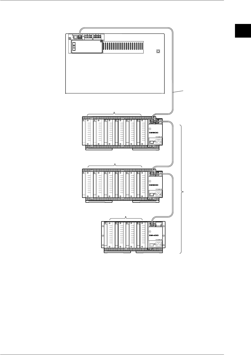
1.2 Product Overview
This product is a hybrid recorder which can record and measure from small-scale 10-ch data up to
widely distributed 300-ch multi-point data.
The number of measurement points can be expanded up to a maximum of 300-ch by connecting
up to six subunits (DS400/DS600) to a main unit (DR232/242). Using dedicated extension cables
between units, interconnections can be extended up to 500 m. Since measured objects scattered
over a wide area can be wired fast and with a minimum of wiring, a flexible, extensive
measurement system can be configured. The input modules to be incorporated in the DR232/242
or DS400/600 can be selected from the following, to suit your measurement conditions:
• Universal input module and DCV/TC/DI input module
Temperature, DC voltage and contact signals can be measured, but cannot be connected to the
main unit.
• mA-input Module
This module can directly measure DC currents ranging from -20 mA to 20 mA since it contains
shunt resistors. It cannot be connected to a system's main unit.
• Power Monitor Module
This module can measure the effective voltage, effective current, active power, reactive power,
apparent power, frequency, power factor and phase angle for an AC voltage or AC current input.
It is available in either a single-phase or three-phase model. This module cannot be connected to
a system's main unit.
• Strain Input Module
This module can measure strain. It is available in either a model with built-in 120- or 350-Ω
bridge resistors or a model with NDIS terminals where bridge resistors are connected externally.
The module cannot be connected to a system's main unit.
• Pulse Input Module
This module can measure pulses. It cannot be connected to a system's main unit.
• Digital input module
This module can measure contact signals. It cannot be connected to a system’s main unit.
• Communication interface module
This module is necessary when communicating with a personal computer. Measurement
conditions can be set and data acquired via the communication interface (GP-IB, RS-232-C, etc.)
of this dule. This module can only be connected to the main unit.
• Alarm module
This module can output alarm signals as contact signals. The module can be connected to the
main unit or the subunit.
• DI/DO module
This module allows a signal to be output in the case of alarm, failure, or chart end and a remote
control signal for the product to be input. The module can be connected to the main unit or the
subunit but only one module in all units.
Note
When the following handling is done, it is necessary to carry out “system construction” to operate the
instrument correctly. After executing system construction, confirm the module information. For details,
see page 9-16.
• Connection (including addition or replacement)/removal of subunits, or unit number setting (see page 3-
7)
• Mounting (including addition or replacement)/removal of modules
1-3
IM DR232-01E
1
System Configuration
Connection example
CH
1
CH
2
CH
3
CH
4
CH
5
CH
6
CH
7
CH
8
CH
9
CH
10
b -/B +/A
CH
1
CH
2
CH
3
CH
4
CH
5
CH
6
CH
7
CH
8
CH
9
CH
10
b -/B +/A
CH
1
CH
2
CH
3
CH
4
CH
5
CH
6
CH
7
CH
8
CH
9
CH
10
b -/B +/A
CH
1
CH
2
CH
3
CH
4
CH
5
CH
6
CH
7
CH
8
CH
9
CH
10
b -/B +/A
CH
1
CH
2
CH
3
CH
4
CH
5
CH
6
CH
7
CH
8
CH
9
CH
10
b -/B +/A
CH
1
CH
2
CH
3
CH
4
CH
5
CH
6
CH
7
CH
8
CH
9
CH
10
b -/B +/A
CH
1
CH
2
CH
3
CH
4
CH
5
CH
6
CH
7
CH
8
CH
9
CH
10
b -/B +/A
CH
1
CH
2
CH
3
CH
4
CH
5
CH
6
CH
7
CH
8
CH
9
CH
10
b -/B +/A
CH
1
CH
2
CH
3
CH
4
CH
5
CH
6
CH
7
CH
8
CH
9
CH
10
b -/B +/A
CH
1
CH
2
CH
3
CH
4
CH
5
CH
6
CH
7
CH
8
CH
9
CH
10
b -/B +/A
CH
1
CH
2
CH
3
CH
4
CH
5
CH
6
CH
7
CH
8
CH
9
CH
10
b -/B +/A
CH
1
CH
2
CH
3
CH
4
CH
5
CH
6
CH
7
CH
8
CH
9
CH
10
b -/B +/A
CH
1
CH
2
CH
3
CH
4
CH
5
CH
6
CH
7
CH
8
CH
9
CH
10
b -/B +/A
CH
1
CH
2
CH
3
CH
4
CH
5
CH
6
CH
7
CH
8
CH
9
CH
10
b -/B +/A
CH
1
CH
2
CH
3
CH
4
CH
5
CH
6
CH
7
CH
8
CH
9
CH
10
b -/B +/A
CH
1
CH
2
CH
3
CH
4
CH
5
CH
6
CH
7
CH
8
CH
9
CH
10
b -/B +/A
SUB UNIT
POWER
STATUS
POWER
STATUS
POWER
100-240V 50/60Hz 55VA MAX
STATUS
100-240V 50/60Hz 70VA MAX
SUB UNIT
100-240V 50/60Hz 70VA MAX
SUB UNIT
Subunit
DS600
Subunit
DS600
Subunit
DS400
Extension cable
10ch Universal Input module
10ch Universal Input module
10ch Universal Input module
Up to 6 subunits
can be connected
Main unit DR232/DR242
1.2 Product Overview
1-4 IM DR232-01E
1.3 Names of Parts
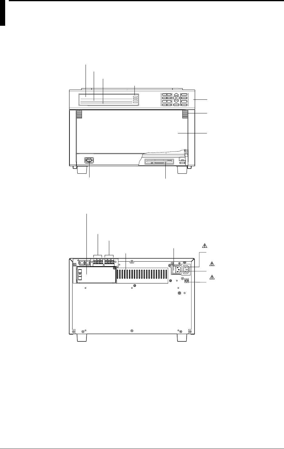
DR232 Main Unit (desk-top hybrid recorder)
Front
Main display (See chapter 4.)
Sub-display 1 (See chapter 4.)
Sub-display 2 (See chapter 4.)
Status indicator
Operation panel
(See chapters 3 to 12.)
Handle to open/close
the front door
Power switch (See page 3-22)
Front door
Floppy disk drive (Only for DR232-1)
Rear
Heat sink fins Power fuse ( See page 13-2)
Power connector
( See page 3-29)
Vacant slot with cover
(for communication interface,
alarm, or DI/DO modules)
Failure output terminals
Chart end output terminals
Function grounding
terminal
AC outlet(Au xiliary
for DS400/DS600
: See page 3-29)
1-5
IM DR232-01E
1
System Configuration
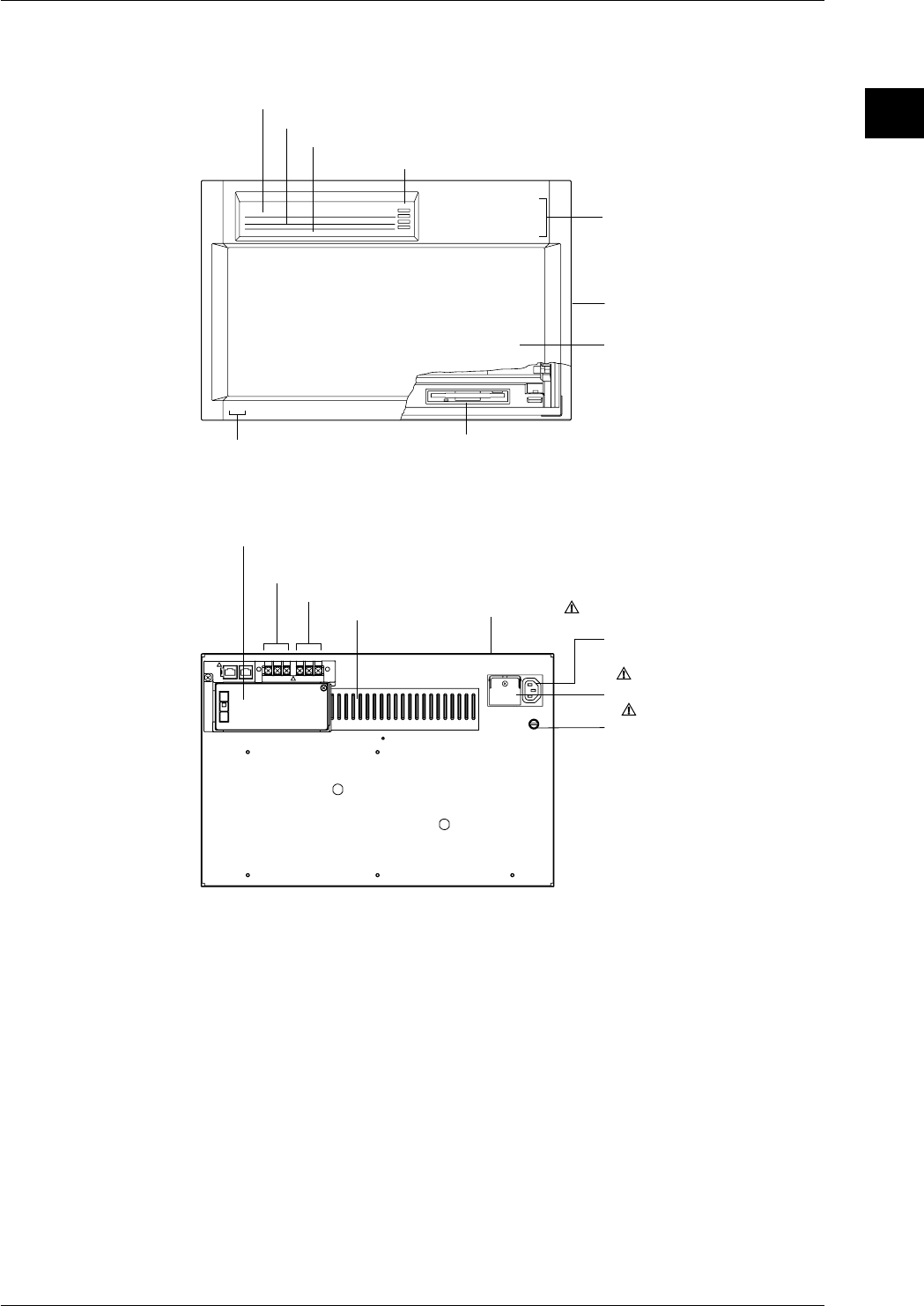
DR242 Main Unit (panel-mount hybrid recorder)
Front
Main display (See chapter 4.)
Sub-display 1 (See chapter 4.)
Sub-display 2 (See chapter 4.)
Status indicator
Operation panel
(Located behind the front door.
See chapters 3 to 12.)
Handle to open/close
the front door
Front door
Power switch
(Located inside the front door. See page 3-22.)
Floppy disk drive (Only for /DR242-1)
Rear
Heat sink fins
Power terminals with a cover
( See page 3-30)
Vacant slot with cover
(for communication interface, alarm, or DI/DO modules)
Failure output terminals
Chart end output terminalsPower fuse (See page 13-2)
(located in the main unit)
Function grounding
terminal
AC outlet(Auxiliary
for DS400/DS600
: See page 3-30)
1.3 Names of Parts
1-6 IM DR232-01E
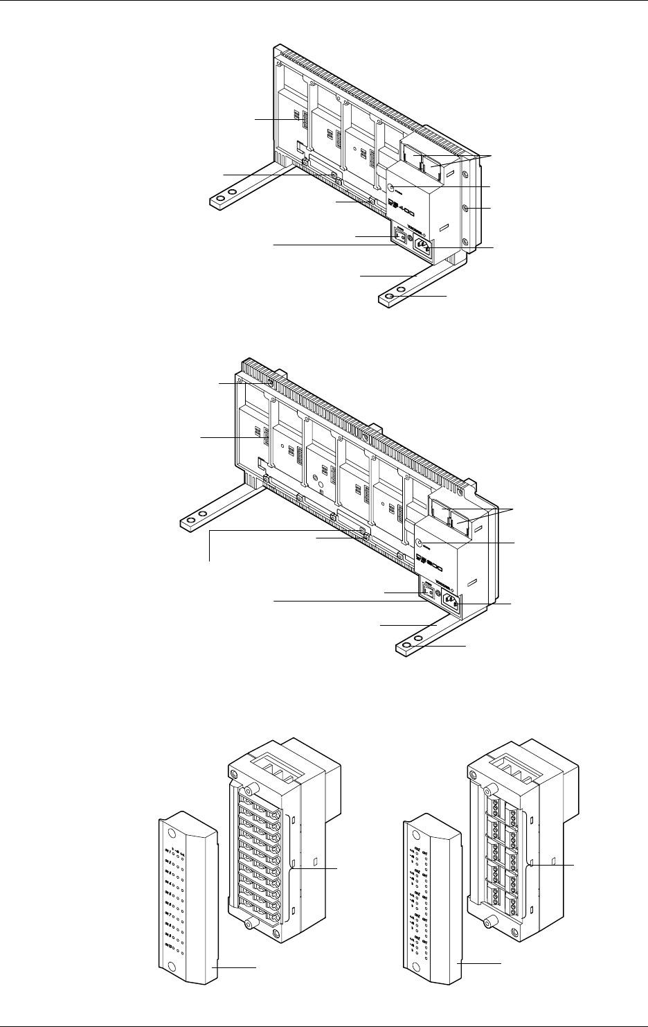
Subunit DS400
Power connector
Power switch
Feet
Status indicator
Module connector
Installation holes
Screw holes for
module installation
Holes for fastening the feet
Lid covering the extension
cable connector
Switch to set the
unit number
Function grounding
terminal (below power switch)
Subunit DS600
Power connector
Power switch
Feet
Status indicator
Module
connector
Installation
holes
Screw holes for
module installation
Holes for fastening
the feet
Lid covering the
extension cable
connector
Switch to set
the unit number
Function grounding
terminal (below power switch)
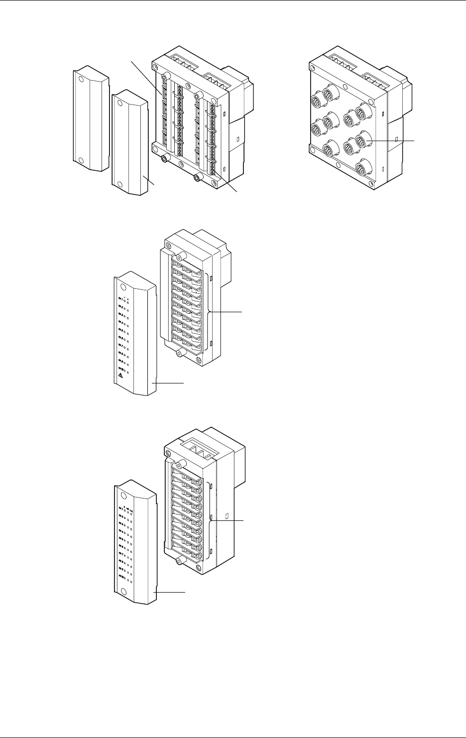
Input modules
10-ch Universal input module (DU100-11/DU100-12)
Cover
Screw
terminal
DU100-11
Cover
Clamp
terminal
DU100-12
The 20-ch Universal input modules (DU100-21/DU100-22) and the 30-ch Universal input modules
(DU100-31/DU100-31) are similar to the ones shown above.
1.3 Names of Parts
1-7
IM DR232-01E
1
System Configuration
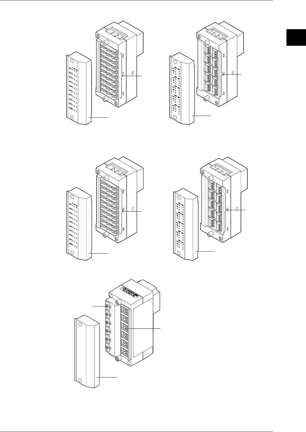
10-ch DCV/TC/DI input module (DU200-11/DU200-12)
Cover
Screw
terminal
DU200-11
Cover
Clamp
terminal
DU200-12
The 20-ch DCV/TC/DI input modules (DU200-21/DU200-22) and the 30-ch DCV/TC/DI input modules
(DU200-31/DU200-31) are similar to the ones shown above.
mA input module (DU300-11/DU300-12)
Cover
Screw
terminal
Cover
Clamp
terminal
AC input module (DU400-12/22)
Cover
Wire clip
Clamp terminal
1.3 Names of Parts
1-8 IM DR232-01E
Strain input module (DU500-12/DU500-13/DU500-14)
DU500-14
DU500-12/DU500-13
NDI terminal
Gauge method setup switch
Clamp terminal
Cover
Pulse input module (DU600-11)
Cover
Screw terminal
Digital input module (DU700-11)
Cover
Screw
terminal
1.3 Names of Parts
1-9
IM DR232-01E
1
System Configuration
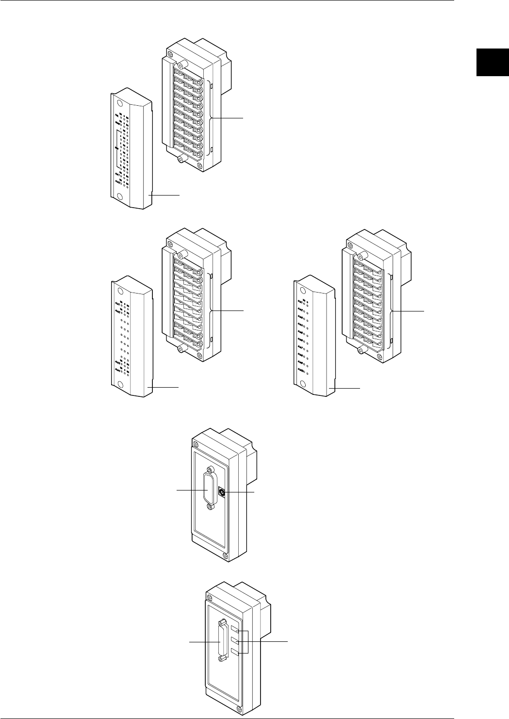
I/O Terminal Modules DI/DO module (DT100-11)
Cover
Screw terminal
Alarm module (DT200-11/DT200-21)
Cover
Screw
terminal
DT200-11
Cover
Screw
terminal
DT200-21
Communication Module
GP-IB module (DT300-11)
GP-IB connector Switch to set
the address
RS-232-C module (DT300-21)
RS-232-C connector Switches to set
communication parameters
1.3 Names of Parts
1-10 IM DR232-01E
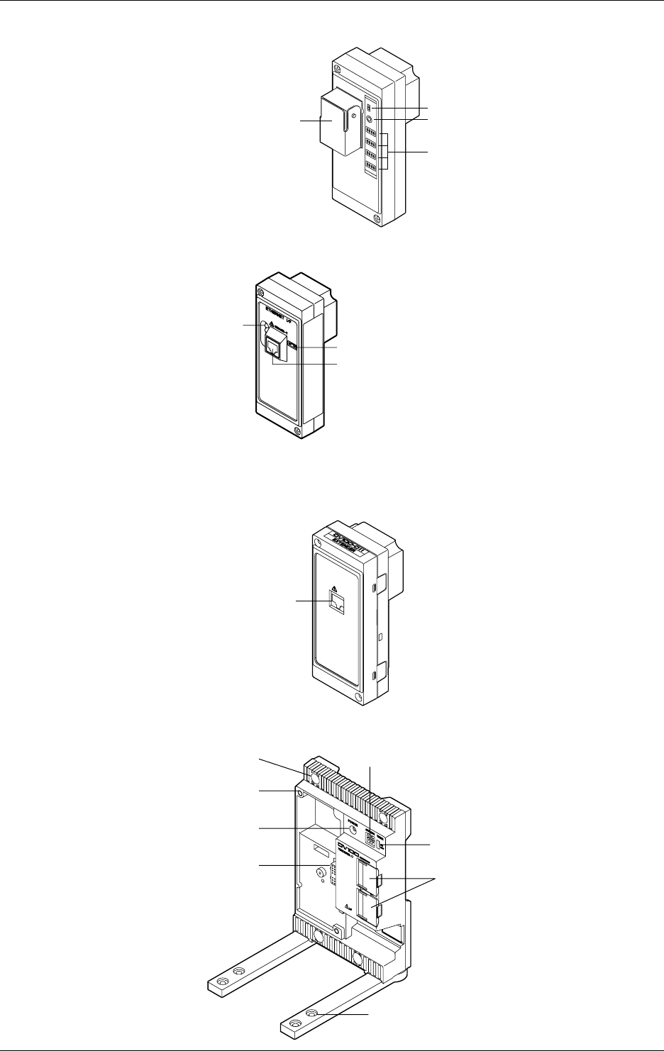
RS-422-A/RS-485 Module (DT300-31)
ON/OFF switch of built-in terminating resistor
LED
Switches to set
communication parameters
RS-422-A/RS-485 terminal
Ethernet module (DT300-41)
Switch to set mode
Status indicator
10BASE-T port
Extender Module/Extender Base
Extender Module (DV100-011)
EXTENDER I/F
I/F
Extension cable connector
Extender Base (DV100-012)
Lid covering the extension
Holes for fastening the feet
Terminator on/off switch
Slot number setup switch
Inatallation
holes
Screw holes for
module installation
Power indicator
Module connector
1.3 Names of Parts
1-11
IM DR232-01E
1
System Configuration
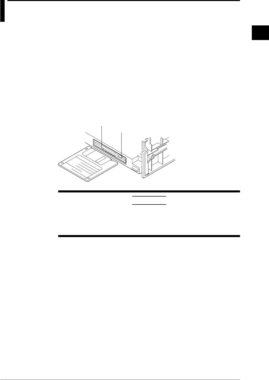
1.4 Floppy Disk
A floppy disk drive is provided with the DR232-1 and DR242-1.
Applicable Floppy Disks
3. 5-inch floppy disks can be used for this instrument. They can also be formatted on this
instrument.
• 2HD type: 1.2 MB or 1.44 MB (MS-DOS format)
• 2DD type; 720 MB (MS-DOS format)
Inserting a Floppy Disk into the Drive
Insert the floppy disk into the floppy disk drive, shutter side first and with the label face up.
Make sure that the floppy disk is inserted until the eject button pops up.
Removing the Floppy Disk from the Drive
Make sure that the access indicator is not lit, then push the eject button to remove the floppy disk.
eject button
access indicator
CAUTION
If the floppy disk is removed when the access indicator is still lit, damage to
the magnetic head of the floppy disk drive or to data saved on the floppy
disk may result. Before removing the floppy disk, always make sure that
the access indicator is OFF.
General Precautions Regarding Handling of Floppy Disk
For general precautions regarding handling of floppy disks, refer to the instruction manual
provided with the disk.

2-1
IM DR232-01E
2
Functions
2.1 Display Functions
The inter-active front panel display consists of three rows. The first row is the main display, and
the second and third row are sub-display 1 and 2 respectively.
Monitor Mode and Status Display
Monitor Mode
• Auto Mode
This mode can be set for the main display, sub-display 1 and sub-display 2. Measurement
values of all channels will be consecutively displayed with update interval.
• Manual Mode
This mode can be set for the main display, sub-display 1 and sub-display 2. Measurement
values of a single channel will be displayed. The display update interval is the same as the
measurement interval (refer to page 2-4).
• Manual Mode
This mode can be set for the main display. When choosing this display, the measurement values
of 5 consecutive channels will be displayed as a page using also sub-display 1 and 2. The
display update interval is the same as the measurement interval (refer to page 2-4).
• Alarm Search Mode
This mode can be set for the main display, sub-display 1 and sub-display 2. Channels at which
an alarm occurred will be searched for and their measurement values displayed. The display
update interval is 2 seconds.
• Bargraph Mode
This mode can be set for sub-display 1. Measurement values which are shown on the main
display will be shown as a bargraph. The display update interval is the same as the interval of
the main display.
• Alarm Status Mode
This mode can be set for sub-display 1 and 2. The display will show per channel whether or not
an alarm occurred (refer to page 2-13). On one display the alarm status of a maximum of 30
channels can be monitored (depending on the number of input channels). The display update
interval is 0.5 seconds.
• Relay Status Mode
This mode can be set for sub-display 1 and 2. The display will show the operating status of
internal switches/alarm output relays (refer to page 2-13). On one display a maximum of 30
relay statuses can be monitored. The display update interval is 1 second.
• Clock Mode
This mode can only be set for sub-display 2. The current date and time are shown.
• Displaying the Selected Mode
To the right of sub-display 1 the currently selected display mode is shown for a specific
display.
Status Display
Indicators at the right side of the display will light up to show that recording is in progress (refer
to page 2-5), alarms are occuring (refer to page 2-13), keys are locked (refer to page 2-17) and
chart needs to be replaced (refer to page 2-18).
Remote/Local Status Display
The status of remote/local control will be show on sub-display 2. Keys cannot be operated in
remote control.

2-2 IM DR232-01E
Display for Setting the Type of Input, Computation and Recording Conditions
Menus for setting each of the following functions will be displayed.
• measurement input functions (refer to page 2-3)
• recording functions (refer to page 2-5)
• alarm functions (refer to page 2-13)
• calculation functions (refer to page 2-16)
• event/action function, key-lock function and external in/output function (refer to page 2-17, 18)
Display for Setting Fundamental Functions
Menus for performing fundamental settings will be displayed.
2.1 Display Functions

2-3
IM DR232-01E
2
Functions
2.2 Measurement Input Functions
Input Type
DC Voltage
Measurements can be done after selecting the measurement range per channel. The minimum
range is 20mV, the maximum range is 50V.
Thermocouple
Measurements can be done after selecting the type of thermocouple per channel. The available
types are R, S, B, K, E, J, T, L, U, N, W and KPvsAU7FE.
Reference Junction Compensation (RJC) can be set to either use Internal RJC (INT) or External
RJC (EXT) per channel.
Burnout function can be set OFF per channel or it can be selected in which direction the trend line
will move if burnout occurs (right or left)
Resistance Temperature Detector
Measurements can be done after selecting the type of resistance temperature detector (RTD) per
channel. The available 17 types are Pt100(1mA), Pt100(2mA), JPt100(1mA), JPt100(2mA),
Pt50(2mA), Ni100(1mA)SAMA, Ni100(1mA)DIN, Ni120(1mA), J263*B, Cu10GE, Cu10L&N,
Cu10WEED, Cu10BAILEY, Pt100 (1mA) high resolution, Pt100 (2mA) high resolution, JPt100
(1mA) high resolution and JPt100 (2mA) high resolution.
Contact Input
The type of contact input can be selected from voltage level input or contact input, and recording
can be set ON or OFF per channel. In case of the voltage level input a voltage level up to 2.4V
results in recording OFF, whereas a voltage level of 2.4V or more results in recording ON.
DC Currents
DC currents ranging from -20 mA to 20 mA can be measured by means of the built-in 250-Ω
shunt resistors.
AC Voltages/Currents
The effective voltage, effective current, active power, reactive power, apparent power, frequency,
power factor and phase angle can be measured. The measuring range is common to all terminals.
The input terminals of the module with this input mode, unlike those of modules with other input
modes, are not consistent with a setup screen in terms of the channel number.
Strain
The module for this input mode supports the single-gauge, single-gauge three-wire (not yet
supported by the DU500-14 module), adjacent-side two-gauge, opposed-side two-gauge and four-
gauge methods. If you have connected any new strain gauge or changed the measuring range, go
through initial balancing before starting measurement.
Pulses
The module for this input mode can measure the number of pulses per second on a channel basis
or detect the on/off states by means of any variations occurring in the instantaneous value every
second. Once you connect the pulse input module, you can sum up values without the need for
the computing function.
Skipping Input Channels
This function allows skipping measurement, recording and display of channels you are not using.
Measurement, recording and display will not be done for the skipped channels.
Reference Junction Compensation (RJC)
This function is to be used when measuring temperatures using thermocouples. The voltage
generated by a thermocouple depends on the temperature of the spot of measurement and the
reference junction temperature. Reference junction compensation is a function which
compensates the temperature at the side of the measurement instrument to 0 degrees C.
To compensate for the environmental temperature an internal circuit can be selected, or
compensation by a fixed compensation voltage value (external) can be set.
2-4 IM DR232-01E
Scan Interval
• The duration of time (one scan) in which the measurement of all channels is carried out, is
called the scan interval.
• This interval can be set to any value from 0.5 second to 60 seconds. The shortest is 300 ch/500
ms (varies with the shortest measurement period of the input module).
A/D Integration Time
This instrument measures the input signal after putting it through an A/D converter. In order to
minimize the noise imposed on the input signal, specific integration times exist.
The integration time can be selected from 20ms (50Hz), 16.7ms (60Hz) and 100ms (10Hz).
When “AUTO” is selected, the integration time will be automatically decided according to the 50/
60Hz frequency of the power supply.
AUTO does not function if the instrument is the subunit (DS400/DS600) of the DC power supply
model (Selecting “AUTO” will set the A/D integration time to 20 ms (50 Hz)). If you are using
the instrument on a 60-Hz power supply, set the A/D integration time to 16.7 ms (60Hz).
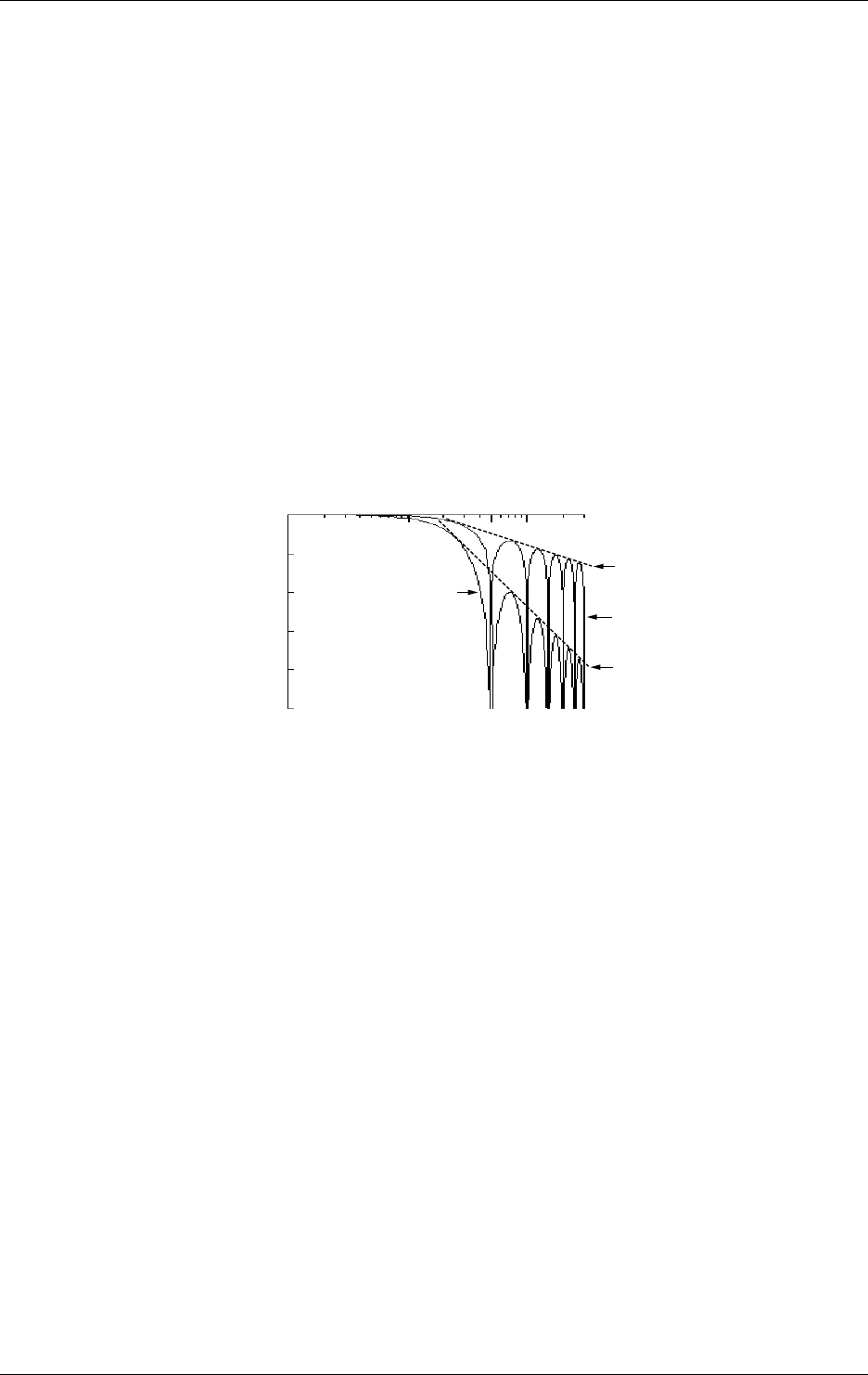
Input Filter
A filter can be set ON/OFF to reduce normal mode noise. Effects on normal mode noise are as
follows depending on the filter being ON/OFF (theoretical values).
0dB
–20dB
–40dB
–60dB
–80dB
–100dB
1Hz 10Hz 100Hz
50Hz 300Hz
Slope:–20dB/dec
Slope:–60dB/dec
Filter OFF
Filter ON
Frequency
Attenuation
2.2 Measurement Input Functions

2-5
IM DR232-01E
2
Functions
2.3 Recording Functions
Chart Speed
The speed at which the chart moves when performing trend recording can be selected from any
value between 1 to 1500mm/h.
Two types of chart speeds can be set. When you are not using the Event/Action function, which
will be described later on in this manual, chart speed 1 will be valid. When the Event/Action
function is being used, you can select whether chart speed 1 will change to speed 2 according to
the event status.
Recording Mode
Two types of recording modes are available; analog trend and logging mode. The default setting
is analog trend mode.
Analog Trend Mode (refer to the next page for a recording example)
Trend Recording (Dot recording)
The recording principle is that, according to measurement data and recording conditions, the
correct position on the chart will be decided and on that position the dot will be printed. Trend
recording conditions consist of the following.
• chart speed
• channels to be recorded
• recording color (refer to page 2-8)
• recording interval (refer to page 2-8)
• recording span (refer to page 2-9)
• recording zone (refer to page 2-9)
• partially expanded recording (refer to page 2-10)
• interpolation function (refer to page 2-10)
Digital Printout
Measurement data will be printed as numerical values. Digital printout conditions consist of the
following.
• channels to be recorded
• recording interval (refer to page 2-8)
• the number of channels to be recorded on the same line (refer to page 2-7)
Logging Mode
In this mode measurement data are only printed as numerical values. Logging recording
conditions consist of the following.
• channels to be recorded
• the recording direction (vertical or horizontal)
• recording interval (refer to page 2-8)
2-6 IM DR232-01E
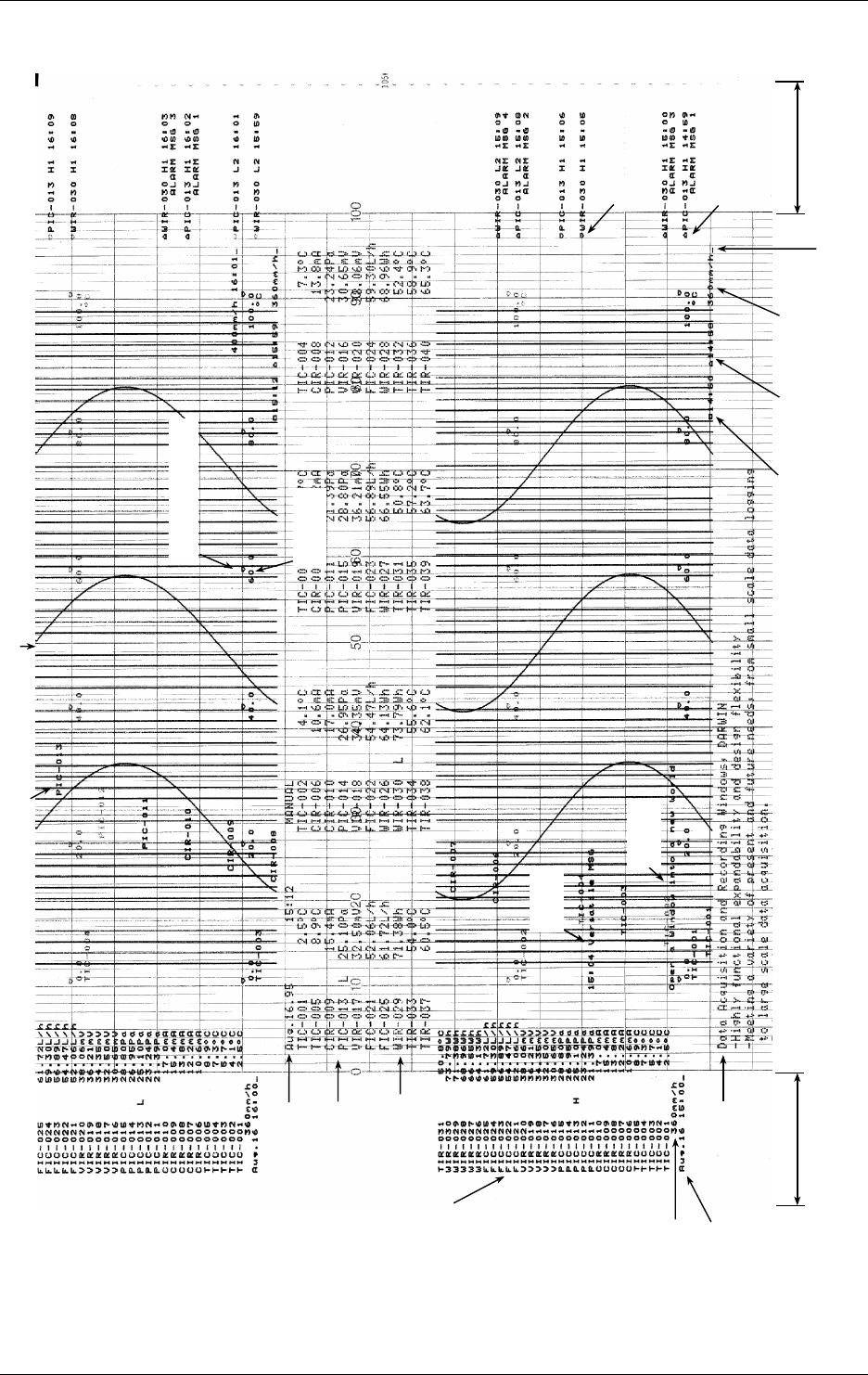
Recording Example
The numbers in parentheses refer to reference pages.
Right margin
Left margin
Header
(Page 2-12)
Digital printout
(Page 2-5)
Starting date/time
of Digital printout
Chart speed
(Page 2-5)
Manual Printout
(Page 2-12)
Starting date/time
of manual printout
Trend recording (Page 2-5)
Channel No. or tag of
dot recording
Channel No. or tag
of manual printout
Alarm occurrence mark
(Page 2-12)
Alarm release mark
(Page 2-12)
Chart speed
(Page 2-5)
Starting time
of dot
recording
(Page 2-7)
Ending time of
previons dot
recording
(Page 2-7) Reference position of
dot recording start
(Page 2-7)
Reference point of scale
(Page 2-7)
Titlle
(Page 2-12)
Message
(Page 2-12)
Scaled value
(Page 2-9)
2.3 Recording Functions
2-7
IM DR232-01E
2
Functions
Recording Format
You can modify the recording format of measurement values according to your own preferences.
The following selections are available.
Items common for Analog Trend and Logging mode
Printing Channel No. or Tag
When printing measurement values, the corresponding channel number or a preset tag can be
recorded with it. This selection will also affect the display the same way. The number of
characters of a tag which will be printed out, can be selected too.
Items for Analog Trend Mode
Printing Starting/Stopping Time of Recording
You can select whether to print the time of starting/stopping the recording (refer to page 2-9) on
the right side of the chart. The first time recording starts after the power has been turned ON, only
the starting time will be printed. After that, the current starting time will be printed together with
the stopping time of the previous recording. To the right of the starting time a bar will be printed
as a reference point to the time of starting.
Selecting the Number of Columns for Digital Printouts
You can select how many columns (where one column equals data of one channel) will be used in
one line for printing out measurement data.
Selection of the Pitch of Channel Printouts
You can select at which distance the channel numbers (or tags) will be printed. You can also
select this printout OFF. When tags have been selected, this distance applies to the tag printout.
Selection of the Pitch of Title Printouts
You can select at which distances the title will be repeatedly printed. You can also select this
printout OFF.
Selection of the Scaled Values Printout
You can select the printing pattern for scaled values (refer to page 2-9). You can also select this
printout OFF.
Selection of the Reference Point of Scaled Values
You can select whether or not to print a reference point for the positions of the scaled values.
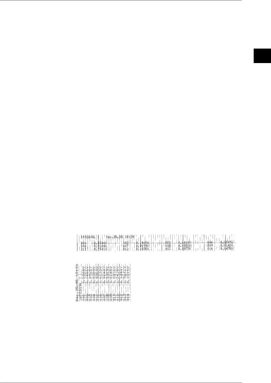
Items for Logging Mode
Selection of the Recording Direction (Horizontal/Vertical)
You can select whether printouts will occur in horizontal or vertical direction,
Example of a printout in horizontal direction
Example of a printout in vertical direction
2.3 Recording Functions

2-8 IM DR232-01E
2.3 Recording Functions
Recording Colors
In the trend recording the color of the recording can be selected per channel. The colors which can
be selected are black, purple, redish purple, navy blue, red, blue, brown, green, orange and
yellowish green.
The recording color of the numerical values in the logging mode is purple only.
Recording Interval
The time during which one scan of trend recording or numerical printout is carried out is called
the recording interval.
Recording interval for trend recording
This recording interval can be selected from AUTO or FIX.
AUTO
The recording interval is decided automatically depending on the measurement (scan) interval
and chart speed in order prevent the dots from overlapping. However, in cases where this
calculation would render the recording interval smaller than the scan interval, the recording
interval will equal the scan interval.
Recording interval = Scan interval × N
where N is an integer satisfying N ≤ 720 / (scan interval × chart speed). 720 is
fixed.
Example: when scan interval is 2s; chart speed is 100mm/h
then N ≤ 720 / (2 × 100) = 3.6
The closest matching integer is 3.
Accordingly, the recording interval becomes 2 × 3 = 6s.
FIX
Recording is carried out at an interval which is the same as the scan interval (2 to 60s)
regardless of the chart speed.
Recording interval for digital printouts
This recording interval can be selected from MULTIPLE or SINGLE
MULTIPLE
Six preset recording intervals (Timer 1 to 6) can be set and a recording interval can be selected
per channel. The timer setting can be selected from relative and absolute.
• Relative time: Time will be counted from the point of turning the power switch ON or of
resetting the timer. Each time the preset length of time is reached (and thus when time is
up), recording will start.
• Absolute time: A reference time is set, and from that time recording will start at preset time
intervals (each time when time is up).
SINGLE
The logging interval is decided automatically depending on the chart speed and the number of
columns for digital printouts.
Recording interval in logging mode
This recording interval can be selected from MULTIPLE or SINGLE
MULTIPLE
Same as for the analog trend mode
SINGLE
From the above mentioned six preset recording intervals, the interval set as Timer 1 will
become the recording interval.
Resetting the Recording Interval (Timer Reset)
This function will reset the elapsed time of the above mentioned MULTIPLE recording interval to
zero. Usually recording will start according to the recording intervals, but when you reset the
elapsed time using this function, the results are the same as for time-up.
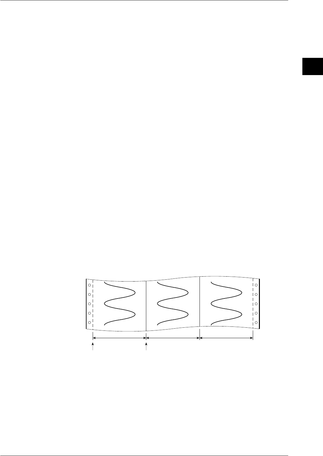
2-9
IM DR232-01E
2
Functions
Recording Span
The maximum value and the minimum value of the measurement range are decided when setting
the type of input. The difference between the minimum value and maximum value which will be
recorded within this measurement range, is called the recording span. The value on the left and
right side of the recording are called the left span and right span respectively.
Starting/Stopping Recording
Usually starting/stopping movement of the chart and trend recording is carried out by pressing the
appropriate key on the operation panel. But movement of the chart and trend recording can also
be started/stopped upon alarm occurrence or by remote control (event/action function).
Recording Method of Trend Recording
Chart movement can start by either key operation or event/action function and selected channels
will thus be recorded as trend recording.
Normal Recording
Selected channels will all be recorded regardless of the below mentioned occurrence/release of
alarms or group settings. Recording will start when the chart starts moving.
Trend Recording upon Alarm Occurrence
• Trigger Recording
All channels where an alarm occurred will be recorded. Even when the alarm is released,
recording will continue.
• Level Recording
All channels where an alarm occurred will be recorded. When the alarm is released, recording
will stop.
Group Trend Recording
Channels can be clustered in a group, and only those channels will be recorded.
Recording Zone
The recording span of measurement values on the chart is called recording zone. For each channel
you can set between what locations on the chart the measurement values will be recorded.
It is possible to assign zones so that the analog trend recordings of each individual channel will
not overlap. This setting is only valid for trend recordings in the analog trend mode. The default
setting is the full recording width of 250mm.
The left and right boundary of the recording zone (left position and right position respectively)
correspond to respectively the left and right span of the recording span.
Zone 1 Zone 2 Zone 3
Left position of zone 1
(=left span of ch1) Right position of zone 1
(=right span of ch1)
Trend of channel 1 Trend of channel 2 Trend of channel 3
Scale Values
Scale values are used to mark the divisions of zones and three different scale format can be
selected.
2.3 Recording Functions
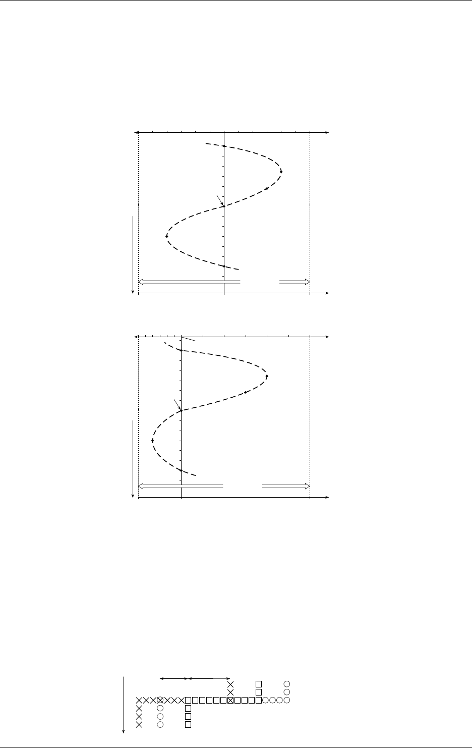
2-10 IM DR232-01E
Partially Expanded Recording
When carrying out trend recording, partially expanded recording enables you to compress a part
of the recording span in order to examine the expanded (other) part of the span in more detail. The
left boundary of the recording span being 0%, and the right boundary of the recording span being
100%, a segment of the recording span can be compressed. The following example shows a
situation where 25% of the recording span has been compressed. The points A, B, C, D, E and F
before compression correspond to the points A’, B’, C’, D’, E’ and F’ in the figure after
compression. The 25% left of the boundary shows —6 to 0V, whereas the 75% right of the
boundary shows 0 to 6V.
6 (V)
0 50 100
–6–5–4–3–2–1012345
Measurement value
(Recording span)
% of full recording
span
Recording
span
Recording
span
A
B
C
D
E
F
0
6 (V)
0 25 100
–6 –5 –4 –3 –2 –1
Measurement value
(Recording span)
% of full recording
span
A’
B’
C’
E’
F’
012345
D’
(% of compression:RATE)
(% of compression:RATE)
•Before compressing
•After compressing 25% of recording span
Bounda value
Chart direction
Chart direction
Interpolation Function
When carrying out trend recording and a measurement value differs greatly from the previous
one, the track of the recording changes stepwise in the dot printing. In cases like this,
interpolation will be carried out on the horizontal line to connect the two divergent trend tracks.
When the horizontal lines of channels are to be recorded on exactly the same location, only the
recording color with the higher priority will be used.
The priority of recording colors is black > purple > redish purple > navy blue > red > blue >
brown > green > orange > yellowish green, which means that black has the highest priority. In the
figure below a recording example is given of a horizontal line in the colors black, red and
yellowish green. In the area where red and yellowish green overlap (labeled as a), only red dots
will be recorded, and in the area where black, red and yellowish green overlap (labeled as b), only
black dots will be recorded.
However, at the locations where the recordings diverge after the connecting a horizontal line, all
recording colors will be recorded.
ab
Red Yellowish
green
Black
Chart direction
2.3 Recording Functions
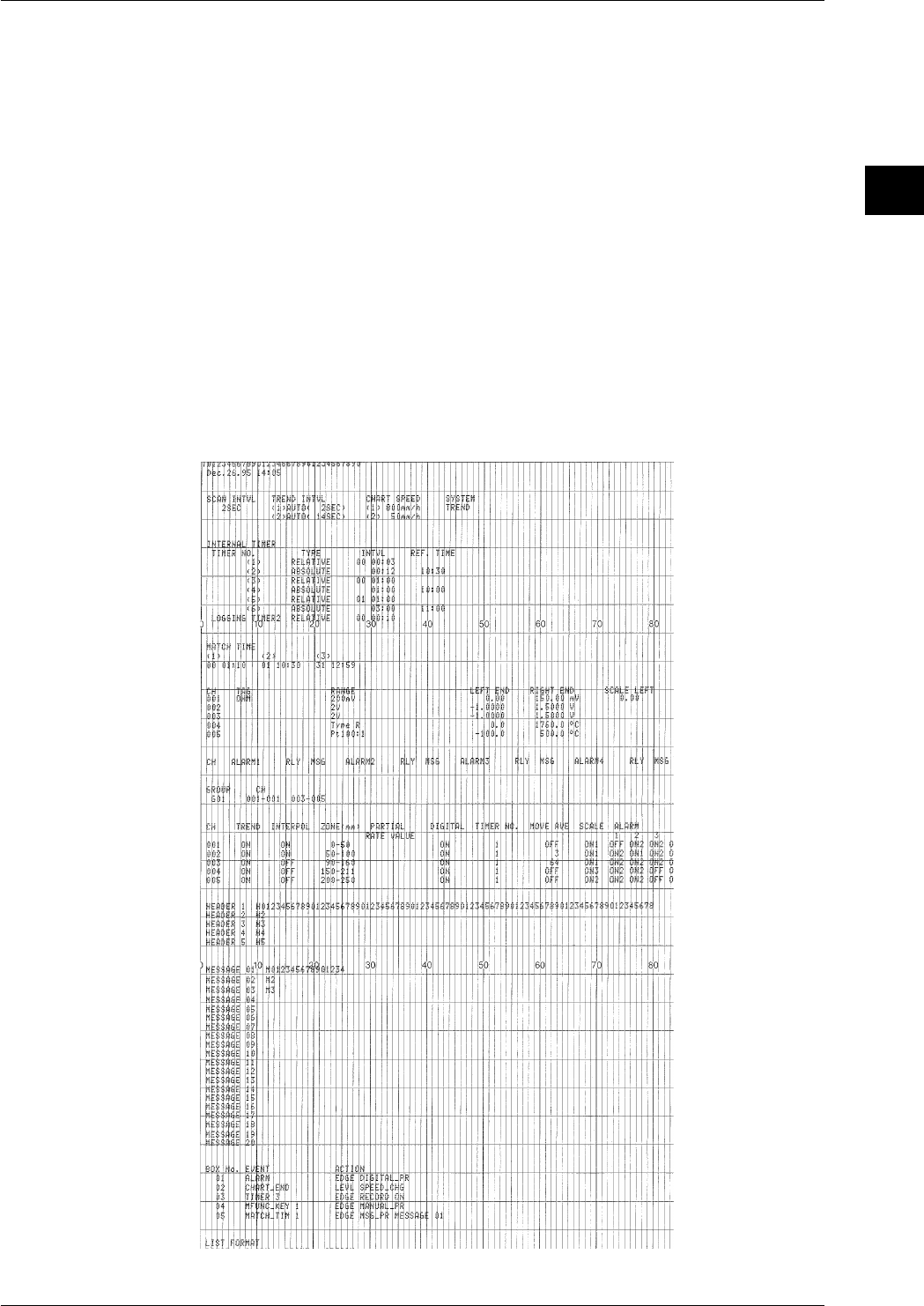
2-11
IM DR232-01E
2
Functions
List Printout
A list printout will show the following items.
• Title (if a title has been entered)
• Date and time
• Measurement interval, recording interval, chart speed and recording mode
• Timer setting (6 Multiple and Single)
• Match time: a specific time is set and when that time is reached, a preset operation will be
carried out (refer to event/action function on page 2-17)
• Tags for each channel, input type, recording span and linear scaling values (this print can be
selected ON/OFF)
• Alarm (this print can be selected ON/OFF)
• Group setting
• For each individual channel: whether the trend mode is ON/OFF, whether interpolation is ON/
OFF, recording zone settings, partially expanded recording settings, selected Timer No.,
whether moving average is ON/OFF, alarm type and whether manual print is ON/OFF (this
print can be selected ON/OFF)
• Headers (only when input is applied)
• Contents of up to 20 messages
• Settings related to event/action function
• Selections related to this list printout
2.3 Recording Functions

2-12 IM DR232-01E
Manual Printout
One scan of measurement values of selected channels will be recorded as digital values together
with the date and time. This printout can be executed by key operation or by event/action function
(refer to page 2-17). Refer to page 2-6 for a recording example.
Header Printout
A header can consist of up to 80 characters for each to up to 5 lines and recording can be executed
by key operation.
Additional Printouts
While recording analog trends it is possible to have engineering units, tags, scales, alarm, title,
messages, etc. printed along with the measurement values and the date/time.
• Engineering units; these will be printed in combination wiht the linear scaling function (refer to
page 2-16)
• Channel No. or tag; a preset tag can be printed for each channel; the selection whether to print
the channel No. or the tag (refer to page 2-7) can also be done
• Scale printout; values corresponding to the scales will be printed (refer to page 2-9)
• Alarm printout; alarm information (refer to page 2-15) will be printed upon occurrence (or
release) of an alarm. You can also set a message to appear upon occurrence of an alarm
• Title printout; A title of up to 32 characters can be printed. Furthermore, the title can be set to
be printed at regular intervals (refer to title pitch on page 2-7)
• Message printout; Recording of messages of up to 16 characters can be executed by key
operation or event/action function. Time will also be printed together with the message. Up to
20 different messages can be entered.
Set-Up List Printout
Each item as described in Ch. 10 will be printed.
Match Time Function
You can preset a time when you want recording to start/stop using the event/action function (refer
to page 2-12). When this time is reached, recording in the analog trend or logging mode will start/
stop.
2.3 Recording Functions
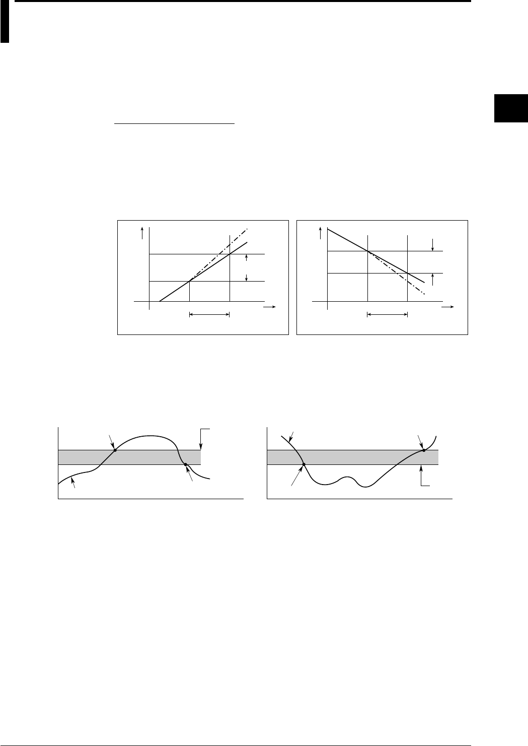
2-13
IM DR232-01E
2
Functions
2.4 Alarm Function
This function will show an alarm on the display or generate an alarm output signal when the
measurement conditions of a channel exceed/fall below preset values. Up to four alarms can be
set for each channel. Alarms can be set up to 4 items per channel.
Type of Alarms
Six types of alarms are available, namely high limit alarm, low limit alarm, high limit on rate-of-
change, low limit on rate-of-change, difference high limit and difference low limit.
Interval for Rate-of-Change Alarms
In case of high/low limit on rate-of-change alarms, variation is measured over a preset interval,
and if the variation exceeds a preset value, an alarm occurs. This interval can be set and applies to
all channels.
Measur-
ement
value
Measured
variation
T
Time
Set interval
1
T
2
t
1
t
2
21
Set variation
21
T
Time
2
T
1
t
1
t
2
Measur-
ement
value
Measured variation
T –T
t –t Set interval
21
t –t
Set variation
21
T –T
•High limit on rate-of-change •Low limit on rate-of-change
Alarm Hysteresis
You can set the width between the value of alarm occurrence and its release. This setting prevents
frequent alarm occurrences/releases in an unstable environment. Hysteresis values can be set in
the 0-1% percentage range of the recording span. The hysteresis setting is used for high and low
limit alarms.
Set alarm
value
Alarm release
Measurement values
Alarm occurrence
1V
Hysteresis
(Approx. 0.5%)
1V
Measurement values Alarm release
Hysteresis (Approx. 0.5%)
Set alarm
value
Alarm occurrence
•High limit alarm •Low limit alarm
Internal Switches
Sixty internal switches are provided which can be operated upon alarm occurrences. These
switches are only for internal operations and are used in combination with the event/action
function (refer to page 2-17).
Alarm Output Relays
The alarm module or the DI/DO module includes an alarm output relay. The contact of this relay
can be output to the outside. For how to mount modules, see 3.3, “How to Connect Input/Output
Modules” (page 3-7).
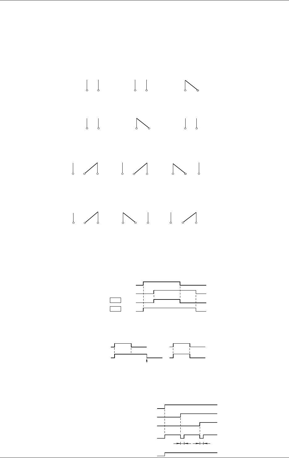
2-14 IM DR232-01E
Operation Mode
Energizing/De-energizing Setting
The alarm output relays can be selected to be energized or de-energized on alarm occurrence.
Using de-energizing, the alarm output relay will be activated when the power drops in the same
way as when an alarm occurs. This setting can be done for each relay individually.
Relay contacts in case of energizing
A-contact
NO CNOC
When power is OFF When power is on
and no alarm has
occurred
When power is on
and an alarm has
occurred
NO C
NO CNO C
When power is OFF When power is on
and no alarm has
occurred
When power is on
and an alarm has
occurred
NO C
C-contact
NO C NC NO C NC NO C NC
When power is OFF When power is on
and no alarm has
occurred
When power is on
and an alarm has
occurred
Relay contacts in case of de-energizing
NO C NCNO C NC NO C NC
When power is OFF When power is on
and no alarm has
occurred
When power is on
and an alarm has
occurred
AND/OR Setting
When a group of alarms share the same internal switch or alarm output relay, you can select how
the internal switches/alarm output relays will be operated.
AND: will be operated when all alarms are occurring;
OR: will be operated when at least one alarm is occurring.
Alarm occurrence
Channel 1
AND
Channel 2
Alarm output
relay status
Alarm occurrence
Operation
Operation
OR
Alarm status
HOLD/NON-HOLD Setting
You can select whether to hold the operating status of operated internal switches or alarm output
relays. This setting applies to both the internal switches and the alarm output relays.
Alarm release
Alarm reset
(Refer to page 2-5)
Alarm status
Operation of
Internal switch/
alarm output
relay
Alarm release
Working
Working
Reflashing Alarm Setting
When several alarms share the same alarm output relay, you can select this setting which results
in a short de-operation of the relay when a second alarm occurs.
Reflash=ON
Reflash=OFF
Alarm status
Alarm output relay
Channel 1
Channel 2
Channel 3
Approx. 200ms Approx. 200ms
Alarm occurrence
Alarm occurrence
Alarm occurrence
Working
Working Working
Working
2.4 Alarm Function

2-15
IM DR232-01E
2
Functions
Recording Alarm Information
Analog Trend Mode
When an alarm occurs (or releases), the occurrence/release mark, message, channel No. or tag and
time of occurrence/release will be printed on the right side of the chart.
Logging Mode
• If an alarm occurs, the type of alarm will be printed together with the measured value.
• If an alarm occurs (or is canceled), the alarm occurrence/cancellation mark, channel No./TAG,
the type of alarm, time when the alarm occurs/cancels, and messages are printed after all the
measured values.
Displaying Alarm Information
Alarm Indicator
“ALARM” Indicator
When at least one alarm occurs, the “ALARM” indicator at the right of the display will light.
Display per Channel
In sub-display 1 or 2, the alarm statuses of a maximum of 30 channels (according to the
specifications) can be displayed (refer to page 2-1). Besides, when the measurement value of a
channel where an alarm occurred is being displayed, the type of alarm will appear between the
channel number and the measurement value.
Channel No. Type of alarm Measurement value
001 H 10.000mV
Alarm Display Hold Function
This function allows the alarm display to remain even when the alarm has already been released.
This function can be selected ON or OFF and applies to all alarms. When the function is set to
ON, if an alarm occurs, the alarm display flashes.
Alarm Acknowledge Function
This function only resets the display and therefore allows you to verify the current alarm status on
the display. When the alarm display hold function is ON, selecting the ALARM ACK menu
results the alarm display changing from flashing to lit and will turn off when the alarm is released.
This setting applies to all alarms.
Alarm Reset
You can reset the internal switches and alarm output relays and the corresponding displays. The
previously mentioned alarm acknowledge function has the same function as resetting the alarm
display here. Resetting the internal switches and alarm output relays when the relay hold function
is set to ON has the following affects and depends on the alarm status.
• when alarms occur continuously, the internal switches/alarm output relays will turn to their
non-operative status for a short period but soon change into their operation status.
• when alarms are released, the internal switches/alarm output relays turn to their non-operative
status.
2.4 Alarm Function
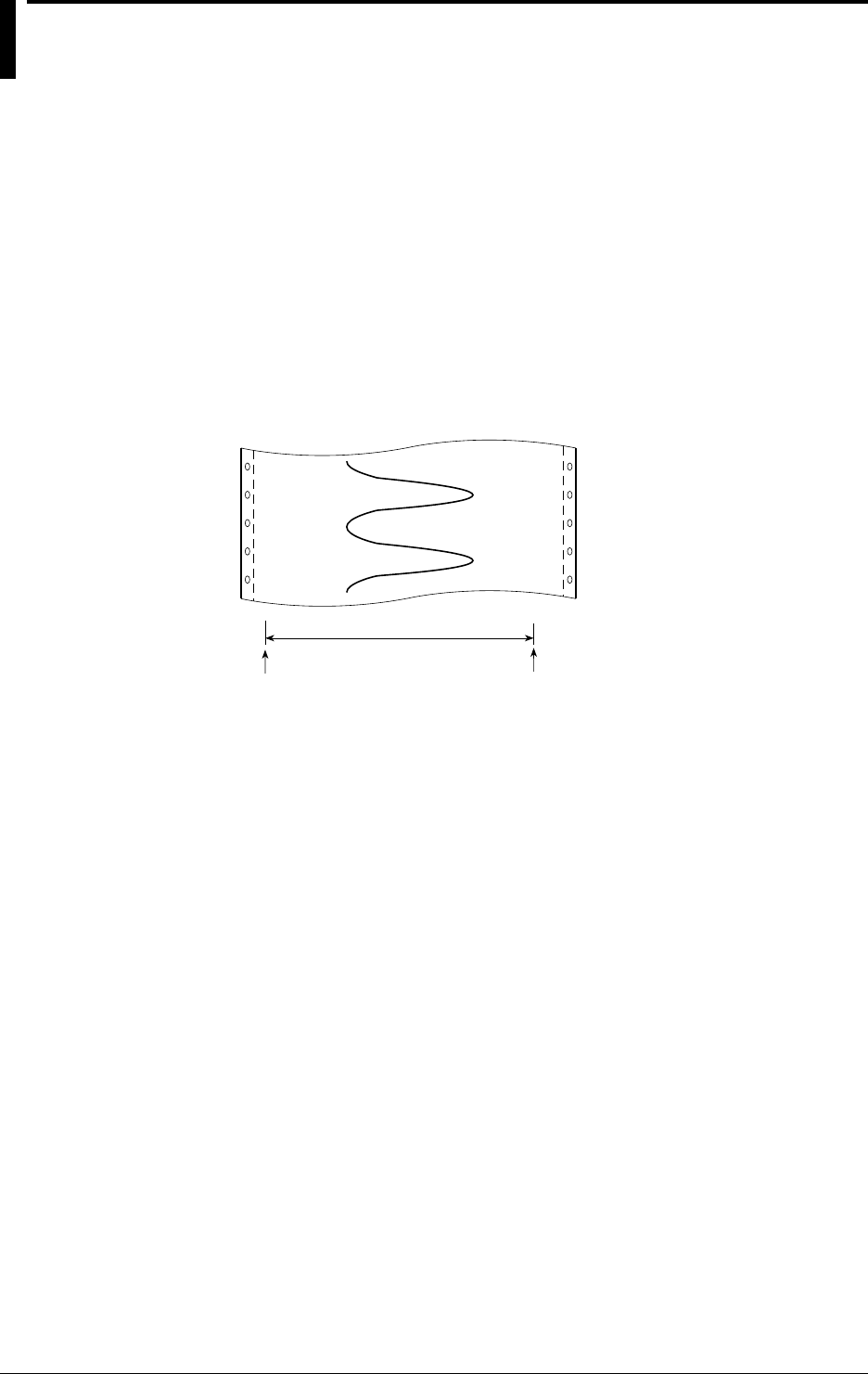
2-16 IM DR232-01E
2.5 Standard Computation Functions
Standard computations such as difference between channels and linear scaling can be set with
measurement input settings. A moving average computation is also available.
Difference between Channels
This function conputes the difference between the measurement values of a selected channel
(=reference channel) and any other channel (=destination channel). This can be applied to each
channel in the same unit. The computation formula is as follows:
Result of difference between channels computation = measurement value of destination
channel — measurement values of reference channel
Linear Scaling
This function changes the left and right span of the recording span to left and right scale values
which are converted to a different physical quantity. This can be applied to each channel and a
different engineering unit can be entered for display and printouts.
Example where voltage values are cenverted into linear scaling values
Left span:-2V
(=left scale:-0.1A) Right span:2V
(=Right scale:1.1A)
Moving Average
This function computes a moving average over a preset number of (K) measurement values. This
function is useful for displaying and recording of unsteady measurement values. The computation
formula is as follows.
Dm= (Mm-(K-1) + Mm-(K-2) + ... + Mm-2 +Mm-1 + Mm) / K
where
Dm: “m”th average value
Mm-(K-1) : the measurement value of the “K-1”th measurement before the “m”th
measurement
Mm-(K-2) : the measurement value of the “K-2”th measurement before the “m”th
measurement
..
..
Mm-2: the measurement value of the second last measurement before the “m”th
measurement
Mm-1: the measurement value of the last measurement before the “m”th measurement
Mm: the measurement value of the “m”th measurement
K : number of samples, and an integer ranging from 2 to 64
At the first computation, the measurement value of the first measurement will be multiplied by
the number of samples, after which the average will be taken. The measurement values of the
second and later measurements will replace these in turn, after which the average will be
calculated each time.

2-17
IM DR232-01E
2
Functions
2.6 Other Functions
Event/Action Function
Following the occurrence of an event such as remote control signal (12), alarm, internal switch,
chart end signal (out-of-paper), timer, match time or key operation, any of the following actions
can occur.
• Alarm acknowledge
(refer to page 2-15)
• Alarm reset
(refer to page 2-15)
• Timer reset
(refer to page 2-8)
• Recording start/stop
According to the recording mode and recording format, recording will start/stop
• Manual printout
(refer to page 2-12)
• Digital printout
(refer to page 2-6)
• Message printout
(refer to page 2-12)
• Message display
A preset message will be displayed on the main display
• Change of chart speed/recording interval
Chart speed 1 and recording interval 1 will change to chart speed 2 and recording interval 2,
and analog trend and logging recording will be carried out. Usually recording will be carried
out using chart speed 1 (set at the menu displayed after having pressed the CHART key) and
with recording interval 1 (set at the menu displayed after having pressed the SET key at a
touch). Upon the occurrence of an event, recording will be carried out using chart speed 2 and
with recording interval 2 (set at the menu displayed after having pressed the SET key for three
seconds).
• Group trend recording
(refer to page 2-9)
• Saving and reading of measured data, computed data and set-up data
This function is available if the instrument is equipped with a floppy disk drive.
This function enables saving of data to the internal RAM disk or floppy disk and reading of
data into the instrument.
• Starting/stopping of computation, reset, clear, status clear, and group reset
This function is available if the instrument is equipped with the computation function or
equipped with a floppy disk drive.
This function enables starting and stopping of computation and resetting and clearing of
computed data.
• Flag
Valid only for models with mathematical option (/M1.)
Set the flag to 1.
Key-Lock Function
This function prevents alterations by careless key operations. When the key-lock function is
activated, the indicator “KEYLOCK” at the right side of the display will be lit. All key
operations, except power ON/OFF, DISP/MODE key and the cursor, will then be disabled.
However, you can preset whether RECORD/FEED/PRINT/FUNC/M.FUNC1 and M.FUNC2
keys will remain operable even after key-lock has been set. Furthermore, when activating or
releasing the key-lock, a menu for password verification appears to prevent the key-lock to be
used by unauthorized operators.

2-18 IM DR232-01E
External In/Output Function (alarm module or DI/DO module is required)
Alarm Output
This output can be performed from the internal relay in the alarm module or the DI/DO module.
These relays will be operated when an alarm occurs. For details concerning their settings and their
relation with alarms, refer to page 2-14, 2-15.
Fail Output
One transfer contact in the DI/DO module is used for fail output. This relay will change to the de-
energized status when a failure of the recorder occurs.
NO CNC NO CNC NO C NC
Usually In case of failure In case of power OFF
Chart End Output
One transfer contact in the DI/DO module is used for chart end output. When the chart has only
2cm or less paper, the “CHART” indicator at the right of the display will light, and recording will
stop. The relay will change to the energized status.
NO C NC NO CNC NO C NC
Usually In case of Chart end In case of power
OFF
Controlling Recording Functions by Remote Control
The recording functions can be controlled by inputting up to 12 contact signals to the DI/DO
module. You can choose one of the following operations for each of the 12 signals. The remote
control function can be one of the events of the event/action function described on the previous
page.
• Alarm acknowledge
• Alarm reset
• Timer reset
• Recording start/stop
• Manual printout
• Digital printout
• Message printout
• Message display
• Change of chart speed/recording interval
• Group trend recording
2.6 Other Functions
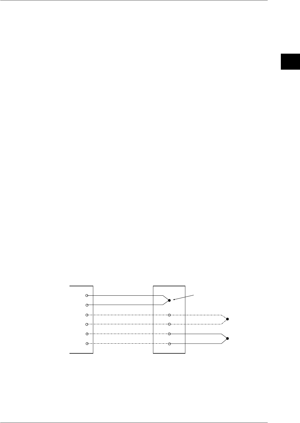
2-19
IM DR232-01E
2
Functions
Communication Interface (Communication module required)
Either GP-IB interface module, the RS-232-C interface module or RS-422-A/RS-485 interface
module can be connected. For details regarding operation and commands, refer to IMDR231-11E.
Internal Illumination (Option)
Clear internal illumination for easy distinction of traces is available as an option. Internal
illumination will be provided when the power is turned ON.
FDD (DR232-1, DR242-1)
This function enables saving/reading of measured data, computed data and set-up data for SET
mode to/from the internal RAM disk, and saving/reading of set-up data for SET and SETUP
modes to/from a floppy disk.
This also allows you to use events provided by the event/action function as a trigger to save/
retrieve measured/computed data to/from the internal RAM or retrieve set-up data when an event
takes place.
Computation Function (Option)
This function is available if the instrument is equipped with the computation function (/M1
model).
This function executes the following computations, and displays and records the results.
Four arithmetical operations (addition, subtraction, multiplication, division), square root, absolute
values, common logarithm, natural logarithm, power, logical product, logical sum, exclusive OR,
logical negation, statistical operation, relational operation
Up to 60 channels can be used for computation. It is also possible to use the event/action function
to start/stop computation or clear data for computation channels. Furthermore, up to 4 levels of
alarm (upper-limit alarm, lower-limit alarm) can be set for computation channels.
RRJC (Remote RJC, available if the instrument is equipped with the optional MATH
function)
In cases where the object is located in distance for temperature measurement using
thermocouples, the temperature of the object can be measured without using a number of
expensive thermocouples if a junction terminal is installed near the object. This method requires
the object to be connected to the terminal via a thermocouple, and the terminal to this instrument
via copper lead wires. Furthermore, the junction terminal needs to be connected to an input
terminal of this instrument via a thermocouple. The temperature of the junction terminal is then
measured to carry out compensation for the reference contact point used for measurement of
temperature of the object, then finally temperature of the object is measured.
This instrument
Input
terminals
Thermocoupler*
Copper lead wire
Copper lead wire
Thermocoupler*
Thermocoupler*
Junction terminal
(to be provided by the customer)
Reference channel
* Thermocouplers of the same type must be used
Computing & Report Function (Option)
This function can print the results of a statistical calculation of data on a specified channel
(measurement or computation channel), in a format predetermined for a preset time, date or
month, or send out the results to a communication line. The types of computations are averaging
(mean value, maximum and minimum), instantaneous value calculation and summation (sum,
cumulative sum).
2.6 Other Functions

3-1
IM DR232-01E
3
Installation and Wiring
3.1 General Precautions for Installation
Safety Precautions
Read the safety precautions
Make sure to read the safety precautions described on page 6 before using the instrument for the
first time.
Do not remove any covers from the instrument
For internal inspection or adjustment, contact your nearesst sales representative. Addresses may
be found on the back cover of this manual.
In case of malfunctioning
Never continue to use the instrument if there are any symptoms of malfunctioning such as unusual
sounds, smell or smoke coming from the instrument. Immediately turn OFF the power and unplug
the power cord. When using an adapter for direct wiring to the power supply, immediately turn
OFF the power supply. Also disconnect the power to the equipment under measurement. Contact
your sales representative or nearest service center. Addresses may be found on the back cover of
this manual.
Power Cord
Nothing should be placed on the power cord ; it should also be kept away from any heat sources.
When unplugging the power cord from the outlet, never pull the cord itself. Always hold the plug
and pull it. If the power cord is damaged, contact your dealer for replacement. Refer to page 2 for
the part number when placing an order.
General Handling Precautions
Never place anything on top of the instrument
Never place another instrument or any objects containing water on top of the instrument.
Otherwise a failure may occur.
When moving the instrument
First turn off the power of the equipment being measured and disconnect the measurement
leadwires and the communication cable. Then turn the power switch of this instrument OFF and
unplug the power cord from the outlet. When carrying the instrument, securely hold the
instrument with both arms and take care not to drop it.
Ventilation openings
Do not block the ventilation openings in order not to raise the internal temperature.
Electrically charged objects
Don’t bring electrically charged objects near the input terminals. The internal circuitry might be
damaged.
Chemicals
Do not pour volatile agents on the case nor leave the case in contact with rubber or PVC products
for a long period. The case is made of a thermoplastic resin, so take care not to let anything hot
such as a soldering iron touch the case.
Cleaning
When cleaning the case or any other part of the instrument, first remove the power cord from the
receptacle (and in case of direct connection, disconnect the power lines). Do not use volatile
chemicals since this might result in dis-coloring etc. Always use a dry, soft cloth for cleaning.
When not using the instrument for a long time
When the instrument is not being used for an extensive period of time, unplug the power cord
from the outlet (when using an adapter for direct wiring to the power supply, disconnect the
power cord from the outlet).
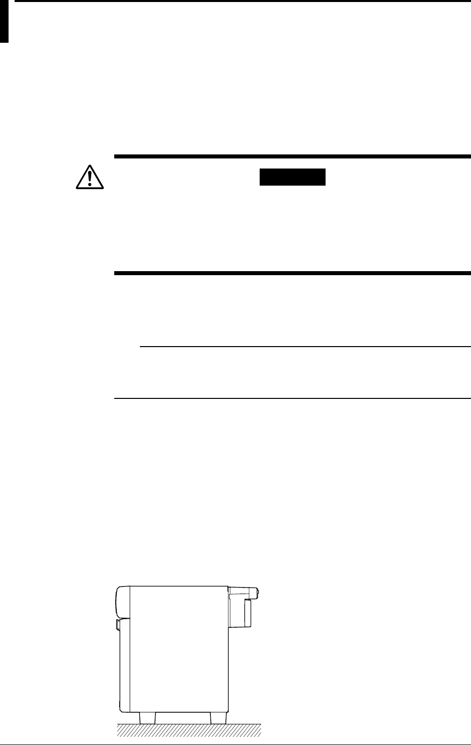
3-2 IM DR232-01E
3.2 How to Install
Installation Conditions
The instrument must be installed in a location where the following conditions are met.
Ambient temperature and humidity
• Ambient temperature: 0 to 50°C
However, in case you mount the AC power supply model subunits DS400/DS600 directly to a
panel, or if you apply the DIN rail, or mount them in a rack, it is possible to use them in a range
of –10 to 60°C.
WARNING
• When the environmental temperature is 50°C or more, the temperature
of the rear panel may rise to more than 70°C. Thus, touching the rear
panel under these circumstances has the danger of sustaining burns.
• To prevent a fire, always use the instrument in a vertical position, and
do not block the upper side of the modules (a space of at least 3cm is
necessary).
• Ambient humidity: 20 to 80%RH for –10 to 40°C, 10 to 50%RH for 40 to 50°C, 5 to 30%RH
for 50 to 60°C (However, no condensation should be present.)
• Installation location: Room
• Installation height: Altitude up to 2,000 m
Note
Internal condensation may occur if the instrument is moved to another place where both the ambient
temperature and humidity are higher, or if the temperature changes rapidly. In case of thermocouple input,
this might result in erroneous measurements. In those cases, allow the instrument to achieve eqailibrium
with to its new environment for at least one hour before starting operation.
Never install the instrument in any of the following locations:
• in direct sunlight or near heat sources
• where an excessive amount of soot, steam, dust or corrosive gases are present
• near strong magnetic field sources
• near high voltage equipment or power lines
• where the level of mechanical vibrations is high
• in an unstable place
Installation Method
DR232
Can be used on a desk-top, installed on the floor, or rack-mounted. Always install the instrument
vertically.
• saDesk-top or floor installation
Install the instrument vertically on a horizontal flat floor as shown below.
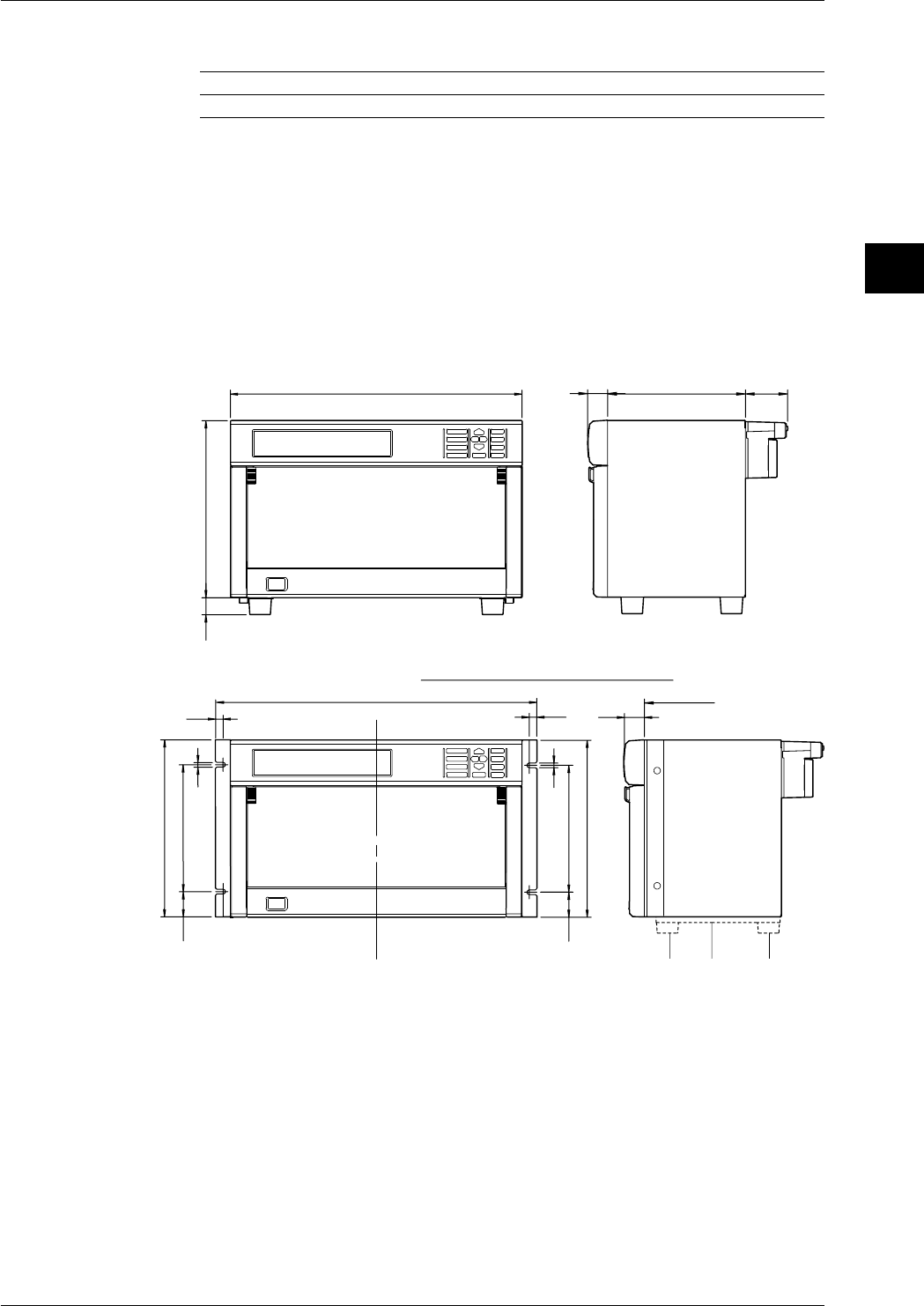
3-3
IM DR232-01E
3
Installation and Wiring
• Rack mounting
The following fittings can be supplied for rack mounting.
Name Model Description
Rack mount fitting DV400-013 Conforming to ANSI/EIA
• External dimensions and rack mounting dimensions for the DR232 are shown below.
• To install the rack mount fitting on the instrument, remove the screws at the right and left
forward of the instrument and use the mounting screws attached to the rack mount fitting.
Be careful that right and left screws have different lengths. The screw at the right when
facing the front of the instrument is M4 of 20 mm long and the left screw is M4 of 16 mm
long. Appropriate tightening torque is 1.4 to 1.5 N·m (14 to 15 kgf·cm).
• If another instrument is to be mounted under this instrument in an ANSI/EIA rack, remove
the prong or brackets designated with 2 and 3 in the figure below because they may interfere
with both instruments.
30 207 63.6
112
438
266
25
Rack Mounting Dementions
11.3
482.6±1
265.9±1
190.5±0.537.7
37.7
6.8
6.8
30
Panel face
1&2 : Removed
11.3
265.9±1
190.5±0.5
3.2 How to Install
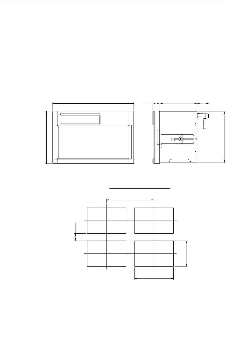
3-4 IM DR232-01E
DR242
• Panel mounting
Use steel plates 3 mm thick or more for panel mounting.
The external and panel cutting dimensions for the DR242 are shown below. The panel cutting
dimensions include the cutting interval for multiple mounting on the same panel.
The DR242 weighs about 12 kg, so a shelf should be provided to support the DR242 behind the
panel.
Insert the instrument from the front face of the panel.
Insert the blocks of the mounting brackets as accessories into the rectangular holes (after
removing seals) on right and left sides of the instrument, push the brackets toward the rear, and
engage the blocks with rectangular holes.
When a screw attached on each bracket is turned clockwise, the entire brackets are pushed
against the panel rear. Tighten the screws to securely fix the instrument to the panel. Proper
screw-tightening torque is 0.8 to 1.2 N·m (8 to 12 kgf·cm).
The brackets can be used for panels of 3 to 26 mm thick.
288
444
Panel cutting dimensions
At least 80 mm
At least 520 mm
281
425
+2
0
40 203 64.8
280
3.2 How to Install
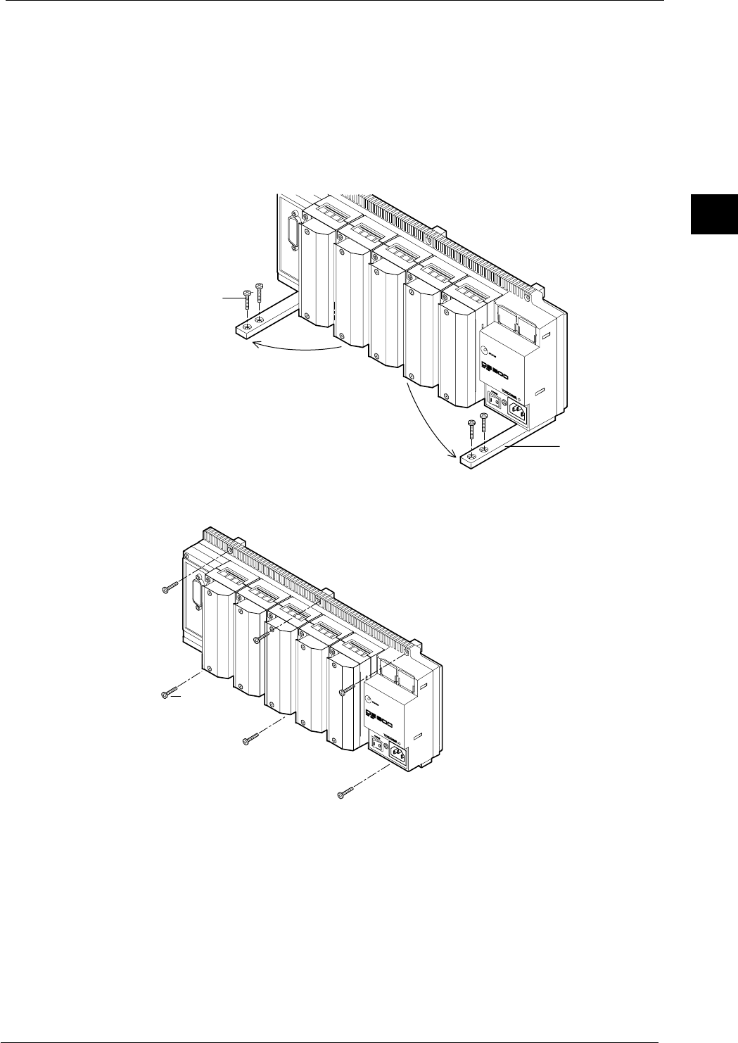
3-5
IM DR232-01E
3
Installation and Wiring
DS400/DS600
The subunit DS400/DS600 can be used on a desk-top, installed on the floor, directly panel-
mounted, mounted on DIN rails, or rack-mounted. Always mount the instrument vertically. If
the power terminals of the unit are screw terminals, directly mount the unit on the panel to
prevent electric shock.
• Desk-top use or installed on the floor
Extend the legs on the bottom of the unit forward as shown below and place the unit vertically.
If the unit could fall when wired, use the through-holes of the legs to fix the legs with the
attached four 4-mm screws.
Legs
M4 screws
• Direct panel mounting
Following the figure below, fix the unit at six places using the attached screws (length: 16 mm).
M4 screws
• Mounting on DIN rails
For the mounting procedure, see the instruction manual for “DIN rail mounting fitting.”
3.2 How to Install

3-6 IM DR232-01E
• Rack mounting
The following fittings are supplied for rack mounting. For details of the mounting procedure,
see the instruction manual for “rack mounting fitting.”
Name Model Description
Rack mounting fitting DV400-011 For DS400/DS600 conforming to ANSI/EIA
3.2 How to Install
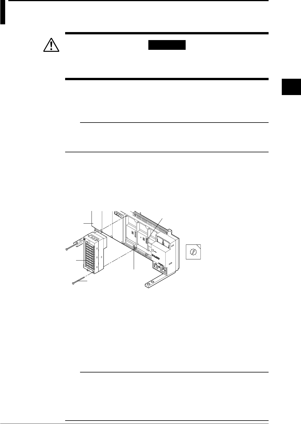
3-7
IM DR232-01E
3
Installation and Wiring
3.3 How to Connect the Input/Output Modules
WARNING
When connecting the Input/Output modules, make sure to turn OFF the
power to the DR232/DR242/DS400/DS600 to prevent an electric shock
or damage to the instrument.
Setting the Unit Number of each Subunit
When connecting subunits to the DR232/DR242, it is necessary to assign a distinctive unit-
number to each subunit. This number can be selected from 0 to 5 (the setting 6 and up will not be
recognized) and is set, as shown in the figure below, by a setting switch (rotary dipswitch).
Note
When you connect an input module at the location of the setting switch, the switch can not be operated
anymore. Therefore, make sure you set the switch before connecting any input module there.
It is convenient for confirming unit numbers to write each unit number setting on the gray concave surface
at the top of DS600 subunit (or on the left side of DS400 subunit).
Connecting Method
1. Verify that the power to the DR232/DR242/DS400/DS600 has been turned OFF.
2. Remove the cover of the location where the module will be connected. Do not remove any
cover of locations where no module will be connected.
3. Hold the input unit so that the male part of the connector at the back side of the input unit
matches the female part of the receiving connector. Then connect the unit.
4. Fasten the input unit by fastening the two accessory M3 screws.
0
1
2
3
4
5
6
7
8
9
Module connector
Screws to fasten the module
Input
module
Switch for setting
the unit number
• Switch for setting the
unit number
(settable from 0 to 5)
Cover
Modules Which Can be Used
Not more than one DI/DO module can be connected to all units.
• Main unit DR232/DR242
Alarm module, DI/DO module, and communication interface module.
(Note: The input module cannot be connected.)
Number of modules that can be connected: 1
• Subunit DS400/DS600
Input module, alarm module, and DI/DO module.
Number of modules that Dqn be connected: 4 for DS400, 6 for DS600 (up to 300)
DS400: Input module + alarm module + DI/DO module: max. four
DS600: Input module + alarm module + DI/DO module: max. six
Note
• No alarm module or DI/DO module can be connected to the right side of an input module, since the rise
in temperature would hinder the measurement accuracy. Verify the type of module by the seal on the top
side.
• Do not connect the universal input module and the power monitor module in slots next to eachother.
Keep them at least 1 slot apart. If you mount the power module immediately beside the universal
module, the measuring accuracy of the universal module may fall out of its guaranteed range because of
the heat radiating from the power module.
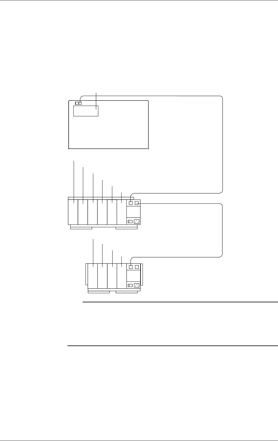
3-8 IM DR232-01E
Location and Location Number (Channel Number, Alarm Output Relay Number, DI/DO
Number)
The location numbers correspond to channel numbers for locations where the input module is
connected, to alarm output numbers for locations where the alarm module is connected, and to DI/
DO numbers for locations where the DI/DO module is connected.
Modules are mounted on a unit in slots. The number of each module is the same as that of the
slot.
As shown below, input/output location numbers are assigned related to the unit number (see the
previous page; the main unit number is fixed at I) and module location.
Module 0 (Location numbers:001 to 010)
Module 1 (Location numbers:011 to 020)
Module 2 (Location numbers:021 to 030)
Module 3 (Location numbers:031 to 040)
Module 4 (Location numbers:041 to 050)
Module 5 (Location numbers:051 to 060)
Unit No.:0
Subunit DS600
Module 0 (Location numbers:101 to 110)
Module 1 (Location numbers:111 to 120)
Module 2 (Location numbers:121 to 130)
Module 3 (Location numbers:131 to 140)
Unit No.:1
Subunit DS400
Module 0 (Location numbers:101 to I10)
Unit No.:I
Main unit DR232/DR242
Input modules cannot be
connected.
Note
When the following handling is done, it is necessary to carry out “system construction” to operate the
instrument correctly. After executing system construction, confirm the module information. For details,
see page 9-16.
· Connection (including addition or replacement)/removal of subunits, or unit number setting (see page 3-
7)
· Mounting (including addition or replacement)/removal of modules
3.3 How to Connect the Input/Output Modules
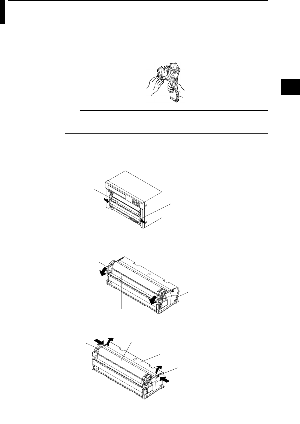
3-9
IM DR232-01E
3
Installation and Wiring
3.4 Installing the Chart and Ribbon Cassette
Install the chart.
Preparing the Chart
1. To prevent double feed of the folded chart, sufficiently ruffle and fan the chart on both folded
side ends.
Note
• Use chart papers specified by Yokogawa (part number: B9627RY or B9627AY). Using chart papers
other than those specified may cause problems such as large recording errors or the paper getting caught
under the sprocket.
Preparing the Chart Cassette
2. Open the front door and draw out the chart cassette from inside of the main unit by pulling
forward the chart cassette pressers while simultaneously pushing them (both right and left
pressers) toward the center.
Chart cassette
Chart cassette presser
3. Open the chart pressure plate 1 by pulling the right and left lever of the chart pressure
plate 1.
Chart pressure plate 1
Chart cassette
Lever of chart
pressure plate 1
4. Open upward the chart pressure plate 2 by simultaneously pushing the right and left latch
release buttons of the chart pressure plate 2.
Chart pressure plate 2
Latch release button of
chart pressure plate 2
Platen
Sprocket
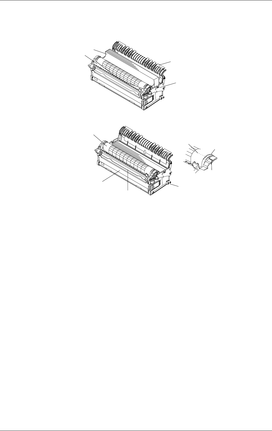
3-10 IM DR232-01E
Loading the Chart Paper
5. Place the chart paper in the chart storage housing, and move the paper to the left. Position the
chart so that its round perforations are on the left and the recording surface faces upward when
the chart paper is wound around the platen.
Chart paper
Chart pressure plate 2
Chart storage housing
Platen
6. Pass the chart paper through the gap between the chart pressure plate 1 and the platen.
Chart paper
Chart pressure plate 1
Guide pin
Chart rest cover
Sprocket
Right and left
position mark
Fold line of chart paper
7. Align the right and left chart paper perforations. Set the chart paper so that the right and left
marks of the sprockets and the fold line are aligned.
8. Close the chart pressure plate 1 until it latches. Confirm that the horizontal lines of the chart
paper are parallel with the horizontal line of the chart pressure plate 1. If they are not parallel,
open the chart pressure plate 1 and align the right and left perforations again.
9. Close the chart pressure plate 2 until it latches.
10.Fitting the guide pin of the chart cassette in the main unit guide groove, place the chart cassette
on the bottom of the main unit and slide the cassette deep inside the main unit until the latch
engages.
11.Turn on the power of the main unit and feed the chart paper by pressing the FEED key on the
operation panel. Feed the chart paper by three folds or more to the chart paper rest and check
that the paper is fed properly. Check this in the same way when the chart paper is fed manually
without recording. If the chart paper is not fed properly, repeat the procedure from step 2. For
details of turning the power on, see page 3-31.
12.When the chart paper approaches the end, the words “RENEW CHART” in an scarlet strip on
the paper appear. Prepare a new set of chart paper.
13.When the letters “CHART” in the status indicator in the display light, it indicates that the
paper has run out. Replace the chart with a new one according to the above procedure.
*To remove the chart paper from the chart rest, open the chart rest cover and take out the paper.
3.4 Installing the Chart and Ribbon Cassette
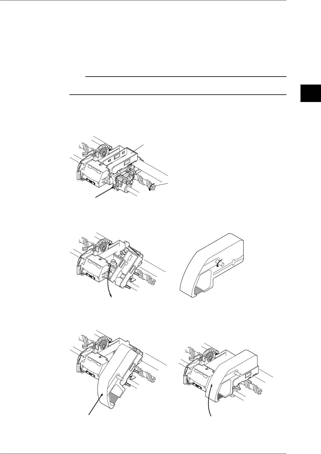
3-11
IM DR232-01E
3
Installation and Wiring
Loading the Ribbon Cassette
Preliminary Preparation
• If the carriage to which the ribbon cassette is to be mounted is located near the right end, turn
off the power and bring the carriage to a location near the left end by turning the screw shaft,
then load the ribbon cassette.
• Set the RECORD key on the operation panel to OFF and set all the recording actions for the
event/action functions (see page 9-1) to OFF so that recording does not start while loading the
ribbon cassette. If applicable, turn off the power.
Note
Do not perform recording without the ribbon cassette loaded, otherwise the platen may be scratched or the
chart paper may break.
Load the Ribbon Cassette in the DR232.
1. Open the front door and remove the chart cassette cassette from the main unit.
2. Press the red lever at the bottom of the carriage. The ribbon cassette holder moves to the right.
Red lever
Screw shaft
Ribbon cassette holder
3. Touch the ribbon cassette holder with a finger and tilt the housing downward.
4. Turn the ribbon cassette rotating knob in the direction of the arrow (counterclockwise) to take
up the ribbon slack.
5. Fit the projection of the housing into the slot of the ribbon cassette and insert the cassette fully
into the holder.
6. Bring up the front part of the cassette until it latches and make sure it is horizontal.
3.4 Installing the Chart and Ribbon Cassette
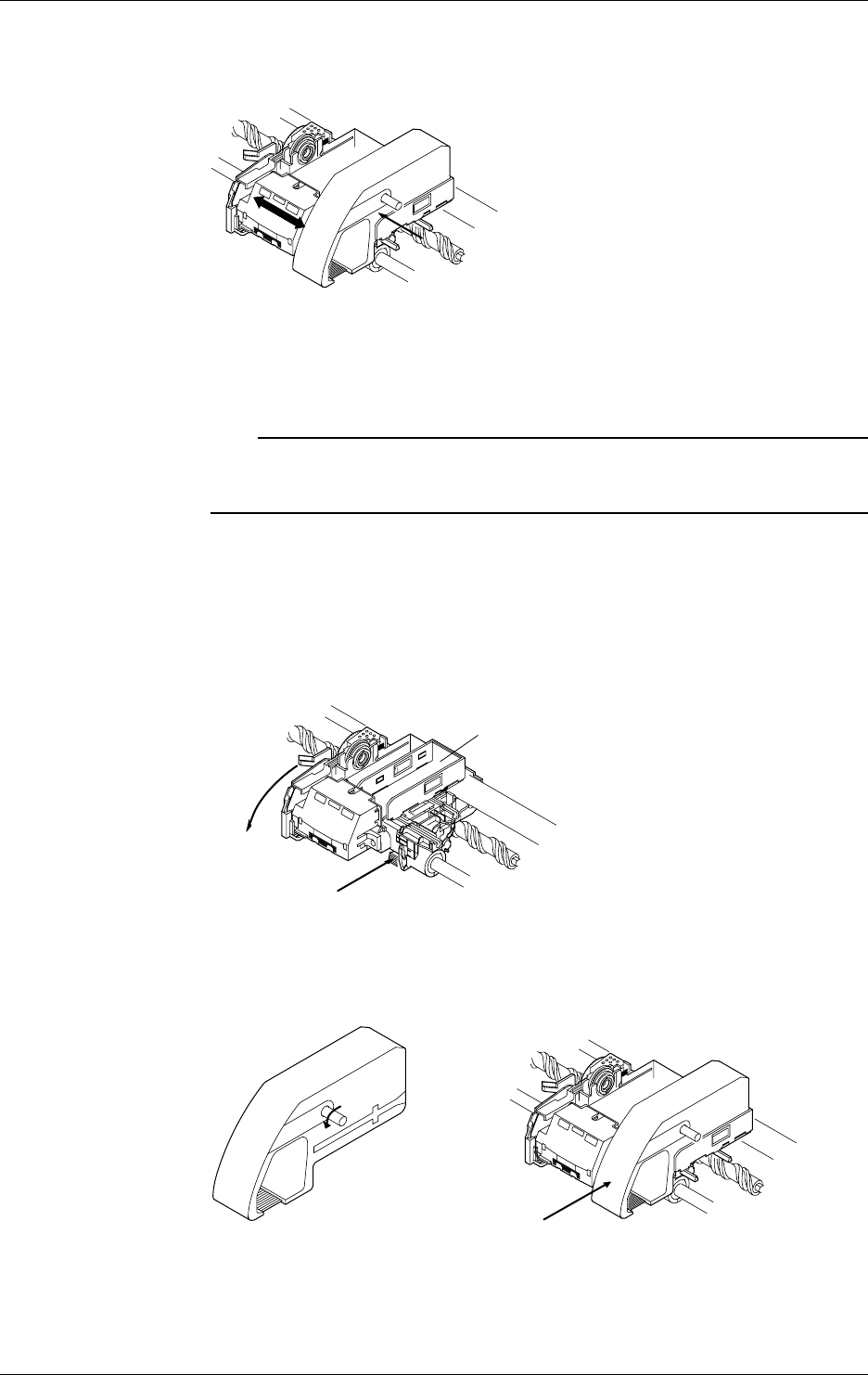
3-12 IM DR232-01E
7. Push the ribbon cassette to the left until the latch engages. Check that the three white lines of
the printer head are not visible when viewed from the front. If the white lines can be seen, the
ribbon cassette is not properly loaded. Push the cassette to the left again.
8. Turn the ribbon cassette rotating knob once more in the direction of the arrow
(counterclockwise) to take up the ribbon slack.
9. Return the chart cassette to the main unit.
10.Feed the chart paper by pressing the FEED key on the operation panel to prevent a delay in
starting the chart paper feed.
Note
• Check that the ribbon cassette is properly loaded in the carriage.
• If a ribbon cassette is used for a long time, the ribbon may become wavy and move out of the dot printing
range of the printer head. If this happens, replace the ribbon with a new one.
Load the Ribbon Cassette into the DR242.
1. Open the front door and open the display door. The ribbon cassette can be loaded without
removing the chart cassette from the main unit.
2. When the chart cassette is removed, press the red lever 1 at the bottom of the carriage. When
the chart cassette is not removed, pull forward the red lever 2, then the ribbon cassette holder
moves to the right.
Red lever 1
Red lever 2 Ribbon cassette holder
3. Turn the ribbon cassette rotating knob in the direction of the arrow (counterclockwise) to take
up the ribbon slack.
4. Fit the projection of the holder into the slot of the ribbon cassette and insert the cassette fully
into the holder.
3.4 Installing the Chart and Ribbon Cassette

3-13
IM DR232-01E
3
Installation and Wiring
5. Push the ribbon cassette to the left until the latch engages. Check that the three white lines of
the printer head are not visible when viewed from the front. If the white lines can be seen, the
ribbon cassette is not properly loaded. Push the cassette to the left again.
6. Turn the ribbon cassette rotating knob once more in the direction of the arrow
(counterclockwise) to take up the ribbon slack.
7. Feed the chart paper by pressing the FEED key on the operation panel to prevent a delay in
starting the chart paper feed.
Note
• Check that the ribbon cassette is properly loaded in the carriage.
• If a ribbon cassette is used for a long time, the ribbon may become wavy and move out of the dot printing
range of the printer head. If this happens, replace the ribbon with a new one.
3.4 Installing the Chart and Ribbon Cassette
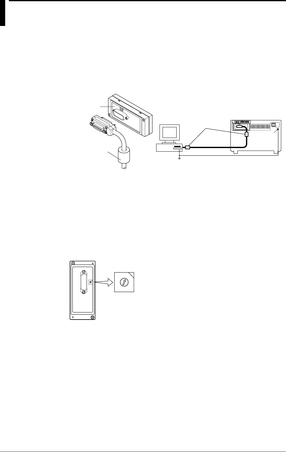
3-14 IM DR232-01E
3.5 Connecting the Interface Cables
When connecting a personal computer to the instrument via a communication interface, observe
the following:
GP-IB
The GP-IB connector of the GP-IB communication module is a 24-pin connector of IEEE St’d
488-1978. Only use cables that conform to IEEE St’d 488-1978 as a communication cable.
Connection Procedure
Connect the cable as shown in the figure below.
GP-IB module
Ferrite core
Personal
computer Ferrite core
Function
grounding
terminal
•When connecting the cable, take note of the following.
• To reduce noise, use two ferrite cores (e.g., ZCAT 3035-1330 from TDK) at both ends of the
interface cable as shown above.
• Securely tighten the screws which fasten the GP-IB cable connector.
• If more than one equipment is connected, the same addresses cannot be assigned to different
equipment.
• Use only cables of 2 m or less to interconnect each equipment.
How to Assign an Address
The address can be assigned easily by turning the rotary dipswitch as shown in the figure below.
Any address can be set from “0” to “15”; the characters “A” to “F” on the dipswitch correspond to
the address “10” to “15” respectively.
0
1
2
3
4
5
6
7
8
9
F
E
D
C
B
A
0
1
2
3
4
5
6
7
8
9
F
E
D
C
B
A
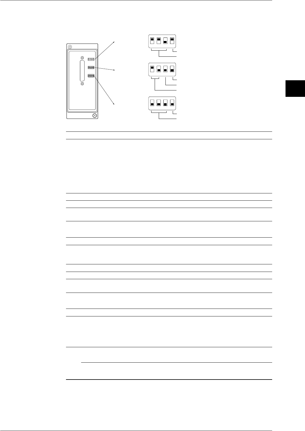
3-15
IM DR232-01E
3
Installation and Wiring
RS-232-C
Communication Settings
Communication parameters are set using the three switches located on the RS-232-C modules.
1234
Switch 1
Data length
Baud rate
1234
Switch 2
Not used
Parity
Stop bit
1234
Switch 3
Not used
Handshake format
ON
OFF
OFF
OFF
ON
ON
Switch 1 and No.4 of switch 2
Baudrate dipswitch No.1 No.2 No.3 No.4 (Switch 2)
150 OFF OFF OFF OFF
300 OFF OFF ON OFF
600 OFF ON OFF OFF
1200 OFF ON ON OFF
2400 ON OFF OFF OFF
4800 ON OFF ON OFF
9600 ON ON OFF OFF ←initial value
19200 ON ON ON OFF
38400 OFF OFF OFF ON
Data length dipswitch No.4
7 OFF
8ON←initial value
Switch 2
Parity dipswitch No.1 No.2
NONE OFF OFF
ODD OFF ON
EVEN ON OFF ←initial value
Stop bit dipswitch No.3
1 OFF ←initial value
2ON
Switch 3
Handshake format dipswitch No.1 No.2 No.3
no handshake OFF OFF OFF ←initial value
XON-DTR* OFF OFF ON
XON-RTS* OFF ON OFF
CTS-DTR OFF ON ON
CTS-RTS ON OFF OFF
* When the baud rate is set to 38400, there is no handshake.
Note
When you are using the accessory standard software, the settings should be as follows: baud rate 2400 to
19200bps, data length: 8 bit, parity: ODD, stop bit: 1.
3.5 Connecting the Interface Cables
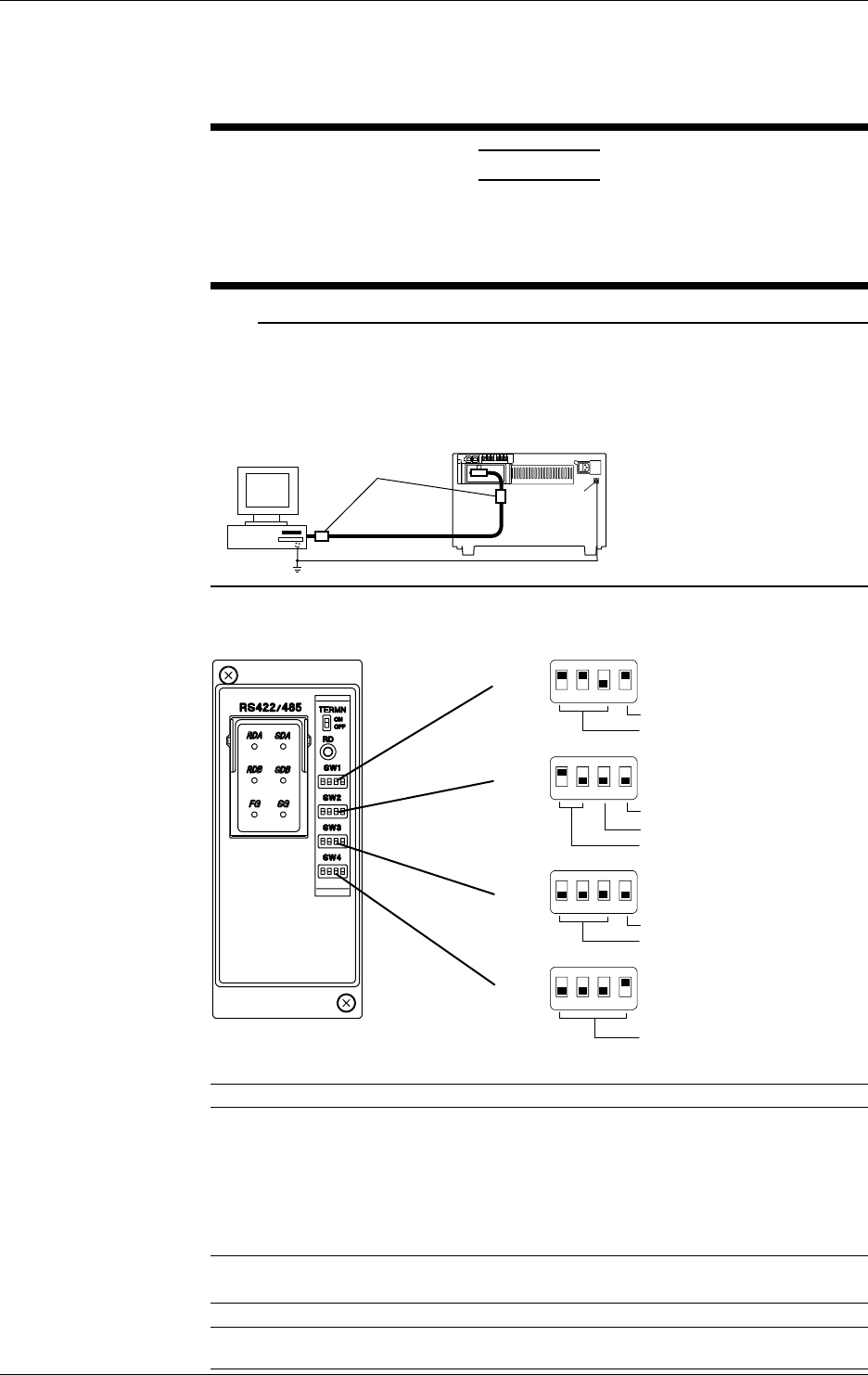
3-16 IM DR232-01E
Connecting the RS-232-C cable
For details on connecting the RS-232-C connector of the RS-232-C communication interface
module to a personal computer, see IM DR231-11E, “DR231/DR232/DR241/DR242
Communication Interface User’s Manual.”
CAUTION
When (dis)connecting the RS-232-C cable, turn OFF the power of both
the personal computer and the instrument. If the power is not turned
OFF, malfunctions may occur and the internal circuitry may be
damaged.
Note
To reduce noise, use ferrite cores (e.g., ZCAT 3035-1330 from TDK) for the interface cable as shown
below. Two ferrite cores should be installed near both ends of the interface cable. If the noise is
particularly bad, use several ferrite cores in series. Use a shielded cable for the interface cable and make a
one-point grounding at the ground terminal of this instrument together with the functional-ground terminal
of the personal computer.
Personal
computer Ferrite core
Function
grounding
terminal
RS-422-A/RS-485
1234
SW1
Data length
Baud rate
ON
OFF
1234
SW2
four-wire/two-wire
Stop bit
Parity
ON
OFF
1234
SW3
Address (upper)
Minimum response time
ON
OFF
1234
SW4
Address (lower)
ON
OFF
Baud rate (No.1 to 3 of SW1)
Baud rate No.1 No.2 No.3
300 OFF OFF ON
600 OFF ON OFF
1200 OFF ON ON
2400 ON OFF OFF
4800 ON OFF ON
9600 ON ON OFF ←Default Setting
19200 ON ON ON
38400 OFF OFF OFF
Data length (No.4 of SW1)
Data length No.4
7 OFF
8ON←Default Setting
3.5 Connecting the Interface Cables

3-17
IM DR232-01E
3
Installation and Wiring
Parity (No.1 to 2 of SW2)
Parity No.1 No.2
None OFF OFF
ODD OFF ON
EVEN ON OFF ←Default Setting
Stop bit (No.3 of SW2)
Stop bit No.3
1 OFF ←Default Setting
2ON
Switch between four-wire/two-wire systems (No.4 of SW2)
four-wire/two-wire No.4
four-wire OFF ←Default Setting
two-wire ON
Minimum response time (No.1 to 3 of SW3)
Minimum response time No.1 No.2 No.3
0ms OFF OFF OFF ←Default Setting
10ms OFF OFF ON
20ms OFF ON OFF
50ms OFF ON ON
100ms ON OFF OFF
Address (No.4 of SW3 and No.1 to 4 of SW4)
Address No.4(SW3) No.1(SW4) No.2(SW4) No.3(SW4) No.4(SW4)
1 OFF OFF OFF OFF ON ←Default Setting
2 OFF OFF OFF ON OFF
3 OFF OFF OFF ON ON
4 OFF OFF ON OFF OFF
5 OFF OFF ON OFF ON
6 OFF OFF ON ON OFF
7 OFF OFF ON ON ON
8 OFF ON OFF OFF OFF
9 OFF ON OFF OFF ON
10 OFF ON OFF ON OFF
11 OFF ON OFF ON ON
12 OFF ON ON OFF OFF
13 OFF ON ON OFF ON
14 OFF ON ON ON OFF
15 OFF ON ON ON ON
16 ON OFF OFF OFF OFF
17 ON OFF OFF OFF ON
18 ON OFF OFF ON OFF
19 ON OFF OFF ON ON
20 ON OFF ON OFF OFF
21 ON OFF ON OFF ON
22 ON OFF ON ON OFF
23 ON OFF ON ON ON
24 ON ON OFF OFF OFF
25 ON ON OFF OFF ON
26 ON ON OFF ON OFF
27 ON ON OFF ON ON
28 ON ON ON OFF OFF
29 ON ON ON OFF ON
30 ON ON ON ON OFF
31 ON ON ON ON ON
3.5 Connecting the Interface Cables
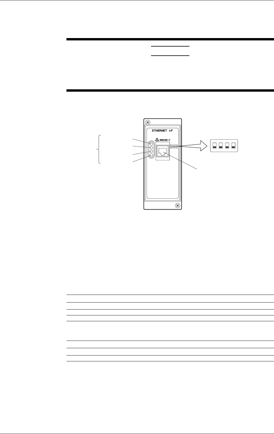
3-18 IM DR232-01E
3.5 Connecting the Interface Cables
For details on connectin the RS-422-A/RS-485 connector of the RS-422-A/RS-485
communication interface module to a personal computer, see IM DR231-11E, “DR231/DR232/
DR241/DR242 Communication Interface User’s Manual.”
CAUTION
When (dis) connecting the RS-422-A/RS-485 cable, turn OFF the power
of both the personal computer and the instrument. If the power is not
turned OFF, malfunctions may occur and the internal circuitry may be
damaged.
Ethernet
Tx (yellow)
)
LINK (yellow)
STS1 (green)
STS2 (green)
Status
Indicator LED
Dip Switch
1234
ON
OFF
10BASE-T Port
Connect the RJ-45 modular jack
of the twist pair cable connected
to the 10BASE-T network.
You can select the following three modes by setting the dip switch.
Configuration mode: A mode in which the IP address, subnet mask, and default gateway are set
for the DR.
Test mode: A mode in which the condition of the physical connection is tested.
Communication mode: A mode in which the DR is connected to the network to carry out
communication. Use this mode to read in the DR measurement data with
the PC.
In addition, you can turn ON/OFF the Keepalive function.
Mode Setting
Mode Switch 1 Switch 2
Configuration mode ON OFF
Test mode OFF ON
Communication mode OFF OFF ←Default Setting
Do not set both dip switches, 1 and 2, to ON.
Keepalive Setting
Keepalive Switch 3
Enable ON
Disable OFF ←Default Setting
Keepalive is a function supported by TCP. It sends packets at constant time intervals and
automatically disconnects when there is no corresponding response. This instrument sends
packets at 30-second time intervals. If a response is not received, it sends 4 more packets at one-
second intervals. If a response is still not received, the connection is dropped.
Have dip switch 4 turned OFF.
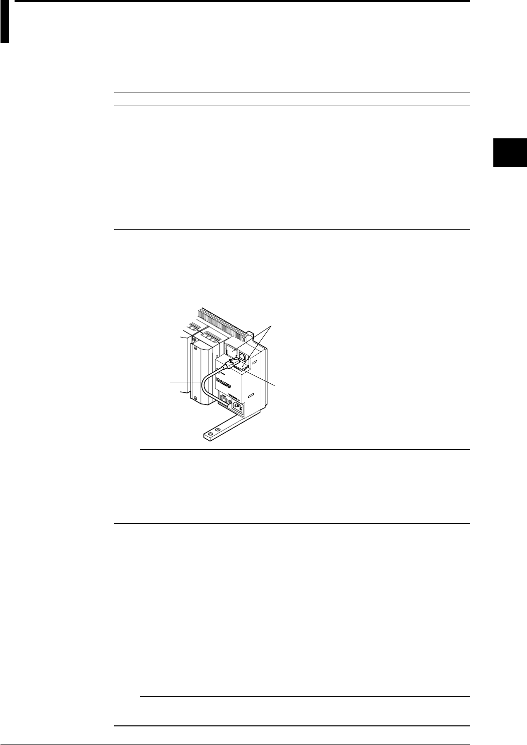
3-19
IM DR232-01E
3
Installation and Wiring
3.6 Connecting the Extension Cables-
Extension Cables
Any of the following extension cables can be used for connections between the DA100 main unit
and subunits or for connections between subunits.
Name Model Description
Extension cable DV200-000 Length: 0.5m
Extension cable DV200-001 Length: 1m
Extension cable DV200-002 Length: 2m
Extension cable DV200-005 Length: 5m
Extension cable DV200-010 Length: 10m
Extension cable DV200-020 Length: 20m
Extension cable DV200-050 Length: 50m
Extension cable DV200-100 Length: 100m
Extension cable DV200-200 Length: 200m
Extension cable DV200-300 Length: 300m
Extension cable DV200-400 Length: 400m
Extension cable DV200-500 Length: 500m
Connecting Procedure
Insert the plug of the extension cable in the connector until you hear a click. Since both
connectors are identical, it makes no difference which connector you use. Furthermore, since both
plugs of the cable are identical, you may use either end.
When pulling the plug from the connector, gently press the peg of the plug and pull it forward.
Lid
Plug
Extension cable
Note
When the following handling is done, it is necessary to carry out “system construction” to operate the
instrument correctly. After executing system construction, confirm the module information. For details,
see page 9-16.
• Connection (including addition or replacement)/removal of subunits, or unit number setting (see page 3-
7)
• Mounting (including addition or replacement)/removal of modules
Points to Note when Using the Extension Cables
• The maximum rated temperature is 60°C;
• Never disconnect the extension cable from the connector by pulling the cable, since this might
damage the signal cable. Always hold the plug.
• When wiring the extension cable through a cable duct, or metal pipe or such, protect the peg on
top of the plug by covering it with tape.
• For extension cables of longer than 50 m connect the plug with copper foil directed towards the
main unit DA100. Applying it in reverse direction might increase noise.
• Fasten the cabels in such a way that no force is applied to the connector or the plug.
• To prevent the wire from snapping, etc. do no apply a tensile force of more than 70N.
Furthermore, do not bend the cable in a radius of 3 centimeters or less.
• For the environmental conditions for wiring, refer to Section 3.11, “Countering Noise” (page 3-
35).
Note
When several sub-units are connected, and the power is turned off of one of them, the other connected sub-
units which are further away from the main unit will not be recognized anymore.
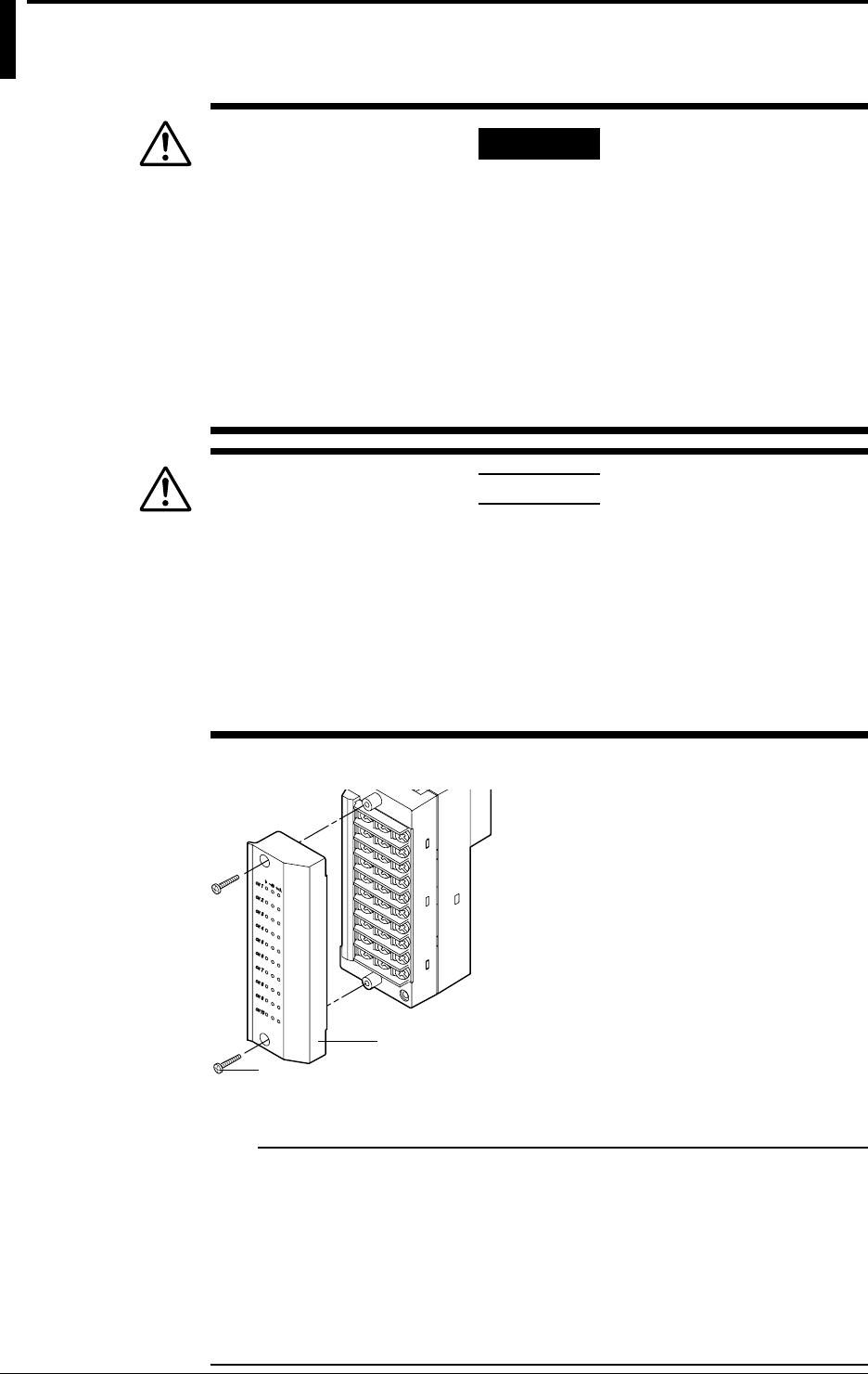
3-20 IM DR232-01E
3.7 Connecting the Signal Lines
WWARNING
• To prevent electric shock, always make sure that the power supply is
turned OFF before connecting.
• When 30VAC or 60VDC and more is applied to the output terminal of the alarm
module or the output terminal of the DI/DO module, use double-insulated
wires(withstand voltage performance: more than 2300VAC) for those wires
which apply 30VAC or 60VDC and more. All other wires can be basic-
insulated(withstand voltage performance: more than 1350VAC). Furthermore,
use “crimp-on” lugs (for 4mm screws) with insulation sleeves for connecting to
the screw terminal. Make sure that the crimp-on tool must be one specified by
the crimp-on lugs manufacture, and that the crimp-on lugs and tool must be
matched to the wire size. To prevent electric shock, do not touch the terminal
after wiring and make sure to re-apply the cover.
CAUTION
• Do not apply an input voltage exceeding the following levels to each
terminal of the universal or DCV/TC/DI input module. Otherwise, the
internal circuits may be damaged.
• Max. allowable input voltage
2 VDC range or less, RTD, TC and DI (CONT): ±10 VDC
6 to 20 VDC range, DI (LEVEL): ±60 VDC
• Max. common mode noise voltage : 250 VACrms (50/60Hz)
For the maximum voltage of the remote control signal input, see “DI:
remote control of recorder functions” on page 14-14.
• The overvoltage category of each input module is CAT ll (IEC 1010-1).
1 Check that the power switch of this instrument is turned off.
2 Remove the terminal cover. (the figure below shows DU100-11.)
Terminal cover
Screws for fastenin
g
the cover
3 Fasten the signal wires to the terminals as shown in the figure on the next page.
4 Re-apply the terminal cover and fasten the screws.
Note
Make sure that the equipment connected to the signal in-/output conforms IEC (CSA) 950 or IEC (CSA)
1010. Also, make sure to use cables that conform to IEC (CSA) standards.
In case you are using an internal RJC in case of thermocouple input, the following considerations are
necessary to stabilize the temperature at the terminals. Always make sure to re-apply the terminal cover;
The thermal capacity of the wiring should be small (cross sectional area of less than 0.5mm2); Minimize
outside temperature fluctuations as much as possible.
To prevent noise, make sure to ground each unit at the grounding function terminal (below the power
switch) together at one point.
Refrain from wiring the input signals parallel. However, if you do, then the following considerations are
necessary. Ground all equipment at the same point; Do not turn the power of other equipment ON/OFF
during operation; Do not use the burnout function.
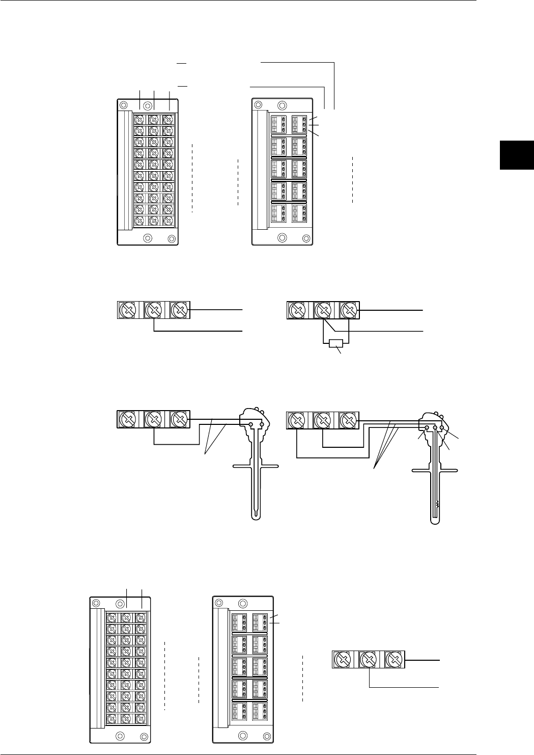
3-21
IM DR232-01E
3
Installation and Wiring
Wiring Input Signal Lines (to Universal, DCV/TC/DI, and Digital input modules)
Terminals
Screw type terminal Clamp type terminal*2
+
-
A
Bb
DC voltage • TC •
contact
RTD*1
A
B
b
CH1
CH2
CH10
CH1
CH2
CH3
CH4
CH9CH10
+
-
*1 There are no RTD
input terminals on
the DCV/TC/DI and
Digital input module.
*2 There is no clamp
type terminal for
Digital input module.
Wiring Diagram
DC voltage input
Compensation lead
DC current input
Shunt resistor
Note:For 4 to 20mA input, shunt
resistance value should
be 250Ω ±0.1%
10Ω* max./leadwire
Three wire resistances
should be approx. equal.
*10Ω max. for Pt100Ω and
Pt50Ω, 1Ω max. for Cu10Ω.
DC input
RTD inputTC input
DC voltage input/DI input (contact)
bAB
A
bB
+
-
+-+-
+
-
+-
Wiring DC-current Input Signal Lines (mA-input Module)
Diagrams of Terminal Block and Wiring
Model with Screw Terminals Model with Clamp Terminals
+
–
+
–
CH1
CH2
CH10
CH1
CH2
CH3
CH4
CH9
CH10
DC-current input
+
–
+
–
3.7 Connecting the Signal Lines
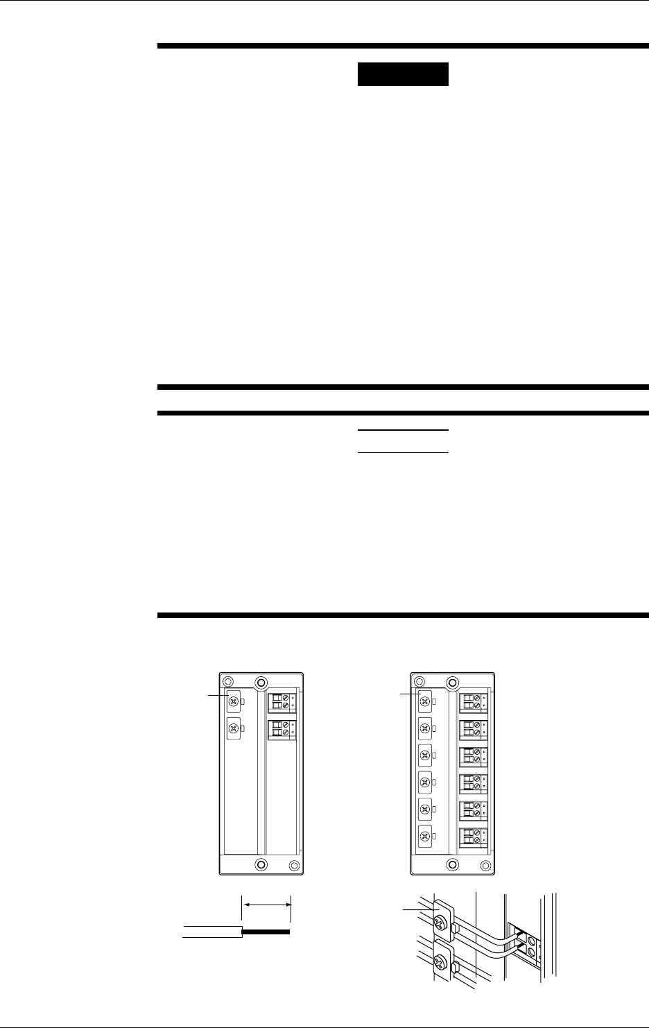
3-22 IM DR232-01E
Wiring AC Input Signal Lines (Power Monitor Module)
WARNING
• For hazard prevention, ALWAYS provide protective grounding before
connecting measuring leadwires.
• When connecting any object being measured, ALWAYS turn off the
power to the object. It is extremely dangerous to connect or disconnect
interconnecting leadwires with the power to the object left on.
• Exercise utmost care to avoid connecting any current-mode circuit to a
voltage-input terminal or any voltage-mode circuit to a current-input
terminal. Wrong connection may result in damage to the circuit or
equipment being measured or the DR232 or DR242 recorder itself, as
well as bodily injury.
• Fuses are not built into voltage- and current-input terminals. ALWAYS
install a fuse on the interconnecting leadwire. Use a fuse that will not
permit the voltage or current being measured to exceed the maximum
ratings of an AC input module.
The maximum voltage and current that can continuously be imposed on
an AC input module are as follows:
Voltage: 250 Vrms; current: 5 Arms
• To avoid electrical shock, ALWAYS attach the terminal cover in place
after the completion of wiring to the terminals so that the terminals
cannot be accidentally touched.
CAUTION
• In wiring, use double-insulated leadwires that have sufficient
withstanding-voltage and current-carrying-capacity margins against the
voltage and current being measured and meet the ratings at which they
are used.
• ALWAYS clamp measuring leadwires with the wire clips to prevent the
wires from being disconnected from their terminals. As the measuring
leadwires, use wires 0.2 to 2.5 mm2 (AWG14 to 25) thick so they can
be fastened securely with the wire clips.
• The power monitor module is a product belonging to Installation (Over-
voltage) Category CAT II.
Diagram of Terminal Block
V1
I1
V1
I1
V2
I2
V3
I3
Wire clip
Single-phase Model Three-phase Model
Wire clip
Wire clip
9mm
• Strip 9 mm of insulation off the leadwire.
• ALWAYS clamp the leadwire with the wire
clip.
• The recommended torque for fastening the
wire clip screw is 0.4 to 0.5 N•m.
3.7 Connecting the Signal Lines
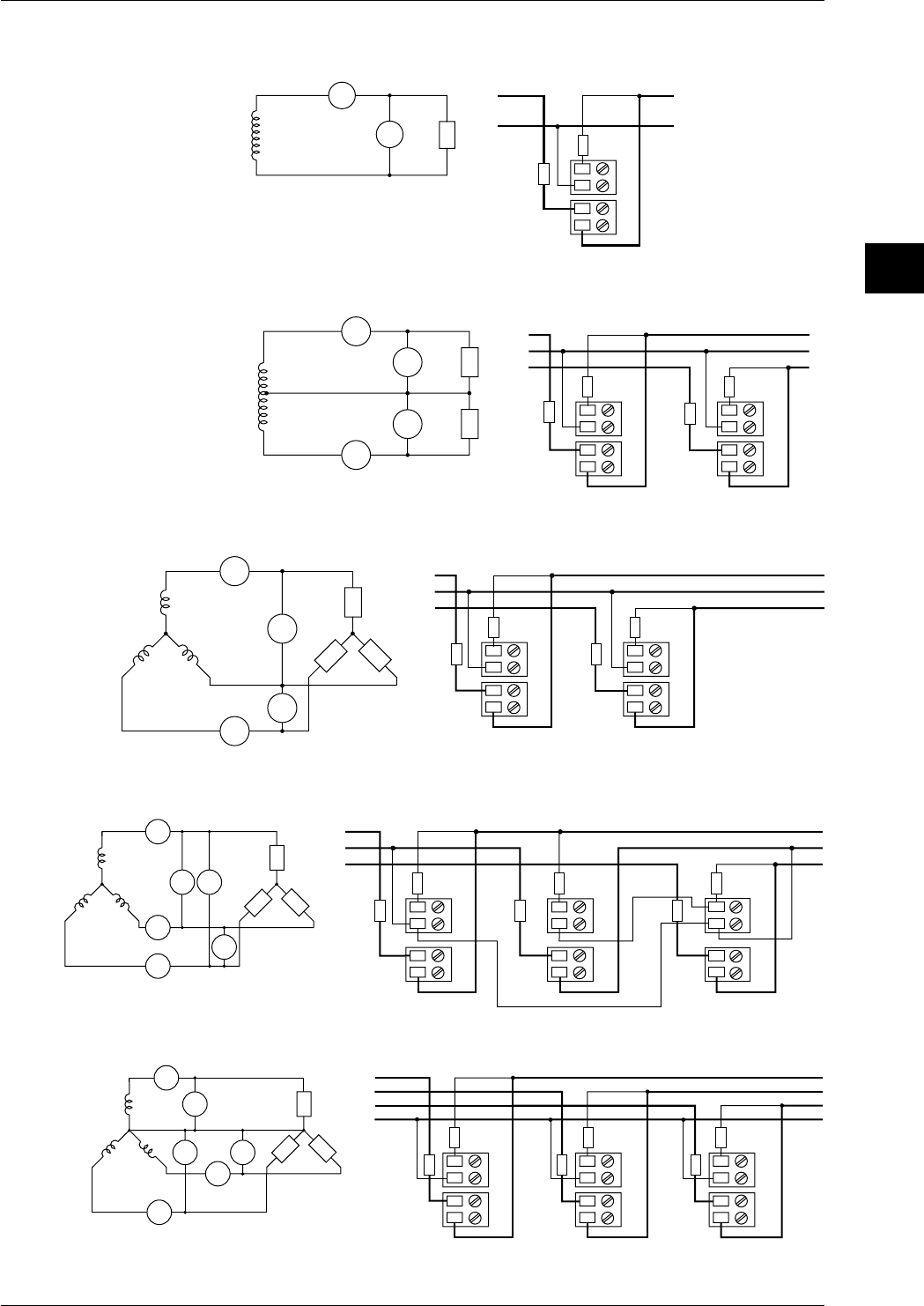
3-23
IM DR232-01E
3
Installation and Wiring
Wiring Diagrams
• Single-phase Two-wire Configuration
LOAD
V
±
V
A±
A
SOURCE
SOURCE LOAD
FUSE
FUSE
A1
V1
• Single-phase Three-wire Configuration (power monitor modules for three-phase
use only)
SOURCE
LOAD
V
A
±
±
A
V
V
±
V
A
±
A
1
3
1
3
N
SOURCE LOAD
N
FUSE FUSE
FUSE
A1
V1
A3
V3
FUSE
• Three-phase Three-wire Configuration (dual-current/dual-voltage measurement;
power monitor modules for three-phase use only)
SOURCE
LOAD
A
±
A
±
A
A
1
3
V
±
V
VV
3
1
R
ST
±
SOURCE LOAD
S
T
R
FUSE FUSE
FUSE
A1
V1
A3
V3
FUSE
• Three-phase Three-wire Configuration (triple-current/triple-voltage
measurement; power monitor modules for three-phase use only)
SOURCE
LOAD
A
±
A
A
±
A
1
3
R
ST
V
±
V
1
±
VV
3
±
V
V
2
A
±
A
2
SOURCE LOAD
S
T
R
FUSE FUSE
FUSE
A1
V1
A2
V2
FUSE
FUSE
A3
V3
FUSE
• Three-phase Four-wire Configuration (power monitor modules for three-phase
use only)
SOURCE
LOAD
A
±
A
A
±
A
1
3
R
ST
V
±
V
1
±
V
V
3
±
V
V
2
A
±
A
2
N
LOAD
SOURCE
S
R
T
N
A1
V1
A2
V2
A3
V3
FUSEFUSEFUSE
FUSEFUSEFUSE
3.7 Connecting the Signal Lines
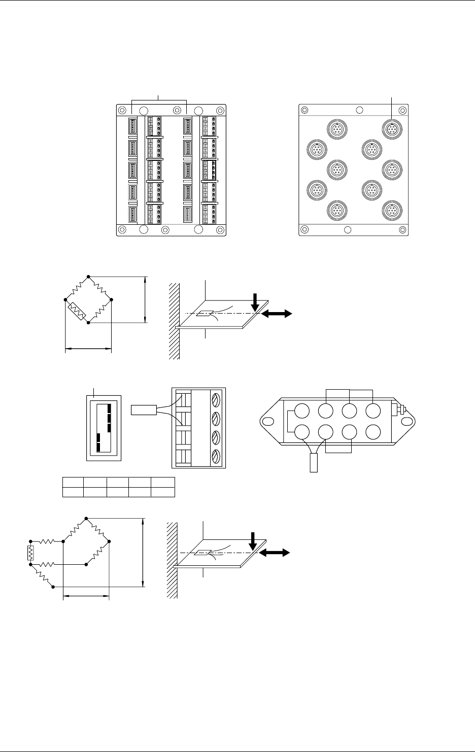
3-24 IM DR232-01E
Wiring Strain Input Signal Lines
Please apply the optional DV450-001 strain conversion cable when using a bridge box or strain
gage without sensor line.
Wiring Diagrams
Model with Built-in Bridge Model with External Bridge Resistors
CH2
CH3
CH5
CH7
CH9
CH1
CH4
CH6
CH8
CH10
Jumper setup switches
CH1
CH3
CH5
CH7
CH9
CH2
CH4
CH6
CH8
CH10
NDI terminal
Wiring Diagrams
• Single-gauge method
ON
OFF
No.1
No.2
No.3
No.4
No.5
A(+)
B(L)
C(-V)
D(H)
DU500-12/DU500-13
Jumper setup switch DU500-14
E
e
Rg
R
R
R
Rg
No.1
ON No.2
ON No.3
ON No.4
OFF No.5
OFF
Rg
R = fixed resistor
r = resistance of leadwire
Rg = resistance of strain gauge
e = output voltage developed across bridge
E = voltage imposed across bridge
12 3 4
5678
• Single-gauge three-wire method
RR
R
Rg
r
r
rE
e
R = fixed resistor
r = resistance of leadwire
Rg = resistance of strain gauge
e = output voltage developed across bridge
E = voltage imposed across bridge
3.7 Connecting the Signal Lines
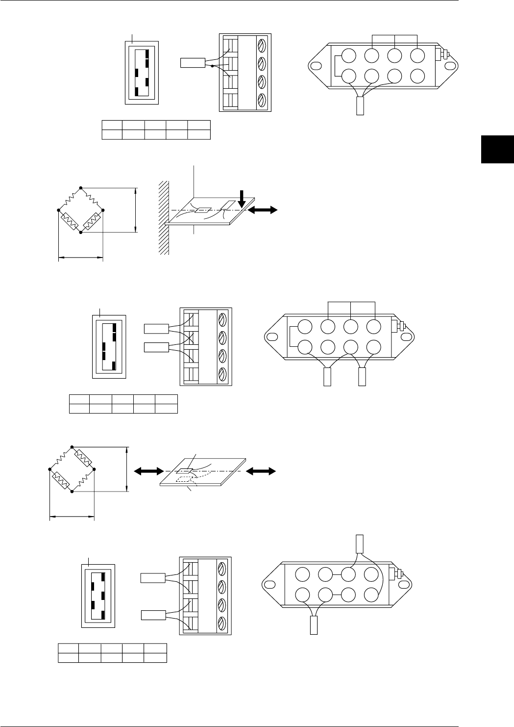
3-25
IM DR232-01E
3
Installation and Wiring
Jumper setup switch
DU500-12/DU500-13 DU500-14
ON
OFF
No.1
No.2
No.3
No.4
No.5
A(+)
B(L)
C(-V)
D(H)
No.1
ON No.2
ON No.3
OFF No.4
ON No.5
OFF
Rg 12 3 4
5678
• Adjacent-side two-gauge method
Jumper setup switch
DU500-12/DU500-13 DU500-14
ON
OFF
No.1
No.2
No.3
No.4
No.5
A(+)
B(L)
C(-V)
D(H)
No.1
ON No.2
ON No.3
OFF No.4
OFF No.5
ON
Rg1
Rg2
R
R
E
eRg1 Rg2
Rg1
Rg2
R = fixed resistor
r = resistance of leadwire
Rg = resistance of strain gauge
e = output voltage developed across bridge
E = voltage imposed across bridge
12 3 4
5678
Rg2
Rg1
• Opposed-side two-gauge method
Jumper setup switch
DU500-12/DU500-13 DU500-14
ON
OFF
No.1
No.2
No.3
No.4
No.5
A(+)
B(L)
C(-V)
D(H)
No.1
ON No.2
OFF No.3
ON No.4
OFF No.5
ON
Rg1
Rg2
R
R
Rg2
Rg1
E
e
Rg1
Rg2
R = fixed resistor
r = resistance of leadwire
Rg = resistance of strain gauge
e = output voltage developed across bridge
E = voltage imposed across bridge
1234
678
Rg2
Rg1
5
3.7 Connecting the Signal Lines
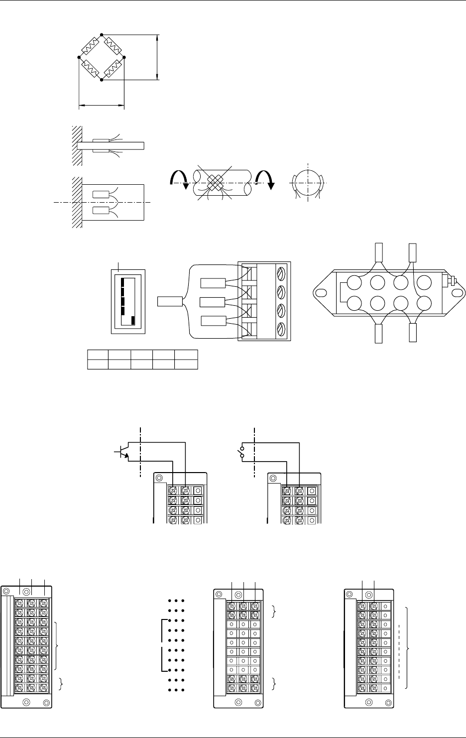
3-26 IM DR232-01E
• Four-gauge method
Jumper setup switch
DU500-12/DU500-13 DU500-14
ON
OFF
No.1
No.2
No.3
No.4
No.5
A(+)
B(L)
C(-V)
D(H)
No.1
OFF No.2
OFF No.3
OFF No.4
OFF No.5
ON
Rg1
Rg2
Rg4
Rg1 Rg2
Rg3
E
e
Rg1, Rg3
Rg2, Rg4
Rg1
Rg3
Rg1
Rg3 Rg4
Rg2
Rg1, Rg2 Rg3 Rg4
Rg3
Rg4
R = fixed resistor
r = resistance of leadwire
Rg = resistance of strain gauge
e = output voltage developed across bridge
E = voltage imposed across bridge
12 3 4
5678
Rg2
Rg1
Rg3Rg4
Wiring Pulse Input Signal Lines (to Pulse Input Module)
-+ -+
Open collector
TTL open collector
Contact
CH1
CH2
CH3
CH4
CH1
CH2
CH3
CH4
Wiring Output Signal and Remote Control Signal Lines (to DI/DO and Alarm modules)
Terminals
NO CNC
Failure output (transfer-contact)
REM
CHART
FAIL
ALM
1
ALM
2
NO
NO
1
3
5
7
9
11
NO
NO
C
C
C
C
C
C
C
C
C
C
NC
NC
2
4
6
8
10
12
NC
NC
Chart end output (transfer-contact)
Remote control signal input
(12 contact terminals)
Terminal arrangement
1
2ALM output
(transfer-contact)
NO C
1
2
4
NC
3
Alarm output
(transfer contact)
Alarm output
(transfer contact)
DT200-11DT100-11 NO C
1
2
10
Alarm
output
(make
contact)
DT200-21
Output contact rating: 250 V DC/0.1 A (resistive load), 250 V AC/2A (resistive load), 30 V DC/
2A (resistive load)
3.7 Connecting the Signal Lines
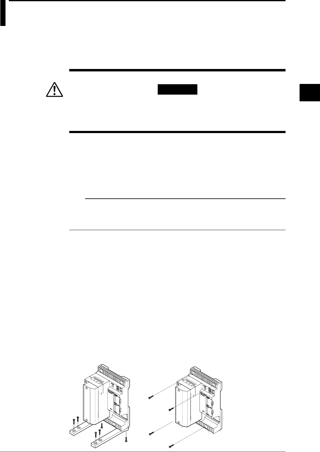
3-27
IM DR232-01E
3
Installation and Wiring
3.8 Connecting an Extension Module to Extension
Bases
Using an extension module and extension bases, you can install input modules at a location
distant from the sub-unit(s). The module and bases are powered from the sub-unit and, therefore,
can be located even in a place where there is no power source nearby.
Installing an Extension Base
WARNING
• For fire prevention, use extension bases in an upright position.
Do not cover up the extension base's module (allow a clearance of at
least 3 cm around the module).
Ambient Temperature and Humidity
Use an extension base under the following environmental conditions:
• Ambient temperature: –10˚ to 60˚C
• Ambient humidity: 20 to 80% RH at -10˚ to 40˚C
10 to 50% RH at 40˚ to 50˚C
5 to 30% RH at 50˚ to 60˚C
Use the extension base in a condensation-free condition.
Note
Condensation may occur if you move the extension base from an area of low humidity to an area of high
humidity or if any drastic temperature variation takes place. In addition, a measurement error will result if
the DR recorder is in the thermocouple input mode. In that case, allow at least one hour for the extension
base to adjust to the ambient atmosphere before using it.
Do not install the extension base where:
• it is exposed to direct sunlight or there is a heat source nearby;
• soot, steam, dust and/or corrosive gas is relatively abundant;
• there is a strong electromagnetic source nearby;
• there is high-voltage equipment or a power line nearby;
• it is exposed to severe and/or frequent mechanical vibration; or
• it is not positioned stably.
Desk-top or Floor Installation
Attach the two supplied shoe plates onto the extension base with two screws (4-mm screws 16
mm long, supplied as standard accessories), as shown in the figure on the left below. Then, place
the extension base in an upright position. If the base is liable to fall on its side after wiring, fix
the shoe plates with the four supplied screws (4-mm screws 12 mm long) using the through-holes
(for 4-mm screws) of the shoe plates.
Direct Mounting on Panel
According to the figure on the right below, fix the extension base onto a panel by fastening the
four corners with the supplied screws (4-mm screws 12 mm long).
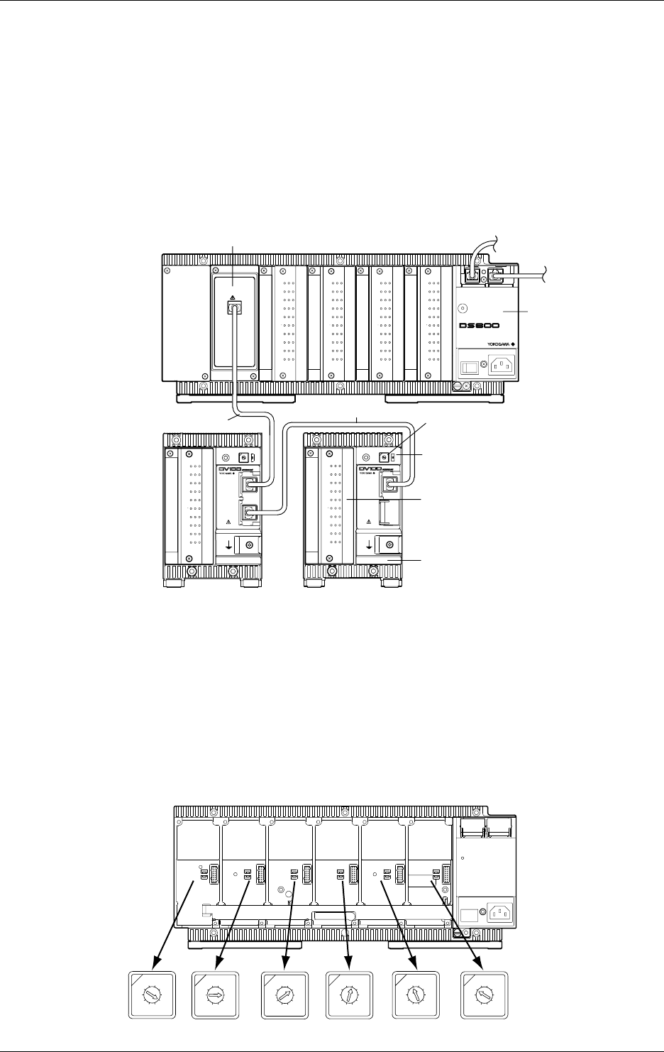
3-28 IM DR232-01E
Connecting Extension Bases to an Extension Module
Verify that the power of the DR/DS400/DS600 has been turned off before connecting the
extension module/extention base.
Mount the extension module onto the sub-unit. The module cannot be mounted to the DR
recorder itself. Wire the extension module to the extension base with an extension cable. You
can wire a maximum of three extension bases to one extension module at the same time. It is not
possible, however, to wire extension bases in such a manner that the total sum of modules already
mounted on the sub-unit and the extension bases being wired exceeds the maximum number of
modules (four for the DS400 sub-unit and six for the DS600 sub-unit) allowed for mounting on
the sub-unit.
Either a 10-channel universal input module (DU100-11 or DU100-12) or a 10-channel DCV/TC/
DI module (DU200-11 or DU200-12) can be mounted onto each extension base.
CH 1
CH 2
CH 3
CH 4
CH 5
CH 6
CH 7
CH 8
CH 9
CH10
b -/B +/A
CH 1
CH 2
CH 3
CH 4
CH 5
CH 6
CH 7
CH 8
CH 9
CH10
b -/B +/A
CH 1
CH 2
CH 3
CH 4
CH 5
CH 6
CH 7
CH 8
CH 9
CH10
b -/B +/A
CH 1
CH 2
CH 3
CH 4
CH 5
CH 6
CH 7
CH 8
CH 9
CH10
b -/B +/A
POWER
STATUS
100-240V 50/60Hz 70VA MAX
SUB UNIT
EXTENDER I/F
I/F
POWER ADDRESS TERMN
ON
OFF
I/F
1
2
3
4
5
6
7
8
9
0
CH 1
CH 2
CH 3
CH 4
CH 5
CH 6
CH 7
CH 8
CH 9
CH10
b -/B +/A
POWER ADDRESS TERMN
ON
OFF
I/F
1
2
3
4
5
6
7
8
9
0
CH 1
CH 2
CH 3
CH 4
CH 5
CH 6
CH 7
CH 8
CH 9
CH10
b -/B +/A
Extension module (DV100-011)
Sub-unit (DS400/600)
Extension
cable
Extension cable
Extension base (DV100-012)
Terminator on/off switch
Set this switch to ON for the last extension
base in the connection.
Slot number setup switch
Select an unused slot number.
Either a 10-channel universal input module
(DU100-11 or DU100-12) or a 10-channel
DCV/TC/DI module (DU200-11 or DU200-12)
Wiring Distance
The last extension base in the connection can be located at a maximum distance of 30 m from the
sub-unit.
Setting of Terminator On/Off Switch
Set the terminator on/off switch of an extension base to ON for the base that is the last in the
connection. Set these switches of all other extension modules to OFF.
Setting of Slot Numbers
Select an unused slot number for each extension base. This can include, however, a slot number
for an extension module. The following figure shows how the numbers you set correspond to the
positions of slots and relate to channel numbers.
1
2
3
4
5
6
7
8
9
0
1
2
3
4
5
6
7
8
9
0
1
2
3
4
5
6
7
8
9
0
1
2
3
4
5
6
7
8
9
0
1
2
3
4
5
6
7
8
9
0
1
2
3
4
5
6
7
8
9
0
Setpoint 1
X01-X10
Setpoint 2
X11-X20
Setpoint 3
X21-X30
Setpoint 4
X31-X40
Setpoint 5
X41-X50
Setpoint 6
X51-X60
Setpoints of slot number
setup switch on an
extension base
Channel numbers, where
X is the unit number
3.8 Connecting an Extension Module to Extension Bases
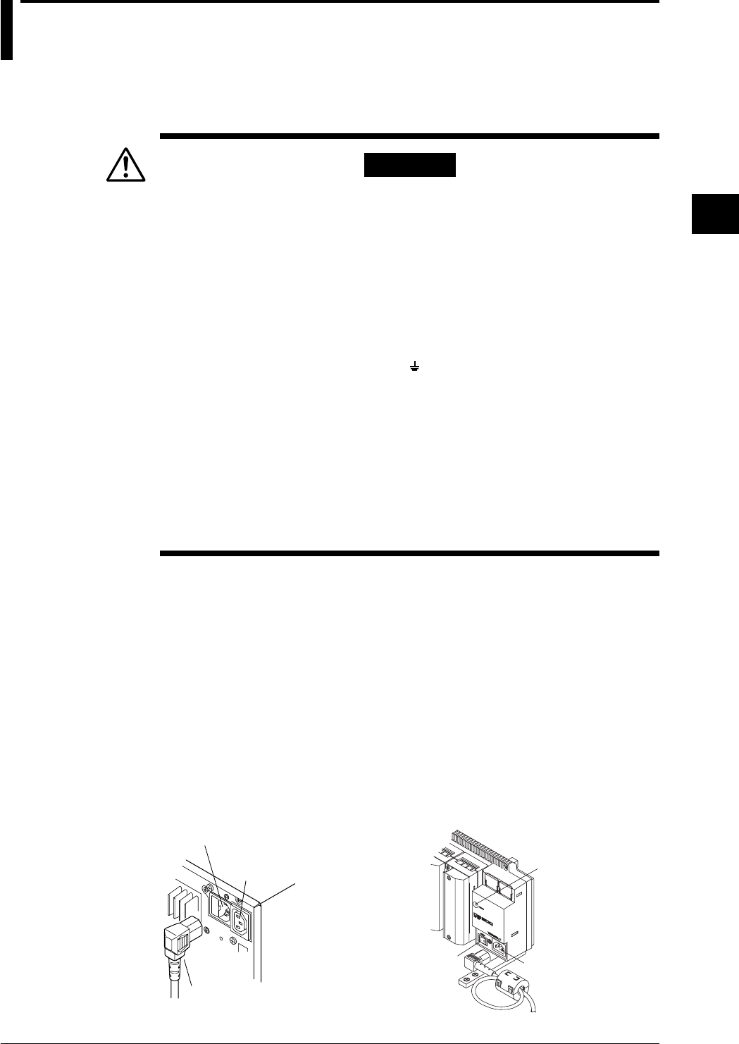
3-29
IM DR232-01E
3
Installation and Wiring
3.9 Connecting the Power Cord and Turning the
Power ON/OFF
When Using the Accessory Power Cord
DR232/DS400/DS600 (when using the accessory power cord)
Follow the warnings below to avoid electric shock or damaging the instrument.
WARNING
• Connect the power cord only after confirming that the voltage of the
power supply matches the rated electric power voltage for this
instrument.
• Connect the power cord after checking that the power switch of this
instrument is turned off.
• To prevent electric shock or fire, always use the power cord supplied by
Yokogawa.
• Always use protective grounding to prevent electric shock. Connect the
power cord of the instrument to a three-pole power outlet which has a
protective ground terminal.
Do not use the function grounding ( marked terminal) under the power
connecting part as the protective ground terminal.
• Never use an extension cord that does not have protective grounding,
otherwise the protection feature will be negated.
• An AC outlet (auxiliary for the DS400/DS600) should be used to supply
power to the DS400/DS600 using a power cable(DV400-051)
separately available. Do not use this AC outlet to supply power to the
other equipments nor use other cables for the power connection.
Otherwise, the current flowing through the AC outlet will exceed the
permissible current, thereby resulting in the fuse blowing, overheating
or burning may occur.
Connecting Procedure
1. Check that the power switch is turned off.
2. Connect the plug of the accessory power cord to the power connector.
3. Plug the other end of the power cord into a power outlet that satisfies the following conditions:
For DS400/DS600 in order to cut down on unnecessary radio interference, attach a clamp filter
(accessory) near the power cord plug as shown below. Make a loop with the power cord and
clamp it in the clamp filter.
Rated supply voltage : 100 to 240 V AC (free power supply),operating voltage: 90 to 250 V AC
Rated supply voltage frequency : 50/60 Hz
Power consumption : DR232 ... About 130 VA max.
DS400 ... About 55 VA max.
DS600 ... About 70 VA max.
Use a three-pole power outlet provided with a protective ground terminal.
Power connector
Power cord
• DR232 • DS400/DS600
AC outlet(Auxiliary
for DS400/DS600)
Status
indicator
Power connector
Power switch
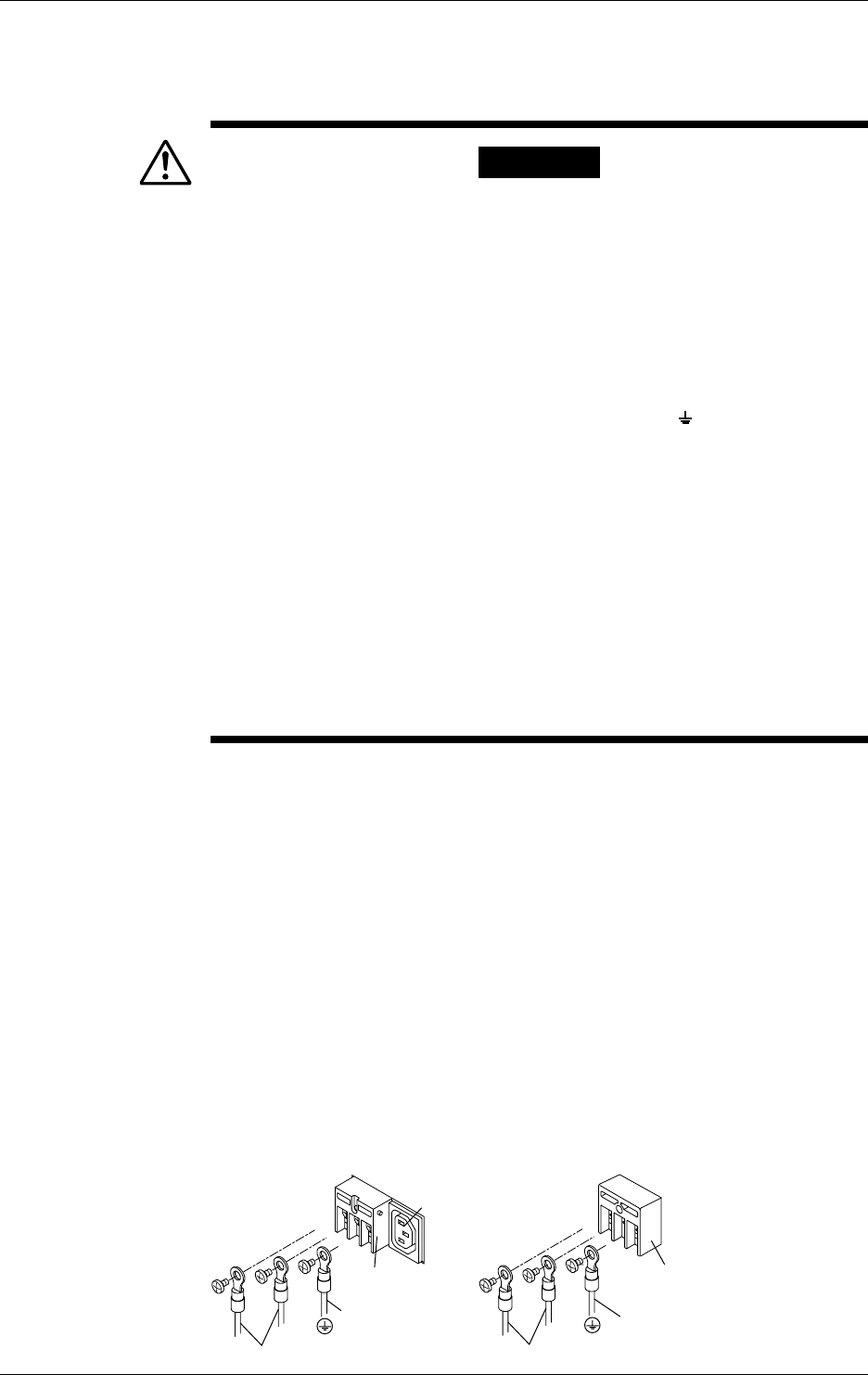
3-30 IM DR232-01E
When Using an Adapter for Direct Wiring to the Power Supply
DR242/DS400/DS600 (when connecting wires to screw terminals)
This applies only to products with power inlet W suffix code.
Follow the warnings below to avoid electric shock or damaging the instrument.
WARNING
• Connect the power wires after checking that the power supply is turned
off to prevent electric shock.
• To prevent fire, use 600 V PVC insulated wire (AWG18) for both power
and ground wiring (cross section of 0.83 mm2 or thicker, anti-galvanic
corrosion finish, insulation thickness more than 0.8 mm, insulation
resistance more than 50 MΩ/km at 20°C, approved EN60 320
(VDE0625)), or equivalent cables.
• Units equiped with screw type terminals should only be used in panel
installations.
• Before turning on the power, always ground the protective ground
terminal. Do not use the function grounding terminal ( marked
terminal) under the power connecting part as the protective grounding
terminal.
• For AC power and ground wiring, use “crimp on” lugs (for 4mm screws)
with insulation sleeves. Make sure that the crimp-on tool must be one
specified by the crimp-on lugs manufacture, and that the crimp-on lugs
and tool must be matched to the wire size.
• To prevent electric shock, do not touch the terminals after wiring.
• An AC outlet (auxiliary for the DS400/DS600) should be used to supply
power to the DS400/DS600 using a power cable(DV400-051)
separately available. Do not use this AC outlet to supply power to the
other equipments nor use other cables for the power connection.
Otherwise, the current flowing through the AC outlet will exceed the
permissible current, thereby resulting in the fuse blowing, overheating
or burning may occur.
Connecting procedure (DR242)
1. Check that the power switch is turned off.
2. Remove the cover protecting the power terminals.
3. Connect the power supply wires and the protecting ground wire to the power terminals.
4. Replace the cover.
Connecting procedure (DS400/DS600)
1. Check that the power switch is turned off.
2. Remove the cover protecting the power terminals.
3. Connect the power supply wires and the protecting ground wire to the power terminals.
4. Replace the cover.
In order to cut down on unnecessary radio interference, attach a clamp filter (accessory) near
the power cord plug. Make a loop with the power cord and clamp it in the clamp filter.
Rated supply voltage : 100 to 240 V AC (free power supply),operating voltage: 90 to 250 V AC
Rated supply voltage frequency : 50/60 Hz
Power consumption : DR242 ... About 130 VA max.
DS400 ... See previous page.
DS600 ... See previous page.
• DR242 • DS400/DS600
LN
Protective ground wire
Power supply wires
Power terminals
LN
Protective ground wire
Power supply wires
Power terminals
AC outlet(Auxiliary
for DS400/DS600)
3.9 Connecting the Power Cord and Turning the Power ON/OFF
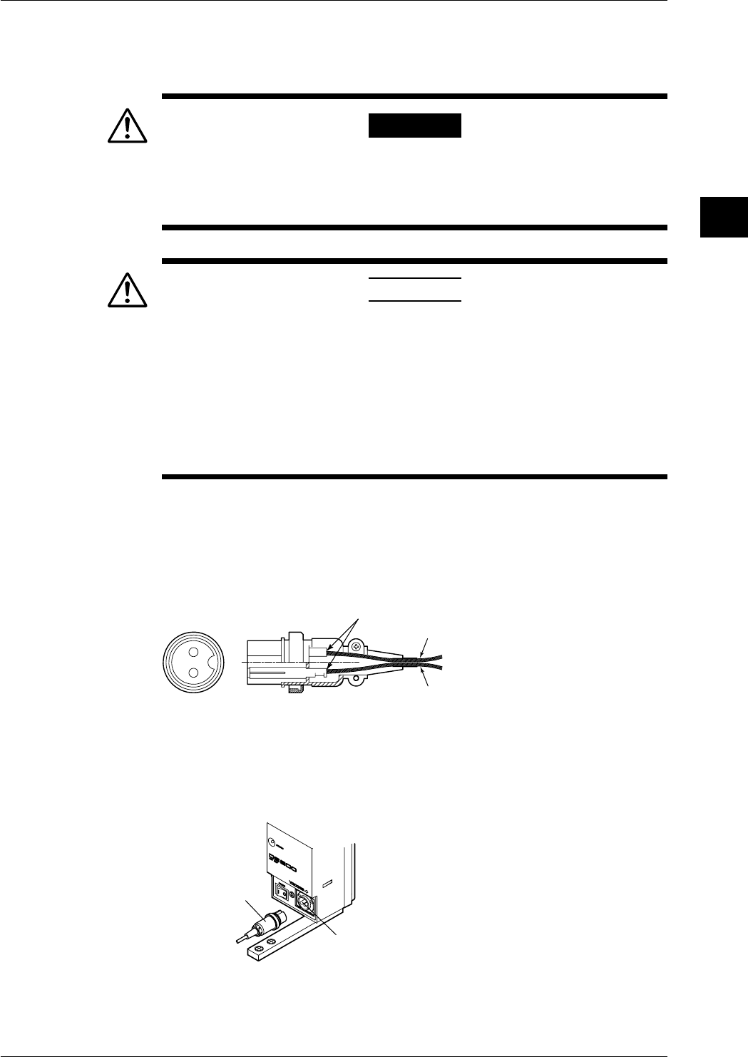
3-31
IM DR232-01E
3
Installation and Wiring
3.9 Connecting the Power Cord and Turning the Power ON/OFF
DS400/DS600(when using DC power supply connecter)
This applies only to products with power supply 2 suffix code.
Follow the warnings below to avoid electric shock or damaging the instrument.
WARNING
• Connect the power wires after checking that the power supply is turned
off to prevent electric shock.
• To prevent fire, use wires with cross sectional area of 0.3mm2(22AWG)
or more.
CAUTION
• If you connect the + and - terminals in reverse on the DS400/DS600,
the internal fuse will be blown (You cannot replace the fuse by yourself.
The instrument needs servicing in this case). If there is a possibility of
reversing the polarity, insert a fuse (rating shown below) in the wiring.
This will lower the chances of blowing the internal fuse.
Fuse : 250 V/T2.5 A to T4A (time lag), 20 mm glass tube fuse,
I2t = 12.5 to 32
(Recommended: A1350EF (250 V/T2.5 A, I2t=12.5: SCHURTER:
FST0034.3121))
Connecting procedure
1.Check thst the power switch is turned off.
2.Connect the accessory DC power terminal connector (part No. A1105JC) to the power wire and
the DS400/DS600. Use a power wire with a cross sectional area of 0.3 mm2 (22AWG) or
more.
21
Soldering
- (0 V DC)
+ (10 to 32 V DC)
DS400/DS600
Rated supply voltage:12 to 28 V DC
Operating supply voltage:10 to 32 V DC
Power consumption:About 25 VA max.
• DS400/DS600: DC power supply model
DC power terminal
connector
DC power
terminal
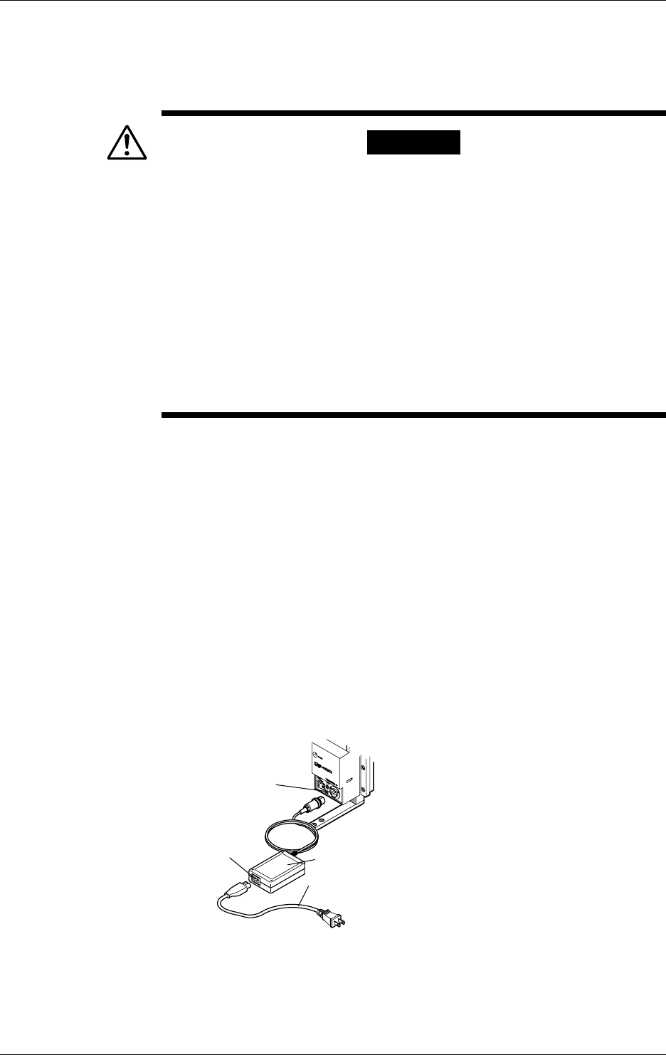
3-32 IM DR232-01E
3.9 Connecting the Power Cord and Turning the Power ON/OFF
DS400/DS600(when using optional AC adapter)
This applies only to products with power supply 2 suffix code.
Follow the warnings below to avoid electric shock or damaging the instrument.
WARNING
• Connect the power wires after checking that the power supply is turned
off to prevent electric shock.
• To prevent electric shock or fire, always use the power cable supplied
by YOKOGAWA.
• Before connecting the power cord, check that the voltage on the supply
side matches with the voltage rating of this recorder.
• When not using the instrument for a long time, unplug the power cord of
the AC adapter.
• Only use the AC adapter from YOKOGAWA (Model No.: DV500-00x).
• Do not put objects on top of the AC adapter or the power cord. Also, do
not let heat generating objects come in contact with them.
• When unplugging the power cord, do not pull on the power cord.
Always hold the plug. If the power cord becomes damaged, contact
your nearest representative listed on the back cover of this manual.
Connecting Procedure
1. Check that the power switch is turned OFF.
2. Connect the AC adapter to the AC adapter jack on DS400/DS600.
3. Connect the power cord plug that came with the AC adapter to the power supply connector of
the AC adapter.
4. Connect the plug on the other end of the power cord to a power outlet meeting the following
specifications.
The power outlet should be a three-pole type with a protective grounding terminal.
Rated power supply voltage: 100 to 240 VAC
Permissible supply voltage range: 90 to 250 VAC
Rated supply voltage frequency: 50/60 Hz
Maximum power consumption: 90 VA
AC adapter rated output voltage: 12 VDC
AC adapter maximum rated output current: 2.6 A
• DS400/DS600: DC power supply model
Power cord for
AC power supply
DC power terminal
connector
AC adapter
Power connector
for AC power supply
Functional grounding
When using the AC adapter, noise may be reduced if the functional ground is connected to the
earth GND. Use the functional ground terminal as necessary.

3-33
IM DR232-01E
3
Installation and Wiring
Switching the Power ON/OFF
DR232/DR242
The power switch is a push-button; the power is turned on when pressed once and turned off
when pressed again.
Power switch
Note
• Before turning the power on, check that each unit is properly mounted and the power cord is correctly
connected.
• If nothing appears on the display when the power switch is turned on, turn off the power and check the
following:
• Is the power cord properly connected?
• Is the supply voltage within the range noted on the previous page?
• Is the power fuse blown (see page 13-2)
If the problem still cannot be fixed, there may be an equipment problem; please contact your nearest
sales representative. Addresses may be found on the back cover of the manual.
• The device takes about 30 minutes to warm up.
• The service life of the lithium battery used to save the settings is about 10 years at an ambient
temperature of 23°C. If the settings cannot be held because the lithium battery has run down, please
contact your nearest sales representative. Addresses may be found on the back cover of the manual.
DS400/DS600
When the “ ” side of the power switch is pressed, the power is turned on and when the “O” side
of the switch is pressed, the power is turned off. When the power is turned on, the status indicator
(see the figure on page 3-29) lights.
Note
• Before turning the power on, check that each unit is properly mounted and the power cord is correctly
connected.
• If the status indicator does not go on when the power switch is turned on, turn off the power and check
the following:
• Is the power cord properly connected?
• Is the supply voltage within the range noted on the previous page?
If the problem still cannot be fixed, there may be an equipment problem; please contact Yokogawa
Engineering Service Corporation (contact details on rear cover) for repair.
• If the status lamp flashes, it means that there is an internal error. Turn off the power switch and check the
same items as for the DR242. If the problem still cannot be fixed, there may be an equipment problem;
please contact your nearest sales representative. Addresses may be found on the back cover of the
manual.
• If the power of a subunit is turned on and off with multiple subunits connected, subunits connected
subsequently to the end from the subunit whose power is turned off will not be recognized temporarily.
• The device takes about 30 minutes to warm up.
3.9 Connecting the Power Cord and Turning the Power ON/OFF
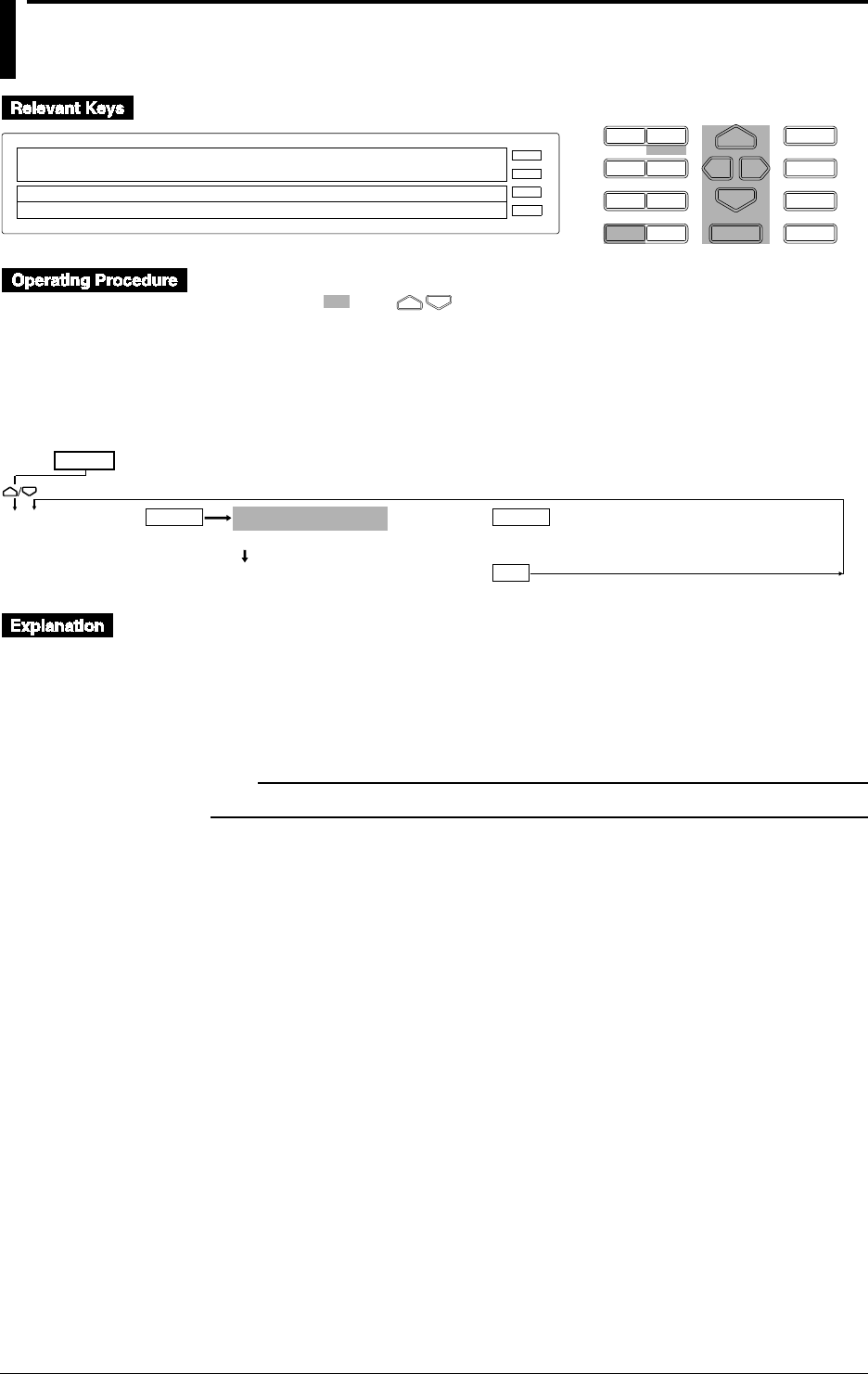
3-34 IM DR232-01E
3.10 Setting the Date and Time
D I S P M O D E
P R I N TF U N C
I N S D E L
R A N G E A L A R M
S E TC H A R T E N T E R
F E E D
M. F U N C 1
M. F U N C 2
RECORD
ALARM
CHART
KEYLOCK
R E C O R D
SET=CLOCK
CHART CLOCK
>Select Setting Parameter
E S C
• Press the CHART key to display the CHART menu.
• Set and select using .
• To escape while using a single menu, press the MODE(ESC) key. The menu returns to the first
menu to which the single menu belongs. Note that newly selected or set items will be
canceled.
• When the device displays that setting is completed, the newly set or selected details are fixed.
CLOCK 96/01/01 03:36:23
>Set Date & Time YY/MM/DD HH:MM:SS
*** SET OK***
ENTERENTER
ESC
SET=
Main menu
Lower menu
Setting the Date and Time
Set them in the order of year/month/day, hour:minutes:seconds.
• Year: Specify the lower two digits of the year. Example: 1996 → 96, 2000 → 00
• Month, day: Use two digits for each.
• Hour: 00 to 23
Press the ENTER key at the set time to make it effective.
Note
The date and time settings are backed up by the lithium battery in the main unit.
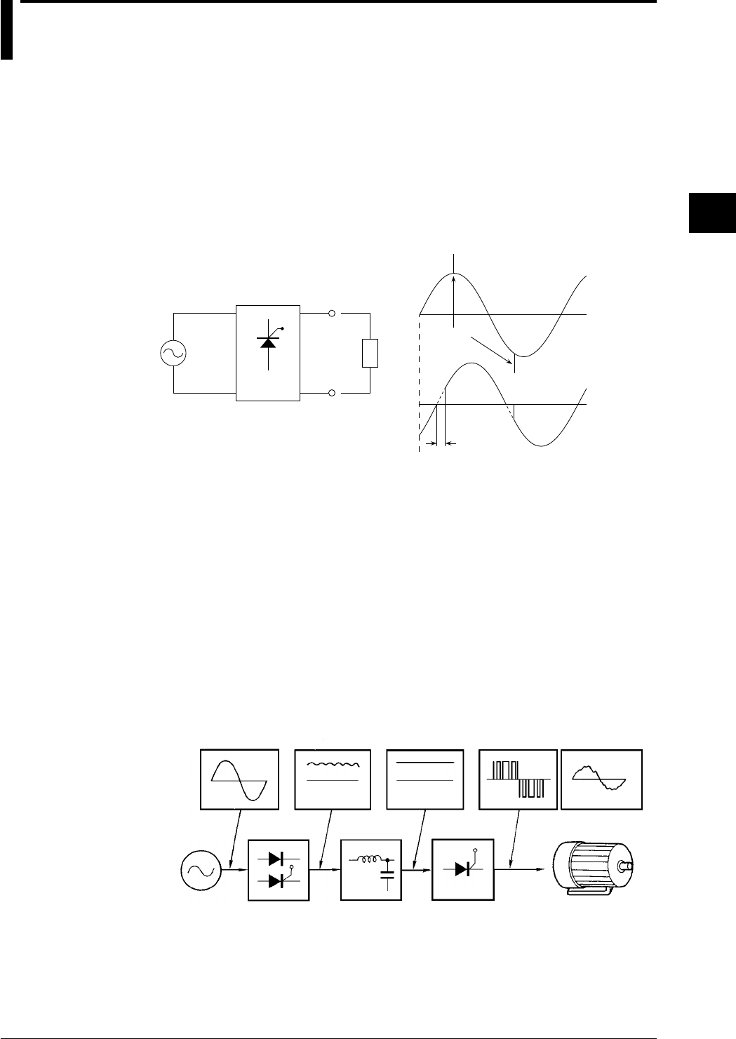
3-35
IM DR232-01E
3
Installation and Wiring
3.11 Countering Noise
Types and Features of Noise Sources
Commercial Power Supply
It is necessary to consider both 50 and 60Hz as noise components. It is important to note that a
power supply line in which a thyristor or inverter is incorporated functions not only as an “energy
surplus line”, but also as a “supply surplus line”.
Thyristor (SCR)
A thyristor is used to control power through ON/OFF modulation of commercial power by
controlling the phase angle.
50Hz
or
60Hz
*heaters, etc.
noise
phase angle
Current
Voltage
Thyristor waveform
Thyristor
Unit
*Load
When the thyristor turns ON or OFF, a pulse noise is superimposed on commercial power supply,
and its pulse width is approximately 1µs. Accordingly, thyristor noise can be defined as follows.
· thyristor noise = commercial power supply + pulse noise
Inverter
Commercial power supply is converted to direct current by a rectifier (sometimes the thyristor is
used as the rectifier to stabilize direct current) and then modulated by a switching transistor and
finally converted into alternating current at the desired frequency (from tens to hundreds of Hz) to
drive a motor, for example. If the load to be driven is a fluorescent lamp, the frequency is tens of
kHz. Accordingly, inverter noise can be defined as follows.
Inverter noise = commercial power supply + pulse noise (high density) + variable low frequency
noise
Since the density of pulse noise is high compared to that of a thyristor and in addition, there is
variable frequency noise, it is difficult to consider a countermeasure for inverter noise.
Commercial
power supply Rectifier output DC output Inverter output
Commercial
power supply Rectifier DC filter Inverter Motor
Principle of inverter
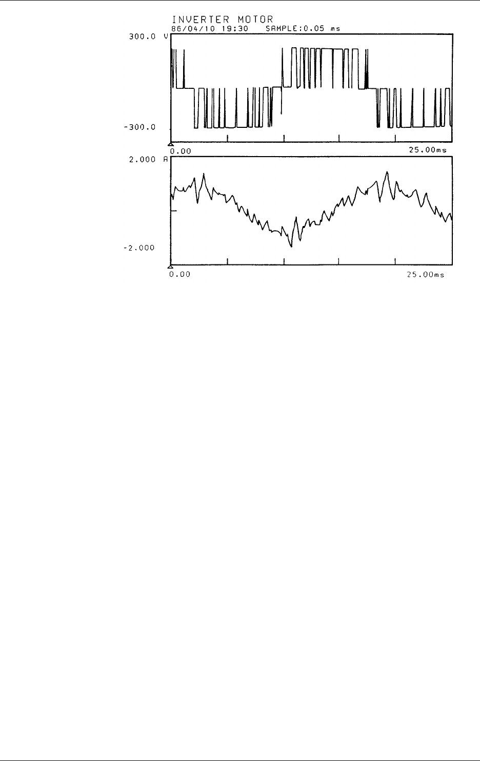
3-36 IM DR232-01E
Voltage
waveform
Current
waveform
Voltage/current waveforms of an inverter
Relay
A relay is frequently used to amplify alarm and temperature controller outputs. However, since a
counter-electromotive force (counter e.m.f.) is produced by coil inductance when the relay is
turned off and the e.m.f. becomes noise, care must be taken. Due to chattering at the relay contact,
tens to hundreds of kHz noise occurs mainly in bursts. Thus, the noise energy often becomes high.
Transceiver
In large-scale plants, transceivers are often used for communications between the field and the
control room. Although W/G of the Japanese Electric Measuring Instruments Manufacturers
Association recommends to use transceivers covering a wave band of 27MHz, smaller-sized
transceivers for the 140 or 470MHz wave band are often used.
Noise Simulator
To test the immunity to pulse noise (mainly thyristor noise), a noise simulator is often used. A test
noise of approximately 1kV for 0.8µs is used synchronously with the power supply frequency.
Since data acquisition equipment is often used for measurements of equipment subjected to the
pulse noise test, the influence of noise must be considered.
Propagation of Noise
• Noise is propagated in the following three ways.
Conduction: noise is conducted through a power line, input wiring, etc.
Electrostatic induction: noise leaks through capacitances between wires and instruments.
Electromagnetic induction: a loop in the input line, etc. induces an AC voltage by detecting the
AC magnetic field.
In real applications, the above three propagation paths are not independent of each other. Their
combination propagates noise to the equipment and causes problems.
• Examples of noise propagated through each of these paths are given below.
Conduction: inverter noise, relay noise, thyristor noise, and noise caused by
surface temperature measurement of a power transistor, etc.
Electrostatic induction: commercial power supply noise such as the hum of audio
equipment, relay noise, etc.
Electromagnetic induction: magnetic leakage flux from a power transformer or motor, magnetic
field from a high-frequency induction furnace, the rotating magnetic
field of a power generator (Cu10Ω), etc.
The figure on the next page shows the propagation paths using practical examples.
3.11 Countering Noise
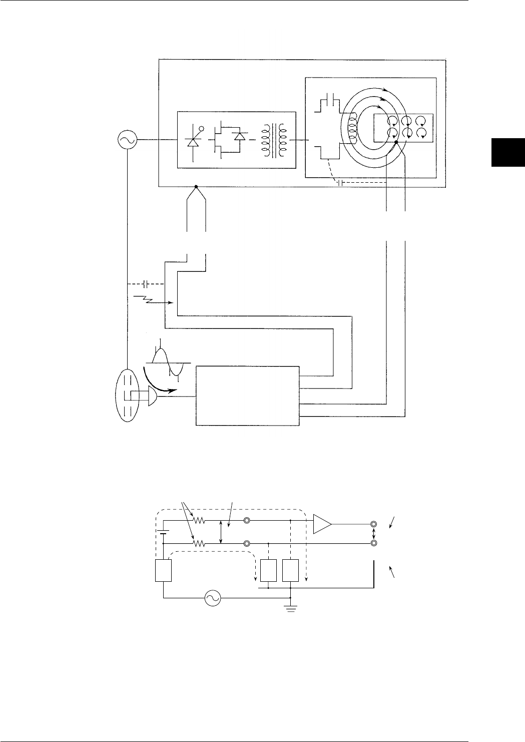
3-37
IM DR232-01E
3
Installation and Wiring
Power
supply
Example of a high-frequency
induction furnace
Inverter power supply
(20 to 3500kW)
Furnace
C
r
i
(0.2k to 10kHz)
Electrostatic
induction noise
Hot-line conduction
noise
Electro magnetic
induction noise
Electrostatic induction noise
Electro magnetic induction noise
Room
temperature
Line noise
The instrument
Temperature
inside
furnace
* Due to electromagnetic induction, current i flows
through the conductor, creating joule heat which
heats the furnace.
J=i
2
r
Φ
Power
supply Inputs
Basics of Anti-Noise Measures (part 1)
Common Mode Noise and Normal Mode Noise
R
1
R
2
E
NM
H
L
Z
2
Z
1
E
CM
Z
3
i
2
i
1
E
O
+
E
ONM
Case
Circuit
common
Floating amp
Signal source
resistances Normal mode noise
Signal
voltage E
Common mode noise
Signal component
Normal mode noise
component
Output
Common Mode Noise (ECM)
Noise generated between the signal source and the ground of a measuring instrument. Since it is
applied to both the H and L input terminals in phase with one another, it is also called in-phase
voltage.
Normal Mode Noise (ENM)
This is an unfavorable noise that is superimposed on a signal voltage. Since it is a voltage
between the H and L terminals, it is also called the line voltage, or since it is a voltage in series
with the signal voltage, it is sometimes called the series mode voltage.
3.11 Countering Noise
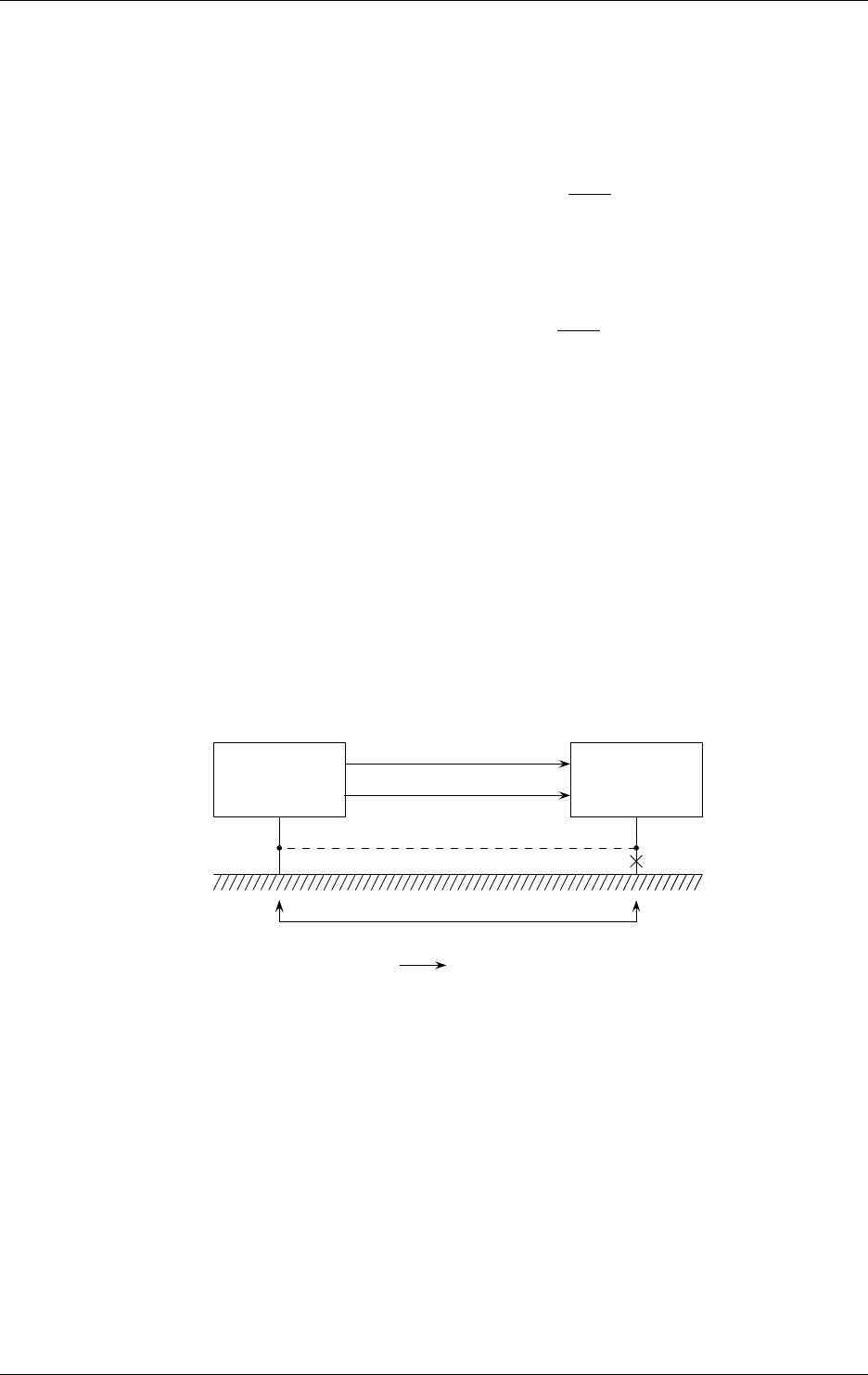
3-38 IM DR232-01E
In the figure on the previous page, due to common mode voltage ECM, noise currents i1 and i2
flow through the impedance to grounds Z1 and Z2 and coupling impedance Z3, resulting in the
generation of normal mode noise ENM between input terminals H and L. Like this, common mode
noise is converted to normal mode noise. The amp is equipped with a built-in filter and in case of
output EO the normal mode noise will be eliminated. This rate of conversion is called the
common mode rejection ratio and expressed by the following equation.
• Common mode rejection ratio
(CMRR)=20Log E
O
E
C M
(dB)
Since the actual CMRR is expressed using the ratio of an error component output caused by
common mode noise to common mode noise, it contains the normal mode rejection ratio (NMRR)
expressed by the following equation.
• Normal mode rejection ratio
(NMRR)=20Log E
O
E
N M
(dB)
The NMRR is a value that shows the ability to reject the output error (normal mode noise
component: ENM) by normal mode noise. Thus, this is also a very important value which shows
the resistance-to-noise characteristics of the measuring instrument.
Basics of Anti-Noise Measures (part 2)
Decreasing and Increasing Impedance
As described in the previous section, conversion of common mode noise into normal mode noise
causes an error in the measured output. In other words, prevention of such a conversion is the key
to anti-noise measures. As can be understood from the previous section, it is important to take the
following measures to reduce normal mode noise.
· reduce the wiring resistances R1 and R2, including the resistance of the wires.
· increase the coupling impedance of common mode voltage ECM.
These are called the decrease and increase of impedance as basics of anti-noise measures.
In the above discussions, anti-noise measures have been described on the assumption that
common mode noise has already been given. In real applications, common mode noise often
occurs owing to grounding resistance as shown in the figure below.
Signal source The instrument
H
L
One-point grounding
Grounding resistance and E
CM
Ground current
In such a case, perform one-point grounding as indicated by the dotted line, as an extreme
example of decreasing impedance, to equalize the potentials of the signal source and the
instrument. Rejecting common mode noise in this way is the basics of anti-noise measures.
Anti-Noise Measures in the Instrument Itself
Pulse width modulation type A/D converter (PWM type A/D)
This instrument uses a feedback pulse width modulation type A/D converter and has the
following features:
• Linearity and stability are good because of the feedback effect.
• Integration type A/D converter ensures excellent noise suppression.
If the integration time is equal to the noise period, the positive and negative sides of the shaded
part in the figure below cancel each other out and thus the average value becomes zero.
3.11 Countering Noise
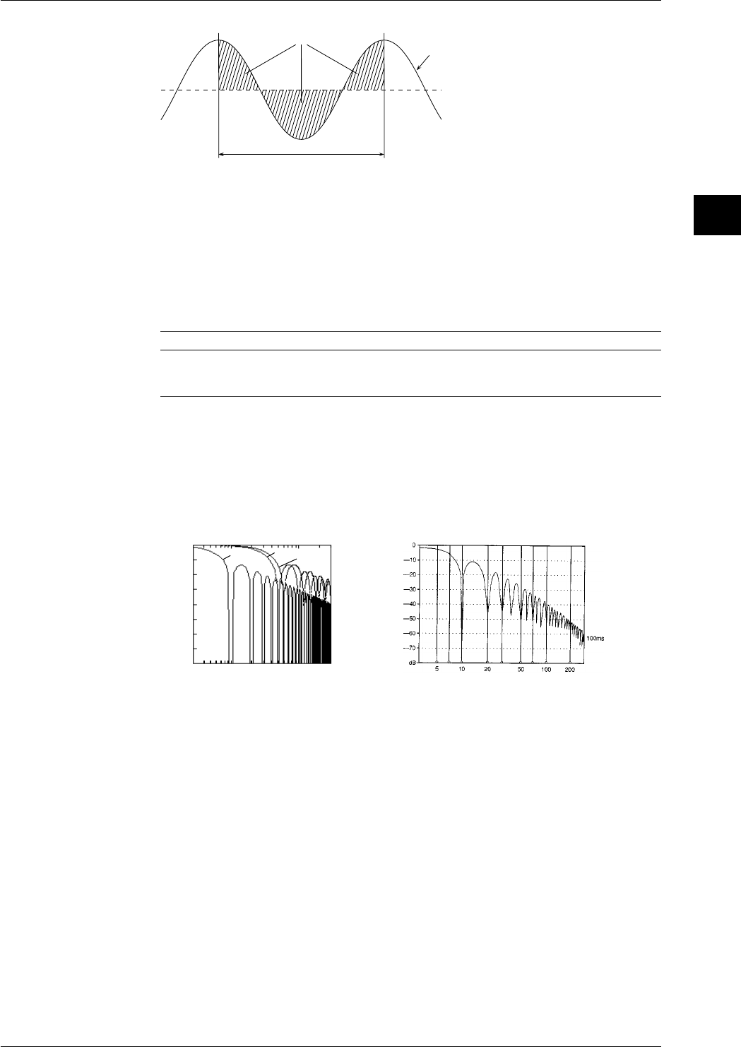
3-39
IM DR232-01E
3
Installation and Wiring
Balance each other
integration time
DC voltage (average value)
Input voltage (instantaneous value)
Normally, an integration time of 20ms (50Hz) or 16.7ms (60Hz) is selected depending on the
commercial power supply frequencies. A 100-ms integration mode is added to the instrument to
achieve superior noise rejection. However, when using the 100ms setting, the smallest
measurement interval is longer than in case of the 20ms or 16.7ms setting. The integration effect
enables the PWM A/D converter to perform the following two functions.
• Rejection of frequency determined by the reciprocal of the integration time and frequencies
which are whole multiples of that frequency;
• First-order lag filter provided with cut-off frequency proportional to the reciprocal of the
integration time.
The following table compares the integration times of 16.7ms, 20ms and 100ms.
Integration time Rejection frequency Cut-off frequency Remarks
16.7ms n×60Hz approx. 19Hz for 60Hz
20.0ms n×50Hz approx. 16Hz for 50Hz
100.0ms n×10Hz approx. 3.2Hz for both 50Hz/60Hz
n=1,2,3...
As shown in the table, the merit of 100.0-ms integration is not only that it applies to both 50 and
60Hz, but also that it provides a low cut-off frequency as the first-order lag filter and improves
the noise rejection ability.
The following figure shows the calculation values of the NMRR for three integration times and an
example of actual measurement of the NMRR for a 100-ms integration signal.
• Calculated values of NMRR • Example of actual measurement of NMRR
(100ms)
0
-20
-40
-60
-10
-30
-50
-70
510 20 50 100 200
Frequency (Hz)
dB
16.7ms
20.0ms
100ms
Frequency (Hz)
Noise Filter
This instrument is equipped with a low-pass filter (cutoff-frequency of 10Hz (for both 50/60 Hz),
50Hz,60Hz) which functions as a way of noise rejection. Also exponential averaging functions as
a noise filter.
Anti-Noise Measures: Applications
Practical Measures
• Reducing noise itself
The basics of this practical measures dictates using the instrument in conditions where noise is
suppressed as much as possible.
• for power lines: an increase of impedance;
Separate the power lines for noise source equipment (inverter, thyristor, etc.) from those for
the measuring instrument.
3.11 Countering Noise
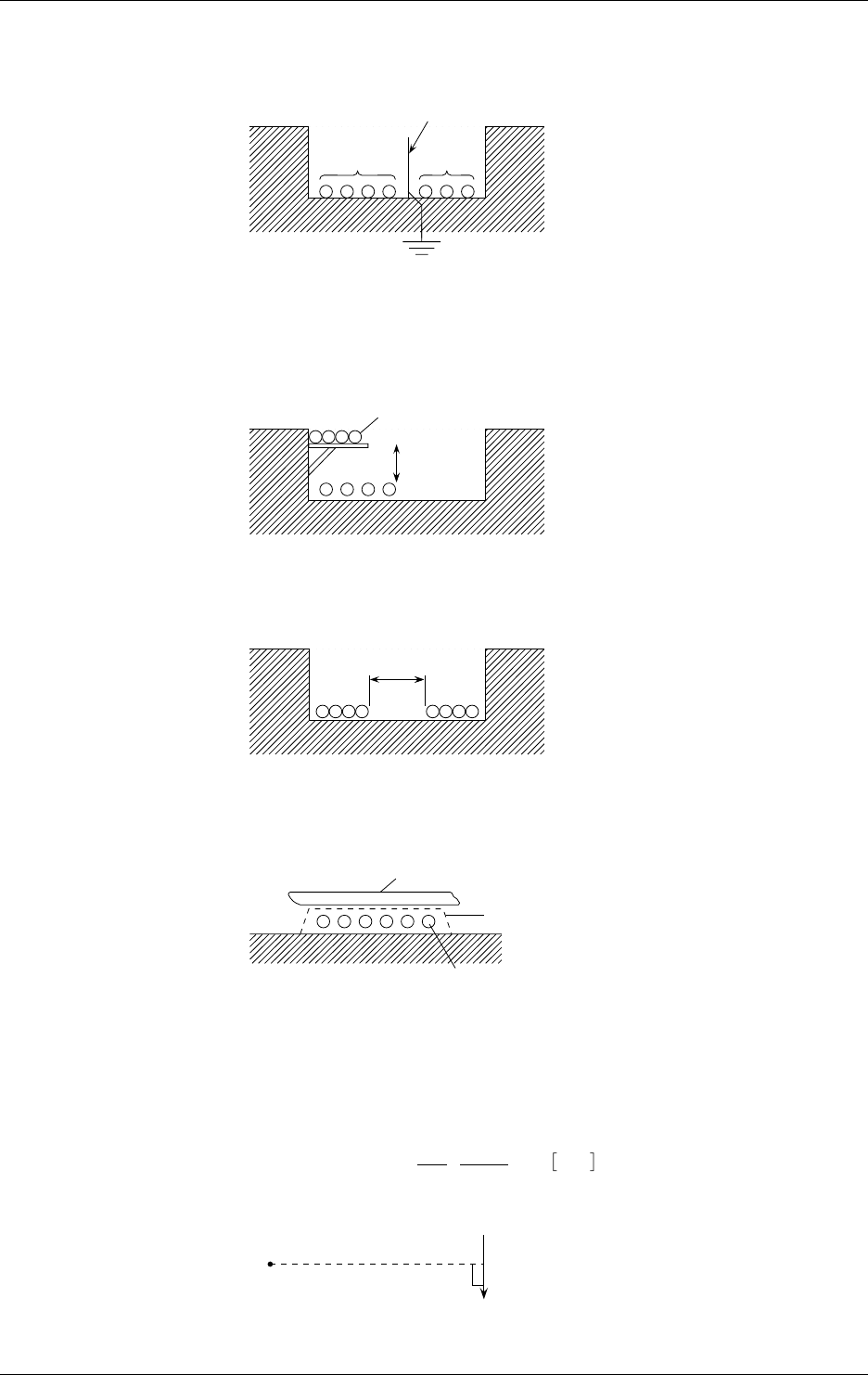
3-40 IM DR232-01E
• for input lines: an increase of impedance;
Always separate the input line from the noise source lines (power and alarm lines).
Step 1 : Install a separator.
Separator
Special class 3 ground
(10Ω or less)
Signal*
lines Power
lines
Step 2 : Keep the signal cables at least 15cm above the power lines using a bracket.
If the power lines are not shielded, the operating voltage is 220V or less, and the operating
current is 10A or more, the distance between the signal cables and power cords must be
60cm or more.
Signal lines*
Power
lines
at least
15 cm
Step 3 : Leave a clearance of at least 15 cm between the signal lines and power lines.
If the power lines are not shielded, the operating voltage is 220V or less, and the operating
current is 10A or more, the distance between the signal cables and power cords must be
60cm or more.
Signal*
lines Power
lines
at least 15 cm
Step 4 : Lay the signal lines at right angles to the power lines.
If the power lines are not shielded, separate the signal lines and power lines where they cross
using steel sheeting at least 1.6mm thick.
Signal lines*
Power lines
1.6mm
* Separate analog signal lines and communication cables in the same manner as from power
cords.
• When there is influence from a magnetic or electrical field: an increase of
impedance
Step 1 : Keep the noise source as far away as possible.
Magnetic field strength
H = I
2πr=2,400
6= 400 A/m
Example I=2,400A
r=1m
H
The influence of the external magnetic field on the measuring instrument: 400A/m or less.
3.11 Countering Noise
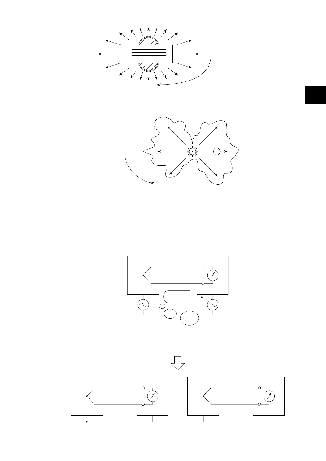
3-41
IM DR232-01E
3
Installation and Wiring
Step 2 : Change the position of the noise source.
A) Leakage magnetic flux of transformer:
Φ = strong
Φ = weak Move the instrument to a location
where the influence from magnetic
flux is weak.
B) Sparks
strong electromagnetic
radiation
weak electrogmagnetic
radiation
Move the instrument to a location
where the influence from electro-
magnetic radiation is weak.
spark
• Grounding: a decrease of impedance
The grounding method is the point of common mode noise suppression.
Equipment
under
measurement
(EUM) The instrument
ec ec'
EUM The instrument EUM The instrument
(if grounding is difficult)
or
The difference in the potential to the ground between EUM
and the instrument may cause a ground current, resulting in noise.
Equalize the potentials to the ground so
that the common mode noise becomes zero.
One-point grounding Potential equalization
The basic means to obtain stable measurement is to set the circuit potential with proper
grounding. Thus, potential equalization is the means to be adopted only when grounding is
impossible.
3.11 Countering Noise

3-42 IM DR232-01E
• Shielded and twisted pair (prevention of electromagnetic coupling): an increase
of impedance
If it is difficult to keep the noise source away from the measuring instrument due to space
limitations, the use of a shielded twisted pair is effective.
• electrostatic coupling can be completely cut off by shielding;
• for a magnetic field, shielding with a magnetic material (iron, permalloy, etc.) can be
employed. However, there are many restrictions on this use and perfect shielding is
impossible. Therefore, use of a twisted pair is preferable.
Voltage em induced by the coil is proportional to the area of the coil.
=> The smaller the area of the coil becomes, the smaller the noise becomes.
em
Magnetic field Φ
Coil
If the directions of coils 1 and 2 are reversed by twisting, as shown, if the areas of the two coils
are equal, the induced voltages of the coils offset each other and total induced voltage em
becomes zero.
em
coil 1 coil 2
The above two principles are combined as a twisted pair.
Even though a shielded twisted pair is used, a proper grounding method is still important.
Connected
equipment
Signal
source twisted pair shield
If the signal source is not grounded
connected
equipment
Power
source twisted pair shield
Ground the signal cable shields collectively but separately from the power line ground. If the
separation of grounds is impossible, use the guard terminal.
3.11 Countering Noise
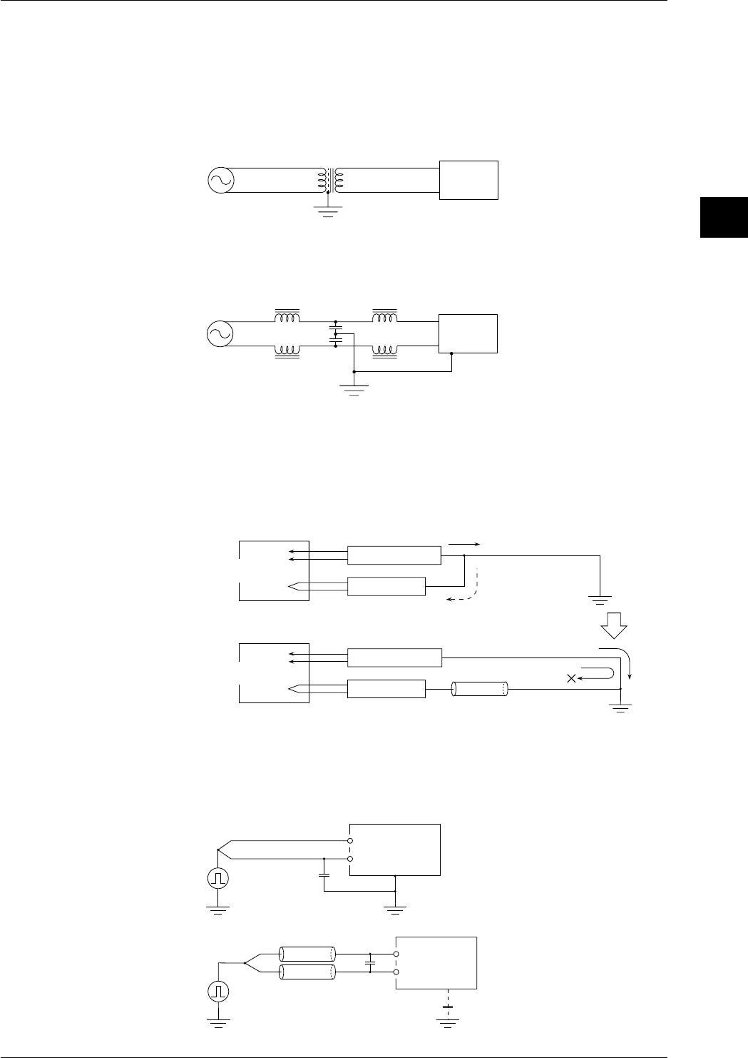
3-43
IM DR232-01E
3
Installation and Wiring
• Insertion of noise filter and noise killer
If the influence from noise cannot be eliminated by the methods described before, use noise
filter or noise killer.
Power line noise rejection
Step 1 : Insert an isolation transformer into the power line.
Increasing impedance to high frequency
with shield, which is grounded
1:1
The
instrument
(Most of the noise is
high-frequency noise)
100V AC
Power
supply
Step 2 : Insert a power line noise filter (available on the market)
High frequency noise is divided by decreasing impedance to ground through C and
increasing impedance through L.
The
instrument
100V AC
L
C
Power
supply
Note 1:Ground the noise filter and the recorder in common.
Note 2:Since insertion of a noise filter increases the by-pass current (regarded as leakage
current), make sure that the leakage current is within the specified value.
• When the noise contains wide frequency components
While one-point grounding is effective at a low frequency, it sometimes forms a loop and
has an adverse effect on a high frequency.
Ex: Connecting a power meter and the recorder grounded at one point to an inverter
AC power meter
The instrument
Noise source
(inverter, etc.) High-frequency noise
(reverse flow)
One-point
grounding
AC power meter
The instrument
Noise
blocking of reverse flow
Ferrite beads
(high impedance at high frequency)
Reverse flow of high-frequency to the recorder is thus suppressed.
The power meter leaks the high-frequency noise component to the
ground and that noise flows back to the DA100 side.
Noise source
(inverter, etc.)
• Input noise rejection
If input noise cannot be rejected by means of one-point grounding or 100-ms integration,
insert capacitor or ferrite beads as they are effective in rejecting pulse noise.
Step 1 : Connect a capacitor between the L input and ground.
C
H
L
The instrument
Use a capacitor from a hundred
to thousands of pF which can
withstand high voltages and
must be grounded.
Step 2 : Rejection of pulse noise when grounding is impossible.
CH
L
The instrument
Use a capacitor from a hundred
to thousands of pF.
Ferrite beads
Insert the ferrite beads as necessary.
3.11 Countering Noise
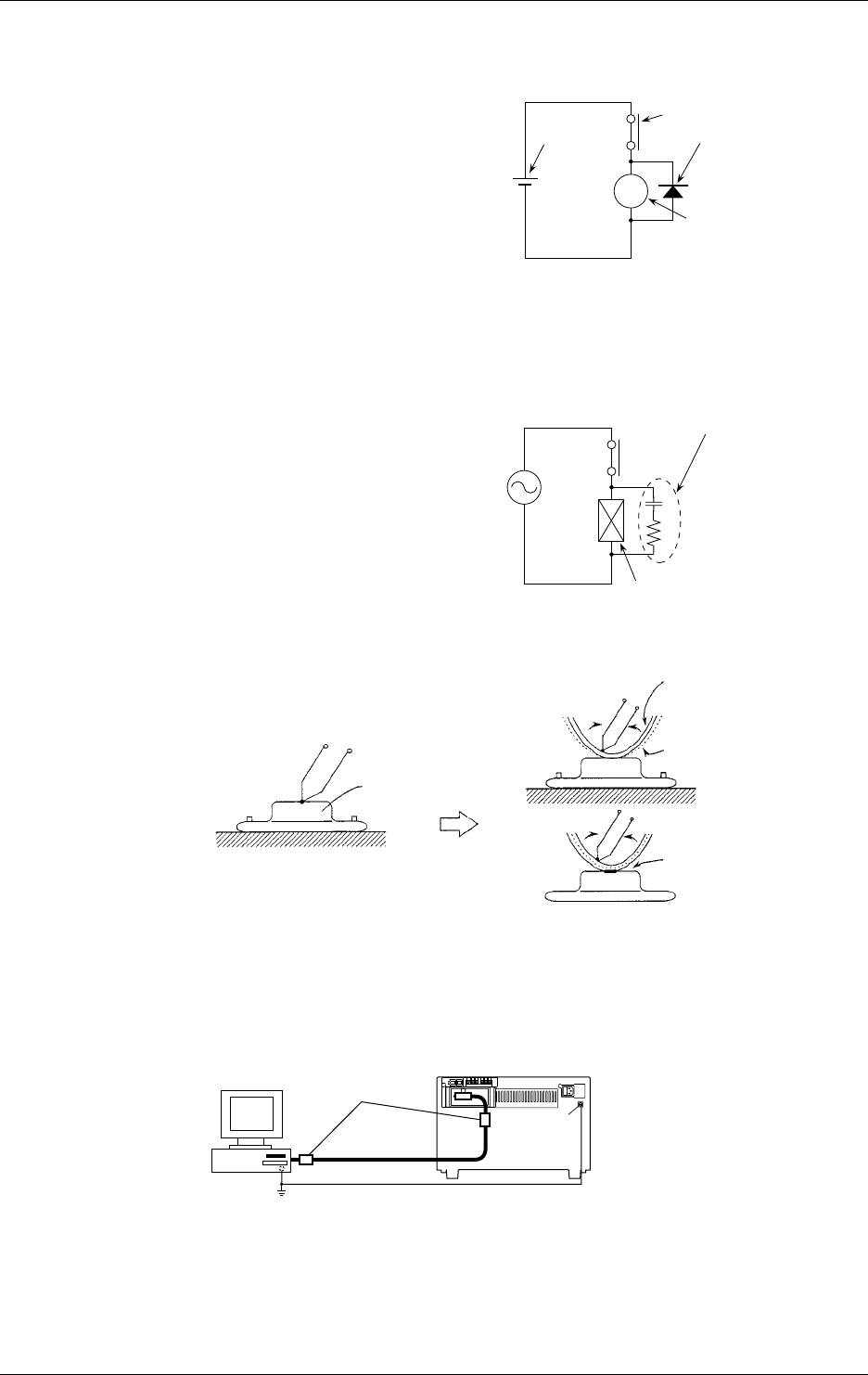
3-44 IM DR232-01E
3.11 Countering Noise
• Relay noise suppression
R
Dc external
power supply Contact
Diode
connect to the relay
coil terminal (socket)
directly.
()
()
Relay
the relay coil rating must
be as low as possible.
<DC relay>
• To prevent noise and protect the contact,
connect the diode to the relay coil terminal
directly.
• In addition to the above measure, reduce
the rated voltage of the relay circuit as
much as possible for higher reliability.
• It is necessary to choose a diode that
matches the relay. Generally, a diode
whose rated rectifying current is at least
three times the current flowing through
the relay coil must be used.
And the rated reverse voltage must be at
least three time the operating voltage.
(Note) Across the relay or solenoid coil, a counter-electromotive force is produced by an
inductive load. This phenomenon may damage the contact or, as the noise source,
cause a malfunctioning of the equipment, and have an unfavorable effect on the
entire system.
Surge suppresser circuit
connect to the
relay socket
terminal directly.
()
C
R
C=0.01 to 1µF
Must withstand a voltage
of at least three times
the operating voltage.
R=0.3Re to 1Re
Re=Relay coil's DC resistance
<AC relay>
• If a relay contact is connectd to the input
of the system components, apply the
measure shown in the figure at the right
to the relay coil. Otherwise, a counter-
electromotive force produced across the
coil may be induced on the contact side
through the relay's internal coupling or
coupling between the lines, and may
cause a malfunctioning of the equipment.
• Others (isolation from noise source: for hot line measurement)
(Hot line) Power transistor
(Vcc)
Wrap
At high temperatures
At low temperatures Mylar isolation film
Adhesive copper
foil tape
Adhesion
Anti-Noise Measures for PC Connection
When connecting the instrument to a PC, it is recommended to apply ferrite cores (e.g.
ZCAT3035-1303 from TDK) to the interface cable as a noise countering measure. Apply a ferrite
core on both sides of the cable as shown below, when the noise persists, apply more ferrite cores.
Personal
computer Ferrite core
Function
grounding
terminal
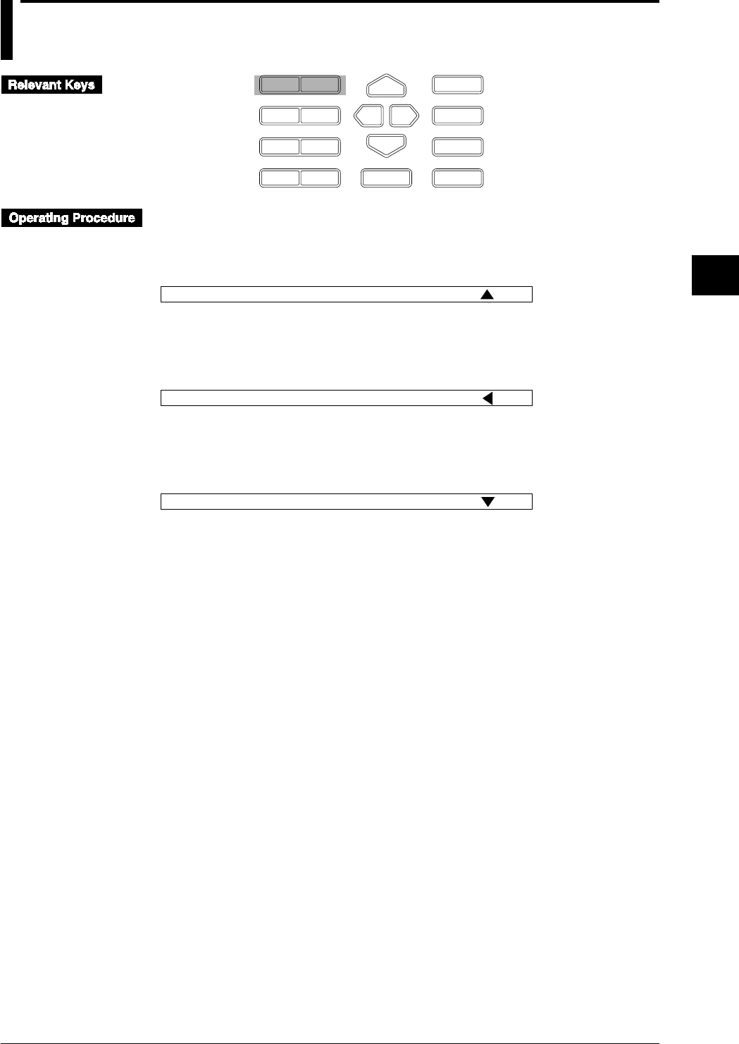
4-1
IM DR232-01E
4
Setting the Monitor Mode Display
4.1 Using the AUTO Display
D I S P M O D E
P R I N TF U N C
I N S D E L
R A N G E A L A R M
S E TC H A R T E N T E R
F E E D
M. F U N C 1
M. F U N C 2
R E C O R D
E S C
AUTO Display for the Main Display
1 Select the main display using the DISP key. Direct the arrow mark on the Sub-display upward.
2 Select “AUT” using the MODE key.
003 0.0045V 004 0.0931V AUT
Sub-display 1
AUTO Display for Sub-display 1
1 Select sub-display 1 using the DISP key. Direct the arrow mark on the Sub-display leftward.
2 Select “AUT” using the MODE key.
004 0.0926V 005 0.0824V
Sub-display 1
AUT
AUTO Display for Sub-display 2
1 Select sub-display 2 using the DISP key. Direct the arrow mark on the Sub-display downward.
2 Select “AUT” using the MODE key.
005 0.8210V 006 0.0095V
Sub-display 1
AUT

4-2 IM DR232-01E
AUTO Display for the Main Display
Channel No.
The first three characters are used for displaying the channel number. Delete “The first character
always displays “0”.” “A” will be displayed in the case of optional computation channels.
If you selected TAG at the channel No./TAG setting in the set-up mode (refer to 10.2 on page 10-
4), the assigned tag will appear for each channel.
• The first 7 characters of the TAG setting will be displayed;
• If the TAG setting consists of only spaces, the channel number will be displayed instead;
• If the first character of the TAG setting is a space, the 2nd to 8th character will be displayed.
Difference between Channels (delta)
One character is used to let you know that difference between channels (delta) is displayed.
However, it will not be displayed in the case of optional computation channels.
Only if you selected the difference between channels (delta) as the input type, “d” will be
displayed here.
Alarms
Two characters are used for displaying alarms. One channel is used in the case of optional
channels.
When an alarm occurs, the kind of alarm will be displayed. When in one channel several alarms
occur at the same time, the priority of display becomes H > L > dH > dL > RH > RL. For details
on H, L, dH, dL, RH and RL alarms, refer to page 8-2.
Measurement Values
Seven characters are used for displaying the measurement values. The decimal point uses up one
character. Nine channel is used in the case of optional computation channels.
When a measurement value does not reach the following value, “– *****” will be displayed.
• DC voltage: a minimum value of the measuring range – (max. value – min. value) × 0.05
• TC/RTD: min. value of the measurement range –10°C
• Linear scaling: –32000, or a minimum value of the recording span – (max. value – min. value)
× 0.05
When a measurement value exceeds the following value, “+ *****” will be displayed.
• DC voltage: a maximum value of the measuring range + (max. value – min. value) × 0.05
• TC/RTD: min. value of the measurement range +10°C
• Linear scaling: +32000, or a maximum value of the recording span + (max. value – min. value)
× 0.05
If the input module is not connected properly, “ XXXXXX” will be displayed.
While waiting for an input signal “ OOOOOO” will be displayed.
Engineering Units
If the channel number has been selected to appear on the display, six characters are used for
displaying engineering units. If TAG has been selected to appear on the display, only three
characters are used for displaying units. Only the first three characters of the unit setting will then
be displayed, even if the first character of the unit setting is a space.
When “ XXXXXX” or “ OOOOOO” are displayed as measurement value, no engineering unit
will be displayed.
001
Engineering unit
V0.0467 H d
Measurement value
Alarm
Difference between channels
"A" will be displayed in the case of optional computation channels.
Channel No.
1st digit: unit No.
2nd digit: slot No.
3rd digit: channel No. (in units of 1)
Others
If you selected “SKIP” as the input type, that channel will not be displayed.
When the input type of all channels is set to “SKIP”, “***ALL SKIP***” will be displayed.
4.1 Using the AUTO Display
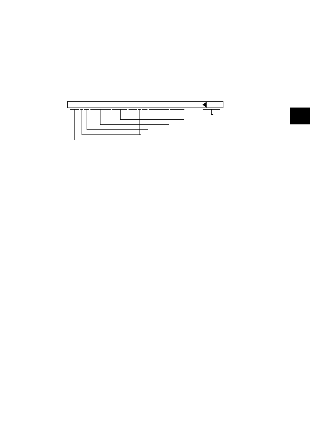
4-3
IM DR232-01E
4
Setting the Monitor Mode Display
AUTO Display for Sub-display 1
Data of two channels are displayed here simultaneously.
Channel No., Difference between Channels (delta), Alarms, Measurement Values
Same as for the main display.
Engineering Units
If the channel number has been selected to appear on the display, the first four characters of the
unit setting are used for displaying engineering units. If TAG has been selected to appear on the
display or when “ XXXXXX” or “ OOOOOO” are displayed as measurement value, no
engineering unit will be displayed.
Selected Display Mode (refer to page 4-1 for procedure)
This only appears on sub-display 1 when monitoring. The arrow shows to which display the
display mode refers.
004d L 0.0926V 005 0.0824V AUT
Selected display mode
Engineering unit
Measurement value
Alarm
Difference between channels
Channel No.
1st digit: unit No. A will be displayed in the case of optional
computation channels.
2nd digit: slot No.
3rd digit: channel No. (in units of 1)
Others
Same as for the main unit.
AUTO Display for Sub-display 2
Data of two channels are displayed here simultaneously.
Channel No., Difference between Channels (delta), Alarms, Measurement Values,
Engineering Units and Selected Display Mode
Same as for the sub-display 1.
Others
Same as for the sub-display 1.
Points to Note when Using the AUTO Display
• When all three displays are set to AUTO display, the main display will start displaying data of
the channel with the smallest channel number, on sub-display 1 data of the next two channels
will be displayed, while on sub-display 2 data of the next two channels will be displayed. When
the data are updated, the display will be replaced with data of the next, consecutive, channel.
• When the input type of all channels is set to “SKIP”, then depending on the display as
described below, “***ALL SKIP***” will be displayed.
• When the main display is set to AUTO display, then this will be displayed settings on the
main display, regardless of the settings of sub-display 1 and 2.
• When sub-display 1 is set to AUTO display, and the main display is set to any other mode
than AUTO, then this will be displayed on sub-display 1, regardless the setting of sub-
display 2.
• When sub-display 2 is set to AUTO display, and the main display is set to any other mode
than AUTO, and sub-display 1 to any other mode than AUTO, then this will be displayed on
sub-display 2.
• When on any of the main, sub-display1 or sub-display 2 “***ALL SKIP***” appears, other
displays which may have been set to AUTO will turn blank. Only the selected display mode
on sub-display 1 and the status display will appear.
4.1 Using the AUTO Display
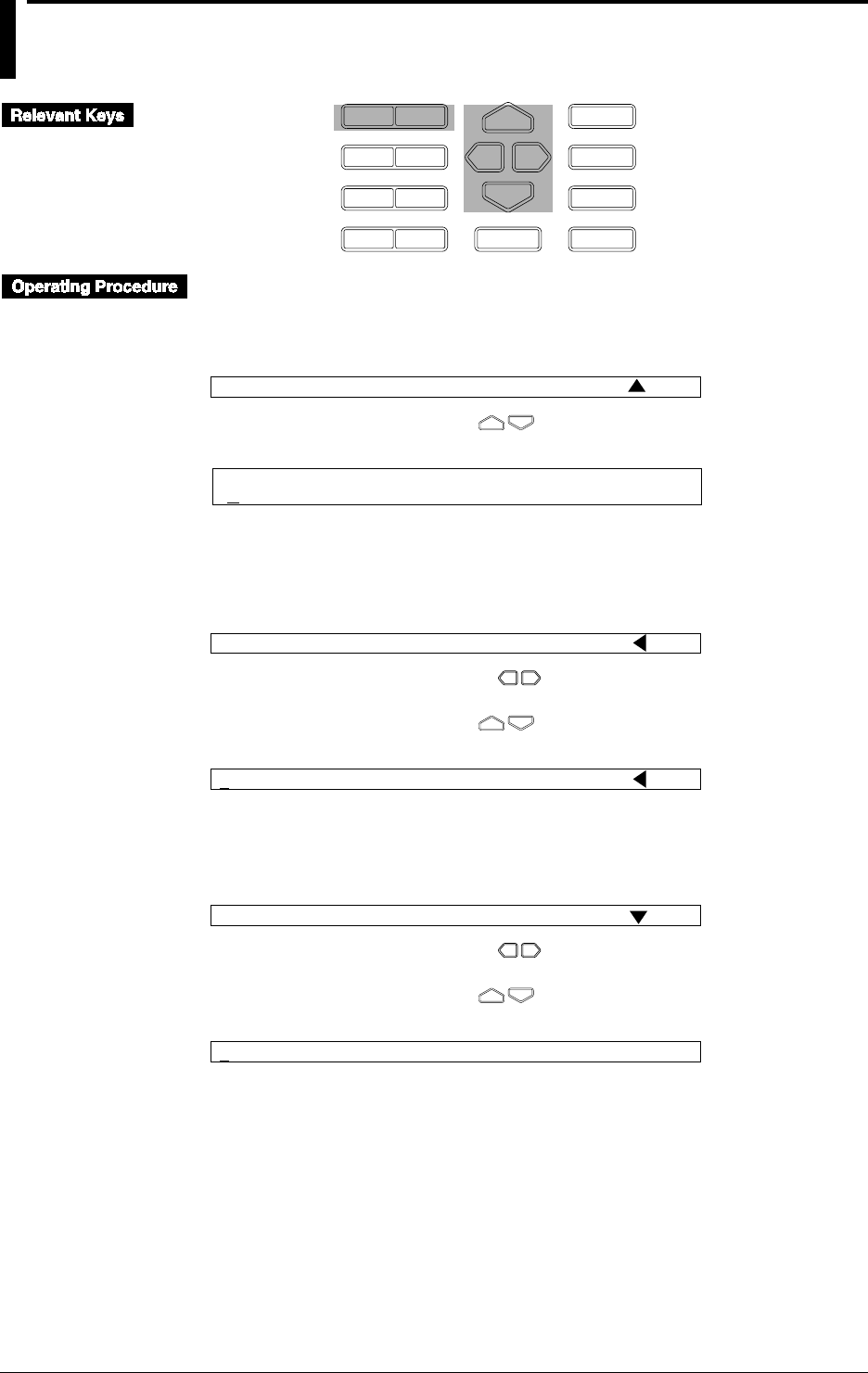
4-4 IM DR232-01E
4.2 Using the MANUAL Display
D I S P
P R I N TF U N C
I N S D E L
R A N G E A L A R M
S E TC H A R T E N T E R
F E E D
M. F U N C 1
M. F U N C 2
R E C O R D
M O D E
E S C
MANUAL Display for the Main Display
1 Select the main display using the DISP key.
2 Select “MAN” using the MODE key.
002 0.0034V 003 0.0920V MAN
Sub-display 1
3 Select the required channel using the keys.
001 V0.0057
Main display
MANUAL Display for Sub-display 1
1 Select sub-display 1 using the DISP key.
2 Select “MAN” using the MODE key.
002 0.0422V 003 0.0726V
Sub-display 1
MAN
3 Select the right or left channel using the keys. A dash [—] will appear below the unit
number of the selected channel.
4 Select the required channel using the keys.
006 0.0892V 003 0.0726V
Sub-display 1
MAN
MANUAL Display for Sub-display 2
1 Select sub-display 2 using the DISP key.
2 Select “MAN” using the MODE key.
005 0.0931V 006 0.0092V
Sub-display 1
MAN
3 Select the right or left channel using the keys. A dash [—] will appear below the unit
number of the selected channel.
4 Select the required channel using the keys.
009 1.0075V 008 0.0154V
Sub-display 2

4-5
IM DR232-01E
4
Setting the Monitor Mode Display
4.2 Using the MANUAL Display
MANUAL Display for the Main Display
Channel No., Difference between Channels (delta) and Alarms
Same as for the AUTO display (refer to page 4-2).
Measurement Values
Same as for the AUTO display (refer to page 4-2), except for the following.
When the input type of the channel is set to “SKIP”, then “SKIP” will be displayed.
When the channel other than the channel of the input module is selected, “- - - - - -” appears.
Engineering Units
Same as for the AUTO display (refer to page 4-2), except for the following.
When the input type of the channel is set to “SKIP”, then no engineering unit will be displayed.
MANUAL Display for the Sub-display 1 and 2
Data of two channels are displayed here simultaneously on each display.
Channel No., Difference between Channels (delta), Alarms and Selected Display
Mode
Same as for the AUTO display (refer to page 4-3).
Measurement Values
Same as for the AUTO display (refer to page 4-3), except for the following.
When the input type of the channel is set to “SKIP”, then “SKIP” will be displayed.
When the channel other than the channel of the input module is selected, “- - - - - -” appears.
Engineering Units
Same as for the AUTO display (refer to page 4-3), except for the following.
When the input type of the channel is set to “SKIP”, then no engineering unit will be displayed.
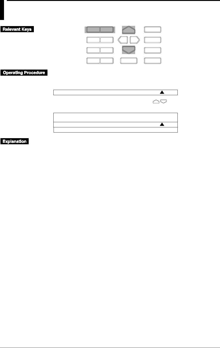
4-6 IM DR232-01E
4.3 Using the PAGE Display
D I S P
P R I N TF U N C
I N S D E L
R A N G E A L A R M
S E TC H A R T E N T E R
F E E D
M. F U N C 1
M. F U N C 2
R E C O R D
M O D E
E S C
1 Select the main display using the DISP key.
2 Select “PGE” using the MODE key.
002 0.1936V 003 0.0995V PGE
Sub-display 1
3 Select the required set of five channels (page) using the keys.
007 0.0197V 008 0.0074V PGE
006 V0.0173
009 0.0162V 010 0.0102V
Display
PAGE Display for the Main Display
When this display is selected, the measurement values of five consecutive channels will be
displayed using sub-display 1 and 2 also.
Channel No., Difference between Channels (delta) and Alarms
Same as for the AUTO display (refer to page 4-2).
Measurement Values
Same as for the AUTO display (refer to page 4-2), except for the following.
When the input type of the channel is set to “SKIP”, then “SKIP” will be displayed.
When the channel other than the channel of the input module is selected, “- - - - - -” appears.
Engineering Units
Same as for the AUTO display (refer to page 4-2), except for the following.
When the input type of the channel is set to “SKIP”, then no engineering unit will be displayed.
PAGE Display for the Sub-display 1 and 2
In combination with the page display of the main display, data of two channels are displayed here
simultaneously on each display. Other display modes cannot be selected.
Channel No., Difference between Channels (delta), Alarms and Selected Display Mode
Same as for the AUTO display (refer to page 4-3).
Measurement Values
Same as for the AUTO display (refer to page 4-3), except for the following.
When the input type of the channel is set to “SKIP”, then “SKIP” will be displayed.
When the channel other than the channel of the input module is selected, “- - - - - -” appears.
Engineering Units
Same as for the AUTO display (refer to page 4-3), except for the following.
When the input type of the channel is set to “SKIP”, then no engineering unit will be displayed.
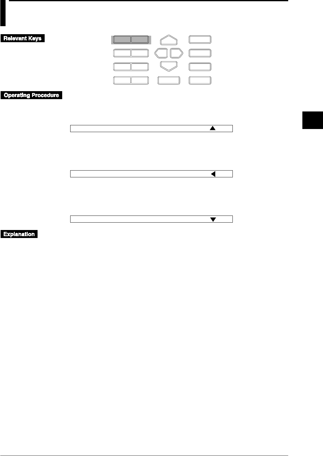
4-7
IM DR232-01E
4
Setting the Monitor Mode Display
4.4 Using the ALARM SEARCH Display
D I S P
P R I N TF U N C
I N S D E L
R A N G E A L A R M
S E TC H A R T E N T E R
F E E D
M. F U N C 1
M. F U N C 2
R E C O R D
M O D E
E S C
ALARM SEARCH Display for the Main Display
1 Select the main display using the DISP key.
2 Select “SER” using the MODE key.
003 0.0054V 004 0.0319V SER
Sub-display 1
ALARM SEARCH Display for Sub-display 1
1 Select sub-display 1 using the DISP key.
2 Select “SER” using the MODE key.
004 H 0.0269V 005 RH 0.0248V
Sub-display 1
SER
ALARM SEARCH Display for Sub-display 2
1 Select sub-display 2 using the DISP key.
2 Select “SER” using the MODE key.
005 0.2108V 006 0.0951V
Sub-display 1
SER
ALARM SEARCH Display for the Main Display
Only the channels in which an alarm occurred, will be displayed. When an alarm occurs in several
channels, the channels will be displayed consecutively.
Channel No., Difference between Channels (delta), Alarms, Measurement Values
and Engineering Units
Same as for the AUTO display (refer to page 4-2).
Others
When the input types of all channels are set to “SKIP” or no alarms occur, “***NO ALARM***”
will be displayed.
ALARM SEARCH Display for the Sub-display 1 and 2
Only the channels in which an alarm occurred, will be displayed. Two channels will be displayed
on each sub-display.
Channel No., Difference between Channels (delta), Alarms, Measurement Values,
Engineering Units and Selected Display Mode
Same as for the AUTO display (refer to page 4-3).

4-8 IM DR232-01E
4.4 Using the ALARM SEARCH Display
Points to Note when Using the ALARM SEARCH Display
• When all three displays are set to ALARM SEARCH display, the main display will start
displaying data of the channel with the smallest channel number, on sub-display 1 data of the
next two channels will be displayed, while on sub-display 2 data of the next two channels will
be displayed. When the data are updated, the display will be replaced with data of the next,
consecutive, channel.
• When the input type of all channels is set to “SKIP”, then depending on the display settings as
described below, “***NO ALARM***” will be displayed.
• When the main display is set to ALARM SEARCH display, then this will be displayed on the
main display, regardless the settings of sub-display 1 and 2.
• When sub-display 1 is set to ALARM SEARCH display, and the main display is set to any
other mode than ALARM SEARCH, then this will be displayed on sub-display 1, regardless
the setting of sub-display 2.
• When sub-display 2 is set to ALARM SEARCH display, and the main display is set to any
other mode than ALARM SEARCH, and sub-display 1 to any other mode than ALARM
SEARCH, then this will be displayed on sub-display 2.
• When on any of the main, sub-display1 or sub-display 2 “***NO ALARM***” appears,
other displays which may have been set to ALARM SEARCH will turn blank. Only the
selected display mode on sub-display 1 and the status display on sub-display 2 will appear.

4-9
IM DR232-01E
4
Setting the Monitor Mode Display
4.5 Using the BARGRAPH Display
D I S P
P R I N TF U N C
I N S D E L
R A N G E A L A R M
S E TC H A R T E N T E R
F E E D
M. F U N C 1
M. F U N C 2
R E C O R D
M O D E
E S C
1 Select the sub-display 1 using the DISP key.
2 Select “BAR” using the MODE key.
- 1.5000> < 2.0000 BAR
003 V0.0172
004 0.0153V 005 0.0123V
Display
Bargraph Display
Sub-display 1 can be turned into a bargraph display.
The measurement data on the main display are displayed as a bargraph on sub-display 1. The
bargraph shows a graph corresponding to the measurement value, showing the recording span
divided into 40 equal parts. The left side of the bargraph shows the left span, the right side of the
bargraph shows the right span. When you are using the linear scaling function, the left and right
side of the bargraph show the left scaling and right scaling value respectively. Engineering units
are not displayed.
When the main display shows “SKIP”, “***ALL SKIP***”, “NO ALARM”, “OOOOOO”,
“XXXXXX”, or “- - - - - -” the bargraph will not appear. Only the selected display mode will
appear.
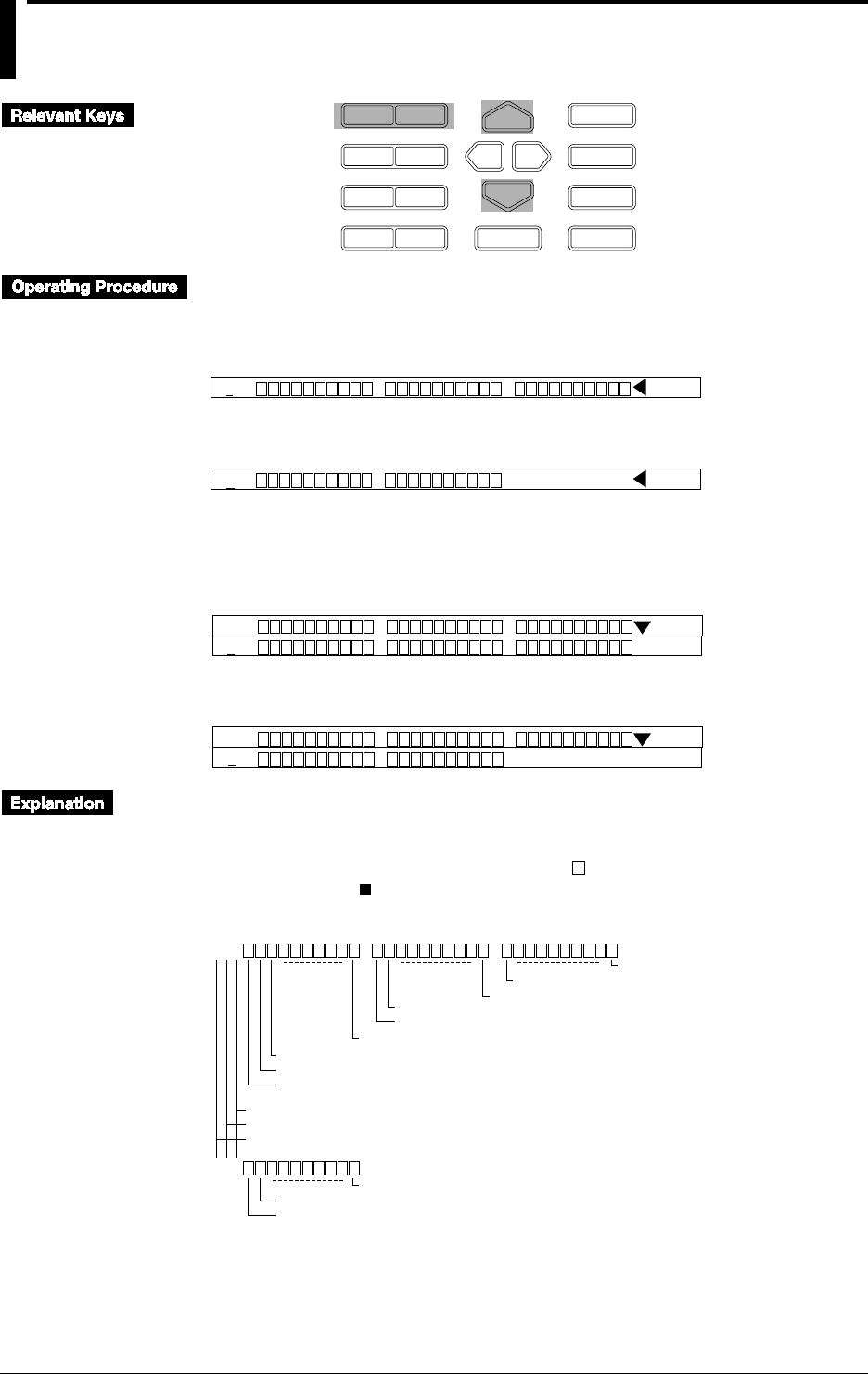
4-10 IM DR232-01E
4.6 Using the ALARM STATUS Display
D I S P
P R I N TF U N C
I N S D E L
R A N G E A L A R M
S E TC H A R T E N T E R
F E E D
M. F U N C 1
M. F U N C 2
R E C O R D
M O D E
E S C
ALARM STATUS Display for Sub-display 1
1 Select the sub-display 1 using the DISP key.
2 Select “ALM” using the MODE key.
001
Sub-display 1
ALM
3 Select the range to be displayed in blocks of 10 channels.
011
Sub-display 1
ALM
ALARM STATUS Display for Sub-display 2
1 Select the sub-display 2 using the DISP key.
2 Select “ALM” using the MODE key.
001
Sub-display 1 and 2
ALM
001
3 Select the range to be displayed in blocks of 10 channels.
001
Sub-display 1 and 2
ALM
011
Alarm Status Display
The status of alarms can be displayed on sub-display 1 and 2.
On each sub-display the alarms of maximum 30 channels can be monitored which also depends
on the number of input channels. The display shows “ ” for channels where no alarm has
occurred, and shows “ ” for channels where an alarm has occurred. The relation between the
alarm status display and channel number is as shown below.
001
021
Alarm status of channel 3
Alarm status of channel 2
Alarm status of channel 1
Channel 12
Channel 11
Channel 30
Channel 21
Channel 20
Channel 10
Alarm status of channel 22
Alarm status of channel 21
Channel 30
"A" will be displayed in the case of optional computation channels.
Channel No. (fixed to 1 in units of 1)
Slot No.
Unit No.
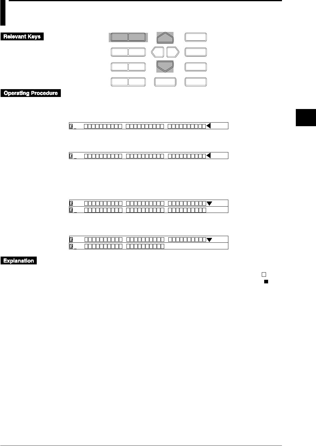
4-11
IM DR232-01E
4
Setting the Monitor Mode Display
4.7 Using the RELAY STATUS Display
D I S P
P R I N TF U N C
I N S D E L
R A N G E A L A R M
S E TC H A R T E N T E R
F E E D
M. F U N C 1
M. F U N C 2
R E C O R D
M O D E
E S C
RELAY STATUS Display for Sub-display 1
1 Select the sub-display 1 using the DISP key.
2 Select “RLY” using the MODE key.
S01
Sub-display 1
RLY
3 Select the range to be displayed in blocks of 10 channels.
S11
Sub-display 1
RLY
RELAY STATUS Display for Sub-display 2
1 Select the sub-display 2 using the DISP key.
2 Select “RLY” using the MODE key.
S01
Sub-display 1 and 2
RLY
S01
3 Select the range to be displayed in blocks of 10 channels.
S01
Sub-display 1 and 2
RLY
041
Relay Status Display
The status of relays can be displayed on sub-display 1 and 2.
On each display the status of maximum 30 relays can be monitored. The display shows “ ” for
relays which are currently not operated by internal switch/alarm output relay, and shows “ ” for
relays which are currently operated by internal switch/alarm output relay.
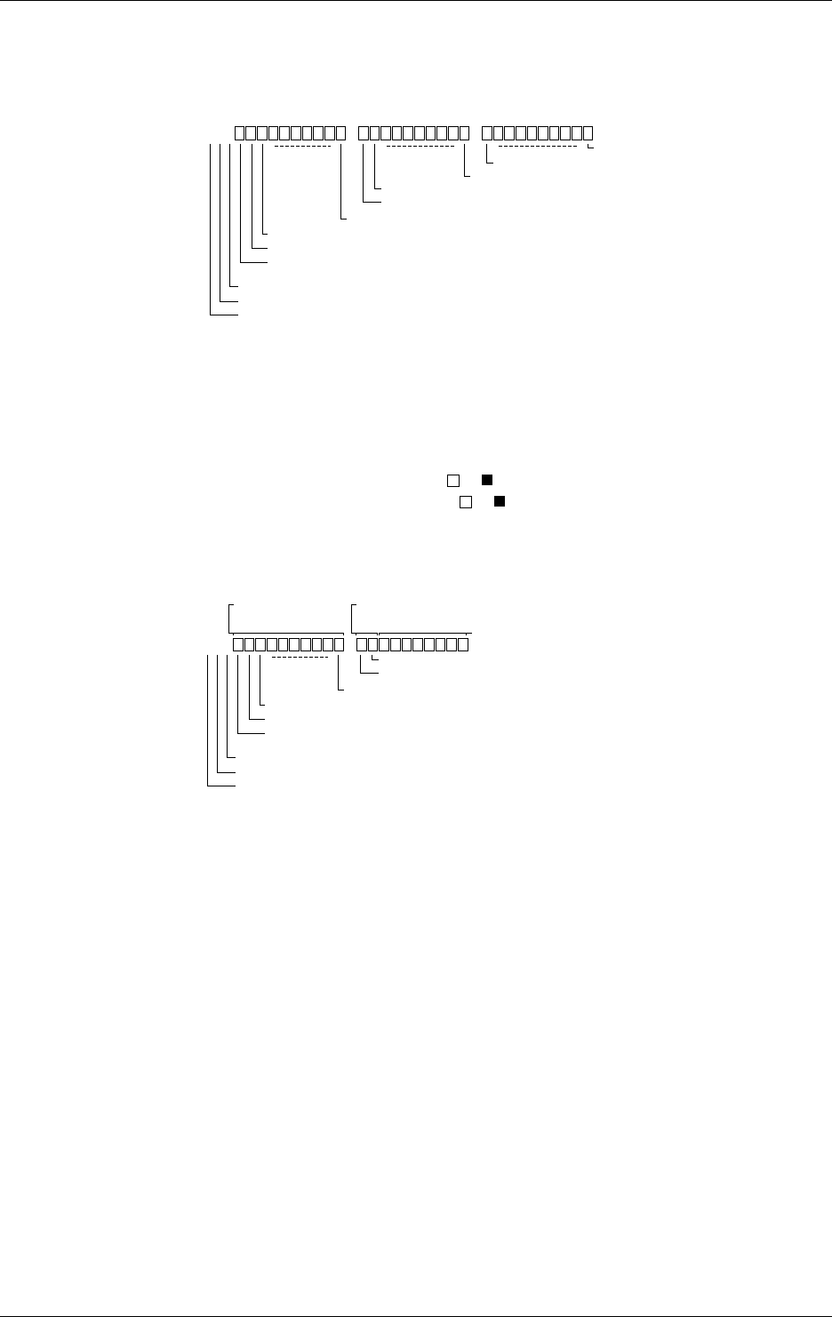
4-12 IM DR232-01E
4.7 Using the RELAY STATUS Display
Relation between the Relay Status and Internal Switch
If the relay status of the internal switches is being displayed, an “S” will be displayed as the first
character. The next two characters show the number of the internal switch which corresponds to
the first batch of the display and range from 01 to 51. There are 60 internal switches.
S01
Relay status of internal switch 3
Relay status of internal switch 2
Relay status of internal switch 1
Internal switch 12
Internal switch 11
Internal switch 30
Internal switch 21
Internal switch 20
Internal switch 10
Internal switch no. in units of 1 (fixed to 1)
Tens of internal switch no. (0 to 5)
Internal switch (S)
Relation between the Relay Status and Alarm Output Relay
If the relay status of the alarm output relays is being displayed, a unit number will be displayed in
the first character position. The slot number in the second character position represents the
number of slot in which the alarm module or the DI/DO module is mounted. The alarm output
relay is different in relay status display whether it is in the alarm module or in the DI/DO module
as shown below.
• If an alarm module is mounted, ten or indicators are displayed.
• If the DI/DO module is mounted, ten or indicators are displayed but the right 8 indicators
of ten are not used because two alarm output relays are used.
Example for mounting the alarm module and the DI/DO module:
011
Relay status of alarm output relay 13
Relay status of alarm output relay 12
Relay status of alarm output relay 11
Alarm relay 22
Alarm relay 21
Alarm relay 20
Alarm relay No. (in units of 1)
Slot No.
Unit No.
Display for alarm
module Display for DI/DO
module Not used
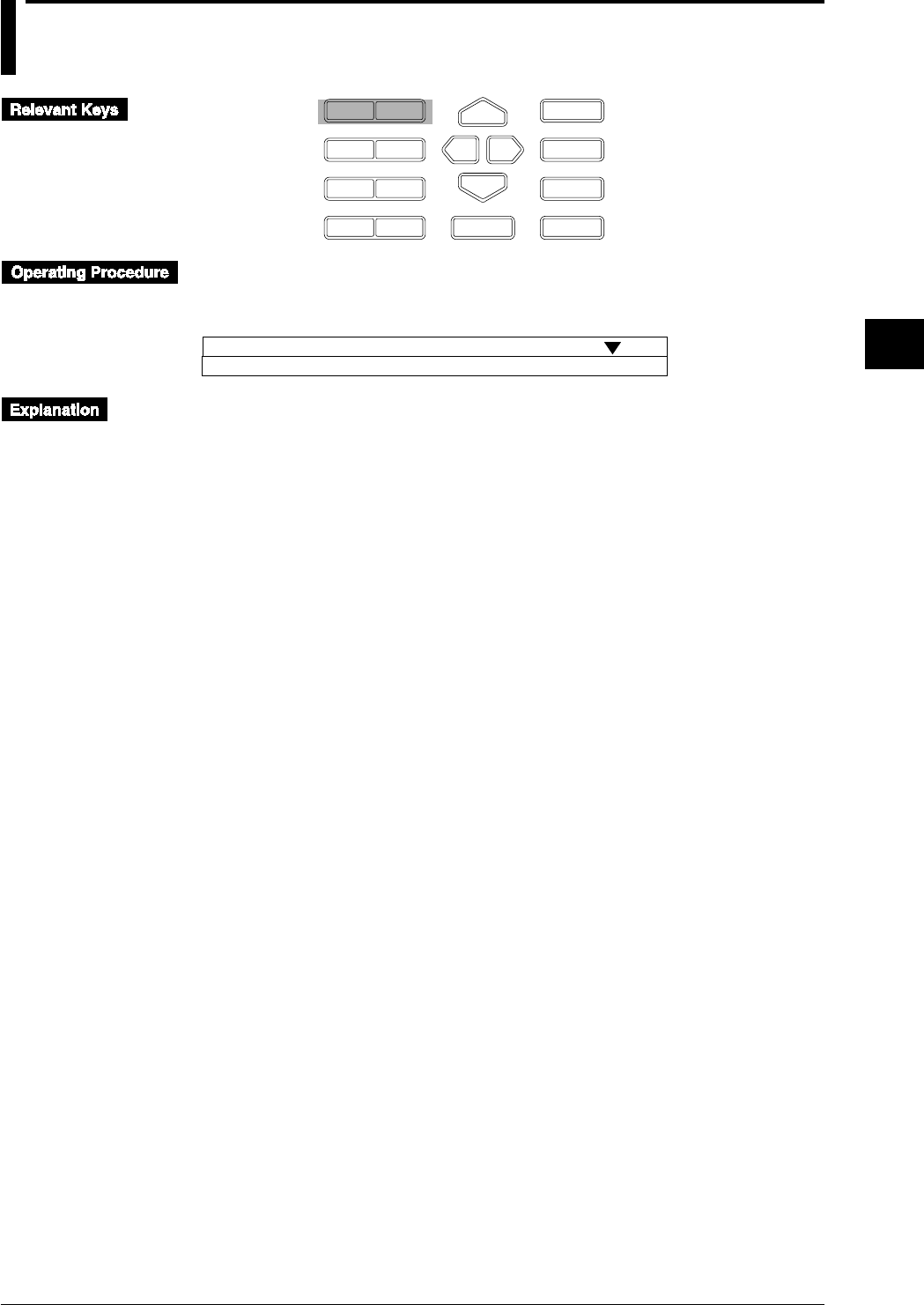
4-13
IM DR232-01E
4
Setting the Monitor Mode Display
4.8 Using the CLOCK (Data & Time) Display
D I S P
P R I N TF U N C
I N S D E L
R A N G E A L A R M
S E TC H A R T E N T E R
F E E D
M. F U N C 1
M. F U N C 2
R E C O R D
M O D E
E S C
1 Select the sub-display 2 using the DISP key.
2 Select “CLK” using the MODE key.
005 0.8210V 006 0.0095V
Sub-display 1 and 2
CLK
Dec. 30. 95 13:16:19
Clock Display
The date and time can be displayed on sub-display 2.
According to the set time in 3.9, “Setting the Date and Time” (see page 3-23), the current date and
time is displayed.
The display shows the month, day, year and hour, minute, second in this sequence.
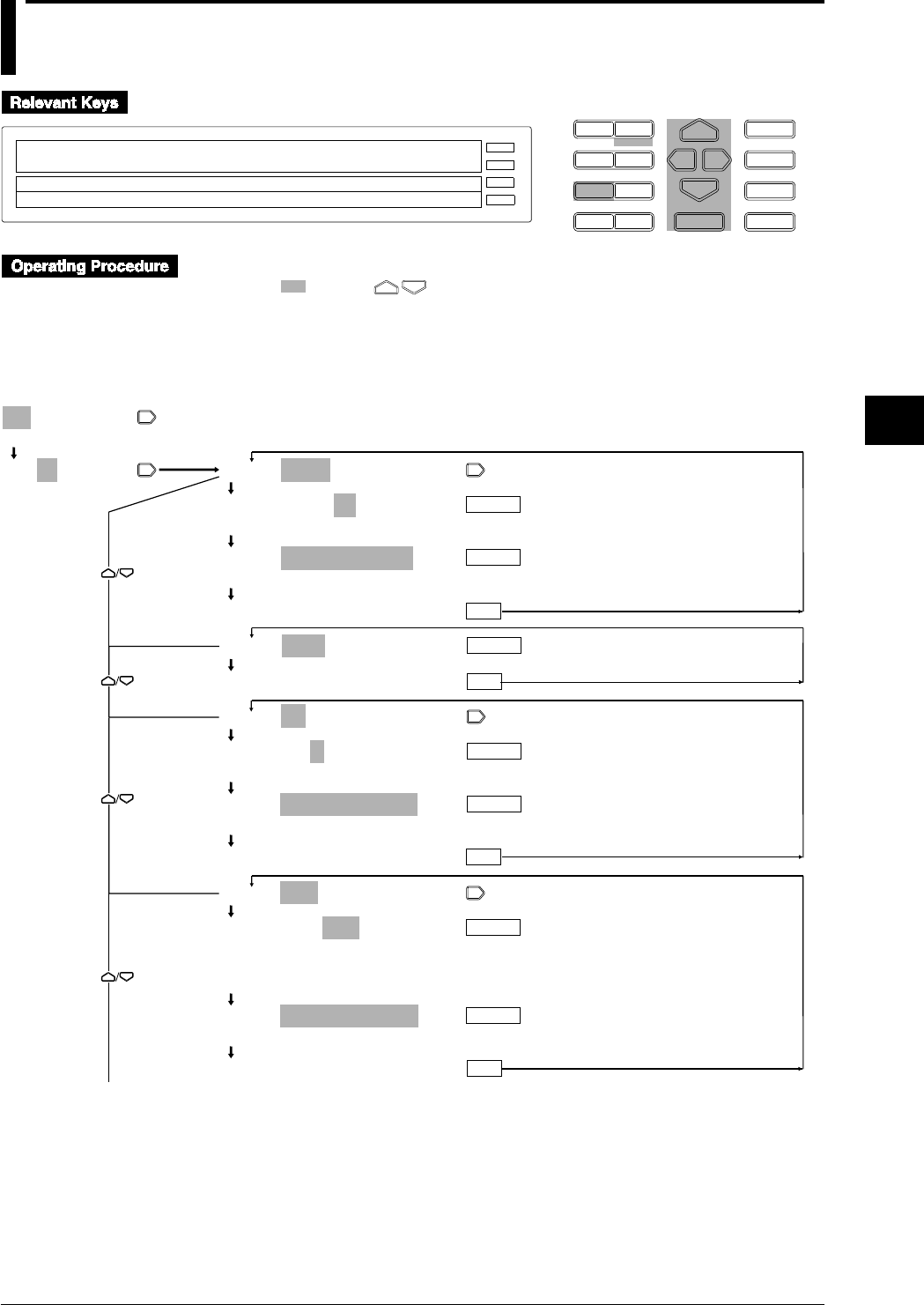
5-1
IM DR232-01E
5
Setting the Input Type/Recording Span/Linear Scaling
5.1 Setting the Type of Input and Recording Span
D I S P M O D E
P R I N TF U N C
I N S D E L
R A N G E A L A R M
S E TC H A R T E N T E R
F E E D
M. F U N C 1
M. F U N C 2
RECORD
ALARM
CHART
KEYLOCK
R E C O R D
001-10:VOLT/2V
SKIP VOLT TC RTD DI DELTA SCL
SPAN=–2.0000/ 2.0000V
E S C
1 Press the RANGE key to enter the RANGE menu.
2 Select/set using the keys.
3 To escape from a lower menu, press the “MODE (ESC)” key. Its main menu will appear,
although new settings/selections will not be kept.
4 New settings/selections will be kept when you reach the final display of that setting.
001-01:VOLT/2V
>Select Channel No.
001-01:VOLT/2V
>Select Channel No.
001-01:VOLT/2V
001-01:VOLT/2V
20mV 60mV 200mV 2V 6V 20V 50V
SPAN=–2.0000/_2.0000V
>Span limit(–2.0000~2.0000V)
***SET OK***
001-01:SKIP
***SET OK***
001-01:TC/R
001-01:TC/R
R S B K E J T N W L U KP
SPAN=_ _ _ _0.0/1760.0˚C
>Span limit(0.0~1760.0˚C)
***SET OK***
001-01:RTD/PT1
001-01:RTD/PT1
PT1 PT2 JPT1 JPT2 PT50 NI1 NI2 NI3
CU1 CU2 CU3 CU4 PT1S PT2S JPT1S
JPT2S J263B
SPAN=–_200.0/_ _600.0˚C
>Span limit(–200.0~600.0˚C)
***SET OK***
ENTER
ENTER
ENTER
ENTER
ENTER
ENTER
ESC
ENTER
ESC
ESC
ESC
To the next page
(Main menu)
(Lower menu)
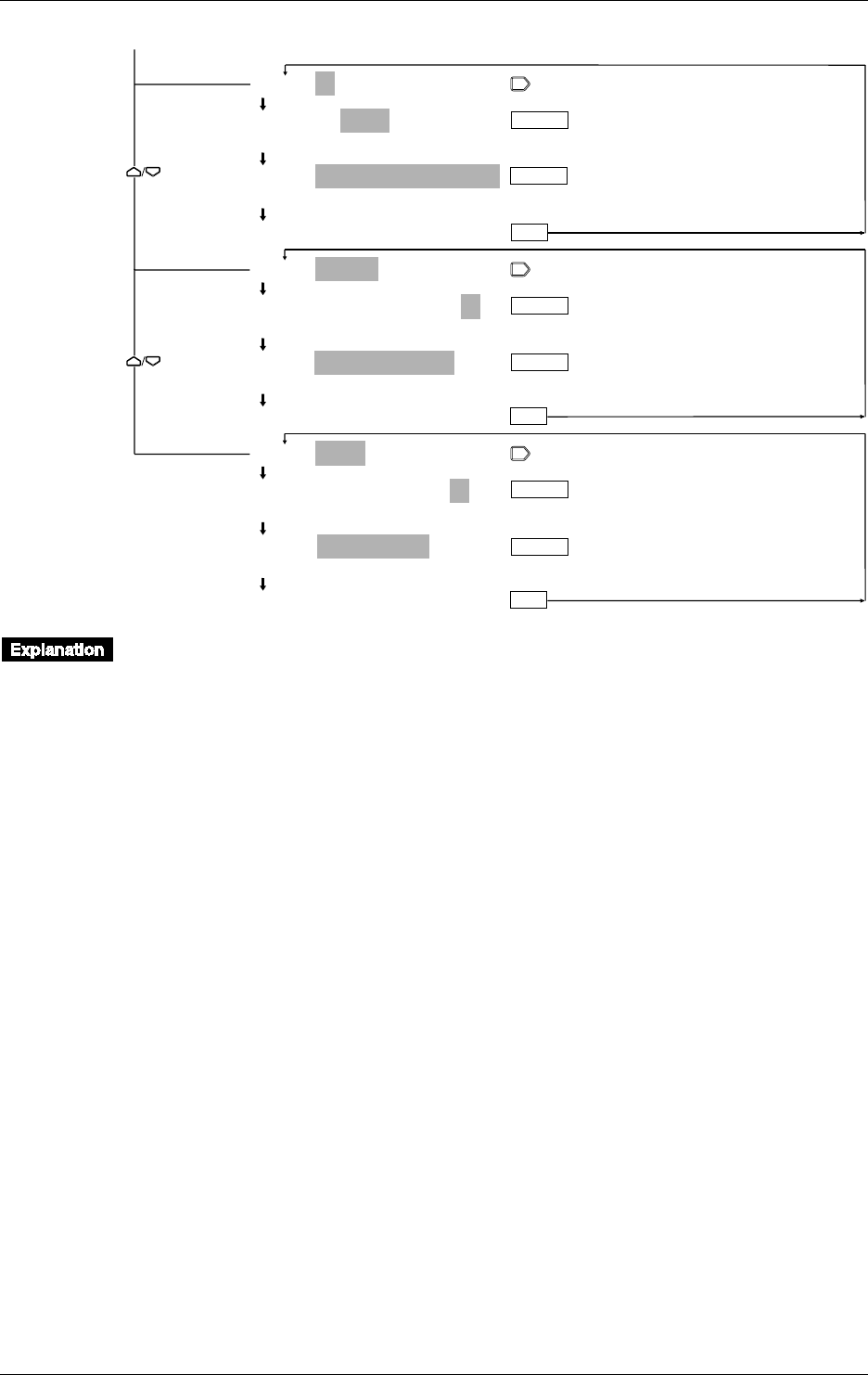
5-2 IM DR232-01E
5.1 Setting the Type of Input and Recording Span
ENTER
ESC
ENTER
001-01:DI/LEVL
001-01:DI/LEVL
LEVL CONT
SPAN=
_ _ _ _ _ _
0/
_ _ _ _ _ _
1
>Span limit(0~1)
***SET OK***
002-02:DELTA/REF Ch=01
002-02:DELTA/REF Ch=01
>Select Channel No.
SPAN=–2.0000/_2.0000V
>Span limit(–2.0000~2.0000V)
***SET OK***
002-02:RRJC/RJC Ch=01
002-02:RRJC/RJC Ch=01
>Select Channel No.
SPAN= 0.0/1760.0˚C
>Span limit(0.0~1760.0˚C)
***SET OK***
ENTER
ENTER
ENTER
ESC
ESC
From the previous page
ENTER
Setting the Channel No.
This setting specifies the channels to which the type of input and recording span applies. Set a
range of channels in the same unit, whether you specify from what channel (the first channel) to
what channel (the last channel).
First Channel No. (Begin)
The first three characters on the main display show the number of the first channel to which
settings apply.
• A numeral in the first character position shows a unit number. A numeral in the second
character position represents a module number (slot number).
• Setting range: Determined by the positions in which the input modules are connected. For
details, see page 3-8.
Last Channel No. (End)
The two characters following the first channel number show the number of the last channel to
which settings apply.
• Setting range: See description of the above “The first channel number.” The number of the last
channel cannot be smaller than the number of the first channel. When both channel numbers are
equal, settings will only apply to that particular channel. When you have set the first channel
number and you move the cursor to the last channel setting, the channel number of the first
channel setting will appear here.

5-3
IM DR232-01E
5
Setting the Input Type/Recording Span/Linear Scaling
5.1 Setting the Type of Input and Recording Span
Selecting the Type of Input
The following types of input can be selected. The default setting is VOLT.
• SKIP
Measurement, recording and display (except for page display) will not be carried out.
Measurement, recording and display will be carried out for the next channel whose input type is
not set to SKIP.
• VOLT (DC voltage)
This input type can be selected from 20mV, 60mV, 200mV, 2V, 6V, 20V and 50V. Refer to
chapter 14 for the measurement range of each setting. The default setting is 2V.
• TC (thermocouple)
This input type can be selected from R, S, B, K, E, J, T, N, W, L, U and KP (KPvsAU7Fe).
Refer to chapter 14 for the measurement range of each setting. The default setting is R.
• RTD (resistance temperature detector)
This input type can be selected from PT1 (Pt100 1mA), PT2 (Pt100 2mA), JPT1 (JPt100 1mA),
JPT2 (JPt100 2mA), PT50 (Pt50 2mA), NI1 (Ni100 1mA SAMA), NI2 (Ni100 1mA DIN), NI3
(Ni120 1mA), CU1 (Cu10 GE), CU2 (Cu10 L&N), CU3 (Cu10 WEED), CU4 (Cu10
BAILEY), PT1S (Pt100 1mA high resolution), PT2S (Pt100 2mA high resolution), JPT1S
(JPt100 1mA high resolution), JPT2S (JPt100 2mA high resolution) and J263B (J263*B). Refer
to chapter 14 for the measurement range of each setting. The default setting is PT1.
• DI (voltage level: LEVL; contact:CONT)
This input type can be selected from LEVL and CONT.
In case of LEVL, a voltage of less than approx. 2.4 V will be recognized as “0 (OFF)”, whereas
a voltage of approx. 2.4V or more (max. allowable voltage is up to ±60 VDC) will be
recognized as “1 (ON)”.
In case of CONT, an open, externally connected contact to which no voltage is applied, will be
recognized as “0 (OFF)”, whereas a closed contact will be recognized as “1 (ON)”.
The default setting is LEVL.
• DELTA (difference between channels)
Computation can be done only in the same unit. Destination channels should lie within the first
channel No. to the last channel No. range. The number of the reference channel should be lower
than the number of the destination channels. The default setting for the reference channel is 01.
The type of input and the measuring range in the distination channel are the same as for the
reference channel. After setting the DELTA (difference between channels), if you attempted to
change the type of input and the measuring range, setting the difference between channels is
released, thereby the type of input and the measuring range in the destination channel are
returned to their original settings, and the recording span is returned to its initial value.
• RRJC (Remote RJC, available if the instrument is equipped with the optional MATH function)
Reference channel (RJC): Within the setting range of reference channel No.
TC (thermocouple) must be selected as the type of input to the reference channel.
If the channel No. or type of input for the reference channel, or the type of thermocouple is
changed, the alarm and partial compression recording functions will be turned OFF.
If the type of input for the reference channel or the type of thermocouple is changed, the RRJC
settings will be cleared and the type of input and measuring range for the reference channel will
be set to the one which was in effect before the change was made. The recording span will be
set to the initial value of the measuring range.
• mA (DC current, mA input module)
This input can be set only for mA input channels. The measuring range is -20 mA to 20 mA.
Setting the Recording Span
The measurement range is decided according to the type of input. The recording left and right
span must lie within the measurement range. However, the recording span is 0 to 1 for the DI
input type. The value on the left side of the SPAN menu shows the left span, and the value on the
right side of the SPAN menu shows the right span.
For the remote RJC, the setting range for recording span is the same as that for the reference
channel.
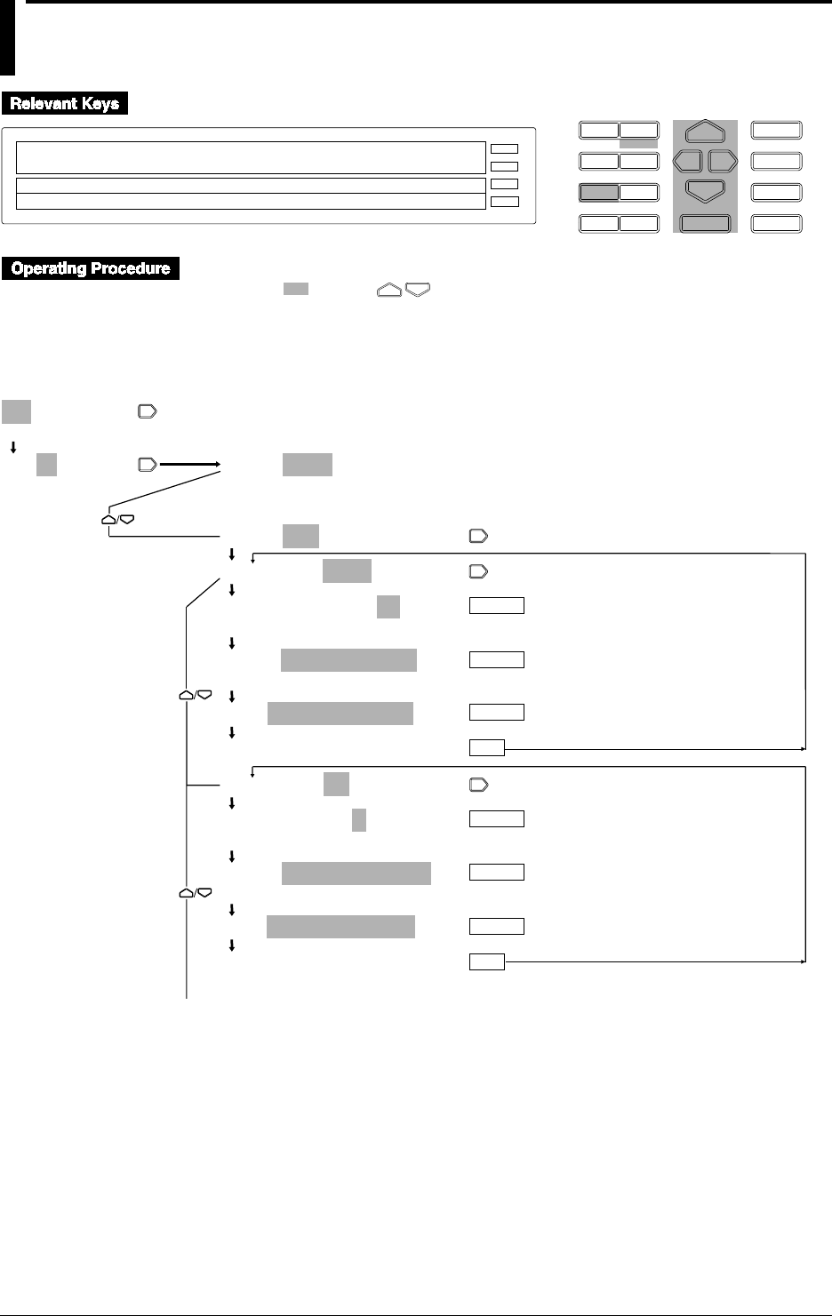
5-4 IM DR232-01E
5.2 Setting Linear Scaling and the Recording Span
D I S P M O D E
P R I N TF U N C
I N S D E L
R A N G E A L A R M
S E TC H A R T E N T E R
F E E D
M. F U N C 1
M. F U N C 2
RECORD
ALARM
CHART
KEYLOCK
R E C O R D
001-10:SCL:VOLT/2V
SKIP VOLT TC RTD DI DELTA SCL
>
E S C
1 Press the RANGE key to enter the RANGE menu.
2 Select/set using the keys.
3 To escape from a lower menu, press the “MODE (ESC)” key. Its main menu will appear,
although new settings/selections will not be kept.
4 New settings/selections will be kept when you reach the final display of that setting.
001-01:VOLT/2V
>Select Channel No.
001-01:VOLT/2V
>Select Channel No.
001-01:VOLT/2V
(Main menu)
(Lower menu)
001-01:SCL:VOLT/2V
001-01:SCL:VOLT/2V
001-01:SCL:VOLT/2V
20mV 60mV 200mV 2V 6V 20V 50V
SPAN=–2.0000/_2.0000V
>Span limit(–2.0000~2.0000V)
SCL=_ _ _0.00/_100.00
***SET OK***
001-01:SCL:TC/R
001-01:SCL:TC/R
R S B K E J T N W L U KP
SPAN=_ _ _ _0.0/_1760.0˚C
>Span limit(0.0~1760.0˚C)
SCL=_ _ _0.00/_100.00
***SET OK***
ENTER
ENTER
ENTER
ENTER
ESC
ESC
ENTER
ENTER
To the next page
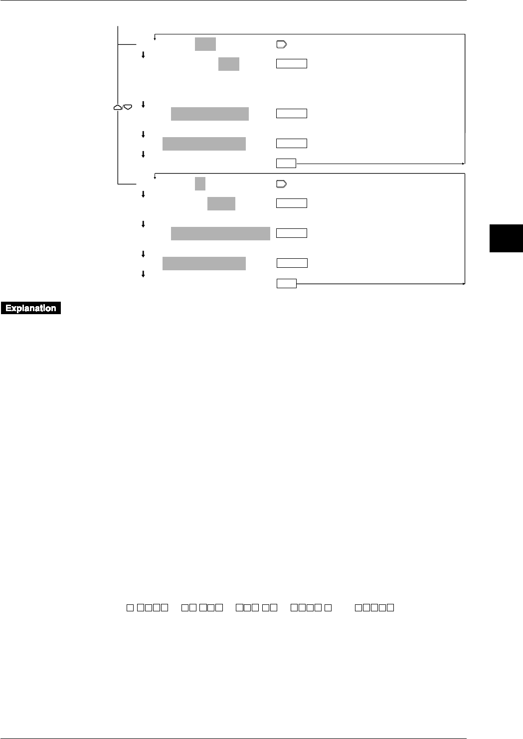
5-5
IM DR232-01E
5
Setting the Input Type/Recording Span/Linear Scaling
5.2 Setting Linear Scaling and the Recording Span
001-01:SCL:RTD/PT1
001-01:SCL:RTD/PT1
PT1 PT2 JPT1 JPT2 PT50 NI1 NI2 NI3
CU1 CU2 CU3 CU4 PT1S PT2S JPT1S
JPT2S J263B
SPAN=–_200.0/_ _600.0°C
>Span limit(–200.0~600.0°C)
SCL=_ _ _0.00/_100.00
***SET OK***
001-01:SCL:DI/LEVL
001-01:SCL:DI/LEVL
LEVL CONT
SPAN=_ _ _ _ _ _0/_ _ _ _ _ _1
>Span limit(0~1)
SCL=_ _ _0.00/_100.00
***SET OK***
ENTER
ENTER
ENTER
ENTER
ESC
ENTER
ESC
ENTER
From the previous page
The setting of the channel number is the same as explained in 5.1 on page 5-2. The following
explanation assumes that you already carried out the channel setting and that you selected “SCL”
as the input type.
Selecting the Input Type for Linear Scaling
The input type can be selected from the following. The default setting is VOLT.
• VOLT (DC voltage)
Refer to page 5-3.
• TC (thermocouple)
Refer to page 5-3.
• RTD (resistance temperature detector)
Refer to page 5-3.
• DI (contact)
Refer to page 5-3.
Setting the Recording Span
Refer to page 5-3.
Setting the Scaling Values (SCL)
The left scaling and right scaling values are set following the left and right span values of the span
menu. The value on the left side of the SCL menu shows the left scaling value, and the value on
the right side of the SCL menu shows the right scaling menu. The setting ranges from -30000 to
30000.
• The decimal point can be set in any position of the scale as shown below. Set it when the left
scale is set.
“.,” “ .,” “ .,” “ .,” or “ .”
• The default settings are 0.00 for the left span and 100.00 for the right span.
For details on setting the engineering units for linear scaling, refer to page 6-2.
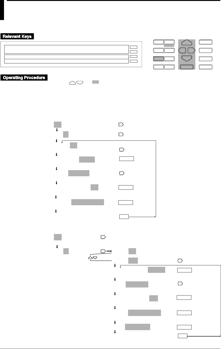
5-6 IM DR232-01E
5.3 Configuring the Input Range and Recording
Span or the Linear Scaling of a Power
Monitoring Channel
D I S P M O D E
P R I N TF U N C
I N S D E L
R A N G E A L A R M
S E TC H A R T E N T E R
F E E D
M. F U N C 1
M. F U N C 2
RECORD
ALARM
CHART
KEYLOCK
R E C O R D
001-01:AC/1Ph3W
SPAN= - 1250 / 1250W
RNG=250-5A/ V1 002:VA1
E S C
• Press the RANGE key to enter the RANGE menu.
• Using and , select and/or enter a value for each of the shaded fields shown below.
• To exit any of the following menu items during the procedure, press the MODE (ESC) key.
This returns to the first item of the menu. Note, however, that your new settings and selections
are canceled.
• Reaching the step showing the message “***SET OK***” confirms the latest settings/
selections.
Setting the Measuring Range and Recording Span
001-01:AC/1Ph3W
001-01:AC/1Ph3W
(Main menu item)
001-01:AC/1Ph3W
SKIP AC SCALE
001-01:AC/1Ph3W
1Ph2W 1Ph3W 3Ph3W-2I 3Ph3W-3I 3Ph4W
RNG= 250V - 5A/P1
250V-0.5A 250V-5A 25V-0.5A 25V-5A
RNG= 250V - 5A/P1
P1 P3 P13
SPAN= - 125.0/125.0W
>Span Limit (- 125.0 to 125.0W)
***SET OK***
(configuration complete)
ENTER
ESC
ENTER
ENTER
Setting Linear Scaling
001-01:AC/1Ph3W
>Select Channel No.
001-01:AC/1Ph3W
>Select Channel No.
001-01:AC/1Ph3W
(Main menu item)
(Submenu items)
001-01:SCL:AC/1Ph3W
001-01:SCL:AC/1Ph3W
2k 20k 200k
RNG=250V-0.5A/P13
250V-0.5A 250V-5A 25V-0.5A 25V-5A
RNG=250V-0.5A/P13
P1 P2 P3 P13
SPAN=–125.0/125.0W
>Span limit(–125.0 to 125.0W)
SCL=0.00/100.00
***SET OK***
(configuration complete)
ENTER
ESC
(Press twice)
ENTER
ENTER
ENTER

5-7
IM DR232-01E
5
Setting the Input Type/Recording Span/Linear Scaling
Setting the Channel Number
This procedure sets the channel number for which you want to show and record the values of a
parameter selected from the effective voltage, effective current, active power, reactive power,
apparent power, frequency, power factor and phase angle which were calculated using the
measured data. Therefore, it does not correlate with the terminals of an input module. In this
procedure, determine from which channel (starting channel) to which channel (ending channel)
you want to include in your configuration.
Starting Channel Number
The first three digits on the main display constitute the starting channel number.
• The first digit is the unit number. The second digit denotes the module number (slot number).
• The configurable range depends on the location where the power monitor module is connected.
See page 3-8 for more information.
Ending Channel Number
The two digits that follow the starting channel number constitute the ending channel number.
Normally, the starting channel number and the ending channel number should be the same. If you
want to skip any consecutive number of channels, enter the range of those channel numbers.
• When you move the cursor from the starting to the ending channel number, the ending channel
number becomes the same as the last two digits of the starting channel number.
Setting the Wiring Method
Select from the following methods:
Single-phase two-wire (1Ph2W)
Single-phase three-wire (1Ph3W; three-wire input modules only)
Three-phase three-wire 2 Voltage 2 Current (3Ph3W-2I; three-wire input modules only)
Three-phase three-wire 3 Voltage 3 Current (3 Ph3W-3I; three-wire input module only)
Three-phase four-wire (3Ph4W; three-wire input modules only)
Setting the Input Range
Select from the following ranges:
250V-0.5A 250V-5A
25V-0.5A 25V-5A
This setting is common to all channels. Any change to this setting also changes the settings of the
rest of the channels. Impose a voltage or current signal to the input module within the limits you
set here.
Setting the Parameter Being Shown and Recorded
A power monitor module measures the voltage or current through the respective channels. The
values that are shown and recorded are not those of the voltage and current being actually
measured through each channel but the values of the parameters you set here.
A combination of parameters being measured is fixed for each group of channels 1-2, 3-4 and 5-6
within the same module. For example, setting channel 1 to P1 (active power 1) sets channel 2 to
VA1 (apparent power 1). In addition, the configurable parameters being measured varies
depending on the wiring method selected. See the lists on the next page for more information.
The respective mnemonics in the lists should be interpreted as noted below:
Vi (i=1, 2, 3) : effective voltage Ii (i=1, 2, 3) : effective current
V13 : (V1+V3)/2 I13 : (I1+L3)/2
V0 : (V1+V2+V3)/3 I0 : (I1+I2+I3)/3
Pi (i=1, 2, 3) : active power Vari (i=1, 2, 3) : reactive power
P13 : P1+P3 Var13 : PF1+PF3
P0 : P1+P2+P3 Var 0 : Var1+Var2+Var3
VAi (i=1, 2, 3) : apparent power PFi (i=1, 2, 3) : power factor
VA13 : VA1+VA3 PF13 : P13/(P132+Var132)1/2=P13/VA13
VA0 : VA1+VA2+VA3 PF0 : P0/(P02+Var02)1/2=P0/VA0
PHi (i=1, 2, 3) : phase FREQ : frequency
PH13 : tan–1 (Var13/P13)
PH0 : tan–1 (Var0/P0)
5.3 Configuring the Input Range and Recording Span or the Linear Scaling of a Power Monitoring Channel
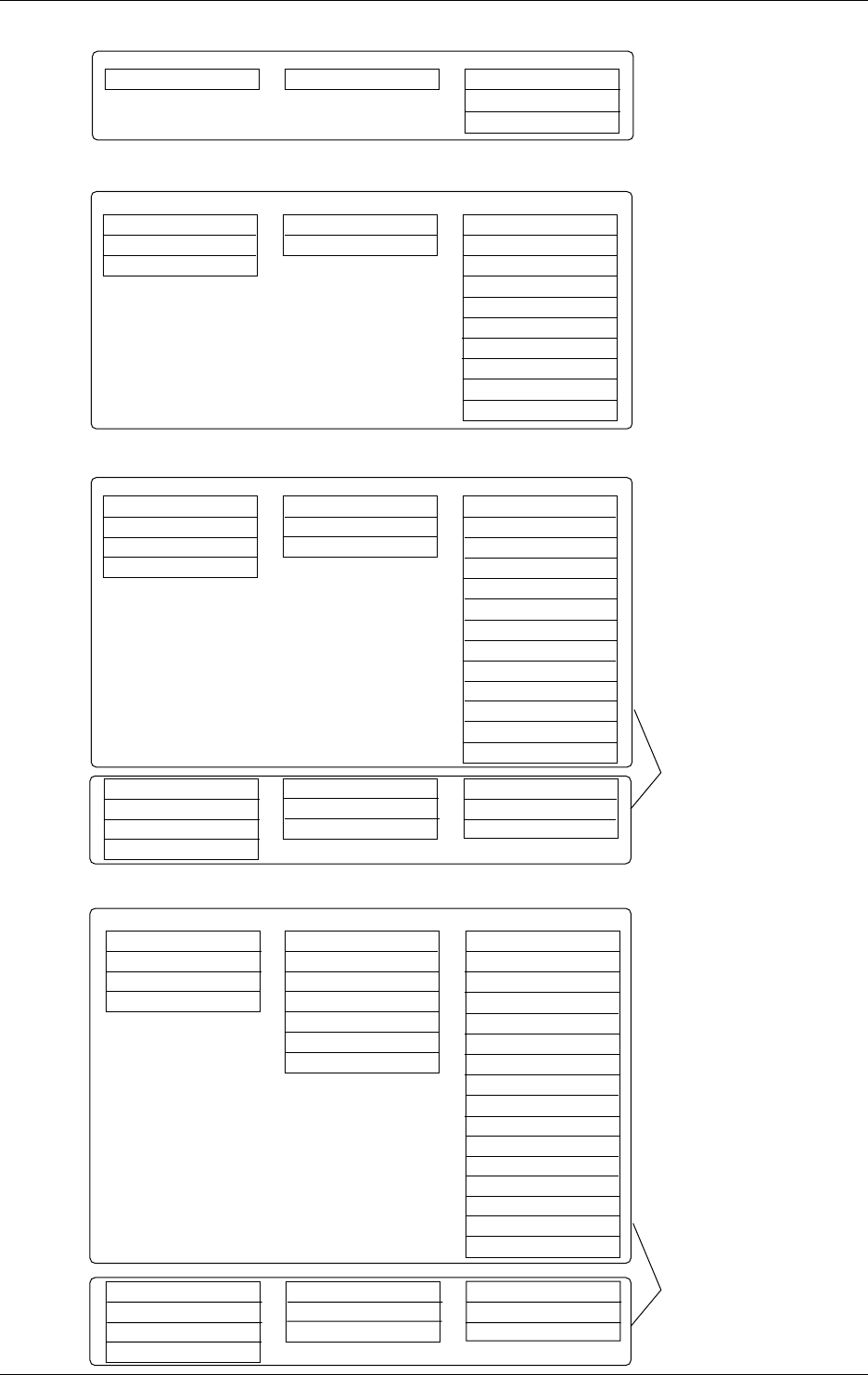
5-8 IM DR232-01E
CH1
P1
CH2
VA1
CH3
V1
CH4
I1
CH5
PF1
Var1
FREQ
CH6
PH1
PF1
V1
Single-phase two-wire configuration
CH1
P1
P3
P13
CH2
VA1
VA3
VA13
CH3
V1
V3
CH4
I1
I3
CH5
PF1
PF3
PF13
V1
V3
V13
FREQ
Var1
Var3
Var13
CH6
PH1
PH3
PH13
I1
I3
I13
V1
PF1
PF3
PF13
Single-phase three-wire/three-phase three-wire configurations
(dual-voltage, dual-current; modules for three-phase use only)
CH1
P1
P2
P3
P13
CH2
VA1
VA2
VA3
VA13
CH3
V1
V2
V3
CH4
I1
I2
I3
CH5
PF1
PF2
PF3
PF13
V1
V2
V3
V13
FREQ
Var1
Var2
Var3
Var13
CH6
PH1
PH2
PH3
PH13
I1
I2
I3
I13
V1
PF1
PF2
PF3
PF13
Three-phase three-wire configuration
(triple-voltage, triple-current; modules for three-phase use only)
V0
V1
V2
V3
I0
I1
I2
I3
V1
V2
V3
I1
I2
I3
V1
V2
V3
I1
I2
I3
CH1
P0
P1
P2
P3
CH2
VA0
VA1
VA2
VA3
CH3
V1
V2
V3
P0
P1
P2
P3
CH4
I1
I2
I3
VA0
VA1
VA2
VA3
CH5
PF0
PF1
PF2
PF3
V1
V2
V3
FREQ
Var0
Var1
Var2
Var3
P0
P1
P2
P3
CH6
PH0
PH1
PH2
PH3
I1
I2
I3
V1
PF0
PF1
PF2
PF3
VA0
VA1
VA2
VA3
Three-phase four-wire configuration
(modules for three-phase use only)
V0
V1
V2
V3
I0
I1
I2
I3
V1
V2
V3
I1
I2
I3
V1
V2
V3
I1
I2
I3
Select from these combinations.
Select from these combinations.
Select from either of the
two groups of
combinations.
Select from either of the
two groups of
combinations.
5.3 Configuring the Input Range and Recording Span or the Linear Scaling of a Power Monitoring Channel

5-9
IM DR232-01E
5
Setting the Input Type/Recording Span/Linear Scaling
Setting the Recording Span (SPAN)
Set the left and right spans within the limits of an input range. In the SPAN menu item, the left-
hand value is the left span and the right-hand value the right span. Set the recording span within
the measuring range. The measurable limits vary depending on the measuring range you select,
as shown below.
25V-0.5A 25V-5A 250V-0.5A 250V-5A
Effective voltage 0.00 to 25.00Vrms 0.00 to 25.00Vrms 0.0 to 250.0Vrms 0.0 to 250.0Vrms
Vi (i=1,2,3,13,0)
Effective current 0.0000 to 0.5000Arms 0.000 to 5.000Arms 0.0000 to 0.5000Arms 0.000 to 5.000Arms
Ii (i=1,2,3,13,0)
Active power –12.50 to 12.50W –125.0 to 125.0W –125.0 to 125.0W –1250 to 1250W
P1,P2,P3
Active power –25.00 to 25.00W –250.0 to 250.0W –250.0 to 250.0W –2500 to 2500W
P13
Active power –37.50 to 37.50W –375.0 to 375.0W –375.0 to 375.0W –3750 to 3750W
P0
Apparent power 0.00 to 12.50VA 0.0 to 125.0VA 0.0 to 125.0VA 0 to 1250VA
VA1,VA2,VA3
Apparent power 0.00 to 25.00VA 0.0 to 250.0VA 0.0 to 250.0VA 0 to 2500VA
VA13
Apparent power 0.00 to 37.50VA 0.0 to 375.0VA 0.0 to 375.0VA 0 to 3750VA
VA0
Reactive power 0.00 to 12.50Var 0.0 to 125.0Var 0.0 to 125.0Var 0 to 1250Var
Var1,Var2,Var3
Reactive power 0.00 to 25.00Var 0.0 to 250.0Var 0.0 to 250.0Var 0 to 2500Var
Var13
Reactive power 0.00 to 37.50Var 0.0 to 375.0Var 0.0 to 375.0Var 0 to 3750Var
Var0
Power factor –1.00 to 1.00 –1.00 to 1.00 –1.00 to 1.00 –1.00 to 1.00
PFi(i=1,2,3,13,0)
Phase –80.0 to 80.0deg –80.0 to 80.0deg –80.0 to 80.0deg –80.0 to 80.0deg
PHi(i=1,2,3,13,0)
Frequency 45.00 to 65.00Hz 45.00 to 65.00Hz 45.00 to 65.00Hz 45.00 to 65.00Hz
FREQ
Precautions in Measurement
• Input the voltage or current being measured at a level between 10% and 100% of the measuring
range. The DR recorder bases its calculations of all other parameters on the frequency of V1.
Extra care must therefore be taken when setting the input level of V1. If the input level fails to
fall within the given limits, there is no guarantee that the measurement of any other parameters
will be reliable.
5.3 Configuring the Input Range and Recording Span or the Linear Scaling of a Power Monitoring Channel
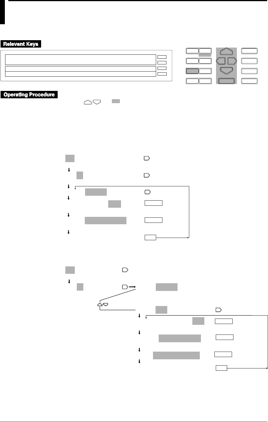
5-10 IM DR232-01E
5.4 Configuring the Measuring Range and
Recording Span or the Linear Scaling of a
Strain Input Channel
D I S P M O D E
P R I N TF U N C
I N S D E L
R A N G E A L A R M
S E TC H A R T E N T E R
F E E D
M. F U N C 1
M. F U N C 2
RECORD
ALARM
CHART
KEYLOCK
R E C O R D
001-01:STRAIN/200k
> Select Channel Number
SPAN=–20000/ 20000 * 10µε
E S C
• Press the RANGE key to enter the RANGE menu.
• Using and , select and/or enter a value for each of the shaded fields shown below.
• To exit any of the following menu items during the procedure, press the MODE (ESC) key.
This returns to the first item of the menu. Note, however, that your new settings and selections
are canceled.
• Reaching the step showing the message “***SET OK***” confirms the latest settings/
selections.
Setting the Measuring Range and Recording Span
001-01:STRAIN/200k
>Select Channel No.
001-01:STRAIN/200k
>Select Channel No.
(Main menu item)
001-01:STRAIN/200k
001-01:STRAIN/200k
2k 20k 200k
SPAN=–20000/_20000
>Span limit(–20000 to 20000*10 µε)
***SET OK***
(configuration complete)
ENTER
ENTER
ESC
Setting Linear Scaling
001-01:STRAIN/200k
>Select Channel No.
001-01:STRAIN/200k
>Select Channel No.
001-01:STRAIN/200k
(Main menu item)
(Submenu items)
001-01:SCL:STRAIN/200k
001-01:SCL:STRAIN/200k
2k 20k 200k
SPAN=–20000/_20000
>Span limit(–20000 to 20000 *10µε)
SCL=-100.00/_100.00
***SET OK***
(configuration complete)
ENTER
ESC
ENTER
(Press twice)
ENTER

5-11
IM DR232-01E
5
Setting the Input Type/Recording Span/Linear Scaling
Setting the Channel Number
Set the channel number for which you want to configure the type of input, recording span and so
on. In this procedure, determine from which channel (starting channel) to which channel (ending
channel) you want to include in your configuration.
Starting Channel Number
The first three digits on the main display constitute the starting channel number.
• The first digit is the unit number. The second digit denotes the module number (slot number).
• The configurable range depends on the location where the power monitor module is connected.
A strain input module takes up twice the space of a standard-size module. This results in the
number of the slot following the one where the strain input module is installed being a missing
number. See page 3-8 for more information.
Ending Channel Number
The two digits that follow the starting channel number constitute the ending channel number.
• For the configurable range, see “Starting Channel Number” above.
• You cannot enter a channel number that is smaller than the starting channel number.
• If you have entered the same number as the starting channel number, only that one particular
channel is included in your configuration (configuration of the type of input, recording span,
etc.).
• When you move the cursor from the starting to the ending channel number, the ending channel
number becomes the same as the last two digits of the starting channel number.
Setting the Recording Span (SPAN)
Set the left and right spans within the limits of the input range. In the SPAN menu item, the left-
hand value is the left span and the right-hand value the right span.
Note
If you have connected any new strain gauge or changed the measuring range (initialization of settings or
reconfiguration of the system also changes the measuring range back to its default), you must go through
initial balancing. See Section 5.5, “Performing Initial Balancing/Initialization on a Strain Input Channel,”
for more information.
5.4 Configuring the Measuring Range and Recording Span or the Linear Scaling of a Strain Input Channel
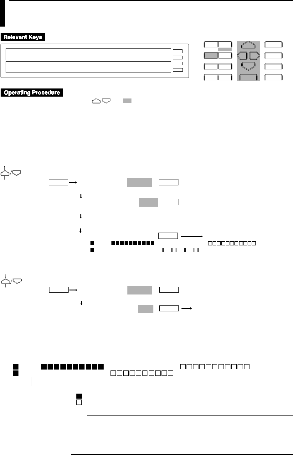
5-12 IM DR232-01E
5.5 Performing Initial Balancing/Initialization on a
Strain Input Channel
D I S P M O D E
P R I N TF U N C
I N S D E L
R A N G E A L A R M
S E TC H A R T E N T E R
F E E D
M. F U N C 1
M. F U N C 2
RECORD
ALARM
CHART
KEYLOCK
R E C O R D
INIT BALANCE
>Select Function item
E S C
• Press the FUNC key to enter the FUNC menu.
• Using and , select and/or enter a value for each of the shaded fields shown below.
• To exit any of the following menu items during the procedure, press the MODE (ESC) key.
This returns to the first item of the menu. Note, however, that your new settings and selections
are canceled.
• If you have made changes to any item executable with the FUNC key, information on initial
balancing may not appear on the display.
Performing Initial Balancing
ALARM ACK
INIT_BALANCE
(Operating status)
ENTER
(Main menu item)
BALANCE CH=001-010
>Select Channel No.
BALANCE MODE = EXEC
ABORT EXEC INIT
Balancing... *
> CHANNEL = 001-60
>OK 001
>OK 031
ENTER
ENTER
ENTER
Initializing the Strain Input Channels
ALARM ACK
INIT_BALANCE
(Operating status)
ENTER
(Main menu item)
BALANCE CH=001-010
>Select Channel No.
BALANCE MODE = INIT
ABORT EXEC INIT
ENTER
ENTER
Indication of the Status of Initial Balancing
If you have performed initial balancing, the DR recorder shows whether the initial balancing is
successful or not in the following format. Using the $ and $ keys, you can change the unit
number for which you want the status shown.
> CHANNEL = 001-60
>OK 001
>OK 031
Module-by-module status indication
: successful end of initial balancing
: unsuccessful end of initial balancing
Starting channel
Note
• This function is disabled during making a report.
• The following operations are stopped when this function is performed.
• Recording
• Saving data to the memory and reading data from it.
• Computing
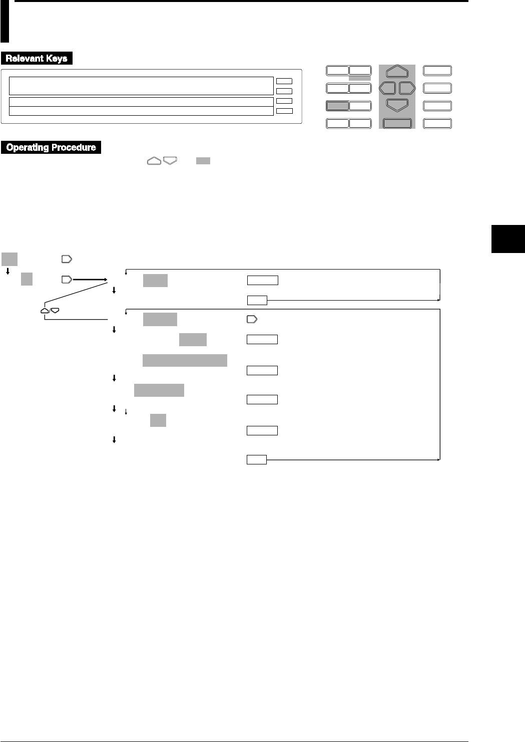
5-13
IM DR232-01E
5
Setting the Input Type/Recording Span/Linear Scaling
5.6 Configuring the Pulse Input Channel
D I S P M O D E
P R I N TF U N C
I N S D E L
R A N G E A L A R M
S E TC H A R T E N T E R
F E E D
M. F U N C 1
M. F U N C 2
RECORD
ALARM
CHART
KEYLOCK
R E C O R D
001-01:PULSE/RATE
SKIP PULSE
SPAN= 0/ 6000
E S C
• Press the RANGE key to enter the RANGE menu.
• Using and , select and/or enter a value for each of the shaded fields shown below.
• To exit any of the following menu items during the procedure, press the MODE (ESC) key.
This returns to the first item of the menu. Note, however, that your new settings and selections
are canceled.
• Reaching the step showing the message “***SET OK***” confirms the latest settings/
selections.
001-01:SKIP
001-01:SKIP 001-01:SKIP
***SET OK***
(configuration complete)
(Main menu item)
(Submenu items)
ENTER
ESC
001-60:PULSE/RATE
001-60:PULSE/RATE
RATE GATE
SPAN=
_ _ _ _ _ _
0/
_ 30000
>Span limit(0 to 30000)
SCL=
_
0/
_ 30000
>SPAN(0/30000)
FILTER=ON
ON OFF
***SET OK***
(configuration complete)
ENTER
ENTER
ENTER
ENTER
ESC
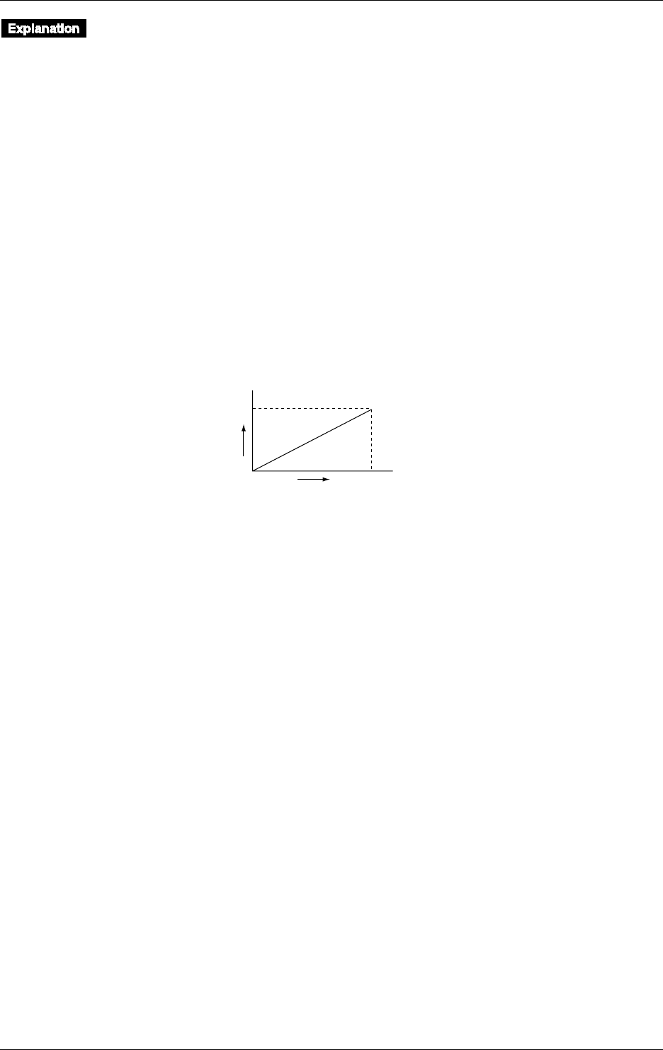
5-14 IM DR232-01E
Types of Input
• Pulse Input Measurement (PULSE)
Select this option when measuring pulse input.
• Skip (SKIP)
No measurement is done.
Measurement Mode
Select the mode used in pulse input measurement. Use the computing function when summing
the count or turn-on time over a given period of time.
• Instantaneous Count Mode (RATE)
Select this option when determining the count for one second.
• Instantaneous Turn-on Time Mode (GATE)
Select this option when detecting the on/off states by means of variations in the instantaneous
value every second.
Span (SPAN)
Set the upper and lower limits of the pulse count and turn-on time. The maximum configurable
value is 30000.
Scale (SCL)
Set the upper and lower limits of the pulse count and turn-on time. The maximum configurable
value is 30000.
Configure this menu item when converting the scale values to those of a system of units suited for
your purpose. The maximum configurable range is 0-30000, excluding the decimal point.
Count/sec
03000
0
100
Revolution
rpm
Span Lower
Scale Lower
Span Upper
Scale Upper
Filter On/Off (FILTER)
Set this menu item to ON when eliminating chatter (up to 5 ms).
Unit (UNIT)
Configure this menu item when assigning a unit to the measured value. See Section 6.1, “Setting
the Recording Mode, Engineering Unit, Recording Channel and Recording Interval,” (on page 6-
1) for more information on how to assign the unit.
5.6 Configuring the Pulse Input Channel
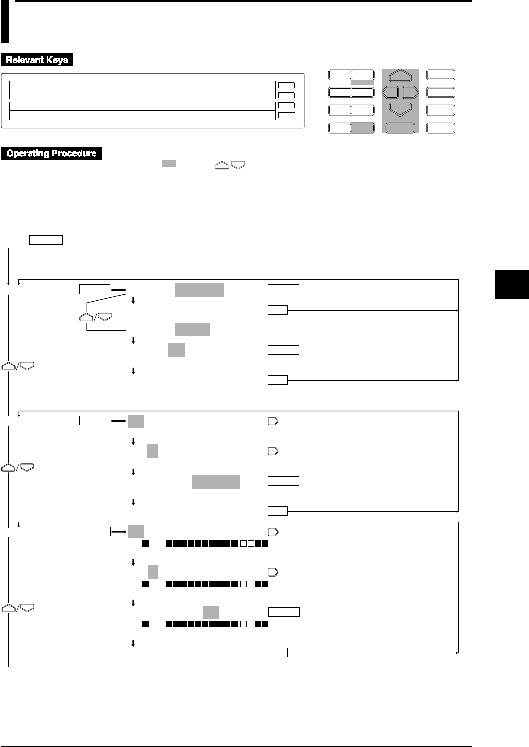
6-1
IM DR232-01E
6
Setting the Recording Conditions
6.1 Setting the Recording Mode, Engineering Unit,
Recording Channel and Recording Interval
D I S P M O D E
P R I N TF U N C
I N S D E L
R A N G E A L A R M
S E TC H A R T E N T E R
F E E D
M. F U N C 1
M. F U N C 2
RECORD
ALARM
CHART
KEYLOCK
R E C O R D
SET=SYSTEM
SYSTEM UNIT TREND TIMER LOGIC COPY
>Select Setting Parameter
E S C
1 Press the SET key to enter the SET menu.
2 Select/set using the keys.
3 To escape from a lower menu, press the “MODE (ESC)” key. Its main menu will appear,
although new settings/selections will not be kept.
4 New settings/selections will be kept when you reach the final display of that setting.
SET=
SYSTEM
UNIT
TREND
SYSTEM=LOGGING
***SET OK***
SYSTEM=TREND
TREND=FIX
FIX AUTO
***SET OK***
001-01:UNIT=_ _ _ _ _ _
>Select Channel No.
001-01:UNIT=_ _ _ _ _ _
>Select Channel No.
001-01:UNIT=Ω_ _ _ _ _
>↓%&()+-*/.:˚ µ ε 0123- - -89 ABC- - -KL↑
***SET OK***
001-01:TREND=ON
>ON 001
>Select Channel No.
001-01:TREND=ON
>ON 001
>Select Channel No.
001-01:TREND=ON
>ON 001
OFF ON
***SET OK***
ENTER ENTER
ENTER
ENTER
ESC
ENTER
ESC
ENTER
ESC
ENTER
ENTER
ESC
To the next page
(Main menu)
(Lower menu)
Delete two lines of description in Japanese in this position.
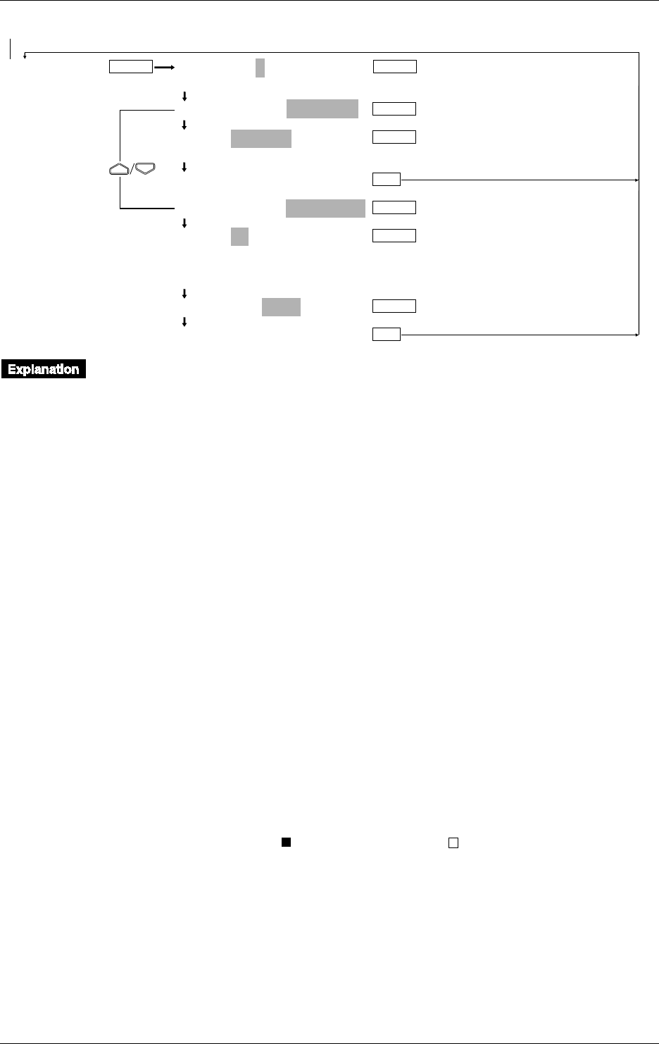
6-2 IM DR232-01E
6.1 Setting the Recording Mode/Engineering Unit/Recording Channel and Recording Interval
TIMER TIMER No.=1
1 2 3 4 5 6
1:TIMER MODE=RELATIVE
1:TIME=00 01: 00
>Set DD HH:MM:00
***SET OK***
1:TIMER MODE=ABSOLUTE
1:TIME=1h
1min 2min 3min 4min 5min 6min 10min
12min 15min 20min 30min 1h 2h 3h 4h 6h
8h 12h 24h
1:REF TIME=00:00
***SET OK***
ENTER
ENTER
ENTER
ENTER
ENTER
ENTER
ESC
ENTER
ESC
From the previous page
Recording Mode (SYSTEM)
The following types of recording mode can be selected. The default is TREND.
• LOGGING (LOGGING MODE); measurement values will be printed out as digital values.
• TREND (ANALOG TREND MODE); measurement values will be recorded as analog trends
(dot recording) and printed out as digital values.
• Selecting the recording interval
This setting can only be done for the TREND mode, and its default setting is AUTO.
FIX: Recording takes place at intervals equal to the measurement period (scan interval).
However, if the measuring period is 0.5 or 1 second, the recording interval is fixed to 2
seconds. The measured data during the excess period is ignored.
AUTO: recording takes place at intervals automatically decided by measurement interval and
chart speed.
Engineering Unit (UNIT)
An engineering unit of up to six characters can be assigned to each channel. The default setting is
all spaces.
The characters/numbers can be selected by cursor from the displayed row on sub-display 1. An
engineering unit can only be assigned to channels to which linear scaling is applied. For details
concerning entering characters/numbers, refer to page 6-15.
If the instrument is equipped with the optional computation function or floppy disk drive, make
sure that channel Nos. are set between A01 and A60 when specifying the measurement units for
computation channels.
Setting the Channels to be Recorded (TREND)
Dot Recording
Recording can be set ON/OFF per channel. The default setting is ON.
ON: recording will take place;
OFF: recording will not take place.
The display will show “ ” for channels set to ON, and “ ” for channels set to OFF. Refer to
page 4-10 on which channel is being displayed.
If you are installing optional computation channels, channel Nos. must be set to A01 to A60.
Digital Printout in the Analog Trend Mode
Refer to 6.4 Setting Tag, Digital Printout and Manual Printout on page 6-9.

6-3
IM DR232-01E
6
Setting the Recording Conditions
6.1 Setting the Recording Mode/Engineering Unit/Recording Channel and Recording Interval
Setting the Recording Interval (TIMER) of the Digital Printout for the Logging and
Analog Trend Mode
• TIMER No.
You can set up to six recording intervals. A recording interval can be set for each channel
individually. Refer to 6.4 on page 6-9 for details.
• TIME MODE
The following two modes can be selected. The default is RELATIVE.
• RELATIVE; the number of days/hours/minutes can be set to any value between 00 days 00
hours 01 minute to 31 days 23 hours and 59 minutes, in one-minute steps. The default
setting is 00 days, 01 hours and 00 minutes.
• ABSOLUTE; the time interval can be selected from the following settings. The default
setting is 1h.
1min, 2min, 3min, 4min, 5min, 6min, 10min, 12min, 15min, 20min, 30min, 1h, 2h, 3h, 4h,
6h, 8h, 12h, and 24h.
The reference time is set by the hour and minutes. The default value is 00 hrs, 00 min.
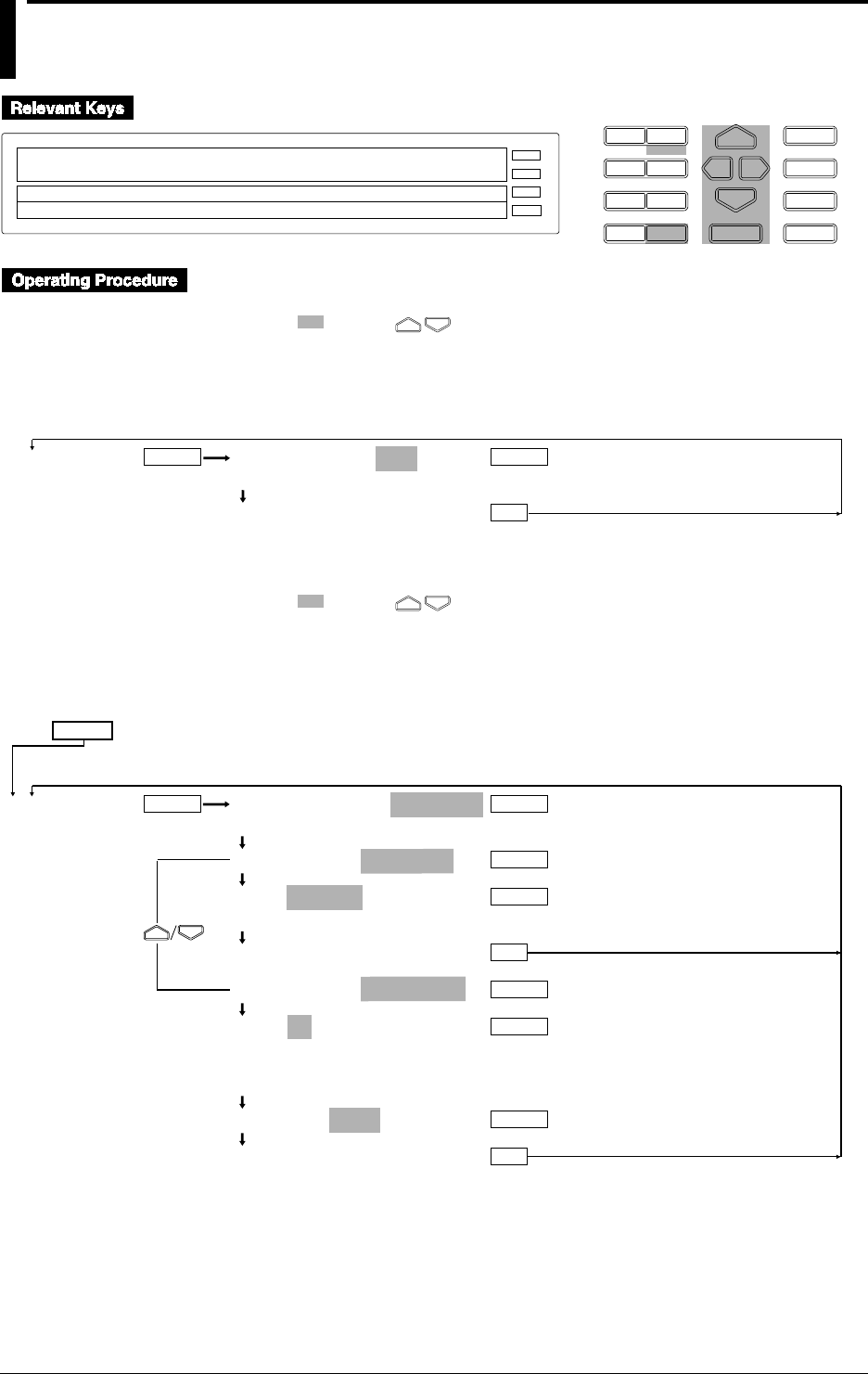
6-4 IM DR232-01E
6.2 Setting the Chart Speed
D I S P M O D E
P R I N TF U N C
I N S D E L
R A N G E A L A R M
S E TC H A R T E N T E R
F E E D
M. F U N C 1
M. F U N C 2
RECORD
ALARM
CHART
KEYLOCK
R E C O R D
SET=CHART
CHART CLOCK
>Select Setting Parameter
E S C
Setting Chart Speed 1
1 Press the CHART key to enter the SET menu.
2 Select/set using the keys.
3 To escape from a lower menu, press the “MODE (ESC)” key. Its main menu will appear,
although new settings/selections will not be kept.
4 New settings/selections will be kept when you reach the final display of that setting.
CHART CHART SPEED=_100mm/H
>Chart Speed Max 1500mm/H
***SET OK***
ENTER ENTER
ESC
(Main menu) (Lower menu)
Setting Chart Speed 2
1 Press the SET key for three seconds to enter the SET3 menu.
2 Select/set using the keys.
3 To escape from a lower menu, press the “MODE (ESC)” key. Its main menu will appear,
although new settings/selections will not be kept.
4 New settings/selections will be kept when you reach the final display of that setting.
SET=
CHART2 SECOND SPEED=_100mm/H
>Chart Speed Max 1500mm/H
TIMER MODE=RELATIVE
TIME=00 01:00
>Set Day & Time DD HH:MM:00
***SET OK***
TIMER MODE=ABSOLUTE
TIME=1h
1min 2min 3min 4min 5min 6min 10min
12min 15min 20min 30min 1h 2h 3h 4h 6h
8h 12h 24h
REF TIME=00:00
***SET OK***
ENTER ENTER
ENTER
ESC
ESC
ENTER
ENTER
ENTER
ENTER
(Main menu)
(Lower menu)

6-5
IM DR232-01E
6
Setting the Recording Conditions
6.2 Setting the Chart Speed
Chart Speed 1 (CHART)
This setting specifies the chart speed of ordinary trend recordings. The setting ranges from 1 to
1500mm/h, in 1 mm steps. The default setting is 100mm/h.
Chart Speed 2 (CHART2)
This setting consists of a chart speed and recording interval. Depending on the Event/Action
function (refer to 9.1 on page 9-1), the chart speed and recording interval will change into chart
speed 2 and its corresponding interval.
• Chart speed 2 setting
This setting is the same as for chart speed 1, and its default setting is 100mm/h.
• Recording interval
This setting specifies the recording interval for the digital prinout in the logging and analog
trend recording mode. One type of recording interval can be set. The setting is done the same
way as described on page 6-3, although only one type can be set.
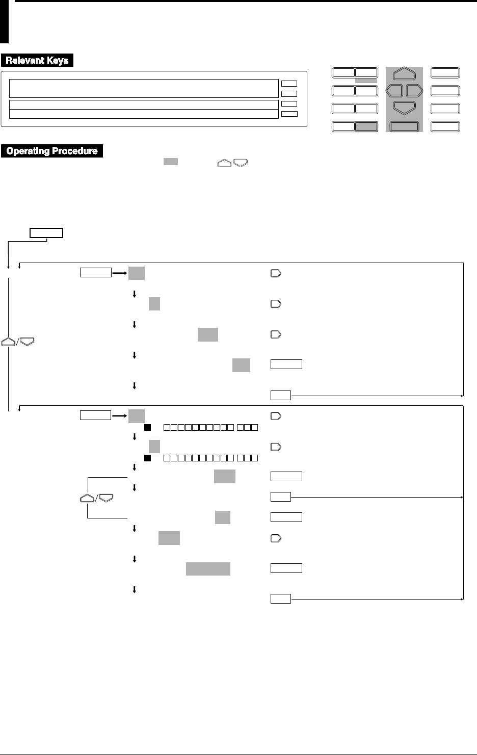
6-6 IM DR232-01E
6.3 Setting Recording Zones and Partially
Expanded Recording
D I S P M O D E
P R I N TF U N C
I N S D E L
R A N G E A L A R M
S E TC H A R T E N T E R
F E E D
M. F U N C 1
M. F U N C 2
RECORD
ALARM
CHART
KEYLOCK
R E C O R D
SET=ZONE
CHART2 ZONE PARTIAL TAG DIGITAL_PR MAN↑
>Select Setting Parameter
E S C
1 Press the SET key for three seconds to enter the SET3 menu.
2 Select/set using the keys.
3 To escape from a lower menu, press the “MODE (ESC)” key. Its main menu will appear,
although new settings/selections will not be kept.
4 New settings/selections will be kept when you reach the final display of that setting.
SET=
ZONE
PARTIAL
001-01:ZONE=_ _0 to 250mm
>Select Channel No.
001-01:ZONE=_ _0 to 250mm
>Select Channel No.
001-01:ZONE=_ _0 to 250mm
>Left limit(0 to 245mm)
001-01:ZONE=_ _0 to 250mm
>Right limit(5 to 250mm)
***SET OK***
001-01:PARTIAL=OFF
>ON 001 - - -
001-01:PARTIAL=OFF
>ON 001 - - -
001-01:PARTIAL=OFF
***SET OK***
001-01:PARTIAL=ON
RATE 50%=_0.0000V
>Rate Limit(1 to 99%)
RATE 50%=_0.0000V
>Boundary Limit(–1.9999 to 1.9999V)
***SET OK***
ENTER
ENTER
ENTER
ENTER
ESC
ESC
ENTER
ENTER
ESC
(Main menu)
(Lower menu)

6-7
IM DR232-01E
6
Setting the Recording Conditions
Setting Recording Zones (ZONE)
This setting specifies the recording zones for each channel. The set left and right position of the
zone correspond to the left and right span set at the SPAN menu (recording span). The left value
of the ZONE menu corresponds to the value of the left position of the zone, whereas the right
value of the ZONE menu corresponds to the value of the right position of the zone.
Zones can be set in 1mm steps and cannot exceed the recording range (i.e. 250mm). The left
position setting ranges from 0 to 245mm, whereas the right position setting ranges from 5 to
250mm. The minimum width of a zone is 5mm. A decimal point cannot be set. The default
settings are 0mm for the left position and 250mm for the right position.
If the instrument is equipped with the optional computation function or floppy disk drive, this
setting can also be made for computation channels A01 to A60.
Partially Expanded Recording (PARTIAL)
This setting specifies whether to carry out partially expanded recording, and if so, which
percentage of the recording span will be compressed and the corresponding boundary value.
If the instrument is equipped with the optional computation function or floppy disk drive, this
setting can also be made for computation channels A01 to A60.
Selecting Partial Recording ON/OFF
ON: Partial recording will be carried out;
OFF: Partial recording will not be carried out.
The default setting is OFF.
Specifying the Compressed Part and Boundary Value
RATE
This setting specifies which percentage (1 to 99%) of the full recording span will be
compressed. The default value is 50%.
Boundary value
This setting specifies the boundary value which corresponds to the previous set compressed
part. The setting lies within the recording span, but when linear scaling is being used, the
setting lies within the left/right scale range. The default value is 0.
Note
If boundary values are to be set for succeeding channels, the decimal point is handled as shown below.
If succeeding channels are set, the decimal point position of boundary values when the measurement range
for each channel setting is different, is that determined for each corresponding range. As a result, it exceeds
the measurable range, an error occurs.
For example, if channels whose measurement ranges are 20 mV, 2 V, and type T thermocouple are set and
the boundary value is set to 10000, the following applies:
The boundary value of the channel whose measurement range is 20 mV: 10.000 mV;
The boundary value of the channel whose measurement range is 2 V: 1.0000 V; and
The boundary value of the channel whose measurement range is type T thermocouple: 1000.0 °C
As the measurement range of type T thermocouple is -200.0 to 400.0 °C, an error occurs for this channel.
For decimal point positions for each measurement range, see Chapter 14, “Specifications.”
Points to Note when Using Partially Expanded Recording
• Partial recording cannot be carried out if the input type of the computation channels is SKIP or
DI or if the computation channels are OFF.
• Partially expanded settings will be automatically canceled when either of the following changes
occur.
• the input type has been changed;
• the measurement range has been changed;
• the recording span has been changed;
• linear scaling settings have been changed;
• the reference channel for difference between channels has been changed.
6.3 Setting Recording Zones and Partially Expanded Recording
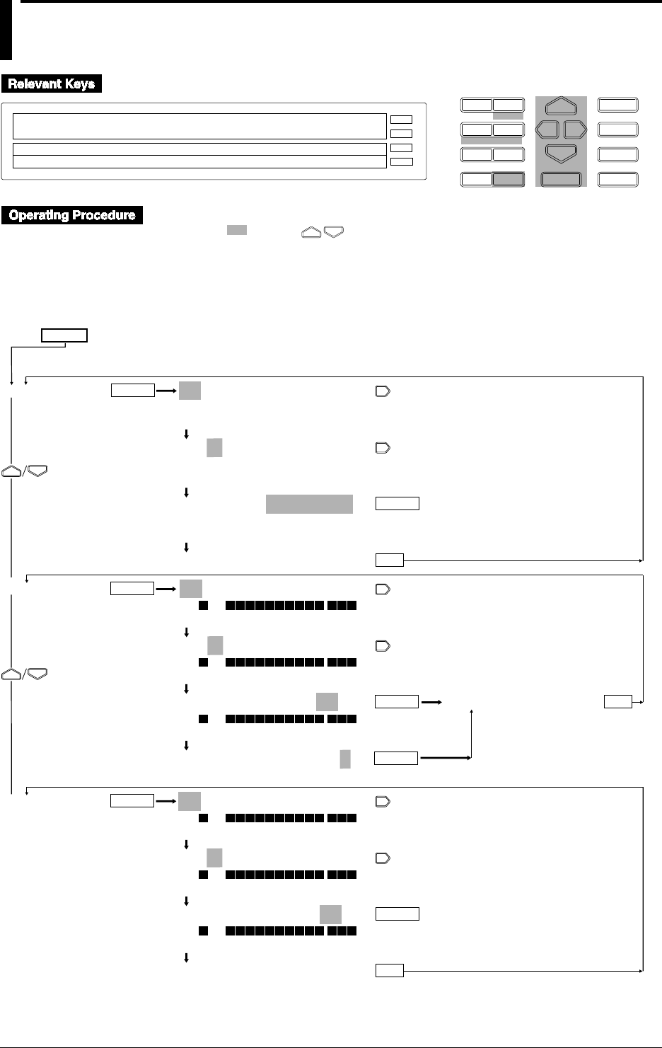
6-8 IM DR232-01E
6.4 Setting Tag, Digital Printout and Manual
Printout
D I S P M O D E
P R I N TF U N C
I N S D E L
R A N G E A L A R M
S E TC H A R T E N T E R
F E E D
M. F U N C 1
M. F U N C 2
RECORD
ALARM
CHART
KEYLOCK
R E C O R D
SET=TAG
CHART2 ZONE PARTIAL TAG DIGITAL_PR MAN↑
>Select Setting Parameter
E S C
1 Press the SET key for three seconds to enter the SET3 menu.
2 Select/set using the keys.
3 To escape from a lower menu, press the “MODE (ESC)” key. Its main menu will appear,
although new settings/selections will not be kept.
4 New settings/selections will be kept when you reach the final display of that setting.
001-01:TAG=
_ _ _ _ _ _ _ _ _ _ _
>TAG=[
_ _ _ _ _ _ _ _ _ _ _ _ _ _ _ _
]
>Select Channel No.
001-01:TAG=
_ _ _ _ _ _ _ _ _ _ _
>TAG=[
_ _ _ _ _ _ _ _ _ _ _ _ _ _ _ _
]
>Select Channel No.
001-01:TAG=12345678901
>TAG=[1234567890123456]
↓%&()+-*/.:- - - 0123456789 ABC- - -KL↑
***SET OK***
001-01:DIGITAL PR=ON
>ON 001 - - -
>Select Channel No.
001-01:DIGITAL PR=ON
>ON 001 - - -
>Select Channel No.
001-01:DIGITAL PR=ON
>ON 001 - - -
OFF ON
DIGITAL PR TIMER No.=1
1 2 3 4 5 6
001-01:MANUAL PR=ON
>ON 001 - - -
>Select Channel No.
001-01:MANUAL PR=ON
>ON 001 - - -
>Select Channel No.
001-01:MANUAL PR=ON
>ON 001 - - -
OFF ON
***SET OK***
TAG
DIGITAL PR
MANUAL PR
ENTER
ESC
ESC
ENTER
ENTER
ENTER
ENTER
ENTER
***SET OK***
In case “SINGLE” is set as log interval at
the “RECORD” setting in the SET UP mode.
ENTER
ESC
In case “MULTIPLE” is set as log interval at
the “RECORD” setting in the SET UP mode.
SET=
(Main menu)
(Lower menu)

6-9
IM DR232-01E
6
Setting the Recording Conditions
Tag Setting
A tag of up to 16 characters can be assigned to each channel. If the instrument is equipped with
the optional computation function or floppy disk drive, this setting can also be made for
computation channels A01 to A60. The characters/numbers for the tag can be selected by cursor
from the displayed row on sub-display 1. For details on the number of characters which will be
printed, refer to 10.2 on page 10-4. For details on the number of characters which will be
displayed, refer to 4.1 on page 4-2. To select whether the tag or channel number are displayed/
printed, refer to 10.2 on page 10-4. The default settings are all spaces. For details concerning
entering characters/numbers, refer to page 6-15.
Digital Printout Setting (DIGITAL PR)
This setting can be selected for each channel from the following. This setting applies to the digital
print of the analog mode and logging mode. The default setting is ON.
OFF: Digital printout will not be carried out for this channel;
ON: Digital printout will be carried out for this channel.
The recording interval can be selected from the following. For details on LOG INTERVAL, refer
to 10.2, page 10-6.
If the instrument is equipped with the optional computation function or floppy disk drive, this
setting can also be made for computation channels A01 to A60.
When LOG INTERVAL is set to SINGLE:
The recording interval is decided automatically, depending on the chart speed, and the columns
of channels to be printed.
When LOG INTERVAL is set to MULTIPLE:
The recording interval can be selected from six timer settings. The default value is 1. For
details on the timer setting, refer to 6.1, page 6-3.
Columns selecting
Refer to 10.2, page 10-5.
Manual Printout Setting (MANUAL PR)
This setting can be selected from the following. The default setting is ON.
If the instrument is equipped with the optional computation function or floppy disk drive, this
setting can also be made for computation channels A01 to A60.
OFF: Manual printout will not be carried out for this channel;
ON: Manual printout will be carried out for this channel.
6.4 Setting Tag, Digital Printout and Manual Printout
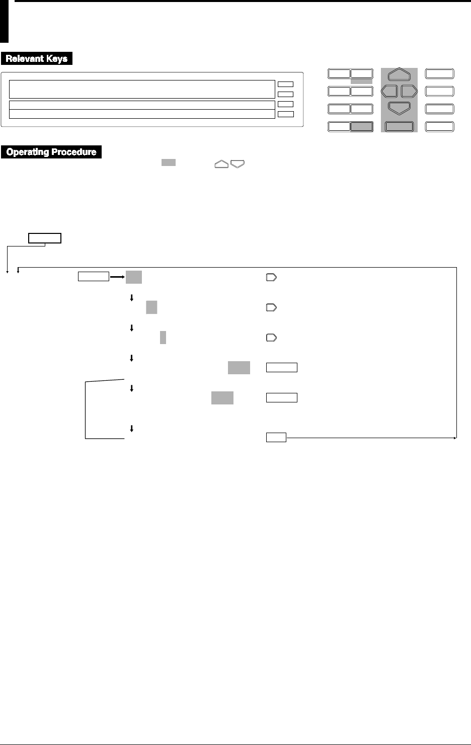
6-10 IM DR232-01E
6.5 Setting the Alarm Printout
D I S P M O D E
P R I N TF U N C
I N S D E L
R A N G E A L A R M
S E TC H A R T E N T E R
F E E D
M. F U N C 1
M. F U N C 2
RECORD
ALARM
CHART
KEYLOCK
R E C O R D
SET=ALARM_PR
↓TIAL TAG DIGITAL_PR MANUAL_PR ALARM_PR↑
>Select Setting Parameter
E S C
1 Press the SET key for three seconds to enter the SET3 menu.
2 Select/set using the keys.
3 To escape from a lower menu, press the “MODE (ESC)” key. Its main menu will appear,
although new settings/selections will not be kept.
4 New settings/selections will be kept when you reach the final display of that setting.
001-01:1/ALARM PR=ON2
>Select Channel No.
001-01:1/ALARM PR=ON2
>Select Channel No.
001-01:1/ALARM PR=ON2
1 2 3 4
001-01:1/ALARM PR=ON2
OFF ON1 ON2
MSG ON ALARM=OFF
OFF 01 02 03 04 05 06 07 08 09 10
11 12 13 14 15 16 1718 19 20
***SET OK***
ALARM PR
ENTER
ESC
ENTER
ENTER
In case
of OFF
SET=
(Main menu)
(Lower menu)

6-11
IM DR232-01E
6
Setting the Recording Conditions
Selecting the Alarm Items
Although up to four alarm headings can be set per channel, this setting specifies the number of the
heading which will be printed. The default setting is 1.
If the instrument is equipped with the optional computation function or floppy disk drive, this
setting can also be made for computation channels A01 to A60.
For details on alarm settings, see 8.1, “Setting Alarms and Relays (including internal switches”
(on page 8-1).
Selecting the Alarm Printout (ALARM PR)
This setting can be selected from the following. The default setting is ON2.
OFF: Alarm printout will not be carried out;
ON1: Alarms will only be printed out on occurrence.
The alarm occurrence mark, channel No. or tag, type of alarm, alarm heading or time of
occurrence will be printed with trend recordings.
ON2: Alarms will both be printed out on occurrence and release.
The alarm occurrence/release mark, channel No. or tag, type of alarm, alarm heading or time of
occurrence/release will be printed with trend recordings.
Alarm Printout Buffer
• Analog Trend Mode
Up to 30 alarm occurrences/releases can be stored in memory.
• Information on more than 30 alarm occurrences/releases will be discarded. After one alarm
printout, 29 alarm occurrences/releases are stored and another alarm occurrence/release can
then be stored.
• If 31 alarm occurrences/releases (exceeding the allowed number of 30) are entered, an
asterisk (*) will be printed at the top of the alarm message when 30 alarm printouts are
executed.
• The alarm buffer clear function is available for canceling the stored alarm printout
information (see page 9-17).
• Logging Mode
Up to 10 alarm occurrences/releases can be stored in memory.
• Information on more than 10 alarm occurrences/releases will be discarded.
• If 11 alarm occurrences/releases (exceeding the allowed number of 10) are entered, an
asterisk (*) will be printed at the top of the alarm message when 10 alarm printouts are
executed.
• The alarm buffer clear function is available for canceling the stored alarm printout
information (see page 9-17).
Selecting a Message Printout
This setting specifies whether to print a message on alarm occurrence, and if so, which message
will be printed. The default setting is OFF.
OFF: No message will be printed.
Message No.
This setting can be selected from 01, 02, 03, 04, 05, 06, 07, 08, 09, 10, 11, 12, 13, 14, 15, 16, 17,
18, 19 and 20. When a message No. has been selected where no message has been entered,
printout will not be carried out.
For details on setting messages, refer to 6.7 on page 6-15.
6.5 Setting the Alarm Printout
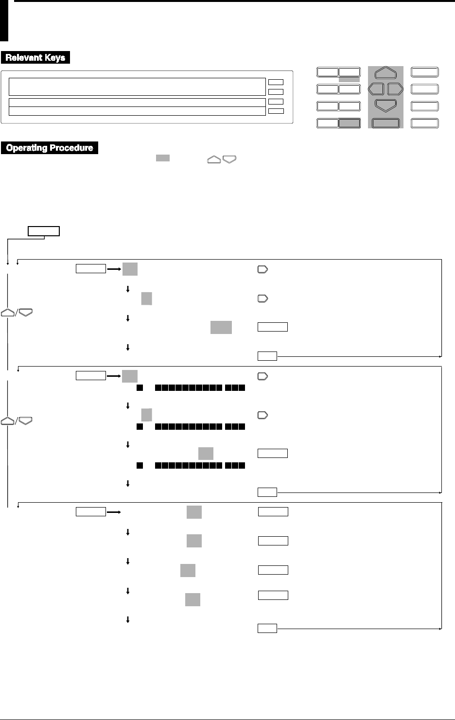
6-12 IM DR232-01E
6.6 Setting Scale Printout, List Printout and List
Format
D I S P M O D E
P R I N TF U N C
I N S D E L
R A N G E A L A R M
S E TC H A R T E N T E R
F E E D
M. F U N C 1
M. F U N C 2
RECORD
ALARM
CHART
KEYLOCK
R E C O R D
SET=SCALE_PR
↓DIGITAL_PR MANUAL_PR ALARM_PR SCALE PR↑
>Select Setting Parameter
E S C
1 Press the SET key for three seconds to enter the SET3 menu.
2 Select/set using the keys.
3 To escape from a lower menu, press the “MODE (ESC)” key. Its main menu will appear,
although new settings/selections will not be kept.
4 New settings/selections will be kept when you reach the final display of that setting.
001-01:SCALE PR=ON2
>Select Channel No.
001-01:SCALE PR=ON2
>Select Channel No.
001-01:SCALE PR=ON2
OFF ON1 ON2 ON3
***SET OK***
001-01:LIST PR=ON
>ON 001 - - -
>Select Channel No.
001-01:LIST PR=ON
>ON 001 - - -
>Select Channel No.
001-01:LIST PR=ON
>ON 001 - - -
OFF ON
***SET OK***
LIST RANGE=ON
OFF ON
LIST ALARM=ON
OFF ON
LIST PRINT=ON
OFF ON
LIST OTHER=ON
OFF ON
***SET OK***
SCALE PR
LIST PR
LIST FMT
ENTER
ESC
ENTER
ESC
ESC
ENTER
ENTER
ENTER
ENTER
ENTER
ENTER
ENTER
SET=
(Main menu)
(Lower menu)

6-13
IM DR232-01E
6
Setting the Recording Conditions
Scale Printout (SCALE PR)
This setting can be assigned to each channel individually. The scaled values will be printed out
with trend recordings. This printout will not occur when a zone of 49mm or less is set. The scaled
values of the following channels will be printed. For example, when the recording zone of ch. 1 is
set to 49mm, and of ch. 2 is 150mm, the scaled values of ch. 2 will be printed at the position of
ch. 1. The default setting is ON2. If the instrument is equipped with the optional computation
function or floppy disk drive, this setting can also be made for computation channels A01 to A60.
When Partial Expanded Recording is OFF
OFF: Scaled values will not be printed.
ON1:
• when the recording zone is 150mm or more: scaled values at each 20%-interval of the
recording span will be printed at positions at 20%-intervals of the zone.
• when the recording zone is 50mm to 149mm: scaled values at 0% and 100% of the
recording span will be printed at 0% and 100% positions of the zone.
ON2:
Scaled values at 0% and 100% of the recording span will be printed at 0% and 100% positions
of the zone.
ON3:
• when the recording zone is 100mm or more: scaled values at 0%, 50% and 100% of the
recording span will be printed at 0%, 50% and 100% positions of the zone.
• when the recording zone is 50mm to 99mm: scaled values at 0% and 100% of the recording
span will be printed at 0% and 100% positions of the zone.
When Partial Expanded Recording is ON
OFF: Scaled values will not be printed.
ON1/ON2/ON3:
• when the recording zone is 100mm or more: scaled values at 0%, 100% of the recording
span and at the boundary value will be printed at 0%, 100% and boundary value positions of
the zone.
• when the recording zone is 50mm to 99mm: scaled values at 0% and 100% of the recording
span will be printed at 0% and 100% positions of the zone.
List Printout (LIST PR)
This setting can be assigned to each channel individually. The default setting is ON. Starting a list
printout can be done at the PRINT menu (refer to 7.2 on page 7-2). If the instrument is equipped
with the optional computation function or floppy disk drive, this setting can also be made for
computation channels A01 to A60.
OFF: List printout will not be printed.
ON: Setting information per channel will be printed.
Setting the List Format (LIST FMT)
This setting specifies which setting information will be printed out in case of list printouts. Each
of the following lists can be selected ON or OFF, and the default setting is ON.
LIST RANGE (information about the setting range)
Information about settings related to tags, type of input, recording span, linear scaling and
computation equation.
LIST ALARM (information about the alarm settings)
Alarm settings
LIST PRINT (information about the printing settings)
Information about settings related to analog trend recording, digital printout, interpolation,
recording zones, partial expanded recording, recording interval of digital printouts for logging
mode and analog mode, moving average, scaled values, alarm printout, manual printout and data
saving ON/OFF.
LIST OTHER (information about other settings)
Information about settings related to match time, groups, headers, messages, event/action
function, list format and computation constant.
Information which always be included in a list printout, regardless of the above settings, are title,
measurement interval, recording interval (trend), chart speeds 1 and 2, recording mode and time.
6.6 Setting Scale Printout, List Printout and List Format
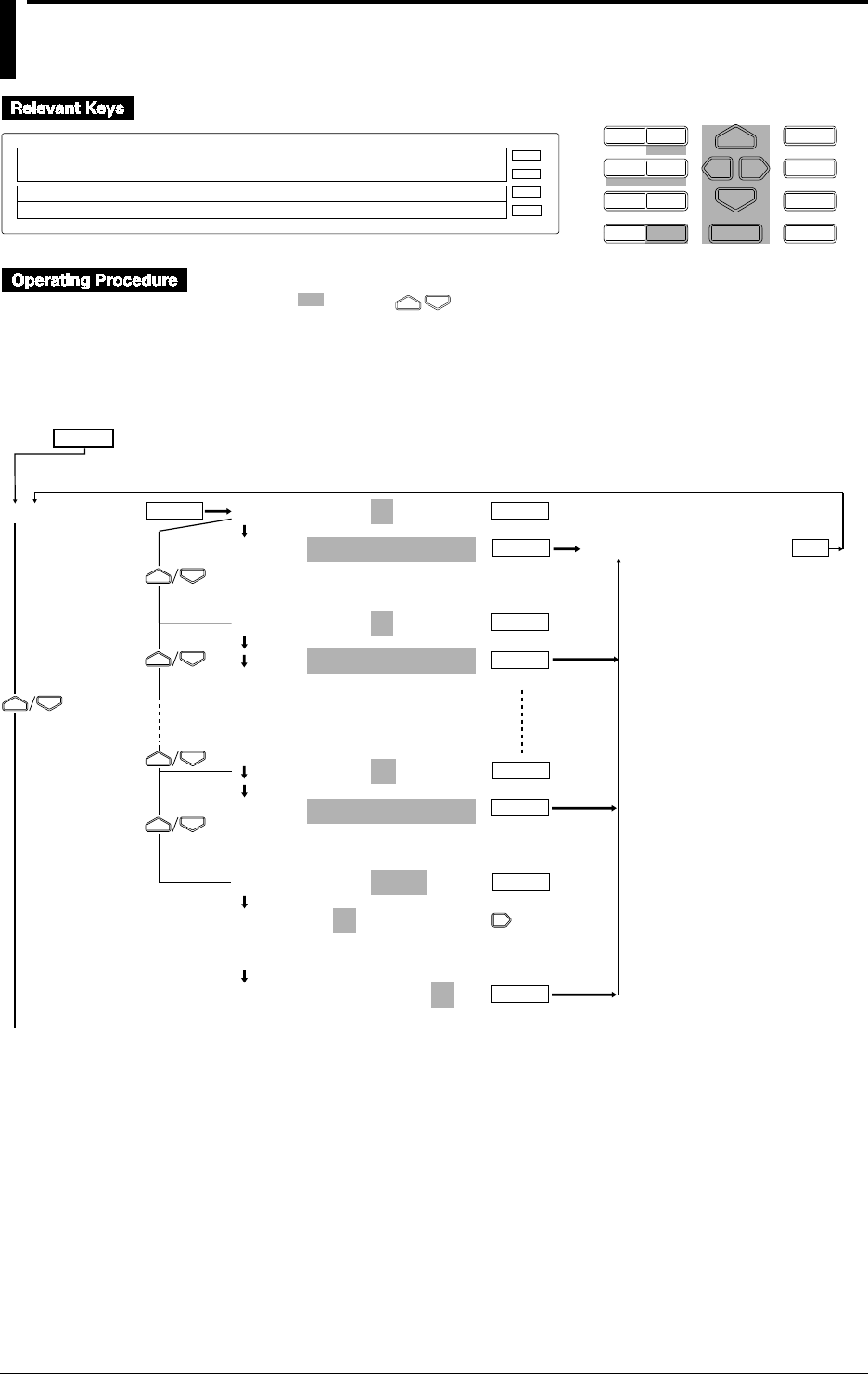
6-14 IM DR232-01E
6.7 Entering Messages, Headers and Title
D I S P M O D E
P R I N TF U N C
I N S D E L
R A N G E A L A R M
S E TC H A R T E N T E R
F E E D
M. F U N C 1
M. F U N C 2
RECORD
ALARM
CHART
KEYLOCK
R E C O R D
SET=MESSAGE
↓ LIST_PR LIST_FMT MESSAGE HEADER TITLE↑
>Select Setting Parameter
E S C
1 Press the SET key for three seconds to enter the SET3 menu.
2 Select/set using the keys.
3 To escape from a lower menu, press the “MODE (ESC)” key. Its main menu will appear,
although new settings/selections will not be kept.
4 New settings/selections will be kept when you reach the final display of that setting.
MESSAGE No.=01
MSG01=
_ _ _ _ _ _ _ _ _ _ _ _ _ _ _ _
>MSG01=[_ _ _ _ _ _ _ _ _ _ _ _ _ _ _ _ ]
↓%&()+-*/.:- - - 0123456789 ABC- - -KL↑
MESSAGE No.=02
MSG02=
_ _ _ _ _ _ _ _ _ _ _ _ _ _ _ _
>MSG02=[_ _ _ _ _ _ _ _ _ _ _ _ _ _ _ _ ]
↓%&()+-*/.:- - - 0123456789 ABC- - -KL↑
: :
: :
: :
MESSAGE No.=20
MSG20=
_ _ _ _ _ _ _ _ _ _ _ _ _ _ _ _
>MSG20=[_ _ _ _ _ _ _ _ _ _ _ _ _ _ _ _ ]
↓%&()+-*/.:- - - 0123456789 ABC- - -KL↑
MESSAGE No.=COPY
COPY MSG01 TO MSG01
01 02 03 04 05 06 07 08 09 10
11 12 13 14 15 16 17 18 19 20
COPY MSG01 TO MSG02
01 02 03 04 05 06 07 08 09 10
11 12 13 14 15 16 17 18 19 20
MESSAGE
ENTER
To the next page
ENTER
ENTER
ENTER
ENTER
ENTER
ENTER
ENTER
ESC
***SET OK***
ENTER
SET=
(Main menu)
(Lower menu)

6-15
IM DR232-01E
6
Setting the Recording Conditions
HEADER LINE No.=1
1 2 3 4 5
LINE1=
_ _ _ _ _ _ _ _ _ _ _ _ _ _ _ _
>1=[
_ _ _ _ _ _ _ _ _ _ _ _ _ _ _ _
]
↓%&()+-*/.:- - - 0123456789 ABC- - -KL↑
***SET OK***
TITLE=
_ _ _ _ _ _ _ _ _ _ _ _ _ _ _ _
>=[
_ _ _ _ _ _ _ _ _ _ _ _ _ _ _ _
]
↓%&()+-*/.:- - - 0123456789 ABC- - -KL↑
***SET OK***
HEADER
TITLE
ENTERENTER
ENTER
ENTER ENTER
ESC
ESC
From the previous page
Entering a Message
MESSAGE No. (selection of the message No.)
Up to 20 messages can be entered.
MSG01 to 20 (entering the message)
The message contents can be entered here using up to 16 characters. Characters and numerals
can be selected from the menu. The default setting is all spaces.
COPY (copying messages)
The contents of an entered message (message No. at the left side of the setting) can be copied to
another message number (at the right side of the setting). You cannot copy to the same message
number.
Printing out a message
A message can be printed out on the occurrence of an alarm (refer to 6.5 on page 6-11 for
details), using the FUNC menu (refer to 7.3 on page 7-3 for details), or using the event/action
function (refer to 9.1 on page 9-1 for details).
Displaying a message
A message can be displayed on the main display using the even/action function.
Entering a Header
HEADER LINE No. (selection of the header line)
One header can consist of up to five lines.
LINE 1 to 5 (entering one line of the header)
The header contents can be entered here using up to 80 characters for each line, and thus up to
400 characters for the entire header. Characters and numerals can be selected from the menu.
The default setting is all spaces.
Entering a Title
One title can be set, using up to 32 characters. Characters and numerals can be selected from the
menu. The default setting is all spaces.
Inserting/Deleting a Character or Numeral
Press the PRINT(DEL) key to delete a set character or numeral. The digit at the location of the
cursor will be deleted.
Press the FUNC(INS) key to insert a character or numeral. The digit at the location of the cursor
will become a space, while all the characters/numeral at the right side of the cursor will move one
digit to the right.
6.7 Entering Messages, Headers and Title
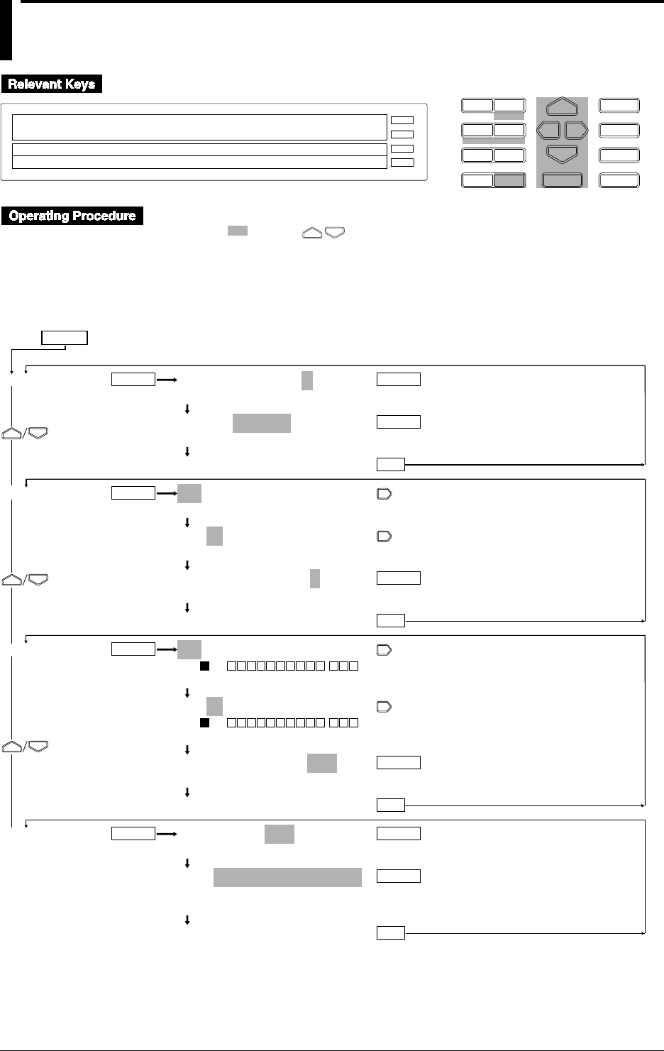
6-16 IM DR232-01E
6.8 Setting Match Time, Moving Average,
Interpolation and Groups
D I S P M O D E
P R I N TF U N C
I N S D E L
R A N G E A L A R M
S E TC H A R T E N T E R
F E E D
M. F U N C 1
M. F U N C 2
RECORD
ALARM
CHART
KEYLOCK
R E C O R D
SET=MATCH_TIME
↓TLE MATCH_TIME MOVE_AVE INTERPOL GROUP↑
>Select Setting Parameter
E S C
1 Press the SET key for three seconds to enter the SET3 menu.
2 Select/set using the keys.
3 To escape from a lower menu, press the “MODE (ESC)” key. Its main menu will appear,
although new settings/selections will not be kept.
4 New settings/selections will be kept when you reach the final display of that setting.
MATCH TIME No.=1
1 2 3
1:TIME=01 00:00
>Set Day & Time DD HH:MM:00
***SET OK***
001-01:MOVE AVE=0
>Select Channel No.
001-01:MOVE AVE=0
>Select Channel No.
001-01:MOVE AVE=0
>2~64:Move Average Number [0=OFF]
***SET OK***
001-01:INTERPOL=OFF
>ON 001 - - -
>Select Channel No.
001-01:INTERPOL=OFF
>ON 001 - - -
>Select Channel No.
001-01:INTERPOL=OFF
OFF ON
***SET OK***
GROUP No.=G01
G01 G02 03 G04 G05 G06 G07
G01=001,010-020
_ _ _ _ _ _ _ _
>=[
_ _ _ _ _ _ _ _ _ _ _ _ _ _ _ _ _ _ _ _ _ _ _ _ _ _ _ _ _ _ _ _ _ _ _ _
]
, –_ 0123456789
***SET OK***
MATCH TIME
MOVE AVE
INTERPOL
GROUP
ENTER ENTER
ENTER
ESC
ENTER
ESC
ENTER
ENTER
ESC
ENTER
ENTER ENTER
ESC
ENTER
SET=
(Main menu)
(Lower menu)

6-17
IM DR232-01E
6
Setting the Recording Conditions
Setting the Match Time
MATCH TIME No. (selection of the match time number)
Three kinds of match times can be set.
TIME
Any time between 00 days, 00 hrs., 00 min. and 31 days, 23 hrs, 59 min. can be set in 1-minute
units. The default setting is 01 days 00 hrs 00 min.
If 00 is set to day (DD), HH:MM every day shows the set time. If day (DD) is set to a value
other than 00, HH:MM of DD day every month shows the set time. DD, HH, and MM give the
set numeric values respectively.
The match time setting is used with the event/action function. Refer to 9.1 on page 9-1 for details.
Moving Average (MOVE AVE)
This setting can be set for each channel individually. The number of samples used for the moving
average can be set from 2 to 64. The default value is 0, which means that no moving average is
carried out. The result of the moving average is being displayed/printed.
Interpolation (INTERPOL)
This setting can be set for each channel individually. If the instrument is equipped with the
optional computation function or floppy disk drive, this setting can also be made for computation
channels A01 to A60. The default setting is OFF.
OFF: no interpolation will be carried out.
ON: interpolation will be carried out according to the priority of recording colors. The priority of
recording colors is black > purple > redish purple > navy blue > red > blue > brown > green >
orange > yellowish green.
Group setting (GROUP)
• GROUP No. (selection of the group number)
Up to seven groups can be set.
• G01 to G07
This setting specifies which channel numbers will be included in one group. A “,” is used for
entering a single channel, while a “-” can be used to enter a range of channels. Setting the same
channel two or more times in one group causes an error. For example, if you configure G01 as
003, 001-010, an error will result because 003 is included in this range. The default setting is
001.
• The group setting is used with the event/action function. Refer to 9.1 on page 9-1 for details.
6.8 Setting Match Time, Moving Average, Interpolation and Groups
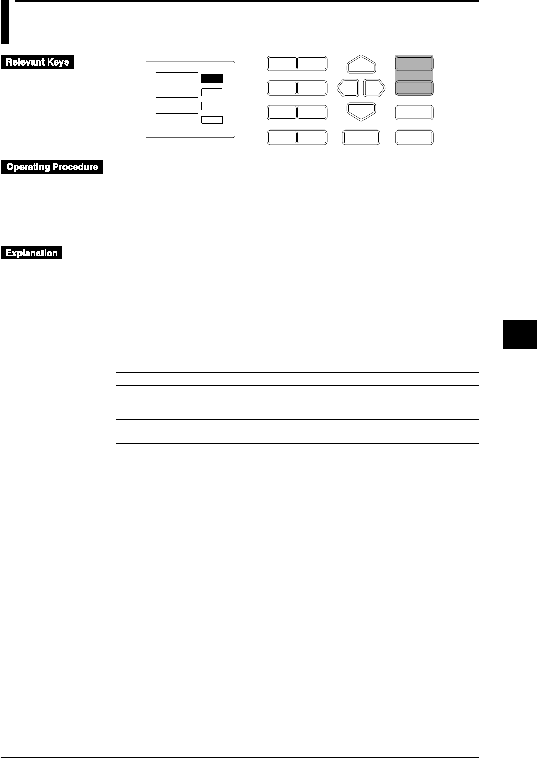
7-1
IM DR232-01E
7
Executing Recording
7.1 Starting Dot Printing, Digital Printing and
Printing in Logging Mode
D I S P M O D E
P R I N TF U N C
I N S D E L
R A N G E A L A R M
S E TC H A R T E N T E R
F E E D
M. F U N C 1
M. F U N C 2
ALARM
CHART
KEYLOCK
R E C O R D
E S C
RECORD
To start recording
Press the RECORD key. The status display [RECORD] lights.
To stop recording
Press the [RECORD] key once again. The status display [RECORD] turns off.
To feed the recording paper
Press the [FEED] key.
Starting dot printing, digital printing, and recording in logging mode
• See Chapter 6, “Setting.”
• Event/action functions can also be used to perform the above printing and recording (see Page
9-1).
Feeding the recording paper
Press the [FEED] key to feed the recording paper. Even if the [FEED] key is pressed while
recording, the paper is fed without stopping the recording.
Notes on starting recording
The carriage will stop temporarily at the left or right side for each line as shown below.
• When printing in logging mode or manual printing:
Printing direction Channel no./TAG selection Temporary stop (in seconds)
Horizontal Channel 4
TAG of 7 to 8 characters 3
TAG of 9 to 16 characters 5
Vertical Channel 2
TAG of 7 to 16 characters 3
• List printing
Temporary stop: For 0.5 secondsList printing
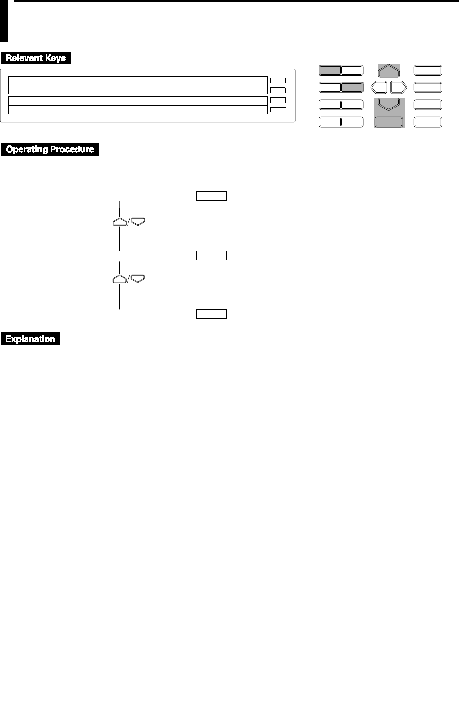
7-2 IM DR232-01E
7.2 Starting Manual Printing, List Printing and
Header Printing
D I S P M O D E
P R I N TF U N C
I N S D E L
R A N G E A L A R M
S E TC H A R T E N T E R
F E E D
M. F U N C 1
M. F U N C 2
RECORD
ALARM
CHART
KEYLOCK
R E C O R D
MAN_PR_START
MAN_PR_START LIST_START HEADER_START
>Enter & Print Start/Stop
E S C
• Press the [PRINT] key to enter the print menu.
• To display the print menu from the [RANGE][ALARM] or [CHART][SET] (SET3) menu,
press the [DISP] key.
MAN PR START
LIST START
HEADER START
ENTER
ENTER
ENTER
Starting the manual print (MAN PR START)
• Press the [ENTER] key to start manual printing.
• After printing starts, the operation display mode appears.
• During manual printing, the menu displays “MAN PR STOP.”
• During manual printing, enter the PRINT menu again and select [MAN PR STOP]. Then press
the [ENTER] key to stop the manual printing.
• After manual printing terminates or stops, the display returns to [MAN PR START].
Starting the list print (LIST START)
• Press the [ENTER] key to start list printing. For details on setting the time for temporarily
stopping printing, see the previous page.
• After list printing starts, the operation display mode appears.
• During list printing, the menu displays [LIST STOP].
• During list printing, if the PRINT menu is displayed to select the [LIST STOP] and the
[ENTER] key is then pressed, the list printing stops.
• After list printing terminates or stops, the display returns to [LIST START].
Starting the header print ( HEADER START)
• To start the header print, press the [ENTER] key.
• After header printing starts, the operation display mode appears.
• During header printing, the [HEADER STOP] menu appears.
• During header printing, if the PRINT menu is displayed to select the [HEADER STOP] and the
[ENTER] key is then pressed, the header printing stops.
• After header printing terminates or stops, the display returns to [HEADER START].
Notes on starting the above menus
• If the above menus are executed, analog trend recording will stop. After returning from the
menus, analog trend recording resumes.
• While the above menus are being executed, if any other menu is selected, the previous menu is
first executed and the later menu is then executed.
• See Chapter 6 for details on setting the above menus.
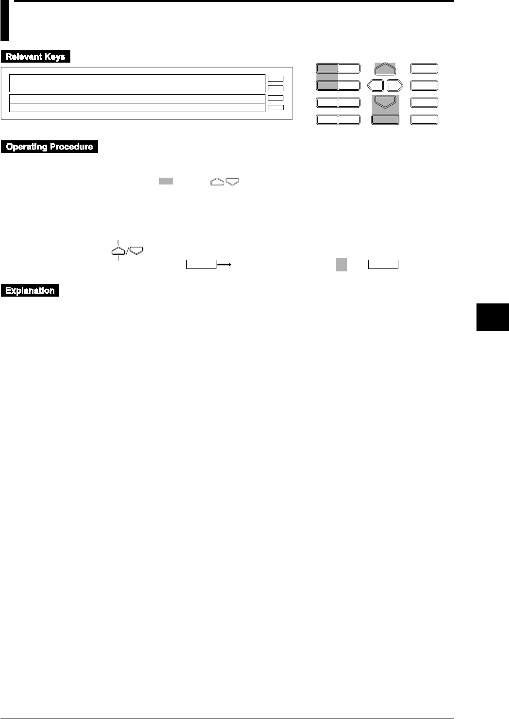
7-3
IM DR232-01E
7
Executing Recording
7.3 Starting Message Printing
D I S P M O D E
P R I N TF U N C
I N S D E L
R A N G E A L A R M
S E TC H A R T E N T E R
F E E D
M. F U N C 1
M. F U N C 2
RECORD
ALARM
CHART
KEYLOCK
R E C O R D
MSG_PRINT
>Select Function item
E S C
• Press the [FUNC] key to enter the FUNC menu.
• To display the print menu from the [RANGE][ALARM] or [CHART][SET] (SET3) menu,
press the [DISP] key.
• Select / set using the keys.
• To escape from a lower menu, press the MODE (ESC) key. Its main menu will appear,
although new settings / selections will not be kept.
MSG PRINT PRINT MESSAGE No.=01
ENTER ENTER
(Main menu)
(Lower menu)
Starting message printing (MSG PRINT)
• Select a message number from 01 to 20. For details on how to set the message, see Section 6.7,
“Entering Messages, Headers and Titles” on page 6-15.
• While the instrument is recording, if the [ENTER] key is pressed, messages are printed.
• If an alarm occurs, messages are also printed. See Section 6.5, “Setting the Alarm Printout” on
page 6-11.
Message printout buffer
• Analog trend
Up to 10 message printouts can be stored in memory.
• Information exceeding 10 message printouts will be discarded.
• After one message printout, 9 are stored and another printout message can then be stored.
• If 11 message printouts (exceeding the allowed number of 10) are entered, an asterisk (*)
will be printed at the top of the message when 10 message printouts are executed.
• The message buffer clear function is available for canceling stored printout messages (see
page 9-17).
• Logging mode
Up to 5 message printouts can be stored in memory.
• Information exceeding 5 message printouts will be discarded.
• If 6 message printouts (exceeding the allowed number of 5) are entered, an asterisk (*) will
be printed at the top of the message when 5 message printouts are executed.
• The message buffer clear function is available for canceling stored printout messages (see
page 9-17).

7-4 IM DR232-01E
7.4 Printing Set-up Lists
D I S P M O D E
P R I N TF U N C
I N S D E L
R A N G E A L A R M
S E TC H A R T E N T E R
F E E D
M. F U N C 1
M. F U N C 2
RECORD
ALARM
CHART
KEYLOCK
R E C O R D
S/U_LIST_START
>Select Function item
E S C
S/U_LIST_START ALM_BUF_CLEAR MSG_BUF_C↑
• Press and hold the [FUNC] key for three seconds to enter the FUNC3 menu.
S/U LIST START
ENTER
Printing the set-up list (S/U LIST START)
Prints a list of the settings made in the SETUP menu. For details of the settings and their values,
see Chapter 10.
• Press the [ENTER] key to start printing the set-up list.
• After printing starts, the operation display mode appears.
• During list printing, the [S/U LIST STOP] menu appears.
• During list printing, if the FUNC3 menu is displayed to select the [S/U LIST STOP] and the
[ENTER] key is then pressed, the list printing stops.
• After the list print terminates or stops, the display returns to the [S/U LIST START].
• If the setup list printing starts, analog trend recording will stop. After the printing is completed,
analog trend recording resumes.
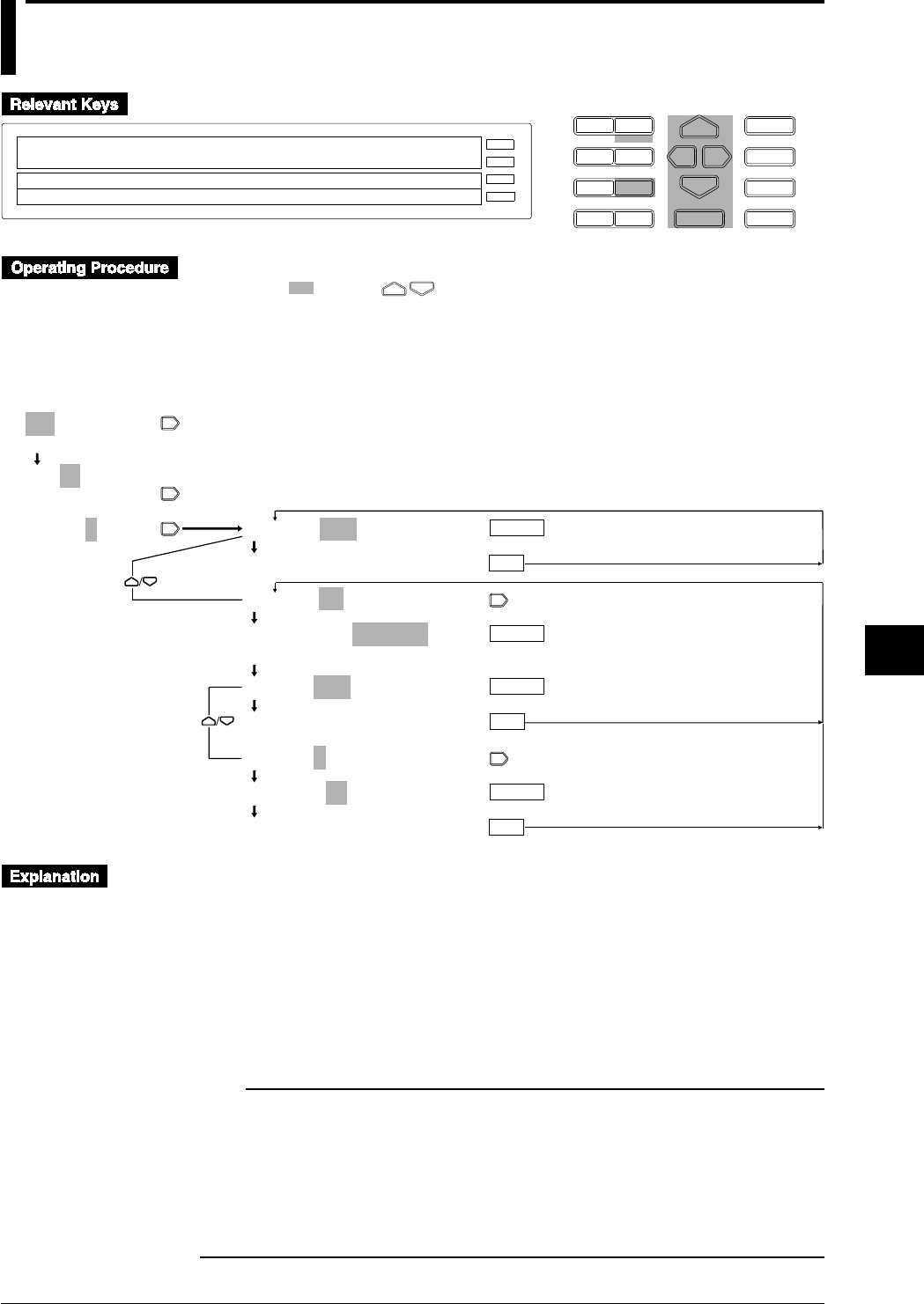
8-1
IM DR232-01E
8
Setting, Displaying and Recording Alarms
8.1 Setting Alarms and Relays (including internal
switches)
D I S P M O D E
P R I N TF U N C
I N S D E L
R A N G E A L A R M
S E TC H A R T E N T E R
F E E D
M. F U N C 1
M. F U N C 2
RECORD
ALARM
CHART
KEYLOCK
R E C O R D
001–01:1/OFF
1=OFF 2=OFF 3=OFF 4=OFF
>
E S C
• Press the [ALARM] key to enter the ALARM menu.
• Select / set using the keys.
• To escape from a lower menu, press the MODE (ESC) key. Its main menu will appear,
although new settings / selections will not be kept.
• New settings/selections will be kept when you rach the final display of that setting.
001-01:1/OFF
>Select Channel No.
001-01:1/OFF
>Select Channel No.
001-01:1/OFF
1 2 3 4
001-01:1/OFF
***SET OK***
001-01:1/H_=_ _ _0.00
001-01:1/H_=_ _ _0.00
>Alarm Limit(0.00~100.00)
RELAY=OFF
***SET OK***
RELAY=S01
RELAY=S01
***SET OK***
ENTER
ENTER
ENTER
ESC
ESC
ESC
ENTER
(Main menu)
(Lower menu)
Selecting channel Nos.
Channels Nos. A01 to A60 are available for computation channels (optional).
Selecting the alarm item number
Set the alarm item number for each channel as follows:
• Select any number from among 1, 2, 3, and 4.
• Alarm numbers 1 to 4 can be set for one channel.
• For details on setting the alarm printout, see Section 6.5, “Setting the Alarm Printout” on page
6-10.
Note
• If SKIP is selected for the input type or if the computation channels are OFF, alarms cannot be set.
• If the following cases, the alarm is set to OFF:
• If the input type or measuring range in the related channel is changed,
• If computation channels are turned ON/OFF or the computation equation is changed.
• If the recording span for the linear scaling, or linear scaling values is changed, or
• If the standard channel for differential computation between channels is changed.
• Setting the alarm or relay (including internal switches) gives more functions to this recorder. For details,
see Section 9.1, “Setting Event and Action Functions” on page 9-1.

8-2 IM DR232-01E
Selecting the type of alarm
• Select an alarm type for each alarm number from among the following:
• OFF (default set): No alarm is set.
• H: Upper-limit alarm. An alarm occurs when the measured value exceeds the upper-limit
alarm setpoint.
• L: Lower-limit alarm. An alarm occurs when the measured value exceeds the lower-limit
alarm setpoint.
• RH: Rate-of-change upper-limit alarm. An alarm occurs when the measured value changes
in the increasing direction within a certain time (rate-of-change alarm interval) and exceeds
the upper-limit alarm setpoint.
• RL: Rate-of-change lower-limit alarm. An alarm occurs when the measured value changes
in the decreasing direction within a certain time (rate-of-change alarm interval) and exceeds
the lower-limit alarm setpoint.
• dH: An alarm occurs when the difference between two channels exceeds the alarm setpoint.
This only applies to a channel for which interchannel differential computation is selected,
and can be set as a type of alarm.
• dL: An alarm occurs when the difference between two channels exceeds the lower-limit
alarm setpoint. This only applies to a channel for which interchannel differential
computation is selected, and can be set as a type of alarm.
• For details on the rate-of-change alarm interval setting or other basic alarm settings, see Section
10.3, “Select Alarm Interval/Hystresis/Hold/A/D Converter integration Timer/filter” on page
10-8.
• For details on interchannel differential computation, see Section 5.1, “Setting the Type of Input
and Recording Span” on page 5-3.
• Only H (upper-limit alarm) and L (lower-limit alarm) are available for computation channels.
Setting alarm values
Set one alarm value for each alarm number within the following range, depending on the type of
input. The default value is 0 (zero).
• H and L
• VOLT, TC, RTD, DI, and DELTA: Within the measuring range in the related channel. DI
can be set to either 0 or 1.
• SCALE: Within a linear scaling value.
• Computation channel: Within the range specified by the computation function
• RH and RL
• VOLT, TC, RTD, DI, and DELTA: Within 1 to [maximum measuring range minus
minimum measuring range] in the related channel. For example, set 30000 (without using a
decimal point) if the maximum value exceeds 30000. DI can be set to only 1.
• SCALE: Set 1 to 30000 without using a decimal point.
• dH and dL
• When the standard channel uses VOLT: Within the measuring range.
• When the standard channel uses other than VOLT: [maximum measuring range minus
minimum measuring range] to - [maximum measuring range minus minimum measuring
range]
• For the type of input, see Section 5.1, “Setting the Type of Input and Recording Span” on page
5-3.
Note
When setting alarm values in continuous channels, use the decimal point as follows:
The decimal point of an alarm value when the continuous channels have different measuring ranges
should be in the position determined by the individual measuring range. If the decimal point is outside
the measuring range, an error occurs. For example, if channels with measuring ranges 20 mV and 2 V,
and a type T thermocouple channel, are all set to an alarm value of 10000, then the alarm values in the
respective channels are as follows:
10.000 mV in the 20 mV measuring range channel
1.0000 V in 2 V measuring range channel
1000.0°C in the type T thermocouple channel
A type T thermocouple has a measuring range from -200.0 to 400.0°C, so an error results. For details on
the decimal point positions in individual measuring ranges, see Chapter 14, “Specifications.”
8.1 Setting Alarms and Relays (including internal switches)

8-3
IM DR232-01E
8
Setting, Displaying and Recording Alarms
Setting Relays (Internal Switches)
Set which alarm output relay or internal switch should be triggered when an alarm occurs:
• Select the desired alarm output relay or internal switch from among the following. The default
setting is OFF.
• OFF: Alarm output relays and internal switches remain OFF.
• S01 to S60: 60 internal switches are provided.
• UMN
U: Unit number for an alarm module or a DI/DO module. M: Slot number for an alarm
module or a DI/DO module. N: Number 0 to 9. For details, see page 3-8.
• 0M1 to 0M2: /R1 option. M = Slot number for a DI/DO module. Two relays are provided.
• For the model with both /A4 and /R1 options, both the above can be selected
simultaneously.
• Multiple alarm setpoints can be set for one alarm output relay or internal switch.
• The operation mode in the alarm output relay or internal switch can be set when an alarm
occurs. For details, see Section 10.4, “Setting Operation Mode of Relay/Internal Switch” on
page 10-9.
• When the alarm module on the DI/DO modules are not recognized as system modules, the relay
is st to OFF. For the system recognition, see page 9-17.
8.1 Setting Alarms and Relays (including internal switches)

8-4 IM DR232-01E
8.2 Alarm Display and Printing
CHART
KEYLOCK
RECORD
ALARM
Alarm display
• When an alarm status is detected and an alarm is issued, the [ALARM] lights.
• To display the alarm status for each channel, see Section 4.4, “Using the ALARM SEARCH
Display” on page 4-7 or Section 4.6, “Using the ALARM STATUS Display” on page 4-10.
• To display the alarm output relay or internal switch status, see Section 4.7, “Using the RELAY
STATUS Display” on page 4-11.
• If an alarm occurs while the alarm display hold (ALARM HOLD) is ON (because the alarm has
already been triggered), the [ALARM] and alarm status displays flash. Even after the alarm
status is released, the displays still flash.
• When the alarm status hold function is ON, use the alarm acknowledge function to determine
the current status of the alarm. To do this, display the FUNC menu, select ALARM-ACK, then
press the [ENTER] key to use the alarm acknowledge function. For details, see Section 2.4,
“Alarm Function” on page 2-15.
Alarm printing
For details on setting the alarm printing, see Section 6.5, “Setting the Alarm Printout” on page 6-
10. The alarms are printed after making this setting.
Alarm reset
This function is selected from the FUNC menu when the relay hold function (see page 10-11) is
activated. To use the alarm reset function, select [ALARM RST], then press the ENTER key to
use the alarm reset function. For details on the alarm reset, see Section 2.4, “Alarm Function” on
page 2-15.
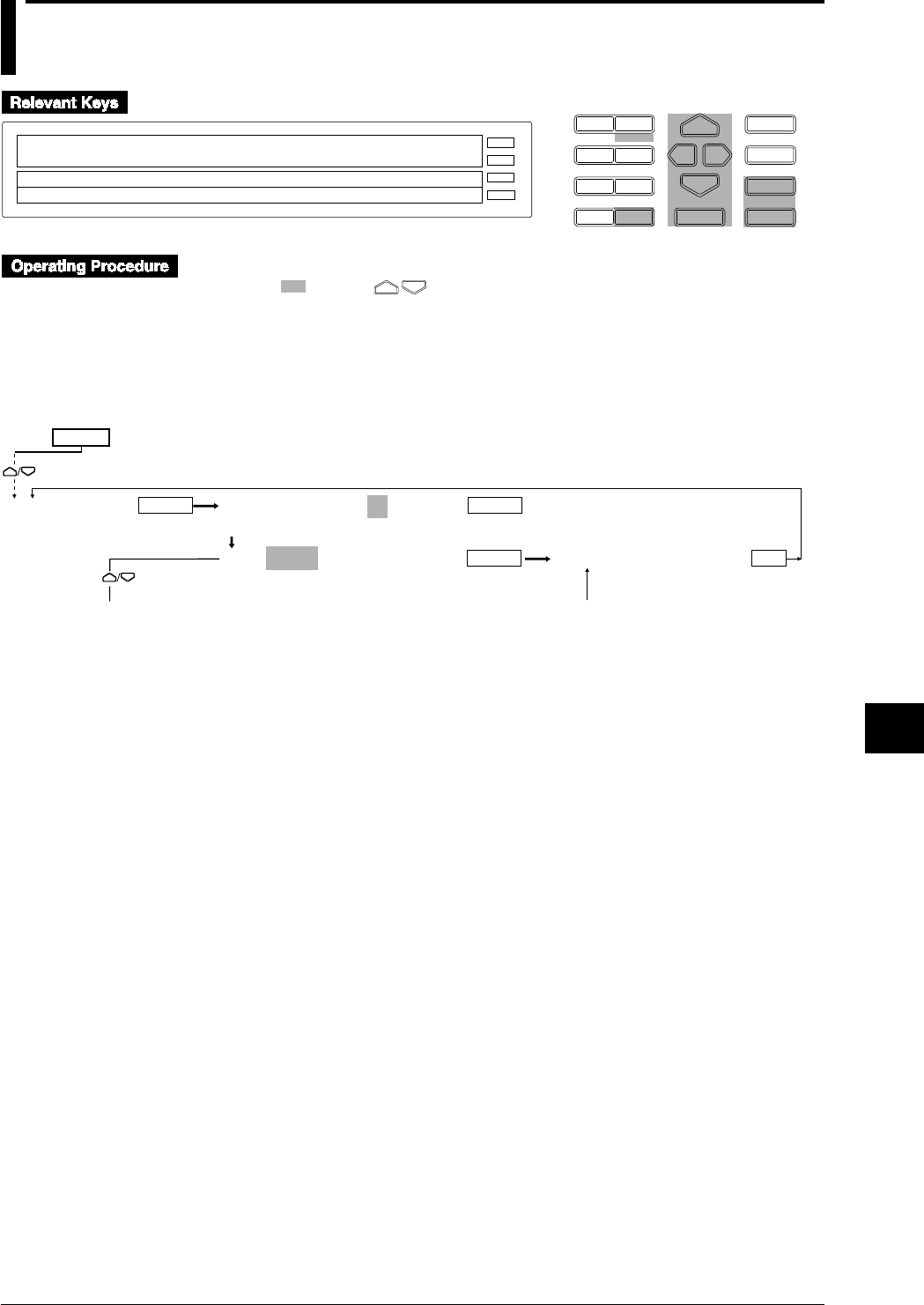
9-1
IM DR232-01E
9
Event/Action Function and Other Functions
9.1 Setting Event/Action Functions
D I S P M O D E
P R I N TF U N C
I N S D E L
R A N G E A L A R M
S E TC H A R T E N T E R
F E E D
M. F U N C 1
M. F U N C 2
RECORD
ALARM
CHART
KEYLOCK
R E C O R D
SET=LOGIC
SYSTEM UNIT TREND TIMER LOGIC COPY
>Select Setting Parameter
E S C
• Press the SET key to enter the SET menu.
• Select/set using the keys.
• To escape from a lower menu, press the MODE (ESC) key. Its main menu will appear,
although new settings/selections will not be kept.
• New settings/selections will be kept when you reach the final display of that setting.
Selection of the logic box and event [NONE]
ENTER
LOGIC LOGIC BOX NO.=01
(01~30)
EVT=NONE
ENTER
ENTER ENTER
ESC
***SET OK***
To the next page From the following page
SET=
(Main menu)
(Lower menu)
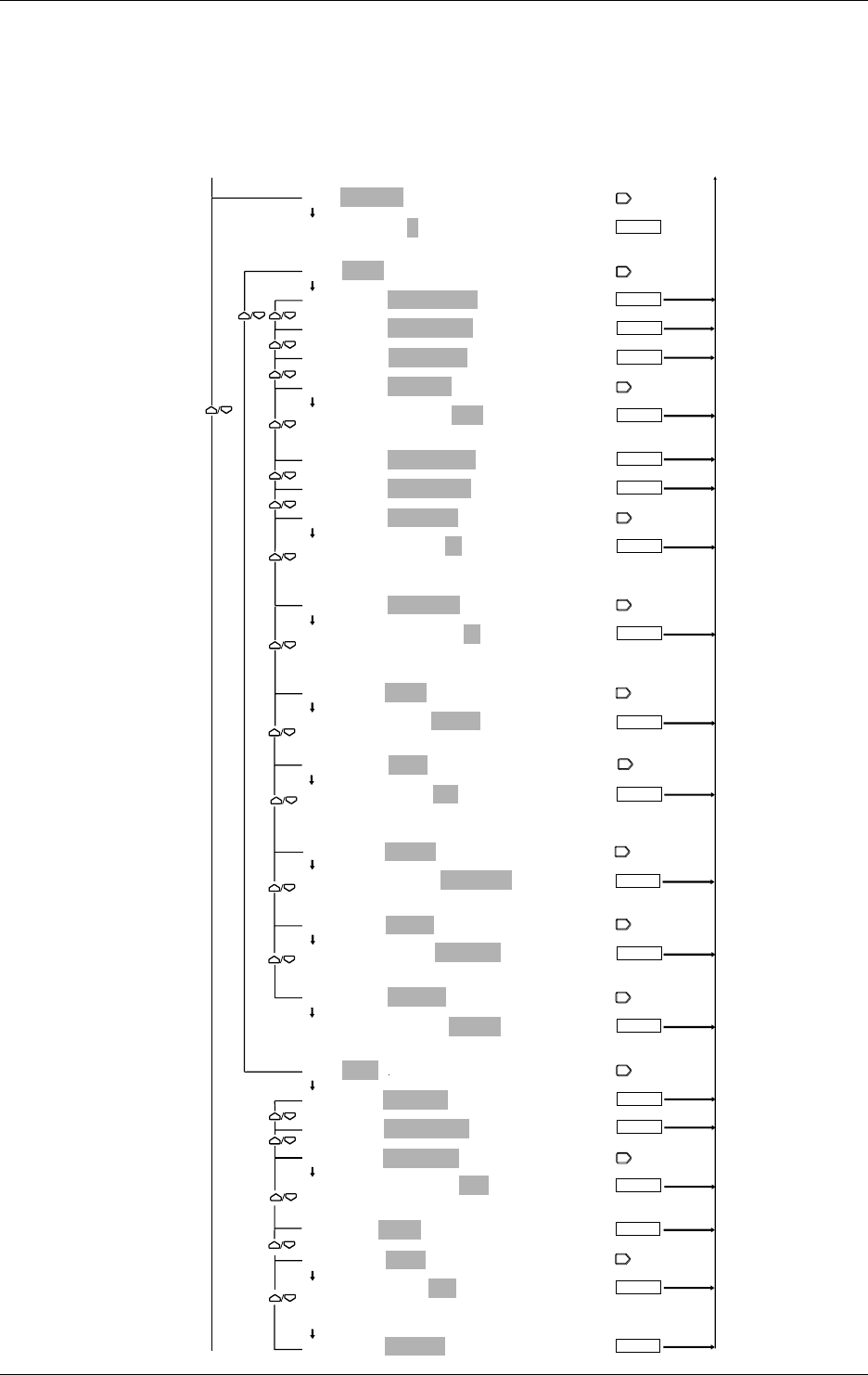
9-2 IM DR232-01E
9.1 Setting Event/Action Functions
Selection of event (REMOTE)/actions
The [REMOTE] menu is displayed only with the models with DI/DO module.
The [MATH] menu is displayed only with the DR232-1/DR242-1 and models with the /M1
option.
The [MEMRY] and [FLOPPY] menus are displayed only with the DR232-1/DR242-1.
The [REPORT] menu is displayed only with models with the /M3 option.
EVT=REMOTE:1
EVT=REMOTE:1
1 2 3 4 5 6 7 8 9 10 11 12
ACT=EDGE/ALARM ACK
ACT=EDGE/ALARM ACK
ACT=EDGE/ALARM RST
ACT=EDGE/TIMER RST
ACT=EDGE/RECORD:OFF
ACT=EDGE/RECORD:OFF
OFF ON
ACT=EDGE/MANUAL PR
ACT=EDGE/DIGITAL PR
ACT=EDGE/MSG PR:01
ACT=EDGE/MSG PR:01
01 02 03 04 05 06 07 08 09 10
11 12 13 14 15 16 17 18 19 20
ACT=EDGE/MSG DISP:01
ACT=EDGE/MSG DISP:01
01 02 03 04 05 06 07 08 09 10
11 12 13 14 15 16 17 18 19 20
ACT=EDGE/MATH:START
ACT=EDGE/MATH:START
START STOP CLEAR RESET
ACT=EDGE/FLAG:F01
ACT=EDGE/FLAG:F01
ENTER
F01 F02 F03 F04 F05 F06 F07 F08 F09 F10
F11 F12 F13 F14 F15 F16
ACT=EDGE/MEMRY:DATA_WR
ACT=EDGE/MEMRY:DATA_WR
DATA_WR WR_TRIG RD_TRIG LD_TRG1 LD_TRG2 LD_TRG3
ACT=EDGE/FLOPY:LD_TRG1
ACT=EDGE/FLOPY:LD_TRG1
LD_TRG1 LD_TRG2 LD_TRG3
ACT=EDGE/REPORT:START
ACT=EDGE/REPORT:START
START STOP
ACT=LEVL/RECORD
ACT=LEVL/RECORD
ACT=LEVL/SPEED CHG
ACT=LEVL/GR TREND:G01
ACT=LEVL/GR TREND:G01
G01 G02 G03 G04 G05 G06 G07
ACT=LEVL/MATH
ACT=LEVL/FLAG:F01
ACT=LEVL/FLAG:F01
F01 F02 F03 F04 F05 F06 F07 F08 F09 F10
F11 F12 F13 F14 F15 F16
ACT=LEVL/REPORT
ENTER
ENTER
ENTER
ENTER
ENTER
ENTER
ENTER
ENTER
ENTER
ENTER
ENTER
To the next page From the following page
ENTER
From the previous page To the previous page
ENTER
ENTER
ENTER
ENTER
ENTER
ENTER
ENTER
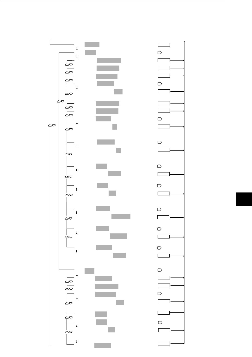
9-3
IM DR232-01E
9
Event/Action Function and Other Functions
9.1 Setting Event/Action Functions
Selection of event (ALARM)/actions
The [MATH] menu is displayed only with the DR232-1/DR242-1 and models with the /M1
option.
The [MEMRY] and [FLOPPY] menus are displayed only with the DR232-1/DR242-1.
The [REPORT] menu is displayed only with models with the /M3 option.
ENTER
ENTER
ENTER
EVT=ALARM
ACT=EDGE/ALARM ACK
ACT=EDGE/ALARM ACK
ACT=EDGE/ALARM RST
ACT=EDGE/TIMER RST
ACT=EDGE/RECORD:OFF
ACT=EDGE/RECORD:OFF
OFF ON
ACT=EDGE/MANUAL PR
ACT=EDGE/DIGITAL PR
ACT=EDGE/MSG PR:01
ACT=EDGE/MSG PR:01
01 02 03 04 05 06 07 08 09 10
11 12 13 14 15 16 17 18 19 20
ACT=EDGE/MSG DISP:01
ACT=EDGE/MSG DISP:01
01 02 03 04 05 06 07 08 09 10
11 12 13 14 15 16 17 18 19 20
ACT=EDGE/MATH:START
ACT=EDGE/MATH:START
START STOP CLEAR RESET
ACT=EDGE/FLAG:F01
ACT=EDGE/FLAG:F01
F01 F02 F03 F04 F05 F06 F07 F08 F09 F10
F11 F12 F13 F14 F15 F16
ACT=EDGE/MEMRY:DATA_WR
ACT=EDGE/MEMRY:DATA_WR
DATA_WR WR_TRIG RD_TRIG LD_TRG1 LD_TRG2 LD_TRG3
ACT=EDGE/FLOPY:LD_TRG1
ACT=EDGE/FLOPY:LD_TRG1
LD_TRG1 LD_TRG2 LD_TRG3
ACT=EDGE/REPORT:START
ACT=EDGE/REPORT:START
START STOP
ACT=LEVL/RECORD
ACT=LEVL/RECORD
ACT=LEVL/SPEED CHG
ACT=LEVL/GR TREND:G01
ACT=LEVL/GR TREND:G01
G01 G02 G03 G04 G05 G06 G07
ACT=LEVL/MATH
ACT=LEVL/FLAG:F01
ACT=LEVL/FLAG:F01
F01 F02 F03 F04 F05 F06 F07 F08 F09 F10
F11 F12 F13 F14 F15 F16
ACT=LEVL/REPORT
ENTER
ENTER
ENTER
ENTER
ENTER
ENTER
ENTER
ENTER
ENTER
ENTER
ENTER
To the next page From the following page
To the previous page
From the previous page
ENTER
ENTER
ENTER
ENTER
ENTER
ENTER
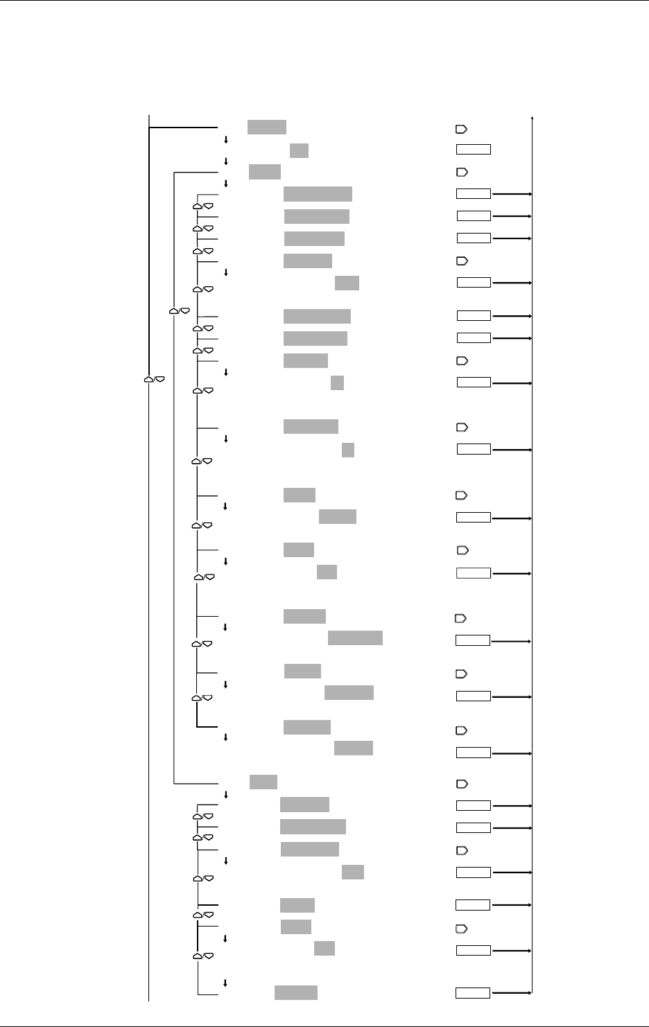
9-4 IM DR232-01E
Selection of event (RELAY)/actions
The [MATH] menu is displayed only with the DR232-1/DR242-1 and models with the /M1
option.
The [MEMRY] and [FLOPPY] menus are displayed only with the DR232-1/DR242-1.
The [REPORT] menu is displayed only with models with the /M3 option.
ENTER
ENTER
ENTER
EVT=RELAY:S01
EVT=RELAY:S01
ACT=EDGE/ALARM ACK
ACT=EDGE/ALARM ACK
ACT=EDGE/ALARM RST
ACT=EDGE/TIMER RST
ACT=EDGE/RECORD:OFF
ACT=EDGE/RECORD:OFF
OFF ON
ACT=EDGE/MANUAL PR
ACT=EDGE/DIGITAL PR
ACT=EDGE/MSG PR:01
ACT=EDGE/MSG PR:01
01 02 03 04 05 06 07 08 09 10
11 12 13 14 15 16 17 18 19 20
ACT=EDGE/MSG DISP:01
ACT=EDGE/MSG DISP:01
01 02 03 04 05 06 07 08 09 10
11 12 13 14 15 16 17 18 19 20
ACT=EDGE/MATH:START
ACT=EDGE/MATH:START
START STOP CLEAR RESET
ACT=EDGE/FLAG:F01
ACT=EDGE/FLAG:F01
F01 F02 F03 F04 F05 F06 F07 F08 F09 F10
F11 F12 F13 F14 F15 F16
ACT=EDGE/MEMRY:DATA_WR
ACT=EDGE/MEMRY:DATA_WR
DATA_WR WR_TRIG RD_TRIG LD_TRG1 LD_TRG2 LD_TRG3
ACT=EDGE/FLOPY:LD_TRG1
ACT=EDGE/FLOPY:LD_TRG1
LD_TRG1 LD_TRG2 LD_TRG3
ACT=EDGE/REPORT:START
ACT=EDGE/REPORT:START
START STOP
ACT=LEVL/RECORD
ACT=LEVL/RECORD
ACT=LEVL/SPEED CHG
ACT=LEVL/GR TREND:G01
ACT=LEVL/GR TREND:G01
G01 G02 G03 G04 G05 G06 G07
ACT=LEVL/MATH
ACT=LEVL/FLAG:F01
ACT=LEVL/FLAG:F01
F01 F02 F03 F04 F05 F06 F07 F08 F09 F10
F11 F12 F13 F14 F15 F16
ACT=LEVL/REPORT
ENTER
ENTER
ENTER
ENTER
ENTER
ENTER
ENTER
ENTER
ENTER
ENTER
ENTER
To the next page From the following page
To the previous page
From the previous page
ENTER
ENTER
ENTER
ENTER
ENTER
ENTER
9.1 Setting Event/Action Functions
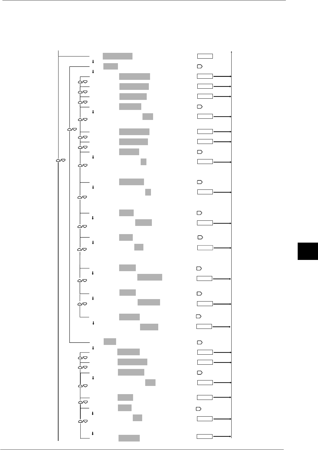
9-5
IM DR232-01E
9
Event/Action Function and Other Functions
Selection of event (CHART END)/actions
The [MATH] menu is displayed only with the DR232-1/DR242-1 and models with the /M1
option.
The [MEMRY] and [FLOPPY] menus are displayed only with the DR232-1/DR242-1.
The [REPORT] menu is displayed only with /M3 option.
ENTER
ENTER
ENTER
EVT=CHART END
ACT=EDGE/ALARM ACK
ACT=EDGE/ALARM ACK
ACT=EDGE/ALARM RST
ACT=EDGE/TIMER RST
ACT=EDGE/RECORD:OFF
ACT=EDGE/RECORD:OFF
OFF ON
ACT=EDGE/MANUAL PR
ACT=EDGE/DIGITAL PR
ACT=EDGE/MSG PR:01
ACT=EDGE/MSG PR:01
01 02 03 04 05 06 07 08 09 10
11 12 13 14 15 16 17 18 19 20
ACT=EDGE/MSG DISP:01
ACT=EDGE/MSG DISP:01
01 02 03 04 05 06 07 08 09 10
11 12 13 14 15 16 17 18 19 20
ACT=EDGE/MATH:START
ACT=EDGE/MATH:START
START STOP CLEAR RESET
ACT=EDGE/FLAG:F01
ACT=EDGE/FLAG:F01
F01 F02 F03 F04 F05 F06 F07 F08 F09 F10
F11 F12 F13 F14 F15 F16
ACT=EDGE/MEMRY:DATA_WR
ACT=EDGE/MEMRY:DATA_WR
DATA_WR WR_TRIG RD_TRIG LD_TRG1 LD_TRG2 LD_TRG3
ACT=EDGE/FLOPY:LD_TRG1
ACT=EDGE/FLOPY:LD_TRG1
LD_TRG1 LD_TRG2 LD_TRG3
ACT=EDGE/REPORT:START
ACT=EDGE/REPORT:START
START STOP
ACT=LEVL/RECORD
ACT=LEVL/RECORD
ACT=LEVL/SPEED CHG
ACT=LEVL/GR TREND:G01
ACT=LEVL/GR TREND:G01
G01 G02 G03 G04 G05 G06 G07
ACT=LEVL/MATH
ACT=LEVL/FLAG:F01
ACT=LEVL/FLAG:F01
F01 F02 F03 F04 F05 F06 F07 F08 F09 F10
F11 F12 F13 F14 F15 F16
ACT=LEVL/REPORT
ENTER
ENTER
ENTER
ENTER
ENTER
ENTER
ENTER
ENTER
ENTER
ENTER
ENTER
To the next page From the following page
To the previous page
From the following page
ENTER
ENTER
ENTER
ENTER
ENTER
ENTER
9.1 Setting Event/Action Functions
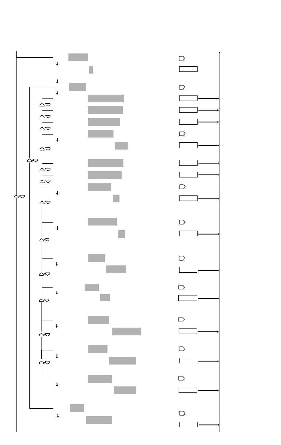
9-6 IM DR232-01E
Selection of event (TIMER)/actions
The [MATH] menu is displayed only with the DR232-1/DR242-1 and models with the /M1
option.
The [MEMRY] and [FLOPPY] menus are displayed only with the DR232-1/DR242-1.
The [REPORT] menu is displayed only with models with /M3 option.
ENTER
ENTER
ENTER
EVT=TIMER:1
EVT=TIMER:1
1 2 3 4 5 6
ACT=EDGE/ALARM ACK
ACT=EDGE/ALARM ACK
ACT=EDGE/ALARM RST
ACT=EDGE/TIMER RST
ACT=EDGE/RECORD:OFF
ACT=EDGE/RECORD:OFF
OFF ON
ACT=EDGE/MANUAL PR
ACT=EDGE/DIGITAL PR
ACT=EDGE/MSG PR:01
ACT=EDGE/MSG PR:01
01 02 03 04 05 06 07 08 09 10
11 12 13 14 15 16 17 18 19 20
ACT=EDGE/MSG DISP:01
ACT=EDGE/MSG DISP:01
01 02 03 04 05 06 07 08 09 10
11 12 13 14 15 16 17 18 19 20
ACT=EDGE/MATH:START
ACT=EDGE/MATH:START
START STOP CLEAR RESET
ACT=EDGE/FLAG:F01
ACT=EDGE/FLAG:F01
F01 F02 F03 F04 F05 F06 F07 F08 F09 F10
F11 F12 F13 F14 F15 F16
ACT=EDGE/MEMRY:DATA_WR
ACT=EDGE/MEMRY:DATA_WR
DATA_WR WR_TRIG RD_TRIG LD_TRG1 LD_TRG2 LD_TRG3
ACT=EDGE/FLOPY:LD_TRG1
ACT=EDGE/FLOPY:LD_TRG1
LD_TRG1 LD_TRG2 LD_TRG3
ACT=EDGE/REPORT:START
ACT=EDGE/REPORT:START
START STOP
ACT=LEVL/RECORD
ACT=LEVL/RECORD
ENTER
ENTER
ENTER
ENTER
ENTER
ENTER
ENTER
ENTER
ENTER
To the next page From the following page
To the previous page
From the previous page
ENTER
ENTER
ENTER
9.1 Setting Event/Action Functions
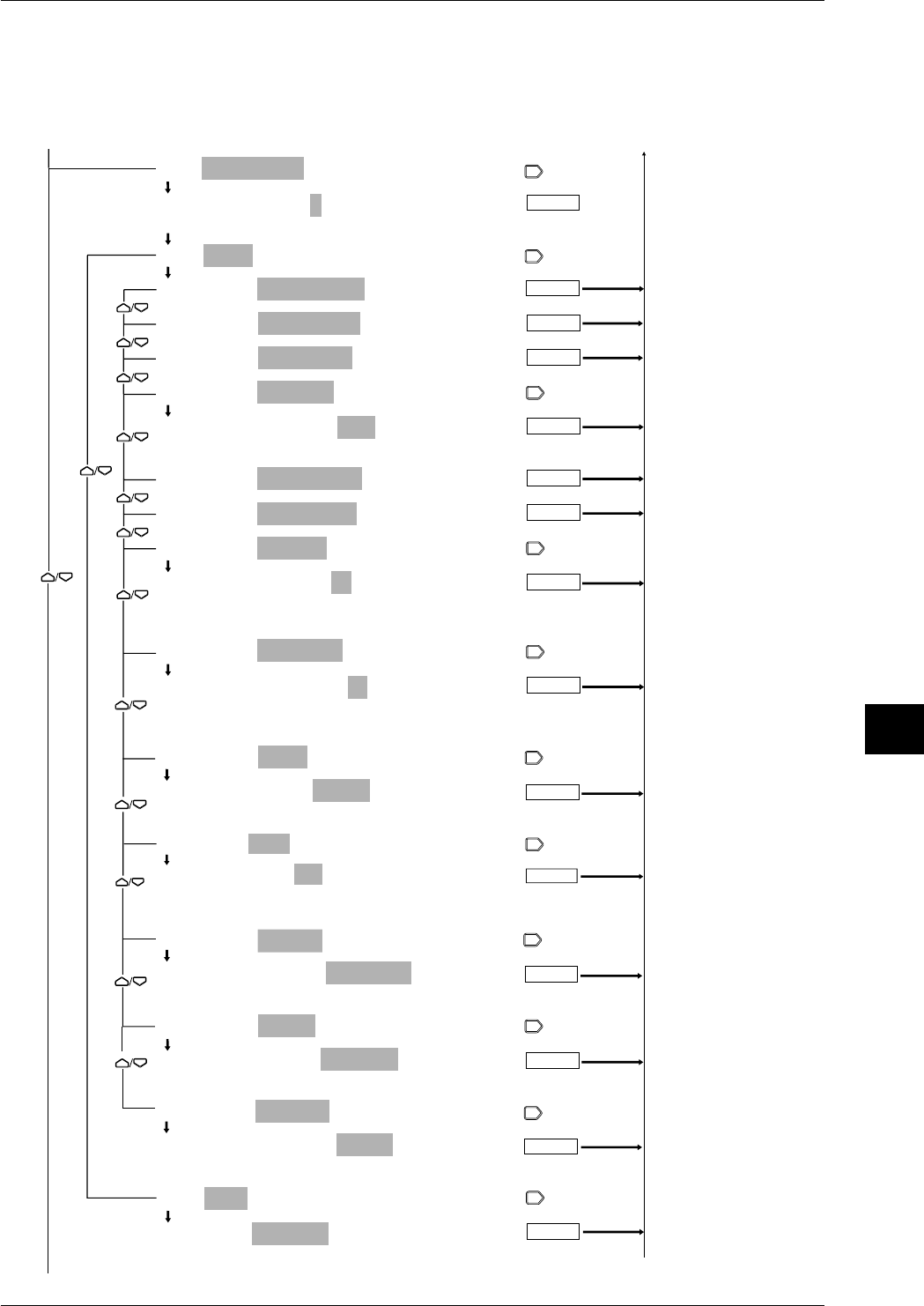
9-7
IM DR232-01E
9
Event/Action Function and Other Functions
Selection of Event (MFUNC KEY)/actions
The [MATH] menu is displayed only with the DR232-1/DR242-1 and models with the /M1
option.
The [MEMRY] and [FLOPPY] menus are displayed only with the DR232-1/DR242-1.
The [REPORT] menu is displayed only with models with /M3 option.
ENTER
ENTER
ENTER
ENTER
EVT=MFUNC KEY:1
EVT=MFUNC KEY:1
1 2
ACT=EDGE/ALARM ACK
ACT=EDGE/ALARM ACK
ACT=EDGE/ALARM RST
ACT=EDGE/TIMER RST
ACT=EDGE/RECORD:OFF
ACT=EDGE/RECORD:OFF
OFF ON
ACT=EDGE/MANUAL PR
ACT=EDGE/DIGITAL PR
ACT=EDGE/MSG PR:01
ACT=EDGE/MSG PR:01
01 02 03 04 05 06 07 08 09 10
11 12 13 14 15 16 17 18 19 20
ACT=EDGE/MSG DISP:01
ACT=EDGE/MSG DISP:01
01 02 03 04 05 06 07 08 09 10
11 12 13 14 15 16 17 18 19 20
ACT=EDGE/MATH:START
ACT=EDGE/MATH:START
START STOP CLEAR RESET
ACT=EDGE/FLAG:F01
ACT=EDGE/FLAG:F01
F01 F02 F03 F04 F05 F06 F07 F08 F09 F10
F11 F12 F13 F14 F15 F16
ACT=EDGE/MEMRY:DATA_WR
ACT=EDGE/MEMRY:DATA_WR
DATA_WR WR_TRIG RD_TRIG LD_TRG1 LD_TRG2 LD_TRG3
ACT=EDGE/FLOPY:LD_TRG1
ACT=EDGE/FLOPY:LD_TRG1
LD_TRG1 LD_TRG2 LD_TRG3
ACT=EDGE/REPORT:START
ACT=EDGE/REPORT:START
START STOP
ACT=LEVL/RECORD
ACT=LEVL/RECORD
ENTER
ENTER
ENTER
ENTER
ENTER
ENTER
ENTER
ENTER
ENTER
To the next page From the following page
To the previous page
From the previous page
ENTER
ENTER
9.1 Setting Event/Action Functions
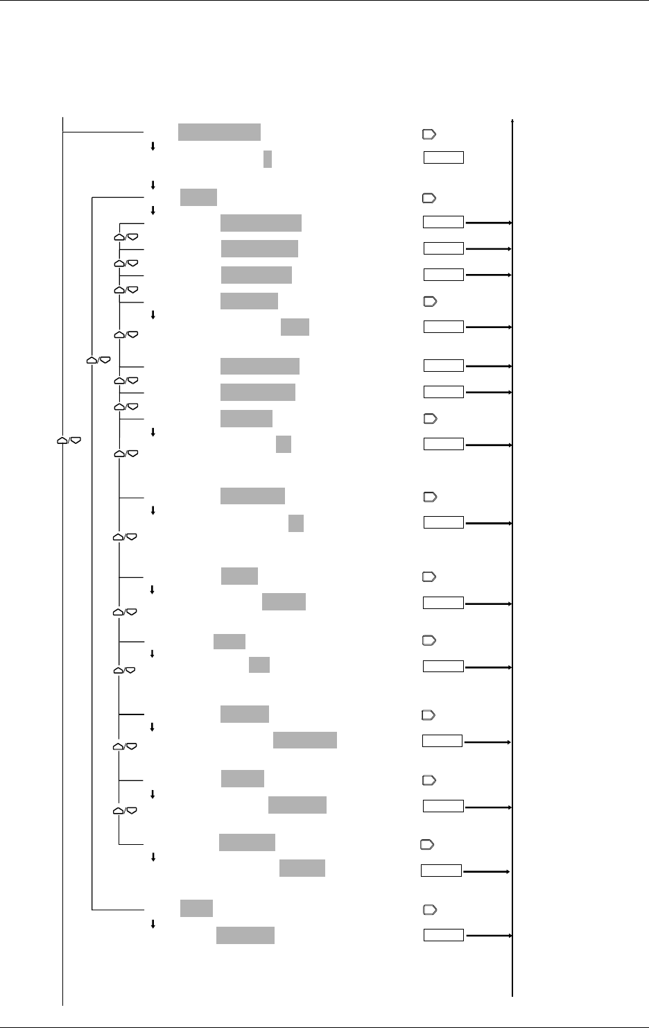
9-8 IM DR232-01E
Selection of event (MATCH TIME)/actions
The [MATH] menu is displayed only with the DR232-1/DR242-1 and models with the /M1
option.
The [MEMRY] and [FLOPPY] menus are displayed only with the DR232-1/DR242-1.
The [REPORT] menu is displayed only with models with the /M3 option.
ENTER
ENTER
ENTER
ENTER
EVT=MATCH TIME:1
EVT=MATCH TIME:1
1 2 3
ACT=EDGE/ALARM ACK
ACT=EDGE/ALARM ACK
ACT=EDGE/ALARM RST
ACT=EDGE/TIMER RST
ACT=EDGE/RECORD:OFF
ACT=EDGE/RECORD:OFF
OFF ON
ACT=EDGE/MANUAL PR
ACT=EDGE/DIGITAL PR
ACT=EDGE/MSG PR:01
ACT=EDGE/MSG PR:01
01 02 03 04 05 06 07 08 09 10
11 12 13 14 15 16 17 18 19 20
ACT=EDGE/MSG DISP:01
ACT=EDGE/MSG DISP:01
01 02 03 04 05 06 07 08 09 10
11 12 13 14 15 16 17 18 19 20
ACT=EDGE/MATH:START
ACT=EDGE/MATH:START
START STOP CLEAR RESET
ACT=EDGE/FLAG:F01
ACT=EDGE/FLAG:F01
F01 F02 F03 F04 F05 F06 F07 F08 F09 F10
F11 F12 F13 F14 F15 F16
ACT=EDGE/MEMRY:DATA_WR
ACT=EDGE/MEMRY:DATA_WR
DATA_WR WR_TRIG RD_TRIG LD_TRG1 LD_TRG2 LD_TRG3
ACT=EDGE/FLOPY:LD_TRG1
ACT=EDGE/FLOPY:LD_TRG1
LD_TRG1 LD_TRG2 LD_TRG3
ACT=EDGE/REPORT:START
ACT=EDGE/REPORT:START
START STOP
ACT=LEVL/RECORD
ACT=LEVL/RECORD
ENTER
ENTER
ENTER
ENTER
ENTER
ENTER
ENTER
ENTER
ENTER
To the next page From the following page
To the previous page
From the previous page
ENTER
ENTER
9.1 Setting Event/Action Functions

9-9
IM DR232-01E
9
Event/Action Function and Other Functions
When an event is detected, this menu allows you to set and execute a certain action.
Selection of logic (LOGIC) box number
• Select a box number from among 01 to 30 for storing a combination logic from events to
actions.
• Select the same number as the box number already indicating events and actions, and set an
event and action to overwrite the logic number.
Selection of events (EVT)
Select any event from among the following:
• NONE — releases the event/action setting.
• REMOTE
• This menu is displayed only with the DI/DO modules that are recognized as system modules
(see page 9-16).
• When a remote control signal is applied, the action is executed.
• There are 12 control signals available. Select any control signal from these numbers for
event setting. Remote control signal terminal numbers are applicable for this selection. See
page 3-19 for the remote control terminal numbers.
• ALARM
If an alarm occurs, the action is executed. See Section 8.1, “Setting Alarms and Relays
(including internal switches),” on page 8-1 for setting alarms.
• RELAY
If the selected internal switch or relay is operating, the action is executed. When the alarm
module or the DI/DO modules are not recognized as system modules (see page 9-16), the relay
is set to OFF. See Section 8.1, “Setting Alarms and Relays (including internal switches),” on
page 8-1 for setting internal switches and relays.
• CHART END
When the end of the chart is detected, the action is executed.
• TIMER
• If the selected timer’s set time is up, the action is executed. Six timers are available. Select
any from among these timers. See Section 6.1, “Setting the Recording Mode/Engineering
Unit/Recording Channels/Recording Interval,” on page 6-3 for the timer setting provided
earlier in this manual.
• In combination with the level action, the action is repeated alternately between executing
and stopping each time the timer’s set time is up.
• MFUNC KEY
• When the M.FUNC key on the operation panel is pressed, the action is executed. Select
either M.FUNC 1 or M.FUNC 2.
• In combination with the level action, the action is repeated alternately between executing
and stopping each time the M.FUNC key is pressed.
• MATCH TIME
• When the set time is reached, the action is executed.
• There are three types of applicable MATCH TIMEs. Select any of them. For details, see
Section 6.8, “Setting Match Time, Moving Average, Interpolation and Groups,” on page 6-
17 provided earlier in this manual.
• In combination with the level action, the corresponding action is repeated alternately
between executing and stopping for each set time.
Selecting edge or level action
• Edge action (EDGE)
This action is executed when an event is detected.
• Level action (LEVEL)
This action is executed when an event is detected. When an event is released, this action will
be canceled.
9.1 Setting Event/Action Functions

9-10 IM DR232-01E
Selection of actions
An action that can be selected varies depending on the events and edge or level action. See the
individual procedures. The following describe all actions available.
• ALARM ACK
This allows alarm acknowledgment. For the applicable functions, see Section 2.4, “Alarm
Function,” on page 2-15.
• ALARM RST
This resets alarms. When the “RELAY” is selected for an event, this function cannot be
selected.For the applicable functions, see Section 2.4, “Alarm Function,” on page 2-15.
• TIMER RST
This resets timers. For the applicable functions, see Section 2.3, “Recording Functions,” on
page 2-8.
• RECORD
• ON: Starts recording. The recording format is set individually. For details, see Section
10.2, “Setting Recording Format,” on page 10-3.
• OFF: Stops recording. The level action does not include record ON/OFF functions.
• When the level action is set, the ON/OFF functions using the RECORD key are disabled.
• The edge and level actions cannot be set simultaneously.
• For the level action, only one action is available.
• MANUAL PR
This enables manual printing. For applicable functions, see Section 2.3, “Recording
Functions,” on page 2-12.
• DIGITAL PR
• Digital printing starts in the analog trend mode. The recording intervals depend on the timer
setting (see Section 2-8). When the event/action functions are set, normal digital print
functions are disabled.
• Only one function can be set in the event/action functions.
• MSG PR
• Prints messages. For details, see Section 7.3, “Starting Message Printing,” on page 7-3.
• Select any message from the corresponding codes 01 to 20.
• MSG DISP
• Displays messages. For details, see Section 7.3, “Stating Message Printing,” on page 7-3.
• Select any message from the corresponding codes 01 to 20.
• To cancel the message display, press any key.
• SPEED CHG
• Changes chart speed 1 to chart speed 2. When the recording interval is set to automatic
(page 6-3), the recording interval is also changed. When the event is released, the chart
speed and recording interval return to their original positions.
• Only one function can be set in the event/action functions.
• GR TREND
• This executes the recording in a channel in which the group setting (page 6-17) has already
been made. For this, set the dot-recording (see on page 10-4) to “ GROUP” and start
recording by key operations following the “RECORD” given above.
• Select any group from G01 to G07.
• Only one identical group can be set in the event/action functions.
Note
·If Chart End appears, counter-actions such as RECORD ON are not executed.
·Actions such as RECORD or SPEED CHG may operate later than an event occurrence. For example,
with RECORD set in the action setting, if an alarm occurs, the measured values in that condition are not
recorded. This is because recording operations are delayed due to an action operation.
9.1 Setting Event/Action Functions
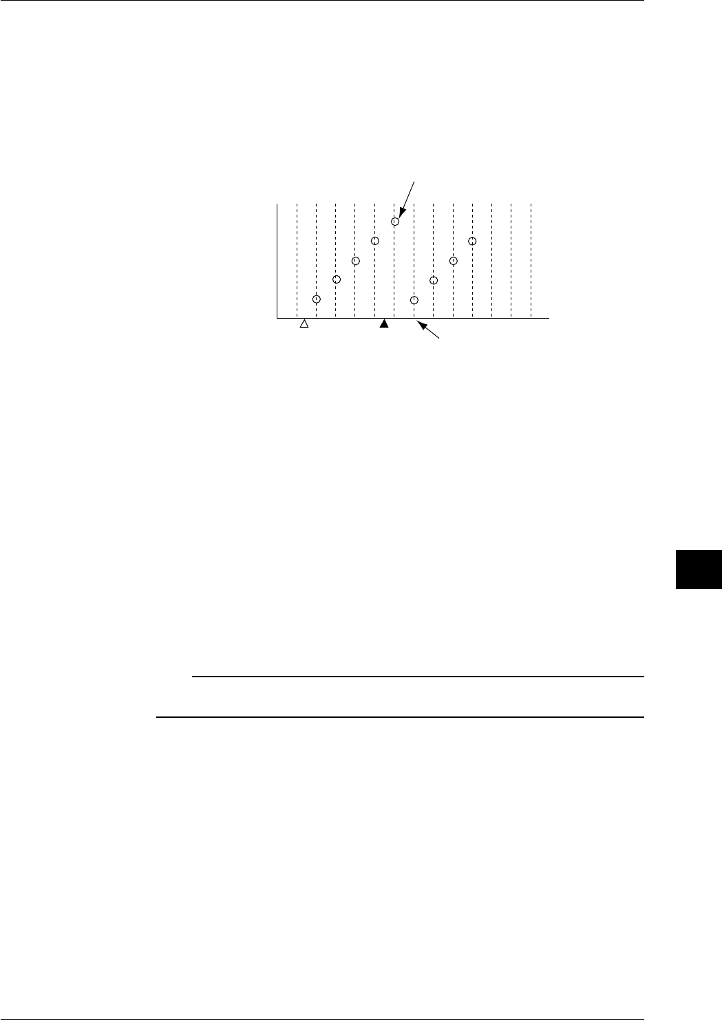
9-11
IM DR232-01E
9
Event/Action Function and Other Functions
• MATH (available if the instrument is equipped with the MATH function or floppy disk drive)
• START: Starts computation.
• STOP: Stops computation.
• RESET: Resets computation channel data at the end of completion of the first computation
in case an event takes place.
• CLEAR: Resets computation channel data immediately in case an event takes place.
• RST_G01 to RESET_G07: Resets the computing channel data registered in the specified
group number to 0. This is invalid for measuring channels. The timing for resetting the data
is as follows.
Reset here
Not reset
Computed value
Start computing Event
• If MATH is selected as a level action, computation will be carried out while an event is
present. Computation will stop when the event is cleared.
• MEMORY (available with the DR232-1/DR242-1 equipped with the floppy disk drive)
• DATA_WR: Saves a data item each time an event occurs, until the specified data length is
reached.
• WR_TRIG: Saves measured/computed data on the built-in RAM disk.
• RD_TRIG: Reads measured/computed data from the built-in RAM disk.
• LD_TRG1-3: Reads setup data from the built-in RAM disk.
• FLOPY (available only with the DR231-1 or DR241-1 equipped with a floppy disk drive)
• LD_TRG1-3: Reads setup data from the floppy disk.
• FLAG (only for /M1 optional model)
• F01 to 16: Set the flag number (F01 to F16) to 1. F01 to F16 are normally 0. Flags can be
placed in computing equations to hold the computed result using a certain event as a trigger,
or reset to 0.
• REPORT (available if the instrument is equiped with the REPORT function.)
• START (Edge action): Starts making up a report.
• STOP (Edge action): Stops making up a report.
• REPORT (Level action): Starts/stops making up a report.
Note
• If, in the SETUP mode, the report function is set to OFF for all data items, you cannot select the action
item REPORT.
9.1 Setting Event/Action Functions
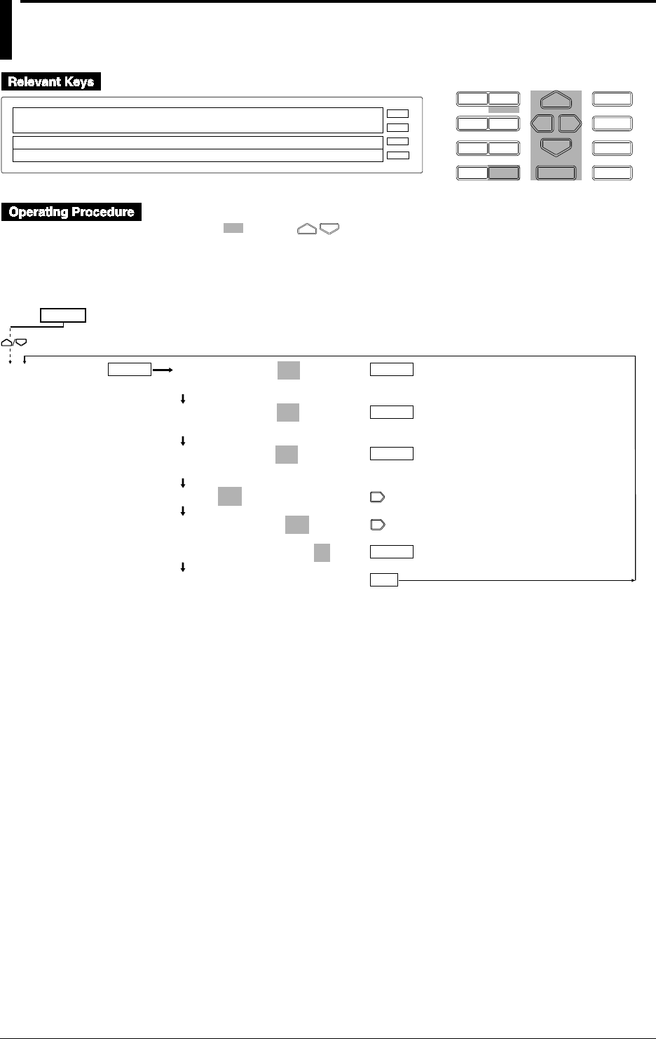
9-12 IM DR232-01E
9.2 Copying
D I S P M O D E
P R I N TF U N C
I N S D E L
R A N G E A L A R M
S E TC H A R T E N T E R
F E E D
M. F U N C 1
M. F U N C 2
RECORD
ALARM
CHART
KEYLOCK
R E C O R D
SET=COPY
SYSTEM UNIT TREND TIMER LOGIC COPY
>Select Setting Parameter
E S C
• Press the SET key to enter the SET menu.
• Select/set using the keys.
• To escape from a lower menu, press the MODE (ESC) key. Its main menu will appear,
although new settings/selections will not be kept.
• New settings/selections will be kept when you reach the final display of that setting.
COPY RANGE=ON
OFF ON
COPY ALARM=ON
OFF ON
COPY OTHER=ON
OFF ON
COPY 001ch TO 002-10ch
COPY 001ch TO 002-10ch
COPY 001ch TO 002-10ch
***SET OK***
COPY
ENTER
ENTER
ENTER
ENTER
ENTER
ESC
SET=
(Main menu)
(Lower menu)

9-13
IM DR232-01E
9
Event/Action Function and Other Functions
Selecting range copying (COPY RANGE)
• ON: Copies the type of input, measuring ranges, recording spans, linear scaling, engineering
units, and tags set.
• OFF: The copying of ranges is disabled.
Selecting alarm copying
• ON: Copies the type of alarm, alarm values, and relay (internal switch) setting.
• OFF: The copying of alarms is disabled.
Selecting copying of other items (COPY OTHER)
• ON: Copies setting recording zones, partial compressions, dot-recording ON/OFF, digital
printing ON/off, manual printing ON/OFF, alarm printout ON1/ON2/OFF, scale-value printout
ON1/ON2/ON3/OFF, list-printout ON/OFF, average numbers in moving averages,
interpolation ON/OFF and measured data saving ON/OFF.
• OFF: The copying of other items is disabled.
Setting a copy-source channel
Sets a copy-source channel with up to three characters. For details on these characters, see
Section 4-1, “Using Auto Display,” on page 4-2.
Setting a destination channel to be copied
Sets a channel to which the setting data in the source channel are copied.
• When the COPY RANGE, COPY ALARM and COPY OTHER are set to ON, individual set
data are copied.
• For the setting of a destination channel number, see Section 5.1, “Setting the Type of Input and
Recording Span,” on page 5-2.
• It is not possible to copy data between measurement channels and computation channels.
Copying Data from a Computation Channel
When copying from an optional computation channel is carried out, the following data will be
copied.
• When COPY RANGE is ON : Computation equation, tag
• When COPY ALARM is ON : Alarm
• When COPY OTHER is ON : Zone, partial compressions, trend ON/OFF, digital printing
ON.OFF, alarm printout ON1/ON2/OFF, scale-value printout
ON/OFF, manual printing ON/OFF, list-printout ON/OFF,
interpolation ON/OFF,
9.2 Copying
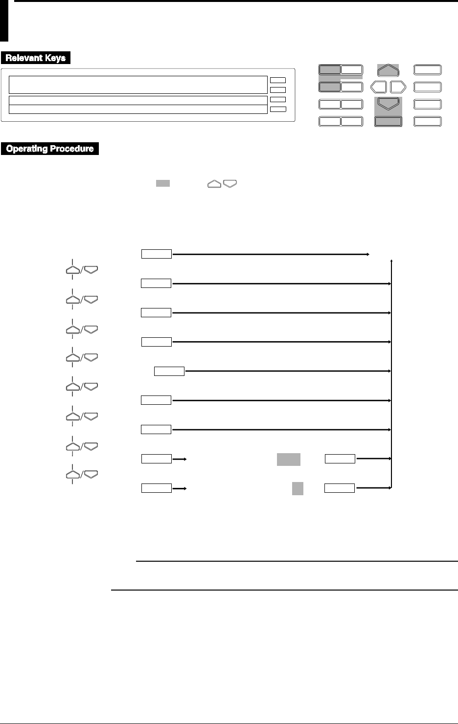
9-14 IM DR232-01E
9.3 Alarm Acknowledgment, Alarm Reset, Timer
Reset, Keylock, and Message Printout
D I S P M O D E
P R I N TF U N C
I N S D E L
R A N G E A L A R M
S E TC H A R T E N T E R
F E E D
M. F U N C 1
M. F U N C 2
RECORD
ALARM
CHART
KEYLOCK
R E C O R D
TIMER_RESET
>Select Function item
E S C
• Press the FUNC key to enter the FUNC menu.
• To enter the FUNC menu from the [RANGE], [ALARM], [CHART], or [SET ](SET3) menu,
press the DISP key.
• Select/set using the keys.
• To escape from a lower menu, press the MODE (ESC) key. Its main menu will appear,
although new settings/selections will not be kept.
• There may be some menus that are not displayed by basic settings in Chapter 10.
ALARM ACK
ALARM RST
TIMER RESET
MATH START
*1
MATH CLR START
MATH STOP
*2
MATH ACK
*3
KEY LOCK ON
MSG PRINT
ENTER
ENTER
Operating status
ENTER
ENTER
(Main menu)
ENTER
PRINT MESSAGE No.=01
ENTER ENTER
ENTER
ENTER
(Lower menu)
A CODE NUMBER=2888
ENTER ENTER
*1: Displayed when computation is not in progress (i.e. when stopped).
*2: Displayed when computation is in progress (i.e. when started).
*3: Displayed only when incomplete measurement occurs during computation.
Note
·If MATH is selected as a level action, MATH START, MATH CLR START and MATH STOP will not
be displayed.

9-15
IM DR232-01E
9
Event/Action Function and Other Functions
Any of the following functions are executed by pressing the ENTER key. After that, the recorder
returns to the operation mode.
Alarm acknowledgment (ALARM ACK)
• When the alarm display hold (ALARM HOLD), on page 10-8 is set to ON, the alarm
acknowledgment menu appears.
• For the alarm display hold functions, see Section 2.4, “Alarm Function,” on page 2-15.
Alarm reset (ALARM RST)
• When the relay hold function (on page 10-11) is set to ON, the alarm reset menu appears.
• For the alarm reset functions, see Section 2.4, “Alarm Function,” on page 2-15.
Timer reset (TIMER RESET)
• For the timer reset functions, see Section 2.3, “Recording Functions,” on page 2-8.
Computation start (MATH START)
• Starts computation. For details, refer to Chapter 12, “Executing Computation”.
Computation clear start (MATH CLR START)
• Clears computation results then re-starts computation.
Computation stop (MATH STOP)
• Stops computation.
Clearing Incomplete Measurement Status (MATH ACK)
• Clears the status indication displayed due to incomplete measurement which occurred during
computation.
Keylock function (KEY LOCK ON)
• For the keylock functions, see Section 2.6, “Other Functions,” on page 2-17.
• The KEY LOCK ON is displayed after selecting the keylock (see page 10-16).
• Enter a password (A CODE NUMBER) and then press the ENTER key to actuate the keylock
functions. The KEY LOCK OFF menu then appears.
• Enter the FUNC menu, select KEY LOCK OFF and then enter a password (A CODE
NUMBER). Press the ENTER key to release the keylock functions. The menu returns to KEY
LOCK ON.
• To set a password, see page 10-16.
• When the keylock functions are actuated, the “KEYLOCK” lights up.
Message printout (MSG PRINT)
• Prints out messages. For details, see Section 7.3, “Starting Message Printing,” on page 7-3.
• Select a message from the corresponding code 01 to 20.
9.3 Alarm Acknowledgment, Alarm Reset, Timer Reset, Keylock, and Message Printout
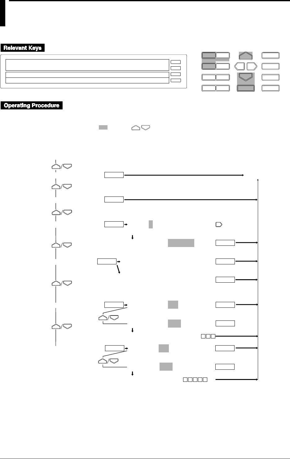
9-16 IM DR232-01E
9.4
Clearing Alarm/Message Buffers, Displaying Module/
Communications Information, Structuring System
Modules, and Initializing Information
D I S P M O D E
P R I N TF U N C
I N S D E L
R A N G E A L A R M
S E TC H A R T E N T E R
F E E D
M. F U N C 1
M. F U N C 2
RECORD
ALARM
CHART
KEYLOCK
R E C O R D
ALM_BUF_CLEAR
>Select Function item
E S C
↓ALM_BUF_CLEAR MSG_BUF_CLEAR MODULE_INF↑
• Press and hold the FUNC key for about three seconds to enter the FUNC3 menu.
• To enter the FUNC menu from the [RANGE], [ALARM], [CHART], or [SET] (SET3) menu,
press the DISP key.
• Select/set using the keys.
• To escape from a lower menu, press the MODE (ESC) key. Its main menu will appear,
although new settings/selections will not be kept.
• There may be some menus that are not displayed by basic settings in Chapter 10.
ALM BUF CLEAR
MSG BUF CLEAR
MODULE INF
COMM INF
RE SYSTEM
RAM INIT
S UNIT0:INF=SYSTEM
0 1 2 3 4 5
S UNIT0:INF=SYSTEM
SYSTEM REAL
MODULE=GP-IB
>ADDR=01
MODULE=RS-232C
>BIT RATE=19200 LENGTH=8BIT PARITY=NONE
>STOP=1BIT HANDSHAKE=OFF:OFF
RE SYSTEM=NO
RE SYSTEM=YES
SYSTEM RESTRUCTING
RAM INIT=NO
RAM INIT=YES
RAM INITIALIZING
ENTER
Operating status
ENTER
ENTER
ENTER
ENTER
ENTER
ENTER
(After about
15 seconds)
ENTER
ENTER
ENTER
(After about 10 seconds)
ENTER
ENTER
(For GP-IB interface)
(For RS-232-C interface)
ENTER
(Lower menu)
(Main menu)

9-17
IM DR232-01E
9
Event/Action Function and Other Functions
Any of the following functions are executed and displayed by pressing the ENTER key, the last
key of the lower menu. After that, the recorder returns to the operation mode.
Clearing the alarm buffer (ALM BUF CLEAR)
Cancels all information in the alarm buffer; see page 6-11.
Clearing the message buffer (MSG BUF CLEAR)
Cancels all information in the message buffer; see page 7-3.
Displaying information set in the modules (MODULE INF)
• Selection of unit numbers (S UNIT)
• Select I from the main unit or 0 to 5 from the sub-unit.
• The unit number that is not recognized for the system cannot be selected.
• Module information (INF)
Displays the information in the module installed in the slot.
• SYSTEM: Displays the information recognized as the system module.
• REAL: Displays the real module information when the recognized system module is
replaced by another one or removed.
• If the SYSTEM displays information different from that of REAL module, the following
system must be configured. Otherwise, an operation error may occur or the recorder may
display measured values incorrectly.
• The information on individual modules is displayed as follows:
Module Display ID inside the display ( ) Description
Input module INPUT 00 to 3F
DI/DO module REMOTE 57
Alarm module RELAY 5C to 5F
Communication module COMM 48 to 4F
Module not installed –––––– FF
Invalid module installed ====== FE
Module error XXXXXX Displays error code (80 to FF).
Displaying communications information (COMM INF)
When the communication module is recognized as a system module, communications information
is displayed. For details on the communication information, see Section 3-5 “Connecting the
Interface Cables,” on page 3-14 or the separate DR231/232/DR241/DR242 Communication
Interface User’s Manual (publication number IM DR231-11E).
System configuration (RE SYSTEM)
Modules are recognized as system modules for this recorder.
• NO: Modules are not recognized as system modules.
• YES: Modules are recognized as system modules. It takes about 15 seconds to recognize
system modules.
Note
• After completing the system configuration, if you attempt to do the following, and then configure the
system again, the setting information for the corresponding module position (slot) will be initialized.
• Install modules with different model codes/style numbers into slots.
• Remove modules.
• Add modules.
• When you attempt the following, you should first configure the DR232/242 system to operate the
instrument correctly. After executing the system configuration, check the module information.
• Sub-unit connections (including additions and replacement)/removal/unit-number setting
• Installation (including additions and replacement)/removal of modules
• If the installed modules are not recognized in the system configuration, check that the:
• same unit number is not used or that the setting is out of range,
• number of modules does not exceed the allowed number,
• modules and units are connected properly, and
• power supply is operating properly.
Initialization (RAM INIT)
This initializes information other than the basic information set in Chapter 10 or calibration set in
Chapter 11. For details on initial setting, see the appropriate sections and explanations. All the
files in the internal RAM disk will be lost when the RAM is initialized.
• NO: Initialization not executed
• YES: Initializes the information. It takes about ten seconds to initialize the information.
9.4 Clearing Alarm/Message Buffers, Displaying Module/Communications Information, Structuring System
Modules, and Initializing Information

9-18 IM DR232-01E
9.5 Fail/Chart End Output, and Remote Control
Signal Input
Function
See Section 2.6, “Other Functions,” on page 2-17.
Connections and Notice
See Section 3-7, “Connecting the Signal Lines,” on page 3-20.
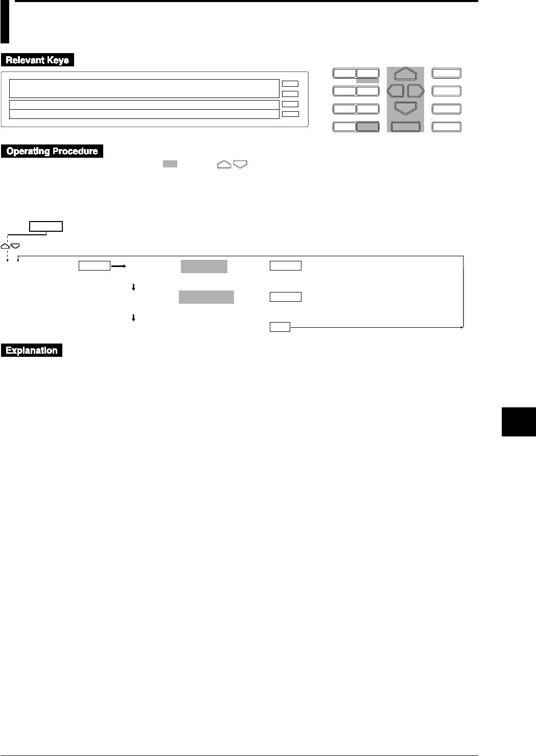
9-19
IM DR232-01E
9
Event/Action Function and Other Functions
9.6 Summer/Winter Time
D I S P M O D E
P R I N TF U N C
I N S D E L
R A N G E A L A R M
S E TC H A R T E N T E R
F E E D
M. F U N C 1
M. F U N C 2
RECORD
ALARM
CHART
KEYLOCK
R E C O R D
SET=DST
SYSTEM UNIT TREND TIMER LOGIC DST COPY
>Select Setting Parameter
E S C
• Press the SET key to enter the SET menu.
• Select/set using the keys.
• To escape from a lower menu, press the MODE (ESC) key. Its main menu will appear,
although new settings/selections will not be kept.
• New settings/selections will be kept when you reach the final display of that setting.
SET TIME=SUMMER
SUMMER WINTER
SUMMER=96/05/01 00
>Set Data & Time YY/MM/DD HH:00:00
***SET OK***
DST
ENTER
ENTERENTER
ESC
SET=
(Main menu)
(Lower menu)
Using this funcion the DR will autonatically change its date and time to the summer time or
winter time when appropriate.
If you specify SUMMER, the time will be ajusted to one hour later when the specified date and
time is reached.
If you specify WINTER, the time will be ajusted to one hour earlier when the specified date and
time is reached.
When the set time is reached, the setting will return to its intial value of 50/01/01 00.
The value of the years are as follows : 00 to 49 stand for the year 2000 to 2049, whereas 50 to 99
stand for the years 1950 to 1999.
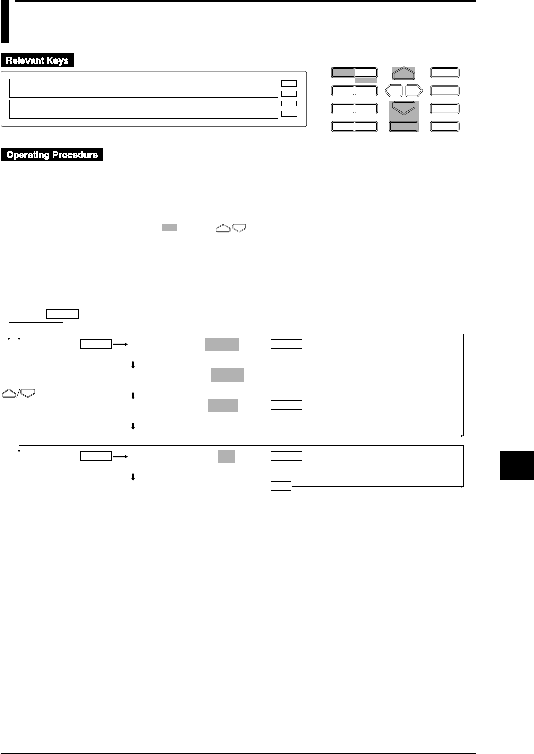
10-1
IM DR232-01E
10
Basic Settings (SET UP)
10.1 Selecting Adjustment of Dot-Printing Position
or Scan Interval
D I S P M O D E
P R I N TF U N C
I N S D E L
R A N G E A L A R M
S E TC H A R T E N T E R
F E E D
M. F U N C 1
M. F U N C 2
RECORD
ALARM
CHART
KEYLOCK
R E C O R D
SETUP=PRN_ADJ
PRN_ADJ SCAN_INTVL RECORD ALARM A/D_IN↑
>Select Setting Parameter
E S C
Recording Mode (SYSTEM)
• Enter the SET UP menu in the following procedure:
1. When the display presents the operation display mode or a menu other than the SET UP
menu, first turn off the power switch.
2. Turn the switch back on while pressing the DISP key and continue pressing the DISP key
for about 5 seconds.
• Select/set using the keys.
• If exiting the following lower menu setting halfway, press the MODE (ESC) key. The display
returns to the main menu to which the lower menu belongs. However, newly set or selected
contents are canceled.
• When setting proceeds to the display for the setting end, the newly set or selected contents are
established.
SET UP=
PRN ADJ
SCAN INTVL
PRINTER HYS=–_ _ _2
>Hys Limit(– 50~ 50)
PRINTER ZERO=_ _326
>Zero Limit (1~500)
PRINTER FULL=_2506
>Full Limit (2400~2600)
***PRINTER SET***
SCAN INTERVAL=0.5 (sec)
0.5 1 2 3 4 5 6 10 12 15 20 30 60
***SCAN INTVL SET***
ENTER
ENTER
ENTER
ENTER
ENTER
ENTER
ESC
ESC
(Main menu)
(Lower menu)

10-2 IM DR232-01E
10.1 Selecting Adjustment of Dot-Printing Position or Scan Interval
In the [PRN ADJ] menu, three lines are dot-printed according to the left and right movements of
the carriage.
Adjustment of Dot-printing Shift (HYS)
Dots are printed in a line along the length of the chart almost in the middle following the right and
left movements of the carriage. If these dots shift either to the left or the right, make a straight
line by adjusting the HYS setting.
• The setting range is -50 to 50.
• The set value 1 corresponds to about 0.1 mm of the dot-printing position.
Adjustment of Zero Position (ZERO)
If a line composed of printed dots shifts from the scale line at the left end of the chart, have the
line of dots just overlap the scale end line by adjusting the ZERO setting.
• The setting range is 1 to 500.
• The set value 1 corresponds to about 0.1 mm of the dot-printing position.
Adjustment of Full-scale Position
If a line composed of printed dots shifts from the scale line at the right end of the chart, have the
line of dots just overlap the scale end line by adjusting the FULL setting.
• The setting range is 2400 to 2600.
• The set value 1 corresponds to about 0.1 mm of the dot-printing position.
Selection of Scan Interval (SCAN INTVL)
• Select 0.5, 1, 2, 3, 4, 5, 6, 10, 12, 15, 20, 30 and 60 seconds as the interval.
• The default setting is 0.5 seconds.
• The shortest selectable scan interval varies with the setting of the number of input channels, A/
D converter integration time, or filter ON/OFF. For details, see chapter 14.
Note
• In order to make the set or selected contents effective, the contents must be registered. For details, see
page 10-23.
• To return from the SET UP menu to the operation display mode, select END in the main menu. For
details, see page 10-23.
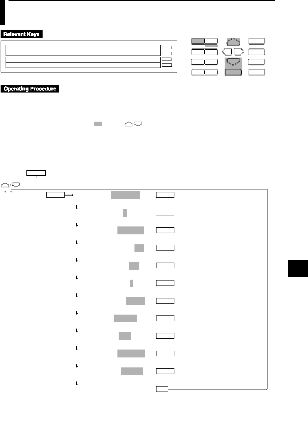
10-3
IM DR232-01E
10
Basic Settings (SET UP)
10.2 Setting Recording Format
D I S P M O D E
P R I N TF U N C
I N S D E L
R A N G E A L A R M
S E TC H A R T E N T E R
F E E D
M. F U N C 1
M. F U N C 2
RECORD
ALARM
CHART
KEYLOCK
R E C O R D
SETUP=RECORD
PRN_ADJ SCAN_INTVL RECORD ALARM A/D_IN↑
>Select Setting Parameter
E S C
• Enter the SET UP menu in the following procedure:
1. When the display presents the operation display mode or a menu other than the SET UP
menu, first turn off the power switch.
2. Turn the switch back on while pressing the DISP key and continue pressing the DISP key
for about 5 seconds.
• Select/set using the keys.
• If exiting the following lower menu setting halfway, press the MODE (ESC) key. The display
returns to the main menu to which the lower menu belongs. However, newly set or selected
contents are canceled.
• When setting proceeds to the display for the setting end, the newly set or selected contents are
established.
SET UP=
CH OR TAG=CHANNEL
CHANNEL TAG
TAG PRINT LEN=7
7 8 9 10 11 12 13 14 15 16
TREND MODE=NORMAL
NORMAL ALARM1 ALARM2 GROUP
SPEED CHANGE PR=ON
OFF ON
ON/OFF MARK PR=ON
OFF ON
DIGITAL PR CLMN=1
1 2 3 4
CHANNEL PITCH=5.0mm
OFF 5.0mm 12.5mm
TITLE PITCH=1500mm
OFF 600mm 1500mm
SCALE TIC PR=OFF
OFF ON
LOG FORMAT=HORIZON
HORIZON VERTICAL
LOG INTERVAL=SINGLE
SINGLE MULTIPLE
***RECORD SET***
ENTER
ENTER
ENTER
ENTER
ENTER
ENTER
ENTER
ENTER
ENTER
ENTER
ENTER
ENTER
ESC
RECORD
(Main menu)
(Lower menu)

10-4 IM DR232-01E
10.2 Setting Recording Format
Selection of Channel Number or Tag (CH OR TAG)
Select the call name for printing or displaying the measured values of either CHANNEL or TAG.
• Select either CHANNEL or TAG. However, if the TAG setting includes all spaces (vacant),
the channel is printed or displayed regardless of selection.
• The default setting is CHANNEL.
• For the TAG setting, see Section 6.4, “Setting Tag, Digital Printout and Manual Printout” (page
6-8).
Selection of Number of TAG Printing Characters
• Select 7, 8, 9, 10, 11, 12, 13, 14, 15 or 16.
• The default setting is 7.
• If the number of printing characters is less than the set TAG set in Sect. 6. 4. Only the
number selected here will be printed.
• For the number of characters when displaying, see chapter 4.
Selection of Dot-printing Recording System
Select it from the following systems. The default setting is NORMAL. To practically record it,
the RECORD must be turned on. Channels to be recorded are those selected to be ON in “Setting
the Channels to be Recorded, Dot Recording” on page 6-2.
• NORMAL:
• Records all channels to be recorded.
• ALARM1:
• Records only those channels in which alarms are generated.
• Continues recording even if the alarm is reset.
• ALARM2:
• Records only the channels in which alarms are generated.
• Stops recording when the alarm is reset.
• GROUP:
• Records the channels which are set into a group (see page 6-16).
• Recording can be done only if “GR TREND” is set in the event/action function.

10-5
IM DR232-01E
10
Basic Settings (SET UP)
10.2 Setting Recording Format
Selection of Printing When Chart Speed Is Changed (SPEED CHANGE PR)
When the chart speed is changed in dot-recording, select whether to print with the changed chart
speed or not.
• OFF: does not print.
• ON: prints.
• The default setting is ON.
Selection of Printing Record-Start/Stop Time (ON/OFF MARK PR)
In dot recording, select whether the record-start/stop time is printed or not.
• OFF: not printed.
• ON: printed.
• The default setting is ON.
Selection of Number of Columns for Digital Printing (DIGITAL PR CLMN)
Select to print measured values for the number of channels in a horizontal line.
• Select 1, 2, 3, or 4.
• The default setting is 1.
• If TAG has been selected in selecting the channel number/TAG, this is limited to 3 columns.
• If TAG uses 16 characters, the TAG entry is limited to two columns.
Selection of Channel Number Printing Pitch (CHANNEL PITCH)
In dot recording, select how many millimeters are taken as the channel number printing interval.
When TAG has been selected in channel number/TAG selection, the TAG corresponding to the
channel number is printed.
• OFF: not printed.
• 5.0 mm: printed every 5.0 mm.
• 12.5 mm: printed every 12.5 mm.
• The default setting is 5.0 mm.
Selection of Title Printing Pitch (TITLE PITCH)
In dot recording, select how many millimeters are taken as the title printing interval. For setting a
title, see Section 6.7, “Entering Messages, Headers and Title” (page 6-15).
• OFF: not printed.
• 600 mm: printed every 600 mm.
• 1500 mm: printed every 1500 mm.
• The default setting is 1500 mm.
Selection of Scale Check Mark Printing (SCALE TIC PR)
In dot recording, select whether a tic mark indicating the scale mark positions is printed or not.
For setting the scale mark printing, see Section 6.6, “Setting Scale Printout, List Printout and List
Format” (page 6-13).
• OFF: not printed
• ON: printed
• The default setting is OFF.
Selection of Horizontal or Vertical Printing (LOG FORMAT)
In logging mode, select either horizontal or vertical printing of the channel number/TAG. For
examples of printing, see Section 2.3, “Recording Functions” (page 2-7).
• HORIZON: printed horizontally.
• VERTICAL: printed vertically
• The default setting is HORIZON.

10-6 IM DR232-01E
10.2 Setting Recording Format
Selection of Recording Interval in Digital Printing/ Logging Mode (LOG INTERVAL)
Select recording of the channel number/TAG and measured values whether at one interval or at a
selected interval for each channel from the 6 timers. For the setting of the timer, see Section 6.1,
“Setting the Recording Mode/Engineering Unit/Recording Channel and Recording Interval” (page
6-3), and for the selection of the timer for each channel, see Section 6.4, “Setting Tag, Digital
Printout and Manual Printout” (page 6-9).
• SINGLE:
• Digital print: The interval is determined by the chart speed and the number of columns to be
printed. See the table in chapter 14 (page 14-3).
• Logging mode: interval for timer No. 1
• MULTIPLE: intervals selected for each channel from 6 kinds of timers for either Digital
printing or the Logging mode.
• The default setting is SINGLE.
Note
• In order to make the set or selected contents effective, the contents must be registered. For details, see
page 10-23.
• To return from the SET UP menu to the operation display mode, select END in the main menu. For
details, see page 10-23.
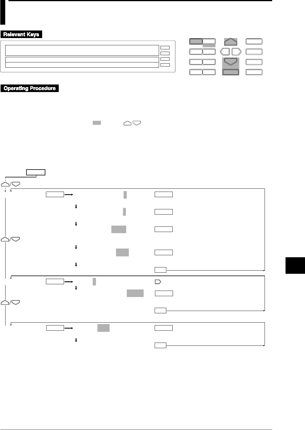
10-7
IM DR232-01E
10
Basic Settings (SET UP)
10.3 Select Alarm Interval/Hysteresis/Hold/A/D
Converter Integration Time/Filter
D I S P M O D E
P R I N TF U N C
I N S D E L
R A N G E A L A R M
S E TC H A R T E N T E R
F E E D
M. F U N C 1
M. F U N C 2
RECORD
ALARM
CHART
KEYLOCK
R E C O R D
SETUP=ALARM
↓TVL RECORD ALARM A/D_INTG FILTER RELAY↑
>Select Setting Parameter
E S C
• Enter the SET UP menu in the following procedure:
1. When the display presents the operation display mode or a menu other than the SET UP
menu, first turn off the power switch.
2. Turn the switch back on while pressing the DISP key and continue pressing the DISP key
for about 5 seconds.
• Select/set using the keys.
• If exiting the following lower menu setting halfway, press the MODE (ESC) key. The display
returns to the main menu to which the lower menu belongs. However, newly set or selected
contents are canceled.
• When setting proceeds to the display for the setting end, the newly set or selected contents are
established.
ALARM RH TIME=8
1 2 3 4 5 6 7 8 9 10 11 12 13 14 15
ALARM RL TIME=8
1 2 3 4 5 6 7 8 9 10 11 12 13 14 15
ALARM HYS=0.5%
0.0 0.1 0.2 0.3 0.4 0.5
0.6 0.7 0.8 0.9 1.0
ALARM HOLD=OFF
OFF ON
***ALARM SET***
S UNIT0:A/D INTG=AUTO
S UNIT0:A/D INTG=AUTO
AUTO 50Hz 60Hz 100ms
***A/D INTG SET***
FILTER=OFF
OFF ON
***FILTER SET***
ESC
ENTER
ENTER
ENTER
ENTER
ENTER
ENTER
ENTERENTER
ESC
ESC
ALARM
A/D INTG
FILTER
(Main menu)
(Lower menu)
ENTER
SET UP=

10-8 IM DR232-01E
10.3 Select Alarm Interval/Hysteresis/Hold/A/D Converter Integration Time/Filter
Selection of Interval for High Limit of Rate-Of-Change Alarm (ALARM RH TIME)
Set the number of measurement repeats in “Interval = measurement interval x measurement
repeats.”
• Select 1, 2, 3, 4, 5, 6, 7, 8, 9, 10, 11, 12, 13, 14, or 15.
• The default setting is 8.
Selection of Interval for Low Limit of Rate-Of-Change Alarm (ALARM RL TIME)
• The same selection method as the above.
Selection of Alarm Hysteresis (ALARM HYS)
Applied to high/low limit alarm.
• Select 0.0, 0.1, 0.2, 0.3, 0.4, 0.5, 0.6, 0.7, 0.8, 0.9 or 1.0%.
• The default setting is 0.5%.
Selection of Alarm Display Hold (ALARM HOLD)
Select whether the alarm display is held or not when the alarm is reset.
• OFF: hold
• ON: not hold
• The default setting is OFF.
Selection of A/D Converter Integration Time (A/D INTG)
Select each A/D converter integration time for each unit. Select it from the following:
• AUTO: the frequency of 50/60 Hz is automatically switched corresponding to the power
frequency of this instrument.
However, AUTO does not function on the the subunit of the DC power supply model.
Selecting “AUTO” will set the A/D integration time to 20 ms (50 Hz).
• 50 Hz: the integration time is set to 20 ms (50 Hz).
• 60 Hz: the integration time is set to 16.7 ms (60 Hz).
• 100 ms: the integration time is set to 100 ms (10 Hz)
• The default setting is AUTO.
Selection of Filter (FILTER)
Select whether the input filter is operated or not. Select it from the following:
• OFF: Not operated
• ON: Operated
• The default setting is OFF.
Note
• In order to make the set or selected contents effective, the contents must be registered. For details, see
page 10-23.
• To return from the SET UP menu to the operation display mode, select END in the main menu. For
details, see page 10-23.
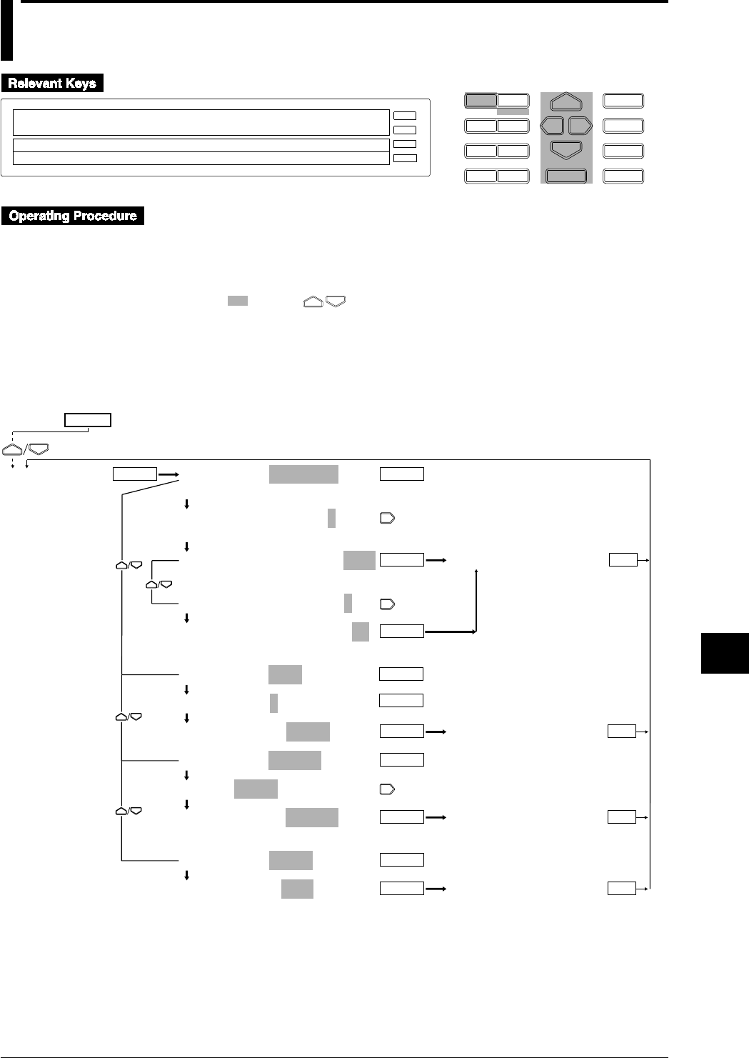
10-9
IM DR232-01E
10
Basic Settings (SET UP)
10.4 Setting Operation Mode of Relay/Internal Switch
D I S P M O D E
P R I N TF U N C
I N S D E L
R A N G E A L A R M
S E TC H A R T E N T E R
F E E D
M. F U N C 1
M. F U N C 2
RECORD
ALARM
CHART
KEYLOCK
R E C O R D
SETUP=RELAY
↓TVL RECORD ALARM A/D_INTG FILTER RELAY↑
>Select Setting Parameter
E S C
• Enter the SET UP menu in the following procedure:
1. When the display presents the operation display mode or a menu other than the SET UP
menu, first turn off the power switch.
2. Turn the switch back on while pressing the DISP key and continue pressing the DISP key
for about 5 seconds.
• Select/set using the keys.
• If exiting the following lower menu setting halfway, press the MODE (ESC) key. The display
returns to the main menu to which the lower menu belongs. However, newly set or selected
contents are canceled.
• When setting proceeds to the display for the setting end, the newly set or selected contents are
established.
RELAY SET=REFLASH
REFLASH AND ENERG HOLD
REFLASH RELAY No.1=OFF
1 2 3 4 5 6
REFLASH RELAY No.1=OFF
OFF 0
REFLASH RELAY No.1=001
REFLASH RELAY No.1=001
RELAY SET=AND
AND RELAY:S=NONE
AND RELAY:S=NONE
RELAY SET=ENERG
RELAY:001-01=ENERG
RELAY:001-01=ENERG
ENERG DE EN
RELAY SET=HOLD
RELAY HOLD=OFF
OFF ON
ENTERENTER
RELAY
ESC
ENTER
ENTER
ENTER
***REFLASH SET***
ENTER
***AND RELAY SET***
ESCENTER
ENTER
***RELAY MODE SET***
ENTER ESC
ENTER
***RELAY HOLD SET***
ENTER ESC
SET UP=
(Main menu)
(Lower menu)

10-10 IM DR232-01E
10.4 Setting Operation Mode of Relay/Internal Switch
The following operation mode is set to the alarm output relays and the internal switches. There
are menus which cannot be displayed unless the alarm module or the DI/DO module is mounted
and recognized as the system of this instrument. Also, there are menus which cannot be set to the
internal switches.
Setting Re-failure or Re-alarm (REFLASH)
This is a menu which canot be displayed unless the alarm module or the DI/DO module is
mounted and recognized as the system of this instrument. Setting for the internal switches cannot
be done. REFLASH setting is available for up to six relays.
• Selection of REFLASH number
Select from 1 to 6.
• Setting of REFLASH relay
• OFF: not set.
• Setting with numerals for 3 characters:
• The first character is the unit number.
• For the second and third characters, a number from 01 to 60 can be set but the effective
setting range is as shown in the following examples: (Check which what slot the alarm
module or the DI/DO module is mounted in using the model number of mounted modules
and their mounted positions. Slot numbers are set in the order of slot 0, slot 1, ..... facing
the front.)
Ex. 1: When the alarm module is mounted in slot 3: 31 to 40
Ex. 2: The DI/DO module is mounted in slot4: 41 to 42
• The default setting is OFF.
• After REFLASH setting, when the alarm module or the DI/DO module becomes
unrecognized as the system of this instrument, the relay setting becomes OFF.
Setting AND/OR (AND)
This can be set either to the relays or the internal switches. However, the relay cannot be set
unless the alarm module or DI/DO module is mounted and recognized as the system of this
instrument.
• Selection of Internal Switch/Relay
• S: internal switch is set.
• I, 0 to 5: relay is set.
• The default setting is S.
• Setting AND/OR
The relays or the internal switches are set to AND in up to the set range and set to OR in the range
exceeding the set range.
• For internal switches: set from 01-01 to 01-60.
• For one alarm module: 01-01 to 01-60 can be displayed. However, if this option is installed
in slot 4, 01-41 to 01-50 is the effective setting range.
• For one DI/DO module: 01-01 to 01-60 can be displayed. However, if this option is
installed in slot 5, 01-51 to 01-52 is the effective setting range.
• For two alarm modules: 01-01 to 01-60 can be displayed. However, is one module is
installed in slot 3 and an other is installed in slot 5, 01-31 to 01-60 is the effective setting
range. No relay is in the range from 01-41 to 01-50.
• In either case above, if all are to be set to OR or reset, set “NONE.”
• The default setting is NONE.

10-11
IM DR232-01E
10
Basic Settings (SET UP)
10.4 Setting Operation Mode of Relay/Internal Switch
Setting Energizing/Deenergizing (ENERG)
This is a menu which canot be displayed unless the alarm module or the DI/DO module is
mounted and recognized as the system of this instrument.
• Relay Setting
Set the object relays from one number relay (first relay) to another number relay (end relay). Set
it under the condition that the first relay number ≤ end relay number.
• First relay number:
• The first character is a unit number.
• For the second and third characters, a number from 01 to 60 can be set but the effective
setting range is as shown in the following examples: (Check which what slot the alarm
module or the DI/DO module is mounted in using the model number of mounted modules
and their mounted positions. Slot numbers are set in the order of slot 0, slot 1, ..... facing
the front.)
Ex. 1: When the alarm module is mounted in slot 3: 31 to 40
Ex. 2: The DI/DO module is mounted in slot4: 41 to 42
• End relay number: The same settings of the second or third characters in the first relay
number.
• The default setting is 001-01.
• Selection of energizing/deenergizing
• ENERG: energizing
• DE EN: deenergizing
• The default setting is ENERG.
Setting Relay Hold (HOLD)
This is a menu which canot be displayed unless the alarm module or the DI/DO module is
mounted and recognized as the system of this instrument. However, the internal switches are set
simultaneously with relays.
• OFF: No relays/internal switches hold.
• ON: all relays/internal switches hold.
• The default setting is OFF.
Note
• In order to make the set or selected contents effective, the contents must be registered. For details, see
page 10-24.
• To return from the SET UP menu to the operation display mode, select END in the main menu. For
details, see page 10-24.
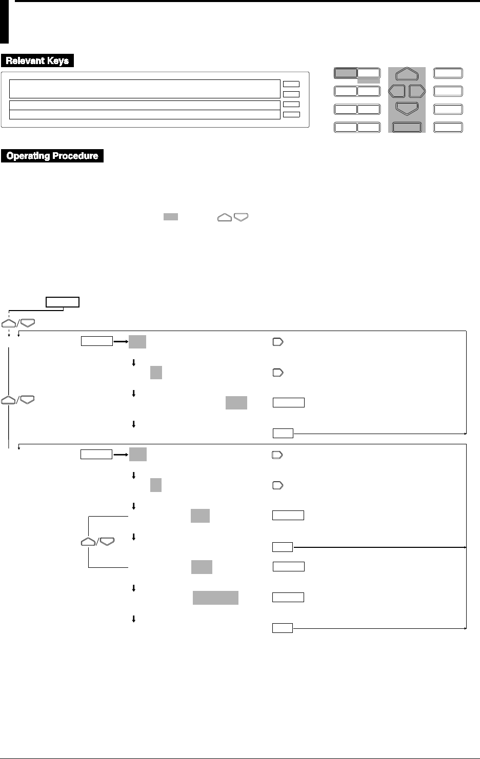
10-12 IM DR232-01E
10.5 Setting Burn-out/Reference Junction
Compensation
D I S P M O D E
P R I N TF U N C
I N S D E L
R A N G E A L A R M
S E TC H A R T E N T E R
F E E D
M. F U N C 1
M. F U N C 2
RECORD
ALARM
CHART
KEYLOCK
R E C O R D
SETUP=BURN_OUT
↓D ALARM A/D_INTG FILTER RELAY BURN_OUT↑
>Select Setting Parameter
E S C
• Enter the SET UP menu in the following procedure:
1. When the display presents the operation display mode or a menu other than the SET UP
menu, first turn off the power switch.
2. Turn the switch back on while pressing the DISP key and continue pressing the DISP key
for about 5 seconds.
• Select/set using the keys.
• If exiting the following lower menu setting halfway, press the MODE (ESC) key. The display
returns to the main menu to which the lower menu belongs. However, newly set or selected
contents are canceled.
• When setting proceeds to the display for the setting end, the newly set or selected contents are
established.
ENTER
ENTER
ESC
BURN OUT
RJC
ENTER
ENTER
ESC
ENTER
ESC
ENTER
001-01:BURN OUT=OFF
>Select Channel No.
001-01:BURN OUT=OFF
>Select Channel No.
001-01:BURN OUT=OFF
OFF DOWN UP
***BURN OUT SET***
001-01:RJC=INT
>Select Channel No.
001-01:RJC=INT
>Select Channel No.
001-01:RJC=INT
INT EXT
***RJC SET***
001-01:RJC=EXT
INT EXT
EXT VALUE=_ _ _ _ _0µV
>Ext Value Limit(– 20000~ 20000µV)
***RJC SET***
(Main menu)
(Lower menu)
SET UP=

10-13
IM DR232-01E
10
Basic Settings (SET UP)
10.5 Setting Burn-out/Reference Junction Compensation
Setting Burn-out (BURN OUT)
Set the dot-printing position when burn-out occurs for each channel.
• OFF: the burn-out function is not actuated.
• DOWN: a dot is printed at the end of chart width on the minimum value setting side of the
recording span.
• UP: Dot is printed at the end of chart width on the maximum value setting side of the recording
span.
• The default setting is OFF.
Setting Reference Junction Compensation (RJC)
Set either the internal or the external compensation for each channel.
• INT: internal compensation is performed.
• EXT: external compensation is performed. For external compensation, set the voltage to be
compensated.
Voltage to be externally compensated: set in the range of -20000 to 20000 mV.
• The default setting is INT.
Note
• In order to make the set or selected contents effective, the contents must be registered. For details, see
page 10-23.
• To return from the SET UP menu to the operation display mode, select END in the main menu. For
details, see page 10-23.
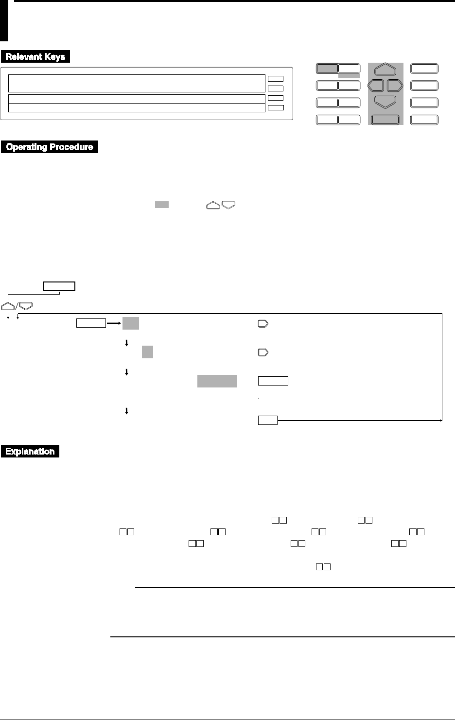
10-14 IM DR232-01E
10.6 Setting Recording Colors
D I S P M O D E
P R I N TF U N C
I N S D E L
R A N G E A L A R M
S E TC H A R T E N T E R
F E E D
M. F U N C 1
M. F U N C 2
RECORD
ALARM
CHART
KEYLOCK
R E C O R D
SETUP=COLOR
↓D_INTG FILTER RELAY BURN_OUT RJC COLOR↑
>Select Setting Parameter
E S C
• Enter the SET UP menu in the following procedure:
1. When the display presents the operation display mode or a menu other than the SET UP
menu, first turn off the power switch.
2. Turn the switch back on while pressing the DISP key and continue pressing the DISP key
for about 5 seconds.
• Select/set using the keys.
• If exiting the following lower menu setting halfway, press the MODE (ESC) key. The display
returns to the main menu to which the lower menu belongs. However, newly set or selected
contents are canceled.
• When setting proceeds to the display for the setting end, the newly set or selected contents are
established.
ENTER
ENTER
ESC
COLOR 001-01:COLOR=PURPLE
>Select Channel No.
001-01:COLOR=PURPLE
>Select Channel No.
001-01:COLOR=PURPLE
PURPLE RED GREEN BLUE BROWN
BLACK NAVY YEL_GR RED_PR ORANGE
***COLOR SET***
(Main menu)
(Lower menu)
SET UP=
Setting Recording Color
Set the recording colors for each channel. This setting can also be made for optional computation
channels.
• Select a color from the following ten colors:
PURPLE, RED, GREEN, BLUE, BROWN, BLACK, NAVY (navy blue), YEL_GR (yellowish
green), RED_PR (redish purple), and ORANGE
• The default setting is PURPLE for channel 1, RED for channel 2, GREEN for channel
3, BLUE for channel 4, BROWN for channel 5, BLACK for channel 6,
NAVY for channel 7, YEL_GR for channel 8, RED_PR for channel 9, and
ORANGE for channel 0.
Enter a unit number and a slot number in the two boxes .
Note
• In order to make the set or selected contents effective, the contents must be registered. For details, see
page 10-23.
• To return from the SET UP menu to the operation display mode, select END in the main menu. For
details, see page 10-23.
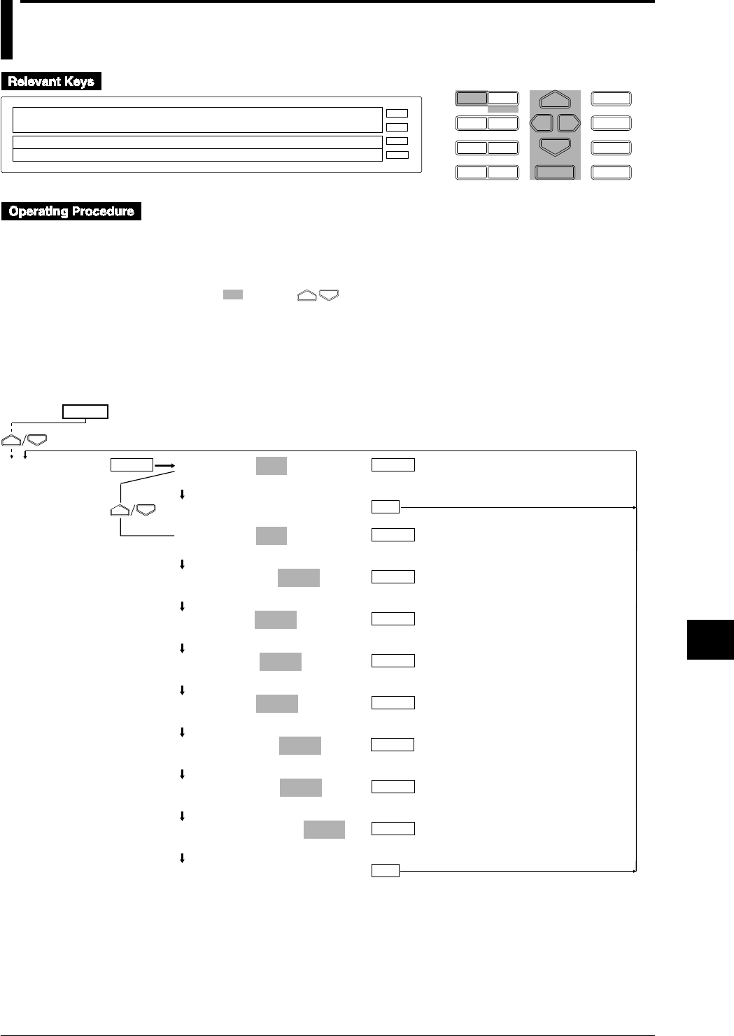
10-15
IM DR232-01E
10
Basic Settings (SET UP)
10.7 Setting Key Lock
D I S P M O D E
P R I N TF U N C
I N S D E L
R A N G E A L A R M
S E TC H A R T E N T E R
F E E D
M. F U N C 1
M. F U N C 2
RECORD
ALARM
CHART
KEYLOCK
R E C O R D
SETUP=LOCK
↓G FILTER RELAY BURN_OUT RJC COLOR LOCK↑
>Select Setting Parameter
E S C
• Enter the SET UP menu in the following procedure:
1. When the display presents the operation display mode or a menu other than the SET UP
menu, first turn off the power switch.
2. Turn the switch back on while pressing the DISP key and continue pressing the DISP key
for about 5 seconds.
• Select/set using the keys.
• If exiting the following lower menu srtting halfway, press the MODE (ESC) key. The display
returns to the main menu to which the lower menu belongs. However, newly set or selected
contents are canceled.
• When setting proceeds to the display for the setting end, the newly set or selected contents are
established.
KEY LOCK=NOT
NOT USE
***KEY LOCK SET***
KEY LOCK=USE
NOT USE
RECORD KEY=LOCK
FREE LOCK
FEED KEY=LOCK
FREE LOCK
PRINT KEY=LOCK
FREE LOCK
FUNC KEY=LOCK
FREE LOCK
M.FUNC1 KEY=LOCK
FREE LOCK
M.FUNC2 KEY=LOCK
FREE LOCK
A CODE NUMBER=_ _ _0
(Set the pass word.)
***KEY LOCK SET***
ENTER
ENTER
ENTER
LOCK
ENTER
ENTER
ESC
ENTER
ESC
ENTER
ENTER
ENTER
ENTER
(Main menu)
(Lower menu)
SET UP=

10-16 IM DR232-01E
Selection of Use or Nonuse of Key Lock
Select whether the key lock function is used or not used.
• NOT: the key lock function cannot be used.
• USE: the key lock function can be used. The menu “KEY LOCK ON” is displayed in the
FUNC menu and key lock can be executed. For details, see Section 9.3, “Alarm
Acknowledgment, Alarm Reset, Timer Reset, Keylock, and Message Printout” (page 9-15).
• The default setting is NOT.
Selection of Making Key Lock Ineffective
Even if key lock is executed, the turning on/off of the power switch, DISP/MODE key operation
and cursor key operation are effective. Other than the above, whether operation of the following
keys is made effective or locked can be selected.
• Selectable keys
RECORD, FEED, PRINT, FUNC, M.FUNC1, and M.FUNC2
• Choice
• FREE: made effective.
• LOCK: locked.
• The default setting is LOCK.
Setting Password (A CODE NUMBER)
Set a password for executing/resetting key lock.
• Can be set in the range of 0 to 9999.
• The default setting is 0.
Note
• In order to make the set or selected contents effective, the contents must be registered. For details, see
page 10-23.
• To return from the SET UP menu to the operation display mode, select END in the main menu. For
details, see page 10-23.
10.7 Setting Key Lock
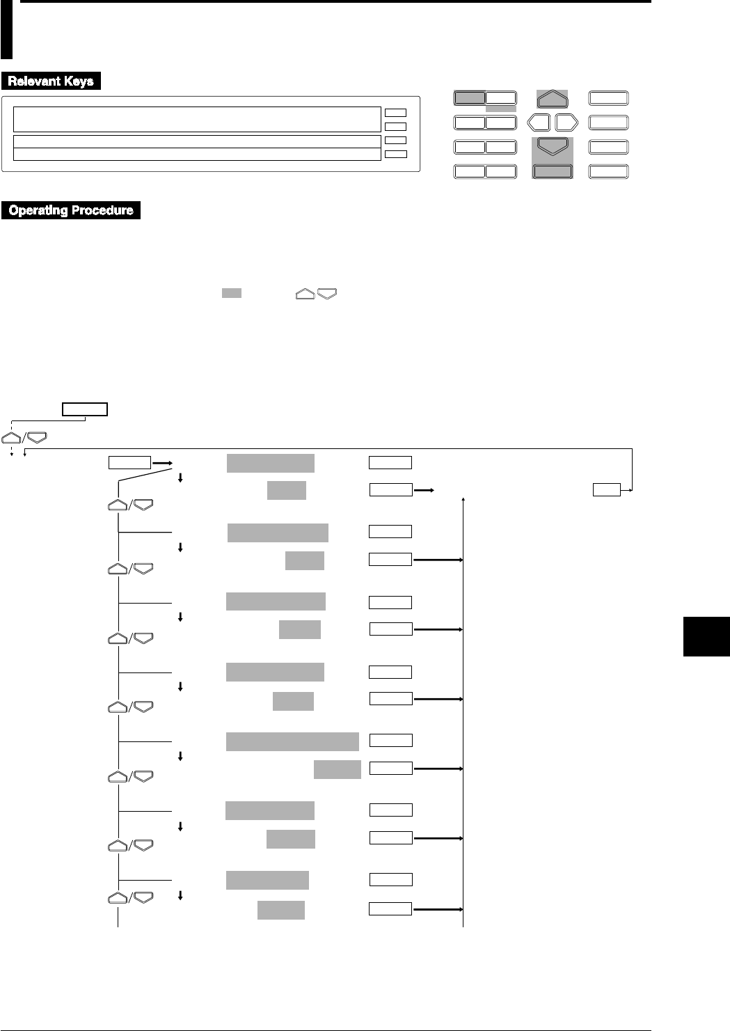
10-17
IM DR232-01E
10
Basic Settings (SET UP)
10.8 Setting FUNC/FUNC3 Menu
D I S P M O D E
P R I N TF U N C
I N S D E L
R A N G E A L A R M
S E TC H A R T E N T E R
F E E D
M. F U N C 1
M. F U N C 2
RECORD
ALARM
CHART
KEYLOCK
R E C O R D
SETUP=FUNC_PARM
↓ELAY BURN_OUT RJC COLOR LOCK FUNC_PARM↑
>Select Setting Parameter
E S C
• Enter the SET UP menu in the following procedure:
1. When the display presents the operation display mode or a menu other than the SET UP
menu, first turn off the power switch.
2. Turn the switch back on while pressing the DISP key and continue pressing the DISP key
for about 5 seconds.
• Select/set using the keys.
• If exiting the following lower menu setting halfway, press the MODE (ESC) key. The display
returns to the main menu to which the lower menu belongs. However, newly set or selected
contents are canceled.
• When setting proceeds to the display for the setting end, the newly set or selected contents are
established.
PANEL:ALARM ACK
ALARM ACK=FUNC
FUNC FUNC3 OFF
PANEL:ALARM RESET
ALARM RESET=FUNC
FUNC FUNC3 OFF
PANEL:TIMER RESET
TIMER RESET=FUNC
FUNC FUNC3 OFF
PANEL:MATH START
MATH START=FUNC
FUNC FUNC3 OFF
PANEL:MATH_CLR_START
MATH_CLR_START=FUNC
FUNC FUNC3 OFF
PANEL:MATH STOP
MATH STOP=FUNC
FUNC FUNC3 OFF
PANEL:MATH ACK
MATH ACK=FUNC
FUNC FUNC3 OFF
ESC
ENTER
ENTER
ENTER
ENTER
ENTER
To next page
FUNC PARM
ENTER
ENTER
ENTER
***FUNC PARM SET***
ENTER
ENTER
ENTER
ENTER
ENTER
ENTER
ENTER
From the following page
(Main menu)
(Lower menu)
SET UP=
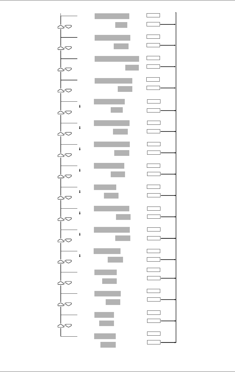
10-18 IM DR232-01E
PANEL:REPORT_START
REPORT_START=FUNC
FUNC FUNC3 OFF
PANEL:REPORT_START
REPORT_START=FUNC
FUNC FUNC3 OFF
PANEL:REP_RECALL_START
REP_RECALL_START=FUNC
FUNC FUNC3 OFF
PANEL:REP_PRINT_STOP
REP_PRINT_STOP=FUNC
FUNC FUNC3 OFF
PANEL:KEY LOCK ON
KEY LOCK ON=FUNC
FUNC FUNC3 OFF
PANEL:KEY LOCK OFF
KEY LOCK OFF=FUNC
FUNC FUNC3 OFF
PANEL:S/U LIST START
S/U LIST START=FUNC3
FUNC FUNC3 OFF
PANEL:S/U LIST STOP
S/U LIST STOP=FUNC3
FUNC FUNC3 OFF
PANEL:MSG PRINT
MSG PRINT=FUNC
FUNC FUNC3 OFF
PANEL:ALM BUF CLEAR
ALM BUF CLEAR=FUNC3
FUNC FUNC3 OFF
PANEL:MSG BUF CLEAR
MSG BUF CLEAR=FUNC3
FUNC FUNC3 OFF
PANEL:MODULE INF
MODULE INF=FUNC3
FUNC FUNC3 OFF
PANEL:COMM INF
COMM INF=FUNC3
FUNC FUN3 OFF
PANEL:RE SYSTEM
RE SYSTEM=FUNC3
FUNC FUNC3 OFF
PANEL:RAM INT
RAM INT=FUNC3
FUNC FUNC3 OFF
PANEL:ALL ITEM
ALL ITEM=FUNC
FUNC FUNC3 OFF INIT
ENTER
ENTER
ENTER
ENTER
ENTER
ENTER
ENTER
ENTER
ENTER
ENTER
ENTER
ENTER
ENTER
ENTER
ENTER
ENTER
From prevlous page To prevlous page
ENTER
ENTER
ENTER
ENTER
ENTER
ENTER
ENTER
ENTER
ENTER
ENTER
ENTER
ENTER
ENTER
ENTER
ENTER
ENTER
10.8 Setting FUNC/FUNC3 Menu

10-19
IM DR232-01E
10
Basic Settings (SET UP)
Setting FUNC/FUNC3 (FUNC PARM)
Select the menu to be displayed by pressing the FUNC key whether in the FUNC menu or the
FUNC3 menu. The FUNC menu is displayed by pressing the FUNC key at a touch and the
FUNC3 menu is displayed by pressing the FUNC key for about 3 seconds continuously.
• Select any of the following:
• FUNC: displayed in the FUNC menu.
• FUNC3: displayed in the FUNC3 menu.
• OFF: not displayed in either menu.
• The default setting is as shown in the operating procedure diagram on pages 10-17 and 10-18.
• The last operation menu, “PANEL:ALL ITEM” is the menu that globally set all menus.
However, the selection of “INIT” selects the default setting.
• The “COMM INF” menu is displayed if the communication module is mounted and recognized
as the system of this instrument (see page 9-16).
Note
• In order to make the set or selected contents effective, the contents must be registered. For details, see
page 10-23.
• To return from the SET UP menu to the operation display mode, select END in the main menu. For
details, see page 10-23.
10.8 Setting FUNC/FUNC3 Menu

10-20 IM DR232-01E
10.9 Setting SET/SET3 Menu
D I S P M O D E
P R I N TF U N C
I N S D E L
R A N G E A L A R M
S E TC H A R T E N T E R
F E E D
M. F U N C 1
M. F U N C 2
RECORD
ALARM
CHART
KEYLOCK
R E C O R D
SETUP=SET_PARM
↓_OUT RJC COLOR LOCK FUNC_PARM SET_PARM↑
>Select Setting Parameter
E S C
• Enter the SET UP menu in the following procedure:
1. When the display presents the operation display mode or a menu other than the SET UP
menu, first turn off the power switch.
2. Turn the switch back on while pressing the DISP key and continue pressing the DISP key
for about 5 seconds.
• Select/set using the keys.
• If exiting the following lower menu setting halfway, press the MODE (ESC) key. The display
returns to the main menu to which the lower menu belongs. However, newly set or selected
contents are canceled.
• When setting proceeds to the display for the setting end, the newly set or selected contents are
established.
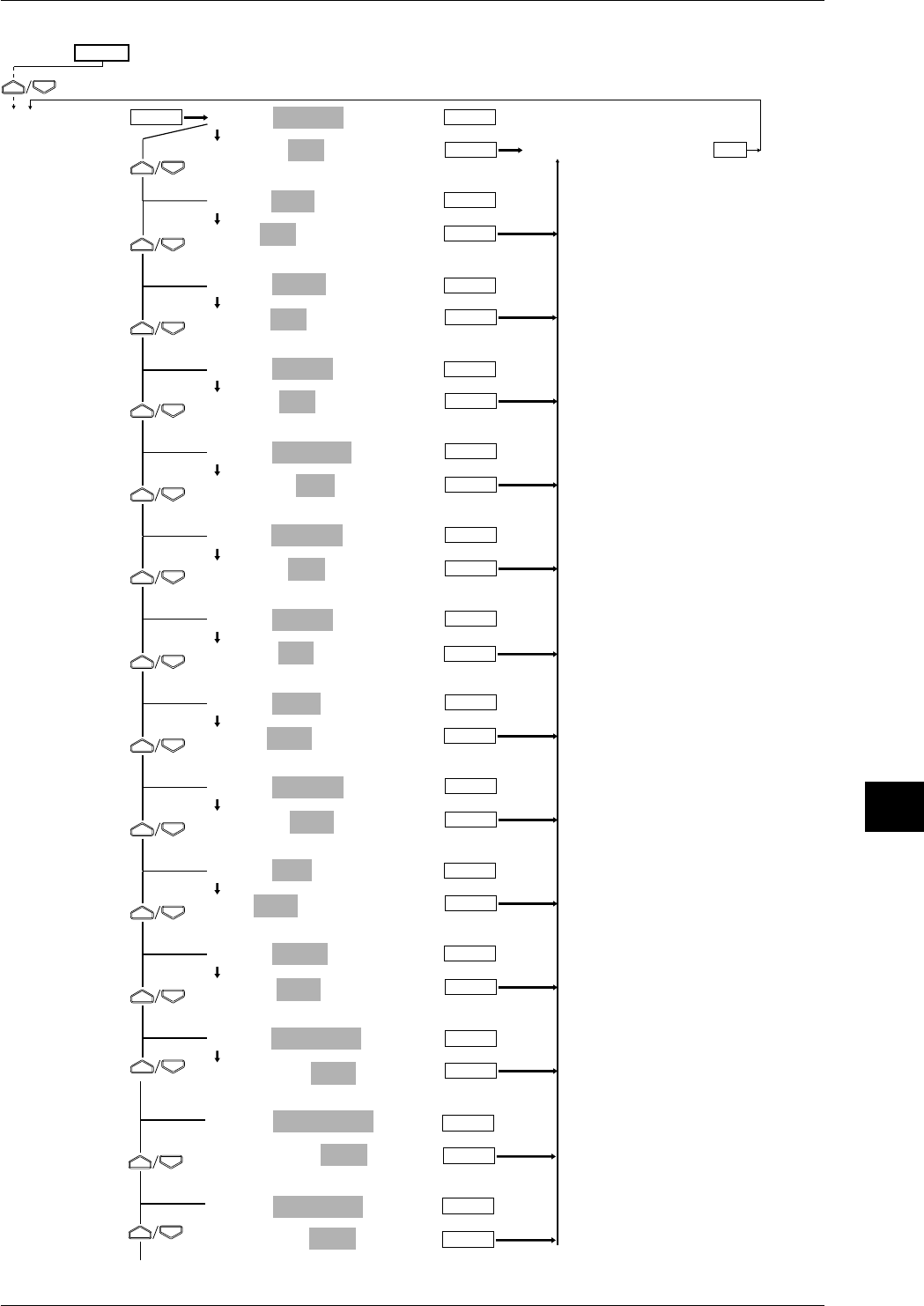
10-21
IM DR232-01E
10
Basic Settings (SET UP)
PANEL:SYSTEM
SYSTEM=SET
SET SET3 OFF
PANEL:UNIT
UNIT=SET
SET SET3 OFF
PANEL:MATH
MATH=SET
SET SET3 OFF
PANEL:CONST
CONST=SET
SET SET3 OFF
PANEL:MEMORY
MEMORY=SET
SET SET3 OFF
PANEL:FLOPPY
FLOPPY=SET
SET SET3 OFF
PANEL:CHART2
CHART2=SET3
SET SET3 OFF
PANEL:ZONE
ZONE=SET3
SET SET3 OFF
PANEL:PARTIAL
PARTIAL=SET3
SET SET3 OFF
PANEL:TAG
TAG=SET3
SET SET3 OFF
PANEL:TREND
TREND=SET
SET SET3 OFF
PANEL:DIGITAL PR
DIGITAL PR=SET3
SET SET3 OFF
PANEL:MANUAL PR
MANUAL PR=SET3
SET SET3 OFF
PANEL:ALARM PR
ALARM PR=SET3
SET SET3 OFF
ESC
ENTER
ENTER
ENTER
ENTER
ENTER
ENTER
SET PARM
ENTER
ENTER
ENTER
ENTER
ENTER
ENTER
ENTER
***SET PARM SET***
ENTER
ENTER
ENTER
ENTER
ENTER
ENTER
ENTER
ENTER
ENTER
ENTER
ENTER
ENTER
From the following page
To next page
(Main menu)
(Lower menu)
SET UP=
ENTER
ENTER
ENTER
ENTER
10.9 Setting SET/SET3 Menu
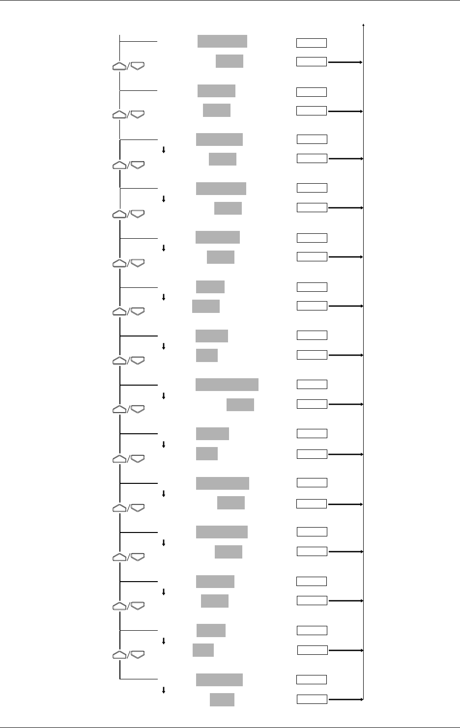
10-22 IM DR232-01E
PANEL:SCALE PR
SCALE PR=SET3
SET SET3 OFF
PANEL:LIST PR
LIST PR=SET3
SET SET3 OFF
PANEL:LIST FMT
LIST FMT=SET3
SET SET3 OFF
PANEL:MESSAGE
MESSAGE=SET3
SET SET3 OFF
PANEL:HEADER
HEADER=SET3
SET SET3 OFF
PANEL:TITLE
TITLE=SET3
SET SET3 OFF
PANEL:TIMER
TIMER=SET
SET SET3 OFF
PANEL:MATCH TIME
MATCH TIME=SET3
SET SET3 OFF
PANEL:LOGIC
LOGIC=SET
SET SET3 OFF
PANEL:MOVE AVE
MOVE AVE=SET3
SET SET3 OFF
PANEL:INTERPOL
INTERPOL=SET3
SET SET3 OFF
PANEL:GROUP
GROUP=SET3
SET SET3 OFF
PANEL:COPY
COPY=SET
SET SET3 OFF
PANEL:ALL ITEM
ALL ITEM=SET
SET SET3 OFF INIT
ENTER
ENTER
ENTER
ENTER
ENTER
ENTER
ENTER
ENTER
ENTER
ENTER
ENTER
ENTER
ENTER
ENTER
ENTER
ENTER
ENTER
ENTER
ENTER
ENTER
From previous page To previous page
ENTER
ENTER
ENTER
ENTER
ENTER
ENTER
ENTER
ENTER
10.9 Setting SET/SET3 Menu

10-23
IM DR232-01E
10
Basic Settings (SET UP)
Setting SET/SET3 (SET PARM)
Select the menu to be displayed by pressing the SET key whether in the SET menu or the SET3
menu. The SET menu is displayed by pressing the SET key at a touch and the SET3 menu is
displayed by pressing the SET key for about 3 seconds continuously.
• Select any of the following:
• SET: displayed in the SET menu.
• SET3: displayed in the SET3 menu.
• OFF: not displayed in either menu.
• The default setting is as shown in the operating procedure diagram on pages 10-20 and 10-21.
• The last operation menu, “PANEL:ALL ITEM,” is the menu that globally set all menus.
However, the selection of “INIT” selects the default setting.
Note
• In order to make the set or selected contents effective, the contents must be registered. For details, see
page 10-23.
• To return from the SET UP menu to the operation display mode, select END in the main menu. For
details, see page 10-23.
10.9 Setting SET/SET3 Menu
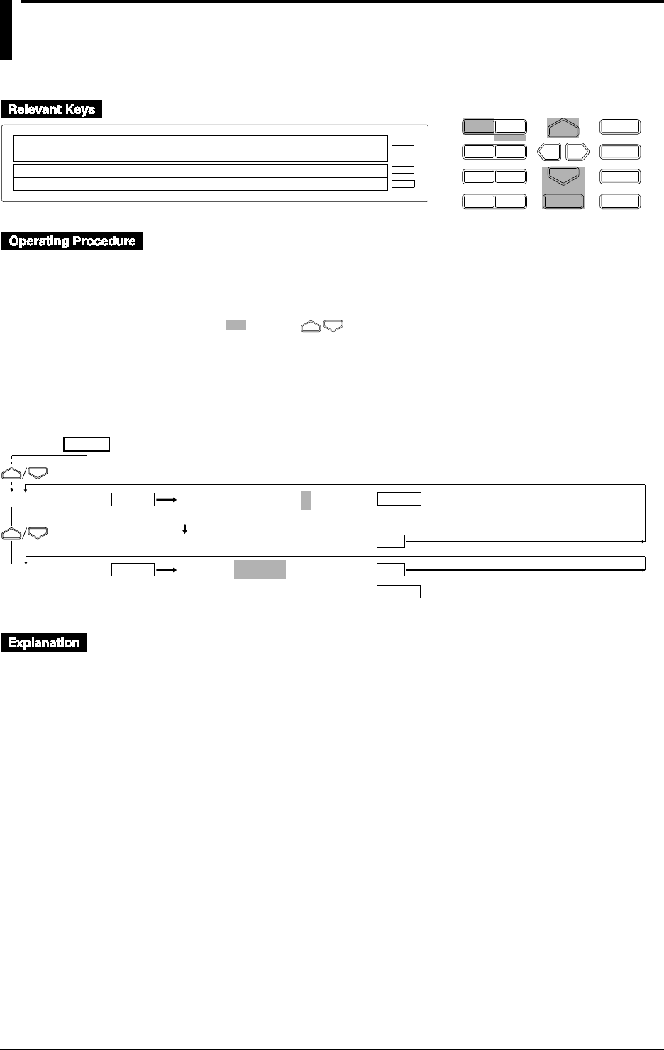
10-24 IM DR232-01E
10.10 Selecting Display Update Interval, Registering
Details Set/Selected with SET UP Menu, and
Terminating SET UP Menu
D I S P M O D E
P R I N TF U N C
I N S D E L
R A N G E A L A R M
S E TC H A R T E N T E R
F E E D
M. F U N C 1
M. F U N C 2
RECORD
ALARM
CHART
KEYLOCK
R E C O R D
SETUP=DISPLAY
↓ COLOR LOCK FUNC_PARM SET_PARM DISPLAY↑
>Select Setting Parameter
E S C
• Enter the SET UP menu in the following procedure:
1. When the display presents the operation display mode or a menu other than the SET UP
menu, first turn off the power switch.
2. Turn the switch back on while pressing the DISP key and continue pressing the DISP key
for about 5 seconds.
• Select/set using the keys.
• If exiting the following lower menu setting halfway, press the MODE (ESC) key. The display
returns to the main menu to which the lower menu belongs. However, newly set or selected
contents are canceled.
• When setting proceeds to the display for the setting end, the newly set or selected contents are
established.
AUTO INTERVAL=2
>2 3 4 5
***AUTO INTVL SET***
SETUP=ABORT
ABORT STORE
DISPLAY
END
ENTER
ESC
ENTER
ENTER
ESC
ENTER
(SET UP end)
(Main menu)
(Lower menu)
SET UP=
Selection of Display Update Period (DISPLAY)
Select the display update interval when the operation display mode in the display is AUTO.
• Select 2, 3, 4, or 5 seconds.
• The default setting is 2 seconds.
Registration/Abortion of Setting/Selection Details and Termination of SET UP
menu (END)
In order to make the details set/selected in the SET UP menu effective, a registering operation is
necessary. In contrast, the status can also be brought to that before setting/selection (abort)
without registration. Terminate the SET UP menu after registering or aborting operation.
• ABORT: Registration is aborted and the SET UP menu is terminated.
• STORE: After registration, the SET UP menu is terminated.
• The default setting is ABORT.
Select the END menu, then press the ENTER key. The operation display mode is reached about
10 seconds after pressing the ENTER key.
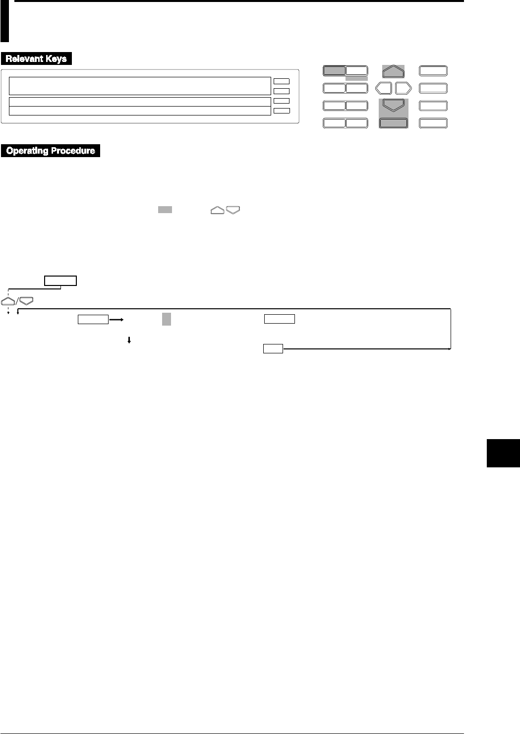
10-25
IM DR232-01E
10
Basic Settings (SET UP)
10.11 Selecting the temperature unit from °C or °F
(option)
D I S P M O D E
P R I N TF U N C
I N S D E L
R A N G E A L A R M
S E TC H A R T E N T E R
F E E D
M. F U N C 1
M. F U N C 2
RECORD
ALARM
CHART
KEYLOCK
R E C O R D
SETUP=TEMP
↓R LOCK FUNC_PARM SET_PARM DISPLAY TEMP↑
>Select Setting Parameter
E S C
• Enter the SET UP menu in the following procedure:
1. When the display presents the operation display mode or a menu other than the SET UP
menu, first turn off the power switch.
2. Turn the switch back on while pressing the DISP key and continue pressing the DISP key
for about 5 seconds.
• Select/set using the keys.
• To escape from a lower menu, press the MODE (ESC) key. The main menu will appear,
although new settings/selections will not be kept.
• New settings/selections will be saved when you reach the final display of that setting.
TEMP=°C
C F
***TEMP SET***
TEMP
ENTER ENTER
ESC
(Main menu)
(Lower menu)
SET UP=

10-26 IM DR232-01E
10.11 Selecting the temperature unit from °C or °F (option)
Selecting the temperature unit (TEMP)
The temperature unit can be selected from the following;
•°C which is the initial value, or
•°F
Note
• In the User’s manual all functions and operations are explained using the °C unit. When using the °F
unit, replace the °C unit with the °F unit. For the measurement range/measurement accuracy and
maximum resolution in case of using the °F range, refer to the following table as a replacement of the one
on page 14-2.
• Measurement range: Refer to the following table;
• Measurement accuracy/maximum resolution: Replace the values using the following formula
°F = (°C value × 9/5) + 32
• When changing the temperature unit as descibred above, other settings will be initialized at the same time
and therefore, all settings need to be done again. This initialization will be the same initialization as
described on page 9-17.
• In order to make the set or selected contents effective, the contents must be registered. For details, see
page 10-23.
• To return from the SET UP menu to the operation display mode, select END in the main menu. For
details, see page 10-23.
Measurement ranges for temperature measurements when using the unit °F
Input
TC
(Note that accuracy
of reference junction
compensation is not
considered.)
RTD
High resolution RTD
R
S
B
K
E
J
T
L
U
N
W
KPvsAu7Fe
Pt100(1mA)
Pt100(2mA)
JPt100(1mA)
JPt100(2mA)
Pt50(2mA)
Ni100(1mA)
SAMA
Ni100(1mA)DIN
Ni120(1mA)
J263*B
Cu10 GE
Cu10 L&N
Cu10 WEED
Cu10 BAILEY
Pt100(1mA)
Pt100(2mA)
JPt100(1mA)
JPt100(2mA)
32 to 3200°F
32 to 3200°F
32 to 3308°F
–328 to 2498°F
–328.0 to 1472.0°F
–328.0 to 2012.0°F
–328.0 to 752.0°F
–328.0 to 1652.0°F
–328.0 to 752.0°F
32 to 2372°F
32 to 4199°F
0.0 to 300.0K
–328.0 to 1112.0°F
–328.0 to 482.0°F
–328.0 to 1022.0°F
–328.0 to 482.0°F
–328.0 to 1022.0°F
–328.0 to 482.0°F
–76.0 to 356.0°F
–94.0 to 392.0°F
0.0 to 300.0K
–328.0 to 572.0°F
–220.0 to 302.0°F
–94.0 to 158.0°F
–220.0 to 302.0°F
–94.0 to 158.0°F
Type Measurement Range
*1
*1
*1
*1
*1
*1
*1
*2
*2
*3
*4
*5
*5
*5
*5
*5
*6
*6
*7
*8
*8
*8
*8
*5
*5
*5
*5
*1 :R, S, B, K, E, J, T :ANSI, IEC 584, DIN IEC 584, JIS C 1602-1981
*2 :L :Fe-CuNi, DIN43710, U :Cu-CuNi, DIN 43710
*3 :N :Nicrosil-Nisil, IEC 584, DIN IEC 584
*4 :W :W·5%RE-W·26%Re (Hoskins Mfg Co)
*5 :Pt50 :JIS C 1604-1981, JIS C 1606-1986
Pt100 :JIS C 1604-1989, JIS C 1606-1989, IEC 751, DIN IEC 751
JPt100 :JIS C 1604-1981, JIS C 1606-1989
*6 :SAMA/DIN
*7 :McGRAW EDISON COMPANY
*8 :Ranges to which accuracy applies :
Cu10 GE :–119.9 to 338.0°F, Cu10 L&N :–103.0 to 302.0°F,
Cu10 WEED :–4.0 to 482.0°F, Cu10 BAILEY :–4.0 to 482.0°F
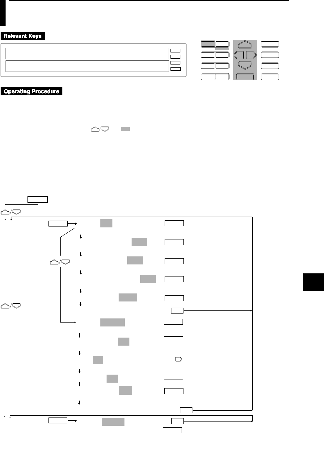
10-27
IM DR232-01E
10
Basic Settings (SET UP)
10.12 Working with the Report Function
D I S P M O D E
P R I N TF U N C
I N S D E L
R A N G E A L A R M
S E TC H A R T E N T E R
F E E D
M. F U N C 1
M. F U N C 2
RECORD
ALARM
CHART
KEYLOCK
R E C O R D
SETUP=REPORT
↓CORD MATH FLOPPY REPORT ALARM A/D_INTG↑
>Select Setting Parameter
E S C
• To enter the SETUP menu, follow the steps below:
1. If the DR recorder is in the OPERATION/DISPLAY mode or shows a menu other than the
SETUP menu, turn off the power switch once.
2. Turn on the power switch while pressing down the DISP key, and then keep holding the key
down for approximately five seconds.
• Using and , select and/or enter a value for each of the shaded fields shown below.
• To exit any of the following menu items during the procedure, press the MODE (ESC) key.
This returns to the first item of the menu. Note however that your new settings and selections
are canceled.
• Reaching the step showing the message “***REPORT SET***” or “***REPORT CH
SET***” confirms the latest settings/selections.
Sending the Instantaneous Value and Average to a Report Output
MODE=SET
SET CH_SET PRINT
HOURLY REPORT=OFF
OFF ON
DAILY REPORT=ON1
OFF ON1 ON2
MONTHLY REPORT=ON1
OFF ON1 ON2
START TIME=01 00 : 00
***REPORT SET***
(configuration complete)
MODE=CH_SET
SET CH_SET PRINT
REPORT CH=R01
R01 R02 R03 R04 R05 R06 R07 R08 R09 R10↑
R01=ON : 001
OFF ON
R01=ON : 001
CALC MODE=AVE
INST AVE SUM
***REPORT CH SET***
(configuration complete)
SETUP=ABORT
REPORT
END
ENTER ENTER
(Main menu item)
(Submenu items)
SET UP=
ENTER
ENTER
ENTER
ENTER
ESC
ENTER
ENTER
ENTER
(Completes the configuration
of the SETUP menu)
ENTER
ENTER
ENTER
ESC
ESC
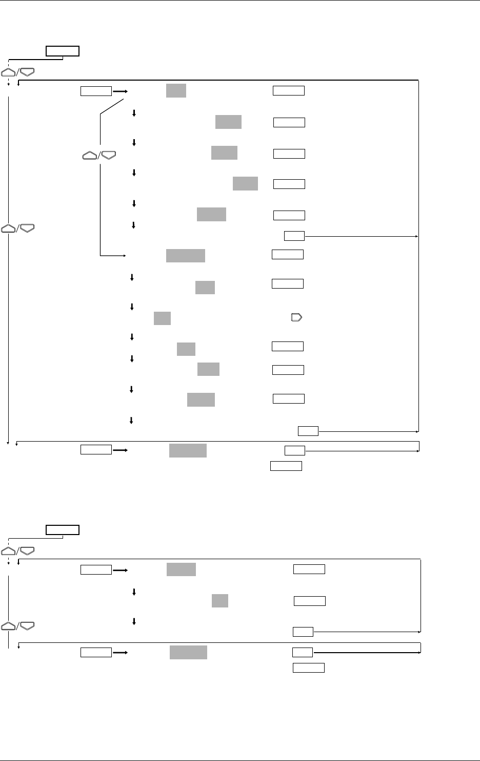
10-28 IM DR232-01E
Sending the Sum to a Report Output
MODE=SET
SET CH_SET PRINT
HOURLY REPORT=OFF
OFF ON
DAILY REPORT=ON1
OFF ON1 ON2
MONTHLY REPORT=ON1
OFF ON1 ON2
START TIME=01 00 : 00
***REPORT SET***
(configuration complete)
MODE=CH_SET
SET CH_SET PRINT
REPORT CH=R01
R01 R02 R03 R04 R05 R06 R07 R08 R09 R10↑
R01=ON : 001
OFF ON
R01=ON : 001
CALC MODE=SUM
INST AVE SUM
SUM UNIT= / sec
INTVL /sec /min /hour /day
***REPORT CH SET***
(configuration complete)
SETUP=ABORT
ABORT STORE
REPORT
END
ENTER ENTER
(Main menu item)
(Submenu items)
SET UP=
ENTER
ENTER
ENTER
ENTER
ESC
ENTER
ENTER
ENTER
(Completes the configuration
of the SETUP menu)
ENTER
ENTER
ENTER
ESC
ESC
ENTER
Printing Reports
MODE=PRINT
SET CH_SET PRINT
REPORT PRINT=ON
OFF ON
***REP PRINT SET***
(configuration complete)
SETUP=ABORT
ABORT STORE
REPORT
END
ENTER
ESC
ENTER
ENTER
ESC
ENTER
(Completes the configuration
of the SETUP menu)
(Main menu item)
(Submenu items)
SET UP=
ENTER
10.12 Working with the Report Function

10-29
IM DR232-01E
10
Basic Settings (SET UP)
The DR recorder calculates and processes an hour's, day's or month's worth of measurement or
computation data into instantaneous values, averages and/or sums to print the results in a
predetermined format at a preset time. The results can be delivered using the communication
function or printed on a recording chart. For more information on output using the
communication function, see the separate DR130/DR231/DR232/DR241/DR242 Communication
Interface User's Manual (IM DR231-11E).
You select from the choices in the FUNC menu, which opens when you press the FUNC key, to
start/stop report making or print reports. You can also start/stop report making using the event/
action functions. Reports come in the following three types.
Type Intervals Between Making Reports Data Item for Computing
Hourly report Every hour (1:00, 2:00 . . ., 23:00, 24:00) An hour's average, maximum and
minimum
An hour's sum and cumulative sum
Instantaneous value at the time of making
the report
Daily report Every other day (preset time) A day's average, maximum and minimum
A day's sum and cumulative sum
Instantaneous value at the time of making
the report
Monthly report Every other month (preset time) A month's average, maximum and
minimum
A month's sum and cumulative sum
Instantaneous value at the time of making
the report
On/Off of Hourly, Daily and Monthly Report Making
Configure the on's and off's of hourly, daily and monthly report making, separately. You can set
hourly, daily and monthly report making all to “on” at the same time. In addition, you can set
daily and monthly reports to either the standard format (ON1) or the enhanced format (ON2) of
output. Note that the enhanced format can only be set for either daily reports or monthly reports.
Output Formats
The format of output is available in either the standard or enhanced format. Hourly reports can
have the standard format only.
Standard format: Prints the results of computing configured on a report-channel basis.
Enhanced format:
Daily reports: the results of computing configured on a report-channel basis plus
information on the result of computing given at each preset time.
Monthly reports: the results of computing configured on a report-channel basis plus
information on given simultaneously with the preset time for making each report
The following shows the format of daily reports:
DAILY REPORT Jan.03.97 00:00 (START=Jan.01.97 00:00)
RCH CH/TAG MODE UNIT Jan.03 00:00 MIN/TOTAL MAX Jan.02 01:00 Jan.02 02:00... Jan.03 00:00
R01 TAG-001CH____ AVE V -1.0000 -2.0000 1.0000 -2.0000 -2.0000 -2.0000
R02 002 INST V 10.000 9.000 9.000 10.000
R03 003 SUM L 2.400000E+01 4.800000E+01 1.000000E+0 1.000000E+00 1.000000E+00
R04
R05
R06 TAG-A01CH____ AVE unit06 20000.000 10000.000 30000.000 10000.000 10000.000 10000.000
R07 A02 INST 200000.00 9999.99 9999.99 200000.00
R08 A03 SUM 2.400000E+01 4.800000E+01 1.000000E+0 1.000000E+00 1.000000E+00
R09
R10
:
R60
Starting timeTime to make report
Standard-format section of report
(results of computing on a report-channel basis)
Enhanced-format section of report
(list of the result of computing at
respective preset times)
10.12 Working with the Report Function
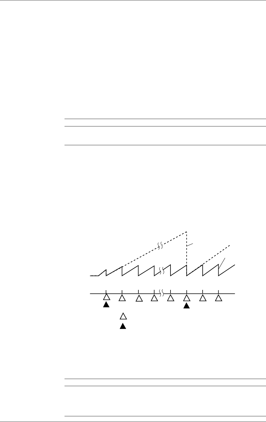
10-30 IM DR232-01E
Time to Make Report (START TIME)
Set the time to make a report in the format day of month : time. Define the day of month field
within a 01-28 range and the time field within a 00-23 range.
Hourly reports:
The DR recorder makes reports every hour on the hour (1:00, 2:00, . . ., 23:00, 24:00). For
cumulative summation, it resets the cumulative sum at a preset time.
Daily reports:
The DR recorder makes reports at a preset time or times. For cumulative summation, it resets the
cumulative sum at the preset time of a day.
Monthly reports:
The DR recorder makes reports at a preset time of the day.
Report Channels
There are sixty report channels, from R01 to R60. You can assign channels for measuring objects
being computed or computation channels and the type of computing on a report-channel basis.
When making a report of computed data, let computing start before letting the report making start.
Types of Computing
Menu Item Data Item for Computing
INST Instantaneous value at the time of making report
AVE Average, maximum and minimum over the computing period
SUM Sum and cumulative sum over the computing period
Sum and Cumulative Sum
Sum: The total sum over an hour for hourly reports, the sum over a day for daily
reports or the sum over a month for monthly reports. The DR recorder resets
this value each time it makes any of these reports.
Cumulative sum:The total sum up to the preset time to make a report in the case of hourly
reports or the sum up to a preset time of the day to make a report in the case of
daily reports. The DR recorder resets this value at each preset time or at each
preset time of the day for report making. The DR recorder does not perform
cumulative summation for monthly reports.
As an example, the following illustrates the process of summation and cumulative summation for
hourly reports. The example shows the case where the preset time to make a report is 8:00.
9:00 11:00
Results of
computing
Time to make an hourly report
Time
7:0010:00
8:00 8:00 9:00 10:00
Cumulative summation
Summation
Preset time to make report
Unit of Summation (SUM UNIT)
Such input data items as the flowrate that have a unit in /sec, /min, /hour or /day, when simply
summed, give results of computing different from their actual values. This occurs because the
unit of such a data item differs from that of the measurement interval. In that case, you can take
the output after having converted the unit of summation so it matches that of the input data item
applied.
Unit of Input (Preset Unit) Conversion Formula
INTVL (no conversion) ∑ (measured data values)
/sec ∑ (measured data values) × measurement interval
/min ∑ (measured data values) × measurement interval/60
/hour ∑ (measured data values) × measurement interval/3600
/day ∑ (measured data values) × measurement interval/86400
10.12 Working with the Report Function

10-31
IM DR232-01E
10
Basic Settings (SET UP)
Printing Reports on a Recording Chart
You can print created reports on a recording chart. If you set the REPORT PRINT menu item to
on during the configuration of the report function, the DR recorder starts printing automatically at
the same time it finishes making a report. You can also print reports by pressing the FUNC key,
opening the FUNC menu and then selecting the REP RECALL START menu item. In that case,
take note of the following:
• You can print the latest report only, irrespective of whether it is an hourly, daily or monthly
report. Neither daily nor monthly reports are printed if you print immediately after an hourly
report was created.
• Care must be taken when the REPORT PRINT menu item is set to automatic printing. If the
time for automatic printing arrives while printing is enabled from the FUNC menu, the DR
recorder will no longer print reports automatically.
• Even if you have configured the DR recorder so it prints a daily report in the enhanced format,
it prints the report in the standard format if it has been more than an hour since the report was
created.
• Even if you have configured the DR recorder so it prints a monthly report in the enhanced
format, it prints the report in the standard format if it has been more than a day since the report
was created.
To stop printing, press the FUNC key and select REP PRINT STOP from the FUNC menu. The
following are examples of how a daily report prints.
Standard format:
DAILY REPORT Jan.03.97 00:00 (START=Jan.01.97 00:00)
RCH CH/TAG MODE UNIT Jan.03 00:00 MIN/TOTAL MAX
R01 TAG-001CH_______ AVE V -1.0000 -2.0000 1.0000
R02 002 INST V 10.000
R03 003 SUM L 2.400000E+01 4.800000E+01
R04
R05
R06 TAG-A01CH_______ AVE unit06 20000.000 10000.000 30000.000
R07 A02 INST 200000.00
R08 A03 SUM 2.400000E+01 4.800000E+01
R09
R10
:
R60
Report channels
Channels included in printing
(Axx: computing channel)
Results of
computing Minimum or
cumulative sum Maximum
Starting timeTime to make report
Types of
computing Units
Enhanced format:
DAILY REPORT Jan.03.97 00:00 (START=Jan.01.97 00:00)
RCH CH/TAG MODE UNIT Jan.03 00:00 MIN/TOTAL MAX Jan.02 01:00 Jan.02 02:00... Jan.03 00:00
R01 TAG-001CH____ AVE V -1.0000 -2.0000 1.0000 -2.0000 -2.0000 -2.0000
R02 002 INST V 10.000 9.000 9.000 10.000
R03 003 SUM L 2.400000E+01 4.800000E+01 1.000000E+0 1.000000E+00 1.000000E+00
R04
R05
R06 TAG-A01CH____ AVE unit06 20000.000 10000.000 30000.000 10000.000 10000.000 10000.000
R07 A02 INST 200000.00 9999.99 9999.99 200000.00
R08 A03 SUM 2.400000E+01 4.800000E+01 1.000000E+0 1.000000E+00 1.000000E+00
R09
R10
:
R60
Report channels
Channels included in printing (Axx: computing channel)
Results of
computing Minimum or
cumulative sum Maximum
Starting timeTime to make report
Types of
computing Units Enhanced-format section of report
(list of the result of computing at respective
preset times for daily reports)
Note
• If any of the following conditions is true, you cannot print reports even when the preset time to make a
report arrives. In that case, the DR recorder prints reports when the current printing ends.
• Manual printing is in progress.
• List printing or setup list printing is in progress.
• Header printing is in progress.
• Logging printing is in progress.
• The DR recorder does not print reports either even if the preset time to make a report arrives while
printing is enabled from the FUNC menu.
10.12 Working with the Report Function
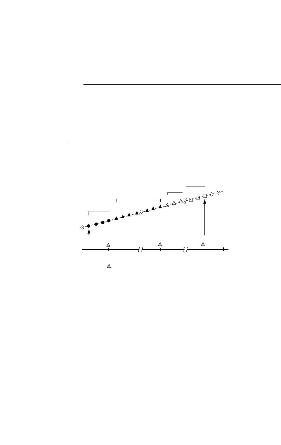
10-32 IM DR232-01E
Starting/Stopping Report Making
Report making can be started or stopped in two ways:
• Press the FUNC key and select REPORT_START or REPORT_STOP from the FUNC menu.
• Use the event/action functions to define the start/stop of making a report for the following
events:
Edge action: You can define every event as an edge action to start/stop report making.
Level action:You can use remote, alarm, relay and end-of-chart signals as events to start/stop
report making. Report making starts at the same time that any of these events
occur. Report making stops when the event clears.
Note
• If you start report making, all reports created up to that point are reset.
• When report making is in progress, you cannot make changes to measurement channels, measuring
ranges or dates and times nor can you copy information on the ranges.
• If any computed data are included in your report making, let computing start first and then get report
making started. If you fail to enable computing, the data in your reports will become meaningless
because no change takes place on the computed data.
• If you want the start of computing and report making enabled at the same time, use the event/action
functions to assign both of these instructions to the same event as actions.
Time Relationship Between the Settings of the REPORT_START/STOP Menu Items
and Report Making
The following figure shows the time relationship between the settings of the REPORT_START/
STOP menu items and report making.
Report 1
Report 2 Report 3
Report n
Start of report
making
denotes the point in time a report is created.
Time to make report Time to make report Time to make report
Stop of report making
• Data items included in the first round of report making after the start of report making are fewer
in number than those included in the second and subsequent rounds of report making.
• The DR recorder samples data before stopping report making. The report created when the DR
recorder stops making reports thus includes those data.
• If the time when report making is started coincides with the time the report is created, the start
of report making precedes. Thus, no report is created.
• The data sampled at the same time report making started are included in first round of report
making. The report created when the DR recorder stops making reports thus includes those
data.
• If you have defined timer and match-time signals as events using the event/action functions so
the time report making starts matches the time the report is created, data items included in the
first round of report making are one data item greater in number than those included in the
second or any subsequent round of report making.
Processing Against Absence of Measurement
Measurement may not take place if the DR recorder is loaded beyond its processing capability. If
absence of measurement occurs, the DR recorder compensates for the missing data with the data it
measures immediately after recovering from the absence of measurement (the data for the period
with no measurement thus match those acquired immediately after recovering from the absence of
measurement).
10.12 Working with the Report Function

10-33
IM DR232-01E
10
Basic Settings (SET UP)
If Power Failure Occurs While Report Function Is Active
The DR recorder takes different actions depending on the length of a power failure.
If the power failure time is longer than 12 hours:
The DR recorder makes a report immediately after it recovers from the power failure and then
stops making reports. It does not execute printing based on the settings for automatic printing.
Print out reports either using the communication function or from the FUNC menu.
Results of computing: The DR recorder computes data measured up to the point immediately
before the power failure.
Time of report making:The time when the power failure occurred.
If the power failure is less than 12 hours:
The DR recorder takes different actions depending on the time it recovers from the power
failure.
Time of Recovery from After the Time of Before the Time of
Power Failure Report Making Report Making
Condition after recovery from Valid report function Valid report function
power failure (start of report making enabled) (start of report making enabled)
Report making Immediately after recovery from Time for report making
power failure
Report printing Immediately after recovery from Time for report making
power failure
Data included in report making Data measured up to the point of Data measured over the given
power failure period except the power failure time
If automatic report printing is turned on:
If the power failure time covers the given period of report making, no report for that period is made.
Handling of Faulty Data
If data being computed contain any faulty data, the DR recorder treats the data as summarized in
the following table, depending on the type of computing and faulty data.
Type of Faulty Data Average Minimum/Maximum Instantaneous Value Sum
Positive overflow Excluded from Included in computing Takes faulty data as Excluded from
computing the result of computing computing
Negative overflow Excluded from Included in computing Takes faulty data as Excluded from
computing the result of computing computing
Channels included in Excluded from
Excluded from computing
Takes faulty data as Excluded from
measurement set to SKIP
computing the result of computing computing
No channel included Excluded from
Excluded from computing
Takes faulty data as Excluded from
in measurement computing the result of computing computing
Error Excluded from
Excluded from computing
Takes faulty data as Excluded from
computing the result of computing computing
Output of data disabled
Excluded from
Excluded from computing
Takes faulty data as Excluded from
computing the result of computing computing
The DR recorder prints the results of computing as shown in the following table if they are special
data.
Type of Data Printout Format
Positive overflow +******
Negative overflow –******
Channels included in measurement set to SKIP Space
No channel included in measurement Space
Error ××××××
Output of data disabled
If data being computed contain faulty data, the DR recorder prints each digital data item,
beginning with an * or × as the status indication.
1. Power failure: ×
In the case of a power failure, the DR recorder prints the time for report making, also beginning
with an ×.
2. Channels included in measurement set to SKIP/no channel included in measurement/error/
output of disabled data: ×
10.12 Working with the Report Function

10-34 IM DR232-01E
3. Positive overflow/negative overflow: *
If more than one faulty data item occurs at the same time, the DR recorder prints them while
giving priority to a data item with a smaller number among the numbers noted above.
Notes on daylight savings time
When the function to shift the time scale between standard time and daylight savings time is
specified, the report for the day to shift from standard time to the daylight savings time seemingly
includes data for only a 23-hour day and, at the same time, the report for the day to shift daylight
savings time to standard time seemingly includes the data for a 25 hour day.
If you specify the time to make a report at the same time as the shift from standard time to
daylight savings time, or vice versa, the report will be generated based on the time scale after the
shift.
10.12 Working with the Report Function

11-1
IM DR232-01E
Saving/Reading Measured,
Computed and Set-up Data
11
11.1 Saving Measured and Computed Data
Procedure for Saving Data
When saving measured/computed data on a floppy disk, save them first on the DR recorder's
built-in RAM disk and then copy them to the floppy disk. You can save the data on the built-in
RAM disk in three ways, as summarized in the following table:
Menu Item Method for Starting Saving Number of Files Saved
DIRECT Immediately starts saving when the setting is complete. One
TRIGGER Starts saving when an event occurs as set using the One
event/action functions.
REPEAT Starts saving when an event occurs as set using the More than one*
event/action functions.
* The DR recorder continues to save an array of files of the specified size until the built-in RAM disk
becomes full.
Flow of Operation
The following paragraphs show the flow operation for a case where a measured data file is saved
using the occurrence of an alarm as a trigger.
1.Setting an Event/Action
Menu Item Setting
LOGIC in SET menu LOGIC BOX No.
EVENT=ALARM
ACT=EDGE/MEMORY : WR_TRIG
2. Selecting a Channel Whose Data Are Saved
Menu Item Setting
MEMORY in SET menu MEMORY=CH SET
001-01: CH SET=ON
(Allowed to set the consecutive numbers of channels)
3. Selecting a Method and Condition for Saving
Menu Item Setting
MEMORY in SET menu MEMORY=WRITE
WRITE=TRIGGER
WRITE file=
(File name: If new, press ENTER leaving the name blank.)
WRITE SAMPLE=
(Interval between file savings)
WRITE LENGTH=
(Size of file being saved)
WRITE PRE TRIG=
(Pre-trigger: not configurable if MEMORY=DIRECT)
4. Copying Files Saved on Built-in RAM Disk to Floppy Disk
Menu Item Setting
MEMORY in SET menu MEMORY=COPY
COPY MODE=TO FDD
COPY TYPE=DATA
COPY FILE=
(Name of file being copied)
COPY CONVERT=OFF
(Saved as binary-data file)
See the following pages for more information on how to configure these menu items.
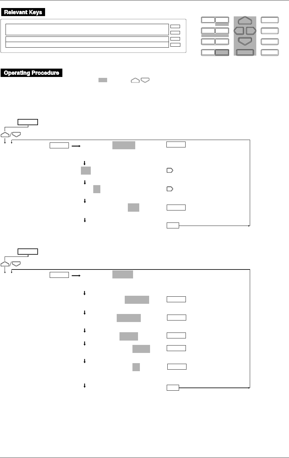
11-2 IM DR232-01E
D I S P M O D E
P R I N TF U N C
I N S D E L
R A N G E A L A R M
S E TC H A R T E N T E R
F E E D
M. F U N C 1
M. F U N C 2
RECORD
ALARM
CHART
KEYLOCK
R E C O R D
SET=MEMORY
SYSTEM UNIT MATH CONST MEMORY FLOPPY TR↑
>Select Setting Parameter
E S C
• Press the SET key to enter the SET menu.
• Select/set using the keys.
• To escape from a lower menu, press the MODE (ESC) key. Its main menu will appear,
although new settings/selections will not be kept.
• New settings/selections will be kept when you reach the final display of that setting.
Selecting the channel to be saved
MEMORY=CH SET
CH_SET WRITE READ SAVE LOAD COPY DELETE
INFO INIT
001-01:CH SET=ON
>Select Channel No.
001-01:CH SET=ON
>Select Channel No.
001-01:CH SET=ON
ON OFF
***CH SET OK***
(End of setting)
SET=
MEMORY
ESC
(Main menu)
ENTER ENTER
ENTER
Saving immediately
ENTER
MEMORY=WRITE
CH_SET WRITE READ SAVE LOAD COPY DELETE
INFO INIT
WRITE MODE=DIRECT
DIRECT TRIGER REPEAT STOP
WRITE file=
_____ AAA BBB CCC
WRITE FILE=DDDD
WRITE SAMPLE=INTVL
INTVL 1min 2min 5min 10min LOGIC
WRITE LENGTH=1k
10 20 30 40 50 100 200 300 400 500 1k 2k
3k 4k 5k 10k 20k 30k 40k 50k
***WRITE START***
(End of setting)
ENTER
SET=
MEMORY
ESC
(Main menu)
ENTER ENTER
ENTER
ENTER
ENTER
11.1 Saving Measured and Computed Data
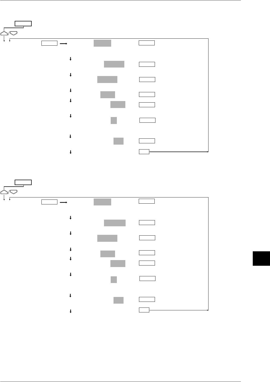
11-3
IM DR232-01E
Saving/Reading Measured,
Computed and Set-up Data
11
11.1 Saving Measured and Computed Data
Saving one file only using the event/action function
ENTER
MEMORY=WRITE
CH_SET WRITE READ SAVE LOAD COPY DELETE
INFO INIT
WRITE MODE=TRIGER
DIRECT TRIGER REPEAT STOP
WRITE file=
_____ AAA BBB CCC
WRITE FILE=DDDD
WRITE SAMPLE=INTVL
INTVL 1min 2min 5min 10min LOGIC
WRITE LENGTH=1k
10 20 30 40 50 100 200 300 400 500 1k 2k
3k 4k 5k 10k 20k 30k 40k 50k
WRITE PRE TRIG=10%
0 10 20 30 40 50 60 70 80 90 100
***WRITE START***
(End of setting)
ENTER
SET=
MEMORY
ESC
(Main menu)
ENTER ENTER
ENTER
ENTER
ENTER
ENTER
Saving files repeatedly using the event/action function
ENTER
MEMORY=WRITE
CH_SET WRITE READ SAVE LOAD COPY DELETE
INFO INIT
WRITE MODE=REPEAT
DIRECT TRIGER REPEAT STOP
WRITE file=
_____ AAA BBB CCC
WRITE FILE=DDDD
WRITE SAMPLE=INTVL
INTVL 1min 2min 5min 10min LOGIC
WRITE LENGTH=1k
10 20 30 40 50 100 200 300 400 500 1k 2k
3k 4k 5k 10k 20k 30k 40k 50k
WRITE PRE TRIG=10%
0 10 20 30 40 50 60 70 80 90 100
***WRITE START***
(End of setting)
ENTER
SET=
MEMORY
ESC
(Main menu)
ENTER ENTER
ENTER
ENTER
ENTER
ENTER
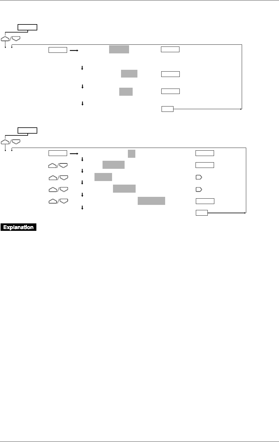
11-4 IM DR232-01E
Stopping saving
MEMORY=WRITE
CH_SET WRITE READ SAVE LOAD COPY DELETE
INFO INIT
WRITE MODE=STOP
DIRECT TRIGER REPEAT STOP
WRITE STOP=YES
NO YES
***WRITE STOP***
(End of setting)
SET=
MEMORY
ESC
(Main menu)
ENTER ENTER
ENTER
ENTER
LOGIC BOX NO.=01
EVENT=ALARM
ACT=EDGE/ALARM ACK
ACT=EDGE/MEMRY:DATA_WR
ACT=EDGE/MEMRY:WR_TRIG
•••SET OK***
(Lower menu)
SET=
LOGIC
ESC
(Main menu)
ENTER ENTER
ENTER
ENTER
Measured/computed data is saved to the internal RAM disk. The memory size of the RAM disk
is 512 KB.
Saving method (WRITE MODE)
The following three methods are available.
• DIRECT
Measured/computed data is saved immediately after setting has been completed. Saving is
complete when data of the specified length has been saved.
• TRIGGER
The event/action function is used to save only one file of measured/computed data when an
event takes place. This function is useful when you want to save measured/computed data in
case of an alarm.
• REPEAT
Same as TRIGGER, except that measured/computed data is saved each time an event takes
place, until the RAM disk is full or saving is stopped by the operator. Events which occur
during saving will be ineffective.
11.1 Saving Measured and Computed Data
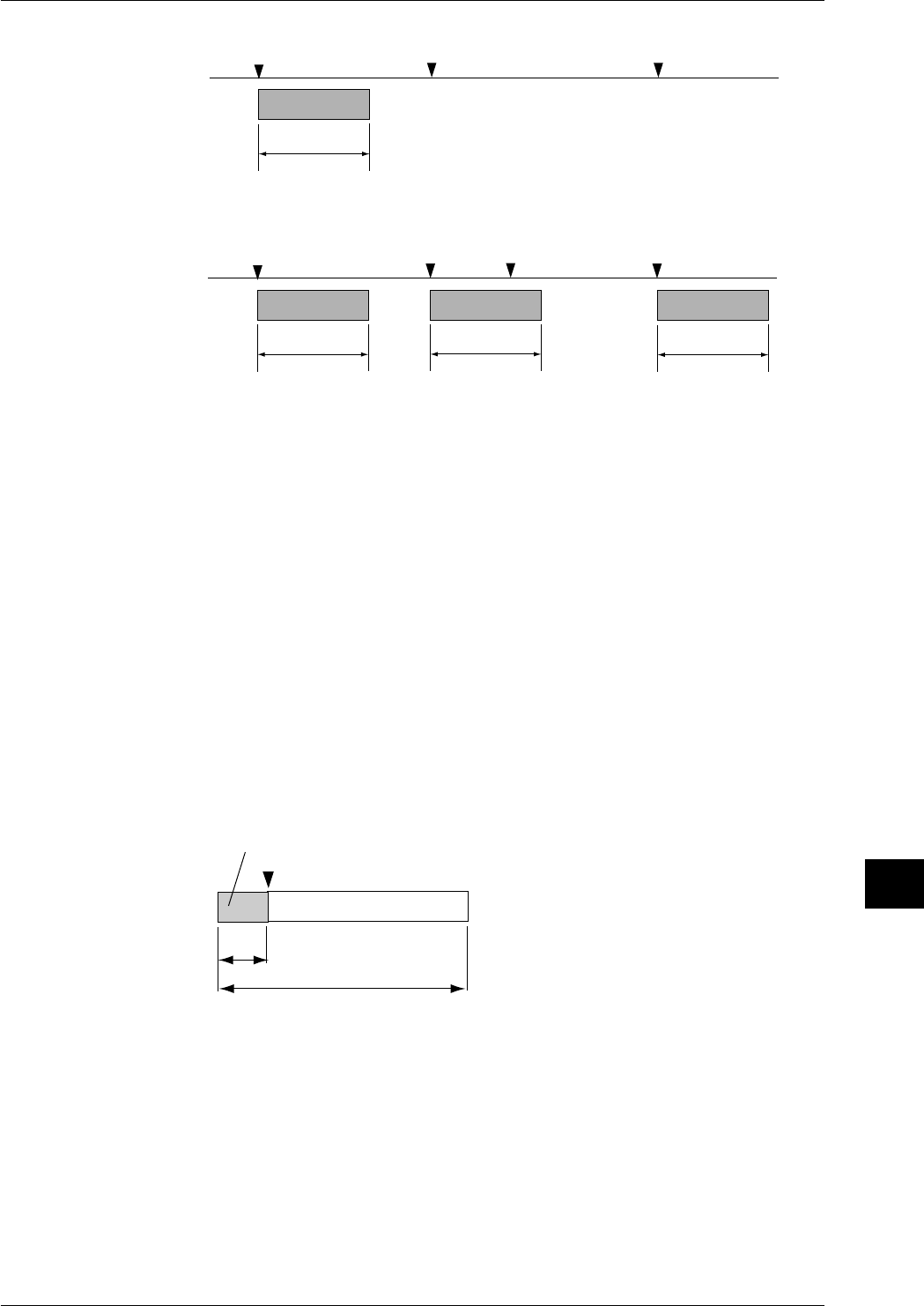
11-5
IM DR232-01E
Saving/Reading Measured,
Computed and Set-up Data
11
Event Event Event
Event Event Event
Specified
data length
Specified
data length Specified
data length Specified
data length
Start of saving End of saving
Start of saving End of saving
Start of saving End of saving Start of saving End of saving
File 001
File 001 File 002 File 003
Event
RAM disk
Event
RAM disk
When TRIGGER is selected as WRITE MODE:
When REPEAT is selected as WRITE MODE:
Event(ineffective)
For TRIGGER or REPEAT, one event must be set for the WR TRIG action during event/action
function setting. For a detailed description of the event/action function, refer to 9.1, “Setting
Event/Action Functions” (page 9-1).
Data write interval (WRITE SAMPLE)
The data write interval at which data is saved can be selected from the following.
INTVL: Same as measurement interval. Every set of measured/computed data is saved.
1 min, 2 min, 5 min, 10 min: Saved at the specified interval.
LOGIC: One piece of data per channel is saved each time the event specified by DATA WR
(event/action function) occurs. For a detailed description of the event/action function,
refer to 9.1, “Setting Event/Action Functions” (page 9-1).
Data length (WRITE LENGTH)
Used to set the number of pieces of data per channel. Select one of the following options.
10, 20, 30, 40, 50, 100, 200, 300,. 400, 500, 1k, 2k, 3k, 4k, 5k, 10k, 20k, 30k, 40k, 50k
Some options cannot be selected depending on the number of channels to be saved or the number
of computation channels.
Pre-trigger (PRE TRIGGER)
If REPEAT or TRIGGER has been selected as WRITE MODE, data which occurs before the
trigger (event) is activated can be saved within the specified data length. Set the trigger timing in
units of percentage (%) of the specified data length in steps of 10%.
Trigger (event)
20%
Data length (100%)
Data which occurs before the trigger
File name
If DIRECT or TRIGGER has been selected as WRITE MODE, the file name must consist of up
to 8 characters. If REPEAT has been selected as WRITE MODE, the file name must be of up to 5
characters in length. The lower 3 digits of the file name indicate the serial number (001 to 208).
AUX, CON, PRN and CLOK cannot be used for a file name. The identifier is .DAT.
11.1 Saving Measured and Computed Data

11-6 IM DR232-01E
Data format
Measured/computed data is saved in binary format.
Data size
Data size can be calculated using the following equations.
Measured data: 2 bytes / 1 data
Computed data: 4 bytes / 1 data
Header: 576 + 64 x (number of measurement channels + number of computation channels) bytes
Data size = 576 + 64 x (number of measurement channels + number of computation channels) +
(number of measurement channels x 2 + number of computation channels x 4 + 6) x specified
data length
For instance, if the number of channels is 10, number of computation channels is 5 and specified
data length is 5k, the data size can be calculated as follows.
Data size = 576 + 64 x (10 + 5) + ((10 x 2 + 5 x 4) + 6) x 5k = 231,536 bytes
Status display during saving
The following status symbols are displayed in the sub-display 2 (lowest display section).
M
: Saving is in progress.
T
: Awaiting a trigger
Restrictions during saving
The following settings can not be made while saving is in progress.
Settings relating to media, except for saving stop setting
Measuring range
Computation equation/constant
Group
11.1 Saving Measured and Computed Data
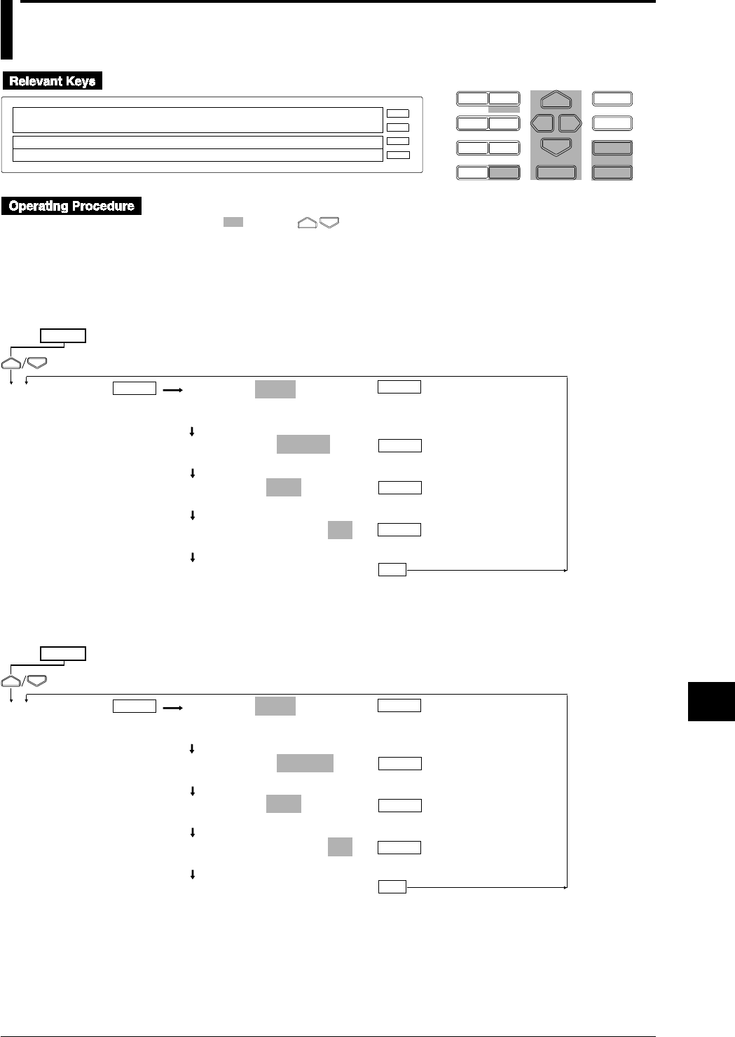
11-7
IM DR232-01E
Saving/Reading Measured,
Computed and Set-up Data
11
11.2 Reading Measured and Computed Data
D I S P M O D E
P R I N TF U N C
I N S D E L
R A N G E A L A R M
S E TC H A R T E N T E R
F E E D
M. F U N C 1
M. F U N C 2
RECORD
ALARM
CHART
KEYLOCK
R E C O R D
SET=MEMORY
SYSTEM UNIT MATH CONST MEMORY FLOPPY TR↑
>Select Setting Parameter
E S C
• Press the SET key to enter the SET menu.
• Select/set using the keys.
• To escape from a lower menu, press the MODE (ESC) key. Its main menu will appear,
although new settings/selections will not be kept.
• New settings/selections will be kept when you reach the final display of that setting.
Reading measured/computed data immediately from the RAM disk
MEMORY=READ
CH_SET WRITE READ SAVE LOAD COPY DELETE
INFO INIT
READ MODE=DIRECT
DIRECT TRIGER STOP INFO
READ FILE=AAA
AAA BBB CCC DDD
READ START DATA= 1
>Start Limit ( 1 ~200000)
***READ START***
(End of setting)
SET=
MEMORY
ESC
(Main menu)
ENTER ENTER
ENTER
ENTER
ENTER
Reading measured/computed data from the RAM disk using the event/action
function
MEMORY=READ
CH_SET WRITE READ SAVE LOAD COPY DELETE
INFO INIT
READ MODE=TRIGER
DIRECT TRIGER STOP INFO
READ FILE=AAA
AAA BBB CCC DDD
READ START DATA= 1
>Start limit ( 1 ~200000)
***READ START***
(End of setting)
SET=
MEMORY
ESC
(Main menu)
ENTER ENTER
ENTER
ENTER
ENTER
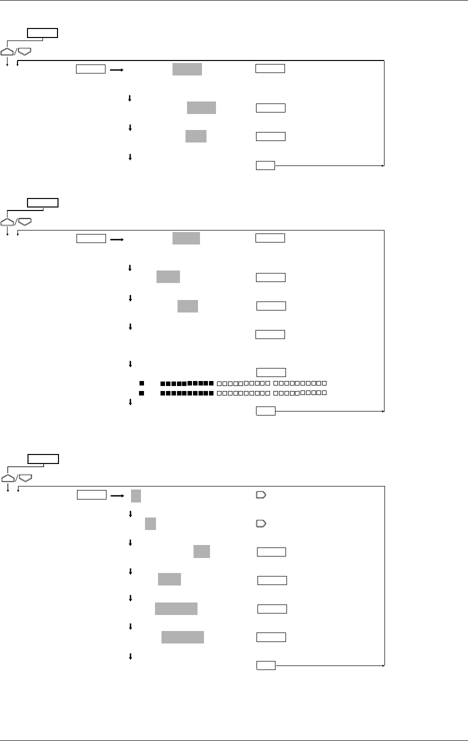
11-8 IM DR232-01E
Stopping reading
MEMORY
=
READ
CH_SET WRITE READ SAVE LOAD COPY DELETE
INFO INIT
READ MODE
=
STOP
DIRECT TRIGER STOP INFO
READ STOP
=
YES
YES NO
***READ STOP***
(End of setting)
SET=
MEMORY
ESC
(Main menu)
ENTER ENTER
ENTER
ENTER
Displaying the contents of the file
MEMORY
=
READ
CH_SET WRITE READ SAVE LOAD COPY DELETE
INFO INIT
READ
=
INFO
DIRECT TRIGER STOP INFO
INFO FILE
=
AAA
AAA BBB CCC DDD
>MODEL=EXPAND
>96/07/07 00:00:00 LENGTH=20000
>SAMPLE= 10(Sec) TRIG DATA No.= 1
>CHANNEL=201-60
>ON 201
>ON 231
***INFO END***
(End of setting)
SET=
MEMORY
ESC
(Main menu)
ENTER ENTER
ENTER
ENTER
ENTER
ENTER
Assigning the read data to a computation channel to display or record the data
ENTER
ENTER
A01-30:MODE=ON
>Select Channel No.
A01-01:MODE=ON
>Select Channel No.
A01-01:MODE=ON
OFF ON
CALC=M001
0 1 2 3 4 5 6 7 8 9 ( ) AM .
LEFT=-3000.000Kg
>Span limit (-9999.999 ~99999.999Kg)
RIGHT= 3000.000Kg
>Span limit (-9999.999 ~99999.999Kg
***SET OK***
(End of setting)
ENTER
SET=
MATH
ESC
(Main menu)
ENTER
ENTER
11.2 Reading Measured and Computed Data
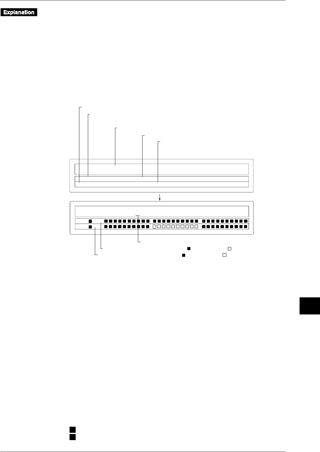
11-9
IM DR232-01E
Saving/Reading Measured,
Computed and Set-up Data
11
Measured/computed data is read from the internal RAM disk.
Reading methods (READ MODE)
The following two methods are available.
• DIRECT
Data is read at the measurement intervals immediately after setting has been completed.
• TRIGGER
The event/action function is used to read data at the measurement intervals when an event takes
place. This function is useful when you want to compare data before an event with data after
an event.
Displaying the contents of the file
The following information of the read file is displayed.
>
MODEL=EXPANDABLE
>SAMPLE= 10(Sec) TRIG DATA No.= 1
>96/07/07 00:00 LENGTH=20000
>
CHANNEL=201–60
>ON 201
>ON 231
Model type on which data was saved
Number of pieces of data per channel
Data No. in effect when the trigger (event) took place
Always "1" if saving was carried out without DIRECT
or PRE TRIGGER settings made.
Date/time on which a trigger (event) took place
Saving start date/time in the case where saving was carried out in DIRECT mode
Sample rate (intervals at which data was saved)
Status of channel Nos. 201 to 230 ( : Data available, : No data available)
Status of channel Nos. 231 to 260 ( : Data available, : No data available)
Channel is changed if this digit is changed.
ENTER key
Displaying/recording the read data
To display or record the read data, it is necessary to assign the read data to computation channels
A01 to A60 using the SET menu. This assignment is still possible even if the instrument is not
equipped with the optional computation function.
Assign the following channels to computation channels A01 to A60.
• M001 to M300: Read data for measurement channels
• MA01 to MA60: Read data for computation channels
If the instrument is equipped with the computation function (/M1 model), read data can be
calculated in the same way that measured/computed data is calculated.
Like measurement channels, it is possible to make the unit, alarm, zone, partial compression, tag,
linear interpolation, dot color and recording settings for computation channels A01 to A60.
However, only the upper-limit and lower-limit alarms are available. Specify channel Nos. A01 to
A60 when specifying channel Nos.
Reading data from a floppy disk
To read data which has been copied to a floppy disk from the RAM disk, it is necessary to copy
the data from the floppy disk to the RAM disk. However, data in ASCII format cannot be read.
Status display during reading
The following status symbols are displayed in the sub-display 2 (lowest display section).
It is not possible to make media settings other than reading stop setting while measured/computed
data is being read.
M
: Reading is in progress.
T
: Awaiting a trigger
11.2 Reading Measured and Computed Data
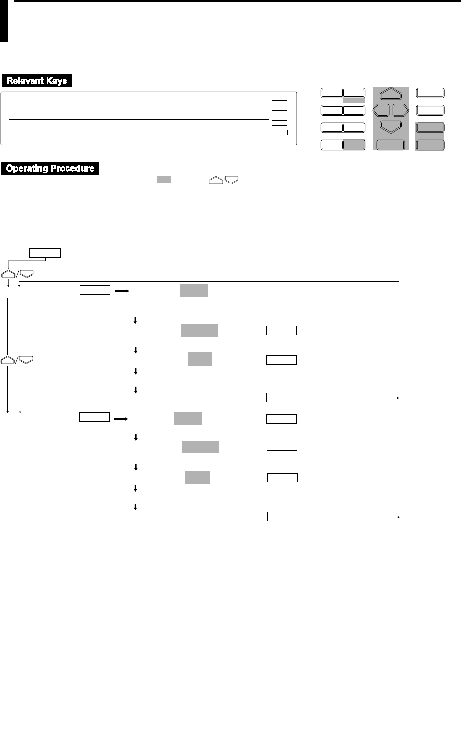
11-10 IM DR232-01E
11.3 Saving Set-up Data
Saving set-up data for the SET mode
D I S P M O D E
P R I N TF U N C
I N S D E L
R A N G E A L A R M
S E TC H A R T E N T E R
F E E D
M. F U N C 1
M. F U N C 2
RECORD
ALARM
CHART
KEYLOCK
R E C O R D
SET=MEMORY
SYSTEM UNIT MATH CONST MEMORY FLOPPY TR↑
>Select Setting Parameter
E S C
• Press the SET key to enter the SET menu.
• Select/set using the keys.
• To escape from a lower menu, press the MODE (ESC) key. Its main menu will appear,
although new settings/selections will not be kept.
• New settings/selections will be kept when you reach the final display of that setting.
MEMORY=SAVE
CH_SET WRITE READ SAVE LOAD COPY DELETE
INFO INIT
SAVE file=
_____ AAA BBB CCC
SAVE FILE=AAA
Saving... *
***SAVE OK***
(End of saving)
SET=
MEMORY
ESC
(Main menu)
ENTER ENTER
ENTER
ENTER
FLOPPY FLOPPY=SAVE
SAVE LOAD DELETE INFO FORMAT
SAVE file=
_____ AAA BBB CCC
SAVE FILE=AAA
Saving... *
***SAVE OK***
(End of saving)
ESC
ENTER
ENTER
ENTER ENTER
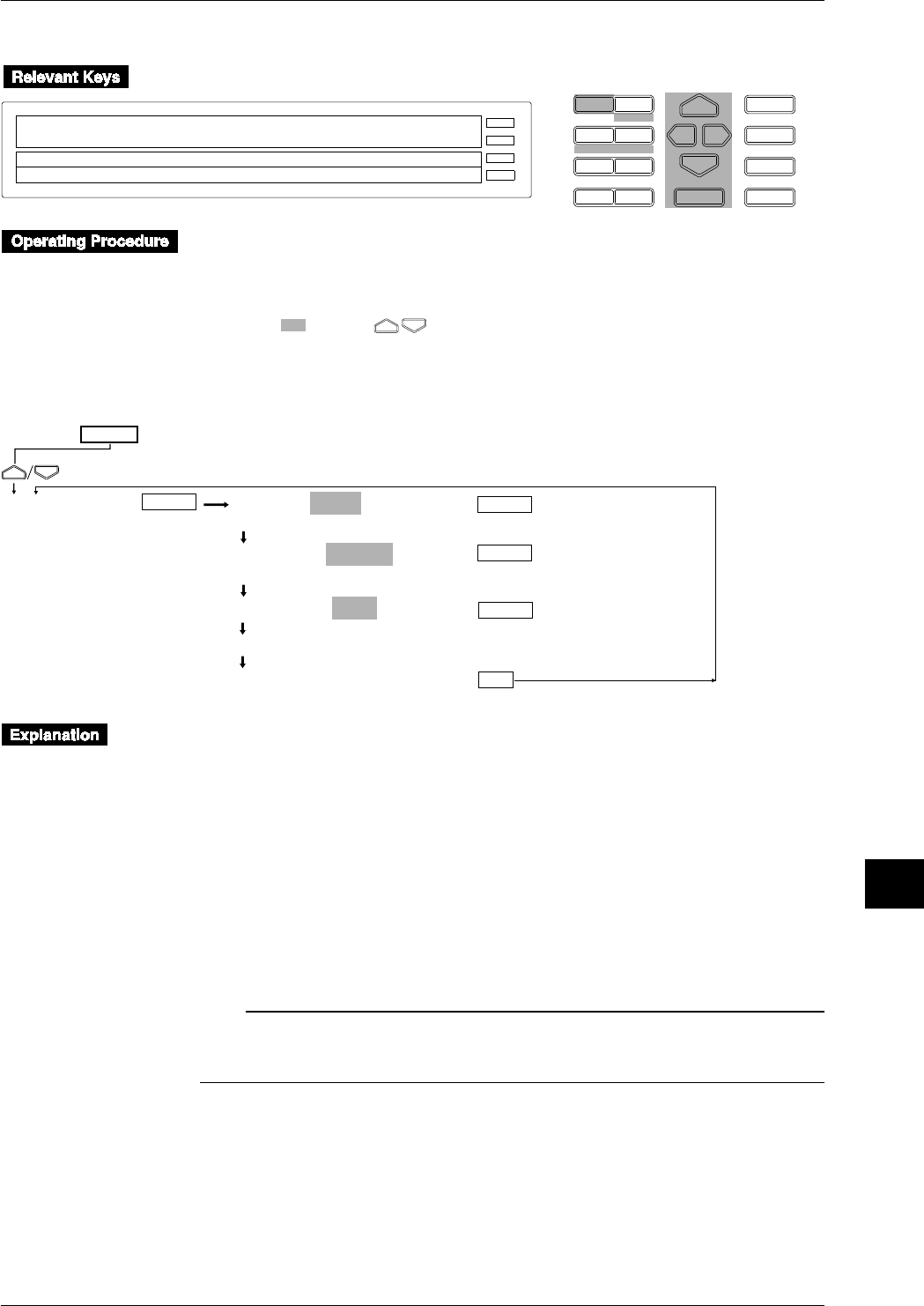
11-11
IM DR232-01E
Saving/Reading Measured,
Computed and Set-up Data
11
Saving set-up data for the SETUP mode
D I S P M O D E
P R I N TF U N C
I N S D E L
R A N G E A L A R M
S E TC H A R T E N T E R
F E E D
M. F U N C 1
M. F U N C 2
RECORD
ALARM
CHART
KEYLOCK
R E C O R D
SETUP=FLOPY
↓ PRN_ADJ SCAN_INTV RECORD MATH FLOPPY↑
>Select Setting Parameter
E S C
• Carry out the following steps to enter the SET UP menu.
1. If the SET UP menu is not currently displayed, turn the power OFF
2. While holding the DISP key, turn the power ON. Make sure depression of the DISP key is
maintained for approximately another five seconds..
• Select/set using the keys.
• To escape from a lower menu, press the MODE (ESC) key. Its main menu will appear,
although new settings/selections will not be kept.
SET UP=
(Main menu)
FLOPPY FLOPPY=SAVE
SAVE LOAD DELETE INFO FORMAT
SAVE file=
_____ AAA BBB CCC
SAVE FILE=AAA
Saving... *
***SAVE OK***
(End of saving)
ESC
ENTER
ENTER
ENTER ENTER
Set-up data except for date/time is saved to the internal RAM disk or a floppy disk. Set-up data
for the SETUP mode can be saved to a floppy disk only. Data is always saved in ASCII format.
The file name must consist of up to 8 characters. The following identifier is used.
Set-up data file for SET mode : .PNL
Set-up data file for SETUP mode : .SET
Data size
Set-up data for the SET mode: Up to approximately 250 KB (300 measurement channels
and 60 computation channels) are available for set-up data for the
SET mode.
Set-up data for SET OR mode: Approx. 50 KB (max) (for 300 measurement channels and
60 computation channels)
Note
• “Saving ...*” will be displayed during saving. During this period, key board operations are not possible.
• No saving is allowed during computing.
• The communication function remains disabled during saving.
11.3 Saving Set-up Data
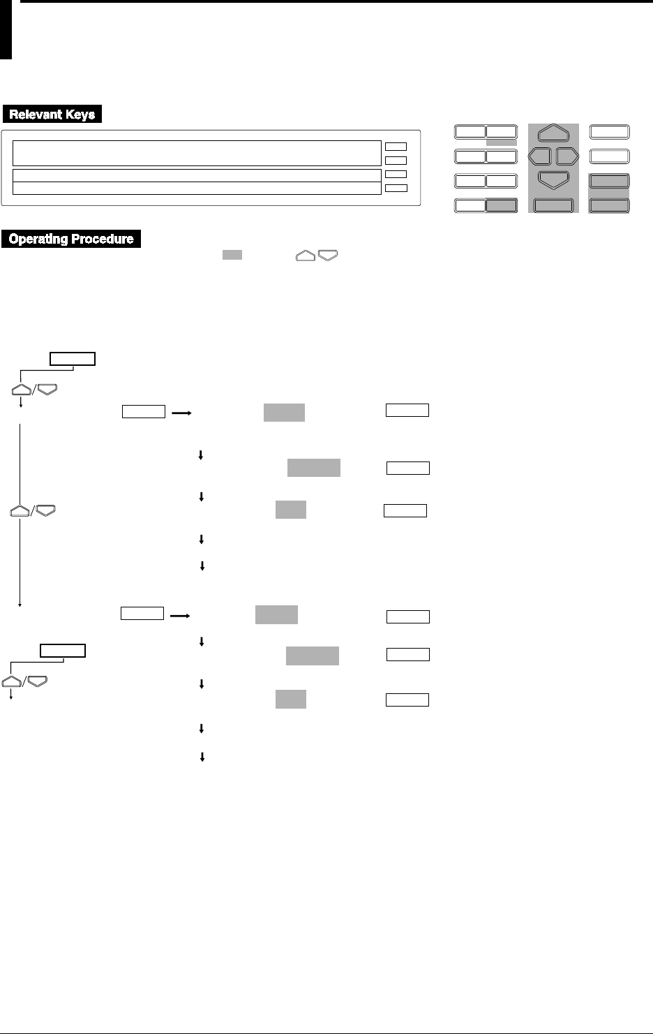
11-12 IM DR232-01E
11.4 Reading Set-up Data
Reading set-up data for the SET mode
D I S P M O D E
P R I N TF U N C
I N S D E L
R A N G E A L A R M
S E TC H A R T E N T E R
F E E D
M. F U N C 1
M. F U N C 2
RECORD
ALARM
CHART
KEYLOCK
R E C O R D
SET=MEMORY
SYSTEM UNIT MATH CONST MEMORY FLOPPY TR↑
>Select Setting Parameter
E S C
• Press the SET key to enter the SET menu.
• Select/set using the keys.
•To escape from a lower menu, press the MODE (ESC) key. Its main menu will appear,
although new settings/selections will not be kept.
•New settings/selections will be kept when you reach the final display of that setting.
MEMORY=LOAD
CH_SET WRITE READ SAVE LOAD COPY DELETE
INFO INIT
LOAD MODE=DIRECT
DIRECT TRIG_1 TRIG_2 TRIG_3
LOAD FILE=AAA
AAA BBB CCC
Loading... *
Operation status displayed
SET=
MEMORY
(Main menu)
ENTER ENTER
ENTER
FLOPPY FLOPPY=LOAD
SAVE LOAD DELETE INFO FORMAT
LOAD MODE=DIRECT
DIRECT TRIG_1 TRIG_2 TRIG_3
LOAD FILE=AAA
AAA BBB CCC
Loading... *
Operation status displayed
ENTER
ENTER
ENTER
ENTER
ENTER
SET=
MEMORY
(Main menu)
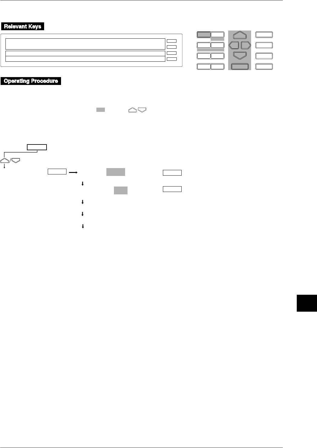
11-13
IM DR232-01E
Saving/Reading Measured,
Computed and Set-up Data
11
Reading set-up data for the SETUP mode
D I S P M O D E
P R I N TF U N C
I N S D E L
R A N G E A L A R M
S E TC H A R T E N T E R
F E E D
M. F U N C 1
M. F U N C 2
RECORD
ALARM
CHART
KEYLOCK
R E C O R D
SETUP=FLOPPY
PRN_ADJ SCAN_INTV RECORD MATH FLOPPY
>Select Setting Parameter
E S C
• Carry out the following steps to enter the SET UP menu.
1. If the SET UP menu is not currently displayed, turn the power OFF
2. While holding the DISP key, turn the power ON. Make sure depression of the DISP key is
maintained for approximately another five seconds.
• Select/set using the keys.
•To escape from a lower menu, press the MODE (ESC) key. Its main menu will appear,
although new settings/selections will not be kept.
FLOPPY FLOPPY=LOAD
SAVE LOAD DELETE INFO FORMAT
LOAD FILE=AAA
AAA BBB CCC
Loading... *
Main menu
STORE for confirmation
ENTER
ENTER ENTER
SET UP=
(Main menu)
11.4 Reading Set-up Data

11-14 IM DR232-01E
Set-up data for the SET mode or SETUP mode is read from the internal RAM disk or a floppy
disk.
Loading methods (LOAD MODE in SET mode)
The following two methods are available.
• DIRECT
Setup data is loaded immediately after setting has been completed.
• TRIGGER 1/TRIGGER 2/TRIGGER 3
The event/action function is used to load set-up data when an event takes place. This function
is useful if you want to record data when an event takes place, with different recording spans.
One event must be set for the LD_TRIG1, LD_TRIG2 and LD_TRIG3 actions during event/
action function setting. For a detailed description of the event/action function, refer to 9.1,
“Setting Event/Action Functions” (page 9-1).
Confirming the set-up data
To confirm the read set-up data for the SETUP mode, specify SETUP = STORE in the same way
as the SETUP mode setting.
Note
• If set-up data saved on another instrument (DR series recorder) is loaded and does not match this
instrument’s configuration, settings which do not comply with the configuration cannot be made.
• No reading is allowed during computing.
• The communication function remains disabled during reading.
11.4 Reading Set-up Data
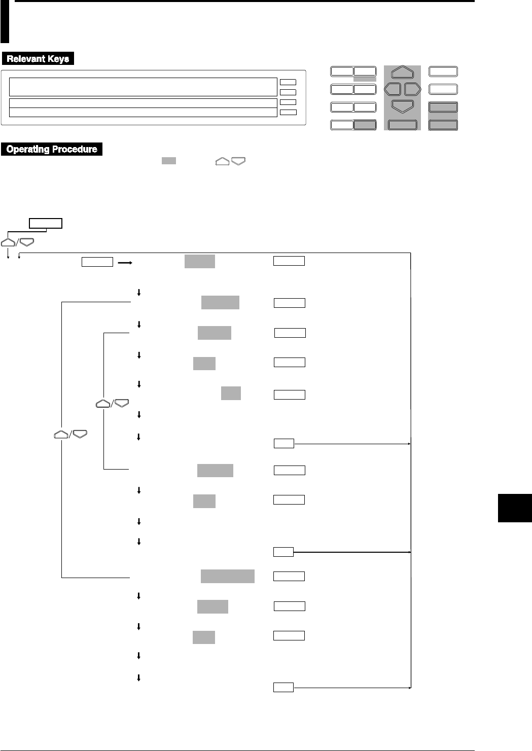
11-15
IM DR232-01E
Saving/Reading Measured,
Computed and Set-up Data
11
11.5 Copying a Data File
D I S P M O D E
P R I N TF U N C
I N S D E L
R A N G E A L A R M
S E TC H A R T E N T E R
F E E D
M. F U N C 1
M. F U N C 2
RECORD
ALARM
CHART
KEYLOCK
R E C O R D
SET=MEMORY
SYSTEM UNIT MATH CONST MEMORY FLOPPY TR↑
>Select Setting Parameter
E S C
• Press the SET key to enter the SET menu.
• Select/set using the keys.
•To escape from a lower menu, press the MODE (ESC) key. Its main menu will appear,
although new settings/selections will not be kept.
•New settings/selections will be kept when you reach the final display of that setting.
MEMORY=COPY
CH_SET WRITE READ SAVE LOAD COPY DELETE
INFO INIT
COPY MODE=TO FDD
TO FDD FROM FDD
COPY TYPE=DATA
DATA PANEL
COPY FILE=AAA
AAA BBB CCC DDD
COPY CONVERT=OFF
ON OFF
Copying... *
***COPY OK***
(End of copy)
ENTER
SET=
MEMORY
ESC
(Main menu)
ENTER ENTER
ENTER
ENTER
ENTER
ESC
ENTER
ENTER
ENTER
COPY MODE=FROM FDD
TO FDD FROM FDD
COPY TYPE=DATA
DATA PANEL
COPY FILE=AAA
AAA BBB CCC DDD
Copying... *
***COPY OK***
(End of copy)
COPY TYPE=PANEL
DATA PANEL
COPY FILE=AAA
AAA BBB CCC DDD
Copying... *
***COPY OK***
(End of copy)
ESC
ENTER
ENTER

11-16 IM DR232-01E
Measured/computed/set-up data is copied from the internal RAM disk to a floppy or vice versa.
Types of files that can be copied (COPY TYPE)
• DATA: copies measured and computed data.
• PANEL: copies set-up data.
Saving measured/computed data to a floppy disk
Data measured or computed using the instrument cannot be saved to a floppy disk directly. It
must be saved to the internal RAM disk first, then copied to a floppy disk.
It is not possible to change the file name when copying the file.
Displaying/recording measured/computed data saved on a floppy disk using the
instrument
To use the instrument to display or record measured/computed data copied to a floppy disk, the
file containing measured/computed data must be copied from the floppy disk to the RAM disk.
However, data in ASCII format cannot be copied.
It is not possible to change the file name when copying the file.
11.5 Copying a Data File
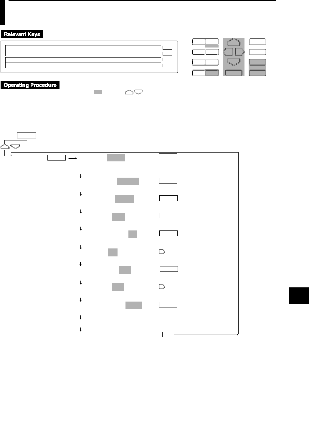
11-17
IM DR232-01E
Saving/Reading Measured,
Computed and Set-up Data
11
11.6 Copying in ASCII Format
D I S P M O D E
P R I N TF U N C
I N S D E L
R A N G E A L A R M
S E TC H A R T E N T E R
F E E D
M. F U N C 1
M. F U N C 2
RECORD
ALARM
CHART
KEYLOCK
R E C O R D
SET=MEMORY
SYSTEM UNIT MATH CONST MEMORY FLOPPY TR↑
>Select Setting Parameter
E S C
• Press the SET key to enter the SET menu.
• Select/set using the keys.
•To escape from a lower menu, press the MODE (ESC) key. Its main menu will appear,
although new settings/selections will not be kept.
•New settings/selections will be kept when you reach the final display of that setting.
ENTER
MEMORY=COPY
CH_SET WRITE READ SAVE LOAD COPY DELETE
INFO INIT
COPY MODE=TO FDD
TO FDD FROM FDD
COPY TYPE=DATA
DATA PANEL
COPY FILE=AAA
AAA BBB CCC DDD
COPY CONVERT=ON
ON OFF
COPY CH=001-A05
>Select Channel No.
COPY CH=001-A05
>Select Channel No.
COPY DAT= 1- 200
>Start limit ( 1~200000 )
COPY DAT= 1- 200
Start limit ( 1~200000 )
Copying... *
***COPY OK***
(End of setting)
SET=
MEMORY
ESC
(Main menu)
ENTER ENTER
ENTER
ENTER
ENTER
ENTER
ENTER

11-18 IM DR232-01E
Measured/computed data in the internal RAM disk is converted to ASCII data, then copied to a
floppy disk. The identifier is .CSV.
Conversion channel (COPY CH)
Used to select a channel whose data is to be converted to ASCII data. Measurement channels and
computation channels are arranged in the order of 001, 002, ... 560, A01, A02, ... A60. For
instance, if “559-A02” is specified, data for channels 559, 560, A01 and A02 will be converted.
Conversion data (COPY DATA)
Used to specify the conversion range for the channels specified by COPY CH. Enter the
conversion start data No. and end data No.
Data size
When measured/computed data is converted to ASCII data, 12 bytes will be used for each data
set. Thus, data size can be calculated as follows.
Data size = 178 + 20 x number of conversion channels - 2 + (24 + 12 x number of conversion
channels -1) x number of data sets to be converted
Copying is not possible if destination’s memory size is insufficient.
Note
When a file is copied to a floppy disk, the file creation date will be replaced by the date on which the file is
copied.
11.6 Copying in ASCII Format

11-19
IM DR232-01E
Saving/Reading Measured,
Computed and Set-up Data
11
Data format
ASCII converted data is saved in the following format.
"Sample by DARWIN"
"Trigger Time","96-02-14 15:05:07"
"Sample Rate(Sec)", 2
"Start Data No.", 1
"Data Length", 20
"Ch.Name","TURBINE1","TURBINE2","TURBINE5","TURBINE7","TURBINE0"
"Unit","mV ","Kg/mm "," C "," C "," C "
"YY-MM-DD HH:MM:SS.S"
"96-02-14 15:05:07.0"," 12.520"," 315.00"," 23.2"," -5.0"," 16.3"
"96-02-14 15:05:09.0"," 12.322"," 315.05"," 23.2"," -4.9"," 15.9"
"96-02-14 15:05:11.0"," 13.724"," 315.20"," 23.3"," -4.8"," 15.9"
"96-02-14 15:05:13.0"," 13.220"," 315.12"," 23.3"," -4.9"," 15.8"
"96-02-14 15:05:15.0"," 13.925"," 315.60"," 23.3"," -4.9"," 15.8"
"96-02-14 15:05:17.0"," 13.227"," 315.55"," 23.3"," -4.9"," 16.0"
"96-02-14 15:05:19.0"," 13.928"," 315.04"," 23.3"," -5.0"," 16.1"
"96-02-14 15:05:21.0"," 12.620"," 315.29"," 23.3"," -5.1"," 16.1"
"96-02-14 15:05:23.0"," 12.643"," 315.01"," 23.2"," -5.1"," 16.2"
"96-02-14 15:05:25.0"," 13.426"," 315.05"," 23.2"," -5.1"," 16.3"
"96-02-14 15:05:27.0"," 12.227"," 315.42"," 23.2"," -5.2"," 15.9"
"96-02-14 15:05:29.0"," 12.233"," 315.81"," 23.2"," -5.2"," 15.8"
"96-02-14 15:05:31.0"," 13.822"," 315.03"," 23.2"," -5.1"," 15.8"
"96-02-14 15:05:33.0"," 12.324"," 315.05"," 23.2"," -5.2"," 15.8"
"96-02-14 15:05:35.0"," 13.220"," 315.07"," 23.2"," -5.1"," 16.0"
"96-02-14 15:05:37.0"," 13.450"," 315.91"," 23.2"," -5.1"," 16.3"
"96-02-14 15:05:39.0"," 13.720"," 315.05"," 23.2"," -5.1"," 16.3"
"96-02-14 15:05:41.0"," 12.670"," 315.02"," 23.2"," -5.2"," 16.2"
"96-02-14 15:05:43.0"," 12.830"," 315.01"," 23.2"," -5.0"," 16.1"
"96-02-14 15:05:45.0"," 12.350"," 315.01"," 23.2"," -5.0"," 16.1"
Saving date/time Data
Trigger date/time
Saving interval
ASCII conversion data No.
Data length (number of data sets)
Channel No. or tag
Unit
Note
• The following special ASCII codes will be converted as follows.
°→ Space (20H)
Ω→ Space (20H)
µ→ u (75H)
ε→ e (65H)
Ω
→ Space (20H)
• No copying is allowed during computing.
• The communication function remains disabled during copying.
• If you save data using a trigger, a T precedes the time attached to the data saved at the time of triggering.
11.6 Copying in ASCII Format
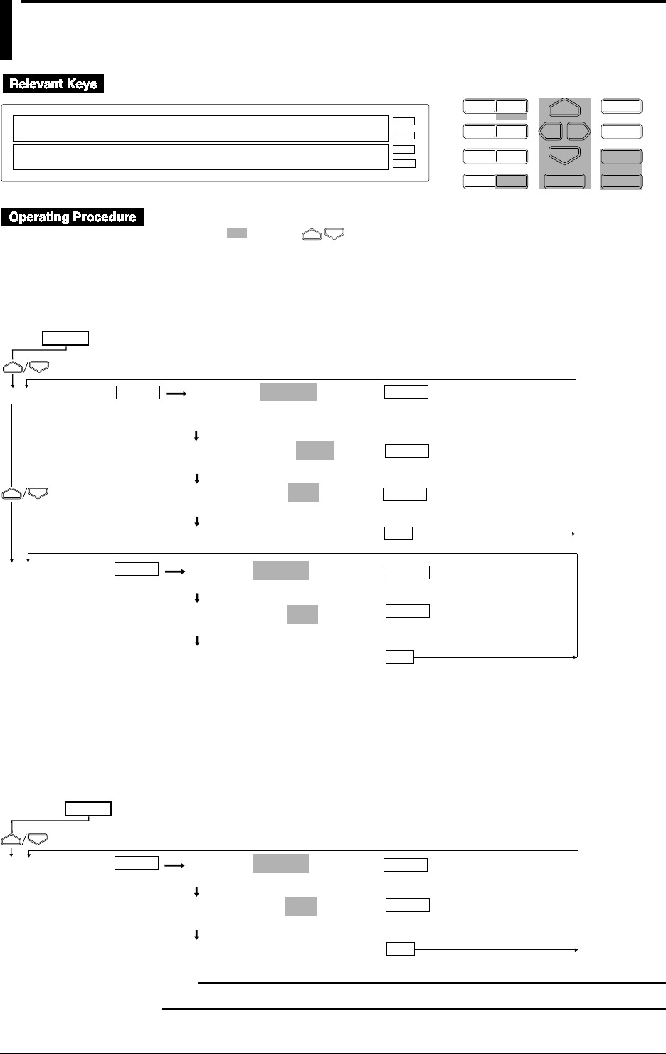
11-20 IM DR232-01E
11.7 Deleting a Data File
D I S P M O D E
P R I N TF U N C
I N S D E L
R A N G E A L A R M
S E TC H A R T E N T E R
F E E D
M. F U N C 1
M. F U N C 2
RECORD
ALARM
CHART
KEYLOCK
R E C O R D
SET=MEMORY
SYSTEM UNIT MATH CONST MEMORY FLOPPY TR↑
>Select Setting Parameter
E S C
• Press the SET key to enter the SET menu.
• Select/set using the keys.
•To escape from a lower menu, press the MODE (ESC) key. Its main menu will appear,
although new settings/selections will not be kept.
•New settings/selections will be kept when you reach the final display of that setting.
MEMORY=DELETE
CH_SET WRITE READ SAVE LOAD COPY DELETE
INFO INIT
DELETE TYPE=DATA
DATA PANEL
DELETE FILE=AAA
AAA BBB CCC
***DELETE OK***
(End of setting)
SET=
MEMORY
(Main menu)
ENTER ENTER
ENTER
FLOPPY FLOPPY=DELETE
SAVE LOAD DELETE INFO FORMAT
DELETE FILE=AAA
AAA BBB CCC
***DELETE OK***
(End of setting)
ENTER
ENTER
ESC
ENTER
ESC
ENTER
Deleting a data file for the SETUP mode
A data file for the SETUP mode can be deleted in the same way as a data file for the SET mode is
deleted.
Select FLOPPY from the SETUP menu.
SET UP=
(Main menu)
FLOPPY FLOPPY=DELETE
SAVE LOAD DELETE INFO FORMAT
DELETE FILE=AAA
AAA BBB CCC
***DELETE OK***
(End of setting)
ESC
ENTER
ENTER ENTER
Note
• The communication function is disabled during deletion.
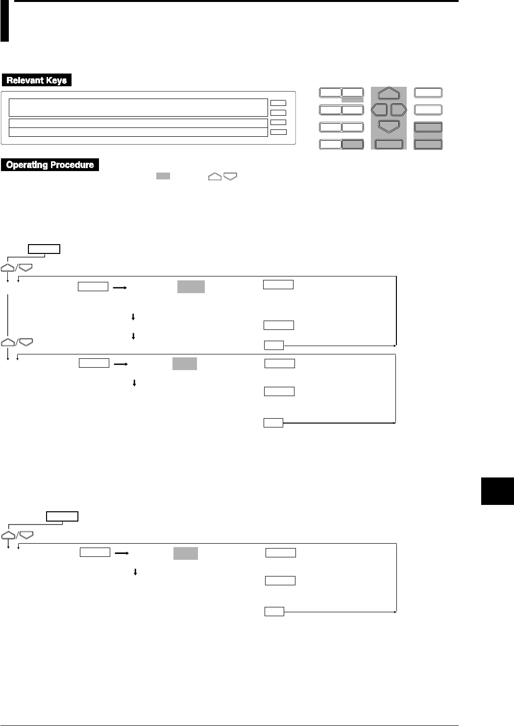
11-21
IM DR232-01E
Saving/Reading Measured,
Computed and Set-up Data
11
11.8 Displaying RAM Disk and Floppy Disk Information
Displaying information in the SET mode
D I S P M O D E
P R I N TF U N C
I N S D E L
R A N G E A L A R M
S E TC H A R T E N T E R
F E E D
M. F U N C 1
M. F U N C 2
RECORD
ALARM
CHART
KEYLOCK
R E C O R D
SET=MEMORY
SYSTEM UNIT MATH CONST MEMORY FLOPPY TR↑
>Select Setting Parameter
E S C
• Press the SET key to enter the SET menu.
• Select/set using the keys.
•To escape from a lower menu, press the MODE (ESC) key. Its main menu will appear,
although new settings/selections will not be kept.
•New settings/selections will be kept when you reach the final display of that setting.
FLOPPY=INFO
SAVE LOAD DELETE INFO FORMAT
>VOLUME=DARWIN
>MEMORY= 20000 BYTES
***INFO END***(End)
SET=
MEMORY
FLOPPY
(Main menu)
ENTER
ENTER
ESC
ENTER
MEMORY=INFO
CH_SET WRITE READ SAVE LOAD COPY DELETE
INFO INIT
>MEMORY = 20000BYTES
***INFO END***(End)
ENTER ENTER
ENTER
ESC
Displaying information in the SETUP mode
Information can be displayed in the same way as the SET mode.
Select FLOPPY from the SETUP menu.
FLOPPY=INFO
SAVE LOAD DELETE INFO FORMAT
>VOLUME=DARWIN
>MEMORY= 20000 BYTES
***INFO END***
(End)
SET UP=
FLOPPY
(Main menu)
ENTER
ENTER
ESC
ENTER

11-22 IM DR232-01E
Internal RAM disk and floppy disk information is displayed.
Internal RAM disk
Remaining memory size is displayed.
Floppy disk
Volume name and remaining memory size are displayed.
11.8 Displaying RAM Disk and Floppy Disk Information
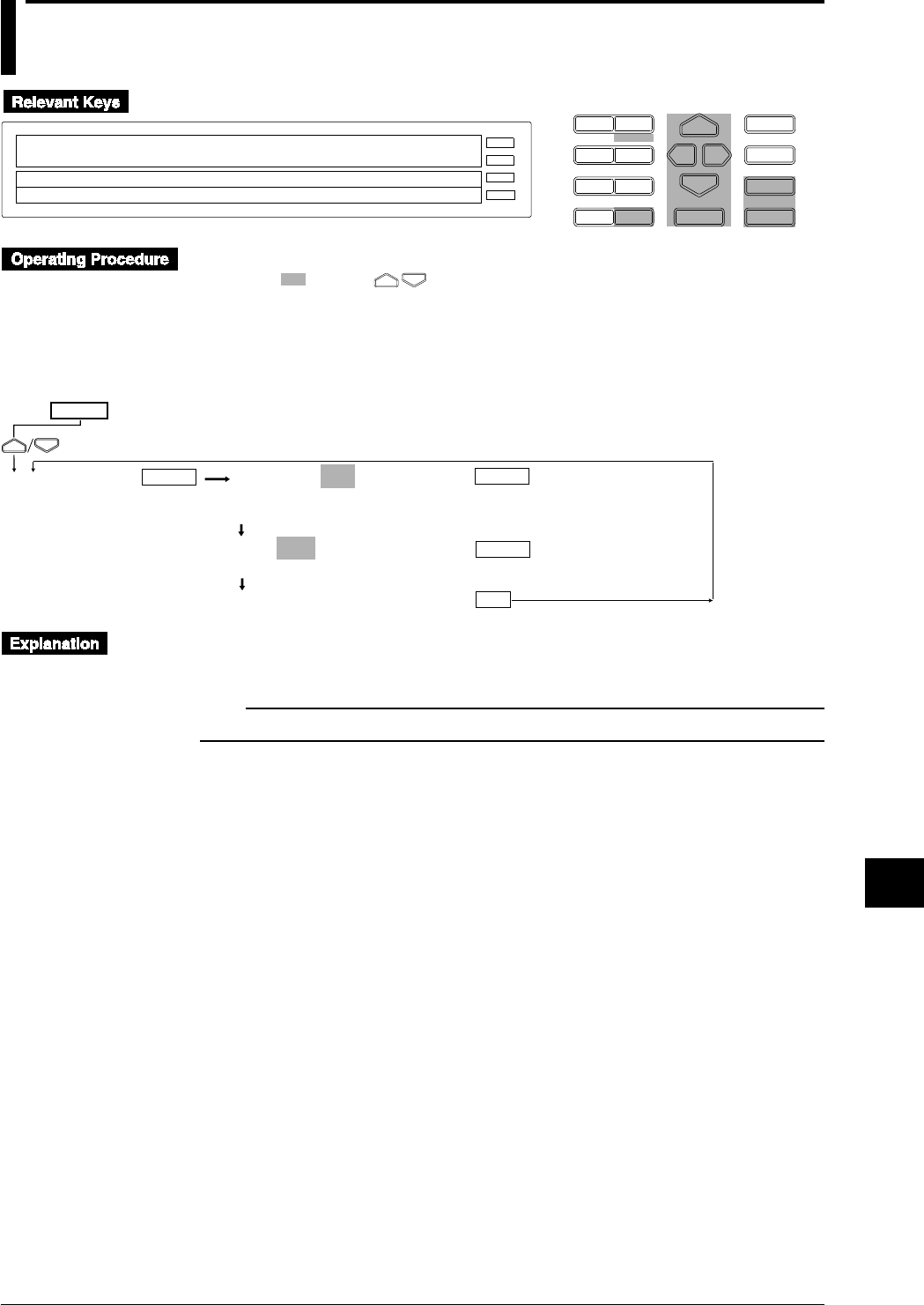
11-23
IM DR232-01E
Saving/Reading Measured,
Computed and Set-up Data
11
11.9 Initializing the RAM Disk
D I S P M O D E
P R I N TF U N C
I N S D E L
R A N G E A L A R M
S E TC H A R T E N T E R
F E E D
M. F U N C 1
M. F U N C 2
RECORD
ALARM
CHART
KEYLOCK
R E C O R D
SET=MEMORY
SYSTEM UNIT MATH CONST MEMORY FLOPPY TR↑
>Select Setting Parameter
E S C
• Press the SET key to enter the SET menu.
• Select/set using the keys.
•To escape from a lower menu, press the MODE (ESC) key. Its main menu will appear,
although new settings/selections will not be kept.
•New settings/selections will be kept when you reach the final display of that setting.
MEMORY=INIT
CH_SET WRITE READ SAVE LOAD COPY DELETE
INFO INIT
INIT=YES
NO YES
***INIT OK***
(End of initialization)
SET=
MEMORY
ESC
(Main menu)
ENTER ENTER
ENTER
The internal RAM disk is initialized. All the data in the RAM disk will be deleted. Thus, copy
necessary data to a floppy disk before carrying out initialization.
Note
• The communication function is disabled during initialization.
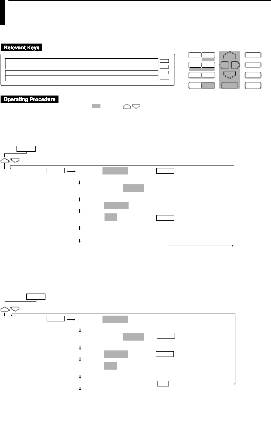
11-24 IM DR232-01E
11.10 Formatting a Floppy Disk
Formatting a floppy disk in the SET mode
D I S P M O D E
P R I N TF U N C
I N S D E L
R A N G E A L A R M
S E TC H A R T E N T E R
F E E D
M. F U N C 1
M. F U N C 2
RECORD
ALARM
CHART
KEYLOCK
R E C O R D
SET=FLOPPY
SYSTEM UNIT MATH CONST MEMORY FLOPPY TR↑
>Select Setting Parameter
E S C
• Press the SET key to enter the SET menu.
• Select/set using the keys.
•To escape from a lower menu, press the MODE (ESC) key. Its main menu will appear,
although new settings/selections will not be kept.
•New settings/selections will be kept when you reach the final display of that setting.
FLOPPY=FORMAT
SAVE LOAD DELETE INFO FORMAT
FORMAT MODE=1.44MB
1.2MB 720KB 1.44MB
VOLUME=DARWIN
FORMAT=YES
NO YES
Formatting... *
***FORMAT OK***
(End)
SET=
FLOPPY
(Main menu)
ENTER
ENTER
ESC
ENTER
ENTER
ENTER
Formatting a floppy disk in the SETUP mode
A floppy disk can be formatted in the same way as in the SETUP mode.
Select FLOPPY from the SETUP menu.
SET UP=
(Main menu)
FLOPPY FLOPPY=FORMAT
SAVE LOAD DELETE INFO FORMAT
FORMAT MODE=1.44MB
1.2MB 720KB 1.44MB
VOLUME=DARWIN
FORMAT=YES
NO YES
Formatting... *
***FORMAT OK***
(End)
ESC
ENTER
ENTER ENTER
ENTER
ENTER

11-25
IM DR232-01E
Saving/Reading Measured,
Computed and Set-up Data
11
A floppy disk is formatted. All the data on the floppy disk will be deleted. Thus, copy necessary
data to another media before carrying out formatting.
Format mode (FORMAT MODE)
Select the format mode from the following.
2HD: 1.44 MB, 1.2 MB
2DD: 720 KB
Volume name
Beginning the volume name with a space is not allowed. If this happens, an error will occur.
Note
• The communication function is disabled during formatting.
11.10 Formatting a Floppy Disk

12-1
IM DR232-01E
Executing Computation
(Available with the /M1 Model)
12
12.1 Overview of the Computation Function
Type Operator Example Description
Addition + 001+002 Obtain the sum of the measured data of channel 001 and channel 002.
Subtraction - 002-001 Obtain the difference of the measured data of channel 002 and channel 001.
Multiplication * 003*K1 Multiply constant K1 to the measured data of channel 003.
Division / 004/K2 Divide the measured data of channel 004 by constant K2.
Power ** 005**006 Take the power of measured data of channel 005 with the measured data of
channel 006.
Absolute value ABS() ABS(001) Obtain the absolute value of the measured data of channel 001.
Square root SQR() SQR(002) Obtain the square root of the measured data of channel 002.
Common logarithmLOG() LOG(003) Obtain the common logarithm of the measured data of channel 003.
Natural Logarithm LN() LN(004) Obtain the natural logarithm of the measured data of channel 004.
Exponent EXP() EXP(005) Make the measured data of channel 005 to be x and obtain ex.
* +/- can be used as signs as in -(001).
Logical operators
Type Operator Example Description
Logical product AND 001AND002 when channel 001=0 and channel 002=0, “0”.
when channel 001=nonzero and channel 002=0, “0”.
when channel 001=0 and channel 002=nonzero, “0”.
when both channel 001 and channel 002 are nonzero, “1”.
Logical sum OR 001OR002 when channel 001=0 and channel 002=0, “0”.
when channel 001=nonzero and channel 002=0, “1”.
when channel 001=0 and channel 002=nonzero, “1”.
when both channel 001 and channel 002 are nonzero, “1”.
Exclusive OR XOR 001XOR002 when channel 001=0 and channel 002=0, “0”.
when channel 001=nonzero and channel 002=0, “1”.
when channel 001=0 and channel 002=nonzero, “1”.
when both channel 001 and channel 002 are nonzero, “0”.
Logical negation NOT NOT001 when channel 001=0, “1”.
when channel 001=nonzero, “0”.
Relational operators
Type Operator Example Description
Equal .EQ. 001.EQ.002 when channel 001 = channel 002, “1”.
when channel 001 ≠ channel 002, “0”.
Not equal .NE. 002.NE.001 when channel 001 ≠ channel 002, “1”.
when channel 001 = channel 002, “0”.
Greater than .GT. 003.GT.K1 when channel 003 > constant K1, “1”.
when channel 003 ≤ constant K1, “0”.
Less than .LT. 004.LT.K10 when channel 004 < constant K10, “1”.
when channel 004 ≥ constant K10, “0”.
Greater than or .GE. 003.GE.K1 when channel 003 ≥ constant constant K1, “1”.
equal to when channel 003 < constant K1, “0”.
Less than or .LE. 004.LE.K10 when channel 004 ≤ constant K10, “1”.
equal to when channel 004 > constant K10, “0”.
Specified channel statistical operators
Type Operator Example Description
Maximum value TLOG.MAX() TLOG.MAX(001) Obtain the maximum value of the measured data of channel
001.
Minimum value TLOG.MIN() TLOG.MIN(002) Obtain the minimum value of the measured data of channel
002.
Max-min value TLOG.P-P() TLOG.P-P(003) Obtain the P-P value of the measured data of channel 003.
Total value TLOG.SUM() TLOG.SUM(004) Obtain the total value of the measured data of channel 004.
Average value TLOG.AVE() TLOG.AVE(005) Obtain the average value of the measured data of channel 005.
* Statistical computation of the measured data from the start of the statistical computation until it is
stopped. When combining with each of the operators, MAX(), MIN(), P-P(), SUM(), and AVE(), the
value that can be specified inside the () is limited to the input channel number or the computation channel
number (refer to next page) (Example: TLOG.MAX(A01)).

12-2 IM DR232-01E
12.1 Overview of the Computation Function
Statistical operators within the group
Type Operator Example Description
Maximum value CLOG.MAX() CLOG.MAX(G01) Obtain the maximum value of the measured data of group G01.
Minimum value CLOG.MIN() CLOG.MIN(G02) Obtain the minimum value of the measured data of group G02.
Max-min value CLOG.P-P() CLOG.P-P(G03) Obtain the P-P value of the measured data of group G03.
Total value CLOG.SUM() CLOG.SUM(G04) Obtain the total value of the measured data of group G04.
Average value CLOG.AVE() CLOG.AVE(G05) Obtain the average value of the measured data of group G05.
* Statistical computation of the measured data of the input channel within the same group measured at the
same time every specified interval.
Special operators
Type Operator Example Description
Previous value* PRE() PRE(001) Obtain the previous measured data of channel 001
Hold** HOLD(): HOLD(001):TLOG.SUM(002)
When the measured value of channel 001 changes from
0 to a nonzero value, maintain the displaying integrated
value of the measured data of channel 002 while the
measured value of channel 001 is nonzero.
Reset** RESET(): RESET(001):TLOG.SUM(002) When the channel 001 = nonzero, reset the integrated
value of the measured data of channel 002
* Previously measured data or computed data. In the case of computed data, the value is set to 0 when the
computation is reset. At the start of the computation, if the computation was reset, the value is “0”. If it
was not reset, the value is the last value of the previous computation. The value that can be specified
inside the() is limited to the input channel number (001 to 060) or the computation channel number (A01
to A60). Each computing equation can be used once.
** When specifying HOLD(A):B or RESET(A):B, A and B are channel numbers or computing equations.
These can be used once in the beginning of the computing equation.
Limitations in computing equations
Multiple operators can be used in 1 computing equation. But, there are following limitations.
- Number of characters that can be used : 40 characters
- Total number of channel numbers and constants: 16 (Computation erroro ccurs when 16
exceeded, and the computed result becomes +OVER or -OVER)
- Computation channel numbers: Computation channel numbers less than the current
computation channel number can be used as variables within the computing equation.
Example: A02=001+A01 ← Computation channel numbers greater than or equal to A03 can
not be used in this computation.
- Statistical operators (TLOG. or CLOG.) can only be used once in 1 computing equation.
Computation channel
A total of 60 computation channels are available (A01 to A60).
Constant
A total of 60 constants can be set (K01 to K60).
Flag (F01 to F16)
Flags can be set in computing equations as constants (1 or 0). Flags are normally 0, but it is set to
1 when a certain event occurs according to the event/action function. For example, if the
computing equation is set to
NOTF01*TLOG.SUM(001),
and FLAG:F01 is set as an edge action of an event/action, F01 becomes 1 when the event occurs.
This causes NOTF01 to become 0 and the SUM of channel 001 to become 0.
Computation range
If the result exceeds ±10308 during computation, an overflow will occur.
Data applicable for computation
The following data is used for computation.
• Measured data: Specified by channel No. (001 to 560).
• Computed data: Specified by computation channel No. (A01 to A60).
• Constant: Value specified for K01 to K60.
• Group data: Measured data of channels belonging to a group. Specified by group No. (G01 to
G07). This is applicable only for CLOG.
• Communication input data: Data written to the instrument’s memory via communication
interface. Specified by data No. (C01 to C60).
• Data on internal RAM disk: Applicable only for the DR232-1/DR242-1 (equipped with a
floppy disk drive). Measured/computed data saved in the internal RAM disk. Specified by
M001 to M560 (for measured data) or MA01 to MA60 (for computed data).

12-3
IM DR232-01E
Executing Computation
(Available with the /M1 Model)
12
12.1 Overview of the Computation Function
Handling of data for computation
For computation, measured/computed data is treated as a value having no unit. For instance, if
the measured data for channel 001 is 20 mV and the measured data for channel 002 is 20 V, the
computation result of “001 + 002” will be 40.
Priority of Operators
Priority of operators when they are used in an equation is shown below. Operators are listed in
order of priority, from the highest to the lowest.
Type Operator
Function ABS(), SQR(), LOG(), LN(), EXP(), MAX(), MIN(), P-P(), SUM(),
AVE(), PRE(), HOLD():, RESET():
Repeated multiplication **
Sign, logical negation +, -, NOT
Multiplication, division *, /
Addition, subtraction +, -
Greater, smaller .GT., .LT., .GE., .LE.
Equal, not equal .EQ., .NE.
Logical AND AND
Logical OR, exclusive OR OR, XOR
Alarm
Up to 4 alarms can be set for each computation channel. Only two types of alarm are available:
upper-limit alarm (H) and lower-limit alarm (L). Hysteresis is always set to “0”. For a detailed
description of alarm setting, refer to 8.1, “Setting Alarms and Relays (including internal
switches)” (page 8-1).
Event/action function
The event/action function can be used to start/stop computation and clear computation channels in
case an event takes place. refer to 9.1, “Setting Event/Action Functions” (page 9-1).
Actions to be taken in case of overflow and computation error
Actions to be taken in case of an error during computation can be specified.
• Error display: +OVER or -OVER is displayed.
• Error data during TLOG or CLOG: The operator is asked to select whether to display the data
as a computation error or ignore the error and continue computation.
• Overflow data during TLOG or CLOG: The operator is asked to select whether to display the
data as a computation error or ignore the error and continue computation. The operator is also
asked to select whether or not the data be used as the upper-/lower-limit value.
Description of the upper-/lower-limit value is given below:
Measurement channels to which linear scaling is applied: Specified scaling upper-/lower-
limit
Measurement channels to which no linear scaling is applied: Upper-/lower-limit of the
measuring range
Computation channels: Specified LEFT/RIGHT value
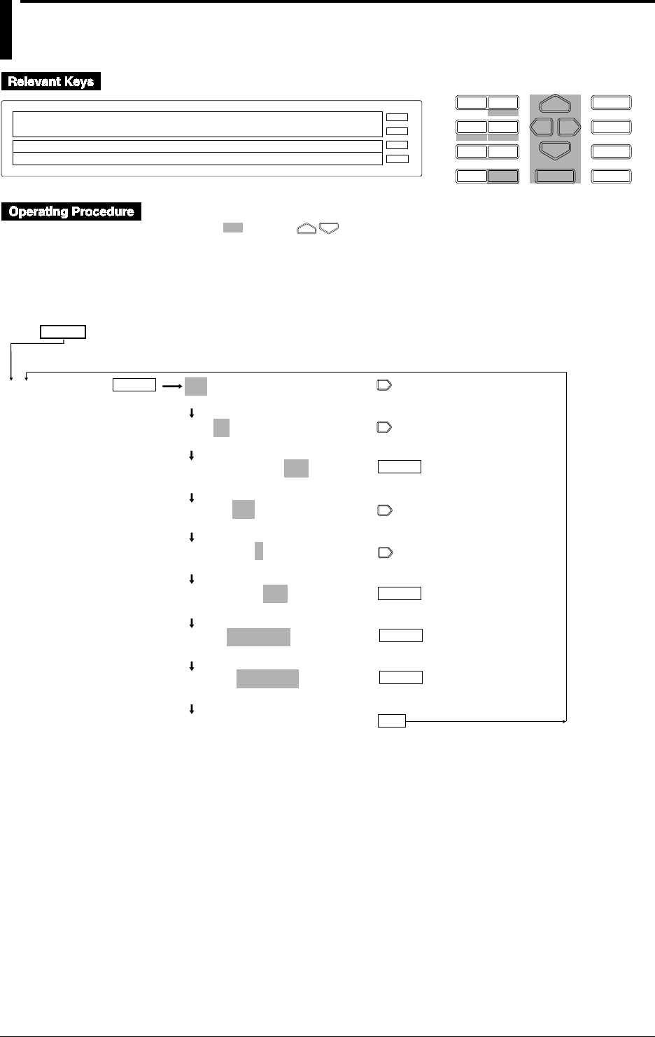
12-4 IM DR232-01E
12.2 Setting a Computation Equation
D I S P M O D E
P R I N TF U N C
I N S D E L
R A N G E A L A R M
S E TC H A R T E N T E R
F E E D
M. F U N C 1
M. F U N C 2
RECORD
ALARM
CHART
KEYLOCK
R E C O R D
SET=MATH
SYSTEM UNIT MATH CONST TREND TIMER LOG ↑
>Select Setting Parameter
E S C
• Press the SET key to enter the SET menu.
• Select/set using the keys.
• To escape from a lower menu, press the MODE (ESC) key. Its main menu will appear,
although new settings/selections will not be kept.
• New settings/selections will be kept when you reach the final display of that setting.
ENTER
ENTER
A01-01:MODE=ON
>Select Channel No.
A01-01:MODE=ON
>Select Channel No.
A01-30:MODE=ON
OFF ON
CALC=001+002
0 1 2 3 4 5 6 7 8 9 ( ) C G M A .NE.
CALC=001+002
0 1 2 3 4 5 6 7 8 9 ( ) C G M A .NE.
CALC=001+002
0 1 2 3 4 5 6 7 8 9 ( ) C G M A .NE.
LEFT=-3000.000Kg
>Span limit (–9999.999 ~9999.999Kg)
RIGHT= 3000.000Kg
>Span limit (–9999.999 ~9999.999Kg)
***SET OK***
(End of setting)
ENTER
ENTER
SET=
MATH
ESC
(Main menu)
ENTER

12-5
IM DR232-01E
Executing Computation
(Available with the /M1 Model)
12
A computation equation can be set for up to 60 channels (A01 to A60).
Setting the mode
If “A01-60 MODE=ON” is specified as in the example given on the previous page, the same
equation can be set for channels A01 to A60. To set an equation for one channel only, specify,
for instance, “A01-A01 MODE=ON”.
Computation equation
In addition to operators described on page 12-1, the following symbols can be used in equations.
(/) : Used for ( ) setting.
K : Used if equations contain constants K01 to K60.
M : Used to specify the measurement channel No. for which the data saved on the RAM disk
is to be re-generated. Applicable for the DR232-1/DR242-1 equipped with a floppy disk
drive.
A : Used to specify the computation channel No. for which the data saved on the RAM disk is
to be re-generated. Applicable for the DR232-1/DR242-1 equipped with a floppy disk
drive.
C : Used to specify communication input data (digital data).
G : Used to specify the group No. for which CLOG (computation of data of a group measured
on the same time) is to be used.
Restrictions in equations
Computation channel No
• The specified computation equation for a computation channel No. can contain only
computation channel Nos. as variable which are equal to or smaller than said computation
channel No.
(Example) A02=001+A01
In this example, any computation channel No. which is equal to or greater than A03 cannot be
used.
• Either TLOG or CLOG can be used in an equation.
Note
• Each equation must consist of up to 40 characters.
• The total number of channels and constants to be used for each equation is 16 or smaller.
Setting the recording span
Set the recording span for computation results. The setting range is from -9999999 to 99999999.
The decimal point can be placed in five positions, as represented in x.xxxx, xx.xxx, xxx.xx,
xxxx.x, xxxxx.. The unit specified in 6.1, “Setting Recording Mode/Engineering Unit/Recording
Channel and Recording Interval” (page 6-1) will be used.
LEFT : Sets the left-limit value of the recording span.
RIGHT: Sets the right-limit value of the recording span.
Note
If the computation ON/OFF, computation equation or span setting is changed, the alarm and partial
compression recording settings for the corresponding channel will be reset.
12.2 Setting a Computation Equation
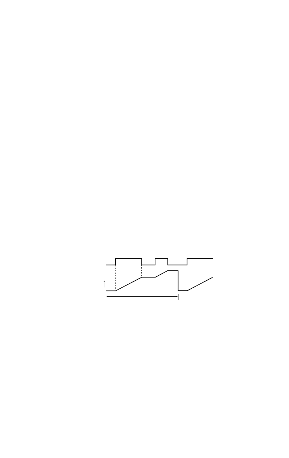
12-6 IM DR232-01E
Example of Settings of CLOG
When computing the maximum, minimum, maximum minus minimum, sum and average of data
measured at the same time on multiple channels, you must configure groups beforehand.
Example of settings where the averages for channels 001, 002, 003, 004, 006 and 008 are
computed:
Configuration of groups:
In the SET menu, assign channels 001, 002, 003, 004, 006 and 008 to group G01, as shown
below:
SET=GROUP
GROUPNo.=G01
G01=001-004, 006, 008
Define the computational expression that computes the average of group 1, as shown below:
CALC=CLOG.AVE (G01)
Computation on Pulse Input Channels
For pulse input channels, you can define the operator TLOG.PSUM (XXXX) where the DR
recorder does not have the optional MATH function (/M1 option). The type of computation is the
integration of the count if the measurement mode is set to RATE (instantaneous count mode) or
the integration of the turn-on time if the measurement mode is set to GATE (instantaneous turn-
on time mode). In either case, the integrated value is the sum of values measured every second.
For this reason, even if you set the measurement interval to 0.5 second, the DR recorder retains
the same value for one second.
Set the maximum count and turn-on time using SPAN. The maximum configurable value is
99999999. Set the interval of summation (integration interval) as a relative or absolute time by
setting the event to TIMER with the event/action functions. Set the action to TIMER RESET.
See Section 9.1, “Setting Event/Action Functions,” (on page 9-1) for details on how to configure
the event/action functions.
If the computational expression is written as TLOG.PSUM (XXX) in the system reconfiguration
where the PULSE INPUT MODULE filed is set to “not installed,” the computational expression,
alarm settings and partial settings are initialized. In addition, if the DR recorder is not a model
with the optional MATH function (/M1 option), groups to which computation channels were
assigned by the group setting and logic boxes to which actions of the MATH function were
assigned by the logic setting are initialized.
Integration interval
Time
State of contact
ON
OFF
0
ON
You can select whether to treat a result of the computational expression TLOG.PSUM (XXXX)
exceeding 99999999 as an overflow or to continue computing with the value following 99999999
reset to 0. For details on how to make the selection, see Section 12.5, “Setting Action to Be
Carried Out in Case of Computation Error and Setting the Time Axis for TLOG SUM.” The
result of computing in this context is that resulting from a separate calculation of TLOG.PSUM
(XXXX). If you set the computational expression as TLOG.PSUM (XXXX)*100, the above
action does not take place even if the result of the calculation TLOG.PSUM (XXXX)*100
exceeds 99999999. If you have made such selection as to continue computing even if the result
exceeds 99999999, the value subsequent to 99999999 is reset to 0. If the next measured value is
4 after the result of computing has proved to be 99999999, that value is not reset to 0 but is
counted in sequence from 0 to 3, giving 3 as the result.
12.2 Setting a Computation Equation
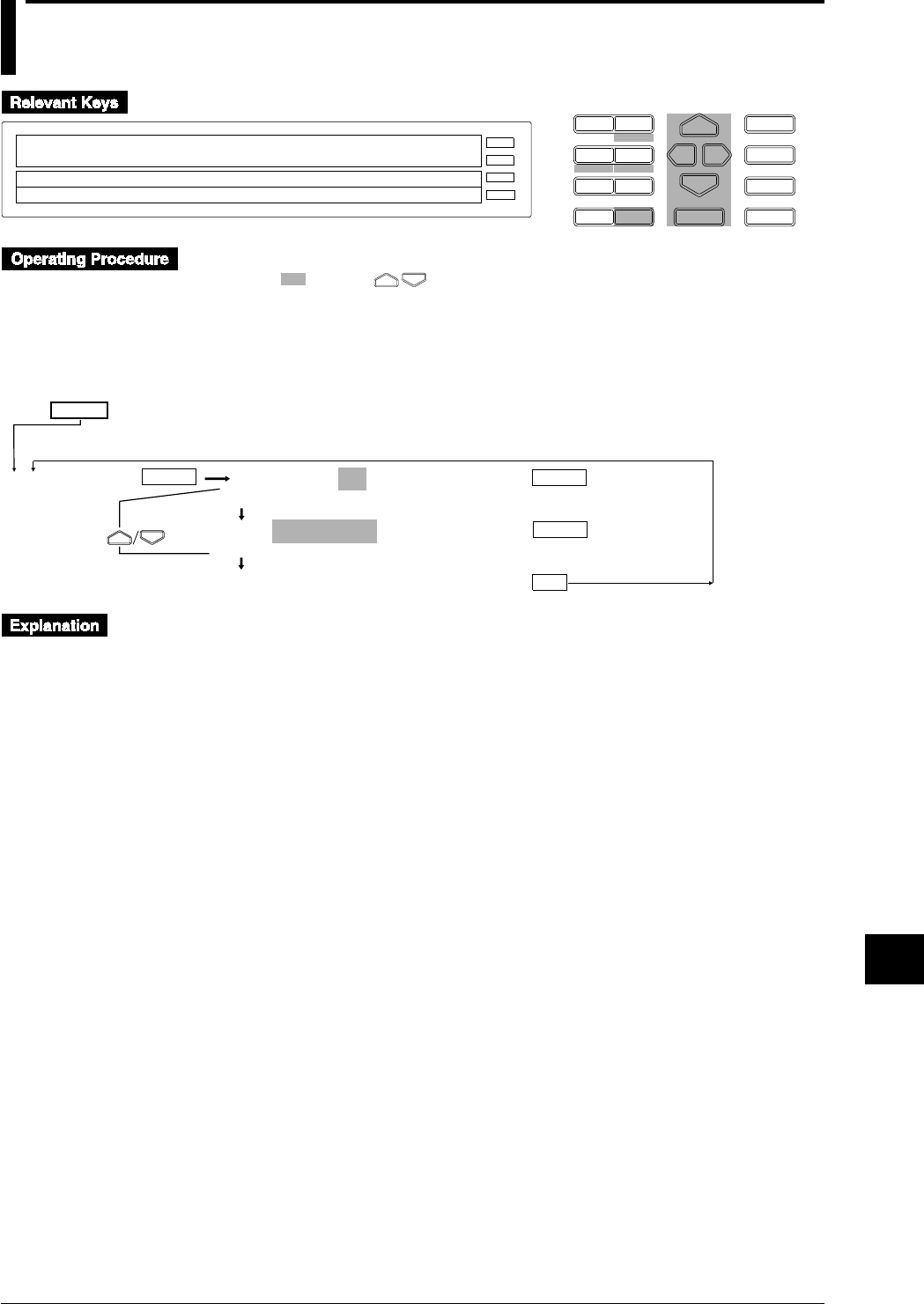
12-7
IM DR232-01E
Executing Computation
(Available with the /M1 Model)
12
12.3 Setting a Constant
D I S P M O D E
P R I N TF U N C
I N S D E L
R A N G E A L A R M
S E TC H A R T E N T E R
F E E D
M. F U N C 1
M. F U N C 2
RECORD
ALARM
CHART
KEYLOCK
R E C O R D
SET=CONST
SYSTEM UNIT MATH CONST TREND TIMER LOG ↑
>Select Setting Parameter
E S C
• Press the SET key to enter the SET menu.
• Select/set using the keys.
• To escape from a lower menu, press the MODE (ESC) key. Its main menu will appear,
although new settings/selections will not be kept.
• New settings/selections will be kept when you reach the final display of that setting.
CONST No.=K01
K01 K02 K03 K04 K05 K06 K07 K08 K09 K10 ↑
K01=-9.9999E+29
. – + 0 1 2 3 4 5 6 7 8 9 E
***SET OK***
(End of setting)
ENTER
SET=
CONST
ESC
(Main menu)
ENTER
ENTER
Up to 60 constants (K01 to K60) can be set.
The number of significant digits is 5 excluding the decimal point. If exponent is used, the
mantissa and exponent must consist of 5 digits and 2 digits, respectively.
Configurable ranges:
-1.0000E+35 to -1.0000E-35
0
1.0000E-35 to -1.0000E35
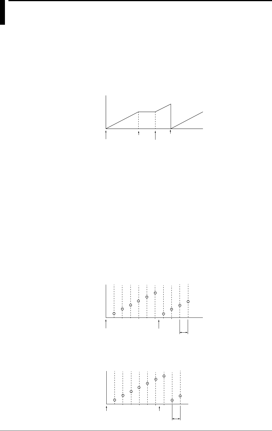
12-8 IM DR232-01E
12.4 Starting/Stopping Computation
Computation can be started and stopped from the FUNC menu or using the event/action function.
Starting/stopping computation from the FUNC menu
Press the FUNC key and select the desired operation from the FUNC menu.
• MATH START
Starts computation. This is displayed while computation is not in progress.
• MATH CLR START
Clears computation results then re-starts computation.
Start
Computed data
Start
Stop Clear/start
• MATH STOP
Stops computation. Computation results are not cleared. This is displayed while computation
is in progress.
• MACH ACK
Clears status indication which is displayed in case of incomplete measurement during
computation.
For a detailed description of the FUNC menu, refer to 9.3, “Alarm Acknowledgment, Alarm Rest,
Timer Reset, Keylock, and Message Printout” (page 9-14).
Starting/stopping computation using the event/action function
The event/action function can be used to carry out the following operations.
• MATH START
Starts computation.
• MATH STOP
Stops computation.
• MATH CLEAR
Clears data before the first computation is carried out.
Start Clear Measurement interval
Computed data
• MATH RESET
Clears data after the first computation is carried out.
Start Reset Measurement interval
Computed data

12-9
IM DR232-01E
Executing Computation
(Available with the /M1 Model)
12
Event/action function
An example of setting the event/action function is given below.
Set the event/action function if you want to reset the results after computation is carried out for a
certain period of time, then resume computation.
1. Set TIMER RST for the MFUNC KEY:1 event.
2. Set MATH:START for the same MFUNC KEY:1 event.
3. Set MATH:RESET for TIMER:1 event.
4. Set the mode for TIMER No.1 to RELATIVE and TIME to “00 01:00”.
After the above settings have been made, press the MFUNC1 key. Timer 1 will be reset
according to the above steps 1 and 2, then computation starts. After elapse of one hour,
computation results will be reset according to step 3, but computation will still continue. When a
further hour elapses, computation results will be reset. The above operations will be carried out
repeatedly until computation is stopped.
For a detailed description of the event/action function, refer to 9.1, “Setting Event/Action
Functions” (page 9-1). Refer to pages 2-9, 6-2 and 6-3 for a description of timers.
Status display during computation
The following status symbols are displayed in the sub-display 2 (lowest display section).
C
: Computation is in progress.
X
: Incomplete measurement has occurred. If this status occurs frequently, reduce the number
of equations or reduce the measurement period. The number of equations may be too large
for computation to be carried out within the specified measurement period.
Restrictions during computation
The following settings cannot be made while computation is in progress.
• Measuring range
• Computation equation/constant
• Group
• Copying with RANGE COPY set to on
12.4 Starting/Stopping Computation
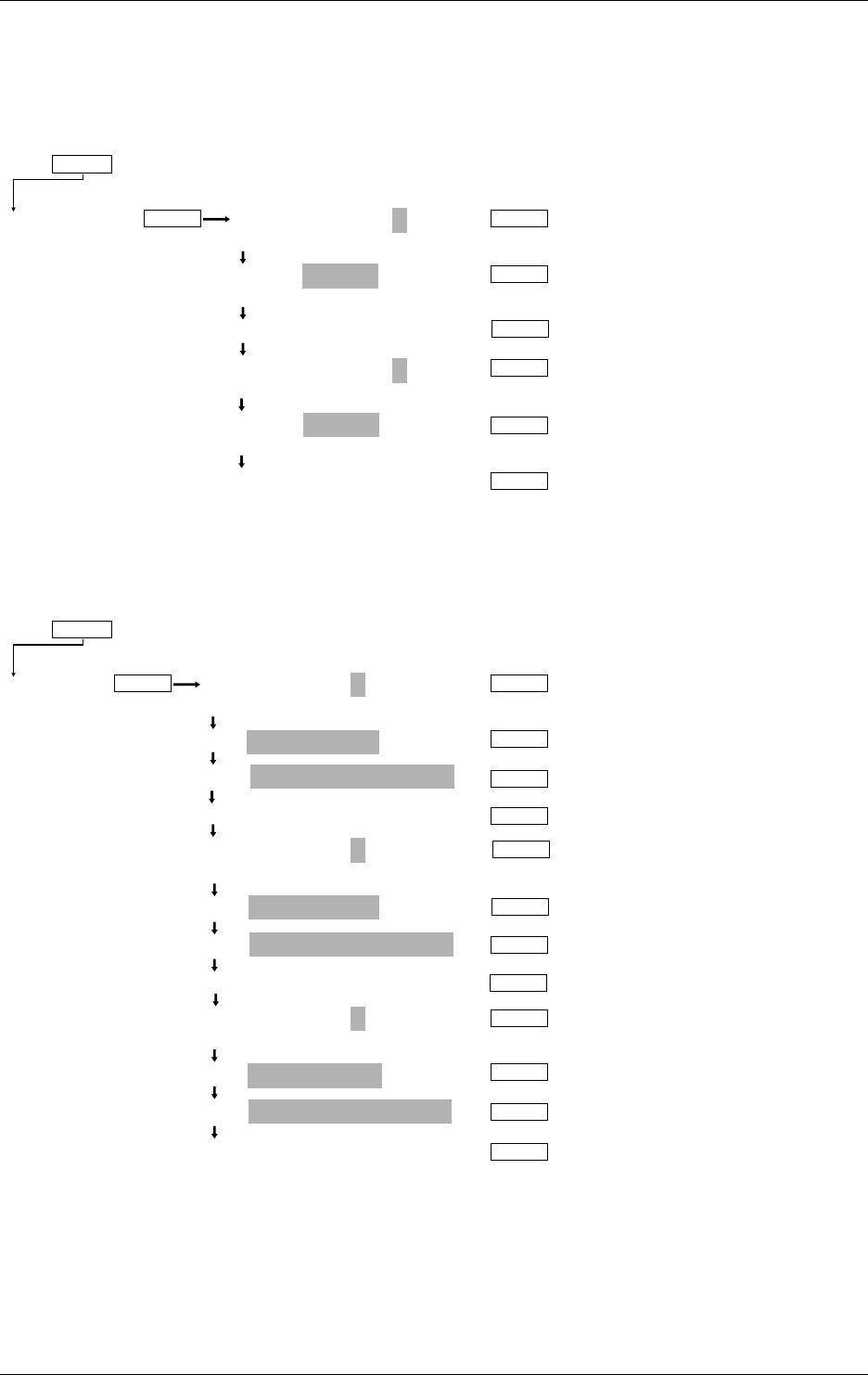
12-10 IM DR232-01E
Examples of Setting Using the Event/Action Functions
• Sum the values measured on channel 001 from 8:00 to 9:00 every day.
Setting the MATCH TIME field:
Configure the DR recorder so events occur at 8:00 and 9:00 every day.
MATCH TIME No.=1
1 2 3
1:TIME=00 08:00
>Set Day & Time DD HH:MM:00
***SET OK***
(configuration complete)
MATCH TIME No.=2
1 2 3
1:TIME=00 09:00
>Set Day & Time DD HH:MM:00
***SET OK***
(configuration complete)
MATCH TIME
ENTER ENTER
ENTER
SET=
(Main menu item)
(Submenu items)
ENTER
ENTER
ENTER
ENTER
Selects match timer no. 1.
Sets the date to 00 and time to
8:00.
Selects match timer no. 2.
Sets the date to 00 and time to
9:00.
Setting the EVENT/ACTION fields:
Configure the DR recorder so it uses the match time as the event to clear computed values and
then start computing at 8:00 and ends computing at 9:00.
LOGIC BOX No.=1
(01 to 30)
EVT=MATCH TIME:1
ACT=EDGE / MATH : CLEAR
***SET OK***(configuration complete)
LOGIC BOX No.=2
(01 to 30)
EVT=MATCH TIME:1
ACT=EDGE / MATH : START
***SET OK***(configuration complete)
LOGIC BOX No.=3
(01 to 30)
EVT=MATCH TIME:2
ACT=EDGE / MATH : STOP
***SET OK***(configuration complete)
LOGIC
ENTER ENTER
ENTER
SET=
(Main menu item)
(Submenu items)
ENTER
ENTER
ENTER
ENTER
ENTER
ENTER
ENTER
ENTER
ENTER
ENTER
Selects match time 1.
Selects match time 1.
Selects match time 2.
Provides the setting
for clearing computed
values.
Provides the setting
for starting computing.
Provides the setting
for ending computing.
Computation equation:
CALC=TLOG.SUM (001)
If, in the event/action functions, you have assigned the same event to more than one LOGIC BOX
number at the same time, the DR recorder executes computing, beginning with the smallest
LOGIC BOX number. In the above configuration, the DR recorder clears computed values at
8:00 and starts computing. The values and behaviors of the event/action functions when
computing is done with the above configuration are as follows:
12.4 Starting/Stopping Computation
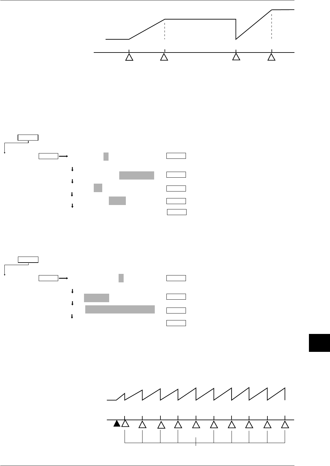
12-11
IM DR232-01E
Executing Computation
(Available with the /M1 Model)
12
8:00 9:00 8:00 of the
next day 9:00 of the next day
Results of
computing
Resetting of computed value
Start of computing Resetting of computed value
Start of computing
End of
computing End of
computing
Time
Logic box 1
Logic box 2
Logic box 3
• Sum the values measured on channel 001 every hour.
Setting the TIMER field:
Configure the DR recorder so an event occurs every hour with reference to the hour 00:00.
TIMER No.=1
1 2 3 4 5 6
1: TIMER MODE=ABSOLUTE
1: TIME=1h
1: REF TIME=00:00
***SET OK***
(configuration complete)
TIMER
ENTER ENTER
ENTER
SET=
(Main menu item)
(Submenu items)
ENTER
ENTER
Absolute time
ENTER
One-hour interval
Sets the
reference time.
Setting the EVENT/ACTION fields:
Configure the DR recorder so it clears computed values at the time set on the timer.
LOGIC BOX No.=1
(01 to 30)
EVT=TIMER:1
ACT=EDGE / MATH : CLEAR
***SET OK***
(configuration complete)
LOGIC
ENTER ENTER
ENTER
SET=
(Main menu item)
(Submenu items)
ENTER
ENTER
Selects timer 1.
Resets the
computed value.
Computation equation:
CALC=TLOG.SUM (001)
To start computing, press the FUNC key and select MATH START from the FUNC menu.
The values and the behaviors of the event/action functions when computing is done with the
above configuration are as follows:
9:00 11:00
Results
of computing
Resetting of computed value
Time
End of setting
Start of computing
00:00
10:00
8:00 13:00 14:00 15:00 16:00 17:00
Reference time
12.4 Starting/Stopping Computation
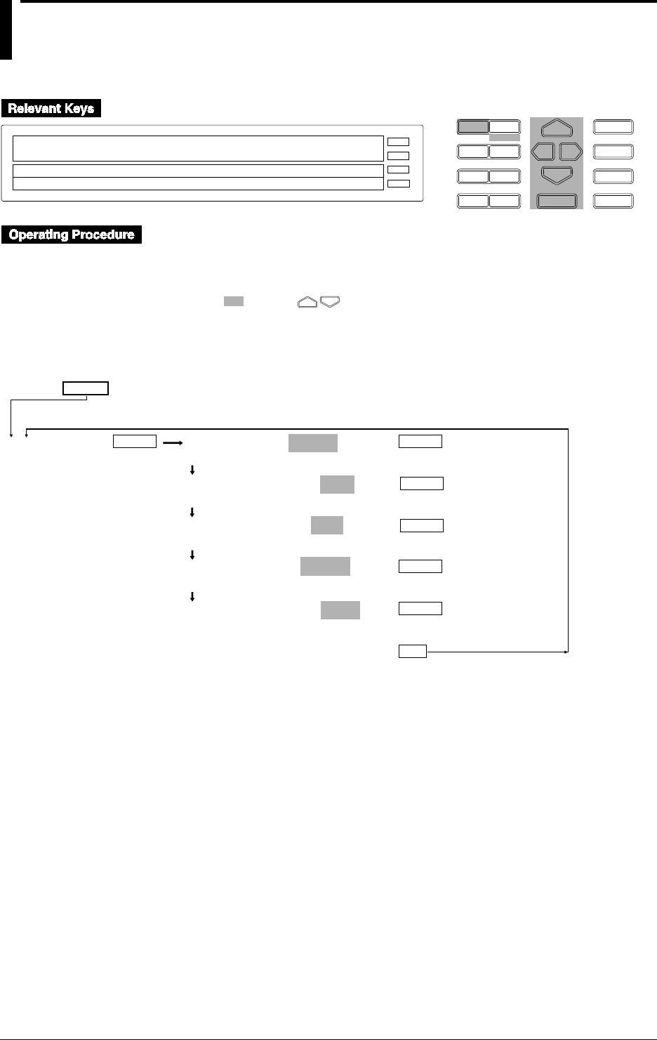
12-12 IM DR232-01E
12.5 Setting Actions to be Carried out in Case of
Computation Error and Setting the Time Axis for
TLOG SUM
D I S P M O D E
P R I N TF U N C
I N S D E L
R A N G E A L A R M
S E TC H A R T E N T E R
F E E D
M. F U N C 1
M. F U N C 2
RECORD
ALARM
CHART
KEYLOCK
R E C O R D
SETUP=MATH
PRN ADJ SCAN INTVL RECORD MATH ALARM A↑
>Select Setting Parameter
E S C
Carry out the following steps to enter the SET UP menu.
1. If the SET UP menu is not currently displayed, turn the power OFF
2. While holding the DISP key, turn the power ON. Make sure you still continue to hold down
the DISP key for approximately another five seconds..
• Select/set using the keys.
• To escape from a lower menu, press the MODE (ESC) key. Its main menu will appear,
although new settings/selections will not be kept.
ENTER
ENTER
MATH ERROR=+OVER
+OVER –OVER
TLOG TIME SCALE=/SEC
OFF /SEC /MIN /HOUR
TLOG CH ERROR=SKIP
ERROR SKIP
TLOG CH OVER=ERROR
ERROR SKIP LIMIT
TLOG PSUM OVER=OVER
OVER ROTATE
***MATH SET***
(End of setting)
ENTER
SET UP=
MATH
ESC
(Main menu)
ENTER
ENTER
ENTER

12-13
IM DR232-01E
Executing Computation
(Available with the /M1 Model)
12
Displaying/recording in case of computation error (MATH ERROR)
Used to determine whether +OVER or -OVER be displayed/recording in case of computation
error.
Time axis scale for TLOG SUM (TLOG TIME SCALE)
For TLOG.SUM of time series, data is added at each measurement interval. However, in the case
of an input having unit of /s, /min or /h like flow rate, the computation result will differ from the
actual value, if addition of data is carried out. In this case, setting TLOG TIME SCALE
according to the unit of the input will cause the data measured at measurement intervals to be
processed according to the unit of the input.
For instance, if the measurement interval is 2s and input value is 100 m3/min, the computation
result will be 30000 after the elapse of one minute, since 100 is added every 2 seconds. Setting
TLOG TIME SCALE to /min will cause the measured data to be multiplied by 2s/60s at each
measurement interval, thus making the result close to the actual input value.
If this function is set to OFF, simple addition of data will be carried out.
Process of abnormal data during TLOG or CLOG (TLOG CH ERROR)
Used to select the process method for abnormal data obtained during TLOG or CLOG.
• ERROR : Abnormal data is processed as a computation error.
• SKIP : Abnormal data is ignored and computation is continued.
Process of overflow data during TLOG or CLOG (TLOG CH OVER, SUM or AVE)
Used to select the process method for overflow data obtained during TLOG or CLOG.
• ERROR : Overflow data is processed as a computation error.
• SKIP : Overflow data is ignored and computation is continued.
• LIMIT : Overflow data is treated as the next data for computation.
Measurement channels to which linear scaling is applied: Specified scaling upper-/lower-limit
Measurement channels to which no linear scaling is applied: Upper-/lower-limit of the
measuring range
Computation channels: Specified LEFT/RIGHT value
Processing of the results of TLOG.PSUM computation
• OVER: If the result of a separate calculation of TLOG.PSUM (XXXX) exceeds 99999999, the
DR recorder goes into an overflow.
• ROTATE: If the result of a separate calculation of TLOG.PSUM (XXXX) exceeds 99999999,
the DR recorder resets the value subsequent to 99999999 to 0 and continues computing.
The process is effective only when a pulse input module is installed.
12.5
Setting Actions to be Carried out in Case of Computation Error and Setting the Time Axis for TLOG SUM

13-1
IM DR232-01E
Trouble-shooting
and Maintenance
13
13.1 Periodic Maintenance and Recommended Parts
Replacement Period
Periodic maintenance
Check the recorder’s operation periodically to keep it in good operating condition. Especially
check the following items and replace consumable parts as needed. Do not use a lubricant for
periodic maintenance.
• Are display and recording functioning properly?
• Are there blurred or broken sections of the recording or printout characters?
When replacing the ribbon cassette, refer to Section 3.4, “Installing the Chart and Ribbon
Cassette.”
• Is the chart paper feeding properly? When replacing the ribbon cassette, see Section 3.4,
“Installing the Chart and Ribbon Cassette.”
• Is there enough chart paper left?
• The remaining chart paper length is printed in the left margin of the chart at 20-cm intervals.
• When replacing the chart paper, see Section 3.4, “Installing the Chart and Ribbon Cassette.”
If problems develop with the recorder, see Section 13.3, “Troubleshooting.”
Recommended parts replacement period
It is necessary that recorder parts be replaced periodically for use of the recorder over an extended
period of time. The table below shows the recommended parts replacement periods for specific
parts that wear out. These replacement periods indicate where the recorders have been used under
normal operating conditions. When replacing parts, refer to these replacement periods taking the
actual operating conditions into consideration. When replacing parts other than the chart paper,
ribbon cassette, or fuse, please contact your nearest Sales representative. Addresses may be found
on the back cover of this manual.
Part Part number Replacement Description
period (in years)
Display B9233KJ 3.4 30,000 hours
Fuse A1350EF 2 For AC power supply (2.5A, time-lag fuse)
Fuse B9573TZ 10 For printer board (500 mA)
Motor B9233EA 5 For chart paper
Motor (DR232) B9232CM 5 For carriage (with a screw shaft)
Motor (DR242) B9233EF 5 For carriage (with a screw shaft)
Motor B9233GR 3 For ribbon cassette
Lithium battery B9234XZ 10 For backup of information that has been set
Fluorescent lamp B9628ZN 3,4 Internal assembly lighting (30,000 hours)
Printer head B9233HZ 3 1.5 × 10⁸ dots (depend on the set conditions)
Carriage B9233GA 5 Depends on the set conditions.
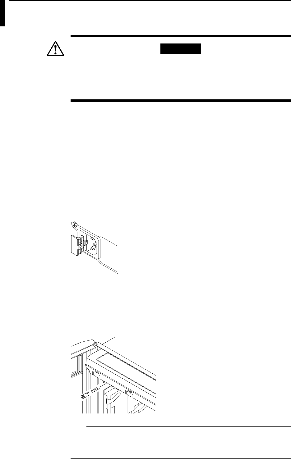
13-2 IM DR232-01E
13.2 Replacing the Fuse
WARNING
• The fuse must be of the specified rating (current, voltage, type) to
prevent a fire hazard.
• Be sure to turn off the power switch and to unplug the power cord
before replacing the fuse.
• Never short-circuit the fuse holder.
Fuse Rating:
The fuse must have the following specifications:
Maximum rated voltage: 250 V Maximum rated current: 2.5 A Type:
time-lag
Standard: IEC/VDE certified Part number: A1350EF
Replacement procedure:
To replace the fuse, proceed as follows:
DR232
1. Turn off the power switch.
2. Unplug the power cord from the power outlet.
3. Remove the fuse holder at the side of the power connector on the rear panel.
4. Remove the blown fuse from the holder.
5. Insert a new fuse into the holder and then install the holder in place.
DR242
1. Turn off the power switch.
2. Disconnect the power connections.
3. Open the front and display doors to gain access to the fuse holder. Use a standard screwdriver
to turn the fuse-holder screw counterclockwise. Then remove the fuse holder.
4. Remove the blown fuse from the holder.
5. Insert a new fuse into the holder and then install the holder in place.
Note
The fuse is located in the subunit. This fuse may not be replaced by the customer. For replacement, contact
your nearest representative. For AC power supply model, the fuse ratings are 250V2A time lag fuse
certified by IEC/VDE. For DC power supply model, the fuse ratings are 250V6.3A time lag fuse certified
by UL/CSA.

13-3
IM DR232-01E
Trouble-shooting
and Maintenance
13
13.3 Troubleshooting
If an error code appears on the display, see Section 13.4, “Error Codes.”
If servicing is necessary, or if the instrument is not operating correctly though the following
corrective actions have been taken, please contact Yokogawa Engineering Service Corporation.
Addresses may be found on the back cover of this manual.
Problem Probable Cause Corrective Action
Recorder does not operate. Power switch is off. Turn on the power.
(The recorder carriage and chart do Power supply is not Connect properly.
not move.) connected properly.
Supplied power does not Use power meeting its requirements.
meet powerrequirements.
Fuse blown. Replace fuse. (If the fuse blows immediately after turning on the
power, servicing will be required.)
Output beyond its limits Input specifications are not Correct input specifications.
Fluctuating indication correct.
Carriage swung over.
Incorrect measuring range or Change measuring range or recording span.
recording span
Noise superimposed. Connect input wiring far away from noise source.
Ground recorder.
Ground measurement object.
Isolate thermocouple from measurement object.
Use shielded wiring for input line.
Change A/D integral times.
Use moving average.
Use input filter.
No countermeasure taken Install input terminal cover properly.
against ambient temperature Protect recorder from blowing air of fan.
changes.
Keep temperature changes near input terminals small.
Input connected improperly. Connect input properly.
Connect module properly.
Tighten screws properly.
Isolate RTD from ground.
Replace disconnected thermocouples.
Recorder connected in parallel Do not use burnout functions in other instruments.
with other instruments.
Ground recorder and other instruments in the same ground line.
Do not connect recorder in parallel with other instruments
(for use with dual-element TC).
RJC set improperly Set RJC properly.
(for TC input)
Dot-printing position Calibrate correctly.
not calibrated correctly.
Other cause. Contact Yokogawa Engineering Service.
Defective display Noise superimposed. Lay input wiring far away from noise source.
Ground recorder.
Ground measurement object.
Isolate TC from measurement object.
Use shielded wires for input line.
Change A/D integration times.
Use input filter.
Data indicates “xxxxxx” Input module connected Connect input properly.
improperly
Recorder does not work even with Key-lock not released. Disable key-lock functions in setup mode.
operation key pressed. Recorder set in remote mode. Set recorder in local mode.
Other cause. Contact Yokogawa Engineering Service.

13-4 IM DR232-01E
13.4 Error Codes
If servicing is necessary, or if the recorder does not operate correctly even though the following
corrective actions have been taken, contact your nearest Sales representative. Addresses may be
found on the back cover of this manual.
Error Code Error Corrective Action
001 System error. Contact your nearest representaive.
002 Set data out of range. Set numeric data correctly.
003 Time set incorrectly. Set time correctly.
004 Channels set incorrectly. Set channels correctly.
005 Invalid setting function parameter. Set parameter correctly.
006 Invalid character string. Set character string correctly.
007 Invalid type of input for input module. Set the type of input correctly.
008 Invalid range setting for input module. Set range correctly.
009 Numeric values out of range. Set numeric values correctly.
011 Attempted to do manual, header, list or Install new chart paper.
setup list printout at the end of chart paper.
030 There may be a module that cannot be set Re-set ranges or channels with
in channels with continuous ranges. continuous ranges.
031 There may be an invalid module in channels Change channels in which
with continuous ranges. continuous ranges are set.
040 Reference channel number greater than Change the reference channel number.
that of the channel for interchannel
differential computations.
041 Skipped range in the reference channel for Change the range in the reference channel.
interchannel differential computations.
042 RPJC range in the reference channel for Change the range in the reference channel.
interchannel differential computations.
043 SCALE in range setting in the reference Change the range in the reference channel.
channel for interchannel differential
computations.
044 The reference channel for interchannel Change the reference channel number.
differential computations does not exist.
045 The left and right spans are identical. Change the scale setpoint.
046 The left and right scale values are identical. Change the scale setpoint value.
060 The alarm setting was made in the channel Change ranges.
where SKIP was set.
061 The alarm was set to a channel with ranges Change ranges.
where alarm setting cannot be set.
062 The alarm setpoint is out of range in a Set correct alarm setpoint.
channel with continuous ranges.
063 Relay number set incorrectly. Set relay number correctly.
080 Invalid character strings for group setting. Set character strings correctly.
081 Invalid channel in character string for group Set channel correctly.
setting.
083 Partial compaction set to a channel where Change ranges.
SKIP was set.
084 Partial compaction set to a channel in Change ranges.
which ranges cannot be partially compacted.
085 Partial compaction out of range in a channel Set correct partial compaction range.
with continuous ranges.
086 The left and right zones have the same values. Change zone set values.
087 The left zone is wider than the right zone. Change zone set values.
088 The left and right zones are less than 5 mm Change zone set values.
apart wide.
089 Copy channel setting error. Sets the correct channel.
090 Attempted to copy a message with the same Change copy source or destination.
source and destination number.
091 Illegal protocol for logic setting. Set correct protocol.
100 No equation option Not possible to make any computation
settings.
101 Invalid code in the equation Set the equation correctly.
102 Incorrect number of ( ) in the equation Set the correct number of ( ).
103 Syntax error Set the equation correctly.

13-5
IM DR232-01E
Trouble-shooting
and Maintenance
13
13.4 Error Codes
104 Illegal character(s) or code(s) is used before Set the equation correctly.
or after an operator.
105 The right and left spans are the same. Change the span.
106 Attempted to make range setting during Stop making range setting.
computation.
110 Syntax error for computation constant Set the constant correctly.
111 Out of constant setting range Set the constant within the range.
120 Floppy disk not inserted or not formatted. Insert a formatted floppy disk into the
drive.
121 Insufficient memory Delete unnecessary files.
122 Incorrect file name or volume name Set the correct file name or volume name.
123 Attempted to make settings which are not Stop making the settings.
allowed to be made during saving or reading
of measured data.
124 Too many files in the media Delete unnecessary files.
125 Attempted to read data which was saved Select data which has been saved
by another instrument model. by DR/DA.
127 Attempted to save data in a write-protected file. Cancel write-protection.
128 No event/action has been set. Set the desired action .
130 Incorrect channel found during saving Set the correct channel.
or reading of measured data.
131 RAM disk error or floppy disk is ejected while Clear the error and attemt the same operation
bein accessed. or contact your nearest sales represantative.
132 Attempted to format the disk while a file is open. Close the file.
134 Set-up data saving error
135 Internal data error
136 Incorrect copy channel Set the correct copy channel.
137 Computation is started while set-up data is Stop Computation.
being saved or read.
138 Floppy disk error Use another floppy disk.
139 Other media related error
140 Sub-units selected which are not connected, Specify correct sub-units.
or the power is not supplied.
141 Disconnected modules were selected. Specify correct modules.
143 Modules selected which cannot be calibrated. Specify correct modules.
144 Calibration done improperly. Check electrical connections.
Calibrate again.
If the same error occurs again, contact
your nearest Sales representative.
145 Hardware becomes faulty during calibration. Turn off the power and then on.
Calibrate again.
If the same error occurs again, contact
your nearest Sales representative.
170 The IP address does not belong to any of the Set the correct IP address.
classes, A, B, or C.
171 There is a hole in the mask or the host Set the correct subnet mask.
address section is not released.
172 The net address section including the subnet Set the correct net address.
does not match the subnet section of the IP
address.
173 The host address section of the IP address is Set the correct IP address.
either all zeroes or all ones.
ROM ERROR System ROM error Contct your nearest sales
representative.
ROM ERROR* System ROM error Contct your nearest sales
representative.
RAM ERROR Main memory error Contct your nearest sales
representative.
RAM-DISK ERROR RAM disk error Contct your nearest sales
representative.
FLOPPY ERROR Floppy disk error Contct your nearest sales
representative.
MAIN NV READ ERROR Internal nonvolatile memory read error Contct your nearest sales
representative.
MAIN NV WRITE ERROR Internal nonvolatile memory write error Contct your nearest sales
representative.
CARRIAGE CANNOT MOVE Printer error Contct your nearest sales
representative.
SYSTEM ERROR System error ( : number) Check whether each unit or
( : number) power code is connected
properly after turning off the
power switch. If the same
error occurs again even though
you turn on the power switch,
contact your nearest sales
representative.
RESET ERROR An error occurs between the main unit Same as abeve.
and communication module.

13-6 IM DR232-01E
13.5 Calibration
Overview
We recommend that you calibrate the DR232 at least once a year to assure its measurement
accuracy. When calibrating, please contact your nearest Sales representative at its address on the
back cover of this manual.
Press and hold the MODE key and then turn on the power switch to place the recorder in the
calibration mode. Select the subunit and module to calibrate the recorder on a module basis.
After completing the calibration, turn off the power and then turn it back on when resuming the
measurements.
CAUTION
You can use the DISPLAY mode only for a calibration adjustment. If it is
maladjusted, the recorder may become faulty. For details, please
contact your nearest Sales representative.
Calibration needs selection of:
• a subunit and module and;
• the calibration mode.
Once the subunit and module have been selected, they are no longer selected again as long as the
calibration END mode is not executed.
Calibration mode
• CAL/EXEC mode: This mode enables specified ranges to be calibrated.
• DISPLAY mode: This mode enables current calibrated values to be displayed.
• END mode: This mode enables calibrated values to be stored in the internal nonvolatile
memory and terminates the calibration mode. (If ABORT is selected, the calibrated values are
not stored in memory.)
Subunit/module selection error
The following error messages are displayed:
• The specified subunit remains disconnected. Or the power supply is not turned on.
• The specified module remains disconnected (ERROR141).
• The specified module is such that it cannot be calibrated (ERROR143).
Calibrated data error
The following error messages are displayed:
• Attempted to remove the module during calibration. Or hardware error: ERROR145
• Invalid calibrated data: ERROR144
• Attempted to set invalid numeric values in the DISPLAY mode: ERROR145
Note
When a calibrated data error appears, the error data are stored in memory.
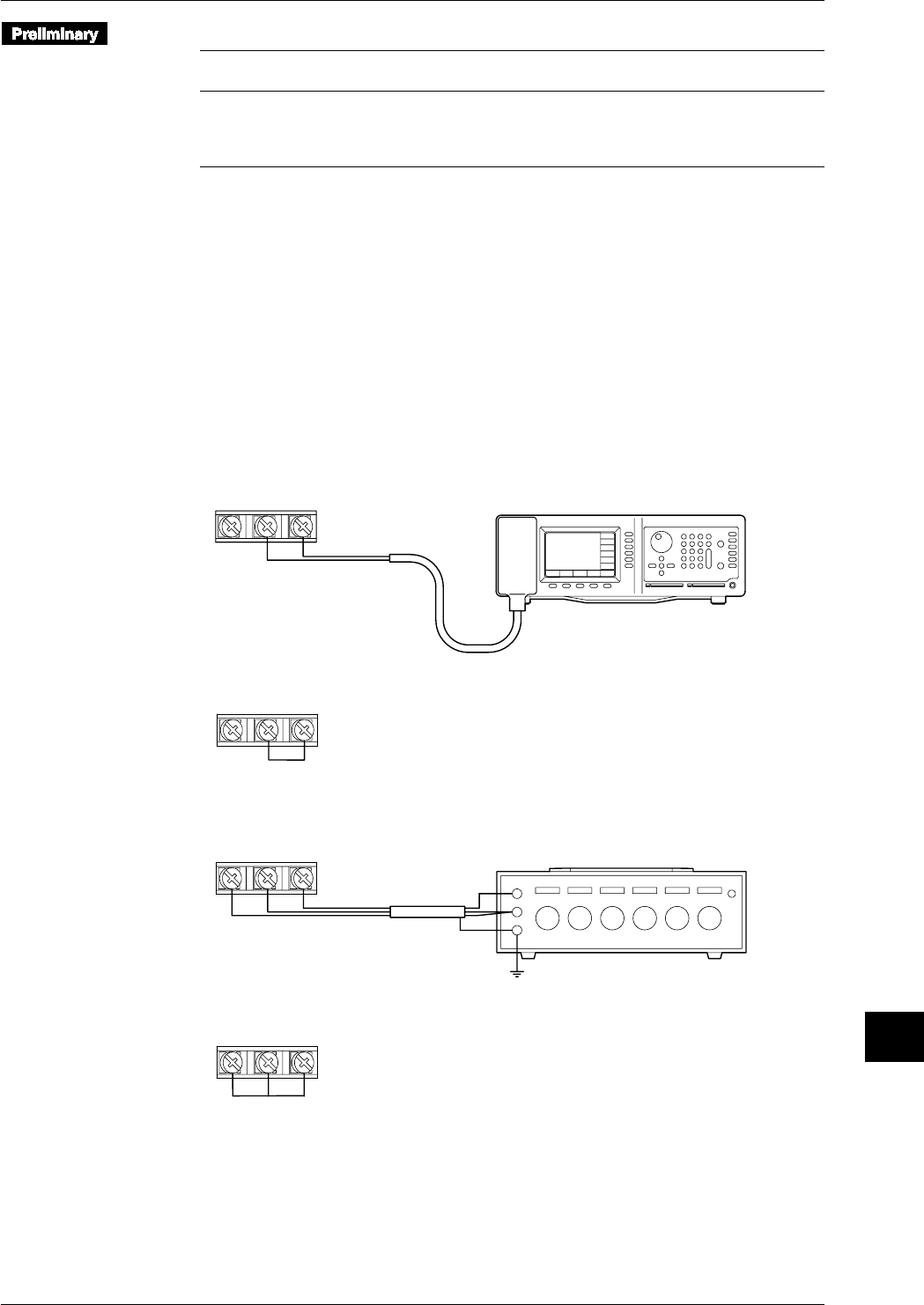
13-7
IM DR232-01E
Trouble-shooting
and Maintenance
13
Required Equipment
Name Measurement Accuracy Recommended
Range
DC Voltage Generator 0V to 50V 0.005% of setting+1µV Yokogawa 9000*, 4808
DMM 0V to 50V 0.005% of setting+1µV HP3458A
Decade Resistance Box 0.1Ω to 1000Ω0.01% Yokogawa 2793
DC Current Generator 0 to 20mA 0.05% of setting Yokogawa 7651
* For 0V input, it is necessary to either short the input terminals, or to monitor the output voltage using the
DMM.
Calibrating Conditions
Ambient temperature : 23°C±2°C
Ambient humidity : 55 ±10%RH
AC power supply voltage: 100 to 240 VAC (AC power supply model)
DC power supply voltage: 12 to 28 VDC (the subunit of DC power supply model omly)
Power supply frequency : 50/60 Hz ±1%
Warm-up time : at least 30 minutes for this recorder, and necessary warm-up time for
the used equipment
Connection (terminal screw connections)
• DC Voltage Measurement
• Apply a rated voltage in the voltage range that is to be calibrated to channel 3.
+–
DC Voltage Generator
Input terminal
(CH3)
• Short-circuit between “+” and “–” terminals in channel 2.
+–
Input terminal
(CH2)
• Temperature Measurement Using RTD
• apply the 100Ω resistance to channel 5.
BbA
Decade Resistance Box
Input terminal
(CH5)
• Short-circuit the resistance input terminals A, B, and b in channel 4.
BbA
Input terminal
(CH4)
13.5 Calibration
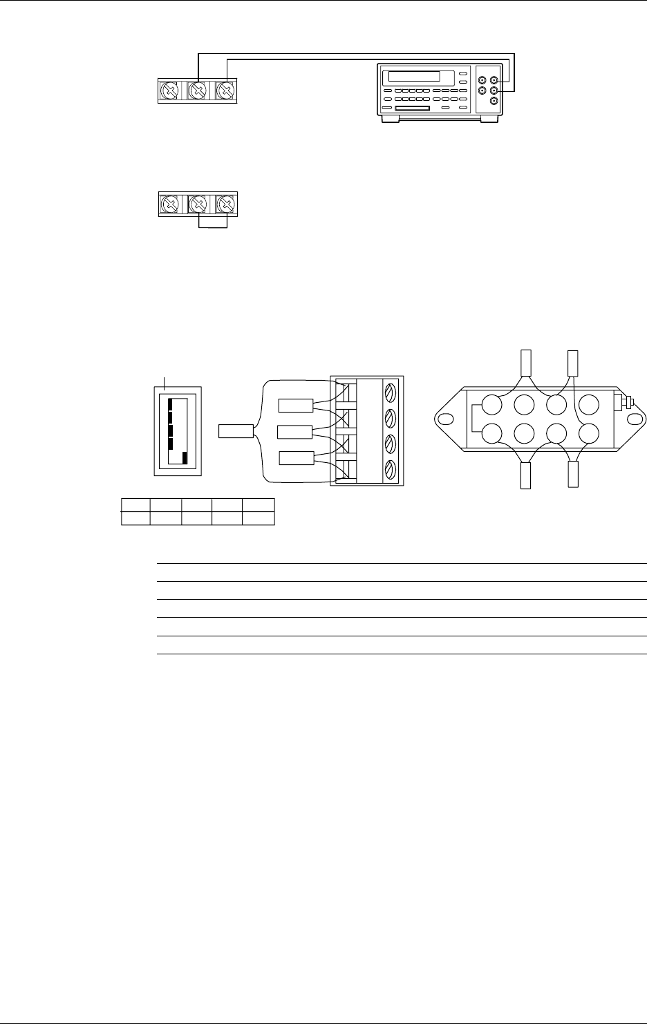
13-8 IM DR232-01E
• DC Current Measurement
Apply the 20mA to channel 3
+–
Input terminal
(CH3)
DC Current Generator
Short circuit between “+” and “–” terminal in channel 2
+–
Input terminal
(CH2)
• Strain measurement
Perform calibrations using 4-gauge method.
Use a 319300 bridge box for the Du500-14’s bridge box.
Wire the strain gauge or the bridge box to the channel 2.
Jumper setting switch
ON
OFF
No.1
No.2
No.3
No.4
No.5
A(+)
B(L)
C(-V)
D(H)
DU500-12/DU500-13 DU500-14
No.1
OFF No.2
OFF No.3
OFF No.4
OFF No.5
ON
12 3 4
5678
R4
R2
R3R1
R2
R4
R3
R1
To R1 to R4, connect resistors with the specifications described below.
Calibration Resistors R1, R2&R3 Resistor R4 Accuracy
ZERO 120.000 120.000 ±0.005%, ±0.3ppm/°C
2k SPAN 120.000 119.521 ±0.005%, ±0.3ppm/°C
20k SPAN 120.000 115.294 ±0.005%, ±0.3ppm/°C
200k SPAN 120.000 80.000 ±0.005%, ±0.3ppm/°C
13.5 Calibration
13-9
IM DR232-01E
Trouble-shooting
and Maintenance
13
Entering the calibration mode
1. While pressing and holding the MODE key, turn on the power.
Selecting the subunit and module numbers
2. With , select the subunit number.
S_UNIT0 : MODULE No=0
>
0 1 2 3 4 5
3. With , move the cursor.
4. With , select the module number.
S_UNIT0 : MODULE No=0
0 1 2 3 4 5
5. Press the ENTER key.
Calibrating in CAL/EXEC mode
6. With , select the CAL/EXEC mode.
ADJUST MODE=CAL/EXEC
>S_UNIT0 : MODULE No=0
DISPLAY CAL/EXEC END
7. Press the ENTER key.
8. With , select the calibration range.
ADJUST RANGE=20mV
>S_UNIT0 : MODULE No=0
20mV 60mV 200mV 2V 6V 20V 50V Pt : 1mA P ↑
9. Enter the rated value in the selected range.
10.Press the ENTER key to execute calibration. During the calibration, the following display
appears.
A/D Adjusting
>S_UNIT0 : MODULE No=0
20mV 60mV 200mV 2V 6V 20V 50V Pt : 1mA P ↑
11.After calibration is completed, the following display appears.
* * * CALC END * * *
>S_UNIT0 : MODULE No=0
>ADJUST RANGE=20mV
12.Press the ENTER key.
13.5 Calibration

13-10 IM DR232-01E
Checking calibrated values in the DISPLAY mode
Use this mode only for checking calibrated values. In this mode, you can adjust a calibrated value,
but, if this value is invalid, the instrument may be inoperative. For details, contact your nearest
Sales representative.
13.With , select the DISPLAY mode.
ADJUST MODE=DISPLAY
>S_UNIT0 : MODULE No=0
DISPLAY CAL/EXEC END
14.Press the ENTER key to display the calibrated value display items.
The following shows where the universal input modules are calibrated.
The calibrating procedures for DC V/TC/DI input modules are those except RTD in universal
input modules.
15.The calibrated values are displayed as follows:
20mV ZERO=– 1
>S_UNIT0 : MODULE No=0
>
16.Press the ENTER key.
17.Display the calibrated-value display items in the following order:
Repeat steps 15 and 16 above.
20 mV SPAN → 60 mV ZERO → 60 mV SPAN → 200 mV ZERO → 200 mV SPAN → 2 V
ZERO → 2 V SPAN → 6 V ZERO → 6 V SPAN → 20 V ZERO → 20 V SPAN → 50 V
ZERO → 50 V SPAN → Pt: 1 mA ZERO → Pt: 1 mA SPAN → Pt: 2 mA ZERO → Pt: 2 mA
SPAN → Pt: 1 mA-H SPAN → Pt: 2 mA-H SPAN → Cu: 2 mA ZERO → Cu: 2 mA SPAN
For a mA-input module, show the calibrated values in the order, 20 mA ZERO and 20 mA
SPAN. For a strain input module, show the calibrated values in the following order:
2k ZERO, 2k SPAN, 20k ZERO, 20k SPAN, 200k ZERO and 200k SPAN.
For a digital input module, show the calibrated value in the following order;
60mV ZERO, 60mV SPAN, 6V ZERO, 6V SPAN.
18.After checking the [Cu: 2 mA SPAN] calibrated value in the above calibrated-value display
items, press the ENTER key.
* * * DISPLAY END * * *
>S_UNIT : MODULE No=0
>
19.Press the ENTER key.
13.5 Calibration
13-11
IM DR232-01E
Trouble-shooting
and Maintenance
13
13.5 Calibration
Completing the selected module calibration with the END mode
20.With , select the END mode.
ADJUST MODE=END
>S_UNIT0 : MODULE No=0
DISPLAY CAL/EXEC END
21.PRESS the ENTER key.
22.With , select STORE or ABORT.
A/D ADJUST END=ABORT
>S_UNIT0 : MODULE No=0
ABORT STORE
23.Press the ENTER key. Return to operation 2.
Terminating the calibration mode
24.When you return to normal measurement after completing calibration, turn off the power and
then back on.
CAL/EXEC mode (for calibration of a specified range)
• Items for calibration range
• Items for the calibration range vary depending on the type of module to be calibrated.
• For use with universal input modules, select the items for the calibration range from among
the following:
20 mV/60 mV/200 mV/2 V/6 V/20 V/50 V/Pt: 1 mA/Pt: 2 mA/Pt: 1 mA-H/Pt: 2 mA-H/Cu:
2 mA
• When the DC V/TC/DI input module is selected, RTD in the universal input module is not
displayed.
• The choice is 20 mA only for mA-input modules.
• For strain input modules, select from 2k, 20k, 200k and INIT.
INIT: Set defaults in the A/D Adjustment section. Calibration is necessary, however, after
execution.
• For digital input modules, select from 60mV and 6V.
• Displaying error messages
The following error messages are displayed.
• Attempted to remove the module during calibration. Or, hardware error: ERROR145
• Invalid calibrated data: ERROR144
Note
• When calibrating a high-precision RTD (Pt: [ ]-H), do so after calibrating the voltages to maintain
accuracy.
• When a calibrated data error appears, the error data are stored in memory.
• If ERROR145 appears, turn off the power and then back on to restart operation. If the same error occurs
again, the recorder may be defective.
• If ERROR144 appears, check the electrical connections and input data. If the same error occurs again,
the module to be calibrated may be defective.
• When calibrating a strain input module, first calibrate zero (ZERO) and then the span (SPAN).

13-12 IM DR232-01E
DISPLAY mode (to display and adjust the calibrated value)
Use this mode only for checking the calibrated value. In this mode, you can adjust the calibrated
value, but, if it is invalid, the instrument may be inoperative. For details, contact your nearest
Sales representative.
• Calibrated-value display items
• Calibrated-value display items vary depending on the type of module to be calibrated.
• For use with universal input modules, display calibrated-value display items in the following
order:
20 mV ZERO → 20 mV SPAN → 60 mV ZERO → 60 mV SPAN → 200 mV ZERO →
200 mV SPAN → 2 V ZERO → 2 V SPAN → 6 V ZERO → 6 V SPAN → 20 V ZERO →
20 V SPAN → 50 V ZERO → 50 V SPAN → Pt: 1 mA ZERO → Pt: 1 mA SPAN → Pt: 2
mA ZERO → Pt: 2 mA SPAN → Pt: 1 mA-H SPAN → Pt: 2 mA-H SPAN → Cu: 2 mA
ZERO → Cu: 2 mA SPAN
For a mA-input module, show the calibrated values in the order, 20 mA ZERO and 20 mA
SPAN. For a strain input module, show the calibrated values in the following order:
2k ZERO, 2k SPAN, 20k ZERO, 20k SPAN, 200k ZERO and 200k SPAN.
For a digital input module, show the calibrated value in the following order;
60mV ZERO, 60mV SPAN, 6V ZERO, 6V SPAN.
• When the DC V/TC/DI input module is selected, the displayed values for RTD in the
universal input module can be modified without influencing operation of the recorder.
• The calibrated values appear in the above order each time the ENTER key is pressed. If the
MODE key is pressed while displaying calibrated values, the display returns to “A/D
calibration mode selection,” and the calibrated value already adjusted before pressing the
MODE key is canceled. Calibrated values are effective immediately after terminating the
DISPLAY mode.
• Adjustable range and error display
• Adjustable ranges are -32768 to 32767 (excepting 16384, -16384, 16385 and -16383).
• If the following numeric values are set, errors appear.
Outside the range from -32768 to 32767: ERROR002
16384 or -16384: ERROR145
16385 or -16383: ERROR144
Note
• In the adjustable ranges, if the following are not satisfied, the adjusted module is recognized as an error
module.
• Calibrated value (ZERO) : -3277 to 3277 (ideal value = 0)
• Calibrated value (SPAN) : 29491 to -29491 (ideal value = -32768)
–29491(21000) 29491(19000)
–32768(20000)
ZERO calibration
SPAN calibration
–3277 0 3277
19000 to 21000 for strain input modules (ideal value: 20000)
Values in ( ) are for strain input modules.
• When calibrating the DC, TC, or DI input module, you need not calibrate an RTD.
END mode (storing a calibrated value in the internal nonvolatile memory)
Select one of the following two:
• STORE : Stores data in the internal nonvolatile memory.
• ABORT : Cancels the storage of data in the internal nonvolatile memory.
13.5 Calibration

14-1
IM DR232-01E
Specifications
14
14.1 Specifications of DR232/DR242 and DS400/
DS600
Style Numbers DR232/DR242: S8
DS400/DS600: S8
Connecting Subunits to the DR232/DR242
Types of Subunits
Subunit DS400: four modules
Subunit DS600: six modules
Number of Subunits which can be connected
Up to six units can be connected (either DS400 or DS600)
Connection method
Using dedicated cables
Available Modules Main Unit
Communication interface modules : Selectable from GP-IB and RS-232-C
DI/DO modules : Alarm 2-ch output (transfer contact), fail output module,
chart-end output and input signal for remote control (12
points)
Alarm modules : 4-ch output(transfer contact) or 10-ch output (make contact)
• Number of modules which can be connected: 1
Communication module + DI/DO module + alarm module: not more than one
Subunit (DS400/DS600)
Input modules : universal (DC voltage, thermocouple, RTD, contact), DCV/TC/DI
Alarm modules : 4-ch output (transfer contact) or 10-ch output (make contact)
DI/DO modules : Alarm 2-ch output (transfer contact), fail output module, chart-end output and
input signal for remote control
• Number of modules which can be connected to one DS400: 4
Input module + alarm module + DI/DO module: max. four
• Number of modules which can be connected to one DS600: 6
Input module + alarm module + DI/DO module: max. six
* Only one DI/DO module can be connected to one system.
Input Measurement range
Refer to 14.2 on page 14-7.
Measurement interval
Selectable from 0.5, 1, 2, 3, 4, 5, 6, 10, 12, 15, 20, 30, 60s; max. 500ms/300ch
(with sub-unit connected, filter: OFF, A/D integration period of 20ms or 16.7ms)
A/D integration time
Selectable from 20ms (50Hz), 16.7ms (60Hz), 100ms (10Hz) selectable, or automatically
switched between 50/60Hz. (Except, auto switch does not function on the subunit (DS400/
DS600) of a DC power supply model. Selecting “AUTO” will set the A/D integration time to 20
ms (50 Hz).)
Recording Recording method
Raster scan method, 10-color wire dot recording
Number of recording points
Measurement results: Max.300 points
Recording paper
Ordinary recording chart, Z-fold chart (total width 342.5mm, length 30m)
Effective recording width: 250mm (for dot recording)
Recording colors
Analog trend mode
Dot recording: purple, red, green, blue, brown, black, navy blue, yellowish green, redish purple,
orange (can be specified for each channel)
Digital printout: black
Alarm printout: red (however, alarm release mark: blue

14-2 IM DR232-01E
14.1 Specifications of DR232/DR242 and DS400/DS600
Logging mode
purple
Recording accuracy
Dot recording: ±(0.1% of recording span + measurement accuracy)
Max. recording resolution
Dot recording: ±0.1mm
Recording interval
Dot recording interval for analog trend recording:
FIX:Min. 2s, and same as measurement interval (skipped recording in case of 0.5/1s scans)
AUTO:Min. 2s and linked to measurement interval and chart speed
Digital printout interval for analog trend recording:
MULTIPLE: Specify for each channel from 6 kinds of intervals
SINGLE : Determined automatically from the chart speed and the number of channels used
to print digital values.
Digital value printing interval in the logging mode:
MULTIPLE:Specify for each channel from 6 kinds of intervals
SINGLE:Common to all points
Recording interval change: 2 kinds; changes by event/action function
Recording modes
Analog trend mode and logging mode
Chart paper feed
Chart speed:1 to 1500 mm/hour
Chart speed change:2 kinds; changes by event/action function
Chart feed method:by pulse motor
Chart feed accuracy:±0.1% of length (when recording is performed continuously for at least
1000mm; does not include elongation or shrinkage of paper)
Recording start/stop
Usually starting and stopping of recording is done by means of key operation. However, this can
also be done by the event/action function.
Normal recording
Trend recording on alarm occurrence: trigger/level
Group trend recording
Auxiliary printing functions
During analog trend recording and logging, setting information and comments and such will be
printed. Chart speed (mm/hour) × analog trend recording interval must not exceed 3000.
Printout items: Engineering unit, channel number/TAG, alarm, scale, title, message
Event/Action function
Recording can be started, or the chart speed changed by alarm output status/remote control signal/
chart end signal/timer or key operation.
Relation between the chart speed and recording interval (analog trend mode)
however, chart speed (mm/hour) × analog trend recording interval must not exceed 3000.
Chanel No.
TAG
Alarm scale
message
Digital print
Record disabled
Record enabled
Record enabled
Record enabled
1~9mm/h
10~1500mm/h
Chart speed
Record enabled
Record enabled
Recording interval for digital printout and chart speed
When the logging interval is SINGLE:
however, chart speed (mm/hour) × analog trend recording interval must not exceed 3000.
24
8
4
2
10~24mm/h
25~49mm/h
50~99mm/h
100~1500mm/h
Chart speed Number of digital print rows
1 row
12
4
2
1
2 row
8
4
2
1
3 row
6
2
1
1
4 row
Unit : hour
When the logging interval is MULTIPLE:
Set by timer.

14-3
IM DR232-01E
Specifications
14
14.1 Specifications of DR232/DR242 and DS400/DS600
Other functions
Manual printout: One scan’s worth of data can be digitally printed by a key operation or
eventlaction function.
Zone recording: Recording width and recording positions (0% and 100% positions) can be set in
mm units for each channel in case of dot recording.
Partial compression: A part of the amplitude can be compressed in case of dot recording (only one
boundary).
Display
Display method
VFD (5 × 7 dot matrix, 3 rows)
Number of characters
Main display: 22 large characters (1 row); Sub-display 1 and 2: 40 small characters (2 rows)
Displayed contents
Digital value display: data for freely selected channels can be displayed on each row (1 channel
per line, max. 5 rows); channel No. or tag (up to 7 characters); alarm search; measurement values;
engineering unit
Bargraph display: measurement data of the main display are displayed as a bargraph
Auxiliary data: clock, alarm status, alarm relay status, logging ON/OFF, recorder operation
Alarms (when equipped with Alarm module)
Number of settings
Up to four alarms can be set for each channel.
Kind of alarms: selection from higher limit, lower limit, difference higher limit, difference lower
limit, higher limit on rate of change, lower limit on rate of change.
Rate of change alarm time interval: Can be set to measurement interval × 1 to 15 (common to
both rising and falling limits).
Output mode
Energize/de-energize setting, AND/OR mode setting, and output hold/non-hold setting can be
made (common to all channels).
A maximum number of 6 reflash alarm output points can be specified.
Number of alarm output points
Max. 300 at sub-units (up to 300 can be achieved by increasing the number of alarm modules)
Max. number of alarm modules
Up to 6 modules can be connected to a sub-unit (4 in case of DS400); by increasing the number of
sub-units, up to 30 modules can be connected.
Alarm recording
Analog trend mode:The occurrence/release mark, channel number or tag, kind of alarm, and alarm
item number are printed in the right margin.
Logging mode: The kind of alarm is printed when the measurement data are recorded.
Alarm display
Alarm status indication: Lights or flashes when an alarm is detected.
Alarm acknowledge indication: Indicator stops flashing by key operation.
Standard Computation Functions
Kinds of computation
Difference between channels, linear scaling (scaling) and moving average.
Scaling
Scalable range: DC voltage, TC, RTD, contact
Scaling range: –30000 to +30000
Measurement accuracy for scaling: measurement accuracy for scaling (digits) = measurement
accuracy (digits) × scaling span (digits) / measurement span (digits) + 2 digits. Numbers below
the decimal point are discarded.
(Example)
Measurement accuracy when the following settings are made:
Measuring range: 6 VDC, Measurement span: 1.000 to 5.000 V, Scaling span: 0.000 to 2.000,
Measured value: 5 V
Measurement accuracy = +/-4 digits = +/-0.004 V
Moving average
Moving average results for between 2 to 64 scans are computed.

14-4 IM DR232-01E
Data Save/Load Function
Media for data save/load
Buffer memory (internal SRAM)
Capacity: 512 KB
Data backup: Around 10 years (backup with lithium battery, at room temperature while power is
off)
Specified data length: 10, 20, 30, 40, 50, 100, 200, 300, 400, 500, 1k, 2k, 3k, 4k, 5k, 10k, 20k,
30k, 40k, and 50k data/ch (Total memory lengt must be within the free memory size.)
3.5-inch floppy disk
Number of drives: 1
Disk types: 2HD, 2DD
Supported formats: 1.2 MB, 1.44 MB, and 720 KB
Applicable data
Setting values, measured values, and computed values (only possible whe optional math function
is specified)
Method to save to the floppy disk
Copies data stored in the buffer memory to the floppy disk, except for setting values which can
be directly saved to the floppy disk.
Method to load from floppy disk
Copies data from the floppy disk to the buffer memory except for settin values which can be
directly loaded from the floppy disk.
Printing and outputing loaded data
Able to print captured data saved in the buffer memory or output to a communication interface.
Data save format
Setting values: ASCII
Measured/computed values: binary (except ASCII (CSV Format) is also possible when saving to
floppy disk.)
Data capacity
Setting values
Maximum about 250 kB (in case when saving the setting values of an operation mode with 300ch
inputs and 60ch computations.)
Measured values
Binary data: 2 bytes / 1 data
ASCII data: 12bytes / 1 data
Computed values
Binary data: 4 bytes / 1 data
ASCII data: 12 bytes / 1 data
Equation to calculate the total data capacity
576 + 64 × (number of measured ch + number of computation ch) + (number of measured ch ×
2 + number of computation ch × 4 + 6) × specified data length
Save interval of measured/computed values
Measurement interval of the recorder, or select from 1 min/2 min/5 min/10 min (By combining
with the event/action function, it can also sample 1 data at a time e.g. at each M.FUNC key or
remote control signal input.)
Selection of the saving method of measured/computed values (WRITE MODE)
Direct: Start saving the data when key operation occurs. After saving specified length of data,
stop the saving process.
Trigger single: Start saving the data when the trigger condition is met.
After saving a specified length of data, stop the saving process.
Trigger repeat: Start saving the data when the trigger condition is met. Repeat the process of
saving a specified length of data to 1 file, until there is no more area in the memory.
Trigger condition
All Trigger conditions are configured with the event/action function.
Trigger condition when saving the measured/computed values: Event/actio function (such as key
operation, remote control signal, alarm status, and chartend)
Trigger condition when loading the measured/computed values (from buffe memory): Event/
action function (such as key operation, remote control signal, and alarm status)
Pretrigger: 0 to 100% (can be specified in 10% intervals)
14.1 Specifications of DR232/DR242 and DS400/DS600

14-5
IM DR232-01E
Specifications
14
14.1 Specifications of DR232/DR242 and DS400/DS600
Filename when saving data
8 ASCII characters input. However, when saving the measured/computed values using trigger
repeat, 5 ASCII characters input (last 3 letters are set automatically from 001 to 208.)
Optional Math Function
Computation types
Types: Four arithmetical operations, SQR(square root), ABS(absolute value), LOG(common
logarithm), LN(natural logarithm), EXP(exponent), statistical computation*, logical computation
(AND, OR, NOT, and XOR), relational computation, exponentiation, previously-measured value
reference, hold**, and reset
* Statistical computation
CLOG: Computation process of simultaneously measured values within a group (total,
maximum, minimum, average, and maximum - minimum)
TLOG: Computation process of a specific channel over time axis (total, maximum, minimum,
average, and maximum - minimum)
Statistical computation interval: Set by the event/action function
**Hold
Temporary suspending of computation and temporary hold of the computed result
During statistical computation, resume the computation from the hold point after the hold is
released.
Number of channels for computing (Number of channels that can be allocated for
computational purposes.)
: 60ch maximum
Computation interval
Every measurement interval (except when the computation becomes too difficult to be processed
every measured interval, in which case an alarm is generated)
Significant digits during computation
±10308
Significant digits of the computed result
-9,999,999 to +99,999,999 (Decimal point can be set to have 1 to 4 digits on the right of the
decimal point)
Input from communication interface
Digital value (ASCII numerical array) input from the communication interface can be handled as
computational data
Computation start/stop
Can be controlled by communication commands, M.FUNC key operation, and event/action
function (such as M.FUNC key operation, remote control signal, timespecified, and alarm status)
Other functions included in the math function: Remote RJC
Input type: Thermocouple (TC)
Accuracy: (Twice the measurement accuracy of the standard thermocouple input) + (temperature
difference between the terminal of the remote terminal section and thermocouple section for
measuring the remote terminal temperature)
Thermocouple burnout: not selectable

14-6 IM DR232-01E
Report Function (feature of the suffix code /M3; available with models with style number
5 or higher)
Report Channels
60 channels, from R01 to R60
Types of Reports
Hourly report: Hourly (every hour) statistical information
Daily report: Statistical information for a day (starting at a specified time)
Monthly report: Statistical information for a month (starting at a specified date and time)
These types of report making can be turned on or off separately.
Output of the Results of Computing for Reports
The DR recorder prints the results on a recording chart or send them to a report output.
Output Formats of the Results of Computing for Reports
Hourly report: Standard format
Daily report: Standard format or enhanced format
Standard format: results of computing daily reports
Enhanced format: results of computing daily reports plus results of computing hourly reports*
Monthly report: Standard format or enhanced format
Standard format: results of computing monthly reports
Enhanced format: results of computing monthly reports plus results of computing daily reports*
The enhanced format applies to either daily reports or monthly reports only.
*: Either the average, instantaneous value or sum in each computing of a report.
Types of Computing for Reports
AVE: Average, maximum and minimum over a preset interval
INST: Instantaneous value at the time of report making
SUM: Sum and cumulative sum over a preset interval
Sum Cumulative Sum
Hourly report Hourly sum Sum over 24 hours (resets at the time to make up a daily report)
Daily report Daily sum Sum over a month (resets at the time to make up a monthly report)
Monthly report Monthly sum Not applicable
Unit Conversion (SUM only)
When inputs over a unit of time are integrated, the unit conversion compensates for any
discrepancy in the unit of value arising between computed values depending on the measurement
interval applied.
INTVL: no conversion; S (results of computing)
/sec: converted to the sum of input in seconds; Σ (results of computing) × measurement interval
/min: converted to the sum of input in minutes; Σ (results of computing) × measurement interval/60
/hour: converted to the sum of input in hours; Σ (results of computing) × measurement interval/3600
/day: converted to the sum of input in days; Σ (results of computing) × measurement interval/
86400
Time to Make Report
Reference dates: 1st to 28th days of a month
Reference times: 00:00 to 23:00
Output Ranges of the Results of Computing for Reports
AVE: -9999999 to 99999999 (with the position of the decimal point dependent on the
measurement and computing channels assigned as report channels)
INST: -9999999 to 99999999 (with the position of the decimal point dependent on the
measurement and computing channels assigned as report channels)
SUM: seven digits for the mantissa and two digits for the exponent
Processing of Faulty Data
AVE: Faulty data are excluded from computing. Data of positive and negative overflows,
however, are included in the computing of the maximum and minimum.
INST: Faulty data are included in computing.
SUM: Faulty data are excluded from computing.
14.1 Specifications of DR232/DR242 and DS400/DS600

14-7
IM DR232-01E
Specifications
14
Information on and Process in Case of Power Failure
• The DR recorder adds ¥ to the time on a printout provided upon recovery from a power failure.
It does not print the character, however, if it has been more than 12 hours since the power
failure occurred.
• The DR recorder excludes data occurring during a power failure from its reports.
• If the DR recorder recovers from a power failure after the time to make a report, it makes a
report immediately after the recovery.
• In an application where the REPORT PRINT menu item is set to on for automatic printing, the
DR recorder prints a report only immediately after it recovers from a power failure if the power
failure time is less than 12 hours and the recorder has recovered after the preset time for report
printing.
• In an application where the REPORT PRINT menu item is set to on for automatic printing, the
DR recorder prints a report at the scheduled time for report printing if a power failure time is
less than 12 hours and the recorder has recovered before the preset time for report printing.
• If a power failure time is longer than 12 hours, the DR recorder stops report making even if the
power is restored.
The recorder prints a report (for data acquired up to the power failure), however, immediately
after it recovers from the power failure.
• If a power failure time is longer than 12 hours, the DR recorder does not print a report even if
the menu item for automatic printing is set to on. In that case, you can print a report from the
FUNC menu or send data to a communication output.
Time Intervals for Printing
Type of Report Printing Format Number of Columns Chart Length Printing Time
Hourly report Standard 77 20 cm approximately 4 minutes
Daily report Standard 77 20 cm approximately 4 minutes
Enhanced 437 114 cm approximately 22 minutes
Monthly report Standard 77 20 cm approximately 4 minutes
Enhanced 542 141 cm approximately 27 minutes
The printing time is maximum when you print an hourly report and a daily report each in the
standard format and a monthly report in the enhanced format, all at the same time.
Required printing time: 4 + 4 + 27 = 35 (minutes)
Format of Output via Communication
Binary
14.1 Specifications of DR232/DR242 and DS400/DS600

14-8 IM DR232-01E
Communication Function
Communication interface is possible by GP-IB, RS-232-C, RS422-A/RS-485, or ethernet.
Power Supply Rated supply voltage
AC power supply : 100 to 240 VAC (freely selected)
DC power supply : 12 to 28 VDC (only for the subunit (DS400/DS600) of a DC power supply
model)
Operating supply voltage
AC power supply : 90 to 250 VAC
DC power supply : 10 to 32 VDC (only for the subunit (DS400/DS600) of a DC power supply
model)
Rated supply frequency
50/60 Hz
Power consumption
Main unit: max. approx. 130 VA
Sub-unit DS400: max. approx. 55 VA (AC power supply), max. approx. 25 VA (DC power
supply)
Sub-unit DS600: max. approx. 70 VA (AC power supply), max. approx. 25 VA (DC power
supply)
Fuse Ratings
• Main unit
Maximum rated voltage/current: 250 V/2.5 A, Type: Time-lag, Standard: IEC/VDE
• Subunit (The fuse may not be replaced by the customer.)
AC power supply
Maximum rated voltage/current: 250 V/2 A, Type: Time-lag, Standard: IEC/VDE
DC power supply
Maximum rated voltage/current: 250 V/6.3 A, Type: Time-lag, Standard: UL/CSA
Normal Operating Conditions
Supply voltage
AC power supply : 90 to 250 VAC
DC power supply : 10 to 32 VDC (only for the subunit (DS400/DS600) of a DC power supply
model)
Supply frequency
50Hz ±2%, 60Hz ±2%
Ambient temperature
Main unit : 0 to 50°C
DS400/DS600 Subunit :
when floor-mounted : 0 to 50°C , when panel-mounted : –10 to 60°C
However, if the subunit DS400/DS600 is a DC power supply model, it can be used in the range
from 0°C to 50°C regardless of the mounting method.
Ambient humidity
20 to 80%RH for –10 to 40°C, 10 to 50%RH for 40 to 50°C, 5 to 30%RH for 50 to 60°C (no condensation)
Vibration
10 to 60 Hz, 0.2m/s2
Shock
Not allowed
Magnetic field
400 A/m max. (50/60Hz)
Position
Unit should be positioned left-right horizontally
Installation location
Room
Installation height
Altitude up to 2,000 m
Installation category based on IEC 1010-1
II*1
Pollution degree based on IEC 1010-1
2*2
Warm-up time
At least 30 minutes after power switch-on.
*1 Installation category is the specification of the inpuls withstanding voltage which is also called as
overvoltage category.
*2 Polution degree is the level of foreign body adhesion such as the solid, liquid, and gas which decrease
the wuthstanding voltage, 2 means general indoor atmosphere.
14.1 Specifications of DR232/DR242 and DS400/DS600

14-9
IM DR232-01E
Specifications
14
Effect of Operating Conditions
Ambient temperature: Variation for a temperature change of 10°C: within ±(0.1% of rdg + 1
digit); ±(0.2% of span + 1 digit) for Cu10Ω
Voltage variation: within ±1 digit over the range of 90 to 132, or 180 to 250 VAC (for AC power
supply, frequency 50/60Hz)/10 to 32 VDC (for the subunit of a DC power supply model)
External magnetic field: variation with respect to AC (50/60Hz) and DC magnetic fields of 400
A/m: within ± (0.1% of rdg + 10 digits) Except for power monitor module: within ±15% of range
Signal source resistance: variation with respect to signal source resistance 1 kΩ change
(1) voltage
2 V range or below: within ±10µV
6 V range or above: within 0.1% of rdg
(2) thermocouple
within ±10µV; however it must be within 100µV when burnout is specified.
(3) RTD
Variation with respect to change of 10Ω per wire (when all wires have the same resistance
value)
Indication: within ±(0.1% of rdg + 1 digit)
Variation in indication with respect to a difference of 40mΩ in the resistance between
conductors (max. difference between 3 wires): approx. 0.1°C (in case of Pt100)
Mounting position
Variation when the unit is mounted horizontally on a panel: within ±(0.1% of rdg + 1 digit)
Vibration
Variation when sinusoidal vibration of acceleration 0.2m/s2 is applied for two hours in each of
the 3 axial directions over a frequency range of 10 to 60Hz: within ±(0.1% of rdg + 1 digit)
Transportation and Storage Conditions
These refer to the environmental conditions existing during transportation and storage from the
time of shipment from the factory until commencement of use, and also during transportation and
storage in the case of a temporary period of non-use.
If the environmental conditions are specified within the specified range, the unit will not incur
permanent damage, and can be returned to a normal working condition (although re-adjustment
may be required in some cases).
Ambient temperature
–25 to 60°C
Humidity
5 to 95% RH
Vibration
10 to 60Hz 4.9m/s2 max
Shock
392 m/s2 max (in packed condition)
General Specifications
EMC Conformity Standard
• Emission EN55011:Class A
• Immunity EN50082-2
IEC1000-4-2 Electrostatic Discharge Performance Criteria A*
8kV(Air), 4kV(Contact)
IEC1000-4-3 Radiated fields Performance Criteria A*
80~1000MHz, 10V/m
IEC1000-4-4 Fast Transients Performance Criteria B
Power line 2kV, The others 1kV
IEC1000-4-6 Conducted Disturbance Performance Criteria A*
0.15~80MHz, 10V
*Universal input module and DCV/TC/DI input module:
±10% of range (except for 50V range)
±20% of range (50V range)
When the extension module is used:
±20% of range (except for 50 V range)
±40% of range (50V range)
Strain input module (DU 500):
±10% of range (except for 2000µε range)
±50% of range (2000µε range)
Other input modules:
±10% of range
14.1 Specifications of DR232/DR242 and DS400/DS600

14-10 IM DR232-01E
Main Unit Installation
Desk-top type: DR232
Panel-mount type: DR242
Regardless of which installation method you use, be sure to install the units in an upright
position.
Sub-Unit Installation
Floor mounting :Use the feet at the bottom of each unit.
Direct panel mounting :Screw the unit directly to the panel at the specified points.
DIN rail mounting :Use the dedicated mounting brackets.
Rack mounting :Use the dedicated mounting brackets.
Regardless of which installation method you use, be sure to install the units in an upright
position.
Materials
Steel plate, aluminium plate, plastic moldings
Color
Main unit
Display: Slate Gray light (equivalent to Munsell 0.1 PB 4.6/0.2)
DR232 main unit: Ice White (equivalent to Munsell 6.6 Y 7.9/0.5)
DR242 main unit: Lamp Black (equivalent to Munsell 0.8 Y 2.5/0.4)
Subunit
Slate Gray light (equivalent to Munsell 0.1 PB 4.6/0.2)
Lamp Black (equivalent to Munsell 0.8 Y 2.5/0.4)
External dimensions
DR232: approx. 438 (W) × 291 (H) × 301 (D) mm
DR242: approx. 444 (W) × 288 (H) × 308 (D) mm
Sub-unit DS400: approx. 336 (W) × 165 (H) × 100 (D) mm
Sub-unit D‚00: approx. 422 (W) × 176(H) × 100 (D) mm
Weight
DR232: approx. 9kg*
DR242: approx. 12kg*
* with no modules installed
Sub-unit DS400: approx. 0.9kg* (with 4 input modules installed: approx. 2.5kg)
Sub-unit DS600: approx. 1.1kg* (with 6 input modules installed: approx. 3.5kg)
* with no modules installed
Clock
with calendar function
Clock accuracy
±100ppm. However, this does not include the delay (less than 1 second) caused when the power is
switched ON and OFF once.
Fail/Chart-end output
Contact output (at rear of main unit, one transfer contact)
Refer to 12.4 for functions/specifications.
Set value backup
Lithium battery backup (approx. 10 years, at ambient temperature of 23°C)
Insulation resistance
At least 20MΩ between the power supply and ground, between each terminal and ground, and
between each input terminal (measured with 500 VDC)
Dielectric strength
Between power supply terminal and ground of DR232/242 main unit: 1500 VAC (50/60Hz) for
one minute , Between input terminal and ground of DR232/242 main unit: 1500 VAC (50/60Hz)
for one minute , Between output terminal and ground of DR232/242 main unit: 2300 VAC (50/
60Hz) for one minute
14.1 Specifications of DR232/DR242 and DS400/DS600
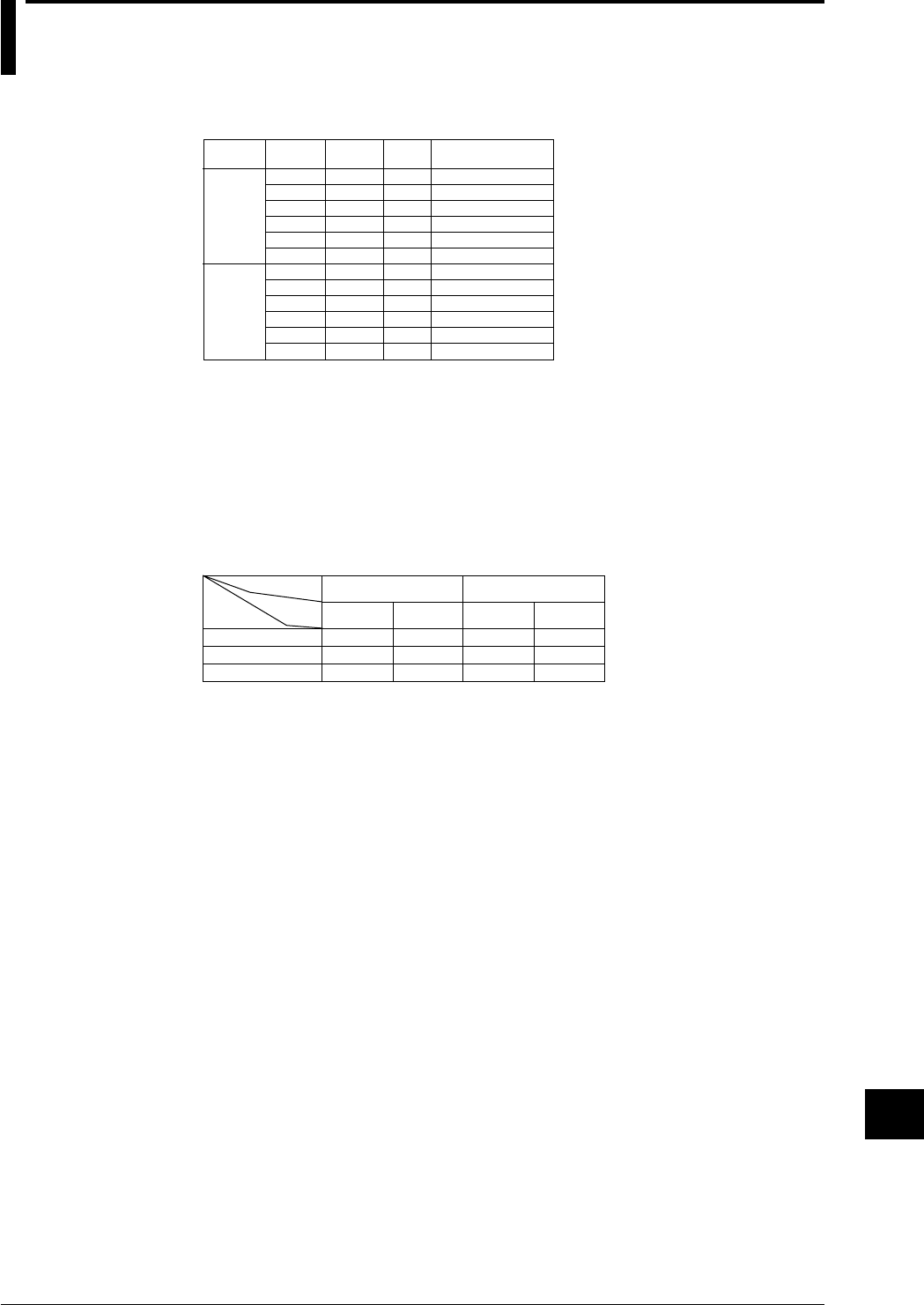
14-11
IM DR232-01E
Specifications
14
14.2 Universal Input Module and DCV/TC/DI Input
Module
Style Number: S2
Type, Number of Channels, Terminal Type and Minimum Measurement Interval
0.5s
0.5s
2s
2s
2s
2s
0.5s
0.5s
2s
2s
2s
2s
screw
clamp
screw
clamp
screw
clamp
screw
clamp
screw
clamp
screw
clamp
10ch
10ch
20ch
20ch
30ch
30ch
10ch
10ch
20ch
20ch
30ch
30ch
DU100-11
DU100-12
DU100-21
DU100-22
DU100-31
DU100-32
DU200-11
DU200-12
DU200-21
DU200-22
DU200-31
DU200-32
Kind
Universal
input
module
mV/TC
input
module
Type Number of
channels Terminal
type Minimum measurement
interval
Input method
floating unbalanced input, each channel mutually isolated (channel independent)
The RTD range (DU100 only) has a common potential (terminal b)
A/D resolution
±20000
A/D integration time
20ms (50Hz), 16.7ms (60Hz), 100ms (10Hz) or auto
(Except, auto switch does not function on the subunit (DS400/DS600) of a DC power supply
model. Selecting “AUTO” will set the A/D integration time to 20 ms (50 Hz).)
Minimum measurement interval
number
of channels 20ms/16.7ms
(50Hz/60Hz)
4s
5s
6s
3s
4s
4s
12s
15s
20s
10
20
30
Low-pass filter OFF Low-pass filter ON
Filter ON/OFF
A/D
integration
time
0.5s*
2s
2s
100ms
(10Hz) 20ms/16.7ms
(50Hz/60Hz) 100ms
(10Hz)
*2s if the power monitor module is installed.
Normal operating temperature/humidity
20 to 80%RH for –10 to 40°C, 10 to 50%RH for 40 to 50°C, 5 to 30%RH for 50 to 60°C (no condensation)
Compensation for the reference junction
Switchable internally or externally for each channel.
Compensation accuracy for the reference junction
(measured at 0°C, where the input terminals are balanced)
Type R, S, B, W : ±1°C
Type K, J, E, T, N, L, U : ±0.5°C
Maximum allowable input voltage
2V DC or lower range, TC, RTD, DI (CONT) : ±10V DC
6V DC or greater range, DI (LEVEL) : ±60V DC
Normal mode voltage
voltage, TC : 1.2 times the rated range or less (at peak value, including 50 or 60Hz signal
component)
RTD : 50 mV or lower (at peak value)
Normal mode rejection ratio
40dB or greater (50/60Hz ±0.1%)
Common mode noise voltage
250VAC rms (50/60Hz)
Common mode rejection ratio
120dB or greater (50/60Hz ±0.1%, 500Ω unbalanced, between the negative measurement terminal
and ground)
Maximum noise between channels
150VAC rms (50/60Hz)

14-12 IM DR232-01E
Measurement range, accuracy and resolution
As described below, under the following operating conditions:
Ambient temperature: 23 ±2°C; ambient humidity: 55 ±10% RH; power supply voltage: 90 to 250
VAC (AC power supply)/10 to 32 VDC (the subunit of a DC power supply model only); power
supply frequency: 50/60Hz within ±1% (AC power supply); warm-up time 30 minutes or more;
vibrations and others not affecting instrument operation. However, RTD input is not possible for
the DCV/TC/DI input module.
Input Measurement (digital display)
DC Voltage
TC
(Note that Accuracy
of reference junction
compensation is not
considered).
RTD
High resolution RTD
Contact
20mV
60mV
200mV
2V
6V
20V
50V
R
S
B
K
E
J
T
L
U
N
W
KPvsAu7Fe
Pt100(1mA)
Pt100(2mA)
JPt100(1mA)
JPt100(2mA)
Pt50(2mA)
Ni100(1mA)
SAMA
Ni100(1mA)DIN
Ni120(1mA)
J263*B
Cu10 GE
Cu10 L&N
Cu10 WEED
Cu10 BAILEY
Pt100(1mA)
Pt100(2mA)
JPt100(1mA)
JPt100(2mA)
Voltage input
Contact input
–20.000 to 20.000mV
–60.00 to 60.00mV
–200.00 to 200.00mV
–2.0000 to 2.0000V
–6.000 to 6.000V
–20.000 to 20.000V
–50.00 to 50.00V
0.0 to 1760.0°C
0.0 to 1760.0°C
0.0 to 1820.0°C
–200.0 to 1370.0°C
–200.0 to 800.0°C
–200.0 to 1100.0°C
–200.0 to 400.0°C
–200.0 to 900.0°C
–200.0 to 400.0°C
0.0 to 1300.0°C
0.0 to 2315.0°C
0.0 to 300.0K
–200.0 to 600.0°C
–200.0 to 250.0°C
–200.0 to 550.0°C
–200.0 to 250.0°C
–200.0 to 550.0°C
–200.0 to 250.0°C
–60.0 to 180.0°C
–70.0 to 200.0°C
0.0 to 300.0K
–200.0 to 300.0°C
–140.00 to 150.00°C
–70.00 to 70.00°C
–140.00 to 150.00°C
–70.00 to 70.00°C
Off for a voltage of less
than 2.4V.
On for a voltage of 2.4V
or more.(TTL)
On/Off of contact
Type Measurement accuracy Maximum
resolution
±(0.05% of rdg + 5digits)
±(0.05% of rdg + 2digits)
±(0.05% of rdg + 2digits)
±(0.05% of rdg + 2digits)
±(0.05% of rdg + 2digits)
±(0.05% of rdg + 2digits)
±(0.05% of rdg + 2digits)
±(0.05% of rdg + 1°C)
However,R,S:0 to 100°C,±3.7°C
100 to 300°C,±1.5°C
B:400 to 600°C,±2°C accuracy
less than 400°C is not specified.
±(0.05% of rdg +0.7°C)
However,K attains an accuracy of
±(0.05% of rdg. +1°C) within the
range between –200 to –100°C.
±(0.05% of rdg +0.5°C)
However,J and L attain an accuracy of
±(0.05% of rdg. +0.7°C) within the
range between –200 to –100°C.
±(0.05% of rdg. +0.7°C)
±(0.05% of rdg. +1°C)
±(0.05% of rdg. +0.7K)
±(0.05% of rdg. +0.3°C)
±(0.05% of rdg. +0.3°C)
±(0.05% of rdg. +0.3°C)
±(0.05% of rdg. +0.3°C)
±(0.05% of rdg. +0.3K)
±(0.2% of rdg. +0.7°C)
±(0.05% of rdg. +0.3°C)
±(0.05% of rdg. +0.3°C)
±(0.05% of rdg. +0.3°C)
±(0.05% of rdg. +0.3°C)
Off for a voltage of less than 2.4V.
On for a voltage of 2.4V or more.
(TTL)
On/Off of contact
Measurement range
1µV
10µV
10µV
100µV
1mV
1mV
10mV
0.1°C
0.1K
0.1°C
0.1K
0.1°C
0.01°C
*
1
*
1
*
1
*
1
*
1
*
1
*
1
*
2
*
2
*
3
*
4
*
5
*
5
*
5
*
5
*
5
*
6
*
6
*
7
*
8
*
8
*
8
*
8
*
5
*
5
*
5
*
5
*1 : R,S,B,K,E,J,T:ANSI,IEC 584,DIN IEC 584,JIS C 1602-1981
*2 : L:Fe-CuNi,DIN43710,U:Cu-CuNi,DIN 43710
*3 : N:Nicrosil-Nisil,IEC 584,DIN IEC 584
*4 : W:W·5%RE-W·26%Re (Hoskins Mfg Co)
*5 : Pt50:JIS C 1604-1981,JIS C 1606-1986
Pt100:JIS C 1604-1989,JIS C 1606-1989,IEC 751,DIN IEC 751
JPt100:JIS C 1604-1981,JIS C 1606-1989
*6 : SAMA/DIN
*7 : McGRAW EDISON COMPANY
*8 : ranges to which accuracy applies:
Cu10 GE:–84.4 to 170.0°C,
Cu10 L&N:–75.0 to 150.0°C,
Cu10 WEED:–200.0 to 250.0°C,
Cu10 BAILEY:–200.0 to 250.0°C
Noise rejection
rejection by integration type A/D, lowpass filter, or moving averaging.
Input resistance
Min. 10MΩ at 2V DC or lower, thermocouple range
Approx. 1MΩ at 6V DC or higher.
Insulation resistance
Min. 20MΩ at 500V DC between the input terminal and ground.
14.2 Universal Input Module and DCV/TC/DI Input Module

14-13
IM DR232-01E
Specifications
14
Input bias current
max. 10nA
Dielectric strength
Between input terminals : 1000V AC (50/60Hz) for one minute
Between an input terminal and ground : 1500V AC (50/60Hz) for one minute
Input source resistance
DCV, TC : 2kΩ or lower
RTD : 10Ω or lower per line (Pt100Ω)
5Ω or lower per line (Pt50Ω)
1Ω or lower per line (Cu10Ω)
Temperature coefficient
zero : 0.01% of range/°C
full span : 0.01% of range/°C (0.02% of span/°C for Cu10Ω)
Thermocouple burnout
Detected in a thermocouple range (On/Off) enabled, current of 4µA, detectable pulse width of
approx. 5ms
2 kΩ or lower is considered “normal”
100 kΩ or greater is considered “disconnected”
Detection interval for thermocouple burnout
2.5 sec. for a measurement period of 0.5 sec; in all other cases: each measurement interval
Detection timing for thermocouple burnout
The burnout condition is detected at each measurement interval. However, with a 10ch universal
input module connected and a measurement interval of 0.5sec, the minimum interval of the
burnout detection becomes 2.5 sec.
Power consumption
Included in the main unit or the subunit to which the module is to be installed.
External dimensions and weight
Weight (kg)
0.5
0.5
1.0
1.0
1.5
1.5
0.5
0.5
1.0
1.0
1.5
1.5
External dimensions(W)×(H)×(D)mm
apporox. 57×137×88
apporox. 57×137×88
apporox. 114×137×88
apporox. 114×137×88
apporox. 172×137×88
apporox. 172×137×88
apporox. 57×137×88
apporox. 57×137×88
apporox. 114×137×88
apporox. 114×137×88
apporox. 172×137×88
apporox. 172×137×88
Type
DU100-11
DU100-12
DU100-21
DU100-22
DU100-31
DU100-32
DU200-11
DU200-12
DU200-21
DU200-22
DU200-31
DU200-32
14.2 Universal Input Module and DCV/TC/DI Input Module

14-14 IM DR232-01E
14.3 Specifications of mA-input Module
Style Number: S5
Model Code, Number of Input Channels, Terminal Configuration and Shortest
Measurement Interval
Model Code Number of Channels Terminal Configuration Shortest Measurement Interval
DU300-11 10 Screw 0.5 s
DU300-12 10 Clamp 0.5 s
Method of Input
Non-balanced floating input with isolation between channels (separated channels)
Resolution of A/D Conversion
±20000
Integral Time of A/D Conversion
Manual or automatic selection between 20 ms (50 Hz), 16.7 ms (60 Hz) and 100 ms (10 Hz)
(Except, auto switch does not function on the subunit (DS400/DS600) of a DC power supply
model. Selecting "AUTO" will set the A/D integration time to 20 ms (50 Hz).)
Shortest Measurement Interval and Cutoff Frequency
When the lowpass filter is turned off:
Cutoff frequency: 50/60 Hz 10 Hz
Shortest measurement interval: 0.5 s 4 s
When the lowpass filter is turned on:
Cutoff frequency: 50/60 Hz 10 Hz
Shortest measurement interval: 3 s 12 s
Normal Operating Temperature/Humidity Range
-10˚ to 60˚C
20 to 80% RH for an ambient temperature range of -10˚ to 50˚C; 10 to 50% RH for 40˚ to 50˚C; 5
to 30% RH for 50˚ to 60˚C (non-condensing)
Maximum Input Voltage
5 V DC
Maximum Normal-mode Noise Current
24 mA (peak value, including 50- and 60-Hz signal components)
Equivalent voltage of 2.4 V
Normal Mode Rejection Ratio (Equivalent Voltage)
40 dB minimum (50/60 Hz ±0.1%)
Maximum Common Mode Noise Voltage
250 V ACrms (50/60 Hz)
Common Mode Rejection Ratio (Equivalent Voltage)
120 dB minimum (50/60 Hz ±0.1%)
Maximum Noise Across Channels
150 V ACrms (50/60 Hz)
Measuring Range/Accuracy
As described below, under the following operating conditions:
Ambient temperature: 23 ±2°C; ambient humidity: 55 ±10% RH; power supply voltage: 90 to 250
VAC (AC power supply)/10 to 32 VDC (the subunit of a DC power supply model only); power
supply frequency: 50/60Hz within ±1% (AC power supply); warm-up time 30 minutes or more;
vibrations and others not affecting instrument operation.
Measuring Range Measuring Accuracy Maximum Resolution
-20.000 to 20.000 mA ±(0.25% of rdg. + 5 digits) 1 µA

14-15
IM DR232-01E
Specifications
14
Filter
Lowpass filter or use of moving average
Cutoff frequencies of lowpass filter: 50/60 Hz and 10 Hz and frequencies of their respective
integral multiples
Input Resistance
100 Ω
Insulation Resistance
Across channels: 50 V DC
Across input terminals and ground: 20 MΩ minimum (500 V DC)
Withstanding Voltage
Across channels: 1,000 V AC, 1 min (50/60 Hz)
Across input terminals and ground: 1,500 V AC, 1 min (50/60 Hz, excluding DU500-14)
Temperature Coefficient
Zero: 0.0125% of range/˚C
Span: 0.0125% of range/˚C
Power Consumption
Included in the value of a system's installed main unit or sub-unit
Dimensions
Approximately 57 (W) × 137 (H) × 88 (D) (mm)
Weight
Approximately 0.5 kg
Installation Category (Overvoltage Category)
CAT II (IEC1010)
14.3 Specifications of mA-input Module

14-16 IM DR232-01E
14.4 Specifications of Power Monitor Module
Model Code, Use (Input Channels), Terminal Configuration and Shortest
Measurement Interval
Model Code Use (Input Channels) Terminal Shortest
Configuration Measurement Interval
DU400-12 Single-phase Clamp* 2 s
(one channel each for voltage and current)
DU400-22 Three-phase Clamp*, ** 2 s
(three channels each for voltage and current)
*: Two-terminal pressure clamping
**: Not usable as an equivalent to three modules of single-phase use
Method of Input
Transformer-isolated input, with isolation between channels (separated channels)
Method of Measurement and Computing
Digital multiplication
Measuring Ranges
Voltage: 25 or 250 Vrms
Current: 0.5 or 5 A
In three-phase measurement or single-phase three-wire measurement, the current/voltage ranges
are identical between the respective phases or lines (the current/voltage ranges are set in common
between the respective channels).
Measured Frequency Range
45 to 65 Hz
Wiring Methods
DU400-12: Single-phase two-wire
DU400-22: Single-phase two-wire, single-phase three-wire, three-phase three-wire (dual-voltage,
dual-current), three-phase three-wire (triple-voltage, triple-current) and three-phase four-wire
Measured Data Items
For each module, a maximum of six data items can be selected from the effective voltage,
effective current, active power, apparent power, reactive power, frequency, power factor and
phase angle. The selected data items can then be assigned to channel numbers xx1 to xx6 to show
them on the display as well as record them. Restrictions apply to the combination of selectable
data items, however, depending on the method of input wiring.
Conditions of Measurement
• Measuring range for current and voltage inputs
10% of the measuring range < current and voltage inputs ≤ 100% of the measuring range
• V1 range is monitored in frequency measurement
• All measurements are done relative to the frequency on a channel for V1 and, therefore, the
results of measurements are not guaranteed if the V1 input is out of the range noted above.
• If the input apparent power falls below 10% of the span, the DR recorder cannot measure the
phase and power factor (negative overflow).
• A maximum of two scans' worth of data become invalid immediately after a change has been
made to the measuring range and/or wiring.
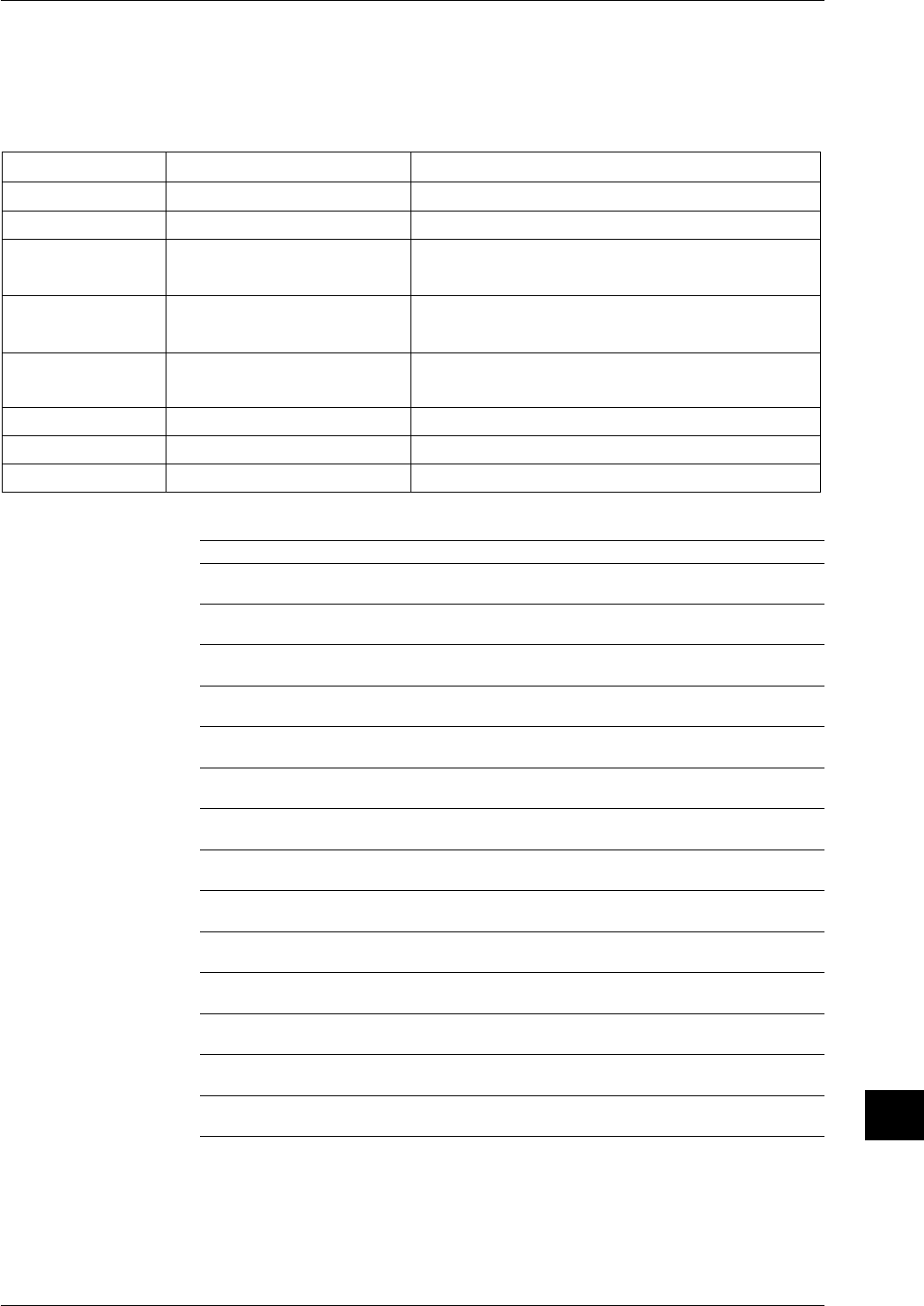
14-17
IM DR232-01E
Specifications
14
Measuring Accuracy and Resolution
As described below, under the following operating conditions:
Ambient temperature: 23 ±2°C; ambient humidity: 55 ±10% RH; power supply voltage: 90 to 250
VAC (AC power supply)/10 to 32 VDC (the subunit of a DC power supply model only); power
supply frequency: 50/60Hz within ±1% (AC power supply); warm-up time 30 minutes or more;
vibrations and others not affecting instrument operation.
Measured Data Item Measuring Accuracy Resolution
Effective voltage ± (0.5% of SPAN) 0.01 Vrms (for 25-V range), 0.1 Vrms (for 250-V range)
Effective current ± (0.5% of SPAN) 0.0001 Arms (for 0.5-A range), 0.001 Arms (for 5-A range)
Active power ± (1% of SPAN) φ = 0 0.01 W (for 12.5-W, 25-W and 37.5-W spans)
± (2.5% of SPAN) 0 <| φ |≤ 30 0.1 W (for 125-W, 250-W and 375-W spans)
± (5% of SPAN) 30 <| φ |≤ 80 1 W (for 1,250-W, 2,500-W and 3,750-W spans)
Apparent power ± (1% of SPAN) 0 ≤| φ |≤ 80 0.01 VA (for 12.5-VA, 25-VA and 37.5-VA spans)
0.1 VA (for 125-VA, 250-VA and 375-VA spans)
1 VA (for 1,250-VA, 2,500-VA and 3,750-VA spans)
Reactive power ± (5% of SPAN) 0 ≤| φ |< 60 0.01 Var (for 12.5-Var, 25-Var and 37.5-Var spans)
± (2.5% of SPAN) 60 ≤| φ |≤ 80 0.1 Var (for 125-Var, 250-Var and 375-Var spans)
1 Var (for 1,250-Var, 2,500-Var and 3,750-Var spans)
Frequency ±0.1Hz 0.01Hz
Power factor ± (2% of SPAN) 0 ≤| φ |≤ 80 0.01
Phase angle ±5deg 0 ≤| φ |≤ 80 0.1deg
Measuring Ranges
Measured Data Item 25 V-0.5A 25 V-5 A 250 V-0.5 A 250 V-5 A
Effective voltage 0.00 to 25.00 V rms 0.00 to 25.00 V rms 0.0 to 250.0 V rms 0.0 to 250.0 V rms
Vi (i = 1, 2, 3, 13, 0)
Effective current
0.0000 to 0.50000A rms
0.000 to 5.000 A rms
0.0000 to 0.5000 A rms
0.000 to 5.000 A rms
Ii (i = 1, 2, 3, 13, 0)
Active power
–12.50 to 12.50 W –125.0 to 125.0 W –125.0 to 125.0 W –1250 to 1250 W
P1, P2, P3
Active power
–25.00 to 25.00 W –250.0 to 250.0 W –250.0 to 250.0 W –2500 to 2500 W
P13
Active power
–37.50 to 37.50 W –375.0 to 375.0 W –375.0 to 375.0 W –3750 to 3750 W
P0
Apparent power 0.00 to 12.50 VA 0.0 to 125.0 VA 0.0 to 125.0 VA 0 to 1250 VA
VA1, VA2, VA3
Apparent power 0.00 to 25.00 VA 0.0 to 250.0 VA 0.0 to 250.0 VA 0 to 2500 VA
VA13
Apparent power 0.00 to 37.50 VA 0.0 to 375.0 VA 0.0 to 375.0 VA 0 to 3750 VA
VA0
Reactive power 0.00 to 12.50 Var 0.0 to 125.0 Var 0.0 to 125.0 Var 0 to 1250 Var
Var1, Var2, Var3
Reactive power 0.00 to 25.00 Var 0.0 to 250.0 Var 0.0 to 250.0 Var 0 to 2500 Var
Var13
Reactive power 0.00 to 37.50 Var 0.0 to 375.0 Var 0.0 to 375.0 Var 0 to 3750 Var
Var0
Power factor –1.00 to 1.00 –1.00 to 1.00 –1.00 to 1.00 –1.00 to 1.00
PFi (i = 1, 2, 3, 13, 0)
Phase
–80.0 to 80.0 deg –80.0 to 80.0 deg –80.0 to 80.0 deg –80.0 to 80.0 deg
PHi (i = 1, 2, 3, 13, 0)
Frequency
45.00 to 65.00 Hz 45.00 to 65.00 Hz 45.00 to 65.00 Hz 45.00 to 65.00 Hz
FREQ
14.4 Specifications of Power Monitor Module

14-18 IM DR232-01E
Ranges of Indication
Measured Data Item 25 V-0.5A 25 V-5 A 250 V-0.5 A 250 V-5 A
Effective voltage 0.00 to 26.25 V rms 0.00 to 26.25 V rms 0.0 to 262.5 V rms 0.0 to 262.5 V rms
Vi (i = 1, 2, 3, 13, 0)
Effective current
0.0000 to 0.5250 V rms 0.000 to 5.250 V rms 0.0000 to 0.5250 V rms 0.000 to 5.250 V rms
Ii (i = 1, 2, 3, 13, 0)
Active power
–13.75 to 13.75 W –137.5 to 137.5 W –137.5 to 137.5 W –1375 to 1375 W
P1, P2, P3
Active power
–27.50 to 27.50 W –275.0 to 275.0 W –275.0 to 275.0 W –2750 to 2750 W
P13
Active power
–41.25 to 41.25 W –412.5 to 412.5 W –412.5 to 412.5 W –4125 to 4125 W
P0
Apparent power 0.00 to 13.75 VA 0.0 to 137.5 VA 0.0 to 137.5 VA 0 to 1375 VA
VA1, VA2, VA3
Apparent power 0.00 to 27.50 VA 0.0 to 275.0 VA 0.0 to 275.0 VA 0 to 2750 VA
VA13
Apparent power 0.00 to 41.25 VA 0.0 to 412.5 VA 0.0 to 412.5 VA 0 to 4125 VA
VA0
Reactive power 0.00 to 13.75 Var 0.0 to 137.5 Var 0.0 to 137.5 Var 0 to 1375 Var
Var1, Var2, Var3
Reactive power 0.00 to 27.50 Var 0.0 to 275.0 Var 0.0 to 275.0 Var 0 to 2750 Var
Var13
Reactive power 0.00 to 41.25 Var 0.0 to 412.5 Var 0.0 to 412.5 Var 0 to 4125 Var
Var0
Power factor –1.00 to 1.00 –1.00 to 1.00 –1.00 to 1.00 –1.00 to 1.00
PFi (i = 1, 2, 3, 13, 0)
Phase
–89.0 to 89.0 deg –89.0 to 89.0 deg –89.0 to 89.0 deg –89.0 to 89.0 deg
PHi (i = 1, 2, 3, 13, 0)
Frequency
41.00 to 69.00 Hz 41.00 to 69.00 Hz 41.00 to 69.00 Hz 41.00 to 69.00 Hz
FREQ
Output Data Items of Each Wiring Method
Output Data Item Single-phase Single-phase Three-phase Three-phase Three-phase
Two-wire Three-wire Three-wire Three-wire Four-wire
(Dual-voltage, (Triple-voltage,
Dual-current) Triple-current)
Effective voltage V V1 V1, V3 V1, V3 V1, V2, V3 V1, V2, V3
V13: (V1+V3)/2 V13: (V1+V3)/2 V13: (V1+V3)/2 V0: (V1+V2+V3)/3
V0: (V1+V2+V3)/3
Effective current I I1 I1, I3 I1, I3 I1, I2, I3 I1, I2, I3
I13: (I1+I3)/2 I13: (I1+I3)/2 I13: (I1+I3)/2 I0: (I1+I2+I3)/3
I0: (I1+I2+I3)/3
Active power W P1 P1, P3 P1, P3 P1, P2, P3 P1, P2, P3
P13: P1+P3 P13: P1+P3 P13: P1+P3 P0: P1+I2+P3
Apparent power VA VA1 VA1, VA3 VA1, VA3 VA1, VA2, VA3 VA1, VA2, VA3
VA13: VA1+VA3 VA13: VA1+VA3 VA13: VA1+VA3 VA0: VA1+VA2+VA3
Reactive power Var Var1 Var1, Var3 Var1, Var3 Var1, Var2, Var3 Var1, Var2, Var3
Var13: Var1+Var3 Var13: Var1+Var3 Var13: Var1+VA3 Var0: Var1+Var2+Var3
Frequency FREQ FREQ FREQ FREQ FREQ FREQ
Power factor PF PF1 PF1, PF3 PF1, PF3 PF1, PF2, PF3 PF1, PF2, PF3
PF13 PF13 PF13 PF0
Phase angle PH PH1 PH1, PH3 PH1, PH3 PH1, PH2, PH3 PH1, PH2, PH3
PH13 PH13 PH13 PH0
14.4 Specifications of Power Monitor Module

14-19
IM DR232-01E
Specifications
14
Continuously Applicable Maximum Voltage and Current
Voltage: 250 Vrms
Current: 5 Arms
Crest Factor
3 maximum (600 Vpeak)
Maximum Common Mode Voltage
250 Vrms
Common Mode Voltage Rejection Ratio (Voltage and Current Ranges)
0.02% of span (when 250 V, 45 to 65 Hz is imposed)
Input Resistance
Voltage input: 300 kΩ minimum for AC voltages
Current input: 1 Ω maximum for AC currents
Filter
Moving average
Wattage Calculation
Use of /M1 computing function
Insulation Resistance
Across output terminals and ground: 20 MΩ minimum
Withstanding Voltage
Across output terminals and ground: 2,300 V AC (50/60 Hz), 1 min
Normal Operating Temperature/Humidity Ranges
0˚ to 50˚C
20 to 80% RH for an ambient temperature range of 0˚ to 40˚C; 10 to 50% RH for 40˚ to 50˚C
(non-condensing)
Power Consumption
Included in the value of a system's installed main unit or sub-unit
Dimensions
Approximately 57 (W) × 137 (H) × 99 (D) (mm)
Weight
Approximately 0.5 kg
Installation Category (Overvoltage Category)
CAT II (IEC1010)
14.4 Specifications of Power Monitor Module

14-20 IM DR232-01E
14.5 Specifications of Strain Input Module
Model Code, Number of Input Channels, Terminal Configuration, Shortest
Measurement Interval and Values of Built-in Resistors
Model Code Number of Input Terminal Shortest Measurement Built-in
Channels Configuration Interval Resistor
DU500-12 10* Clamp 0.5 s 120 Ω
DU500-13 10* Clamp 0.5 s 350 Ω
DU500-14 10* NDI** 0.5 s External
*: Requires the space of two slots.
**: Recommended by the Japanese Nondestructive Inspection Association
Method of Input
Non-balanced floating input, with isolation between channels (separated channels)
Resolution of A/D Conversion
Equivalent to reading on 20000 full scale
Integral Time of A/D Conversion
Manual or automatic selection between 20 ms (50 Hz), 16.7 ms (60 Hz) and 100 ms (10 Hz)
(Except, auto switch does not function on the subunit (DS400/DS600) of a DC power supply
model. Selecting "AUTO" will set the A/D integration time to 20 ms (50 Hz).)
Types of Input
Signals from strain gauge or strain-gauge sensor
Connection Methods
Single-gauge, opposed-side two-gauge, adjacent-side two-gauge or four-gauge configuration
(Configured with built-in DIP switches for DU500-12 and DU500-13)
Applicable Gauge Resistance
100 to 1,000 Ω
The DU500-12 and DU500-13 modules contain 120-Ω and 350-Ω resistors, respectively.
Bridge Voltage
Fixed to 2 V DC (±5% accuracy with a correction function)
Gauges
2.00 (with scaling capability)
Balancing
Automatic
Range of Balancing
Equivalent to ±10,000 µe (for single-gauge method)
Measuring Ranges and Accuracies
As described below, under the following operating conditions:
Ambient temperature: 23 ±2°C; ambient humidity: 55 ±10% RH; power supply voltage: 90 to 250
VAC (AC power supply)/10 to 32 VDC (the subunit of a DC power supply model only); power
supply frequency: 50/60Hz within ±1% (AC power supply); warm-up time 30 minutes or more;
vibrations and others not affecting instrument operation.
Gauge Method Measuring Range Accuracy Resolution
Single-gauge –2000 to 2000 µε 0.5% of Range 0.1 µε
–20000 to 20000 µε 0.3% of Range µε
–200000 to 200000 µε 0.3% of Range 10 µε
Two-gauge –1000 to 1000 µε 0.5% of Range 0.1 µε
10000 to 10000 µε 0.3% of Range 1 µε
–100000 to 100000 µε 0.3% of Range 10 µε
Four-gauge –500 to 500 µε 0.5% of Range 0.1 µε
–5000 to 5000 µε 0.3% of Range 1 µε
–50000 to 50000 µε 0.3% of Range 10 µε
The Accuracies and Resolutions of the DU500-12 and DU500-13 models, do not include the influence of
the internal- and contact-resistance of the jumper setup switch.

14-21
IM DR232-01E
Specifications
14
Accuracy of Bridge Resistors
±0.01%, ±5 ppm/˚C (excludes contact resistance of the jumper setup switch)
Contact Resistance of the Jumper Setup Switch
100 mΩ maximum
Input Resistance
10 MΩ minimum
Filter
Third-order sinc filter, moving-average
Withstanding Voltage
Across channels: 50 V DC (except for DU500-14)
Across output terminals and ground: 1,500 V AC, 1 min (excluding DU500-14)
Normal Operating Temperature/Humidity Range
0˚ to 50˚C
20 to 80% RH for an ambient temperature range of 0˚ to 40˚C; 10 to 50% RH for 40˚ to 50˚C
(non-condensing)
Power Consumption
Included in the value of a system's installed main unit or sub-unit
Dimensions
DU500-12/DU500-13: Approximately 114.3 (W) × 137 (H) × 88 (D) (mm)
DU500-14: Approximately 114.3 (W) × 137 (H) × 77 (D) (mm)
Weight
DV 500 -12, -13 0.6kg
DV 500 -14 0.8kg
Installation Category (Overvoltage Category)
CAT II (IEC1010)
Accessory
Bridge box: 319300 (120 Ω)
14.5 Specifications of Strain Input Module

14-22 IM DR232-01E
14.6 Specifications of Pulse Input Module
Model Code, Number of Input Channels, Terminal Configuration and Shortest
Measurement Interval
Model Code Number of Channels Terminal Configuration Shortest Measurement
Interval
DU600-11 10 Screw 0.5 s*
*: The interval between data updates is fixed to one second.
Method of Input
Potential with reference to the shared voltage of the COMMON line within the same module
Types of Input
Voltage-free contact or open collector (TTL or transistor)
Measurement Modes
RATE (instantaneous count mode): Outputs the prescaled value of the count of pulses imposed
over the last one-second interval of measurement.
GATE (instantaneous turn-on time mode): Outputs the prescaled values of the contact's turn-on
(make) and turn-off (break) times (on = 1; off = 0) over the last one-second interval of
measurement.
Note
The computing function (computational expression: TLOG.PSUM (XXX)) should be used when
integrating an every-second count or turn-on time (maximum count/turn-on time: 99999999).
Input Range
0 to 6,000 pulses, or 0 to 10 pulses (if the filter is on) for voltage-free input.
Ratio of make at input: 35 to 65% at the maximum frequency (ratio of make = closed-contact
time/(closed-contact time + open-contact time) × 100)
Minimum input pulse width: 60 µs (whether the contact is closed or open)
Measuring Accuracies
As described below, under the following operating conditions:
Ambient temperature: 23 ±2°C; ambient humidity: 55 ±10% RH; power supply voltage: 90 to 250
VAC (AC power supply)/10 to 32 VDC (the subunit of a DC power supply model only); power
supply frequency: 50/60Hz within ±1% (AC power supply); warm-up time 30 minutes or more;
vibrations and others not affecting instrument operation.
Count: ±1 pulse (for integration, ±(1 scan + 1 second) at the start of measurement and ±(1 scan +
1.5 seconds) at the end of measurement)
Turn-on time: ±100-ppm accuracy for judgment of one-second-interval sampling; for integration,
±(1 second + 1 scan) at the start of measurement and ±(100 ppm of rdg. + 1.5 seconds + 1 scan) at
the end of measurement
Module-to-module error: ±(3 seconds + 1 pulse) for count and ±(200 ppm + 3 seconds) for turn-
on time
Note
It takes a maximum of 2 seconds for normal measured values to be output when the power is turned on,
when the measurement mode is changed or when the setting for turning on/off the filter is changed. The
DR recorder indicates a value representative of “no data” ( on the display, or 8005H for the
binary format or a faulty data value for the ASCII format in the case of output to the communication line)
until the normal measured values are output.
Filter
Removes chatter of up to 5 ms (can be turned on or off on a channel basis).
Input Signal Levels
Open contact: 200 Ω maximum
Closed contact: 100 kΩ minimum
Normal Operating Temperature/Humidity Range
0˚ to 50˚C
20 to 80% RH for an ambient temperature range of 0˚ to 40˚C or 10 to 50% RH for 40˚ to 50˚C
(non-condensing)
Normal Operating Magnetic-field Strength
400 A/m maximum

14-23
IM DR232-01E
Specifications
14
Maximum Input Voltage
5 V DC
Signal Source Ratings
15 V DC, 30 mA minimum
Insulation Resistance
Across input terminals and ground: 20 MΩ minimum (500 V DC)
Withstanding Voltage
Across output terminals and ground: 500 V DC, 1 min (no channel-to-channel isolation)
Power Consumption
Included in the value of a system's installed main unit or sub-unit
Dimensions
Approximately 57 (W) × 137 (H) × 68 (D) (mm)
Weight
Approximately 0.3 kg
Installation Category (Overvoltage Category)
CAT II (IEC1010)
14.6 Specifications of Pulse Input Module

14-24 IM DR232-01E
14.7 Specifications of Digital Input Module
Style Number: S8
Model, Number of Channels, Terminal Type and Minimum Measurement Interval
Model Number of Channels Terminal Type Minimum Measurement Interval
DU700-11 10 Screw 0.5s
Input method
Floating unbalanced input, each channel mutually isolated (channel independent)
A/D resolution
±20000
A/D integration time
20 ms (50 Hz), 16.7 ms (60 Hz), 100 ms (10 Hz) or auto
(Except, auto switch does not function on the stand-alone DC power supply model or the subunit
(DS400/DS600) of a DC power supply model.)
Minimum measurement interval
Low-pass filter OFF
Cut-off frequency 50/60Hz 10Hz
Minimum measurement interval 0.5 s 4 s
Low-pass filter ON
Cut-off frequency 50/60Hz 10Hz
Minimum measurement interval 3 s 12 s
Normal operating temperature/humidity
20 to 80% RH for –10 to 40°C, 10 to 50% RH for 40 to 50°C, 5 to 30% RH for 50 to 60°C (no
condensation)
Magnetic field
400A/m max (50/60Hz)
Maximum allowable input voltage
CONT (Contact input) : ±10 V DC
LEVEL (Voltage input) : ±60 V DC
Common mode noise voltage
250 V AC rms (50/60 Hz)
Maximum noise between channels
150 V AC rms (50/60 Hz)
Action
At normal operating temperature/humidity
Voltage input (LEVEL) : Off for a voltage of less than 24V.
ON for a voltage 2.4 V or more.
Contact input (CONT) : On/Off of contact.*
*: Contact resistance ON ; 2 kΩ or less, OFF ; 100 kΩ or more
Noise rejection
Rejection by integration type A/D, lowpass filter
Cut-off frequency
50/60/10Hz
Input resistance
CONT : Min. 10 MΩ
LEVEL : Approx. 1 MΩ
Insulation resistance
Min. 20 MΩ at 500 V DC between the input terminal and ground.
Dielectric strength
Between input terminals : 1000 V AC (50/60 Hz) for one minute
Between an input terminal and ground : 1500 V AC (50/60 Hz) for one minute
Input source resistance
LEVEL : 2 kΩ or lower
Power consumption
Included in the main unit or the subunit to which the module is to be installed.

14-25
IM DR232-01E
Specifications
14
Dimensions
Approximately 57(W) × 137(H) × 68(D) (mm)
Weight
0.5 kg
Installation Category (Overvoltage Category)
CAT II (IEC 1010)
14.7 Specifications of Digital Input Module
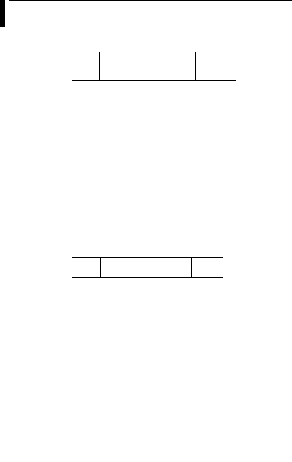
14-26 IM DR232-01E
14.8 Alarm Module
Style Number: S2
Type, Number of outputs, Contact mode, Terminal type
Contact mode
Transfer contact (NO-C-NC)
Make contact(NO-C)
Terminal type
screw
screw
Number of
output
4
10
Type
DT200-11
DT200-21
Normal operating temperature/humidity
20 to 80%RH for 0 to 40°C, 10 to 50%RH for 40 to 50°C (no condensation)
Output updating rate
every measurement interval
Contact mode
Make contact : normal open/common contact type
Transfer contact: normal open/common/normal close type
Energize/de-energize
switchable
Hold/non-hold
switchable
Reflash alarm
up to 6 contacts can be specified.
Contact capacity
250V DC/0.1A (with a resistor load)
250V AC/2A (with a resistor load)
30V DC/2A (with a resistor load)
Dielectric strength
Between the output terminal and ground: 2300V AC (50/60Hz) for one minute.
Power consumption
Included in the main unit or the subunit to which the module is to be installed.
External dimensions and weight
Weight (kg)
0.3
0.4
External dimensions(W)×(H)×(D)mm
apporox. 57×137×68
apporox. 57×137×68
Type
DT200-11
DT200-21

14-27
IM DR232-01E
Specifications
14
14.9 DI/DO Module
Style Number: S2
General Specifications
Terminal type
screw
Normal operating temperature/humidity
20 to 80%RH for 0 to 40°C, 10 to 50%RH for 40 to 50°C (no condensation)
Power consumption
Included in the main unit or the subunit to which the module is to be installed.
Dielectric strength
Between input terminal and ground: 1500V AC (50/60Hz) for one minute.
Between output terminal and ground: 2300V AC (50/60Hz) for one minute.
External dimensions
Approx. 57 (W) × 137 (H) × 68 (D) mm
Weight
0.35kg
DO: Alarm output
Output update rate
every measurement interval
Contact mode
Transfer contact (NO-C-NC)
Energize/de-energize
switchable
hold/non-hold
switchable
Reflash alarm
can be set
Contact rating
250V DC/0.1A (resistive load)
250V AC/2A (resistive load)
30V DC/2A (resistive load)
DO: Failure output
Function
The output relay for a failure becomes de-energized when an error is detected in the system of the
DA100 main unit or the DA/DR subunit which is connected to the module.
Contact mode
Transfer contact (NO-C-NC)
Energize/de-energize
not switchable
Contact rating
250V DC/0.1A (resistive load)
250V AC/2A (resistive load)
30V DC/2A (resistive load)
DO: Chart-end Output
Function
The output relay for chart-end becomes energized when the recorder runs out of chart paper.
Contact mode
Transfer contact: normal open/common/normal close type
Energize/de-energize
not switchable
Contact rating
250V DC/0.1A (resistive load)
250V AC/2A (resistive load)
30V DC/2A (resistive load)

14-28 IM DR232-01E
DI: Remote control of recorder functions
Function
The following functions can be controlled by contact input:
- alarm acknowledge;
- alarm reset;
- timer reset;
- starting/stopping recording;
- manual printout;
- digital printout;
- message printout;
- message display;
- changing chart speed/recording interval;
- group trend recording;
- Starting/stopping/clearing/resetting computation;
- Saving/reading measured/computed data, reading set-up data.
Input signal
No voltage contact, open-collector driven by a TTL or transistor
Rated voltage:0 to 5 V DC (input impedance:4.7kΩ, 5 V DC pull up)
Maximum input voltage (allowable range)
–2 to 7 V DC
Input conditions
• ON voltage:0.5V max. (30mA DC)
• Leakage current at OFF state:0.25mA max.
Duration of input signal
one second or longer (input signal detection internal:approx. 0.5 seconds)
14.9 DI/DO Module

14-29
IM DR232-01E
Specifications
14
14.10 Communication Interface Module
Type
Description
GP-IB
RS-232-C
RS-422-A/RS-485
Ethernet
Type
DT300-11
DT300-21
DT300-31
DT300-41
General Specifications
Power consumption
Included in the main unit or the subunit to which the module is to be installed.
Normal operating temperature/humidity
20 to 80%RH for 0 to 40°C, 10 to 50%RH for 40 to 50°C(no condensation)
GP-IB Module Style Number: S4
Electrical and mechanical specifications
conform to IEEE Standard 488-1978
Code
ISO (ASCII) code
Address
0 to 15
Functions
· Talker functions
Output of measurement values (ASCII, binary); output of setting parameters (ASCII)
· Listener functions
Setting of measurement conditions, control sof starting and stopping measurement, specifying
causes of interrupts (excluding setting and control of power ON/OFF)
Causes of interrupts
Syntax error, chart-end, completion of A/D conversion, operations of internal timer, end of data
saving/reading, incomplete measurement during computation
External dimensions
Approx. 57 (W) × 137 (H) × 54 (D) mm
Weight
0.3kg
RS-232-C Module Style Number: S8
Electrical and mechanical specifications
conform to standard EIA RS-232-C
Connection method
point-to-point
Communication method
half-duplex
Synchronization mode
Start-stop synchronization (synchronized by a start and a stop bit)
Baud rate
150, 300, 600, 1200, 2400, 4800, 9600, 19200 bps
Start bit
Fixed at 1 bit
Data length
7 or 8 bits, selectable
Parity
Selectable from even, odd, or none
Stop bit
1 or 2, selectable
Transmission distance
max. 15 m
Connector
D-sub 25pin

14-30 IM DR232-01E
Handshaking
hardware: transmission and reception control by ‘DTR’ ‘RTS’, ‘CTS’ signal enabled.
Software : transmission control by ‘XON’ and ‘XOFF’ enabled.
Capacity of receiving buffer
200 bytes
Escape sequence
for reception only
Functions
• Talker functions
Output of measurement data (ASCII, binary) and setting parameters (ASCII)
• Listener functions
Setting of measurement conditions, control of measurement start and stop (excluding the setting
and control of power on/off), specifying causes of ‘ESC S’ (output of a status byte)
Contents of ‘status’
Syntax error, chart-end, completion of A/D conversion, operations of internal timer, end of data
saving/reading, incomplete measurement during computation
External dimensions
Approx. 57 (W) × 137 (H) × 54 (D) mm
Weight
0.3kg
RS-422-A/RS-485 Style Number: S8
Electrical & mechanical specs
Conform to the EIA RS-422-A and EIA RS-485 Standard
Connection format
Multi-drop 1:n (n=16 for RS-422-A, n=31 for RS-485)
Communication format
Half duplex
Synchronizing format
Start-stop asynchronous transmission (synchronized by start/stop bit)
Baud rate (bps)
150, 300, 600, 1200, 2400, 4800, 9600 or 19200 (selectable)
START bit
1 bit (fixed)
Data length
Either 7 or 8 bits (selectable)
Parity
Even, Odd, or None (selectable)
STOP bit
Either 1 or 2 bits (selectable)
Connector
6 point screw type terminal (uses M4 screws)
Minimum response time
0, 10, 20, 50 or 100 ms (selectable)
Reception buffer length
250 bytes
Escape sequence
Trigger, Status call, Open and Close
Electrical characteristics
SDA, SDB, RDA, RDB, SG. Between the signal terminal and the main internal circuit is
insulated functionally.
Communication distance
1.2 km maximum
Terminator
Internal resistor (120 ohm, 1W) switch with the slide switch
14.10 Communication Interface Module

14-31
IM DR232-01E
Specifications
14
Ethernet Style number: S8
Electrical and Mechanical specifications
Conforms to IEEE802.3 (Frames are not supported.)
Communication method
Ethernet
Transmission specifications
10BASE-T (CSMA/CD, 10Mbps, Baseband)
Transmission speed
10 Mbps
Protocols
TCP, IP, UDP, ARP, ICMP
Maximum number of connections
4
Input data
ASCII
Supporting RS-232-C commands
Output data
ASCII, Binary
External dimensions
Approx 57 (W) × 137 (H) × 57 (D)
Weight
0.3 kg
14.10 Communication Interface Module

14-32 IM DR232-01E
14.11 Specifications of Extension Module and
Extension Base
Model Codes
Extension module: DV100-011
Extension base: DV100-012
Units to Which Extension Modules Are Connected
DS400/DS600
Input Modules Connectable to an Extension Base
Universal input modules: DU100-11 or DU100-12, 10 channels
DCV/TC/DI input modules: DU200-11 or DU200-12, 10 channels
Maximum Mountable Number of Extension Modules
One each on a sub-unit
Maximum Connectable Number of Extension Bases
Up to three to each extension module. It is not possible, however, to wire extension bases in such
a manner that the total number of modules already mounted on the sub-unit and the extension
bases being wired exceeds the maximum number of modules allowed for mounting on the sub-
unit.
Overall Length of Wiring
30 m maximum
(The maximum overall length of cable measured from the extension module to the farthest
extension base)
Normal Operating Temperature/Humidity Range
-10˚ to 60˚C
20 to 80% RH for an ambient temperature range of -10˚ to 40˚C; 10 to 50% RH for 40˚ to 50˚C; 5
to 30% RH for 50˚ to 60˚C (non-condensing)
Insulation Resistance
Depends on the input module installed.
Withstanding Voltage
Depends on the input module installed.
Power Consumption
Included in the value of a system's installed main unit or sub-unit
Dimensions
Extension module: Approximately 57 (W) × 137 (H) × 49.5 (D) (mm) (The dimensions do not
include the support feet.)
Extension base: Approximately 114.8 (W) × 152.7 (H) × 43.7 (D) mm (The dimensions do not
include the support feet.)
Approximately 114.8 (W) × 171.5 (H) × 143.3 (D) mm (The dimensions include
the support feet.)
Weight
Extension module: Approximately 176 kg
Extension base: Approximately 345 kg
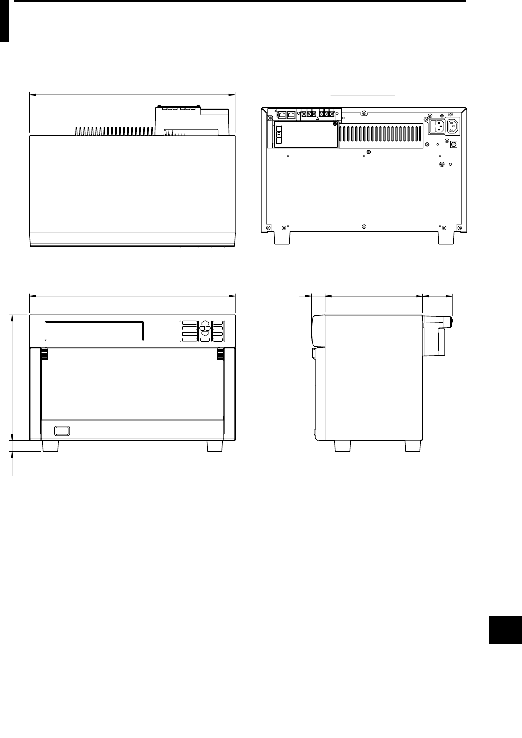
14-33
IM DR232-01E
Specifications
14
14.12 Dimensional Drawings
DR232 Main Unit
438 30 207 63.6
26625
424
Rear Panel
unit : mm
If not specified, the tolerance is ±3%. However, in cases of less than 10mm, the tolerance is ±0.3mm.
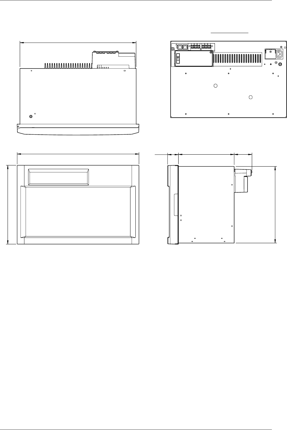
14-34 IM DR232-01E
14.12 Dimensional Drawings
DR242 Main Unit
444
288
424
40 203 64.8
280
Rear Panel
unit : mm
If not specified, the tolerance is ±3%. However, in cases of less than 10mm, the tolerance is ±0.3mm.
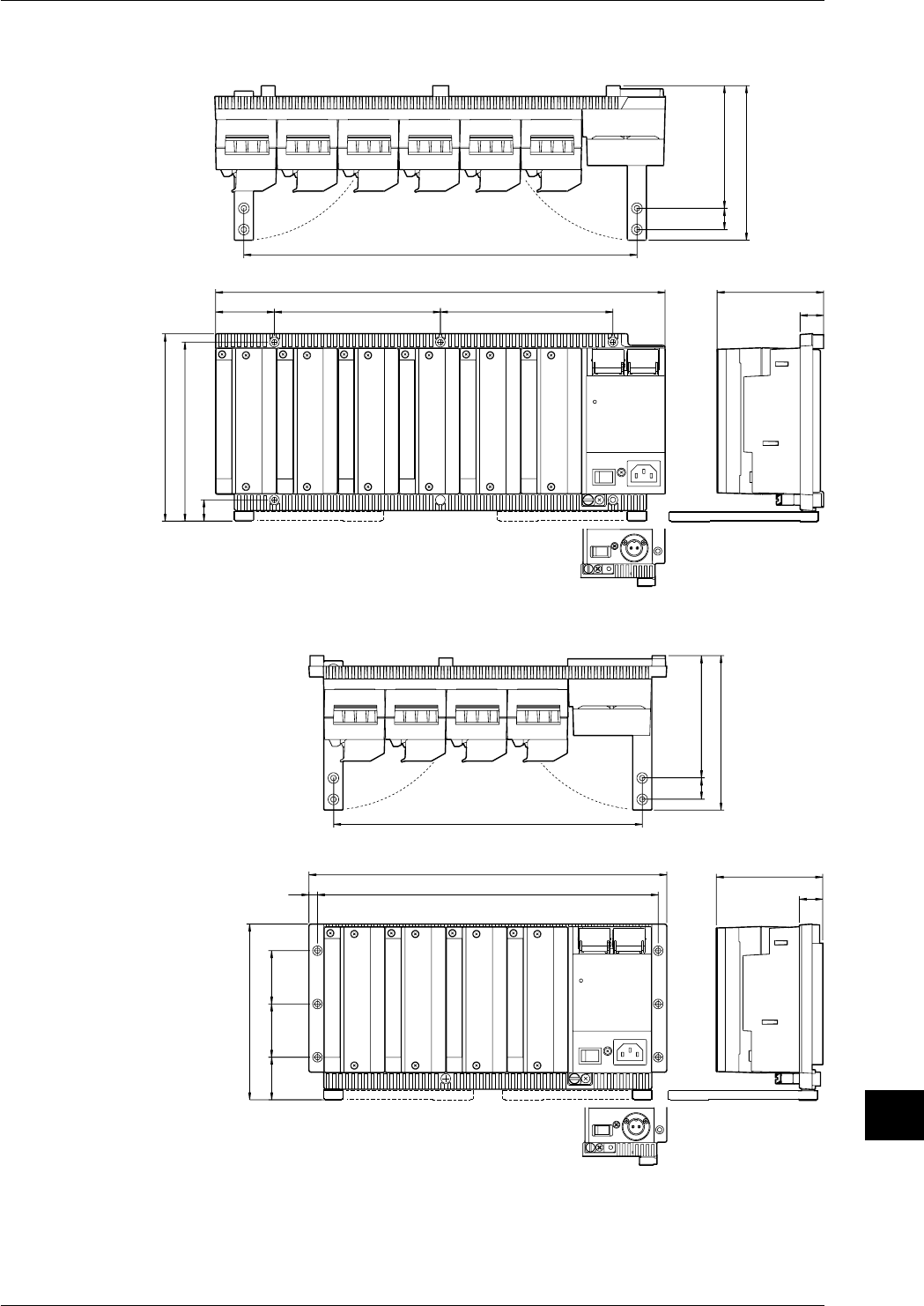
14-35
IM DR232-01E
Specifications
14
14.12 Dimensional Drawings
Sub-unit DS600
156
168
20
100
422
145
22
16255
176
115
369
20
unit : mm
Sub-unit DS400
165
40
100
336
145
22
320
8
50 50
115
290
20
If not specified, the tolerance is ±3%. However, in cases of less than 10mm, the tolerance is
±0.3mm.
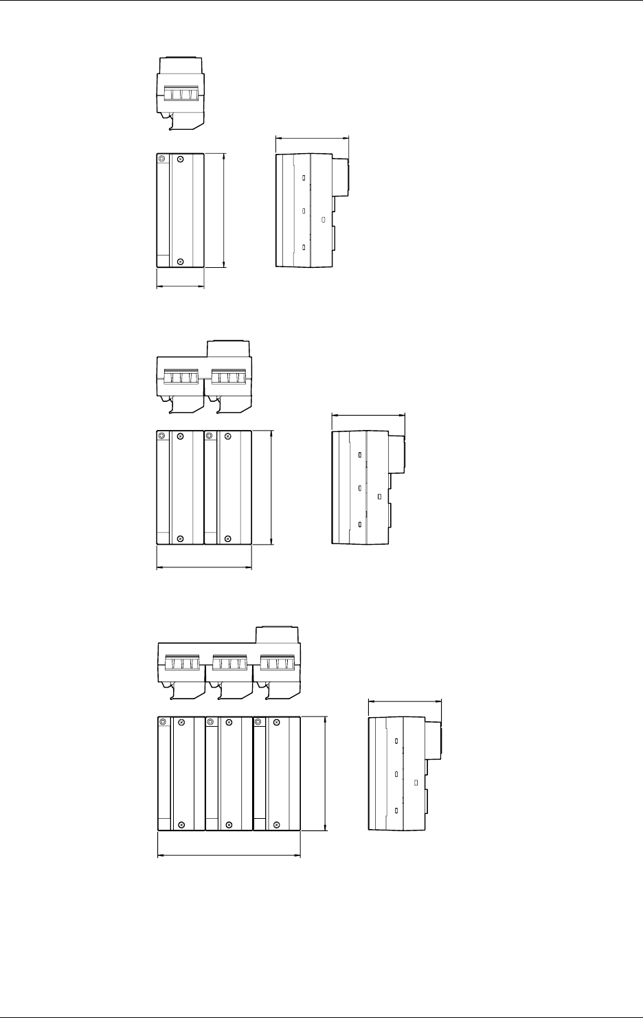
14-36 IM DR232-01E
10ch universal input module/10chDCV/TC/DI input module
unit : mm
137
88
57
20ch universal input module/20chDCV/TC/DI input module
114.3
137
88
30ch universal input module/30chDCV/TC/DI input module
171.6
137
88
If not specified, the tolerance is ±3%. However, in cases of less than 10mm, the tolerance is
±0.3mm.
14.12 Dimensional Drawings
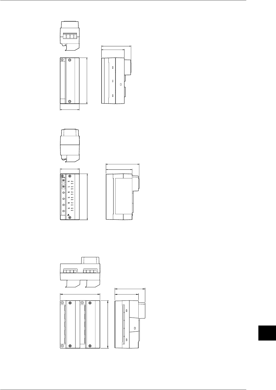
14-37
IM DR232-01E
Specifications
14
mA-input Module
unit : mm
57
88
68
137
Power Monitor Module
57
99
78
137
Unless otherwise specified, the dimensional tolerance is ±3% (though ±0.3% for fractions smaller
than 10 mm).
Strain Input Module (with built-in bridge resistors)
114.3 68
88
137
14.12 Dimensional Drawings
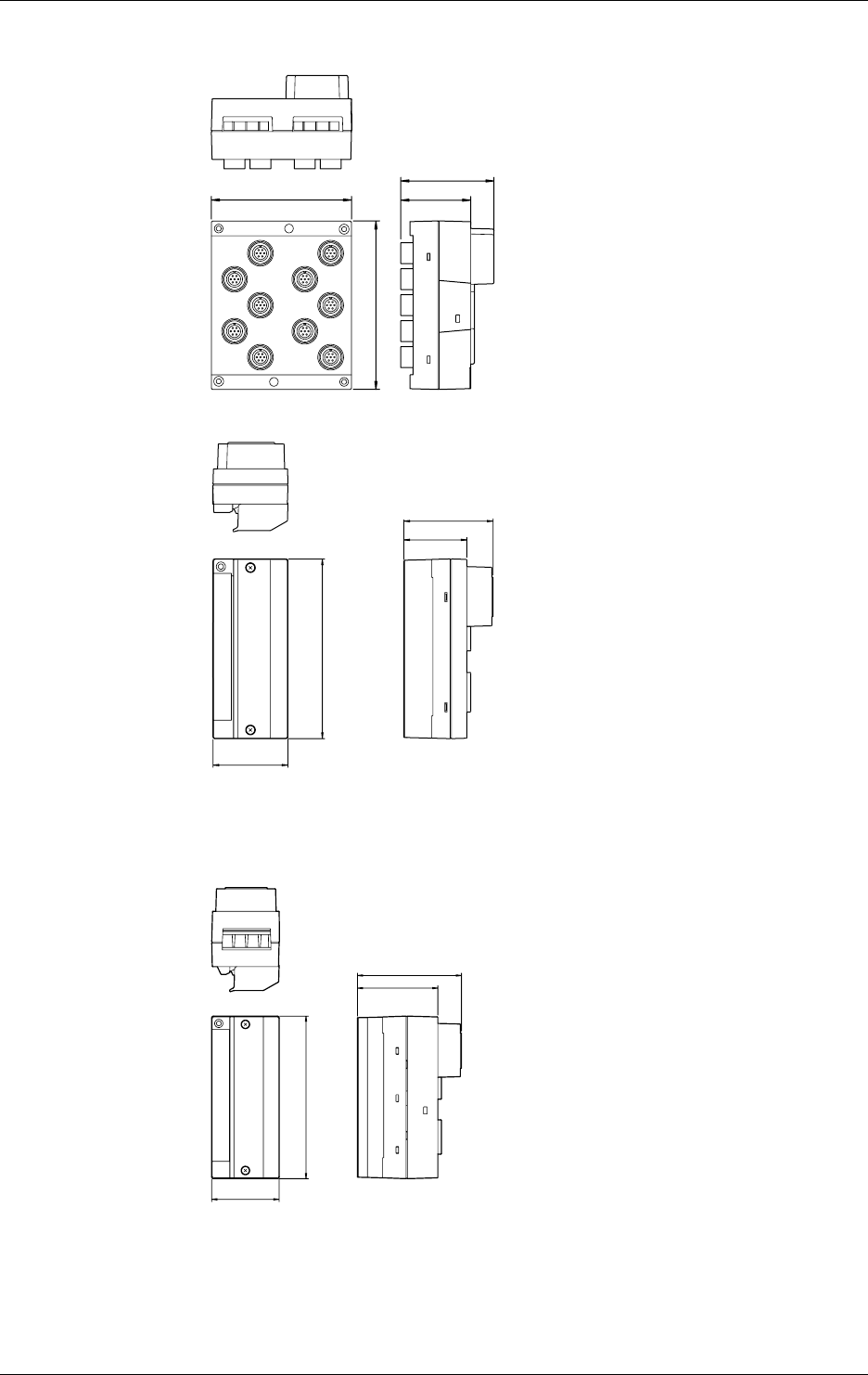
14-38 IM DR232-01E
Strain Input Module (with NDI terminals)
unit : mm
114.3 57
77
137
Pulse Input Module
57
68
48
137
Unless otherwise specified, the dimensional tolerance is ±3% (though ±0.3% for fractions smaller
than 10 mm).
Digital Input Module
57
88
68
137
14.12 Dimensional Drawings
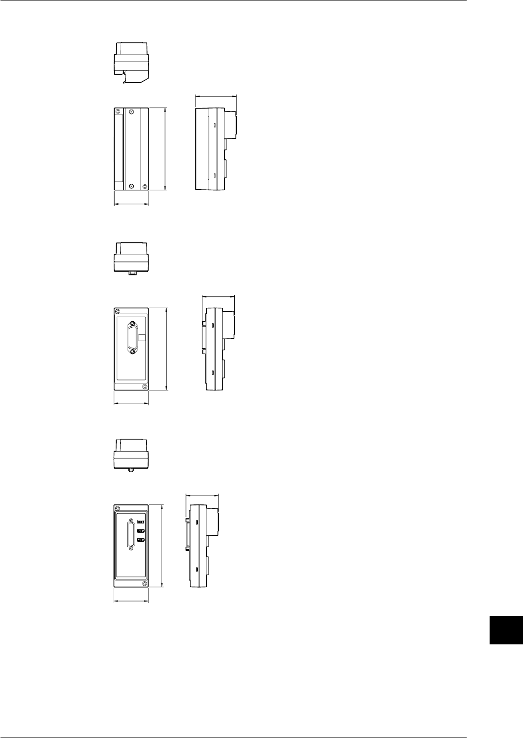
14-39
IM DR232-01E
Specifications
14
14.12 Dimensional Drawings
DI/DO module/Alarm module
unit : mm
137
68
57
GP-IB module
137
54
57
RS-232-C module
137
54
57
If not specified, the tolerance is ±3%. However, in cases of less than 10mm, the tolerance is
±0.3mm.
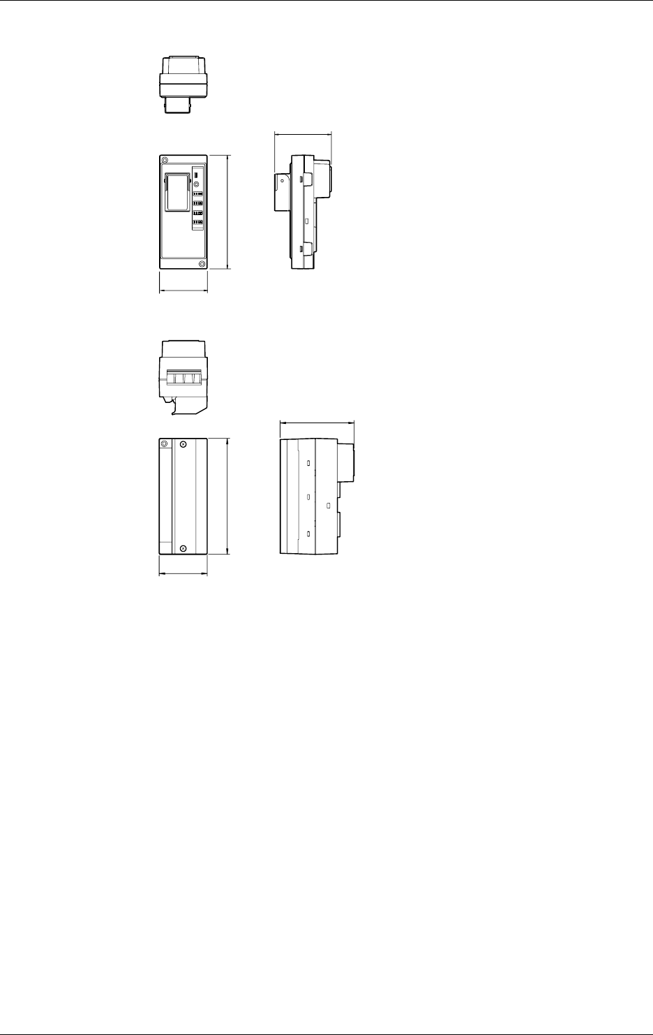
14-40 IM DR232-01E
14.12 Dimensional Drawings
RS-422-A/RS-485 module
unit : mm
57
69
137
Ethernet module
137.4
88
57
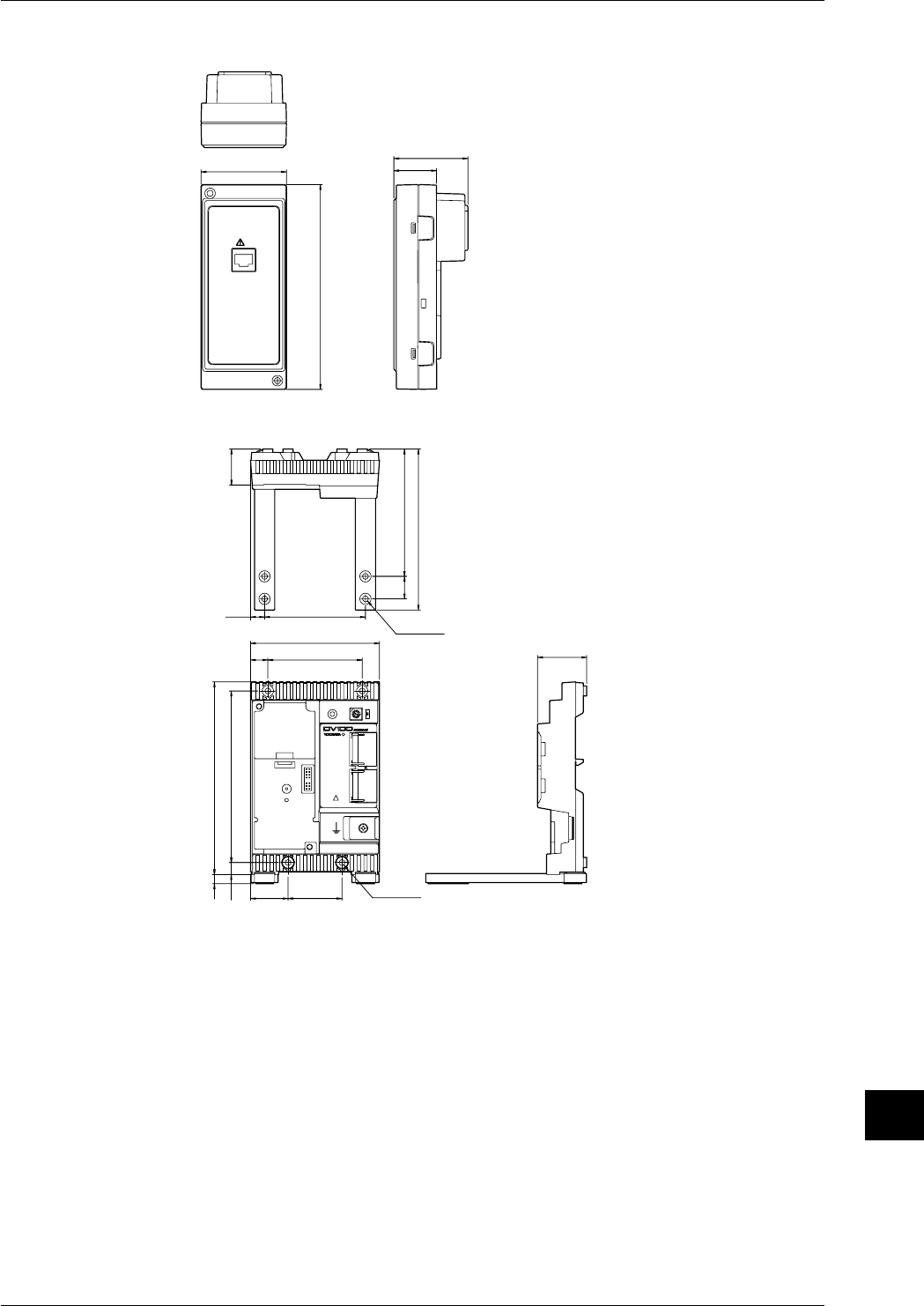
14-41
IM DR232-01E
Specifications
14
Extension module
unit : mm
57 49.5
28.5
137
EXTENDER I/F
I/F
Extension Base
89.812.5
114.8
84 43.7
4833.4 φ5-4
φ5-4
15.4
32
171.58.1
10.7 152.7
113.3
143.3
20
If not specified, the tolerance is ±3%. However, in cases of less than 10mm, the tolerance is
±0.3mm.
14.12 Dimensional Drawings
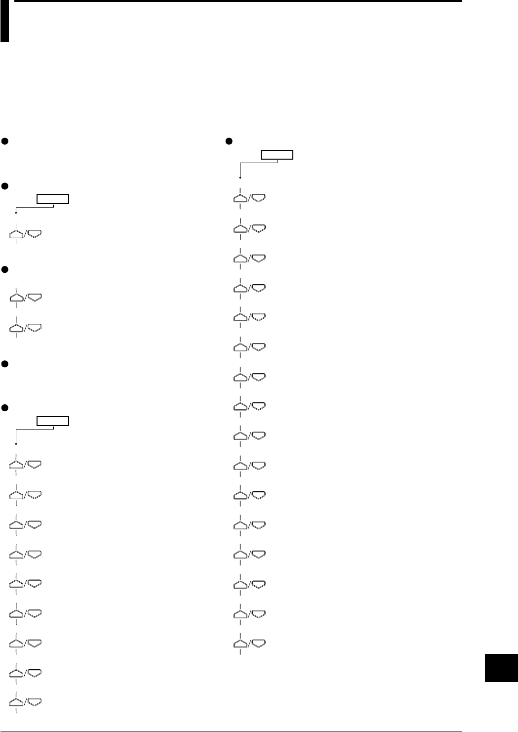
Index-1
IM DR232-01E
Index
Index
Main Menu
Pressing the relevant key, a menu (the main menu) appears in the main display. With the
instrument equipped with a floppy disk drive, pressing the relevant key will cause a menu (the
main menu) to appear in the main display.
When the alarm output and communications modules are installed and system-recognized, the
main menu, indicating that alarm display hold and the relay hold functions are turned on, is
displayed.
SET=
CHART2→
ZONE→
PARTIAL→
TAG→
DIGITAL PR→
MANUAL PR→
ALARM PR→
SCALE PR→
LIST PR→
LIST FMT→
MESSAGE→
HEADER→
TITLE→
MATCH TIME→
MOVE AVE→
INTERPOL→
GROUP→
SET3 menu
001-01:VOLT/2V→
RANGE menu
SET=
CHART→
CLOCK→
Setting the chart speed (page 6-4)
Setting the date and time (page 3-32)
CHART menu
MAN PR START→
LIST START→
HEADER START→
Starting manual printing (page 7-2)
Printing list (page 7-2)
Printing header (page 7-2)
PRINT menu
001-01:1/OFF→
ALARM menu
SET=
SYSTEM→
UNIT→
TREND→
TIMER→
MATH→
CONST→
MEMORY→
FCOPY→
LOGIC→
COPY→
Setting the recording mode (page 6-1)
Setting the engineering unit (page 6-1)
Setting the recording channel (page 6-1)
Setting the recording interval (timer) (page 6-1)
Setting computation (chapter 12)
Setting constant (page 12-7)
Saving/reading data (chapter 11)
Saving/reading set-up data (chapter 11)
Setting event/action functions (page 9-1)
Copying (page 9-11)
SET menu
Selecting the type of input/setting
the recording span/setting linear
scaling (pages 5-1 and 5-4)
Setting alarms and relays (including
internal switches) (page 8-1)
Setting the chart speed (page 6-4)
Setting recording zones (page 6-6)
Setting partially expanded recording (page 6-6)
Setting tags (page 6-8)
Setting digital printout (page 6-8)
Setting manual printout (page 6-8)
Setting alarm printout (page 6-10)
Setting scale printout (page 6-12)
Setting list printout (page 6-12)
Setting list format (page 6-12)
Entering messages (page 6-14)
Entering headers (page 6-14)
Entering title (page 6-14)
Setting match time (page 6-16)
Setting moving average (page 6-16)
Setting interpolation (page 6-16)
Setting groups (page 6-16)
IM DR232-01E
Index-2
FUNC menu
FUNC3 menu
SET UP menu
Alarm acknowledgment (page 9-14)
Alarm reset (page 9-14)
Executing initial balancing (page5-10)
Timer reset (page 9-14)
Starting computation (page 12-8)
Re-starting computation after
clearing computed data (page
12-8)
Stopping computation (page 12-8)
Clearing incomplete measurement status
indication (page 12-8)
Starting report making (page 10-32)
Stopping report making (page 10-32)
Starting report printing
(page 10-31)
Stopping report printing (page 10-
31)
Keylock (page 9-14)
Starting message printing (page 7-3)
Printing set-up lists (page 7-4)
Clearing alarm buffer
(page 9-16)
Clearing message buffer (page 9-
16)
Displaying module information (page 9-
16)
Displaying communications information
(page 9-16)
Structuring system modules
(page 9-16)
Initializing RAM (page 9-16)
Selecting adjustment of dot-printing (page 10-1)
Selecting scan interval (page 10-1)
Setting recording format (page 10-3)
Setting action to be carried out in case of computation
error and setting the units for TLOG.SUM (page 12-12)
Saving/reading set-up data (chapter 11)
Setting report format (page 10-27)
Selecting alarm interval/hysteresis/hold (page 10-7)
Selecting A/D converter integration time
(page 10-7)
Selecting filter (page 10-7)
Setting operation mode of relay/internal switch
(page 10-9)
Setting burn-out (page 10-12)
Setting reference junction compensation (page 10-12)
Setting recording colors (page 10-14)
Setting keylock (page 10-15)
Setting FUNC/FUNC3 menu (page 10-17)
Setting SET/SET3 menu (page 10-20)
Selecting display update interval (page 10-24)
Registering details set/selected with set up menu, and
terminating set up menu (page 10-24)
SET UP=
PRN ADJ→
SCAN INTVL→
RECORD→
MATH→
FLOPPY→
REPORT→
ALARM→
A/D INTG→
FILTER→
RELAY→
BURN OUT→
RJC→
COLOR→
LOCK→
FUNC PARM→
SET PARM→
DISPLAY→
END→
ALARM ACK→
ALARM RST→
INIT BRANCE→
TIMER RESET→
MATH START→
MATH CLR START→
MATH STOP→
MATH ACK→
REPORT START→
REPORT STOP→
REP RECALL START→
REP PRINT STOP→
KEY LOCK ON→
MSG PRINT→
S/U LIST START→
ALM BUF CLEAR→
MSG BUF CLEAR→
MODULE INF→
COMM INF→
RE SYSTEM→
RAM INIT→
Main Menu

Index-3
IM DR232-01E
Index
Index
INDEX
[A]
ABSOLUTE, Absolute time....................................................2-8, 6-3
AC adapter ................................................................................ 6, 3-32
Accessories .................................................................................... 5, 6
AC input module ........................................................... 1-2, 3-22, 5-6
Action ........................................................................................... 2-17
edge ........................................................................................ 9-9
level ........................................................................................ 9-9
setting, selection............................................................9-9, 9-10
Additional printouts ...................................................................... 2-12
A/D (converter) integration time ........................................... 2-4, 10-8
Alarm
acknowledgment of .....................................................2-15, 9-15
Search Display ........................................................ 2-1, 4-7, 4-8
Status Display ............................................................... 2-1, 4-10
copy ........................................................ See also Copying, 9-13
clearing buffer ...................................................................... 9-17
Difference high/low limit..............................................2-13, 8-2
high limit, upper-limit ...................................................2-13, 8-2
low limit, lower-limit ....................................................2-13, 8-2
occurrence of, occurrence mark ..................................................
. See also Trend ecording upon occurrence, 2-6, 2-13 to 2-15
output, output relays....................................................................
See also Alarm module, 2-13 to 2-15, 2-18, 3-26, 4-11, 4-12, 8-
3, 9-9, 10-9 to 10-11
printing, recording......................................................... 2-6, 2-15
rate-of-change, high/low limit of .................................. 2-13, 8-2
REFLASH, Reflashing ............................................. 2-14, 10-10
release ..................................................................... 2-13 to 2-15
reset ..................................................................... 2-15, 8-4, 9-15
setting ............................................................................6-11, 8-4
trend recording upon occurrence .................................. 2-9, 10-4
type ................................................................................2-13, 8-2
upper-limit, high limit ...................................................2-13, 8-2
ALARM key ................................................................................... 8-1
Alarm module ......................................................................................
................... See also Alarm output, 2, 3, 1-5, 3-26, 4-12, 8-3, 9-17
ALL SKIP................................................................................ 4-2, 4-3
Ambient temperature and humidity ................................................ 3-2
for specifications, effect of .................................................. 14-8
for reference conditions ....................................................... 14-2
Analog Trend Mode ........................................2-5, 2-7, 2-15, 6-2, 6-3
AND/OR ............................................................................2-14, 10-10
ASCII conversion ........................................................ 11-17 to 11-19
Asterisk, for the meaning of excess of alarm or message records ......
........................................................................................... 6-11, 7-3
Attenuation ..................................................................................... 2-4
AUTO, for recording interval ..................... See also Display, 2-8, 6-2
Averaging ............................................................See Moving average
[B]
Backup, of set values ........................................................ 3-34, 14-10
Bargraph Display .....................................................................2-1, 4-9
Basic Setting (SET-UP)......................................................Chapter 10
Baud rate......................................................... 3-11, 3-15, 3-17, 14-10
Boundary value, for partial expanded recording ................... 2-10, 6-7
Buffer
Alarm .......................................................................... 6-11, 9-17
Message ................................................................ 7-3, 9-17
Alarm printout...................................................................... 6-11
clearing ........................................................................ 9-17
Digital ........................................ 2-5 to 2-7, 6-9, 7-1, 10-5, 10-6
number of columns for ......................................... 2-7, 10-5
Engineering unit ............................................................ 2-12, 6-2
Header ................................................................. 2-12, 6-15, 7-2
List ...................................................................... 2-11, 6-13, 7-2
Manual ................................................................ 2-12, 7-2, 9-10
Message...................................................... 2-12, 6-15, 7-3, 9-10
Message printout .................................................................... 7-3
clearing ........................................................................ 9-17
Tag ...................................................................... 2-12, 6-9, 10-4
Title .............................................................. 2-6, 2-7, 2-12, 6-15
Scale(d) ................................................................................ 2-12
Burnout ................................................................................2-3, 10-13
[C]
Carriage ................................................................................. 3-7, 13-1
Carrying handle ........................................................................ 2, 2-19
Chart, chart cassette, chart paper ..................................... 4, 3-5 to 3-9
Chart end output .................................................................. 2-18, 3-26
CHART key .................................................................................... 6-4
Chart speed ......................................................2-5, 2-8, 6-4, 6-5, 14-6
setting/change of ................................................... 2-5, 6-5, 9-10
Clamp terminal .......................................................... 2 to 4, 1-4, 3-26
Clock ..................................................................................... 2-1, 4-13
CODE NUMBER .......................................................... See Password
Component type ......................................................................1-1, 1-3
Computation ................................................................................. 2-16
Condition ........................................................................................ 2-1
Computation
Computation error .....................................................12-9, 12-10
Operator ............................................................................... 12-1
Equation .................................................................. 12-1 to 12-5
Constant ............................................................................... 12-6
Starting/stopping/clearing/resetting ............................12-7, 12-8
Computed data
Saving ..................................................................... 11-1 to 11-4
Reading ................................................................... 11-5 to 11-7
Deleting
Copying ............................................................... 11-13 to 11-17
Copying, alarm, other items, range ......................................9-12 9-13
Crimp-on lugs ............................................................................... 3-13
[D]
Data format ................................................................................. 11-19
Data length .......................................................................... 3-15, 3-17
Data size ............................................................................ 11-5, 11-11
DC power terminal connector .................................................. 5, 3-31
DC voltage ...............................................................................2-3, 5-3
DCV/TC/DI input module .................................................4, 1-4, 3-20

IM DR232-01E
Index-4
Deleting a character or numerical .......................................................
............................... See Inserting/deleting a character or numerical
Destination channel, for difference between channels ..........2-16, 5-3
DI, digital input .......................................................................2-3, 5-3
DI/DO module ...................................................................4, 1-5, 3-20
Difference between channels.................................. 2-16, 5-3, 4-2, 5-3
Difference high/low limit ................................................... See Alarm
Digital printout (printing) ................... 2-5 to 2-7, 6-9, 7-1, 10-5, 10-6
number of columns for ......................................................2-7, 10-5
Display...................................... See also Functions, 1-2, 1-3, 4-2, 4-3
Alarm .............................................................................. 4-2, 4-3
hold function.......................................................2-15, 10-8
information .........................................................2-15, 8-14
Alarm Search .......................................................... 2-1, 4-7, 4-8
Alarm Status.................................................................. 2-1, 4-10
AUTO .................................................................. 2-1, 4-1 to 4-3
channel ............................................................................4-2, 4-3
Clock .............................................................................2-1, 4-13
Condition................................................................................ 2-1
difference between channels ...........................................4-2, 5-3
Main ...................................................... 1-2, 1-3, 2-1, 4-1 to 4-3
MANUAL .............................................................................. 4-4
measurement values ........................................................4-2, 4-3
Page, PAGE .................................................................... 2-1, 4-6
remote/local control status ..................................................... 2-1
Relay status ......................................................... 2-1, 4-11, 4-12
DISP key..............................................................................................
...Chapter 4, 7-2, 7-3, 9-14, 9-16, Chapter 10, 11-11, 11-13, 12-12
Display mode ........................................................................ See mode
Display update interval ..................................................... See interval
Dot-printing shift .......................................................................... 10-2
Dot-printing recording system................ See also dot recording, 10-4
Dot recording ............................................................ 2-5, 2-6, 2-9, 6-2
method of .......................................................................... 2-9, 10-4
Dot recording ................................................................ See Recording
[E]
Engineering unit
display .............................................................................4-2, 4-3
Printout of ..................................................................... 2-12, 6-2
Enhanced data logging software........................................................ 6
Edge action ..................................................................................... 9-9
Event, event/action functions ................................... 2-17, 9-1 to 9-10
Extender base ............................................................................... 3-27
Extender module........................................................................... 3-27
External in/output ......................................................................... 2-18
External RJC (EXT) ............................................................... See RJC
[F]
Fail (failure) output ............................................................. 2-18, 3-26
FEED key ........................................................... 3-10, 3-12, 3-13, 7-1
Feed, recording paper ..................................................................... 7-1
Ferrite core ................................................................ 3-10, 3-12, 3-42
Filter
Input .............................................................................. 2-4, 10-8
Noise .................................................................................... 3-39
First channel ................................................................................... 5-2
FIX, recording interval ............................................................2-8, 6-2
INDEX
Floppy disk
Handling ............................................................................... 1-11
Formatting .......................................................................... 11-14
Front door ................................................................................1-2, 1-3
FUNC key............................................................................................
.......... 5-12, 7-3, 7-4, 9-14, 9-16, 10-29, 10-31, 10-32, 12-8, 12-11
Functions
Action................................................................................... 2-17
Alarm ...................................................................... 2-13 to 2-15
Alarm display hold ......................................................2-15, 10-8
Computation......................................................................... 2-16
Display ................................................................................... 2-1
Event/action ..................................................... 2-17, 9-1 to 9-10
External in/output................................................................. 2-18
Interpolation ................................................................2-10, 6-17
Key-lock, keylock ................................ 2-17, 9-15, 10-15, 10-16
Match Time function........................................... 2-12, 6-17, 9-9
Measurement input.......................................................... 2-3, 2-4
Recording .................................................................. 2-5 to 2-12
Relay hold ............... See also HOLD/NON-HOLD, 2-15, 10-11
Function Grounding Terminal, function-ground terminal, .................
........................................................................... 4, 3-10, 3-12, 3-44
Full scale position ......................................................................... 10-2
Fuse .......................................................................................... 5, 3-31
holder ................................................................................... 13-2
replacement of...................................................................... 13-2
[G]
GP-IB interface................................................................ 2, 2-19, 3-10
GP-IB module.................................................................... 4, 1-5, 3-10
Graph ................................................................. See Bargraph display
Grounding, protective grounding ........................................................
.............................................. 7, 3-20, 3-29, 3-30, 3-38, 3-43, 3- 44
Group setting ............................................................. 2-11, 6-17, 10-4
Group trend recording ................................................. 2-9, 9-10, 10-4
[H]
Handshake ......................................................................... 3-15, 14-30
Handle for carrying ............................................. See Carrying handle
Header printout (printing) ........................................... 2-12, 6-15, 7-2
Heat sink fins ........................................................................... 1-2, 1-3
High limit alarm ...................................................................See alarm
High resolution RTD .................................................................... 14-2
HOLD/NON-HOLD ..........................................................2-14, 10-11
Horizontal or vertical printing ....................... See Recording direction
Hysteresis ............................................................................2-13, 10-8
[I]
Initialization.................................................................................. 9-17
Input
channel ........................................................................2, 1-2, 1-3
filter ............................................................................... See filter
terminals........................................................... 1-4, 3-20 to 3-26
type ................................................................... 2, 2-3, 5-1 to 5-3
Inserting/deleting a character or numerical .................................. 6-15
Installation method .............................................................. 3-2 to 3-4
Instrument number ............................................................................ 3

Index-5
IM DR232-01E
Index
Index
Integration time ......................... See A/D (converter) integration time
Internal illumination ..................................................................... 2-19
Internal RJC ............................................................................ See RJC
Internal switches ............................................ 2-13, 8-3, 10-9 to 10-11
Interpolation ........................................................................2-10, 6-17
Interval
Display update ............................................................ 2-1, 10-23
for recording.......................................... 2-8, 6-3, 6-5, 10-6, 14-6
for scan (measurement) ......................................... 2-4, 2-8, 10-2
for rate-of-change alarms ............................................2-13, 10-8
INTVL .......................................................................................... 11-5
[J]
[K]
Key-lock (keylock) function ............................................... 2-17, 9-15
setting of.................................................................. 10-15, 10-16
KEY LOCK, KEYLOCK ................................ See Key-lock function
[L]
Last channel .................................................................................... 5-2
Level action .................................................................................... 9-9
Life of lithium battery .......................................................3-13, 14-10
Linear scaling ........................................................................ 2-16, 5-5
List printout, printing .................................................. 2-11, 6-13, 7-2
Logging, LOGGING ........................................................... See Mode
LOGIC .......................................................................................... 11-5
Logic (LOGIC) box ........................................................................ 9-9
Low limit alarm, lower-limit alarm .................................... See Alarm
[M]
mA input module ................................................................... 1-2, 3-23
MANUAL ........................................................................ See Display
Manual printout, printing ............................................ 2-12, 7-2, 9-10
Margin ............................................................................................ 2-6
Match Time function .................................................................... 2-12
setting of........................................................................ 6-17, 9-9
Measured data
Saving ..................................................................... 11-1 to 11-5
Reading ................................................................... 11-7 to 11-9
Deleting
Copying ............................................................... 11-15 to 11-19
Measurement input functions .................................................. 2-3, 2-4
Measurement interval ....................................................... See interval
Measurement range ...................................................................... 14-2
Memory ............................................................................................. 3
Message printout, printing .................................. 2-12, 6-15, 7-3, 9-10
M. FUNC 1 key .............................................................................. 9-9
M. FUNC 2 key .............................................................................. 9-9
Mode
Analog Trend .......................................... 2-5, 2-7, 2-15, 6-2, 6-3
Display ............................................................... 2-1, 4-1 to 4-13
Logging, LOGGING ....................................................... 2-5, 6-2
Monitor Display ..................................................................... 2-1
Operation...................................................... 2-14, 10-9 to 10-11
Recording ........................................................................2-5, 6-2
TIME mode ............................................................................ 6-3
MODE key .................................................... Chapter 4 to Chapter 12
Model and Suffix Codes ............................................................. 3 to 5
Module information ...................................................................... 9-17
Monitor Display Mode ................................................................... 2-1
Mounting brackets ...................................................................... 6, 3-4
Moving average functions ...................................................2-16, 6-17
number of samples for ................................................ 2-16, 6-17
MULTIPLE ........................................................................... 2-8, 10-6
[N]
Names of parts ....................................................1-2 to 1-5, 3-5 to 3-8
Name plate ......................................................................................... 4
NO ALARM ........................................................................ 4-7 to 4-9
Noise, countermeasures ................................................... 3-35 to 3-44
[O]
Operating conditions (reference) .................................................. 14-2
Operation panel .......................................................................1-2, 1-3
Operation mode .................................................................... See mode
Optional modules ....................................................................... 4, 1-5
alarm module ....................................................................... 2-18
communication interface modules ....................................... 2-19
DI/DO module ..................................................................... 2-18
[P]
Parity ....................................................................... 3-15, 3-17, 14-10
Partially expanded display................................................ See Display
Parts replacement ......................................................................... 13-1
Password ..............................................................................9-15, 2-17
Periodic maintenance ................................................................... 13-1
Pitch ......................................................................... See printing pitch
Platen .............................................................................................. 3-5
Position marks, when installing the chart and ribbon cassette ....... 3-6
Power
connector ............................................................. 1-2, 3-29, 3-32
cable (code) ........................................ 2, 3, 3-1, 3-29, 3-31, 3-32
switch .................................................................... 1-2, 1-3, 3-33
terminals.............................................................. 1-3, 3-30, 3-31
Power supply voltage .............................................. 2, 4, 3-29 to 3-35
Pre trigger ..................................................................................... 11-5
PRINT key ...................................................................................... 7-2
Printing pitch ......................................................................... 2-7, 10-5
Printout, printing
Additional ............................................................................ 2-12
Priority, for recording colors ........................................................ 2-10
Protective grounding .................................................... See grounding
Pulse input module ...................................................... 1-2, 3-26, 5-14
[Q]
[R]
Rack mount kit, rack mounting .................................................. 6, 3-3
RANGE key .........................................................................Chapter 5
RATE, for partially expanded recording ............................... 2-10, 6-7
INDEX

IM DR232-01E
Index-6
Recording
colors .............................................. See also priority, 2-8, 10-14
direction (, horizontal or vertical printing) ................... 2-7, 10-5
example ................................................................. 2-6, 2-7, 2-11
functions ............................................................... 2-5 to 2-12
interval ..................................................................... See Interval
mode ................................................................................2-5, 6-2
Normal (NORMAL) ..................................................... 2-9, 10-4
Partially expanded.........................................................2-10, 6-7
span ................................................................................. 2-9, 5-3
starting/stopping of (to start/stop) ............... 2-9, 7-1 to 7-4, 9-10
starting/stopping time of ....................................... 2-6, 2-7, 10-5
zones ...................................................... See also Zone, 2-9, 6-7
RECORD key ................................................................................. 7-1
Re-failure or re-alarm ........................................ See Alarm reflashing
Reference channel, for difference between channels ............ 2-16, 5-3
Reference junction compensation .......................................... See RJC
REFLASH, Reflashing alarm ............................................ 2-14, 10-10
Registration, of details set/selected with SET UP menu ............ 10-23
RELATIVE, relative time .......................................................2-8, 6-3
Relay
for alarm output.......................................................... See Alarm
energizing/de-energizing setting ...............................2-14, 10-11
Remote control, REMOTE .......................................... 2-18, 3-26, 9-9
Replacement period, for parts ...................................................... 13-1
Report
ON/OFF ............................................................................. 10-27
PRINT ................................................................................ 10-32
START ............................................................................... 10-32
STOP .................................................................................. 10-31
Reset
Alarm ......................................................................... See Alarm
Timer .................................................................. See Timer reset
Resistance temperature detector ............................................ See RTD
Ribbon cassette ................................................................ 3, 3-7 to 3-9
RJC ...................................................................................... 2-3, 10-13
RRJC ..................................................................................... 2-19, 5-3
RS-232C Interface ...............................................................2-19, 3-16
RS-232C module ............................................................... 5, 1-5, 3-15
RS-422-A/RS-485 Interface ................................................2-19, 3-18
RS-422-A/RS-485 module ................................................ 5, 1-6, 3-17
RTD .........................................................................................2-3, 5-3
[S]
Scan interval ..................................................................... See Interval
Scale check mark ............................................... See also Values, 10-5
Scale value ............................................................................ See value
Screw shaft ............................................................................ 3-7, 13-1
Screw terminals ............................................ 2, 3, 1-4, 1-5, 3-19, 3-30
Set-up data
Saving ................................................................. 11-10 to 11-11
Reading ............................................................... 11-12 to 11-14
Deleting
Copying ............................................................... 11-15 to 11-19
SET key ............... Chapter 6, 9-1, 9-12, 9-19, Chapter 11, 12-4, 12-7
Set-up list, printing ......................................................................... 7-4
Shunt resistor (resistance) ........................................................ 6, 3-19
SINGLE ................................................................................. 2-8, 10-6
SKIP, skipping................................. 2-3, 4-2, 4-3, 4-5 to 4-7, 4-9, 5-3
Slots .................................1-2, 1-3, 4-2, 4-3, 4-10, 4-12, 10-10, 10-11
Software............................................................................................. 3
Span
for recording.................................................................... 2-9, 5-3
calibrated values of ............................................................ 13-11
Spares ................................................................................................ 4
Sprocket .......................................................................................... 3-6
Stop bit .................................................................... 3-15, 3-17, 14-10
Strain balance ............................................................................... 5-10
Strain input module ......................................... 1-2, 3-40, 5-10 to 5-12
Style number...................................................................................... 2
Style S1..................................................................................... 1, 14-1
Sub-display 1, 2 ........................................................ 1-2, 1-3, 2-1, 4-3
Suffix codes ........................................... See Model and Suffix Codes
Symbols
for conventions.......................................................................... 8
for safety ................................................ See also WARNING, 7
System module, recognition of ..................................................... 9-17
[T]
Tag
printout ................................................................ 2-12, 6-9, 10-4
selection ......................................................... 2-7, 6-9, 7-1, 10-4
Number of character of ......................................... 2-7, 7-1, 10-4
Temporary stop............................................................................... 7-1
Terminal cover ............................................................................. 3-19
Thermocouple ..........................................................................2-3, 5-3
TIME mode .................................................................................... 6-3
Time-up .......................................................................................... 2-8
Timer No. ................................................................................ 2-8, 6-3
Timer reset ................................................................... 2-8, 9-14, 9-15
Title, title printouts ............................................... 2-6, 2-7, 2-12, 6-15
Trigger .................................................................................11-4, 11-9
Trigger recording .................................................................................
................... See also Alarm (trend recording upon occurence), 2-9
Troubleshooting............................................................................ 13-3
[U]
Unit No. ................................................................ 4-2, 4-3, 4-10, 4-12
Universal input module .............................................................. 3, 1-2
Upper-limit alarm ............................................................... See Alarm
[V]
Value
Scale (scaled) ........................................................ 2-6, 2-9, 6-13
printout ........................................................................ 2-12
Reference point for .............................................................
................................ See also scale check mark, 2-6, 2-7
Vertical printing ............................................ See Recording direction
Voltage level................................................................................... 5-3
[W]
Warm up ....................................................................................... 3-38
WARNING, for safety precautions ................................................... 7
Wiring ........................................................................................... 3-19
INDEX

Index-7
IM DR232-01E
Index
Index
[X]
[Y]
[Z]
Zero position................................................................................. 10-2
calibrated values of ............................................................ 13-11
Zone ......................................................... See also recording, 2-9, 6-7
Left position of ................................................................2-9, 6-7
Right position of ............................................................. 2-9, 6-7
INDEX
