1. INTRODUCTION YSI 2300 Stat Plus Manual J
User Manual: YSI-2300-Stat-Plus-manual-j
Open the PDF directly: View PDF ![]() .
.
Page Count: 202 [warning: Documents this large are best viewed by clicking the View PDF Link!]
- 1. Safety
- 2. Introduction
- 3. Initial Setup
- 4. Basic Operation
- 5. Menu Selections
- 6. Principles Of Operation
- 7. Maintenance
- 8. Troubleshooting
- 9. Communications
- 10. Turntable Operation and Maintenance
- 11. Typical Performance Data
- 12. Appendix A–Line Power Cord and Plug Wiring
- 13. Appendix B–Sample Collection and Handling
- 14. Appendix C–Effects of Selected Substances
- 15. Appendix D–Converting Whole Blood Glucose Values
- 16. Appendix E–YSI Supplies and Reagents
- 17. Appendix F–Warranty and Shipping Information
- 18. Appendix G–Required Notice
- 19. Appendix H–Cleaning, Disinfecting, and Decontamination Procedures
- 20. Appendix I–Printed Setup Information
- 21. Appendix J–Report Formats
- 22. Appendix K–Considerations when Measuring Lactate in Whole Blood
- 23. Appendix L–CE Compliance
www.ysilifesciences.com
User's Manual
YSI 2300 STAT PLUS
Glucose & L-Lactate Analyzer

i
Table of Contents
1. Safety.................................................................................................... 1-1
1.1 Explanation of Symbols............................................................................................. 1-1
1.2 Notes on Safety.......................................................................................................... 1-2
2. Introduction.......................................................................................... 2-1
2.1 Description.................................................................................................................2-1
2.2 Standard Features....................................................................................................... 2-1
2.3 Specifications............................................................................................................. 2-2
2.4 How To Use This Manual.......................................................................................... 2-3
3. Initial Setup.......................................................................................... 3-1
3.1 Unpacking.................................................................................................................. 3-1
3.2 Major Component Identification ...............................................................................3-1
3.3 Reagent Preparation................................................................................................... 3-5
3.4 Enzyme Membrane Installation................................................................................. 3-6
3.5 Power Up Procedures.................................................................................................3-8
3.6 Fluid System Priming ................................................................................................ 3-9
3.7 Printer Paper Installation ......................................................................................... 3-11
3.8 Instrument Parameter Programming........................................................................ 3-12
3.9 Initial Setup Example: Step-By-Step....................................................................... 3-15
3.10 Probe Baseline Check .............................................................................................. 3-25
4. Basic Operation ................................................................................... 4-1
4.1 Main Menu................................................................................................................. 4-1
4.2 Run Mode................................................................................................................... 4-2
4.3 Standby Mode............................................................................................................ 4-6
4.4 Daily Operational Checks.......................................................................................... 4-7
5. Menu Selections ................................................................................... 5-1
5.1 Introduction................................................................................................................5-1
5.2 Service Selections...................................................................................................... 5-3
5.3 Setup Selections......................................................................................................... 5-6
5.4 Diagnostic Selections............................................................................................... 5-19
6. Principles Of Operation ....................................................................... 6-1
6.1 Sensor Technology .................................................................................................... 6-1
ii
6.2 Fluid System .............................................................................................................. 6-3
6.3 Measurement Methodology ....................................................................................... 6-4
6.4 Baseline Stability ....................................................................................................... 6-4
6.5 Calibration .................................................................................................................6-5
6.6 Linearity..................................................................................................................... 6-6
6.7 Temperature Compensation.......................................................................................6-7
6.8 Level Sensing and Sipper Interference ...................................................................... 6-7
6.9 Software Structure ..................................................................................................... 6-8
7. Maintenance ........................................................................................ 7-1
7.1 Daily Maintenance..................................................................................................... 7-1
7.2 Calibration Pumping System Maintenance................................................................ 7-3
7.3 Sample Chamber Cleaning ........................................................................................ 7-4
7.4 Membrane Replacement ............................................................................................ 7-5
7.5 Probe Cleaning........................................................................................................... 7-6
7.6 Tubing Replacement.................................................................................................. 7-7
7.7 Sipper Replacement ................................................................................................... 7-9
7.8 Sipper Ground Cable ................................................................................................. 7-9
7.9 Fuse Replacement.................................................................................................... 7-10
7.10 Sipper Pump Seal Replacement............................................................................... 7-11
7.11 Sipper Mechanism Lubrication................................................................................ 7-13
8. Troubleshooting ................................................................................... 8-1
8.1 Printout Information .................................................................................................. 8-2
8.2 Troubleshooting Chart ............................................................................................... 8-4
9. Communications................................................................................... 9-1
9.1 Communications Protocol.......................................................................................... 9-1
9.2 Communications Modes ............................................................................................ 9-5
9.3 Communications Commands..................................................................................... 9-6
10. Turntable Operation and Maintenance ............................................ 10-1
10.1 Description and Specifications ................................................................................ 10-1
10.2 Setup ........................................................................................................................ 10-3
10.3 Operation ............................................................................................................... 10-10
10.4 Diagnostics and Troubleshooting .......................................................................... 10-18
10.5 Maintenance........................................................................................................... 10-23
iii
11. Typical Performance Data.................................................................. 11-1
12. Appendix A–Line Power Cord and Plug Wiring ................................. 12-1
13. Appendix B–Sample Collection and Handling................................... 13-1
14. Appendix C–Effects of Selected Substances ....................................... 14-1
15. Appendix D–Converting Whole Blood Glucose Values...................... 15-1
16. Appendix E–YSI Supplies and Reagents ............................................ 16-1
17. Appendix F–Warranty and Shipping Information ............................. 17-1
17.1 Cleaning Instructions ............................................................................................... 17-2
17.2 Packing Instructions................................................................................................. 17-3
18. Appendix G–Required Notice............................................................. 18-1
19. Appendix H–Cleaning, Disinfecting, and Decontamination Procedures19-1
20. Appendix I–Printed Setup Information.............................................. 20-1
21. Appendix J–Report Formats ............................................................... 21-1
22. Appendix K–Considerations when Measuring Lactate in Whole Blood22-1
23. Appendix L–CE Compliance................................................................ 23-1
iv
1-1
1. Safety
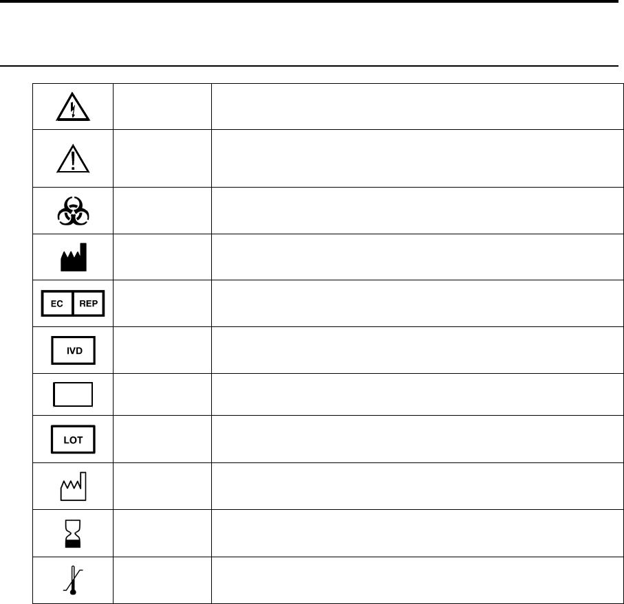
1.1 Explanation of Symbols
WARNING Warning indicates that misuse of the instrument could
result in death or serious injury to a person.
CAUTION
Caution, consult accompanying documents. Caution
indicates that misuse of the instrument could result in mild
or serious injury to a person and/or damage to equipment.
Biological Risks
Manufacturer
Authorized Representative in the European Union
In Vitro Diagnostic Medical Device
REF 2747 Catalog number
03A6549 Lot number
YEAR-MO Date of manufacture
YEAR-MO Use by Date
Temperature Limitation

1-2
1.2 Notes on Safety
Electrical Precautions
1. BEFORE connecting the power cord, check the line voltage selector and confirm that the
selected voltage matches the local power supply (Section 3.5).
2. Use ONLY the line power cord supplied with the instrument. Connect the plug to a
matching three-pronged wall receptacle.
3. Use ONLY fuses of the type supplied (Section 7.9). Replacement power cords and fuses
can be obtained from YSI, or your Dealer Representative.
4. Do NOT use an extension cord without protective grounding.
5. Do NOT remove rear cover. There are no user serviceable parts inside.
6. Repairs are to be performed only by trained and approved personnel.
7. This instrument must be connected to a protectively grounded (earthed) outlet.
8. The following notices are provided in compliance with IEC1010 Part 1 1990.
8.1 Fuses F1–F7 on the main circuit board are type: Subminiature (F) to UL 198G Standard.
Rating: F1–F5, 1A; F6–F7, 2A. These fuses are NOT operator replaceable.
8.2 See Appendix A for mains plug wiring and fusing instructions.
9. If the equipment is used in a manner not specified by YSI, the protection provided by the
equipment may be impaired.
WARNING: For auxiliary connection, refer to section 10.2 Setup, Cable Connection. Use with
the YSI 2710 Turntable only.
WARNING: For remote connection, equipment should be EN 61010 or EN 60950 approved
only.
10. The mains (power) switch is for functional purposes ONLY. To disconnect the instrument
from the mains supply, unplug the mains power cord from the back of the instrument.

2-1
2. Introduction
2.1 Description
The YSI 2300 STAT PLUS Glucose and Lactate Analyzer is a laboratory instrument intended
for use in clinical care and sports medicine applications. It provides quick measurements of
glucose in whole blood, plasma or serum; and of L-lactate in whole blood, plasma, or
cerebrospinal fluid (CSF). In whole blood or plasma, glucose and L-lactate can be measured
simultaneously.
Your YSI 2300 STAT PLUS may also be configured with the YSI 2710 Turntable. Refer to
Section 10 for a description of this accessory.
2.2 Standard Features
• Microprocessor-control.
• Menu-driven setup with battery backed memory.
• Alpha-numeric liquid crystal display.
• Built-in data printer.
• RS-232 serial port installed.
• Turntable interface port installed.
• Complete diagnostic software.
• Automatic calibration.
• Programmable calibration protocol.
• Selectable performance modes.
• Selectable concentration units: mmol/L, mg/dL, mg/L.
• Direct measurement of glucose in whole blood, plasma and serum.
• Direct measurement of lactate in whole blood, plasma and CSF.
• Sample aspiration of only 25 microliters.
• Sample tube holder for "hands off" sampling.
• Manual sampling station for aspirating small volumes.
• Conversion of whole blood to plasma glucose values (user enters hematocrit value at
keypad).

2-2
2.3 Specifications
Sample size: 25 microliters (aspirated volume)
Response Time (from Test Tube Holder station):
Normal Mode: Displayed/printed result in 65 seconds
Sample to sample interval is 100 seconds
Screen Mode: Displayed/printed result in 45 seconds
Sample to sample interval is 70 seconds
Linear Range:
Normal Mode:
Glucose: to 50.0 mmol/L (900 mg/dL or 9000 mg/L)
Lactate: to 30.0 mmol/L (267 mg/dL or 2670 mg/L)
Screen Mode:
Glucose: to 27.8 mmol/L (500 mg/dL or 5000 mg/L)
Lactate: to 15.0 mmol/L (134 mg/dL or 1335 mg/L)
Calibration point:
Glucose: 10.0 mmol/L; 180 mg/dL; 1800 mg/L
Lactate: 5.00 mmol/L; 45 mg/dL; 445 mg/L
Enzyme membrane working life (typical):
Glucose: 21 days (YSI 2365)
Lactate: 14 days (YSI 2329)
Precision:
Glucose: ±2% of the reading or 2.5 mg/dL (25 mg/L, 0.2 mmol/L),
whichever is larger
Lactate: ±2% of the reading or 0.1 mmol/L (1 mg/dL, 10 mg/L),
whichever is larger
Resolution:
Glucose: 1 mg/dL (1 mg/L, 0.1 mmol/L)
Lactate: 0.1 mmol/L (1 mg/L, 1 mg/dL)
NOTE: YSI makes no performance claims for sampling
whole blood using the YSI 2710 Turntable.
Working environment:
Ambient temperature: 15° to 35° Celsius
Relative humidity: 10% to 90% (noncondensing)
Power requirement: 110–120 VAC1, 1A or 220–240 VAC, 0.5A
50–60 Hz
50 Watts nominal
Instrument dimensions: 25.4 x 35.6 x 35.6 centimeters
10.0 x 14.0 x 14.0 inches
Instrument weight: 11.4 kilograms
25 pounds
Regulatory Compliance: CSA, CE, FDA Registered Class II (862.1345)
Pollution degree 2
Installation Category 2
Altitude 2000m
Indoor use only
1 Mains supply voltage fluctuations not to exceed ±10% of nominal supply voltage.

2-3
2.4 How To Use This Manual
This manual is organized in such a way as to give you the quickest possible start in operating
the instrument. However, it cannot be stressed too strongly that informed and safe operation is
more than just a matter of knowing which buttons to push. An understanding of the principles
of operation and potential chemical interferences is necessary for the wisest interpretation of
results. Thorough precautions regarding the handling of biological samples are also essential
for the safety of operators and patients.
The early parts of this manual will teach you how to get the instrument running. Additional
topics are included to help you understand the science it employs, how to use it most effectively
and safely, and how to keep it operating correctly.
Later sections of the manual include instructions for operation and maintenance of the optional
YSI 2710 Turntable.
2-4

3-1
3. Initial Setup
We recommend that your dealer representative or YSI regional representative assist with initial
setup and orientation. YSI warranty and product performance claims, however, are not
dependent upon installation by factory or dealer personnel.
3.1 Unpacking
Remove the instrument from the shipping container and inspect all assemblies and components
for damage. In the event of damaged or missing parts, contact YSI Customer Service or your
Dealer Representative immediately.
Note that reagents for the 2300 STAT PLUS Analyzer are not packaged in the same carton as
the instrument. These materials must be ordered separately as starter supplies and will arrive in
a separate package.
DO NOT PLUG THE INSTRUMENT IN AT THIS TIME. You should apply power only
when directed to do so in the setup instructions.
If you ordered the 2300 STAT PLUS with the 2710 Turntable, first set up the 2300 STAT
PLUS. Once the 2300 STAT PLUS is operating properly, refer to Section 10 Turntable
Operation and Maintenance.
3.2 Major Component Identification
Referring to Figure 3.1 and Figure 3.3, read through the following descriptions and familiarize
yourself with the major components.
NOTE: In maintenance kits, service manuals and part lists the "Sipper" may be referred to as
the Sipper Needle or Sipper Tube.
3-2
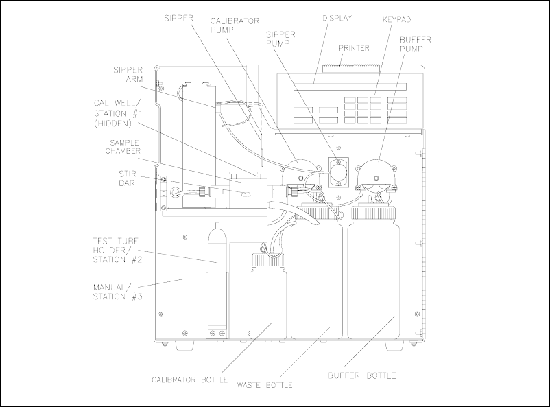
Figure 3.1
Inside Front View of the 2300 STAT PLUS
The Buffer Pump draws buffer from its bottle, pumps it through the Sipper Pump body and the
Sipper, and flushes the Sample Chamber.
The Calibrator Pump draws the appropriate standard solution from the Calibrator Bottle and
fills the Calibrator Well in the Sample Block.
The Sipper Pump retracts its piston to draw in standard from the Calibrator Well or sample
from a tube or container. It extends its piston to dispense standard or sample into the Sample
Chamber.
The Sipper Arm is raised or lowered by one motor, and moved horizontally to its various
positions by another motor. The positions are: Calibrator Well (Station #1), Sample Chamber
("home"), Test Tube Holder Station (Station #2), Manual Station (Station #3), and Turntable
Station (Station #4). The Sipper capacitively senses fluid to control immersion depth and detect
errors.
The Stir Bar is a plastic encapsulated magnet. It is activated by a motor housed below the
Sample Chamber. It provides thorough mixing inside the chamber.
The Buffer, Waste and Calibrator Bottles are visible through the front door window for easy
monitoring of fluid levels. A stainless steel shaft projecting into each bottle terminates with a
connector on the lid, providing a signal used to halt operations when the Buffer or Calibrator
Bottles are empty, or when the Waste bottle is full.
The Sample Chamber is made of clear acrylic plastic. White and black holders for the sensor
probes are screwed to either side. The immobilized enzyme membranes on the sensor probes
are mounted on O-rings which act as fluid seals on each side of the Sample Chamber. A
reference or auxiliary electrode is housed in the temperature probe and positioned at the back of
3-3
the Sample Chamber. It is held in place by a retainer that threads directly into the Sample
Block. A small black O-ring slips over the temperature probe/electrode to provide the seal. The
Calibrator Well is located behind and to the right of the Sample Chamber entry port.
The Test Tube Holder pivots out to allow insertion or removal of several common size test
tubes.
The Display is a 2 line by 40 character liquid crystal display.
The Printer provides a hard copy record of sample results, calibration currents and errors. It
uses 56 mm (2 1/4 inch) wide thermal paper.
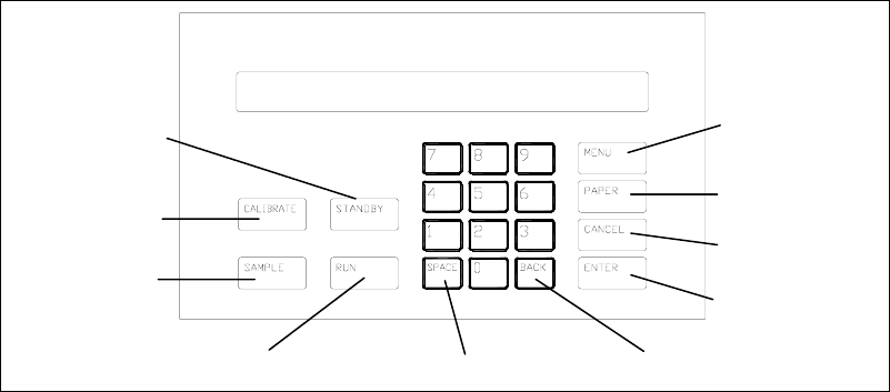
The Keypad is a 20 key membrane switch. It has 0–9 numeric keys, SPACE and BACK keys
and 8 function keys.
Figure 3.2
2300 Stat Plus Keypad
Pa
p
er Ke
y
Menu
Paper
Cancel
Ente
r
Backs
p
ace
Space
Calibrate
Standby
Sam
p
le
Run
3-4
Figure 3.3
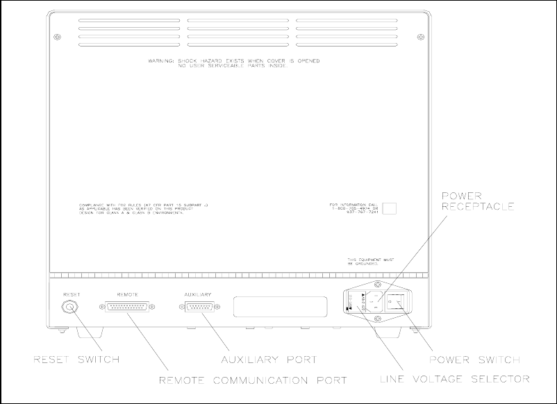
Back View of the 2300 STAT PLUS
The Reset Switch is located on the back of the instrument. It is used to hard reset the operating
system.
The Remote Communication Port is an RS-232 serial port. It is used to interface with host
computers or other laboratory instruments.
The Auxiliary Port is used to interface with the YSI 2710 Turntable.
The Line Voltage Selector selects either 110–120 or 220–240 volt operation. It houses the
fuses and pulls out of the case for fuse replacement.
The Power Receptacle is a power inlet. The power cord plugs into it and an electrical outlet.
The Power Switch is an on/off toggle switch (0-off and I-on). It is located on the back of the
instrument.
3-5
3.3 Reagent Preparation
Prepare the supply buffer and fill the buffer bottle. YSI 2357 buffer is included in the starter
supplies. YSI 2357 is recommended for use with all YSI Enzyme Membranes unless otherwise
stated.
» Place about 500 mL of reagent water (distilled and/or deionized) into a one liter flask,
or other clean container. Add two packages of YSI 2357 Buffer Concentrate and stir.
» If cell lysing is desired (See Appendix K.), add two packets of YSI 1515 Cell Lysing
Agent.
» Add more reagent water until the total volume of solution is between 900 and
1000 mL.
» Stir as necessary, until the buffer chemicals have completely dissolved.
» Disconnect the electrical lead from the level sensor and remove the bottle lid.
IMPORTANT: When adding fresh buffer to the Buffer Supply Bottle or when
installing a new bottle of Calibrator Solution, make every effort to avoid contamination
of the lid and level sensor assemblies.
» Pour the prepared buffer into the supply bottle, replace the lid, and reconnect the lead.
Next install the bottle of calibrator solution. This must be YSI 2747 Standard containing D-
glucose (dextrose) and L-lactate.
» Unplug the electrical lead from the level sensor in the lid of the empty calibrator bottle
and remove the lid.
» Mark the date of installation on the new bottle of YSI calibrator solution.
» Screw the lid and level sensor assembly onto the new bottle and place it in the
instrument compartment. Reconnect the electrical lead.
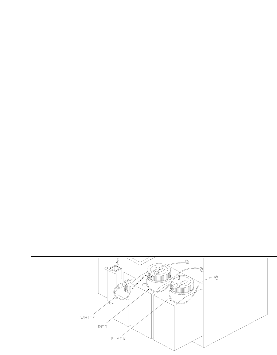
IMPORTANT: The level sensor cables should not touch the instrument housing. It is
best to keep the cable connector on the bottle lid pointed toward the front. False
messages concerning fluid levels may result if the bottles are not installed inside the
fluid compartment and the cables routed as shown in Figure 3.4.
Figure 3.4
Bottles and Level Sensor Cables
3-6
3.4 Enzyme Membrane Installation
Each active probe installed in your instrument is fitted with a protective "shipping membrane"
which must be removed and replaced with a new membrane from the starter supplies.
The Sample Chamber is color coded to assist you in membrane installation and setup (see
Figure 3.5). The left side of the chamber has a black probe housing, and the right side has a
white probe housing. (Throughout this manual, whenever we refer to the "black" or "white"
probe, the reference is to the "black" or the "white" side of the sample chamber.)
One or more packs of YSI Immobilized Enzyme Membranes is provided in the starter supplies.
Each pack contains four membranes. Enzyme Membrane O-rings are color-coded for each type
of chemistry. For dual channel configurations it is important that you note which probe, black
or white, you use to install specific membranes. It will be necessary to assign chemistry to
probe during instrument parameter programming.
Figure 3.5
Sample Chamber/Sensors
To install a membrane, first unscrew the appropriate probe retainer and gently pull the probe
out of the block. Remove the existing O-ring membrane assembly from the end of the probe. A
toothpick or pointed tool may be needed to unseat the old membrane. Be careful not to scratch
the probe face.
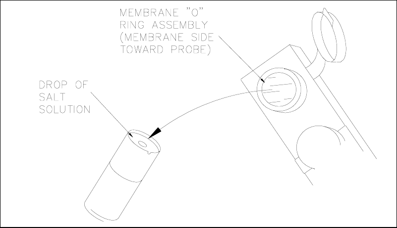
Examine the probe surface and remove any pieces of membrane that remained. Open a cavity of
the plastic membrane holder and rinse the membrane inside with a few drops of salt solution
(YSI 2392 or equivalent). Place one drop of salt solution on the probe face. Using the plastic
membrane holder, press the O-ring membrane assembly gently onto the probe face (Figure 3.6).
Wipe excess salt solution from the probe body, then return the probe to the sample chamber.
Finger tighten the probe retainer so that the O-ring seals the probe in place. Repeat this
procedure for the second probe.
Return the membrane holder to the foil pouch and refrigerate it. Note the expiration date on the
membrane package. It is advisable to maintain an instrument log book in which dates and lot
numbers of reagents are recorded, along with information from daily operational checks and
other relevant information (see Section 1.2).
Enzyme probe,
Black channel Enzyme probe,
White channel
3-7
Figure 3.6
Enzyme Membrane Installation
3-8
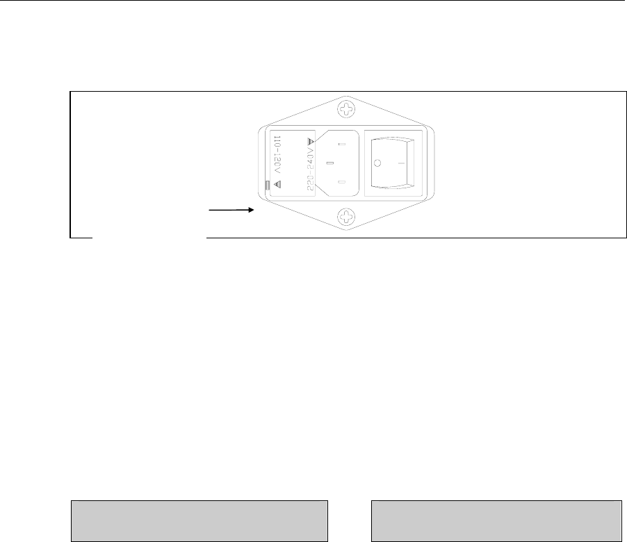
3.5 Power Up Procedures
BEFORE YOU PLUG IN THE POWER CORD, inspect the Line voltage selector on the back
of the instrument (See Figure 3.7). Be certain the correct voltage is selected. The arrowhead on
the power selector must be pointing to the small rectangle on the housing, as shown.
Figure 3.7
Line Voltage Selector
If the voltage selection is incorrect, review Section 7.9 for correct voltage selection and fuse
requirements or contact YSI Customer Service or your Dealer Representative.
If the voltage selection is correct, plug in the unit using the power cord packaged with the
instrument.
Set the power switch to ON. (0-off and I-on).
Correct Power-up operation is confirmed by observing either of the following displays:
Main Menu Display Default Parameters Display
Please select instrument mode:
[RUN] [STANDBY] [MENU]
***Warning: instrument parameters have
been set to default. Press any key to set up.
The instrument will normally arrive with parameters, including date and time, set from the
factory. However, if the backup rechargeable batteries have run down, you will see the Default
Parameters message. This message will also appear if you ever need to change batteries in the
future.
If you see the Default Parameter message, press any key to access the Setup Menu, then press
[MENU] to return to Main Menu as displayed above. Specific instructions to set date, time, and
other parameters are described below.
If the Main Menu Display does not appear immediately or after you have tried the procedures
above, reset the instrument by pressing the reset switch on the back panel or by turning the
power off, waiting about 20 seconds, then turning the power back on.
110-120V Selected
3-9
3.6 Fluid System Priming
Since it may take an hour or more to initially stabilize the probes when setting up for the first
time, now is a good time to prime the fluid system. You have already reconstituted the
appropriate buffer and transferred it to the Buffer Bottle. You have also installed the
appropriate calibrator solution and installed the appropriate Enzyme Membrane(s) in the
Sample Chamber.
With the Main Menu displayed (see below), press [MENU], then press [1] for Service.
Please select instrument mode
[RUN] [STANDBY] [MENU]
Select instrument function
1-Service 2-Setup 3-Diagnostic
Select service: 1-Sipper 2-Buffer 3-Cal
4-Stir speed 5-Turntable
You are now ready to align the Sipper, prime the fluid pumps and adjust the stirring. Since the
adjustments were made prior to shipment, this procedure will likely be just a check. You should
ignore all reference to "Turntable" in the displayed menus. Turntable setup, if required, is
described in Section 10.
IMPORTANT: The front door must remain open to carry out this procedure.
WARNING: Keep hands clear of the sipper arm and
sipper while the instrument is in operation. Service the
sipper only when the instrument is in the service
mode, not in the run mode or standby mode.
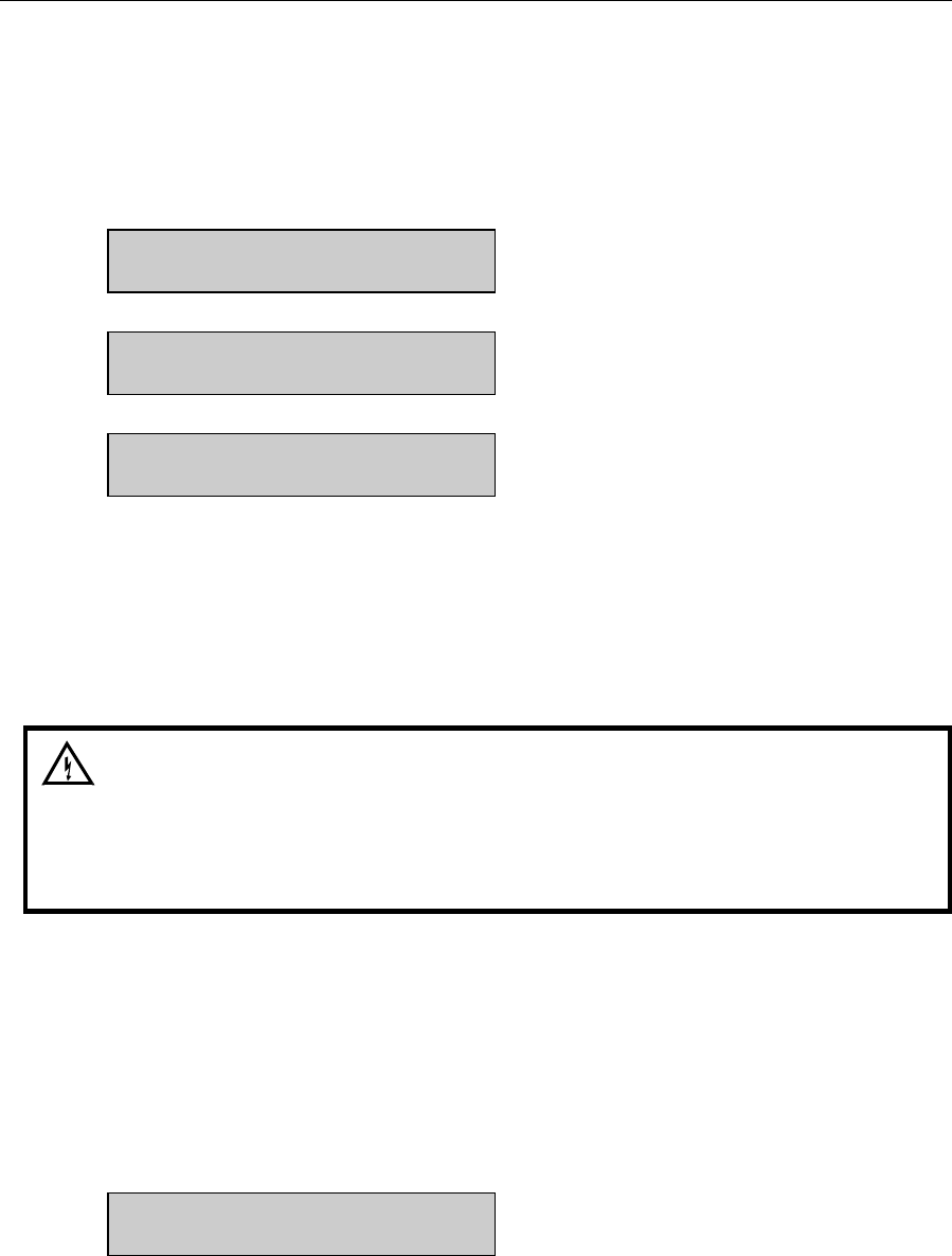
To make certain the Sipper Arm and attached Sipper are correctly aligned, follow the
instructions below.
Press [1] for Sipper. The Sipper Arm will move to the "home" position. The tip of the Sipper
should be centered over the large hole on the top of the Sample Chamber (see Figure 3.8). If
necessary, loosen the adjustment screw and position the Sipper. The adjustment tool (hex key)
is included in the preventive maintenance kit that is packed with your instrument. Retighten the
adjustment screw.
Adjust sipper then select
0-Exit 1-Lower sipper for fine alignment
3-10
Press [1] for Lower sipper for fine alignment. The Sipper will move closer to the small opening
in the stainless steel cone.
Fine align sipper then select
0-Exit 1-Test sipper position
The tip of the Sipper should be exactly centered above this opening. If necessary, loosen the
adjustment screw again and position the Sipper exactly. Retighten the adjustment screw.
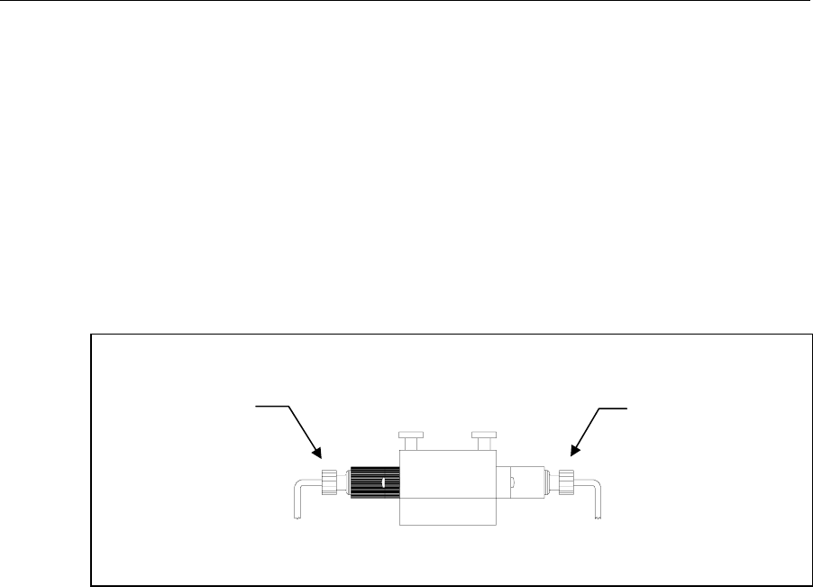
Figure 3.8
Sipper Adjustment Position
Press [1] for Test Sipper position. The Sipper will descend into the Sample Chamber. The
Sipper should not contact the stainless steel cone. If the Sipper position is still not exactly right,
press [1] and readjust it once more, as described above. IT IS VERY IMPORTANT THAT
THE SIPPER BE ACCURATELY ADJUSTED.
Select 1 to restart check sipper cycle
0-Exit 1-Home sipper position
After adjustment is complete, press [0] to exit and return to the Select Service menu level.
Select service: 1-Sipper 2-Buffer 3-Cal
4-Stir speed 5-Turntable
3-11
Press [2] for Buffer. The Sipper will enter the Sample Chamber and the Buffer Pump will begin
to prime the fluid system with buffer solution. The fluid system is completely primed when
buffer flows from the steel cone at the top of the sample chamber. Press [2] again, if necessary.
Select service: 1-Sipper 2-Buffer 3-Cal
4-Stir speed 5-Turntable
Press [3] for Cal. The Calibrator Pump will begin to pump calibrator through the calibrator line
into the Calibrator Well in the Sample Chamber. If necessary, press [3] again until calibrator
flows out of the tube in the cal well.
Select service: 1-Sipper 2-Buffer 3-Cal
4-Stir speed 5-Turntable
Press [4] for Stir Speed. The menu message shown below will appear. The stir bar has two
operating speeds; normal speed, at which the stir bar rotates smoothly in the chamber, and
accelerated speed, at which the stir bar loses synchronization with the motor housed below, and
jumps. This jumping action helps clear the Sample Chamber of air bubbles during a flush cycle.
Adjust until stir bar jumps
1-Increase speed 2-Decrease speed
Adjust the speed until the stir bar jumps or is set to maximum. Next press [0] to return to the
Select service menu level.
Select service: 1-Sipper 2-Buffer 3-Cal
4-Stir speed 5-Turntable
CAUTION! Do not enter the 5-turntable submenu
unless the turntable is installed and the left access
plate is removed. You may seriously damage the
sipper arm assembly.
When all adjustments are complete, press [MENU] to return to Main Menu level.
Please select instrument mode
[RUN] [STANDBY] [MENU]
3.7 Printer Paper Installation
Open the paper cover on top of the instrument. Insert the loose end of the paper into the slot on
the printer. The outermost side of the paper on the roll should be facing down. Press [PAPER]
to advance the paper through the printer.

3-12
3.8 Instrument Parameter Programming
The 2300 STAT PLUS setup is menu driven. Once set up, the system parameters are maintained
in memory. In the event of power loss, the 2300 STAT PLUS has a battery backup to maintain
its memory. Follow the procedure below to program your instrument parameters.
IMPORTANT: You move through the 2300 STAT PLUS menus by selecting options on the
display. Refer to Figure 5.1 for an overview of the menu structure. You can press the MENU
key to get back to the Main Menu, and the 0 key to back up to the previous display. However, it
may be necessary to confirm a response by pressing [ENTER] before continuing to use the
MENU or 0 keys.
The Main Menu display is shown below.
Please select instrument mode
[RUN] [STANDBY] [MENU]
From the Main Menu, press [MENU]. The following display will appear:
Select instrument function
1-Service 2-Setup 3-Diagnostic
Press [2] for Setup. The instrument now displays 6 categories as shown below.
Select setup: 1-General 2-MeasParameter
3-RunMode 4-Report 5-PrntSetup 6-Default
During normal operation you will seldom need to enter the Menu Mode, but it is important to
familiarize yourself with the menu locations of the various parameters over which you have
control. See Section 5.3 for complete details of menu options.
Press [5] for PrntSetup. The data printer will print the instrument setup parameters. This will
take less than a minute and use approximately 18 centimeters (7 inches) of printer paper. The
hard copy of the current parameters setup should help you as you work through this menu.
Each category of the Setup Menu is briefly described below. For now, study the Setup
categories. A step-by-step set of instructions that leads you through an example setup will
follow.
3-13
Press [1] for General. The display will read:
General setup: 1-Date/Time 2-Contrast
3-RS-232 4-Radix 5-Serial# 6-Level 7-Beep
1-General. In this menu you may confirm or change the date, set date format, adjust the display
contrast, define communication parameters, select the radix to express decimal numbers,
confirm or enter the instrument serial number and select whether to deactivate the bottle level
sensor system.
Press [0] to back up, then press [2] for MeasParameter. The display will read:
Measurement parameter setup
1-Mode 2-Black 3-White
2-MeasParameter. "MeasParameter" is an abbreviation for measurement parameters. From this
menu you will choose the performance mode in which you prefer to operate. You will also
confirm or change two specific parameters dealing with the black and white probes. These
parameters are chemistry assignment and units of concentration.
WARNING: It is essential that probe chemistry assign-
ments be made correctly. An incorrect probe
assignment can result in patient misdiagnosis. In
Section 4.4 Daily Operational Checks, you will see that
incorrect probe assignments can be detected by
checking linearity using the appropriate YSI linearity
check standards.
NOTE: YSI has assigned default values for each of these parameters, but provides the
flexibility for the user to change some measurement parameters. During initial setup, YSI
recommends that you use the default settings for the chemistries you choose.
Press [0] to back up, then press [3] for RunMode. The display will read:
RUN mode setup: 1-SampleProtocol
2-AutoStandby 3-AutoCal
3-RunMode. In this menu you select parameters related to sampling protocol, set parameters
that control automatic switching to standby mode, and select parameters that will trigger auto-
calibrations. In Sample Protocol, you can select the sample station (position), activate multi-
sampling and sample identification systems, set the position to which the Sipper descends when
sampling at the Manual Station, and set turntable parameters, if appropriate.

3-14
Press [0] to back up, then press [4] for Report. The display will read:
Select sample report format: Brief
1-None 2-Brief 3-Detail
4-Report. In this menu you select the level of detail you desire for the printed sample and
calibration reports. You probably would reserve detail reporting for troubleshooting a suspected
problem. Press [ENTER] to confirm brief sample report format.
Select cal report format: Brief
1-None 2-Brief 3-Detail
Press [ENTER] again to confirm brief cal report format.
Press [5] for PrntSetup. The display will read:
Printing instrument setup... Please wait
5-PrntSetup. This is an abbreviation for "print setup". Once you have selected your setup
parameters, you may record these choices by printing them on the data printer. You have
already been instructed to print this to learn about the 2300 STAT PLUS menu.
Press [6] for Default. The display will read:
Reset all system parameters? No
1-No 2-Yes
6-Default. In this menu you have the option to reset all default parameters, i.e., those set in the
software to serve your needs for all standard applications. Using this command also requires
that you reset date, time, and all other general parameters. Press [ENTER] to confirm "No" and
return to Select Setup menu.
Now press [MENU] to return to Main Menu display:
Please select instrument mode
[RUN] [STANDBY] [MENU]

3-15
3.9 Initial Setup Example: Step-By-Step
Next we will show a step-by-step instrument programming procedure to illustrate the flexibility
you have with the 2300 STAT PLUS. For illustration purposes, we will demonstrate initial
setup for simultaneous determination of glucose and L-lactate on a dual channel 2300 STAT
PLUS.
Follow along by pressing keys on your 2300 STAT PLUS. This exercise should be a good
learning tool if you are unfamiliar with the instrument.
EXAMPLE: Set up the YSI 2300 STAT PLUS to measure D-glucose (dextrose) and L-lactate,
simultaneously in the "normal" performance mode. Let us assume you have installed a YSI
2329 Lactate Membrane on the black probe and a YSI 2365 Glucose Membrane on the white
probe. YSI 2357 buffer has been reconstituted and poured into the Buffer Bottle and YSI 2747
Standard (1.80 g/L = 10.0 mmol/L glucose and 0.45 g/L = 5.00 mmol/L L-lactate) has been
installed into the Calibrator Bottle position. The instrument has been powered and the printer
paper installed.
Let us also assume that you have your sample in a test tube and want to program the unit to run
the sample three times in succession (triplicate). You would also like to identify the sample by
an identification number to be printed with the result. To conserve printer paper you would like
the "brief" report version of sample and calibration results. As recommended for Initial Setup,
you will use all default measurement parameters.
In Section 3.8 you became familiar with the 6 categories in the Setup Menu, and you were last
instructed to press MENU to display Main Menu. This is the level in the menu where we want
to start.
At this time you may want to refer to Figure 5.2, Menu Flow Chart.
Main Menu:
Please select instrument mode
[RUN] [STANDBY] [MENU]
Press [MENU].
Select instrument function
1-Service 2-Setup 3-Diagnostic
Press [2] for Setup.
Select setup: 1-General 2-MeasParameter
3-RunMode 4-Report 5-PrntSetup 6-Default

3-16
Press [1] for General.
General setup: 1-Date/Time 2-Contrast
3-RS232 4-Radix 5-Serial# 6-Level 7-Beep
Press [1] for Date/Time. Use the number keys to change entries. Press [ENTER] to confirm
each entry.
Enter date and time as required
Year> 03
Enter year.
Enter date and time as required
Month> 2
Enter month.
Enter date and time as required
Date> 14
Enter day.
Enter date and time as required
Hour> 17
Enter hour.
Enter date and time as required
Minute> 22
Enter minute.
Select date format: MM/DD/YY
1-MM/DD/YY 2-DD/MM/YY
Select and/or confirm the format you desire for printed dates: (month/day/year);
(day/month/year).

3-17
With the entry of the date format you will return to the previous menu level, General setup.
General setup: 1-Date/Time 2-Contrast
3-RS232 4-Radix 5-Serial# 6-Level 7-Beep
Press [2] for Contrast.
Adjust the display contrast
1-Raise contrast 2-Lower contrast
Use the appropriate number key to adjust the LC display contrast for comfortable viewing.
When finished, press [0] to return to General setup.
General setup: 1-Date/Time 2-Contrast
3-RS232 4-Radix 5-Serial# 6-Level 7-Beep
Press [3] for RS-232.
RS-232 setup
1-Baud 2-DataLength 3-Parity 4-Handshake
This menu is used to set communication parameters. Press [0] to return to General setup or
explore these parameters, remembering to press [ENTER] to move through each choice and
back to RS-232 setup.
General setup: 1-Date/Time 2-Contrast
3-RS232 4-Radix 5-Serial# 6-Level 7-Beep
Press [4] for Radix.
Select radix mark: "."
1-" . " 2-" , "
In some parts of the world a "," is preferred to express decimal numbers. Example, 2.00 = 2,00.
Confirm your choice by pressing [ENTER] to return to the General setup.
General setup: 1-Date/Time 2-Contrast
3-RS232 4-Radix 5-Serial# 6-Level 7-Beep

3-18
Press [5] for Serial#.
Enter instrument serial number
03 01234
The serial # of your instrument is recorded on the serial plate, lower rear of case. You will find
it helpful to record this number in memory. It will be printed in the detailed report format and
will be very useful if technical assistance or repair is required. Since YSI uses alpha-characters
in the serial #, we recommend that you use a space for these characters. Example: 03B01234AB
can be entered as 03 01234.
You will find the number in memory since it is entered prior to shipment and should be
preserved by battery backup. Press [ENTER] to confirm and return to General setup.
General setup: 1-Date/Time 2-Contrast
3-RS232 4-Radix 5-Serial# 6-Level 7-Beep
Press [6] for LevelSensor.
Activate bottle level sensors? Yes
1-No 2-Yes
Choosing Yes maintains level sensing in the Buffer, Calibrator, and Waste bottles. Press
[ENTER] to return to General setup.
General setup: 1-Date/Time 2-Contrast
3-RS232 4-Radix 5-Serial# 6-Level 7-Beep
Press [7] for "Beep".
Activate keyboard annunciator? Yes
1-No 2-Yes
Press [1] for No if you prefer to turn off the audible signal for keypad confirmation. After your
choice, press [ENTER] to return to Select setup menu level.
You have now completed General setup. Press [0] to return to Select setup menu level.
Select setup: 1-General 2-MeasParameter
3-RunMode 4-Report 5-PrntSetup 6-Default

3-19
Press [2] for MeasParameter.
Measurement parameter setup
1-Mode 2-Black 3-White
Press [1] for Mode. You use this menu to choose one of two instrument performance modes.
You may refer to Sections 2 and 11 for descriptions of the basic differences between these
modes. Basically, the difference between Normal and Screen mode is that Screen mode
provides a faster response (result) and faster cycle time. The compromise for quickness may be
linear range, precision and accuracy. Refer to Section 11 for Typical Performance Data.
Select performance mode: Normal
1-Normal 2-Screen
Press [ENTER] to confirm Normal mode.
Press [2] for Black. At this level you will choose chemistry and other black probe measurement
parameters.
Select BLACK chemistry: L-Lactate
0-Backup 1-Next chemistry [ENTER]-Accept
Press [1] for Next chemistry. Use this key to scroll through the choices in the menu (glucose, L-
lactate, none). For our example, choose L-Lactate, then press [ENTER] to confirm and move on
to the next parameter.
Select BLACK unit of measurement: mmol/L
1-mmol/L 2-mg/L (ppm) 3-mg/dL
Press the appropriate number to change the default setting, if necessary.
NOTE: If you choose a concentration unit other than mmol/L, the value automatically changes.
That is, 5.00 mmol/L becomes 450 mg/L or 45 mg/dL.
When the desired unit of measurement is selected, press [ENTER] to confirm and return to the
Measurement parameter menu.
Measurement parameter setup
1-Mode 2-Black 3-White

3-20
Press [3] for White. Now set the same parameters for the White probe that you set for the Black
probe.
Select WHITE chemistry: Glucose
0-Backup 1-Next chemistry [ENTER]-Accept
Press [ENTER] to confirm.
Select WHITE unit of measurement: mmol/L
1-mmol/L 2-mg/L (ppm) 3-mg/dL
Press [ENTER] to confirm. The display now shows Measurement parameter setup.
Measurement parameter setup
1-Mode 2-Black 3-White
Press [0] to return to the Select setup level.
Select setup: 1-General 2-MeasParameter
3-RunMode 4-Report 5-PrntSetup 6-Default
Press [3] for RunMode.
RUN mode setup: 1-SampleProtocol
2-AutoStandby 3-AutoCal
Press [1] for SampleProtocol.
Sampling protocol setup: 1-SipperHeight
2-Multi 3-ID 4-Station# 5-TTable 6-Hct
Press [1] for SipperHeight.
Select manual sipper height: Medium
1-Low 2-Medium 3-High
This specifies to what vertical position the Sipper descends when sampling at the Manual
Station. For example, with long test tubes and the fluid level near the bottom of the test tube,
use "Low" setting. For now choose Medium level, then press [ENTER] to confirm and return to
Sampling protocol setup.
Sampling protocol setup: 1-SipperHeight
2-Multi 3-ID 4-Station# 5-TTable 6-Hct

3-21
Press [2] for Multi.
Prompt multiple cycle? No
1-No 2-Yes
Since our example setup requests triplicate analysis of the sample, we must activate multiple
cycle. Press [2].
Prompt multiple cycle? Yes
1-No 2-Yes
Press [ENTER] to confirm and return to Sampling protocol setup.
Sampling protocol setup: 1-SipperHeight
2-Multi 3-ID 4-Station# 5-TTable 6-Hct
Press [3] for ID.
Prompt sample ID? No
1-No 2-Yes
Again, our example setup requests that we use sample identification. Press [2].
Prompt sample ID? Yes
1-No 2-Yes
Press [ENTER] to confirm and return to Sampling protocol setup.
Sampling protocol setup: 1-SipperHeight
2-Multi 3-ID 4-Station# 5-TTable 6-Hct
Press [4] for Station#.
Enter Sample Station #
> 2
The default station is Station #2 which is where our test tube will be held. Press [ENTER] to
confirm and return to Sampling protocol setup.
Sampling protocol setup: 1-SipperHeight
2-Multi 3-ID 4-Station# 5-TTable 6-Hct
3-22
Press [0] to return to Run mode setup.
RUN mode setup: 1-SampleProtocol
2-AutoStandby 3-AutoCal
Press [2] for AutoStandby.
Enter autostandby time in hour
0 to disable 4
This entry defines the number of hours the unit will continue to update calibration and be ready
to sample. The default setting is "4". Note that you would press [0], then [ENTER] to disable
autostandby which maintains the unit in a "sample ready" mode indefinitely. For now, press
[ENTER] to confirm four hour autostandby and return to the Run mode setup.
RUN mode setup: 1-SampleProtocol
2-AutoStandby 3-AutoCal
Press [3] for AutoCal.
Autocal setup:
1-Time 2-Sample
The two parameters in this menu level can be used to alter the conditions which trigger
autocalibrations. The maximum time between autocalibrations is 240 minutes. The maximum
number of samples is 200, or you may enter [0] to disable sample as a parameter. For now,
simply explore each menu parameter.
Before you exit this menu level, return settings to the default values:
Time between autocals = 15 minutes
Number of samples between autocals = 5
WARNING: When using autocalibration parameters
other than values described in section 11 of this
manual, the precision claims may be compromised. It
is your responsibility as a user to verify performance
through appropriate quality assurance testing.
Press [ENTER] to confirm the default settings and return to the Autocal setup.
Autocal setup:
1-Time 2-Sample
When you have completed this level, press [0] to return to Run mode setup.

3-23
RUN mode setup: 1-SampleProtocol
2-AutoStandby 3-AutoCal
Press [0] again to return to Select setup.
Select setup: 1-General 2-MeasParameter
3-RunMode 4-Report 5-PrntSetup 6-Default
Press [4] for Report.
Select sample report format: Brief
1-None 2-Brief 3-Detail
The default setting is "brief" report. Press [ENTER] to choose brief Sample report, then press
[ENTER] again to choose brief Cal report. See Appendix J for example printouts of each type
of report.
Select cal report format: Brief
1-None 2-Brief 3-Detail
The Select setup menu is again displayed.
Select setup: 1-General 2-MeasParameter
3-RunMode 4-Report 5-PrntSetup 6-Default
Press [5] for PrntSetup.
Printing instrument setup... Please wait
The instrument will print the setup information. The information is an itemized list of the key
parameters that you have entered into memory for running the 2300 STAT PLUS. See Appendix
I for an example of this report.
When finished, the display again shows the Select setup menu.
Select setup: 1-General 2-MeasParameter
3-RunMode 4-Report 5-PrntSetup 6-Default
Press [6] for Default.
Reset all system parameters? No
1-No 2-Yes

3-24
This menu allows you to reset all system parameters to the default settings, that is, those that
would appear if you were to unpower the instrument (including backup battery power). Do not
select 1-Yes now. Instead, press [ENTER] to confirm "No" to resetting system parameters. The
instrument will return to the Select setup menu.
Select setup: 1-General 2-MeasParameter
3-RunMode 4-Report 5-PrntSetup 6-Default
YOU HAVE NOW COMPLETED THE INITIAL SETUP EXAMPLE.
As you learn more about the 2300 STAT PLUS you will gain greater familiarity with the menu
system. If you would like to revisit levels of the Select setup menu, press the appropriate
number(s). If not, press [0] to return to Select instrument function.
Select instrument function
1-Service 2-Setup 3-Diagnostic
Now press [0] again to return to Main menu.
Please select instrument mode
[RUN] [STANDBY] [MENU]
HINT: Use the Print Setup option to confirm that you have correctly setup your instrument.
Remember, "PrntSetup" can be accessed from Main Menu by pressing [MENU], then [2] for
Setup and then [5] for PrntSetup. Again, refer to Figure 5.2, Menu Flow Chart for an overview.

3-25
3.10 Probe Baseline Check
You were previously instructed to prime the fluid system. Since then, you have been learning
about the menu selections. Now it is time to check the probe baseline current to determine if the
installed enzyme membrane sensor(s) and probe(s) have equilibrated and are stable enough to
initiate calibration.
From the previous instructions your instrument should be displaying Main Menu.
Please select instrument mode
[RUN] [STANDBY] [MENU]
If your instrument display shows another message, press [MENU] on the keypad. The
instrument should display the message above. If you inadvertently entered the Run Mode or
Standby Mode, you will need to exit to return to the Main Menu. See instructions in Section 4.1
regarding entering and exiting these modes.
Press [MENU] to display instrument function options.
Select instrument function
1-Service 2-Setup 3-Diagnostic
Press [3] for Diagnostic.
Select diagnostic
1-Motor 2-Pump 3-Probe 4-I/O 5-Sensor
Press [3] for Probe.
B:LAC 4.23 nA W:DEX 3.10 nA
1-Flush 2-Calibrator 3-Sample
Observe the probe current values. If they are above 6 nA (nA = nanoamp), check to see if they
are decreasing in value. Check the Sample Chamber; it should be full of buffer. If necessary,
press [1] for Flush. The Buffer Pump will turn on and flush buffer through the Sample
Chamber. Watch the baseline nA values to see if they are decreasing during the flush.
NOTE: Other options in this mode (2-Calibrator and 3-Sample) are used to observe the probe
current after injection of calibrator and sample solutions, respectively. You should not need to
use these probe diagnostics at this point.

3-26
Once the baseline currents are below 6 nA and reasonably stable, press [MENU] to return to
Main Menu. You may need to allow an hour or more to establish stability when initially setting
up the 2300 STAT PLUS.
Please select instrument mode
[RUN] [STANDBY] [MENU]
Once the installed membranes and probes are equilibrated, the probe current typically runs
below 2 nA. This equilibration may take a day or two and does not usually affect operation
during the first day since autocalibrations compensate for probe current drift.
When enzyme membrane replacements are required in the future, stabilization will occur much
more rapidly, usually within several minutes of installation, if there has been no power
disruption to the instrument.
4-1
4. Basic Operation
4.1 Main Menu
When you power on or reset your 2300 STAT PLUS the Main Menu appears on the instrument
display.
Please select instrument mode
[RUN] [STANDBY] [MENU]
From Main Menu you may enter any of three modes by pressing the appropriate function key.
The modes are RUN, STANDBY and MENU. You may also transfer from one mode to another
using the function keys, however, there are limits to what submenus you can access. Refer to
Figure 3.1.
If you press [RUN] from Main Menu, the instrument initializes and self-calibrates. Once
calibrated it maintains a "sample ready" status. If 4 hours pass without a sample being
processed, the unit automatically transfers to STANDBY Mode, where reagents are conserved.
(In Section 4 you will learn how to change this 4 hour threshold value to better fit your
application.)
If you press [STANDBY] from Main Menu, the instrument flushes buffer through the Sample
Chamber that houses the Enzyme Electrodes. It then continues to flush buffer once an hour to
maintain fresh solution in the Sample Chamber. If you transfer from STANDBY to RUN Mode,
a calibration is initiated to update the calibration reference value stored in memory.
If you press [MENU] from Main Menu, you enter a series of submenus that allow you to
reconfigure your setup parameters, perform service functions and utilize diagnostic routines.
You will learn about MENU selections in Section 4.
Figure 4.1
2300 STAT PLUS Software Structure
4-2
IMPORTANT: The RUN and STANDBY keys act as toggle keys:
You enter RUN Mode by pressing [RUN] and
you exit RUN Mode by pressing [RUN].
You enter STANDBY Mode by pressing [STANDBY] and
you exit STANDBY Mode by pressing [STANDBY].
In each action above you must confirm your intention by pressing [2] or [1] for yes or no,
respectively, then press [ENTER] to confirm your choice.
4.2 Run Mode
To enter Run Mode, follow the instructions below.
If required, return to the Main Menu by pressing [MENU] or by exiting RUN or STANDBY
Mode. The display must read as follows:
Please select instrument mode
[RUN] [STANDBY] [MENU]
Press [RUN] to enter Run Mode. The Buffer Pump will operate through two cycles and the
instrument will "initialize the baseline current" which means it will ready itself to calibrate.
Two or more calibration cycles will be run automatically. The Sipper moves out of the Sample
Chamber and enters the Calibrator Well. Calibration standard is aspirated into the Sipper, which
then returns to the Sample Chamber and dispenses the standard. After the measurement, the
Buffer Pump flushes the standard from the chamber.
The following display messages will appear during initialization:
Entering RUN mode, please standby
Initializing mechanism...
Entering RUN mode, please standby
Stabilizing baseline current...
Entering RUN mode, please standby
Stabilizing calibration...
NOTE: In Run Mode, the unit calibrates itself every 15 minutes or every 5 samples. It will
sometimes self-calibrate several times until a stable calibration is established. In Section 4 you
will learn to change some default calibration parameters to better fit your application.
4-3
Once a stable calibration is established, the following display will appear:
Ready to sample at Station #2 HH:MM:SS
You are now ready to run a sample.
In the status block (upper right hand corner of display) there is a running countdown timer
showing time to next autocalibration. This status block does not indicate number of samples
between calibrations. For example, if 5 samples are run before 15 minutes expire, then an
autocalibration will be triggered on sample number, and time will reset to 15 minutes.
Instructions for changing autocalibration parameters are described in Section 5. For example,
you may disable the "samples per calibration" parameter and autocalibrate on time alone (up to
240 minutes between autocalibrations). At any time you may press [CALIBRATE] and initiate a
calibration update, which resets the countdown timer.
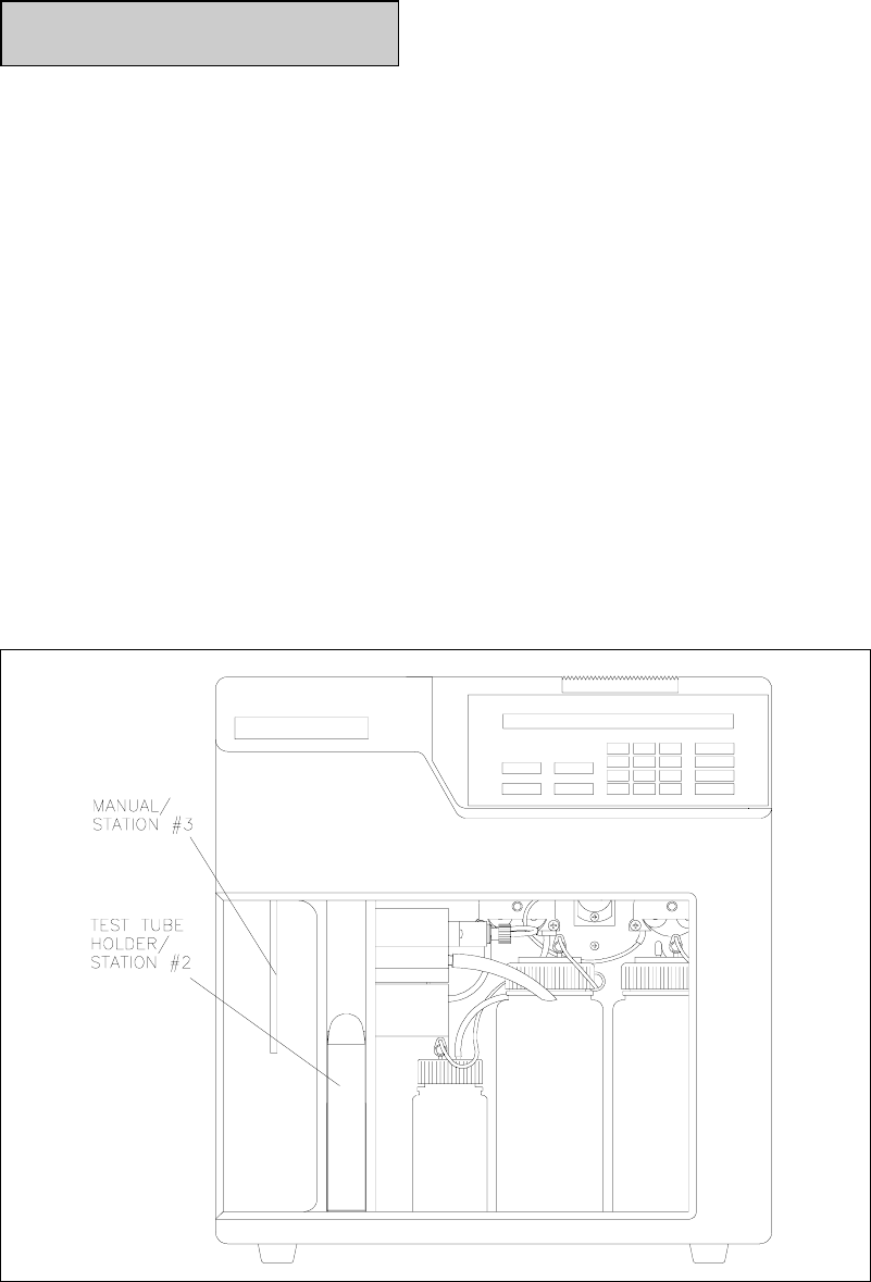
There are two stations at which a sample may be presented: Station #2 (Test Tube Holder
Station) and Station #3 (Manual Station). If your instrument is configured with a YSI 2710
Turntable, refer to Section 10 for operation instructions.
See Figure 4.2. The Test Tube Holder accepts tubes from 9 to 16 millimeters in diameter and 50
to 100 millimeters long. Any container other than a tube with the dimensions indicated should
be presented at the Manual Station (Station #3).
Figure 4.2
Sampling Stations
4-4
Operation At The Test Tube Holder Station
For the purposes of demonstrating basic operation, choose a standard for the chemistry you are
set up to run. For example, if you have installed a YSI 2365 (glucose oxidase) membrane,
calibrate with YSI 2747 standard and use another standard containing glucose to run as a
sample.
Using this standard, fill a test tube about half full. The Test Tube Holder is hinged at the
bottom. Pull the top out, as shown in Figure 4.3. Place the tube in the holder. The Sipper is not
designed to pierce septa, but can be used for some flexible evaporator covers that are pre-slit.
Figure 4.3
The Test Tube Holder Pivoted Out
Push the holder back into place. Press [SAMPLE]. The 2300 STAT PLUS will do the rest. The
Sipper moves to the sample test tube and travels about 3 millimeters below the surface of the
fluid.
The Sipper Pump Piston retracts and draws in 25 microliters of sample. The Sipper moves back
to the Sample Chamber, the Sipper Pump Piston extends and the sample is dispensed. In about
one minute the sample's analyte values are displayed and printed. An example of the display
format is shown below. Notice that the results are shown on the bottom line, while the "sample
ready" message for the next analysis and the calibration countdown timer are on the top line.
4-5
Ready to sample at Station #2 HH:MM:SS
B:LAC 0.002 mmol/L W:GLU 49.8 mmol/L
The printer format can be configured to express sample ID, date, time, temperature, instrument
serial number, probe currents and more. See Appendix J for example printouts.
Compare the displayed/printed value with the expected value. If the reading differs
significantly, your instrument calibration may not yet be stable. Initiate a calibration by
pressing [CALIBRATE]. After recalibration repeat the analysis described above. If your result
is still outside the expected range, proceed for now with the operation demonstrations. Later in
this section, specific actions for linearity checks will be described.
Operation At The Manual Station
Remove the tube from the Test Tube Holder. Rotate the Tube Holder back into place. Next
press [3] on the keypad. Note the change in Station # on the LC display. Alternatively, rotate
the Test Tube Holder out to trigger the switch that senses a test tube. The Sipper will
automatically go to Station #3 (Manual).
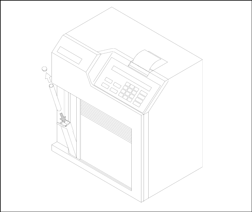
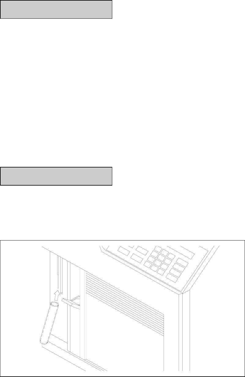
With the door fully closed, press [SAMPLE]. The display reads:
Manual sample pause moving MS
Wait for the Sipper to come to a stop at the Manual Station, then bring the sample up to the
Sipper so the tip is just immersed, about 3 millimeters below the fluid surface (See Figure 4.4).
If the Sipper dips too deeply into the sample, future measurements may be contaminated
by carry-over of excess sample on the outside of the Sipper.
Figure 4.4
The Manual Station

4-6
Be very careful not to jar or push on the Sipper during manual operation. You could disturb its
critical alignment.
The display now reads:
Present sample to sipper and
press [SAMPLE] to aspirate
Press [SAMPLE]. The sample will be aspirated and the Sipper will return to the Sample
Chamber. Do not move the sample container until the Sipper has returned to the Sample
Chamber.
Aspirating sample...
The results are then displayed and printed as shown above.
4.3 Standby Mode
If no sample is processed for 4 hours, the 2300 STAT PLUS automatically exits RUN Mode and
enters STANDBY Mode. In STANDBY Mode, the unit conserves reagents. It does not self-
calibrate; it only freshens the Sample Chamber with buffer, using less than 1 milliliter every
hour.
You can manually enter STANDBY Mode from either RUN Mode or the Main Menu by
pressing the [STANDBY] key.
The 4 hour default for entering STANDBY Mode can be changed to better fit your application.
If you have not yet done so, press [MENU]. The following menu should appear.
Select setup: 1-General 2-MeasParameter
3-RunMode 4-Report 5-PrntSetup 6-Default
Press [3] for RunMode.
Then press [2] for AutoStandby. The following display will appear.
Enter autostandby time in hour
0 to disable> 4
If you would like your 2300 STAT PLUS never to leave Run Mode, press [0] and it will con-
tinually self-calibrate and maintain a "sample ready" status. Otherwise, enter the number of
hours (0 to 30,000) you would like to maintain a "sample ready" status before reverting to
STANDBY Mode. Press [ENTER], then [MENU] to return to the Main Menu.

4-7
4.4 Daily Operational Checks
To ensure that your 2300 STAT PLUS is operating properly, perform the following operational
checks on a daily basis.
It is advisable to maintain an instrument log book in which dates and lot numbers of reagents
are recorded, along with information from daily operational checks and other relevant
information. In the log book you may want to paste a printed record of your operational checks.
Membrane Integrity Test
Use YSI 2363 Potassium Ferrocyanide (FCN) Standard to determine if your membranes are
structurally intact. This standard is packaged in your starter supplies or may be ordered
separately. The test is semiquantitative, but should offer useful information on "membrane
leakage".
Place your instrument in RUN Mode. When the unit is ready, the following display will appear.
Ready to sample at Station #2 HH:MM:SS
Pour a small amount of FCN Standard (1000 mg/dL) into a tube or cup and run it as a sample at
either the Manual or Test Tube Holder Station. Listed below are the recommended limits for the
FCN reading when calibrated with the YSI 2747 standard (glucose and L-lactate).
2365 DEXTROSE (GLUCOSE) SENSOR:
FCN readings greater than 0.3 mmol/L (5 mg/dL) after a stable calibration with YSI 2747 may
indicate membrane structural problems.
2329 L-LACTATE SENSOR:
FCN readings greater than 0.6 mmol/L (5 mg/dL) after a stable calibration with YSI 2747 may
indicate structural problems within the membrane.
NOTE: If any readings exceed the limits, recalibrate and repeat the FCN test. If they are still
high, refer to Section 8 Troubleshooting.
Linearity Test
Use the appropriate YSI linearity standard to test the linear range of the chemistry.
Calibrate using YSI 2747 Dual Standard, which contains 10.0 mmol/L glucose and 5.00
mmol/L L-lactate. These concentrations in mg/dL are 180 and 45, respectively.

4-8
Check glucose linearity using YSI 1531 Glucose Standard (50.0 mmol/L or 900 mg/dL) for
NORMAL Performance Mode setup.
Check glucose linearity using YSI 2356 Glucose Standard (27.8 mmol/L or 500 mg/dL) for
SCREEN Performance Mode setup.
Check L-lactate linearity using YSI 1530 L-Lactate Standard (30.0 mmol/L or 267 mg/dL) for
NORMAL Performance Mode setup.
Check L-lactate linearity using YSI 2328 L-Lactate Standard (15.0 mmol/L or 134 mg/dL) for
SCREEN Performance Mode setup.
Place your instrument in RUN Mode. When the unit is ready, the following display will appear.
Ready to sample at Station #2 HH:MM:SS
Pour a small amount of linearity standard into a test tube or cup and run it as a sample at either
the Manual or Test Tube Holder Station.
YSI specifies linearity to be better than +/-5% from the calibration concentration to the
detection range limit. The acceptable values depend on the performance mode you have chosen.
The modes are referred to as NORMAL and SCREEN. The acceptable ranges for both modes
are shown below in two commonly used concentration units.
Normal Mode:
Glucose: 47.5 to 52.5 mmol/L or 855 to 945 mg/dL
Lactate: 28.5 to 31.5 mmol/L or 254 to 280 mg/dL
Screen Mode:
Glucose: 26.9 to 29.2 mmol/L or 475 to 525 mg/dL
Lactate: 14.2 to 15.8 mmol/L or 126 to 141 mg/dL
NOTE: If any reading is outside of the specified tolerance limits, recalibrate and repeat the
linearity test. If it is still out of tolerance, refer to Section 8 Troubleshooting.
Above Linear Range
The acceptable 2300 STAT PLUS limits for the linear range of glucose and L-lactate are stated
above. However, results above the linear range are reported up to specific limits, above which
results are not reported. The reason for displaying and printing any results above the linear
limits of the 2300 STAT PLUS is to provide information for diluting samples appropriately for
retest.
Normal Performance Mode
For millimolar expression in the Normal Performance Mode, the warning message "ABOVE
LINEAR RANGE" is displayed and printed (with results) for glucose from 53 to 90 mmol/L,
and for lactate from 32 to 40 mmol/L.

4-9
For milligram/deciliter expression in the Normal Performance Mode the warning message
"ABOVE LINEAR RANGE" is displayed and printed (with results) for glucose from 945 to
1500 mg/dL, and for lactate from 284 to 350 mg/dL.
Above these ranges the message "OVER RANGE" is displayed and printed and no results are
presented.
Screen Performance Mode
For millimolar expression in the Screen Performance Mode the warning message "ABOVE
LINEAR RANGE" is displayed and printed (with results) for glucose from 30 to 50 mmol/L,
and for lactate from 16 to 40 mmol/L.
For milligram/deciliter expression in the Screen Performance Mode the warning message
"ABOVE LINEAR RANGE" is displayed and printed (with results) for glucose from 525 to
900 mg/dL, and for lactate from 142 to 350 mg/dL.
Above these ranges, the message "OVER RANGE" is displayed and printed; and no results are
presented.
IMPORTANT: YSI performance claims must not be
assumed to be valid for results displayed and printed
with the "Above Linear Range" message.
Clinical Controls
Use clinical controls on a daily basis to verify that the YSI 2300 STAT PLUS is operating
properly. Clinical controls are available from most laboratory and hospital supply distributors.
Both normal value and elevated value controls should be used.
Pour a small amount of the control into a container and run it as a sample at either the Manual
or Test Tube sample station. Results should compare to the stated value for the control.
4-10
5-1
5. Menu Selections
5.1 Introduction
In this section you will learn about the specific commands required to move through the 2300
STAT PLUS menu structure. You should begin by studying Figure 5.1 below, recognizing that
the instrument has two operating modes and a menu mode. Also refer to Figure 5.2, next page.
The operating modes are RUN Mode and STANDBY Mode. In RUN Mode the instrument
calibrates, samples or simply remains ready to sample. In STANDBY Mode the instrument
remains powered to keep the probes polarized, and periodically freshens the buffer to the
sample chamber. When entering RUN Mode, the unit will automatically update its calibration
as required.
In MENU Mode there are three submenu levels: Service, Setup and Diagnostics. Notice that
you may move from RUN Mode or STANDBY Mode to limited menus in Setup. However, to
fully access MENU Mode you must exit RUN or STANDBY modes.
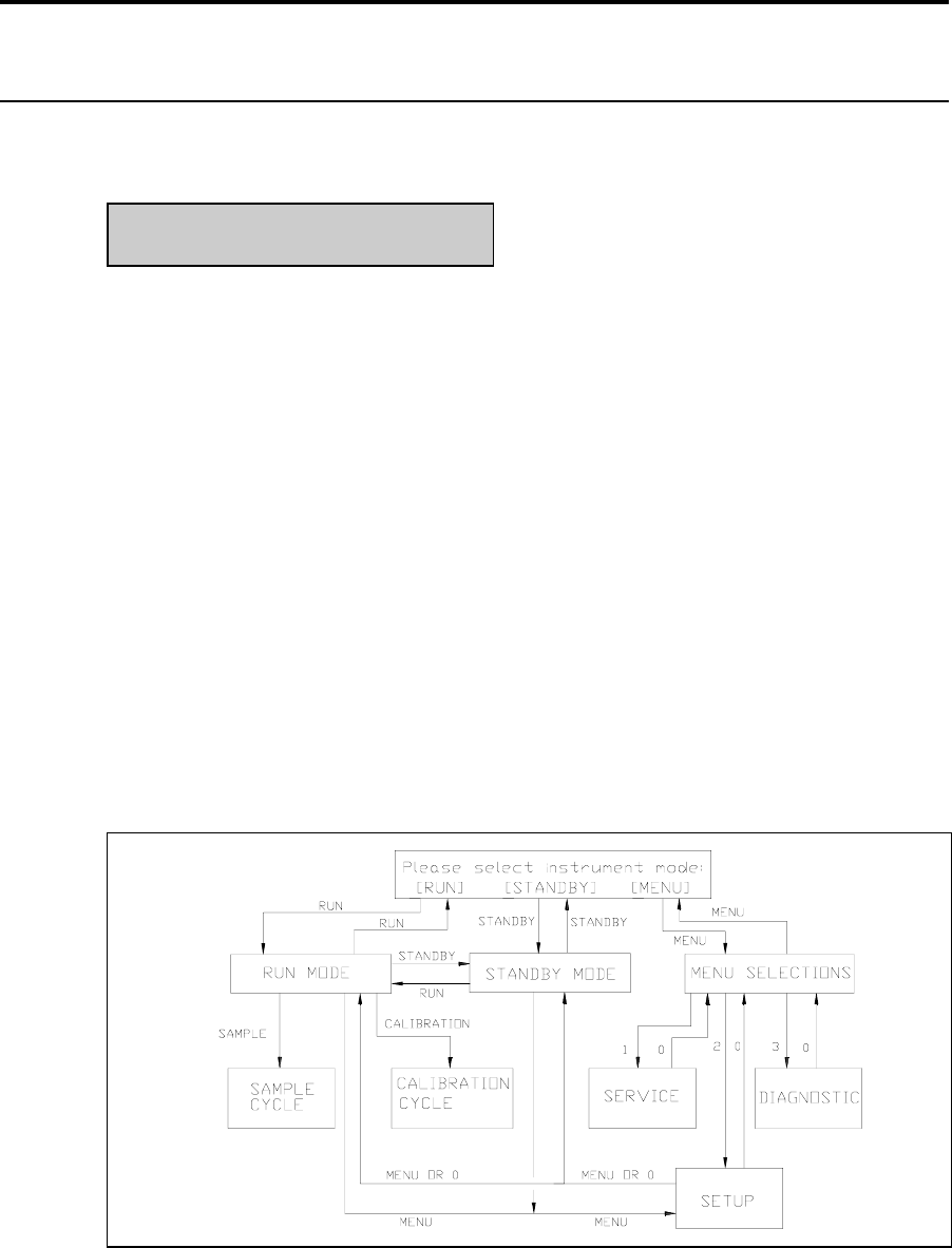
Figure 5.1
2300 STAT PLUS Software Structure
To exit RUN Mode press [RUN], then confirm your exit by pressing [2] for Yes, then
[ENTER]. The instrument will next display the message shown below.
To exit STANDBY Mode press [STANDBY], then confirm your exit by pressing [2] for Yes,
then [ENTER]. The instrument will also display the message shown below.
The display message shown below is referred to as Main Menu display. This is where we will
begin.
Please select instrument mode
[RUN] [STANDBY] [MENU]
5-2
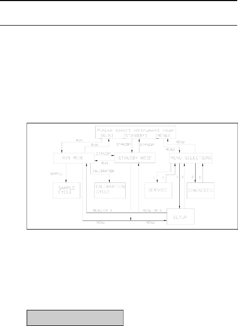
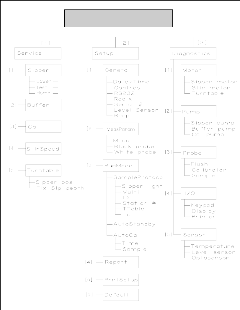
Figure 5.2
YSI 2300 STAT PLUS Menu Flow Chart
REMEMBER: You move through the 2300 STAT PLUS menus by selecting options on the
display. You can press [MENU] to get back to the Main Menu, and [0] to back up to the
previous display. However, it may be necessary to confirm a response by pressing [ENTER]
before continuing to use the [MENU] or [0] keys.
Please select instrument mode
[RUN] [STANDBY] [MENU]

5-3
5.2 Service Selections
Service functions are primarily used during initial setup and anytime reagent changes are made.
Both Cal Pump and Buffer Pump can be primed using this menu level. In addition, Sipper
alignment and Stir Bar speed adjustment can be performed from this level. Use the display
messages and text below to learn the service functions.
Main Menu display:
Please select instrument mode
[RUN] [STANDBY] [MENU]
From Main Menu press [MENU] to display instrument functions.
Select instrument function
1-Service 2-Setup 3-Diagnostic
Press [1] for Service to display service functions.
Select service: 1-Sipper 2-Buffer 3-Cal
4-Stir speed 5-Turntable
Press [1] for Sipper to initiate Sipper alignment. This procedure was used during initial
instrument setup. Refer to Section 3.9 for more information.
The Sipper Arm Assembly will move to the home position. Loosen the adjustment screw that
holds the Sipper flange to the arm to center the Sipper over the Sample Chamber injection port.
The display messages will guide you through the procedure. It is very important that the Sipper
be accurately adjusted.
Adjust sipper then select
0-Exit 1-Lower sipper for fine alignment
Fine align sipper then select
0-Exit 1-Test sipper position
Select 1 to restart check sipper cycle
0-Exit 1-Home sipper position
Adjust sipper then select
0-Exit 1-Lower sipper for fine alignment

5-4
When completed, press [0] for Exit to return to service selections.
Select service: 1-Sipper 2-Buffer 3-Cal
4-Stir speed 5-Turntable
Press [2] for Buffer to initiate a 15-second cycle of the Buffer Pump. This selection allows you
to prime the buffer system. Use it after replenishing the buffer bottle or replacing tubing. Also
use it to troubleshoot problems or find leaks.
Select service: 1-Sipper 2-Buffer 3-Cal
4-Stir speed 5-Turntable
Press [3] for Cal to initiate a 10-second cycle of the Cal Pump. This selection allows you to
prime the calibrator system. Use it after changing the calibration solution or replacing tubing.
Also use it to troubleshoot problems or find leaks.
Select service: 1-Sipper 2-Buffer 3-Cal
4-Stir speed 5-Turntable
Press [4] for Stir Bar to adjust the stir bar speed. During RUN Mode operation the stir bar has
two operating speeds: normal speed, at which the stir bar rotates smoothly in the chamber and
accelerated speed, at which the stir bar looses synchronization with the motor housed below
and jumps. This jumping action helps clear the sample chamber of air bubbles during a flush
cycle.
Adjust until stir bar jumps
1-Increase speed 2-Decrease speed
Using the 1-Increase and 2-Decrease choices adjust the Stir Bar. Lower the speed to observe
synchronous rotation, then increase the speed until the stir bar "jumps" and looses synchronous
rotation. At this point release the [1] key. If jumping does not occur, adjust the Stir Bar speed to
the maximum setting.
5-5
Press [0] to exit the stir bar menu level.
Select service: 1-Sipper 2-Buffer 3-Cal
4-Stir speed 5-Turntable
CAUTION! Do not enter the 5-turntable submenu
unless the turntable is installed and the left access
plate is removed. You may seriously damage the
sipper arm assembly.
If you press [5] for Turntable you will access two functions used to align the YSI 2710
Turntable. Refer to Section 10 on operation and maintenance of the turntable for details.
Press [0] two times to backup to the instrument function selections.
Select instrument function
1-Service 2-Setup 3-Diagnostic
You have now completed the Service menu selections.

5-6
5.3 Setup Selections
Setup menu is where you will enter system parameters that define the specific information
required to run the 2300 STAT PLUS for your particular application. You will set general
information such as date, time, display and print formats. You will enter specific information
related to chemistry selection, concentration units, calibration and sampling protocols,
communication parameters, and other features. Once set, the parameters are maintained in
memory. In the event of power loss, the 2300 STAT PLUS has battery backup to preserve this
information.
NOTE: When first powered, the instrument will contain most of the general information you
need. Some information is set prior to delivery and preserved by battery; and other information
will be set as default values which are appropriate for many standard applications. Use the
display messages and text below to learn the flexibility you have in setting up your 2300 STAT
PLUS.
You may find it helpful to use the Menu Flow Chart (Figure 5.2), to follow the menu levels.
Main Menu display:
Please select instrument mode
[RUN] [STANDBY] [MENU]
From Main Menu press [MENU] to display instrument functions.
Select instrument function
1-Service 2-Setup 3-Diagnostic
Press [2] for Setup to display setup selection categories.
Select setup: 1-General 2-MeasParameter
3-RunMode 4-Report 5-PrntSetup 6-Default
Press [1] for General. The display will read:
General setup: 1-Date/Time 2-Contrast
3-RS232 4-Radix 5-Serial# 6-Level 7-Beep
In General setup menu, you may confirm or change the date, set date format, adjust the display
contrast, define communication parameters, select the radix to express decimal numbers,
confirm or enter the instrument serial number, select whether to deactivate the bottle level
sensor system and to deactivate the keypad annunciator.

5-7
Press [1] for Date/Time. Use the number keys to change entries. Press [ENTER] to confirm
your selection. You will see the display messages below, leading you through the complete date
entry sequence.
Enter date and time as required
Year> 03
Enter date and time as required
Month> 2
Enter date and time as required
Date> 14
Enter date and time as required
Hour> 17
Enter date and time as required
Minute> 22
Select and/or confirm the format you desire for printed dates; (month/day/year) or
(day/month/year).
Select date format: MM/DD/YY
1-MM/DD/YY 2-DD/MM/YY
When you press [ENTER], you will return to the General setup level.
General setup: 1-Date/Time 2-Contrast
3-RS232 4-Radix 5-Serial# 6-Level 7-Beep
Press [2] for Contrast. Use the appropriate number key to adjust the LC display contrast for
your comfort. When finished, press [0] to return to General setup level.
Adjust the display contrast
1-Raise contrast 2-Lower contrast
General setup: 1-Date/Time 2-Contrast
3-RS232 4-Radix 5-Serial# 6-Level 7-Beep

5-8
Press [3] for RS232. Use this menu to set communication parameters if you are using the serial
interface port. See Section 9 for detailed information on communications. Below are the display
messages showing default settings and your options. Press [ENTER] to confirm your choices
for each parameter.
If you are not using the serial port, you need not worry about setting these parameters. They
will not interfere with other parameter settings.
RS-232 setup 1-Baud 2-Data 3-Parity
4-Stop 5-Handshake 6-Configuration
Select baud rate: 9600
1-9600 2-4800 3-2400 4-1200 5-600 6-300
Select number of data bits: Seven bits
1-Seven bit 2-Eight bit
Select parity: Odd
1-None 2-Even 3-Odd 4-Low 5-High
Select number of stop bits: One bit
1-One bit 2-Two bits
Select handshaking type: RTS/CTS
1-RTS/CTS 2-XON/XOFF 3-NONE
If you choose XON/XOFF, you will go one menu level deeper to enter or confirm XON and
XOFF values.
Enter XON character
> 17
Enter XOFF character
> 19
Press [ENTER] to confirm and return to RS-232 setup.

5-9
RS-232 setup 1-Baud 2-Data 3-Parity
4-Stop 5-Handshake 6-Configuration
Select configuration: Non-multidrop
1-Non-multidrop 2-Multidrop
The default configuration is Non-multidrop. If you press [2] for Multidrop, you will see the
following.
Enter node address
>
The node address is only used when networking 2300s in a multi-instrument system. Now press
[0] to return to the General setup level.
General setup: 1-Date/Time 2-Contrast
3-RS232 4-Radix 5-Serial# 6-Level 7-Beep
Press [4] for Radix. In some parts of the world, a "," is preferred to express decimal numbers
(For example: 2.00 = 2,00). Confirm your choice by pressing [ENTER] to return to the General
setup level.
Select radix mark: "."
1-"." 2-",
General setup: 1-Date/Time 2-Contrast
3-RS232 4-Radix 5-Serial# 6-Level 7-Beep
Press [5] for Serial #. The serial # of your instrument is recorded on the serial plate, lower rear
of case. Enter this number in memory. It will be printed for certain report formats.
NOTE: YSI uses alpha-characters in the serial number. We recommend that you press [SPACE]
for the first alpha-character and omit the last two. Example, 03B01234AB can be entered as 03
01234. This number is normally set prior to delivery, and preserved in memory by battery
backup. Press [ENTER] to confirm and return to General setup level.
Enter instrument serial number
03 01234
General setup: 1-Date/Time 2-Contrast
3-RS232 4-Radix 5-Serial# 6-Level 7-Beep

5-10
Press [6] for Level Sensor. Choose "Yes" to maintain level sensing in the buffer, calibrator and
waste bottles. One reason to inactivate the level sensors would be if you use a non-standard
container for buffer or waste.
Activate bottle level sensors? Yes
1-No 2-Yes
Press [ENTER] to confirm and return to General setup level.
General setup: 1-Date/Time 2-Contrast
3-RS232 4-Radix 5-Serial# 6-Level 7-Beep
Press [7] for "Beep".
Activate keyboard annunciator? Yes
1-No 2-Yes
Press [1] for No if you prefer to turn off the audible signal for keypad confirmation. After your
choice, press [ENTER] to return to Select setup menu level.
You have now completed General setup. Press [0] to return to Select setup menu level.
Select setup: 1-General 2-MeasParameter
3-RunMode 4-Report 5-PrntSetup 6-Default
Press [2] for MeasParameter. The display will read:
Measurement parameter setup
1-Mode 2-Black 3-White
"MeasParameter" is an abbreviation for measurement parameters. In this menu you will select
between two performance modes, Normal and Screen modes. You will also assign specific
chemistry parameters to the Black and White probes. These parameters are chemistry
assignment and units of concentration. YSI has assigned default values for each of these
parameters, but provides flexibility so the user can change values to optimize for a particular
application. However, see warning statements in Section 3 (3-13 and 3-22), and additional
information in Section 11 Typical Performance Data.
Press [1] for Mode.
Select performance mode: Normal
1-Normal 2-Screen

5-11
Use this menu to choose one of two instrument performance modes. Refer to Sections 2 and 11
for descriptions of the basic differences between these modes. Basically, Screen mode provides
faster response (result) and faster cycle time than Normal mode. The tradeoff for these faster
times may be reduced linear range, precision and accuracy. Refer to Section 11 for data on
Typical Performance.
Press [ENTER] to confirm Normal mode.
Press [2] for Black. At this level, you will choose chemistry and other black probe measurement
parameters.
Select BLACK chemistry: L-Lactate
0-Backup 1-Next chemistry [ENTER]-Accept
Press [1] for Next chemistry. You use this key to scroll through the choices in the menu
(Glucose, L-Lactate, None). Select the appropriate chemistry then press [ENTER] to confirm
and move on to the next parameter.
Select BLACK unit of measurement: mmol/L
1-mmol/L 2-mg/L (ppm) 3-mg/dL
Press the appropriate number to change the default setting, if necessary.
NOTE: If you choose a concentration unit other than mmol/L, the value automatically changes.
That is, 5.00 mmol/L becomes 450 mg/L or 45 mg/dL.
When the desired unit of measurement is selected, press [ENTER] to confirm and move to the
next parameter.
Measurement parameter setup
1-Mode 2-Black 3-White
Press [3] for White. Now set the same parameters for the White probe that you just set for the
Black probe.
Select WHITE chemistry: Glucose
0-Backup 1-Next chemistry [ENTER]-Accept

5-12
Press [ENTER] to confirm Glucose as the WHITE chemistry.
Select WHITE unit of measurement: mmol/L
1-mmol/L 2-mg/L (ppm) 3-mg/dL
Press [ENTER] to confirm. The display now shows Measurement parameter setup.
Measurement parameter setup
1-Mode 2-Black 3-White
Press [0] to return to the Select setup level.
Select setup: 1-General 2-MeasParameter
3-RunMode 4-Report 5-PrntSetup 6-Default
Press [3] for RunMode. The display will read:
RUN mode setup: 1-SampleProtocol
2-AutoStandby 3-AutoCal
In this menu, you select parameters related to sampling protocol, set parameters that control
automatic switching to standby mode and select parameters that will trigger autocalibrations. In
Sampling Protocol, you can select the sample station (position), activate multisampling and
sample identification systems, and set the position to which the Sipper descends when sampling
at the Manual Station.
Press [1] for SampleProtocol. The display will read:
Sampling protocol setup: 1-SipperHeight
2-Multi 3-ID 4-Station# 5-TTable 6-Hct
Press [1] for SipperHeight. This specifies to what vertical position the Sipper descends when
sampling at the Manual Station. For example, with long test tubes and the fluid level near the
bottom of the test tube, use "Low" setting.
Select manual sipper height: Medium
1-Low 2-Medium 3-High

5-13
Press [ENTER] to confirm and return to Sampling protocol setup.
Sampling protocol setup: 1-SipperHeight
2-Multi 3-ID 4-Station# 5-TTable 6-Hct
Press [2] for Multi (abbreviation for multiple cycles). The default setting is No. The display
prompts reflect messages for single sampling and single calibrations. If Yes is confirmed, you
will be prompted at the display each time you press [SAMPLE] or [CALIBRATE] to enter how
many times the sample or cal solution should be run for that one command. The number that
you assign to Multicycle must be between 1 and 99 (samples or calibrations). During RUN
Mode, you may cancel the assigned number of cycles by pressing [CANCEL].
As an example, Multicycle allows you to configure your system to run a sample in the Test
Tube Holder unattended in duplicate or triplicate. Multicycle also allows you to check
calibration stability by assigning some number of consecutive calibrations to be run without
requiring repeated key commands of [CALIBRATE].
Prompt multiple cycle? No
1-No 2-Yes
Press [ENTER] to confirm and return to Sampling protocol setup.
Sampling protocol setup: 1-SipperHeight
2-Multi 3-ID 4-Station# 5-TTable 6-Hct
Press [3] for ID. If you wish to assign sample identification numbers to each sample, enter [2]
for Yes here. When you press [SAMPLE] in RUN Mode, the display will prompt you to enter a
sample ID number. You may elect not to assign a number for each sample, in which case the
prompt display disappears and the sample is run identified only by time and date.
Prompt sample ID? No
1-No 2-Yes
Press [ENTER] to confirm and return to Sample protocol setup.
Sampling protocol setup: 1-SipperHeight
2-Multi 3-ID 4-Station# 5-TTable 6-Hct
Press [4] for Station# to assign the position at which the sample will be aspirated. The default
location is Station #2, the Test Tube Holder station. You may also elect to sample from Station
#3, the Manual Station.
5-14
If you are operating the 2300 STAT PLUS with the 2710 Turntable, you would enter "4" for
station #. Refer to Section 10 Turntable Operation and Maintenance for details.
Enter Sample Station#
> 2
Press [ENTER] to confirm and return to Sampling protocol setup.
Sampling protocol setup: 1-SipperHeight
2-Multi 3-ID 4-Station# 5-TTable 6-Hct
CAUTION: Do not press [5] for turntable unless the YSI
2710 Turntable has been installed.
Refer to Section 10 for setup, operation and maintenance of the turntable.
Press [6] for Hct (Hematocrit Correction prompt).
Prompt for Hematocrit? No
1-No 2-Yes
If you select "Yes" to this menu question, the LC display will prompt you each time you press
[SAMPLE] for entry of a hematocrit value. Any whole number between 17 and 70 will be
accepted. This value converts ONLY WHOLE BLOOD GLUCOSE TO PLASMA
GLUCOSE (see Appendix D for specific information on the correction equation).
If you do not enter a value within 30 seconds, no correction factor is applied to the glucose
result. When you do enter a hematocrit value, the value you enter is printed with the corrected
result on the printout. (See Appendix J for example.)
NOTE: Hematocrit correction for whole blood to
plasma L-lactate CANNOT be performed with
consistency and is not available in the software
protocol.
Press [ENTER] to confirm and return to Sampling protocol setup.
Sampling protocol setup: 1-SipperHeight
2-Multi 3-ID 4-Station# 5-TTable 6-Hct
5-15
Press [0] to return to RUN mode setup.
RUN mode setup: 1-SampleProtocol
2-AutoStandby 3-AutoCal
Press [2] for AutoStandby to define the number of hours the unit will continue to update
calibration and be ready to sample. The default setting is 4. If you press [0] and confirm with
[ENTER], AutoStandby is disabled. The instrument then remains "sample ready" indefinitely.
You may enter any number between 0 and 99.
Enter autostandby time in hour
0 to disable> 4
Press [ENTER] to confirm and return to RUN mode setup.
RUN mode setup: 1-SampleProtocol
2-AutoStandby 3-AutoCal
Press [3] for AutoCal to define parameters that initiate autocalibrations. Only two menu
categories are adjustable, time and sample per calibration. The default settings that initiate
calibration are: 1) temperature drift of more than 1°C since last cal, 2) after 15 minutes without
cal update, 3) after 5 samples run without a cal update, 4) after a probe current shift of 2% or
greater compared to the last cal, and 5) after certain errors are detected in the software.
Autocal setup:
1-Time 2-Sample
CAUTION: The instrument specifications described in
Section 2.3 are based on extensive testing, performed
under calibration conditions as described in Section 11
Typical Performance Data. Refer to Section 11 before
arbitrarily changing calibration parameters, since any
changes may compromise precision and/or accuracy.
These selections are provided as part of the overall concept of the 2300 STAT PLUS, flexibility.
You may have an application where 5% precision is acceptable if you can guarantee that the
instrument will not initiate a calibration at a critical sampling time. This menu allows you to
make that possible.

5-16
The two displays are shown below, each showing the default value. Near each display block is
information related to the range of values that you may enter. Press [ENTER] to confirm and
proceed to the next parameter.
Confirm value shown or enter and confirm any number from 1 to 240. The autocal time interval
parameter can not be disabled. An autocalibration will occur at least once every 240 minutes (4
hours) regardless of how the sample parameter is set.
Enter autocal time interval in minute
> 15
Autocal setup:
1-Time 2-Sample
Confirm value shown or enter and confirm any number of samples from 0 to 200.
Enter number of samples between autocals
0 to disable> 5
Autocal setup:
1-Time 2-Sample
Press [0] to return to RUN mode setup.
RUN mode setup: 1-SampleProtocol
2-AutoStandby 3-AutoCal
You have now completed Run mode setup. Press [0] to return to Select setup menu level.
Select setup: 1-General 2-MeasParameter
3-RunMode 4-Report 5-PrntSetup 6-Default
Press [4] for Report. The display will read:
Select sample report format: Brief
1-None 2-Brief 3-Detail
Press [ENTER] to confirm sample report format and move to cal report format.
Select cal report format: Brief
1-None 2-Brief 3-Detail

5-17
Report Format refers to the information that will be printed each time the 2300 STAT PLUS
runs a sample or a calibration. The default settings are "Brief".
Detail report formats are typically used when you want to study probe currents and temperature
changes with newly installed reagents or enzyme membranes. You may also elect to choose
Detail report for the first few calibrations or samples after a long idle period where no samples
or cals are run. If you suspect problems with the instrument, you should run Detail reports to
provide more information for troubleshooting.
See Appendix J–Report Formats for example report formats.
Press [0] to return to Select Setup.
Select setup: 1-General 2-MeasParameter
3-RunMode 4-Report 5-PrntSetup 6-Default
You have completed Report setup.
Press [5] for PrntSetup. The display will read:
Printing instrument setup... Please wait
The instrument will print the setup information you have entered. The information is an item-
ized list of the key parameters that you have chosen. The printing will take about 45 seconds
and use about 15 cm (6 inches) of printer paper. See Appendix I for a sample printout.
When printing is completed the instrument returns to Select setup menu.
Select setup: 1-General 2-MeasParameter
3-RunMode 4-Report 5-PrntSetup 6-Default
You have completed Print Setup (PrntSetup) level.
Press [6] for Default. The display will read:
Reset all system parameters? No
1-No 2-Yes
This menu allows you to reset all system parameters to the default settings, that is, those that
reside in ROM (Read Only Memory) when the instrument is manufactured. DO NOT DO
THIS AT THIS TIME! If you have been entering setup information for a particular
application, resetting to Default will clear some or all of your selections and restore Default
system parameters.

5-18
You will likely use Default to return to YSI-recommended settings if you have been
experimenting with the selections and would like to start at the beginning.
Press [ENTER] to confirm your choice and return to Select setup.
Select setup: 1-General 2-MeasParameter
3-RunMode 4-Report 5-PrntSetup 6-Default
Press [0] to return to Select instrument function.
Select instrument function
1-Service 2-Setup 3-Diagnostic
YOU HAVE NOW COMPLETED THE SETUP MENU OF THE SOFTWARE.
As you gain more familiarity with the 2300 STAT PLUS menus, the setup will not seem so
complicated. You will learn to "jump in and out" of the menus quickly, sometimes not even
needing to exit RUN or STANDBY mode to make a change.
When you have completed Service, Setup or Diagnostic functions press [0] (or [MENU]) to
return to Main Menu. From Main Menu you may enter RUN or STANDBY modes.
Please select instrument mode
[RUN] [STANDBY] [MENU]
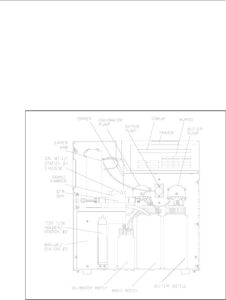
5-19
5.4 Diagnostic Selections
Diagnostic menu functions are used primarily during troubleshooting. In this menu, you will
learn to gain individual control of components in the instrument. For example, you can turn
motors on and off, and even "exercise" motor-controlled devices. You can run pumps to check
fluid movement. You can check probe electrical current and even simulate a calibration or
sample cycle. You can check I/O (input/output) devices such as display, keypad and printer for
proper function. And finally, you can check the status of most sensors in the system. These
include the temperature sensor in the Sample Chamber; the level sensors in the reagent and
waste bottles; the Sipper capacitance sensing; and the optical sensors that control motors, the
Sipper Pump and sense the Test Tube Holder position.
Follow the display prompts and information below to learn about the 2300 STAT PLUS menu
diagnostics mode. As before, you will often need to press [0] to return to a previous menu level.
Occasionally, the instrument will print diagnostic information.
Refer to Figure 4.3 below to become familiar with major components of the instrument.
Additional figures in Sections 4 and 5 may be useful, especially Figure 5.2, Menu Flow Chart.
Figure 5.3
2300 STAT PLUS Major Components

5-20
As discussed in the Introduction to this section, you must exit RUN Mode or STANDBY Mode
to gain complete access to the diagnostic menu functions. To exit Run or Standby modes, press
the appropriate key ([RUN] or [STANDBY]), then follow the prompts to exit. You will now be
in Main Menu mode and the display will appear as shown below.
Please select instrument mode
[RUN] [STANDBY] [MENU]
Press [MENU], then [3] for Diagnostic to display the five categories of diagnostic selections.
Select instrument function
1-Service 2-Setup 3-Diagnostic
Select diagnostic
1-Motor 2-Pump 3-Probe 4-I/O 5-Sensor
Press [1] for Motor to gain access to two motors, the Sipper Arm assembly (vertical and
horizontal motions) and the Stir Motor that turns the magnetic stir bar in the Sample Chamber.
Motor diagnostic
1-Sipper motor 2-Stir motor 3-Turntable
Press [1] for Sipper motor to display the following motion selections.
Sipper diagnostic: 1-Up 2-Down 3-Home
4-Clockwise 5-Counterclock 6-Exercise
When you press one of the keys (1-5), a movement of the Sipper should be observed. Press [1]
and the Sipper moves up until the upper limit optosensor is detected. Press [2] and the Sipper
moves down into the Sample Chamber or to its limit, if at another station.
In the horizontal plane, press [3] and the Sipper moves to the position directly over the Sample
Chamber opening. Press [4] and the Sipper moves horizontally clockwise one station, for ex-
ample from "home" to Test Tube Holder Station (Station #2). Press [5] and the Sipper moves
horizontally counterclockwise one station, for example from Manual Station (Station #3) to
Test Tube Holder Station (Station #2).
If the Sipper is "down" and you press a command for horizontal movement, the Sipper first
moves up before beginning horizontal motion.
5-21
CAUTION: Before you initiate exercise in the horizontal
plane, remove the left side access plate to prevent
damage if the sipper moves to the turntable position.
If you have a turntable installed properly, the access
plate will already be removed.
Press [6] to initiate repeated motions in the same plane. We refer to this as" Exercise". The
motion (horizontal or vertical) is determined by the last command you choose. The instrument
counts the number of cycles and displays them as shown below. When you press a key to
terminate the exercise mode, the printer records the activity and number of cycles completed.
Exercising sipper motor
Cycle = 3 Hit any key to stop
Press [0] to return to Sipper diagnostic selections.
Sipper diagnostic: 1-Up 2-Down 3-Home
4-Clockwise 5-Counterclock 6-Exercise
Press [0] again to return to Motor diagnostic selections.
Motor diagnostic
1-Sipper motor 2-Stir motor 3-Turntable
Press [2] for Stir motor to turn on the motor that spins the magnetic stir bar in the Sample
Chamber. The bar should spin in "synch", i.e., not "jump" about the chamber as is observed
during brief periods of normal operation. The asynchronous motion is used to dispel air bubbles
from the chamber wall and probe surfaces.
You turn the Stir Motor off by pressing [2] again. The Stir motor may be activated with the
Sipper either in or out of the Sample Chamber.
Motor diagnostic
1-Sipper motor 2-Stir motor 3-Turntable
Press [0] to return to the five diagnostic selections.
Select diagnostic
1-Motor 2-Pump 3-Probe 4-I/O 5-Sensor

5-22
Press [2] for Pump to access the Sipper Pump, Calibrator Pump and Buffer Pump.
Pump diagnostic
1-SipperPump 2-Buffer 3-Calibrator
Press [1] for Sipper Pump to begin a sequence of five distinct movements of the plunger rod in
the Sipper Pump. Locate the Sipper Pump, a clear plastic cylindrical body mounted between the
two peristaltic pumps on the fluid wall. See Figure 7.2. Focus on the metal plunger rod inside
this plastic body. Some movements will be brief, so watch closely.
Sipper pump diagnostic
1-Home
Press [1] for Home. You will see a small movement of the plunger, but you will hear a clicking
sound that lasts 3 or 4 seconds as the pump motor oversteps to detect "home".
The display will now update to give two new selections as shown below.
Sipper pump diagnostic
1-Home 2-Aspirate separator 3-Exercise
Press [2] for Aspirate separator. A short retraction of the plunger should occur. This simulates
the aspiration of an air bubble to isolate sample from the buffer stream. The display updates to
read the following.
Sipper pump diagnostic
1-Home 2-Aspirate sample 3-Exercise
Press [2] for Aspirate sample. A longer retraction of the plunger should occur. This simulates
the aspiration of sample. The display updates to read the following.
Sipper pump diagnostic
1-Home 2-Dispense sample 3-Exercise
Press [2] for Dispense sample. An extension of the plunger should occur. This simulates
dispensing the sample into the Sample Chamber. The display updates to read the following.
Sipper pump diagnostic
1-Home 2-Dispense separator 3-Exercise
Press [2] for Dispense separator. A short extension of the plunger should occur. This simulates
dispensing the air bubble into the Sample Chamber after the sample reading at the probe would
have occurred. The plunger is now back to "home" position.

5-23
Sipper pump diagnostic
1-Home 2-Aspirate separator 3-Exercise
Press [3] for Exercise. All of the plunger movements will occur in the sequence described
above.
The complete retraction and extension represents one cycle. The cycle number is displayed.
Exercising sipper pump
Cycle = 3 Hit any key to stop
When you press a key to terminate the exercise mode, the printer records the activity and
number of cycles completed. The display returns to Sipper pump diagnostic menu.
Sipper pump diagnostic
1-Home 2-Aspirate separator 3-Exercise
Press [0] to return to Pump diagnostic menu.
Pump diagnostic
1-SipperPump 2-Buffer 3-Calibrator
Press [2] for Buffer to turn on the Buffer Pump. The pump runs until you press [2] a second
time. The display does not change messages during this activity. You should hear the pump and
see fluid moving through the Sample Chamber and exiting through the opening of the steel
cone, then through the Waste Tube to the Waste Bottle.
Pump diagnostic
1-SipperPump 2-Buffer 3-Calibrator
Press [3] for Calibrator to turn on the Calibrator Pump. The pump runs until you press [3] a
second time. The display remains as shown below. You should hear the pump, and see fluid
moving into the Cal Well of the Sample Chamber Block, and then flowing out through the
Waste Tube to the Waste Bottle.
Pump diagnostic
1-SipperPump 2-Buffer 3-Calibrator
Press [0] to return to the five diagnostic selections.
Select diagnostic
1-Motor 2-Pump 3-Probe 4-I/O 5-Sensor

5-24
Press [3] for Probe. You will observe a brief display message, as shown below, which then
changes to show probe currents. The probe activity is expressed in nA (nanoamperes) of
electrical current. A nanoampere is 10-9 amperes, which is a very low level of electrical current.
Reading probe current...
Please wait.
B:LAC 0.50 nA W:GLU 0.76 nA
1-Flush 2-Calibrator 3-Sample
NOTE: If you assign "none" for a probe in the Setup (measurement parameters) menu, the
display appears as shown below.
B:LAC 0.50 nA W: -Not assigned-
1-Flush 2-Calibrator 3-Sample
Press [2] for Calibrator. The Calibrator Pump turns on as the Sipper moves to the Cal Well and
descends. Calibrator solution is aspirated, then moved to the Sample Chamber and dispensed,
just as you would observe in a normal calibration cycle.
The display probe current should rise above baseline and within 20 to 30 seconds should level
off at some nanoampere value indicative of the particular chemistry you have setup.
B:LAC 11.77 nA W:GLU 23.17 nA
1-Flush 2-Calibrator 3-Sample
Next, press [1] for Flush to clear the calibrator solutions from the Sample Chamber. The flush
will take about 30-40 seconds. If the baseline has not returned to levels you previously
observed, you may want to initiate a second flush cycle. Baseline values are shown again
below.
B:LAC 0.55 nA W:GLU 0.80 nA
1-Flush 2-Calibrator 3-Sample
Press [3] for Sample. The Sipper will move to the assigned sample station and aspirate sample,
then move to the Sample Chamber to dispense sample, just as was observed in the calibrator
cycle above. Again, you must initiate the flush cycle by pressing [1] for Flush. Probe current
values will vary based on concentrations used for sampling.
B:LAC 91.83 nA W:GLU 112.9 nA
1-Flush 2-Calibrator 3-Sample

5-25
Press [0] to return to the five diagnostic selections.
Select diagnostic
1-Motor 2-Pump 3-Probe 4-I/O 5-Sensor
Press [4] for I/O. From this menu level you can run diagnostic tests on the input/output devices
of the instrument.
I/O diagnostic
1-Keypad 2-Display 3-Printer
Press [1] for Keypad. You may now test each of the 20 keys on the keypad. There are 12
numeric keys (including space and backspace) and 8 function keys. To exit the keypad test,
press and hold [CANCEL].
Hit keys - Hold [CANCEL] to exit
Key>
When you press and immediately release a key, we refer to this as a "hit". The following will be
displayed (example is [RUN] key).
Hit keys - Hold [CANCEL] to exit
Key> [RUN] hit
When you press and hold a key down and then release it, the following display messages
should be observed.
Hit keys - Hold [CANCEL] to exit
Key> [RUN] held down
Hit keys - Hold [CANCEL] to exit
Key> [RUN] released
To exit the keypad test, press and hold down the [CANCEL] key.
Hit keys - Hold [CANCEL] to exit
Key> [CANCEL] held down
The following message appears after you exit the keypad test.

5-26
I/O diagnostic
1-Keypad 2-Display 3-Printer
Press [2] for Display. You should now see 95 different characters (including a blank) appear in
each of the 40 segments of the liquid crystal display. The total test takes about 40 seconds.
Terminate the test at any time by pressing any key. The first few characters are shown below.
!!!!!!!!!!!!!!!!!!!!!!!!!!!!!!!!!!!!!!!!
!!!!!!!!!!!!!!!!!!!!!!!!!!!!!!!!!!!!!!!!
"""""""""""""""""""""""""""""""""
"""""""""""""""""""""""""""""""""
#######################################
########################################
$$$$$$$$$$$$$$$$$$$$$$$$$$$$$$$$$$$$$$$$
$$$$$$$$$$$$$$$$$$$$$$$$$$$$$$$$$$$$$$$$
I/O diagnostic
1-Keypad 2-Display 3-Printer
Press [3] for Printer. The printer prints the same 95 characters described above in the display
test. The printout uses 5 lines and takes about 10 seconds to complete. The display momentarily
flashes the message "Printer test", then returns to I/O diagnostic menu.
Printer test
I/O diagnostic
1-Keypad 2-Display 3-Printer
Press [0] to return to the five diagnostic selections.
Select diagnostic
1-Motor 2-Pump 3-Probe 4-I/O 5-Sensor

5-27
Press [5] for Sensor. You may select one of three categories of sensors: temperature, fluid
level or detection, and optosensors for a variety of motion status signals.
Sensor diagnostic
1-Temperature 2-LevelSensor 3-OptoSensor
Press [1] for Temperature. The display shows the current temperature of buffer in the Sample
Chamber. The temperature display is "live", i.e., changes will be updated continuously.
Reading sample chamber temperature...
Please wait
Sample chamber temperature: 25.10 C
Hit any key to exit
Sensor diagnostic
1-Temperature 2-LevelSensor 3-OptoSensor
Press [2] for LevelSensor. You will observe the current status of each of the four level sensors
shown below. The Sipper will show "fluid" or "air". The Cal and Buffer will show "OK" or
"Empty". The Waste will show "OK" or "Full".
Level sensor status: Sipper:Fluid
Cal:OK Waste:OK Buffer:Empty
Press [0] to return to Sensor diagnostic menu.
Sensor diagnostic
1-Temperature 2-LevelSensor 3-OptoSensor
Press [3] for OptoSensor. Optosensors are used to track horizontal and vertical movement of
the Sipper, the movement of the Sipper Pump plunger and the presence of a test tube in the Test
Tube Holder.
Opto sensor status: Horiz:OFF Vert:ON
SipperPump:ON TestTube:ON
If the Sipper is positioned at Station #2 or #3, the Horiz message should be OFF; if at "home"
or Station #1, the message should be ON.
If the Sipper is down in the Sample Chamber, the Vert message should be OFF; if up, the
message should be ON.

5-28
If the Sipper Pump plunger is at "home", i.e. extended, the SipperPump message should be ON;
if the plunger is in any position other than home, the message should be OFF.
If there is a test tube in the Test Tube Holder and it is in a vertical orientation, the "TestTube"
message should be ON; if not, then the message should be OFF.
Press [0] to return to Sensor diagnostic menu.
Sensor diagnostic
1-Temperature 2-LevelSensor 3-OptoSensor
Press [0] to return to the five diagnostic selections.
Select diagnostic
1-Motor 2-Pump 3-Probe 4-I/O 5-Sensor
Press [0] to return to Select instrument function.
Select instrument function
1-Service 2-Setup 3-Diagnostic
Press [0] to return to Main Menu display.
Please select instrument mode
[RUN] [STANDBY] [MENU]
NOTE: You may press [MENU] from most levels of diagnostics to return directly to Main
Menu.
You now have had a complete look at the Diagnostic Menu. You may press [RUN] or
[STANDBY] to enter an operating mode, or remain in Main Menu indefinitely, however, note
that no automatic calibrations or sample chamber flushes will occur in this mode.
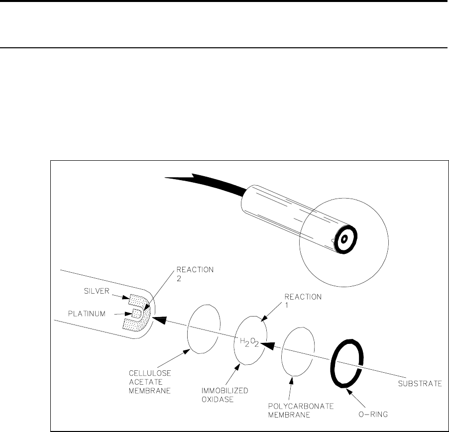
6-1
6. Principles Of Operation
6.1 Sensor Technology
The sensor technology of the YSI 2300 STAT PLUS is based on the principles conceived by Dr.
Leland Clark, formerly of Children’s Hospital Foundation, Cincinnati, Ohio. The immobilized
enzyme membrane was invented by YSI and is covered by U.S. Patent 4,073,713. This sensor
technology has been used successfully since 1975 in the YSI 23A Blood Glucose Analyzer;
then later in the YSI 27 Industrial Analyzer and the YSI 23L Blood Lactate Analyzer. Most
recently, the same technology has been employed in the YSI 2700 SELECT Biochemistry
Analyzer and the YSI 1500 SPORT Lactate Analyzer.
Figure 6.1
Sensor Probe and Enzyme Membrane
Each probe is fitted with a three-layer membrane containing immobilized enzyme in the middle
layer. Figure 6.1 shows an exploded view of the membrane and its relationship to face of the
probe.
6-2
The face of the probe, covered by the membrane, is situated in a buffer-filled sample chamber
into which a sample is injected. Some of the substrate diffuses through the membrane. When it
contacts the immobilized oxidase enzyme, it is rapidly oxidized, producing hydrogen peroxide.
See Reaction 1, using glucose as an example.
The hydrogen peroxide (H2O2) is, in turn, oxidized at the platinum anode, producing electrons
(Reaction 2). A dynamic equilibrium is achieved when the rate of H2O2 production and the rate
at which H2O2 leaves the immobilized enzyme layer are constant and is indicated by a steady
state response (Figure 6.3). The electron flow is linearly proportional to the steady state H2O2
concentration and, therefore, to the concentration of the substrate.
REACTION 1 (glucose): β-D-glucose + O2 GOx Glucono-δ-lactone + H2O2
REACTION 2: H2O2 Pt anode 2H+ + O2 + 2e-
The platinum electrode is held at an anodic potential and is capable of oxidizing many
substances other than H2O2. To prevent these reducing agents from contributing to sensor
current, the membrane contains an inner layer consisting of a very thin film of cellulose acetate.
This film readily passes H2O2 but excludes chemical compounds with molecular weights above
approximately 200.
The cellulose acetate film also protects the platinum surface from proteins, detergents, and
other substances that could foul it. However, the cellulose acetate film can be penetrated by
such compounds as hydrogen sulfide, low molecular weight mercaptans, hydroxylamines,
hydrazines, phenols and anilines.
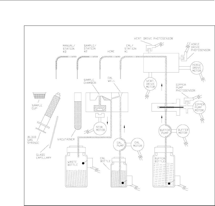
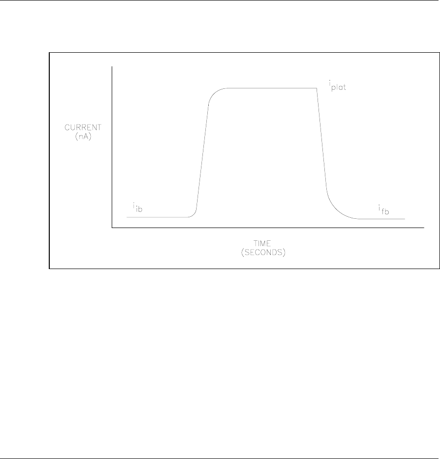
6-4
6.3 Measurement Methodology
The 2300 STAT PLUS employs a steady state measurement methodology. A typical sensor
response is shown in Figure 6.3.
Figure 6.3
Typical Sensor Response
When sample or calibration standard is dispensed into the chamber, it is diluted into 600
microliters of buffer. The sensor response increases and plateaus. After several seconds, the
buffer pump flushes the chamber and the sensor response decreases.
The net response is the difference between the plateau current (iplat) and the initial baseline
current (iib). Typical net responses for the 2300 STAT PLUS are between 10 and 25 nA
(nanoamps) for YSI calibration solutions. The maximum net probe current is about 500
nanoamps.
6.4 Baseline Stability
The 2300 STAT PLUS monitors the probe baseline current for nA activity and stability. If an
unstable baseline is detected, the buffer pump will continue to flush the sample chamber with
buffer. When a stable baseline is established, an automatic calibration is initiated.
After every calibration and sample, the final baseline current (ifb) is compared to the initial
baseline current (iib) during the flush cycle. If a significant shift is detected, the buffer pump
continues to flush. As soon as the baseline recovers, buffer flushing ceases and the instrument
performs its next command. There is a limit of about 3 minutes, at which time the instrument
displays a baseline error message.

6-5
6.5 Calibration
To maintain a sample ready status, the 2300 STAT PLUS self- calibrates. Calibrating
establishes the sensors’ response, in nanoamps of current, to a known concentration of
substrate.
The sensors calibration response must be above 5 nA. A response below this value will result in
an error.
The 2300 STAT PLUS self-calibrates when entering RUN Mode. While in RUN Mode, it
calibrates every 5 samples or 15 minutes. However, default calibration parameters can be
altered to tighten or loosen calibration specifications. In RUN Mode a manual calibration can
be initiated by pressing [CALIBRATE] or by remote control through an RS-232 interface.
A STABLE CALIBRATION IS IMPORTANT. The instrument re-establishes a calibration
reference point after every calibration. If a difference of more than 2% between the present and
previous net calibration currents occurs, the instrument repeats calibration. The sensors’ net
current for a calibration is displayed and printed. An unstable calibration is displayed and
printed as a "cal shift". While establishing a stable calibration, the 2300 STAT PLUS will run 5
calibrations before the error 'unable to calibrate' is displayed.
In summary, by the default calibration settings, recalibration will occur after every 5 samples or
15 minutes, after a calibration shift of 2% or greater, or after a sample chamber temperature
drift of more than 1°C. After 5 attempts without successfully calibrating, the instrument
displays a calibration error message.
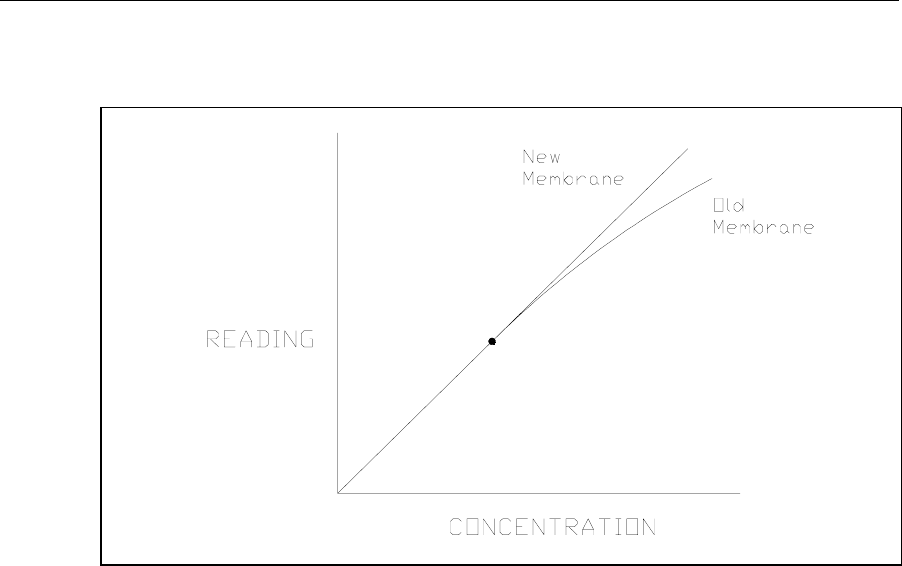
6-6
6.6 Linearity
As discussed in Section 6.1, a sensor consists of an electrode and an enzyme membrane. As a
membrane ages, its response becomes non-linear (shown in Figure 6.4).
Figure 6.4
Aging Membrane Response
Under optimal conditions the sensor response depends on diffusion limitation of the substrate.
When the substrate can diffuse at a greater rate than the enzyme can turnover product, enzyme
kinetics defines the response and nonlinearity is a symptom. This occurs as an enzyme
membrane ages.
It is necessary to periodically check sensor linearity. YSI offers linearity standards for all of the
recommended calibration values. See Appendix E–YSI Supplies and Reagents for product
information.

6-7
6.7 Temperature Compensation
The sensitivity of the sensors, in the 2300 STAT PLUS, varies with temperature changes. The
temperature probe in the sample chamber monitors the fluid temperature very near to the
enzyme sensor. The sample results are temperature corrected for the difference in temperature
between the sample and the calibration.
6.8 Level Sensing and Sipper Interference
The 2300 STAT PLUS employs capacitive level sensing on the Sipper and in the calibrator,
waste and supply bottles.
The Sipper level sensor detects the sample surface at the Test Tube Sample station and then
travels into the sample about 3 millimeters. This controlled immersion depth permits the use of
sample tubes that are filled to different heights without significant carry-over between samples.
This same technique can be employed when using the optional 2710 Turntable (See Section
10).
The Sipper and Arm Assembly should never be touched while the unit is in operation. As an
extra safety precaution, the Sipper detects contact with a conductive body, such as a hand. If a
conductive body is detected, the Sipper immediately stops, waits for several seconds and then
returns to the Sample Chamber.
The calibrator and supply bottles are monitored for low levels and the waste bottle is monitored
for high level. The capacitive method depends on close proximity between the bottles and the
metal chassis of the 2300 STAT PLUS. The bottles should always rest on the metal floor inside
of the instrument. It is also very important that the level sensor cables do not contact the metal
chassis.
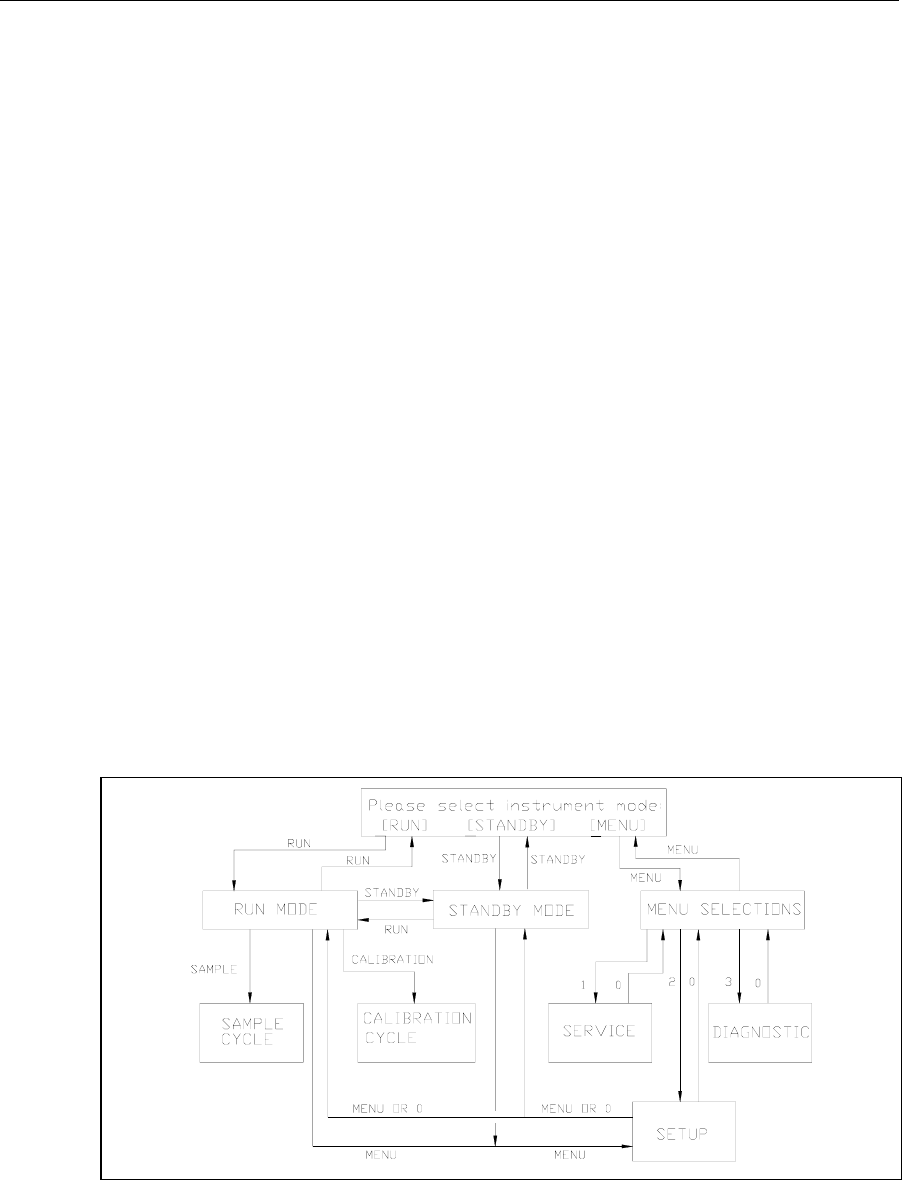
6-8
6.9 Software Structure
The 2300 STAT PLUS has two operation modes: RUN Mode, where calibration and sample
analysis occur and STANDBY Mode, where system power is on, but only a few maintenance
functions occur. This conserves reagents during extended periods of inactivity.
The 2300 STAT PLUS also has menu selections for service, setup and diagnostics. The Main
Menu of the software therefore provides three options: RUN, STANDBY, and MENU.
Figure 6.5 shows you how to move from one mode to another and how to access the different
functions within the menu selections and operating modes. The lines of progress are marked
with the name or number of the key you press to take that route.
Note that the RUN and STANDBY keys are toggle keys.
You may enter RUN Mode by pressing [RUN] and you may enter STANDBY Mode by
pressing [STANDBY]. You may switch back and forth from RUN Mode to STANDBY Mode
by using these keys and confirming your choice by pressing [ENTER].
To return to the Main Menu to have access to the full Menu options of Service, Setup and
Diagnostics, you must exit RUN Mode or STANDBY Mode by pressing [RUN] to exit RUN
Mode or pressing [STANDBY] to exit STANDBY Mode.
You have limited access to Setup options by pressing [MENU] from the RUN or STANDBY
modes. This enables you to correct the time or date, change report format or turn on a special
feature without leaving the operating mode. The only Setup selections not accessible from RUN
or STANDBY mode are "MeasParameter" and "Default", both of which allow you to change
parameters that could affect sample results leading to erroneous data.
For detail on menu selections see Section 5. For an overview see Figure 5.2, Menu Flow Chart.
2300 STAT PLUS Software Structure
Figure 6.5
2300 STAT PLUS Software Structure
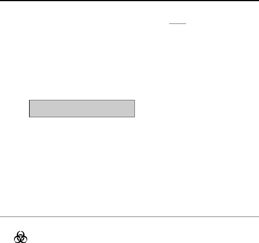
7-1
7. Maintenance
Before performing maintenance on the 2300 STAT PLUS, always exit RUN or STANDBY
Mode. While in these modes, the unit periodically calibrates or flushes. Servicing the fluid
system in either RUN or STANDBY Mode can lead to spills or air in the tubing.
To exit RUN Mode, press [RUN] and confirm your intent to exit by pressing [2] for Yes and
then [ENTER]. The Main Menu display will appear.
To exit STANDBY Mode, press [STANDBY] and confirm your intent to exit by pressing [2]
for Yes and then [ENTER]. The Main Menu display will appear.
Main Menu display:
Please select instrument mode
[RUN] [STANDBY] [MENU]
Preventive Maintenance
The YSI 2788 Preventive Maintenance Kit contains all supplies necessary to keep your 2300
STAT PLUS operating properly. Perform the Calibration Pumping System Maintenance detailed
in Section 7.2 at least once every month. Perform the maintenance procedures in Sections 7.3 to
7.11 every 6 months or as necessary. Section 7.9 Fuse Replacement is not preventive
maintenance, and obviously requires attention only when fuses fail. Section 7.5 Probe Cleaning
is not recommended unless problems related to the enzyme sensor system are indicated.
7.1 Daily Maintenance
Empty the Waste Bottle
Dispose of the waste bottle contents in a manner suitable for biohazardous waste. The reagents
used in the 2300 STAT PLUS are non-toxic and, unless otherwise specified, consist of a
phosphate salt buffer with small amounts of preservatives. Refer to reagent bottle labels and
Material Safety Data Sheets for more information.
Check the Calibrator Bottle
If the fluid level is low or the bottle has been in the instrument longer than 30 days, install a
new bottle of calibrator solution. Follow the instructions in Section 3.3 Reagent Preparation.
After installation, prime the Calibrator Well. From Main Menu, press [MENU]. See menu
information displayed below. Next press [1] for Service, then press [3] for Cal to initiate a 10
second run of the Cal pump.

7-2
Please select instrument mode
[RUN] [STANDBY] [MENU]
Select instrument function
1-Service 2-Setup 3-Diagnostic
Select service: 1-Sipper 2-Buffer 3-Cal
4-Stir speed 5-Turntable
Make certain that all air bubbles are out of the calibrator tubing when the new calibration
solution is pumped to the Calibrator Well. You may need to initiate a second run to insure the
delivery of calibrator solution to the Calibrator Well.
If the calibrator bottle cap assembly needs cleaning, make sure it is thoroughly rinsed and dried
before it is attached to a fresh bottle of calibrator solution.
Check the Buffer Bottle
Replace the buffer if the bottle is low or the buffer has been in the instrument longer than 1
week. Follow the instructions in Section 3.3 Reagent Preparation. You may find it convenient to
make more than one liter of buffer at a time, in order to have it on hand to replenish the buffer
bottle. Prepare it in a clean bottle with cap. You should store it at room temperature.
After a buffer change, prime the buffer system. From Main Menu, press [MENU]. See menu
information displayed above. Next press [1] for Service, then press [2] for Buffer to initiate a
15 second run of the Buffer pump. Make certain that all air is out of the buffer tubing. Buffer
should be exiting the Sipper inside the Sample Chamber and overflowing to waste. You may
need to initiate a second or third run of the buffer pump to complete the priming process.
Remember: The fluid level sensor cables should not contact the instrument housing. See Figure
3.3 for proper cable routing.
Check the Printer Paper
Open the Paper Cover on the top of the instrument and check to see that there is sufficient
paper. Replace the paper roll as necessary. See Appendix E for replacement part number. Use
the [PAPER] key to advance paper into the printer.
Check for Leaks
Examine the tubing for leaks. Also, check for large air bubbles in the tubing. These are caused
either by loose connections or worn pump tubing. Refer to Section 7.6 if tubing replacement is
needed.

7-3
Clean up Spills
Spills should be cleaned up promptly to prevent biohazard build-up and corrosion. Clean any
spills of biological material from the sample area.
If there is any evidence of salt build-up around the base of the sample chamber, follow the
procedure in Section 7.3 to disassemble the chamber and clean the base. Check that the drain
tube fits tightly over the fitting at the bottom of the chamber. If loose, replace the tubing.
Daily Operational Checks
To verify proper instrument performance, perform the daily operational checks described in
Section 4.4.
7.2 Calibration Pumping System Maintenance
Perform this procedure at least once a month, to minimize the possibility of contamination. The
most convenient time to perform this maintenance is before installation of a new bottle of
calibration standard at Station #1.
Exit Run or Standby Mode to prevent autoflushing and autocalibrations. This also allows you to
access Service Menu from the keypad.
Press [MENU], then [1], for Service.
Prepare about 100 mL of a nominal 1% solution of hypochlorite (1 part commercial bleach with
3 parts deionized or distilled water) and place this solution in a clean 250 mL bottle that has
threads compatible with the Cal Cap Assembly at Station #1.
Attach the Cal Cap Assembly, tighten, and shake gently to insure thorough washing of the
inside of the cap assembly.
From the Service Menu, initiate cal priming to flush hypochlorite solution through the pump
tubing and steel tubes to the Sample Chamber Waste Bottle. Repeat this flush cycle 3 times,
wait 10 minutes, then flush one more time.
Remove and discard the hypochlorite solution, then rinse the bottle thoroughly with water.
Next, add deionized or distilled water to the bottle, reattach the Cal Cap Assembly at Station
#1, and shake gently to thoroughly rinse the inside of the cal cap.
From the Service Menu, initiate 3 flushes to rinse the tubing and steel tubes with water.
Remove the Cal Cap Assembly, flush one time with air, and wipe the cal cap and steel tubes
with a clean laboratory tissue.
Install a new bottle of calibration standard and mark the installation date on the bottle as
described in Section 3.3 Reagent Preparation.
From the Service Menu, initiate 3 Cal flushes to prime the Calibration Pumping System. You
are now ready to re-enter Run Mode.

7-4
7.3 Sample Chamber Cleaning
It is necessary to periodically clean both the sample chamber and the base plate it sets on.
Move the Sipper to the manual sample position. From the Main Menu press [MENU]. Next
press [3] for Diagnostic, then press [1] for Motor, then press [1] for Sipper motor. Press [1] for
Up, to raise the Sipper from the Sample Chamber, then press [4] for Clockwise to move the
Sipper over to the Manual Sample position. Note: You must press [4] (Clockwise) twice to
reach the manual position. See the menu displays below to better understand this sequence of
events.
Please select instrument mode
[RUN] [STANDBY] [MENU]
Select instrument function
1-Service 2-Setup 3-Diagnostic
Select diagnostic
1-Motor 2-Pump 3-Probe 4-I/O 5-Sensor
Motor diagnostic
1-Sipper motor 2-Stir motor 3-Turntable
Sipper diagnostic: 1-Up 2-Down 3-Home
4-Clockwise 5-Counterclock 6-Exercise
Unscrew and remove all three probes from the sample chamber. If your membranes are in good
condition (that is, if they pass the tests in Section 4.4) it is not necessary to replace them. It is
important that the membranes do not dry out. If the chamber is to be disassembled from the
instrument for more than 15 minutes, the membranes should be replaced.
Unscrew the two thumb nuts on top of the sample chamber. Remove the sample chamber and
waste chamber from the base plate (see Figure 7.1).
You will need to disconnect the calibrator well tube and the drain tube. Be careful not to
discard the small magnetic stir bar. An extra one is supplied in your maintenance kit. Clean the
chambers with the appropriate disinfecting agent. After cleaning, flush the chambers with
copious amounts of warm water, then rinse with distilled water to remove any traces of the
disinfecting agent.
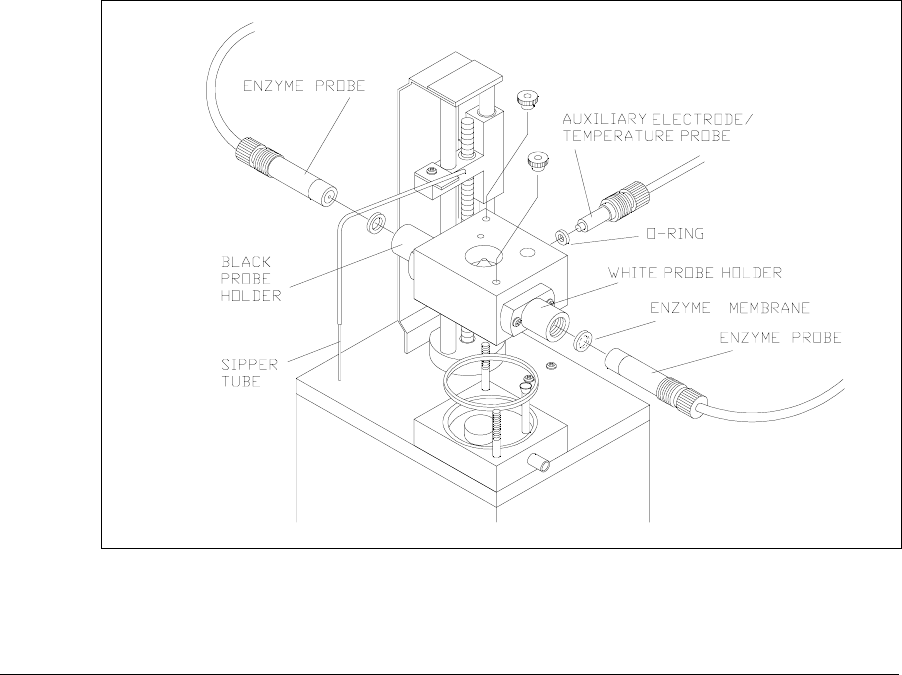
7-5
Clean up any salt deposits or fluid on the base plate. Be sure that the base plate and all other
parts are dry. Refer to Figure 7.1 and reassemble the chamber. Remember to return the stir bar
to the chamber and be sure to install the chamber seal O-ring. Insert the probes into the
chamber, installing new membranes (see Section 3.4) or O-rings as necessary. Extra O-rings are
supplied in your Preventive Maintenance Kit. Connect the calibrator well tube and drain tube.
Refer to Section 3.6 to check the Sipper alignment and prime the buffer and calibration
systems.
Figure 7.1
Sample Chamber Illustration
7.4 Membrane Replacement
To assure proper performance and prevent unexpected down-time, check membrane integrity
and linearity on a daily basis. Refer to Section 4.4 Daily Operational Checks for details. When
enzyme membrane installation is required, refer to Section 3.4 Enzyme Membrane Installation.
The typical working life of an enzyme membrane is three weeks for 2365 and two weeks for
2329. You may want to use the expected life as a guideline for scheduling replacement.

7-6
7.5 Probe Cleaning
With normal use, enzyme sensors may become fouled and cease to operate in a normal mode. A
fouled sensor’s output current will decrease and calibration may become unstable. Since the
severity of fouling will vary, listed below are methods of cleaning which should be matched to
the cleaning needs. Follow the steps carefully and in order.
Sensor Maintenance
It is necessary to maintenance the enzyme sensor when the 2788 PM kit is installed and
periodically as needed.
1. Remove the enzyme membrane and hold the probe with the electrodes facing up.
2. Wad a small portion of a lint free tissue and wet it with 70% isopropyl alcohol.
3. Using your thumb, press the alcohol soaked wad against the probe’s surface and rotate the
probe back and forth.
4. Rinse the sensor with reagent grade water and return the sensor to normal service.
Sensor Cleaning and Reconditioning
The following procedure is recommended to be used only when the enzyme sensor stops
operating normally and the above maintenance procedure is ineffective. This is not a routine
maintenance procedure.
1. With the membrane removed, immerse the sensor in a 14% solution of ammonia for 3
minutes.
2. Immediately after soaking, rinse the sensor with reagent grade water for 3-5 minutes. It is
important that all the residual ammonia is removed.
3. Prepare a small amount of 0.5% sodium hypochlorite solution.
4. Immerse the sensor in the solution for 30–45 seconds. Check periodically...sensor should
darken, but do not allow it to become black.
5. Remove the sensor and immediately rinse it with reagent water for at least 2 minutes.
6. Install a new membrane and return the probe to service.
The procedure below is only recommended as a last resort for revitalizing a sensor after the
above cleaning procedure has been unsuccessfully attempted.
WARNING: The following procedure may cause
permanent damage to the enzyme sensor.
1. Using a clean new pencil eraser, carefully, rub the center electrode (platinum) of the sensor.
Do not rub the epoxy between the two electrodes or the outer silver electrode.
2. To remove any eraser dust or residual, rinse sensor with 70% isopropyl alcohol and then
reagent grade water.
3. Prepare a small amount of 0.5% sodium hypochlorite solution.
4. Immerse the sensor in the solution for about 45 seconds.
5. Remove the sensor and immediately rinse it with reagent grade water for at least 2 minutes.
6. Install a new membrane and return the probe to service.
Note: Several hours may be required for the sensor to stabilize after cleaning.
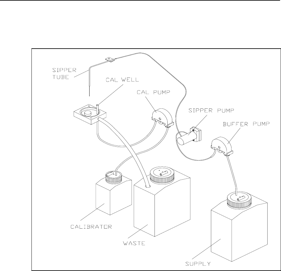
7-7
7.6 Tubing Replacement
The buffer and calibrator pumps in the 2300 STAT PLUS are peristaltic tubing pumps. The
tubing life depends on instrument usage. The pump tubes should be replaced at least every 6
months, more frequently if necessary. Other tubes become loose at the fittings and should also
be replaced every 6 months.
Figure 7.2
Tubing Connections
Remove the screws holding the buffer and calibrator pumps to the instrument wall and remove
the pumps. Remove the front housing from each pump by pulling it out at the bottom. Remove
the roller assembly and tubing from each pump. Disconnect and remove all the instrument
tubing. New tubing is supplied in the Preventive Maintenance Kit. Connect the new tubing as
shown in Figure 7.2.
When installing new pump tubing, insert the roller assembly into the rear pump housing (rollers
facing out). Starting on one side, place the tubing between the pump housing and roller as
shown in Figure 7.3.
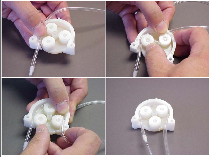
7-8
Figure 7.3
Pump Tubing Installation
Make sure that the correct length of tubing is sticking out of the pump (1 to 1½″ [2.5 to 3.5 cm]
of the large diameter tubing on the left side of the buffer pump), then rotate the roller assembly
while pushing the tubing down into the pump ahead of the roller. Once the tubing is installed in
the pump, insert that tab on the rear pump housing into the slot at the top of the front pump
housing (see Figure 7.4). Lower the front pump housing while guiding the tubing into the slots
at the bottom. Gently squeeze the two housings together, while pushing up on the roller
assembly.
Align the slot in the rear of the pump with the motor shaft, then slide the pump onto the shaft.
Remount the pump to the instrument wall using the mounting screws (pull up on the pump to
ease installation of the screws).
Remember to install the tube bushing on the right side of the pump.
1
3
2
4
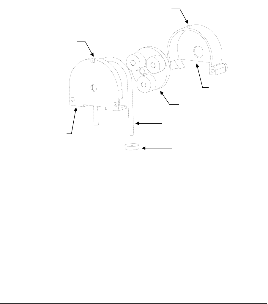
7-9
Figure 7.4
Pump Assembly
When all tubes are properly connected, see Section 3.6 to readjust the Sipper and prime the
calibrator and buffer systems.
7.7 Sipper Replacement
The Sipper can be damaged if it is not properly aligned or if its alignment is disturbed. If your
Sipper needs replaced, remove the screw that mounts it to the sipper arm, disconnect the tubing
and remove the Sipper. Install the new Sipper. Reconnect the Sipper ground cable and tubing to
the new sipper. Refer to Section 3.6 to readjust the Sipper.
7.8 Sipper Ground Cable
The Sipper Ground Cable flexes with every sample. After several thousand samples, the cable
may break. To prevent unexpected down time, replace this cable every 6 months. Extra cables
are supplied in the Preventive Maintenance Kit.
Pull the connector out of the printed circuit board on the Sipper Arm. Remove the terminal end
of the cable from under the Sipper mounting screw. Install a new cable. Refer to Section 3.6 to
readjust the Sipper.
Roller Assembl
y
Rear Housin
g
Tubing
Tube Bushing
Slot
Tab
Front
Housing
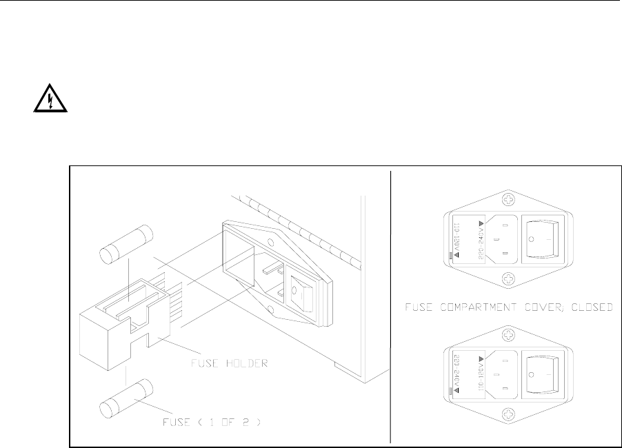
7-10
7.9 Fuse Replacement
It may be necessary to replace the fuses in the 2300 STAT PLUS. New fuses may be purchased
from YSI, or obtained from many local electrical component suppliers. Be sure to obtain the
correct fuse rating as indicated below.
WARNING: UNPLUG THE INSTRUMENT FROM THE MAINS SUPPLY.
Using a small screwdriver, pry open the fuse holder on the power receptacle (see Figure 7.5).
110-120V Selected
220-240V Selected
Figure 7.5
Fuse Replacement
Fuse Requirements
Fuse Type: 110-120 VAC Operation -- 1 Amp (YSI #062443, Fast acting)
3AG, 250 volt, 0.25D x 1.25L inches
For Europe and UK use fuse type:
220-240 VAC Operation -- 1/2 Amp (YSI #019722)
Anti-surge(T), 250 volt, 5mm x 20mm (L), IEC127 & BS4265
Install new fuses in place of the old ones and return the fuse holder to the power receptacle. Be
certain the correct voltage is selected. The arrowhead on the power selector must be pointing to
the small rectangle on the housing, as shown (inset).
With the power switch in the off (O) position, plug the power cord into the instrument and then
into the power mains. Refer to Section 3.5 Power Up Procedures to confirm correct power up
response.
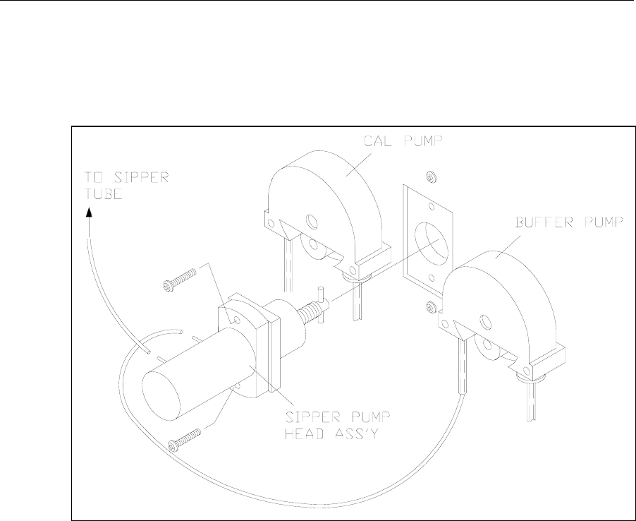
7-11
7.10 Sipper Pump Seal Replacement
Replace the Sipper Pump seals every 6 months. Heavy usage may warrant more frequent
replacement.
Disconnect the tubings to the Sipper Pump. Remove the Sipper Pump head from the instrument
wall (see Figure 7.6).
Figure 7.6
Sipper Pump Head Removal
Pull the white pump base from the clear pump housing. If salt deposits have formed on the
parts, wash them off with warm water. Replace the seals as shown in Figure 7.6. Extra seals are
supplied in the Preventive Maintenance Kit.
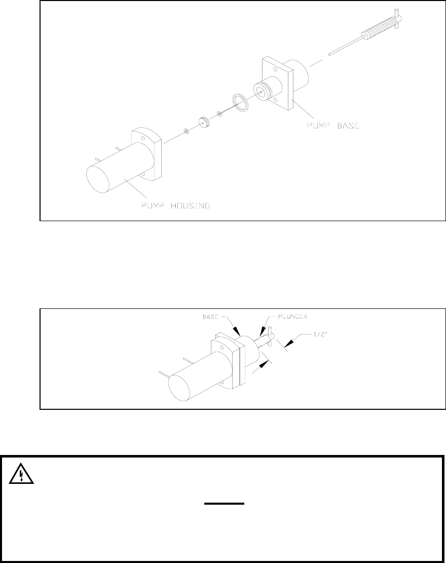
7-12
Figure 7.7
Sipper Pump Seal Replacement
Reassemble the pump, position the plunger as shown in Figure 7.8 and install it back on the
instrument.
Figure 7.8
Sipper Pump Plunger Position
WARNING: When re-installing the pump head
assembly, the plunger MUST extend at least ½″ from
the base of the pump (see Figure 7.8). This will assure
proper alignment between the pump head and the
drive hub.
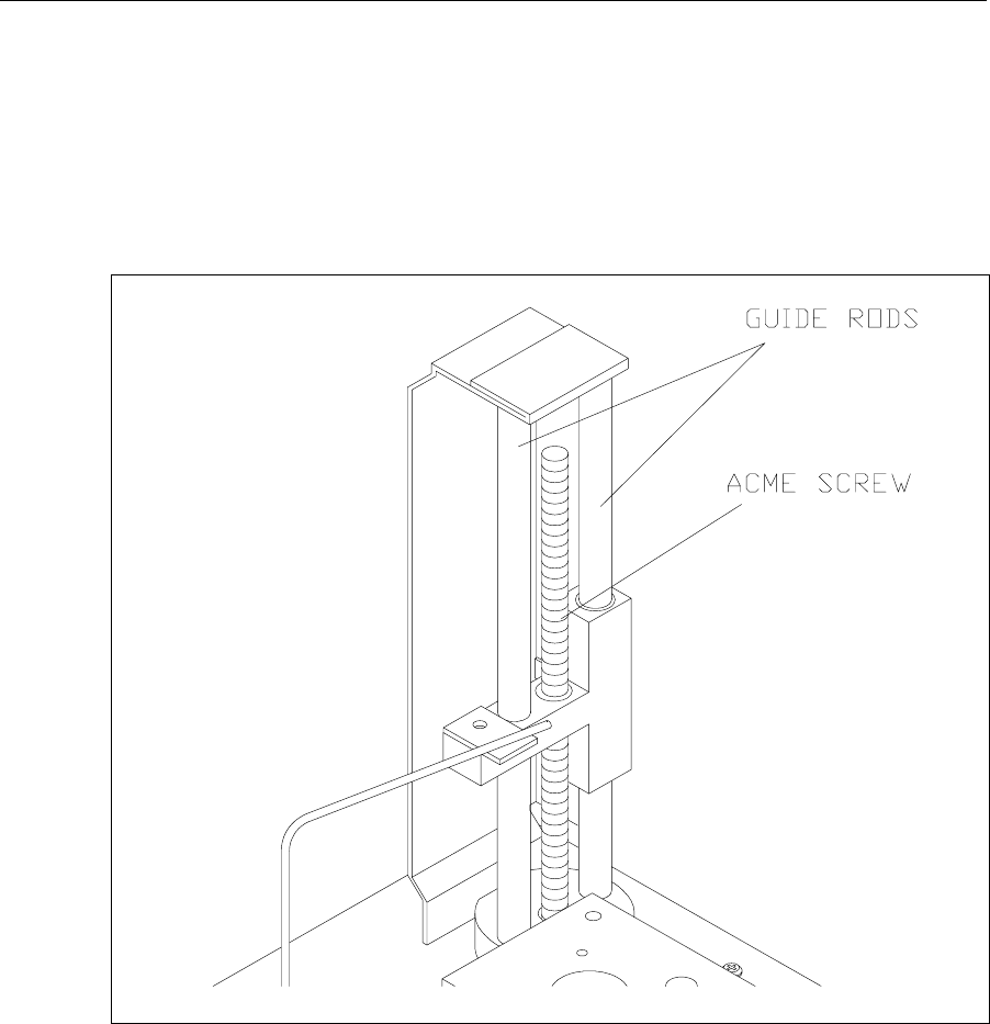
7-13
7.11 Sipper Mechanism Lubrication
The sipper mechanism needs only occasional cleaning and lubrication. If the acme screw and
guide rods are reasonably clean and have a thin film of lubricant on them, no further
maintenance is required. If the screw or either rod has a dirt build-up, or if the mechanism
squeaks or jams, then clean the screw and guide rods with a lint-free towel. Apply Lubriplate
105 grease (supplied in YSI 2788 Preventive Maintenance Kit) to two or three threads of the
Acme screw. Normal operation will distribute the grease along the length of the screw.
Lubricate each guide rod with a drop of light machine oil. Wipe off any excess lubricant
promptly.
Figure 7.9
Sipper Mechanism Drive Screw and Guide Rods
7-14

8-1
8. Troubleshooting
This section provides a systematic approach to establishing the cause of an instrument
malfunction. Before taking any corrective action, be certain you have collected as much
pertinent information as possible.
To establish probable cause, you should:
» Review the printed reports for trends in data and errors. Use the detailed format, if
possible, to obtain as much information as possible. An explanation of the report data is
covered in this section.
» Check reagent and membrane installation dates. Compare the elapsed time to the
recommended time.
» Look and listen for problems (fluid leaks, salt build-ups, air bubbles in the chamber,
loose connections, noisy components, etc.).
» Review Section 5.4 Diagnostic Selections to learn more about how you can test
individual components of the 2300 STAT PLUS.
» Use the troubleshooting chart in this section to assist you in identifying the problem,
then use the chart to guide you to a corrective action.
If the problem cannot be resolved, contact YSI Customer Service (address and phone
information in Appendix F–Warranty and Shipping Information). When communicating with
service personnel, please indicate the serial number of the instrument. If writing or transmitting
a FAX for assistance, please include a thorough description of the problem and copies of
printouts, if possible.

8-2
8.1 Printout Information
Refer to Appendix J–Report Formats to learn more about report format options for the 2300
STAT PLUS. For troubleshooting, or even daily log information, the "detail" report format is
preferable.
The Detail Report provides a complete description of the sensors for a calibration or sample.
Information for both the black and white probes, as well as the temperature probe, is included.
You may access the report format level without exiting RUN or STANDBY modes. Press
[menu] on the keypad to display the Select setup menu level. Press [4] for Report to change or
confirm sample and calibration formats.
Listed below are example printouts and explanations of the Detail format information.
Sample Report (Detail) Calibration Report (Detail)
-----Sample Report----- ==CALIBRATION REPORT==
ID: 123456789-05-03 B:Lactate * Unstable *
B:L-Lactate 4.82 mmol/L IB current 1.79 nA
IB current 2.11 nA PL current 11.63 nA
PL current 118.65 nA FB current 1.51 nA
Slope 4.6 nA/min *Base shift -2.65 %
End Point 35 Sec Slope 1.42 nA/min
W:Glucose 8.3 mmol/L End Point 35 Sec
IB current 0.88 nA *Cal shift 3.64 %
PL current 58.96 nA W:Glucose 10.0 mmol/L
Slope 2.39 nA/min IB current 0.88 nA
End Point 35 Sec PL current 5.81 nA
Temperature 26.28 °C FB current 0.76 nA
Sample size 25 uL Base shift -1.95 %
Fri 02/22/03 08:12:34 Slope 0.09 nA/min
YSI 2300D - 03 01234 End Point 35 Sec
----------------------- Cal shift -0.10 %
Temperature 26.33 °C
Sample size 25 uL
Thu 02/22/03 14:55:10
YSI 2300D - 03 01234
=======================
8-3
IB current (Initial Baseline Current). The initial baseline current is monitored before a sample
or calibration and while stabilizing baseline current upon entering RUN Mode. To successfully
enter RUN Mode, the IB current must be stable and below 6 nA.
PL current (Plateau Current). The minimum acceptable plateau current is 5 nA. The maximum
plateau current is 500 nA. A plateau current larger than this will be printed as a string of
asterisks '*****'.
FB current (Final Baseline Current). The final baseline current is printed for calibrations and
samples. The baseline current is monitored during the buffer flush and compared to the initial
baseline current.
Base shift (Baseline Shift). The final and initial baselines are compared and reported as percent
shift. A negative baseline shift is not uncommon with newly-installed membranes. High
concentration samples may yield positive baseline shifts. An excessive positive shift can be an
indicator of the presence of an interfering substance. The message 'Final baseline error' is
printed when the instrument can not adequately flush the chamber.
Slope (Slope of the plateau). See Figure 6.3. The slope is reported in nanoamps per minute. A
newly-installed membrane may have an elevated plateau slope. An excessive slope can be an
indicator of the presence of an interfering substance.
End Point is the time from dispensing the sample into the sample chamber until the instrument
reads the probe signal. The default value is 35 seconds (Normal Mode). The Screen Mode value
is 15 seconds. This value is displayed in the report. Note: This is not through-put time, but
rather best thought of as "reaction" time or "probe signal development" time.
Cal shift (Calibration Shift). A calibration result is compared to the previous calibration result
and the percent shift is reported. The default setting is 2%. That is, if the shift is greater than
2%, the 2300 STAT PLUS performs another calibration. Up to 5 successive calibration shifts
are permitted before the 'Unable to calibrate' error is displayed. Excessive calibration shifts may
be caused by faulty membranes, newly-installed membranes or air in the sample chamber.
Temperature (Sample Chamber Temperature) The sample chamber temperature is measured
during a calibration and a sample. The results of a sample are temperature corrected. The 2300
STAT PLUS works at sample chamber temperatures between 15° and 35°C. The 2300 STAT
PLUS only measures and displays temperatures between 10° and 40°C. If the temperature is
outside this range, a string of asterisks '*****' will be printed.

8-4
8.2 Troubleshooting Chart
SYMPTOM: ERROR: Baseline
POSSIBLE CAUSE: Pinched, leaking or disconnected tube.
ACTION: Fix or replace tubing.
SECTION: 7.6
POSSIBLE CAUSE: Sipper misaligned.
ACTION: Check Sipper alignment.
SECTION: 3.6
POSSIBLE CAUSE: Buffer pump not operating properly.
ACTION: Replace tubing.
SECTION: 7.6
POSSIBLE CAUSE: Stir bar not in chamber.
ACTION: Disassemble chamber and reinstall stir bar.
SECTION: 7.3
POSSIBLE CAUSE: Newly installed enzyme membrane.
ACTION: Enter probe diagnostics and check probe currents.
SECTION: 3.6
POSSIBLE CAUSE: Newly installed probe.
ACTION: Enter probe diagnostics and check probe currents.
SECTION: 3.6
POSSIBLE CAUSE: Power disruption.
ACTION: Enter probe diagnostics and check probe currents.
SECTION: 3.6
POSSIBLE CAUSE: Failing enzyme membrane.
ACTION: Perform daily operational checks and replace membrane(s)
if necessary.
SECTION: 4.4, 3.4
POSSIBLE CAUSE: Enzyme Probe surface(s) fouled.
ACTION: Clean probe surface(s).
SECTION: 7.5
POSSIBLE CAUSE: Temperature Probe (auxiliary electrode) fouled.
ACTION: Clean probe surface.
SECTION: 7.5
POSSIBLE CAUSE: Sample may contain an interfering substance.
ACTION: Attempt to confirm interference.
SECTION: Appendix C–Effects of Selected Substances
SYMPTOM: ERROR: Empty Buffer Bottle
POSSIBLE CAUSE: Low buffer level.
ACTION: Refill the buffer.
SECTION: 3.3

8-5
SYMPTOM: ERROR: Empty Buffer Bottle (Continued)
POSSIBLE CAUSE: Level sensor cable not plugged in.
ACTION: Plug in cable.
SECTION: 3.3
SYMPTOM: ERROR: Empty Calibrator Bottle
POSSIBLE CAUSE: Low calibrator level.
ACTION: Install new calibrator.
SECTION: 3.3
POSSIBLE CAUSE: Level sensor cable not plugged in.
ACTION: Plug in cable.
SECTION: 3.3
SYMPTOM: ERROR: Full Waste Bottle
POSSIBLE CAUSE: High waste level.
ACTION: Empty bottle.
SECTION:
POSSIBLE CAUSE: Level sensor cable in contact with instrument housing or
another conductive body.
ACTION: Reroute cables.
SECTION: 3.3
SYMPTOM: ERROR: Motor Failure
POSSIBLE CAUSE: One of the motors is jammed.
ACTION: Enter motor diagnostics and cycle the suspected motor.
SECTION: 5.4
POSSIBLE CAUSE: Dirty drive screw on sipper mechanism.
ACTION: Clean and lightly oil.
SECTION: 7.11
POSSIBLE CAUSE: Worn sipper pump seals.
ACTION: Replace seals.
SECTION: 7.10
SYMPTOM: ERROR: Overrange
POSSIBLE CAUSE: Sample concentration to high, resulting in high probe nA.
ACTION: Dilute sample and repeat.
SECTION:
SYMPTOM: ERROR: Printer Failure Detected
POSSIBLE CAUSE: Printer paper or roll jam.
ACTION: Open paper well and clear obstruction. Reset instrument,
if required.
SECTION: 3.6

8-6
SYMPTOM: ERROR: Sample Chamber Temperature Out of Range
POSSIBLE CAUSE: Ambient temperature too cold or hot.
ACTION: Operate at ambient temperatures between 15 and 35 degrees C.
SECTION:
SYMPTOM: ERROR: Sipper Interference or Fault in Fluid Level Detector
POSSIBLE CAUSE: Sipper detects a conductive body.
ACTION: Repeat sample.
SECTION:
SYMPTOM: ERROR: Test Tube Interference
POSSIBLE CAUSE: Sample tube holder not in position.
ACTION: Reposition and repeat sample.
SECTION:
SYMPTOM: ERROR: Unable to Calibrate
POSSIBLE CAUSE: Pinched, leaking or disconnected tube.
ACTION: Fix or replace tubing.
SECTION: 7.6
POSSIBLE CAUSE: Sipper misaligned.
ACTION: Check Sipper alignment.
SECTION: 3.6
POSSIBLE CAUSE: Stir bar not in chamber.
ACTION: Disassemble chamber and reinstall stir bar.
SECTION: 7.3
POSSIBLE CAUSE: Newly installed enzyme membrane.
ACTION: Enter probe diagnostics and check probe currents.
SECTION: 3.6
POSSIBLE CAUSE: Newly installed probe.
ACTION: Enter probe diagnostics and check probe currents.
SECTION: 3.6
POSSIBLE CAUSE: Calibrator solution out of spec: contaminated or installed for
more than 30 days.
ACTION: Install new calibrator.
SECTION: 3.3
POSSIBLE CAUSE: Net calibration current (PL current) below 5 nA.
ACTION: Replace enzyme membrane and check calibrator solution.
SECTION: 3.4

8-7
SYMPTOM: ERROR: Unable to Calibrate (Continued)
POSSIBLE CAUSE: Failing enzyme membrane.
ACTION: Perform daily operational checks and replace membrane(s)
if necessary.
SECTION: 4.4, 3.4
POSSIBLE CAUSE: Probe surface fouled.
ACTION: Clean probe surface.
SECTION: 7.5
POSSIBLE CAUSE: Temperature Probe (auxiliary electrode) fouled.
ACTION: Clean probe surface.
SECTION: 7.5
SYMPTOM: ERROR: Undetectable Fluid
POSSIBLE CAUSE: Low calibrator solution.
ACTION: Install new calibrator.
SECTION: 3.3
POSSIBLE CAUSE: Pinched, blocked, leaking or disconnected tube.
ACTION: Fix or install new tubing.
SECTION: 7.6
POSSIBLE CAUSE: Calibrator pump not operating properly.
ACTION: Replace tubing.
SECTION: 7.6
POSSIBLE CAUSE: Low sample level.
ACTION: Run sample at manual position.
SECTION:
SYMPTOM: Blank Printout
POSSIBLE CAUSE: Printing on wrong side of paper.
ACTION: Install paper correctly.
SECTION: 3.7
POSSIBLE CAUSE: Using wrong type of paper.
ACTION: Install correct thermal paper (YSI 2751).
SECTION: 3.7
SYMPTOM: Fail FCN Test
POSSIBLE CAUSE: Damaged or old membrane.
ACTION: Replace membrane.
SECTION: 3.4

8-8
SYMPTOM: Fail Linearity Test
POSSIBLE CAUSE: Probe assignment incorrect.
ACTION: Make correct assignment.
SECTION: 3.8
POSSIBLE CAUSE: Damaged or old membrane.
ACTION: Replace membrane.
SECTION: 3.4
POSSIBLE CAUSE: Contaminated or old calibration or linearity standard.
ACTION: Repeat test with new standards.
SECTION: 4.4
SYMPTOM: Keypad Disabled
POSSIBLE CAUSE: Instrument in Remote Control Mode.
ACTION: Switch communications mode or reset.
SECTION: 9.3
POSSIBLE CAUSE: Faulty keypad or cable.
ACTION: Check keypad in I/O diagnostics.
SECTION: 5.4
SYMPTOM: Printer Does Not Advance
POSSIBLE CAUSE: Paper or roll jammed.
ACTION: Open paper well and clear obstruction. Reset instrument
if necessary. If printer still does not advance, turn instrument off
for 30 seconds, then back on.
SECTION:
SYMPTOM: Sipper Does Not Enter Chamber
POSSIBLE CAUSE: Sipper misaligned.
ACTION: Check alignment.
SECTION: 3.6
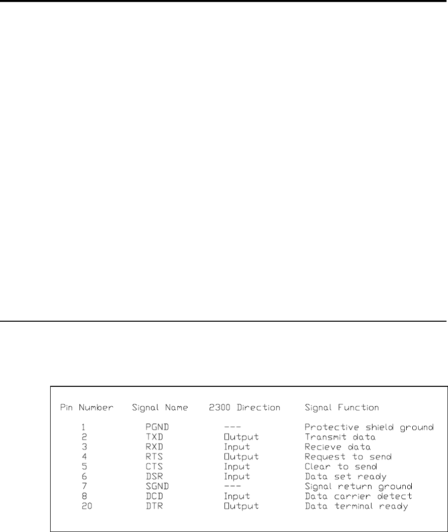
9-1
9. Communications
This section describes the communications protocol between the 2300 STAT PLUS and a host
computer. The 2300 STAT PLUS has an RS-232 serial port. When you install the appropriate
hardware interface (e.g., shielded NULL modem cable), the 2300 STAT PLUS communicates in
ASCII over this interface.
The protocol used by the 2300 has been designed to be compatible with most computer
database applications and most computer interface protocols. The 2300 STAT PLUS can be
configured to communicate in Result Reporting mode or Remote Control mode.
The communications module also provides networking capability. You may configure a 2300
STAT PLUS to operate in either multidrop or non-multidrop environments. Multidrop refers to
networking several 2300s and/or other controllers to a host, while non-multidrop (point-to-
point) refers to a single 2300 connected to a host/controller. Multidrop is targeted primarily to
the bioprocessing marketplace and would rarely be used in a hospital clinical setting.
In sections below you will learn about communications handshaking, software setup, command
structure, communication modes and data base format.
Note: The term "2300 STAT PLUS" has been shortened to "2300" in many sentences and
figures below. They are synonymous.
9.1 Communications Protocol
The 2300 communicates with a host computer through its RS-232 serial port, acting as a DTE.
The handshaking can be hardware or software configured. The method is user-selectable.
Figure 9.1 shows the RS-232 signal descriptions and directions with respect to the 2300.
Figure 9.1
RS-232 Signal Description and Direction
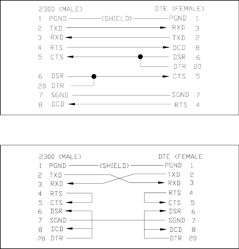
9-2
Hardware Handshaking Signals. The four handshaking signals used to control the data flow
are RTS/CTS and DTR/DCD. The 2300 drives RTS when it wishes to transmit and waits for
CTS before transmitting each character. Likewise, the 2300 asserts DTR when it is ready to
receive data and receives only when DCD is asserted. DSR is not used.
Software Handshaking Signals. In the XON/XOFF handshaking protocol, RTS and DTR are
always asserted and CTS and DCD are always ignored.
Since the 2300 acts as a DTE, it requires a shielded NULL modem cable to connect to another
DTE, such as the PC. Figure 9.2 and Figure 9.3 show possible NULL modem cable
connections.
Figure 9.2
Full Handshaking DTE Interface
Figure 9.3
Three Wire DTE Interface
9-3
You can select the 2300 handshaking protocol, RTS/CTS or XON/XOFF. In addition, you can
select baud rate, data length (bits per character), parity, stop bit, and configuration (multipoint
or point-to-point). For information on communications setup, see Section 5.3 Setup Selections.
The communications menu is a submenu of General setup.
Listed below are the default settings and options for each communications parameter mentioned
above. The default value is listed first. The options are in parentheses.
Baud rate: 9600 (4800, 2400, 1200, 600, 300)
Data Length: 7 (8)
Parity: Even (odd, low, high, none)
Stop Bit: 1 (2)
Handshake: RTS/CTS (XON/XOFF, None)
Configuration: non-multidrop (multidrop)
Data and Command Format. The 2300 behaves like a "slave" to the host computer. It never
talks to the host unless in response to a command from the host. The 2300 will respond with an
ASCII < BEL> followed by the display of an error code, or "?" for an illegal command.
A command is defined to be a string of printable upper case ASCII characters. Blanks are
ignored.
Command Grammar. The command grammar is shown below. Abbreviations include ESC
(escape), cmd (command), addr (address), arg (argument) and cr (carriage return).
< ESC> &< cmd> [arg]< cr> (non-multidrop)
< ESC> < addr> < cmd> [arg]< cr> (multidrop)
In this grammar, < addr> is a single byte (binary) node address that you assign to the 2300
STAT PLUS. You make the assignment via the instrument keypad. The 2300 STAT PLUS only
responds to commands with the < addr> field that matches the assigned address.
A command may require one or more arguments. If multiple arguments are given, they must be
separated by a semicolon (;). Two consecutive semicolons indicate a NULL argument, in which
case, depending on the command, a default parameter is supplied.
The 2300 responds to a legal command with a status acknowledgment (A), or an error code
(1,2,6,7,8 or 9) The interpretations of the status characters are discussed under Communications
Commands, Remote Control Commands.
9-4
Error Codes
Code 1 indicates that the 2300 is not in remote control mode.
Code 2 indicates that the 2300 is busy in RUN mode.
Code 6 indicates that the assignment of station # is out of range (s< 1 or s> 4).
Code 7 means that Station #5 was requested. Station #5 is not available in the 2300 STAT
PLUS software.
Code 8 indicates a zero turntable position number (t, n = 0 or default t, n = 0).
Code 9 may mean that sample or calibration results were not found when requested or it may
mean that the 2300 is not in RUN mode. You may need to check 2300 status to
determine the exact meaning of the error. See Section 9.3 Communications Commands
for more information.
The internal receiver buffer in the 2300 is 80 characters long. A string longer than 80 characters
without the terminating CR., will cause this buffer to overflow. When this occurs, the 2300 will
reset the receiver buffer, ignore the previous 80 characters and start to receive the new
command. Most commands are 2 or 3 characters long. Thus, there is no real restriction with this
buffer size.

9-5
9.2 Communications Modes
The 2300 can be placed in one of two communications modes: Result Reporting Mode or
Remote Control Mode. The selection between modes is made by the remote host. The default
mode at power-up is Result Reporting Mode.
2300 Data Base. The 2300 keeps a data base of 32 sample results and 1 calibration result in its
battery-backed RAM (random access memory). Only the most recent sample or calibration
result is shown on the instrument display. However, a remote host can ask for any of these
results at any time. This data base can be cleared by the host in Remote Control Mode (see
Section 9.3 Communications Commands).
Result Reporting Mode. Result Reporting Mode is designed for use with a computer system
that gathers sample results from various analyzers and records the results in a central data base.
In this mode, the host can always talk to the 2300 and get the result records.
The host requests the results by either sending the sample ID number and getting the result
record or by querying the unit for any untransmitted result in the data base.
Remote Control Mode. Remote Control Mode is designed primarily for industrial and research
applications where process control may be an important consideration.
In Remote-Control mode, the instrument is in RUN Mode and under control of the host
computer. The instrument keypad is disabled; thus, the operator can not run a sample or
calibration locally at the 2300.
The host tells the 2300 to run a sample or a calibration. The samples are typically assigned to
run at Station #2 (Test Tube Holder), but may be assigned to Station #4 for turntable sampling.

9-6
9.3 Communications Commands
Data Transmission Records. The data report format from "2300 to HOST" is transmitted as
shown in the example below. Information includes:
» time
» date
» temperature (sample chamber)
» node address (re: multidrop mode; instrument identification)
» ID (sample identification number)
» chemistry (assigned to probe)
» value (sample or calibration reading)
» unit of concentration (nA current for calibrations)
» error codes
Notes:
A "-1" in the ID column specifies calibration report.
A "-2" in the ID column specifies STAT-interrupt report.
A "-3" in the ID column specifies parameter information request.
A back-slash "\" in the column preceding the carriage return < CR> indicates that more
information from that reading continues on the next line.
If two lines of information are combined, the first is black probe data, the second is white probe
data. In single channel units, this will not be a concern.
Time Date Temp ID Chem Value Unit Err
10:00:11 02/12/90 25.05 -1 LAC -123.45 nA 0001\ < CR> < LF>
10:02:35 02/12/90 25.01 -1 GLU 201.23 nA 0000 < CR> < LF>
10:06:59 02/12/90 25.15 12345 LAC 12345.67 mmol/L 0000\ < CR> < LF>
10:06:59 02/12/90 25.15 12345 GLU 1234 mmol/L 0000 < CR> < LF>
10:07:10 02/12/90 25.15 0 LAC 23 mg/L 0000\ < CR> < LF>
10:07:10 02/12/90 25.15 0 GLU 1234 mg/L 0000 < CR> < LF>
10:00:11 02/12/90 25.05 -1 LAC 123.45 nA 0000\ < CR> < LF>
10:02:35 02/12/90 25.02 -1 GLU 201.23 nA 0000 < CR> < LF>
10:07:10 02/12/90 25.15 123 GLU 1234 mg/L 010F\ < CR> < LF>
Figure 9.4
2300 STAT PLUS Data Report Format
NOTE: The specific information above is not intended to appear realistic, but rather to account
for all characters and spaces in the report format. See Figure 9.5 for specific field location
information.

9-7
123456789| 123456789| 123456789| 123456789| 123456789| 123456789| 123456789| 12345
11:11:11 22/22/22 33333 444 555555555 6666 77777777 88888888 9999\ < cr> < lf>
11:11:11 22/22/22 33333 444 555555555 6666 77777777 88888888 9999 < cr> < lf>
FIELD OFFSET WIDTH DESCRIPTIONS
NO. COLUMN (BYTE)
01 01 08 Time
02 10 08 Date
03 19 05 Temperature
04 25 03 Node Address
05 29 09 Sample ID: 0 = no ID
-1 = Cal Report
-2 = STAT-interrupt Report
-3 = Information Report
06 39 04 Probe Chemistry Assignment:
None*** no chemistry
GLU Glucose
LAC L-Lactate
07 44 08 Sample or Calibration Result
08 53 08 Sample or Calibration Concentration Unit
09 62 04 Error Code (hexadecimal)
10 66 01 Continuation character:
‘\’ more data follows
<space> end of record
Figure 9.5
Report Format Field Information
9-8
Command Description. For quick reference, the communications commands are divided into
five functional groups: process, report database, database management, control, and report
system information. For details on process commands, see "Remote Control Commands", later
in this section.
PROCESS
PC Process calibration
PS1 Process sample from calibration well (Station #1)
PS2 Process sample from test tube holder (Station #2)
PS4 Process turntable batch (Station #4)
REPORT DATABASE
RC Report calibration result
RS Report sample result
RS# Report sample result with sample ID number
RY Report status of instrument
RX Report last transmission
DATABASE MANAGEMENT
RZ Clear database memory
CONTROL
TR0 Turn remote control off
TR1 Turn remote control on
TP0 Turn 2300 printer off
TP1 Turn 2300 printer on
PA Abort Turntable Sampling
REPORT SYSTEM INFORMATION
V0 Report instrument model number
V1 Report software version number
V2 Report software revision date
RM Report system time, date and measurement parameters
RI Report instrument setup information

9-9
Common Commands. The commands below can be invoked in either Remote Control Mode
or in Result Reporting Mode, unless otherwise stated. Available commands are those in Report
Database and Report System Information categories above.
When Report Status (RY) is invoked, the command obtains the 2300 status. The status
includes communications mode, sample result status, calibration result status, machine status
and remote command status. Below is a summary of responses and the interpretations.
Host to 2300: RY Report status of instrument
2300 to Host:
Communications mode R Result reporting mode
C Remote control mode
— Unknown
Sample status result U Results exist not sent to host
N No unsent results
Calibrate status result U Last cal not sent to host
N No unsent calibration results
Machine status I Idle in Run Mode
S Processing sample
C Processing calibration
A Processing autocalibration
M Processing manual sample
F Flushing and aborting error cycle
B Stabilizing baseline current
K Stabilizing calibration current
E Stabilizing motors
H Aborting Run Mode
R In Run Mode
S In Standby Mode
D In Main Menu Mode
Remote command status I Idle, no pending command
S Sam command recvd. Pending
C Cal command recvd. Pending
— Unknown
An example status line may appear as follows:
CNUII
The information stated is that the 2300 is under remote control (C), no sample results are in
memory (N), calibration results remain unsent (U), the 2300 is idle in Run mode (I) and there
are no remote commands pending (I).
9-10
When Report Last Transmission (RX) is invoked, the last transmission of the 2300 is sent to
the host. It is used when the response received by the 2300 contains an unknown character, is
not in the correct format, or whenever in doubt due to communications error.
Host to 2300: RX Report last transmission
2300 to Host: [last transmitted record]
When Report Calibration Result (RC) is invoked, the 2300 sends back time, date, chamber
temperature, probe chemistry and probe current from the last calibration cycle. The calibration
cycle may be a user-activated calibration cycle, a computer-demanded cycle or an
autocalibration cycle. If no result is found, the 2300 sends back error code "9".
Host to 2300: RC Report last calibration result
2300 to Host: [cal result] (see format Fig 8.4)
When Report Sample Result (RS) is invoked, the 2300 sends back the last sample processed.
When combined with an ID number, the 2300 searches its database and sends back the most
recent matching ID result. After the result has been transmitted, its entry in the database is
marked as sent. Another request for the same sample ID result will cause the 2300 to send the
next most recent result for the matching ID result. If no result is found, the 2300 sends back
error code "9".
If the host has received the result in error due to a data transmission error, it should request
retransmission using the RX command.
Host to 2300: RS Report last sample result
2300 to Host: [sam result] (see format Fig 8.4)
Host to 2300: RS< ID> Report sam ID result
(max = 9 digits)
2300 to Host: [sam result] (see format Fig 8.4)
Remote Control Commands. The commands outlined above in the "Process" category can be
invoked only in Remote Control Mode. If the system is not in the Remote Control Mode, you
must first invoke the Turn Remote Control On (TR1) command.
Host to 2300: TR1 Turn on remote control mode
2300 to Host: A Acknowledge. 2300 switched to Remote
Control. This must be done when 2300 is in
Run mode, idle.
2 2300 busy in Run Mode.
9 2300 is not in Run Mode.
Note: For each command from Host to 2300, the 2300 sends back an acknowledgment (A) or
an error code (2 or 9). Codes 2 and 9 require invoking the Report Status (RY) command to gain
further information on machine status.
9-11
In a similar manner, you can invoke the Turn Remote Control Off (TR0) command to return
to Result Reporting Mode.
In the Remote Control Mode you may elect to invoke the Turn 2300 Printer Off (TP0)
command. The 2300 responses are outlined below.
Host to 2300: TP0 Turn 2300 printer off
2300 to Host: A Acknowledge. 2300 printer turned off.
1 2300 is not in Remote Control Mode.
In a similar manner you may use TP1 to turn the 2300 printer on.
The calibration and sample process commands are outlined below. The process sample
commands are described together, the only difference between the commands being the location
from which to sample (1, 2 or 4).
When you invoke the Process Calibration (PC) command, the Host commands the 2300 to run
a calibration cycle. If the 2300 is running an autocalibration, calibration stabilization or
baseline stabilization, the command is acknowledged and the sample is processed as soon as the
instrument finishes the existing task.
Host to 2300: PC Process calibration
2300 to Host: A Acknowledge. Calibration in process or
pending upon completion of current task.
1 2300 is not in Remote Control Mode.
2 2300 is busy processing last PC or
PS command.
9-12
When you invoke the Process Sample (PS) command, the Host commands the 2300 to sample
from one of three locations depending on the specific command (PS1, PS2 or PS4). If the 2300
is running an autocalibration, calibration stabilization or baseline stabilization, the command is
acknowledged and the sample is processed as soon as the instrument finishes the existing task.
Host to 2300: PS Process sample at PS1, PS2 or PS4.
2300 to Host: A Acknowledge. Sample in process or pending
upon completion of current task.
1 2300 is not in Remote Control Mode.
2 2300 is busy processing last PC or
PS command.
9 For PS2 command, Test Tube Holder switch
is off.
The PS command may take three optional arguments:
PS[s][;t][;n]
In these arguments s is the station number from which to sample. If s is not given, or NULL,
the currently assigned sample station is used.
The character t is the turntable starting position, which is only valid when s = 4. Remember,
station #4 is the turntable sampling position. If t is not provided or NULL, the default starting
position will be used.
The character n is the number of turntable positions to be sampled, which also is only valid
when s = 4. If n is not given or NULL, the default value will be used.
When the Clear Database Memory (RZ) command is invoked, all of the sample results
maintained by the 2300 database are cleared. It is useful when the remote host is first switched
to Remote Control Mode and wants to "forget" all previous samples that have been taken by an
operator.
Host to 2300: RZ Clear 2300 database memory
2300 to Host: A Acknowledge. Result data cleared.
1 2300 is not in Remote Control Mode.

9-13
When you invoke the RM command the instrument reports to you the current system time,
date and measurement parameters. For ease of deciphering this information, the report format is
almost identical to that of the sample and calibration reports. The only difference is that the
Error Field, beginning at column 62, contains additional information about the calibration
parameters.
Figure 9.6 shows you the report format. The first line is basically a ruler. The second and third
lines identify each field by an upper case letter (A,B,C,etc.). The number of characters in each
field is the field width.
123456789|123456789|123456789|123456789|123456789|123456789|123456789|12345
AA:AA:AA BB/BB/BB CCCCC DDD EEEEEEEEE FFFF GGGGG.GG HHHHHHHH II J\<cr><lf>
AA:AA:AA BB/BB/BB CCCCC DDD EEEEEEEEE KKKK LLLLL.LL MMMMMMMM NN O <cr><lf>
In the fields above the characters represent the following:
A: current system time (hh:mm:ss, 24 hour clock)
B: current system date (mm/dd/yy or dd/mm/yy, depends on format)
C: not used. Always *****.
D: comm node address if multidrop. Blank for point-to-point.
E: measurement parameter report ID. Always "-3".
F: black channel chemistry abbreviation
G: black channel calibration standard value
H: black channel calibration concentration unit
I: black channel calibration endtime (always 35)
J: black channel calibration station number (always 1)
K: white channel chemistry abbreviation
L: white channel calibration standard value
M: white channel calibration concentration unit
N: white channel calibration endtime (always 35)
O: white channel calibration station number (always 1)
Figure 9.6
RM Command Report Format

9-14
When you invoke the RI command, the instrument uploads the instrument setup that is not
reported by the RM command, except communications and local control parameters. The
information reported by this command is coded to conserve space. You must know the codes
listed in Figure 9.7 to understand these setup parameters. The report is divided into five
categories similar to "PrntSetup" ( Print Setup) in the 2300 STAT PLUS menu option. Note, all
fields in this report are right-justified.
123456789|123456789|123456789|123456789|123456789|123456789|123456789|123456789|
a b c dd e f g hh iiiii jjjjj kkk lllll mmm nnn o p qqqqq rrrrr sssss ttttt <cr>
Interpretation:
General
a: radix (0 for ".", 1 for ",")
b: date format (0 for mm/dd/yy; 1 for dd/mm/yy)
c: bottle level sensor flag (0 for off; 1 for on)
d: sample size, uL (always 25)
e: sample station (2 to 4)
f: calibration method (always 0 for single)
Autocal
g: autocal on sample error flag (always 1 for on)
h: temperature shift between autocals, °C (always 1)
i: time interval between autocals, minutes (0 to 240)
j: number of samples between autocals (0 to 200)
k: cal shift allowed between cals, % (always 2)
RunMode
l: autostandby time, hours ( 0 to 30000)
m: default starting turntable position (0 to 255)
n: default number of turntable test tubes loaded (0 to 255)
o: turntable fluid detection flag (0 for off; 1 for on)
Note: p, q, r, s, and t field information is not relevant to the 2300 STAT
PLUS, Software.
Figure 9.7
RI Command Report Format

10-1
10. Turntable Operation and Maintenance
10.1 Description and Specifications
The YSI Model 2710 Turntable is a laboratory instrument intended for use as an accessory to
the YSI Model 2300 STAT PLUS Glucose and L-Lactate Analyzer.
The YSI 2710 provides batch sampling and multiple sampling when under control of the YSI
2300 STAT PLUS. The results of sampling are displayed and printed by the YSI 2300 STAT
PLUS. The results are also stored in a 32 place sample memory buffer and can be retrieved via
an RS 232 link between the 2300 STAT PLUS and a computer.
The YSI 2710 contains a 24 position sample wheel that rotates to bring each sample position to
an area where the 2300 STAT PLUS Sipper automatically descends to aspirate a sample.
The Sample Wheel accommodates tubes or vials that range in size from 10 to 16 millimeters in
diameter and from 20 to 100 millimeters high. To minimize carry-over, the YSI 2710 was
designed to employ the same unique fluid level detection scheme found on the 2300 STAT
PLUS. Alternatively, a fixed-depth aspiration protocol may be employed.
A loaded sample wheel may be given a batch identification number. Each sample is identified
by position number, date and time of analysis. For a given batch, multiple sampling can be
specified for each position. For example, you may program every position to be sampled in
duplicate, triplicate and so on, up to 99 samples per position.
10-2
Features
Sturdy 24-position aluminum alloy sample wheel
Accommodates a variety of tubes or vials
Fluid sensing or fixed-depth fluid aspiration
Removable sample wheel for easy loading and cleaning
Compact (occupies about 500 cm2 or 0.5 ft2 of bench space)
Power and control through interconnect cable to 2300 STAT PLUS
Batch and sample identification capability
Programmable multisampling scheme for every position
Batch interrupt without interfering with turntable run
Turntable service, setup and diagnostic menus
Specifications
Size:
Case: 23.5 x 20.3 x 12.7 cm (9.3 x 8.0 x 5.0 in)
Sample wheel: 19.1 dia x 1.9 cm (7.5 dia x 0.75 in)
Weight:
2.5 kilograms (5.5 pounds)
Power requirements:
15 VDC, 1 ampere maximum (via interconnect cable from 2300)
Sample container:
Diameter: 10 to 16 millimeters
Height: 20 to 100 millimeters
Note: Automatic fluid sensing works with single wall glass containers
and most plastic containers. Fixed-depth aspiration works with all
sample containers having dimensions described above.

10-3
10.2 Setup
Preliminary Preparation
Remember, the YSI 2710 Turntable is an accessory product. You can only operate the 2710
Turntable while it is connected to a YSI 2300 STAT PLUS Analyzer. The 2300 STAT PLUS has
supportive electronics and software necessary for power and control of the turntable.
If you have received your new 2300 STAT PLUS and 2710 Turntable together, first take time to
set up the 2300 STAT PLUS. Refer to the 2300 STAT PLUS operation sections of the manual
for setup instructions. Once you are familiar with the 2300 STAT PLUS operation, proceed with
the 2710 installation.
Unpacking
After you remove the instrument and accessories from the shipping container, be careful not to
discard any parts or supplies. Check off all items on the packing list and inspect all components
for damage. If any parts are damaged or missing, contact YSI Customer Service or your dealer
representative immediately.
DO NOT DISCARD THE SHIPPING CONTAINER.
If it becomes necessary to return the instrument to YSI or your dealer representative, we
recommend that the original shipping container be used. This container was custom-designed to
protect the instrument and accessories during transportation.
Refer to Appendix F–Warranty and Shipping Information for specific information about
returning a product to YSI or other dealer representative.
10-4
Component Identification
In this section you will learn about major parts of the YSI 2710 Turntable. Figure 10.1 and
Figure 10.2 identify the parts. Information about the function of each part follows.
SAMPLE WHEEL. The Sample Wheel holds up to 24 sample tubes/vials. It is indexed onto the
drive hub and you can easily remove it without the use of tools. This feature makes loading
tubes and cleaning very convenient.
POWER ON INDICATOR. The Power On Indicator is an LED (light emitting diode) that
confirms the turntable is powered up and ready.
RESET PUSH-BUTTON. The Reset Push-button is used to reset the microcontroller within the
2710 turntable. Note that the 2300 STAT PLUS analyzer has a reset switch that resets the entire
2300/2710 system.
HOLDING SPRING. The Holding Spring is a garter spring that holds all sample tubes/vials
securely in the Sample Wheel. There are two slots that run the circumference of the Sample
Wheel. These slots are cut to different depths. The Holding Spring may be positioned in either
slot. The position of the spring in a particular slot determines how easy it is to insert a sample
container into the wheel and also the holding force of the spring. Generally, you use the upper
slot with sample containers ranging in size from 13 mm to 16 mm diameter. You use the lower
slot with sample containers ranging in size from 10 mm to 13 mm in diameter.
INTERCONNECT CABLE. The Interconnect Cable is a 15 conductor shielded cable that
carries all power and control signals between the 2300 STAT PLUS and the 2710 Turntable.
INDEXING FIXTURE. The Indexing Fixture is a plate that assures correct positioning of the
2300 STAT PLUS to the 2710 Turntable.
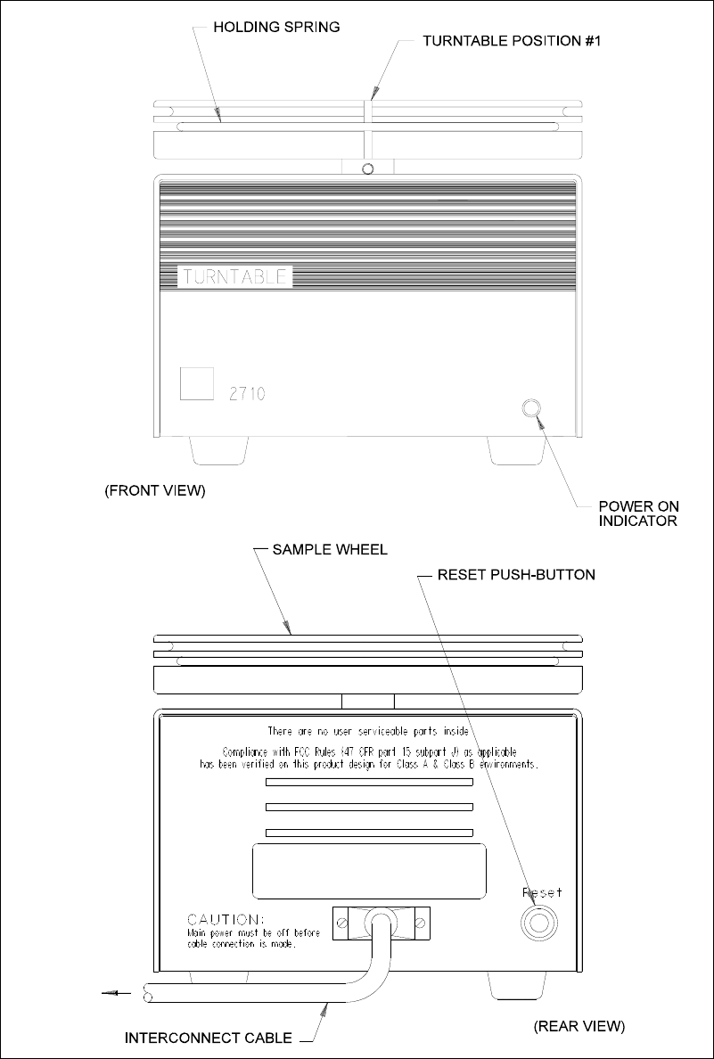
10-5
Figure 10.1
2710 Turntable Major Components

10-6
Installation
Next you will learn how to install the 2710 Turntable to a 2300 STAT PLUS. This process
involves indexing the two instruments together and then aligning the 2300 STAT PLUS Sipper
to the 2710 Sample Wheel home position. The following subsections lead you through the
process step-by-step.
NOTE: You must begin with the 2300 STAT PLUS power off. If you have not already done so,
use the power switch on the rear of the 2300 STAT PLUS case to turn instrument power off.
Remember, the 2710 Turntable has no line power cord. Power is delivered through the
Interconnect Cable.
Indexing the Turntable
Clear a flat surface at least 61 centimeters (24 in) wide by 38 centimeters (15 in) deep to set up
your 2300/2710 system.
Refer to Figure 10.2, Instrument Indexing, for proper orientation of the instruments and the
indexing fixture. Follow these steps:
» Place the Indexing Fixture on the flat surface, for example, a benchtop.
» Lower the 2300 STAT PLUS into the fixture, capturing both the left front and left back
feet in their respective holes.
» Lower the 2710 Turntable into the fixture capturing both the right front and right back
feet in their respective holes.
Cable Connection
Connect the Interconnect Cable into the back panel of the 2710 Turntable and then into the
Auxiliary connector on the back of the 2300 STAT PLUS. Secure both connectors using the
screws provided.
CAUTION: Failure to remove the Access Panel will likely
result in damage to the Sipper when it moves toward
the turntable sampling position. Check and confirm
that the Access Panel has been removed from the side
of the 2300 STAT PLUS. This will require a small
adjustable wrench, or an 8 mm (5/16 in) wrench. Refer
to Figure 10.2 for location.
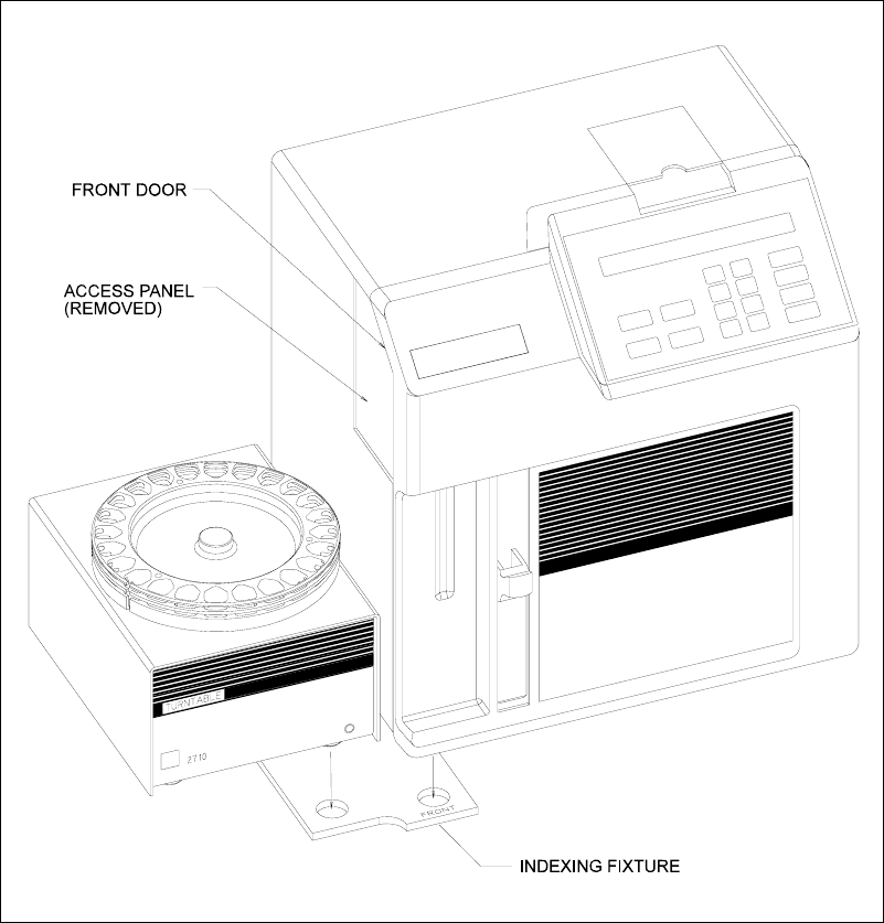
10-7
Figure 10.2
Instrument Indexing

10-8
Power Up
Before you continue with the 2710 Turntable setup, follow steps described in Section 3.5 Power
Up Procedures. Once you have turned on power to the 2300 STAT PLUS, the 2710 Power
Indicator LED should illuminate. If the LED does not illuminate, check to make certain that the
Interconnect Cable is correctly engaged. If everything appears to be connected correctly and the
LED still does not illuminate, unplug the turntable from the 2300 STAT PLUS and contact YSI
Customer Service for assistance. See Appendix F for contact information.
Aligning The Turntable
There are provisions in the 2300 STAT PLUS software that allow you to fine-adjust the Sipper
in order to better align the Sipper to the sampling position (home position) of the turntable.
NOTE: If a single turntable is being used alternately between two or more 2300 STAT PLUS
instruments, you may need to use this alignment procedure whenever you move the turntable to
another 2300 STAT PLUS unit. You may also need to use this procedure whenever you replace
a Sipper.
We recommend that you align the two instruments with the front door of the 2300 STAT PLUS
open. This way you can view the Sipper movements and detect any potential positioning
problems.
Follow the step-by-step procedure described below. Since you just powered the 2300 STAT
PLUS, the Main Menu should appear on the display.
Please select instrument mode:
[RUN] [STANDBY] [MENU]
Press [MENU]. The display reads:
Select instrument function:
1-Service 2-Setup 3-Diagnostic
Press [1]. The display reads:
Select service: 1-Sipper 2-Buffer 3-Cal
4-Stir speed 5-Turntable
Press [5]. The Sample Wheel rotates searching for "home" position. The home position is
turntable position 1 and is clearly identified by the vertical slot in the edge of the wheel. Once
located, the wheel stops and the display reads:
Select turntable service
1-Sipper position 2-Fixed sipper depth

10-9
Press [1]. The Sipper rotates out through the access opening and stops above the turntable
"home" position. The display reads
Finetune turntable sipper position
0-Exit 1-Clkwise 2-CClkwise 3-Test
Visually check to see that the Sipper centers above the "home" position (turntable position 1).
YSI sets this position during manufacturing, however, if the turntable stops at a position other
than position 1, the turntable must be realigned manually. For manual realignment instructions
refer to Section 10.5 Maintenance.
If the turntable stops in the correct position, but the Sipper does not center directly above
"home position", you need to fine- adjust using software menu selections described below.
Press [1] or [2] to rotate the Sipper in either clockwise or counterclockwise preset increments.
Press the appropriate key as required to set the Sipper position.
Once satisfied that the Sipper is correctly aligned (centered), press [3] to test the location. The
Sipper rotates back into the 2300 STAT PLUS, stops directly over the Sample Chamber, then
rotates back out through the access opening and stops at the previously chosen location. You do
this to visually confirm that the alignment is correct.
When you complete the alignment procedure, press [0]. The Sipper rotates back into the 2300
STAT PLUS and the display reads
Select turntable service
1-Sipper Position 2-Fixed sipper depth
At this point you need to decide whether to use the automatic fluid sensing feature or,
alternately, set the Sipper to a fixed point depth. If you decide to use automatic sensing, you
need not continue reading. Press [MENU].
NOTE: Additional information on the use of fluid detection is described in Section 10.3
Operation.
If you decide to establish a fixed-point depth for retrieving a sample, press [2]. The Sipper
rotates through the access opening and stops above the turntable "home" position at the system
default height. This height is about 3 centimeters above the Sample Wheel. The display reads:
Set turntable fixed sipper depth
0-Exit 1-Up 2-Down 3-Test
You press [2] to drive the Sipper down a preset increment, or press [1] to drive it up. Press it
again and it moves up or down depending on the key you press. Repeat this process until the
Sipper is at the desired height. Once at the desired height press [3] to test the setting. The
Sipper rotates back into the 2300 STAT PLUS, stops directly over the Sample Chamber, then
rotates back out through the access opening and stops at the previously chosen location.
Perform this test to visually confirm that your setting is correct.

10-10
Press [0]. The Sipper rotates back into the 2300 STAT PLUS and the display reads
Select turntable service
1-Sipper position 2-Fixed sipper depth
Press [MENU] to return to the Main Menu.
Please select instrument mode:
[RUN] [STANDBY] [MENU
You now have completed alignment of the 2710 Turntable to the 2300 STAT PLUS. This
alignment should not change as long as the Indexing Fixture is not removed. For example, if
you remove the Sample Wheel, you will not affect the alignment because it is indexed to the
drive hub and can only be reinstalled to the same position.
10.3 Operation
In this section we discuss several important topics that are necessary to properly load and
operate the 2710 Turntable.
First, we discuss the type and size of test tubes/vials you should use.
Second, we focus on choosing the proper sampling protocol for your application.
Third, we describe how you cancel or interrupt turntable sampling to stop its programmed run.
Fourth, we describe how to interrupt batch sampling to perform a STAT sample at the Test Tube
Holder position, and not interfere with the turntable run that was initiated.
In addition, we discuss some special configurations to help you learn to use the turntable most
efficiently.
10-11
Test Tube and Vial Choices
There are a variety of test tube and vial sizes and types that work with the 2710 Turntable.
Make certain that your test tube choice is consistent with dimensions described in Section 10.1
Description and Specifications.
Once you have chosen a particular test tube or vial, you should make sure that you have
configured the 2300/2710 system to settings for optimal performance. Review the suggestions
below to help you make or confirm your choices. We use the phrase "sample container" below
to describe any test tube, vial or other vessel you may choose.
» Your sample container should be no taller than 100 mm and the bottom of the sample
container should be resting on the bottom of the Sample Wheel floor.
» Sample containers less than 20 mm tall may present some difficulty. You may need to
convince yourself they will work by trial and error.
» If you select Fluid Detection from the Turntable menu, two conditions are important.
First, a single wall sample container is normally required. Double wall sample
containers and some plastic containers do not work with the 2300/2710 capacitive
sensing technique. Second, your sample must be conductive, that is, it must contain
ionic species. For example, solutions such as deionized water will not work reliably.
» To avoid the drawbacks of Fluid Detection, use single wall sample containers whenever
possible. Use YSI buffer solution or normal saline solution (without analyte) as a blank
in your turntable run.
» Alternatively, you may turn off Fluid Detection in the 2300 STAT PLUS Setup menu.
See Figure 5.2 Menu Flow Chart, to locate the specific submenu Setup, then submenu
Turntable. When you turn off Fluid Detection, you must be certain that the Sipper
depth is appropriately set at the turntable sampling position. Avoid deep immersion into
sample solutions to reduce carry-over errors during sampling. You will find instructions
in Section 10.2 Setup that describe how to set Sipper depth.
» Choose the appropriate position (upper or lower slot) for the garter spring. Generally,
for 10-13 mm diameter tubes, use the lower slot. For diameters greater than 13 mm use
the upper slot.
» When in doubt about the proper Sipper depth setting, enter Diagnostics menu,
specifically Sipper motor diagnostics, to check your setting. See Figure 5.2, Menu
Flow Chart, to locate the proper menu level.
» If you encounter problems related to finding an appropriate sample container or finding
the correct settings for your sample container, contact YSI Customer Service. See
Appendix F for phone and FAX information.

10-12
Setting Sample Protocol
As we continue describing basic operation, we assume you have followed the 2300 STAT
PLUS setup instructions regarding Measurement Parameters. We also assume that all Run
Mode selections related to Sample Protocol are currently default settings. See Appendix I,
Printed Setup Information, to review the default settings.
If you have entered RUN Mode and the 2300 STAT PLUS is calibrated, the display top line
should read:
Ready to sample at Station #2 HH:MM:SS
NOTE: If the 2300 STAT PLUS is not yet calibrated, return to Sections 3 and 4 for setup and
operation instructions.
It is important that you understand "stations" at this point. The 2300 STAT PLUS software
defines four stations at which aspiration of a sample and/or calibration may occur. The
Turntable sampling occurs at Station #4. All station descriptions are outlined below.
Abbreviations used below: CW = clockwise; CCW = counterclockwise
The Sample Chamber (where enzyme probes are housed) is the "home" position.
Station #1 Calibration Well. (one stop CCW to "home")
Station #2 Test Tube Holder. (one stop CW to "home")
Station #3 Manual Sampling. (one stop CW to Station #2)
Station #4 Turntable. (outside left side of instrument case, approximately 180 degrees
CW to Cal Well or Station #1)
Now, since we want to sample at the turntable sampling position, press [4] on the 2300 STAT
PLUS keypad. The display changes to read
Ready to sample at Station #4 HH:MM:SS
There are several ways to setup turntable sampling protocol. The simplest is described first,
followed by an alternative that may be more appropriate for your application.
Setting Sampling Protocol from Run Mode
If your sample containers are loaded and the Sample Wheel properly installed on the turntable
hub, you are ready to start.
Press [SAMPLE].

10-13
The wheel will rotate counterclockwise until Position #1 is at Station #4 sampling position. The
display now prompts you to enter the starting position in your run. Position #1 is the default
option. The display reads:
Enter starting turntable position
>1
You may now change the "1" to whatever starting position you desire. Once correct, press
[ENTER]. The display now prompts you to enter the number of samples in your run. The
number "1" is the default option. The display reads:
Enter number of samples in run
>1
Now enter the number of consecutive positions loaded with sample containers that you want
sampled in this run (batch). When correct, press [ENTER].
Turntable sampling now begins and will automatically stop when the programmed number of
samples is complete. Note that autocalibrations based on time or number of samples will
interrupt sampling as necessary, but will not stop the turntable run.
Each sample result is displayed and printed with turntable position number, date and time. See
Appendix J, Report Formats for sample printouts. Batch identification and multicycle options
have not been described yet. They will be considered under Special Configurations later in this
section.
Setting Sample Protocol from Setup Menu
If you will be running a series of turntable runs (batches) using the same sampling protocol
each time, you may want to use Menu setup of sampling protocol. For example, if you plan to
use the same starting position and the same number of consecutive samples in several runs, this
approach may be more appropriate.
If you choose this approach, you load the Sample Wheel, press [SAMPLE] and the turntable
run begins. In this case there will be no prompts regarding starting position or number of
samples in the run, as before.
To program the 2300/2710 system to run from Menu setup, start at the Main Menu display and
do the following.
Main Menu display:
Please select instrument mode:
[RUN] [STANDBY] [MENU]

10-14
From Main Menu, press [MENU].
Select instrument function
1-Service 2-Setup 3-Diagnostic
From Select instrument function, press [2] for Setup.
NOTE: If you are in RUN or STANDBY modes, press [MENU] to go directly to the display
shown below.
Select setup:1-General 2-MeasParameter
3-RunMode 4-Report 5-PrntSetup 6-Default
From Select setup, press [3] for RunMode.
Run Mode Setup:1-Sample Protocol
2-AutoStandby 3-AutoCal
From Run Mode setup, press 1-Sample Protocol
Sampling Protocol Setup: 1-SipperHeight
2-Multi 3-ID 4-Station# 5-TTable 6-Hct
Although Station #4 may already be programmed, you should confirm this. From Sampling
Protocol Setup menu, press 4-Station#. The display reads
Enter sample station
>4
If necessary change to "4" by pressing [4], then press [ENTER]. The display again reads
Sampling Protocol Setup: 1-SipperHeight
2-Multi 3-ID 4-Station# 5-TTable 6-Hct
Now you will identify the starting turntable position and the number of positions you want to
sample in the run.
Press [5], the display reads
Enter starting turntable position
>1

10-15
Enter the desired number (0 to 24, but typically 1), then press [ENTER]. Enter 0 if you want
the instrument to prompt you for the starting position each time [Sample] is pressed. The
display reads
Enter number of turntable samples
>1
Enter the desired number (0 to 255, but typically 0). Enter 0 if you want the instrument to
prompt you for the number of samples each time [Sample] is pressed. Numbers greater than 24
will be explained under Special Configurations. Now press [ENTER]. The display reads
Turn Station #4 Fluid Detection ON: Yes
1-No 2-Yes
Decide whether you wish to use the automatic fluid detection capability described previously.
Select On or Off by pressing the appropriate numerical key, then press [ENTER]. The display
reads:
Sampling Protocol Setup: 1-SipperHeight
2-Multi 3-ID 4-Station# 5-TTable 6-Hct
Press [MENU] to return to the Main Menu or back to RUN Mode. If the instrument is not yet
calibrated, it now reads
Please select instrument mode:
[RUN] [STANDBY] [MENU]
If the 2300 STAT PLUS is calibrated, the display should read
Ready to sample at Station #4 HH:MM:SS
Now, when you press [SAMPLE], the instrument proceeds immediately with the
preprogrammed turntable sampling protocol. You will not see display prompts for start position
or for number of samples in the run (batch).

10-16
How to Cancel a Turntable Run
Once the 2300/2710 system begins a turntable run, it proceeds uninterrupted to completion, as
programmed (whether by RUN Mode setup or by MENU Mode setup).
However, for whatever reason, you may halt a turntable run by pressing [CANCEL]. The
2300/2710 system will complete any sample in progress, display and print the results. The
turntable run is now complete and the display reads:
Ready to sample at Station #4 HH:MM:SS
NOTE: if you also configured the system to "multicycle", that is, perform multiple samples at
each turntable position, you must press [CANCEL] twice. The first press of [CANCEL]
disables multicycling. The second press disables the turntable run. More information on
multicycling is presented below under Special Configurations.
If you now wish to perform a discrete sample at another station, you have the ability to simply
press a numeric key, typically 2 or 3, and run that sample. For example, let us assume you want
to sample at the Test Tube Holder position (Station #2). Press [2] and display changes to read
Ready to sample at Station #2 HH:MM:SS
Press [SAMPLE] and the discrete analysis will proceed. When completed the display returns to
show
Ready to sample at Station #2 HH:MM:SS
NOTE: Once interrupted by the [CANCEL] command, the turntable cannot resume
automatically, nor can it identify where it was interrupted. However, in the next section, a
single key interrupt function is described.
Stat Interrupt Of Turntable Run
If you have initiated a turntable run (batch), and do not want to interrupt it, yet have a sample
that needs immediate analysis ("STAT sample"), there is a procedure. It works as follows:
» Press [SAMPLE] to signal a STAT request.
» The message "STAT sample requested" is briefly displayed.
» After completion of the turntable sample in progress, the instrument shifts to STAT
mode whereby it looks for a sample at the Test Tube Holder position. At this point, the
top line of the display indicates turntable sample pause and the word STAT appears.
The bottom line of the display indicates the results of the previous sample.
10-17
» The STAT sample is run and the results displayed and printed. The printed result is
clearly labeled as a STAT result.
» The instrument automatically returns to the next "scheduled" sample in the
programmed turntable run (batch).
There is a maximum of one STAT interruption per scheduled turntable sample. That is, you
cannot perform back-to-back STAT samples. You may, however, interrupt as many samples as
necessary in a batch, limited only by the number of positions programmed times the number of
replicates per position.
You may, therefore, interrupt in the middle of replicates at a particular position. The instrument
will return to the next replicate scheduled.
If several STAT samples show up unexpectedly in your laboratory, then canceling the turntable
run makes sense. You can always restart the turntable where you aborted by entering the
appropriate starting position and number of positions remaining in the batch.
An example printout (brief format) of a STAT result is shown below:
Sample Report (Brief)
-----Sample Report-----
ID:STAT-000000001
B:L-Lactate 2.02 mmol/L
W:Glucose 6.22 mmol/L
Tue 02/22/03 14:36:21
-----------------------
Special Configurations
There are a number of features available in the 2300/2710 system that may be of interest in
your applications. Three of these features are described below.
Multicycle
Multicycle refers to replicate sampling at each turntable position. You may program your
system to make duplicate, triplicate, or up to 99 replicates at each turntable position. The
replicates are performed consecutively. For example, for triplicate sampling, Turntable Position
#1 would be sampled 3 times, followed by 3 times at Position #2 and so on.
You initiate "multicycle" by selection in the Setup menu, specifically 3-RunMode, then 2-
Multicycle. See Figure 5.2, Menu Flow Chart, to locate the option. Once selected, a display
prompt requests the number of multicycles (replicates). This prompt appears after pressing
[SAMPLE] to initiate a turntable batch.
You may cancel the multicycle function in any turntable run or batch by pressing [CANCEL]
one time. This only cancels the multicycle function at the position where it is invoked. To
cancel or alter multicycle for the entire batch, you must cancel the turntable batch and
reprogram.

10-18
Turntable Batch Identification (ID)
An identification number (9 digits maximum) may be assigned to a turntable batch. The
number identifies the batch only. There is no mechanism through the 2300 STAT PLUS
keypad to assign an ID number to each sample position in a run. However, the date and time,
along with the turntable position number and replicate number permits a unique set of markers
for each sample or replicate.
You initiate "ID" by selection in the Setup menu, specifically 3- RunMode, then 3-ID. To locate
the option see Figure 5.2, Menu Flow Chart. Once selected, a display prompt requests the entry
of an ID number. This prompt appears after pressing [SAMPLE]. You are not required to enter
an ID number. Just press enter to continue.
Extending a Turntable Run
There are 24 positions in the Sample Wheel. However, when prompted to enter the number of
samples in a run, you may enter up to 255. There are at least two situations where this may be
of interest to you.
First, you may want to repeat a 24 position run to check whether the analyte concentration of
interest has changed with time. In this case you might enter "48" for the number of samples.
This permits unattended analyses of the full sample wheel two times in succession.
Second, you may have more than 24 samples to analyze, but would like them all sampled in one
report. As earlier positions are analyzed, new samples can be added to these positions by
exchange. In this case Position #1 becomes Position #25, then #49 and so on.
To initiate "extension", simply enter the desired number at the prompt asking "number of
samples in run". Review Sampling Protocol above for more specific information.
10.4 Diagnostics and Troubleshooting
Diagnostic routines in the 2300 STAT PLUS software provide help in troubleshooting two
major components, the turntable motor and position sensing electronics. Instructions below
describe how to access the Diagnostics menu and how to use the routines. Refer to Figure 5.2,
Menu Flow Chart, for an overview of the diagnostics routines.
Accessing Turntable Diagnostics
You first must return to Main Menu. This may require that you exit RUN Mode or STANDBY
Mode.
From the 2300 STAT PLUS Main Menu, which appears as
Please select instrument mode
[RUN] [STANDBY] [MENU]

10-19
Press [MENU], the display reads
Select instrument function
1-Service 2-Setup 3-Diagnostic
Press [3], the display reads
Select diagnostic
1-Motor 2-Pump 3-Probe 4-I/O 5-Sensor
Press [1], the display reads
Motor diagnostic
1-SipperMotor 2-StirMotor 3-Turntable
Press [3], the display reads
Turntable diagnostic XX
1-Home 2-Goto 3-Step 4-Exercise 5-Reset
Using Turntable Diagnostics
There are three specific functions that you can initiate. In addition, the Sample Wheel may be
set to continuously turn (exercise). The XX displayed in the upper right corner of the display
identifies position number. The position number counter may need to be reset, since it counts
from home position rather than electronically "sensing" position.
Turntable diagnostic XX
1-Home 2-Goto 3-Step 4-Exercise 5-Reset
If you press [1], the turntable wheel rotates to the home position. The display does not update.
If you press [2], this routine allows you to direct the Sample Wheel to a specified position. The
display reads
Enter turntable position
> 1

10-20
Enter the desired turntable position (1 to 255), then press [ENTER]. The turntable rotates to the
selected position and the display returns to the previous screen. The upper right screen should
now indicate the Sample Wheel position (1 to 24). If you entered a number greater than 24, the
indicator still should agree with the number label on the wheel.
Turntable diagnostic XX
1-Home 2-Goto 3-Step 4-Exercise 5-Reset
If you press [3], the Sample Wheel rotates counterclockwise to the next position. The display
will not change except for the position indicator in the upper right screen which updates with
each step. Note, the wheel moves quickly enough that every position is not displayed on the
screen as it moves.
If you press [4], you initiate an exercise routine in which the turntable starts rotating, updating
the position indicator as each position is passed. The display now reads:
Exercising turntable XX
Hit any key to stop
After one complete revolution, a "hesitation" at each position will become obvious. This is not
a failure, but rather the software stopping and starting the turntable at each position. It occurs
so fast that it is visually imperceptible. Press any key to stop the routine. The display returns to
the previous screen.
Turntable diagnostic XX
1-Home 2-Goto 3-Step 4-Exercise 5-Reset
If you press [5], the position indicator resets to 00.
To return to the Main Menu, press [MENU].
Please select instrument mode:
[RUN] [STANDBY] [MENU]
In addition to the 2710 Turntable diagnostic routines, many routines related to the 2300 STAT
PLUS are available for better understanding of instrument function,and, if required, to
troubleshoot problems.
10-21
Troubleshooting
This section provides a simple, but systematic, approach to establishing the cause of the most
common turntable malfunctions. Symptoms related to 2710 Turntable problems are somewhat
limited. Most often, one of the following may occur. The 2300 STAT PLUS Sipper may miss
target or come up with a detection error, or the Sample Wheel may not rotate.
When you consider the 2300/2710 system, the possible problems increase significantly. For this
reason you should consider Section 8 Troubleshooting as an extension of this troubleshooting
section.
Before taking corrective action related to any problem, be certain to collect as much pertinent
data as possible. Try to make use of the 2710 service and diagnostic routines to test potential
problem areas.
If you cannot resolve a problem, contact YSI Technical Support for help. When you
communicate with service personnel, please indicate the serial numbers of both the 2710
Turntable and the 2300 STAT PLUS with which the turntable is configured. If you are writing
or transmitting a FAX, include a thorough description of the problem. Include printouts in the
"detail" report format, if possible.
You can find phone, FAX and address information for YSI in Appendix F–Warranty and
Shipping Information.

10-22
SAMPLE WHEEL ROTATION PROBLEM
DESCRIPTION: The 2710 Turntable Sample Wheel fails to rotate or rotates
improperly.
POSSIBLE CAUSE: The Interconnect Cable has been disconnected.
ACTION: Reconnect Interconnect Cable or check the cable connector
mounting screws to make sure they are snug.
POSSIBLE CAUSE: The 2710 Turntable Drive Hub has worked loose.
ACTION: Tighten the Drive Hub set screws, then re- align the turntable with
the 2300 STAT PLUS.
SIPPER ALIGNMENT PROBLEM
DESCRIPTION: The 2300 STAT PLUS Sipper misses intended sample cup.
POSSIBLE CAUSE: The 2710 Turntable and the 2300 STAT PLUS have become
misaligned because the feet of the instruments have been moved
from the Indexing Fixture.
ACTION: Reinstall the feet into their respective positions, then re-align
turntable and 2300 STAT PLUS.
POSSIBLE CAUSE: The 2710 Turntable and the 2300 STAT PLUS have become
misaligned due to a loose turntable Drive Hub.
ACTION: Tighten the Drive Hub set screws, then re- align the turntable with
the 2300 STAT PLUS.
POSSIBLE CAUSE: The 2300 STAT PLUS and the 2710 Turntable have become
misaligned because the 2300 STAT PLUS Sipper has been
knocked out of it's aligned position.
ACTION: Re-align the 2300 STAT PLUS Sipper to "home" position (Sample
Chamber).
POSSIBLE CAUSE: The 2300 STAT PLUS fluid detection has been turned off and the
fixed point is set too low for the sample container.
ACTION: Reset the fixed sipper depth setting.
FLUID DETECTION PROBLEM
DESCRIPTION: Fluid Detection error displayed on 2300 STAT PLUS.
POSSIBLE CAUSE: The 2300 STAT PLUS fluid detection has failed due to low
conductivity of the sample solution.
ACTION: Verify fluid detection turned on in menu. Check fluid detection
function by loading a YSI Standard solution, buffer or saline into
a sample container and running it as a sample.

10-23
10.5 Maintenance
With normal usage there is little maintenance required of the 2710 Turntable. The drive train
inside the case is protected from sample spills and does not require any regular lubrication. All
exposed surfaces have protective finishes that prevent corrosion if they are cleaned
periodically.
Cleaning
The Sample Wheel is made from an aluminum alloy and has been treated with a protective
coating. You can remove the wheel easily, without the use of tools, and take it to a wash station
where cleaning is more practical.
CAUTION: When cleaning the Sample Wheel, avoid the use of nonpolar solvents such as
acetone. Commonly used laboratory cleaning and disinfecting agents such as detergents, 70%
isopropyl alcohol, 0.5% hypochlorite (bleach), and 3% hydrogen peroxide will not harm the
protective finish.
To remove the wheel from the 2710 Turntable case, grasp firmly with both hands and raise it
straight up. The wheel should become disengaged from the drive hub and slide freely off the
shaft. If the wheel seems resistant to disengagement, a slight rocking motion should be
sufficient to allow removal.
To re-install the Sample Wheel, simply slide the wheel down over the drive shaft until the
wheel stops. Gently rotate the wheel until it drops down into the indexing slot. We recommend
that whenever the wheel has been removed and replaced that you visually check to verify that it
is still properly aligned. If alignment appears to be a problem, enter Service or Diagnostic menu
to check more methodically.
The turntable Drive Hub should be checked occasionally to assure that it is secured tightly. A
loose Drive Hub causes the 2710 Turntable to become misaligned with the 2300 STAT PLUS
Sipper. This could result in damage to the Sipper. A T-handle allen wrench has been provided
with the 2710 Turntable for tightening the Drive Hub should it become loose over time.
To re-align the 2710 Turntable, refer to instructions below and in Section 10.2.
Sample Wheel/Drive Hub Alignment
Remove the Sample Wheel as described above.
Enter the 2300 STAT PLUS Service menu, then proceed to Turntable Diagnostics. Follow the
steps described below, if necessary.
2300 STAT PLUS Main Menu:
Please select instrument mode:
[RUN] [STANDBY] [MENU]

10-24
Press [MENU], the display reads
Select instrument function:
1-Service 2-Setup 3-Diagnostic
Press [1], the display reads
Select service: 1-Sipper 2-Buffer 3-Cal
4-Stir speed 5-Turntable
Press [5]. The Sample Wheel rotates counterclockwise until it reaches the "home" position. The
home position is Turntable Position #1 and is clearly identified by the vertical slot on the side
of the wheel.
Select turntable service
1-Sipper position 2-Fixed sipper depth
Now press [1] to move the 2300 STAT PLUS Sipper into position. The Sipper rotates out
through the access opening and stops above the turntable "home " position.
Loosen both set screws in the Drive Hub with the allen wrench that has been provided. Replace
the Sample Wheel.
Rotate the Sample Wheel by hand until the #1 position is directly under the 2300 STAT PLUS
Sipper. Hold the Sample Wheel securely while tightening the two set screws in the Drive Hub.
Now repeat the turntable alignment procedure described in Section 10.2.

11-1
11. Typical Performance Data
Introduction
In 1989 YSI introduced the 2300 STAT Glucose and L-Lactate Analyzer. This analyzer was
designed to measure glucose in whole blood, plasma or serum and measure L-lactate in whole
blood, plasma or cerebrospinal fluid. Among the 2300 STAT features were (1) fixed-parameter
automatic calibration, (2) sample results displayed 65 seconds after sample presentation and (3)
glucose linearity to 27.8 mmol/L (500 mg/dL) and L-lactate linearity to 15.0 mmol/L (134
mg/dL).
Fixed-parameter automatic calibration in the 2300 STAT triggered calibrations every 5 samples
or 15 minutes, whichever occurred first. This is referred to below as the "5/15" routine. The
2300 STAT PLUS (the STAT's successor) now provides programmable options in the
autocalibration routine, but maintains "5/15" as the default autocalibration setting. The
autocalibration routine is flexible, but has an upper limit of one calibration update every 4
hours (240 minutes). This would be considered "worst case". This is referred to below as the
"0/240" routine.
The 2300 STAT PLUS offers operation in one of two performance modes related to sample
cycle time. The user selects the mode. The default mode is referred to as Normal Mode, which
uses the same cycle time criteria as the 2300 STAT. Alternatively, the user may choose Screen
Mode, which provides results more rapidly reducing sample cycle time by about 30%.
However, the user is cautioned that accuracy, precision and/or linearity may be compromised in
this mode (see Section 2.3). Data presented below compare these two modes of operation.
Each set of data below is categorized by analyte (glucose or lactate), specimen type (whole
blood, plasma, etc.), performance mode (Normal or Screen) and autocalibration routine (5/15 or
0/240). There are twenty sets of information in all.
NOTE: The specified linear limits of the 2300 STAT are 500 mg/dL glucose and 15.0 mmol/L
lactate. The specified limits of the 2300 STAT PLUS are 900 mg/dL glucose and 30.0 mmol/L
lactate. When glucose or lactate values exceeded the linear limit of the 2300 STAT during
testing, samples were diluted 1:1 with normal saline solution and reanalyzed. The adjusted
results (multiplied by 2) were then used for statistical analysis in the comparison of the 2300
STAT to the 2300 STAT PLUS.
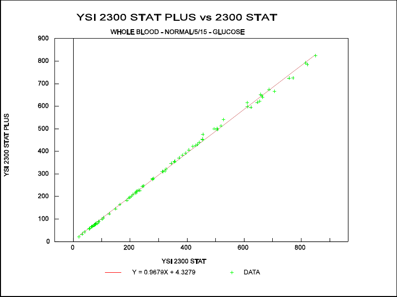
11-2
SET 1: WHOLE BLOOD GLUCOSE
NORMAL MODE
5/15 CAL ROUTINE
Comparison of Glucose Measurements (0-900 mg/dL) done on the 2300 STAT PLUS vs. the
2300 STAT.
Figure 11.1
Comparison Plot, 0-900 mg/dL
Data Ranges and statistics:
PESD = Pooled Estimate Standard Deviation
Mean
Range Bias PESD
(mg/dL) (mg/dL) (mg/dL)
0-150 –1.2 * 0.8
150-300 –3.0 * 1.7
300-500 –1.0 * 2.4
500-900 –20.06 8.67
0-900 –5.85 4.40
Regression Equation (0-900 mg/dL) :
2300 STAT PLUS = 0.968 (2300 STAT) +4.33
Correlation Coefficient (R) = 0.999
n = 83
* Data from 2300 STAT FDA 510k.

11-3
SET 2: WHOLE BLOOD GLUCOSE
NORMAL MODE
0/240 CAL ROUTINE
Comparison of Glucose Measurements (0-900 mg/dL) done on the 2300 STAT PLUS vs. the
2300 STAT.
Figure 11.2
Comparison Plot, 0-900 mg/dL
Data Ranges and statistics:
PESD = Pooled Estimate Standard Deviation
Mean
Range Bias PESD
(mg/dL) (mg/dL) (mg/dL)
0-150 –0.75 2.27
150-300 –0.90 6.03
300-500 –4.71 5.26
500-900 –15.68 10.69
0-900 –4.89 6.52
Regression Equation (0-900 mg/dL) :
2300 STAT PLUS = 0.970 (2300 STAT) +4.11
Correlation Coefficient (R) = 0.999
n = 80
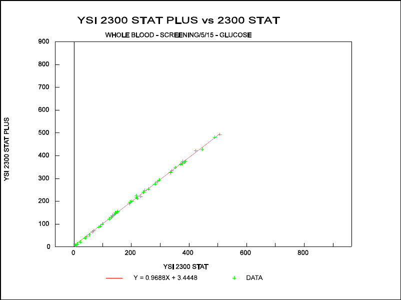
11-4
SET 3: WHOLE BLOOD GLUCOSE
SCREEN MODE
5/15 CAL ROUTINE
Comparison of Glucose Measurements (0-500 mg/dL) done on the 2300 STAT PLUS vs. the
2300 STAT.
Figure 11.3
Comparison Plot, 0-500 mg/dL
Data Ranges and statistics:
PESD = Pooled Estimate Standard Deviation
Mean
Range Bias PESD
(mg/dL) (mg/dL) (mg/dL)
0-150 +0.49 0.92
150-300 –2.35 2.06
300-500 –9.95 4.90
0-500 –3.36 2.92
Regression Equation (0-500 mg/dL) :
2300 STAT PLUS = 0.969 (2300 STAT) +3.44
Correlation Coefficient (R) = 0.999
n = 49
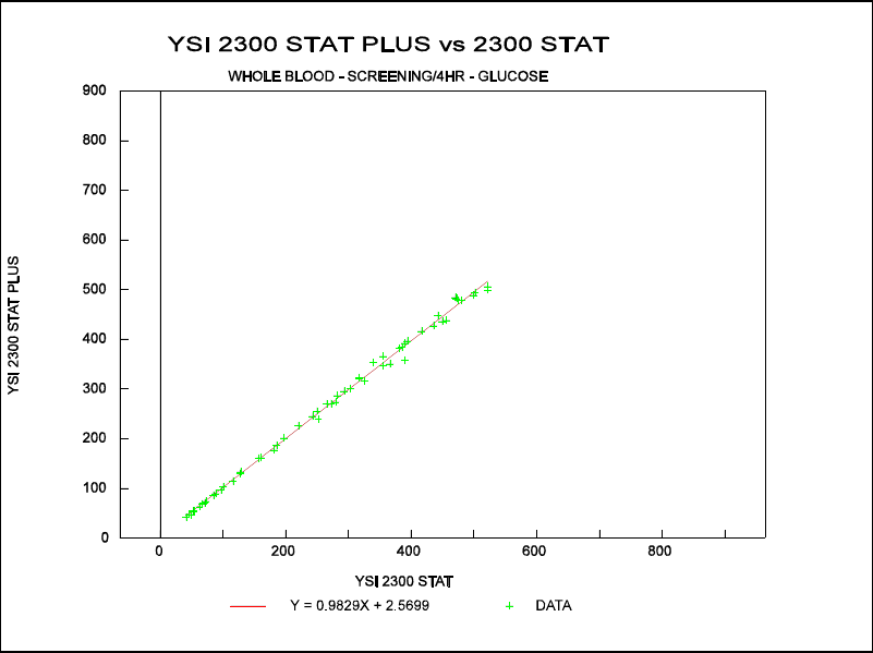
11-5
SET 4: WHOLE BLOOD GLUCOSE
SCREEN MODE
0/240 CAL ROUTINE
Comparison of Glucose Measurements (0-500 mg/dL) done on the 2300 STAT PLUS vs. the
2300 STAT.
Figure 11.4
Comparison Plot, 0-500 mg/dL
Data Ranges and statistics:
PESD = Pooled Estimate Standard Deviation
Mean
Range Bias PESD
(mg/dL) (mg/dL) (mg/dL)
0-150 +0.10 2.04
150-300 –0.20 5.43
300-500 –4.47 10.12
0-500 –2.10 7.49
Regression Equation (0-500 mg/dL) :
2300 STAT PLUS = 0.983 (2300 STAT) +2.57
Correlation Coefficient (R) = 0.999
n = 56
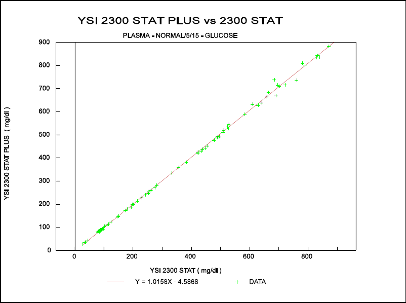
11-6
SET 5: PLASMA GLUCOSE
NORMAL MODE
5/15 CAL ROUTINE
Comparison of Glucose Measurements (0-900 mg/dL) done on the 2300 STAT PLUS vs. the
2300 STAT.
Figure 11.5
Comparison Plot, 0-900 mg/dL
Data Ranges and statistics:
PESD = Pooled Estimate Standard Deviation
Mean
Range Bias PESD
(mg/dL) (mg/dL) (mg/dL)
0-150 –1.9 * 0.7
150-300 –2.8 * 2.2
300-500 –1.5 * 2.9
500-900 +8.08 10.41
0-900 +0.86 5.89
Regression Equation (0-900 mg/dL) :
2300 STAT PLUS = 1.016 (2300 STAT) –4.59
Correlation Coefficient (R) = 0.999
n = 82
* Data from 2300 STAT FDA 510k
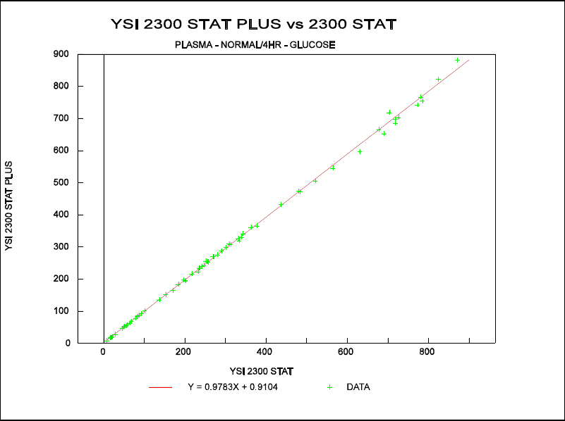
11-7
SET 6: PLASMA GLUCOSE
NORMAL MODE
0/240 CAL ROUTINE
Comparison of Glucose Measurements (0-900 mg/dL) done on the 2300 STAT PLUS vs. the
2300 STAT.
Figure 11.6
Comparison Plot, 0-900 mg/dL
Data Ranges and statistics:
PESD = Pooled Estimate Standard Deviation
Mean
Range Bias PESD
(mg/dL) (mg/dL) (mg/dL)
0-150 –0.35 0.69
150-300 –2.96 2.66
300-500 –6.49 5.70
500-900 –16.86 15.19
0-900 –6.13 7.94
Regression Equation (0-900 mg/dL) :
2300 STAT PLUS = 0.978 (2300 STAT) +0.91
Correlation Coefficient (R) = 0.999
n = 67
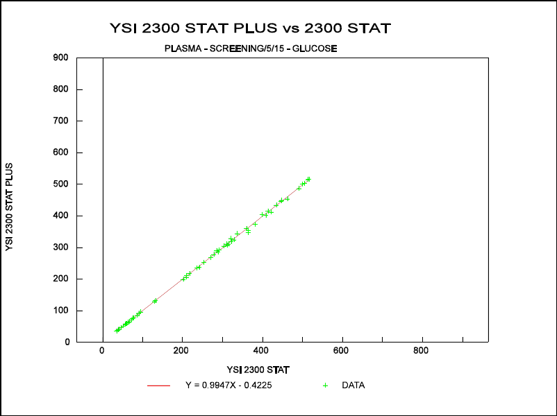
11-8
SET 7: PLASMA GLUCOSE
SCREEN MODE
5/15 CAL ROUTINE
Comparison of Glucose Measurements (0-500 mg/dL) done on the 2300 STAT PLUS vs. the
2300 STAT.
Figure 11.7
Comparison Plot, 0-500 mg/dL
Data Ranges and statistics:
PESD = Pooled Estimate Standard Deviation
Mean
Range Bias PESD
(mg/dL) (mg/dL) (mg/dL)
0-150 –0.75 0.84
150-300 –1.24 2.97
300-500 –2.80 5.93
0-500 –1.77 4.22
Regression Equation (0-500 mg/dL) :
2300 STAT PLUS = 0.995 (2300 STAT) –0.42
Correlation Coefficient (R) = 0.999
n = 56
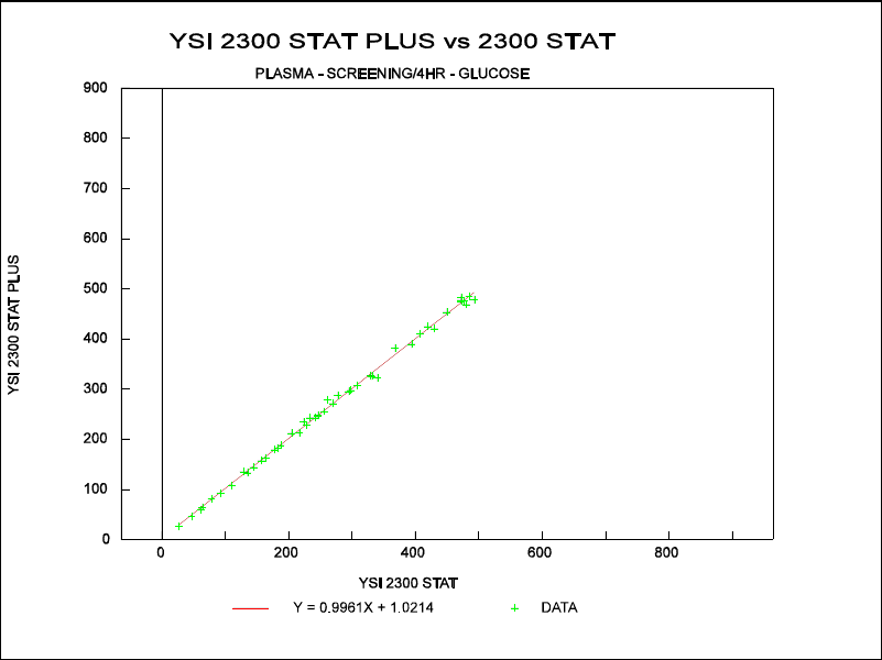
11-9
SET 8: PLASMA GLUCOSE
SCREEN MODE
0/240 CAL ROUTINE
Comparison of Glucose Measurements (0-500 mg/dL) done on the 2300 STAT PLUS vs. the
2300 STAT.
Figure 11.8
Comparison Plot, 0-500 mg/dL
Data Ranges and statistics:
PESD = Pooled Estimate Standard Deviation
Mean
Range Bias PESD
(mg/dL) (mg/dL) (mg/dL)
0-150 –0.62 1.77
150-300 +2.00 3.90
300-500 –1.93 6.00
0-500 –0.02 4.50
Regression Equation (0-500 mg/dL) :
2300 STAT PLUS = 0.996 (2300 STAT) +1.02
Correlation Coefficient (R) = 0.999
n = 46
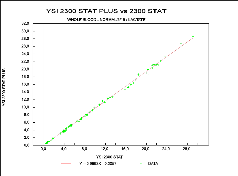
11-10
SET 9: WHOLE BLOOD LACTATE
NORMAL MODE
5/15 CAL ROUTINE
Comparison of L-lactate Measurements (0-30 mmol/L) done on the 2300 STAT PLUS vs. the
2300 STAT.
Figure 11.9
Comparison Plot, 0-30 mmol/L
Data Ranges and statistics:
PESD = Pooled Estimate Standard Deviation
Mean
Range Bias PESD
(mmol/L) (mmol/L) (mmol/L)
0-5 –0.05 * 0.1
5-10 –0.3 * 0.1
10-15 –0.3 * 0.2
15-30 –0.68 0.31
0-30 –0.28 0.18
Regression Equation (0-30 mM) :
2300 STAT PLUS = 0.969 (2300 STAT) –0.01
Correlation Coefficient (R) = 0.999
n = 85
* Data from 2300 STAT FDA 510k
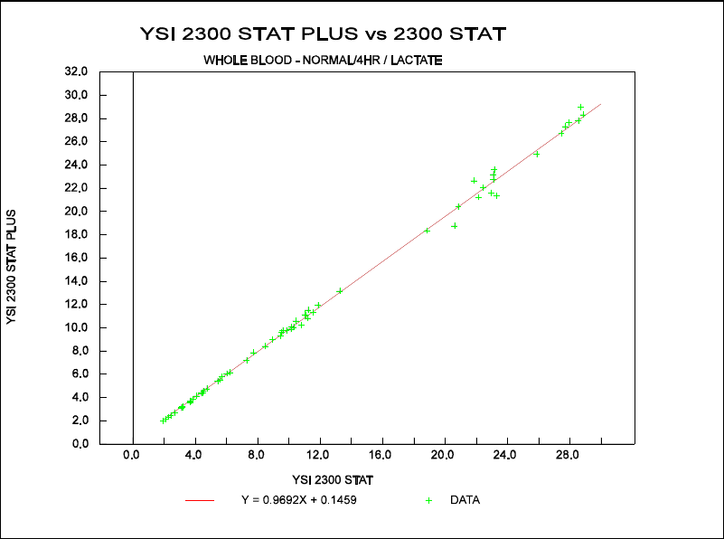
11-11
SET 10: WHOLE BLOOD LACTATE
NORMAL MODE
0/240 CAL ROUTINE
Comparison of L-lactate Measurements (0-30 mmol/L) done on the 2300 STAT PLUS vs. the
2300 STAT.
Figure 11.10
Comparison Plot, 0-30 mmol/L
Data Ranges and statistics:
PESD = Pooled Estimate Standard Deviation
Mean
Range Bias PESD
(mmol/L) (mmol/L) (mmol/L)
0-5 –0.01 0.05
5-10 –0.02 0.10
10-15 –0.12 0.21
15-30 –0.66 0.71
0-30 –0.23 0.40
Regression Equation (0-30 mM) :
2300 STAT PLUS = 0.969 (2300 STAT) +0.15
Correlation Coefficient (R) = 0.999
n = 66
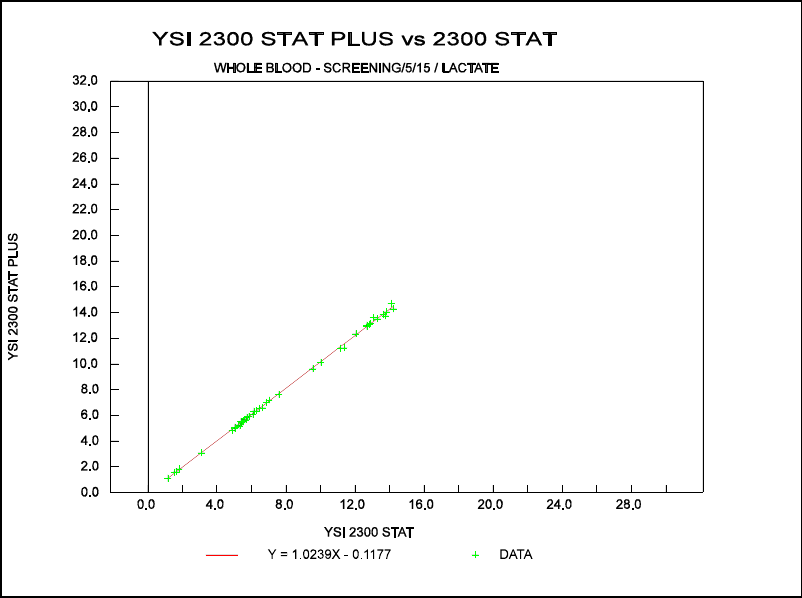
11-12
SET 11: WHOLE BLOOD LACTATE
SCREEN MODE
5/15 CAL ROUTINE
Comparison of L-lactate Measurements (0-15 mmol/L) done on the 2300 STAT PLUS vs. the
2300 STAT.
Figure 11.11
Comparison Plot, 0-15 mmol/L
Data Ranges and statistics:
PESD = Pooled Estimate Standard Deviation
Mean
Range Bias PESD
(mmol/L) (mmol/L) (mmol/L)
0-5 –0.05 0.04
5-10 +0.02 0.11
10-15 +0.19 0.15
0-15 +0.07 0.12
Regression Equation (0-15 mM) :
2300 STAT PLUS = 1.024 (2300 STAT) –0.12
Correlation Coefficient (R) = 0.999
n = 42
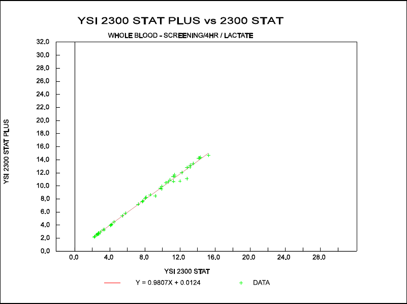
11-13
SET 12: WHOLE BLOOD LACTATE
SCREEN MODE
0/240 CAL ROUTINE
Comparison of L-lactate Measurements (0-15 mmol/L) done on the 2300 STAT PLUS vs. the
2300 STAT.
Figure 11.12
Comparison Plot, 0-15 mmol/L
Data Ranges and statistics:
PESD = Pooled Estimate Standard Deviation
Mean
Range Bias PESD
(mmol/L) (mmol/L) (mmol/L)
0-5 –0.07 0.10
5-10 –0.13 0.24
10-15 –0.22 0.34
0-15 –0.14 0.25
Regression Equation (0-15 mM) :
2300 STAT PLUS = 0.981 (2300 STAT) +0.01
Correlation Coefficient (R) = 0.997
n = 46
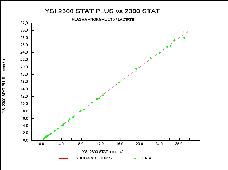
11-14
SET 13: PLASMA LACTATE
NORMAL MODE
5/15 CAL ROUTINE
Comparison of L-lactate Measurements (0-30 mmol/L) done on the 2300 STAT PLUS vs. the
2300 STAT.
Figure 11.13
Comparison Plot, 0-30 mmol/L
Data Ranges and statistics:
PESD = Pooled Estimate Standard Deviation
Mean
Range Bias PESD
(mmol/L) (mmol/L) (mmol/L)
0-5 +0.1 * 0.1
5-10 0.0 * 0.1
10-15 +0.1 * 0.1
15-30 +0.06 0.27
0-30 +0.06 0.16
Regression Equation (0-30 mM) :
2300 STAT PLUS = 0.998 (2300 STAT) +0.09
Correlation Coefficient (R) = 0.999
n = 79
* Data from 2300 STAT FDA 510k
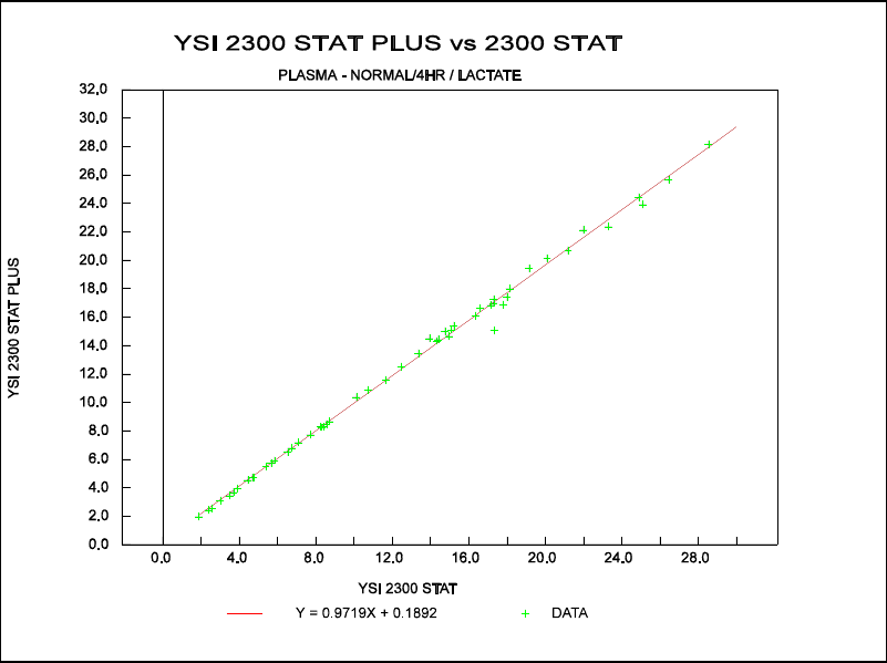
11-15
SET 14: PLASMA LACTATE
NORMAL MODE
0/240 CAL ROUTINE
Comparison of L-lactate Measurements (0-30 mmol/L) done on the 2300 STAT PLUS vs. the
2300 STAT.
Figure 11.14
Comparison Plot, 0-30 mmol/L
Data Ranges and statistics:
PESD = Pooled Estimate Standard Deviation
Mean
Range Bias PESD
(mmol/L) (mmol/L) (mmol/L)
0-5 –0.01 0.04
5-10 –0.02 0.06
10-15 +0.07 0.18
15-30 –0.45 0.39
0-30 –0.17 0.26
Regression Equation (0-30 mM) :
2300 STAT PLUS = 0.972 (2300 STAT) +0.19
Correlation Coefficient (R) = 0.999
n = 53
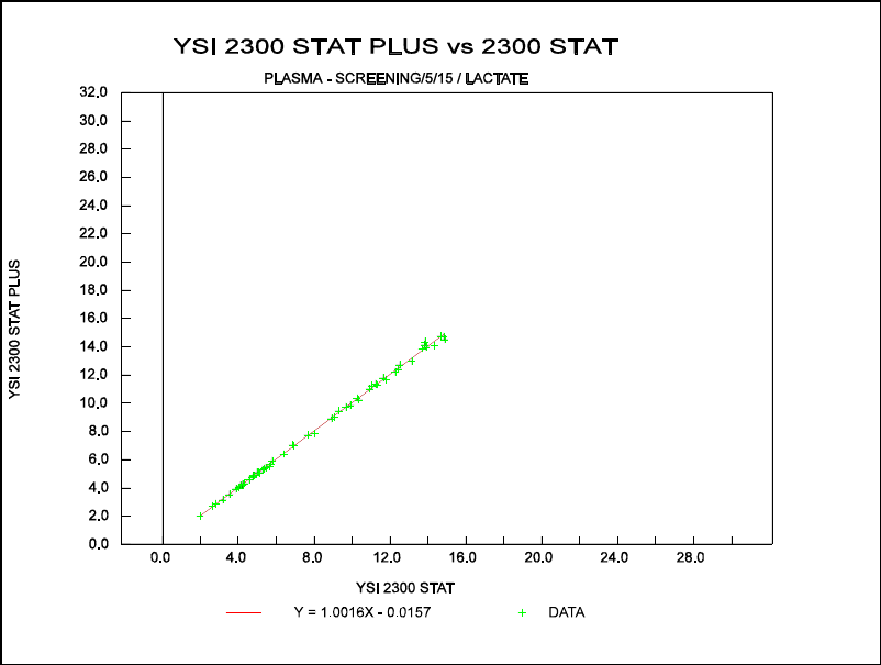
11-16
SET 15: PLASMA LACTATE
SCREEN MODE
5/15 CAL ROUTINE
Comparison of L-lactate Measurements (0-15 mmol/L) done on the 2300 STAT PLUS vs. the
2300 STAT.
Figure 11.15
Comparison Plot, 0-15 mmol/L
Data Ranges and statistics:
PESD = Pooled Estimate Standard Deviation
Mean
Range Bias PESD
(mmol/L) (mmol/L) (mmol/L)
0-5 –0.01 0.06
5-10 –0.01 0.14
10-15 +0.01 0.27
0-15 0.0 0.18
Regression Equation (0-15 mM) :
2300 STAT PLUS = 1.002 (2300 STAT) –0.02
Correlation Coefficient (R) = 0.999
n = 57
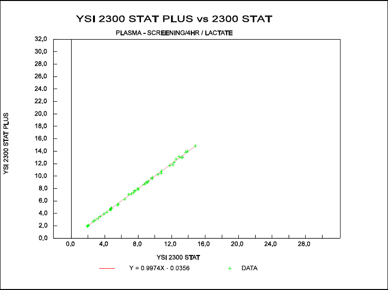
11-17
SET 16: PLASMA LACTATE
SCREEN MODE
0/240 CAL ROUTINE
Comparison of L-lactate Measurements (0-15 mmol/L) done on the 2300 STAT PLUS vs. the
2300 STAT.
Figure 11.16
Comparison Plot, 0-15 mmol/L
Data Ranges and statistics:
PESD = Pooled Estimate Standard Deviation
Mean
Range Bias PESD
(mmol/L) (mmol/L) (mmol/L)
0-5 –0.03 0.07
5-10 –0.06 0.14
10-15 –0.08 0.33
0-15 –0.06 0.21
Regression Equation (0-15 mM) :
2300 STAT PLUS = 0.997 (2300 STAT) –0.04
Correlation Coefficient (R) = 0.999
n = 42

11-18
SET 17: CEREBROSPINAL FLUID LACTATE
NORMAL MODE
5/15 CAL ROUTINE
Comparison of L-lactate Measurements (0-30 mmol/L) done on the 2300 STAT PLUS vs. the
2300 STAT.
Figure 11.17
Comparison Plot, 0-30 mmol/L
Data Ranges and statistics:
PESD = Pooled Estimate Standard Deviation
Mean
Range Bias PESD
(mmol/L) (mmol/L) (mmol/L)
0-5 +0.01 * 0.1
5-10 0.0 * 0.1
10-15 –0.01 * 0.1
15-30 +0.28 0.57
0-30 +0.05 0.27
Regression Equation (0-30 mM) :
2300 STAT PLUS = 1.010 (2300 STAT) –0.03
Correlation Coefficient (R) = 0.999
n = 80
* Data from 2300 STAT FDA 510k
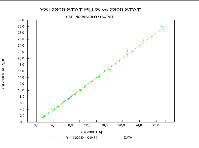
11-19
SET 18: CEREBROSPINAL FLUID LACTATE
NORMAL MODE
0/240 CAL ROUTINE
Comparison of L-lactate Measurements (0-30 mmol/L) done on the 2300 STAT PLUS vs. the
2300 STAT.
Figure 11.18
Comparison Plot, 0-30 mmol/L
Data Ranges and statistics:
PESD = Pooled Estimate Standard Deviation
Mean
Range Bias PESD
(mmol/L) (mmol/L) (mmol/L)
0-5 +0.03 0.04
5-10 –0.06 0.20
10-15 –0.08 0.20
15-30 +0.07 0.61
0-30 –0.01 0.35
Regression Equation (0-30 mM) :
2300 STAT PLUS = 1.003 (2300 STAT) –0.04
Correlation Coefficient (R) = 0.999
n = 63
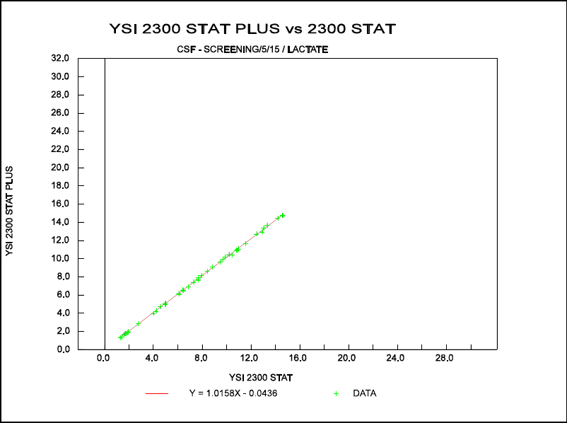
11-20
SET 19: CEREBROSPINAL FLUID LACTATE
SCREEN MODE
5/15 CAL ROUTINE
Comparison of L-lactate Measurements (0-15 mmol/L) done on the 2300 STAT PLUS vs. the
2300 STAT.
Figure 11.19
Comparison Plot, 0-15 mmol/L
Data Ranges and statistics:
PESD = Pooled Estimate Standard Deviation
Mean
Range Bias PESD
(mmol/L) (mmol/L) (mmol/L)
0-5 0.0 0.05
5-10 +0.10 0.09
10-15 +0.13 0.23
0-15 +0.07 0.14
Regression Equation (0-15 mM) :
2300 STAT PLUS = 1.016 (2300 STAT) –0.04
Correlation Coefficient (R) = 0.999
n = 45
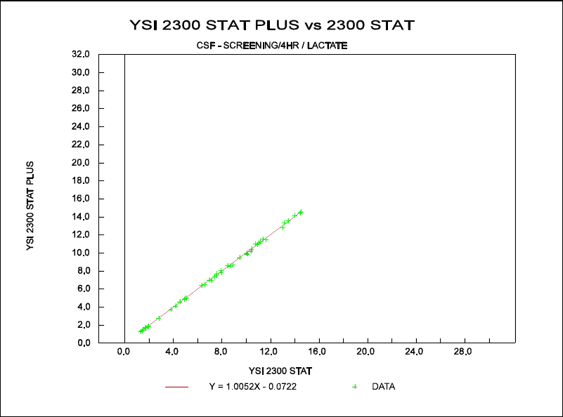
11-21
SET 20: CEREBROSPINAL FLUID LACTATE
SCREEN MODE
0/240 CAL ROUTINE
Comparison of L-lactate Measurements (0-15 mmol/L) done on the 2300 STAT PLUS vs. the
2300 STAT.
Figure 11.20
Comparison Plot, 0-15 mmol/L
Data Ranges and statistics:
PESD = Pooled Estimate Standard Deviation
Mean
Range Bias PESD
(mmol/L) (mmol/L) (mmol/L)
0-5 –0.05 0.06
5-10 –0.05 0.15
10-15 –0.01 0.17
0-15 –0.03 0.14
Regression Equation (0-15 mM) :
2300 STAT PLUS = 1.005 (2300 STAT) –0.07
Correlation Coefficient (R) = 0.999
n = 45
11-22
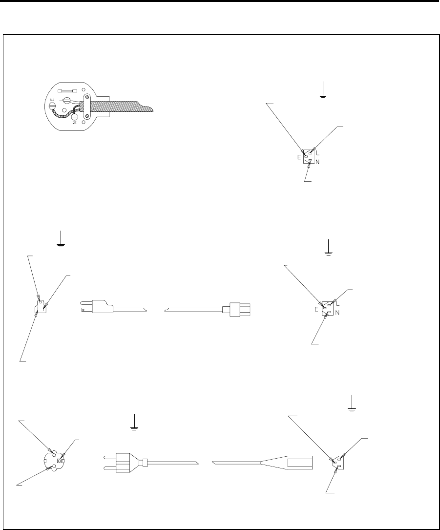
12-1
12. Appendix A–Line Power Cord and
Plug Wiring
Make sure that the cord and plug are appropriate for the power output you intend to use.
Make sure you use a plug to BS1363 and ASTA approval.
Use fuse 3A to BS1362 and ASTA approval.
Green and Yellow wire to E (Earth)
BROWN wire to BROWN or L (live)
BLUE wire to BLUE or N (neutral)
Before refitting the top cover of the plug or socket, make sure that
the cable clamp is securely holding the outer sheath of the cable.
240 VAC
110 VAC
AC GROUND - GREEN
LINE - BLACK
AC EARTH
(GREEN / TELLOW)
LINE - BROWN
NEUTRAL - BLUE
CEE TYPE 27
IEC TYPE 320
AC EARTH - GREEN
LINE - BLACK
NEUTRAL - WHITE
CEE TYPE 27
IEC TYPE 320
220 VAC
NEUTRAL - BLUE
AC GROUND (GREEN / YELLOW)
LINE - BROWN
DIN TYPE 49-450
CEE TYPE 7-7
SCHUKO
NEUTRAL - WHITE
NEMA TYPE 5-15P
CEE TYPE 27
IEC TYPE 320
AC EARTH
(GREEN / YELLOW)
LINE - BROWN
NEUTRAL - BLU
Figure 12.1
Line Power Cord and Plug Wiring
12-2

13-1
13. Appendix B–Sample Collection and
Handling
Proper sample collection and preparation are vital factors in obtaining reliable results with the
YSI 2300. This section covers the basic guidelines for collecting and preparing plasma, whole
blood, and serum samples.
Much of the Blood Plasma and Blood Serum material is abstracted from "Workshop Manual of
Methods for the Determination of Glucose" by Gerald R. Cooper, M.D., Ph.D. published by the
Commission on Continuing Education, Council on Clinical Chemistry, American Society of
Clinical Pathologists (1966).
B.1 BLOOD PLASMA
Be sure that all collection equipment is sterile and chemically clean. Use aseptic techniques in
handling the sample from collection through assay.
During, or immediately after collection, mix the specimen with an anticoagulant and
preservative to prevent coagulation, inhibit enzyme activity, and prevent bacterial growth.
Separate the red blood cells by centrifugation within 30 minutes of collection. Do not allow
plasma to stand on the red cells for long periods at room temperature as this will cause a drop
in the glucose level.
If delays between collection and assay are unavoidable, follow one of these procedures:
1. Refrigerate the whole blood at +4°C. This is acceptable for periods up to four hours.
2 Or, refrigerate the plasma with preservatives at +4°C for up to three days. Plasma with
preservative left at room temperature may keep up to four hours.
3. Or, freeze the cell-free plasma with preservative at -10°C or colder. Plasma will keep
indefinitely at this temperature. Thaw the frozen plasma rapidly at 25°C and analyze
promptly. The freeze-thaw cycle should not be repeated. Tubes containing cells should
never be frozen.
NOTE: Chilling or freezing may precipitate aggluten or fibrinogen masses which may not
redissolve. In such cases, remove them by centrifugation before assay.
Several common anticoagulants are suitable for use with specimens being prepared for assay.
These include
» Potassium oxalate in a concentration of 2 mg/ml of blood.
» Sodium fluoride in a concentration of 5–10 mg/ml of blood.
» EDTA in a concentration of 1 mg/ml of blood.
» Sodium fluoride and potassium oxalate in combination in a total concentration of 2
mg/ml of blood.
» Heparin (sodium or lithium) as commonly supplied in Vacutainer collection tubes.
13-2
WARNING: The YSI 2300 is not suitable for use with
samples containing thymol or other phenol preservatives.
These are interfering substances.
Oxalate anticoagulants, and particularly the combination of sodium fluoride and oxalate, may
produce hemolysis, which can cause disagreement between results from the YSI 2300 and some
reference methods.
WARNING: Frozen blood-bank blood, which contains a
high percentage of glycerin, is not a suitable specimen for
diagnostic work with the YSI 2300.
B.2 WHOLE BLOOD
If more than five minutes will elapse between the time you draw a specimen and analyze it, you
should mix the blood with an anticoagulant during or immediately after collection. Analysis of
whole blood without an anticoagulant is not recommended. The preferred anticoagulants are
EDTA in a concentration of 1 mg/ml of blood, or heparin sodium as commonly supplied in
Vacutainer collection tubes.
Other effective anticoagulants which may be used are potassium oxalate in a concentration of 2
mg/ml of blood, sodium fluoride in a concentration of 5–10 mg/ml of blood, or sodium fluoride
and EDTA in a concentration of 2.5 mg fluoride and 1 mg EDTA per ml of blood.
These are not known to cause any error in the measurement of whole blood glucose or lactate,
but they may cause a reduction of the sample's hematocrit value with or without accompanying
hemolysis. This would lead to a slight error in the calculated plasma glucose value. Hemolysis
can cause disagreement between readings on the YSI 2300 and some reference methods.
Cell metabolism or microbial growth can cause rapid loss of glucose in the specimen through
glycolysis, which will result in erroneously low assay values. Glycolysis is particularly rapid in
whole blood specimens, and these should be analyzed within an hour of drawing. Refrigeration
at +4°C will retard glycolysis and extend the acceptable delay to four hours. Whole blood
specimens must not be frozen. Some authorities recommend the use of chemical preservatives
to minimize glycolysis:
» Fluoride in concentrations of 7.5 mg/ml of blood.
» Boric acid in concentrations of 8 mg/ml of blood.
» Sodium iodoacetate; if sodium iodoacetate is used as the antiglycolytic, it must be free
of iodide and iodine.
YSI has not evaluated the effects of these antiglycolytics.
WARNING: The YSI 2300 is not suitable for use with
samples containing thymol or other phenol preservatives.
These are interfering substances.
13-3
Before taking a sample from a whole blood specimen, any cells which may have settled out
must be resuspended. Invert the collection tube three times, gently enough not to cause
frothing, just before sampling. Samples which have settled for more than an hour (particularly
if they have been refrigerated) should be placed on a blood rotator for five minutes to break up
clumps of cells.
Air bubbles or froth in the sample drawn into the sipper can lead to significant errors in the
form of low glucose and lactate readings. Because it is difficult to detect bubbles visually in
whole blood specimens, you should exercise great care. Any unexpectedly low glucose or
lactate readings may indicate a bubble; if possible, repeat the determination.
WARNING: Frozen blood-bank blood, which contains a
high percentage of glycerin, is not a suitable specimen for
diagnostic work with the YSI 2300.
B.3 BLOOD SERUM
Draw blood for serum preparation into a dry tube without additives. Silicone-coated tubes and
stoppers lubricated with glycerine or silicone are acceptable.
After the specimen stands 15 minutes at room temperature, loosen the clot from the wall of the
tube with a sterile glass rod or applicator. Add sterile beads, if desired. Centrifuge the specimen
promptly to separate the serum from the clot.
Cell metabolism or microbial growth can cause rapid loss of glucose in the specimen through
glycolysis. This will result in erroneously low assay values. Minimize glycolysis by assaying
the serum as soon as possible, preferably within four hours.
If delays are unavoidable follow one these procedures:
1. Refrigerate the whole blood at +4°C. This is acceptable for periods of up to 4 hours.
2. Or, prolonged storage, isolate the serum from the clot within 30 minutes of collection
and freeze it at -10°C or colder. Serum will keep indefinitely at this temperature. Thaw
the frozen serum rapidly at 25°C and analyze promptly. The freeze-thaw cycle should
not be repeated. Tubes containing cells should never be frozen.
NOTE: Freezing may precipitate aggluten or fibrinogen masses which may not
redissolve. You can remove these by centrifugation before assay.
3. Add a chemical preservative. Preservatives are not commonly used with serum;
however, sodium fluoride in concentrations of 7.5 mg/ml of blood, EDTA in
concentrations of 1 mg/ml of blood, or boric acid in concentrations of 8 mg/ml of
blood will substantially halt glycolysis in most, but not all, specimens. If sodium
iodoacetate is used as an antiglycolytic, it must be free of iodide and iodine.
WARNING: The YSI 2300 is not suitable for use with
samples containing thymol or other phenol preservatives.
These are interfering substances.

13-4
WARNING: Frozen blood-bank blood, which contains a
high percentage of glycerine, is not a suitable specimen
for diagnostic work with the YSI 2300.

14-1
14. Appendix C–Effects of Selected
Substances
WARNING: The following preservatives interfere with the
measurement and should not be used: Phenol,
Benzalkonium Chloride, Methyl Paraben, Perchloric Acid,
Sodium Azide, Thymol, Trichloracetic Acid.
Several classes of chemicals can damage the YSI sensor system or cause erroneous readings.
Most of these have no place in diagnostic medicines, but may be of scientific interest. Some
substances such as triglycerides, which are interferences for photometric sensor systems, do not
interfere with the 2300 electrochemical sensor system.
Side Substrates of Glucose Oxidase
The glucose oxidase used in YSI glucose membranes reacts with beta-D-glucose and with
certain analogs differing only at carbon position 2 or 6. A specimen containing these substances
would give a falsely elevated reading, but there would be no damage to the sensor nor any
effect on readings from other specimens. Side substrate response is greatest when the
membrane is first installed and declines with use.
Reducing Agents
Many reducing agents would give rise to a false signal current (and falsely elevated reading) if
they succeeded in reaching the sensing anode of the YSI 2300 probe. Most of these are
excluded from the probe by the cellulose acetate layers of the membrane, However, thymol,
phenols, anilines, hydrazines and hydrazides, hydroxylamines, oximes and a few other
compounds of molecular weight below 150 which are cationic or uncharged in neutral solution
can interfere.
Homologues and isomers may be expected to behave similarly, except that relative response
generally declines with increasing molecular (or ionic) bulkiness. Hydrogen Sulfide,
Hydrazine, Methylhydrazine, Phenylhydrazine, Oxamic Hydrazide, Hydroxyethylhydrazine,
Acetone Oxime, Hydroxylamine and Sodium Borohydride are also known to give a significant
relative response. Relative response to reducing agents may vary from membrane lot to
membrane lot, and may depend on the service history of the probe and membrane.
14-2
The following reducing agents may result in an elevated background current when present at
low levels (only a few milligrams per liter):
» Aniline
» Catechol
» Ethyl Carbazate
» Formic Acid Hydrazide
» Guaiacol
» 2-Mercaptoethanol
» Phenol
» Resorcinol
» Thiocarbohydrazide
» Thiourea
The following materials may cause trouble at higher concentrations:
» 2-Amino-4-nitrophenol
» p-Aminophenol
» p-Cresol
» N.N-Dimethylhydroxylamine
» 4-Ethylphenol
» Hydroquinone
» 2-Hydroxybenzyl Alcohol
» Isoniazid
» Methimazole
» Oxalyl Dihydrazide
» p-Phenylenediame
» Pyrogallol
» Sodium Azide
» o-Toluidine
14-3
Calibration Shift by Detergents
The sensitivity of the platinum anode of the sensor is affected somewhat by absorption or
desorption of material from the buffer which bathes it. In normal operation, such changes are
quite gradual and are corrected in the periodic recalibration of the instrument. However,
concentrated detergent solutions may have a much more sudden effect. Concentrated anionic
detergents can cause readings to be abruptly elevated or depressed; concentrated nonionic
detergents generally depress readings. For this reason, concentrated detergent solutions should
not be sampled. No problem has been observed from the naturally occurring detergency of
specimens.
Endogenous and Exogenous Substances
YSI has tested hundreds of substances to determine whether they have any effect on the sensor
system used in the YSI 2300.
The endogenous substances listed were all tested at levels far higher than can be found in the
body, and all were found to be noninterfering at the highest naturally occurring levels. The
column headed "Interfering Level" indicates the concentration at which each substance
might be expected to cause an error of 1 mmol/l in the lactate reading, or 5 mg/dl in the
glucose reading. Certain exogenous substances can interfere with measurements, and nothing
should be added to the specimens except those anticoagulants and antiglycolytics recommended
in the section on Sample Collection and Handling.
Recent information indicates that some of the exogenous substances listed are now drugs that
are abused, that is, ingested at levels much higher than the usually recommended therapeutic
doses. In patients with higher than therapeutic levels, there is hazard of gross masking of
glucose or lactate concentration by the interfering substance. The YSI 2300 should not be used
to analyze specimens containing any of these substances at or above the listed Interfering
Level.
Physical Damage
Never inject concentrated mineral acids, concentrated bases, or strong organic solvents into the
YSI 2300 as these may permanently damage the enzyme membranes or the plastic parts of the
probe and sample chamber. Do not inject water-insoluble oils or greases, because it may be
difficult to clear them from the sample chamber. Blood specimens with excessive content of
fats are not a problem.
NOTE: Chlorpromazine, Iodoacetamide, Phloridzin and various mercurials have been reported
to inhibit the transport of glucose through erthrocyte membranes in vitro5, which could
conceivably lead to erroneously low whole blood glucose readings by YSI methods. We have
been unable to produce any error in our laboratory with reasonable levels of these materials,
but it may nevertheless be prudent to determine glucose in plasma, rather than whole blood, for
specimens in which these substances (or any other reported glucose transport inhibitors) are
believed to be present.
14-4
INTERFERING FORMULA INTERFERING LEVELS
SUBSTANCE WEIGHT FOR GLUCOSE
mg/dL mmol/L
ANTICOAGULANTS:
Sodium Oxalate 134.01 69000 5100
Sodium Fluoride 41.99 54000 13000
Heparin Sodium --- 1800U/ml 1800U/ml
Dipotassium EDTA 404.46 5200 129
Sodium Citrate 294.10 31000 1100
PRESERVATIVES:
2-Iodoacetamide 184.96 900 49
Iodoacetic Acid 185.96 50000 2400
Sodium Iodoacetate,free of iodine and iodide 207.93 8000 385
Sodium Tetraborate Decahydrate 381.37 68000 1700
DO NOT USE:
Benzalkonium Chloride 396.11 416 10.5
Methylparaben 152.15 691 45.4
Phenol 94.11 4.78 0.51
Sodium Azide 65.01 827 127
Thymol 150.22 54.9 3.66
SUBSTANCES OF PARTICULAR INTEREST IN DIABETES:
Acetone 58.08 26000 4500
beta-Hydroxybutyric Acid 126.10 14000 1100
L-Leucine 131.20 21000 1600
Sorbitol 182.17 14000 770
Tolbutamide 270.34 2200 81
D-Xylose 150.13 730 49
RADIOPAQUES:
Meglumine lodipamide 1335.02 25000 190
Meglumine lothalamate 809.13 29000 360
Renografine (Squibb) mixture 22000 220 gm/1
Sodium Methioda 244.01 9000 370
ENDOGENOUS SUBSTANCES OF GENERAL INTEREST:
D(-)Adrenaline 183.21 110 6.0
Ascorbic Acid 176.21 1000 57
Billirubin(dissolved in DMSO) 584.70 140 2.4
L(+)Cysteine Hydrochloride 256.63 100 3.9
D(-)Fructose 180.16 5400 300
d-Galactose 180.16 300 17
Gentisic Acid 154.12 110 7.1
D(+)Glucosamine Hydrochloride 215.64 280 13
Glucose 6-phosphate 336.32 3000 89
Glutathione, reduced 307.30 100 3.3
d-Mannose 180.17 170 9.4
Tyrosine 181.20 160 8.8
Uric Acid 168.11 170 9.9
LIPIDS AND RELATED SUBSTANCES:
Cholesterol (in isopropanol) 386.66 2800 72
Cholesteryl Octanoate(in isopropanol) 512.86 8600 170
Cholic Acid 408.58 16000 390
Nonanoic Acid(in isopropanol) 158.23 2700 170
Octanol(inisopropanol) 130.23 500 38
Silicone Oil (SF-90)(50)(in isopropanol) --- 18000 180 gm/l
Tripalmitin (inisopropanol) 807.30 2100 26
14-5
INTERFERING FORMULA INTERFERING LEVELS
SUBSTANCE WEIGHT FOR GLUCOSE
mg/dL mmol/L
DRUGS, POISONS, AND MISCELLANEOUS EXOGENOUS SUBSTANCES:
Acetaminophen 151.16 564 37.3
Acetylsalicylic Acid 180.16 608 34.7
D-Allose 180.16 500 27.8
P-Aminosalicylic Acid 153.13 32.7 2.1
Catechol 110.11 0.3 .03
6-Chloro-Glucose 214.61 29.4 1.37
2-Deoxy-D-Galactose 164.16 500 30.5
2-Deoxy-D-Glucose 164.16 5.0 .31
6-Deoxy-D-glucose 164.16 6.9 .42
Dextran 2000.00 2000 .1
L-3, 4-Dihydro-phenylalanine 197.20 1400 71
2,3-Dimercapto-propanol 124.20 5 .40
Ethanol 46.07 8200 1800
Formaldehyde 30.03 42 14
D-Fructose 180.16 ---- ----
D-Galactose 180.16 62.5 3.47
Gentiobiose 342.20 250 7.31
D-Glucosamine 179.17 45.5 2.54
Guaiacol 124.14 12.5 1.01
Hydrazine Sulfate 130.12 28 2.15
Hydrogen Peroxide 34.01 0.2 0.05
Hydroquinone 110.11 3.7 0.3
Hydroxylamine Hydrochloride 69.49 0.3 0.04
D-Idose 180.16 167 9.27
Isoniazid 137.15 80 5.83
D-Mannosamine 179.17 125 6.98
D-Mannose 180.16 29.4 1.63
Melibiose 342.20 250 7.31
2-Mercaptoethanol 78.13 0.8 0.1
Methylene Blue 373.9 370 9.9
3-0-Methylglucoside 194.18 250 12.9
D-Penicillamine 149.20 18600 1200
P-Phenylenediamine 108.14 1.0 .09
Potassium Cyanide 65.12 1600 250
Potassium Iodide 166.02 4400 260
Potassium Thiocyanate 97.18 36 3.7
Pyridoxine Hydro-chloride 205.70 5900 290
Salicylamide 137.14 62.6 4.56
Sodium Nitrite 69.01 78.7 11.4
Sodium Salicylate 160.10 6400 400
Sodium Sulfide Nonhydrate 240.18 0.4 0.02
D-Talose 180.16 500 27.8
2-Thiouracil 128.15 0.6 .04
Thiourea 76.12 1.4 0.18
o-Tolidine Dihydro-chloride 285.22 2800 97.4
o-Toluidine 107.16 8.3 0.78
14-6
INTERFERING FORMULA INTERFERING LEVELS
SUBSTANCE WEIGHT FOR LACTATE
mg/dL mmol/L
ENDOGENOUS SUBSTANCES:
DL-a-Glycerophosphate,Disodium salt 216.1 --- ---
Glyceric Acid 106.08 100 9.4
Glycolic Acid 76.05 25.9 3.4
B-Hydroxypyruvic Acid,Lithium salt 111.0 --- ---
DL-B-Hydroxybutyric Acid,Sodium salt 126.1 --- ---
4-Hydroxybutyric Acid,Sodium salt 126.1 --- ---
DL-Malic Acid 134.1 --- ---
DL-a-Hydroxybutyric Acid 126.1 250 19.8
L-B-Phenyllactic Acid 166.2 51.5 3.1
B-Chlorolactic Acid 124.5 417 33.5
DL-a-Hydroxycaproic Acid 132.2 312 23.6
Oxalacetic Acid 132.07 --- ---
DL-a-Hydroxycaproic Acid 132.2 178 13.5
Pyruvic Acid 88.06 --- ---
Uric Acid 168.11 --- ---
DL-a- Hydroxyisovaleric Acid 118.13 --- ---
L-a-Glycerophosphate, 370.4 --- ---
Di(monocyclohexyl-ammonium salt)
L-a-Hydroxyisocaprioc Acid 132.16 96.5 7.3
a-Hydroxyisobutyric Acid 104.10 --- ---
Glycerol 92.09 --- ---
EXOGENOUS SUBSTANCES:
DRUGS AND OTHER CHEMICALS:
Acetaminophen 151.16 12.1 0.8
Metaphosphoric Acid 79.98 --- ---
Ethanol 46.07 --- ---
Acetylsalicylic Acid 180.16 --- ---
Formaldehyde 30.03 625 208.1
Hydrogen Peroxide 34.01 3.4 1.0
D-Penicillamine 149.2 2500 167.5
Salicylamide 137.14 30.2 2.2
Sodium Nitrite 69.01 1000 145.0
Sodium Salicylate 160.10 27.2 1.7
ANTICOAGULANTS:
Sodium Oxalate 134.01 --- ---
Ammonium Oxalate 124.10 --- ---
Potassium Oxalate 184.23 --- ---
Sodium Heparin --- --- ---
GLYCOLYTIC INHIBITORS:
Sodium Fluoride 41.98 --- ---
Iodoacetic Acid 185.96 --- ---

15-1
15. Appendix D–Converting Whole Blood
Glucose Values
To determine the plasma glucose value of a whole blood sample, you must convert the whole
blood glucose reading. You can make this conversion in any of four ways, all of which involve
the specimen’s hematocrit value:
» Use of Numerical Calculation.
» Use of Whole Blood Glucose Factor Chart.
» Use of Conversion Glucose Nomogram.
» Use of keypad entry of hematocrit (see Section 5.3)
WARNING: To obtain the stated typical performance, be
sure to use the correct hematocrit value. Elevated
hematocrits are typical in neonatal specimens.
Numerical Calculation
To convert whole blood values to equivalent plasma glucose values, use the following equation:
Equivalent Plasma Glucose Value =
(Whole Blood Reading)/(1.0 - (2.4 x 10⁻³ x H%))
where H % is the hematocrit percentage in the whole blood sample.
Example: Whole Blood Reading = 85 mg/dL (4.7 mmol/L)
Hematocrit = 40 %
Equivalent Plasma Glucose Value =
(85)/(1.0 - (2.4 x 10-3 x 40)) = 94 mg/dL (5.2 mmol/L)

15-2
Conversion Nomograms (Figure 15.1 and Figure 15.2)
Use a straight-edge to align the whole blood reading and the samples whole blood hematocrit
percentage. Then, read the equivalent plasma glucose value where the straight-edge crosses the
BLOOD PLASMA column.
Example: Whole Blood Reading = 85 mg/dL (4.7 mmol/L)
Hematocrit = 40 %
Equivalent Plasma Glucose Value = 94 mg/dL (5.2 mmol/L)
Separate nomograms are included for determining the Equivalent Plasma Glucose Values in
both mg/dL and mmol/L.
WARNING: Do not use the equations and nomograms
below to convert whole blood lactate values to plasma
lactate values. A reliable correlation factor between whole
blood and plasma lactate has not been determined for
general use.
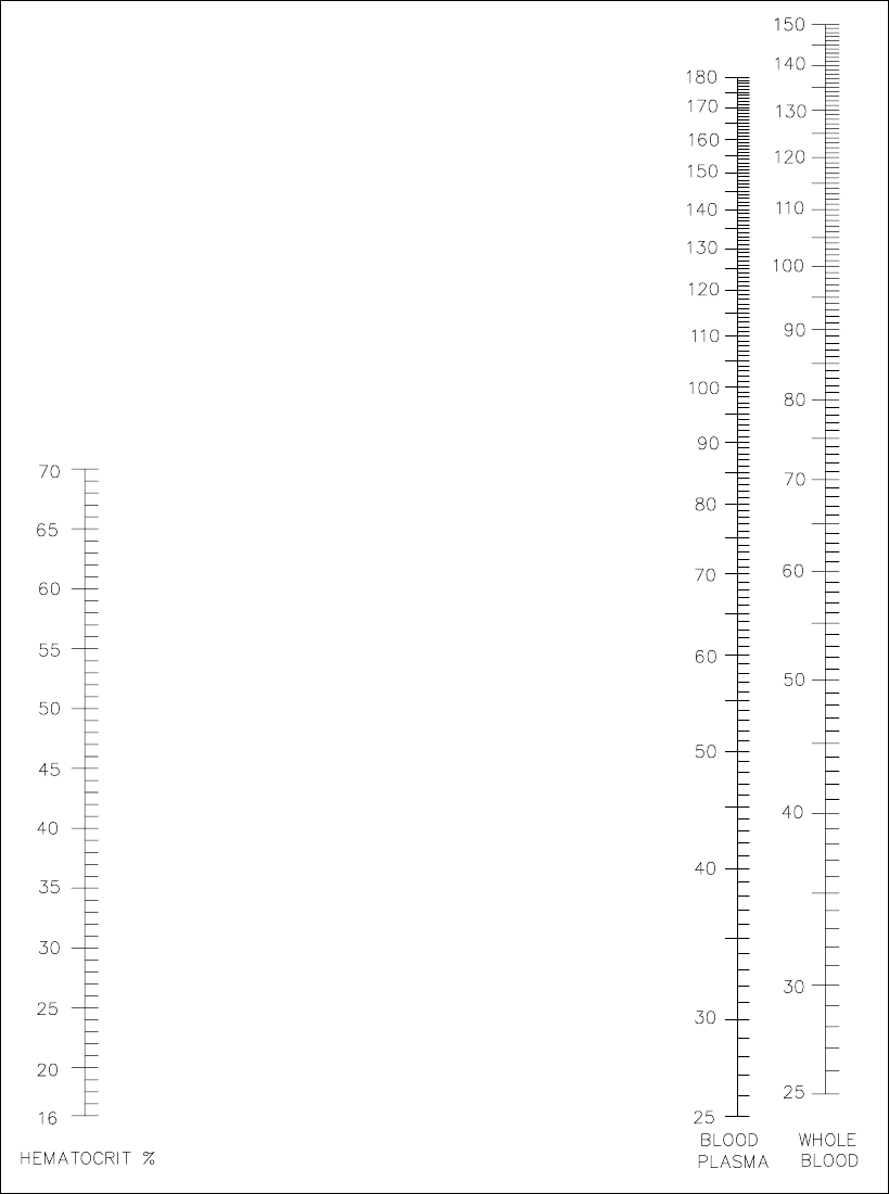
15-3
Figure 15.1
Whole Blood Conversion Nomogram (mg/dL)
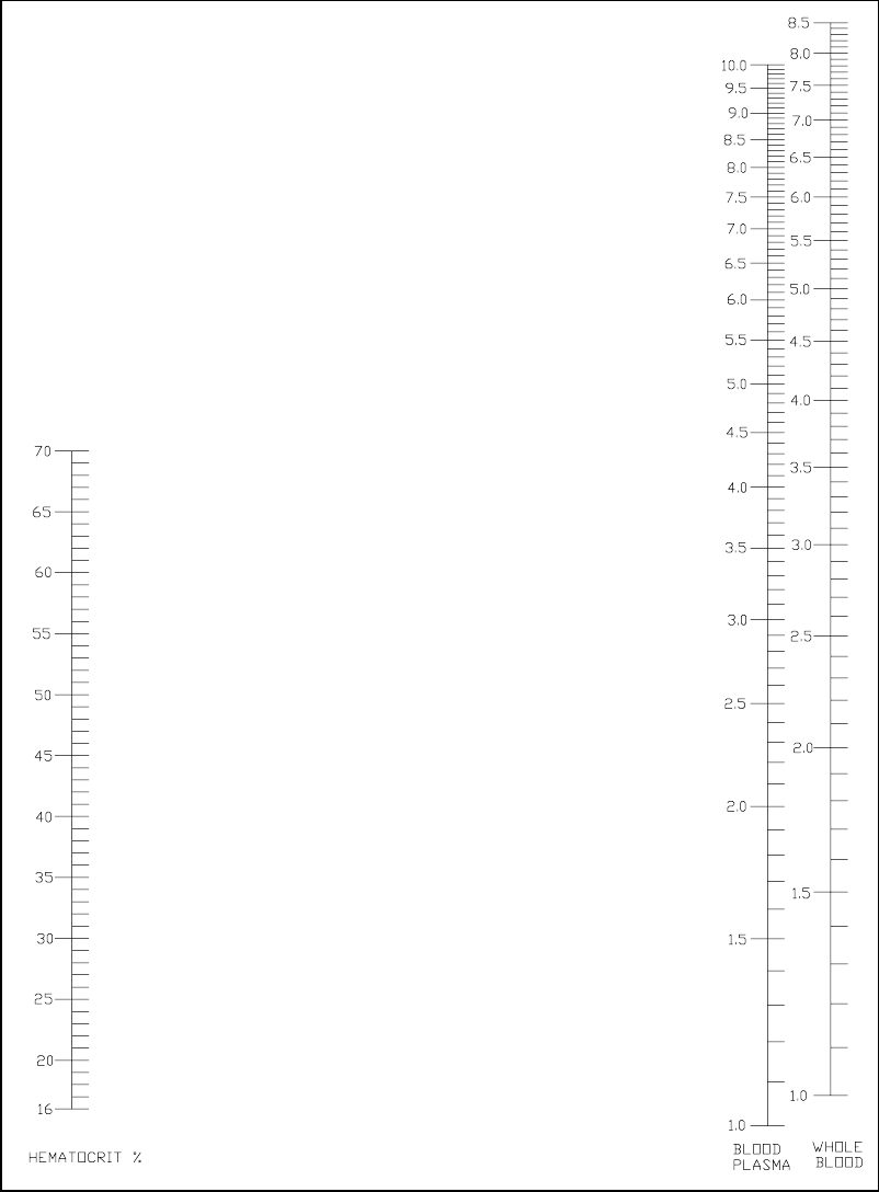
15-4
Figure 15.2
Whole Blood Conversion Nomogram (mmol/L)
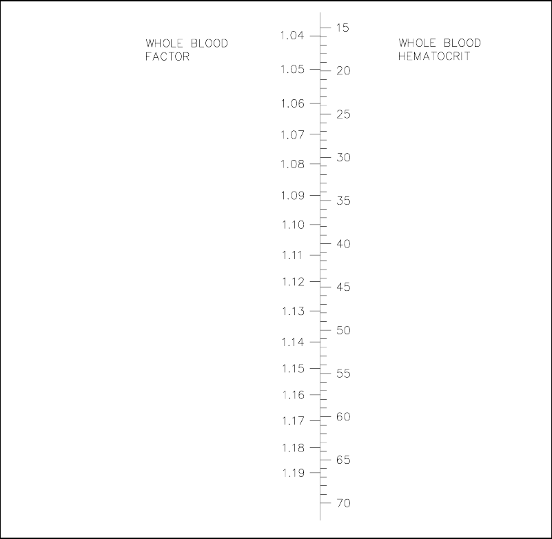
15-5
To convert whole blood glucose values to equivalent plasma glucose values, find the Whole
Blood Factor which corresponds to the sample’s whole blood hematocrit percentage and then
use the following equation:
Equivalent Plasma Glucose Value =
(Whole Blood Reading x Whole Blood Factor)
Example: Whole Blood Reading = 85 mg/dL (4.7 mmol/L)
Hematocrit = 40 %
Whole Blood Factor = 1.11
Equivalent Plasma Glucose Value =
(85 x 1.11) = 94 mg/dL (5.2 mmol/L)
Figure 15.3
Whole Blood Factor Chart
15-6

16-1
16. Appendix E–YSI Supplies and
Reagents
September 2009
ENZYME MEMBRANE KITS
YSI # PRODUCT DESCRIPTION QUANTITY
2329 L-Lactate Membrane Kit 4/kit
2365 Dextrose Membrane Kit 4/kit
BUFFER
YSI # PRODUCT DESCRIPTION QUANTITY
2357 Buffer Kit (for all membranes listed above) 4 liters*
STANDARDS FOR 2300 STAT PLUS
YSI # PRODUCT DESCRIPTION QUANTITY
2747 Dual Standard (glucose/L-lactate) 250 mL
(Glu: 10.0 mmol/L, 180 mg/dL)
(Lac: 5.0 mmol/L, 45 mg/dL)
2328 L-Lactate Standard, 15.0 mmol/L or 134 mg/dL 125 mL
2356 Glucose Standard, 500 mg/dL or 27.8 mmol/L 125 mL
1530 L-Lactate Standard, 30.0 mmol/L or 267 mg/dL 125 mL
1531 Glucose Standard, 900 mg/dL or 50.0 mmol/L 125 mL
GENERAL REAGENTS AND MISCELLANEOUS SUPPLIES
YSI # PRODUCT DESCRIPTION QUANTITY
1515 Cell Lysing Agent 4 Liters*
2363 Potassium Ferrocyanide, 1000 mg/dL 125 mL*
2392 NaCl Solution (sodium chloride) 125 mL*
2751 Printer Paper (5 rolls/box) 1 box
2788 Preventitive Maintenance Kit 1 kit
2399 IQ/OQ Documentation Package
2340 Data Collection Software
* Makes specified volume when reconstituted.
Contact YSI or your authorized dealer for more information on ordering supplies and reagents
for the YSI 2300 STAT PLUS.
16-2

17-1
17. Appendix F–Warranty and Shipping
Information
The YSI Model 2300 STAT PLUS Analyzer is warranted for one year from date of purchase by
the end user against defects in materials and workmanship, exclusive of batteries. Within the
warranty period, YSI will repair or replace, at its sole discretion, free of charge, any product
that YSI determines to be covered by this warranty. To exercise this warranty, write or call your
local YSI representative, or contact YSI Customer Service in Yellow Springs, Ohio. Send the product
and proof of purchase, transportation prepaid, to the Authorized Service Center selected by YSI.
Repair or replacement will be made and the product returned, transportation prepaid. Repaired or
replaced products are warranted for the balance of the original warranty period, or at least 90 days
from date of repair or replacement.
Limitation of Warranty
This Warranty does not apply to any YSI product damage or failure caused by (i) failure to install,
operate or use the product in accordance with YSI’s written instructions, (ii) abuse or misuse of the
product, (iii) failure to maintain the product in accordance with YSI’s written instructions or standard
industry procedure, (iv) any improper repairs to the product, (v) use by you of defective or improper
components or parts in servicing or repairing the product, or (vi) modification of the product in any
way not expressly authorized by YSI.
THIS WARRANTY IS IN LIEU OF ALL OTHER WARRANTIES, EXPRESSED OR IMPLIED,
INCLUDING ANY WARRANTY OF MERCHANTABILITY OR FITNESS FOR A PARTICULAR
PURPOSE. YSI’s LIABILITY UNDER THIS WARRANTY IS LIMITED TO REPAIR OR
REPLACEMENT OF THE PRODUCT, AND THIS SHALL BE YOUR SOLE AND EXCLUSIVE
REMEDY FOR ANY DEFECTIVE PRODUCT COVERED BY THIS WARRANTY. IN NO EVENT
SHALL YSI BE LIABLE FOR ANY SPECIAL, INDIRECT, INCIDENTAL OR CONSEQUENTIAL
DAMAGES RESULTING FROM ANY DEFECTIVE PRODUCT COVERED BY THIS WARRANTY.
YSI Factory Service Centers
United States
YSI Incorporated • Repair Center • 1725 Brannum Lane • Yellow Springs, OH • 45387 • Phone: 937 767-7241
• Fax: 937 767-9353
Europe
YSI (UK) Ltd • 119 Fleet Road • Fleet, Hampshire • GU51 3PD • Phone: 44 1252 819844 • Fax: 44 1252 819544
Japan
YSI (Japan) Ltd • 3Fl., Sakura Building 5-6-13 • Shinjuku • Shinjuku-ku • Tokyo 160 • Phone: 813 5360-3561
• Fax: 813 5360-3565

17-2
17.1 Cleaning Instructions
NOTE: Before they can be serviced, equipment exposed to biological, radioactive, or toxic
materials must be cleaned and disinfected. Biological contamination is presumed for any
instrument, probe, or other device that has been used with body fluids or tissues, or with waste
water. Radioactive contamination is presumed for any instrument, probe or other device that
has been used near any radioactive source.
If an instrument, probe, or other part is returned or presented for service without a Cleaning
Certificate, and if in our opinion it represents a potential biological or radioactive hazard, our
service personnel reserve the right to withhold service until appropriate cleaning,
decontamination, and certification has been completed. We will contact the sender for
instructions as to the disposition of the equipment. Disposition costs will be the responsibility
of the sender.
When service is required, either at the user's facility or at YSI, the following steps must be
taken to insure the safety of our service personnel.
1. In a manner appropriate to each device, decontaminate all exposed surfaces, including any
containers. See Appendix H for cleaning instructions.
2. The user shall take normal precautions to prevent radioactive contamination and must use
appropriate decontamination procedures should exposure occur.
3. If exposure has occurred, the customer must certify that decontamination has been
accomplished and that no radioactivity is detectable by survey equipment.
4. Any product being returned to the YSI Repair Center, should be packed securely to prevent
damage.
5. Cleaning must be completed and certified on any product before returning it to YSI.

17-3
17.2 Packing Instructions
1. Clean and decontaminate items to insure the safety of the handler.
2. Complete and include the Cleaning Certificate.
3. Place the product in a plastic bag to keep out dirt and packing material.
4. Use a large carton, preferably the original, and surround the product completely with
packing material.
5. Insure for the replacement value of the product.
Cleaning Certificate
Organization
Department
Address
City State Zip
Country Phone
Model No. of Device Lot Number
Contaminant (if known)
Cleaning Agent(s) used
Radioactive Decontamination Certified?
(Answer only if there has been radioactive exposure)
Yes No
Cleaning Certified By
Name Date
17-4

18-1
18. Appendix G–Required Notice
The Federal Communications Commission defines this product as a computing device and
requires the following notice:
This equipment generates and uses radio frequency energy and if not installed and used
properly, may cause interference to radio and television reception. It has been type tested and
found to comply with the limits for a Class A or Class B computing device in accordance with
the specification in Subpart J of Part 15 of FCC Rules, which are designed to provide
reasonable protection against such interference in a residential installation. However, there is
no guarantee that interference will not occur in a particular installation. If this equipment does
cause interference to radio or television reception, which can be determined by turning the
equipment off and on, the user is encouraged to try to correct the interference by one or more of
the following measures:
a) reorient the receiving antenna
b) relocate the computer with respect to the receiver
c) move the computer away from the receiver
d) plug the computer into a different outlet so that the computer and receiver are on
different branch circuits.
If necessary, the user should consult the dealer or an experienced radio/television technician for
additional suggestions. The user may find the following booklet prepared by the Federal
Communications Commission helpful: "How to Identify and Resolve Radio-TV Interference
Problems." This booklet is available from the U.S. Government Printing Office, Washington,
D.C. 20402, Stock No. 0004-000-00345-4.
18-2

19-1
19. Appendix H–Cleaning, Disinfecting,
and Decontamination Procedures
Proper precautionary lab practices should be followed when handling biological hazards.
Suggested cleaning and disinfecting solutions include:
» Isopropanol 70%
» Sodium hypochlorite, 5000 ppm free available chlorine (1:10 solution of household
bleach)
Decontamination Procedures
Remove and discard all tubing. New tubing is provided in preventive maintenance kit. Empty
waste bottle and wash with disinfecting agent. Remove Sample Chamber, Sipper, Test Tube
Holder and probes according to instructions.
Thoroughly clean with disinfecting agent, then rinse with warm water. Remove probes and
discard membranes. Clean probes with isopropanol only, rinse with warm water. Clean up all
spills, then reassemble.
19-2

20-1
20. Appendix I–Printed Setup Information
You may print your 2300 STAT PLUS instrument setup anytime by entering the Setup menu.
You are not required to leave RUN Mode or STANDBY Mode to access this information.
Main Menu display:
Please select instrument mode
[RUN] [STANDBY] [MENU]
From Main Menu, press [MENU].
Select instrument function
1-Service 2-Setup 3-Diagnostic
From Select instrument function, press [2] for Setup.
NOTE: If you are in RUN or STANDBY modes, press [MENU] to go directly to the display
shown below.
Select setup: 1-General 2-MeasParameter
3-RunMode 4-Report 5-PrntSetup 6-Default
From Select setup, press [5] for PrntSetup, to print all of the instrument parameters currently in
memory.
If you repowered the instrument, or reset the instrument using the reset button, the printout first
shows an instrument identification, including the software version number. Once you command
the instrument to "Print Setup", the Instrument Setup prints out on the paper tape. This takes
about 45 seconds.
The information on the printout completely describes the system parameters, whether using
default settings or settings that you configured for your particular application.
The Instrument Setup printout can be very useful when compiling your daily log or simply to
check your system if you suspect a problem.
You can learn about the system parameters by referring to Section 5 Menu Selections. If you
have a YSI 2710 Turntable refer to Section 10.
20-2
The printout for the 2300 STAT PLUS is shown below. Note, if calibration or sample data are
due to print while you are performing PrntSetup, the instrument will interrupt PrntSetup to print
results. PrntSetup printing then resumes automatically.
INSTRUMENT SETUP
----------------
Sample size 25 uL
SamStation#: 2
Mode : Normal
BLACK PROBE
Chemistry : L-Lactate
Unit : mmol/L
Calibrator : 5.00
WHITE PROBE
Chemistry : Glucose
Unit : mmol/L
Calibrator : 10.0
AUTOCAL
Time : 15 Min
Sample : 5 Sam
RUN MODE
Multicycle : OFF
Sample ID : OFF
Sip Height : Medium
Autostandby: 4 Hr
TT StartPos: 0
TT # in Run: 0
TT FluidDet: ON
Hematocrit : OFF
RS-232
Baud rate : 9600
Data : Seven bit
Stop : One bit
Parity : Even
Handshake : RTS/CTS
XON char : 17
XOFF char : 19
Mode : Non-multidrop
Address: 38
GENERAL
Radix mark : "."
Level sensor : ON
Cal Report : Brief
SampleReport : Brief
DateFormat : MM/DD/YY
Software revision: 2.25
YSI 2300D
Thu 02/26/03 00:00:48
-----------------------

21-1
21. Appendix J–Report Formats
When you setup your YSI 2300 STAT PLUS from the Setup Menu, you have the option to print
the calibration and sample results in "brief" or "detail" format. You also have the option not to
print calibration values. Review Section 5.3 Setup Selections, specifically choice 4-Report in
the Setup selection menu.
Below are example printouts of the brief and detail formats. You can learn more about the
information on the "detail" printout in Section 8 Troubleshooting.
Sample Report (Detail) Calibration Report (Detail)
-----Sample Report----- ==CALIBRATION REPORT==
ID: 123456789-05-03 B:L-Lactate* Unstable *
B:L-Lactate 4.82 mmol/L IB current 1.79 nA
IB 2.11 nA PL current 11.63 nA
PL current 18.65 nA FB current 1.51 nA
Slope 4.69 nA/min *Base shift -2.65 %
End Point 35 Sec Slope 1.42 nA/min
W:Glucose 5.38 mmol/L End Point 35 Sec
IB current 0.88 nA *Cal shift 3.64 %
PL current 15.96 nA W:Glucose 10.0 mmol/L
Slope 2.39 nA/min IB current 0.88 nA
End Point 35 Sec PL current 5.81 nA
Temperature 26.28 °C FB current 0.76 nA
Sample size 25 uL Base shift -1.95 %
Fri 02/22/03 08:12:34 Slope 0.09 nA/min
YSI 2300D - 03 01234 End Point 35 Sec
----------------------- Cal shift -0.10 %
Temperature 26.33 °C
Sample Report (Brief) Sample size 25 uL
From Test Tube Holder Thu 02/22/03 14:55:10
Sample ID: "123456789" YSI 2300D - 03 01234
Sample 1 of 3 =======================
-----Sample Report-----
ID: 123456789-03-01
B:L-Lactate 0.82 mmol/L Calibration Report (Brief)
W:Glucose 5.31 mmol/L
Wed 02/22/03 13:22:56 ==CALIBRATION REPORT==
----------------------- B:L-Lactate
16.68 nA
W:Glucose 12.81 nA
Mon 02/22/03 17:12:09
=======================
21-2
Sample Report (Brief)
From Manual position
Sample ID: "123456789"
45% Hct value entered
-----Sample Report-----
ID: MANUAL-123456789
B:L-Lactate 0.82 mmol/L
W:Glucose 5.31 mmol/L
Hematocrit 45
Wed 02/22/03 13:42:50
-----------------------
The example printouts below illustrate the report formats used by the YSI 2300 STAT PLUS
when configured for turntable sampling with the YSI 2710 Turntable. Examples of both the
brief and detail formats are presented. These examples show results of turntable runs. Note that
part of each ID is Txx, where x is a number. The ID: T01-123456789-05-03 in the first example
indicates that the third sample of five replicates at Turntable Position #1 has been reported. The
number 123456789 is a nine digit ID number that describes the current batch or run.
Remember, you can only assign an ID number to a batch. The specific sample is identified by
turntable position #, date and time.
Turntable Sample Report Calibration Report
(Detailed Format) (Detailed Format)
-----Sample Report----- ==CALIBRATION REPORT==
ID: T01-123456789-05-03 B:L-Lactate* Unstable *
B:L-Lactate 0.82 mmol/L IB current 1.79 nA
IB current 2.11 nA PL current 11.63 nA
PL current 118.65 nA FB current 1.51 nA
Base shift 0.91 % *Base shift -2.65 %
Slope 4.69 nA/min Slope 1.42 nA/min
End Point 30 Sec End Point 35 Sec
W:Glucose 8.30 mmol/L *Cal shift 3.64 %
IB current 0.88 nA W:Glucose 10.0 mmol/L
PL current 58.96 nA IB current 0.88 nA
Base shift 0.27 % PL current 5.81 nA
Slope 2.39 nA/min FB current 0.76 nA
End Point 35 Sec Base shift -1.95 %
Temperature 26.28 °C Slope 0.09 nA/min
Sample size 25 uL End Point 35 Sec
Fri 02/22/03 08:12:34 Cal shift -0.10 %
YSI 2300D - 03 01234 Temperature 26.33 °C
----------------------- Sample size 25 uL
Thu 02/22/03 14:55:10
Turntable Sample Report YSI 2300D - 03 01234
(Brief Format) =======================
Batch ID: 123456789
Turntable Position #01
Replicate 1 of 3 Calibration Report
(Brief Format)
-----Sample Report-----
ID: T01-123456789-03-01 ==CALIBRATION REPORT==
B:L-Lactate 0.82 mmol/L B:L-Lactate 16.68 nA
W:Glucose 5.31 mmol/L W:Glucose 12.81 nA
Wed 02/22/03 13:22:56 Mon 02/22/03 17:12:09
----------------------- =======================

22-1
22. Appendix K–Considerations when
Measuring Lactate in Whole Blood
L-lactate is present both inside (intracellular) and outside (extracellular) red blood cells in a
whole blood sample. As lactate production in the body occurs, the intracellular and
extracellular lactate concentrations adjust toward equilibrium. However, this process occurs
continuously and relatively slowly, possibly leading to situations where intracellular and
extracellular lactate levels differ significantly. As a result, lactate measurement methods which
measure only extracellular lactate are highly dependent on timing and hematocrit.
To avoid these timing and hematocrit dependencies, a cell lysing system can be used when
measuring lactate in whole blood. Cell lysing allows for the measurement of both intracellular
and extracellular lactate, giving a Total Blood Lactate measurement.
The YSI 2300 STAT Plus has the capability of measuring either extracellular lactate or Total
Blood Lactate. YSI 2357 Buffer, used in the instrument, is isosmotic with respect to red blood
cells.
EXTRACELLULAR LACTATE MEASUREMENT - NON-LYSING
By using YSI 2357 Buffer and analyzing whole blood samples, a non-lysing system is
achieved. When sample is introduced into the sample chamber, the red blood cell membrane
acts as a barrier, prohibiting the intracellular lactate from interacting with the YSI measurement
sensor. Only the extracellular lactate is detected by the sensor. However, any unintentional cell
lysing caused by sample handling can affect extracellular lactate measurements.
TOTAL BLOOD LACTATE - LYSING
YSI offers the 1515 Cell Lysing agent, which is added to the 2357 Buffer. As samples are
introduced into the sample chamber containing this agent, the red blood cells are ruptured. The
intracellular lactate and the extracellular lactate then become accessible to the YSI
measurement sensor. This system yields Total Blood Lactate values. Total blood lactate
measurements are unaffected by equilibrium issues.
A NOTE ABOUT GLUCOSE
The behavior of glucose under these conditions is quite different than that of lactate. In a non-
lysing system, glucose migrates through the red blood cell membrane immediately and quickly
upon introduction of the sample into the sample chamber. Glucose measurements, therefore,
reflect the total of both the intracellular and extracellular glucose concentrations. And, of
course, in a lysing system, the total glucose concentration is also measured. Glucose results on
the YSI 2300 STAT Plus are unaffected by YSI 1515 Cell Lysing agent.
22-2

23-1
23. Appendix L–CE Compliance
Important Notice regarding CE standards compliance:
1. Users should not open the front access door during operation, internal components may be
susceptible to ESD (electrostatic discharge).
2. Users are cautioned not to touch the sipper needle during operation, as discussed in the
users manual. The sipper mechanism is equipped with contact-sensing circuitry for the
purposes of fluid detection and human safety. This circuitry may be susceptible to ESD.
ESD to the sipper needle may cause instrument malfunction.
3. Users should note that RS232 communications may be susceptible to ESD. Data corruption
or serial communications failure may occur. If malfunction occurs, users may restore
proper operation by resetting communications parameters under the “General/RS-232”
setup menu.

YSI Incorporated
1725 Brannum Lane
Yellow Springs, Ohio 45387 USA
937 767-7241 • 800 659-8895
Fax 937 767-8058
Info@ysi.com
www.ysilifesciences.com
CEPartner4U BV
Esdoornlaan 13
3951DB Maarn
The Netherlands
+31 (0) 6-516.536.26
062861
A62861J
2009-09
© 2009 YSI Incorporated
