Yamaha SY99 Battery Replacement
User Manual: SY99
Open the PDF directly: View PDF ![]() .
.
Page Count: 13
1
Yamaha SY99 Battery Replacement Procedure
Author
Derek Cook, December 2012
Purpose of Document
Like a lot of synthesizers, the SY99 uses CR2032 Lithium Cells to backup the data and
internal sample memory.
The SY99 has two batteries
• One on the DM1 card for internal data such as voices;
• One on the DM2 card for internal custom samples.
These batteries tend to go for 20+ years without any problems; much longer than the
typical life quoted in the user manual.
Unfortunately on the SY99 the batteries are of the type that have solder connections, and
are soldered to the PCBs, which makes replacing them awkward.
Whilst performing my SY99 display upgrade (see related guide), I noted that one of the
batteries was quite low in voltage (around 1.1V), so time to replace them, and also time to
put in batteries holders to make replacement easier next time around (circa 2034!).
This guide shows you what I did to achieve this, written as a separate guide, and assuming
this is the only job that you are doing on the synth.
I couldn’t find battery holders that had the correct pin spacing for the PCB layout for the
soldered batteries, but this didn’t deter me!
Disclaimer
Whilst I have taken care in preparing this guide, and whilst the upgrade worked fine on my
SY99, I cannot be held responsible for any damage that you could do to your machine or
injury to yourself and/or others as a result of you following these notes; either on your own
account or by any error or omission in this guide. You do this upgrade entirely at your own
risk!
Please bear in mind that during a production run of any manufactured item, a manufacturer
can make changes, and I can’t guarantee that all SY99 machines are identical, as I only
have the one. So care is needed in checking that the steps advised are appropriate for your
machine, as it might be different to mine.
Pre-Requisites
First of all, make sure that you’re comfortable with the concept of dismantling your beloved
SY99, including unsoldering the batteries from the synth’s circuit boards.
You also need to be proficient in soldering, or know somebody who is and who can help you.

2
You will need the following tools to do this job:
• Posidrive screwdrivers;
• Wire cutters;
• Some small fine nose pliers also come in handy;
• Soldering iron and solder;
• A desoldering pump, or solder removal wick;
• An anti-static wrist strap is recommended;
• Voltmeter (to check battery voltage before closing up).
You need to ensure that you take anti-static precautions whilst the synth is open. If you
don’t have an anti-static wrist strap, then ensure that you regularly earth yourself on a
metal object, such as a radiator to prevent the build up of any static charge.
Electric Shock Hazard Warning
Be very aware that in opening the keyboard, and if it is powered whilst it is open, there will
be exposed mains voltages on the power supply board and thus a risk of electric shock.
Obviously, the synth only needs to be powered up for short periods whilst it is disassembled.
If you keep your hands well away from the power supply board when the case is open and
the synth is powered, then the odds of you getting an electric shock will be very small.
If you are in any doubt regarding your ability to work safely with a potential exposed mains
voltage hazard, then you should refer this job to a competent electronics technician.
3
Procedure
Step 1 – Backup your Data
Removing the backup batteries whilst power is off is going to cause data loss, so ensure that
all of your important user data (Voices, Waves, etc.) is backed up to floppy disk, or via MIDI
to computer.
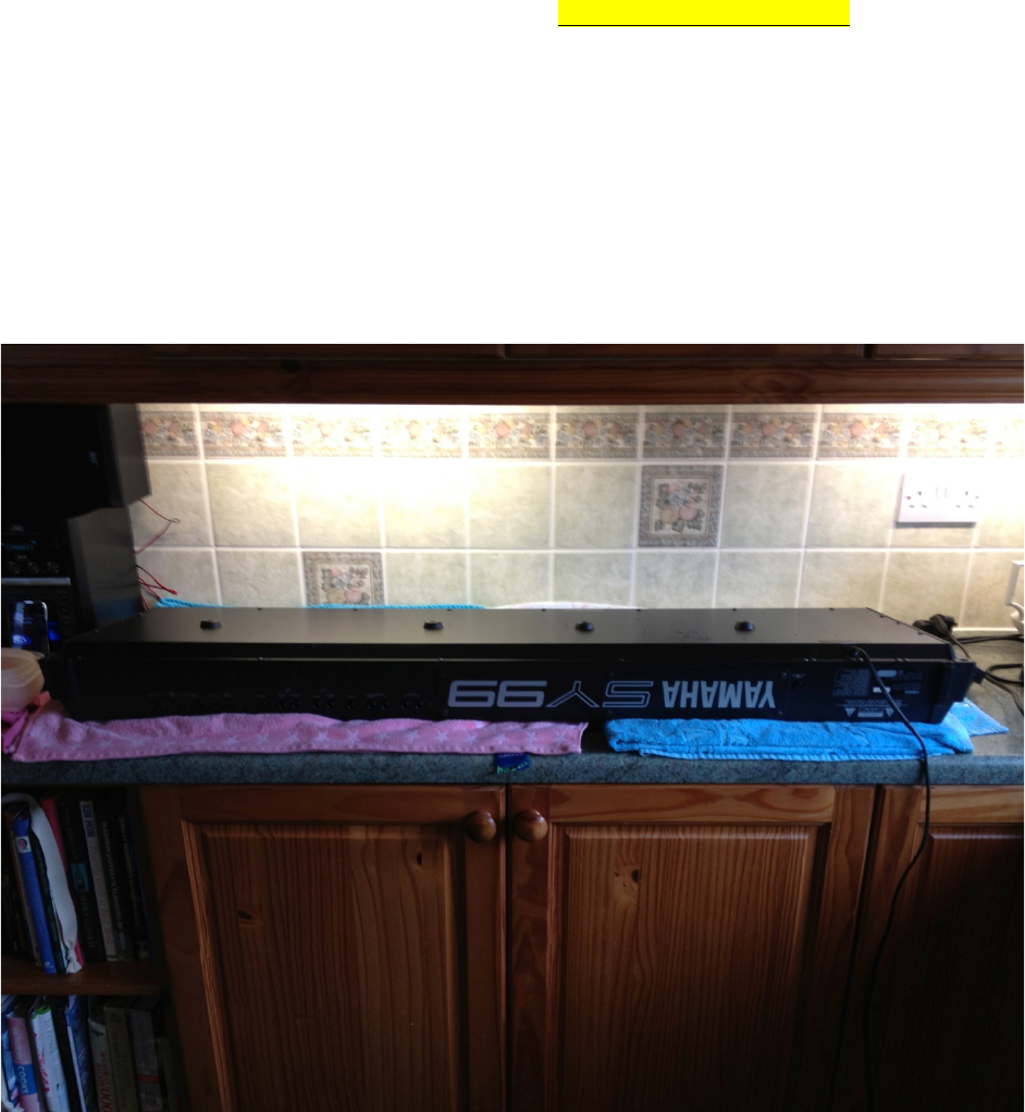
Step 2 – Find a Good Work Area
You’ll be working on this for a little while, so find somewhere comfortable and where there’s
plenty of light. My kitchen was the best place for this in my house. Note the towels under
the keyboard to protect the fascia.
References in this document to “top” and “bottom”, “left” and “right”, refer to you looking at
the keyboard in this orientation of the base upwards and the back panel towards you.
Whilst on the subject of avoiding scratches, the next step is very important!
4
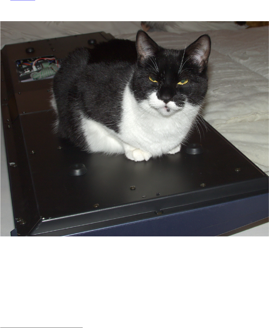
Step 3 – Remove Cat from Work Area
An EX5Tech pre-requisite in the guides we write, and a very important step if you wish to
avoid being “scrammed”! And of course, cat hair is terrible for static, and it gets
everywhere1!
1 Synth Trivia: If you’re in the market for an OSCAR monosynth, look out for one where the
innards contain cigarette ash and cat hair; as these were supposedly hand built by chain
smoking, cat loving Chris Huggett, the main man behind the Oxford Synthesiser Company.
5
Step 4 – Remove Bottom Plate
The first big step is to undo all the screws on the bottom plate (including the four rubber
feet). The plastic end cheeks can be left in place.
As there are only a few different types of screws, I didn’t worry about making diagrams as
to where they came from, but I kept the external screws in one bowl, and the internal
screws in another to make it easier to sort them out later.
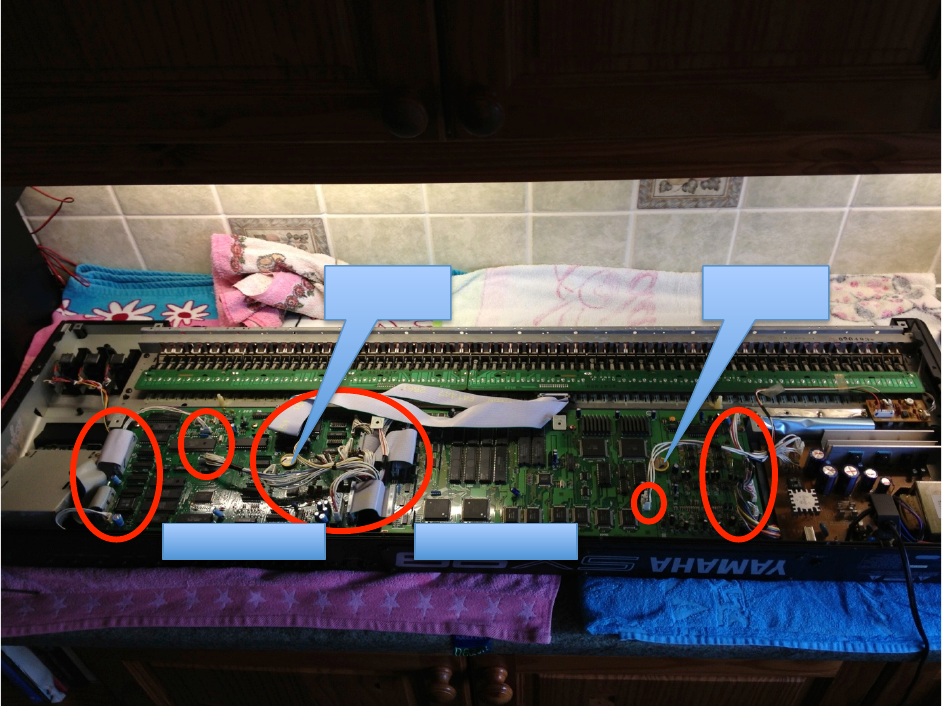
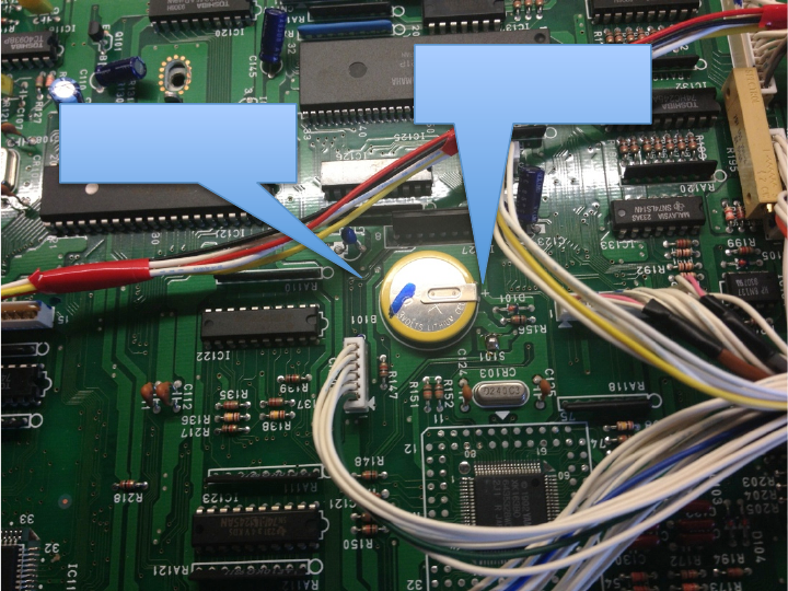
With the bottom cover removed you can see that there are two main boards, DM1 and DM2,
with quite a few connectors going between them. All of these connectors need to be
removed. Fortunately, all of them have different numbers of pins, and thus their associated
plugs cannot be connected in the wrong place. So I didn’t worry about labeling the leads
with the numbers of the Printed Circuit Board (PCB) connectors that they go to.
DM1 Board
DM2 Board
Battery 1
Battery 2
6
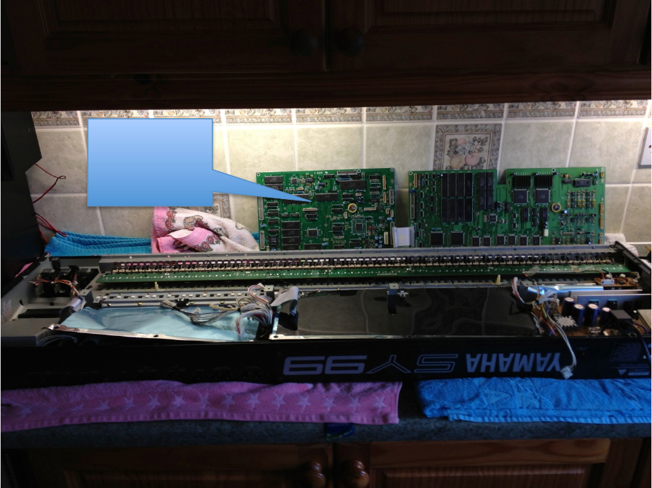
Step 5 – Remove Main Boards
Remove all the identified connectors and unscrew and remove the boards. Each board is
held by six screws, three at the front and three at the back. Alternatively, if you wish, undo
the connectors on one side of the boards only and you can then gently turn the boards over
whilst some of the connectors are still attached.
Fortunately, compared to the display upgrade, this is all of the dismantling that you need to
do!
Boards
removed
ready for the
upgrade
7
Step 6 – Remove the Existing Batteries
Locate the batteries on the DM1 and DM2 boards and desolder them, ensuring that the
through holes in the PCB are clear of solder.
Soldered Battery
on DM1 Card
Note the + mark
on the board

8
Step 7 – Prepare the Battery Holders
As mentioned, I couldn’t find battery holders with the correct pin spacing, but I was OK with
that as I felt that I could improvise! The holders that I found (see the Parts List at the end of
the guide) had the terminals on small legs, so there was space to feed a wire underneath
them.
The following worked for me. Prepare two battery holders like this.
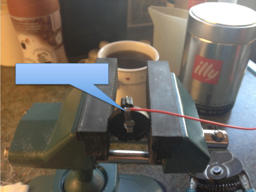
Cut the +VE terminal underneath the holder, flush to the base of the holder. This pin is used
for the modification, because there is some “real estate” above the holder on this terminal
on which a lead can be soldered.
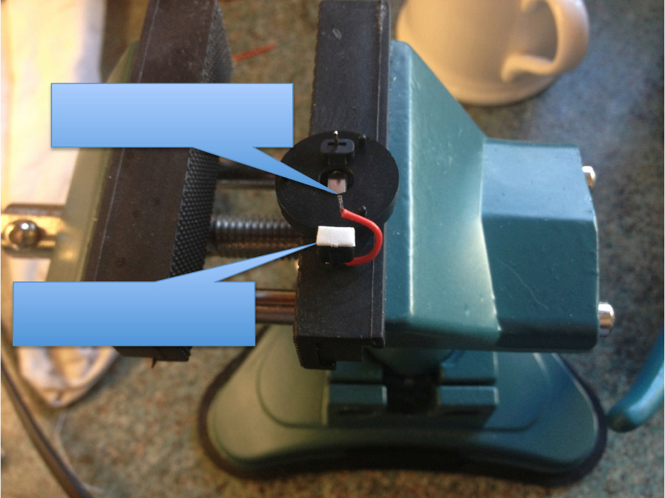
Leave the 0V pin alone.
The +VE pin has been cut
close to the base
The morning brew of Java!
The 0V pin has been left
alone
9
Solder a lead direct to the +VE terminal on the top of the holder.
Lead soldered on the upper
side of the +VE terminal
10
Shape the lead and cut it short so that it fits under the holder.
Strip and tin the lead ready for soldering into the PCB.
Put a double sided self adhesive pad, cut to size, where the +VE pin was cut short. This will
help secure this side of the holder to the PCB, and it also insulates the pin that was cut
short.
Step 8 – Solder the Battery Holders
This is the same for both DM1 and DM2 cards.
Insert the lead into the +VE hole on the PCB, where the original battery was soldered, then
put the 0V terminal in and press down to secure the holder with the self adhesive pad.
And of course, solder the leads.
Step 9 – Insert Batteries and Check Voltage
Place the fresh batteries into the holder, taking care not to short the positive and negative
terminals. Check the voltage to ensure that it is better than 3V, which indicates a nice
healthy battery.
Lead now cut short, stripped,
tinned and shaped to come
under the holder
Double sided self adhesive pad
covering the pin that was cut
short
11
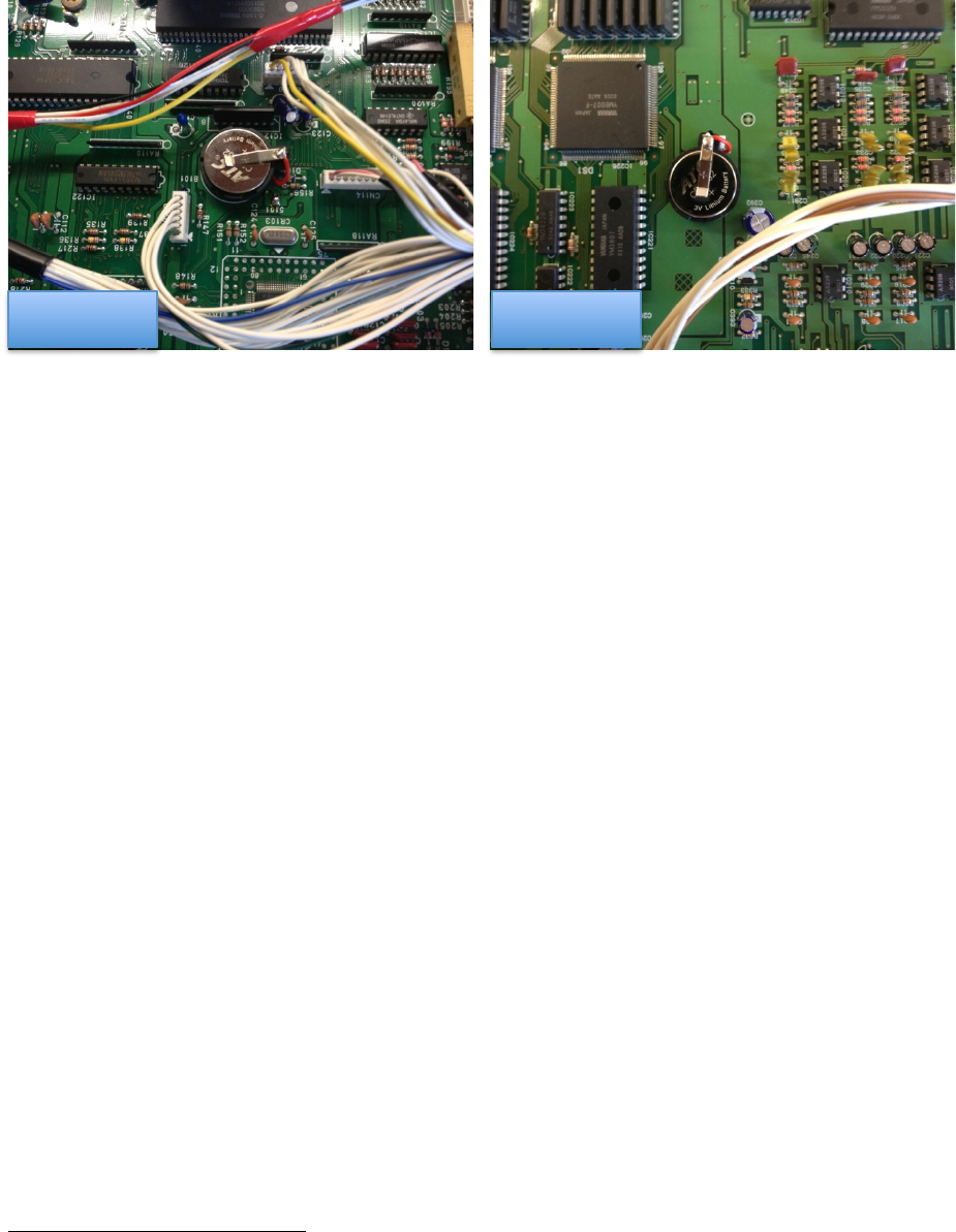
Here is what the completed job looks like on the DM1 and DM2 Cards.
Step 10 – Reassemble Keyboard
So easy to say it, but assembly is “simply” the reverse of disassembly, replacing the boards
into the synth, taking care that all the connectors go back in the right place!
Step 11 – Power on and Reset Synth
Power the synth on. The chances are that it will not even make as sound (mine didn’t, even
on the preset sounds) as the internal memory (including system settings) are now blank.
To get going again, press the Voice, D and 82 keys together to enter the diagnostic mode.
Press the COPY button to reinitialize the synth with the factory set data. This should get it
all going again.
Conclusion
By the end of this, hopefully you now have fresh batteries in the keyboard, which are now
also easier to replace in future, but probably good for another 20 years!
And hopefully, you had no screws left over!
2 The 8 button in the Voice select buttons 1-16 under the D button, not the one on the
numeric pad.
DM1 Card
DM2 Card

12
Acknowledgements
The “Cat on Keyboard” shot is courtesy of my EX5Tech colleague, Jim Attfield. The
observant of you will notice that the keyboard in this instance was not an SY99.
Parts List
The following table provides a list of parts that I used in this project.
Part
Description
Supplier
Link
L01AC
CR2032 PCB Battery Holder
Maplin
http://www.maplin.co.uk
ZB74R
CR2032 Lithium Cell
Maplin
http://www.maplin.co.uk

13
Links
EX5Tech as a good resource for the EX5, with sub forums for other Yamaha synths:
http://www.ex5tech.com
The Yamaha UK forums also provide a very good forum for all things Yamaha (and more),
which is a good resource for the Yamaha SY series, and there has been a lot of activity
recently about doing upgrades on the SY77, TG77 and SY99.
http://www.yamahaforums.co.uk/
Finally, a bit of blatant self promotion(!):
My website for my Java based x.factory librarians, available for the EX5, AN1x, FS1R,
DX7/DX7II and Motif synthesizers and, of course, the SY77, TG77 and SY99!
http://www.xfactory-librarians.co.uk/
My Pink Floyd Tribute Band, Pure Floyd
http://www.purefloyd.co.uk/
My Celtic/Ambient/Progressive project, Carreg Ddu
http://www.carregddu.co.uk/
And my progressive/classic rock influenced project, Echoes
http://www.echoes-music.co.uk/
