Z Uno Quick Start Guide
User Manual:
Open the PDF directly: View PDF ![]() .
.
Page Count: 21
Create your own
Z-Wave device

Сontents
Introduction
What is Z-Uno? What is Arduino?
What is Z-Wave? What is the difference between Z-Uno and Arduino?
What can I do with Z-Uno? Share your experience!
First use
Connecting the Z-Uno to your PC Uploading user sketch
Installing Arduino IDE Including Z-Uno in Z-Wave controller
Z-Uno in Arduino IDE
Basic programming
setup and loop PWM
C language USB
delay Using breadboard
Input and output Precautions about connecting 5 V sensors
ADC
Z-Uno channels
Channels concept Sensor Binary
Switch Binary Meter
Switch Multilevel Combining several channels
Sensor Multilevel Controlling the Z-Uno from other Z-Wave devices
Controlling other Z-Wave devices from Z-Uno
Associations concept Scene activation
Setting Value Door lock operation
Dimming Controlling multiple devices on different events
More powering options
Battery devices
Sleeping
FLiRS
Security considerations
Debugging your code
Debugging via USB Rescue Mode
Compilation errors Factory Reset
Precautions and common errors
Z-Uno advanced features
Where to get more info?
4
6
10
16
24
30
34
34
36
38
38
4 5
What is Z-Uno?
What is Z-Wave?
What can I do with Z-Uno?
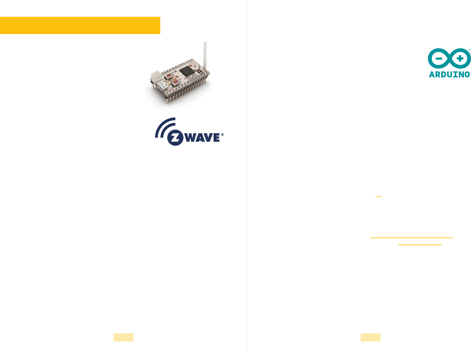
Z-Uno is a prototyping and development board
tobuild your own smart home and IoT devices
based on Z-Wave technology. Using Z-Uno
neither requires hard programming skills nor
aspecial expensive development environment.
Using Z-Uno is very simple.
With Z-Uno you can make devices similar to an existing one, as well as create entirely
new devices with more features or devices adopted to your own case. Forexample,
with Z-Uno you can make a ten channel Z-Wave switch, irrigation system controller
ora radiation sensor.
Z-Wave is the leading wireless technology for
smart homes and IoT. Z-Wave is used inmillions
of smart homes worldwide.
Z-Wave is a mesh network — devices use their neighbours to route messages from
sender to destination device.
Compared to other technologies Z-Wave implies product certication to keep a very
high level of compatibility across brands. Z-Wave Alliance is in charge of protocol
evolution and compatibility tests. There are more than 1700 certied devices from
more than 450 Z-Wave Alliance members.
Creating your own Z-Wave devices requires a special toolkit and very deep program-
ming skills. Z-Uno solves this by providing an easy, but still powerful way tomake
your own Z-Wave devices.
Introduction
Share your experience!
The Z-Uno community is very creative and likes to share. You can nd many exam-
ples andprojects made by other people on https://z-uno.z-wave.me/examples. Made
something worth sharing? Do not hesitate to send it to z-uno@z-wave.me.
This guide is released under a Creative Commons Attribution-ShareAlike 3.0 License.
You are free to use, modify and share it as long as you keep the same license and the
reference to the original artwork.
What is Arduino?
What is the difference between Z-Uno and Arduino?
Arduino is the name of very popular development and proto-
typing boards made for education and do-it-yourself. There
are many different variants and clones of Arduino boards
and many compatible hardware and peripheral solutions.
Think of Z-Uno as a variant ofArduino with built-in Z-Wave support.
To make your experience smooth and easy Z-Uno is using the same programming
environment as Arduino. Arduino IDE allows to easily write and upload your program
(called sketch) in your Z-Uno as well as to do simple debugging and upgrade it to the
latest version.
Most Arduino boards are based on an Atmel microcontroller from the AVR family.
Incontrast, Z-Uno is based on a Sigma Designs microcontroller based on the Intel
8051 family. This implies some restrictions on big programs.
While choosing hardware for your Z-Uno from the Arduino world please note that
Arduino boards and compatible sensors are usually powered by 5 V, while Z-Uno
requires 3.3V. Consider precautions on page 15.
6 7
First use
Connecting the Z-Uno to your PC
Installing Arduino IDE
Creating new devices with Z-Uno is simple:
• design your electrical schematics
• connect peripherals to Z-Uno according to the schematics
• write and upload your program into Z-Uno
To program Z-Uno connect it with a USB cable to a computer with Arduino IDE
installed. Once Z-Uno is programmed it can be disconnected from USB (if your Z-Uno
usage does not require USB connection).
Z-Uno can also be powered from 3.3 V (3V pin), 5 V (5V pin) or 7-18 V (Vin pin). On 3V
pin Z-Uno tolerates voltage in range from 2.8 to 3.6 V.
Arduino IDE is a user interface for editing and uploading new sketches to Z-Uno.
Arduino IDE is developed by https://arduino.cc and the Arduino Community world-
wide and can be downloaded from https://www.arduino.cc/en/Main/
OldSoftwareReleases#1.5.x
Do not connect more than one power source atatime.
Thiscan damage the Z-Uno power circuit oryour power
source.
Currently only version 1.6.5 of Arduino IDE is supported.
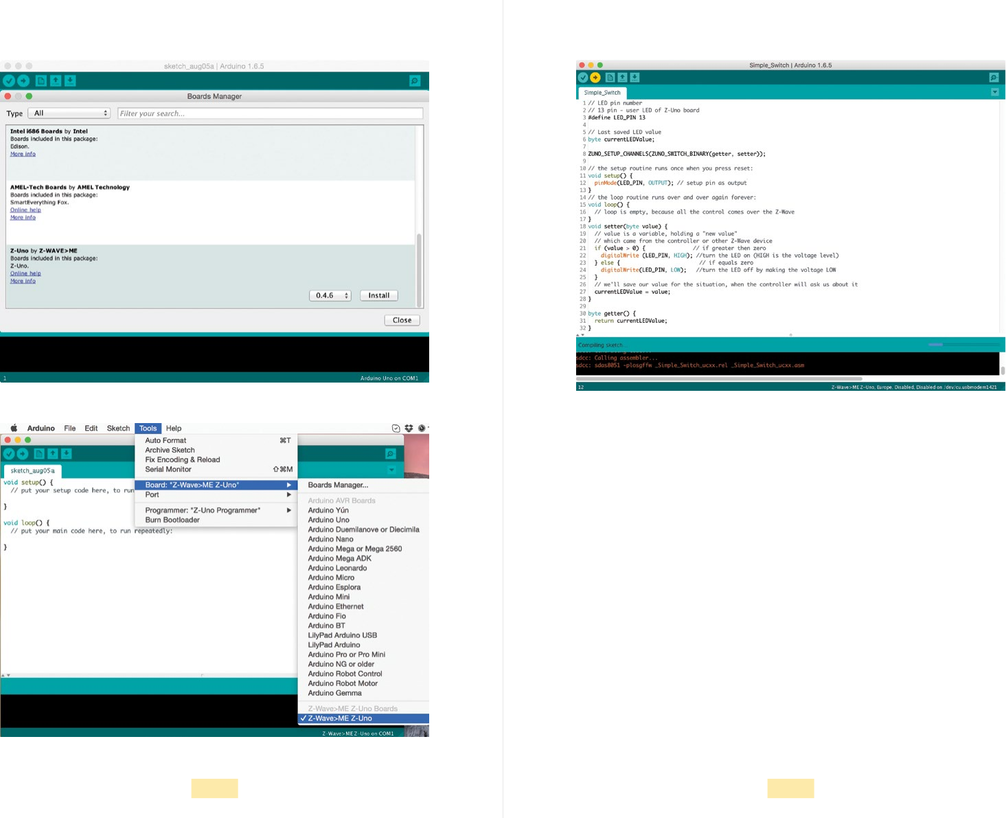
Z-Uno in Arduino IDE
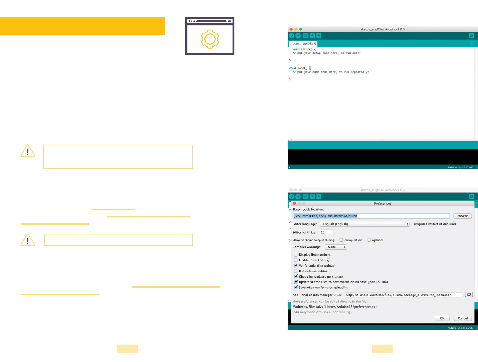
Arduino IDE requires a special Z-Uno package. To install Z-Uno package rst go
toPreferences (File > Preferences) and enter http://z-uno.z-wave.me/les/z-uno/
package_z-wave.me_index.json in Additional Board Manager URLs eld. Then go
toBoard Manager (Tools > Board > Board Manager) and scroll to Z-Uno package.
Wesuggest to always use the latest version of Z-Uno package. Once done, connect
your Z-Uno, InTools > Board menu select Z-Uno board, in Tools > Port menu select
the port that isrelated with your Z-Uno and upgrade it’s bootloader code (Tools >
Burn Bootloader).
Picture 1. Installing Arduino IDE
Picture 2. Z-Uno in Arduino IDE
8 9
Picture 3. Z-Uno in Arduino IDE Picture 5. Uploading user sketch
Picture 4. Z-Uno in Arduino IDE Every few months a new version of Z-Uno package is released. Use Board Manager
toupdate and then upgrade Z-Uno bootloader again.
Uploading user sketch
To upload user program to your Z-Uno use Upload button in Arduino IDE.
User sketch can also be loaded wirelessly via Z-Wave protocol (so called Over-The-Air
or OTA). See online manual for more details.
10 11
Including Z-Uno in Z-Wave controller
To fully benet from your Z-Uno, include it in your Z-Wave network. For this turn your
controller in Inclusion (Add) mode (refer to the user manual of your Z-Wave controller)
and then start Learn mode on Z-Uno by pressing three times the Service button.
Sometimes user sketch prevents Z-Uno from entering into Learn mode. Use Rescue
Mode to temporarily disable user sketch.
Z-Uno is a Z-Wave Plus certied device and should work with any Z-Wave controller.
But some controllers have limited support for multiple channels, security or certain
types of sensors. To fully benet from your Z-Uno we suggest to use RaZberry orother
Z-Way based controller. See https://razberry.z-wave.me for more info.
Basic programming
If you are already familiar with Arduino programming you can skip this part. Making
Z-Uno we tried to keep it very similar to Arduino to make it easy for Arduino users.
Most of the functions have the same syntax. Still there is a slight difference in some
aspects. Please refer to Z-Uno programming reference on https://z-uno.z-wave.me/
Reference.
setup and loop
Like in Arduino, Z-Uno user code starts with setup function. The code in setup
isexecuted only once on Z-Uno power on as well on any Z-Uno wake up (for FLiRS
orSleeping devices).
It is a good practice to place here code that initializes hardware and connected
peripherals. For example, instruct Z-Uno to set pins in input or output mode or set
UART speed to 115.2 kbps.
Once Z-Uno has started, loop function is called eternally when Z-Uno is idle. This is the
right place to poll sensor values, talk to peripherals and control other Z-Wave devices.
It is a good practice to place a small delay at the end of loop function to slow down
sensors polling.
One can dene own functions and call them from setup and loop.
C language
Z-Uno uses a simplied C++ language. In most programs
you will need only simple Csyntax constructions like:
• Conditional statements and loops: if-else, switch, for,
while, do
• Variables denition: byte, int, long, char
• Math operations: +, -, *, /, %, ^, ++, --
• Comparisons: ==, !=, >, <, >=, <=
We assume the reader is familiar with basics of C. Complete language reference
isavailable on https://z-uno.z-wave.me/Reference.
delay
Sometimes you might need to pause your program for some amount of time. This is
done using the delay function. It is important to know that unlike Arduino, Z-Uno will
continue to execute system code like Service button handling, Z-Wave radio transmis-
sion and even requests from and replies to Z-Wave network.
Input and output
The Z-Uno has 26 pins for connecting external peripherals. Many sensors and actors
work with a digital signal: interprets pin low voltage (0 V) as binary 0 and high voltage
(3.3 V) as binary 1. (In fact Z-Uno will consider any value in range 0–1 V as 0 and
1.5–3.3 V as 1, voltage between those ranges can return unpredictable values). Z-Uno
can communicate and control such hardware using digitalRead and digitalWrite
functions.
digitalRead(pin) returns LOW or HIGH values depending on the state of pin.
digitalWrite(pin, value) sets the voltage on pin 0 V if value is LOW or 3.3 V otherwise.
pinMode(pin, mode) is used to change mode of the pin: OUTPUT (0 or 3.3 V), INPUT
(three state for read) or INPUT_PULLUP (pulled to 3.3 V for read). INPUT_PULLUP
isused when your sensor can remain pin in oating state — pin is pulled to 3.3 V
in that case.
12 13
Example 1. Using built-in button and LED. If button pressed LED shines
byte buttonState; // Variables we use in this sketch
void setup() { // This function will run once
pinMode(23, INPUT_PULLUP); // Set digital pin as output. Use Service button
pinMode(13, OUTPUT); // Set digital pin as input. Use built-in LED
}
void loop() { // This function will run in a loop
buttonState = digitalRead(23); // Read state of the Service button
digitalWrite(13, buttonState); // Set LED state to the same state as the button
delay(100); // Repeat every 100 ms
}
ADC
PWM
Sometimes you need to measure a voltage in the range 0–3.3 V and convert it into an
integer value range. This is called Analog-to-Digital Converter or ADC. Z-Uno provides
four ADC pins and analogRead(pin) function. Pin number is referenced as A0, A1, A2
or A3 according to Z-Uno schematics. By default analogRead returns values from 0 to
1023 corresponding to voltage in range from 0-Vcc, where Vcc is the voltage on Z-Uno
3V pin (it might be 3 V or 3.3 V depending on how you power Z-Uno). Online you can
nd more info on ADC features.
Z-Uno can only produce 0 or 3.3 V voltage on its pins. But you can switch it very fast.
This is called Pulse Width Modulation (PWM). By changing the ratio between low and
high voltage periods you can control the brightness of the connected LED. There are
four PWM pins referenced as PWM1, PWM2, PWM3 and PWM4 that are controlled via
the analogWrite(pin, value) function that accepts values in the range 0–255.
USB
The simplest way for Z-Uno to communicate with your computer is through USB. The
same USB cable as used for programming can transfer messages between Z-Uno and
Arduino IDE Serial Monitor or any other serial communication program. To enable USB
communication put Serial.begin() in setup function and Serial.println(“text”) in the
place you need. Again, syntax is same as in Arduino.
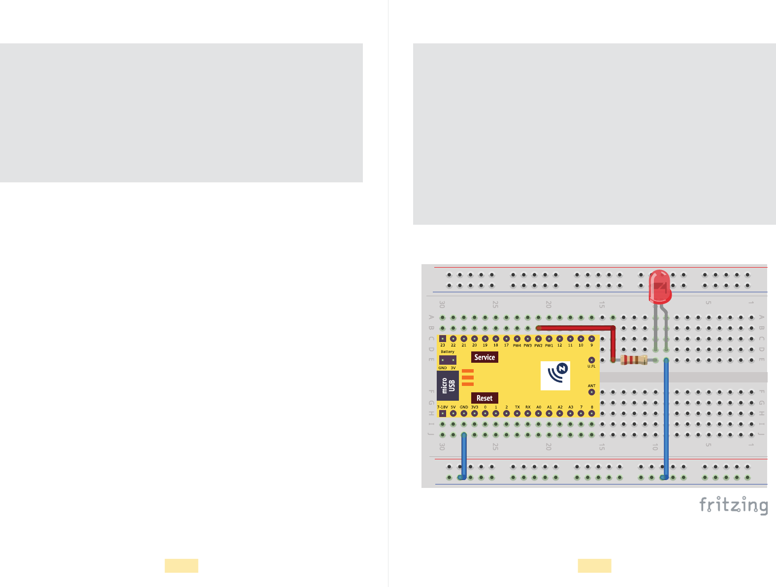
Example 2. Adding analogWrite function to blink external LED on pin 14
byte buttonState;
byte dimLevel = 0; // Added dimmer level variable with initial value 0
void setup() {
pinMode(23, INPUT_PULLUP);
pinMode(13, OUTPUT);
}
void loop() {
buttonState = digitalRead(23);
digitalWrite(13, buttonState);
dimLevel = 128 - dimLevel; // Values are 0% or 50% (0 or 128)
analogWrite(PWM2, dimLevel); // Set PWM2 (pin 14) to dimLevel
delay(100);
}
Figure 1. Wiring diagram for examples 2-4
14 15
Precautions about connecting 5 V sensors
It is important to notice that many Arduino compatible sensors are powered from 5V.
This is not a problem if you provide them dedicated power from a USB or external
source. But sometimes they also output 5 V on their pins and expect 5 V as input.
Z-Uno can be damaged by 5 V on any of its input/output
pins. Use voltage divider for input pins to down voltage
to 3.3 V. For example use 1 kΩ and 2 kΩ resistors.
Output pins in most cases can be connected directly—
most digital sensors interpret 3.3 V as high voltage.
Ifyou still need to convert 3.3 V to 5 V output, use
transistor. Logic level converter can also be used.
Z-Uno can not source more than 8 mA on its pins.
If more is required, a transistor key should be used.
Maximum current sourcing from 5V pin is 900 mA,
from 3V pin is 200 mA.
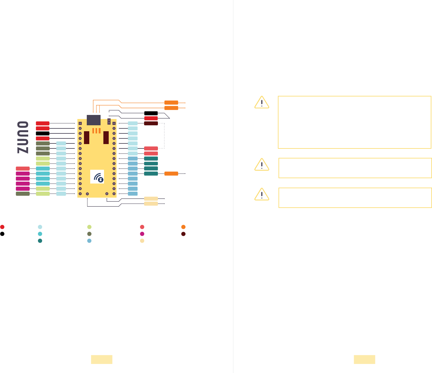
Using breadboard
For faster prototyping we recommend to use breadboards. Z-Uno ts perfectly in stan-
dard breadboards. No soldering is needed to make Z-Wave devices!
Figure 2. Z-Uno pinout
0
1
2
24
25
3
4
5
6
7
8
3V3
23
22
21
20
19
18
17
16
15
14
11
10
13
12
9
PWM 1
ANT
ANT
LED
PWM 2
PWM 3
PWM 4
INT 1
INT 0
ADC 3
ADC 2
ADC 1
ADC 0
RX 0
TX 0
RX 1
INT 2
IR TX 2
IR TX 1
IR TX 0
TX 1
IR RX
MOSI
SPI CS
MISO
SCK
Battery connector
micro
USB
Z-Wave chip
Wire antenna
User LED
LED
LED
Service LED
User LED
External connector
Service
GND
3V3
7-18V
5V
GND
Power Pin
GND Pin
Digital Pin
Analog Read Pin
Analog Write Pin
UART Pin
SPI Pin
Fast Pin, I2C, 1-Wire
Interrupt Pin
IR Pin
Antenna
LED
Button
Reset
Service
16 17
Z-Uno channels
Built-in Z-Wave support is the distinctive feature of Z-Uno compared to other Arduino
boards. Z-Wave devices can present many different features to Z-Wave controller and
other devices in your Z-Wave network. Wireless Z-Wave communication is well struc-
tured to keep things compatible between different devices from different manufactur-
ers. Z-Uno inherits and extends Z-Wave concepts. The most important is Channel.
Channels concept
Switch Binary
Similar devices on the market
How to dene
Z-Uno channel is a set of features available via the Z-Wave radio protocol. These
features allow you to control Z-Uno wirelessly as well as request current Z-Uno state.
Z-Uno supports few types of channels. Each channel is associated with some basic
functionality like on/off relay or dimmable light or idle/triggered alarm or an environ-
mental sensor. Think of a channel as a dedicated “device” inside the Z-Uno. Z-Uno
can host up to 10 channels simultaneously.
Channels are dened using special word ZUNO_SETUP_CHANNELS.
This type of channel is used to control a relay or turn on/off a light. It can only receive
two values from and report to the Z-Wave network: on or off. No other values are
possible.
There are a lot of similar devices on the market: lamp switches, sprinklers
control, power strip switches and many others.
The Switch Binary channel is dened using the ZUNO_SWITCH_BINARY
special word as follows:
getter and setters are names of functions.
ZUNO_SETUP_CHANNELS(ZUNO_SWITCH_BINARY(getter, setter));
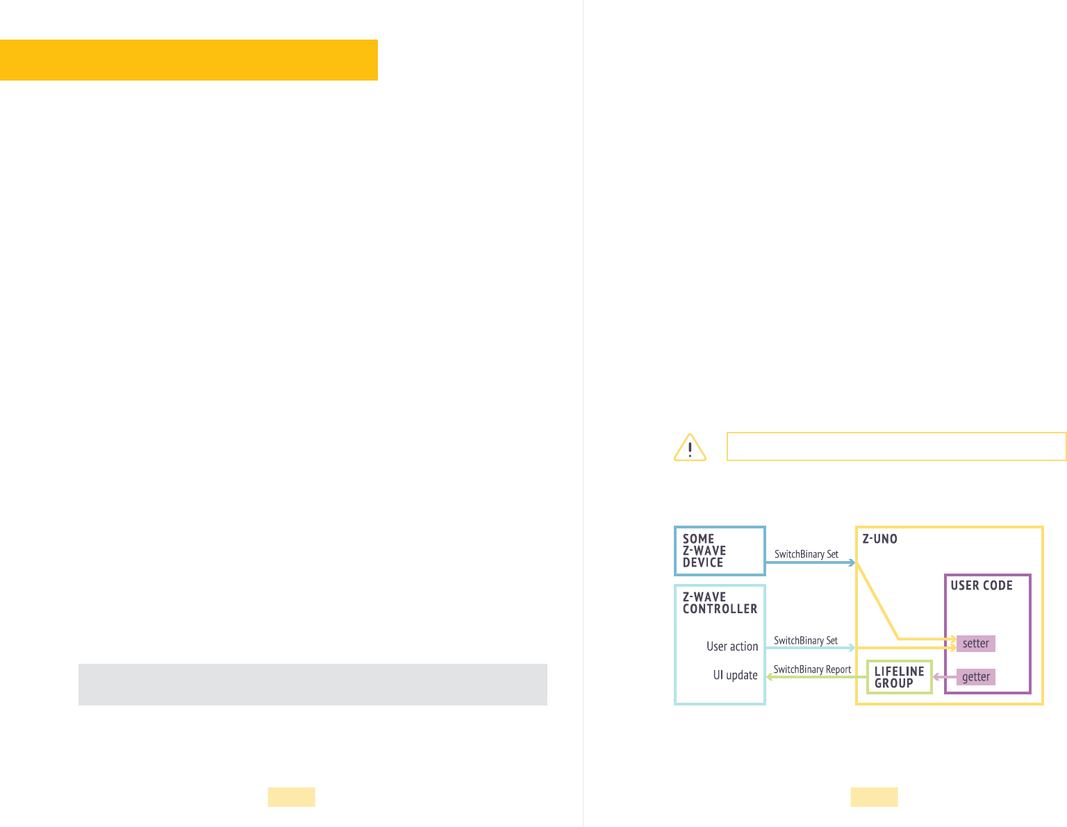
Getter/Setter concept
Getter and setter are special functions that are called by the Z-Uno core when
Z-Wave communication occurs.
The setter is called when the Z-Wave Set command is received in the channel.
Forexample, when Switch Binary Set ON is received, the setter is called with
value 255 as a parameter. For the OFF command the parameter value is0.
This allows the Z-Uno to handle actions coming from a controller or other
Z-Wave devices.
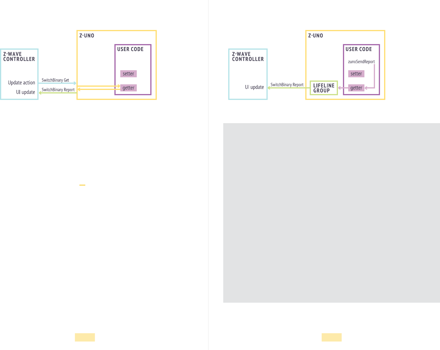
The aim of the getter function is to return the current state of the channel to
report ittothe Z-Wave network. Getter is called in three cases:
• a Get command is received from the Z-Wave network,
• a Set command resulted in device state change or
• user code explicitly asked to send a report with the current state.
Getter and setter should work as fast as possible. The best is to just to return
current value and save new value in a variable. We recommend not to call any
heavy functions from getter and setter.
delay function will be ignored in getter and setter.
Figure 3. Z-Uno new value set
18 19
Reporting values to Z-Wave controllers, LifeLine
Channel reports can be solicited or unsolicited.
Solicited reports are a result of a Get command received by the Z-Uno. In that
case the report is sent back to the asker.
Unsolicited reports happen when a device state changes due to the Set
command or when a user explicitely instructs the Z-Uno to send a report.
Unsolicited reports are sent only to alimited list of devices called the LifeLine
group (this is a Z-Wave commonly known term). This group is managed
like other associations (see page 24) by the Z-Wave controller and usually
itcontains only the controller itself.
To force Z-Uno to send report for a channel use the function
zunoSendReport(channelNumber).
This function will internally call the getter function and then send reports to the
LifeLine group.
The gures 4 and 5 show how the Z-Wave controller interacts with Z-Uno user
code viagetters and setters.
Figure 4. Z-Uno solicited report Figure 5. Z-Uno unsolicited report
Example 3. Added Switch Binary channel to control built-in LED
byte buttonState;
byte dimLevel = 0;
byte ledLevel = 0; // Adding LED level variable with initial value 0
ZUNO_SETUP_CHANNELS(ZUNO_SWITCH_BINARY(getterLED, setterLED));
// Adding switch binary channel
void setup() {
pinMode(23, INPUT_PULLUP);
pinMode(13, OUTPUT);
}
void loop() {
buttonState = digitalRead(23); // Not used in this sketch
digitalWrite(13, ledLevel); // LED value is not set in the channel setter
dimLevel = 128 - dimLevel;
analogWrite(PWM2, dimLevel);
delay(100);
}
void setterLED(byte value) { // This function accepts new channel value
ledLevel = value; // Save new value to use in loop and getter
}
byte getterLED() { // This function should report channel value
return ledLevel; // Report the saved value
}
20 21
Sensor BinarySwitch Multilevel
Similar devices on the market
How to dene
How to dene
This type of channel is used to report events from security or any other binary sensors.
They can only report two values: on (triggered) or off (idle). No other values are possible.
This type of channel is used to control dimmable loads like light lamps. It can only
receive values in the range 0 (off) to 99 (maximum level). The special value 255 means
set last or maximum (depending on what you decide). Reported values should be in the
range 0–99.
Most of the security sensors belong to this type of devices: motion, door/
window, smoke, leakage sensors and many others.
Sensor Binary channel is dened using the ZUNO_SENSOR_BINARY special
word as follows:
Switch Multilevel channel is dened using the ZUNO_SWITCH_MULTILEVEL
special word as follows:
Unlike the Switch Binary channel, the Sensor Binary channel does not have
asetter function, since it can only report values.
Parameter type denes the type of the sensor. See online reference for more
info. For your comfort there are predened strings like ZUNO_SENSOR_
BINARY_MOTION(getter), ZUNO_SENSOR_BINARY_DOOR_WINDOW(getter),
ZUNO_SENSOR_BINARY_WATER(getter) and others described in the online
reference. As with other channels, reports are sent to the LifeLine group
(unsolicited) or to the asker (solicited).
ZUNO_SETUP_CHANNELS(ZUNO_SENSOR_BINARY(type, getter));
ZUNO_SETUP_CHANNELS(ZUNO_SWITCH_MULTILEVEL(getter, setter));
Sensor Multilevel
How to dene
This type of channel is used to report environmental sensor values like temperature,
luminance, humidity, pressure, radiation, velocity and others. Z-Wave denes a set
ofpossible sensor types and scales.
Sensor Multilevel channel is dened using the ZUNO_SENSOR_MULTILEVEL
special word as follows:
Parameter type denes the type to be reported with the value. Possible values
are described in the Z-Uno online reference.
Parameter scale_size_precision denes the scale and precision of the value
tobe reported.
But we recommend using predened strings like ZUNO_SENSOR_
MULTILEVEL_TEMPERATURE(getter), ZUNO_SENSOR_MULTILEVEL_
HUMIDITY(getter) and others (check Z-Uno online reference for more) instead
of a more general ZUNO_SENSOR_MULTILEVEL.
ZUNO_SETUP_CHANNELS(ZUNO_SENSOR_MULTILEVEL(type, scale_size_precision, getter)); Meter
How to dene
This type is very similar to the Sensor Multilevel, but for meter types: water, electrical
and gas meters.
Like with the Sensor Multilevel, for Meter we recommend using predened
strings: ZUNO_METER_ELECTRIC_KWH(getter, resetter), ZUNO_METER_
GAS(getter, resetter) or ZUNO_METER_WATER(getter, resetter). Meter
channel allows an additional resetter function to reset accumulated value
tozero.
22 23
Combining several channels
The Z-Uno allows up to ten channels. Any type of channels can be combined. For
example, to dene a double relay with two electrical meters and a temperature sensor
use:
In this example the Z-Uno will create ve channels: relay 1 (channel #1), relay 2 (channel
#2), meter 1 (channel #3), meter 2 (channel #4), temperature sensor (channel #5).
The channel number (order in the denition above) is to be used in the zunoSendReport
function to send an unsolicited report.
ZUNO_SETUP_CHANNELS(
ZUNO_SWITCH_BINARY(getterCh1, setterCh1),
ZUNO_SWITCH_BINARY(getterCh2, setterCh2),
ZUNO_METER_ELECTRIC_KWH(meterCh1, resetterCh1),
ZUNO_METER_ELECTRIC_KWH(meterCh2, resetterCh2),
ZUNO_SENSOR_MULTILEVEL_TEMPERATURE(tempGetter));
Controlling the Z-Uno from other Z-Wave devices
Not only the Z-Wave controller, but any other Z-Wave device in your network can
control the Z-Uno. This is done by sending a Get or Set command to the desired
channel of the Z-Uno.
For example, a Z-Wave remote control can directly send commands to the Z-Uno
Switch Binary or Switch Multilevel channels. Or a Z-Wave door sensor can send
adirect command to the Z-Uno upon a door open event. Thanks to this, the Z-Uno
can be part of your smart home.
Example 4. Adding Sensor Binary and Switch Multilevel channels
byte buttonState;
byte sensLastState; // Variable to store sensor binary value
byte dimLevel = 0;
byte ledLevel = 0;
ZUNO_SETUP_CHANNELS(
ZUNO_SWITCH_BINARY(getterLED, setterLED),
ZUNO_SWITCH_MULTILEVEL(getterDimmer, setterDimmer),
ZUNO_SENSOR_BINARY_GENERAL_PURPOSE(getterButton)
); // Adding two more channels
void setup() {
pinMode(23, INPUT_PULLUP);
pinMode(13, OUTPUT);
}
void loop() {
buttonState = digitalRead(23); // If state changes, send unsolicited report
if (sensLastState != buttonState) {
zunoSendReport(3); // Send it. Sensor binary channel is #3
sensLastState = buttonState; // Update last sensor state
}
digitalWrite(13, ledLevel);
analogWrite(PWM2, dimLevel); // Dimmer level is now set in channel setter
delay(100);
}
void setterLED(byte value) {
ledLevel = value;
}
byte getterLED() {
return ledLevel;
}
void setterDimmer(byte value) { // Setter for dimmer
dimLevel = value;
}
byte getterDimmer() { // Getter for dimmer
return dimLevel;
}
byte getterButton() { // Getter for binary sensor
return sensLastState; // Report sensor state
}
24 25
Controlling other Z-Wave devices from Z-Uno
As discussed above, any Z-Wave device in your network can control Z-Uno. But Z-Uno
is also able to control other devices in the network. To understand it we need to learn
the Association concept.
Associations concept
Setting Value
The Association group is a list of devices that receive some command on some par-
ticular event. The command depends on the Association group type. The event isuser
dened. For example, Association group “turn on/off light on motion detected” should
send On/Off commands on motion detection events. Or group “open the lock on pin
code enter” should send an Open command to door locks in the group. Association
groups are managed by the Z-Wave controller.
This is the most common type of association — it sends Basic Set command (inter-
preted by switch devices as Switch Binary, by dimmers as Switch Multilevel). Here
ishow to dene such association:
To send a command from your code, use the following function:
The parameter groupNumber is the sequence of association group in the denition
(here it is 1).
The parameter value is the value to send. For switches values are interpreted as 0 for
Off and any in range 1–255 for On. For dimmers 0–99 is the % of brightness and 255
for maximum/last. More interpretations are dened in the Z-Wave protocol.
Each Association group can host up to 5 devices. This means all devices in the group
will receive the same command.
zunoSendToGroupSetValueCommand(groupNumber, value);
Dimming
Scene activation
This type is like the Setting Value, but also allows additional types of commands
forsmooth dimming. Here is how to dene such an association:
To send a command from your code, use the following function:
Parameter downUp is TRUE to start dimming down and FALSE to start dimming up.
Parameter startStop should be TRUE for start up/down command and FALSE for stop
command (downUp is ignored in that case).
Some devices accept scene numbers to activate some state in smart home devices
(dim light, open jalusie, roll up cinema screen, …). In Z-Wave this is done using Scene
Activation. This type of association can also be used to trigger scenes on the control-
ler. Dene it as
To activate a scene use
zunoSendToGroupSetValueCommand(groupNumber, value);
zunoSendToGroupDimmingCommand(groupNumber, downUp, startStop)
zunoSendToGroupScene(groupNumber, sceneNumber);
ZUNO_SETUP_ASSOCIATIONS(
ZUNO_ASSOCIATION_GROUP_SET_VALUE
);
ZUNO_SETUP_ASSOCIATIONS(
ZUNO_ASSOCIATION_GROUP_SET_VALUE_AND_DIM
);
ZUNO_SETUP_ASSOCIATIONS(
ZUNO_ASSOCIATION_GROUP_SCENE_CONTROL
);

26 27
Door lock operation
The Z-Uno can also operate door locks with open and close commands. Such
commands are always sent with encryption to keep your house secure.
Dene it as
To operate the lock use
Where state is 0 for closed and 255 for open.
zunoSendToGroupDoorlockControl(groupNumber, state)
ZUNO_SETUP_ASSOCIATIONS(
ZUNO_ASSOCIATION_GROUP_DOORLOCK
);
Example 5. Remotely control light and door lock with two buttons
byte buttonUpPressed = 0; // Is button Up pressed
byte buttonDownPressed = 0; // Is button Down pressed
ZUNO_SETUP_ASSOCIATIONS( // Two association groups
ZUNO_ASSOCIATION_GROUP_SET_VALUE,
ZUNO_ASSOCIATION_GROUP_DOORLOCK // Works only if Security is enabled in Z-Uno!
);
void setup() {
pinMode(19, INPUT_PULLUP); // Two buttons to send On and Off
pinMode(20, INPUT_PULLUP); // Use internal pull up on both
}
void loop() {
if (digitalRead(19) == LOW) { // Button Up is pressed
if (buttonUpPressed == 0) { // It was not pressed – press event detected
zunoSendToGroupSetValueCommand(CTRL_GROUP_1, 50); // Dim light to 50%
zunoSendToGroupDoorlockControl(CTRL_GROUP_2, 255); // Open the door
buttonUpPressed = 1; // Save the state not to send the command again
}
} else {
buttonUpPressed = 0; // Reset the state on release
}
if (digitalRead(20) == LOW) { // Button Down is pressed
if (buttonDownPressed == 0) { // It was not pressed – press event detected
zunoSendToGroupSetValueCommand(CTRL_GROUP_1, 0); // Turn off light
zunoSendToGroupDoorlockControl(CTRL_GROUP_2, 0); // Close the door
buttonDownPressed = 1; // Save the state not to send the command again
}
} else {
buttonDownPressed = 0; // Reset the state on release
}
delay(10); // Check buttons state every 10 ms
}
28 29
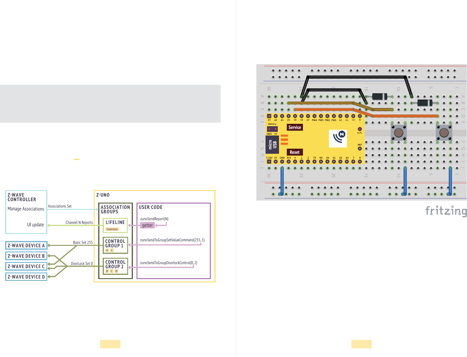
Figure 7. Wiring diagram for examples 5 and 6.
The two diods are needed for Z-Uno to wakeup in example 6
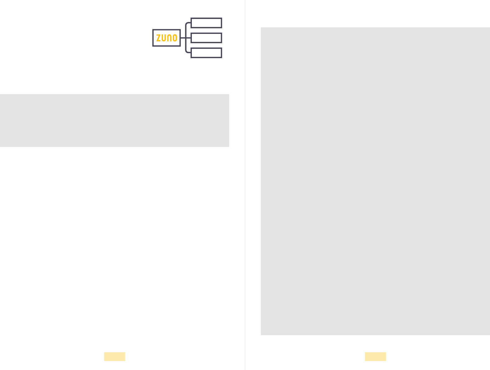
Controlling multiple devices on different events
You can dene multiple Association groups. For example, we can dene one group
tocontrol light bulb brightness and another to open/close an entrance lock:
Z-Uno supports up to 5 association groups.
Note that Association groups as seen in Z-Wave controllers start from #2. Association
group #1 is always present and is called LifeLine. It is used in unsolicited reports
ofchannel states. See page 18 for more info.
ZUNO_SETUP_ASSOCIATIONS(
ZUNO_ASSOCIATION_GROUP_SET_VALUE,
ZUNO_ASSOCIATION_GROUP_DOORLOCK
);
Figure 6. Z-Uno Associations
30 31
More powering options
So far we were assuming the Z-Uno to be powered from some
power supply. But in many cases devices need to be powered
from a battery or even a solar battery. The Z-Wave protocol
iswell known for being optimized for battery operated devices.
The Z-Uno allows tomake battery operated devices too.
Battery devices
Sleeping
There are many examples of battery operated sensors: motion, temperature, leakage,
smoke, door/window and other types of sensors are often placed far from existing
power sources.
Note that battery operated devices are always tricky — they have to go into sleep
assoon as possible to save battery power. Hence, they are not reachable at any time
and need to wake up to send reports and control commands to associated devices.
Battery devices are also not participating in the mesh network — they don’t help others
todeliver messages, but do benet themself from a Z-Wave mesh network.
Z-Wave denes two ways to save battery power to allow devices to live for years
onasingle battery. The rst way is to sleep all the time and wake up rarely periodi-
cally oronexternal events only. The second way is to wake up every second to check
ifsomeone wants to talk to us.
In sleeping mode, the Z-Uno is consuming around 25 μA (can be tuned to less than
10μA). This is virtually nothing. But todo something useful, the Z-Uno needs to wake
up and communicate with other Z-Wave devices.
Being asleep, the Z-Uno will wake up on the INT1 pin. Once voltage on this pin drops
to zero, the Z-Uno wakes up and starts executing user code. Like on Z-Uno power on,
the setup function will be executed rst and then loop will be executed eternally until
theZ-Uno isinstructed to go back to sleep.
In operating mode, the Z-Uno is consuming about 35–45 mA. Additional consumption
might come from connected peripherals.
Sending Z-Uno to sleep
Wakeup timer
Battery level
It is very important to do all tasks as fast as possible and send Z-Uno back
into sleep mode. This is done using the zunoSendDeviceToSleep function.
This function will only instruct the Z-Uno that user code do not need to stay
awake anymore. Z-Uno will nish its current jobs and go to sleep as soon as
possible.
Note that while being asleep, the Z-Uno is not reachable anymore. To request
new values orcongure the Z-Uno, it must be woken up. There are three ways
to wake it up: on INT1 interrupt, on key scanner oronwakeup timer.
It is also important to wake up from time to time to inform the controller that
the device is alive and well. This allows the Z-Uno to do measurements and
possibly report them to theLifeLine group. This also allows the controller to
query the Z-Uno for remaining battery level, current channel values or do some
congurations.
The wakeup period can be congured from your Z-Wave gateway. The mini-
mum is4minutes, but in daily usage we recommend to set the wakeup period
as long as possible if the Z-Uno should react only on external events from
peripheral. For example, a door/window sensor needs to wake up only on an
INT1 pin state change. In contrast, a temperature sensor should wake up from
time to time tomeasure the current temperature.
Being set up in battery powered mode, the Z-Uno will automatically announce
to the controller that it can also report remaining battery level. The percentage
value will be measured on each Z-Uno wake up and reported to the LifeLine
group. The sleep mode is set as follows:
ZUNO_SETUP_SLEEPING_MODE(
ZUNO_SLEEPING_MODE_SLEEPING
);
32 33
byte buttonUpPressed = 0;
byte buttonDownPressed = 0;
ZUNO_SETUP_SLEEPING_MODE(ZUNO_SLEEPING_MODE_SLEEPING);
// Sleeping mode. Wake up on INT1
// Note the two diodes from buttons to INT1
ZUNO_SETUP_ASSOCIATIONS(
ZUNO_ASSOCIATION_GROUP_SET_VALUE,
ZUNO_ASSOCIATION_GROUP_DOORLOCK
);
void setup() {
pinMode(19, INPUT_PULLUP);
pinMode(20, INPUT_PULLUP);
}
void loop() {
if (digitalRead(19) == LOW) {
if (buttonUpPressed == 0) {
zunoSendToGroupSetValueCommand(CTRL_GROUP_1, 50);
zunoSendToGroupDoorlockControl(CTRL_GROUP_2, 255);
buttonUpPressed = 1;
}
} else {
buttonUpPressed = 0;
}
if (digitalRead(20) == LOW) {
if (buttonDownPressed == 0) {
zunoSendToGroupSetValueCommand(CTRL_GROUP_1, 0);
zunoSendToGroupDoorlockControl(CTRL_GROUP_2, 0);
buttonDownPressed = 1;
}
} else {
buttonDownPressed = 0;
}
if (buttonUpPressed == 0 && buttonDownPressed == 0) {
zunoSendDeviceToSleep(); // Send into sleep once buttons are released
}
delay(10);
}
Example 6. Battery operated remote control FLiRS
Frequently Listening Routing Slave (or FLiRS) is the other way to save battery power.
Inthis mode, the Z-Uno will wake up for a very short time every second to listen for
aspecial “beam” packet. Such a packet is transmitted by the sender when it wants to
speak to a FLiRS device. This means that a FLiRS device can be reached at any time,
but it will take up to one second.
Once a “beam” packet is received, the Z-Uno will wake up completely following the
normal startup process and user code will be executed as usual: setup function rst
and then loop until Z-Uno is sent back into sleep with zunoSendDeviceToSleep.
In FLiRS mode, the Z-Uno will also measure the battery power, but there is no wakeup
period to be dened (as the Z-Uno is waking up every second anyway).
FLiRS mode is set as follows:
The Z-Wave specication restricts which types of devices can be FLiRS to doorlock,
siren, water orgas valve.
ZUNO_SETUP_SLEEPING_MODE(
ZUNO_SLEEPING_MODE_FREQUENTLY_AWAKE
);
It is important to note that the Z-Uno memory is not retained
during sleep mode and all variables in are cleared and re-
initialized on each wakeup. To keep data across sleeps use
NZRAM (special type of memory) or EEPROM storage (see
online reference for more info).
34 35
Debugging your code
Debugging via USB
Compilation errors
The easiest way to debug your code is to enable USB com-
munication and print debug strings and variable values there.
Use the Arduino built-in Serial Monitor (Tools > Serial Monitor)
toread those strings on your computer.
Note that UART can be used instead of USB (change Serial to Serial0 or Serial1
depending on the pins chosen). For sleeping devices UART is better as USB
should beexplicitly turned on.
If you get a compilation error but can not nd the problem in your code, try to enable
verbose logging. For this go to Preferences (File > Preferences) and check Show
verbose output during compilation.
Example 7. Debugging with Serial (USB and UART)
int n = 0;
void setup() {
Serial.begin(); // USB (Serial) do not require speed
// Serial0.begin(115200); // Serial0 and Serial1 need speed parameter
Serial.println(" St a r t i n g ..."); // Print string with new line
}
void loop() {
Serial.println(n); // Print decimal number with new line
Serial.print(n, HEX ); // Print heximal number without new line
Serial.println("h"); // Print string with new line
delay(1000);
}
Rescue Mode
Factory Reset
Sometimes user code blocks USB communication, preventing further sketch upload
or is even claiming the Z-Uno is dead. This can happen due to many reasons: innite
loop in user code, too slow operations in user code that breaks radio transmission,
entering sleep mode, stack overow problems. In any of those cases, use the Rescue
Mode. In this mode, the Z-Uno starts with user sketch temporarily disabled (as no
user sketch is loaded). To revert back to normal mode, upload a new sketch or restart
Z-Uno by pressing the Reset button or by power cycling.
To erase Z-Uno conguration and Z-Wave network information, exclude it using
Exclusion mode in your Z-Wave controller.
You can also reset the Z-Uno via the Service button: hold the Service button for 5
seconds andthen press three times.
User sketch is not deleted during reset or exclusion.
Security considerations
Z-Wave security ensures that your data is not intercepted, mangled or replayed
andauthenticates the sender. To enable the security feature in the Z-Uno use
Tools > Security menu item.
While included securely, the Z-Uno will use strong AES encryption to transmit reports
and commands to other devices in the network. On rst communication with a node,
the Z-Uno will automatically detect if the recipient supports secure communication
ornot.
Non secure devices will not be able to control a secure Z-Uno.
36 37
Precautions and common errors
Don’t feed Z-Uno pins with more than 3.3 V
Always use limiting resistors on output pins
Do not bare antenna wire
I can not include Z-Uno
I can not nd the serial port of my Z-Uno
This can damage the Z-Uno input pins. Always use a voltage
divider or a level converter when connecting higher voltages.
When connecting LED or other components to Z-Uno pin, don’t forget to limit the
current with a limiting resistor. This will prevent Z-Uno output pins from burning. We
recommend to use a 220 Ω resistor.
If you want to switch a bigger current than the Z-Uno can feed, use a relay or transis-
tor to switch an external power source. Don’t forget to use a limiting resistor when
connecting the relay or transistor.
An electrostatic discharge on the antenna wire can damage the Z-Uno chip.
Maybe your Z-Uno was included in another Z-Wave network? Try to exclude it rst.
If this does not help, check that the Z-Uno frequency selected in Arduino IDE during
last sketch upload matches your Z-Wave network.
Does not help either? Disable user sketch by turning on the Rescue mode (see page
35). Finally, do Factory Reset (see page 35).
If your device is sleeping or user sketch runs into some slow job or innite loop, the
USB port will not be available anymore. Use Rescue mode (see page 35) to restore
the USB connection and load a new sketch.
Z-Uno is not reachable by the controller
Integer type conversion
Changes in channels or associations are not applied
More troubleshooting
Stack overow precautions
If your Z-Uno is in sleeping mode, you need to wake it up to allow communications
with the controller. Press the Service button three times. Maybe the frequency setting
has changed during the last sketch upload. Doublecheck it in Arduino IDE settings.
Your sketch might also prevent the Z-Uno from handling Z-Wave operations (you
created aninnite loop). Use the rescue mode to disable your sketch and upload
acorrect one.
If the Z-Uno is too far from the controller or any other mesh capable Z-Wave device
inthenetwork, it will also be unreachable. Move the Z-Uno closer to the controller.
While doing math operations with numbers, remember to explicitely specify the
space to work in if it should be bigger than the space of variables. For example, value
*99/255 will give a wrong result unless changed to (word) value *99/255.
Changes of channels or association number, types or order are not applied unless
the Z-Uno is excluded. This is because the Z-Wave protocol does not allow changing
those settings on the y. Though you can bypass this restriction by enabling a special
conguration parameter (see online reference for more information).
More information can be found on https://z-uno.z-wave.me/getting-started/
troubleshooting.
Sometimes complex or big user code can lead to unexpected Z-Uno behavior
orhangs. Usually this is caused by stack overow problems. Try to move local vari-
ables from functions in the global scope, lower the number of nested function calls
andnumber of parameters passed to functions.
38
Where to get more info?
Z-Uno advanced features
Z-Uno language reference https://z-uno.z-wave.me/Reference.
Examples of devices based on Z-Uno https://z-uno.z-wave.me/examples.
The Z-Uno is very powerful and it is not possible to cover all features in such asmall
book. The following topics are outside of the scope of this book and can befound
inthe online reference.
Advanced hardware features
Fast GPIO I2C
External interrupts IR
Key Scanner SPI
UART and USB GPT and Timers
1-wire EEPROM and NZRAM
Math operations
Libraries
Porting libraries from Arduino to Z-Uno
List of supported h/w or other features
Math
Tuning the Z-Uno
Conguration parameters Desoldering of stub between INT1 and BTN
Security Optimizing power consumption
Multi Command Using OTA to upload sketches
External antenna soldering
Compiler tips & tricks
How to minimize stack usage
Using xed point math instead of oating point math
How to use pointers
Deep inside interrupt handlers
Z-Wave certication requirements