INS10244 5 Z Wave Technical Information
User Manual: Z-Wave Technical Information AlarmHow.net Library
Open the PDF directly: View PDF ![]() .
.
Page Count: 43

CONFIDENTIAL
Instruction
Z-Wave Node Type Overview and Network Installation
Guide
Document No.: INS10244
Version: 5
Description: This document describes how to setup a network with regard to inclusion of nodes
in the network, operation and exclusion of nodes from the network.
Written By: ABR;JFR;SML
Date: 2008-12-04
Reviewed By: JFR;SML;JBU;JSI;JKA;CHL
Restrictions: Partners Only
Approved by:
Date CET Initials Name Justification
2008-12-04 13:43:47 JFR Jørgen Franck on behalf of NTJ
This document is the property of Zensys A/S. The data contained herein, in whole or in
part, may not be duplicated, used or disclosed outside the recipient for any purpose. This
restriction does not limit the recipient's right to use information contained in the data if it is
obtained from another source without restriction.

INS10244-5 Z-Wave Node Type Overview and Network Installation Guide 2008-12-04
Zensys A/S Revision Record and Tables of Contents Page ii of v
CONFIDENTIAL
REVISION RECORD
Doc. Rev Date By Pages
affected Brief description of changes
1 20050118 SML
JFR ALL Revised document.
Added SUC and SIS.
Primary Controller does not use Node ID 0xEF anymore.
2 20060105 MVO All New 1st page/header/footer contents. New Doc No
3 20060426 JFR All Fixed page number problem
4 20061212 ABR All Fixed various small typos
Added clarifying comments
Added silent ack description to section on routing
Added new sections on Zensor Net basics and Zensor Net features
4 20061221 ABR
JFR All Updated doc after review – minor typos and clarifications
5 20080626 ABR
JFR All Added features of Dev. Kit 4.50:
Random home ID after exclusion/reset
Explorer route resolution and Network-Wide Inclusion
5 20080805 ABR All Revised sections on Zensor Net and FLiRS nodes.

INS10244-5 Z-Wave Node Type Overview and Network Installation Guide 2008-12-04
Zensys A/S Revision Record and Tables of Contents Page iii of v
CONFIDENTIAL
Table of Contents
1 ABBREVIATIONS.................................................................................................................................1
2 INTRODUCTION...................................................................................................................................2
2.1 Purpose ..............................................................................................................................................2
2.2 Backward compatibility.......................................................................................................................2
2.3 Audience and prerequisites................................................................................................................2
3 Z-WAVE BASICS..................................................................................................................................3
3.1 Network Nodes...................................................................................................................................3
3.1.1 Controller Nodes.........................................................................................................................3
3.1.1.1 Portable Controller ..............................................................................................................3
3.1.1.2 Installation Controller...........................................................................................................3
3.1.1.3 Static Controller...................................................................................................................4
3.1.1.4 Bridge Controller .................................................................................................................4
3.1.2 Slave Nodes ...............................................................................................................................4
3.1.2.1 Slave....................................................................................................................................5
3.1.2.2 Routing Slave......................................................................................................................5
3.1.2.3 Frequently Listening Routing Slave (FLiRS).......................................................................5
3.1.2.4 Enhanced Slave ..................................................................................................................5
3.1.2.5 Zensor Net Routing Slave ...................................................................................................5
3.2 Home ID .............................................................................................................................................6
3.3 Node ID ..............................................................................................................................................6
3.4 Routing ...............................................................................................................................................9
3.5 Initiators............................................................................................................................................10
3.5.1 Slave Initiators ..........................................................................................................................10
3.5.2 Controller Initiators ...................................................................................................................11
3.6 Node Information Frame ..................................................................................................................11
4 Z-WAVE NETWORK FEATURES ......................................................................................................12
4.1 Include/exclude Process ..................................................................................................................12
4.1.1 Include Nodes...........................................................................................................................12
4.1.1.1 Include slaves....................................................................................................................12
4.1.1.2 Include controllers .............................................................................................................12
4.1.2 Exclude Nodes .........................................................................................................................12
4.2 Association of nodes ........................................................................................................................13
4.2.1 Associating a Slave with a Controller .......................................................................................13
4.2.2 Associating a (Routing) Slave with a Routing Slave ................................................................13
4.2.3 Associating a Static Controller with a Routing Slave ...............................................................13
5 ZENSOR NET TECHNOLOGY...........................................................................................................15
5.1 The Zensor Net Beam......................................................................................................................15
5.2 The Zensor Net node .......................................................................................................................18
5.3 Applications that benefit from Zensor Net technology......................................................................18
5.3.1 Doorbell chime..........................................................................................................................18
5.3.2 Smoke alarm.............................................................................................................................19
5.4 Zensor Net Binding...........................................................................................................................20
5.5 Zensor Net Flooding.........................................................................................................................20
6 EXPLORER FEATURES ....................................................................................................................22
6.1 On-demand Route Resolution..........................................................................................................22
6.2 Network-Wide Inclusion....................................................................................................................22
6.3 Network migration ............................................................................................................................22
6.3.1 Compatibility .............................................................................................................................22
6.3.2 Route resolution strategy..........................................................................................................22

INS10244-5 Z-Wave Node Type Overview and Network Installation Guide 2008-12-04
Zensys A/S Revision Record and Tables of Contents Page iv of v
CONFIDENTIAL
6.3.3 SIS functionality for improved plug and play experience .........................................................23
7 BASIC INSTALLATION EXAMPLE ...................................................................................................24
7.1 Initial Setup.......................................................................................................................................24
7.2 Associating Nodes............................................................................................................................24
7.3 Adding Slave Nodes.........................................................................................................................25
7.4 Adding Controllers............................................................................................................................26
7.5 Removing Slaves .............................................................................................................................27
7.6 Removing Secondary Controllers.....................................................................................................27
7.7 Recover from Controller Node Error ................................................................................................27
8 STATIC CONTROLLER AND ROUTING SLAVE EXAMPLE ...........................................................29
8.1 Including Routing Slaves..................................................................................................................29
8.2 Including Static Controllers...............................................................................................................31
9 STATIC UPDATE CONTROLLER (SUC) EXAMPLE........................................................................33
9.1 Including a SUC to the network........................................................................................................33
10 SUC ID SERVER (SIS) EXAMPLE.....................................................................................................34
10.1 Including a SIS to the network..........................................................................................................34
10.2 Adding inclusion controllers to the network......................................................................................35
11 NETWORK-WIDE INCLUSION EXAMPLE........................................................................................36
11.1 Initial Setup.......................................................................................................................................36
11.2 Adding additional nodes...................................................................................................................36
11.3 Removing Nodes..............................................................................................................................37
11.4 Recover from Controller Node Error ................................................................................................37
12 REFERENCES....................................................................................................................................38
Table of Figures
Figure 1. Assigning Home ID and Node ID ................................................................................................. 7
Figure 2. Unique Home ID for two adjacent homes .................................................................................... 8
Figure 3. Routed frame flow ........................................................................................................................ 9
Figure 4. Routed frame flow w. silent ack.................................................................................................. 10
Figure 5. Reception timing when sending beams ..................................................................................... 16
Figure 6. Structure of the beam................................................................................................................. 17
Figure 7. Battery-to-battery communication; direct reach and routed....................................................... 18
Figure 8. A flooded Zensor Net ................................................................................................................. 19
Figure 9. Including a Slave node............................................................................................................... 24
Figure 10. Associating a Slave Node with a Controller. ............................................................................ 24
Figure 11. Including Slave node 2............................................................................................................. 25
Figure 12. Associating Slave Node 2 with the Controller. ......................................................................... 25
Figure 13. Including a second Controller................................................................................................... 26
Figure 14. Including and associating additional Slave nodes. .................................................................. 27
Figure 15. Including a Routing Slave......................................................................................................... 29
Figure 16. Associating a “Simple” Slave with a Routing Slave. ................................................................ 30
Figure 17. Controller with three associated Routing Slaves. .................................................................... 31
Figure 18. Including a Static Controller. .................................................................................................... 31
Figure 19. Associating a Static Controller with a Routing Slave. .............................................................. 32
Figure 20. Including a SUC to the network................................................................................................ 33
Figure 21. Including a SIS to the network. ................................................................................................ 34
Figure 22. After SIS is included to the network. ........................................................................................ 34

INS10244-5 Z-Wave Node Type Overview and Network Installation Guide 2008-12-04
Zensys A/S Revision Record and Tables of Contents Page v of v
CONFIDENTIAL
Figure 23. Including an Inclusion Controller to the network. ..................................................................... 35
Figure 24. Including a Slave node............................................................................................................. 36
Figure 25. Including additional nodes........................................................................................................ 37

INS10244-5 Z-Wave Node Type Overview and Network Installation Guide 2008-12-04
Zensys A/S Abbreviations Page 1 of 38
CONFIDENTIAL
1 ABBREVIATIONS
Abbreviation Explanation
ACK Acknowledge
FLiRS Frequently Listening Routing Slave
GUI Graphical User Interface
RTC Real Time Clock
SIS SUC ID Server
SUC Static Update Controller
WUT Wake-up timer
ZDK Z-Wave Developer’s Kit

INS10244-5 Z-Wave Node Type Overview and Network Installation Guide 2008-12-04
Zensys A/S Introduction Page 2 of 38
CONFIDENTIAL
2 INTRODUCTION
2.1 Purpose
The purpose of this document is to provide guidelines for installation, maintenance and operation of a Z-
Wave network consisting of controller and slave nodes. Refer to [1] regarding how the functionality is
implemented in the described devices.
2.2 Backward compatibility
The latest ZDK’s contain new features to improve installation flexibility and network topology distribution
of a Z-Wave network. Therefore is it important to understand these features in detail to ensure backward
compatibility with Z-Wave enabled products built on older Developer’s Kit releases.
From ZDK v3.3x the Static Update Controller (SUC) was introduced to allow slave and controller nodes
to request network topology updates.
From ZDK v3.4x the SUC can in addition also function as a node ID server (SIS) to allow other
controllers to include/exclude nodes to/from the network. Furthermore, the unique node ID 0xEF for
primary controllers was discontinued.
From ZDK Kit v4.2x the silent acknowledge mechanism was introduced to reduce routing latency. Refer
to section 3.4 for details.
From ZDK v5.0x Zensor Net technology was introduced. This enables the creation of FLiRS and Zensor
nodes.
From ZDK v4.5x (v4.50 came after v5.02) explorer frames were introduced to improve network
management and inclusion flexibility. FLiRS and Zensor nodes are not supported but all kind of v4.50
slaves are able to beam when acting as repeater. Refer to section 6 for details.
2.3 Audience and prerequisites
The audience is considered to be OEM’s implementing the Z-Wave technology into their products.

INS10244-5 Z-Wave Node Type Overview and Network Installation Guide 2008-12-04
Zensys A/S Z-Wave basics Page 3 of 38
CONFIDENTIAL
3 Z-WAVE BASICS
This chapter describes the basic building blocks of the Z-Wave technology.
3.1 Network Nodes
The Z-Wave network consists of two different types of network nodes; controllers and slaves. The
controller nodes are able to calculate routes (and alternative routes). The second node type is the slave
node, which generally acts as input and output units. Both types exist in different versions as described
below. The Z-Wave protocol supports networks of up to 232 nodes, which can be freely shared between
controller and slave nodes.
3.1.1 Controller Nodes
A controller in the Z-Wave terminology is defined as a unit that has the ability to host a routing table of
the entire network and calculate routes on the basis thereof. Moreover, the controller has the ability to
pass on routes to slave units, in order to enable them to transmit routed signals.
Z-Wave networks are established around a controller. The controller used to include the first node is by
default configured to act as Primary Controller with the capability to include/exclude nodes. The Primary
Controller is used to include all subsequent nodes in the network.
Being primary is just a role. Any controller can be primary but only one controller can be primary at a
time. The primary controller manages the allocation of node IDs and gathers information about which
nodes can reach each other via direct RF links. More Portable Controllers as well as Static Controllers
can be added as needed as the network grows and are denominated as secondary controllers. The
secondary controllers can get copies of the network information gathered by the primary controller.
A Static Controller can be enabled to become a Static Update Controller (SUC), which adds advanced
self-organization functionalities to the network. A SUC can furthermore be enabled to become a SUC Id
Server (SIS), which adds more flexibility to the installation process. At the same time, the SUC improves
the self-healing properties of the network, as the SUC introduces a redundant representation of the
network topology. Thus, a lost or crashed controller may have its topology awareness restored from the
information stored in the SUC. The SIS is by default a Primary Controller because it can include/exclude
nodes. Furthermore it enables other controllers to include/exclude nodes on behalf of the SIS.
The controller exists in a number of fundamentally different versions, which are described in the following
sections.
3.1.1.1 Portable Controller
The Portable Controller has the ability to discover its own position in the network, when it needs
to communicate with other nodes. An example of a device using this type could be a remote
control unit, e.g. for controlling light or HVAC systems. Because the Portable Controller can be
carried around in the network, it is also typically used to include/exclude nodes and maintaining
the Z-Wave network. Portable controllers are typically battery powered.
3.1.1.2 Installation Controller
The Installation Controller is essentially a Portable Controller node, which incorporates extra
functionality that can be used to implement professional installer tools, which need extended

INS10244-5 Z-Wave Node Type Overview and Network Installation Guide 2008-12-04
Zensys A/S Z-Wave basics Page 4 of 38
CONFIDENTIAL
network diagnostics. Like the Portable Controller, Installation Controller is a typically also battery
powered.
3.1.1.3 Static Controller
The Static Controller is required to remain in a fixed position in the network, meaning that it
should not be physically moved when it has been included in the network. Moreover it is required
that the Static Controller is always in “listening mode” and it must therefore be mains powered.
Other alternatives include mains-powered with battery backup as well as running from a large
battery which regularly recharged or replaced.
The “always listening” advantage of the Static Controller allows other nodes to transmit frames to
it whenever needed, both for uploading purposes as well as for consulting purposes.
The Static Controller also exists in two variants used for more advanced installations. Both
variants are described more thoroughly in the installation example chapters (4, 5):
Static Update Controller (SUC):
When a Static Controller is configured as a SUC, the primary controller automatically sends
network updates to the SUC, e.g. when a new node is included to the network. The node will
therefore automatically appear in the SUC’s topology map. Other controllers in the network may
individually request the SUC for network updates. If no SUC is present the Primary Controller is
responsible of updating all controllers in the network, which will typically be a manual process for
the end-user. The SUC is capable of creating a new Primary Controller in case the original
Primary Controller is lost or malfunctioning. There can only be one SUC in each individual
network.
SUC ID Server (SIS):
When a SUC is also configured as a node ID server (SIS) it enables all other controllers to
include/exclude nodes. The SIS automatically becomes the Primary Controller in the network
when enabled. There can only be one SIS in each individual network. To avoid inconsistency, all
node ID allocations are maintained by the SIS.
3.1.1.4 Bridge Controller
The Bridge Controller is essentially a Static Controller node, which has the additional capability
of representing devices from other network types like X10 or TCP/IP as virtual nodes in a Z-
Wave network. This enables control of Z-Wave nodes from e.g. an X10 controller or vise versa.
3.1.2 Slave Nodes
The slave nodes are devices that do not contain routing tables. The so-called Routing Slave nodes and
Enhanced Routing Slave nodes however can contain a number of pre-configured routes (assigned to
them by a controller).
Any slave node can act as repeater for frames going to other nodes. The only requirement for being able
to act as repeater is that the node is in listening state. This requires that the node is permanently
powered, and in order to limit battery consumption, this means that only mains-powered nodes will act as
repeaters in most practical installations.
Battery operated slaves that do not listen continually are disregarded by controllers when they calculate
routes.

INS10244-5 Z-Wave Node Type Overview and Network Installation Guide 2008-12-04
Zensys A/S Z-Wave basics Page 5 of 38
CONFIDENTIAL
There are three types of slave nodes.
3.1.2.1 Slave
The Slave node type is able to receive frames and reply if necessary. The slave node cannot
host pre-configured routes to other nodes. The slave node is typically used for devices that only
require input (and report status if polled) and do not generate frames unsolicited. An example of
a device using this type could be a power outlet.
3.1.2.2 Routing Slave
The Routing Slave can host a number of routes for reaching other slaves or controllers. Such
routes are called “Return Routes”1. Routing Slaves can use these routes to communicate with
either controllers or other slave nodes. The Routing Slave can either be A/C powered or battery
powered. If the Routing Slave is A/C powered it is used as a repeater in the Z-Wave network,
otherwise it will be disregarded when routes are calculated. The Routing Slave functionality is
used for devices that need to report unsolicited status or alarms.
An example of a routing slave node could be a thermostat or a Passive Infra Red (PIR)
movement sensor. A wall switch might also be a routing slave and could then be used to control
small lighting scenes, or to establish a kind of “virtual” 3-way switching.
3.1.2.3 Frequently Listening Routing Slave (FLiRS)
A special case of a battery powered routing slave is the Frequently Listening Routing Slave
(FLiRS). This is a routing slave configured to listen for a wakeup beam in every wake-up interval.
This enables other nodes to wake up the FLiRS node and send a message to it.
One example of a FLiRS node is as chime node in a wireless doorbell system.
3.1.2.4 Enhanced Slave
The Enhanced Slave has the same basic functionality as a routing slave node, but more
software components are available because of more features on the hardware. Enhanced slave
nodes have software support for External EEPROM and an RTC2. An example of a device using
this type of Slave nodes could be a Thermostat.
3.1.2.5 Zensor Net Routing Slave
The Zensor Net routing slave node is basically a routing slave node configured as FLiRS with the
additional functionalities:
• Zensor Net binding
• Zensor Net flooding
1 ”Return Route” is a controller-centric term that was originally referring to a route going back to the controller. Seen from the
routing slave, “Controller Assigned Route” might be a better term. However, “Return Route” is the established term in all Z-Wave
documentation.
2 Applies to the Z-Wave 100 series only. Later families feature an internal timer for wake-up control

INS10244-5 Z-Wave Node Type Overview and Network Installation Guide 2008-12-04
Zensys A/S Z-Wave basics Page 6 of 38
CONFIDENTIAL
The Zensor Net is an alternative network to the classic Z-Wave network having its own binding
method and a mechanism to flood messages to the entire Zensor Net.
An example of a Zensor Net routing slave node could be a smoke detector.
3.2 Home ID
The Z-Wave protocol uses a unique identifier called the Home ID to separate networks from each other.
A 32 bits unique identifier is pre programmed in all controller nodes at manufacturing. This unique 32 bits
identifier is automatically used as Home ID during the installation of the Z-Wave network. If more than
one controller is used in the network it is the 32 bits unique identifier of the first controller node used that
governs the Home ID. Additional controller nodes will be assigned that same Home ID when included
into the network. This is an automatic process that leaves the initial controller as the Primary Controller
and the other controller(s) as Secondary Controller(s). In case a SIS is present in the network will it be
allocated the Primary Controller role leaving the remaining controllers as Inclusion Controllers.
All slave nodes in the network will initially have a Home ID that is set to zero. In order to communicate in
the network the Primary Controller need to assign them with its Home ID. It is only a Primary Controller
or an Inclusion Controller that can assign Home ID’s to a node.
With the introduction of ZDK 4.50, the home ID may still be programmed. However, when excluding or
resetting a controller it generates a new random home ID.
The generation of a random home ID not only simplifies production, but also eliminates the risk of
creating node ID duplicates because a new home ID is used when creating the network.
With ZDK’s before v4.50, this would typically happen when resetting a Primary Controller without first
removing all nodes from the network.
With the introduction of ZDK 4.50, slave nodes also generate a new random home ID after each reset.
During Network-Wide Inclusion, the home ID is used to identify the node. Once included, the node takes
on the home ID of the primary controller and the slave's random home ID is never used again.
3.3 Node ID
Node ID’s are used to address individual nodes in a network. A Node ID is an 8 bits value and it is
assigned to slave and controller nodes by a Primary Controller or an Inclusion Controller. The Node ID
assigned to a device is only unique within a network defined by the unique Home ID. The application
must not assume a default Node ID allocation when a network is created because the Node ID allocation
algorithm depends on a number of factors.
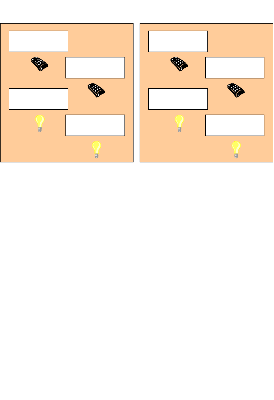
See Figure 1 for a graphical representation of the Home ID and Node ID of four different nodes before
and after installation. The original Home ID (0x00002222) is preserved when the Portable Controller gets
the secondary controller role but not used as long it is a part of the network with Home ID 0x00001111.
INS10244-5 Z-Wave Node Type Overview and Network Installation Guide 2008-12-04
Zensys A/S Z-Wave basics Page 7 of 38
CONFIDENTIAL
Figure 1. Assigning Home ID and Node ID
Portable Controlle
r
Home ID: 0x00001111
Node ID: 0x01
Portable Controlle
r
Home ID: 0x00002222
Node ID: 0x01
Slave
Home ID: 0x00000000
Node ID: 0x00
Slave
Home ID: 0x00000000
Node ID: 0x00
Li
g
ht Control S
y
stem
(
Before Installation
)
Primary Controlle
r
Home ID: 0x00001111
Node ID: 0x01
Secondary Ctrl.
Home ID: 0x00001111
Node ID: 0x02
Slave
Home ID: 0x00001111
Node ID: 0x03
Slave
Home ID: 0x00001111
Node ID: 0x04
Li
g
ht Control S
y
stem
(
After Installation
)
INS10244-5 Z-Wave Node Type Overview and Network Installation Guide 2008-12-04
Zensys A/S Z-Wave basics Page 8 of 38
CONFIDENTIAL
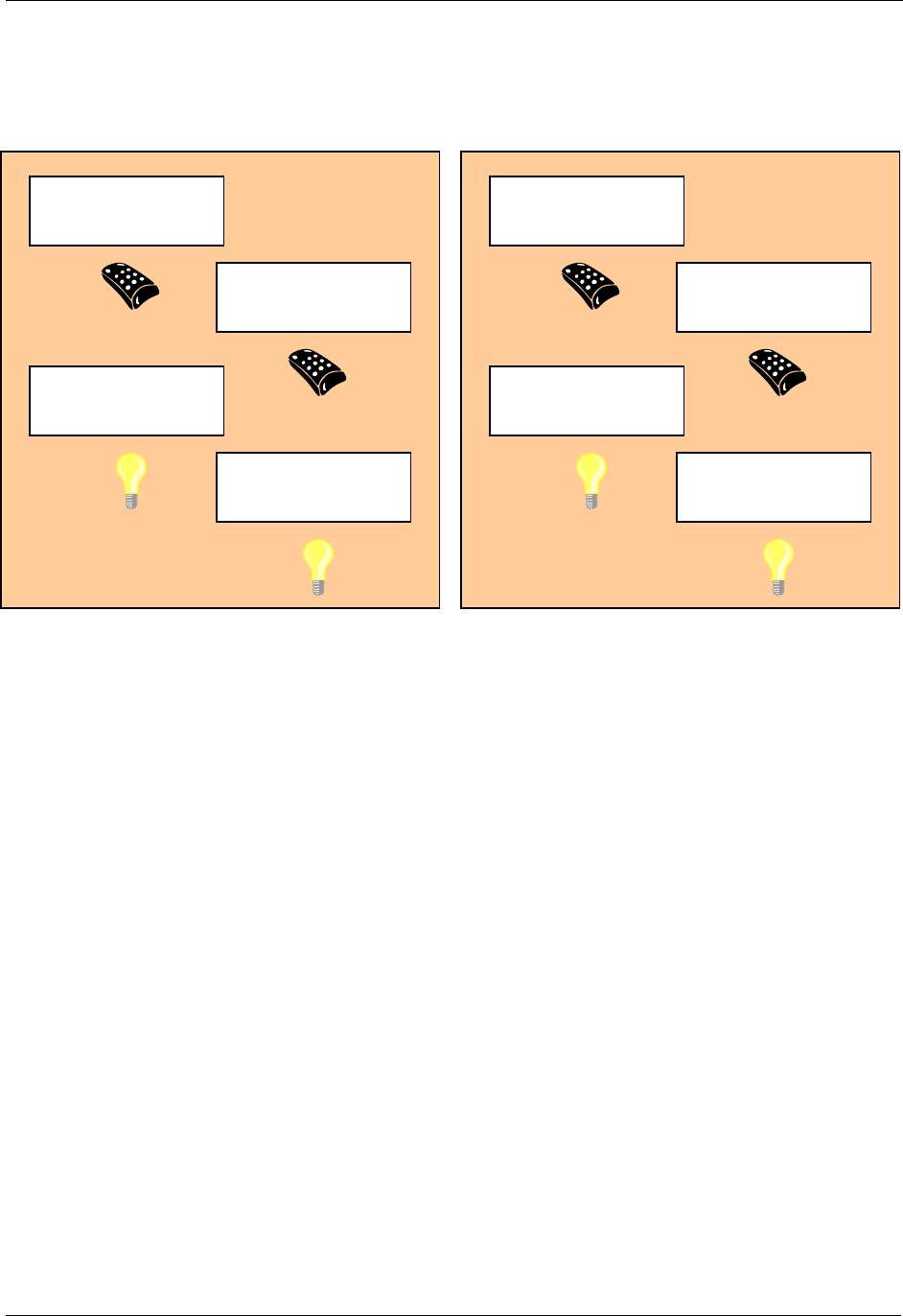
See Figure 2 for an illustration of how two adjoining networks will have different Home ID’s because
different controllers, with each their own unique Home ID’s, were used to do the installation.
Figure 2. Unique Home ID for two adjacent homes
While the inclusion process is different when performing network-wide inclusion via explorer frames, the
end result is the same. All nodes assume the home ID of the primary controller and individual, unique
node IDs.
Primary Controlle
r
Home ID: 0x00001111
Node ID: 0x01
Secondary Ctrl.
Home ID: 0x00001111
Node ID: 0x02
Slave
Home ID: 0x00001111
Node ID: 0x03
Slave
Home ID: 0x00001111
Node ID: 0x04
Li
g
ht Control S
y
stem
(
Home A
)
Primary Controlle
r
Home ID: 0x00003333
Node ID: 0x01
Secondary Ctrl.
Home ID: 0x00003333
Node ID: 0x02
Slave
Home ID: 0x00003333
Node ID: 0x03
Slave
Home ID: 0x00003333
Node ID: 0x04
Li
g
ht Control S
y
stem
(
Home B
)
INS10244-5 Z-Wave Node Type Overview and Network Installation Guide 2008-12-04
Zensys A/S Z-Wave basics Page 9 of 38
CONFIDENTIAL
3.4 Routing
All controllers contain a routing table, which enables the controller to calculate routes in the Z-Wave
network. Slave nodes will not have the ability to initiate transmission of routed frames, unless the
controller has provided one or more controller assigned routes to the Routing Slave or Enhanced Routing
Slave.
The forwarding mechanism for routed frames changed significantly from version 4.2x. Before that
version, every frame transmission was acknowledged before the frame was forwarded to the next node
in the path.
Version 4.2x makes use of the fact that the frame forwarded to the next node in the path is just as easy
to hear from the originator as an acknowledgement frame would be. This trick is nicknamed “Silent Ack”.
By using silent ack, a lot of airtime is freed up and protocol latency is reduced.
Before version 4.2x: Full acknowledgement
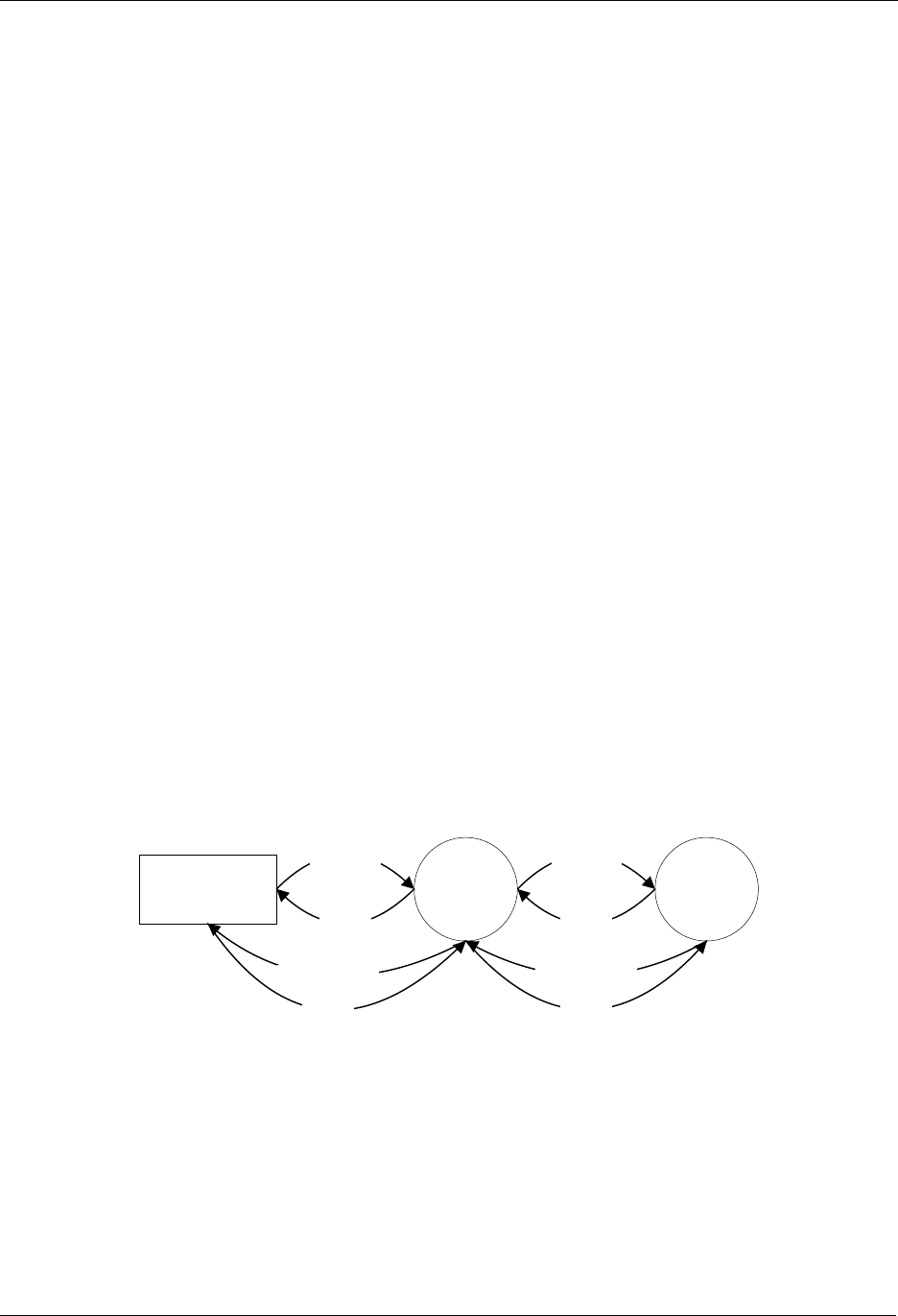
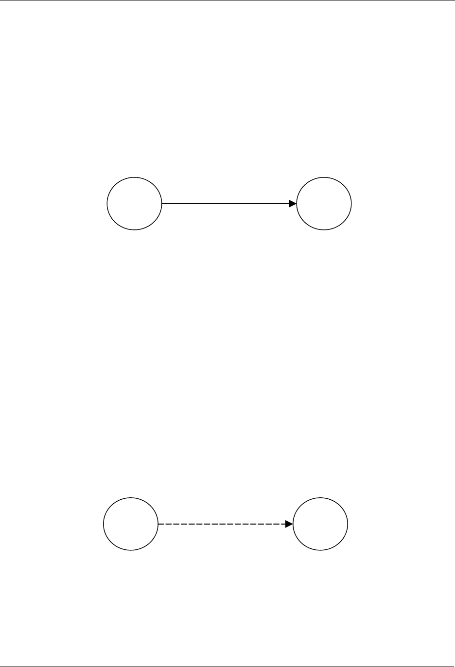
The figure below shows an example of the frame flow when a frame is sent from a controller, repeated
through a slave, to a second slave.
1. The controller sends a frame for slave 2 routed via slave 1
2. Slave 1 confirms the reception of the frame by sending out an ack.
3. Slave 1 repeats the frame.
4. Slave 2 confirms the reception of the frame by sending out an ack.
5. Slave 2 sends out a routed ack for end-to-end confirmation
6. Slave 1 confirms the reception of the frame by sending out an ack.
7. Slave 1 repeats the frame.
8. The controller confirms the reception of the frame by sending out an ack.
Figure 3. Routed frame flow
Controlle
r
Slave 1 Slave 2
Frame (1)
A
ck (2)
Frame (3)
A
ck (4)
Routed Ack (5) Routed Ack (7)
A
ck (6)
A
ck (8)

INS10244-5 Z-Wave Node Type Overview and Network Installation Guide 2008-12-04
Zensys A/S Z-Wave basics Page 10 of 38
CONFIDENTIAL
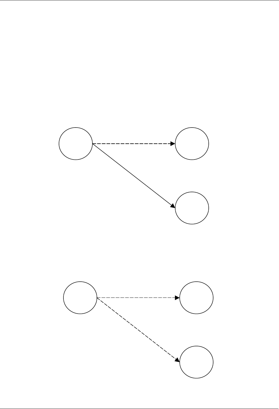
From version 4.2x: Silent acknowledgement
The figure below shows an example of the frame flow when a frame is sent from a controller, repeated
through a slave, to a second slave.
1. The controller sends a frame for slave 2 routed via slave 1
2. Slave 1 repeats the frame.
The controller receives the frame and interprets this as an acknowledgement
3. Slave 2 sends out a routed ack for end-to-end confirmation
Slave 1 receives the frame and interprets this as an acknowledgement
4. Slave 1 repeats the frame.
Slave 2 receives the frame and interprets this as an acknowledgement
5. The controller confirms the reception of the frame by sending out an ack frame
Figure 4. Routed frame flow w. silent ack
3.5 Initiators
The Z-Wave system is relying on the ability to include, exclude and operate nodes in the network, as
described below. This requires that each device has a number of “Initiators”. In the rest of this document
an initiator does not necessarily mean a physical button. An Initiator can either be a physical button, a
special activation of a button (e.g. activating a button for 2 seconds), a combination of buttons (e.g.
activating two buttons simultaneously) or an item in a menu system.
3.5.1 Slave Initiators
The slave nodes only need one Initiator since all the intelligence is placed in the controller nodes. The
slave initiator will be used for inclusion/exclusion, association/disassociation and operation depending on
whether the initiators on the controller are activated or not. If additional features need to be supported,
additional initiators may be required.
Controlle
r
Slave 1 Slave 2
Frame (1) Frame (2)
Routed Ack (3)Routed Ack (4)
A
ck (5)

INS10244-5 Z-Wave Node Type Overview and Network Installation Guide 2008-12-04
Zensys A/S Z-Wave basics Page 11 of 38
CONFIDENTIAL
3.5.2 Controller Initiators
The controller nodes need at least the following initiators:
Include Initiator:
The include initiator is used when Primary and Inclusion Controllers include nodes in the
network. When both the include initiator on the Primary/Inclusion Controller and a slave initiator
have been activated simultaneously, the new node will be included to the network if the node
was not included previously. Include initiator is activated on a Primary Controller or Inclusion
Controller and on a controller that is un-initialized, this will result in the new controller is included
to.
Exclude Initiator:
The exclude initiator is used by Primary Controllers to exclude nodes from the network. When
the exclude initiator and a slave initiator are activated simultaneously, it will result in the slave
being excluded from the network (and reset to Home ID zero). Even if the slave was not part of
the network it will still be reset by this action.
Associate Initiator:
The associate initiator is used to associate nodes when both initiators on two nodes have been
activated, the two nodes will be associated. This has the effect that when activating the operate
initiator, all devices associated with this node is being operated.
Operate Initiator:
The operate initiator is used for controlling the functionality of the associated devices (e.g. a
portable controller turning light on/off).
Controller Assigned Route Initiator:
The controller assigned route initiator is only needed in systems where the Primary Controller is
required to generate controller assigned routes for Routing Slaves. The initiator is used to
associate a Routing Slave with Static Controllers and other slaves.
Static Route Initiator:
The static route initiator is used when creating associations between slaves and static controllers
out of direct reach. Using a portable controller, a two-step process is used to create an
association. Refer to Figure 19, page 32, for details.
If additional features need to be supported, additional initiators may be required.
3.6 Node Information Frame
When the Include Initiator in a node is activated it will issue a node information frame. This frame is part
of the Z-Wave protocol, and specifies the capabilities of the node. These capabilities announced include
the node type, whether the node is able to repeat frames, and other protocol relevant issues. The node
information frame also contains the Home ID and the Node ID.
It is possible for the application to ask for the Node Information Frame from all nodes in the network and
hence enabling any node to acquire information regarding any other nodes features in the network at any
given time.

INS10244-5 Z-Wave Node Type Overview and Network Installation Guide 2008-12-04
Zensys A/S Z-Wave Network Features Page 12 of 38
CONFIDENTIAL
4 Z-WAVE NETWORK FEATURES
This chapter contains information about functionalities in a Z-Wave Network.
4.1 Include/exclude Process
All nodes are required to take part in the include/exclude process. Only the Primary Controller and
Inclusion Controllers in the network are able to include and exclude nodes. This strategy is chosen to
ensure that the network stays consistent with respect to the Node ID’s allocated.
From the Installer viewpoint all Z-Wave nodes (regardless of their node type) will use the same
installation process.
4.1.1 Include Nodes
When a node is to be included in the network, the Primary Controller or Inclusion Controller will grant the
request if there is Node ID’s available. The network can consist of maximum 232 nodes.
4.1.1.1 Include slaves
The Include process is initiated by activating both the include initiator on the controller and the slave
initiator. This causes the slave node to send out its node information frame. When the node information
frame is received from an un-initialized node the controller will assign Home ID and Node ID to the slave.
If a slave has already been assigned a Home ID and Node ID, it will not accept the inclusion. The Node
will have to be excluded (or reset) before the node can be included again.
4.1.1.2 Include controllers
The include process is initiated by activating the include initiator on the Primary Controller or Inclusion
Controller and the include initiator on the new controller that should be included into the network. The
Primary Controller or Inclusion Controller will assign Home ID and Node ID to the new controller, which
will then automatically become a Secondary or Inclusion Controller.
As part of the inclusion of additional controllers into the network, a replication of the routing tables and
optionally other information will automatically take place. This ensures that the new controller have the
newest information available. At later stages, when the Primary Controller has been updated with new
nodes (or nodes have been deleted), a new replication can be initiated by activating the include initiators
on both controllers as desired above. This network information updating can also be done automatically
using the Static Update Controller functionality.
4.1.2 Exclude Nodes
The exclusion of Slave nodes happens when the exclude initiator on the Primary Controller and the slave
initiator are activated. When nodes are excluded it will result in the node being reset and the topology
information in the Primary Controller or Inclusion Controller being updated to reflect the change. This
information is then passed on to the SUC if one is present.
When a slave node is reset, it will assume Home ID zero again. When a controller is reset, it will assume
the Home ID it was originally programmed with during the manufacturing process. This applies for ZDK’s
different from v4.5x.
Using ZDK v4.5x a reset result in a new random Home ID in both slaves and controllers respectively.

INS10244-5 Z-Wave Node Type Overview and Network Installation Guide 2008-12-04
Zensys A/S Z-Wave Network Features Page 13 of 38
CONFIDENTIAL
The exclusion of a Controller happens when the exclude initiator both on the Primary and the Secondary
Controllers are activated.
4.2 Association of nodes
When two nodes have been assigned to the network it is possible to associate these with each other.
The following describes the different possibilities for associating nodes.
Convention: “A is associated with B” means that A is under the control of B.
For instance, A could be an outlet dimmer module and B could be a remote control.
4.2.1 Associating a Slave with a Controller
A slave node is associated with a controller by activating both the associate initiator on the controller to
make it go into receive mode and the slave initiator on the slave to make it transmit its node information
frame. The controller will receive the node information from the slave node and add the slave node to its
internal associated nodes list maintained by the application layer.
Once a slave has been included to the network (see above) then it is possible to create associations with
any controller. This functionality can typically be supported by a GUI wherefrom the node can be
selected in a list.
Example: The slave is an outlet dimmer module and the controller is a remote control
4.2.2 Associating a (Routing) Slave with a Routing Slave
A (Routing) Slave is associated with a Routing Slave by using a Controller. The association of the nodes
takes place by first activating the controller assigned route initiator on the Controller and the initiator on
the destination Node (node that should be controlled). Secondly the controller assigned route initiator on
the Controller and the initiator on the source node (node that should be controlling the association) are
activated simultaneously. The Controller will then generate one or more routes and transmit these to the
source node. This functionality can typically be supported by a GUI wherefrom the source and
destination can be selected in a list and finally push out routes to the source via RF.
Example: The slave is an outlet switch module and the routing slave is a movement sensor.
The controller used for association might be a portable controller.
4.2.3 Associating a Static Controller with a Routing Slave
A Static Controller is associated with a Routing Slave by use of a Controller. The association of the
nodes takes place by first activating the controller assigned route initiator on the Controller and the
associate initiator on the destination Static Controller (node that should be controlled or informed about
events). Secondly the controller assigned route initiator on the Controller and the initiator on the source
node (Routing Slave node that should be controlling the association sending the event information) are
activated. The Controller will then generate one or more routes and send them to the source node.
Example: The static controller is a wireless wall switch and the routing slave is a wall mounted.
scene controller. The controller used for association might be a portable controller.
Note: The static controller could set up this association by itself if it is somehow possible to communicate
to it who the source node is (it is assumed that they are not within direct range in which case the situation
would be similar to the “Associate a Slave with a Controller” example above). By using a controller for
this job, the same procedure can be followed whether a routing slave is to control a slave, a routing slave

INS10244-5 Z-Wave Node Type Overview and Network Installation Guide 2008-12-04
Zensys A/S Z-Wave Network Features Page 14 of 38
CONFIDENTIAL
or a static controller. Even more important, this procedure makes it possible for an end-user to set up his
wall mounted scene controller without having to bother with whether this product is based on the
controller or the routing slave libraries.

INS10244-5 Z-Wave Node Type Overview and Network Installation Guide 2008-12-04
Zensys A/S Zensor Net Technology Page 15 of 38
CONFIDENTIAL
5 ZENSOR NET TECHNOLOGY
Zensor Net technology was introduced with the release of ZDK 5.0.
The purpose of Zensor Net technology is to support communication to battery-operated nodes.
In a classic Z-Wave network, the receiving node must be always listening.
A Zensor Net is a network of battery-operated nodes that are able to operate for months or even years
on the same battery, yet they are still able to communicate internally or via some master node.
One part of the solution is a special extended preamble, called a beam, allowing sleeping nodes to
detect a frame within a very short wake-up interval.
Another part offers special binding between identical node types and network flooding.
A node implementing all features is called a Zensor Node. The beaming feature used together with
wakeup timer in a Routing Slave leads to a "Frequently Listening Routing Slave" (FLiRS) node.
The following sections present the Zensor Net Technology components in detail.
5.1 The Zensor Net Beam
The solution for reaching sleeping nodes is to introduce a “Beam”; a long preamble saying: “I have
something for you, please hold the line”. The real frame then follows the beam.
The Zensor Net beam is used in FLiRS nodes as well as Zensor Net nodes.
Sender and receiver are not synchronized.
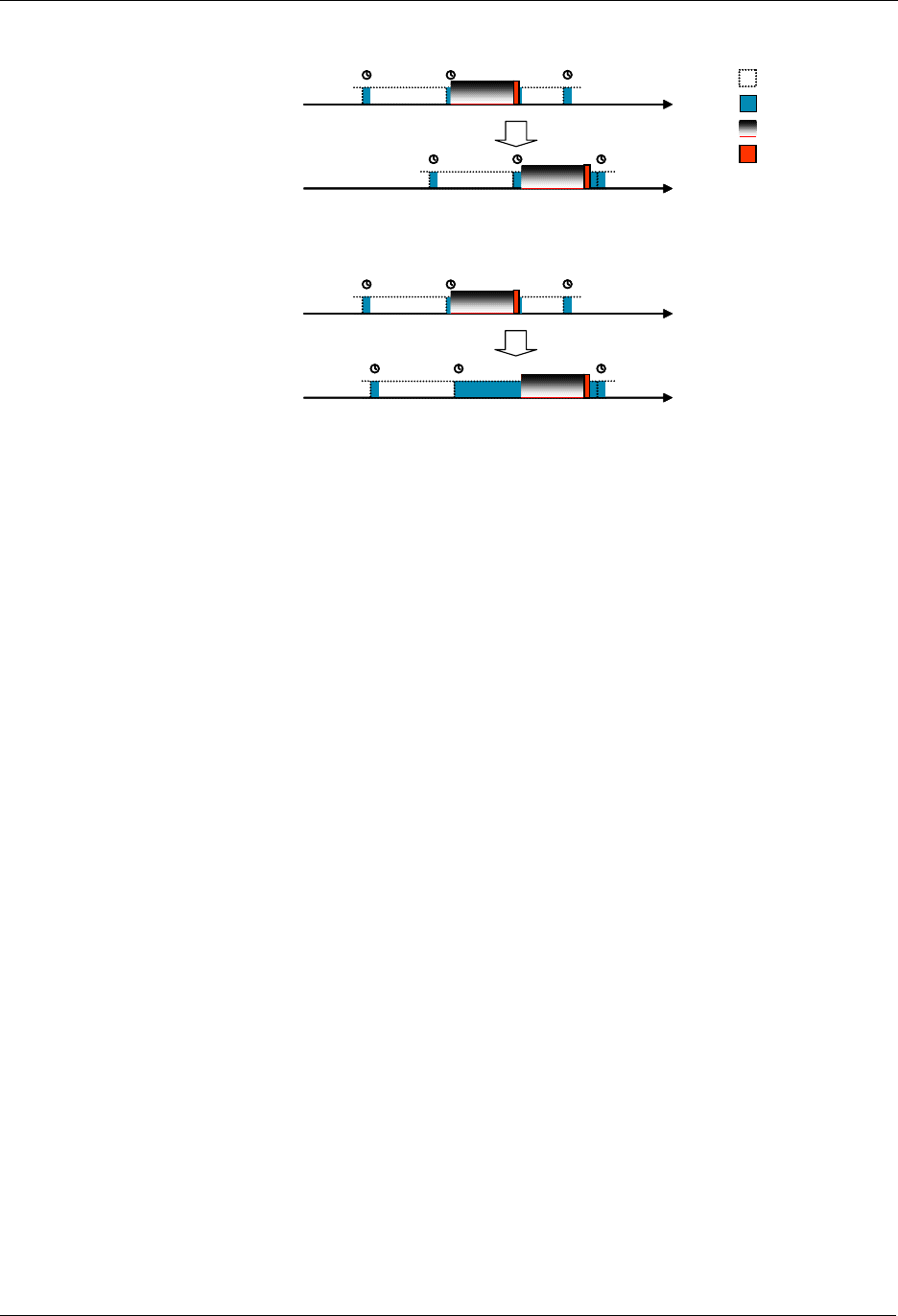
Figure 5 shows best case and worst case timing for a repeater node in a battery-to-battery
communication using Zensor Net beaming.
From a battery point of view, the best case is if the receiver wakes up just in time to detect the last
preamble segment of the beam before the real frame follows.
The worst case is if the receiver wakes up and receives the very first beam fragment.
Each beam fragment carries information on the remaining number of fragments. This allows a node to
return to sleep and wake up again shortly before the beam ends.
Note: A high-precision Wake-Up Timer (WUT) is required for making use of this power-saving feature.
The Zensys 400 series chip family offers such a WUT.
INS10244-5 Z-Wave Node Type Overview and Network Installation Guide 2008-12-04
Zensys A/S Zensor Net Technology Page 16 of 38
CONFIDENTIAL
Node beamingNode beaming
Best case Rx
Receiver wakes up just
before frame arrives
Destination
Source Node sleepingNode sleeping
Node awakeNode awake
Node transmittingNode transmitting
Worst case Rx
Receiver wakes up just
after start of beam
Destination
Source
Figure 5. Reception timing when sending beams
In average, a listening node will detect the beam halfway through the beam.
There are multiple purposes of the beam:
1. It makes sure that a battery node detects that data is ready for it when the node actually wakes
up.
By making the beam (slightly longer than) the length of the wake-up interval, the node will always
wake up somewhere inside the beam.
2. The wake-up time is completely asynchronous and the precision of the wake-up timer is so
limited that after 1 minute, the wake-up time may have drifted almost one second away from the
nominal wake-up time.
Thus, a management system trying to read sensors will have no knowledge of the next expected
wake-up time of a node that is read out at a rate lower than once per minute – which is the case
for most battery sensor systems.
3. Without the beam, one could send out a high number of copies of the same frame from the
application layer until an acknowledgement is received.
This strategy has two problems:
First, the listening node would have to be awake for a longer duration to detect the frame.
Second, there would be small pauses between the frames forcing the listening node to be awake
for an even longer duration and even worse, there would be a risk that other nodes could send a
frame in just that critical period where the listening node was awake and listening.
INS10244-5 Z-Wave Node Type Overview and Network Installation Guide 2008-12-04
Zensys A/S Zensor Net Technology Page 17 of 38
CONFIDENTIAL
In ZDK 5.0, there is support for wake-up intervals of 250msec and 1000msec.
Node beamingNode beaming
Node sleepingNode sleeping
Node awakeNode awake
Node transmittingNode transmitting
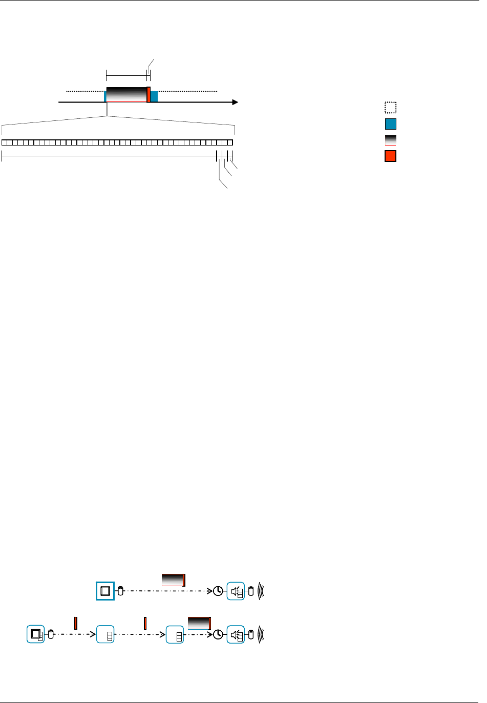
Beam fragment (4.5ms)
Preamble pattern (20 bytes)
Beam Frame (up to 64 bytes)
Zensor ID (7 bits) + info field control (1 bit)
Start-of-frame pattern (1 byte)
Info field (1 byte)
Figure 6. Structure of the beam
As mentioned above, one of the purposes of the beam is to block the air, ensuring that no other nodes
disturb this attempt to reach a node.
Blocking the air inevitably affects latency, command response times and ultimately end-user experience.
Everybody having tried satellite telephony or bad graphical user interfaces knows that a half-second
delay from action to response is confusing and highly unsatisfactory. It is a known fact inside the telecom
industry that the limit is somewhere around 300ms.
The 250msec wake-up interval stays below the 300msec limit. Actually, it is the absolute worst-case
delay cased by the beam that is 250msec. In average, it is 125msec, which hardly will be noticed at all by
normal users turning a lamp on or off. Applications benefiting from the 250msec wake-up interval are
battery-operated FLiRS nodes such as wireless doorbell chimes and wireless motion alarms, where low
latency is critical.
The 1000msec wake-up interval is well beyond the 300msec limit and is not intended for use in Z-Wave
environments during normal operation. The only application addressed by the 1000msec interval is a
Zensor Net system of networked smoke alarms with a requirement for very long battery lifetime and
moderate response times. The philosophy is that an emergency like a fire in the building is an extreme
situation where longer response times are accepted. The important part is that all alarms get started and
battery life time is long.
The beam is implemented as a backwards compatible extension to the classic Z-Wave protocol. Z-Wave
nodes not capable of receiving or sending beams will discard the preamble as invalid.
Power information (battery / AC) and beam speed are taken into account when creating routes so that
battery-operated nodes are not used as repeaters and so that a battery-operated node sending a frame
takes into account the mode of the receiving node, as well as any repeaters used to reach the
destination.
The routing header of the frame carries beam speed for each hop; allowing each repeater to know if
beaming should be used when forwarding a frame.
Direct reach. Push button sends a 250msec beam.
Routed path. Push button sends a normal frame
to the first repeater. So does the first repeater.
The second repeater sends a 250msec beam.

INS10244-5 Z-Wave Node Type Overview and Network Installation Guide 2008-12-04
Zensys A/S Zensor Net Technology Page 18 of 38
CONFIDENTIAL
Figure 7. Battery-to-battery communication; direct reach and routed
Many topologies may be envisioned for battery-to-battery networks. Many of them focus heavily on
battery lifetime and the ability to form ad-hoc networks. Some sensor networks have a large geographical
coverage, causing some nodes to be out of direct reach from the management system controlling the
sensors. In such environments, the principle outlined in Figure 7 may be used to create a mesh of many
long-living FLiRS nodes and a few strategically located repeater nodes with large batteries, which takes
all the burden of sending out beams.
5.2 The Zensor Net node
Certain applications (e.g. networked smoke alarms) have a hard requirement for robust, autonomous
operation. During network configuration, it may be acceptable to have some centralistic approach, but
operation must be 100% mesh oriented. Any subset of nodes breaking down must not cause the
remaining nodes to loose contact to each other.
Zensor Net nodes are able to forward broadcasted frames under certain conditions. This is covered in
section 5.5.
In order to achieve a long battery life, Zensor Net nodes must be sleeping most of the time.
The challenge in a Zensor Net is to deliver a frame to nodes that only listen for a very short time now and
then.
5.3 Applications that benefit from Zensor Net technology
A range of applications may utilize the Zensor functionality.
All make use of Zensor Net beaming to deliver a frame to a sleeping node.
Application Communication
mode Node type Latency Battery
lifetime Z-Wave
co-existence
Doorbell
chime Singlecast;
classic Z-Wave @
250msec wake-up
FLiRS Very low
latency Moderate lifetime
2800mAh/year Required
Environmental
sensor
rain, wind...
Singlecast;
classic Z-Wave @
250msec wake-up
FLiRS Very low
latency Moderate lifetime
2800mAh/year Required
Smoke alarm Multicast flooding
@ 1000msec
wake-up
Zensor Node Low latency Long lifetime
700mAh/year Some impact
accepted
5.3.1 Doorbell chime
The doorbell application uses two battery-operated nodes; a doorbell push button and a chime. Figure 7
(first part) outlines such a system. The doorbell push button only wakes up when the button is pressed.
The battery lifetime of the doorbell push button is very long.
In order to detect the button being pressed, the chime must wake up frequently, e.g. every 250msec.
Therefore, the chime is using significantly more power than the doorbell pushbutton.
INS10244-5 Z-Wave Node Type Overview and Network Installation Guide 2008-12-04
Zensys A/S Zensor Net Technology Page 19 of 38
CONFIDENTIAL
In most cases, no traffic is detected and the node can return to sleep again after 4.5msec. When the
button is pressed, the doorbell pushbutton node must send out a 250msec beam followed by a frame to
ensure that the chime receives the frame.
A special case of the doorbell application is outlined in the second part of Figure 7. Here, the pushbutton
cannot reach the chime directly, but sends a routed frame, which eventually ends up being beamed to
the chime.
Setup of the system is entirely classic Z-Wave: The chime node is included with the doorbell pushbutton
node.
Average current for a chime node based on a FLiRS node is 320µA. On a year basis this equals
2800mAh, i.e. the capacity of normal AA cells; assuming a very low rate of chime activations.
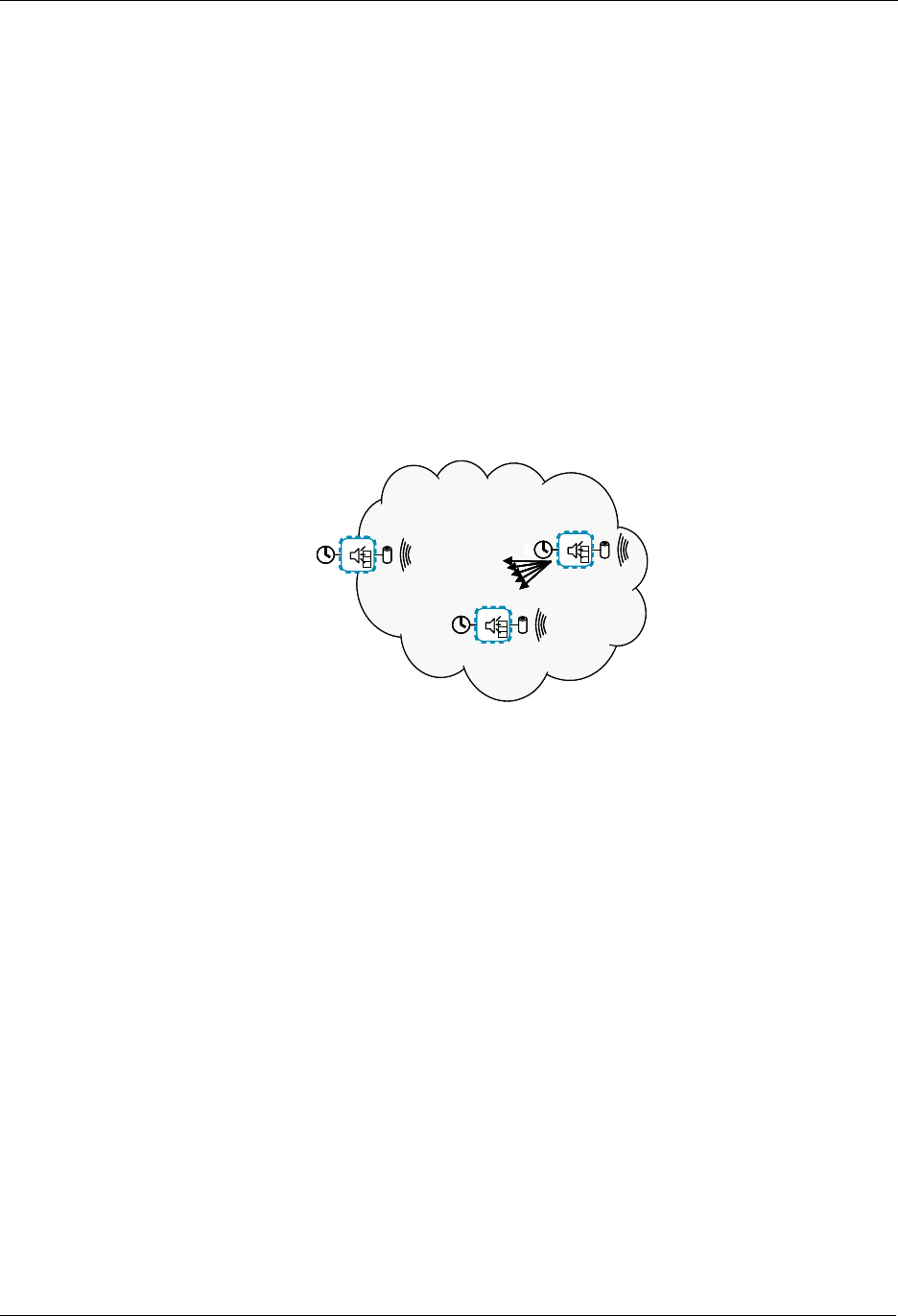
5.3.2 Smoke alarm
The smoke alarm application is an extreme solution to an extreme situation. Up to 16 nodes must be
able to reach each other at typically 10 seconds given whatever topology with no structured network
configuration upfront.
Zensor netZensor net
EDGE NODE
”SMOKE!!!”
Figure 8. A flooded Zensor Net
The smoke alarm application makes use of beaming as well as flooding and special frame formats.
The network configuration is limited to selecting one random smoke alarm and “binding” up to 15 other
smoke alarms to that alarm. The binding process provides all alarm devices with the same, unique
Zensor Net home ID.
The alarm devices can now be spread over a large area without any risk of breaking any pre-planned
routed paths.
If a fire breaks out, the first smoke alarm to discover the fire starts sounding its audible alarm and at the
same time, it sends out a 1000msec beam followed by a special “Zensor Net flooding frame” to the
broadcast Zensor Net node ID 0xFF. The broadcast node ID makes all other smoke alarms within direct
reach receive the transmission. The special flooding frame makes all receiving nodes forward the frame;
also using the broadcast node ID. Broadcast loops are killed by having every smoke alarm only forward
one copy of a given frame.
If many nodes received the broadcasted frame, many nodes will now want to forward a copy of the
frame. A delicate arbitration mechanism ensures that the nodes spread out the transmissions in time,
thus avoiding (or limiting) collisions.
Extensive simulations indicate that all nodes are reached and that the required time for activating all
alarms is achieved in 99% of the cases. Up to 16 beams of 1000msec each jams the air effectively, but
in a case of emergency, users may prefer that all alarms get started as fast as possible.
Note that a users command to turn on the light will not be dropped. Worst case, it will be delayed up to
1000msec, but it will end up reaching the lamp, thus allowing the user to get out of a smoke filled house.

INS10244-5 Z-Wave Node Type Overview and Network Installation Guide 2008-12-04
Zensys A/S Zensor Net Technology Page 20 of 38
CONFIDENTIAL
As mentioned earlier, alarm nodes are interconnected using “Binding”. A high-end option exists, though.
On top of a bind-configured Zensor Net, it is possible to include all Zensor Net nodes with a controller
using classic Z-Wave inclusion. This enables a management system to make periodical checks of the
availability and battery status of the nodes, while the nodes are still able to trigger each other completely
independent of the central management system; a handy feature in case of power failure.
In this special case, a node is at the same time a FLiRS node and a Zensor node.
The average current of a smoke alarm is 80µA. On a year basis this equals 700mAh, i.e. less than the
capacity of normal AAA cells (800mAh) and bit more than a 9V battery (650mAh); assuming no
management communication.
In a managed system requesting status on a periodic basis, power consumption will be higher. One
reading per hour, i.e. one message processing per 3600 wake-ups will only add marginally to the power
consumption. An even more economical approach could be to program an interval in which the node by
itself reports its presence to an always-on node; only contacting the node when initializing the
management system or re-programming report intervals.
Checking for a beam takes 4.5ms radio listening. 3600 wake-ups equals 16.2 radio listening seconds.
Thus, sending a 1sec beam once per hour would add 6% power consumption. Using always-on
repeaters saves the Zensor beaming and makes status communication virtually costless.
5.4 Zensor Net Binding
Binding provides Zensor Net nodes with a unique Zensor Net home ID and Zensor Net node ID.
Binding is not a substitute for classic Z-Wave inclusion. Binding enables flooding in a restricted Zensor
subnet and it enables the use of specially formatted flooding frames not compatible with classic Z-Wave,
but required for controlling flooding.
The Zensor Net home ID is used to restrict flooding within a specific Zensor Net. Flooding is explained in
section 5.5.
Binding of Zensor Net nodes is performed by the user choosing one random node as the master. This
master node has a role resembling that of a controller node in a classic Z-Wave network. All other
Zensor Net nodes are bound to the master node, one at a time (The user should tag the master
somehow in order to identify it again later). Binding may be performed by carrying the master around the
house, binding nodes one at a time in their final locations or on the dining room table, binding all nodes in
one chunk and mounting them afterwards. No routing tables are used, so the nodes may be moved
around or exchanged without any implications for the operation of the remaining Zensor Net.
5.5 Zensor Net Flooding
Zensor Net flooding is a mechanism that ensures that all nodes can be reached at any time. A node
running out of battery or being moved does not become a critical missing link for the distribution of a
smoke alarm frame.
Flooding broadcast frames is not for free. Every node receiving a frame sends out a new broadcast
frame. With no countermeasures, this behavior would lead to air congestion, collisions and infinite loops.
Infinite loops are avoided in Zensor Nets by monitoring incoming broadcast frames. All Zensor Net
frames carry a unique token, the “Flooding Frame ID”. If a frame requests flooding, the node first checks
if the Flooding Frame ID has been detected recently. The frame is only flooded if the Flooding Frame ID
has not been met recently.
Trajectories of frames forwarded by Zensor Net flooding have some resemblance to the topology created
by the Spanning Tree Protocol used to prevent infinite loops in Ethernet.

INS10244-5 Z-Wave Node Type Overview and Network Installation Guide 2008-12-04
Zensys A/S Zensor Net Technology Page 21 of 38
CONFIDENTIAL
Collisions are another challenge. Zensor Net flooding uses a significantly different strategy for sending
frames than classic Z-Wave.
A Zensor Net with flooding is an environment with concurrent transmissions in different parts of the
network and a high potential for collisions.
The strategy defined for Zensor Net traffic management is as follows:
• Zensor Nets with few nodes should have low latency for activation of all nodes.
• Zensor Nets with many nodes should relax the load; spreading out traffic in time in order to lower
the amount of undetected collisions.
• Zensor Nets should leave room for other Z-Wave traffic. The latency is increased thanks to the
one second beams but bandwidth must be available for control commands between the beams.
The Zensor Net features collision avoidance and protocol back-off takes into account the number of
nodes traversed before the actual transmission. The more hops, the bigger or more complex network. If
the network has a high number of nodes, the risk of collisions is also bigger. Therefore, a large number
of hops lead to a bigger window of time slots to choose between; the rationale being that if too many
frames collide, there is a risk that some nodes do not receive a valid frame at all. On the other hand,
there is no need to delay frames too much if there are a low number of nodes in the network.

INS10244-5 Z-Wave Node Type Overview and Network Installation Guide 2008-12-04
Zensys A/S Explorer Features Page 22 of 38
CONFIDENTIAL
6 EXPLORER FEATURES
With the introduction of ZDK 4.50, a new class of services was added to the Z-Wave protocol layer. All
these services make use of Explorer frames. Explorer frames are broadcasted Z-Wave frames, which
carries a special explorer header and optionally an embedded Z-Wave command to be executed by a
target addressed inside the explorer header.
Special rules specify how explorer-supporting nodes should forward copies of explorer frames.
6.1 On-demand Route Resolution
If failing classic routing, a node may issue an explorer SearchRequest frame.
All nodes supporting explorer frames may forward the request in accordance with the forwarding rules.
Once the explorer frame reaches the target of the search, the target looks for an embedded command to
execute and returns an explorer SearchResult to the requester.
The SearchResult frame carries a Stop flag to prevent all neighbor nodes from sending more explorer
frame copies.
The flag is copied from the SearchRequest, which carries the flag from the requester to the target.
6.2 Network-Wide Inclusion
Unlike earlier versions of Z-Wave, explorer-supporting nodes may issue an explorer InclusionRequest
frame. The InclusionRequest may be forwarded by all other included nodes.
While primarily intended as an enhancement to classic direct-range inclusion, Network-Wide Inclusion
also supports the "New House" scenario, where a (high) number of nodes are turned on synchronously.
Once turned on, the nodes may start requesting inclusion on their own. Random scheduling is used to
spread out transmissions in order to lower the risk collisions.
6.3 Network migration
ZDK 4.50 allows implementers to create products that benefit from new v4.50 features while maintaining
full compatibility with existing designs.
6.3.1 Compatibility
ZDK 4.50 is backwards compatible with earlier versions. This means that a v4.50 slave may be included
with a v4.20 controller and a v4.20 slave may be included with a v4.50 controller. In both cases, classic
inclusion will be used.
With classic inclusion, a controller asks the included slave to perform a neighbor discovery. A v4.50
controller also asks a v4.50 slave to perform a neighbor discovery. This allows a v4.20 secondary
controller included subsequently to calculate routes to v4.50 slaves.
6.3.2 Route resolution strategy
In order to support pre-4.50 nodes, a v4.50 controller always uses the following strategy:
1. Try last working route

INS10244-5 Z-Wave Node Type Overview and Network Installation Guide 2008-12-04
Zensys A/S Explorer Features Page 23 of 38
CONFIDENTIAL
2. Try a number of routes calculated from the routing table
3. Issue an explorer search request
Thus, in a predominantly static infrastructure, explorer frames may only be used during network-wide
inclusion, as the route table stays valid.
Now, if the nodes are moved around, earlier versions may fail calculating alternative routes.
ZDK 4.50 nodes will also fail trying the last working route and calculation of alternative routes. If this
happens, v4.50 node may send out an explorer SearchRequest frame.
For an explorer frame to reach its target, a number of repeater nodes must be present. The sufficient
number depends on the actual network topology and the amount of RF noise in the environment. This
observation applies to route resolution as well as network-wide inclusion.
In short, v4.50 provides the same level of network robustness as previous versions plus improved
discovery features if a sufficient number of nodes support v4.50 functionality.
6.3.3 SIS functionality for improved plug and play experience
Network-wide inclusion via explorer InclusionRequest makes use of a central primary controller. The
primary controller assigns a unique node ID to each new node included.
V4.50 nodes may be included from anywhere in the network; also when out of direct reach.
By implementing SIS functionality in a central controller based on v4.50, one may get the best of both
worlds. Nodes prior to v4.50 may be included via any inclusion controller in the network.
V4.50 nodes may also be included via any inclusion controller in the network. In addition, the user may
activate network-wide inclusion in the central controller, e.g. via a web page. In this mode, v4.50 nodes
may be included from anywhere in the network without any interaction with the controller.
INS10244-5 Z-Wave Node Type Overview and Network Installation Guide 2008-12-04
Zensys A/S Basic Installation Example Page 24 of 38
CONFIDENTIAL
7 BASIC INSTALLATION EXAMPLE
This chapter contains some examples of how to install elements of a Z-Wave system in a sequential
order. It also describes how nodes are associated.
7.1 Initial Setup
The most basic setup is one controller node and one slave node, as depicted in Figure 9.
Figure 9. Including a Slave node.
Initially both the controller and the slave node are reset. The controller will have a predefined Home ID =
0x00000020) and a Node ID =0x01. The slave have a predefined Home ID = 0x00000000 and Node ID =
0x00. Being the first controller in the system and therefore determining the Home ID, the controller
defaults to become the Primary Controller and takes node ID = 0x01.
When the include initiator on the controller and the slave Initiator is activated simultaneously, the include
procedure is initiated. The controller assigns the Home ID = 0x00000020 and the Node ID = 0x02 to the
slave node. The slave is now part of the Z-Wave network, but no specific association has been made
between the two nodes (the inclusion and the association process can be done as one interlinked action
from the end-user’s perspective).
7.2 Associating Nodes
The two nodes in Figure 10 are included in the same Z-Wave network, but have not yet been associated.
Figure 10. Associating a Slave Node with a Controller.
If the two nodes should be associated, this can happen by activating the associate initiator on the
controller and the slave initiator simultaneously. This will cause the controller to listen for a node to
associate. When the slave sends a node info frame (specified by the Z-Wave protocol and prompted by
activating the slave initiator), the controller will include the slave in the associated slaves list.
Slave
Portable
Controller
Home ID: 0x00000020
N
ode ID: 0x01
Home ID: 0x00000020
N
ode ID: 0x02
Slave
Portable
Controller
Home ID: 0x00000020
Node ID: 0x01
Home ID: 0x00000020
N
ode ID: 0x02
INS10244-5 Z-Wave Node Type Overview and Network Installation Guide 2008-12-04
Zensys A/S Basic Installation Example Page 25 of 38
CONFIDENTIAL
Every time the operate initiator on the controller is activated, the controller will send a message to the
slave node, which will cause the slave node to perform the specified action.
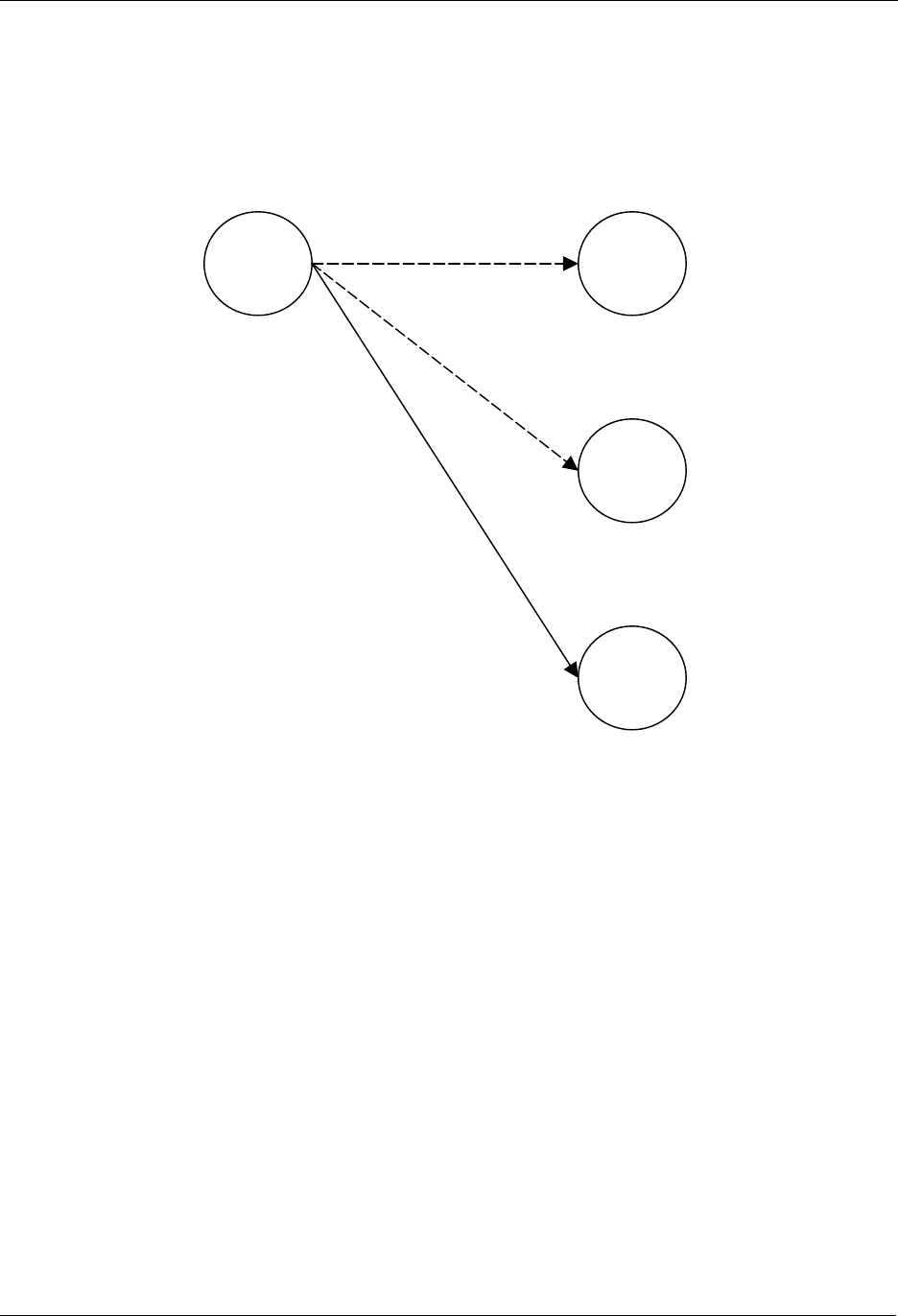
7.3 Adding Slave Nodes
New slave nodes can be included in the Z-Wave network as the network is gradually expanded. In Figure
11, the example is extended to include another slave node. The inclusion happens the exact same way
as for the first slave node. The second slave node will be assigned the Home ID = 0x00000020 and the
Node ID = 0x03. The second slave node can also be associated with the controller by activating the
associate initiator on the controller and the slave initiator simultaneously. The result is depicted in Figure
11.
Figure 11. Including Slave node 2.
The second slave node can also be associated with the controller by activating the associate initiator on
the controller and the slave initiator simultaneously as shown on Figure 12.
Figure 12. Associating Slave Node 2 with the Controller.
Slave 2
Slave 1
Portable
Controller
Home ID: 0x00000020
Node ID: 0x01
Home ID: 0x00000020
N
ode ID: 0x02
Home ID: 0x00000020
N
ode ID: 0x03
Slave 2
Slave 1
Portable
Controller
Home ID: 0x00000020
Node ID: 0x01
Home ID: 0x00000020
N
ode ID: 0x02
Home ID: 0x00000020
N
ode ID: 0x03
INS10244-5 Z-Wave Node Type Overview and Network Installation Guide 2008-12-04
Zensys A/S Basic Installation Example Page 26 of 38
CONFIDENTIAL
7.4 Adding Controllers
The Z-Wave network can also be extended to include multiple controllers. Figure 13 shows a system with
2 controllers.
Figure 13. Including a second Controller.
The second controller to be added comes with another unique default Home ID, for example 0x00000030
and Node ID = 0x01. When the Include initiator is activated on both controllers, the include process is
initiated. The first controller, which acts as Primary Controller for the Z-Wave network, will assign the
Home ID = 0x00000020 and the Node ID = 0x04 to the second controller, which now assumes the
position as a Secondary Controller.
Following the exchange of network identifiers a replication will take place. During the replication process,
all routing information will be transferred from the Primary Controller to the Secondary Controller. The
Secondary Controller is now able to perform all the same functionalities as the Primary Controller except
from including/excluding nodes in the Z-Wave network.
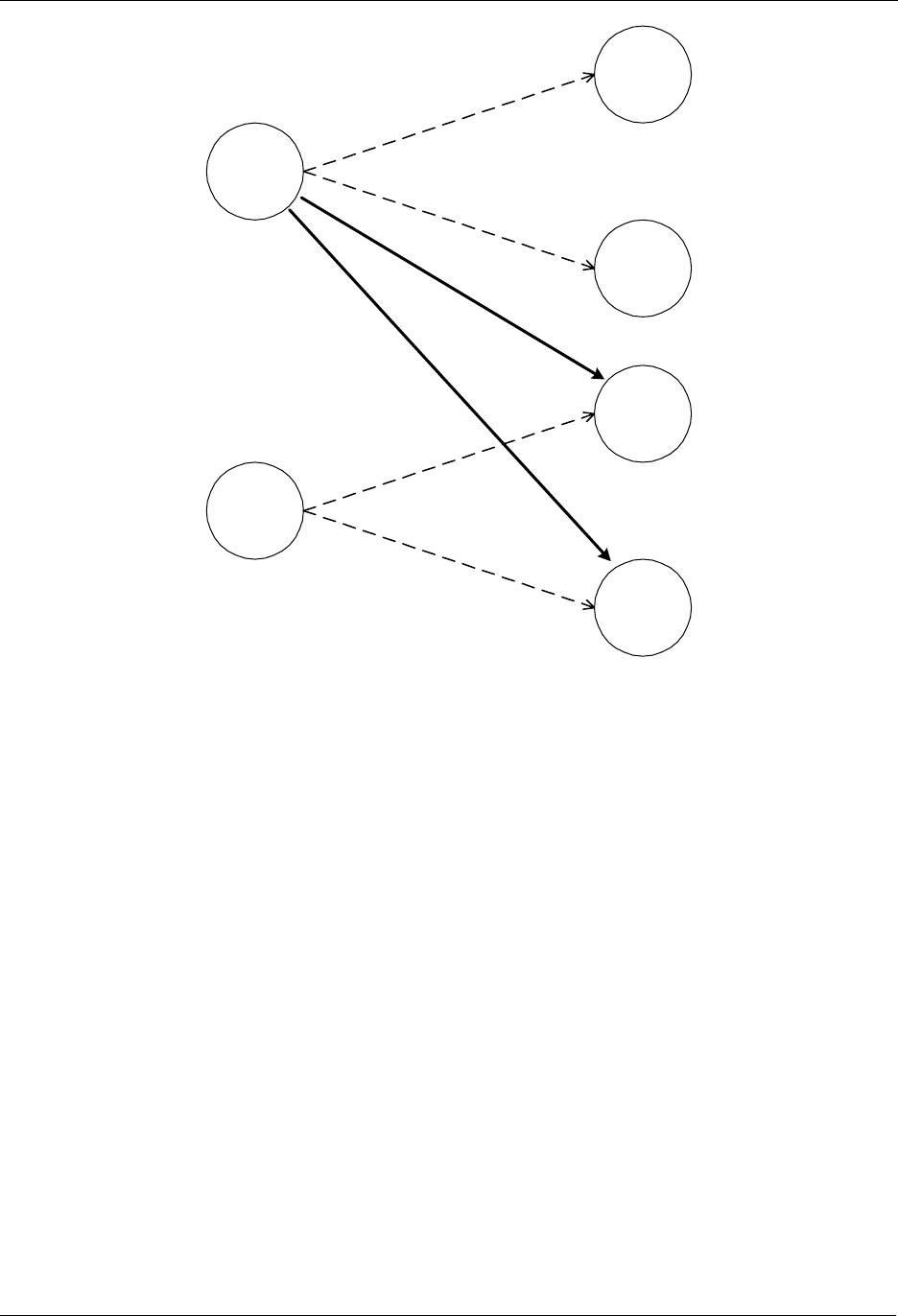
Additional slave nodes can be assigned to the Z-Wave network by the Primary Controller and associated
with either controller 1, controller 2 or both. In Figure 14 below two slave nodes has been included with
the Primary Controller and associated with controller 2.
Portable
Controller
2
Slave 2
Slave 1
Portable
Controller
1
Home ID: 0x00000020
Node ID: 0x01
Home ID: 0x00000020
N
ode ID: 0x02
Home ID: 0x00000020
N
ode ID: 0x03
Home ID: 0x00000020
N
ode ID: 0x04
INS10244-5 Z-Wave Node Type Overview and Network Installation Guide 2008-12-04
Zensys A/S Basic Installation Example Page 27 of 38
CONFIDENTIAL
Portable
Controller 1
(Primary)
Portable
Controller 2
Slave 1
Slave 2
Slave 3
Slave 4
Figure 14. Including and associating additional Slave nodes.
The Portable Controller 2 can be associated with slave 3 and slave 4. The routing table of Portable
Controller 2 will not be updated before Portable Controller 1 performs a controller replication.
7.5 Removing Slaves
A slave node can be removed from the Z-Wave network by activating the exclude initiator on the Primary
Controller and the slave initiator. This action will cause the controller to send Home ID = 0x00000000 and
Node ID = 0x00 to the slave, thereby resetting the slave. The controller will also remove the routing
information from the routing table.
7.6 Removing Secondary Controllers
A Secondary Controller can be removed by activating the exclusion initiator on both the Primary
Controller and the Secondary Controller.
7.7 Recover from Controller Node Error
If a controller fails, recovery depends on whether it is a Primary Controller or a Secondary Controller. If it
is a Secondary Controller it can just be removed, a new can be included and the routing information can
be replicated.

INS10244-5 Z-Wave Node Type Overview and Network Installation Guide 2008-12-04
Zensys A/S Basic Installation Example Page 28 of 38
CONFIDENTIAL
If the failed controller is the Primary Controller the situation is different. Basically the entire network can
be reset and then reconfigured with a new controller. This controller will then become the new Primary
Controller. The unique 32 bits identifier of the new Primary Controller will now be the new Home ID for
the entire Z-Wave network.
A more advanced method is to use the Network management features of the Z-Wave Network.
If a Static Controller is configured as a Static Update Controller (SUC), it will keep an updated version of
the routing table. All controllers in the system may request updates from the SUC. The primary controller
is required to send updates to the SUC when new nodes have been included or old nodes have been
reset. If the Primary Controller malfunctions, a secondary controller can be requested to be primary by
making replication from the SUC.
A SUC basically implements a mirror service for the primary controller, allowing the user to reconstruct all
topology settings and inclusion data in a new primary controller; should the primary controller break
down.
Note that associations and other application-level data is not stored in the SUC. The SUC only holds
protocol-level data. Thus, the SUC increases the network robustness but it is not a general backup
service.
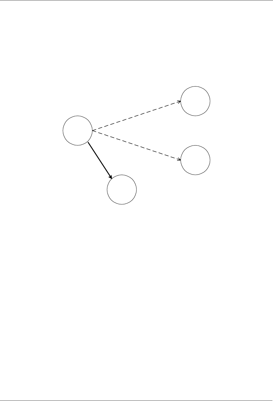
INS10244-5 Z-Wave Node Type Overview and Network Installation Guide 2008-12-04
Zensys A/S Static Controller and Routing Slave Example Page 29 of 38
CONFIDENTIAL
8 STATIC CONTROLLER AND ROUTING SLAVE EXAMPLE
This chapter extends the previous example to also include Static Controllers and Routing Slaves. The
starting point for this example is a network with a Portable Controller and two slave nodes.
8.1 Including Routing Slaves
The first step in this scenario is to include a Routing Slave, see Figure 15.
Portable
Controller
Slave 1
Slave 2
Routing
Slave
Figure 15. Including a Routing Slave.
The Routing Slave is included in the network in the exact same way as any other slave node. When the
include initiator on the controller and the initiator on the Routing Slave are activated, the controller will
assign Home ID and Node ID to the Routing Slave.
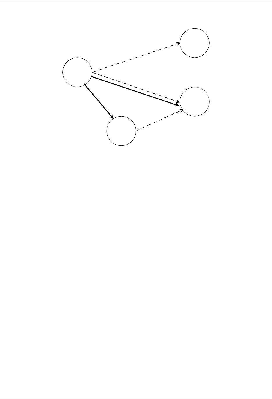
INS10244-5 Z-Wave Node Type Overview and Network Installation Guide 2008-12-04
Zensys A/S Static Controller and Routing Slave Example Page 30 of 38
CONFIDENTIAL
The Routing Slave can now be associated with a controller or another slave. The controller is an
important part of facilitating the association process although it is not part of the final association.
Portable
Controller
Slave 1
Slave 2
Routing
Slave
1
2
3
Figure 16. Associating a “Simple” Slave with a Routing Slave.
The controller needs an extra initiator compared to the previous example. This initiator is called a
controller assigned route initiator. The controller assigned route initiator on the controller and the initiator
on slave 2 (the device to be controlled) are activated. The procedure is repeated for the Routing Slave.
Upon doing the second part of the association, the controller will calculate one or more routes between
the Routing Slave and Slave 2. These routes will be sent to the Routing Slave, which will use the routes
when communicating with Slave 2.
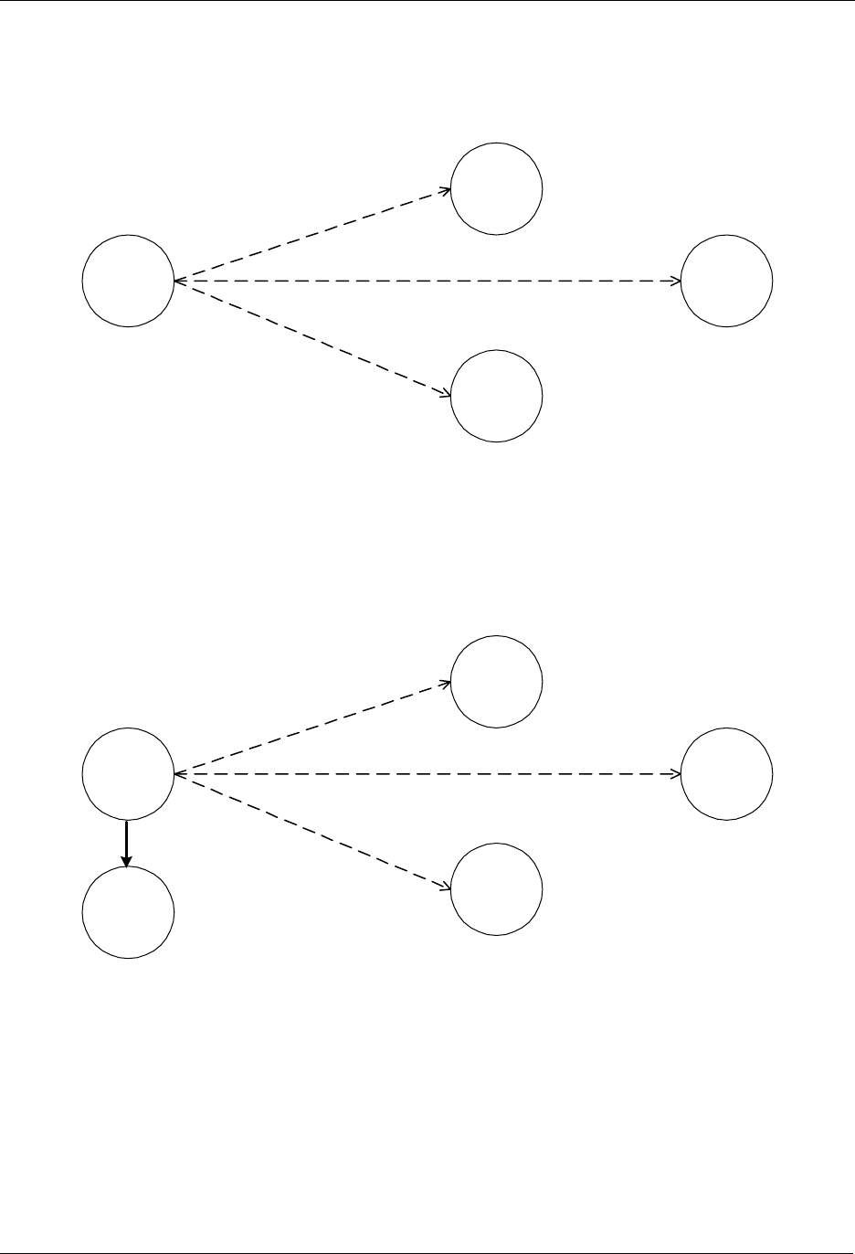
INS10244-5 Z-Wave Node Type Overview and Network Installation Guide 2008-12-04
Zensys A/S Static Controller and Routing Slave Example Page 31 of 38
CONFIDENTIAL
8.2 Including Static Controllers
This part of the example describes a situation where the network initially consists of one controller and
three Routing Slaves. This network is depicted in Figure 17.
Portable
Controller
Routing
Slave 1
Routing
Slave 2
Routing
Slave 3
Figure 17. Controller with three associated Routing Slaves.
The following figure shows the previous example extended with a Static Controller. A Static Controller is
included in the same way as a Portable Controller. The Static Controller will be assigned a Home ID and
a Node ID, and the topology information is transferred. The main difference in the inclusion procedure is
that the Static Controller automatically investigates which neighbours it is able to see during the include
process. Figure 18 illustrates the network after the Static Controller has been included.
Portable
Controller
Routing
Slave 1
Routing
Slave 2
Routing
Slave 3
Static
Controller
Figure 18. Including a Static Controller.
The Portable Controller now contains the full routing information, including the knowledge of which nodes
that can be reached directly from the Static Controller.
In this scenario it is now possible to create an association that allows a Routing Slave to communicate
with the Static Controller.
In the following example we want to associate the Static Controller with the Routing Slave 3. In the
example it is assumed that the Static Controller can only reach Routing Slave 1 and Routing Slave 2
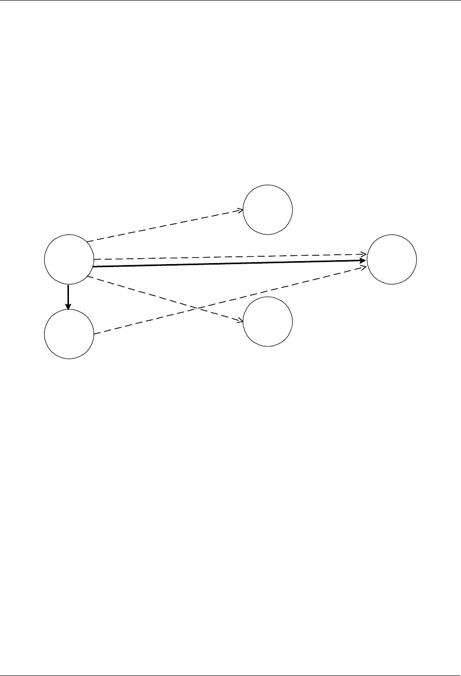
INS10244-5 Z-Wave Node Type Overview and Network Installation Guide 2008-12-04
Zensys A/S Static Controller and Routing Slave Example Page 32 of 38
CONFIDENTIAL
directly. Also for the Routing Slave 3 it is assumed that it is able to reach Routing Slave 1 and Routing
Slave 2 directly, but not the Static Controller.
The Association is done as described in the previous example, by first moving the Portable Controller
within range of the Static Controller, and then activating the static route initiator on the Portable
Controller and the associate initiator on the Static Controller. Secondly the Portable Controller is moved
closer to Routing Slave 3. When the associate initiator on the Portable Controller and the initiator on
slave 3 have been activated, the Portable Controller will calculate routes from Routing Slave 3 to the
Static Controller. In this example the Portable Controller will come up with two alternative routes. The first
route is to reach the Static Controller through Routing Slave 1. The second route is to reach the Static
Controller through Routing Slave 2.
Figure 19 shows the Z-Wave network after the Static Controller has been associated with Routing Slave
3.
Portable
Controller
Routing
Slave 1
Routing
Slave 2
Routing
Slave 3
Static
Controller
1
2
3
Figure 19. Associating a Static Controller with a Routing Slave.
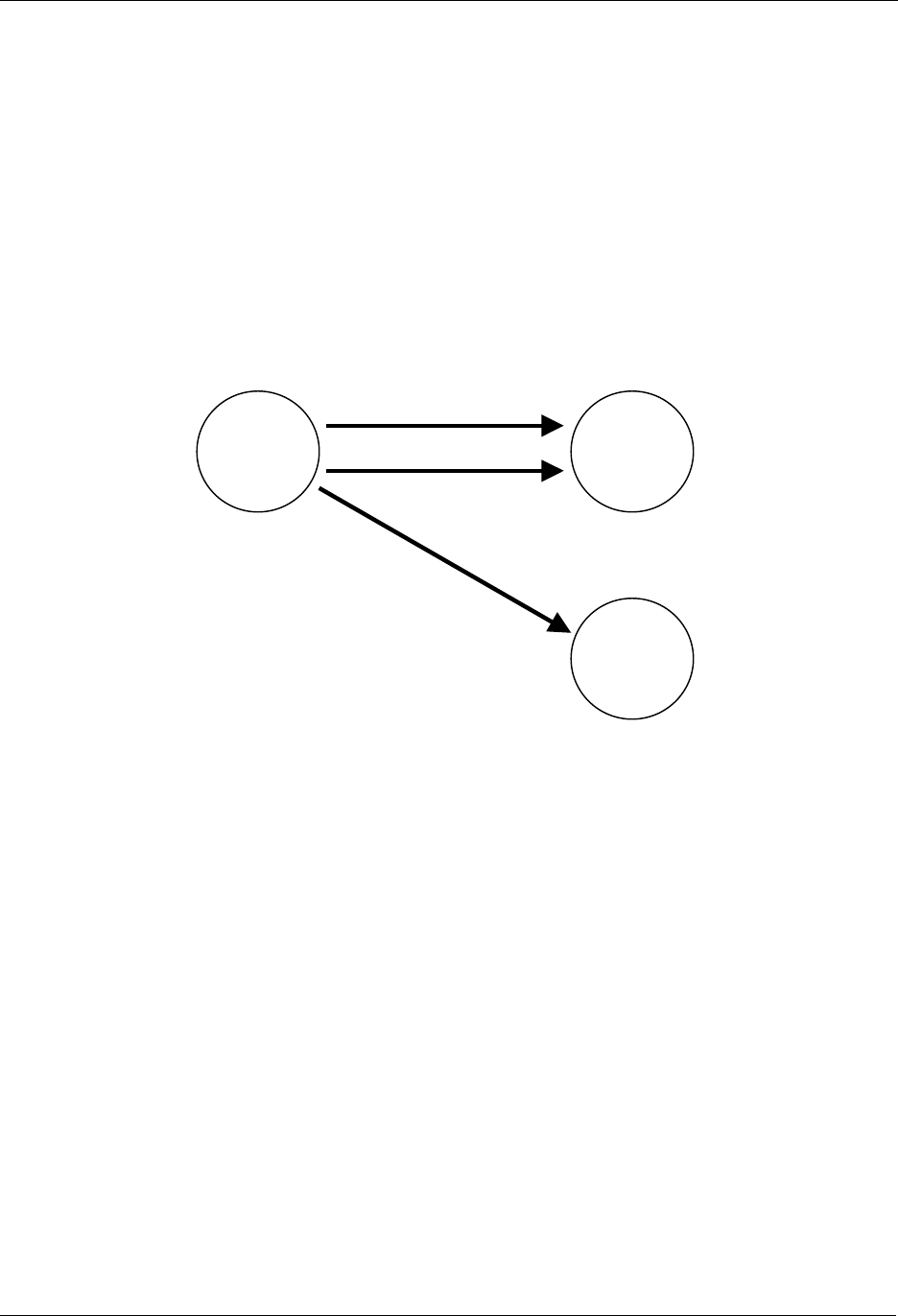
INS10244-5 Z-Wave Node Type Overview and Network Installation Guide 2008-12-04
Zensys A/S Static UPDATE Controller (SUC) Example Page 33 of 38
CONFIDENTIAL
9 STATIC UPDATE CONTROLLER (SUC) EXAMPLE
When a Static Controller is configured as a Static Update Controller (SUC) then it will automatically
receive all changes in the network topology from the Primary Controller. Other nodes in the network can
acquire this information.
Note that only one SUC can be present in each individual network.
9.1 Including a SUC to the network
The following step describes the process of including a SUC to the network:
Figure 20. Including a SUC to the network.
1) Include the Static Controller as described in the previous chapter by replicating the information
from the Primary Controller to the Static Controller. The Static Controller is now included to the
network and is secondary. Afterwards will the application on the Primary Controller assign the
Secondary Static Controller to become the SUC.
2) The Primary Controller includes an additional Portable Controller node to the network in same
way as described in previous chapters.
3) The Primary Controller will automatically send the updated network topology for the included
Secondary Portable Controller to the SUC. From now on every time a new node (controller or
slave) is included to the network the SUC will get the updates automatically.
Association is done exactly as described in previous chapters.
It is recommended to include the SUC as the first node in the network because new nodes can then be
advised about its presence when included.
Adding a SUC to an existing network will cause battery-operated nodes, such as portable controllers, to
be unaware of the SUC. Such nodes will never be able to request topology updates from the SUC.
2
3
Portable
Controller
Secondary
Static
Controller
SUC
Portable
Controller
Primary
1
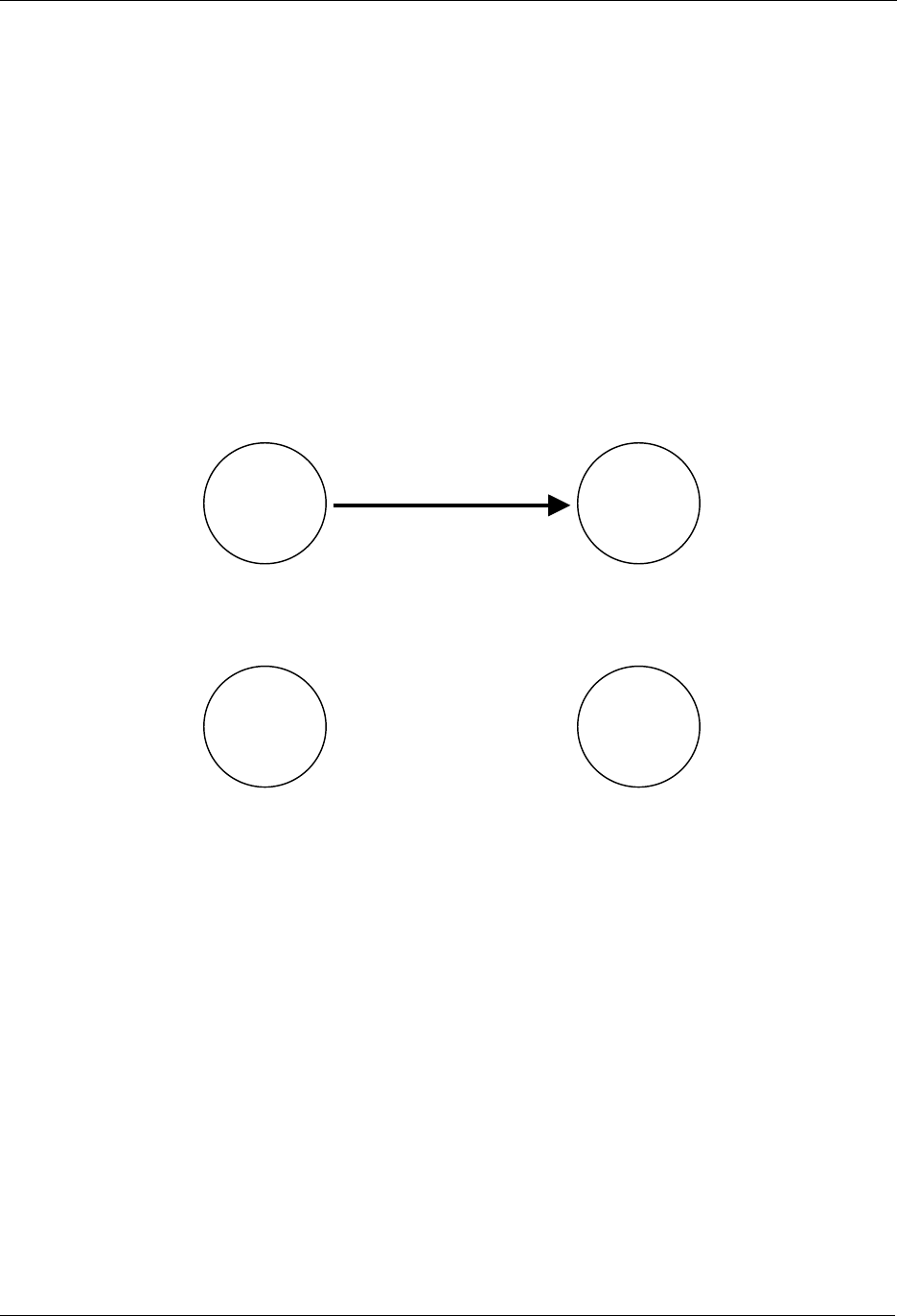
INS10244-5 Z-Wave Node Type Overview and Network Installation Guide 2008-12-04
Zensys A/S SUC ID Server (SIS) Example Page 34 of 38
CONFIDENTIAL
10 SUC ID SERVER (SIS) EXAMPLE
The SUC may be further configured with node ID server (SIS) functionality to enhance installation
flexibility. The SIS enables other controllers to include/exclude nodes to/from the network. When SIS
functionality is enabled the controller also takes the role as the Primary Controller because it has both
latest network topology and allocated node IDs. All the other controllers are called Inclusion Controllers
because they can include/exclude nodes to/from the network. Until the SIS is included to the network the
installation process is as described in the previous installation chapters.
Note that only one SIS can be present in each individual network.
10.1 Including a SIS to the network
The following step describes the process of including a SIS to the network.
Figure 21. Including a SIS to the network.
Figure 22. After SIS is included to the network.
1. Include the Static Controller as described in the previous chapter by replicating the information from
the Primary Controller to the Static Controller. The Static Controller is now included to the network
and is secondary. Afterwards will the application on the Primary Controller assign the Secondary
Static Controller to become the SIS. The SIS becomes the Primary Controller after inclusion and the
old Primary Controller becomes an Inclusion Controller.
It is recommended to include the SIS as the first node in the network because new nodes can then be
advised about its presence when included.
Adding a SIS to an existing network will cause battery-operated nodes, such as portable controllers, to
be unaware of the SIS. Such nodes will never be able to request topology updates from the SIS.
1Static
Controller
SIS
Portable
Controller
Primary
Static
Controller
Primary
SIS
Portable
Inclusion
Controller 1
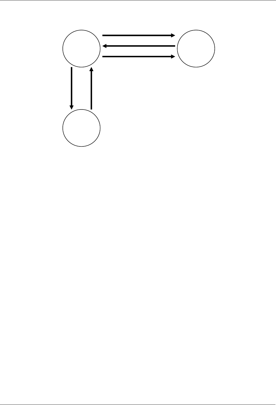
INS10244-5 Z-Wave Node Type Overview and Network Installation Guide 2008-12-04
Zensys A/S SUC ID Server (SIS) Example Page 35 of 38
CONFIDENTIAL
10.2 Adding inclusion controllers to the network
3 4
1
Static
Inclusion
Controller 2
Static
Controller
Primary
SIS
Portable
Inclusion
Controller 1
5
2
Figure 23. Including an Inclusion Controller to the network.
1. Inclusion Controller 1 requests an available node ID for the new Static Inclusion Controller 2 and the
latest network topology from the SIS
2. The SIS provides a node ID and the latest network topology to the Inclusion Controller 1.
3. Inclusion Controller 1 now assigns the allocated node ID to Static Inclusion Controller 2. Based on
the latest network topology the Static Inclusion Controller 2 check for neighbors within direct range.
(Check for neighbors within direct range is not done in case the Inclusion Controller 2 is portable)
4. The Inclusion Controller 2 returns neighbor information to Inclusion Controller 1.
In case Controller 2 is a static controller based on an old library without Inclusion Controller capability
then it becomes a Secondary Static Controller.
5. The Inclusion Controller 1 updates the SIS with the latest network topology discovered during the
inclusion of Inclusion Controller 2.
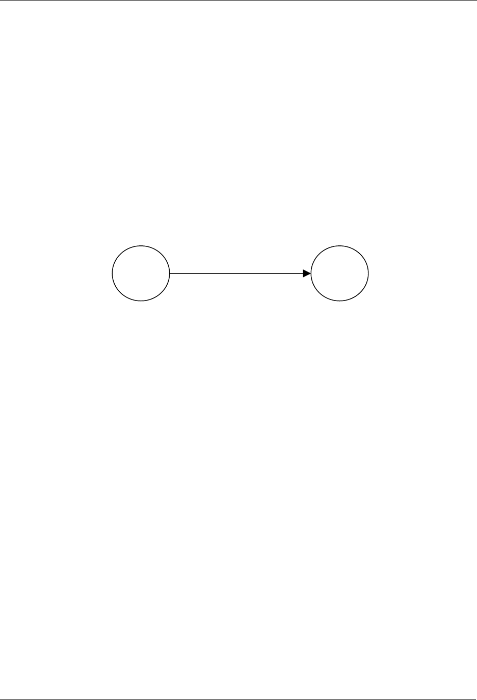
INS10244-5 Z-Wave Node Type Overview and Network Installation Guide 2008-12-04
Zensys A/S Network-wide Inclusion Example Page 36 of 38
CONFIDENTIAL
11 NETWORK-WIDE INCLUSION EXAMPLE
This chapter discusses inclusion of nodes using network-wide inclusion via explorer frames.
11.1 Initial Setup
Inclusion mode is enabled in the central (primary) controller. Typically this is done via a web page or
other sort of GUI.
When in inclusion mode, the controller accepts multiple inclusion requests. Inclusion mode times out
after a period of time when no new inclusion requests have been received.
The most basic setup is one controller node and one slave node, as depicted in Figure 24.
Figure 24. Including a Slave node.
Initially both the controller and the slave node are reset. The controller will have a predefined Home ID
(e.g. 0x00000020) and a Node ID =0x01. The slave may have a predefined (non-zero) Home ID and
Node ID = 0x00. Being the first controller in the system and therefore determining the Home ID, the
controller defaults to become the Primary Controller and takes node ID = 0x01.
Inclusion mode is enabled in the controller. Auto-inclusion is enabled in the slave. This may be done by
activating a special key sequence in the slave or simply resetting the slave. The slave chooses a new
random home ID after each reset.
The controller assigns the Home ID = 0x00000020 and the Node ID = 0x02 to the slave node. The slave
is now part of the Z-Wave network, but no specific association has been made between the two nodes.
When nodes are included via network-wide inclusion, the user typically has access to some kind of GUI.
Associations may be created via the GUI rather than pushing buttons on the devices being associated.
11.2 Adding additional nodes
New slave nodes can be included in the Z-Wave network as the network is gradually expanded. In Figure
25, the example is extended to include another slave node.
If the new node is within direct range of the controller, the inclusion happens the exact same way as for
the first slave node. If out of range, the new node cannot reach the controller.
The explorer frame carrying the InclusionRequest is forwarded by the already included slave node. The
following inclusion process resembles classic Z-Wave inclusion with minor difference that the new node
uses a non-zero home ID and the controller AssignId message may be routed rather than direct range.
The second slave node will be assigned the Home ID = 0x00000020 and the Node ID = 0x03.
The result is depicted in Figure 25.
Slave
Portable
Controller
Home ID: 0x00000020
N
ode ID: 0x01
Home ID: 0x00000020
N
ode ID: 0x02
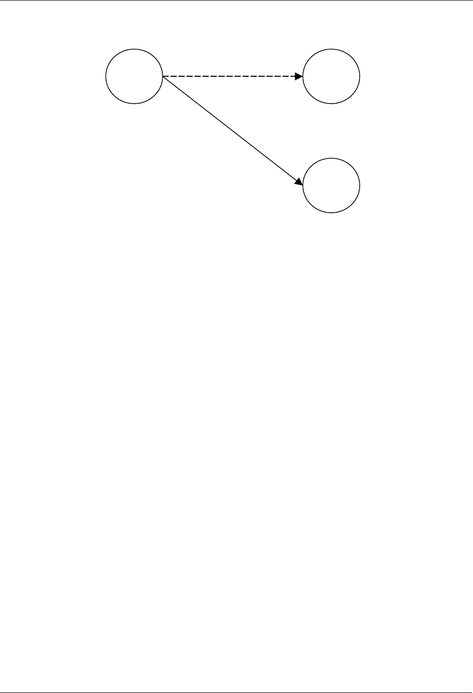
INS10244-5 Z-Wave Node Type Overview and Network Installation Guide 2008-12-04
Zensys A/S Network-wide Inclusion Example Page 37 of 38
CONFIDENTIAL
Figure 25. Including additional nodes.
11.3 Removing Nodes
A node can be removed from the Z-Wave network by activating the exclude initiator on the Primary
Controller and the node initiator. This action will cause the controller to send Home ID = 0x00000000 and
Node ID = 0x00 to the node, thereby resetting the node. The controller will also remove the routing
information from the routing table.
11.4 Recover from Controller Node Error
If operating a mixed network containing non-explorer Z-Wave nodes, refer to section 7.7.
If all nodes support explorer route resolution, reconstruction of the route map is not important. Any node
may send out an explorer SearchRequest frame to locate the destination node in question.
However, since the distribution of node IDs are managed by the primary controller, the loss of the
primary controller still means that the network has to be re-built.
Unlike earlier versions, v4.50 every controller reset operation causes the controller to choose a new
homeID every time. This means that there is no risk of duplicate nodeIDs; even if the controller is just
reset and used again.
Slave 2
Slave 1
Portable
Controller
Home ID: 0x00000020
Node ID: 0x01
Home ID: 0x00000020
N
ode ID: 0x02
Home ID: 0x00000020
N
ode ID: 0x03

INS10244-5 Z-Wave Node Type Overview and Network Installation Guide 2008-12-04
Zensys A/S References Page 38 of 38
CONFIDENTIAL
12 REFERENCES
[1] Zensys, INS10247, Instruction, Z-Wave ZW0201/ZW0301 Application Programming Guide.
