TLPG38 Zetron 38A Repeater Tone Panel Instruction Manual
User Manual: Zetron 38A Repeater Tone Panel Instruction Manual
Open the PDF directly: View PDF ![]() .
.
Page Count: 96

ZETRON
Model 38A Repeater Tone Panel
Instruction Manual
Part No. 025-9043Y
Please check for change information at the end of this manual.
Copyright © 1986 - 1999 by Zetron, Inc.
All Rights Reserved

Zetron Master Product Manual
Model 38A Part No. 025- 9043Y
Special Instructions for Printer
None
Zetron QC Checklist
✔ Unbroken numerical page sequence in each section.
✔ Complete front matter consisting of:
Title Page
Table of Contents ( 3 pages)
Statements ( 3 pages)
Other special pages ( 1 pages)
✔ Correctly printed photos on:
Page:
Page:
Page:
Page:
✔ Last page in each section:
1-1 6-10
2-2 7-7
3-13
4-24
5-27
✔ Total number of fold-outs: 7 (pages 6-5, 6-6, 6-7, 6-8, 6-9, 6-10, 7-7
✔ No other inconsistencies, e.g., light print, missing sections, misaligned pages, bad binders.
Special notes to QC:
Table of Contents
1. INTRODUCTION
INTRODUCTION ...................................................................................................... 1-1
FEATURES ................................................................................................................ 1-1
2. SPECIFICATIONS
GENERAL.................................................................................................................. 2-1
CTCSS / DCS ............................................................................................................. 2-1
INTERFACE............................................................................................................... 2-2
3. OPERATION
OVERVIEW ............................................................................................................... 3-1
CTCSS TONES AND DIGITAL CODED SQUELCH (DCS) .................................. 3-1
HOW TONES/CODES ARE ENABLED .................................................................. 3-2
User Validation ............................................................................................... 3-2
Disabled Tones ............................................................................................... 3-2
Enabled Users, CTCSS / DCS Encode ........................................................... 3-2
Carrier Controlled Repeat (Open Repeater) ................................................... 3-3
Reserved Users ............................................................................................... 3-3
WHAT HAPPENS WHEN A MOBILE UNKEYS....................................................3-3
Airtime Accumulation .................................................................................... 3-5
Repeater Hold Time........................................................................................3-5
Timeout Timer ................................................................................................3-5
Timeout User Identification............................................................................ 3-5
DTMF Regeneration ....................................................................................... 3-5
Airtime Hog Penalty .......................................................................................3-6
Temporary Cross-tone or Cross-code Encoding............................................. 3-6
Temporary Defeat of Cross-tone or Cross-code Encoding............................. 3-6
Remote PTT Function..................................................................................... 3-7
Site Alarm ....................................................................................................... 3-7
CONSIDERATIONS WHEN USING DIGITAL CODED SQUELCH (DCS)......... 3-8
REVERSE FREQUENCY WORKING (OPTION) ................................................... 3-11
Programming................................................................................................... 3-12
4. PROGRAMMING
OVERVIEW ............................................................................................................... 4-1
PROGRAMMING MODES ....................................................................................... 4-1
DTMF Programming Via The Radio Channel................................................ 4-1
Programming Via The Model 8 Repeater Programmer / Timekeeper............4-2
Programming Via The RS-232 Interface ........................................................ 4-3
CRT Mode ...................................................................................................... 4-4
PROGRAMMING COMMANDS.............................................................................. 4-6
Program Mode Access .................................................................................... 4-6
User Commands.............................................................................................. 4-7
System Commands..........................................................................................4-13
Table of Contents
(Continued)
List And Airtime Functions ............................................................................ 4-20
Diagnostic Commands.................................................................................... 4-21
5. INSTALLATION
GENERAL.................................................................................................................. 5-1
REQUIRED EQUIPMENT ........................................................................................ 5-1
SCREW TERMINAL CONNECTIONS.................................................................... 5-1
INSTALLATION PROCEDURE............................................................................... 5-2
Installation Tips .............................................................................................. 5-2
ADJUSTMENT PROCEDURE USING THE DTMF PROGRAM MODE .............. 5-3
ADJUSTMENT PROCEDURE USING THE SITE ALARM INPUT ...................... 5-4
RADIO-SPECIFIC CONNECTIONS ........................................................................ 5-6
GE MASTR III Base/Repeater ....................................................................... 5-7
GE MASTR II Base/Repeater.........................................................................5-8
GE Exec II Base.............................................................................................. 5-9
ICOM IC-RP1510 Repeater............................................................................5-10
E.F. Johnson CR1010 Repeater ...................................................................... 5-11
E.F. Johnson CR1010 Repeater (Alternate Hookup)...................................... 5-12
E.F. Johnson Viking Universal Station........................................................... 5-13
Kenwood TKR-720 / TKR-820 Repeater ....................................................... 5-14
Motorola GR300 Repeater (or Two GM300 Radios)..................................... 5-15
Motorola MTR2000 Stations .......................................................................... 5-16
Motorola MSF 5000 Analog Repeater............................................................ 5-17
Motorola MSF 5000 Digital Repeater ............................................................ 5-18
Motorola MCR-100 / RADIUS R-100 ........................................................... 5-19
Motorola MICOR Single User Repeater ........................................................5-20
Motorola MICOR Community Repeater ........................................................ 5-21
Tait T800 Series Repeater............................................................................... 5-22
Tait T300 Series Radio ................................................................................... 5-23
TONE PANEL PERFORMANCE TEST................................................................... 5-24
RS-232 CABLE DIAGRAMS.................................................................................... 5-25
PROGRAMMING THE MODEL 38 VIA FRONT PANEL CONNECTOR............ 5-26
INSTALLING A NEW PROM................................................................................... 5-27
6. REPAIR
IN CASE OF DIFFICULTY....................................................................................... 6-1
SERVICE NOTES ...................................................................................................... 6-1
MODEL 38 REPEATER PANEL PARTS LIST (702-9075) .................................... 6-2
MODEL 38 REPEATER PANEL ASSEMBLY DIAGRAM.................................... 6-5
MODEL 38 REPEATER PANEL SCHEMATIC (008-9075) ................................... 6-6
MODEL 38 REPEATER PANEL SILKSCREEN (702-9075) .................................. 6-10
7. QUICK REFERENCE
Table of Contents
(Continued)
DTMF REMOTE PROGRAMMING MODE NOTES .............................................. 7-1
MODEL 38 SYSTEM PROGRAMMING LOG........................................................ 7-2
MODEL 38 CTCSS USER DATABASE PROGRAMMING LOG .......................... 7-4
MODEL 38 DCS USER DATABASE PROGRAMMING LOG ..............................7-6
MODEL 38 PROGRAM MODE COMMAND SUMMARY.................................... 7-7
CHANGE INFORMATION
1-1
1. INTRODUCTION
INTRODUCTION
The Zetron Model 38 is a flexible repeater panel that provides individualized repeater service
to up to 60 or 68 different customer groups. It is a complete interface between a transmitter
and receiver, providing CTCSS encode/decode, repeat audio processing, and all timer
functions. It can be remote-controlled from a variety of sources. The Model 38A is equipped
with an RS-232 serial port for connection to computers and modems. An internal database
keeps track of all airtime use and, for accounting purposes, downloads into a PC. Nearly all
of the Model 38’s functions can easily be customized for each of the 38 or 50 CTCSS tones
and 22 or 18 digital coded squelch codes.
FEATURES
• Supports 38 or 50 CTCSS user groups, with ToneLock™ high sensitivity decoding
• Supports 18 or 22 digital coded squelch (DCS) codes
• Programmable via RS-232 and DTMF
• Attributes are programmable for each user group
• Remote enable and disable of all tones and DCS codes
• Temporary enable and disable of cross encoding
• Automatic Morse code station identification
• Stuck microphone timeout and identification
• DTMF paging when site alarm triggered
• Vacant tones and codes can be reserved
• Airtime Hog Penalty mode
• Cross-tone, cross-code, tone-code encoding
• Courtesy beeps and tailbips
• Privacy mode to prevent “barge-ins”
• Airtime is tallied for each user group
• Prepaid airtime feature
2-1
2. SPECIFICATIONS
GENERAL
Radio interface Compatible with most any commercial FM two-way radio or
repeater.
User group capacity 38 CTCSS tones and 22 DCS codes, or 50 CTCSS tones and 18
DCS codes.
Airtime capacity 249 hours, 59 minutes, 59 seconds per user group.
Airtime retrieval RS-232 port, DTMF or Morse code over radio channel.
Station ID Callsigns configurable for each user group, with independent
activity timers.
Station ID frequency 1,200 Hz; adjustable ± 800 Hz. (per FCC rules).
Courtesy tone
frequency
1,000 Hz; adjustable 400 to 3,000 Hz.
Indicators Power, carrier, transmit, decode, encode, DTMF.
Current consumption 350 mA at 13.8 VDC.
Operating voltage 11.0 to 15.0 VDC.
Rack space 1.7 x 19 x 4.8 inches.
Weight 2.2 lb.
Operating
temperature
0 to 65° Celsius.
CTCSS / DCS
CTCSS frequencies 67.0 to 254.1 Hz. Tables include all standard EIA frequencies
and extensions.
CTCSS sensitivity Better than 3dB SINAD.
CTCSS accuracy Better than 0.1 Hz.
Digital squelch codes Selectable, any octal codes between 000 to 777.
Squelch tail
elimination
Compatible with CTCSS reverse burst, DCS turn-off code, and
loss of carrier.
Section 2. Specifications
2-2
INTERFACE
Connections Rx audio, Tx key, CTCSS / DCS encode, Tx audio (mic), 12
VAC or DC power, ground. Optional carrier detect, alarm input
and aux output.
Connector type Detachable screw terminal.
Rx input impedance 50 KΩ AC coupled. For connection to unsquelched
discriminator audio.
CTCSS / DCS output Level: 0 to 4 Volts p-p. Impedance: Less than 1 KΩ AC
coupled.
Transmitter type Direct FM, or phase modulation. Flat or de-emphasized CTCSS
encode.
Transmitter keying SPDT relay.
Carrier detect Internal noise detector or external carrier detect input. External
input threshold adjustable 0 to 7 VDC.
Adjustments Four adjustments from rear panel: Rx input gain, CTCSS / DCS
encode gain, Tx audio output gain, and carrier detect threshold.
Configuration
switches
Eight switches on rear panel: Rx audio gain high/low, repeat
audio flat/de-emphasized, encode gain high/low, encode flat/de-
emphasized, tx audio gain high/low, COR source
internal/external, COR polarity positive/negative, COR pull up
on/off.
RS-232 serial data
port
Front panel DB9 connector (non-standard pinout). Interface
cables available.
Alarm / Remote PTT
input
Activated via contact closure to ground.
Cables, interface
notes
Available for most repeaters and two-way radios.

3-1
3. OPERATION
OVERVIEW
This section of the manual covers key ideas and features that define the operation of the
Model 38A Repeater Tone Panel.
CTCSS TONES AND DIGITAL CODED SQUELCH (DCS)
The Model 38 monitors the channel for CTCSS tones and/or DCS codes. When a tone or
code is detected, it is converted into a User-Number that contains the user privileges and
attributes. The DCS decode numbers are completely user programmable. Two versions of the
Model 38 are available; 38 CTCSS + 22 DCS users (see Table 3. -1), or 50 CTCSS + 18
DCS users (Table 3. -2).
When ordered with the 50 tone set, the unit has a narrower CTCSS decoder bandwidth than
the standard 38 tone version. The 50 tone version is not recommended for use with radios
that use tunable encoders, due to the possibility of the encoder becoming mistuned or drifting
onto adjacent tones.
Table 3. -1. User Number Cross reference Table: 38 Tone Version
User Tone User Tone User Tone User Code
1 67.0 16 114.8 31 192.8 46 DCS
2 71.9 17 118.8 32 203.5 47 DCS
3 74.4 18 123.0 33 210.7 48 DCS
4 77.0 19 127.3 34 218.1 49 DCS
5 79.7 20 131.8 35 225.7 50 DCS
6 82.5 21 136.5 36 233.6 51 DCS
7 85.4 22 141.3 37 241.8 52 DCS
8 88.5 23 146.2 38 250.3 53 DCS
9 91.5 24 151.4 39 DCS 54 DCS
10 94.8 25 156.7 40 DCS 55 DCS
11 97.4 26 162.2 41 DCS 56 DCS
12 100.0 27 167.9 42 DCS 57 DCS
13 103.5 28 173.8 43 DCS 58 DCS
14 107.2 29 179.9 44 DCS 59 DCS
15 110.9 30 186.2 45 DCS 60 DCS

Section 3. Operation
3-2
Table 3. -2. User Number Cross Reference Table: 50 Tone Version
User Tone User Tone User Tone User Tone
1 67.0 18 118.8 35 183.5 52 DCS
2 69.4 19 123.0 36 186.2 53 DCS
3 71.9 20 127.3 37 189.9 54 DCS
4 74.4 21 131.8 38 192.8 55 DCS
5 77.0 22 136.5 39 196.6 56 DCS
6 79.7 23 141.3 40 199.5 57 DCS
7 82.5 24 146.2 41 203.5 58 DCS
8 85.4 25 151.4 42 206.5 59 DCS
9 88.5 26 156.7 43 210.7 60 DCS
10 91.5 27 159.8 44 218.1 61 DCS
11 94.8 28 162.2 45 225.7 62 DCS
12 97.4 29 165.5 46 229.1 63 DCS
13 100.0 30 167.9 47 233.6 64 DCS
14 103.5 31 171.3 48 241.8 65 DCS
15 107.2 32 173.8 49 250.3 66 DCS
16 110.9 33 177.3 50 254.1 67 DCS
17 114.8 34 179.9 51 DCS 68 DCS
HOW TONES/CODES ARE ENABLED
User Validation
The Model 38 is always listening to the receive audio for the presence of an enabled user. All
38 or 50 CTCSS tones and 18 or 22 of the digital codes can be marked as enabled or disabled
(consult the programming section).
Disabled Tones
When a disabled CTCSS tone is detected, the time accumulator will keep track of the airtime
used by that tone. This feature lets the system manager gain information about the CTCSS
tones that are in use on the channel, perhaps by another repeater in the area. The Model 38
will accumulate airtime for all CTCSS tones, but not disabled DCS codes.
Enabled Users, CTCSS / DCS Encode
When an enabled tone or digital code is detected, the transmitter will be keyed. Depending
on programming, the system will: (1) encode nothing, (2) regenerate the received tone or
code, or (3) encode a different tone or digital code (cross-tone encoding).

Section 3. Operation
3-3
Carrier Controlled Repeat (Open Repeater)
The Model 38 can be programmed to activate based on just carrier. In this mode the Model
38 will provide simultaneous tone and open repeater operation; users that have CTCSS or
Digital Squelch encode operate normally, users that have no encode repeat also. This allows
a mix of CTCSS tone users with open repeat capability and is ideal when adding tone users
to an existing open repeater.
To enable carrier (COR) for repeat, a user number is identified as the “CARRIER” repeat
user. This allows all standard user-programmable attributes to apply to open repeat,
including; enable/disable for the carrier user, CTCSS or digital code encoding, airtime
accumulation, station ID, etc. If the COR user number is set to “0”, the carrier repeat
function is disabled.
Reserved Users
If a user is marked as “Reserved,” the repeat audio will be squelched and a beep tone sent in
place of voice communications. A chirp tone will be sent when the user unkeys to indicate
reserve mode. This mode allows the system manager to reserve CTCSS tones and DCS codes
for seasonal users, or to temporarily prevent communications for a delinquent account.
WHAT HAPPENS WHEN A MOBILE UNKEYS
When a mobile unkeys, CTCSS tone or DCS code is no longer detected, the Model 38 will
do the following:
Anti-Kerchunker Filter
The anti-kerchunker filter cancels the transmit hold time and drops the repeater
immediately if a mobile transmission is less than the programmed “anti-kerchunk”
time. This serves two main purposes:
• It will discourage users from “kerchunking” the repeater to death.
• It will make the repeater co-exist better on shared-channels. When a lot of CTCSS
tones are enabled on a single channel, it’s not uncommon for voice falsing of
active CTCSS tones on a co-channel repeater to occur. This is because a human
voice often contains frequencies in the CTCSS band. A radio user could be
talking and cause a co-channel repeater to key up over the conversation. When the
repeater transmit hold time is greater than about a second, this causes major
interference to the voice communication. With the anti-kerchunker filter enabled,
the repeater will key ONLY for the duration that the voice simulates CTCSS, not
the entire transmit hold time. The anti-kerchunker filter is disabled by
programming the time to zero.
Courtesy Tone
If the courtesy tone is enabled for the user group, a short beep will be sent. The beep
frequency may be set from 400 to 4000 Hz (default setting is 1000 Hz). A system
programmable setting called “tailbips” can be enabled to cause the courtesy tone to

Section 3. Operation
3-4
be sent every second during the transmit hold time. If a 400 Hz beep (low tone) is
heard just prior to the transmitter unkeying, a system memory error has been detected,
consult the repair section.
Prepaid Customer Low-Airtime Warning
The repeater operator (or owner) can allow a customer to purchase a block of airtime
in advance (see “Prepaid Users” in the programming section). These prepaid blocks
decrease as the customer uses the repeater. When the remaining airtime falls below
two hours, a low-airtime warning chirp will be heard when the user unkeys. The chirp
sounds like a fast “bee-doo-bee-doo-bee-doo”. If the airtime drops to zero, the tone is
“reserved” as described above. A prepaid user who falls all the way into the
“reserved” mode will still hear warning chirps upon unkeying.
Reserved User Mode
If a user is programmed as reserve tone mode, a “chirp” will be sent when the user
unkeys. This gives a positive indication that communication has not occurred.
CTCSS / DCS Encode During Transmit Hold Time
When a valid user unkeys, the CTCSS or DCS encode may either be left on during
the transmitter hold time or turned off. This feature is programmable for each user.
When using a control station phone patch through the repeater, the encode should be
turned off during Tx-hold. This allows the phone patch to know when the mobile has
unkeyed, as opposed to knowing when the repeater has dropped off the channel.
When using the repeater for dispatch only, the encode may be left on during the Tx-
hold time to keep the mobile decoders open. This feature eliminates the decode delay
observed in the mobile between transmissions, and is generally required in order for
the busy channel lockout feature to function properly in the subscriber radios.
Morse Code Station Identification
When an enabled user unkeys, the Model 38 looks to see how long it has been since
the station ID was last sent. If enough time has passed (initially 15 minutes,
programmable 1-99 minutes) then the call sign will be sent. Each user group has its
own call sign and individual ID interval timer. The Morse ID is sent at the selected
ID speed (15 to 25 words per minute). The call sign is sent at 30% deviation (meets
FCC Part 90 rules) such that voice communication can occur during the ID. Note: if
the Morse ID is not programmed, or the first character is a “space”, an ID will not be
sent. A single system ID may also be programmed for use in co-op and private carrier
applications.
Last User Identification via DTMF
The Model 38 checks to see if the user is configured to send “Last User ID”. If
enabled, the user number will be sent via fast DTMF. This allows the system manager
to identify which users are active on the system in real time. All that’s required is a
DTMF decoder with display capability, such as the Zetron Model 8 Repeater
Programmer / Timekeeper.

Section 3. Operation
3-5
Privacy Mode
Finally, the Model 38 checks to see if the user is set for “Privacy Mode”. If enabled,
then no other users (CTCSS or DCS) will be allowed on the system until the transmit
hold time has expired. This feature can prevent other user groups from “barging in”
on the conversation and taking over control of the repeater.
Airtime Accumulation
The Model 38 keeps track of the airtime used by each customer group on the channel. Both
enabled and disabled users are logged. The airtime is stored in “hours:minutes:seconds”
format and will hold up to 250 hours per user. The airtime counts may be retrieved over the
channel or via the RS-232 port. The airtime may be set to accumulate including or excluding
the repeater transmit hold time (see programming section).
Repeater Hold Time
The programmable repeater transmit hold timer is adjustable from 0.0 to 9.9 seconds. When a
mobile unkeys, the Model 38 will begin monitoring for a valid CTCSS tone or DCS code to
be received again. If a valid user is not detected within a timeout period, a reverse burst for
CTCSS or digital turn-off code will be sent then the encode will be turned off (if it was
previously on). After a 0.2 second delay, the transmitter PTT will be dropped. This method
will remove the second squelch tail heard by the mobiles when the repeater transmitter
unkeys. Repeater “tailbips” may be enabled to beep once every second during the repeater
hold time.
Timeout Timer
While mobiles are conversing through the repeater, a timeout timer is running. If a mobile
does not un-key within the timeout period, warning tones will be sent, and then the
transmitter PTT will be dropped. This is a “stuck mic” time-out feature.
Timeout User Identification
After a timeout occurs, the system may be set to transpond (via slow DTMF) the user number
of the mobile that is still keyed up. The repeater will key up every 15 seconds while the
mobile is transmitting and send the user number. This feature can be enabled or disabled by
the system manager.
DTMF Regeneration
The Model 38 may be used to regenerate DTMF tones over the radio channel for applications
involving mobile DTMF decoders or control station telephone interconnects (such as Zetron
Models 30 or 45). DTMF regeneration ensures that all DTMF signaling occurs at the same
tone level. DTMF regeneration can occur for any or all users. A user commands the repeater
to regenerate DTMF digits by sending a DTMF “*” for greater than 1 second. When the digit
is released, the Model 38 squelches the repeat audio and begins regenerating all DTMF tones
received from the user until no digit has been received for the interdigit timeout
(programmable; factory set at 4 seconds). All sixteen DTMF tones can be regenerated.
Section 3. Operation
3-6
Airtime Hog Penalty
The Airtime Hog Penalty feature allows the system manager to penalize “airtime hogs” so
that other users on the system have a chance to complete dispatch calls. This feature
disallows a user from conversing through the repeater for a penalty duration (programmable
10-9990 seconds) if the user has recently exceeded the maximum allowable conversation
time limit (1-99 minutes). While a user is being penalized, the system will ignore the user. A
long-winded talker who is approaching the end of the conversation time limit will start
hearing warning tones (sounding like “bee-doo”) 1 per second prior to cut-off. To avoid an
impending Hog Penalty, the user must let the repeater transmitter un-key for an “idle
duration” (1-99 seconds), giving another mobile a chance to use the system. If another user
keys up, or if the idle duration is met, the conversation timer is reset. The Hog Penalty is
programmable on/off for each tone, and all users have their own penalty timers in the case of
multiple hogs on the system.
Temporary Cross-tone or Cross-code Encoding
Temporary cross-tone or cross-code encoding allows the system manager to converse with a
subscriber on any CTCSS tone or digital code. This mode is a temporary cross-tone or cross-
code assignment that allows users on different tones/codes to communicate. It is accessed
with a DTMF command sequence, and can be enabled/disabled on a per-user basis. An alert
signal is sent during the transmitter hang time while the temporary cross-tone or cross-code
mode is active. Command sequence:
• If the DTMF regenerate mode is enabled for the user, a long “#” (greater than two
seconds) plus a tone or code number, then a “#” (# 12#) will activate cross
encoding.
• Any channel activity will encode the originating mobile’s tone or code.
• When the originating mobile transmits, the called mobile’s CTCSS tone or digital
code will be encoded.
• The Tx-hold time is set at 30 seconds during cross encoding.
• An “Eeddll-eeddll-eeddll” queuing tone will indicate cross encoding is active.
• A long “#” (greater than .75 second) will exit the mode.
Temporary Defeat of Cross-tone or Cross-code Encoding
In many dispatch systems the Repeater Panel is programmed to always perform cross-tone or
cross-code encoding, which enables the dispatcher to communicate with vehicles operating
on a different tone or code, but prevents the vehicles from communicating directly with each
other. The dispatcher is usually the center of all communications: when a vehicle needs to
relay information to another vehicle, the dispatcher must listen to one vehicle, then transmit
the information to the other vehicle. This method wastes airtime and increases the chance of
miscommunication. If the dispatcher temporarily defeats cross encoding, users can talk
amongst themselves, and the dispatcher doesn’t have to relay information. Temporarily
defeating cross encoding is achieved by a DTMF command sequence, and is enabled or
Section 3. Operation
3-7
disabled for each user with the “DTMF COMMANDS” enable function. An alert tone is sent
in the squelch tail while the cross encoding is active. Command sequence:
• If the DTMF regenerate mode is enabled for the user, a long “0” will enter the
car-to-car mode.
• The Tx-hold time is set at 30 seconds during the cross-tone mode.
• An “Eeddll-eeddll-eeddll” queuing tone will indicate that cross-tone encoding is
defeated.
• A long “#” (greater than .75 second) will exit the mode.
Remote PTT Function
The site alarm input may be used as a “Remote PTT” function. This feature is initiated by the
site alarm input being pulled to ground by a contact closure or other input. When the alarm
input goes active, any repeater activity will be suspended, then the programmed CTCSS tone
or DCS code will be encoded, the repeat audio squelched, and the transmitter keyed. This
condition will continue until the site alarm input is released.
This feature can be used for wireline control of the transmitter from a tone or DC remote
control, or by wiring the local mic PTT to this input, a method of local control to talk to
specific users. See the site alarm system programming section.
Site Alarm
The Site Alarm feature sends out an audible alert, DTMF page, and CTCSS/DCS encode in
response to a contact closure input. This can be used to monitor external functions such as
system break-in or power failure. The alarm DTMF code can be received by a Zetron Model
8 Repeater Programmer / Timekeeper for remote alarm monitoring. Whenever the alarm
input is held in the active state, a 2000 Hz confirmation beep tone is sent over the transmit
audio just prior to unkeying when the repeater is in use.
Section 3. Operation
3-8
CONSIDERATIONS WHEN USING DIGITAL CODED SQUELCH (DCS)
When a DCS radio unkeys, it sends a 134.4 Hz squelch tail elimination turn off code bit
sequence for about 120 milliseconds. To avoid potential problems, users should not be
installed on the adjacent CTCSS frequencies of 131.8 and 136.5 if possible.
When installing DCS codes for the first time, use this procedure:
1. Use a radio with a known digital code.
2. Use the DCS encode test mode in the Model 38 to generate the digital squelch code that
the mobile is set to. If the mobile does not unsquelch, use the Model 38 digital encode
invert selection. The mobile should unsquelch on either the normal or inverted code.
3. Set the transmitter CTCSS/DCS encode deviation using a CTCSS tone, not a DCS code.
Most deviation meters will give an inaccurate reading of DCS deviation.
4. Make sure Jumper JP3 is in the “B” position (factory default).
5. To setup a DCS user in the Model 38 database, select a user number above the last
CTCSS tone (38 or 50). Enable the user and set the DCS decode number. Key up the
mobile and verify that the Model 38 “decode” led follows the transmission. If the mobile
is not decoded, try inverting the Model 38 receive polarity.
6. Once a single mobile is working through the Model 38, additional mobiles may be added.

Section 3. Operation
3-9
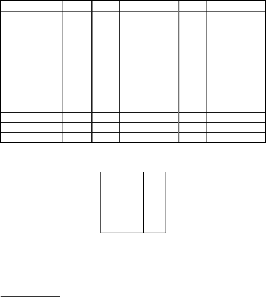
Table 3. -3. Commonly Used DCS Codes, with Binary and Hex Shown
Code Binary Hex Code Binary Hex
023 11101100011100000010011 640E37 311 01110001101100011001001 498D8E
025 11010110111100000010101 540F6B 315 11011000110100011001101 598B1B
026 11001011101100000010110 340DD3 325 00110010110100011010101 558B4C
031 10100011111100000011001 4C0FC5 331 01000111110100011011001 4D8BE2
032 10111110101100000011010 2C0D7D 332 01011010100100011011010 2D895A
036 00010111110100000011110 3C0BE8 343 01010010111100011100011 638F4A
043 10110110110100000100011 620B6D 346 01110101001100011100110 338CAE
047 00011111101100000100111 720DF8 351 00011101011100011101001 4B8EB8
051 11111001010100000101001 4A0A9F 356 10101001010100011101110 3B8A95
053 01101010101100000101011 6A0D56 364 11010000101100011110100 178D0B
054 11011110100100000101100 1A097B 365 01011110000100011110101 57887A
065 10111010001100000110101 560C5D 371 00101011000100011111001 4F88D4
071 11001111001100000111001 4E0CF3 411 11101110110100100001001 484B77
072 11010010011100000111010 2E0E4B 412 11110011100100100001010 2849CF
073 01011100110100000111011 6E0B3A 413 01111101001100100001011 684CBE
074 11101000111100000111100 1E0F17 423 10010111001100100010011 644CE9
114 01101011110100001001100 190BD6 431 11011000101100100011001 4C4D1B
115 11100101011100001001101 590EA7 432 11000101111100100011010 2C4FA3
116 11111000001100001001110 390C1F 445 11110111000100100100101 5248EF
122 10111011010100001010010 250ADD 446 11101010010100100100110 324A57
125 00001111011100001010101 550EF0 452 10011111010100100101010 2A4AF9
131 01111010011100001011001 4D0E5E 454 10100101110100100101100 1A4BA5
132 01100111001100001011010 2D0CE6 455 00101011011100100101101 5A4ED4
134 01011101101100001011100 1D0DBA 462 01110101010100100110010 264AAE
143 01101111010100001100011 630AF6 464 01001111110100100110100 164BF2
145 01010101110100001100101 530BAA 465 11000001011100100110101 564E83
152 00111101100100001101010 2B09BC 466 11011100001100100110110 364C3B
155 10001001101100001101101 5B0D91 503 01111000110100101000011 614B1E
156 10010100111100001101110 3B0F29 506 01011111000100101000110 3148FA
162 11010111100100001110010 2709EB 516 10000011011100101001110 394EC1
165 01100011101100001110101 570DC6 523 01001110101100101010011 654D72
172 00001011111100001111010 2F0FD0 526 01101001011100101010110 354E96
174 00110001011100001111100 1F0E8C 532 00011100011100101011010 2D4E38
205 11011101001100010000101 508CBB 546 00110011110100101100110 334BCC
212 10110101011100010001010 288EAD 565 00011000111100101110101 574F18
223 11010001110100010010011 648B8B 606 10111011001100110000110 30CCDD
225 11101011010100010010101 548AD7 612 11001110001100110001010 28CC73
226 11110110000100010010110 34886F 624 00011110101100110010100 14CD78
243 10001011011100010100011 628ED1 627 00000011111100110010111 74CFC0
244 00111111010100010100100 128AFC 631 11100101000100110011001 4CC8A7
245 10110001111100010100101 528F8D 632 11111000010100110011010 2CCA1F
246 10101100101100010100110 328D35 654 10011000011100110101100 1ACE19
251 11000100111100010101001 4A8F23 662 01001000111100110110010 26CF12
252 11011001101100010101010 2A8D9B 664 01110010011100110110100 16CE4E
255 01101101100100010101101 5A89B6 703 01000101011100111000011 61CEA2
261 00101110111100010110001 468F74 712 00010111101100111001010 29CDE8
263 10111101000100010110011 6688BD 723 01110011000100111010011 65C8CE
265 10000111100100010110101 5689E1 731 00111100100100111011001 4DC93C
266 10011010110100010110110 368B59 732 00100001110100111011010 2DCB84
271 11110010100100010111001 4E894F 734 00011011010100111011100 1DCAD8
274 11010101010100010111100 1E8AAB 743 00101001101100111100011 63CD94
306 00011001111100011000110 318F98 754 01000001111100111101100 1BCF82

Section 3. Operation
3-10
Table 3. -4. Normal and Inverted DCS Codes
Normal Inverted Normal Inverted Normal Inverted
023 047 223 134 445 043
025 244 225 122 446 255
026 464 226 411 452 053
031 627 243 351 454 266
032 051 244 025 455 332
036 172 245 072 462 252
043 445 246 523 464 026
047 023 251 165 465 331
051 032 252 462 466 662
053 452 255 446 503 162
054 413 261 732 506 073
065 271 263 205 516 432
071 306 265 156 523 246
072 245 266 454 526 325
073 506 271 065 532 343
074 174 274 145 546 132
114 712 306 071 565 703
115 152 311 664 606 631
116 754 315 423 612 346
122 225 325 526 624 632
125 365 331 465 627 031
131 364 332 455 631 606
132 546 343 532 632 624
134 223 346 612 654 743
143 412 351 243 662 466
145 274 356 212 664 311
152 115 364 131 703 565
155 731 365 125 712 114
156 265 371 734 723 431
162 503 411 226 731 155
165 251 412 143 732 261
172 036 413 054 734 371
174 074 423 315 743 654
205 263 431 723 754 116
212 356 432 516

Section 3. Operation
3-11
REVERSE FREQUENCY WORKING (OPTION)
Reverse Frequency Working or “RFW” is a method of controlling a repeater from a control
station or fixed location mobile. The purpose is to replicate the service previously only
available using a direct audio connection from the radio operator to repeater site. This
connection would usually be a leased line for EIA tone or DC remote control.
The document from the (UK) Radio Agency RA263 titled “Reverse frequency working and
talkthrough for PMR (standard) licenses” fully details what is available and who can use it.
The following is a description of an implementation of this method of operation using the
Zetron Model 38.
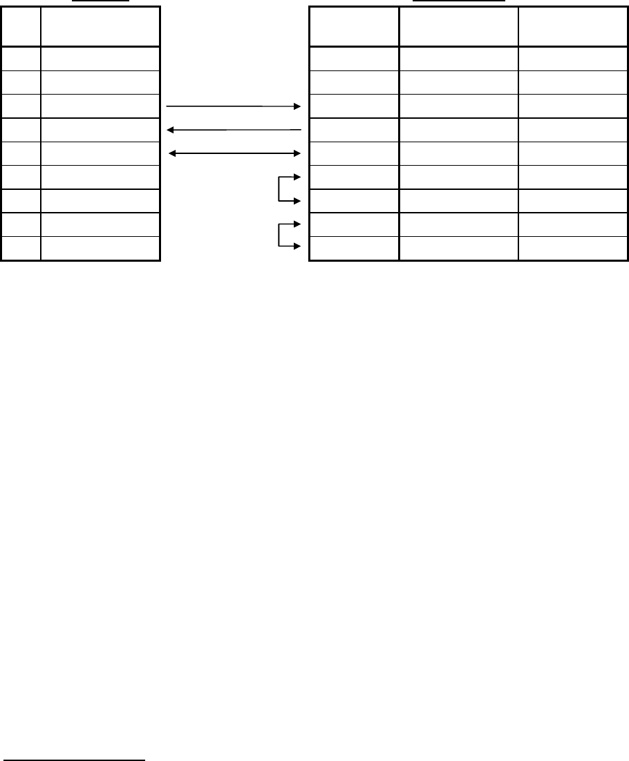
The Model 38 equipped with the RFW option will operate as standard or RFW mode. RFW
mode allows the unit to act as a cross tone encoder and decoder as shown below.
RFW mode
Description Dispatcher radio setup Model 38 Mobile radio setup
Dispatcher to mobile call Tx CTCSS 01 → Rx 01 Tx 02 → Rx CTCSS 02
Mobile to dispatcher call Rx CTCSS 01 ← Tx 01 Rx 02 ← Tx CTCSS 02
In this mode the dispatcher can communicate with the fleet, but the fleet can not hear each
other.
In order for talkthrough to be used, the Model 38 is sent a 4 or 5 digit code in DTMF which
changes the mode of operation. In talkthrough mode, the radio fleet can talk to each other. In
order for the dispatcher to also communicate it must change its CTCSS encode and decode
tone to the same as the fleet. As it would be usual for only the dispatcher to have the ability
to switch talkthrough then this would be done at the same time.
Some radios have the ability to send a DTMF sequence when the channel is changed. This
would then completely automate operation. If the dispatch radio does not have a DTMF
capability, then a Zetron ZMX microphone could be used. This could have two speed dials
programmed to allow switching modes from a single button press.
Talkthrough mode
Description Dispatcher radio setup Model 38 Mobile radio setup
Mobile to mobile call Tx 02 Rx 02 Tx / Rx CTCSS 02
Dispatcher to mobile call Tx CTCSS 02 → Rx 02 Tx 02 → Rx CTCSS 02
Mobile to dispatcher call Rx CTCSS 02 ← Tx 02 Rx 02 ← Tx CTCSS 02

Section 3. Operation
3-12
Programming
In order for RFW to be used, two users must be enabled on the Model 38. An example of this
programming shown in Table 3. -5. The necessary system programming is shown in Table 3.
-6.
Table 3. -5. RFW User Programming
User 10 - Dispatcher User 15 - Radio fleet
1. User enable = On 1. User enable = On
2. Decode (DCS) = 91.5 Hz 2. Decode (DCS) = 107.2 Hz
3. Encode = 15 107.2 Hz 3. Encode = 10 91.5 Hz
4. Tx hold time = 0 4. Tx hold time = 20
5. CTCSS tail = On 5. CTCSS tail = On
6. Morse Id = DISPATCH 6. Morse Id = FLEET
7. Reserve mode = Off 7. Reserve mode = Off
8. Privacy mode = On 8. Privacy mode = On
9. Courtesy tone = Off 9. Courtesy tone = Off
10. Last user Id = Off 10. Last user Id = Off
11. DTMF function = Off 11. DTMF function = Off
12. Hog limit = 0 12. Hog limit = 0
13. Prepay mode = Off 13. Prepay mode = Off
14. Airtime = 000:00:00 14. Airtime = 000:00:00
15. Aux relay = Off 15. Aux relay = Off
Table 3. -6. RFW System Programming
System Programming
1. Timeout time = 3 16. Remote PTT = 0
2. Timeout ID = Off 17. DCStx invert = Off
3. AntiKerchunk = 0 18. DCSrx invert = Off
4. ID timer = 15 19. Password = 123
5. ID freq = 1200 20. Access alarm = Off
6. ID speed = 22 21. Remote type = 0 Morse
7. ID sys user = 0 22. COR user# = 0
8. ID periodic = Off 23. Min airtime = Off
9. Beep freq = 1000 24. Serial tone# = Off
10. Tail bips = On 25. CTCSS hold = 0
11. Hog idle = 5 26. Slow CTCSS = Off
12. Hog penalty = 30 27. Interdigit = 4
13. Alarm DTMF = 28. DCS bit errs = 2
14. Alarm tone = 0 29. CTCSS delay = 70
15. Alarm pwr up = Off 30. Reverse Chn = 9801
The RFW feature is enabled and disabled globally, that is, only one command is used for On
and Off, and all users which have a cross tone set will be effected by enabling RFW.

Section 3. Operation
3-13
The command for RFW On is the Reverse Chn value (Item 30 in system programming) plus
1 then the # key. To disable RFW, send the access code plus a #. For standard Model 38
operation, send the access code plus 2, and #. The range for the RFW password is 100 to
9997. An example is provided in Table 3. -7.
Table 3. -7. RFW Password Examples
Description DTMF command
RFW Off 9801#
RFW On 9802#
Standard Model 38 operation 9803#
Note
When in RFW mode, users may notice a small delay from pushing the PTT to being heard by
the dispatcher. This is due to the model 38 CTCSS decode time followed by the receiving
radio CTCSS decode time. This effect is not a fault, but is inherent in the basic concept of
how RFW works.

4-1
4. PROGRAMMING
OVERVIEW
The Model 38 can be programmed from a variety of sources, they are:
1. DTMF over the radio channel, from a mobile, base station or handheld.
2. CRT/display terminal with an RS-232 serial port directly connected to the Model 38.
3. CRT/display terminal with an RS-232 serial port connected to a modem on a phone line
to the repeater site, and an auto-answer modem connected to the Model 38.
4. CRT/display terminal with an RS-232 serial port connected to a packet radio controller
attached to a control station, and a packet controller at the repeater site connected to the
Model 38.
5. A Model 8 DTMF terminal connected to a base station or mobile for “over the air”
programming.
6. A Model 8 DTMF terminal directly connected to the Model 38 for “front panel keyboard
and display” operation.
7. A DTMF audio source connected to the “Program” connector on the front of the Model
38, which is the same as DTMF over-the-air programming.
PROGRAMMING MODES
DTMF Programming Via The Radio Channel
Program Mode Access
To program the Model 38, the program mode password must first be entered. The code is a 5
or 6 digit sequence. The default password is 12123#. To access the program mode, a CTCSS
tone or DCS code may be required if desired. While programming the unit, it is helpful to
have a secondary receiver (scanner, or monitor receiver) tuned to the repeater output
frequency to hear the prompt tones generated by the Model 38.
When the program mode is activated, the repeater transmitter is keyed, and a chirp will
indicate proper access. A command is provided which will cause the transmitter to unkey
except during progress tones. Usually it is a good idea to keep the transmitter keyed during
the program mode to discourage traffic on the repeater.
Entering a Command
To execute a program command, a DTMF number is entered followed by the “#” key. Some
commands require additional numbers, as in the case of cross tone encoding. While entering
a command or data, the “*” key may be used as a “clear entry” key. While programming, a
key must be depressed every 90 seconds, or the Model 38 will automatically exit the program
mode. All numbers may be entered with or without leading zeros (one may be entered as

Section 4. Programming
4-2
0001, or 1). Some commands will send a progress or prompt tone while programming, and
all commands will send either a “go-ahead” or “error” tone after completion of the command.
If the programming radio does not switch from transmit to receive very quick, a delay before
sending the prompt tones may be programmed (see the Program Mode Progress Tone Delay
command). Please note that you do not have to wait for the prompt tones before entering the
next command as all commands are internally buffered (although it is a good idea to listen
for the proper acknowledge tones).
Commands identified with “tt” may have the user number entered to program a single user,
or by entering “99” ALL users will be programmed with the same information.
Programming Via The Model 8 Repeater Programmer / Timekeeper
Local Programming
For local programming, the Model 8 is attached directly to the Model 38 RS-232 serial data
port. The Model 38 must know whether a Model 8 or a CRT terminal is connected to the
port, since the output data formats are completely different, and possibly the baud rate. See
“RS-232 Port Configuration”.
The Model 8 must be in the “PANEL” mode to communicate with the Model 38. It operates
like a front panel keyboard and display. Most functions may be executed while the panel is in
operation. There is no “Program mode access” required, and no repeater “down-time” while
programming.
Remote Programming
When using the Model 8 to program from a remote location, the Model 8 is connected to a
control station or a mobile transceiver. The Model 8 and 38 communicate using DTMF
tones. When the “Prog” mode is entered, the Model 8 will send the DTMF code required to
put the Model 38 into the “Program mode”. Since the Model 38’s program mode password is
user programmable, the Model 8 must be told what the code is. It is set in the Model 8 with
the “Setup” command (See the Model 8 manual “Setup” mode). If the Model 8 sends the
correct password to the Model 38, after a short delay, the LED read-out should display
“READY”. The prompt to enter a command is indicated by a blank display with a single “_”
prompt character. No transmission of data will take place until the “Enter” key is pressed.
The “Clear” key may be used to backspace over incorrect data. Please note that if the
READY prompt does not appear, you should press the MODE key to back out of the “Prog”
mode. The password is sent only when the “Prog” mode is first entered.
When a command is sent to the Model 38, an alphanumeric prompt will be returned along
with the requested data. To examine a setting in the Model 38, enter the command, then
when prompted to enter a new setting, simply press the “Enter” key. The data will not be
changed. Some settings such as the Site Alarm code, may be greater than 6 digits in length.
To display these, the Model 8 will scroll the code slowly across the display. For faster
operation, when a alphanumeric prompt is displayed, pressing any key will cause the Model
8 will jump to the next phase of programming.

Section 4. Programming
4-3
When prompted with a “Yes/No” question, enter a “1” for “Yes” or “0” for “No”. When
prompted for a value with a decimal place, enter the number ignoring the decimal. Example:
Tx-hold = 0.0 to 9.9 seconds, to enter 1.5 seconds, press “15 Enter”, or to enter 0.5 seconds,
press “5 Enter” or “05 Enter”.
Programming Via The RS-232 Interface
The Model 38 RS-232 port is valuable for initial test and adjustment, as well as general
purpose programming and monitoring. All programming is done with friendly menus and
plain English prompts. Programming is best done with an RS-232 display terminal or PC.
Tasks such as adding, deleting, modifying parameters, retrieving airtime, and real-time
monitoring may all be accomplished without disrupting communications. Most any RS-232
terminal or computer running a communications program may be used.
The Model 38 may be connected directly to an RS-232 terminal or computer when the
equipment is located near each other. When this is not possible, other methods may be
considered such as phone modems or packet radio controllers. For phone modem
programming, an auto-answer modem is typically connected between the phone line and the
Model 38 RS-232 port. Multiple Model 38s or other units programmable via RS-232 may be
programmed over a single telephone line with the use of an RS-232 port selector.
RS-232 Port Configuration
The RS-232 serial data port on the Model 38 may be configured for three different modes of
operation:
• CRT mode.
This mode is for connection to a PC or CRT terminal, and provides menu-driven
text prompts. The baud rate may be set from 150 to 4800 baud. This is the default
RS-232 Interface mode, at 1200 baud.
• Modem mode.
This mode functions like the CRT mode except that it will ignore the “temporary
Model 8 mode” feature. This mode should be selected in all applications
(especially modems) that won’t have a Model 8 connected to the RS-232 port.
• Model 8 direct connect mode.
This mode expects a Zetron Model 8 Repeater Programmer / Timekeeper will be
connected via RS-232 interface. The Model 8 will operate as sort of a “front
panel” keypad and display resource for the Model 38.
Setting the RS-232 Port for CRT Mode
Often the easiest method is to use the DTMF programming commands over the radio channel
to change the port configuration. The baud rate may also be set via DTMF commands. Cycle
power or send a DTMF digit for at least 15 seconds to cause the unit to update the port
operating mode.

Section 4. Programming
4-4
If the port is currently set for Model 8 mode and DTMF programming on the radio channel is
not possible, the terminal may be used to simulate a Model 8 to change the settings. Perform
the following procedure: Set the terminal for 4800 baud, then cycle power on the Model 38.
The message “rEAdY” will appear on the terminal, followed by a “_” prompt. On the CRT,
type in “19”, then press the ENTER key. The message “rS232” should appear, followed by
“=2”. Type in a “0” (selects CRT mode) and press “ENTER”. When the “_” prompt returns,
type in “25” and press “ENTER”. Then at the prompt “bAUd =“, type a “6” (selects 4800
baud) and press “ENTER”. Now cycle power on the panel to update the parameters on the
serial port.
Setting the RS-232 Port for Modem Mode
The modem mode is selected via RS-232 system programming in the RS-232 port menu.
Setting the RS-232 Port for Model 8 Mode
There are multiple methods of changing the port configuration to Model 8 direct connect,
select one of the following:
• The easiest method is to use the DTMF programming commands over the radio channel
to change the port configuration to Model 8 mode (see the DTMF command summary).
• If this is not possible, use a paper clip or jumper wire to short pins 3 and 4 together on the
RS-232 connector. Remove power, then reapply power and wait 15 seconds. Remove the
short between pins 3 and 4 then plug the Model 8 into the RS-232 connector. Note: This
is only a temporary switch to Model 8 mode, use the Model 8 command “19” to select
the permanent operating mode of the RS-232 port.
• Connect the DTMF output from the Model 8 into the “program” connector on the front
panel of the Model 38. Use the “Live” mode to DTMF-program the Model 38 port
configuration.
After doing step one or three, remove then reapply the power to the Model 38, or generate a
DTMF digit on the receiver frequency for at least 15 seconds. This will reinitialize the port
configuration.
CRT Mode
Access to Programming via RS-232 Port
When a user first accesses the Model 38 either over the phone line or directly connected, the
message “Enter Password ==> _” will appear. This is to prevent unauthorized access to the
programming information. The password is the same five-digit program password used for
“over the air” programming (default is 12123). The only difference in the passwords is the
trailing “#” is not used. If the code is incorrect, the terminal will beep, delay one second,
beep, and repeat this sequence 10 times. This slows down any “hackers” from attempting to
find the password by trial and error methods.

Section 4. Programming
4-5
XON / XOFF Protocol
The Model 38 follows “XOFF/XON” protocol. This sequence prevents data from flowing too
rapidly for the display device (printer/terminal) or host to assimilate. If the Model 38
receives an “XOFF” code (Control S), the data output will pause until a “XON” code
(Control Q) is received.
RS-232 Buffer
The serial data port has a “type-ahead” buffer to allow the input to get ahead of the printout.
This feature should be used with caution since the operator cannot see the results of an input
command immediately. The buffer does allow faster programming once the operator gets
used to it.
Disable Panel Command
The CRT programming task is the lowest priority for the Repeater Panel, so when users are
active on the channel, the CRT programming menu outputs will begin to slow down. A
command is provided at the main menu level to disable the Repeater Panel. This command
provides for much faster programming when using baud rates above 300. Be sure to re-
enable the Panel when programming is completed.
Serial Interface Connections
The RS-232 Interface port on the Model 38 is compatible with RS-232C signals and uses an
asynchronous ASCII serial communications protocol. Only three wires need to be connected
between the PC or terminal to the connector on the Model 38: Pin-3, (Txdata) Pin-4 (Rxdata)
and Pin-5 (GND) (see Table 4-1). The connector on the PC or terminal end should have
jumpers installed to connect the handshake lines DTR to DSR, and CTS to RTS. Set the
terminal for 8 bits per character, no parity bit, and 1 or 2 stop bits (see the reference manual
for the terminal you are using). The Model 38 defaults to 1200 baud. To change the baud
rate, use the DTMF programming commands (programming section).
Many people ask why the pinout of the DB9 connector on the Model 38 is not “PC
standard”? The reason is that the Zetron DB9 RS-232 pinout was introduced to the market
when personal computers and terminals all had DB25 connectors. No DB9 standard existed.
Due to the volume of Zetron products in the field with DB9 connectors, and the existing
Zetron serial cables in use, it is not likely to change. Newer Zetron products often include
internal jumpers for the serial port to select “Zetron” or “PC” compatibility.
Section 4. Programming
4-6
Table 4-1. Typical Connections to a Viedo Terminal or Computer
Model 38: PC or Terminal:
Pin
Function
Connections & Signal
Direction
Signal Name Terminal or PC
with DB-25
PC with DB-9
1 Ground
2 Ground
3 RS-232 Transmit Rx data Pin 3 Pin 2
4 RS-232 Receive Tx data Pin 2 Pin 3
5 Ground Ground Pin 7 Pin 5
6 +12VDC fused Jumper DTR Pin 20 Pin 4
7 No connect DSR Pin 6 Pin 6
8 No connect Jumper RTS Pin 4 Pin 7
9 No connect CTS Pin 5 Pin 8
PROGRAMMING COMMANDS
The following is a description of the programmable features in the Model 38, divided into
categories as shown:
• Access and exit from the programming mode.
• User Commands, for items selectable on a “per-user” basis.
• System Commands, for items that relate to overall system operation.
• Diagnostic Tests, that aid the installer in system setup.
A summary of all of the commands is included in the quick reference section at the back of
the manual. The list shows the following information for each programmable setting:
• The item description
• The DTMF programming command
• The default setting
• The programmable range of values
• Comments
A similar summary is provided for the Model 8 programming commands.
Program Mode Access
RS-232 CRT or PC
The prompt “Enter Password --> _” will appear at top level access. The password is
a four or five digit number followed by ENTER. The default is 12123 <CR>. If the
password is correct, the main menu will be displayed. If the password is incorrect, the Model

Section 4. Programming
4-7
38 will beep, send a carriage return, and delay one second, then repeat the sequence 10 times
before prompting for a password again, to reduce the possibility of unauthorized access.
The unit may be set back to the password prompt by entering the EXIT command from the
main menu. It is not necessary to exit the CRT mode, as the Model 38 will operate while
programming. Only when in the Test Menu, or using the Disable Panel command, does the
unit disable the repeat function.
DTMF radio or keypad
The DTMF access code is a four or five digit number followed by the “#” key, the default
being 12123#. NOTE: The access code may be set to require a specific CTCSS tone or DCS
code in order to respond. Upon access, the unit will key and send a “chirp” tone. A delay
before acknowledging is user programmable, as well as the possibility of sending the site
alarm. During the program mode, the repeater will remain keyed to keep other mobiles from
trying to access the channel. Since the repeater transmitter is continuous duty, this should not
present a problem. The DTMF programming commands are not repeated out the transmit
audio as a security measure. If desired, the transmitter may be set to unkey during the
program mode (except during prompt beeps), refer to the PTT OFF command.
Command 293# will cause the unit to exit the program mode. A confirmation tone that
sounds like telephone ringing will be heard. Please note that the unit will exit the program
mode automatically if no DTMF digits are decoded within a 90 second period.
Zetron Model 8 Repeater Programmer / Timekeeper
When locally connected to a Model 38 via RS-232 port, no password is required. For remote
access the password is automatically sent when the “PROG” mode is first entered. The code
must match between the Model 8 and the Model 38. The code may be set in the Model 8 with
the SETUP mode.
Note
The password is only sent when the ENTER key is pressed after selecting the PROG mode.
This causes the DTMF password to be sent as above. By monitoring the repeater transmit
channel, the prompt tone from DTMF program mode access may be heard when proper
access occurs. For more information, refer to the Model 8 instruction manual.
To exit the program mode, press “99 ENTER”. If locally connected, the message “READY”
will be displayed. For remote “PROG” mode, “DONE” will be displayed.
User Commands
Enable a User
To activate a CTCSS or DCS group in the Model 38 (similar to plugging in a tone card) a
“user number” must be enabled. When a user is enabled, the repeater transmitter will key

Section 4. Programming
4-8
whenever carrier and the CTCSS tone or DCS code are decoded. Please note that for DCS
operation, the user must be enabled AND a DCS decode number set (000 and 777).
Disable a User
In order to de-activate a CTCSS tone or DCS code, the user number is disabled (same as
unplugging a tone card). When a user is disabled, the transmitter will no longer key in
response to the user group.
Note
For expired user groups (no-pay) or seasonal use, the “reserved mode” may be used which is
separate from user enable/disable.
DCS Decode Number
The Model 38 is capable of decoding all 38 or 50 CTCSS tones and up to 22 or 18 digital
squelch codes. The digital user numbers exist above the CTCSS users. Each of these user
“slots” are capable of decoding any digital code, so the decode “code number” must be set by
the system operator. The selection of digital polarity is done with System Programming, and
affects all users equally. Please note, the user must also be enabled (see Enable a User) in
order to function.
CTCSS / DCS Encode and Tone Translation
Typically, a repeater panel will encode the same tone or DCS code that it decodes. For each
user, the Model 38 may be set to encode any CTCSS tone, DCS code, or no encode at all
(just carrier). The encode number may be set to a tone number (1 to 38, or 50), no encode (0),
or for DCS enter the octal code plus 1000 (code 023 would be entered as 1023). Please note
that the Model 38 is capable of cross format operation, in that when decoding CTCSS is can
encode DCS, or when decoding DCS, it can encode CTCSS.
Transmit Hold Time
The transmitter hold time is the amount of time the repeater transmitter remains keyed after
mobile activity is no longer detected. It may be set from 0.0 to 25.0 seconds in 0.1 second
increments.
CTCSS Encode During Transmit Hold Time
When a user unkeys, the CTCSS or DCS encode may either be left on during the transmitter
hold time, or turned off. When using a control station phone patch through the repeater, the
encode should be turned off during tx-hold. This allows the phone patch to know when the
mobile has unkeyed, as opposed to knowing when the repeater has dropped off the channel.
When using the repeater for dispatch only, the encode may be left on during the tx-hold time
to keep the mobile decoders open. This feature eliminates the decode delay observed in the

Section 4. Programming
4-9
mobile between transmissions, and is generally required in order for the busy channel
lockout feature to function properly in the subscriber radios.
Privacy Mode
The “Privacy” mode (when enabled) won’t allow other CTCSS or DCS user groups to access
the repeater until the transmit hold time has expired. This feature can prevent other user
groups from “barging in” on the conversation and taking over control of the repeater.
Reserve a User
A CTCSS tone or digital squelch code may need to be reserved for future use. If a user keys
up on a “Reserved” user, the transmitter will key but the repeat audio will be disabled. A
beep tone will be sent for the duration of the transmission and a chirp tone sent when the user
unkeys. This mode is designed to be used when disabling a user possibly due to a “no-pay”
condition, or seasonal use. A “Reserved” user will keep the tone active in the repeater so as
to prevent other repeater operators from seeing the tone as “Available”.
Note
The User must be ENABLED as well as Reserved.
Courtesy Beep
A courtesy tone may be sent whenever a user unkeys if desired. The frequency of the beep
can be set in the System Programming section. The system operator can use this feature on a
per user basis as required.
Last User DTMF Identification
The last user DTMF ID will send the DTMF user number when the user unkeys. With the
use of a DTMF decoder on the repeater output frequency, the system operator can keep track
of problem users (misuse of the channel, etc..) by seeing which user was just active. A two
digit DTMF code (the User number) is sent whenever the user unkeys. The DTMF is sent at
high speed, so as to sound similar to a courtesy tone.
Hog Mode
The hog penalty allows the system operator to penalize “airtime hogs” so that other users on
the system have a chance to complete calls. This feature disallows a user from conversing
through the repeater for a penalty duration (10-9990 sec.) if the user has recently exceeded a
specified conversation limit (1-25.0 min.). While a user is penalized, the system will ignore
the user. Warning tones are sent to the user prior to cut-off. To avoid the penalty, the mobile
must let the repeater transmitter unkey for an “Idle duration” (1-99 sec.), to allow another
mobile to use the system. If another user keys up, or the idle duration is met, the conversation
timer is reset. The Hog Mode conversation limit time is programmable for each user, and all
users have their own penalty timers in the case of multiple hogs on the system. The

Section 4. Programming
4-10
conversation limit timer is programmable in 0.1-minute increments (10 = 1 minute). See
System Programming for penalty and idle timer settings. To disable the Hog mode for a user,
set the conversation limit time to zero.
DTMF Functions Enable
Subscribers may be allowed to initiate a temporary cross tone mode to communicate with a
group on a different CTCSS tone or DCS code. A DTMF regenerate mode is also available
for use with a phone patch or mobile DTMF decoders, and a temporary cross tone disable
mode may be accessed to allow a group normally disabled by cross tone to communicate.
This feature determines whether or not the user has access to these functions. Since they are
all accessed by a DTMF sequence, it may be desirable to disable these functions and cause
the Model 38 to ignore any DTMF from the mobile. The operation section of this manual
explains the detailed operation of these modes when selected.
Set Station ID Call Sign
Each user group in the Model 38 can have their own Morse code station ID. Each group also
has its own ID timer. The Morse ID is sent the first time the user unkeys after the interval
timer has expired. If the user keys up again, voice communications may occur while the
station ID is being sent. The call sign is sent at 30% deviation and a selectable speed from 15
to 25 (default is 22) words per minute (to meet FCC Part 90 regulations). The Morse code
tone frequency may be set with the System programming from 400 to 2000 Hz so as not to
interfere with paging or other tone signaling on the channel. The ID interval may be set with
System programming anywhere from 1 to 99 min. The call sign may be 0 to 8 characters. A
single System ID call sign may be selected and the unit may be configured to send the ID at
regular intervals, not based on repeater activity, see the System Programming Section.
When installing the call signs via DTMF programming, a simple, easy to remember
procedure is used as follows: Look at Table 4-2 or Table 4-3; notice the first digit of a letter
code is selected from the top row (1,2, or 3). This is a “shift” key. Now notice the letters
above each key. By using the “shift” key plus a letter key, the code is complete. The only
letters not represented are Q and Z. Numbers are entered directly. Just remember to insert the
“#” key between all characters. To enter a call sign less than 8 characters, press the “#” key
for the last code. The call sign will be sent back in Morse code after entering the call. To
remove a call sign, enter a “#” for the first character.
Section 4. Programming
4-11
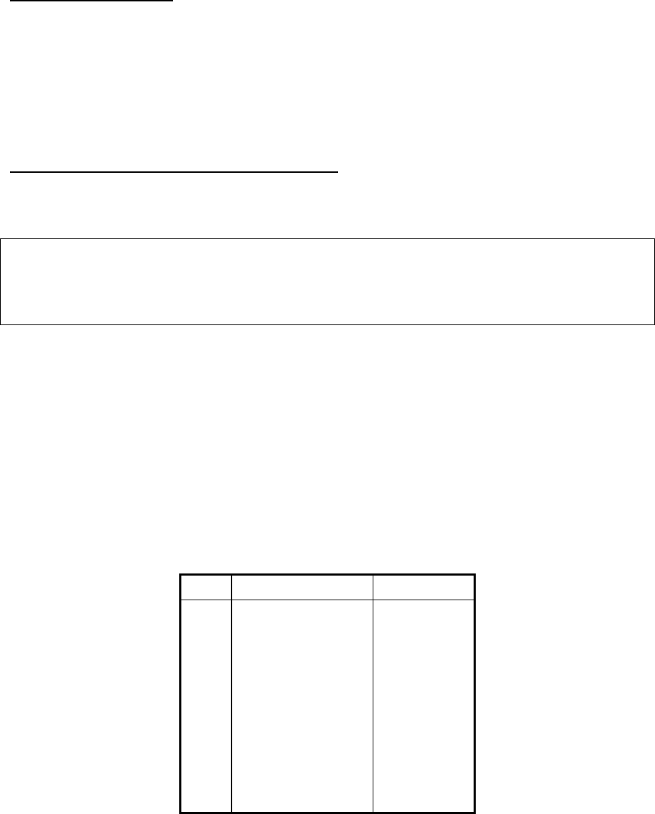
Table 4-2. Station ID Cross Reference
Digits Number Code Digits Letter Code Digits Letter Code
00 0 – – – – – 12 A • – 26 N – •
01 1
• – – – – 22 B
– • • • 36 O – – –
02 2
• • – – – 32 C
– • – • 17 P
• – – •
03 3
• • • – – 13 D
– • • 10 Q
– – • –
04 4
• • • • – 23 E • 27 R
• – •
05 5
• • • • • 33 F
• • – • 37 S
• • •
06 6
– • • • • 14 G
– – • 18 T –
07 7
– – • • • 24 H
• • • • 28 U
• • –
08 8
– – – • • 34 I • • 38 V
• • • –
09 9
– – – – • 15 J
• – – – 19 W
• – –
25 K
– • – 29 X
– • • –
35 L
• – • • 39 Y
– • – –
# (DONE) 16 M – – 20 Z
– – • •
Table 4-3. DTMF Keypad with Letters Shown
1
A B C
2
D E F
3
G H I
4
J K L
5
M N O
6
P R S
7
T U V
8
W X Y
9
*
0
#
Example: Set the station ID call sign “WNCR-414” to 100.0 Hz CTCSS tone (user # 12):
DTMF commands: 43# 12# 19# 25# 32# 27# 4# 1# 4# #
Comments: Set ID User 12 W N C R 4 1 4 done
Playback Morse ID
The station ID for a user may be played back over the channel while in the program mode.
This command is only available when using the DTMF program mode (not from RS-232 or
Model 8 mode).
Section 4. Programming
4-12
Prepaid Airtime Mode
The Prepaid Airtime feature allows a customer to purchase a block of airtime in advance. As
the customer groups uses the repeater, the amount of airtime decreases, and when the supply
is nearly gone (below two hours remaining) the customer hears warning beeps upon
unkeying. Unless a new payment is received, the tone becomes “reserved” as soon as the
prepaid airtime runs out. This feature eliminates billing since customers always know when
it’s time to pay.
Display or Change a User’s Airtime Counter
The airtime counter for each user may be viewed, cleared, or changed perhaps to add airtime
when the user is in prepay mode.
Note
The maximum airtime allowed is 249 hours:59 minutes:59 seconds. If a user exceeds this
time, the counter limits at 249:59:59, and will not roll over.
When programming the unit via DTMF over the radio channel, the airtime counts may be
retrieved and displayed using a Zetron Model 8 Repeater Programmer / Timekeeper or any
other DTMF display device. Commands are supplied to support DTMF display devices that
only have four digit displays. If desired, the data may also be sent via Morse code, at any
speed from 4 to 25 words per minute. The format of the data is selected from the System
Programmable Feature “DTMF repeater programmer unit type”. When a remote DTMF
display decoder is not available, anyone should be able to copy slow Morse code digits.
Digits are the easiest code to remember, since all characters are 5 elements in length. Table
4-4 is provided for reference.
Table 4-4. Numerals in Morse Code
Digit Sound Dot / Dash
1 dit dah dah dah dah • – – – –
2 dit dit dah dah dah • • – – –
3 dit dit dit dah dah • • • – –
4 dit dit dit dit dah • • • • –
5 dit dit dit dit dit • • • • •
6 dah dit dit dit dit – • • • •
7 dah dah dit dit dit – – • • •
8 dah dah dah dit dit – – – • •
9 dah dah dah dah dit – – – – •
0 dah dah dah dah dah – – – – –

Section 4. Programming
4-13
Optional Auxiliary Relay Function
This option allows the aux relay to close while a predetermined CTCSS tone, or DCS code,
or group of tones or codes is received. The aux relay will follow the CTCSS or digital decode
for programmed users; closing only while the user is transmitting. Jumpers allow the system
operator to provide a pair of normally open or normally closed contacts. With the auxiliary
relay option installed, the Model 38 provides a ground on TB1, pin 8 upon receipt of a tone
or code programmed for auxiliary relay activation.
System Commands
Carrier Repeat (Open Repeater)
The Model 38 can be programmed to repeat based on just carrier, sometimes called “carrier
controlled repeat”, or “open repeater”. In this mode the unit will provide simultaneous tone,
DCS, and open repeater operation; users that have CTCSS or DCS encode operate normally,
users that have no encode repeat also. This allows a mix of CTCSS tone users with open
repeat capability and is ideal when adding tone users to an existing open repeater.
To enable the carrier repeat function, a user number is identified as the “CARRIER” repeater
user. This allows all of the user programmable features to be applied to open repeat,
including; enable/disable for the carrier user, CTCSS or DCS encode, air time accumulation,
etc. If the COR user number is set to “0”, the no carrier repeat is available.
Anti-Kerchunker Filter
The anti-kerchunker filter cancels the transmit hold time and drops the repeater immediately
if a mobile transmission is less than the programmed “anti-kerchunk” time. This serves two
main purposes:
• It will discourage users from “kerchunking” the repeater to death.
• It will make the repeater co-exist better on shared-channels. When a lot of CTCSS tones
are enabled on a single channel, it’s not uncommon for voice falsing of active CTCSS
tones on a co-channel repeater to occur. This is because a human voice often contains
frequencies in the CTCSS band. A radio user could be talking and cause a co-channel
repeater to key up over the conversation. When the repeater transmit hold time is greater
than about a second, this causes major interference to the voice communication. With the
anti-kerchunker filter enabled, the repeater will key ONLY for the duration that the voice
simulates CTCSS, not the entire transmit hold time. The anti-kerchunker filter is disabled
by programming the time to zero.
Morse ID Frequency, Interval, Speed, and System ID
The Morse code station identification is programmable in frequency, interval and speed.
Each user group has its own independent station ID callsign, and timer accurate to one
second per interval. The timer is reset when the station ID is sent. The call will be
transmitted on the first dispatch message after the timer has expired.

Section 4. Programming
4-14
The frequency is programmable from 400 to 2000 Hz (per FCC part 90), the default setting
being 1200 Hz.
The interval is selectable from 1 to 99 minutes, with a default of 15.
The Morse ID speed is selectable from 4 to 25 words per minute, the default setting being 22
WPM. During normal dispatch, the minimum speed will be 15 WPM. This allows the “List”
functions in the program mode (using Morse code) such as airtime retrieval to be sent at real
slow speed, while maximizing airtime use during normal dispatch.
For co-op systems and other requirements, the repeater may have a single call sign that may
need to be sent at regular intervals (periodic ID enabled) or based on repeater usage. This is
referred to as the “System ID”, and it is enabled in the unit by selecting one of the user slots
(CTCSS or DCS) as an index. The user can be either a valid (enabled) subscriber or disabled
user. The System ID user number will specify the call sign and CTCSS or DCS encode
attached to the repeater ID. When it’s time to ID, the transmitter will be keyed and after a
0.75 second delay, the call sign sent. The conditions that must be met before the system ID is
sent include:
• The ID interval timer must expire (adjustable 1 to 99 minutes)
• The Model 38 must be inactive (DECODE LED off), no conversation in process
• The System ID must have a user number programmed
Courtesy Tone Frequency
The Courtesy tone is programmable in frequency from 400 to 4000 Hz. The default setting is
1000 Hz. It is used for courtesy tones and prompt beeps. It may be desirable to change the
frequency of the tone in order to distinguish co-channel repeaters at different locations.
Tailbips
For some installations, a courtesy beep sent once per second during the transmit hold time
can help users identify repeater access. To activate Tailbips, the Courtesy Tone must also be
enabled for each user group desiring the feature. Please note that the tone frequency of the
Tailbips is system programmable as the Courtesy Tone Frequency.
Hog Mode
The Airtime Hog feature penalizes long-winded talkers. If a talker exceeds a time limit
(programmable per-user), he will be prohibited from placing a call for a penalty period.
Warning tones are sounded when a Hog penalty is imminent.
The hog mode requires three separate timer functions. They are the Conversation time limit,
Idle timer, and Penalty timer. The Idle timer runs whenever a mobile is inactive, and when
satisfied will reset the conversation time limit. The penalty time is the amount of time a
mobile will be disabled when the conversation time limit is reached. Each user may have the
Hog function enabled or disabled (see user programmable features). The Conversation timer

Section 4. Programming
4-15
is programmable per user from 1 to 25.0 minutes, the Idle time programmable from 1 to 99
seconds, and the Penalty timer programmable from 10 to 9990 seconds in 10-second
increments. Hog mode may be disabled for a user by setting the conversation limit time to
zero.
A long-winded talker who is approaching the end of the conversation time limit will start
hearing warning tones (sounding like “bee-doo”) 1 per second prior to cut-off. To avoid an
impending Hog Penalty, the user must let the repeater transmitter un-key for the idle
duration, giving another mobile a chance to use the system. If another user keys up, or if the
idle duration is met, the conversation timer is reset. The Hog Penalty is programmable user,
and all users have their own penalty timers in the case of multiple hogs on the system.
Timeout Timer
The timeout timer is the maximum amount of time a mobile may continuously transmit on
the channel. This is a stuck mic timeout feature. The timer is reset each time CTCSS or DCS
decode stops. During a timeout condition, an alert tone will be sent, then the repeater
transmitter will unkey. If desired, the user number causing the timeout can be identified via
DTMF every 15 seconds while the fault exists. This is referred to as Timeout ID. To disable
the timeout timer, set the value to zero.
Timeout ID
In order to determine what user group has a stuck transmitter, the timeout ID feature can be
enabled. During a timeout condition with timeout ID enabled, the repeater will key every 15
seconds (while the user is still transmitting) and send the user number via slow DTMF.
Site Alarm Programming / Remote PTT Function
The Site Alarm function of the Model 38 has multiple purposes. It can be used to:
• Generate a programmable DTMF sequence, a warble alert tone, and a specific CTCSS
tone or DCS code.
• Indicate an event triggering the site alarm input pin (on the back of the Model 38) such as
a door contact, high temperature, AC fail, low fuel...
• Indicate the program mode has been accessed.
• Indicate power has been restored to the repeater (power on alarm).
• Indicate when the site alarm input pin is being held active by generating a 2 Khz beep
whenever the repeater is in use just before unkeying.
• Interrupt repeater operation, key the transmitter, and generate carrier or a specific CTCSS
or DCS code (remote PTT function). This can provide the capability for a tone/dc remote
or local mic to communicate with a specific user group.
The site alarm DTMF sequence can be set for 0-8 digits, including the 0 to 9, *, #, A, B, C,
or D keys. The Site Alarm may be sent with a contact closure input, and/or each time power

Section 4. Programming
4-16
is restored to the Model 38. When the Alarm is tripped, the Model 38 will wait until dispatch
activity is completed, then wait for 2 seconds of clear channel, key the transmitter, select a
CTCSS or DCS encode tone, wait 1 second, then send the DTMF digits. Following the
DTMF code, a warble alert tone will be sent. If the alarm is from the contact closure, a slow
warble will be heard. If the alarm is from a power up condition, a fast warble will be heard.
The site alarm may also be sent upon program mode access. This can be useful information
where unauthorized access is suspected. If the site alarm is enabled for program mode access,
the DTMF alarm is sent followed by the five unique digits of the Model 38’s serial number.
The serial number can be useful for verification of the panel being programmed.
Note
This function should not be used when using a Model 8 for over-the-air programming.
The site alarm input may be used as a “Remote PTT” function. This feature is initiated by the
site alarm input being pulled to ground by a contact closure or other input. When the alarm
input goes active, any repeater activity will be suspended, then the programmed CTCSS tone
or DCS code will be encoded, the repeat audio squelched, and the transmitter keyed. This
condition will continue until the site alarm input is released.
When the site alarm digits are entered via DTMF programming (command 25276#), the input
is terminated with a timeout period, not the “#” key. For example: To set the site alarm code
to “12345”, press 25276#12345 then wait for the go-ahead “chirp”. Don’t press
25276#12345#
A Model 8 Repeater Programmer / Timekeeper may be used to decode the DTMF digits sent
during an alarm condition. The Model 8 will flash it’s display and close a relay in response to
an alarm decode.
Digital Coded Squelch Data Polarity
Since the polarity of the encode and decode data depends on which radio it’s attached to, and
the connection points within the radio, programmable inverters are incorporated into the
DCS encoder and decoder software. The polarity is either Normal, or Inverted. The digital
code being sent is not changed, only the polarity of the bits. The easiest way to verify proper
data polarity is trial and error during installation.
Program Mode Access Code
The program mode password is a number between 1000 and 32000. If it is set to less than
1000, the password will be 12nnn (where nnn is the password). If it is set to greater than
1000, the password is the number entered.
When the program mode is accessed via DTMF over-the-air, a programmable delay may be
included after the code is recognized, but before the program mode becomes active. This
feature provides added security from hackers using trial-and-error techniques to break into a

Section 4. Programming
4-17
tone panel. During the delay time, the tone panel continues to operate normally. The delay
can be set from 0 to 30 seconds. For additional security, the site alarm and serial number of
the panel may be sent upon access (see Site Alarm programming above).
Note
The setup mode in the Model 8 controls which code it sends to the Model 38A when the
Model 8 is in the program mode. Model 8 units with software prior to version 3.7 only
support the 12nnn format of Model 38 password. Model 8s with version 3.7 and later support
12nnn or 1000 to 32000.
Program mode progress tone delay (DTMF Mic Hold Time)
This function allows a delay to be inserted before the progress tones are sent during DTMF
programming. In many radios equipped with DTMF encode, the transmitter remains keyed
for a short time after releasing a DTMF digit. This can prevents the user from hearing the
prompt tones. To remedy this condition, a delay may be inserted into the Model 38. Enter the
number of seconds to delay, from 0 to 3, the default setting being 0.
Note
While programming, the user does not have to wait for the prompt tones, all DTMF is
received even while processing a command, or issuing a prompt tone.
DTMF Repeater Programmer Unit type
When programming the unit over the channel via DTMF, the “list” functions (such as airtime
retrieval) send back data as either DTMF or Morse code. The format may be “straight
DTMF” for use with a Zetron Model 8 Repeater Programmer / Timekeeper, or compatible
with the RDU or DI-16 terminals. For Morse code format, the speed may be set with System
programming from 4 to 25 words per minute. Once the command is recognized (the “#” key
released) the Model 38 will delay for three seconds then begin sending back the data. If a
remote DTMF display decoder is not available, anyone should be able to copy the Morse
code digits. Digits are the easiest code to remember, since all characters are 5 elements in
length. Table 4-5 is provided for reference.
Table 4-5. Numerals in Morse Code
Digit Sound Dot / Dash
1 dit dah dah dah dah • – – – –
2 dit dit dah dah dah • • – – –
3 dit dit dit dah dah • • • – –
4 dit dit dit dit dah • • • • –
5 dit dit dit dit dit • • • • •
6 dah dit dit dit dit – • • • •

Section 4. Programming
4-18
7 dah dah dit dit dit – – • • •
8 dah dah dah dit dit – – – • •
9 dah dah dah dah dit – – – – •
0 dah dah dah dah dah – – – – –
DTMF Interdigit Timeout
The DTMF timeout is used to detect when the radio user has finished entering DTMF digits.
It is used during program mode access, DTMF regenerate mode, and a few other places. The
default setting of four seconds should be adequate for nearly all applications.
Select RS-232 Port Configuration
The RS-232 port may be configured for connection to a Model 8 Repeater Programmer /
Timekeeper, an RS-232 terminal, PC, or modem. When changing port configuration, the new
configuration is loaded after power on, top menu access, and long digit DTMF reset. Refer to
the beginning of this section for more information.
RS-232 Baud Rate
The baud rate of the RS-232 port when configured for CRT or Modem mode may be set to
any one of the following baud rates. The default baud rate is 1200.
Baud Rate 150 300 600 1200 2400 4800
Enter number 1 2 3 4 5 6
RS-232 Port Serial Tone Output
When enabled, the Model 38 will send a character out the serial port whenever CTCSS or
DCS is decoded, and another character when decode is lost. This feature can be used to
inform other equipment of real-time channel status. The format is a follows: When the Model
38 decodes a user (CTCSS or DCS) it will take the user number of the decode, add 96 then
send it as a character. When decode is dropped the ASCII character with a decimal value of
96 will be sent. Table 4-6 provides an example.
Table 4-6. Serial Tone Decode Output
Model 38 decodes Serial tone output character
User 13, 103.5 CTCSS ASCII 109
Decode goes away ASCII 96
User 55, DCS 047 ASCII 151
Decode goes away ASCII 96

Section 4. Programming
4-19
Airtime Accumulation
The airtime may be accumulated including or excluding the transmit hold time.
DCS Bit Errors
This feature allows adjustment of the number of allowable bit errors that are acceptable when
acquiring a DCS code. Setting this value to 1 means that one bit error is allowed for each
DCS code word when the panel is attempting to determine if a digital code is being received.
The number of allowable bit errors is adjustable form 1 to 4. This adjustment only affects
DCS acquisition and does not affect operation once a code has been decoded. Operation once
DCS decode has been acquired is set to ignore up to 4 bit errors in any position of the code
word. Setting a low value will cause the unit to require better signal quality for access,
setting a higher value will cause the unit to decode in poorer signal conditions but be more
likely to false on noise. Note: For proper DCS decode operation without noise falsing, the
carrier detect LED on the front panel should be set to come on at a 6 dB SINAD level.
Voted CTCSS Acquire, Slower Decode
Two algorithms are selectable for CTCSS acquisition which affect CTCSS tone frequencies
below 140 Hz. The selections are either fast decode with some chance of falsing, or slightly
slower decode with little chance of falsing. The selection typically only affects the first time
a mobile keys up during a conversation.
CTCSS Delay
This command allows the CTCSS squelch tail elimination detector in the Model 38A to
function despite the variations between manufacturers in how long the phase reverse burst is
sent when the radio is unkeyed. When the phase inverted CTCSS tone is sent too long by a
radio, the Model 38A can reacquire the tone and open up the repeat path again, causing a
long squelch tail “crunch”. By adding the CTCSS delay, when the reverse burst is detected it
will mute the repeat audio path and refuse to decode the tone again until the time period set
by this command has expired. The default setting is 70 milliseconds which should work well
with all current radio manufactures.
CTCSS Decode Hold Time
A timer is available to extend the duration between loss of CTCSS decode and repeat audio
muting (while carrier is still present). The unit will always mute within 5 milliseconds after
loss of carrier.
The industry standard DCS hold time is one second. If the CTCSS hold time is set above one
second, it will apply to DCS also. Whenever the squelch tail elimination “turnoff code” bit
sequence is recognized, repeat audio will be muted independent of any hold time.

Section 4. Programming
4-20
Note
This value should be left at the factory default setting of “0” except in very special situations.
About the only reason to use this timer is the case where low frequency paging tones close to
a CTCSS tone need to be sent through the repeater. Since the paging tone deviation is
generally 5 times higher than the CTCSS tone, it can de-sense the decoder, causing repeat
audio to mute.
List And Airtime Functions
List the Number of Active Users
Programming commands are available to show how many users (CTCSS tones and DCS
codes) are enabled in the repeater panel. The number will be sent back via Morse code or
DTMF as selected.
List the Active User Numbers
The active users in the Model 38 may be displayed for reference. The user numbers will be
sent via two digit numbers, in DTMF or Morse code. To interrupt the display, press the “*”
key between packets. If using a DI-16 remote, the numbers will be sent in “high-speed”
download mode.
List Airtime Counts Greater than Zero
This command will display the user number and associated airtime count, if greater than
zero. All airtime accumulated will be displayed, not just enabled users to allow the system
operator to monitor co-channel airtime use. The user number will be sent, a 1-second delay,
then the Hours:Minutes will be sent as a 4-digit number. A 3-second delay will separate the
user numbers. For use with a DI-16 remote, the counts will be sent in “high-speed” download
mode.
Clear All Airtime Counters
All user airtime counts may be reset to zero with a command. A password is required to
reduce the possibility of accidentally loosing the airtime counts.
Diagnostic Commands
The following commands are provided to aid the system operator and installer in setting up
the system. All commands may be used interactively with other commands. For example, the
transmitter may be keyed, the repeat audio path opened, a CTCSS tone generated, and a
DTMF tone generated all at the same time.
Site Alarm
The site alarm may be sent in order to verify proper decoding with associated equipment.
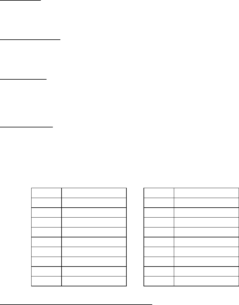
Section 4. Programming
4-21
PTT On / Off
The transmitter may be keyed and unkeyed in order to test PTT function. If left in the Off
state, it will still key to send progress tones or download data.
Repeat Audio Path
The repeat audio path may be opened or closed (squelch or unsquelched) for testing
purposes.
DTMF Encode
A DTMF digit may be generated on the repeater output channel to set the deviation of the
transmitter, and the Audio Output adjustment in the Model 38. When using the DTMF
program mode, use Table 4-7 as a cross reference.
Audio Test Tone
An audio test tone may be generated if desired. The tone generator is used for Morse ID and
various prompt tones. The amplitude and shape of the signal will vary with frequency, since
it is not a pure sign wave generator. Any frequency between 400 and 4000 Hz may be
encoded.
Table 4-7. Digit Assignments for DTMF Encode Test
Number DTMF Encode Digit Number DTMF Encode Digit
0 0 9 9
1 1 10 A
2 2 11 B
3 3 12 C
4 4 13 D
5 5 14 *
6 6 15 #
7 7 99 Turn off DTMF tone
8 8
CTCSS Tone or Digital Squelch Code Encoding
This function is used to set the CTCSS deviation and test the DCS encode polarity. All of the
CTCSS tones, any frequency between 50.0 and 300.0 Hz, and any octal DCS code (000-777)
can be generated. For DCS enter the octal code plus 1000 (023 is entered as 1023). To
disable the encode, enter zero.
A CTCSS tone sweep mode is provided (via DTMF programming) which will generate a
low, mid, and high frequency CTCSS tone. Each tone is turned on for 4 seconds. This mode
is good for checking the deviation of the tones at each end of the CTCSS limits. All tones

Section 4. Programming
4-22
should be close in deviation. If not, de-emphasis may need to be switched in or out. To
terminate the sweep command hold down the DTMF “*” key for 5 seconds. Note: This test
may be slow to exit.
The precise sub-audible frequency encode command can be used to test the bandwidth of a
CTCSS decoder over the air. As an example, testing a mobile decoder on 100.0 Hz. By
entering 1015 the Model 38 will encode 101.5 Hz, the mobile should unsquelch. Then
encode 98.5 Hz , the mobile should still unsquelch. If it doesn’t, the decoder bandwidth is
wrong, or in the case of a tunable decoder, the center frequency is probably adjusted wrong.
List Resets, Power Fails, Program Access
The Model 38 keeps track of the number of program mode access, resets or brownouts, and
power fails. The counters limit at 9999 and may be read via RS-232, Morse code, DTMF or
Model 8. The counters may be cleared via DTMF programming.
Repeater Enable / Disable (setup / knockdown)
The Repeater Panel may be temporarily disabled if required. When disabled, it will remain
out of service until the program mode is accessed again, or the main power is cycled, or a
“long DTMF digit reset” is performed.
System Memory Test
The program and database memory in the unit include integrity check features to ensure
proper operation. The status of the system can be checked with program mode commands.
When an error condition exists, the unit will generate a 400 Hz beep over the transmit audio
during repeater operation just before unkeying. If this tone is heard, the unit can be
interrogated as to the source of the problem. Use Table 4-8 to identify system memory errors.
Table 4-8. System Memory Errors
Error number Type of fault
0 None, system is functioning properly
1 EPROM memory error, U14 or U16 defect
2 An error may exist in the System programmable features setting area
3 EPROM and System programming errors
4 User database error (CTCSS / DCS attributes)
5 User database and EPROM memory errors
6 User database and System programming errors
7 User database, System programming, and EPROM errors
When an EPROM error exists (error number 1, 3, 5 or 7), the unit may or may not function
properly. The EPROMs contain the operating software program that determines all of the

Section 4. Programming
4-23
operation of the unit. In case of an EPROM error (which is extremely rare) the EPROMs
should be replaced as soon as possible, or the unit returned for service.
If a system programming error exists, some value in the system programmable features is
either out of range or somehow changed unintentionally. If this occurs, the system
programmable settings should be viewed to look for undesirable settings. The error may be
cleared by simply changing any of the system programmable settings.
If a user database memory error is indicated, a value in the user database area is either out of
range or somehow changed unintentionally. The items affected by a user error may or may
not affect operation. In this case, the number of users with errors may be important as well as
the actual user numbers with errors. If only a few users have errors, they may be
reprogrammed with little trouble. If many errors are reported, it may be a better idea to clear
all memory and reset the system.
What will the unit do in response to an error?
• If more than 20 users report errors when the unit is powered up, it will automatically
reset the entire system to the factory default values.
• If the error is an out of range system or user programmable settings, the factory default
will be used.
• EPROM errors may cause undesirable operation of the unit. Some errors can be tolerated,
others cannot, depending upon the location of the error.
What can cause an error?
• The system and user programmable values in the unit are contained in a battery backed
memory. The memory contains two batteries for redundancy: if one fails or gets used up,
the other one takes over. The lifetime of the batteries is between 5 and 12 years with or
without power applied. When the battery is used up and power is removed from the unit,
errors may be introduced into the programmable settings.
• A direct hit or near strike of lightning may contain enough energy to alter a setting within
the system or user database memory.
• Installing different versions of software in the unit, upgrades, swapping EPROMs,
changing between 38 or 50 tone versions may introduce memory errors.
• EPROM errors should not occur.
Reset the unit to the Factory Default Settings
This command will load the factory defaults into the system and user database settings, and
clear the airtime totals.
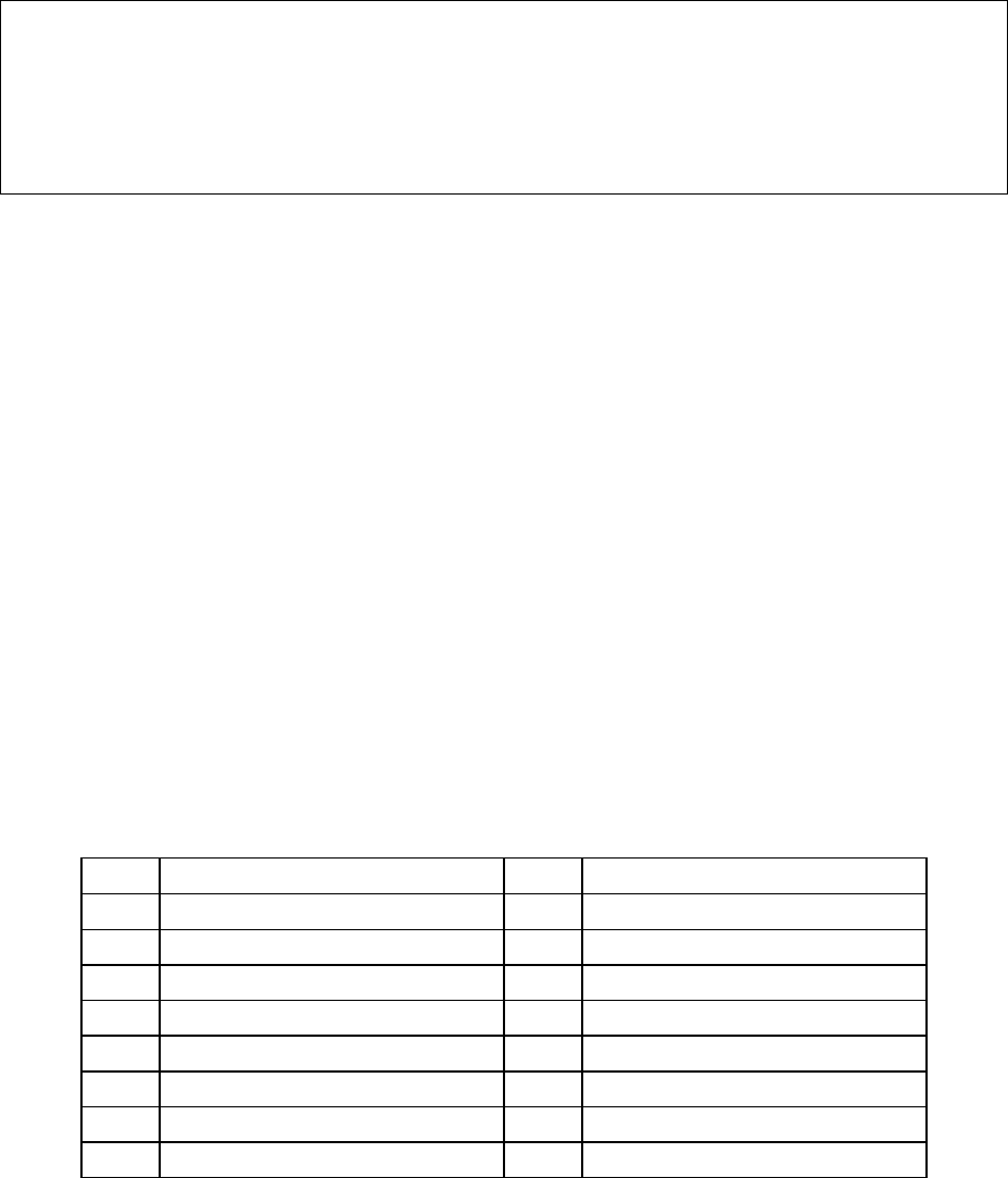
5-1
5. INSTALLATION
INSTALLATION WARNING
This equipment generates, uses, and can radiate radio frequency energy. If not installed and
used in accordance with the instruction manual, it may cause interference to radio
communications. Installation of the Model 38 Repeater Panel should only be attempted by
qualified radio service personnel.
For instructions on installing new software, see “INSTALLING A NEW PROM” on page 5-
27.
GENERAL
Connections to the transmitter, receiver, and power are grouped on a detachable terminal
strip on the rear for ease of installation. The Model 38 includes installation test modes to aid
in installation. All adjustments and switches are accessible from the rear.
REQUIRED EQUIPMENT
Required equipment includes:
• A communications service monitor
• A handheld or mobile radio with DTMF encode capability
• A VOM (volt-ohmmeter).
• A PC or terminal with RS-232 is desirable
SCREW TERMINAL CONNECTIONS
Pin # Signal Pin # Signal
1 +12 VDC or 9 VAC, fused input 9 Site alarm input
2 9 VAC input 10 Rx carrier input
3 DC supply ground 11 Tx microphone audio
4 Ground 12 Ground
5 PTT N.C. 13 CTCSS / DCS encode
6 PTT common 14 Ground
7 PTT N.O. 15 Rx discriminator input
8 Auxiliary relay output

Section 5. Installation
5-2
INSTALLATION PROCEDURE
1. Remove the 15-pin screw-terminal connector from the rear of the unit.
2. POWER SUPPLY: Locate the 12 Volt DC supply for the repeater receiver/transmitter.
With a VOM, measure the DC voltage. It should be between 10.5 and 15.0. If 12 Volt DC
is not available, a 9 Volt AC wall transformer may be used. For DC operation, connect
the power supply ground lead to pin 3, and the positive supply lead to pin 1. For 9 Volt
AC operation, connect between pins 1 and 2 (pin 1 is internally fused).
3. GROUND CONNECTION: Connect a chassis ground wire from pin 3 to the chassis
ground of the transmitter / receiver.
4. TRANSMITTER PTT: For most transmitters, a contact closure to ground will cause the
transmitter to key. For this configuration, connect a wire from pin 7 (relay N.O. contact)
to the PTT input of the transmitter, then ground pin 6 (relay common contact).
5. TRANSMITTER AUDIO INPUT: Connect pin 11 to the mic or line input of the
transmitter. Shielded cable may be used for this connection, connect the braid to pin 12.
6. CTCSS / DCS ENCODE: Connect pin 13 to the direct modulation or CTCSS tone input
of the transmitter. Shielded cable may be used for this connection, connect the braid to
pin 12.
7. DISCRIMINATOR INPUT: Connect pin 15 to the receiver discriminator output.
Shielded cable may be used for this connection, connect the braid to pin 14.
8. COR INPUT: Connect pin 10 to the carrier detector in the receiver. The signal must be
between 0 and 7 VDC, and change at least 1 volt between carrier and no-carrier
conditions. A built in noise detector squelch can be used if a carrier indication from the
receiver is not readily available.
9. ALARM / REMOTE PTT: Connect pin 9 to alarm input or the remote PTT source. A
closure to ground will actuate the input.
10. Reconnect the screw terminal connector.
Installation Tips
The following are some hints for correctly installing a Zetron Model 38 Repeater Panel.
Audio Input Connection
Older repeater panels just decode CTCSS tones, and don’t handle repeat audio or squelch-
related functions. Repeat audio is usually passed between the receiver and transmitter
through a “Repeater Audio” circuit board. This board or circuitry must be removed.

Section 5. Installation
5-3
To ensure that CTCSS tones and/or DCS codes will be decoded, and that repeat audio signals
will be processed correctly, the Model 38 must be connected to an audio source within the
receiver that passes frequencies from 1 Hz to at least 3,500 Hz.
If the internal noise squelch is to be used, the audio source must pass frequencies up to at
least 6 kHz. Without such an audio source, the noise detector will operate as a VOX detector
only. Many receivers have a signal brought out that is labeled “discriminator”. Quite often
this signal is low pass filtered, and removes the high frequencies required for proper noise
detector operation. Look at the diagram for any caps or filtering in the chain before using the
noise detector.
Audio Output Adjustment
The “Audio Output” potentiometer (on the back panel) is not a “repeat audio” level control.
It’s a deviation control that regulates the levels of the DTMF encode and audible tones (e.g.
warning beeps), along with repeat audio.
To properly set these levels, put the Model 38 into the Test Mode and have it encode a
DTMF tone. Using a service monitor, set the potentiometer for 60% of full channel (typically
3 kHz) deviation.
The “Audio Output” potentiometer should be adjusted before setting repeat audio deviation
with the “Audio Input” potentiometer.
Shielding, Grounding
Using quality shielded cable for audio connections and practicing good grounding techniques
will eliminate the possibility of “hiss” and “hum” interfering with the repeat audio.
ADJUSTMENT PROCEDURE USING THE DTMF PROGRAM MODE
1. AUDIO INPUT GAIN FROM RECEIVER
Rough setting. Key up on the repeater receiver frequency, and generate the DTMF tones
0 to 9, * and #. Please note that CTCSS encode is not required yet. The DTMF indicator
should light with every key. Adjust the AUDIO INPUT GAIN to a rough setting where
all tones are decoded (switch 1 may need to be toggled).
2. ACCESS THE PROGRAM MODE
Key in the DTMF program mode password. It is initially set to “12123#”. When the
mode is accessed, the transmitter will be keyed.
3. SET THE AUDIO OUTPUT GAIN
Access the DTMF encode test mode (key 3863#) then encode the DTMF digit 5 (key 5#).
Set the deviation to 60% of full channel (typically 3 kHz) with AUDIO OUTPUT GAIN
adjustment. If the deviation will not go high enough, move switch 2 to the off position,
and readjust. Note: This is not the repeat audio level! Exit the DTMF encode test (key
3863# 99#).
Section 5. Installation
5-4
4. SET THE CTCSS ENCODE OUTPUT GAIN
Access the CTCSS encode test mode (key 28277# 18#) and generate tone number 18
(123.0 Hz). Adjust the CTCSS OUTPUT GAIN for 0.75 kHz deviation. If the deviation
will not go high enough, move switch 3 to the OFF position, and readjust. Now access
the CTCSS tone sweep mode (key 8378#), and monitor the deviation. It should be the
same for each of the three tones. If the 250 Hz tone is much lower than the 67.0 Hz tone,
move switch 5 to the OFF position. The gain may need to be readjusted. Exit the test
mode (key # for 5 seconds).
5. SET THE REPEAT AUDIO GAIN
Access the repeat audio test mode (key 7781#). Supply a test tone of known deviation on
the receiver frequency, then monitor the deviation of the transmit frequency. Adjust the
AUDIO INPUT GAIN for unity gain (input deviation = output deviation). If the level
cannot be adjusted high enough, move switch 1 to the off position, then readjust. Now
insert 500 Hz, 1000 Hz, and 2000 Hz. The output deviation should be flat. If not, move
switch 4 to the off position (no de-emphasis). Readjustment of the AUDIO INPUT GAIN
may be necessary. Be aware that if you are using a DTMF test tone, you should not hold
the digit for greater than 8 seconds or a reset will occur.
6. COR (SQUELCH) ADJUSTMENT
Internal Squelch (no connection to pin 10). Set Sw-6 ON, and Sw-7 ON. Adjust the COR
threshold by watching the CARRIER LED. It should be set exactly like the squelch
would be set on a receiver. This adjustment must be made AFTER the repeat audio level.
When using an external COR, set Sw-6 OFF, and Sw-7 will select COR polarity (off for
positive, on for negative COR). Adjust the COR threshold while watching the CARRIER
LED for optimum performance. When using a dry contact closure for COR input, switch
8 should be set in the ON position to enable the internal pull-up resistor.
7. CTCSS DECODE VERIFICATION
The DECODE indicator should light whenever a CTCSS tone is present on the radio
channel.
8. Exit the program mode (key 293#).
ADJUSTMENT PROCEDURE USING THE SITE ALARM INPUT
1. Connect the Model 38 to the radio using the installation instructions on the previous
pages, or follow the application note supplied for your specific radio.
2. Connect a clip lead to the site alarm input of the Model 38 (pin 9).
3. Connect the communications service monitor to the antenna, set for receive deviation
display on the repeater transmit frequency.
Section 5. Installation
5-5
4. Power on the Model 38 and immediately pulse the site alarm jumper to ground at least
fifteen times during the first ten seconds of power up. This will cause the Model 38 to
access the following test sequence.
PTT on.
DTMF digit 5 encoded.
CTCSS mid tone encode.
CTCSS high tone.
CTCSS low tone.
DCS code 023.
Repeat audio enabled.
PTT off.
5. Each test lasts 15 seconds and may be advanced by momentarily grounding the SITE
ALARM. The test will repeat up to 20 times (approx. 40 minutes if left unattended).
6. Hit the site alarm input (ground) until the DTMF digit is being encoded on the transmit
channel. Set the deviation for 3kHz (or 60% of maximum allowable deviation) using the
AUDIO OUTPUT level adjustment.
7. Hit the site alarm again to advance to the CTCSS output test. Set the CTCSS OUTPUT
adjustment for 700Hz (or 15%) deviation of the CTCSS encode tone.
8. Hit the site alarm again then verify the deviation of the 250Hz CTCSS tone is similar
deviation.
9. Hit the site alarm again then verify the deviation of the 67Hz CTCSS tone. If the tones
are not close to the same deviation, toggle the CTCSS DE-EMPHASIS switch and
readjust.
10. Hit the site alarm again then verify the deviation and polarity of DCS code 023. Note:
DCS encode may cause the deviation meter to give inaccurate (high) reading.
11. Hit the site alarm again then verify the operation of the CARRIER LED on the front
panel. Generate a carrier signal on the repeater input (receiver) frequency, then reduce
the RF level until the led goes out. The LED should follow the squelch noise from the
receiver, and is usually controlled by the receiver squelch knob. If the LED does not
light, adjust the COR level until the CARRIER LED follows carrier on the channel.
12. Now supply a test tone of known deviation on the receiver frequency, then monitor the
deviation of the transmit frequency. Adjust the AUDIO INPUT GAIN for unity gain
(input deviation = output deviation). If the level cannot be adjusted high enough, move
switch 1, then readjust. Now insert 500 Hz, 1000 Hz, and 2000 Hz. The output deviation
should be flat. If not, move switch 4 then readjust. Note: If using a DTMF test tone, do
not hold the digit for greater than 8 seconds or a reset will occur.
Section 5. Installation
5-6
13. Note: DO NOT use the AUDIO OUTPUT control to adjust the repeat audio level! The
AUDIO INPUT control MUST be used for repeat level.
RADIO-SPECIFIC CONNECTIONS
The following pages provide information for connecting specific radios to the Model 38.
These same application notes can be used with the Model 39, Model 39-MAX, Model 45B,
Model 48B, and Model 48-MAX.

Section 5. Installation
5-7
GE MASTR III Base/Repeater
For: Zetron Model 38, 38-MAX, 39, 39-MAX, 45B, 48B, 48-MAX
To: GE MASTR III base/repeater
Using: 709-7112 Generic radio cable
Pin Zetron Signal Name Wire Radio Connection / Signal Name
1 12 volts AC/DC in Red P5.1 (A+ / DC Power)
2 12 volts AC input --- No Connection
3 DC ground Black P2.2, P2.3 (Power ground)
4 Ground Drain No Connection
5 PTT NC --- No Connection
6 PTT COM (to GND, pin 4) Jumper No Connection
7 PTT NO Orange P2.13 (Repeat PTT In)
8 Aux relay --- No Connection
9 Sense / alarm --- No Connection
10 COR input Yellow P3.5 (CAS)
11 Tx audio Blue P5.8 (Repeat Audio)
12 Ground --- No Connection
13 CTCSS/DCS/encode Green P3.14 (CTCSS Encode)
14 Ground Brown P4.2
15 Discriminator in White P2.5 (Demodulated Audio
MASTR III Configuration:
1. Connectors P2, P3, P4, and P5 are located on the GE Mastr III backplane.
2. Cut the printed wire pattern at JP-1 on the T/R Shelf’s backplane 19D902948.
3. Program the base station using the standard PC programming software. For proper
operation, the station firmware must be 344A3307G12 (Group 12) or higher (see the
label at Mastr III System Board - U4).
4. Program the following parameters in the Mastr III:
A. Repeater (Single Channel only) E. Set the TX Pot to 200.
B. Repeater Panel option F. Set the CG pot to 255.
C. RF duplex G. No CCT or DODT Timers (set to 0)
D. No TX CG or RX CG (leave blank) H. Remote Control optional
5. Set the repeat and CTCSS modulation levels by adjusting the Zetron unit. See the Tests
and Adjustments subsection.

Section 5. Installation
5-8
GE MASTR II Base/Repeater
For: Zetron Model 38, 38-MAX, 39, 39-MAX, 45B, 48B, 48-MAX
To: GE MASTR II base/repeater
Using: 709-7112 Generic radio cable
Pin Zetron Signal Name Wire Radio Connection / Signal Name
1 12 volts AC/DC in Red Station Supply +12VDC
2 12 volts AC input --- No Connection
3 DC ground Black Station Supply Ground
4 Ground Drain No Connection
5 PTT NC --- No Connection
6 PTT COM (to GND, pin 4) Jumper No Connection
7 PTT NO Orange J931 Pin 14, Local PTT
8 Aux relay --- No Connection
9 Sense/alarm --- No Connection
10 COR input Yellow J932 Pin 18, CAS
11 Tx audio Blue J933 Pin 6 in OLD stations,
Control board P2 Pin 4 on NEW IDA stations
12 Ground --- No Connection
13 CTCSS/DCS encode Green J933 Pin 3, CG Hi
14 Ground Brown J933 Pin 2, CG Lo
15 Discriminator in White J606 on IF/Audio/ Sq. board
MASTR II Configuration:
1. Two versions of the GE Repeater Control Panel exist. The “Earlier” version is identified
by multiple plug-in cards, the 10 volt regulator card being on the far right. The “Later”
version is a single panel (no plug-in cards), and is identified by the local mic connector,
speaker and volume knob on the front. All connections are the same except the for TX
AUDIO. On “Late” models, the audio is connected to the “battery alarm audio” point.
2. Remove the jumper between H16 and H17 (if installed) on the 10-volt regulator card.
3. If DCS decode is required, discriminator audio MUST be connected to J606 on the
IF/Audio/Squelch board. If only CTCSS tone decode is required, discriminator audio
may be connected to Volume Squelch Hi (J932 Pin 3).
4. Remove any existing repeater tone panel (card-per-tone), and “Repeater Audio” and/or
“Repeater Control” cards (if installed).
5. If digital coded squelch encode is to be used, the exciter MUST be the newer style “FM”
unit. If using the Audio Processor board number 19C321542G1, C105 must be 10uf, and
C110 must be 22uf for proper digital encoding.

Section 5. Installation
5-9
GE Exec II Base
For: Zetron Model 38, 38-MAX, 39, 39-MAX, 45B, 48B, 48-MAX
To: GE Exec II base
Using: 709-7112 Generic radio cable
Pin Zetron Signal Name Wire Radio Connection / Signal Name
1 12 volts AC/DC in Red J904 pin 8
2 12 volts AC input --- No Connection
3 DC ground Black J904 pin 5
4 Ground Drain No Connection
5 PTT NC --- No Connection
6 PTT COM (to GND, pin 4) Jumper No Connection
7 PTT NO Orange H6 or J907 pin 10
8 Aux relay --- No Connection
9 Sense/alarm --- No Connection
10 COR input Yellow Q923 collector (CAS)
11 Tx audio Blue J902 pin 4
12 Ground --- No Connection
13 CTCSS/DCS encode Green J902, pin 9 (CG Hi)
14 Ground Brown J904 pin 5
15 Discriminator in White J907, pin 8 (Vol. Hi)
GE Exec II Configuration:
To modify the radio for full duplex (repeater) operation, make the following changes on the
System Audio Squelch board:
1. Remove Q905, or disconnect Q905 collector.
2. Install a wire jumper from Q908 emitter to Q908 collector.
3. Short CR901 cathode to CR902 cathode.
4. Care should be taken not to damage the transmitter PA due to continuous duty operation.

Section 5. Installation
5-10
ICOM IC-RP1510 Repeater
For: Zetron Model 38, 38-MAX, 39, 39-MAX, 45B, 48B, 48-MAX
To: ICOM IC-RP1510 repeater
Using: 709-7112 Generic radio cable
Pin Zetron Signal Name Wire Radio Connections / Signal Name
1 12 volts AC/DC in Red Anode DC, power bus
2 12 volts AC input --- No Connection
3 DC ground Black J2 pin 1, GND (logic board)
4 Ground Drain No Connection
5 PTT NC --- No Connection
6 PTT COM (to GND, pin 4) Jumper No Connection
7 PTT NO Orange J2 pin 5, PTT (logic board)
8 Aux relay --- No Connection
9 Sense/alarm --- No Connection
10 COR input Yellow P5 pin 2, Sqlsw (green wire RX unit)
11 Tx audio Blue Junction of R49 and C20 (logic board)
12 Ground --- No Connection
13 CTCSS/DCS encode Green Right side of R43 (logic board)
14 Ground Brown J2 pin 3, GND (logic board)
15 Discriminator in White Negative side of C32 (logic board)
Radio Configuration:
1. Remove R22 (22K) to isolate PTT indication to control logic.
2. Isolate PTT control line from control logic by cutting trace next to J2 pin 6 (PTT).
3. Remove C20 (0.1uf) to isolate voice audio from summing amp.
4. Change R43 to 10K ohm, and cut trace between IC8 pin 7 and R43.
5. Remove C32 (0.47uf) to isolate discriminator output from logic board.
Operational Notes:
1. Squelch control on front panel sets COR for tone panel and speaker.
2. Front panel speaker will monitor all channel activity.
3. Microphone jack on front panel will still function.
4. This transmitter is not capable of DCS encode.

Section 5. Installation
5-11
E.F. Johnson CR1010 Repeater
For: Zetron Model 38, 38-MAX, 39, 39-MAX, 45B, 48B, 48-MAX
To: E.F. Johnson CR1010
Using: 709-7112 Generic radio cable
Pin Zetron Signal Name Wire Radio Connection / Signal Name
1 12 volts AC/DC in Red Logic Drawer Pin 15, +13.8V
2 12 volts AC input --- No Connection
3 DC ground Black Logic Drawer Pin 13, Gnd
4 Ground Drain No Connection
5 PTT NC --- No Connection
6 PTT COM (to GND, pin 4) Jumper No Connection
7 PTT NO Orange Logic Drawer Pin 23, PTT
8 Aux relay --- No Connection
9 Sense/alarm --- No Connection
10 COR input Yellow Logic Drawer Pin 19, Fast squelch
11 Tx audio Blue Exciter Drawer Pin 1, Tx audio
12 Ground --- No Connection
13 CTCSS/DCS encode Green Logic Drawer Pin 18, Tx tone CG
14 Ground Brown Ground
15 Discriminator in White Logic Drawer Pin 5, CG Audio
CR1010 Configuration:
1. Remove the brown wire from receiver going to the exciter transmit audio (Pin 1).
2. Please note, this configuration uses the limiter and high-pass filter in the exciter. Since
the Zetron unit has a high-pass filter to remove the CTCSS or digital coded squelch
encode from the repeat audio, as well as the exciter, two high-pass filters in series may
degrade the audio quality. The repeat audio quality may be improved by deleting
(bypassing) the high-pass filter in either the Zetron unit or the exciter.
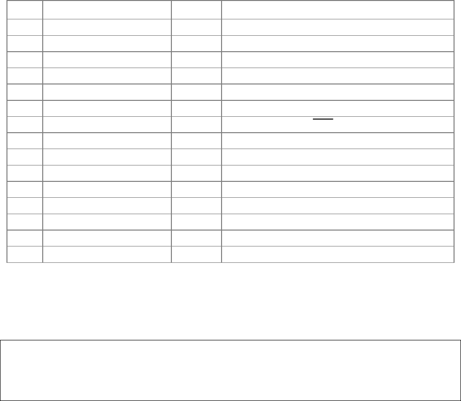
Section 5. Installation
5-12
E.F. Johnson CR1010 Repeater (Alternate Hookup)
For: Zetron Model 38, 38-MAX, 39, 39-MAX, 45B, 48B, 48-MAX
To: E.F. Johnson CR1010, alternate hookup
Using: 709-7112 Generic radio cable
Pin Zetron Signal Name Wire Radio Connection / Signal Name
1 12 volts AC/DC in Red Logic Drawer Pin 15, +13.8V
2 12 volts AC input --- No Connection
3 DC ground Black Logic Drawer Pin 13, Gnd
4 Ground Drain No Connection
5 PTT NC --- No Connection
6 PTT COM (to GND, pin 4) Jumper No Connection
7 PTT NO Orange Logic Drawer Pin 23 PTT
8 Aux relay --- No Connection
9 Sense/alarm --- No Connection
10 COR input Yellow Logic Drawer Pin 19, Fast squelch
11 Tx audio Blue Via 56K resistor Logic Drawer Pin 18, Tx tone CG
12 Ground --- No Connection
13 CTCSS/DCS encode Green Via 15K resistor Logic Drawer Pin 18, Tx tone CG
14 Ground Brown Ground
15 Discriminator in White Logic Drawer Pin 5, CG Audio
CR1010 Configuration:
1. Remove the brown wire from receiver going to the exciter transmit audio (Pin 1).
2. Add a 10K ohm resistor across R123 in the exciter.
NOTE
This configuration does not use the deviation limiter in the exciter. It does provide a higher
quality repeat audio quality than the hookup on the previous page.

Section 5. Installation
5-13
E.F. Johnson Viking Universal Station
For: Zetron Model 38, 38-MAX, 39, 39-MAX, 45B, 48B, 48-MAX
To: E.F. Johnson Viking Universal Station
Using: 709-7112 Generic radio cable
Pin Zetron Signal Name Wire Radio Connection / Signal Name
1 volts AC/DC in Red J2-23, +15_ACC
2 12 volts AC input --- No Connection
3 DC ground Black J2-21, Ground
4 Ground Shield No Connection
5 PTT NC --- No Connection
6 PTT COM (to GND, pin 4) Jumper No Connection
7 PTT NO Orange J2-7, PTT
8 Aux relay --- No Connection
9 Sense/alarm --- No Connection
10 COR input Yellow J2-4, SQUELCH
11 Tx audio Blue J2-5, TX_AUDIO
12 Ground --- No Connection
13 CTCSS/DCS encode Green J2-6, TX_DATA
14 Ground Brown J2-22, Ground
15 Discriminator in White J2-2, WB_DISC
Radio Configuration:
1. The radio requires the Third Party Interface Card.
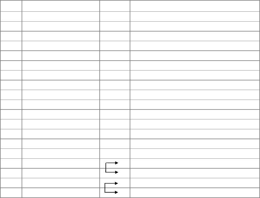
Section 5. Installation
5-14
Kenwood TKR-720 / TKR-820 Repeater
For: Zetron Model 38, 38-MAX, 39, 39-MAX, 45B, 48B, 48-MAX
To: Kenwood TKR-720 / TKR-820 repeater
Using: 709-7112 Generic radio cable
Pin Zetron Signal Name Wire Radio Connection / Signal Name
1 12 volts AC/DC in Red Pin 7 SB
2 12 volts AC input --- No Connection
3 DC ground Black Pin 11 Ground
4 Ground Shield No Connection
5 PTT NC --- No Connection
6 PTT COM (to GND, pin 4) Jumper No Connection
7 PTT NO Orange Pin 8 PTT
8 Aux relay --- No Connection
9 Sense/alarm --- No Connection
10 COR input Yellow Pin 13 CO
11 Tx audio Blue Pin 5 L1
12 Ground --- No Connection
13 CTCSS/DCS encode Green Pin 3 D1
14 Ground Brown Pin 6 SG
15 Discriminator in White Pin 4 DE
PTT enable Pin 1 HK
jumper Pin 2 LG
Speaker enable Pin 9 SI
jumper Pin 12 SO
Radio Modifications:
[Note: These modifications may not apply to all versions of the TKR-radio. Refer to the
Kenwood service manual and schematic diagram.]
1. On the TX/RX Unit board, foil side: Cut the trace leading to CN3-8 (AFO). Add a
jumper wire between CN3-8 and CN6-9 (DET). This corrects a foil error found in older
Kenwood units. Cut the trace between CN7-1 (tone) and R68. This isolates the tone
board injection point when the Zetron device keys the repeater.
2. On the Display Unit board, foil side: Remove J14, and add a jumper wire between CN8-4
(DE) and CN2-6 (DET). This bypasses C22 on the display board for DCS decode
capability.
3. Set the switches for: Takeover = Off / disabled
Repeat = Off / full duplex transceiver
Monitor = DC
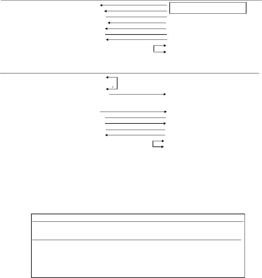
Section 5. Installation
5-15
Motorola GR300 Repeater (or Two GM300 Radios)
For: Zetron Model 38, 39-MAX, 45B, 48B, 48-MAX
To: Motorola GR300 repeater or a pair of GM300 mobiles
Using: 709-7264 Interface Cable
ZETRON END RECEIVE GM300
Function Pin Color Connection / notes
12 volts AC/DC in 1 Red
DC ground 3 Black
Ground 4 Shield AUX Pin 9, Emergency Alert
COR input 10 Yellow AUX Pin 8, CSQ Detect
Discriminator in 15 W hite AUX Pin 11, Disc audio
Ground 12 Brown AUX Pin 7, Ground
Green AUX Pin 14, Alternate CSQ
Speaker enable AUX Pin 15, Internal speaker
jum pe r A U X P in 16 , E xternal speaker
ZETRON END TRANSMIT GM300
Function Pin Color Connection / notes
Ground 4 Jmpr
PTT NC 5 ---
PTT COM 6 Jmpr
PTT NO 7 Orange AUX Pin 3, Microphone PTT
A
ux relay 8 ---
Sense/alarm 9 ---
Tx audio 11 Blue AUX Pin 2, Microphone audio
Ground 4 Shield AUX Pin 9, Emergency Alert
CTCSS/DCS encode 13 Green AUX Pin 5, Flat Tx audio
Ground 14 Brown AUX Pin 7, Ground
W hite AU X P in 8 , C S Q D etect
Speaker enable AUX Pin 15, Internal speaker
jum pe r A U X P in 16 , E xternal speaker
STATION POW ER
SUPPLY
Radio Configuration:
1. Set radio jumpers as follows: JU551 position A, flat/unmuted discriminator audio
JU651 position A, Tx audio gain selection
JU701 position B, flat Tx audio limiter bypass (16ch only)
2. Program both radio accessory connectors (with the RSS) as follows:
ACCESSORY CONNECTOR CONFIG
INT Accessory: None EXT Accessory: General I/O Custom: Y
PIN# DESCRIPTION DATA DIR DEBOUNCE ACT LEVEL
4 NULL 2 Output No High
6 NULL 1 Input No High
8 CSQ Detect Output No Low
9 NULL 1 Input No High
12 NULL 1 Input No High
14 NULL 1 Input No High
3. Install the cable (709-7264) from the 15-pin connector on the controller to the appropriate 16-pin
connectors on the rear of the Radius mobiles. Remove the power cable from the mobile being
used as a receiver. CAUTION! Observe correct polarity (wire colors) while connecting power
cables. Connect the “TO RADIO” plug on the Zetron power cable to the receive radio, and
connect the remaining plug to the station power supply cable.
Section 5. Installation
5-16
Motorola MTR2000 Stations
For: Zetron Model 38, 39-MAX, 45B, 48-MAX, 735, 748
To: Motorola MTR2000 Station
Using: 950-9919 MTR2000 Interface kit
Radio Configuration:
1. On the rear of the MTR2000, remove the screw centered under the SYSTEM J5
connector. Remove the connector strain relief / fuse access plate.
2. Connect the Zetron supplied interface cable to the MTR2000 “J5” backplane connector.
Use caution when installing the cable so as not to damage the equipment with ESD.
☞ Note
The component side of the Zetron interface circuit board should be facing up. If not, the MTR2000 is
an older revision (J5 connector is upside-down) and SHOULD NOT BE USED! Reference Motorola
PSB # 793, December 1996.
3. Re-install the connector strain relief / fuse access plate.
4. Configure the radio using the MTR2000 RSS as follows:
RSS Screen Item Setting
Personality: Station Configuration: Station Options: Base Operation Base Operation, not Repeater
Personality: Station Configuration: Station Options: System Type Conventional
Personality: Channel Information: Option Audio: Analog Audio Activation Carrier, for repeater controllers,
PL/DPL, if required for interconnects
Personality: Channel Information: Option Audio: Aux Tx Audio Control Flat
Personality: Channel Information: Option Audio: Audio Control All OFF, no boxes checked:
Υ De-Emphasis
Υ Pre-Emphasis
Υ Noise Canceller
Υ Compander
Υ Rx Signal Inversion
Υ MRTI
Personality: Channel Information: Option Audio: PTT Priority Local = Low
Personality: Channel Information: Option PTT: External PTT Mapping Aux Audio
Service: Station Alignment: Audio Input/Output: Discriminator Set the slider mid-point
Service: Station Alignment: Transmitter:
Note: for MTR2000 version R3.01.01 and later
Aux Tx Input Set the level control slider to “50”
5. The Interface Adapter provides the following signals to the Model 38 Repeater Panel:
Signal Configuration
Rx Audio Unfiltered discriminator audio, delayed ~ 2.5 ms
Tx Audio Pre-emphasized “microphone” audio, delayed ~ 4.5 ms
PL, DPL, LTR or FSK encode Flat Tx audio input
PTT Active low Push-TO-Talk input
Carrier Detect Input External, active high polarity
Decode Validation Input Active high during PL/DPL decode

Section 5. Installation
5-17
Motorola MSF 5000 Analog Repeater
For: Zetron Model 38, 38-MAX, 39, 39-MAX, 45B, 48B, 48-MAX
To: Motorola MSF 5000 analog (older) repeater
Using: 709-7112 Generic radio cable
Pin Zetron Signal Name Wire Radio Connection / Signal Name
1 12 volts AC/DC in Red J800 Pins 1 and 2, or TB601 (A+) on pwr supply
2 12 volts AC input --- No Connection
3 DC ground Black J800 Pins 7 and 8, or TB601 (GND) on pwr supply
4 Ground Drain No Connection
5 PTT NC --- No Connection
6 PTT COM (to GND, pin 4) Jumper No Connection
7 PTT NO Orange J801 Pin 14
8 Aux relay --- No Connection
9 Sense/alarm --- No Connection
10 COR input Yellow Test Point 6 (0.5v SQ., 2.9v US)
11 Tx audio Blue Via 33KΩ resistor U834 Pin 13 (1vpp=3kHz)
12 Ground --- No Connection
13 CTCSS/DCS encode Green Via 33KΩ resistor, Wiper of R889 IDC pot(3vpp =
750 kHz)
14 Ground Brown No connection
15 Discriminator in White Test Point 3 (3kHz=1vpp)
MSF 5000 Configuration:
1. Make all connections to the Station Control Module PCB.
2. Set “AccDis” switch UP.
Section 5. Installation
5-18
Motorola MSF 5000 Digital Repeater
For: Zetron Model 38, 38-MAX, 39, 39-MAX, 45B, 48B, 48-MAX
To: Motorola MSF 5000 “digital capable” station
Using: 709-7112 Generic radio cable
Pin Zetron Signal Name Wire Radio Connection / Signal Name
1 12 volts AC/DC in Red R8121, side closest to center of PCB
2 12 volts AC input --- No Connection
3 DC ground Black TP2
4 Ground Drain No connection
5 PTT NC --- No Connection
6 PTT COM (to GND, pin 4) Jumper No Connection
7 PTT NO Orange SW800 (pin closest to outer edge of PCB)
8 Aux relay --- No Connection
9 Sense/alarm --- No Connection
10 COR input Yellow U1552, pin 1
11 Tx audio Blue Via 33KΩ resistor U814, pin 2
12 Ground --- No Connection
13 CTCSS/DCS encode Green Via 33KΩ resistor U831, pin 3
14 Ground Brown TP2
15 Discriminator in White Test point 3
MSF 5000 Digital Capable Station Configuration:
1. Drill a cable access hole in the rear of the Station Control Module plastic housing, about
mid point. Install a cable access hole grommet and strain relief.
2. Make all connections to the Station Control Module PCB.
3. Set “AccDis” switch UP.
CAUTION
The front panel SQUELCH control (on the MSF) will set the CARRIER threshold for the
Zetron unit.

Section 5. Installation
5-19
Motorola MCR-100 / RADIUS R-100
For: Zetron Model 38, 38-MAX, 39, 39-MAX, 45B, 48B, 48-MAX
To: Motorola MCR-100 / Radius R-100
Using: 709-7112 Generic radio cable, or 709-7109
Pin Zetron Signal Name Wire Radio Connection / Signal Name
1 12 volts AC/DC in Red JAUX Pin 3, A+
2 12 volts AC input --- No Connection
3 DC ground Black JAUX Pin 14, Desk set ground
4 Ground Drain No Connection
5 PTT NC --- No Connection
6 PTT COM (to GND, pin 4) Jumper No Connection
7 PTT NO Orange JAUX Pin 4, PTT
8 Aux relay --- No Connection
9 Sense/alarm --- No Connection
10 COR input Yellow JAUX Pin 12, Audio Control
11 Tx audio Blue JAUX Pin 5, Audio from phone patch
12 Ground --- No Connection
13 CTCSS/DCS encode Green JAUX Pin 23, uncommitted
14 Ground Brown JAUX Pin 6
15 Discriminator in White JAUX Pin 25, uncommitted
Radio Modifications:
1. Install a jumper from U601 pin 9 on the TX Command Board to JAUX Pin 23. This
routes CTCSS/DCS modulation to the TX Command Board.
2. Install a jumper from U551A pin 4 on the RX Board to JAUX Pin 25. This routes
unfiltered discriminator audio to the JAUX connector. For newer units, use pin 7 of U552
(identified by two 8-pin surface mount ICs soldered in at U552, instead of a single DIP).
3. Program the R-100 for carrier squelch operation and disable repeater operation using the
RPTR Disable Switch on the RPT Control Board.
4. If the R-100 was ordered as either the PL or carrier squelch model, several capacitors
need to be changed in the receiver and transmitter to support DPL operation. See the R-
100 service manual for additional information concerning what capacitor values require
changing.
5. Repeat audio from the Zetron unit will be heard in the local speaker if the transmit audio
is connected to JAUX Pin 5. This is because audio appearing at pin 5 is distributed to
several points in the R-100 Interface Board before being sent to the TX Command Board.
If desired, transmitted voice modulation may be applied directly to the TX Command
Board using the emitter of Q601.
Section 5. Installation
5-20
Motorola MICOR Single User Repeater
For: Zetron Model 38, 38-MAX, 39, 39-MAX, 45B, 48B, 48-MAX
To: Motorola MICOR Single User Repeater
Using: 709-7112 Generic radio cable
Pin Zetron Signal Name Wire Radio Connection / Signal Name
1 12 volts AC/DC in Red Power Supply A+
2 12 volts AC input --- No Connection
3 DC ground Black Power Supply A-
4 Ground Drain No Connection
5 PTT NC --- No Connection
6 PTT COM (to GND, pin 4) Jumper No Connection
7 PTT NO Orange 1N4148 TB3 Pin 14, Repeater PTT on backplane
8 Aux relay --- No Connection
9 Sense/alarm --- No Connection
10 COR input Yellow J2 Pin 5, Rx Unsquelch on backplane
11 Tx audio Blue Station Control Pin 16, on backplane
12 Ground --- No Connection
13 CTCSS/DCS encode Green 10 k
Ω
J5 Pin 27, on backplane
14 Ground Brown No Connection
15 Discriminator in White Squelch Gate Pin 10, on backplane
Radio Modifications:
1. Remove all modules except Station Control and the Squelch Gate card. Remove the PL/DPL
encoder and decoder cards.
2. Modify the control modules as follows:
a) Station Control: Jumper the PL Disable switch ON
b) Squelch Gate: Remove C17, in the exciter output line
3. Modify RX Audio Squelch Board (TRN-6006A); add a jumper from U202 pin 10 to P903 pin 14.
4. Modify the Exciter Board (TLE-1720A); add a jumper from the IDC pot wiper to P902 pin 8, cut
the trace between P902 pin 8 and JU401.
5. Modify the backplane board (TLN-5644A); cut the trace going to J2 pin 5, cut the trace going to
J5 pin 27.
Model 38 Switches: Set switches as shown; DPL Polarity: Encode = invert, Decode = normal
1 2 3 4 5 6 7 8
Section 5. Installation
5-21
Motorola MICOR Community Repeater
For: Zetron Model 38, 38-MAX, 39, 39-MAX, 45B, 48B, 48-MAX
To: Motorola MICOR Community Repeater
Using: 709-7112 Generic radio cable
Pin Zetron Signal Name Wire Radio Connection / Signal Name
1 12 volts AC/DC in Red Power Supply A+
2 12 volts AC input --- No Connection
3 DC ground Black Power Supply A-
4 Ground Drain No Connection
5 PTT NC --- No Connection
6 PTT COM (to GND, pin 4) Jumper No Connection
7 PTT NO Orange 1N4148 TB3 Pin 14, Repeater PTT
8 Aux relay --- No Connection
9 Sense/alarm --- No Connection
10 COR input Yellow J2 Pin 5, Rx Unsquelch
11 Tx audio Blue Station Control Pin 16
12 Ground --- No Connection
13 CTCSS/DCS encode Green 10 k
Ω
J5 Pin 27
14 Ground Brown No Connection
15 Discriminator in White Squelch Gate Pin 10
Radio Modifications:
1. Remove all modules except Station Control and the Squelch Gate card.
2. Modify the control modules as follows:
a) Station Control: Jumper the PL Disable switch ON
b) Squelch Gate: Remove C17, in the exciter output line
[Both of these steps disable installed PL circuits.]
3. Modify RX Audio Squelch Board (TRN-6006A); add a jumper from U202 pin 10 to P903 pin 14.
[Brings out a negative squelch indication, 0 VDC = Unsquelched.]
4. Modify the Exciter Board (TLE-1720A); add a jumper from the IDC pot wiper to P902 pin 8, cut
the trace between P902 pin 8 and JU401. [Provides a path for Tx Audio to a point just before the
Deviation Adjust pot.]
5. Modify the backplane board (TLN-6421A); cut the trace going to J2 pin 5, cut the trace going to
J5 pin 27. [Frees up these two pins to be used by COR and CTCSS/DCS Encode.]
Model 38 Switches: Set switches as shown; DPL Polarity: Encode = invert, Decode = normal
1 2 3 4 5 6 7 8

Section 5. Installation
5-22
Tait T800 Series Repeater
For: Zetron Model 38, 38-MAX, 39, 39-MAX, 45B, 48B
To: Tait T800 Series Repeater
Using: 709-7112 Generic radio cable
Pin Zetron Signal Name Wire Radio Connection / Signal Name
1 12 volts AC/DC in Red +13.8V
2 12 volts AC input --- No Connection
3 DC ground Black TX LINE (ground)
4 Ground Shield No Connection
5 PTT NC --- No Connection
6 PTT COM (to GND, pin 4) Jumper No Connection
7 PTT NO Orange 12 TX KEY
8 Aux relay --- No Connection
9 Sense/alarm --- No Connection
10 COR input Yellow RX GATE
11 Tx audio Blue TX LINE
12 Ground --- No Connection
13 CTCSS/DCS encode Green CTCSS
14 Ground Brown (ground)
15 Discriminator in White RX AUDIO
RX LINE CT (jumper)
RX LINE CT (jumper)
TX LINE CT (jumper)
TX LINE CT (jumper)
Radio Configuration:
1. The wiring to the terminal blocks on the Tait T800 repeaters will vary depending on what
configuration of features and options was ordered. Documentation of this wiring is
supplied along with each repeater, and should be referred to in order to obtain the correct
terminal numbers for each signal.
2. Set the jumpers in the receiver as follows: a) PL101: 1-2. Flat audio.
b) PL105: 1-2 and 4-5.
c) PL106: 1-2.
3. Disable the transmitter timeout timer by removing R257 (near IC202 on bottom of PCB).
4. Default levels: Tx-audio = 0.11vrms = 3 kHz deviation
CTCSS/DCS = 0.32vrms = 700 Hz deviation
COR = +12vdc SQ., 0vdc USQ
Rx-audio = 0.77vrms = 3 kHz deviation, flat 3-3000 Hz. Do not use
with noise detector.

Section 5. Installation
5-23
Tait T300 Series Radio
For: Zetron Model 38, 38-MAX, 39, 39-MAX, 45B, 48B, 48-MAX
To: Tait T300 series base station Direct replacement for Tait T311 panel
Pin Zetron Signal Name Wire Radio Connection / Signal Name
(25 way “D” range female socket)
1 12 volts AC/DC in Red Pin 8, +VE 12V
2 12 volts AC input --- No Connection
3 DC ground Gray Pin 5, GROUND
4 Ground --- No Connection
5 PTT NC --- No Connection
6 PTT COM (to GND, pin 4) Jumper No Connection
7 PTT NO Yellow Pin 10, TX KEY
8 Aux relay --- No Connection
9 Sense/alarm --- No Connection
10 COR input Purple Pin 20, RX GATE (NOTE 2)
11 Tx audio Brown Pin 7, TX AF
12 Ground --- No Connection
13 CTCSS/DCS encode White Pin 2, CTCSS ENCODE
14 Ground ---
15 Discriminator in Blue Pin 6, RX AF
Tait Configuration:
1. Links made on “D” range socket: 1 to 4 = Earth one side Rx 600 ohm
1 to 3 = Earth one side Tx 600 ohm
1 to 5 = Earth
2. Check that the RX GATE lead goes to RX GATE on the Tait Base Station as on some
models this lead may have been left disconnected.

Section 5. Installation
5-24
TONE PANEL PERFORMANCE TEST
Put your repeater to the test! To insure maximum performance of the system, all elements
must be functioning properly. The repeater is much like a chain in that total performance is
only as good as the weakest part. To guard against weak links, the system should be
thoroughly tested including:
• Receive antenna and feedline
• Receiver sensitivity
• Tone panel sensitivity and audio response
• Transmitter power, purity and deviation
• Duplexer or combiner
• Transmitter feedline and antenna
RECEIVER AND TONE PANEL TEST:
1. Set a service monitor to generate a full quieting signal on the repeater receiver frequency.
Verify the “CARRIER” LED is lit when signal is applied to the receiver.
2. Encode a 1kHz audio tone at 3kHz deviation.
3. Encode a valid (enabled) CTCSS tone (67-250Hz) at 600 Hz deviation, verify the
“DECODE” and “TRANSMIT” LEDs are lit.
4. Reduce the RF signal strength into the receiver until the “DECODE” LED goes out, then
increase it until the LED just goes back on. With a SINAD meter connected to the
speaker terminals of the receiver, note the SINAD reading. This number represents the
decode sensitivity of the tone panel. The lower the SINAD reading, the better the tone
panel. For good operation, the tone panel must decode CTCSS at 6dB SINAD or lower.
The Zetron Model 38 should decode CTCSS tones reliably at below 3dB SINAD.
NOTE
The squelch control of the receiver may have to be set “open” during the test to keep the
“Carrier” indication on to the tone panel, and unsquelched audio to the SINAD meter.
5. Measure the RF input (in microvolts) signal strength into the receiver. The lower the
number, the higher the sensitivity. For most UHF receivers, a desirable number is about
0.35 µV for 12-dB SINAD. The squelch adjustment in the receiver should be set for 6 dB
SINAD.
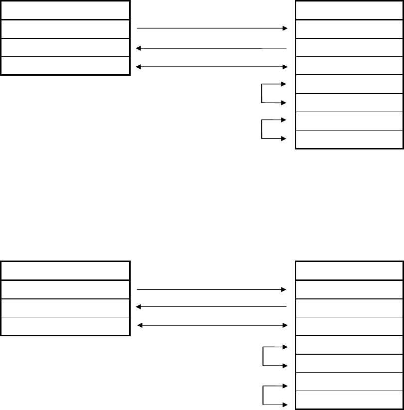
Section 5. Installation
5-25
RS-232 CABLE DIAGRAMS
A cable diagram for connecting a Model 38 to a 9 pin RS-232 port is shown in Table 5-1.
This cable is available from Zetron as part number 709-7144.
Table 5-1. Serial Cable for 9-pin Connector
Model 38 PC with DB9
Pin Function Connections & Signal Direction Pin Signal Name
3 RS-232 Transmit 2 Rx data
4 RS-232 Receive 3 Tx data
5 Ground 5 Ground
Jumper 4 DTR
6 DSR
Jumper 7 RTS
8 CTS
A cable diagram for connecting a Model 38 to a 25 pin RS-232 port is shown in Table 5-2.
This cable is available from Zetron as part number 709-9030 for connection to a PC
(DB25S), or 709-7027 for connection to a terminal (DB25P).
Table 5-2. Serial Cable for 25-pin Connector
Model 38: PC with DB25:
Pin Function Connections & Signal Direction: Pin Signal name
3 RS-232 Transmit 3 Rx data
4 RS-232 Receive 2 Tx data
5 Ground 7 Ground
Jumper 4 DTR
6 DSR
Jumper 7 RTS
8 CTS

Section 5. Installation
5-26
Auto-Answer Modem Settings
When connecting an external modem to a Zetron RS-232 port for remote dial-up
programming or control, the modem must be configured for auto-answer. The modem may
need to be set so as not to send status information to the Zetron equipment, which may cause
interference to the system. For most applications, the commands shown in Table 5-3 may be
used to configure an “AT” command set compatible modem for auto-answer service. The
modem is configured by connecting it to a terminal or PC and sending the following
commands.
Table 5-3. Modem Initialization Commands
Command Description
AT&F Reset to factory defaults
ATSO=1 Answer on first telephone ring
ATE0 Disable command state character echo
ATQ1 Disable result codes
AT&W0 Write settings to stored profile #0
AT&Y0 Select stored profile #0 at power-up
PROGRAMMING THE MODEL 38 VIA FRONT PANEL CONNECTOR
To use the front panel “Program” connector, a DTMF encoder must be provided that can
generate DTMF tones between 0.5 and 2.0 volts peak-to-peak. The connector is a three wire
interface (miniature, stereo type, phone plug) that provides the following signals:
• Signal Ground on the “ring” conductor.
• DTMF audio is sent to the Model 38 on the “sleeve” conductor.
• Model 38 transmit audio is output on the “tip” conductor.
An amplifier may be used on the transmit audio output to hear the prompt tones generated by
the Model 38 during programming.
Note
While the stereo plug is installed in the Program connector, DTMF on the radio channel will
not reach the DTMF decoder in the Model 38.

Section 5. Installation
5-27
INSTALLING A NEW PROM
IMPORTANT NOTE
The EPROM label has the sequence portion of the serial number written on it. This must
match the serial number of the panel it is to be installed in.
The software is contained in an Integrated Circuit (IC) called an Erasable Programmable
Read Only Memory (EPROM). This device is delicate and sensitive to static electricity.
When handling it, be sure to keep your fingers in contact with the chassis sheet metal to keep
yourself grounded. Only remove the IC from the static protective shipping material when
ready for installation. To install the new EPROM IC, do the following:
1. Turn off the power.
2. Remove the cover.
3. Remove the old EPROM from the board.
4. Look at the old EPROM carefully. There is an orientation notch on the end.
5. Install the new EPROM(s) in the socket with the orientation notches aligned with the
notches in the socket.
6. Now take some time to look carefully at all of the pins of the chip. Make sure that the
pins are aligned in the socket and are fully inserted, not bent out, and not bent under. If
the unit is powered on without proper EPROM connection, the programmable settings
(database) may be cleared.
7. If using Digital Coded Squelch (DCS) decode, on older units circuit board 702-9075
revision E to H put JP4 in position “B”, or for “J” and later units - put JP3 in position
“B”. If this jumper is not moved to the “B” position, digital squelch decode will exhibit
poor sensitivity.
8. Read any attached rework instructions for your hardware version.
9. Replace the cover and turn on the power and make sure that the display indicates normal.
6-1
6. REPAIR
IN CASE OF DIFFICULTY
In case of installation difficulty, call Zetron Model 38 Applications Engineering Department
at (425) 820-6363. Engineers are available. Please have the serial number of the unit and/or
the Zetron Order number. If the call is made from the installation site by the installer or radio
technician, the problem can usually be solved over the phone. If a problem develops after a
unit has been in service for some time, call the Zetron Model 38 Service Department. If the
call is made from the installation site by a radio tech, the problem can often be solved over
the phone.
SERVICE NOTES
1. If a 400 Hz. beep is heard just prior to the transmitter being unkeyed, the Model 38 is
reporting a memory problem. Use the “Diagnostic Commands” (Programming Section)
to find the source of the problem.
2. When the unit is reset or powered on, automatic self test functions are performed. If a
large number of errors exist in the User programmable database, it will reset all settings
to the factory defaults.
3. If the unit fails to operate (possibly due to a lightning strike to the radio tower), a DTMF
key may be held for greater than 15 seconds to perform a complete reset of the unit.
4. If the audio does not sound proper, perform an audio sweep test by generating an audio
signal on the RF input of the repeater (of known deviation), and monitor the repeater
output deviation. The deviation should be flat from 300 to 3000 Hz.
5. When using the internal noise detector for COR, if the COR polarity switch seems
backwards, the audio input from the receiver does not have enough high frequency
content for the noise detector to operate. It is usually caused by a capacitor or some low
pass filtering of the actual discriminator signal. An alternate connection point must be
found in the receiver for either audio, or a receiver generated COR signal must be
connected.
6. The “Carrier” LED MUST follow carrier activity on the channel. If it is always off, the
Model 38 will not detect CTCSS tones or DCS codes. If it is always on, the unit may
false DCS decode.
7. If DCS decode seems sluggish or exhibits poor sensitivity, verify jumper JP4 (circuit
board revisions E through H) or JP3 (revision J or later) is in the “B” position.
8. When power is applied to the unit it will perform a self test. The Decode LED will flash
20 times if any memory errors are detected in the firmware or database segments of the
unit. It will also flash the Decode LED twice to indicate a 38 CTCSS tone version, or 5
flashes for 50 tone units.
Section 6. Repair
6-2
MODEL 38 REPEATER PANEL PARTS LIST (702-9075)
ZETRON MODEL 38 REPEATER TONE PANEL PARTS LIST (702-9075S)
ITEM QTY ZETRON P/N DESCRIPTION COMPONENT REF. MFG.PART NO.
---- ------ ----------- ------------------- ------------------------- --------------
1. 1 101-0010 1 R7
2. 3 101-0047 47 R21 30 31
3. 1 101-0061 330 R93
4. 3 101-0066 510 R22 23 55
5. 2 101-0068 620 R25 59
6. 6 101-0071 820 R8 89-92 94
7. 2 101-0073 1K R24 36
8. 1 101-0074 1.2K R58
9. 2 101-0081 2.2K R46 48
10. 2 101-0085 3.3K R33 77
11. 11 101-0089 4.7K R2 9 29 40 41 50 51 57 64-66
12. 2 101-0091 5.6K R53 78
13. 15 101-0097 10K R4 5 10 16 17 20 26 27 35 37
42 43 47 61 63
14. 1 101-0101 15K R39
15. 3 101-0103 18K R18 85 100
16. 7 101-0105 22K R49 80 81 86 97 98 99
17. 1 101-0107 27K R60
18. 5 101-0113 47K R32 52 56 84 95
19. 3 101-0115 56K R19 44 45
20. 1 101-0117 68K R87
21. 6 101-0121 100K R38 62 69 76 82 88
22. 1 101-0123 120K R83
23. 5 101-0145 1M R3 6 67 68 79
24. 1 105-0001 VARISTOR 250V AC RV1
25. 1 107-0005 5K POT 1T RA R14
26. 3 107-0015 50K POT 1T RA R11-13
27. 1 119-0008 10Kx7 R-SIP RP1
28. 2 150-0024 24pf/D C50 51
29. 1 151-0047 470pf/TS C16
30. 1 151-0120 .01/TS C44
31. 1 151-0100 .033/TS C23
32. 2 151-0199 .47/50V/P C5 22
33. 10 152-0012 .1/50V/P C18 26 35-37 56 57 59 64 70
34. 2 152-0040 4.7/50V/P C17 19
35. 19 152-0085 .01/50V/P C7 9 12 25 32 40 43 45-47 49
52 53 61 63 65 66 68 69
36. 11 152-0089 .001/50V/P C21 27-29 33 34 38 39 48 60 62
37. 3 152-0250 .047/50V/P C30 41 42
38. 1 154-0025 1/35V/T C20
39. 3 154-0100 10/16V/T C10 54 58
40. 8 155-0052 10/35V/A C1 C2 NOTE 1 C3 C4 11 13 15 24
41. 3 155-0080 100/25V/A C14 31 71
42. 1 155-0140 3300/25V/A C67
43. 1 210-0001 #4 NUT XVR1
44. 1 220-0103 440x1/2" XVR1
44.5 1 236-0005 CRYSTAL INSULATOR XY1
45. 5 305-0001 FERRITE W/LEADS E1-5
46. 5 311-0011 LED RED FLUSH DS1-5
47. 1 311-0012 LED GREEN FLUSH DS6
48. 1 316-0004 TONE FILTER U6 MF4CN-50
49. 1 316-1232 RS232 DRIVER U1 RS232
Section 6. Repair
6-3
MODEL 38 REPEATER PANEL PARTS LIST (702-9075, Continued)
ITEM QTY ZETRON P/N DESCRIPTION COMPONENT REF. MFG.PART NO.
---- ------ ----------- ------------------- ------------------------- --------------
50. 2 316-0353 OP-AMP,DUAL BIFFET U7 9 LF353
51. 5 316-0358 OP-AMP, DUAL U10 11 21-23 LM358N
52. 1 316-7805 REG. +5V 1.5A VR1 LM340T-5
53. 1 316-7808 REG. +8V VR2 LM78L08CZ
54. 1 321-2090 DTMF XCVR U5 20C90
55. 1 321-6264 8Kx8 RAM U15 HM6264 LP-15
56. 1 321-6804 MICROPROCESSOR U12 MC6803P
57. 1 321-6840 PTM U17 MC6840
58. 1 323-4053 3PDT SWITCH U8 MC144053
59. 1 324-4139 DUAL 2-4 DECODER U4 74HC139
60. 1 324-7400 QUAD NAND U2 74HC00
61. 1 324-7414 HEX SCHMIDT U3 74HC14
62. 1 325-4373 OCTAL LATCH U13 74HCT373
63. 1 340-2003 RELAY DRIVER U19 ULN2003
64. 4 340-3904 NPN-4OV/200MA Q2 3 4 5 2N3904
65. 4 342-0001 SILICON 1A 100V CR9-12 1N4002
66. 7 342-3009 SILICON CR3 4 7 8 16 1N4148
67. 2 343-3017 1/2W, 6.2V CR1 15 1N5234B
68. 1 371-0008 SW OCTAL DIP SW1
69. 1 376-4032 4.032MHz XTAL Y2
70. 1 376-0358 3.58 MHZ XTAL Y1
71. 1 380-0030 RELAY DPDT K2
72. 1 381-0010 HEATSINK XVR1
73. 1 401-0664 CONN,D-SUB,9-PIN RA J5 NOTE 3
74. 1 401-0034 3 CON STEREO JACK J6
75. 3 401-0052 STAKE PINS JP3 (3 EA)
76. 1 401-0059 15 POS R/A HEADER TB1
77. 1 402-3040 MINI JUMPER JP3 (POS B)
78. 8 407-0008 SKT, 8 PIN DIP U6 7 9-11 21-23
79. 2 407-0014 SKT, 14 PIN DIP U2 3
80. 4 407-0016 SKT, 16 PIN DIP U1 4 8 19
81. 1 407-0020 SKT, 20 PIN DIP U13
82. 1 407-0022 SKT, 22 PIN DIP U5
83. 4 407-0028 SKT, 28 PIN DIP U14 15 16 17
84. 1 407-0040 SKT, 40 PIN DIP U12
85. 1 408-0001 WIRE JUMPER JP6A
86. 1 410-9075F.2 PCB
87. 1 416-1214 SMART SOCKET U15
88. 2 416-1576 FUSE 1A AGC F1 2
89. 4 416-3040 FUSE CLIP XF1 2
90. 6 417-0010 LED R/A XDS1-6
91. 1 561-0001 THERMAL COMPOUND XVR1
NOT INSTALLED:
C6 8 55
CR2 5 6
J1-4
JP2 4 5 7
K1
Q1
R1 15 28 34 54 70-75 96
U14 16 18 20
NOTES: (Notes are for production use only.)
Section 6. Repair
6-4
(THIS PAGE INTENTIONALLY LEFT BLANK)
Section 6. Repair
6-5
MODEL 38 REPEATER PANEL ASSEMBLY DIAGRAM
Section 6. Repair
6-6
MODEL 38 REPEATER PANEL SCHEMATIC (008-9075)
Section 6. Repair
6-7
MODEL 38 REPEATER PANEL SCHEMATIC (008-9075, Continued)
Section 6. Repair
6-8
MODEL 38 REPEATER PANEL SCHEMATIC (008-9075, Continued)
Section 6. Repair
6-9
MODEL 38 REPEATER PANEL SCHEMATIC (008-9075, Continued)
Section 6. Repair
6-10
MODEL 38 REPEATER PANEL SILKSCREEN (702-9075)
7-1
7. QUICK REFERENCE
The following section includes a log to keep track of the settings installed in the unit. A
complete list of the programming commands is also included.
DTMF REMOTE PROGRAMMING MODE NOTES
1. Numbers may be entered with or without leading zeros.
2. All commands are ended with the “#” key (except the site alarm DTMF code).
3. The “*” key may be used as a Clear Entry key.
4. Where the variable “uu” is used, user numbers are to be entered. To program all users in
a single operation, the number “99” should be entered.
5. The remote program mode will automatically terminate if no keys are pressed within 90
seconds.
6. The default DTMF program mode access code is 12123#.

Section 7. Quick Reference
7-2
MODEL 38 SYSTEM PROGRAMMING LOG
SYSTEM FUNCTIONS Command Default Range Comments LOG
Carrier repeat enable / user
number
267# nn# 0 0 - 68 0=disable carrier repeat
Anti-Kerchunker filter, qualifies
txhold
5371# nn# 0 0 - 50 0.1 second increment
Station ID interval timer 436# nn# 15 1 - 99 Minutes
Station ID tone frequency 433#
nnnn#
1200 400 -
2000
Hz
Station ID speed in words per
minute
976# nn# 22 4 - 25 Minimum 15 wpm during
operation
Station ID system user number 437# nn# 0 0 - 68 0=disable, user number
Station ID periodic mode on/off 430# -
431#
0 0 - 1 0=disable, 1=enable
Courtesy tone frequency 23373#
nnnn#
1000 400 -
4000
Hz
Tailbip, courtesy beeps during tx-
hold
8920# -
8921#
Off 0 - 1 0=disable, 1=enable
Hog mode idle reset time 4648# nn# 5 1 - 99 Seconds
Hog mode penalty timer 4678# nn# 30 1 - 999 10 second increments (10-
9990 sec)
Stuck mic timeout timer 868# n# 3 0 - 9 Minutes, 0=disable
Timeout ID of stuck mic via
DTMF
8640# -
8641#
0 0 - 1 0=disabled, 1=enabled
Site alarm DTMF encode 25276#
nnn...
blank Up to 8 DTMF digits, 0-9
ABCD*#
Site alarm CTCSS/DCS encode 258#
nnnn#
0 0 -
1777
0=none, 1-50=CTCSS
1nnn=DCS
Site alarm sent when powers is
applied
250# -
251#
0 0 - 1 0=Off, 1=On
Site alarm sent at program mode
access
254# -
255#
Off Off - On 0=disable, 1=enable
Remote PTT encode (site alarm
input)
7788#
nnnn#
0 0 -
1777
0=disabled, 1-50=CTCSS
1nnn=DCS
DCS encode data polarity 3750# -
3751#
Off 0 - 1 0=normal, 1=invert
DCS decode data polarity 3758# -
3759#
Off 0 - 1 0=normal, 1=invert
Program mode access code 7764#
nnnnn#
12123 0 -
32000
DTMF / CRT access code
Program mode DTMF access
delay
7463# nn# 0 0 - 30 Seconds of delay before
confirmation
Program mode progress tone
delay
642# n# 0 0 - 3 Seconds, delays response
prompts

Section 7. Quick Reference
7-3
SYSTEM FUNCTIONS Command Default Range Comments LOG
DTMF repeater programmer unit
type
7360# -
7363#
0 0 - 3 0=Morse, 1=Model 8,
2=RDU, 3=DI-16
DTMF interdigit timeout 386# n# 4 1 - 9 Seconds
RS-232 port mode CRT=680#
M8=681#
0 0 - 2 0=CRT, 1=Modem, 2=Model
8
RS-232 port CRT / Modem baud
rate
2283# n# 2 1 - 6 1=150 2=300 3=600
4=1200 5=2400 6=4800
RS-232 port CRT mode sign on
message
n/a blank Characters (site name or
freq)
RS-232 port serial tone output 7720# -
7721#
Off Off - On Decoder output via rs232
Airtime accumulation including
txhold
281# 9 Default setting
Airtime accumulation excluding
txhold
280#
DCS bit errors, maximum for
access
3273# n# 2 1 - 4 For acquire only
Voted CTCSS acquire, slower
decode
2870# -
2871#
0 0 - 1 0=fastest decode, 1=slower
CTCSS delay after decode drops 3755#
nnn#
70 1 - 150 Milliseconds, prevents
acquire on STE
CTCSS hold time [should always
be 0]
4653# nn# 0 0 - 25 0.1 second increment (0-2.5
sec)
Reverse channel working access
code
9801#
nnnn#
9801 100 -
9997
DTMF code

Section 7. Quick Reference
7-4
MODEL 38 CTCSS USER DATABASE PROGRAMMING LOG
38
Tone
50
Tone
Decode
Encode
O
SPRL
Q
DAX
Hog
Limit
Tx-hold
Station ID
1 1 67.0
2 69.4
2 3 71.9
3 4 74.4
4 5 77.0
5 6 79.7
6 7 82.5
7 8 85.4
8 9 88.5
9 10 91.5
10 11 94.8
11 12 97.4
12 13 100.0
13 14 103.5
14 15 107.2
15 16 110.9
16 17 114.8
17 18 118.8
18 19 123.0
19 20 127.3
20 21 131.8
21 22 136.5
22 23 141.3
23 24 146.2
24 25 151.4
25 26 156.7
27 159.8
26 28 162.2
29 165.5
27 30 167.9
31 171.3
28 32 173.8
33 177.3
29 34 179.9
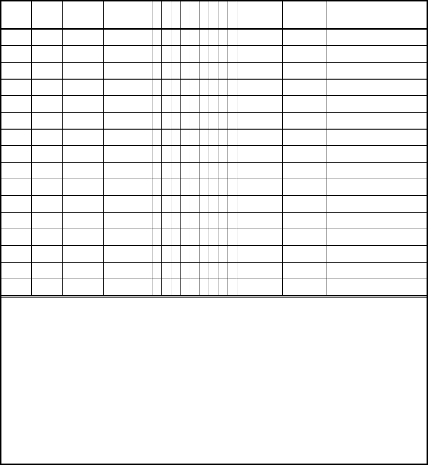
Section 7. Quick Reference
7-5
38
Tone
50
Tone
Decode
Encode
O
SPRL
Q
DAX
Hog
Limit
Tx-hold
Station ID
35 183.5
30 36 186.2
37 189.9
31 38 192.8
39 196.6
40 199.5
32 41 203.5
42 206.5
33 43 210.7
34 44 218.1
35 45 225.7
46 229.1
36 47 233.6
37 48 241.8
38 49 250.3
50 254.1
O
========= User On / Off, enable / disable user decode
S======== Send CTCSS/DCS during transmit hold time
P======= Privacy mode (no new user decode during
txhold)
R====== Reserved user mode
L===== Last user DTMF ID sent when users unkey
Q
==== Queuing beep (courtesy tone) enable
D= = = DTMF functions enable (temporary cross
tone)
A== Prepaid Airtime mode
X
= AuX relay enable

Section 7. Quick Reference
7-6
MODEL 38 DCS USER DATABASE PROGRAMMING LOG
38
Tone
50
Tone
DCS
Decode
Encode
O
S P R L
Q
DAX
Hog
Limit
Tx-hold
Station ID
39 51
40 52
41 53
42 54
43 55
44 56
45 57
46 58
47 59
48 60
49 61
50 62
51 63
52 64
53 65
54 66
55 67
56 68
57
58
59
60
O
= ======== User On / Off, enable / disable user decode
S ======== Send CTCSS/DCS during transmit hold time
P======= Privacy mode (no new user decode during
txhold)
R====== Reserved user mode
L===== Last user DTMF ID sent when users unkey
Q
==== Queuing beep (courtesy tone) enable
D= = = DTMF functions enable (temporary cross
tone)
A== Prepaid Airtime mode
X
= AuX relay enable

Section 7. Quick Reference
7-7
MODEL 38 PROGRAM MODE COMMAND SUMMARY
GENERAL FUNCTIONS DTMF command Default Range Comments Model 8 prompt
PTT off during DTMF program mode 7880# Unit will key PTT during prompt tones n/a
PTT on during DTMF program mode 7881# 9 n/a
Repeater disable (knock down) 7633# To re-enable, access/exit prog mode n/a
Exit the DTMF remote program mode 293# Return to operational mode 99 donE
SYSTEM FUNCTIONS DTMF command Default Range Comments Model 8 prompt
Carrier repeat enable / user number 267# nn# 0 0 - 68 0=disable carrier repeat 27 cor-r=
Anti-Kerchunker filter, qualifies txhold 5371# nn# 0 0 - 50 0.1 second increment 24 Chunk=
Station ID interval timer 436# nn# 15 1 - 99 Minutes 10 Id-int=
Station ID tone frequency 433# nnnn# 1200 400 - 2000 Hz 9 Id-F=
Station ID speed in words per minute 976# nn# 22 4 - 25 Minimum 15 wpm during operation 22 Id-SP=
Station ID system user number 437# nn# 0 0 - 68 0=disable, user number 26 Id-S=
Station ID periodic mode on/off 430# - 431# 0 0 - 1 0=disable, 1=enable n/a
Courtesy tone frequency 23373# nnnn# 1000 400 - 4000 Hz 8 BEEP-F=
Tailbip, courtesy beeps during tx-hold 8920# - 8921# Off 0 - 1 0=disable, 1=enable 23 t-bip=
Hog mode idle reset time 4648# nn# 5 1 - 99 Seconds 4 HOG-I=
Hog mode penalty timer 4678# nn# 30 1 - 999 10 second increments (10-9990 sec) 6 HOG-P=
Stuck mic timeout timer 868# n# 3 0 - 9 Minutes, 0=disable 2 tot=
Timeout ID of stuck mic via DTMF 8640# - 8641# 0 0 - 1 0=disabled, 1=enabled 17 TO-Id=
Site alarm DTMF encode 25276# nnn... blank Up to 8 DTMF digits, 0-9 ABCD*# 11 S-codE=
Site alarm CTCSS/DCS encode 258# nnnn# 0 0 - 1777 0=none, 1-50=CTCSS 1nnn=DCS 12 S-tonE=
Site alarm sent when powers is applied 250# - 251# 0 0 - 1 0=Off, 1=On 13 S-Pron=
Site alarm sent at program mode access 254# - 255# Off Off - On 0=disable, 1=enable n/a
Remote PTT encode (site alarm input) 7788# nnnn# 0 0 - 1777 0=disabled, 1-50=CTCSS 1nnn=DCS 29 r-Ptt=
DCS encode data polarity 3750# - 3751# Off 0 - 1 0=normal, 1=invert 20 d-inv=
DCS decode data polarity 3758# - 3759# Off 0 - 1 0=normal, 1=invert 21 r=inv=
Program mode access code 7764# nnnnn# 12123 0 - 32000 DTMF / CRT access code 18 A-code=
Program mode DTMF access delay 7463# nn# 0 0 - 30 Seconds of delay before confirmation n/a
Program mode progress tone delay 642# n# 0 0 - 3 Seconds, delays response prompts n/a
DTMF repeater programmer unit type 7360# - 7363# 0 0 - 3 0=Morse 1=Model 8, 2=RDU 3=DI-16 n/a
DTMF interdigit timeout 386# n# 4 1 - 9 Seconds 7 Dt-to=
RS-232 port mode CRT=680#
M8=681#
0 0 - 2 0=CRT, 1=Modem, 2=Model 8 19 rS232=
RS-232 port CRT / Modem baud rate 2283# n# 2 1 - 6 1=150 2=300 3=600 4=1200 5=2400 6=4800 25 Baud=
RS-232 port CRT mode sign on message n/a blank Characters (site name or freq) n/a
RS-232 port serial tone output 7720# - 7721# Off Off - On Decoder output via rs232 n/a
Airtime accumulation including txhold 281# 9 Default setting n/a
Airtime accumulation excluding txhold 280# 28 d-bill=
DCS bit errors, maximum for access 3273# n# 2 1 - 4 For acquire only n/a
Voted CTCSS acquire, slower decode 2870# - 2871# 0 0 - 1 0=fastest decode, 1=slower n/a
CTCSS delay after decode drops 3755# nnn# 70 1 - 150 Milliseconds, prevents acquire on STE n/a
CTCSS hold time [should always be 0] 4653# nn# 0 0 - 25 0.1 second increment (0-2.5 sec) 3 C-hold
Reverse channel working access code 9801# nnnn# 9801 100 - 9997 DTMF code n/a
LIST and AIRTIME FUNCTIONS DTMF command Default Range Comments Model 8 prompt
List number of enabled users 568# Sends result to repeater programmer 14 TONES=
List the enabled user numbers 528# 15 TONES=
List all airtime counts 522# n/a
Clear all airtime counts 8463# 25327# 16, 12345 CLEAr
USER FUNCTIONS DTMF command Default Range Comments Model 8 prompt
Enable user number “nn” 66# nn# Off Off - On Repeater keys for enabled users 30nn Enable=
Disable user number “nn” 633# nn# 9 Repeater ignores disabled users 30nn Enable=
Set user nn’s DCS decode number 3753# nn# xxx# 0 0 - 777 Any octal DCS code 000-777 41nn Decode=
Set user nn’s CTCSS/DCS encode to xxxx 89# nn# xxxx# 0 - 1777 0=Carrier, 1-50=CTCSS, 1xxx=DCS 31nn EncodE=
Transmit hold time 8245# uu# nn# 20 0 - 250 0 to 25.0 seconds 43nn T-hold=
CTCSS/DCS during tx-hold disable
CTCSS/DCS during tx-hold enable
890# uu#
891# uu#
9 Encode CTCSS/DCS during tx-hold 32nn tAIL=
Privacy mode, anti barge-in disable
Privacy mode, anti-barge-in enable
760# uu#
761# uu#
9 Prevents other groups from barging in during
transmit hold time.
33nn Priv=
Reserved user mode disable
Reserved user mode enable
780# uu#
781# uu#
9 Keys with CTCSS/DCS, but doesn’t pass
audio, for reserve or no-pay.
34nn Res=
Courtesy tone disabled
Courtesy tone sent when user unkeys
220# uu#
221# uu#
9 Send a courtesy beep when each radio user
unkeys.
35nn CUE=
Last user ID via DTMF disabled
Last user ID via DTMF enabled
540# uu#
541# uu#
9 Send the user number via fast DTMF when
each user unkeys.
36nn LU-id=
Hog mode conversation limit time. 4658# uu# nnn# 0 0 - 250 0=Disabled, 1-250 = .1 - 25.0 min 37nn HOG-L=
DTMF user functions disabled
DTMF user functions enabled
360# uu#
361# uu#
9 Subscriber DTMF functions such as temp
cross tone, DTMF regenerate...
38nn Dt=
Station ID call sign 43# uu# xx# xx#... blank 8 char Enter characters from table n/a
Playback station ID 743# uu# - Playback a station ID n/a
Prepaid airtime mode disable
Prepaid airtime mode enable
770# uu#
771# uu#
9 Prepaid airtime counts down, when 0
reserves the user.
40nn PrePay=
Display & set user airtime see other cmds - 0 - 249.59.5 Model 8 shows airtime in HH:MM:S format
(10 sec increment)
39nn Air=
Clear a users airtime count 25327# nn# - - Resets airtime count to zero 39nn
Add “hhh” hours to user “nn” airtime count 247# nn# hhh# - 0 - 249 Adds airtime for prepay mode 39nn
List airtime hours 547# nn# - 39nn
List hours:minutes 546# nn# - 39nn
List minutes:seconds 567# nn# - 39nn
Auxiliary relay disable
Auxiliary relay enable
290# uu#
291# uu#
9 Aux relay will follow user “uu” CTCSS/DCS
decode
42nn relay=
DIAGNOSTIC FUNCTIONS DTMF command Default Range Comments Model 8 prompt
List number of program mode accesses 5764# Data sent to repeater programmer 70 P-Cnt=
List number of resets and brownouts 5778# Formatted as Morse code / DTMF 71 R-Cnt=
List number of power fails 5797# 72 PF-Cnt=
List system error number (memory test) 5377# 73 SySErr=
List number of users with suspect data 5637# 74 t-Err=
List the user numbers with suspect data 5837# 75 tn-Err=
Clear reset, power fail & access counters 797# Model 8 password = 12345 76 C-SyS=
Reset to factory defaults 3282# 25327# Model 8 password = 25327 77 ErASE
Site alarm test 252# 60 Site-A=
Repeat audio on/off 7780# - 7781# **61 rEPEAT
Encode a DTMF digit 3863# nn# 0 - 15, 99 0-15, 99=off **62 Dt=
Encode CTCSS/DCS 28277# nnnn# 0 - 1777 0=Carrier, 1-50=CTCSS, 1nnn=DCS 63 SQ=
Encode audio frequency 8663# nnnn# 400 - 4000 400-4000, 0=off **64 BEEP=
Encode sub-tone 7823# nnn.n# 500 - 3000 50.0-300.0 65 Ct-F=
CTCSS sweep 8378# Test ends with a DTMF digit 66 C-Test
Display CTCSS/DCS decode ** Model 8 direct connect mode only. **80 [ 100.0 ]
Display rx/tx user number ** Model 8 direct connect mode only. **81 [r12.t12]
Display user / airtime ** Model 8 direct connect mode only. **82 [hhh.mm.s]
Section 7. Quick Reference
7-8
WARRANTY
Zetron’s warranty is published in the current Zetron United States Price Book.
LIMITATION OF LIABILITY
Zetron makes no representation with respect to the contents of this document and/or the
contents, performance, and function of any accompanying software and specifically
disclaims any warranties, expressed or implied, as to merchantability, fitness for purpose
sold, description, or quality.
Further, Zetron reserves the right to revise this document or the accompanying software and
to make changes in it from time to time without obligation to notify any person or
organization of such revisions or changes.
This document and any accompanying software are provided “as is.” Zetron shall not under
any circumstances be responsible for any indirect, special, incidental, or consequential
damages or losses to the buyer or any third party arising out of or connected with the buyer’s
purchase and use of Zetron’s products or services.
COPYRIGHT
This publication is protected by copyright by Zetron, Inc. and all rights are reserved
worldwide. This publication may not, in whole or in part, be copied, photocopied,
reproduced, translated, or reduced to any electronic medium or machine-readable form
without prior written consent from Zetron, Inc.
The software in this product is protected by copyright by Zetron, Inc. and remains the
property of Zetron, Inc. Reproduction, duplication, or disclosure is not permitted without
prior written consent of Zetron, Inc.
TRADEMARKS
Zetron is a registered trademark of Zetron, Inc.
All other product names in this document are trademarks or registered trademarks of their
respective owners.
FEDERAL COMMUNICATIONS COMMISSION (FCC) REGULATIONS
This equipment has been tested and found to comply with the limits for a Class A digital
device, pursuant to Part 15 of the FCC Rules. These limits are designed to provide
reasonable protection against harmful interference when the equipment is operated in a
commercial environment. This equipment generates, uses, and can radiate radio frequency
energy and, if not installed and used in accordance with the instruction manual, may cause
harmful interference to radio communications. Operation of this equipment in a residential
area is likely to cause harmful interference in which case the user will be required to correct
the interference at his or her own expense.
Changes or modifications not expressly approved by the manager of Zetron’s compliance
department can void the FCC authorization to operate this equipment.
Repair work on this device must be done by Zetron, Inc. or a Zetron authorized repair
station.
CANADIAN EMC COMPLIANCE NOTICE
This Class A digital apparatus meets all requirements of the Canadian Interference-Causing
Equipment Regulations.
AVIS CANADIEN
Cet appareil numérique de la classe A respecte toutes les exigences du Règlement sur le
matériel brouilleur du Canada.
CHANGE INFORMATION
A
t Zetron, we continually strive to improve ou
r
products by updating hardware components and
software as soon as they are developed and tested.
Due to printing and shipping requirements, this
manual may include information about the latest
changes on the following pages.
702-9075S
#/3
ZETRON INC ASSEMBLY PARTS LIST:
702-9075
MODEL 38
REPEATER
TONE PANEL
DATE REV DESCRIPTION DN CK APD
-------- --- ------------ -- -- ---
06-03-90 M ECN 948 KN
10-04-90 M.1 ECN 1158 GN
11-15-90 N ECN 1239 KN
02-24-92 P HCN 1789 DW
08-24-93 Q HCN 2233 AH
09-13-95 Q.4 REDLINES GH WW
10-17-96 R ECN 3880 GH SR
01-13-98 S ECN 4811 BW
ZETRON MODEL 38 REPEATER TONE PANEL PARTS LIST (702-9075S)
ITEM QTY ZETRON P/N DESCRIPTION COMPONENT REF. MFG.PART NO.
---- ------ ----------- ------------------- ------------------------- --------------
1. 1 101-0010 1 R7
2. 3 101-0047 47 R21 30 31
3. 1 101-0061 330 R93
4. 3 101-0066 510 R22 23 55
5. 2 101-0068 620 R25 59
6. 6 101-0071 820 R8 89-92 94
7. 2 101-0073 1K R24 36
8. 1 101-0074 1.2K R58
9. 2 101-0081 2.2K R46 48
10. 2 101-0085 3.3K R33 77
11. 11 101-0089 4.7K R2 9 29 40 41 50 51 57 64-66
12. 2 101-0091 5.6K R53 78
13. 15 101-0097 10K R4 5 10 16 17 20 26 27 35 37
42 43 47 61 63
14. 1 101-0101 15K R39
15. 3 101-0103 18K R18 85 100
16. 7 101-0105 22K R49 80 81 86 97 98 99
17. 1 101-0107 27K R60
18. 5 101-0113 47K R32 52 56 84 95
19. 3 101-0115 56K R19 44 45
20. 1 101-0117 68K R87
21. 6 101-0121 100K R38 62 69 76 82 88
22. 1 101-0123 120K R83
23. 5 101-0145 1M R3 6 67 68 79
24. 1 105-0001 VARISTOR 250V AC RV1
25. 1 107-0005 5K POT 1T RA R14
26. 3 107-0015 50K POT 1T RA R11-13
27. 1 119-0008 10Kx7 R-SIP RP1
28. 2 150-0024 24pf/D C50 51
29. 1 151-0047 470pf/TS C16
30. 1 151-0120 .01/TS C44
31. 1 151-0100 .033/TS C23
702-9075S
#/3
32. 2 151-0199 .47/50V/P C5 22
33. 10 152-0012 .1/50V/P C18 26 35-37 56 57 59 64 70
34. 2 152-0040 4.7/50V/P C17 19
35. 19 152-0085 .01/50V/P C7 9 12 25 32 40 43 45-47 49
52 53 61 63 65 66 68 69
36. 11 152-0089 .001/50V/P C21 27-29 33 34 38 39 48 60 62
37. 3 152-0250 .047/50V/P C30 41 42
38. 1 154-0025 1/35V/T C20
39. 3 154-0100 10/16V/T C10 54 58
40. 8 155-0052 10/35V/A C1 C2 NOTE 1 C3 C4 11 13 15 24
41. 3 155-0080 100/25V/A C14 31 71
42. 1 155-0140 3300/25V/A C67
43. 1 210-0001 #4 NUT XVR1
44. 1 220-0103 440x1/2" XVR1
44.5 1 236-0005 CRYSTAL INSULATOR XY1
45. 5 305-0001 FERRITE W/LEADS E1-5
46. 5 311-0011 LED RED FLUSH DS1-5
47. 1 311-0012 LED GREEN FLUSH DS6
48. 1 316-0004 TONE FILTER U6 MF4CN-50
49. 1 316-1232 RS232 DRIVER U1 RS232
50. 2 316-0353 OP-AMP,DUAL BIFFET U7 9 LF353
51. 5 316-0358 OP-AMP, DUAL U10 11 21-23 LM358N
52. 1 316-7805 REG. +5V 1.5A VR1 LM340T-5
53. 1 316-7808 REG. +8V VR2 LM78L08CZ
54. 1 321-2090 DTMF XCVR U5 20C90
55. 1 321-6264 8Kx8 RAM U15 HM6264 LP-15
56. 1 321-6804 MICROPROCESSOR U12 MC6803P
57. 1 321-6840 PTM U17 MC6840
58. 1 323-4053 3PDT SWITCH U8 MC144053
59. 1 324-4139 DUAL 2-4 DECODER U4 74HC139
60. 1 324-7400 QUAD NAND U2 74HC00
61. 1 324-7414 HEX SCHMIDT U3 74HC14
62. 1 325-4373 OCTAL LATCH U13 74HCT373
63. 1 340-2003 RELAY DRIVER U19 ULN2003
64. 4 340-3904 NPN-4OV/200MA Q2 3 4 5 2N3904
65. 4 342-0001 SILICON 1A 100V CR9-12 1N4002
66. 7 342-3009 SILICON CR3 4 7 8 16 1N4148
67. 2 343-3017 1/2W, 6.2V CR1 15 1N5234B
68. 1 371-0008 SW OCTAL DIP SW1
69. 1 376-4032 4.032MHz XTAL Y2
70. 1 376-0358 3.58 MHZ XTAL Y1
71. 1 380-0030 RELAY DPDT K2
72. 1 381-0010 HEATSINK XVR1
73. 1 401-0664 CONN,D-SUB,9-PIN RA J5 NOTE 3
74. 1 401-0034 3 CON STEREO JACK J6
75. 3 401-0052 STAKE PINS JP3 (3 EA)
76. 1 401-0059 15 POS R/A HEADER TB1
77. 1 402-3040 MINI JUMPER JP3 (POS B)
78. 8 407-0008 SKT, 8 PIN DIP U6 7 9-11 21-23
79. 2 407-0014 SKT, 14 PIN DIP U2 3
80. 4 407-0016 SKT, 16 PIN DIP U1 4 8 19
81. 1 407-0020 SKT, 20 PIN DIP U13
702-9075S
#/3
82. 1 407-0022 SKT, 22 PIN DIP U5
83. 4 407-0028 SKT, 28 PIN DIP U14 15 16 17
84. 1 407-0040 SKT, 40 PIN DIP U12
85. 1 408-0001 WIRE JUMPER JP6A
86. 1 410-9075F.2 PCB
87. 1 416-1214 SMART SOCKET U15
88. 2 416-1576 FUSE 1A AGC F1 2
89. 4 416-3040 FUSE CLIP XF1 2
90. 6 417-0010 LED R/A XDS1-6
91. 1 561-0001 THERMAL COMPOUND XVR1
NOT INSTALLED:
C6 8 55
CR2 5 6
J1-4
JP2 4 5 7
K1
Q1
R1 15 28 34 54 70-75 96
U14 16 18 20
NOTES:
1. ON SOLDER SIDE CUT TRACE FROM C2 (-) SIDE.
JUMPER FROM C2 (-) TO U1.16 (+5V).
2. JUMPER FROM U1.10 TO U1.11.
3. ON SOLDER SIDE, CUT THE THREE TRACES THAT CONNECT TO THE MOUNTING SCREW
HOLES OF J5.

QUICK! --- GET ME ON THE AIR!
If this is your first Model 38 Repeater Tone Panel, your first questions probably are, “What
do I have to do to enable a tone?” and “Do I have to understand all the features just to make
it work?” Here are the answers: Before you can work with the Model 38, it must be installed.
FOLLOW THE INSTALLATION INSTRUCTIONS. Installation should be accomplished by
a qualified radio service technician. Then get your transceiver (on the repeater frequency
with a touch-tone keypad) ready to enable some tones.
ACCESS THE PROGRAM MODE
To access the program mode, key up and press “12123#”. A chirp should be heard coming
back from the repeater (the chirp, or 5 beeps, is the “go-ahead” prompt tone). If the program
mode is not accessed, check the DTMF LED on the front panel to see if it lights with every
key pressed.
PROGRAM MODE PROMPT TONES
During programming, the Model 38 will issue prompt tones to indicate how it’s doing. A
“warble” or “dee-doo dee-doo dee-doo” tone indicates an invalid command, or error
condition exists. A “chirp” or “bip bip bip bip bip” indicates proper completion of a
command, and ready for the next command. A single “bip” indicates ready for more digits.
When exiting the program mode a “ringing” sound will be sent to verify exit from the
program mode. If a key is not pressed within 90 seconds, the Model 38 will exit
automatically.
ENABLE A CTCSS TONE
A CTCSS tone may be enabled by pressing “66# nn#” where “nn” is the tone number from
the chart in the operation section of this manual.
PROGRAMMING EXAMPLES
Enable user groups 67.0, 100.0, DCS 023, and 186.2 (user numbers are shown for the 38 tone
version):
Description
User Group
DTMF
Commands
Progress tones heard
Access the DTMF program mode. 12123# 5-beep go-ahead “chirp”.
Enable 67.0 Hz CTCSS user group. 1 = 67.0 CTCSS 66# 1# Bip, chirp.
Enable 100.0 Hz. 12 = 100.0 CTCSS 66# 12# Bip, chirp.
Enable DCS user 40. 40 = Any DCS 66# 40# Bip, chirp.
Install DCS 023 decode into user 40. 40 = 023 now 3753# 40# 023# Bip, bip, chirp.
Install DCS 023 encode into user 40. 40 = 023 89# 40# 1023# Bip, bip, chirp.
Enable 186.2 Hz. 30 = 186.2 CTCSS 66# 30# Bip, chirp.
Exit the program mode. 293# Ringing tone.
