Condensing Unit Installation And Maintenance Accu_manual_rev9 Accu Manual Rev9
User Manual: accu_manual_rev9
Open the PDF directly: View PDF ![]() .
.
Page Count: 20
- General Safety
- Inspection
- Handling, Placement and Installation
- Ventilation
- Electrical Information
- Wiring Diagrams
- Refrigerant Piping
- Water-Cooled Condensers
- System Accessories
- Leak Testing
- Evacuation and Dehydration
- Dehydration Procedure
- Line Insulation
- Refrigerant Charging
- Compressor Oils
- System Start-up Check List
- Low Temperature Room Pull-Down
- Checking Superheat
- System Operational Check List
- System Troubleshooting
- Customer Instructions
- Maintenance Program
- Service Parts Availability
- General Warranty Policy
- Warranty Activation Certificate
Air-Cooled Condensing Units
ACCU
www.compu-aire.com
Installation and maintenance instructions:
2
General Safety
IMPORTANT SAFETY NOTE
ed refrigeration mechanic who is familiar with refrigeration systems and components, including all
controls sh ould perform the installation and start-up of the syste m. To avoid potential inju ry, use care when
working around coil surfaces (if applicable) or sharp edge s of metal ca binets. All piping and electrical wiring
should be installed in accordance with all applicable codes, ordinances and local by-laws.
WARNING
Always disconnect and the main power supply on any system that will be worked on to avoid
accidental start up of the equipment.
Inspection
Inspect all equipment before unpacking for visible signs of damage or loss. Check shipping list against material
received to ensure shipment is complete. IMPORTANT: Remember, you, the consignee, must make any claim
necessary against the transportation company. Shipping damage or missing parts, when discovered at the outset,
will prevent later unnecessary and costly delays. If damage or loss during transport is evident, make claim to carrier,
as this will be their responsibility, not that of the manufacturer. Should carton be damaged, but damage to
IMPORTANT: Check the electrical ratings on the unit to make sure they correspond to those ordered and to
electrical power available at the job site. Save all shipping papers, tags, and instruction sheets for reference by
installer and owner.
Handling, Placement and Installation
IMPORTANT: When selecting a location for the condensing unit, consideration should be given to the
following:
(a) Loading capacity of the oor or roof. Check bu ilding codes for weight distribution requirements.
(b) Distance to suitable electrical supply.
(c) Distance to the evaporator.
(d) Adequate air circulation and ventilation.
(e) Close proximity to water source and oor drains (water-cooled units)
(f) Accessibility for maintenance.
(g) Local building codes.
(h) Adjacent buildings re lative to noise levels.
(i) Wishes of the end user / owner.
When all of the above points have been considered and a specic location has been chosen, it is advisable
to obtain written approval of this location from the building and/or condensing unit owner. This may be
a means of avoiding disagreement and expense at a later date.
A fully qualied and properly equipped crew with the necessary tackle and rigging should be engaged to
locate the condensing unit in position. When lifting the unit, spreader bars and chang gear should be used to
prevent damage.
The unit should be placed on a base, which is level and even. Units should be lagged to sleepers or support
base. Place unit where it will not be subject to damage by trac or ooding. On critical installations where noise
is liable to be transmitted through the oor structure, vi bration isolators should be inst alled. Isolators should be
installed under mounting base and may be rubber or cork or equal.
DO NOT USE THE SHIPPING SKID AS A PERMANENT BASE.
The condensing unit should be positioned to allow adequate space for performing service work.
3
4
SPECIAL NOTE FOR LARGE AIR COOLED CONDENSING UNITS: Vertical flow air cooled condensing units
are large and heavy pieces of mechanical equipment and must be handled as such. A fully qualified and
properly equipped crew with the necessary tackle and rigging should be engaged to locate the condensing unit
into location. The unit can be lifted by means of lifting holes located in the base frame of the unit. Spreader
bars should be used to prevent damage to the sides of the unit. Do not sling directly around the base of unit.
The unit should be placed on a base which is level and even.
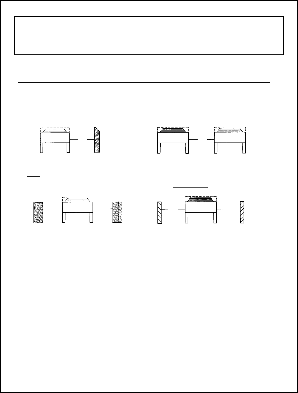
Air Cooled Condensing Unit Minimum Clearance (For Vertical Air Flow Units)
Units equipped with spring-mounted compressors have shipping spacers that are designed to hold the
compressor rigidly during transit to prevent possible damage. Before operating the unit, it is necessary to
remove these spacers. To remove the shipping spacers, follow these steps:
(a) Remove the upper nuts / washers.
(b) Discard the shipping spacers.
(c) Install the rubber cone washers (located in the electrical box).
(d) Replace the upper mounting nuts / washers.
(e) Allow 1/16 inch space between the mounting nuts / washers and the compressor foot.
On units equipped with rigid mounted compressors, check the compressor mounting bolts to insure they have
not vibrated loose during shipping.
WALLS OR OBSTRUCTIONS
All sides of the unit must be a minimum of 4 feet
(1.25 m) away from the wall or obstruction.
Overhead obstructions are not permitted. If
enclosed by three walls, the unit must be installed as
indicated for units in a pit.
MULTIPLE UNITS
A minimum of 8 feet (2.5 m) is required between
multiple units placed side by side. If placed end to
end, the minimum distance between units is 4 feet
(1.25 m)
UNITS IN PITS:
The top of the unit must be level with, or
above the top of the pit. In addition, a
minimum of 8 feet (2.5 m) is required between
the unit and the pit walls.
LOUVERS / FENCES:
Louvers/fences must have a minimum of 80% free
area and 4 feet (1.25 m) minimum clearance
between the unit and the louver/fence. Height of
louver/fence must not exceed top of unit.
4 ft
(1.25 m)
min.
8 ft
(2.5 m)
min.
8 ft
(2.5 m)
min.
8 ft
(2.5 m)
min.
4 ft
(1.25 m)
min.
4 ft
(1.25 m)
min.
5
Electrical Information
WARNING
All wiring and connections to the unit must be made in accordance with national as well as local electrical codes
and by-laws.
Electrical wiring should be sized in accordance with the minimum circuit ampacities shown on the unit
nameplate and applicable electrical codes. The unit power connections are approved for copper wire only.
Connect the field power supply through a fused branch circuit disconnect switch. The entering service fuse must
not exceed the maximum overcurrent protection (MOP) value on the unit data plate.
Field connected control circuit wires are terminated directly at the control circuit terminal block in accordance
with the appropriate wiring diagram.
Voltage at the unit terminals must not vary more than the allowable variation during start-up and while under full
load. If the voltage is normal at the supply with the compressor not running and drops considerably when the
switch is closed and the motor is trying to start, there is a high resistance due to undersized wires or faulty
connections. Voltage drop between inoperative and full load must not exceed 3% of line voltage. In addition, the
phase imbalance at the motor terminals should be within 2% on three phase units.
60 Hz Supply 50 Hz Supply
Power Allowable Variation Power Allowable Variation
115-1-60 103-127 V 100-1-50 90-110 V
208/230-1-60 197-254 V 200/220-1-50 190-242 V
208/230-3-60 187-254 V 200/220-3-50 180-242 V
460-3-60 414-506 V 380/400-3-50 342-440 V
575-3-60 518-632 V
All systems should use a liquid line solenoid valve and should be energized by the room or fixture thermostat.
WARNING
Any deviation or change to the electrical components or wiring as supplied on the original equipment, or
noncompliance with the voltage and phase balance requirements without written authorization will void the
warranty.
6
Refrigerant Piping
WARNING
All local codes must be observed in the installation of refrigerant piping.
IMPORTANT PIPING NOTE
Appropriate line sizing practices must be used throughout the installation of the refrigeration system. Special
consideration must be taken when the condensing unit is installed above the evaporator. REFRIGERATION
GRADE COPPER TUBING MUST BE USED FOR PIPING SYSTEMS.
Piping practice and line sizing charts as recommended by A.S.H.R.A.E. or other reputable refrigeration
standards must be followed to ensure minimum pressure drop and correct oil return. An inert gas such as dry
nitrogen should be passed through the piping during welding or brazing operations. This reduces or eliminates
oxidation of the copper and formation of scale inside the piping. For specific piping requirements refer to your
local distributor or sales representative.
Correct line sizing is most critical because of the several factors involved:
(a) Minimum pressure drop to ensure efficient compressor performance.
(b) Sufficient gas velocity to maintain proper oil return to the compressor under all load conditions.
(c) Elimination of conditions on multiple evaporators whereby oil may log in an idle evaporator.
Suction lines should be sized on the basis of a maximum total pressure drop equivalent to a 2oF (1.1oC) change
in saturated temperature. At 40oF (4.4oC) suction temperature, this is approximately 3 psig (20.7 kPa) for R-22
and R-407C.
Horizontal liquid lines should be sized on a basis of a maximum pressure drop equivalent to a 2oF (1.1oC) drop
in the sub-cooling temperature. If the lines must travel up vertically then adequate sub-cooling must be provided
to overcome the vertical liquid head pressures. A head of two feet of liquid refrigerant is approximately
equivalent to 1 psig (6.9 kPa). Liquid line velocities should not exceed 300 fpm (1.52 m/s). This will prevent
possible liquid hammering when the solenoid valve closes.
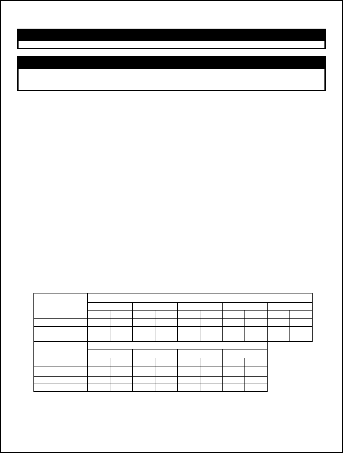
PSIG oFPSIG oFPSIG oFPSIG oFPSIG oF
R-407C 4 1.6 7.3 2 9 3.1 12.1 3.8 14.5 4.7
-
PSIG oFPSIG oFPSIG oFPSIG oF
R-407C
R-407C 19.4 6.2 24.2 8.0 36.3 12.1 48.4 16.5
N/A
Based on 110 oF liquid temperature at bottom of riser.
Refrigerant
-
Liquid Line Rise in Feet
Pressure Loss of Liquid Refrigerant in Liquid Line Risers
(Expressed in Pressure Drop PSIG and Subcooling Loss oF)
40' 50' 75' 100'
Refrigerant 30'10' 15' 20' 25'
7
At the temperatures encountered in the condenser, receiver and liquid line a certain amount of oil is always
being circulated with the refrigerant through the system by the compressor. However, at the evaporator
temperature, and with the refrigerant in a vapor state, the oil and refrigerant separate. This oil can only be
returned to the compressor by gravity or by entrainment in the suction gas. Roof installations leave no
alternative but by entrainment for oil return, so suction gas velocity and correct line sizing to maintain this
velocity are imperative. Care must be taken not to oversize the suction line in the desire for maximum
performance.
Gas velocity in vertical suction lines must not be less than 1,000 fpm (5 m/s) and preferably 1,250 to
1,500 fpm (6 to 8 m/s).
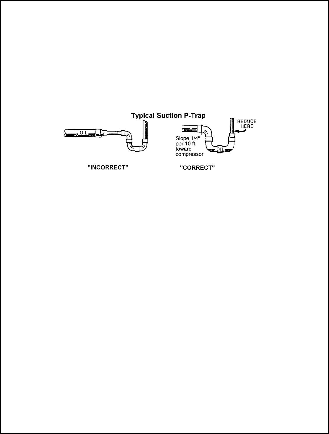
Important: A suction trap must be installed at the base of all suction risers of four (4) feet or more in order to
trap oil and allow entrainment in the suction gas.
LOW AMBIENT CONTROL OPTIONS:
A) FAN SPEED CONTROL (Low ambient control up to -200 F) The Fan speed control provides an infinite
number of speed variaon(s) on specially designed permanent split-capacitor motor(s). Controller varies
the quanty of air passing through the air-cooled condenser by directly sensing the refrigerant pressure.
Fan speed control provides air delivery in direct proporon to heat rejecon requirements of the
system. This is to maintain opmum system capacies and pressures in widely varying operang
ambient(s). As ambient temperature drops, the refrigerant pressure will also drop. As the ref. pressure
drops, this will be sensed by the pressure transducer and the air quanty will be reduced by reducing
the motor (fan) speed. Fan Speed Controller Refrigerant Connecon: The fan speed control requires that
the capillary be connected to the hot gas header through the shraeder fing provided.
Also, for mul-fan unites) there are thermostats for each condenser fan motor with the excepon of the
control motor (variable-speed). The thermostats should be set in accordance with wiring diagram
provided with the unit.
B) HEAD PRESSURE CONTROL VALVE (Low ambient control below -200 F)
This type of low ambient control includes head pressure control valve(s) and the receiver(s) package.
The receiver(s) are installed in separate enclosure(s). The enclosure(s) are shipped loose for field
installaon at the condenser. The head pressure control valve(s) are installed on the condenser or
shipped separately for field installaon on the air-cooled condenser. Upon receipt of these items should
be checked against the packing list and stored inside the building unl they are ready to be installed.
Operation: During periods of low ambient temperatures the condensing temperature falls unl it
approaches the seng of the head pressure control valve, which throles towards a closed seng, thus
restricng the flow of the liquid from the condenser. This causes the refrigerant to back up in the
condenser and reduces the effecve condenser surface. The check valve opens aer the head pressure
control has offered enough restricon and then causes the differenal between the condensing
pressure and the receiver pressure to exceed 20 psig. The hot gas flowing through the check valve
serves to heat the cold liquid being passed by the limizer valve. Thus, the liquid reaches the receiver
warm and with sufficient pressure to assure proper expansion valve operaon. The check valve and
limizer valve modulate the flow automacally to maintain proper condensing pressures.
Installation of Head Pressure Control Valve: There is one head pressure control valve on each of the
limizer system. These control valves, or limizer valves as they are called, can be installed in a
horizontal or a vercal line, whichever applicaon permits easy adjustment and accessibility to either
valve. Care should be taken to install the valves with the flow in the proper direcon. It is
8
important that head pressure control valve be protected by wrapping the valve with a wet cloth to keep
the body of valve at a temperature below 2500 F. It is important to keep the flame away from the valve
body, to insure that nobody damage is done to the valve. The valve should not be subjected to pressure
in excess of 250 psig during the leak tesng procedure. The limizer valves are factory set to maintain
180 psig. The Head Pressure Control Valves are hermecally sealed therefore, when a valve comes
inoperave, it must be replaced. There are two types of malfuncons that may occur. (I) Failure to open
or (II) failure to close. If parcles of solder are in the system, they can restrict the orifice of the valve and
cause the valve to malfuncon. If this occurs, gently tap the valve, this will possibly allow the parcles to
flow through the valve. Since a synthec material is used in the construcon of the valve, damage to this
will cause hot gas to leak constantly. If this occurs, the valve must be replaced.
Liquid Receiver(s) Installation: Liquid receiver(s) are factory installed in the separate enclosure(s). These
enclosure(s) need to be field installed on side(s) of the air-cooled condenser. Also, the liquid receiver(s)
need to be field piped. Install a Refrigerant Sight Glass (By Others immediately aer the Liquid Receiver
Outlet. Only the sight glass at the receiver outlet should be used to determine if the addional
refrigerant must be added.
Liquid Receiver(s) are wrapped with the Self Regulang Heang Cable and insulated. Provide 240Vac
Power Supply to the Heang Cable as shown in the wiring diagram.
9
10
System Accessories
In order to ensure trouble free operation of the refrigeration system it is important that the following system
accessories be reviewed and installed.
.
(a) A LIQUID LINE SOLENOID VALVE must be installed at the evaporator. Installing a solenoid valve will
allow all of the refrigerant to be pumped out of the low side (evaporator and suction line) when the
thermostat has been satisfied. This reduces the risk of refrigerant migrating or flooding back to the
compressor. Locating the solenoid at the evaporator (instead of the condensing unit) will minimize the
pump-down time and refrigerant capacity required by the receiver.
(b) A SUCTION LINE FILTER (sealed or replaceable core) when used are always installed upstream of the
compressor suction service valve and any accumulators or other options that may be installed. Suction
filters are equipped with “Schrader” type access valves that allow plugged filters and elements to be
identified quickly when the pressure drops get too high. Refer to the specific manufacturer’s
recommendation for servicing.
(c) A SUCTION TO LIQUID HEAT EXCHANGER should be used if a system requires long liquid lines from
the receiver to the evaporator or if the liquid has to rise vertically upward any distance. It can help
prevent excessive frosting on the compressor body and increase superheat in the suction line reducing
the possibility of liquid refrigerant from returning to the compressor.
(d) A PHASE / VOLTAGE MONITOR protects the system against phase loss (single phasing), phase
reversal (improper sequence), high voltage and low voltage (brownouts).
11
Leak Testing
IMPORTANT: All system piping, including the condensing unit and accessories should be thoroughly tested for
leaks prior to start up and charging. The system should be initially pressurized to a maximum of 150 psig (1136
kPa) with dry nitrogen to ensure that the system is free of major leaks. With the system free of major leaks, a
more detailed leak check should be performed. Discharge the initial dry nitrogen charge and add enough
refrigerant to raise the system pressure up to 10 psig (170 kPa) (tracer amount). Add dry nitrogen to increase
the system pressure to a maximum of 150 psig (1136 kPa). It is recommended that an electronic leak detector
be used when checking for leaks because of its greater sensitivity to small leaks. As a further check it is
recommended that this pressure be held for a minimum of 12 hours and then rechecked. The system must be
leak free for satisfactory operation.
IMPORTANT ENVIRONMENTAL NOTE
When conventional leak detection methods are employed using HCFC or CFC tracer gas, all of the tracer gas
must be reclaimed and disposed of in a proper manner.
Evacuation and Dehydration
When the system is completely free of refrigerant leaks, an evacuation of the entire system should be completed
by using a “high vacuum” pump. This evacuation, if completed correctly, will ensure long life for the system as
well as elimination of moisture and non-condensable gas problems. Moisture problems causing compressor
failure will void warranty. Follow the recommended procedure carefully.
CAUTION
Do not use the refrigeration compressor to evacuate the system. Never start the compressor or perform a
megger insulation test while the system is in a vacuum.
Dehydration Procedure
Use only a “high vacuum” pump capable of drawing a vacuum of 100 microns. Change the vacuum pump oil
frequently. Gauges or vacuum measuring instruments should be suitable to measure conditions at any stage of
the process in order to give the operator indications of progress. For specific recommendations, refer to the
vacuum pump supplier for these instruments.
Copper jumper lines should be used to interconnect both high and low-pressure sides of the system. These
lines should be at least 3/8” O.D. in order to handle the light density vapor at high vacuum obtained at
completion of operation. Lines smaller than 3/8” O.D. will slow down the process considerably as well as making
final system vacuum questionable. The entire system temperature should be over 60 oF (16 oC) for evacuation to
be effective. If the temperature is less than 60 o
F (16 o
C) the final vacuum should be 50 microns. Double
evacuation with a “sweeping “ of dry nitrogen is recommended. First evacuation should be to at least 750-micron
depth. When this point is reached, break the vacuum with refrigerant or dry nitrogen to melt any moisture, which
may have frozen during the first vacuum stage.
IMPORTANT ENVIRONMENTAL NOTE
When conventional leak detection methods are employed using HCFC or CFC tracer gas, all of the tracer gas
must be reclaimed and disposed of in the proper manner.
Reclaim any tracer gas from the system and re-evacuate to a final vacuum of at least 100 microns at a minimum
60 o
F (16 o
C) system temperature. With this degree of evacuation, all moisture and non-condensables will be
removed from the entire system.
12
Line Insulation
After the final system leak test is complete, it is important that all refrigerant lines exposed to high ambient
conditions must be insulated to reduce the heat pick-up and prevent the formation of flash gas in the liquid lines.
Suction lines should be insulated with 3/4 inch wall insulation, Armstrong “Armaflex” or equal. To prevent rupture
due to condensate re-freezing, all suction vibration eliminators on low temperature systems must be
completely insulated. Liquid lines exposed to high ambient temperatures should be insulated with 1/2 inch wall
insulation or better. Any insulation that is to be located in an outdoor environment should be protected from UV
exposure to prevent deterioration of the insulating value.
Refrigerant Charging
Condensing units must be charged only with the refrigerant for which they were designed. The type of
refrigerant to be used is specified on the name plate of the unit. Installing a liquid line drier between the service
gauge and the liquid service port when charging a unit will ensure the refrigerant supplied to the system is clean
and dry. This is especially important when charging a low temperature system. Blend type refrigerants (400
series, i.e. R404A) must not be vapor charged unless the cylinder is completely emptied into the system.
Weigh the refrigerant drum before and after charging in order to keep an accurate record of the weight
of refrigerant put into the system.
IMPORTANT REFRIGERANT CHARGING NOTE
Overcharging a system can result in poor system performance, personal injury and / or compressor damage.
DO NOT charge strictly by the holding capacity of the receiver. DO NOT assume that bubbles in a sight glass,
when located at the condensing unit, indicates the system is undercharged.
Note: To estimate the total system requirement, refer to the manufacturer’s evaporator and condensing unit
specifications on typical operating charges and include the amount for the liquid lines (see tables below). Allow
an extra 10% to 15% safety factor. Ensure the receiver can handle the required charge during the pump down
mode. (Refer to the condensing unit brochure pump down specifications).
Break the vacuum by charging liquid refrigerant into the receiver side only (charge through the receiver outlet
valve gauge port with the valve in the open position). Close the valve and then continue to charge through the
gauge port feeding the liquid line and evaporator. Start the compressor and continue to charge.
Refrigerant may be added at the compressor through the compressor suction service valve in gas form only.
When liquid charging is used, a liquid charging valve must be installed. While charging the system, special
attention should be paid to the oil level in the compressor.
If charging to the “bubble” method (observing liquid line sight glass), always use a sight glass located directly
before the TXV (thermostatic expansion valve) for the final indicator.
On units that use an adjustable flooded condenser pressure-regulating valve the
proper adjustment must be set. Sporlan set their controls at 120 psig (929 kPa). These controls should be re-
adjusted to the following pressures:
185 psig (1377 kPa) for R-22/R-407C (2 1/2 turns in clockwise for ORI-6, 4 turns in for ORI-10)
Refer to Sporlan’s installation instructions for further details.
13
System Start-up Check List
IMPORTANT START-UP NOTE
Only a qualified refrigeration mechanic who is familiar with compressor performance and the function and
adjustment of all controls and components should start up the compressor. Finishing up work on the
installations should be planned so that a qualified mechanic is on the job for at least the first full day that the
unit is in operation.
Before any refrigeration system is started, the following items should be checked:
(1) Check that all electrical and refrigeration connections are tight.
(2) Check compressor crankcase oil level (if equipped with sight glass). It should be from 1/8 to 1/2 full in
the sight glass.
(3) Insure that compressor shipping spacers (spring mounted compressors) or hold down nut (solid
mounted compressors are properly in place.
(4) Check that the compressor discharge and suction shut-off valves are open.
(5) Ensure that the high and low pressure controls (see table below) pressure regulating valves, oil
pressure safety controls and any other safety controls are adjusted properly.
(6) Check that the room thermostat or microprocessor is set for normal operation and adjust if required.
(7) Check all motors, fans and pump bearings in the condenser and evaporator. If they are the type that
require oil or grease, make sure that this is attended to in accordance with the tag, which will be
attached. Fan blades and pumps should be checked for correct rotation, tightness and alignment. Air
should draw air through the condenser (air cooled condensing unit models).
(8) Electric and hot gas evaporator fan motors should be temporarily wired for continuous operation until
the room temperature has stabilized.
(9) Observe the system pressures during the charging and initial operation process. DO NOT add oil while
the system is low on refrigerant charge unless the oil level is dangerously low.
(10) Continue to charge the system until it has enough charge for proper operation. DO NOT
OVERCHARGE THE SYSTEM. Note that bubbles in the sight glass may not necessarily mean a
shortage of refrigerant. It could be caused by a restriction.
(11) DO NOT leave the system unattended until the system has reached its normal operating condition and
the oil charge has properly adjusted itself to maintain the proper level in the sight glass.
(12) Compressor performance, and that of all of the moving components, should be watched carefully
throughout the first operating cycle and then checked periodically during the first day of operation.
Careful attention to details at this time will pay dividends in trouble-free performance of the
entire system.
(13) Check that the wiring diagrams, instructions bulletins etc. are read and attached to the unit for future
reference. Ensure that the Warranty Activation Certificate is filled in and either faxed or mailed back to
the number or address provided.
CAUTION
Extreme care must be used when starting a compressor for the first time after the system has been charged.
During this time liquid refrigerant may have migrated to the compressor crankcase, creating a condition that
could cause the compressor damage due to slugging. Energizing a crankcase heater (if so equipped) 24 hours
prior to start-up is recommended. If the compressor is not equipped with a crankcase heater, directing a 500
watt heat lamp or other safe heat source on the lower shell or crankcase of the compressor for approximately
thirty minutes is recommended.
WARNING
Three phase scroll compressors must be checked for correct rotation. During the initial start up, observe the
suction and discharge gauges to ensure the suction pressure drops and the discharge pressure rises.
14
Checking Superheat
IMPORTANT SYSTEM BALANCING NOTE
To obtain maximum system capacity and insure trouble free operation it is necessary to check both the
compressor and evaporator superheat.
Compressor Superheat
Compressor suction superheat must be checked. To check the superheat at the compressor the following steps
should be followed:
(1) Measure the suction pressure at the suction service valve of the compressor. Determine the saturated
temperature corresponding to this pressure from a “Pressure- Temperature” chart.
(2) Measure the suction temperature of the suction line about 6 inches (15 cm) back from the compressor
suction valve using an accurate thermometer.
(3) Subtract the saturated temperature (from step 1) from the actual suction line temperature (from step 2).
This difference is the actual superheat at the compressor.
System capacity decreases as the suction superheat increases. For maximum system capacity, the suction
superheat should be kept as low as is practical. The superheat at the compressor should range within
20 to 45 oF (11.2 to 25.2 oC) Superheat.
NOTE: Too low of a suction superheat can result in liquid being returned to the compressor. This can cause
dilution of the oil and eventually cause failure of the bearings and rings through wash out as well as liquid
slugging.
NOTE: Too high of a suction superheat will cause excessive discharge temperatures which cause a break down
of the oil and will result in piston ring wear, piston and cylinder wall damage.
If adjustment to the suction superheat is required, it should be done either by adjusting the thermostatic
expansion valve at the evaporator, the use of liquid to suction heat exchanger or suitable use of suction line
insulation.
Evaporator Superheat
Once the refrigerated space is at its design temperature or close to design temperature, the evaporator
superheat must be checked. To check the suction superheat at the evaporator the following steps should be
followed:
(1) Measure the suction pressure in the suction line at the bulb location by either,
(a) A gauge in the external equalizer line will indicate the pressure directly and accurately.
(b) A gauge directly in the suction line near the evaporator or directly in the suction header will suffice.
(2) Measure the temperature of the suction line at the point where the thermostatic expansion valve bulb is
clamped to the suction line.
(3) Convert the pressure obtained in step 1 above to a saturated evaporator temperature from a “Pressure-
Temperature” chart.
(4) Subtract the saturated temperature (from step 1) from the actual suction line temperature (from step 2).
This difference is the actual superheat at the evaporator.
The superheat at the evaporator should be a minimum of 6 to 10 oF (3.4 to 5.6 oC) for systems with a 10 oF (5.6
oC) design TD (temperature difference) to a maximum of 12 to 15 oF (6.7 to 8.4 o
C) for systems with a higher
operating TD.
Low temperature applications (freezers) should be set at superheats of 4 to 6 oF (2.2 to 3.4 oC).
TD = Box temperature – evaporating temperature.
15
System Operational Check List
When the system has been running trouble free for an extended time (two weeks or more) and design
conditions are satisfied, the following check list should be followed:
(1) Check that compressor discharge and suction pressures are operating within the allowable design
limits for the compressor. If not, take the necessary corrective action.
(2) Check the liquid line sight glass and expansion valve operation. If there is an indication that the system
is low on refrigerant, thoroughly check the system for leaks before adding refrigerant.
(3) Check the level of the oil in the compressor sight glass (if so equipped). Add oil as necessary.
(4) The thermostatic expansion valve must be checked for proper superheat settings. The sensing bulb
must have positive contact with the suction line and should be insulated. Valves operating at a high
superheat setting results in low refrigeration capacity. Low superheat settings can cause liquid slugging
and compressor bearing washout. (Refer to the section on compressor and evaporator superheats)
(5) Check the voltage and amperage readings at the compressor terminals. Voltage reading must be
within the recommended guidelines. Normal operating amperages can be much lower than the
compressor nameplate values.
(6) To check the high pressure control setting it is necessary to build up the head pressure to the cut-out
point of the control. This can be done by stopping the condenser fan(s) (air cooled condensing units) or
pump and watching the pressure rise on a high pressure gauge to make sure the high pressure control
is operating at the setting.
(7) Check the low pressure settings by throttling the compressor shut-off valve and allowing the
compressor to pump down. This operation must be done with extreme caution to avoid too sudden a
reduction in crankcase pressure, which will cause oil slugging and possible damage to the compressor
valves. Close the valve a turn at a time while watching the compound gauge for change and allowing
time for the crankcase pressure to equalize with the pressure control bellows pressure. The slower the
pressure is reduced, the more accurate will be the check on the pressure control setting.
(8) Recheck all safety and operating controls for proper operation and adjust as necessary.
(9) Check defrost controls for initiation and termination settings, and the length of defrost period. Set
the fail safe on the time clock at the length of defrost plus 25 %.
(10) If the system is equipped with winter head pressure controls (fan cycling or flooded valves), check for
operation.
(11) Fill in the Service Log in the back of this Installation Manual.
16
System Troubleshooting
The following System Troubleshooting Guide lists the most common types of malfunctions encountered with
refrigeration systems. These simple troubleshooting techniques can save time and money minimizing
unnecessary downtime and end-user dissatisfaction.
Contact the factory or your local sales representative for further information or assistance.
System Troubleshooting Guide
Condensing Unit Problem Possible Causes
Compressor will not run. Does not try to start.
1. Main power switch open.
2. Fuse blown or tripped circuit breaker.
3. Thermal overloads tripped.
4. Defective contactor or coil.
5. System shut down by safety devices.
6. Open thermostat or control. No cooling required.
7. Liquid line solenoid will not open.
8. Loose wiring.
Compressor hums, but will not start. 1. Improperly wired.
2. Low line voltage.
3. Loose wiring.
4. Defective start or run capacitor.
5. Defective start relay.
6. Motor windings damaged.
7. Internal compressor mechanical damage.
Compressor starts, but trips on overload
protector.
1. Improperly wired.
2. Low line voltage.
3. Loose wiring.
4. Defective start or run capacitor.
5. Defective start relay.
6. Excessive suction or discharge pressure.
7. Tight bearings or mechanical damage in compressor.
8. Defective overload protector.
9. Motor windings damaged.
10. Overcharged system.
11. Shortage of refrigerant.
12. Suction or discharge pressure too high.
13. Inadequate ventilation.
14. Operating system beyond design conditions.
Compressor short cycles. 1. Low pressure control differential set too low.
2. Shortage of refrigerant.
3. Low airflow at evaporator(s).
4. Discharge pressure too high.
5. Compressor internal discharge valves leaking.
6. Incorrect unit selection (oversized).
Start relay burns out. 1. Improperly wired.
2. Low or high line voltage.
3. Short cycling.
4. Improper mounting of relay.
5. Incorrect start or run capacitor.
6. Incorrect relay.
Contact welded stuck on start relay 1. Short cycling.
2. No bleed resistor on start capacitor.
Start capacitor burns out 1. Improperly wired.
2. Short cycling.
3. Low line voltage.
4. Relay contacts sticking.
5. Incorrect capacitor.
6. Start winding remaining in circuit for prolonged period.
17
Condensing Unit Problem Possible Causes
Compressor noisy or vibrating. 1. Flood back of refrigerant.
2. Improper piping support on the suction or discharge lines.
3. Broken or worn internal compressor parts.
4. Incorrect oil level.
5. Scroll compressor rotating in reverse (three phase).
6. Improper mounting on unit base.
Discharge pressure too high. 1. Non-condensables in the system.
2. System overcharged with refrigerant.
3. Discharge service valve partially closed.
4. Condenser fan not running.
5. Dirty condenser coil.(air-cooled condensers)
6. Dirty tubes. .(water-cooled condensers)
7. Defective or improperly set water regulating valve.
(water-cooled condensers)
8. Defective or improperly set flooded head pressure control.
Discharge pressure too low. 1. Low suction pressure.
2. Cold ambient air.
3. Suction service valve partially closed.
4. Shortage of refrigerant.
5. Defective or improperly set water regulating valve.
(water-cooled condensers)
6. Defective or improperly set flooded head pressure control.
Suction pressure too high. 1. Excessive load.
2. Compressor internal valves broken.
3. Incorrect unit selection (undersized).
4. Improper TXV bulb charge.
Suction pressure too low. 1. Shortage of refrigerant.
2. Evaporator dirty or iced up.
3. Clogged liquid line filter drier.
4. Clogged suction line filter or compressor suction strainers.
5. Expansion valve malfunctioning.
6. Condensing temperature too low.
7. Improper TX valve selection.
8. Evaporator distributor feed problems.
Low or no oil pressure. 1. Low oil level. (trapped oil in evaporator or suction line)
2. Clogged suction oil strainer.
3. Excessive liquid refrigerant in the crankcase.
4. Worn oil pump.
5. Oil pump reversing gear sticking in the wrong position.
6. Worn bearings.
7. Loose fitting on oil line.
8. Pump housing gasket leaking.
Compressor loses oil. 1. Refrigerant leak.
2. Short cycling.
3. Excessive compressor ring blowby.
4. Refrigerant flood back.
5. Improper piping or traps.
6. Trapped oil in evaporator.
Compressor runs continuously 1. Excessive load.
2. Too low of a system thermostat setting or defective
thermostat.
3. Shortage of refrigerant.
4. Leaking compressor internal valves.
5. Malfunctioning liquid line solenoid.
6. Incorrect unit selection (undersized).
18
System Troubleshooting Guide
Fixture Problem Possible Causes
Room temperature too high.
1. Defective room thermostat or improper differential / setting.
2. Malfunctioning liquid line solenoid valve.
3. Insufficient air across evaporator coil (iced up coil, product
blocking evaporator, fan blade / motor problem).
4. Improper evaporator superheat (low refrigerant charge,
plugged TXV strainer, poor TXV bulb contact, incorrect
TXV setting).
5. Malfunctioning condensing unit.
Room temperature too low. 1. Defective room thermostat or improper differential / setting.
2. Malfunctioning liquid line solenoid valve.
Ice accumulating on ceiling. 1. Defrost on too long (improper setting / defective termination
thermostat, improper setting / defective time clock).
2. Too many defrosts per day.
3. Fans not delayed after defrost (improper setting / defective
fan delay thermostat).
Evaporator coil not clear of ice after defrost. 1. Defrost on too short (improper setting / defective
termination thermostat, improper setting / defective time
clock).
2. Electric heaters defective / miswired / low voltage.
3. Not enough defrosts per day.
4. Air defrost evaporator operating at too low of temperature
(require electric defrost).
5. Defective / miswired interlock at compressor contactor.
6. Defective defrost contactor or coil.
Ice building up in drain pan. 1. Improper slope in pan.
2. Blocked drain line (unheated , not insulated).
3. Electric heater in drain pan defective / miswired / low
voltage).
4. Not enough defrosts per day.
5. Lack of or improper P-trap in drain line.
Evaporator fans will not operate. 1. Main power switch open.
2. Fuse blown or tripped circuit breaker.
3. Defective contactor or coil.
4. Room temperature too high (fan delay thermostat open).
5. Fan delay thermostat improper setting / defective.
6. Defective fan motor (low voltage / tripped on thermal
overload).
7. Defective time clock.
8. Normal mode during defrost cycle (electric defrost type
evaporator).
IMPORTANT TROUBLESHOOTING NOTE
Before any components are changed on the refrigeration system, the cause of the failure must be identified.
Further problems will exist unless the true cause or problem is identified and corrected.
19
Customer Instructions
Completely fill in Warranty Activation Certificate located inside of the back cover of this Installation and
Maintenance Manual. The top (white) copy should be faxed or mailed per the instructions on this form. The
(pink) copy is for the installing contractor’s files and the (yellow) copy is to be left attached inside of the
Installation and Maintenance Manual for the owner / end user’s future reference.
Give the owner / end user instructions on normal operation of the system. Explain electrical characteristics,
location of disconnect switches as well as other safety precautions. Advise on keeping equipment area clean
and free of debris. If system has operational features, point these out to the operator.
Maintenance Program
In order to ensure that the refrigeration system runs trouble free for many years, a follow-up maintenance
program (consisting of a minimum of two inspections per year) should be set up. A qualified refrigeration service
mechanic should carry out this semi-annual inspection. The main power supply must be disconnected and
locked off to avoid accidental start up of the equipment.
(1) Check electrical components and tighten any loose connections.
(2) Check all wiring and electrical insulators.
(3) Check contactors to ensure proper operation and contact point for wear.
(4) Check that fan motors (if applicable) are operational, ensure fan blades are tight and all mounting bolts
are tight.
(5) Check oil and refrigerant levels in the system.
(6) Ensure that the condenser surface (if applicable) is cleaned and free of dirt and debris.
(7) Check the operation of the control system. Make certain that all of the safety controls are operational
and functioning properly.
(8) Check all refrigeration piping. Make sure that all mechanical joints and flare nuts are tight.
Service Parts Availability
Genuine replacement service parts should be used whenever possible. Parts may be obtained by
contacting your local sales representative or authorized distributor. Contact us 562.945.8971
20
We warranty this Compu-Aire, Inc. computer room unit to be free from defects in material and workman-
ship; our obligation being limited to repairing or replacing at our factory any part (except as noted below)
within one year from the date of shipment to the original purchaser. Parts to be returned to us PREPAID.
Proof of start-up date must be submitted to the factory.
This warranty is eective only if the unit has been installed in accordance with our instructions and
connected to proper and adequate electric, water and drain services, correctly dehydrated and placed into
operation by a competent service representative.
Fan motor and compressor warranty is covered by original manufacturer’s warranty and any repair or
replacement should be made by the local authorized service facility as listed the telephone book.
Maintenance and service such as replacing lters, humidier cylinder, infra-red lamps, oat valve assemblies,
belts, cleaning, lubrication, calibration and adjusting are NOT INCLUDED in this warranty.
Replacement or repair parts shall be shipped from the factory pre-paid and invoiced for the full amount.
Upon receipt of warranteed parts within 30 days with prepayment of the component and which our inspec-
tion discloses the parts are defective, and show no signs of misuse, alterations, or abuse, full credit will be
issued.
Compu-Aire, Inc. does not assume any responsibility for the labor expense for changing defective parts or
replacement of any refrigerant or other cooling medium such as glycol etc.
All parts and goods are thoroughly inspected and packed to meet the requirements of railroad freight
classications bureaus, and under standard shippers risk, when they leave our factory. SHOULD GOODS
ARRIVE DAMAGED, call the agents attention to damage, and have same noted on freight bill. For concealed
damage, demand immediate inspection from agent of the shipping company and insist on a notation being
made on freight bill.
WARRANTY
General Warranty Policy
