CD3610 Acdc Mo 7 Medium Dc
User Manual: CD3610
Open the PDF directly: View PDF ![]() .
.
Page Count: 92
Medium DC Motors
CD180 to CD6900 Frame
CD180 to CD6900 Frame
Medium DC Motors
GE Support Services
e
• Overview & History . . . . . . . . . . . . . . . . . . . . . . . . . . . . . . . . . . . . .128
• Products/Types—(Frames) . . . . . . . . . . . . . . . . . . . . . . . . . . . . .129
• Model Numbers . . . . . . . . . . . . . . . . . . . . . . . . . . . . . . . . . . . . . . . .130
• Serial Numbers . . . . . . . . . . . . . . . . . . . . . . . . . . . . . . . . . . . . . . . . .133
• Parts & Exploded Views
– Kinamatic I–Type CD, Frames 210A to 680A . . . . . . . . . . . . .135
– Kinamatic II–Type CD, Frames 180AT to 500AT and
Frames 2512AT, 2513AT, 2812AT, 2813AT . . . . . . . . . . . . . . .137
– Types CD and MCD, Frames 4300 to 4700 . . . . . . . . . . . . . . .145
– Types CD and MCD, Frames 6000 to 6200, 6700 to 6900 . . .151
– Types CD and MCD, Frames 5000 to 9000
and Type CD, Frames 580 to 680 . . . . . . . . . . . . . . . . . . . . . . .155
– Type MD, Frames 402 to 423 . . . . . . . . . . . . . . . . . . . . . . . . . . .159
– Type MD, Frames 602 to 624 . . . . . . . . . . . . . . . . . . . . . . . . . . .163
– Type MD, Frames 802 to 828 . . . . . . . . . . . . . . . . . . . . . . . . . . .170
– Excavator Motor Generators–Type CDS, Frames 320 to 8000
and Types MPC and MCF, Frames 500 to 900 . . . . . . . . . . . .182
– Electric Vehicle–Type BT, Frames 1300 to 2300 . . . . . . . . . .189
• Maintenance Tips . . . . . . . . . . . . . . . . . . . . . . . . . . . . . . . . . . . . . .190
• Standard Brushholders with Springs and Springs Only . . . . . .195
• Commutator Information . . . . . . . . . . . . . . . . . . . . . . . . . . . . . . .196
• Field Modifications/Accessories . . . . . . . . . . . . . . . . . . . . . . . . . .202
Medium DC

128 DC Motors
For more information contact a GE Motor Parts Master Distributor or GE Support Services.
7–Medium DC
Overview and History of Medium DC Motors
GE DC motors rated between 1 and 2500 horsepower, as well as generator ratings up to over 1300KW are
manufactured in Dothan, AL, Monterrey, Mexico and Peterborough, Ontario.
The basic DC motor design is the same, that is, there is a stationary magnetic field structure and a rotating
element. The rotating portion, the armature, is supported by a bearing structure.
The field frame consists of a ferrous frame with coils to provide for magnetic coupling of flux to the
armature. There are main coils in the field to provide the magnetics. Comm coils are also used.
The armature has a shaft, coils to provide the magnetics to interact with the field coils, and a commutator.
The commutator enables the coils on the rotating armature to be electrified. The brushes give a rotating
connection between the armature and the power source.
The bearings are supported by bearing brackets or endbells. The bearings themselves can be ball
bearings, roller bearings, or sleeve bearings. Sleeve bearings can be Bronze or Babbitt.
These basic elements are common to all DC motors. It is important to understand their relative positions
when locating parts. There are also accessories which are added to the motor to improve performance,
provide control data, and to protect the motor.
Medium DC Motors 129
GE Support Services
7–Medium DC
Products/ Types (Frames)
CD180A/AT–680A
Kinamatic Line Industrial Motors
CD1000/1700
Early Motors/Some Parts
CD5000/9000
Obsolete Motors/Parts Generally Available
MD400/600/800
Mill Drive and Excavator Motors, Parts available on 800,
some 400 and 600
GTE and LY
Motors and Generators for the elevator industry
BT
Lift Truck, Electric vehicle motors, Mining Motors
BY, CY
Special Purpose Motors, Roll Grinder Transit
CD4300/4700
Industrial Drive Motors, High HP
CD6200/6700
Industrial Drive Motors, High HP
Dynomometer
Device to Measure Engine Performance or Motor Output
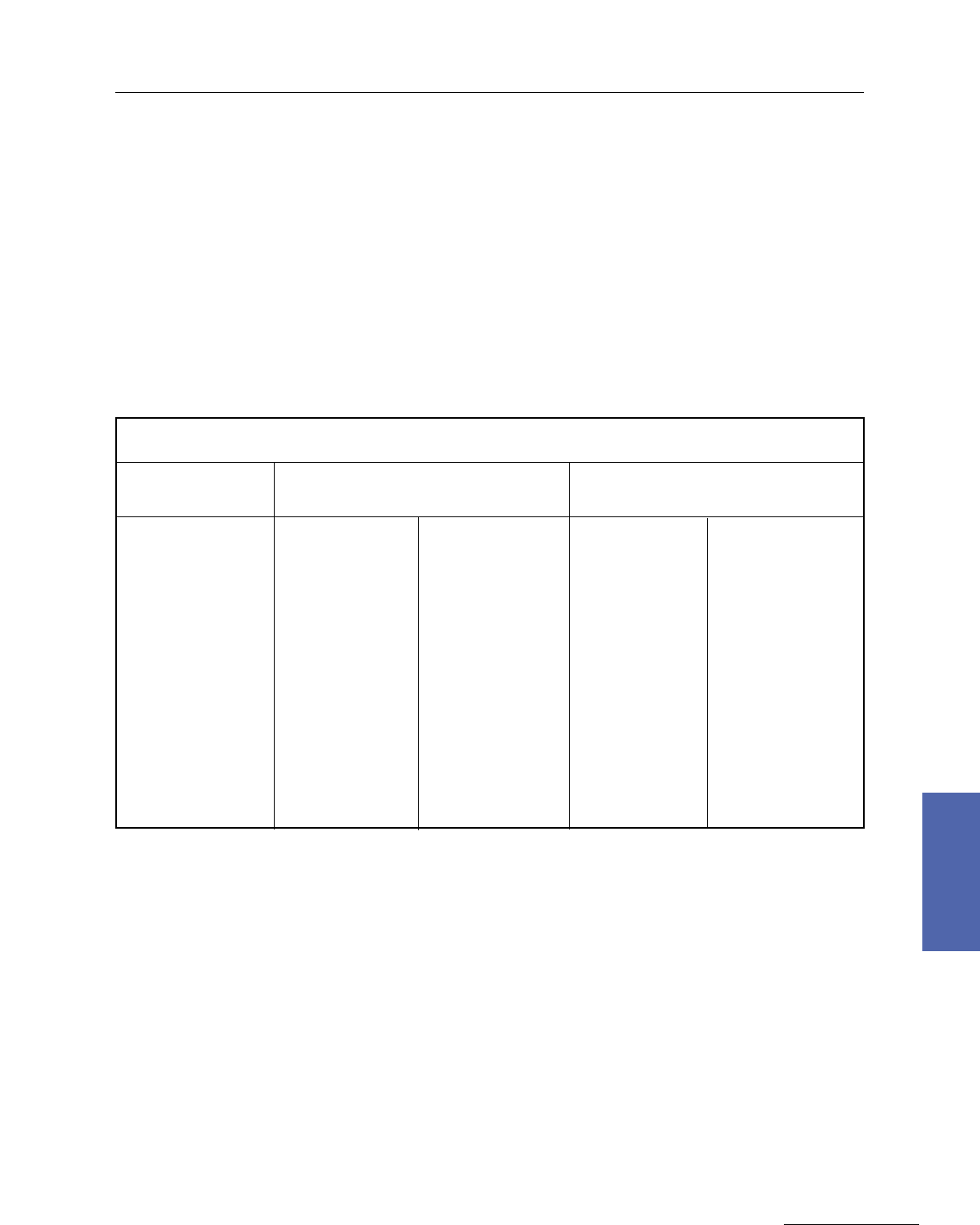
Motor Type Market Application
CD180AT
MOTOR TYPE
Accessory
Mounting Face
Radiant Heat
Process (RHP)
Vacuum Pressure
Impregnation (VPI)
2 Cycles
Adjustable
Fixed
Cast Equalizer Comm End
Coil Assembly and Support
Glass Banded
(w/Viton Sealant)
Interlocking
Molded
Cap and Cone
(V Ring)
Compensated Pole
Face Wadings
Laminated
Round
Split
Class F
Class H
TIG Welded
Riser Construction
TREC Field Coils
CD210–320AT
CD360–500AT, 5010
CD2512–2813AT
CD6000–6200
CD6700–6900
MD802–812
MD814–826
When specified
✔
✔
✔
✔
✔
✔
✔
✔
✔
✔
✔
✔
✔
✔
✔
✔
✔
✔
✔
✔
✔
✔
✔
✔
✔
✔
✔
✔
✔
✔
✔
✔
✔✔
✔
✔
✔
✔
✔
✔
✔
✔
✔
✔
✔
✔
✔
✔
✔✔
✔
✔
✔
✔
✔
✔
✔
✔
✔
✔
✔
✔
✔
✔
✔
✔
✔
✔
✔
✔
✔
✔
✔
✔
1
1
With Viton sealant and polyurethane
overcoat
2
1
12
3
3
3
3
2
2
4
Optional
3
Not available on TEFC, CD210AT
4
Armature
Treatment Brush
Riggings Commutators Frames Insulation

130 DC Motors
For more information contact a GE Motor Parts Master Distributor or GE Support Services.
7–Medium DC
Medium DC Motors Model Numbers
Typical Format: 5CD NNN LL NNN L NNN . . . . . . . . . . N = Number; L = Letter
Model Number Frame Design
Examples: 5CD152GA001B002 CD218AT KII
5CD194SA005A007 CD368AT KII
5CD435LA805C801 CD4366 CD4000
Others: 5CD505G329 CD505 KI
5BY444A27 CD3610 LOW INERTIA
5CY949E9 CY949AY ROLL GRINDER
5MD160D100000AB MD816AE MD
5AM604B218 AM604 AMPLIDYNE
5CDS365G322 CDS365AY EXCAVATOR
5MD824C81 MDP824 EXCAVATOR MD
223X782CF MCF868C EXCAVATOR GENERATOR
5SDE2635A100 SDE2600 SYNCHRONOUS MOTOR
Model Numbers
The history of the GE model numbering system is actually quite old dating back to the early 1900’s.
Today’s system has evolved from many years of experience. Learning from the past, it became quite clear
to GE a system was needed to identify motor characteristics, ratings, and accessories with the model
number alone. This system was first devised and implemented around 1970. An example of a model
number would be 5CD194HA001A001. About 75% of our replacement requests are of this format.
Another format for model numbers following this pattern:
5CD14D02A112003 5CD580G12AB
These types of model numbers have been in use since about 1960 and are the second most frequent style
seen on a daily basis representing about 15% of our requests. With these two types of model numbers, it is
impossible to specify completely which motor is being requested without a serial number.
About 5% of the replacement requests have model numbers with format:
33A1557 5B225A50
Every motor is also assigned a serial number which is unique to that motor. Serial numbers for GE DC
motors are one of two forms depending on the date the motor was built. The years between 1930 and
1956, serial numbers took the form of a seven digit code. Theses generally look like this:
7283200 7079100 2355299
2164851 1839846 1590324
From about 1956 on to the present, serial numbers took the form of LL – N – NNN – LL where L = Letter
and N = Number. These generally look like this:
GC–1–510–LC LL–N–NNN–LL
CK–1–1085–EK the first N is always one of the follow
RE–1–471–RE 1, 2, or 8
AR–2–420–AR
For parts identification, the last two letters are dropped from this format. For instance, GC–1–510 would
be typed in for C–1–510–LC.

Medium DC Motors 131
GE Support Services
7–Medium DC
Model Number Also known as:
5AM602B23 5AM602B23
5AN102B1G02 AN102B1G02
5BT1328B7 BT1328B7
5BY435A65 5BY435A65
5BT2379M2 5BT2378M2
5CD14E06A36630 14EO6A36630
5CD123WE001B 5CD123WE001B
5CD144WA801A800 5CD144WA801A800
5CD25D26G001513 25D26G001513
5CD362MA001A001 5CD362001A001
5CD432EA001C800 5CD432EA001C800
5CD256G177 5CD256E177
5CD684E143BE 5CD684E143BE
5CDS326G230 5CD326G230
5CY1031E1 5CY1032E1
5GTE20D03A1 5GTE20D03A1
5MD020D114100SD 020D1141100SD
5MD824A3 5MD824A3
34B615 34B615
36X958083 36X958083
Model Numbers
and Their Equivalents
When having difficulty with a model: 1. drop 5 and impute, 2. drop 5 and first letter and impute, 3. drop
5 and first two letters and impute. In many cases, it is easier to inquire in the model list, E.G.
5CD184TA001A rather than the entire model number.
General Notes
Kinamatic II Models, for example, 5CD184TA001A001, the full number is the model list which includes
accessories, covers, thermostats, and so forth. These make the unit unique. The base number, E.G.
5CD184TA001A, is the machine list, which list the field coils, armature, bearings, brushrigging, and so
forth. Armature coils are found on the armature list on the machine list.
MD800 motors are imputed with the 5MD dropped from the model. The last two letters indicate the
ventilation and some other accessories. The basic number, without the 5MD and the two letter suffix has
most of the data that is normally requested.
When listing part numbers, always line the extension on the space 12, 13 and 14.
For example: _ _ _ _ _ _ _ _ _ _ _ _ XXX XXX = appropriate group or part number.
Serial numbers are entered with dashes.

Kinamatic II Design CD4000 Line CD6000 Line
132 DC Motors
For more information contact a GE Motor Parts Master Distributor or GE Support Services.
7–Medium DC
MODEL NUMBER FRAME MODEL NUMBER FRAME MODEL NUMBER FRAME
PREFIX SIZE PREFIX SIZE PREFIX SIZE
5CD122 CD146 5CD431 D–K CD4350 5CD601 D–K CD6050
5CD123 CD148 5CD431 L–N CD4354 5CD601 L–M CD6054
5CD124 CD149 5CD432 D–K CD4352 5CD602 D–K CD6052
5CD125 CD1412 5CD432 L–N CD4357 5CD602 L–M CD6057
5CD142 CDL182AT 5CD433 D–K CD4355 5CD603 D–K CD6055
5CD143 CD186AT 5CD433 L–N CD4359 5CD603 L–M CD6059
5CD144 CDL186AT 5CD434 D–K CD4358 5CD604 D–K CD6058
5CD145 CD189AT 5CD434 L–N CD4363 5CD604 L–M CD6063
5CD152 CD218AT 5CD435 D–K CD4362 5CD605 D–K CD6062
5CD153 CD219AT 5CD435 L–N CD4366 5CD605 L–M CD6066
5CD154 CD2110AT 5CD442 E–K CD4454 5CD612 E–K CD6154
5CD163 CD258AT 5CD442 L–N CD4463 5CD612 L–N CD6163
5CD164 CD259AT 5CD443 E–K CD4457 5CD613 E–K CD6157
5CD173 CD287AT 5CD443 L–N CD4465 5CD613 L–N CD6165
5CD174 CD288AT 5CD444 E–K CD4460 5CD614 E–K CD6160
5CD183 CD327AT 5CD444 L–N CD4468 5CD614 L–N CD6168
5CD184 CD328AT 5CD445 E–K CD4464 5CD615 E–K CD6164
5CD192 CD365AT 5CD445 L–N CD4473 5CD615 L–N CD6173
5CD193 CD366AT 5CD446 E–K CD4469 5CD616 E–K CD6169
5CD194 CD368AT 5CD446 L–N CD4477 5CD616 L–N CD6177
5CD203 A CDL407AT 5CD453 E–K CD4559 5CD623 E–K CD6259
5CD203 B–R CD407AT 5CD453 L–N CD4568 5CD623 L–M CD6268
5CD203 S–Y CDL407AT 5CD454 E–K CD4562 5CD624 E–K CD6262
5CD204 A CDL409AT 5CD454 L–N CD4570 5CD624 L–M CD6270
5CD204 B–R CD409AT 5CD455 E–K CD4566 5CD625 E–K CD6266
5CD204 S–Y CDL409AT 5CD455 L–N CD4575 5CD625 L–M CD6275
5CD222 A–T,X,Y CD504AT 5CD456 E–K CD4571 5CD626 E–K CD6271
5CD222 U–W CDL504AT 5CD456 L–N CD4580 5CD626 L–M CD6280
5CD223 A–T,X,Y CD506AT 5CD463 H–M CD4670 5CD673 G–N CD6766
5CD223 U–W CDL506AT 5CD463 N–R CD4674 5CD673 P CD6771
5CD224 A–T,X,Y CD508AT 5CD464 H–M CD4673 5CD674 G–N CD6770
5CD224 U–W CDL508AT 5CD464 N–R CD4678 5CD674 P CD6776
5CD226 CD5010ATZ 5CD465 H–M CD4677 5CD675 G–N CD6774
5CD362 CD2512AT 5CD465 N–R CD4681 5CD675 P CD6778
5CD363 CD2513AT 5CD466 H–M CD4682 5CD676 G–N CD6779
5CD372 CD2812AT 5CD466 N–R CD4686 5CD676 P CD6785
5CD373 CD2813AT 5CD473 K–N CD4773 5CD683 H–N,W CD6873
5CD473 P–T CD4781 5CD683 P,R,S CD6882
5CD474 K–N CD4776 5CD684 H–N,W CD6876
5CD474 P–T CD4784 5CD684 P,R,S CD6885
5CD475 K–N CD4780 5CD685 H–N,W CD6881
5CD475 P–T CD4789 5CD685 P,R,S CD6890
5CD476 K–N CD4785 5CD686 H–N,W CD6887
5CD476 P–T CD4793 5CD686 P,R,S CD6896
5CD477 K–N CD4791 5CD693 L–N CD6977
5CD477 P–T CD4799 5CD693 P–T CD6986
5CD694 L–N CD6981
5CD694 P–T CD6990
5CD695 L–N CD6985
5CD695 P–T CD6996
5CD696 L–N CD6991
5CD696 P–T CD6999
Model Numbers
Medium DC Motors 133
GE Support Services
7–Medium DC
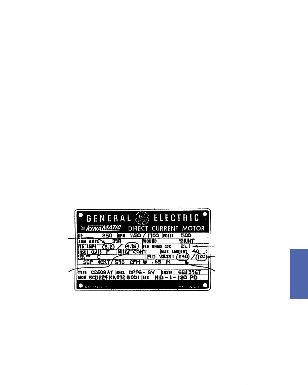
Serial Numbers are stamped on the nameplate. Model numbers are also on the nameplate. If the
nameplate is gone, the serial number is also metal stenciled into the frame, usually in the general area of
the nameplate. Modern serial numbers are AA–N–NNNN. Older motors can have a scheme NNNNNNN
(seven numbers).
The DC Buyers Guide (GEP387) has the most commonly used motors and accessories.
Please Note the renewal parts accessory guide at the end of this section.
Serial Numbers
Nameplate Info.
CD180AT – 500AT
CD580 –9000
IF@
Base
Speed
VF@
2 Circuit
VF@
1 Circuit
4 Field
Leads Out
IF@
Top
Speed
1 Circuit 1 Circuit

134 DC Motors
For more information contact a GE Motor Parts Master Distributor or GE Support Services.
7–Medium DC
Serial Numbers
Serial numbers are of the form… LL – B – NNN – KK
The letters stand for:
LL Month of year and manufacture...See table
B Place of manufacture...1 = Building 13, Erie, (medium)
2 Building 17, Erie, ( large)
8 Dothan Motor Plant, AL., (small)
NNN Consecutively numbered individual units each month
KK Month and year of shipment....See table.
Example: ZE – 1 – 125 – NF
Indicates—Erie, Medium, Shipped Jan’91
Note: Serial Number is also stamped in the frame, near the nameplate
YEAR
1965
1966
1967
1968
1969
1970
1971
1972
1973
1974
1975
1976
1977
1978
1979
1980
1981
1982
1983
1984
1985
1986
1987
1988
1989
1990
1991
1992
1993
1994
1995
1996
1997
1998
1999
2000
2001
2002
2003
2004
2005
2006
1923
1924
1925
1926
1927
1928
1929
1930
1931
1932
1933
1934
1935
1936
1937
1938
1939
1940
1941
1942
1943
1944
1945
1946
1947
1948
1949
1950
1951
1952
1953
1954
1955
1956
1957
1958
1959
1960
1961
1962
1963
1964
AA
AB
AC
AD
AE
AF
AG
AH
AJ
AK
AL
AM
AN
AP
AR
AS
AT
AU
AW
AX
AY
NA
NB
NC
ND
NE
NF
NG
NH
NJ
NK
NL
NM
NN
NP
NR
NS
NT
NV
NW
NX
NY
BA
BB
BC
BD
BE
BF
BG
BH
BJ
BK
BL
BM
BN
BP
BR
BS
BT
BU
BW
BX
BY
OA
OB
OC
OD
OE
OF
OG
OH
OJ
OK
OL
OM
ON
OP
OR
OS
OT
OV
OW
OX
OY
CA
CB
CC
CD
CE
CF
CG
CH
CJ
CK
CL
CM
CN
CP
CR
CS
CT
CU
CW
CX
CY
PA
PB
PC
PD
PE
PF
PG
PH
PJ
PK
PL
PM
PN
PP
PR
PS
PT
PV
PW
PX
PY
DA
DB
DC
DD
DE
DF
DG
DH
DJ
DK
DL
DM
DN
DP
DR
DS
DT
DU
DW
DX
DY
RA
RB
RC
RD
RE
RF
RG
RH
RJ
RK
RL
RM
RN
RP
RR
RS
RT
RV
RW
RX
RY
EA
EB
EC
ED
EE
EF
EG
EH
EJ
EK
EL
EM
EN
EP
ER
ES
ET
EU
EW
EX
EY
SA
SB
SC
SD
SE
SF
SG
SH
SJ
SK
SL
SM
SN
SP
SR
SS
ST
SV
SW
SX
SY
FA
FB
FC
FD
FE
FF
FG
FH
FJ
FK
FL
FM
FN
FP
FR
FS
FT
FU
FW
FX
FY
TA
TB
TC
TD
TE
TF
TG
TH
TJ
TK
TL
TM
TN
TP
TR
TS
TT
TV
TW
TX
TY
GA
GB
GC
GD
GE
GF
GG
GH
GJ
GK
GL
GM
GN
GP
GR
GS
GT
GU
GW
GX
GY
UA
UB
UC
UD
UE
UF
UG
UH
UJ
UK
UL
UM
UN
UP
UR
US
UT
UV
UW
UX
UY
HA
HB
HC
HD
HE
HF
HG
HH
HJ
HK
HL
HM
HN
HP
HR
HS
HT
HU
HW
HX
HY
VA
VB
VC
VD
VE
VF
VG
VH
VJ
VK
VL
VM
VN
VP
VR
VS
VT
VV
VW
VX
VY
JA
JB
JC
JD
JE
JF
JG
JH
JJ
JK
JL
JM
JN
JP
JR
JS
JT
JU
JW
JX
JY
WA
WB
WC
WD
WE
WF
WG
WH
WJ
WK
WL
WM
WN
WP
WR
WS
WT
WV
WW
WX
WY
KA
KB
KC
KD
KE
KF
KG
KH
KJ
KK
KL
KM
KN
KP
KR
KS
KT
KU
KW
KX
KY
XA
XB
XC
XD
XE
XF
XG
XH
XJ
XK
XL
XM
XN
XP
XR
XS
XT
XV
XW
XX
XY
LA
LB
LC
LD
LE
LF
LG
LH
LJ
LK
LL
LM
LN
LP
LR
LS
LT
LU
LW
LX
LY
YA
YB
YC
YD
YE
YF
YG
YH
YJ
YK
YL
YM
YN
YP
YR
YS
YT
YV
YW
YX
YY
MA
MB
MC
MD
ME
MF
MG
MH
MJ
MK
ML
MN
MM
MP
MR
MS
MT
MU
MW
MX
MY
ZA
ZB
ZC
ZD
ZE
ZF
ZG
ZH
ZJ
ZK
ZL
ZM
ZN
ZP
ZR
ZS
ZT
ZV
ZW
ZX
ZY
Jan Feb Mar Apr May June July Aug Sept Oct Nov Dec
PRIOR
YEARS
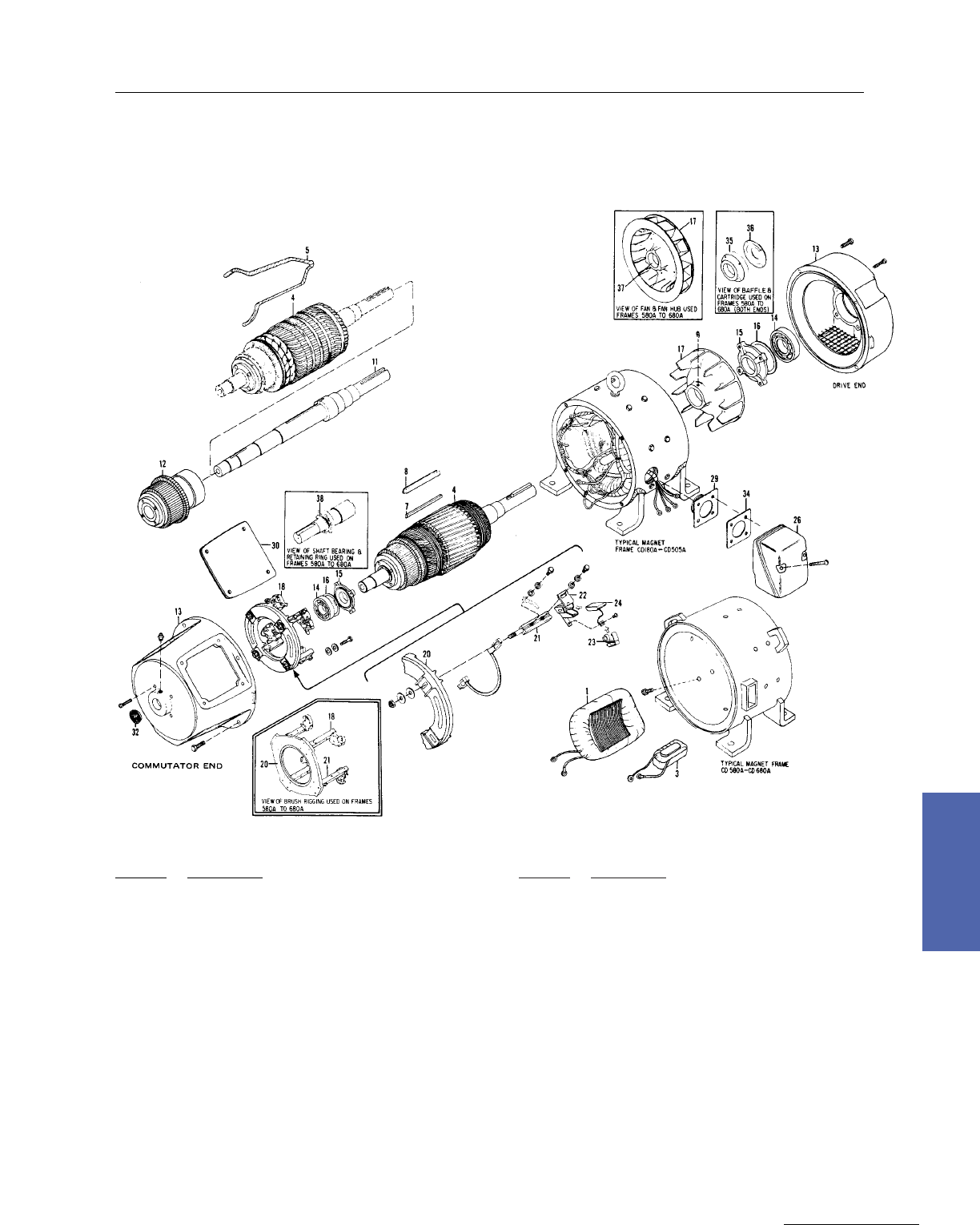
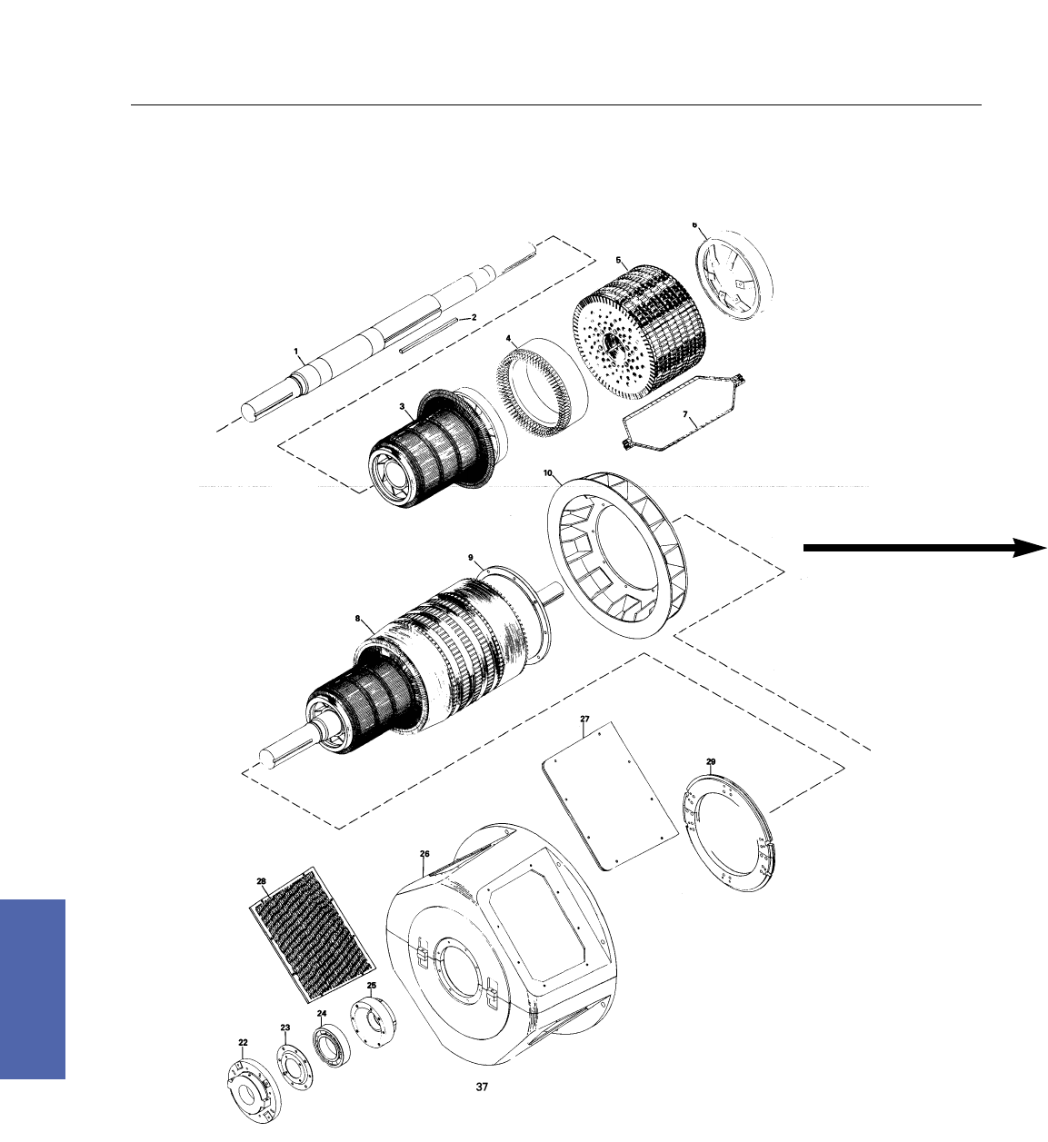
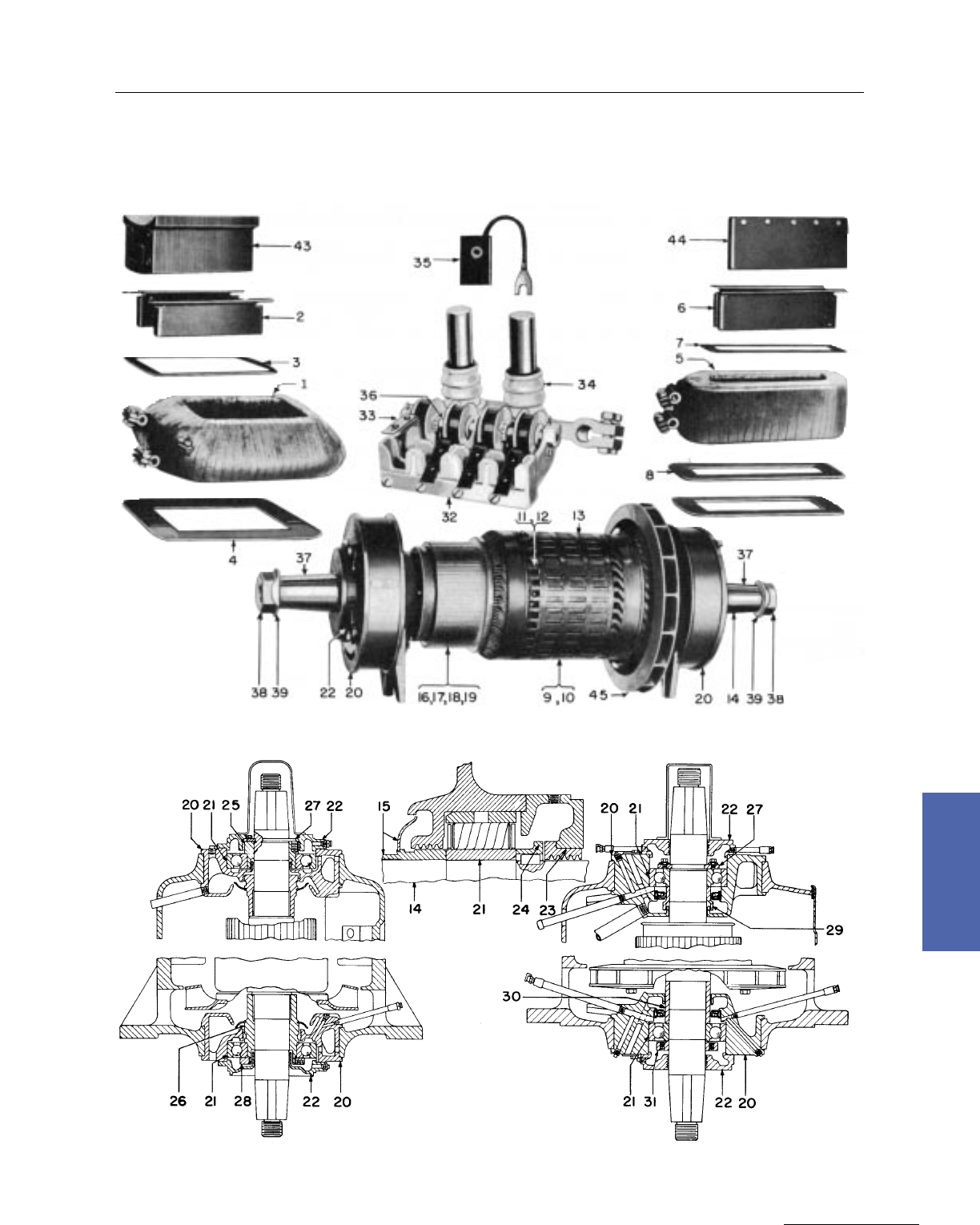
Ref. No. Description
1Coil, main and pole
3 Coil, comm and pole
4 Armature
5 Coil, armature
7 Wedge, slot (through CD250A)
8 Strip, slot insulation
11 Shaft, armature (not available for frame
256 and smaller)
12 Commutator
13 § Bracket, bearing
14 § Bearing, ball antifriction
15 § Cap, bearing
16 § Gasket, bearing cap
17 Fan, armature
Ref. No. Description
18 Rigging holder
20 Yoke , brush holder
21 Stud, brush holder
22 Brush holder (with pressure spring)
23 Spring, brush holder
24 Brush, carbon
26 Conduit box
29 Adapter, conduit box (not used on
CD580A & CD680A)
30 Cover, hand hole
32 Monogram (not used on CD580A & CD680A)
34 Gasket, adapter, conduit box
35 § Cartridge, bearing
36 § Baffle, metering plate
37 Hub, fan
38 § Ring, retaining
§Specify whether for drive end or commutator end.
Medium DC Motors 135
GE Support Services
7–Medium DC
Kinamatic I
Type CD, Frames 210A–680A
Exploded View, Type CD, Frames 215A to L685A

136 DC Motors
For more information contact a GE Motor Parts Master Distributor or GE Support Services.
7–Medium DC
Renewal Parts
As insurance against costly downtime, it is strongly recommended that spare parts be kept on hand in
accordance with the chart below.
Recommended Parts
NUMBER OF DUPLICATE MOTORS IN SERVICE
Description 1 2–4 5–10 10–20 More than 20
WITH OR WITHOUT ELECTRICAL SHOP FACILITIES
Complete Machine . . . . . . . . . 1 2
Drive End Ball Bearing 1 1 1 2 3
Commutator End Ball Bearing 1 1 1 2 3
Brushes (Sets) 2 4 6 8 10
Brush holders (Sets) . . . 1/2 1/2 1 1
Brush holder Spring (Sets) 1/2 1 1 2 2
Main Field Coil and Pole . . . 1 1 2 3
Commutating Field Coil and Pole . . . 1 1 2 3
Armature Complete* . . . 1 1 2 2
Blower vent, motors
Blower motors . . . 1 1 2 2
Filters 2 4 6 8 10
WITH ELECTRICAL SHOP FACILITIES
Shaft** . . . . . . . . . 1 1
Armature Rewinding Supplies . . . 1 1 2 3
*If shop facilities are available the quantity of armatures may be reduced by stocking the armature
parts listed in the second group.
** Shaft not replaceable in diameters 250 and smaller.
Kinamatic I
Type CD, Frames 210A–680A

Medium DC Motors 137
GE Support Services
7–Medium DC
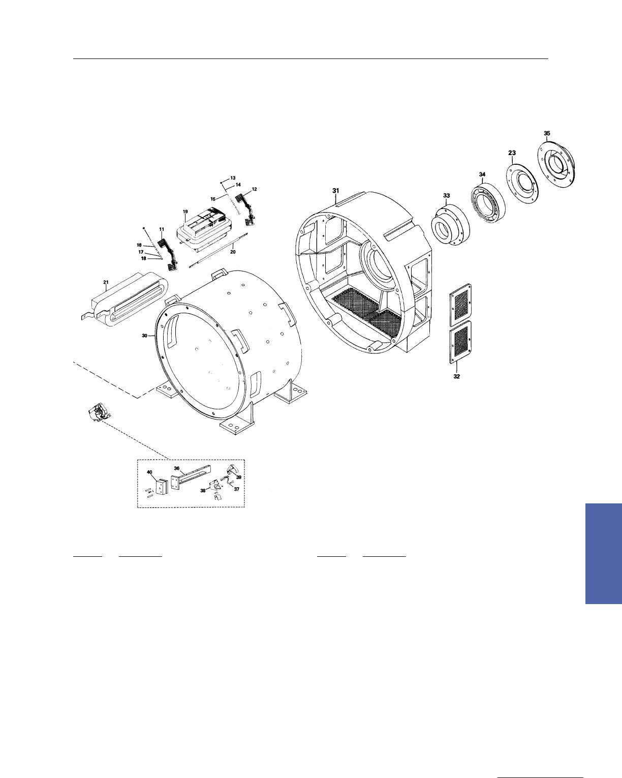
Kinamatic II
Type CD, Frames 180AT–500AT; Frames 2512AT, 2513AT, 2812AT, 2813AT
Approximate Net Weights*
*Appropriate weights for typical motors in each frame size. Does not
include weights of accessories such as tachometers, blowers, heat
exchangers, etc. For specific weights, refer to certified outline.
Frame Size Armature Weight
lbs. kgs. lbs. kgs.
Motor Weight
CDL182AT
CD186AT
CDL186AT
CD189AT
CD218AT
CD219AT
CD2110AT
CD258AT
CD259AT
CD287AT
CD288AT
CD289AT
CD2811AT
CD327AT
CD328AT
CD365AT
CD366AT
CD368AT
CD3610AT
CD3612AT
CD407AT
CDL407AT
CD409AT
CDL409AT
CD4012AT
CD504AT
CDL504AT
CD506AT
CDL506AT
CD508AT
CDL508AT
CD5010AT
17
25
35
45
50
56
63
78
89
113
130
175
210
158
181
220
260
300
400
530
400
400
500
500
780
590
590
720
720
890
890
1200
8
11
16
20
23
25
29
35
40
51
59
80
95
72
82
100
120
140
130
240
180
180
225
225
350
265
265
330
330
405
405
545
80
102
128
162
240
250
280
360
400
500
550
660
790
690
770
750
860
1020
1310
1650
1300
1350
1600
1650
3210
1900
2070
2290
2440
2810
2970
4260
36
46
58
74
106
114
127
164
183
225
250
300
360
315
350
340
390
465
595
750
590
610
725
750
1460
860
940
1040
1110
1275
1350
1935
Commutator
Diameters (IN INCHES)
Frame New Minimum
CD180AT 2.76 2.62
CD210AT 4.50 4.27
CD250AT 5.00 4.75
CD280AT 5.78 5.49
CD320AT 6.50 6.17
CD360AT 7.50 7.13
CD400AT 8.32 7.92
CD500AT 10.25 9.75
138 DC Motors
For more information contact a GE Motor Parts Master Distributor or GE Support Services.
7–Medium DC
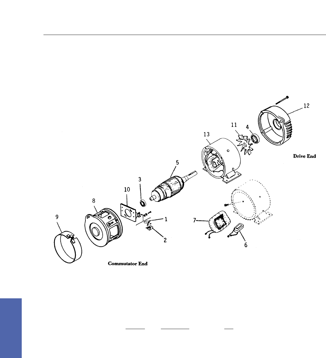
Ref. No. Description Qty.
1 Brush 2
2 Brush Springs 2
3 Bearing C.E. 1
4 Bearing D.E. 1
5 Armature 1
6 Coil & Pole Comm. 2
7 Coil Main 2
8 Bearing Bracket (CE) 1
9 Access Cover 1
10 Brush Rigging 1
11 Armature Fan 1
12 Bearing Bracket (DE) 1
13 Wound Frame Assembly 1
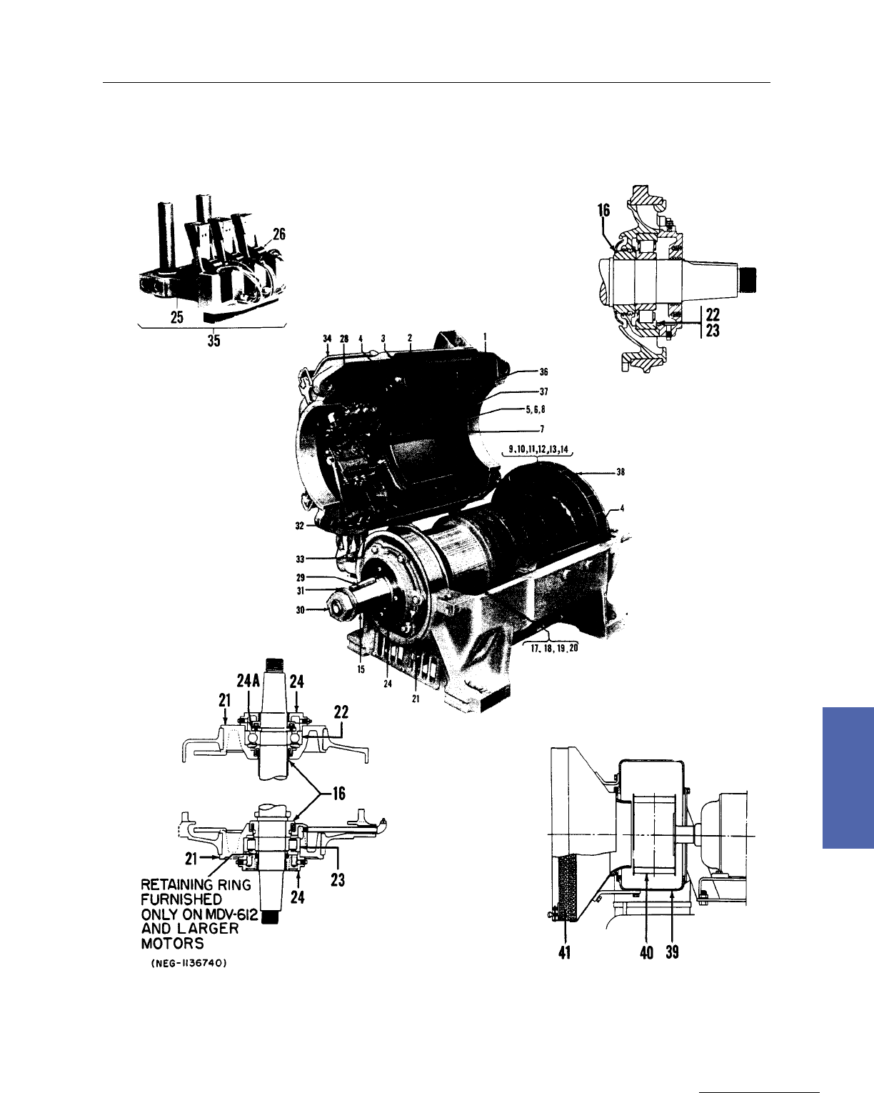
Exploded View, Kinamatic II • CD180AT Frames
Kinamatic II
CD180AT Frames
Ref. No. Description
1 Main Coil and Pole Assembly
3 Comm. Coil and Pole Assembly
4 Armature
5 Armature Coil
7 Slot Wedge (through CD400AT)
8 Slot Insulation (through CD400AT)
11 Armature Shaft and Core Assembly
12 Commutator
12A Balance Rings (used on CD180AT–CD320AT)
13 § Bearing Bracket
14 § Ball Bearing
15 § Bearing Cap
17 Armature Fan
§ Specify whether for drive end or commutator end
Ref. No. Description
18 Brush Rigging (includes complete assembly
for CD180AT)
20 Brushholder Yoke
21 Brushholder Stud (includes Insulator on CD500AT)
22 Brushholder (with Pressure Spring and Clip, if needed)
23 Brushholder Spring
24 Carbon Brush
26 Conduit Box
29 Conduit Box Adapter
30 § Bearing Bracket Covers (specify side, bottom or top)
32 Shaft Cover
34 Conduit Box Gasket
38 Bearing Retaining Ring (used on CD360AT–CD500AT
Drive End Only)
Medium DC Motors 139
GE Support Services
7–Medium DC
Exploded View, Kinamatic II • CD210AT–CD500AT Frames
Kinamatic II
CD210AT–CD500AT Frames

140 DC Motors
For more information contact a GE Motor Parts Master Distributor or GE Support Services.
7–Medium DC
5CD14 – (CD1801A) – Example 5CD14E01A900001
Qty. 1 – 36A164935AAG01 – Brush Rigging
Qty. 2 – 36A164933CAG01 – Spring Only
Qty. 2 – 894A506 P01 – Brush
5CD142 – 143 – 144 – 145 – (CD180AT) – Example 5CD143BA001A001
Qty. 1 – 36A167271AAG01 – Brush Rigging
Qty. 2 – 36B467022AA001 – Spring Only
Qty. 2 – 36A167400AAP01 – Brush GE–581 GRADE .375 X 1.00
5CD152 – 153 – 154 – (CD210AT) – Example 5CD152JA003B007
The winding letter determines brush rigging quantities:
A to S – Qty is 2 per motor
T to X – Qty. is 4 per motor
Z – Consult Factory
36A167280AAG01 – Brushholder with Spring
36B467011AA001 – Brushholder only
36B467020AA001 – Spring only – 2.9 lbs. Max. 2.00 lbs Min.
36A167401AAP08 – Brush T–563 Grade .625 x .875 x 1.5 (.70 is min length)
36A167401AAP02 – Brush T–566 Grade Papermill & Extruder
5CD163 – 164 – (CD250AT) – Example 5CD163RA001A014
The winding letter determines brush rigging quantities:
A to N – Qty is 2 per motor
P to W – Qty. is 4 per motor
Z – Consult Factory
36A167280AAG01 – Brushholder with Spring
36B467011AA001 – Brushholder only
36B467020AA001 – Spring only – 2.9 lbs. Max. 2.00 lbs Min.
36A167401AAP08 – Brush T–563 Grade .625 x .875 x 1.5 (.70 is min length)
36A167401AAP02 – Brush T–566 Grade Papermill & Extruder
5CD173 – 174 – (CD280AT) – Example 5CD174RA006A034
The winding letter determines brush rigging quantities:
A to T – Qty is 2 per motor
U to X – Qty. is 4 per motor
Z – Consult Factory
36A167281AAG01 – Brushholder with Spring
36B467012AA001 – Brushholder only
36B467021AA001 – Spring only – 4.75 lbs. Max. 3.0 lbs Min.
36A167402AAP04 – Brush T–563 Grade .75 x 1.25 x 2.0 (.90 is min length)
36A167402AAP02 – Brush T–566 Grade Papermill & Extruder
5CD362 – 363 – (CD2512AT and CD2513AT) – Example 5CD363MA001A001
5CD372 – 373 – (CD2812AT and CD2813AT) – Example 5CD373LA003A007
The winding letter determines brush rigging quantities:
A to P – Qty is 2 per motor
R to X – Qty. is 4 per motor
Z – Consult Factory
36B473004AAG01 – Brushholder only for CD2512 and CD2513
36B473004AAG02 – Brushholder only for CD2812 and CD2813
36C703083AA001 – Spring only – 5.1 lbs. Max. 4.0 lbs Min.
36A171014AAP11 – Brush T–559 Grade 1.00 x 1.25 x 2.6 (1.00 is min length)
36A171014AAP12 – Brush T–566 Grade Papermill & Extruder
Kinamatic II
CD180 to CD500AT
Identification of Brushholders, Springs and Brushes
Medium DC Motors 141
GE Support Services
7–Medium DC
5CD183 – 184 – (CD320AT) – Example 5CD184TA004A010
The winding letter determines brush rigging quantities:
A to R – Qty is 2 per motor
S to Y – Qty. is 4 per motor
X – Qty. is 6 per motor
Z – Consult Factory
36A167281AAG01 – Brushholder with Spring
36B467012AA001 – Brushholder only
36B467021AA001 – Spring only – 4.6 lbs. Max. 3.0 lbs Min.
36A167402AAP04 – Brush T–563 Grade
.75 x 1.25 x 2.0 (.90 is min length)
36A167402AAP02 – Brush T–566 Grade Papermill & Extruder
5CD192 – 193 – 194 – (CD360AT) – Example 5CD193PA007A814
The winding letter determines brush rigging quantities:
D to P – Qty is 4 per motor
B,C,R,S,T,X – Qty. is 8 per motor
U,V,W – Qty. is 12 per motor
Z – Consult Factory
36A160426AAG01 – Brushholder with Spring
36B465476AA001 – Brushholder only
36B465486AA001 – Spring only (86A) – 4.75 lbs. Max. 3.0 lbs Min.
36A164456AAP21 – Brush T–563 Grade .625 x 1.25 x 2.1 (1.06 is min length)
36A164456AAP05 – Brush T–566 Grade Papermill & Extruder
5CD203 – 204 (CD400AT) – Example 5CD203PA001A007
The winding letter determines brush rigging quantities:
D to M – Qty is 4 per motor
B,C,N,P,R – Qty. is 8 per motor
A,S,T,X,Y – Qty. is 12 per motor
u,v,w – Qty. is 16 per motor
Z – Consult Factory
36A160421AAG02 – Brushholder with Spring
36B465471AA001 – Brushholder only
36B465481AA001 – Spring only (81A) – 4.75 lbs. Max. 3.62 lbs Min.
36A164451ABP18 – Brush T–563 Grade .75 x 1.5 x 2.75 (1.5 is min length)
36A164451ABP05 – Brush T–566 Grade Papermill & Extruder
5CD222 – 223 – 224 – 226 – (CD500AT) – Example 5CD224TA010B024
The winding letter determines brush rigging quantities:
F to L – Qty is 4 per motor
D,E,M,N,P – Qty. is 8 per motor
C,R,S,Y – Qty. is 12 per motor
A,B,T – Qty. is 16 per motor
U,V,W – Qty. is 20 per motor
Z – Consult Factory
36A160422AAG02 – Brushholder with Spring
36B465472AA001 – Brushholder only
36B465482AA001 – Spring only (82A) – 5.6 lbs. Max. 4.6 lbs Min.
36A164452AAP21 – Brush T–563 Grade .88 x 1.5 x 3.25 (1.6 is min length)
36A164452AAP05 – Brush T–566 Grade Papermill & Extruder
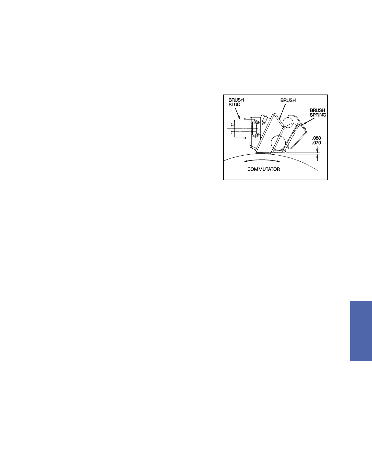
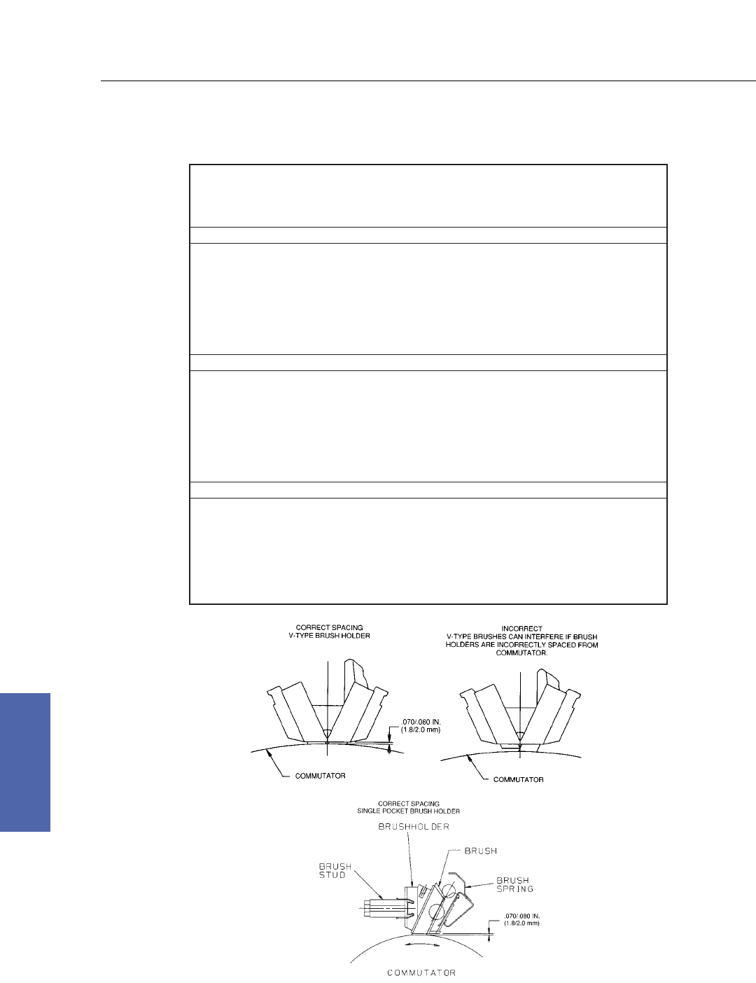
Correct Spacing of Brushholder
to Commutator
Kinamatic II
CD180 to CD500AT
Identification of Brushholders, Springs and Brushes

142 DC Motors
For more information contact a GE Motor Parts Master Distributor or GE Support Services.
7–Medium DC
Kinamatic II
Standard Bearing Information
The following chart shows
the standard ball bearings
used in Kinamatic motors.
Standard practice for
oversized shafts and/or
oversized ball bearings is to
use the ball bearing size of
the next larger frame (no
oversized bearings or shafts
available in CD5010AY
frame). This chart does not
apply to motors with roller
bearings. Non–standards are
manufactured for special
applications. Therefore, not
all Kinamatic motors follow
the chart below. Refer to GE
Support Services for
non–standard motors.
Standard Bearings for Kinamatic DC Motors
Drive End Comm End
Frame Size GE Part Number GE Part Number
CD140AT 894A605ZJ 005 894A605ZJ 004
CD2512AT / CD2513AT 894A605AB 009 894A605AB 007
CD2812AT / CD2813AT 894A605AB 010 894A605AB 009
CD180AT 894A605ZJ 006 894A605ZJ 006
CD210AT 894A605ZJ 007 894A605ZJ 006
CD250AT 894A605 009 894A605 007
CD280AT 894A605 010 894A605 009
CD320AT 894A605 011 894A605 010
CD360AT 894A605 013 894A605 011
CD400AT 894A605 014 894A605 013
CD504AT / CD508AT 894A605 018 894A605 016
CD5010AY 894A605 022 894A605 018
CD6000 894A605 023 894A605 020
CD6100 894A605 025 894A605 023
CD6200 894A605 027 894A605 025
CD6700 894A605 029 894A605 029
CD6800 894A605 029 894A605 029
CD6900 894A605 031 894A605 031
Renewal Parts Service
The Kinamatic motor is designed for tough industrial applications. Maintain the original performance
standards of the Kinamatic design by using genuine GE renewal parts. Kinamatic renewal parts, such as
main and commutator coils, pole assemblies, and armature coils are produced to original factory
specifications including form fits, materials, and dimensions. A permanently attached stainless steel
nameplate displays the model and serial number, providing all the information needed for ordering.
Parts are available directly from authorized GE parts distributors. For authorized distributor information
or technical support, contact GE Support Services. Also, Repair service is available from authorized GE
service facilities.
Recommended Spare Parts for Frames CD180AT–CD500AT
In an effort to minimize costly downtime, it is recommended that spare parts be kept on hand in
accordance with the chart below:
Number of Duplicate Motors in Service
Description 1 2–4 5–10 10–20 More than 20
With or Without Electrical Shop Facilities
Complete Machine . . . . . . . . . 1 2
Ball Bearing (sets) 1 1 1 2 3
Brushes (Sets) 2 4 6 8 10
Brushholders (Sets) . . . 1/2 1/2 1 1
Brushholder Springs (Sets) 1/2 1 1 2 2
Main Field Coil and Pole . . . 1 1 2 3
Commutating Field Coil and Pole . . . 1 1 2 3
Armature Complete . . . 1 1 2 2
Blower Ventilated, motors
Blower motors . . . 1 1 2 2

Medium DC Motors 143
GE Support Services
7–Medium DC
Typical Weights* Commutator Diameters (in Inches)
Frame Motor (Less Armature Start Min. Wear
Size Accessories)
CD2512AT 500 120 5.30 5.02 0.140
CD2513AT 550 135
CD2812AT 650 160 5.96 5.66 0.150
CD2813AT 750 190
Kinamatic II
Type CD, Frames 2512AT, 2513AT, 2812AT, 2813AT
* Typical weights. For specific weight, see certified outline.
144 DC Motors
For more information contact a GE Motor Parts Master Distributor or GE Support Services.
7–Medium DC
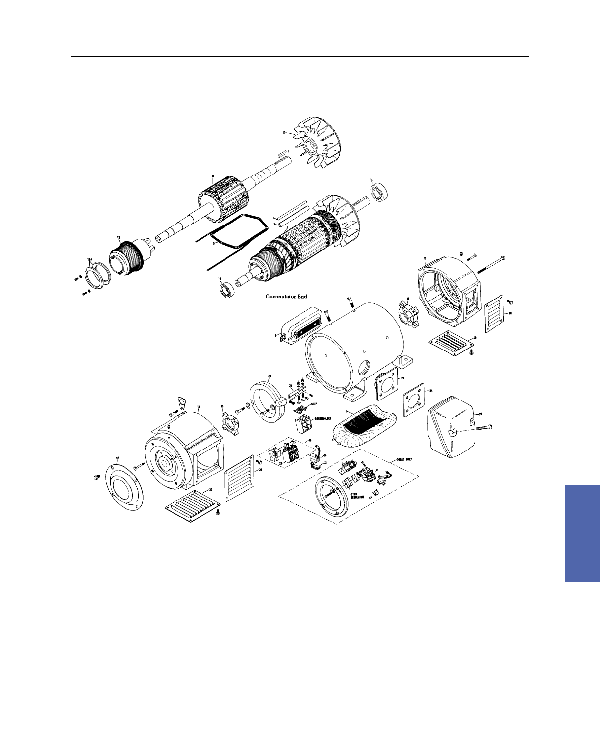
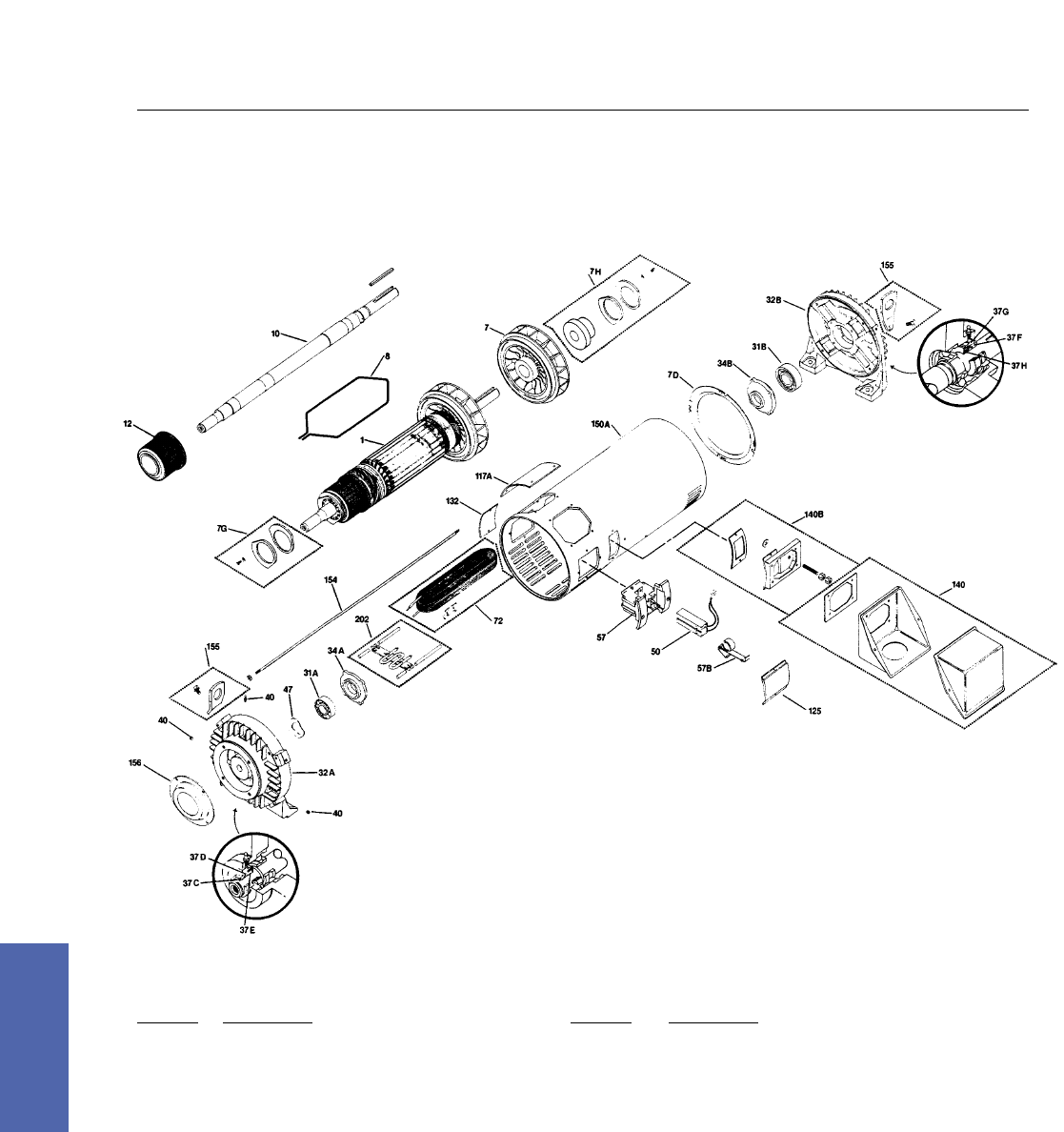
Exploded View, Type CD Frames 2512AT–2813AT
Ref. No. Description Ref. No. Description
1 Armature 37G Bearing Seal, Adapter DE (when specified)
7 Armature Fan 37H Bearing Seal, Rubbing DE (when specified)
7D Armature Baffle 40 Grease Fitting Kit
7G Balance Ring Kit, CE 47 Bearing Preload Spring
7H Balance Ring Kit, DE 50 Brush
8 Armature Rewind Kit 57 Brush Holder
10 Shaft w/Key 57B Brush Holder Spring
12 Commutator (Requires No. 8 Rewind Kit) 72 Comm Coil Kit
31A Bearing, CE 117A Cover, Top CE, Solid
31B Bearing, DE 125 Cover, Brush Holder w/Gasket
32A Bearing Bracket, CE 132 Cover, Opposite Conduit Box
32B Bearing Bracket, DE 140 Conduit Box
34A Bearing Cap, CE 140B Conduit Box Adapter Kit
34B Bearing Cap, DE 150A Coiled Frame
37C Bearing Seal, Labyrinth CE (when specified) 153 Shaft Thimble
37D Bearing Seal, Adapter CE (when specified) 154 Bracket to Frame Stud
37E Bearing Seal, Rubbing CE (when specified) 155 Lifting Lug Kit
37F Bearing Seal, Labyrinth DE (when specified) 202 Space Heater Kit
Kinamatic II
Type CD, Frames 2512AT, 2513AT, 2812AT, 2813AT

Medium DC Motors 145
GE Support Services
7–Medium DC
CD4350
CD4352
CD4354
CD4355
CD4357
CD4358
CD4359
CD4362
CD4363
CD4366
CD4454
CD4457
CD4460
CD4463
CD4464
CD4465
CD4468
CD4469
CD4473
CD4477
CD4559
CD4562
CD4566
CD4568
CD4570
CD4571
CD4575
CD4580
CD4670
CD4673
CD4674
CD4677
CD4678
CD4681
CD4682
CD4686
CD4773
CD4776
CD4780
CD4781
CD4784
CD4785
CD4789
CD4791
CD4793
CD4799
LBS.
3900
4200
4100
4700
4500
5300
5000
6000
5600
6300
5800
6500
7300
6300
8300
7000
7800
9500
8800
10000
9800
11100
12700
10400
11700
14500
13300
15200
14700
16100
15300
17900
16900
18700
19900
20600
18700
20800
23500
20100
21900
26100
24600
29700
27200
30800
KG
1770
1910
1860
2130
2040
2400
2270
2720
2540
2860
2630
2950
3310
2860
3760
3180
3540
4310
3990
4540
4450
5040
5760
4720
5310
6580
6030
6890
6670
7300
6940
8120
7670
8480
9030
9340
8480
9430
10660
9120
9930
11840
11160
13470
12340
13970
LBS.
1100
1200
1300
1400
1500
1500
1600
1700
1800
1900
1700
1900
2200
2400
2500
2500
2700
2800
3000
3200
2700
3100
3600
3700
4000
4100
4300
4500
4400
5000
5100
5700
5700
6200
6400
6500
5400
5900
6700
6700
6900
6900
7400
8200
8200
9300
KG
500
540
600
640
680
680
730
770
820
860
770
860
1000
1090
1130
1130
1230
1270
1360
1450
1230
1410
1630
1600
1810
1860
1980
2040
2000
2270
2310
2590
2590
2810
2900
2950
2450
2680
3040
3040
3130
3130
3360
3720
3720
4220
Aprox. Net Weight
Frame Aprox. Arm Net Weight
Types CD and MCD, Frames 4300 to 4700
146 DC Motors
For more information contact a GE Motor Parts Master Distributor or GE Support Services.
7–Medium DC
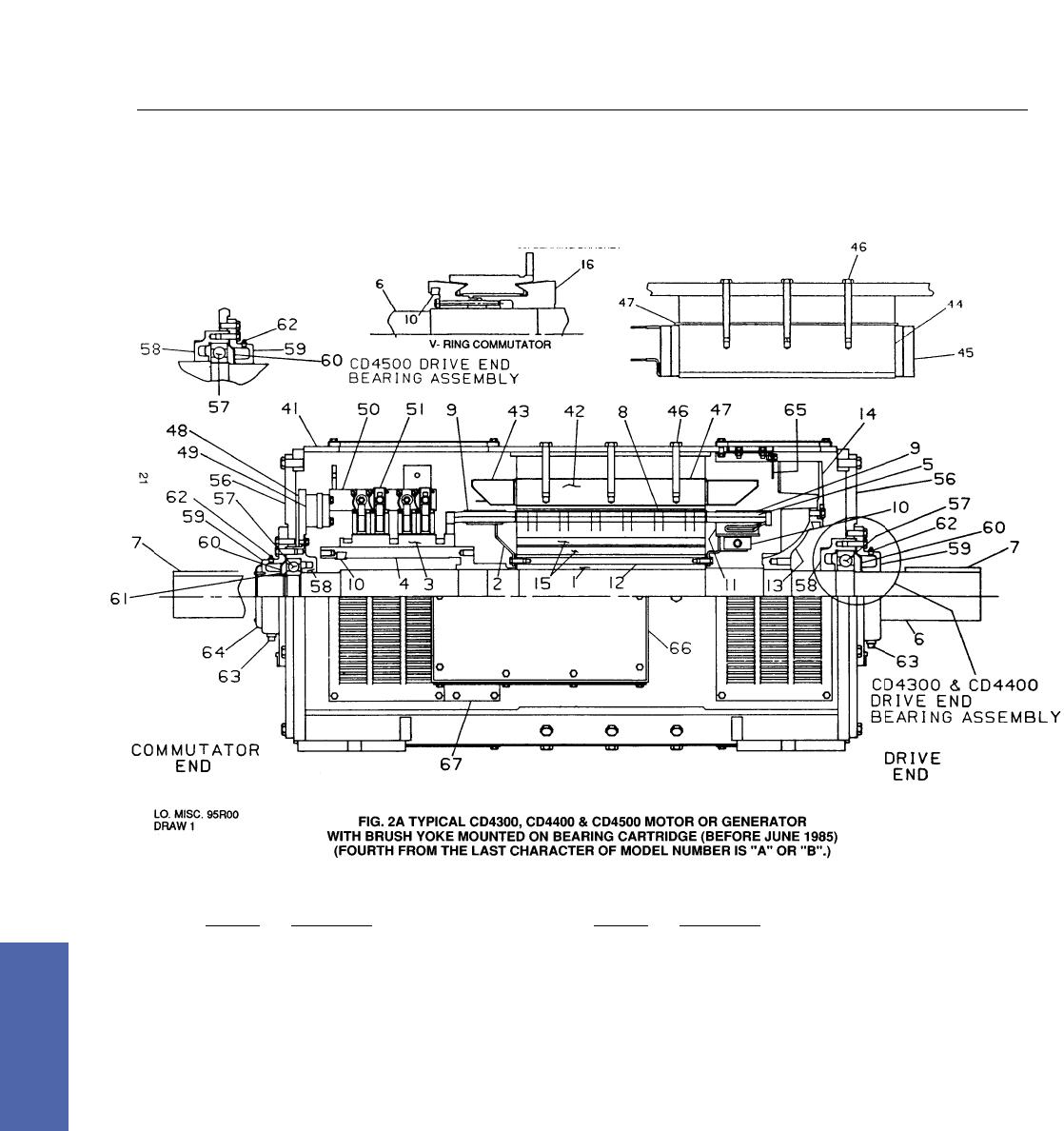
Type CD, Frames 4300, 4400 and 4500
Rotating Parts
Ref. No. Description
1 Armature Core
2 Armature Coil Support
3 Commutator (Glass–Banded)
4 Commutator Shell
5 Armature Coils
6 Shaft
7 Key
8 Glass Banding (Core)
9 Glass Banding (End Turns)
10 Balance Weight
11 Molded Equalizer or Armature Coil Support
12 Core Rivet
13 Fan Hub (Self–Vent Only)
14 Fan (Self–Vent. Only)
15 Axial Vent Holes
16 Commutator (V–Ring)
Stationary Parts
Ref. No. Description
41 Magnet Frame
42 Main Pole
43 Main Coil
44 Commutating Pole
45 Commutating Coil
46 Pole Bolt
47 Pole Shims
48 Brush Holder Yoke
49 Insulation Block
50 Brush Holder Stud
51 Brush Holder & Spring
56 Bearing Bracket
57 Ball Bearing
58 Bearing Cartridge
58 Bearing Cap
60 Grease Metering Plate
61 Bearing Retaining Ring
62 Grease Fitting
63 Grease Relief Plug
64 Shaft Cover
65 Fan Baffle (Self–Vent. Only)
66 Conduit Box
67 Conduit Box Adapter
Medium DC Motors 147
GE Support Services
7–Medium DC
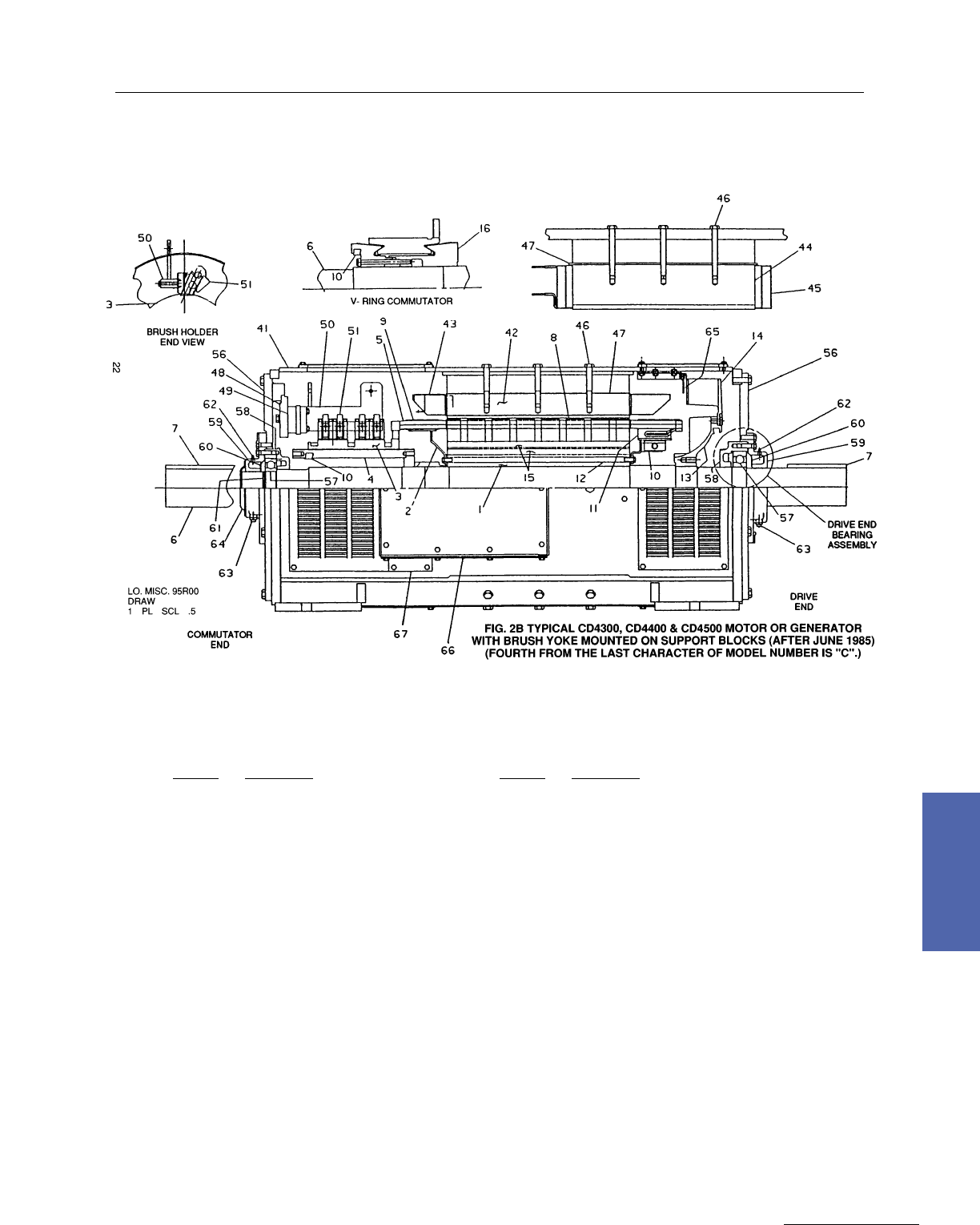
Type CD, Frames 4300, 4400 and 4500
Rotating Parts
Ref. No. Description
1 Armature Core
2 Armature Coil Support
3 Commutator (Glass–Banded)
4 Commutator Shell
5 Armature Coils
6 Shaft
7 Key
8 Glass Banding (Core)
9 Glass Banding (End Turns)
10 Balance Weight
11 Molded Equalizer Or Armature Coil Support
12 Core Rivet
13 Fan Hub (Self–Vent. Only)
14 Fan (Self–Vent. Only)
15 Axial Vent Holes
16 Commutator (V–Ring)
Stationary Parts
Ref. No. Description
41 Magnet Frame
42 Main Pole
43 Main Coil
44 Commutating Pole
45 Commutating Coil
46 Pole Bolt
47 Pole Shims
49 Brush Holder Yoke
49 Insulation Block
50 Brush Holder Stud
51 Brush Holder & Spring
56 Bearing Bracket
57 Ball Bearing
58 Bearing Cartridge
59 Bearing Cap
60 Grease Metering Plate
61 Bearing Retaining Ring
62 Grease Fitting
63 Grease Relief Plug
64 Shaft Cover
65 Fan Baffle (Self–Vent. Only)
66 Conduit Box
67 Conduit Box Adapter
148 DC Motors
For more information contact a GE Motor Parts Master Distributor or GE Support Services.
7–Medium DC
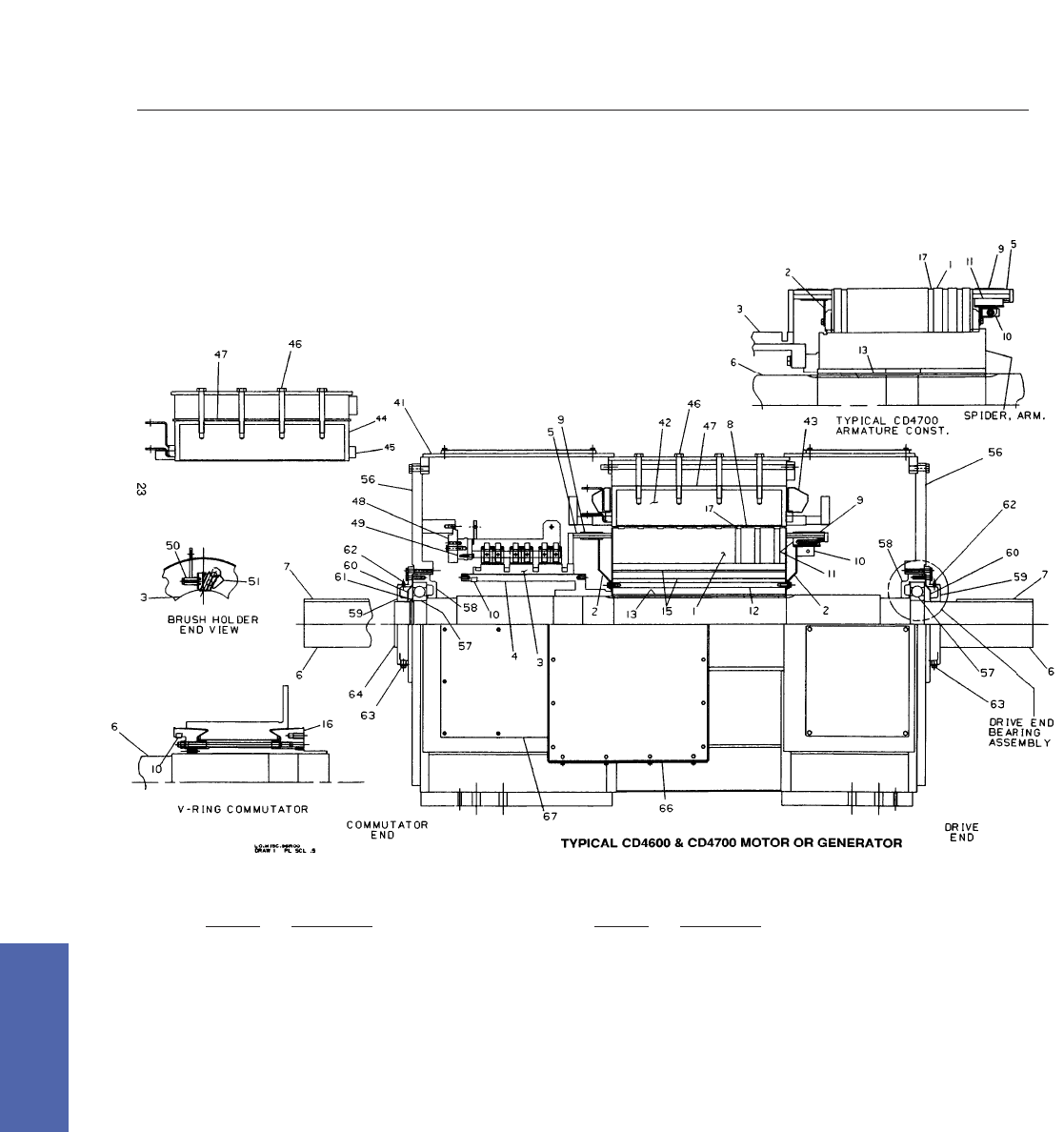
Type CD, Frames 4600 and 4700
Rotating Parts
Ref. No. Description
1 Armature Core
2 Armature Coil Support
3 Commutator (Glass–Banded)
4 Commutator Shell
5 Armature Coils
6 Shaft
7 Key
8 Glass Banding (Core)
9 Glass Banding (End Turns)
10 Balance Weight
11 Molded Equalizer Or Armature Coil Support
12 Core Rivet
13 Armature Core Key
15 Axial Vent Holes
16 Commutator (V–Ring)
17 Radial Ventilation Ducts
Stationary Parts
Ref. No. Description
41 Magnet Frame
42 Main Pole
43 Main Coil
44 Commutating Pole
45 Commutating Coil
46 Pole Bolt
47 Pole Shims
48 Brush Holder Yoke
49 Insulation Block
50 Brush Holder Stud
51 Brush Holder & Spring
56 Bearing Bracket
57 Ball Bearing
58 Bearing Cartridge
59 Bearing Cap
60 Grease Metering Plate
61 Bearing Retaining Ring
62 Grease Fitting
63 Grease Relief Plug
64 Shaft Cover
66 Conduit Box
67 Conduit Box Adapter
Medium DC Motors 149
GE Support Services
7–Medium DC
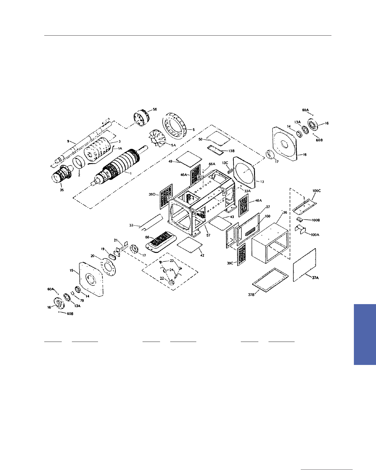
Type CD, Frames 4300–4500 (Four Pole)
Type CD, Frames 4600–4700 (Six Pole)
Exploded View, Type CD and MCD Renewal Parts. Four pole Motor shown,
but parts identification are typical to both Four and Six pole Motors.
Ref. No. Description
1 Armature
1A Armature Coil
2 Armature Coil Support
3 Armature Core
5 Armature Fan
5A Armature Fan Hub
9 Armature Shaft
13 Baffle, Fan
13A Baffle, Metering Plate
13B Baffle, Handhole Fan
13C Baffle, Hand Hole Bracket
14 Bearing
15 Bearing Bracket
16 Bearing Cap
17 Bearing Cartridge
19 Brushholder Stud Ins Blk
Ref. No. Description
20 Brushholder Yoke
21 Brushholder Stud
22 Brushholder (w/Spring)
23 Brushholder Spring
24 Brush
33 Comm Coil & Pole
33A Comm Coil & Pole Bolt
35 Commutator
36 Conduit Box
37 Conduit Box Adapter
37A Conduit Box Cover–End
37B Conduit Cox Cover–Bottom
39C Cover, Adapter Conduit–CE
39D Cover, Side Louvered–CE
42 Cover, Bottom–CE
43 Cover, Bottom–DE
Ref. No. Description
46A Cover, Side Louvered–DE
49 Cover, Top–CE
50 Cover, Top–DE
56 Equalizer Coil
57 Frame
60A Grease Fitting
60B Grease Pipe Plug
66 Main Coil & Pole
66A Main Coil & Pole Bolt
79 Retaining Ring
100 Terminal Board
100A Line Adapter, Arma Series Fld.
100B Line Adapter, Ins. Blk.
100C Line Adapter Support
150 DC Motors
For more information contact a GE Motor Parts Master Distributor or GE Support Services.
7–Medium DC
Brush Box Spacing
Type CD and MCD, Frames 4300–4700
CD4000
V – Holder Style Brush Rigging
Identification of Brushholders, Springs, and Brushes
.375 x 1.50 Brush
36A172040AAG03 Brushholder with Springs
36C702000AA003 Brushholder only
36B472000AA003 Springs Only (0A3) 3.0 lbs max. 2.16 lbs min.
36A164454DAP01 Brush T–563 Grade .375 x 1.5 x 2.5 (1.25 is min. length)
36A164454DAP05 Brush T–606 Grade Papermill
36A164454DAP02 Brush T–566 Grade Extruder
.500 x 1.50 Brush
36A172040AAG02 Brushholder with Springs
36C702000AA002 Brushholder only
36B472000AA002 Springs Only (0A2) 4.0 lbs max. 2.7 lbs min.
36A164455DAP01 Brush T–563 Grade .50 x 1.5 x 2.5 (1.25 is min. length)
36A164455DAP05 Brush T–606 Grade Papermill
36A164455DAP02 Brush T–566 Grade Extruder
.625 x 1.50 Brush
36A172040AAG01 Brushholder with Springs
36C702000AA001 Brushholder only
36B472000AA001 Springs Only (0A1) 5.75 lbs max. 3.4 lbs min.
36A164456DAP01 Brush T–563 Grade .625 x 1.5 x 2.5 (1.25 is min. length)
36A164456DAP05 Brush T–606 Grade Papermill
36A164456DAP02 Brush T–566 Grade Extruder

Medium DC Motors 151
GE Support Services
7–Medium DC
Type CD and MCD,
Frames 6000–6200, 6700–6900
Typical Weights**
Frame
CD6050
CD6052
CD6054
CD6055
CD6057
CD6058
CD6059
CD6062
CD6063
CD6066
CD6154
CD6157
CD6160
CD6163
CD6164
CD6165
CD6168
CD6169
CD6173
CD6177
CD6259
CD6262
CD6266
CD6268
CD6270
CD6271
CD6275
CD6280
lbs.
3900
4200
4100
4700
4500
5300
5000
6000
5600
6300
5800
6500
7300
6300
8300
7000
7800
9500
8800
10000
9800
11100
12700
10400
11700
14500
13300
15200
kgs.
1770
1910
1860
2130
2040
2400
2270
2720
2540
2860
2630
2950
3310
2860
3760
3180
3540
4310
3990
4540
4450
5040
5760
4720
5310
6580
6030
6890
lbs.
1100
1200
1300
1400
1500
1500
1600
1700
1800
1900
1700
1900
2200
2400
2500
2500
2700
2800
3000
3200
2700
3100
3600
3700
4000
4100
4300
4500
kgs
500
540
600
640
680
680
730
770
820
860
770
860
1000
1090
1130
1130
1230
1270
1360
1450
1230
1410
1630
1600
1810
1860
1980
2040
FRAME
CD6766
CD6770
CD6771
CD6774
CD6776
CD6778
CD6779
CD6785
CD6873
CD6876
CD6881
CD6882
CD6885
CD6887
CD6890
CD6896
CD6977
CD6981
CD6985
CD6986
CD6990
CD6991
CD6996
CD6999
lbs.
12100
14000
12400
15200
14000
15600
17200
17600
16000
17700
20300
16800
18500
23500
21000
23500
23400
26000
28700
24300
26900
31700
29600
34400
kgs
5490
6350
5630
6900
6350
7080
7810
7990
7260
8040
9220
7630
8400
10670
9530
10670
10620
11800
13030
11030
12210
14390
13440
15620
lbs.
3565
3915
3835
4410
4185
4685
4920
5205
4730
5120
6090
5250
5640
7440
6610
7960
5925
6685
7540
6480
7240
8770
8095
9325
kgs
1620
1780
1740
2000
1900
2130
2230
2360
2150
2320
2560
2380
2860
3380
3000
3610
2690
3030
3420
2940
3290
3980
3680
4230
Approx.
Net Weight Approx. Arm
Net Weight Approx.
Net Weight Approx. Arm
Net Weight
** Approximate weights for typical motors in each
frame size. Does not include weight of accessories
such as tachometers, blowers, heat exchangers,
etc. For specific weights, refer to certified outline.
152 DC Motors
For more information contact a GE Motor Parts Master Distributor or GE Support Services.
7–Medium DC
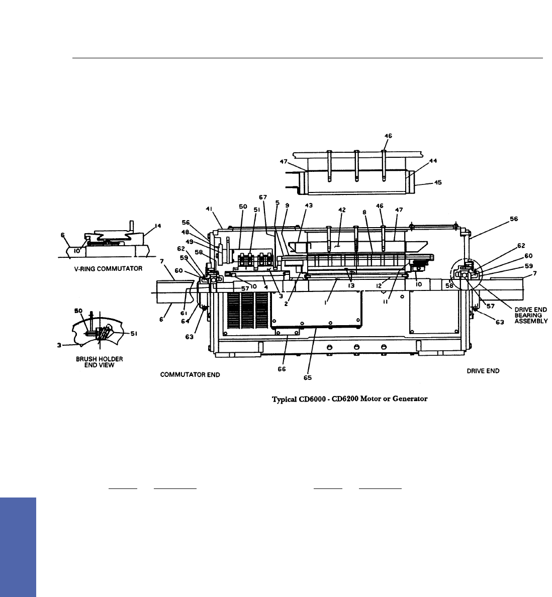
Type CD, Frames 6000 and 6200
Rotating Parts
Ref. No. Description
1 Armature Core
2 Armature Coil Support
3 Commutator (Glass–Banded)
4 Commutator Shell
5 Armature Coils
6 Shaft
7 Key
8 Glass Banding (Core)
9 Glass Banding (End Turns)
10 Balance Weight
11 Molded Equalizer or Armature Coil Support
12 Core Rivet
13 Axial Vent Holes
14 Commutator (V–Ring)
Stationary Parts
Ref. No. Description
41 Magnet Frame
42 Main Pole
43 Main Coil
44 Commutating Pole
45 Commutating Coil
46 Pole Bolt
47 Pole Shims
48 Brush Holder Yoke
49 Insulation Block
50 Brush Holder Stud
51 Brush Holder & Spring
56 Bearing Bracket
57 Ball Bearing
58 Bearing Cartridge
59 Bearing Cap
60 Grease Metering Plate
61 Bearing Retaining Ring
62 Grease Fitting
63 Grease Relief Plug
64 Shaft Cover
66 Conduit Box
67 Air Baffle (on CD6000 only)
Medium DC Motors 153
GE Support Services
7–Medium DC
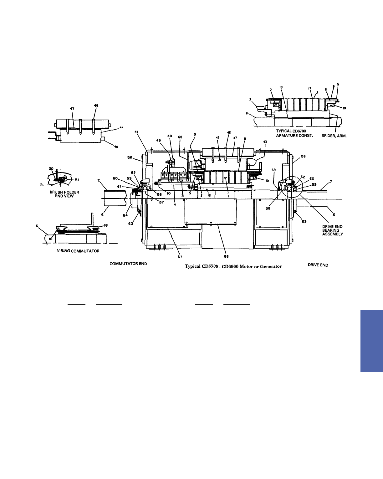
Type CD, Frames 6700–6900
Rotating Parts
Ref. No. Description
1 Armature Core
2 Armature Coil Support
3 Commutator (Glass–Banded)
4 Commutator Shell
5 Armature Coils
6 Shaft
7 Key
8 Glass Banding (Core)
9 Glass Banding (End Turns)
10 Balance Weight
11 Molded Equalizer or Armature Coil Support
13 Armature Core Key
16 Commutator (V–Ring)
17 Radial Ventilation Ducts
Stationary Parts
Ref. No. Description
41 Magnet Frame
42 Main Pole
43 Main Coil
44 Commutating Pole
45 Commutating Coil
46 Pole Bolt
47 Pole Shims
48 Brush Holder Yoke
49 Insulation Block
50 Brush Holder Stud
51 Brush Holder & Spring
56 Bearing Bracket
57 Ball Bearing
58 Bearing Cartridge
59 Bearing Cap
60 Grease Metering Plate
61 Bearing Retaining Ring
62 Grease Fitting
63 Grease Relief Plug
64 Shaft Cover
66 Conduit Box
66 Conduit Box Adapter
67 Air Baffle (on CD6200 only)
154 DC Motors
For more information contact a GE Motor Parts Master Distributor or GE Support Services.
7–Medium DC
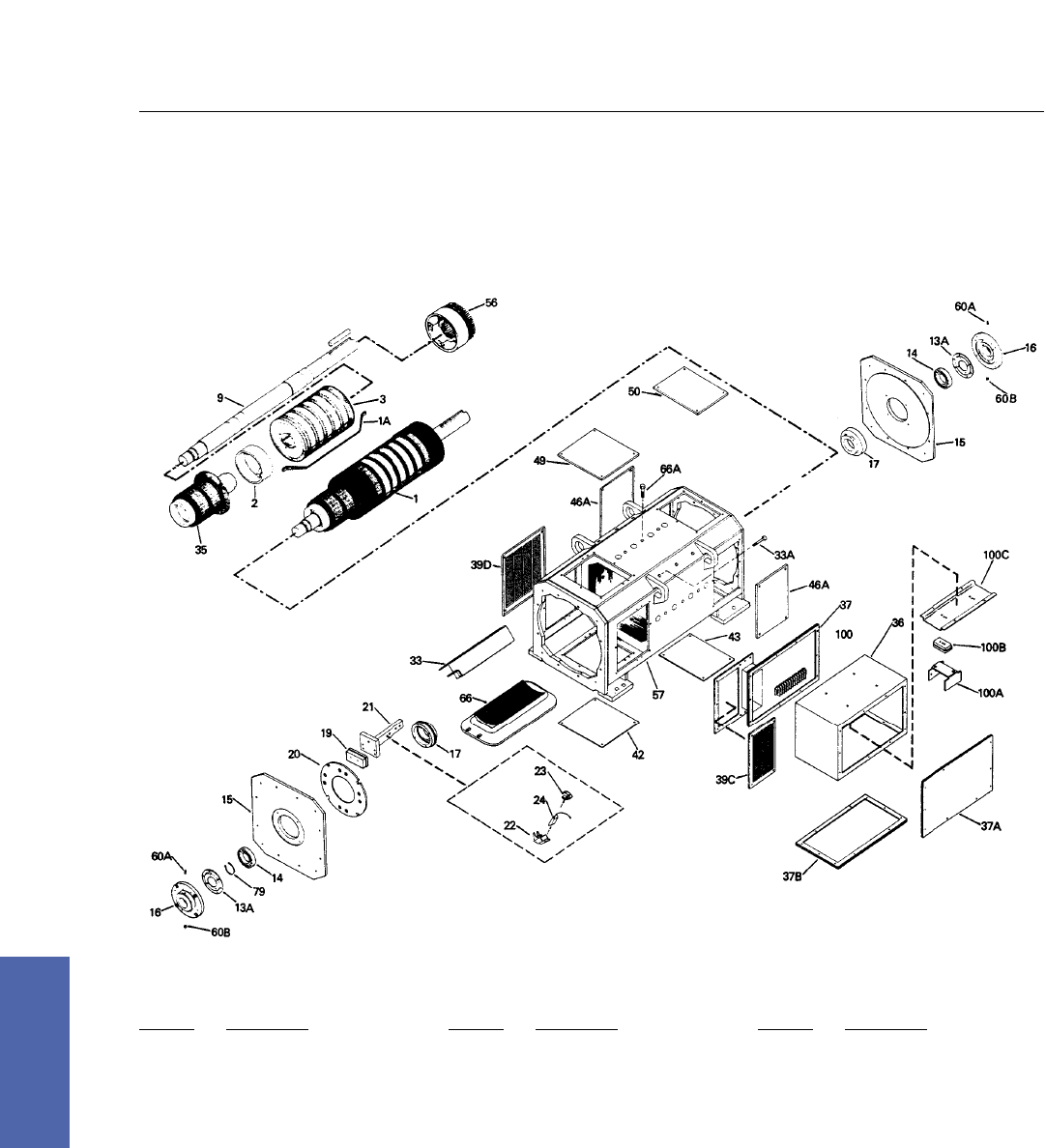
Type CD, Frames 6000–6200 (Four Pole)
Type CD, Frames 6700–6900 (Six Pole)
Ref. No. Description
1 Armature
1A Armature Coil
2 Armature Coil Support
3 Armature Core
9 Armature Shaft
13A Baffle, Metering Plate
14 Bearing
15 Bearing Bracket
16 Bearing Cap
17 Bearing Cartridge
19 Brushholder Stud Ins. Blk.
20 Brushholder Yoke
21 Brushholder Stud
22 Brushholder (w/Spring)
Ref. No. Description
23 Brushholder Spring
24 Brush
33 Comm Coil & Pole
33A Comm Coil & Pole Bolt
35 Commutator
36 Conduit Box
37 Conduit Box Adapter
37A Conduit Box Cover–End
37B Conduit Box Cover–Bottom
39C Cover, Adapter Conduit–CE
39D Cover. Side Louvered–CE
42 Cover Bottom–CE
43 Cover Bottom–DE
46A Cover, Side Louvered–CE
Ref. No. Description
49 Cover, Top–CE
50 Cover, Top–DE
56 Equalizer Coil
57 Frame
60A Grease Fitting
60B Grease Pipe Plug
66 Main Coil & Pole
66A Main Coil & Pole Bolt
79 Retaining Ring
100 Terminal Board
100A Line Adapter, Arma/Series Fld.
100B Line Adapter, Ins. Blk.
100C Line Adapter Support
Exploded View, Type CD and MCD Renewal Parts. Four pole Motor shown,
but parts identification are typical to both Four and Six pole Motors.
Medium DC Motors 155
GE Support Services
7–Medium DC
Type CD and MCD, Frames 5000–9000
Type CD, Frames 580–680
Typical Weights**
Frame Size
584
585
586
683
684
685
5423
5545
6453
6665
7452
7666
8482
8836
9542
9966
Armature Only
620
700
800
1000
1100
1300
1400
1800
2000
2900
2700
4100
4000
6900
4900
9500
Complete Motor
2600
2900
3400
4000
4600
5300
5700
7200
8100
11900
10500
15000
14800
25500
17000
33100
Armature Only
280
320
360
450
500
600
640
820
900
1300
1200
1900
1800
3100
2200
4300
Complete Motor
1200
1300
1500
1800
2100
2400
2600
3300
3700
5400
4800
7200
6700
11600
7700
15000
**Weights for typical machines in each frame size. For specific weights, refer to certified outline.
Pounds Kilograms
156 DC Motors
For more information contact a GE Motor Parts Master Distributor or GE Support Services.
7–Medium DC
Type CD, Frames 5000–9000
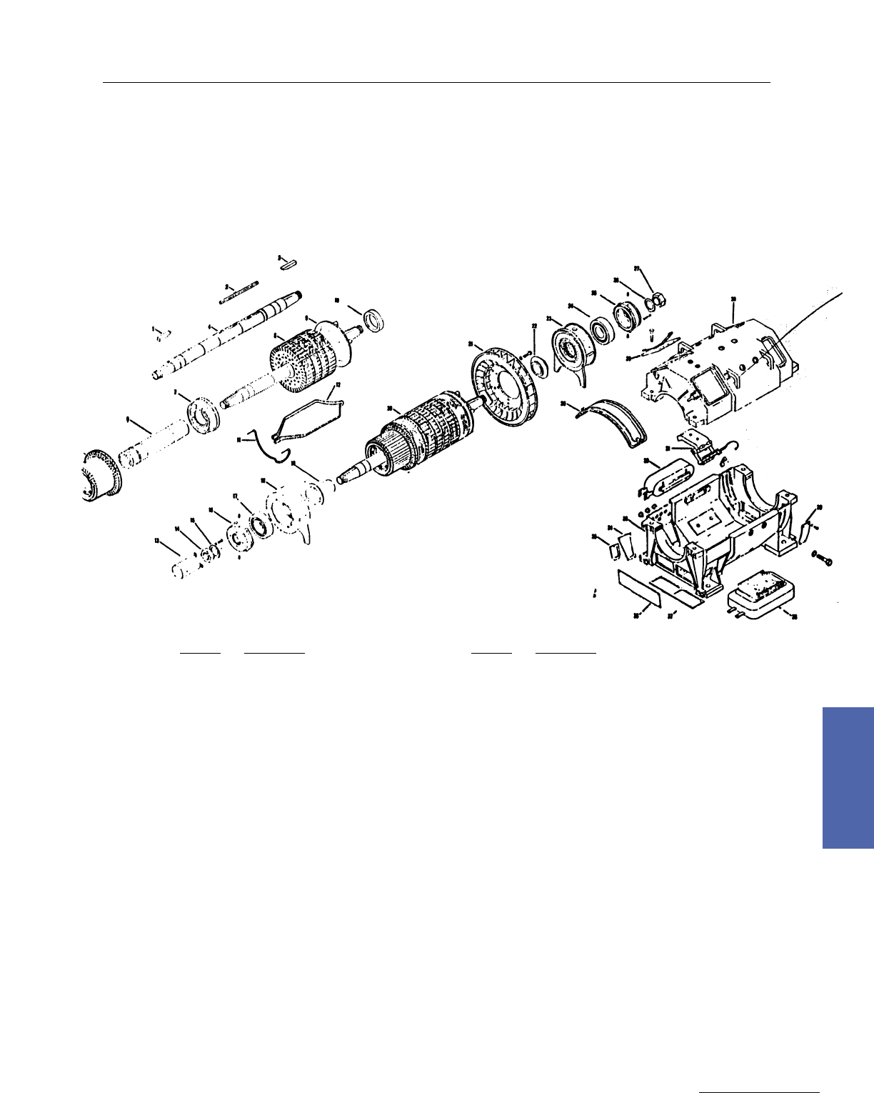
Exploded View, Type CD and MCD Renewal Parts.
See facing page for descriptions.
Continuation of Exploded View
Medium DC Motors 157
GE Support Services
7–Medium DC
Type CD, Frames 5000–9000
Ref. No. Description
1 Shaft
2 Key
3 Commutator
4 Equalizer Coils–Molded
5 Armature Core
6 Coil Support (Drive End)
7 Armature Coil
8 Armature
9 Fan Hub
11 Pole Face Bar Connections (Commutator End)
12 Pole Face Bar Connections (Drive End)
13 “T” Nut
14 Stud
15 Insulating Tube
18 Insulating Spacer
17 Belleville Washer
18 Lock Nut
19 Main Coil And Pole And Pole Face Bar Assembly
20 Pole Face Bar
21 Commutating Coil L And Pole Assembly
Ref. No. Description
22 Bearing Cap (Commutator End}
23 Grease Metering Plate
24 Bearing (Commutator End)
25 Bearing Cartridge Commutator End)
28 Bearing Bracket Commutator End}
27 Cover, Upper (Commutator End)
28 Screen Cover, Lower (Commutator End)
29 Brushholder Yoke
30 Magnet Frame
31 Bearing Bracket (Drive End)
32 Screen Cover, Side (Drive End}
33 Bearing Cartridge (Drive End)
34 Bearing (Drive End)
35 Bearing Cap (Drive End)
36 Stud, Brushholder
37 Brush, Carbon
38 Brushholder
39 Brushholder Spring
40 Insulating Block–Brushholder Stud
158 DC Motors
For more information contact a GE Motor Parts Master Distributor or GE Support Services.
7–Medium DC
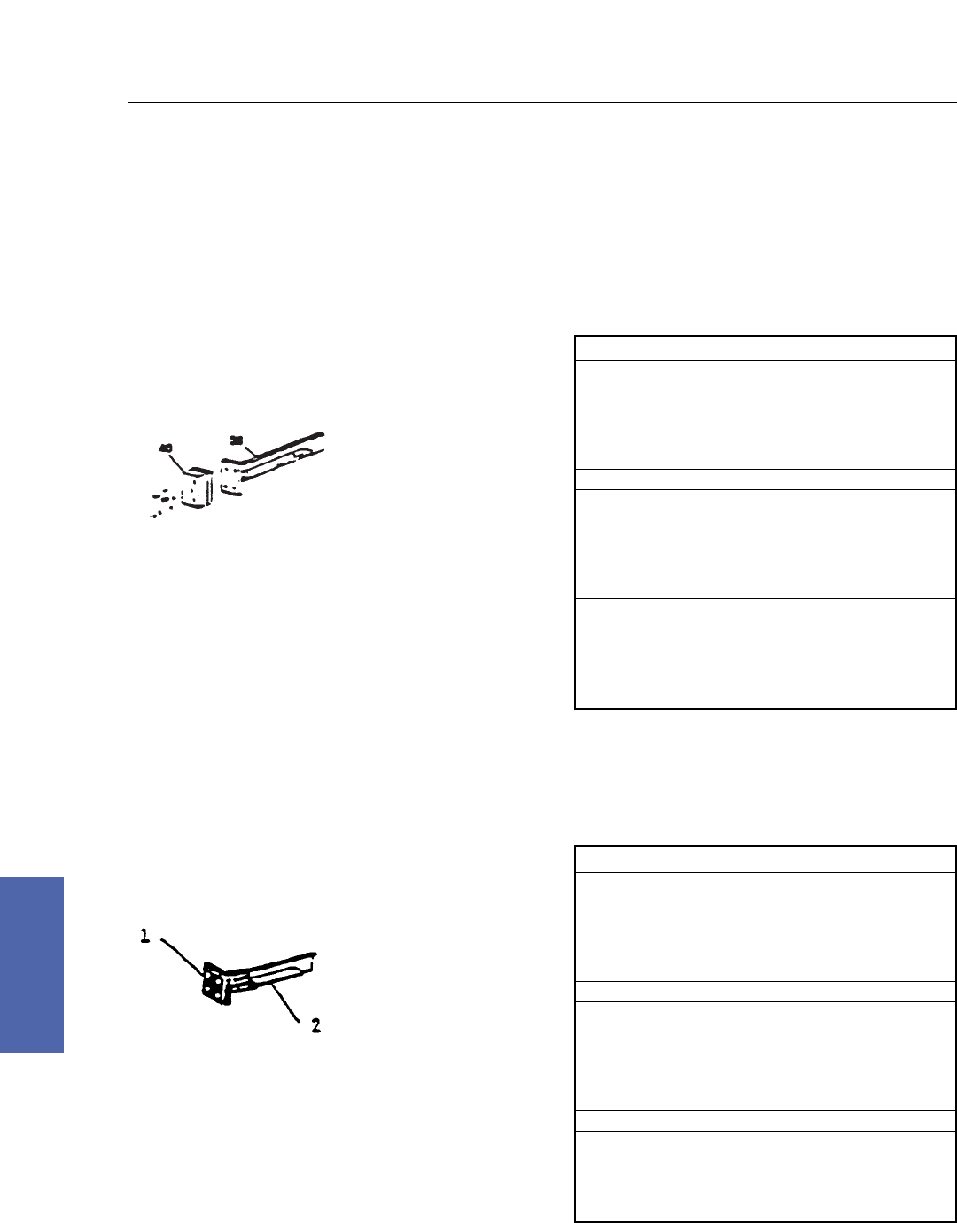
Type CD and MCD, Frames 5000–9000
Type CD, Frames 580–680
Ask customer for type of stud being used and thickness
of brush. Use this chart for: Insulated block & stud (2
piece design)
36 – Brushholder Stud
40 – Insulated Block
3/4" Thick Brush
36A160421AAG02 Brushholder w/Spring
36B465481AA001 Spring Only
36A164451AAP21 Brush (Standard)
36A164451AAP05 Brush (Papermill Use Only)
7/8" Thick Brush
36A160422AAG02 Brushholder w/Spring
36B465482AA001 Spring Only
36A164452AAP21 Brush (Standard)
36A164452AAP05 Brush (Papermill Use Only)
1" Thick Brush
36A160423AAG02 Brushholder w/Spring
36B465483AA001 Spring Only
36A164453AAP21 Brush (Standard)
36A164453AAP05 Brush (Papermill Use Only)
Type CD and MCD, Frames 5000–9000
Type CD, Frames 580–680
Ask customer for type of stud being used and thickness
of brush.
Use this chart for: Fluid Bed Stud (1 piece design)
1 – Fluid Bed
(Epoxy Coating)
2 – Stud
3/4" Thick Brush
36A161101AAG01 Brushholder w/Spring
36B465081AA001 Spring Only
36A161401AAP20 Brush (Standard)
36A161401AAP06 Brush (Papermill Use Only)
7/8" Thick Brush
36A161102AAG01 Brushholder w/Spring
36B465082AA001 Spring Only
36A161402AAP20 Brush (Standard)
36A161402AAP06 Brush (Papermill Use Only)
1" Thick Brush
36A161103AAG01 Brushholder w/Spring
36B465083AA001 Spring Only
36A161403AAP20 Brush (Standard)
36A161403AAP06 Brush (Papermill Use Only)
Identification of Brushholders, Springs,
and Brushes
Medium DC Motors 159
GE Support Services
7–Medium DC
Type MD, Frames 402 to 423
Exploded View, Type MD 402–423 Renewal Parts.
See following page for descriptions.

Principal Renewal Parts
Give Description, Cat. No. and Quantity of Each Item Required
Ref. No. Description
1 Exciting field coil
5 Commutating field coil
9 Armature with frame heads, bearing cap and bearings
10 Armature
11 Armature coil
12 Set of armature rewinding insulation
14 Shaft with key
16 Commutator
17 Set of copper and mica segments, finished and bound
18 Combination inner and outer mica cone for front and back of commutator
19 Mica collar under segments
21 Roller bearing
32 Brush holder with pressure arms and insulated studs (Position_____) see ◆◆• footnote
32 Brush holder with pressure arms and insulated studs (Position______) see ◆◆• footnote
33 Pressure arm with tip
34 Insulator for stud
35 Carbon brush with pigtail and terminal
ø 41 Set of cables
ø Not Shown in illustration.
160 DC Motors
For more information contact a GE Motor Parts Master Distributor or GE Support Services.
7–Medium DC
Renewal Parts Available if Required
Ref. No. No. Req. Description Ref. No. No. Req. Description
2▲▲Spring flange for exciting field coil 27 1 Split retaining ring for bearing or mounting sleeve
3▲▲Metal pad for exciting field coil 28 1 Lock nut for lower mounting sleeve
4▲▲Insulating pad for exciting field coil 29 1 Spacing collar, upper
6▲▲Spring flange for commutating field coil 30 1 Spacing collar, lower
7▲▲Metal pad for commutating field coil 31 1 Shrink ring for bearing
8▲▲Insulating pad for commutating field coil 36 ▲▲Hinge pin for ratchet
13 ▲▲Set of punches 37 2 § Pinion key
15 2 § Thrust collar with grease deflector 38 2 Pinion nut
20 2 § Frame head with bearing cap and grease fittings 39 2 Washer for pinion nut
22 2 Bearing cap with thrust bushing ø 40 ▲▲‡ Rubber bushing
23 2 § Thrust bushing for bearing cap ø 42 ▲▲† Cover for frame over commutator
24 2 § Thrust ring for frame head 43 ▲▲Laminated pole piece for exciting field coil
25 1 Mounting sleeve, upper, including Ref. 27 44 ▲▲Commutating pole piece
26 1 Mounting sleeve, lower 45 1 Fan for armature
‡ Specify cable hole size. § Specify whether for pinion end or commutator end.
▲▲ Quantity variable. † Specify whether right– or left–hand facing commutator end.
◆◆• Brush holder position, facing commutator end. The position (a to h) must be filled in on line for Ref. No. 32.
(a) Right–hand. (f) Upper left– or right– or upper middle right– or lower
(b) Left–hand. middle left–hand.
(c) Upper–right– or lower left–hand. (g) Upper right– or lower left– or upper middle left– or lower
(d) Upper left– or lower right–hand. middle right–hand.
(e) Top or bottom or upper left– or lower right hand. (h) Top or bottom, or upper right– or lower left–hand.
◆◆•
◆◆•
Type MD, Frames 402 to 423

Medium DC Motors 161
GE Support Services
7–Medium DC
Renewal Parts MD402 Qty. MD403 Qty. MD404 Qty. MD406 Qty. MD407 Qty. MD408 Qty.
Armature Coils 2721244G02 1 2721160G02 1 2721099G02 1 2721094G02 1 –––– 1 2721085G04 1
Shaft 2721248G01 1 2721158–001 1 2721100G01 1 2721129G01 1 –––– 2721072G01 1
Coil & Pole – Comm 2721249G65 2 2721154G65 2 2721149G65 2 2721092G65 2 2721505G65 2 2721027G65 2
Coil Only – Comm 2721249G61 2 2721154G61 2 2721149G61 2 2721092G61 2 2721505G61 2 2721027G61 2
Coil & Pole –Series 2721250G65 4 2721155G65 4 2721150G65 4 2721093G65 4 2721506G65 4 2721028G65 4
Coil Only –Series 2721250G61 4 2721155G61 4 2721150G61 4 2721093G61 4 2721506G61 4 2721028G61 4
Coil & Pole –Shunt 2721447G65 4 2721280G65 4 2721595G65 4 2721664G65 4 –––– 4 2721563G65 4
Coil Only – Shunt 2721447G61 4 2721280G61 4 2721595G61 4 2721664G61 4 –––– 4 2721563G61 4
Coil & Pole –Compound 2721260G65 4 2721283G65 4 2721266G65 4 2721261G65 4 4728401G65 4 2721236G65 4
Coil Only – Compound 2721260G61 4 2721283G61 4 2721266G61 4 2721261G61 4 4728401G61 4 2721236G61 4
CE/DE Bearing 8832705–001 2 751722–005 2 751722–005 2 7517722–007 2 –––– 751722–009 2
Brushholder & Spring
–Right Hand Side 6x523 1 4750665–001 1 6x10⁴ 1 6x10⁴ 1 –––– 6x531 1
–Left Hand Side 6x524 1 4750665–001 6x10⁵ 1 6x10⁵ 1 –––– 6x532 1
Spring only
Brush 6709782–P01 6709782–P01 8809558–P01 8809558–P01 –––– 6709784–P01
CE Insp. Cover
Lockwasher – Spring 36A164222AA001 2 36A164222AA001 2 36A164222AA001 2 36A164222AA002 2 –––– 36A164222AA003 2
Lockwasher–Flat 431832–001 2 2706929–001 2 2906929–001 2 419082–001 2 –––– 4714021–101 2
Pinion Nut 8815254–001 2 2706022–001 2 2706022–001 2 8815257–001 2 –––– 2706023–001 2
Cable Bushings
Series Motor 41B533331–013 8 41B533331–013 8 41B453331–013 8 41B533331–006 8 –––– 41B533331–009 8
Shunt Motor–Field 41B533331–013 8 41B533331–013 8 41B533331–013 8 41B533331–003 4 –––– 41B533331–004 4
Armature –––– –––– ––––– 41B533331–006 4 –––– 41B533331–006 4
Compound Motor
Field/Armature 41B533331–013 8 41B533331–103 8 41B533331–013 8 41B533331–006 8 ––––– 41B533331–009 8
Series Lead 41B533331–001 4 41B533331–001 4 41B533331–001 4 41B533331–001 4 –––– 41BB53331–001 4
Type MD, Frames 402 to 408
Standard Renewal Parts Identification

162 DC Motors
For more information contact a GE Motor Parts Master Distributor or GE Support Services.
7–Medium DC
Renewal Part MD410 Qty. MD412 Qty. MD414 Qty. MD416 Qty. MD418 Qty. MD420 Qty.
Armature Coils 2721029G02 1 4722976G02 1 2721183G02 1 2721148G02 1 2721193G02 1 2721875G02 1
Shaft 2721125G01 1 2721175G01 1 2721185G01 1 272136AAG01 1 2721529G01 2721049G01 1
Coil & Pole – Comm 2721018G65 2 41C631195G65 2 41C631174G65 2 2721128G65 2 4722726G65 2 2721394G65 2
Coil Only – Comm 2721018G61 2 41C631195G61 2 41C631174G61 2 2721128G61 2 4722726G61 2 2721394G61 2
Coil & Pole –Series 2721019G65 4 41C631209G65 2 41C631214G65 2 2721130G65 4 2721190G65 4 2721209G65 4
Coil Only –Series 2721019G61 4 41C631209G61 2 41C631214G61 2 2721130G61 4 2721190G61 4 2721209G61 4
Coil & Pole –Shunt 2721281G65 4 2721326G65 4 2721343G65 4 2721430G65 4 2721190G65 4 2721345G65 4
Coil Only – Shunt 2721281G61 4 2721326G61 4 2721343G61 4 2721430G61 4 2721190G61 4 2721345G61 4
Coil & Pole –Compound 41C631223G65 4 41C631207G65 2 41C631176G65 2 2721253G65 4 2721334G65 4 2721229G65 4
Coil Only – Compound 41C631223G61 4 41C631207G61 2 41C631176G61 2 2721253G61 4 2721334G61 4 2721229G61 4
CE/DE Bearing 6x515 2 751722–010 2 8832705AB016 2 8832705AB017 2 8832705AB020 2 8832705AB022 2
Brushholder & Spring
–Right Hand Side 6x10⁶ 1 907A683AG001 1 747939G07 747926G01 2721046G03 754124G01
–Left Hand Side 6x10⁶ 1 747916G13 1 747939G10 7479926G02 2721046G01 754124G02
Spring only
Brush 8809563–P01 6709782–P01 6709764–P01 6709784–P01 8809553–P01 6709741–P01
Lockwasher – Spring 36A164222AA004 2 36A164222AA0052 36A164222AA006 2 36A164222AA007 2 36A164222AA009 2 36A160422AA009 2
Lockwasher–Flat 435173–001 2 434161–001 2 8809867–001 2 433635–001 2 433635–001 2 433636–001 2
Pinion Nut 2706024–001 2 2706043–001 2 2706025–001 2 2706026–001 2 6709539–001 2 6709762–001 2
Cable Bushings
Series Motor 41B533331–009 8 717502–001 8 41B533331–020 8 41B453331–010 12 41B533331–022 12 2702930–001 4
Shunt Motor 41B533331–004 4 41B533331–020 4 422356–001 4 422356–001 4 41B533331–024 4 2702930–001 2
41B533331–009 4 717502–001 4 41B533331–020 4 41B533331–010 8 41B533331–022 12 422356–001 2
Compound Motor 41B533331–013 4 422356–001 4 422356–001 4 422356–001 4 422356–001 8 422356–001 2
41B533331–009 8 717502–001 8 41B533331–20 8 41B533331–010 12 41B533331–022 12 2702930–001 4
Field/Armature 41B533331–013 8 41B533331–103 8 41B533331–013 8 41B533331–006 8 –––––––––––––– 41B533331–009 8
Series Lead 41B533331–001 4 41B533331–001 4 41B533331–001 4 41B533331–001 4 –––––––––––––– 41BB53331–001 4
Type MD, Frames 410 to 420
Standard Renewal Parts Identification
Medium DC Motors 163
GE Support Services
7–Medium DC
Type MD, Frames 602 to 624
Exploded View, Type MD 602–624 Renewal Parts.
See following page for descriptions.

164 DC Motors
For more information contact a GE Motor Parts Master Distributor or GE Support Services.
7–Medium DC
Renewal Parts Available if Required
Ref. No. No. Req. Description Ref. No. No. Req. Description
2 8 Spring flange for exciting field coil 30 ▲▲§Pinion nut
3 4 Metal pad for exciting field coil 31 ▲▲§Washer for pinion nut
4▲▲Insulating pad for exciting field coil 32 ▲▲‡Rubber bushing
6 8 Spring flange for commutating field coil 34 ▲▲†Cover for frame over commutator
7 4 Metal pad for commutating field coil 36 4 Laminated pole piece for exciting field coil
8▲▲Insulating pad for commutating field coil 37 4 Commutating pole piece
16 2 §Thrust collar with grease deflector 38 1 Fan for armature
21 2 §Frame head with bearing cap and grease fittings 39 1 Shell with inlet flange
24 2 §Bearing cap 40 1 Impeller
24A 1 Split retaining ring, commutator end 41 ▲▲Filter pad
29 ▲▲§Pinion key
‡Specify cable hole size. §Specify whether for pinion end or commutator end.
▲▲Quantity variable. †Specify whether right– or left–hand facing commutator end.
*Not illustrated.
◆◆• Brush holder position, facing commutator end. The position (a to b) must be filled in on line for Ref. No. 25.
(a) Right–hand
(b) Left–hand
Principal Renewal Parts
Give Description, Cat. No. and Quantity of Each Item Required
Ref. No. Description
1 Exciting field coil
5 Commutating field coil
9 Armature with frame heads, bearing cap and bearings
10 Armature
11 Armature coil
12 Equalizer coil
13 Set of armature rewinding insulation
14 Set of punchings
15 Shaft with keys
17 Commutator
18 Set of copper and mica segments, finished and bound
19 Combination inner and outer mica cone for front and back of commutator
20 Mica collar under segments
22 Ball or roller bearing, commutator end
23 Roller bearing, pinion end
25 Brush holder with spring assembly and insulated studs (Position_____) see ◆◆• footnote
25 Brush holder with spring assembly and insulated studs (Position______) see ◆◆• footnote
26 Constant pressure spring assembly
*27 Insulated stud
28 Carbon brush with pigtail and terminal
33 Set of cables
35 Complete conversion kit
◆◆•
◆◆•
Type MD, Frames 602 to 624
Medium DC Motors 165
GE Support Services
7–Medium DC
Type MD 600
Ref. No. Description
1 Key, Pinion
2 Key, Spider
3 Key, Pinion
4 Shaft
5 Commutator
6 Armature Spider
7 Armature Head
8 Armature Core
9 Armature Flange
10 Shrink Ring
11 Coil, Equalizer
12 Coil, Armature
13 Thimble, Shaft
14 Nut, Pinion
15 Washer, Pinion
16 Cap, Bearing
17 ‡ Bearing
18 Frame Head
19 Thrust Collar & Grease Slinger
20 Armature
21 Armature Fan
22 Thrust Collar & Grease Slinger
23 Frame Head
24 Bearing, Roller
25 Cap, Bearing
Ref. No. Description
26 Washer, Pinion
27 Nut, Pinion
28 Cover, Topside, Comm. End (MD602–MD612)
29 Cover, Topside, Comm. End (MD614–MD618)
30 Frame, Top Half
31 Brush Holder Assembly
32 Commutating Coil & Pole Assembly
33 Frame, Bottom Half
34 Large Cover, Bottom (Side), Commutator End
35 Small Cover, Bottom (Side), Commutator End
36 Cover, Bottom (Front), Commutator End
37 Cover, Bottom (Front), Commutator End
38 Main Coil & Pole Assembly
39 Cover, Bottom (Side), Drive End
40 Hood, Top (Side), Drive End
41 Cover Adapter, Blower
42 Screen
43 Connection Elbow
44 Band
45 Blower Housing
46 Screen Housing
47 Impeller
48 Blower Mounting Bracket
49 Blower Motion
‡ Roller Bearing–Horizontal Construction
Ball Bearing–Vertical Construction

166 DC Motors
For more information contact a GE Motor Parts Master Distributor or GE Support Services.
7–Medium DC
Renewal Part MD602 Qty. MD603 Qty. MD604 Qty. MD606 Qty. MD608 Qty. MD610 Qty.
Armature 6791731G01 1 6791759G01 1 6791729G01 1 6791734G01 1 6791772G01 1 6791782G01 1
Armature Coils 6739323G01 1 8832060G01 1 6739295G01 1 88320419G01 1 6739487G01 1 6739255G01 1
Insulation Set 6739363ABG01 1 36C695833AAG01 1 36C695834AAG01 1 36C695835AAG01 1 36C695836AAG01 1 36C695837AAG01 1
Commutator 764979G01 1 8822219G01 1 8822635G01 1 8822951G01 1 8822696G01 1 8822852G01 1
Shaft 6739383G02 1 8832390G02 1 8832022G03 1 8832307G02 1 8832542G01 1 8832543G01 1
Fan 6739486–001 1 8832383–001 1 8832027–001 1 8832312–001 1 8832100–001 1 8832166–001 1
Coil & Pole – Comm 6739324G65 4 8832061G65 4 6739296G65 4 8832050G65 4 6739488G65 4 6739256G65 1
Coil Only – Comm 6739324G61 4 8832061G61 4 6739296G61 4 8832050G61 4 6739488G61 4 6739256G61 1
Coil & Pole –Series 6739325G65 4 8832062G65 4 6739297G65 4 8832051G65 4 6739489G65 4 6739257G65 4
Coil Only –Series 6739325G61 4 8832062G61 4 6739297G61 4 8832051G61 4 6739489G61 4 6739257G61 4
Coil & Pole –Shunt 6739326G65 4 8832064G65 4 6739298G65 4 8832053G65 4 6739491G65 4 6739258G65 4
Coil Only – Shunt 6739326G61 4 8832064G61 4 6739298G65 4 8832053G61 4 6739491G61 4 6739258G61 4
Coil & Pole –Compound 6739354G65 4 8832063G65 4 6739479G65 4 8832052G65 4 6739490G65 4 6739482G65 4
Coil Only – Compound 6739354G61 4 8832063G61 4 6739479G61 4 8832052G61 4 6739490G61 4 6739490G61 4
Coil & Pole–Stab Shunt 8832779G65 4 8832066G65 4 6739481G65 4 8832055G65 4 6739493G65 4 6739482G65 4
Coil Only–Stab Shunt 8832779G61 4 8832066G61 4 6739481G61 4 8832055G61 4 6739493G61 4 6739484G61 4
CE/DE Bearing 8832705–002 2 8832705–002 2 8832705–004 2 8832705–005 2 8832705–006 2 8832705–007 2
Brushholder & Spring Constant Pressure
–Right Hand Side 428C685G01 1 428C685G01 1 428C694G01 1 428C695G01 1 428C686G01 1 428C697G01 1
–Left Hand Side 428C685G02 1 428C685G02 1 428C694G02 1 428C695G02 1 428C686G02 1 428C697G02 1
Spring only 41B533105G01 4 41B533105G01 4 36B465487AA001 4 337B689G02 4 337B689G02 4 337B689G02 4
Brush 337B696–P02 4 337B696–P02 4 337B696–P03 4 337B696–P04 4 337B696–P05 4 337B696–P08 4
Brushholder & Spring Clockspring
–Right Hand Side 6748708G01 1 6748708G01 1 6749037G01 1 6749232G01 1 6749108G01 1 6749108G03 1
–Left Hand Side 6748708G02 1 6748708G02 1 6749037G02 1 6749232G02 1 6749108G02 1 6749108G04 1
Brush 6709783–P01 4 6709783–P01 4 6709786–P01 4 8809716–P01 4 8809563–P01 4 8809552–P01 4
CE Insp. Cover 6739384G01 1 6736007G01 1 6736007G01 1 8832322G01 1 8832105G01 1 8832105G01 1
Lockwasher – Spring 36A164222AA001 2 36A164222AA001 2 36A164222AA001 2 36A164222AA002 2 36A164222AA003 2 36A164222AA004 2
Lockwasher–Flat 88099863–001 2 2706929–001 2 2706929–001 2 8809863–001 2 8809864–001 2 8809865–001 2
Pinion Nut 8815255–001 2 8815256–001 2 8815256–001 2 8815257–001 2 8815258–001 2 8815259–001 2
Cable Bushings
Series Motor 41B533331–001 8 41B533331–001 8 41B533331–002 8 41B533331–003 8 41B533331–003 8 41B533331–005 8
Shunt Motor–Field 41B533331–001 4 41B533331–001 4 41B533331–001 4 41B533331–001 4 41B533331–001 4 41B533331–001 4
Armature 41B533331–001 4 41B533331–001 4 41B533331–002 4 41B533331–003 4 41B533331–003 4 41B533331–005 4
Compound Motor Field 41B533331–001 4 41B533331–001 4 41B533331–001 4 41B533331–001 4 41B533331–001 4 41B533331–001 4
Armature 41B533331–001 4 41B533331–001 4 41B533331–0021 4 41B533331–003 4 41B533331–003 4 41B533331–005 4
Type MD, Frames 602 to 610
230V Standard Renewal Parts Identification

Medium DC Motors 167
GE Support Services
7–Medium DC
Renewal Part MD612 Qty. MD614 Qty. MD616 Qty. MD618 Qty. MD620 Qty. MD622 Qty.
Armature 6791786G01 1 6792403G01 1 6793951G01 1 6792407G01 1
Armature Coils 6739237G01 1 8832010G01 1 8832037G01 1 6739341G01 1 428C588G01 1 428C564G01 1
Equalizer Coils –––––––––––––– 8832919G01 1 8832924G01 1 8832923G01 1
Insulation Set 36C695838AAG01 1 36C695839AAG01 1 428C345G01 1 8842626ABG01 1 428C587ABG01 1 428C562ABG01 1
Commutator 6727740G01 1 8822836G01 1 8822910G01 1 6739413G01 1
Shaft 8832544G01 1 8832545G01 1 8832546G01 1 8832547G01 1
Fan 6739459–001 1 8832138–001 1 8832260–001 1 6739496–001 1
Coil & Pole – Comm 6739238G65 4 8832011G65 4 8832038G65 4 6739342G65 4 428C333G65* 4 8842401G65** 6
4 8842624G65** 4
Coil Only – Comm 6739238G61 4 8832011G61 4 8832038G61 4 6739342G61 4 428C333G61* 4 8842401G61** 6
8842624G61** 4
Coil & Pole –Series 6739239G65 4 8832012G65 4 8832039G65 4 6739343G65 4 428C348G65 4
Coil Only –Series 6739239G61 4 8832012G61 4 8832039G61 4 6739343G61 4 428C348G61 4
Coil & Pole –Shunt 6739243G65 4 8832016G65 4 8832043G65 4 6739345G65 4 8842697G65 4
Coil Only – Shunt 6739243G61 4 8832016G61 4 8832043G61 4 6739345G61 4 8842697G61 4 8842631G61** 6
Coil & Pole – Shunt w/bars 8842644ABG62 4 8842441ABG63 6
Coil & Pole –Compound 6793241G65 4 8832014G65 4 8832041G65 4 6739344G65 4 428C308G65* 4 8851734G65 6
Coil Only – Compound 6793241G61 4 8832014G61 4 8832041G61 4 6739344G61 4 428C308G61 4 8851734G61 6
Coil & Pole–Stab Shunt 6739247G65 4 8832020G65 4 8832047G65 4 6739347G65 4
Coil Only–Stab Shunt 6739247G61 4 8832020G61 4 8832047G61 4 6739347G61 4
CE/DE Bearing 8832705–008 2 8832705–009 2 8832705–010 2 8832705–011 2 8832705–012 2 8832705–013 2
Brushholder & Spring Constant Pressure
428C682G02 2 428C683G02 4 428C687G02 4 428C689G02 4
Spring only 337B689G02 6 337B689G02 16 337B689G02 16 337B689G02 16
Brush 337B696–P07 6 337B696–P08 16 337B696–P07 4 337B696–P09 16 337B696–P07
Brushholder & Spring Clockspring
6748585G02 2 6749126G01 2 6749126G04 2 6748745G02 4
Brush 6709764–P01 6 8809552–P01 16 8670764–P01 16 6709776–P01 16
CE Insp. Cover 6739277G01 2 8832142G01 2 8832142G01 2 8832142G01 2 8819615–001
Lockwasher – Spring 36A164222AA005 2 36A164222AA006 2 36A164222AA007 2 36A164222AA007 2 36A160535AA009 2 36A160535AA009
Lockwasher–Flat 8809866–001 2 8809867–001 2 8809868–001 2 8809869–001 2 8819685–001 2 8819685–001 2
Pinion Nut 8815260–001 2 8815261–001 2 8815262–001 2 8815263–001 2 8819612–001 2 88519629–001 2
Cable Bushings
Series Motor 41B533331–009 8 41B533331–009 8 41B533331–011 8 41B533331–010 8
Shunt Motor–Field 41B533331–001 4 41B533331–001 4 41B533331–025 4 41B533331–025 4 41B533331–002 6
Armature 41B533331–009 4 41B533331–009 4 41B533331–011 4 41B533331–010 4 41A236629AA00160
Compound Motor Field 41B533331–001 4 41B533331–001 4 41B533331–025 4 41B533331–025 4 41B533331–002 6
Armature 41B533331–009 8 41B533331–009 8 41B533331–011 8 41B533331–010 8
Type MD, Frames 612 to 622
230V Standard Renewal Parts Identification
*Non Compensated **Compensated

168 DC Motors
For more information contact a GE Motor Parts Master Distributor or GE Support Services.
7–Medium DC
230 Volt Constant Pressure
602 Qty. 1 – 428C685G01 – RH Brushholder w/Spring
Qty. 1 – 428C685G02 – LH Brushholder w/Spring
Qty. 4 – 41B533105G01 – Spring Only
Qty. 4 – 337B696 P02 – Brush
603 Qty. 1 – 428C685G01 – RH Brushholder w/Spring
Qty. 1 – 428C685G02 – LH Brushholder w/Spring
Qty. 4 – 41B533105G01 – Spring Only
Qty. 4 – 337B696 P02 – Brush
604 Qty. 1 – 428C694G01 – RH Brushholder w/Spring
Qty. 1 – 428C694G02 – LH Brushholder w/Spring
Qty. 4 – 36B465487AA001 – Spring Only
Qty. 4 – 337B696 P03 – Brush
606 Qty. 1 – 428C695G01 – RH Brushholder w/Spring
Qty. 1 – 428C695G02 – LH Brushholder w/Spring
Qty. 4 – 337B689G01 – Spring Only
Qty. 4 – 337B696 P04 – Brush
608 Qty. 1 – 428C686G01 – RH Brushholder w/Spring
Qty. 1 – 428C686G02 – LH Brushholder w/Spring
Qty. 4 – 337B689G01 – Spring Only
Qty. 4 – 337B696 P05 – Brush
610 Qty. 1 – 428C697G01 – RH Brushholder w/Spring
Qty. 1 – 428C697G02 – LH Brushholder w/Spring
Qty. 6 – 337B689G02 – Spring Only
Qty. 6 – 337B696 P08 – Brush
612 Qty. 2 – 428C682G02 – Brushholder w/Spring
Qty. 6 – 337B689G01 – Spring Only
Qty. 6 – 337B696 P07 – Brush
614 Qty. 4 – 428C683G02 – Brushholder w/Spring
Qty. 16 – 337B689G01 – Spring Only
Qty. 16 – 337B696 P08 – Brush
616 Qty. 4 – 428C687G02 – Brushholder w/Spring
Qty. 16 – 337B689G01 – Spring Only
Qty. 16 – 337B696 P07 – Brush
618 Qty. 4 – 428C689G02 – Brushholder w/Spring
Qty. 16 – 337B689G01 – Spring Only
Qty. 16 – 337B696 P09 – Brush
230 Volt Coil Spring
602 Qty. 1 – 6748708G01 – RH Brushholder
Qty. 1 – 6748708G02 – LH Brushholder
Qty. 4 – 6709783 P01 – Brush
603 Qty. 1 – 6748708G01 – RH Brushholder
Qty. 1 – 6748708G02 – LH Brushholder
Qty. 4 – 6709783 P01 – Brush
604 Qty. 1 – 6749037G01 – RH Brushholder
Qty. 1 – 6749037G02 – LH Brushholder
Qty. 4 – 6709786 P01 – Brush
606 Qty. 1 – 6749232G01 – RH Brushholder
Qty. 1 – 6749232G02 – LH Brushholder
Qty. 4 – 8809716 P01 – Brush
608 Qty. 1 – 6749108G01 – RH Brushholder
Qty. 1 – 6749108G02 – LH Brushholder
Qty. 4 – 8809563 P01 – Brush
610 Qty. 1 – 6749108G03 – RH Brushholder
Qty. 1 – 6749108G04 – LH Brushholder
Qty. 6 – 8809552 P01 – Brush
612 Qty. 2 – 6748585G02 – Brushholder
Qty. 6 – 6709764 P01 – Brush
614 Qty. 4 – 6749126G02 – Brushholder
Qty. 16 – 8809552 P01 – Brush
616 Qty. 4 – 6749126G04 – Brushholder
Qty. 16 – 6709764 P01 – Brush
618 Qty. 4 – 6748745G02 – Brushholder
Qty. 16 – 6709776 P01 – Brush
Above quantities represent total required per motor.
Type MD, Frames 602 to 624
Identification of Brushholders, Springs and Brushes

Medium DC Motors 169
GE Support Services
7–Medium DC
550 Volt Constant Pressure
602 No constant pressure replacement.
603 Qty. 1 – 428C685G01 – LH Brushholder w/Spring
Qty. 1 – 428C685G02 – RH Brushholder w/Spring
Qty. 4 – 41B533105G01 – Spring Only
Qty. 4 – 337B696 P02 – Brush
604 Qty. 1 – 428C685G01 – LH Brushholder w/Spring
Qty. 1 – 428C685G02 – RH Brushholder w/Spring
Qty. 4 – 41B533105G01 – Spring Only
Qty. 4 – 337B696 P02 – Brush
606 Qty. 1 – 428C694G01 – LH Brushholder w/Spring
Qty. 1 – 428C694G02 – RH Brushholder w/Spring
Qty. 4 – 36B465487AA001 – Spring Only
Qty. 4 – 337B696 P03 – Brush
608 Qty. 1 – 428C695G01 – LH Brushholder w/Spring
Qty. 1 – 428C695G02 – RH Brushholder w/Spring
Qty. 4 – 337B689G01 – Spring Only
Qty. 4 – 337B696 P04 – Brush
610 Qty. 1 – 428C686G01 – LH Brushholder w/Spring
Qty. 1 – 428C686G02 – RH Brushholder w/Spring
Qty. 4 – 337B689G01 – Spring Only
Qty. 4 – 337B696 P05 – Brush
612 Qty. 2 – 41C631160G02 – Brushholder w/Spring
Qty. 4 – 337B689G01 – Spring Only
Qty. 4 – 337B696 P05 – Brush
614 Qty. 4 – 41C631160G02 – Brushholder w/Spring
Qty. 8 – 337B689G01 – Spring Only
Qty. 8 – 337B696 P05 – Brush
616 Qty. 2 – 41C31397G01 – Brushholder w/Spring
Qty. 12 – 337B689G01 – Spring Only
Qty. 12 – 337B696 P08 – Brush
618 Qty. 4 – 428C683G02 – Brushholder w/Spring
Qty. 16 – 337B689G01 – Spring Only
Qty. 16 – 337B696 P08 – Brush
Above quantities represent total required per motor.
Type MD, Frames 602 to 624
Identification of Brushholders, Springs and Brushes
550 Volt Coil Spring
602 Qty. 1 – 6748708G03 – RH Brushholder
Qty. 1 – 6748708G04 – LH Brushholder
Qty. 4 – 8807309 P01 – Brush
603 Qty. 1 – 6748708G01 – RH Brushholder
Qty. 1 – 6748708G02 – LH Brushholder
Qty. 4 – 6709783 P01 – Brush
604 Qty. 1 – 6748708G01 – RH Brushholder
Qty. 1 – 6748708G02 – LH Brushholder
Qty. 4 – 6709783 P01 – Brush
606 Qty. 1 – 6749232G03 – RH Brushholder
Qty. 1 – 6749232G04 – LH Brushholder
Qty. 4 – 6709786 P01 – Brush
608 Qty. 1 – 6749232G01 – RH Brushholder
Qty. 1 – 6749232G02 – LH Brushholder
Qty. 4 – 8809716 P01 – Brush
610 Qty. 1 – 6749108G01 – RH Brushholder
Qty. 1 – 6749108G02 – LH Brushholder
Qty. 4– 8809563 P01 – Brush
612 Qty. 2 – 6749310G02 – Brushholder
Qty. 4 – 8809563 P01 – Brush
614 Qty. 4 – 6749310G02 – Brushholder
Qty. 8 – 8809563 P01 – Brush
616 Qty. 2 – 6749315G02 – Brushholder
Qty. 12 – 8809522 P01 – Brush
618 Qty. 4 – 6749126G02 – Brushholder
Qty. 16 – 8809522 P01 – Brush
170 DC Motors
For more information contact a GE Motor Parts Master Distributor or GE Support Services.
7–Medium DC
Size
802
803
804
806
808
810
812
814
816
818
820
822
824
828
Armature Only
160
210
290
370
540
720
960
1140
2030
2630
3040
3850
4650
11060
Complete Motor
550
780
960
1300
1820
2480
3310
4620
5840
7730
12100
15200
19100
39100
Armature Only
75
95
130
170
245
325
435
655
920
1195
1380
1745
2110
5020
Complete Motor
250
355
435
590
825
1125
1500
2100
2650
3500
5490
6700
8660
17740
PoundsFrame Kilograms
Type MD, Frames 802 to 828
Typical Weights
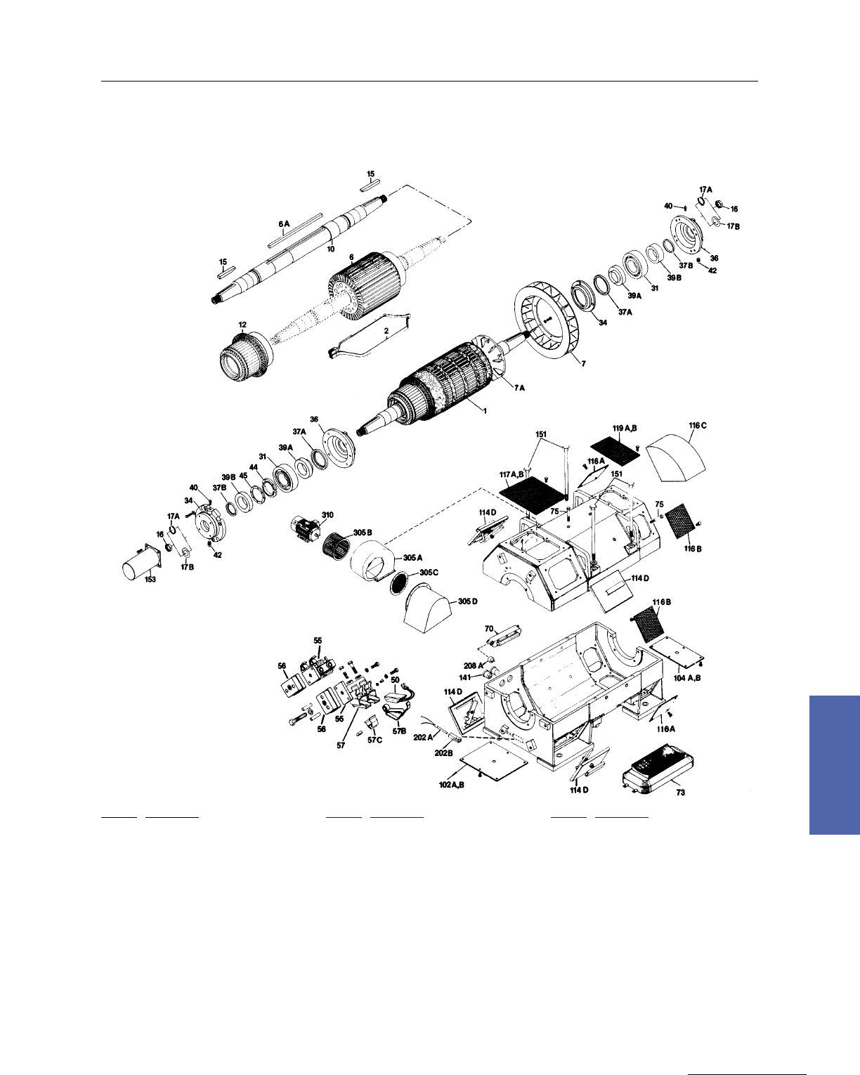
Medium DC Motors 171
GE Support Services
7–Medium DC
MDP804 thru MDP808 Motors
Exploded View Horizontal
Ref. No. Description
1 Armature
2Armature Coil
6 Armature Core
6A Armature Core Key
7 Armature Fan
7A Armature Fan Hub
10 Shaft
12 Commutator
15 Pinion Key
16 Pinion Nut
17A Pinion Lock Washer–Split Type
17B Pinion Lock Washer–Bent Type
31 Bearing
34 Bearing Cap
36 Bearing Cartridge
37A Bearing Seal–Inner
37B Bearing Seal–Outer
39A Thrust Collar–Inner
39B Thrust Collar–Outer
Ref. No. Description
40 Grease Fitting
42 Pipe Plug
44 Split Ring
45 Locking Ring
50 Brush
55 Brushholder Stud
56 Brushholder Stud Insulation
57 Brushholder
57B Brushholder Spring
57C Brushholder Mounting Clip
70 Comm Coil & Pole Assembly
73 Main Field Coil & Pole
75 Pole Bolts
102A Cover, Bottom Comm End–Solid
102B Cover, Bottom Comm End–Screen
104A Cover, Bottom Drive End–Solid
104B Cover, Bottom Drive End–Screen
114D Cover, Quick Access–Comm End–Solid
116A Cover, Side Drive End–Solid
Ref. No. Description
116B Cover, Side Drive End–Screen
116C Cover, Side Drive End–Hood
117A Cover, Top Comm End–Solid
117B Cover, Top Comm End–Screen
119A Cover, Top Drive End–Solid
119B Cover, Top Drive End–Screen
141 Cable Bushing
151 Frame Split Bolt
153 Shaft Thimble
202A Space Heater Only
202B Heat Sink–Space Heater
208A Thermostat
305A Blower Housing
305B Blower Impeller
305C Air Inlet Screen
305D Air Inlet Hood With Screen
310 Blower Motor
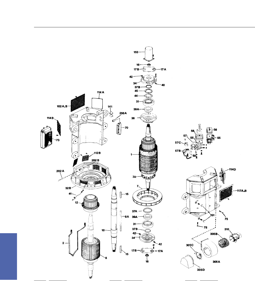
172 DC Motors
For more information contact a GE Motor Parts Master Distributor or GE Support Services.
7–Medium DC
MDV804 thru MDV808 Motors
Exploded View Vertical
Ref. No. Description
1 Armature
2 Armature Coil
6 Armature Core
6A Armature Core Key
7 Armature Fan
7A Armature Fan Hub
10 Shaft
12 Commutator
15 Pinion Key
16 Pinion Nut
17A Pinion Lock Washer–Split Type
17B Pinion Lock Washer–Bent Type
31 Bearing
32B Bearing Bracket–Drive End
34 Bearing Cap
36 Bearing Cartridge
37A Bearing Seal–Inner
37B Bearing Seal–Outer
Ref. No. Description
39A Thrust Collar–Inner
40 Grease Fitting
41 Grease Tube Assembly
42 Pipe Plug
44 Split Ring
45 Locking Ring
50 Brush
55A Brushholder Stud–Right Hand
55B Brushholder Stud–Left Hand
56 Brushholder Stud Insulation
57 Brushholder
57B Brushholder Spring
57C Brushholder Mounting Clip
70 Comm Coil & Pole Assembly
73 Main Field Coil & Pole
75 Pole Bolts
102A Cover, Bottom Comm End–Solid
102B Cover, Bottom Comm End–Screen
Ref. No. Description
112B Cover, Bottom Side Drive End–Screen
114A Cover, Side Comm End–Solid
114B Cover, Side Comm End–Screen
114D Cover, Quick Access–Comm End–Solid
117A Cover, Top Comm End–Solid
117B Cover, Top Comm End–Screen
141 Cable Bushing
151 Frame Split Bolt
153 Shaft Thimble
202A Space Heater Only
202B Heat Sink–Space Heater
208A Thermostat
305A Blower Housing
305B Blower Impeller
305C Air Inlet Screen
305D Air Inlet Hood With Screen
310 Blower Motor
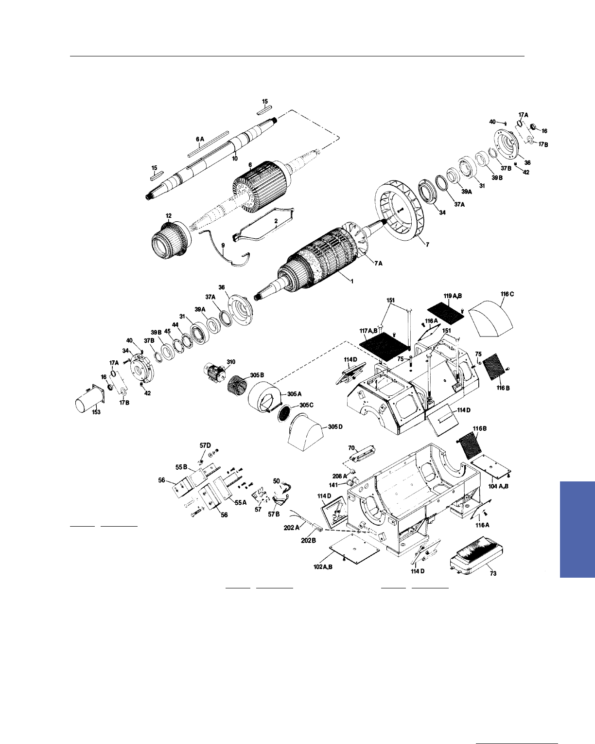
Medium DC Motors 173
GE Support Services
7–Medium DC
MDP810 thru MDP818 Motors
Exploded View Horizontal
Ref. No. Description
1 Armature
2 Armature Coil
6 Armature Core
6A Armature Core Key
7 Armature Fan
7A Armature Fan Hub
9 Equalizer Coil
10 Shaft
12 Commutator
15 Pinion Key
16 Pinion Nut
17A Pinion Lock Washer–Split Type
17B Pinion Lock Washer–Bent Type
31 Bearing
34 Bearing Cap
36 Bearing Cartridge
37A Bearing Seal–Inner
37B Bearing Seal–Outer
39A Thrust Collar–Inner
39B Thrust Collar–Outer
40 Grease Fitting
42 Pipe Plug
44 Split Ring
45 Locking Ring
50 Brush
Ref. No. Description
55A Brushholder Stud–Right Hand
55B Brushholder Stud–Left Hand
56 Brushholder Stud Insulation
57 Brushholder
57B Brushholder Spring
57D Brushholder Mounting Bolt
70 Comm Coil & Pole Assembly
73 Main Field Coil & Pole
75 Pole Bolts
102A Cover, Bottom Comm End–Solid
102B Cover, Bottom Comm End–Screen
104A Cover, Bottom Drive End–Solid
104B Cover, Bottom Drive End–Screen
114D Cover, Quick Access–Comm End–Solid
116A Cover, Side Drive End–Solid
116B Cover, Side Drive End–Screen
116C Cover, Side Drive End–Hood
Ref. No. Description
117A Cover, Top Comm End–Solid
117B Cover, Top Comm End–Screen
119A Cover, Top Drive End–Solid
119B Cover, Top Drive End–Screen
141 Cable Bushing
151 Frame Split Bolt
153 Shaft Thimble
202A Space Heater Only
202B Heat Sink–Space Heater
208A Thermostat
305A Blower Housing
305B Blower Impeller
305C Air Inlet Screen
305D Air Inlet Hood With Screen
310 Blower Motor
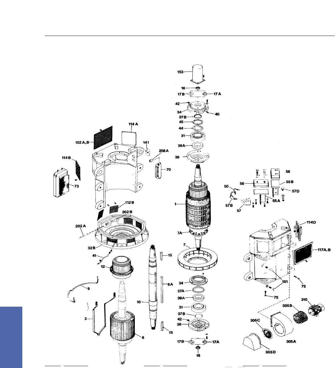
174 DC Motors
For more information contact a GE Motor Parts Master Distributor or GE Support Services.
7–Medium DC
MDV810 thru MDV818 Motors
Exploded View Vertical
Ref. No. Description
1 Armature
2 Armature Coil
6 Armature Core
6A Armature Core Key
7 Armature Fan
7A Armature Fan Hub
9 Equalizer Coil
10 Shaft
12 Commutator
15 Pinion Key
16 Pinion Nut
17A Pinion Lock Washer–Split Type
17B Pinion Lock Washer–Bent Type
31 Bearing
32B Bearing Bracket–Drive End
34 Bearing Cap
36 Bearing Cartridge
37A Bearing Seal–Inner
Ref. No. Description
37B Bearing Seal–Outer
39A Thrust Collar–Inner
40 Grease Fitting
41 Grease Tube Assembly
42 Pipe Plug
44 Split Ring
45 Locking Ring
50 Brush
55A Brushholder Stud–Right Hand
55B Brushholder Stud–Left Hand
56 Brushholder Stud Insulation
57 Brushholder
57B Brushholder Spring
57D Brushholder Mounting Bolt
70 Comm Coil & Pole Assembly
73 Main Field Coil & Pole
75 Pole Bolts
102A Cover, Bottom Comm End–Solid
Ref. No. Description
102B Cover, Bottom Comm End–Screen
112B Cover, Bottom Side Drive End–Screen
114A Cover, Side Comm End–Solid
114B Cover, Side Comm End–Screen
114D Cover, Quick Access–Comm End–Solid
117A Cover,Top Comm End–Solid
117B Cover, Top Comm End–Screen
141 Cable Bushing
151 Frame Split Bolt
153 Shaft Thimble
202A Space Heater Only
202B Heat Sink–Space Heater
208A Thermostat
305A Blower Housing
305B Blower Impeller
305C Air Inlet Screen
305D Air Inlet Hood With Screen
310 Blower Motor
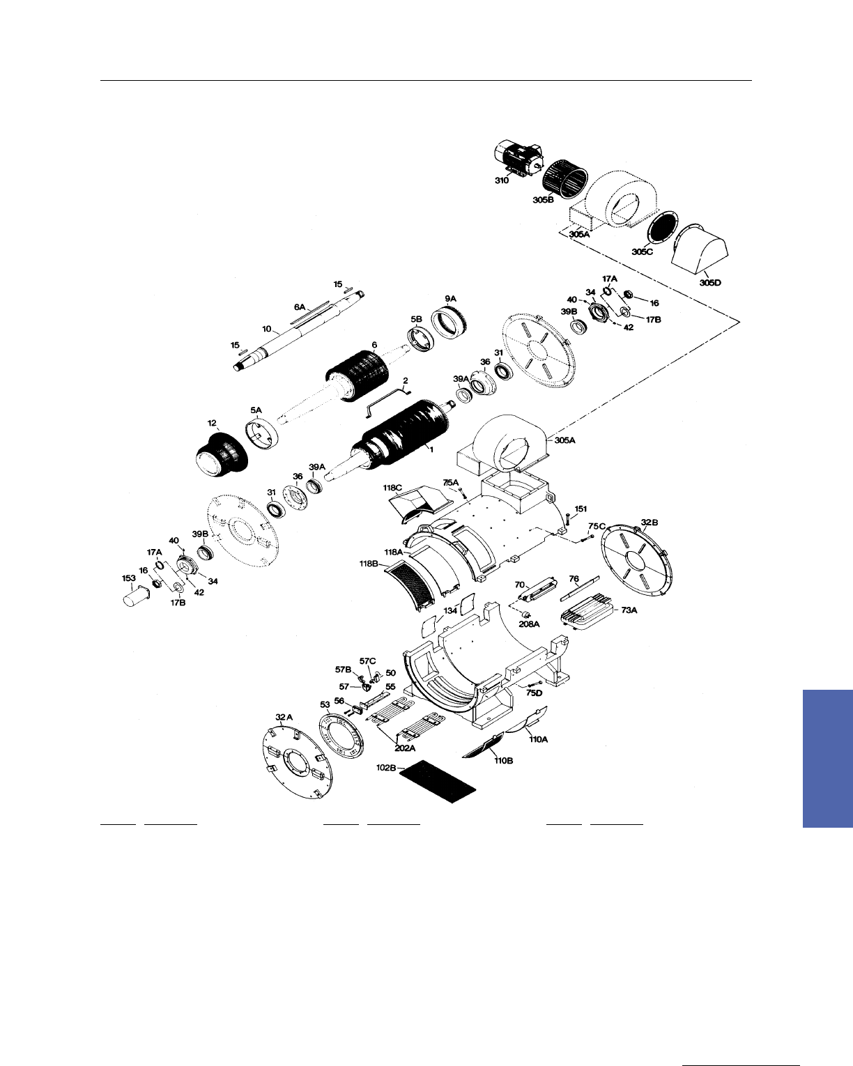
Medium DC Motors 175
GE Support Services
7–Medium DC
MDP820
Exploded View Horizontal
Ref. No. Description
1 Armature
2 Armature Coil
5A Armature Coil Support–Comm End
5B Armature Coil Support–Drive End
6 Armature Core
6A Armature Core Key
9A Equalizer–Molded
10 Shaft
12 Commutator
15 Pinion Key
16 Pinion Nut
17A Pinion Lock Washer–Split Type
17B Pinion Lock Washer–Bent Type
31 Bearing
32A Bearing Bracket–Comm End
32B Bearing Bracket–Drive End
34 Bearing Cap
36 Bearing Cartridge
Ref. No. Description
39A Thrust Collar–Inner
39B Thrust Collar–Outer
40 Grease Fitting
42A Pipe Plug
50 Brush
53 Brushholder Yoke
55 Brushholder Stud
56 Brushholder Stud Insulation
57 Brushholder
57B Brushholder Spring
57C Brushholder Mounting Clip
70 Comm Coil & Pole Assembly
73A Main Field Coil & Pole With Bars
75A Comm Pole Bolt
75C Main Field Pole Bolt
75D Main Field Pole Bolt–Bottom
76 Pole Face Bars
Ref. No. Description
102B Cover, Bottom Comm End–Screen
11OA Cover, Bottom Side Comm End–Solid
110B Cover, Bottom Side Comm End–Screen
118A Cover, Top Side Comm End–Solid
118B Cover, Top Side Comm End–Screen
118C Cover, Top Side Comm End–Hood
134 Cover, Lead
151 Frame Split Bolt
153 Shaft Thimble
202A Space Heater Only
208A Thermostat
305A Blower Housing
305B Blower Impeller
305C Air Inlet Screen
305D Air Inlet Hood With Screen
310 Blower Motor
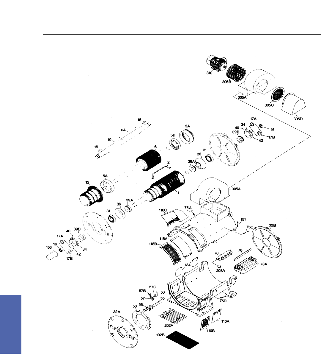
176 DC Motors
For more information contact a GE Motor Parts Master Distributor or GE Support Services.
7–Medium DC
MDP822 Motors
Exploded View Horizontal
Ref. No. Description
1 Armature
2 Armature Coil
5A Armature Coil Support–Comm End
5B Armature Coil Support–Drive End
6 Armature Core
6A Armature Core Key
9A Equalizer–Molded
10 Shaft
12 Commutator
15 Pinion Key
16 Pinion Nut
17A Pinion Lock Washer–Split Type
17B Pinion Lock Washer–Bent Type
31 Bearing
32A Bearing Bracket–Comm End
32B Bearing Bracket–Drive End
34 Bearing Cap
Ref. No. Description
36 Bearing Cartridge
39A Thrust Collar–Inner
39B Thrust Collar–Outer
40 Grease Fitting
42 Pipe Plug
50 Brush
53 Brushholder Yoke
55 Brushholder Stud
56 Brushholder Stud Insulation
57 Brush Holder
57B Brushholder Spring
57C Brushholder Mounting Clip
70 Comm Coil & Pole Assembly
75A Comm Pole Bolt
73A Main Field Coil & Pole With Bars
75C Main Field Pole Bolt
75D Main Field Pole Bolt–Bottom
Ref. No. Description
76 Pole Face Bars
102B Cover, Bottom Comm End–Screen
110A Cover, Bottom Side Comm End–Solid
110B Cover, Bottom Side Comm End–Screen
118A Cover, Top Side Comm End–Solid
118B Cover, Top Side Comm End–Screen
118C Cover, Top Side Comm End–Hood
134 Cover, Lead
151 Frame Split Bolt
153 Shaft Thimble
202A Space Heater Only
208A Thermostat
305A Blower Housing
305B Blower Impeller
305C Air Inlet Screen
305D Air Inlet Hood With Screen
310 Blower Motor
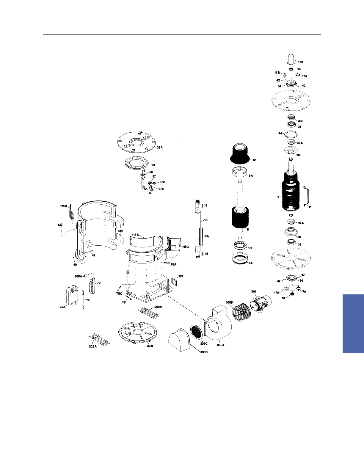
Medium DC Motors 177
GE Support Services
7–Medium DC
MDV820, MDV822 Motors
Exploded View Vertical
Ref. No. Description
1 Armature
2 Armature Coil
5A Armature Coil Support–Comm End
5B Armature Coil Support–Drive End
6 Armature Core
6A Armature Core Key
9A Equalizer–Molded
10 Shaft
12 Commutator
15 Pinion Key
16 Pinion Nut
17A Pinion Lock Washer–Split Type
17B Pinion Lock Washer–Bent Type
31 Bearing
32A Bearing Bracket–Comm End
32B Bearing Bracket–Drive End
34 Bearing Cap
Ref. No. Description
36 Bearing Cartridge
39A Thrust Collar–Inner
39B Thrust Collar–Outer
40 Grease Fitting
41 Grease Tube Assembly
42 Pipe Plug
44 Split Ring
50 Brush
53 Brushholder Yoke
55 Brushholder Stud
56 Brushholder Stud Insulation
57 Brushholder
57B Brushholder Spring
57C Brushholder Mounting Clip
70 Comm Coil & Pole Assembly
73A Main Field Coil & Pole With Bars
75A Comm Pole Bolt
Ref. No. Description
75C Main Field Pole Bolt
76 Pole Face Bars
118A Cover, Top Side Comm End–Solid
118B Cover, Top Side Comm End–Screen
118C Cover, Top Side Comm End–Hood
122 Cover, Space Heater Access
124 Cover, Frame Mounting Access
134 Cover, Lead
151 Frame Split Bolt
153 Shaft Thimble
202A Space Heater Only
208A Thermostat
305A Blower Housing
305B Blower Impeller
305C Air Inlet Screen
305D Air Inlet Hood w/Screen
310 Blower Motor
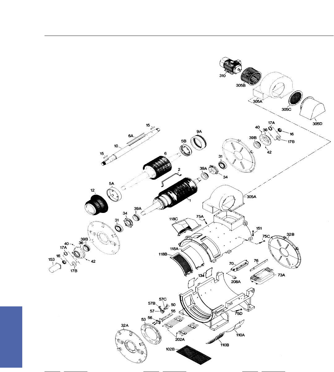
178 DC Motors
For more information contact a GE Motor Parts Master Distributor or GE Support Services.
7–Medium DC
MDP824 Motors
Exploded View Horizontal
Ref. No. Description
1 Armature
2 Armature Coil
5A Armature Coil Support–Comm End
5B Armature Coil Support–Drive End
6 Armature Core
6A Armature Core Key
9A Equalizer–Molded
10 Shaft
12 Commutator
15 Pinion Key
16 Pinion Nut
17A Pinion Lock Washer–Split Type
17B Pinion Lock Washer–Bent Type
31 Bearing
32A Bearing Bracket–Comm End
32B Bearing Bracket–Drive End
34 Bearing Cap
Ref. No. Description
36 Bearing Cartridge
39A Thrust Collar–Inner
39B Thrust Collar–Outer
40 Grease Fitting
42 Pipe Plug
50 Brush
53 Brushholder Yoke
55 Brushholder Stud
56 Brushholder Stud Insulation
57 Brushholder
57B Brushholder Spring
57C Brushholder Mounting Clip
70 Comm Coil & Pole Assembly
73A Main Field Coil & Pole With Bars
75A Comm Pole Bolt
75C Main Field Pole Bolt
75D Main Field Pole Bolt–Bottom
Ref. No. Description
76 Pole Face Bars
102B Cover, Bottom Comm End–Screen
11OA Cover, Bottom Side Comm End–Solid
110B Cover, Bottom Side Comm End–Screen
118A Cover, Top Side Comm End–Solid
118B Cover, Top Side Comm End–Screen
118C Cover, Top Side Comm End–Hood
134 Cover, Lead
151 Frame Split Bolt
153 Shaft Thimble
202A Space Heater Only
208A Thermostat
305A Blower Housing
305B Blower Impeller
305C Air Inlet Screen
305D Air Inlet Hood With Screen
310 Blower Motor
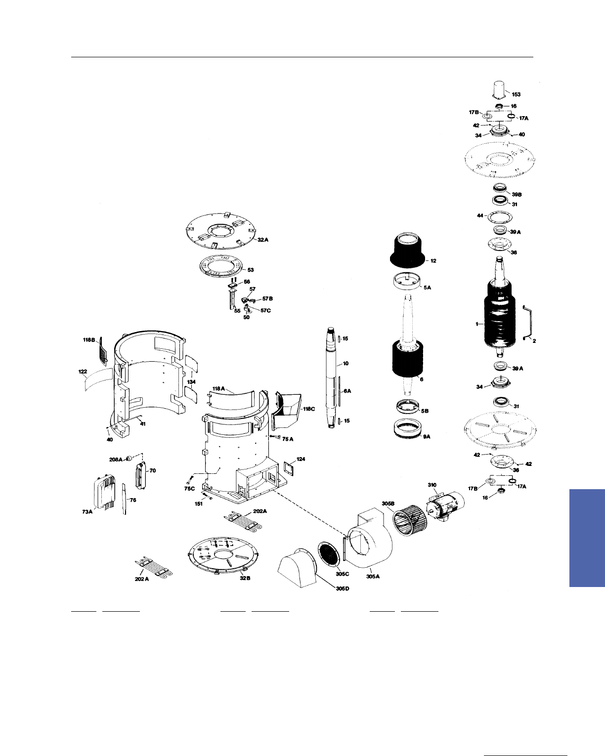
Medium DC Motors 179
GE Support Services
7–Medium DC
Ref. No. Description
1 Armature
2 Armature Coil
5A Armature Coil Support–Comm End
5B Armature Coil Support–Drive End
6 Armature Core
6A Armature Core Key
9A Equalizer–Molded
10 Shaft
12 Commutator
15 Pinion Key
16 Pinion Nut
17A Pinion Lock Washer–Split Type
17B Pinion Lock Washer–Bent Type
31 Bearing
32A Bearing Bracket–Comm End
32B Bearing Bracket–Drive End
34 Bearing Cap
Ref. No. Description
36 Bearing Cartridge
39A Thrust Collar–Inner
39B Thrust Collar–Outer
40 Grease Fitting
41 Grease Tube Assembly
42 Pipe Plug
44 Split Ring
50 Brush
53 Brushholder Yoke
55 Brushholder Stud
56 Brushholder Stud Insulation
57 Brushholder
57B Brushholder Spring
57C Brushholder Mounting Clip
70 Comm Coil & Pole Assembly
73A Main Field Coil & Pole With Bars
75A Comm Pole Bolt
Ref. No. Description
75C Main Field Pole Bolt
76 Pole Face Bars
118A Cover, Top Side Comm End–Solid
118B Cover, Top Side Comm End–Screen
118C Cover, Top Side Comm End–Hood
122 Cover, Space Heater Access
124 Cover, Frame Mounting Access
134 Cover, Lead
151 Frame Split Bolt
153 Shaft Thimble
202A Space Heater Only
208A Thermostat
305A Blower Housing
305B Blower Impeller
305C Air Inlet Screen
305D Air Inlet Hood With Screen
310 Blower Motor
MDV824 Motors
Exploded View Vertical

180 DC Motors
For more information contact a GE Motor Parts Master Distributor or GE Support Services.
7–Medium DC
Renewal Part MD802A Qty. MD802B Qty. MD802C Qty. MD803 Qty. MD804 Qty. MD806 Qty.
Armature 36A164230AAG01 1 36A164230AAG01 1 36A164230AAG01 1 36A164231AAG01 1 36A164232AAG01 1 36A164233AAG01 1
Armature w/Frameheads 36A164230AAG03 1 36A164230AAG03 1 36A164230AAG03 1 36A164231AAG03 1 36A164232AAG03 1 36A164232AAG03 1
Armature Coils 36A164160AAG01 1 36A164160AAG01 1 36A164160AAG01 1 36A164161AAG01 1 36A164162AAG01 1 36A164163AAG01 1
Equalizer Coils –––––––––––––––– –––––––––––––––– –––––––––––––––– –––––––––––––––– –––––––––––––––– ––––––––––––––––
Insulation Set 36A164190AAG01 1 36A164190AAG01 1 36A164190AAG01 1 36A164191AAG01 1 36A164192AAG01 1 36A164193AAG01 1
Commutator 36A164080AAG01 1 36A164080AAG01 1 36A164080AAG01 1 36A164081AAG01 1 36A164082AAG01 1 36A164083AAG01 1
Shaft 36B465450AAG01 1 36B465450AAG01 1 36B465450AAG01 1 36B465451AAG01 1 36B465452AAG01 1 36B465453AAG01 1
Fan 36A164070CA001 1 36A164070CA001 1 36A164070CA001 1 36A164071CA001 1 36A164072CBG01 1 36A164072CA001 1
Coil & Pole – Comm 36A164360BAG01 4 36A164360BAG01 4 36A164360BBG01 4 36A164361BAG01 4 36A164362AAG01 4 36A164363AAG01 4
Coil Only – Comm 36A164360BAG02 4 36A164360BAG02 4 36A164360BBG02 4 36A164361AAG02 4 36A164362AAG02 4 36A164363AAG02 4
Coil & Pole –Series 36A164400TCG01 4 36A164400TDG01 4 36A164400TEG01 4 36A164401TBG01 4 36A164402TBG01 4 36A164403TBG01 4
Coil Only –Series 36A164400TCG02 4 36A164400TDG02 4 36A164400TEG02 4 36A164401TBG02 4 36A164402TBG02 4 36A164403TBG02 4
Coil & Pole –Shunt 36A164400AGG01 4 36A164400AAG01 4 36A164400AAG01 4 36A164400AAG01 4 36A164402AAG01 4 36A164403AAG01 4
Coil Only – Shunt 36A164400AGG02 4 36A164400AAG02 4 36A164400AAG02 4 36A164401AAG02 4 36A164402AAG02 4 36A164403AAG02 4
Coil & Pole –Compound 36A164400JDG01 4 36A164400JEG01 4 36A164400JFG01 4 36A164401JCG01 4 36A164402JCG01 4 36A164403JCG01 4
Coil Only – Compound 36A164400JDG02 4 36A164400JEG02 4 36A164400JFG02 4 36A164401JCG02 4 36A164402JCG02 4 36A164403JCG02 4
Coil & Pole–Stab Shunt 36A164400JRG01 4 36A164400JRG01 4 36A164400JRG01 4 36A164401JRG01 4 36A164402JEG01 4 36A164403JDG01 4
Coil Only–Stab Shunt 36A164400JRG02 4 36A164400JRG02 4 36A164400JRG02 4 36A164401JRG02 4 36A164402JEG02 4 36A164403JDG02 4
CE/DE Bearing 8832705–002 2 8832705–002 2 8832705–002 2 8832705–003 2 8832705–004 2 8832705–005 2
Brushholder & Spring 36A160424AAG01 4 36A160424AAG01 4 36A160424AAG01 4 36A164425AAG01 4 36A160426AAG01 4 36A160427AAG01 4
Spring only 36B465484AA001 4 36B465484AA001 4 36B465484AA001 4 36B465485AA001 4 36B465486AA001 4 36A164487AA001 4
Brush 36A164454AAP20 4 36A164454AAP20 4 36A164454AAP20 4 36A164455AAP20 4 36A164456AAP20 4 36A164457AAP20 4
CE QCK Removal Cover 36A164470CAG01 2 36A164470CAG01 2 36A164470CAG01 2 36A164471CAG01 2 36A164472CAG01 2 36A164473CAG01 2
Lockwasher – Spring 36A164222AA001 2 36A164222AA001 2 36A164222AA001 2 36A164222AA001 2 36A164222AA001 2 36A164222AA002 2
Lockwasher–Flat 36A164222AB001 2 36A164222AB001 2 36A164222AB001 2 36A164222AB001 2 36A164222AB002 2 36A164222AB003 2
Pinion Nut 36A164223AA001 2 36A164223AA001 2 36A164223AA001 2 36A164223AA002 2 36A164223AA002 2 36A164223AA003 2
Cable Bushings
Series Motor 36A164527AA001 4 36A164527AC001 4 36A164527AC001 4 36A164527AC001 4 36A164527CAG01 2 36A164527AC001 2
Larger Hole –––––––––––––––– –––––––––––––––– –––––––––––––––– –––––––––––––––– 36A164527AC002 2 36A164527AC002 2
Shunt Motor–Field 36A164527AC001 2 36A164527AC001 2 36A164527AC001 2 36A164527AC001 2 36A164527AC001 2 36A164527AC002 2
Blank 36A164527AA004 2 36A164527AA004 2 36A164527AA004 2 36A164527AA004 2 36A164527AA004 2 36A164527AA004 2
Compound Motor 36A164527AC001 4 36A164527AC001 4 36A164527AC001 4 36A164527AC001 2 36A164527AC001 2 36A164527AC001 2
Larger Hole –––––––––––––––– –––––––––––––––– –––––––––––––––– –––––––––––––––– 36A164527AC002 2 36A164527AC002 2
Type MD, Frames 802 to 806
230V Standard Renewal Parts Identification

Medium DC Motors 181
GE Support Services
7–Medium DC
Renewal Part MD808 Qty. MD810 Qty. MD812 Qty. MD814 Qty. MD816 Qty. MD818 Qty.
Armature 36A164234AAG01 1 36A164235AAG01 1 36A164236AAG01 1 36A164237AAG01 1 36A164238AAG01 1 36A164239AAG01 1
Armature w/Frameheads 36A164234AAG03 1 36A164235AAG03 1 36A164236AAG03 1 36A164237AAG03 1 36A164238AAG03 1 36A164239AAG03 1
Armature Coils 36A164164AAG01 1 36A164165AAG01 1 36A164166AAG01 1 36A164167AAG01 1 36A164168AAG01 1 36A164169AAG01 1
Equalizer Coils –––––––––––––––– –––––––––––––––– ––––––––––––––––– 36A164177AB001 29 36A164178AB001 29 36A164179AB001 27
Insulation Set 36A164194AAG01 1 36A164195AAG01 1 36A164196AAG01 1 36A164197AAG01 1 36A164198AAG01 1 36A164199AAG01 1
Commutator 36A164084AAG01 1 36A164085AAG01 1 36A164086AAG01 1 36A164087AAG01 1 36A164088AAG01 1 36A164089AAG01 1
Shaft 36B465454AAG01 1 36B465455AAG01 1 36B465456AAG01 1 36B465457AAG01 1 36B465458AAG01 1 36B465459AAG01 1
Fan 36A164074CB001 1 36A164074CA001 1 36A164076CA001 1 36A164077CA001 1 36A164078CAG01 1 36A164079CA001 1
Coil & Pole – Comm 36A164364AAG01 4 36A164365AAG01 4 36A164366AAG01 4 36A164367AAG01 4 36A164368AAG01 4 36A164369AAG01 4
Coil Only – Comm 36A164364AAG02 4 36A164365AAG02 4 36A164366AAG02 4 36A164367AAG02 4 36A164368AAG02 4 36A164369AAG02 4
Coil & Pole –Series 36A164404SBG01 4 36A164405SBG01 4 36A164406SBG01 4 36A164407SBG01 4 36A164408SBG01 4 36A164409SBG01 4
Coil Only –Series 36A164404SBG02 4 36A164405SBG02 4 36A164406SBG02 4 36A164407SBG02 4 36A164408SBG02 4 36A164409SBG02 4
Coil & Pole –Shunt 36A164404AAG01 4 36A164405AAG01 4 36A164406AAG01 4 36A164407AAG01 4 36A164408AAG01 4 36A164409AAG01 4
Coil Only – Shunt 36A164404AGG02 4 36A164405AAG02 4 36A164406AAG02 4 36A164407AAG02 4 36A164408AAG02 4 36A164409AAG02 4
Coil & Pole –Compound 36A164404KBG01 4 36A164405KBG01 4 36A164406KBG01 4 36A164407KBG01 4 36A164408KBG01 4 36A164409KBG01 4
Coil Only – Compound 36A164404KBG02 4 36A164405KBG02 4 36A164406KBG02 4 36A164407KBG02 4 36A164408KBG02 4 36A164409KBG02 4
Coil & Pole–Stab Shunt 36A164400KFG01 4 36A164405KDG01 4 36A164406KEG01 4 36A164407KDG01 4 36A164408KDG01 4 36A164409KDG01 4
Coil Only–Stab Shunt 36A164400KFG02 4 36A164405KDG02 4 36A164406KEG02 4 36A164407KDG02 4 36A164408KDG02 4 36A164409KDG02 4
CE/DE Bearing 8832705–006 2 8832705–007 2 8832705–008 2 8832705–009 2 8832705–010 2 8832705–011 2
Brushholder & Spring 36A160421AAG01 6 36A160421AAG01 8 36A160422AAG01 8 36A160422AAG01 12 36A160422AAG01 16 36A160423AAG01 16
Spring only 36B465481AA001 6 36B465481AA001 8 36B465482AA001 8 36B465482AA001 12 36B465482AA001 16 36A164483AA001 16
Brush 36A164451AAP20 6 36A164451AAP20 8 36A164452AAP20 8 36A164452AAP20 12 36A164452AAP20 16 36A164453AAP20 16
CE QCK Removal Cover 36A164471CAG01 2 36A164472CAG01 2 36A164476CAG01 2 36A164477CAG01 2 36A164478CAG01 2 36A164479CAG01 2
Lockwasher – Spring 36A164222AA003 2 36A164222AA004 2 36A164222AA005 2 36A164222AA006 2 36A164222AA007 2 36A164222AA007 2
Lockwasher–Flat 36A164222AB004 2 36A164222AB005 2 36A164222AB006 2 36A164222AB007 2 36A164222AB008 2 36A164222AB009 2
Pinion Nut 36A164223AA004 2 36A164223AA005 2 36A164223AA006 2 36A164223AA007 2 36A164223AA008 2 36A164223AA009 2
Cable Bushings
Series Motor 36A164527AC002 4 36A164527AB001 1 36A164527AB002 1 36A164527AB001 6 36A164527AB002 2 36A164527AB003 4
–––––––––––––––– 36A164527AD006 1 36A164527AD003 1 36A164527AD006 2 36A164527AD003 2 36A164527AB003 2
–––––––––––––––– 36A164527AE004 2 36A164527AE002 2
Shunt Motor–Field 36A164527AC002 2 36A164527AE004 2 36A164527AE002 2 36A164527AA001 2 36A164527AB002 5 36A164527AA003 4
36A164527AA004 2 36A164527AA001 1 36A164527AA002 1 36A164527AB001 2 36A164527AA002 3 36A164527AB003 2
–––––––––––––––– 36A164527AF001 1 36A164527AF003 1 36A164527AA001 4 –––––––––––––––– 36A164527AD004 2
Compound Motor 36A164527AC002 4 36A164527AB001 1 36A164527AB002 1 36A164527AB001 6 36A164527AB002 6 36A164527AD003 6
–––––––––––––––– 36A164527AD006 1 36A164527AD003 1 36A164527AD006 2 36A164527AD003 2 36A164527AD004 2
–––––––––––––––– 36A164527AE004 2 36A164527AE002 2 ––––––––––––––– –––––––––––––––– –––––––––––––––
Type MD, Frames 808 to 818
230V Standard Renewal Parts Identification
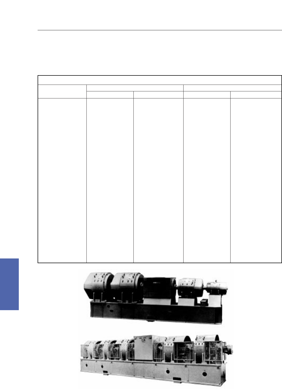
182 DC Motors
For more information contact a GE Motor Parts Master Distributor or GE Support Services.
7–Medium DC
Excavator Motor Generators
Type CDS, Frames 320 to 8000
Types MPC and MCF, Frames 500 to 900
Frame Size
CD250
CD280
CD320
CD360
CD400
CD440
CD500
CDS580
CDS680
CDS5000
MPC500
CDS6000
MCF600
CDS7000
MCF700
CDS8000
MCF800
MCF900
Pounds
60
100
140
200
260
350
550
800
1050
2350
1700
2800
2900
4000
4000
5850
5850
5454
Kilograms
30
50
60
90
120
160
250
360
480
1070
770
1270
1320
1810
1810
2650
2650
2470
Pounds
240
360
520
720
950
1320
1890
2900
4400
6600
5600
10100
10100
13650
12300
14850
17500
16565
Kilograms
110
170
240
330
440
600
860
1320
2000
3000
2540
4580
4580
6190
5580
6740
7940
7510
Armature Only Generator Complete
Typical Generator Weights in Pounds and Kilograms*
*These weights are approximated and do not necessarily reflect specific generator ratings.
DC–1725–1
MG–5394–1
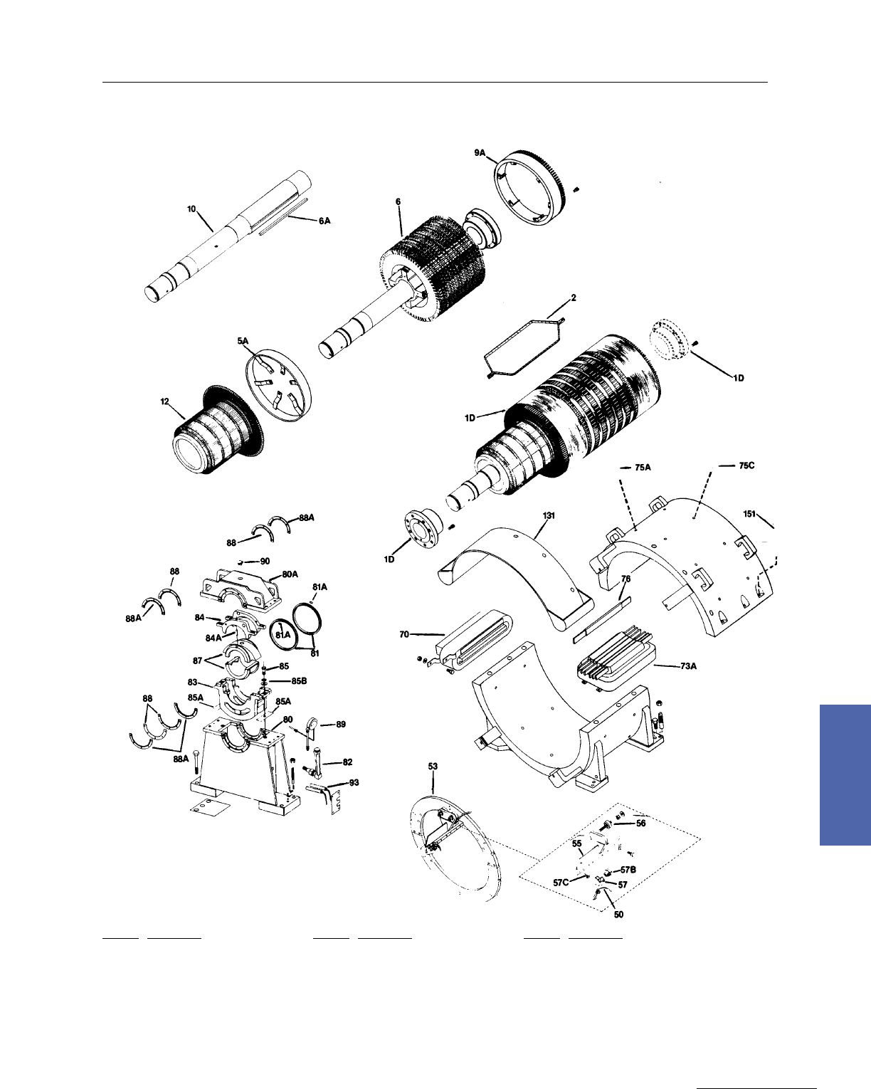
Medium DC Motors 183
GE Support Services
7–Medium DC
Excavator Motor Generators
MCF700–900 Generators,
Exploded View
Ref. No. Description
1D Armature & Couplings
2 Armature Coil Set
5A Armature Coil Support–Comm End
5B Armature Coil Support–Drive End
6 Armature Core
6A Armature Core Key
9A Equalizer–Molded
10 Shaft
12 Commutator
50 Brush
53 Brushholder Yoke
55 Brushholder Stud
56 Brushholder Stud Insulation
Ref. No. Description
57 Brushholder
57B Brushholder Spring
57C Brushholder Mounting Clip
70 Comm Coil & Pole Assembly
73A Main Field Coil & Pole With Bars
75A Comm Pole Bolt
75C Main Field Pole Bolt
76 Pole Face Bars
80A Pedestal Cap
81 Oil Ring
81A Oil Ring Wear Pads
82 Sight Gauge
83 Cradle Bottom
Ref. No. Description
84 Cradle Cap
84A Cradle Cap Dowel Pin
85 Insulating Bolt
85A Insulating Shim
85B Insulating Washer–Cradle Cap
87 Sleeve Bearing
88 Oil Seals–Leather
88A Oil Seal Ring
89 Oil Temperature Gauge
90 Filler Cap
93 Space Heater, Pedestal
131 Cover, Hood Comm End
151 Frame Split Bolt
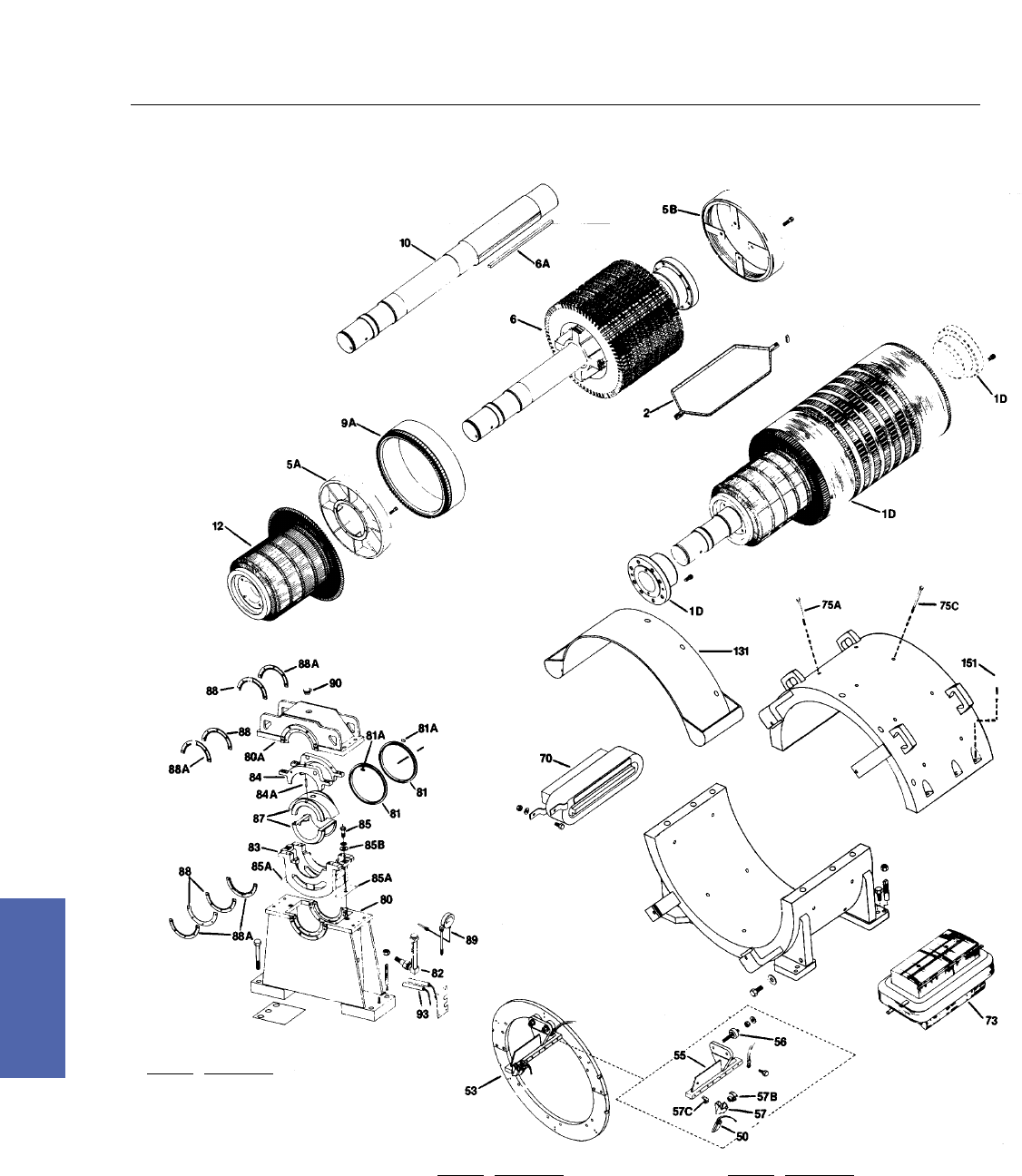
184 DC Motors
For more information contact a GE Motor Parts Master Distributor or GE Support Services.
7–Medium DC
Excavator Motor Generators
MPC500–600 Generators,
Exploded View
Ref. No. Description
1D Armature & Couplings
2 Armature Coil Set
5A Armature Coil Support–Comm End
5B Armature Coil Support–Drive End
6 Armature Core
6A Armature Core Key
9A Equalizer–Molded
10 Shaft
12 Commutator
50 Brush
53 Brushholder Yoke
55 Brushholder Stud
56 Brushholder Stud Insulation
57 Brush Holder
57B Brushholder Spring
57C Brushholder Mounting Clip
70 Comm Coil & Pole Assembly
Ref. No. Description
73 Main Field Coil & Pole
75A Comm Pole Bolt
75C Main Field Pole Bolt
80A Pedestal Cap
81 Oil Ring
81A Oil Ring Wear Pads
82 Sight Gauge
83 Cradle Bottom
84 Cradle Cap
84A Cradle Cap Dowel Pin
Ref. No. Description
85 Insulating Bolt
85A Insulating Shim
85B Insulating Washer–Cradle Cap
87 Sleeve Bearing
88 Oil Seals–Leather
88A Oil Seal Ring
89 Oil Temperature Gauge
90 Filler Cap
93 Spacer Heater, Pedestal
131 Cover, Hood Comm End
151 Frame Split Bolt
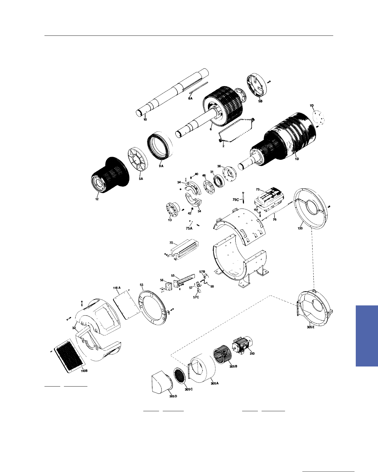
Medium DC Motors 185
GE Support Services
7–Medium DC
Excavator Motor Generators
CDS5000–6000 Excavator Generators,
Exploded View
Ref. No. Description
1D Armature & Couplings
2 Armature Coil Set
5A Armature Coil Support–Comm End
5B Armature Coil Support–Drive End
6 Armature Core
6A Armature Core Key
9A Equalizer–Molded
10 Shaft
12 Commutator
31 Bearing
32 Bearing Bracket
34 Bearing Cap
36 Bearing Cartridge
40 Grease Fitting
42 Pipe Plug
46 Grease Metering Plate
50 Brush
53 Brushholder Yoke
Ref. No. Description
55 Brushholder Stud
56 Brushholder Stud Insulation
57 Brushholder
57B Brushholder Spring
57C Brushholder Mounting Clip
70 Comm Coil & Pole Assembly
73 Main Field Coil & Pole
75A Comm Pole Bolt
75C Main Field Pole Bolt
76 Pole Face Bars
110B Cover, Bottom Side Comm End–Screen
118A Cover, Top Side Comm End–Solid
133 Cover, Drive End
Ref. No. Description
151 Frame Split Bolt
305A Blower Housing
305B Blower Impeller
305C Air Inlet Screen
305D Air Inlet Hood With Screen
305E Blower Bracket
310 Blower Motor
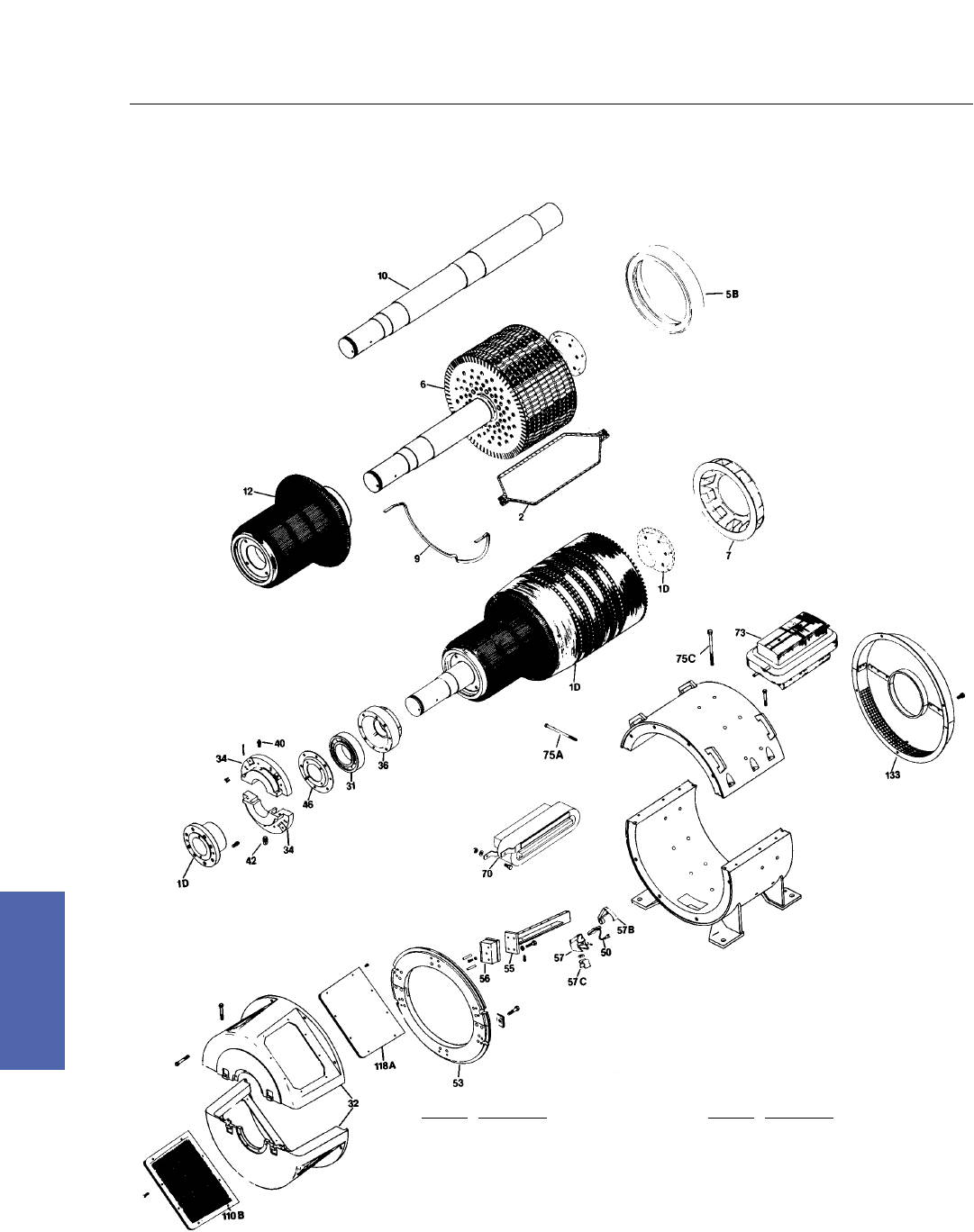
186 DC Motors
For more information contact a GE Motor Parts Master Distributor or GE Support Services.
7–Medium DC
Excavator Motor Generators
CDS580–680 Excavator Generator,
Exploded View
Ref. No. Description
1D Armature & Couplings
2 Armature Coil Set
5B Armature Coil Support–Drive End
6 Armature Core
7 Armature Fan
9 Equalizer Coil
10 Shaft
12 Commutator
31 Bearing
32 Bearing Bracket
34 Bearing Cap
36 Bearing Cartridge
40 Grease Fitting
42 Pipe Plug
46 Grease Metering Plate
Ref. No. Description
50 Brush
53 Brushholder Yoke
55 Brushholder Stud
56 Brushholder Stud Insulation
57 Brush Holder
57B Brushholder Spring
57C Brushholder Mounting Clip
70 Comm Coil & Pole Assembly
73 Main Field Coil & Pole
75A Comm Pole Bolt
75B Main Field Pole Bolt
110B Cover, Bottom Side Comm End–Screen
118A Cover, Top Side Comm End–Solid
133 Cover, Drive End
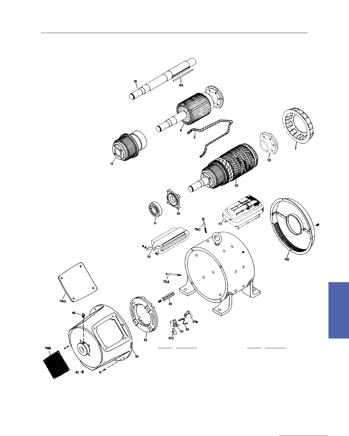
Medium DC Motors 187
GE Support Services
7–Medium DC
Excavator Motor Generators
CDS320–500 Excavator Generators,
Exploded View
Ref. No. Description
1D Armature & Couplings
2 Armature Coil Set
6 Armature Core
6A Armature Core Key
7 Armature Fan
9 Equalizer Coil
10 Shaft
12 Commutator
31 Bearing
32 Bearing Bracket
34 Bearing Cap
40 Grease Fitting
42 Pipe Plug
Ref. No. Description
50 Brush
53 Brushholder Yoke
55 Brushholder Stud
57 Brushholder
57B Brushholder Spring
57C Brushholder Mounting Clip
70 Comm Coil 8 Pole Assembly
73 Main Field Coil 8 Pole
75A Comm Pole Bolt
75C Main Field Pole Bolt
110B Cover, Bottom Side Comm End–Screen
118A Cover, Top Side Comm End–Solid
133 Cover, Drive End
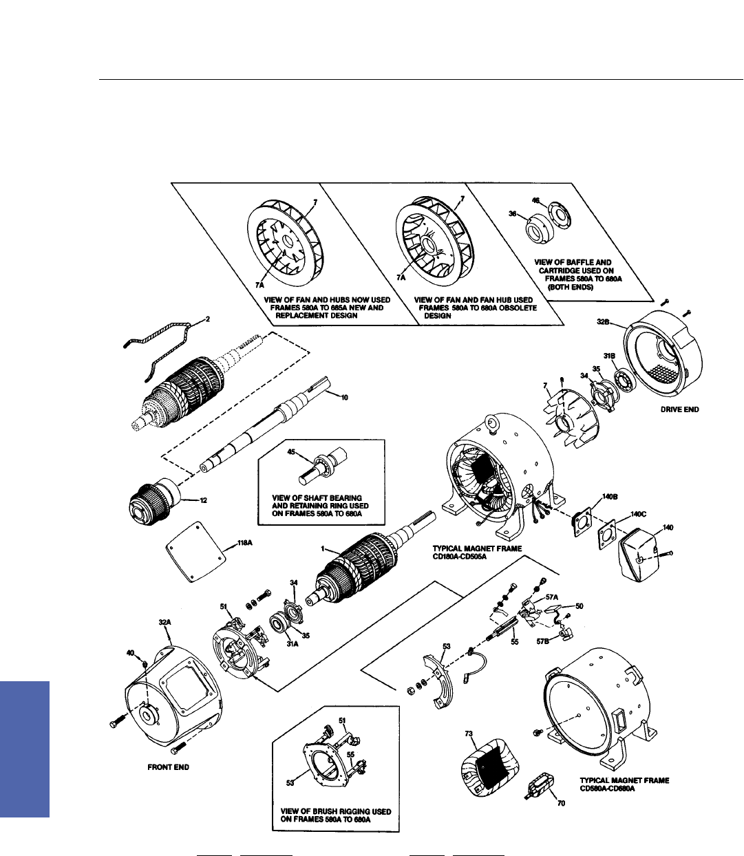
188 DC Motors
For more information contact a GE Motor Parts Master Distributor or GE Support Services.
7–Medium DC
Excavator Motor Generators
Type CD, Frames 186A to 685A Kinamatic, Exploded View
Ref. No. Description
1 Armature
2 Armature Coil
7 Armature Fan
7A Armature Fan Hub
10 Armature Shaft
46 Grease Metering Plate
31A,B Bearing
32A,B Bearing Bracket
34 Bearing Cap
35 Bearing Cap Gasket
36 Bearing Cartridge
51 Brush Rigging
53 Brushholder Yoke
Ref. No. Description
55 Brushholder Stud
57A Brushholder
57B Brushholder Spring
50 Brush
70 Comm Coil And Pole Assembly
12 Commutator
140 Conduit Box
140B Conduit Box Adapter
140C Conduit Box Adapter Gasket
118A Cover, Topside Comm End–Solid
73 Field Coil & Pole
45 Locking Ring
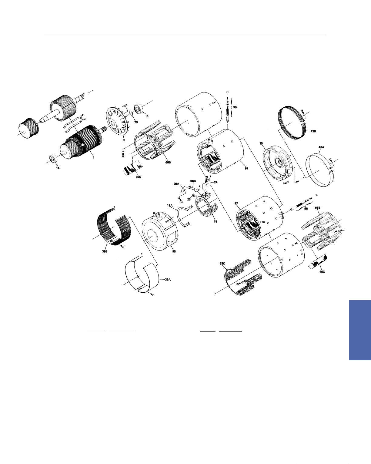
Medium DC Motors 189
GE Support Services
7–Medium DC
Electric Vehicles
BT1300 Thru BT2300
Ref. No. Description
1 Armature
5 Armature Fan
14 Bearing–CE/DE
15 Bearing Bracket—DE
18 Brush Rigging
18A Cross Connector
23 Brushholder Spring
24 Brush
33C Commutating Coil Asm.
39A Cover, Access Solid–CE
39B Cover, Access Screen–CE
Ref. No. Description
43A Cover, Solid–DE
43B Cover, Screen–DE
66B Main Coil Assembly
66C Main Pole
79 Retaining Ring
95 Yoke And Bearing Support–CE
96 Stud And Tube Assembly
97 Coiled Frame
98A Connector–Short
98B Connector–Long

190 DC Motors
For more information contact a GE Motor Parts Master Distributor or GE Support Services.
7–Medium DC
Maintenance Tips
Armature Banding
Incorrect core band tension ia a common cause of armature failures. A loose band will allow the coils
to move and abrade, causing a short or ground. Proper tension should draw the coils to about
one–third of the banding groove height. Under no circumstances should the tape rest on the bottom
of the groove.
Recommended absolute pressures for glass tape of the armature core:
3/8 wide 30 end 200–225 lbs.
3/4 wide 60 end 400–450 lbs.
The armature should be preheated to 120˚C. The tension device must be able to maintain tape
pressure when stopped.
Bearings
Grease–Generally used is GE D6A2C5, lithium soap base. Do not use grease with EP designation and
do not mix greases. EP designated greases should not be used on DC motors. The additives work at
elevated temperatures above the normal capability and the grease materials may deteriorate the
winding insulation.
Oil Leaks–Sleeve bearing housings are designed with vent passages to equalize air pressure on both
sides of the bearing. Blockage of vents can cause oil leakage.
Warning: Ensure all power has been removed from the machine before performing maintenance.
To Replace Bearings–
1. First verify that the bearings are the problem. Symptoms may include contaminated oil, excessive
vibration, noise, or heat.
2. Lubricate each bearing before installing: speeds below 1200 RPM use 300 SSU (Saybolt Seconds
Universal) oil. Use 150 SSU oil for speeds above 1200 RPM.
3. Check for damaged seals and rings. Replacements are available from GE Support Services.
Warning: Ensure all power has been removed from the machine before performing maintenance.
Blower Impellers
These will move air in either direction of rotation. Make sure that the rotation maximizes air flow.
Blower Kit Modification
–Comm end mount, F1 or F2, 230/460V, 3 Phase, 60 Hz. For other requirements, refer to GE Support
Services.
–CD180AT machines require drilling and tapping of mounting holes.
–Check the direction of rotation of the impeller before placing motor into service.
–Air flow may be reduced up to 30% due to accumulation of dirt on the impeller blades.
–Maximum air rise through the machine is 25˚C.
Brushholder Replacement
Brush Box Height–Brush boxes are set .070–.080” above the commutator diameter on all GE Industrial
DC motors, CD210AT–CD9000.
Brushholder setting spacers are available through GE Support Services to ensure uniform height
above the commutator:
PT#36A178125AA001 for CD580AT–CD9000
PT#36A178125AA002 for CD210AT–CD500AT
Cleaning brushholder springs by sand blasting may erode spring material changing the force constant
and may introduce sand into the motor.Glass beading brushholder springs is acceptable.
Warning: Ensure all power has been removed from the machine (e.g., lock out/tag out) before checking brush box
heights.

Medium DC Motors 191
GE Support Services
7–Medium DC
Enclosures
–DPFG, SPFG, TEFC, TAEO constant torque to 60% base speed
–TEUC, TEWC constant torque to 40% base speed
–BV, SV constant torque to 5% base speed
Endplay
Always measure with dial indicator.
Motors: MD600–800 .109 – .172”
Kinamatic I .005 – .040”
Kinamatic II–2 Pole .005 – .040”
Kinamatic II–4 Pole .000 – .015”
CD580 .029 – .044”
CD680 .037 – .052”
Field, Commutating
Commutating Pole Shims–When maintaining large DC machines, it is important to keep the same
number of shims between the magnet frame and the pole. The order of the shims is also important to
maintain magnetic balance. The correct order of the shims, starting from the comm pole out is:
1. Thick steel shims (.125” thick)
2. Thick aluminum shims (.125” thick)
3. Thin aluminum shims
4. Thin steel shims
The thin steel shims should rest against the frame.
Field, Data
– N/P volts = N/P current x N/P resistance x heat factor (1.39 Class F)
(1.29 Class B)
Field, Kinamatic II Connections Information
The field data listed on the nameplate with two field voltages assumes high voltage excitation. The
field amps are listed for base speed and weak field speed. Resistance is given for series connection
(one circuit) at 25˚C. If operating at low voltage (two circuit), field data must be adjusted. Multiply
the field amps by two and divide the field resistance by four. All data is given hot, except the field
resistance.
Field, Main
– Up to 110% excitation…within speed and load capability of the armature
– Limit current to 50% maximum…armature at standstill or no blower use field economy relay
– Resistance increase of 40% not uncommon from cold to hot
Field, TREC Coils
Bonding New Coils to Poles–
1. Note the vertical position of the original coil on the pole and the position of the leads.
Repositioning coils exactly on the pole is critical to the machine performance.
2. When bonding new coils to poles, first travel bonding compound directly to the pole, ensuring
adequate compound fills 100% of the space between the coil and pole. Center the new coil on the
pole and position the coil as noted in Step #1. GE Support Services recommends EPC PREG X93C
1961 bonding compound, which can be purchased through Epic Resins at 1–800–242–6649.
Recommended cure time is 6 hours at 165˚C.
3. Be sure to replace all magnetic pole shims in their original order.
Warning: Ensure all power has been removed from the machine before performing maintenance.
Maintenance Tips

192 DC Motors
For more information contact a GE Motor Parts Master Distributor or GE Support Services.
7–Medium DC
Maintenance Tips
Filler
Filler compound for hand wound equalizers is DOLPH CW–340–1 stator compound.
Ref: A50CD157A, 905A999AC218 purchase locally.
Filters
Kinamatic II: Numbers are molded in the plastic caps. The following identifies the filter number.
36A173048AAH01 – 36A173049AAH01 = FILTER #37A173047AAG01
36A173048AAH02 – 36A173049AAH02 = FILTER #37A173047ABG01
36A173048AAH03 – 36A173049AAH03 = FILTER #37A173047ACG01
36A173048AAH03 – ONE END ONLY = FILTER #37A173047ADG01
Miscellaneous
– Torque = (horsepower x 5252) divided by base speed
– Air rise = air exhaust temperature minus air intake temperature in degrees C
(25 degrees C is considered high)
Molded Commutators
Molded commutator construction has been a feature of GE Motors for about twenty–five years.
Molded commutators have proven to be a reliable and stable design. The use of molded commutators
is being expanded. Heating of the replacement commutator is not generally required for a successful
installation.
CD180AT –Comm is cemented to shaft, cold.
CD210AT–CD320AT –Comm is furnished on an aluminum shell. Press on cold.
CD360AT–CD500AT –Comm is furnished on a cast iron shell. Permissible to preheat
to 150˚C to install.
Caution: Avoid excessive/uneven heating.
Motor Heating
Rule of thumb is that the air rise through the motor should be a max of 25 degree C. The allowable
ampere rating of a drip proof motor drops significantly at speeds less than 60%. See heating curves.
Normal Environment
– Temperature 0 to 40 degrees C (32 to 104 degrees F)
– Humidity 40 to 99%
– Altitude less than3300 feet
– Loading 20 to 100% + occasional 150% current (100% base speed)
occasional = 1 min or less, not part of regular duty cycle
– Starting 250% full load current – CD180AT thru CD5010AT
300% full load current – CD4000
less than 10 seconds, not stalled
Paint
GE motors gray paint is a standard ASA#49.
Pedestal Pads
Pedestal pads on drag line sets are small molded plastic pads used to guide oil rings. There are 2 per
pedestal. 36A160583AA001

Medium DC Motors 193
GE Support Services
7–Medium DC
Maintenance Tips
Sealant
Silicone, RTV, or Bathtub Seal/Caulking is not recommended for sealing DC motors. The silicone
compounds destroy brushes, use “Titeseal” sealing compound GE MOTORS #8064200000
Titeseal
Titeseal is the preferred sealant used on waterproof motors to seal fits and bolts. It is non–hardening,
non–silicone. GE#8064200000.
Viton Protection
Viton protection kit for glass bound commutators – protects new bands from contamination. Kit is part
36A173329AAG02. Apply two coats of DOLPH ER41 (not included) over Viton.
DOLPH ER–41
This is the insulating enamel used for pole face connections.
Serial Number
Serial numbers for motors are stamped in the frame, usually near lift lugs.
Shaft Grounding Brushes
Voltage spikes from some static DC drives can be high enough to damage the bearings. One solution is
to mount a brush on the shaft which grounds the voltage. These are constant pressure.
Motor Frame Ground Brush Kit Comments
CD2800 36B472160GGG02 DE OUTSIDE W/LABYRINTH
CD280AT 36B472160GBG05 DE OUTSIDE W/LABYRINTH
CD320AT 36B472160GBG04 DE OUTSIDE W/LABYRINTH
CD360AT 36B472160GBG01 DE OUTSIDE W/LABYRINTH
CD400AT 36B472160GBG02 DE OUTSIDE W/LABYRINTH
CD500AT 36B472160GBG03 DE OUTSIDE W/LABYRINTH
CD5010 36B472160GBG07 DE OUTSIDE W/LABYRINTH
CD4000/6000 36B472712AAG01 DE INSIDE NO LABYRINTH
Grounding brushholder with brush and spring – 36A180199AA001
Replacement brush only – 36A180199AA003
Speed Variation
– Plus or minus 7.5% at rated armature voltage and field current
– Not to exceed 15% full load (cold) to full load (hot) ––ventilated
– Not to exceed 20% full load (cold) to full load (hot) ––totally enclosed
Tachometer
Kit Modification
–The center hole of the motor shaft should not be used to locate the stub shaft for coupling.
–CD180AT TENV, CD180AT TEFC, and CD210AT TEFC motors should be reviewed by GE Support
Services.
–BC tach kits will mount 56C face (5/8” shaft) tachs, such as Aviron (M738), Dynapar (62P), and
Lakeshore (6200).
–Older helical spring–type couplings can be replaced with up–to–date Thomas flexible disc–type
couplings.
Tachometers Type AN–DC
Tachometers type AN–DC use brush 36B467072AA003, Qty 4 per motor.

194 DC Motors
For more information contact a GE Motor Parts Master Distributor or GE Support Services.
7–Medium DC
Maintenance Tips
Thermostats
Thermostats are generally attached to the Comm Coil with a two part high temp epoxy.
GE #905A999AC222 generally a class F epoxy will work.
Unit Coolers
Unit coolers supplied on DC motors are not waterproof.
Weight of Steel
.28 lb per cubic inch.
Wire
Non–Magnetic banding steel wire is no longer used by GE Motors.

Medium DC Motors 195
GE Support Services
7–Medium DC
Standard Brushholders with Springs and
Springs Only
Spring Identification by Brushholder Number
36A160421AAG02 36B465481AA001
36A160421AAG03 36B465481AA001
36A160422AAG02 36B465482AA001
36A160422AAG03 36B465482AA001
36A160422AAG04 36B465482AA001
36A160423AAG02 36B465483AA001
36A160423AAG03 36B465483AA001
36A160423AAG05 36B465483AA001
36A160424AAG01 36B465484AA001
36A160424AAG03 36B465484AA001
36A160425AAG01 36B465485AA001
36A160425AAG03 36B465485AA001
36A160426AAG01 36B465486AA001
36A160426AAG02 36B465486AA001
36A160426AAG03 36B465486AA001
36A160427AAG01 36B465487AA001
36A160427AAG02 36B465487AA001
36A160427BAG01 36B465487AA001
36A161101AAG01 36B465081AA001
36A161101AAG03 36B465081BA001
36A161101AAG04 36B465081AA001
36A161101AAG05 36B465481AB001
36A161102AAG01 36B465082AA001
36A161103AAG01 36B465083AA001
36A161971AAG01 36B465081AA001
36A161973AAG01 36B465083AA001
36A167280AAG01 36B467020AA001
36A167281AAG01 36B467021AA001
41C631160G02 337B689 G01
428C682 G02 337B689 G01
428C683 G02 337B689 G01
428C685 G01 41B533105G01
428C685 G02 41B533105G01
428C686 G01 337B689 G01
428C686 G02 337B689 G01
428C687 GO2 337B689 G01
428C689 GO2 337B689 G01
428C694 GO1 36B465487AA001
428C694 GO2 36B465487AA001
428C695 GO1 337B689 G01
428C695 GO2 337B689 G01
428C697 GO1 337B689 G01
428C697 GO2 337B689 G01
527B837 GO1 9973178 001
527B837 GO2 9973178 001
527B837 GO3 9973179 001
527B837 GO4 9973179 001
5980811 G01 2415295 001
5980811 G02 2415896 001
5980811 G03 2415296 001
5980822 G01 2415295 001
5980822 G02 2415896 001
5980822 G03 2415296 001
5980924 G01 2415295 001
5980924 G02 2415896 001
5980924 G03 2415296 001
608C878 G01 626B204 G01
692B656 G01 265A236 001
692B656 G02 265A237 001
692B656 G03 265A238 001
894A627 G01 626B202 G01
894A627 G02 626B203 G01
894A627 G03 626B203 G01
894A627 G04 767B958 G01
894A684 G01 626B204 G01
894A684 G02 626B204 G01
894A684 G03 626B205 G01
894A684 G04 626B206 G01
894A684 G05 626B207 G01
Brushholder w/Spring Spring Only Brushholder w/Spring Spring Only
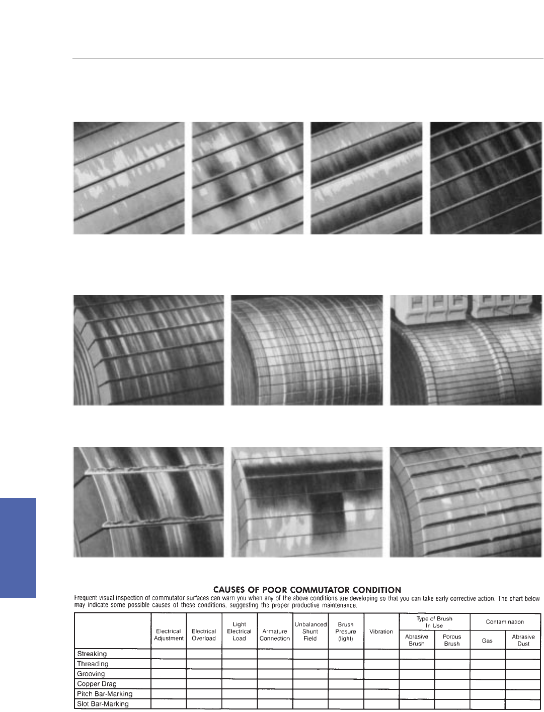
196 DC Motors
For more information contact a GE Motor Parts Master Distributor or GE Support Services.
7–Medium DC
Commutators
Check Chart for Comparing Commutator Surface Markings
Satisfactory Commutator Surfaces
LIGHT TAN FILM over entire commutator
surface is one of many normal conditions
often seen on a well–functioning machine.
MOTTLED SURFACE with random film
pattern is probably the most frequently
observed condition of commutators in
industry.
SLOT BAR–MARKING, a slightly darker
film, appears on bars in a definite pattern
related to number of conductors per slot.
HEAVY FILM can appear over entire area
of efficient and normal commutator and, if
uniform, is quite acceptable.
STREAKING on the commutator surface signals the
beginning of serious metal transfer to the carbon brush.
Check the chart below for possible causes.
THREADING of commutator with fine lines results when
excessive metal transfer occurs. It usually leads to
resurfacing of commutator and rapid brush wear.
COPPER DRAG, an abnormal build–up of commutator
material, forms most often at trailing edge of bar.
Condition is rare, but can cause flashover if not checked.
PITCH BAR–MARKING produces low or burned spots on
the commutator surface. The number of these markings
equals half or all the number of poles on the motor.
HEAVY SLOT BAR–MARKING can involve etching of
trailing edge of commutator bar. Pattern is related to
number of conductors per slot.
GROOVING is a mechanical condition caused by
abrasive material in the brush or atmosphere. If grooves
form, start corrective action.
x x x x x x
x x x x
x x
x x x x
x x x x x
x x x
HOW TO GET THE MOST VALUE FROM THIS CHART
The purpose of the Commutator Check Chart is to help you spot undesirable commutator conditions as they develop so you can take corrective action before the
condition becomes serious. This chart will also serve as an aid in recognizing satisfactory surfaces.
The box chart above indicates the importance of selecting the correct brush and having the right operating conditions for optimum brush life and commutator wear.
For additional information or help with carbon brush application or commutation problems, contact your nearest GE Sales Office or Distributor.
Watch for These Danger Signs

Medium DC Motors 197
GE Support Services
7–Medium DC
Glass Bound Comms have reached their
minimum diameter when there is not enough
copper above the bands to allow undercutting
without cutting the bands.
Commutators
Minimum Diameters
Kinamatic I
FRAME MAX MIN
CD180A 2.75 2.38
CD210A 3.25 2.88
CD250A 4.50 4.00
CD280A 4.75 4.25
CD320A 6.62 5.12
CD360A 6.38 5.75
CD400A 7.12 6.50
CD440A 7.88 7.25
CD500A 9.00 8.25
Kinamatic II
FRAME MAX MIN
CD180AT 2.76 2.63
CD210AT 4.50 4.27
CD250AT 5.00 4.75
CD280AT 5.78 5.49
CD320AT 6.50 6.17
CD360AT 7.50 7.13
CD400AT 8.32 7.92
CD500AT 10.25 9.75
K3 3.50 3.32
CD2512/13 5.30 5.02
CD2812/13 5.96 5.66
MD800 Glass Bound
FRAME MAX MIN
MD802 6.38 6.00
MD803 7.12 6.75
MD804 7.88 7.50
MD806 7.88 7.50
MD808 9.00 8.50
MD810 10.00 9.44
MD812 11.25 10.62
MD814 12.50 11.88
MD816 14.50 13.75
MD818 16.00 15.25
MD820 17.00 16.25
MD822 19.50 18.62
MD824 19.500 18.62
MD828 22.00 21.14
MD600 Cap & Cone
FRAME MAX MIN
MD603 6.38 5.75
MD603 7.00 6.38
MD604 7.50 6.75
MD606 8.50 7.62
MD608 9.62 8.62
MD610 10.62 9.50
MD612 11.75 10.62
MD614 13.25 12.12
MD616 15.00 13.38
MD618 16.62 15.38
MD620 17.00 16.00
MD622 19.00 17.75
MD624 22.50 21.25
MD400 Cap & Cone
FRAME MAX MIN
MD402 4.75 4.00
MD403 5.50 5.00
MD404 5.50 5.00
MD406 6.50 5.87
MD408 8.25 7.62
MD410 9.50 8.50
MD412 10.12 9.18
MD414 11.00 10.12
MD416 13.87 12.68
MD418 15.75 14.31
MD420 18.00 16.56
MD422 22.00 20.62
MD423 22.00 10.62
CD4000
FRAME MAX MIN
CD4300 11.50 11.00
CD4400 13.00 12.30
CD4500 15.00 14.25
CD4600 18.00 17.10
CD4700 22.00 20.90
CD6000 11.50 11.00
CD6100 13.00 12.30
CD6200 15.00 14.25
CD6700 19.50 18.50
CD6800 22.00 21.00
CD6900 22.00 21.00
CD1100–1700
FRAME MAX MIN
CD1100 8.00 7.25
CD1200 9.00 8.25
CD1300 10.25 9.50
CD1400 11.50 10.50
CD1500 13.25 12.25
CD1600 15.12 14.12
CD1700 18.00 16.75
CDS
FRAME MAX MIN
CDS103 8.00 7.25
CDS113 8.00 7.25
CDS115 9.00 8.25
CDS123 10.25 9.50
CDS133 11.50 10.50
CDS135 11.50 10.50
CDS173 13.25 12.25
CDS176 13.25 12.25
CDS177 13.25 12.25
CDS179 13.25 14.12
MCF 15.12 14.12
CD580–9000
FRAME MAX MIN
CD580 10.75 10.25
CD680 12.50 12.00
CD5000 14.50 13.88
CDS5000 14.50 13.88
CD6000* 17.00 16.25
CDS6000 14.50 13.88
CD7000 19.50 18.62
CDS7000 19.50 18.62
CD8000 22.00 21.00
CDS8000 19.50 18.62
CD9000 22.00 21.00
* Also see CD6000–6900
MDY
FRAME MAX MIN
MDY441 5.50 4.87
MDY442 8.50 7.87
MDY443 5.50 4.87
MDY444 5.50 4.87
MDY445 8.00 7.12
MDY446 8.50 7.62
MDY448 8.00 7.12
MDY449 5.50 4.87
MDY501 7.50 6.75
MDY502 5.50 4.87
MDY510 11.75 10.75
Amplidyne
FRAME MAX MIN
AM602 3.37 3.12
AM604 3.87 3.50
AM610 5.12 4.87
AM614 5.12 4.87
AM628 6.75 6.50
EDF
FRAME MAX MIN
EDF73 6.00 5.25
EDF83 6.37 5.755
EDF93 7.25 6.25
EDF95 7.25 6.25
EDF–4 8.22 7.50
EDF 165KW 8.22 7.50
5B––/CD––
FRAME MAX MIN
220 3.37 3.12
250 4.50 4.25
280 4.75 6.25
60 5.12 4.75
70 6.00 5.62
80 6.75 6.25
90 7.12 6.62
MPC/MCF Generators
FRAME MAX MIN
MPC500 14.50 13.88
MPC600 14.50 13.88
MPF700 19.50 18.62
MPF800 19.50 18.62
MD100
FRAME MAX MIN
MD101 5.00 4.56
MD102 6.50 5.85
MD103 7.00 6.18
MD104 7.00 6.25
MD104 1/2 9.00 7.87
MD105 10.50 9.25
MD106 11.50 10.00
MD107 13.00 11.62
MD108 14.00 12.56
MD109 20.00 18.43
MD109 1/2 20.00 18.56
MD110 22.00 20.68
CO
FRAME MAX MIN
CO1803 4.75 4.12
CO1804 5.50 4.87
CO1805 5.50 4.87
CO1806 6.50 5.87
CO1807 8.25 7.62
CO1808 8.25 7.62
CO1809 9.50 8.62
CO1810 9.50 8.50
CO1811 11.00 10.12
CO1812 11.00 10.12
CO1822 4.37 3.62
CO1823 4.75 4.00
CO1824 5.50 4.87
CO1825 5.59 4.87
CO1826 6.50 5.87
CO1827 8.25 7.50
CO1828 8.25 7.25
CO1829 9.50 8.62
CO1830 9.50 8.50
CO1831 11.00 10.00
CO1832 11.00 10.12
CO2502 3.25 2.74
CO2503 4.00 3.37
CO2504 4.75 3.25
CO2505 6.50 5.87
CO2506 7.00 6.25
CO2507 8.00 7.25
CO2508 11.00 10.12
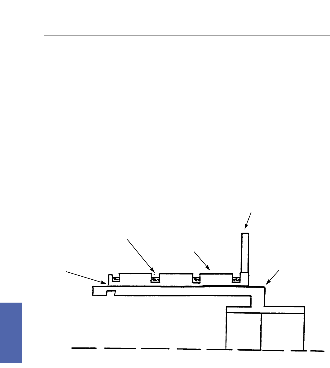
198 DC Motors
For more information contact a GE Motor Parts Master Distributor or GE Support Services.
7–Medium DC
Commutators
Glass Banded
Medium DC Motors and Generator’s standard commutator on larger machines from 300HP and above is
made of glass banded construction. The copper and insulation segment pack has grooves machined
between brush paths for application of high tension glass banding tape. This tape continually applies
tension on the segment pack during service to maintain excellent stability at high speed. The shell
consists of steel and covered with mica to provide ground insulation for the segment pack. An
interference fit exists between the insulated shell and segment pack. Both open (separate piece) and
closed (solid) risers are used. Band protection is provided by Viton (blue coating) to resist contamination
that may attack bands. Solvent cleaning should not be used on commutators as contamination can be
washed under the bands which could burn and deteriorate the bands from underneath which could lead
to band failure.
GLASS BAND
IN GROVES (4)
INSULATION
LAYER
SHAFT
BRUSH
TRACKS (3)
STEEL
SHELL
RISER
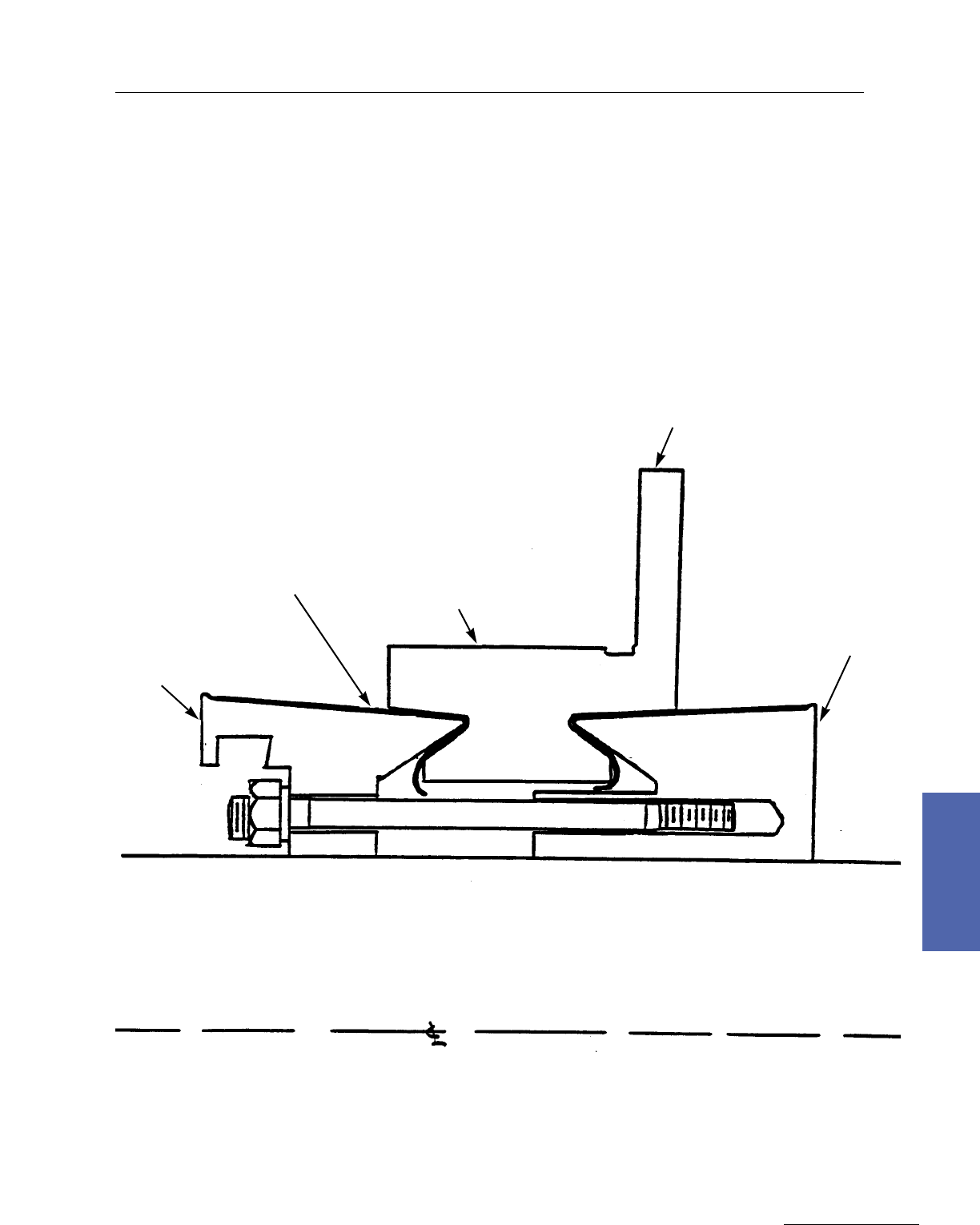
Medium DC Motors 199
GE Support Services
7–Medium DC
Commutators
Cap and Cone or V–Ring
This construction is typically used on smaller horsepower machines or ones specifically ordered for steel
or papermill applications. The segment pack has “V” grooves machined into the ends. The inner
clamping side has a thirty degree angle and outer clearance side a three degree angle. Mica cones insulate
the segment pack from the steel shell and provide ground support. The steel clamp rings are held in
tension by studs with nuts or long bolts. During manufacture, the commutator is pressed together and the
studs tightened. While this construction is not as stable for high speed as a glass banded commutator, the
design is a rugged one and repairability is often performed by users.
SHAFT
STEEL
CLAMP RING
(CAP)
BRUSH
TRACK
MICA CONE
(EACH END)
STEEL
CLAMP RING
(CAP)
RISER
30O
30O
3O3O
STUD
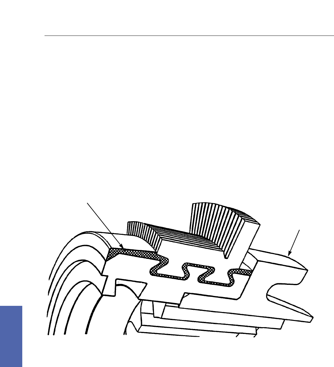
200 DC Motors
For more information contact a GE Motor Parts Master Distributor or GE Support Services.
7–Medium DC
Commutators
Interlocking
A relatively new design of commutator is called the interlocking commutator. The copper segments have
integral dovetails which are inserted into the steel shell with a matching dovetail. Mica insulation is then
inserted between the copper segments and the segment pack is subjected to high circumferential pressure
while epoxy compound is injected into the space between the shell and segment pack. The epoxy
provides both the bond and ground insulation for the segment pack. The result is a very high quality
commutator for high speed use.
This commutator is used on the CD360–5010 motor line.
EPOXY
SHELL
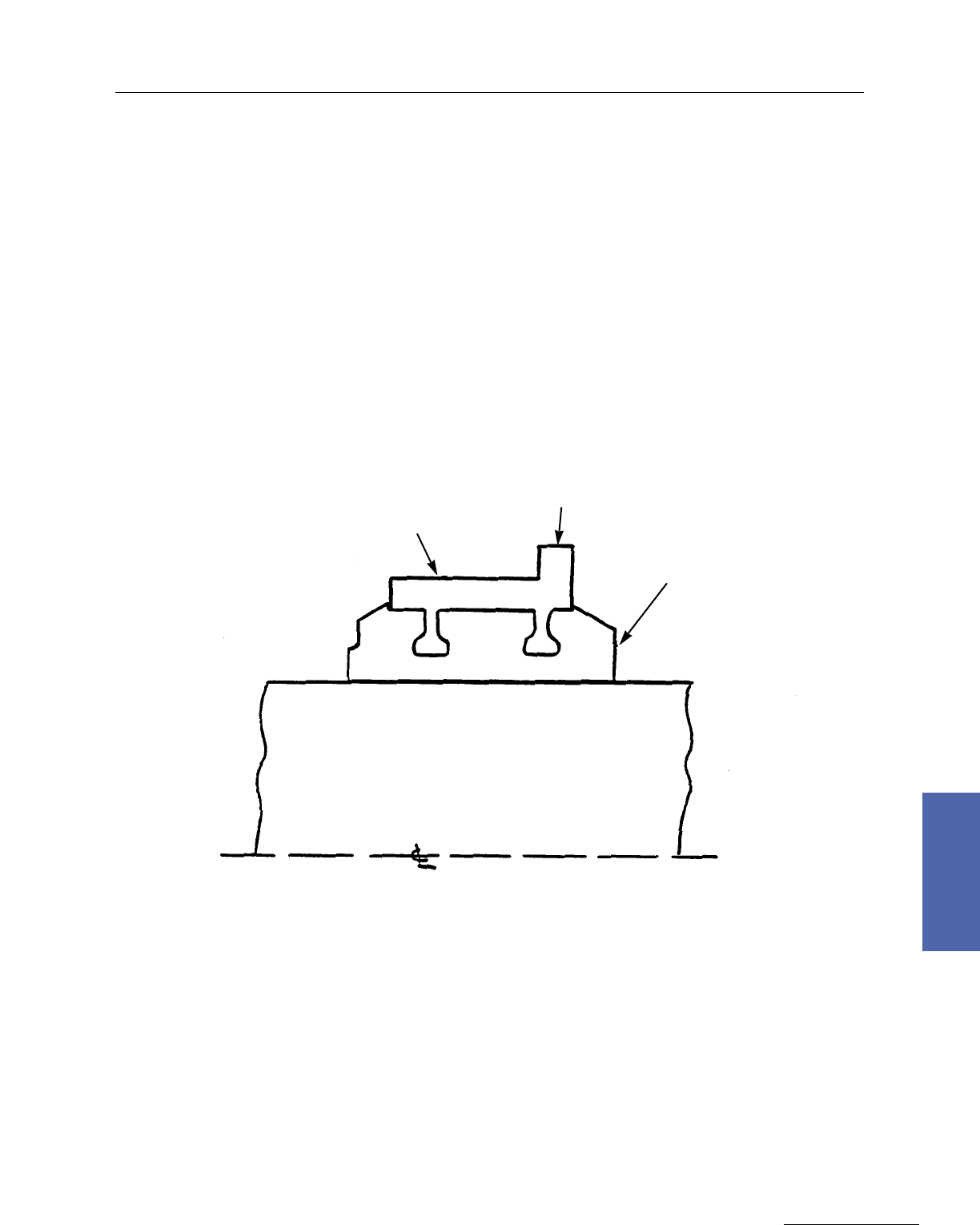
Medium DC Motors 201
GE Support Services
7–Medium DC
Commutators
Molded
For cost purposes, the smallest machines use a molded style commutator. These machines are very
standardized, high volume, and low cost. The copper and insulation pieces are normally punched out
with a notch in the center. Following stacking , an epoxy compound is injected to form the shell. This
commutator is not repairable and the design is cost effective and adequate for most small motor
applications.
EPOXY
COMPOUND
RAISERS
SHAFT
BRUSH
TRACK

202 DC Motors
For more information contact a GE Motor Parts Master Distributor or GE Support Services.
7–Medium DC
Field Modifications/Accessories
Field Modification Kits, Frames CD180AT to CD5010AY
Custom Modification Kit
Custom modification kits allow modification of Kinamatic motors which have been shipped from the
factory. They are designed for maximum flexibility and ease of installation, and are stocked by authorized
GE Motors parts distributors to provide immediate availability.
The quick kit reference on the following pages lists the numbers of the most commonly used accessory
kits and modification by frame size. Field modification kits cannot be mounted on all frame sizes or
enclosures. Please review the application information carefully to determine availability. Contact GE
Support Services or your GE Motors parts distributor for kit prices. The information given is not to be
used for new motor specification.
Application Information
Blower Kits
Blower kits are designed for standard mounting on the motor commutator end and for addition only to
dripproof fully guarded, separately ventilated motors. Blower motors are 230/460 volt AC, 3 phase, 60
hertz. To properly mount a blower kit on CD180AT frames, drilling and tapping of three holes is required.
Tachometer Kits
Tachometer kits are designed to be mounted on motors with an accessory comm end shaft extension of
any fully guarded or totally enclosed Kinamatic motor, with the exception of totally enclosed fan cooled
(TEFC) machines. Tach adapters are made of cast iron and are supplied with appropriate covers. Refer to
GE Support Services for mounting of tachometer kits on TEFC motors. Note: Type BC and Type PY
tachometers must be ordered independently of the tachometer kits less tachometer.
Type C Face Endshield Kits
Type C Face endshield kits are designed for mounting on the fully guarded or totally enclosed
nonventilated (TENV) frames listed below. Addition of Type C Face endshield kits requires machine
disassembly by a qualified service facility. For frames CD218AT–CD2110AT, refer to GE Support Services.
Sliding Bases
Sliding bases are suggested as a convenient means for adjusting belt tension or may be used as mounting
plates. (For horizontal mounting only–not available for ceiling or sidewall mounting. Sliding bases not
available on CD6000 frames and above.)
Frame Standard C Face
Series Dimension (in inches)
CDL182AT 8.5
CD287AT & CD288AT 10.5
CD327AT & CD328AT 12.5
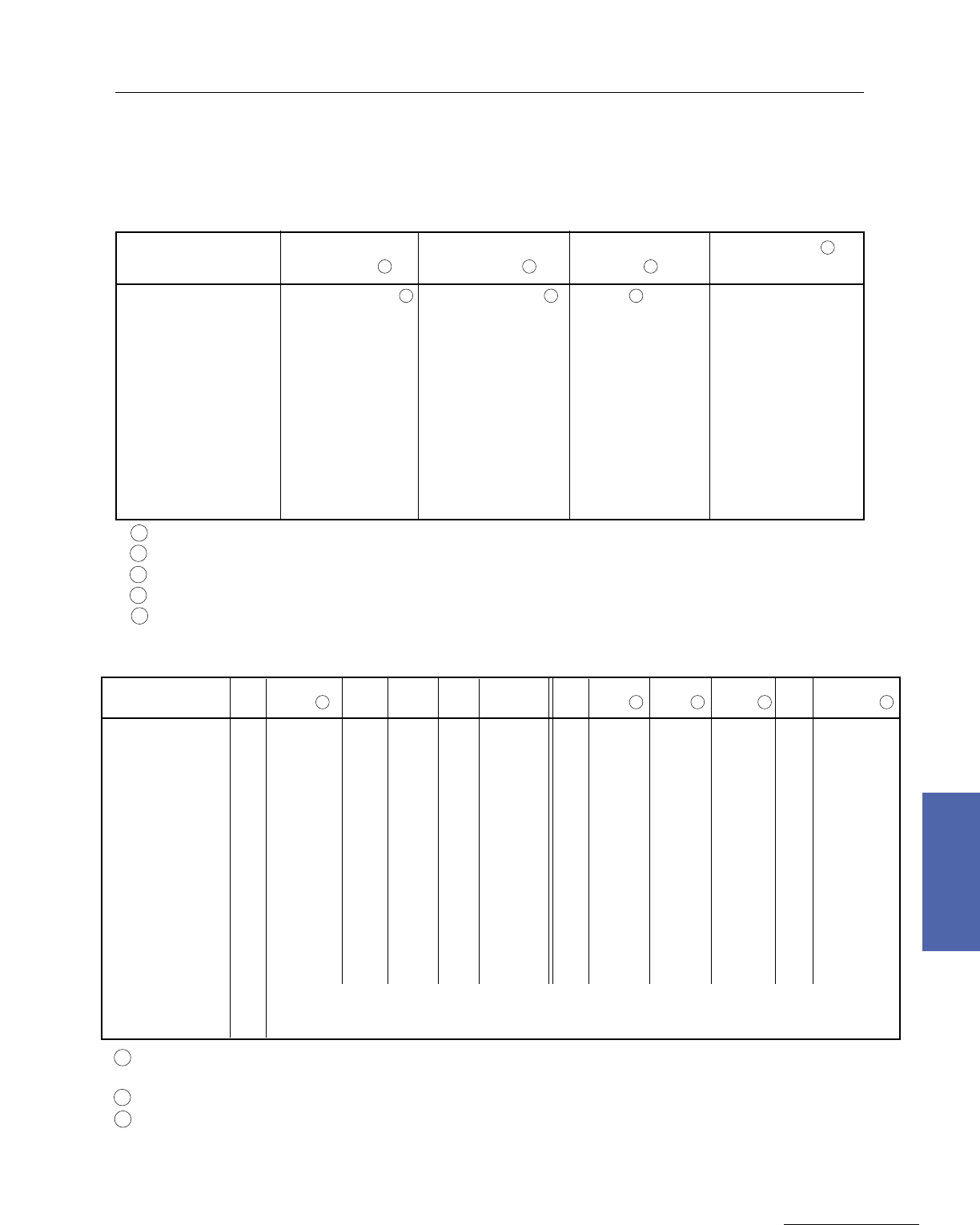
Medium DC Motors 203
GE Support Services
7–Medium DC
Field Modifications/Accessories
Field Modification Kits, Frames CD180AT to CD5010AY
Frame Blower Kit Blower Kit C–Face Lexan Covers 5
Series Less Filter 1with Filter 1Kit 3(Qty. 2 required)
CDL182AT–CD189AT 36A167741CAG01 236A167741CBG01 2 4 NOT AVAILABLE
CD218AT–CD2110AT 36A167742AAG02 36A167742ABG02 36A172472AAG01 36A167802BAG02
CD258AT–CD259AT 36A167743AAG02 36A167743ABG02 36A172473AAG01 36A167803BAG02
CD2512AT–CD2513AT 36A171113AAG02 36A171113AAG01 36A172476AAG01 36A167804BAG02
CD287AT–CD288AT 36A167744AAG03 36A167744ABG03 36A172474AAG01 36A167805BAG02
CD2812AT–CD2813AT 36A171114AAG02 36A171114AAG01 36A172477AAG01 36A167806BAG02
CD327AT–CD328AT 36A167745GAG10 36A167745GBG10 36A172475AAG01 36A167806BAG02
CD365AT–CD368AT 36A167746GAG10 36A167746GBG10 NOT AVAILABLE 36A167807BAG02
CD407AT & CD409AT 36A167747GAG10 36A167747GBG10 NOT AVAILABLE 36A167809BAG02
CDL407AT & CDL409AT 36A167747GCG10 36A167747GDG10 NOT AVAILABLE 36B473083CAG01
CD504AT–CD5010AY 36A167749EAG30 36A167749EBG34 NOT AVAILABLE 36B473084CAG01
Application Information
Full Load Full Load
Frame HP Volts 8Hertz Phase RPM Amperes HP Volts 7Hertz 8Phase 6RPM Amperes 7
CD180AT 1/12 230/460 60 3 3600 .53/.25 1/12 380 50 3 3000 .3
CD210AT 1/12 230/460 60 3 3600 .53/.25 1/12 380 50 3 3000 .3
CD258AT, CD259AT 1/12 230/460 60 3 3600 .53/.25 1/12 380 50 3 3000 .3
CD287AT, CD288AT 1/3 200–230/460 60 3 3600 1.8/.9 1/3 380 50 3 3000 .76
CD320AT 1 200–230/460 60 3 3600 3.6/1.8 1 380 50 3 3000 1.6
CD360AT 1 200–230/460 60 3 3600 3.6/1.8 1 380 50 3 3000 1.6
CD400AT 1 200–230/460 60 3 3600 3.6/1.8 1 380 50 3 3000 1.6
CD504AT–CD5010AY 2 200–230/460 60 3 1800 5.8/2.9 2 380 50 3 1500 3.0
CD2512AT, CD2513AT 1 200–230/460 60 3 3600 3.6/1.8 1 380 50 3 3000 1.6
CD2812AT, CD2813AT 1 200–230/460 60 3 3600 3.6/1.8 1 380 50 3 3000 1.6
CD6000 5 230/460 60 3 1800 13.4/6.7 3 380 50 3 1500 5.2
CD6100 7.5 230/460 60 3 1800 19.6/9.8 5 380 50 3 1500 8
CD6200 10 230/460 60 3 1800 25.2/12.6 7.5 380 50 3 1500 11.4
CD6700 15 230/460 60 3 1800 38.8/19.4 10 380 50 3 1500 15.8
CD6800 < =1500 HP 15 230/460 60 3 1800 38.8/19.4 10 380 50 3 1500 15.8
> 1500 HP 15
CD6900 < =2000 HP 20 230/460 60 3 1800 49.6/24.8 15 380 50 3 1500 22.4
> 2000 HP 20 > 15
REFER TO GE MOTORS
REFER TO GE MOTORS
6The use of a 50 Hertz blower may affect motor frame size and will affect motor price and delivery. Refer to GE
Motors for use of 50 Hertz blowers.
7 Full load amperes for blower motors are typical values.
8 Suitable for operation with up to plus or minus 10% variation from rated voltage (i.e. 207–253V/414–506V, 60Hz;
342–418V, 50Hz).
1 Blower motor is 230/460 volt AC, 3 phase, 60 hertz.
2 Requires drilling and tapping of three holes to install.
3 Requires motor disassembly by qualified service facility to install.
4 For dripproof motors use 36A172471AAG02. For totally enclosed motors use 36A172471AAG01.
5 For commutator end only.
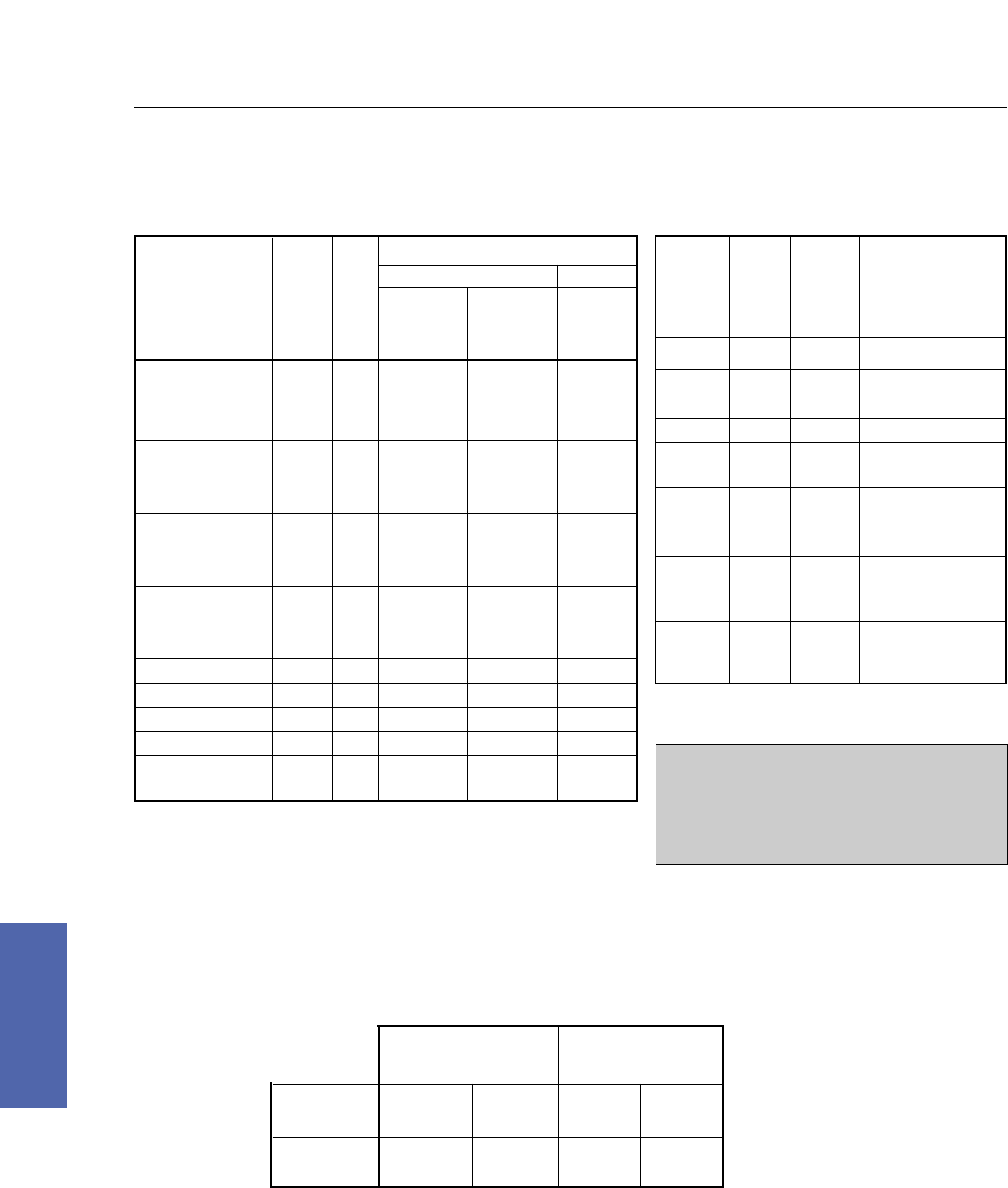
*1750 RPM or lower
A. Standard Separately Ventilated
Air in one CE opening with solid covers on the other CE openings. Standard louvered covers on DE air outlets.
B. Enclosed Separately Ventilated (Air ducted in and air ducted out)
Air in one CE opening with solid covers on the other CE opening. Air out one DE opening.
C. Blown from Drive End
Air in one DE opening with solid covers on the other DE openings. Standard louvered covers on CE air outlets.
204 DC Motors
For more information contact a GE Motor Parts Master Distributor or GE Support Services.
7–Medium DC
Field Modifications/Accessories
Air Flow Requirements for Separately Ventilated Motors
Static Pressure Inches of Water
A B C
Base Standard Enclosed Blown
Speed Separately Separately from
Frame RPM CFM Ventilated Ventilated Drive End
CD180AT 3500 70 1.0 1.0
2500 50 0.6 0.6
1750* 35 0.3 0.3
CD210AT 3500 180 1.6 2.96 3.7
2500 130 0.8 1.5 1.9
1750* 90 0.4 0.74 0.9
CD250AT 3500 320 1.8 3.28 4.0
2500 230 0.86 1.66 2.0
1750* 160 0.45 0.82 1.0
CD280AT 3500 540 2.16 3.92 4.3
2500 385 1.04 1.96 2.4
1750* 270 0.54 0.98 1.2
CD320AT ALL 650 2.0 3.2 3.0
CD360AT ALL 610 2.2 3.9 3.4
CD400AT ALL 830 2.6 3.65 4.0
CD504AT–CD5010AY ALL 1425 3.0 4.1 3.8
CD2512AT, CD2513AT ALL 300 4.85 6.1
CD2812AT, CD2813AT ALL 455 4.8 5.64
Static
Base Pressure
Speed Inches of
Frame HP RPM CFM Water
CD6000 ALL ALL 2400 3
CD6100 ALL ALL 3400 3
CD6200 ALL ALL 4000 5
CD6700 ALL ALL 5000 5
CD6800 ≤1500 ALL 6200 5
>1500 ALL 8000 8
CD6900 ≤2000 ALL 7500 5
>2000 ALL 10000 9
CDF1800 ALL ALL 8000 3
CDF1900 ≤1500 ALL 6000 2
<3000 ALL 8000 3
≤4500 ALL 12000 5.5
CDF2000 ≤1500 ALL 6000 2
<3000 ALL 10500 4.5
≤4500 ALL 13500 5.5
NOTE: Airflows are for clean dry air less than 40˚C
(104˚F) and at altitudes less than 1000M. (3330 FT).
CE–Commutator End ESV–Enclosed Separately Ventilated
DE–Drive End SV–Separately Ventilated
*Motors are shipped with solid covers on both sides and top and bottom.
Any DE cover may be removed for air entry and any CE cover for air exit. If
a transparent cover is ordered, it will be located on the CE, conduit box side.
**If a transparent cover is ordered, air exit is opposite conduit box side and
bottom. If no transparent cover is ordered, air is exited on both sides.
WARNING: The static pressure values listed in the
tabulations are based upon standard air inlet and
standard air outlet utilization. The static pressure
will be higher if either the air inlet or outlet
openings are restricted or reduced in size or, in the
case of air outlets, reduced in number.
CD5010AY & Below CD6000 & Above
ESV SV ESV SV
Standard Air CE TOP CE TOP DE* DE*
Inlet Location
Standard Air DE DE Side & CE* CE**
Exit Location (either side) Bottom
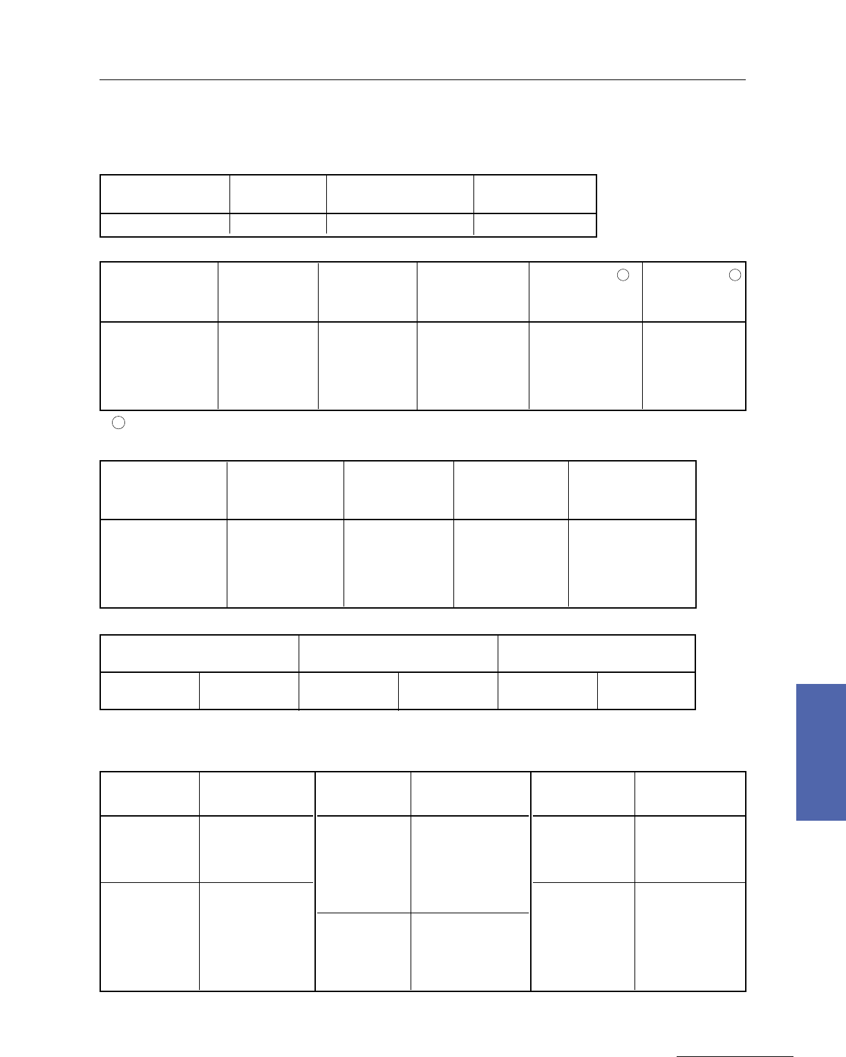
Medium DC Motors 205
GE Support Services
7–Medium DC
Field Modifications/Accessories
Field Modification Kits, Frames CD180AT to CD5010AY
FRAME PY TACH KIT SERVO–TEK TACH KIT THERMOSTAT
SERIES (LESS TACH) (LESS TACH) KIT
CD146ATC–CD1412ATC 893A690AAG01 893A666AAG01 893A659AAG01
AN–AC TACH ANDG240A4 9ANDG240D4 9
FRAME PY TACH KIT BC TACH KIT 45/90V/1000 RPM 240 PPR 240 PPR
SERIES (LESS TACH) (LESS TACH) (INCLUDES TACH) (INCLUDES TACH) (INCLUDES TACH)
CDL182AT–CD328AT 36A167701AAG01 36A167700AAG01 36A167702AAG01 36A167712AAG04 36A167713AAG04
CD2512AT–CD2813AT 36A167701AAG01 36A167700AAG01 36A167702AAG01 36A167712AAG04 36A167713AAG04
CD365AT–CD368AT 36A167701BAG01 36A167700BAG01 36A167702BAG01 36A167712BAG04 36A167713BAG04
CD407AT–CDL409AT 36A167701CAG01 36A167700CAG01 36A167702CAG01 36A167712CAG04 36A167713CAG04
CD504AT–CD5010AY 36A167701CAG01 36A167700CAG01 36A167702DAG01 36A167712DAG04 36A167713DAG04
AN–DG240L3 AN–DG240L4 AN–DG600L3 AN–DG600L4
FRAME 240 PPR 240 PPR 600 PPR 600 PPR
SERIES ONE OUTPUT DUAL OUTPUT ONE OUTPUT DUAL OUTPUT
CDL182AT–CD328AT 36C706050DA001 36C706050DB001 36C706050DC001 36C706050DD001
CD2512AT–CD2813AT 36C706050DA001 36C706050DB001 36C706050DC001 36C706050DD001
CD365AT–CD368AT 36C706050AA001 36C706050AB001 36C706050AC001 36C706050AD001
CD407AT–CDL409AT 36C706050AA002 36C706050AB002 36C706050AC002 36C706050AD002
CD504AT–CD5010AY 36C706050AA003 36C706050AB003 36C706050AC003 36C706050AD003
DC PY TACH ONLY DC BC42 TACH ONLY DC BC46 TACH ONLY
(USES PY KIT) (USES BC KIT) (USES BC KIT)
50V/1000 RPM 897A594–002 50V/1000 RPM 897A590–032 50V/1000 RPM 897A591–041
100V/1000 RPM 897A594–001 100V/1000 RPM 897A590–024 100V/1000 RPM 897A591–029
9Bi–directional, dual output.
Sliding Base, Frames CD180AT to CD5010AY
FRAME SLIDING
SERIES BASE
CDL182AT 533C400–034
CD186AT 533C400–001
CDL186AT 533C400–001
CD189AT 533C400–023
CD218AT 533C400–019
CD219AT 533C400–022
CD2110AT 533C400–039
CD258AT 533C400–040
CD259AT 533C400–041
FRAME SLIDING
SERIES BASE
CD2512AT 533C400AH001
CD2513AT 533C400AH002
CD287AT 533C400–020
CD288AT 533C400–042
CD2812AT 533C400AH003
CD2813AT 533C400AH004
CD327AT 533C400–043
CD328AT 533C400–044
CD365AT 533C400–011
CD366AT 533C400–012
CD368AT 533C400–046
FRAME SLIDING
SERIES BASE
CD407AT 533C400–047
CDL407AT 533C400–047
CD409AT 533C400–048
CDL409AT 533C400–048
CDL504AT 533C400–017
CD504AT 533C400–017
CDL506AT 533C400–049
CD506AT 533C400–049
CD508AT 533C400–050
CDL508AT 533C400–050
CD5010AT 533C400AK001
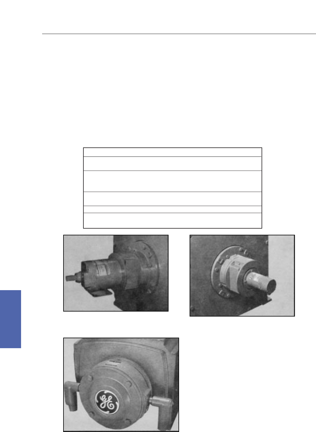
206 DC Motors
For more information contact a GE Motor Parts Master Distributor or GE Support Services.
7–Medium DC
Field Modifications/Accessories
Accessories and Modifications, CD180AT–CD6900
Description
Tachometer Generator Equipment
On CD180AT or CD210AT fan cooled motors or where other accessories will be mounted on the motor,
refer to GE Support Services to assure that the tachometer mounting can be accommodated. Refer to GE
Support Services for use of tachometers on crane motors. Refer to appropriate section of Application
Manual for indicating or regulating accuracy.
Speed Ranges
The following tachometer generator operating speeds are available with listed items:
Type Tachometer Output Operating Range
BC42 50 Volts/1000 RPM 100–5000 RPM
100 Volts/1000 RPM 100–2750 RPM
50 Volts/1000 RPM 100–5000 RPM
BC46 100 Volts/1000 RPM 100–3600 RPM
200 Volts/1000 RPM 100–1800 RPM
Form Y 50 Volts/1000 RPM 100–5000 RPM
100 Volts/1000 RPM 100–2500 RPM
AN–AC 90 Volts/1000 RPM 100–5000 RPM
AN–DG 240 pulses/revolution 0–5000 RPM
600 pulses/revolution 0–5000 RPM
BC tachometers produce DC output to
provide high accuracy speed regulation or
speed indication. PY tachometers provide a medium accuracy DC output
for use with a regulated drive or for speed indication.
AN Series tachometers provide a
compact construction with
thru–shaft capabilities. The AN
Series tachometers can be
furnished with either AC or
digital output signal for speed
regulation or speed indication.
(Type AN–DG tachometer
shown above.)
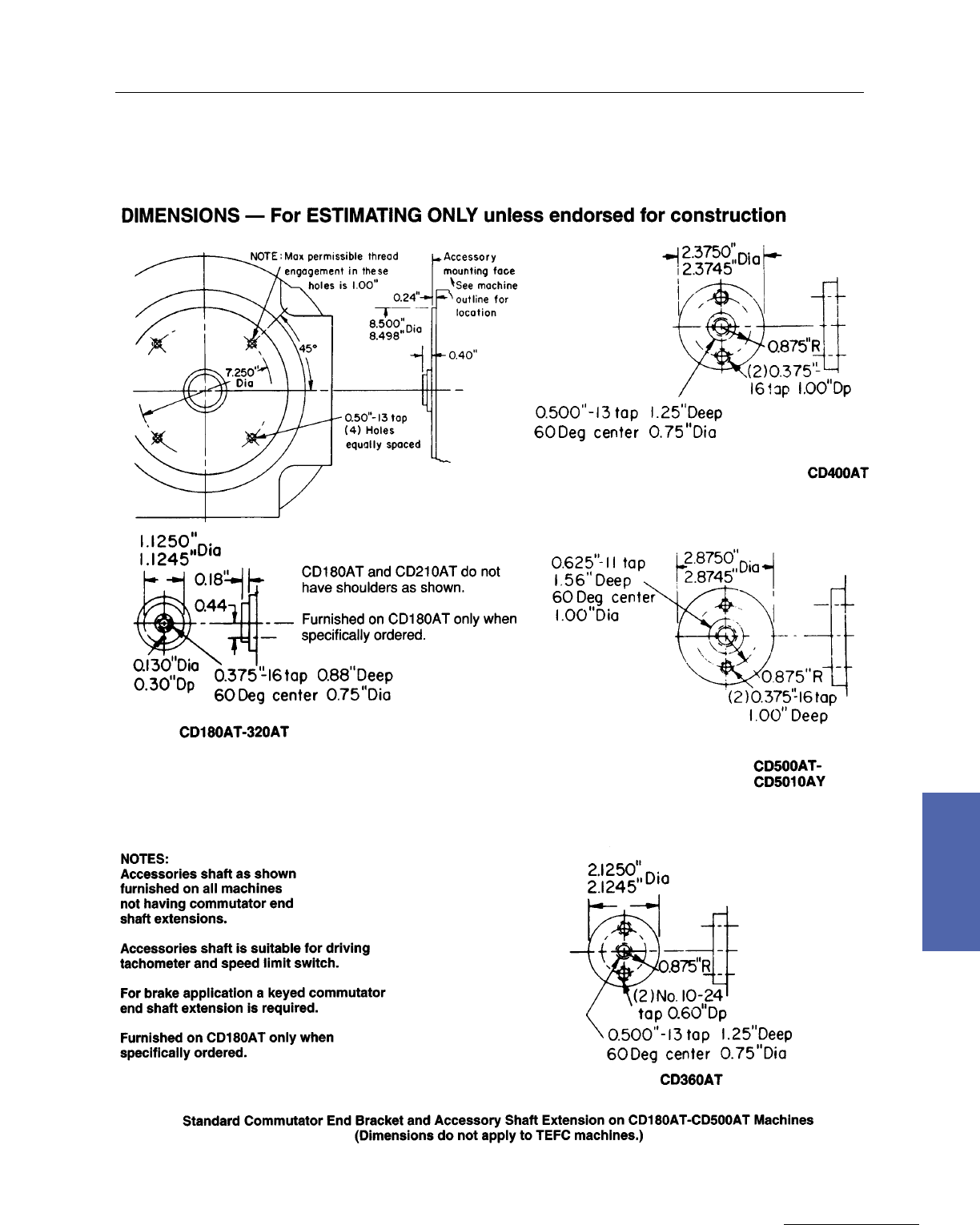
Medium DC Motors 207
GE Support Services
7–Medium DC
Field Modifications/Accessories
Accessory and Mountings, Frames 180AT to 5010AY
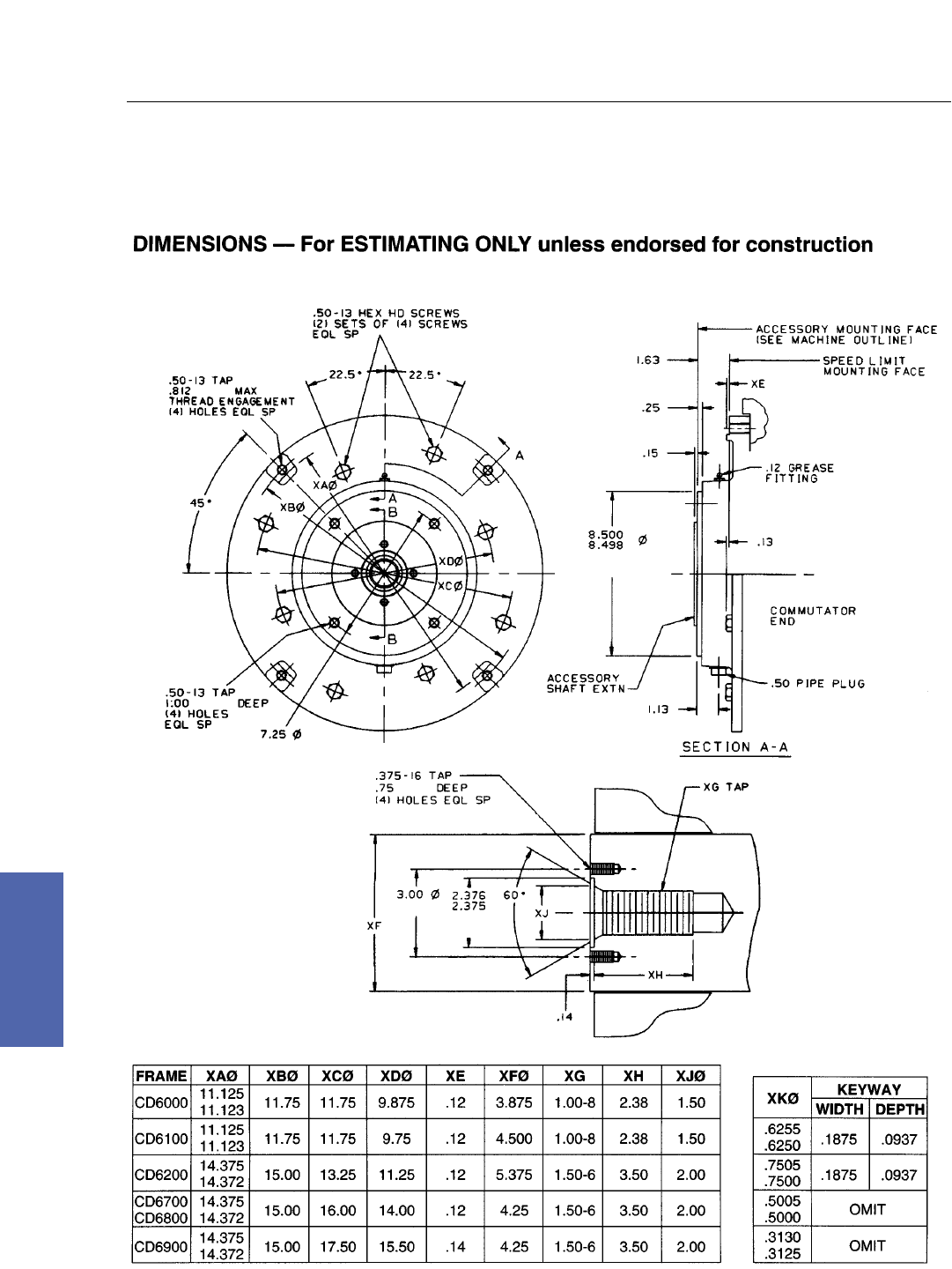
208 DC Motors
For more information contact a GE Motor Parts Master Distributor or GE Support Services.
7–Medium DC
Field Modifications/Accessories
Accessory Mountings, Frames 6000 to 6900
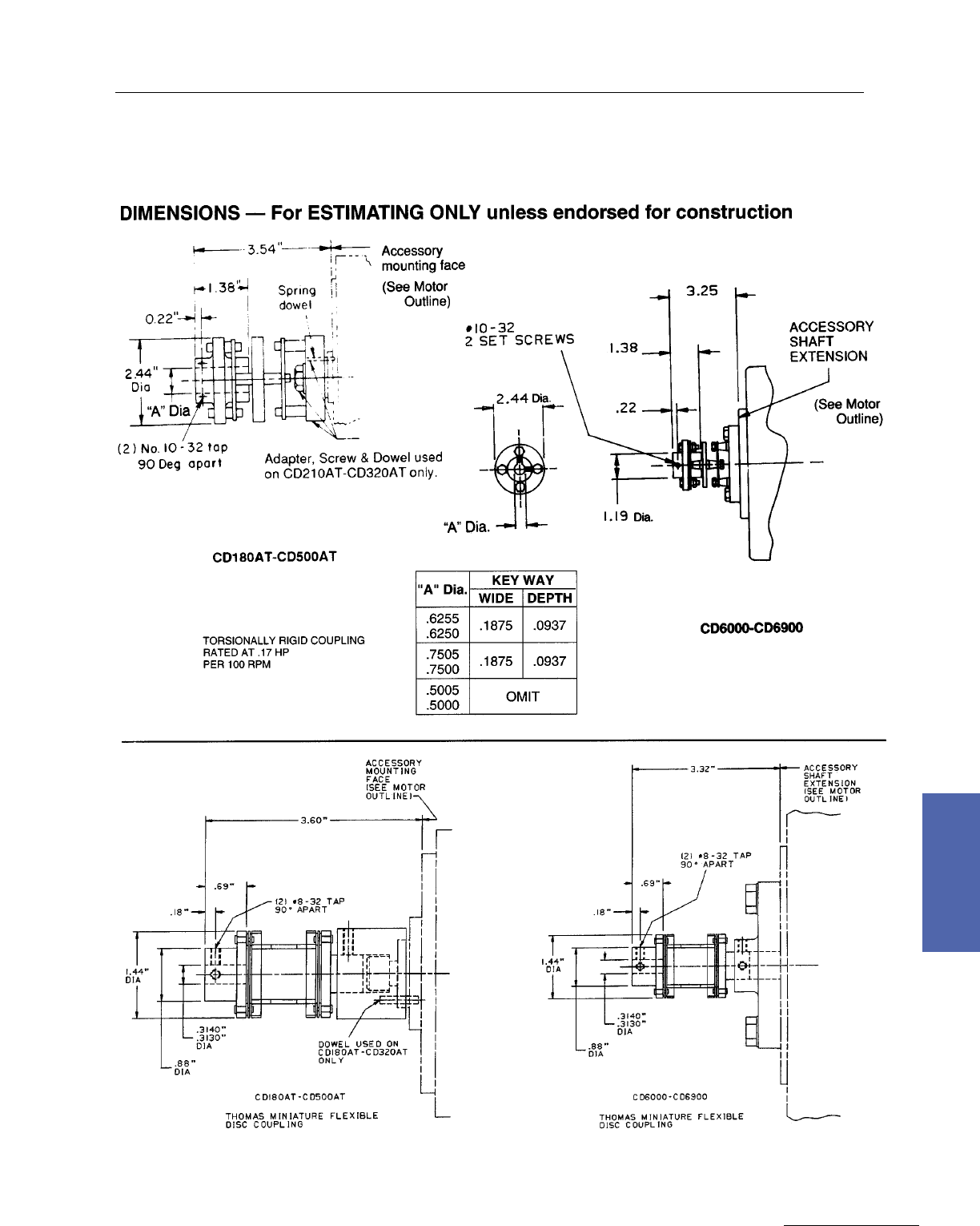
Medium DC Motors 209
GE Support Services
7–Medium DC
Field Modifications/Accessories
Accessory Couplings, Frames 180AT to 500AT and 6000 to 6900
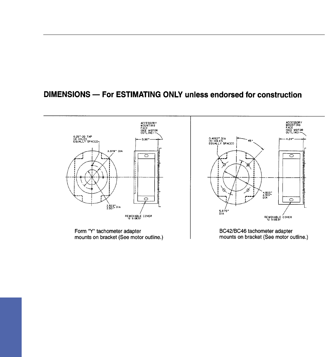
210 DC Motors
For more information contact a GE Motor Parts Master Distributor or GE Support Services.
7–Medium DC
Field Modifications/Accessories
Accessory Adapters, Frames 180AT to 500AT and 6000 to 6900
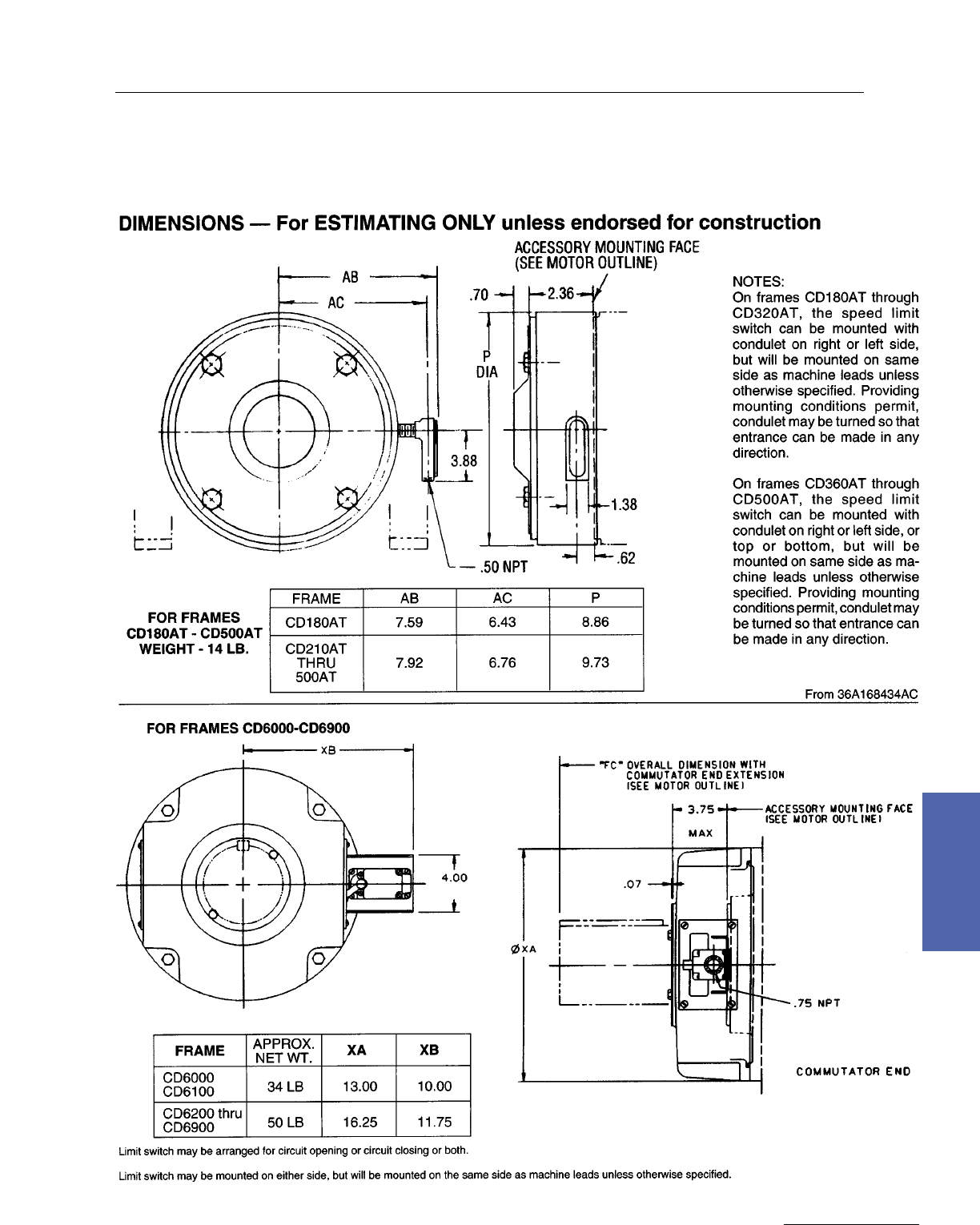
Medium DC Motors 211
GE Support Services
7–Medium DC
Field Modifications/Accessories
Speed Limit Device, Frames 180AT to 6900
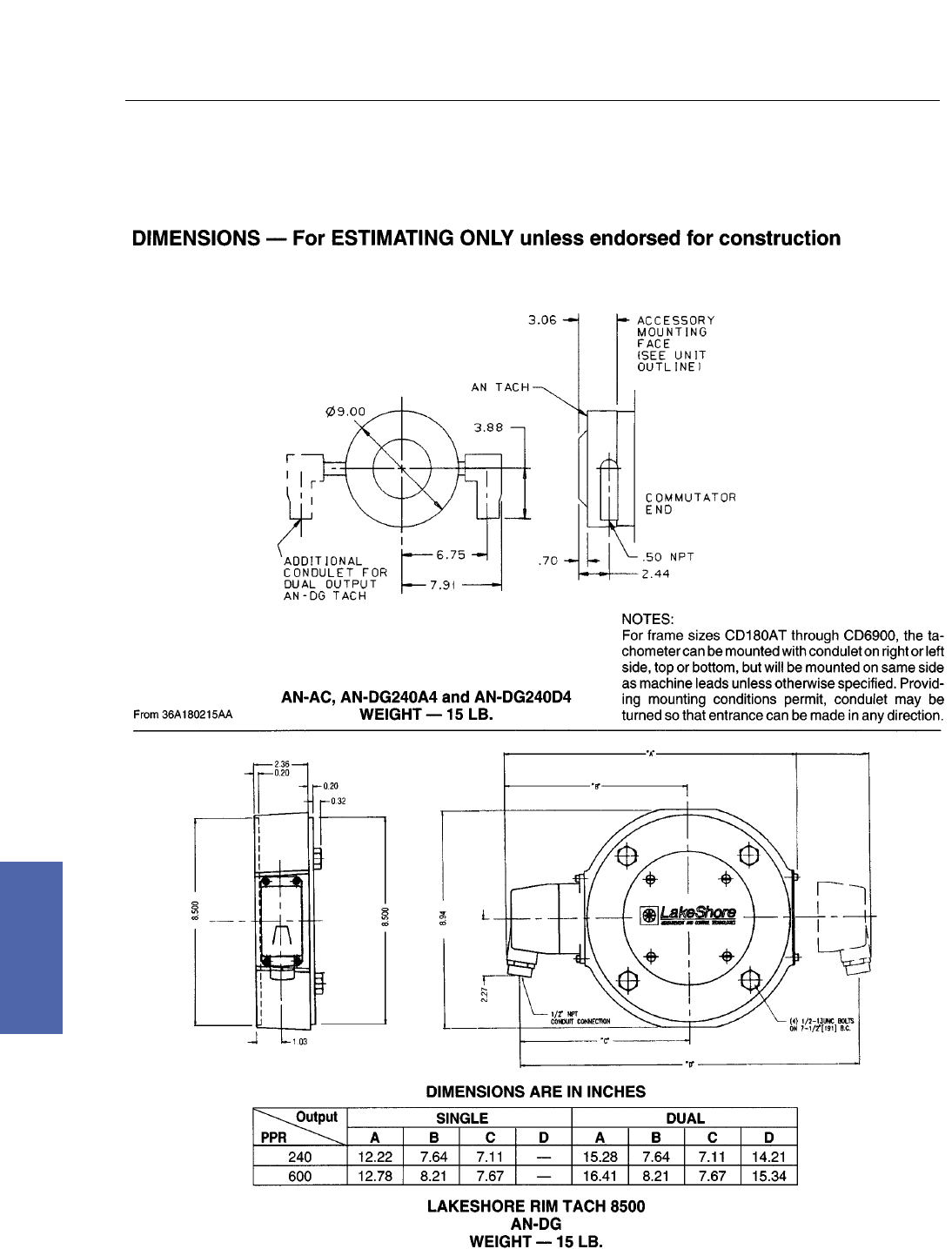
212 DC Motors
For more information contact a GE Motor Parts Master Distributor or GE Support Services.
7–Medium DC
Field Modifications/Accessories
Type AN Tachometer Generators, Frames 180AT to 6900

Medium DC Motors 213
GE Support Services
7–Medium DC
Field Modifications/Accessories
Lakeshore Tachometer
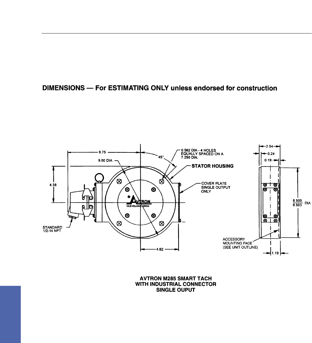
214 DC Motors
For more information contact a GE Motor Parts Master Distributor or GE Support Services.
7–Medium DC
Field Modifications/Accessories
Avtron Tachometer, Frames 180AT to 6900
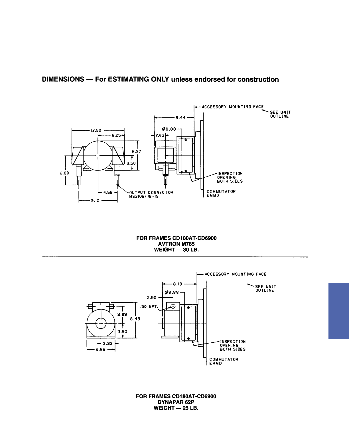
Medium DC Motors 215
GE Support Services
7–Medium DC
Field Modifications/Accessories
Avtron M785 & Dynapar 62P Tachometer Generators, Frames 180AT to 6900
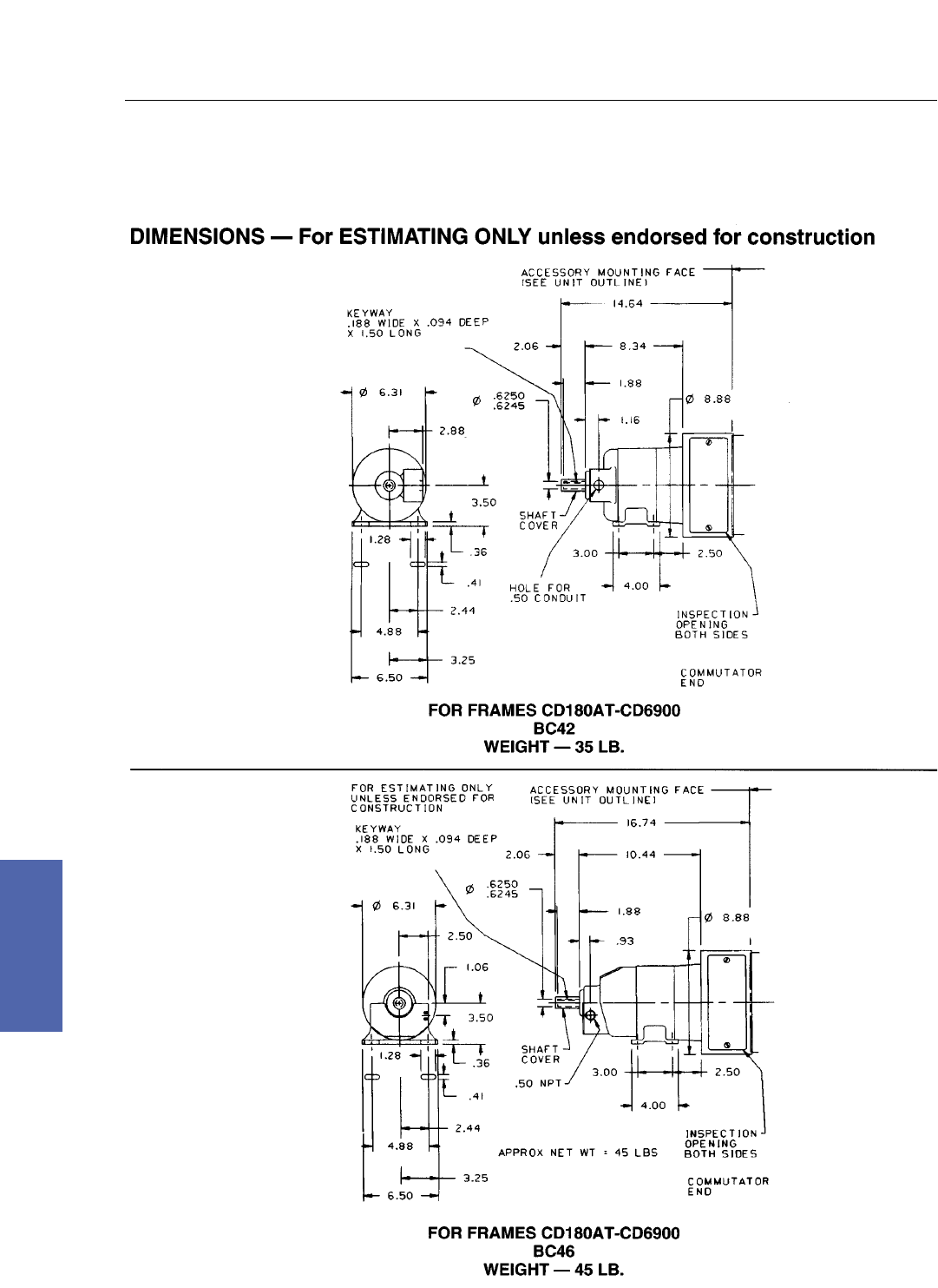
216 DC Motors
For more information contact a GE Motor Parts Master Distributor or GE Support Services.
7–Medium DC
Field Modifications/Accessories
Type BC Tachometer Generator, Frames 180AT to 6900
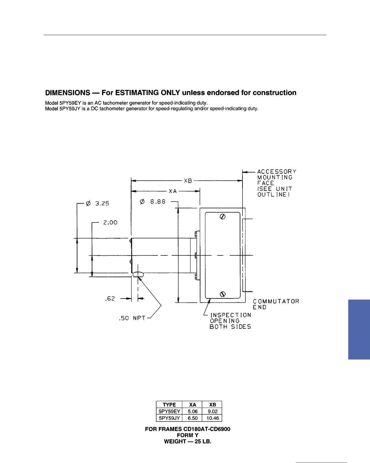
Medium DC Motors 217
GE Support Services
7–Medium DC
Field Modifications/Accessories
Form PY Tachometer Generator, Frames 180AT to 6900
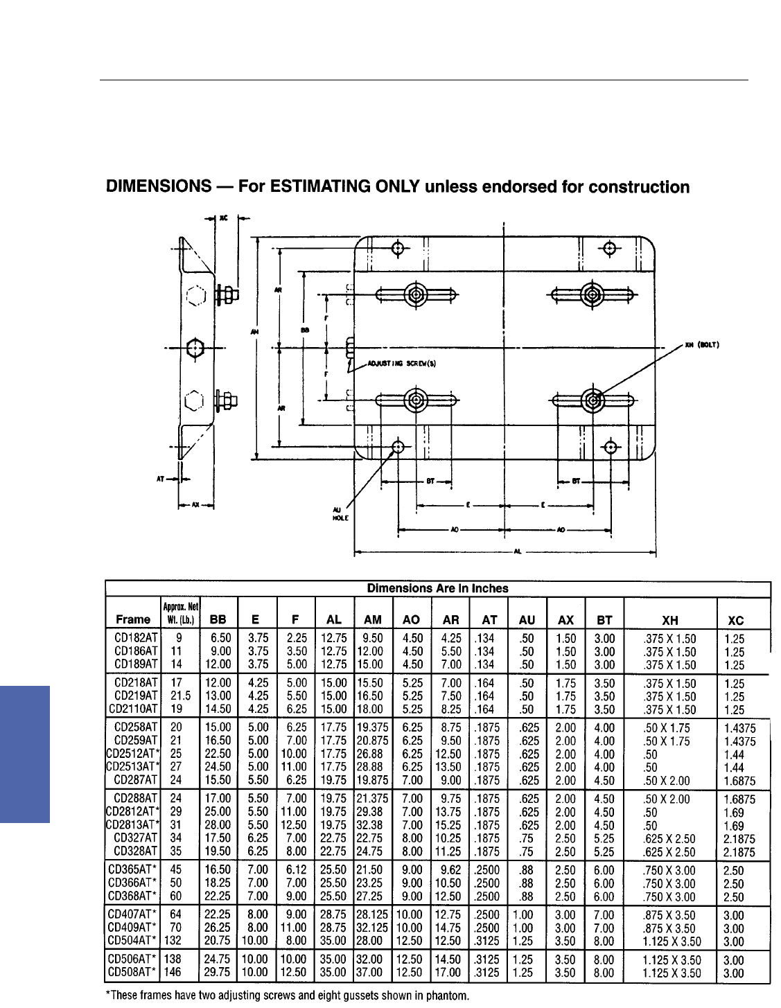
218 DC Motors
For more information contact a GE Motor Parts Master Distributor or GE Support Services.
7–Medium DC
Field Modifications/Accessories
Sliding Base, Frames 180AT to 500AT
