SNIB2 Configuration Guide Admin 2011 02 03
User Manual:
Open the PDF directly: View PDF ![]() .
.
Page Count: 28

Configuration Guide
SNIB2
SUPP009

ii
Rev. F September, 2007
SUPP009-0907
The National Institute of Standards and Technology (NIST) has awarded the SNIB2 AES Certificate #280
Copyright © 2007 Hirsch Electronics Corporation. All rights reserved. SCRAMBLE*NET™ (abbreviated S*NET) is a
trademark of Hirsch Electronics Corporation.
Hirsch Electronics Corporation
1900-B Carnegie Avenue
Santa Ana, CA 92705-5520
Phone: (949) 250-8888
Fax: (949) 250-7372
Web: www.HirschElectronics.com

Getting Help iii
Getting Help
If you encounter a problem that is not discussed in this guide and you need technical
support, do the following:
1. Contact your local dealer or the provider of this product.
2. If your dealer is not available, contact Hirsch Technical Support directly. This can be
done in a number of ways:
Whenever you call your local dealer or Hirsch, be sure to have your registration material,
serial number and software version number available.
For future reference, record these numbers here.
Mail: Hirsch Electronics Corporation
1900-B Carnegie Avenue
Santa Ana, CA 92705-5520
Attn: Technical Services
Phone: 877-HIRSCHX (877-447-7249) toll-free
Fax: (949) 250-7362
Email: support@HirschElectronics.com
WWW: www.HirschElectronics.com
SNIB2 MAC Address: _____________________
SNIB2 Firmware #: _____________________
Dealer: _____________________
Dealer Phone #: _____________________
CCM Firmware #: _____________________
CCM BIOS #: _____________________

iv Getting Help

SUPP009-0907
v
Table of Contents
Getting Help.................................................................................................................................. .............................. iii
SNIB2 Configuration Guide .............................................................................................................1
Configuration Options................................................................................................................ .............................. 4
Installing the SNIB2.................................................................................................................... .............................. 6
Cabling the SNIB2............................................................................................................................................. 8
Setting Up the SNIB2....................................................................................................................................... 9
Deploying the SNIB2......................................................................................................................................12
Configuring a Master SNIB2 on the Same Subnet ..........................................................................13
Configuring a Master SNIB2 in a Different Subnet..........................................................................15
Resetting SNIB2 Encryption Keys.......................................................................................... ............................18
Controller and SNIB2 LED Diagnostics ............................................................................... ............................19
Special Light Patterns: Start Up ...............................................................................................................19
Normal Operation........................................................................................................................................19
Checking CCM and BIOS Version.......................................................................................... ............................22

SNIB2 Configuration Guide
vi
SUPP009-0907
1
SNIB2 Configuration Guide
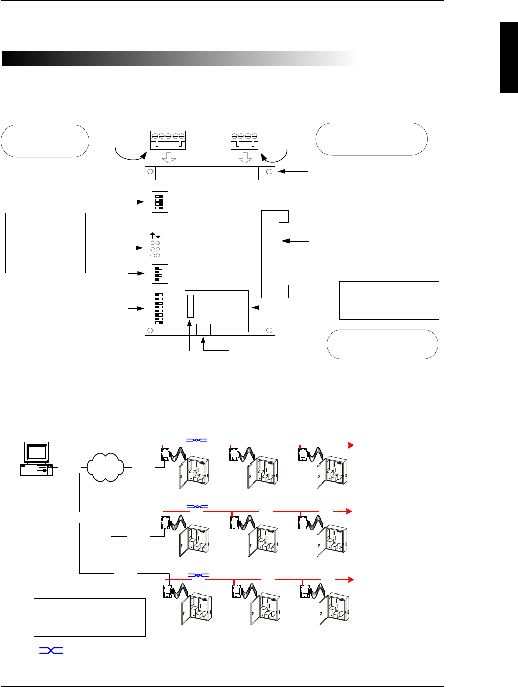
The SNIB2 is a high-security encryption Secure Network Interface Board. An example of
the SNIB2 is shown below:
The SNIB2 is a controller-resident communication board that enables a host PC
running Velocity 2.6 SP2 or higher to program, monitor, and control up to 63
SNIB2-resident controllers per SNIB2 Ethernet port. A NET*MUX4 is required whenever
there are more than 16 controllers. Additional NET*MUX4s may be required to ensure
that there are never more than 16 controllers per port.
Standoff Mounting
Holes
RS232
Connector
LEDs
SW3 DIP
switch bank
SW1
ON
RS485 RS232
SW3
ON
1
2
3
4
5
6
G - RX + - TX+ G RX TX V
1
2
Expansion Board
Interface Cable
Connector
(EBIC5)
SW1 DIP
switch bank
RS485
Connector
SW2
ON
1
2
P1
P2
P3
7
8
3
4
3
4
SW2 DIP
switch bank
RJ-45 Ethernet connector
Ethernet
daughterboard
P1
P2
MAC Address label
If you plan to
multidrop SNIB2s
using RS-485, refer
to the wiring
diagram on page 8.
Never detach the
daughterboard from the
SNIB2 motherboard.
For downstream
multi-drop connections
For upstream 10/100 Mbps
connections
For direct host connections
(not dialup)
Velocity Host
Ethernet
DIGI*TRAC
Controller
Subordinate
SNIB2/SNIB
DIGI*TRAC
Controller
Ethernet
Ethernet
DIGI*TRAC
Controller
RS-485 Additional
Controllers
(SNIB2s/SNIBs)
DIGI*TRAC
Controller
Additional
Controllers
(SNIB2s / SNIBs)
XNET 2
Master
SNIB2
Master
SNIB2
DIGI*TRAC
Controller
RS-485 RS-485
DIGI*TRAC
Controller
RS-485
RS-485RS-485
DIGI*TRAC
Controller
DIGI*TRAC
Controller
Master
SNIB2
DIGI*TRAC
Controller
RS-485
RS-485RS-485
COM
RS232 Additional
Controllers
(SNIB2s / SNIBs)
Subordinate
SNIB2/SNIB
Subordinate
SNIB2/SNIB Subordinate
SNIB2/SNIB
Subordinate
SNIB2/SNIB Subordinate
SNIB2/SNIB
XNET 2
Up to 16
controllers
= this cable segment swaps the RX± and TX± wires. See page 8 for details.
When using one or more
NET*MUX4s, the max. SNIB2
speed is limited to 9600 bps.
SNIB2 Configuration Guide
2
Each connected controller must have its own SNIB2 or SNIB board installed. The
SNIB2 provides RS-485, RS-232, and 10/100BaseT Ethernet ports. The SNIB2
supports the XNET2 protocol.
XNET2 is only supported by Velocity version 2.6 with Service Pack 2 or
higher.
Physically, the SNIB2 board differs from the original SNIB in three obvious respects.
The SNIB2 has:
Othree switch banks (SW1, SW2, and SW3)
Oan Ethernet RJ-45 connector with its accompanying daughterboard
Othree pairs of status LEDs (see page 19)
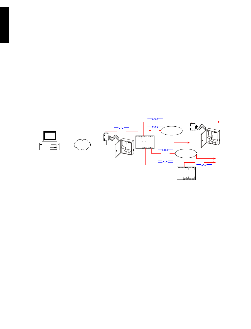
With the SNIB2 board, a host PC running Velocity can program, monitor, and control up
to 63 controllers with NET*MUX4 (as shown in the example below), or up to 16
without NET*MUX4. Each connected controller must have its own SNIB2 or SNIB
board installed. The SNIB2 provides a downstream/multi-drop RS-485 port as well as
an upstream 10/100 Mbps Ethernet port and an RS-232 port for direct host
connections (not dial-up).
The SNIB2 provides these functional advantages over the original SNIB:
OAES encryption
OEthernet connectivity (if required)
OXBox functionality
Each of these features is explained below.
AES Encryption
The SNIB2 employs AES-Rijndael asymmetric 128-bit block data encryption.
The National Institute of Standards and Technology (NIST) has awarded
the SNIB2 AES Certificate #280.
Ethernet Connectivity
A standard RJ-45 Ethernet port is included on the SNIB2. This enables the connected
controller installed with a SNIB2 to communicate with the server using TCP/IP over
10BaseT or 100BaseT Ethernet networks. This eliminates the need for external device
servers for LAN connectivity.
Host
NET*MUX4
RS-485
RS-485
RS-485
RS-485
RS-485
NET*MUX4
SNIB2 or
NETMUX
SNIB2 or
NETMUX
DIGI*TRAC
Controller
DIGI*TRAC
Controller
RS-485
Ethernet
Ethernet
RS-485
Encrypted X*NET 2
Master
SNIB2 Subordinate
SNIB2/SNIB
Up to 63
controllers

SUPP009-0907
3
XBox Functionality
The SNIB2 also incorporates full XBox gateway functionality, thereby eliminating the
need for an XBox. This enables the SNIB2 to function as a gateway for up to 63
controllers (with inclusion of the NET*MUX4), and provides the ability to globalize
certain features.
Globalizing is the task of connecting two or more controllers in order to share credential
user management and control zone information amongst all connected controllers.
Globalization can only be performed within a local XBox node. One SNIB2 acting as an
XBox cannot talk to and share information with another XBox or another master SNIB2.
Higher Serial Communication Speeds
Communications between multidropped SNIB2s are now supported at speeds up to
115,200 bps with Cat5/Cat6 cable.
When using one or more NET*MUX4s, the maximum SNIB2 speed is limited to 9600
bps. When combining SNIBs and SNIB2s, the maximum speed is limited to the lower
SNIB speed – that is, the lowest speed that all connected devices have in common.
Communications become less robust as baud rates increase, wire gauge decreases,
and distances increase. Most tables in the DIGI*TRAC Design and Installation Guide for
wire gauge and distance are based on 9600 bps.
At higher baud rates, maximum distances are decreased and minimum wire gauge is
increased. It may not be possible to implement the higher baud rates supported by the
SNIB2 if you have long wire runs or small wire gauges.
In order to use the SNIB2, your controller must be running
CCM 7.3.08 or higher; use Vn. 7.4.00 or higher if your
computer has Velocity 3.0. To check your current version
number, refer to “Checking CCM and BIOS Version” on page
22.
You can install the SNIB2 board in any Hirsch DIGI*TRAC
controller except the M1N.
SNIB2 Configuration Guide
4Configuration Options
Configuration Options
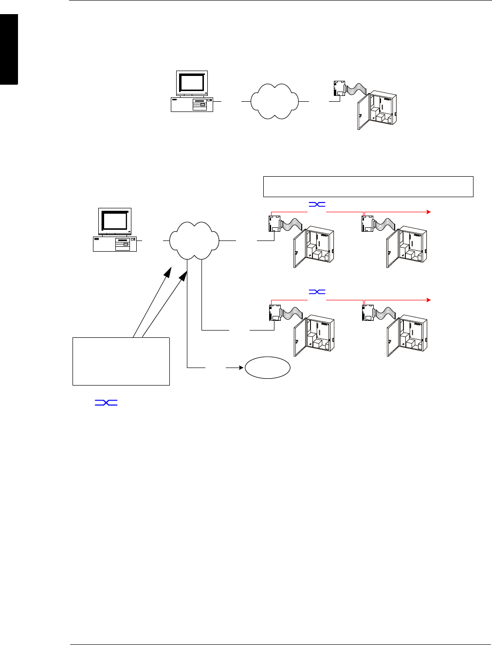
The SNIB2’s Ethernet port provides high-speed TCP/IP communication over an
Ethernet network between the host computer and the controller.
In a multiple controller sequence, the configuration can look like this example:
This enables communication between the controller with the master SNIB2 and host
PC at 10/100BaseT. Speeds between the master SNIB2 and other connected
downstream SNIB2s range up to 115200 bps when using Cat5/Cat6 cable. Speeds
between a master SNIB2 and downstream SNIBs are limited by the top speed of the
older SNIBs (38400 bps).
Higher baud rates are also more dependent on the number of twists per foot, so
capacitance specifications must be strictly followed: total wire run per port is not to
exceed 100,000 pf per foot.
Before the Velocity server can communicate over Ethernet with a SNIB2, you must first
configure the SNIB2 through Velocity. For more on this, refer to “Configuring a Master
SNIB2 on the Same Subnet” starting on page 13.
Whenever an Ethernet connection is employed between the host and the SNIB2,
Velocity views the SNIB2 as an XNET port since the SNIB2 includes XBox functionality.
The host communicates with the Ethernet-connected SNIB2 using AES-encrypted
XNET 2.
Host
Ethernet
SNIB2
DIGI*TRAC
Controller
Ethernet
XNET 2
Host
Ethernet
All SNIB2s connected to a master SNIB2 must be set to the same speed.
RS-485 Speeds Available: 9600, 38400, 57600, 115200.
DIGI*TRAC
Controller
SNIB2
DIGI*TRAC
Controller
Ethernet
Ethernet
SNIB2
DIGI*TRAC
Controller
SNIB2
RS-485 Additional
Controllers
RS-485
SNIB
DIGI*TRAC
Controller
Additional
Controllers
(SNIB2s / SNIBs)
Ethernet Additional
SNIBs/SNIB2s
XNET 2
Each Ethernet connection
represents an independent
communication path with a
unique IP address.
= this cable segment swaps the RX± and TX± wires. See page 8 for details.
SUPP009-0907
Configuration Options 5
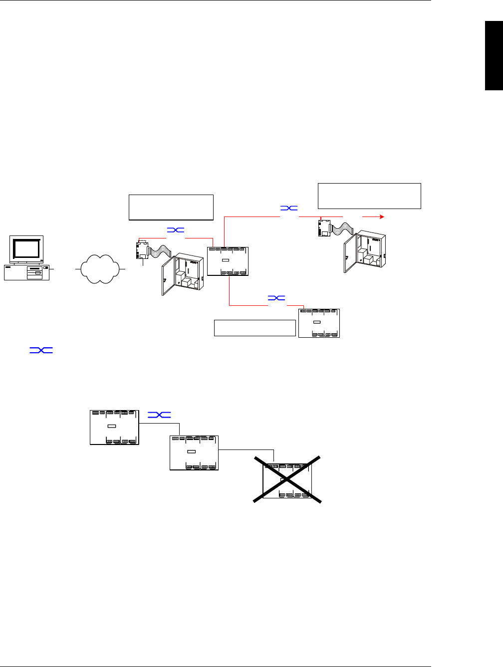
Controller-to-controller speeds range from 9600 to 115200 bps. For each string of
controllers, the first (master) SNIB2 with the Ethernet connection must be assigned the
same address as the XBox port.
For more on this, refer to “Configuring a Master SNIB2 on the Same Subnet” starting on
page 13.
When the host is connected to a SNIB2 using Ethernet, Velocity views the
first (master) SNIB2 as both a DIGI*TRAC controller and an XBox residing
on an XNET port. Subsequent multidropped controllers in the sequence
do not appear as XBox controllers.
You can also use the SNIB2 with the NET*MUX4. The NET*MUX4 consists of a single
input for either RS-232 or RS-485 and four outputs to which a series of controllers or
additional NET*MUX4s can be wired as shown in the following illustration:
If required, you can add a second level of NET*MUX4s to create additional controller
runs; however, Hirsch does not support more than two levels of NET*MUX4s.
NET*MUX4 speeds are dictated by wire gauge and distance. We
recommend using Cat5/Cat6 cable.
= this cable segment swaps the RX± and TX± wires. See page 8 for details.
Host
NET*MUX4
RS-485
XNET 2
RS-485
SNIB2 Address: 1
Speeds Available: 9600
RS-485
NET*MUX4
SNIB2 Address: 2
Speeds Available: same as Address 1
Additional
Controllers
Only two levels of NET*MUX
are allowed.
SNIB2
DIGI*TRAC
Controller
SNIB2
DIGI*TRAC
Controller
RS-485
Ethernet Ethernet
First Level
Second Level
Third Level NOT supported
SNIB2 Configuration Guide
6Installing the SNIB2
Installing the SNIB2
To install the SNIB2:
1. Download CCM 7.3.08 or later firmware to the required controllers.
For instructions on doing this, refer to “Download Firmware Revision” in Velocity
help or the Velocity Administrator’s Guide.
2. Make sure each controller in the sequence shows the CCM version as 7.3.08 or
later, and the BIOS as Version 7.2.19 or later.
For more on checking this, refer to “Checking CCM and BIOS Version” on page 22.
If these version numbers do not appear, replace the controller’s CCM.
3. Pull the original SNIBs from each required controller.
Hint We recommend removing the SNIBs controller-by-controller to ensure that each
SNIB2 comes online successfully.
Follow the instructions in Chapter 7 of the DIGI*TRAC Design & Installation Guide.
4. Run the required network cable to the controller(s) with the master SNIB2s.
The Ethernet cable you are connecting to each master SNIB2 should be connected
to the Velocity host through a hub or switch.
5. Run RS-485 cable downstream from the master SNIB2.
The run between the master SNIB2 and the second SNIB2 should be wired
according to the instructions in “Cabling the SNIB2” starting on page 8.
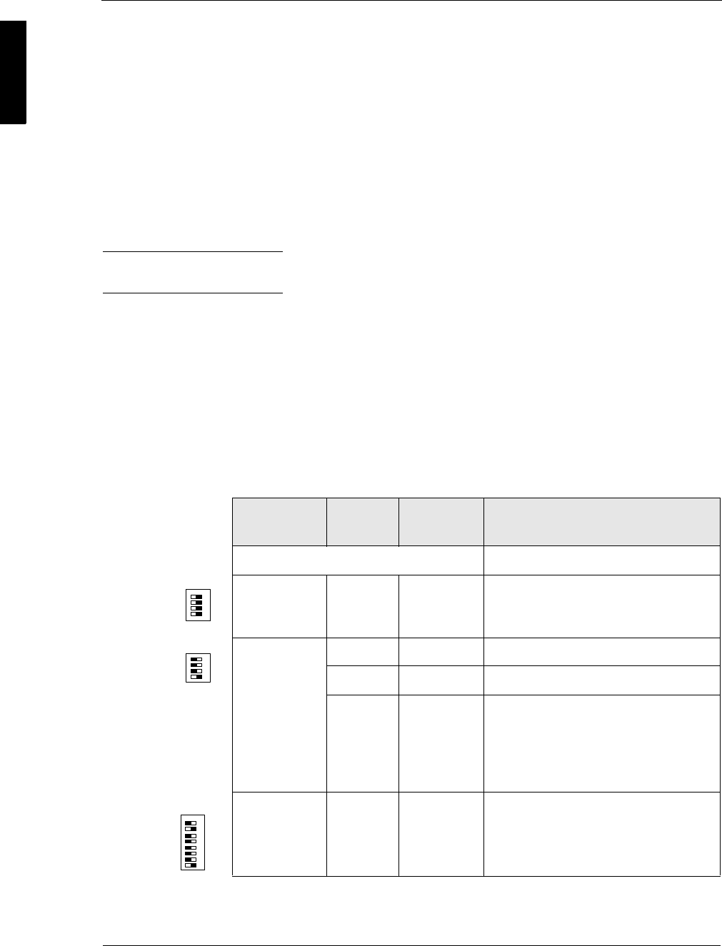
6. Set the DIP switches on each SNIB2.
In general, do this:
Switch
Bank Switch Setting Comments
Master SNIB2
SW1 S1-S4 all ON This SNIB2 is either first (master) or
last (termination) in the multidrop
sequence
SW2 S1 OFF Encryption key reset
S2 - S3 OFF
Reserved
S4 ON
Indicates this SNIB2 is first in the
sequence (master) and is connected
to the host via Ethernet or direct
RS-232 connection (not dial-up). This
SNIB2 controls polling.
SW3 S1
S2
S3-S8
OFF
ON
—
Set downstream RS-485 speed
(38400 in this example)
Address as required (Address 1
shown)
SW1
ON
1
2
3
4
SW2
ON
1
2
3
4
SW3
ON
1
2
3
4
5
6
7
8
SUPP009-0907
Installing the SNIB2 7
For specific cases, refer to “Setting Up the SNIB2” starting on page 9.
7. Install the new SNIB2s into their controllers.
Follow the instructions in Chapter 7 of the DIGI*TRAC Design & Installation Guide.
Handle the SNIB2 with care. The board is very sensitive to
static discharges. Observe the normal anti-static precautions
by using grounded wrist straps and anti-static devices when
installing the board.
8. Plug the RJ-45 connector from the cable into the Ethernet connector on the
SNIB2.
9. Connect the RS-485 cables to their respective SNIB2.
10. Reconnect and power up the controllers.
11. At the host, open Velocity and configure the new SNIB2s using the instructions in
“Configuring a Master SNIB2 on the Same Subnet” starting on page 13.
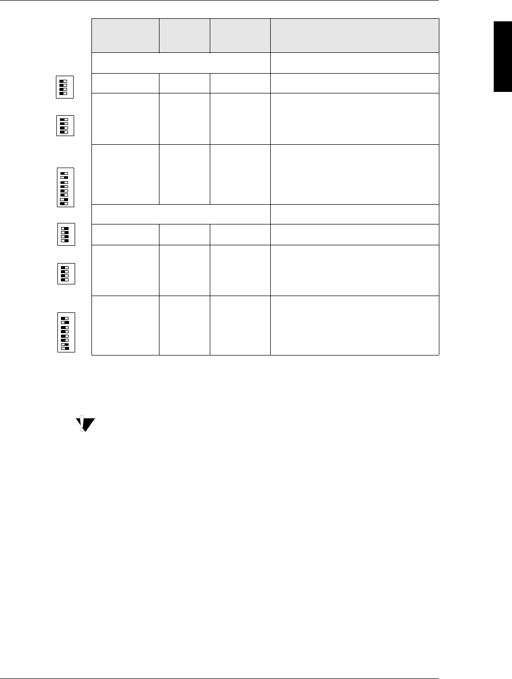
SNIB2s in the middle
SW1 S1-S4 all OFF Indicates this is middle SNIB2 of run
SW2 S1
S2-S3
S4
OFF
OFF
OFF
Encryption key reset
Reserved
SNIB2 not first
SW3 S1
S2
S3-S8
OFF
ON
—
Set downstream RS-485 (38400 in
this example)
Address as required (Address 2
shown)
Last SNIB2 in run
SW1 S1-S4 all ON Indicates this is last SNIB2 in run
SW2 S1
S2-S3
S4
OFF
OFF
OFF
Encryption key reset
Reserved
SNIB2 not first
SW3 S1
S2
S3-S8
OFF
ON
—
Set downstream RS-485 (38400 in
this example)
Address as required (Address 3
shown)
Switch
Bank Switch Setting Comments
ON
1
2
3
4
SW1
ON
1
2
3
4
SW2
ON
1
2
3
4
5
6
7
8
SW3
ON
1
2
3
4
SW1
ON
1
2
3
4
SW2
ON
1
2
3
4
5
6
7
8
SW3
SNIB2 Configuration Guide
8Installing the SNIB2
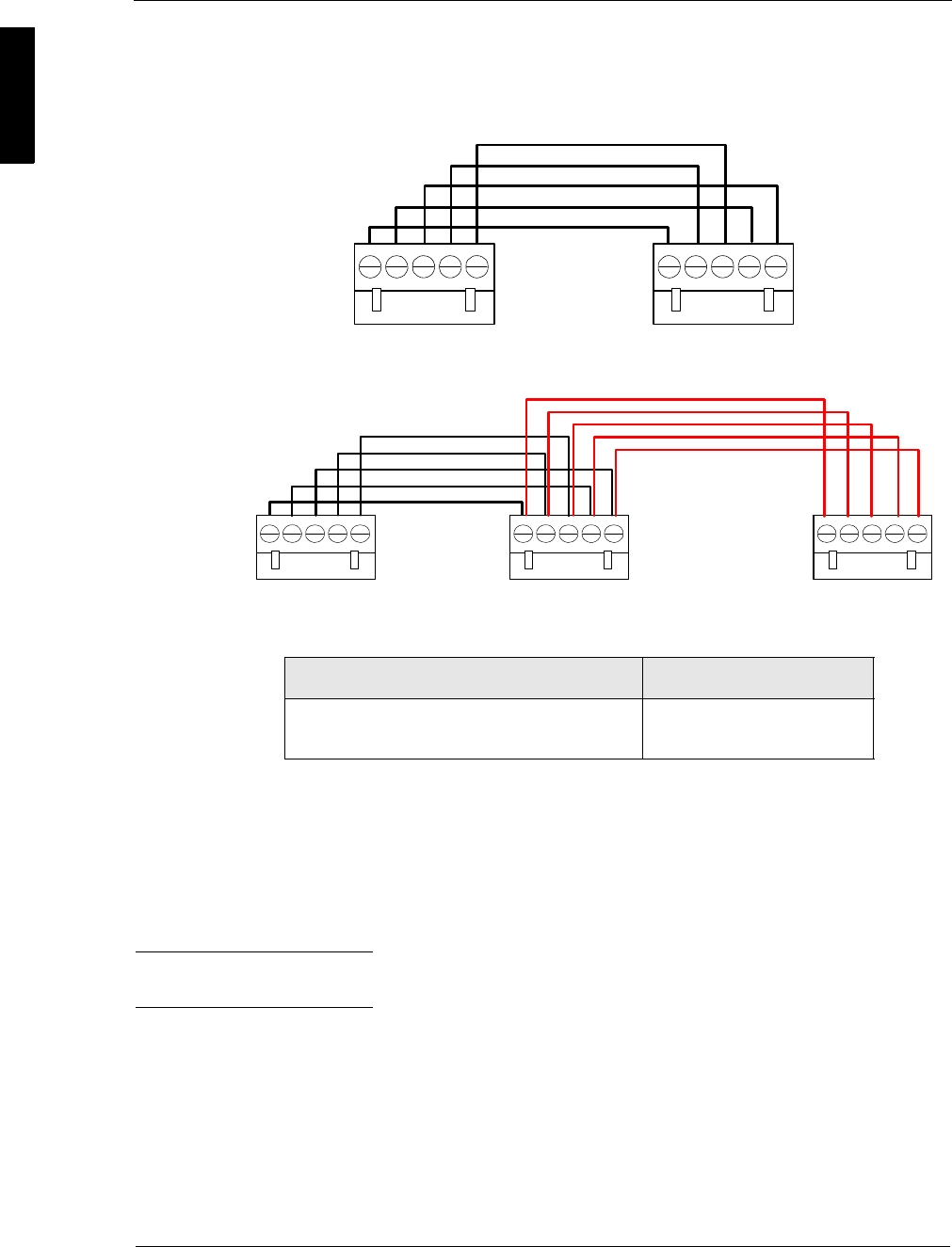
Cabling the SNIB2
The cable linking the first controller (master) to the second (subordinate) in a
multidropped RS-485 series must cross the RX± and TX± wires in this manner:
If more than two controllers are connected in the series, the wiring would look like this:
At 9600 baud, the maximum allowed cable run between controllers is shown in the
following table:
In general, communications become less robust as baud rates increase, wire gauge
decreases, and distances increase. For this reason, it may not be possible to implement
the higher baud rates supported by the SNIB2 if you have long wire runs or small wire
gauges.
Higher baud rates are also more dependent on the number of twists per foot, so
capacitance specifications must be strictly adhered to: total wire run per port is not to
exceed 100,000 pf per foot.
Hint We recommend using Cat5/Cat6 cable for your cable runs. Use 1 pair for the RX
pair, 1 pair for the TX pair, and 1 conductor or pair for the ground connection.
Connection Maximum Distance
Total Max. Run from Master SNIB2 to Last
Downstream SNIB2
4000 feet (1,220 m.)
Address 1 Address 2
RX- to TX-
RX+ to TX+
TX- to RX-
TX+ to RX+
Ground
Master Subordinate
Address 1 Address 2
RX- to TX-
RX+ to TX+
TX- to RX-
TX+ to RX+
Ground
Address 3
Ground
TX- to TX-
RX+ to RX+
TX+ to TX+
RX- to RX-
Master Subordinate Subordinate
SUPP009-0907
Installing the SNIB2 9
Setting Up the SNIB2
The SNIB2 includes three DIP switch banks. The first bank (SW1) and second bank
(SW2) have four DIP switches each. The third bank (SW3) possesses eight DIP
switches.
SNIB2s can be used throughout a multidrop run; however, you must specify whether a
specific SNIB2 is connected to a controller that is in the beginning, middle, or at the
end of a run.
To do this, set S1-S4 on switch bank SW1 to all ON or all OFF in this way:
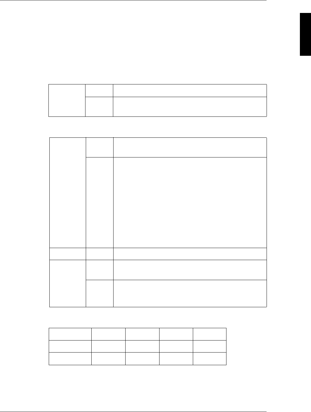
The second switch bank at SW2 has 4 switches which configure such properties as the
type of XNET protocol you are using and the SNIB2’s location in the multidrop run.
Switch bank SW3 is used to specify the SNIB2 speed (S1-S2) and the SNIB2 address
(S3-S8). DIP switch settings for this are:
This controls the baud rate for the RS-485 multi-drop line and the RS-232 connection.
57600 and 115200 bps are only available if your RS-485 cables are made from
Cat5/Cat6 data grade wire. These speeds are not recommended for installations using:
S1-S4 OFF This SNIB2 is in the middle of a multidrop sequence.
ON This SNIB2 is either first (master) or last (termination) in
the multidrop sequence.
S1 OFF The SNIB2 communicates with the host PC in XNET 2
using the encryption keys stored in memory.
ON Return the encryption keys to their default settings. If this
switch is set when the SNIB2 powers up or reboots after
a firmware upgrade, the keys reset.
Note: This switch should be turned off after the LED patterns
begin to light. See the SNIB2 Troubleshooting Guide for
details.
If this is the master SNIB2, you must also ‘Reset
Encryption’ on the Velocity Port settings. All downstream
units must have their encryption keys reset as well. If this
is a downstream unit, the master SNIB2 automatically
detects that the keys have been reset.
S2-S3 OFF Reserved.
S4 OFF Indicates this SNIB2 is NOT first in the multidrop
sequence, or you only have one controller.
ON Indicates this SNIB2 is first in the sequence (master) and
is connected to the host via Ethernet or direct RS-232
connection (not dial-up). This SNIB2 controls polling.
S1 OFF OFF ON ON
S2 OFF ON OFF ON
Baud Rate 9600 38400 57600 115200
Switch Bank 1
(SW1)
Switch Bank 2
(SW2)
Switch Bank 3
(SW3)

SNIB2 Configuration Guide
10 Installing the SNIB2
ORS-232 connections to host
O18- to 22-gauge shielded twisted-pair cable
ONET*MUX4s
OMixed SNIBs/SNIB2s
Baud rates only apply to the SNIB2's RS-485 and RS-232 ports. The SNIB2's Ethernet
port is used for host-to-controller connections and runs at 10/100 BaseT speeds. All
SNIBs/SNIB2s in an RS-485 multi-drop sequence must be set to the same speed, and
if connected to a host PC using RS-232 direct connection, the same speed must also
be used. For example, if one SNIB2 in the sequence is set to 9600, all other SNIBs and
SNIB2s (and the RS-232 host connection, if used) must be set to the same baud rate.
The remaining DIP switches on SW3 set the SNIB2 address:
Address S3 S4 S5 S6 S7 S8
1 OFF OFF OFF OFF OFF ON
2 OFF OFF OFF OFF ON OFF
3OFFOFFOFFOFFONON
4 OFF OFF OFF ON OFF OFF
5 OFF OFF OFF ON OFF ON
6 OFF OFF OFF ON ON OFF
7 OFF OFF OFF ON ON ON
8 OFF OFF ON OFF OFF OFF
9 OFF OFF ON OFF OFF ON
10 OFF OFF ON OFF ON OFF
11 OFF OFF ON OFF ON ON
12 OFF OFF ON ON OFF OFF
13 OFF OFF ON ON OFF ON
14 OFF OFF ON ON ON OFF
15 OFF OFF ON ON ON ON
16 OFF ON OFF OFF OFF OFF
17 OFF ON OFF OFF OFF ON
18 OFF ON OFF OFF ON OFF
19 OFF ON OFF OFF ON ON
20 OFF ON OFF ON OFF OFF
21 OFF ON OFF ON OFF ON
22 OFF ON OFF ON ON OFF
23 OFF ON OFF ON ON ON
24 OFFONONOFFOFFOFF
25 OFFONONOFFOFFON
26 OFFONONOFFONOFF
27 OFFONONOFFONON

SUPP009-0907
Installing the SNIB2 11
28 OFFONONONOFFOFF
29 OFFONONONOFFON
30 OFFONONONONOFF
31 OFFONONONONON
32 ON OFF OFF OFF OFF OFF
33 ON OFF OFF OFF OFF ON
34 ON OFF OFF OFF ON OFF
35 ON OFF OFF OFF ON ON
36 ON OFF OFF ON OFF OFF
37 ON OFF OFF ON OFF ON
38 ON OFF OFF ON ON OFF
39 ON OFF OFF ON ON ON
40 ON OFF ON OFF OFF OFF
41 ON OFF ON OFF OFF ON
42 ON OFF ON OFF ON OFF
43 ON OFF ON OFF ON ON
44 ONOFFONONOFFOFF
45 ONOFFONONOFFON
46 ONOFFONONONOFF
47 ONOFFONONONON
48 ON ON OFF OFF OFF OFF
49 ON ON OFF OFF OFF ON
50 ON ON OFF OFF ON OFF
51 ON ON OFF OFF ON ON
52 ON ON OFF ON OFF OFF
53 ON ON OFF ON OFF ON
54 ON ON OFF ON ON OFF
55 ON ON OFF ON ON ON
56 ON ON ON OFF OFF OFF
57 ON ON ON OFF OFF ON
58 ON ON ON OFF ON OFF
59 ON ON ON OFF ON ON
60 ON ON ON ON OFF OFF
61 ON ON ON ON OFF ON
62 ON ON ON ON ON OFF
63 ON ON ON ON ON ON
Address S3 S4 S5 S6 S7 S8
SNIB2 Configuration Guide
12 Installing the SNIB2
Deploying the SNIB2
Each master SNIB2 (Velocity port) must be assigned a unique IP address in order to
communicate with Velocity on the host PC. Depending on the network location of the
master SNIB2, this is accomplished in one of two ways:
OIf the SNIB2 is located within the same subnet as the host PC, then you can use
Velocity to assign the IP address. For more on this, refer to “Configuring a Master
SNIB2 on the Same Subnet” starting on page 13.
OIf the master SNIB2 is located outside the host PC’s subnet, you must use the
SNIB2 Configuration Utility. For more on this, refer to “Configuring a Master SNIB2
in a Different Subnet” starting on page 15.
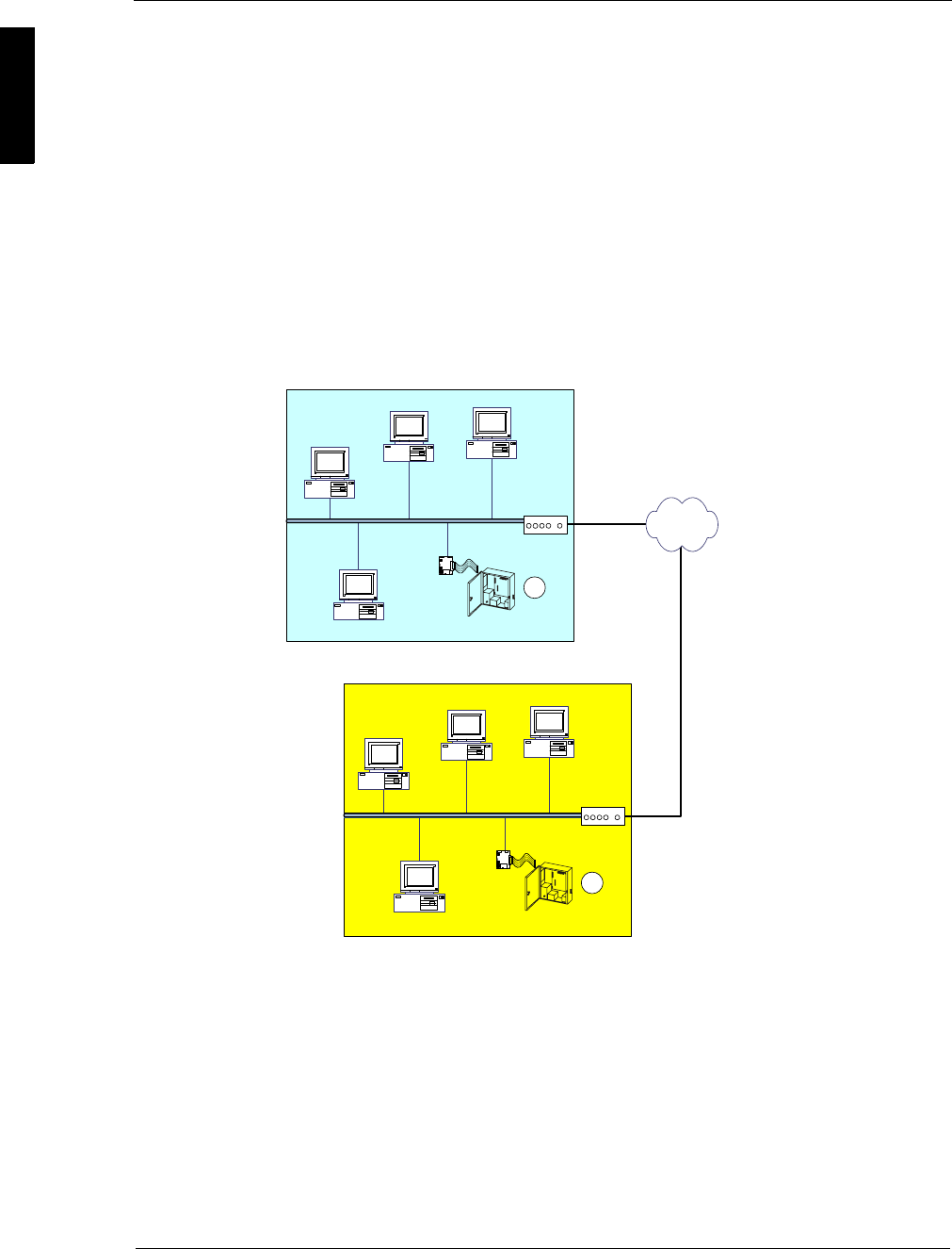
What is a subnet? Put simply, a subnet is any group of PCs and other devices, such as
printers and scanners, connected by network cable to a network router. Anything
behind the router is considered part of the subnet. Anything beyond this router is not
part of the subnet.
In the preceding illustration, the master SNIB2 and controller labeled 1 is located in the
same subnet as the host PC (Subnet A). This SNIB2 can therefore be configured using
Velocity; however, the master SNIB2 and controller labeled 2 is located behind a
different router, in a different subnet (Subnet B), and must be configured using the
SNIB2 Configuration Utility.
Any number of computers and devices can be behind a single router, but for reasons
of security and speed, a company network often incorporates many routers. It isn’t
uncommon to find that each department within a company has its own router. Routers
not only find the quickest way to ferry packets of information between two points, but
also could serve as a rudimentary firewall against potential intrusion.
Subnet A
Subnet B
SNIB2
DIGI*TRAC
Controller
SNIB2
DIGI*TRAC
Controller
Velocity Host PC
1
2
Router
Router
SUPP009-0907
Installing the SNIB2 13
Configuring a Master SNIB2 on the Same Subnet
When a master SNIB2 is connected via Ethernet to the host PC sharing the same
subnet, configure and assign a new IP address through the Velocity port properties
dialog box.
To do this:
1. At the System Tree window, click and expand the DIGI*TRAC Configuration system
folder, .
Three port folders are currently available: SNET, XNET, or Dial-Up.
2. Expand the XNET Port folder.
When the Velocity host is connected to a SNIB2 via Ethernet, it treats it as an XNET
port.
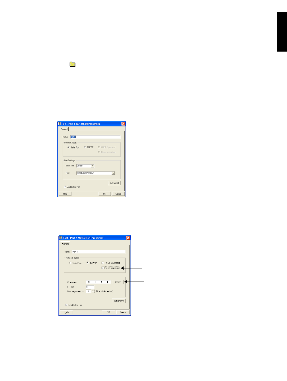
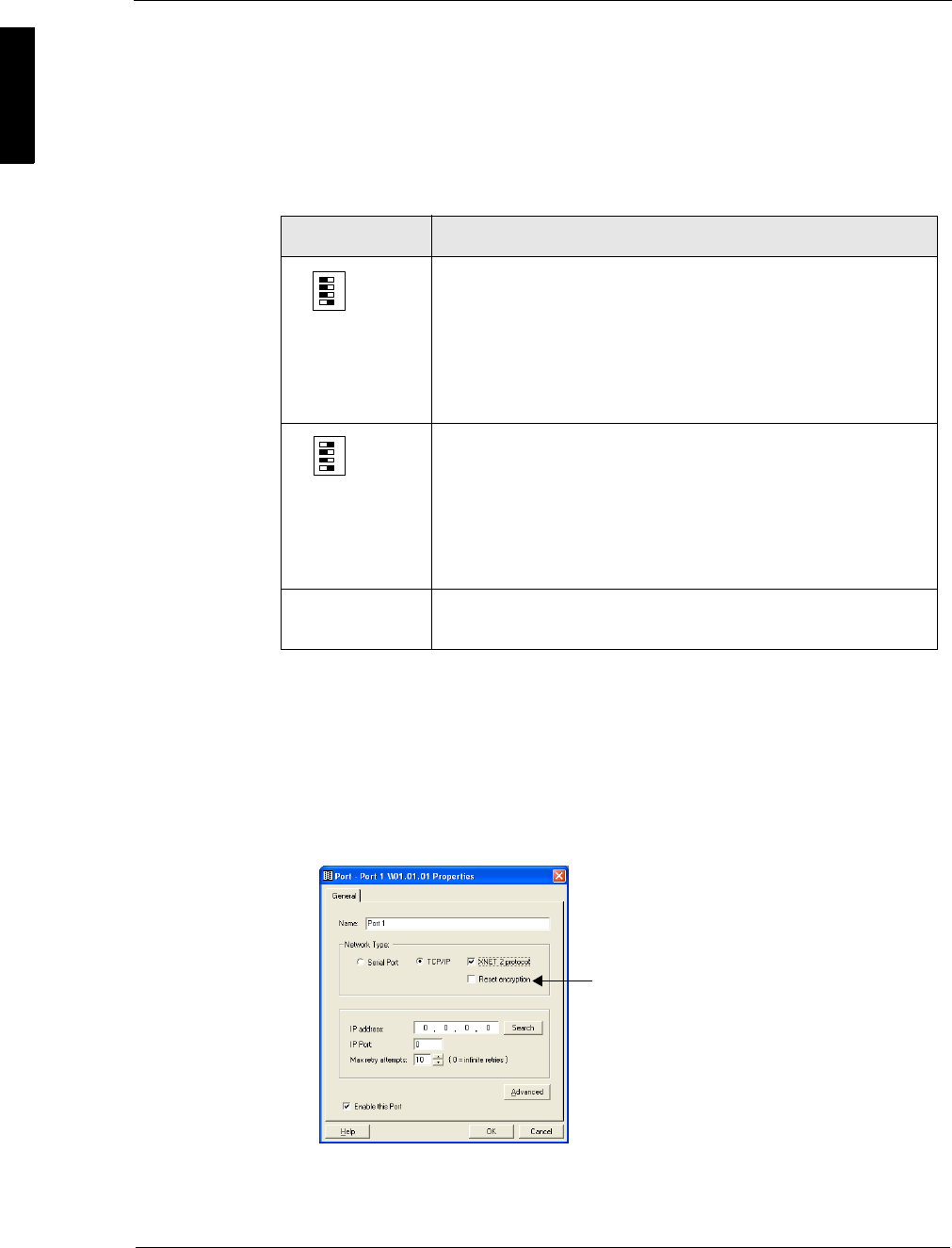
3. Double click Add New XNET Port in the Components window.
The Port Properties dialog box appears like this:
4. Click to select the TCP/IP radio button.
The dialog box changes to show the ‘IP Address’, ‘Port’, and ‘Max Attempts’ fields.
5. Check the XNET 2 Protocol checkbox to indicate this port is using encrypted
XNET 2 protocol.
6. Click the Search button.
Velocity searches on the subnet for all SNIB2s that Velocity is not using.
If a SNIB2 is currently logged on, the search feature will not detect it.
A dialog box appears listing all new SNIB2s like the following example:
Notice when you check this box...
... this Search button is activated.
SNIB2 Configuration Guide
14 Installing the SNIB2
While a newly-detected SNIB2 does not possess an IP address, port number, or
name, it should have a unique MAC address. To see this MAC address, drag the
slide bar at the bottom of the dialog box to the right. The MAC address for each
SNIB2 is printed on a white label located on the left side of the SNIB2’s
daughterboard. This label contains both a barcode and a six-digit number. This
number is the last six digits of the MAC address.
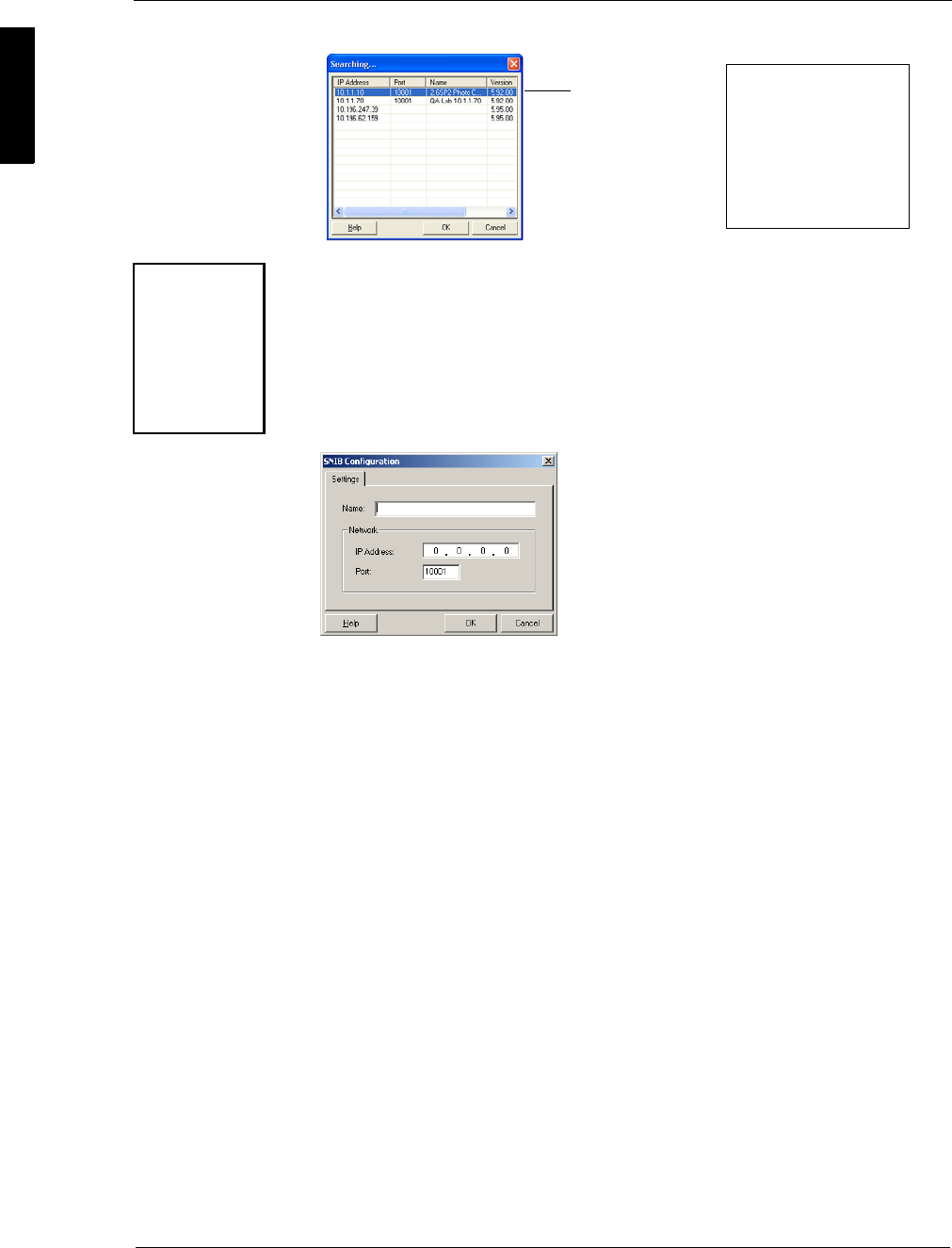
7. From this list, double click the SNIB2 entry you want to configure.
The SNIB2 Configuration dialog box appears like this example:
8. In the 'Name' field, enter the name you want to assign to the SNIB2.
9. At the ‘IP Address’ field, enter the IP address for the SNIB2 connected to this
Velocity PC.
In version 5.95 and later, all SNIB2s will have a factory default IP address in the
format 10.x.y.z where the variables are supplied from a hash of the MAC address.
For versions earlier than this, you must enter the required IP address.
10. At the 'Port' field, enter the correct port number.
All network ports possess an address used to identify the SNIB2’s physical port
address. The default Velocity port is 10001.
Consult your system administrator for the correct values for both the IP
and port address.
11. Click OK. The Searching screen reappears.
12. Click OK.
The Port Properties screen reappears with the Name, IP Address, and IP Port fields
populated.
13. At the 'Max retry attempts' field, specify the maximum number of retries this PC
will attempt. Increment or decrement the value using the counter buttons.
If you get port errors, increase this number.
14. Check the 'Enable this Port' box if this port is currently active. Clear this box if the
port is not currently active.
15. If required, click the Advanced button to access the Advanced Settings dialog box
to specify additional options for this port.
Drag the slide bar over to
the right to see the MAC
Address column. While a
newly detected SNIB2
does not have an
assigned IP address, it
always has a unique MAC
address.
New SNIB2 detected
Since all SNIB2
MAC addresses
start with the
same six digits
(00:90:C2), the
label on the
SNIB2 only lists
the last six digits.
SUPP009-0907
Installing the SNIB2 15
16. When you're finished, click OK.
The new SNIB2 port appears in the Components window.
If you ever need to reassign an IP address, repeat this procedure.
Configuring a Master SNIB2 in a Different Subnet
To connect a master SNIB2 via Ethernet to a host PC residing outside the host PC’s
subnet, configure and assign a new IP address for the master SNIB2 on its own subnet
using the SNIB2 Configuration Utility as described in this section.
To configure a master SNIB2 using the SNIB2 Configuration Utility:
1. If you haven’t already, install the SNIB2 Configuration Utility in a PC in the same
subnet as the master SNIB2 you want to configure. To do this:
a. Insert the Velocity CD in your CD drive or go to the \Velocity folder.
b. Using Windows Explorer, navigate to the \SNIB2 folder. The file
SNIB2CONFIG.EXE should be located here.
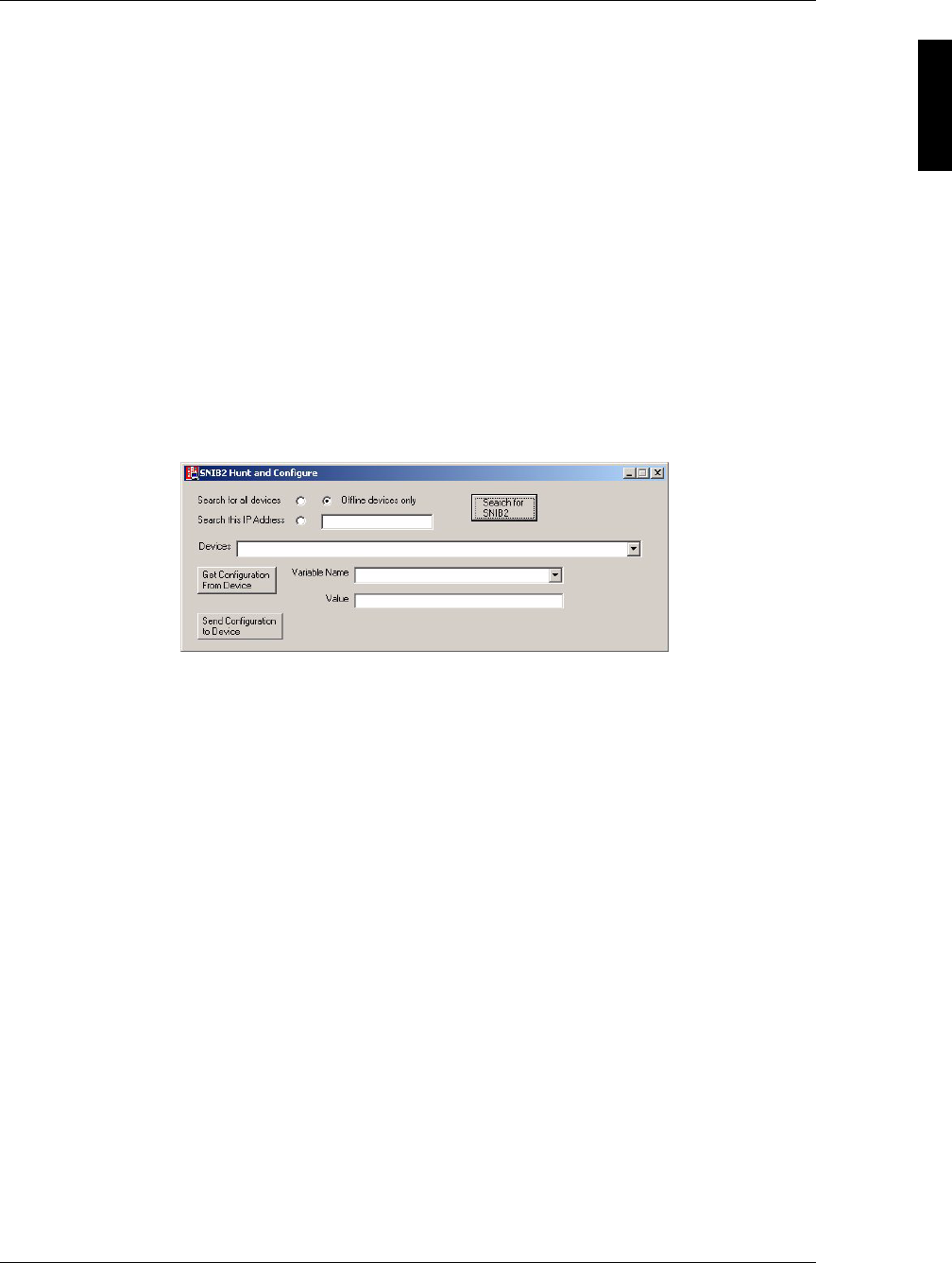
2. Double click SNIB2CONFIG.EXE.
The SNIB2 Configuration Utility appears like this example:
3. Select one of these radio buttons:
4. Click the Search for SNIB2 button.
The utility scans the network within the current subnet and returns a list of all
devices meeting the criterion specified by the radio button.
Search for all devices Select this option to search for all SNIB2s on this
subnet.
Note: If a SNIB2 is currently logged on, the utility will not
detect it.
Offline devices only Select this option to search only for SNIB2s that are
currently offline. It automatically eliminates all
SNIB2s that are already configured for this subnet.
This is the default selection.
Search this IP Address Select this option if you know the address of the
SNIB2 you are programming, then enter the SNIB2s
current IP address in the field to the right of this
radio button.
Use this option to change the IP or port address of a
previously-configured SNIB2.
SNIB2 Configuration Guide
16 Installing the SNIB2
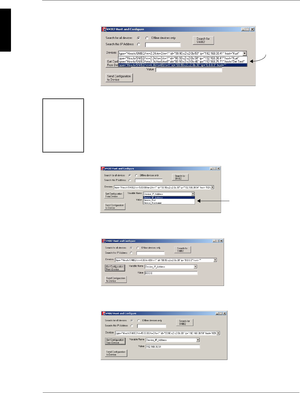
5. Click the ‘Devices’ pick list to display all devices currently detected by the utility, like
the following example:
6. Select the correct SNIB2.
You can identify which SNIB2 you need, by its MAC address (id=). The MAC
address for each SNIB2 is printed on a white label located on the left side of the
SNIB2’s daughterboard. This label contains both a barcode and a six-digit number.
This number is the second half of the MAC address.
7. Select the Get Configuration From Device button.
A list of variables specific to this SNIB2 appear in the ‘Variable Name’ window.
The three options used for SNIB2 configuration are: Device_IP_Address,
Device_Port, and Device_Hostname as shown in the following example:
8. From the ‘Variable Name’ pick list, select Device_IP_Address.
A screen like this example appears:
9. In the ‘Value’ field, enter the IP address you require for this SNIB2.
A screen like this example appears:
Consult your IT or Security Administrator for the proper address.
10. From the ‘Variable Name’ pick list, select Device_Port.
All detected
devices
The MAC address
has the prefix id=
Since all SNIB2
MAC addresses
start with the
same six digits
(00:90:C2), the
label on the
SNIB2 only lists
the last six digits.
These 3 options are available.

SUPP009-0907
Installing the SNIB2 17
11. At the ‘Value’ field, enter a port address for this SNIB2.
All network ports possess an address used to identify the SNIB2’s physical port
address. The default Velocity port is 10001.
12. From the ‘Variable Name’ pick list, select Device_Hostname.
13. At the ‘Value’ field, enter a name for this SNIB2.
14. Click the Send Configuration to Device button to send the information to the
SNIB2.
15. Click the Search for SNIB2 button again to verify that the SNIB2 has correctly
received the information.
Make sure to write down the address, port, and host name you assigned for each
SNIB2. These values are required when you configure the SNIB2 in Velocity.
Hint If there are a lot of master SNIB2s to configure remotely, we recommend using a
dedicated portable computer with SNIB2CONF already installed. This should
enable the installer to do the job more rapidly. But be careful: make sure you are
on-site when you do this. A SNIB2 does not retain its IP address for more than 5
minutes after being unplugged from a controller. If you are planning to program
several SNIB2s from a controller then move them to a remote site, you probably
won’t have time before the IP address in each SNIB2 is irrevocably lost.
Once the installer has assigned the remote master SNIB2 an IP address and port, use
Velocity on the host PC to identify it to the system. To do this:
1. Create a new XNET port as specified in Steps 1–5 of “Configuring a Master SNIB2
on the Same Subnet” starting on page 13.
Do not use the Search button. This only works for finding SNIB2s that are
currently residing on the host PC’s subnet.
2. In the 'Name' field, enter the name you assigned to the SNIB2 using the SNIB2
Configuration Utility (Device_Hostname).
3. At the ‘IP Address’ field, enter the IP address you assigned to this device using the
SNIB2 Configuration Utility (Device_IP_Address).
4. At the 'Port' field, enter the port number you assigned to this device using the
utility (Device_Port). The default value is 10001.
5. Make sure the ‘Enable this Port’ box is checked.
6. Click OK.
This enables Velocity to find and monitor the remote SNIB2.
SNIB2 Configuration Guide
18 Resetting SNIB2 Encryption Keys
Resetting SNIB2 Encryption Keys
Once Velocity creates the encryption keys required for secure Host-to-SNIB2
communication, it continues to use those keys. If, for whatever reason, you need to
change these keys, there are several ways to do it.
Several of these techniques reset not only the SNIB2 encryption keys but
also the controller.
Once you have reset the encryption key to its default value (set SW2-1 to ON, recycle
controller power, then reset SW2-1 to OFF), you must assign a new key so that Velocity
and the master SNIB2 can talk to each other. To do this:
1. From the Velocity Administrator system tree, click and expand the DIGI*TRAC
Configuration system folder until the master SNIB2 port you require appears.
2. Right click on the SNIB2 port and select Properties.
The Port Properties dialog box appears. The master SNIB2 Properties should look
like this example:
3. Check the ‘Reset Encryption’ box and click OK.
This resets and syncs the encryption key at host SNIB2.
Set SW2-1 to: Procedures/Results
OFF • Cycle power on controller. SNIB2 retains encryption keys.
Controller retains setups.
• Press the blue button on the controller until it resets. SNIB2
retains encryption keys. Controller loses setups.
• Download SNIB2 firmware through Velocity. SNIB2 retains
encryption keys. Controller retains setups.
ON • Cycle power on controller. SNIB2 resets encryption keys.
Controller retains setups.
• Press the blue button on the controller until it resets. SNIB2
resets encryption keys. Controller loses setups.
• Download SNIB2 firmware through Velocity. SNIB2 resets
encryption keys. Controller retains setups.
OFF or ON Download CCM firmware through Velocity. SNIB2 retains
encryption keys. Controller retains setups.
SW2
ON
1
2
3
4
SW2
ON
1
2
3
4
Check this box to reset the
SNIB2 encryption keys.
SUPP009-0907
Controller and SNIB2 LED Diagnostics 19
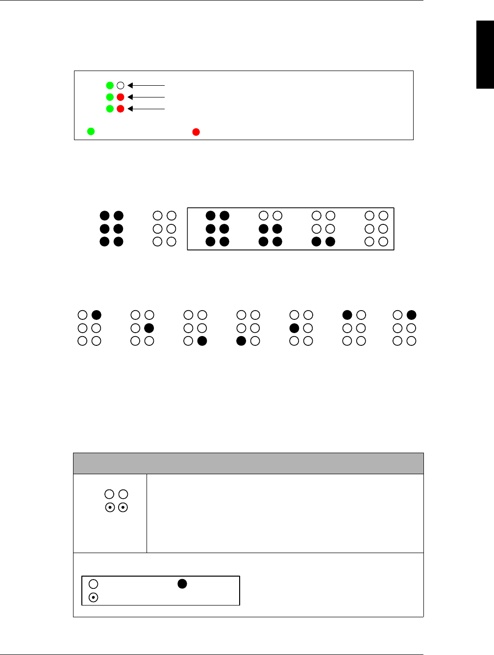
Controller and SNIB2 LED Diagnostics
The SNIB2 has three pairs of LEDs that show you how the SNIB2 is communicating
with the host PC.
Special Light Patterns: Start Up
This consists of the following light patterns during start up.
First comes the Lamp Test.
Power-up might include the first two patterns. If you’ve just reflashed the SNIB2, the
sequence starts with the ones in the box.
This pattern is followed by:
This is the SNIB2/CCM Synchronization. This pattern repeats until the CCM and
SNIB2 are synchronized. This light pattern should not persist longer than four minutes if
there are no memory expansion boards on the controller.
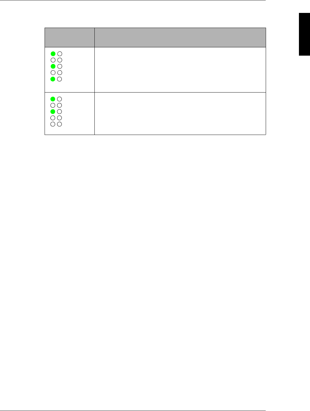
Normal Operation
This table illustrates the various light patterns displayed during normal operation for
both the master and subordinate SNIB2s:
Master or Subordinate
Ordinary communication between master and subordinates.
Lights may blink or stay lit during heavy data transfers. They will
go out every 4 seconds during idle or low-traffic periods; this is
normal, indicating the master is hunting for new addresses, such
as newly-added controllers or controllers that went offline and are
expected back online.
Legend:
P1
P2
P3 Host communication
RS-485 communication
Green = firmware download; Yellow (Rev. D)/Red (Rev. C) = data trouble
transmitting data receiving data
P2
P1
P3 P2
P1
P3 P2
P1
P3 P2
P1
P3 P2
P1
P3 P2
P1
P3
P2
P1
P3
P2
P1
P3
P2
P1
P3
P2
P1
P3
P2
P1
P3
P2
P1
P3
P2
P1
P3
P2
P1
= LED OFF = LED ON
= LED Flashing or ON = LED Flashing
:
SNIB2 Configuration Guide
20 Controller and SNIB2 LED Diagnostics
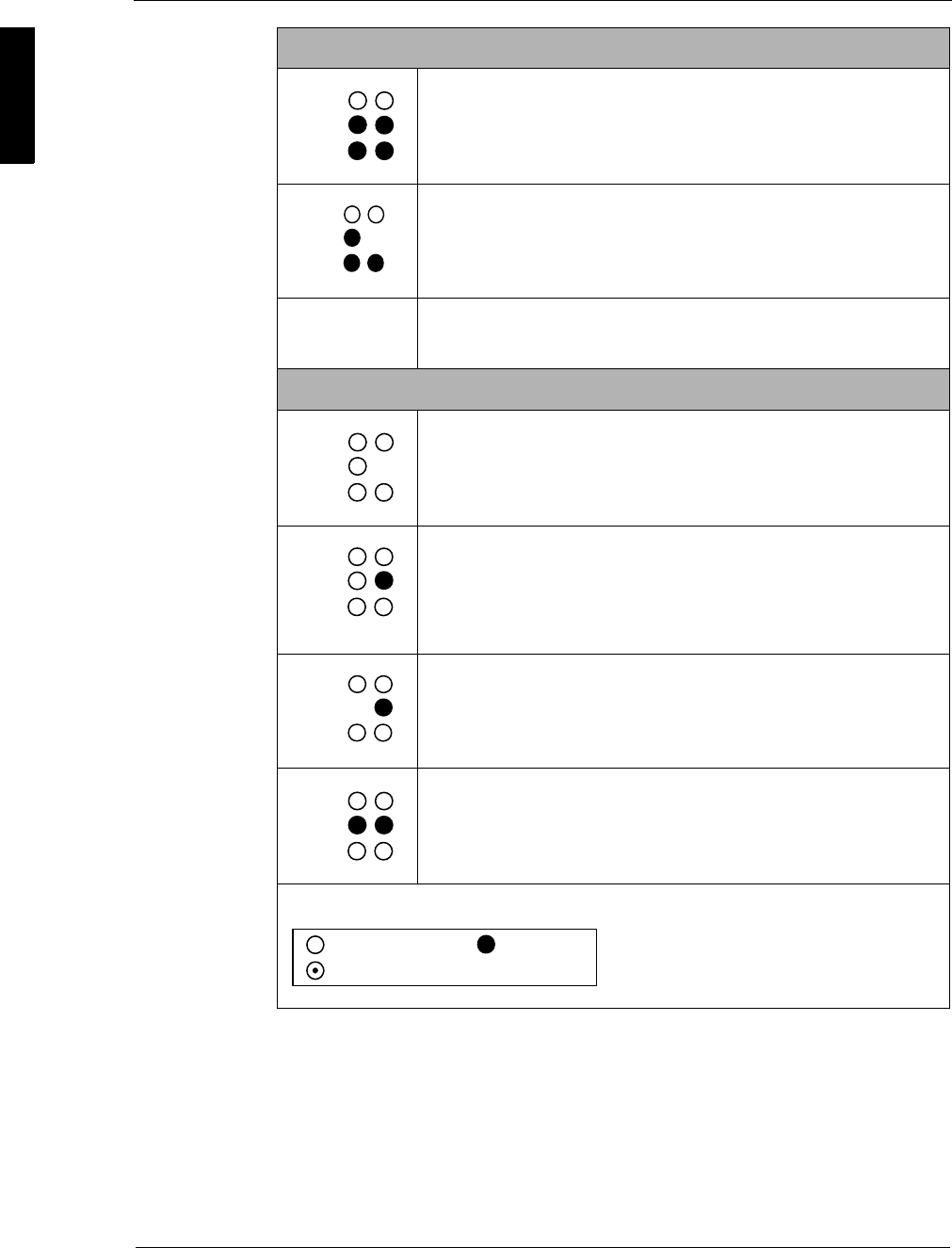
For more on this, refer to the SNIB2 Troubleshooting Guide included with the SNIB2.
Master
This could be programming activity (downloads) or events, or
both.
P2's red LED flashes while P2 green and P3 red and green stays
lit. This normally means that the Velocity server is in the process
of downloading CCM or SNIB2 firmware to one or more
controllers.
Heartbeat. If the P3 LED flashes appear to be about 5 seconds
apart, it means the host is keeping the communication link open.
Subordinate
The master is polling a different SNIB2. This SNIB2 ignores those
polls.
If this stays lit and doesn’t go out every 4 seconds, that means
there’s a lot of data going to or coming from some other
controller(s). If you don’t see any green flashes at all, this unit
won’t come online until the data traffic decreases. This pattern
may also alternate with occasional red or green P3 flashes.
If these stay flashing and lit, it means there is a lot of data going
to or coming from several controllers. This occurs particularly
when you have many controllers.
If these stay lit, it means there is a lot of data going to or coming
from this particular controller.
Legend:
P2
P1
P3
P2
P1
P3
;
P3 ;;
P2
P1
C
P3
:
P2
P1
P3
P2
P1
¯
P3
:
P2
P1
P3
= LED OFF = LED ON
= LED Flashing or ON = LED Flashing
:
SUPP009-0907
Controller and SNIB2 LED Diagnostics 21
The SNIB2 also causes certain changes to the way the controller LEDs display as
shown below:
For more on this, refer to “Status LED Configurations” starting on page 166 of the
DIGI*TRAC Design and Installation Guide.
LED
Configuration Meaning
The NET green LED is on; the NET red LED blinks intermittently
depending on the amount of data being received from the host.
This indicates the SNIB2 is working properly.
Note: The exact NET LED behavior depends on the controller version.
Neither NET LED is blinking or only the NET green LED is on. In
either case, the master SNIB2 is not communicating with the
host.
Check both your Ethernet connection and your Velocity port
configuration.
NET
AC
BAT
SYS
KPD
AC
BAT
SYS
KPD
NET
SNIB2 Configuration Guide
22 Checking CCM and BIOS Version
Checking CCM and BIOS Version
Before you can flash your current CCM to 7.3.08 or higher, you must first check the
CCM BIOS level. In order for the 7.3.08 or higher flash update to work properly, you
must be running a CCM with a CCM BIOS level of 7.1.20 or higher.
If you are running a CCM with CCM BIOS 7.1.8, you will need to
replace your CCM, since the flash will not work properly and the
controller may not reboot if powered off.
The CCM BIOS level currently shipping is 7.3.17.
To determine the CCM BIOS of your controllers, use one of two methods.
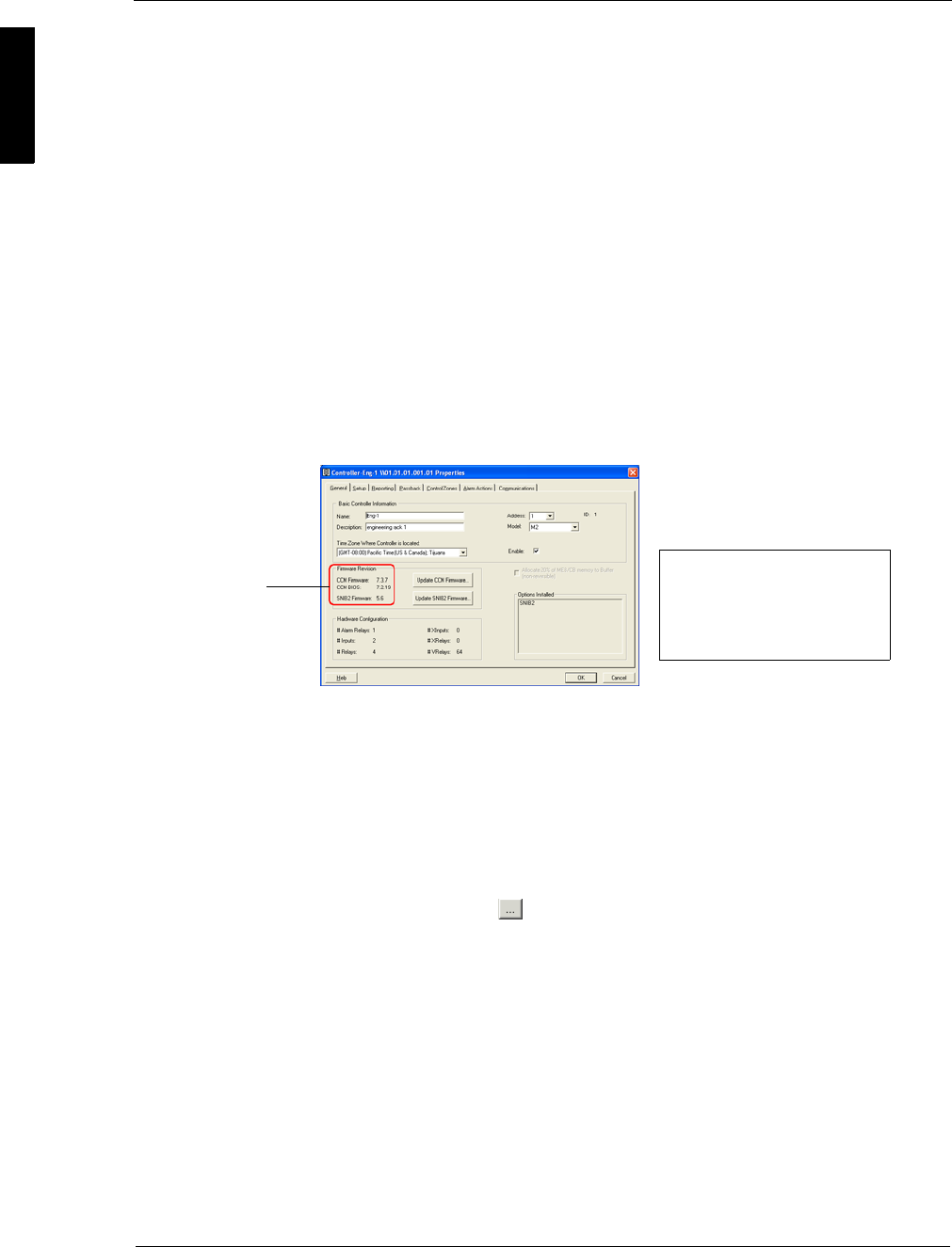
The simplest method is to check the General page of Controller Properties for the
specific controller in this way:
1. Expand the Velocity system tree until the selected controller appears.
2. Right click the selected controller and select Properties.
The CCM Firmware and CCM BIOS versions appear in the ‘Firmware Revision’
section of the General page like this example:
The second method requires use of Velocity’s Diagnostic Window. To do this:
1. From Velocity menu tool bar, select Help > Diagnostic Window.
The Diagnostic Window appears.
2. At the top of the window, click the red Diagnostic Stream button.
The button turns green.
3. From the ‘Controller’ pick list, select the appropriate controller.
4. From the ‘Diagnostics Command’ pick list, select 1 - Date, Time, Version
Number, then click the button to the right of this pick list.
The controller displays system information in the bottom pane. Look for the
following information and determine the BIOS level of your CCM:
1:24:40 PM 001:001:001 SNET Message 110 Current Date and Time is Thu
28-Oct-2004 13:25:19 (Regular)
1:24:40 PM 001:001:001 SNET Message 139 Device Info Device Type 3 M2
1:24:40 PM . ROM Sig. ffffffffffffffffx BIOS=7.2.19 Firmware
Date=20041027 Vn. 7.3.08
In this example, we ran CCM BIOS 7.2.19. (The Firmware version number may be
different from the BIOS number. Only determine the BIOS Level.)
5. If you are running BIOS Level 7.1.20 or higher you can use Velocity to flash your
CCM with 7.3.08 or higher.
You can find the latest CCM firmware in your ...\Velocity\Firmware subfolder.
Method 1
BIOS and CCM
version number
Notice that the Update buttons for
both CCM Firmware and SNIB2
Firmware are located on this page.
For more on using these buttons,
refer to Velocity Help.
Method 2
