A FreeCAD Manual
a-freecad-manual
a-freecad-manual
User Manual:
Open the PDF directly: View PDF ![]() .
.
Page Count: 181 [warning: Documents this large are best viewed by clicking the View PDF Link!]

1.1
1.2
1.2.1
1.2.2
1.2.2.1
1.2.2.2
1.2.2.3
1.2.2.4
1.2.2.5
1.2.2.6
1.2.3
1.2.3.1
1.2.3.2
1.2.3.3
1.2.4
1.2.4.1
1.2.4.2
1.2.4.3
1.2.5
1.2.6
1.2.7
1.3
1.3.1
1.3.2
1.3.3
1.3.4
1.3.5
1.3.5.1
1.3.5.2
1.3.5.3
TableofContents
Introduction
DiscoveringFreeCAD
WhatisFreeCAD?
Installing
InstallingonWindows
InstallingonLinux
InstallingonMacOS
Uninstalling
Settingbasicpreferences
Installingadditionalcontent
TheFreeCADinterface
Workbenches
Theinterface
Customizingtheinterface
Navigatinginthe3Dview
Awordaboutthe3Dspace
TheFreeCAD3Dview
Selectingobjects
TheFreeCADdocument
Parametricobjects
Importandexporttootherfiletypes
WorkingwithFreeCAD
Allworkbenchesataglance
Traditionalmodeling,theCSGway
Traditional2Ddrafting
Modelingforproductdesign
Preparingmodelsfor3Dprinting
Exportingtoslicers
Convertingobjectstomeshes
UsingSlic3r
2

1.3.5.4
1.3.5.5
1.3.6
1.3.7
1.3.8
1.3.8.1
1.3.8.2
1.3.9
1.3.10
1.4
1.4.1
1.4.1.1
1.4.1.2
1.4.1.3
1.4.2
1.4.3
1.4.4
1.5
UsingtheCuraaddon
GeneratingG-code
Generating2Ddrawings
BIMmodeling
Usingspreadsheets
Readingproperties
Writingproperties
CreatingFEManalyses
Creatingrenderings
Pythonscripting
Agentleintroduction
WritingPythoncode
ManipulatingFreeCADobjects
VectorsandPlacements
Creatingandmanipulatinggeometry
Creatingparametricobjects
Creatinginterfacetools
Thecommunity
3

AFreeCADmanual
Note:ThemanualhasbeenmovedtotheofficialFreeCADwikiwhichisnowitsnewhome.
If you wish to propose edits, please do them there, as thisrepository will be kept only for
generatingtheebookversionsandwillnotbedirectlyeditedanymore.
Introduction
FreeCADisafree,open-sourceparametric3Dmodelingapplication.Itismadeprimarilyto
modelreal-worldobjects,rangingfromthesmallelectroniccomponentsuptobuildingsand
civil engineering projects, with a strong focus on 3D-printable objects. FreeCAD is free to
download,use,distributeandmodify,anditssourcecodeisopenandpublishedunderthe
verypermissiveLGPLlicense.ThedatayouproducewithFreeCADisfullyyours,andcan
berecoveredwithoutFreeCAD.
FreeCAD is also fundamentally a social project, as it is developed and maintained by a
communityofdevelopersandusersunitedbytheirpassionforFreeCAD.
This manual is an experiment at taking the opposite way from the official FreeCAD
documentation wiki. The wiki is written collaboratively by dozens of community members
and,likemostwikis,itcontainshugeamountsofinformation,butisveryhardtoaccessand
navigate by newcomers. This makes it a precious resource for reference, but not a very
practical tool to learn FreeCAD. This manual will walk you through the same information
available on the wiki. However, we hope that the more step-by-step pace, based on
examples,andthemoreunifiedtonegivenbyasmallernumberofauthors,willmakeitmore
suitableforafirstcontactwithFreeCAD,andthatitwillbecomeaperfectcompanionforthe
wiki.
This manual has been written for the current stable version of FreeCAD which is version
0.16.
AllthecontentsofthismanualarepublishedundertheCreativeCommons4.0license,and
canbefreelyused,downloaded,copied,andmodified.Thesourcefilesofthismanualare
hostedongithub.
ThisbookhasbeenwrittenmostlybyYorik,butusingalotofinformationbuiltbyFreeCAD
users, mostly from the FreeCAD wiki. The real author of this book is actually the whole
FreeCADcommunity!
Introduction
4

Introduction
5

DiscoveringFreeCAD
DiscoveringFreeCAD
6
WhatisFreeCAD?
FreeCADisanopen-sourceparametric 3Dmodelingapplication,madeprimarilyto design
real-lifeobjects.Parametricmodelingdescribesacertaintypeofmodeling,wheretheshape
of the 3D objects you design are controlled by parameters. For example, the shape of a
brickmightbecontrolledbythreeparameters:height,widthandlength.InFreeCAD,asin
otherparametricmodelers,theseparametersarepartoftheobject,andstaymodifiableat
any time, after the object has been created. Some objects can have other objects as
parameters,forexampleyoucouldhaveanobjectthattakesourbrickasinput,andcreates
a column from it. You could think of a parametric object as a small program that creates
geometryfromparameters.
FreeCADisnotdesignedforaparticularkindofwork,ortomakeacertainkindofobjects.
Instead,itallowsawiderangeofuses,andpermitsuserstoproducemodelsofallsizesand
purposes, from small electronic components to 3D-printable pieces and all the way up to
buildings.Eachofthesetaskshavedifferentdedicatedsetsoftoolsandworkflowsavailable.
FreeCADisalsomultiplatform(itrunsexactlythesamewayonWindows,MacOSandLinux
platforms), and it is open-source. Being open-source, FreeCAD benefits from the
contributions and efforts of a large community of programmers, enthusiasts and users
worldwide.FreeCADisessentiallyanapplicationbuiltbythepeoplewhouseit,insteadof
being made by a company trying to sell you a product. And of course, it also means that
FreeCADisfree,notonlytouse,butalsotodistribute,copy,modify,orevensell.
WhatisFreeCAD?
7

FreeCADalsobenefitsfromthehuge,accumulatedexperienceoftheopen-sourceworld.In
its bowels, it includes several other open source components, as FreeCAD itself can be
usedasacomponentinotherapplications.Italsopossessesallkindsoffeaturesthathave
become a standard in the open-source world, such as supporting a wide range of file
formats,beinghugelyscriptable,customizableandmodifiable.Allmadepossiblethrougha
dynamicandenthusiastcommunityofusers.
TheofficialwebsiteofFreeCADisathttp://www.freecadweb.org
Readmore:
AboutFreeCAD:http://www.freecadweb.org/wiki/index.php?title=About_FreeCAD
Listoffeatures:http://www.freecadweb.org/wiki/index.php?title=Feature_list
Screenshotsandusercases:http://forum.freecadweb.org/viewforum.php?f=24
WhatisFreeCAD?
8

Installing
FreeCADusestheLGPLlicense,whichmeansyouarefreetodownload,install,redistribute
and use FreeCAD the way you want, regardless of the type of work you'll do with it
(commercialornon-commercial).Youarenotboundtoanyclauseorrestriction,andthefiles
youproducewithitarefullyyours.Theonlythingthatthelicenseprohibits,really,istoclaim
thatyouprogrammedFreeCADyourself!
FreeCADrunswithoutanydifferenceonWindows,MacOSandLinux.However,thewaysto
install it differ slightly depending on your platform. On Windows and Mac, the FreeCAD
community provides precompiled packages (installers) ready to download, while on Linux,
the source code is made available to Linux distributions maintainers, who are then
responsibleforpackagingFreeCADfortheirspecificdistribution.Asaresult,onLinux,you
canusuallyinstallFreeCADrightfromthesoftwaremanagerapplication.
The official FreeCAD download page for Windows and Mac OS is
https://github.com/FreeCAD/FreeCAD/releases
FreeCADversions
The official releases of FreeCAD, on the page above or in your distribution's software
manager,arestableversions.However,thedevelopmentofFreeCADisfast!Newfeatures
andbugfixesareaddedalmosteverysingleday.Sinceitcansometimestakealongtime
betweenstablereleases,youmightbeinterestedintryingamorebleeding-edgeversionof
FreeCAD.Thesedevelopmentversions,orpre-releases,areuploadedfromtimetotimeto
thedownloadpagementionedabove,or,ifyouareusingUbuntu,theFreeCADcommunity
also maintains PPA (Personal Package Archives) or 'daily builds' which are regularly
updatedwiththemostrecentchanges.
If you are installing FreeCAD in a virtual machine, please be aware that the performance
mightbelow,orinsomecasesunusableduetothelimitsofOpenGLsupportonmostvirtual
machines.
InstallingonWindows
1. Downloadaninstaller(.exe)packagecorrespondingtoyourversionofWindows(32bit
or64bit)fromthedownloadpage.TheFreeCADinstallersshouldworkonanywindows
versionstartingfromWindows7.
2. Double-clickthedownloadedinstaller.
3. AcceptthetermsoftheLGPLlicense(thiswillbeoneofthefewcaseswhereyoucan
really,safelyclickthe"accept"buttonwithoutreadingthetext.Nohiddenclauses):
Installing
9
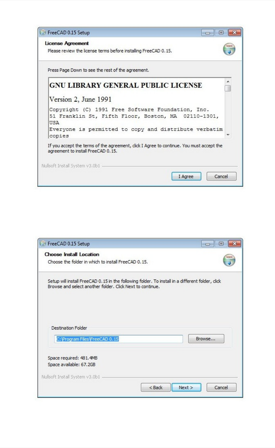
4. Youcanleavethedefaultpathhere,orchangeifyouwish:
5. NoneedtosetthePYTHONPATHvariable,unlessyouplantodosomeadvanced
Installing
10
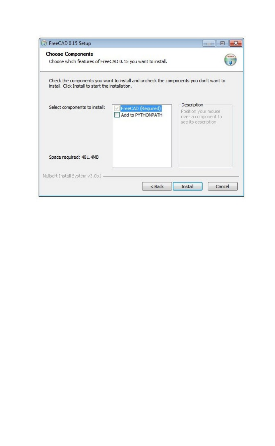
pythonprogramming,inwhichcaseyouprobablyalreadyknowwhatthisisfor:
6. Duringtheinstallation,acoupleofadditionalcomponents,whicharebundledinsidethe
installer,willbeinstalledtoo:
Installing
11
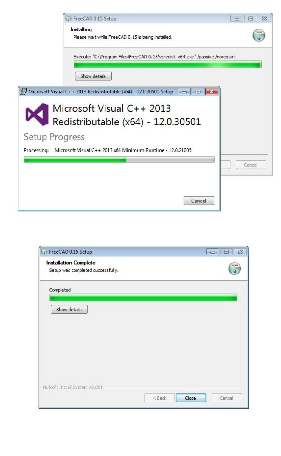
7. That'sit,FreeCADisinstalled.Youwillfinditinyourstartmenu.
Installingadevelopmentversion
Installing
12
PackagingFreeCAD andcreatingan installertakes sometime and dedication,so usually,
development(alsocalledpre-release)versionsareprovidedas.zip(or.7z)archives.These
don't need to be installed, just unpack them and lauch FreeCAD by double-clicking the
FreeCAD.exefilethatyouwillfindinside.Thisalsoallowsyoutokeepboththestableand
"unstable"versionstogetheronthesamecomputer.
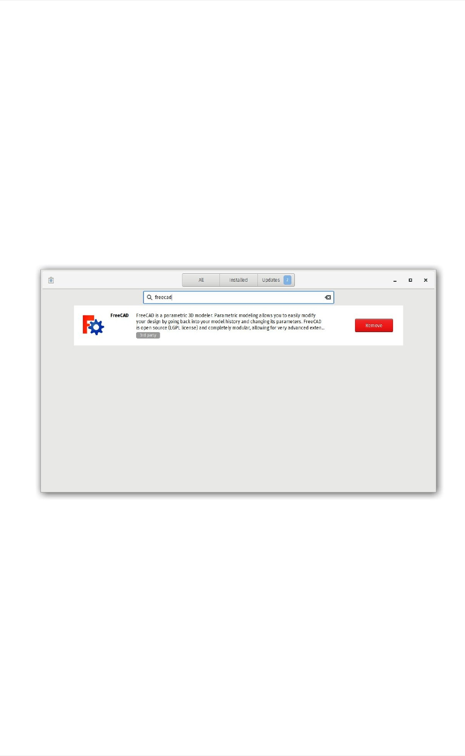
InstallingonLinux
On most modern Linux distributions (Ubuntu, Fedora, OpenSUSE, Debian, Mint,
Elementary, etc), FreeCAD can be installed with the click of a button, directly from the
software management application provided by your distribution (the aspect of it can differ
fromtheimagesbelow,eachdistributionusesitsowntool).
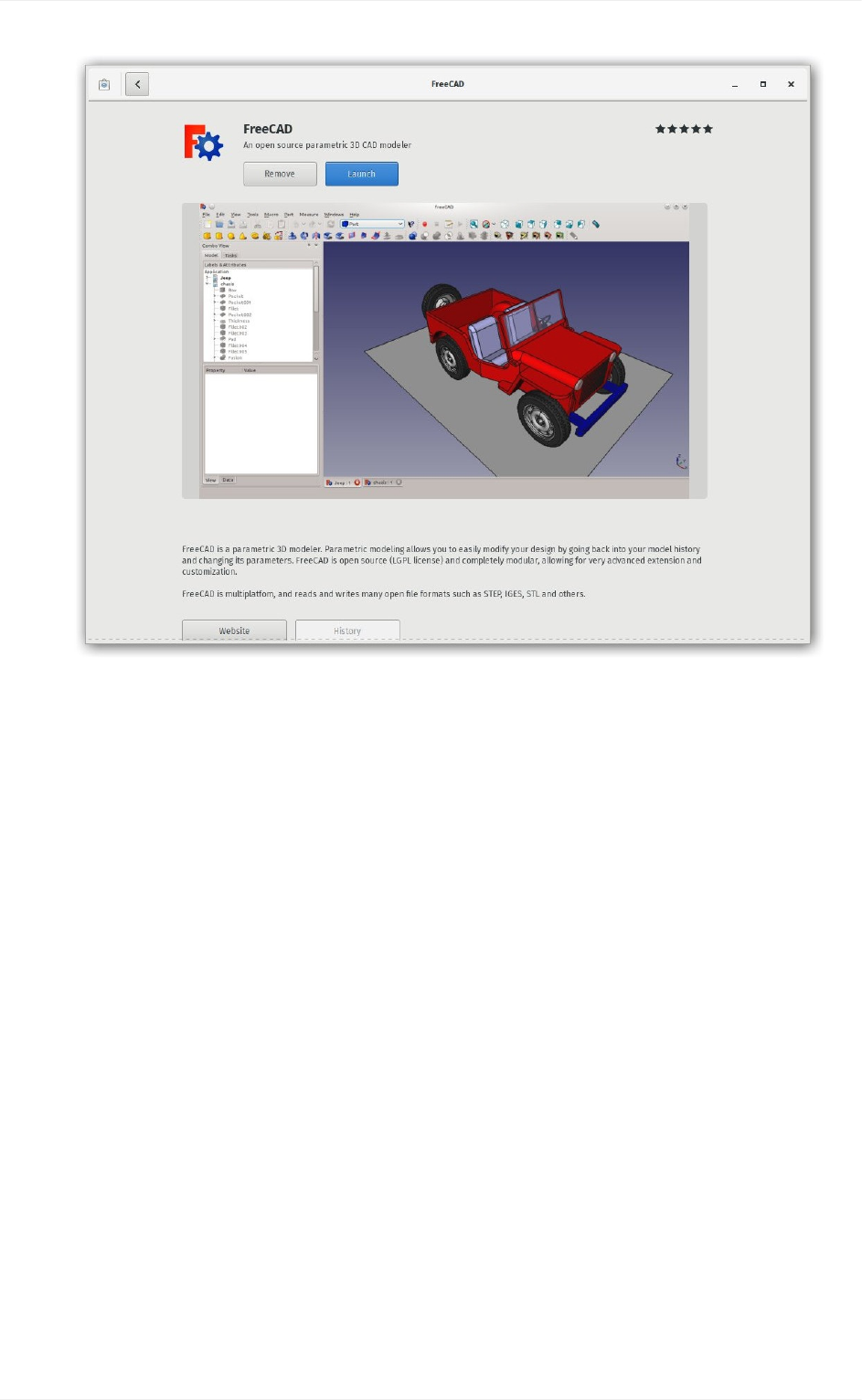
1. Openthesoftwaremanagerandsearchfor"freecad":
2. Clickthe"install"buttonandthat'sit,FreeCADgetsinstalled.Don'tforgettorateit
afterwards!
Installing
13
Alternativeways
OneofthebigjoysofusingLinuxisthemultitudeofpossibilitiestotailoryoursoftware,so
don't restrain yourself. On Ubuntu and derivatives, FreeCAD can also be installed from a
PPA maintained by the FreeCAD community (it contains both stable and development
versions) and since this is open-source software, you can also easily compile FreeCAD
yourself.
InstallingonMacOS
InstallingFreeCADonMacOSXisnowadaysaseasyasonotherplatforms.However,since
therearelesspeopleinthecommunitywhoownaMac,theavailablepackagesoftenlaga
coupleofversionsbehindtheotherplatforms.
1. Downloadazippedpackagecorrespondingtoyourversionfromthedownloadpage.
2. OpentheDownloadsfolder,andexpandthedownloadedzipfile:
Installing
14
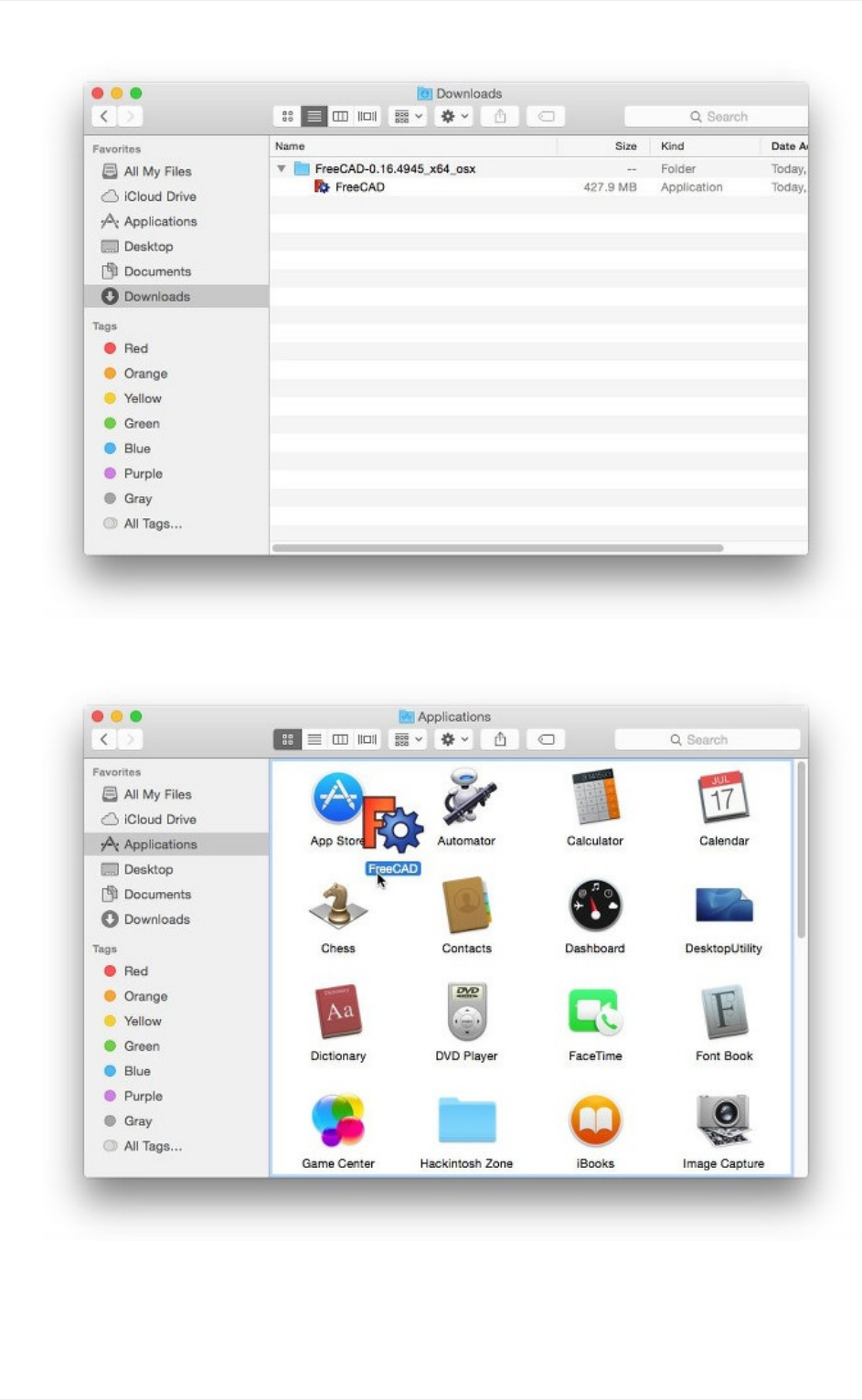
3. DragtheFreeCADapplicationfrominsidetheziptotheApplicationsfolder:
4. That'sit,FreeCADisinstalled!
Installing
15
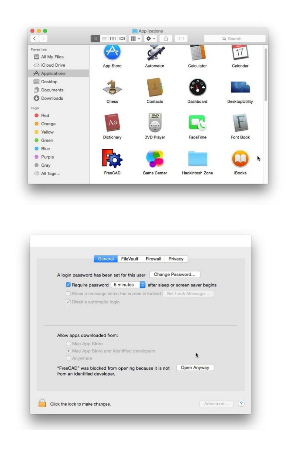
5. IfthesystempreventsFreeCADtolaunch,duetorestrictedpermissionsforapplications
notcomingfromtheAppstore,youwillneedtoenableitinthesystemsettings:
Installing
16

Uninstalling
Hopefullyyouwon'twanttodothat,butitisgoodtoknowanyway.OnWindowsandLinux,
uninstalling FreeCAD is very straightforward. Use the standard "remove software" option
foundinthecontrol panelonWindows,or removeitwiththe samesoftwaremanageryou
used to install FreeCAD on Linux. On Mac, all you need to do is remove it from the
Applicationsfolder.
Settingbasicpreferences
Once FreeCAD is installed, you might want to open it and set a couple of preferences.
Preferences settings in FreeCAD are located under menu Edit -> Preferences. You can
browse through the different pages to see if there is anything else you would want to
change,buthereareacoupleofbasicones:
1. Language:FreeCADwillautomaticallypickthelanguageofyouroperatingsystem,but
youmightwanttochangethat.FreeCADisalmostfullytranslatedto5or6languages,
plusmanyothersthatareatthemomentonlypartiallytranslated.Youcaneasilyhelpto
translateFreeCAD.
Installing
17
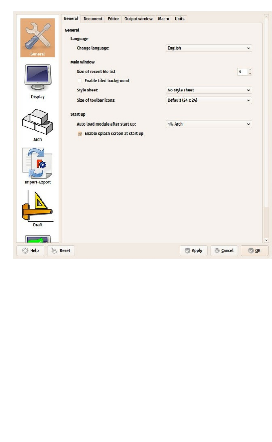
2. Auto-loadmodule:Normally,FreeCADwillstartshowingyouthestartcenterpage.
YoucanskipthisandbeginaFreeCADsessiondirectlyintheworkbenchofyour
choice.Workbencheswillbeexplainedindetailinthenextchapter.
3. Createdocumentatstartup:Combinedwiththeoptionabove,thisstartsFreeCAD
readyforwork.
Installing
18
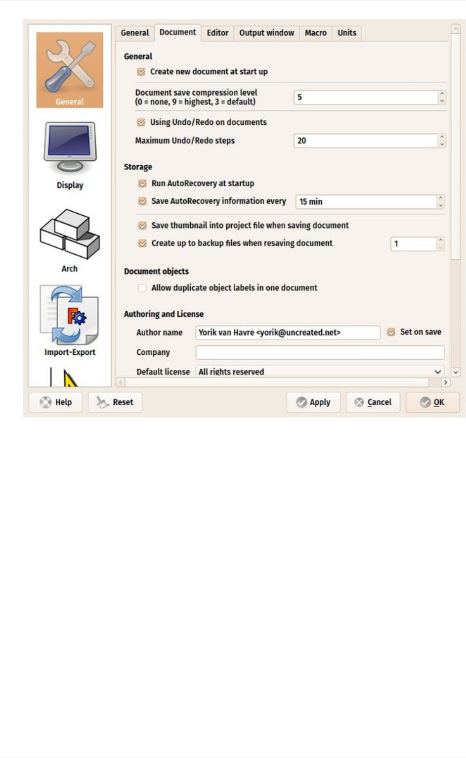
4. Storageoptions:Asanycomplexapplication,FreeCADmightcrashfromtimetotime.
Hereyoucanconfigureafewoptionsthatwillhelpyoutorecoveryourworkincaseofa
crash.
5. Authoringandlicense:Youcansetthedefaultsettingsthatwillbeusedforyournew
files.Considermakingyourfilesshareablerightfromthestart,byusingafriendlier,
copyleftlicenselikeCreativeCommons.
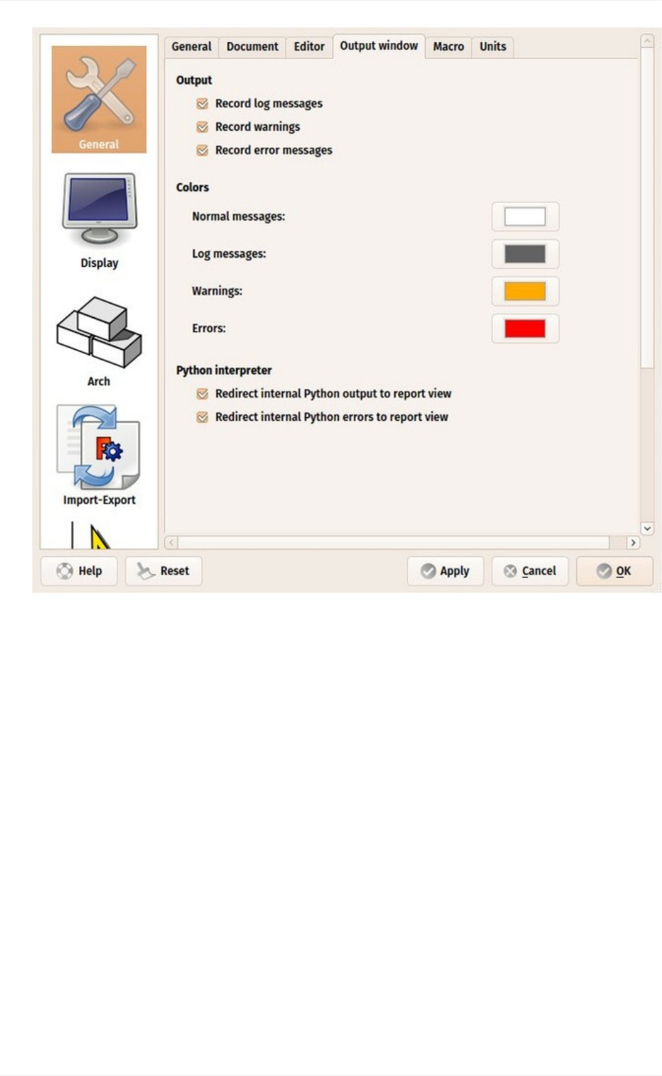
6. Redirectpythonmessagestooutputview:Thesetwooptionsarealwaysgoodto
mark,astheywillpermityoutoseewhat'swrongintheReportViewwhenthere'sa
problemwithrunningaparticularpythonscript.
Installing
19
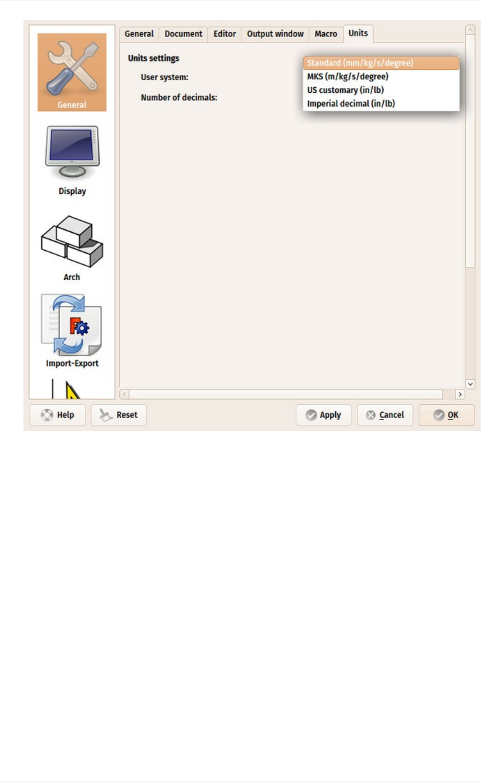
7. Units:Hereyoucansetthedefaultunitsyouwishtouse.Itwillbeeasierworkingthe
exampleslater,tostayinMKS.
Installing
20
Installingadditionalcontent
As the FreeCAD project and its community grows quickly, and also because it is easy to
extend, external contributions and side-projects made by community members and other
enthusiastsbegintoappeareverywhereontheinternet.Thereisaneffortgoingontogather
all these interesting additions in one place, on the FreeCAD github page. There, among
otherthings,youwillfind:
1. APartslibrary,whichcontainsallkindsofusefulmodels,orpiecesofmodels,created
byFreeCADusersthatcanbefreelyusedinyourprojects.Thelibrarycanbeusedand
accessedrightfrominsideyourFreeCADinstallation.
2. Acollectionofaddons,mostofthemadditionalworkbenches,thatextendthe
functionalityofFreeCADforcertaintasks.Instructionsforinstallingaregivenoneach
separateaddonpage.
3. Acollectionofmacros,whicharealsoavailableontheFreeCADwikialongwith
documentationabouthowtousethem.Thewikicontainsmanymoremacros.
Installing
21
IfyouareusingUbuntuoranyofitsderivatives,theFreeCAD-extrasPPAcontainsmostof
theseaddons.Onotherplatforms,anyoftheaddons,includingthePartslibrary,caneasily
beinstalledusinganaddon-installermacroprovidedintheaddonsrepository.Thefollowing
procedureshowshowtoinstalltheaddon-installer(othermacroscanbeinstalledthesame
way)
1. Downloadtheaddons-installer.FCMacrofilefrom
https://github.com/FreeCAD/FreeCAD-addonsbyclickingit,thenright-clickingthe
"RAW"button,andchoosing"Saveas".
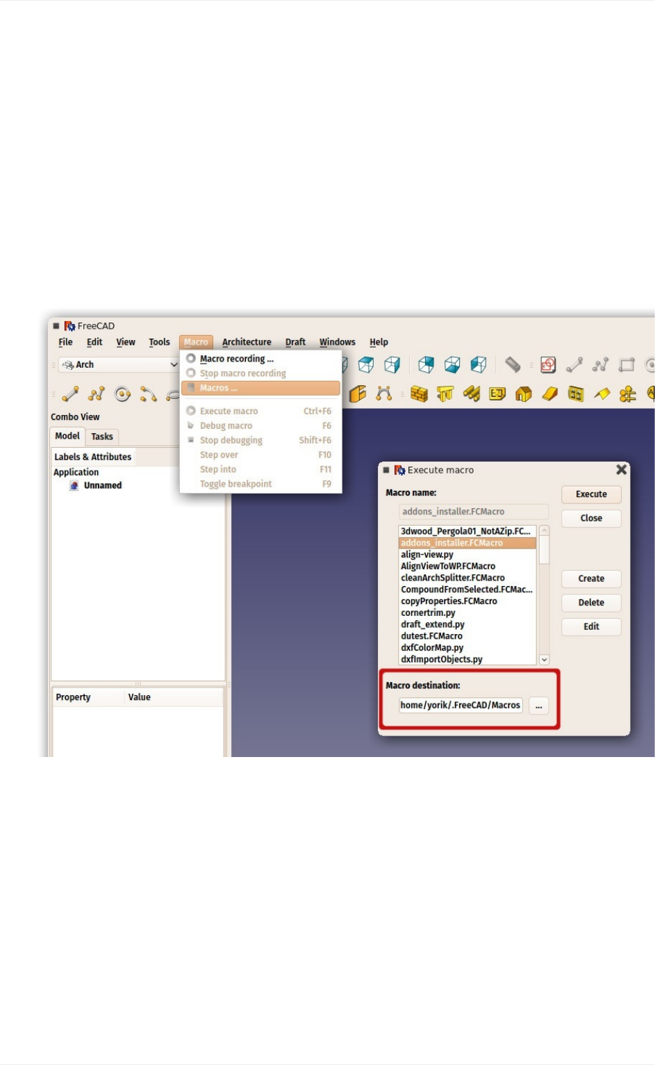
2. PlacethemacroinyourFreeCADMacrosdestinationpath.YouFreeCADMacros
destinationpathisindicatedatthebottomoftheExecutemacrodialoginFreeCAD:
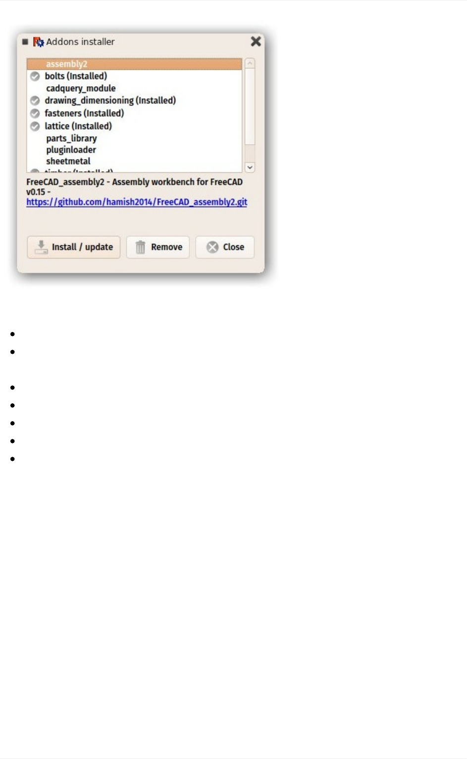
3. CloseandreopentheExecutemacrodialog,andstartthe
addons_installer.FCMacro.Theinstallerwilllaunch,fromwhereyoucaninstall,
updateanduninstallanyoftheaddons:
Installing
22
Readmore
Moredownloadoptions:http://www.freecadweb.org/wiki/index.php?title=Download
Detailedinstallationinstructions:http://www.freecadweb.org/wiki/index.php?
title=Installing
FreeCADPPAforUbuntu:https://launchpad.net/~freecad-maintainers
FreeCADaddonsPPAforUbuntu:https://launchpad.net/freecad-extras
CompileFreeCADyourself:http://www.freecadweb.org/wiki/index.php?title=Compiling
FreeCADtranslations:https://crowdin.com/project/freecad
FreeCADgithubpage:https://github.com/FreeCAD
Installing
23
TheFreeCADinterface
FreeCADusestheQtframework)todrawandmanageitsinterface.Thisframeworkisused
inawiderangeofapplications,sotheFreeCADinterfaceisveryclassicalandpresentsno
particular difficulty to understand. Most buttons are standard and will be found where you
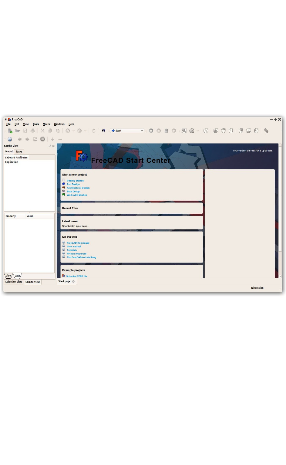
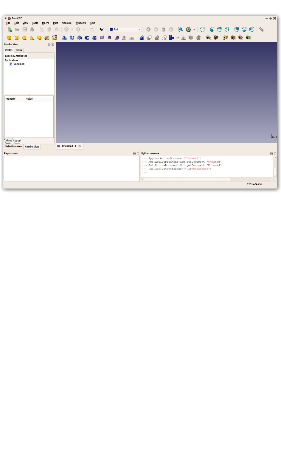
expectthem(File->Open,Edit->Paste,etc).HereisthelookofFreeCADwhenyouopen
itforthefirsttime,justafterinstalling,showingyouthestartcenter:
The start center is a convenient "welcome screen", that shows useful information for
newcomers, like the latest files you have been working on, what's new in the FreeCAD
world, or quick info about the most common Workbenches. It will also notify you if a new
stableversionofFreeCADisavailable.
ClosetheStartPage tab(clickonthetab xnearthebottom)and createanewdocument
(Ctrl-N):
TheFreeCADinterface
24
Workbenches
Notethatsomeoftheiconshavechangedbetweenthetwoscreencapturesabove.Thisis
where the most important concept used in the FreeCAD interface comes into play:
Workbenches.
Workbenchesaregroupoftools(toolbarbuttons,menus,andotherinterfacecontrols)that
are grouped together by specialty. Think of a workshop where you have different people
workingtogether:Apersonwhoworkswithmetal,anotherwithwood.Eachofthemhas,in
their workshop, a separate table with specific tools for his/her job. However, they can all
workonthesameobjects.ThesamehappensinFreeCAD.
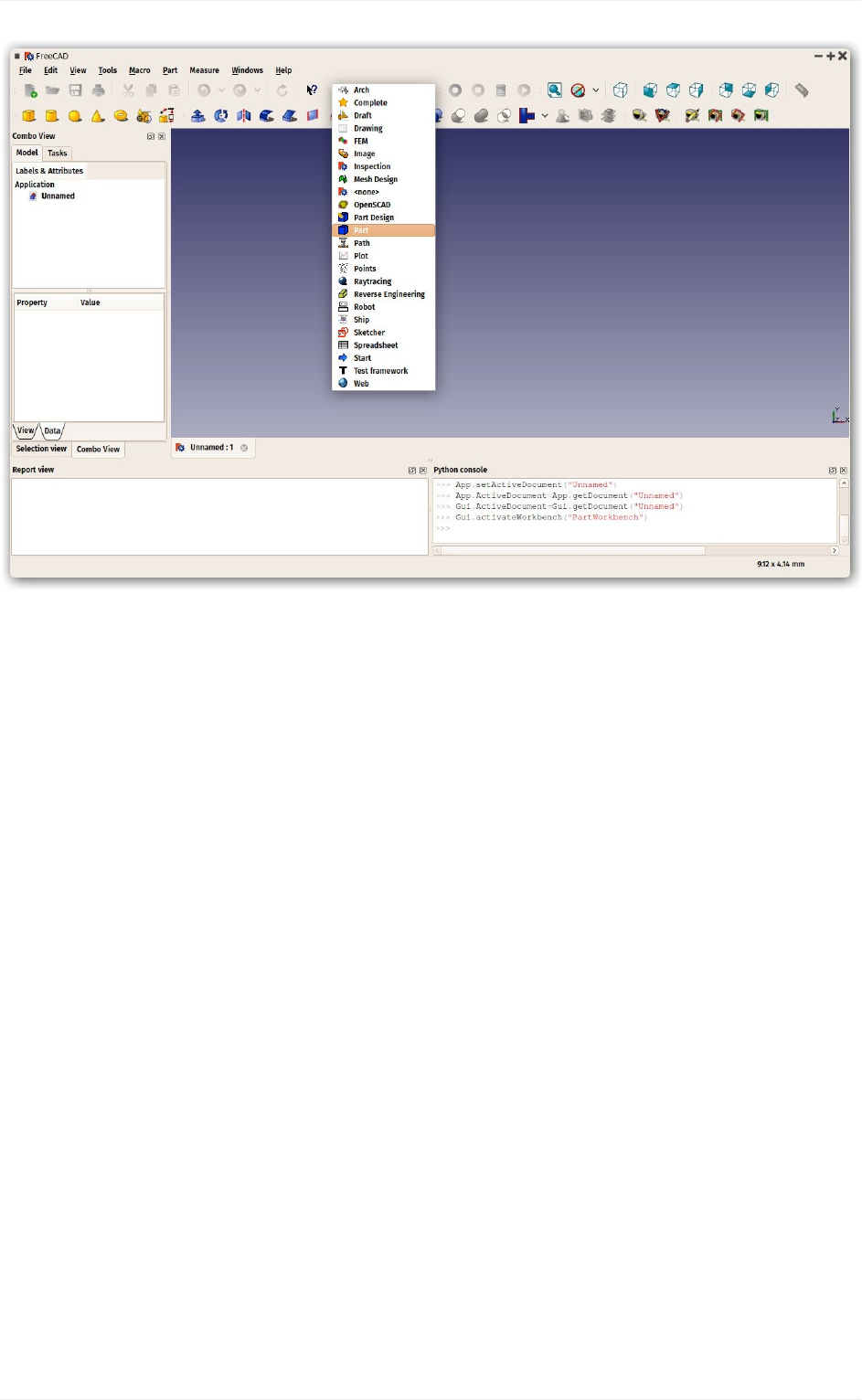
ThemostimportantcontroloftheFreeCADinterfaceistheWorkbenchselector,whichyou
usetoswitchfromoneWorkbenchtoanother:
TheFreeCADinterface
25
Workbenches often confuse new users, since it's not always easy to know in which
Workbench to look for a specific tool. But they are quick to learn, and after a short while,
they will feel natural. New users quickly realize Workbenches are a convenient way to
organizethemultitudeoftoolsFreeCADhastooffer.Inaddition,Workbenchesarealsofully
customizable(seebelow).
Laterinthismanual,youwillfindatableshowingtypicalWorkbenchcontents.
Theinterface
Let'shaveabetterlookatthedifferentpartsoftheinterface:
TheFreeCADinterface
26
The3Dviewisthemaincomponentoftheinterface.Itcanbeundockedoutofthemain
window,youcanhaveseveralviewsofthesamedocument(orsameobjects),or
severaldocumentsopenedatthesametime.Youcanselectobjectsorpartsofobjects
byclickingthem,andyoucanpan,zoomandrotatetheviewwiththemousebuttons.
Thiswillbeexplainedfurtherinthenextchapter.
Thecomboviewontheleftsideofthewindow,hastwotabs:
TheModeltabshowsyouthecontentsandstructureofyourdocument(seeabove)
andtheproperties(orparameters)oftheselectedobject(s)(seebelow.)These
ModelTabpropertiesareseparatedintwocategories:
Data(propertieswhichconcernthegeometryitself)
View(propertiesthataffecthowthegeometrylookslikeonscreen).
TheTaskstabiswhereFreeCADwillpromptyouforvaluesspecifictothetool
you'recurrentlyusingatthetime—forexample,enteringa'length'valuewhenthe
Linetoolisbeingused.ItwillcloseautomaticallyafterpressingtheOK(orCancel)
button.Also,bydouble-clickingtherelatedobjectinthecomboview,mosttoolswill
allowyoutoreopenthattaskpanelinordertomodifythesettings.
Thereportviewisnormallyhidden,butitisagoodideatoleaveopenasitwilllistany
information,warningsorerrorstohelpyoudecipher(ordebug)whatyoumayhave
donewrong.(Viewmenu->Panels->ReportViewchecked)
ThePythonconsoleisalsohiddenbydefault.Thisiswhereyoucaninteractwiththe
contentsofthedocumentusingthePythonlanguage.Sinceeveryactionyoudoonthe
FreeCADinterfaceactuallyexecutesapieceofPythoncode,havingthisopenallows
youtowatchthecodeunfoldinrealtime—allowingyouawonderfulandeasywayto
TheFreeCADinterface
27
learnalittlePythonontheway,almostwithoutnoticingit.(Viewmenu->Panels->
PythonConsolechecked)
Anyofthepanelsabovecanbeturnedon/offfrommenuView->Panels.
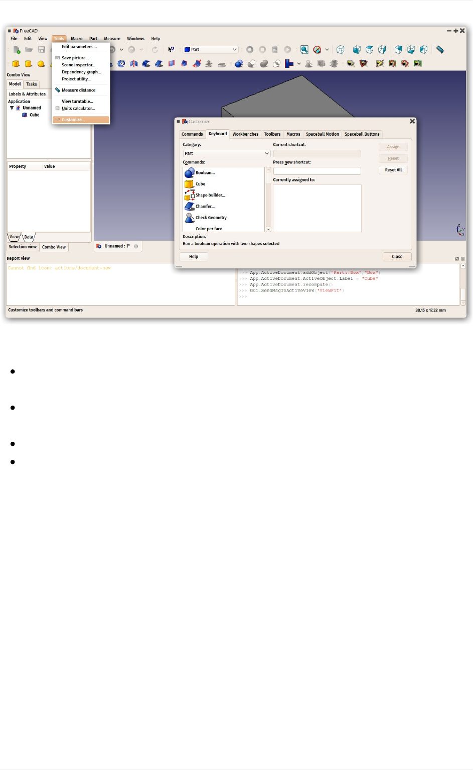
Customizingtheinterface
TheinterfaceofFreeCADisdeeplycustomizable.Allpanelsandtoolbarscanbemovedto
differentplacesorstackedonewithanother.Theycanalsobeclosedandreopenedwhen
neededfromtheViewmenuorbyright-clickingonanemptyareaoftheinterface.Thereare,
however,manymoreoptionsavailable,suchascreatingcustomtoolbarswithtoolsfromany
oftheWorkbenches,orassigningandchangingkeyboardshortcuts.
TheseadvancedcustomizationoptionsareavailabefromtheTools->Customizemenu:
TheFreeCADinterface
28
Readmore
GettingstartedwithFreeCAD:http://www.freecadweb.org/wiki/index.php?
title=Getting_started
Customizingtheinterface:http://www.freecadweb.org/wiki/index.php?
title=Interface_Customization
Workbenches:http://www.freecadweb.org/wiki/index.php?title=Workbenches
MoreaboutPython:https://www.python.org
TheFreeCADinterface
29
Navigatinginthe3Dview
Awordaboutthe3Dspace
Ifthisisyourfirstcontactwitha3Dapplication,youwillneedtograbsomeconceptsfirst.If
not,youcansafelyskipthissection.
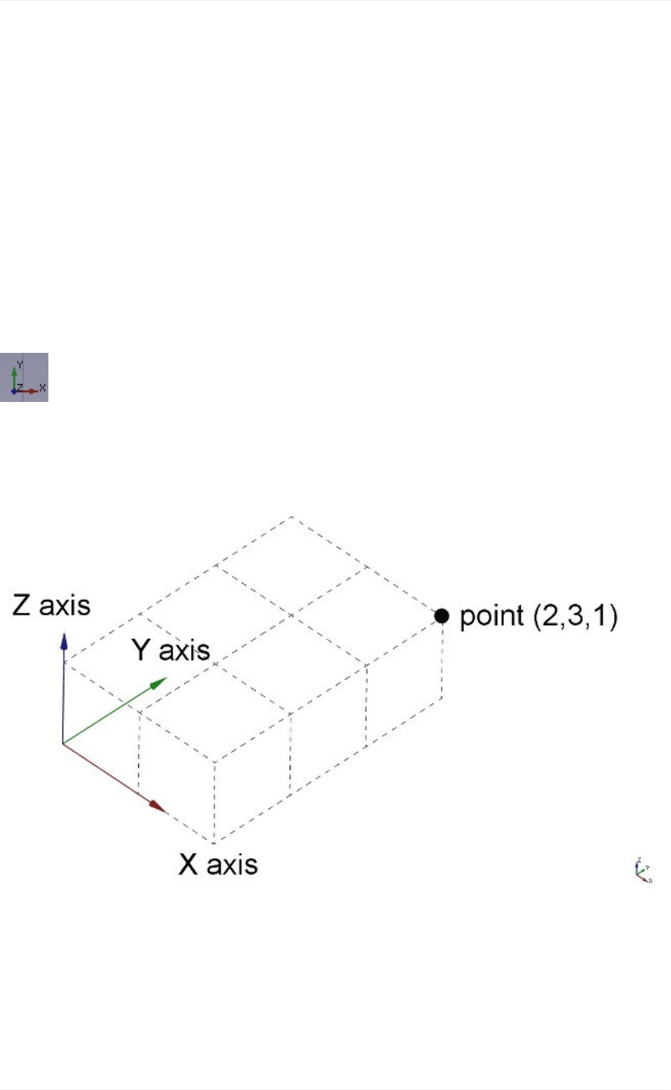
TheFreeCAD3Dspace isaneuclidianspace. Ithas an originpoint andthree axes:X, Y
andZ.Ifyoulookatyourscenefromabove,conventionally,theXaxispointstotheright,the
Yaxistotheback,andtheZaxisupwards.InthelowerrightcorneroftheFreeCADview,
youcanalwaysseefromwhereyouareviewingthescene:
Everypointofeveryobjectthatexistsinthatspacecanbelocatedbyits(x,y,z)coordinates.
Forexample,apointwithcoordinates(2,3,1)willlieat2unitsontheXaxis,3unitsontheY
axis,and1unitontheZaxis:
Youcanlookatthatscenefromanyangle,likeifyouwereholdingacamera.Thatcamera
canbemovedleft,right,upanddown(pan),rotatedaroundwhatitislookingat(rotate)and
broughtcloserorfurtherfromthescene(zoom).
TheFreeCAD3Dview
Navigatinginthe3Dview
30
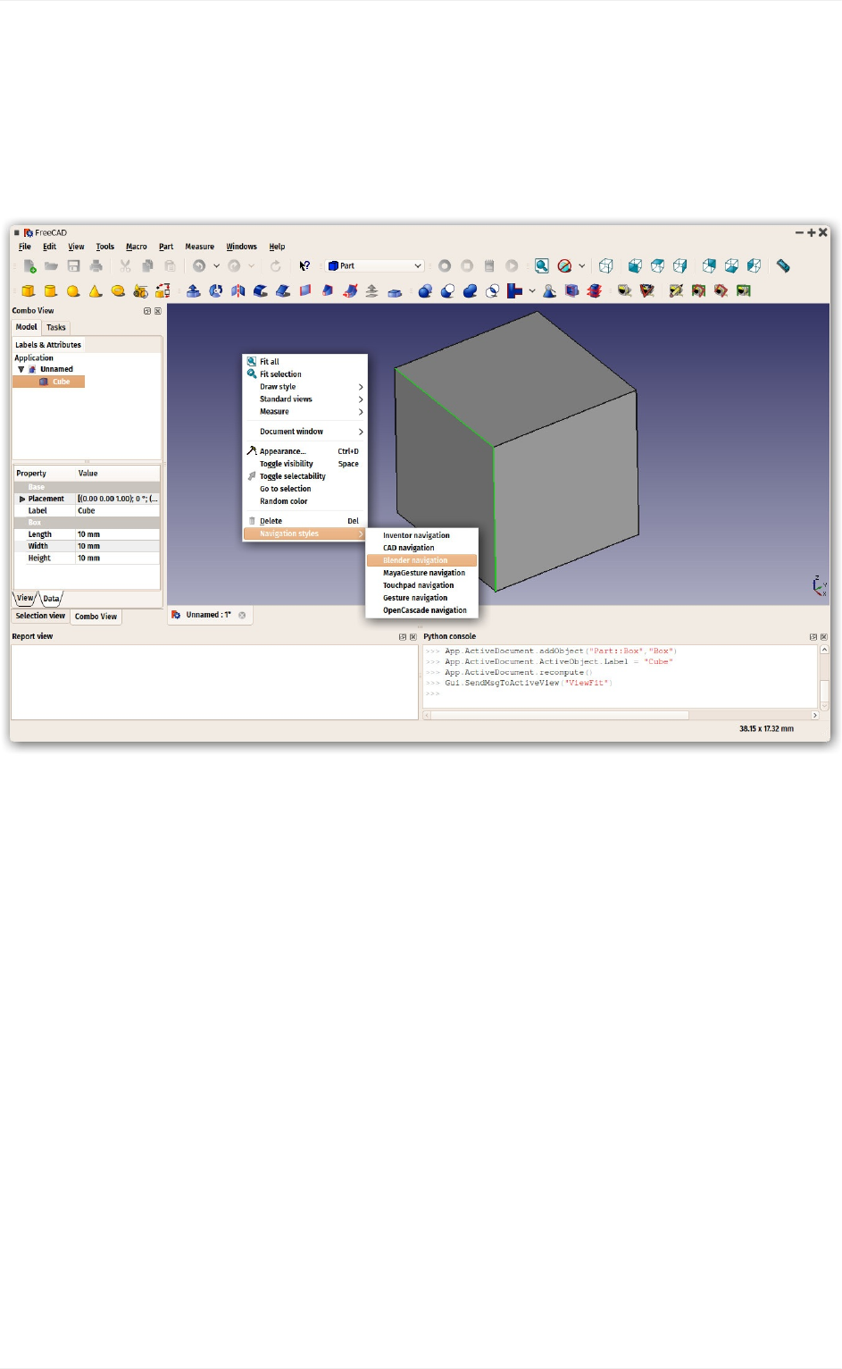
NavigatingintheFreeCAD3Dviewcanbedonewithamouse,aSpaceNavigatordevice,
thekeyboard,atouchpad,oracombinationofthose.FreeCADcanuseseveralnavigation
modes,whichdeterminehowthethreebasicviewmanipulationoperations(pan,rotateand
zoom) are done, as well as how to select objects on the screen. Navigation modes are
accessedfromthePreferencesscreen,ordirectlybyright-clickinganywhereonthe3Dview:
Eachofthesemodesattributesdifferentmousebuttons,ormouse+keyboardcombinations,
or mouse gestures, to these four operations. The following table shows the principal
availablemodes:
Navigatinginthe3Dview
31
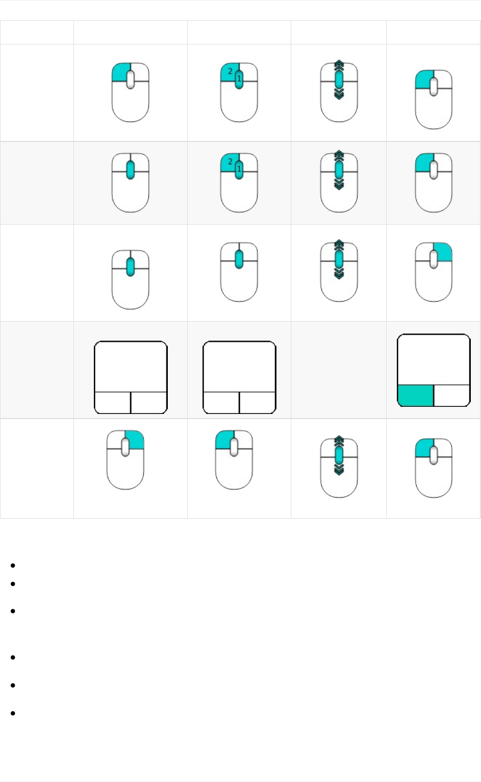
Mode Pan Rotate Zoom Select
Inventor
CTRL+
CAD
(default)
Blender
SHIFT+
Touchpad
SHIFT+ ALT+
PGUP/
PGDOWN
Gesture
+
DRAG
+
DRAG
Alternatively,somekeyboardcontrolsarealwaysavailable,nomatterthenavigationmode:
CTRL+andCTRL-tozoominandzoomout
Thearrowkeystoshift(pan)theviewleft/rightandup/down
thenumerickeys,1to6,forthesixstandardviews,top,front,right,bottom,backand
left
Owillsetthecamarainorthographicmode,
whilePsetsitinperspectivemode.
CTRLwillallowyoutoselectmorethanoneobjectorelement
ThesecontrolsarealsoavailablefromtheViewmenuandsomefromtheViewtoolbar.
Navigatinginthe3Dview
32
Selectingobjects
Objects in the 3D view can be selected by clicking them with the corresponding mouse
button, depending on the navigation mode. (For the rest of the manual we'll assume the
defaultCADnavigation.)Asingleclickwillselecttheobject,andoneofitssubcomponents
(edge, face, vertex). Double-clicking will select the object, and all its subcomponents. You
can select more than one subcomponent, or even different subcomponents from different
objects, by pressing the CTRL key. With multiple items selected, keeping the CTRL key
pressed, and pressing a selected item removes it from the selection. Clicking with the
selectionbuttononanemptyportionofthe3Dviewwilldeselecteverything.
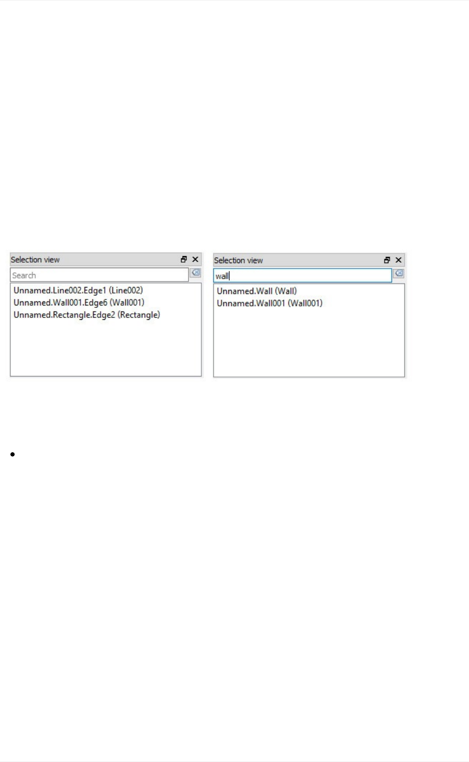
Apanelcalled"Selectionview",availablefromtheViewmenu,canalsobeturnedon,which
showsyouwhatiscurrentlyselected:
YoucanalsousetheSelectionViewtoselectobjectsbysearchingforaparticularobject.
Readmore
TheFreeCADnavigationmodes:http://www.freecadweb.org/wiki/index.php?
title=Mouse_Model
Navigatinginthe3Dview
33
TheFreeCADdocument
A FreeCAD document contains all the objects of your scene. It can contain groups and
objectsmadewithanyworkbench.Youcanthereforeswitchbetweenworkbenches,andstill
work on the same document and/or objects within that document. The document is what
getssavedtodiskwhenyousaveyourwork.Youcanalsoopenseveraldocumentsatthe
sametimeinFreeCAD,andopenseveralviewsofthesamedocument.
Inside the document, the objects can be moved into groups, and have a unique name.
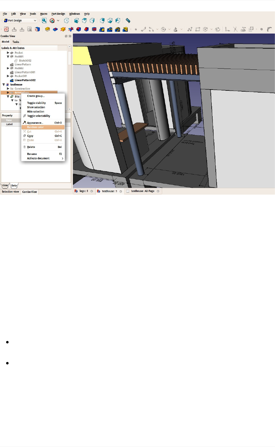
Managinggroups,objectsandobjectnamesisdonemainlyfromtheTreeview.There,you
cancreategroups,moveobjectstogroups,deleteobjectsorgroups.Byright-clickinginthe
treevieworonanobject,youcanrenameobjects,changetheircolor,hideorshowthem,or
possiblyotheroperations,dependingonthecurrentworkbench.
TheFreeCADdocument
34
TheobjectsinsideaFreeCADdocumentcanbeofdifferenttypes.Eachworkbenchcanadd
its own types of objects, for example the Mesh Workbench adds mesh objects, the Part
WorkbenchaddsPartobjects,etc.
Thereisalwaysoneandonlyoneactivedocument.That'sthedocumentthatappearsinthe
current3Dview,the documentyouarecurrently workingon.Ifyou switchtabstoanother
document, that one becomes the active document. Most operations always work on the
activedocument.
FreeCADdocumentsaresavedwiththe.FcStdextension,whichisazip-basedcompound
format,similartoLibreOffice. If something goes very wrong, it is often possible to unzip it
andfixtheproblemorrescuethedata.
Readmore
TheFreeCADdocument:http://www.freecadweb.org/wiki/index.php?
title=Document_structure
TheFcStdfileformat:http://www.freecadweb.org/wiki/index.php?
title=File_Format_FCStd
TheFreeCADdocument
35

Parametricobjects
FreeCAD is designed for parametric modeling. This means that the geometry that you
create, instead of being freely sculptable, is produced by rules and parameters. For
example, a cylinder might be produced from a radius and a height. With these two
parameters,theprogramhasenoughinformationtobuildthecylinder.
Parametricobjects,inFreeCAD,areinrealitysmallpiecesofaprogramthatrunwhenever
oneoftheparametershaschanged.Objectscanhavealotofdifferentkindsofparameters:
numbers (integers like 1, 2, 3 or floating-point values like 3.1416), real-world sizes (1mm,
2.4m,4.5ft),(x,y,z)coordinates,textstrings("hello!")orevenanotherobject.
Thislasttypeallowsquicklybuildingcomplexchainsofoperations,eachnewobjectbeing
basedonapreviousone,addingnewfeaturestoit.
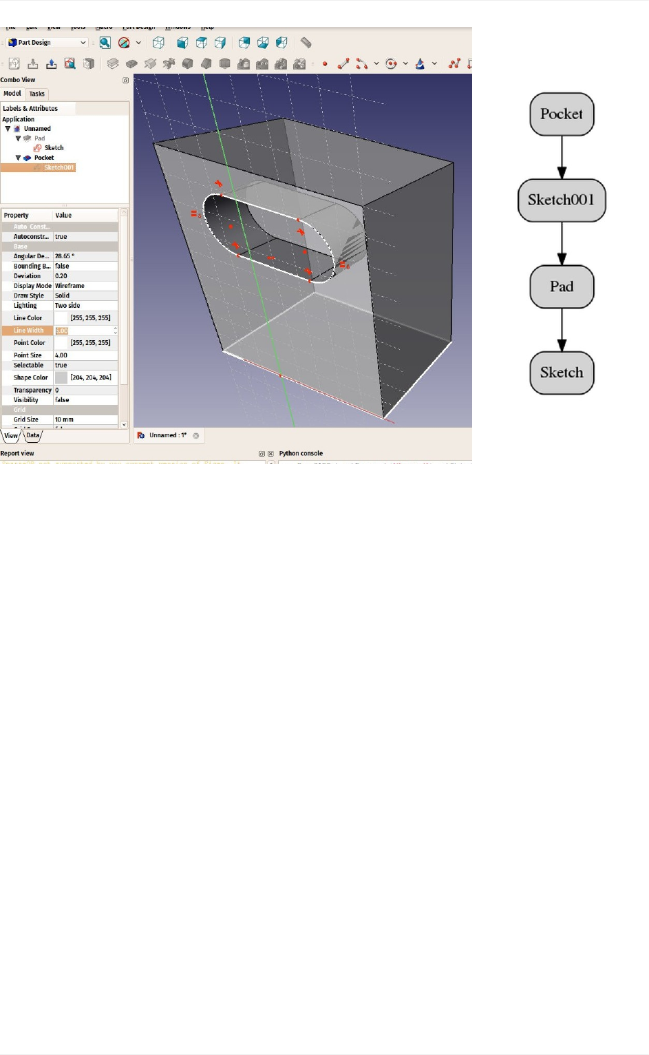
In the example below, a solid, cubic object (Pad) is based on a rectangular 2D shape
(Sketch)andhasanextrusiondistance.Withthesetwoproperties,itproducesasolidshape
byextrudingthebaseshapebythegivendistance.Youcanthenusethisobjectasabase
forfurtheroperations,suchasdrawinganew2Dshapeononeofitsfaces(Sketch001)and
thenmakingasubtraction(Pocket),untilarrivingatyourfinalobject.
Alltheintermediaryoperations(2Dshapes,pad,pocket,etc)arestillthere,andyoucanstill
change any of their parameters anytime. The whole chain will be rebuilt (recomputed)
wheneverneeded.
Parametricobjects
36
Twoimportantthingsarenecessarytoknow:
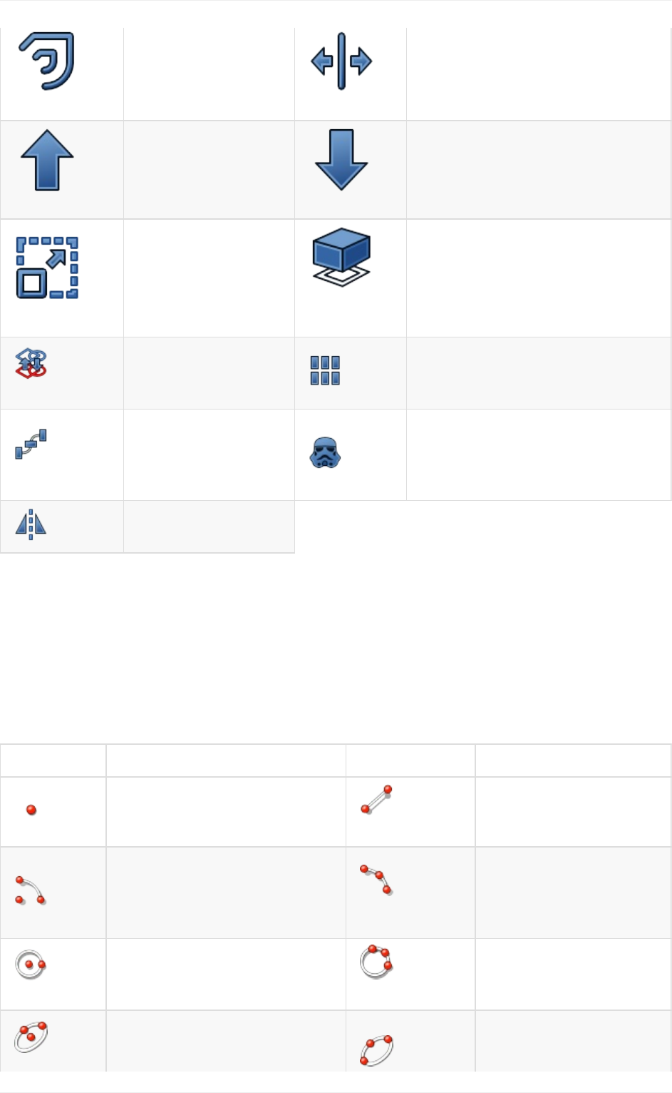
1. Recomputationisnotalwaysautomatic.Heavyoperations,thatmightmodifyabig
portionofyourdocument,andthereforetakesometime,arenotperformed
automatically.Instead,theobject(andalltheobjectsthatdependonit)willbemarked
forrecomputation(asmallblueiconappearsontheminthetreeview).Youmustthen
presstherecomputebutton(F5keyorthetwobluearrowspointingheadtotail)tohave
allthemarkedobjectsrecomputed.
2. Thedependencytreemustalwaysflowinthesamedirection.Loopsareforbidden.You
canhaveobjectAwhichdependsonobjectBwhichdependonobjectC.Butyou
cannothaveobjectAwhichdependsonobjectBwhichdependsonobjectA.That
wouldbeacirculardependency.However,youcanhavemanyobjectsthatdependon
thesameobject,forexampleobjectsBandCbothdependonA.MenuTools->
Dependencygraphshowsyouadependencydiagramliketheimageabove.Itcanbe
usefultodetectproblems.
NotallobjectsareparametricinFreeCAD.Often,thegeometrythatyouimportfromother
files won't contain any parameter, and will be simple, non-parametric objects. However,
thesecanoftenbe usedasabase,orstartingpointfor newlycreatedparametricobjects,
depending,ofcourse,onwhattheparametricobjectrequiresandthequalityoftheimported
geometry.
Parametricobjects
37

Allobjects,however, parametricor not,willhave acouple ofbasicparameters, suchasa
Name, which is unique in the document and cannot be edited, a Label, which is a user-
definednamethatcanbeedited,andaplacement,whichholdsitspositioninthe3Dspace.
Finally,itisworthnotingthatcustomparametricobjectsareeasytoprograminpython.
Readmore
Thepropertieseditor:http://www.freecadweb.org/wiki/index.php?title=Property_editor
Howtoprogramparametricobjects:http://www.freecadweb.org/wiki/index.php?
title=Scripted_objects
PositioningobjectsinFreeCAD:http://www.freecadweb.org/wiki/index.php?
title=Placement
Enablingthedependencygraph:http://www.freecadweb.org/wiki/index.php?
title=Std_DependencyGraph
Parametricobjects
38
Importandexporttootherfiletypes
FreeCADcanimportandexporttomanyfiletypes.Hereisalistofthemostimportantones
withashortdescriptionoftheavailablefeatures:
Format Import Export Notes
STEP Yes Yes
Thisisthemostfaithfulimport/exportformatavailable,
sinceitsupportssolidgeometryandNURBS.Useit
wheneverpossible.
IGES Yes Yes Anoldersolidformat,alsoverywellsupported.Some
olderapplicationsdon'tsupportSTEPbuthaveIGES.
BREP Yes Yes ThenativeformatofOpenCasCade,FreeCAD's
geometrykernel.
DXF Yes Yes
AnopenformatmaintainedbyAutodesk.Sincethe3D
datainsideaDXFfileisencodedinaproprietary
format,FreeCADcanonlyimport/export2Ddata
to/fromthisformat.
DWG Yes Yes
Aproprietaryfileformat.Requirestheinstallationof
theTeighaFileConverterutility.Thisformatsuffers
fromthesameproprietarylimitationsasDXF.
OBJ Yes Yes
Amesh-basedformat.Canonlycontaintriangulated
meshes.AllsolidandNURBS-basedobjectsof
FreeCADwillbeconvertedtomeshonexport.An
alternativeexporterisprovidedbytheArch
workbench,moresuitedtotheexportofarchitectural
models.
DAE Yes Yes
Themainimport/exportformatofSketchup.Canonly
containtriangulatedmeshes.AllsolidandNURBS-
basedobjectsofFreeCADwillbeconvertedtomesh
onexport.
STL Yes Yes
Amesh-basedformat,commonlyusedfor3Dprinting.
Canonlycontaintriangulatedmeshes.Allsolidand
NURBS-basedobjectsofFreeCADwillbeconverted
tomeshonexport.
PLY Yes Yes
Anoldermesh-basedformat.Canonlycontain
triangulatedmeshes.AllsolidandNURBS-based
objectsofFreeCADwillbeconvertedtomeshon
export.
IFC Yes Yes
IndustryFoundationClasses.Requirestheinstallation
ofIfcOpenShell-python.TheIFCformatandits
compatibilitywithotherapplicationsisacomplex
affair,usewithcare.
Importandexporttootherfiletypes
39
SVG Yes Yes Anexcellent,widespread2Dgraphicsformat
VRML Yes Yes Aratheroldmesh-basedwebformat.
GCODE Yes Yes
FreeCADcanimportandexportto/fromseveral
flavorsofGCode,(akaRS-274)butonlyasmall
numberofmachinesaresupportedatthemoment.
CSG Yes No OpenSCAD'sCSG(ConstructiveSolidGeometry)
format.
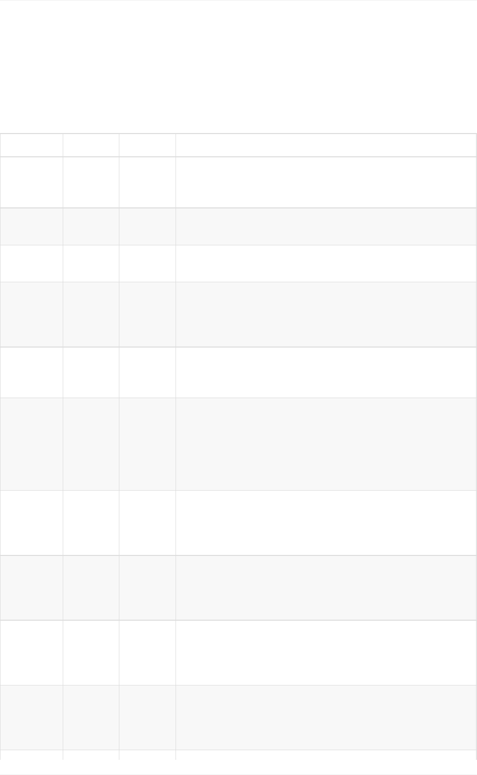
Some of these file formats have options. These can be configured from menu Edit ->
Preferences -> Import/export:
Readmore
AllfileformatssupportedbyFreeCAD:http://www.freecadweb.org/wiki/index.php?
title=Import_Export
WorkingwithDXFfilesinFreeCAD:http://www.freecadweb.org/wiki/index.php?
title=Draft_DXF
EnablingDXFandDWGsupport:http://www.freecadweb.org/wiki/index.php?
title=Dxf_Importer_Install
WorkingwithSVGfilesinFreeCAD:http://www.freecadweb.org/wiki/index.php?
title=Draft_SVG
Importandexporttootherfiletypes
40

ImportingandexportingtoIFC:http://www.freecadweb.org/wiki/index.php?
title=Arch_IFC
OpenCasCade:http://www.opencascade.com
TeighaFileConverter:https://www.opendesign.com/guestfiles
TheIFCformat:http://www.buildingsmart-tech.org/ifc/IFC4/final/html/index.htm
IfcOpenShell:http://ifcopenshell.org/
Importandexporttootherfiletypes
41

WorkingwithFreeCAD
WorkingwithFreeCAD
42

Allworkbenchesataglance
OneofthebiggestdifficultyfornewusersofFreeCAD,istoknowinwhichworkbenchtofind
aspecifictool.Thetablebelowwillgiveyouanoverviewofthemostimportantworkbenches
andtheir tools.Referto eachworkbench page inthe FreeCAD documentationfor a more
completelist.
Fourworkbenchesarealsodesignedtoworkinpairs,andoneofthemisfullyincludedinto
theother:ArchcontainsalltheDrafttools,andPartDesignalltheSketchertools.However,
forclarity,theyareseparatedbelow.
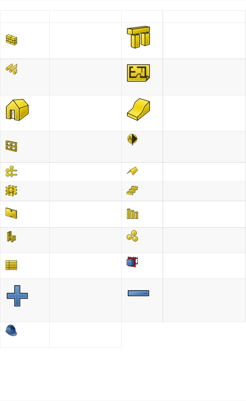
Part
The Part Workbench provides basic tools for working with solid parts: primitives, such as
cubeandsphere,andsimplegeometricoperationsandbooleanoperations.Beingthemain
anchorpointwithOpenCasCade,thePartworkbenchprovidesthefoundationofFreeCAD's
geometrysystem,andalmostallotherworkbenchesproducePart-basedgeometry.
Allworkbenchesataglance
43
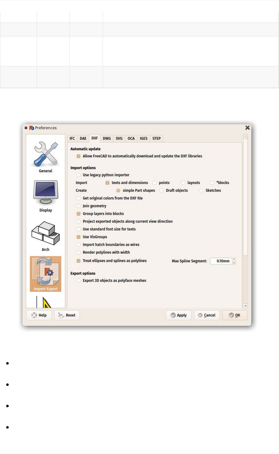
Tool Description Tool Description
Box Drawsabox
Cone
Drawsacone
Cylinder
Drawsacylinder
Sphere
Drawsasphere
Torus
Drawsatorus(ring) Create
Primitives
Createsvariousother
parametricgeometric
primitives
Shape
Builder
Createmorecomplex
shapesfromprimitives Fuse
Fuses(unions)twoobjects
Common
Extractsthecommon
(intersection)partoftwo
objects Cut
Cuts(subtracts)oneobject
fromanother
Join
Connect
Connectsinteriorsofwalled
objects Join
Embed
Embedsawalledobjectinto
anotherwalledobject
Join
Cutout
Createsacutoutinawall
ofanobjectforanother
walledobject Extrude
Extrudesplanarfacesofan
object
Fillet
Fillets(rounds)edgesofan
object Revolve
Createsasolidbyrevolving
anotherobject(notsolid)
aroundanaxis
Section
Createsasectionby
intersectinganobjectwith
asectionplane Section
Cross
Createsmultiplecross
sectionsalonganobject
Chamfer
Chamfersedgesofan
object Mirror
Mirrorstheselectedobject
onagivenmirrorplane
Ruled
Surface
Createaruledsurface
betweenselectedcurves Sweep
Sweepsoneormoreprofiles
alongapath
Loft
Loftsfromoneprofileto
another Offset
Createsascaledcopyofthe
originalobject
Thickness
Assignathicknesstothe
facesofashape
Allworkbenchesataglance
44
Draft
TheDraftWorkbenchprovidestoolstodobasic2DCADdraftingtasks:lines,circles,etc...
andaseriesofgenerichandytoolssuchasmove,rotateorscale.Italsoprovidesseveral
drawingaids, such asgrid and snapping.It is principallymeant to drawthe guidelines for
Archobjects,butalsoservesasFreeCAD's"swissknife".
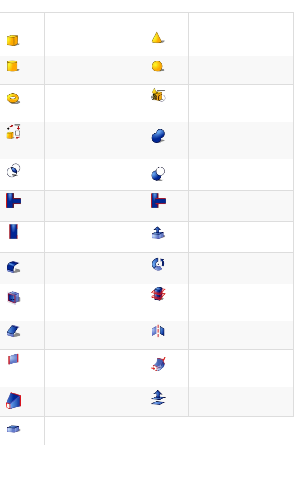
Tool Description Tool Description
Line
Drawsaline
segmentbetween2
points Wire
Drawsalinemadeofmultiple
linesegments(polyline)
Circle
Drawsacirclefrom
centerandradius
Arc
Drawsanarcsegmentfrom
center,radius,startangleand
endangle
Ellipse
Drawsanellipse
fromtwocorner
points Polygon
Drawsaregularpolygonfroma
centerandaradius
Rectangle
Drawsarectangle
from2opposite
points Text
Drawsamulti-linetext
annotation
Dimension
Drawsadimension
annotation
BSpline
DrawsaB-Splinefromaseries
ofpoints
Point
Insertsasingle
point Shape
String
TheShapeStringtoolinsertsa
compoundshaperepresentinga
textstringatagivenpointinthe
currentdocument
Facebinder
Createsanew
objectfrom
selectedfaceson
existingobjects
Bezier
Curve
DrawsaBeziercurvefroma
seriesofpoints
Move
Movesorcopies
objectsfromone
locationtoanother Rotate
Rotatesobjectsbyacertain
anglearoundapoint
Allworkbenchesataglance
45
Offset
Offsetsanobjectto
acertaindistance
Trimex
Trims,extendsorextrudesan
object
Upgrade
Turnsorjoins
objectsintoa
higher-levelobject Downgrade
Turnsorsepartesobjectsinto
lower-levelobjects
Scale
Scalesobjectsin
relationtoapoint Shape2D
View
Createsa2Dobjectwhichisa
flattenedviewofanotherobject
Draft2Sketch
ConvertsaDraft
objecttoaSketch
andvice-versa Array
Createsapolarorrectangular
arrayfromanobject
PathArray
Createsanarray
fromanobjectby
placingcopies
alongapath
Clone Createslinkedcopiesofobjects
Mirror
Mirrorsobjects
acrossaline
Sketcher
The Sketcher Workbench contains tools to build and edit complex 2D objects, called
sketches.Thegeometryinsidethesesketchescanbepreciselypositionedandrelationedby
the use of constraints. They are meant primarily to be the building blocks of PartDesign
geometry,butareusefuleverywhereinFreeCAD.
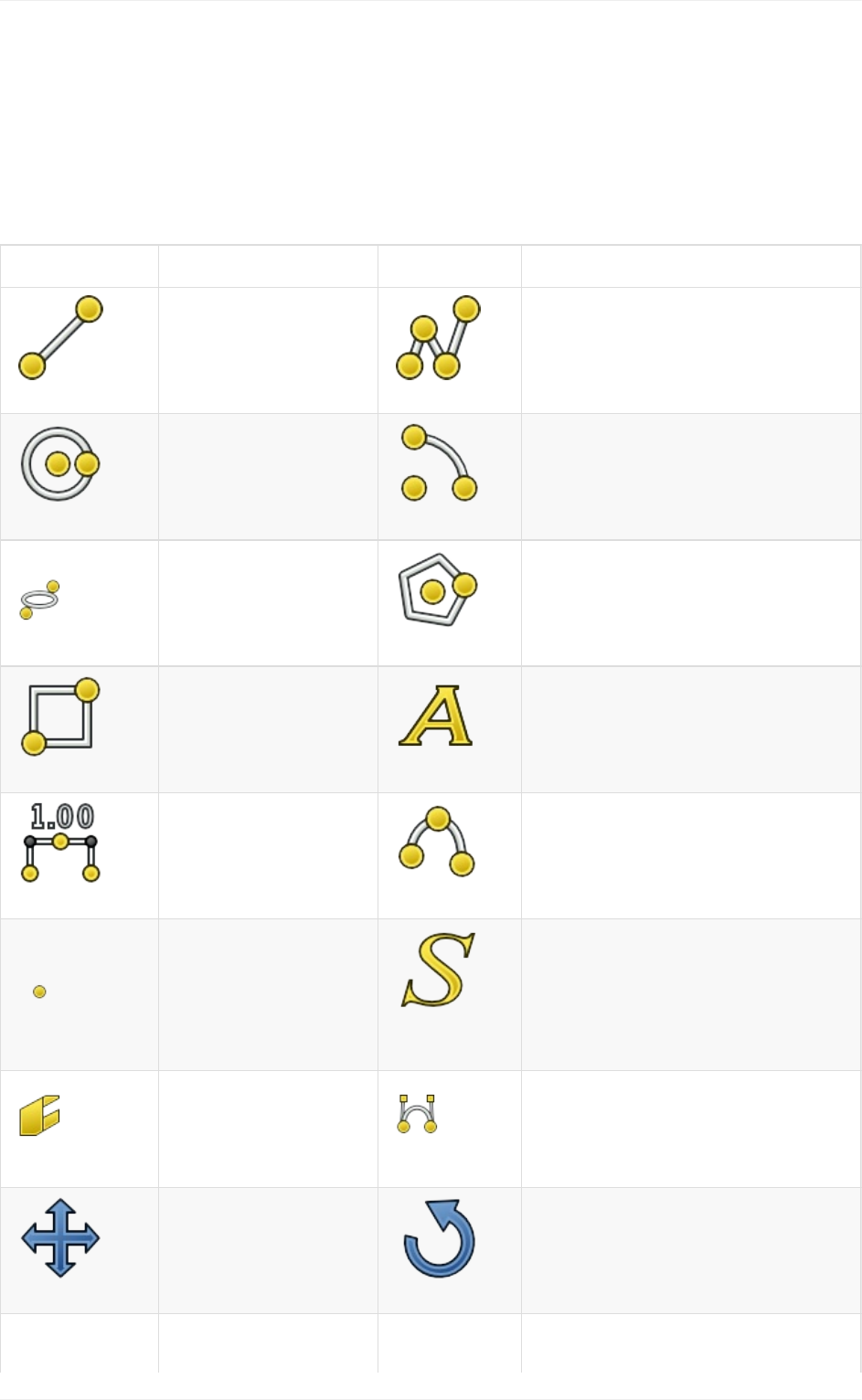
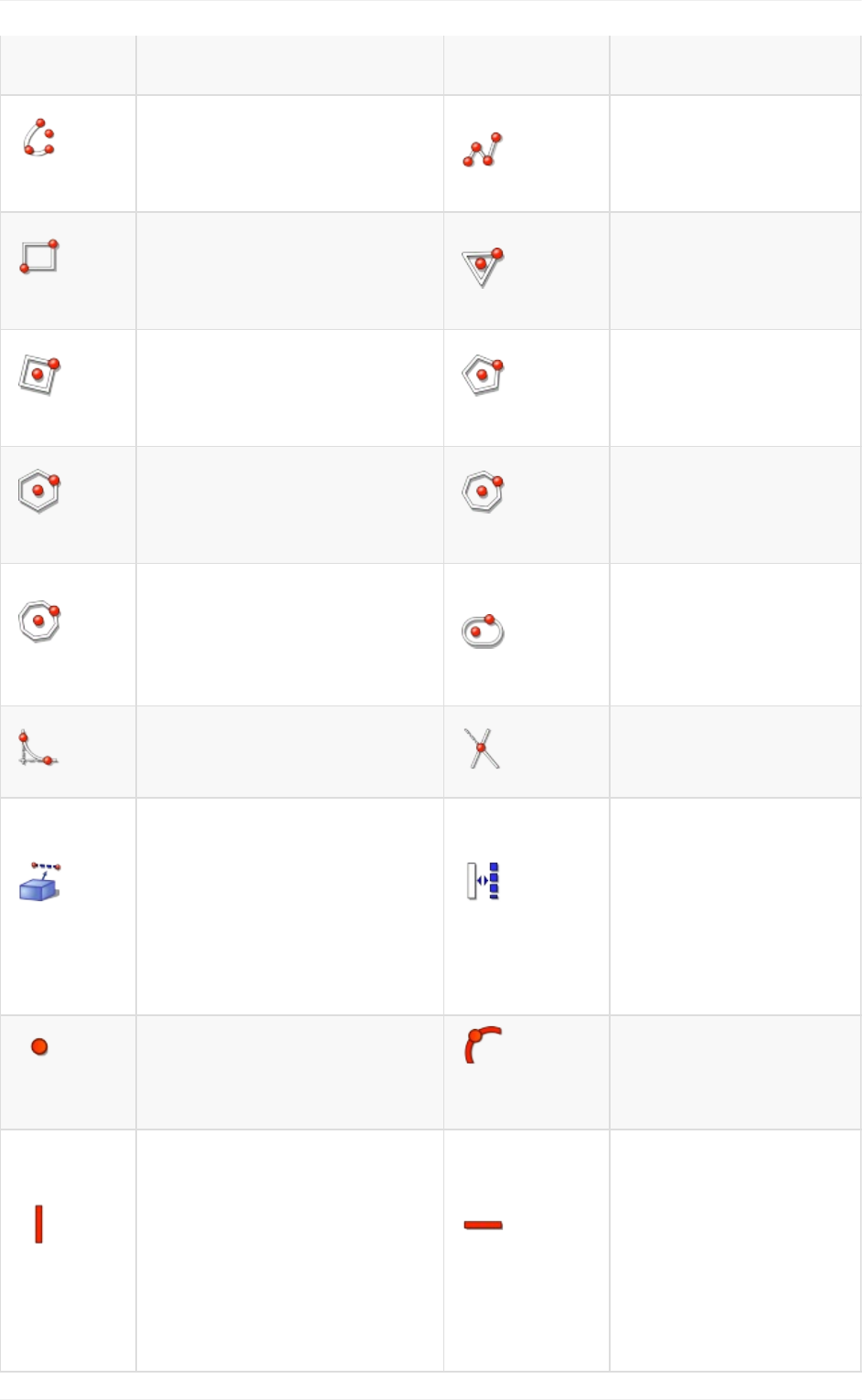
Tool Description Tool Description
Point Drawsapoint Lineby
2points
Drawsalinesegment
from2points
Arc
Drawsanarcsegmentfrom
center,radius,startangle
andendangle
Arcby3
points
Drawsanarcsegment
fromtwoendpoints
andanotherpointon
thecircumference
Circle
Drawsacirclefromcenter
andradius Circleby
3points
Drawsacirclefrom
threepointsonthe
circumference
Drawsanellipsebycenter
point,majorradiuspointand Ellipse
Drawsanellipseby
majordiameter(2
Allworkbenchesataglance
46
center minorradiuspoint by3points points)andminor
radiuspoint
Arc
ofellipse
Drawsanarcofellipseby
centerpoint,majorradius
point,startingpointand
endingpoint
Polyline
Drawsalinemadeof
multiplelinesegments.
Severaldrawing
modesavailable
Rectangle
Drawsarectanglefrom2
oppositepoints Triangle
Drawsaregular
triangleinscribedina
constructiongeometry
circle
Square
Drawsaregularsquare
inscribedinaconstruction
geometrycircle Pentagon
Drawsaregular
pentagoninscribedin
aconstruction
geometrycircle
Hexagon
Drawsaregularhexagon
inscribedinaconstruction
geometrycircle Heptagon
Drawsaregular
heptagoninscribedin
aconstruction
geometrycircle
Octagon
Drawsaregularoctagon
inscribedinaconstruction
geometrycircle Slot
Drawsanovalby
selectingthecenterof
onesemicircleandan
endpointoftheother
semicircle
Fillet
Makesafilletbetweentwo
linesjoinedatonepoint Trim
Trimsaline,circleor
arcwithrespecttoa
clickedpoint
External
Geometry
Createsanedgelinkedto
externalgeometry Construction
Mode
Togglesanelement
to/fromconstruction
mode.Aconstruction
objectwillnotbeused
ina3Dgeometry
operationandisonly
visiblewhileeditingthe
Sketchthatcontainsit
Coincident
constraint
Affixesapointonto
(coincidentwith)oneormore
otherpoints.
PointOn
Object
constraint
Affixesapointonto
anotherobjectsuchas
aline,arc,oraxis.
Vertical
constraint
Constrainstheselectedlines
orpolylineelementstoatrue
verticalorientation.More
thanoneobjectcanbe
selectedbeforeapplyingthis
constraint.
Horizontal
constraint
Constrainsthe
selectedlinesor
polylineelementstoa
truehorizontal
orientation.Morethan
oneobjectcanbe
selectedbefore
applyingthis
constraint.
Allworkbenchesataglance
47
constraint.
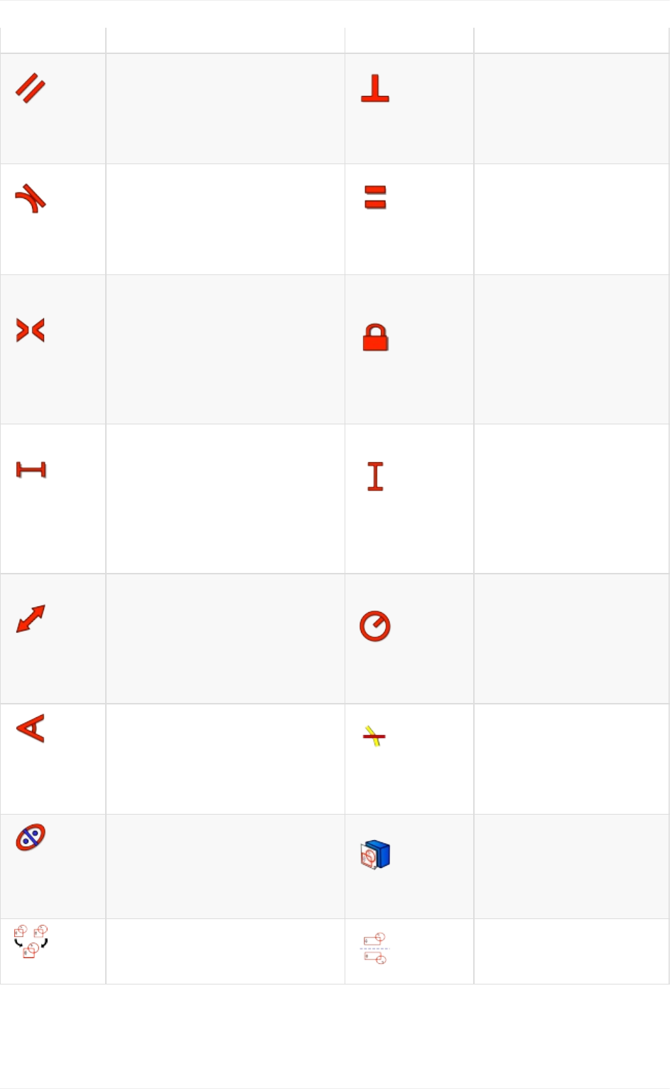
Parallel
constraint
Constrainstwoormorelines
paralleltooneanother. Perpendicular
constraint
Constrainstwolines
perpendiculartoone
another,orconstrains
alineperpendicularto
anarcendpoint.
Tangent
constraint
Createsatangentconstraint
betweentwoselected
entities,oraco-linear
constraintbetweentwoline
segments.
Equal
Length
constraint
Constrainstwo
selectedentitiesequal
tooneanother.Ifused
oncirclesorarcstheir
radiiwillbesetequal.
Symmetric
constraint
Constrainstwopoints
symmetricallyaboutaline,
orconstrainsthefirsttwo
selectedpoints
symmetricallyaboutathird
selectedpoint.
Lock
constraint
Constrainsthe
selecteditemby
settingverticaland
horizontaldistances
relativetotheorigin,
therebylockingthe
locationofthatitem
Horizontal
Distance
constraint
Fixesthehorizontaldistance
betweentwopointsorline
endpoints.Ifonlyoneitemis
selected,thedistanceisset
totheorigin.
Vertical
Distance
constraint
Fixesthevertical
distancebetween2
pointsorline
endpoints.Ifonlyone
itemisselected,the
distanceissettothe
origin.
Length
constraint
Definesthedistanceofa
selectedlinebyconstraining
itslength,ordefinesthe
distancebetweentwopoints
byconstrainingthedistance
betweenthem.
Radius
constraint
Definestheradiusofa
selectedarcorcircle
byconstrainingthe
radius.
Internal
Angle
constraint
Definestheinternalangle
betweentwoselectedlines.
Snell's
Law
constraint
Constrainstwolinesto
obeyarefractionlaw
tosimulatethelight
goingthroughan
interface
Internal
Alignment
constraint
Alignsselectedelementsto
selectedshape(e.g.alineto
becomemajoraxisofan
ellipse)
Map
sketchtoface
Mapsasketchtothe
previouslyselected
faceofasolid
Merge
Mergetwoormoresketches Mirror
Mirrorsselected
elementsofasketch
PartDesign
Allworkbenchesataglance
48
ThePartDesignWorkbenchcontainsadvancedtoolstobuildsolidparts.Italsocontainsall
thetoolsfromthesketcher.Sinceitcanonlyproducessolidshapes(therulenumberoneof
Part Design), it is the main workbench to use when designing pieces (parts) to be
manufacturedor3D-printed,asyouwillalwaysobtainaprintableobject.
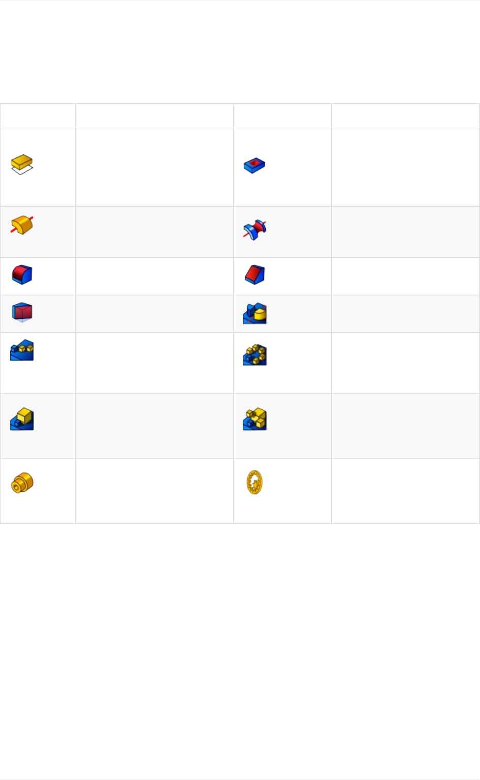
Tool Description Tool Description
Pad
Extrudesasolidobject
fromaselectedsketch Pocket
Createsapocketfroma
selectedsketch.The
sketchmustbemapped
toanexistingsolid
object'sface
Revolution
Createsasolidby
revolvingasketcharound
anaxis Groove
Createsagrooveby
revolvingasketch
aroundanaxis
Fillet
Fillets(rounds)edgesof
anobject Chamfer
Chamfersedgesofan
object
Draft
Appliesangulardraftto
facesofanobject Mirrored
Mirrorsfeaturesona
planeorface
Linear
Pattern
Createsalinearpatternof
features Polar
Pattern
Createsapolarpattern
offeatures
Scaled
Scalesfeaturestoa
differentsize MultiTransform
Allowscreatinga
patternwithany
combinationoftheother
transformations
Shaft
wizard
Generatesashaftfroma
tableofvaluesandallows
toanalyzeforcesand
moments
Involute
Gearwizard
Allowsyoutocreate
severaltypesofgears
Arch
The Arch Workbench contains tools to work with BIM projects (civil engineering and
architecture). It also contains all the tools from the Draft workbench. The main use of the
Arch Workbench is to create BIM objects or give BIM attributes to objects built with other
workbenches,inordertoexportthemtoIFC.
Allworkbenchesataglance
49
Tool Description Tool Description
Wall
Createsawallfrom
scratchorusinga
selectedobjectasa
base Structure
Createsastructural
elementfromscratchor
usingaselectedobjectas
abase
Reinforcement
Bar
Createsa
reinforcementbarina
selectedstructural
element Floor
Createsafloorincluding
selectedobjects
Building
Createsabuilding
includingselected
objects Site
Createsasiteincluding
selectedobjects
Window
Createsawindow
usingaselectedobject
asabase Section
Plane
Addsasectionplane
objecttothedocument
Axes
Addsanaxessystem
tothedocument Roof
Createsaslopedrooffrom
aselectedface
Space
Createsaspaceobject
inthedocument Stairs
Createsastairsobjectin
thedocument
Panel
Createsapanelobject
fromaselected2D
object Frame
Createsaframeobject
fromaselectedlayout
Equipment
Createsanequipment
orfurnitureobject Set
Material
Attributesamaterialto
selectedobjects
Schedule
Createsdifferenttypes
ofschedules Cut
Plane
Cutanobjectaccordingto
aplan.
Add
Component
Addsobjectstoa
component Remove
Component
Subtractsorremoves
objectsfromacomponent
Survey
Mode
Entersorleaves
surveyingmode
Drawing
Allworkbenchesataglance
50
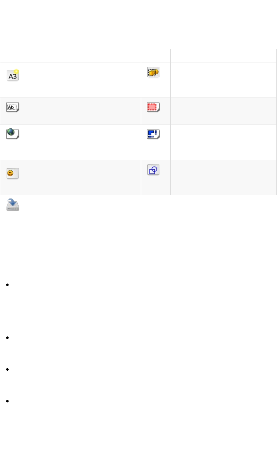
TheDrawingWorkbenchhandlesthecreationandmanipulationof2Ddrawingsheets,used
for displaying views of your 3D work in 2D. These sheets can then be exported to 2D
applicationsinSVGorDXFformats,toaPDFfileorprinted.
Tool Description Tool Description
New
sheet
Createsanewdrawing
sheet Insert
view
Insertsaviewoftheselected
objectintheactivedrawing
sheet
Annotation
Addsanannotationtothe
currentdrawingsheet Clip
Addsaclipgrouptothecurrent
drawingsheet
Browser
preview
Opensapreviewofthe
currentsheetinthebrowser Ortho
Views
Automaticallycreates
orthographicviewsofanobject
onthecurrentdrawingsheet
Symbol
AddsthecontentsofaSVG
fileasasymbolonthe
currentdrawingsheet Draft
View
InsertsaspecialDraftviewof
theselectedobjectinthe
currentdrawingsheet
Export
Savesthecurrentsheetas
aSVGfile
Otherbuilt-inworkbenches
Although the above summarizes the most important tools of FreeCAD, many more
workbenchesareavailable,amongthem:
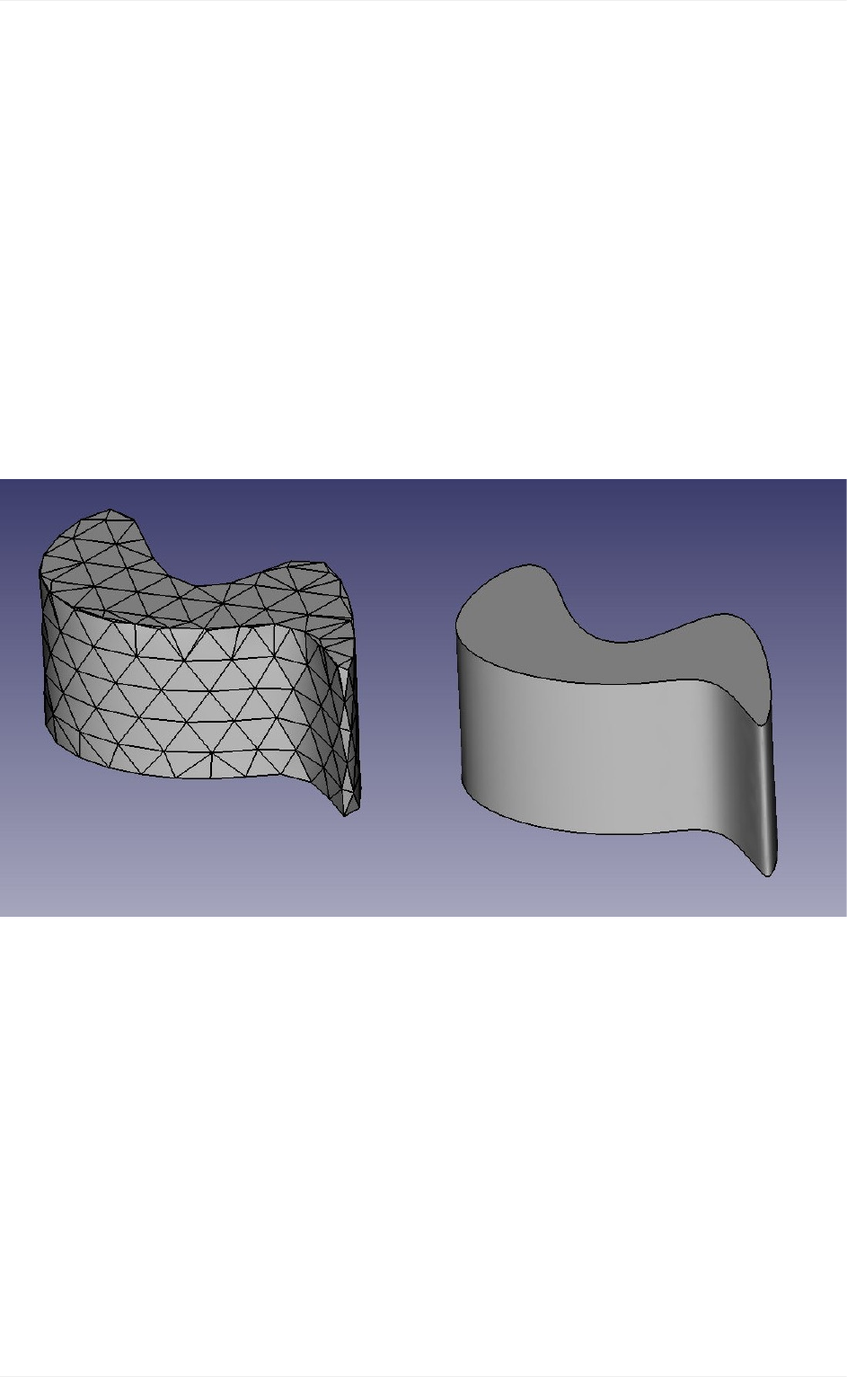
TheMeshWorkbenchallowstoworkwithpolygonmeshes.Althoughmeshesarenot
thepreferredtypeofgeometrytoworkwithinFreeCAD,becauseoftheirlackof
precisionandsupportforcurves,meshesstillhavealotofuses,andarefullysupported
inFreeCAD.TheMeshWorkbenchalsooffersanumberofPart-to-MeshandMesh-to-
Parttools.
TheRaytracingWorkbenchofferstoolstointerfacewithexternalrendererssuchas
povrayorluxrender.RightfrominsideFreeCAD,thisworkbenchallowsyoutoproduce
high-qualityrenderingsfromyourmodels.
TheSpreadsheetWorkbenchpermitsthecreationandmanipulationofspreadsheet
data,thatcanbeextractedfromFreeCADmodels.Spreadsheetcellscanalsobe
referencedinmanyareasofFreeCAD,allowingtousethemasmasterdatastructures.
TheFEMWorkbenchdealswithFiniteElementsAnalysis,andpermitstheperformingof
pre-andpost-processingFEMcalculationsandtodisplaytheresultsgraphically.
Externalworkbenches
Allworkbenchesataglance
51

A number of other very useful workbenches produced by FreeCAD community members
alsoexist.AlthoughtheyarenotincludedinastandardFreeCADinstallation,theyareeasy
toinstallasplug-ins.TheyareallreferencedintheFreeCAD-addonsrepository.Amongthe
mostdevelopedare:
TheDrawingDimensioningWorkbenchoffersmanynewtoolstoworkdirectlyon
DrawingSheetsandallowyoutoadddimensions,annotationsandothertechnical
symbolswithgreatcontrolovertheiraspect.
TheFastenersWorkbenchoffersawiderangeofready-to-insertfastenersobjectslike
screws,bolts,rods,washersandnuts.Manyoptionsandsettingsareavailable.
TheAssembly2Workbenchoffersaseriesoftoolstomountandworkwithassemblies.
Readmore
Thecompletelistofworkbenches:http://www.freecadweb.org/wiki/index.php?
title=Workbenches
ThePartWorkbench:http://www.freecadweb.org/wiki/index.php?title=Part_Module
TheDraftWorkbench:http://www.freecadweb.org/wiki/index.php?title=Draft_Module
TheSketcherandPartDesignWorkbench:http://www.freecadweb.org/wiki/index.php?
title=PartDesign_Workbench
TheArchWorkbench:http://www.freecadweb.org/wiki/index.php?title=Arch_Module
TheDrawingWorkbench:http://www.freecadweb.org/wiki/index.php?
title=Drawing_Module
TheFEMWorkbench:http://www.freecadweb.org/wiki/index.php?title=Fem_Workbench
TheFreeCAD-addonsrepository:https://github.com/FreeCAD/FreeCAD-addons
Allworkbenchesataglance
52
Traditionalmodeling-theCSGway
CGSstandsforConstructiveSolidGeometryanddescribesthemostbasicwaytoworkwith
solid3Dgeometry,whichiscreatingcomplexobjectsbyaddingandremovingpiecesto/from
solidsbyusingBooleanoperationssuchasunion,subtractionorintersection.
As we saw earlier in this manual, FreeCAD can handle many types of geometry, but the
preferred and most useful type for the kind of 3D objects that we want to design with
FreeCAD, that is, real-world objects, is, without a doubt, solid, BREP geometry, that is
mainly handled by the Part Workbench. Unlike polygon meshes, which are made only of
pointsandtriangles,BREPobjectshavetheirfacesdefinedbymathematicalcurves,which
permitsaboluteprecision,nomatterthescale.
The difference between the two can be compared to the difference between bitmap and
vectorial images. As with bitmap images, polygon meshes have their curved surfaces
fractionnedinaseriesofpoints.Ifyoulookatitfromveryclose,orprintitverylarge,youwill
seenotacurvedbutafacetedsurface.InbothvectorialimagesandBREPdata,theposition
of any point on a curve is not stored in the geometry but calculated on the fly, with exact
precision.
In FreeCAD, all BREP-based geometry is handled by another piece of open-source
software, OpenCasCade. The main interface between FreeCAD and the OpenCasCade
kernelisthePartWorkbench.Mostotherworkbenchesbuildtheirfunctionalityontopofthe
PartWorkbench.
Traditionalmodeling,theCSGway
53
Although other workbenches often offer more advanced tools to build and manipulate
geometry,sincetheyallactuallymanipulatePartobjects,itisveryusefultoknowhowthese
objectsworkinternally,andbeabletousetheParttoolssince,beingmoresimple,theycan
very often help you to work around problems that the more intelligent tools fail to solve
properly.
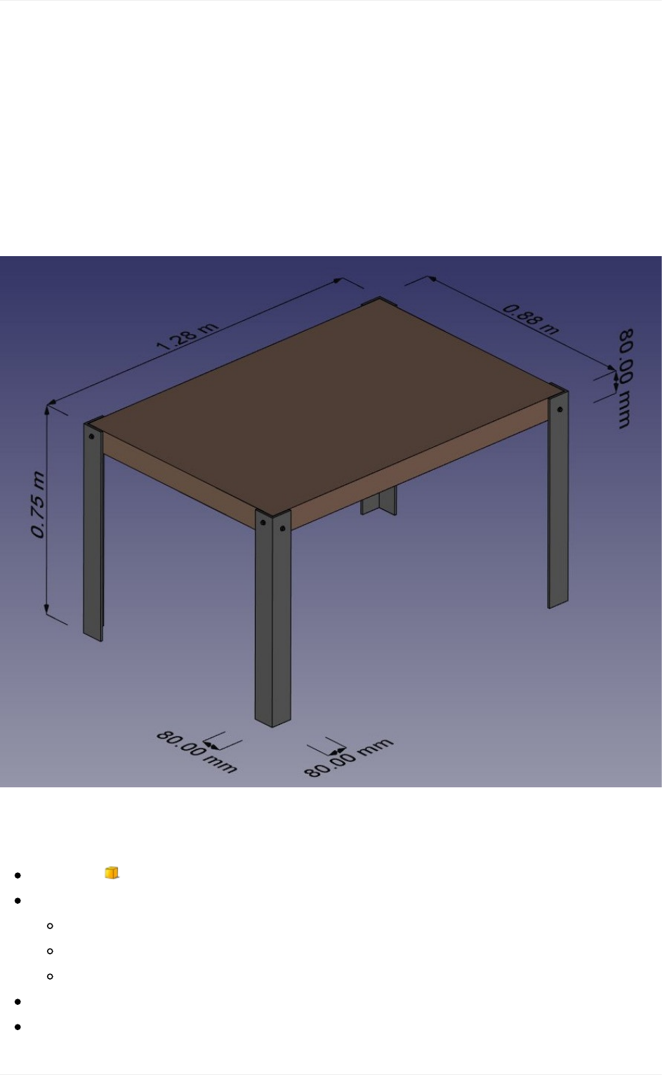
To illustrate the working of the Part Workbench, we will model this table, using only CSG
operations(exceptthescrews,forwhichwewilluseoneoftheaddons,andthedimensions,
whichwillseeinthenextchapter):
Let'screate anew document(Ctrl+N or menu File -> New Document), switch to the Part
Workbench,andbeginwiththefirstfoot:
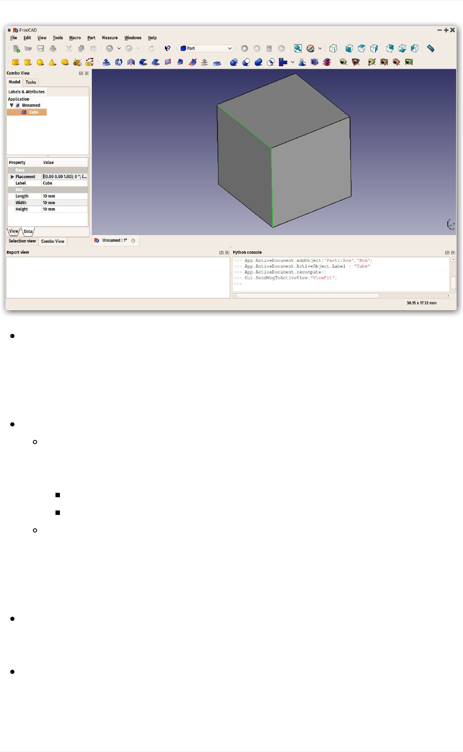
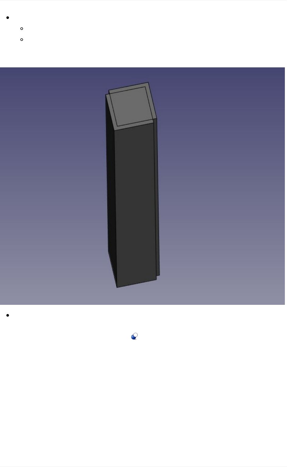
Pressthe Boxbutton
Selectthebox,thensetthefollowingproperties(intheDatatab):
Length:80mm(or8cm,or0.8m,FreeCADworksinanyunit)
Width:80mm
Height:75cm
DuplicatetheboxbypressingCtrl+CthenCtrl+V(ormenuEdit->CopyandPaste)
Selectthenewobjectthathasbeencreated
Traditionalmodeling,theCSGway
54
ChangeitspositionbyeditingitsPlacementproperty:
Positionx:8mm
Positiony:8mm
Youshouldobtaintwohighboxes,one8mmapartfromtheother:
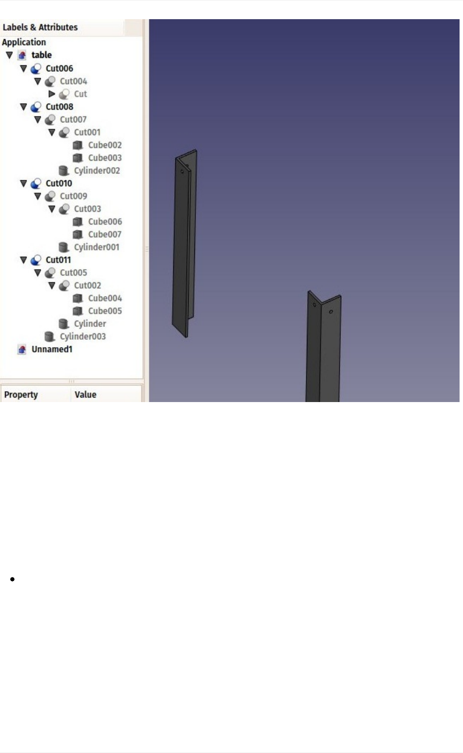
Nowwecansubtractonefromtheother:Selectthefirstone,thatis,theonethatwill
stay,then,withtheCTRLkeypressed,selecttheotherone,thatwillbesubtracted
(theorderisimportant)andpressthe Cutbutton:
Traditionalmodeling,theCSGway
55
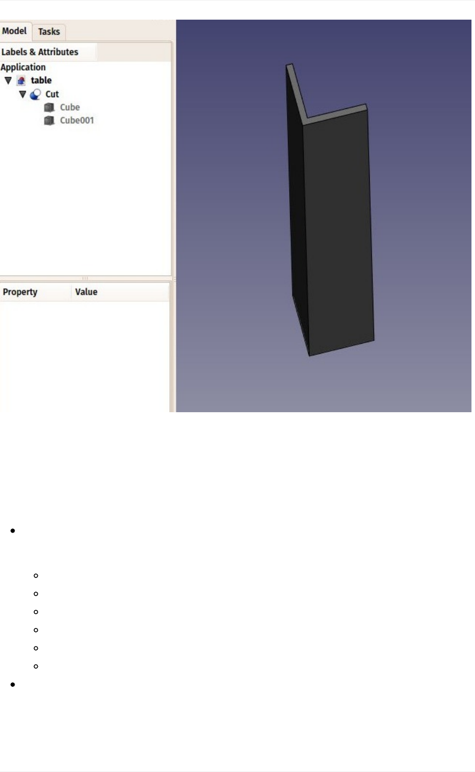
Observethatthenewlycreatedobject,called"Cut",stillcontainsthetwocubesweusedas
operands. In fact, the two cubes are still there in the document, they have merely been
hidden and grouped under the Cut object in the tree view. You can still select them by
expandingthearrownexttotheCutobject,and,ifyouwish,turnthemvisibleagainbyright-
clickigthemorchangeanyoftheirproperties.
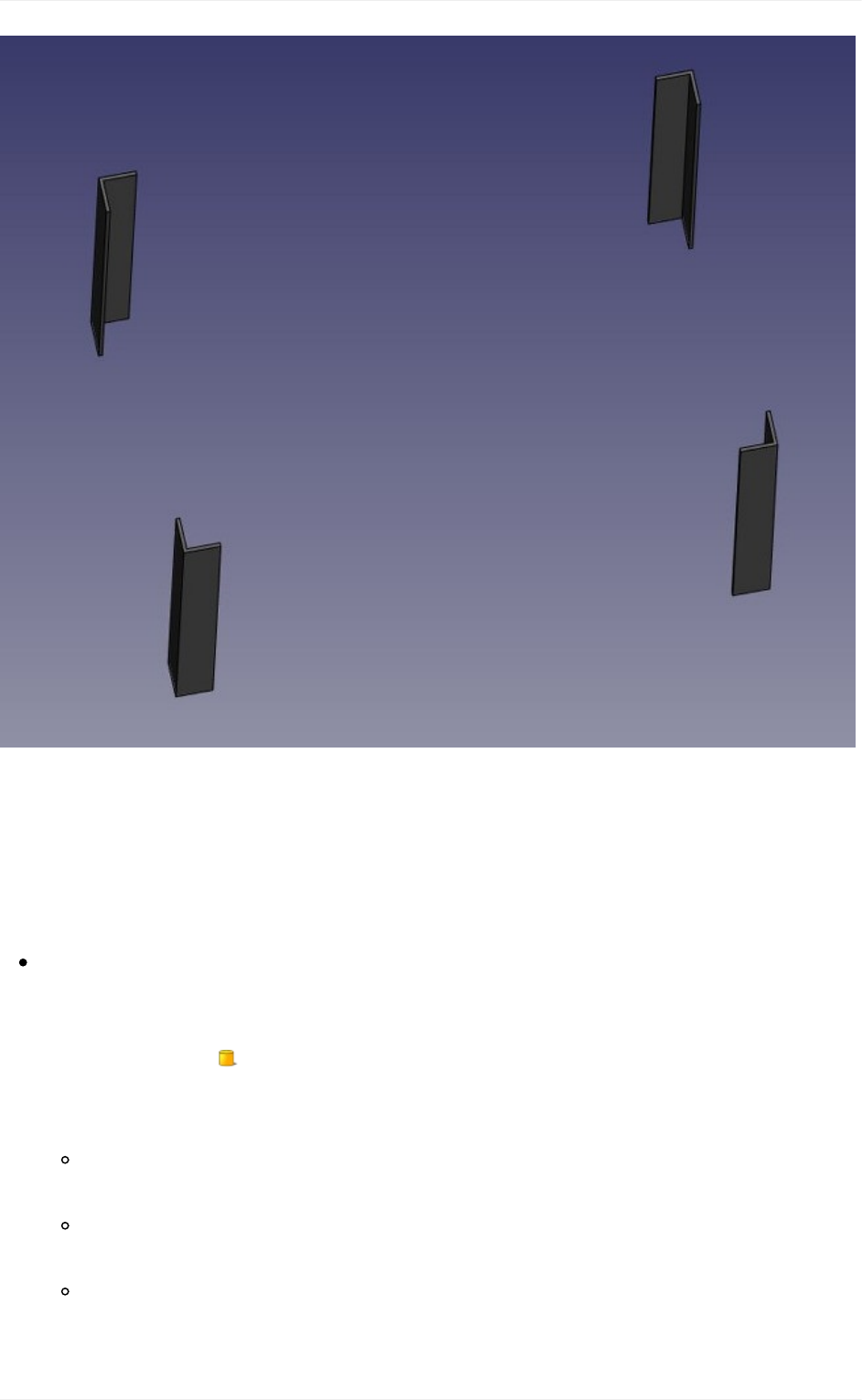
Nowlet'screatethethreeotherfeetbyduplicatingourbasecube6othertimes.Sinceit
isstillcopied,youcansimplypaste(Ctrl+V)6times.Changetheirpositionasfollows:
cube002:x:0,y:80cm
cube003:x:8mm,y:79.2cm
cube004:x:120cm,y:0
cube005:x:119.2cm,y:8mm
cube006:x:120cm,y:80cm
cube007:x:119.2cm,y:79.2cm
Nowlet'sdothethreeothercuts,selectingfirstthe"host"cubethenthecubetobecut
off.WenowhavefourCutobjects:
Traditionalmodeling,theCSGway
56
Youmighthavebeenthinkingthat,insteadofduplicatingthebasecubesixtimes,wecould
have duplicated the complete foot three times. This is totally true, as always in FreeCAD,
there are many ways to achieve a same result. This is a precious thing to remember,
because,aswewilladvanceintomorecomplexobjects,someoperationsmightnotgivethe
correctresultandweoftenneedtotryotherways.
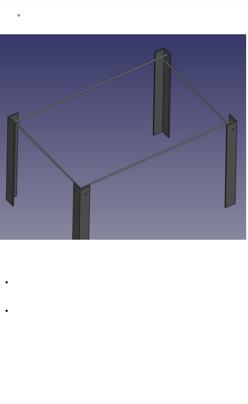
Wewillnowmakeholesforthescrews,usingthesameCutmethod.Sinceweneed8
holes,twoineachfoot,wecouldmake8objectstobesubtracted.Instead,let'sexplore
otherwaysandmake4tubes,thatwillbereusedbytwoofthefeet.Solet'screatefour
tubesbyusingthe Cylindertool.Youcanagain,makeonlyoneandduplicateit
afterwards.Giveallcylindersaradiusof6mm.Thistime,wewillneedtorotatethem,
whichisalsodoneviathePlacementproperty:
cylinder:height:130cm,angle:90°,axis:x:0,y:1,position:x:-10mm,y:40mm,
z:72cm
cylinder001:height:130cm,angle:90°,axis:x:0,y:1,position:x:-10mm,y:84cm,
z:72cm
cylinder002:height:90cm,angle:90°,axis:x:-1,y:0,position:x:40mm,y:-10mm,
z:70cm
Traditionalmodeling,theCSGway
57
cylinder003:height:90cm,angle:90°,axis:x:-1,y:0,position:x:124cm,y:-10mm,
z:70cm
You will notice that the cylinders are a bit longer than needed. This is because, as in all
solid-based3Dapplications,booleanoperationsinFreeCADaresometimesoversensitiveto
face-on-facesituationsandmightfail.Bydoingthis,weputourselvesonthesafeside.
Nowlet'sdothesubtractions.Selectthefirstfoot,then,withCTRLpressed,selectone
ofthetubesthatcrossesit,presstheCutbutton.Theholewillbedone,andthetube
hidden.Finditinthetreeviewbyexpandingthepiercedfoot.
Selectanotherfootpiercedbythishiddentube,thenrepeattheoperation,thistime
Ctrl+selectingthetubeinthetreeview,asitishiddeninthe3Dview(youcanalso
makeitvisibleagainandselectitinthe3Dview).Repeatthisfortheotherfeetuntil
eachofthemhasitstwoholes:
Traditionalmodeling,theCSGway
58
As you can see, each foot has become a quite long series of operations. All this stays
parametric,andyoucangochangeanyparameterofanyoftheolderoperationsanytime.In
FreeCAD, we often refer to this pile as "modeling history", since it in fact carries all the
historyoftheoperationsyoudid.
Another particularity of FreeCAD is that the concept of 3D object and the concept of 3D
operationtendtoblendintoonesamething.TheCutisatthesametimeanoperation,and
the3Dobjectresultingfromthisoperation.InFreeCADthisiscalleda"feature",ratherthan
objectoroperation.
Nowlet'sdothetabletop,itwillbeasimpleblockofwood,let'sdoitwithanotherBox
withlength:126cm,width:86cm,height:8cm,position:x:10mm,y:10mm,z,67cm.In
theViewtab,youcangiveitanicebrownish,wood-likecolorbychangingitsShape
Colorproperty:
Traditionalmodeling,theCSGway
59
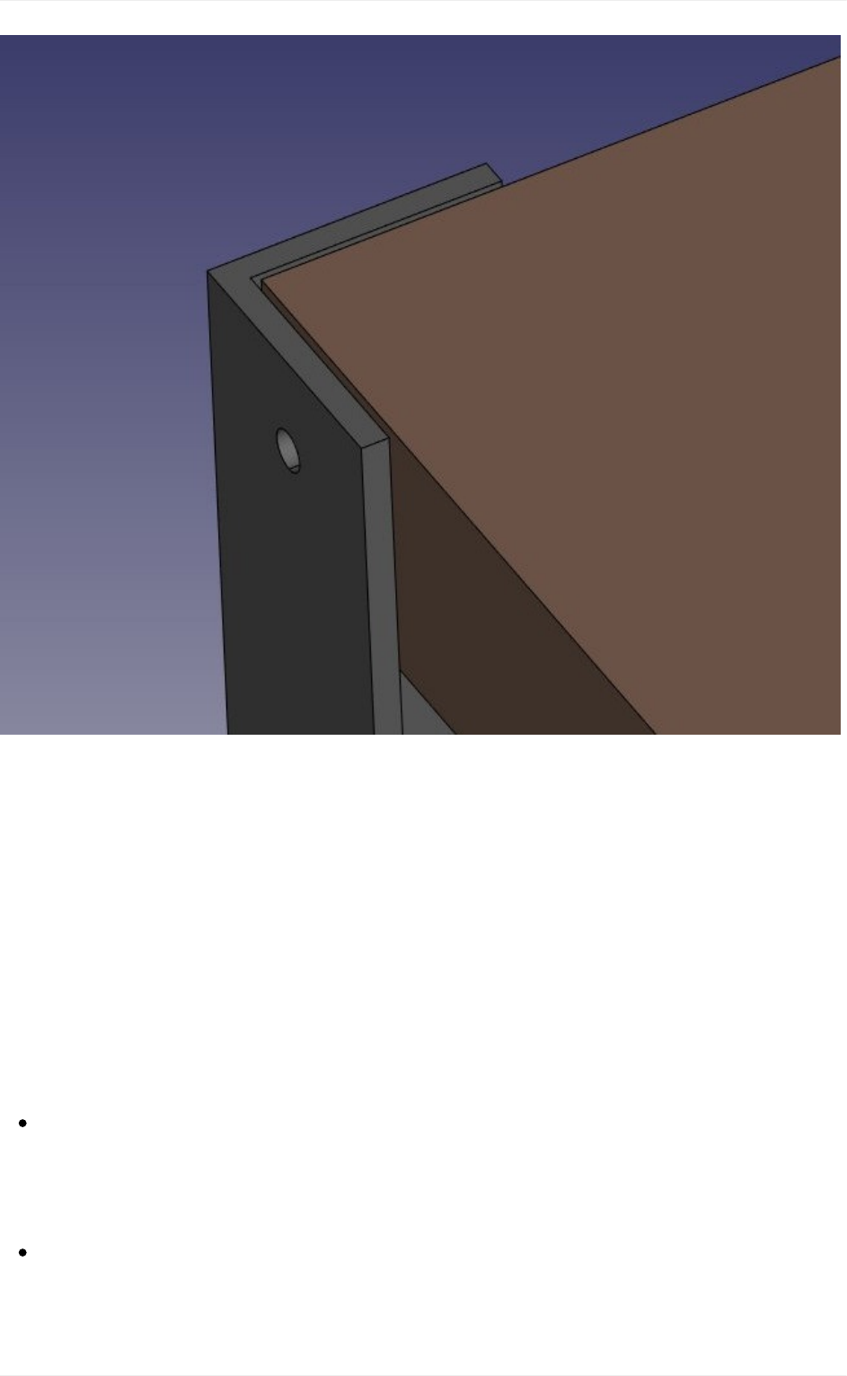
Notice that, although the legs are 8mm thick, we placed it 10mm away, leaving 2mm
betweenthem.Thisisnotnecessary,ofcourse,itwon'thappenwiththerealtable,butitisa
common thing to do in that kind of "assembled" models, it helps people who look at the
modeltounderstandthattheseareindependentparts,thatwillneedtobeattachedtogether
manuallylater.
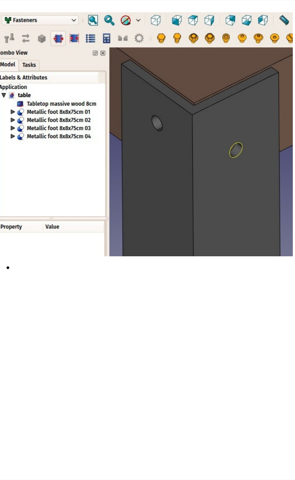
Nowthat ourfive pieces arecomplete, itis a goodtime togive themmore proper names
than"Cut015".Byright-clickingtheobjectsinthetreeview(orpressingF2),youcanrename
themtosomethingmoremeaningfultoyourselfortoanotherpersonwhowouldopenyour
file later. It is often said that simlpy giving proper names to your objects is much more
importantthanthewayyoumodelthem.
Wewillnowplacesomescrews.Thereisnowadaysanextremelyusefuladdon
developedbyamemberoftheFreeCADcommunity,thatyoucanfindontheFreeCAD
addonsrepository,calledFasteners,thatmakestheinsertionofscrewsveryeasy.
Installingadditionalworkbenchesiseasyanddescribedontheaddonspages.
OnceyouhaveinstalledtheFastenersWorkbenchandrestartedFreeCAD,itwill
appearintheworkbencheslist,andwecanswitchtoit.Addingascrewtooneofour
holesisdonebyfirstselectingthecircularedgeofourhole:
Traditionalmodeling,theCSGway
60
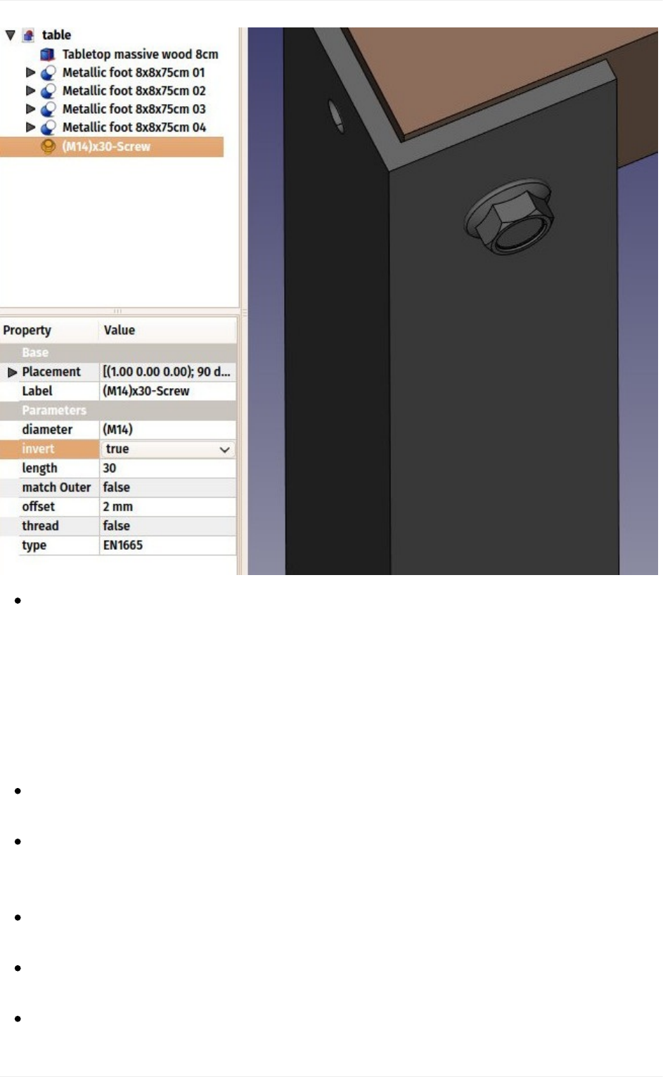
ThenwecanpressoneofthescrewbuttonsoftheFastenersWorkbench,forexample
theEN1665Hexagonboltwithflanges,heavyseries.Thescrewwillbeplacedand
alignedwithourhole,andthediameterwillautomaticallybeselectedtomatchthesize
ofourhole.Sometimesthescrewwillbeplacedinverted,whichwecancorrectby
flippingitsinvertproprty.Wecanalsosetitsoffsetto2mm,tofollowthesamerulewe
usedbetweenthetabletopandthefeet:
Traditionalmodeling,theCSGway
61
Repeatthisforalltheholes,andourtableiscomplete!
TheinternalstructureofPartobjects
Aswesawabove,itispossibleinFreeCADtoselectnotonlywholeobjects,butpartsfor
them,suchasthecircularborderofourscrewhole.Thisisagoodtimetohaveaquicklook
at how Part objects are constructed internally. Every workbench that produces Part
geometrywillbebasedonthese:
Vertices:Thesearepoints(usuallyendpoints)onwhichalltherestisbuilt.For
example,alinehastwovertices.
Edges:theedgesarelineargeometrylikelines,arcs,ellipsesorNURBScurves.They
usuallyhavetwovertices,butsomespecialcaseshaveonlyone(aclosedcirclefor
example).
Wires:Awireisasequenceofedgesconnectedbytheirendpoints.Itcancontain
edgesofanytype,anditcanbeclosedornot.
Faces:Facescanbeplanarorcurved,andcanbeformedbyoneclosedwire,which
formstheborderoftheface,ormorethanone,incasethefacehasholes.
Shells:Shellsaresimplyagroupoffacesconnectedbytheiredges.Itcanbeopenor
Traditionalmodeling,theCSGway
62

closed.
Solids:Whenashellistighlyclosed,thatis,ithasno"leak",itbecomesasolid.Solids
carrythenotionofinsideandoutside.Manyworkbenchrelyonthistomakesurethe
objectstheyproducecanbebuiltintherealworld.
Compounds:Compoundsaresimplyaggegatesofothershapes,nomattertheirtype,
intoasingleshape.
Inthe3Dview,youcanselectindividualvertices,edgesorfaces.Selectingoneofthese
alsoselectsthewholeobject.
Anoteaboutshareddesign
Youmightlookatthetableabove,andthinkitsdesignisnotgood.Thetighteningofthefeet
withthetabletopisprobablytooweak.Youmightwanttoaddreforcingpieces,orsimplyyou
have other ideas to make it better. This is where sharing becomes interesting. You can
download the file made during this exercise from the link below, and modify it to make it
better.Then,ifyousharethatimprovedfile,othersmightbeabletomakeitevenbetter,or
use your well-designed table in their projects. Your design might then give other ideas to
otherpeople,andmaybeyouwillhavehelpedatinybittomakeabetterworld...
Downloads
Thefileproducedinthisexercise:https://github.com/yorikvanhavre/FreeCAD-
manual/blob/master/files/table.FCStd
Readmore
ThePartWorkbench:http://www.freecadweb.org/wiki/index.php?title=Part_Module
TheFreeCADaddonsrepository:https://github.com/FreeCAD/FreeCAD-addons
TheFastenersWorkbench:https://github.com/shaise/FreeCAD_FastenersWB
Traditionalmodeling,theCSGway
63

Traditional2Ddrafting
You might be interested by FreeCAD because you already have some technical drawing
experience,forexamplewithsoftwarelikeAutoCAD.Oryoualreadyknowsomethingabout
design,oryouprefertodrawthingsbeforebuildingthem.Ineithercases,FreeCADfeatures
a more traditional workbench, with tools found in most 2D CAD applications: The Draft
Workbench.
TheDraftWorkbench,althoughitadopts waysofworking inheritedfromthetraditional 2D
CADworld,isnotlimitedatalltothe2Drealm.Allitstoolsworkinthewhole3Dspaceand
many of the Draft tools, for example Move or Rotate, are commonly used all over
FreeCAD because they are often more intuitive than changing placement parameters
manually.
AmongthetoolsofferedbytheDraftWorkbench,youwillfindtraditionaldrawingtoolslike
Line, Circle,or Wire(polyline),modificationtoolslike Move, Rotateor Offset,
a working plane/grid system that allows you to define precisely in which plane you are
working, and a complete snapping system that makes it very easy to draw and position
elementspreciselyinrelationtoeachother.
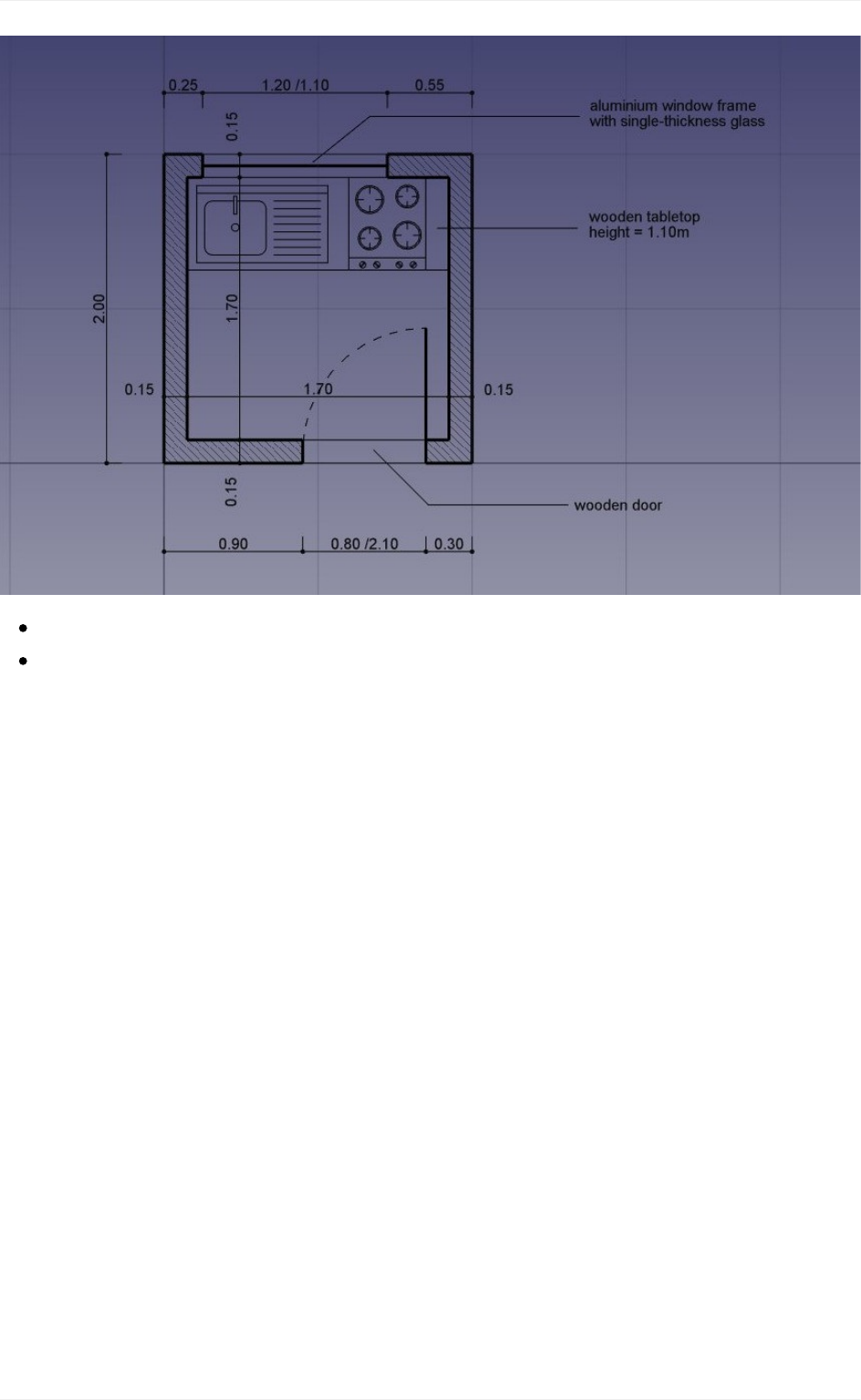
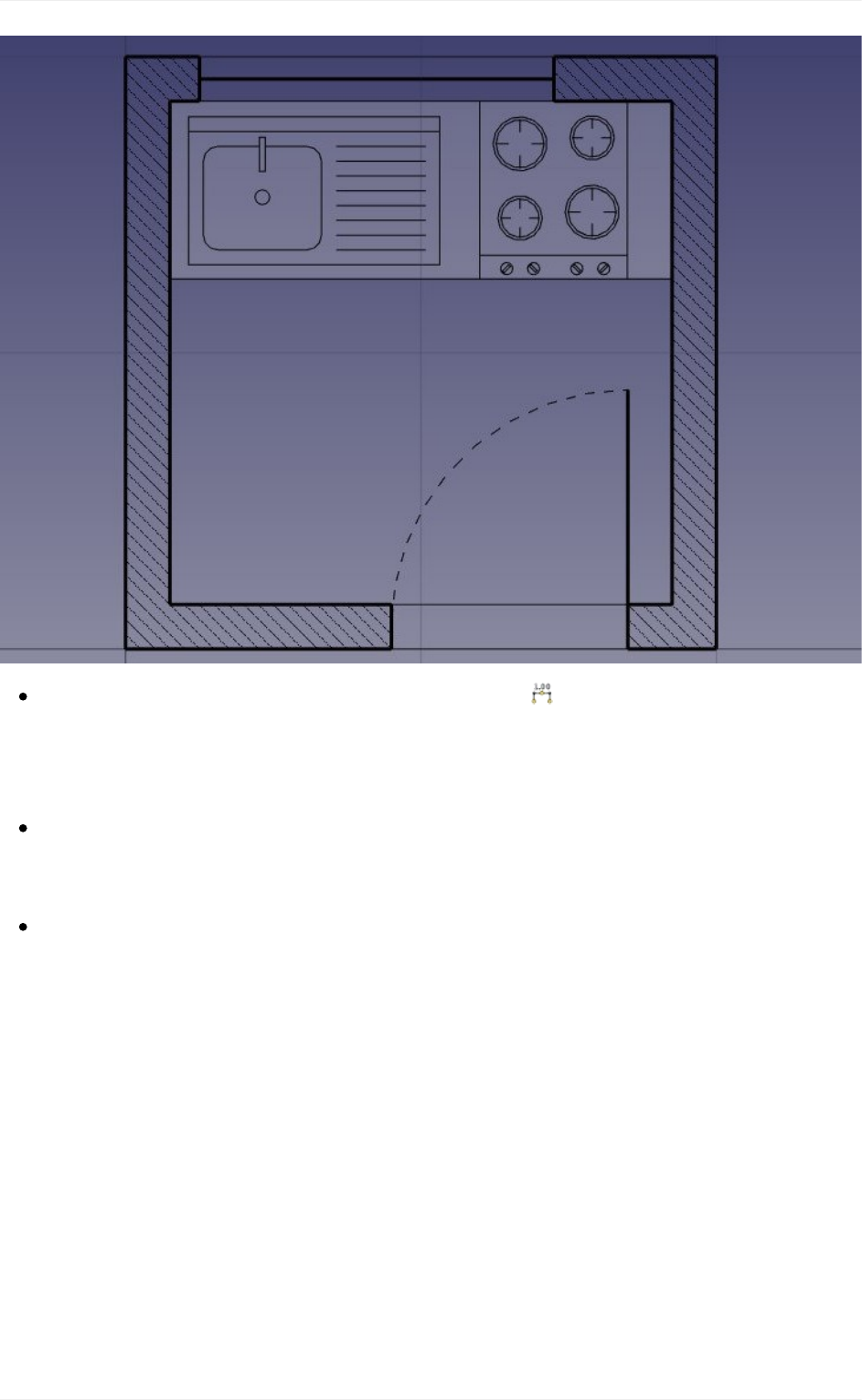
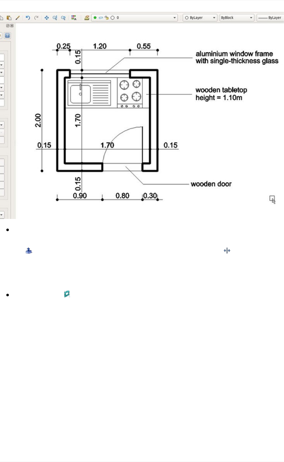
Toshowcase theworkingand possibilitiesof the DraftWorkbench,we will walkthrough a
simple exercise, the result of which will be this little drawing, showing the floor plan of a
smallhousethatcontainsonlyakitchentop(Aprettyabsurdfloorplan,butwecandowhat
wewanthere,can'twe?):
Traditional2Ddrafting
64
SwitchtotheDraftWorkbench
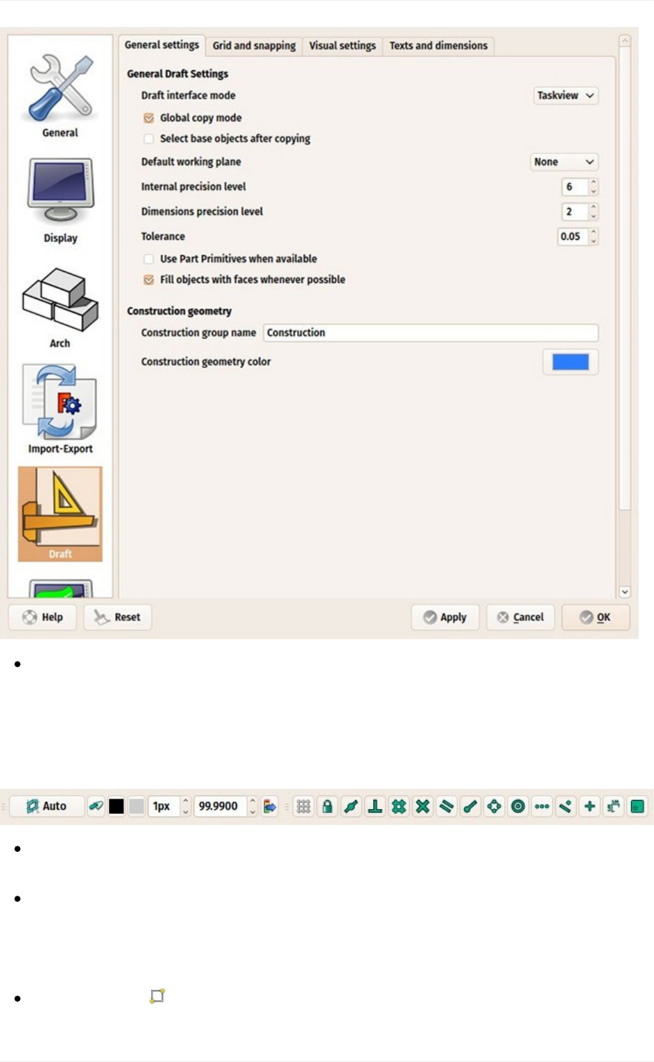
Asinalltechnicaldrawingapplications,itiswisetosetupyourenvironmentcorrectly,it
willsaveyoualotoftime.Configurethegridandworkingplane,textanddimensions
settingstoyourlikingsinmenuEdit->Preferences->Draft.Inthisexercise,however,
wewillactasifthesepreferencesettingswerelefttotheirdefaultvalues.
Traditional2Ddrafting
65
TheDraftWorkbenchalsohastwospecialtoolbars:Onewithvisualsettings,where
youcanchangethecurrentworkingplane,turnconstructionmodeon/off,settheline
color,facecolor,lineweightandtextsizetobeusedfornewobjects,andanotherone
withsnaplocations.There,youcanturnthegridon/ofandset/unsetindividualSnap
locations:
Let'sstartbyturningconstructionmodeon,whichwillallowustodrawsome
guidelinesonwhichwewilldrawourfinalgeometry.
Ifyouwish,settheworkingplaneto*XY.Ifyoudothis,theworkingplanewon't
change,nomatterthecurrentview.Ifnot,theworkingplanewilladaptautomaticallyto
thecurrentview,andyoushouldtakecareofstayingintopviewwheneveryouwantto
drawontheXY(ground)plane.
Then,selectthe Rectangletoolanddrawarectangle,startingatpoint(0,0,0),of2
metersby2meters(leavetheZatzero).NotethatmostoftheDraftcommandscanbe
Traditional2Ddrafting
66
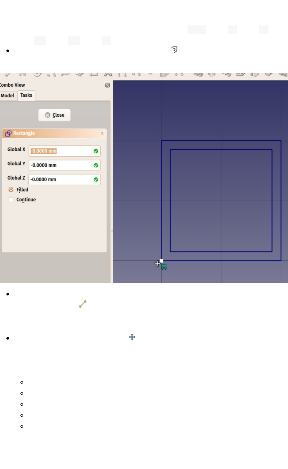
fullyperformedfromthekeyboard,withouttouchingthemouse,usingtheirtwo-letter
shortcut.Ourfirst2x2mrectanglecanbedonelikethis: re0Enter0Enter0
Enter2mEnter2mEnter0Enter.
Duplicatethatrectangleby15cminside,usingthe Offsettool,turningitsCopymode
on,andgivingitadistanceof15cm:
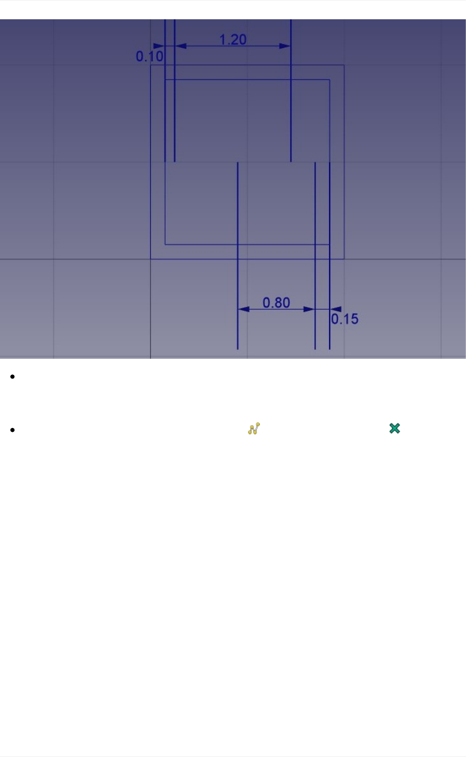
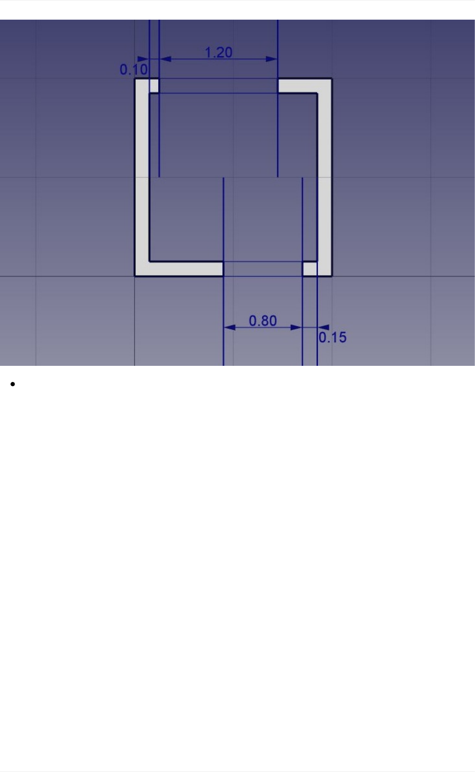
Wecanthendrawacoupleofverticallinestodefinewhereourdoorsandwindowswill
beplaced,usingthe Linetool.Thecrossingoftheselineswithourtworectangleswill
giveususefulintersectionstosnapourwallsto.Drawthefirstlinefrompoint(15cm,
1m,0)topoint(15cm,3m,0).
Duplicatethatline5times,usingthe MovetoolwithCopymodeturnedon.Turnalso
theRelativemodeon,whichwillallowustodefinemovementsinrelativedistances,
whichiseaierthancalculatetheexactpositionofeachline.Giveeachnewcopyany
startpoint,youcanleaveitat(0,0,0)forexample,andthefollowingrelativeendpoints:
line001:x:10cm
line002:x:120cm
line003:x:-55cm,y:-2m
line004:x:80cm
line005:x:15cm
Traditional2Ddrafting
67
Thatisallweneednow,sowecanswitchconstructionmodeoff.Checkthatallthe
constructiongeometryhasbeenplacedintoa"Construction"group,whichmakesit
easytohideitallatonceorevendeleteitcompletelylateron.
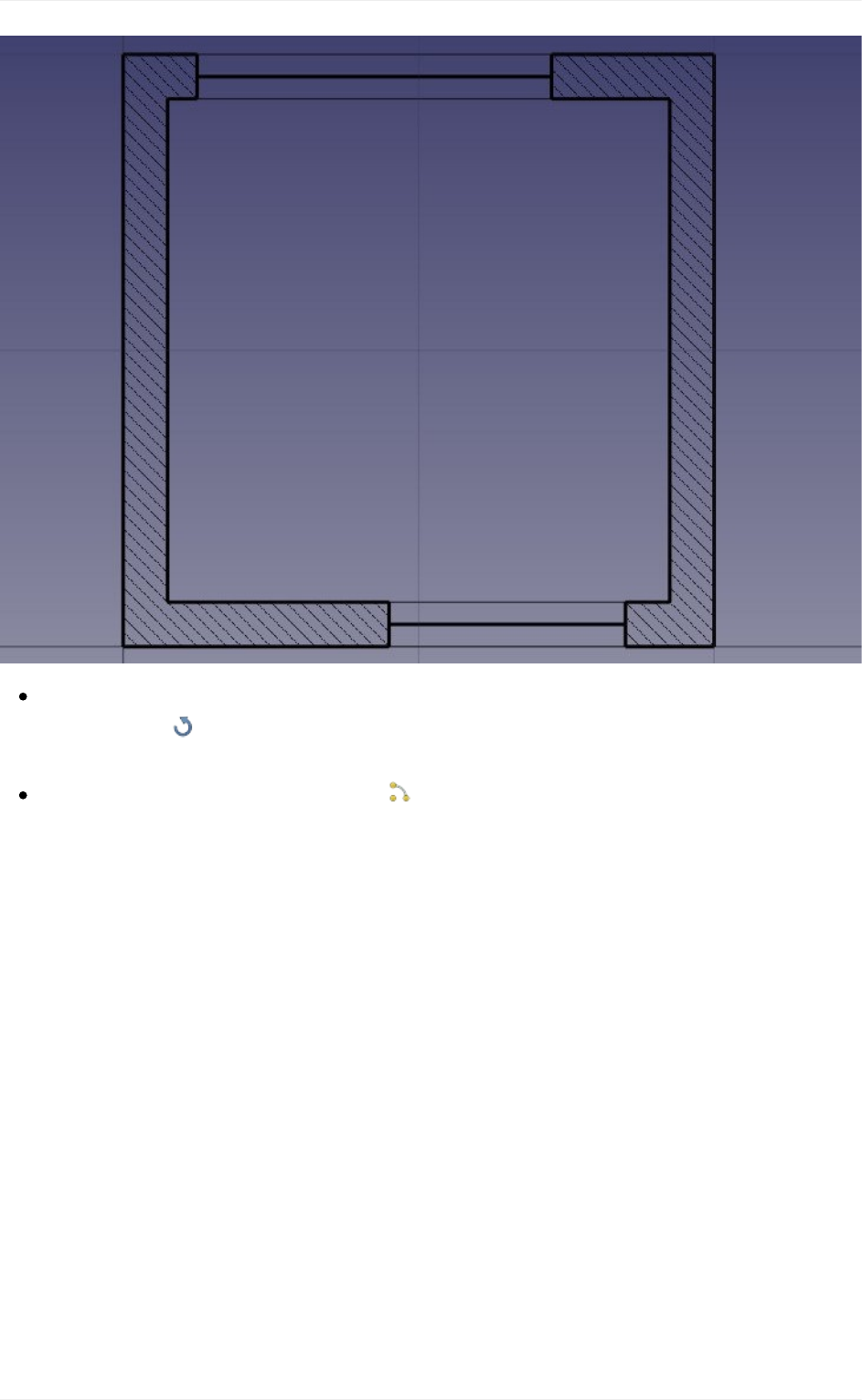
Nowlet'sdrawourtwowallpiecesusingthe Wiretool.Makesurethe intersection
snapisturnedon,aswewillneedtosnaptotheintersectionsofourlinesand
rectangles.Drawtwowiresasfollow,byclickingallthepointsoftheircontours.Toclose
them,eitherclickonthefirstpointagain,orpresstheClosebutton:
Traditional2Ddrafting
68
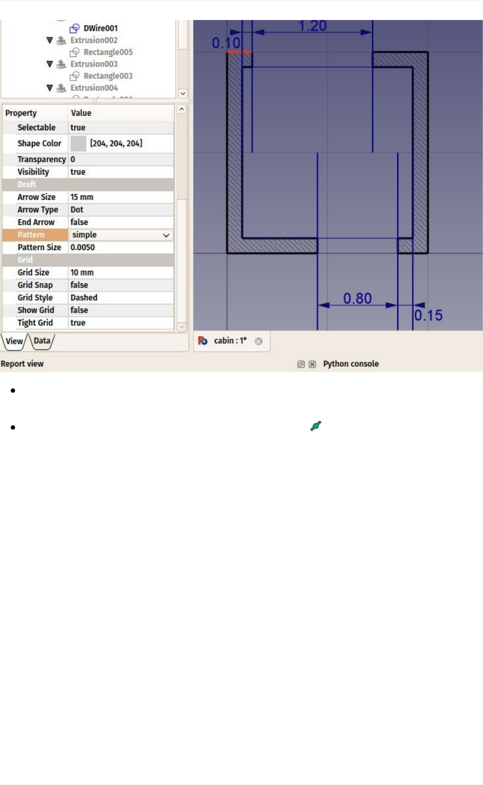
Wecanchangetheirdefaultgreycolortoanicehatchpattern,byselectingbothwalls,
thensettingtheirPatternpropertytoSimple,andtheirPatternsizetoyourliking,for
example0.005.
Traditional2Ddrafting
69
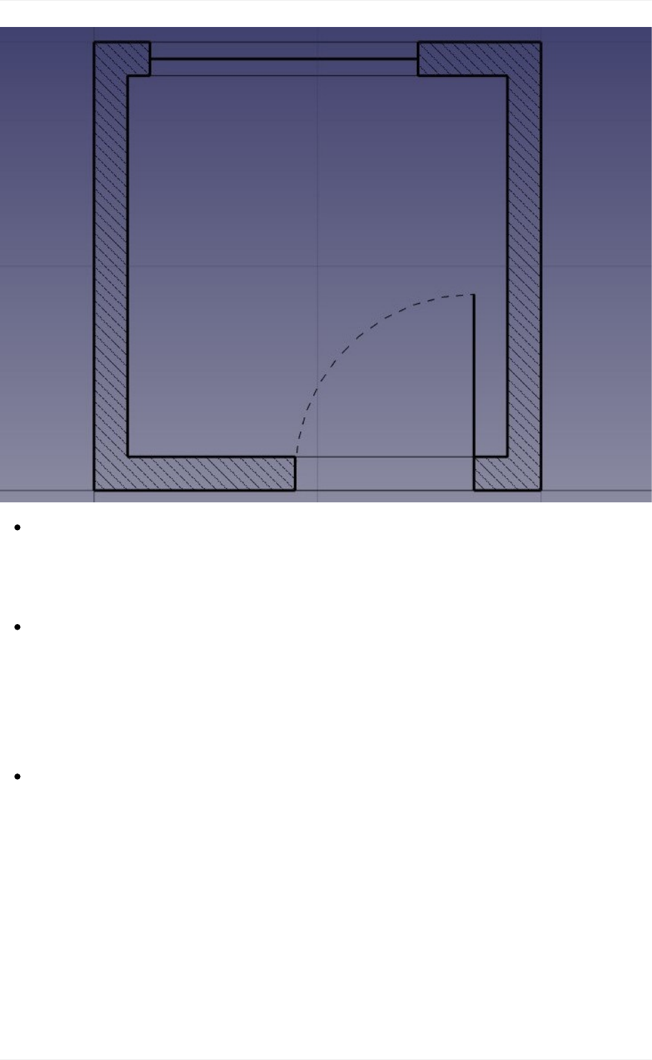
Wewillnowchangethedoorlinetocreateanopeneddoorsymbol.Startbyrotatingthe
lineusingthe Rotatetool.Clicktheenpointofthelineasrotationcenter,giveita
startangleof0,andanendangleof-90.
Thencreatetheopeningarcwiththe Arctool.Pickthesamepointastherotation
centerweusedinthepreviousstepascenter,clicktheotherpointofthelinetogivethe
radius,thenthestartandendpointsasfollow:
Traditional2Ddrafting
71
Wecannowstartplacingsomefurniture.Tobeginwith,let'splaceacounterbydrawing
arectanglefromtheupperleftinnercorner,andgivingitawidthof170cmandaheight
of-60cm.Intheimagebelow,theTransparencypropertyoftherectangleissetto80%,
togiveitanicefurniturelook.
Thenlet'saddasinkandacooktop.Drawingthesekindsofsymbolsbyhandcanbe
verytedious,andtheyareusuallyeasytofindontheinternet,forexampleon
http://www.cad-blocks.net.IntheDownloadssectionbelow,forconvenience,we
separatedasinkandacooktopfromthissite,andsavedthemasDXFfiles.Youcan
downloadthesetwofilesbyvisitingthelinksbelow,andright-clickingtheRawbutton,
thenchoosingsaveas.
InsertingaDXFfileintoanopenedFreeCADdocumentcanbedoneeitherbychoosing
theFile->Importmenuoption,orbydragginganddroppingtheDXFfilefromyourfile
explorerintotheFreeCADwindow.ThecontentsoftheDXFfilesmightnotappearright
onthecenterofyourcurrentview,dependingonwheretheywereintheDXFfile.You
canusemenuView->Standardviews->Fitalltozoomoutandfindtheimported
objects.InsertthetwoDXFfiles,andmovethemtoasuitablelocationonthetabletop:
Traditional2Ddrafting
72
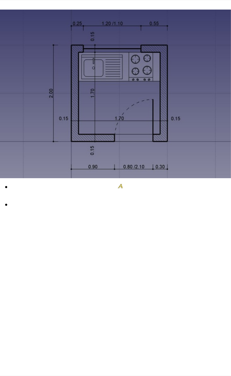
Wecannowplaceacoupleofdimensionsusingthe Dimensiontool.Dimensionsare
drawnbyclicking3points:thestartpoint,anendpoint,andathirdpointtoplacethe
dimensionline.Tomakehorizontalorverticaldimensions,evenifthetwofirstpointsare
notaligned,pressShiftwhileclickingthesecondpoint.
Youcanchangethepositionofadimensiontextbydouble-clickingthedimensioninthe
treeview.Acontrolpointwillallowyoutomovethetextgraphically.Inourexercise,the
"0.15"textshavebeenmovedawayforbetterclarity.
YoucanchangethecontentsofthedimensiontextbyeditingtheirOverrideproperty.In
ourexample,thetextsofthedoorandwindowsdimensionshavebeeneditedto
indicatetheirheights:
Traditional2Ddrafting
73
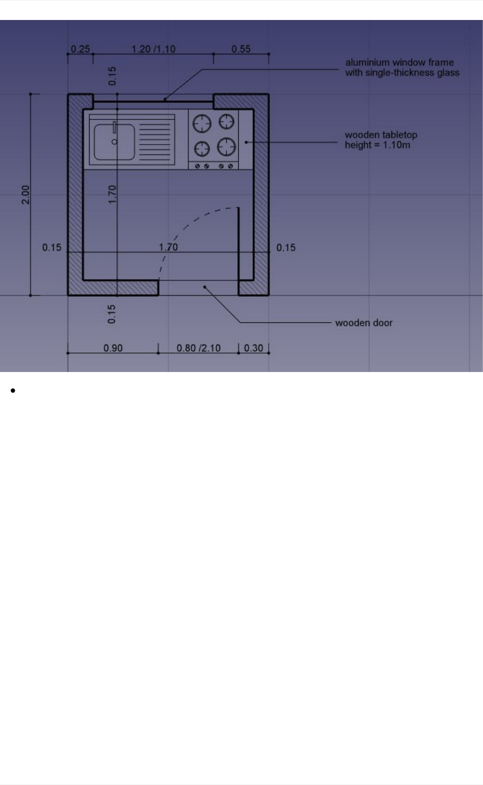
Let'saddsomedescriptiontextsusingthe Texttool.Clickapointtopositionthetext,
thenenterthelinesoftext,pressingEnteraftereachline.Tofinish,pressEntertwice.
Theindicationlines(alsocalled"leaders")thatlinkthetextstotheitemtheyare
describingaresimplydonewiththeWiretool.Drawwires,startingfromthetext
position,totheplacebeingdescribed.Oncethatisdone,youcanaddabulletorarrow
attheendofthewiresbysettingtheirEndArrowpropertytoTrue
Traditional2Ddrafting
74
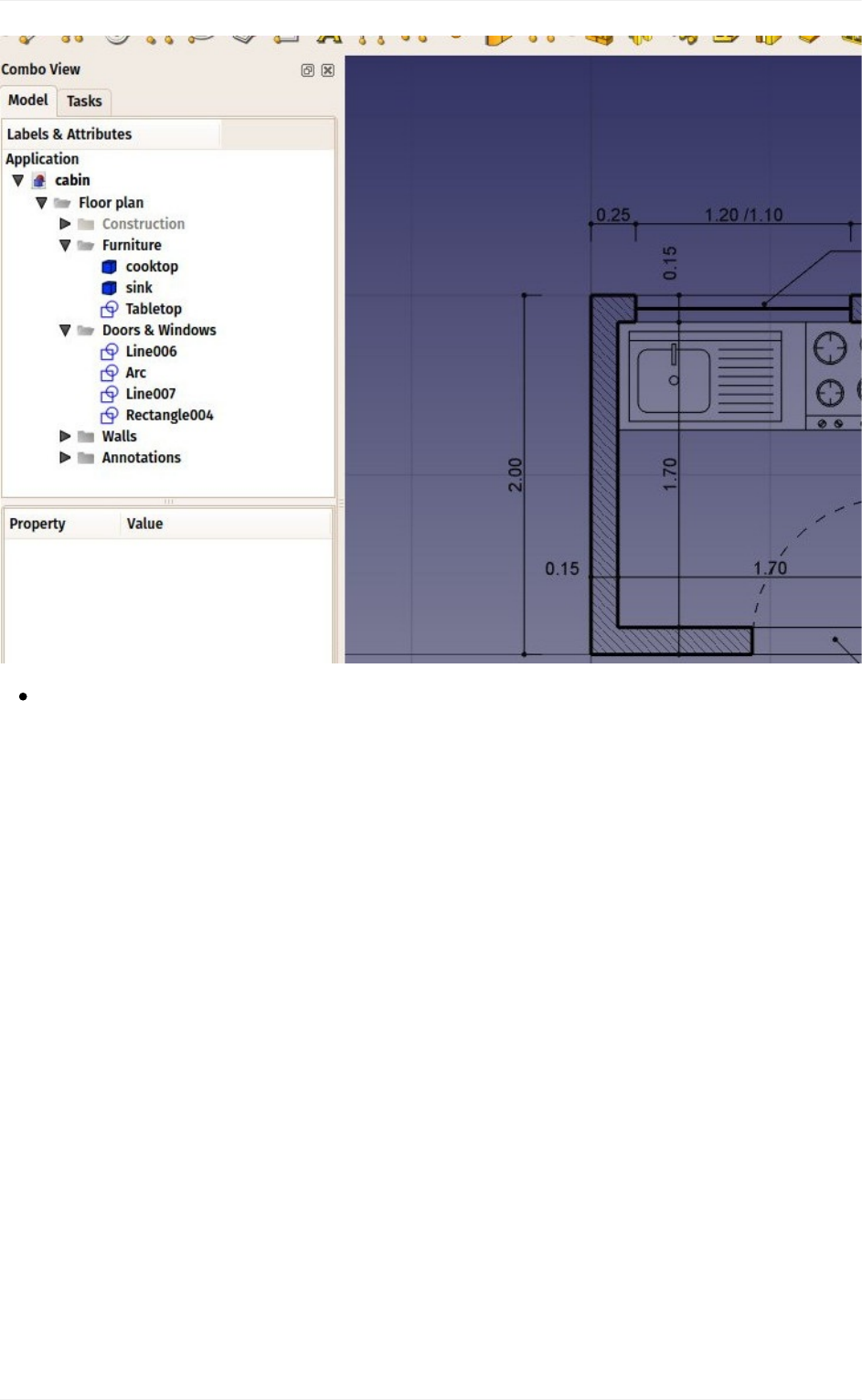
Ourdrawingisnowcomplete!Sincetherebeginstobequiteanumberofobjectsthere,
itwouldbewisedosomecleaningandplaceeverythinginanicestructureofgroups,to
makethefileeasiertounderstandtoanotherperson:
Traditional2Ddrafting
75
WecannowprintourworkbyplacingitonaDrawingsheet,whichwewillshowfurther
inthismanual,ordirectlyexportourdrawingtootherCADapplications,byexportingit
toaDXFfile.Simplyselectour"Floorplan"group,selectmenuFile->Export,and
selecttheAutodeskDXFformat.Thefilecanthenbeopenedinanyother2DCAD
applicationsuchasLibreCAD.Youmightnoticesomedifferences,dependingonthe
configurationsofeachapplication.
Traditional2Ddrafting
76
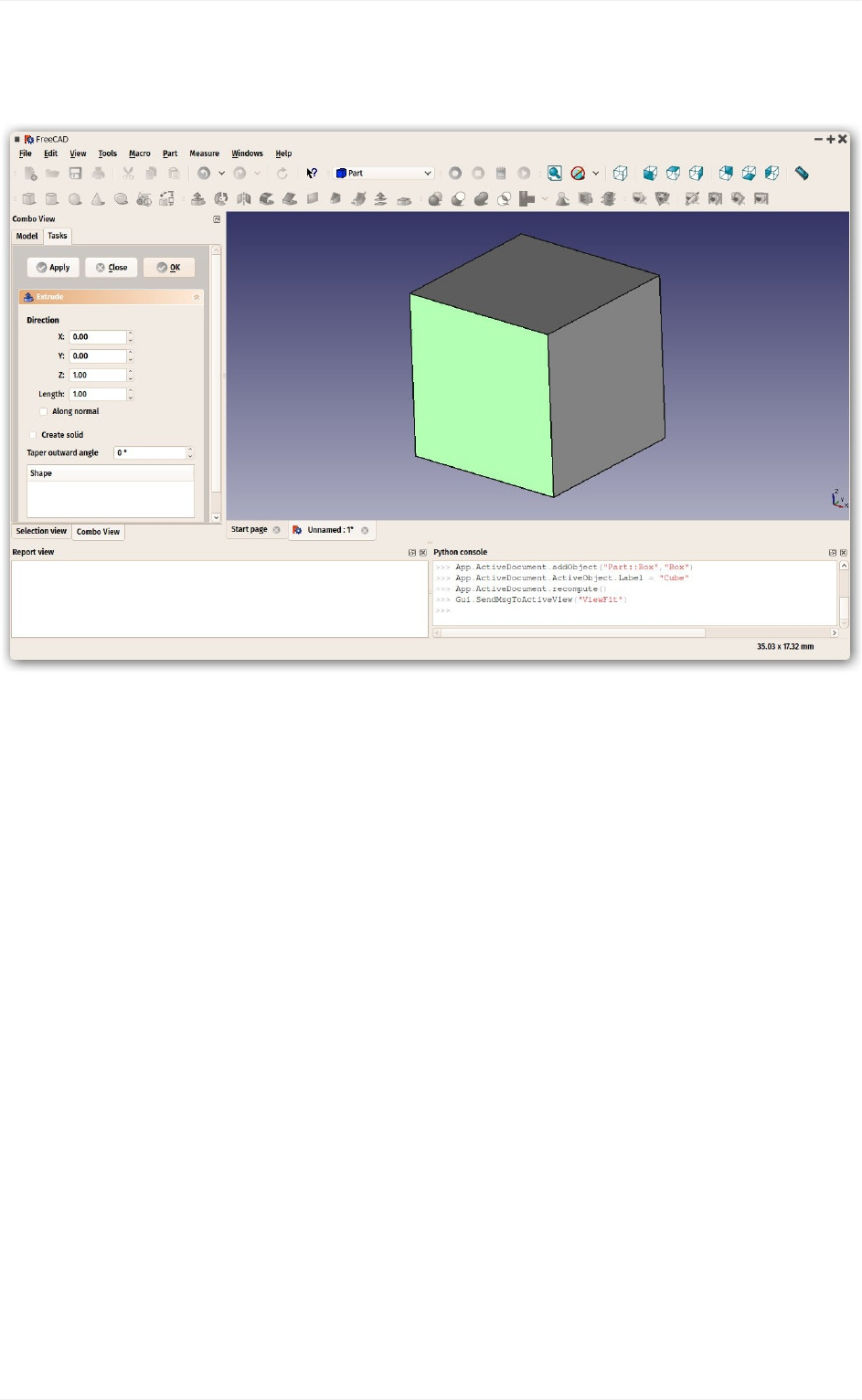
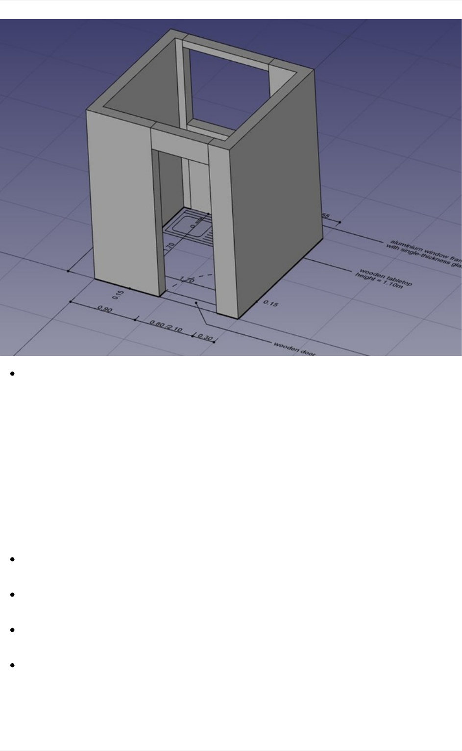
ThemostimportantthingabouttheDraftWorkbench,however,isthatthegeometryyou
createwithitcanbeusedasabaseoreasilyextrudedinto3Dobjects,simplybyusing
the ExtrudetoolfromthePartWorkbench,or,tostayinDraft,the Trimex
(Trim/Extend/Extrude)tool,whichunderthehoodperformsaPartExtrusion,butdoesit
"theDraftway",thatis,allowsyoutoindicateandsnaptheextrusionlengthgraphically.
Experimentextrudingourwallsasshownbelow.
Bypressingthe workingplanebuttonafterselectingafaceofanobject,youarealso
abletoplacetheworkingplaneanywhere,andthereforedrawDraftobjectsindifferent
planes,forexampleontopofthewalls.Thesecanthenbeextrudedtoformother3D
solids.Experimentsettingtheworkingplaneononeofthetopfacesofthewalls,then
drawsomerectanglesupthere.
Traditional2Ddrafting
77
AllkindsofopeningscanalsobedoneaseasilybydrawingDraftobjectsonthefaces
ofwalls,thenextrudingthem,thenusingthebooleantoolsfromthePartWorkbenchto
subtractthemfromanothersolid,aswesawinthepreviouschapter.
Fundamentally, what the Draft Workbench does is provide graphical ways to create basic
Part operations. While in Part you will usually position objects by setting their placement
propertybyhand,inDraftyoucandoiton-screen.Therearetimeswhenoneisbetter,other
times when the other is preferable. Don't forget, you can create custom toolars in one of
theseworkbenches,addthetoolsfromtheother,andgetthebestofbothworlds.
Downloads
Thefilecreatedduringthisexercise:https://github.com/yorikvanhavre/FreeCAD-
manual/blob/master/files/cabin.FCStd
ThesinkDXFfile:https://github.com/yorikvanhavre/FreeCAD-
manual/blob/master/files/sink.dxf
ThecooktopDXFfile:https://github.com/yorikvanhavre/FreeCAD-
manual/blob/master/files/cooktop.dxf
ThefinalDXFfileproducedduringthisexercise:
https://github.com/yorikvanhavre/FreeCAD-manual/blob/master/files/cabin.dxf
Readmore
Traditional2Ddrafting
78

Modelingforproductdesign
Productdesignisoriginallyacomercialterm,butinthe3Dworld,itoftenmeansmodeling
something with the idea to have it 3D-printed or, more generally, manufactured by a
machine,beinga3DprinteroraCNCmachine.
Whenyouprintobjectsin3D,itisofultimateimportancethatyourobjectsaresolid.Asthey
will become real, solid objects, this is obvious. Nothing prevent them from being hollow
inside, of course. But you always need to have a clear notion of which point is inside the
material,andwhichpointisoutside,becausethe3DprinterortheCNCmachineneedsto
knowexactlywhatisfilledwithmaterialandwhatisnot.For thisreason,inFreeCAD,the
PartDesignWorkbenchistheperfecttooltobuildsuchpieces,becauseitwillalwaystake
careforyouthatyourobjectsstaysolidandbuildable.
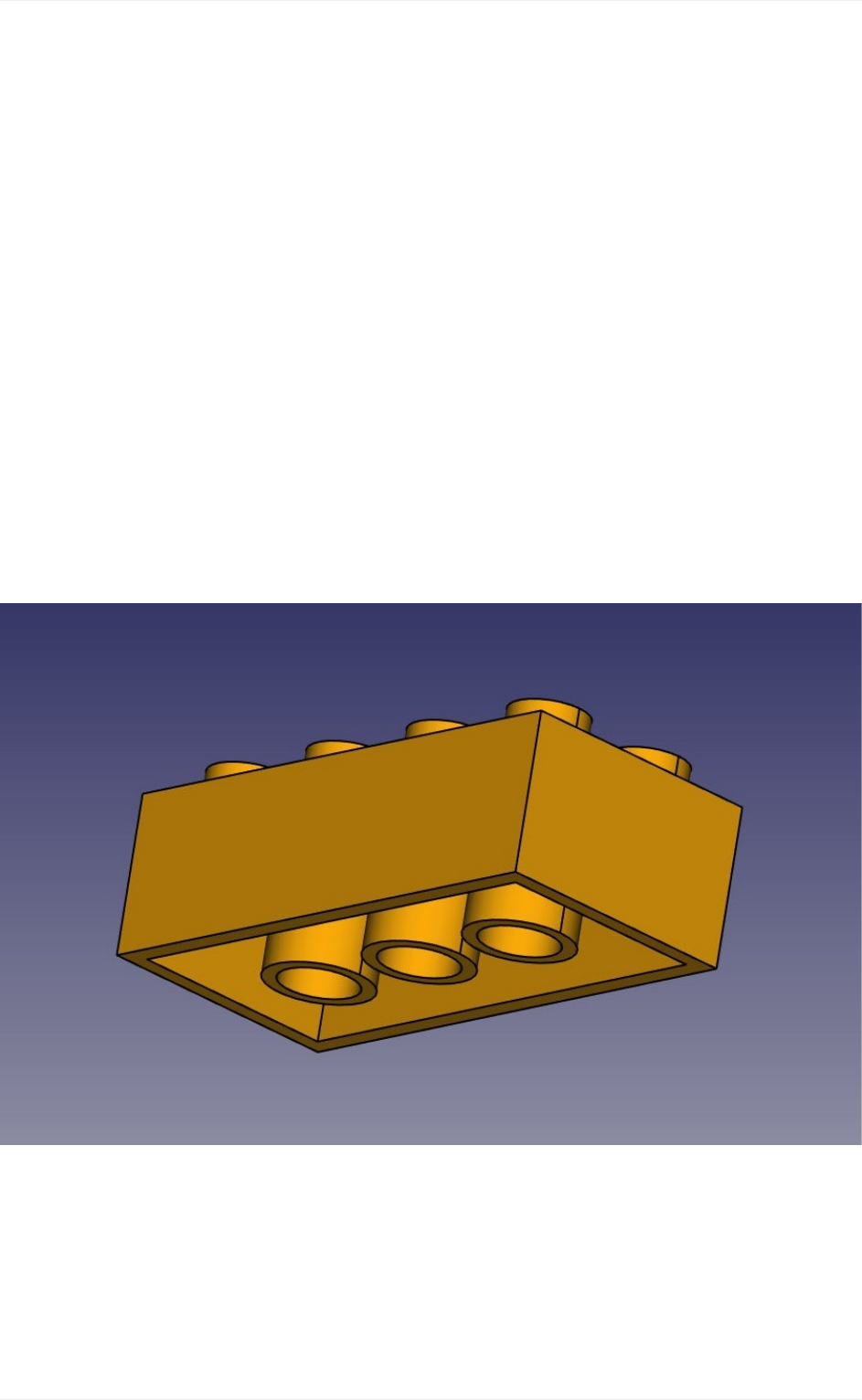
To illustrate how the PartDesign Workbench works, let's model this well-known piece of
Lego:
ThecoolthingwithLegopiecesisthatthedimensionsareeasytoobtainontheinternet,at
leastforthestandardpieces.Theseareprettyeasytomodelandprintona3Dprinter,and
withabitofpatience(3Dprintingoftenrequiresmuchadjustmentandfine-tuning)youcan
make pieces that are totally compatible and click perfectly into original Lego blocks.In the
examplebelow,wewillmakeapiecethatis1.5timesbiggerthantheoriginal.
Modelingforproductdesign
80
WewillnowuseexclusivelytheSketcherandPartDesigntools.Sinceallthetoolsfromthe
SketcherWorkbencharealsoincludedinthePartDesignWorkbench,wecanstayinPart
Designandwewillnotneedtoswitchbackandforthbetweenthetwo.
PartDesignobjects arefullybased onSketches.A Sketchisa2D object,madeoflinear
segments(lines,arcsofcircleorellipses)andconstraints.Theseconstraintscanbeapplied
eitheronlinearsegmentsorontheirendpointsorcenterpoints,andwillforcethegeometry
toadoptcertainrules.Forexample,youcanplaceaverticalconstraintonalinesegmentto
forceittostayvertical,oraposition(lock)constraintonanendpointtoprohibitittomove.
Whenasketchhasanexactamountofconstraintsthatprohibitsanypointofthesketchto
be moved anymore, we talk about a fully constrained sketch. when there are redundant
constraints,thatcould beremovedwithout allowingthegeometry tobemoved, itiscalled
over-constrained.Thisshouldbeavoided,andFreeCADwillnotifyyouifsuchcaseoccurs.
Sketcheshaveaneditmode,wheretheirgeometryandconstraintscanbechanged.When
youaredonewithediting,andleaveeditmode,sketchesbehaveslikeanyotherFreeCAD
object, and can be used as building blocks for all the Part Design tools, but also in other
workbenches,suchasPartorArch.TheDraftWorkbenchalsohasatoolthatconvertsDraft
objectstoSketches,andvice-versa.
Let'sstartbymodelingacubicshapethatwillbethebaseofourLegobrick.Lateron
wewillcarvetheinsides,andaddthe8dotsontopofit.Solet'sstartthisbymakinga
rectangularsketchthatwewillthenextrude:
SwitchtothePartDesignWorkbench
Clickonthe NewSketchbutton.Adialogwillappearaskingwhereyouwanttoliethe
sketch,choosetheXYplane,whichisthe"ground"plane.Thesketchwillbecreated
andwillimmediatelybeswitchedtoeditmode,andtheviewwillberotatedtolookat
yoursketchorthogonally.
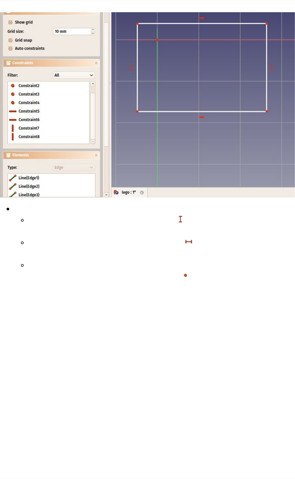
Nowwecandrawarectangle,byselectingthe Rectangletoolandclicking2corner
points.Youcanplacethetwopointsanywhere,sincetheircorrectlocationwillbesetin
thenextstep.
Youwillnoticethatacoupleofconstraintshaveautomaticallybeenaddedtoour
rectangle:theverticalsegmentshavereceivedaverticalconstraint,thehorizontalones
ahorizontalconstraint,andeachcornerapoint-on-pointconstraintthatgluesthe
segmentstogether.Youcanexperimentmovingtherectanglearoundbydraggingits
lineswiththemouse,allthegeometrywillkeepobeyingtheconstraints.
Modelingforproductdesign
81
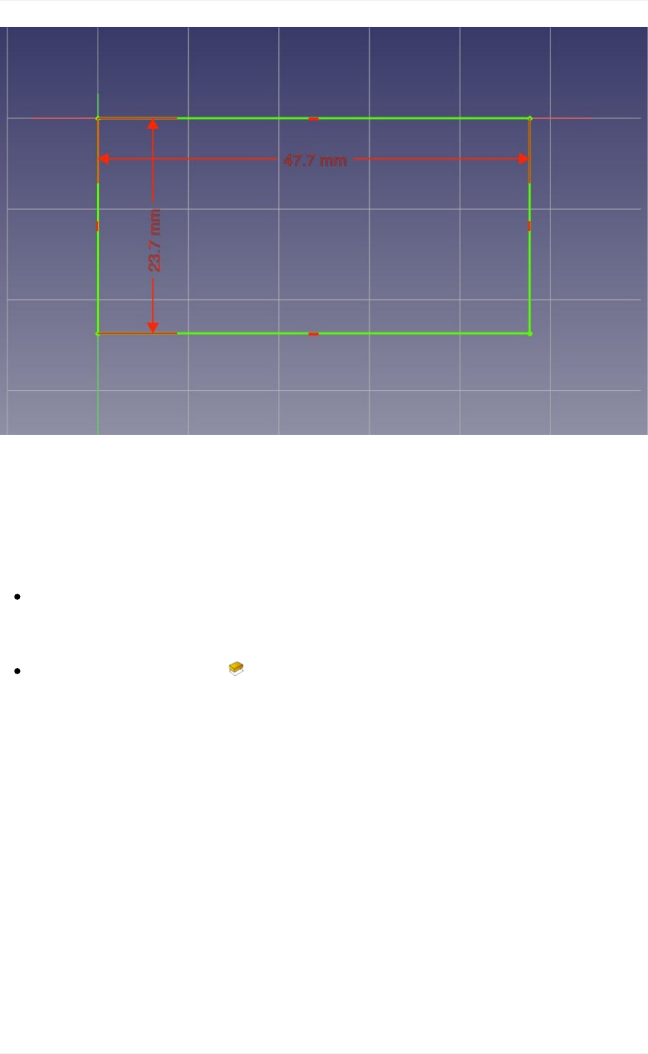
Now,let'saddthreemoreconstraints:
Selectoneoftheverticalsegmentsandadda VecticalDistanceConstraint.Give
itasizeof23.7mm.
Selectoneofthehorizontalsegmentsandadda HorizontalDistanceConstraint.
Makeit47.7mm.
Finally,selectoneofthecornerpoints,thentheoriginpoint(whichisthedotatthe
crossingoftheredandgreenaxes),thenadda Point-on-PointConstraint.The
rectanglewillthenjumptotheoriginpoint,andyoursketchwillturngreen,meaning
itisnowfullyconstrained.Youcantrymovingitslinesorpoints,nothingwillmove
anymore.
Modelingforproductdesign
82
Note that the last point-on-point constraint was not absolutely necessary. You are never
forcedtoworkwithfullyconstrainedsketches.However,ifwearegoingtoprintthisblockin
3D, it will be necessary to maintain our piece close to the origin point (which will be the
center of the space where the printer head can move). By adding that constraint we are
makingsurethatourpiecewillalwaysstay"anchored"tothatoriginpoint.
Ourbasesketchisnowready,wecanleaveeditmodebypressingtheClosebuttonon
topofitstaskpanel,orsimplybypressingtheEscapekey.Ifneededlateron,wecan
reentereditmodeanytimebydouble-clickingthesketchinthetreeview.
Let'sextrudeitbyusingthe Padtool,andgivingitadistanceof14.4mm.Theother
optionscanbeleftattheirdefaultvalues:
Modelingforproductdesign
83
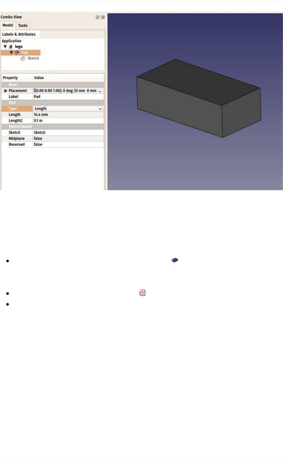
ThePadbehavesverymuchlikethePartExtrudetoolthatweusedinthepreviouschapter.
Thereareacoupleofdifferences,though,themainonebeingthatapadcannotbemoved.
Itisattachedforevertoitssketch.Ifyouwanttochangethepositionofthepad,youmust
movethebasesketch.Inthecurrentcontext,wherewewanttobesurenothingwillmove
outofposition,thisisanadditionalsecurity.
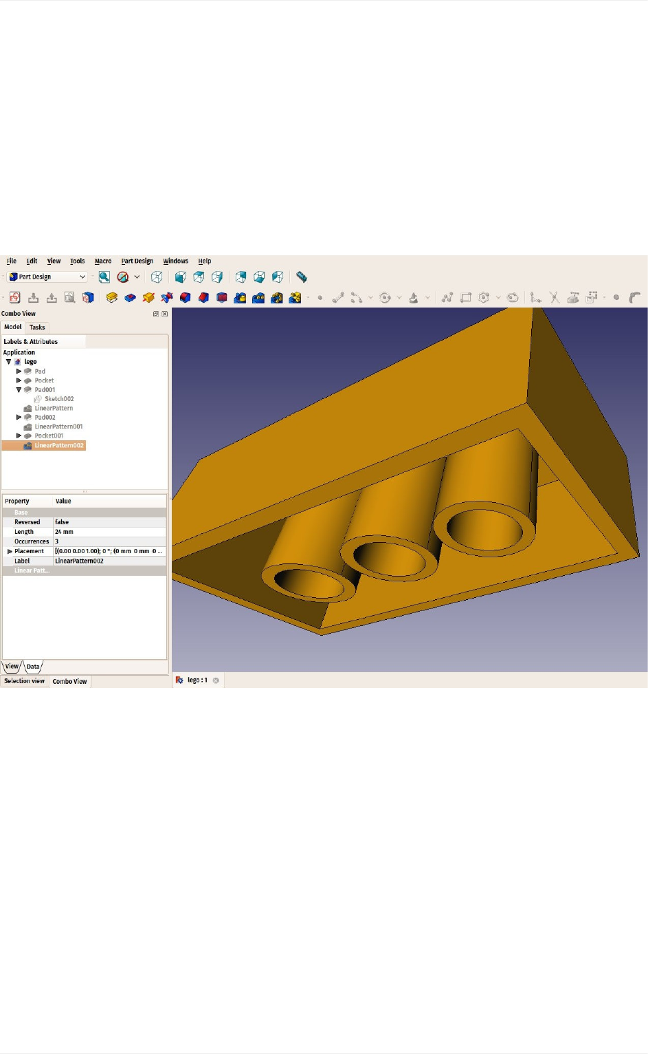
Wewillnowcarvetheinsideoftheblock,usingthe Pockettool,whichisthe
PartDesignversionofPartCut.Tomakeapocket,wewillcreateasketchonthebottom
faceofourblock,whichwillbeusedtoremoveapartoftheblock.
Withthebottomfaceselected,pressthe NewSketchbutton.
Drawarectangleontheface.
Modelingforproductdesign
84
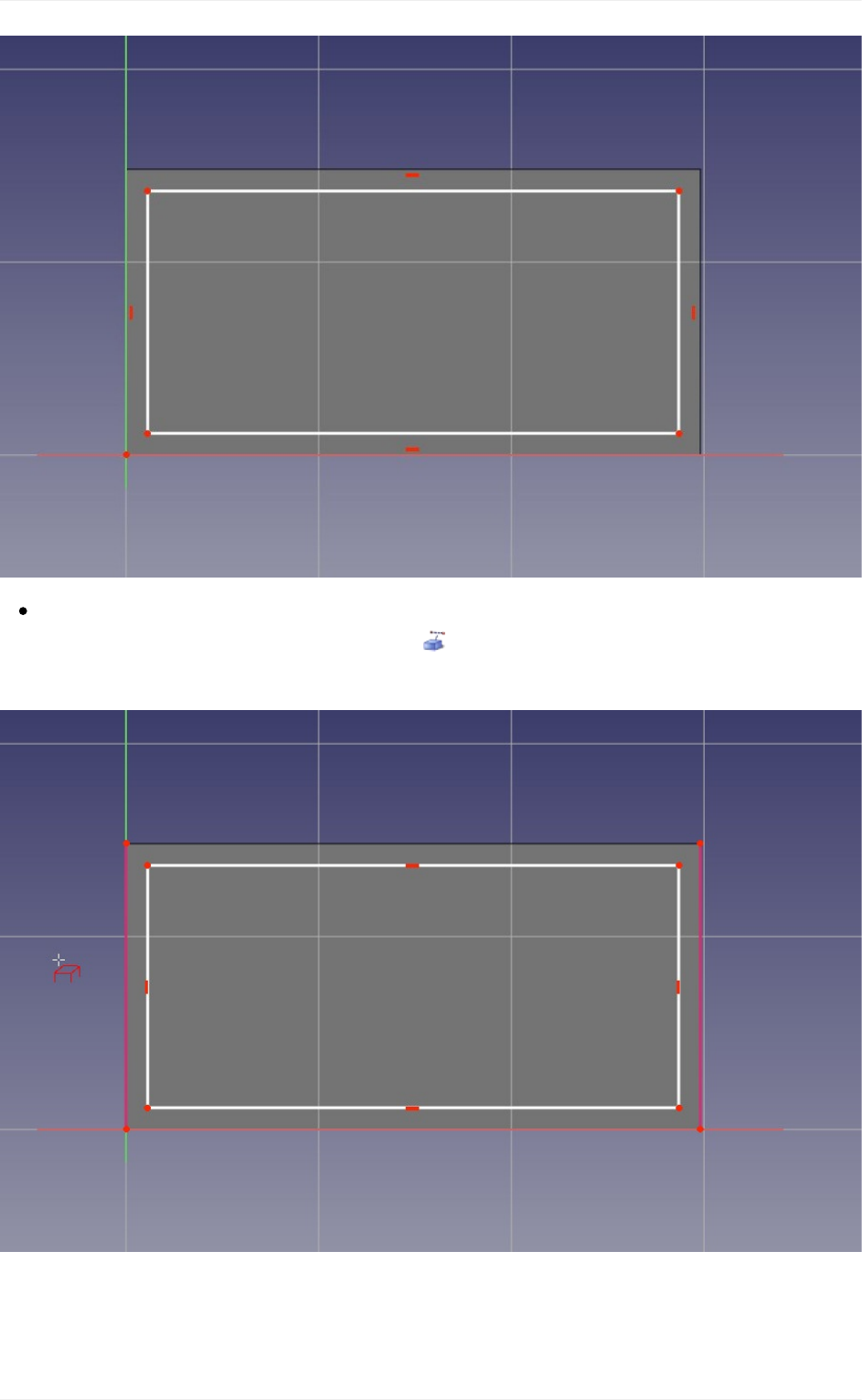
Wewillnowconstraintherectangleinrelationtothebottomface.Todothis,weneedto
"import"someedgesofthefacewiththe Externalgeometrytool.Usethistoolonthe
twoverticallinesofthebottomface:
Youwillnoticethatonlyedgesfromthethebasefacecanbeaddedbythistool.Whenyou
createasketchwithafaceselected,arelationiscreatedbetweenthatfaceandthesketch,
which is important for further operations. You can always remap a sketch to another face
Modelingforproductdesign
85
laterwiththe MapSketchtool.
Theexternalgeometryisnot"real",itwillbehiddenwhenweleaveeditmode.Butwe
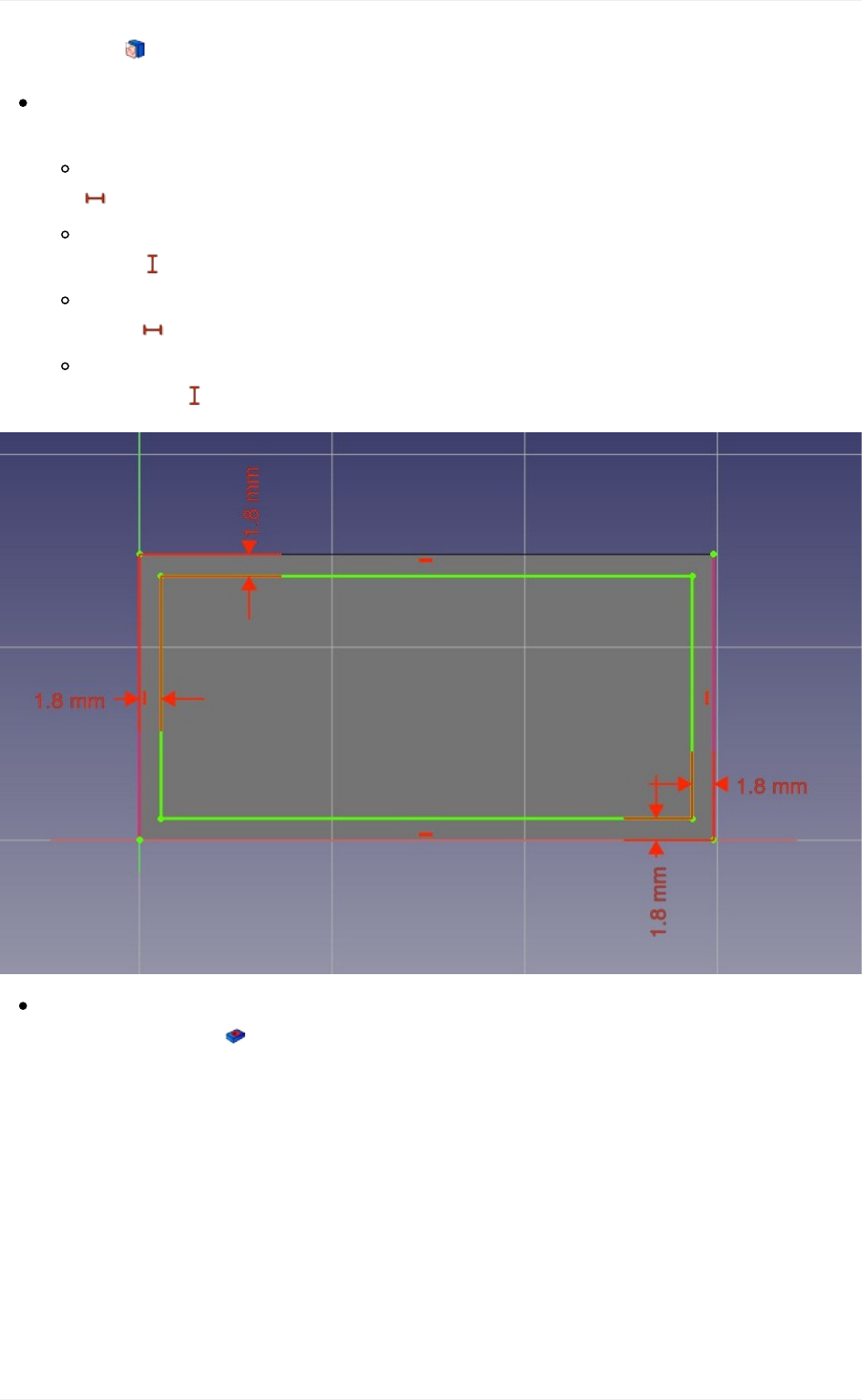
canuseittoplaceconstraints.Placethe4followingconstraints:
Selectthetwoupperleftpointsoftherectangleandtheleftimportedlineandadda
HorizontalDistanceConstraintof1.8mm
Selectagainthetwoupperleftpointsoftherectangleandtheleftimportedlineand
adda VecticalDistanceConstraintof1.8mm
Selectthetwolowerrightpointsoftherectangleandtherightimportedlineand
adda HorizontalDistanceConstraintof1.8mm
Selectagainthetwolowerrightpointsoftherectangleandtherightimportedline
andadda VecticalDistanceConstraintof1.8mm
Leaveeditmodeandwecannowperformthepocketoperation:Withthesketch
selected,pressthe Pocketbuttton.Giveitalengthof12.6mm,whichwillleavethe
upperfaceofourpadwithathicknessof1.8mm(remember,thetotalheightofourpad
was14.4mm).
Modelingforproductdesign
86
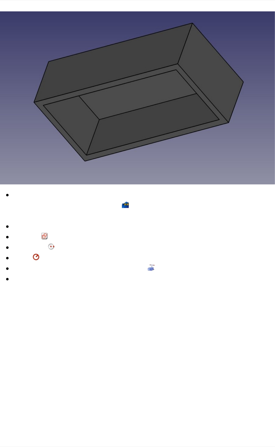
Wewillnowattackthe8dotsonthetopface.Todothis,sincetheyarearepetitionofa
samefeature,wewillusethehandy LinearPatterntoolofthePartDesign
Workbench,whichallowstomodelonceandrepeattheshape.
Startbyselectingthetopfaceofourblock
Createa NewSketch.
Createtwo circles.
Adda RadiusConstraintof3.6mmtoeachofthem
Importtheleftedgeofthebasefacewiththe Externalgeometrytool.
Placetwoverticalconstraintsandtwohorizontalconstraintsof6mmbetweenthecenter
pointofeachcircleandthecornerpointsoftheimportededge,soeachcirclehasits
centerat6mmfromtheborderoftheface:
Modelingforproductdesign
87
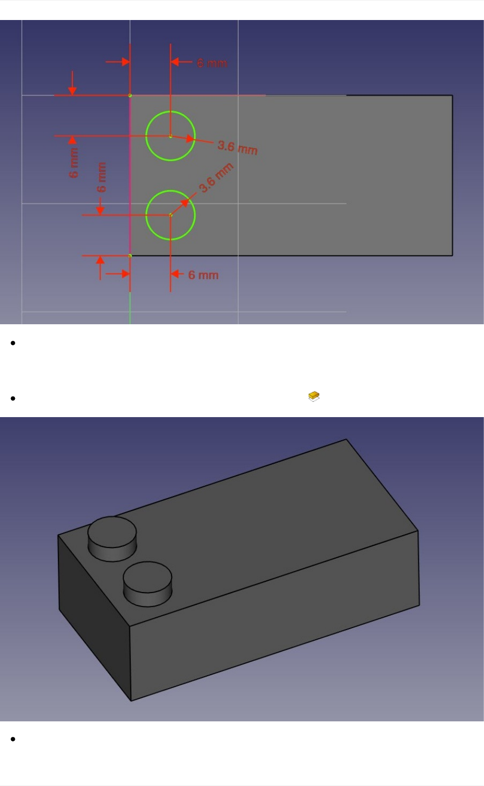
Noticehow,onceagain,whenyoulockthepositionanddimensionofeverythinginyour
sketch,itbecomesfullyconstrained.Thisalwayskeepsyouonthesafeside.Youcould
changethefirstsketchnow,everythingwedidafterwardswouldkeeptight.
Leaveeditmode,selectthisnewsketch,andcreatea Padof2.7mm:
Noticethat,asearlierwiththepocket,sinceweusedthetopfaceofourbaseblockasa
baseforthislatestsketch,anyPartDesignoperationwedowiththissketchwillcorrectly
Modelingforproductdesign
88
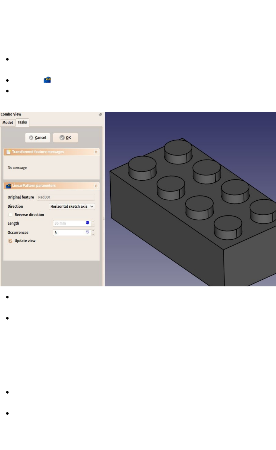
bebuiltontopofthebaseshape:Thetwodotsarenotindependentobjects,theyhave
beenextrudeddirectlyfromourbrick.Thisisthegreatadvantageofworkingwiththe
PartDesignWorkbench,aslongasyoutakecareofalwaysbuildingonestepontopof
thepreviousone,youareactuallybuildingonefinalsolidobject.
Wecannowduplicateourtwodotsfourtimes,sowegeteight.SelectthelatestPadwe
justcreated.
Pressthe LinearPatternbutton.
Giveitalengthof36mm(whichisthetotal"span"wewantourcopiestofitin),inthe
"horizontalsketchaxis"direction,andmakeit4occurences:
Onceagain,seethatthisisnotjustaduplicationofanobject,itisafeatureofour
shapethathasbeenduplicated,thefinalobjectisstillonlyonesolidobject.
Nowlet'sworkonthethree"tubes"thatfillthevoidwecreatedonthebottomface.We
haveseveralpossibilities:createasketchwiththreecircles,paditthenpocketitthree
times,orcreateabasesketchwithonecircleinsidetheotherandpadittoformthe
completetubealready,orevenothercombinations.LikealwaysinFreeCAD,thereare
manywaystodoachieveasameresult.Sometimesonewaywillnotworkthewaywe
want,andwemusttryotherways.Here,wewilltakethesafestapproach,anddothings
onestepatatime.
Selectthefacethatisatthebottomofthehollowspacewecarvedearlierinsidethe
block.
Createanewsketch,addacirclewitharadiusof4.8825mm,importtheleftborderof
theface,andconstrainitverticallyandhorizontallyat10.2mmfromtheuppercornerof
theface:
Modelingforproductdesign
89
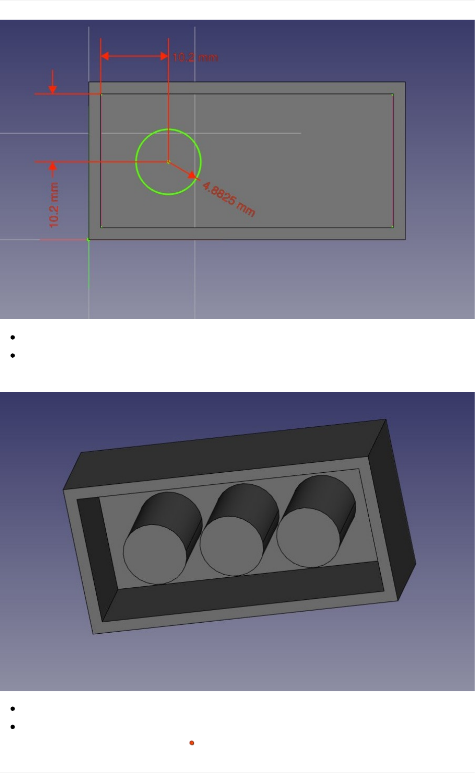
Leaveeditmode,andpadthissketchwithadistanceof12.6mm
Createalinearpatternfromthislastpad,giveitalengthof24mmand3occurences.
Wenowhavethreefilledtubesfillingthehollowspace:
Nowlet'smakethefinalholes.Selectthecircularfaceofthefirstofourthree"pins"
Createanewsketch,importthecircularboderofourface,createacirclewitharadius
constraintof3.6mm,andadda Point-on-PointConstraintbetweenthecenterofthe
Modelingforproductdesign
90
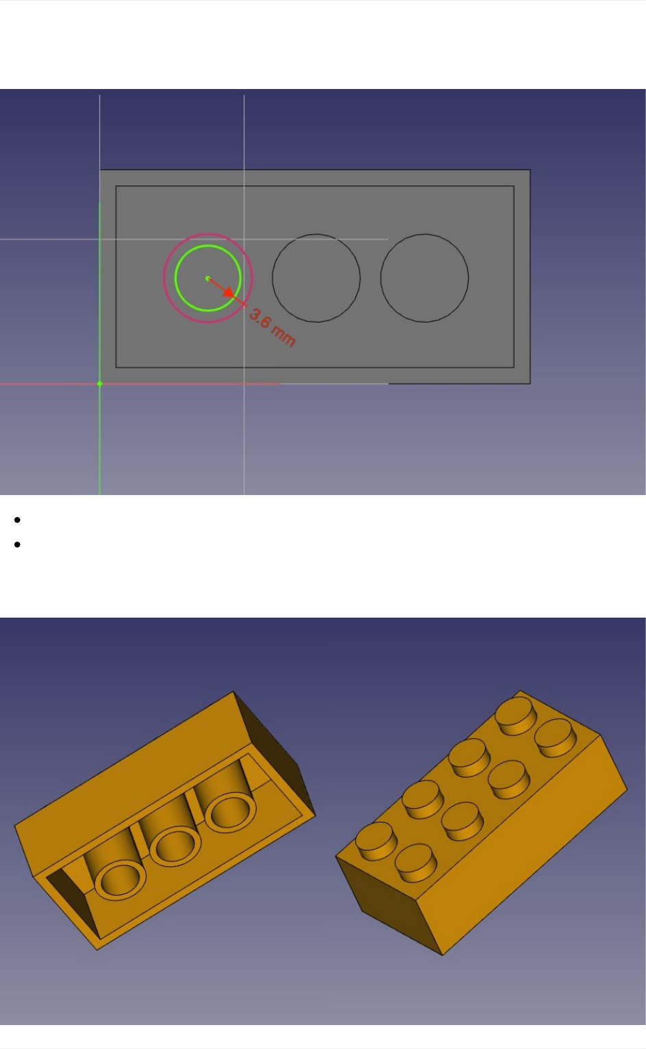
importedcircleandournewcircle.Wenowhaveaperfectlycenteredcircle,andonce
againfullyconstrained:
Leaveeditmode,andcreateapocketfromthissketch,withalengthof12.6mm
Createalinearpatternfromthispocket,withalengthof24mmand3occurences.
That'sthelaststep,ourpieceoflegoisnowcomplete,wecangiveitanicecolorof
Victory!
Modelingforproductdesign
91

Youwillnoticethatourmodelinghistory(whatappearsinthetreeview)hasbecomequite
long.Thisisofpreciousbecauseeverysinglestepofwhatwedidcanbechangedlateron.
Adaptingthismodelforanotherkindofbrick,forexampleonewith2x2dots,insteadof2x4,
would be a piece of cake, we would just need to change a couple of dimensions and the
numberofoccurencesinlinearpatterns.Wecouldaseasilycreatebiggerpiecesthatdon't
existintheoriginalLegogame.
Butwecouldalsoneedtogetridofthehistory,forexampleifwearegoingtomodelacastle
withthisbrick,andwedon'twanttohavethiswholehistoryrepeated500timesinourfile.
Therearetwosimplewaystogetridofthehistory,oneisusingtheCreatesimplecopytool
fromthePartWorkbench,whichwillcreateacopyofourpiecethatdoesn'tdependanymore
onthehistory(youcandeletethewholehistoryafterwards),theotherwayisexportingthe
pieceasaSTEPfileandreimportingit.
Assembling
Butthebestofbothworldsalsoexists,whichistheAssembly2Workbench,anaddonthat
can be installed from the FreeCAD-addons repository. This Workbench is named "2"
becausethereisalsoanofficialbuilt-inAssemblyWorkbenchindevelopment,whichisnot
ready yet. The Assembly2 Workbench, however, already works very well to construct
assemblies,andalsofeaturesacoupleofobject-to-objectconstraintswhichyoucanuseto
constrainthepositionofoneobjectinrelationtoanother.Intheexamplebelow,however,it
will be quicker and easier to position the pieces using Draft Move and Draft Rotate
thanusingtheAssembly2constraints.
Savethefilewediduntilnow
InstalltheAssembly2WorkbenchandrestartFreeCAD
Createanewemptydocument
SwitchtotheAssembly2workbench
PresstheImportapartfromanotherFreeCADdocumentbutton
Selectthefilewesavedabove
Thefinalpiecewillbeimportedinthecurrentdocument.TheAssembly2workbenchwill
determineautomaticallywhatisthefinalpieceinourfilethatneedstobeused,andthe
newobjectstayslinkedtothefile.Ifwegobackandmodifythecontentsofthefirstfile,
wecanpresstheUpdatepartsimportedintotheassemblybuttontoupdatethe
pieceshere.
ByusingtheImportapartfromanotherFreeCADdocumentbuttonseveraltimes,
andmovingandrotatingthepieces(withtheDrafttoolsorbymanipulatingtheir
Placementproperty),wecanquicklycreateasmallassembly:
Modelingforproductdesign
92
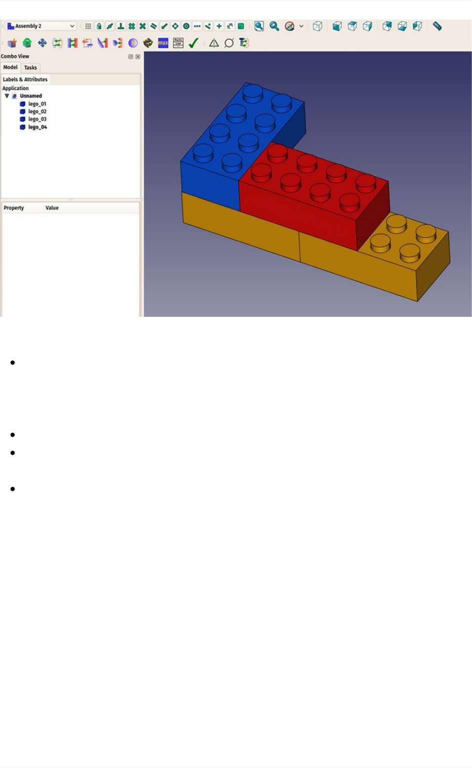
Downloads
Themodelproducedduringthisexercise:https://github.com/yorikvanhavre/FreeCAD-
manual/blob/master/files/lego.FCStd
Readmore
TheSketcher:http://www.freecadweb.org/wiki/index.php?title=Sketcher_Module
ThePartDesignWorkbench:http://www.freecadweb.org/wiki/index.php?
title=PartDesign_Workbench
TheAssembly2Workbench:https://github.com/hamish2014/FreeCAD_assembly2
Modelingforproductdesign
93

Preparingmodelsfor3Dprinting
OneofthemainusesofFreeCADistoproducereal-worldobjects.Thesecanbedesigned
inFreeCAD,andthenmaderealbydifferentways,suchascommunicatedtootherpeople
whowillthenbuildthem,or,moreandmorefequently,sentdirectlytoa3DprinteroraCNC
mill.Thischapterwillshowyouhowtogetyourmodelsreadytosendtothesemachines.
Ifyouhavebeencautiouswhilemodeling,mostofthedifficultyyoumightencounterwhen
printingyourmodelin3Dhasalreadybeenavoided.Thisinvolvesbasically:
Makingsurethatyour3Dobjectsaresolid.Real-worldobjectsaresolid,the3Dmodel
mustbesolidtoo.WesawinearlierchaptersthatFreeCADhelpsyoualotinthat
regard,andthatthePartDesignWorkbenchwillnotifyyouifyoudoanoperationthat
preventsyourmodeltostaysolid.ThePartWorkbenchalsocontainsa Check
Geometrytoolthatishandytocheckfurtherforpossibledefects.
Makingsureaboutthedimensionsofyourobjects.Onemillimeterwillbeone
millimeterinreal-life.Everydimensionmatters.
Controllingthedegradation.No3DprintingorCNCmillingsystemcantakeFreeCAD
filesdirectly.MostofthemwillonlyunderstandamachinelanguagecalledG-Code.G-
codehasdozensofdifferentdialects,eachmachineorvendorusuallyusingitsown.
TheconversiomofyourmodelsintoG-Codecanbeeasyandautomatic,butyoucan
alsodoitmanually,withtotalcontrolovertheoutput.Inanycase,somelossofquality
ofyourmodelwillunavoidablyoccurduringtheprocess.Whenprintingin3D,youmust
alwaysmakesurethislossofqualitystaysbelowyourminimalrequirements.
Below,wewillassumethatthefirsttwocriteriasaremet,andthatbynowyouareableto
produce solid objects with correct dimensions. We will now see how to address the third
point.
Exportingtoslicers
This is the technique most commonly used for 3D printing. The 3D object is exported to
anotherprogram(theslicer)whichwillgeneratetheG-codefromtheobject,byslicingitinto
thinlayers(hencethename),whichwillreproducethemovementsthatthe3Dprinterwilldo.
Sincemanyofthose printersarehome-built,thereareoften smalldifferencesfromoneto
the other. These programs usually offer advanced configuration possibilities that allow to
tailortheoutputexactlyfortheparticularitiesofyour3Dprinter.
Actual 3D printing, however, is a too vast subject for this manual. But we will see how to
exportandusetheseslicerstocheckthattheoutputiscorrect.
Preparingmodelsfor3Dprinting
94

Convertingobjectstomeshes
Noneoftheslicerswill,atthisdate,takedirectlysolidgeometryasweproduceinFreeCAD.
Sowewillneedtoconvertanyobjectwewantto3Dprintintoameshfirst,thattheslicer
canopen.Fortunately,convertingasolidtoamesh,isverystraightforward.Allweneedto
becarefulabout,isthatit isnowthatthedegradationwe mentionedabovewilloccur.We
needtocheckthatthedegradationstaysinsideacceptablelimits.
All the mesh handling, in FreeCAD, is done by another specific workbench, the Mesh
Workbench. This workbench contains, the tools that convert between Part and Mesh
objects,severalutilitiesmeanttoanalyzeandrepairmeshes.Althoughworkingwithmeshes
isnotthefocusofFreeCAD,whenworkingwith3Dmodeling,youoftenneedtodealwith
meshobjects,sincetheiruseisverywidespreadamongotherapplications.Thisworkbench
allowsyoutohandlethemfullyinFreeCAD.
Let'sconvertoneoftheobjectswemodelledinthepreviouschapters,suchasthelego
piece(whichcanbedownloadedfromtheendofthepreviouschapter).
OpentheFreeCADfilecontainingthelegopiece.
SwitchtotheMeshWorkbench
Selectthelegobrick
SelectmenuMeshes->CreateMeshfromShape
Ataskpanelwillopenwithseveraloptions.Someadditionalmeshingalgorithms
(MefistoorNetgen)mightnotbeavailable,dependingonhowyourversionofFreeCAD
wascompiled.TheStandardmeshingalgorithmwillalwaysbepresent.Itoffersless
possibilitiesthanthetwoothers,butistotallysufficientforsmallobjectsthatfitintothe
maximumprintsizeofa3Dprinter.
Preparingmodelsfor3Dprinting
95
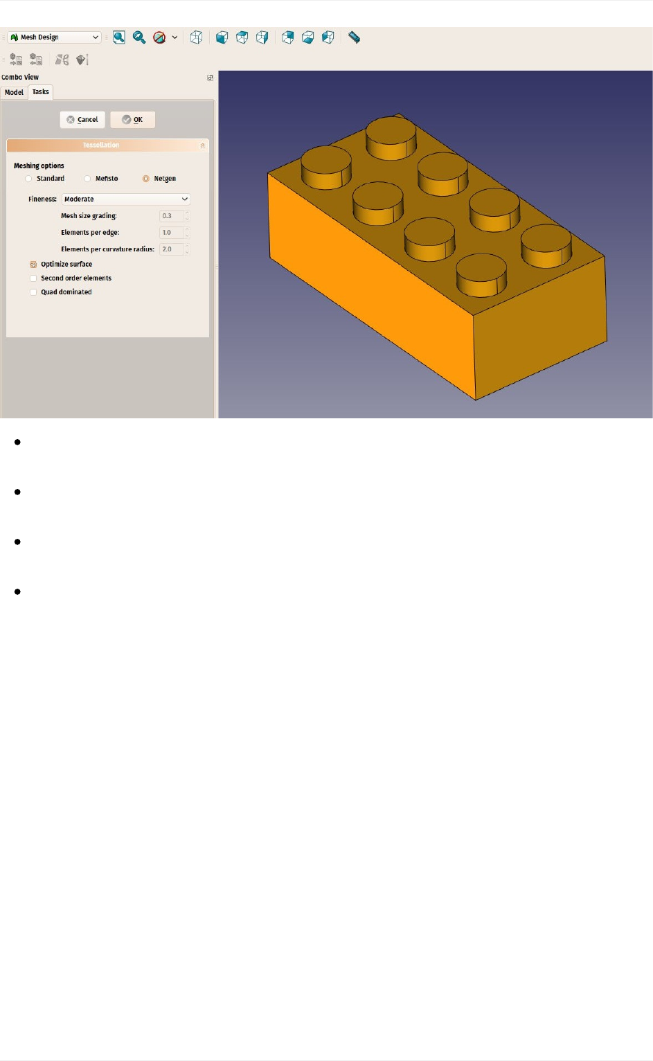
SelecttheStandardmesher,andleavethedeviationvaluetothedefaultvalueof0.10.
PressOk.
Ameshobjectwillbecreated,exactlyontopofoursolidobject.Eitherhidethesolid,or
moveoneoftheobjectsapart,soyoucancompareboth.
ChangetheView->DisplayModepropertyofthenewmeshobjecttoFlatLines,in
ordertoseehowthetriangulationoccured.
Ifyouarenothappy,andthinkthattheresultistoocoarse,youcanrepeatthe
operation,loweringthedeviationvalue.Intheexamplebelow,theleftmeshusedthe
defaultvalueof0.10,whiletherightoneuses0.01:
Preparingmodelsfor3Dprinting
96
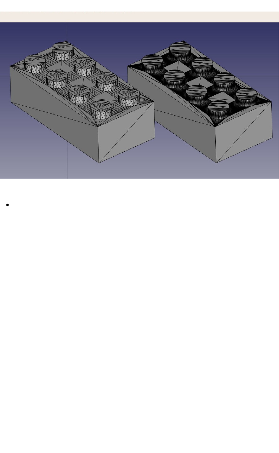
Inmostcases,though,thedefaultvalueswillgiveasatisfyingresult.
Wecannowexportourmeshtoameshformat,suchasSTL,whichiscurrentlythe
mostwidelyusedformatin3Dprinting,byusingmenuFile->Exportandchoosingthe
STLfileformat.
Ifyoudon'towna3Dprinter,itisusuallyveryeasytofindcommercialservicesthatwillprint
and send you the printed objects by mail. Among the famous ones are Shapeways and
Sculpteo,butyouwillalsousuallyfindmanyothersinyourowncity.Inallmajorcities,you
will also nowadays find Fab labs, which are workshops equipped with a range of 3D
manufacturing machines, almost always including at least one 3D printer. Fab labs are
usually community spaces, that will let you use their machines, for a fee or for free
dependingontheFablab,butalsoteachyouhowtousethem,andpromoteotheractivities
around3Dmanufacturing.
UsingSlic3r
Slic3risanapplicationthatconvertsSTLobjectsintoG-codethatcanbesentdirectlyto3D
printers.Like FreeCAD, itis free, open-sourceand runsonWindows, MacOS and Linux.
Correctlyconfiguratingthingsfor3Dprintingisacomplicatedprocess,whereyoumusthave
a good knowledge of your 3D printer, so it is not very useful to generate G-code before
actually going to print (your G-code file might not work well on another printer), but it is
usefulforusanyway,tocheckthatourSTLfilewillbeprintablewithoutproblems.
Preparingmodelsfor3Dprinting
97
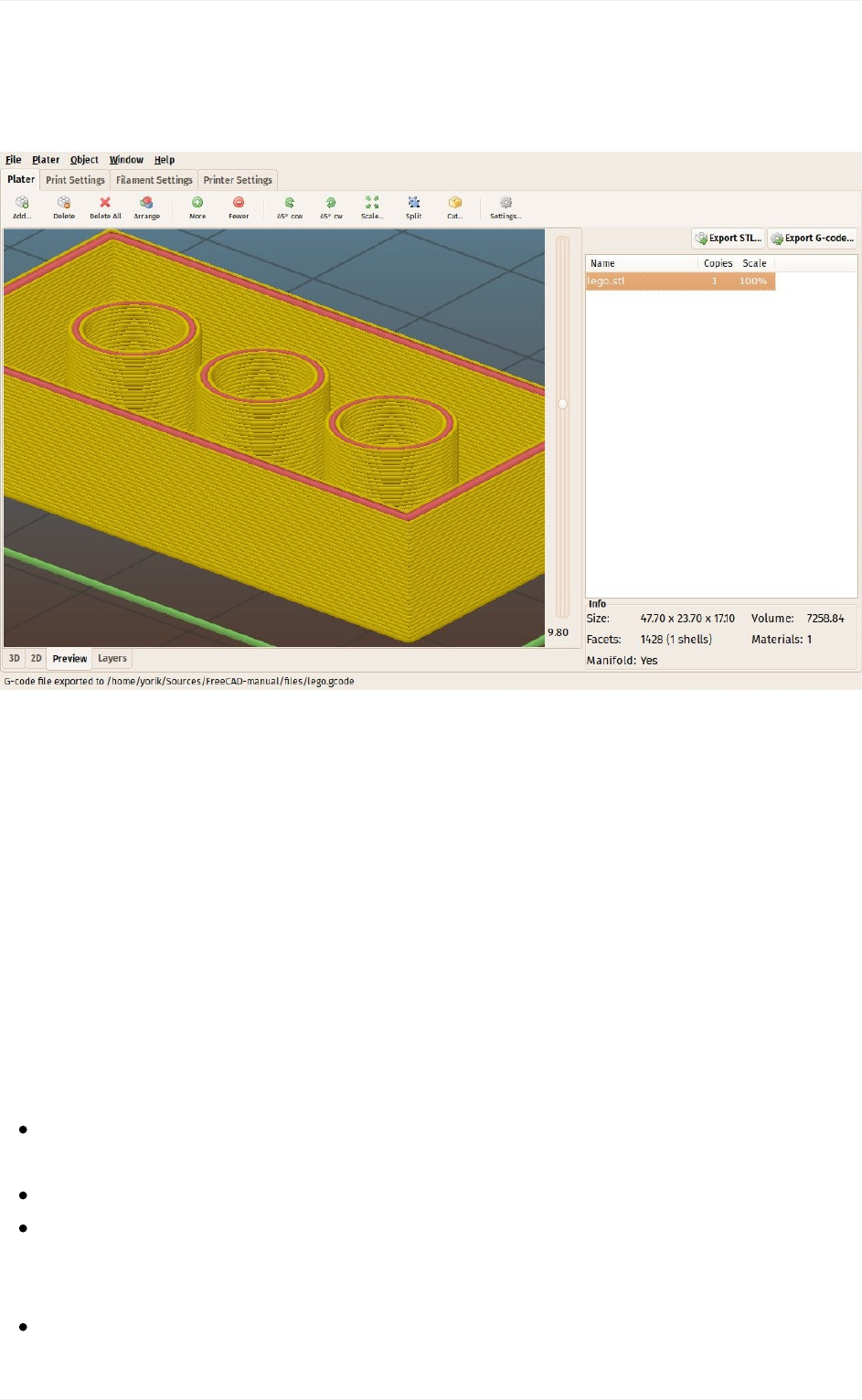
This is our exported STL file opened in Slic3r. By using the preview tab, and moving the
right slider, we can visualize the path that the 3D printer head will follow to construct our
object.
UsingtheCuraaddon
Cura is another free and open-source slicer application for Windows, Mac and Linux,
maintainedbythe3DprintermakerUltimaker.SomeFreeCADusershavecreatedaCura
Workbench that uses cura internally. The Cura Workbench is available from the FreeCAD
addonsrepository.TousetheCuraWorkbench,youalsoneedtoinstallCuraitself,whichis
notincludedintheworkbench.
Onceyou haveinstalledboth Curaand theCura Workbench,youwill be ableto useit to
produce the G-code file directly from Part objects, without the need to convert them to
meshes, and without the need to open an external application. Producing another G-code
filefromourLegobrick,usingtheCuraWorkbenchthistime,isdoneasfollows:
LoadthefilecontainingourLegobrick(itcanbedownloadedattheendoftheprevious
chapter)
SwitchtotheCuraWorkbench
Setuptheprinterspacebychoosingmenu3Dprinting->Createa3Dprinter
definition.Sincewearen'tgoingtoprintforreal,wecanleavethesettingsastheyare.
Thegeometryoftheprintingbedandavailablespacewillbeshowninthe3Dview.
MovetheLegobricktoasuitablelocation,suchasthecenteroftheprintingbed.
Preparingmodelsfor3Dprinting
98
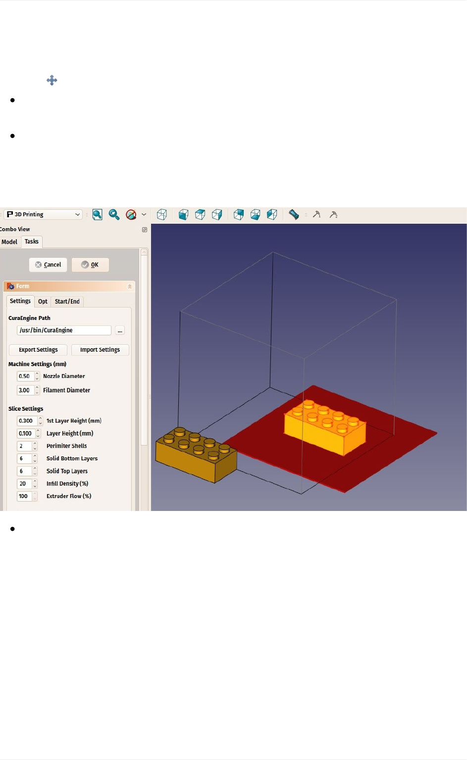
RememberthatPartDesignobjectscannotbemoveddirectly,soyouneedeitherto
moveitsveryfirstsketc(thefirstrectangle),ortomove(andprint)acopy,whichcanbe
madewiththePart->CreateSimpleCopytool.Thecopycanbemoved,forexample
with Draft->Move.
Selecttheobjecttobeprinted,andselectmenu3Dprinting->SlicewithCura
Engine.
Inthetaskpanelthatwillopen,makesurethepathtotheCuraexecutableiscorrectly
set.Sincewearenotgoingtoreallyprint,wecanleaveallotheroptionsastheyare.
PressOk.TwofileswillbegeneratedinthesamedirectoryasyourFreeCADfile,an
STLfileandaG-codefile.
ThegeneratedG-codecanalsobereimportedintoFreeCAD(usingtheslic3r
preprocessor)forchecking.
GeneratingG-code
FreeCADalsooffersmoreadvancedwaystogenerateG-codedirectly.Thisisoftenmuch
morecomplicatedthanusingautomatictoolsaswesawabove,buthastheadvantagetolet
youfullycontroltheoutput.Thisisusuallynotneededwhenusing3Dprinters,butbecomes
veryimportantwhendealingwithCNCmilling,asthemachinesaremuchmorecomplex.
G-codepathgenerationinFreeCADisdonewiththePathWorkbench.Itfeaturestoolsthat
generatefullmachinepathsandothersthatgenerateonlypartsofaG-codeproject,thatcan
beassembledtoformawholemillingoperation.
Preparingmodelsfor3Dprinting
99
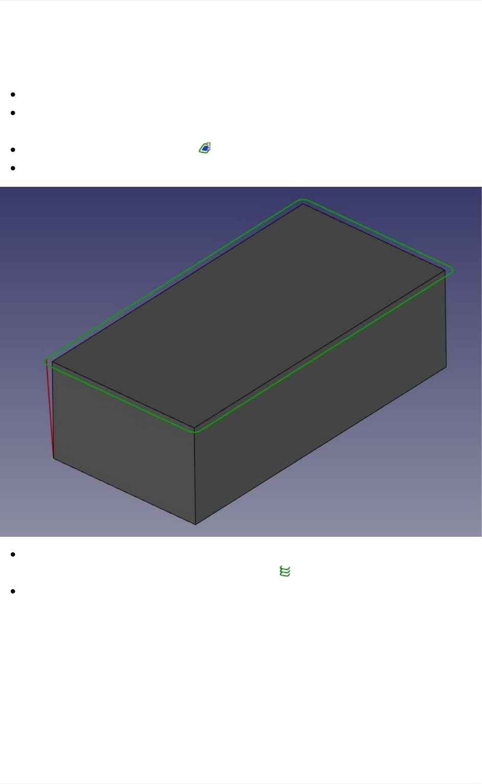
GeneratingCNCmillingpathsisanothersubjectthatismuchtoovasttofitinthismanual,
sowearegoingtoshowhowtobuildasimplePathproject,withoutcaringmuchaboutmost
ofthedetailsofrealCNCmachining.
Loadthefilecontainingourlegopiece,andswitchtothePathWorkbench.
Sincethefinalpiecedoesn'tcontainanymorearectangulartopface,hidethefinallego
piece,andshowthefirstcubicpadthatwedid,whichhasarectangulartopface.
Selectthetopfaceandpressthe FaceProfilebutton.
SetitsOffsetpropertyto1mm.
Then,let'sduplicatethisfirstloopacoupleoftimes,sothetoolwillcarveoutthewhole
block.SelecttheFaceProfilepath,andpressthe Arraybutton.
SettheCopiespropertyofthearrayto8,anditsOffsetto-2mmintheZdirection,and
movetheplacementofthearrayby2mmintheZdirection,sothecuttingwillstartabit
abovethepad,andincludetheheightofthedotstoo.
Preparingmodelsfor3Dprinting
100
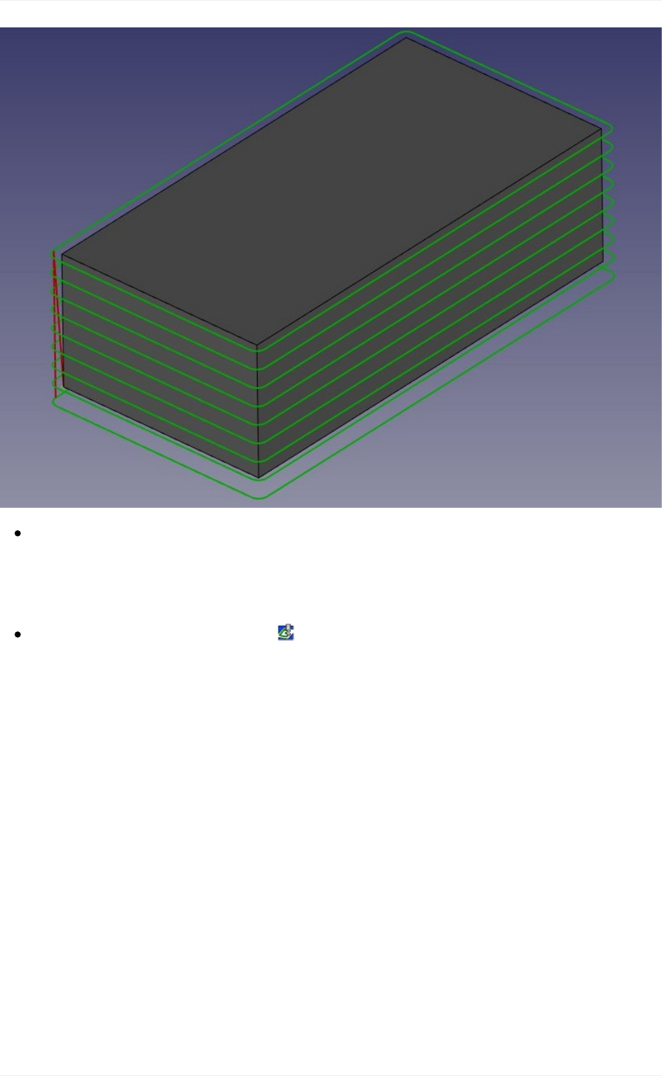
Nowwehavedefinedapaththat,whenfollowedbythemillingmachine,willcarvea
rectangularvolumeoutofablockofmaterial.Wenowneedtocarveoutthespace
betweenthedots,inordertorevealthem.HidethePad,andshowthefinalpieceagain,
sowecanselectthefacethatliesbetweenthedots.
Selectthetopface,andpressthe FacePocketbutton.SettheOffsetpropertyto
1mm,andtheretractionheightto20mm.Thatistheheighttowherethecutterwill
travelwhenswitchingfromonelooptoanother.Otherwise,thecuttermightcutright
throughoneofourdots:
Preparingmodelsfor3Dprinting
101
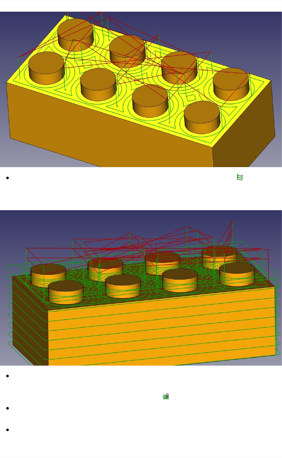
Onceagain,makeanarray.SelecttheFacePocketobject,andpressthe Array
button.SettheCopiesnumberto1andtheoffsetto-2mmintheZdirection.Movethe
placementofthearrayby2mmintheZdirection.Ourtwooperationsarenowdone:
Nowallthatislefttodoistojointhesetwooperationsintoone.Thiscanbedonewitha
PathCompoundoraPathProject.Sincewewillneednothingmoreandwillbereadyto
exportalready,wewillusetheproject.Pressthe Projectbutton.
SettheUsePlacementspropertyoftheprojectistoTrue,becausewechangedthe
placementofthearrays,andwewantthattobetakenintoaccountintheproject.
Inthetreeview,draganddropthetwoarraysintotheproject.Youcanreorderthe
arraysinsidetheprojectifneeded,bydouble-clickingit.
Preparingmodelsfor3Dprinting
102

TheprojectcannowbeexportedtoG-code,byselectingit,choosingmenuFile->
Export,selectingtheG-codeformat,andinthepop-updialogthatwillopen,selectinga
post-procesingscriptaccordingtoyourmachine.
Therearemanyapplicationsavailabletosimulatetherealcutting,oneofthemthatisalso
multi-platformandopen-source,likeFreeCAD,isCamotics.
Downloads
TheSTLfilegeneratedinthisexercise:https://github.com/yorikvanhavre/FreeCAD-
manual/blob/master/files/lego.stl
Thefilegeneratedduringthisexercise:https://github.com/yorikvanhavre/FreeCAD-
manual/blob/master/files/path.FCStd
TheG-codefilegeneratedinthisexercise:https://github.com/yorikvanhavre/FreeCAD-
manual/blob/master/files/lego.gcode
Readmore
TheMeshWorkbench:http://www.freecadweb.org/wiki/index.php?title=Mesh_Module
TheSTLfileformat:https://en.wikipedia.org/wiki/STL_%28file_format%29
Slic3r:http://slic3r.org/
Cura:https://ultimaker.com/en/products/cura-software
TheCuraWorkbench:https://github.com/cblt2l/FreeCAD-CuraEngine-Plugin
ThePathWorkbench:http://www.freecadweb.org/wiki/index.php?title=Path_Workbench
Camotics:http://camotics.org/
Preparingmodelsfor3Dprinting
103

Generating2Ddrawings
Whenyourmodelcannotbeprintedormilleddirectlybyamachine,forexampleitistoobig
(abuilding)oritrequiresmanualassemblyafterthepiecesareready,youwillusuallyneed
to explain to another person how to do that. In technical fields (engineering, architecture,
etc),thisisusuallydonewithdrawings,thatarehandedovertothepersonresponsiblefor
assemblingthefinalproduct,thatwillexplainhowtodoit.
TypicalexamplesareIkeainstructions,architecturaldrawingsorblueprints.Thesedrawings
usually contain not only the drawing itself, but also many annotations, such as texts,
dimensions,numbers,symbolsthatwillhelpother peopletounderstandwhatneedstobe
doneandhow.
In FreeCAD, the workbench responsible for making such drawings is the Drawing
Workbench.
TheDrawingWorkbenchallowsyoutocreatesheets,whichcanbeblankoruseapre-made
templatetoalreadyhaveaseriesofitemsonthesheet,suchasbordersandtitle.Onthese
sheets,youcanthenplaceviewsofthe3Dobjectsyoumodeledpreviously,andconfigure
how these views must appear on the sheet. Finally, thanks to an addon called Drawing
DimensioningWorkbench,youcanalsoplaceallkindsofannotationsonthesheet,suchas
dimensions,texts,andotherusualsymbolscommonlyusedintechnicaldrawings.
Drawingsheets,oncecomplete,canbeprintedorexportedasSVG,PDForDXFfiles.
Inthefollowingexercise,wewillseehowtocreateasimpledrawingofachairmodelfound
intheFreeCADlibrary(Furniture->Chairs->IkeaChair).TheFreeCADlibrarycaneasilybe
addedtoyourFreeCADinstallation(refertotheinstallingchapterofthismanual),oryoucan
simplydownloadthemodel fromthelibrarywebpage, orviathedirect linkprovidedatthe
bottomofthischapter.
Generating2Ddrawings
104
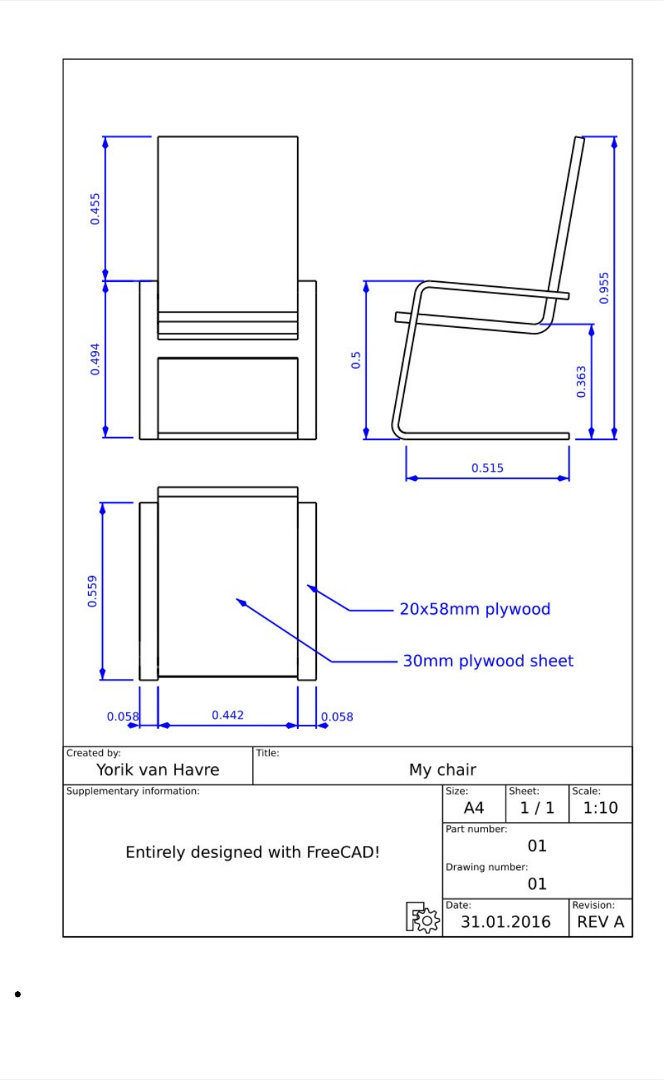
LoadtheIkeaChairfilefromthelibrary.Youcanchoosebetweenthe.FCStdversion,
whichwillloadthefullmodelinghistory,orthe.stepversion,whichwillcreateonlyone
object,withoutthehistory.Sincewewon'tneedtomodelanyfurthernow,itisbestto
Generating2Ddrawings
105
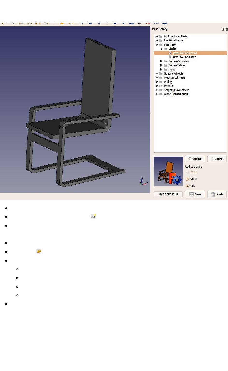
choosethe.stepversion,asitwillbeeasiertomanipulate.
SwitchtotheDrawingWorkbench
Pressthelittlearrownexttothe NewDrawingPagebutton.
SelecttheA4Portrait/ISO7200template.AnewtabwillopeninyourFreeCAD
window,showingthenewpage.
Inthetreeview(orinthemodeltab),selectthechairmodel.
Pressthe Insertviewbutton.
AViewobjectwillbecreatedonourpage.Givetheviewthefollowingproperties:
X:100
Y:150
Scale:0.1
Rotation:270
Wenowhaveanicetopview(whichisthedefaultprojection)ofourchair:
Generating2Ddrawings
106
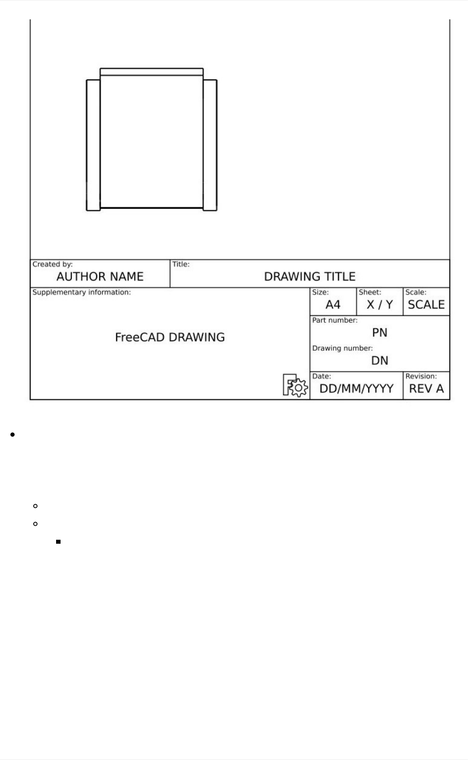
Let'srepeattheoperationtwice,tocreatetwomoreviews.WewillsettheirXandY
values,whichindicatethepositionoftheviewonthepage,inordertoshowthemapart
fromthetopview,andtheirdirection,tocreatedifferentvieworientations.Giveeach
newviewthefollowingproperties:
View001(frontview):X:100,Y:130,Scale:0.1,Rotation:90,Direction:(-1,0,0)
View002(sideview):X:180,Y:130,Scale:0.1,Rotation:90,Direction:(0,-1,0)
Afterthat,weobtainthefollowingpage:
Generating2Ddrawings
107
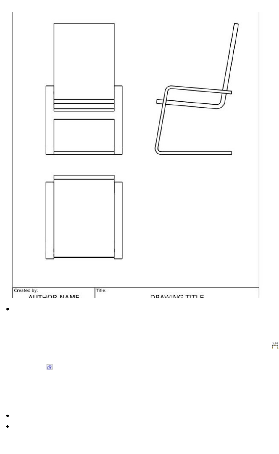
Wecantweakabittheaspectofourviewsifwewant,forexamplewecanraisetheir
LineWidthpropertyto0.5.
Wewillnowplacedimensionsandindicationsonourdrawing.Therearetwowaysto add
dimensions to a model, one is placing the dimensions inside the 3D model, using the
DimensiontooloftheDraftWorkbench,andthenplaceaviewofthesedimensionsonour
sheet with the Draft View tool (which can be used with a single dimension or a group
containing dimensions), or we can do things directly on the Drawing sheet, using the
DrawingDimensioningWorkbench,whichisinstallablefrom theFreeCADaddons. We will
useherethislattermethod.
SwitchtotheDrawingDimensioningWorkbench
PresstheAddLinearDimensionbutton.Availablenodesarehighlightedingreenon
thedrawingpage:
Generating2Ddrawings
108
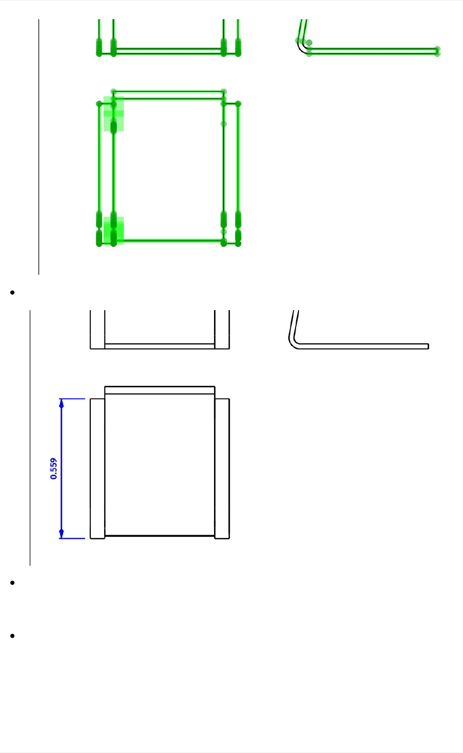
Clicktwoofthesepoints,thenclickathirdpointtoplacethedimensionline:
TheLinearDimensiontool,asmostoftheotherDrawingDimensioningtools,willnot
exitafteryoufinished,allowingyoutoplacemoredimensions.Whenyouaredone,
simplyclicktheClosebuttonintheTaskpanel.
Repeattheoperation,untilallthedimensionsyouwishtoindicateareplaced.Takea
minutetobrowsethroughthedifferentoptionsproposedintheLinearDimension'stask
panel.Forexample,byuntickingtheautoplacetextoption,youwillbeabletoplace
thetextofthedimensionelsewhere,likeontheimagebelow:
Generating2Ddrawings
109
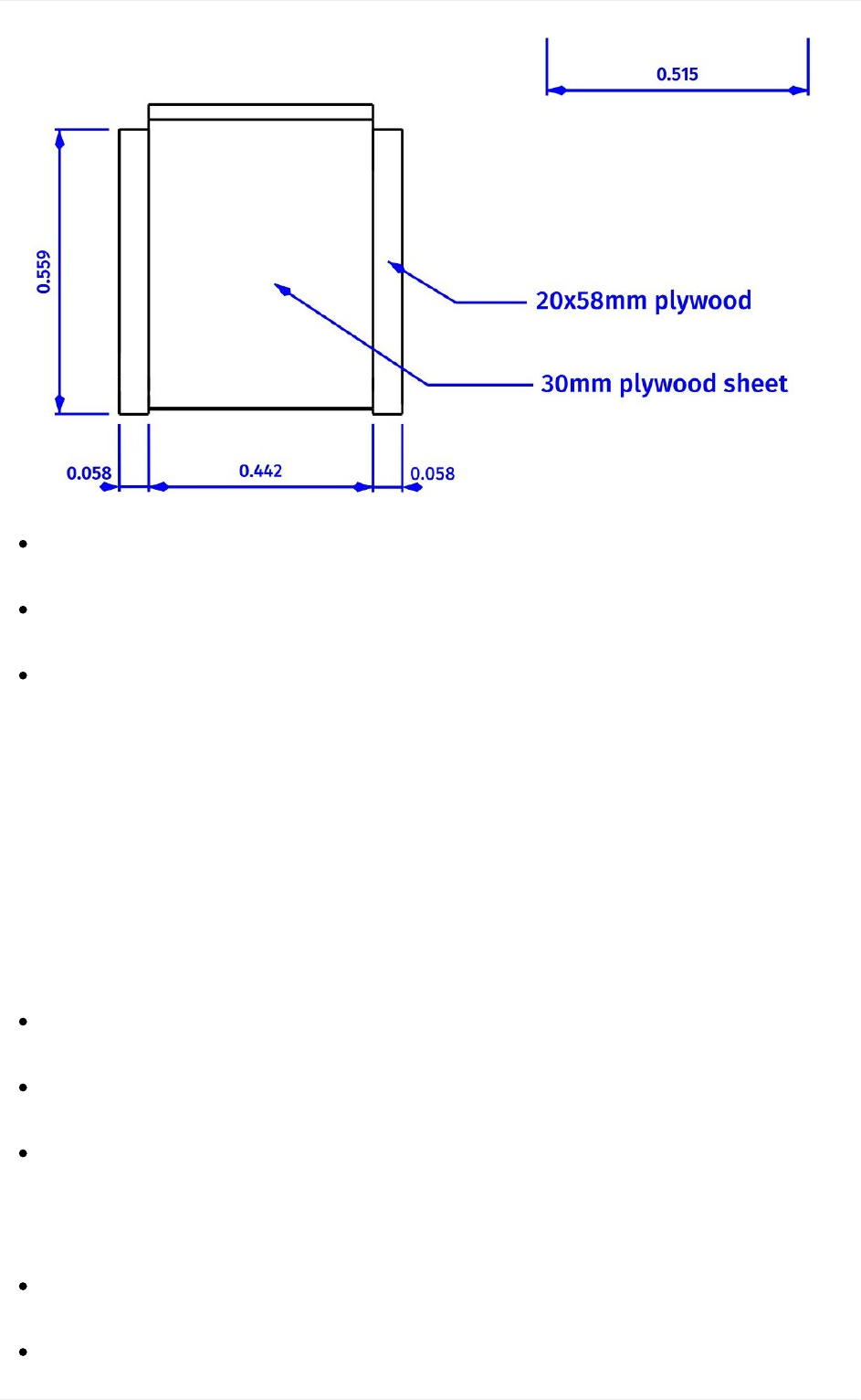
Wewillnowplacetwoindications,usingtheWelding/Groovesymbolstool,selecting
thedefaultone(nogroovesymbol).Drawthetwolineslikeontheimageabove.
NowplacetwotextsusingtheAddtexttool,andchangetheirtextpropertytothe
contentsofyourlikings.
Ourdrawingisnowcomplete,allthatislefttodoistofillintheinformationsofthesheet
titleblock.WithmostofthedefaultFreeCADtemplates,thiscanbedoneeasily,by
changingtheEditableTextspropertyofthepage.
Our page can now be exported to SVG to be worked further in graphical applications like
inkscape, or to DXF by selecting menu File -> Export. The Drawing Dimensioning
workbench also features its own DXF export tool, which also supports the annotations
added with that workbench. The DXF format is importable in almost all existing 2D CAD
applications.DrawingpagescanalsobedirectlyprintedorexportedtoPDF.
Downloads
Thechairmodel:https://github.com/FreeCAD/FreeCAD-
library/blob/master/Furniture/Chairs/IkeaLikeChair.step
Thefilecreatedduringthisexercise:https://github.com/yorikvanhavre/FreeCAD-
manual/blob/master/files/drawing.FCStd
TheSVGsheetproducedfromthatfile:https://github.com/yorikvanhavre/FreeCAD-
manual/blob/master/files/drawing.svg
Readmore
TheDrawingWorkbench:http://www.freecadweb.org/wiki/index.php?
title=Drawing_Module
TheDrawingDimensioningWorkbench:
Generating2Ddrawings
110


BIMmodeling
BIMstandsforBuildingInformationModeling.Theexactdefinitionofwhatitisvaries,butwe
cansay simplythat ishow buildingsand otherlarge structureslike bridges,tunnels, etc...
aremodeledtoday.BIMmodelsareusuallybasedon3Dmodels,andalsoincludeaseries
of additional layers of information, such as materials information, relationships to other
objectsormodels,orspecialinstructionsforbuildingormaintenance.Thisextrainformation
permitsallkindsofadvancedanalysesofthemodel,suchasstructuralresistance,costand
constructiontimeestimations,orcalculaitonsofenergyconsumption.
The Arch Workbench of FreeCAD implements a series of tools and facilities for BIM
modeling.Althoughithasadifferentpurpose,itismadetoworkintightintegrationwiththe
rest of FreeCAD: Anything made with any other workbench of FreeCAD can become an
Archobject,orbeusedasabaseforanArchobject.
AsinthePartDesignWorkbench,theobjectsproducedbytheArchWorkbencharemeantto
bebuiltintherealworld.Therefore,theyneedtobesolid.TheArchtoolsusuallytakecare
ofthatautomatically,andalsoprovideutilitytoolstohelpyoucheckthevalidityofobjects.
TheArchWorkbenchalsoincludesallthetoolsfromtheDraftWorkbench,andusesitsgrid
and snapping system. Before beginning, it is always a good idea to browse through the
preferencespagesofbothDraftandArchandsetthedefaultsettingstoyourlikings.
Inthischapter,wewillseehowtomodelthissmallbuilding:
BIMmodeling
112
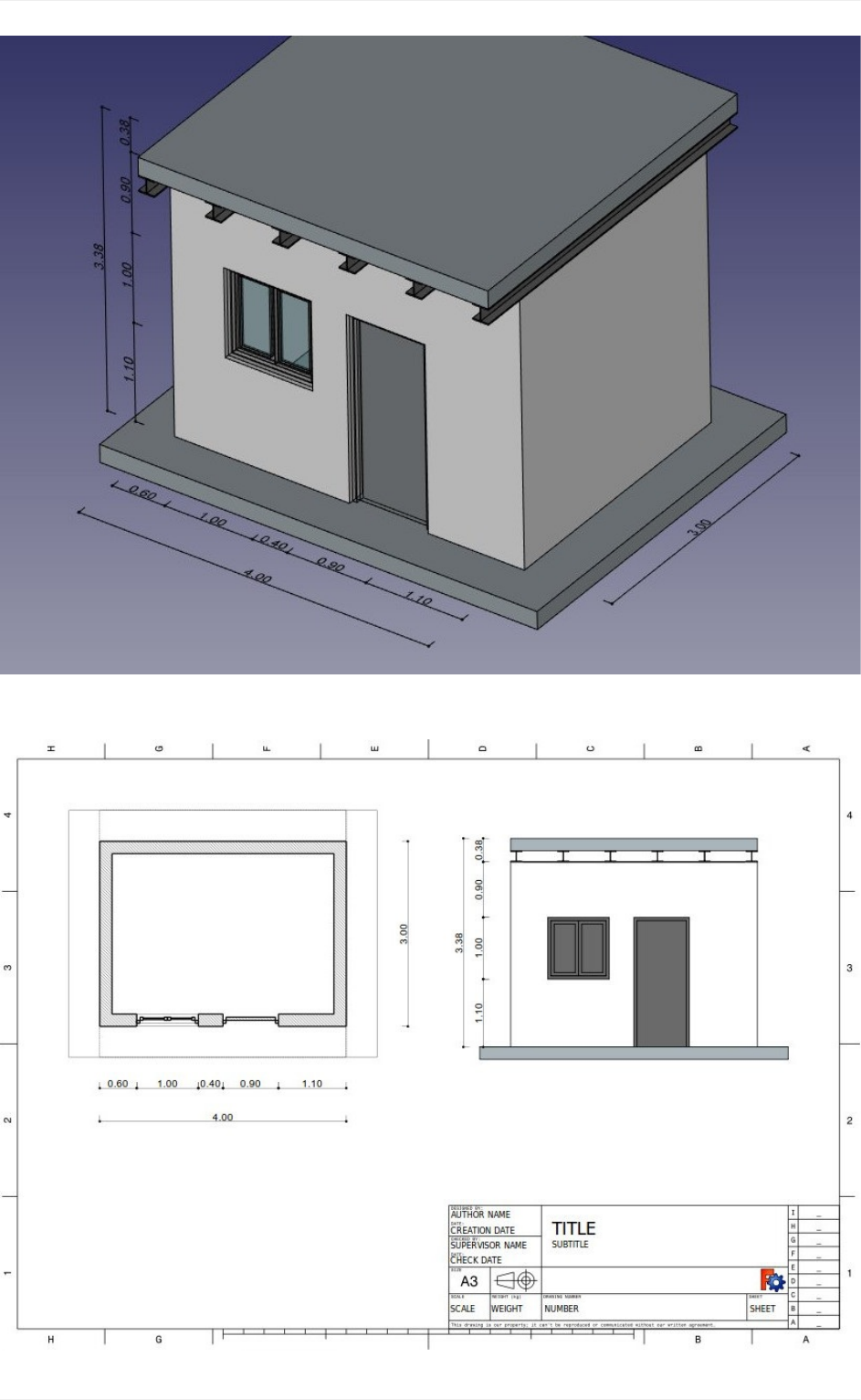
andproduceaplanandasectionviewfromit:
BIMmodeling
113
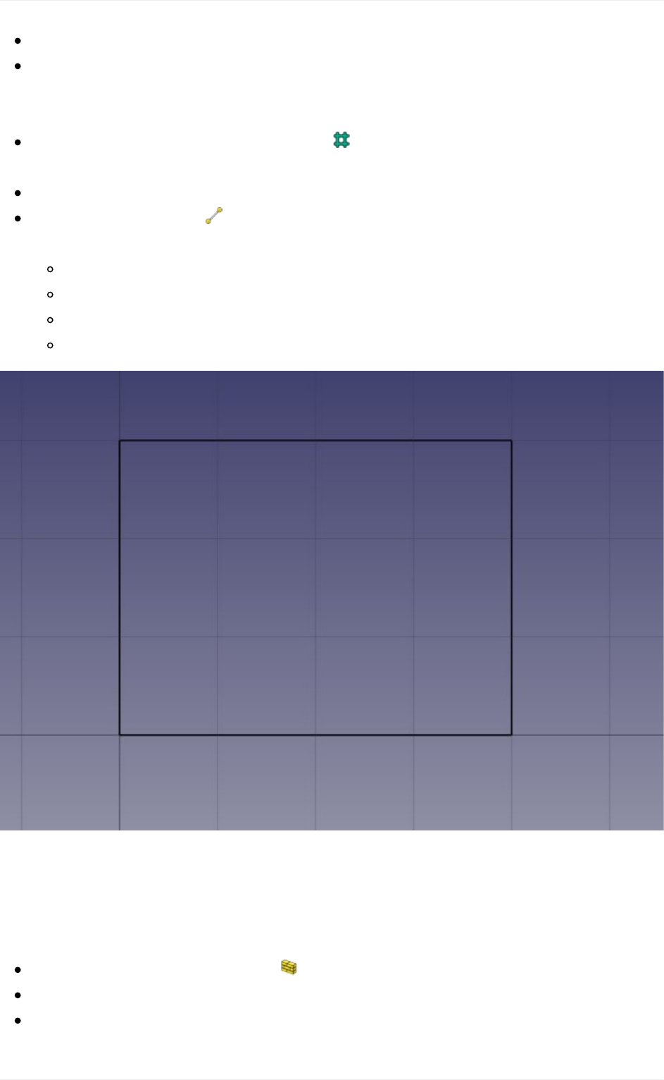
Createanewdocument,andswitchtotheArchWorkbench.
OpenmenuEdit->Preferences->Draft->GridandSnappingandsetthegrid
spacingsettingto1000mm,sowehaveaonemeter-basedgrid,whichwillbe
convenientforthesizeofourbuiding.
Onthesnappingtoolbar,makesurethe gridsnapbuttonisenabled,sowecanuse
thegridasmuchaspossible.
SettheWorkingPlanetoXYplane
Drawfourlineswiththe DraftLinetool.Youcanentercoordinatesmanually,or
simplypickthepointsonthegridwiththemouse:
Frompoint(0,0)topoint(0,3)
Frompoint(0,3)topoint(4,3)
Frompoint(4,3)topoint(4,0)
Frompoint(4,0)topoint(0,0)
Noticethatwedrewalwaysinthesamedirection(clockwise).Thisisnotnecessary,butwill
ensurethatthewallsthatwewillbuildnextallhavethesameleftandrightdirections.You
mightalso think wecouldsimply have drawna rectangle here,which is true.But the four
lineswillallowustoillustratebetterhowtoaddoneobjectintoanother.
Selectthefirstline,thenpressthe ArchWallbutton.
Repeatthisforthe3otherlines,untilyouhave4walls.
Selectthefourwalls,andsettheirHeightpropertyto3.00mandtheirAlignment
BIMmodeling
114
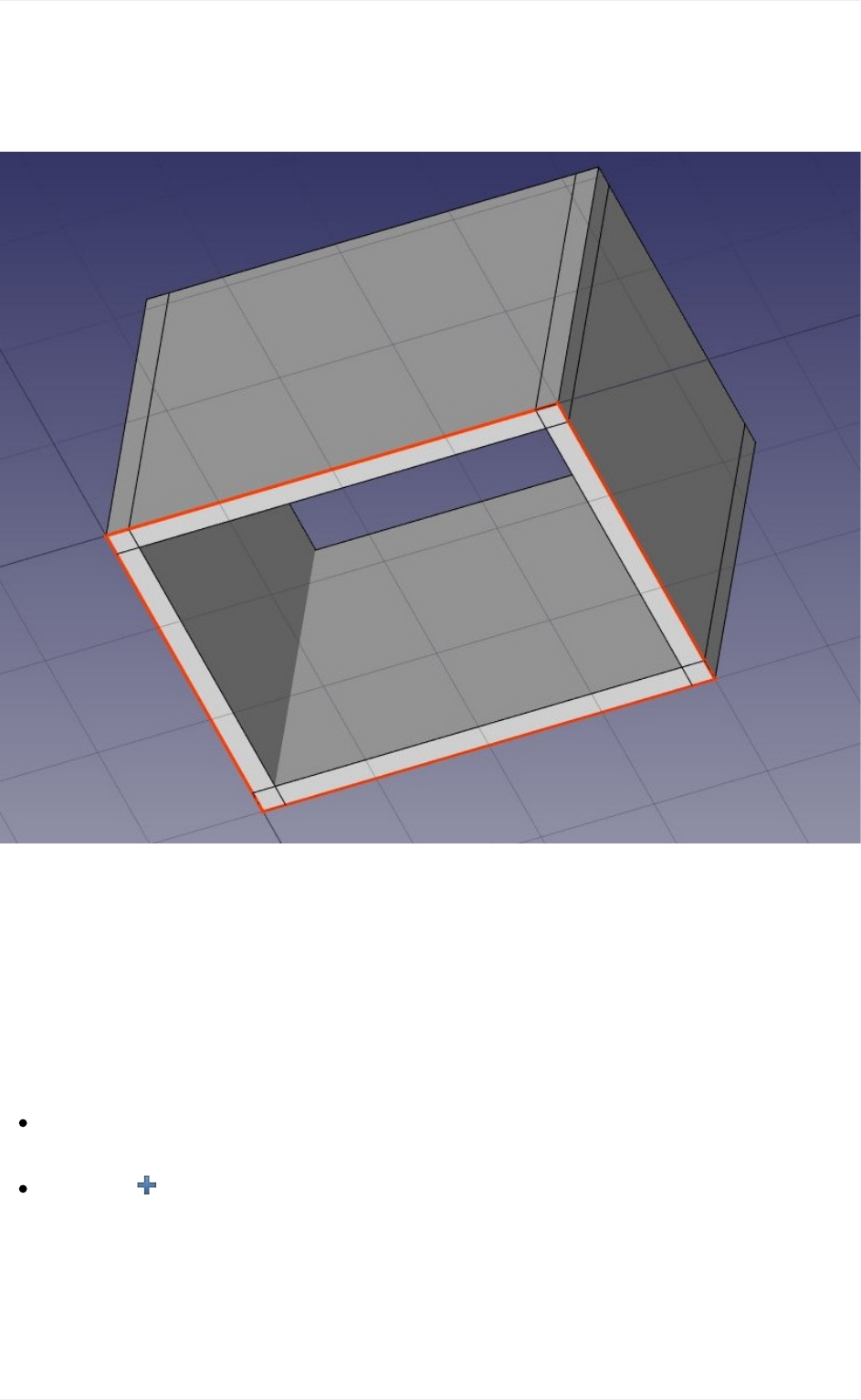
propertytoleft.Ifyoudidn'tdrawthelinesinthesameorderaswedidabove,someof
thewallsmighthavetheirleftandrightdirectionsflipped,andmightneedtobesetto
rightinstead.Youwillobtainfourintersectingwalls,ontheinsideofthebaselines:
Nowweneedtojointhesewallstogether,sotheyintersectproperly.Thisisnotnecessary
whenyourwallsaredrawninawaythattheyalreadyconnectcleanly,buthereweneedto,
sincetheyareintersecting.InArch,thisisdonebyelectingoneofthewallstobethe"host",
andaddingtheotherstoit,as"additions".Allarchobjectscanhaveanynumberofadditions
(objects whose geometry will be added to the host's geometry), and subtractions (objects
whose geometry will be subtracted). The additions and subtractions of an object can be
managedanytimebydouble-clickingtheobjectinthetree.
SelectthefourwallswithCtrlpressed,thelastonebeingthewallthatyouchoseto
becomethehost
Pressthe ArchAddbutton.Thefourwallshavenowbeenturnedintoone:
BIMmodeling
115
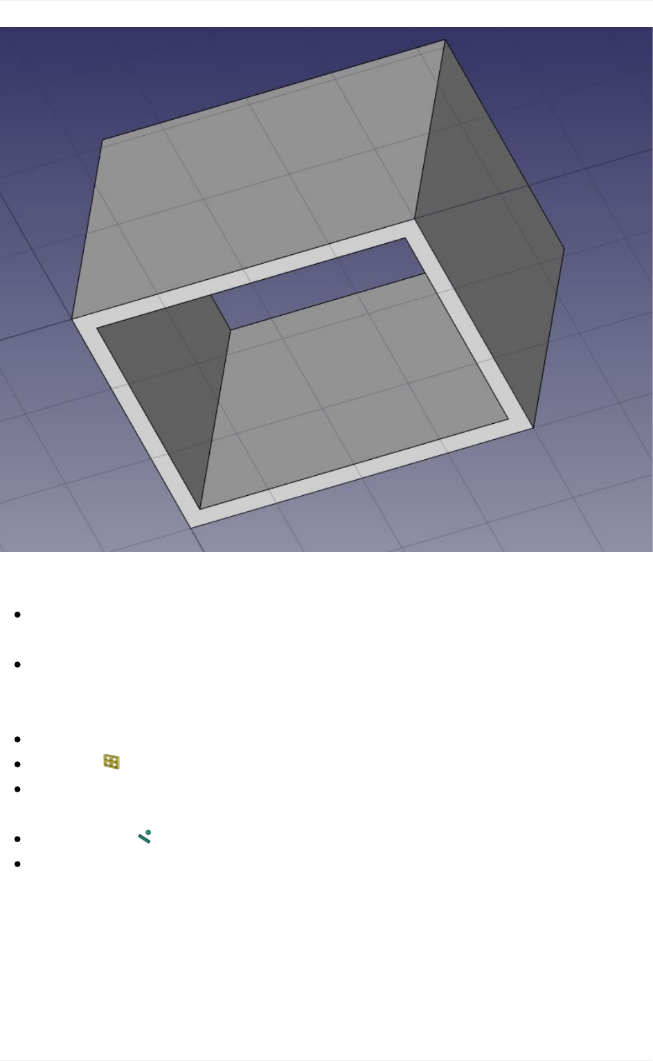
Theindividualwallsarehoweverstillaccessible,byexpandingthewallinthetreeview.
Let'snowplaceadoor.InFreeCAD,doorsareconsideredaspecialcaseofwindows,
sothisisdoneusingtheWindowtool.
Startbyselectingthewall.Thisisnotnecessary,butagoodhabittotake.Ifanobjectis
selectedwhenstartingthewindowtool,youwillforcethewindowtobeinsertedinthat
object,evenifyousnaptoanotherobject.
SettheWorkingPlanetoautosowearenotrestrictedtothegroundplane
Pressthe Windowbutton.
Inthewindowcreationpanel,selecttheSimpledoorpreset,andsetitsWidthto0.9m
anditsHeightto2.1m
Makesurethe Nearsnaplocationisturnedon,sowecansnaponfaces
Placeyourwindowroughlyonthemiddleofthefrontfaceofthewall:
BIMmodeling
116
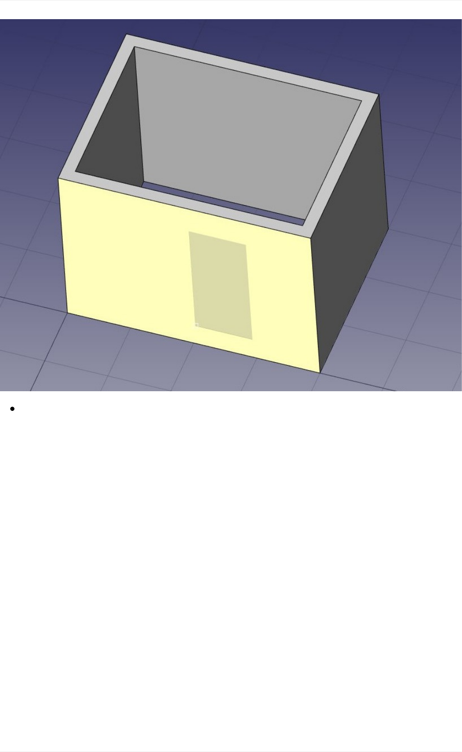
Afterclicking,ourwindowisplacedonthecorrectface,butnotexactlywherewewant:
BIMmodeling
117
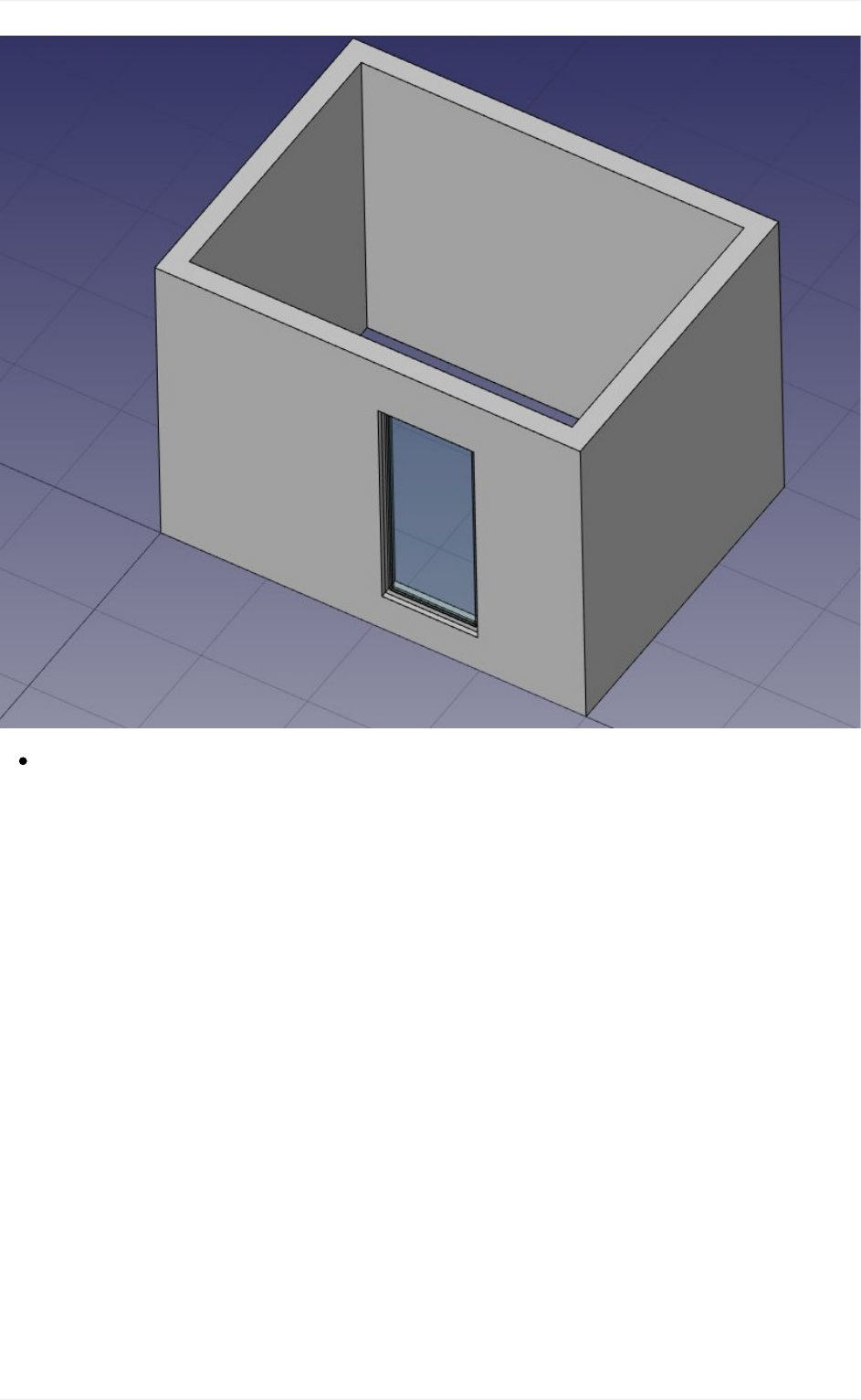
Wecannowsetthepreciselocationbyexpandingthewallandthewindowobjectsin
thetreeview,andchangingthePlacementpropertyofthebasesketchofourdoor.Set
itspositiontox=2m,y=0,z=0.Ourwindowisnowexactlywherewewantit:
BIMmodeling
118
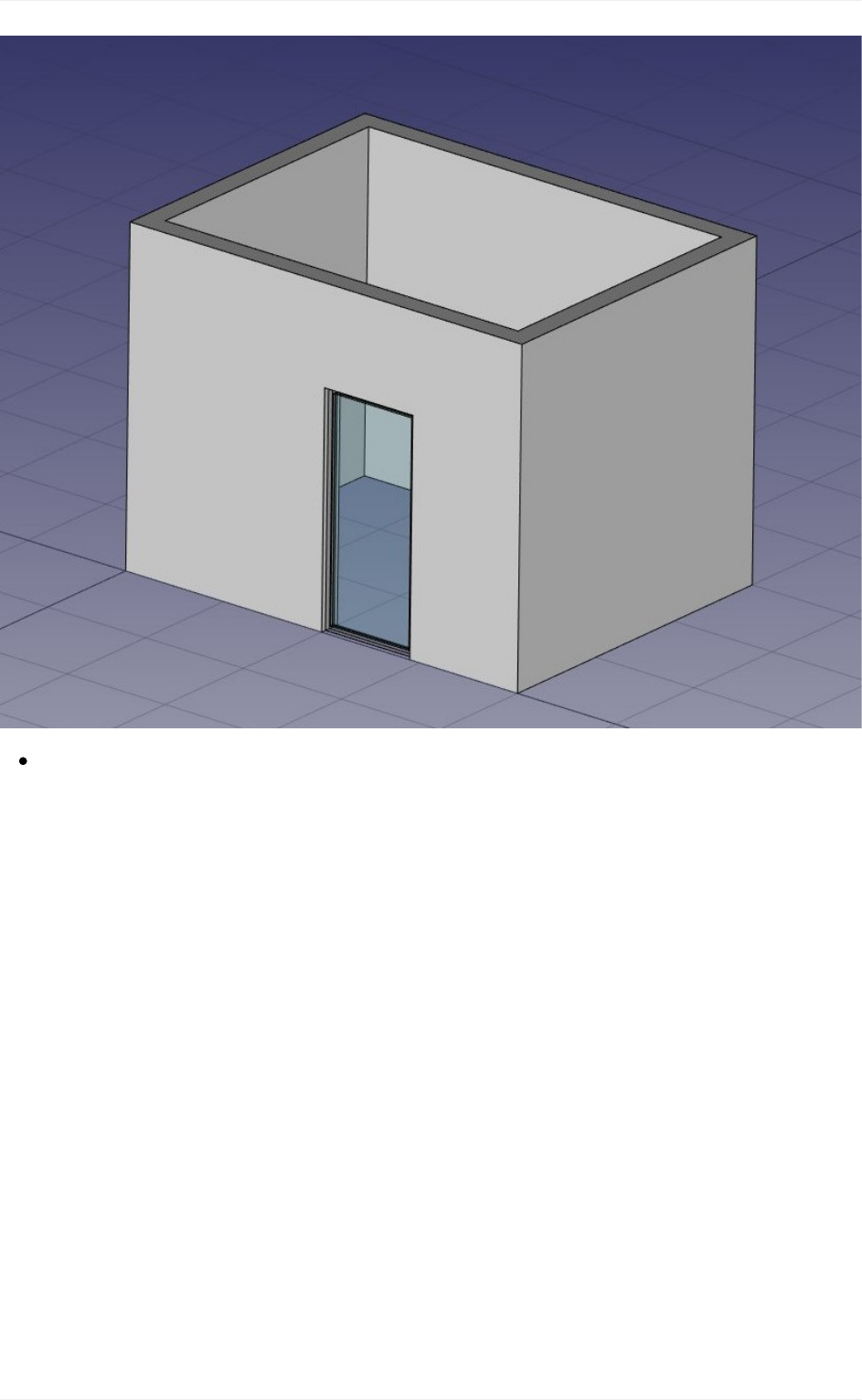
Repeattheoperationtoplaceawindow:Selectthewall,pressthewindowtool,select
theOpen2-panepreset,andplacea1mx1mwindowinthesamefaceasthedoor.
Settheplacementoftheunderlyingsketchtopositionx=0.6m,y=0,z=1.1m,sothe
upperlineofthewindowisalignedtothetopofthedoor.
BIMmodeling
119
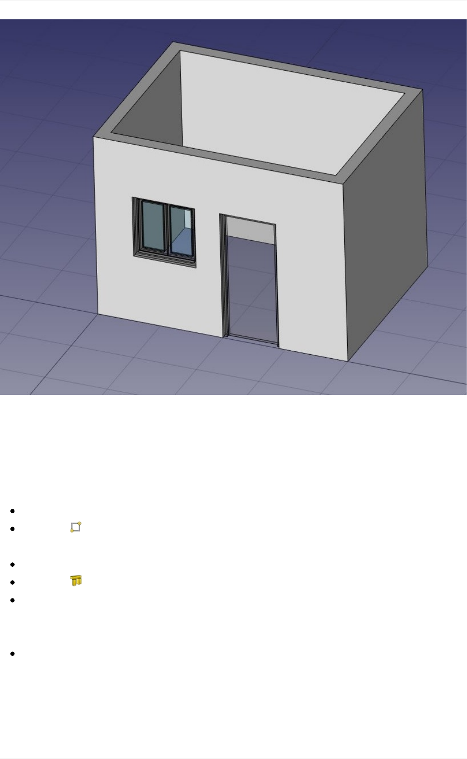
Windowsarealwaysbuiltonsketches.Itiseasytocreatecustomwindowsbyfirstcreating
asketchonaface,thenturningitintoa windowbyselectingit,thenpressingthewindow
button. Then, the window creation parameters, that is, which wires of the sketch must be
extrudedandhowmuch,canbedefinedbydouble-clickingthewindowinthetreeview.Let's
nowcreateaslab:
SettheWorkingPlanetoXYplane
Createa rectanglewithalengthof5m,aheightof4m,andplaceitatposition
x:-0.5m,y:-0.5m,z:0.
Selecttherectangle
Clickthe structuretooltocreateaslabfromtherectangle
Settheheightpropertyoftheslabto0.2manditsnormaldirectionto(0,0,-1)because
wewantittoextrudedownwards.Wecouldalsosimplyhavemovedit0.2mdown,butit
isalwaysgoodpracticetokeepextrudedobjectsatthesameplaceastheirbaseprofile.
SettheRolepropertyoftheslabtoslab.ThisisnotnecessaryinFreeCAD,butis
importantforIFCexport,asitwillensurethattheobjectisexportedwiththecorrectIFC
type.
BIMmodeling
120
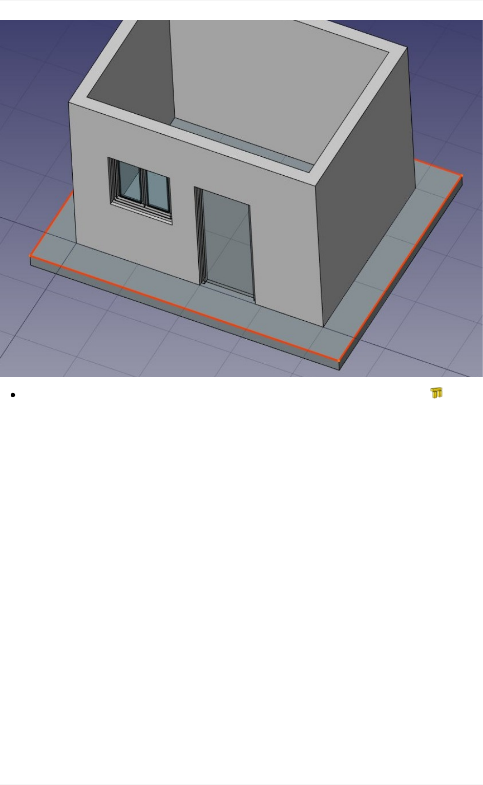
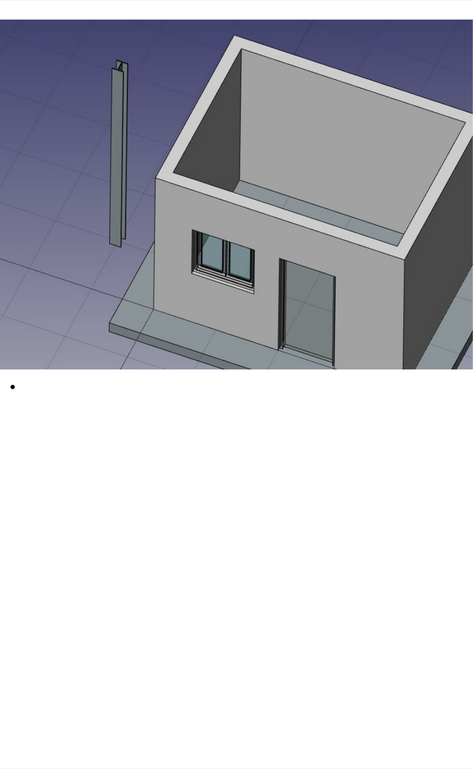
Adjustitsplacementbysettingitsrotationto90°inthe(1,0,0)axis,anditspositionto
x:90mm,y:3.5m,z:3.09m.Thiswillpositionthebeamexactlyononeofthesidewalls:
BIMmodeling
122
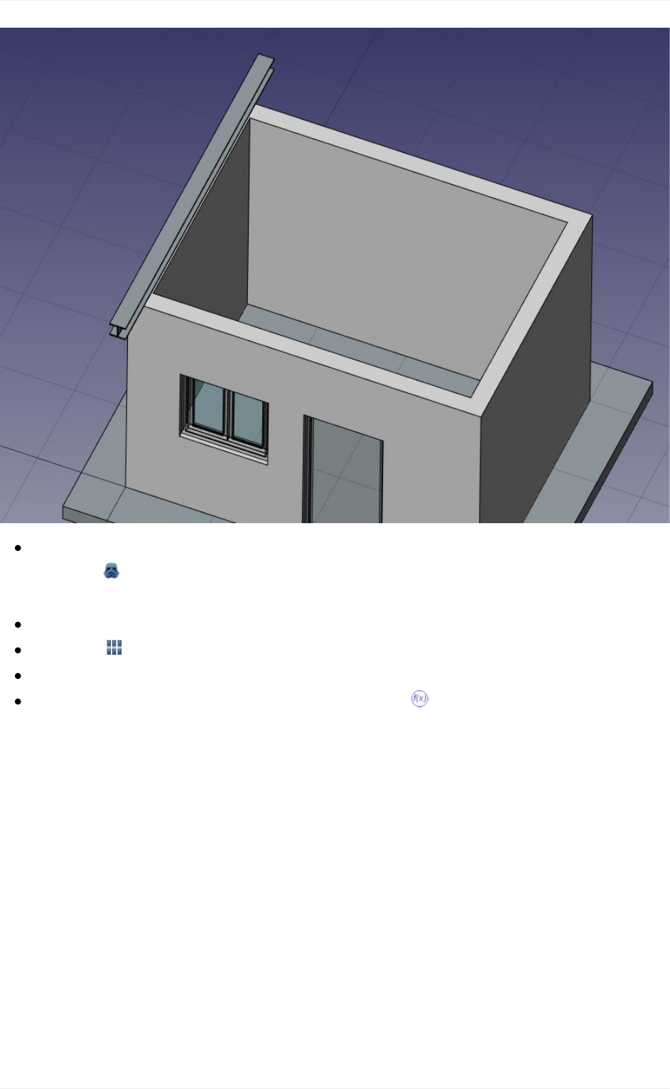
Weneednowtoduplicatethisbeamacoupleoftimes.Wecoulddothatonebyone
usingthe clonetool,butthereisabetterway,todoallthecopiesatonceusingan
array:
Selectthebeam
Pressthe Arraybutton
SettheNumberXpropertyofthearrayto6,leavetheYandZnumbersto1
ExpandtheintervalXproperty,andpressthesmall expressioniconattheright
sideoftheXfield.Thiswillopenanexpressionseditor:
BIMmodeling
123
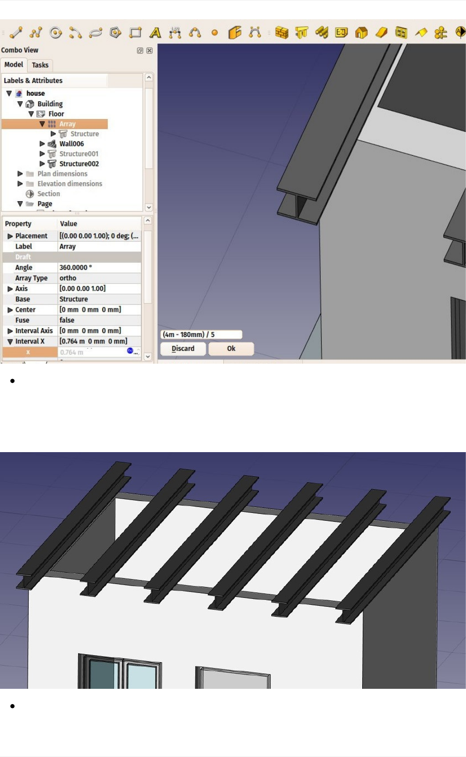
Write(4m-180mm)/5intheexpressionfield,andpressOK.Thiswillsetthexvalueto
0.764(4misthetotallengthofourfrontwall,180mmisthewidthofthebeam,whichis
whyitiscalledHEB180,andwewantafifthofthatspaceasintervalbetweeneach
beam):
Wecannoweasilybuildasimpleslabontopofthem,bydrawingarectangledirectlyon
thetopplaneofthebeams.Selectatopfaceofoneofthebeams
BIMmodeling
124
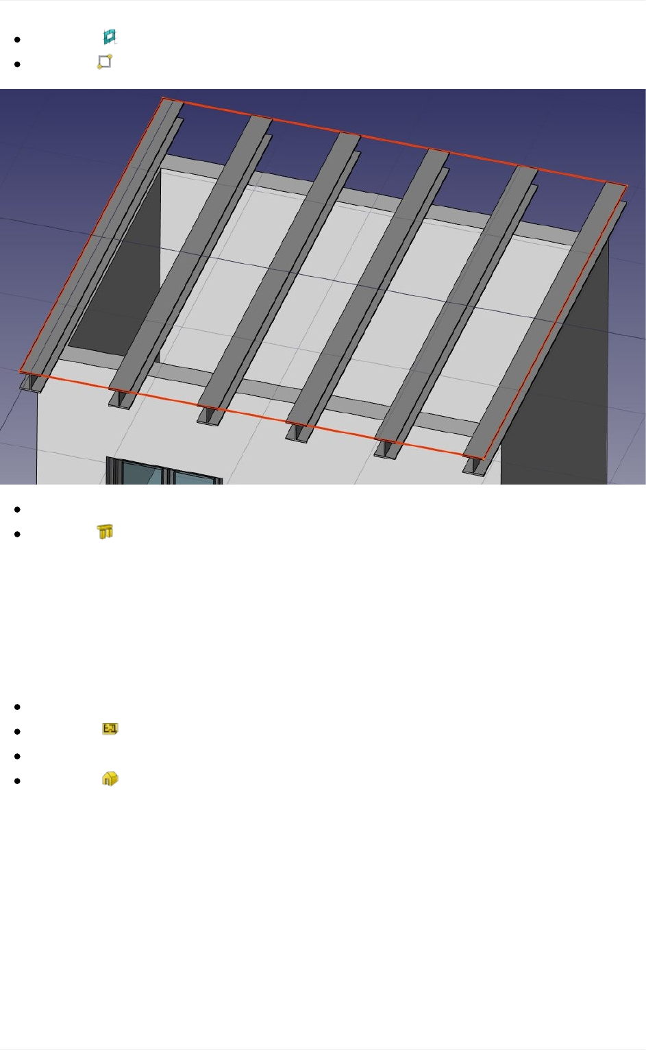
Pressthe workingplanebutton.Theworkingplaneisnowsettothatface.
Createa rectangle,snappingtotwooppositepointsoftheborderbeams:
Selecttherectangle
Clickthe structurebuttonandcreateaslabwithaheightof0.2m.
That's it, our model is now complete. We should now organize it so it exports correctly to
IFC.TheIFCformatrequiresthatallobjectsofabuildingareinsideabuildingobject,and
optionally,insideastorey.Italsorequiresthatallbuildingsareplacedonasite,buttheIFC
exporterofFreeCADwilladdadefaultsiteautomaticallyifneeded,sowedon'tneedtoadd
onehere.
Selectthetwoslabs,thewall,andthearrayofbeams
Pressthe Floorbutton
Selectthefloorwejustcreated
Pressthe Buildingbutton
Ourmodelisnowreadytoexport:
BIMmodeling
125
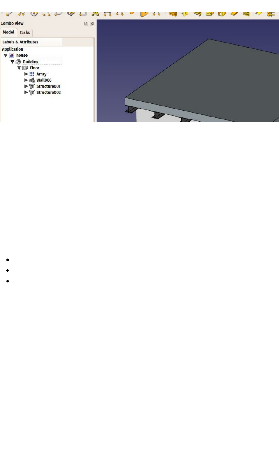
TheIFCformatisoneofthemostpreciousassetsinafreeBIMworld,becauseitallowsthe
exchangeofdata betweenanyapplication andactorof theconstructionworld, inanopen
manner(theformatisopen,freeandmaintainedbyanindependentconsortium).Exporting
your BIM models as IFC ensures that anyone can see and analyze them, no matter the
applicationused.
In FreeCAD, IFC import and export is done by interfacing with another piece of software,
called IfcOpenShell. To be able to export to IFC from FreeCAD, the IfcOpenShell-python
package must be installed on your system. Be sure to select one which uses the same
python version as FreeCAD. The python version that FreeCAD uses is informed when
openingtheView->Panels->PythonconsolepanelinFreeCAD.Whenthatisdone,we
cannowexportourmodel:
Selectthetopobjectyouwanttoexport,thatis,theBuildingobject.
SelectmenuFile->Export->IndustryFoundationClassesandsaveyourfile.
TheresultingIFCfilecannowbeopenedinawiderangeofapplicationsandviewers
(theimagebelowshowsthefileopenedinthefreeIfcPlusPlusviewer.Checkingthe
exportedfileinsuchaviewerapplicationbeforedistributingittootherpeopleis
importanttocheckthatallthedatacontainedinthefileiscorrect.FreeCADitselfcan
alsobeusedtore-opentheresultingIFCfile.
BIMmodeling
126
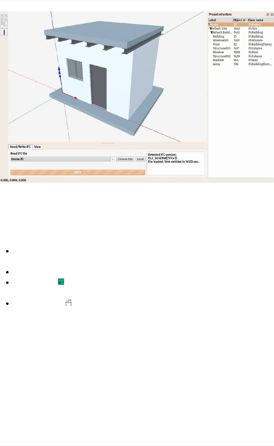
We will now place some dimensions. Unlike the previous chapter, where we drew all the
dimensionsdirectlyontheDrawingsheet,wewilluseanothermethodhere,andplaceDraft
dimensionsdirectlyinthe3Dmodel.ThesedimensionswillthenbeplacedontheDrawing
sheet. We will first make two groups for our dimensions, one for the dimensions that will
appearintheplanview,andanotherforthosethatappearontheelevation.
Right-clickthe"house"documentinthetreeview,andcreatetwonewgroups:Plan
dimensionsandElevationdimensions.
SettheWorkingPlanetoXYplane
Makesurethe restrictsnaplocationisturnedon,soeverythingyoudrawstayson
theworkingplane.
Drawacoupleof dimensions,forexampleasontheimagebelow.PressingShift
andCtrlwhilesnappingthedimensionpointswillgiveyouadditionaloptions.
BIMmodeling
127
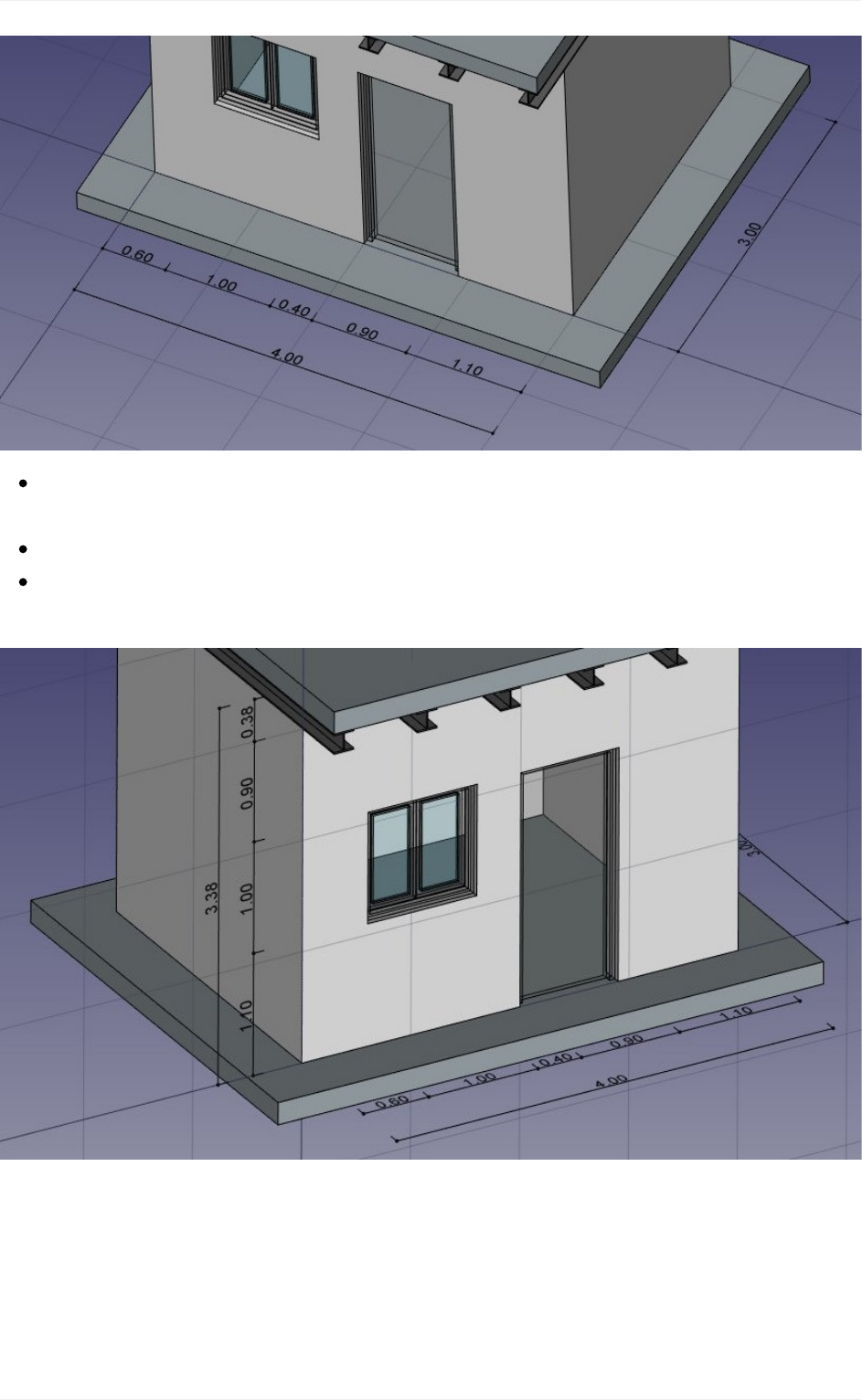
Selectallyourdimensions,anddragthemtothePlandimensionsgroupinthetree
view
SettheWorkingPlanetoXZplane,thatis,thefrontalverticalplane.
Repeattheoperation,drawacoupleofdimensions,andplacethemintheElevation
dimensionsgroup.
Wewillnowprepareasetofviewsfromourmodel,tobepacedonaDrawingpage.Wecan
do that with the tools from the Drawing Workbench, as we have seen in the previous
chapter, but the Arch Workbench also offers an all-in-one advanced tool to produce plan,
section and elevation views, called Section Plane. We will now add two of these section
planes,tocreateaplanviewandanelevationview.
BIMmodeling
128
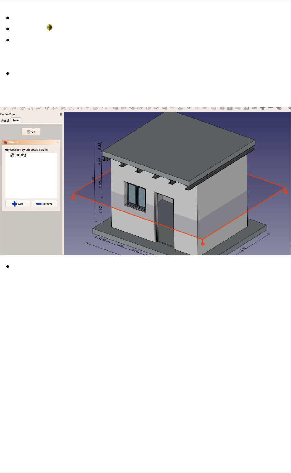
Selectthebuildingobjectinthetreeview
Pressthe SectionPlanebutton.
SetitsDisplayHeightpropertyto5m,itsDisplayLengthto6m,soweencompassour
house(thisisnotneeded,butwilllookbetter,asitwillshownaturallywhatitisused
for),anditsPlacementpositionatx:2m,y:1.5m,z:1.5m.
CheckthelistofobjectsconsideredbytheSectionPlanebydouble-clickingitinthetree
view.SectionPlanesonlyrenderspecifiedobjectsfromthemodel,notallofthem.The
objectsconsideredbytheSectionPlanecanbechangedhere.
Repeattheoperationtocreateanothersectionplane,giveitthesamedisplaylength
andheight,andgiveitthefollowingPlacement:position:x:2m,y:-2m,z:1.5m,angle:
90°,axis:x:1,y:0,z:0.Makesurethisnewsectionplanealsoconsidersthebuilding
object.
BIMmodeling
129
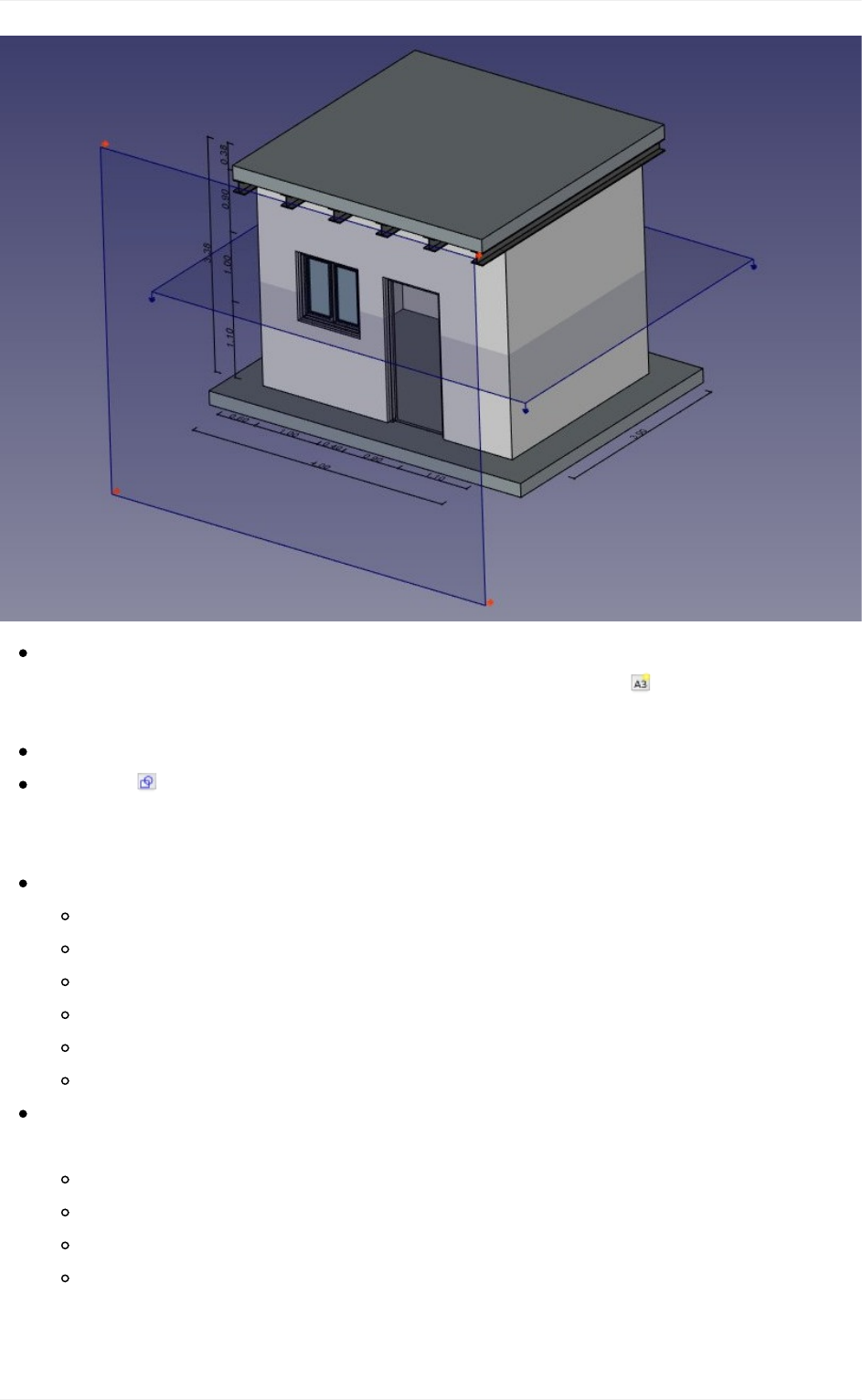
Nowwehaveeverythingweneed,andwecancreateourDrawingpage.Startby
switchingtotheDrawingWorkbench,andcreateanewdefault A3page(orselect
anothertemplateifyouwish).
Selectthefirstsectionplane,usedfortheplanview
Pressthe DraftViewbutton.Thistooloffersacoupleofadditionalfeaturesoverthe
standardDrawingViewtool,andsupportstheSectionPlanesfromtheArch
Workbench.
Givethenewviewthefollowingproperties:
X:50
Y:140
Scale:0.03
Linewidth:0.15
ShowCutTrue
ShowFill:True
Selecttheothersectionplane,andcreateanewDraftView,withthefollowng
properties:
X:250
Y:150
Scale:0.03
Rendering:Solid
BIMmodeling
130
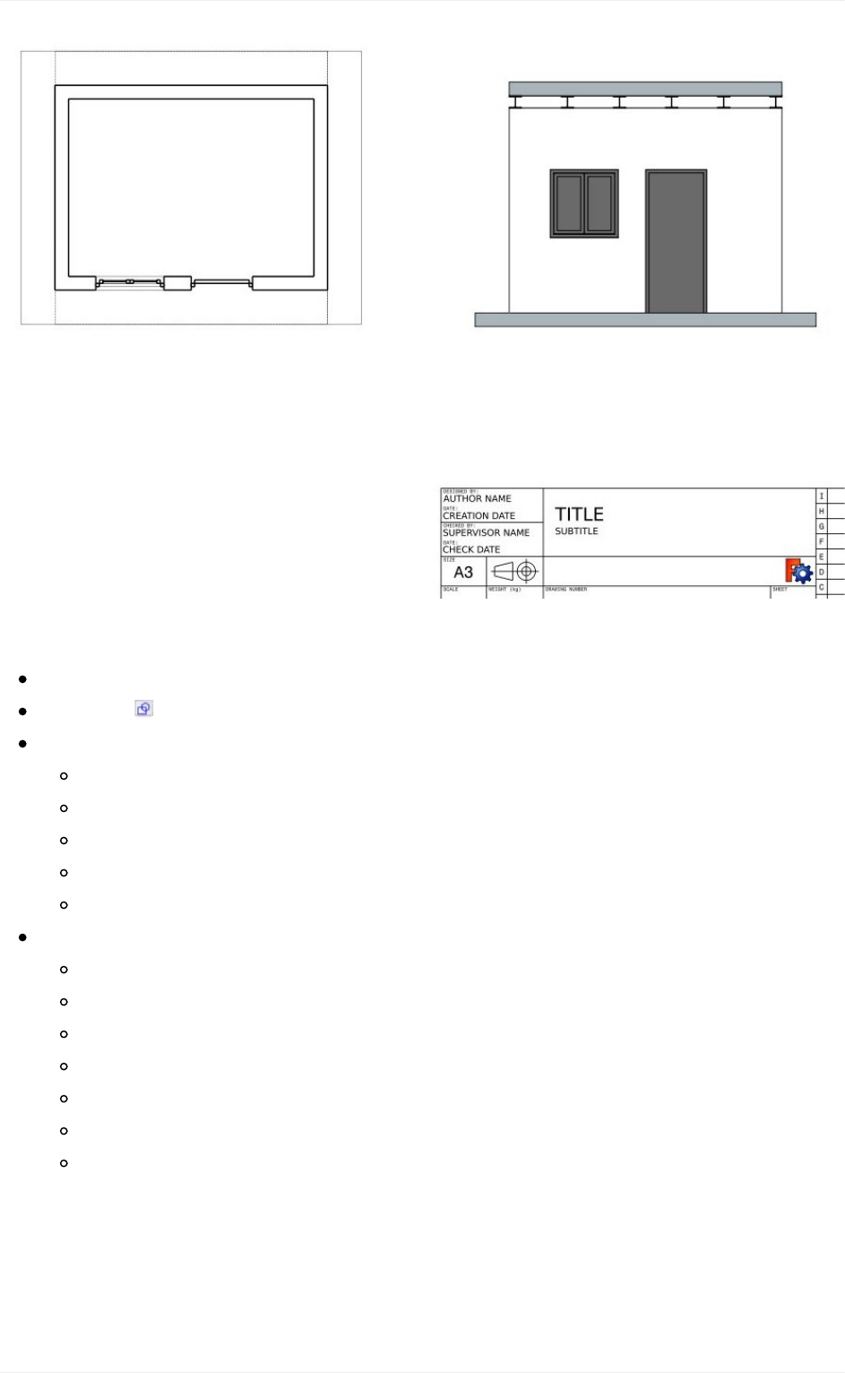
WewillnowcreatetwomoreDraftViews,oneforeachgroupofdimensions.
SelectthePlandimensionsgroup
Pressthe DraftViewbutton.
Givethenewviewthefollowingproperties:
X:50
Y:140
Scale:0.03
Linewidth:0.15
Fontsize:10mm
Repeattheoperationfortheothergroup,withthefollowingsettings:
X:250
Y:150
Scale:0.03
Linewidth:0.15
Fontsize:10mm
Direction:0,-1,0
Rotation:90°
Ourpageisnowready,andwecanexportittoSVGorDXFformats,orprintit.TheSVG
formatallowstoopenthefileillustrationapplicationssuchasinkscape,withwhichyoucan
quicklyenhancetechnicaldrawingsandturnthemintomuchnicerpresentationdrawings.It
offersmanymorepossibilitiesthantheDXFformat.
BIMmodeling
131

Downloads
Thefileproducedduringthisexercise:https://github.com/yorikvanhavre/FreeCAD-
manual/blob/master/files/house.FCStd
TheIFCfileexportedfromtheabovefile:https://github.com/yorikvanhavre/FreeCAD-
manual/blob/master/files/house.ifc
TheSVGfileexportedfromtheabovefile:https://github.com/yorikvanhavre/FreeCAD-
manual/blob/master/files/house.svg
Readmore
TheArchWorkbench:http://www.freecadweb.org/wiki/index.php?title=Arch_Module
TheDraftworkingplane:http://www.freecadweb.org/wiki/index.php?
title=Draft_SelectPlane
TheDraftsnappingsettings:http://www.freecadweb.org/wiki/index.php?title=Draft_Snap
Theexpressionssystem:http://www.freecadweb.org/wiki/index.php?title=Expressions
TheIFCformat:https://en.wikipedia.org/wiki/Industry_Foundation_Classes
IfcOpenShell:http://ifcopenshell.org/
IfcPlusPlus:http://ifcplusplus.com/
Inkscape:http://www.inkscape.org
BIMmodeling
132
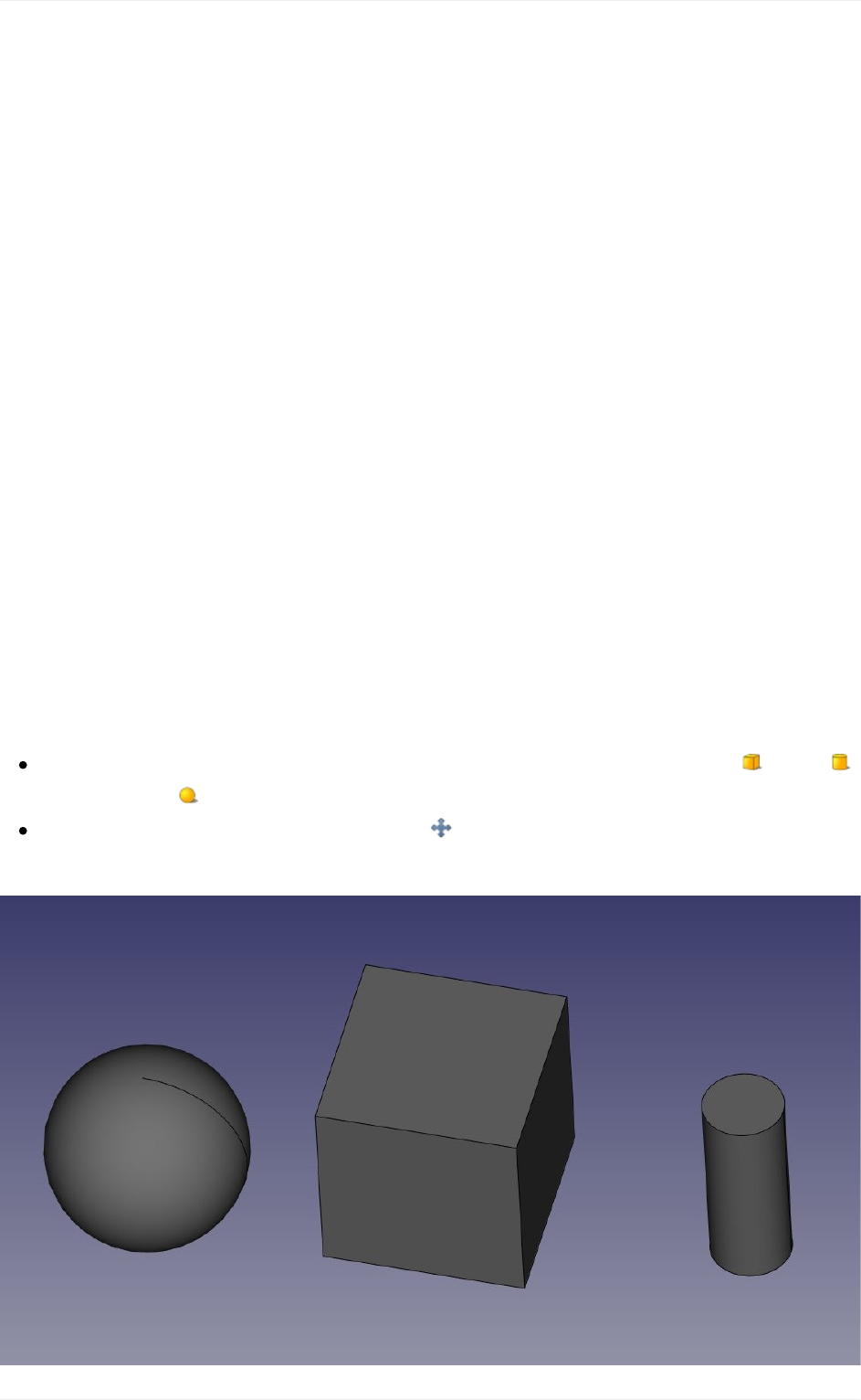
Usingspreadsheets
FreeCADfeatures another interestingworkbench to explore:the Spreadsheet Workbench.
ThisworkbenchallowstocreatespreadsheetssuchasthosemadewithExcelorLibreOffice
directly in FreeCAD. These spreadsheets can then be populated with data extracted from
your model, and can also perform a series of calculations between values. Spreadsheets
canbeexportedasCSVfiles,whichcanbeimportedinanyotherspreadsheetapplication.
In FreeCAD, however, spreadsheets have an additional utility: Their cells can receive a
name,andcanthenbereferencedbyanyfieldsupportedbytheexpressionsengine. This
turns spreadsheets into powerful control structures, where the values inserted in specific
cells can drive dimensions of the model. There is only one thing to keep in mind, as
FreeCADprohibitscirculardependenciesbetweenobjects,asamespreadsheetcannotbe
usedtosetapropertyofanobjectandatthesametimeretrieveapropertyvaluefromthe
sameobject.Thatwouldmakethespreadsheetandtheobjectdependingoneachother.
Inthefollowingexample,wewillcreateacoupleofobjects,retrievesomeoftheirproperties
inaspreadsheet,thenusethespreadsheettodirectlydrivepropertiesofotherobjects.se
Readingproperties
StartbyswitchingtothePartWorkbench,andcreateacoupleofobjects:a box,a
cylinderanda sphere.
EdittheirPlacementproperty(orusethe DraftMovetool)toplacethemalittleapart,
sowecanwatchbettertheeffectsofwhatwe'lldo:
Usingspreadsheets
133
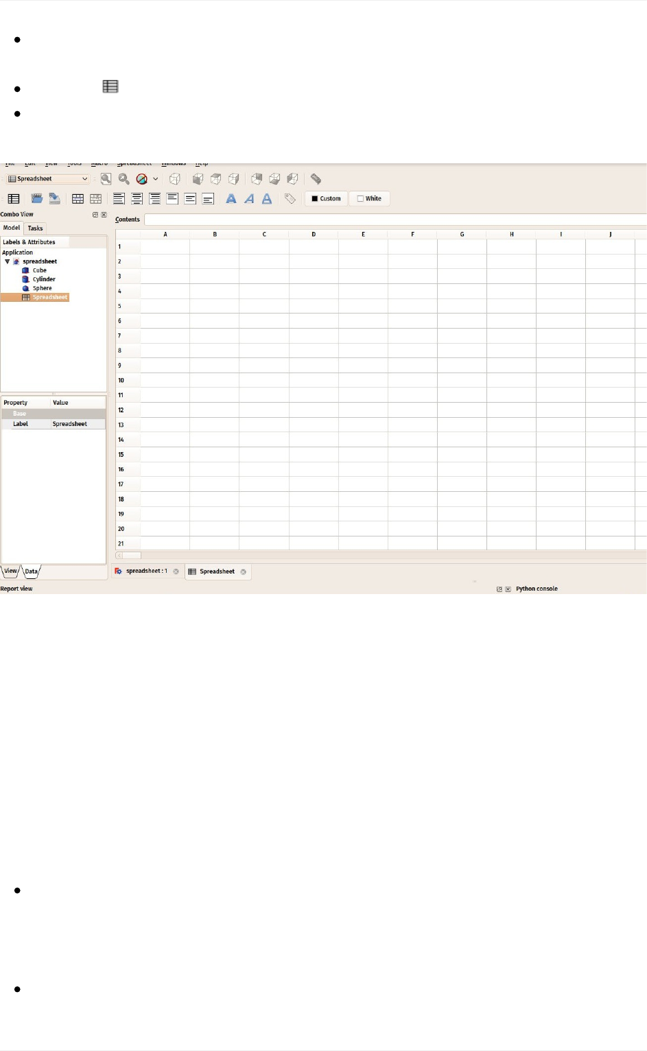
Now,lt'sextractsomeinformationabouttheseobjects.SwitchtotheSpreadsheet
Workbench
Pressthe NewSpreadsheetbutton
Double-clickthenewSpreadsheetobjectinthetreeview.Thespreadsheeteditor
opens:
ThespreadsheeteditorofFreeCAD,althoughitisnotascompleteandpowerfulasthemore
completespreadsheetapplicationswelistedabove,hasneverthelessmostofthebasictools
andfunctionsthatarecommonlyused,suchasthepossibilitytochangetheaspectofthe
cells (size, color, alignment), join and split cells, use formulas such as =2+2, or reference
othercellswith=B1.
In FreeCAD, to these common behaviours, has been added one very interesting: The
possibilitytoreferencenotonlyothercells,butotherobjectsfromthedocument,andretrieve
values from their properties. For example, let's retrieve a couple of properties from the 3
objectswecreatedabove.Propertiesarewhatwecanseeinthepropertieseditorwindow,
undertheDatatab,whenanobjectisselected.
Let'sstartbyenteringacoupleoftextsinthecellsA1,A2amdA3,soweremember
whatiswhatlateron,forexampleCubeLength,CylinderRadiusandSphereRadius.
Toentertext,justwriteinthe"Contents"filedabovethespreadsheet,ordouble-clicka
cell.
Nowlet'sretrievetheactuallengthofourcube.IncellB1,type=Cube.Length.Youwill
noticethatthespreadhseethasanautocompletionmechanism,whichisactuallythe
Usingspreadsheets
134
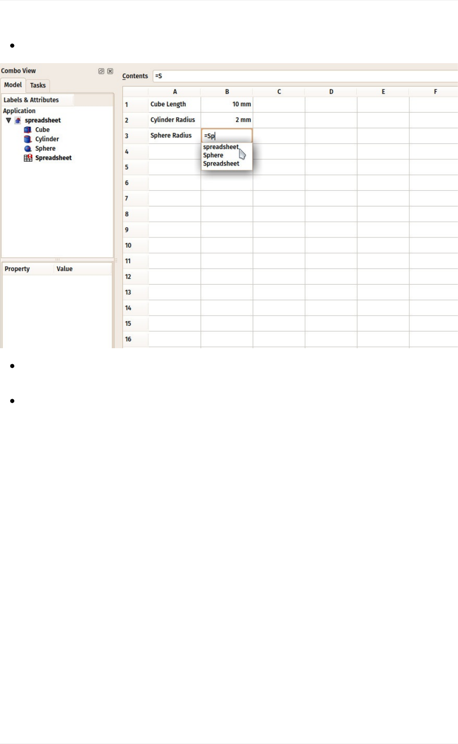
sameastheexpressioneditorweusedinthepreviouschapter.
DothesameforcellB2(=Cylinder.Radius)andB3(=Sphere.Radius).
Althoughtheseresultsareexpressedwiththeirunits,thevaluescanbemanipulatedas
anynumber,tryforexampleenteringincellC1:=B1*2.
Wecannowchangeoneofthesevaluesintheproperttieseditor,andthechangewillbe
immediatelyreflectedinthespreadsheet.Forexample,let'schangethelengthofour
cubeto20mm:
Usingspreadsheets
135
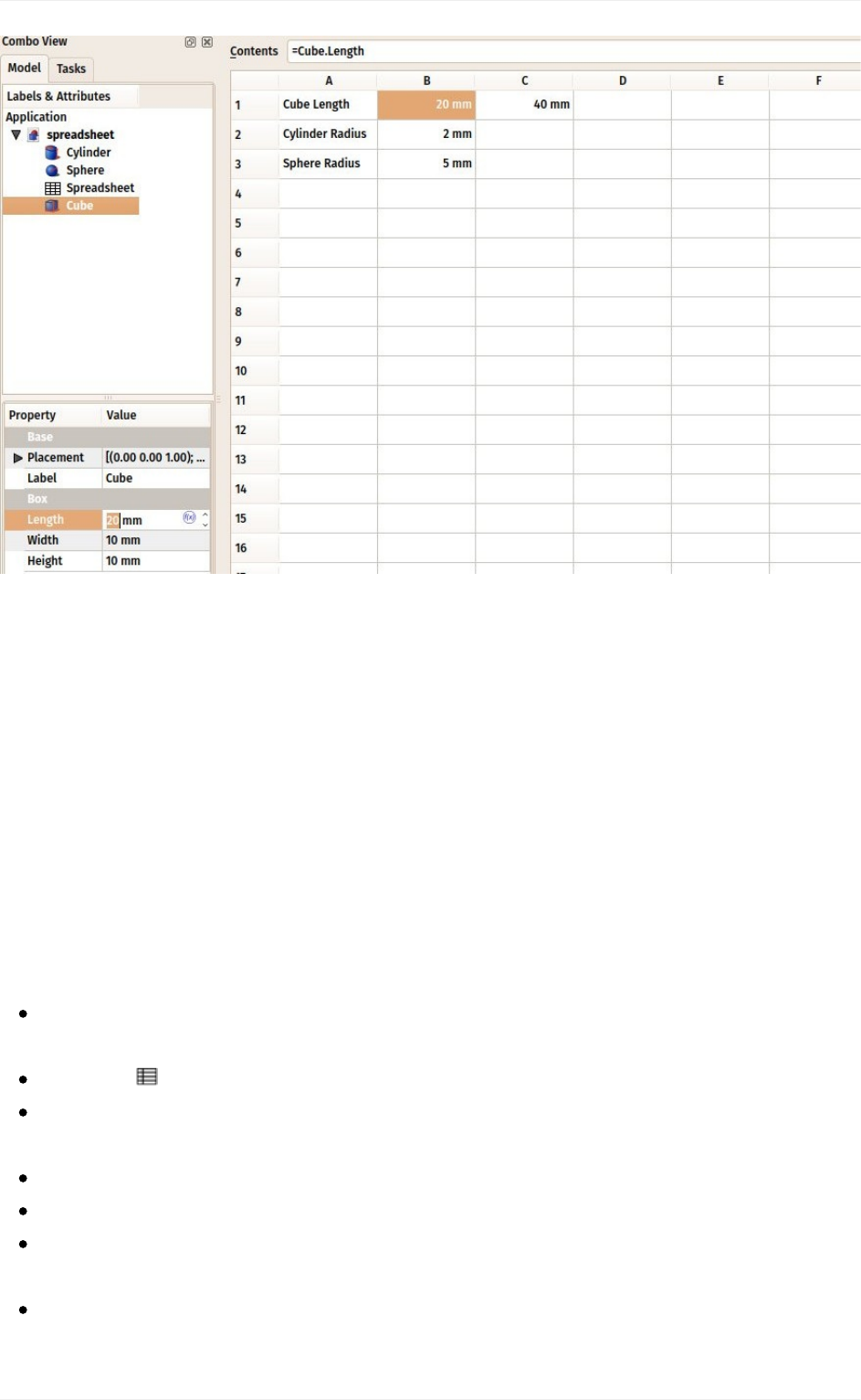
The Spreadsheet Workbench page will describe more in detail all the possible operations
andfunctionsthatyoucanuseinspreadsheets.
Writingproperties
Another very interesting use of the Spreadsheet Workbench in FreeCAD is to do the
contraryofwhatwehavebeendoinguntilnow:Insteadofreadingthevaluesofpropertiesof
3D objects, we can also assign values to these objects. Remember, however, one of the
fundamentalrulesofFreeCAD:Circulardependenciesareforbidden.Wecanthereforenot
usethe same spreadsheetto readand write values to a 3D object. That would make the
objectdependonthespreadsheet,whichwouldalsodependontheobject.Instead,wewill
createanotherspreadsheet.
Wecannowclosethespreadsheettab(underthe3Dview).Thisisnotmandatory,
thereisnoprobleminkeepingseveralspreadsheetwindowsopen.
Pressthe NewSpreadsheetbuttonagain
Changethenameofthenewspreadsheettosomethingmoremeaningful,suchasInput
(dothisbyright-clickingthenewspreadsheetobject,andchoosingRename).
Double-clicktheInputspreadsheettoopenthespreadsheeteditor.
IncellA1,let'sputadescriptivetext,forexample:"Cubedimensions"
IncellB1,write=5mm(usingthe=signmakessurethevalueisinterpretedasaunit
value,notatext).
Nowtobeabletousethisvalueoutsidethespreadsheet,weneedtogiveaname,or
alias,totheB1cell.Right-clickthecells,clickPropertiesandselecttheAliastab.Give
Usingspreadsheets
136
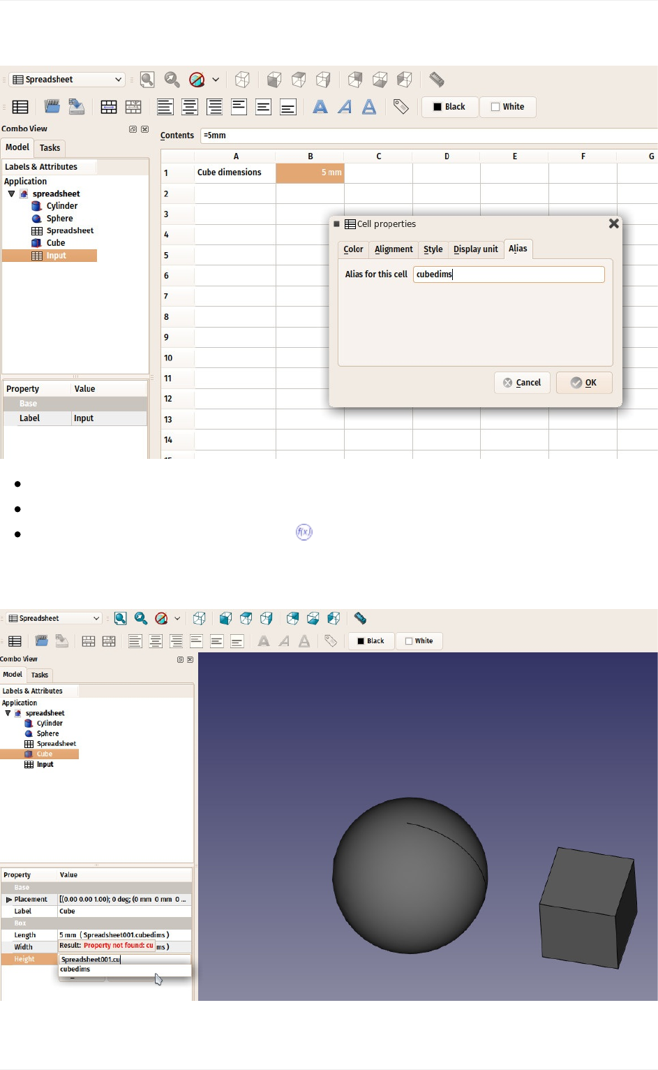
itaname,suchascubedims:
PressOK,thenclosethespreadsheettab
Selectthecubeobject
Inthepropertieseditor,clickthelittle expressioniconattherightsideoftheLength
field.Thiswillopenthenexpressionseditor,whereyoucanwrite
Spreadsheet001.cubedims.RepeatthisforHeightandWidth:
Usingspreadsheets
137
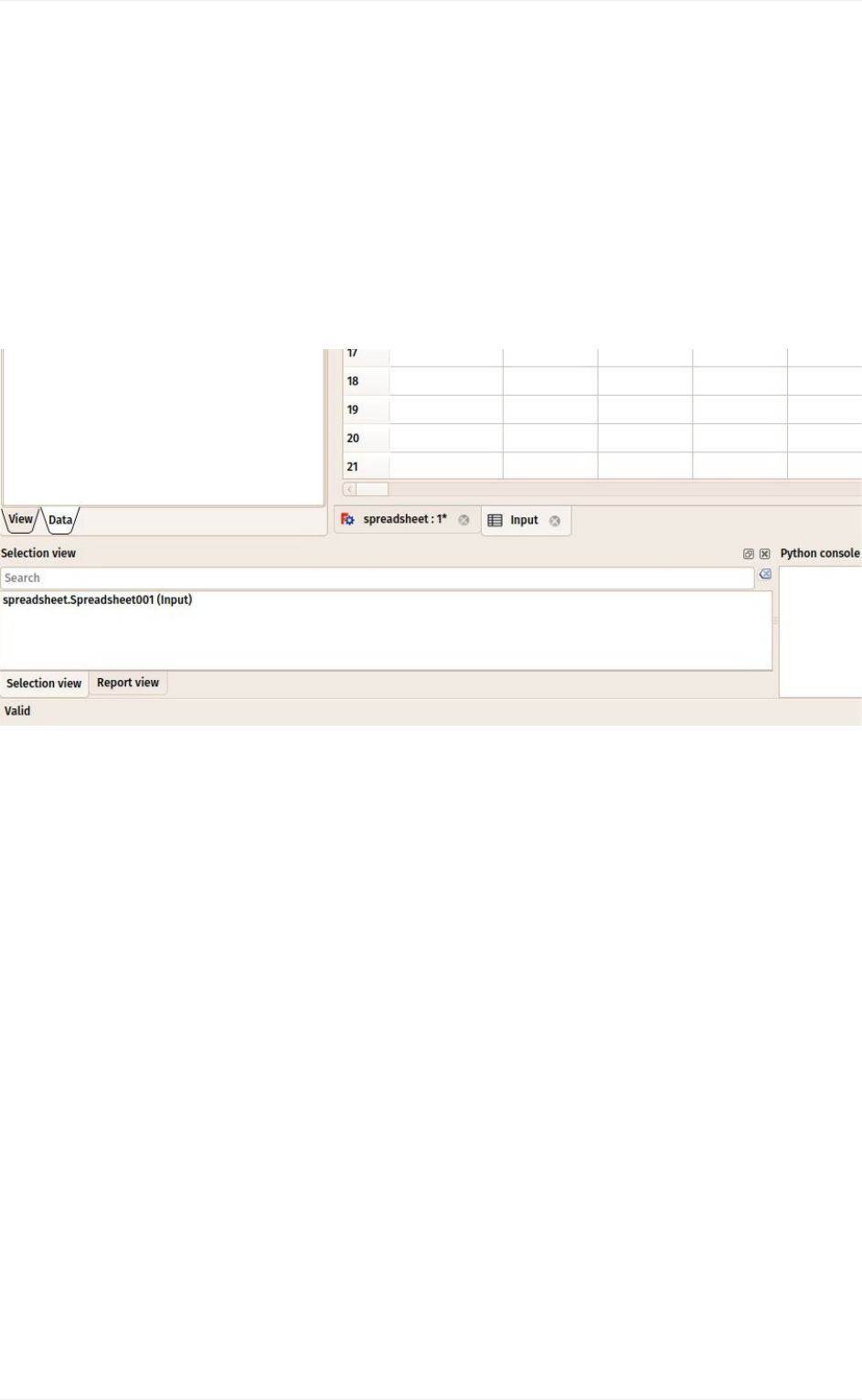
Youmightwonderwhywehadtouse"Spreadsheet001"insteadof"Input"intheexpression
above.Thisisbeacauseeachobject,inaFreeCADdocument,hasaninternalname,which
is unique in the document, and a label, which is what appears in the tree view. If you
unchecktheappropriateoptioninthepreferencessettings,FreeCADwillallowyoutogive
the same label to more than one object. This is why all operations that must identify an
objectwithabsolutelynodoubt,willusetheinternalnameinsteadofthelabel,whichcould
designatemorethanoneobject.Theeasiestwaytoknowtheinternalnameofanobjectis
bykeepingtheselectionpanel(menuEdit->Panels)open,itwillalwaysindicatetheinternal
nameofaselectedobject:
By using cell aliases in spreadsheets, we are able to use a spreadsheet to store "master
values"inaFreeCADdocument.Thiscanbeused,forexample,tohaveamodelofapiece
ofcertaindimensions,andtostorethesedimensionsinaspreadsheet.Itbecomesthenvery
easytoproduceanothermodelwithdifferentdimensions,itisjustamatterofopeningthe
fileandchangingacoupleofdimensionsinthespreadsheet.
Finally,notethattheconstraintsinsideasketchcanalsoreceivethevalueofaspreadsheet
cell:
Usingspreadsheets
138
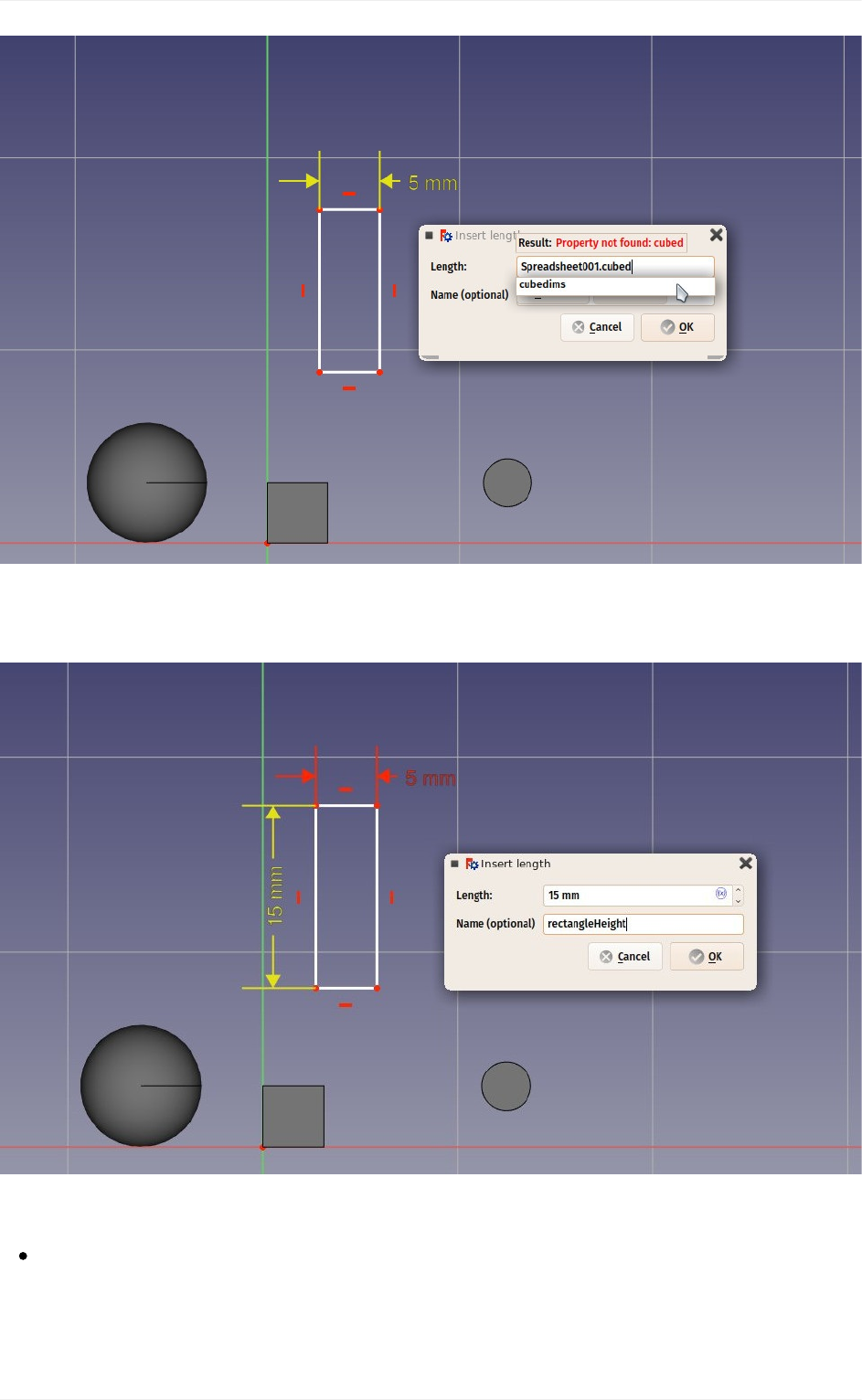
You can also give aliases to dimensional constraints (horizontal, vertical or distance) in a
sketch(youcanthenusethatvaluefromoutsidethesketchaswell):
Download
Thefileproducedinthisexercise:https://github.com/yorikvanhavre/FreeCAD-
manual/blob/master/files/spreadsheet.FCStd
Readmore
Usingspreadsheets
139

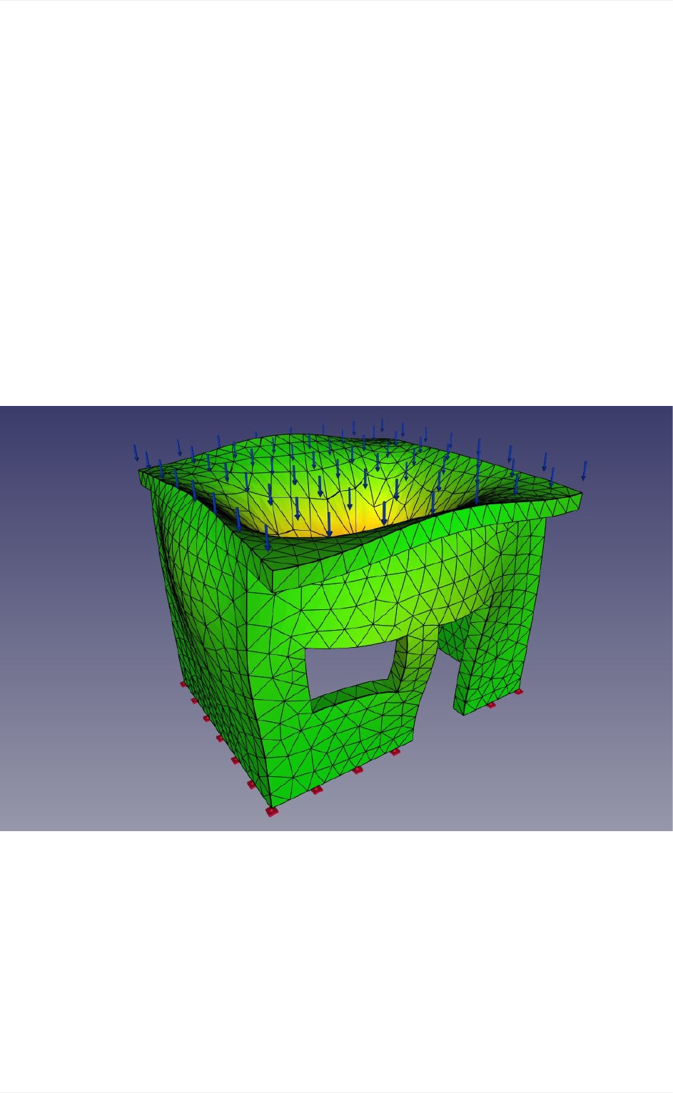
CreatingFEManalyses
FEMstandsforFiniteElementMethod.Itisavastmathematicalsubject,butinFreeCADwe
canresumeitasawaytocalculatepropagationsinsidea3Dobject,bycuttingitintosmall
pieces,andanalyzingtheimpactofeachsmallpieceoveritsneighbours.Thishasseveral
usesintheengineeringandelectomagnetismfields,butwewilllookheremoreindepthat
one use that is already well developed in FreeCAD, which is simulating deformations in
objectswhicharesubmittedtoforcesandweights.
ObtainingsuchsimulationisdoneinFreeCADwiththeFEMWorkbench.Itinvolvesdifferent
steps: Preparing the geometry, setting its material, performing the meshing (division into
smaller parts, like we did in the Preparing objects for 3D printing chapter, and finally
calculatingthesimulation.
PreparingFreeCAD
Thesimulationitselfisdonebyanotherpieceofsoftware,thatisusedbyFreeCADtoobtain
the results. As there are several interesting open-source FEM simulation applications
available,theFEMWorkbenchhasbeenmadetobeabletousemorethanone.However,
currentlyonlyCalculiXisfullyimplemented.Anotherpieceofsoftware,calledNetGen,which
isresponsibleforgeneratingthesubdivisionmesh,isalsorequired.Detailedinstructionsto
installthesetwocomponentsareprovidedintheFreeCADdocumentation.
CreatingFEManalyses
141
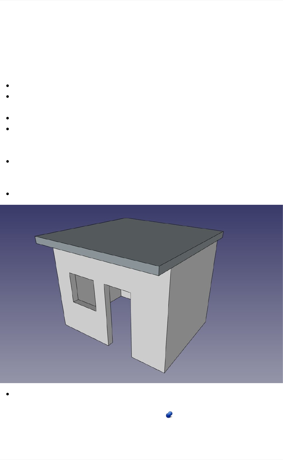
Preparingthegeometry
We will start with the house we modelled in the BIM modeling chapter. However, some
changeshavetobemadetomakethemodelsuitableforFEMcalculations.Thisinvolves,
basically,discardingtheobjectsthatwedon'twanttoincludeinthecalculaiton,suchasthe
doorandwindow,andjoiningalltheremainingobjectsintoone.
Loadthehousemodelwemodeledearlier
Deleteorhidethepageobject,thesectionplanesandthedimensions,sowestayonly
withourmodel
Hidethewindow,thedoorandthegroundslab
Alsohidethemetalbeamsfromtheroof.Sincetheyareverydifferentobjectsfromthe
restofthehouse,wewillsimplifyourcalculationbynotincludingit.Instead,wewill
considerthattheroofslabisdirectlyplacedontopofthewall.
Nowmovetheroofslabdownsoitrestsontopofthewall:EdittheRectangleobject
thatweusedasabaseoftheroofslab,andchangeit'sPlacement->Position->Xvalue
from3.18mto3.00m
Ourmodelisnowclean:
TheFEMWorkbenchcancurrentlycalculatedeformationsononesingleobjectonly.
Therefore,weneedtojoinourtwoobjects(thewallandtheslab).SwitchtothePart
Workbench,selectthetwoobjects,andpressthe Fuse.Wenowhaveobtainedone
fusedobject:
CreatingFEManalyses
142
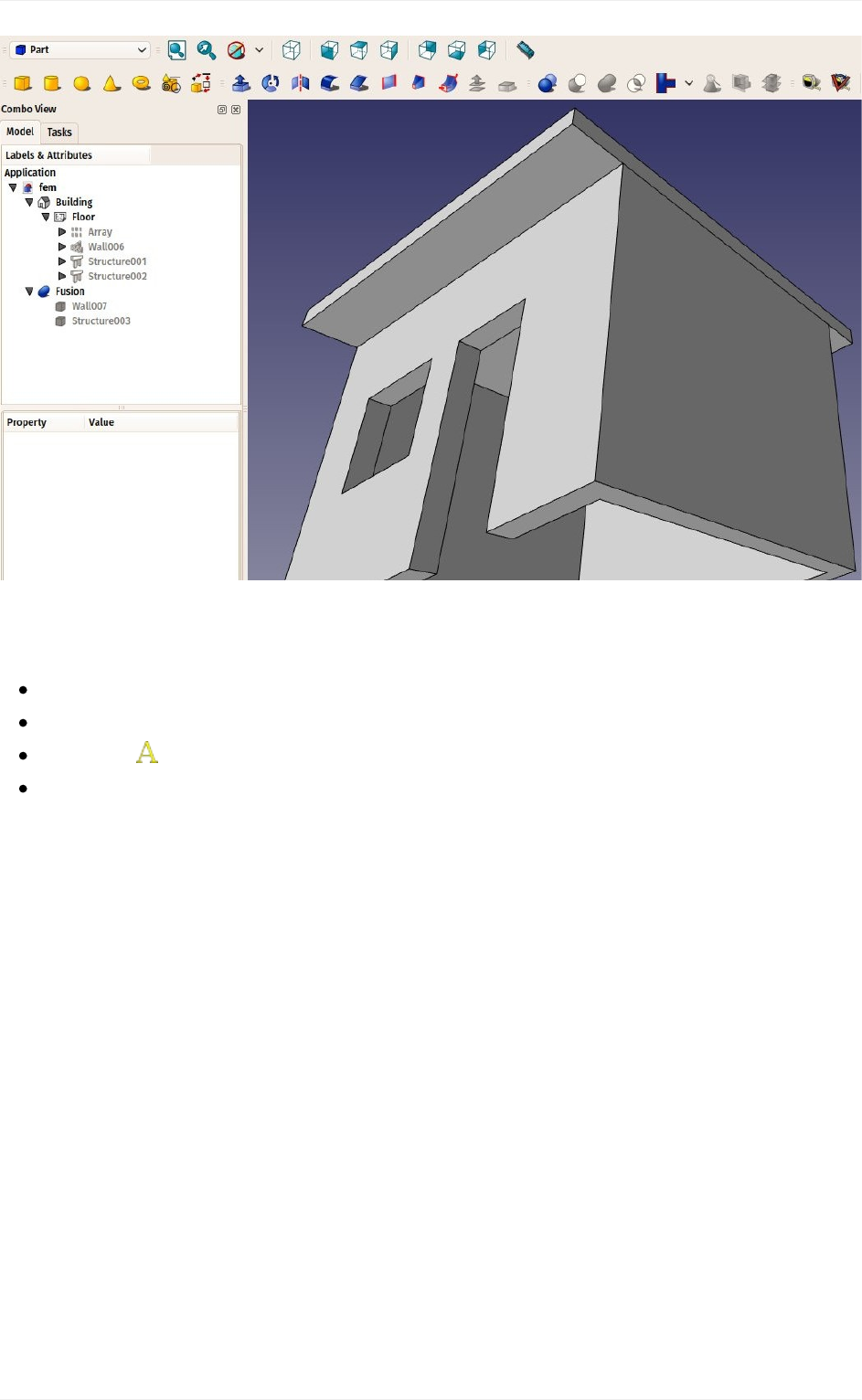
Creatingtheanalysis
WearenowreadytostartaFEManalysis.Let'sswitchtotheFEMWorkbench
Selectthefusionobject
Pressthe NewAnalysisbutton
Anewanalysiswillbecreatedandasettingspanelsopened.Hereyoucandefinethe
meshingparameterstobeusedtoproducetheFEMmesh.Themainsettingtoeditis
theMaxSizewhichdefinesthemaximumsize(inmillimeters)ofeachpieceofthe
mesh.Fornow,wecanleavethedefaultvalueof1000:
CreatingFEManalyses
143
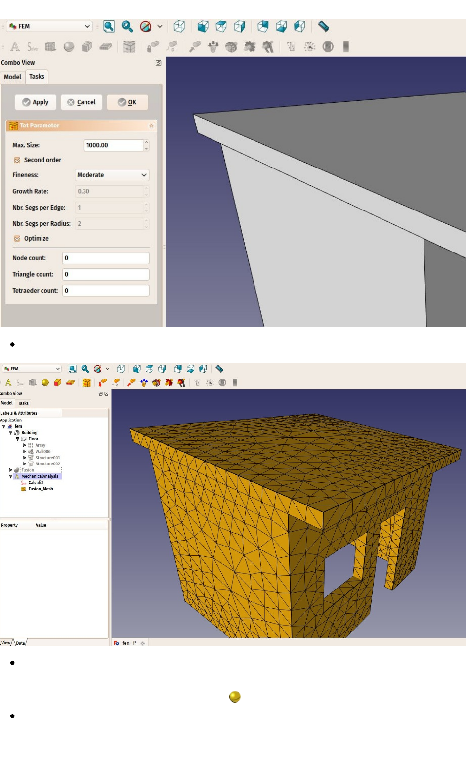
AfterpressingOKandafewsecondsofcalculaiton,ourFEMmeshisnowready:
Wecannowdefinethematerialtobeappliedtoourmesh.Thisisimportantbecause
dependingonthematerialstrength,ourobjectwillreactdifferentlytoforcesappliedtoit.
Selecttheanalysisobject,andpressthe NewMaterialbutton.
Ataskpanelwillopentoallowustochooseamaterial.IntheMaterialdrop-downlist,
CreatingFEManalyses
144
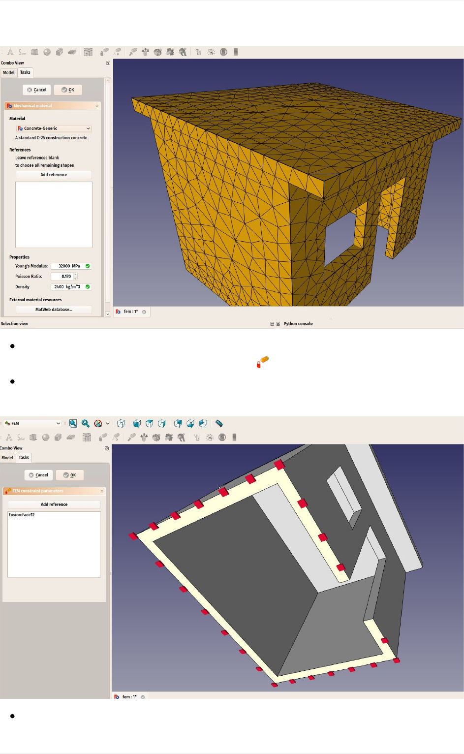
choosetheConcrete-genericmaterial,andpressOK.
Wearenowreadytoapplyforces.Let'sstartbyspecifyingwhichfacesarefixedintothe
groundandcanthereforenotmove.Pressthe FixedConstraintbutton.
ClickonthebottomfaceofourbuildingandpressOK.Thebottomfaceisnowindicated
asunmovable:
Wewillnowaddaloadonthetopface,thatcouldrepresente,forexample,amassive
CreatingFEManalyses
145
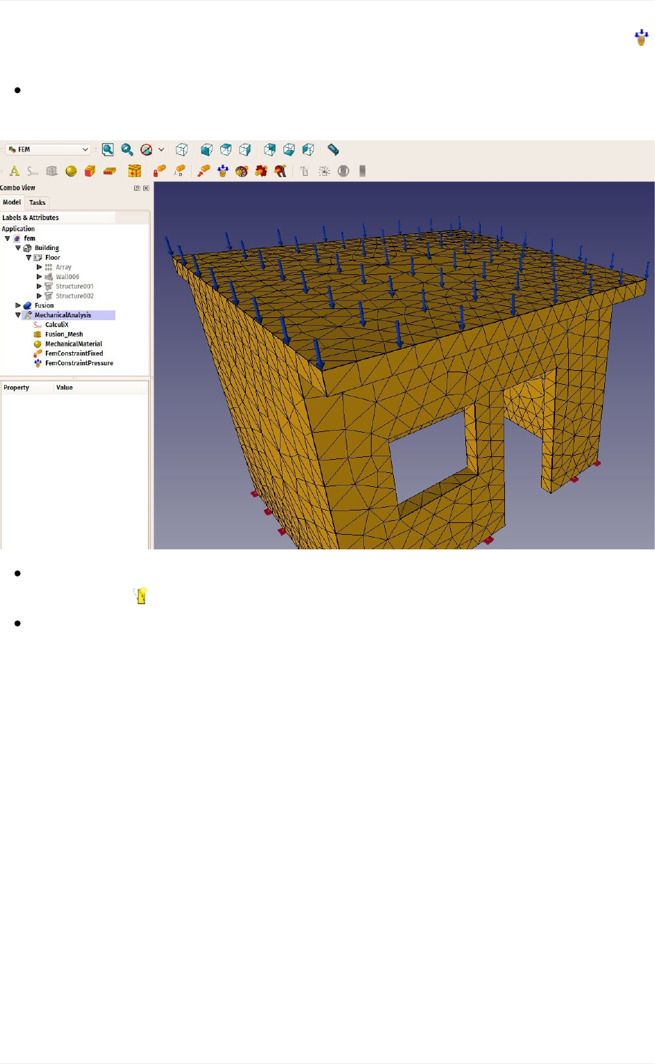
weightbeingspreadontheroof.Forthiswewilluseapressureconstraint.Pressthe
PressureConstraintbutton.
Clickthetopfaceoftheroof,setthepressureto10MPa(thepressureisappliedby
squaremillimeter)andclicktheOKbutton.Ourforceisnowapplied:
Wearenowreadytostartthecalculation.SelecttheCalculiXobjectinthetreeview,
andpressthe StartCalculationbutton.
Inthetaskpanelthatwillopen,clickfirsttheWrite.inpfilebuttontocreatetheinputfile
forCalculiX,thentheRunCalculiXbutton.Afewmomentslater,thecalculationwillbe
done:
CreatingFEManalyses
146
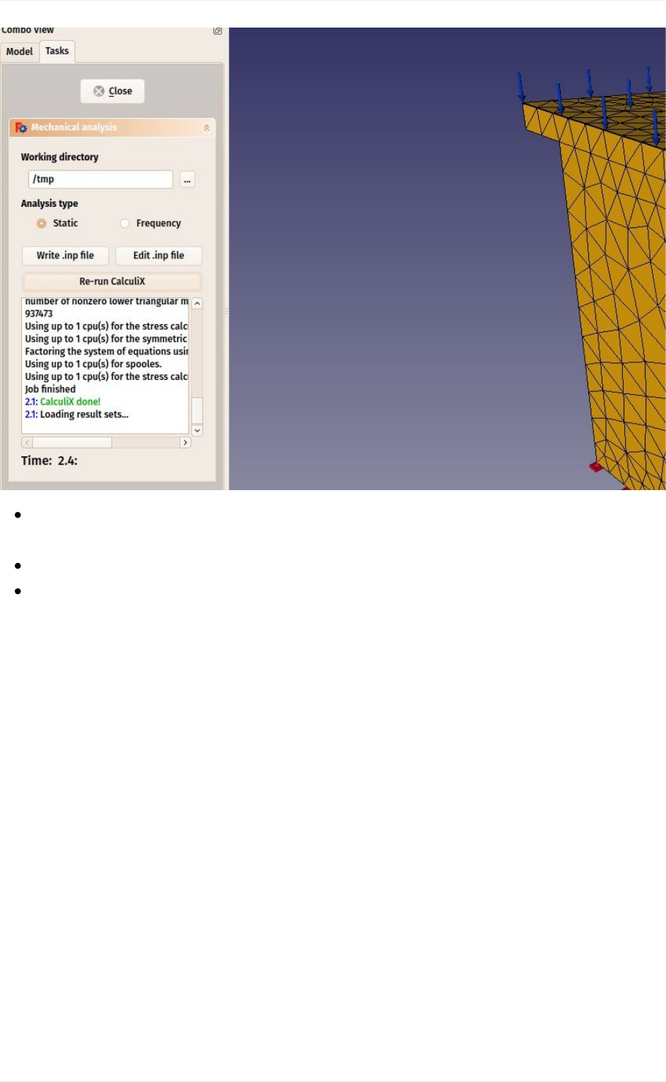
Wecannowlookattheresults.Closethetaskpanel,andseethatanewResults
objecthasbeenaddedtoouranalysis.
Double-clicktheResultsobject
Setthetypeofresultthatyouwanttoseeonthemesh,forexample"absolute
displacement",ticktheshowcheckboxunderDisplacement,andmovetheslidernext
toit.Youwillbeabletoseethedeformationgrowingasyouapplymoreforce:
CreatingFEManalyses
147
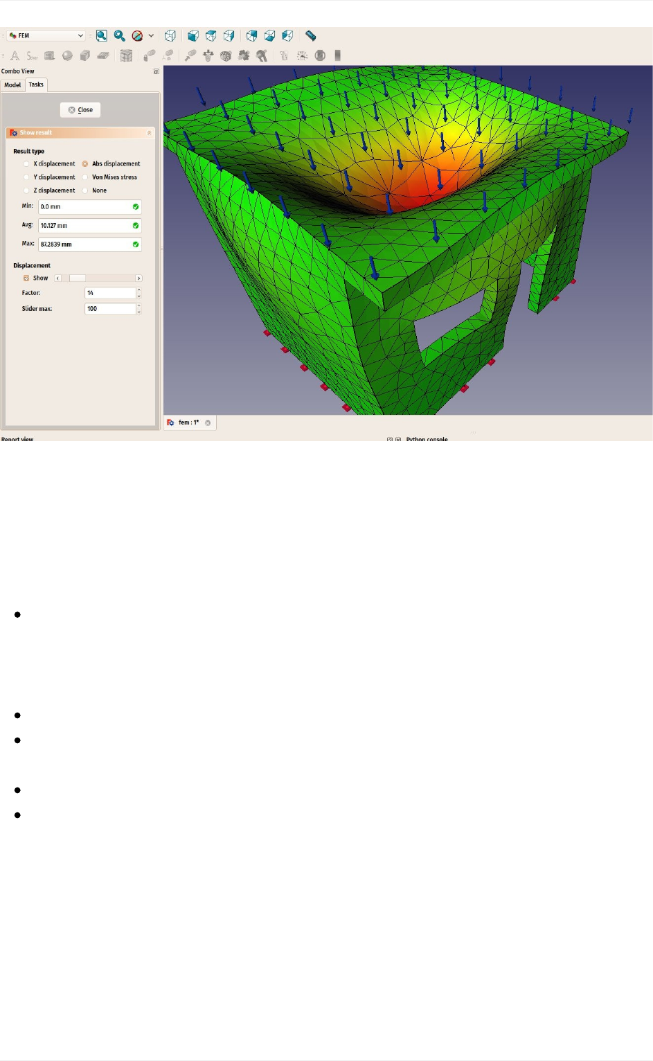
TheresultsdisplayedbytheFEMworkbenchareofcoursecurrentlynotenoughtoperform
real-lifedecisionsaboutstructuresdimensionningandmaterials.However,theycanalready
givepreciousinformationabouthowtheforcesflowthroughastructure,andwhicharethe
weakareasthatwillbearthemorestress.
Downloads
Thefilecreatedduringthisexercise:https://github.com/yorikvanhavre/FreeCAD-
manual/blob/master/files/fem.FCStd
Readmore
TheFEMWorkbench:http://www.freecadweb.org/wiki/index.php?title=Fem_Workbench
InstallingrequiredFEMcomponents:http://www.freecadweb.org/wiki/index.php?
title=FEM_Install
CalculiX:http://www.calculix.de/
NetGen:https://sourceforge.net/projects/netgen-mesher/
CreatingFEManalyses
148

Creatingrenderings
Incomputertalk,arenderingisawordusedtodescribeaniceimageproducedfroma3D
model.Ofcourse,wecouldsaythatwhatseseeintheFreeCAD3Dviewisalreadynice.
ButanybodywhosawarecentHollywoodmovieknowsthatitispossibletoproduceimages
withacomputerthatarealmostundistinguishablefromaphotograph.
Ofcourse,producingsuchphoto-realisticimagesrequiresalotofwork,anda3Dapplication
that offers specific tools for that, such as precise controls for materials and lighting.
FreeCAD being an application more geared towards technical modeling, it doesn't feature
anyadvancedrenderingtool.
Fortunately, the opens-source world offers many applications to produce realistic images.
Probably the most famous one is Blender, which is very popular and widely used in the
movies and gaming industries. 3D models can very easily and faithfully be exported from
FreeCADandimportedintoBlender,whereyoucanaddrealisticmaterialsandillumination,
andproducethefinalimagesorevenanimations.
Some other open-source rendering tools are made to be used inside another application,
andwilltakecareofdoingthecomplexcalculationstoproducerealisticimages.Throughits
Raytracing Workbench, FreeCAD can use two of these rendering tools: POV-Ray and
Luxrender.POV-Rayisaveryoldproject,andisconsideredaclassicalraytracing engine,
whileLuxrenderismuchnewer,andiscategorizedasanunbiasedrenderer.Bothhavetheir
strengthsandweaknesses,dependingonthetypeofimageonewantstorender.Thebest
waytoknowistolookatexamplesonbothengineswebsites.
Installation
BeforebeingabletousetheRaytracingWorkbenchinFreeCAD,oneofthesetworendering
applicationsneedstobeinstalledonyoursystem.Thisisusuallyverystraightforward,both
provideinstallersformanyplatformsorareusuallyincludedinthesoftwarerepositoriesof
mostLinuxdistributions.
OncePOV-RayorLuxrenderisinstalled,weneedtosetthepathtotheirmainexecutablein
the FreeCAD preferences. This is usually only required on Windows and Mac. On Linux
FreeCAD will pick it from the standard locations. The location of the povray or luxrender
executables can be found by simply searching your system for files named povray (or
povray.exeonWindows)andluxrender(orluxrender.exeonWindows).
Creatingrenderings
149
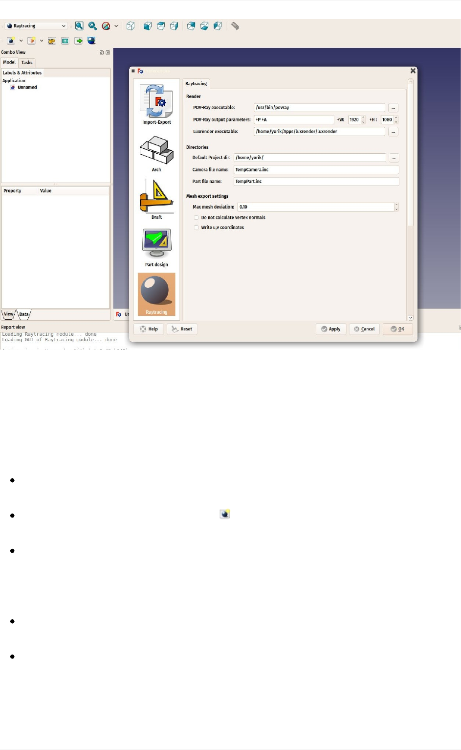
Inthispreferencesscreenwecanalsosetthedesiredimagesizewewanttoproduce.
RenderingwithPovRay
Wewillusethetablewehavebeenmodelinginthetradtionalmodelingchaptertoproduce
renderingswithPovRayandLuxrender.
Startbyloadingthetable.FCStdfilethatwemodeledearlierorfromthelinkatthe
bottomofthischapter.
Pressthesmalldownarrownexttothe NewPovrayprojectbutton,andchoosethe
RadiosityNormaltemplate
Awarningmessagemightappeartellingyouthatthecurrent3Dviewisnotin
perspectivemodeandtherenderingwillthereforediffer.CorrectthisbychoosingNo,
choosingmenuView->PerspectiveviewandchoosingtheRadiosityNormaltemplate
again.
Youmightalsotryothertemplatesafteryoucreatedanewproject,simplybyeditingits
Templateproperty.
Anewprojecthasnowbeencreated:
Creatingrenderings
150
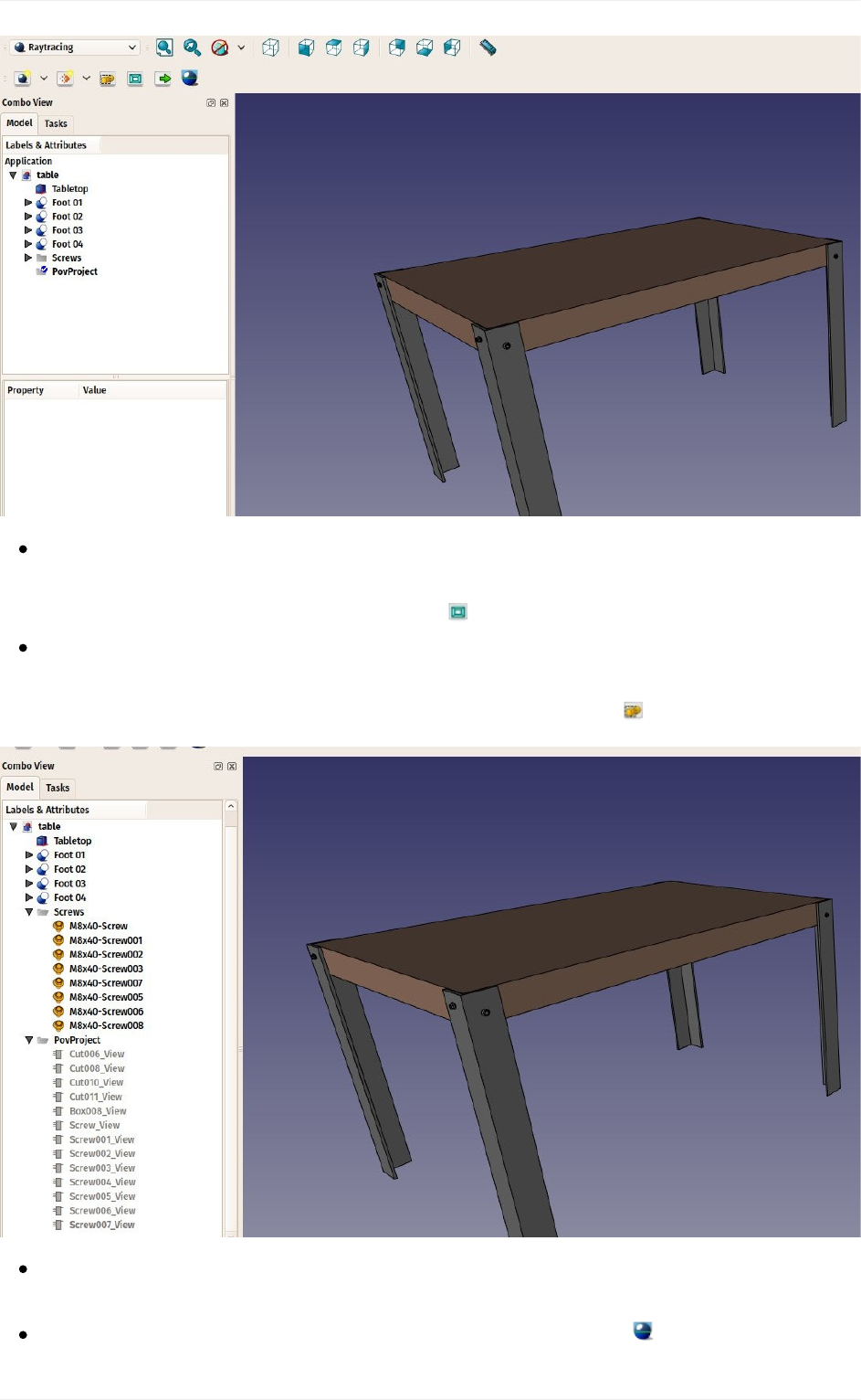
Thenewprojecthasadoptedthepointofviewofthe3Dviewasitwasatthemoment
wepressedthebutton.Wecanchangetheview,andupdatetheviewpositionstoredin
thepovrayprojectanytime,bypressingthe Resetcamerabutton.
TheRaytracingWorkbenchworksthesamewayastheDrawingWorkbench:Oncea
projectfolderiscreated,wemustaddViewsofourobjectstoit.Wecannowdothatby
selectingalltheobjectsthatcomposethetable,andpressthe Insertpartbutton:
Theviewshavetakenthecolorandtransparencyvaluesfromtheiroriginalparts,but
youcanchangethatinthepropertiesofeachindividualviewifyouwish.
Wearenowreadytoproduceourfirstpovrayrender.Pressthe Renderbutton.
Creatingrenderings
151
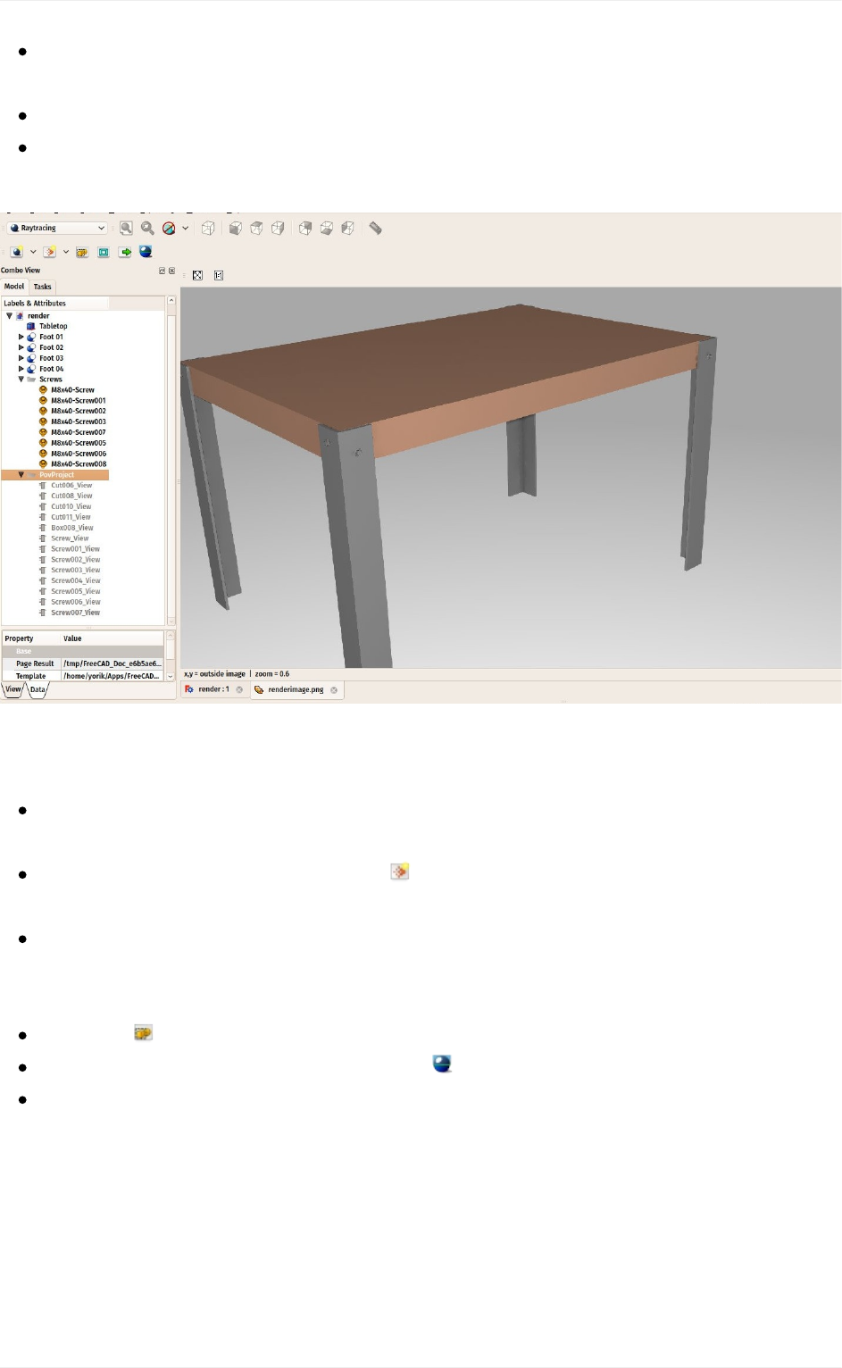
Youwillbeaskedtogiveafilenameandpathforthe.pngimagethatwillbesavedby
povray.
Thepovraywillthenopenandcalculatetheimage.
Whenthisisdone,simplyclicktheimagetoclosethepovraywindow.Theresulting
imagewillbeloadedinFreeCAD:
RenderingwithLuxRender
RenderingwithLuxrenderworksalmostthesameway.Wecanleaveourfileopenand
createanewLuxrenderprojectinthesamefile,orreloadittostartfromscratch.
Pressthelittledownarrownexttothe NewLuxrenderprojectbuttonandchoosethe
LuxOutdoortemplate.
Selectallthecomponentsofthetable.Ifyoustillhavethepovrayprojectinyour
document,besuretoalsoselecttheluxprojectitself,sotheviewscreatedinthenext
stepwon'tgointhewrongprojectbymistake.
Pressthe Insertpartbutton.
Selecttheluxrenderproject,andpressthe Renderbutton.
Luxrenderworksdifferentlythanpovray.Whenyoustarttherender,theluxrender
applicationwillopenandimmediatelystartrendering:
Creatingrenderings
152
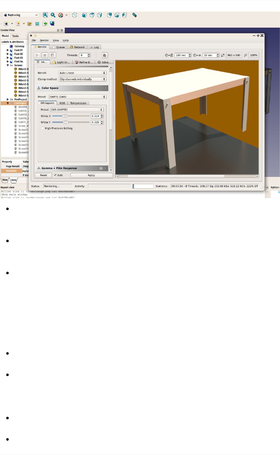
Ifyouleavethatwindowopen,Luxrenderwillcontinuecalculatingandrenderingforever,
progressivelyrefiningtheimage.Itisuptoyoutodecidewhentheimagehasreacha
sufficientqualityforyourneeds,andstoptherender.
Therearealsomanycontrolstoplaywith,ontheleftpanel.Allthesecontrolswill
changetheaspectoftheimagebeingrenderedonthefly,withoutstoppingthe
rendering.
Whenyoufeelthequalityisgoodenough,simplypressRender->stop,andthenFile-
>Exporttoimage->Tonemappedlowdynamicrangetosavetherenderedimagetoa
pngfile.
You can extend greatly the render possibilities of FreeCAD by creating new templates for
povrayorluxrender.ThisisexplainedintheRaytracingWorkbenchdocumentation.
Downloads
Thetablemodel:https://github.com/yorikvanhavre/FreeCAD-
manual/blob/master/files/table.FCStd
Thefileproducedduringthisexercise:https://github.com/yorikvanhavre/FreeCAD-
manual/blob/master/files/render.FCStd
Readmore
TheRaytracingWorkbench:http://www.freecadweb.org/wiki/index.php?
title=Raytracing_Module
Blender:http://www.blender.org
Creatingrenderings
153


Pythonscripting
Pythonscripting
155
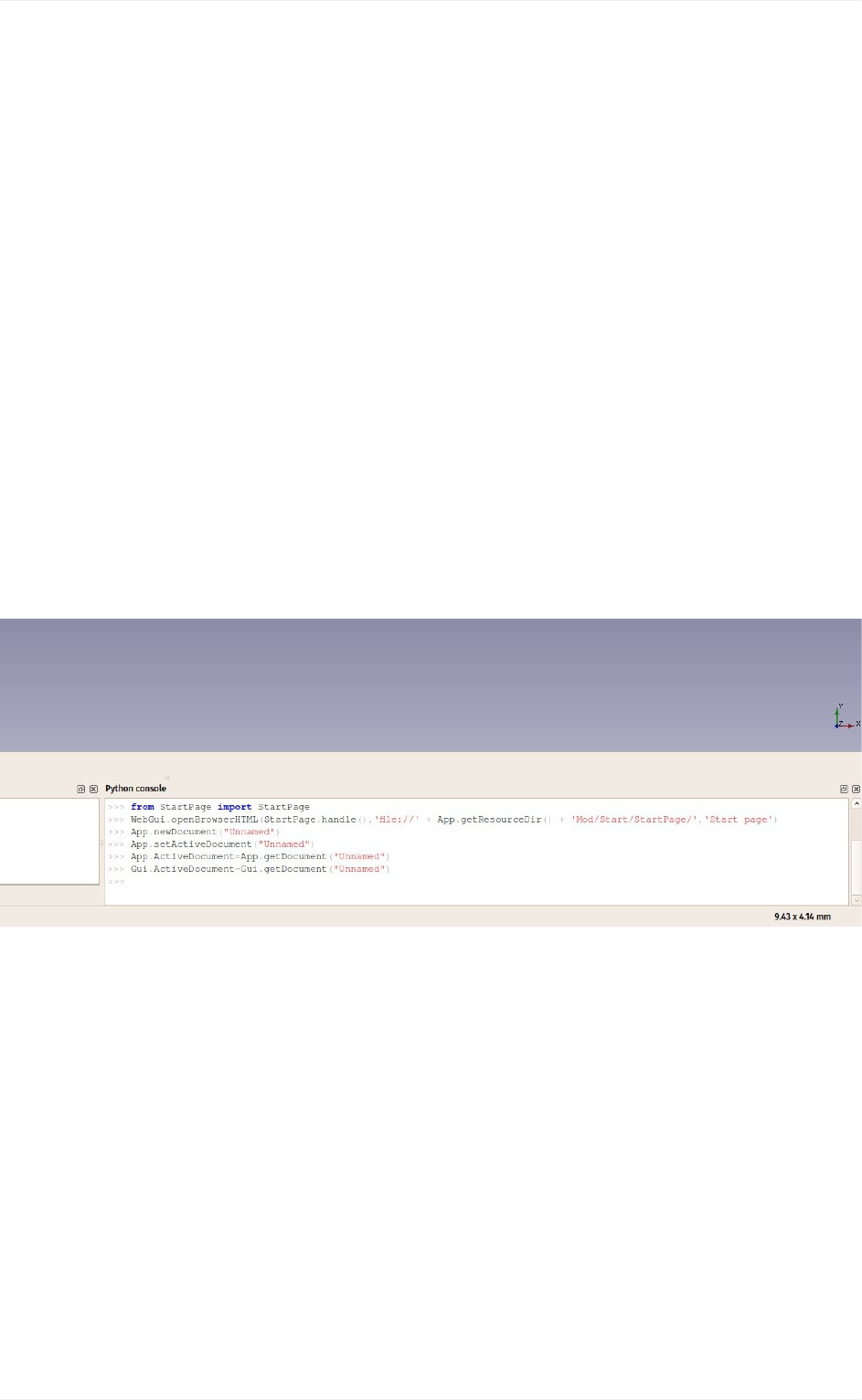
Agentleintroduction
Python is a widely popular, open-source programming language, very often used as a
scriptinglanguage,embeddedinapplications,asthisisthecasewithFreeCAD.Italsohasa
seriesoffeaturesthatmakesitspeciallyinterestingforusFreeCADusers:Itisveryeasyto
learn,speciallyforpeoplewhohadneverprogrammedbefore,anditisembeddedinmany
otherapplications,whichmakesitaveryvaluabletooltolearn,asyouwillbeabletouseit
inmanyotherapplications,suchasBlender,InkscapeorGRASS.
FreeCADmakesanextensiveuseofPython.Withit,youcanaccessandcontrolalmostany
feature of FreeCAD. You can for example create new objects, modify their geometry,
analyze their contents, or even create new interface controls, tools and panels. Some
workbenches of FreeCAD and most of the addon workbenches are fully programmed in
python. FreeCAD has an advanced python console, available from menu View->Panels-
>Python console. It is often useful to perform operations for which there is no toolbar
buttonyet,ortocheckshapesforproblems,ortoperformrepetitivetasks:
Butthepythonconsolealsohasanotherveryimportantuse:Everytimeyoupressatoolbar
button,orperformotheroperationsinFreeCAD,somepythoncodeisprintedintheconsole
andexecuted.By leavingthePython consoleopen,you canlitterallysee thepythoncode
unfold as you work, and in no time, almost without knowing it, you will be learning some
pythonlanguage.
FreeCADalsohasamacrossystem,whichallowsyoutorecordactionstobereplayedlater.
ThissystemalsousesthePythonconsole,bysimplyrecordingeverythingthatisdoneinit.
Inthischapter,wewilldiscoververygenerallythePythonlanguage.Ifyouareinterestedin
learningmore,theFreeCADdocumentationwikihasanextensivesectionrelatedtopython
programming.
Agentleintroduction
156
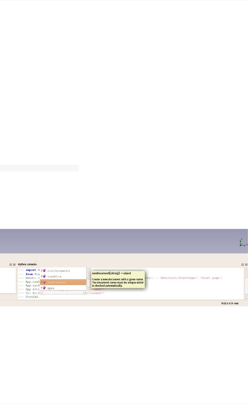
Writingpythoncode
TherearetwoeasywaystowritepythoncodeinFreeCAD:Fromthepythonconsole(menu
View->Panels->PythonConsole),orfromtheMacroeditor(menuTools->Macros->
New). In the console, you write python commands one by one, which are executed when
youpressreturn,whilethemacroscancontainamorecomplexscriptmadeofseverallines,
whichisexecutedonlywhenthemacroislaunchedfromthesameMacroswindow.
Inthischapter,youwillbeabletousebothmethods,butitishighlyrecommendedtousethe
PythonConsole,sinceitwillimmediatelyinformyouofanyerroryoucoulddowhiletyping.
IfthisisthefirsttimeyouaredoingPythoncoding,considerreadingthisshortintroductionto
Pythonprogrammingbeforegoingfurther,itwillmakethebasicconceptsofPythonclearer.
ManipulatingFreeCADobjects
Let'sstartbycreatinganewemptydocument:
doc=FreeCAD.newDocument()
If you type this in the FreeCAD python console, you will notice that as soon as you type
"FreeCAD."(thewordFreeCADfollowedbyadot),awindowspopsup,allowingtoquickly
autocomplete the rest of your line. Even better, each entry in the autocomplete list has a
tooltipexplainingwhatitdoes.Thismakesitveryeasytoexplorethefunctionalityavailable.
Beforechoosing"newDocument",havealookattheotheroptionsavailable.
AssoonasyoupressEnterournewdocumentwillbecreated.Thisissimilartopressing
the"newdocument"buttononthetoolbar.InPython,thedotisusedtoindicatesomething
that is contained inside something else (newDocument is a function that is inside the
FreeCAD module). The window that pops up therefore shows you everything that is
contained inside "FreeCAD". If you would add a dot after newDocument, instead of the
parentheses, it would show you everything that is contained inside the newDocument
function.TheparenthesesaremandatorywhenyouarecallingaPythonfunction,suchas
thisone.Wewillillustratethatbetterbelow.
Agentleintroduction
157

Nowlet'sgetbacktoourdocument.Let'sseewhatwecandowithit:
doc.
Explorethe availableoptions.Usually namesthat beginwith acapital letterare attributes,
they contain a value, while names that begin with small letter are functions (also called
methods),they"dosomething".Namesthatbeginwithanunderscoreareusuallytherefor
theinternalworkingofthemodule,andyoushouldn'tcareaboutthem.Let'suseoneofthe
methodstoaddanewobjecttoourdocument:
box=doc.addObject("Part::Box","myBox")
Ourboxisaddedinthetreeview,butnothinghappensinthe3Dviewyet,becausewhen
working from Python, the document is never recomputed automatically. We must do that
manually,wheneverweneed:
doc.recompute()
Now our box appeared in the 3D view. Many of the toolbar buttons that add objects in
FreeCADactuallydotwothings:addtheobject,andrecompute.Ifyouturnedonthe"show
script commands in python console" option above, try now adding a sphere with the
appropriate button in the Part Workbench, and you will see the two lines of python code
beingexecutedoneaftertheother.
YoucangetalistofallpossibleobjecttypeslikePart::Box:
doc.supportedTypes()
Nowlet'sexplorethecontentsofourbox:
box.
You'llimmediatelyseeacoupleofveryinterestingthingssuchas:
box.Height
Thiswillprintthecurrentheightofourbox.Nowlet'strytochangethat:
box.Height=5
Ifyou selectyour boxwiththe mouse,you willsee thatin theproperties panel,underthe
Data tab, our Height property appears with the new value. All properties of a FreeCAD
objectthatappearintheDataandViewtabsaredirectlyaccessiblebypythontoo,bytheir
names,likewedidwiththeHeightproperty.Datapropertiesareaccesseddirectlyfromthe
objectitself,forexample:
box.Length
Agentleintroduction
158

View properties are stored inside a ViewObject. Each FreeCAd object possesses a
ViewObject,whichstoresthevieualpropertiesoftheobject.WhenrunningFreeCADwithout
itsGraphicalInterface(forexamplewhenlaunchingitfromaterminalwiththe-ccommand
line option, or using it from another Python script), the ViewObject is not available, since
thereisnovisualatall.
Forexample,toaccessthelinecolorofourbox:
box.ViewObject.LineColor
VectorsandPlacements
Vectorsareaveryfundamentalconceptinany3Dapplication.Itisalistof3numbers(x,y
and z), describing a point or position in the 3D space. A lot of things can be done with
vectors, such as additions, subtractions, projections and much more. In FreeCAD vectors
worklikethis:
myvec=FreeCAD.Vector(2,0,0)
print(myvec)
prnimarkdownt(myvec.x)
print(myvec.y)
othervec=FreeCAD.Vector(0,3,0)
sumvec=myvec.add(othervec)
Another common feature of FreeCAD objects is their Placement. As we saw in earlier
chapters, each object has a Placement property, which contains the position (Base) and
orientation (Rotation) of the object. It is easy to manipulate from Python, for example to
moveourobject:
print(box.Placement)
print(box.Placement.Base)
box.Placement.Base=sumvec
otherpla=FreeCAD.Placement()
otherpla.Base=FreeCAD.Vector(5,5,0)
box.Placement=otherpla
Readmore
Python:https://www.python.org/
WorkingwithMacros:http://www.freecadweb.org/wiki/index.php?title=Macros
IntroductiontoPythonscripting:http://www.freecadweb.org/wiki/index.php?
title=Introduction_to_Python
UsingPythoninFreeCAD:http://www.freecadweb.org/wiki/index.php?
title=Python_scripting_tutorial
Agentleintroduction
159


Creatingandmanipulatinggeometry
Inthepreviouschapters,welearnedaboutthedifferentworkbenchesofFreeCAD,andthat
each of them implements its own tools and geometry types. The same concepts applies
whenworkingfromPythoncode.
We also saw that the big majority of the FreeCAD workbenches depend on a very
fundamental one: the Part Workbench. In fact, may other workbenches, such as Draft or
Arch, do exactly what we will do in this chapter: They use Python code to create and
manipulatePartgeometry.
SothefirstthingweneedtodotoworkwithPartgeometry,istodothePythonequivalentto
switchingtothePartWorkbench:importthePartmodule:
importPart
Takeaminutetoexplorethecontentsof thePartmodule,bytyping Part. and browsing
through the different methods offered there. The Part module offers several convenience
fuctionssuchasmakeBox,makeCircle,etc...whichwillinstantlybuildanobjectforyou.Try
this,forexample:
Part.makeBox(3,5,7)
When you press Enter after typing the line above, nothing will appear in the 3D view, but
somethinglikethiswillbeprintedonthePythonConsole:
<Solidobjectat0x5f43600>
Thisiswhereanimportantconcepttakesplace.WhatwecreatedhereisaPartShape.Itis
not a FreeCAD document object (yet). In FreeCAD, objects and their geometry are
independent. Think of a FreeCAD document object as a container, that will host a shape.
ParametricobjectswillalsohavepropertiessuchasLengthandWidth,andwillrecalculate
their Shape on-the-fly, whenever one of the properties changes.What we did here is
calculateashapemanually.
Wecannoweasilycreatea"generic"documentobjectinthecurrentdocument(makesure
youhaveatleastonenewdocumentopen),andgiveitaboxshapelikewejustmade:
boxShape=Part.makeBox(3,5,7)
myObj=FreeCAD.ActiveDocument.addObject("Part::Feature","MyNewBox")
myObj.Shape=boxShape
FreeCAD.ActiveDocument.recompute()
Creatingandmanipulatinggeometry
161

Notehowwehandled myObj.Shape,seethat itisdoneexactly likewedidin theprevious
chapter,whenwechangedotherpropertiesofanobject,suchas box.Height=5.Infact,
Shapeisalsoaproperty,justlikeHeight.OnlyittakesaPartShape,notanumber.Innext
chapterwewillhaveadeeperlookathowthoseparametricobjectsareconstructed.
For now, let's explore our Part Shapes more in detail. At the end of the chapter about
traditional modeling with the Part Workbench we showed a table that explains how Part
Shapes are constructed, and their different components (Vertices, edges, faces, etc). The
exactsamecomponentsexisthereandcanberetrievedfromPython.AllPartShapealways
havethefollowingattributes:Vertexes,Edges,Wires,Faces,ShellsandSolids.Allofthem
arelists,thatcancontainanynumberofelementsorbeempty:
print(boxShape.Vertexes)
print(boxShape.Edges)
print(boxShape.Wires)
print(boxShape.Faces)
print(boxShape.Shells)
print(boxShape.Solids)
Forexample,let'sfindtheareaofeachfaceofourboxshapeabove:
forfinboxShape.Faces:
print(f.Area)
Or,foreachedge,itsstartpointandendpoint:
foreinboxShape.Edges:
print("Newedge")
print("Startpoint:")
print(e.Vertexes[0].Point)
print("Endpoint:")
print(e.Vertexes[1].Point)
Asyousee,ifourboxShapehasa"Vertexes"attribute,eachEdgeoftheboxShapealsohas
a"Vertexes"attribute.Aswecanexpect,theboxShapewillhave8vertices,whiletheedge
willonlyhave2,whicharebothpartofthelistof8.
Wecanalwayscheckwhatisthetypeofashape:
print(boxShape.ShapeType)
print(boxShape.Faces[0].ShapeType)
print(boxShape.Vertexes[2].ShapeType)
Creatingandmanipulatinggeometry
162
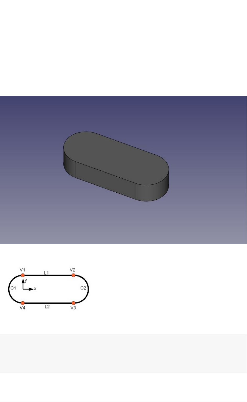
SotoresumethewholediagramofPartShapes:EverythingstartswithVertices.Withoneor
twovertices,youformanEdge(fullcircleshaveonlyonevertex).WithoneormoreEdges,
you form a Wire. With one or more closed Wires, you form a Face (the additional Wires
become"holes" inthe Face). Withone ormore Faces,youform aShell. Whena Shell is
fullyclosed(watertight),youcanformaSolidfromit.Andfinally,youcanjoinanynumberof
Shapesofanytypestogether,whichisthencalledaCompound.
Wecannowtrycreatingcomplexshapesfromscratch,byconstructingalltheircomponents
onebyone.Forexample,let'strytocreateavolumelikethis:
Wewillstartbycreatingaplanarshapelikethis:
First,let'screatethefourbasepoints:
V1=FreeCAD.Vector(0,10,0)
V2=FreeCAD.Vector(30,10,0)
V3=FreeCAD.Vector(30,-10,0)
V4=FreeCAD.Vector(0,-10,0)
Thenwecancreatethetwolinearsegments:
Creatingandmanipulatinggeometry
163
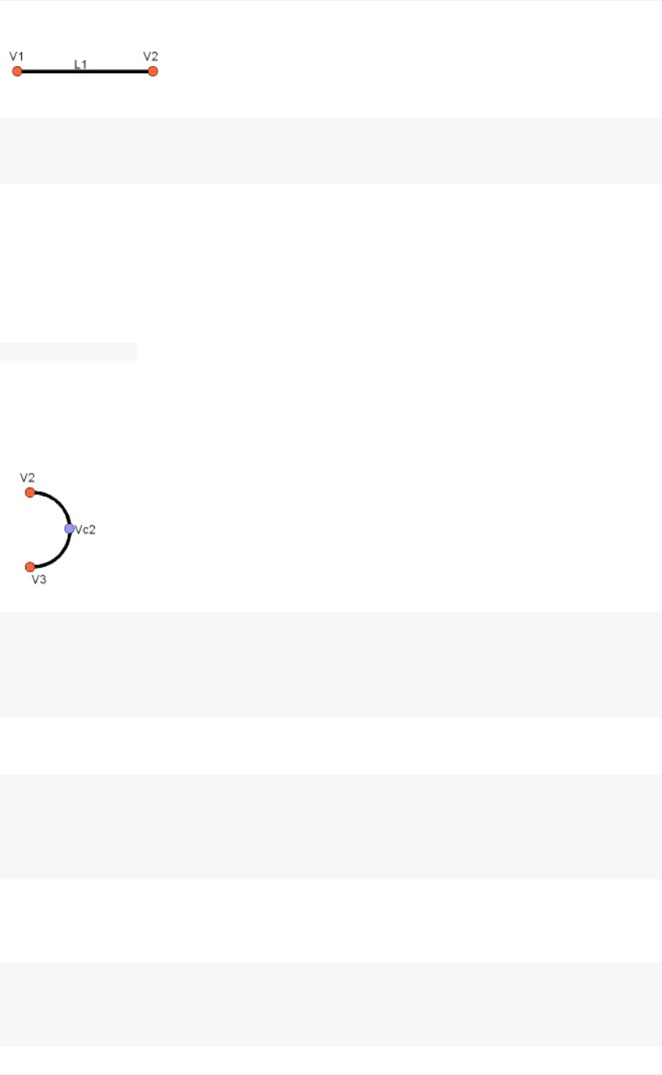
L1=Part.Line(V1,V2)
L2=Part.Line(V4,V3)
Notethat we didn'tneed tocreate Vertices? Wecould immediately createPart.Lines from
FreeCADVectors.Thisisbecauseherewehaven'tcreatedEdgesyet.APart.Line(aswell
asPart.Circle,Part.Arc,Part.EllipseorPArt.BSpline)doesnotcreateanEdge,butrathera
basegeometryonwhichanEdgewillbecreated.Edgesarealwaysmadefromsuchabase
geometry,whichisstoreditsCurveattribute.SoifyouhaveanEdge,doing:
print(Edge.Curve)
willshowyouwhatkindofEdgethisis,thatis,ifitisbasedonaline,anarc,etc...Butlet's
comebacktoourexercise,andbuildthearcsegments.Forthis,wewillneedathirdpoint,
sowecanusetheconvenientPart.Arc,whichtakes3points:
VC1=FreeCAD.Vector(-10,0,0)
C1=Part.Arc(V1,VC1,V4)
VC2=FreeCAD.Vector(40,0,0)
C2=Part.Arc(V2,VC2,V3)
Nowwehave2lines(L1andL2)and2arcs(C1andC2).Weneedtoturnthemintoedges:
E1=Part.Edge(L1)
E2=Part.Edge(L2)
E3=Part.Edge(C1)
E4=Part.Edge(C2)
Alternatively, base geometries also have a toShape() function that do exactly the same
thing:
E1=L1.toShape()
E2=L2.toShape()
...
Creatingandmanipulatinggeometry
164

OncewehaveaseriesofEdges,wecannowformaWire,bygivingitalistofEdges.We
don'tneedtotakecareoftheorder.OpenCasCade,thegeometry"engine"ofFreeCAD,is
extraordinarilytoleranttounorderedgeometry.Itwillsortoutwhattodo:
W=Part.Wire([E1,E2,E3,E4])
AndwecancheckifourWirewascorrectlyunderstood,andthatitiscorrecltyclosed:
print(W.isClosed())
Whichwillprint"True"or"False".InordertomakeaFace,weneedclosedWires,soitis
alwaysagoodideatocheckthatbeforecreatingtheFace.NowwecancreateaFace,by
givingitasingleWire(oralistofWiresifwehadholes):
F=Part.Face(W)
Thenweextrudeit:
P=F.extrude(FreeCAD.Vector(0,0,10))
NotethatPisalreadyaSolid:
print(P.ShapeType)
BecausewhenextrudingasingleFace,wealwaysgetaSolid.Thiswouldn'tbethecase,for
example,ifwehadextrudedtheWireinstead:
S=W.extrude(FreeCAD.Vector(0,0,10))
print(s.ShapeType)
Whichwillofcoursegiveusahollowshell,withthetopandbottomfacesmissing.
Now that we have our final Shape, we are anxious to see it on screen! So let's create a
genericobject,andattributeitournewSolid:
myObj2=FreeCAD.ActiveDocument.addObject("Part::Feature","My_Strange_Solid")
myObj2.Shape=P
FreeCAD.ActiveDocument.recompute()
Altenatively,thePartmodulealsoprovidesashortcutthatdoestheaboveoperationquicker
(butyoucannotchoosethenameoftheobject):
Part.show(P)
Alloftheabove,andmuchmore,isexplainedindetailonthePartScriptingpage,together
withexamples.
Readmore:
Creatingandmanipulatinggeometry
165


Creatingparametricobjects
In the previous chapter, we saw how to create Part geometry, and how to display it on
screen,byattachingittoa"dumb"(non-parametric)documentobject.Thisistediouswhen
wewant tochange theshapeof thatobject. Wewouldneedto createa newshape, then
attributeitagaintoourobject.
However,wealsosawinalltheprecedingchaptersofthismanualhowparametricobjects
arepowerful.Weonlyneedtochangeoneproperty,andtheshapeisrecalculatedon-the-fly.
Internally, parametricobjects don'tdo anythingdifferentthan wejustdid: Theyrecalculate
the contents of their Shape property, over and over, each time another property has
changed.
FreeCADprovidesaveryconvenientsystemtobuildsuchparametricobjectsfullyinPython.
TheyconsistofasimplePythonclass,whichdefinesallthepropertiesthattheobjectneeds,
and what will happen when one of these properties changes. The structure of such
parametricobjectisassimpleasthis:
classmyParametricObject:
def__init__(self,obj):
obj.Proxy=self
obj.addProperty("App::PropertyFloat","MyLength")
...
defexecute(self,obj):
print("Recalculatingtheshape...")
print("ThevalueofMyLengthis:")
print(obj.MyLength)
...
All Python classes usually have an init method. What is inside that method is executed
whenthatclassisinstantiated(whichmeans,inprogrammingslang,thataPythonObjectis
createdfromthatclass.Thinkofaclassasa"template"tocreatelivecopiesofit).Inourinit
functionhere,wedotwoimportantthings:1)storeourclassitselfintothe"Proxy"attributeof
ourFreeCAD documetn object,that is,the FreeCAD documentobject willcarry this code,
inside itself, and 2) create all the properties our object needs. There are many types of
propertiesavailable,youcangetthefulllistbytypingthiscode:
FreeCAD.ActiveDocument.addObject("Part::FeaturePython","dummy").supportedProperties()
Creatingparametricobjects
167

Then, the second important part is the execute method. Any code in this method will be
executedwhentheobjectismarkedtoberecomputed,whichwillhappenwhenaproperty
hasbeen changed.That is allthere is toit. Insideexecute, youneed to doall thatneeds
tobedone,thatis,calculatinganewshape,andattributingtotheobjectitselfwithsomething
like obj.Shape = myNewShape. That is why the execute method takes an "obj" argument,
whichwillbetheFreeCADdocumentobjectitself,sowecanmanipulateitinsideourpython
code.
One last thing is important to remember: When you create such parametric objects in a
FreeCADdocument,whenyousavethefile,thepythoncodeaboveisnotstoredinsidethe
file.Thisisforsecurityreasons,ifaFreeCADfilecontainedcode,itwouldbepossiblefor
someone to distribute FreeCAD files containing malicious code that could harm other
people's computers. So, if you distribute a file that contains objects made with the above
code,suchcodemustalsobepresentonthecomputerthatwillopenthefile.Theeasiest
waytoachievethatisusuallytosavethecodeaboveinamacro,anddistributethemacro
together with your FreeCAD file, or share your macro on the FreeCAD macros repository
whereanybodycandownloadit.
Below,wewilldoasmallexercise,buildingaparametricobjectthatisasimpleparametric
rectangular face. More complex examples are available on the parametric object example
andintheFreeCADsourcecodeitself.
Wewillgiveourobjecttwoproperties:LengthandWidth,whichwewillusetoconstructa
rectangle. Then, since our object will already have a pre-built Placement property (all
geometric object have one by default, no need to add it ourselves), we will displace our
rectangletothelocation/rotationsetinthePlacement,sotheuserwillbeabletomovethe
rectangleanywherebyeditingthePlacementproperty.
Creatingparametricobjects
168

classParametricRectangle:
def__init__(self,obj):
obj.Proxy=self
obj.addProperty("App::PropertyFloat","Length")
obj.addProperty("App::PropertyFloat","Width")
defexecute(self,obj):
#weneedtoimporttheFreeCADmoduleheretoo,becausewemightberunningouto
ftheConsole
#(inamacro,forexample)wheretheFreeCADmodulehasnotbeenimportedautomat
ically
importPart,FreeCAD
#firstweneedtomakesurethevaluesofLengthandWidtharenot0
#otherwisethePart.Linewillcomplainthatbothpointsareequal
if(obj.Length==0)or(obj.Width==0):
#ifyes,exitthismethodwithoutdoinganything
return
#wecreate4pointsforthe4corners
v1=FreeCAD.Vector(0,0,0)
v2=FreeCAD.Vector(obj.Length,0,0)
v3=FreeCAD.Vector(obj.Length,obj.Width,0)
v4=FreeCAD.Vector(0,obj.Width,0)
#wecreate4edges
e1=Part.Line(v1,v2).toShape()
e2=Part.Line(v2,v3).toShape()
e3=Part.Line(v3,v4).toShape()
e4=Part.Line(v4,v1).toShape()
#wecreateawire
w=Part.Wire([e1,e2,e3,e4])
#wecreateaface
f=Part.Face(w)
#AllshapeshaveaPlacementtoo.Wegiveourshapethevalueoftheplacement
#setbytheuser.Thiswillmove/rotatethefaceautomatically.
f.Placement=obj.Placement
#alldone,wecanattributeourshapetotheobject!
obj.Shape=f
InsteadofpastingtheabovecodeinthePythonconsole,we'dbettersaveitsomewhere,so
we can reuse and modify it later. For example in a new macro (menu Tools -> Macros ->
Create). Name it, for example, "ParamRectangle". However, FreeCAD macros are saved
witha.FCMacroextension,whichPythondoesn'trecognizewhenusing import.So,before
Creatingparametricobjects
169

using the above code, we will need to rename the ParamRectangle.FCMacro file to
ParamRectangle.py. This can be done simply from your file explorer, by navigating to the
MacrosfolderindicatedinmenuTools->Macros.
Oncethatisdone,wecannowdothisinthePythonConsole:
importParamRectangle
By exploring the contents of ParamRectangle, we can verify that it contains our
ParametricRectangleclass.
To create a new parametric object using our ParametricRectangle class, we will use the
following code. Observe that we use Part::FeaturePython instead of Part::Feature that we
have been using in the previous chapters (The Python version allows to define our own
parametricbehaviour):
myObj=FreeCAD.ActiveDocument.addObject("Part::FeaturePython","Rectangle")
ParamRectangle.ParametricRectangle(myObj)
myObj.ViewObject.Proxy=0#thisismandatoryunlesswecodetheViewProvidertoo
FreeCAD.ActiveDocument.recompute()
Nothing will appear on screen just yet, because the Length and Width properties are 0,
which will trigger our "do-nothing" condition inside execute. We just need to change the
valuesofLengthandWidth,andourobjectwillmagicallyappearandberecalculatedon-the-
fly.
Of course it would be tedious to have to type these 4 lines of Python code each time we
wanttocreateanewparametricrectangle.Averysimplewaytosolvethisisplacingthe4
lines above inside our ParamRectangle.py file, at the end, after the end of the
ParametricRectangeclass(WecandothisfromtheMacroeditor).
Now,whenwetype importParamRectangle , a new parametric rectangle will automatically
becreated.Evenbetter,wecanaddatoolbarbuttonthatwilldojustthat:
OpenmenuTools->Customize
Underthe"Macros"tab,selectourParamRectangle.pymacro,fillinthedetailsasyou
wish,andpress"Add":
Creatingparametricobjects
170
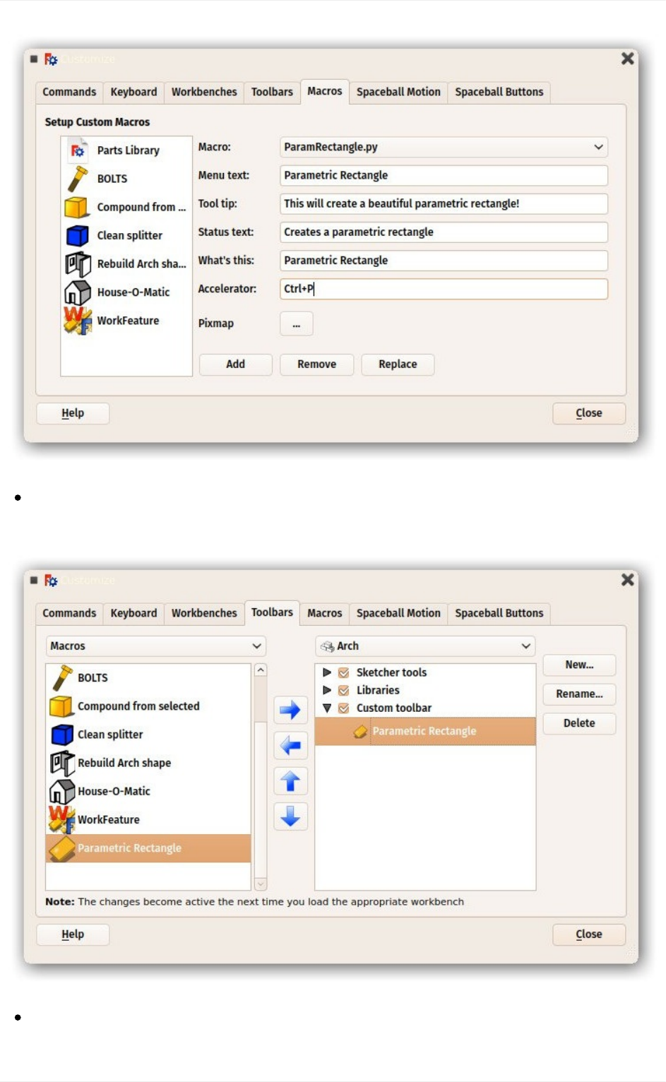
UndertheToolbarstab,createanewcustomtoolbarintheworkbenchofyourchoice
(orglobally),selectyourmacroandaddittothetoolbar:
That'sit,wenowhaveanewtoolbarbuttonwhich,whenclicked,willcreatea
parametricrectangle.
Creatingparametricobjects
171

Remeber,ifyouwanttodistributefilescreatedwiththisnewtooltootherpeople,theymust
havetheParamRectangle.pymacroinstalledontheircomputertoo.
Readmore
TheFreeCADmacrosrepository:http://www.freecadweb.org/wiki/index.php?
title=Macros_recipes
Parametricobjectexample:http://www.freecadweb.org/wiki/index.php?
title=Scripted_objects
MoreexamplesintheFreeCADcode:
https://github.com/FreeCAD/FreeCAD/blob/master/src/Mod/TemplatePyMod/FeaturePyt
hon.py
Creatingparametricobjects
172

Creatinginterfacetools
Inthelasttwochapters,wesawhowtocreatePartgeometryandcreateparametricobjects.
One last piece is missing to gain full control over FreeCAD: Create tools that will interact
withtheuser.
Inmanysituations,itisnotveryuser-friendlytoconstructanobjectwithzero-values,likewe
didwiththerectangleinthepreviouschapter,andthenasktheusertofillintheHeightand
WidthvaluesinthePropertiespanel.Thisworksforaverysmallnumberofobjects,butwill
becomeverytediousifyouhavealotofrectanglestomake.Abetterwaywouldbetobe
abletoalreadygivetheHeightandWidthwhencreatingtherectangle.
Pythonoffersabasictooltohavetheuserentertextonscreen:
text=raw_input("Heightoftherectangle?")
print("Theenteredheightis",text)
However,thisrequiresarunningPythonconsole,andwhenrunningourcodefromamacro,
wearenotalwayssurethatthePythonconsolewillbeturnedonontheuser'smachine.
TheGraphicalUserInterface,or GUI,thatis, allthe part ofFreeCAD thatis displayed on
yourscreen(themenu,toolbars,3Dview,etc),isallthereforthatpurpose:interactwiththe
user. FreeCAD's interface is built with Qt), a very common open-source GUI toolkit that
offers a big range of tools such as dialog boxes, buttons, labels, text input boxes or pull-
downmenus(allthesearegenericallycalled"widgets").
The Qt tools are very easy to use from Python, thanks to a Python module called Pyside
(there are several other Python modules to communicate with Qt from Python too). This
module allows you to create and interact with widgets, read what the user did with them
(whatwasfilledintextboxes)ordothingswhen,forexample,abuttonwaspressed.
QtalsoprovidesanotherinterestingtoolcalledQtDesigner,whichistodayembeddedinside
abiggerapplicationcalledQtCreator.Itallowstodesigndialogboxesandinterfacepanels
graphically,insteadofhavingtocodethemmanually.Inthischapter,wewilluseQtCreator
todesigapanelwidgetthatwewilluseintheTaskpanelofFreeCAD.Soyouwillneedto
download and install Qt Creator from its official page if you are on Windows or Mac (on
Linuxitwillusuallybeavailablefromyoursoftwaremanagerapplication).
In the following exercise, we will first create a panel with Qt Creator that asks for length,
width and height values, then we will create a Python class around it, that will read the
valuesenteredbytheuserfromthepanel,andcreateaboxwiththegivendimensions.This
Creatinginterfacetools
173
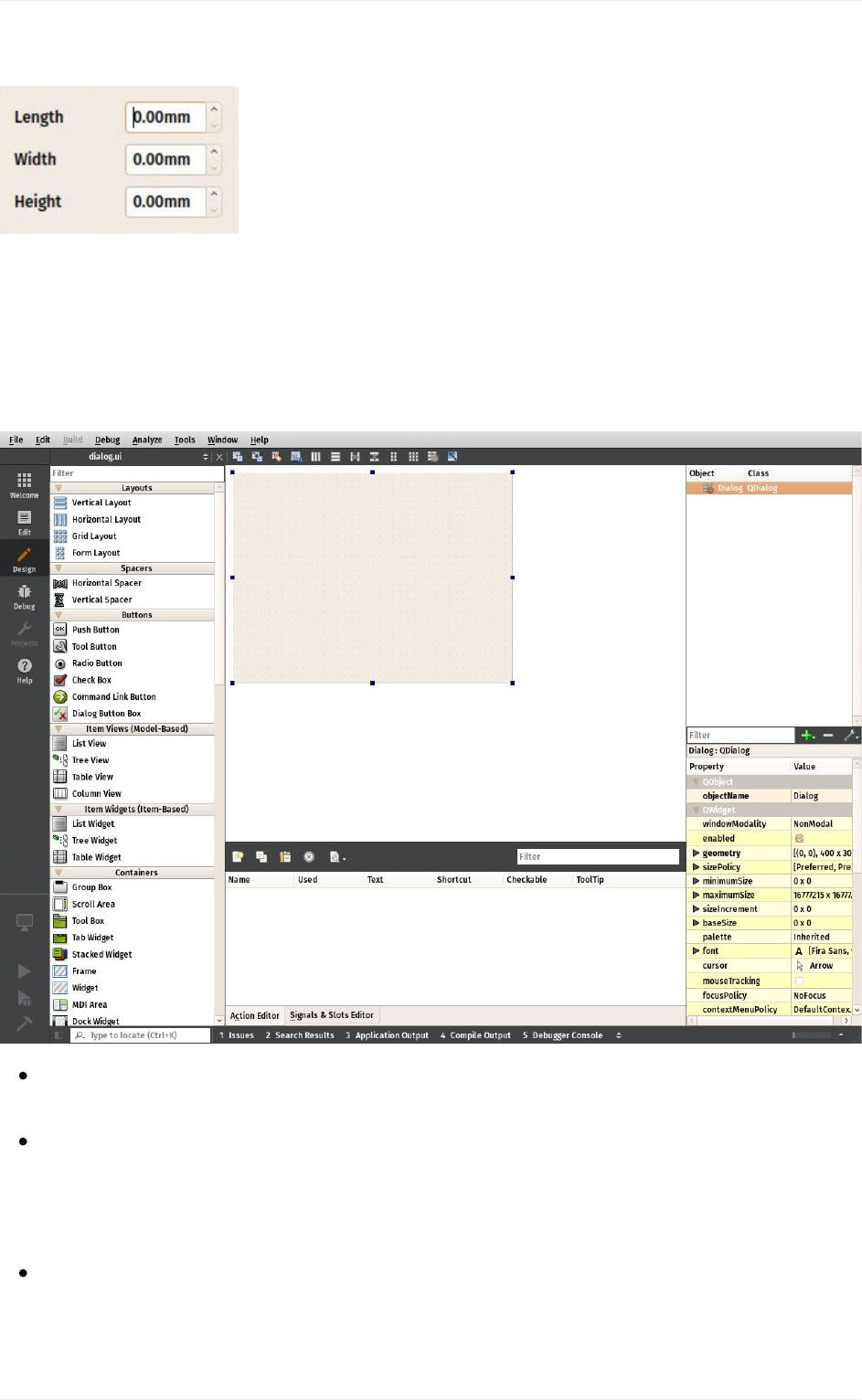
PythonclasswillthenbeusedbyFreeCADtodisplayandcontrolthetaskpanel:
Let'sstartbycreatingthewidget.StartQtCreator,thenmenuFile->NewFileorProject->
FilesandClasses->Qt->QtDesignerForm->Dialogwithoutbuttons.ClickNext,give
itafilenametosave,clickNext,leaveallprojectfieldstotheirdefaultvalue(""),andCreate.
FreeCAD'sTasksystemwillautomaticallyaddOK/Cancelbuttons,that'swhywechosehere
adialogwithoutbuttons.
FindtheLabelinthelistintheleftpanel,anddragitontothecanvasofourwidget.
Double-clicktherecentplacedLabel,andchangeitstexttoLength.
Right-clickthewidgetcanvas,andchooseLayout->LayoutinaGrid.Thiswillturn
ourwidgetintoagridwithcurrentlyonlyonecell,occupiedbyourfirstlabel.Wecannow
addthenextitemsattheleft,right,toporbottomofourfirstlabel,andthegridwil
lexpandautomatically.
Addtwomorelabelsbelowthefirstone,andchangetheirtexttoWidthandHeight:
Creatinginterfacetools
174
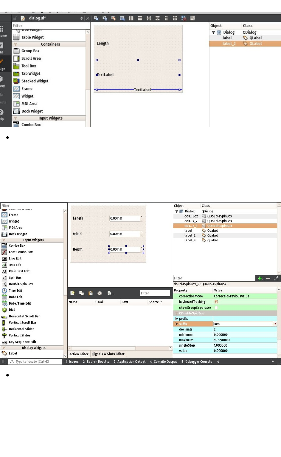
Nowplace3DoubleSpinBoxwidgetsnexttoourLength,WidthandHeightlabels.For
eachofthem,inthelowerleftpanel,whichshowsalltheavailablesettingsforthe
selectedwidget,locateSuffixandsettheirsuffixtomm.FreeCADhasamore
advancedwidget,thatcanhandledifferentunits,butthatisnotavailableinQtCreator
bydefault(butcanbecompiled),sofornowwewilluseastandardDoubleSpinBox,
andweaddthe"mm"suffixtomakesuretheuserknowsinwhichunitstheywork:
Nowourwidgetisdone,wejustneedtomakesureofonelastthing.SinceFreeCAD
willneedtoaccessthatwidgetandreadtheLength,WidthandHeightvalues,weneed
togivepropernamestothosewidgets,sowecaneasilyretrivethemfromwithin
FreeCAD.ClickeachoftheDoubleSpinBoxes,andintheupperrightwindow,double-
clicktheirObjectName,andchangethemtosomethingeasytoremember,forexample:
BoxLength,BoxWidthandBoxHeight:
Creatinginterfacetools
175
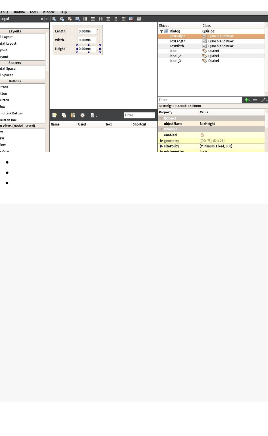
Savethefile,youcannowcloseQtCreator,therestwillbedoneinPython.
OpenFreeCADandcreateanewmacrofrommenuMacro->Macros->Create
Pastethefollowingcode.Makesureyouchangethefilepathtomatchwhereyousaved
the.uifilecreatedinQtCreator:
importFreeCAD,FreeCADGui,Part
#CHANGETHELINEBELOW
path_to_ui="C:\Users\yorik\Documents\dialog.ui"
classBoxTaskPanel:
def__init__(self):
#thiswillcreateaQtwidgetfromouruifile
self.form=FreeCADGui.PySideUic.loadUi(path_to_ui)
defaccept(self):
length=self.form.BoxLength.value()
width=self.form.BoxWidth.value()
height=self.form.BoxHeight.value()
if(length==0)or(width==0)or(height==0):
print("Error!Noneofthevaluescanbe0!")
#webailoutwithoutdoinganything
return
box=Part.makeBox(length,width,height)
Part.show(box)
FreeCADGui.Control.closeDialog()
panel=BoxTaskPanel()
FreeCADGui.Control.showDialog(panel)
Creatinginterfacetools
176

In the code above, we used a convenience function (PySideUic.loadUi) from the
FreeCADGuimodule.Thatfunction loadsa.uifile,creates aQtWidgetfrom it,andmaps
names,sowecaneasilyaccessthesubwidgetbytheirnames(ex:self.form.BoxLength).
The"accept"functionisalsoaconvenienceofferedbyQt.Whenthereisa"OK"buttonina
dialog (which is the case by default when using the FreeCAD Tasks panel), any funcion
named"accept"willautomaticallybeexecutedwhenthe"OK"buttonispressed.Similarily,
you can also add a "reject" function which gets executed when the "Cancel" button is
pressed. In our case, we ommitted that function, so pressing "Cancel" will do the default
behaviour(donothingandclosethedialog).
Ifweimplementanyoftheacceptorrejectfunctions,theirdefaultbehaviour(donothingand
close)willnotoccuranymore.SoweneedtoclosetheTaskpanelourselves.Thisisdone
with:
FreeCADGui.Control.closeDialog()
Oncewe haveour BoxTaskPanelthat has1) awidget called"self.form" and2) ifneeded,
acceptandrejectfunctions,wecanopenthetaskpanelwithit,whichisdonewiththesetwo
lastlines:
panel=BoxTaskPanel()
FreeCADGui.Control.showDialog(panel)
NotethatthewidgetcreatedbyPySideUic.loadUiisnotspecifictoFreeCAD,itisastandard
Qt widget which can be used with other Qt tools. For example, we could have shown a
separate dialog box with it. Try this in the Python Console of FreeCAD (using the correct
pathtoyour.uifileofcourse):
fromPySideimportQtGui
w=FreeCADGui.PySideUic.loadUi("C:\Users\yorik\Documents\dialog.ui")
w.show()
Ofcoursewedidn'taddany"OK"or"Cancel"buttontoourdialog,sinceitwasmadetobe
used from the FreeCAD Task panel, which already provides such buttons. So there is no
way to close the dialog (other than pressing its Window Close button). But the function
show()creates anon-modal dialog,which meansit doesn'tblock therest ofthe interface.
So,whileourdialogisstillopen,wecanreadthevaluesofthefields:
w.BoxHeight.value()
Thisisveryusefulfortesting.
Creatinginterfacetools
177

Finally, don't forget there is much more documentation about using Qt widgets on the
FreeCADWiki, inthePythonScripting section, which contains a dialog creation tutorial, a
special3-partPySidetutorialthatcoversthesubjectextensively.
Readmore
QtCreator:https://en.wikipedia.org/wiki/Qt_Creator
InstallingQtCreator:https://www.qt.io/ide/
Pythonscriptingdocumentation:http://www.freecadweb.org/wiki/index.php?
title=Power_users_hub
Dialogcreationtutorial:http://www.freecadweb.org/wiki/index.php?title=Dialog_creation
PySidetutorials:http://www.freecadweb.org/wiki/index.php?title=PySide
PySidedocumentation:http://srinikom.github.io/pyside-docs/index.html
Creatinginterfacetools
178

TheCommunity
Nomanualdealingwithfreeandopen-sourcesoftwarewouldbecompletewithoutachapter
about the community. As the vast majority of free and open-source software projects,
FreeCAD is made by a community, and maintained by that community. Instead of the
opaque,unknown, impersonaland inaccessable firmthat ismore than oftenfound behind
commercialsoftware,freeandopen-sourcesoftwarecommunitiesareopenspaces,where
youasauserarewelcome,andwhereyoucangetanswersveryfast,andevenhaveyour
sayinthedevelopmentofthesoftwareitself.Youarealsomorethanwelcometohelp,there
aretasksforeverybody.
Thecommunityisagrowing,eclecticgroupofallkindsofpeopleunitedbytheirpassionfor
FreeCAD.AllworkonFreeCADvoluntarily,duringtheirfreetime(althoughsometimesfirms
orindividualsgathertopayacoupleofprogramminghourstoadevelopertoimplementa
specificfunction).Someareprofessionalprogrammers,somearelong-timeFreeCADusers
(someofthemaretrueFreeCADgurus,whoknowalmosteverything,andmanyofthemend
upknowingalotaboutFreeCADprogrammingtoo),andmanyarenewusersofFreeCAD.
Thereisnothingspecifictodotobepartofthecommunity.JustuseFreeCAD!
ThemainplacewherethecommunitymeetsanddiscussesistheFreeCADforum.Allyou
needtodotoparticipatetothediscussionsistoregisteranaccountontheforum(Yourfirst
post will need to be approved by a moderator before you can post more, to prevent
spamming). The forum is a great place to ask questions when you are new to FreeCAD.
Providedyoumadeagoodquestion(besuretoreadtheforumrulesastheycontainuseful
informationtoturnyourquestionintoagoodquestion),youwillusuallygetseveralreplies
withinthesamehour.Ifyouthinksomeonemighthaveaskedyourquestionalready,besure
tosearch,youranswermightalreadybethere.
The forum is also a great place to show what you achieved with FreeCAD, to help
newcomerswhenyouaremoreexperienced,andtofollowandgiveyouropinionsinmore
technicaldiscussionsaboutdevelopment.AlltheFreeCADdevelopmentisdiscussedonthe
forum,andanybodyisfreetoreadorparticipate.
TherearealsoFreeCADcommunitiesformingoutsideoftheFreeCADforum,forexample
onFacebookorGoogle+.
IfyouarebecomingasenthusiasticaboutFreeCADasweare,youmightwanttohelpthe
project. This can be done in many different ways, and there are tasks for everybody,
programmersandnon-programmers,forexample:
Helptospreadtheword:Manypeoplewouldgethugebenefitfromusingafree,open-
Thecommunity
179

source3DmodelerlikeFreeCAD,butsimplydon'tknowitsexistence.Publishingthe
workyoudowithFreeCAD,talkingaboutitonsocialnetworks,etc...helpsthesepeople
todiscoverFreeCAD.
Helpnewcomers:Thevastmajorityofdiscussionsontheforumarequestionsasked
bynewusers.Youmightknowgoodanwerstogivethem.
Helpreportingbugs:ThestablilityofFreeCADcomesinlargepartfromthefixingof
bugs.SinceitisnotpossiblefortheFreeCADdeveloperstotestallpossibleusecases,
itisimportantthatusersreportproblemswhentheydetectthem.Besuretoreadthe
guidelinesifyouthinkyoufoundabug,andthenwriteareportonthebugtracker.
Helptowritedocumentation:TheFreeCADdocumentationwikiisalsowrittenby
communitymembers.Somesectionsofitarestillincomplete,ortheirinformation
incorrectorobsolete.Youmightbeabletohelptofixthat.Tobeabletoworkonthe
wiki,youwillneedtofamiliarizeyourselfwithwikiediting,andaskpermissiontoeditthe
FreeCADwikiontheforum.
HelptotranslateFreeCAD:ThetranslationofFreeCADisdoneonlinebycommunity
members,oncrowdin.Ifyoudon'tseeyourlanguagethere,askoneofthe
administratorstohaveitadded.
Helptotranslatethewikidocumentation:Everypageofthewikiistranslatable,and
requiresverylittleknowledgeofthewikisyntax.Helpingwithtranslationisalsoagreat
waytolearnFreeCAD.
Writescriptsandmacros:FreeCADhasagrowinglistofMacros.Ifyouwrotesome
interestingfunctionality,considersharingitthere.
Programming:Forthis,youneedtoknowhowtoprograminPythonorC++,andhave
agoodknowledgeofFreeCADitself.
The source code of FreeCAD is located on the Github account of the FreeCAD project.
Anybodycan download, useand modifythe code. You canpublish your modifications(on
GithuboranyotherGithostingservice).Ifyoumadeinterestingmodifications,thatyouwish
to see included in the FreeCAD source code, you must ask the community to have them
included.ThiscanbedoneusingGithub'spullrequestsmechanism,buttheverybestwayis
todiscusswhatyouintendtodofirstontheforum,andthenpostanofficialrequestinthe
Pullrequests sectionof the forumwhen your codeis ready. This avoidsthat you workon
somethingthatsomeoneelseisalreadyworkingontoo,andensuresthatothersagreewith
thewayyouaredoingit,sothereisnoriskofhavingyourworkrefusedforsomereasonyou
didn'tforesee.
Hopefully, wemanaged togive youa goodtaste of FreeCADin thismanual, andyou are
alreadyournewestcommunitymember.Welcome!
Readmore
TheFreeCADforum:http://forum.freecadweb.org
Thecommunity
180

ThesourcecodeofFreeCAD:https://github.com/FreeCAD/FreeCAD
TheFacebookFreeCADcommunity:https://www.facebook.com/FreeCAD
TheGoogle+FreeCADcommunity:
https://plus.google.com/u/0/communities/103183769032333474646
TheFreeCADdocumentationwiki:http://www.freecadweb.org/wiki
TranslatingFreeCADoncrowdin:https://crowdin.com/project/freecad
TheFreeCADbugtracker:http://www.freecadweb.org/tracker
Thecommunity
181
