User Guide USB Starter Kit AMS 5812 Ams5812 Users Starterkit
User Manual:
Open the PDF directly: View PDF ![]() .
.
Page Count: 10

USB Starter Kit AMS 5812
May 2012 - Rev. 1.0 Page 3/10
www.analogmicro.de
INTRODUCTION
The USB Starter Kit AMS 5812 is designed for quick and easy initial operation of AMS 5812 pressure
sensors with I2C interface. Together with a standard PC with Windows operating system and the relevant
software, the kit enables current digital pressure and temperature values to be read out via the AMS 5812
I2C sensor interface and to be displayed on the PC.
In addition the starter kit can be used to program a second individual I2C address into each AMS 5812
pressure sensor. This customized I2C address is prerequisite for the operation of several AMS 5812
pressure sensors together on one I2C bus. This address is valid in addition to the default I2C address 78hex.
The starter kit consists of two printed circuit boards and the relevant communication software package
CS5812 distributed on the starter kit CD. A Windows PC with an USB port and with operating system XP
SP3 or above is required for operation. The kit will be supplied by the USB port, an external supply isn’t
necessary.
NB: We recommend that you read the AMS 5812 sensor datasheet before putting the starter kit into
operation.
Hardware
The starter kit hardware consists of two printed circuit boards: the communication board CB-I2C and the
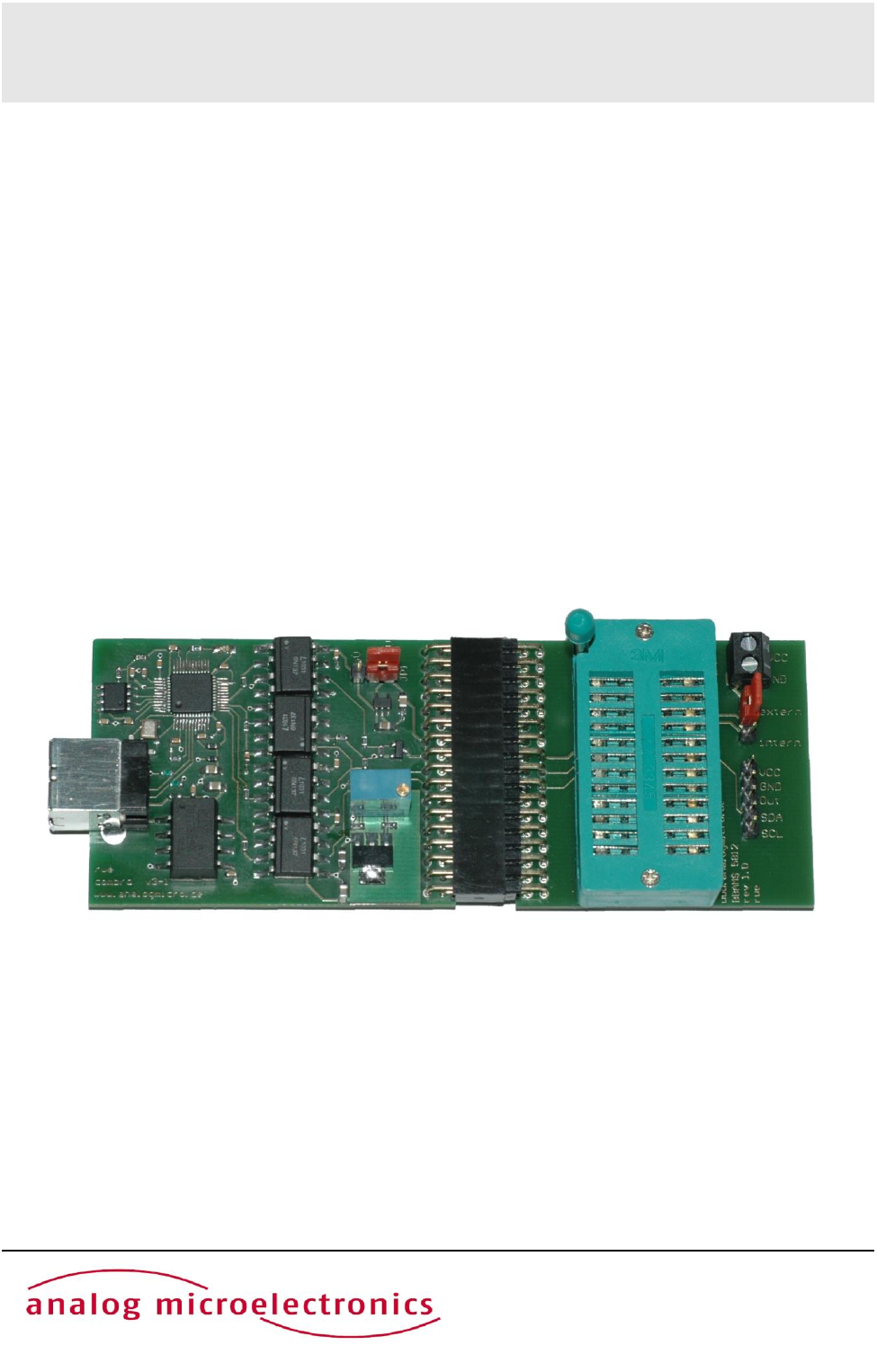
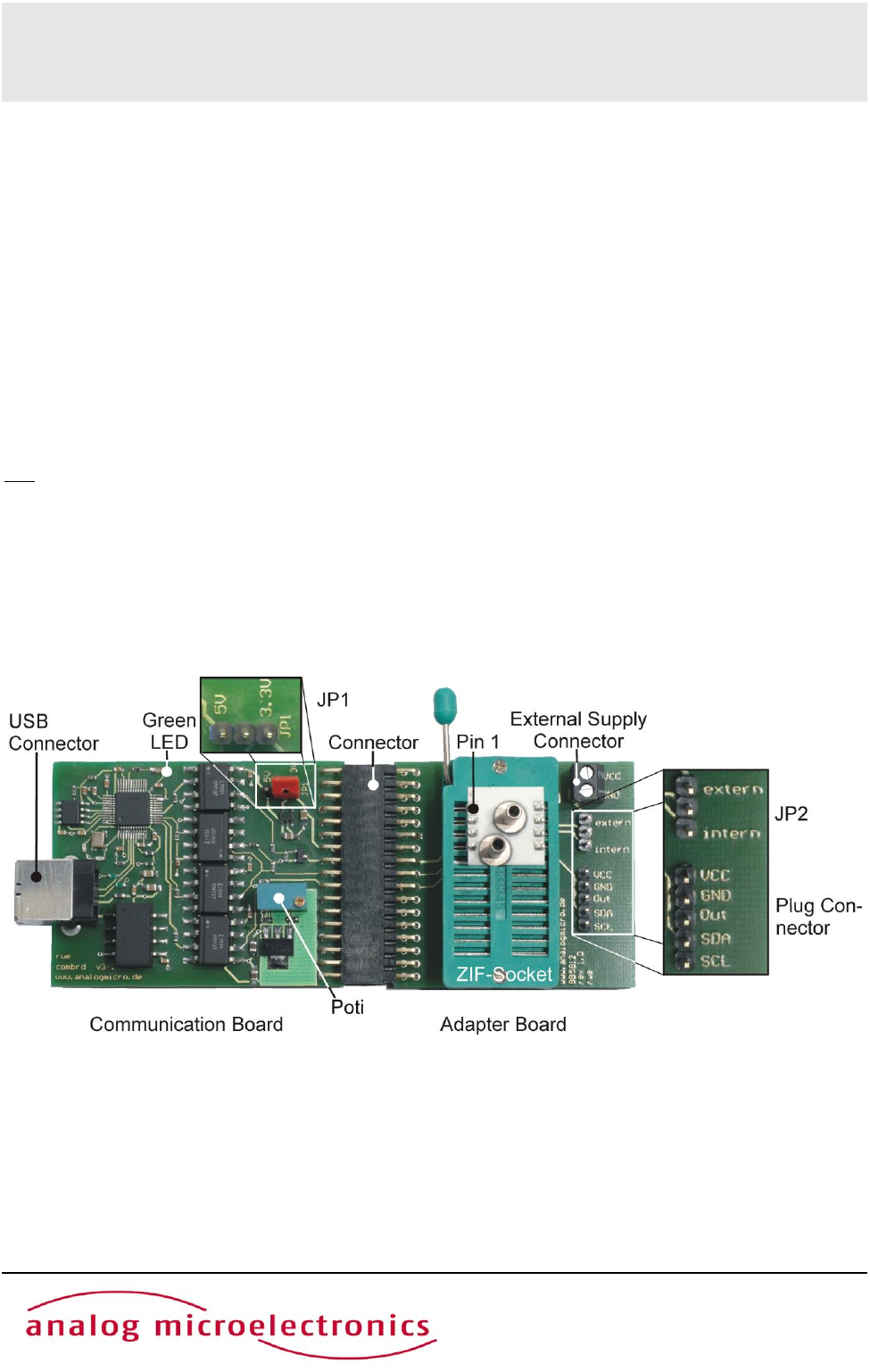
adapter board BB5812 with a ZIF-socket to connect one AMS 5812 sensor. Figure 1 shows the assembled
kit with mounted sensor.
Figure 1: USB Starter Kit AMS 5812 with connected sensor.
The kit consists of a communication board CB-I2C and an adapter board BB5812, connected by a
34-pin connector.
USB Starter Kit AMS 5812
May 2012 - Rev. 1.0 Page 4/10
www.analogmicro.de
The CB-I2C printing circuit board provides the hardware which enables a PC with USB 2.0 port to
communicate with a pressure sensor with I2C interface. The BB5812 printed circuit board provides an easy
way to connect an AMS 5812 pressure sensor with the CB-I2C. The two printed circuit boards are connected
by a 34 pin connector.
Using a standard USB cable the USB jack on the CB-I2C is connected to a free USB-port at the PC. The
PCs USB-port is used for communication and for power supply of the starter kit and the sensor; an additional
supply isn’t required.
The connection between CB-I2C and BB5812 is realised by a 34 pin connector. A zero injection force (ZIF)
socket on the BB5812 allows easy mounting and exchanging of an AMS 5812 pressure sensor. Pin 1 of the
sensor is at the upper left edge of the ZIF-Socket (see Figure 1).
For the internal power supply of the connected AMS 5812 by the USB Port, JP 2 on board BB5812 has to
connect to position “intern“. Additionally the sensors supply voltage has to be chosen by the jumper JP1 on
board CB-I2C (see Figure 1); for standard products of AMS 5812 series connect JP1 to 5V.
For external supply of the connected AMS 5812, remove jumper JP1 and connect jumper JP2 to position
“extern“. Subsequent the external power supply can be connected to the screw terminal block “external
supply connector” on board BB5812.
Further, for exchanging the mounted AMS5812 the sensor voltage supply can be turned off by removing JP1
and JP2. The jumper positions are summarised in table1.
At the 5 pin plug connector on the BB5812 the sensor voltage supply VCC, GND, the analog output and the
I2C-bus lines are connected. This plug can be used for monitoring the sensor supply voltage and further for
connecting and testing sensors, which are already assembled.
For safety in cause of failure an electrical isolation between the sensor and the PC was realised on the CB-
IC. This avoids effectively an energy flow into the connected PC.
Sensor voltage
Jumper position JP1
Jumper position JP2
internal supply 3.3 V
central pin together with pin 3.3V
central pin together with pin intern
internal supply 5 V
central pin together with pin 5V
central pin together with pin intern
external supply
removed
central pin together with pin extern
turned off
removed
removed
Important: If JP1 isn’t removed in case of an external sensor power supply at pin VCC, the starter kit can be
damaged!
Table 1: Jumper configuration of JP1 on CB-I2C and JP2 on BB5812
USB Starter Kit AMS 5812
May 2012 - Rev. 1.0 Page 5/10
www.analogmicro.de
Software – CS5812
The communication between the PC and the AMS 5812 pressure sensor mounted onto the starter kit is
realised by means of the software package CS5812. This software is provided on the starter kit CD and runs
under Windows operating systems (XP SP3 or above).
Installation
Before installation of the software package CS5812, please disconnect the starter kit. By executing the file
CS5812_Setup.exe on the CD-ROM (must be run as an administrator), an installer is started which guides
through the installation process. After the installation process is finished, the necessary files for operating the
starter kit are copied to the target directory and the needed drivers are installed, too. The starter kit is now
ready to use and can be connected to the PC.
CS5812 user interface
The software CS5812 can be run via the “AMS 5812” icon in the program group “AMS 5812” in the folder
programs in the windows start menu.
The user interface (menu) is shown in Figure 2. The menu is divided in three submenus: “Communication
Check”, “Measurement” und “Second I2C Address” which are designed as index sheets. They will be
described in detail below.
Figure 2: CS5812 user interface
USB Starter Kit AMS 5812
May 2012 - Rev. 1.0 Page 6/10
www.analogmicro.de
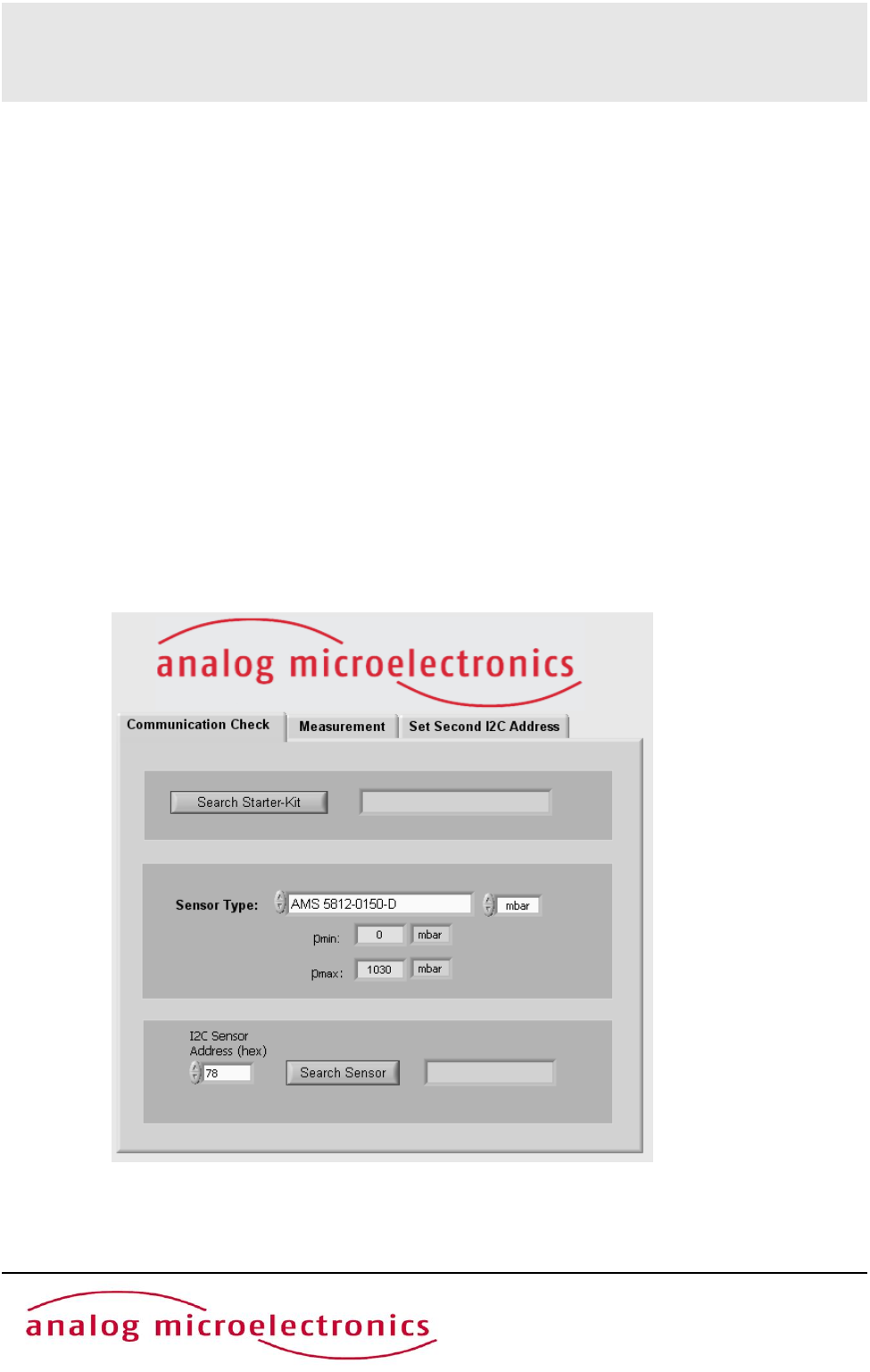
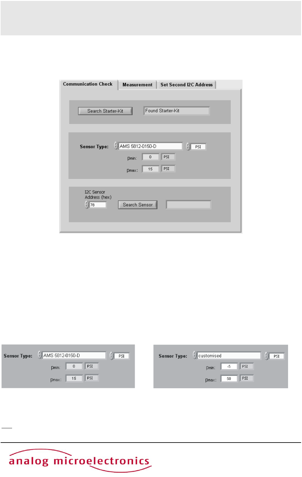
Submenu “Communication Check”
In the submenu “Communication Check” (see Figure 3) the type of the AMS5812, which is connected to the
starter kit, has to be defined and the communication between the PC and the AMS5812 can be established
and tested.
By pushing the button “Search Starter Kit” (in the upper third of the submenu) the link connection between
the PC and the starter kit will be initiated. If it is successful (message: “Found Starter Kit”), the starter kit will
be ready to use. If no starter kit was found please follow the tips given in section Initial Operation in
paragraph 5.
In the next step, the connected sensor type has to be selected in the drop down menu with its exact ordering
code (e.g.: AMS 5812-0150-D) (see middle part in Figure 3 and Figure 4 left). To the right side the physical
pressure unit can be selected by a drop down menu. The units PSI, kPa, mbar and bar are available. The
pressure range of the sensor type will be shown below. In case of a custom specific version or a sensor
which is not listed in the menu, the sensor type “customised” has to be selected and the specified minimal
and maximal pressure values pmin and pmax have to be filled into the adequate fields below (see Figure 4
right).
NB: If the wrong sensor type is selected, sensor measurement data cannot be accurately evaluated and the
displayed pressure value in physical units is wrong!
Figure 3: Overview of submenu “Communication Check”
Figure 4: Selection of the sensor type.
Left: sensor type AMS 5812-0150-D with a measuring range of 0 - 15 PSI
Right: custom specific sensor with manually adjusted measuring rage of -5 – 50 PSI.
USB Starter Kit AMS 5812
May 2012 - Rev. 1.0 Page 7/10
www.analogmicro.de
Now, a connection to the AMS 5812 pressure sensor (mounted onto the starter kit) can be established. In
the lower third of the submenu, the sensor I2C address has to be filled into the field “I2C Sensor Address”
(standard I2C address: 78hex) and the Button “Search Sensor” has to be pushed. A message follows,
whether a corresponding sensor was found or not.
In case of the error message “No Sensor found” (after pushing the button “Search Sensor”) please check the
following: the connection of the two PCBs, the position of JP1, the position of the AMS 5812 in the ZIF
socket and the locking of the ZIF-socket.
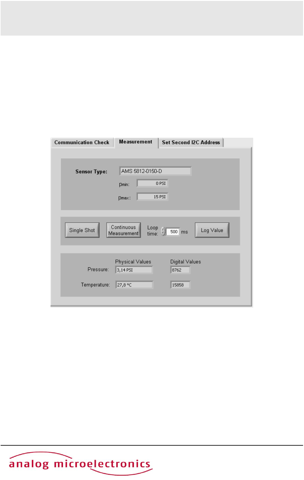
Submenu “Measurement”
Within the submenu “Measurement” (see Figure 5) it is possible to display the AMS 5812 digital pressure
and temperature values.
The field “Sensor Type” (upper third part of the submenu) displays the selected senor type with its pressure
range, which was stipulated in the submenu “Communication Check”.
With the buttons “Single Shot” and “Continuous Measurement” respectively (in the middle part of this
submenu) the user can start a single measurement or a continuous measurement. In case of a continuous
measurement, the time interval between the discrete measurements can be selected by the drop down menu
“Loop Time”. The continuous measurement can be stopped by pushing the button “Continuous
Measurement” again. By pushing the button “Log Value” at the right side, the readout digital values can be
saved in a file. At the first time values have to be written, a windows dialog appears to assign the file name
and the folder to save in. The file includes only the digital values
In the lower third of the submenu the measurement data for pressure and temperature are displayed as
digital (decimal) values and also as values in physical units. For a single measurement “Single Shot” the
current measurement data available at the AMS 5812 output register is one-time read and continuously
Figure 5: View on submenu “Measurement”.
USB Starter Kit AMS 5812
May 2012 - Rev. 1.0 Page 8/10
www.analogmicro.de
displayed. In case of the continuous measurement the measurement data is repeatedly read out and
displayed.
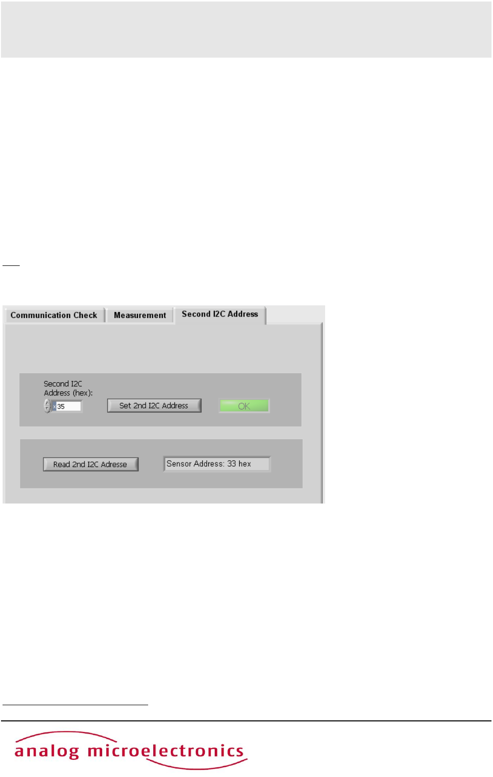
Submenu “Second I2C Address“
The submenu “Second I2C Address” is divided into an upper and a lower part (see Figure 6):
In the upper part an individual second I2C address can be programmed into the connected AMS 5812
pressure sensor
1
. The second I2C address (between 00hex and 7Fhex) has to be written in the box “New I2C
Address” as a hexadecimal value. By pushing the button “Set 2nd Address”, the I2C address will be
programmed to the AMS 5812 EEPROM. If the operation was successfully the field “OK” lights up green for
a few seconds. The sensor corresponds now to the second I2C address and the standard address, too.
By pushing the button “Read 2nd I2C Address” the user can read out the second I2C address. Figure 6
shows an example with a sensor address 33 hex.
NB: If several AMS 5812 sensors are to be operated together on one I2C bus, each sensor must first be
allocated its own individual second I2C address.
1
The second I2C is additionally valid to the standard I2C address 78 hex
Figure 6: View on submenu “Second I2C Address”
The second I2C address can be programmed in the upper part. The optionally programmed
second I2C address can be read out in the lower part.

USB Starter Kit AMS 5812
May 2012 - Rev. 1.0 Page 9/10
www.analogmicro.de
INITIAL OPERATION
The following steps are necessary for the starter kit initial operation setup:
1. Installation of the Software CS5812 (for details see section software)
2. Assembly starter kit
First, the adapter board BB5812 for AMS 5812 sensor and the communication board CB-I2C are
connected together by the 34 pin connector. Then, the sensor AMS 5812 has to be connected into
the ZIF-socket on BB5812 (orientation of pin 1: see Figure 1).
3. Select sensor voltage supply (for details see section hardware):
For internal power supply (AMS 5812 is supplied by the USB Port) JP 2 on board BB5812 has to be
connected to position “intern“. Additionally the sensor supply voltage has to be chosen by the jumper
JP1 on board CB-I2C to 5V.
For external power supply (with additional power supply) remove jumper JP1 on board CB-I2C.
Connect the external power supply to the screw terminal block “external supply connector” on board
BB5812 and set jumper JP2 to position “extern“.
4. Connect the starter kit to a free USB-port at the PC by an USB cable.
5. The green LED on the communication board flashes up, when the board is detected by the PC and
the drivers are loaded successfully (see Figure 1).
If the green LED remains dark, the user has to look in the device manager for a new device called
“USB Serial Converter” in the device group “USB-Controller”. If this doesn’t exist, the user has to
disconnect the starter kit from the PC by removing the USB-cable. At a reconnection, the device
“USB Serial Converter” should appear. If not, the problem could be solved by manually executing the
file Treiber_Setup.exe in the program folder of the AMS 5812 Software (e.g.: C:\program files\AMS
5812). If the led remains still dark and the starter kit wasn’t found, contact Analog Microelectronics
GmbH for further support.
6. A voltmeter can be connected up to the 5 pin plug connector on the BB5812 if the AMS 5812 analog
output signal is to be read.

USB Starter Kit AMS 5812
May 2012 - Rev. 1.0 Page 10/10
www.analogmicro.de
IMPORTANT NOTES
1. For changing an AMS 5812 pressure sensor while the communication board is connected to the PC,
we recommend to remove the jumpers JP1 and JP2. It prevents sensor damage.
2. If JP1 won’t be removed in case of external supply, the starter kit could be damaged
3. As there is no protective circuitry safeguarding against reverse polarity and overvoltage, the polarity
and voltage of the external voltage supply of +5 V must be checked before voltage is applied.
4. The Communication Board CB-I2C can be used for read out pressure sensors of the series AMS
5105 and AMS 5915, too. For starting up, only the corresponding adapter boards BB5105
respectively BB5912 and the according software CS5105 respectively CS5915 are necessary.
5. The analog output signal is ratiometric to the supply voltage. If AMS 5812's specifications are to be
tested, the supply voltage must be exactly 5.000 V. Any deviation in percent must be accounted for
accordingly.In case of internal power supply the sensor voltage can be adjusted by the potentiometer
on the CB-I2C (see Figure 1) exactly.
ADDITIONAL EQUIPMENT
USB-Cable 2.0, FullSpeed A-St to B-St .
ADDITIONAL DOCUMENTS
Data Sheet of AMS 5812 Pressure Sensor Series
Analog Microelectronics GmbH reserves the right to amend any dimensions, technical data or other information contained herein without prior notification.
