IOM B3B6 Rev 01 AOP Series B3 And B6 Floating Ball Valve
User Manual: AOP Series B3 and B6 Floating Ball Valve IOM Resource Library
Open the PDF directly: View PDF ![]() .
.
Page Count: 2

Page 1 of 2
Rev. 01
1-31-07
AOP SERIES B3, B6 Floating Ball Valve
2. Tack weld valve into position and check for appropriate
alignment.
3. Finish weld following proper weld procedure for material
grade and condition, and the above caution.
4. If weld procedure being used requires post weld heat
treament, the folowing is applicable.
A.) Localized post weld heat treatment limited to the weld and the
heat affected zone does not require disassembly of the valve,
and use of this method does not void the valves pressure test
certifications. However, it is imperative that the body temper-
ature be monitored and controlled as described in note 1.
B.) Post weld heat treatment of the entire body does require dis-
assembly of the valve in order to pervent damage to the valve
internals. Disassembly of the valve voids testing certifications.
AOP Series B3 and B6 ball valves are recommended for on-off
service only. Throttling may cause excessive and non-uniform
Install valve in piping system using proper size taper thread wear on the seats, preventing tight shut-off. All AOP Ball Valves
NPT connections with fluid and pressure compatible thread open by rotating handle in a counter-clockwise direction.
sealant.
Caution:
Inspect male pipe thread for damage (l.e. nicks,
burrs ect.) prior to installation. Also, do not over tighten NPT AOP Series B3 and B6 ball valves are permanently lubricated
connection or thread joint damage may occur. during assembly and normally require no routine maintenance.
Threaded-End valves should be installed using two pipe However, if necessary, stem-packing adjustments may be
wrenches, one on the flats of the adapter or body and accomplished by tightening stem-packing screw until leakage
the other on the adjacent pipe.
DO NOT
apply wrench to
stops. (
Do not overtighten
)
the body section or opposite side when making up pipe CAUTION:
as this may result in damage to the body or breaking Before removing valve from line, turn valve to half-open position
loose the threaded adapter-to-body connection. In to relieve any body pressure. Return valve to closed position.
addition, all pipe sections should be properly supported
to prevent excessive bending loads applied to the valve.
WARNING, weighted objects suspended on the down- To replace Seats, Ball or Body Seal:
stream endof a threaded connection, create bending See detail view on page two. Open valve, unscrew
loads and may result in failure of the body to adapter adapter (2) from body (1). Remove body seal (6). Turn ball (3)
connection. to the closed postion and remove. Remove seats (5) with care
to prevent damage to surfaces of the seat cavity in body and
ATTENTION: SOCKETWELD VALVES
adapter. Clean seat cavities and body seal (6) seating surfaces
For socket welded valves, weld valve in full open position only and using fine emery. Replace seats (5) and ball (3). Grease new
using 2 weld passes max. 3/32" Root, 1/8" or 3/32" Cap. body seal (6) before positioning it inside the body (1). Replace
adapter, assuring that it butts metal-to-metal against the body.
1. Prior to welding it is impeerative that all welding surfaces be To replace Stem, Thrust bearing and Stem Packing:
clean from contamination such as dirt, rust and grease which Remove ball (3) as above. Loosen and remove handle nut (12)
may affect weld performance. and lock washer (13). Lift handle (10) up to remove from stem.
Remove packing nut (9). Remove stem (4) and thrust bearing (7)
CAUTION:
During the welding process use tempil stick or other through body bore. Remove packing (8). Clean stem journal in
reliable temperature indicator on outside diameter of valve body body using fine emery. Place thrust bearing on stem. Replace
(center section) directly adjacent to adapter (end piece) being stem through body port. Replace new packing and packing nut.
welded to assure that body metal temperature does not exceed Tighten packing nut per table. Reaffix handle with lock washer
300
°
F. This precaution is necessary to assure that non-metallic
and handle nut and tighten. Rassemble valve as stated above.
seat/seals do not suffer heat damage.
The World Standard in Quality Flow Management Products and Service
2101 South Broadway Tel: 405/912-4446
Moore, Oklahoma 73160 Toll Free: 800-654-4493
P.O. Box 6979 Fax: 405/912-4440
Moore, Oklahoma 73153-0979 Email: sales@aopind.com
http://www.aopind.com
Installation,
Maintenance
Installation
Operation
Maintenance
Reconditioning
Operation, And
Page 2 of 2
Rev. 01
1-31-07
AOP SERIES B3, B6 Floating Ball Valve
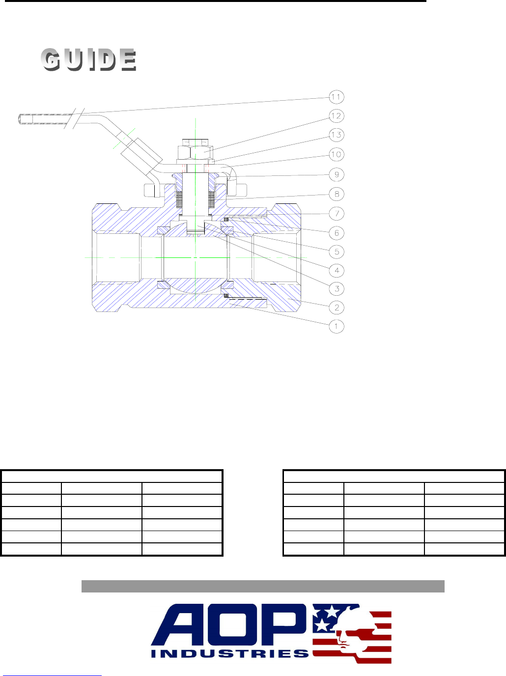
Component Parts,
Parts List
No.
Desciption
No.
Desciption
No.
Desciption
No.
Desciption
1
Body
5
Seat
9
Packing Nut
13
Lock Washer
2
Adapter
6
Body Seal
10
Handle - Locking
3
Ball
7
Thrust Bearing
11
Grip - Handle
4
Stem
8
Packing
12
Handle Nut
The World Standard in Quality Flow Management Products and Service
2101 South Broadway Tel: 405/912-4446
Moore, Oklahoma 73160 Toll Free: 800-654-4493
P.O. Box 6979 Fax: 405/912-4440
Moore, Oklahoma 73153-0979 Email: sales@aopind.com
http://www.aopind.com
1/4 FP
1/2 FP
3/4 FP
1 FP
1/2 FP
3/4 FP
1 FP
1-1/2FP/2RP
6000 PSI Valve
PACKING NUT TORQUE
Valve Size
1/4 FP
3000 PSI Valve
115 in lbs
35 in lbs
35 in lbs
83 in lbs
130 in lbs
180 in lbs
23 in lbs
23 in lbs
52 in lbs
80 in lbs
1-1/2FP/2RP
ADAPTER TORQUE
3000 & 6000 ft lbs 3000 & 6000 in lbs
40 to 52 ft. lbs 480 to 624 in lbs
Valve Size
40 to 52 ft. lbs
110 to 145 ft. lbs
210 to 280 ft. lbs
585 to715 ft. lbs
480 to 624 in lbs
132 to 1740 in lbs
2520 to 3360 in lbs
7020 to 8580 in lbs
