IOM CTDT Rev 01 Aop Ct Dt
User Manual: Resource Library
Open the PDF directly: View PDF ![]() .
.
Page Count: 2
Page 1 of 2
Rev. 01
1-31-07
AOP SERIES CT, DT Floating Ball Valve
Installation,
Operation, And
Maintenance
Installation Maintenance
Install valve in piping system using proper size gaskets/seals AOP Ball Valves are permanently lubricated during
rings or threaded end connections. Threaded valves require assembly and normally require no routine mainte-
a thread sealant/lubricant for proper make-up. nance. However all Series CT, DT assemblies include
Caution:
Inspect male pipe thread for damage (l.e. nicks,
an external stem lube fitting for periodic lubrication
burrs ect.) prior to installation. Also, do not over tighten NPT of stem journal if desired.
connection or thread joint damage may occur.
Threaded-End valves should be installed using two pipe
wrenches, one on the flats of the adapter or body and To replace seats, ball or body seal:
the other on the adjacent pipe.
DO NOT
apply wrench to
See exploded view on page two. Open valve, unscrew
the body section or opposite side when making up pipe adapter (2) from body (1). Remove body seal(10). Turn ball (3)
as this may result in damage to the body or breaking to the closed postion and remove. Remove seats (4) with care
loose the threaded adapter-to-body connection. In to prevent damaging flats surfaces of the seat cavity in body and
addition, all pipe sections should be properly supported adapter. Clean seat cavities and body seal seating surfaces
to prevent excessive bending loads applied to the valve. using fine emery. Replace seats and ball. Grease body seal and
WARNING, weighted objects suspended on the down- position it in its groove in the adapter. Replace adapter, assuring
stream endof a threaded connection, create bending that it butts metal-to-metal against the body.
loads and may result in failure of the body to adapter To replace Stem or Stem Seal:
connection. With ball removed loosen locknut and lift handle/square nut from
stem. Remove retainer (12), allowing removal of stop plate (10)
and stem bearing (8). Remove stem (5), stem seals (11), and
AOP Ball Valves are recommended for on-off service thrust bearing (9) through body bore. Clean stem journal in body
only. Throttling may cause excessive non-uniform using fine emery. Grease stem journal. Place thrust bearing and
wear on seats, preventing tight shut-off. All AOP Ball stem seals on stem in that order. Apply a coat of grease to all parts
Valves open by rotating handle in counter-clock- Replace stem, using a wooded pry against the bottom of the stem
wise direction. if necessary. Assure that the stem seals are not pinched during
re-assembly. Replace stem bearing, stop plate and retainer.
Reaffix handle/square nut on stem and tighten locknut.
Reassembly valve as above.
The World Standard in Quality Flow Management Products and Service
2101 South Broadway Tel: 405/912-4446
Moore, Oklahoma 73160 Toll Free: 800-654-4493
P.O. Box 6979 Fax: 405/912-4440
Moore, Oklahoma 73153-0979 Email: sales@aopind.com
http://www.aopind.com
Operation
Reconditioning
Page 2 of 2
Rev. 01
1-31-07
AOP SERIES CT, DT Floating Ball Valve
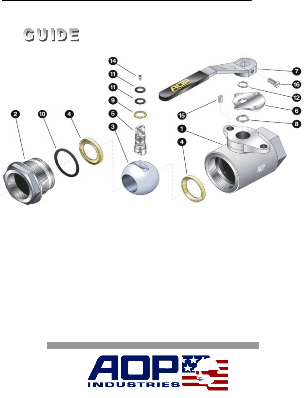
Component Parts,
Parts List
No.
Desciption
No.
Desciption
No.
Desciption
No.
Desciption
1
Body
5
Stem
9
Thrust Bearing
14
Lube Fitting
2
Adapter
6
Stop Plate
10
Body Seal
15
Stop Pin
3
Ball
7
Handle
11
Stem Seal
16
Handle Bolt
4
Seat
8
Stem Bearing
12
Retainer Ring
The World Standard in Quality Flow Management Products and Service
2101 South Broadway Tel: 405/912-4446
Moore, Oklahoma 73160 Toll Free: 800-654-4493
P.O. Box 6979 Fax: 405/912-4440
Moore, Oklahoma 73153-0979 Email: sales@aopind.com
http://www.aopind.com
