Switched Rack PDU Installation And Quick Start AP7902 AP7911 Apc
User Manual: AP7902 AP7911
Open the PDF directly: View PDF ![]() .
.
Page Count: 26


More user manuals on ManualsBase.com
Contents
Switched Rack PDU Installation and Quick Start i
Product Description and Inventory . . . . . . . . . . . . . . . . . . . . . . 1
AP7902 . . . . . . . . . . . . . . . . . . . . . . . . . . . . . . . . . . . . . . 1
AP7911 . . . . . . . . . . . . . . . . . . . . . . . . . . . . . . . . . . . . . . 1
Additional documentation . . . . . . . . . . . . . . . . . . . . . . . . . 2
Inventory . . . . . . . . . . . . . . . . . . . . . . . . . . . . . . . . . . . . . 2
Receiving inspection . . . . . . . . . . . . . . . . . . . . . . . . . . . . . 2
Please recycle . . . . . . . . . . . . . . . . . . . . . . . . . . . . . . . . . . 2
InfraStruXure-certified . . . . . . . . . . . . . . . . . . . . . . . . . . . . 2
How to Install the Rack PDU . . . . . . . . . . . . . . . . . . . . . . . . . . . 3
Installation guidelines . . . . . . . . . . . . . . . . . . . . . . . . . . . . 3
Attach the cord retention tray . . . . . . . . . . . . . . . . . . . . . . . 3
Additional cord retention tray (optional) . . . . . . . . . . . . . . . . 3
Attach cords to the tray . . . . . . . . . . . . . . . . . . . . . . . . . . . 4
Mounting options . . . . . . . . . . . . . . . . . . . . . . . . . . . . . . . 4
Operation . . . . . . . . . . . . . . . . . . . . . . . . . . . . . . . . . . . . . . . . . 6
Display interface . . . . . . . . . . . . . . . . . . . . . . . . . . . . . . . . 6
Quick Configuration . . . . . . . . . . . . . . . . . . . . . . . . . . . . . . . . . 7
Overview . . . . . . . . . . . . . . . . . . . . . . . . . . . . . . . . . . . . . 7
TCP/IP configuration methods . . . . . . . . . . . . . . . . . . . . . . . 7
APC Management Card Wizard . . . . . . . . . . . . . . . . . . . . . . 8
BOOTP & DHCP configuration . . . . . . . . . . . . . . . . . . . . . . . 8
Local access to the control console . . . . . . . . . . . . . . . . . . . 11
Remote access to the control console . . . . . . . . . . . . . . . . . 11
Control console . . . . . . . . . . . . . . . . . . . . . . . . . . . . . . . . 12
How to Access a Configured Rack PDU . . . . . . . . . . . . . . . . . . 13
Overview . . . . . . . . . . . . . . . . . . . . . . . . . . . . . . . . . . . . 13
Web interface . . . . . . . . . . . . . . . . . . . . . . . . . . . . . . . . . 13
Telnet/SSH . . . . . . . . . . . . . . . . . . . . . . . . . . . . . . . . . . . 14
SNMP . . . . . . . . . . . . . . . . . . . . . . . . . . . . . . . . . . . . . . 14
FTP/SCP . . . . . . . . . . . . . . . . . . . . . . . . . . . . . . . . . . . . . 15
How to Recover From a Lost Password . . . . . . . . . . . . . . . . . . 16

More user manuals on ManualsBase.com
ii Switched Rack PDU Installation and Quick Start
How to Download Firmware Updates . . . . . . . . . . . . . . . . . . . 17
Specifications. . . . . . . . . . . . . . . . . . . . . . . . . . . . . . . . . . . . . . 18
AP7902/AP7911 . . . . . . . . . . . . . . . . . . . . . . . . . . . . . . . 18
Warranty and Service . . . . . . . . . . . . . . . . . . . . . . . . . . . . . . . 19
Limited warranty . . . . . . . . . . . . . . . . . . . . . . . . . . . . . . 19
Warranty limitations . . . . . . . . . . . . . . . . . . . . . . . . . . . . 19
Obtaining service . . . . . . . . . . . . . . . . . . . . . . . . . . . . . . 19
Life-Support Policy . . . . . . . . . . . . . . . . . . . . . . . . . . . . . . . . . . 20
General policy . . . . . . . . . . . . . . . . . . . . . . . . . . . . . . . . 20
Examples of life-support devices . . . . . . . . . . . . . . . . . . . . 20
More user manuals on ManualsBase.com
Switched Rack PDU Installation and Quick Start 1
Product Description and Inventory
AP7902 and AP7911 are Switched Rack Power Distribution Units (Rack PDUs) that distribute power to
devices in the rack. The user can turn on, turn off, or recycle power back to the individually controlled
outlets. The Rack PDUs also have a sensor that measures the current being used by the Rack PDUs and
their attached devices. The Rack PDUs can be monitored through Web, Telnet, SNMP, or InfraStruXure
Manager interfaces.
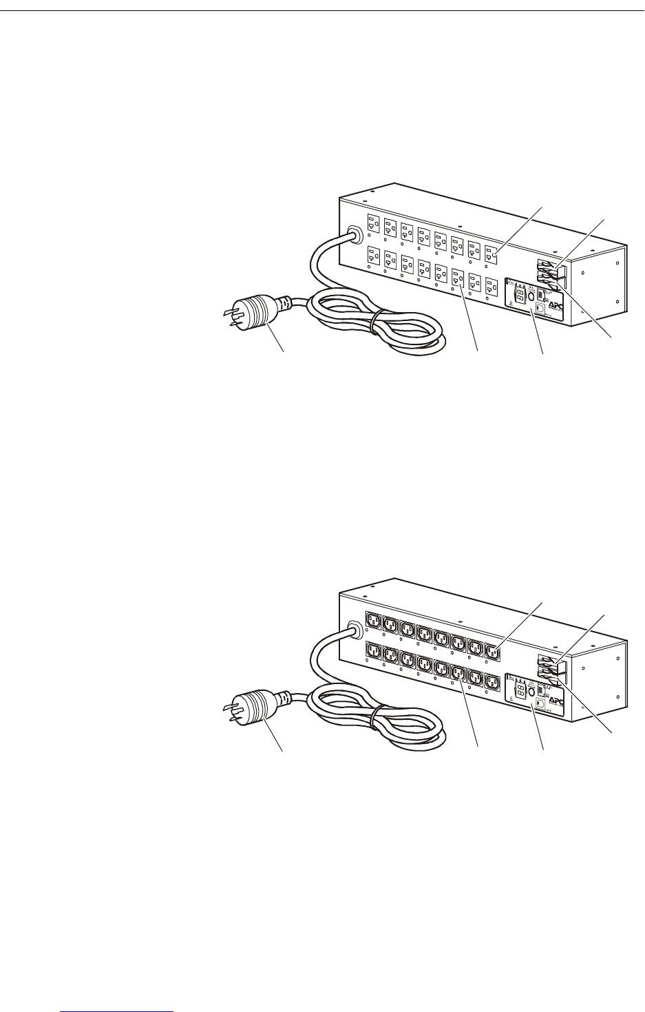
AP7902
AP7911
Bank 1 — Eight NEMA 5-20 outlets
20A circuit breaker for Bank 1
20A circuit breaker for Bank 2
Display interface
Bank 2 — Eight NEMA 5-20 outlets
NEMA L5-30 plug with a 12-foot power cord
Bank 1 — Eight IEC 320 C13 outlets
15A circuit breaker for Bank 1
15A circuit breaker for Bank 2
Display interface
Bank 2 — Eight IEC 320 C13 outlets
NEMA L6-30 plug with a 12-foot power cord

More user manuals on ManualsBase.com
Product Description and Inventory
2 Switched Rack PDU Installation and Quick Start
Additional
documentation
The Rack PDU User’s Guide and the Rack PDU Addendum are available
on the supplied CD and on the APC Web site: www.apc.com.
The User’s Guide (.\doc\eng\usrguide.pdf) contains additional
information about the following topics related to the Rack PDU:
• Management interfaces
• User accounts
• Customizing setup
•Security
The Addendum (.\doc\eng\addendum.pdf) contains additional
information about the following topics:
• The Management Card Wizard
• Configuration utilities
• File transfers
Inventory The Rack PDU is shipped with the following items:
Receiving inspection Inspect the package and contents for shipping damage, and make sure
that all parts were sent. Report any damage immediately to the shipping
agent, and report missing contents, damage, or other problems
immediately to APC or your APC reseller.
Please recycle
InfraStruXure-certified This product is certified for use in InfraStruXure systems. The
Configuration section, beginning on page 7, does not apply to Rack
PDUs that are part of InfraStruXure systems managed by an
InfraStruXure Manager.
Quantity Item
1 Configuration cable (940-0144)
1 Cord retention tray (with 4 flat-head screws and
16 wire ties)
2 Mounting brackets (with 8 flat-head screws)
4 Rubber feet
1 APC Switched Rack PDU Utility CD
1 Warranty registration card
The shipping materials are recyclable. Please save them for
later use, or dispose of them appropriately.
More user manuals on ManualsBase.com
Switched Rack PDU Installation and Quick Start 3
How to Install the Rack PDU
Installation guidelines • For a Rack PDU installed in an enclosed communications rack, the
recommended maximum ambient temperature is 45° C (113º F).
• Install the Rack PDU so that it does not reduce the air flow
required for safe operation of the equipment.
• Install the Rack PDU so that there is an even mechanical load.
• Follow the nameplate ratings when connecting equipment to the
supply circuit. Avoid overloading the circuits, which could affect
over-circuit protection and supply wiring.
• Maintain reliable earthing of the Rack PDU, especially supply-
connections that do not directly connect to the branch circuit.
• Install the Rack PDU so that the power plug is accessible to be
disconnected for service.
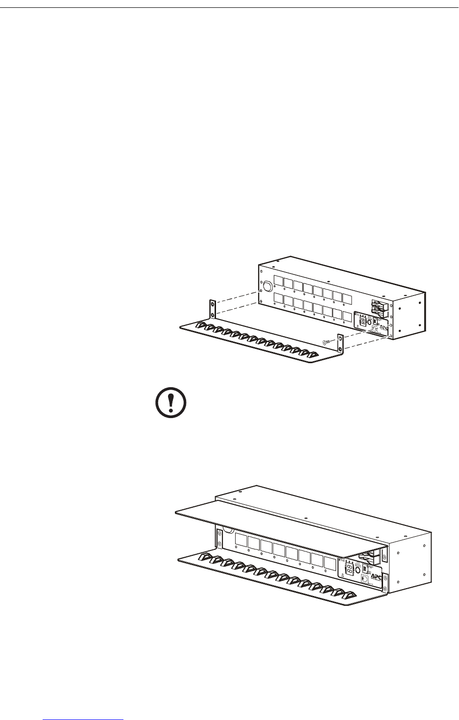
Attach the cord
retention tray
Attach the cord retention tray to the Rack PDU, using four flat-head
screws (provided) per tray.
Additional cord
retention tray (optional)
Attach a second cord retention tray to the PDU, with the cord retainers
facing down.
Note
Mount an additional cord retention tray to secure cords
from the top bank of outlets. Purchase additional tray kits
from APC (AP9569).
More user manuals on ManualsBase.com
How to Install the Rack PDU
4 Switched Rack PDU Installation and Quick Start
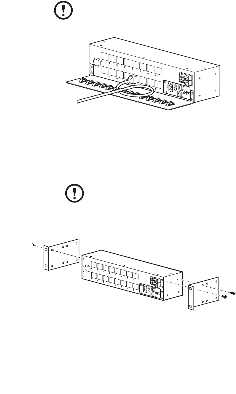
Attach cords to the tray Attach a cord to the tray by looping the cord and securing it to the tray,
using a wire tie (provided). Cords from both banks of outlets may be
secured to the bottom tray, or you may attach an additional tray (shown
on the preceding page) to secure cords from the top bank of outlets.
Make sure the cords that are attached to the upper tray do not interfere
with the operation of the circuit breakers.
Mounting options You can install the Rack PDU in one of two ways: flush with the rack, or
recessed to allow the use of the cord retention bracket. To mount the
Rack Rack PDU horizontally in a NetShelter® or any other standard
EIA-310 rack or enclosure:
1. Attach the mounting brackets to the Rack PDU, using the flat-head
screws (provided).
For placement flush-to-rack: use four flat-head screws (provided)
for each bracket.
Note
Each cord must be secured to the tray so that you can unplug
it from the Rack PDU without removing the wire tie.
Note
Some enclosures may require you to recess the Rack
PDU so that the back doors of the enclosure will close
when other devices are plugged in to the Rack PDU.
More user manuals on ManualsBase.com
How to Install the Rack PDU
Switched Rack PDU Installation and Quick Start 5
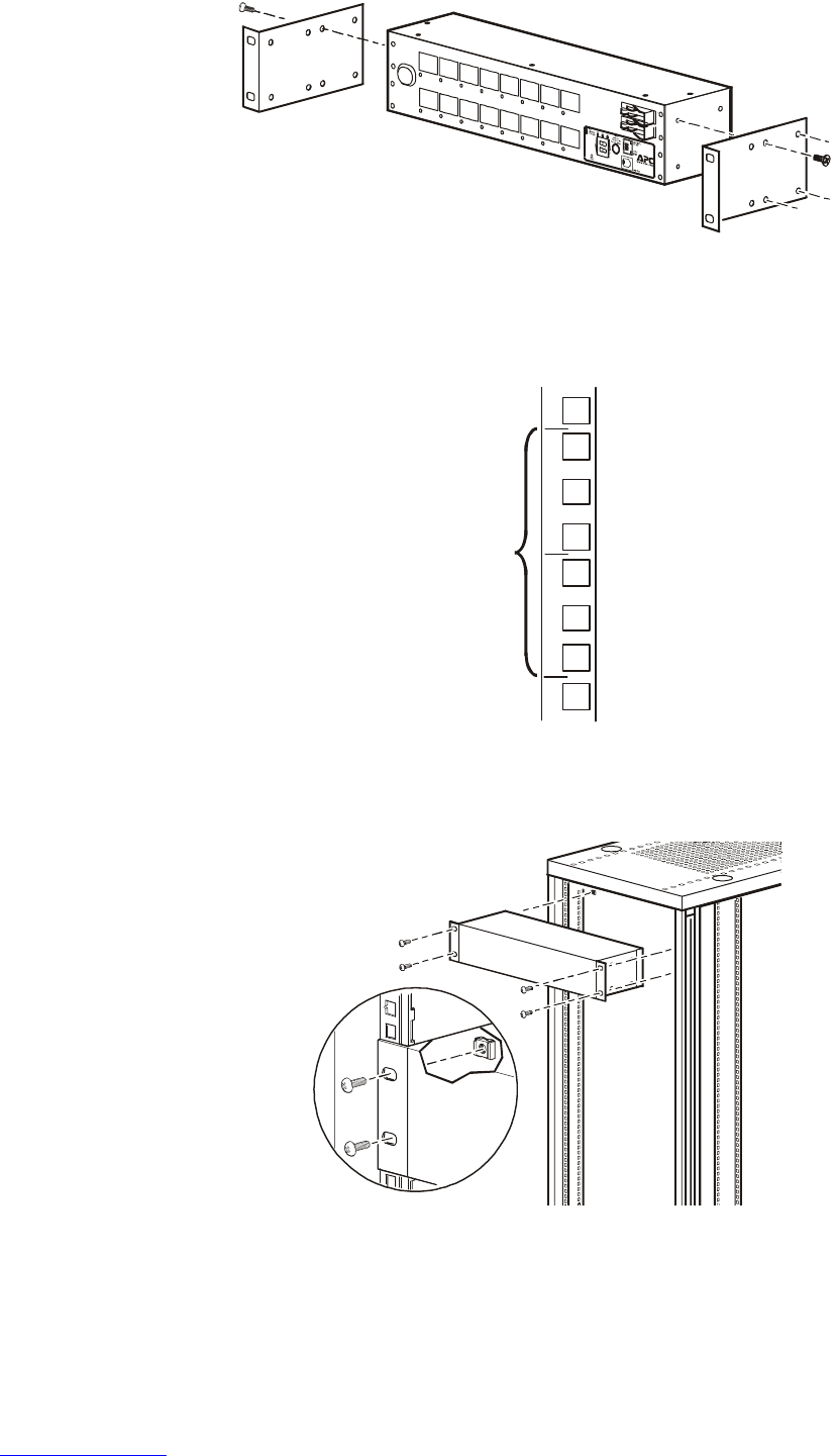
For a recessed placement: use four flat-head screws (provided)
through the last four holes of each bracket.
2. Insert caged nuts (provided with the rack) on the vertical mounting
rails above a number at the start of two U-spaces in your enclosure
and below a number at the lower end of those two U–spaces.
3. Align the mounting holes on the brackets with the caged nuts you
installed in step 2, and insert four mounting screws (provided with
the rack) to secure the brackets to the enclosure.
2U

More user manuals on ManualsBase.com
6 Switched Rack PDU Installation and Quick Start
Operation
Display interface
Link - Rx/Tx
10/100
Status
Serial Port
Reset
- Warning
- OK
- Overload
B2B1
TOTAL
Amps
Amps
Amps
Switched Rack PDU
Line Indicator LED: Indicates normal (green), warning (yellow), and
alarm (red) conditions for bank 1 (B1), bank 2 (B2), or the total of the
two banks (both B1 and B2 illuminated).
Control button:
• Press and hold for five seconds to view the orientation; hold for an
additional five seconds to change the orientation.
• Press to change from B1 to B2, B2 to TOTAL, or TOTAL to B1.
Ethernet port: Connects the Rack PDU to your network, using a CAT5
network cable.
Status LED: Indicates the status of the Ethernet LAN connection and
the state of the Rack PDU.
•Off– The Rack PDU has no power.
•Solid green–The Rack PDU has valid TCP/IP settings.
•Flashing green–The Rack PDU does not have valid TCP/IP
settings.
•Solid orange–A hardware failure has been detected in the Rack
PDU. Contact Customer Support at a phone number on the back
cover of this manual.
•Flashing orange–The Rack PDU is making BOOTP requests.
Link LED: Indicates whether there is activity on the network.
Serial port: Access internal menus by connecting this port (RJ-11
modular port) to a serial port on your computer, using the supplied
serial cable (940-0144).
Digital display: Displays the current used by the Rack PDU and
attached devices. Shows the aggregate current for the Rack PDU for
bank 1 (B1), bank 2 (B2), or the total current of both bank 1 and
bank 2 (TOTAL).
Reset switch: Resets the Rack PDU without affecting the outlet status.

More user manuals on ManualsBase.com
Switched Rack PDU Installation and Quick Start 7
Quick Configuration
Overview You must configure the following TCP/IP settings before the Rack PDU
can operate on a network:
•IP address of the Rack PDU
• Subnet mask
• Default gateway
TCP/IP configuration
methods
Use one of the following methods to define the TCP/IP settings:
• APC Management Card Wizard (See “APC Management Card
Wizard” on page 8.)
• BOOTP or DHCP server (See “BOOTP & DHCP configuration”
on page 8.)
• Local computer (See “Local access to the control console” on
page 11.)
• Networked computer (See “Remote access to the control console”
on page 11.)
Warn
i
ng
Disregard the procedures in this section if you have APC
InfraStruXure Manager as part of your system. See the
InfraStruXure Manager’s documentation for more
information.
Note
If a default gateway is unavailable, use the IP address of a
computer that is located on the same subnet as the Rack
PDU and that is usually running. The Rack PDU uses the
default gateway to test the network when traffic is very
light.
S
ee also
See “Watchdog Features” in the “Introduction” of the
User’s Guide for more information about the watchdog
role of the default gateway.

More user manuals on ManualsBase.com
Quick Configuration
8 Switched Rack PDU Installation and Quick Start
APC Management Card
Wizard
You can use the APC Management Card Wizard at a Windows® 98,
Windows NT® 4.0, Windows 2000, or Windows XP computer to
configure a Rack PDU.
1. Insert the APC Switched Rack PDU Utility CD into a computer on
your network.
2. Launch the Wizard, when prompted, or, if prompted to restart the
computer, access the Wizard from the Start menu after the
computer has restarted.
3. Wait for the Wizard to discover the unconfigured Rack PDU, then
follow the on-screen instructions.
BOOTP & DHCP
configuration
The Boot Mode setting, a TCP/IP option in the Rack PDU’s Network
menu, identifies how TCP/IP settings will be defined. The possible
settings are Manual, DHCP only, BOOTP only, and DHCP &
BOOTP (the default setting).
With Boot Mode set to DHCP & BOOTP, the Rack PDU attempts to
discover a properly configured server. It first searches for a BOOTP
server, and then a DHCP server. It repeats this pattern until it discovers a
BOOTP or DHCP server.
Note
If you leave the Start a Web browser when finished
option enabled, you can use apc for both the user name
and password to access the Rack PDU through your
browser.
Note
The DHCP & BOOTP setting assumes that a properly
configured DHCP or BOOTP server is available to provide
TCP/IP settings to the Rack PDU. If these servers are
unavailable, see “APC Management Card Wizard” on this
page, “Local access to the control console” on page 11, or
“Remote access to the control console” on page 11 to
configure the TCP/IP settings.
For more information, see “BOOTP” on page 9 or “DHCP”
on page 10.

More user manuals on ManualsBase.com
Quick Configuration
Switched Rack PDU Installation and Quick Start 9
BOOTP. You can use an RFC951-compliant BOOTP server to configure
the TCP/IP settings for the Rack PDU. If the BOOTP server is properly
configured, the Rack PDU’s default setting (DHCP & BOOTP) for
BOOT Mode causes it to discover the BOOTP server.
1. Enter the Rack PDU’s MAC and IP addresses, the subnet mask and
default gateway settings, and an optional bootup file name in the
BOOTPTAB file of the BOOTP server.
2. When the Rack PDU reboots, the BOOTP server provides it with
the TCP/IP settings.
– If you specified a bootup file name, the Rack PDU attempts to
transfer that file from the BOOTP server using TFTP or FTP.
The Rack PDU assumes all settings specified in the bootup file.
– If you did not specify a bootup file name, the Rack PDU can be
configured remotely by using Telnet or by using the Web
interface: user name and password are both apc, by default. See
“Remote access to the control console” on page 11 for
configuration instructions.
If a BOOTP server is unavailable, see “APC Management
Card Wizard” on page 8, “Local access to the control
console” on page 11, or “Remote access to the control
console” on page 11 to configure TCP/IP settings.
Note
The MAC address is on the bottom of the Rack PDU and
on the Quality Assurance slip included in the package.
S
ee also
You must use the APC Management Card Wizard to
create the bootup file. To create a bootup file, see the
BOOTP section in the Addendum.

More user manuals on ManualsBase.com
Quick Configuration
10 Switched Rack PDU Installation and Quick Start
DHCP. You can use a RFC2131/RFC2132-compliant DHCP server to
configure the TCP/IP settings for the Rack PDU.
1. The Rack PDU sends a DHCP request that uses the following to
identify itself:
– Vendor Class Identifier (APC by default)
– Client Identifier (by default, the Rack PDU’s MAC address)
– User Class Identifier (by default, the identification of the Rack
PDU’s application firmware)
2. A properly configured DHCP server responds with a DHCP offer
that includes all of the settings that the Rack PDU needs for
network communication. The DHCP offer also includes the Vendor
Specific Information option (DHCP option 43). By default, the
Rack PDU ignores DHCP offers that do not encapsulate the APC
cookie in the Vendor Specific Information option using the
following hexidecimal format:
Option 43 = 01 04 31 41 50 43
where
– The first byte (01) is the code
– The second byte (04) is the length
– The remaining bytes (31 41 50 43) are the APC cookie
S
ee also
This section summarizes the Rack PDU communication
with a DHCP server. For more detail about how a DHCP
server is used to configure the network settings for the Rack
PDU, see “DHCP Configuration” in the User’s Guide.
S
ee also
See your DHCP server documentation to add code to
the Vendor Specific Information option.
To disable the APC cookie requirement you can use a local
computer. See “Local access to the control console” on
page 11. To change the control console’s DHCP Cookie Is
setting, an Advanced option in the TCP/IP menu, use
Telnet or another remote accessing method. See “Remote
access to the control console” on page 11.

More user manuals on ManualsBase.com
Quick Configuration
Switched Rack PDU Installation and Quick Start 11
Local access to the
control console
You can use a local computer to connect to the Rack PDU to access the
control console.
1. Select a serial port at the local computer, and disable any service
which uses that port.
2. Use the configuration cable (940-0144) to connect the selected port
to the serial port on the front panel of the Rack PDU.
3. Run a terminal program (such as HyperTerminal) and configure
the selected port for 9600 bps, 8 data bits, no parity, 1 stop bit, and
no flow control, and save the changes.
4. Press ENTER to display the User Name prompt.
5. Use apc for the user name and password.
6. See “Control console” on page 12 to finish the configuration.
Remote access to the
control console
From any computer on the same subnet as the Rack PDU, you can use
ARP and Ping to assign an IP address to the Rack PDU, and then use
Telnet to access that Rack PDU’s control console and configure the
needed TCP/IP settings.
1. Use ARP to define an IP address for the Rack PDU, and use the
Rack PDU’s MAC address in the ARP command. For example, to
define an IP address of 156.205.14.141 for the Rack PDU that has
a MAC address of 00 c0 b7 63 9f 67, use one of the following
commands:
– Windows command format:
arp -s 156.205.14.141 00-c0-b7-63-9f-67
– LINUX command format:
arp -s 156.205.14.141 00:c0:b7:63:9f:67
2. Use Ping with a size of 113 bytes to assign the IP address defined
by the ARP command. For example:
– Windows command format:
ping 156.205.14.141 -l 113
– LINUX command format:
ping 156.205.14.141 -s 113
Note
After the Rack PDU has its IP address configured, you can
use Telnet, without first using ARP and Ping, to access that
Rack PDU.
Note
The MAC address is on the bottom of the Rack PDU and on
the Quality Assurance slip included in the package.

More user manuals on ManualsBase.com
Quick Configuration
12 Switched Rack PDU Installation and Quick Start
3. Use Telnet to access the Rack PDU at its newly assigned IP
address. For example:
telnet 156.205.14.141
4. Use apc for both user name and password.
5. See “Control console” on this page to finish the configuration.
Control console After you log on at the control console, as described in “Local access to
the control console” on page 11 or “Remote access to the control
console” on page 11:
1. Choose Network from the Control Console menu.
2. Choose TCP/IP from the Network menu.
3. If you are not using a BOOTP or DHCP server to configure the
TCP/IP settings, select the Boot Mode menu. Select Manual boot
mode, and then press ESC to return to the TCP/IP menu. (Changes
will take effect when you log out.)
4. Set the System IP, Subnet Mask, and Default Gateway address
values.
5. Press CTRL-C to exit to the Control Console menu.
6. Log out (option 4 in the Control Console menu).
Note
If you disconnected a cable during the procedure
described in “Local access to the control console” on
page 11, reconnect that cable and restart the associated
service.

More user manuals on ManualsBase.com
Switched Rack PDU Installation and Quick Start 13
How to Access a Configured Rack PDU
Overview After the Rack PDU is running on your network, you can use the
interfaces summarized here to access the unit.
Web interface As your browser, you can use Microsoft® Internet Explorer 5.0 (and
higher) or Netscape® 4.0.8 (and higher, except Netscape 6.x) to access
the Management Card through its Web interface. Other commonly
available browsers also may work but have not been fully tested by
APC.
To use the Web browser to configure Rack PDU options or to view the
event log, you can use either of the following:
• The HTTP protocol (enabled by default), which provides
authentication by user name and password but no encryption.
• The HTTPS protocol, which provides extra security through
Secure Socket Layer (SSL) and encrypts user names, passwords,
and data being transmitted. It also provides authentication of
Network Management Cards by means of digital certificates.
To access the Web interface and configure the security of your device on
the network:
1. Address the Rack PDU by its IP address or DNS name (if
configured).
2. Enter the user name and password (by default, apc and apc for an
Administrator, or device and apc for a Device Manager).
3. Select and configure the type of security you want. (This option is
available only for Admininistrators.)
S
ee also
For more information on the interfaces, see the User’s
Guide, located on the supplied CD and on the APC Web
site: www.apc.com
S
ee also
See the chapter entitled “Security” in the User’s Guide
for information on choosing and setting up your network
security. Use the Web/SSL/TLS option of the Network
menu to enable or disable the HTTP or HTTPS protocols.

More user manuals on ManualsBase.com
How to Access a Configured Rack PDU
14 Switched Rack PDU Installation and Quick Start
Telnet/SSH You can access the control console through Telnet or Secure SHell
(SSH), depending on which is enabled. An Administrator can enable
these access methods through the Telnet/SSH option of the Network
menu. By default, Telnet is enabled. Enabling SSH automatically
disables Telnet.
Telnet for basic access. Telnet provides the basic security of
authentication by user name and password, but not the high-security
benefits of encryption. To use Telnet to access a Rack PDU’s control
console from any computer on the same subnet:
1. At a command prompt, use the following command line, and press
ENTER:
telnet address
As address, use the Rack PDU’s IP address or DNS name (if
configured).
2. Enter the user name and password (by default, apc and apc for an
Administrator, or device and apc for a Device Manager).
SSH for high-security access. If you use the high security of SSL for
the Web interface, use Secure SHell (SSH) for access to the control
console. SSH encrypts user names, passwords, and transmitted data.
The interface, user accounts, and user access rights are the same whether
you access the control console through SSH or Telnet, but to use SSH,
you must first configure SSH and have an SSH client program installed
on your computer.
SNMP After you add the PowerNet MIB to a standard SNMP MIB browser,
you can use that browser for SNMP access to the Rack PDU. The
default read community name is public; the default read/write
community name is private.
S
ee also
See the User’s Guide for more information on configuring
and using SSH.
Note
If you enable SSL and SSH disable SNMP. Allowing SNMP
access compromises the high security environment of SSL
and SSH. Administrators can disable SNMP using the
SNMP option of the Network menu.

More user manuals on ManualsBase.com
How to Access a Configured Rack PDU
Switched Rack PDU Installation and Quick Start 15
FTP/SCP You can use FTP (enabled by default) or Secure CoPy (SCP) to transfer
new firmware to the Rack PDU, or to access a copy of the Rack PDU’s
event logs. SCP provides the higher security of encrypted data
transmission and is automatically enabled when you enable SSH.
To access the Rack PDU through FTP or SCP, the default user name and
password are apc and apc for an Administrator, or device and apc for a
Device Manager. In the command line, use the IP address of the unit.
Note
If you enable SSL and SSH, disable FTP. Allowing file
transfers using FTP compromises the high security
environment of SSL and SSH. Administrators can disable
FTP using the FTP Server option of the Network menu.
S
ee also
See the Network Management Card Addendum to use FTP
or SCP to transfer firmware files to the Network
Management Card. See the User’s Guide to use FTP or SCP
to retrieve log files from the Network Management Card.

More user manuals on ManualsBase.com
16 Switched Rack PDU Installation and Quick Start
How to Recover From a Lost Password
You can use a local computer, a computer that connects to the Rack PDU
or other device through the serial port to access the control console.
1. Select a serial port at the local computer, and disable any service
that uses that port.
2. Connect the APC smart-signaling cable (940-0144) to the selected
port on the computer and to the serial port at the Rack PDU:
3. Run a terminal program (such as HyperTerminal®) and configure
the selected port as follows:
– 9600 bps
– 8 data bits
–no parity
–1 stop bit
– no flow control.
4. Press ENTER, repeatedly if necessary, to display the User Name
prompt. If you are able to display the User Name prompt, verify
the following:
– The serial port is not in use by another application
– The terminal settings are correct as specified in step 3
– The correct cable is being used as specified in step 2
5. Press the Reset button. The Status LED will flash between red or
orange and green. Press the Reset button a second time
immediately while the LED is flashing to reset the user name and
password to their defaults temporarily.
6. Press ENTER as many times as necessary to redisplay the User
Name prompt, then use the default, apc, for the user name and
password. (If you take longer than 30 seconds to log on after the
User Name prompt is redisplayed, you must repeat step 5 and log
on again.)
7. From the Control Console menu, select System, then User
Manager.
8. Select Administrator, and change the User Name and Password
settings, both of which are now defined as apc.
9. Press CTRL-C, log off, reconnect any serial cable you disconnected,
and restart any service you disabled.

More user manuals on ManualsBase.com
Switched Rack PDU Installation and Quick Start 17
How to Download Firmware Updates
You can use a local computer that connects to the Rack PDU through the
serial port on the front of the unit.
1. Select a serial port at the local computer, and disable any service
that uses that port.
2. Use the configuration cable (940-0144) to connect the selected port
to the RJ-12 serial port on the front panel of the Rack PDU.
3. Run a terminal program (such as HyperTerminal) and configure
the selected port for 9600 bps, 8 data bits, no parity, 1 stop bit, and
no flow control. Save the changes.
4. Press ENTER twice to display the User Name prompt.
5. Enter your user name and password (both apc, for administrators
only) and press ENTER.
6. From the Control Console menu, select System, then Tools, then
XMODEM.
7. The system will prompt you with Perform transfer with
XMODEM -CRC? Type Yes and press ENTER.
8. The system will then prompt you to choose a transfer rate and to
change your terminal settings to match the transfer rate. Press
ENTER to set the Rack PDU to accept the download.
9. In the terminal program, send the file using the XMODEM
protocol. Upon completion of the transfer, the console will prompt
you to restore the baud rate to normal.
The Rack PDU will reboot when the download is complete.
S
ee also
For a complete description on how to download a firmware
upgrade for your Rack PDU, see the Addendum on the
provided APC Switched Rack PDU Utility CD.
C
aut
i
on
Do not interrupt the download.
Note
Upgrading the firmware will not interfere with the
operation of the outlets.

More user manuals on ManualsBase.com
18 Switched Rack PDU Installation and Quick Start
Specifications
AP7902/AP7911
Electrical AP7902 AP7911
Nominal input voltage 120 V 208 V
Acceptable input voltage ± 10% Nominal input voltage
Maximum input current 24 A
Input frequency 47– 63 Hz
Cord length 12 ft
Input connectors NEMA L5-30 plug NEMA L6-30 plug
Output connectors Sixteen NEMA 5-20
outlets
Sixteen IEC 320 C13
outlets
Overload protection 20 A 15 A
Physical
Size (H × W × D) 3.5 ×17.5×4.5 in (88.9 ×444.5×114.3 mm)
Weight 9.9 lb ( 4.49 kg)
Shipping weight 14.4 lb (6.53 kg)
Environmental
Elevation (above MSL)
Operating
Storage
0–15 000 ft (0–4500 m)
0–50 000 ft (0–15 000 m)
Temperature
Operating
Storage
–5 to 45° C (23 to 115° F)
–25 to 65° C (–13 to 149° F)
Humidity
Operating
Storage
5– 95% RH Non-condensing
5– 95% RH Non-condensing
Compliance
Safety verification UL, cUL 60950
EMC verification FCC Part 15 Class A, ICES-003 Class A

More user manuals on ManualsBase.com
Switched Rack PDU Installation and Quick Start 19
Warranty and Service
Limited warranty APC warrants the Rack PDU to be free from defects in materials and
workmanship for a period of two years from the date of purchase. Its
obligation under this warranty is limited to repairing or replacing, at its
own sole option, any such defective products. This warranty does not
apply to equipment that has been damaged by accident, negligence, or
misapplication or has been altered or modified in any way. This
warranty applies only to the original purchaser.
Warranty limitations Except as provided herein, APC makes no warranties, express or
implied, including warranties of merchantability and fitness for a
particular purpose. Some jurisdictions do not permit limitation or
exclusion of implied warranties; therefore, the aforesaid limitation(s) or
exclusion(s) may not apply to the purchaser.
Except as provided above, in no event will APC be liable for direct,
indirect, special, incidental, or consequential damages arising out of
the use of this product, even if advised of the possibility of such
damage.
Specifically, APC is not liable for any costs, such as lost profits or
revenue, loss of equipment, loss of use of equipment, loss of software,
loss of data, costs of substitutes, claims by third parties, or otherwise.
This warranty gives you specific legal rights and you may also have
other rights, which vary according to jurisdiction.
Obtaining service To obtain support for problems with your Rack PDU:
0
1. Note the serial number and date of purchase. The serial number is
located on the safety label on the back of the Rack PDU.
2. Contact Customer Support at a phone number located on the back
cover. A technician will try to help you solve the problem by
phone.
3. If you must return the product, the technician will give you a return
material authorization (RMA) number. If the warranty expired, you
will be charged for repair or replacement.
4. Pack the unit carefully. The warranty does not cover damage
sustained in transit. Enclose a letter with your name, address, RMA
number and daytime phone number; a copy of the sales receipt;
and a check as payment, if applicable.
5. Mark the RMA number clearly on the outside of the shipping
carton.
6. Ship by insured, prepaid carrier to the address provided by the
Customer Support technician.

More user manuals on ManualsBase.com
20 Switched Rack PDU Installation and Quick Start
Life-Support Policy
General policy American Power Conversion (APC) does not recommend the use of any
of its products in the following situations:
• In life-support applications where failure or malfunction of the
APC product can be reasonably expected to cause failure of the
life-support device or to affect significantly its safety or
effectiveness.
• In direct patient care.
APC will not knowingly sell its products for use in such applications
unless it receives in writing assurances satisfactory to APC that (a) the
risks of injury or damage have been minimized, (b) the customer
assumes all such risks, and (c) the liability of American Power
Conversion is adequately protected under the circumstances.
Examples of life-support
devices
The term life-support device includes but is not limited to neonatal
oxygen analyzers, nerve stimulators (whether used for anesthesia, pain
relief, or other purposes), autotransfusion devices, blood pumps,
defibrillators, arrhythmia detectors and alarms, pacemakers,
hemodialysis systems, peritoneal dialysis systems, neonatal ventilator
incubators, ventilators (for adults and infants), anesthesia ventilators,
infusion pumps, and any other devices designated as “critical” by the
U.S. FDA.
Hospital-grade wiring devices and leakage current protection may be
ordered as options on many APC UPS systems. APC does not claim that
units with these modifications are certified or listed as hospital-grade by
APC or any other organization. Therefore these units do not meet the
requirements for use in direct patient care.

More user manuals on ManualsBase.com
Radio Frequency Interference
USA—FCC This equipment has been tested and found to comply with the limits for a
Class A digital device, pursuant to part 15 of the FCC Rules. These limits are
designed to provide reasonable protection against harmful interference when
the equipment is operated in a commercial environment. This equipment
generates, uses, and can radiate radio frequency energy and, if not installed
and used in accordance with this user manual, may cause harmful
interference to radio communications. Operation of this equipment in a
residential area is likely to cause harmful interference. The user will bear sole
responsibility for correcting such interference.
Canada—ICES This Class A digital apparatus complies with Canadian ICES-003.
Cet appareil numérique de la classe A est conforme à la norme NMB-003 du
Canada.
Japan—VCCI This is a Class A product based on the standard of the Voluntary Control
Council for Interference by Information Technology Equipment (VCCI). If
this equipment is used in a domestic environment, radio disturbance may
occur, in which case, the user may be required to take corrective actions.
この装置は、情報処理装置等電波障害自主規制協議会(VCCI)
の基準に基づくクラス A 情報技術装置です。この装置を家庭
環境で使用すると、電波妨害を引き起こすことがあります。こ
の場合には、使用者が適切な対策を講ずるように要求されるこ
とがあります。
Warn
i
ng
Changes or modifications to this unit not
expressly approved by the party
responsible for compliance could void the
user’s authority to operate this
equipment.

*990-1664*
APC Worldwide Customer Support
Customer support for this or any other APC product is available at no charge in any of the following ways:
• Visit the APC Web site to find answers to frequently asked questions (FAQs), to access
documents in the APC Knowledge Base, and to submit customer support requests.
–www.apc.com (Corporate Headquarters)
Connect to localized APC Web sites for specific countries, each of which provides customer
support information.
– www.apc.com/support/
Global support with FAQs, knowledge base, and e-support.
• Contact an APC Customer Support center by telephone or e-mail.
– Regional centers:
– Local, country-specific centers: go to www.apc.com/support/contact for contact information.
Contact the APC representative or other distributor from whom you purchased your APC product for
information on how to obtain local customer support.
Direct InfraStruXure Customer Support (1)(877)537-0607 (toll free)
APC headquarters U.S., Canada (1)(800)800-4272 (toll free)
Latin America (1)(401)789-5735 (USA)
Europe, Middle East, Africa (353)(91)702000 (Ireland)
Japan (0) 35434-2021
Australia, New Zealand, South Pacífic (61) (2) 9955 9366 (Australia)
Entire contents copyright © 2003 American Power Conversion. All rights reserved.
Reproduction in whole or in part without permission is prohibited. APC, the APC logo,
InfraStruXure, and NetShelter are trademarks of American Power Conversion Corporation
and may be registered in some jurisdictions. All other trademarks, product names, and
corporate names are the property of their respective owners and are used for informational
purposes only.
990-1664 11/2003
