Appendix B Appxb
User Manual: Appendix B SureServo™ AC Servo Systems User Manual - AutomationDirect
Open the PDF directly: View PDF ![]() .
.
Page Count: 18
- Search�������������
- Save File����������������
- Print this PDF���������������������
- E-mail this PDF����������������������
- Appendix B: SELECTING THE SureServo™ SERVO SYSTEM
- Selecting the SureServo™ Servo System
- Leadscrew - Example Calculations
- Belt Drive - Example Calculations
- Index Table - Example Calculations
- Engineering Unit Conversion Tables, Formulas, & Definitions
B
B
B
APPENDIX
APPENDIX
APPENDIX
SELECTING THE
SureServo™
SERVO SYSTEM
In This Appendix ...
Selecting the SureServo™ Servo System . . . . . . . . . . . .B–2
The Selection Procedure . . . . . . . . . . . . . . . . . . . . . . . . . . . . . . . . . . . . . .B–2
How many pulses from the PLC to make the move? . . . . . . . . . . . . . . . .B–2
What is the positioning resolution of the load? . . . . . . . . . . . . . . . . . . . .B–3
What is the indexing speed to accomplish the move time? . . . . . . . . . . .B–3
Calculating the Required Torque . . . . . . . . . . . . . . . . . . . . . . . . . . . . . . .B–4
Leadscrew - Example Calculations . . . . . . . . . . . . . . . . .B–8
Step 1 - Define the Actuator and Motion Requirements . . . . . . . . . . . . . .B–8
Step 2 - Determine the Positioning Resolution of the Load . . . . . . . . . . . .B–8
Step 3 - Determine the Motion Profile . . . . . . . . . . . . . . . . . . . . . . . . . . .B–9
Step 4 - Determine the Required Motor Torque . . . . . . . . . . . . . . . . . . . .B–9
Step 5 - Select and Confirm the Servo Motor and Driver System . . . . . .B–10
Belt Drive - Example Calculations . . . . . . . . . . . . . . . .B–11
Step 1 - Define the Actuator and Motion Requirements . . . . . . . . . . . . .B–11
Step 2 - Determine the Positioning Resolution of the Load . . . . . . . . . . .B–11
Step 3 - Determine the Motion Profile . . . . . . . . . . . . . . . . . . . . . . . . . .B–12
Step 4 - Determine the Required Motor Torque . . . . . . . . . . . . . . . . . . .B–12
Step 5 - Select and Confirm the Servo Motor and Driver System . . . . . .B–13
Index Table - Example Calculations . . . . . . . . . . . . . . .B–14
Step 1 - Define the Actuator and Motion Requirements . . . . . . . . . . . . .B–14
Step 2 - Determine the Positioning Resolution of the Load . . . . . . . . . . .B–14
Step 3 - Determine the Motion Profile . . . . . . . . . . . . . . . . . . . . . . . . . .B–15
Step 4 - Determine the Required Motor Torque . . . . . . . . . . . . . . . . . . .B–15
Step 5 - Select and Confirm the Servo Motor and Driver System . . . . . .B–16
Engineering Unit Conversion Tables, Formulas, &
Definitions . . . . . . . . . . . . . . . . . . . . . . . . . . . . . . . . . .B–17
Appendix B: Selecting the SureServo™ Servo System
SureServo™ Servo Systems User Manual
B–2 2nd Ed, Rev B 08/2011
Selecting the SureServo™ Servo System
The selection of your SureServo™ servo system follows a defined process. Let's go
through the process and define some useful relationships and equations. We will
use this information to work some typical examples along the way.
The Selection Procedure
The motor provides for the
required motion of the load
through the actuator (mechanics
that are between the motor shaft
and the load or workpiece). Key
information to accomplish the
required motion is:
• total number of pulses from
the PLC
• positioning resolution of the
load
• indexing speed (or PLC pulse
frequency) to achieve the
move time
• required motor torque
(including the 25% safety
factor)
• load to motor inertia ratio
In the final analysis, we need to achieve the required motion with acceptable
positioning accuracy.
How many pulses from the PLC to make the move?
The total number of pulses to make the entire move is expressed with the equation:
Equation 햲: Ptotal = total pulses = (Dtotal ÷ (dload ÷ i)) x θcount
Dtotal = total move distance
dload = lead or distance the load moves per revolution of the actuator's drive shaft
(P= pitch = 1/dload)
θcount = servo resolution (counts/revmotor) (default = 10,000)
i= gear reduction ratio (revmotor/revgearshaft)
Example 1: The motor is directly attached to a disk and we need to move the disk
5.5 revolutions. How many pulses does the PLC need to send to the driver?
Ptotal = (5.5 revdisk ÷ (1 revdisk/revdriveshaft ÷ 1 revmotor/revdriveshaft))
5.5 ÷ (1.0 ÷ 10) x 10,000 =550,000
x 10,000 counts/revmotor
= 55,000 pulses
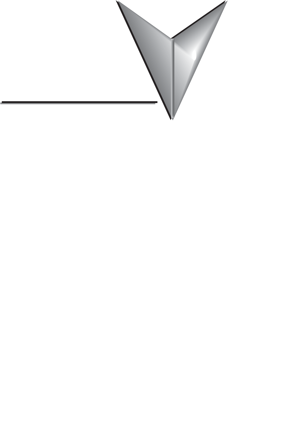
Acceleration Deceleration
Indexing
Speed
Move Time
SureServo™ Servo Systems User Manual B–3
Appendix B: Selecting the SureServo™ Servo System
2nd Ed, Rev B 08/2011
Example 2: The motor is directly attached to a ballscrew where one turn of the
ballscrew results in 20 mm of linear motion and we need to move 45 mm. How
many pulses do we need to send the driver?
Ptotal = (45 mm ÷ (20 mm/revscrew ÷ 1 revmotor/revscrew)) x 10,000 counts/revmotor
=22,500 pulses
Example 3: Let's add a 2:1 belt reduction between the motor and ballscrew in
example 2. Now how many pulses do we need to make the 45 mm move?
Ptotal = (45 mm ÷ (20mm/revscrew ÷ 2 revmotor/revscrew)) x 10,000 counts/revmotor
= 45,000 pulses
What is the positioning resolution of the load?
We want to know how far the load will move for one command pulse. The equation
to determine the positioning resolution is:
Equation 햳: L= load positioning resolution = (dload ÷ i) ÷ count
Example 4: What is the positioning resolution for the system in example 3?
L= (dload ÷ i) ÷ count
= (20 mm/revscrew ÷ 2 revmotor/revscrew) ÷ 10,000 counts/revmotor
= 0.001mm/count
0.00004"/count
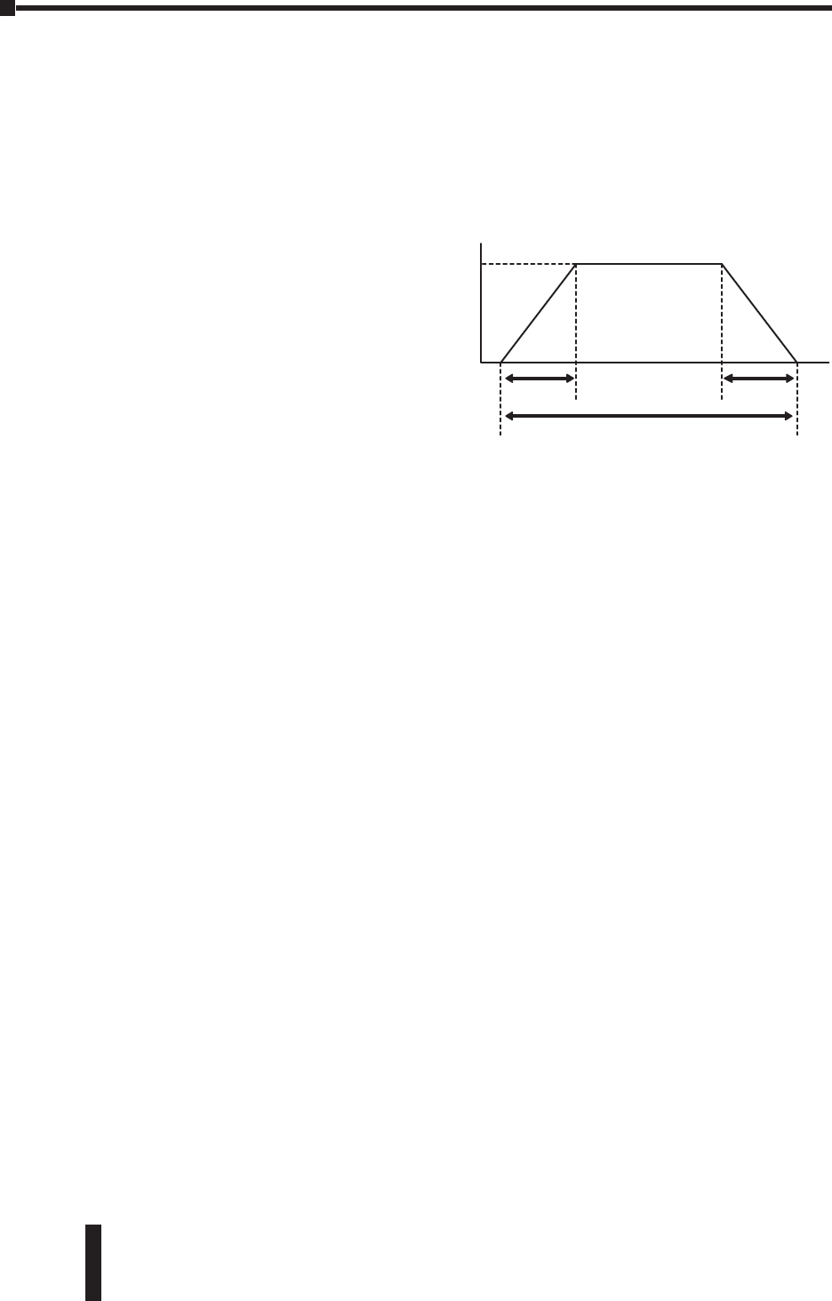
What is the indexing speed to accomplish the move time?
The most basic type of motion profile is a
"start-stop" profile where there is no
acceleration or deceleration period. This
type of motion profile is only used for
low speed applications because the load
is "jerked" from one speed to another and
the servo system may experience a
position deviation error if excessive
speed changes are attempted. The
equation to find indexing speed for "start-
stop" motion is:
Equation 햴: fSS = indexing speed for start-stop profiles = Ptotal ÷ ttotal
ttotal = move time
Indexing
Speed
Move Time
Start - Stop Profile
45 mm 1 revscrew 1 revmotor 10,000 pulses
move 20 mm 1 revscrew 1 revmotor
Appendix B: Selecting the SureServo™ Servo System
SureServo™ Servo Systems User Manual
B–4 2nd Ed, Rev B 08/2011
Example 5: What is the indexing speed to make a "start-stop" move with 10,000
pulses in 800 ms?
fSS = indexing speed = Ptotal ÷ ttotal = 10,000 pulses ÷ 0.8 seconds
= 12,500 Hz.
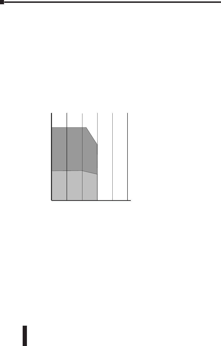
For higher speed operation, the "trapezoidal" motion profile includes controlled
acceleration & deceleration and, in
some cases, an initial non-zero
starting speed. With the acceleration
and deceleration periods equally set,
the indexing speed can be found
using the equation:
Equation 햵: fTRAP = (Ptotal - (fstart
x tramp)) ÷ (ttotal -
tramp)
for trapezoidal
motion profiles
fstart = starting speed
tramp = acceleration or deceleration time
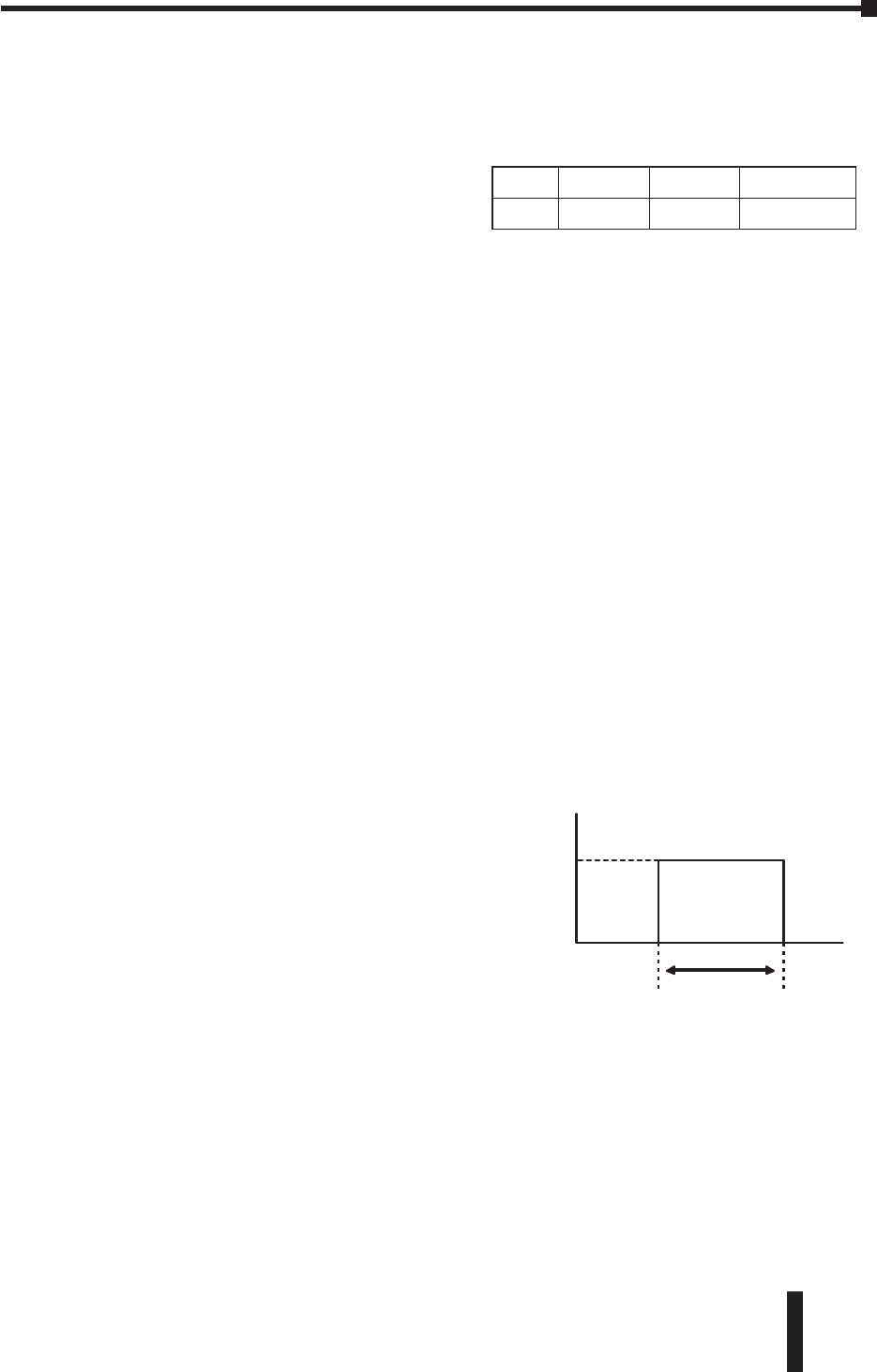
Example 6: What is the required indexing speed to make a "trapezoidal" move in
1.8s, accel/decel time of 200 ms each, 100,000 total pulses, and a starting speed of
40 Hz?
fTRAP = (100,000 pulses - (40 pulses/sec x 0.2 sec)) ÷
(1.8 sec - 0.2 sec)
62,375 Hz.
Calculating the Required Torque
The required torque is the sum of acceleration (or
deceleration) torque and the running torque. The
equation for required motor torque is:
Equation 햶: Tmotor = Taccel (or decel) + Trun
Taccel = motor torque required to accelerate the total
system inertia (including motor inertia).
Tdecel = motor torque required to decelerate; not
always the same as acceleration.
Trun = constant motor torque requirement to run the
mechanism due to friction, external load
forces, etc.
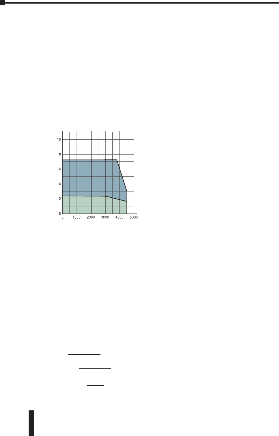
Continuous Duty Zone means the system can provide the torque under the curve
100% of the time.
Intermittent Duty Zone means the system can provide the torque under the curve
LESS THAN 100% of the time.
The amount of time the system can operate in this region depends on the amount
of torque. In general, the higher the torque, the shorter period of time is allowed.
See overload curves information in Chapter 1. If a system requires more than
rated torque occasionally, but only for a short time, the system can do it. Running
in this zone continuously will result in an overload fault.
In Table 1 we show how to calculate torque required to accelerate or decelerate an
inertia from one speed to another and the calculation of running torque for common
mechanical actuators.
Acceleration Deceleration
Indexing
Speed
Move Time
Start
Speed
Trapezoidal Profile
Torque
(N•m)
400W Low Inertia
SVL-204
Speed
(rpm)
Intermittent
Duty Zone
Continuous
Duty Zone
SureServo™ Servo Systems User Manual B–5
Table 1 - Calculate the Torque for "Acceleration" and "Running"
Appendix B: Selecting the SureServo™ Servo System
2nd Ed, Rev B 08/2011
The torque required to accelerate or decelerate a constant inertia with a linear
change in velocity is:
Equation 햷: Taccel = Jtotal x (speed ÷ time) x (2÷ 60)
Jtotal is the motor inertia plus load
inertia ("reflected" to the motor
shaft). The (2÷ 60) is a factor used
to convert "change in speed"
expressed in rpm into angular
speed (radians/second). Refer to
information in this table to
calculate "reflected" load inertia for
several common shapes and
mechanical mechanisms.
Example 7: What is the required
torque to accelerate an inertia of
0.002 lb-in-sec2(motor inertia is 0.0004 lb-in-sec2and "reflected" load inertia is
0.0016 lb-in-sec2) from zero to 600 rpm in 50 ms?
Taccel = 0.002 lb-in-sec2x (600 rpm ÷ 0.05 seconds) x (2÷ 60)
2.5 lb-in
Accel
Period
Velocity Indexing Velocity
Torque
Decel
Period
time
time
T1
T2
T3
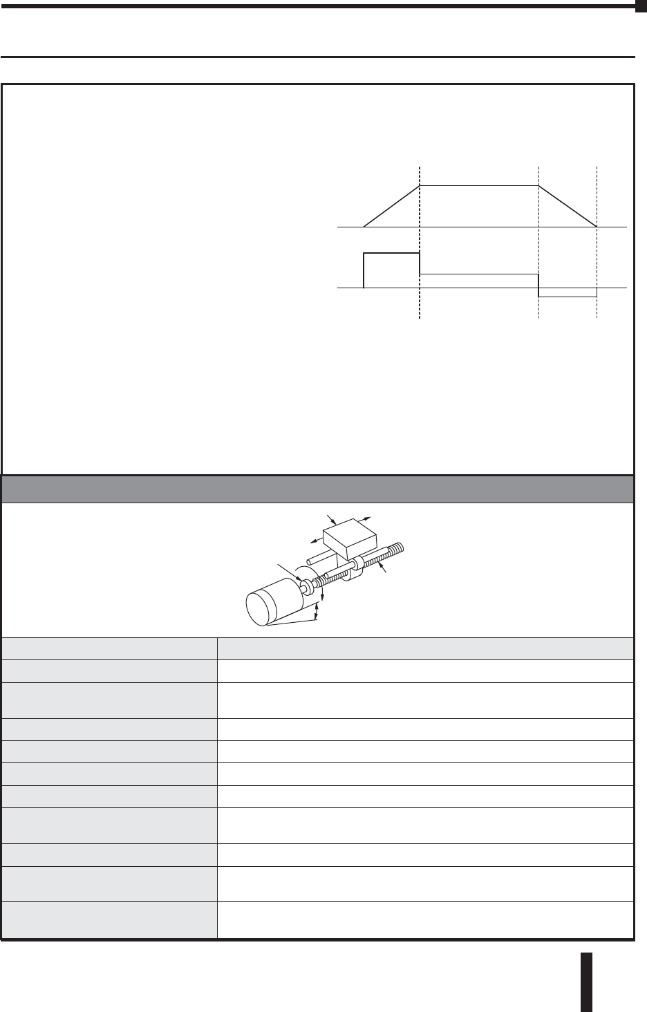
Leadscrew Equations
J
W
motor
Jgear
Jcoupling
Fext
Jscrew
Fgravity
JW
Description: Equations:
Motor rpm nmotor = (vload x P) x i, nmotor (rpm), vload (in/min)
Torque required to accelerate
and decelerate the load Taccel Jtotal x (speed ÷ time) x 0.1
Motor total inertia Jtotal = Jmotor + Jgear + ((Jcoupling + Jscrew + JW) ÷ i2)
Inertia of the load JW= (W ÷ (g x e)) x (1 ÷ 2 P)2
Pitch and Efficiency P = pitch = revs/inch of travel, e = efficiency
Running torque Trun = ((Ftotal ÷ (2 P)) + Tpreload) ÷ i
Torque due to preload
on the ballscrew Tpreload = ballscrew nut preload to minimize backlash
Force total Ftotal = Fext + Ffriction + Fgravity
Force of gravity and
Force of friction Fgravity = Wsinθ, Ffriction = µWcosθ
Incline angle and
Coefficient of friction θ= incline angle, µ = coefficient of friction
i = gear ratio
Appendix B: Selecting the SureServo™ Servo System
SureServo™ Servo Systems User Manual
B–6 2nd Ed, Rev B 08/2011
Table 1 (cont’d)
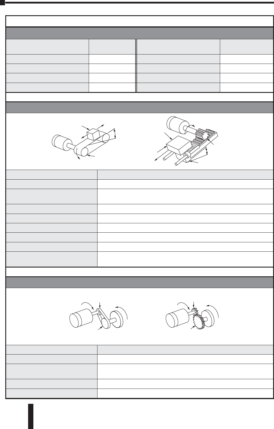
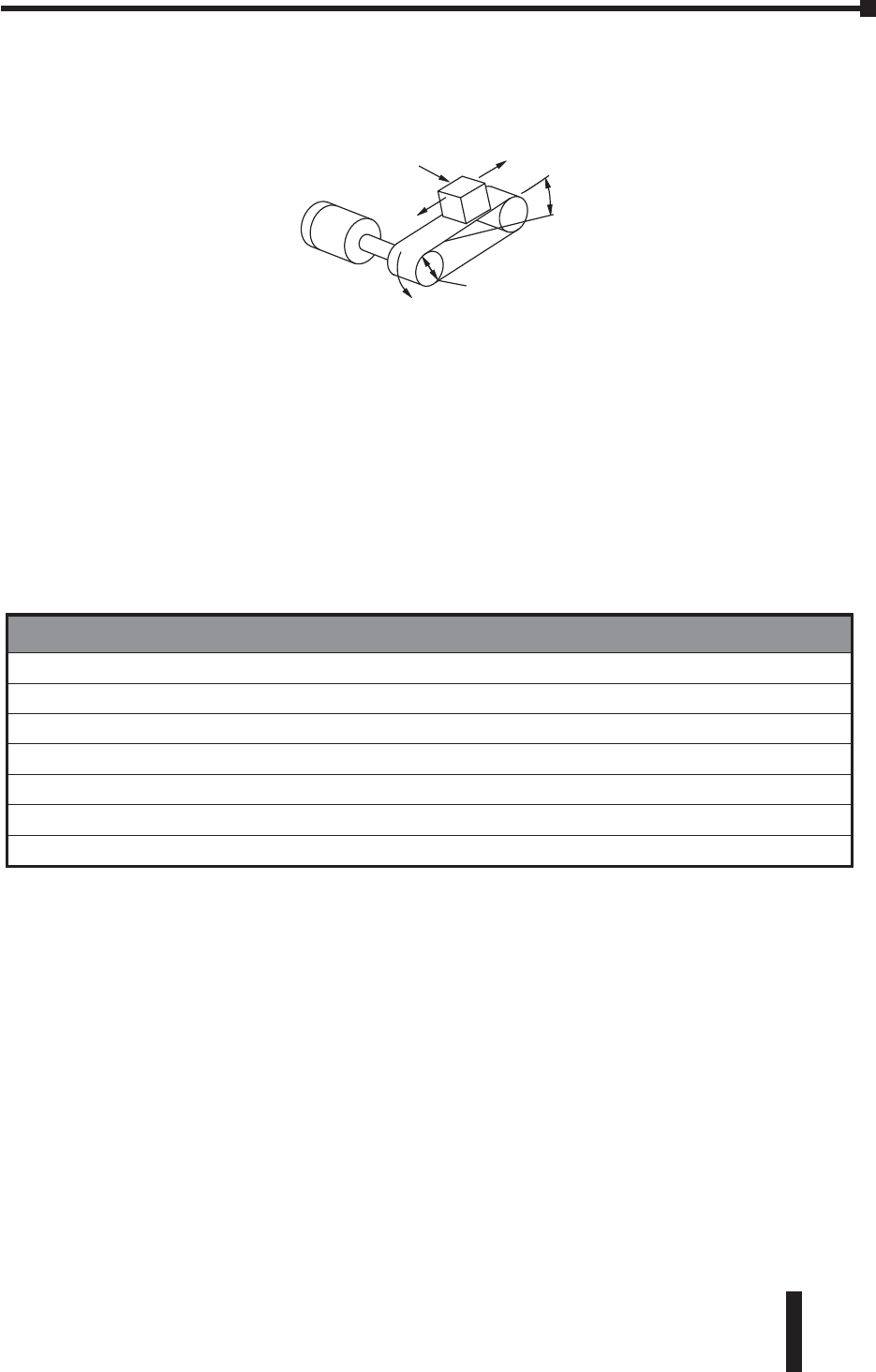
Belt Drive (or Rack & Pinion) Equations
J
W
motor
Jgear
Fext
Fgravity
JW
Jpinion
Jmotor Jgear
JW
W
Fext
Fgravity
1
W2
Jpinion
Description: Equations:
Motor rpm nmotor = (vload x 2 r) x i
Torque required to accelerate
and decelerate the load Taccel Jtotal x (speed ÷ time) x 0.1
Inertia of the load Jtotal = Jmotor + Jgear + ((Jpinion + JW) ÷ i2)
Inertia of the load JW= (W ÷ (g x e)) x r2; JW= ((W1+ W2) ÷ (g x e)) x r2
Radius of pulleys r = radius of pinion or pulleys (inch)
Running torque Trun = (Ftotal x r) ÷ i
Force total Ftotal = Fext + Ffriction + Fgravity
Force of gravity and
Force of friction Fgravity = Wsinθ; Ffriction = µWcosθ
Belt (or Gear) Reducer Equations
Jmotor Jmotor
Jmotorpulley Jmotorpulley
Jloadpulley
Jloadpulley
JLoad JLoad
Description: Equations:
Motor rpm nmotor = nload x i
Torque required to accelerate
and decelerate the load Taccel Jtotal x (speed÷time) x 0.1
Inertia of the load Jtotal = Jmotor + Jmotorpulley + ((Jloadpulley + JLoad) ÷ i2)
Motor torque Tmotor x i = TLoad
Typical Leadscrew Data
Material: e=
efficiency Material: µ =
coef. of friction
ball nut 0.90 steel on steel 0.580
acme with plastic nut 0.65 steel on steel (lubricated) 0.150
acme with metal nut 0.40 teflon on steel 0.040
ball bushing 0.003
i = gear ratio
SureServo™ Servo Systems User Manual B–7
Appendix B: Selecting the SureServo™ Servo System
2nd Ed, Rev B 08/2011
Table 1 (cont’d)
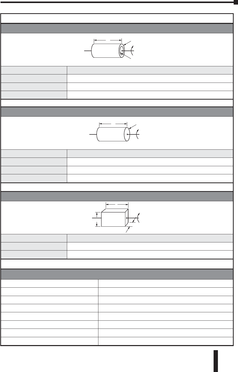
Inertia of Hollow Cylinder Equations
LDo = 2ro
Di = 2ri
Description: Equations:
Inertia (known weight) J = (W x (ro2+ ri2)) ÷ (2g)
Inertia (known density) J = (x L x x (ro4– ri4)) ÷ (2g)
Volume volume = 4 x (Do2- Di2) x L
Inertia of Solid Cylinder Equations
LD = 2r
Description: Equations:
Inertia (known weight) J = (W x r2) ÷ (2g)
Inertia (known density) J = (x L x x r4) ÷ (2g)
Volume volume = x r2x L
Inertia of Rectangular Block Equations
hw
l
Description: Equations:
Inertia (known weight) J = (W ÷ 12g) x (h2+ w2)
Volume volume = l x h x w
Symbol Definitions
J = inertia lb-in-s2 (Kg-m-s2)= density
L = Length, inches (m) = 0.098 lb/in3(aluminum)
h = height, inches (m) = 0.28 lb/in3(steel)
w = width, inches (m) = 0.04 lb/in3(plastic)
W = weight, lbs. (Kg) = 0.31 lb/in3(brass)
D = diameter, inches (m) = 0.322 lb/in3 (copper)
r = radius, inches (m)
g = gravity = 386 in/sec2(9.8 m/s2)3.14
Appendix B: Selecting the SureServo™ Servo System
SureServo™ Servo Systems User Manual
B–8 2nd Ed, Rev B 08/2011
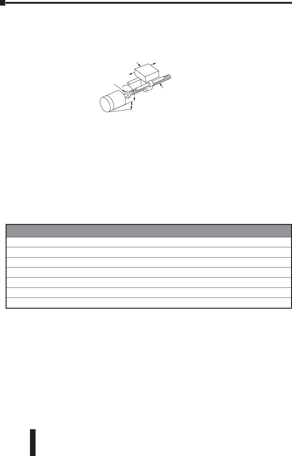
Leadscrew - Example Calculations
Step 1 - Define the Actuator and Motion Requirements
Weight of table and workpiece = 150 lb
Angle of inclination = 0°
Friction coefficient of sliding surfaces = 0.05
External load force = 0
Ball screw shaft diameter = 0.8 inch
Ball screw length = 96 inch
Ball screw material = steel
Ball screw lead = 8.0 inch/rev (P 0.125 rev/in)
Desired Resolution = 0.0005 inches/count
Gear reducer = 2:1
Stroke = 78 inches
Move time = 12 seconds
Step 2 - Determine the Positioning Resolution of the Load
The resolution of the load can be determined using Equation 햳. If the servo motor
is connected directly to the ballscrew, then the best resolution possible would be:
Lθ= (dload ÷ i) ÷ θcount
= (8 ÷ 1) ÷ 10,000
= 0.0008
This does not meet the system requirements; however, if we add a 2:1 transmission
with no lost motion (backlash, etc.) to the output of the motor, the resolution gets
better by a factor of 2, so the minimum requirements would be met.
Lθ= (8 ÷ 2) ÷ 10,000
= 0.0004
J
W
motor
Jgear
Jcoupling
Fext
Jscrew
Fgravity
JW
Definitions
dload = lead or distance the load moves per revolution of the actuator’s drive shaft (P = pitch = 1/dload)
Dtotal = total move distance
θcount = servo resolution (counts/revmotor)
i = gear reduction ratio (revmotor/revgearshaft)
Taccel = motor torque required to accelerate and decelerate the total system inertia (including motor inertia)
Trun = constant motor torque requirement to run the mechanism due to friction, external load forces, etc.
ttotal = move time

SureServo™ Servo Systems User Manual B–9
Appendix B: Selecting the SureServo™ Servo System
2nd Ed, Rev B 08/2011
Step 3 - Determine the Motion Profile
From Equation 햲, the total pulses to make the required move is:
Ptotal = (Dtotal ÷ (dload ÷ i)) x count
= (78 ÷ (8 ÷ 2)) x 10,000 = 195,000 pulses
From Equation 햵, the indexing frequency for a trapezoidal move is:
fTRAP = (Ptotal - (fstart x tramp)) ÷ (ttotal - tramp)
= (195,000 - (100 x 0.6)) ÷ (12 - 0.6) 17.1 KHz
where accel time is 5% of total move time and starting speed is 100 Hz.
=17.1 KHz x (60 sec/1 min) ÷ 10,000 counts/rev
103 rpm
Step 4 - Determine the Required Motor Torque
Using the equations in Table 1:
Jtotal = Jmotor + Jgear + ((Jcoupling + Jscrew + JW) ÷ i2)
For this example, let's assume the gearbox and coupling inertia are zero.
JW= (W÷ (g x e)) x (1 ÷ 2P)2
= (150 ÷ (386 x 0.9)) x (1 ÷ 2 x 3.14 x 0.125)2
0.700 lb-in-sec2
Jscrew (x L x x r4) ÷ (2g)
(3.14 x 96 x 0.28 x 0.0256) ÷ (2 x 386)
0.0028 lb-in-sec2
The inertia of the load and screw reflected to the motor is:
J(screw + load) to motor = ((Jscrew + JW) ÷ i2)
((0.0028 + 0.700) ÷ 22) = 0.176 lb-in-sec2
The torque required to accelerate the inertia is:
Taccel Jtotal x (speed ÷ time) x 0.1
= 0.176 x (103 ÷ 0.6) x 0.1 1.08 lb-in
Next, we need to determine running torque. If the machine already exists then it is
sometimes possible to actually measure running torque by turning the actuator
driveshaft with a torque wrench.
Trun = ((Ftotal ÷ (2 P)) + Tpreload) ÷ i
Ftotal = Fext + Ffriction + Fgravity
= 0 + µWcos+ 0 = 0.05 x 150 = 7.5 lb
Trun = (7.5 ÷ (2 x 3.14 x 0.125)) ÷ 2
4.77 lb-in
where we have assumed preload torque to be zero.
From Equation 햶, the required motor torque is:
Tmotor = Taccel + Trun = 1.08 + 4.77 5.85 lb-in 0.66 N•m
However, this is the required motor torque before we have picked a motor and
included the motor inertia.
Appendix B: Selecting the SureServo™ Servo System
SureServo™ Servo Systems User Manual
B–10 2nd Ed, Rev B 08/2011
Step 5 - Select and Confirm the Servo Motor and Driver System
It looks like a reasonable choice for a motor would be the SVL-207. This motor has
an inertia of:
Jmotor = 0.00096 lb-in-sec2
The actual motor torque would be modified:
Taccel = Jtotal x (speed ÷ time) x 0.1
= (0.176 + 0.00096) x (103 ÷ 0.6) x 0.1
1.09 lb-in
so that:
Tmotor = Taccel + Trun
= 1.09 + 4.77 5.86 lb-in 0.66 N•m
It looks like the 750W system will work. However, we still need to check the load
to motor inertia ratio:
Ratio = J(screw + load) to motor ÷ Jmotor
= 0.176 ÷ 0.00096 = 183.3
It is best to keep the load to motor inertia ratio below 10, so 183 is well outside this
guideline. Although the servo has enough power to control the system, the large
mismatch ratio may prevent proper tuning and faster acceleration settings in the
future. Since the motor speed required to move the system is well within the motor
specs, we can change the gear ratio to use a 750W motor or select a much larger
motor such as the SVM-220. Because the reflected inertia is decreased by the square
of the ratio, we will change the gear ratio to 10:1. By doing this, the mismatch ratio
is now 7.3 (before we consider any added inertia due to the reducer).
Reflected J = Jscrew+Jload = .176, so
22
New Reflected J = Jscrew+Jload = .00704
102
New J Ratios = .00704 = 7.33
.00096
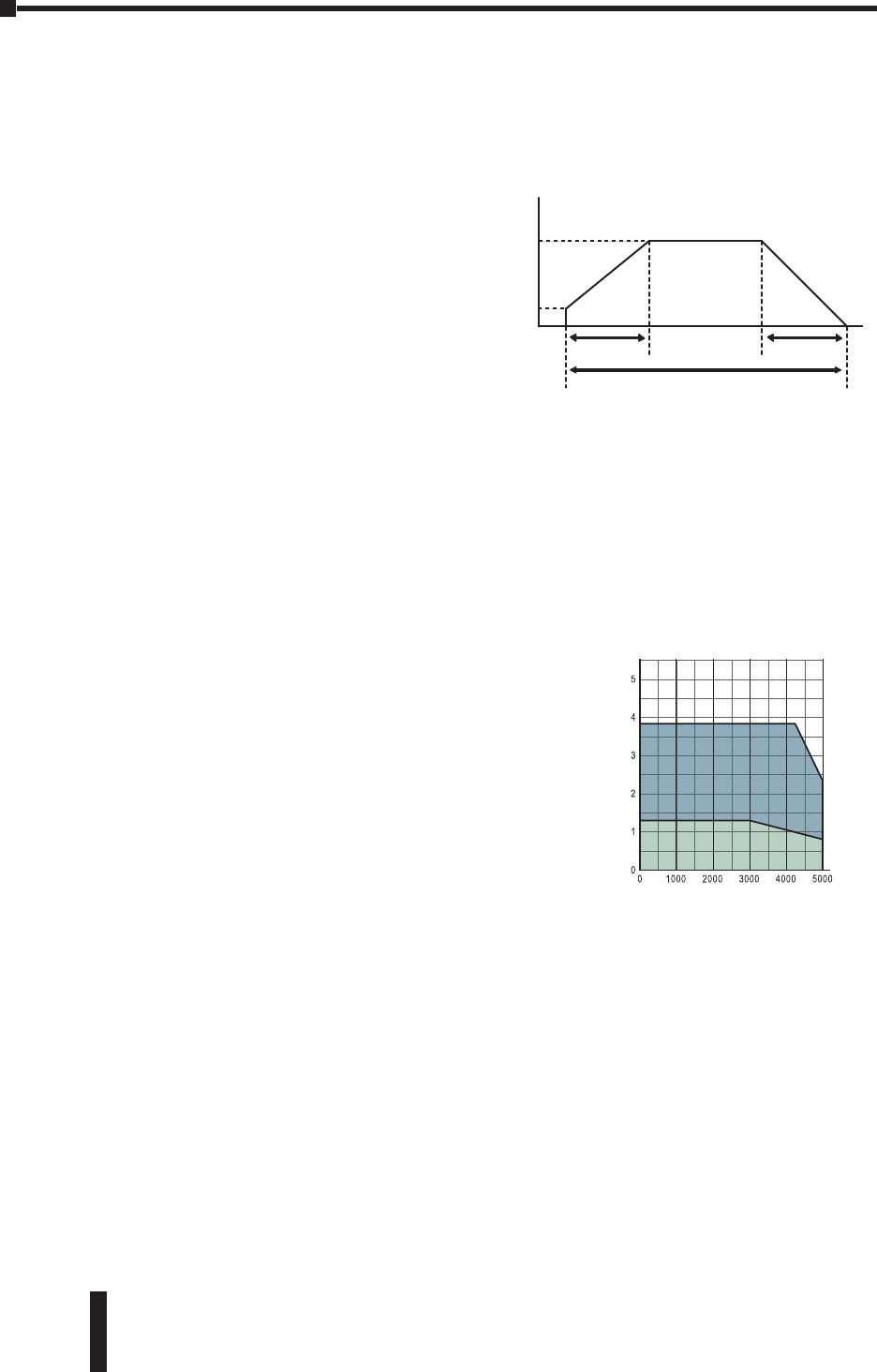
Torque
(N•m)
Intermittent
Duty Zone
Continuous
Duty Zone
750W Low Inertia
SVL-207
Speed
(rpm)
SureServo™ Servo Systems User Manual B–11
Appendix B: Selecting the SureServo™ Servo System
2nd Ed, Rev B 08/2011
Belt Drive - Example Calculations
Step 1 - Define the Actuator and Motion Requirements
Weight of table and workpiece = 90 lb
External force = 0 lb
Friction coefficient of sliding surfaces = 0.05
Angle of table = 0º
Belt and pulley efficiency = 0.8
Pulley diameter = 2.0 inch
Pulley thickness = 0.75 inch
Pulley material = aluminum
Desired Resolution = 0.0005 inch/step
Gear Reducer = 10:1
Stroke = 50 inch
Move time = 4.0 seconds
Accel and decel time = 1.0 seconds
Step 2 - Determine the Positioning Resolution of the Load
The resolution of the load can be determined using Equation 햳. If the servo
motor is connected directly to the pulley, then the best resolution possible would
be:
L= (dload ÷ i) ÷ count
= ((x 2.0) ÷ 1) ÷10,000
= =0.00063
where dload = x Pulley Diameter.
This does not meet the system requirements. However, if we add a 10:1
transmission to the output of the motor, the resolution improves by a factor of 10,
meeting the minimum system requirements.
Lu = ((p x 2.0) ÷ 10) ÷10,000
= 0.000063
Definitions
dload = lead or distance the load moves per revolution of the actuator’s drive shaft (P = pitch = 1/dload)
Dtotal = total move distance
count = servo resolution (counts/revmotor)
i = gear reduction ratio (revmotor/revgearshaft)
Taccel = motor torque required to accelerate and decelerate the total system inertia (including motor inertia)
Trun = constant motor torque requirement to run the mechanism due to friction, external load forces, etc.
ttotal = move time
J
W
motor
Jgear
Fext
Fgravity
JW
Jpinion

Appendix B: Selecting the SureServo™ Servo System
SureServo™ Servo Systems User Manual
B–12 2nd Ed, Rev B 08/2011
Step 3 - Determine the Motion Profile
From Equation 햲, the total pulses to make the required move is:
Ptotal = (Dtotal ÷ (dload ÷ i)) x count
= 50 ÷ ((3.14 x 2.0) ÷ 10 x 10,000
795,775 pulses
From Equation 햵, the running frequency for a trapezoidal move is:
fTRAP = (Ptotal - (fstart x tramp)) ÷ (ttotal - tramp)
= 795,775 ÷ (4 - 1)
265,258 Hz or 265.3 KHz
where accel time is 25% of total move time and starting speed is zero.
= 265.3 KHz x (60 sec/1 min) ÷ 10,000 counts/rev
1,592 rpm motor speed
Step 4 - Determine the Required Motor Torque
Using the equations in Table 1:
Jtotal = Jmotor + Jgear + ((Jpulleys + JW) ÷ i2)
For this example, let's assume the gearbox inertia is zero.
JW= (W÷ (g x e)) x r2
= (90 ÷ (386 x 0.8)) x 1
0.291 lb-in-sec2
Pulley inertia (remember, there are two pulleys) can be calculated as:
Jpulleys ((x L x x r4) ÷ (2g)) x 2
((3.14 x 0.75 x 0.098 x 1) ÷ (2 x 386)) x 2
0.0006 lb-in-sec2
The inertia of the load and pulleys reflected to the motor is:
J(pulleys + load) to motor = ((Jpulleys + JW) ÷ i2)
((0.291 + 0.0006) ÷ 100) 0.0029 lb-in-sec2
The torque required to accelerate the inertia is:
Tacc Jtotal x (speed ÷ time) x 0.1
= 0.0029 x (1592 ÷ 1) x 0.1
= 0.46 lb-in
Trun = (Ftotal x r) ÷ i
Ftotal = Fext + Ffriction + Fgravity
= 0 + µWcos+ 0 = 0.05 x 100 = 5.0 lb
Trun = (5.0 x 1) ÷ 10
0.50 lb-in
From Equation 햶, the required motor torque is:
Tmotor = Taccel + Trun = 0.46 + 0.50 0.96 lb-in 0.11 N•m
However, this is the required motor torque before we have picked a motor and
included the motor inertia.
SureServo™ Servo Systems User Manual B–13
Appendix B: Selecting the SureServo™ Servo System
2nd Ed, Rev B 08/2011
Step 5 - Select and Confirm the Servo Motor and Driver System
It looks like a reasonable choice for a motor would be the SVL-2040. This motor has
an inertia of:
Jmotor = 0.0003 lb-in-sec2
The actual motor torque would be modified:
Taccel = Jtotal x (speed ÷ time) x 0.1
= (0.0029 + 0.0003) x (1592 ÷ 1) x 0.1 0.51 lb-in
so that:
Tmotor = Taccel + Trun
= 0.51 + 0.5 1.01 lb-in 0.12 N•m
It looks like the 400W system will work. However, we still need to check the load
to motor inertia ratio:
Ratio = J(pulleys + load) to motor ÷ Jmotor
= 0.0029 ÷ 0.0003 = 9.6
It is best to keep the load to motor inertia ratio at or below 10, so 9.6 is within an
acceptable range.
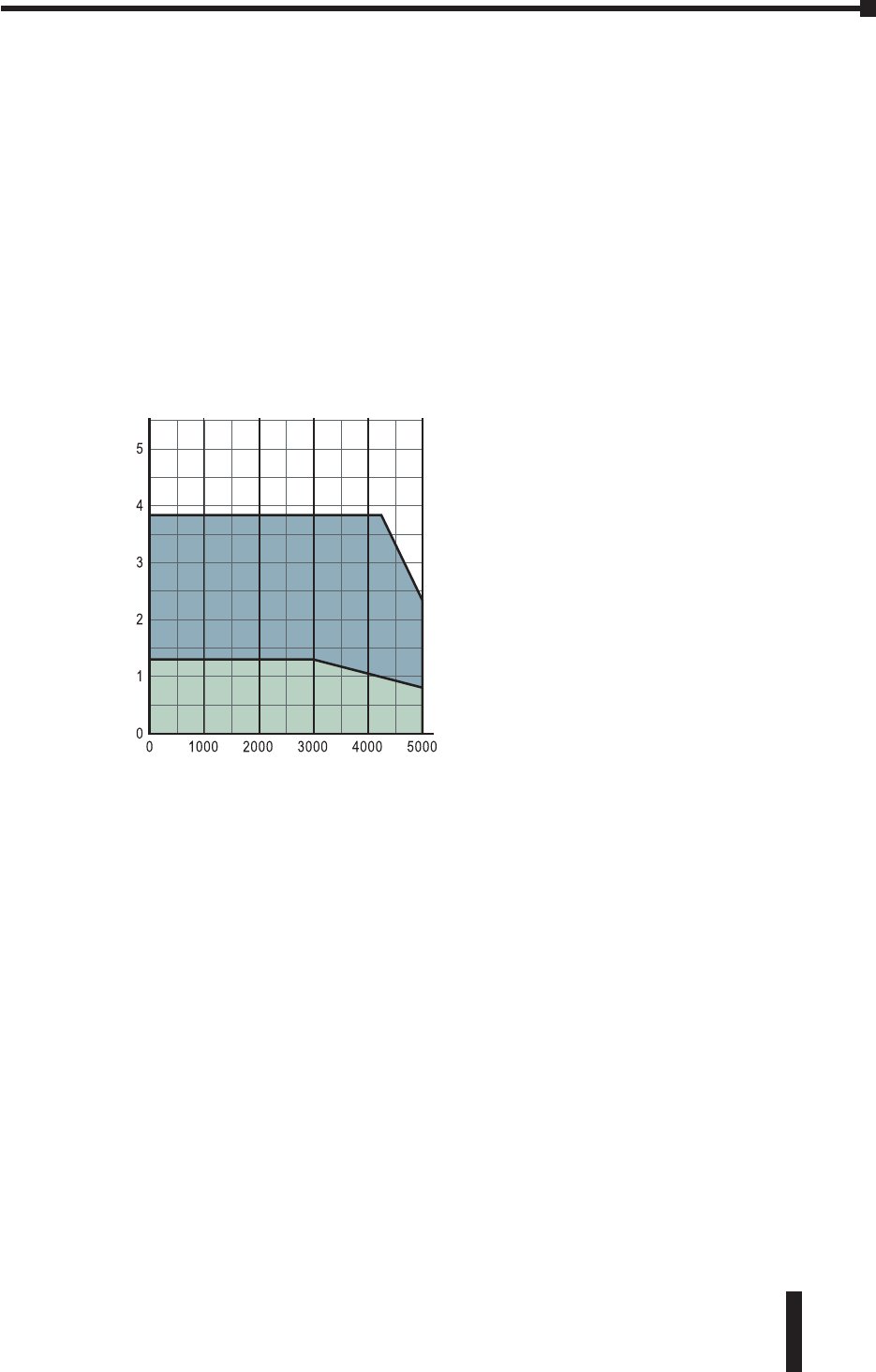
Torque
(N•m)
400W Low Inertia
SVL-204
Speed
(rpm)
Intermittent
Duty Zone
Continuous
Duty Zone
Appendix B: Selecting the SureServo™ Servo System
SureServo™ Servo Systems User Manual
B–14 2nd Ed, Rev B 08/2011
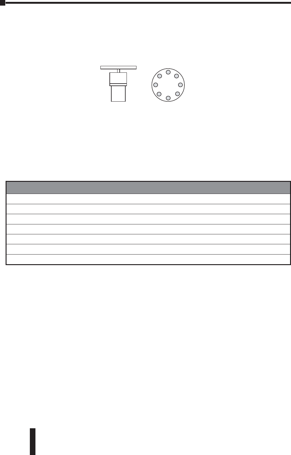
Index Table - Example Calculations
Step 1 - Define the Actuator and Motion Requirements
Diameter of index table = 12 inch
Thickness of index table = 3.25 inch
Table material = steel
Number of workpieces = 8
Desired Resolution = 0.006º
Gear Reducer = 6:1
Index angle = 45º
Index time = 0.5 seconds
Step 2 - Determine the Positioning Resolution of the Load
The resolution of the load can be determined using Equation 햵If the servo
motor is connected directly to the table, then the best resolution possible would
be:
L= (dload ÷ i) ÷ count
= (360º ÷ 1) ÷ 10,000
= 0.036°
This does not meet the system requirements. However, if we add a 6:1 transmission
to the output of the motor, the resolution gets better by a factor of 6, meeting the
minimum system requirements.
= (360º ÷ 6) ÷ 10,000
= 0.006°
Jmotor
Jgear
Definitions
dload = lead or distance the load moves per revolution of the actuator’s drive shaft (P = pitch = 1/dload)
Dtotal = total move distance
count = servo resolution (counts/revmotor)
i = gear reduction ratio (revmotor/revgearshaft)
Taccel = motor torque required to accelerate and decelerate the total system inertia (including motor inertia)
Trun = constant motor torque requirement to run the mechanism due to friction, external load forces, etc.
ttotal = move time

SureServo™ Servo Systems User Manual B–15
Appendix B: Selecting the SureServo™ Servo System
2nd Ed, Rev B 08/2011
Step 3 - Determine the Motion Profile
From Equation 햲, the total pulses to make the required move is:
Ptotal = (Dtotal ÷ (dload ÷ i)) x count
= (45º ÷ (360º ÷ 6) x 10,000
= 7,500 pulses
From Equation 햵, the running frequency for a trapezoidal move is:
fTRAP = (Ptotal - (fstart x tramp)) ÷ (ttotal - tramp)
= 7,500 ÷ (0.5 - 0.13) 20.27 kHz
where accel time is 25% of total move time and starting speed is zero.
= 20.27 kHz x (60 sec/1 min) ÷ 10,000 counts/rev
121 rpm
Step 4 - Determine the Required Motor Torque
Using the equations in Table 1:
Jtotal = Jmotor + Jgear + (Jtable ÷ i2)
For this example, let's assume the gearbox inertia is zero.
Jtable (x L x x r4) ÷ (2g)
(3.14 x 3.25 x 0.28 x 1296) ÷ (2 x 386)
4.80 lb-in-sec2
The inertia of the indexing table reflected to the motor is:
Jtable to motor = Jtable ÷ i2
0.133 lb-in-sec2
The torque required to accelerate the inertia is:
Taccel Jtotal x (speed ÷ time) x 0.1
= 0.133 x (121 ÷ 0.13) x 0.1
12.38 lb-in
From Equation 햶, the required motor torque is:
Tmotor = Taccel + Trun
=12.38 + 0 = 12.38 lb-in 1.40 N•m
However, this is the required motor torque before we have picked a motor and
included the motor inertia.
Appendix B: Selecting the SureServo™ Servo System
SureServo™ Servo Systems User Manual
B–16 2nd Ed, Rev B 08/2011
Step 5 - Select and Confirm the Servo Motor and Driver System
It looks like a reasonable choice for a motor would be the SVM-220. This motor has
an inertia of:
Jmotor = 0.014 lb-in-sec2
The actual motor torque would be modified:
Taccel = Jtotal x (speed ÷ time) x 0.1
= (0.133 + 0.014) x (121 ÷ 0.13) x 0.1
13.68 lb-in
so that:
Tmotor = Taccel + Trun
= 13.68 + 0
= 13.68 lb-in 1.55 N•m
It looks like the 2 kW medium inertia system will work. However, we still need to
check the load to motor inertia ratio:
Ratio = Jtable to motor ÷ Jmotor
= 0.133 ÷ 0.014 = 9.5
It is best to keep the load to motor inertia ratio at or below 10, so 9.5 is within an
acceptable range.
Speed
(rpm)
2kW Medium Inertia
SVM-220
......................................................................
......................................................................
......................................................................
......................................................................
......................................................................
......................................................................
......................................................................
......................................................................
......................................................................
......................................................................
......................................................................
................................................................................
................................................................................
................................................................................
................................................................................
................................................................................
Torque
(N•m)
25
20
15
10
5
0
0 1000 2000 3000 4000 5000
IntermittentIntermittent
Duty ZoneDuty Zone
Continuous
Duty Zone

SureServo™ Servo Systems User Manual B–17
Appendix B: Selecting the SureServo™ Servo System
2nd Ed, Rev B 08/2011
Engineering Unit Conversion Tables, Formulas, &
Definitions
Conversion of Length
To convert A to B,
multiply A by the
entry in the table.
B
µm mm mmil in ft
A
µm 11.000E–03 1.000E–06 3.937E–02 3.937E–05 3.281E–06
mm 1.000E+03 11.000E–03 3.937E+01 3.937E–02 3.281E–03
m1.000E+06 1.000E+03 13.937E+04 3.937E+01 3.281E+00
mil 2.540E+01 2.540E–02 2.540E–05 11.000E–03 8.330E–05
in 2.540E+04 2.540E+01 2.540E–02 1.000E+03 18.330E–02
ft 3.048E+05 3.048E+02 3.048E–01 1.200E+04 1.200E+01 1
Conversion of Torque
To convert A to B,
multiply A by the
entry in the table.
B
Nm kpm(kg-m) kg-cm oz-in lb-in lb-ft
A
Nm 11.020E–01 1.020E+01 1.416E+02 8.850E+00 7.380E-01
kpm(kg-m) 9.810E+00 11.000E+02 1.390E+03 8.680E+01 7.230E+00
kg-cm 9.810E–02 1.000E–02 11.390E+01 8.680E–01 7.230E–02
oz-in 7.060E–03 7.200E–04 7.200E–02 16.250E–02 5.200E–03
lb-in 1.130E–01 1.150E–02 1.150E+00 1.600E+01 18.330E–02
lb-ft 1.356E+00 1.380E–01 1.383E+01 1.920E+02 1.200E+01 1
Conversion of Moment of Inertia
To convert A to B,
multiply A by the
entry in the table.
B
kg-m2kg-cm-s2oz-in-s2lb-in-s2oz-in2lb-in2 lb-ft2
A
kg-m211.020E+01 1.416E+02 8.850E+00 5.470E+04 3.420E+03 2.373E+01
kg-cm-s29.800E–02 11.388E+01 8.680E–01 5.360E+03 3.350+02 2.320E+00
oz-in-s27.060E–03 7.190E–02 16.250E–02 3.861E+02 2.413E+01 1.676E–01
lb-in-s21.130E–01 1.152E+00 1.600E+01 16.180E+03 3.861E+02 2.681E+00
oz-in21.830E–05 1.870E–04 2.590E–03 1.620E–04 16.250E–02 4.340E–04
lb-in22.930E–04 2.985E–03 4.140E–02 2.590E–03 1.600E+01 16.940E–03
lb-ft24.210E–02 4.290E–01 5.968E+00 3.730E–01 2.304E+03 1.440E+02 1

Appendix B: Selecting the SureServo™ Servo System
SureServo™ Servo Systems User Manual
B–18 2nd Ed, Rev B 08/2011
Engineering Unit Conversion Tables, Formulas, & Definitions (continued)
General Formulae & Definitions
Description: Equations:
Gravity gravity = 9.8 m/s2= 386 in/s2
Torque T = J , = rad/s2
Power (Watts) P(W) = T(N·m) · (rad/s)
Power (Horsepower) P(hp) = T(lb·in) · ν(rpm) / 63,024
Horsepower 1 hp = 746 W
Revolutions 1 rev = 1,296,000 arc·sec = 21,600 arc·min = 360 degrees
Equations for Straight-Line Velocity & Constant Acceleration
Description: Equations:
Final velocity vf= vi+ at
final velocity = initial velocity + (acceleration · time)
Final position xf= xi+ ½(vi+vf)t
final position = initial position + [1/2 · (initial velocity + final velocity) · time]
Final position xf= xi+ vit + ½at2
final position = initial position + (initial velocity · time) + (1/2 · acceleration · time squared)
Final velocity
squared vf2= vi2+ 2a(xf– xi)
final velocity squared = initial velocity squared + [2 · acceleration · (final position – initial
position)]
