Appendix C Appxc
User Manual: Appendix C Terminator I/O DeviceNet Base Controller User Manual
Open the PDF directly: View PDF ![]() .
.
Page Count: 8
1C
Image Table Mapping
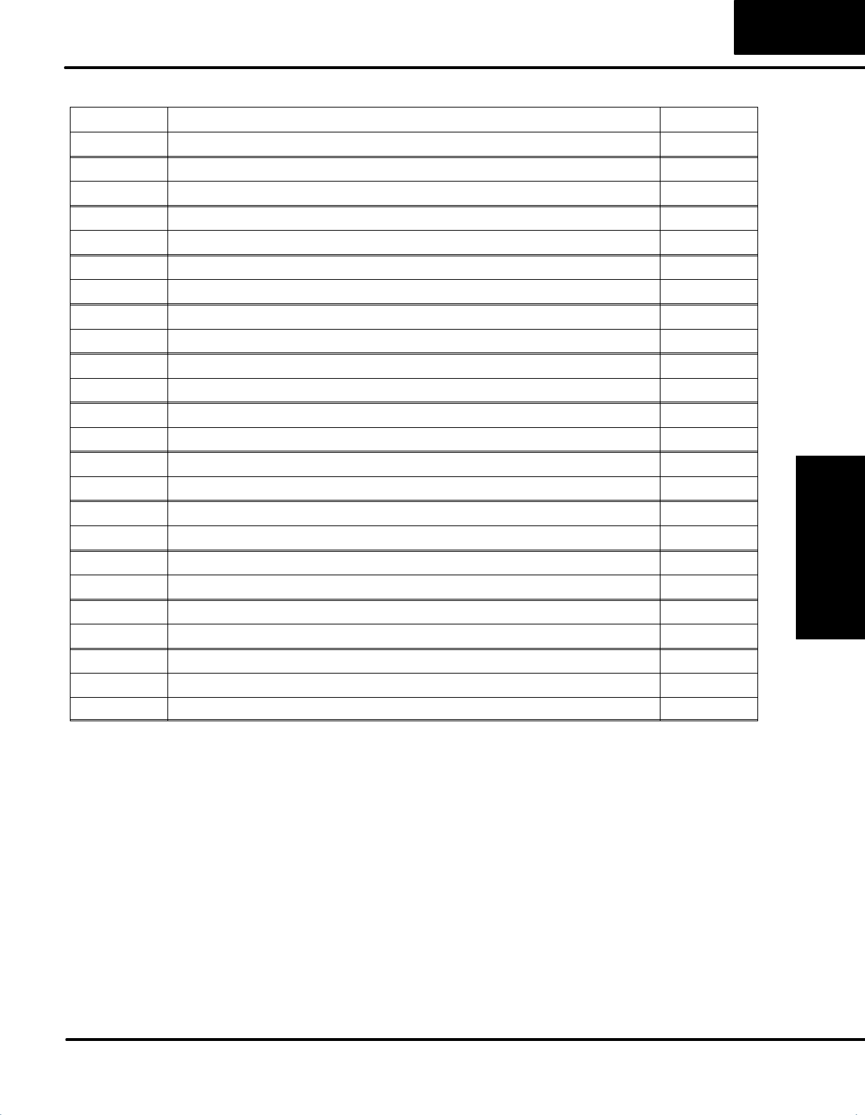
In This Appendix. . . .
Ċ Image Table Mapping
Appendix C
Image Table Mapping
Image Table Mapping
C–2
Image Table Mapping
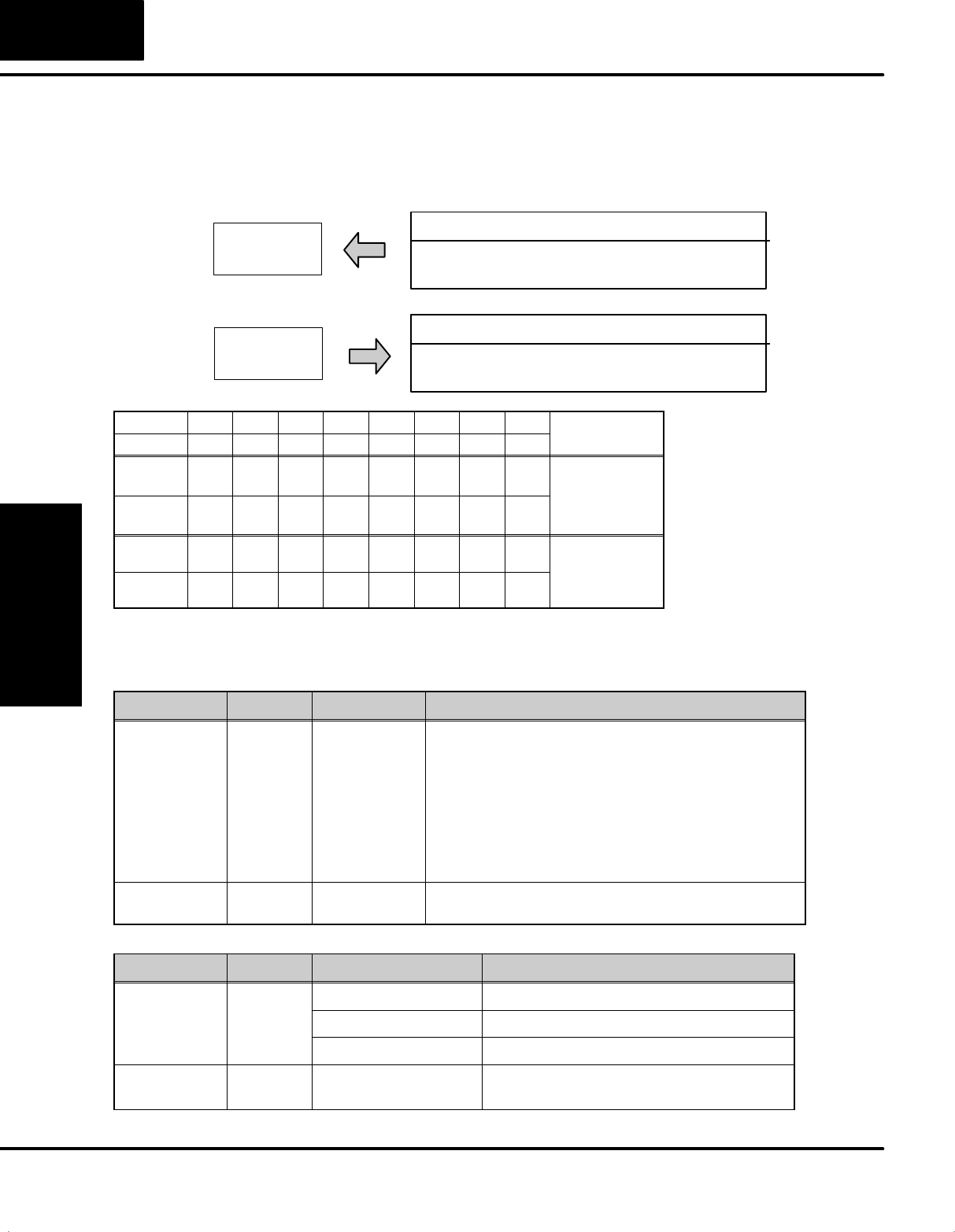
Read, Write and Status Byte References
T1K–DEVNETS can access data bytes.
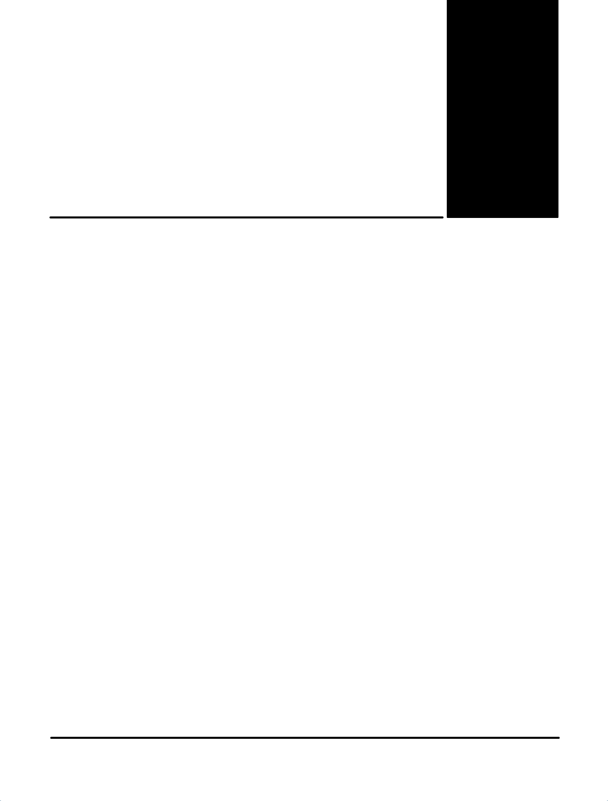
Discrete Input
Discrete Input Point (X,Y,C,S,T,CT,SP) Image Table Mapping
Inputs
Inputs
7 6 5 4 3 2 1 0
17 16 15 14 13 12 11 10
27 26 25 24 23 22 21 20
Inputs
Inputs
1 to 8 bytes
37 36 35 34 33 32 31 30
47 46 45 44 43 42 41 40
57 56 55 54 53 52 51 50
67 66 65 64 63 62 61 60
77 76 75 74 73 72 71 70
Inputs
Inputs
Inputs
Inputs
Inputs
I/O Image
Input Size
Read
Dec. Bit 07 06 05 04 03 02 01 00 Size
Oct. Bit 07 06 05 04 03 02 01 00
76543210Read Byte 1
17 16 15 14 13 12 11 10 Read Byte 2
27 26 25 24 23 22 21 20 Read Byte 3
37 36 35 34 33 32 31 30 Read Byte 4
47 46 45 44 43 42 41 40 Read Byte 5
57 56 55 54 53 52 51 50 Read Byte 6
67 66 65 64 63 62 61 60 Read Byte 7
77 76 75 74 73 72 71 70 Read Byte 8
Not Supported Write Byte 1
Appendix C
Image Table Mapping
C–3
Image Table Mapping
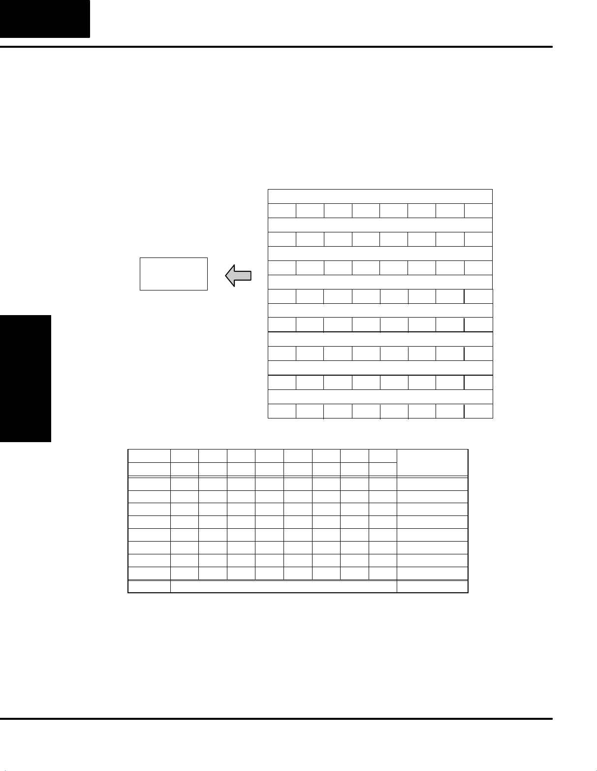
Discrete Output Point (X,Y,C,S,T,CT,SP) Image Table Mapping
Inputs
Outputs
7 6 5 4 3 2 1 0
17 16 15 14 13 12 11 10
27 26 25 24 23 22 21 20
Outputs
Outputs
1 to 8 bytes 37 36 35 34 33 32 31 30
47 46 45 44 43 42 41 40
57 56 55 54 53 52 51 50
67 66 65 64 63 62 61 60
77 76 75 74 73 72 71 70
Outputs
Outputs
Outputs
Outputs
Outputs
I/O Image
Output Size
Write
Dec. Bit 07 06 05 04 03 02 01 00 Size
Oct. Bit 07 06 05 04 03 02 01 00 Size
Not Supported Read Byte 1
76543210Write Byte 1
17 16 15 14 13 12 11 10 Write Byte 2
27 26 25 24 23 22 21 20 Write Byte 3
37 36 35 34 33 32 31 30 Write Byte 4
47 46 45 44 43 42 41 40 Write Byte 5
57 56 55 54 53 52 51 50 Write Byte 6
67 66 65 64 63 62 61 60 Write Byte 7
77 76 75 74 73 72 71 70 Write Byte 8
Appendix C
Image Table Mapping
Image Table Mapping
C–4
Register Input (V–memory) Image Table Mapping
Low Byte
High Byte
High Byte
High Byte
Low Byte
Low Byte
2 to 128 bytes
High Byte
I/O Image
Input Size
Read
Low Byte
Low Byte
Low Byte
Low Byte
Low Byte
High Byte
High Byte
High Byte
High Byte
Inputs Data Vn+00
Inputs Data Vn+01
Inputs Data Vn+02
Inputs Data Vn+03
Inputs Data Vn+04
Inputs Data Vn+61
Inputs Data Vn+62
Inputs Data Vn+63
Bit 07 06 05 04 03 02 01 00 Size
Vn + 00 V memory Low byte data Read Byte 1
Vn + 00 V memory High byte data Read Byte 2
Vn + 01 V memory Low byte data Read Byte 3
Vn + 01 V memory High byte data Read Byte 4
Vn + 02 V memory Low byte data Read Byte 5
Vn + 02 V memory High byte data Read Byte 6
Vn + 03 V memory Low byte data Read Byte 7
Vn + 03 V memory High byte data Read Byte 8
Vn + 04 V memory Low byte data Read Byte 9
Vn + 04 V memory High byte data Read Byte 10
Vn + 05 V memory Low byte data Read Byte 11
Vn + 05 V memory High byte data Read Byte 12
Vn + 06 V memory Low byte data Read Byte 13
Vn + 06 V memory High byte data Read Byte 14
Vn + 07 V memory Low byte data Read Byte 15
Vn + 07 V memory High byte data Read Byte 16
Appendix C
Image Table Mapping
C–5
Image Table Mapping
Vn + 08 V memory Low byte data Read Byte 17
Vn + 08 V memory High byte data Read Byte 18
Vn + 09 V memory Low byte data Read Byte 19
Vn + 09 V memory High byte data Read Byte 20
: :
: :
: :
: :
Vn + 30 V memory Low byte data Read Byte 61
Vn + 30 V memory High byte data Read Byte 62
Vn + 31 V memory Low byte data Read Byte 63
Vn + 31 V memory High byte data Read Byte 64
: :
: :
: :
: :
Vn + 60 V memory Low byte data Read Byte 121
Vn + 60 V memory High byte data Read Byte 122
Vn + 61 V memory Low byte data Read Byte 123
Vn + 61 V memory High byte data Read Byte 124
Vn + 62 V memory Low byte data Read Byte 125
Vn + 62 V memory High byte data Read Byte 126
Vn + 63 V memory Low byte data Read Byte 127
Vn + 63 V memory High byte data Read Byte 128
Not Supported Write Byte 1

Appendix C
Image Table Mapping
Image Table Mapping
C–6
Register Output (V–memory) Image Table Mapping
Low Byte
High Byte
High Byte
High Byte
Low Byte
Low Byte
2 to 128 bytes
High Byte
I/O Image
Input Size
Write
Low Byte
Low Byte
Low Byte
Low Byte
Low Byte
High Byte
High Byte
High Byte
High Byte
Outputs Data Vn+00
Outputs Data Vn+01
Outputs Data Vn+02
Outputs Data Vn+03
Outputs Data Vn+04
Outputs Data Vn+61
Outputs Data Vn+62
Outputs Data Vn+63
Bit 07 06 05 04 03 02 01 00 Size
Not Supported Read Byte 1
Vn + 00 V memory Low byte data Write Byte 1
Vn + 00 V memory High byte data Write Byte 2
Vn + 01 V memory Low byte data Write Byte 3
Vn + 01 V memory High byte data Write Byte 4
Vn + 02 V memory Low byte data Write Byte 5
Vn + 02 V memory High byte data Write Byte 6
Vn + 03 V memory Low byte data Write Byte 7
Vn + 03 V memory High byte data Write Byte 8
Vn + 04 V memory Low byte data Write Byte 9
Vn + 04 V memory High byte data Write Byte 10
Vn + 05 V memory Low byte data Write Byte 11
Vn + 05 V memory High byte data Write Byte 12
Vn + 06 V memory Low byte data Write Byte 13
Vn + 06 V memory High byte data Write Byte 14
Vn + 07 V memory Low byte data Write Byte 15
Vn + 07 V memory High byte data Write Byte 16

Appendix C
Image Table Mapping
C–7
Image Table Mapping
Vn + 08 V memory Low byte data Write Byte 17
Vn + 08 V memory High byte data Write Byte 18
Vn + 09 V memory Low byte data Write Byte 19
Vn + 09 V memory High byte data Write Byte 20
: :
: :
: :
: :
Vn + 30 V memory Low byte data Write Byte 61
Vn + 30 V memory High byte data Write Byte 62
Vn + 31 V memory Low byte data Write Byte 63
Vn + 31 V memory High byte data Write Byte 64
: :
: :
: :
: :
Vn + 60 V memory Low byte data Write Byte 121
Vn + 60 V memory High byte data Write Byte 122
Vn + 61 V memory Low byte data Write Byte 123
Vn + 61 V memory High byte data Write Byte 124
Vn + 62 V memory Low byte data Write Byte 125
Vn + 62 V memory High byte data Write Byte 126
Vn + 63 V memory Low byte data Write Byte 127
Vn + 63 V memory High byte data Write Byte 128
Appendix C
Image Table Mapping
Image Table Mapping
C–8
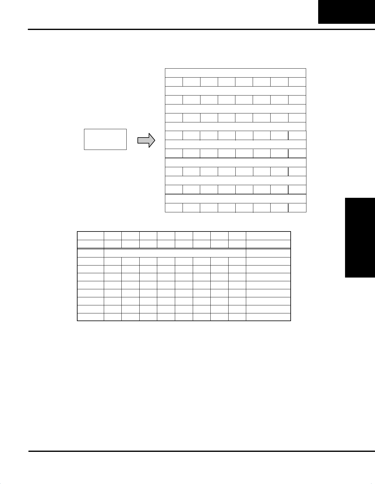
PLC Mode Image Table Mapping
2 byte
I/O Image
Input Size
Read
Write 2 byte
Output Size
Inputs
00:RUN Mode
03:STOP Mode
Outputs
01:RUN Request
02:STOP Request
Dec. Bit 07 06 05 04 03 02 01 00 Size
Oct. Bit 07 06 05 04 03 02 01 00
RUN
Mode 00000000Read Byte 2
STOP
Mode 00000011
RUN
Request 00000001Write Byte 2
STOP
Request 00000010
y
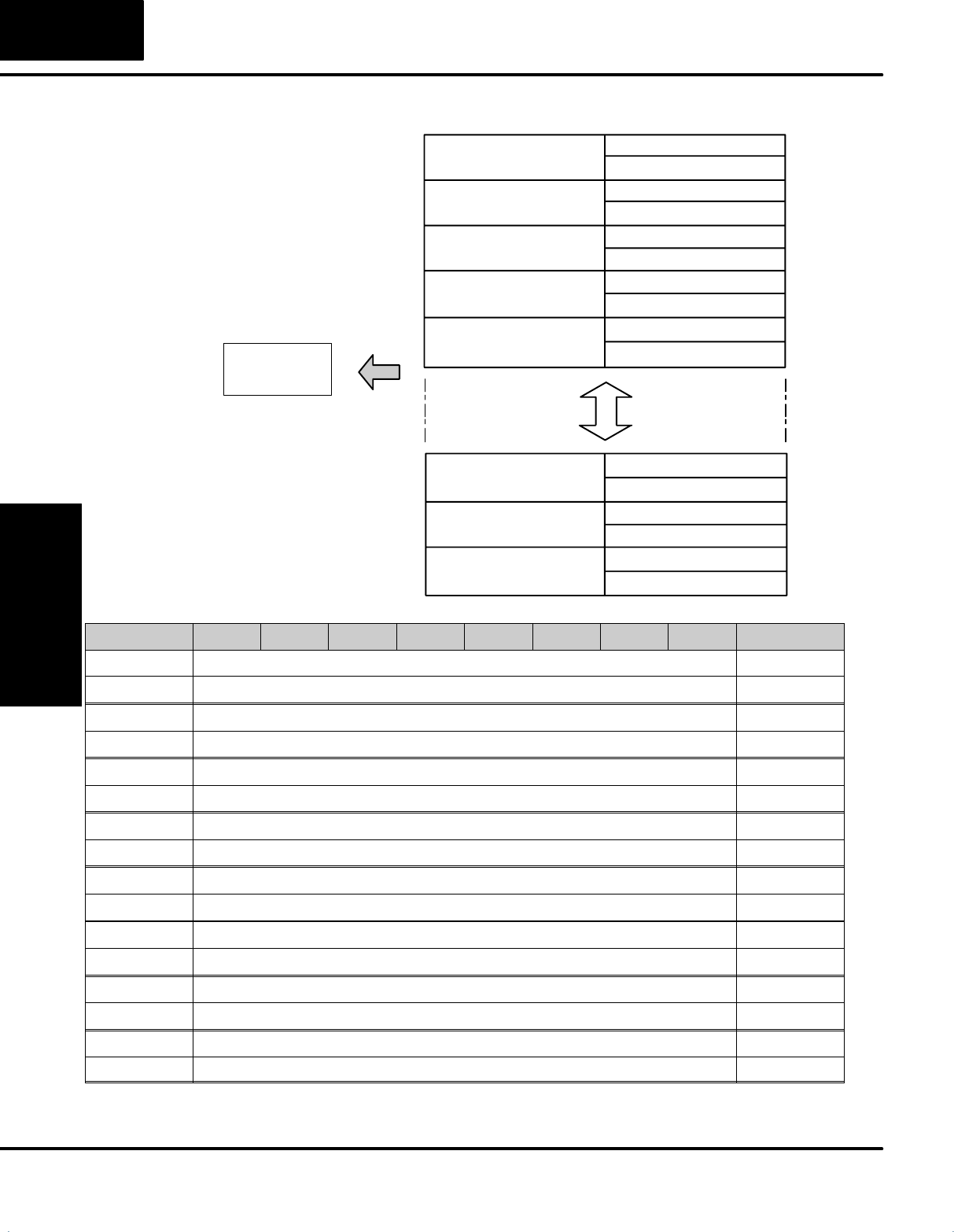
Adapter Input/Output Status Word
Polling format that the T1K–DEVNETS (slave) transmits to a master.
Address Bytes Data Comment
Bit 0: Not used
Bit 1: Not used
+ 0 1I/O Status
Bit 2: Not used
Bit 3: Node Error (Node number has changed)
ON: Error/OFF: Normal
+
0
1
I/O
Status
ON
:
E
rror
/OFF
:
N
orma
l
Bit 4: IDLE (Output is IDLE)
ON: Idle/OFF: Normal
ON:
Idle/OFF:
Normal
Bit 7: OUTPUT Status
ON: Disable/OFF: Enable
+ 1 1PLC Mode
00h: Mode = STOP
03h: Mode = RUN
Polling format that a master transmits to a DO–DEVNETS (slave).
Address Bytes Data Comment
No Code No request
+0
1
C3h Enable OUTPUT
+
0
1
3Ch Disable OUTPUT
+ 1 1PLC Mode
01h: RUN request
02h: STOP request
