Arctic_cat_2011_450XC_450_XC_service_manual Arctic Cat 2011 450XC 450 XC Service Manual
User Manual: arctic_cat_2011_450XC_450_XC_service_manual
Open the PDF directly: View PDF ![]() .
.
Page Count: 123 [warning: Documents this large are best viewed by clicking the View PDF Link!]
- FOREWORD
- TABLE OF CONTENTS
- General Information
- Periodic Maintenance
- SPECIAL TOOLS
- Periodic Maintenance Chart
- Lubrication Points
- Air Filter
- Valve/Tappet Clearance
- Testing Engine Compression
- Spark Plug
- Liquid Cooling System
- Muffler/Spark Arrester
- Adjusting Throttle Cable
- Adjusting Engine RPM (Idle)
- Engine/Transmission Oil - Filter
- Front Differential/Rear Drive Lubricant
- Tires
- Driveshaft/Coupling
- Nuts/Bolts/Cap Screws
- Ignition Timing
- Lights
- Shift Lever
- Frame/Welds
- Hydraulic Brake Systems
- Burnishing Brake Pads
- Checking/Replacing V- Belt
- Engine/Transmission
- SPECIAL TOOLS
- Specifications
- Troubleshooting
- Removing Engine/ Transmission
- Top-Side Components
- Removing Top-Side Components
- Servicing Top-Side Components
- VALVE ASSEMBLY
- Cleaning/Inspecting Cylinder Head Cover
- Removing Valves
- Measuring Valve Stem Runout
- Measuring Valve Stem Outside Diameter
- Measuring Valve Face/Seat Width
- Measuring Valve Face Radial Runout
- Measuring Valve Guide (Inside Diameter)
- Servicing Valves/Valve Guides/Valve Seats
- Measuring Rocker Arm (Inside Diameter)
- Measuring Rocker Arm Shaft (Outside Diameter)
- Installing Valves
- PISTON ASSEMBLY
- CYLINDER/CYLINDER HEAD ASSEMBLY
- Cleaning/Inspecting Cylinder Head
- Measuring Cylinder Head Distortion
- Cleaning/Inspecting Cylinder
- Inspecting Cam Chain Guide
- Honing Cylinder
- Measuring Camshaft Runout
- Measuring Camshaft Lobe Height
- Inspecting Camshaft Bearing Journal
- Measuring Camshaft to Cylinder Head Clearance
- Inspecting Camshaft Spring/Drive Pin
- VALVE ASSEMBLY
- Installing Top-Side Components
- Left-Side Components
- Removing Left-Side Components
- Servicing Left-Side Components
- Installing Left-Side Components
- Right-Side Components
- Removing Right-Side Components
- Servicing Right-Side Components
- Installing Right-Side Components
- Center Crankcase Components
- Separating Crankcase Halves
- Disassembling Crankcase Half
- Servicing Center Crankcase Components
- Assembling Crankcase Half
- Joining Crankcase Halves
- Installing Engine/ Transmission
- Fuel/Lubrication/Cooling
- Electrical System
- SPECIAL TOOLS
- Specifications
- Electrical Connections
- Battery
- RPM Limiter
- Testing Electrical Components
- Accessory Receptacle/ Connector
- Brakelight Switch (Pressure)
- Engine Coolant Temperature (ECT) Sensor
- Fan Motor
- Power Distribution Module (PDM)
- Ignition Coil
- Speed Sensor
- Ignition Switch
- Handlebar Control Switches
- Front Drive Selector Switch
- Front Drive Selector Actuator
- Gear Position Switch
- Stator Coil
- Starter Relay
- Starter Motor
- Electronic Control Unit (ECU)
- Regulator/Rectifier
- Lights
- Ignition Timing
- Diagnostic Trouble Codes (DTC)
- Tilt Sensor
- Throttle Position Sensor (TPS)
- Troubleshooting
- Drive System
- Suspension
- Steering/Frame

FOREWORD
This Arctic Cat Service Manual contains service, maintenance, and troubleshooting information for the 2011 Arc-
tic Cat 450 XC ATV. The complete manual is designed to aid service personnel in service-oriented applications.
This manual is divided into sections. Each section covers a specific ATV component or system and, in addition to
the standard service procedures, includes disassembling, inspecting, and assembling instructions. When using this
manual as a guide, the technician should use discretion as to how much disassembly is needed to correct any given
condition.
The service technician should become familiar with the operation and construction of each component or system
by carefully studying the complete manual. This manual will assist the service technician in becoming more aware
of and efficient with servicing procedures. Such efficiency not only helps build consumer confidence but also saves
time and labor.
All Arctic Cat ATV publications and decals display the words Warning, Caution, Note, and At This Point to
emphasize important information. The symbol ! WARNING identifies personal safety-related information.
Be sure to follow the directive because it deals with the possibility of severe personal injury or even death. A
CAUTION identifies unsafe practices which may result in ATV-related damage. Follow the directive because it
deals with the possibility of damaging part or parts of the ATV. The symbol NOTE: identifies supplementary
information worthy of particular attention. The symbol AT THIS POINT directs the technician to certain
and specific procedures to promote efficiency and to improve clarity.
At the time of publication, all information, photographs, and illustrations were technically correct. Some photo-
graphs used in this manual are used for clarity purposes only and are not designed to depict actual conditions.
Because Arctic Cat Inc. constantly refines and improves its products, no retroactive obligation is incurred.
All materials and specifications are subject to change without notice.
Keep this manual accessible in the shop area for reference.
Product Service and
Warranty Department
Arctic Cat Inc.
© 2011 Arctic Cat Inc. February 2011
®™ Trademarks of Arctic Cat Inc., Thief River Falls, MN 56701
For Discount Arctic Cat Parts Call 606-678-9623 or 606-561-4983
www.mymowerparts.com

2
011
ATV Service
Manual
450 XC
TM
SHARE OUR PASSION.
1
TABLE OF CONTENTS
General Information ........................................................ 2 Testing Oil Pump Pressure..........................................69
General Specifications.................................................. 2 Liquid Cooling System ................................................70
Torque Specifications.................................................... 2 Electric Fuel Pump/Fuel Level Sensor ........................72
Torque Conversions (ft-lb/N-m)..................................... 3 Troubleshooting ...........................................................74
Break-In Procedure ...................................................... 3 Electrical System .......................................................... 75
Gasoline - Oil - Lubricant.............................................. 3 Specifications ..............................................................75
Genuine Parts............................................................... 4 Electrical Connections.................................................75
Preparation For Storage ............................................... 4 Battery.........................................................................75
Preparation After Storage ............................................. 5 RPM Limiter ................................................................76
Periodic Maintenance...................................................... 6 Testing Electrical Components....................................76
Periodic Maintenance Chart ......................................... 6 Accessory Receptacle/Connector ...............................76
Lubrication Points ......................................................... 7 Brakelight Switch (Pressure) .......................................76
Air Filter ........................................................................ 7 Engine Coolant Temperature (ECT) Sensor................77
Valve/Tappet Clearance................................................ 8 Fan Motor ....................................................................77
Testing Engine Compression ........................................ 9 Power Distribution Module (PDM) ...............................78
Spark Plug .................................................................... 9 Ignition Coil .................................................................78
Liquid Cooling System................................................ 10 Speed Sensor .............................................................79
Muffler/Spark Arrester ................................................ 10 Ignition Switch .............................................................79
Adjusting Throttle Cable ............................................. 11 Handlebar Control Switches........................................80
Adjusting Engine RPM (Idle)....................................... 11 Front Drive Selector Switch.........................................80
Engine/Transmission Oil - Filter ................................. 11 Front Drive Selector Actuator ......................................81
Front Differential/Rear Drive Lubricant ....................... 12 Stator Coil ...................................................................81
Tires............................................................................ 12 Starter Relay ...............................................................82
Driveshaft/Coupling .................................................... 13 Starter Motor ...............................................................82
Nuts/Bolts/Cap Screws ............................................... 13 Electronic Control Unit (ECU)......................................83
Ignition Timing ............................................................ 13 Regulator/Rectifier ......................................................83
Lights .......................................................................... 13 Lights...........................................................................83
Shift Lever................................................................... 15 Ignition Timing.............................................................85
Frame/Welds............................................................... 16 Diagnostic Trouble Codes (DTC).................................85
Hydraulic Brake Systems............................................ 16 Tilt Sensor ...................................................................86
Burnishing Brake Pads ............................................... 17 Throttle Position Sensor (TPS)....................................87
Checking/Replacing V-Belt ........................................ 17 Troubleshooting ...........................................................89
Engine/Transmission .................................................... 21 Drive System ................................................................. 91
Specifications ............................................................. 21 Front Drive Actuator ....................................................91
Troubleshooting .......................................................... 22 Front Differential ..........................................................92
Removing Engine/Transmission ................................. 25 Drive Axles ................................................................103
Top-Side Components ................................................ 27 Rear Gear Case ........................................................104
Removing Top-Side Components ............................... 27 Hub............................................................................104
Servicing Top-Side Components ................................ 30 Hand Brake Lever/Master Cylinder Assembly...........105
Installing Top-Side Components ................................. 37 Hydraulic Brake Caliper.............................................106
Left-Side Components................................................ 41 Troubleshooting Drive System...................................109
Removing Left-Side Components............................... 41 Troubleshooting Brake System..................................109
Servicing Left-Side Components ................................ 43 Suspension.................................................................. 110
Installing Left-Side Components................................. 45 Shock Absorbers.......................................................110
Right-Side Components ............................................. 47 Front A-Arms .............................................................110
Removing Right-Side Components ............................ 47 Rear A-Arms .............................................................111
Servicing Right-Side Components.............................. 50 Wheels and Tires ......................................................112
Installing Right-Side Components .............................. 51 Troubleshooting .........................................................113
Center Crankcase Components ................................. 54 Steering/Frame............................................................ 114
Separating Crankcase Halves .................................... 54 Steering Post/Tie Rods .............................................114
Disassembling Crankcase Half................................... 55 Speedometer/LCD Gauge.........................................115
Servicing Center Crankcase Components ................. 57 Handlebar Grip..........................................................116
Assembling Crankcase Half........................................ 61 Throttle Control .........................................................116
Joining Crankcase Halves .......................................... 64 Steering Knuckles .....................................................117
Installing Engine/Transmission ................................... 65 Measuring/Adjusting Toe-Out....................................118
Fuel/Lubrication/Cooling .............................................. 67 Front Bumper Assembly............................................119
Electronic Fuel Injection ............................................. 67 Front Body Panel/Fender...........................................119
Throttle Body .............................................................. 67 Exhaust System ........................................................120
Throttle Cable Free-Play............................................. 68 Rear Body Panel .......................................................120
Gas Tank..................................................................... 68 Seat ...........................................................................121
Oil Filter/Oil Pump....................................................... 69 Troubleshooting .........................................................122
For Discount Arctic Cat Parts Call 606-678-9623 or 606-561-4983
www.mymowerparts.com
Note: To navigate through this manual, use the PAGE UP/PAGE DOWN buttons on the keyboard, click on the
Table of Contents bookmarks on the left side of the screen, or click the blue text below. To return to this page,
click the Manual Table of Contents button at the bottom of each page.
Click on the blue text to go.

2
General Information
NOTE: Some photographs and illustrations used in
this section are used for clarity purposes only and
are not designed to depict actual conditions.
General Specifications
Specifications subject to change without notice.
* One inch below plug threads.
** At the plug threads.
Torque Specifications
* w/Blue Loctite #243
** w/Red Loctite #271
*** w/Green Loctite #609
****w/“Patch-Lock”
CHASSIS
Brake Type Hydraulic w/Brake Lever Lock
Tire Size 23 x 8-12 (Front); 23 x 10-12 (Rear)
Tire Inflation Pressure 40.0 kPa (5.7 psi)
MISCELLANY
Gas Tank Capacity 16.3 L (4.3 U.S. gal.)
Rear Drive Capacity 250 ml (8.5 fl oz)*
Front Differential Capacity 275 ml (9.3 fl oz)**
Coolant Capacity 1.8 L (1.9 U.S. qt)
Engine Oil Capacity 3.3 L (3.5 U.S. qt) - Overhaul
2.8 L (3.0 U.S. qt) - Change
Gasoline (recommended) 87 Octane Regular Unleaded
Engine Oil (recommended) Arctic Cat ACX All Weather
(Synthetic)
Differential/Rear Drive Lubricant SAE Approved 80W-90 Hypoid
Drive Belt Width (minimum) 28.5 mm (1.12 in.)
Brake Fluid DOT 4
Taillight/Brakelight 12V/5W/21W (2)
Headlight 12V/35W (4)
Running Light 5W (2)
EXHAUST COMPONENTS
Part Part Bolted To Torque
ft-lb N-m
Exhaust Pipe Engine 20 27
Spark Arrester Muffler 48 in.-lb 5.5
BRAKE COMPONENTS
Brake Disc* Hub 15 20
Brake Hose Caliper 20 27
Brake Hose Master Cylinder 20 27
Brake Hose Brake Cylinder 20 27
Master Cylinder (Rear) Frame 811
Master Cylinder Clamp (Front) Master Cylinder 5.5 8
Hydraulic Caliper**** Knuckle 20 27
Brake Pedal Frame 20 27
ELECTRICAL COMPONENTS
Coil Frame 12 16
Starter Motor Positive Cable Starter Motor 811
Stator** Housing 811
CHASSIS COMPONENTS
Footrest Frame 20 27
Bumper Frame (8 mm) 20 27
SUSPENSION COMPONENTS (Front)
Part Part Bolted To Torque
ft-lb N-m
A-Arm Frame 35 47
Knuckle Ball Joint 35 47
Shock Absorber Frame 35 47
Shock Absorber Upper A-Arm 35 47
Knuckle A-Arm 35 47
SUSPENSION COMPONENTS (Rear)
Shock Absorber (Upper) Frame 35 47
Shock Absorber (Lower) Lower A-Arm 35 47
A-Arm Frame 35 47
Knuckle A-Arm 35 47
STEERING COMPONENTS
Steering Post Bearing Housing Frame 20 27
Handlebar Cap Steering Post 20 27
Lower Steering Post Bearing Cap
Screw
Steering Post 40 54
Tie Rod End** Steering Post Arm 30 41
ENGINE/TRANSMISSION
Clutch Shoe** Crankshaft 147 199
Clutch Cover/Housing Assembly Crankcase 811
Left-Side Cover Crankcase 811
Crankcase Half (6 mm) Crankcase Half 10 13.5
Crankcase Half (8 mm) Crankcase Half 21 28
Cylinder Nut Crankcase Half 811
Cylinder Head (Cap Screw) Crankcase 28 38
Cylinder Head Nut Cylinder 20 27
Cylinder Head Cover Cylinder Head 811
Oil Pump Drive Gear** Crankshaft 63 86
Driven Pulley Nut** Driveshaft 147 199
Ground Cable Engine 811
Magneto Rotor Flange Nut Crankshaft 107 146
One-Way Clutch** Flywheel 26 35
Cam Sprocket** Camshaft 11 15
V-Belt Cover Clutch Cover 811
Valve Adjuster Jam Nut Valve Adjuster 79.5
Starter Motor Crankcase 811
Oil Fitting Engine 811
Oil Pump** Crankcase 811
Movable Drive Face Nut** Clutch Shaft 147 199
Output Shaft Flange Nut Output Shaft 59 80
Cam Chain Tensioner Guide Cylinder 11 15
Valve Cover Cylinder 811
Tappet Cover Valve Cover 811
Cam Chain Tensioner Cylinder 10 13.5
Magneto Cover Crankcase 811
Rear Driveline Output Drive Flange 20 27
Water Pump Cover/Housing Magneto Cover 811
Water Pump Drive Gear Crankshaft 28 38
Intake Clamp Intake Boot 30 in.-lb 3.4
For Discount Arctic Cat Parts Call 606-678-9623 or 606-561-4983
www.mymowerparts.com

3
* w/Blue Loctite #243
** w/Red Loctite #271
*** w/Green Loctite #609
Torque Conversions
(ft-lb/N-m)
Break-In Procedure
A new ATV and an overhauled ATV engine require a
“break-in” period. The first 10 hours (or 200 miles) are
most critical to the life of this ATV. Proper operation dur-
ing this break-in period will help assure maximum life
and performance from the ATV.
During the first 10 hours (or 200 miles) of operation,
always use less than 1/2 throttle. Varying the engine
RPM during the break-in period allows the components
to “load” (aiding the mating process) and then “unload”
(allowing components to cool). Although it is essential to
place some stress on the engine components during
break-in, care should be taken not to overload the engine
too often. Do not pull a trailer or carry heavy loads dur-
ing the 10-hour break-in period.
When the engine starts, allow it to warm up properly. Idle
the engine several minutes until the engine has reached
normal operating temperature. Do not idle the engine for
excessively long periods of time.
During the break-in period, a maximum of 1/2 throttle is
recommended; however, brief full-throttle accelerations
and variations in driving speeds contribute to good
engine break-in.
After the completion of the break-in period, the engine
oil and oil filter should be changed. Other maintenance
after break-in should include checking of all prescribed
adjustments and tightening of all fasteners.
Gasoline - Oil - Lubricant
RECOMMENDED GASOLINE
The recommended gasoline to use is 87 minimum octane
regular unleaded. In many areas, oxygenates (either etha-
nol or MTBE) are added to the gasoline. Oxygenated
gasolines containing up to 10% ethanol, 5% methane, or
5% MTBE are acceptable gasolines.
When using ethanol blended gasoline, it is not necessary
to add a gasoline antifreeze since ethanol will prevent the
accumulation of moisture in the fuel system.
RECOMMENDED ENGINE/
TRANSMISSION OIL
DRIVE TRAIN COMPONENTS
Part Part Bolted To Torque
ft-lb N-m
Engine Mounting Through-Bolt Frame 38 52
Front Differential Frame/Differential
Bracket
38 52
Output Flange Rear Flange Output
Joint
20 27
Input Shaft Housing Differential Housing 18 25
Pinion Housing Gear Case Housing 18 25
Differential Housing Cover*** Differential Housing 18 25
Drive Bevel Gear Nut** Shaft 59 80
Driven Bevel Gear Nut** Driven Shaft 59 80
Thrust Button** Gear Case Cover 811
Hub Nut Shaft/Axle (max) 200 272
Oil Drain Plug Front Differential/Rear
Drive
45 in.-
lb
5
Oil Fill Plug Front Differential/Rear
Drive
16 22
Oil Drain Plug Engine 20 27
Rear Drive Input Shaft Housing Differential Housing 23 31
Lock Collar Differential Housing 125 169
Wheel Hub 40 54
Rear Drive Gear Case Frame 38 52
Engine Output Flange Rear Gear Case Input
Flange
20 27
ft-lb N-m ft-lb N-m ft-lb N-m ft-lb N-m
11.4 26 35.4 51 69.4 76 103.4
22.7 27 36.7 52 70.7 77 104.7
34.1 28 38.1 53 72.1 78 106.1
45.4 29 39.4 54 73.4 79 107.4
56.8 30 40.8 55 74.8 80 108.8
68.2 31 42.2 56 76.2 81 110.2
79.5 32 43.5 57 77.5 82 111.5
810.9 33 44.9 58 78.9 83 112.9
912.2 34 46.2 59 80.2 84 114.2
10 13.6 35 47.6 60 81.6 85 115.6
11 15 36 49 61 83 86 117
12 16.3 37 50.3 62 84.3 87 118.3
13 17.7 38 51.7 63 85.7 88 119.7
14 19 39 53 64 87 89 121
15 20.4 40 54.4 65 88.4 90 122.4
16 21.8 41 55.8 66 89.8 91 123.8
17 23.1 42 57.1 67 91.1 92 125.1
18 24.5 43 58.5 68 92.5 93 126.5
19 25.8 44 59.8 69 93.8 94 127.8
20 27.2 45 61.2 70 95.2 95 129.2
21 28.6 46 62.6 71 96.6 96 130.6
22 29.9 47 63.9 72 97.9 97 131.9
23 31.3 48 65.3 73 99.3 98 133.3
24 32.6 49 66.6 74 100.6 99 134.6
25 34 50 68 75 102 100 136
CAUTION
Do not use white gas. Only Arctic Cat approved gaso-
line additives should be used.
CAUTION
Any oil used in place of the recommended oil could
cause serious engine damage. Do not use oils which
contain graphite or molybdenum additives. These oils
can adversely affect clutch operation. Also, not recom-
mended are racing, vegetable, non-detergent, and cas-
tor-based oils.
For Discount Arctic Cat Parts Call 606-678-9623 or 606-561-4983
www.mymowerparts.com
4
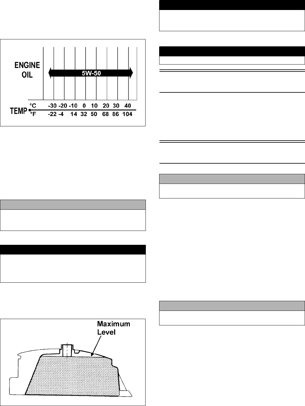
The recommended oil to use is Arctic Cat ACX All
Weather synthetic engine oil, which has been specifically
formulated for use in this Arctic Cat engine. Although
Arctic Cat ACX All Weather synthetic engine oil is the
only oil recommended for use in this engine, use of any
API certified SM 5W-50 oil is acceptable.
OILCHARTI
RECOMMENDED FRONT
DIFFERENTIAL/REAR DRIVE
LUBRICANT
The recommended lubricant is Arctic Cat Gear Lube or
an equivalent gear lube which is SAE approved 80W-90
hypoid. This lubricant meets all of the lubrication
requirements of the Arctic Cat ATV front differentials
and rear drives.
FILLING GAS TANK
Since gasoline expands as its temperature rises, the gas
tank must be filled to its rated capacity only. Expansion
room must be maintained in the tank particularly if the tank
is filled with cold gasoline and then moved to a warm area.
ATV0049B
Tighten the gas tank cap securely after filling the tank.
Genuine Parts
When replacement of parts is necessary, use only genuine
Arctic Cat ATV parts. They are precision-made to ensure
high quality and correct fit. Refer to the Illustrated Parts
Manual for the correct part number, quantity, and
description.
Preparation For Storage
1. Clean the seat cushion (cover and base) with a damp
cloth and allow it to dry.
2. Clean the ATV thoroughly by washing dirt, oil,
grass, and other foreign matter from the entire ATV.
Allow the ATV to dry thoroughly. DO NOT get
water into any part of the engine or air intake.
3. Either drain the gas tank or add Fuel Stabilizer to the
gas in the gas tank. Remove the air filter housing
cover and air filter. Start the engine and allow it to
idle; then using Arctic Cat Engine Storage Preserver,
rapidly inject the preserver into the air filter opening
for a period of 10 to 20 seconds; then stop the
engine. Install the air filter and housing cover.
4. Plug the exhaust outlet on the muffler with a clean
cloth.
5. Apply light oil to the upper steering post bushing and
plungers of the shock absorbers.
6. Tighten all nuts, bolts, cap screws, and screws. Make
sure rivets holding components together are tight.
Replace all loose rivets. Care must be taken that all
calibrated nuts, cap screws, and bolts are tightened to
specifications.
7. Fill the cooling system to the bottom of the stand
pipe in the radiator neck with properly mixed cool-
ant.
CAUTION
Any lubricant used in place of the recommended lubri-
cant could cause serious front differential/rear drive
damage.
! WARNING
Always fill the gas tank in a well-ventilated area. Never
add fuel to the ATV gas tank near any open flames or
with the engine running. DO NOT SMOKE while filling
the gas tank.
! WARNING
Do not overflow gasoline when filling the gas tank. A
fire hazard could materialize. Always allow the engine to
cool before filling the gas tank.
! WARNING
Do not over-fill the gas tank.
CAUTION
Prior to storing the ATV, it must be properly serviced to
prevent rusting and component deterioration.
CAUTION
If the interior of the air filter housing is dirty, clean the
area before starting the engine.
For Discount Arctic Cat Parts Call 606-678-9623 or 606-561-4983
www.mymowerparts.com

5
8. Disconnect the battery cables; then remove the bat-
tery, clean the battery posts and cables, and store in a
clean, dry area.
9. Store the ATV indoors in a level position.
Preparation After
Storage
Taking the ATV out of storage and correctly preparing it
will assure many miles and hours of trouble-free riding.
1. Clean the ATV thoroughly.
2. Clean the engine. Remove the cloth from the muffler.
3. Check all control cables for signs of wear or fraying.
Replace if necessary.
4. Change the engine/transmission oil and filter.
5. Check the coolant level and add properly mixed
coolant as necessary.
6. Charge the battery; then install. Connect the battery
cables.
6. Check the entire brake systems (fluid level, pads,
etc.), all controls, lights, and headlight aim; adjust or
replace as necessary.
7. Tighten all nuts, bolts, cap screws, and screws mak-
ing sure all calibrated nuts, cap screws, and bolts are
tightened to specifications.
8. Check tire pressure. Inflate to recommended pressure
as necessary.
9. Make sure the steering moves freely and does not
bind.
10. Check the spark plug. Clean or replace as necessary.
CAUTION
Avoid storing outside in direct sunlight and avoid using
a plastic cover as moisture will collect on the ATV caus-
ing rusting.
CAUTION
The ignition switch must be in the OFF position prior to
installing the battery or damage may occur to the igni-
tion system.
CAUTION
Connect the positive battery cable first; then the negative.
For Discount Arctic Cat Parts Call 606-678-9623 or 606-561-4983
www.mymowerparts.com

6
Periodic Maintenance
This section has been organized into sub-sections which
show common maintenance procedures for the Arctic Cat
ATV.
SPECIAL TOOLS
A number of special tools must be available to the techni-
cian when performing service procedures in this section.
Refer to the current Special Tools Catalog for the appro-
priate tool description.
NOTE: Special tools are available from the Arctic
Cat Service Department.
Periodic Maintenance
Chart
A = Adjust I = Inspect C = Clean L = Lubricate R = Replace T = Tighten
* Service/Inspect more frequently when operating in adverse conditions. ** When using an API certified SM 5W-50 oil.
*** When using Arctic Cat ACX All Weather synthetic oil, oil change interval can be increased to every 1,000 miles or every year.
Description p/n
Compression Tester Kit 0444-213
Oil Filter Wrench 0644-389
Tachometer 0644-275
Timing Light 0644-296
Valve Clearance Adjuster 0444-078
Item
Initial Service After
Break-In (First Mo
or 100 Mi)
Every
Day
Every Month
or 100 Miles
Every 3
Months or
300 Miles
Every 6
Months or
500 Miles
Every Year
or 1500
Miles
As
Needed
Battery II C
Fuses IR
Air Filter/Drain Tube IIC* R
Valve/Tappet Clearance IIA
Engine Compression I
Spark Plug I I R (4000 Mi
or 18 Mo)
Muffler/Spark Arrester CR
Gas Hoses II R (2 Yrs)
Throttle Cable II C-L A-R
Engine-Transmission Oil Level IA
Engine-Transmission Oil/Filter R R*/R**/R***
Front Differential/Rear Drive Lubricant II R (4 Yrs)
Tires/Air Pressure II R
Steering Components II I R
V-Belt IlR
Suspension (Ball joint boots, drive axle boots front
and rear, tie rods, differential and rear drive bellows)
II R
Nuts/Cap Screws/Screws II A
Ignition Timing I
Lights II R
Switches II R
Shift Lever IA-L
Handlebar Grips IR
Handlebar II R
Gauges/Indicators II R
Frame/Welds Il
Electrical Connections IlC
Complete Brake System II C L-R
Brake Pads II*R
Brake Fluid IIR (2 Yrs)
Brake Hoses IIR (4 Yrs)
Coolant/Coolant System II R (2 Yrs)
For Discount Arctic Cat Parts Call 606-678-9623 or 606-561-4983
www.mymowerparts.com
7
Lubrication Points
It is advisable to lubricate certain components periodi-
cally to ensure free movement. Apply light oil to the
throttle lever and brake lever pivots.
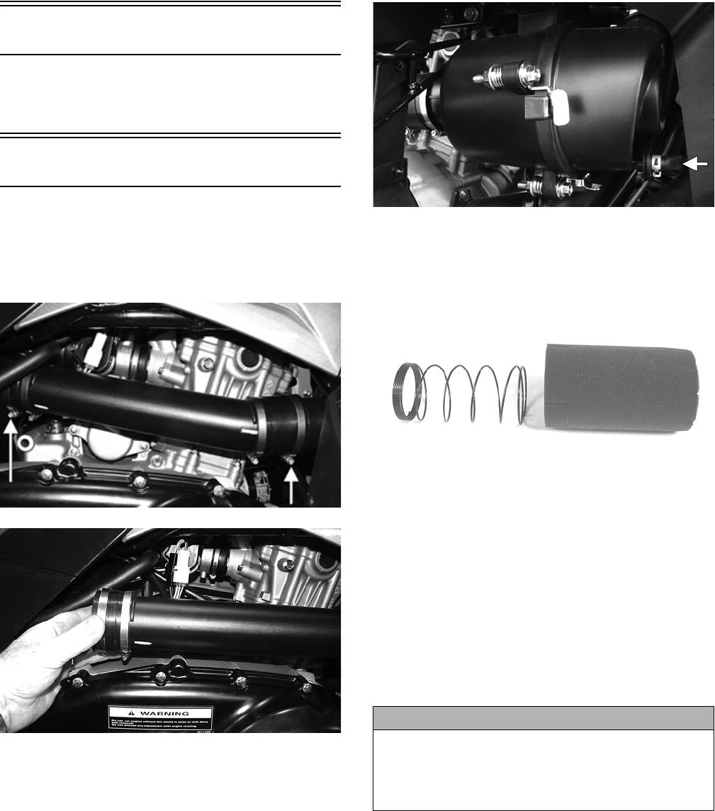
Air Filter
CLEANING AND INSPECTING FILTER
1. Loosen the clamp securing the front air inlet boot to
the air filter housing; then loosen the clamp securing
the rear inlet boot to the air box. Remove the inlet
pipe.
KC445A
KC446
2. Remove two reinstallable rivets from the air filter
housing mounting bracket and slide the air filter
housing rearward out of the mounting bracket.
KC447A
3. Turn and release the three locking lugs on the air fil-
ter housing and separate the air filter cover from the
housing; then remove the air filter element. Separate
the foam element from the spring.
KC143
4. Fill a wash pan larger than the element with a non-
flammable cleaning solvent; then dip the element in
the solvent and wash it.
NOTE: Foam Air Filter Cleaner and Foam Air Fil-
ter Oil are available from Arctic Cat.
5. Dry the element.
6. Put the element in a plastic bag; then pour in air filter
oil and work the oil into the element. Insert the form-
ing spring into the element with the closely wrapped
end of the spring toward the open end of the element.
7. Clean any dirt or debris from inside the air filter
housing.
8. Place the filter assembly in the air filter housing
making sure it is properly positioned and properly
seated with the filter element straight in the housing.
CAUTION
A torn air filter element can cause damage to the ATV
engine. Dirt and dust may get inside the engine if the
element is torn. Carefully examine the element for tears
before and after cleaning it. Replace the element with a
new one if it is torn.
For Discount Arctic Cat Parts Call 606-678-9623 or 606-561-4983
www.mymowerparts.com
8
KC449
9. Install the air filter housing cover and secure with the
locking tabs.
10. Install the air filter housing assembly into the mount-
ing bracket and secure with two reinstallable rivets.
11. Install the inlet pipe onto the air box; then connect to
the air filter assembly making sure the boots are fully
engaged. Tighten the clamps securely.
KC445A
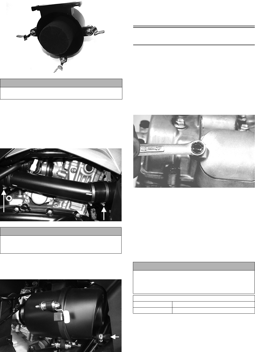
CHECKING AND CLEANING DRAIN
1. Inspect the drain on the filter housing cover and
clean out any dirt or debris.
KC397B
2. Replace any drain that is cracked or shows any signs
of hardening or deterioration.
3. Wipe any accumulation of oil or gas from the filter
housing and drain.
Valve/Tappet Clearance
To check and adjust valve/tappet clearance, use the fol-
lowing procedure.
NOTE: The seat, left-side and right-side engine
covers, and gas tank must be removed for this pro-
cedure.
1. Remove the timing inspection plug and spark plug;
then remove the tappet covers (for more detailed
information, see Engine/Transmission - Servicing
Top-Side Components).
CF005
2. Rotate the crankshaft to the TDC position on the
compression stroke.
NOTE: At this point, the rocker arms and adjuster
screws must not have pressure on them.
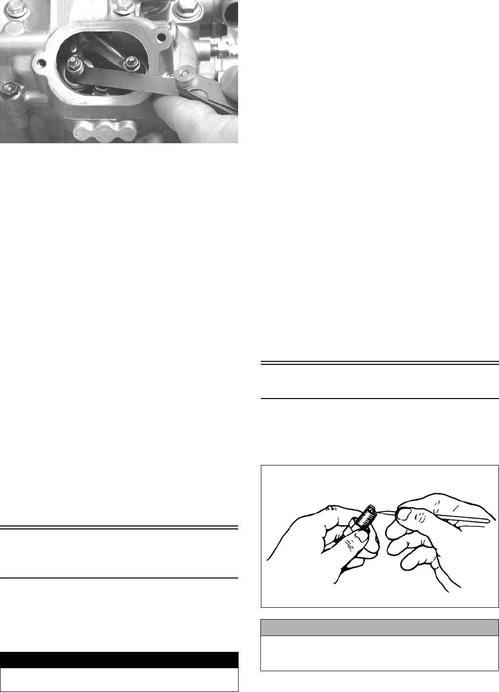
Feeler Gauge Procedure
Using a feeler gauge, check each valve/tappet clearance.
If clearance is not within specifications, loosen the jam
nut and rotate the tappet adjuster screw until the clear-
ance is within specifications. Tighten each jam nut
securely after completing the adjustment.
CAUTION
Failure to properly seat and align the filter element may
cause severe engine damage.
CAUTION
Failure to fully engage the inlet boots to the indicator
marks could result in ingestion of dirt and severe
engine damage.
CAUTION
The feeler gauge must be positioned at the same angle
as the valve and valve adjuster for an accurate measure-
ment of clearance. Failure to measure the valve clear-
ance accurately could cause valve component damage.
VALVE/TAPPET CLEARANCE
Intake 0.076-0.127 mm (0.003-0.005 in.)
Exhaust 0.152-0.203 mm (0.006-0.008 in.)
For Discount Arctic Cat Parts Call 606-678-9623 or 606-561-4983
www.mymowerparts.com
9
CC007DC
Valve Adjuster Procedure
A. Place the Valve Clearance Adjuster onto the jam
nut securing the tappet adjuster screw; then rotate
the valve adjuster dial clockwise until the end is
seated in the tappet adjuster screw.
B. While holding the valve adjuster dial in place, use
the valve adjuster handle and loosen the jam nut;
then rotate the tappet adjuster screw clockwise
until friction is felt.
C. Align the valve adjuster handle with one of the
marks on the valve adjuster dial.
D. While holding the valve adjuster handle in place,
rotate the valve adjuster dial counterclockwise
until proper valve/tappet clearance is attained.
NOTE: Refer to the appropriate specifications in
Feeler Gauge Procedure sub-section for the proper
valve/tappet clearance.
NOTE: Rotating the valve adjuster dial counter-
clockwise will open the valve/tappet clearance by
0.05 mm (0.002 in.) per mark.
E. While holding the adjuster dial at the proper
clearance setting, tighten the jam nut securely
with the valve adjuster handle.
3. Install the timing inspection plug.
4. Place the two tappet covers with O-rings into posi-
tion; then tighten the covers securely.
5. Install the spark plug; then install the timing inspec-
tion plug.
Testing Engine
Compression
To test engine compression, use the following procedure.
1. Remove the high tension lead from the spark plug.
2. Using compressed air, blow any debris from around
the spark plug.
3. Remove the spark plug; then attach the high tension
lead to the plug and ground the plug on the cylinder
head well away from the spark plug hole.
4. Attach the Compression Tester Kit.
NOTE: The engine must be warm and the battery
must be fully charged for this test.
5. While holding the throttle lever in the full-open posi-
tion, crank the engine over with the electric starter
until the gauge shows a peak reading of 95-115 psi
(five to 10 compression strokes).
6. If compression is abnormally low, inspect the
following items.
A. Verify starter cranks engine over at normal speed
(approximately 400 RPM).
B. Gauge functioning properly.
C. Throttle lever in the full-open position.
D. Valve/tappet clearance correct.
E. Valve not bent or burned.
F. Valve seat not burned.
NOTE: To service valves, see Engine/Transmis-
sion.
7. Pour approximately 30 ml (1 fl oz) of oil into the
spark plug hole, reattach the gauge, and retest com-
pression.
8. If compression is now evident, service the piston
rings (see Engine/Transmission).
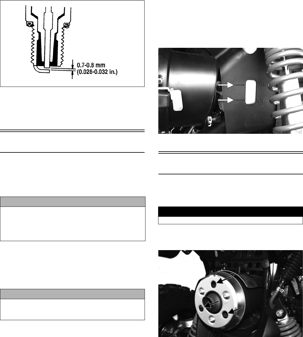
Spark Plug
A light brown insulator indicates that a plug is correct. A
white or dark insulator indicates that the engine may need
to be serviced. To maintain a hot, strong spark, keep the
plug free of carbon.
ATV-0051
Adjust the gap to 0.7-0.8 mm (0.028-0.032 in.) for proper
ignition. Use a feeler gauge to check the gap.
! WARNING
Always wear safety glasses when using compressed
air.
CAUTION
Before removing a spark plug, be sure to clean the area
around the spark plug. Dirt could enter engine when
removing or installing the spark plug.
For Discount Arctic Cat Parts Call 606-678-9623 or 606-561-4983
www.mymowerparts.com
10
ATV0052C
When installing the spark plug, be sure to tighten it
securely. A new spark plug should be tightened 1/2 turn
once the washer contacts the cylinder head. A used spark
plug should be tightened 1/8 - 1/4 turn once the washer
contacts the cylinder head.
Liquid Cooling System
NOTE: Debris in front of the engine or packed
between the cooling fins of the radiator can reduce
cooling capability. Using a garden hose, wash the
radiator to remove any debris preventing air flow.
The cooling system capacity can be found in the specifi-
cations chart. The cooling system should be inspected
daily for leakage and damage. If leakage or damage is
detected, take the ATV to an authorized Arctic Cat ATV
dealer for service. Also, the coolant level should be
checked periodically.
NOTE: High engine RPM, low vehicle speed, or
heavy load can raise engine temperature. Decreas-
ing engine RPM, reducing load, and selecting an
appropriate transmission gear can lower the tem-
perature.
When filling the cooling system, use a coolant/water
mixture which will satisfy the coldest anticipated weather
conditions of the area in accordance with the coolant
manufacturer’s recommendations. While the cooling sys-
tem is being filled, air pockets may develop; therefore,
run the engine for five minutes after the initial fill, shut
the engine off, and then fill the cooling system to the bot-
tom of the stand pipe in the radiator neck.
Checking/Filling
1. Locate the coolant reservoir on the right side behind
the radiator.
2. Remove the cap and fill with the appropriate coolant
until coolant level is between the LOW and FULL
lines. Do not overfill.
KC396A
3. Install the cap on the reservoir.
Muffler/Spark Arrester
At the intervals shown in the Periodic Maintenance
Chart, clean the spark arrester using the following proce-
dure.
1. Remove the cap screws securing the spark arrester
assembly to the muffler; then loosen and remove the
arrester.
KC374A
2. Using a suitable brush, clean the carbon deposits
from the screen taking care not to damage the screen.
NOTE: If the screen or gasket is damaged in any
way, it must be replaced.
3. Install the spark arrester assembly with gasket; then
secure with the cap screws. Tighten to 48 in.-lb.
CAUTION
Do not use a pressure washer to clean the radiator core.
The pressure may bend or flatten the fins causing
restricted air flow, and electrical components on the
radiator could be damaged. Use only a garden hose with
spray nozzle at normal tap pressure.
CAUTION
Continued operation of the ATV with high engine tem-
perature may result in engine damage or premature
wear.
! WARNING
Wait until the muffler cools to avoid burns.
For Discount Arctic Cat Parts Call 606-678-9623 or 606-561-4983
www.mymowerparts.com
11
Adjusting Throttle Cable
To adjust the throttle cable free-play, follow this proce-
dure.
1. Slide the rubber boot away; then loosen the jam nut
from the throttle cable adjuster.
AL611D
2. Turn the adjuster until the throttle cable has proper
free-play of 3-6 mm (1/8-1/4 in.) at the lever.
ATV-0047
3. Tighten the jam nut against the throttle cable adjuster
securely; then slide the rubber boot over the adjuster.
Adjusting Engine RPM
(Idle)
NOTE: Engine idle RPM is not adjustable on this
model.
Engine/Transmission Oil -
Filter
The engine should always be warm when the oil is
changed so the oil will drain easily and completely.
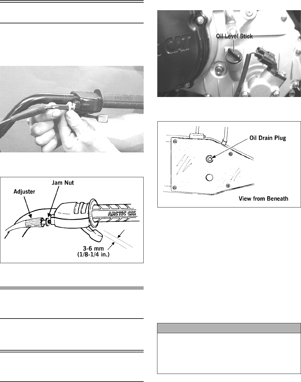
1. Park the ATV on level ground.
2. Remove the seat and left-side engine cover.
3. Remove the oil level stick/filler plug.
KC0051A
4. Remove the drain plug from the bottom of the engine
and drain the oil into a drain pan.
733-441A
5. Remove the oil filter plug from the filter mounting
boss (located on the front side of the transmission
case) and allow the filter to drain completely. Install
the plug and tighten securely.
6. Using the adjustable Oil Filter Wrench and a suitable
wrench, remove the old oil filter.
NOTE: Clean up any excess oil after removing
the filter.
7. Apply oil to a new filter seal ring and check to make
sure it is positioned correctly; then install the new oil
filter. Tighten securely.
8. Install the engine drain plug and tighten to 20 ft-lb.
Pour the specified amount of the recommended oil in
the filler hole. Install the oil level stick/filler plug.
9. Start the engine (while the ATV is outside on level
ground) and allow it to idle for a few minutes.
10. Turn the engine off and wait approximately one min-
ute.
11. Remove the oil level stick and wipe it with a clean
cloth.
12. Install the oil level into engine case.
CAUTION
Any oil used in place of the recommended oil could
cause serious engine damage. Do not use oils which
contain graphite or molybdenum additives. These oils
can adversely affect clutch operation. Also, not recom-
mended are racing, vegetable, non-detergent, and cas-
tor-based oils.
For Discount Arctic Cat Parts Call 606-678-9623 or 606-561-4983
www.mymowerparts.com
12
NOTE: The oil level stick should be threaded into
the case for checking purposes.
13. Remove the oil level stick; the engine oil level should
be above the illustrated “L” mark but not higher than
the illustrated “F” mark.
ATV-0100AA
14. Inspect the area around the drain plug and oil filter
for leaks.
15. Install the left-side engine cover and the seat.
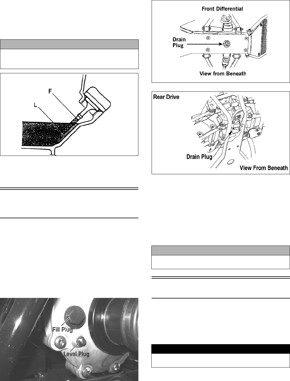
Front Differential/Rear
Drive Lubricant
When changing the lubricant, use approved SAE 80W-90
hypoid gear lube.
To check lubricant, remove the rear drive filler plug; the
lubricant level should be 1 in. below the threads of the
plug. If low, add SAE approved 80W-90 hypoid gear
lubricant as necessary.
To change the lubricant, use the following procedure.
1. Place the ATV on level ground.
2. Remove each fill plug.
KC0077A
3. Drain the lubricant into a drain pan by removing the
drain plug from each.
ATV0082A
737-651B
4. After all the oil has been drained, install the drain
plugs and tighten to 45 in.-lb.
5. Pour the appropriate amount of approved SAE 80W-
90 hypoid gear lubricant into the filler hole.
6. Install the fill plugs and tighten to 16 ft-lb.
NOTE: If the differential/rear drive oil is contami-
nated with water, inspect the drain plug, filler plug,
and/or bladder.
Tires
TIRE SIZES
The ATV is equipped with low-pressure tubeless tires of
the size and type listed (see General Information). Do not
under any circumstances substitute tires of a different
type or size.
TIRE INFLATION PRESSURE
Front and rear tire inflation pressure should be 40.0 kPa
(5.7 psi).
CAUTION
Do not over-fill the engine with oil. Always make sure
that the oil level is above the “L” mark but not higher
than the “F” mark.
CAUTION
Water entering the outer end of the axle will not be able
to enter the rear drive unless the seals are damaged.
! WARNING
Always use the size and type of tires specified. Always
maintain proper tire inflation pressure.
For Discount Arctic Cat Parts Call 606-678-9623 or 606-561-4983
www.mymowerparts.com
13
Driveshaft/Coupling
The following drive system components should be
inspected periodically to ensure proper operation.
A. Spline lateral movement (slop).
B. Coupling cracked, damaged, or worn.
Nuts/Bolts/Cap Screws
Tighten all nuts, bolts, and cap screws. Make sure rivets
holding components together are tight. Replace all loose
rivets. Care must be taken that all calibrated nuts, bolts,
and cap screws are tightened to specifications.
Ignition Timing
The ignition timing cannot be adjusted; however, verifying
ignition timing can aid in troubleshooting other components.
To verify ignition timing, use the following procedure.
1. Attach the Timing Light to the spark plug high ten-
sion lead; then remove the timing inspection plug
from the left-side crankcase cover.
2. Using the Tachometer, start the engine and run at
1500 RPM; ignition timing should be 10° BTDC.
3. Install the timing inspection plug.
If ignition timing cannot be verified, the rotor may be
damaged, the key may be sheared, the trigger coil bracket
may be bent or damaged, or the CDI unit/ECU may be
faulty.
Lights
Rotate the ignition switch to the running lights position;
the running lights and taillights should illuminate. Test the
brakelights by compressing the brake lever. The brake-
lights should illuminate. Shift the Hi/Lo beam switch to
the Lo position; the low beam headlights should illumi-
nate. In the Hi position, the high beam headlights should
illuminate. The running/tail lights will remain illuminated
until the ignition switch is switched to the run position.
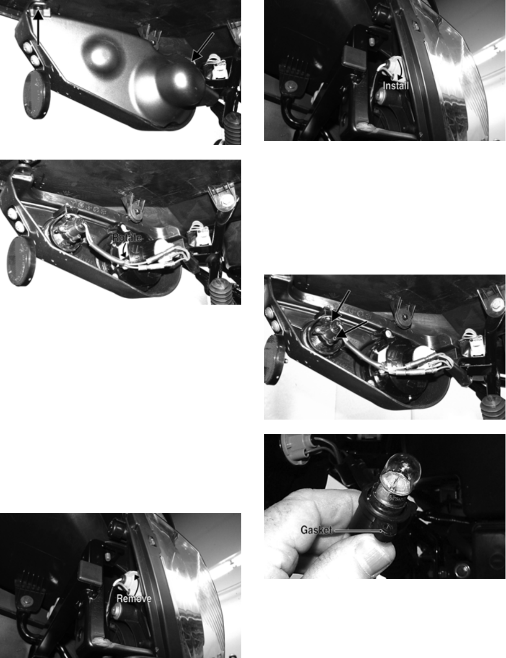
HEADLIGHTS
NOTE: The bulb portion of a headlight is fragile.
HANDLE WITH CARE. When replacing a headlight
bulb, do not touch the glass portion of the bulb. If
the glass is touched, it must be cleaned with a dry
cloth before installing. Skin oil residue on the bulb
will shorten the life of the bulb.
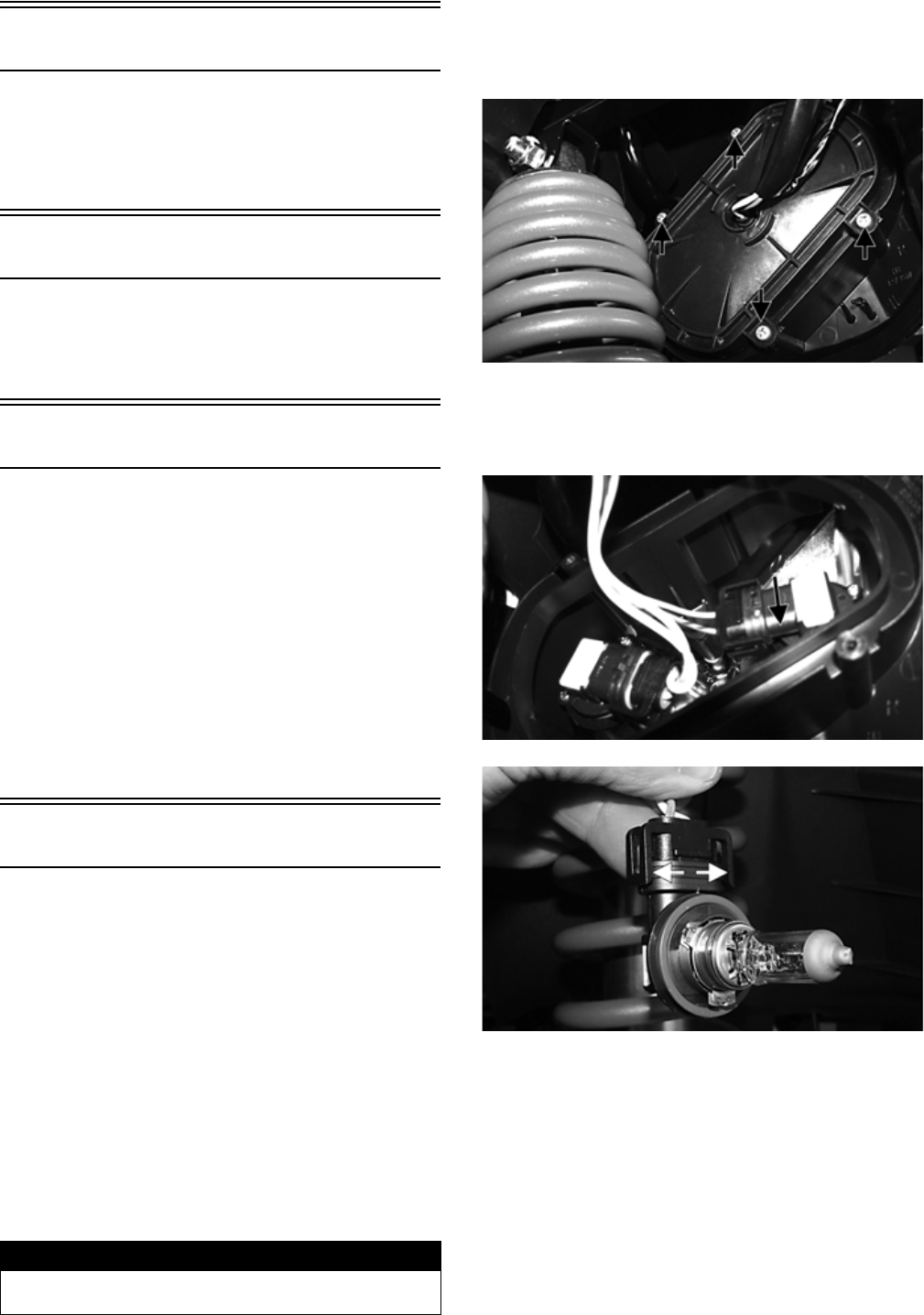
To replace the headlight bulbs, use the following proce-
dure.
1. Remove four screws securing the headlight access
panel to the headlight housing.
KC429A
2. Remove the headlight bulb by rotating the bulb
assembly and removing from the headlight housing;
then spread the retaining clips and disconnect the
bulb assembly from the connector.
KC431A
KC432A
3. Install the new bulb assembly into the connector;
then insert the bulb assembly into the housing and
rotate to lock.
4. Install the access panel and secure with the screws.
TAILLIGHTS-BRAKELIGHTS
To replace a taillight-brakelight bulb, use the following
procedure.
1. Remove the cap screw and screw securing the tail-
light housing cover to the taillight housing; then
twist and remove the bulb socket.
! WARNING
Do not attempt to remove a bulb when it is hot. Severe
burns may result.
For Discount Arctic Cat Parts Call 606-678-9623 or 606-561-4983
www.mymowerparts.com
14
KC433A
KC434A
2. Turn the bulb socket assembly counterclockwise and
remove from the housing.
3. Press in and turn the bulb counterclockwise to
remove. Press in and turn clockwise to install the
bulb.
4. Insert the bulb socket assembly into the housing and
turn it clockwise to secure.
5. Secure the housing cover with the two fasteners.
RUNNING LIGHTS
The running lights are located outboard of the headlights.
To replace the running light bulbs, use the following pro-
cedure.
1. Rotate the bulb socket counterclockwise to release
from light housing; then press in on the bulb and turn
counterclockwise to release from the socket.
KC428A
2. Install a new bulb and press in rotating clockwise to
secure; then place the socket into the light housing
and turn clockwise to secure.
KC428B
BACK-UP LIGHTS
The back-up lights are located outboard of the taillights/
brakelights. To replace the back-up light bulbs, use the
following procedure.
1. Remove the taillight housing cover (see taillights-
brakelights in this section).
2. Remove two screws securing the back-up light
socket to the taillight housing. Account for a small
gasket.
KC435A
KC436A
3. Twist the bulb counterclockwise and remove from
the socket; then press in and rotate the new bulb
clockwise.
4. Secure the socket to the housing making sure the
gasket is in place.
5. Install the housing cover.
For Discount Arctic Cat Parts Call 606-678-9623 or 606-561-4983
www.mymowerparts.com
15
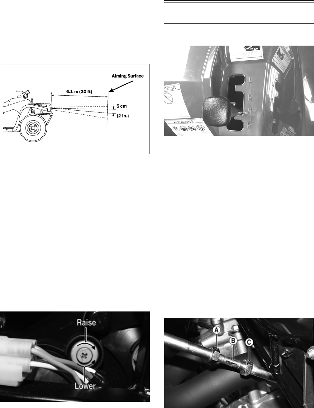
CHECKING/ADJUSTING HEADLIGHT
AIM
The headlights can be adjusted vertically and horizon-
tally. The geometric center of the HIGH beam light zone
is to be used for vertical and horizontal aiming.
1. Position the ATV on a level floor so the headlights
are approximately 6.1 m (20 ft) from an aiming sur-
face (wall or similar aiming surface).
ATV-0070C
NOTE: There should be an average operating
load on the ATV when adjusting the headlight aim.
2. Measure the distance from the floor to the mid-point
of each headlight.
3. Using the measurements obtained in step 2, make
horizontal marks on the aiming surface.
4. Make vertical marks which intersect the horizontal
marks on the aiming surface directly in front of the
headlights.
5. Switch on the lights. Make sure the HIGH beam is
on. DO NOT USE LOW BEAM.
6. Observe each headlight beam aim. Proper aim is
when the most intense beam is centered on the verti-
cal mark 5 cm (2 in.) below the horizontal mark on
the aiming surface.
7. Adjust each headlight by turning the adjuster screw
clockwise to raise the beam or counterclockwise to
lower the beam.
KC406A
Shift Lever
CHECKING ADJUSTMENT
KC165
With the engine stopped and the brake lever lock
engaged, turn the ignition switch to the ON position; then
shift the transmission into each of the gear positions and
note that the gear position indicated on the LCD corre-
sponds to the gear position selected by the lever.
If the indicator does not correspond to the selected gear,
it will be necessary to test drive the ATV to determine if
the gear position switch is faulty or the shift lever needs
adjustment.
If the ATV functions in the gear selected by the shift
lever, troubleshoot the gear position switch (see Electri-
cal System).
If the ATV functions but the shift lever does not corre-
spond with the gear indicated on the LCD, adjust the shift
linkage. To adjust, proceed to ADJUSTING.
ADJUSTING
1. Remove the seat; then remove the left-side engine
cover.
2. With the ignition switch in the ON position, loosen
jam nut (A) (left-hand threads); then loosen jam nut
(C) and with the shift lever in the reverse position,
adjust the coupler (B) until the transmission is in
reverse and the “R” icon appears on the LCD.
KC437A
3. Tighten the jam nuts securely; then shift the trans-
mission to each position and verify correct adjust-
ment.
For Discount Arctic Cat Parts Call 606-678-9623 or 606-561-4983
www.mymowerparts.com
16
4. Install the left-side engine cover and seat making
sure the seat locks securely in place.
Frame/Welds
The frame and welds should be checked periodically for
damage, bends, cracks, deterioration, broken compo-
nents, and missing components. If replacement or repair
constitutes removal, see Steering/Frame.
Hydraulic Brake Systems
CHECKING/BLEEDING
The hydraulic brake systems have been filled and bled at
the factory. To check and/or bleed a hydraulic brake sys-
tem, use the following procedure.
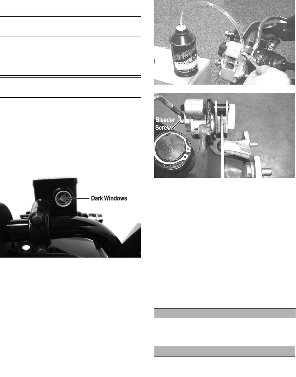
1. With the master cylinders in a level position, check
the fluid level in the reservoirs. On the hand brakes if
the level in the reservoir is adequate, the sight win-
dows will appear dark. If the level is low, the sight
windows will appear clear.
KC387A
2. Compress the brake levers/pedal several times to
check for a firm brake. If the brake is not firm, the
systems must be bled.
3. To bleed the brake systems, use the following proce-
dure.
A. Remove the cover and fill the appropriate reser-
voir with DOT 4 Brake Fluid (left hand brake/foot
pedal - rear system; right hand brake - front brake
system).
B. Install and secure the cover; then slowly compress
the brake lever several times.
C. Remove the protective cap, install one end of a
clear hose onto one FRONT bleeder screw, and
direct the other end into a container; then while
holding slight pressure on the right brake lever,
open the bleeder screw and watch for air bubbles.
Close the bleeder screw before releasing the brake
lever. Repeat this procedure until no air bubbles
are present.
AF637D
PR377C
NOTE: During the bleeding procedure, watch the
appropriate reservoir very closely to make sure
there is always a sufficient amount of brake fluid. If
low, refill the reservoir before the bleeding proce-
dure is continued. Failure to maintain a sufficient
amount of fluid in the reservoir will result in air in
the system.
D. Repeat step C until the brake lever is firm.
E. At this point, perform step B, C, and D on the
other FRONT bleeder screw; then move to the
REAR bleeder screw and follow the same proce-
dure using the left brake lever or foot pedal.
4. Carefully check the entire hydraulic brake system
that all hose connections are tight, the bleed screws
are tight, the protective caps are installed, and no
leakage is present.
INSPECTING HOSES
Carefully inspect the hydraulic brake hoses for cracks or
other damage. If found, the brake hoses must be replaced.
CAUTION
Brake fluid that has been drained or bled from the brake
system must NEVER be re-used or severe brake system
corrosion and damage may occur. Always discard used
brake fluid in an appropriate manner.
CAUTION
This hydraulic brake system is designed to use DOT 4
brake fluid only. If brake fluid must be added, care must be
taken as brake fluid is very corrosive to painted surfaces.
For Discount Arctic Cat Parts Call 606-678-9623 or 606-561-4983
www.mymowerparts.com
17
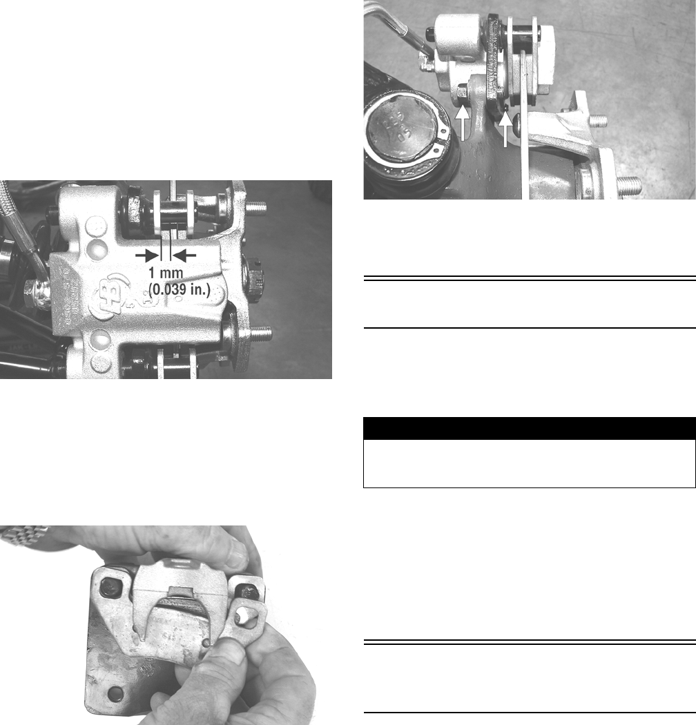
CHECKING/REPLACING PADS
The clearance between the brake pads and brake discs is
adjusted automatically as the brake pads wear. The only
maintenance that is required is replacement of the brake
pads when they show excessive wear. Check the thick-
ness of each of the brake pads as follows.
1. Remove a front wheel.
2. Measure the thickness of each brake pad.
3. If thickness of either brake pad is less than 1.0 mm
(0.039 in.), the brake pads must be replaced.
PR376B
NOTE: The brake pads should be replaced as a
set.
4. To replace the brake pads, use the following proce-
dure.
A. Remove the cap screws securing the caliper
holder to the knuckle; then remove the pads.
PR237
B. Install the new brake pads.
C. Secure the caliper to the knuckle and/or axle
housing with the cap screws. Tighten to 20 ft-lb.
PR377B
5. Install the wheel. Tighten to 40 ft-lb.
6. Burnish the brake pads (see Burnishing Brake Pads
in this section).
Burnishing Brake Pads
Brake pads must be burnished to achieve full braking
effectiveness. Braking distance will be extended until
brake pads are properly burnished. To properly burnish
the brake pads, use the following procedure.
1. Choose an area large enough to safely accelerate the
ATV to 30 mph and to brake to a stop.
2. Accelerate to 30 mph; then compress brake levers or
brake pedal to decelerate to 0-5 mph.
3. Repeat procedure on each brake system twenty
times.
4. Verify the brakelights illuminate when the hand lever
is compressed or the brake pedal is depressed.
Checking/Replacing V-
Belt
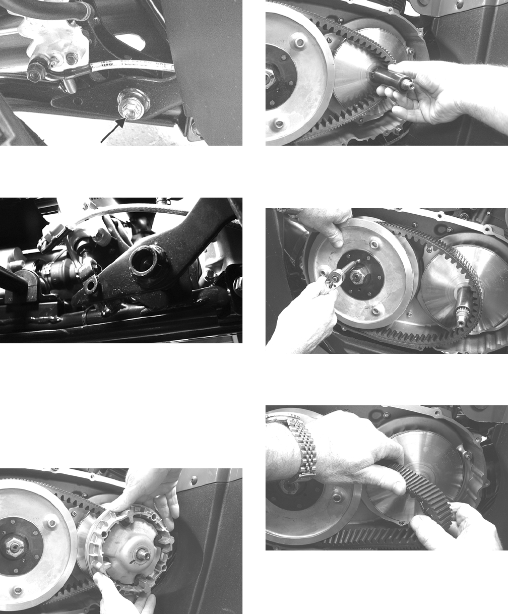
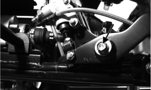
REMOVING
1. Remove the cap screw securing the brake pedal to
the frame. Account for a flat washer.
! WARNING
Failure to properly burnish the brake pads could lead to
premature brake pad wear or brake loss. Brake loss can
result in severe injury.
For Discount Arctic Cat Parts Call 606-678-9623 or 606-561-4983
www.mymowerparts.com
18
KC149A
2. Remove the cotter pin from the brake clevis pin; then
slide the brake pedal away from the frame suffi-
ciently to remove the clevis pin.
KC439
3. Lower the brake pedal down to the foot wells and
remove the reinstallable rivet from the CVT cut-out
in the foot well.
4. Remove the cap screws from the CVT cover and
remove the cover accounting for two alignment pins.
5. Remove the nut securing the movable drive face to
the clutch shaft; then remove the movable drive face
assembly being careful not to let the rollers fall out.
Account for a bushing.
KC127
KC128
6. Thread a cap screw from the V-belt cover into the
driven pulley fixed face and push the movable face
open allowing the V-belt to drop down between the
pulley faces approximately 3/4 in.
KC137
7. Pinching the V-belt together in front of the driven
pulley, pull it forward and outward off the clutch
shaft; then remove it from the driven pulley.
KC136
8. Inspect the faces of the drive and driven pulleys for
scoring, pitting, cracks, or grooving; then clean any
dirt and debris from the V-belt housing and cover.
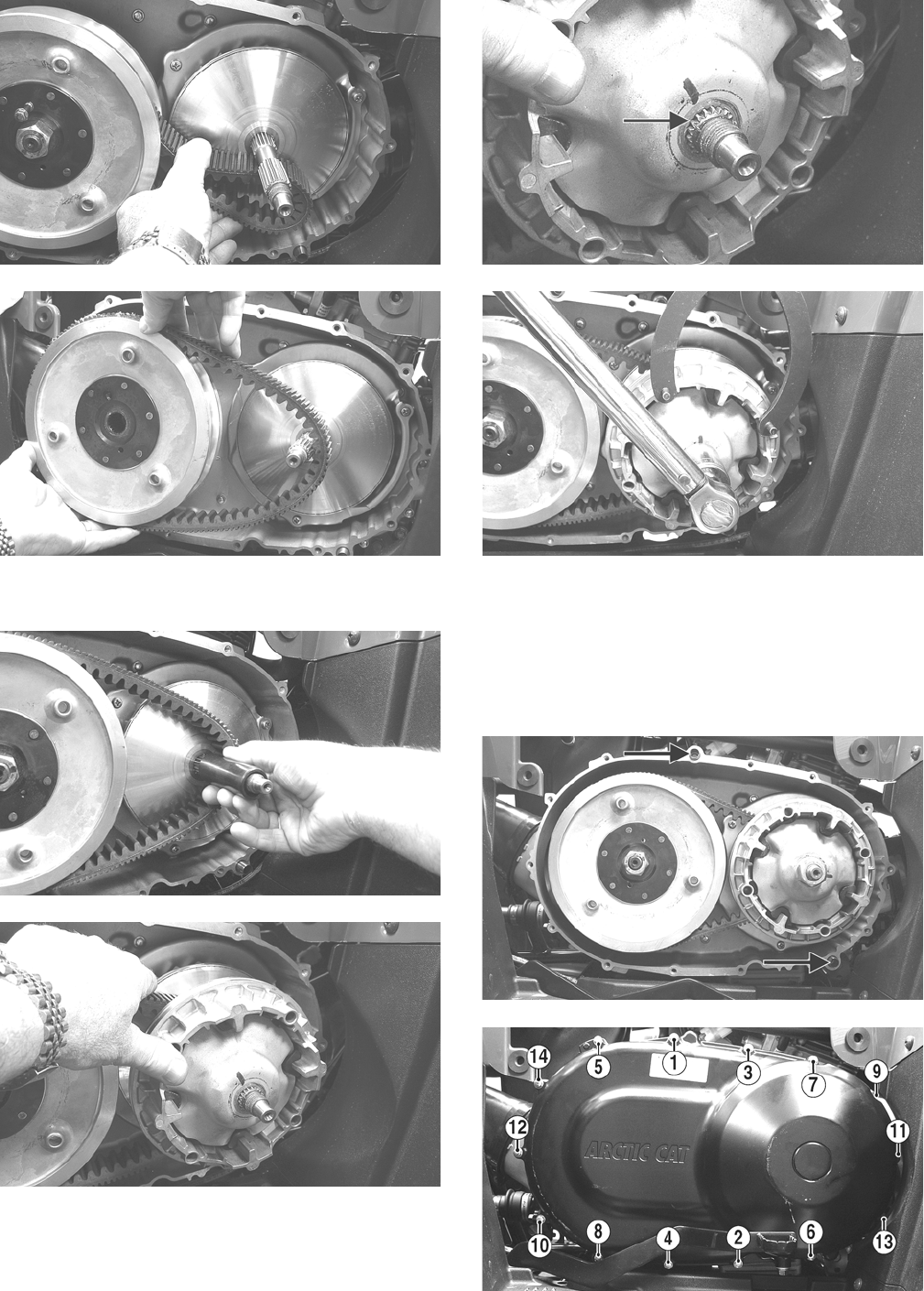
INSTALLING
1. Place the V-belt onto the driven pulley making sure
the arrows on the belt point in the direction of rota-
tion; then pinch the belt together in front of the
driven pulley and place it over the clutch shaft.
For Discount Arctic Cat Parts Call 606-678-9623 or 606-561-4983
www.mymowerparts.com
19
KC135
KC131
2. Install the bushing over the clutch shaft; then install
the movable drive face assembly on the clutch shaft.
KC128
KC138
3. With two drops of red Loctite #271 on the threads
and with the splines of the clutch shaft protruding
through the movable drive face, install the nut and
tighten to 147 ft-lb.
KC152A
KC141
4. Remove the cap screw from the fixed driven face;
then rotate the pulleys counterclockwise until the
driven pulley faces are together.
5. With the two alignment pins installed in the V-belt
housing and a new V-belt cover gasket in place,
install the V-belt cover. Using the pattern shown,
secure with the cap screws tightened to 8 ft-lb.
KC142A
KC153A
For Discount Arctic Cat Parts Call 606-678-9623 or 606-561-4983
www.mymowerparts.com
20
6. Install the clevis pin connecting the brake pedal to
the master cylinder and secure with a new cotter pin;
then install the cap screw and flat washer securing
the brake pedal to the frame and tighten to 20 ft-lb.
KC438A
For Discount Arctic Cat Parts Call 606-678-9623 or 606-561-4983
www.mymowerparts.com

21
Engine/Transmission
This section has been organized into sub-sections which
show a progression for the complete servicing of the Arc-
tic Cat ATV engine/transmission.
To service the center crankcase halves, the engine/trans-
mission must be removed from the frame. To service top-
side, left-side, and right-side components, the engine/
transmission does not have to be removed from the
frame.
NOTE: Use new gaskets, lock nuts, and seals and
lubricate all internal components when servicing the
engine/transmission.
SPECIAL TOOLS
A number of special tools must be available to the techni-
cian when performing service procedures in this section.
Refer to the current Special Tools Catalog for the appro-
priate tool description.
NOTE: Special tools are available from the Arctic
Cat Service Department.
Specifications
Specifications subject to change without notice.
Description p/n
Crankcase Separator/Crankshaft Remover 0444-152
Magneto Rotor Remover Set 0444-254
Oil Filter Wrench 0644-389
Piston Pin Puller 0644-328
Spanner Wrench 0444-251
Surface Plate 0644-016
V Blocks 0644-535
CYLINDER, PISTON, AND RINGS
Piston Skirt/Cylinder Clearance 0.025-0.055 mm
Piston Diameter 8 mm from Skirt End 88.96-89.01 mm
Piston Ring Free End Gap (min) (1st)
(2nd)
8.0 mm
8.3 mm
Bore x Stroke 89.0 x 71.2 mm
Cylinder Trueness (max) 0.01 mm
Piston Ring End Gap - Installed (min) 0.15 mm
Piston Ring to Groove Clearance (max) (1st/2nd) 0.06 mm
Piston Ring Groove Width (1st)
(2nd)
(oil)
1.01-1.03 mm
1.21-1.23 mm
2.01-2.03 mm
Piston Ring Thickness (1st/2nd) 1.97-1.99 mm
Piston Pin Bore (max) 20.20 mm
Piston Pin (min) 19.994 mm
VALVES AND GUIDES
Valve Face Diameter (intake)
(exhaust)
35.0 mm
30.5 mm
Valve/Tappet Clearance (cold engine) (intake)
(exhaust)
0.10 mm
0.17 mm
Valve Guide/Stem Clearance (max) (intake)
(exhaust)
0.1 mm
0.3 mm
Valve Guide Inside Diameter 5.000-5.012 mm
Valve Stem Outside Diameter (intake)
(exhaust)
4.975-4.990 mm
4.955-4.970 mm
Valve Stem Runout (max) 0.10 mm
Valve Margin (min) (intake) 1.1 mm
Valve Face/Seat Width (min) (intake) 0.99 mm
Valve Seat Angle (intake/exhaust) 45°-75°
Valve Face Radial Runout (max) 0.15 mm
Valve Spring Free Length (min) 44.73 mm
Valve Spring Tension @ 32.5 mm (outer) 17.23 kg (37.98 lb)
CAMSHAFT AND CYLINDER HEAD
Cam Lobe Height (min) (intake)
(exhaust)
34.71 mm
34.48 mm
Camshaft Journal/Cylinder Head Clearance(max) 0.074 mm
Camshaft Journal Holder (right & center)
Inside Diameter (left)
22.01-22.04 mm
17.51-17.54 mm
Camshaft Journal Outside (center)
Diameter (left)
(right)
21.959-21.980 mm
17.466-17.480 mm
21.966- 21.980 mm
Camshaft Runout (max) 0.03 mm
Rocker Arm Inside Diameter 10.00-10.15 mm
Rocker Arm Shaft Outside Diameter 9.972-9.987 mm
Cylinder Head/Cover Distortion (max) 0.05 mm
CRANKSHAFT
Connecting Rod (small end) (max) 20.021 mm
Connecting Rod (big end side-to-side) (max) 0.7 mm
Connecting Rod (big end width) 21.95-22.00 mm
Connecting Rod (small end deflection) (max) 0.15 mm
Crankshaft (web-to-web) 60.9 mm
Crankshaft Runout (max) 0.03 mm
For Discount Arctic Cat Parts Call 606-678-9623 or 606-561-4983
www.mymowerparts.com

22
Troubleshooting
Problem: Engine will not start or is hard to start (Compression too low)
Condition Remedy
1. Valve clearance out of adjustment
2. Valve guides worn
3. Valves timing incorrect
4. Piston rings worn excessively
5. Cylinder bore worn
6. Starter motor cranks too slowly - does not turn
1. Adjust clearance
2. Replace cylinder head
3. Correct valve timing - check chain, sprockets, and cam chain
tensioner
4. Replace rings
5. Replace cylinder
6. Check - replace starter motor
Problem: Engine will not start or is hard to start (No spark)
Condition Remedy
1. Spark plug fouled
2. Spark plug wet
3. Crankshaft position sensor defective
4. ECU defective
5. Ignition coil defective
6. High-tension lead open - shorted
1. Clean - replace plug
2. Clean - dry plug
3. Replace stator assembly
4. Replace ECU
5. Replace ignition coil
6. Replace high tension lead
Problem: Engine will not start or is hard to start (No fuel reaching the throttle body
Condition Remedy
1. Fuel hose obstructed
2. Fuel screens obstructed
3. Fuel pump/relay defective
4. Fuel injector defective
1. Clean - replace hose
2. Clean - replace inlet screen - valve screen
3. Replace fuel pump/relay
4. Replace fuel injector
Problem: Engine stalls easily
Condition Remedy
1. Spark plug fouled
2. Crank angle sensor defective
3. ECU defective
4. Valve clearance out of adjustment
1. Clean plug
2. Replace stator assembly
3. Replace ECU
4. Adjust clearance
Problem: Engine noisy (Excessive valve chatter)
Condition Remedy
1. Valve clearance excessive
2. Valve spring(s) weak - broken
3. Rocker arm - rocker arm shaft worn
4. Camshaft worn
5. Valve tappets worn
1. Adjust clearance
2. Replace spring(s)
3. Replace arm - shaft
4. Replace camshaft
5. Replace tappets
Problem: Engine noisy (Noise seems to come from piston)
Condition Remedy
1. Piston - cylinder worn
2. Combustion chamber carbon buildup
3. Piston pin bore worn
4. Piston pin worn
5. Piston rings - ring groove(s) worn
1. Replace - service piston - cylinder
2. Clean chamber
3. Replace piston
4. Replace piston pin
5. Replace rings - piston
Problem: Engine noisy (Noise seems to come from timing chain)
Condition Remedy
1. Chain stretched
2. Sprockets worn
3. Tension adjuster malfunctioning
1. Replace chain
2. Replace sprockets
3. Repair - replace adjuster
Problem: Engine noisy (Noise seems to come from crankshaft)
Condition Remedy
1. Bearing worn - burned
2. Lower rod-end bearing worn - burned
3. Connecting rod side clearance too large
1. Replace bearing
2. Replace crankshaft
3. Replace crankshaft
For Discount Arctic Cat Parts Call 606-678-9623 or 606-561-4983
www.mymowerparts.com

23
Problem: Engine noisy (Noise seems to come from transmission)
Condition Remedy
1. Gears worn - rubbing
2. Splines worn
3. Primary gears worn - rubbing
4. Bearings worn
5. Bushing worn
1. Replace gears
2. Replace shaft(s)
3. Replace gears
4. Replace bearings
5. Replace bushing
Problem: Engine noisy (Noise seems to come from secondary bevel gear and final driven shaft)
Condition Remedy
1. Drive - driven bevel gears damaged - worn
2. Backlash excessive
3. Tooth contact improper
4. Bearing damaged
5. Gears worn - rubbing
6. Splines worn
7. Final driven shaft thrust clearance too large
1. Replace gears
2. Adjust backlash
3. Adjust contact
4. Replace bearing
5. Replace gears
6. Replace shaft(s)
7. Replace thrust washer(s)
Problem: Engine idles poorly
Condition Remedy
1. Valve clearance out of adjustment
2. Valve seating poor
3. Valve guides defective
4. Rocker arms - arm shaft worn
5. Crankshaft position sensor defective
6. ECU defective
7. Spark plug fouled - gap too wide
8. Ignition coil defective
9. Idle Step Control (ISC) malfunction
1. Adjust clearance
2. Replace - cylinder head - valves
3. Replace cylinder head
4. Replace arms - shafts
5. Replace stator assembly
6. Replace ECU
7. Adjust gap - replace plug
8. Replace ignition coil
9. Replace ISC
Problem: Engine runs poorly at high speed
Condition Remedy
1. High RPM “cut out” against RPM limiter
2. Valve springs weak
3. Valve timing incorrect
4. Cam - rocker arms - tappets worn
5. Spark plug gap too narrow
6. Ignition coil defective
7. Air cleaner element obstructed
8. Fuel hose obstructed
9. Fuel pump defective
1. Shift into higher gear - decrease speed
2. Replace springs
3. Correct timing - check chain, sprockets, and cam chain ten-
sioner
4. Replace cam - arms - tappets
5. Adjust gap
6. Replace ignition coil
7. Clean element
8. Clean or replace hose
9. Replace fuel pump
Problem: Exhaust smoke dirty or heavy
Condition Remedy
1. Oil (in the engine) overfilled - contaminated
2. Piston rings - cylinder worn
3. Valve guides worn
4. Cylinder wall scored - scuffed
5. Valve stems worn
6. Stem seals defective
1. Drain excess oil - replace oil
2. Replace - service rings - cylinder
3. Replace cylinder head
4. Replace - service cylinder
5. Replace valves
6. Replace seals
For Discount Arctic Cat Parts Call 606-678-9623 or 606-561-4983
www.mymowerparts.com

24
Problem: Engine lacks power
Condition Remedy
1. Valve clearance incorrect
2. Valve springs weak
3. Valve timing incorrect
4. Piston ring(s) - cylinder worn
5. Valve seating poor
6. Spark plug fouled
7. Rocker arms - shafts worn
8. Spark plug gap incorrect
9. Air cleaner element obstructed
10. Oil (in the engine) overfilled - contaminated
11. Intake manifold leaking air
12. Cam chain worn
1. Adjust clearance
2. Replace springs
3. Re-time valve gear
4. Replace - service rings - cylinder
5. Replace cylinder head/valves
6. Clean - replace plug
7. Replace arms - shafts
8. Adjust gap - replace plug
9. Clean element
10. Drain excess oil - change oil
11. Tighten - replace manifold
12. Replace cam chain
Problem: Engine overheats
Condition Remedy
1. Carbon deposit (piston crown) excessive
2. Oil low
3. Octane low - gasoline poor
4. Oil pump defective
5. Oil circuit obstructed
6. Intake manifold leaking air
7. Fan malfunctioning
8. Fan switch malfunctioning
9. Radiator fins obstructed
10. Coolant level low
11. Thermostat sticking
1. Clean piston
2. Add oil
3. Drain - replace gasoline
4. Replace pump
5. Clean circuit
6. Tighten - replace manifold
7. Check fan fuse - replace fan
8. Replace fan switch
9. Clean radiator
10. Add coolant
11. Replace thermostat
For Discount Arctic Cat Parts Call 606-678-9623 or 606-561-4983
www.mymowerparts.com
25
Removing Engine/
Transmission
Many service procedures can be performed without
removing the engine/transmission from the frame.
Closely observe the note introducing each sub-section for
this important information.
Secure the ATV on a support stand to elevate the wheels.
1. Remove the battery case access cover and disconnect
the negative battery cable; then remove the seat.
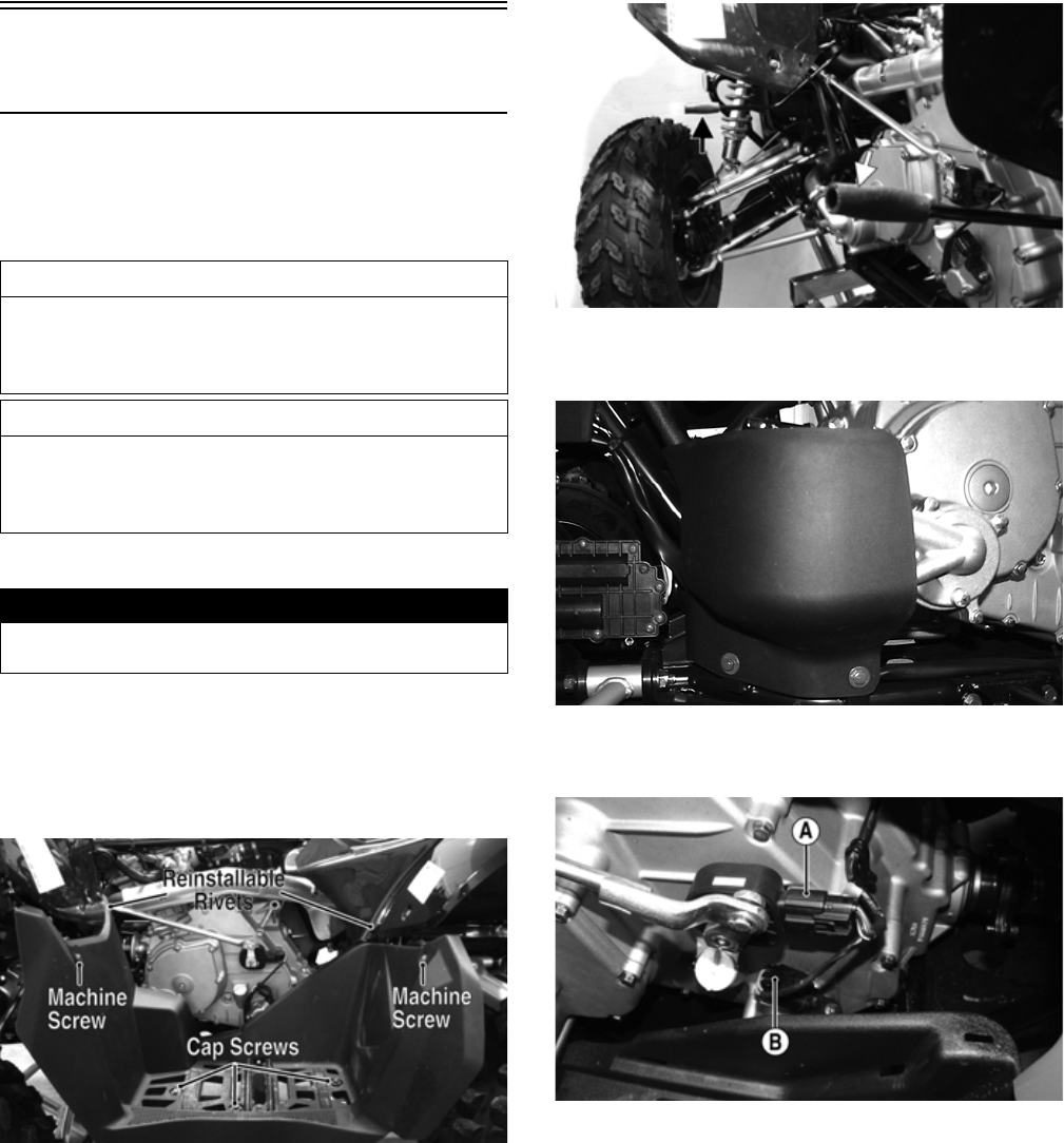
2. Remove three cap screws, two machine screws with
nuts, and two reinstallable rivets from the left foot-
well. Remove the footwell.
KC460A
3. Install short lengths of hose or other protective
device over the support rods to prevent personal
injury.
KC464A
4. Remove the water pump splash guard; then drain the
coolant into a suitable container.
KC463
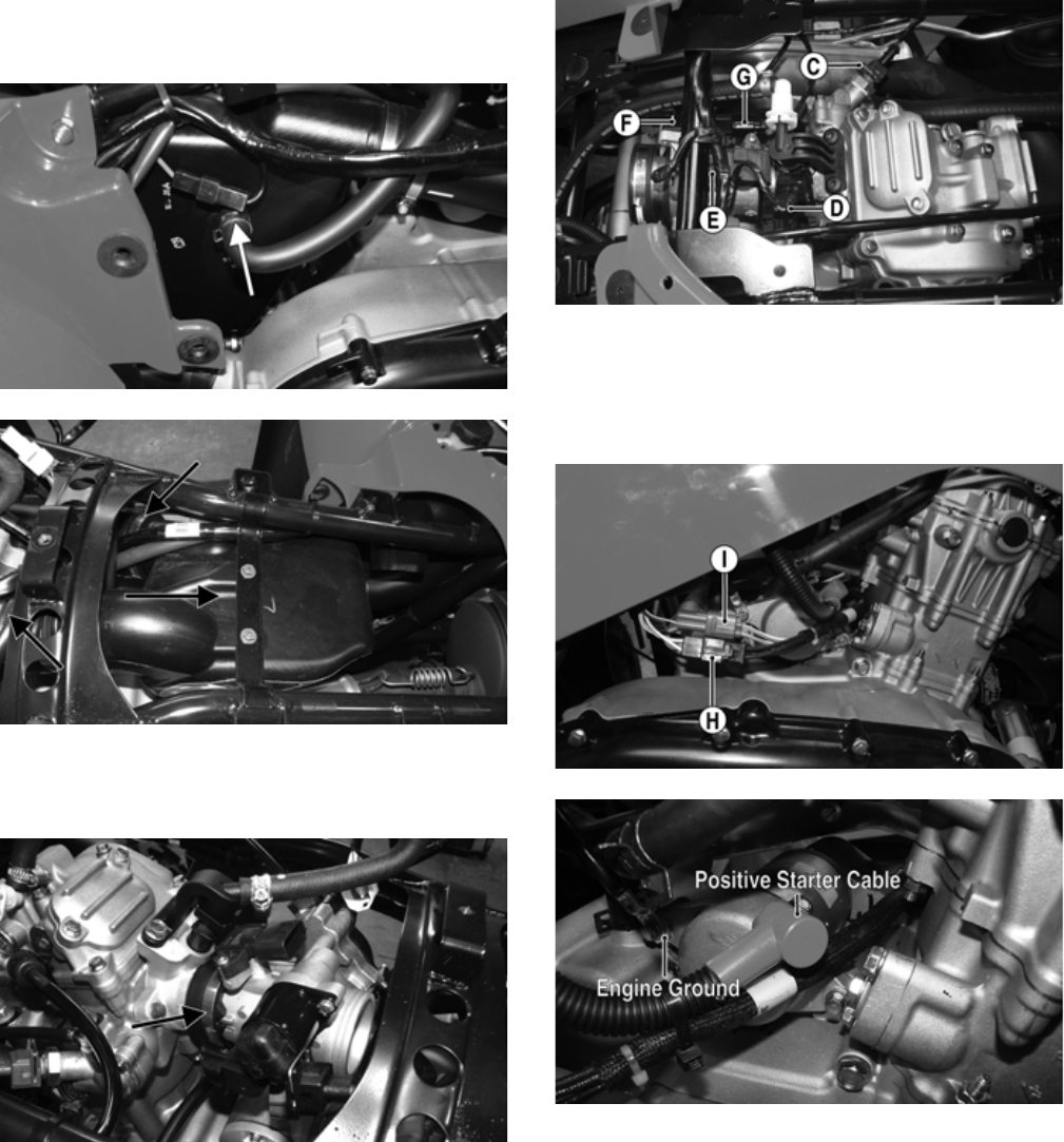
5. From the left side, remove the gear position switch
connector (A) and the speed sensor connector (B).
FI525A
6. Drain the engine oil into a suitable container.
7. Remove the gas tank (see Fuel/Lubrication/Cooling).
8. Remove the air inlet and outlet ducts from the CVT
housing.
9. Remove the cap screws securing the exhaust pipe to
the cylinder head; then remove the springs securing
the muffler to the exhaust pipe.
10. Remove the muffler and exhaust pipe. Account for a
grafoil seal on each end of the exhaust pipe.
11. Loosen the clamp securing the air box to the front air
inlet duct.
AT THIS POINT
If the technician’s objective is to service Top-Side Com-
ponents, Left-Side Components, or Right-Side Compo-
nents, the engine/transmission does not have to be
removed from the frame.
AT THIS POINT
If the technician’s objective is to service/replace mag-
neto cover oil seals or the oil strainer (from beneath the
engine/transmission), the engine/transmission does not
have to be removed from the frame.
! WARNING
Make sure the ATV is solidly supported on the support
stand to avoid injury.
For Discount Arctic Cat Parts Call 606-678-9623 or 606-561-4983
www.mymowerparts.com
26
12.Disconnect the crankcase breather hose from the air
box; then loosen the clamp securing the air box boot
to the throttle body and remove the air box.
FI692A
FI691A
13. Loosen the clamp securing the throttle body to the
intake pipe and remove the throttle body. Secure the
throttle body assembly clear of the work area.
FI695A
14. From the top side, remove the engine coolant tem-
perature (ECT) sensor connector (C), fuel injector
connector (D), manifold absolute pressure (MAP)
sensor connector (E), idle step control (ISC) connec-
tor (F), and throttle position sensor (TPS) connector
(G).
FI522A
15. From the right side, disconnect the stator connector
(H) and crankshaft position sensor connector (I)
from the main harness; then disconnect the positive
cable from the starter motor and the engine ground
cable from the starter mounting flange.
FI523A
FI533A
16. Remove the spark plug cap from the spark plug and
secure the wire away from the work area.
17. Remove coolant hoses (A) and (B) from the water
pump; then remove the upper coolant hose from the
thermostat housing.
For Discount Arctic Cat Parts Call 606-678-9623 or 606-561-4983
www.mymowerparts.com
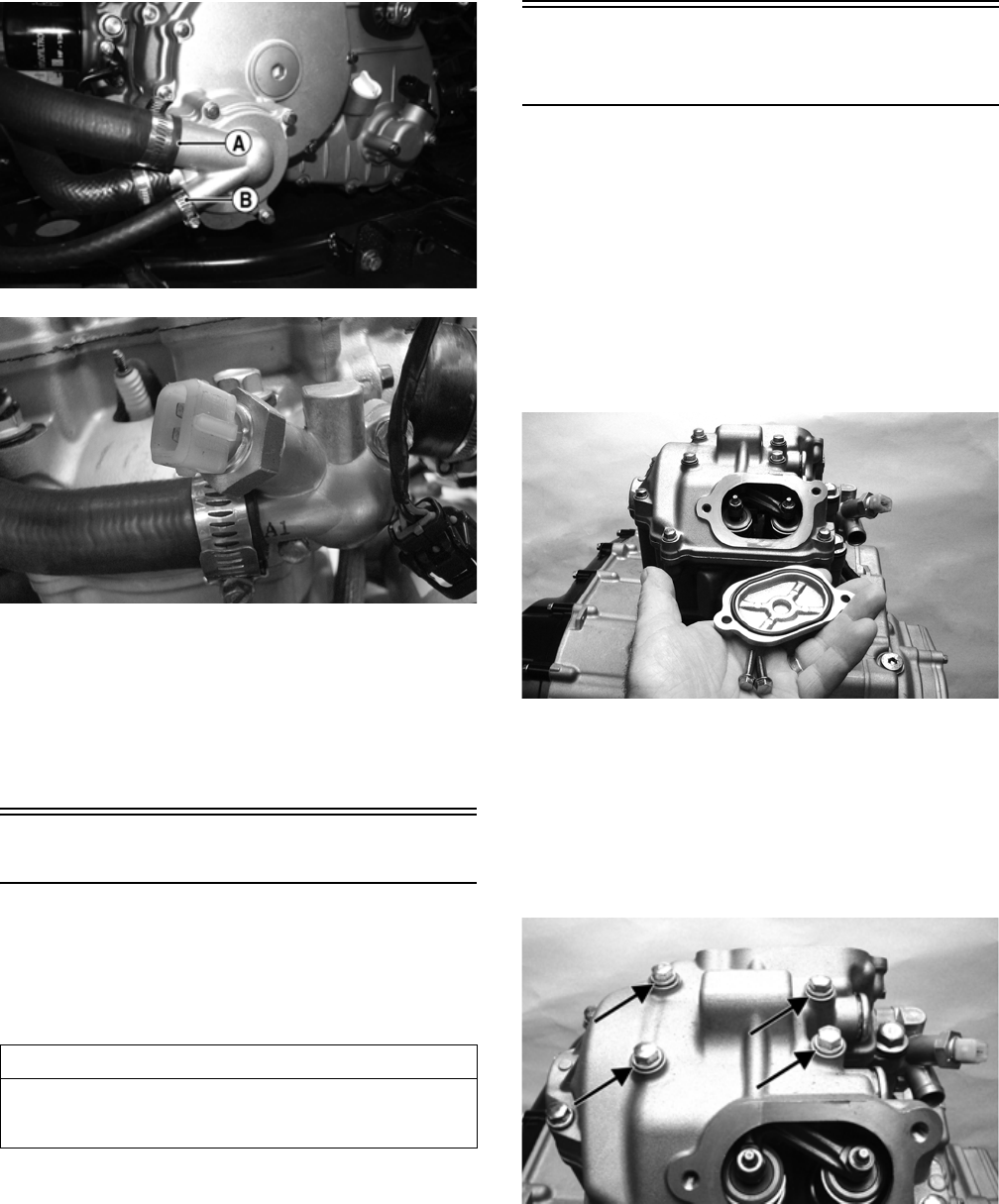
27
FI530B
FI537
18. Remove the four cap screws securing the rear drive-
line to the output drive flange.
19. Support the engine and remove the two through-bolts
securing the engine assembly to the frame; then
move the engine rearward sufficiently to disengage
the front driveline and remove the engine from the
left side.
Top-Side Components
NOTE: For efficiency, it is preferable to remove and
disassemble only those components which need to
be addressed and to service only those components.
The technician should use discretion and sound
judgment.
NOTE: The engine/transmission does not have to
removed from the frame for this procedure.
Removing Top-Side
Components
A. Cylinder Head Cover/
Rocker Arms
B. Cylinder Head/Camshaft
NOTE: Remove the spark plug, timing inspection
plug, and outer magneto cover; then using an appro-
priate wrench, rotate the crankshaft to top-dead-cen-
ter of the compression stroke.
1. Remove the cap screws securing the two tappet cov-
ers. Remove the two tappet covers. Account for the
O-rings.
FI603
NOTE: Keep the mounting hardware with the covers
for assembly purposes.
2. Remove the cylinder head cover cap screws. Note
the rubber washers on the four top-side cap screws;
remove the cylinder head cover. Note the orientation
of the cylinder head plug and remove it. Note the
location of the two alignment pins.
FI606A
AT THIS POINT
To service any one specific component, only limited dis-
assembly of components may be necessary. Note the
AT THIS POINT information in each sub-section.
For Discount Arctic Cat Parts Call 606-678-9623 or 606-561-4983
www.mymowerparts.com
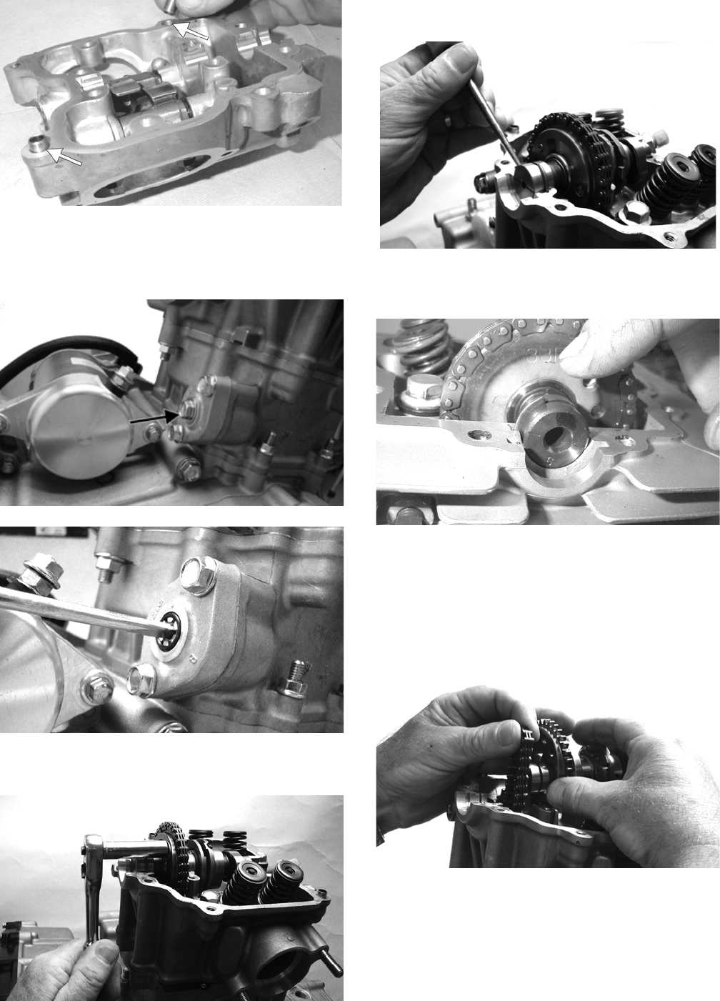
28
MD1354A
3. Remove the cap screw from the tension adjuster;
then using a common screwdriver, relax the cam
chain tension by rotating the adjuster screw clock-
wise until it locks.
FI607A
FI608
4. Bend the washer tabs and remove the two cap screws
securing the sprocket to the camshaft.
FI612
5. Using an awl, rotate the C-ring in its groove until it is
out of the cylinder head; then remove the C-ring.
FI613
NOTE: Care should be taken not to drop the C-ring
down into the crankcase.
MD1131
6. Noting the timing marks for installing purposes, drop
the sprocket off the camshaft. While holding the cam
chain, slide the sprocket and camshaft out of the cyl-
inder head. Account for an alignment pin.
NOTE: Loop the chain over the cylinder and secure
it to keep it from falling into the crankcase.
FI620
For Discount Arctic Cat Parts Call 606-678-9623 or 606-561-4983
www.mymowerparts.com
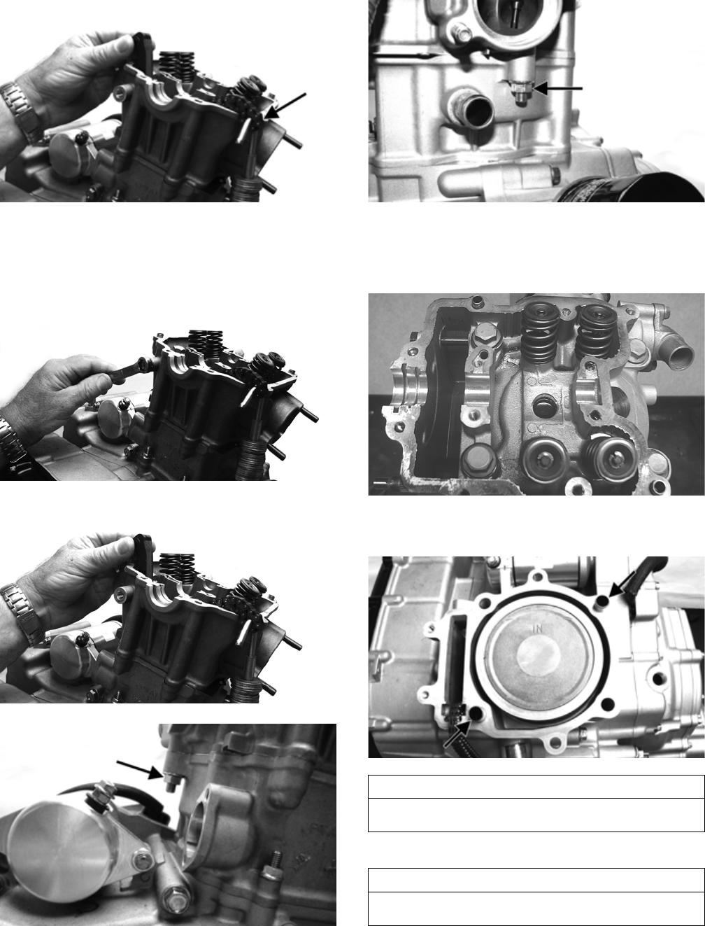
29
FI617A
7. Remove the cam chain tensioner pivot bolt and
remove the chain tensioner; then remove the two
nuts securing the cylinder head to the cylinder.
FI616
FI617
FI618A
FI619A
8. Remove the four cylinder head cap screws and wash-
ers. Note that the two cap screws on the right side of
the cylinder head nearest the cam sprocket are longer
than the two cap screws on the left (spark plug) side.
CD211
9. Remove the cylinder head from the cylinder, remove
the gasket, and account for two alignment pins.
FI623A
10. Remove the cam chain guide.
AT THIS POINT
To service valves and cylinder head, see Servicing Top-
Side Components sub-section.
AT THIS POINT
To inspect cam chain guide, see Servicing Top-Side
Components sub-section.
For Discount Arctic Cat Parts Call 606-678-9623 or 606-561-4983
www.mymowerparts.com
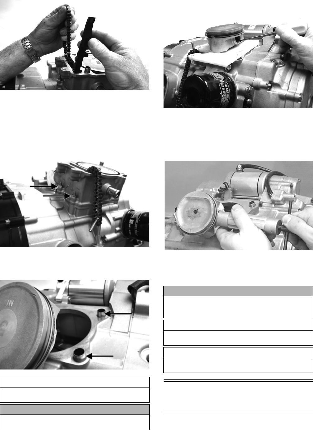
30
FI621
C. Cylinder
D. Piston
NOTE: Steps 1-10 in the preceding sub-section
must precede this procedure.
11. Remove the two nuts securing the right side of the
cylinder to the right-side crankcase half.
FI622A
12. Lift the cylinder off the crankcase taking care not to
allow the piston to drop against the crankcase.
Account for the gasket and two alignment pins.
FI624A
13. Using an awl, remove one piston-pin circlip. Take
care not to drop it into the crankcase.
FI625
14. Using Piston Pin Puller, remove the piston pin.
Account for the opposite-side circlip. Remove the
piston.
NOTE: It is advisable to remove the opposite-side
circlip prior to using the puller.
MD1219
NOTE: Support the connecting rod with rubber
bands to avoid damaging the rod or install a connect-
ing rod holder.
Servicing Top-Side
Components
NOTE: Whenever a part is worn excessively,
cracked, or damaged in any way, replacement is nec-
essary.
AT THIS POINT
To service cylinder, see Servicing Top-Side Compo-
nents sub-section.
CAUTION
When removing the cylinder, be sure to support the
piston to prevent damage to the crankcase and piston.
CAUTION
Do not allow the connecting rod to go down inside the
crankcase. If the rod is down inside the crankcase and
the crankshaft is rotated, severe damage will result.
AT THIS POINT
To service piston, see Servicing Top-Side Components
sub-section.
AT THIS POINT
To service center crankcase components only, proceed
to Removing Left-Side Components.
For Discount Arctic Cat Parts Call 606-678-9623 or 606-561-4983
www.mymowerparts.com
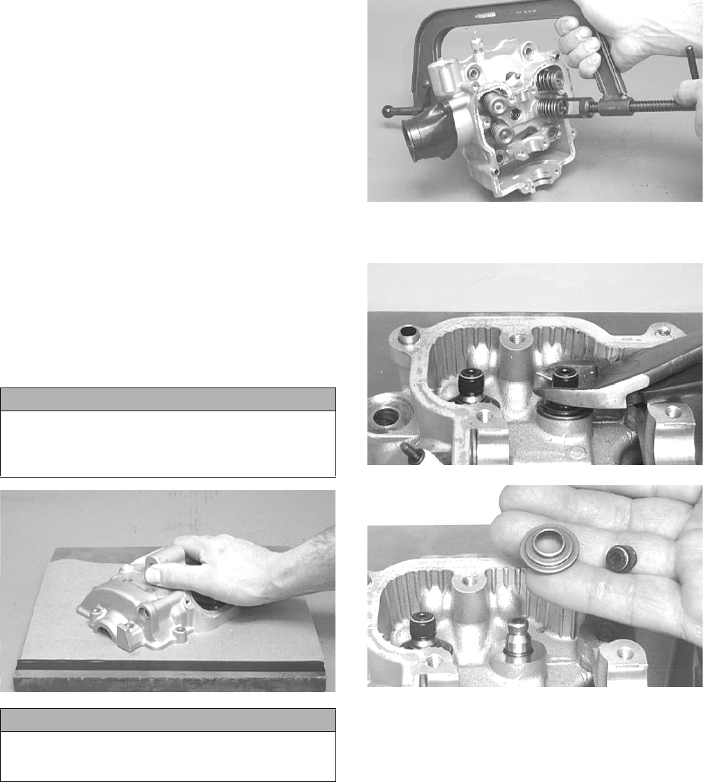
31
VALVE ASSEMBLY
When servicing valve assembly, inspect valve seats,
valve stems, valve faces, and valve stem ends for pits,
burn marks, or other signs of abnormal wear.
NOTE: Whenever a valve is out of tolerance, it must
be replaced.
Cleaning/Inspecting Cylinder Head
Cover
NOTE: If the cylinder head cover cannot be trued,
the cylinder head assembly must be replaced.
1. Wash the cylinder head cover in parts-cleaning sol-
vent.
2. Place the cylinder head cover on the Surface Plate
covered with #400 grit wet-or-dry sandpaper. Using
light pressure, move the cylinder head cover in a fig-
ure eight motion. Inspect the sealing surface for any
indication of high spots. A high spot can be noted by
a bright metallic finish. Correct any high spots
before assembly by continuing to move the cylinder
head cover in a figure eight motion until a uniform
bright metallic finish is attained.
CC130D
Removing Valves
NOTE: Keep all valves and valve components as a
set. Note the original location of each valve set for
use during installation. Return each valve set to its
original location during installation.
1. Using a valve spring compressor, compress the valve
springs and remove the valve keepers. Account for
an upper spring retainer.
CC132D
2. Remove the valve seal and the lower remaining
spring seat. Discard the valve seal.
CC134D
CC136D
NOTE: The valve seals must be replaced.
3. Remove the valve springs; then invert the cylinder
head and remove the valves.
Measuring Valve Stem Runout
1. Support each valve stem end with the V Blocks; then
check the valve stem runout using a dial indicator.
CAUTION
Do not remove an excessive amount of the sealing
surface or damage to the camshaft will result. Always
check camshaft clearance when resurfacing the cylin-
der head cover.
CAUTION
Water or parts-cleaning solvent must be used in con-
junction with the wet-or-dry sandpaper or damage to
the sealing surface may result.
For Discount Arctic Cat Parts Call 606-678-9623 or 606-561-4983
www.mymowerparts.com
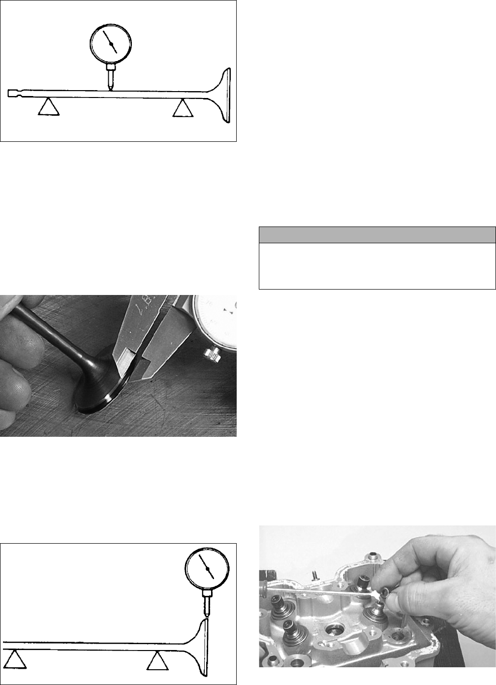
32
ATV-1082
2. Maximum runout must not exceed specifications.
Measuring Valve Stem Outside
Diameter
1. Using a micrometer, measure the valve stem outside
diameter.
2. Acceptable diameter ranges must be within specifi-
cations.
Measuring Valve Face/Seat Width
1. Using a calipers, measure the width of the valve face.
FI367
2. Acceptable width must be at or above specifications.
Measuring Valve Face Radial Runout
1. Mount a dial indicator on the surface plate; then
place the valve stem on a set of V blocks.
2. Position the dial indicator contact point on the out-
side edge of the valve face; then zero the indicator.
ATV1082A
3. Rotate the valve in the V blocks.
4. Maximum runout must not exceed specifications.
Measuring Valve Guide
(Inside Diameter)
1. Insert a snap gauge 1/2 way down into each valve
guide bore; then remove the gauge and measure it
with a micrometer.
2. Acceptable inside diameter range must be within
specifications.
3. If a valve guide is out of tolerance, the cylinder head
must be replaced.
Servicing Valves/Valve Guides/Valve
Seats
If valves, valve guides, or valve seats require servicing or
replacement, Arctic Cat recommends that the compo-
nents be taken to a qualified machine shop for servicing.
Measuring Rocker Arm
(Inside Diameter)
1. Using a dial calipers, measure the inside diameter of
the rocker arm.
2. Acceptable inside diameter range must be within
specifications.
Measuring Rocker Arm Shaft
(Outside Diameter)
1. Using a micrometer, measure the outside diameter of
the rocker arm shaft.
2. Acceptable outside diameter range must be within
specifications.
Installing Valves
1. Apply grease to the inside surface of the valve seals;
then place a lower spring seat and valve guide seal
over each valve guide.
CC144D
2. Insert each valve into its original valve location.
CAUTION
If valves are discolored or pitted or if the seating sur-
face is worn, the valve must be replaced. Do not
attempt to grind the valves or severe engine damage
may occur.
For Discount Arctic Cat Parts Call 606-678-9623 or 606-561-4983
www.mymowerparts.com
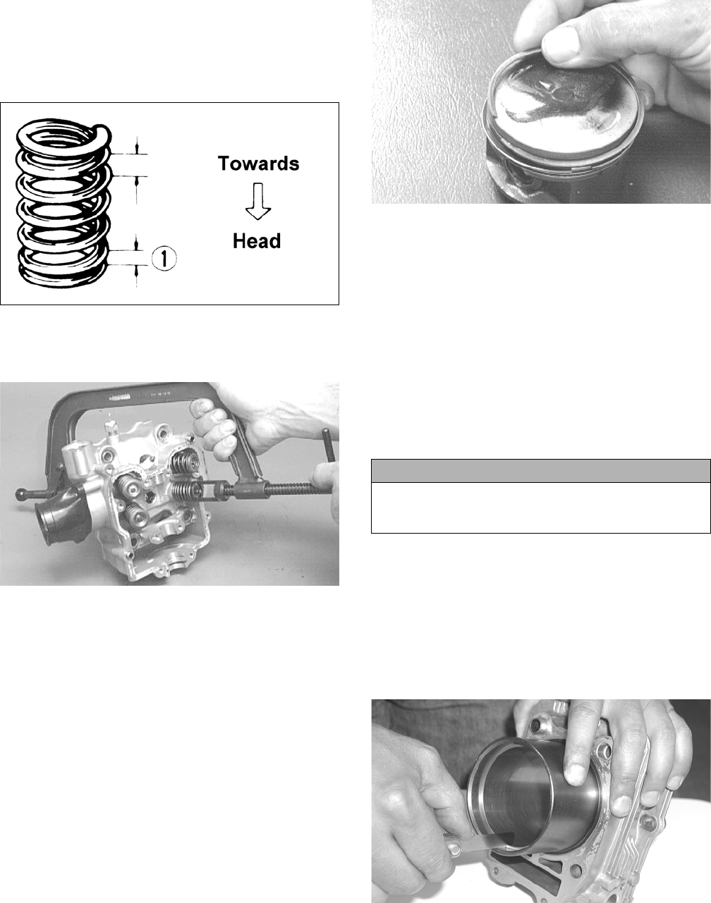
33
3. Install the valve springs with the painted end of the
spring facing away from the cylinder head.
NOTE: If the paint is not visible, install the ends of
the springs with the closest wound coils toward the
head.
ATV-1011A
4. Place a spring retainer over the valve springs; then
using the valve spring compressor, compress the
valve springs and install the valve keepers.
CC132D
PISTON ASSEMBLY
NOTE: Whenever a piston, rings, or pin are out of
tolerance, they must be replaced.
Cleaning/Inspecting Piston
1. Using a non-metallic carbon removal tool, remove
any carbon buildup from the top of the piston.
2. Inspect the piston for cracks in the piston pin, boss,
top, and skirt areas.
3. Inspect the piston for seizure marks or scuffing. If
piston is scored or galled, replace it with a new one.
4. Inspect the perimeter of each piston for signs of
“blowby” indicated by dark discoloration. “Blowby”
is caused by worn piston rings, excessive carbon in
ring grooves, or an out-of-round cylinder.
Removing Piston Rings
1. Starting with the top ring, slide one end of the ring
out of the ring-groove.
CC400D
2. Remove each ring by working it toward the top of
the piston while rotating it out of the groove.
NOTE: When installing new rings, install as a com-
plete set only.
Cleaning/Inspecting Piston Ring
Grooves
1. Take an old piston ring and snap it into two pieces;
then grind the end of the old ring to a 45° angle and
to a sharp edge.
2. Using the sharpened ring as a tool, clean carbon from
the ring grooves. Be sure to position the ring with its
tapered side up.
Measuring Piston-Ring End Gap
(Installed)
1. Place each piston ring in the wear portion of the cyl-
inder. Use the piston to position each ring squarely in
the cylinder.
2. Using a feeler gauge, measure each piston-ring end
gap. Acceptable ring end gap must be within specifi-
cations.
CC995
Measuring Piston Pin, Connecting
Rod Small End, and Piston-Pin Bore
1. Measure the piston pin outside diameter at each end
and in the center. If measurement does not meet
specifications, the piston pin must be replaced.
CAUTION
Improper cleaning of the ring grooves by the use of
the wrong type of ring groove cleaner will result in
severe damage to the piston.
For Discount Arctic Cat Parts Call 606-678-9623 or 606-561-4983
www.mymowerparts.com
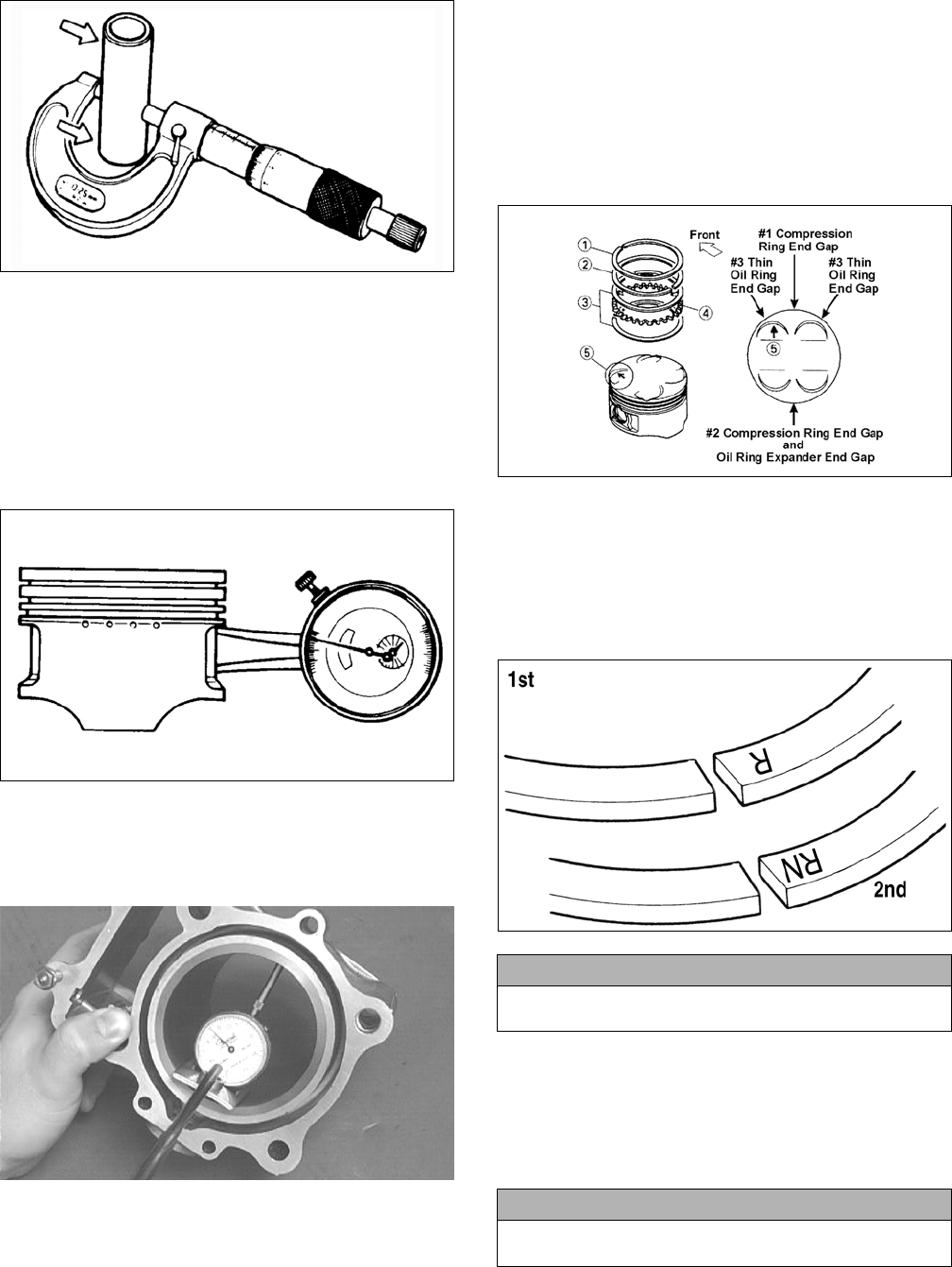
34
ATV-1070
2. Inspect and measure the connecting rod small end. If
the measurement exceeds specifications, the con-
necting rod must be replaced (see Center Crankcase
Components in this section).
3. Insert an inside dial indicator into the piston-pin
bore. Take two measurements to ensure accuracy.
The diameter must not exceed specifications. If the
diameter exceeds specifications, the piston must be
replaced.
ATV-1069
Measuring Piston Skirt/
Cylinder Clearance
1. Measure the cylinder front to back in six places.
CC127D
2. Measure the corresponding piston diameter at a point
8 mm (0.3 in.) above the piston skirt at a right angle
to the piston-pin bore. Subtract this measurement
from the measurement in step 1. The difference
(clearance) must be within specifications.
Installing Piston Rings
1. Install ring expander (4) in the bottom groove of the
piston; then install the thin oil rings (3) over the
expander making sure the expander ends do not
overlap. Stagger the end gaps of the upper and lower
thin oil rings according to the illustration.
NOTE: Note the direction of the exhaust side of the
piston (5) for correct ring end gap orientation.
ATV-1085B
2. Install the compression rings (1 and 2) so the letter(s) on
the top surface of each ring faces the dome of the piston.
Rotate the rings until the ring end gaps are on directly
opposite sides of the piston according to the illustration.
NOTE: The chrome (silver) ring should be installed
in the top position.
MD1343A
CYLINDER/CYLINDER HEAD
ASSEMBLY
NOTE: If the cylinder/cylinder head assembly can-
not be trued, they must be replaced.
Cleaning/Inspecting Cylinder Head
1. Using a non-metallic carbon removal tool, remove
any carbon buildup from the combustion chamber
being careful not to nick, scrape, or damage the com-
bustion chamber or the sealing surface.
CAUTION
Incorrect installation of the piston rings will result in
engine damage.
CAUTION
The cylinder head studs must be removed for this pro-
cedure.
For Discount Arctic Cat Parts Call 606-678-9623 or 606-561-4983
www.mymowerparts.com
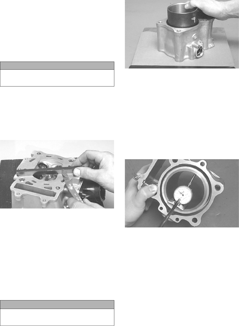
35
2. Inspect the spark plug hole for any damaged threads.
Repair damaged threads using a “heli-coil” insert.
3. Place the cylinder head on the Surface Plate covered
with #400 grit wet-or-dry sandpaper. Using light
pressure, move the cylinder head in a figure eight
motion. Inspect the sealing surface for any indication
of high spots. A high spot can be noted by a bright
metallic finish. Correct any high spots before assem-
bly by continuing to move the cylinder head in a fig-
ure eight motion until a uniform bright metallic
finish is attained.
Measuring Cylinder Head Distortion
1. Remove any carbon buildup in the combustion
chamber.
2. Lay a straightedge across the cylinder head; then
using a feeler gauge, check the distortion factor
between the head and the straightedge.
3. Maximum distortion must not exceed specifications.
CC141D
Cleaning/Inspecting Cylinder
1. Wash the cylinder in parts-cleaning solvent.
2. Inspect the cylinder for pitting, scoring, scuffing,
warpage, and corrosion. If marks are found, repair
the surface using a cylinder hone (see Honing Cylin-
der in this sub-section).
3. Place the cylinder on the surface plate covered with
#400 grit wet-or-dry sandpaper. Using light pressure,
move the cylinder in a figure eight motion. Inspect
the sealing surface for any indication of high spots.
A high spot can be noted by a bright metallic finish.
Correct any high spots before assembly by continu-
ing to move the cylinder in a figure eight motion
until a uniform bright metallic finish is attained.
CC129D
Inspecting Cam Chain Guide
1. Inspect cam chain guide for cuts, tears, breaks, or
chips.
2. If the chain guide is damaged, it must be replaced.
Honing Cylinder
1. Using a slide gauge and a dial indicator or a snap
gauge, measure the cylinder bore diameter in three
locations from top to bottom and again from top to
bottom at 90° from the first measurements for a total
of six measurements. The trueness (out-of-round-
ness) is the difference between the highest and low-
est reading. Maximum trueness (out-of-roundness)
must not exceed specifications.
CC127D
2. Wash the cylinder in parts-cleaning solvent.
3. Inspect the cylinder for pitting, scoring, scuffing, and
corrosion. If marks are found, repair the surface
using a #320 grit ball hone.
NOTE: To produce the proper 60° cross-hatch pat-
tern, use a low RPM drill (600 RPM) at the rate of 30
strokes per minute. If honing oil is not available, use
a lightweight petroleum-based oil. Thoroughly clean
cylinder after honing using soap and hot water. Dry
with compressed air; then immediately apply oil to
the cylinder bore. If the bore is severely damaged or
gouged, replace the cylinder.
CAUTION
Water or parts-cleaning solvent must be used in con-
junction with the wet-or-dry sandpaper or damage to
the sealing surface may result.
CAUTION
Water or parts-cleaning solvent must be used in con-
junction with the wet-or-dry sandpaper or damage to
the sealing surface may result.
For Discount Arctic Cat Parts Call 606-678-9623 or 606-561-4983
www.mymowerparts.com
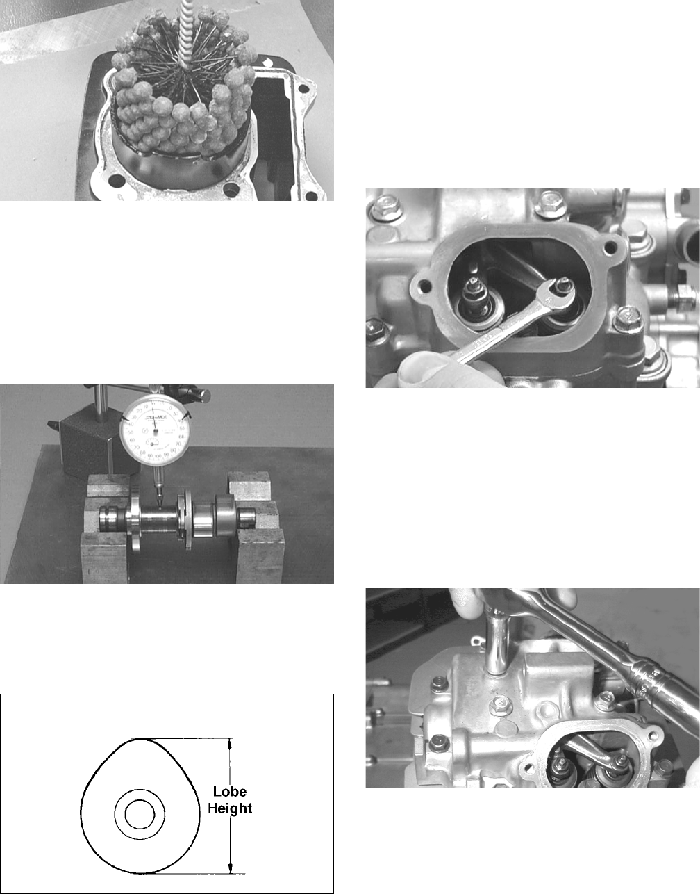
36
CC390D
4. If any measurement exceeds the limit, the cylinder
and piston must be replaced.
Measuring Camshaft Runout
NOTE: If the camshaft is out of tolerance, it must be
replaced.
1. Place the camshaft on a set of V blocks; then position
the dial indicator contact point against the shaft and
zero the indicator.
CC283D
2. Rotate the camshaft and note runout; maximum tol-
erance must not exceed specifications.
Measuring Camshaft Lobe Height
1. Using a calipers, measure each cam lobe height.
ATV1013A
2. The lobe heights must not exceed minimum specifi-
cations.
Inspecting Camshaft Bearing
Journal
1. Inspect the bearing journal for scoring, seizure
marks, or pitting.
2. If excessive scoring, seizure marks, or pitting is
found, the cylinder head assembly must be replaced.
Measuring Camshaft to
Cylinder Head Clearance
1. Loosen the jam nuts and adjuster screws.
CC005D
2. Place a strip of plasti-gauge in each of the camshaft
lands in the cylinder head.
3. Place the valve cover on the cylinder head and secure
with the valve cover cap screws. Tighten securely.
NOTE: Do not rotate the camshaft when measuring
clearance.
4. Remove the cap screws securing the valve cover to
the cylinder; then remove the valve cover and cam-
shaft.
MD1261
5. Match the width of the plasti-gauge with the chart
found on the plasti-gauge packaging to determine
camshaft to cylinder head and valve cover clearance.
For Discount Arctic Cat Parts Call 606-678-9623 or 606-561-4983
www.mymowerparts.com
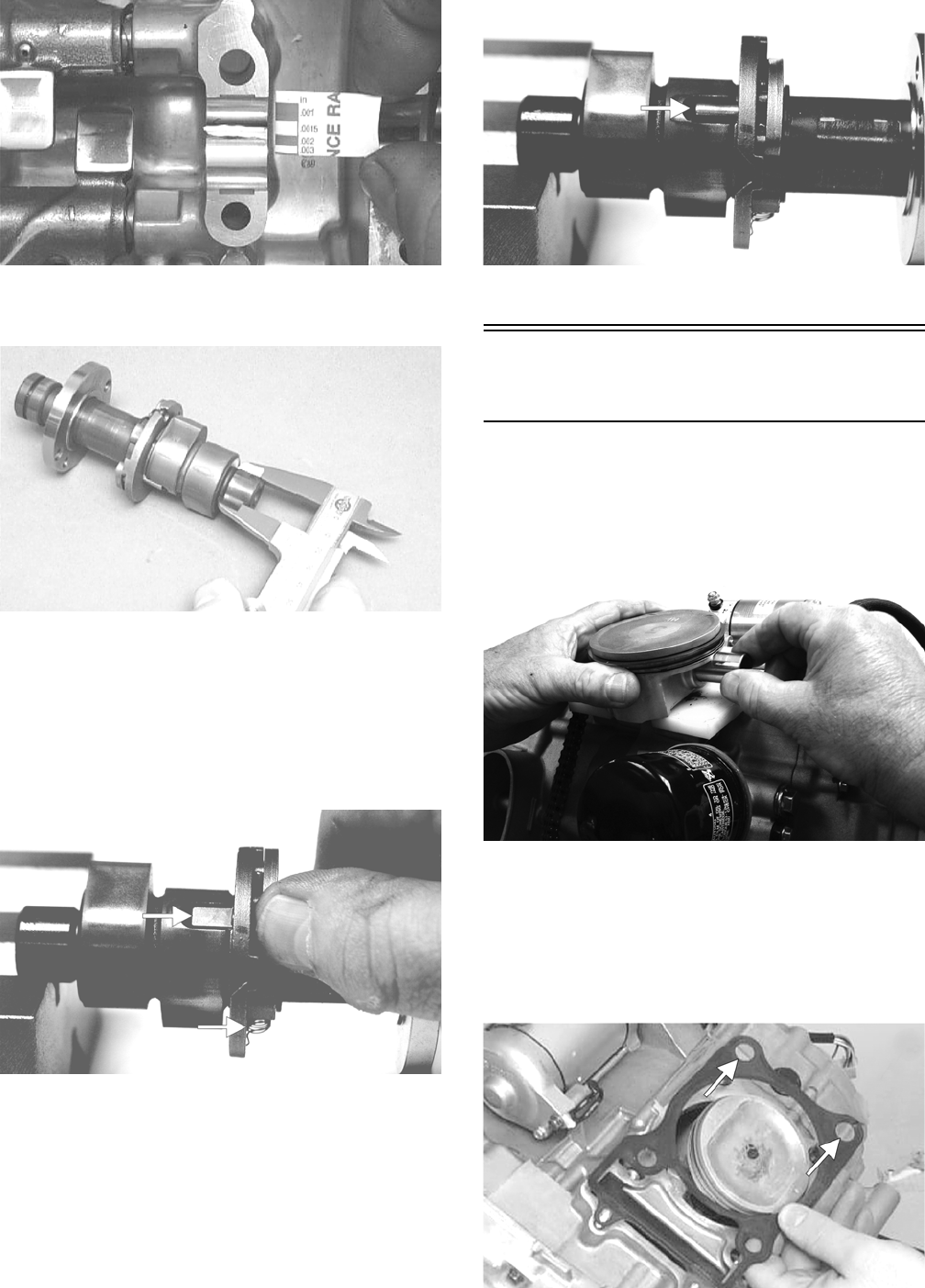
37
CC145D
6. If clearance is excessive, measure the journals of the
camshaft.
CC287D
NOTE: If the journals are worn, replace the cam-
shaft; then measure the clearance again. If it is still
out of tolerance, replace the cylinder head.
Inspecting Camshaft Spring/Drive
Pin
1. Inspect the spring and unloader pin for damage.
CF061A
NOTE: With the weight extended, the unloader pin
should be flat-side out; with the weight retracted, the
unloader pin should be round-side out.
CF060A
2. If damaged, the camshaft must be replaced.
Installing Top-Side
Components
A. Piston
B. Cylinder
1. Lubricate the piston pin, connecting rod, and piston pin
bore with motor oil; then install the piston on the con-
necting rod making sure there is a circlip on each side.
FI626
NOTE: The piston should be installed so the IN
points towards the intake side.
2. Place the two alignment pins into position. Place a
new cylinder gasket into position; then place a piston
holder (or suitable substitute) beneath the piston skirt
and square the piston in respect to the crankcase.
MD1344
For Discount Arctic Cat Parts Call 606-678-9623 or 606-561-4983
www.mymowerparts.com
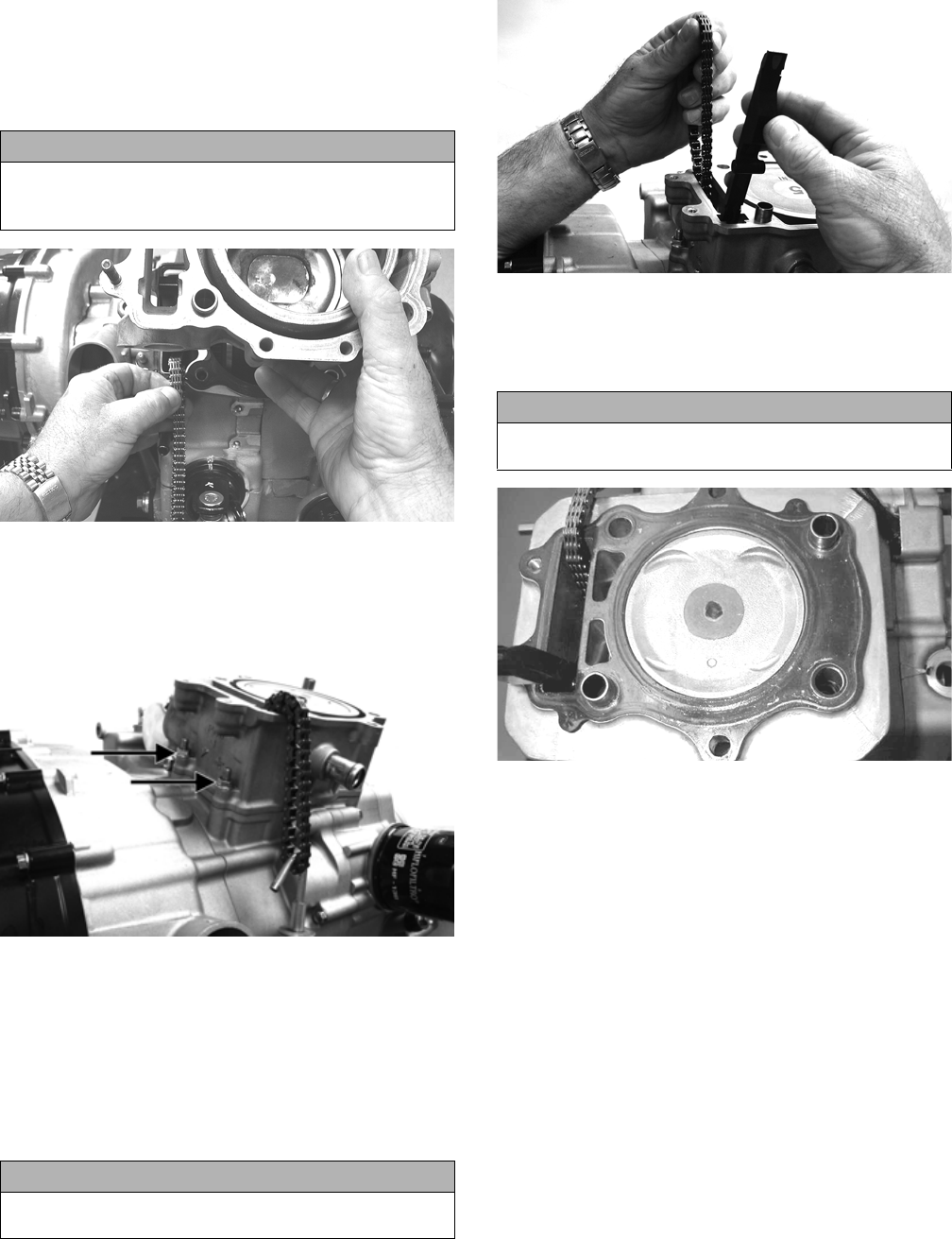
38
3. Lubricate the inside wall of the cylinder; then using a
ring compressor or the fingers, compress the rings
and slide the cylinder over the piston. Route the cam
chain up through the cylinder cam chain housing;
then remove the piston holder and seat the cylinder
firmly on the crankcase.
GZ142
4. Loosely install the two nuts securing the cylinder to
the right-side crankcase half.
NOTE: The two cylinder-to-crankcase nuts will be
tightened in step 9.
FI622A
C. Cylinder Head/Camshaft
D. Cylinder Head Cover/
Rocker Arms
NOTE: Steps 1-4 in the preceding sub-section must
precede this procedure.
5. While keeping tension on the cam chain, place the
front cam chain guide into the cylinder.
FI621
6. Place a new gasket into position on the cylinder.
Place the alignment pins into position; then place the
head assembly into position on the cylinder making
sure the cam chain is routed through the chain cavity.
MD1347
7. Install the four cylinder head cap screws with wash-
ers. Note that the two cap screws on the right side of
the cylinder head nearest the cam sprocket are longer
than the two cap screws on the left (spark plug) side.
Tighten only until snug.
8. Install the two lower nuts securing the cylinder head
to the cylinder, one in front and one in rear.
9. In a crisscross pattern, tighten the four cylinder head
cap screws (from step 7) to 28 ft-lb. Tighten the two
lower cylinder head nuts (from step 8) to 20 ft-lb and
the cylinder-to-crankcase nuts (from step 4) to 8 ft-
lb.
10. With the timing inspection plug removed and the
cam chain held tight, rotate the crankshaft until the
piston is at top-dead-center.
11. While holding the cam chain to the front, install the
rear cam chain tensioner guide into the cylinder
head. Install the pivot cap screw and washer. Tighten
to 11 ft-lb.
CAUTION
The cylinder should slide on easily. Do not force the
cylinder or damage to the piston, rings, cylinder, or
crankshaft assembly may occur.
CAUTION
Care should be taken that the bottom of the chain
guide is secured in the crankcase boss.
CAUTION
Keep tension on the cam chain to avoid damaging the
crankcase boss.
For Discount Arctic Cat Parts Call 606-678-9623 or 606-561-4983
www.mymowerparts.com
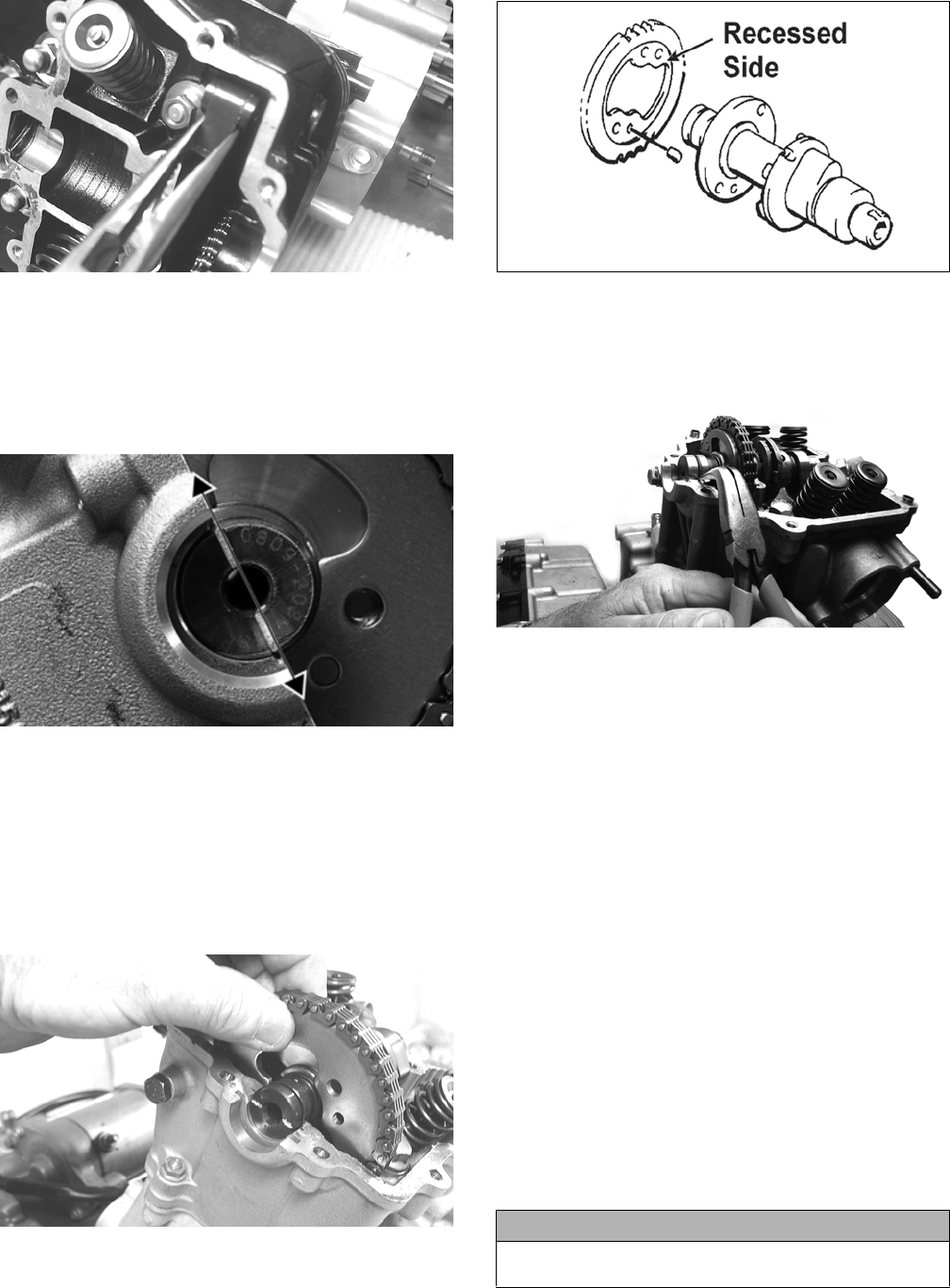
39
CD383
12. With the alignment pin installed in the camshaft and
the cam lobes directed down (toward the piston),
place the camshaft in position and verify that the tim-
ing mark on the magneto is visible through the
inspection plug and that the timing marks on the
camshaft sprocket are parallel with the valve cover
mating surface.
GZ190C
NOTE: When the camshaft assembly is seated,
make sure the alignment pin in the camshaft aligns
with the smallest hole in the sprocket.
13. With the alignment pin installed in the camshaft,
loosely place the cam sprocket (with the recessed
side facing the camshaft lobes) onto the camshaft
and place it into position with the cam chain over the
sprocket.
CD463
MD1359
14. Place the C-ring into position in its groove in the cyl-
inder head.
FI615
NOTE: At this point, oil the camshaft bearings, cam
lobes, and the three seating journals on the cylinder
head.
NOTE: Note the position of the alignment marks on
the end of the camshaft. They must be parallel with
the valve cover mating surface. If rotating the cam-
shaft is necessary for alignment, do not allow the
chain and sprocket to rotate and be sure the cam
lobes end up in the down position.
15. When the camshaft assembly is seated, ensure the
following.
A. Piston still at top-dead-center.
B. Camshaft lobes directed down (toward the pis-
ton).
C. Camshaft alignment marks parallel to the valve
cover mating surface.
D. Recessed side of the sprocket directed toward
the cam lobes.
E. Camshaft alignment pin and sprocket alignment
hole (smallest) are aligned.
16. Place the tab washer onto the sprocket making sure it
covers the pin in the alignment hole.
CAUTION
If any of the above factors are not as stated, go back to
step 13 and carefully proceed.
For Discount Arctic Cat Parts Call 606-678-9623 or 606-561-4983
www.mymowerparts.com
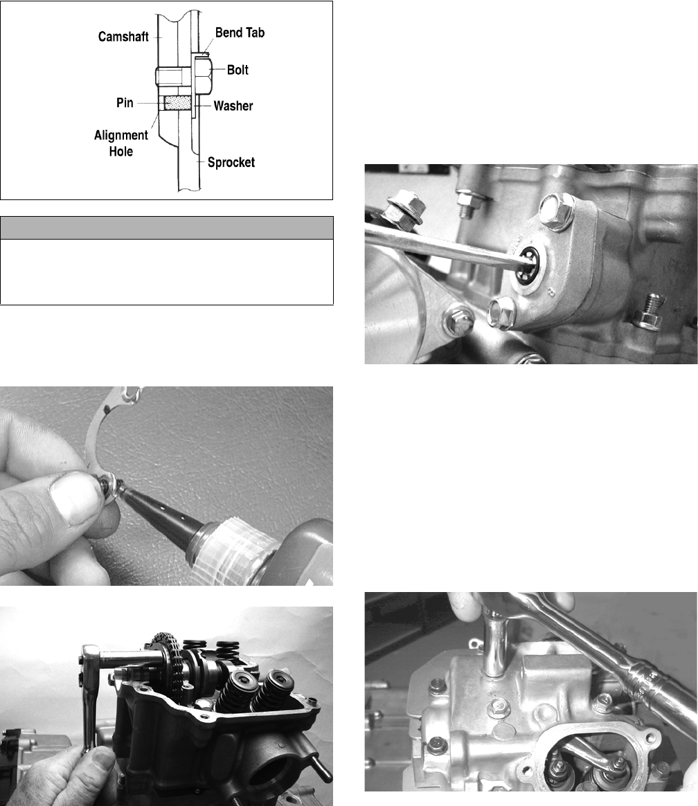
40
MD1363
17. Apply red Loctite #271 to the first cap screw secur-
ing the sprocket and tab washer to the camshaft; then
install the cap screw and tab washer. Tighten cap
screw only until snug.
CC404D
FI612
18. Rotate the crankshaft until the second cap screw
securing the sprocket to the camshaft can be
installed; then install the cap screw (threads coated
with red Loctite #271). Tighten to 11 ft-lb; then bend
the tab to secure the cap screw.
19. Rotate the crankshaft until the first cap screw (from
step 17) securing the sprocket to the camshaft can be
addressed; then tighten to 11 ft-lb. Bend the tab to
secure the cap screw.
20. Install the cylinder head plug with the cupped end
facing the camshaft and the opening directed down-
wards.
21. Place the cam chain tensioner assembly and gasket
into the cylinder. Tighten to 10 ft-lb.
22. Using a flat-blade screwdriver, turn the tensioner
screw counterclockwise to apply tension to the cam
chain; then install the cap screw plug and washer and
tighten securely.
FI608
23. Loosen the adjuster screw jam nuts; then loosen the
adjuster screws on the rocker arms in the valve cover.
24. Apply a thin coat of Three Bond Sealant to the mat-
ing surface of the valve cover; then place the valve
cover into position. Note that the two alignment pins
are properly positioned.
NOTE: At this point, the rocker arms and adjuster
screws must not have pressure on them.
25. Install the four top-side cap screws with rubber
washers; then install the remaining cap screws.
Tighten only until snug.
MD1261
26. In a crisscross pattern starting from the center and
working outward, tighten the cap screws (from step
25) to 8 ft-lb.
27. Adjust valve/tappet clearance (see Periodic Mainte-
nance).
28. Place the two tappet covers with O-rings into position;
then install and tighten the cap screws to 8 ft-lb.
CAUTION
Care must be taken that the tab washer is installed
correctly to cover the alignment hole on the sprocket.
If the alignment pin falls out, severe engine damage
will result.
For Discount Arctic Cat Parts Call 606-678-9623 or 606-561-4983
www.mymowerparts.com
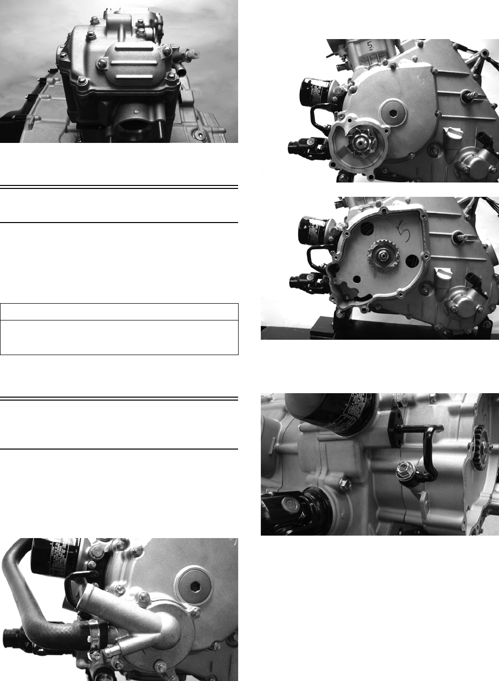
41
FI602
29. Install the spark plug and tighten securely; then
install the timing inspection plug.
Left-Side Components
NOTE: For efficiency, it is preferable to remove and
disassemble only those components which need to
be addressed and to service only those components.
The technician should use discretion and sound
judgment.
NOTE: The engine/transmission does not have to
be removed from the frame for this procedure.
Removing Left-Side
Components
A. Water Pump
B. Speed Sensor
C. Magneto Cover/Stator Assembly
1. Remove the coolant hose connecting the water pump
to the cylinder; then remove the water pump cover.
FI538
2. Remove the water pump housing assembly noting
the location of the longer cap screw. Account for a
gasket and two alignment pins.
FI539
FI541
3. Remove two cap screws and the oil bolt securing the
oil pressure relief line to the engine. Account for two
crush washers and an O-ring.
FI544
4. Remove the water pump drive gear; then remove the
speed sensor housing assembly. Account for two
alignment pins, a gasket, and two seal washers.
AT THIS POINT
To service any one specific component, only limited dis-
assembly of components may be necessary. Note the
AT THIS POINT information in each sub-section.
For Discount Arctic Cat Parts Call 606-678-9623 or 606-561-4983
www.mymowerparts.com
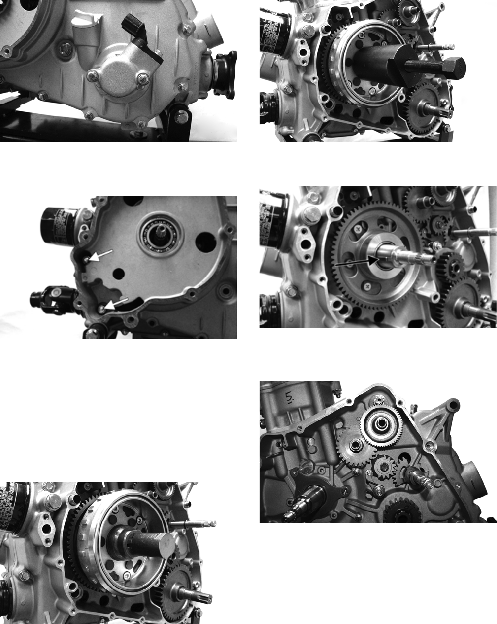
42
FI543
5. Remove the cap screws securing the magneto cover
to the crankcase. Note the location of the two inter-
nal cap screws and the two longer cap screws.
FI596A
6. Remove the magneto cover and account for two
alignment pins and the gasket.
D. Rotor/Flywheel
E. Starter Clutch/Gear
F. Starter Motor
NOTE: Steps 1-6 in the preceding sub-section must
precede this procedure.
7. Remove the nut securing the rotor/flywheel on the
crankshaft and install the crankshaft protector.
FI549
8. Using the Magneto Rotor Remover Set, break the
rotor/flywheel loose from the crankshaft; then
remove the puller and crankshaft protector and
remove the rotor/flywheel.
FI550
9. Remove the flywheel key from the crankshaft; then
remove the starter clutch gear.
FI551A
10. Remove starter idler gears and their respective
shafts; then remove the starter motor. Account for an
O-ring on the starter drive housing.
FI555
G. Shift Shaft
H. Drive Gear
NOTE: Steps 1-10 in the preceding sub-sections
must precede this procedure.
11. Remove the shift shaft noting a washer on each end;
then remove the cap screw securing the gear shift
cam plate and remove the plate from the shaft.
For Discount Arctic Cat Parts Call 606-678-9623 or 606-561-4983
www.mymowerparts.com
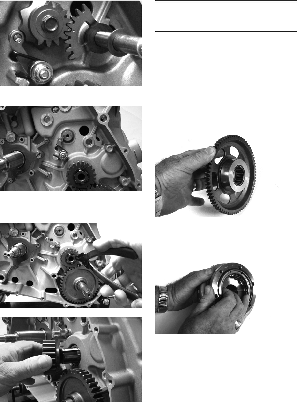
43
FI559
12. Remove the shift detent cam arm and spring.
FI560
13. Remove the snap ring securing the output drive gear
to the output shaft and remove the gear noting that
the hub flange is directed toward the crankcase.
FI564
FI566
Servicing Left-Side
Components
INSPECTING STARTER CLUTCH/
GEAR
1. Place the starter clutch gear onto the rotor/flywheel
and attempt to rotate the starter clutch gear clock-
wise. It should lock up to the rotor/flywheel. Rotate
the gear counterclockwise and it should turn freely. If
it moves or locks up both ways, the starter clutch
must be replaced.
2. Inspect the starter clutch gear for chipped or missing
teeth or discoloration/scoring of the clutch surface.
Inspect the bearing for loose, worn, or discolored
rollers. If bearing is damaged, it must be replaced.
FI569
3. Inspect the one-way bearing for chipped surfaces,
missing rollers, or discoloration. If any of the above
conditions exist, replace the starter clutch assembly.
FI572
REPLACING STARTER CLUTCH
ASSEMBLY
1. Remove the cap screws securing the one-way clutch
assembly to the flywheel; then remove from the fly-
wheel.
For Discount Arctic Cat Parts Call 606-678-9623 or 606-561-4983
www.mymowerparts.com
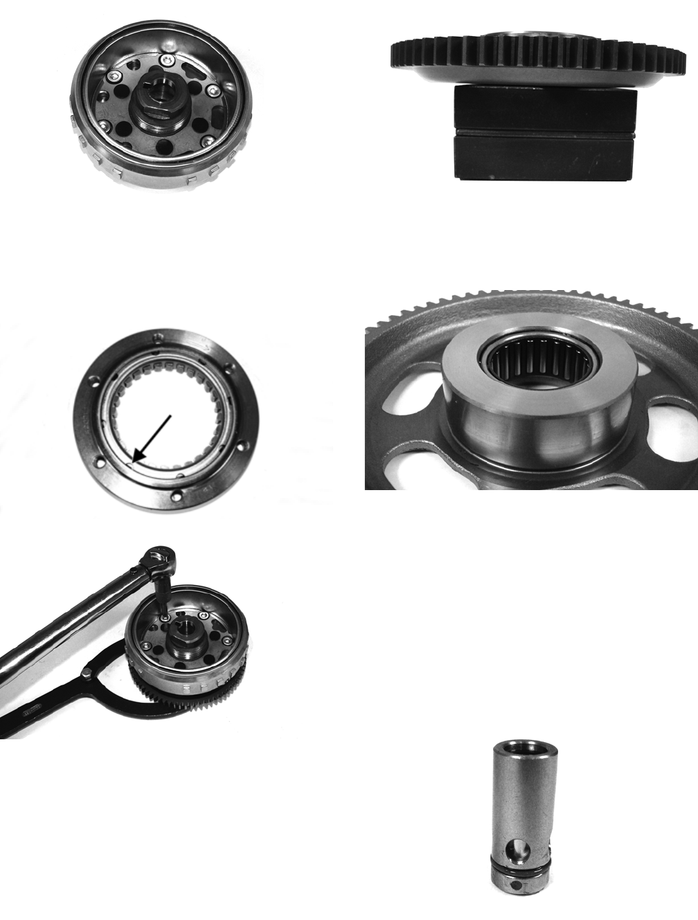
44
FI570
2. Thoroughly clean the rotor/flywheel; then install the
new one-way clutch and secure with the cap screws
after applying a drop of red Loctite #271 to the
threads. Tighten to 26 ft-lb using a crisscross pattern.
Make sure the one-way bearing is installed with the
notches directed away from the rotor/flywheel.
FI576A
FI578
REPLACING STARTER GEAR
BEARING
1. Support the starter clutch gear in a press making sure
to support the hub around the entire circumference;
then using a suitable bearing driver, press the bearing
from the gear.
FI583
2. Thoroughly clean the gear hub; then apply a drop of
green Loctite #620 to the bearing outer race and
press into the gear hub until even with the lower
chamfer radius.
FI580
INSPECTING STATOR/MAGNETO
COVER ASSEMBLY
1. Inspect the stator for burned or discolored wiring,
broken or missing hold-down clips, or loose cap
screws.
2. Inspect the bearings in the magneto housing for dis-
coloration, roughness when rotated, and secure fit in
bearing bores.
3. Inspect the oil pressure relief valve for evidence of
metal chips or contamination. Do not disassemble
the valve.
FI588
For Discount Arctic Cat Parts Call 606-678-9623 or 606-561-4983
www.mymowerparts.com
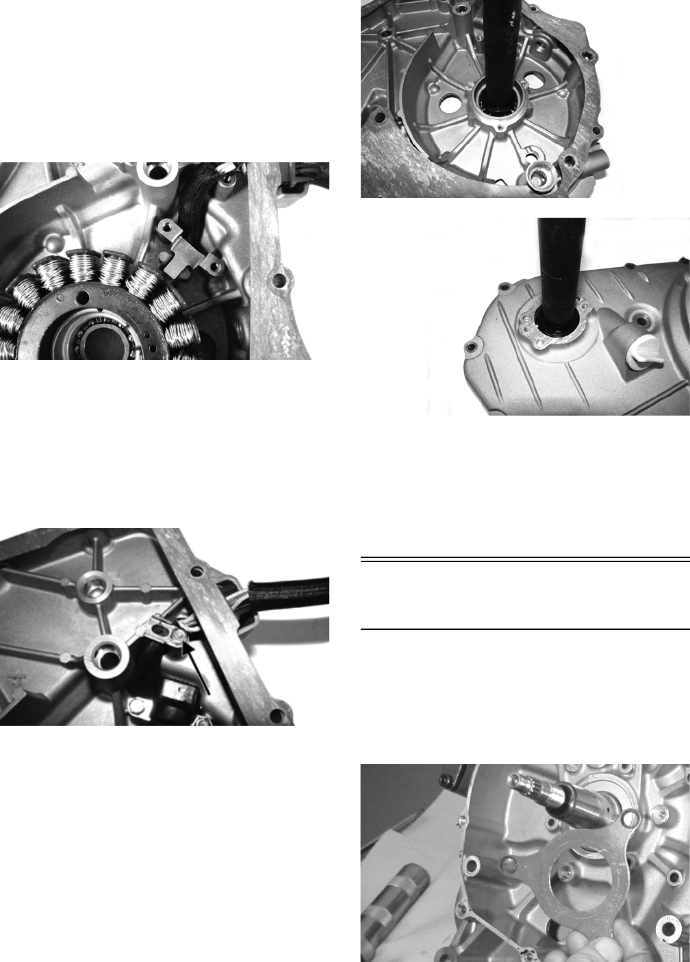
45
REPLACING STATOR/CRANKSHAFT
POSITION SENSOR
1. Remove the three cap screws securing the stator coil,
two cap screws securing the crankshaft position sen-
sor, and one cap screw from the harness hold-down.
2. Lift the rubber grommet out of the housing; then
remove the stator coil/crankshaft position sensor.
Account for and note the position of the harness
hold-down under the crankshaft position sensor.
FI590
3. Install the new stator assembly and secure with three
cap screws using a drop of red Loctite #271 on each.
Tighten to 8 ft-lb.
4. Place the stator wire harness hold-down into posi-
tion; then install the crankshaft position sensor and
secure with two cap screws. Tighten securely.
5. Install the upper cable hold-down and secure with a
cap screw. Tighten securely.
FI595A
REPLACING MAGNETO COVER
BEARINGS
1. Using a suitable press and proper support, press the
bearing from the housing as indicated (one from out-
side and one from inside).
FI593
FI594
2. Clean the bearing bores in the housing and inspect
closely for cracks or shiny areas indicating bearing
movement. Replace the housing if any of the above
are evident.
3. With a drop of red Loctite #271 around the bearing
bore, press a new bearing into the magneto cover
until the bearing is firmly seated in the bearing bore.
Installing Left-Side
Components
A. Starter Clutch/Gear
B. Rotor/Flywheel
1. If removed, place the crankshaft bearing retainer into
position. Apply red Loctite #271 to the three cap
screws. Install and tighten the three cap screws
securely.
MD1122
For Discount Arctic Cat Parts Call 606-678-9623 or 606-561-4983
www.mymowerparts.com
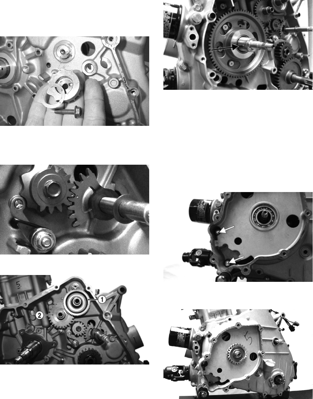
46
2. Install the starter motor and tighten the two cap
screws to 8 ft-lb.
3. Install the shift detent cam making sure the washer is
installed.
MD1086
4. Install the shift detent cam arm and spring.
5. Install the gear shift shaft assembly and washer mak-
ing sure to align the alignment marks.
FI559
6. Install starter idler gears (1) and (2).
FI555A
7. Install the starter clutch gear onto the crankshaft;
then install the rotor/flywheel key in the crankshaft.
FI551A
8. Install the rotor/flywheel and secure with the flange
nut. Tighten to 107 ft-lb.
C. Magneto Cover
D. Water Pump
NOTE: Steps 1-8 in the preceding sub-section must
precede this procedure.
9. Install two alignment pins and place the magneto
cover gasket into position. Install the magneto cover.
Noting the different-lengthed 6 mm cap screws and
the location of the two internal cap screws, tighten
cap screws in a crisscross pattern to 8 ft-lb.
FI596A
10. Install the water pump drive gear and secure with the
nut. Tighten to 28 ft-lb.
FI547
11. Install two alignment pins and a gasket on the mag-
neto cover; then install the water pump housing
assembly. Tighten the cap screws to 8 ft-lb.
For Discount Arctic Cat Parts Call 606-678-9623 or 606-561-4983
www.mymowerparts.com
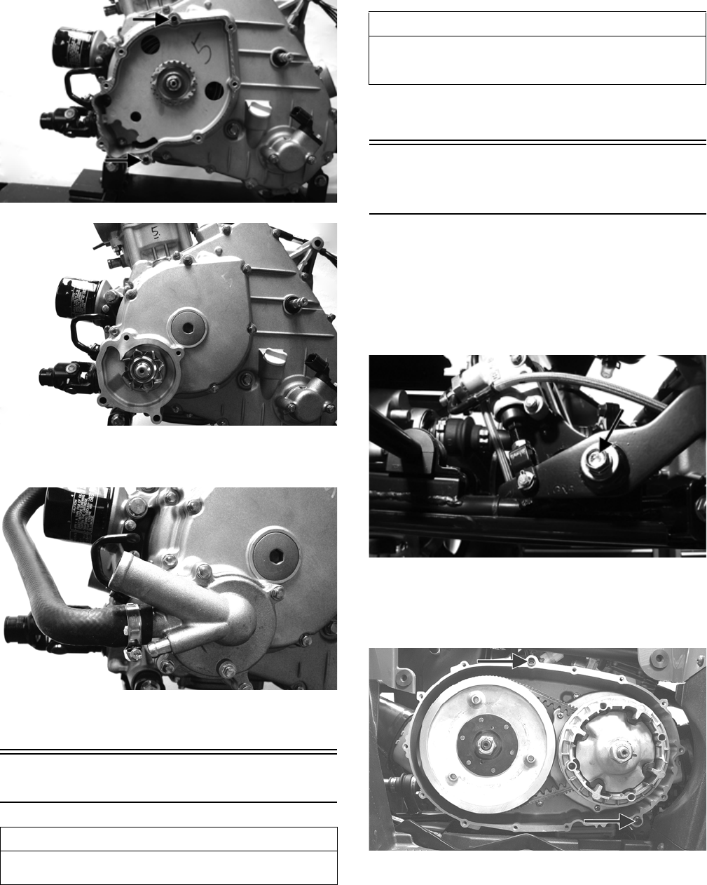
47
FI541A
FI539
12. Install the water pump cover with a new O-ring and
secure with the four cap screws. Tighten to 8 ft-lb.
FI538
13. Connect the coolant hoses to the water pump and
secure with the hose clamps. Tighten securely.
Right-Side Components
NOTE: For efficiency, it is preferable to remove and
disassemble only those components which need to
be addressed and to service only those components.
The technician should use discretion and sound
judgment.
NOTE: The engine/transmission does not have to
be removed from the frame for this procedure.
Removing Right-Side
Components
A. V-Belt Cover
B. Driven Pulley
C. Clutch Cover
1. If the engine is still in the frame, remove the cap
screw securing the brake pedal to the frame; then
slide the pedal outward.
KC438A
2. Remove the cap screws securing the V-belt cover to
the clutch cover; then slide the brake pedal outward
and remove the V-belt cover. Account for two align-
ment pins and a gasket.
KC142A
3. Mark the movable drive face and the fixed drive face
for installing purposes; then remove the nut holding
the movable drive face onto the crankshaft.
AT THIS POINT
To service center crankcase components only, proceed
to Removing Right-Side Components.
AT THIS POINT
To service any one specific component, only limited dis-
assembly of components may be necessary. Note the
AT THIS POINT information in each sub-section.
For Discount Arctic Cat Parts Call 606-678-9623 or 606-561-4983
www.mymowerparts.com
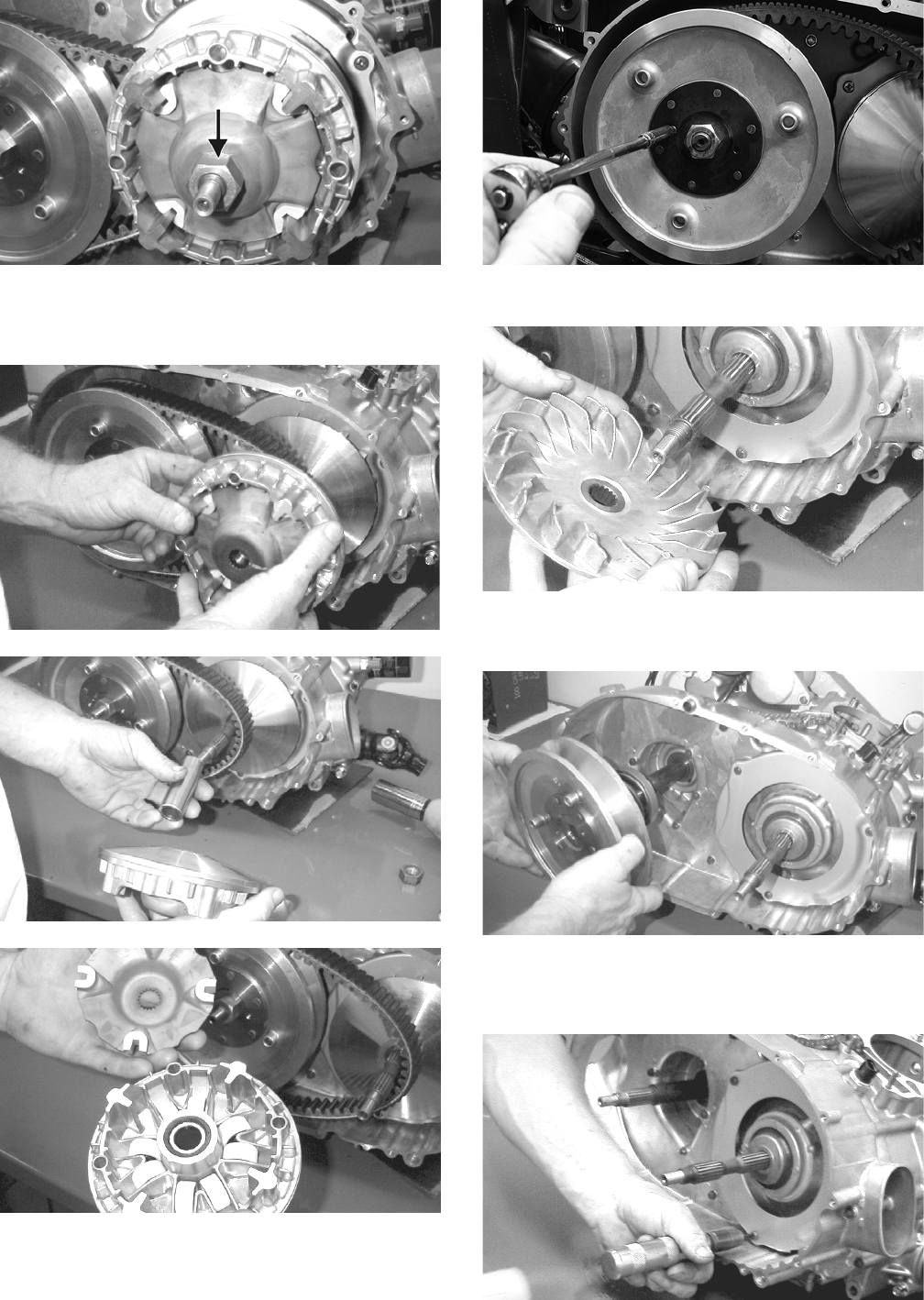
48
MD1033
4. Remove the movable drive face and spacer. Account
for the movable drive face rollers and outer drive
face cover.
MD1035
MD1034
MD1036
5. Using a 6 mm cap screw threaded into the fixed
driven face, spread the driven pulley by turning the
cap screw clockwise; then remove the V-belt.
KC132
6. Remove the fixed drive face.
MD1094
7. Remove the nut holding the driven pulley assembly;
then remove the driven pulley assembly.
MD1068
8. Using an impact screwdriver, remove the three Phil-
lips-head cap screws holding the air intake plate.
Remove the air intake plate.
MD1092
For Discount Arctic Cat Parts Call 606-678-9623 or 606-561-4983
www.mymowerparts.com
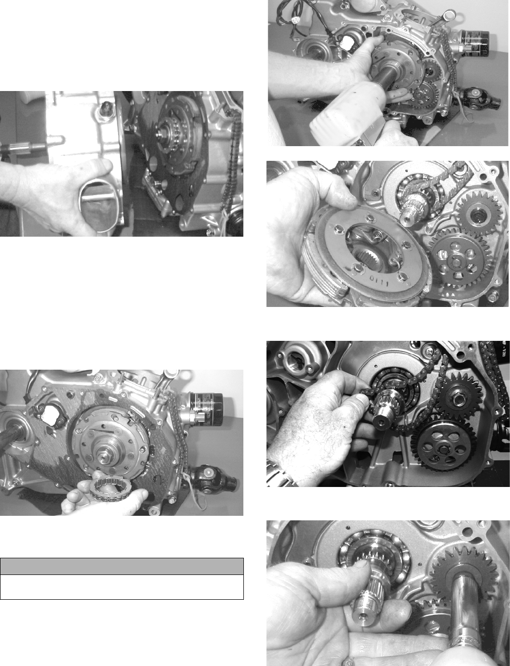
49
9. Remove the cap screws holding the clutch cover onto
the right-side crankcase half. Note the positions of
the different-lengthed cap screws for installing pur-
poses.
10. Using a rubber mallet, loosen the clutch cover; then
pull it away from the right-side crankcase half.
Account for two alignment pins and gasket.
MD1115
D. Centrifugal Clutch Assembly
E. Oil Pump Drive Gear
F. Oil Pump Driven Gear
NOTE: Steps 1-10 in the preceding sub-section
must precede this procedure.
11. Remove the one-way clutch noting the direction of
the green dot or the word OUTSIDE for installing
purposes.
MD1286
12. Remove the left-hand threaded nut holding the cen-
trifugal clutch assembly.
MD1014
MD1016
13. Remove the cam chain.
FI630
14. Remove the oil pump drive gear cap screw.
MD1018
15. Remove oil pump drive gear. Account for the pin.
CAUTION
Care must be taken when removing the nut; it has
“left-hand” threads.
For Discount Arctic Cat Parts Call 606-678-9623 or 606-561-4983
www.mymowerparts.com
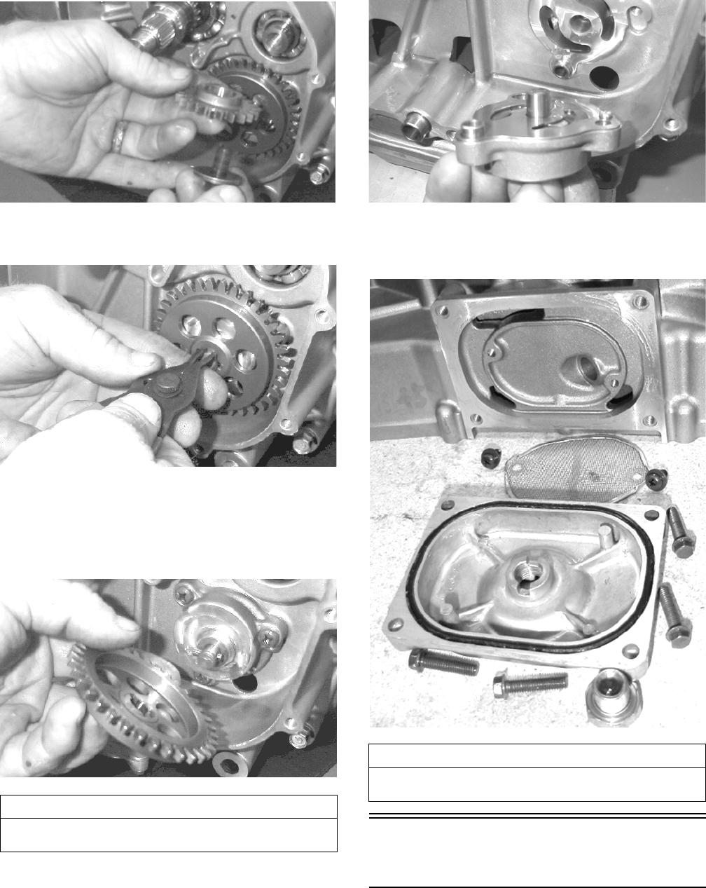
50
MD1017
16. Remove the snap ring holding the oil pump driven
gear.
MD1019
NOTE: Always use a new snap ring when installing
the oil pump driven gear.
17. Remove oil pump driven gear. Account for the drive
pin and thrust washer.
MD1020
G. Oil Pump/Oil Strainer
NOTE: Steps 1-17 in the preceding sub-sections
must precede this procedure.
18. Remove three cap screws holding the oil pump and
remove the oil pump. Account for two alignment
pins.
MD1060
19. Remove the four cap screws securing the oil strainer
cap; then remove the Phillips-head screws securing
the oil strainer. Account for the O-ring.
MD1207
Servicing Right-Side
Components
NOTE: Whenever a part is worn excessively,
cracked, damaged in any way, or out of tolerance,
replacement is necessary.
AT THIS POINT
To service clutch components, see Servicing Right-Side
Components sub-section.
AT THIS POINT
To service center crankcase components only, proceed
to Separating Crankcase Halves.
For Discount Arctic Cat Parts Call 606-678-9623 or 606-561-4983
www.mymowerparts.com
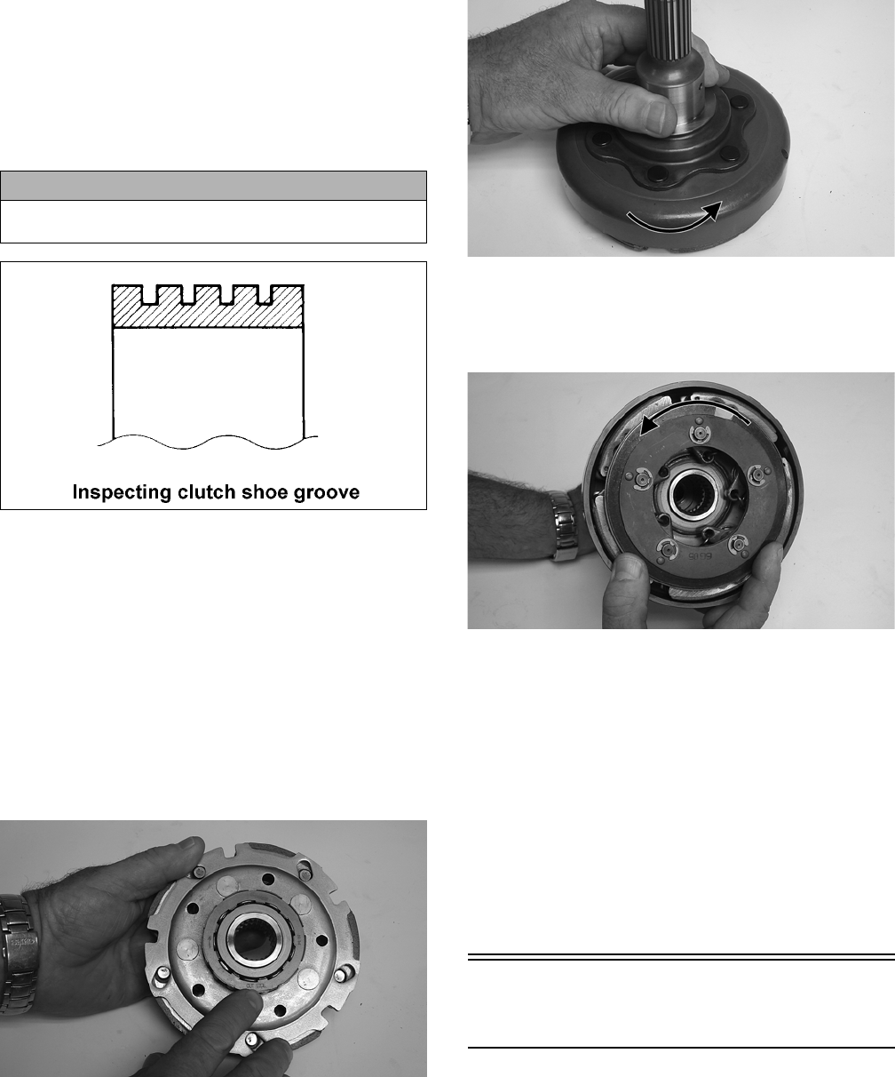
51
INSPECTING CENTRIFUGAL CLUTCH
SHOE
1. Inspect the clutch shoe for uneven wear, chips,
cracks, or discoloration.
2. Inspect the depth of the grooves in the clutch shoes.
If any shoe is worn to the bottom of the groove,
replace the complete set.
ATV1014
INSPECTING CENTRIFUGAL CLUTCH
HOUSING
1. Inspect the clutch housing for burns, marks, scuffs,
cracks, scratches, or uneven wear.
2. If the housing is damaged in any way, the housing
must be replaced.
INSPECTING PRIMARY
ONE-WAY DRIVE
1. Place the one-way clutch onto the clutch shoe assem-
bly with the green dot or the word “OUTSIDE”
directed away from the clutch shoe.
KC330
2. Place the clutch housing onto the clutch shoe/one-
way clutch.
NOTE: It will be necessary to rotate the clutch hous-
ing counterclockwise to properly seat the one-way
clutch.
KC331A
3. Check that the clutch shoe can only be rotated coun-
terclockwise in respect to the clutch housing. If the
clutch shoe locks up or turns in both directions, the
one-way clutch must be replaced.
KC332A
INSPECTING OIL PUMP
1. Inspect the pump for damage.
2. It is inadvisable to remove the screw securing the
pump halves. If the oil pump is damaged, it must be
replaced.
NOTE: The oil pump is a non-serviceable compo-
nent and must be replaced as a complete assembly.
DRIVEN PULLEY ASSEMBLY
NOTE: The driven pulley assembly is a non-service-
able component and must be replaced as a complete
assembly.
Installing Right-Side
Components
A. Oil Strainer/Oil Pump
1. Place the oil strainer into position beneath the crank-
case. Tighten the Phillips-head screws securely.
CAUTION
Always replace clutch shoes as a complete set or
severe imbalance could occur.
For Discount Arctic Cat Parts Call 606-678-9623 or 606-561-4983
www.mymowerparts.com
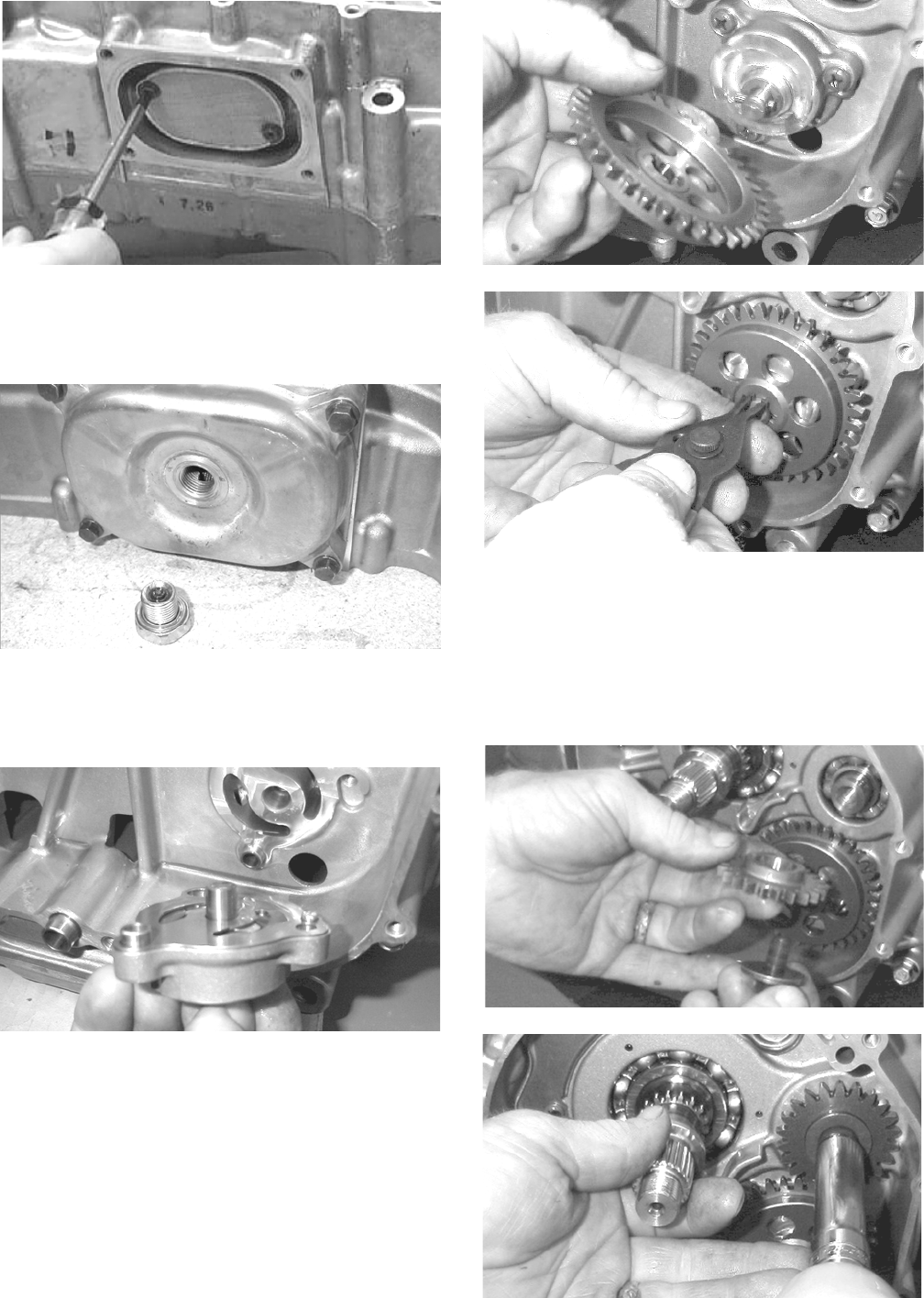
52
MD1337
2. Place the strainer cap into position on the crankcase
making sure the O-ring is properly installed and
secure with the four cap screws; then tighten the oil
drain plug to 20 ft-lb.
MD1208
3. Place two alignment pins and the oil pump into posi-
tion on the crankcase and secure with the Phillips-
head screws coated with red Loctite #271. Tighten to
8 ft-lb.
MD1060
4. Place the thrust washer and drive pin into position on
the oil pump shaft, install the oil pump driven gear
making sure the recessed side of the gear is directed
inward, and secure with a new snap ring.
NOTE: Always use a new snap ring when installing
the oil pump driven gear.
MD1020
MD1019
5. Install the cam chain.
NOTE: Keep tension on the cam chain to avoid dam-
aging the crankcase boss.
6. Place the pin into position, install the oil pump drive
gear, and tighten the cap screw (coated with red Loc-
tite #271) to 63 ft-lb.
MD1017
MD1018
For Discount Arctic Cat Parts Call 606-678-9623 or 606-561-4983
www.mymowerparts.com
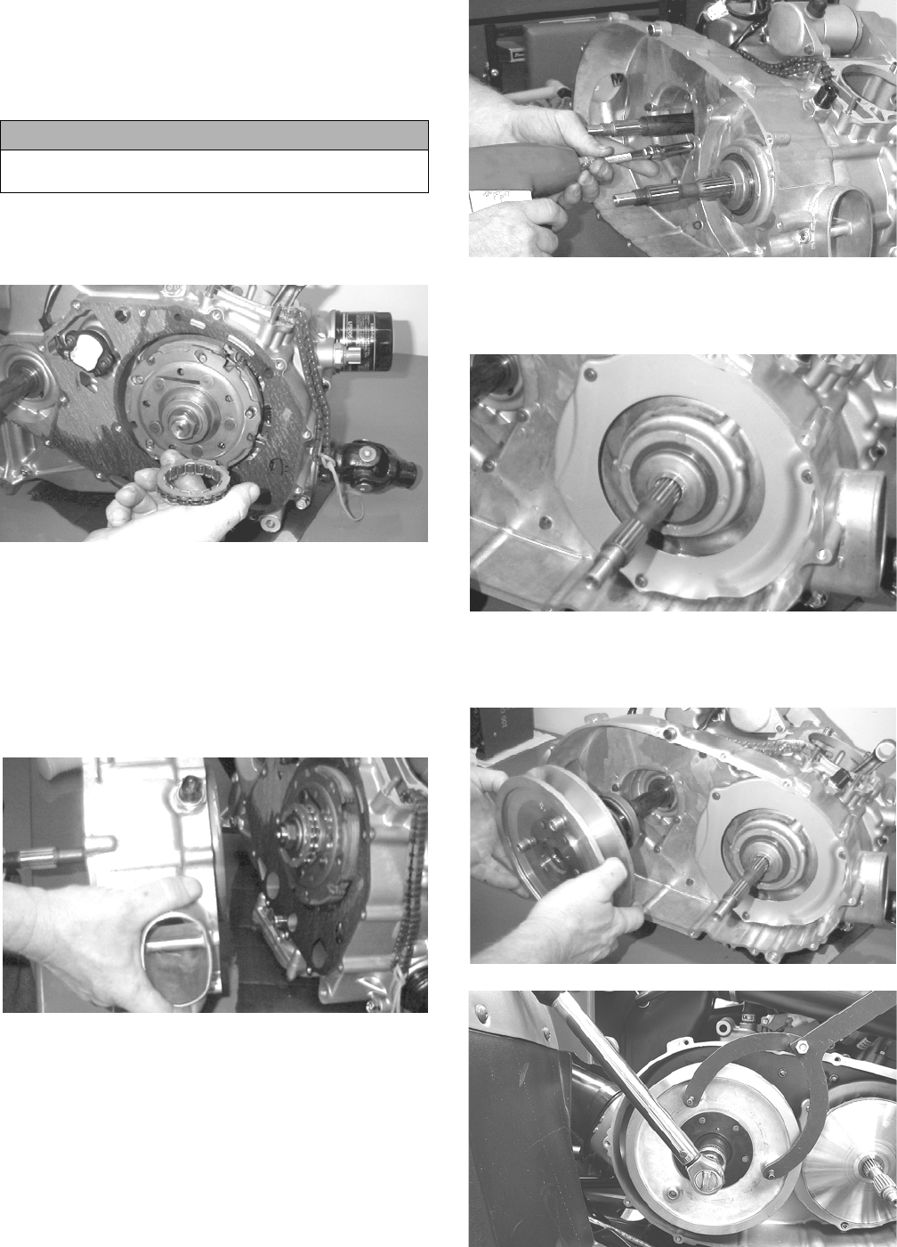
53
7. Install the clutch shoe assembly on the crankshaft;
then install the flange nut (left-hand thread) (coated
with red Loctite #271). Tighten to 147 ft-lb.
NOTE: The flat side of the flange nut should be
directed towards the clutch shoe.
8. Install the one-way clutch making sure that the green
dot or the word OUTSIDE is directed away from the
crankcase.
MD1286
B. Clutch Cover
C. Fixed Drive Face
D. Movable Drive Face
NOTE: Steps 1-8 in the preceding sub-section must
precede this procedure.
9. Install two alignment pins and place the clutch cover
gasket into position. Install the clutch cover.
MD1115
10. Tighten the clutch cover cap screws to 8 ft-lb.
MD1117
11. Install the air intake plate. Apply red Loctite #271 to
the threads of the three Phillips-head cap screws;
then install and tighten securely.
MD1342
12. Place the driven pulley assembly into position and
secure with the nut (threads coated with red Loctite
#271). Tighten to 147 ft-lb.
MD1068
KC134
CAUTION
Care must be taken when installing the flange nut; it
has “left-hand” threads.
For Discount Arctic Cat Parts Call 606-678-9623 or 606-561-4983
www.mymowerparts.com
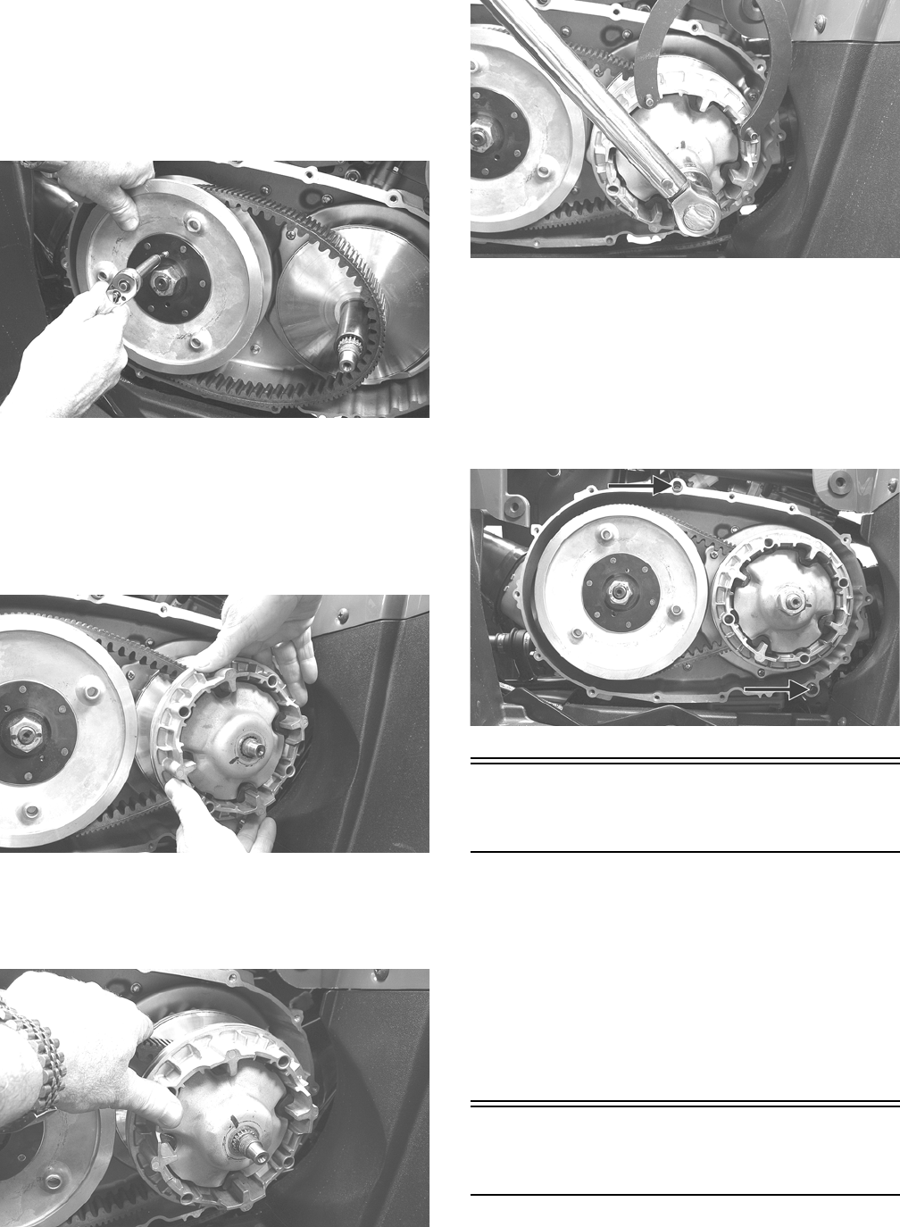
54
13. Slide the fixed drive face assembly onto the front
shaft.
14. Spread the faces of the driven pulley by threading a
V-belt cover cap screw into the fixed driven face and
tightening until the faces open sufficiently to allow
the V-belt to drop into the pulley approximately 3/4
in.
KC137
NOTE: The arrows on the V-belt should point in
direction of engine rotation.
15. Making sure the movable drive face rollers are in
position, pinch the V-belt together near its center and
slide the spacer and movable drive face onto the
shaft.
KC127
16. Coat the threads of the nut with red Loctite #271;
then making sure the splines of the clutch shaft pro-
trude through the cover plate, secure with the nut and
tighten to 147 ft-lb.
KC138
KC141
NOTE: At this point, the cap screw can be removed
from the driven pulley face.
17. Rotate the V-belt and drive/driven assemblies until
the V-belt is flush with the top of the driven pulley.
18. Install two alignment pins and place a new V-belt
cover gasket into position on the clutch cover. In a
crisscross pattern, tighten cap screws to 8 ft-lb.
KC142A
Center Crankcase
Components
NOTE: This procedure cannot be done with the
engine/transmission in the frame. Complete Remov-
ing procedures for Top-Side, Left-Side, and Right-
Side must precede this procedure.
NOTE: For efficiency, it is preferable to remove and
disassemble only those components which need to
be addressed and to service only those components.
The technician should use discretion and sound
judgment.
Separating Crankcase
Halves
1. Remove the left-side and right-side cap screws
securing the crankcase halves noting the position of
the different-sized cap screws for joining purposes.
For Discount Arctic Cat Parts Call 606-678-9623 or 606-561-4983
www.mymowerparts.com
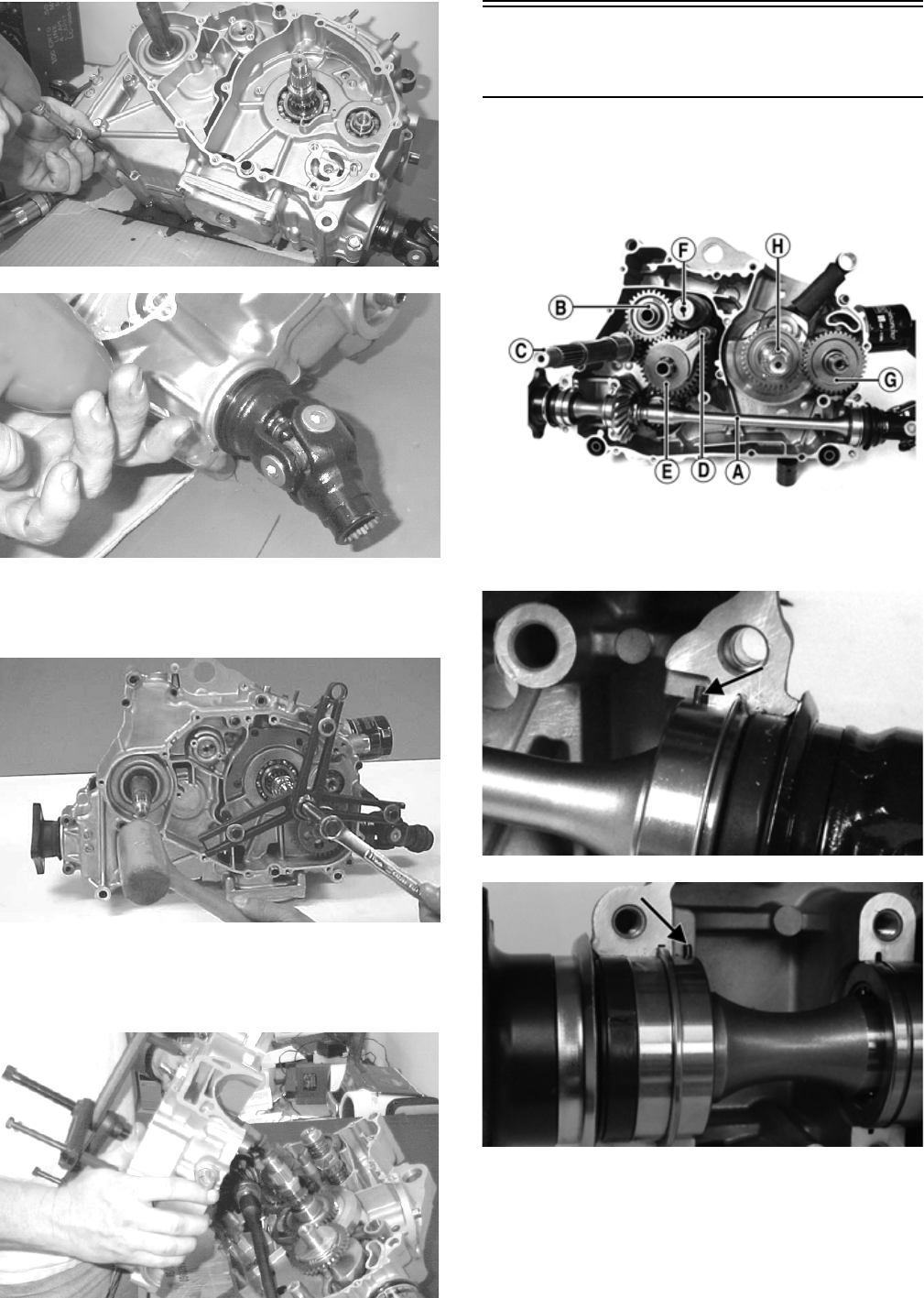
55
MD1006
MD1012
2. Using Crankcase Separator/Crankshaft Remover and
tapping lightly with a rubber mallet, separate the
crankcase halves. Account for two alignment pins.
CC869
NOTE: To keep the shaft/gear assemblies intact for
identification, tap the shafts toward the left-side
crankcase half when separating the halves.
MD1313
Disassembling Crankcase
Half
NOTE: To aid in installing, keep the assemblies
together and in order.
NOTE: For steps 1-6, refer to illustration FI639A.
FI639A
1. Remove the secondary driven shaft assembly (A)
noting the location of the front and rear bearing
locating pins and the center bearing locating ring.
FI660A
FI659A
For Discount Arctic Cat Parts Call 606-678-9623 or 606-561-4983
www.mymowerparts.com
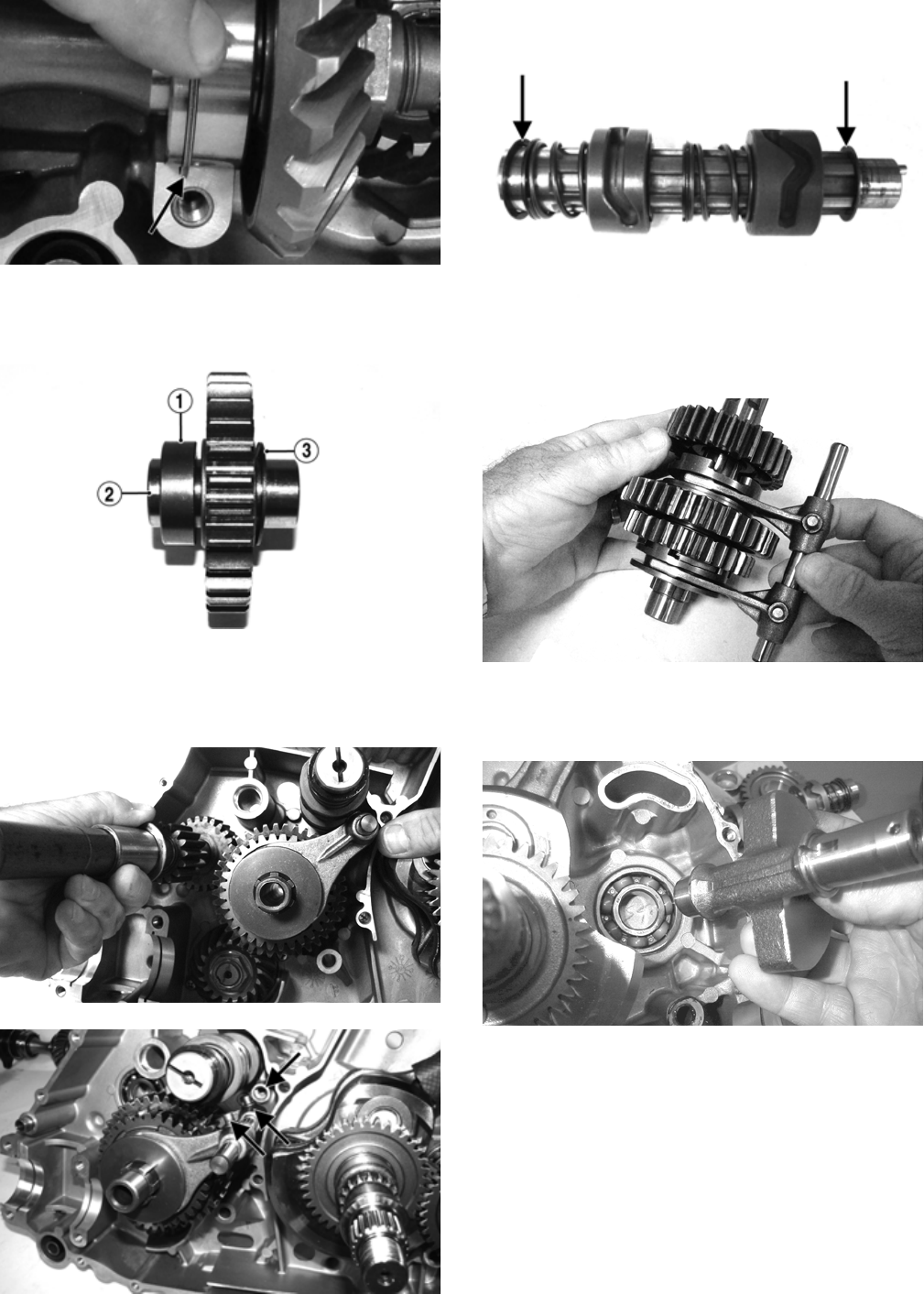
56
FI661A
2. Remove the reverse idler assembly (B). Account for
and note the location of the inner bushing (1), idler
shaft (2), and outer washer (3).
FI641A
3. Remove the driveshaft (C); then pull the shift fork
locating shaft (D) out of the crankcase locating boss
and allow the shift forks to disengage from the gear
shift shaft (F).
FI646
FI653A
4. Remove the gear shift shaft (F) noting the inner and
outer washers.
FI650A
5. Remove the countershaft assembly (E) along with
the shift fork assembly.
FI662
6. Remove the crank balancer driven gear (G) and
account for a key; then remove the crankshaft bal-
ancer shaft.
MD1024
7. Using Crankcase Separator/Crankshaft Remover
with the appropriate crankshaft protector, remove the
crankshaft.
For Discount Arctic Cat Parts Call 606-678-9623 or 606-561-4983
www.mymowerparts.com
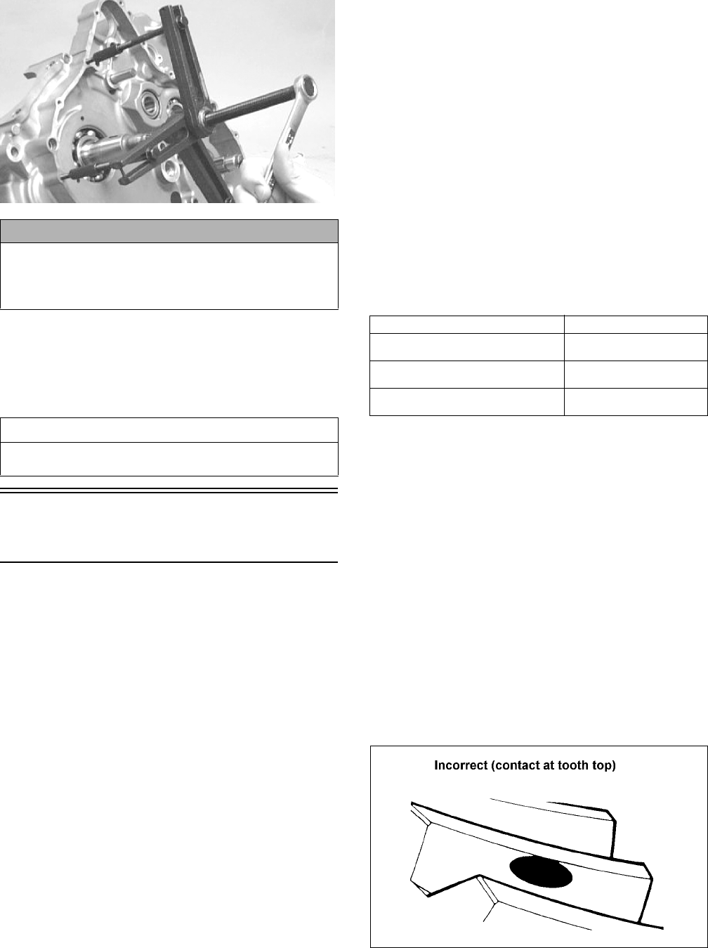
57
MD1330
8. Remove the secondary drive gear/secondary driven
gear retaining nut. From inside the crankcase using a
rubber mallet, drive out the output shaft assembly.
Account for the output shaft, a shim, a washer, and
the nut.
Servicing Center
Crankcase Components
NOTE: Whenever a part is worn excessively,
cracked, damaged in any way, or out of tolerance,
replacement is necessary.
SECONDARY GEARS
NOTE: When checking and correcting secondary
gear backlash and tooth contact, the universal joint
must be secured to the front shaft or false measure-
ments will occur.
Checking Backlash
NOTE: The rear shaft and bevel gear must be
removed for this procedure. Also, always start with
the original shims on the rear shaft.
1. Place the left-side crankcase cover onto the left-side
crankcase half to prevent runout of the secondary
transmission output shaft.
2. Install the secondary driven output shaft assembly
onto the crankcase.
3. Mount the indicator tip of the dial indicator on the
secondary driven bevel gear (centered on the gear
tooth).
4. While rocking the driven bevel gear back and forth,
note the maximum backlash reading on the gauge.
5. Acceptable backlash range is 0.05-0.33 mm (0.002-
0.013 in.).
Correcting Backlash
NOTE: If backlash measurement is within the
acceptable range, no correction is necessary.
1. If backlash measurement is less than specified,
remove an existing shim, measure it, and install a
new thinner shim.
2. If backlash measurement is more than specified,
remove an existing shim, measure it, and install a
thicker shim.
NOTE: Continue to remove, measure, and install
until backlash measurement is within tolerance. Note
the following chart.
Checking Tooth Contact
NOTE: After correcting backlash of the secondary
driven bevel gear, it is necessary to check tooth con-
tact.
1. Remove the secondary driven output shaft assembly
from the left-side crankcase half.
2. Clean the secondary driven bevel gear teeth of old oil
and grease residue.
3. Apply a thin, even coat of a machinist-layout dye to
several teeth of the gear.
4. Install the secondary driven output shaft assembly.
5. Rotate the secondary driven bevel gear several revo-
lutions in both directions.
6. Examine the tooth contact pattern in the dye and
compare the pattern to the illustrations.
ATV-0103
CAUTION
Do not remove the remaining output shaft assembly
unless absolutely necessary. If the shaft is removed,
the shaft nut must be replaced with a new one and the
shaft must be re-shimmed.
AT THIS POINT
To service crankshaft assembly, see Servicing Center
Crankcase Components sub-section.
Backlash Measurement Shim Correction
Under 0.05 mm (0.002 in.) Decrease Shim
Thickness
At 0.05-0.33 mm
(0.002-0.013 in.)
No Correction Required
Over 0.33 mm (0.013 in.) Increase Shim
Thickness
For Discount Arctic Cat Parts Call 606-678-9623 or 606-561-4983
www.mymowerparts.com
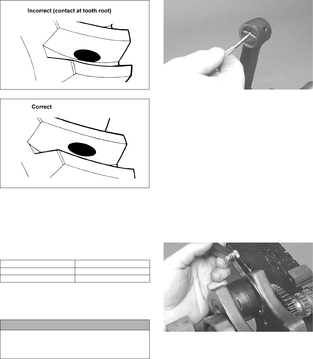
58
ATV-0105
ATV-0104
Correcting Tooth Contact
NOTE: If tooth contact pattern is comparable to the
correct pattern illustration, no correction is neces-
sary.
If tooth contact pattern is comparable to an incorrect pat-
tern, correct tooth contact according to the following
chart.
NOTE: To correct tooth contact, steps 1 and 2 (with
NOTE) of “Correcting Backlash” must be followed
and the above “Tooth Contact/Shim Correction” chart
must be consulted.
CRANKSHAFT ASSEMBLY
NOTE: The crankshaft and connecting rod is a non-
serviceable assembly. If any component is out of
specification, the assembly must be replaced.
Measuring Connecting Rod
(Small End Inside Diameter)
1. Insert a snap gauge into the upper connecting rod
small end bore; then remove the gauge and measure
it with micrometer.
CC290D
2. Maximum diameter must not exceed specifications.
Measuring Connecting Rod
(Small End Deflection)
1. Place the crankshaft on a set of V blocks and mount a
dial indicator and base on the surface plate. Position
the indicator contact point against the center of the
connecting rod small end journal.
2. Zero the indicator and push the small end of the con-
necting rod away from the dial indicator.
3. Maximum deflection must not exceed specifications.
Measuring Connecting Rod
(Big End Side-to-Side)
1. Push the lower end of the connecting rod to one side
of the crankshaft journal.
2. Using a feeler gauge, measure the gap between the
connecting rod and crankshaft journal.
CC289D
3. Acceptable gap range must be within specifications.
Measuring Crankshaft (Runout)
1. Place the crankshaft on a set of V blocks.
2. Mount a dial indicator and base on the surface plate.
Position the indicator contact at point 1 of the crank-
shaft.
Tooth Contact Shim Correction
Contacts at Top Decrease Shim Thickness
Contacts at Root Increase Shim Thickness
CAUTION
After correcting tooth contact, backlash must again be
checked and corrected (if necessary). Continue the
correcting backlash/correcting tooth contact proce-
dures until they are both within tolerance values.
For Discount Arctic Cat Parts Call 606-678-9623 or 606-561-4983
www.mymowerparts.com
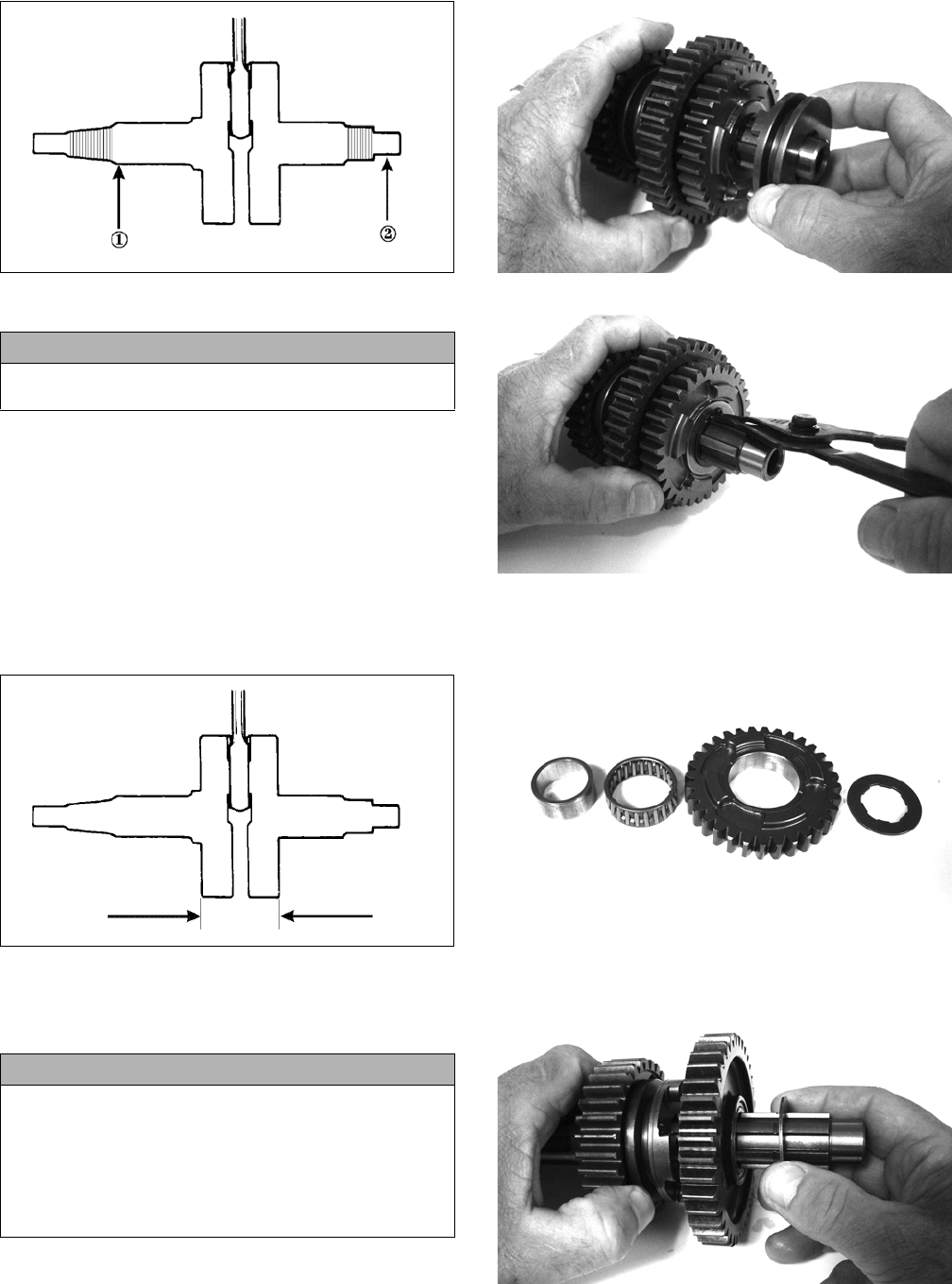
59
ATV-1074
3. Zero the indicator and rotate the crankshaft slowly.
4. Maximum runout must not exceed specifications.
NOTE: Proceed to check runout on the other end of
the crankshaft by positioning the indicator contact at
point 2 and following steps 3-4.
Measuring Crankshaft (Web-to-
Web)
1. Using a calipers, measure the distance from the out-
side edge of one web to the outside edge of the other
web.
ATV-1017
2. Acceptable width range must be within specifica-
tions.
COUNTERSHAFT
Disassembling
1. Remove the reverse driven gear dog; then remove
the circlip securing the reverse driven gear.
FI663
FI664
2. Remove the splined washer; then remove the reverse
driven gear along with the bearing and bushing.
FI665
3. Remove the low driven gear washer; then remove the
low driven gear along with the bearing and bushing.
FI666
CAUTION
Care should be taken to support the connecting rod
when rotating the crankshaft.
CAUTION
When disassembling the countershaft, care must be
taken to note the direction each major component
(dog, gear) faces. If a major component is installed
facing the wrong direction, transmission damage may
occur and/or the transmission will malfunction. In
either case, complete disassembly and assembly will
be required.
For Discount Arctic Cat Parts Call 606-678-9623 or 606-561-4983
www.mymowerparts.com
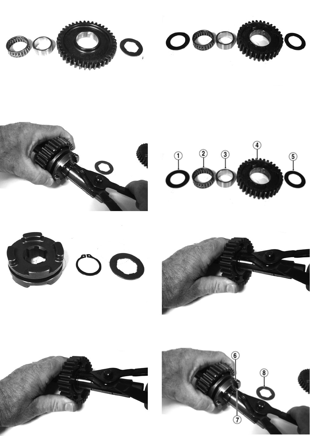
60
FI667
4. Remove the splined washer; then remove the circlip
securing the high-low sliding dog. Remove the slid-
ing dog.
FI668
FI669
5. Remove the circlip securing the high driven gear;
then remove a washer, the high driven gear along
with the bearing and bushing, and remove the high
driven washer.
FI670
FI671
ASSEMBLING
1. With the high driven washer (1) on the countershaft,
install the high driven gear bushing (3), bearings (2),
and gear (4) on the countershaft; then install the
washers (5) and secure with the snap-ring.
FI671A
FI670
2. Install the high/low shift dog (6) on the countershaft
and secure with snap-ring (7); then install the splined
washer (8).
FI668A
For Discount Arctic Cat Parts Call 606-678-9623 or 606-561-4983
www.mymowerparts.com
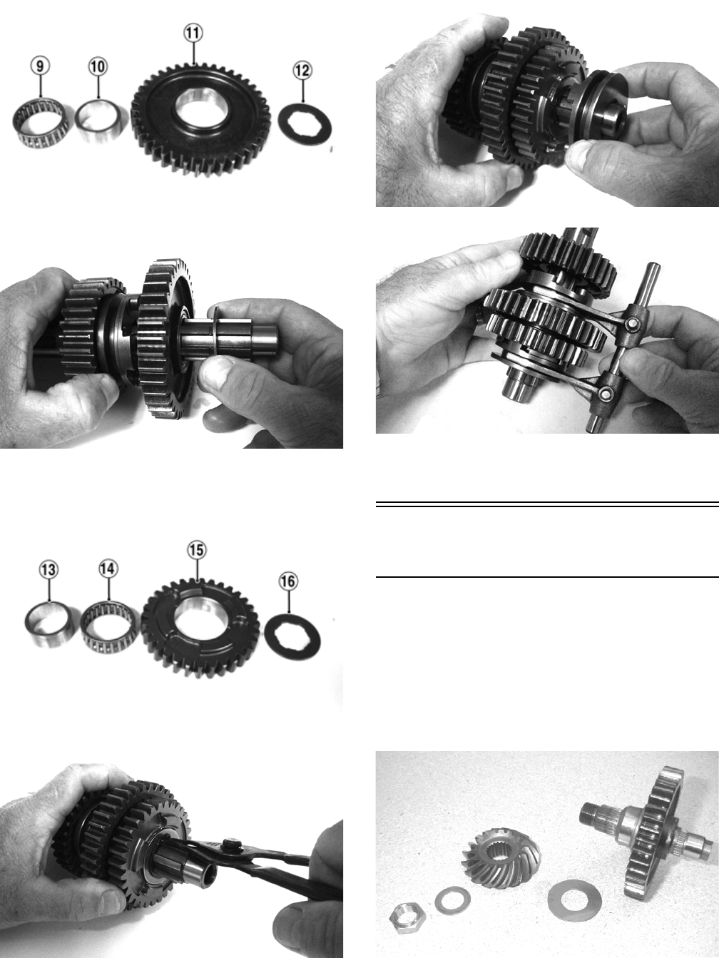
61
3. Install the low driven bushing (10), bearing (9), and
gear (11) on the countershaft; then install splined
washer (12).
FI667A
FI666
4. Place the reverse driven bushing (13) onto the shaft;
then install the bearing (14), gear (15), and splined
washer (16). Secure with a snap-ring.
FI665A
FI664
5. Install the reverse dog on the shaft; then place the
shift forks and shift shaft into position.
FI663
FI662
NOTE: The countershaft assembly is now ready to
be installed.
Assembling Crankcase
Half
NOTE: For ease of assembly, install components on
the right-side crankcase half.
NOTE: If the output shaft was removed, make sure
that the proper shim is installed.
1. Install the output shaft into the crankcase making
sure the two gears, shim, washer, and nut are in the
correct order.
MD1199
For Discount Arctic Cat Parts Call 606-678-9623 or 606-561-4983
www.mymowerparts.com
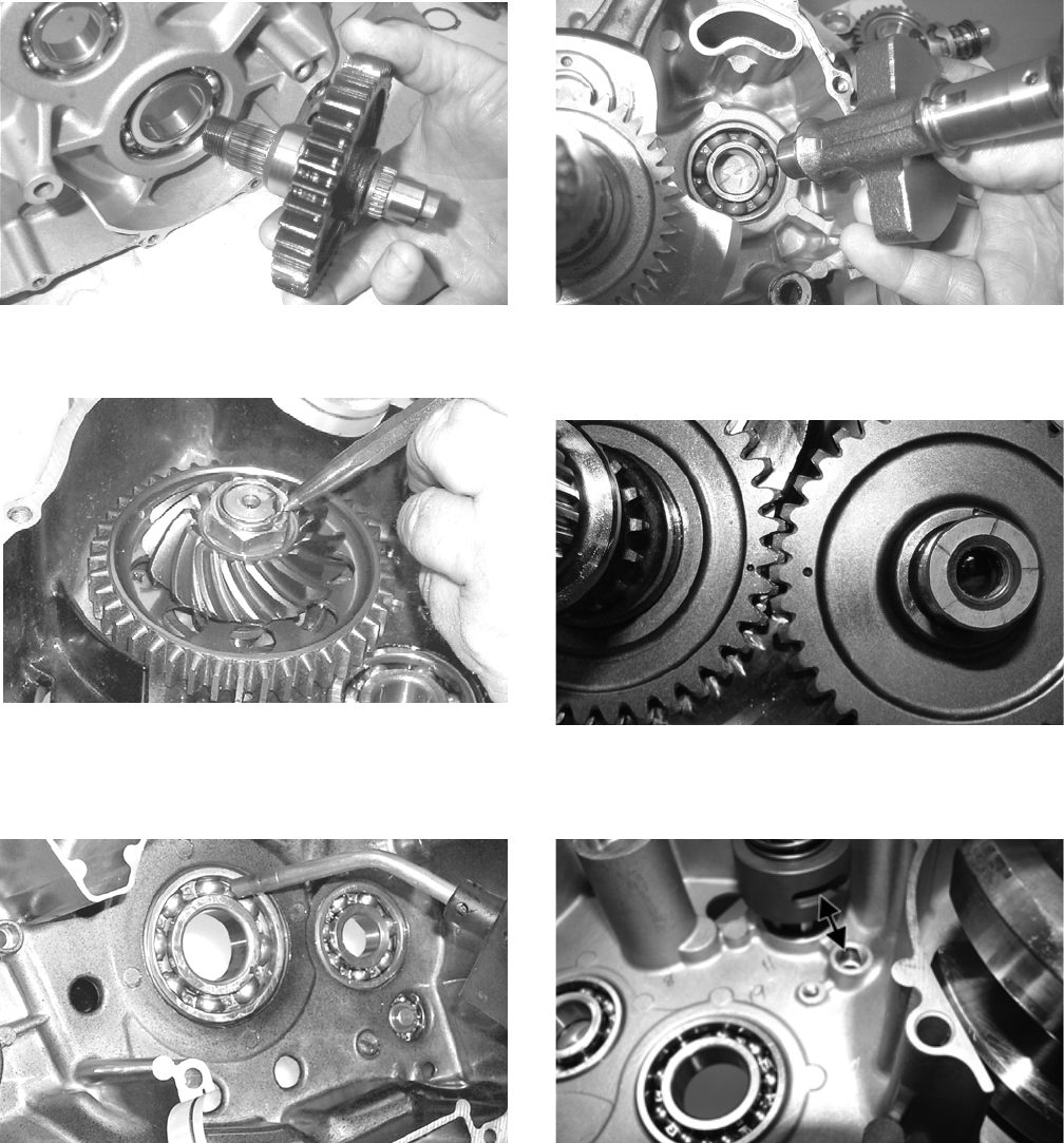
62
MD1079
2. Install and tighten the output shaft flange nut to 59 ft-
lb. Using a punch, peen the nut.
MD1333
3. Apply a liberal amount of oil to the crankshaft bear-
ing. Using a propane torch, heat the bearing until the
oil begins to smoke; then slide the crankshaft assem-
bly into place.
MD1334
NOTE: If heating the bearing is not possible, the
crankshaft can be installed using a crankshaft
installer.
4. Rotate the crankshaft so the counterweight is toward
the rear of the engine. Install the crank balancer
shaft.
MD1024
5. Install the key in the crank balancer shaft; then install
the gear and aligning the timing marks, slide the gear
into place.
FI658
6. Align the shift cam fork slots with the shift fork shaft
locating boss and with a washer on each end, install
in the crankcase.
FI652A
7. Place the shift forks into position on the assembled
countershaft and install into the crankshaft as an
assembly.
For Discount Arctic Cat Parts Call 606-678-9623 or 606-561-4983
www.mymowerparts.com
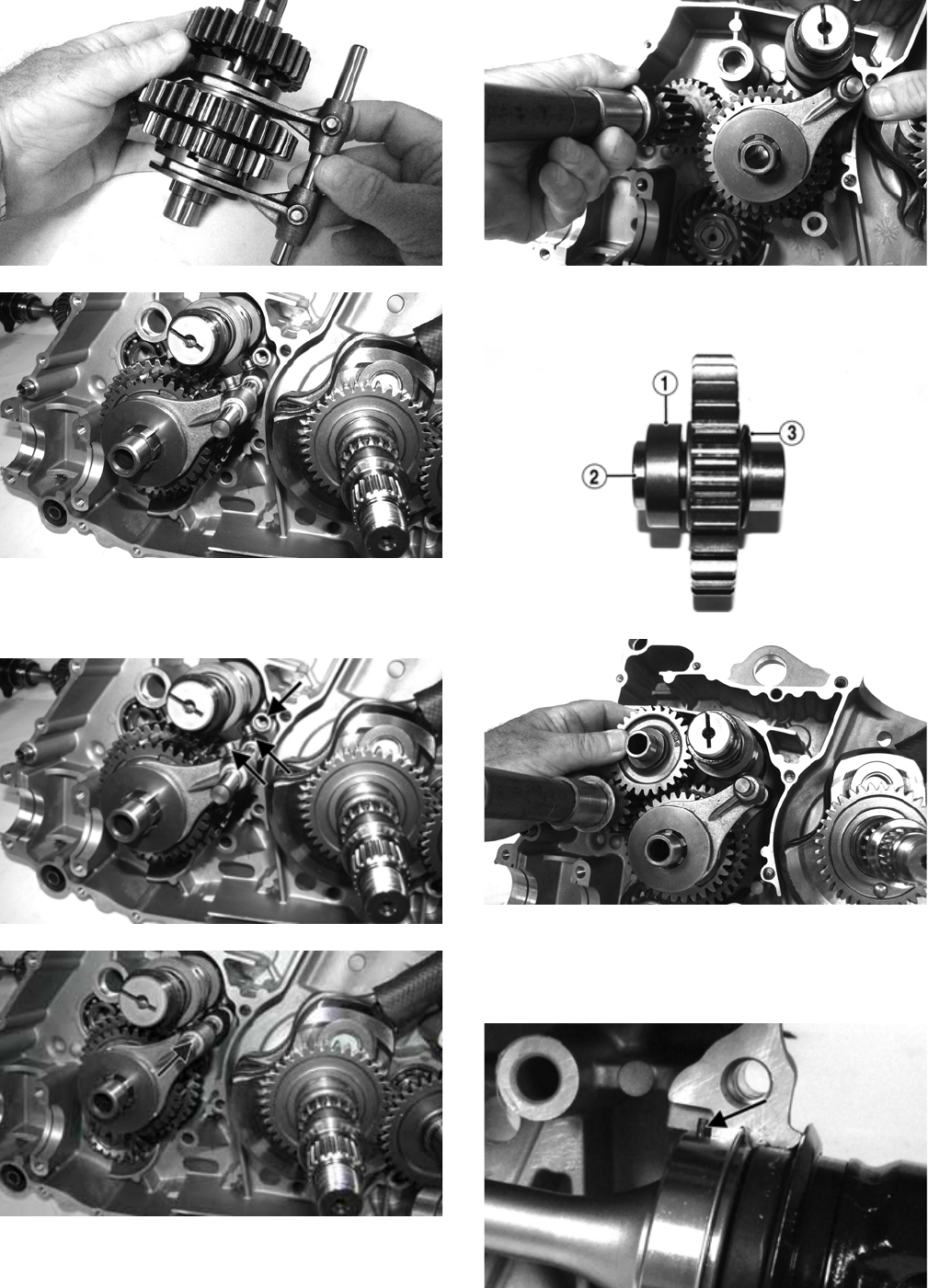
63
FI662
FI653
8. Align the shift forks to allow engagement with the
shift cam; then engage the shift forks and slide the
shift fork shaft into the locating boss in the crankcase.
FI653A
FI655A
9. Install the input driveshaft.
FI646
10. Install the spacer (1), shaft (2), reverse idler gear, and
washer (3).
FI641A
FI645
11. Install the secondary output driveshaft assembly into
the crankcase half making sure the front and rear bear-
ing alignment pins are seated in the recesses; then
install the center carrier bearing alignment C-ring.
FI660A
For Discount Arctic Cat Parts Call 606-678-9623 or 606-561-4983
www.mymowerparts.com
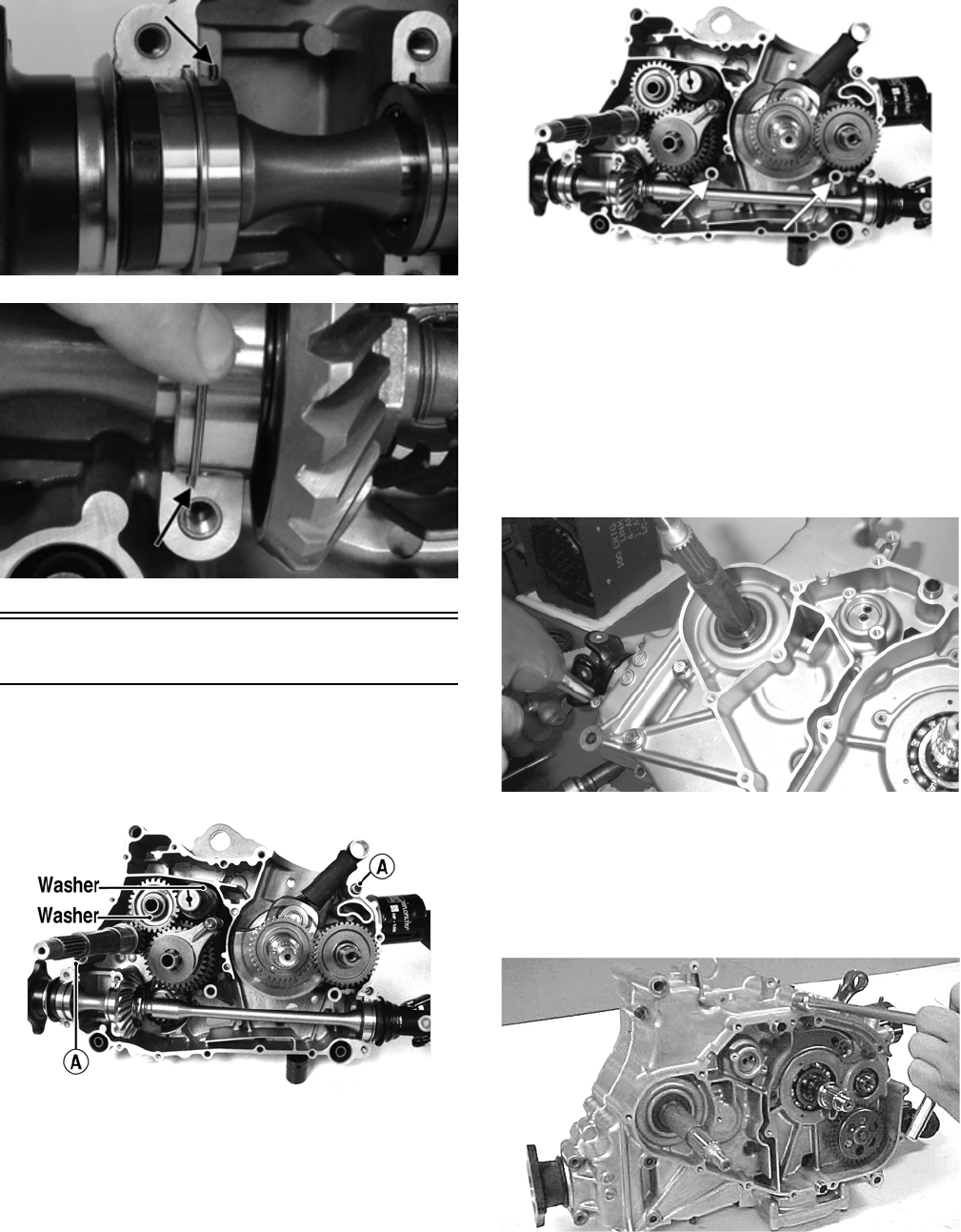
64
FI659A
FI661A
Joining Crankcase Halves
1. Verify that the two alignment pins (A) are in place
and that both case halves are clean and grease free.
Apply Three Bond Sealant to the mating surfaces.
Place the right-side half onto the left-side half.
FI639B
NOTE: Be sure to apply sealant to the inside radius
of all cap screw locations and the entire surface of
the internal cap screw bosses.
FI639C
2. Using a plastic mallet, lightly tap the case halves
together until cap screws can be installed.
3. From the right side, install the crankcase cap screws
noting the location of the different-sized cap screws;
then tighten only until snug.
NOTE: Rotate the shafts back and forth to ensure
no binding or sticking occurs while tightening the
cap screws.
MD1008
4. From the left side, install the remaining crankcase
cap screws; then tighten only until snug.
NOTE: Rotate the shafts back and forth to ensure
no binding or sticking occurs while tightening the
cap screws.
CC871
5. In a crisscross pattern, tighten the 8 mm cap screws
until the halves are correctly joined; then tighten to
21 ft-lb.
For Discount Arctic Cat Parts Call 606-678-9623 or 606-561-4983
www.mymowerparts.com
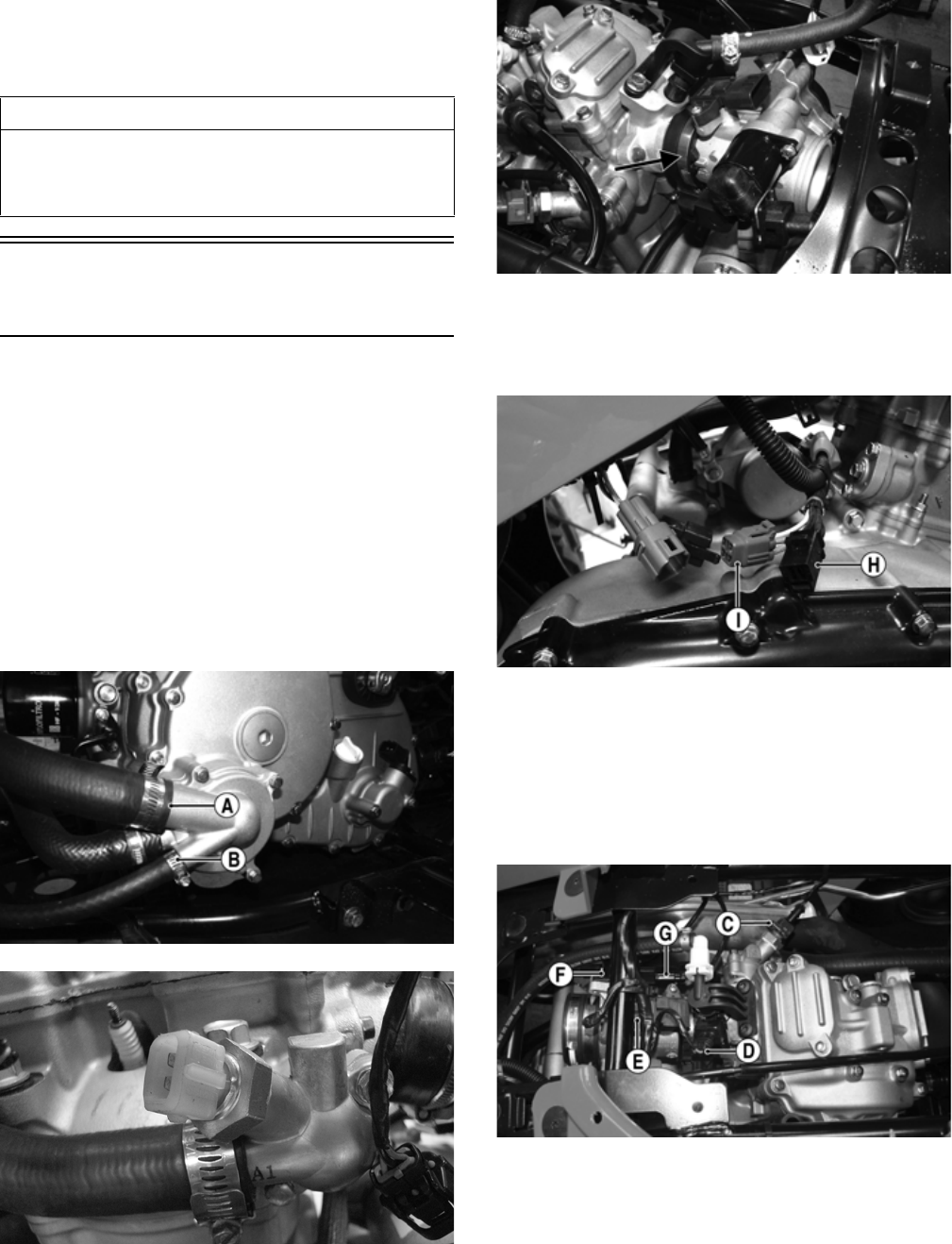
65
NOTE: Rotate the shafts back and forth to ensure
no binding or sticking occurs.
6. In a crisscross pattern, tighten the 6 mm cap screws
to 10 ft-lb.
NOTE: Rotate the shafts back and forth to ensure
no binding or sticking occurs.
Installing Engine/
Transmission
1. From the left side, place the engine into the frame
(rear of engine first) tilting the rear up to allow cylin-
der head to clear frame.
2. With engine moved rearward, engage the splines of
the front driveline into the front output drive yoke;
then move into position and install the two through-
bolts. Secure with lock nuts and tighten to 38 ft-lb.
3. Install the four cap screws securing the rear driveline
to the output drive flange and tighten to 20 ft-lb.
4. Connect coolant hoses (A) and (B) to the water pump
and connect the upper coolant hose to the thermostat
housing. Tighten all clamps securely.
FI530B
FI537
5. Install the spark plug cap on the spark plug; then
install the throttle body into the intake boot and
tighten the intake clamp to 30 in.-lb.
FI695A
6. Connect the stator connector (H) and crankshaft
position sensor connector (I) to the main harness;
then connect the positive cable to the starter motor
and tighten securely.
FI534A
7. Connect the engine ground cable to the starter
mounting flange and secure with a cap screw tight-
ened to 8 ft-lb.
8. From the top side, install the ECT sensor connector
(C), fuel injector connector (D), MAP sensor con-
nector (E), ISC connector (F), and the TPS connector
(G).
FI522A
9. Place the air filter assembly into position and con-
nect the crankcase breather securing with the clamp,
then connect the air inlet boot to the throttle body
and secure with a hose clamp.
AT THIS POINT
After completing center crankcase components, pro-
ceed to Installing Right-Side Components, to Installing
Left-Side Components, and to Installing Top-Side Com-
ponents.
For Discount Arctic Cat Parts Call 606-678-9623 or 606-561-4983
www.mymowerparts.com
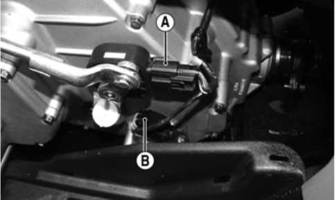
66
10. Install the exhaust pipe using a new seal at the cylin-
der head and loosely install the retaining cap screws;
then install the muffler with a new grafoil seal and
secure with two springs. Tighten the exhaust pipe
retainer cap screws to 20 ft-lb.
11. Connect the air ducts to the CVT housing and tighten
the clamps securely; then connect the air inlet tube to
the throttle body and secure with the clamps.
12. Install the gas tank (see Fuel/Lubrication/Cooling)
and connect the negative battery cable; then install
the battery case access cover.
13. From the left side, install the gear position switch
connector (A) and the speed sensor connector (B). FI525A
14. Pour the specified amount of coolant into the radiator
and the specified amount and grade of oil into the
engine.
15. Install the water pump splash guard and left footwell.
Tighten all fasteners securely.
16. Install the seat making sure it locks securely in place;
then start the engine and allow to warm up while
checking for leaks.
17. Shut engine off and inspect coolant and oil levels.
Add fluids as required.
For Discount Arctic Cat Parts Call 606-678-9623 or 606-561-4983
www.mymowerparts.com
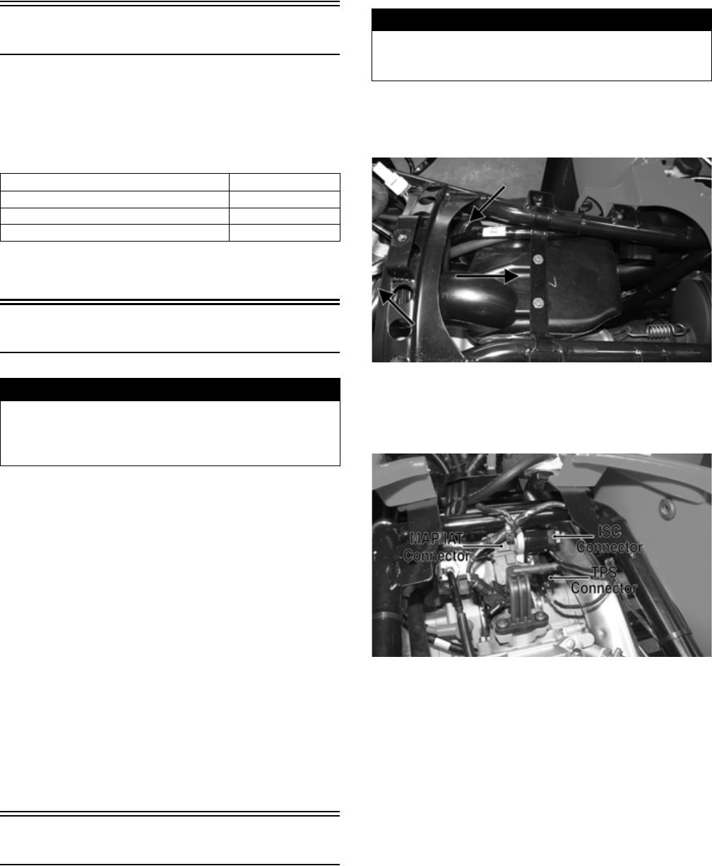
67
Fuel/Lubrication/Cooling
SPECIAL TOOLS
A number of special tools must be available to the techni-
cian when performing service procedures in this section.
Refer to the current Special Tools Catalog for the appro-
priate tool description.
NOTE: Special tools are available from the Arctic
Cat Service Department.
Electronic Fuel Injection
TROUBLESHOOTING
1. Verify that the electric fuel pump is operating by lis-
tening for a “whirring” sound for several seconds
after the ignition switch is turned to the ON position.
If no sound can be heard, see Electric Fuel Pump/
Fuel Level Sensor in this section.
2. Check for a flashing Diagnostic Trouble Code (DTC)
and a Malfunction Indicator Light (MIL) in the form
of a wrench icon on the LCD. If a code is flashing,
see Diagnostic Trouble Codes (DTC) in Electrical
System.
3. Make sure there is sufficient, clean gas in the gas
tank.
4. Verify that the battery is sufficiently charged to crank
the engine over at normal speed.
5. Check the air filter housing and air filter for contam-
ination. Clean or replace as necessary (see Periodic
Maintenance).
Throttle Body
REMOVING
1. Remove the heat shields and seat.
2. Disconnect the negative battery cable; then remove
the gas tank (see Gas Tank in this section).
3. Loosen the clamp securing the intake boot to the
throttle body; then loosen the clamp securing the
intake boot to the intake housing and slide the intake
housing rearward.
FI691A
4. Disconnect the MAP/IAT sensor connector, ISC con-
nector, and TPS connector; then loosen the clamp
securing the throttle body to the intake manifold boot
and slide the throttle body out.
FI528A
5. Remove the throttle arm cover and loosen the throttle
cable jam nut; then disconnect the throttle cable and
remove the throttle body.
INSTALLING
1. Connect the throttle cable to the throttle arm; then
install the throttle cable housing in the throttle body
and tighten the jam nut. Install the throttle arm cover
and secure with two machine screws.
2. Place the throttle body into the intake manifold boot
and tighten the boot clamp securely.
3. Place the intake housing into the boots and tighten
the boot clamps securely.
4. Install the gas tank; then the heat shields and seat.
Description p/n
Oil Pressure Test Kit 0644-495
Tachometer 0644-275
Fuel Pressure Test Kit 0644-571
! WARNING
Whenever any maintenance or inspection is performed
on the fuel system during which there may be fuel leak-
age, there should be no welding, smoking, open flames,
etc., in the area.
! WARNING
Gasoline may be under pressure. Place an absorbent
towel under the connector to absorb any gasoline spray
when disconnecting.
For Discount Arctic Cat Parts Call 606-678-9623 or 606-561-4983
www.mymowerparts.com
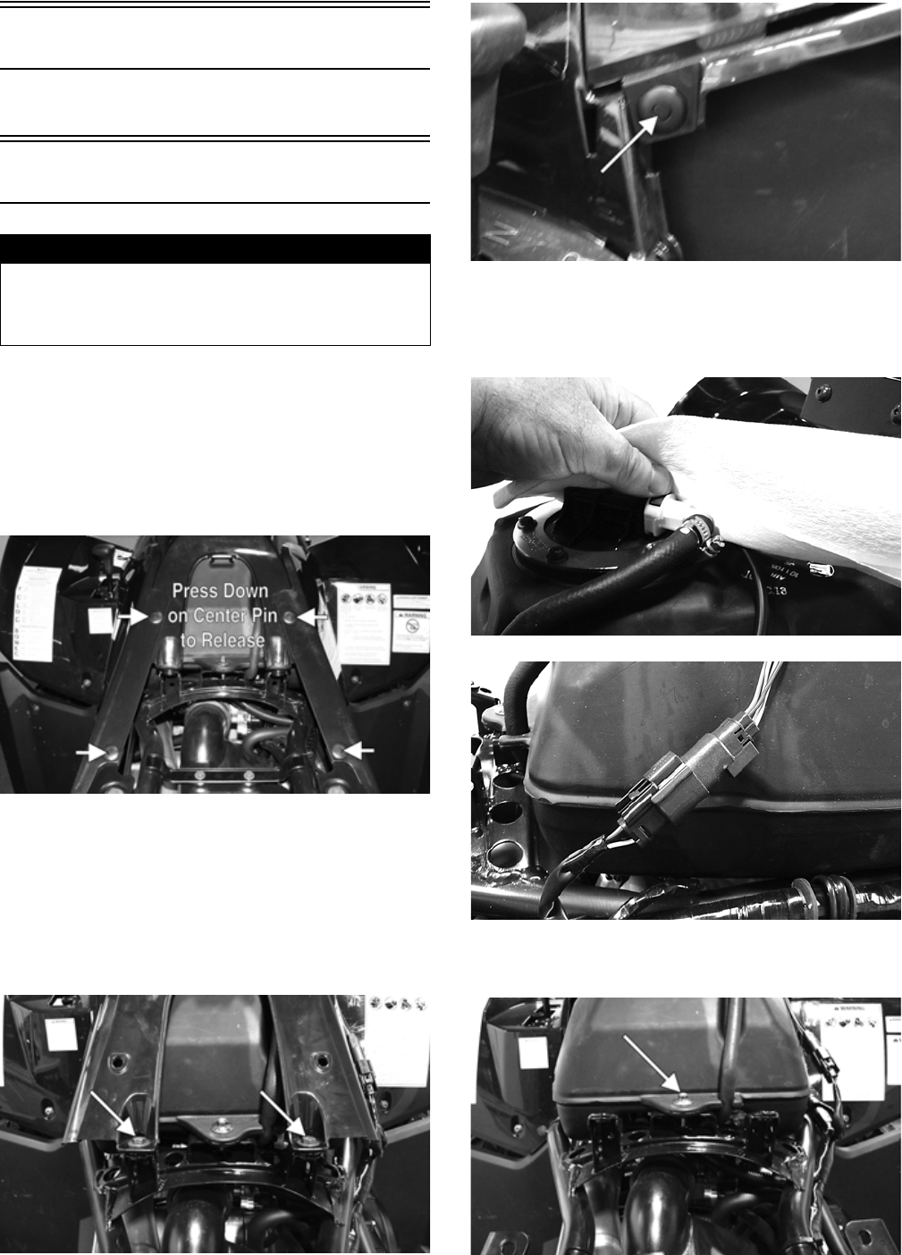
68
Throttle Cable Free-Play
To adjust throttle cable free-play, see Periodic Maintenance.
Gas Tank
REMOVING
1. Remove the battery case access cover from the bat-
tery case; then disconnect the negative battery cable
and remove the seat.
2. Remove the reinstallable rivets securing the side
panels (two on each side) and remove the side pan-
els.
KC450A
NOTE: The reinstallable rivets may be easily
released by depressing the pin in the center of the
head.
3. Remove two cap screws and four reinstallable rivets
from the gas tank cover; then remove the gas tank
cap and remove the cover panel. Reinstall the gas
tank cap.
KC453A
KC454A
4. Using a shop towel to catch any leaking gasoline,
disconnect the gasline hose from the fuel pump out-
let; then disconnect the fuel pump/fuel gauge con-
nector from the harness.
KC455
KC456
5. Remove the mounting bolt at the rear of the gas tank;
then remove the gas tank.
KC457A
! WARNING
Whenever any maintenance or inspection is made on
the fuel system during which there may be fuel leakage,
there should be no welding, smoking, open flames, etc.,
in the area.
For Discount Arctic Cat Parts Call 606-678-9623 or 606-561-4983
www.mymowerparts.com
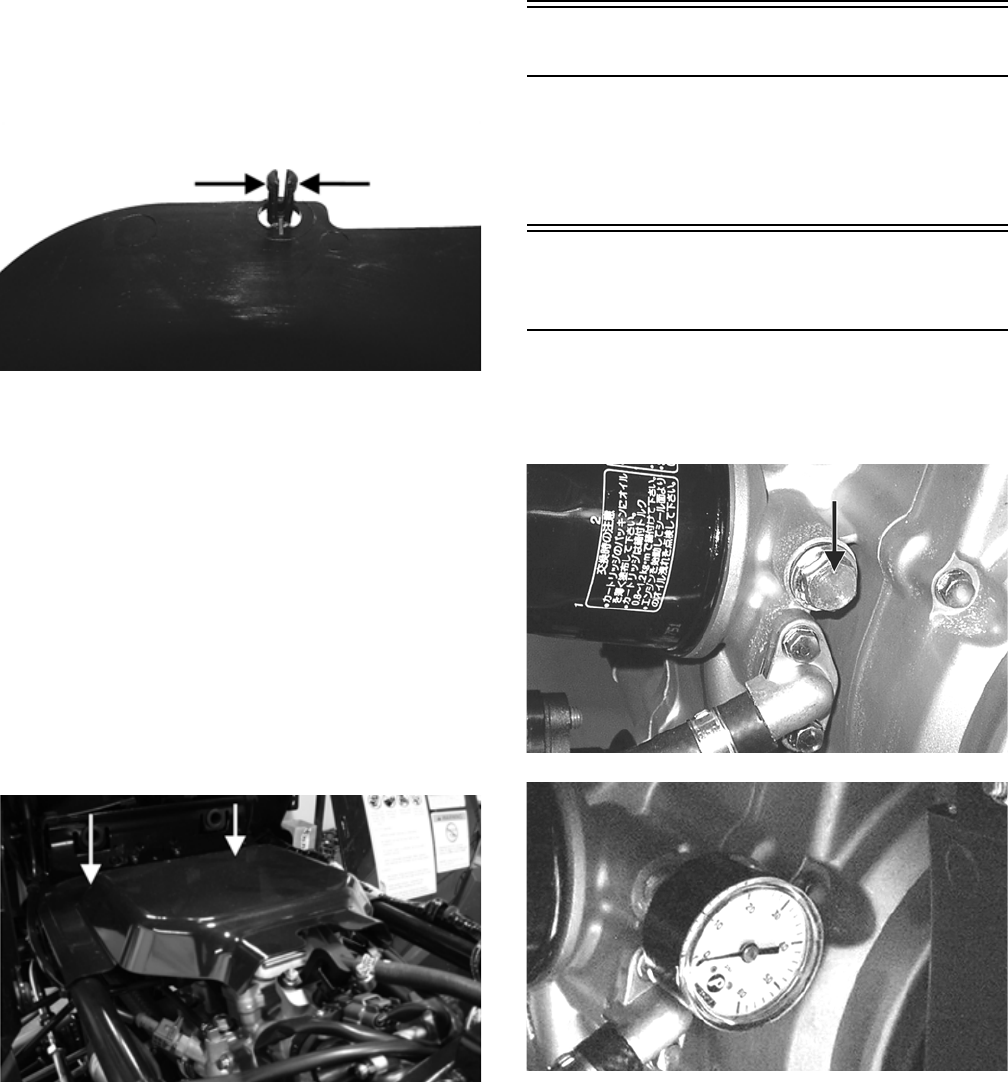
69
6. Remove the heat shield by reaching under the front
of the shield and compressing the retainer posts to
release.
KC459A
CLEANING AND INSPECTING
NOTE: Whenever a part is worn excessively,
cracked, or damaged in any way, replacement is nec-
essary.
1. Clean all gas tank components with parts-cleaning
solvent.
2. Inspect all hoses for cracks or leaks.
3. Inspect tank cap and tank for leaks, holes, and dam-
aged threads.
INSTALLING
1. Install the heat shield making sure the mounting
studs lock in the bracket; then install the gas tank and
secure with the mounting bolt. Tighten securely.
KC458A
2. Connect the gasline connector to the fuel pump out-
let making sure it locks securely in place; then con-
nect the fuel pump/fuel gauge connector to the
harness.
3. Remove the gas tank cap and place the gas tank
cover over the gas tank. Install the gas tank cap; then
secure the cover with two reinstallable rivets and two
cap screws.
4. Install the side panels and secure with four reinstall-
able rivets making sure the tabs on the panels engage
the slots on the gas tank cover.
5. Connect the negative battery cable and install the
battery case access cover; then install the seat.
Oil Filter/Oil Pump
NOTE: Whenever internal engine components wear
excessively or break and whenever oil is contami-
nated, the oil pump should be replaced. The oil pump
is not a serviceable component.
Testing Oil Pump
Pressure
1. Connect the Tachometer to the engine.
2. Connect the Oil Pressure Test Kit to the oil filter
drain plug.
KC195A
KC267
NOTE: Some oil seepage may occur when installing
the oil pressure gauge. Wipe up oil residue with a
cloth.
3. Warm up the engine to normal operating temperature
(cooling fan cycling); then increase engine RPM to
3000 RPM. The oil pressure must read 0.6-0.7 kg/
cm2 (8.5-17 psi).
For Discount Arctic Cat Parts Call 606-678-9623 or 606-561-4983
www.mymowerparts.com
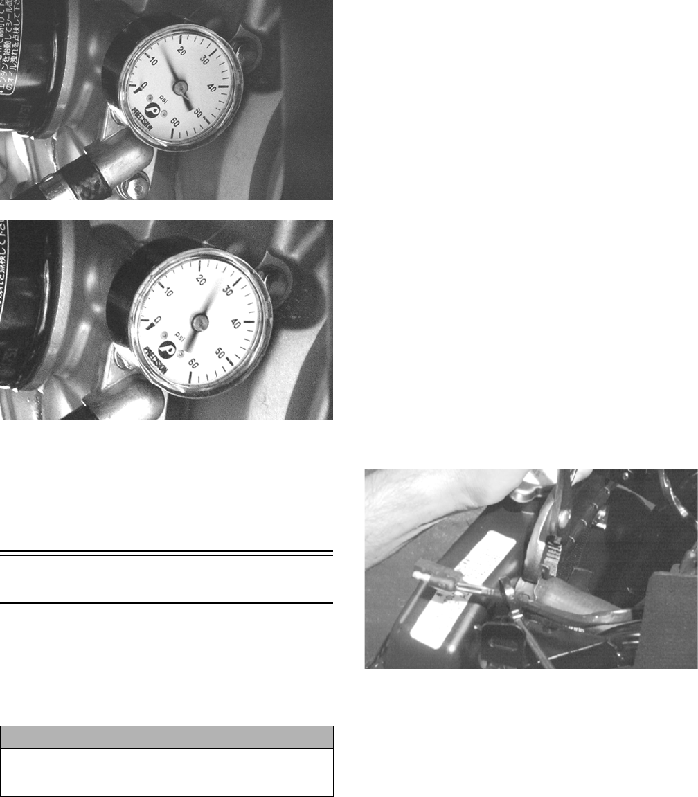
70
KC268
KC269
NOTE: If the oil pressure is lower than specified,
check for low oil level or defective oil pump.
NOTE: If the oil pressure is higher than specified,
check for clogged oil passage, clogged oil filter, or
improper installation of the oil filter.
Liquid Cooling System
When filling the cooling system, use premixed Arctic Cat
Antifreeze. While the cooling system is being filled, air
pockets may develop; therefore, run the engine for five
minutes after the initial fill, shut the engine off, and then
fill the cooling system to the bottom of the stand pipe in
the radiator neck.
RADIATOR
Removing
1. Drain the coolant at the engine.
2. Remove the radiator/electrical access panel and front
fender panel (see Steering/Frame).
3. Remove the upper and lower coolant hoses; then
remove the fill hose and air bleed hose.
4. Remove the cap screws securing the radiator to the
frame.
5. Disconnect the fan wiring from the main wiring har-
ness; then remove the radiator/fan assembly and
account for the grommets and collars.
6. Remove the fan/fan shroud assembly from the radia-
tor.
Cleaning and Inspecting
NOTE: Whenever a part is worn excessively,
cracked, or damaged in any way, replacement is nec-
essary.
1. Flush the radiator with water to remove any contami-
nants.
2. Inspect the radiator for leaks and damage.
3. Inspect all hoses for cracks and deterioration.
4. Inspect all fasteners and grommets for damage or
wear.
Installing
1. Position the fan/fan shroud assembly on the radiator;
then secure with existing hardware.
2. Place the radiator with grommets and collars into
position on the frame; then install the cap screws.
Tighten securely.
3. Install the upper and lower coolant hoses, fill hose,
and air bleed hose; then secure with hose clamps.
AF734D
4. Install the fender panel (see Steering/Frame).
5. Fill the cooling system with the recommended
amount of antifreeze. Check for leakage.
6. Connect the fan wiring to the main wiring harness.
THERMOSTAT
Removing
1. Drain approximately one quart of coolant from the
cooling system.
2. Remove the two cap screws securing the thermostat
housing to the mounting bracket. Remove the ther-
mostat housing cover and account for an O-ring and
a thermostat.
Inspecting
NOTE: Whenever a part is worn excessively, cracked,
or damaged in any way, replacement is necessary.
CAUTION
After operating the ATV for the initial 5-10 minutes, stop
the engine, allow the engine to cool down, and check
the coolant level. Add coolant as necessary.
For Discount Arctic Cat Parts Call 606-678-9623 or 606-561-4983
www.mymowerparts.com
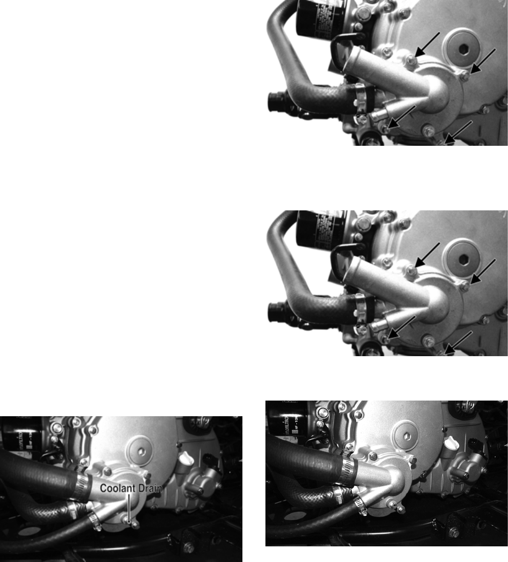
71
1. Inspect the thermostat for corrosion or spring damage.
2. Using the following procedure, inspect the thermo-
stat for proper operation.
A. Suspend the thermostat in a container filled
with water.
B. Heat the water and monitor the temperature
with a thermometer.
C. The thermostat should start to open at 71-86° C
(160-187° F).
D. If the thermostat does not open, it must be
replaced.
3. Inspect all coolant hoses, connections, and clamps
for deterioration, cracks, and wear.
NOTE: All coolant hoses and clamps should be
replaced every four years or 4000 miles.
Installing
1. Place the thermostat and O-ring into the thermostat
housing; then secure the thermostat housing to the
mounting bracket with the two cap screws.
2. Fill the cooling system to the recommended level
with antifreeze. Check for leakage.
WATER PUMP
NOTE: The water pump is a non-serviceable compo-
nent. It must be replaced as an assembly.
Removing
1. Remove the radiator cap; then remove the water
pump drain and drain the coolant.
FI530A
2. Drain the oil from the engine/transmission.
3. Remove the four torx-head cap screws securing the
front and rear fenders to the footrest; then remove the
four cap screws securing the footrest to the frame.
Remove the footrest.
4. Loosen the hose clamps and slide the clamps away
from the hose ends approximately 2 in.; then remove
the hoses from the water pump.
5. Remove the four cap screws securing the water
pump to the engine; then remove the water pump.
FI538A
Installing
1. Secure the water pump to the engine with the four
cap screws tightened to 8 ft-lb.
FI538A
2. Connect the coolant hoses to the water pump and
secure with the clamps. Tighten securely.
FI530
3. Place the footrest into position on the frame and
loosely secure with four cap screws; then secure the
front and rear fenders to the footrest with the four
torx-head cap screws. Tighten the four torx-head cap
screws securely; then tighten the remaining cap
screws to 20 ft-lb.
4. Fill the engine/transmission with the proper amount
of recommended oil.
5. Fill the cooling system with the proper amount of
recommended coolant.
For Discount Arctic Cat Parts Call 606-678-9623 or 606-561-4983
www.mymowerparts.com
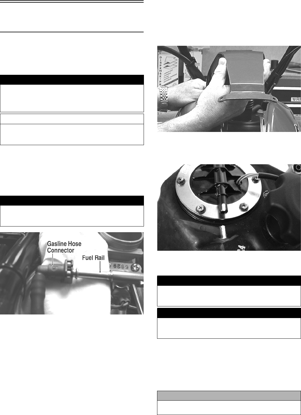
72
Electric Fuel Pump/Fuel
Level Sensor
The electric fuel pump and fuel level sensor are not ser-
viceable components. If either component fails, it must
be replaced.
TESTING
1. Turn the ignition switch ON and listen for a momen-
tary “whirring” sound of the pump building pressure.
If the sound is heard (10 seconds), no electrical
checks are necessary. Turn the ignition switch OFF.
2. Disconnect the gasline hose from the throttle body;
then install a suitable pressure gauge.
FI092A
3. Turn the ignition switch to the ON position. The fuel
pressure should build until the pump shuts off. Pres-
sure should read 3.0 kg-cm2 (43 psi).
4. If the pump is not running, disconnect the fuel pump/
tank sensor connector located behind the right side
panel.
5. Connect a multimeter to the power supply leads with
the red tester lead to the red wire and the black tester
lead to the black wire; then turn the ignition switch to
the ON position. The meter should read battery volt-
age. If battery voltage is indicated and the fuel pump
does not run, replace the pump assembly. If no bat-
tery voltage is indicated, check the ECU and the
vehicle tilt sensor.
REMOVING
1. Disconnect the negative battery cable from the bat-
tery.
2. Remove the side panels and gas tank cover (see Gas
Tank in this section).
KC220
3. Mark the fuel pump and gas tank for proper orienta-
tion during assembly; then disconnect the fuel pump/
fuel level sender connector.
KC423
4. Disconnect the gasline connector from the fuel pump
outlet.
5. Remove the screws securing the fuel pump to the gas
tank; then make a reference mark on the fuel pump
and tank.
6. Lift out the fuel pump assembly and carefully guide
the pump and float lever through the opening in the
gas tank.
! WARNING
Whenever any maintenance or inspection is made on
the fuel system during which there may be fuel leakage,
there should be no welding, smoking, open flames, etc.,
in the area.
AT THIS POINT
Prior to removing the electric fuel pump, the following
check should be performed to determine that removal is
necessary.
! WARNING
Gasoline may be under pressure. Place an absorbent
towel under the connector to absorb any gasoline spray
when disconnecting.
! WARNING
Gasoline may be under pressure. Place an absorbent
towel under the connector to absorb any gasoline spray
when disconnecting.
! WARNING
Do not turn the ignition switch to the ON position with
the hoses removed. Gasoline will be pumped by the
electric fuel pump causing a safety hazard.
CAUTION
Take care not to damage the float or float arm or
replacement of the entire assembly will be necessary.
For Discount Arctic Cat Parts Call 606-678-9623 or 606-561-4983
www.mymowerparts.com
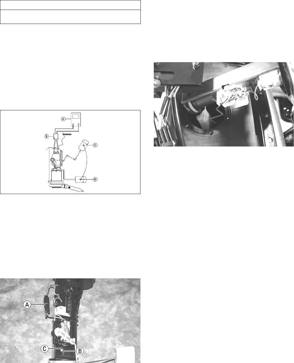
73
7. Using duct tape or other suitable means, cover the
fuel pump opening.
INSPECTING
1. Inspect the fuel screen and blow clean with low pres-
sure compressed air.
2. Move the float lever and check for free movement.
The float assembly should return to the lower posi-
tion without force. If not, replace the fuel pump
assembly.
3. Test the fuel level sensor by connecting a multimeter
(A) to the fuel level sensor leads (B); then select
OHMS. The multimeter should show 5 ohms at full
fuel position (C) and 95 ohms at empty fuel position
(D).
ATV2116
NOTE: If readings are erratic, clean the resistor
wiper and resistor with clean alcohol and retest. If
still not correct, replace the fuel level sensor.
4. To replace the fuel level sensor, use the following
procedure.
A. Disconnect the two-wire connector (A); then
press the fuel level sensor toward the top of the
fuel pump to release it from the mounting slot
(B).
FI460A
B. Engage the tabs (C) of the fuel level sensor into
the mounting slot (B) and press toward the bot-
tom of the fuel pump to latch in place; then con-
nect the two-wire connector (A).
INSTALLING
1. Mark the new fuel pump with a reference mark in the
same location as the removed pump; then place the
new gasket on the pump.
2. Remove the material covering the fuel pump open-
ing; then carefully guide the fuel pump into position
taking care not to damage the float or float lever.
KX190
3. Rotate the fuel pump until the match marks align;
then install the mounting screws and tighten securely
using a crisscross pattern.
NOTE: It is important to install the fuel pump with
the correct orientation to ensure adequate float lever
clearance.
4. Connect the wires and fuel hose; then connect the
negative battery cable and turn the ignition switch to
the ON position. Note that the fuel pump runs
momentarily and the fuel gauge indicates the proper
fuel level.
5. With the transmission in neutral and brake lever lock
engaged, start the engine and check for normal oper-
ation. Check for any fuel leaks.
6. Install the side panels and gas tank cover (see Gas
Tank in this section).
AT THIS POINT
If the pump has failed earlier test and must be replaced,
proceed to INSTALLING.
For Discount Arctic Cat Parts Call 606-678-9623 or 606-561-4983
www.mymowerparts.com

74
Troubleshooting
Problem: Starting impaired
Condition Remedy
1. Gas contaminated 1. Drain gas tank and fill with clean gas
Problem: Idling or low speed impaired
Condition Remedy
1. TPS out of adjustment 1. Adjust TPS
Problem: Medium or high speed impaired
Condition Remedy
1. High RPM “cut out” against RPM limiter 1. Decrease RPM speed
For Discount Arctic Cat Parts Call 606-678-9623 or 606-561-4983
www.mymowerparts.com

75
Electrical System
This section has been organized into sub-sections which
show procedures for the complete servicing of the Arctic
Cat ATV electrical system.
SPECIAL TOOLS
A number of special tools must be available to the techni-
cian when performing service procedures in this section.
Refer to the current Special Tools Catalog for the appro-
priate tool description.
NOTE: Special tools are available from the Arctic
Cat Service Department.
Specifications
Electrical Connections
The electrical connections should be checked periodi-
cally for proper function. In case of an electrical failure,
check fuses, connections (for tightness, corrosion, dam-
age), and/or bulbs.
Battery
After being in service, batteries require regular cleaning
and recharging in order to deliver peak performance and
maximum service life. The following procedure is rec-
ommended for cleaning and maintaining sealed batteries.
Always read and follow instructions provided with bat-
tery chargers and battery products.
1. Remove the battery case access cover; then discon-
nect the battery cables (negative cable first).
2. Remove the battery from the battery case; then thor-
oughly wash the battery and battery case with soap
and water.
NOTE: If battery posts, cable ends, or the battery
case has a build-up of white/green powder residue,
apply water and baking soda to neutralize acid; then
flush off with warm soapy water.
3. Using a wire brush, clean the battery posts and cable
ends removing all corrosive buildup. Replace dam-
aged cables or cable ends.
4. Using a multimeter, test the battery voltage. The
meter must read 12.5 or more DC Volts for a fully
charged battery.
NOTE: At this point, if the meter reads as specified,
the battery may be returned to service (see step 8).
5. If the meter reads less than specified voltage, charge
the battery using the following guidelines.
A. When using an automatic battery charger, always
follow the charger manufacturer’s instructions.
B. When using a constant-current battery charger,
use the following Battery Charging Chart.
Description p/n
Fluke Model 73 Multimeter 0644-191
Fluke Model 77 Multimeter 0644-559
MaxiClips 0744-041
Ignition Timing 10° BTDC @ 1500 RPM
Spark Plug Type NGK CR7E
Spark Plug Gap 0.7-0.8 mm (0.028-0.032 in.)
Spark Plug Cap 5000 ohms
Ignition Coil (primary)
Resistance
(secondary)
Less than 5.0 ohms
(terminal (+) to terminal (-))
12k-19k ohms (high tension - plug
cap to terminal (+))
Ignition Coil Primary Voltage Battery Voltage
(orange (+) to blue/white(-))
Stator Coil Resistance
(crankshaft position sensor)
(AC generator)
150-250 ohms (blue to green)
Less than 1 ohm (black to black)
Crankshaft Position Sensor AC
Voltage
2.5 volts or more (blue to green)
AC Generator (no load)
Output
60 AC volts @ 5000 RPM
(black to black)
! WARNING
Any time service is performed on a battery, the follow-
ing must be observed: keep sparks, open flame, ciga-
rettes, or any other flame away. Always wear safety
glasses. Protect skin and clothing when handling a bat-
tery. When servicing battery in enclosed space, keep
the area well-ventilated. Make sure battery venting is
not obstructed.
! WARNING
Battery acid is harmful if it contacts eyes, skin, or cloth-
ing. Care must be taken whenever handling a battery.
CAUTION
Never exceed the standard charging rate.
! WARNING
An overheated battery could explode causing severe
injury or death. Always monitor charging times and
charge rates carefully. Stop charging if the battery
becomes very warm to the touch. Allow it to cool before
resuming charging.
For Discount Arctic Cat Parts Call 606-678-9623 or 606-561-4983
www.mymowerparts.com

76
NOTE: If the battery voltage is 11.5 DC Volts or less,
some chargers may “cut off” and fail to charge. If this
occurs, connect a fully charged booster battery in
parallel (positive to positive and negative to negative)
for a short period of time with the charger connected.
After 10-15 minutes, disconnect the booster battery
leaving the charger connected and the charger
should continue to charge. If the charger “cuts off,”
replace the battery.
6. After charging the battery for the specified time,
remove the battery charger and allow the battery to
sit for 1-2 hours.
7. Connect the multimeter and test the battery voltage.
The meter should read 12.5 or more DC Volts. If the
voltage is as specified, the battery is ready for ser-
vice.
NOTE: If voltage in step 7 is below specifications,
charge the battery an additional 1-5 hours; then
retest.
8. Place the battery in the battery case; then coat the
battery posts and cable ends with a light coat of
multi-purpose grease.
9. Connect the battery cables (positive cable first); then
install the battery case access cover.
RPM Limiter
NOTE: The ATV is equipped with an ECU that
retards ignition timing when maximum RPM is
approached. When the RPM limiter is activated, it
could be misinterpreted as a high-speed misfire.
Testing Electrical
Components
All of the electrical tests should be made using the Fluke
Model 73 Multimeter or Fluke Model 77 Multimeter and
when testing peak voltage, the Peak Voltage Reading
Adapter must be used. If any other type of meter is used,
readings may vary due to internal circuitry. When trou-
bleshooting a specific component, always verify first that
the fuse(s) are good, that the bulb(s) are good, that the
connections are clean and tight, that the battery is fully
charged, and that all appropriate switches are activated.
NOTE: For absolute accuracy, all tests should be
made at room temperature of 68° F.
Accessory Receptacle/
Connector
NOTE: This test procedure is for either the recepta-
cle or the connector.
VOLTAGE
1. Turn the ignition switch to the ON position; then set
the meter selector to the DC Voltage position.
2. Connect the red tester lead to the red wire; then con-
nect the black tester lead to ground.
3. The meter must show battery voltage.
NOTE: If the meter shows no battery voltage, trou-
bleshoot the battery, fuse, receptacle, connector, or
the main wiring harness.
Brakelight Switch
(Pressure)
The brakelight switch is located on the top of the brake
master cylinder and is pressure activated by the hand
brake or the brake pedal. This switch also activates the
start-in-gear (SIG) relay in the power distribution module
(PDM).
NOTE: The ignition switch must be in the ON posi-
tion.
VOLTAGE
(Wiring Harness Side)
1. Set the meter selector to the DC Voltage position.
2. Connect the red tester to the brown/black wire; then
connect the black tester lead to ground.
3. The meter must show battery voltage.
Battery Charging Chart (Constant-Current Charger)
Battery Voltage
(DC)
Charge
State
Charge Time Required
(at 1.5-2.0 Amps)
12.5 or more 100% None
12.2-12.4 75%-99% 3-6 hours
12.0-12.2 50%-74% 5-11 hours
11.0-11.9 25%-49% 13 hours (minimum)
11.5 or less 0-24% 20 hours (minimum)
CAUTION
Before installing the battery, make sure the ignition
switch is in the OFF position.
CAUTION
Connecting cables in reverse (positive to negative and
negative to positive) can cause serious damage to the
electrical system.
For Discount Arctic Cat Parts Call 606-678-9623 or 606-561-4983
www.mymowerparts.com
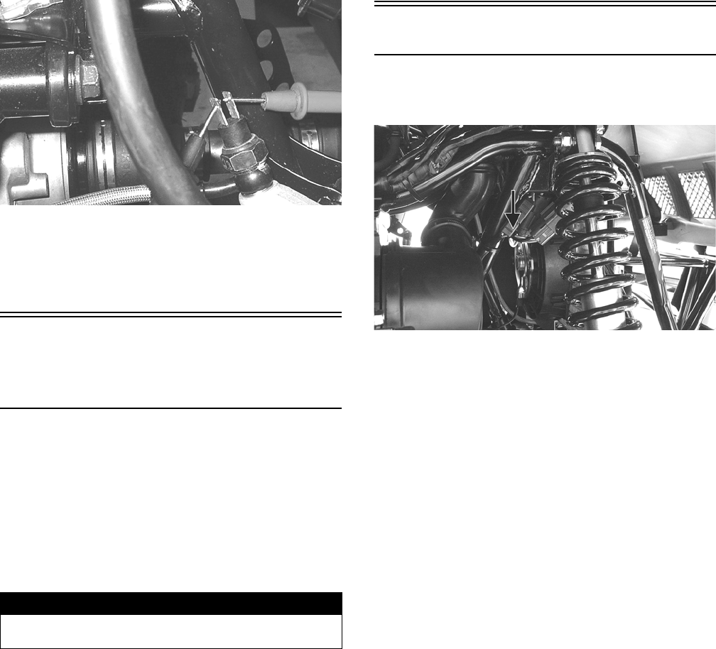
77
NOTE: If the meter shows no battery voltage, trou-
bleshoot the battery, fuse, switch, or the main wiring
harness.
NOTE: If the meter shows battery voltage, the main
wiring harness is good; proceed to test the switch/
component or connector.
RESISTANCE (Switch)
1. Remove the spade connectors from the brake switch.
2. Set the meter selector to the OHMS position.
3. Connect the red tester lead to one switch terminal;
then connect the black tester lead to the other switch
terminal.
KC274
4. When the brake pedal is depressed, the meter must
show less than 1 ohm.
NOTE: If the meter shows more than 1 ohm of resis-
tance, replace the switch.
Engine Coolant
Temperature (ECT)
Sensor
1. Connect the meter leads (selector in OHMS position)
to the sensor terminals.
2. Suspend the sensor and a thermometer in a container
of cooking oil; then heat the oil.
NOTE: Neither the sensor nor the thermometer
should be allowed to touch the bottom of the con-
tainer or inaccurate readings will occur. Use wire
holders to suspend the sensor and thermometer.
3. On the ECT sensor when the temperature reaches
20° C (68° F), the meter should read approximately
2.45k ohms.
4. On the ECT sensor when the temperature reaches
50° C (122° F), the meter should read approximately
800 ohms.
5. On the ECT sensor when the temperature reaches
80° C (176° F), the meter should read approximately
318 ohms.
6. On the ECT sensor when the temperature reaches
110° C (230° F), the meter should read approxi-
mately 142 ohms.
7. If the readings are not as indicated, the sensor must
be replaced.
8. Install the sensor and tighten securely.
9. Connect the leads.
Fan Motor
The connector is the black two-prong one located behind
the fan assembly along the right-side frame tube.
KC270A
NOTE: The ignition switch must be in the ON posi-
tion.
VOLTAGE (Main Harness Connector
to Fan Motor)
1. Set the meter selector to the DC Voltage position.
2. Connect the red tester lead to the orange wire; then
connect the black tester lead to ground.
3. The meter must show battery voltage.
NOTE: If the meter shows no battery voltage, trou-
bleshoot the battery, fuse, motor, or the main wiring
harness.
NOTE: If the meter shows battery voltage, the main
wiring harness is good. The connector should be
checked for resistance.
RESISTANCE (Fan Motor Connector)
1. Set the meter selector to the OHMS position.
2. Connect the red tester lead to the red wire; then con-
nect the black tester lead to the black wire.
! WARNING
Wear insulated gloves and safety glasses. Heated oil
can cause severe burns.
For Discount Arctic Cat Parts Call 606-678-9623 or 606-561-4983
www.mymowerparts.com
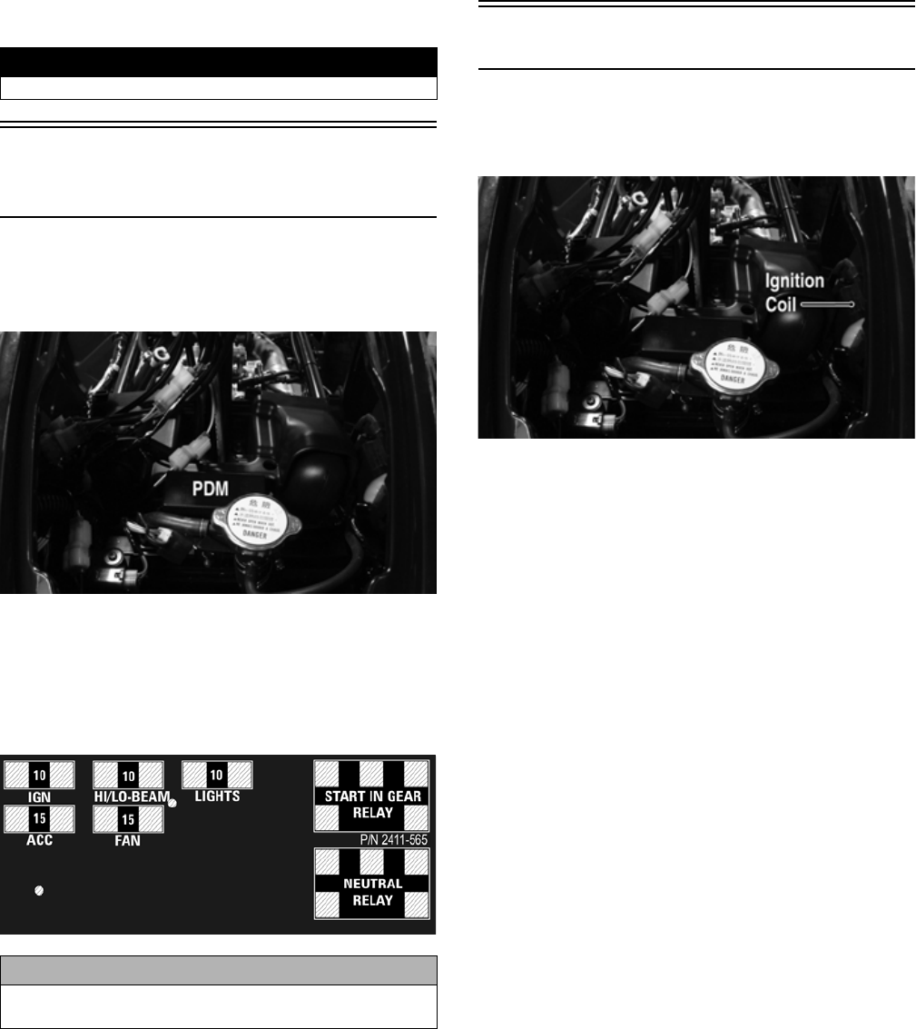
78
3. The meter must show less than 1 ohm.
NOTE: If the meter shows more than 1 ohm of resis-
tance, troubleshoot or replace the switch/component,
the connector, or the switch wiring harness.
NOTE: To determine if the fan motor is good, con-
nect the blue wire from the fan connector to the posi-
tive side of a 12 volt DC power supply; then connect
the black wire from the fan connector to the negative
side. The fan should operate.
Power Distribution
Module (PDM)
The fuses are located in the power distribution module in
front of the steering post under the radiator/electrical
access panel.
KC466A
If there is any type of electrical system failure, always
check the fuses first.
NOTE: To remove a fuse, compress the locking tabs
on either end of the PDM cover and lift off; then
remove the applicable fuse.
2411-565
RELAYS
The relays are identical plug-in type located on the PDM.
Relay function can be checked by switching relay posi-
tions. The relays are interchangeable.
NOTE: The PDM and wiring harness are not a ser-
viceable components and must be replaced as an
assembly.
Ignition Coil
The ignition coil is on the frame above the radiator. To
access the coil, the radiator/electrical access panel must
be removed.
KC466B
RESISTANCE
NOTE: For these tests, the meter selector must be
set to the OHMS position and the primary plug dis-
connected.
Primary Winding
1. Connect the red tester lead to either terminal; then
connect the black tester lead to the other terminal.
2. The meter reading must be within specification.
Secondary Winding
1. Remove the plug cap from the high tension lead;
then connect the red tester lead to the high tension
lead.
2. Connect the black tester lead to ground.
3. The meter reading must be within specification.
NOTE: If the meter does not show as specified,
replace ignition coil.
Spark Plug Cap
1. Connect the red tester lead to one end of the cap;
then connect the black tester lead to the other end of
the cap.
! WARNING
Care should be taken to keep clear of the fan blades.
CAUTION
Always replace a blown fuse with a fuse of the same
type and rating.
For Discount Arctic Cat Parts Call 606-678-9623 or 606-561-4983
www.mymowerparts.com
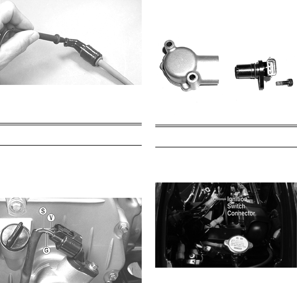
79
AR603D
2. The meter reading must be within specification.
NOTE: If the meter does not read as specified,
replace the spark plug cap.
Speed Sensor
1. Set the meter selector to the DC Voltage position.
2. With appropriate needle adapters on the meter leads,
connect the red tester lead to the voltage lead (V);
then connect the black tester lead to the ground lead
(G).
KC248A
3. Turn the ignition switch to the ON position.
4. The meter must show greater than 5.0 volts.
5. Leave the black tester lead connected; then connect
the red tester lead to the signal lead pin (S).
6. Slowly move the ATV forward or backward; the
meter must show 0 and >5 volts alternately.
NOTE: If the sensor tests are within specifications,
the speedometer/LCD gauge must be replaced (see
Steering/Frame).
To replace a speed sensor, use the following procedure.
1. Disconnect the three-wire connector from the speed
sensor; then remove the cap screw securing the sen-
sor to the sensor housing.
2. Remove the sensor from the sensor housing account-
ing for an O-ring.
3. Install the new speed sensor into the housing with
new O-ring lightly coated with multi-purpose grease;
then secure the sensor with the cap screw (threads
coated with blue Loctite #242). Tighten securely.
CD071
Ignition Switch
The ignition switch harness connects to the switch with a
three-pin connector. To access the connector, remove the
radiator/electrical access panel.
KC466C
VOLTAGE
NOTE: Perform this test on the main harness con-
nector.
1. Set the meter selector to the DC Voltage position.
2. Connect the red meter lead to the red/white wire;
then connect the black meter lead to ground.
3. Meter must show battery voltage.
NOTE: If the meter shows no battery voltage, trou-
bleshoot the battery or the main wiring harness.
RESISTANCE
NOTE: Perform this test on the switch harness
using the following procedure.
For Discount Arctic Cat Parts Call 606-678-9623 or 606-561-4983
www.mymowerparts.com
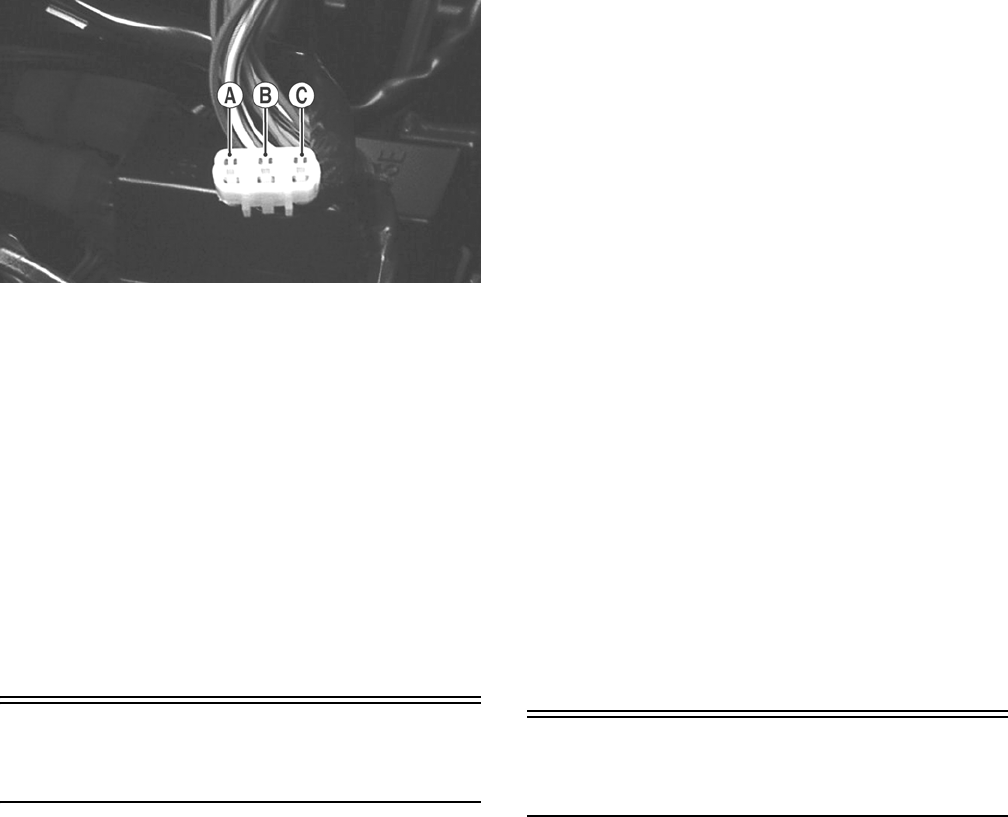
80
KC276A
1. Turn the ignition switch to the ON position.
2. Set the meter selector to the OHMS position.
3. Connect either tester lead to pin B; then connect the
other tester lead to pin A.
4. The meter must show less than 1 ohm.
5. Turn the ignition switch to the LIGHTS position.
The meter must show less than 1 ohm.
6. Leaving the tester lead on pin B, connect the other
tester lead to pin C.
7. The meter must show less than 1 ohm.
NOTE: If the meter shows more than 1 ohm of resis-
tance, replace the switch.
Handlebar Control
Switches
The connectors are located on the right side of the ATV
next to the PDM. To access the connector, the radiator/
electrical access panel must be removed.
NOTE: These tests should be made on the switch
side of the connector.
RESISTANCE (HI Beam)
1. Set the meter selector to the OHMS position.
2. Connect one tester lead to the brown/black wire; then
connect the other tester lead to the lavender wire.
3. With the dimmer switch in the HI position, the meter
must show less than 1 ohm.
NOTE: If the meter shows more than 1 ohm of resis-
tance, replace the switch.
RESISTANCE (LO Beam)
1. Connect one tester lead to the brown/black wire; then
connect the other tester lead to the white wire.
2. With the dimmer switch in the LO position, the
meter must show less than 1 ohm.
NOTE: If the meter shows more than 1 ohm of resis-
tance, replace the switch.
RESISTANCE (Emergency Stop)
1. Set the meter selector to the OHMS position.
2. Connect the one lead to the brown/lavender wire;
then connect the other tester lead to the black/white
wire.
3. With the switch in the OFF position, the meter must
show an open circuit.
4. With the switch in the RUN position, the meter must
show less than 1 ohm.
NOTE: If the meter shows more than 1 ohm of resis-
tance, replace the switch.
RESISTANCE (Reverse Override)
NOTE: The handlebar control switch connectors are
a six pin and a three pin. Both must be disconnected
for this test.
1. Set the meter selector to the OHMS position.
2. Connect one tester lead to one lavender/red wire
(three-pin connector); then connect the other tester
wire to the green/red wire on the six-pin connector.
The meter must show less than 1 ohm.
3. Depress and hold the reverse override button. The
meter must show an open circuit.
NOTE: If the meter does not show as specified,
replace the switch.
Front Drive Selector
Switch
The connector is the snap-lock one in front of the steering
post. To access the connector, the radiator/electrical
access panel cover must be removed.
NOTE: Resistance tests should be made with the
connector disconnected and on the selector-side of
the connector.
RESISTANCE
1. Set the meter selector to the OHMS position.
2. Connect the one tester lead to the white/blue wire;
then connect the other tester lead to the black wire.
3. With the selector switch in the 2WD position, the
meter must show an open circuit.
4. With the selector switch in the 4WD position, the
meter must show less than 1 ohm.
NOTE: If the meter does not show as specified,
replace the front drive selector switch.
VOLTAGE
NOTE: The battery must be connected when per-
forming voltage tests.
For Discount Arctic Cat Parts Call 606-678-9623 or 606-561-4983
www.mymowerparts.com
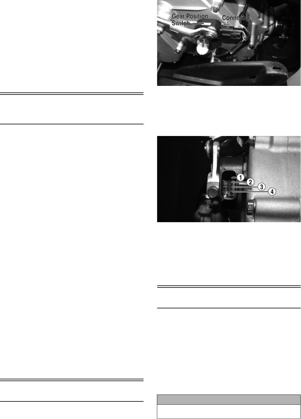
81
1. Set the meter selector to the DC Voltage position.
2. Connect the black tester lead to the negative battery
terminal.
3. Connect the red tester lead to the white/blue wire on
the harness side of the connector.
4. Turn the ignition switch to the RUN position.
5. The meter must show battery voltage.
NOTE: If the meter shows other than specified,
check the harness, connector, 30 amp fuse, and bat-
tery connections.
Front Drive Selector
Actuator
NOTE: With the engine stopped and the ignition
switch in the ON position, a momentary “whirring”
sound must be noticeable each time the selector
switch is moved to 2WD and 4WD. Test the switch, 30
amp fuse, and wiring connections prior to testing the
actuator.
VOLTAGE
1. Select the 2WD position on the front drive selector
switch; then disconnect the connector on the actuator
wiring harness.
2. With the ignition switch in the OFF position, connect
the black tester lead to the black wire in the supply
harness; then connect the red tester lead to either
orange wire in the supply harness.
3. Turn the ignition switch to the ON position. The
meter must show 12 DC volts.
4. Connect the red tester lead to the second orange wire
in the supply harness. The meter must show 12 DC
volts.
5. Connect the red tester lead to the white/green wire in
the supply harness. The meter must show 12 DC
volts.
6. Select the 4WD position on the front drive selector
switch; then connect the red tester lead to the white/
blue wire in the supply harness. The meter must
show 0 DC volts.
NOTE: The 4WD icon on the LCD should illuminate.
NOTE: If the voltage readings are as specified and
the actuator does not function correctly, replace the
actuator (see Drive System).
Gear Position Switch
The gear position switch is located on the engine/trans-
mission next to the shift arm.
FI525B
To troubleshoot the switch, use the following procedure.
1. Disconnect the gear position switch connector; then
using a multimeter, test the switch in each position as
follows. Resistance must be less than 1 ohm for all
tests.
KC410A
A. Neutral (N)Pins 3 to 4
B. Reverse (R)Pins 3 to 4 and 3 to 2
C. High (H)Pins 3 to 4 and 3 to 1
D. Low (L)Pins 3 to 1
2. Connect the harness to the gear position switch.
Stator Coil
VOLTAGE
(AC Generator - Regulated Output)
1. Set the meter selector to the DC Voltage position.
2. Connect the red tester lead to the positive battery
post; then connect the black tester lead to the nega-
tive battery post.
3. With the engine running at a constant 3000 RPM
(with the headlights on), the meter must show 14-
15.5 DC volts.
CAUTION
Do not run the engine at high RPM for more than 10 sec-
onds.
For Discount Arctic Cat Parts Call 606-678-9623 or 606-561-4983
www.mymowerparts.com
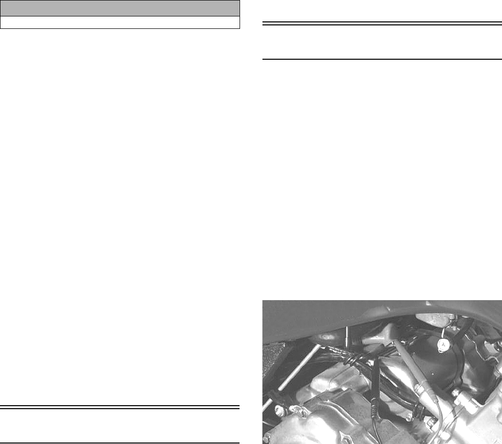
82
NOTE: If voltage is lower than specified, test AC
Generator coil - no load.
VOLTAGE (AC Generator Coil - No
Load)
The connector is the black three-pin one on the right side
of the engine just above the starter motor.
NOTE: Test the engine-side of the connector.
1. Set the meter selector to the AC Voltage position.
2. Test between the three black wires for a total of three tests.
3. With the engine running at the specified RPM, all
wire tests must show 60 AC volts.
NOTE: If both AC Generator coil tests failed, check
all connections, etc., and test again. If no voltage is
present, replace the stator assembly.
RESISTANCE (AC Generator Coil)
1. Set the meter selector to OHMS position.
2. Test between the three black wires for a total of three tests.
3. The meter reading must be within specification.
RESISTANCE (Crankshaft Position
Sensor)
1. Disconnect the gray four-pin connector on the right
side of the engine just above the starter motor.
2. Set the meter selector to the OHMS position.
3. Connect the red tester lead to the green wire; then
connect the black tester lead to the blue wire. The
meter reading must be within specification.
NOTE: The battery must be at full charge for this test.
VOLTAGE (Crankshaft Position
Sensor)
1. Set the meter selector to the DC Voltage position.
2. Connect the red tester lead to the green wire; then
connect the black tester lead to the blue wire.
3. Crank the engine over using the electric starter.
4. The meter reading must be within specification.
Starter Relay
1. Remove the battery case access cover; then using the
multimeter set to the DC Voltage position, check the
relay as follows.
2. Connect the red tester lead to the positive battery ter-
minal; then connect the black tester lead to the starter
cable connection on the starter relay. The meter must
show battery voltage.
NOTE: Make sure that the ignition switch is in the ON
position, transmission in neutral, brake lock released,
and the emergency stop switch in the RUN position.
3. Depress the starter button while observing the multi-
meter. The multimeter should drop to 0 volts, a
“click” should be heard from the relay, and the starter
motor should run.
NOTE: If a “click” is heard and any voltage is indi-
cated by the multimeter, replace the starter relay. If no
“click” is heard and the multimeter continues to indi-
cate battery voltage, test the neutral start relay.
Starter Motor
NOTE: The starter is a non-serviceable component.
If the following test does not result as specified, the
starter must be replaced.
TESTING VOLTAGE
Perform this test on the starter motor positive terminal.
To access the terminal, slide the boot away.
NOTE: The ignition switch must be in the ON posi-
tion, the emergency stop switch in the RUN position,
and the shift lever in the NEUTRAL position.
1. Set the meter selector to the DC Voltage position.
2. Connect the red tester lead to the starter terminal;
then connect the black tester lead to ground.
3. With the starter button depressed, the meter must
show approximately 10.0 DC volts and the starter
motor should operate.
AR607D
NOTE: If the meter showed correct voltage but the
starter did not operate or operated slowly, the starter
motor is defective.
CAUTION
Do not run the engine at high RPM for more than 10 seconds.
For Discount Arctic Cat Parts Call 606-678-9623 or 606-561-4983
www.mymowerparts.com
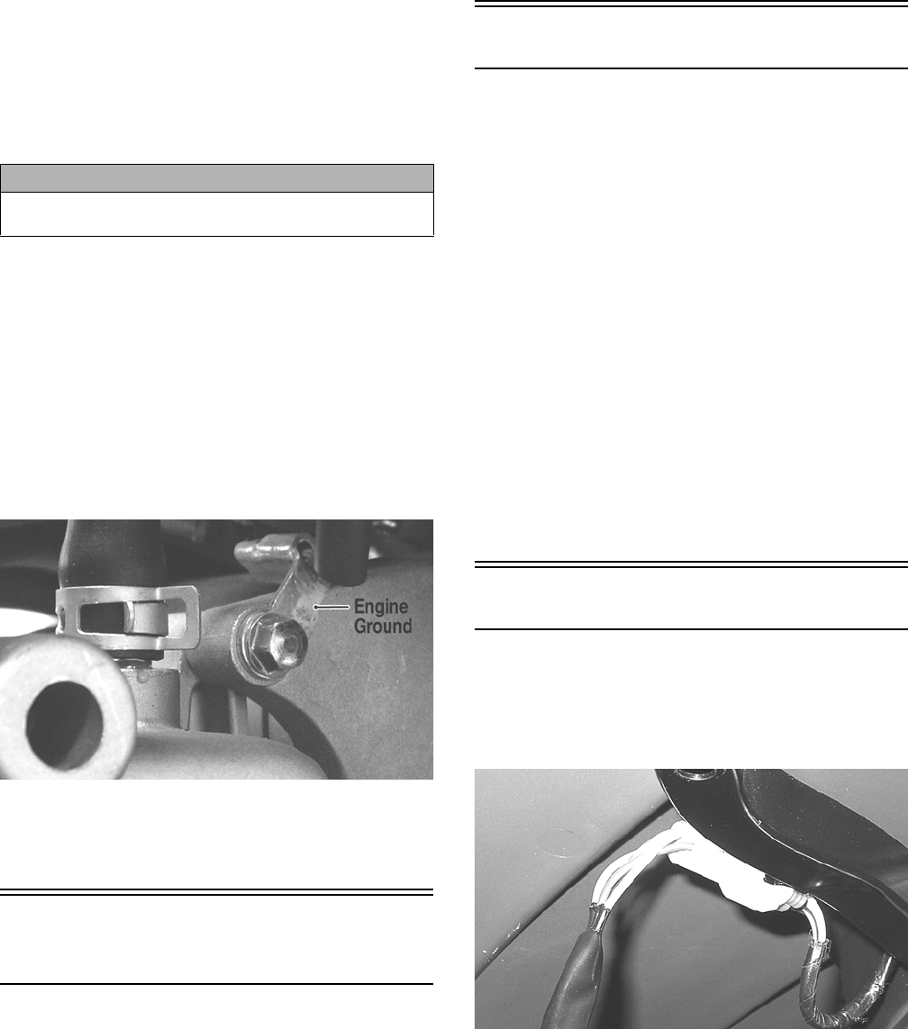
83
NOTE: If the meter showed no voltage, inspect
ground connections, starter motor lead, battery volt-
age (at the battery), starter relay, or the neutral start
relay.
REMOVING
1. Disconnect the battery.
2. Remove the nut securing the positive cable to the
starter; then remove the cable from the starter.
3. Remove the two cap screws securing the starter to
the crankcase; then remove the starter. Account for
an O-ring.
INSTALLING
1. Apply a small amount of grease to the O-ring seal on
the starter; then install the starter into the crankcase.
Secure with two cap screws making sure the engine
ground is secured by the rear cap screws. Tighten to
8 ft-lb.
KC201A
2. Secure the positive cable to the starter with the nut.
Tighten to 8 ft-lb.
3. Connect the battery.
Electronic Control Unit
(ECU)
The electronic control unit (ECU) is located above the
radiator under the radiator/electrical access panel.
NOTE: The ECU is not a serviceable component. If
the unit is defective, it must be replaced.
The ECU is rarely the cause for electrical problems; how-
ever, if the ECU is suspected, substitute another ECU of
the same part number to verify the suspected one is
defective.
Diagnostic Trouble Codes (DTC) can be cleared by fol-
lowing the procedures located in the Diagnostic Trouble
Codes (DTC) sub-section in this section.
Regulator/Rectifier
The regulator/rectifier is located under the radiator/elec-
trical access panel.
TESTING
1. Start engine and warm up to normal operating tem-
peratures; then connect a multimeter to the battery as
follows.
2. Select the DC Voltage position; then connect the red
tester lead to the positive battery post and the black
tester lead to the negative battery post.
3. Start the engine and slowly increase RPM. The volt-
age should increase with the engine RPM to a maxi-
mum of 15.5 DC volts.
NOTE: If voltage rises above 15.5 DC volts, the reg-
ulator is faulty or a battery connection is loose or cor-
roded. Clean and tighten battery connections or
replace the regulator/rectifier. If voltage does not rise,
check Voltage (Charging Coil - No Load) in this sec-
tion. If charging coil voltage is normal, replace the
regulator/rectifier.
Lights
HEADLIGHTS - RUNNING LIGHTS
The connectors are the two 4-pin ones snapped onto the
front body panel support. To release the connectors from
the frame, press the release tab with a small screwdriver.
KC224
CAUTION
Always disconnect the negative battery cable from the
battery first; then disconnect the positive cable.
For Discount Arctic Cat Parts Call 606-678-9623 or 606-561-4983
www.mymowerparts.com
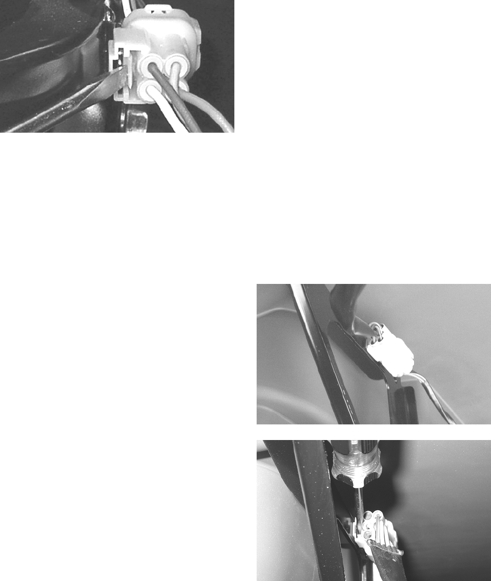
84
KC223
Voltage (Headlights)
NOTE: Perform this test on the main harness side of
the connectors. Also, the ignition switch must be in
the LIGHTS position.
1. Set the meter selector to the DC Voltage position.
2. Connect the black tester lead to the black wire; then
connect the red tester lead to the white wire.
3. With the dimmer switch in the LO position, the
meter must show battery voltage.
4. Remove the red tester lead from the white wire and
connect to the lavender wire.
5. With the dimmer switch in the HI position, the meter
must show battery voltage.
NOTE: If battery voltage is not shown in any test,
inspect the fuses, battery, main wiring harness, con-
nectors, or the left handlebar switch.
Voltage (Running Lights)
1. Release the wire connector from the frame; then
release and separate the connectors.
NOTE: Perform this test on the wiring harness side
of the connectors.
2. Connect the black tester lead of the meter to the
black wire; then with the tester in the DC Volts posi-
tion, connect the red tester lead to the brown/black
wire.
3. Turn the ignition switch to the LIGHTS position.
The meter must show battery voltage.
NOTE: If the meter does not show voltage, inspect
the LIGHTS fuse, battery connections, or trouble-
shoot the main wiring harness.
TAILLIGHTS - BRAKELIGHTS
Voltage (Taillights)
NOTE: Perform this test on the main harness side of
the connector. Also, the ignition switch should be in
the LIGHTS position.
1. Set the meter selector to the DC Voltage position.
2. Connect the black tester lead to the black wire; then
connect the red tester lead to the brown/blue wire.
3. The meter must show battery voltage.
NOTE: If the meter does not show voltage, inspect
fuses, wiring harness, connectors, and switches.
Voltage (Brakelights)
NOTE: Perform this test on the main harness side of
the connector. Also, the ignition switch should be in
the ON position and the brake (either foot pedal or
hand lever) must be applied.
1. Set the meter selector to the DC Voltage position.
2. Connect the black tester lead to the black wire; then
connect the red tester lead to the green/yellow wire.
3. The meter must show battery voltage.
NOTE: If the meter does not show voltage, inspect
bulb, fuses, wiring harness, connectors, and
switches.
BACK-UP LIGHTS
The connectors are located on the rear frame supports
attached by a metal tab. They may be released from the
frame by depressing the release with a small screwdriver.
KC279
KC280
Voltage
1. Release the wire connectors from the frame; then
disconnect the connectors.
NOTE: Perform this test on the main harness side of
the connectors.
For Discount Arctic Cat Parts Call 606-678-9623 or 606-561-4983
www.mymowerparts.com

85
2. Connect the black tester lead to the brown/lavender
wire; then connect the red tester lead to the lavender/
red wire.
3. Set the tester to DC VOLTS; then turn the ignition
switch to the ON position and move the shift lever to
the R (reverse) position. The meter must show bat-
tery voltage.
NOTE: If the meter does not show battery voltage,
use the following procedure to troubleshoot.
4. Remove the black tester lead from the brown/laven-
der wire and connect to a suitable ground.
A. If the meter shows battery voltage, troubleshoot
the gear shift position switch connector or the
gear shift position switch.
B. If the meter does not show battery voltage, inspect
the LIGHTS fuse, ignition switch, or the main
wiring harness.
Ignition Timing
The ignition timing cannot be adjusted; however, verifying
ignition timing can aid in troubleshooting other compo-
nents. To verify engine timing, see Periodic Maintenance.
Diagnostic Trouble
Codes (DTC)
If an EFI or related chassis component fails or an out-of-
tolerance signal is detected by the ECU, a diagnostic trou-
ble code (DTC) will be generated in the ECU and dis-
played on the LCD. For the first thirty seconds, the LCD
will go blank and the DTC will be displayed alternately
with a wrench icon or malfunction indicator light (MIL).
After thirty seconds, the digital display will return to nor-
mal; however, the MIL and DTC will continue to flash.
Code List
NOTE: Each of the following numerical codes will
have a one-letter prefix of C or P. A “C” prefix denotes
a chassis malfunction and a “P” prefix denotes a
power train malfunction.
NOTE: Normal malfunction codes are cleared from
the LCD when the component is replaced or the mal-
function is corrected; however, intermittent codes
must be cleared as noted in the code chart.
High Signal Level too High (Possible Short-to-Battery (+))
Low Signal Level too Low (Possible Short-to-Ground or Short-
to-Chassis)
SG Possible Short-to-Ground or Short-to-Chassis
Open Open-Circuit (Possible Broken-Wire or No-Connection)
1These codes cleared by one complete power-cycle only
(key-off, key-on)
2These codes cleared by one complete starting-cycle only
(key-off, key-on, start, key-off, key-on)
Code ECU
PIN Description Problem
C00631D2 Tilt Sensor Circuit High
C00641D2 Tilt Sensor Circuit Low SG/Open
P0107 F2 MAP Sensor Circuit Low SG/Open
P0108 F2 MAP Sensor Circuit High SP
P0112 F3 IAT Sensor Circuit Low SG
P0113 F3 IAT Sensor Circuit High Open
P0114¹ F3 IAT Sensor Circuit Intermittent
P0116 F4 ECT Sensor Circuit Range/Performance
P0117 F4 ECT Sensor Circuit Low SG
P0118 F4 ECT Sensor Circuit High Open/SP
P0119¹ F4 ECT Sensor Circuit Intermittent
P0121 G3 TPS Range/Performance
P0122 G3 TPS Circuit Low SG
P0123 G3 TPS Circuit High
P0219 N/A Engine Over-Speed Condition
P0231 J1 Fuel Pump Relay Circuit Low SG/Open
P0232 J1 Fuel Pump Relay Circuit High
P0233 J1 Fuel Pump Relay Circuit
P0264² K4 Cylinder Injector Circuit Low/SG SG
P0265² K4 Cylinder Injector Circuit High
P0266² K4 Cylinder Injector Balance Open
P0336¹ D1/E1 CKP Sensor Synchronization
P0337¹ D1/E1 CKP Sensor Circuit SG
P0339¹ D1/E1 CKP Sensor Intermittent/Erratic
P0480 K2 Fan Relay Control Circuit
P0484 K2 Fan Relay Control Circuit High
P0485 K2 Fan Relay Control Circuit Low SG/Open
P0500 Vehicle Speed Sensor
P0508 C4/D3/
D4/E4
Idle Air Control System Circuit Low SG
P0509 C4/D4 Idle Air Control System Circuit High Open
P0562 L1 System Voltage Low
P0563 L1 System Voltage High
P0601 N/A ECU Memory Check-Sum Error
P0615¹ L3 Starter Relay Circuit
P0616 L3 Starter Relay Circuit Low
P0617 L3 Starter Relay Circuit High
P0630 N/A VIN Not Programmed or Incompatible
P0642 A1 Sensor Power Circuit Low
P0643 A1 Sensor Power Circuit High
P2303² M2 Ignition Coil Primary Circuit Low Open
P2304² M2 Ignition Coil Primary Circuit High
P2531 A4 Ignition Switch Circuit Low
P2532 A4 Ignition Switch Circuit High
U0155 B1/C1 LCD Gauge Communication Lost
*FUEL
OFF
*Tilt Sensor Activation Operator-Code
For Discount Arctic Cat Parts Call 606-678-9623 or 606-561-4983
www.mymowerparts.com
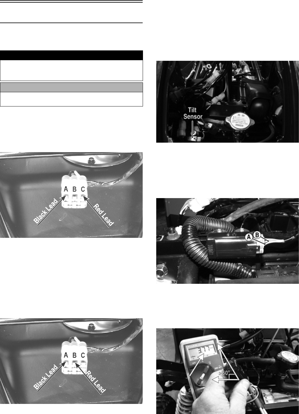
86
Tilt Sensor
The tilt sensor is located above the radiator under the
radiator/electrical access panel.
SUPPLY VOLTAGE
1. Disconnect the three-wire connector from the sensor;
then select DC Voltage on the multimeter and con-
nect the red tester lead to the (C) pin and the black
tester lead to the (A) pin.
CD706A
2. Turn the ignition switch to the ON position. The
multimeter should read approximately 5 DC volts. If
correct voltage is not indicated, check the 30-amp
main and 10-amp ignition fuses, wiring harness, or
the ignition switch.
3. Remove the red tester lead and connect to the (B)
pin. The multimeter should read approximately 0.5
DC volts. If the specified voltage is not indicated,
check wire connections at the ECU or substitute
another ECU to verify the test.
CD706B
OUTPUT VOLTAGE
NOTE: Needle adapters or a “break-out” harness
will be required on the multimeter leads as the follow-
ing tests are made with the sensor connected.
1. Connect the three-wire plug to the sensor; then
remove the mounting screws securing the sensor to
the frame.
KC466F
2. Install the needle adapters to the multimeter leads;
then select DC Voltage on the multimeter.
3. Connect the red tester lead to the blue/brown wire
(B) and the black tester lead to the pink/black wire
(A); then turn the ignition switch ON and observe the
meter. The meter should read 0.3-1.5 DC volts.
KC416A
4. Tilt the sensor 60° or more to the left and right
observing the meter. The meter should read 3.0-7.0
DC volts after approximately one second in the tilted
position. If the meter readings are not as specified,
the tilt sensor is defective.
KC414A
! WARNING
Incorrect installation of the tilt sensor could cause sud-
den loss of engine power which could result in loss of
vehicle control resulting in injury or death.
CAUTION
Do not drop the tilt sensor as shock can damage the
internal mechanism.
For Discount Arctic Cat Parts Call 606-678-9623 or 606-561-4983
www.mymowerparts.com
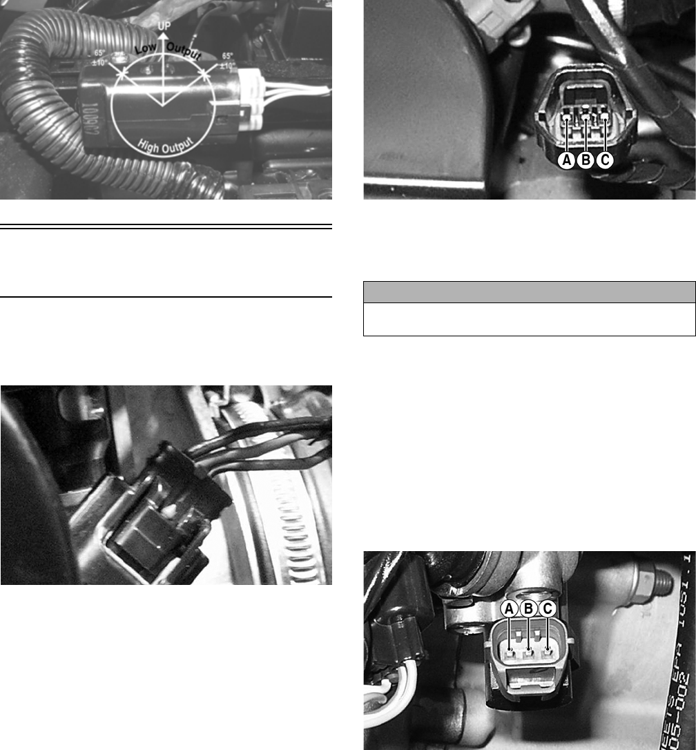
87
KC416B
Throttle Position Sensor
(TPS)
INSPECTING
1. Remove the left-side engine cover; then disconnect
the three-wire TPS connector plug.
PR544
NOTE: Prior to testing the TPS, inspect the three-
wire plug connector on the main harness and the
three-pin plug on the TPS for contamination, broken
pins, and/or corrosion.
2. Make sure the ignition switch is in the OFF position;
then select the DC Voltage position on the meter.
3. Connect the black tester lead to terminal B and the
red tester lead to terminal A. Turn the ignition switch
to the ON position. The meter should read approxi-
mately 5.0 DC volts.
PR538A
NOTE: If the meter does not read as specified,
check for poor connections at the ECU or open/bro-
ken wires in the wiring harness.
4. Turn the ignition switch to the OFF position.
5. Select the OHMS position on the meter; then per-
form the following resistance tests on the TPS.
A. Pin (B) to ground - infinity (open circuit).
B. Pin (A) to pin (B) - approximately 1.22k ohms
(throttle closed).
C. Pin (A) to pin (B) - approximately 4.5k ohms
(throttle full-open).
D. Pin (A) to pin (C) - approximately 5.5k ohms.
PR535A
NOTE: If any meter reading is not as specified,
replace or adjust the TPS (see INSTALLING/ADJUST-
ING in this sub-section).
6. Connect the positive lead to the battery; then connect
the negative lead.
7. Connect the main harness TPS connector to the TPS;
then using MaxiClips, connect the black tester lead
to the black/green wire and the red tester lead to the
green/black wire.
CAUTION
Always make sure the ignition switch is in the OFF posi-
tion before disconnecting the ECU.
For Discount Arctic Cat Parts Call 606-678-9623 or 606-561-4983
www.mymowerparts.com
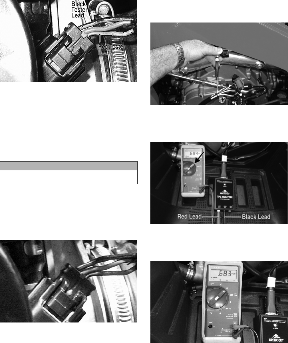
88
PR546A
8. Select the DC Voltage position on the meter and turn
the ignition switch to the ON position. The meter
should read approximately 4.5 DC volt with the
throttle closed and approximately 1.5 DC volts with
the throttle in the full-open position.
NOTE: If the meter readings are as specified, check
the main harness connector at the ECU main harness
wiring. If the meter readings are not as specified,
replace the TPS and adjust to specifications (see
INSTALLING/ADJUSTING in this sub-section).
9. Verify all malfunction codes are closed after servic-
ing is complete (see Diagnostic Trouble Codes
(DTC) in this section).
REMOVING
1. Remove the left-side engine cover; then disconnect
the three-wire TPS connector plug.
PR544
2. Remove the screw securing the TPS to the throttle
body and remove the TPS.
INSTALLING/ADJUSTING
1. Place the TPS into position on the throttle body and
secure with the screw. Do not tighten at this time.
2. Connect the TPS Multi-Analyzer Harness connector
#8 to the TPS; then connect the harness to the TPS
Analyzer Tool.
FI672
3. Using a multimeter, connect the black tester lead to
the black socket (GND) on the analyzer and the red
tester lead to the white socket (VAR); then select the
Voltage position.
FI673A
4. Adjust the TPS until a reading of 0.68 DC volts is
obtained; then tighten the screw securely. Open and
close the throttle and determine the reading returns to
0.68 DC volts. Readjust as necessary.
FI674
5. Disconnect the harness from the analyzer; then dis-
connect the harness from the TPS and reconnect the
TPS main harness connector.
6. Tighten the mounting screws securely.
CAUTION
Always make sure the ignition switch is in the OFF posi-
tion before disconnecting the ECU.
For Discount Arctic Cat Parts Call 606-678-9623 or 606-561-4983
www.mymowerparts.com

89
Troubleshooting
Problem: Spark absent or weak
Condition Remedy
1. Ignition coil defective
2. Spark plug defective
3. Alternator defective
4. ECU defective
5. Pick-up coil defective
1. Replace ignition coil
2. Replace plug
3. Replace magneto
4. Replace ECU
5. Replace pick-up coil
Problem: Spark plug fouled with carbon
Condition Remedy
1. Gasoline incorrect
2. Air cleaner element dirty
3. Spark plug incorrect (too cold)
4. Valve seals cracked - missing
5. Oil rings worn - broken
1. Change to correct gasoline
2. Clean element
3. Replace plug
4. Replace seals
5. Replace rings
Problem: Spark plug electrodes overheat or burn
Condition Remedy
1. Spark plug incorrect (too hot)
2. Engine overheats
3. Spark plug loose
1. Replace plug
2. Service cooling system
3. Tighten plug
Problem: Alternator does not charge
Condition Remedy
1. Lead wires/connections shorted - loose - open
2. Stator coils shorted - grounded - open
3. Regulator/rectifier defective
1. Repair - replace - tighten lead wires
2. Replace stator coils
3. Replace regulator/rectifier
Problem: Alternator charges, but charging rate is below the specification
Condition Remedy
1. Lead wires shorted - open - loose (at terminals)
2. Stator coils grounded - open
3. Regulator/rectifier defective
4. Battery defective
1. Repair - tighten lead wires
2. Replace stator coils
3. Replace regulator/rectifier
4. Replace battery
Problem: Alternator overcharges
Condition Remedy
1. Internal battery short circuited
2. Regulator/rectifier damaged - defective
3. Regulator/rectifier poorly grounded
1. Replace battery
2. Replace regulator/rectifier
3. Clean - tighten ground connection
Problem: Charging unstable
Condition Remedy
1. Lead wire intermittently shorting
2. Alternator internally shorted
3. Regulator/rectifier defective
1. Replace lead wire
2. Replace stator coil
3. Replace regulator/rectifier
Problem: Starter button inoperative
Condition Remedy
1. Battery charge low
2. Switch contacts defective
3. Starter motor defective
4. Starter relay defective
5. Emergency stop - ignition switch off
6. Wiring connections loose - disconnected
1. Charge - replace battery
2. Replace switch
3. Replace starter motor
4. Replace relay
5. Turn on switches
6. Connect - tighten - repair connections
For Discount Arctic Cat Parts Call 606-678-9623 or 606-561-4983
www.mymowerparts.com

90
Problem: Battery “sulfation” (Acidic white powdery substance or spots on surfaces of cell plates)
Condition Remedy
1. Charging rate too low - too high
2. Battery run-down - damaged
3. Electrolyte contaminated
1. Repair charging system
2. Replace battery
3. Replace battery
Problem: Battery discharges too rapidly
Condition Remedy
1. Electrolyte contaminated
2. Charging system not charging
3. Battery overcharged - damaged
4. Battery short-circuited
1. Replace battery
2. Check alternator - regulator/rectifier - circuit connections
3. Replace battery - correct charging system
4. Replace battery
Problem: Battery polarity reversed
Condition Remedy
1. Battery incorrectly connected 1. Reverse connections - replace battery - repair damage
For Discount Arctic Cat Parts Call 606-678-9623 or 606-561-4983
www.mymowerparts.com
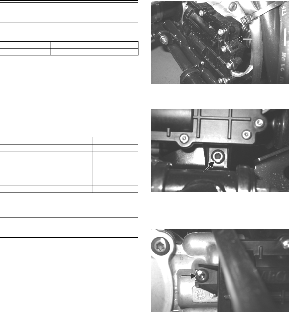
91
Drive System
GENERAL INFORMATION
All gear cases are tagged beneath a cover bolt. This tag is
marked with a production date code, sequence code, and
a ratio code.
The “1” or “3.1” on the lower-right corner indicates a
3.1:1 gear set ratio (11:34 teeth).
SPECIAL TOOLS
A number of special tools must be available to the techni-
cian when performing service procedures in this section.
Refer to the current Special Tools Catalog for the appro-
priate tool description.
NOTE: Special tools are available from the Arctic
Cat Service Parts Department.
Front Drive Actuator
NOTE: The actuator is not a serviceable compo-
nent. If it is defective, it must be replaced.
NOTE: The actuator will operate only when the igni-
tion switch is in the ON position.
The front drive actuator is located on the side of the front
drive input housing. With the engine stopped and the
ignition switch in the ON position, a momentary “whir-
ring” sound can be heard each time the front drive selec-
tor switch is shifted. If no sound is heard, see Electrical
System. If the actuator runs constantly or makes squeal-
ing or grinding sounds, the actuator must be replaced.
REMOVING
1. Disconnect the connector on the actuator harness.
2. Remove the mounting cap screw from the driveshaft
side of the actuator.
KC293A
3. Remove the mounting cap screw from below the
actuator on the suspension side.
KC294A
4. Loosen but do not remove the mounting cap screw at
the front of the actuator; then slide the actuator to the
rear enough to clear the slotted mounting tab and the
selector shaft.
KC295A
INSTALLING
1. Lubricate the O-ring on the actuator; then ensure that
all mounting surfaces are clean and free of debris.
2. Align the actuator with the selector shaft and slide it
forward onto the shaft taking care to engage the cap
screw in the slot of the front mounting tab.
Ring Gear Backlash 0.28-0.38 mm (0.011-0.015 in.)
Ring Gear End Play 0.1-0.2 mm (0.004-0.008 in.)
Description p/n
Backlash Measuring Tool 0544-010
CV Boot Clamp Tool 0444-120
Gear Case Seal Installer Tool 0444-224
Internal Hex Socket 0444-104
Pinion Gear/Shaft Removal Tool 0444-127
Slide Hammer Kit 0444-225
Multi-Seal Remover 0644-180
For Discount Arctic Cat Parts Call 606-678-9623 or 606-561-4983
www.mymowerparts.com
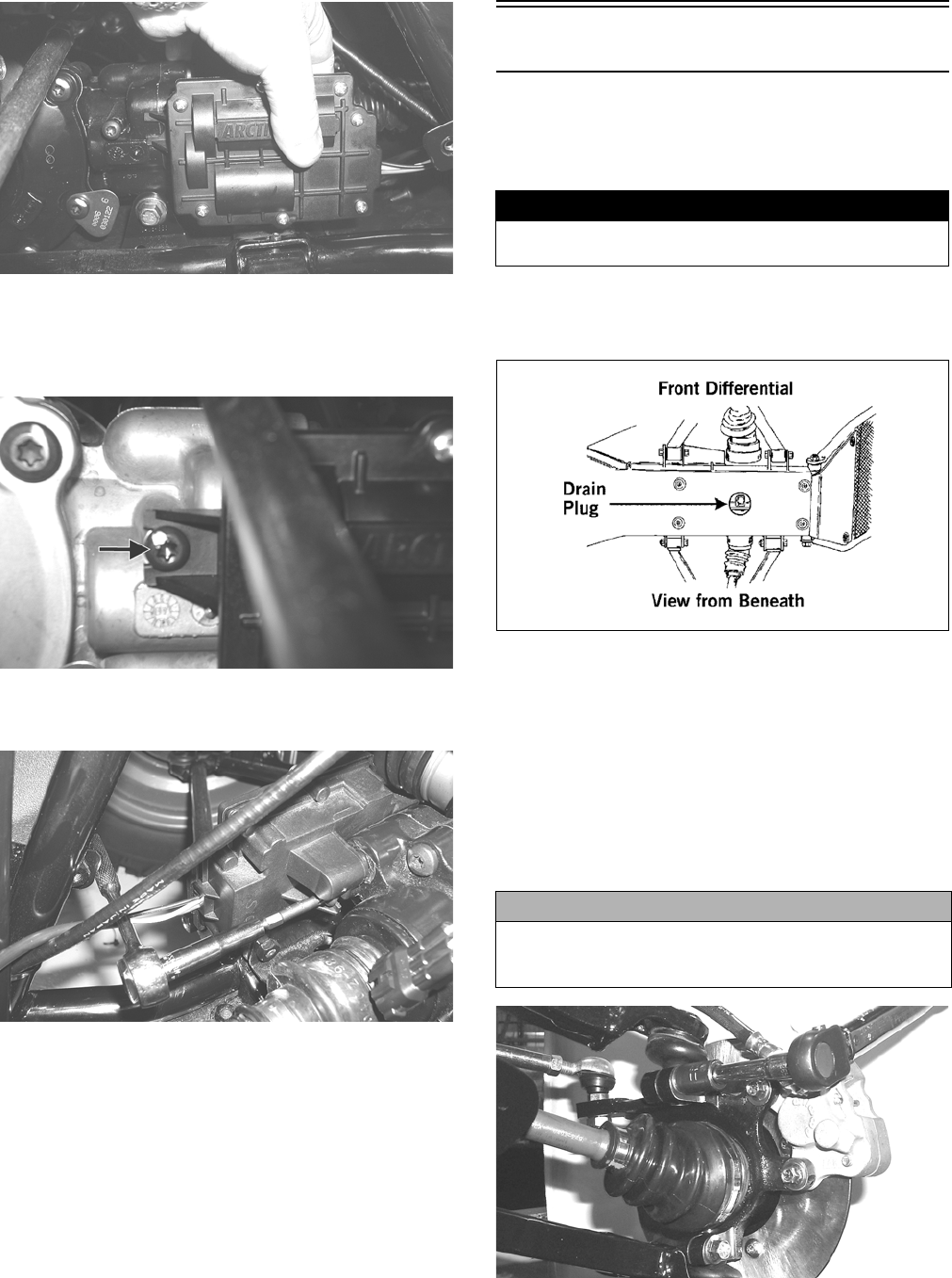
92
AG925
3. While holding the actuator firmly forward, tighten
the front cap screw to hold the actuator in place; then
install but do not tighten the two remaining cap
screws.
KC295A
4. Loosen the front cap screw; then tighten the cap
screw on the driveshaft side.
AG926
NOTE: It is important to tighten this cap screw while
the others are loose to ensure proper seating of the
actuator.
5. Tighten the remaining cap screws; then connect the
electrical plug to the main harness.
6. Turn the ignition switch to the ON position and
check the operation by shifting the selector switch
several times.
7. Secure the wiring harness to the frame with a nylon
cable tie.
Front Differential
REMOVING DIFFERENTIAL
1. Secure the ATV on a support stand to elevate the
wheels.
2. Remove the drain plug and drain the gear lubricant
into a drain pan; then reinstall the plug and tighten to
45 in.-lb.
ATV0082A
3. Remove the front wheels.
4. Pump up the hand brake; then engage the brake lever
lock.
5. Remove the cotter pin securing the hub nut; then
remove the nut.
6. Release the brake lever lock.
7. Remove the upper and lower ball joint cap screws
taking care not to strip the threads.
AF628D
! WARNING
Make sure the ATV is solidly supported on the support
stand to avoid injury.
CAUTION
Apply pressure to hold the ball joint firmly in the knuckle
or the threads will be stripped when the retaining cap
screws are removed.
For Discount Arctic Cat Parts Call 606-678-9623 or 606-561-4983
www.mymowerparts.com
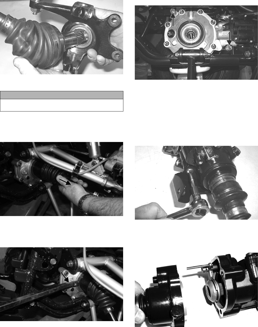
93
8. Pull the steering knuckle away from the axle taking
care not to damage the seals as the axle clears the
knuckle.
KC314
9. Support the axle to not allow it to drop or hang.
10. Pull out on the axle until completely extended; then
push it back in approximately one half inch and pull
out sharply. Repeat until axle spline dislodges from
the gear case.
KC425A
NOTE: In some instances it may be necessary to
use a pry-bar between the gear case housing and
axle coupler shoulder to dislodge the splines.
KC426A
11. Remove the cap screws from the drive coupler
flange; then remove the upper and lower mounting
cap screws and remove the differential from the
frame.
KC291A
Disassembling Input Shaft
NOTE: This procedure can be performed on a rear
gear case; however, some components may vary
from model to model. The technician should use dis-
cretion and sound judgment.
1. Remove the cap screws securing the front drive actu-
ator and remove the actuator; then remove the cap
screws securing the pinion housing.
CD102
2. Using a rubber mallet, remove the housing. Account
for a gasket. Remove the fork, collar, and spring.
Note the location of all the components for assem-
bling purposes.
CD103
CAUTION
The axle must be supported. If the axle is allowed to
drop or hang, damage to the inner CV joint may occur.
For Discount Arctic Cat Parts Call 606-678-9623 or 606-561-4983
www.mymowerparts.com
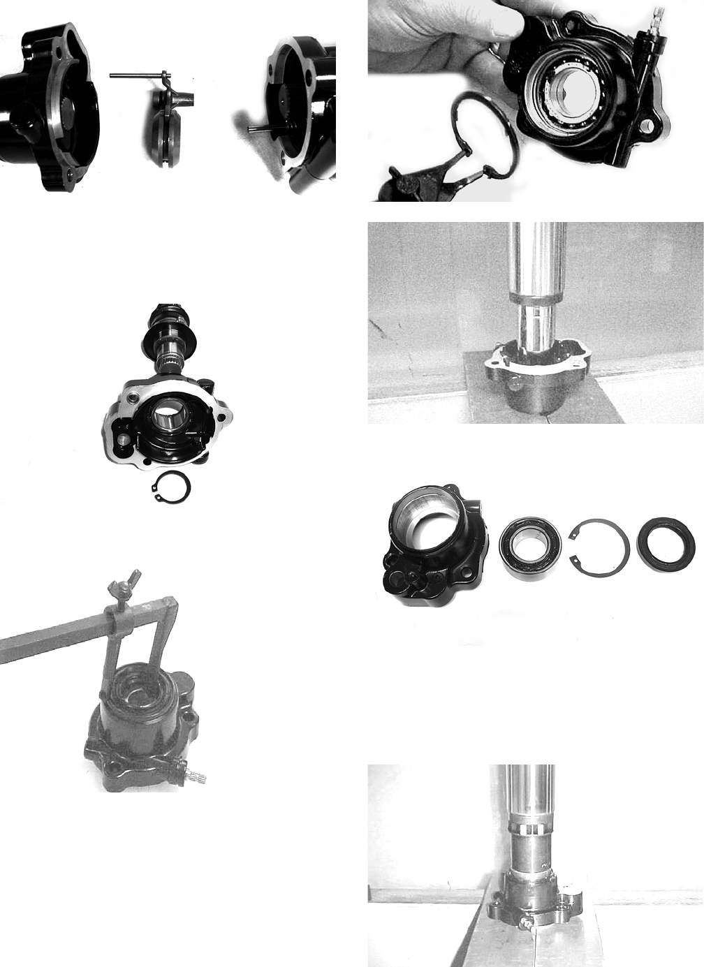
94
CD106
3. Using a side-cutter (or suitable substitute), remove
the boot clamps; then remove the boots and splined
drive from the input shaft.
4. Remove the input shaft from the pinion housing.
CD107
5. Using the Multi-Seal Remover, remove the input
shaft seal. Account for a spacer.
AF982
6. Remove the snap ring securing the input shaft bear-
ing; then place the pinion housing in a press and
remove the bearing.
AF983
AF984
KX219
Assembling Input Shaft
1. Place the pinion housing in a press and install the
input shaft bearing. Secure the bearing with the
existing snap ring making sure the sharp edge of the
snap ring faces to the outside.
AF993
For Discount Arctic Cat Parts Call 606-678-9623 or 606-561-4983
www.mymowerparts.com
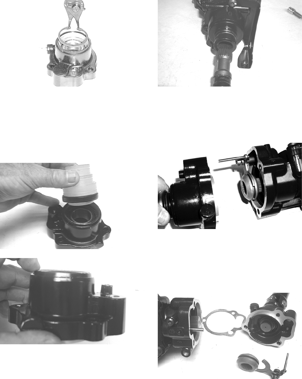
95
AF994
2. Install the input shaft seal making sure it is flush with
the edge of the housing.
3. Lubricate the input shaft splines with High-Perfor-
mance #2 Molybdenum Disulfide Grease.
NOTE: Any time drive splines are separated, clean
all splines with parts-cleaning solvent and dry with
compressed air; then lubricate with recommended
grease.
KX221
KX222
4. Install the input shaft into the housing; then install
the front boot and secure with an appropriate boot
clamp and the rear boot with an appropriate boot
clamp.
CD112
5. Using a new O-ring lubricated with grease, install
the front drive actuator and secure with the cap
screws.
6. Place the pinion housing with new gasket onto the
gear case housing; then secure with the existing cap
screws. Tighten to 18 ft-lb.
CD103
Disassembling Pinion Gear
NOTE: This procedure can be performed on a rear
gear case.
1. Remove the cap screws securing the pinion housing;
then remove the housing and account for a gasket.
Account for the coupler, fork, and spring.
KX209
2. Remove the cap screws securing the gear case cover.
Account for and make note of the ID tag location for
assembling purposes.
For Discount Arctic Cat Parts Call 606-678-9623 or 606-561-4983
www.mymowerparts.com
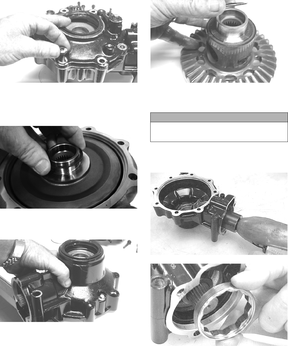
96
KX173
3. Using a plastic mallet, tap lightly to remove the dif-
ferential cover. Account for an O-ring and a shim.
NOTE: If the cover is difficult to remove, pry on the
cover in more than one recessed location.
GC063
4. Place the differential with the open side down; then
lift the housing off the spider assembly. Account for
shim(s) and mark as right-side.
KX179
KX181
5. Unstake the lock collar; then using the 48 mm Inter-
nal Hex Socket, remove the lock collar securing the
pinion gear assembly.
NOTE: On a front differential, the lock collar has
right-hand threads. On a rear gear case, the lock col-
lar has left-hand threads.
CC875
CC876
6. Using the Pinion Gear/Shaft Removal Tool and a
hammer, remove the pinion gear from the gear case
housing.
CAUTION
Failure to completely remove the staked material from
the lock collar will result in the destruction of the
threads in the gear case housing.
For Discount Arctic Cat Parts Call 606-678-9623 or 606-561-4983
www.mymowerparts.com
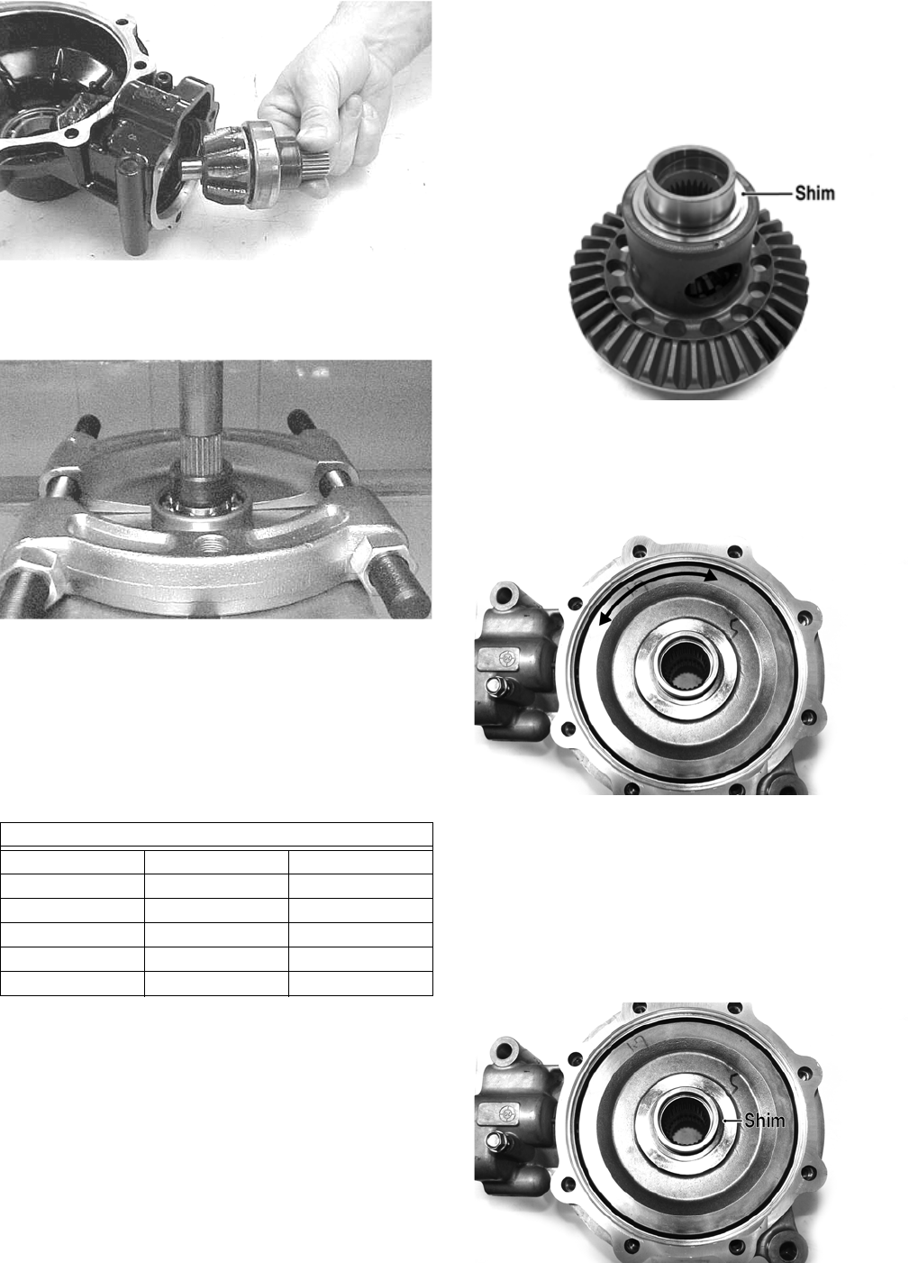
97
CC878
7. Secure the pinion gear in a bearing puller; then
remove the pinion bearing using a press. Account for
a collar and a bearing.
CC879
NOTE: If gears are being replaced, use the existing
shims.
NOTE: If the gear case housing is being replaced,
proceed to the following Shimming Procedure/Shim
Selection sub-section.
Shimming Procedure/Shim Selection
It is very important to adjust bevel gears for the proper
running tolerances. Gear life and gear noise are greatly
affected by these tolerances; therefore, it is very impor-
tant to properly adjust any gear set prior to final assem-
bly.
The following procedure can be used on both front differ-
ential or rear drive gear case.
NOTE: All bearings must be installed in the gear
case and the pinion properly installed before pro-
ceeding.
Backlash
NOTE: Always set backlash prior to any other shim-
ming.
1. Install the existing shim or a 0.051-0.055-in. shim on
the gear case side of the ring gear assembly.
GC031A
2. Install the ring gear with shim in the gear case; then
while holding the pinion stationary, rock the ring
gear forward and back to determine if any backlash
exists. If no backlash exists, install a thicker shim
and recheck.
GC059A
3. Install the bearing flange onto the gear case cover
making sure the alignment/locating pin engages the
locating hole in the cover; then make sure the bear-
ing flange is completely seated in the cover.
4. Install the existing shim or a 0.063 in. shim on the cover
side of the ring gear; then place the assembled gear case
cover onto the gear case and secure with three cap
screws. Tighten evenly using a crisscross pattern.
GC059B
Shims
p/n mm in.
0402-405 1.3 0.051
0402-406 1.4 0.055
0402-407 1.5 0.059
0402-408 1.6 0.063
0402-409 1.7 0.067
For Discount Arctic Cat Parts Call 606-678-9623 or 606-561-4983
www.mymowerparts.com
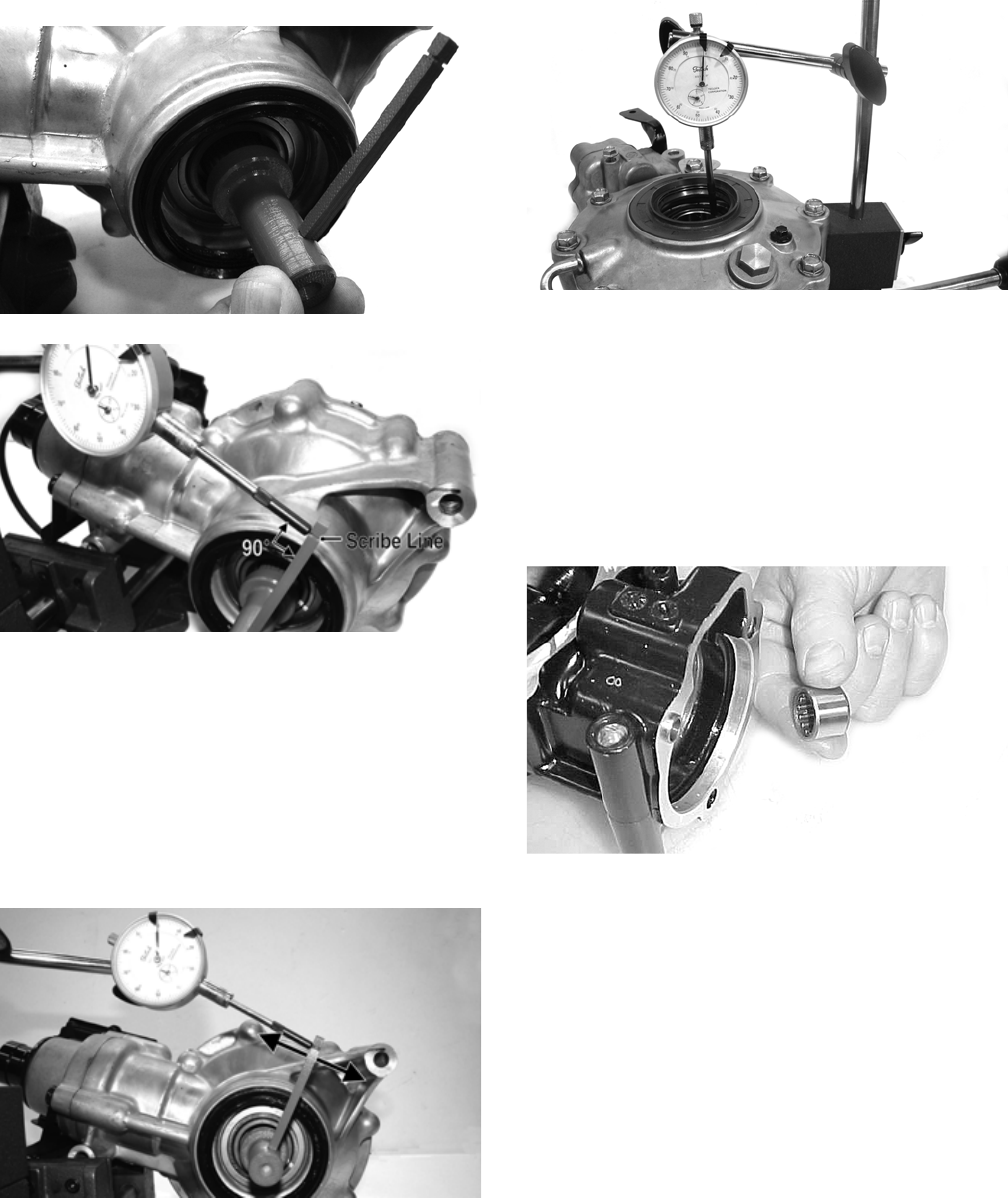
98
5. Place the Backlash Measuring Tool into the splines
of the ring gear and install a dial indicator making
sure it contacts the gauge at a 90° angle and on the
index mark.
GC070
GC072A
6. Zero the dial indicator; then while holding the pinion
stationary, rock the ring gear assembly forward and
back and record the backlash. Backlash must be
0.011-0.015 in. If backlash is within specifications,
proceed to Ring Gear End-Play. If backlash is not
within specifications, increase shim thickness to
increase backlash or decrease shim thickness to
decrease backlash.
NOTE: Higher backlash settings usually result in
quieter gear operation.
GC071A
Ring Gear End-Play
After correcting backlash, ring gear end-play can be
adjusted. To adjust end-play, use the following proce-
dure.
1. Secure the gear case in a holding fixture with the
cover side up; then install a dial indicator contacting
the ring gear axle flange.
GC065
2. Zero the dial indicator; then push the ring gear
toward the dial indicator and release. End-play
should be 0.004-0.008 in.
3. To increase end-play, decrease the shim thickness. To
decrease end-play, increase the shim thickness.
NOTE: Once proper backlash and end play are
established, the gear case can be assembled (see
Assembling Differential Assembly in this sub-sec-
tion).
CC888
RING GEAR/THRUST BUTTON
Removing
Remove the thrust button from the gear case cover (left-
hand threads). Account for a shim.
Inspecting
1. Inspect the ring gear for excessive wear or discolor-
ation.
2. Inspect the thrust button for excessive wear or dis-
coloration.
3. Inspect the bearings for discoloration, roughness, or
excessive wear.
Installing/Shimming
NOTE: Ring gear end-play must be adjusted prior to
selecting shim for the thrust button.
1. Install the thrust button with shim into the gear case
cover and tighten securely (left-hand threads).
For Discount Arctic Cat Parts Call 606-678-9623 or 606-561-4983
www.mymowerparts.com
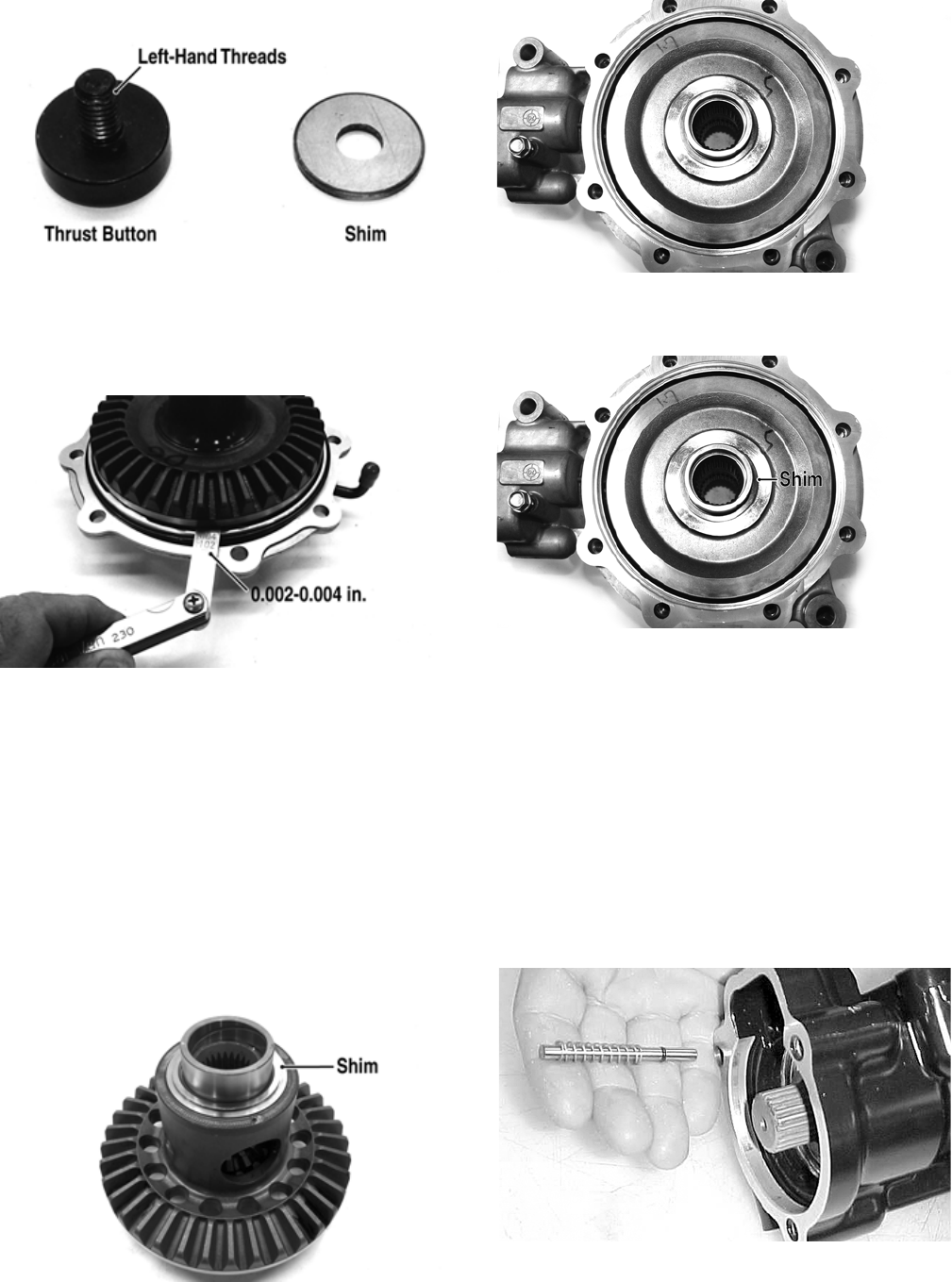
99
GC057A
2. Place the ring gear with selected shim into the cover
and measure the ring gear to thrust button clearance
with a thickness gauge. Clearance should be 0.002-
0.004 in.
GC058A
3. If clearance is as specified, remove the ring gear and
thrust button; then place a drop of red Loctite #271
on the threads and tighten to 8 ft-lb (left-hand
threads).
4. If clearance is not as specified, repeat steps 1 and 2
using thicker (clearance too great) or thinner (clear-
ance too small) until correct specification is reached.
Assembling Differential Assembly
1. With the pinion gear and new bearings installed,
place the selected (backlash) shim on the gear case
side of the ring gear with the chamfered side toward
the ring gear; then install into gear case/differential
housing.
GC031A
GC059
2. Place the selected (end-play) shim, chamfered side
toward the gear, onto the cover side of the ring gear.
GC059B
NOTE: The spider and ring gear assembly must be
replaced as a complete unit.
3. Making sure the O-ring is properly positioned on the
differential housing cover assembly, install the cover
with existing cap screws (coated with green Loctite
#609). Account for the ID tag. Tighten the cap
screws evenly to 18 ft-lb.
NOTE: Grease can be applied to the O-ring for ease
of assembling.
4. Install the shift fork shaft w/spring into the housing
making sure the shaft O-ring is positioned to the
inside.
CC892
5. Install the shift fork assembly making sure the fork
leg is facing upward. Apply a small amount of oil to
the gasket; then install the gasket.
For Discount Arctic Cat Parts Call 606-678-9623 or 606-561-4983
www.mymowerparts.com
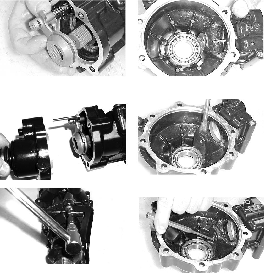
100
CC893
6. Place the input shaft housing assembly onto the gear
case housing; then secure with the existing cap
screws. Tighten to 18 ft-lb.
CD103
CD110
Removing Needle Bearing
NOTE: Removing the needle bearing is rarely nec-
essary. Avoid removing the needle bearing unless the
bearing is clearly damaged.
NOTE: This procedure can be performed on a rear
gear case.
1. Place a 1/4 in. drill bit on the inside surface of the
needle bearing (against the bottom side); then drill
through the pinion shaft needle bearing housing.
CC885
2. Using a propane torch, heat the area surrounding the
needle bearing to soften the Loctite.
CC886
3. Using a flat-nosed punch, drive the bearing out of the
housing.
CC887
Installing Needle Bearing
1. Apply green Loctite #609 to the outside of a new
bearing; then place the new bearing into the housing.
For Discount Arctic Cat Parts Call 606-678-9623 or 606-561-4983
www.mymowerparts.com
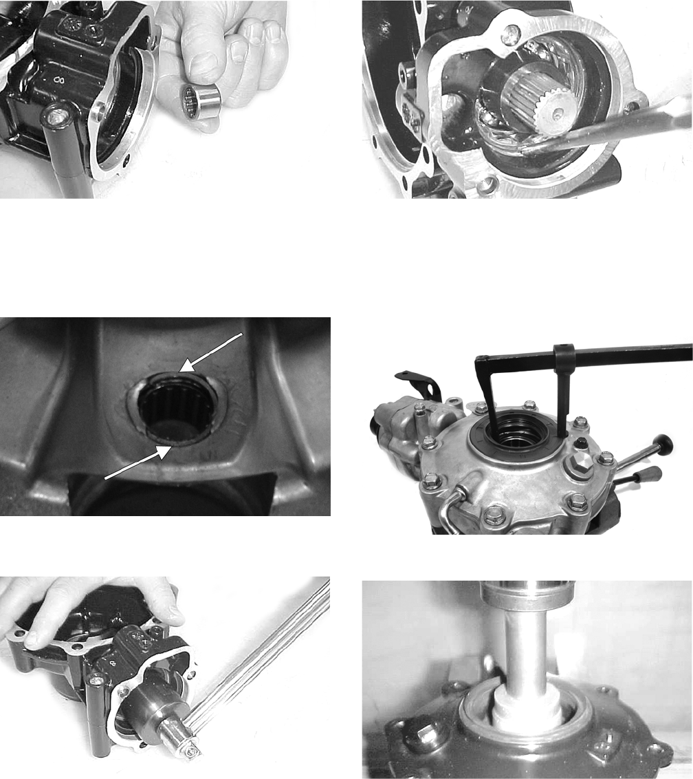
101
CC888
2. Using a suitable driver, install the needle bearing into
the gear case housing making sure the bearing is
seated.
NOTE: Do not push the bearing too far into the
housing.
GC045A
3. Install the pinion shaft and secure with a new 48 mm
lock collar. Tighten to 125 ft-lb.
CC890
4. Place a punch on the edge of the lock collar in the oil
gallery area; then using a hammer, stake the lock col-
lar to ensure that the collar will remain securely
tightened.
CC891
5. Install the pinion housing.
Removing/Installing Axle Seal
NOTE: This procedure can be performed on a rear
gear case.
1. Remove the seal using a seal removal tool.
GC066
2. Using a press, remove the bearing.
CC900
3. Using a press, install the new bearing into the hous-
ing.
For Discount Arctic Cat Parts Call 606-678-9623 or 606-561-4983
www.mymowerparts.com
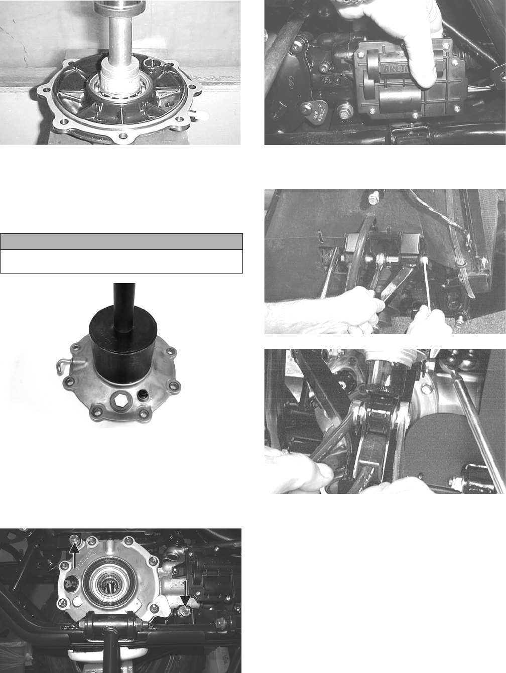
102
CC901
NOTE: Prior to installing the seal, apply High Perfor-
mance #2 Molybdenum Disulfide Grease to the seal
outside diameter.
4. Using an appropriate seal installation tool, evenly
press the seal into the cover bore until seated.
GC060
5. Repeat steps 1-4 for the opposite side.
INSTALLING DIFFERENTIAL
1. Align the input flange with the front output flange;
then place the differential into position on the frame
and install the cap screws and nuts. Tighten to 38 ft-
lb.
KC291A
2. Install the cap screws securing the flange couplers
together and tighten to 20 ft-lb.
AG925
3. Install the front axles (see Drive Axles in this sec-
tion).
AF610D
AF897D
4. Install the wheels and tighten to 40 ft-lb.
5. Pour 275 ml (9.3 fl oz) of SAE 80W-90 hypoid gear
lubricant into the differential and install the fill plug.
Tighten to 16 ft-lb.
6. Remove the ATV from the support stand.
CAUTION
Make sure the tool is free of nicks or sharp edges or the
seal will be damaged.
For Discount Arctic Cat Parts Call 606-678-9623 or 606-561-4983
www.mymowerparts.com
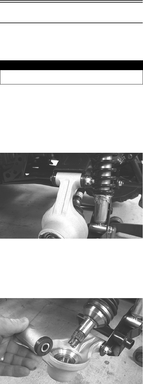
103
Drive Axles
REMOVING REAR DRIVE AXLE
1. Secure the ATV on a support stand to elevate the
wheels.
2. Pump up the hand brake; then engage the brake lever
lock.
3. Remove the rear wheels.
4. Remove the cotter pins securing the hex nuts; then
remove the hex nuts. Release the brake lever lock.
5. Remove the cap screw and lock nut securing the
knuckle to the upper A-arm. Discard the lock nut.
KC284
NOTE: Never reuse a lock nut. Once a lock nut has
been removed, it must be replaced with a new lock
nut.
6. While holding the drive axle stationary, pull the top
of the knuckle out and down until it is free of the
drive axle.
KC285
7. Place a drain pan under the ATV to contain any oil
leakage; then pull out sharply on the axle to dislodge
the splines from the gear case. Remove the axle.
REMOVING FRONT DRIVE AXLE
NOTE: For removing a front drive axle, see Front
Differential in this section.
CLEANING AND INSPECTING
NOTE: Always clean and inspect the drive axle com-
ponents to determine if any service or replacement is
necessary.
1. Using a clean towel, wipe away any oil or grease
from the axle components.
2. Inspect boots for any tears, cracks, or deterioration.
NOTE: If a boot is damaged in any way, it must be
replaced with a boot kit.
3. Inspect the gear case seals for nicks or damage.
DISASSEMBLING AXLES
NOTE: To disassemble/assemble axles, refer to
appropriate boot kit instructions.
INSTALLING REAR DRIVE AXLE
1. Slide the drive axle into place in the gear case.
NOTE: To assure proper seating of the axle, give it a
light pull; the axle should remain “clipped” in place.
2. Swing the knuckle up and onto the drive axle; then
place the knuckle into place in the upper A-arm.
Secure the knuckle to the A-arm with a cap screw
and a new lock nut. Tighten to 35 ft-lb.
3. Place the hub into position on the axle followed by a
hex nuts. Tighten the hex nuts finger-tight at this
time.
4. Pump up the hand brake lever; then engage the brake
lever lock.
5. Tighten the hub hex nuts (from step 3) to 200 ft-lb;
then install and spread a new cotter pin making sure
each side of the pin is flush to the hub nut.
6. Install the wheel. Tighten to 40 ft-lb.
7. Remove the ATV from the support stand and release
the brake lever lock.
INSTALLING FRONT DRIVE AXLE
1. Position the drive axle in the gear case and steering
knuckle; then insert the upper A-arm ball joint into
the steering knuckle. Secure with a cap screw tight-
ened to 35 ft-lb.
2. Slide the hub w/brake disc into position in the steer-
ing knuckle followed by a washer and hex nut.
Tighten finger-tight at this time.
3. Install the brake caliper on the steering knuckle.
Tighten to 20 ft-lb; then pump up the hand brake
lever and engage the brake lever lock.
4. Tighten the hub hex nut (from step 2) to 200 ft-lb;
then install and spread a new cotter pin making sure
each side of the pin is flush to the hub nut.
! WARNING
Make sure the ATV is solidly supported on the support
stand to avoid injury.
For Discount Arctic Cat Parts Call 606-678-9623 or 606-561-4983
www.mymowerparts.com
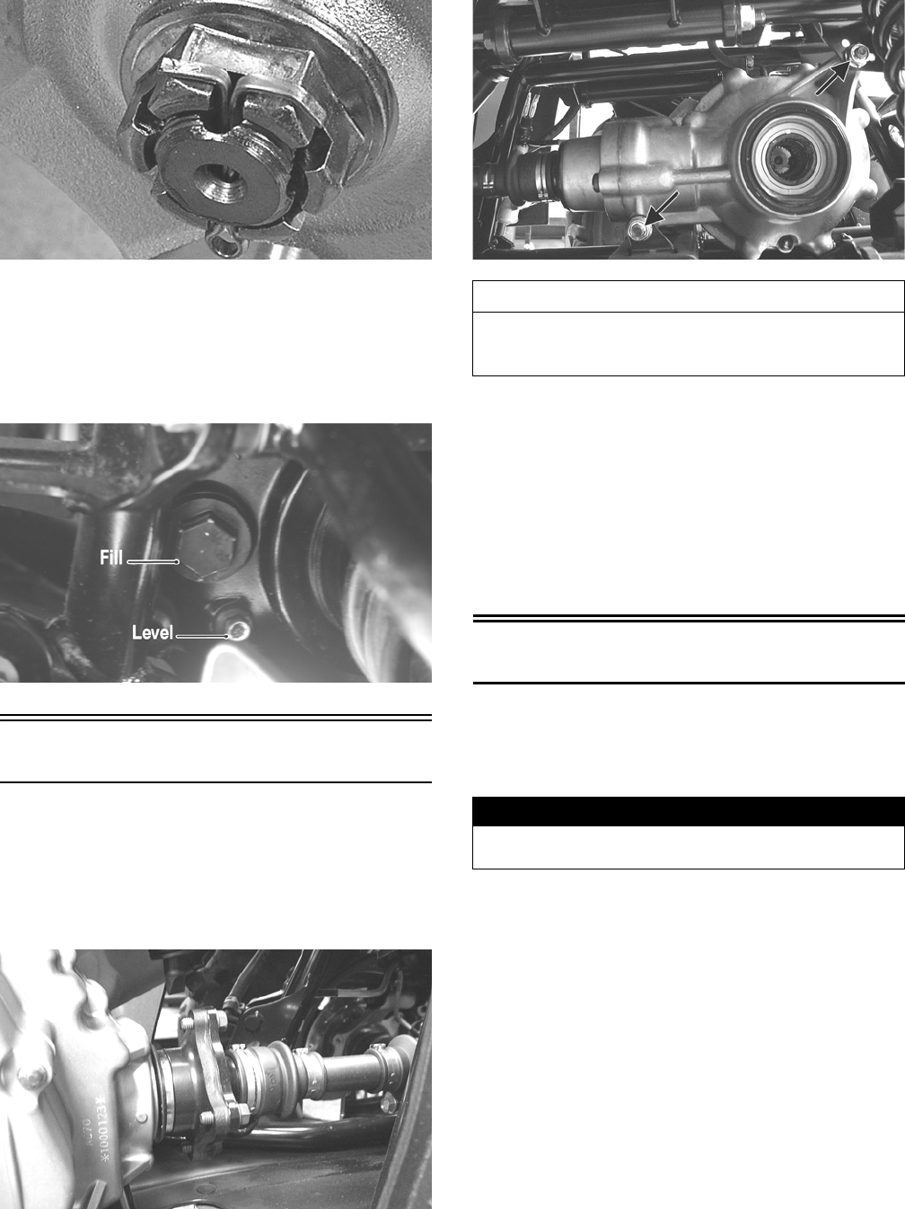
104
KC305
5. Install the wheel and tighten to 40 ft-lb.
6. Remove the ATV from the support stand and release
the brake lever lock.
7. Check the front differential oil level and add oil as
necessary.
CF113A
Rear Gear Case
REMOVING
1. Remove both of the rear drive axles (see Drive Axles
in this section).
2. Remove the four cap screws securing the engine out-
put shaft to the rear gear case input flange.
KC169
3. Remove the two cap screws and lock nuts securing
the rear gear case to the frame; then remove the gear
case through the left side.
KC288A
INSTALLING
1. Slide the gear case into position through the left side
of the frame; then secure it to the frame with cap
screws and lock nuts. Tighten to 38 ft-lb.
2. Secure the engine output flange to the rear gear case
input flange with four cap screws and lock nuts.
Tighten to 20 ft-lb.
3. Install the rear drive axles (see Drive Axles in this
section).
Hub
REMOVING
1. Secure the ATV on a support stand to elevate the
wheel; then remove the wheel.
2. Remove the cotter pin from the nut.
NOTE: During assembly, new cotter pins should be
installed.
3. Remove the flange nut securing the hub.
4. Remove the brake caliper.
AT THIS POINT
For servicing the input shaft, pinion gear, needle bear-
ing, thrust button, and axle seal, see Front Differential
in this section.
! WARNING
Make sure the ATV is solidly supported on the support
stand to avoid injury.
For Discount Arctic Cat Parts Call 606-678-9623 or 606-561-4983
www.mymowerparts.com
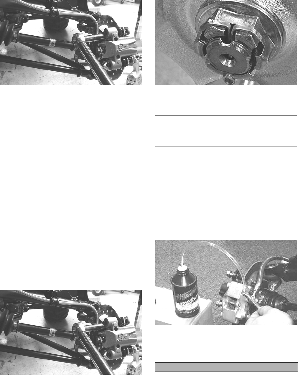
105
KC283
5. Remove the hub assembly.
6. Remove the four cap screws securing the brake disc.
CLEANING AND INSPECTING
NOTE: Whenever a part is worn excessively,
cracked, or damaged in any way, replacement is nec-
essary.
1. Clean all hub components.
2. Inspect all threads for stripping or damage.
3. Inspect the brake disc for cracks or warping.
4. Inspect the hub for pits, cracks, loose studs, or spline
wear.
INSTALLING
1. Secure the brake disc to the hub with the four cap
screws coated with blue Loctite #243. Tighten to 15
ft-lb.
2. Apply grease to the splines in the hub.
3. Install the hub assembly onto the shaft.
4. Secure the hub assembly with the nut. Tighten only
until snug.
5. Secure the brake caliper to the knuckle with the two
cap screws. Tighten the caliper to 20 ft-lb.
KC283
6. Tighten the hub nut (from step 4) to 200 ft-lb; then
install and spread a new cotter pin making sure each
side of the pin is flush to the hub nut.
KC305
7. Install the wheel and tighten to 40 ft-lb.
8. Remove the ATV from the support stand.
Hand Brake Lever/Master
Cylinder Assembly
NOTE: The master cylinder is a non-serviceable
component; it must be replaced as an assembly.
REMOVING
1. Slide a piece of flexible tubing over one of the wheel
bleeder valves and direct the other end into a con-
tainer. Remove the reservoir cover; then open the
bleeder valve. Allow the brake fluid to drain com-
pletely.
NOTE: Compressing the brake lever several times
will quicken the draining process.
AF637D
2. Place an absorbent towel around the connection to
absorb brake fluid. Remove the banjo-fitting bolt
from the master cylinder. Account for two crush
washers and a banjo-fitting bolt.
3. Remove the clamp screws securing the brake hous-
ing to the handlebar, then remove the assembly from
the handlebar.
CAUTION
Brake fluid is highly corrosive. Do not spill brake fluid
on any surface of the ATV.
For Discount Arctic Cat Parts Call 606-678-9623 or 606-561-4983
www.mymowerparts.com
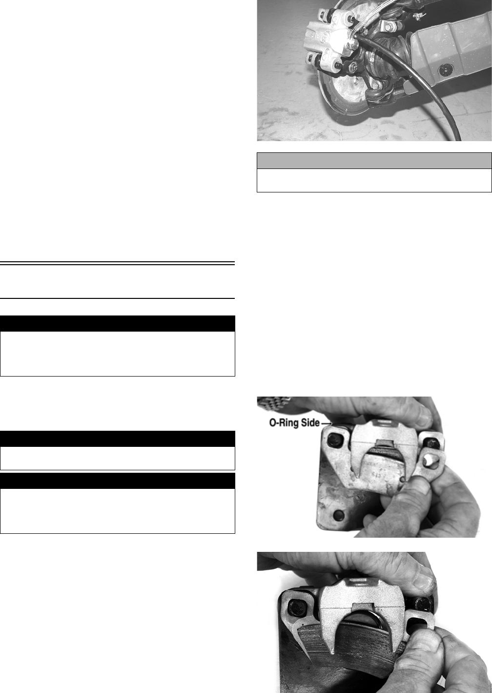
106
INSPECTING
NOTE: Whenever a part is worn excessively,
cracked, or damaged in any way, replacement is nec-
essary.
1. Inspect the pin securing the brake lever for wear.
2. Inspect the brake lever for elongation of the pivot
hole.
3. Inspect the reservoir for cracks and leakage.
4. Inspect the banjo-fitting and bolt for cracks and dete-
rioration and the condition of the fittings (threaded
and compression).
INSTALLING
1. Position the brake housing on the handlebar. Secure
with clamp screws; then tighten securely.
2. Using two new crush washers, connect the banjo-fit-
ting to the master cylinder; then secure with the
banjo-fitting bolt. Tighten to 20 ft-lb.
3. Bleed the brake system (see Periodic Maintenance).
Hydraulic Brake Caliper
REMOVING/DISASSEMBLING
1. Secure the ATV on a support stand to elevate the
wheel; then remove the wheel.
2. Drain the brake fluid from the caliper, hose, and mas-
ter cylinder through the bleed screw by pumping the
brake lever/pedal.
PR235
NOTE: Whenever brake components are removed,
disassembled, or repaired where brake fluid is
exposed to air, drain all fluid and replace with new
DOT 4 brake fluid from an unopened container. Brake
fluid readily absorbs moisture from the air signifi-
cantly lowering the boiling point. This increases the
chance of vapor lock reducing braking power and
increasing stopping distance.
3. Remove the brake hose from the caliper and close
the bleed screw; then remove the caliper.
4. Compress the caliper holder against the caliper
(opposite the O-ring side) and remove the outer
brake pad; then remove the inner brake pad.
NOTE: If brake pads are to be returned to service,
do not allow brake fluid to contaminate them.
PR237A
PR238
! WARNING
Arctic Cat recommends that only authorized Arctic Cat
ATV dealers perform hydraulic brake service. Failure to
properly repair brake systems can result in loss of con-
trol causing severe injury or death.
! WARNING
Make sure the ATV is solidly supported on the support
stand to avoid injury.
! WARNING
Never let brake fluid contact the eyes. Damage to the
eyes will occur. Always wear appropriate protective
safety goggles and latex gloves when handling brake
fluid.
CAUTION
Brake fluid is highly corrosive. Do not spill brake fluid
on any surface of the ATV and do not reuse brake fluid.
For Discount Arctic Cat Parts Call 606-678-9623 or 606-561-4983
www.mymowerparts.com
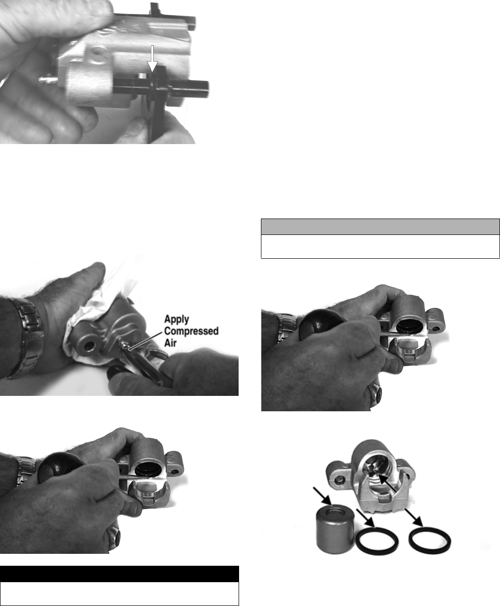
107
5. Remove the caliper holder from the caliper and dis-
card the O-ring.
PR239B
NOTE: The O-ring is used for shipping purposes
and provides no function in operation.
6. Cover the piston end of the housing with a shop
towel; then keeping fingers clear of piston travel,
apply compressed air to the fluid port to blow the
piston free of the housing. Account for two seal rings
in the housing.
PR713A
PR715
7. Using an appropriate seal removal tool, carefully
remove the seals from the brake caliper housing;
then remove four O-rings from the brake caliper
housing noting the location of the different sized O-
rings. Discard all seals, O-rings, and crush washers.
CLEANING AND INSPECTING
1. Clean all caliper components (except the brake pads)
with DOT 4 brake fluid. Do not wipe dry.
2. Inspect the brake pads for damage and excessive
wear.
NOTE: For measuring brake pads, see Periodic
Maintenance.
3. Inspect the brake caliper housings for scoring in the
piston bores, chipped seal ring grooves, or signs of
corrosion or discoloration.
4. Inspect the piston surface for scoring, discoloration,
or evidence of binding or galling.
5. Inspect the caliper holder for wear or bending.
ASSEMBLING/INSTALLING
1. Install new seals into the brake caliper housing and
apply a liberal amount of DOT 4 brake fluid to the
cylinder bore of the housing, seals, and brake piston.
PR715
PR717A
2. Press the piston into the caliper housing using hand
pressure only. Completely seat the piston; then wipe
off any excessive brake fluid.
! WARNING
Make sure to hold the towel firmly in place or the piston
could be ejected from the housing causing injury.
CAUTION
Make sure the seals are properly in place and did not
twist or roll during installation.
For Discount Arctic Cat Parts Call 606-678-9623 or 606-561-4983
www.mymowerparts.com
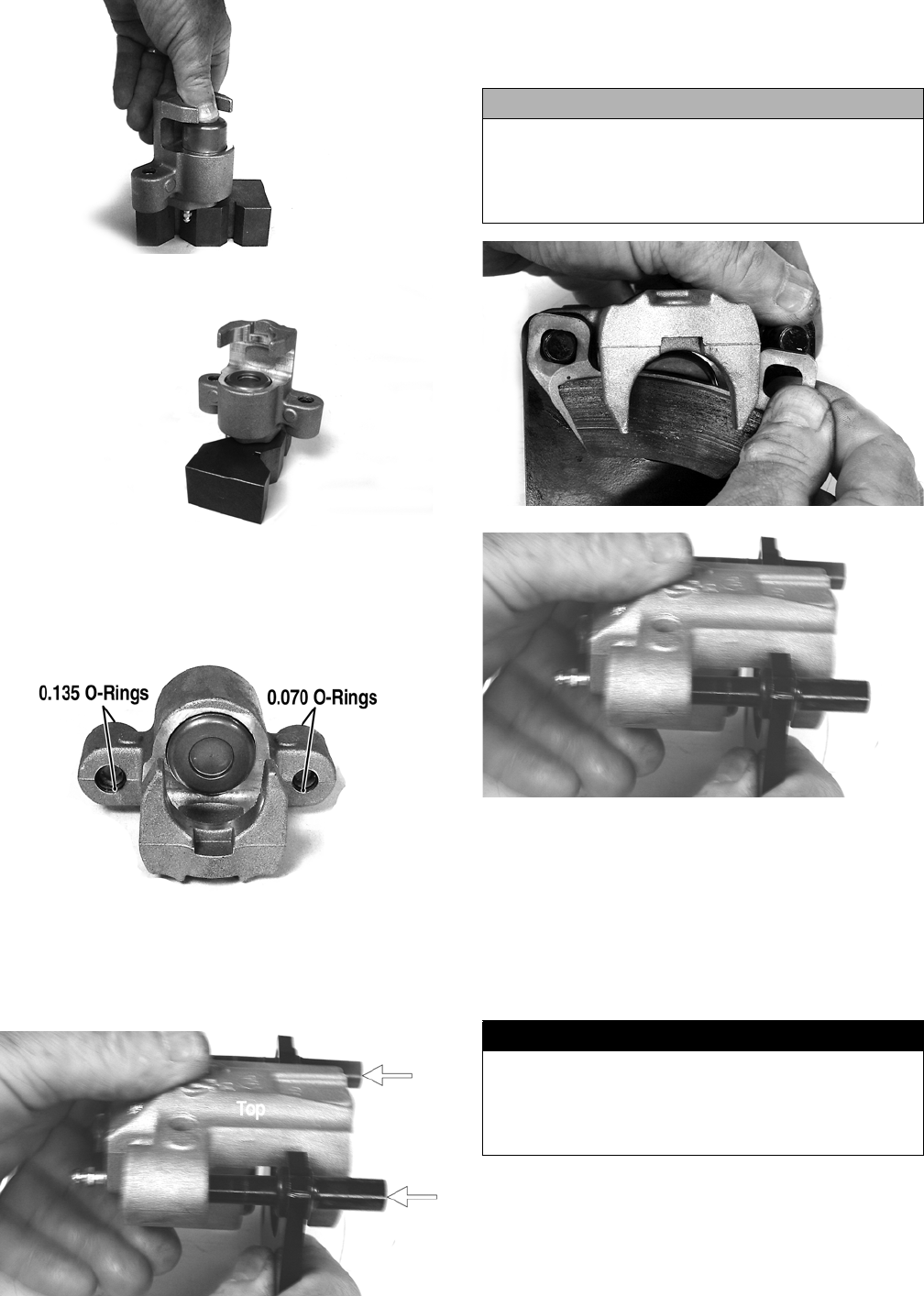
108
PR711A
PR712
3. Apply high-temperature silicone grease (supplied
with the O-ring kit) to the inside of the caliper holder
bores and O-rings; then install the four O-rings into
the caliper.
PR719C
4. Install the caliper onto the caliper holder making sure
the caliper and holder are correctly oriented.
NOTE: It is very important to apply silicone grease
to the O-rings and caliper bores prior to assembly.
PR239C
5. Making sure brake fluid does not contact the brake
pads, compress the caliper holder toward the caliper
and install the inner brake pad; then install the outer
pad.
PR238
PR239
6. Place the brake caliper assembly into position and
secure with new “patch-lock” cap screws. Tighten
the caliper to 20 ft-lb.
7. Place a new crush washer on each side of the brake
hose fitting and install it on the caliper. Tighten to 20
ft-lb.
8. Fill the reservoir; then bleed the brake system (see
Periodic Maintenance).
9. Install the wheel. Tighten to 40 ft-lb.
10. Remove the ATV from the support stand and verify
brake operation.
CAUTION
If brake pads become contaminated with brake fluid,
they must be thoroughly cleaned with brake cleaning
solvent or replaced with new pads. Failure to do so
will result in reduced braking and premature brake
pad failure.
! WARNING
Never use brake fluid from an open container or reuse
brake fluid. Moisture-contaminated brake fluid could
cause vapor build-up (expansion) during hard braking
resulting in greatly increased stopping distance or loss
of control leading to injury or death.
For Discount Arctic Cat Parts Call 606-678-9623 or 606-561-4983
www.mymowerparts.com

109
Troubleshooting Drive
System
Troubleshooting Brake
System
Problem: Power not transmitted from engine to wheels
Condition Remedy
1. Rear axle shafts serration worn - broken 1. Replace shaft
Problem: Power not transmitted from engine to either front wheel
Condition Remedy
1. Secondary drive - driven gear teeth broken
2. Propeller shaft serration worn - broken
3. Coupling damaged
4. Coupling joint serration worn - damaged
5. Front drive - driven bevel gears broken - damaged
6. Front differential gears/pinions broken - damaged
7. Sliding dogs/shaft fork worn - damaged
8. Front drive axle worn - damaged
9. Front drive axle serration worn - damaged
1. Replace gear(s)
2. Replace shaft
3. Replace coupling
4. Replace joint
5. Replace gear(s)
6. Replace gears - pinions
7. Replace gear(s)
8. Replace axle
9. Replace axle
Problem: Braking poor
Condition Remedy
1. Pad worn
2. Pedal free-play excessive
3. Brake fluid leaking
4. Hydraulic system spongy
5. Master cylinder/brake cylinder seal worn
1. Replace pads
2. Replace pads
3. Repair - replace hydraulic system component(s)
4. Bleed hydraulic system - correct or repair leaks
5. Replace master cylinder
Problem: Brake lever travel excessive
Condition Remedy
1. Hydraulic system entrapped air
2. Brake fluid low
3. Brake fluid incorrect
4. Piston seal - cup worn
1. Bleed hydraulic system
2. Add fluid to proper level
3. Drain system - replace with correct fluid
4. Replace master cylinder
Problem: Brake fluid leaking
Condition Remedy
1. Connection joints loose
2. Hose cracked
3. Piston seal worn
1. Tighten joint
2. Replace hose
3. Replace brake caliper
For Discount Arctic Cat Parts Call 606-678-9623 or 606-561-4983
www.mymowerparts.com
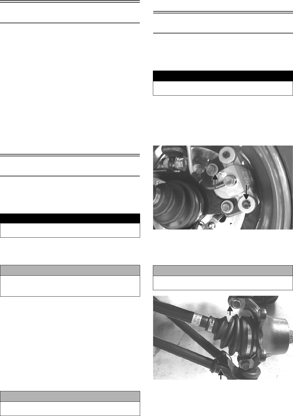
110
Suspension
The following suspension system components should
be inspected periodically to ensure proper operation.
A. Shock absorber rods not bent, pitted, or dam-
aged.
B. Rubber damper not cracked, broken, or miss-
ing.
C. Shock absorber body not damaged, punctured,
or leaking.
D. Shock absorber eyelets not broken, bent, or
cracked.
E. Shock absorber eyelet bushings not worn, dete-
riorated, cracked, or missing.
F. Shock absorber spring not broken or sagging.
Shock Absorbers
REMOVING
1. Secure the ATV on a support stand to elevate the
wheels and to release load on the suspension.
2. Remove the two cap screws and nuts securing each
front shock absorber to the frame and the upper A-
arm. Account for bushings and sleeves from each.
3. Remove the two cap screws and nut securing each
rear shock absorber to the frame and lower A-arm.
Account for bushings and sleeves from each.
NOTE: The shock absorbers are not serviceable
components. If leaking, dented, or there are miss-
ing or broken parts, the shock absorber assembly
must be replaced.
INSTALLING
1. Place bushings and sleeves (where appropriate) into
shock eyelet; then install shock with cap screws and
nuts. Tighten all nuts to 35 ft-lb.
2. Remove the ATV from the support stand.
Front A-Arms
REMOVING
1. Secure the ATV on a support stand to elevate the
front wheels; then remove the wheels.
2. Remove the cotter pin from the nut. Discard the cot-
ter pin.
3. Remove the nut securing the hub.
4. Remove the brake caliper. Account for two cap
screws.
KC187A
5. Remove the hub assembly.
6. Remove the cap screws securing the ball joints to the
knuckle.
KC313A
7. Tap the ball joints out of the knuckle; then free the
knuckle from the axle and swing out of the way.
! WARNING
Make sure the ATV is solidly supported on the support
stand to avoid injury.
CAUTION
Additional support stands are necessary to support
the rear axle when the shock absorbers are removed
or damage may occur.
CAUTION
Do not tighten the nuts beyond the 35 ft-lb specifica-
tion or the shock eyelet or mount WILL be damaged.
! WARNING
Make sure the ATV is solidly supported on the support
stand to avoid injury.
CAUTION
Support the knuckle when removing the cap screws or
damage to the threads will occur.
For Discount Arctic Cat Parts Call 606-678-9623 or 606-561-4983
www.mymowerparts.com
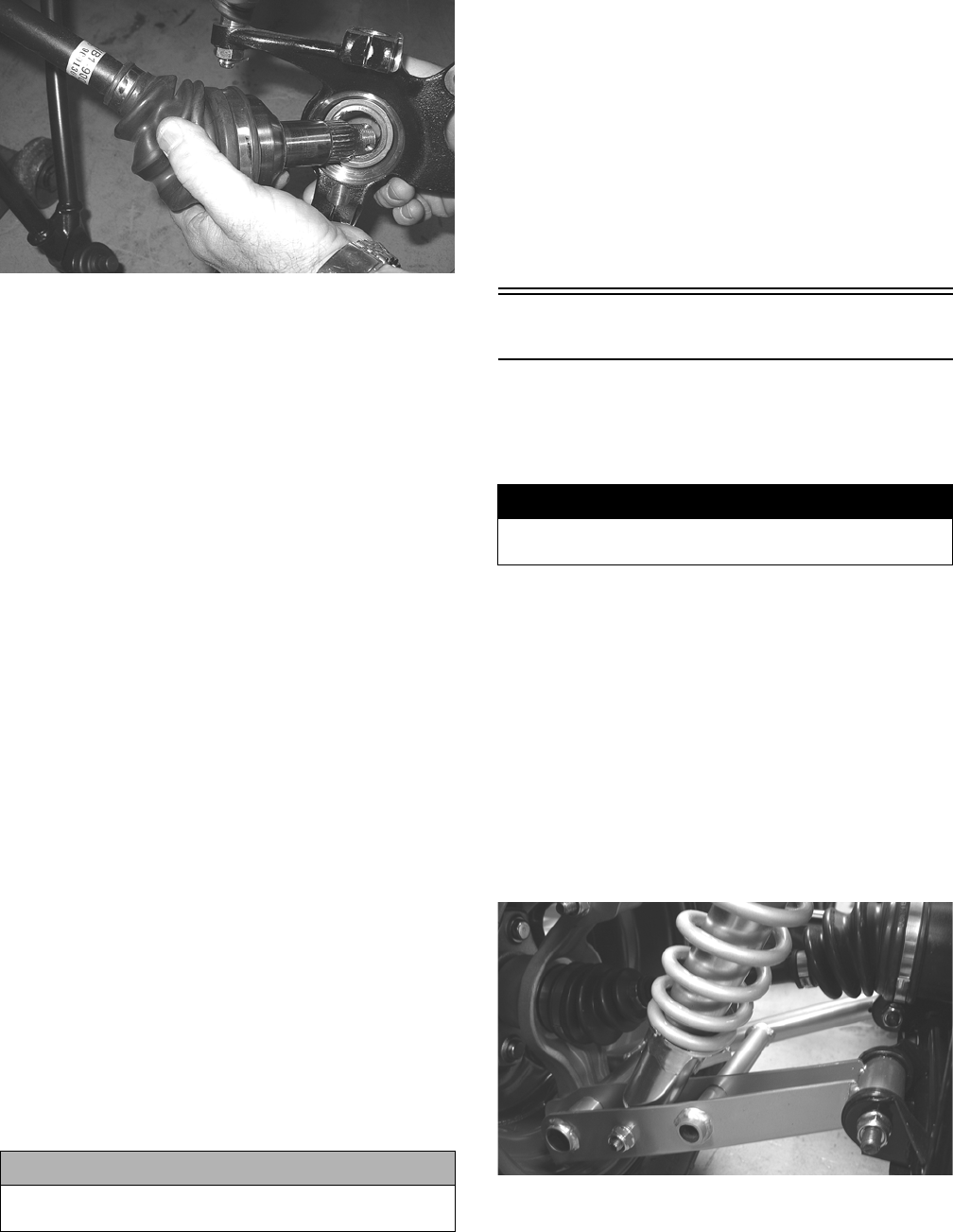
111
KC297
8. Remove the lower shock absorber eyelet from the
upper A-arm.
9. Remove the cap screws securing the A-arms to the
frame.
10. Remove the circlip from the ball joint; then remove
the ball joint from the A-arm.
CLEANING AND INSPECTING
NOTE: Whenever a part is worn excessively,
cracked, or damaged in any way, replacement is
necessary.
1. Clean all A-arm components using a pressure
washer.
2. Clean the ball joint mounting hole of all residual
Loctite, grease, oil, or dirt for installing purposes.
3. Inspect the A-arm for bends, cracks, and worn bush-
ings.
4. Inspect the ball joint mounting holes for cracks or
damage.
5. Inspect the frame mounts for signs of damage, wear,
or weldment damage.
INSTALLING
1. Apply green Loctite #609 to the entire outside diam-
eter of the ball joint; then install the ball joint into the
A-arm and secure with the circlip.
2. Install the A-arm assemblies into the frame mounts
and secure with the cap screws. Only finger-tighten
at this time.
3. Secure the lower eyelet of the shock absorber to the
upper A-arm. Tighten nut to 35 ft-lb.
4. Secure the A-arm assemblies to the frame mounts
(from step 2). Tighten the cap screws to 35 ft-lb.
5. Install the knuckle assembly onto the ball joints and
secure with cap screws. Tighten to 35 ft-lb.
6. Apply grease to the hub and drive axle splines; then
install the hub assembly onto the drive axle.
7. Secure the hub assembly with the nut. Tighten only
until snug.
8. Secure the brake caliper to the knuckle with the two
“patch-lock” cap screws. Tighten to 20 ft-lb.
9. Secure the hub nut (from step 7) to the shaft/axle.
Tighten to 200 ft-lb.
10. Install a new cotter pin and spread the pin to secure
the nut.
11. Install the wheel and tighten to 40 ft-lb.
12. Remove the ATV from the support stand.
Rear A-Arms
REMOVING
1. Secure the ATV on a support stand to elevate the
wheels.
2. Pump up the hand brake; then engage the brake lever
lock.
3. Remove the wheel.
4. Remove the cotter pin securing the hex nut; then
remove the hex nut. Release the brake lever lock.
5. Remove the caliper (right side only).
NOTE: Do not allow the brake caliper to hang
from the hose.
6. Remove the cap screws and lock nut securing the
shock absorber to the frame and lower A-arm; then
remove the shock absorber.
KC0100
7. Slide the hub out of the knuckle and set aside.
8. Remove the cap screws and lock nuts securing the
knuckle to the A-arms. Discard the lock nuts.
NOTE: Never reuse a lock nut. Once a lock nut
has been removed, it must be replaced with a new
lock nut.
CAUTION
Do not tighten the nut beyond the 35 ft-lb specification
or the shock eyelet or mount WILL be damaged.
! WARNING
Make sure the ATV is solidly supported on the support
stand to avoid injury.
For Discount Arctic Cat Parts Call 606-678-9623 or 606-561-4983
www.mymowerparts.com

112
9. Remove the cap screws and lock nuts securing the A-
arms to the frame; then remove the A-arms.
NOTE: If removing the upper right A-arm, it will
be necessary to disconnect the brake hose from
the A-arm.
CLEANING AND INSPECTING
NOTE: Whenever a part is worn excessively,
cracked, or damaged in any way, replacement is
necessary.
1. Clean all A-arm components using a pressure
washer.
2. Inspect the A-arm for bends, cracks, and worn bush-
ings.
3. Inspect the frame mounts for signs of damage, wear,
or weldment damage.
INSTALLING
1. Install the A-arm assemblies into the frame mounts
and secure with the cap screws and new lock nuts.
Only finger-tighten at this time.
2. Slide the knuckle onto the drive axle and into posi-
tion on the A-arms; then secure the knuckle to the A-
arms with cap screws and new lock nuts. Tighten to
35 ft-lb.
3. Tighten the hardware securing the A-arms to the
frame mounts (from step 1) to 35 ft-lb.
4. Apply grease on the drive axle splines; then install
the hub assembly onto the drive axle.
5. Secure the hub assembly with the nut. Tighten only
until snug.
6. Secure the brake caliper to the knuckle with the two
“patch-lock” cap screws (right side only). Tighten
the caliper to 20 ft-lb.
7. Compress the hand brake lever and engage the brake
lever lock; then secure the hub nut (from step 5) to
the drive axle. Tighten to 200 ft-lb.
8. Install a new cotter pin and spread the pin to secure
the nut.
9. Secure the shock absorber to the frame with a cap
screw and new lock nut. Tighten to 35 ft-lb.
10. Secure the shock absorber to the lower A-arm with a
cap screw and new lock nut. Tighten to 35 ft-lb.
11. Secure the boot guard to the lower A-arm with the
two cap screws. Tighten securely.
12. Install the wheel and tighten to 40 ft-lb.
13. Remove the ATV from the support stand.
Wheels and Tires
TIRE SIZE
The ATV is equipped with low-pressure tubeless tires
of the size and type listed in General Information. Do
not under any circumstances substitute tires of a differ-
ent type or size.
TIRE INFLATION PRESSURE
Front and rear tire inflation pressure should be 40.0
kPa (5.7 psi).
REMOVING
1. Secure the ATV on a support stand to elevate the
wheels.
2. Remove the wheels.
NOTE: Keep left-side and right-side wheels sepa-
rated for installing them on their proper sides.
CLEANING AND INSPECTING
NOTE: Whenever a part is worn excessively,
cracked, or damaged in any way, replacement is
necessary.
1. Clean the wheels and hubs using a pressure washer.
2. Inspect each wheel for cracks, dents, or bends.
3. Inspect each tire for cuts, wear, missing lugs, and
leaks.
INSTALLING
Install each wheel on its hub. Tighten to 40 ft-lb.
NOTE: Make sure each wheel is installed on its
proper hub as noted in removing (the “rotation
arrow” (if applicable) must indicate forward direc-
tion of rotation).
! WARNING
Use only Arctic Cat approved tires when replacing
tires. Failure to do so could result in unstable ATV
operation.
! WARNING
Do not mix tire tread patterns. Use the same pattern
type on front and rear. Failure to heed warning could
cause poor handling qualities of the ATV and could
cause excessive drive train damage not covered by
warranty.
! WARNING
Make sure the ATV is solidly supported on the support
stand to avoid injury.
For Discount Arctic Cat Parts Call 606-678-9623 or 606-561-4983
www.mymowerparts.com

113
AF612D
CHECKING/INFLATING
1. Using an air pressure gauge, measure the air pressure
in each tire. Adjust the air pressure as necessary to
meet the recommended inflation pressure.
2. Inspect the tires for damage, wear, or punctures.
NOTE: If repair is needed, follow the instructions
found on the tire repair kit or remove the wheel and
have it repaired professionally.
NOTE: Be sure all tires are the specified size and
have identical tread pattern.
3. Check the front wheel toe-in and toe-out and adjust
as necessary (see Steering/Frame).
4. Test drive the ATV on a dry, level surface and note
any pulling to the left or right during acceleration,
deceleration, and braking.
NOTE: If pulling is noted, measure the circumfer-
ence of the front and rear tires on the pulling side.
Compare the measurements with the tires on the
opposite side. If pulling is noted during braking
only, check and adjust the brakes as necessary
and recheck operation (see Periodic Maintenance).
5. Increase the air pressure in the tires with the smallest
circumference measurement until all tires are equal
in circumference.
6. Repeat steps 4-5 as necessary to ensure proper han-
dling.
Troubleshooting
! WARNING
Do not operate the ATV if tire damage exists.
Problem: Suspension too soft
Condition Remedy
1. Spring(s) weak
2. Shock absorber damaged
3. Shock absorber preload too low
1. Replace spring(s)
2. Replace shock absorber
3. Adjust shock absorber preload
Problem: Suspension too stiff
Condition Remedy
1. A-arm-related bushings worn
2. Shock absorber preload too high
1. Replace bushing
2. Adjust shock absorber preload
Problem: Suspension noisy
Condition Remedy
1. Cap screws (suspension system) loose
2. A-arm-related bushings worn
1. Tighten cap screws
2. Replace bushings
Problem: Rear wheel oscillation
Condition Remedy
1. Rear wheel hub bearings worn - loose
2. Tires defective - incorrect
3. Wheel rim distorted
4. Wheel hub cap screws loose
5. Brake adjusted incorrectly
6. Rear suspension arm-related bushing worn
7. Rear shock absorber damaged
8. Rear suspension arm nut loose
1. Replace bearings
2. Replace tires
3. Replace rim
4. Tighten cap screws
5. Adjust brake
6. Replace bushing
7. Replace shock absorber
8. Tighten nut
For Discount Arctic Cat Parts Call 606-678-9623 or 606-561-4983
www.mymowerparts.com
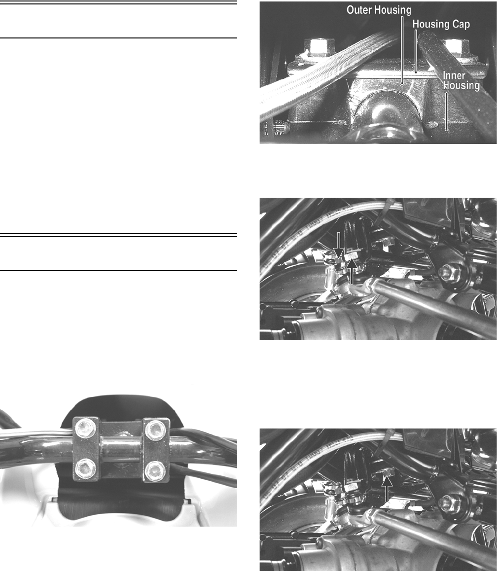
114
Steering/Frame
The following steering components should be inspected
periodically to ensure safe and proper operation.
A. Handlebar grips not worn, broken, or loose.
B. Handlebar not bent, cracked, and has equal and
complete full-left and full-right capability.
C. Steering post bearing assembly/bearing housing
not broken, worn, or binding.
D. Ball joints not worn, cracked, or damaged.
E. Tie rods not bent or cracked.
F. Knuckles not worn, cracked, or damaged.
G. Cotter pins not damaged or missing.
Steering Post/Tie Rods
REMOVING
1. Remove the front body panel/fender (see Front Body
Panel/Fender in this section).
2. Remove the steering post cover; then remove the cap
screws securing the handlebar caps and move the
handlebar out of the way. Account for the two han-
dlebar caps.
KC0058
3. Remove the cap screws securing the upper steering
post to the frame. Account for the housing cap, outer
housing, and inner housing.
KC307A
4. Remove the cotter pins from the inner tie rod ends;
then remove the nuts and disconnect the inner tie rod
ends.
KC184A
NOTE: If tie rods are to be completely removed,
remove the outer tie rod ends from the knuckles at
this time.
5. Remove the cap screw securing the lower steering
post to the bearing. Account for a flat washer.
KC184B
6. Remove the steering post from the ATV.
CLEANING AND INSPECTING
NOTE: Whenever a part is worn excessively, cracked,
or damaged in any way, replacement is necessary.
1. Wash the tie rod ends in parts-cleaning solvent. Dry
with compressed air. Inspect the pivot area for wear.
Apply a low-temperature grease to the ends.
For Discount Arctic Cat Parts Call 606-678-9623 or 606-561-4983
www.mymowerparts.com
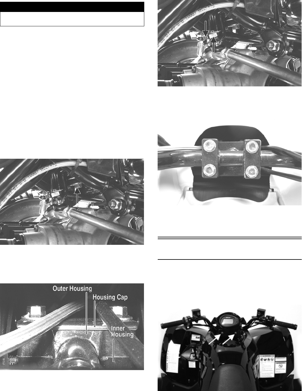
115
2. Inspect the tie rods for damaged threads or wear.
3. Inspect the tie rods for cracks or unusual bends.
4. Inspect all welded areas for cracks or deterioration.
5. Inspect the steering post and steering-post brackets
for cracks, bends, or wear.
6. Inspect the bearing halves, bearing caps, and bearing
housings for cracks or wear.
7. Inspect the handlebar tube for cracks, wear, or
unusual bends.
8. Inspect the handlebar grips for damage or wear.
INSTALLING
1. Install the steering post into the frame and secure the
lower end in the bearing with a flat washer and cap
screw. Tighten to 40 ft-lb.
KC184B
2. Apply grease to the inner and outer housings of the
upper steering post support; then with the housing
cap in place, secure with the cap screws. Tighten to
20 ft-lb.
KC307A
3. Using red Loctite #271 on the threads, install the tie
rod ends into the lower steering post arm and tighten
to 30 ft-lb; then install new cotter pins.
KC184A
4. Place the handlebar and caps in place on the steering
post and with the handlebar correctly positioned,
tighten the cap screws to 20 ft-lb.
KC0058
5. Install the steering post cover; then install the front
body panel/fender (see Front Body Panel/Fender in
this section).
Speedometer/LCD Gauge
REPLACING
1. Remove two machine screws securing the gauge pod
to the handlebar; then lift the gauge pod up and dis-
connect the harness plug from the gauge.
KC391B
2. Loosen the gauge mounting nuts and remove the
gauge from the pod.
3. Install the new gauge and secure with the mounting
nuts; then plug the harness into the gauge and secure
the gauge pod with the machine screws. Tighten
securely.
! WARNING
Always wear safety glasses when using compressed
air.
For Discount Arctic Cat Parts Call 606-678-9623 or 606-561-4983
www.mymowerparts.com
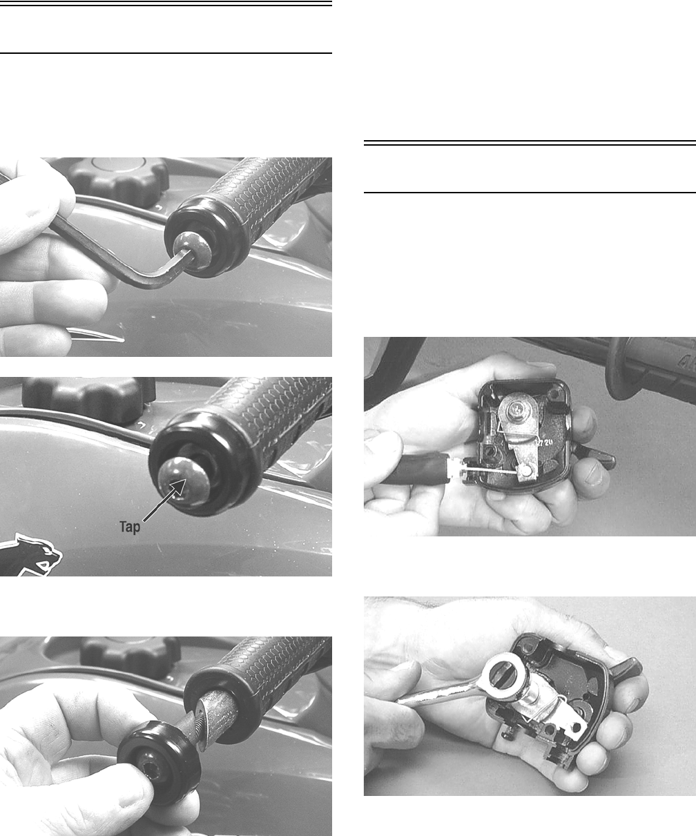
116
Handlebar Grip
REMOVING
1. Loosen but do not remove the cap screw in the end of
the handlebar; then tap lightly on the head to dis-
lodge the handlebar plug.
KC310
KC309A
2. Grasp the end and remove the cap screw, plug, and
end cap.
KC308
3. Using a sharp utility knife, split the handlebar grip
from end to end and peel off the rubber.
4. Using an adhesive solvent, clean all glue residue
from the handlebar.
INSTALLING
1. Apply a liberal amount of Handlebar Grip Adhesive
to the inside of the new grip.
2. Slide the grip onto the handlebar until it is fully
seated with the smooth part of the grip facing up.
NOTE: A quick, firm push is required to seat the
grip completely on the handlebar. Install while the
glue is wet.
3. Wipe off any excess glue; then secure the grip with
the plug, end cap, and cap screw.
Throttle Control
REMOVING
1. Remove the two machine screws securing the throt-
tle control to the handlebar.
2. Slide the grommet out of the lower half of the throt-
tle control; then remove the cable from the actuator
arm.
AF676D
3. Remove the cap screw, lock washer, and washer
securing the actuator arm to the throttle control lever.
AF677D
4. Remove the actuator arm and account for a bushing.
Note the position of the return spring for installing
purposes.
For Discount Arctic Cat Parts Call 606-678-9623 or 606-561-4983
www.mymowerparts.com
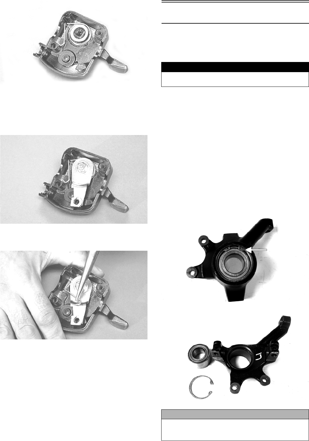
117
AF678D
INSTALLING
1. Place the return spring into the throttle control; then
place the bushing and actuator arm into position.
Secure with the cap screw, lock washer, and washer.
AF679D
2. Using a pair of needle-nose pliers, place the spring
into position on the actuator arm.
AF680D
3. Place the two halves of the throttle control onto the
handlebar and secure with the two machine screws.
ADJUSTING
To adjust throttle cable free-play, see Periodic Mainte-
nance.
Steering Knuckles
REMOVING AND DISASSEMBLING
1. Secure the ATV on a support stand to elevate the
wheel; then remove the wheel.
2. Remove the wheel cap from the hub; then remove
the cotter pin from the nut.
3. Remove the nut securing the hub.
4. Remove the brake caliper.
5. Remove the hub assembly.
6. Remove the cotter pin from the tie rod end and
remove the tie rod end from the knuckle.
7. Remove the two cap screws securing the ball joints
in the knuckle.
8. Tap the ball joint end out of the knuckle; then
remove the knuckle.
9. Remove the snap ring from the knuckle; then remove
the bearing.
PR287A
PR288
! WARNING
Make sure the ATV is solidly supported on the support
stand to avoid injury.
CAUTION
Use extreme care when removing the bearing. If the
bearing is allowed to fall, it will be damaged and will
have to be replaced.
For Discount Arctic Cat Parts Call 606-678-9623 or 606-561-4983
www.mymowerparts.com
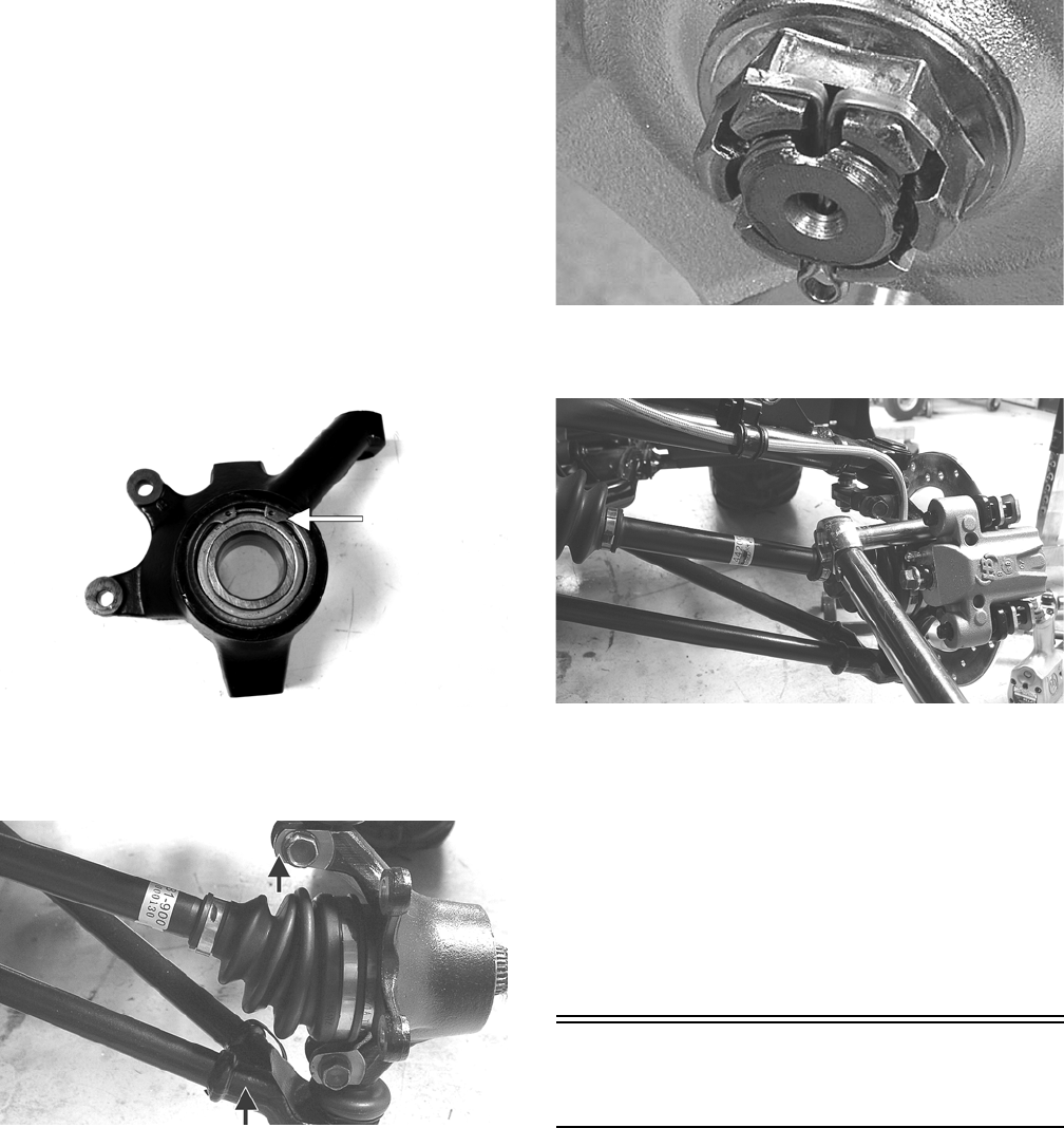
118
CLEANING AND INSPECTING
NOTE: Whenever a part is worn excessively,
cracked, or damaged in any way, replacement is nec-
essary.
1. Clean all knuckle components.
2. Inspect the bearing for pits, gouges, rusting, or pre-
mature wear.
3. Inspect the knuckle for cracks, breaks, or porosity.
4. Inspect threads for stripping or damage.
ASSEMBLING AND INSTALLING
1. Install the bearing; then install the snap ring making
sure it seats into the knuckle.
PR287A
2. Install the knuckle to the upper and lower ball joints
and secure with the two cap screws. Tighten to 35 ft-
lb.
KC313A
3. Install the tie rod end and secure with the nut.
Tighten to 30 ft-lb; then install a new cotter pin and
spread the pin.
NOTE: During assembling, new cotter pins should
be installed.
4. Apply a small amount of grease to the hub splines.
5. Install the hub assembly onto the splines of the shaft.
6. Secure the hub assembly with the nut. Tighten only
until snug.
KC305
7. Secure the brake caliper to the knuckle with the
“patch-lock” cap screws. Tighten to 20 ft-lb.
KC283
8. Pump the hand brake lever; then engage the brake
lever lock.
9. Secure the hub nut (from step 6) to the shaft. Tighten
to 200 ft-lb.
10. Install a new cotter pin and spread the pin to secure
the nut.
11. Install the wheel; then using a crisscross pattern,
tighten to 40 ft-lb.
12. Remove the ATV from the support stand.
Measuring/Adjusting Toe-
Out
1. Thoroughly wash the ATV to remove excess weight
(mud, etc.).
2. Refer to the specifications and ensure the tires are
properly inflated to the recommended pressure.
NOTE: Ensure the inflation pressure is correct in
the tires or inaccurate measurements can occur.
3. Place the ATV in a level position taking care not to
push down or lift up on the front end; then turn the
handlebar to the straight ahead position.
NOTE: When measuring and adjusting, there should
be a normal operating load on the ATV (without an
operator but with Arctic Cat approved accessories).
For Discount Arctic Cat Parts Call 606-678-9623 or 606-561-4983
www.mymowerparts.com
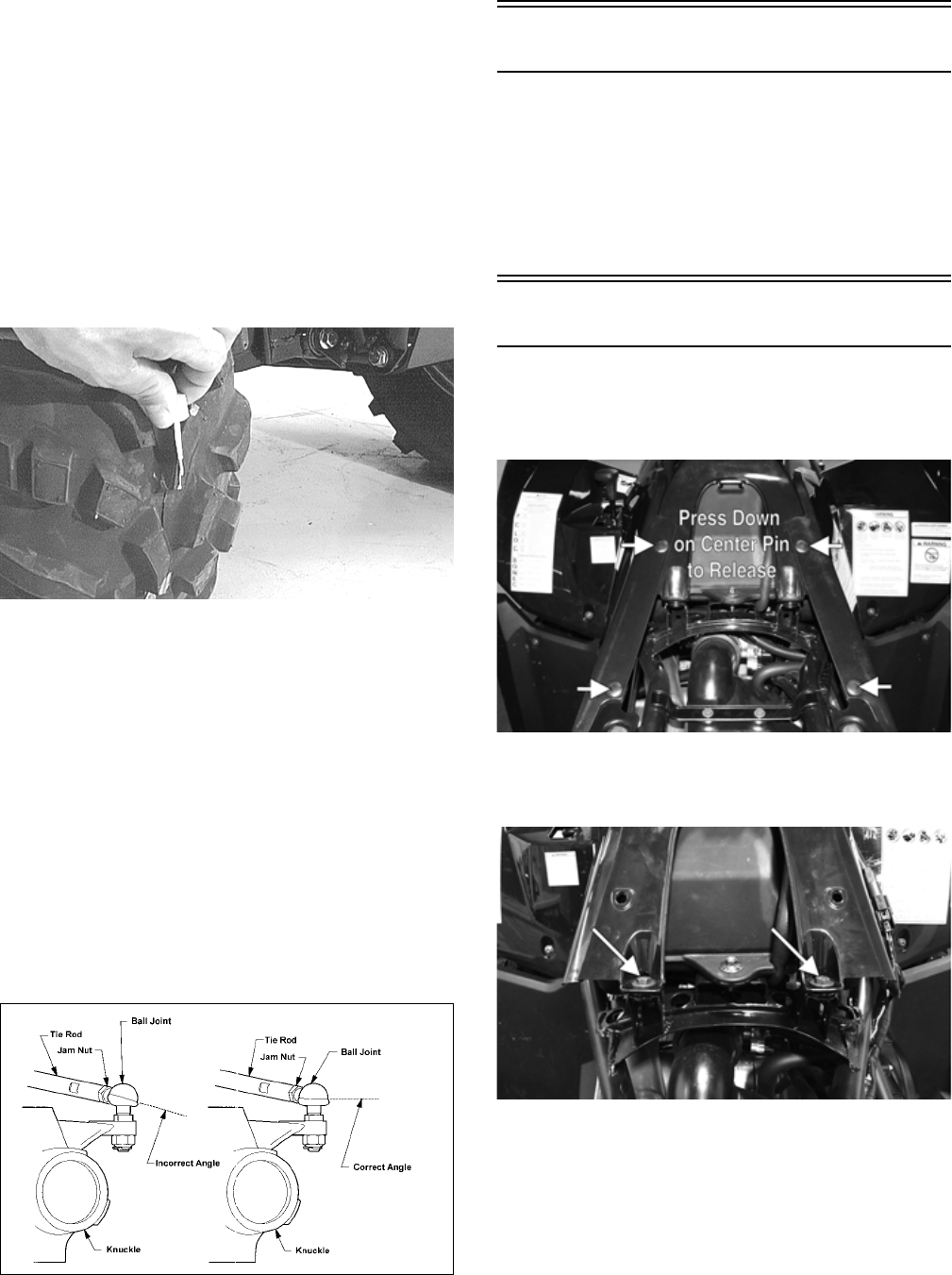
119
4. Measure the distance from the outside edge of each
handlebar grip to equal reference points on each side.
5. Adjust the handlebar direction until the two measure-
ments are equal; then secure the handlebar.
NOTE: Care must be taken not to allow the handle-
bar to turn while securing it.
NOTE: The front wheels do not have to be removed
to adjust the tie rod. Also, care should be taken not to
disturb the handlebar position.
6. Using a permanent marker of some type, mark the
center of each front tire (at a height parallel to the
belly panel).
AF789D
7. Measure the distance between the marks (at a height
parallel to the belly panel) at the front side; then
record the measurement.
8. Push the ATV forward until the marks are parallel to
the belly panel on the back side; then measure the
distance between the marks.
9. The difference in the measurements must show 1/8-
1/4 in. toe-out (the front measurement 1/8-1/4 in.
more than the rear measurement).
10. If the difference in the measurements is not within
specifications, adjust both tie rods equally until
within specifications.
NOTE: Prior to locking the jam nuts, make sure the
ball joints are at the center of their normal range of
motion and at the correct angle.
733-559A
Front Bumper Assembly
REMOVING
Remove the four front cap screws securing the bumper
support tubes to the frame.
INSTALLING
Install the cap screws in the support tubes to frame.
Tighten the cap screws securely.
Front Body Panel/Fender
REMOVING
1. Remove the seat; then remove four reinstallable riv-
ets and the side panels.
KC450A
2. Remove two cap screws and two reinstallable rivets;
then remove the gas tank cap and remove the gas
tank cover. Reinstall the gas tank cap.
KC453A
3. Remove the shift lever knob.
4. Remove two reinstallable rivets, two fender bolts,
and four cap screws; then lift the front fender panel
off and set aside. Account for the shift lever spring.
For Discount Arctic Cat Parts Call 606-678-9623 or 606-561-4983
www.mymowerparts.com
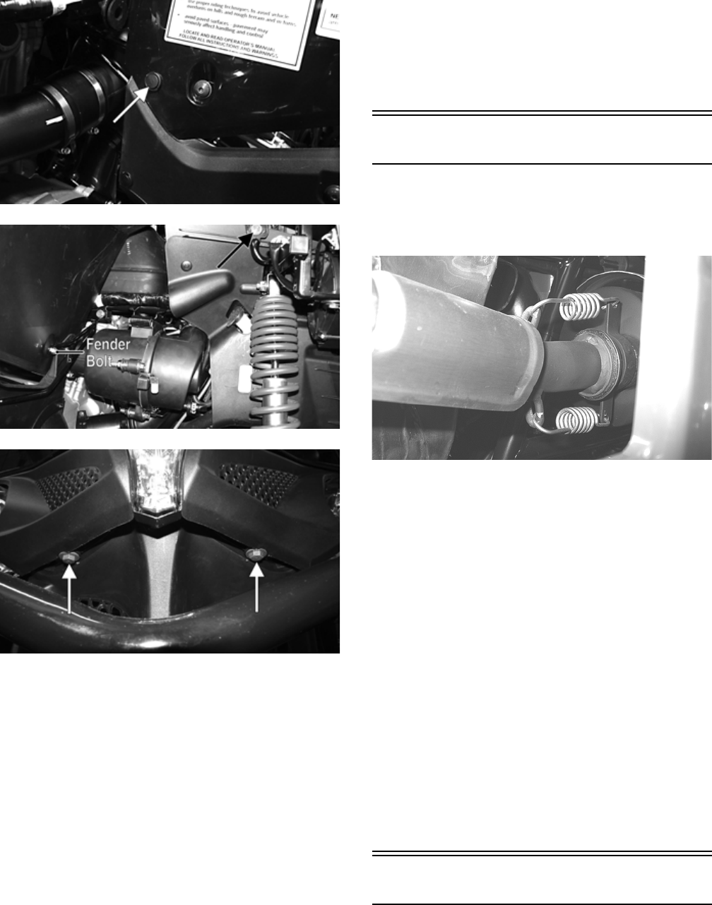
120
KC469A
KC467A
KC470A
CLEANING AND INSPECTING
NOTE: Whenever a part is worn excessively,
cracked, or damaged in any way, replacement is nec-
essary.
1. Clean all fender components with warm soap and
water.
2. Inspect fenders for cracks or other damage.
3. Inspect for any missing decals.
INSTALLING
1. Making sure the shift spring is in place and the shift
lever is properly positioned, place the front body
fender panel onto the ATV.
2. Loosely install the four cap screws and two finder
bolts; then install and lock the two reinstallable rivets.
3. Place the gas tank cover into position and secure
with the existing hardware; then install the two cap
screws securing the rear of the panel to the frame.
Tighten all cap screws and fasteners securely.
4. Install the side panels and secure with the four rein-
stallable rivets; then install the seat.
Exhaust System
REMOVING MUFFLER
1. Remove the two exhaust springs at the muffler/
exhaust pipe juncture.
KC170
2. Slide the muffler rearward to clear the mounting lugs
and remove the muffler. Account for a grafoil seal.
INSPECTING MUFFLER
NOTE: Whenever a part is worn excessively,
cracked, or damaged in any way, replacement is nec-
essary.
1. Inspect muffler externally for cracks, holes, and
dents.
2. Inspect the muffler internally by shaking the muffler
back and forth and listening for rattles or loose debris
inside the muffler.
NOTE: For additional details on cleaning the muf-
fler/spark arrester, see Periodic Maintenance.
INSTALLING MUFFLER
1. Using a new grafoil seal, place the muffler into posi-
tion engaging the mounting lugs into the grommets;
then slide the muffler forward.
2. Install the two exhaust springs.
Rear Body Panel
REMOVING
1. Remove the seat; then remove four cap screws secur-
ing the rear body panel/fender to the frame and the cap
screws securing the rear fenders to the fender supports.
For Discount Arctic Cat Parts Call 606-678-9623 or 606-561-4983
www.mymowerparts.com
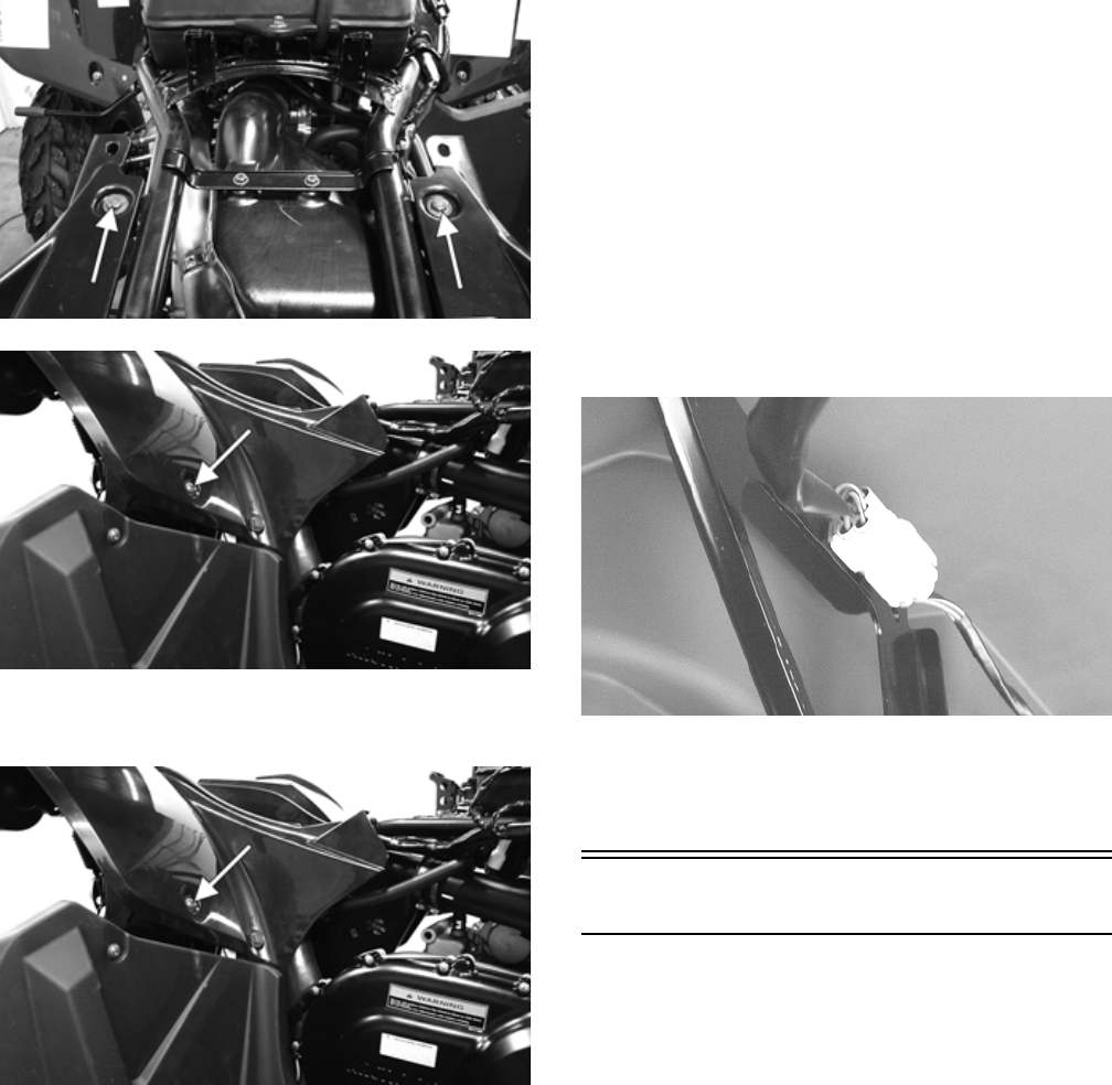
121
KC473A
KC472A
2. Remove two reinstallable rivets securing the fenders
to the footwells.
KC472A
3. Using a small screwdriver, remove the light connec-
tors from the frame; then disconnect both connectors
and remove the rear body panel/fender.
CLEANING AND INSPECTING
NOTE: Whenever a part is worn excessively, cracked,
or damaged in any way, replacement is necessary.
1. Clean all rear body panel components with warm
soap and water.
2. Inspect side panels and rear body panel for cracks
and loose rivets.
3. Inspect threaded areas of all mounting bosses for
stripping.
4. Inspect for missing decals.
INSTALLING
1. Place the rear body panel/fender in place on the
ATV; then secure with the cap screws on the frame
and fender supports. Tighten all fasteners securely.
2. Connect the light connectors and secure to the frame.
KC279
3. Secure the rear fenders to the footwells with the
reinstallable rivets and lock.
4. Install the seat.
Seat
REMOVING/INSTALLING
1. To remove the seat, pull rearward on the latch release
(located under the rear of the seat). Raise the rear of
the seat and slide it rearward.
2. To lock the seat into position, slide the front of the
seat into the seat retainers and push down firmly on
the rear of the seat. The seat should automatically
lock into position.
For Discount Arctic Cat Parts Call 606-678-9623 or 606-561-4983
www.mymowerparts.com

122
Troubleshooting
Problem: Handling too heavy or stiff
Condition Remedy
1. Front wheel alignment incorrect
2. Lubrication inadequate
3. Tire inflation pressure low
4. Tie rod ends seizing
5. Linkage connections seizing
1. Adjust alignment
2. Lubricate appropriate components
3. Adjust pressure
4. Replace tie rod ends
5. Repair - replace connections
Problem: Steering oscillation
Condition Remedy
1. Tires inflated unequally
2. Wheel(s) wobbly
3. Wheel hub cap screw(s) loose - missing
4. Wheel hub bearing worn - damaged
5. Tie rod ends worn - loose
6. Tires defective - incorrect
7. A-arm bushings damaged
8. Bolts - nuts (frame) loose
1. Adjust pressure
2. Replace wheel(s)
3. Tighten - replace cap screws
4. Replace bearing
5. Replace - tighten tie rod ends
6. Replace tires
7. Replace bushings
8. Tighten bolts - nuts
Problem: Steering pulling to one side
Condition Remedy
1. Tires inflated unequally
2. Front wheel alignment incorrect
3. Wheel hub bearings worn - broken
4. Frame distorted
5. Shock absorber defective
1. Adjust pressure
2. Adjust alignment
3. Replace bearings
4. Repair - replace frame
5. Replace shock absorber
Problem: Tire wear rapid or uneven
Condition Remedy
1. Wheel hub bearings worn - loose
2. Front wheel alignment incorrect
3. Tire inflation pressure incorrect
1. Replace bearings
2. Adjust alignment
3. Adjust pressure
Problem: Steering noise
Condition Remedy
1. Cap screws - nuts loose
2. Wheel hub bearings broken - damaged
3. Lubrication inadequate
1. Tighten cap screws - nuts
2. Replace bearings
3. Lubricate appropriate components
For Discount Arctic Cat Parts Call 606-678-9623 or 606-561-4983
www.mymowerparts.com
