Product Detail Manual AT
User Manual: at
Open the PDF directly: View PDF ![]() .
.
Page Count: 380 [warning: Documents this large are best viewed by clicking the View PDF Link!]
- QUICK REFERENCE INDEX
- Table of Contents
- INDEX FOR DTC
- PRECAUTIONS
- Precautions for Supplemental Restraint System (SRS) “AIR BAG” and “SEAT BELT PRE-TENSIONER”
- Precautions for On Board Diagnostic (OBD) System of A/T and Engine
- Precautions for TCM, A/T Assembly and Control Valve Assembly Replacement
- Precautions
- Service Notice or Precautions
- Wiring Diagrams and Trouble Diagnosis
- PREPARATION
- A/T FLUID
- A/T CONTROL SYSTEM
- ON BOARD DIAGNOSTIC (OBD) SYSTEM
- TROUBLE DIAGNOSIS
- DTC Inspection Priority Chart
- Fail-Safe
- FAIL-SAFE FUNCTION
- Vehicle Speed Sensor
- Accelerator Pedal Position Sensor
- Throttle Position Sensor
- PNP Switch
- Starter Relay
- A/T Interlock
- A/T 1st Engine Braking
- Line Pressure Solenoid
- Torque Converter Clutch Solenoid
- Low Coast Brake Solenoid
- Input Clutch Solenoid
- Direct Clutch Solenoid
- Front Brake Solenoid
- High and Low Reverse Clutch Solenoid
- Turbine Revolution Sensor 1 or 2
- FAIL-SAFE FUNCTION
- How To Perform Trouble Diagnosis For Quick and Accurate Repair
- A/T Electrical Parts Location
- Circuit Diagram
- Inspections Before Trouble Diagnosis
- Check Before Engine is Started
- Check at Idle
- Cruise Test - Part 1
- Cruise Test - Part 2
- Cruise Test - Part 3
- Vehicle Speed When Shifting Gears
- Vehicle Speed When Performing and Releasing Complete Lock-up
- Vehicle Speed When Performing and Releasing Slip Lock-up
- Symptom Chart
- TCM Input/Output Signal Reference Values
- CONSULT-II
- Diagnostic Procedure Without CONSULT-II
- DTC U1000 CAN COMMUNICATION LINE
- DTC P0615 START SIGNAL CIRCUIT
- DTC P0705 PARK/NEUTRAL POSITION SWITCH
- DTC P0720 VEHICLE SPEED SENSOR A/T (REVOLUTION SENSOR)
- DTC P0725 ENGINE SPEED SIGNAL
- DTC P0740 TORQUE CONVERTER CLUTCH SOLENOID VALVE
- DTC P0744 A/T TCC S/V FUNCTION (LOCK-UP)
- DTC P0745 LINE PRESSURE SOLENOID VALVE
- DTC P1701 TRANSMISSION CONTROL MODULE (POWER SUPPLY)
- DTC P1702 TRANSMISSION CONTROL MODULE (RAM)
- DTC P1703 TRANSMISSION CONTROL MODULE (ROM)
- DTC P1704 TRANSMISSION CONTROL MODULE (EEPROM)
- DTC P1705 THROTTLE POSITION SENSOR
- DTC P1710 A/T FLUID TEMPERATURE SENSOR CIRCUIT
- DTC P1716 TURBINE REVOLUTION SENSOR
- DTC P1721 VEHICLE SPEED SENSOR MTR
- DTC P1730 A/T INTERLOCK
- DTC P1731 A/T 1ST ENGINE BRAKING
- DTC P1752 INPUT CLUTCH SOLENOID VALVE
- DTC P1754 INPUT CLUTCH SOLENOID VALVE FUNCTION
- DTC P1757 FRONT BRAKE SOLENOID VALVE
- DTC P1759 FRONT BRAKE SOLENOID VALVE FUNCTION
- DTC P1762 DIRECT CLUTCH SOLENOID VALVE
- DTC P1764 DIRECT CLUTCH SOLENOID VALVE FUNCTION
- DTC P1767 HIGH AND LOW REVERSE CLUTCH SOLENOID VALVE
- DTC P1769 HIGH AND LOW REVERSE CLUTCH SOLENOID VALVE FUNCTION
- DTC P1772 LOW COAST BRAKE SOLENOID VALVE
- DTC P1774 LOW COAST BRAKE SOLENOID VALVE FUNCTION
- DTC P1815 MANUAL MODE SWITCH
- DTC P1841 ATF PRESSURE SWITCH 1
- DTC P1843 ATF PRESSURE SWITCH 3
- DTC P1845 ATF PRESSURE SWITCH 5
- DTC P1846 ATF PRESSURE SWITCH 6
- PARK/NEUTRAL POSITION, MANUAL MODE, BRAKE AND THROTTLE POSITION SWITCH CIRCUIT
- TROUBLE DIAGNOSIS FOR SYMPTOMS
- Wiring Diagram — AT — NONDTC
- A/T Check Indicator Lamp Does Not Come On
- Engine Cannot Be Started In “P” or “N” Position
- In “P” Position, Vehicle Moves When Pushed
- In “N” Position, Vehicle Moves
- Large Shock (“N” to “D” Position)
- Vehicle Does Not Creep Backward In “R” Position
- Vehicle Does Not Creep Forward In “D” Position
- Vehicle Cannot Be Started From D1
- A/T Does Not Shift: D1 -> D2
- A/T Does Not Shift: D2 -> D3
- A/T Does Not Shift: D3 -> D4
- A/T Does Not Shift: D4 -> D5
- A/T Does Not Perform Lock-up
- A/T Does Not Hold Lock-up Condition
- Lock-up Is Not Released
- Engine Speed Does Not Return To Idle
- Cannot Be Changed to Manual Mode
- A/T Does Not Shift: 5th gear -> 4th gear
- A/T Does Not Shift: 4th gear -> 3rd gear
- A/T Does Not Shift: 3rd gear -> 2nd gear
- A/T Does Not Shift: 2nd gear -> 1st gear
- Vehicle Does Not Decelerate By Engine Brake
- SHIFT CONTROL SYSTEM
- A/T SHIFT LOCK SYSTEM
- KEY INTERLOCK CABLE
- ON-VEHICLE SERVICE
- AIR BREATHER HOSE
- TRANSMISSION ASSEMBLY
- OVERHAUL
- DISASSEMBLY
- REPAIR FOR COMPONENT PARTS
- ASSEMBLY
- SERVICE DATA AND SPECIFICATIONS (SDS)
- General Specifications
- Vehicle Speed When Shifting Gears
- Vehicle Speed When Performing and Releasing Complete Lock-up
- Vehicle Speed When Performing and Releasing Slip Lock-up
- Stall Speed
- Line Pressure
- Solenoid Valves
- A/T Fluid Temperature Sensor
- Turbine Revolution Sensor
- Vehicle Speed Sensor A/T (Revolution Sensor)
- Reverse Brake
- Total End Play
- ELECTRICAL UNITS
- SUPER MULTIPLE JUNCTION (SMJ)
- FUSE BLOCK - JUNCTION BOX (J/B)
- FUSE, FUSIBLE LINK AND RELAY BOX

AT-1
AUTOMATIC TRANSMISSION
C TRANSMISSION/TRANSAXLE
CONTENTS
D
E
F
G
H
I
J
K
L
M
SECTION
A
B
AT
AUTOMATIC TRANSMISSION
INDEX FOR DTC ........................................................ 5
Alphabetical Index .................................................... 5
DTC No. Index ......................................................... 6
PRECAUTIONS .......................................................... 7
Precautions for Supplemental Restraint System
(SRS) “AIR BAG” and “SEAT BELT PRE-TEN-
SIONER” .................................................................. 7
Precautions for On Board Diagnostic (OBD) System
of A/T and Engine .................................................... 7
Precautions for TCM, A/T Assembly and Control
Valve Assembly Replacement .................................. 8
Precautions .............................................................. 9
Service Notice or Precautions ................................ 10
Wiring Diagrams and Trouble Diagnosis ................ 10
PREPARATION ..........................................................11
Special Service Tools ..............................................11
Commercial Service Tools ...................................... 12
A/T FLUID ................................................................. 13
Changing A/T Fluid ................................................ 13
Checking A/T Fluid ................................................. 13
A/T Fluid Cooler Cleaning ...................................... 15
A/T CONTROL SYSTEM .......................................... 18
Cross-Sectional View ............................................. 18
Shift Mechanism ..................................................... 19
TCM Function ......................................................... 30
CAN Communication .............................................. 31
Input/Output Signal of TCM .................................... 31
Line Pressure Control ............................................ 32
Shift Control ........................................................... 34
Lock-Up Control ..................................................... 34
Engine Brake Control ............................................. 36
Control Valve .......................................................... 36
ON BOARD DIAGNOSTIC (OBD) SYSTEM ............ 38
Introduction ............................................................ 38
OBD-II Function for A/T System ............................. 38
One or Two Trip Detection Logic of OBD-II ............ 38
OBD-II Diagnostic Trouble Code (DTC) ................. 38
Malfunction Indicator Lamp (MIL) ........................... 41
TROUBLE DIAGNOSIS ............................................ 42
DTC Inspection Priority Chart ................................ 42
Fail-Safe ................................................................. 42
How To Perform Trouble Diagnosis For Quick and
Accurate Repair ...................................................... 44
A/T Electrical Parts Location .................................. 49
Circuit Diagram ....................................................... 50
Inspections Before Trouble Diagnosis .................... 51
Check Before Engine is Started .............................. 55
Check at Idle ........................................................... 55
Cruise Test - Part 1 ................................................. 56
Cruise Test - Part 2 ................................................. 58
Cruise Test - Part 3 ................................................. 59
Vehicle Speed When Shifting Gears ...................... 61
Vehicle Speed When Performing and Releasing
Complete Lock-up .................................................. 61
Vehicle Speed When Performing and Releasing
Slip Lock-up ............................................................ 61
Symptom Chart ....................................................... 62
TCM Input/Output Signal Reference Values ........... 89
CONSULT-II ............................................................ 92
Diagnostic Procedure Without CONSULT-II .........103
DTC U1000 CAN COMMUNICATION LINE ............105
Description ............................................................105
On Board Diagnosis Logic ....................................105
Possible Cause .....................................................105
DTC Confirmation Procedure ...............................105
Wiring Diagram — AT — CAN ..............................106
Diagnostic Procedure ...........................................107
DTC P0615 START SIGNAL CIRCUIT ...................108
Description ............................................................108
On Board Diagnosis Logic ....................................108
Possible Cause .....................................................108
DTC Confirmation Procedure ...............................108
Wiring Diagram — AT — STSIG ..........................109
Diagnostic Procedure ...........................................110
DTC P0705 PARK/NEUTRAL POSITION SWITCH .112
Description ............................................................112
On Board Diagnosis Logic ....................................112
Possible Cause .....................................................112
DTC Confirmation Procedure ...............................112
Wiring Diagram — AT — PNP/SW .......................113

AT-2
Diagnostic Procedure ...........................................114
Component Inspection ..........................................116
DTC P0720 VEHICLE SPEED SENSOR A/T (REV-
OLUTION SENSOR) ...............................................117
Description ............................................................117
On Board Diagnosis Logic ....................................117
Possible Cause .....................................................117
DTC Confirmation Procedure ...............................117
Wiring Diagram — AT — VSSA/T .........................118
Diagnostic Procedure ...........................................119
DTC P0725 ENGINE SPEED SIGNAL ...................122
Description ............................................................122
On Board Diagnosis Logic ....................................122
Possible Cause .....................................................122
DTC Confirmation Procedure ...............................122
Diagnostic Procedure ...........................................123
DTC P0740 TORQUE CONVERTER CLUTCH
SOLENOID VALVE .................................................124
Description ............................................................124
CONSULT-II Reference Value ..............................124
On Board Diagnosis Logic ....................................124
Possible Cause .....................................................124
DTC Confirmation Procedure ...............................124
Wiring Diagram — AT — TCV ..............................125
Diagnostic Procedure ...........................................126
Component Inspection ..........................................128
DTC P0744 A/T TCC S/V FUNCTION (LOCK-UP) .129
Description ............................................................129
On Board Diagnosis Logic ....................................129
Possible Cause .....................................................129
DTC Confirmation Procedure ...............................129
Wiring Diagram — AT — TCCSIG ........................130
Diagnostic Procedure ...........................................131
Component Inspection ..........................................133
DTC P0745 LINE PRESSURE SOLENOID VALVE .134
Description ............................................................134
On Board Diagnosis Logic ....................................134
Possible Cause .....................................................134
DTC Confirmation Procedure ...............................134
Wiring Diagram — AT — LPSV ............................135
Diagnostic Procedure ...........................................136
Component Inspection ..........................................138
DTC P1701 TRANSMISSION CONTROL MODULE
(POWER SUPPLY) ..................................................139
Description ............................................................139
On Board Diagnosis Logic ....................................139
Possible Cause .....................................................139
DTC Confirmation Procedure ...............................139
Wiring Diagram — AT — POWER ........................140
Diagnostic Procedure ...........................................142
Component Inspection ..........................................144
DTC P1702 TRANSMISSION CONTROL MODULE
(RAM) ......................................................................145
Description ............................................................145
On Board Diagnosis Logic ....................................145
Possible Cause .....................................................145
DTC Confirmation Procedure ...............................145
Diagnostic Procedure ...........................................146
DTC P1703 TRANSMISSION CONTROL MODULE
(ROM) ......................................................................147
Description ............................................................147
On Board Diagnosis Logic ....................................147
Possible Cause .....................................................147
DTC Confirmation Procedure ................................147
Diagnostic Procedure ............................................148
DTC P1704 TRANSMISSION CONTROL MODULE
(EEPROM) ...............................................................149
Description ............................................................149
On Board Diagnosis Logic ....................................149
Possible Cause .....................................................149
DTC Confirmation Procedure ................................149
Diagnostic Procedure ............................................150
DTC P1705 THROTTLE POSITION SENSOR ........151
Description ............................................................151
On Board Diagnosis Logic ....................................151
Possible Cause .....................................................151
DTC Confirmation Procedure ................................151
Diagnostic Procedure ............................................152
DTC P1710 A/T FLUID TEMPERATURE SENSOR
CIRCUIT ..................................................................153
Description ............................................................153
CONSULT-II Reference Value ...............................153
On Board Diagnosis Logic ....................................153
Possible Cause .....................................................153
DTC Confirmation Procedure ................................153
Wiring Diagram — AT — FTS ...............................154
Diagnostic Procedure ............................................155
Component Inspection ..........................................158
DTC P1716 TURBINE REVOLUTION SENSOR ....159
Description ............................................................159
On Board Diagnosis Logic ....................................159
Possible Cause .....................................................159
DTC Confirmation Procedure ................................159
Wiring Diagram — AT — TRSA/T .........................160
Diagnostic Procedure ............................................161
DTC P1721 VEHICLE SPEED SENSOR MTR .......164
Description ............................................................164
On Board Diagnosis Logic ....................................164
Possible Cause .....................................................164
DTC Confirmation Procedure ................................164
Diagnostic Procedure ............................................165
DTC P1730 A/T INTERLOCK .................................166
Description ............................................................166
On Board Diagnosis Logic ....................................166
Possible Cause .....................................................166
DTC Confirmation Procedure ................................166
Wiring Diagram — AT — I/LOCK ..........................167
Judgement of A/T Interlock ...................................171
Diagnostic Procedure ............................................171
DTC P1731 A/T 1ST ENGINE BRAKING ...............173
Description ............................................................173
On Board Diagnosis Logic ....................................173
Possible Cause .....................................................173
DTC Confirmation Procedure ................................173
Wiring Diagram — AT — E/BRE ...........................174
Diagnostic Procedure ............................................175
DTC P1752 INPUT CLUTCH SOLENOID VALVE ..177
Description ............................................................177

AT-3
D
E
F
G
H
I
J
K
L
M
A
B
AT
On Board Diagnosis Logic ................................... 177
Possible Cause .................................................... 177
DTC Confirmation Procedure ............................... 177
Wiring Diagram — AT — I/C ................................ 178
Diagnostic Procedure ........................................... 179
Component Inspection ......................................... 181
DTC P1754 INPUT CLUTCH SOLENOID VALVE
FUNCTION .............................................................. 182
Description ........................................................... 182
On Board Diagnosis Logic ................................... 182
Possible Cause .................................................... 182
DTC Confirmation Procedure ............................... 182
Wiring Diagram — AT — I/CF .............................. 183
Diagnostic Procedure ........................................... 184
DTC P1757 FRONT BRAKE SOLENOID VALVE .. 186
Description ........................................................... 186
On Board Diagnosis Logic ................................... 186
Possible Cause .................................................... 186
DTC Confirmation Procedure ............................... 186
Wiring Diagram — AT — FR/B ............................. 187
Diagnostic Procedure ........................................... 188
Component Inspection ......................................... 190
DTC P1759 FRONT BRAKE SOLENOID VALVE
FUNCTION .............................................................. 191
Description ........................................................... 191
On Board Diagnosis Logic ................................... 191
Possible Cause .................................................... 191
DTC Confirmation Procedure ............................... 191
Wiring Diagram — AT — FR/BF ........................... 192
Diagnostic Procedure ........................................... 193
DTC P1762 DIRECT CLUTCH SOLENOID VALVE . 196
Description ........................................................... 196
On Board Diagnosis Logic ................................... 196
Possible Cause .................................................... 196
DTC Confirmation Procedure ............................... 196
Wiring Diagram — AT — D/C ............................... 197
Diagnostic Procedure ........................................... 198
Component Inspection ......................................... 200
DTC P1764 DIRECT CLUTCH SOLENOID VALVE
FUNCTION .............................................................. 201
Description ........................................................... 201
On Board Diagnosis Logic ................................... 201
Possible Cause .................................................... 201
DTC Confirmation Procedure ............................... 201
Wiring Diagram — AT — D/CF ............................. 202
Diagnostic Procedure ........................................... 203
DTC P1767 HIGH AND LOW REVERSE CLUTCH
SOLENOID VALVE ................................................. 205
Description ........................................................... 205
On Board Diagnosis Logic ................................... 205
Possible Cause .................................................... 205
DTC Confirmation Procedure ............................... 205
Wiring Diagram — AT — HLR/C .......................... 206
Diagnostic Procedure ........................................... 207
Component Inspection ......................................... 209
DTC P1769 HIGH AND LOW REVERSE CLUTCH
SOLENOID VALVE FUNCTION ............................. 210
Description ........................................................... 210
On Board Diagnosis Logic ................................... 210
Possible Cause .....................................................210
DTC Confirmation Procedure ...............................210
Wiring Diagram — AT — HLR/CF ........................211
Diagnostic Procedure ...........................................212
DTC P1772 LOW COAST BRAKE SOLENOID
VALVE .....................................................................215
Description ............................................................215
On Board Diagnosis Logic ....................................215
Possible Cause .....................................................215
DTC Confirmation Procedure ...............................215
Wiring Diagram — AT — LC/B .............................216
Diagnostic Procedure ...........................................217
Component Inspection ..........................................219
DTC P1774 LOW COAST BRAKE SOLENOID
VALVE FUNCTION ..................................................220
Description ............................................................220
On Board Diagnosis Logic ....................................220
Possible Cause .....................................................220
DTC Confirmation Procedure ...............................220
Wiring Diagram — AT — LC/BF ...........................221
Diagnostic Procedure ...........................................222
DTC P1815 MANUAL MODE SWITCH ..................224
Description ............................................................224
CONSULT-II Reference Value in Data Monitor Mode
.224
On Board Diagnosis Logic ....................................224
Possible Cause .....................................................224
DTC Confirmation Procedure ...............................224
Wiring Diagram — AT — MMSW .........................225
Diagnostic Procedure ...........................................226
Component Inspection ..........................................227
Position Indicator Lamp ........................................227
DTC P1841 ATF PRESSURE SWITCH 1 ...............228
Description ............................................................228
On Board Diagnosis Logic ....................................228
Possible Cause .....................................................228
DTC Confirmation Procedure ...............................228
Wiring Diagram — AT — FPSW1 .........................229
Diagnostic Procedure ...........................................230
DTC P1843 ATF PRESSURE SWITCH 3 ...............232
Description ............................................................232
On Board Diagnosis Logic ....................................232
Possible Cause .....................................................232
DTC Confirmation Procedure ...............................232
Wiring Diagram — AT — FPSW3 .........................233
Diagnostic Procedure ...........................................234
DTC P1845 ATF PRESSURE SWITCH 5 ...............236
Description ............................................................236
On Board Diagnosis Logic ....................................236
Possible Cause .....................................................236
DTC Confirmation Procedure ...............................236
Wiring Diagram — AT — FPSW5 .........................237
Diagnostic Procedure ...........................................238
DTC P1846 ATF PRESSURE SWITCH 6 ...............240
Description ............................................................240
On Board Diagnosis Logic ....................................240
Possible Cause .....................................................240
DTC Confirmation Procedure ...............................240

AT-4
Wiring Diagram — AT — FPSW6 .........................241
Diagnostic Procedure ...........................................242
PARK/NEUTRAL POSITION, MANUAL MODE,
BRAKE AND THROTTLE POSITION SWITCH CIR-
CUIT ........................................................................244
Diagnostic Procedure ...........................................244
TROUBLE DIAGNOSIS FOR SYMPTOMS ............246
Wiring Diagram — AT — NONDTC ......................246
A/T Check Indicator Lamp Does Not Come On ....248
Engine Cannot Be Started In “P” or “N” Position ..250
In “P” Position, Vehicle Moves When Pushed ......250
In “N” Position, Vehicle Moves ..............................251
Large Shock (“N” to “D” Position) .........................253
Vehicle Does Not Creep Backward In “R” Position .255
Vehicle Does Not Creep Forward In “D” Position . 258
Vehicle Cannot Be Started From D1 .....................260
A/T Does Not Shift: D1 → D2 ................................263
A/T Does Not Shift: D2 → D3 ................................265
A/T Does Not Shift: D3 → D4 ................................267
A/T Does Not Shift: D4 → D5 ................................270
A/T Does Not Perform Lock-up ............................272
A/T Does Not Hold Lock-up Condition ..................274
Lock-up Is Not Released ......................................276
Engine Speed Does Not Return To Idle ................276
Cannot Be Changed to Manual Mode ..................278
A/T Does Not Shift: 5th gear → 4th gear ..............278
A/T Does Not Shift: 4th gear → 3rd gear ..............280
A/T Does Not Shift: 3rd gear → 2nd gear .............282
A/T Does Not Shift: 2nd gear → 1st gear .............284
Vehicle Does Not Decelerate By Engine Brake ....286
SHIFT CONTROL SYSTEM ....................................288
Control Device Removal and Installation ..............288
Adjustment of A/T Position ...................................289
Checking of A/T Position ......................................289
A/T SHIFT LOCK SYSTEM .....................................291
Description ............................................................291
Shift Lock System Electrical Parts Location .........291
Wiring Diagram — AT — SHIFT ...........................292
Diagnostic Procedure ...........................................293
KEY INTERLOCK CABLE ......................................296
Components .........................................................296
Removal ...............................................................297
Installation .............................................................298
ON-VEHICLE SERVICE ..........................................299
Control Valve Assembly ........................................299
Rear Oil Seal .........................................................306
Parking Components ............................................307
AIR BREATHER HOSE ...........................................313
Removal and Installation .......................................313
TRANSMISSION ASSEMBLY .................................314
Removal and Installation .......................................314
OVERHAUL .............................................................317
Components ..........................................................317
Oil Channel ...........................................................323
Locations of Adjusting Shims, Needle Bearings,
Thrust Washers and Snap Rings ..........................324
DISASSEMBLY .......................................................325
Disassembly ..........................................................325
REPAIR FOR COMPONENT PARTS ......................339
Oil Pump ...............................................................339
Front Sun Gear, 3rd One-Way Clutch ...................342
Front Carrier, Input Clutch, Rear Internal Gear .....344
Mid Sun Gear, Rear Sun Gear, High and Low
Reverse Clutch Hub ..............................................349
High and Low Reverse Clutch ..............................354
Direct Clutch .........................................................356
ASSEMBLY .............................................................358
Assembly (1) .........................................................358
Adjustment ............................................................369
Assembly (2) .........................................................371
SERVICE DATA AND SPECIFICATIONS (SDS) ....377
General Specifications ..........................................377
Vehicle Speed When Shifting Gears .....................377
Vehicle Speed When Performing and Releasing
Complete Lock-up .................................................377
Vehicle Speed When Performing and Releasing
Slip Lock-up ..........................................................377
Stall Speed ............................................................377
Line Pressure ........................................................378
Solenoid Valves ....................................................378
A/T Fluid Temperature Sensor ..............................378
Turbine Revolution Sensor ....................................378
Vehicle Speed Sensor A/T (Revolution Sensor) ...378
Reverse Brake ......................................................378
Total End Play .......................................................378
INDEX FOR DTC
AT-5
D
E
F
G
H
I
J
K
L
M
A
B
AT
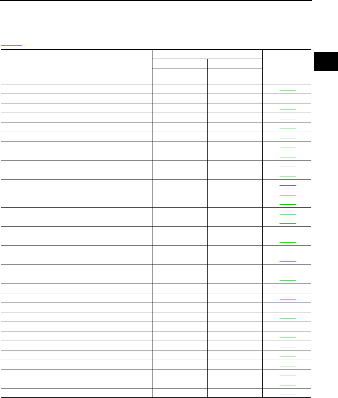
INDEX FOR DTC PFP:00024
Alphabetical Index ACS00081
NOTE:
If DTC U1000 is displayed with other DTCs, first perform the trouble diagnosis for DTC U1000. Refer to
AT-105 .
*1: These numbers are prescribed by SAE J2012.
Items
(CONSULT-II screen terms)
DTC
Reference page
OBD-II Except OBD-II
CONSULT-II
GST*1
CONSULT-II
only “A/T”
A/T 1ST E/BRAKING — P1731 AT-173
ATF PRES SW 1/CIRC — P1841 AT-228
ATF PRES SW 3/CIRC — P1843 AT-232
ATF PRES SW 5/CIRC — P1845 AT-236
ATF PRES SW 6/CIRC — P1846 AT-240
A/T INTERLOCK P1730 P1730 AT-166
A/T TCC S/V FNCTN P0744 P0744 AT-129
ATF TEMP SEN/CIRC P0710 P1710 AT-153
CAN COMM CIRCUIT U1000 U1000 AT-105
D/C SOLENOID/CIRC P1762 P1762 AT-196
D/C SOLENOID FNCTN P1764 P1764 AT-201
ENGINE SPEED SIG P0725 P0725 AT-122
FR/B SOLENOID/CIRC P1757 P1757 AT-186
FR/B SOLENOID FNCT P1759 P1759 AT-191
HLR/C SOL/CIRC P1767 P1767 AT-205
HLR/C SOL FNCTN P1769 P1769 AT-210
I/C SOLENOID/CIRC P1752 P1752 AT-177
I/C SOLENOID FNCTN P1754 P1754 AT-182
L/PRESS SOL/CIRC P0745 P0745 AT-134
LC/B SOLENOID/CIRC P1772 P1772 AT-215
LC/B SOLENOID FNCT P1774 P1774 AT-220
MANU MODE SW/CIR — P1815 AT-224
PNP SW/CIRC P0705 P0705 AT-112
STARTER RELAY/CIRC — P0615 AT-108
TCC SOLENOID/CIRC P0740 P0740 AT-124
TCM·EEPROM — P1704 AT-149
TCM-POWER SUPPLY — P1701 AT-139
TCM·RAM — P1702 AT-145
TCM·ROM — P1703 AT-147
TP SEN/CIRC A/T P1705 P1705 AT-151
TURBINE REV S/CIRC P1716 P1716 AT-159
VEH SPD SE/CIR·MTR — P1721 AT-164
VEH SPD SEN/CIR AT P0720 P0720 AT-117

AT-6
INDEX FOR DTC
DTC No. Index ACS00082
NOTE:
If DTC U1000 is displayed with other DTCs, first perform the trouble diagnosis for DTC U1000. Refer to
AT-105 .
*1: These numbers are prescribed by SAE J2012.
DTC
Items
(CONSULT-II screen terms) Reference page
OBD-II Except OBD-II
CONSULT-II
GST*1
CONSULT-II
only “A/T”
— P0615 STARTER RELAY/CIRC AT-108
P0705 P0705 PNP SW/CIRC AT-112
P0710 P1710 ATF TEMP SEN/CIRC AT-153
P0720 P0720 VEH SPD SEN/CIR AT AT-117
P0725 P0725 ENGINE SPEED SIG AT-122
P0740 P0740 TCC SOLENOID/CIRC AT-124
P0744 P0744 A/T TCC S/V FNCTN AT-129
P0745 P0745 L/PRESS SOL/CIRC AT-134
— P1701 TCM-POWER SUPPLY AT-139
— P1702 TCM·RAM AT-145
— P1703 TCM·ROM AT-147
— P1704 TCM·EEPROM AT-149
P1705 P1705 TP SEN/CIRC A/T AT-151
P1716 P1716 TURBINE REV S/CIRC AT-159
— P1721 VEH SPD SE/CIR·MTR AT-164
P1730 P1730 A/T INTERLOCK AT-166
— P1731 A/T 1ST E/BRAKING AT-173
P1752 P1752 I/C SOLENOID/CIRC AT-177
P1754 P1754 I/C SOLENOID FNCTN AT-182
P1757 P1757 FR/B SOLENOID/CIRC AT-186
P1759 P1759 FR/B SOLENOID FNCT AT-191
P1762 P1762 D/C SOLENOID/CIRC AT-196
P1764 P1764 D/C SOLENOID FNCTN AT-201
P1767 P1767 HLR/C SOL/CIRC AT-205
P1769 P1769 HLR/C SOL FNCTN AT-210
P1772 P1772 LC/B SOLENOID/CIRC AT-215
P1774 P1774 LC/B SOLENOID FNCT AT-220
— P1815 MANU MODE SW/CIRC AT-224
— P1841 ATF PRES SW 1/CIRC AT-228
— P1843 ATF PRES SW 3/CIRC AT-232
— P1845 ATF PRES SW 5/CIRC AT-236
— P1846 ATF PRES SW 6/CIRC AT-240
U1000 U1000 CAN COMM CIRCUIT AT-105

PRECAUTIONS
AT-7
D
E
F
G
H
I
J
K
L
M
A
B
AT
PRECAUTIONS PFP:00001
Precautions for Supplemental Restraint System (SRS) “AIR BAG” and “SEAT
BELT PRE-TENSIONER” ACS004YD
The Supplemental Restraint System such as “AIR BAG” and “SEAT BELT PRE-TENSIONER”, used along
with a front seat belt, helps to reduce the risk or severity of injury to the driver and front passenger for certain
types of collision. This system includes seat belt switch inputs and dual stage front air bag modules. The SRS
system uses the seat belt switches to determine the front air bag deployment, and may only deploy one front
air bag, depending on the severity of a collision and whether the front occupants are belted or unbelted.
Information necessary to service the system safely is included in the SRS and SB section of this Service Man-
ual.
WARNING:
●To avoid rendering the SRS inoperative, which could increase the risk of personal injury or death
in the event of a collision which would result in air bag inflation, all maintenance must be per-
formed by an authorized NISSAN/INFINITI dealer.
●Improper maintenance, including incorrect removal and installation of the SRS, can lead to per-
sonal injury caused by unintentional activation of the system. For removal of Spiral Cable and Air
Bag Module, see the SRS section.
●Do not use electrical test equipment on any circuit related to the SRS unless instructed to in this
Service Manual. SRS wiring harnesses can be identified by yellow and/or orange harnesses or
harness connectors.
Precautions for On Board Diagnostic (OBD) System of A/T and Engine ACS000G0
The ECM has an on board diagnostic system. It will light up the malfunction indicator lamp (MIL) to warn the
driver of a malfunction causing emission deterioration.
CAUTION:
●Be sure to turn the ignition switch “OFF” and disconnect the negative battery cable before any
repair or inspection work. The open/short circuit of related switches, sensors, solenoid valves,
etc. will cause the MIL to light up.
●Be sure to connect and lock the connectors securely after work. A loose (unlocked) connector will
cause the MIL to light up due to an open circuit. (Be sure the connector is free from water, grease,
dirt, bent terminals, etc.)
●Be sure to route and secure the harnesses properly after work. Interference of the harness with a
bracket, etc. may cause the MIL to light up due to a short circuit.
●Be sure to connect rubber tubes properly after work. A misconnected or disconnected rubber tube
may cause the MIL to light up due to a malfunction of the EGR system or fuel injection system, etc.
●Be sure to erase the unnecessary malfunction information (repairs completed) from the TCM and
ECM before returning the vehicle to the customer.
AT-8
PRECAUTIONS
Precautions for TCM, A/T Assembly and Control Valve Assembly Replacement
ACS000G1
CAUTION:
●Check data (Unit ID) in TCM with data monitor of CONSULT-II before replacing A/T assembly (con-
trol valve assembly).
●Check if new data (Unit ID) are entered correctly after replacing A/T assembly (control valve
assembly) and erasing data in TCM.
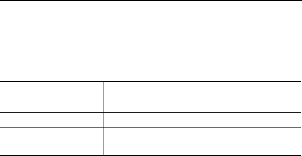
●When replacing A/T assembly, control valve assembly or TCM, refer to the pattern table below and erase
the EEPROM in the TCM if necessary.
EEPROM ERASING PATTERNS
METHOD FOR ERASING THE EEPROM IN THE TCM
1. Connect CONSULT-II to data link connector.
2. Turn ignition switch ON. Confirm that CONSULT-II turn “ON”.
3. Move selector lever in “R” position.
4. Touch “START” on CONSULT-II.
5. Select “SELF-DIAG RESULTS” mode for “A/T” with CONSULT-II.
6. Fully press the accelerator pedal (8/8 throttle), and hold it in the fully open position. (This will set the
closed throttle position signal to “OFF”.)
7. Touch “ERASE” on CONSULT-II, and then touch “YES”.
8. Wait 3 seconds and then release the accelerator pedal.
9. Turn ignition switch OFF.
METHOD FOR WRITING DATA FROM THE ROM ASSEMBLY IN THE TRANSMISSION
In the following procedure, the TCM reads data from the ROM assembly and writes it to the EEPROM in the
TCM.
1. With the EEPROM in the TCM erased.
2. Move selector lever in “P” position.
3. Turn ignition switch ON.
CHECK METHOD
●Normal: About 2 seconds after the ignition switch ON, the A/T CHECK indicator lamp lights up for 2
seconds.
●Abnormal: Even after the ignition switch ON, the A/T CHECK indicator lamp does not light up after 2 sec-
onds or illuminates immediately.
Cope for Abnormal
●Replace the control valve assembly.
●Replace the TCM.
A/T assembly or control
valve assembly TCM Erasing EEPROM in TCM Remarks
Replaced Replaced Not required Not required because the EEPROM in the TCM is in
the default state.
Not replaced Replaced Not required Not required because the EEPROM in the TCM is in
the default state.
Replaced Not replaced Required
Required because data has been written in the
EEPROM in the TCM and because the TCM cannot
write data from the ROM assembly in the transmis-
sion.
PRECAUTIONS
AT-9
D
E
F
G
H
I
J
K
L
M
A
B
AT
Precautions ACS000G2
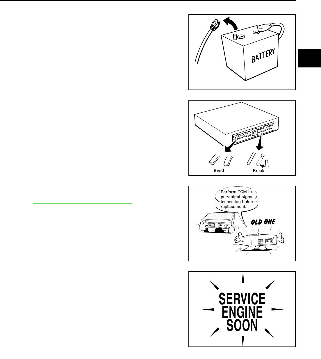
●Before connecting or disconnecting the TCM harness con-
nector, turn ignition switch “OFF” and disconnect negative
battery cable. Because battery voltage is applied to TCM
even if ignition switch is turned “OFF”.
●When connecting or disconnecting pin connectors into or
from TCM, take care not to damage pin terminals (bend or
break).
Make sure that there are not any bends or breaks on TCM
pin terminal, when connecting pin connectors.
●Before replacing TCM, perform TCM input/output signal
inspection and make sure whether TCM functions properly
or not. AT-89, "TCM INSPECTION TABLE".
●After performing each TROUBLE DIAGNOSIS, perform
“DTC (Diagnostic Trouble Code) CONFIRMATION PROCE-
DURE”.
If the repair is completed the DTC should not be displayed in
the “DTC CONFIRMATION PROCEDURE”.
●Always use the specified brand of A/T fluid. Refer to MA-9, "Fluids and Lubricants" .
●Use paper rags not cloth rags during work.
●After replacing the A/T fluid, dispose of the waste oil using the methods prescribed by law, ordinance, etc.
●Before proceeding with disassembly, thoroughly clean the outside of the transaxle. It is important to pre-
vent the internal parts from becoming contaminated by dirt or other foreign matter.
●Disassembly should be done in a clean work area.
SEF289H
SEF291H
MEF040DA
SEF217U

AT-10
PRECAUTIONS
●Use lint-free cloth or towels for wiping parts clean. Common shop rags can leave fibers that could interfere
with the operation of the transaxle.
●Place disassembled parts in order for easier and proper assembly.
●All parts should be carefully cleaned with a general purpose, non-flammable solvent before inspection or
reassembly.
●Gaskets, seals and O-rings should be replaced any time the transaxle is disassembled.
●It is very important to perform functional tests whenever they are indicated.
●The valve body contains precision parts and requires extreme care when parts are removed and serviced.
Place disassembled valve body parts in order for easier and proper assembly. Care will also prevent
springs and small parts from becoming scattered or lost.
●Properly installed valves, sleeves, plugs, etc. will slide along bores in valve body under their own weight.
●Before assembly, apply a coat of recommended ATF to all parts. Apply petroleum jelly to protect O-rings
and seals, or hold bearings and washers in place during assembly. Do not use grease.
●Extreme care should be taken to avoid damage to O-rings, seals and gaskets when assembling.
●After overhaul, refill the transaxle with new ATF.
●When the A/T drain plug is removed, only some of the fluid is drained. Old A/T fluid will remain in torque
converter and ATF cooling system.
Always follow the procedures under “Changing A/T Fluid” in the AT section when changing A/T fluid. Refer
to AT-13, "Changing A/T Fluid" , AT-13, "Checking A/T Fluid" .
Service Notice or Precautions ACS000G3
ATF COOLER SERVICE
If A/T fluid contains frictional material (clutches, bands, etc.), or if an A/T is repaired, overhauled, or replaced,
inspect and clean the A/T fluid cooler mounted in the radiator or replace the radiator. Flush cooler lines using
cleaning solvent and compressed air after repair. For A/T fluid cooler cleaning procedure, refer to AT-15, "A/T
Fluid Cooler Cleaning" . For radiator replacement, refer to CO-13, "RADIATOR" , CO-18, "RADIATOR (ALU-
MINUM TYPE)" .
OBD-II SELF-DIAGNOSIS
●A/T self-diagnosis is performed by the TCM in combination with the ECM. The results can be read through
the blinking pattern of the A/T CHECK indicator or the malfunction indicator lamp (MIL). Refer to the table
on AT-93, "SELF-DIAGNOSTIC RESULT MODE" for the indicator used to display each self-diagnostic
result.
●The self-diagnostic results indicated by the MIL are automatically stored in both the ECM and TCM mem-
ories.
Always perform the procedure on AT-39, "HOW TO ERASE DTC" to complete the repair and avoid
unnecessary blinking of the MIL.
For details of OBD-II, refer to AT-38, "ON BOARD DIAGNOSTIC (OBD) SYSTEM" .
●Certain systems and components, especially those related to OBD, may use the new style slide-
locking type harness connector. For description and how to disconnect, refer to PG-65, "HAR-
NESS CONNECTOR" .
Wiring Diagrams and Trouble Diagnosis ACS000G4
When you read wiring diagrams, refer to the following:
●GI-14, "How to Read Wiring Diagrams".
●PG-3, "POWER SUPPLY ROUTING CIRCUIT" for power distribution circuit.
When you perform trouble diagnosis, refer to the following:
●GI-10, "How to Follow Trouble Diagnoses".
●GI-26, "How to Perform Efficient Diagnosis for an Electrical Incident".
PREPARATION
AT-11
D
E
F
G
H
I
J
K
L
M
A
B
AT
PREPARATION PFP:00002
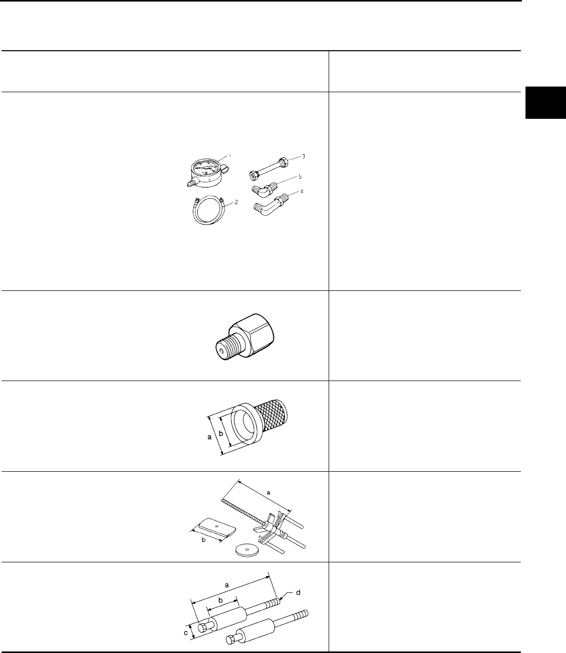
Special Service Tools ACS00087
The actual shapes of Kent-Moore tools may differ from those of special service tools illustrated here.
Tool number
(Kent-Moore No.)
Tool name
Description
ST2505S001
(J-34301-C)
Oil pressure gauge set
1 ST25051001
(—)
Oil pressure gauge
2 ST25052000
(—)
Hose
3 ST25053000
(—)
Joint pipe
4 ST25054000
(—)
Adapter
5 ST25055000
(—)
Adapter
Measuring line pressure
KV31103600
(J-45674)
Joint pipe adapter
(With ST25054000)
Measuring line pressure
ST33400001
(J-26082)
Drift
a: 60 mm (2.36 in) dia.
b: 47 mm (1.85 in) dia.
●Installing rear oil seal
●Installing oil pump housing oil seal
KV31102400
(J-34285 and J-34285-87)
Clutch spring compressor
a: 320 mm (12.60 in)
b: 174 mm (6.85 in)
Installing reverse brake return spring retainer
ST25850000
(J-25721-A)
Sliding hammer
a: 179 mm (7.05 in)
b: 70 mm (2.76 in)
c: 40 mm (1.57 in)
d: M12X1.75P
Remove oil pump assembly
ZZA0600D
ZZA1227D
NT086
NT423
NT422
AT-12
PREPARATION
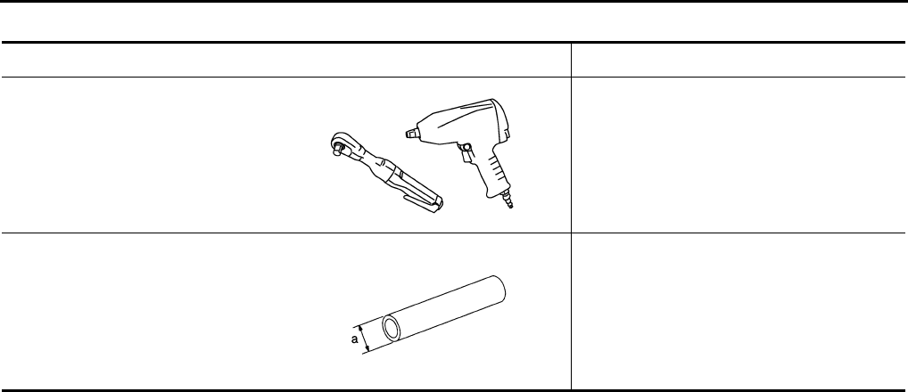
Commercial Service Tools ACS00088
Tool name Description
Power tool Loosening bolts and nuts
Drift
a: 22mm (0.87 in) dia.
Installing manual shaft seal
PBIC0190E
NT083

A/T FLUID
AT-13
D
E
F
G
H
I
J
K
L
M
A
B
AT
A/T FLUID PFP:KLE40
Changing A/T Fluid ACS000G7
1. Warm up A/T fluid.
2. Stop engine.
3. Remove the tightening bolt for A/T fluid level gauge.
4. Drain A/T fluid from drain plug and refill with new A/T fluid. Always refill same volume with drained fluid.
●To replace the A/T fluid, pour in new fluid at the charging pipe with the engine idling and at the same
time drain the old fluid from the radiator cooler hose return side.
●When the color of the fluid coming out is about the same as the color of the new fluid, the replacement
is complete. The amount of new transmission fluid to use should be 30 to 50% increase of the stipu-
lated amount.
CAUTION:
●Use only Genuine Nissan Matic J ATF. Do not mix with other fluid.
●Using automatic transmission fluid other than Genuine Nissan Matic J ATF will cause deteriora-
tion in driveability and automatic transmission durability, and may damage the automatic trans-
mission, which is not covered by the warranty.
●When filling A/T fluid, take care not to scatter heat generating parts such as exhaust.
5. Run engine at idle speed for 5 minutes.
6. Check fluid level and condition. Refer to AT-13, "Checking A/T Fluid" . If fluid is still dirty, repeat step 2.
through 5.
7. Install the removed A/T fluid level gauge in the fluid charging pipe.
Checking A/T Fluid ACS000G8
1. Warm up engine.
2. Check for fluid leakage.
3. Remove the tightening bolt for A/T fluid level gauge.
4. Before driving, fluid level can be checked at fluid temperatures of 30 to 50°C (86 to 122°F) using “COLD”
range on A/T fluid level gauge as follows.
a. Park vehicle on level surface and set parking brake.
b. Start engine and move selector lever through each gear position. Leave selector lever in “P” position.
c. Check fluid level with engine idling.
d. Remove A/T fluid level gauge and wipe clean with lint-free paper.
CAUTION:
When wiping away the fluid level gauge, always use lint-free paper, not a cloth one.
e. Re-insert A/T fluid level gauge into charging pipe as far as it will go.
CAUTION:
To check fluid level, insert the A/T fluid level gauge until the cap contacts the end of the charging
pipe, with the gauge reversed from the normal attachment conditions.
f. Remove A/T fluid level gauge and note reading. If reading is at low side of range, add fluid to the charging
pipe.
CAUTION:
Do not overfill.
5. Drive vehicle for approximately 5 minutes in urban areas.
A/T fluid: Genuine Nissan Matic J ATF
Fluid capacity: 10.3 (10-7/8 US qt, 9-1/8 lmp qt)
Drain plug:
: 34 N·m (3.5 kg-m, 25 ft-lb)
Level gauge bolt:
: 5.1 N·m (0.52 kg-m, 45 in-lb)
AT-14
A/T FLUID
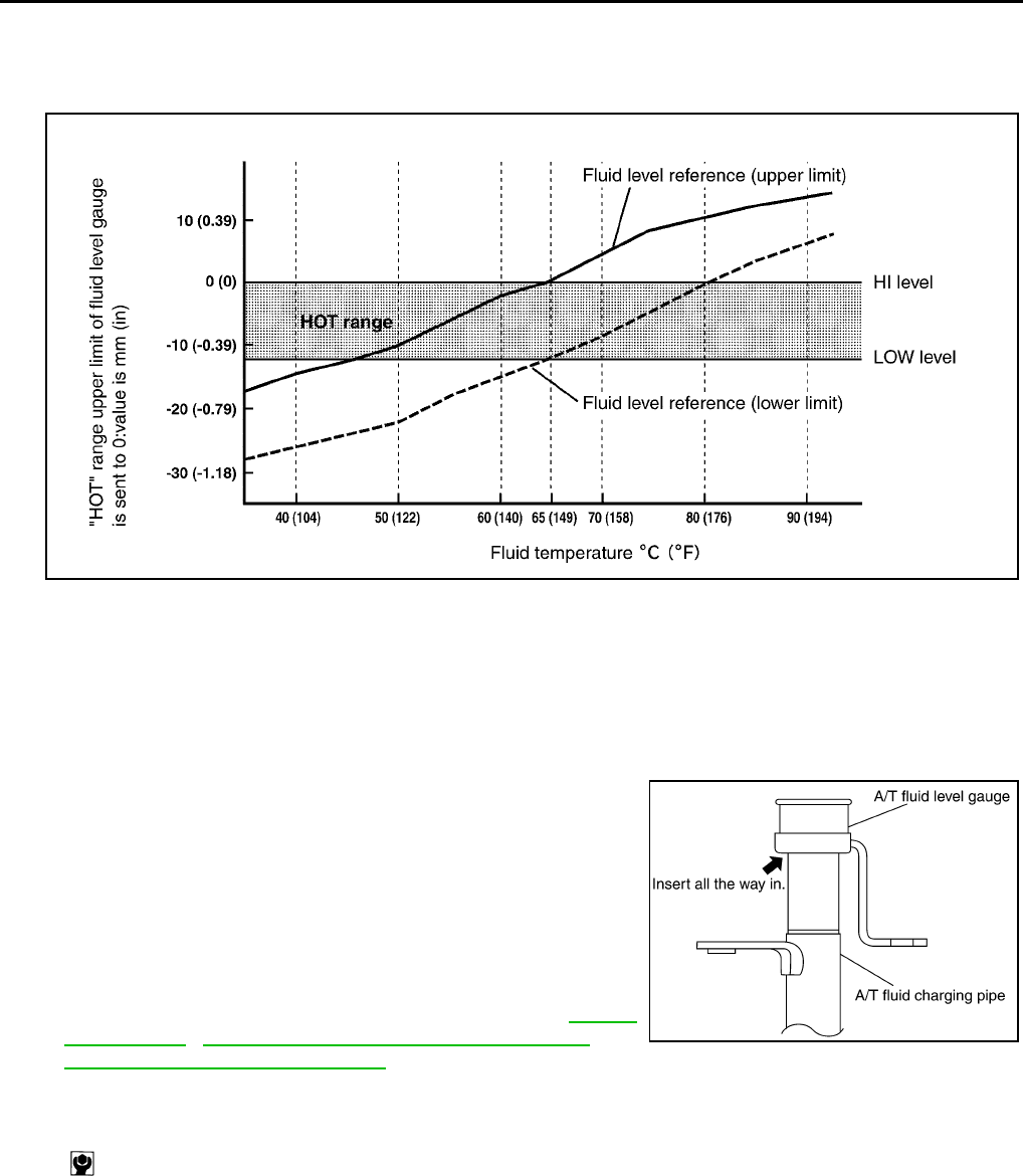
6. Make the fluid temperature approximately 65°C (149°F).
NOTE:
Fluid level will be greatly affected by temperature as shown in figure. Therefore, be certain to per-
form operation while checking data with CONSULT-II.
a. Connect CONSULT-II to data link connector.
b. Select “MAIN SIGNALS” in “DATA MONITOR” mode for “A/T” with CONSULT-II.
c. Read out the value of “ATF TEMP 1”.
7. Re-check fluid level at fluid temperatures of approximately 65°C (149°F) using “HOT” range on A/T fluid
level gauge.
CAUTION:
●When wiping away the fluid level gauge, always use lint-free paper, not a cloth one.
●To check fluid level, insert the A/T fluid level gauge until
the cap contacts the end of the charging pipe, with the
gauge reversed from the normal attachment conditions
as shown.
8. Check fluid condition.
●If fluid is very dark or smells burned, refer to check operation
of A/T. Flush cooling system after repair of A/T.
●If A/T fluid contains frictional material (clutches, bands, etc.),
replace radiator and flush cooler line using cleaning solvent
and compressed air after repair of A/T. Refer to CO-13,
"RADIATOR" , CO-18, "RADIATOR (ALUMINUM TYPE)" and
AT-15, "A/T Fluid Cooler Cleaning" .
9. Install the removed A/T fluid level gauge in the fluid charging pipe.
Level gauge bolt:
: 5.1 N·m (0.52 kg-m, 45 in-lb)
SLIA0016E
SCIA2899E
A/T FLUID
AT-15
D
E
F
G
H
I
J
K
L
M
A
B
AT
A/T Fluid Cooler Cleaning ACS006CU
Whenever an automatic transmission is repaired, overhauled, or replaced, the A/T fluid cooler mounted in the
radiator must be inspected and cleaned.
Metal debris and friction material, if present, can become trapped in the A/T fluid cooler. This debris can con-
taminate the newly serviced A/T or, in severe cases, can block or restrict the flow of A/T fluid. In either case,
malfunction of the newly serviced A/T may result.
Debris, if present, may build up as A/T fluid enters the cooler inlet. It will be necessary to back flush the cooler
through the cooler outlet in order to flush out any built up debris.
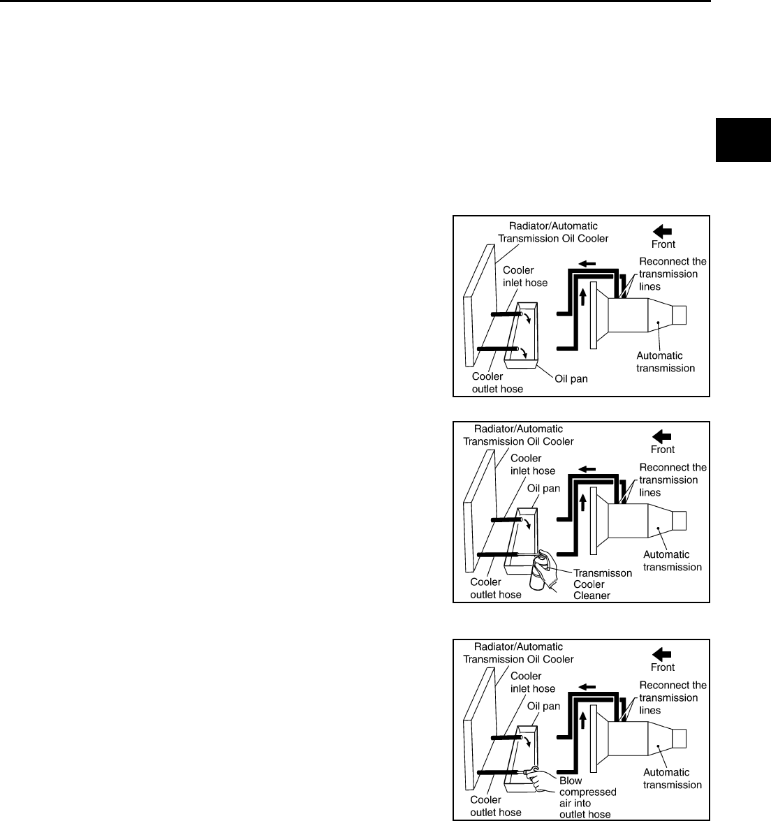
A/T FLUID COOLER CLEANING PROCEDURE
1. Position an oil pan under the automatic transmission's inlet and outlet cooler hoses.
2. Identify the inlet and outlet fluid cooler hoses.
3. Disconnect the fluid cooler inlet and outlet rubber hoses from the
steel cooler tubes or bypass valve.
NOTE:
Replace the cooler hoses if rubber material from the hose
remains on the tube fitting.
4. Allow any A/T fluid that remains in the cooler hoses to drain into
the oil pan.
5. Insert the extension adapter hose of a can of Transmission
Cooler Cleaner (Nissan P/N 999MP-AM006) into the cooler out-
let hose.
CAUTION:
●Wear safety glasses and rubber gloves when spraying
the Transmission Cooler Cleaner.
●Spray cooler cleaner only with adequate ventilation.
●Avoid contact with eyes and skin.
●Do not breath vapors or spray mist.
6. Hold the hose and can as high as possible and spray Transmis-
sion Cooler Cleaner in a continuous stream into the cooler outlet
hose until fluid flows out of the cooler inlet hose for 5 seconds.
7. Insert the tip of an air gun into the end of the cooler outlet hose.
8. Wrap a shop rag around the air gun tip and of the cooler outlet
hose.
9. Blow compressed air regulated to 5 - 9 kg/cm2 (70 - 130 psi) through the cooler outlet hose for 10 sec-
onds to force out any remaining fluid.
10. Repeat steps 5 through 9 three additional times.
11. Position an oil pan under the banjo bolts that connect the fluid cooler steel lines to the transmission.
12. Remove the banjo bolts.
13. Flush each steel line from the cooler side back toward the transmission by spraying Transmission Cooler
Cleaner in a continuous stream for 5 seconds.
SCIA3830E
SCIA3831E
SCIA3832E
AT-16
A/T FLUID
14. Blow compressed air regulated to 5 - 9 kg/cm2 (70 - 130 psi) through each steel line from the cooler side
back toward the transmission for 10 seconds to force out any remaining fluid.
15. Ensure all debris is removed from the steel cooler lines.
16. Ensure all debris is removed from the banjo bolts and fittings.
17. Perform AT-16, "A/T FLUID COOLER DIAGNOSIS PROCEDURE" .
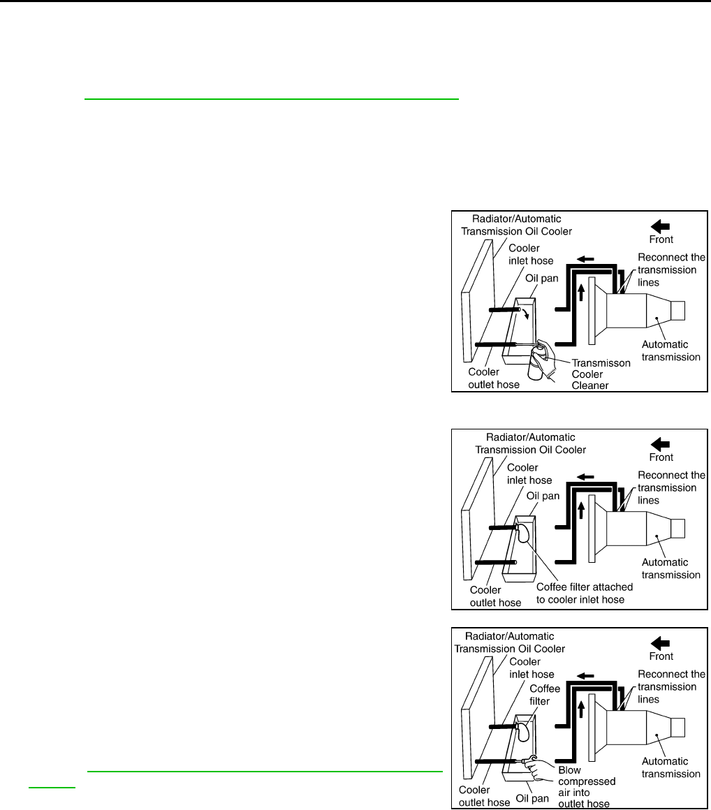
A/T FLUID COOLER DIAGNOSIS PROCEDURE
NOTE:
Insufficient cleaning of the cooler inlet hose exterior may lead to inaccurate debris identification.
1. Position an oil pan under the automatic transmission's inlet and outlet cooler hoses.
2. Clean the exterior and tip of the cooler inlet hose.
3. Insert the extension adapter hose of a can of Transmission
Cooler Cleaner (Nissan P/N 999MP-AM006) into the cooler out-
let hose.
CAUTION:
●Wear safety glasses and rubber gloves when spraying
the Transmission Cooler Cleaner.
● Spray cooler cleaner only with adequate ventilation.
●Avoid contact with eyes and skin.
●Do not breath vapors or spray mist.
4. Hold the hose and can as high as possible and spray Transmis-
sion Cooler Cleaner in a continuous stream into the cooler outlet
hose until fluid flows out of the cooler inlet hose for 5 seconds.
5. Tie a common white, basket-type coffee filter to the end of the
cooler inlet hose.
6. Insert the tip of an air gun into the end of the cooler outlet hose.
7. Wrap a shop rag around the air gun tip and end of cooler outlet
hose.
8. Blow compressed air regulated to 5 - 9 kg/cm2 (70 - 130 psi)
through the cooler outlet hose to force any remaining A/T fluid
into the coffee filter.
9. Remove the coffee filter from the end of the cooler inlet hose.
10. Perform AT-17, "A/T FLUID COOLER INSPECTION PROCE-
DURE" .
SCIA3831E
SCIA3833E
SCIA3834E
A/T FLUID
AT-17
D
E
F
G
H
I
J
K
L
M
A
B
AT
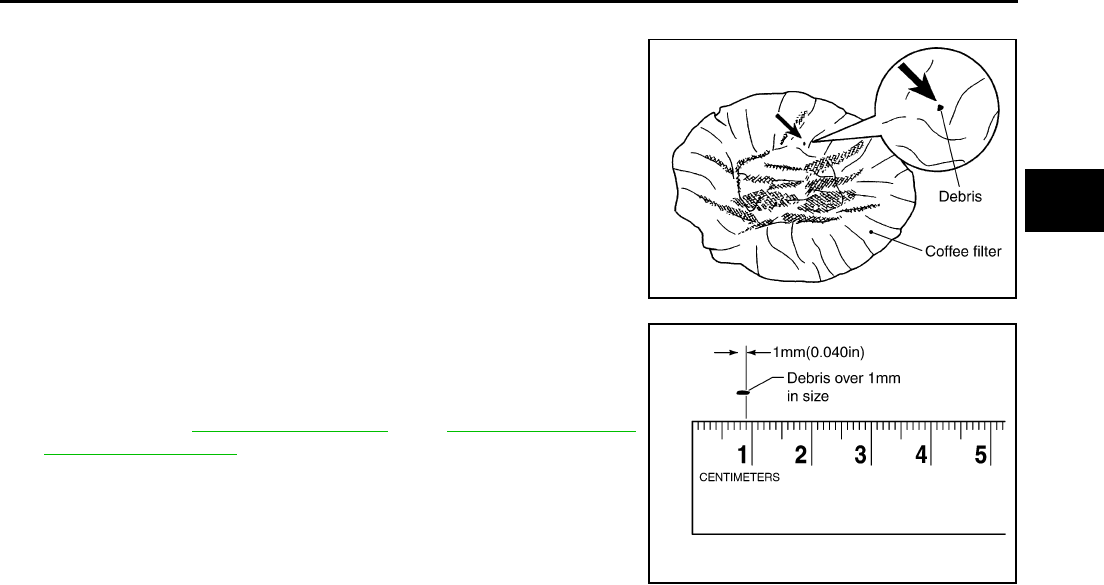
A/T FLUID COOLER INSPECTION PROCEDURE
1. Inspect the coffee filter for debris.
a. If small metal debris less than 1mm (0.040 in) in size or metal
powder is found in the coffee filter, this is normal. If normal
debris is found, the A/T fluid cooler/radiator can be re-used and
the procedure is ended.
b. If one or more pieces of debris are found that are over 1mm
(0.040 in) size and/or peeled clutch facing material is found in
the coffee filter, the fluid cooler is not serviceable. The A/T fluid
cooler/radiator must be replaced and the inspection procedure is
ended.Refer to CO-13, "RADIATOR" and CO-18, "RADIATOR
(ALUMINUM TYPE)" .
A/T FLUID COOLER FINAL INSPECTION
After performing all procedures, ensure that all remaining oil is cleaned from all components.
SCIA2967E
SCIA5257E
AT-18
A/T CONTROL SYSTEM
A/T CONTROL SYSTEM PFP:31036
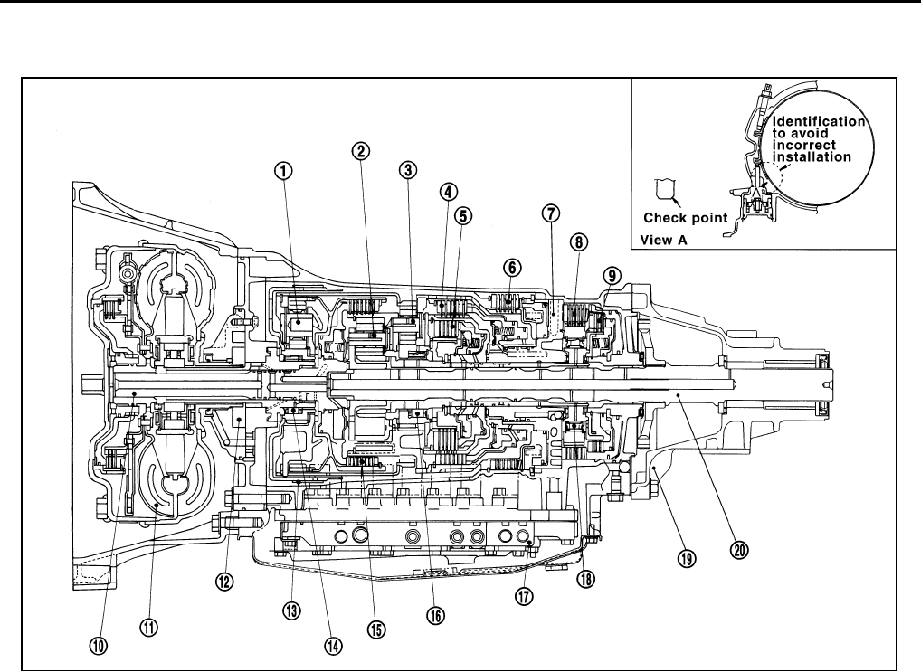
Cross-Sectional View ACS0008B
1. Front planetary gear 2. Mid planetary gear 3. Rear planetary gear
4. Direct clutch 5. High and low reverse clutch 6. Reverse brake
7. Drum support 8. Forward brake 9. Low coast brake
10. Input shaft 11. Torque converter 12. Oil pump
13. Front brake 14. 3rd one-way clutch 15. Input clutch
16. 1st one-way clutch 17. Control valve 18. Forward one-way clutch
19. Rear extension 20. Output shaft
SCIA5262E
A/T CONTROL SYSTEM
AT-19
D
E
F
G
H
I
J
K
L
M
A
B
AT
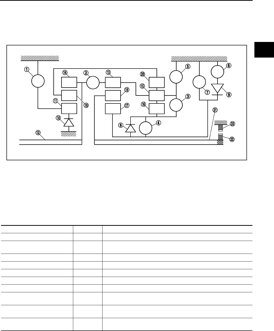
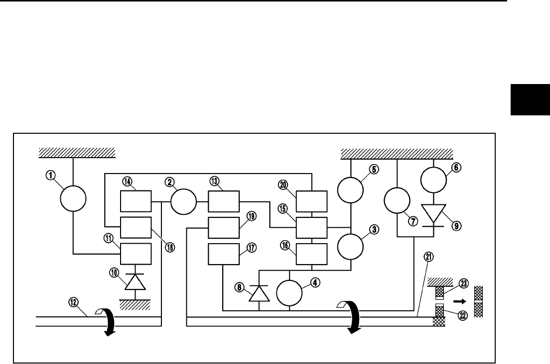
Shift Mechanism ACS0029L
The automatic transmission uses compact dual planetary gear systems to improve power-transmission effi-
ciency, simplify construction and reduce weight.
It also employs an optimum shift control and super wide gear ratios. They improve starting performance and
acceleration during medium and high-speed operation.
CONSTRUCTION
FUNCTION OF CLUTCH AND BRAKE
1. Front brake 2. Input clutch 3. Direct clutch
4. High and low reverse clutch 5. Reverse brake 6. Forward brake
7. Low coast brake 8. 1st one-way clutch 9. Forward one-way clutch
10. 3rd one-way clutch 11. Front sun gear 12. Input shaft
13. Mid internal gear 14. Front internal gear 15. Rear carrier
16. Rear sun gear 17. Mid sun gear 18. Front carrier
19. Mid carrier 20. Rear internal gear 21. Output shaft
22. Parking gear 23. Parking pawl
PCIA0002J
Name of the Part Abbreviation Function
Front brake (1) Fr/B Fastens the front sun gear (11).
Input clutch (2) I/C Connects the input shaft (12), the front internal gear (14) and the mid internal
gear (13).
Direct clutch (3) D/C Connects the rear carrier (15) and the rear sun gear (16).
High and low reverse clutch (4) H&LR/C Connects the mid sun gear (17) and the rear sun gear (16).
Reverse brake (5) R/B Fastens the rear carrier (15).
Forward brake (6) Fwd/B Fastens the mid sun gear (17).
Low coast brake (7) LC/B Fastens the mid sun gear (17).
1st one-way clutch (8) 1st/OWC Allows the rear sun gear (16) to turn freely forward relative to the mid sun gear
(17) but fastens it for reverse rotation.
Forward one-way clutch (9) Fwd/OWC Allows the mid sun gear (17) to turn freely in the forward direction but fastens it
for reverse rotation.
3rd one-way clutch (10) 3rd/OWC Allows the front sun gear (11) to turn freely in the forward direction but fastens
it for reverse rotation.
AT-20
A/T CONTROL SYSTEM
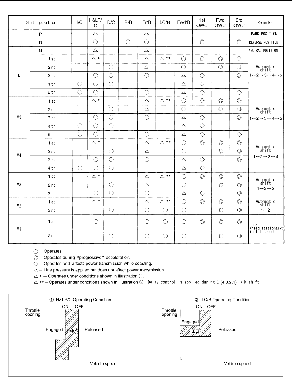
CLUTCH AND BAND CHART
SCIA1524E
A/T CONTROL SYSTEM
AT-21
D
E
F
G
H
I
J
K
L
M
A
B
AT
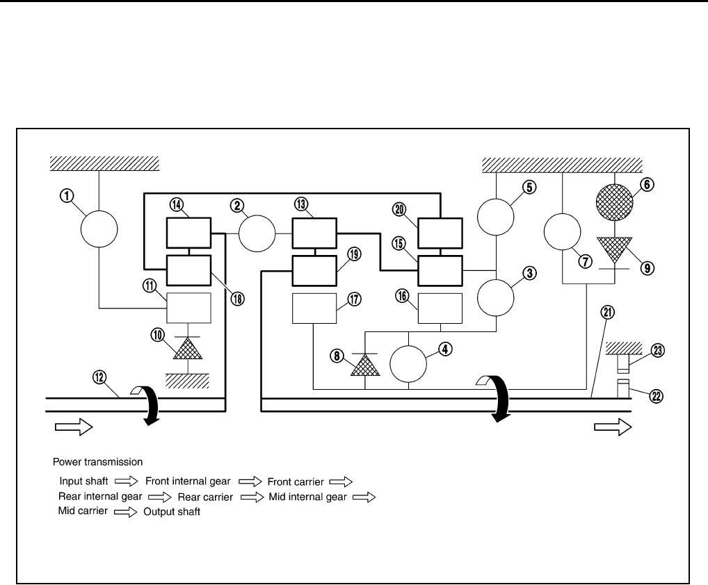
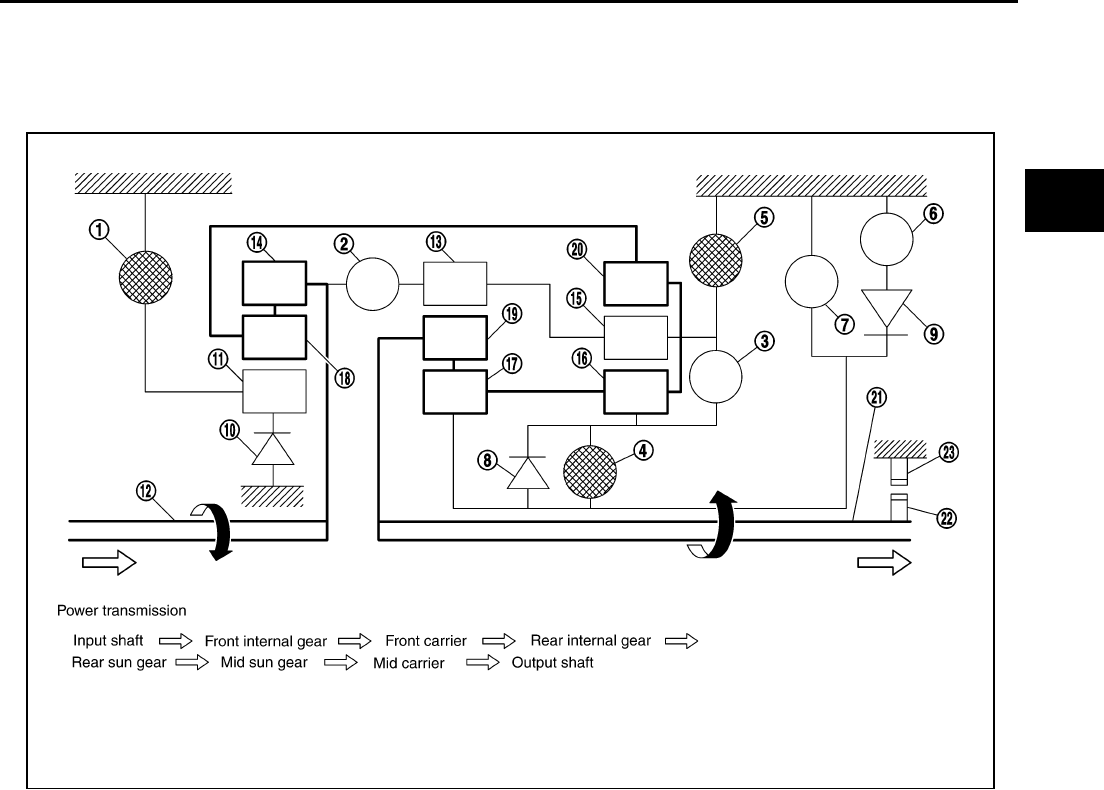
POWER TRANSMISSION
“N” Position
Since both the forward brake and the reverse brake are released, torque from the input shaft drive is not trans-
mitted to the output shaft.
“P” Position
●The same as for the “N” position, both the forward brake and the reverse brake are released, so torque
from the input shaft drive is not transmitted to the output shaft.
●The parking pawl linked with the select lever meshes with the parking gear and fastens the output shaft
mechanically.
1. Front brake 2. Input clutch 3. Direct clutch
4. High and low reverse clutch 5. Reverse brake 6. Forward brake
7. Low coast brake 8. 1st one-way clutch 9. Forward one-way clutch
10. 3rd one-way clutch 11. Front sun gear 12. Input shaft
13. Mid internal gear 14. Front internal gear 15. Rear carrier
16. Rear sun gear 17. Mid sun gear 18. Front carrier
19. Mid carrier 20. Rear internal gear 21. Output shaft
22. Parking gear 23. Parking pawl
PCIA0003J
AT-22
A/T CONTROL SYSTEM
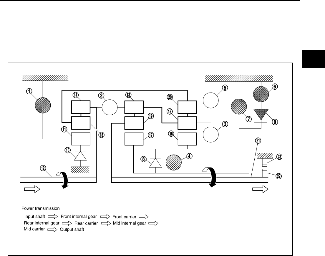
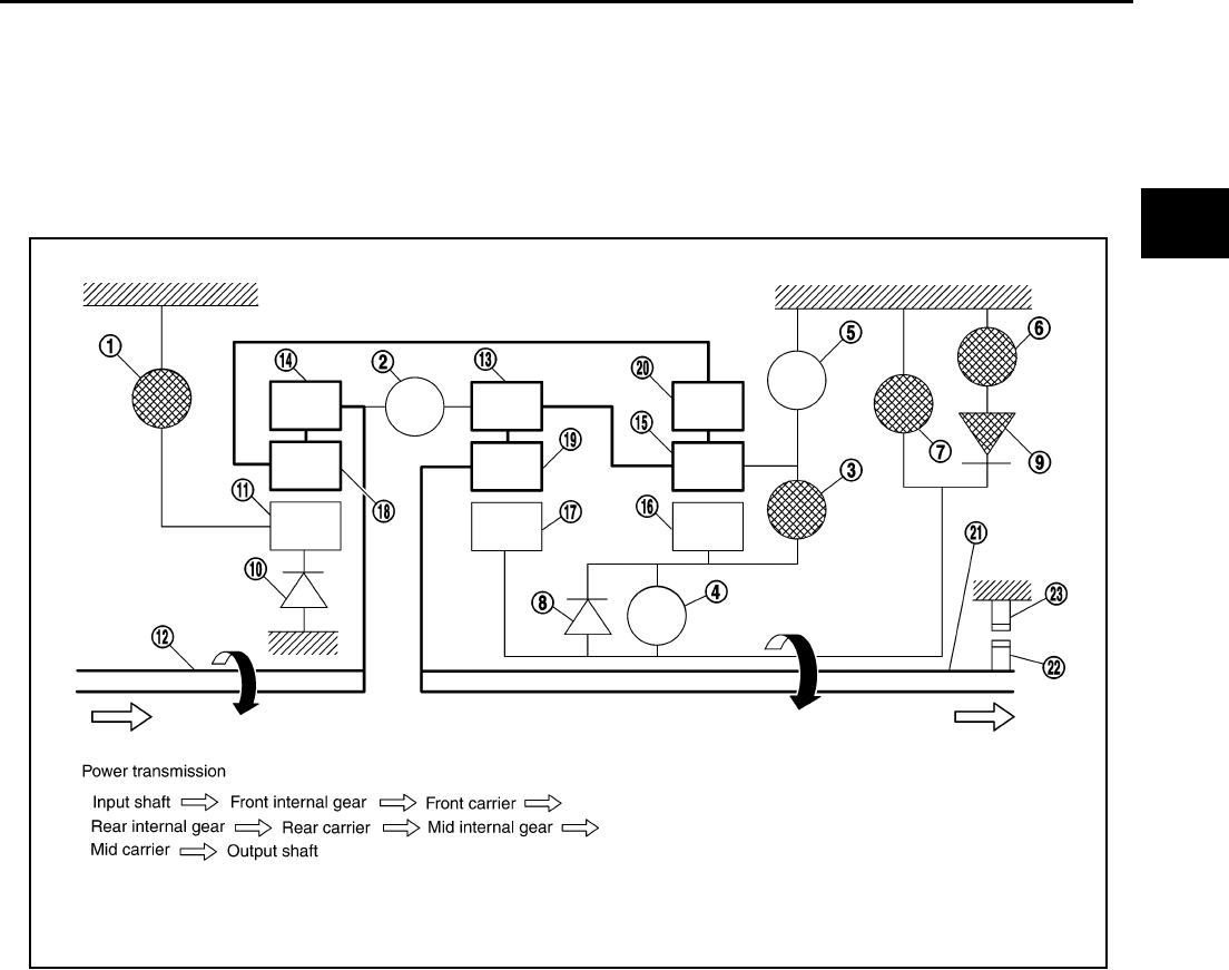
“D”, “M2”, “M3”, “M4”, “M5” Positions 1st Gear
●The forward brake and the forward one-way clutch regulate reverse rotation of the mid sun gear.
●The 1st one-way clutch regulates reverse rotation of the rear sun gear.
●The 3rd one-way clutch regulates reverse rotation of the front sun gear.
●During deceleration, the mid sun gear turns forward, so the forward one-way clutch idles and the engine
brake is not activated.
1. Front brake 2. Input clutch 3. Direct clutch
4. High and low reverse clutch 5. Reverse brake 6. Forward brake
7. Low coast brake 8. 1st one-way clutch 9. Forward one-way clutch
10. 3rd one-way clutch 11. Front sun gear 12. Input shaft
13. Mid internal gear 14. Front internal gear 15. Rear carrier
16. Rear sun gear 17. Mid sun gear 18. Front carrier
19. Mid carrier 20. Rear internal gear 21. Output shaft
22. Parking gear 23. Parking pawl
SCIA1512E
A/T CONTROL SYSTEM
AT-23
D
E
F
G
H
I
J
K
L
M
A
B
AT
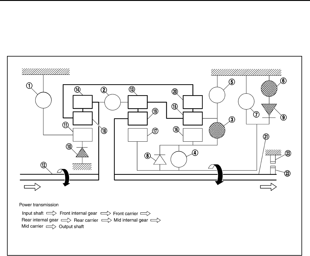
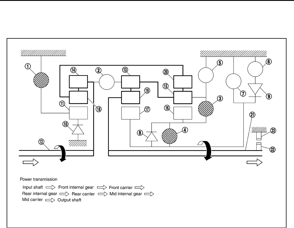
“M1” Position 1st Gear
●The front brake fastens the front sun gear.
●The forward brake and the forward one-way clutch regulate reverse rotation of the mid sun gear.
●High and low reverse clutch connects the rear sun gear and the mid sun gear.
●The low coast brake fastens the mid sun gear.
●During deceleration, the low coast brake regulates forward rotation of the mid sun gear and the engine
brake functions.
1. Front brake 2. Input clutch 3. Direct clutch
4. High and low reverse clutch 5. Reverse brake 6. Forward brake
7. Low coast brake 8. 1st one-way clutch 9. Forward one-way clutch
10. 3rd one-way clutch 11. Front sun gear 12. Input shaft
13. Mid internal gear 14. Front internal gear 15. Rear carrier
16. Rear sun gear 17. Mid sun gear 18. Front carrier
19. Mid carrier 20. Rear internal gear 21. Output shaft
22. Parking gear 23. Parking pawl
SCIA1513E
AT-24
A/T CONTROL SYSTEM
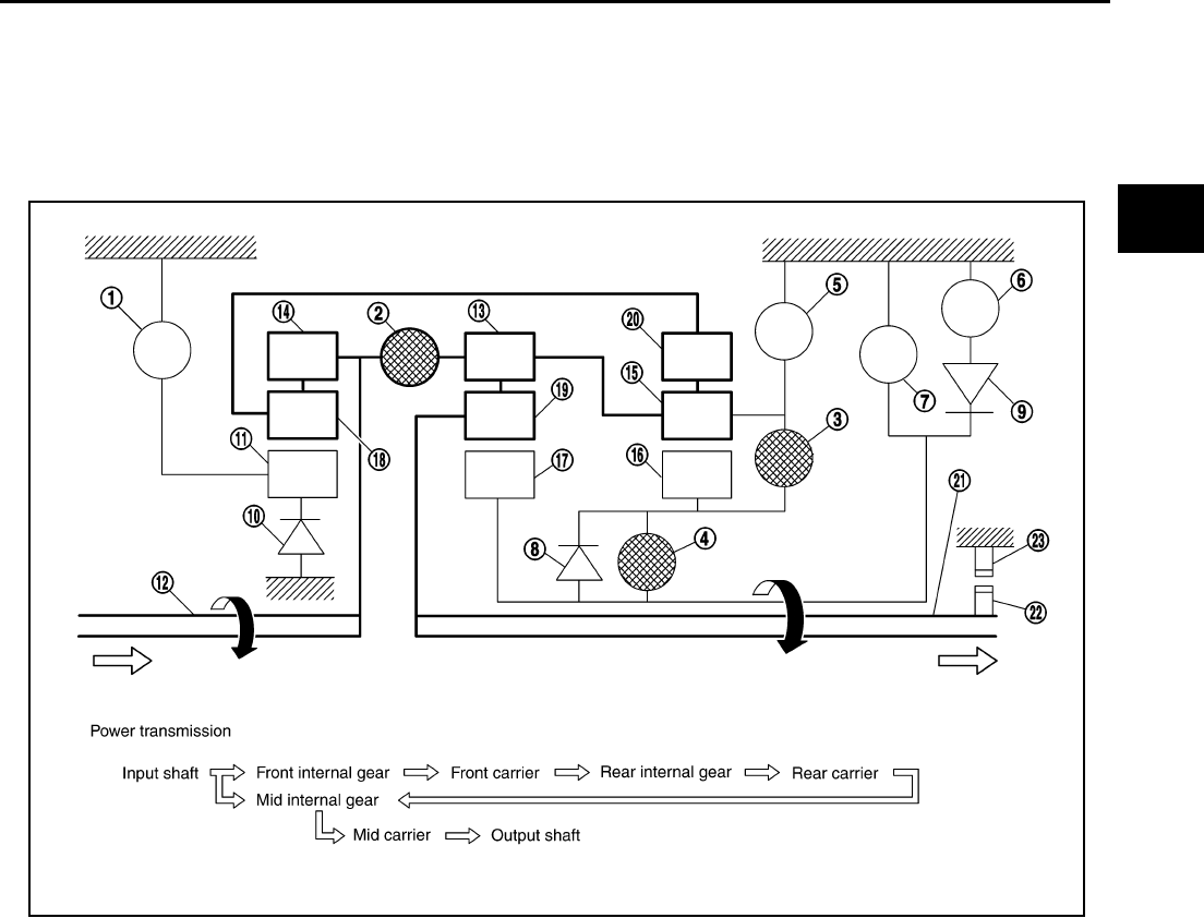
“D”, “M3”, “M4”, “M5” Positions 2nd Gear
●The forward brake and the forward one-way clutch regulate reverse rotation of the mid sun gear.
●The 3rd one-way clutch regulates reverse rotation of the front sun gear.
●The direct clutch is coupled and the rear carrier and rear sun gear are connected.
●During deceleration, the mid sun gear turns forward, so the forward one-way clutch idles and engine
brake is not activated.
1. Front brake 2. Input clutch 3. Direct clutch
4. High and low reverse clutch 5. Reverse brake 6. Forward brake
7. Low coast brake 8. 1st one-way clutch 9. Forward one-way clutch
10. 3rd one-way clutch 11. Front sun gear 12. Input shaft
13. Mid internal gear 14. Front internal gear 15. Rear carrier
16. Rear sun gear 17. Mid sun gear 18. Front carrier
19. Mid carrier 20. Rear internal gear 21. Output shaft
22. Parking gear 23. Parking pawl
SCIA1514E
A/T CONTROL SYSTEM
AT-25
D
E
F
G
H
I
J
K
L
M
A
B
AT
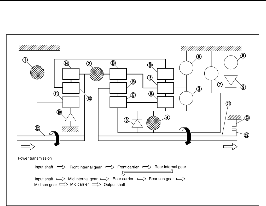
“M1”, “M2” Position 2nd Gear
●The front brake fastens the front sun gear.
●The forward brake and the forward one-way clutch regulate reverse rotation of the mid sun gear.
●The direct clutch is coupled, and the rear carrier and rear sun gear are connected.
●The low coast brake fastens the mid sun gear.
●During deceleration, the low coast brake regulates forward rotation of the mid sun gear and the engine
brake functions.
1. Front brake 2. Input clutch 3. Direct clutch
4. High and low reverse clutch 5. Reverse brake 6. Forward brake
7. Low coast brake 8. 1st one-way clutch 9. Forward one-way clutch
10. 3rd one-way clutch 11. Front sun gear 12. Input shaft
13. Mid internal gear 14. Front internal gear 15. Rear carrier
16. Rear sun gear 17. Mid sun gear 18. Front carrier
19. Mid carrier 20. Rear internal gear 21. Output shaft
22. Parking gear 23. Parking pawl
SCIA1515E
AT-26
A/T CONTROL SYSTEM
“D”, “M3”, “M4”, “M5” Positions 3rd Gear
●The front brake fastens the front sun gear.
●The direct clutch is coupled, and the rear carrier and rear sun gear are connected.
●The high and low reverse clutch is coupled and the mid sun gear and rear sun gear are connected.
1. Front brake 2. Input clutch 3. Direct clutch
4. High and low reverse clutch 5. Reverse brake 6. Forward brake
7. Low coast brake 8. 1st one-way clutch 9. Forward one-way clutch
10. 3rd one-way clutch 11. Front sun gear 12. Input shaft
13. Mid internal gear 14. Front internal gear 15. Rear carrier
16. Rear sun gear 17. Mid sun gear 18. Front carrier
19. Mid carrier 20. Rear internal gear 21. Output shaft
22. Parking gear 23. Parking pawl
SCIA1516E
A/T CONTROL SYSTEM
AT-27
D
E
F
G
H
I
J
K
L
M
A
B
AT
“D”, “M4”, “M5” Positions 4th Gear
●The direct clutch is coupled, and the rear carrier and rear sun gear are connected.
●The high and low reverse clutch is coupled and the mid sun gear and rear sun gear are connected.
●The input clutch is coupled and the front internal gear and mid internal gear are connected.
●The drive power is conveyed to the front internal gear, mid internal gear, and rear carrier and the three
planetary gears rotate forward as one unit.
1. Front brake 2. Input clutch 3. Direct clutch
4. High and low reverse clutch 5. Reverse brake 6. Forward brake
7. Low coast brake 8. 1st one-way clutch 9. Forward one-way clutch
10. 3rd one-way clutch 11. Front sun gear 12. Input shaft
13. Mid internal gear 14. Front internal gear 15. Rear carrier
16. Rear sun gear 17. Mid sun gear 18. Front carrier
19. Mid carrier 20. Rear internal gear 21. Output shaft
22. Parking gear 23. Parking pawl
SCIA1517E
AT-28
A/T CONTROL SYSTEM
“D”, “M5” Positions 5th Gear
●The front brake fastens the front sun gear.
●The input clutch is coupled and the front internal gear and mid internal gear are connected.
●The high and low reverse clutch is coupled and the mid sun gear and rear sun gear are connected.
1. Front brake 2. Input clutch 3. Direct clutch
4. High and low reverse clutch 5. Reverse brake 6. Forward brake
7. Low coast brake 8. 1st one-way clutch 9. Forward one-way clutch
10. 3rd one-way clutch 11. Front sun gear 12. Input shaft
13. Mid internal gear 14. Front internal gear 15. Rear carrier
16. Rear sun gear 17. Mid sun gear 18. Front carrier
19. Mid carrier 20. Rear internal gear 21. Output shaft
22. Parking gear 23. Parking pawl
SCIA1518E
A/T CONTROL SYSTEM
AT-29
D
E
F
G
H
I
J
K
L
M
A
B
AT
“R” Position
●The front brake fastens the front sun gear.
●The high and low reverse clutch is coupled and the mid sun gear and rear sun gear are connected.
●The reverse brake fastens the rear carrier.
1. Front brake 2. Input clutch 3. Direct clutch
4. High and low reverse clutch 5. Reverse brake 6. Forward brake
7. Low coast brake 8. 1st one-way clutch 9. Forward one-way clutch
10. 3rd one-way clutch 11. Front sun gear 12. Input shaft
13. Mid internal gear 14. Front internal gear 15. Rear carrier
16. Rear sun gear 17. Mid sun gear 18. Front carrier
19. Mid carrier 20. Rear internal gear 21. Output shaft
22. Parking gear 23. Parking pawl
SCIA1519E
AT-30
A/T CONTROL SYSTEM
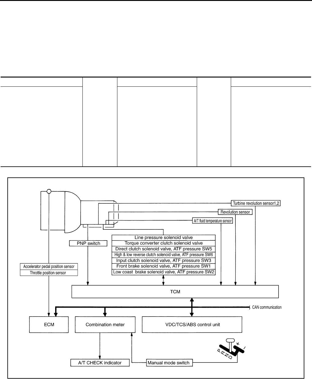
TCM Function ACS0008E
The function of the TCM is to:
●Receive input signals sent from various switches and sensors.
●Determine required line pressure, shifting point, lock-up operation, and engine brake operation.
●Send required output signals to the respective solenoids.
CONTROL SYSTEM OUTLINE
The automatic transmission senses vehicle operating conditions through various sensors or signals. It always
controls the optimum shift position and reduces shifting and lock-up shocks.
CONTROL SYSTEM DIAGRAM
SENSORS
Þ
TCM
Þ
ACTUATORS
PNP switch
Throttle position sensor
Accelerator pedal position sensor
Closed throttle position signal
Wide-open throttle position signal
Engine speed signal
A/T fluid temperature sensor
Revolution sensor
Vehicle speed signal
Manual mode switch
Brake switch signal
Turbine revolution sensor
Shift control
Line pressure control
Lock-up control
Engine brake control
Timing control
Fail-safe control
Self-diagnosis
CONSULT-II communication line
Duet-EA control
CAN system
Input clutch solenoid valve
Direct clutch solenoid valve
Front brake solenoid valve
High and low reverse clutch
solenoid valve
Low coast brake solenoid valve
Torque converter clutch solenoid
valve
Line pressure solenoid valve
A/T CHECK indicator lamp
SCIA5192E
A/T CONTROL SYSTEM
AT-31
D
E
F
G
H
I
J
K
L
M
A
B
AT
CAN Communication ACS0008F
SYSTEM DESCRIPTION
CAN (Controller Area Network) is a serial communication line for real time application. It is an on-vehicle mul-
tiplex communication line with high data communication speed and excellent error detection ability. Many elec-
tronic control units are equipped onto a vehicle, and each control unit shares information and links with other
control units during operation (not independent). In CAN communication, control units are connected with 2
communication lines (CAN H line, CAN L line) allowing a high rate of information transmission with less wiring.
Each control unit transmits/receives data but selectively reads required data only.
For details, refer to LAN-4, "CAN Communication Unit" .
Input/Output Signal of TCM ACS000GO
*1: Spare for vehicle speed sensor·A/T (revolution sensor)
*2: Spare for accelerator pedal position signal
*3: If these input and output signals are different, the TCM triggers the fail-safe function.
*4: Used as a condition for starting self-diagnostics; if self-diagnostics are not started, it is judged that there is some kind of error.
*5: Input by CAN communications.
*6: Output by CAN communications.
Control item
Line
pressure
control
Vehicle
speed
control
Shift
control
Lock-up
control
Engine
brake
control
Fail-safe
function
(*3)
Self-diag-
nostics
function
Input
Accelerator pedal position signal (*5) XXXXXXX
Vehicle speed sensor A/T
(revolution sensor) XXXX XX
Vehicle speed sensor MTR(*1) (*5) XXXX X
Closed throttle position signal(*5) (*2) X (*2) X (*2) X (*4) X
Wide-open throttle position sig-
nal(*5) (*2) X (*2) X (*4) X
Turbine revolution sensor 1 X X X X
Turbine revolution sensor 2
(for 4th speed only) XX XX
Engine speed signals(*5) XX
PNP switch XXXXXX(*4) X
Brake switch signal(*5) XX(*4) X
A/T fluid temperature sensors 1, 2 X X X X X X
ASCD
Cruise signal(*5) XXXX
Overdrive
release signal(*5) XXX
TCM power supply voltage signal XXXXXXX
Out-
put
Direct clutch solenoid
(ATF pressure switch 5) XX XX
Input clutch solenoid
(ATF pressure switch 3) XX XX
High & low reverse clutch solenoid
(ATF pressure switch 6) XX XX
Front brake solenoid
(ATF pressure switch 1) XX XX
Low coast brake solenoid
(ATF pressure switch 2) XX XXX
Line pressure solenoid XXXXXXX
TCC solenoid X X X
Self-diagnostics table(*6) X
AT-32
A/T CONTROL SYSTEM
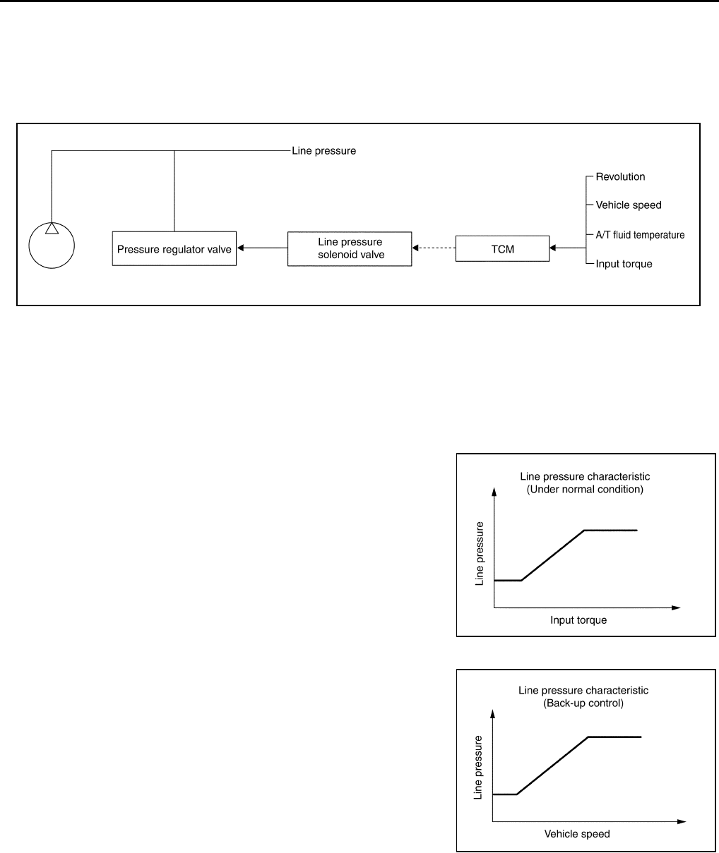
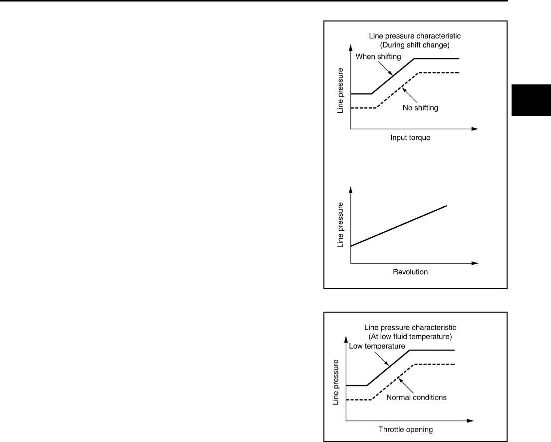
Line Pressure Control ACS0008G
●When an input torque signal equivalent to the engine drive force is sent from the ECM to the TCM, the
TCM controls the line pressure solenoid.
●This line pressure solenoid controls the pressure regulator valve as the signal pressure and adjusts the
pressure of the operating oil discharged from the oil pump to the line pressure most appropriate to the
driving state.
LINE PRESSURE CONTROL IS BASED ON THE TCM LINE PRESSURE CHARACTERISTIC
PATTERN
●The TCM has stored in memory a number of patterns for the optimum line pressure characteristic for the
driving state.
●In order to obtain the most appropriate line pressure characteristic to meet the current driving state, the
TCM controls the line pressure solenoid current valve and thus controls the line pressure.
Normal Control
Each clutch is adjusted to the necessary pressure to match the
engine drive force.
Back-up Control (Engine Brake)
When the select operation is executed during driving and the trans-
mission is shifted down, the line pressure is set according to the
vehicle speed.
PCIA0007E
PCIA0008E
PCIA0009E
A/T CONTROL SYSTEM
AT-33
D
E
F
G
H
I
J
K
L
M
A
B
AT
During Shift Change
The necessary and adequate line pressure for shift change is set.
For this reason, line pressure pattern setting corresponds to input
torque and gearshift selection. Also, line pressure characteristic is
according to engine speed, during engine brake operation.
At Low Fluid Temperature
When the A/T fluid temperature drops below the prescribed tempera-
ture, in order to speed up the action of each friction element, the line
pressure is set higher than the normal line pressure characteristic.
PCIA0010E
PCIA0011E
AT-34
A/T CONTROL SYSTEM
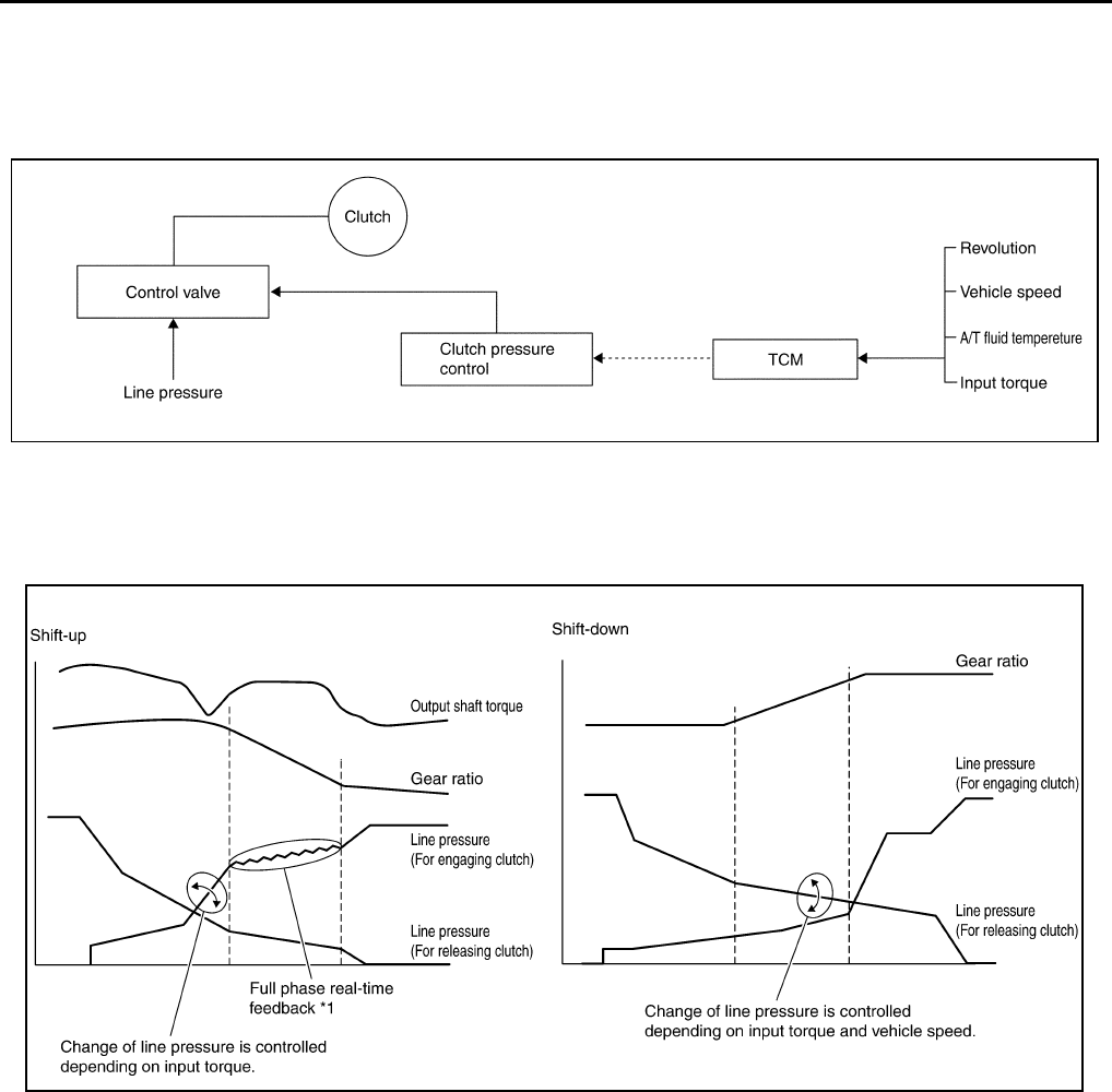
Shift Control ACS0008H
The clutch pressure control solenoid is controlled by the signals from the switches and sensors. Thus, the
clutch pressure is adjusted to be appropriate to the engine load state and vehicle driving state. It becomes
possible to finely control the clutch hydraulic pressure with high precision and a smoother shift change charac-
teristic is attained.
SHIFT CHANGE
The clutch is controlled with the optimum timing and oil pressure by the engine speed, engine torque informa-
tion, etc.
Shift Change System Diagram
*1: Full phase real-time feedback control monitors movement of gear ratio at gear change, and controls oil
pressure at real-time to achieve the best gear ratio.
Lock-Up Control ACS0008I
The torque converter clutch piston in the torque converter is engaged to eliminate torque converter slip to
increase power transmission efficiency.
The torque converter clutch control valve operation is controlled by the torque converter clutch solenoid valve,
which is controlled by a signal from TCM, and the torque converter clutch control valve engages or releases
the torque converter clutch piston.
PCIA0012E
PCIA0013E
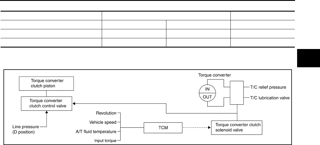
A/T CONTROL SYSTEM
AT-35
D
E
F
G
H
I
J
K
L
M
A
B
AT
Lock-up Operation Condition Table
TORQUE CONVERTER CLUTCH CONTROL VALVE CONTROL
Lock-up Control System Diagram
Lock-up Released
●In the lock-up released state, the torque converter clutch control valve is set into the unlocked state by the
torque converter clutch solenoid and the lock-up apply pressure is drained.
In this way, the torque converter clutch piston is not coupled.
Lock-up Applied
●In the lock-up applied state, the torque converter clutch control valve is set into the locked state by the
torque converter clutch solenoid and lock-up apply pressure is generated.
In this way, the torque converter clutch piston is pressed and coupled.
SMOOTH LOCK-UP CONTROL
When shifting from the lock-up released state to the lock-up applied state, the current output to the torque con-
verter clutch solenoid is controlled with the TCM. In this way, when shifting to the lock-up applied state, the
torque converter clutch is temporarily set to the half-clutched state to reduce the shock.
Half-clutched State
●The current output from the TCM to the torque converter clutch solenoid is varied to steadily increase the
torque converter clutch solenoid pressure.
In this way, the lock-up apply pressure gradually rises and while the torque converter clutch piston is put
into half-clutched status, the torque converter clutch piston operating pressure is increased and the cou-
pling is completed smoothly.
Slip Lock-up Control
●In the slip region, the torque converter clutch solenoid current is controlled with the TCM to put it into the
half-clutched state. This absorbs the engine torque fluctuation and lock-up operates from low speed.
This raises the fuel efficiency for 4th and 5th gear at both low speed and when the accelerator has a low
degree of opening.
Select lever D position, M5 position M4 position
Gear position 5 4 4
Lock-up ×–×
Slip lock-up ××–
PCIA0014E
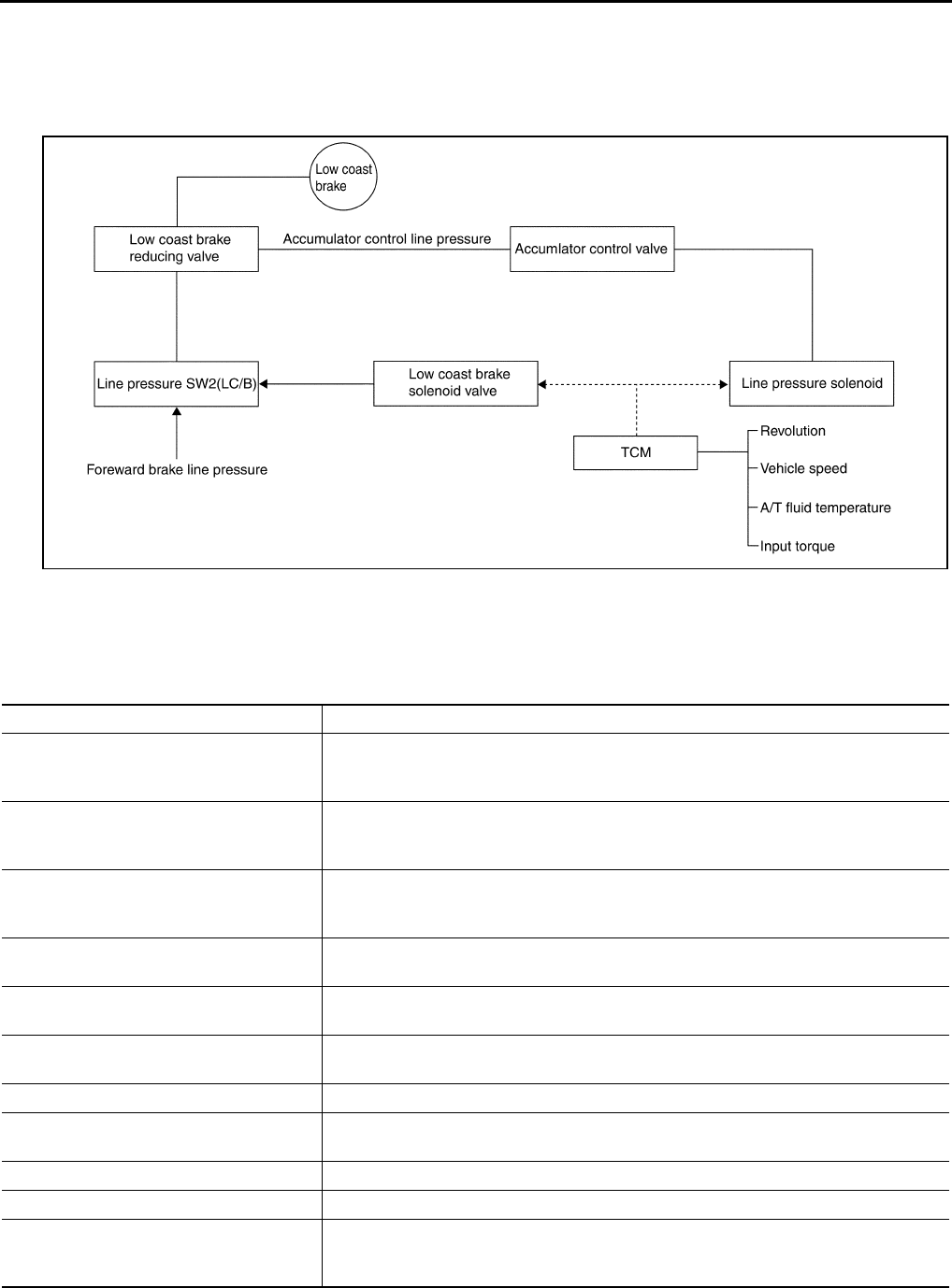
AT-36
A/T CONTROL SYSTEM
Engine Brake Control ACS0008J
●The forward one-way clutch transmits the drive force from the engine to the rear wheels. But the reverse
drive from the rear wheels is not transmitted to the engine because the one-way clutch is idling.
Therefore, the low coast brake solenoid is operated to prevent the forward one-way clutch from idling and
the engine brake is operated in the same manner as conventionally.
●The operation of the low coast brake solenoid switches the low coast brake switching valve and controls
the coupling and releasing of the low coast brake.
The low coast brake reducing valve controls the low coast brake coupling force.
Control Valve ACS0008K
FUNCTION OF CONTROL VALVE
PCIA0015E
Name Function
Torque converter regulator valve
In order to prevent the pressure supplied to the torque converter from being excessive,
the line pressure is adjusted to the optimum pressure (torque converter operating pres-
sure).
Pressure regulator valve
Pressure regulator plug
Pressure regulator sleeve
Adjusts the oil discharged from the oil pump to the optimum pressure (line pressure) for
the driving state.
Front brake control valve
When the front brake is coupled, adjusts the line pressure to the optimum pressure
(front brake pressure) and supplies it to the front brake. (In 1st, 2nd, 3rd, and 5th gears,
adjusts the clutch pressure.)
Accumulator control valve Adjusts the pressure (accumulator control pressure) acting on the accumulator piston
and low coast reducing valve to the pressure appropriate to the driving state.
Pilot valve A Adjusts the line pressure and produces the constant pressure (pilot pressure) required
for line pressure control, shift change control, and lock-up control.
Pilot valve B Adjusts the line pressure and produces the constant pressure (pilot pressure) required
for shift change control.
Low coast brake switching valve During engine braking, supplies the line pressure to the low coast brake reducing valve.
Low coast brake reducing valve When the low coast brake is coupled, adjusts the line pressure to the optimum pressure
(low coast brake pressure) and supplies it to the low coast brake.
N-R accumulator Produces the stabilizing pressure for when N-R is selected.
Direct clutch piston switching valve Operates in 4th gear and switches the direct clutch coupling capacity.
High and low reverse clutch control valve
When the high and low reverse clutch is coupled, adjusts the line pressure to the opti-
mum pressure (high and low reverse clutch pressure) and supplies it to the high and low
reverse clutch. (In 1st, 3rd, 4th and 5th gears, adjusts the clutch pressure.)

A/T CONTROL SYSTEM
AT-37
D
E
F
G
H
I
J
K
L
M
A
B
AT
FUNCTION OF PRESSURE SWITCH
Input clutch control valve
When the input clutch is coupled, adjusts the line pressure to the optimum pressure
(input clutch pressure) and supplies it to the input clutch. (In 4th and 5th gears, adjusts
the clutch pressure.)
Direct clutch control valve
When the direct clutch is coupled, adjusts the line pressure to the optimum pressure
(direct clutch pressure) and supplies it to the direct clutch. (In 2nd, 3rd, and 4th gears,
adjusts the clutch pressure.)
TCC control valve
TCC control plug
TCC control sleeve
Switches the lock-up to operating or released. Also, by executing the lock-up operation
transiently, lock-up smoothly.
Torque converter lubrication valve Operates during lock-up to switch the torque converter, cooling, and lubrication system
oil path.
Cool bypass valve Allows excess oil to bypass cooler circuit without being fed into it.
Line pressure relief valve Discharges excess oil from line pressure circuit.
N-D accumulator Produces the stabilizing pressure for when N-D is selected.
Manual valve Sends line pressure to each circuit according to the select position. The circuits to which
the line pressure is not sent drain.
Name Function
Name Function
Pressure switch 1 (Fr/B) Detects any malfunction in the front brake hydraulic pressure. When it detects any mal-
function, it puts the system into fail-safe mode.
Pressure switch 2 (LC/B) Detects any malfunction in the low coast brake hydraulic pressure. When it detects any
malfunction, it puts the system into fail-safe mode.
Pressure switch 3 (I/C) Detects any malfunction in the input clutch hydraulic pressure. When it detects any mal-
function, it puts the system into fail-safe mode.
Pressure switch 5 (D/C) Detects any malfunction in the direct clutch hydraulic pressure. When it detects any mal-
function, it puts the system into fail-safe mode.
Pressure switch 6 (H&LR/C) Detects any malfunction in the high and low reverse clutch hydraulic pressure. When it
detects any malfunction, it puts the system into fail-safe mode.

AT-38
ON BOARD DIAGNOSTIC (OBD) SYSTEM
ON BOARD DIAGNOSTIC (OBD) SYSTEM PFP:00028
Introduction ACS0008L
The A/T system has two self-diagnostic systems.
The first is the emission-related on board diagnostic system (OBD-II) performed by the TCM in combination
with the ECM. The malfunction is indicated by the MIL (malfunction indicator lamp) and is stored as a DTC in
the ECM memory but not the TCM memory.
The second is the TCM original self-diagnosis indicated by the A/T CHECK indicator lamp. The malfunction is
stored in the TCM memory. The detected items are overlapped with OBD-II self-diagnostic items. For detail,
refer to AT-93, "SELF-DIAGNOSTIC RESULT MODE" .
OBD-II Function for A/T System ACS0008M
The ECM provides emission-related on board diagnostic (OBD-II) functions for the A/T system. One function
is to receive a signal from the TCM used with OBD-related parts of the A/T system. The signal is sent to the
ECM when a malfunction occurs in the corresponding OBD-related part. The other function is to indicate a
diagnostic result by means of the MIL (malfunction indicator lamp) on the instrument panel. Sensors, switches
and solenoid valves are used as sensing elements.
The MIL automatically illuminates in One or Two Trip Detection Logic when a malfunction is sensed in relation
to A/T system parts.
One or Two Trip Detection Logic of OBD-II ACS0008N
ONE TRIP DETECTION LOGIC
If a malfunction is sensed during the first test drive, the MIL will illuminate and the malfunction will be stored in
the ECM memory as a DTC. The TCM is not provided with such a memory function.
TWO TRIP DETECTION LOGIC
When a malfunction is sensed during the first test drive, it is stored in the ECM memory as a 1st trip DTC
(diagnostic trouble code) or 1st trip freeze frame data. At this point, the MIL will not illuminate. — First Trip
If the same malfunction as that experienced during the first test drive is sensed during the second test drive,
the MIL will illuminate. — Second Trip
The “trip” in the “One or Two Trip Detection Logic” means a driving mode in which self-diagnosis is performed
during vehicle operation.
OBD-II Diagnostic Trouble Code (DTC) ACS004ZB
HOW TO READ DTC AND 1ST TRIP DTC
DTC and 1st trip DTC can be read by the following methods.
( with CONSULT-II or GST) CONSULT-II or GST (Generic Scan Tool) Examples: P0705, P0720 etc.
These DTC are prescribed by SAE J2012.
(CONSULT-II also displays the malfunctioning component or system.)
●1st trip DTC No. is the same as DTC No.
●Output of the diagnostic trouble code indicates that the indicated circuit has a malfunction. How-
ever, in case of the Mode II and GST, they do not indicate whether the malfunction is still occurring
or occurred in the past and returned to normal.
CONSULT-II can identify them as shown below, therefore, CONSULT-II (if available) is recom-
mended.
A sample of CONSULT-II display for DTC and 1st trip DTC is shown
on the next page. DTC or 1st trip DTC of a malfunction is displayed
in SELF-DIAGNOSTIC RESULTS mode for “ENGINE” with CON-
SULT-II. Time data indicates how many times the vehicle was driven
after the last detection of a DTC.
SAT014K
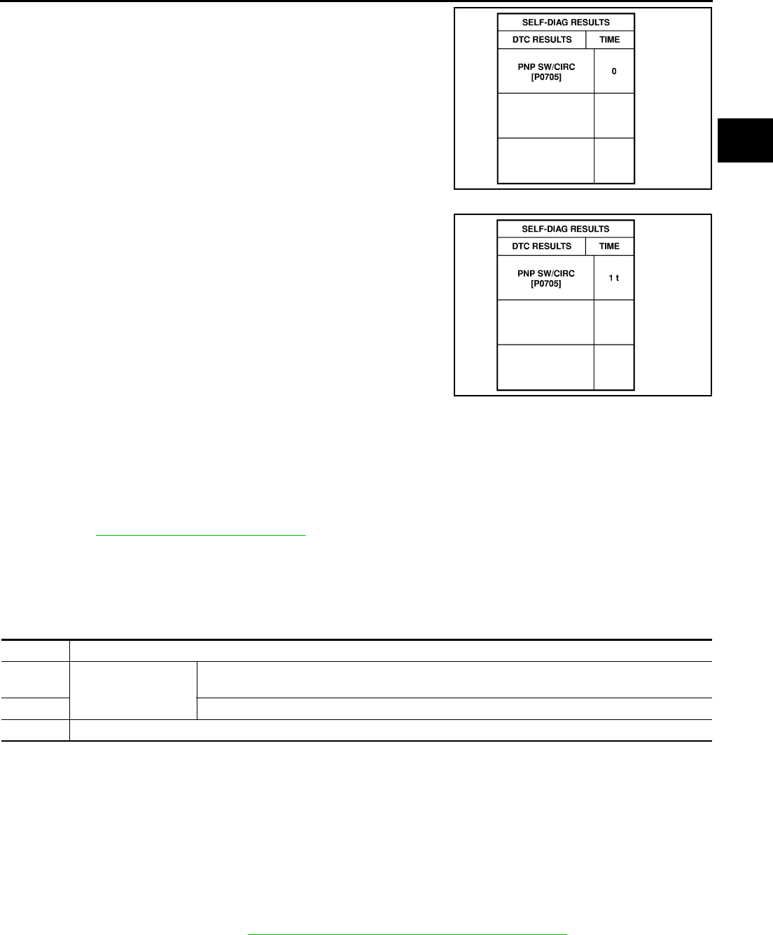
ON BOARD DIAGNOSTIC (OBD) SYSTEM
AT-39
D
E
F
G
H
I
J
K
L
M
A
B
AT
If the DTC is being detected currently, the time data will be “0”.
If a 1st trip DTC is stored in the ECM, the time data will be “1t”.
Freeze Frame Data and 1st Trip Freeze Frame Data
The ECM has a memory function, which stores the driving condition such as fuel system status, calculated
load value, engine coolant temperature, short term fuel trim, long term fuel trim, engine speed and vehicle
speed at the moment the ECM detects a malfunction.
Data which are stored in the ECM memory, along with the 1st trip DTC, are called 1st trip freeze frame data,
and the data, stored together with the DTC data, are called freeze frame data and displayed on CONSULT-II
or GST. The 1st trip freeze frame data can only be displayed on the CONSULT-II screen, not on the GST. For
detail, refer to EC-105, "CONSULT-II Function" .
Only one set of freeze frame data (either 1st trip freeze frame data of freeze frame data) can be stored in the
ECM. 1st trip freeze frame data is stored in the ECM memory along with the 1st trip DTC. There is no priority
for 1st trip freeze frame data and it is updated each time a different 1st trip DTC is detected. However, once
freeze frame data (2nd trip detection/MIL on) is stored in the ECM memory, 1st trip freeze frame data is no
longer stored. Remember, only one set of freeze frame data can be stored in the ECM. The ECM has the fol-
lowing priorities to update the data.
Both 1st trip freeze frame data and freeze frame data (along with the DTC) are cleared when the ECM mem-
ory is erased.
HOW TO ERASE DTC
The diagnostic trouble code can be erased by CONSULT-II, GST or ECM DIAGNOSTIC TEST MODE as
described following.
●If the battery cable is disconnected, the diagnostic trouble code will be lost within 24 hours.
●When you erase the DTC, using CONSULT-II or GST is easier and quicker than switching the mode
selector on the ECM.
The following emission-related diagnostic information is cleared from the ECM memory when erasing DTC
related to OBD-II. For details, refer to EC-47, "Emission-related Diagnostic Information" .
●Diagnostic trouble codes (DTC)
●1st trip diagnostic trouble codes (1st trip DTC)
●Freeze frame data
SAT015K
SAT016K
Priority Items
1Freeze frame data
Misfire — DTC: P0300 - P0306
Fuel Injection System Function — DTC: P0171, P0172, P0174, P0175
2 Except the above items (Includes A/T related items)
3 1st trip freeze frame data
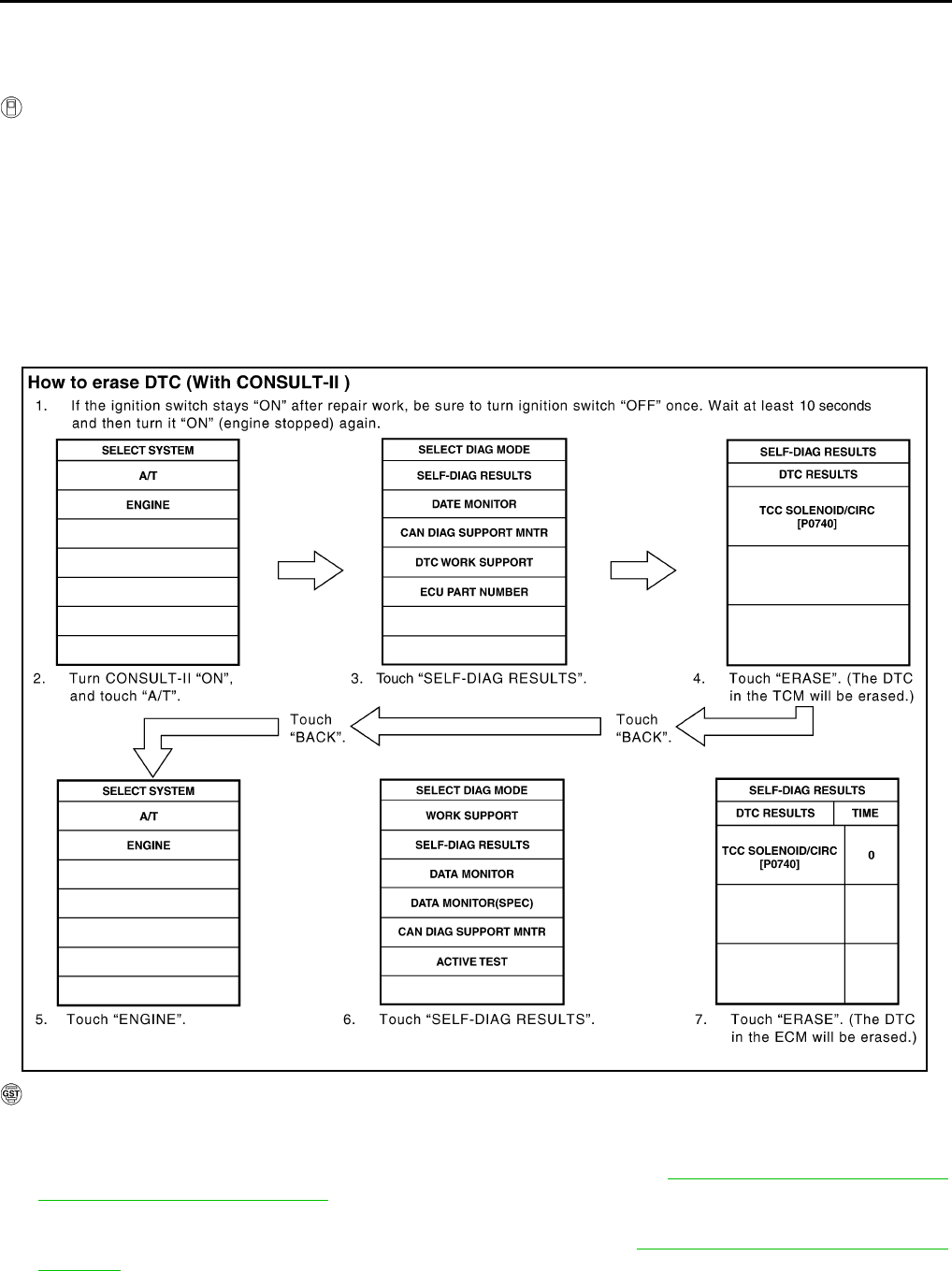
AT-40
ON BOARD DIAGNOSTIC (OBD) SYSTEM
●1st trip freeze frame data
●System readiness test (SRT) codes
●Test values
HOW TO ERASE DTC (WITH CONSULT-II)
●If a DTC is displayed for both ECM and TCM, it is necessary to be erased for both ECM and TCM.
1. If the ignition switch stays “ON” after repair work, be sure to turn ignition switch “OFF” once. Wait at least
10 seconds and then turn it “ON” (engine stopped) again.
2. Turn CONSULT-II “ON” and touch “A/T”.
3. Touch “SELF-DIAG RESULTS”.
4. Touch “ERASE”. (The DTC in the TCM will be erased.) Then touch “BACK” twice.
5. Touch “ENGINE”.
6. Touch “SELF-DIAG RESULTS”.
7. Touch “ERASE”. (The DTC in the ECM will be erased.)
HOW TO ERASE DTC (WITH GST)
1. If the ignition switch stays “ON” after repair work, be sure to turn ignition switch “OFF” once. Wait at least
10 seconds and then turn it “ON” (engine stopped) again.
2. Perform “TCM SELF-DIAGNOSTIC PROCEDURE (No Tools)”. Refer to AT-103, "TCM SELF-DIAGNOS-
TIC PROCEDURE (NO TOOLS)" . (The engine warm-up step can be skipped when performing the diag-
nosis only to erase the DTC.)
3. Select Mode 4 with Generic Scan Tool (GST). For details, refer to EC-117, "Generic Scan Tool (GST)
Function" .
SCIA5334E
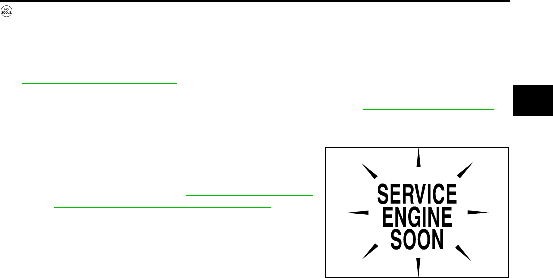
ON BOARD DIAGNOSTIC (OBD) SYSTEM
AT-41
D
E
F
G
H
I
J
K
L
M
A
B
AT
HOW TO ERASE DTC (NO TOOLS)
The A/T CHECK indicator lamp is located on the instrument panel.
1. If the ignition switch stays “ON” after repair work, be sure to turn ignition switch “OFF” once. Wait at least
10 seconds and then turn it “ON” (engine stopped) again.
2. Perform “TCM SELF-DIAGNOSTIC PROCEDURE (No Tools)”. Refer toAT-103, "TCM SELF-DIAGNOS-
TIC PROCEDURE (NO TOOLS)" . (The engine warm-up step can be skipped when performing the diag-
nosis only to erase the DTC.)
3. Perform “OBD-II SELF-DIAGNOSTIC PROCEDURE (No tools)”. Refer to EC-60, "How to Erase DTC" .
Malfunction Indicator Lamp (MIL) ACS0008P
DESCRIPTION
The MIL is located on the instrument panel.
1. The MIL will light up when the ignition switch is turned “ON” with-
out the engine running. This is a bulb check.
●If the MIL does not light up, refer to DI-25, "WARNING LAMPS" ,
or see EC-632, "MIL AND DATA LINK CONNECTOR" .
2. When the engine is started, the MIL should go off.
If the MIL remains on, the on board diagnostic system has
detected an engine system malfunction.
SEF217U

AT-42
TROUBLE DIAGNOSIS
TROUBLE DIAGNOSIS PFP:00004
DTC Inspection Priority Chart ACS0008Q
If some DTCs are displayed at the same time, perform inspections one by one based on the following priority
chart.
NOTE:
If DTC U1000 is displayed with other DTCs, first perform the trouble diagnosis for DTC U1000. Refer to
AT-105 .
Fail-Safe ACS0008R
The TCM has an electrical fail-safe mode. This mode makes it possible to operate even if there is a malfunc-
tion in a main electronic control input/output signal circuit.
In fail-safe mode, even if the select lever is “D” or “M” mode, the transmission is fixed in 2nd or 4th (depending
on the breakdown position), so the customer should feel “slipping” or “poor acceleration”. When fail-safe mode
is triggered, when the ignition switch is switched “ON”, the A/T CHECK indicator lamp flashes for about 8 sec-
onds. (Refer toAT-103, "TCM SELF-DIAGNOSTIC PROCEDURE (NO TOOLS)" ).
Even when the electronic circuits are normal, under special conditions (for example, when slamming on the
brake with the wheels spinning drastically and stopping the tire rotation), the transmission can go into fail-safe
mode. If this happens, switch “OFF” the ignition switch for 10 seconds, then switch it “ON” again to return to
the normal shift pattern. Also, the A/T CHECK indicator lamp flashes for about 8 seconds once, then is
cleared. Therefore, the customer's vehicle has returned to normal, so handle according to the “diagnostics
flow” (Refer to AT-45 ).
FAIL-SAFE FUNCTION
If any malfunction occurs in a sensor or solenoid, this function controls the A/T to make driving possible.
Vehicle Speed Sensor
●Signals are input from two systems - from vehicle speed sensor A/T (revolution sensor) installed on the
transmission and from combination meter so normal driving is possible even if there is a malfunction in
one of the systems. And if vehicle speed sensor A/T (revolution sensor) has unusual cases, 5th gear and
manual mode are prohibited.
Accelerator Pedal Position Sensor
●If there is a malfunction in one of the systems, the accelerator opening angle is controlled by ECM accord-
ing to a pre-determined accelerator angle to make driving possible. And if there are malfunctions in tow
systems, the engine speed is fixed by ECM to a pre-determined engine speed to make driving possible.
Throttle Position Sensor
●If there is a malfunction in one of the systems, the accelerator opening angle is controlled by ECM accord-
ing to a pre-determined accelerator angle to make driving possible. And if there are malfunctions in tow
systems, the accelerator opening angle is controlled by the idle signal sent from the ECM which is based
on input indicating either idle condition or off-idle condition (pre-determined accelerator opening) in order
to make driving possible.
PNP Switch
●In the unlikely event that a malfunction signal enters the TCM, the position indicator is switched “OFF”, the
starter relay is switched “OFF” (starter starting is disabled), and the position is fixed to the “D” range to
make driving possible.
Starter Relay
●The starter relay is switched “OFF”. (Starter starting is disabled.)
Priority Detected items (DTC)
1 U1000 CAN communication line
2 Except above

TROUBLE DIAGNOSIS
AT-43
D
E
F
G
H
I
J
K
L
M
A
B
AT
A/T Interlock
●If there is an A/T interlock judgment malfunction, the transmission is fixed in 2nd gear to make driving pos-
sible.
NOTE:
When the vehicle is driven fixed in 2nd gear, a turbine revolution sensor malfunction is displayed,
but this is not a turbine revolution sensor malfunction.
●When the coupling pattern below is detected, the fail-safe action corresponding to the pattern is executed.
A/T INTERLOCK COUPLING PATTERN TABLE
●: NG X: OK
A/T 1st Engine Braking
●When there is an A/T first gear engine brake judgment malfunction, the low coast brake solenoid is
switched “OFF” to avoid the engine brake operation.
Line Pressure Solenoid
●The solenoid is switched “OFF” and the line pressure is set to the maximum hydraulic pressure to make
driving possible.
Torque Converter Clutch Solenoid
●The solenoid is switched “OFF” to release the lock-up.
Low Coast Brake Solenoid
●When a (electrical or functional) malfunction occurs, in order to make driving possible, if the solenoid is
“ON”, the transmission is held in 2nd gear; if the solenoid is “OFF”, the transmission is held in 4th gear.
(engine brake is not applied in 1st and 2nd gear.)
Input Clutch Solenoid
●If a (electrical or functional) malfunction occurs with the solenoid either “ON” or “OFF”, the transmission is
held in 4th gear to make driving possible.
Direct Clutch Solenoid
●If a (electrical or functional) malfunction occurs with the solenoid either “ON” or “OFF”, the transmission is
held in 4th gear to make driving possible.
Front Brake Solenoid
●If a (electrical or functional) malfunction occurs with the solenoid “ON”, in order to make driving possible,
the A/T is held in 5th gear; if the solenoid is OFF, 4th gear.
High and Low Reverse Clutch Solenoid
●If a (electrical or functional) malfunction occurs with the solenoid either “ON” or “OFF”, the transmission is
held in 4th gear to make driving possible.
Turbine Revolution Sensor 1 or 2
●The control is the same as if there were no turbine revolution sensors, 5th gear and manual mode are pro-
hibited.
Gear position
ATF pressure switch output
Fail-safe
function
Clutch pressure output pattern after fail-safe func-
tion
SW3
(I/C)
SW6
(HLR/
C)
SW5
(D/C)
SW1
(FR/B)
SW2
(LC/B) I/C HLR/C D/C FR/B LC/B L/U
A/T inter-
lock cou-
pling pattern
3rd – X X – ●Held in
2nd gear OFF OFF ON OFF OFF OFF
4th – X X – ●Held in
2nd gear OFF OFF ON OFF OFF OFF
5th X X – X ●Held in
2nd gear OFF OFF ON OFF OFF OFF
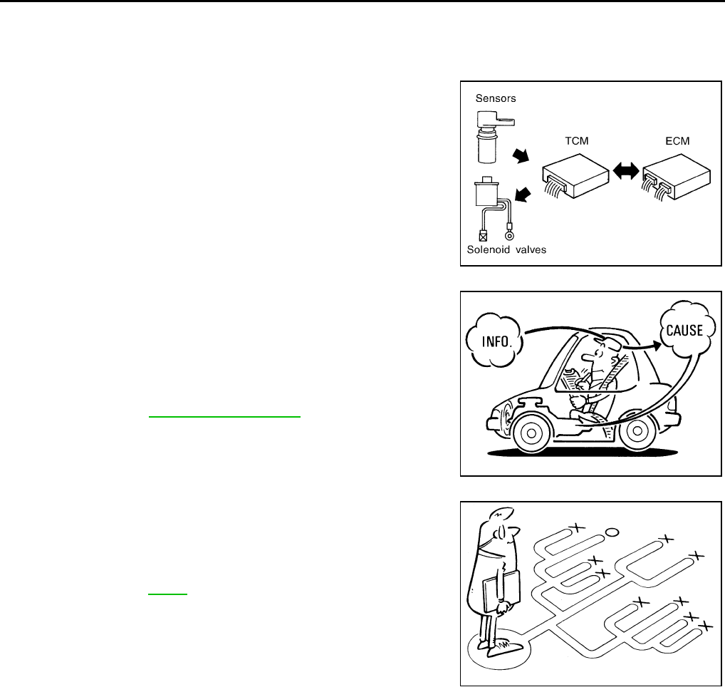
AT-44
TROUBLE DIAGNOSIS
How To Perform Trouble Diagnosis For Quick and Accurate Repair ACS0008S
INTRODUCTION
The TCM receives a signal from the vehicle speed sensor, accelerator pedal position sensor (throttle position
sensor) or PNP switch and provides shift control or lock-up control via A/T solenoid valves.
The TCM also communicates with the ECM by means of a signal
sent from sensing elements used with the OBD-related parts of the
A/T system for malfunction-diagnostic purposes. The TCM is capa-
ble of diagnosing malfunctioning parts while the ECM can store mal-
functions in its memory.
Input and output signals must always be correct and stable in the
operation of the A/T system. The A/T system must be in good oper-
ating condition and be free of valve seizure, solenoid valve malfunc-
tion, etc.
It is much more difficult to diagnose an error that occurs intermit-
tently rather than continuously. Most intermittent errors are caused
by poor electric connections or improper wiring. In this case, careful
checking of suspected circuits may help prevent the replacement of
good parts.
A visual check only may not find the cause of the errors. A road test
with CONSULT-II (or GST) or a circuit tester connected should be
performed. Follow the AT-45, "WORK FLOW" .
Before undertaking actual checks, take a few minutes to talk with a
customer who approaches with a driveability complaint. The cus-
tomer can supply good information about such errors, especially
intermittent ones. Find out what symptoms are present and under
what conditions they occur. A “Diagnostic Worksheet” as shown on
the example (Refer to AT-46 ) should be used.
Start your diagnosis by looking for “conventional” errors first. This will
help troubleshoot driveability errors on an electronically controlled
engine vehicle.
Also check related Service bulletins.
SAT631IB
SAT632I
SEF234G
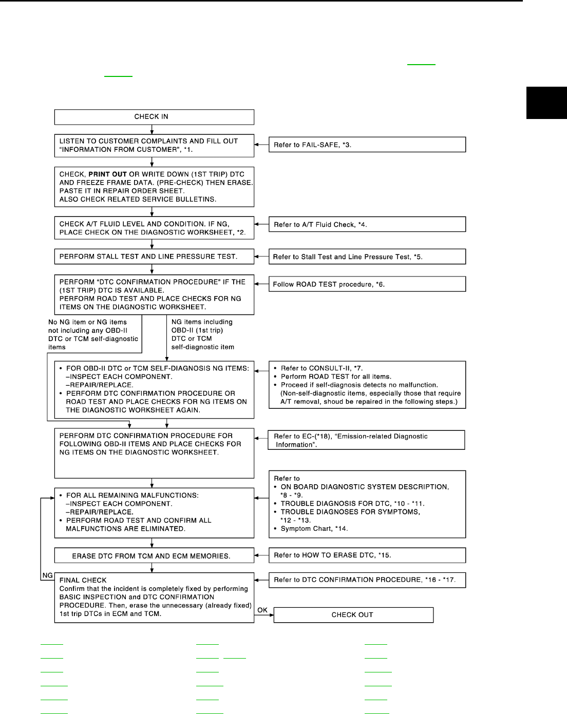
TROUBLE DIAGNOSIS
AT-45
D
E
F
G
H
I
J
K
L
M
A
B
AT
WORK FLOW
A good understanding of the malfunction conditions can make troubleshooting faster and more accurate.
In general, each customer feels differently about a malfunction. It is important to fully understand the symp-
toms or conditions for a customer complaint.
Make good use of the two sheets provided, “Information From Customer” (Refer to AT-46 ) and “Diagnostic
Worksheet” (Refer to AT-46 ), to perform the best troubleshooting possible.
Work Flow Chart
*1. AT-46 *2. AT-46 *3. AT-42
*4. AT-51 *5. AT-51, AT-52 *6. AT-54
*7. AT-92 *8. AT-38 *9. AT-103
*10. AT-105 *11. AT-244 *12. AT-246
*13. AT-286 *14. AT-62 *15. AT-39
*16. AT-105 *17. AT-240 *18. EC-47
SCIA0501E
AT-46
TROUBLE DIAGNOSIS
DIAGNOSTIC WORKSHEET
Information From Customer
KEY POINTS
●WHAT..... Vehicle & A/T model
●WHEN..... Date, Frequencies
●WHERE..... Road conditions
●HOW..... Operating conditions, Symptoms
Diagnostic Worksheet Chart
Customer name MR/MS Model & Year VIN
Trans. Model Engine Mileage
Incident Date Manful. Date In Service Date
Frequency ❏ Continuous ❏ Intermittent ( times a day)
Symptoms ❏ Vehicle does not move. (❏ Any position ❏ Particular position)
❏ No up-shift (❏ 1st → 2nd ❏ 2nd → 3rd ❏ 3rd → 4th ❏ 4th → 5th)
❏ No down-shift (❏ 5th → 4th ❏ 4th → 3rd ❏ 3rd → 2nd ❏ 2nd → 1st)
❏ Lock-up malfunction
❏ Shift point too high or too low.
❏ Shift shock or slip (❏ N → D ❏ Lock-up ❏ Any drive position)
❏ Noise or vibration
❏ No kick down
❏ No pattern select
❏ Others
()
A/T CHECK indicator lamp Blinks for about 8 seconds.
❏ Continuously lit ❏ Not lit
Malfunction indicator lamp (MIL) ❏ Continuously lit ❏ Not lit
1❏ Read the item on “cautions concerning fail-safe and understand the customer's complaint. AT-42
2
❏ A/T fluid inspection
AT-51
❏ Leak (Repair leak location.)
❏ State
❏ Amount
3
❏ Stall test and line pressure test
AT-51, AT-
52
❏ Stall test
❏ Torque converter one-way clutch
❏ Front brake
❏ High and low reverse clutch
❏ Low coast brake
❏ Forward brake
❏ Forward one-way clutch
❏ 1st one-way clutch
❏ 3rd one-way clutch
❏ Engine
❏ Line pressure low
❏ Except for input clutch and direct
clutch, clutches and brakes OK
❏ Line pressure inspection - Suspected part:
TROUBLE DIAGNOSIS
AT-47
D
E
F
G
H
I
J
K
L
M
A
B
AT
4
❏ Execute all road tests and enter checks in required inspection items. AT-54
4-1.
Check before engine is started
AT-55
❏ The A/T CHECK Indicator Lamp does come on. AT-248 .
❏ Execute self-diagnostics Enter checks for detected items.
❏ Vehicle speed sensor·A/T. AT-117 .
❏ Vehicle speed sensor·MTR. AT-164 .
❏ Direct clutch solenoid valve. AT-196 .
❏ TCC solenoid valve. AT-124 .
❏ Line pressure solenoid valve.AT-134 .
❏ Input clutch solenoid valve. AT-177 .
❏ Front brake solenoid valve. AT-186 .
❏ Low coast brake solenoid valve. AT-215 .
❏ High and low reverse clutch solenoid valve. AT-205 .
❏ PNP switch. AT-112 .
❏ A/T fluid temperature sensors 1, 2. AT-153 .
❏ Turbine revolution sensors 1, 2. AT-159 .
❏ A/T interlock. AT-166 .
❏ A/T 1st engine braking. AT-173 .
❏ Start signal. AT-108 .
❏ Accelerator pedal position signal. AT-151 .
❏ Engine speed signal. AT-122 .
❏ CAN communication. AT-105 .
❏ TCM power supply. AT-139 .
❏ Battery
❏ Other
4-2.
Idle inspection
AT-55
❏ Engine Cannot Be Started in “P” and “N” Position. AT-250 .
❏ In “ P” Position, Vehicle Moves When Pushed. AT-250 .
❏ In “N” Position Vehicle Moves. AT-251 .
❏ Large Shock “N” to “D” Position. AT-253 .
❏ Vehicle Does Not Creep Backward In “R” Position. AT-255 .
❏ Vehicle does Not Creep Forward In “D” Position. AT-258 .
4-3.
Driving tests
AT-56
Part 1
❏ Vehicle Cannot Be Started From D1. AT-260 .
❏ A/T Does Not Shift: D1 → D2. AT-263 .
❏ A/T Does Not Shift: D2 → D3. AT-265 .
❏ A/T Does Not Shift: D3 → D4. AT-267 .
❏ A/T Does Not Shift: D4 → D5. AT-270 .
❏ A/T Does Not Perform Lock-up. AT-272
❏ A/T Does Not Hold Lock-up Condition. AT-274 .
❏ Lock-up Is Not Released. AT-276 .
❏ Engine Speed Does Not Return To Idle. AT-276 .
AT-48
TROUBLE DIAGNOSIS
44-3
Part 2
AT-58
❏ Vehicle Cannot Be Started From D1. AT-260 .
❏ A/T Does Not Shift: D1 → D2. AT-263 .
❏ A/T Does Not Shift: D2 → D3. AT-265 .
❏ A/T Does Not Shift: D3 → D4. AT-267 .
Part 3
AT-59
❏ Cannot Be Changed Manual Mode. AT-278
❏ A/T Does Not Shift: 5th gear → 4th gear. AT-278 .
❏ A/T Does Not Shift: 4th gear → 3rd gear. AT-280 .
❏ A/T Does Not Shift: 3rd gear → 2nd gear. AT-282 .
❏ A/T Does Not Shift: 2nd gear →1st gear. AT-284 .
❏ Vehicle Does Not Decelerate By Engine Brake. AT-286 .
❏ Execute self-diagnostics Enter checks for detected items.
❏ Vehicle speed sensor·A/T. AT-117 .
❏ Vehicle speed sensor·MTR. AT-164 .
❏ Direct clutch solenoid valve.AT-196 .
❏ TCC solenoid valve. AT-124 .
❏ Line pressure solenoid valve.AT-134 .
❏ Input clutch solenoid valve. AT-177 .
❏ Front brake solenoid valve. AT-186 .
❏ Low coast brake solenoid valve. AT-215 .
❏ High and low reverse clutch solenoid valve. AT-205
❏ PNP switch. AT-112 .
❏ A/T fluid temperature sensors 1, 2. AT-153 .
❏ Turbine revolution sensors 1, 2. AT-159 .
❏ A/T interlock. AT-166 .
❏ A/T 1st engine braking. AT-173 .
❏ Start signal.AT-108 .
❏ Accelerator pedal position signal. AT-151 .
❏ Engine sped signal. AT-122 .
❏ CAN communication. AT-105 .
❏ TCM power supply. AT-139 .
❏ Battery
❏ Other
5❏ Inspect each system for items found to be NG in the self-diagnostics and repair or replace the malfunction
parts.
6❏ Execute all road tests and enter the checks again for the required items. AT-54
7
❏ For any remaining NG items, execute the “diagnostics procedure” and repair or replace the malfunction parts.
See the chart for diagnostics by symptoms. (This chart also contains other symptoms and inspection proce-
dures.)
AT-62
8❏ Erase the results of the self-diagnostics from the TCM.
AT-92, AT-
103
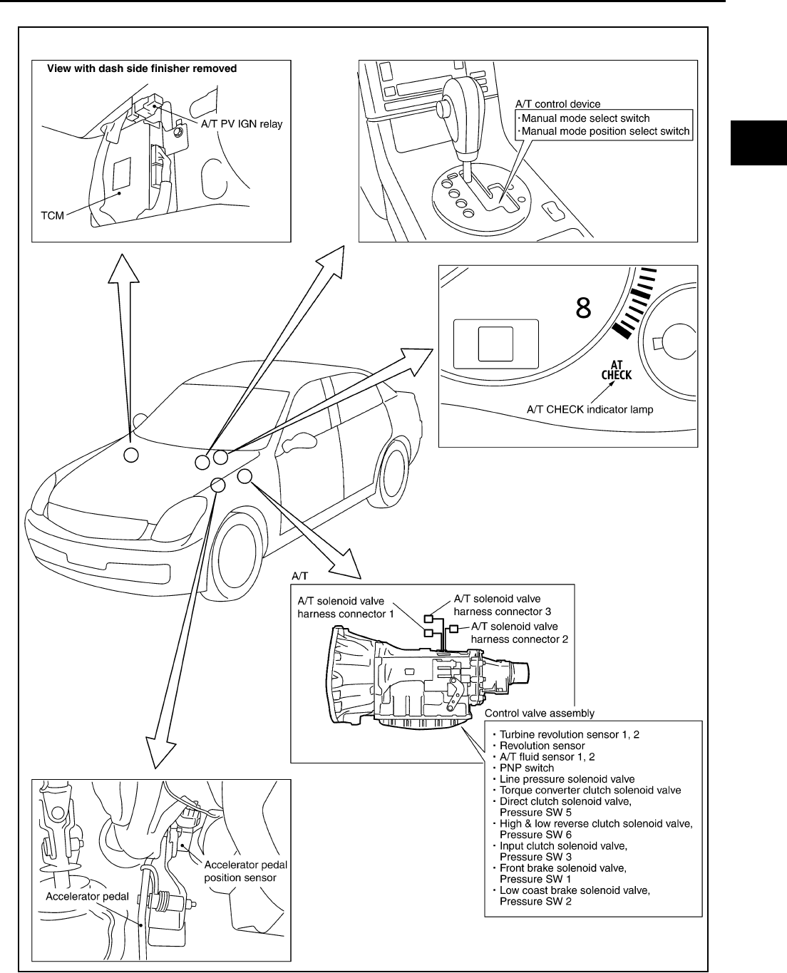
TROUBLE DIAGNOSIS
AT-49
D
E
F
G
H
I
J
K
L
M
A
B
AT
A/T Electrical Parts Location ACS0008T
SCIA1223E
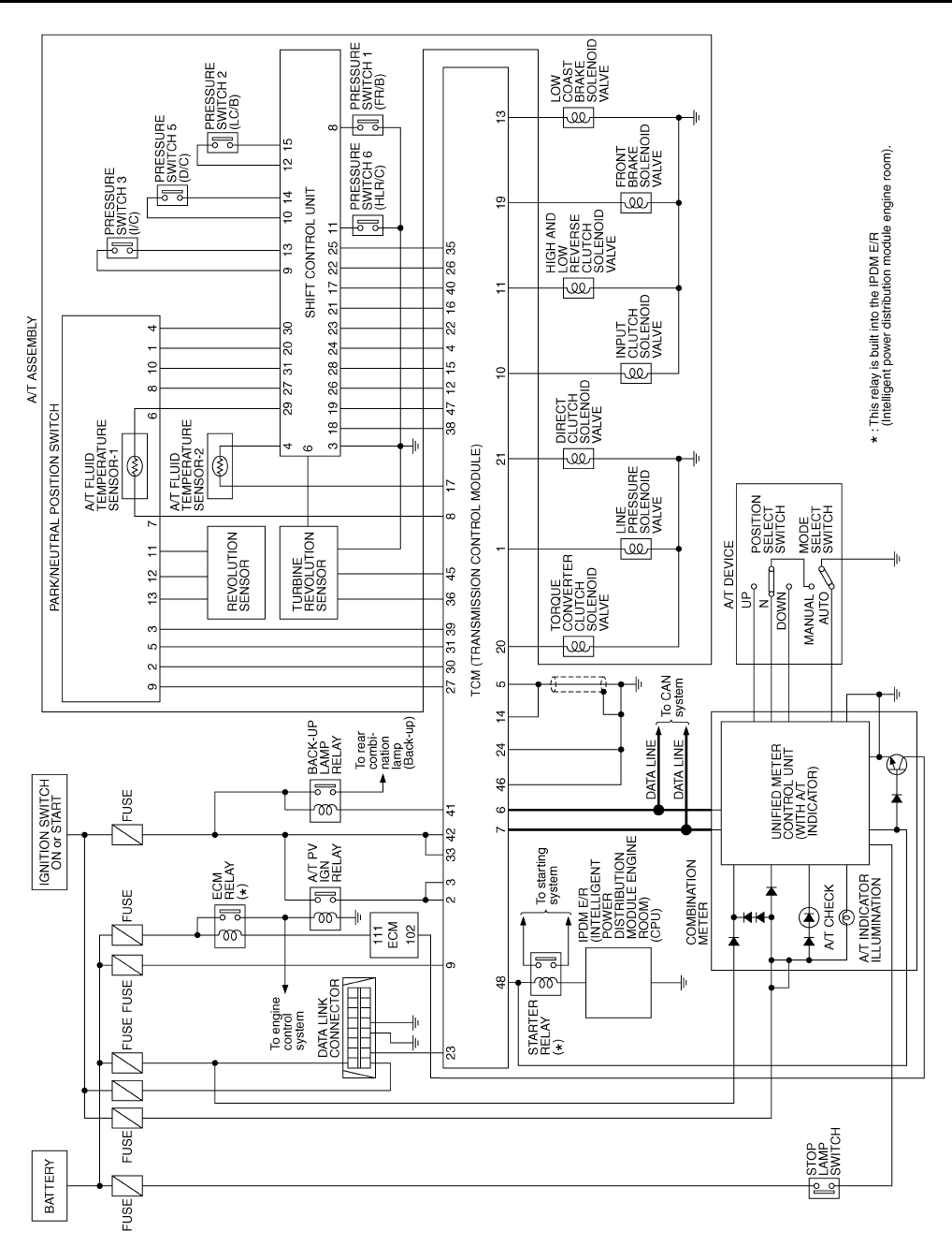
AT-50
TROUBLE DIAGNOSIS
Circuit Diagram ACS0008U
TCWT0218E
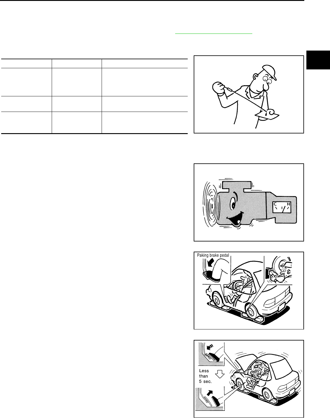
TROUBLE DIAGNOSIS
AT-51
D
E
F
G
H
I
J
K
L
M
A
B
AT
Inspections Before Trouble Diagnosis ACS0008V
A/T FLUID CHECK
Fluid Leakage and Fluid Level Check
●Inspect for fluid leakage and check the fluid level. Refer to AT-13, "Checking A/T Fluid" .
Fluid Condition Check
Inspect the fluid condition.
STALL TEST
Stall Test Procedure
1. Inspect the amount of engine oil. Replenish the engine oil if necessary.
2. Drive for about 10 minutes to warm up the vehicle so that the A/
T fluid temperature is 50 to 80°C (122 to 176°F). Inspect the
amount of A/T fluid. Replenish if necessary.
3. Securely engage the parking brake so that the tires do not turn.
4. Engine start, apply foot brake, and place selector lever in “D”
position.
5. While holding down the foot brake, gradually press down the
accelerator pedal.
6. Quickly read off the stall speed, then quickly remove your foot
from the accelerator pedal.
CAUTION:
Do not hold down the accelerator pedal for more than 5 sec-
onds during this test.
7. Move the selector lever to the “N” position.
8. Cool down the A/T fluid.
Fluid status Conceivable Cause Required Operation
Varnished (viscous
varnish state)
Clutch, brake
scorched
Replace the A/T fluid and check the
A/T main unit and the vehicle for
malfunctions (wire harnesses,
cooler pipes, etc.)
Milky white or
cloudy Water in the fluid Replace the A/T fluid and check for
places where water is getting in.
Large amount of
metal powder mixed
in
Unusual wear of
sliding parts within
A/T
Replace the A/T fluid and check for
improper operation of the A/T.
SAT638A
SAT647B
SCIA1224E
SAT514G
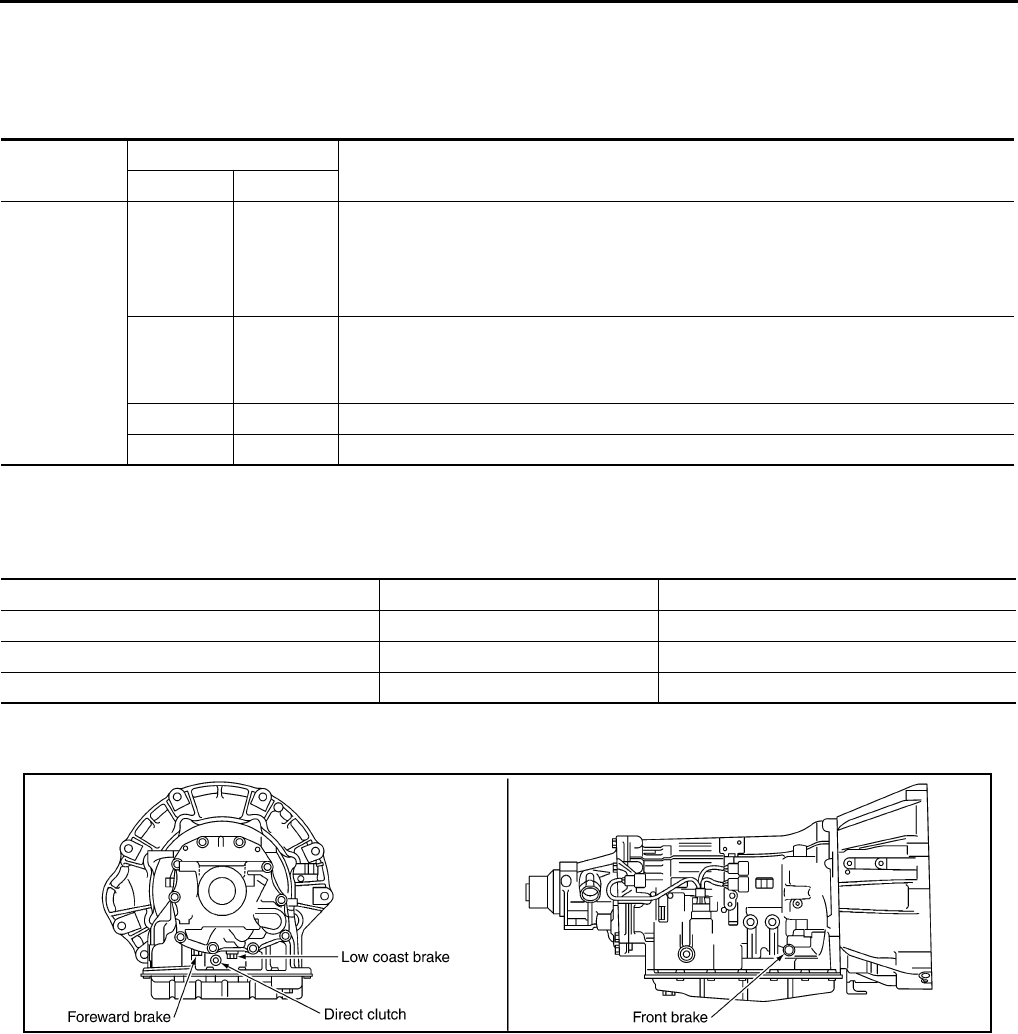
AT-52
TROUBLE DIAGNOSIS
CAUTION:
Run the engine at idle for at least one minute.
Judgement Stall Test
O: Stall speed within standard value position
H: Stall speed higher than standard value
L: Stall speed lower than standard value
Stall test standard value position
LINE PRESSURE TEST
Line Pressure Test Port
Line Pressure Test Procedure
1. Inspect the amount of engine oil and replenish if necessary.
2. Drive the car for about 10 minutes to warm it up so that the A/T fluid reaches in range of 50 to 80°C (122
to 176°F), then inspect the amount of A/T fluid and replenish if necessary.
NOTE:
The automatic fluid temperature rises in range of 50 to 80°C (122 to 176°F) during 10 minutes of
driving.
Stall speed: 2,600 - 2,900 rpm
Selector lever position Expected problem location
D, M R
Stall rotation
HO
●Forward brake
●Forward one-way clutch
●1st one-way clutch
●3rd one-way clutch
OH
●Front brake
●Reverse brake
●1st one-way clutch
LL
●Engine and torque converter one-way clutch
HH
●Line pressure low
Does not shift-up D, M position 1 → 2 Slipping in 2nd, 3rd, 4th gears Direct clutch slippage
Does not shift-up D, M position 2 → 3 Slipping in 3rd, 4th, 5th gears High and low reverse clutch slippage
Does not shift-up D, M position 3 → 4 Slipping in 4th, 5th gears Input clutch slippage
Does not shift-up D, M position 4 → 5 Slipping in 5th gear Front brake slippage
SCIA1291E
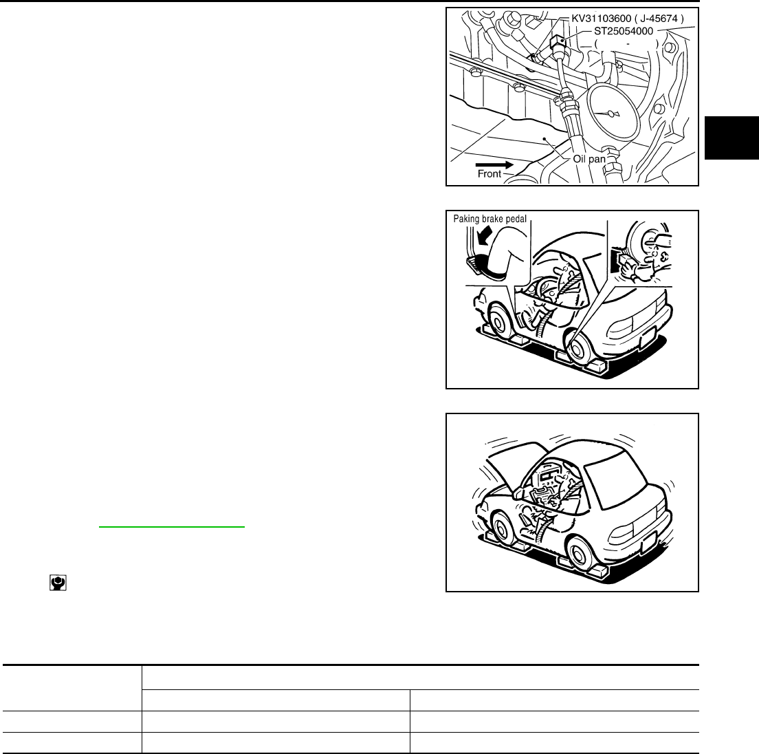
TROUBLE DIAGNOSIS
AT-53
D
E
F
G
H
I
J
K
L
M
A
B
AT
3. After warming up A/T, remove the oil pressure detection plug
and install the oil pressure gauge.
CAUTION:
When using the oil pressure gauge, be sure to use the O-
ring attached to the oil pressure detection plug.
4. Securely engage the parking brake so that the tires do not turn.
5. Start the engine, then measure the line pressure at both idle and
the stall speed.
CAUTION:
●Keep the brake pedal pressed all the way down during
measurement.
●When measuring the line pressure at the stall speed,
refer to AT-51, "STALL TEST" .
6. After the measurements are complete, install the oil pressure
detection plug and tighten to the regulation torque below.
CAUTION:
Do not reuse the O-ring.
Line Pressure
SCIA5309E
SCIA1224E
:7.3 N·m (0.74 kg-m, 65 in-lb) SAT493G
Engine speed Line pressure kPa (kg/cm2 , psi)
R position D, M positions
idle speed 392 - 441 (4.0 - 4.5, 57 - 64) 373 - 422 (3.8 - 4.3, 54 - 61)
stall speed 1,700 - 1,890 (17.3 - 19.3, 247 - 274) 1,310 - 1,500 (13.3 - 15.3, 190 - 218)

AT-54
TROUBLE DIAGNOSIS
Judgement of Line Pressure Test
ROAD TEST
Description
●The road test inspects overall performance of the A/T and analyzes possible malfunction causes.
●The road test is carried out in the following three stages.
1. Check before engine is started. Refer to AT-55 .
2. Check at idle. Refer to AT-55 .
3. Cruise test
●Inspect all the items from Part 1 to Part 3. Refer to AT-56 , AT-58 , AT-59 .
●Before beginning the road test, check the test procedure and inspection items.
●Test all inspection items until the symptom is uncovered. Diagnose NG items when all road tests are com-
plete.
Judgement Possible cause
Idle speed
Low for all positions
(P, R, N, D, M)
Possible causes include malfunctions in the pressure supply system and low oil pump output.
For example
●Oil pump wear
●Pressure regulator valve or plug sticking or spring fatigue
●Oil strainer Þ oil pump Þ pressure regulator valve passage oil leak
●Engine idle speed too low
Only low for a spe-
cific position
Possible causes include an oil pressure leak in a passage or device related to the position after
the pressure is distributed by the manual valve.
High
Possible causes include a sensor malfunction or malfunction in the line pressure adjustment func-
tion.
For example
●Accelerator pedal position signal malfunction
●ATF temperature sensor malfunction
●Line pressure solenoid malfunction (sticking in “OFF” state, filter clog, cut line)
●Pressure regulator valve or plug sticking
Stall speed
Oil pressure does
not rise higher than
the oil pressure for
idle.
Possible causes include a sensor malfunction or malfunction in the line pressure adjustment func-
tion.
For example
●Accelerator pedal position signal malfunction
●TCM breakdown
●Line pressure solenoid malfunction (shorting, sticking in“ ON” state)
●Pressure regulator valve or plug sticking
●Pilot valve sticking or pilot filter clogged
The pressure rises,
but does not enter
the standard posi-
tion.
Possible causes include malfunctions in the pressure supply system and malfunction in the line
pressure adjustment function.
For example
●Accelerator pedal position signal malfunction
●Line pressure solenoid malfunction (sticking, filter clog)
●Pressure regulator valve or plug sticking
●Pilot valve sticking or pilot filter clogged
Only low for a spe-
cific position
Possible causes include an oil pressure leak in a passage or device related to the position after
the pressure is distributed by the manual valve.

TROUBLE DIAGNOSIS
AT-55
D
E
F
G
H
I
J
K
L
M
A
B
AT
Check Before Engine is Started ACS001MD
1. CHECK A/T CHECK INDICATOR LAMP
1. Park vehicle on level surface.
2. Move selector lever to “P” position.
3. Turn ignition switch OFF and wait at least 10 seconds.
4. Turn ignition switch ON. (Do not start engine.)
Does A/T CHECK indicator lamp light up for about 2 seconds?
YES >> GO TO 2.
NO >> Stop the road test and go to AT-248, "A/T Check Indicator Lamp Does Not Come On" .
2. CHECK A/T CHECK INDICATOR LAMP
Does A/T CHECK indicator lamp flash for about 8 seconds?
YES >> For TCM fail-safe mode, carry out self-diagnostics and record all NG items on the diagnostics
worksheet. Refer to AT-92 , AT-103 .
NO >> 1. Turn ignition switch to “OFF” position.
2. Go to AT-55, "Check at Idle" .
Check at Idle ACS001ME
1. CHECK STARTING THE ENGINE
1. Park vehicle on level surface.
2. Move selector lever to “P” position.
3. Turn ignition switch OFF.
4. Turn ignition switch START.
Does the engine start?
YES >> GO TO 2.
NO >> Stop the road test and go to AT-250, "Engine Cannot Be Started In “P” or “N” Position" .
2. CHECK STARTING THE ENGINE
1. Turn ignition switch ON.
2. Move selector lever in “D” or “R” position.
3. Turn ignition switch START.
Does the engine start in either position?
YES >> Stop the road test and go to AT-250, "Engine Cannot Be Started In “P” or “N” Position" .
NO >> GO TO 3.
3. CHECK “P” POSITION FUNCTIONS
1. Move selector lever to “P” position.
2. Turn ignition switch OFF.
3. Disengage the parking brake.
4. Push the vehicle forward or backward.
5. Engage the parking brake.
When you push the vehicle with disengaging the parking brake, does it move?
YES >> Enter a check mark at “Vehicle moves when pushed in “P” position” on the diagnostics worksheet,
then continue the road test.
NO >> GO TO 4.

AT-56
TROUBLE DIAGNOSIS
4. CHECK “N” POSITION FUNCTIONS
1. Start the engine.
2. Move selector lever to “N” position.
3. Release the parking brake.
Does vehicle move forward or backward?
YES >> Enter a check mark at “Vehicle moves in “N” position” on the diagnostics worksheet, then continue
the road test.
NO >> GO TO 5.
5. CHECK SHIFT SHOCK
1. Engage the brake.
2. Move selector lever to “D” position.
When the transmission is shifted from “N” to “D”, is there an excessive shock?
YES >> Enter a check mark at “Large shock when shifted from N to D” on the diagnostics worksheet, then
continue the road test.
NO >> GO TO 6.
6. CHECK “R” POSITION FUNCTIONS
1. Engage the brake.
2. Move selector lever to “R” position.
3. Disengage the brake for 4 to 5 seconds.
Does the vehicle creep backward?
YES >> GO TO 7.
NO >> Enter a check mark at “Vehicle does not creep backward in R position” on the diagnostics work-
sheet, then continue the road test.
7. CHECK “D”, “M” POSITION FUNCTIONS
Inspect whether the vehicle creep forward when the transmission is put into the “D” or “M” position.
Does the vehicle creep forward in the “D” and “M” positions?
YES >> Go to AT-56, "Cruise Test - Part 1" , AT-58, "Cruise Test - Part 2" and AT-59, "Cruise Test - Part 3"
.
NO >> Enter a check mark at “Vehicle does not creep forward in D, M positions” on the diagnostics work-
sheet, then continue the road test.
Cruise Test - Part 1 ACS001MF
Cruise Test Part 1
1. CHECK STARTING OUT FROM D1
1. Drive the vehicle for about 10 minutes to warm up the engine oil and A/T fluid.
Appropriate temperature for the A/T fluid: 50 - 80°C (122 - 176°F)
2. Park the vehicle on a level surface.
3. Move selector lever to “P” position.
4. Start the engine.
5. Move selector lever to “D” position.
6. Press the accelerator pedal about half way down to accelerate the vehicle.
With CONSULT-II
Read off the gear positions.
Starts from D1?
YES >> GO TO 2.
NO >> Enter a check mark at “Vehicle cannot be started from D1” on the diagnostics worksheet, then
continue the road test.

TROUBLE DIAGNOSIS
AT-57
D
E
F
G
H
I
J
K
L
M
A
B
AT
2. CHECK SHIFT-UP D1 → D2
Press down the accelerator pedal about half way and inspect if the vehicle shifts up (D1 → D2) at the appropri-
ate speed.
●Refer to AT-61 .
With CONSULT-II
Read the gear position, throttle degree of opening, and vehicle speed.
Does the A/T shift-up D1 → D2 at the correct speed?
YES >> GO TO 3.
NO >> Enter a check mark at “A/T does not shift D1 → D2” on the diagnostics worksheet, then continue
the road test.
3. CHECK SHIFT-UP D2 → D3
Press down the accelerator pedal about half way and inspect if the vehicle shifts up (D2 → D3) at the appropri-
ate speed.
●Refer to AT-61 .
With CONSULT-II
Read the gear position, throttle degree of opening, and vehicle speed.
Does the A/T shift-up D2 → D3 at the correct speed?
YES >> GO TO 4.
NO >> Enter a check mark at “A/T does not shift D2 → D3” on the diagnostics worksheet, then continue
the road test.
4. CHECK SHIFT-UP D3 → D4
Press down the accelerator pedal about half way and inspect if the vehicle shifts up (D3 → D4) at the appropri-
ate speed.
●Refer to AT-61 .
With CONSULT-II
Read the gear position, throttle degree of opening, and vehicle speed.
Does the A/T shift-up D3 → D4 at the correct speed?
YES >> GO TO 5.
NO >> Enter a check mark at “A/T does not shift D3 → D4” on the diagnostics worksheet, then continue
the road test.
5. CHECK SHIFT-UP D4 → D5
Press down the accelerator pedal about half way and inspect if the vehicle shifts up (D4 → D5) at the appropri-
ate speed.
●Refer to AT-61 .
With CONSULT-II
Read the gear position, throttle degree of opening, and vehicle speed.
Does the A/T shift-up D4 → D5 at the correct speed?
YES >> GO TO 6.
NO >> Enter a check mark at “A/T does not shift D4 → D5” on the diagnostics worksheet, then continue
the road test.

AT-58
TROUBLE DIAGNOSIS
6. CHECK LOCK-UP
When releasing accelerator pedal from D5, check lock-up from D5 to L/U.
●Refer to AT-61 .
With CONSULT-II
Select “TCC SOLENOID 0.00A” with the “MAIN SIGNAL” mode for A/T. Refer to AT-92, "CONSULT-II REF-
ERENCE VALUE" .
Does it lock-up?
YES >> GO TO 7.
NO >> Enter a check mark at “A/T does not perform lock-up” on the diagnostics worksheet, then continue
the road test.
7. CHECK LOCK-UP HOLD
Does it maintain lock-up status?
YES >> GO TO 8.
NO >> Enter a check mark at “A/T hold does not lock-up condition” on the diagnostics worksheet, then
continue the road test.
8. CHECK LOCK-UP RELEASE
Check lock-up cancellation by depressing brake pedal lightly to decelerate.
With CONSULT-II
Select “TCC SOLENOID 0.00A” with the “MAIN SIGNAL” mode for A/T.Refer to AT-92, "CONSULT-II REF-
ERENCE VALUE" .
Does lock-up cancel?
YES >> GO TO 9.
NO >> Enter a check mark at “Lock-up is not released” on the diagnostics worksheet, then continue the
road test.
9. CHECK SHIFT-DOWN D5 → D4
Decelerate by pressing lightly on the brake pedal.
With CONSULT-II
Read the gear position and engine speed.
When the A/T shift-down D5 → D4, does the engine speed drop smoothly back to idle?
YES >> 1. Stop the vehicle.
2. Go to Cruise test - Part 2 (Refer to AT-58 ).
NO >> Enter a check mark at “A/T does not shift down” on the diagnostics worksheet, then continue the
road test. Go to Cruise test - Part 2 (Refer to AT-58 ).
Cruise Test - Part 2 ACS001MG
Cruise Test Part 2
1. CHECK STARTING FROM D1
1. Move selector lever the “D” position.
2. Accelerate at half throttle.
With CONSULT-II
Read the gear position.
Does it start from D1?
YES >> GO TO 2.
NO >> Enter a check mark at “Vehicle cannot be started from D1” on the diagnostics worksheet, then
continue the road test.

TROUBLE DIAGNOSIS
AT-59
D
E
F
G
H
I
J
K
L
M
A
B
AT
2. CHECK SHIFT-UP D1 → D2
Press the accelerator pedal down all the way and inspect whether or not the transmission shifts up (D1 → D2)
at the correct speed.
●Refer to AT-61 .
With CONSULT-II
Read the gear position, throttle position and vehicle speed.
Does the A/T shift-up D1 → D2 at the correct speed?
YES >> GO TO 3.
NO >> Enter a check mark at “Vehicle does not shift D1 → D2” on the diagnostics worksheet, then con-
tinue the road test.
3. CHECK SHIFT-UP D2 → D3
Press the accelerator pedal down all the way and inspect whether or not the transmission shifts up (D2 → D3)
at the correct speed.
●Refer to AT-61 .
With CONSULT-II
Read the gear position, throttle position and vehicle speed.
Does the A/T shift-up D2 → D3 at the correct speed?
YES >> GO TO 4.
NO >> Enter a check mark at “Vehicle does not shift D2 → D3” on the diagnostics worksheet, then con-
tinue the road test.
4. CHECK SHIFT-UP D3 → D4 AND ENGINE BRAKE
When the transmission changes speed D3 → D4, return the accelerator pedal.
Does the A/T shift-up D3 → D4 and apply the engine brake?
YES >> 1. Stop the vehicle.
2. Go to Cruise test - Part 3 (Refer to AT-59 ).
NO >> Enter a check mark at “Vehicle does not shift D3 → D4” on the diagnostics worksheet, then con-
tinue the road test.
Cruise Test - Part 3 ACS001MH
Cruise Test Part 3
1. MANUAL MODE FUNCTION
Move to manual mode from D position.
Does it switch to manual mode?
YES >> GO TO 2.
NO >> Continue road test and add checkmark to “Cannot be changed to manual mode” on diagnostics
worksheet.
2. CHECK SHIFT-DOWN
During manual mode driving, is downshift from 5M → 4M → 3M → 2M → 1M performed?
With CONSULT-II
Read the gear position.
Is downshifting correctly performed?
YES >> GO TO 3.
NO >> Enter a check mark at “Vehicle does not shift” at the corresponding position (5M → 4M , 4M → 3M
, 3M → 2M , 2M → 1M ) on the diagnostics worksheet, then continue the road test.

AT-60
TROUBLE DIAGNOSIS
3. CHECK ENGINE BRAKE
Does engine braking effectively reduce speed in M1 position?
YES >> 1. Stop the vehicle.
2. Carry out the self-diagnostics. Refer to AT-93, "SELF-DIAGNOSTIC RESULT MODE" , AT-103,
"Diagnostic Procedure Without CONSULT-II" .
NO >> Enter a check mark at “Vehicle does not decelerate by engine brake” on the diagnostics work-
sheet, then continue trouble diagnosis.
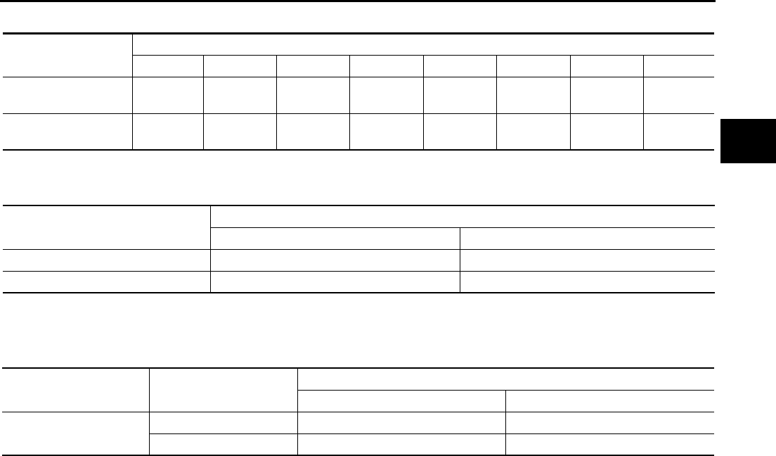
TROUBLE DIAGNOSIS
AT-61
D
E
F
G
H
I
J
K
L
M
A
B
AT
Vehicle Speed When Shifting Gears ACS001MI
●At half throttle, the accelerator opening is 4/8 of the full opening.
Vehicle Speed When Performing and Releasing Complete Lock-up ACS001MJ
●At closed throttle, the accelerator opening is less than 1/8 condition.
●At half throttle, the accelerator opening is 4/8 of the full opening.
Vehicle Speed When Performing and Releasing Slip Lock-up ACS001MK
●At closed throttle, the accelerator opening is less than 1/8 condition.
Throttle position Vehicle speed km/h (MPH)
D1 →D2D2 →D3D3 →D4D4 →D5D5 →D4D4 →D3D3 →D2D2 →D1
Full throttle 58 - 62
(36 - 39)
90 - 98
(56 - 61)
135 - 145
(84 - 90)
201 - 211
(125 - 131)
197 - 207
(122 - 129)
123 - 133
(76 - 83)
76 - 84
(47 - 52)
37 - 41
(23 - 25)
Half throttle 46 - 50
(29 - 31)
71 - 79
(44 - 49)
107 - 117
(66 - 73)
135 - 145
(84 - 90)
88 - 98
(55 - 61)
63 - 73
(39 - 45)
29 - 37
(18 - 23)
11 - 15
(7 - 9)
Throttle position Vehicle speed km/h (MPH)
Lock-up “ON” Lock-up “OFF”
Closed throttle 56 - 64 (35 - 40) 53 - 61 (33 - 38)
Half throttle 168 - 176 (104 - 109) 131 - 139 (81 - 86)
Throttle position Gear position Vehicle speed km/h (MPH)
Slip lock-up “ON” Slip lock-up “OFF”
Closed throttle 4th 37 - 45 (23 - 28) 34 - 42 (21 - 26)
5th 44 - 52 (27 - 32) 41 - 49 (25 - 30)

AT-62
TROUBLE DIAGNOSIS
Symptom Chart ACS001ML
The diagnostics item numbers show the sequence for inspection. Inspect in order from Item 1.
No. Items Symptom Condition Diagnostic Item Reference
page
1
Shift
Shock
Large shock. (“N”
→“ D” position)
Refer to AT-253,
"Large Shock (“N”
to “D” Position)" .
ON vehicle
1. Engine idle speed EC-30
2. Engine speed signal AT-122
3. Accelerator pedal position sensor AT-151
4. Control linkage adjustment AT-289
5. ATF temperature sensor AT-153
6. ATF pressure switch 1 and front brake solenoid valve AT-228,
AT-186
7. CAN communication line AT-105
8. Fluid level and state AT-51
9. Line pressure test AT-52
10. Control valve assembly AT-299
OFF vehicle 11. Forward brake* (ATF condition “NG” only. Refer to AT-
51, "Fluid Condition Check" .) AT-325
2
Shock is too large
when changing D1
→ D2 or M1 → M2
.
ON vehicle
1. Accelerator pedal position sensor AT-151
2. Control linkage adjustment AT-289
3. ATF pressure switch 5 and direct clutch solenoid valve AT-236,
AT-196
4. CAN communication line AT-105
5. Engine speed signal AT-122
6. Turbine revolution sensor AT-159
7. Vehicle speed sensor A/T and vehicle speed sensor MTR AT-117, AT-
164
8. Fluid level and state AT-51
9. Control valve assembly AT-299
OFF vehicle 10. Direct clutch (ATF condition “NG” only. Refer to AT-51,
"Fluid Condition Check" .) AT-356
3
Shock is too large
when changing D2
→ D3 or M2 → M3
.
ON vehicle
1. Accelerator pedal position sensor AT-151
2. Control linkage adjustment AT-289
3. ATF pressure switch 6, high and low reverse clutch sole-
noid valve
AT-240,
AT-205
4. CAN communication line AT-105
5. Engine speed signal AT-122
6. Turbine revolution sensor AT-159
7. Vehicle speed sensor A/T and vehicle speed sensor MTR AT-117, AT-
164
8. Fluid level and state AT-51
9. Control valve assembly AT-299
OFF vehicle 10. High and low reverse clutch (ATF condition “NG” only.
Refer to AT-51, "Fluid Condition Check" .) AT-354
TROUBLE DIAGNOSIS
AT-63
D
E
F
G
H
I
J
K
L
M
A
B
AT
4
Shift
Shock
Shock is too large
when changing D3
→ D4 or M3 → M4 .
ON vehicle
1. Accelerator pedal position sensor AT-151
2. Control linkage adjustment AT-289
3. ATF pressure switch 3 and input clutch solenoid valve AT-232,
AT-177
4. CAN communication line AT-105
5. Engine speed signal AT-122
6. Turbine revolution sensor AT-159
7. Vehicle speed sensor A/T and vehicle speed sensor MTR AT-117, AT-
164
8. Fluid level and state AT-51
9. Control valve assembly AT-299
OFF vehicle 10. Input clutch (ATF condition “NG” only. Refer to AT-51,
"Fluid Condition Check" .) AT-344
5
Shock is too large
when changing D4
→ D5 or M4 → M5 .
ON vehicle
1. Accelerator pedal position sensor AT-151
2. Control linkage adjustment AT-289
3. ATF pressure switch 1 and front brake solenoid valve AT-228,
AT-186
4. CAN communication line AT-105
5. Engine speed signal AT-122
6. Turbine revolution sensor AT-159
7. Vehicle speed sensor A/T and vehicle speed sensor MTR AT-117, AT-
164
8. Fluid level and state AT-51
9. Control valve assembly AT-299
OFF vehicle
10. Front brake [brake band (ATF condition “NG” only. Refer
to AT-51, "Fluid Condition Check" .)] AT-317
11. Input clutch (ATF condition “NG” only. Refer to AT-51,
"Fluid Condition Check" .) AT-344
6
Shock is too large
for downshift when
accelerator pedal is
pressed.
ON vehicle
1. Accelerator pedal position sensor AT-151
2. Control linkage adjustment AT-289
3. CAN communication line AT-105
4. Engine speed signal AT-122
5. Turbine revolution sensor AT-159
6. Vehicle speed sensor A/T and vehicle speed sensor MTR AT-117, AT-
164
7. Fluid level and state AT-51
8. Control valve assembly AT-299
OFF vehicle
9. Front brake [brake band (ATF condition “NG” only. Refer
to AT-51, "Fluid Condition Check" .)] AT-317
10. Input clutch (ATF condition “NG” only. Refer to AT-51,
"Fluid Condition Check" .) AT-344
11. High and low reverse clutch (ATF condition “NG” only.
Refer to AT-51, "Fluid Condition Check" .) AT-354
12. Direct clutch (ATF condition “NG” only. Refer to AT-51,
"Fluid Condition Check" .) AT-356
No. Items Symptom Condition Diagnostic Item Reference
page

AT-64
TROUBLE DIAGNOSIS
7
Shift
Shock
Shock is too large
for upshift when
accelerator pedal is
released.
ON vehicle
1. Accelerator pedal position sensor AT-151
2. Control linkage adjustment AT-289
3. Engine speed signal AT-122
4. CAN communication line AT-105
5. Turbine revolution sensor AT-159
6. Vehicle speed sensor A/T and vehicle speed sensor MTR AT-117, AT-
164
7. Fluid level and state AT-51
8. Control valve assembly AT-299
OFF vehicle
9. Front brake [brake band (ATF condition “NG” only. Refer
to AT-51, "Fluid Condition Check" .)] AT-317
10. Input clutch (ATF condition “NG” only. Refer to AT-51,
"Fluid Condition Check" .) AT-344
11. High and low reverse clutch (ATF condition “NG” only.
Refer to AT-51, "Fluid Condition Check" .) AT-354
12. Direct clutch (ATF condition “NG” only. Refer to AT-51,
"Fluid Condition Check" .) AT-356
8Shock is too large
for lock-up.
ON vehicle
1. Accelerator pedal position sensor AT-151
2. Control linkage adjustment AT-289
3. Engine speed signal AT-122
4. CAN communication line AT-105
5. Turbine revolution sensor AT-159
6. Vehicle speed sensor A/T and vehicle speed sensor MTR AT-117, AT-
164
7. Torque converter clutch solenoid valve AT-124
8. Fluid level and state AT-51
9. Control valve assembly AT-299
OFF vehicle 10. Torque converter (ATF condition “NG” only. Refer to AT-
51, "Fluid Condition Check" .) AT-325
9
Shock is too large
during engine
brake.
ON vehicle
1. Accelerator pedal position sensor AT-151
2. Control linkage adjustment AT-289
3. CAN communication line AT-105
4. Fluid level and state AT-51
5. Control valve assembly AT-299
OFF vehicle
6. Front brake [brake band (ATF condition “NG” only. Refer
to AT-51, "Fluid Condition Check" .)] AT-325
7. Input clutch (ATF condition “NG” only. Refer to AT-51,
"Fluid Condition Check" .) AT-344
8. High and low reverse clutch (ATF condition “NG” only.
Refer to AT-51, "Fluid Condition Check" .) AT-354
9. Direct clutch (ATF condition “NG” only. Refer to AT-51,
"Fluid Condition Check" .) AT-356
No. Items Symptom Condition Diagnostic Item Reference
page
TROUBLE DIAGNOSIS
AT-65
D
E
F
G
H
I
J
K
L
M
A
B
AT
10
No Up
Shift
Gear does not
change from D1 →
D2 or from M1 →
M2 .
Refer to AT-263, "A/
T Does Not Shift:
D1 → D2" .
ON vehicle
1. Fluid level and state AT-51
2. Vehicle speed sensor A/T and vehicle speed sensor MTR AT-117, AT-
164
3. ATF pressure switch 5 and direct clutch solenoid valve AT-236,
AT-196
4. Line pressure test AT-52
5. CAN communication line AT-105
6. Control valve assembly AT-299
OFF vehicle 7. Direct clutch (ATF condition “NG” only. Refer to AT-51,
"Fluid Condition Check" .) AT-356
11
Gear does not
change from D2 →
D3 or from M2 →
M3 .
Refer to AT-265, "A/
T Does Not Shift:
D2 → D3" .
ON vehicle
1. Fluid level and state AT-51
2. Vehicle speed sensor A/T and vehicle speed sensor MTR AT-117, AT-
164
3. ATF pressure switch 6, high and low reverse clutch sole-
noid valve
AT-240,
AT-205
4. Line pressure test AT-52
5. CAN communication line AT-105
6. Control valve assembly AT-299
OFF vehicle 7. High and low reverse clutch (ATF condition “NG” only.
Refer to AT-51, "Fluid Condition Check" .) AT-354
12
Gear does not
change from D3 →
D4 or from M3 →
M4 .
Refer to AT-267, "A/
T Does Not Shift:
D3 → D4" .
ON vehicle
1. Fluid level and state AT-51
2. Vehicle speed sensor A/T and vehicle speed sensor MTR AT-117, AT-
164
3. ATF pressure switch 3 and input clutch solenoid valve AT-232,
AT-177
4. ATF pressure switch 1 and front brake solenoid valve AT-228,
AT-186
5. Line pressure test AT-52
6. CAN communication line AT-105
7. Control valve assembly AT-299
OFF vehicle 8. Input clutch (ATF condition “NG” only. Refer to AT-51,
"Fluid Condition Check" .) AT-344
13
Gear does not
change from D4 →
D5 or from M4 →
M5 .
Refer to AT-270, "A/
T Does Not Shift:
D4 → D5" .
ON vehicle
1. Fluid level and state AT-51
2. Vehicle speed sensor A/T and vehicle speed sensor MTR AT-117, AT-
164
3. ATF pressure switch 1 and front brake solenoid valve AT-228,
AT-186
4. ATF pressure switch 5 and direct clutch solenoid valve AT-236,
AT-196
5. Turbine revolution sensor AT-159
6. Line pressure test AT-52
7. CAN communication line AT-105
8. Control valve assembly AT-299
OFF vehicle
9. Front brake [brake band (ATF condition “NG” only. Refer
to AT-51, "Fluid Condition Check" .)] AT-325
10. Input clutch (ATF condition “NG” only. Refer to AT-51,
"Fluid Condition Check" .) AT-344
No. Items Symptom Condition Diagnostic Item Reference
page

AT-66
TROUBLE DIAGNOSIS
14
No Down
Shift
In D or M range,
does not downshift
to 4th gear.
Refer to AT-278, "A/
T Does Not Shift:
5th gear → 4th
gear" .
ON vehicle
1. Fluid level and state AT-51
2. Vehicle speed sensor A/T and vehicle speed sensor MTR AT-117, AT-
164
3. ATF pressure switch 1 and front brake solenoid valve AT-228,
AT-186
4. ATF pressure switch 5 and direct clutch solenoid valve AT-236,
AT-196
5. CAN communication line AT-105
6. Line pressure test AT-52
7. Control valve assembly AT-299
OFF vehicle
8. Front brake [brake band (ATF condition “NG” only. Refer
to AT-51, "Fluid Condition Check" .)] AT-325
9. Input clutch (ATF condition “NG” only. Refer to AT-51,
"Fluid Condition Check" .) AT-344
15
In D or M range,
does not downshift
to 3rd gear.
Refer to AT-280, "A/
T Does Not Shift:
4th gear → 3rd
gear" .
ON vehicle
1. Fluid level and state AT-51
2. Vehicle speed sensor A/T and vehicle speed sensor MTR AT-117, AT-
164
3. ATF pressure switch 3 and input clutch solenoid valve AT-232,
AT-177
4. ATF pressure switch 1 and front brake solenoid valve AT-228,
AT-186
5. CAN communication line AT-105
6. Line pressure test AT-52
7. Control valve assembly AT-299
OFF vehicle 8. Input clutch (ATF condition “NG” only. Refer to AT-51,
"Fluid Condition Check" .) AT-344
16
In D or M range,
does not downshift
to 2nd gear.
Refer to AT-282, "A/
T Does Not Shift:
3rd gear → 2nd
gear" .
ON vehicle
1. Fluid level and state AT-51
2. Vehicle speed sensor A/T and vehicle speed sensor MTR AT-117, AT-
164
3. ATF pressure switch 6, high and low reverse clutch sole-
noid valve
AT-240,
AT-205
4. CAN communication line AT-105
5. Line pressure test AT-52
6. Control valve assembly AT-299
OFF vehicle 7. High and low reverse clutch (ATF condition “NG” only.
Refer to AT-51, "Fluid Condition Check" .) AT-354
17
In D or M range,
does not downshift
to 1st gear.
Refer to AT-284, "A/
T Does Not Shift:
2nd gear → 1st
gear" .
ON vehicle
1. Fluid level and state AT-51
2. Vehicle speed sensor A/T and vehicle speed sensor MTR AT-117, AT-
164
3. ATF pressure switch 5 and direct clutch solenoid valve AT-236,
AT-196
4. CAN communication line AT-105
5. Line pressure test AT-52
6. Control valve assembly AT-299
OFF vehicle 7. Direct clutch (ATF condition “NG” only. Refer to AT-51,
"Fluid Condition Check" .) AT-356
No. Items Symptom Condition Diagnostic Item Reference
page
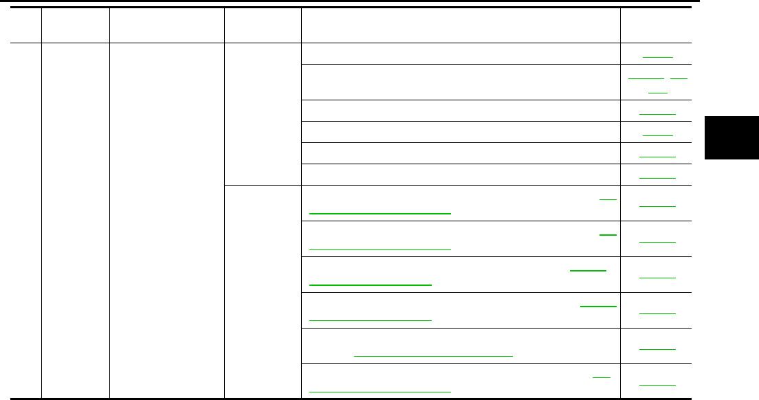
TROUBLE DIAGNOSIS
AT-67
D
E
F
G
H
I
J
K
L
M
A
B
AT
18
Slips/Will
Not
engage
When D or M posi-
tion, remains in 1st
gear.
ON vehicle
1. Fluid level and state AT-51
2. Vehicle speed sensor A/T and vehicle speed sensor MTR AT-117, AT-
164
3. Direct clutch solenoid valve AT-196
4. Line pressure test AT-52
5. CAN communication line AT-105
6. Control valve assembly AT-299
OFF vehicle
7. 3rd one-way clutch (ATF condition “NG” only. Refer to AT-
51, "Fluid Condition Check" .) AT-342
8. 1st one-way clutch (ATF condition “NG” only. Refer to AT-
51, "Fluid Condition Check" .) AT-349
9. Gear system (ATF condition “NG” only. Refer to AT-51,
"Fluid Condition Check" .) AT-317
10. Reverse brake (ATF condition “NG” only. Refer to AT-51,
"Fluid Condition Check" .) AT-325
11. Forward one-way clutch* (ATF condition “NG” only.
Refer to AT-51, "Fluid Condition Check" .) AT-325
12. Forward brake* (ATF condition “NG” only. Refer to AT-
51, "Fluid Condition Check" .) AT-325
No. Items Symptom Condition Diagnostic Item Reference
page
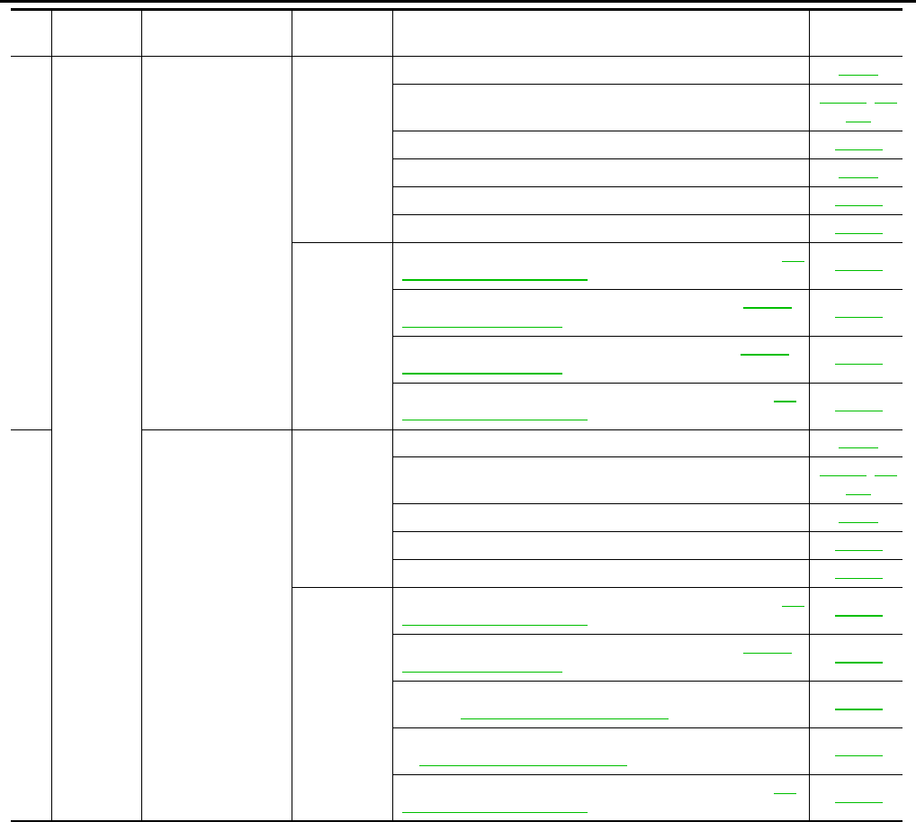
AT-68
TROUBLE DIAGNOSIS
19
Slips/Will
Not
engage
When D or M posi-
tion, remains in 2nd
gear.
ON vehicle
1. Fluid level and state AT-51
2. Vehicle speed sensor A/T and vehicle speed sensor MTR AT-117, AT-
164
3. Low coast brake solenoid valve AT-215
4. Line pressure test AT-52
5. CAN communication line AT-105
6. Control valve assembly AT-299
OFF vehicle
7. 3rd one-way clutch (ATF condition “NG” only. Refer to AT-
51, "Fluid Condition Check" .) AT-342
8. Gear system (ATF condition “NG” only. Refer to AT-51,
"Fluid Condition Check" .) AT-317
9. Direct clutch (ATF condition “NG” only. Refer to AT-51,
"Fluid Condition Check" .) AT-356
10. Forward brake* (ATF condition “NG” only. Refer to AT-
51, "Fluid Condition Check" .) AT-325
20
When D or M posi-
tion, remains in 3rd
gear.
ON vehicle
1. Fluid level and state AT-51
2. Vehicle speed sensor A/T and vehicle speed sensor MTR AT-117, AT-
164
3. Line pressure test AT-52
4. CAN communication line AT-105
5. Control valve assembly AT-299
OFF vehicle
6. 3rd one-way clutch (ATF condition “NG” only. Refer to AT-
51, "Fluid Condition Check" .) AT-342
7. Gear system (ATF condition “NG” only. Refer to AT-51,
"Fluid Condition Check" .) AT-317
8. High and low reverse clutch (ATF condition “NG” only.
Refer to AT-51, "Fluid Condition Check" .) AT-354
9. Forward one-way clutch* (ATF condition “NG” only. Refer
to AT-51, "Fluid Condition Check" .) AT-325
10. Forward brake* (ATF condition “NG” only. Refer to AT-
51, "Fluid Condition Check" .) AT-325
No. Items Symptom Condition Diagnostic Item Reference
page
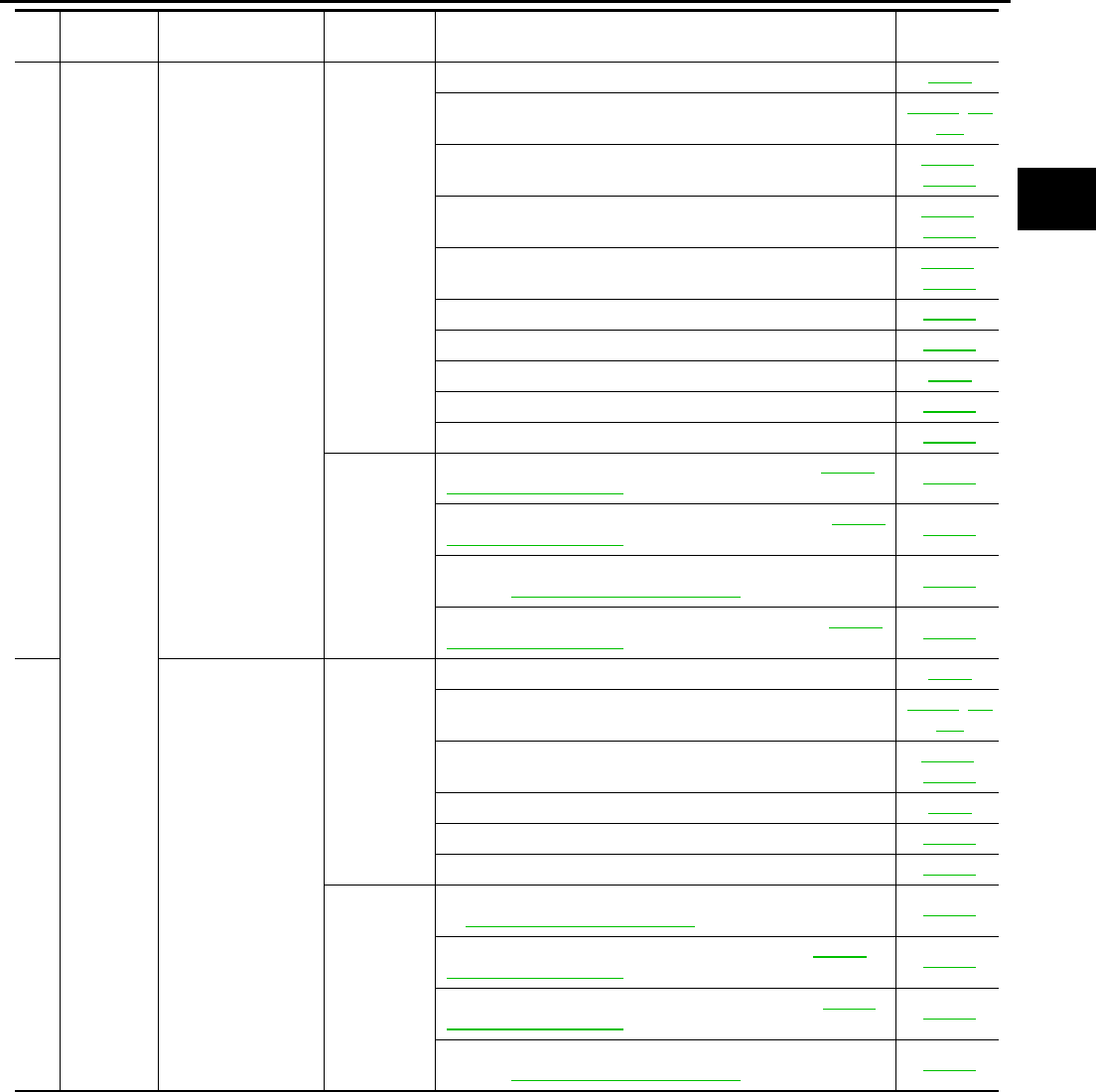
TROUBLE DIAGNOSIS
AT-69
D
E
F
G
H
I
J
K
L
M
A
B
AT
21
Slips/Will
Not
engage
When D or M posi-
tion, remains in 4th
gear.
ON vehicle
1. Fluid level and state AT-51
2. Vehicle speed sensor A/T and vehicle speed sensor MTR AT-117, AT-
164
3. ATF pressure switch 3 and input clutch solenoid valve AT-232,
AT-177
4. ATF pressure switch 5 and direct clutch solenoid valve AT-236,
AT-196
5. ATF pressure switch 6, high and low reverse clutch sole-
noid valve
AT-240,
AT-205
6. Low coast brake solenoid valve AT-215
7. Front brake solenoid valve AT-186
8. Line pressure test AT-52
9. CAN communication line AT-105
10. Control valve assembly AT-299
OFF vehicle
11. Input clutch (ATF condition “NG” only. Refer to AT-51,
"Fluid Condition Check" .) AT-344
12. Gear system (ATF condition “NG” only. Refer to AT-51,
"Fluid Condition Check" .) AT-317
13. High and low reverse clutch (ATF condition “NG” only.
Refer to AT-51, "Fluid Condition Check" .) AT-354
14. Direct clutch (ATF condition “NG” only. Refer to AT-51,
"Fluid Condition Check" .) AT-356
22
When D or M posi-
tion, remains in 5th
gear.
ON vehicle
1. Fluid level and state AT-51
2. Vehicle speed sensor A/T and vehicle speed sensor MTR AT-117, AT-
164
3. ATF pressure switch 1 and front brake solenoid valve AT-228,
AT-186
4. Line pressure test AT-52
5. CAN communication line AT-105
6. Control valve assembly AT-299
OFF vehicle
7. Front brake [brake band (ATF condition “NG” only. Refer
to AT-51, "Fluid Condition Check" .)] AT-325
8. Input clutch (ATF condition “NG” only. Refer to AT-51,
"Fluid Condition Check" .) AT-344
9. Gear system (ATF condition “NG” only. Refer to AT-51,
"Fluid Condition Check" .) AT-317
10. High and low reverse clutch (ATF condition “NG” only.
Refer to AT-51, "Fluid Condition Check" .) AT-354
No. Items Symptom Condition Diagnostic Item Reference
page
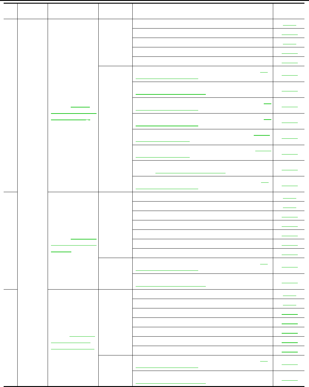
AT-70
TROUBLE DIAGNOSIS
23
Slips/Will
Not
Engage
Vehicle cannot be
started from D1 .
Refer to AT-260,
"Vehicle Cannot Be
Started From D1" .
ON vehicle
1. Fluid level and state AT-51
2. Accelerator pedal position sensor AT-151
3. Line pressure test AT-52
4. CAN communication line AT-105
5. Control valve assembly AT-299
OFF vehicle
6. Torque converter (ATF condition “NG” only. Refer to AT-
51, "Fluid Condition Check" .) AT-325
7. Oil pump assembly (ATF condition “NG” only. Refer to
AT-51, "Fluid Condition Check" .) AT-339
8. 3rd one-way clutch (ATF condition “NG” only. Refer to AT-
51, "Fluid Condition Check" .) AT-342
9. 1st one-way clutch (ATF condition “NG” only. Refer to AT-
51, "Fluid Condition Check" .) AT-349
10. Gear system (ATF condition “NG” only. Refer to AT-51,
"Fluid Condition Check" .) AT-317
11. Reverse brake (ATF condition “NG” only. Refer to AT-51,
"Fluid Condition Check" .) AT-325
12. Forward one-way clutch* (ATF condition “NG” only.
Refer to AT-51, "Fluid Condition Check" .) AT-325
13. Forward brake* (ATF condition “NG” only. Refer to AT-
51, "Fluid Condition Check" .) AT-325
24
Does not lock-up.
Refer to AT-272, "A/
T Does Not Perform
Lock-up" .
ON vehicle
1. Fluid level and state AT-51
2. Line pressure test AT-52
3. Engine speed signal AT-122
4. Turbine revolution sensor AT-159
5. Torque converter clutch solenoid valve AT-124
6. CAN communication line AT-105
7. Control valve assembly AT-299
OFF vehicle
8. Torque converter (ATF condition “NG” only. Refer to AT-
51, "Fluid Condition Check" .) AT-325
9. Oil pump assembly (ATF condition “NG” only. Refer to
AT-51, "Fluid Condition Check" .) AT-339
25
Does not hold lock-
up condition.
Refer toAT-274, "A/
T Does Not Hold
Lock-up Condition"
.
ON vehicle
1. Fluid level and state AT-51
2. Line pressure test AT-52
3. Engine speed signal AT-122
4. Turbine revolution sensor AT-159
5. Torque converter clutch solenoid valve AT-124
6. CAN communication line AT-105
7. Control valve assembly AT-299
OFF vehicle
8. Torque converter (ATF condition “NG” only. Refer to AT-
51, "Fluid Condition Check" .) AT-325
9. Oil pump assembly (ATF condition “NG” only. Refer to
AT-51, "Fluid Condition Check" .) AT-339
No. Items Symptom Condition Diagnostic Item Reference
page
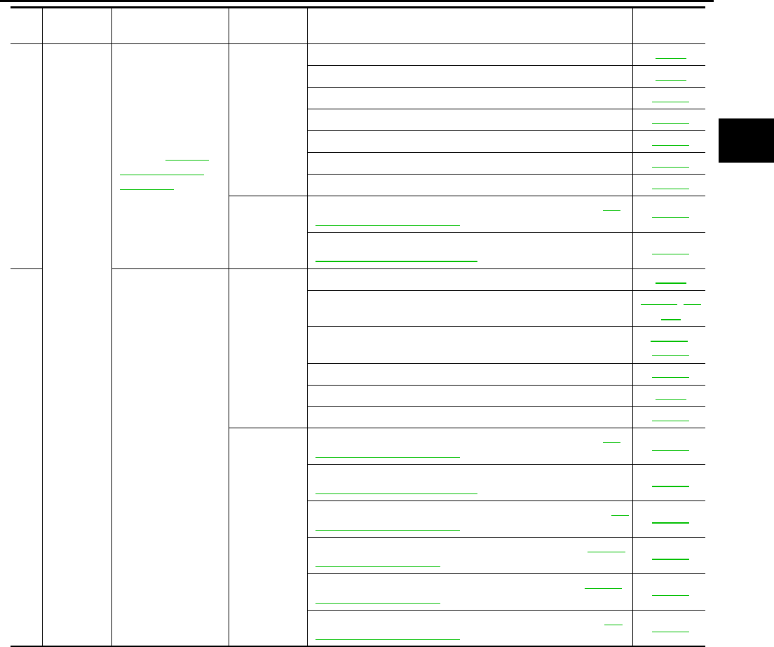
TROUBLE DIAGNOSIS
AT-71
D
E
F
G
H
I
J
K
L
M
A
B
AT
26
Slips/Will
Not
engage
Lock-up is not
released.
Refer to AT-276,
"Lock-up Is Not
Released" .
ON vehicle
1. Fluid level and state AT-51
2. Line pressure test AT-52
3. Engine speed signal AT-122
4. Turbine revolution sensor AT-159
5. Torque converter clutch solenoid valve AT-124
6. CAN communication line AT-105
7. Control valve assembly AT-299
OFF vehicle
8. Torque converter (ATF condition “NG” only. Refer to AT-
51, "Fluid Condition Check" .) AT-325
9. Oil pump assembly (ATF condition “NG” only. Refer to
AT-51, "Fluid Condition Check" .) AT-339
27
No shock at all or
the clutch slips
when vehicle
changes speed D1
→ D2 or M1 → M2 .
ON vehicle
1. Fluid level and state AT-51
2. Vehicle speed sensor A/T and vehicle speed sensor MTR AT-117, AT-
164
3. ATF pressure switch 5 and direct clutch solenoid
valve
AT-236,
AT-196
4. CAN communication line AT-105
5. Line pressure test AT-52
6. Control valve assembly AT-299
OFF vehicle
7. Torque converter (ATF condition “NG” only. Refer to AT-
51, "Fluid Condition Check" .) AT-325
8. Oil pump assembly (ATF condition “NG” only. Refer to
AT-51, "Fluid Condition Check" .) AT-339
9. 3rd one-way clutch (ATF condition “NG” only. Refer to AT-
51, "Fluid Condition Check" .) AT-342
10. Gear system (ATF condition “NG” only. Refer to AT-51,
"Fluid Condition Check" .) AT-317
11. Direct clutch (ATF condition “NG” only. Refer to AT-51,
"Fluid Condition Check" .) AT-356
12. Forward brake* (ATF condition “NG” only. Refer to AT-
51, "Fluid Condition Check" .) AT-325
No. Items Symptom Condition Diagnostic Item Reference
page
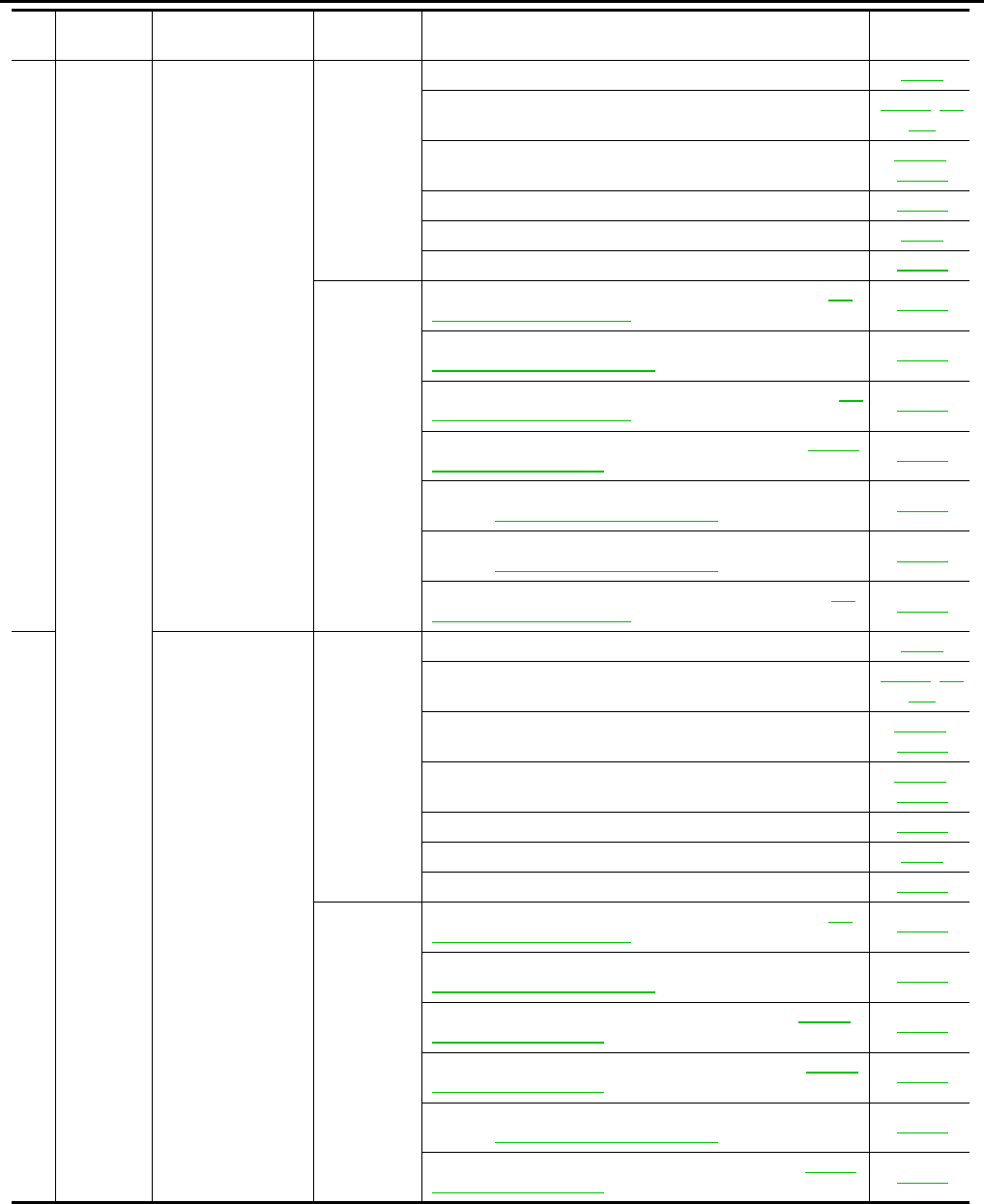
AT-72
TROUBLE DIAGNOSIS
28
Slips/Will
Not
engage
No shock at all or
the clutch slips
when vehicle
changes speed D2
→ D3 or M2 → M3 .
ON vehicle
1. Fluid level and state AT-51
2. Vehicle speed sensor A/T and vehicle speed sensor MTR AT-117, AT-
164
3. ATF pressure switch 6, high and low reverse clutch sole-
noid valve
AT-240,
AT-205
4. CAN communication line AT-105
5. Line pressure test AT-52
6. Control valve assembly AT-299
OFF vehicle
7. Torque converter (ATF condition “NG” only. Refer to AT-
51, "Fluid Condition Check" .) AT-325
8. Oil pump assembly (ATF condition “NG” only. Refer to
AT-51, "Fluid Condition Check" .) AT-339
9. 3rd one-way clutch (ATF condition “NG” only. Refer toAT-
51, "Fluid Condition Check" .) AT-342
10. Gear system (ATF condition “NG” only. Refer to AT-51,
"Fluid Condition Check" .) AT-317
11. High and low reverse clutch (ATF condition “NG” only.
Refer to AT-51, "Fluid Condition Check" .) AT-354
12. Forward one-way clutch* (ATF condition “NG” only.
Refer to AT-51, "Fluid Condition Check" .) AT-325
13. Forward brake* (ATF condition “NG” only. Refer to AT-
51, "Fluid Condition Check" .) AT-325
29
No shock at all or
the clutch slips
when vehicle
changes speed D3
→ D4 or M3 → M4 .
ON vehicle
1. Fluid level and state AT-51
2. Vehicle speed sensor A/T and vehicle speed sensor MTR AT-117, AT-
164
3. ATF pressure switch 3 and input clutch solenoid valve AT-232,
AT-177
4. ATF pressure switch 1 and front brake solenoid valve AT-228,
AT-186
5. CAN communication line AT-105
6. Line pressure test AT-52
7. Control valve assembly AT-299
OFF vehicle
8. Torque converter (ATF condition “NG” only. Refer to AT-
51, "Fluid Condition Check" .) AT-325
9. Oil pump assembly (ATF condition “NG” only. Refer to
AT-51, "Fluid Condition Check" .) AT-339
10. Input clutch (ATF condition “NG” only. Refer to AT-51,
"Fluid Condition Check" .) AT-344
11. Gear system (ATF condition “NG” only. Refer to AT-51,
"Fluid Condition Check" .) AT-317
12. High and low reverse clutch (ATF condition “NG” only.
Refer to AT-51, "Fluid Condition Check" .) AT-354
13. Direct clutch (ATF condition “NG” only. Refer to AT-51,
"Fluid Condition Check" .) AT-356
No. Items Symptom Condition Diagnostic Item Reference
page
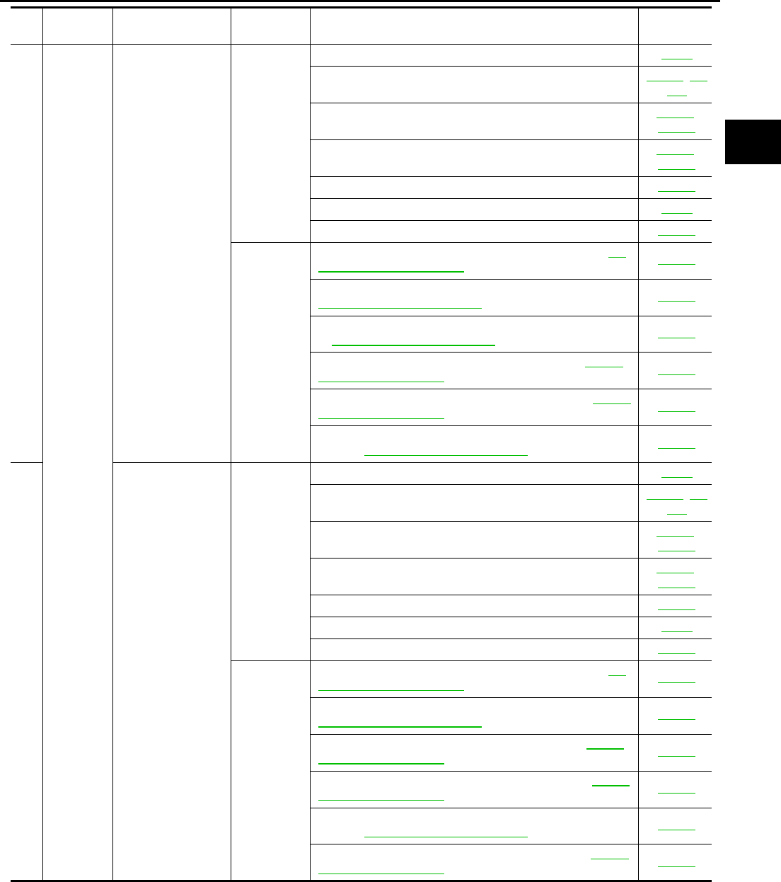
TROUBLE DIAGNOSIS
AT-73
D
E
F
G
H
I
J
K
L
M
A
B
AT
30
Slips/Will
Not
engage
No shock at all or
the clutch slips
when vehicle
changes speed D4
→ D5 or M4 → M5 .
ON vehicle
1. Fluid level and state AT-51
2. Vehicle speed sensor A/T and vehicle speed sensor MTR AT-117, AT-
164
3. ATF pressure switch 1 and front brake solenoid valve AT-228,
AT-186
4. ATF pressure switch 5 and direct clutch solenoid
valve
AT-236,
AT-196
5. CAN communication line AT-105
6. Line pressure test AT-52
7. Control valve assembly AT-299
OFF vehicle
8. Torque converter (ATF condition “NG” only. Refer to AT-
51, "Fluid Condition Check" .) AT-325
9. Oil pump assembly (ATF condition “NG” only. Refer to
AT-51, "Fluid Condition Check" .) AT-339
10. Front brake [brake band (ATF condition “NG” only. Refer
to AT-51, "Fluid Condition Check" .)] AT-325
11. Input clutch (ATF condition “NG” only. Refer to AT-51,
"Fluid Condition Check" .) AT-344
12. Gear system (ATF condition “NG” only. Refer to AT-51,
"Fluid Condition Check" .) AT-317
13. High and low reverse clutch (ATF condition “NG” only.
Refer to AT-51, "Fluid Condition Check" .) AT-354
31
When you press the
accelerator pedal
and shift speed D5
→ D4 or M5 → M4
the engine idles or
the transmission
slips.
ON vehicle
1. Fluid level and state AT-51
2. Vehicle speed sensor A/T and vehicle speed sensor MTR AT-117, AT-
164
3. ATF pressure switch 1 and front brake solenoid valve AT-228,
AT-186
4. ATF pressure switch 5 and direct clutch solenoid
valve
AT-236,
AT-196
5. CAN communication line AT-105
6. Line pressure test AT-52
7. Control valve assembly AT-299
OFF vehicle
8. Torque converter (ATF condition “NG” only. Refer to AT-
51, "Fluid Condition Check" .) AT-325
9. Oil pump assembly (ATF condition “NG” only. Refer to
AT-51, "Fluid Condition Check" .) AT-339
10. Input clutch (ATF condition “NG” only. Refer to AT-51,
"Fluid Condition Check" .) AT-344
11. Gear system (ATF condition “NG” only. Refer to AT-51,
"Fluid Condition Check" .) AT-317
12. High and low reverse clutch (ATF condition “NG” only.
Refer to AT-51, "Fluid Condition Check" .) AT-354
13. Direct clutch (ATF condition “NG” only. Refer to AT-51,
"Fluid Condition Check" .) AT-356
No. Items Symptom Condition Diagnostic Item Reference
page

AT-74
TROUBLE DIAGNOSIS
32
Slips/Will
Not
engage
When you press the
accelerator pedal
and shift speed D4
→ D3 or M4 → M3
the engine idles or
the transmission
slips.
ON vehicle
1. Fluid level and state AT-51
2. Vehicle speed sensor A/T and vehicle speed sensor MTR AT-117, AT-
164
3. ATF pressure switch 3 and input clutch solenoid valve AT-232,
AT-177
4. ATF pressure switch 1 and front brake solenoid valve AT-228,
AT-186
5. CAN communication line AT-105
6. Line pressure test AT-52
7. Control valve assembly AT-299
OFF vehicle
8. Torque converter (ATF condition “NG” only. Refer to AT-
51, "Fluid Condition Check" .) AT-325
9. Oil pump assembly (ATF condition “NG” only. Refer to
AT-51, "Fluid Condition Check" .) AT-339
10. 3rd one-way clutch (ATF condition “NG” only. Refer to
AT-51, "Fluid Condition Check" .) AT-342
11. Gear system (ATF condition “NG” only. Refer to AT-51,
"Fluid Condition Check" .) AT-317
12. High and low reverse clutch (ATF condition “NG” only.
Refer to AT-51, "Fluid Condition Check" .) AT-354
13. Forward one-way clutch* (ATF condition “NG” only.
Refer to AT-51, "Fluid Condition Check" .) AT-325
14. Forward brake* (ATF condition “NG” only. Refer to AT-
51, "Fluid Condition Check" .) AT-325
33
When you press the
accelerator pedal
and shift speed D3
→ D2 or M3 → M2
the engine idles or
the transmission
slips.
ON vehicle
1. Fluid level and state AT-51
2. Vehicle speed sensor A/T and vehicle speed sensor MTR AT-117, AT-
164
3. ATF pressure switch 6, high and low reverse clutch sole-
noid valve
AT-240,
AT-205
4. ATF pressure switch 5 and direct clutch solenoid
valve
AT-236,
AT-196
5. CAN communication line AT-105
6. Line pressure test AT-52
7. Control valve assembly AT-299
OFF vehicle
8. Torque converter (ATF condition “NG” only. Refer to AT-
51, "Fluid Condition Check" .) AT-325
9. Oil pump assembly (ATF condition “NG” only. Refer to
AT-51, "Fluid Condition Check" .) AT-339
10. 3rd one-way clutch (ATF condition “NG” only. Refer to
AT-51, "Fluid Condition Check" .) AT-342
11. Gear system (ATF condition “NG” only. Refer to AT-51,
"Fluid Condition Check" .) AT-317
12. Direct clutch (ATF condition “NG” only. Refer to AT-51,
"Fluid Condition Check" .) AT-356
13. Forward brake* (ATF condition “NG” only. Refer to AT-
51, "Fluid Condition Check" .) AT-325
No. Items Symptom Condition Diagnostic Item Reference
page
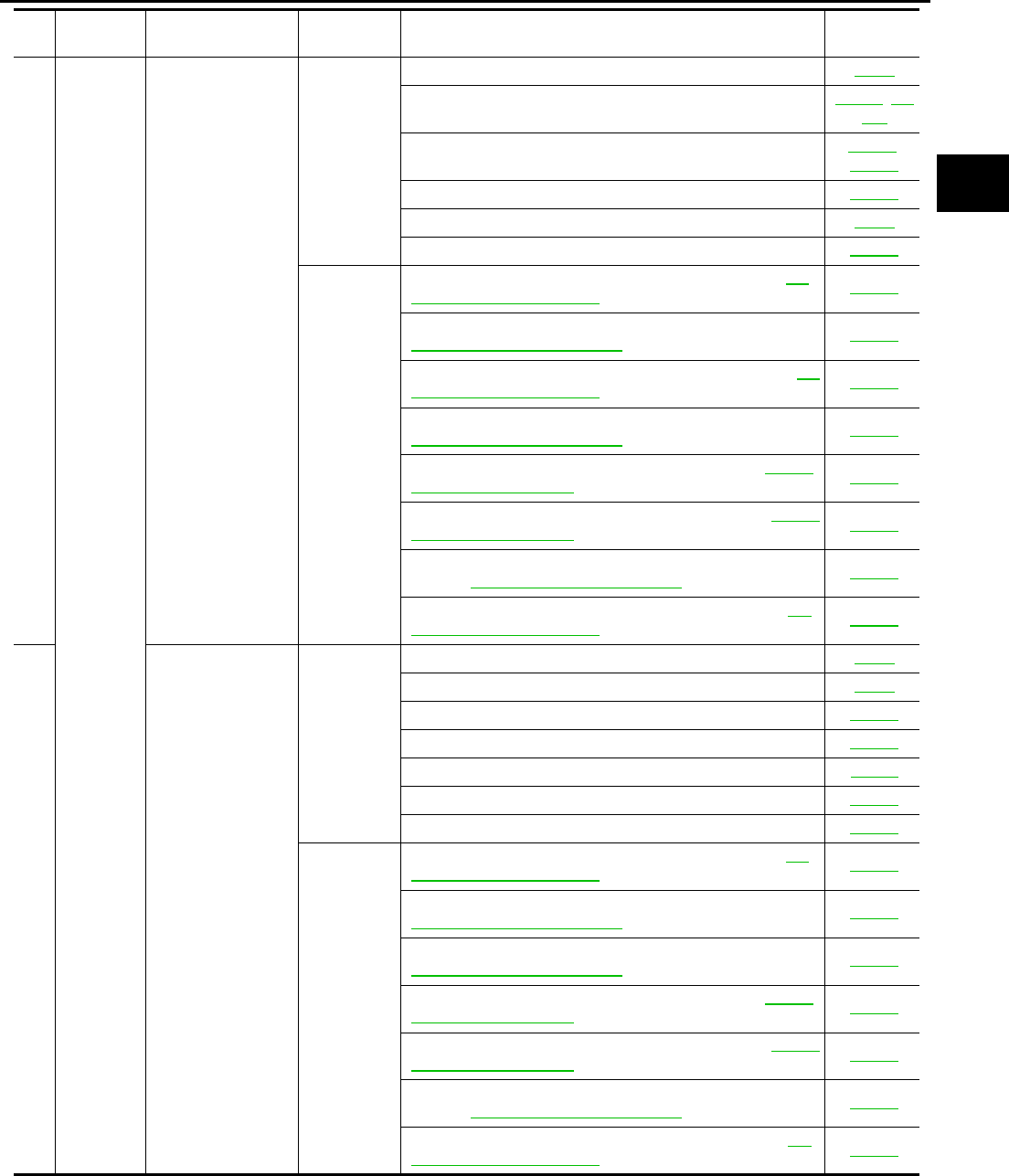
TROUBLE DIAGNOSIS
AT-75
D
E
F
G
H
I
J
K
L
M
A
B
AT
34
Slips/Will
Not
Engage
When you press the
accelerator pedal
and shift speed D2
→ D1 or M2 → M1
the engine idles or
the transmission
slips.
ON vehicle
1. Fluid level and state AT-51
2. Vehicle speed sensor A/T and vehicle speed sensor MTR AT-117, AT-
164
3. ATF pressure switch 5 and direct clutch solenoid
valve
AT-236,
AT-196
4. CAN communication line AT-105
5. Line pressure test AT-52
6. Control valve assembly AT-299
OFF vehicle
7. Torque converter (ATF condition “NG” only. Refer to AT-
51, "Fluid Condition Check" .) AT-325
8. Oil pump assembly (ATF condition “NG” only. Refer to
AT-51, "Fluid Condition Check" .) AT-339
9. 3rd one-way clutch (ATF condition “NG” only. Refer to AT-
51, "Fluid Condition Check" .) AT-342
10. 1st one-way clutch (ATF condition “NG” only. Refer to
AT-51, "Fluid Condition Check" .) AT-349
11. Gear system (ATF condition “NG” only. Refer to AT-51,
"Fluid Condition Check" .) AT-317
12. Reverse brake (ATF condition “NG” only. Refer to AT-51,
"Fluid Condition Check" .) AT-325
13. Forward one-way clutch* (ATF condition “NG” only.
Refer to AT-51, "Fluid Condition Check" .) AT-325
14. Forward brake* (ATF condition “NG” only. Refer to AT-
51, "Fluid Condition Check" .) AT-325
35
With selector lever
in D position, accel-
eration is extremely
poor.
ON vehicle
1. Fluid level and state AT-51
2. Line pressure test AT-52
3. Accelerator pedal position sensor AT-151
4. CAN communication line AT-105
5. PNP switch AT-112
6. Control linkage adjustment AT-289
7. Control valve assembly AT-299
OFF vehicle
8. Torque converter (ATF condition “NG” only. Refer to AT-
51, "Fluid Condition Check" .) AT-325
9. Oil pump assembly (ATF condition “NG” only. Refer to
AT-51, "Fluid Condition Check" .) AT-339
10. 1st one-way clutch (ATF condition “NG” only. Refer to
AT-51, "Fluid Condition Check" .) AT-349
11. Gear system (ATF condition “NG” only. Refer to AT-51,
"Fluid Condition Check" .) AT-317
12. Reverse brake (ATF condition “NG” only. Refer to AT-51,
"Fluid Condition Check" .) AT-325
13. Forward one-way clutch* (ATF condition “NG” only.
Refer to AT-51, "Fluid Condition Check" .) AT-325
14. Forward brake* (ATF condition “NG” only. Refer to AT-
51, "Fluid Condition Check" .) AT-325
No. Items Symptom Condition Diagnostic Item Reference
page
AT-76
TROUBLE DIAGNOSIS
36
Slips/Will
Not
Engage
With selector lever
in R position, accel-
eration is extremely
poor.
ON vehicle
1. Fluid level and state AT-51
2. Line pressure test AT-52
3. Accelerator pedal position sensor AT-151
4. ATF pressure switch 6, high and low reverse clutch sole-
noid valve
AT-240,
AT-205
5. CAN communication line AT-105
6. PNP switch AT-112
7. Control linkage adjustment AT-289
8. Control valve assembly AT-299
OFF vehicle
9. Gear system (ATF condition “NG” only. Refer to AT-51,
"Fluid Condition Check" .) AT-317
10. Output shaft (ATF condition “NG” only. Refer to AT-51,
"Fluid Condition Check" .) AT-325
11. Reverse brake (ATF condition “NG” only. Refer to AT-51,
"Fluid Condition Check" .) AT-325
37
While starting off by
accelerating in 1st,
engine races or
slippage occurs.
ON vehicle
1. Fluid level and state AT-51
2. Line pressure test AT-52
3. Accelerator pedal position sensor AT-151
4. CAN communication line AT-105
5. Control valve assembly AT-299
OFF vehicle
6. Torque converter (ATF condition “NG” only. Refer to AT-
51, "Fluid Condition Check" .) AT-325
7. Oil pump assembly (ATF condition “NG” only. Refer to
AT-51, "Fluid Condition Check" .) AT-339
8. 3rd one-way clutch (ATF condition “NG” only. Refer to AT-
51, "Fluid Condition Check" .) AT-342
9. 1st one-way clutch (ATF condition “NG” only. Refer to AT-
51, "Fluid Condition Check" .) AT-349
10. Gear system (ATF condition “NG” only. Refer to AT-51,
"Fluid Condition Check" .) AT-317
11. Reverse brake (ATF condition “NG” only. Refer to AT-51,
"Fluid Condition Check" .) AT-325
12. Forward one-way clutch* (ATF condition “NG” only.
Refer to AT-51, "Fluid Condition Check" .) AT-325
13. Forward brake* (ATF condition “NG” only. Refer to AT-
51, "Fluid Condition Check" .) AT-325
No. Items Symptom Condition Diagnostic Item Reference
page
TROUBLE DIAGNOSIS
AT-77
D
E
F
G
H
I
J
K
L
M
A
B
AT
38
Slips/Will
Not
Engage
While accelerating
in 2nd, engine
races or slippage
occurs.
ON vehicle
1. Fluid level and state AT-51
2. Line pressure test AT-52
3. Accelerator pedal position sensor AT-151
4. CAN communication line AT-105
5. ATF pressure switch 5 and direct clutch solenoid valve AT-236,
AT-196
6. Control valve assembly AT-299
OFF vehicle
7. Torque converter (ATF condition “NG” only. Refer to AT-
51, "Fluid Condition Check" .) AT-325
8. Oil pump assembly (ATF condition “NG” only. Refer to
AT-51, "Fluid Condition Check" .) AT-339
9. 3rd one-way clutch (ATF condition “NG” only. Refer to AT-
51, "Fluid Condition Check" .) AT-342
10. Gear system (ATF condition “NG” only. Refer to AT-51,
"Fluid Condition Check" .) AT-317
11. Direct clutch (ATF condition “NG” only. Refer to AT-51,
"Fluid Condition Check" .) AT-356
12. Forward brake* (ATF condition “NG” only. Refer to AT-
51, "Fluid Condition Check" .) AT-325
39
While accelerating
in 3rd, engine races
or slippage occurs.
ON vehicle
1. Fluid level and state AT-51
2. Line pressure test AT-52
3. Accelerator pedal position sensor AT-151
4. CAN communication line AT-105
5. ATF pressure switch 6, high and low reverse clutch sole-
noid valve
AT-240,
AT-205
6. Control valve assembly AT-299
OFF vehicle
7. Torque converter (ATF condition “NG” only. Refer to AT-
51, "Fluid Condition Check" .) AT-325
8. Oil pump assembly (ATF condition “NG” only. Refer to
AT-51, "Fluid Condition Check" .) AT-339
9. 3rd one-way clutch (ATF condition “NG” only. Refer to AT-
51, "Fluid Condition Check" .) AT-342
10. Gear system (ATF condition “NG” only. Refer to AT-51,
"Fluid Condition Check" .) AT-317
11. High and low reverse clutch (ATF condition “NG” only.
Refer to AT-51, "Fluid Condition Check" .) AT-354
12. Forward one-way clutch* (ATF condition “NG” only.
Refer to AT-51, "Fluid Condition Check" .) AT-325
13. Forward brake* (ATF condition “NG” only. Refer to AT-
51, "Fluid Condition Check" .) AT-325
No. Items Symptom Condition Diagnostic Item Reference
page
AT-78
TROUBLE DIAGNOSIS
40
Slips/Will
Not
Engage
While accelerating
in 4th, engine races
or slippage occurs.
ON vehicle
1. Fluid level and state AT-51
2. Line pressure test AT-52
3. Accelerator pedal position sensor AT-151
4. CAN communication line AT-105
5. ATF pressure switch 3 and input clutch solenoid valve AT-232,
AT-177
6. Control valve assembly AT-299
OFF vehicle
7. Torque converter (ATF condition “NG” only. Refer to AT-
51, "Fluid Condition Check" .) AT-325
8. Oil pump assembly (ATF condition “NG” only. Refer to
AT-51, "Fluid Condition Check" .) AT-339
9. Input clutch (ATF condition “NG” only. Refer to AT-51,
"Fluid Condition Check" .) AT-344
10. Gear system (ATF condition “NG” only. Refer to AT-51,
"Fluid Condition Check" .) AT-317
11. High and low reverse clutch (ATF condition “NG” only.
Refer to AT-51, "Fluid Condition Check" .) AT-354
12. Direct clutch (ATF condition “NG” only. Refer to AT-51,
"Fluid Condition Check" .) AT-356
41
While accelerating
in 5th, engine races
or slippage occurs.
ON vehicle
1. Fluid level and state AT-51
2. Line pressure test AT-52
3. Accelerator pedal position sensor AT-151
4. CAN communication line AT-105
5. ATF pressure switch 1 and front brake solenoid valve AT-228,
AT-186
6. Control valve assembly AT-299
OFF vehicle
7. Torque converter (ATF condition “NG” only. Refer to AT-
51, "Fluid Condition Check" .) AT-325
8. Oil pump assembly (ATF condition “NG” only. Refer to
AT-51, "Fluid Condition Check" .) AT-339
9. Front brake [brake band (ATF condition “NG” only. Refer
to AT-51, "Fluid Condition Check" .)] AT-325
10. Input clutch (ATF condition “NG” only. Refer to AT-51,
"Fluid Condition Check" .) AT-344
11. Gear system (ATF condition “NG” only. Refer to AT-51,
"Fluid Condition Check" .) AT-317
12. High and low reverse clutch (ATF condition “NG” only.
Refer to AT-51, "Fluid Condition Check" .) AT-354
No. Items Symptom Condition Diagnostic Item Reference
page
TROUBLE DIAGNOSIS
AT-79
D
E
F
G
H
I
J
K
L
M
A
B
AT
42
Slips/Will
Not
Engage
Slips at lock-up.
ON vehicle
1. Fluid level and state AT-51
2. Line pressure test AT-52
3. Engine speed signal AT-122
4. Turbine revolution sensor AT-159
5. Torque converter clutch solenoid valve AT-124
6. CAN communication line AT-105
7. Control valve assembly AT-299
OFF vehicle
8. Torque converter (ATF condition “NG” only. Refer to AT-
51, "Fluid Condition Check" .) AT-325
9. Oil pump assembly (ATF condition “NG” only. Refer to
AT-51, "Fluid Condition Check" .) AT-339
43
No creep at all.
Refer to AT-255,
"Vehicle Does Not
Creep Backward In
“R” Position" , AT-
258, "Vehicle Does
Not Creep Forward
In “D” Position"
ON vehicle
1. Fluid level and state AT-51
2. Line pressure test AT-52
3. Accelerator pedal position sensor AT-151
4. ATF pressure switch 5 and direct clutch solenoid valve AT-236,
AT-196
5. PNP switch AT-112
6. CAN communication line AT-105
7. Control linkage adjustment AT-289
8. Control valve assembly AT-299
OFF vehicle
9. Torque converter (ATF condition “NG” only. Refer to AT-
51, "Fluid Condition Check" .) AT-325
10. Oil pump assembly (ATF condition “NG” only. Refer to
AT-51, "Fluid Condition Check" .) AT-339
11. 1st one-way clutch (ATF condition “NG” only. Refer to
AT-51, "Fluid Condition Check" .) AT-349
12. Gear system (ATF condition “NG” only. Refer to AT-51,
"Fluid Condition Check" .) AT-317
13. Reverse brake (ATF condition “NG” only. Refer to AT-51,
"Fluid Condition Check" .) AT-325
14. Direct clutch (ATF condition “NG” only. Refer to AT-51,
"Fluid Condition Check" .) AT-356
15. Forward one-way clutch* (ATF condition “NG” only.
Refer to AT-51, "Fluid Condition Check" .) AT-325
16. Forward brake* (ATF condition “NG” only. Refer to AT-
51, "Fluid Condition Check" .) AT-325
No. Items Symptom Condition Diagnostic Item Reference
page
AT-80
TROUBLE DIAGNOSIS
44
Slips/Will
Not
Engage
Vehicle cannot run
in all positions.
ON vehicle
1. Fluid level and state AT-51
2. Line pressure test AT-52
3. PNP switch AT-112
4. Control linkage adjustment AT-289
5. Control valve assembly AT-299
OFF vehicle
6. Oil pump assembly (ATF condition “NG” only. Refer to
AT-51, "Fluid Condition Check" .) AT-339
7. Gear system (ATF condition “NG” only. Refer to AT-51,
"Fluid Condition Check" .) AT-317
8. Output shaft (ATF condition “NG” only. Refer to AT-51,
"Fluid Condition Check" .) AT-325
45
With selector lever
in D position, driv-
ing is not possible.
ON vehicle
1. Fluid level and state AT-51
2. Line pressure test AT-52
3. PNP switch AT-112
4. Control linkage adjustment AT-289
5. Control valve assembly AT-299
OFF vehicle
6. Torque converter (ATF condition “NG” only. Refer to AT-
51, "Fluid Condition Check" .) AT-325
7. Oil pump assembly (ATF condition “NG” only. Refer to
AT-51, "Fluid Condition Check" .) AT-339
8. 1st one-way clutch (ATF condition “NG” only. Refer to AT-
51, "Fluid Condition Check" .) AT-349
9. Gear system (ATF condition “NG” only. Refer to AT-51,
"Fluid Condition Check" .) AT-317
10. Reverse brake (ATF condition “NG” only. Refer to AT-51,
"Fluid Condition Check" .) AT-325
11. Forward one-way clutch* (ATF condition “NG” only.
Refer to AT-51, "Fluid Condition Check" .) AT-325
12. Forward brake* (ATF condition “NG” only. Refer to AT-
51, "Fluid Condition Check" .) AT-325
46
With selector lever
in R position, driv-
ing is not possible.
ON vehicle
1. Fluid level and state AT-51
2. Line pressure test AT-52
3. PNP switch AT-112
4. Control linkage adjustment AT-289
5. Control valve assembly AT-299
OFF vehicle
6. Gear system (ATF condition “NG” only. Refer to AT-51,
"Fluid Condition Check" .) AT-317
7. Output shaft (ATF condition “NG” only. Refer to AT-51,
"Fluid Condition Check" .) AT-325
8. Reverse brake (ATF condition “NG” only. Refer to AT-51,
"Fluid Condition Check" .) AT-325
No. Items Symptom Condition Diagnostic Item Reference
page
TROUBLE DIAGNOSIS
AT-81
D
E
F
G
H
I
J
K
L
M
A
B
AT
47
Does Not
Change
Does not change
M5 → M4.
ON vehicle
1. PNP switch AT-112
2. Fluid level and state AT-51
3. Control linkage adjustment AT-289
4. Manual mode switch AT-224
5. ATF pressure switch 1 AT-228
6. CAN communication line AT-105
7. Control valve assembly AT-299
OFF vehicle 8. Front brake [brake band (ATF condition “NG” only. Refer
to AT-51, "Fluid Condition Check" .)] AT-325
48 Does not change
M4 → M3.
ON vehicle
1. PNP switch AT-112
2. Fluid level and state AT-51
3. Control linkage adjustment AT-289
4. Manual mode switch AT-224
5. ATF pressure switch 1 and ATF pressure switch 3 AT-228,
AT-232
6. CAN communication line AT-105
7. Control valve assembly AT-299
OFF vehicle
8. Front brake [brake band (ATF condition “NG” only. Refer
to AT-51, "Fluid Condition Check" .)] AT-325
9. Input clutch (ATF condition “NG” only. Refer to AT-51,
"Fluid Condition Check" .) AT-344
49 Does not change
M3 → M2.
ON vehicle
1. PNP switch AT-112
2. Fluid level and state AT-51
3. Control linkage adjustment AT-289
4. Manual mode switch AT-224
5. ATF pressure switch 6 AT-240
6. CAN communication line AT-105
7. Control valve assembly AT-299
OFF vehicle
8. Front brake [brake band (ATF condition “NG” only. Refer
to AT-51, "Fluid Condition Check" .)] AT-325
9. Input clutch (ATF condition “NG” only. Refer to AT-51,
"Fluid Condition Check" .) AT-344
10. High and low reverse clutch (ATF condition “NG” only.
Refer to AT-51, "Fluid Condition Check" .) AT-354
No. Items Symptom Condition Diagnostic Item Reference
page
AT-82
TROUBLE DIAGNOSIS
50
Does Not
Change
Does not change
M2 → M1.
ON vehicle
1. PNP switch AT-112
2. Fluid level and state AT-51
3. Control linkage adjustment AT-289
4. Manual mode switch AT-224
5. ATF pressure switch 5 AT-236
6. CAN communication line AT-105
7. Control valve assembly AT-299
OFF vehicle
8. Input clutch (ATF condition “NG” only. Refer to AT-51,
"Fluid Condition Check" .) AT-344
9. High and low reverse clutch (ATF condition “NG” only.
Refer to AT-51, "Fluid Condition Check" .) AT-354
10. Direct clutch (ATF condition “NG” only. Refer to AT-51,
"Fluid Condition Check" .) AT-356
51
Can not be
changed to manual
mode.
Refer to AT-278,
"Cannot Be
Changed to Man-
ual Mode" .
ON vehicle
1. Manual mode switch AT-224
2. Turbine revolution sensor AT-159
3. CAN communication line AT-105
52
Others
Shift point is high in
D position. ON vehicle
1. Vehicle speed sensor A/T and vehicle speed sensor MTR AT-117, AT-
164
2. Accelerator pedal position sensor AT-151
3. CAN communication line AT-105
4. ATF temperature sensor AT-153
5. Control valve assembly AT-299
53 Shift point is low in
D position. ON vehicle
1. Vehicle speed sensor A/T and vehicle speed sensor MTR AT-117, AT-
164
2. Accelerator pedal position sensor AT-151
3. CAN communication line AT-105
4. Control valve assembly AT-299
54 Judder occurs dur-
ing lock-up.
ON vehicle
1. Fluid level and state AT-51
2. Engine speed signal AT-122
3. Turbine revolution sensor AT-159
4. Vehicle speed sensor A/T and vehicle speed sensor MTR AT-117, AT-
164
5. Accelerator pedal position sensor AT-151
6. CAN communication line AT-105
7. Torque converter clutch solenoid valve AT-124
8. Control valve assembly AT-299
OFF vehicle 9. Torque converter (ATF condition “NG” only. Refer to AT-
51, "Fluid Condition Check" .) AT-325
No. Items Symptom Condition Diagnostic Item Reference
page
TROUBLE DIAGNOSIS
AT-83
D
E
F
G
H
I
J
K
L
M
A
B
AT
55
Others
Strange noise in “R”
position.
ON vehicle
1. Fluid level and state AT-51
2. Engine speed signal AT-122
3. CAN communication line AT-105
4. Control valve assembly AT-299
OFF vehicle
5. Torque converter (ATF condition “NG” only. Refer to AT-
51, "Fluid Condition Check" .) AT-325
6. Oil pump assembly (ATF condition “NG” only. Refer to
AT-51, "Fluid Condition Check" .) AT-339
7. Gear system (ATF condition “NG” only. Refer to AT-51,
"Fluid Condition Check" .) AT-317
8. High and low reverse clutch (ATF condition “NG” only.
Refer to AT-51, "Fluid Condition Check" .) AT-354
9. Reverse brake (ATF condition “NG” only. Refer to AT-51,
"Fluid Condition Check" .) AT-325
56 Strange noise in “N”
position.
ON vehicle
1. Fluid level and state AT-51
2. Engine speed signal AT-122
3. CAN communication line AT-105
4. Control valve assembly AT-299
OFF vehicle
5. Torque converter (ATF condition “NG” only. Refer to AT-
51, "Fluid Condition Check" .) AT-325
6. Oil pump assembly (ATF condition “NG” only. Refer to
AT-51, "Fluid Condition Check" .) AT-339
7. Gear system (ATF condition “NG” only. Refer to AT-51,
"Fluid Condition Check" .) AT-317
57 Strange noise in “D”
position.
ON vehicle
1. Fluid level and state AT-51
2. Engine speed signal AT-122
3. CAN communication line AT-105
4. Control valve assembly AT-299
OFF vehicle
5. Torque converter (ATF condition “NG” only. Refer to AT-
51, "Fluid Condition Check" .) AT-325
6. Oil pump assembly (ATF condition “NG” only. Refer to
AT-51, "Fluid Condition Check" .) AT-339
7. Gear system (ATF condition “NG” only. Refer to AT-51,
"Fluid Condition Check" .) AT-317
8. Forward brake* (ATF condition “NG” only. Refer to AT-
51, "Fluid Condition Check" .) AT-325
No. Items Symptom Condition Diagnostic Item Reference
page

AT-84
TROUBLE DIAGNOSIS
58
Others
Vehicle dose not
decelerate by
engine brake.
Refer to AT-286,
"Vehicle Does Not
Decelerate By
Engine Brake" .
ON vehicle
1. PNP switch AT-112
2. Fluid level and state AT-51
3. Control linkage adjustment AT-289
4. Manual mode switch AT-224
5. ATF pressure switch 5 AT-236
6. CAN communication line AT-105
7. Control valve assembly AT-299
OFF vehicle
8. Input clutch (ATF condition “NG” only. Refer to AT-51,
"Fluid Condition Check" .) AT-344
9. High and low reverse clutch (ATF condition “NG” only.
Refer to AT-51, "Fluid Condition Check" .) AT-354
10. Direct clutch (ATF condition “NG” only. Refer to AT-51,
"Fluid Condition Check" .) AT-356
59 Engine brake does
not work M5 → M4.
ON vehicle
1. PNP switch AT-112
2. Fluid level and state AT-51
3. Control linkage adjustment AT-289
4. Manual mode switch AT-224
5. ATF pressure switch 1 AT-228
6. CAN communication line AT-105
7. Control valve assembly AT-299
OFF vehicle 8. Front brake [brake band (ATF condition “NG” only. Refer
to AT-51, "Fluid Condition Check" .)] AT-325
60 Engine brake does
not work M4 → M3.
ON vehicle
1. PNP switch AT-112
2. Fluid level and state AT-51
3. Control linkage adjustment AT-289
4. Manual mode switch AT-224
5. ATF pressure switch 1 and ATF pressure switch 3 AT-228,
AT-232
6. CAN communication line AT-105
7. Control valve assembly AT-299
OFF vehicle
8. Front brake [brake band (ATF condition “NG” only. Refer
to AT-51, "Fluid Condition Check" .)] AT-325
9. Input clutch (ATF condition “NG” only. Refer to AT-51,
"Fluid Condition Check" .) AT-344
No. Items Symptom Condition Diagnostic Item Reference
page
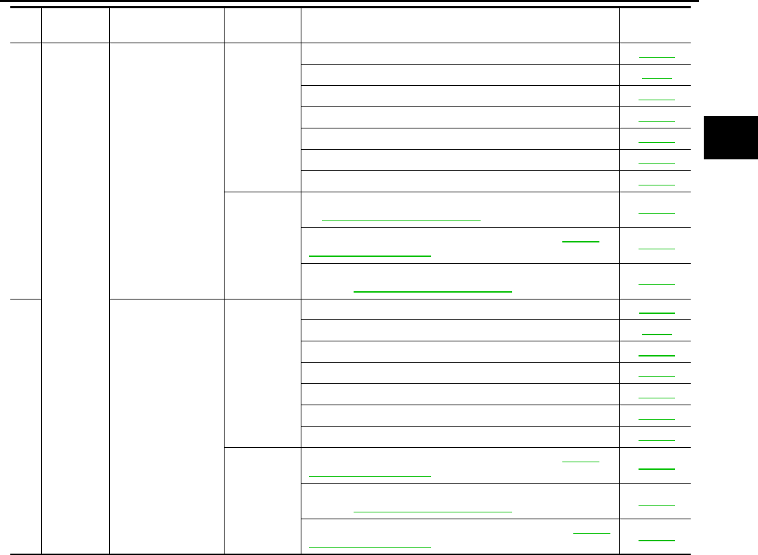
TROUBLE DIAGNOSIS
AT-85
D
E
F
G
H
I
J
K
L
M
A
B
AT
61
Others
Engine brake does
not work M3 → M2.
ON vehicle
1. PNP switch AT-112
2. Fluid level and state AT-51
3. Control linkage adjustment AT-289
4. Manual mode switch AT-224
5. ATF pressure switch 6 AT-240
6. CAN communication line AT-105
7. Control valve assembly AT-299
OFF vehicle
8. Front brake [brake band (ATF condition “NG” only. Refer
to AT-51, "Fluid Condition Check" .)] AT-325
9. Input clutch (ATF condition “NG” only. Refer to AT-51,
"Fluid Condition Check" .) AT-344
10. High and low reverse clutch (ATF condition “NG” only.
Refer to AT-51, "Fluid Condition Check" .) AT-354
62 Engine brake does
not work M2 → M1.
ON vehicle
1. PNP switch AT-112
2. Fluid level and state AT-51
3. Control linkage adjustment AT-289
4. Manual mode switch AT-224
5. ATF pressure switch 5 AT-236
6. CAN communication line AT-105
7. Control valve assembly AT-299
OFF vehicle
8. Input clutch (ATF condition “NG” only. Refer to AT-51,
"Fluid Condition Check" .) AT-344
9. High and low reverse clutch (ATF condition “NG” only.
Refer to AT-51, "Fluid Condition Check" .) AT-354
10. Direct clutch (ATF condition “NG” only. Refer to AT-51,
"Fluid Condition Check" .) AT-356
No. Items Symptom Condition Diagnostic Item Reference
page
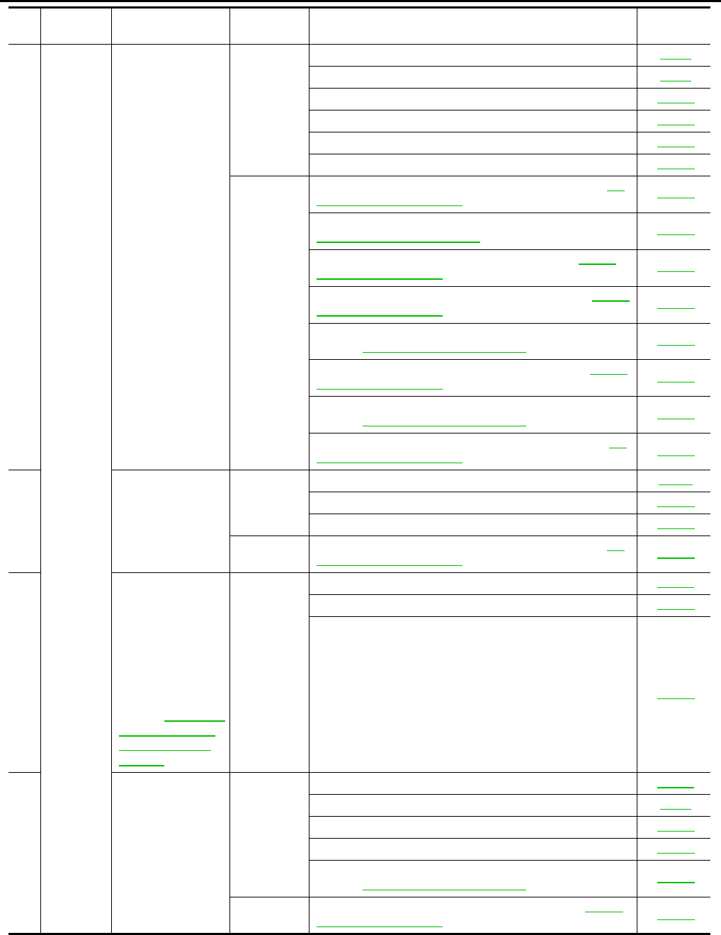
AT-86
TROUBLE DIAGNOSIS
63
Others
Maximum speed
low.
ON vehicle
1. Fluid level and state AT-51
2. Line pressure test AT-52
3. Accelerator pedal position sensor AT-151
4. CAN communication line AT-105
5. Direct clutch solenoid valve AT-196
6. Control valve assembly AT-299
OFF vehicle
7. Torque converter (ATF condition “NG” only. Refer to AT-
51, "Fluid Condition Check" .) AT-325
8. Oil pump assembly (ATF condition “NG” only. Refer to
AT-51, "Fluid Condition Check" .) AT-339
9. Input clutch (ATF condition “NG” only. Refer to AT-51,
"Fluid Condition Check" .) AT-344
10. Gear system (ATF condition “NG” only. Refer to AT-51,
"Fluid Condition Check" .) AT-317
11. High and low reverse clutch (ATF condition “NG” only.
Refer to AT-51, "Fluid Condition Check" .) AT-354
12. Direct clutch (ATF condition “NG” only. Refer to AT-51,
"Fluid Condition Check" .) AT-356
13. Forward one-way clutch* (ATF condition “NG” only.
Refer to AT-51, "Fluid Condition Check" .) AT-325
14. Forward brake* (ATF condition “NG” only. Refer to AT-
51, "Fluid Condition Check" .) AT-325
64 Extremely large
creep.
ON vehicle
1. Engine idle speed EC-30
2. CAN communication line AT-105
3. ATF pressure switch 5 AT-236
OFF vehicle 4. Torque converter (ATF condition “NG” only. Refer to AT-
51, "Fluid Condition Check" .) AT-325
65
With selector lever
in P position, vehi-
cle does not enter
parking condition
or, with selector
lever in another
position, parking
condition is not can-
celled.
Refer to AT-250, "In
“P” Position, Vehi-
cle Moves When
Pushed" .
ON vehicle
1. PNP switch AT-112
2. Control linkage adjustment AT-289
3. Parking pawl components AT-307
66
Vehicle runs with
transmission in “ P”
position.
ON vehicle
1. PNP switch AT-112
2. Fluid level and state AT-51
3. Control linkage adjustment AT-289
4. Control valve assembly AT-299
5. Parking pawl components (ATF condition “NG” only.
Refer to AT-51, "Fluid Condition Check" .) AT-317
OFF vehicle 6. Gear system (ATF condition “NG” only. Refer to AT-51,
"Fluid Condition Check" .) AT-317
No. Items Symptom Condition Diagnostic Item Reference
page
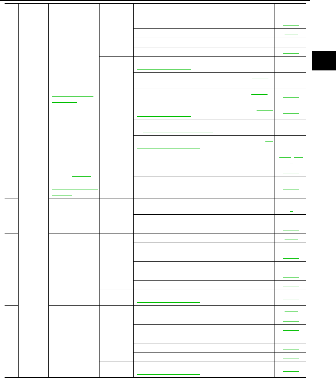
TROUBLE DIAGNOSIS
AT-87
D
E
F
G
H
I
J
K
L
M
A
B
AT
67
Others
Vehicle runs with
transmission in “N”
position.
Refer to AT-251, "In
“N” Position, Vehi-
cle Moves" .
ON vehicle
1. PNP switch AT-112
2. Fluid level and state AT-51
3. Control linkage adjustment AT-289
4. Control valve assembly AT-299
OFF vehicle
5. Input clutch (ATF condition “NG” only. Refer to AT-51,
"Fluid Condition Check" .) AT-344
6. Gear system (ATF condition “NG” only. Refer to AT-51,
"Fluid Condition Check" .) AT-317
7. Direct clutch (ATF condition “NG” only. Refer to AT-51,
"Fluid Condition Check" .) AT-356
8. Reverse brake (ATF condition “NG” only. Refer to AT-51,
"Fluid Condition Check" .) AT-325
9. Forward one-way clutch* (ATF condition “NG” only. Refer
to AT-51, "Fluid Condition Check" .) AT-325
10. Low coast brake* (ATF condition “NG” only. Refer to AT-
51, "Fluid Condition Check" .) AT-325
68
Engine does not
start in “N” or “P”
position.
Refer to AT-250,
"Engine Cannot Be
Started In “P” or “N”
Position" .
ON vehicle
1. Ignition switch and starter PG-3, SC-
9
2. Control linkage adjustment AT-289
3. PNP switch AT-112
69
Engine starts in
positions other than
“N” or “P”.
ON vehicle
1. Ignition switch and starter PG-3, SC-
9
2. Control linkage adjustment AT-289
3. PNP switch AT-112
70 Engine stall.
ON vehicle
1. Fluid level and state AT-51
2. Engine speed signal AT-122
3. Turbine revolution sensor AT-159
4. Torque converter clutch solenoid valve AT-124
5. CAN communication line AT-105
6. Control valve assembly AT-299
OFF vehicle 7. Torque converter (ATF condition “NG” only. Refer to AT-
51, "Fluid Condition Check" .) AT-325
71
Engine stalls when
select lever shifted
“N” → “D”, “R”.
ON vehicle
1. Fluid level and state AT-51
2. Engine speed signal AT-122
3. Turbine revolution sensor AT-159
4. Torque converter clutch solenoid valve AT-124
5. CAN communication line AT-105
6. Control valve assembly AT-299
OFF vehicle 7. Torque converter (ATF condition “NG” only. Refer to AT-
51, "Fluid Condition Check" .) AT-325
No. Items Symptom Condition Diagnostic Item Reference
page
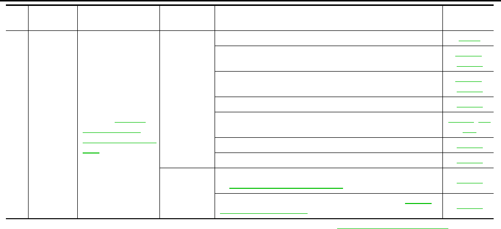
AT-88
TROUBLE DIAGNOSIS
* : Parts behind Drum Support is impossible to perform inspection by disassembly. Refer to AT-18, "Cross-Sectional View"
72 Others
Engine speed does
not return to idle.
Refer to AT-276,
"Engine Speed
Does Not Return To
Idle" .
ON vehicle
1. Fluid level and state AT-51
2. ATF pressure switch 5 and direct clutch solenoid valve AT-236,
AT-196
3. ATF pressure switch 1 and front brake solenoid valve AT-228,
AT-186
4. Accelerator pedal position sensor AT-151
5. Vehicle speed sensor A/T and vehicle speed sensor MTR AT-117, AT-
164
6. CAN communication line AT-105
7. Control valve assembly AT-299
OFF vehicle
8. Front brake [brake band (ATF condition “NG” only. Refer
to AT-51, "Fluid Condition Check" .)] AT-325
9. Direct clutch (ATF condition “NG” only. Refer to AT-51,
"Fluid Condition Check" .) AT-356
No. Items Symptom Condition Diagnostic Item Reference
page
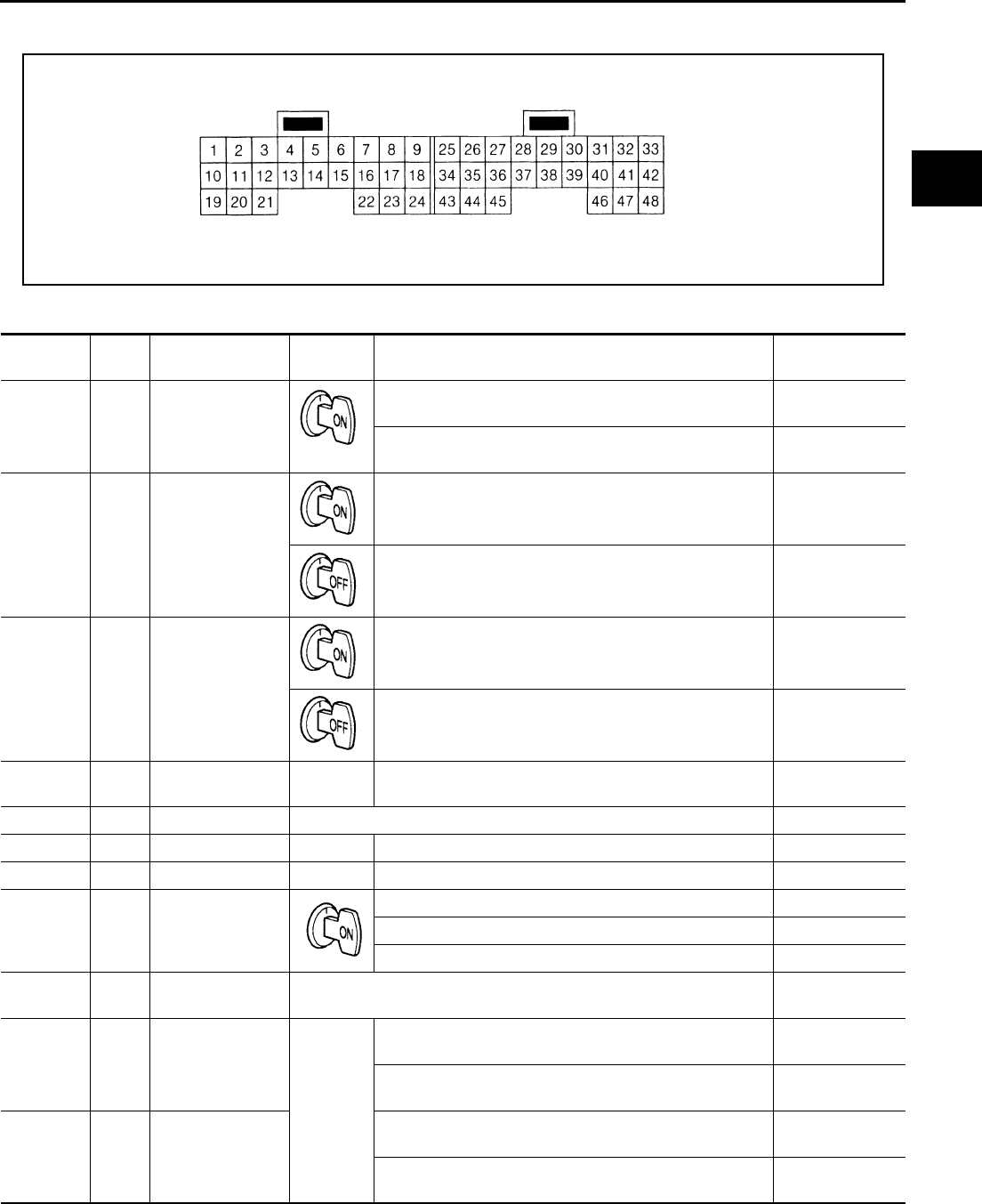
TROUBLE DIAGNOSIS
AT-89
D
E
F
G
H
I
J
K
L
M
A
B
AT
TCM Input/Output Signal Reference Values ACS001MM
TCM TERMINAL CONNECTOR LAYOUT
TCM INSPECTION TABLE
Data are reference value.Measured between each terminals 5, 14, 24 and 46 (TCM ground).
SCIA0495E
Terminal
No.
Wire
color item Condition Data (Approx)
1B/R
Line pressure
solenoid valve
After warming up the engine, release your foot from the
accelerator pedal. 2V
After warming up the engine, press the accelerator pedal
all the way down. 0.7V
2 W Power supply
–- Battery voltage
Measure 3 seconds after switching “OFF” the ignition
switch. 0V
3 W Power supply
–- Battery voltage
Measure 3 seconds after switching “OFF” the ignition
switch. 0V
4P/L
SEL3 (pressure
switch 3) –- –- –-
5 B Ground Always 0V
6LCAN H –- –- –-
7RCAN L –- –- –-
8 B/OR Fluid temperature
sensor 1
When ATF temperature 0°C (32°F) 2.2V
When ATF temperature 20°C (68°F) 1.8V
When ATF temperature 80°C (176°F) 0.6V
9R/W
Power supply
(Memory back-up) Always Battery voltage
10 OR Input clutch sole-
noid valve When
vehicle
cruises
When the solenoid valve operating (in 1st gear, 2nd gear,
or 3rd gear) More than 2V
When the solenoid valve is not operating (4th gear or 5th
gear) 0V
11 R/L
High and low
reverse clutch
solenoid valve
When the solenoid valve operating [6 km/h (4MPH) or
faster in 1st gear or 2nd gear] More than 2V
When the solenoid valve is not operating [6 km/h
(4MPH)or slower in 1st gear or 3rd, 4th, or 5th gear] 0V
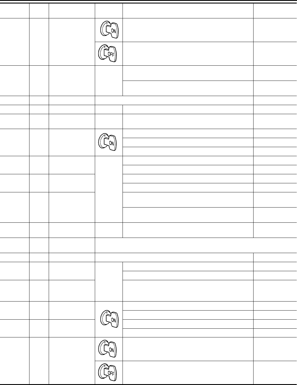
AT-90
TROUBLE DIAGNOSIS
12 Y/R Power Supply
(out)
–- Battery voltage
–- 0V
13 W/L Low coast brake
solenoid valve
When
vehicle
cruises
When the solenoid valve is operating (when running in
M1-1 gear or M2-2 gear) Battery voltage
When the solenoid valve is not operating (when running in
“D”) 0V
14 B Ground Always 0V
15 B/W SEL4 –- –- –-
16 W/G SEL1 (pressure
switch 2) –- –- –-
17 G/R Fluid temperature
sensor 2
When ATF temperature about 0°C (32°F) 2.2V
When ATF temperature about 20°C (68°F) 1.7V
When ATF temperature about 80°C (176°F) 0.45V
19 G/R Front brake sole-
noid valve
When
vehicle
cruises
When the solenoid valve is operating (other than 4th gear) More than 2V
When the solenoid valve is not operating (4th gear) 0V
20 Y TCC solenoid
valve
When lock-up More than 2V
When not lock-up 0V
21 G Direct clutch sole-
noid valve
When the solenoid valve is operating (1st gear or 5th
gear) More than 2V
When the solenoid valve is not operating (2nd gear, 3rd
gear, or 4th gear) 0V
22 P/B SEL2 (pressure
switch 5) –- –- –-
23 LG K-line (CONSULT-
II signal) The terminal is connected to the data link connector for CONSULT-II.
24 B Ground Always 0V
26 G/Y PSC2 (pressure
switch 6) When
vehicle
cruises
When high and low reverse clutch solenoid valve “ON”. 0V
When high and low reverse clutch solenoid valve “OFF”. Battery voltage
27 Y/B
Vehicle speed
sensor A/T (revo-
lution sensor)
When moving at 20 km/h (12MPH). 185 (Hz)
30 R/W PNP switch 1 Selector lever in “P” position. Battery voltage
Selector lever in “N” position. Less than 2.5V
31 OR PNP switch Selector lever in “P” position. Battery voltage
Selector lever in “D” position. Less than 2.5V
33 Y/R Power supply
–- Battery voltage
–- 0V
Terminal
No.
Wire
color item Condition Data (Approx)
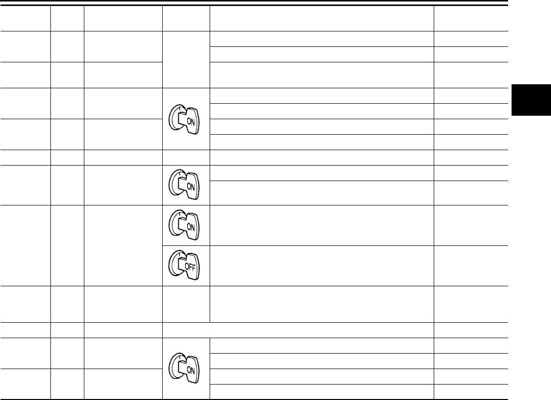
TROUBLE DIAGNOSIS
AT-91
D
E
F
G
H
I
J
K
L
M
A
B
AT
35 B/Y PSB2 (pressure
switch 1) When
vehicle
cruises
When front brake solenoid valve “OFF”. Battery voltage
When front brake solenoid valve“ ON”. 0V
36 L/Y Turbine revolution
sensor 1
When running at 50 km/h (31MPH) in 4th gear with the
closed throttle position signal “OFF”. 1.3 (kHz)
38 SB PNP switch 3 Selector lever in “D” position. Battery voltage
Selector lever in “R” position. Less than 2.5V
39 BR PNP switch 4 Selector lever in “D” position. Less than 2.5V
Selector lever in “P” position. Battery voltage
40 Y/G DATA BITI 1 –- –- –-
41 R Back-up lamp
relay
Selector lever in “R” position. 0V
Selector lever in other position. Battery voltage
42 Y/R Power supply
–- Battery voltage
–- 0V
45 PU Turbine revolution
sensor 2
When
vehicle
cruises
When moving at 20 km/h (12MPH) in 1st gear with the
closed throttle position signal “OFF”. 1.3 (kHz)
46 B Ground Always 0V
47 G/W PNP switch 3
(monitor)
Selector lever in “D” position. Battery voltage
Selector lever in “R” position. Less than 2.5V
48 GY/R Starter relay Selector lever in “N”,“P” position. Battery voltage
Selector lever in other position. 0V
Terminal
No.
Wire
color item Condition Data (Approx)
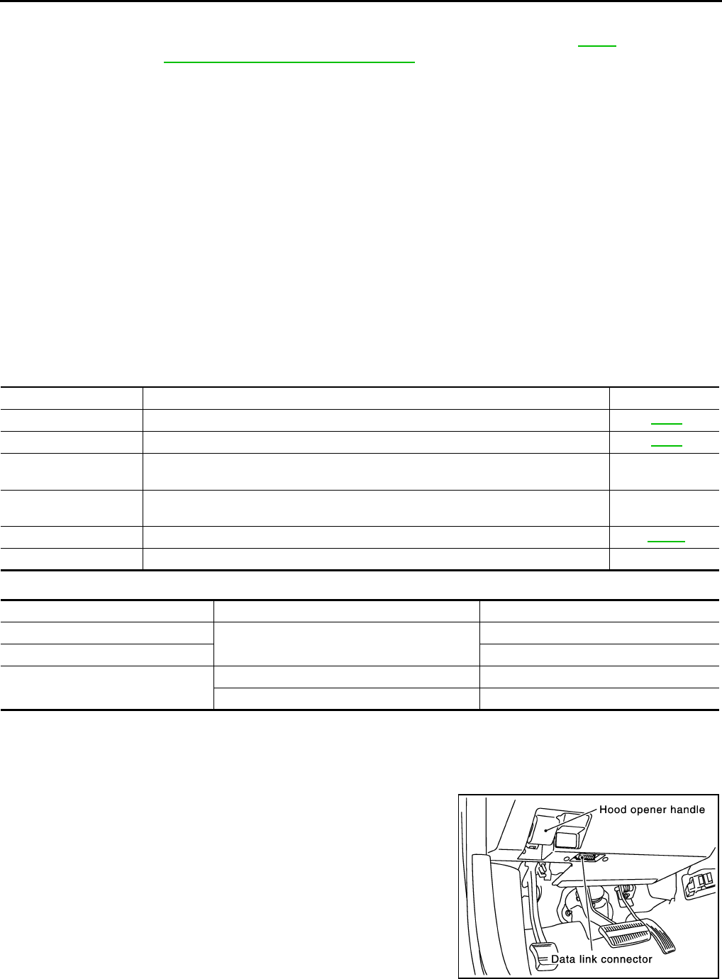
AT-92
TROUBLE DIAGNOSIS
CONSULT-II ACS001MN
After performing “SELF-DIAGNOSTIC PROCEDURE (WITH CONSULT-II)” (Refer to AT-92 ), place check
marks for results on the AT-46, "DIAGNOSTIC WORKSHEET" . Reference pages are provided following the
items.
NOTICE:
1. The CONSULT-II electrically displays shift timing and lock-up timing (that is, operation timing of each sole-
noid).
Check for time difference between actual shift timing and the CONSULT-II display. If the difference is
noticeable, mechanical parts (except solenoids, sensors, etc.) may be malfunctioning. Check mechanical
parts using applicable diagnostic procedures.
2. Shift schedule (which implies gear position) displayed on CONSULT-II and that indicated in Service Man-
ual may differ slightly. This occurs because of the following reasons:
–Actual shift schedule has more or less tolerance or allowance,
–Shift schedule indicated in Service Manual refers to the point where shifts start, and
–Gear position displayed on CONSULT-II indicates the point where shifts are completed.
3. Display of solenoid valves on CONSULT-II changes at the start of shifting, while gear position is displayed
upon completion of shifting (which is computed by TCM).
4. Additional CONSULT-II information can be found in the Operation Manual supplied with the CONSULT-II
unit.
FUNCTION
CONSULT-II REFERENCE VALUE
CONSULT-II SETTING PROCEDURE
CAUTION:
If CONSULT-II is used with no connection of CONSULT-II CONVERTER, malfunctions might be
detected in self-diagnosis depending on control unit which carry out CAN communication.
●For details, refer to the separate “CONSULT-II Operations Man-
ual”.
1. Turn ignition switch “OFF”.
2. Connect CONSULT-II and CONSULT-II CONVERTER to data
link connector, which is located in instrument lower panel on
driver side.
3. Turn ignition switch “ON”. (Do not start engine.)
Diagnostic test mode Function Reference page
Self-diagnostic results Self-diagnostic results can be read and erased quickly. AT-93
Data monitor Input/Output data in the ECM can be read. AT-96
CAN diagnostic support
monitor The results of transmit/receive diagnosis of CAN communication can be read. —
Function test Conducted by CONSULT-II instead of a technician to determine whether each system
is “OK” or “NG”. —
DTC work support Select the operating condition to confirm Diagnosis Trouble Codes. AT-100
ECM part number ECM part number can be read. —
Item name Condition Display value (Approx.)
ATF TEMP SE 1 0°C (32° F) - 20°C (68°F) - 80°C (176°F) 2.2 - 1.8 - 0.6 V
ATF TEMP SE 2 2.2 - 1.7 - 0.45 V
TCC SOLENOID When perform slip lock-up 0.2 - 0.4 A
When perform lock-up 0.4 - 0.6 A
PHIA0096E
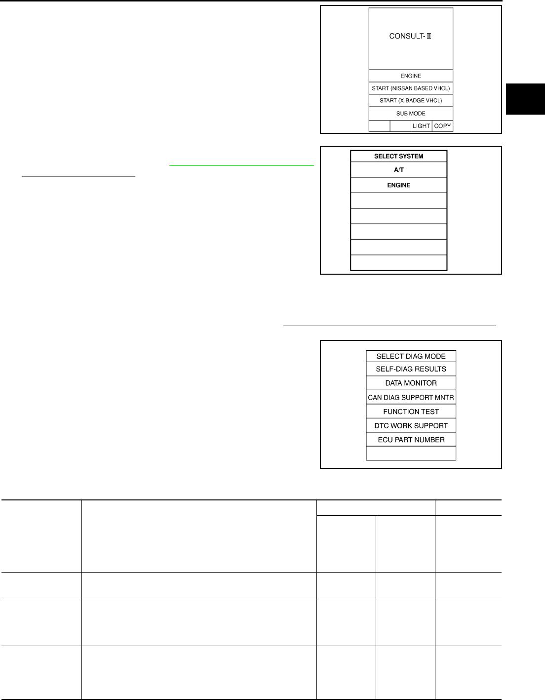
TROUBLE DIAGNOSIS
AT-93
D
E
F
G
H
I
J
K
L
M
A
B
AT
4. Touch “START (NISSAN BASED VHCL)”.
5. Touch “A/T”.
If “A/T” is not indicated, go to GI-38, "CONSULT-II Data Link
Connector (DLC) Circuit" .
6. Perform each diagnostic test mode according to each service
procedure.
SELF-DIAGNOSTIC RESULT MODE
Operation Procedure
1. Perform “CONSULT-II SETTING PROCEDURE” Refer to AT-92, "CONSULT-II SETTING PROCEDURE" .
2. Touch “SELF-DIAG RESULTS”.
Display shows malfunction experienced since the last erasing
operation.
Display Items List X: Applicable, —: Not applicable
SAIA0450E
SAT014K
SCIA5304E
Items (CONSULT-
II screen terms) Malfunction is detected when...
TCM self-diagnosis OBD-II (DTC)
A/T CHECK
indicator
lamp
“A/T” with
CONSULT-II
MIL indicator
lamp*1,
“ENGINE” with
CONSULT-II or
GST
CAN COMM CIR-
CUIT ●When a malfunction is detected in CAN communications X U1000 U1000
STARTER RELAY/
CIRC
●If this signal is ON other than in P or N position, this is
judged to be a malfunction.
(And if it is OFF in P or N position, this too is judged to be a
malfunction.)
X P0615 —
PNP SW/CIRC
●PNP switch 1-4 signals input with impossible pattern
●PNP switch 3 monitor terminal cut line
●P position is detected from N position without any other
position being detected in between.
X P0705 P0705

AT-94
TROUBLE DIAGNOSIS
VEH SPD SEN/
CIR AT (Revolution
sensor)
●Signal from vehicle speed sensor A/T (Revolution sensor)
not input due to cut line or the like
●Unexpected signal input during running
●After ignition switch is turned ON, unexpected signal input
from vehicle speed sensor MTR before the vehicle starts
moving
X P0720 P0720
ENGINE SPEED
SIG
●TCM does not receive the CAN communication signal from
the ECM. X P0725 —
TCC SOLENOID/
CIRC
●Normal voltage not applied to solenoid due to cut line,
short, or the like X P0740 P0740
A/T TCC S/V
FNCTN
●A/T cannot perform lock-up even if electrical circuit is good.
●TCM detects as irregular by comparing difference value
with slip rotation.
X P0744 P0744*2
L/PRESS SOL/
CIRC
●Normal voltage not applied to solenoid due to cut line,
short, or the like
●TCM detects as irregular by comparing target value with
monitor value.
X P0745 P0745
TCM-POWER
SUPPLY
●When the power supply to the TCM is cut “OFF”, for exam-
ple because the battery is removed, and the self-diagnos-
tics memory function stops
●This is not a malfunction message (Whenever shutting
“OFF” a power supply to the TCM, this message appears
on the screen.)
— P1701 —
TCM·RAM ●TCM memory (RAM) is malfunctioning. — P1702 —
TCM·ROM ●TCM memory (ROM) is malfunctioning. — P1703 —
TCM·EEPROM ●TCM memory (EEP ROM) is malfunctioning. — P1704 —
TP SEN/CIRC A/T ●TCM does not receive the proper accelerator pedal position
signals (input by CAN communication) from ECM. X P1705 P1705
ATF TEMP SEN/
CIRC
● During running, the ATF temperature sensor signal voltage
is excessively high or low X P1710 P0710
TURBINE REV S/
CIRC
●TCM does not receive the proper voltage signal from the
sensor.
●TCM detects an irregularity only at position of 4th gear for
turbine revolution sensor 2.
X P1716 P1716
VEH SPD SE/
CIR·MTR
●Signal (CAN communication) from vehicle speed sensor
MTR not input due to cut line or the like
●Unexpected signal input during running
— P1721 —
A/T INTERLOCK
●Except during shift change, the gear position and ATF pres-
sure switch states are monitored and comparative judge-
ment made.
X P1730 P1730
A/T 1ST E/BRAK-
ING
●Each ATF pressure switch and solenoid current is moni-
tored and if a pattern is detected having engine braking 1st
gear other than in the M1 position, a malfunction is
detected.
X P1731 —
I/C SOLENOID/
CIRC
●Normal voltage not applied to solenoid due to functional
malfunction, cut line, short, or the like
●TCM detects as irregular by comparing target value with
monitor value.
X P1752 P1752
Items (CONSULT-
II screen terms) Malfunction is detected when...
TCM self-diagnosis OBD-II (DTC)
A/T CHECK
indicator
lamp
“A/T” with
CONSULT-II
MIL indicator
lamp*1,
“ENGINE” with
CONSULT-II or
GST

TROUBLE DIAGNOSIS
AT-95
D
E
F
G
H
I
J
K
L
M
A
B
AT
I/C SOLENOID
FNCTN
●TCM detects that actual gear ratio is irregular, and relation
between gear position and condition of ATF pressure
switch 3 is irregular during depressing accelerator pedal.
(Other than during shift change)
●TCM detects that relation between gear position and condi-
tion of ATF pressure switch 3 is irregular during releasing
accelerator pedal. (Other than during shift change)
X P1754 P1754*2
FR/B SOLENOID/
CIRC
●Normal voltage not applied to solenoid due to functional
malfunction, cut line, short, or the like
●TCM detects as irregular by comparing target value with
monitor value.
X P1757 P1757
FR/B SOLENOID
FNCT
●TCM detects that actual gear ratio is irregular, and relation
between gear position and condition of ATF pressure
switch 1 is irregular during depressing accelerator pedal.
(Other than during shift change)
●TCM detects that relation between gear position and condi-
tion of ATF pressure switch 1 is irregular during releasing
accelerator pedal. (Other than during shift change)
X P1759 P1759*2
D/C SOLENOID/
CIRC
●Normal voltage not applied to solenoid due to cut line,
short, or the like
●TCM detects as irregular by comparing target value with
monitor value.
X P1762 P1762
D/C SOLENOID
FNCTN
●TCM detects that actual gear ratio is irregular, and relation
between gear position and condition of ATF pressure
switch 5 is irregular during depressing accelerator pedal.
(Other than during shift change)
●TCM detects that relation between gear position and condi-
tion of ATF pressure switch 5 is irregular during releasing
accelerator pedal. (Other than during shift change)
X P1764 P1764*2
HLR/C SOL/CIRC
●Normal voltage not applied to solenoid due to functional
malfunction, cut line, short, or the like
●TCM detects as irregular by comparing target value with
monitor value.
X P1767 P1767
HLR/C SOL
FNCTN
●TCM detects that actual gear ratio is irregular, and relation
between gear position and condition of ATF pressure
switch 6 is irregular during depressing accelerator pedal.
(Other than during shift change)
●TCM detects that relation between gear position and condi-
tion of ATF pressure switch 6 is irregular during releasing
accelerator pedal. (Other than during shift change)
X P1769 P1769*2
LC/B SOLENOID/
CIRC
●Normal voltage not applied to solenoid due to functional
malfunction, cut line, short, or the like X P1772 P1772
LC/B SOLENOID
FNCT
●TCM detects an improper voltage drop when it tries to oper-
ate the solenoid valve.
●Condition of ATF pressure switch 2 is different from monitor
value, and relation between gear position and actual gear
ratio is irregular.
X P1774 P1774*2
MANU MODE SW/
CIRC
●When an impossible pattern of switch signals is detected, a
malfunction is detected. — P1815 —
Items (CONSULT-
II screen terms) Malfunction is detected when...
TCM self-diagnosis OBD-II (DTC)
A/T CHECK
indicator
lamp
“A/T” with
CONSULT-II
MIL indicator
lamp*1,
“ENGINE” with
CONSULT-II or
GST
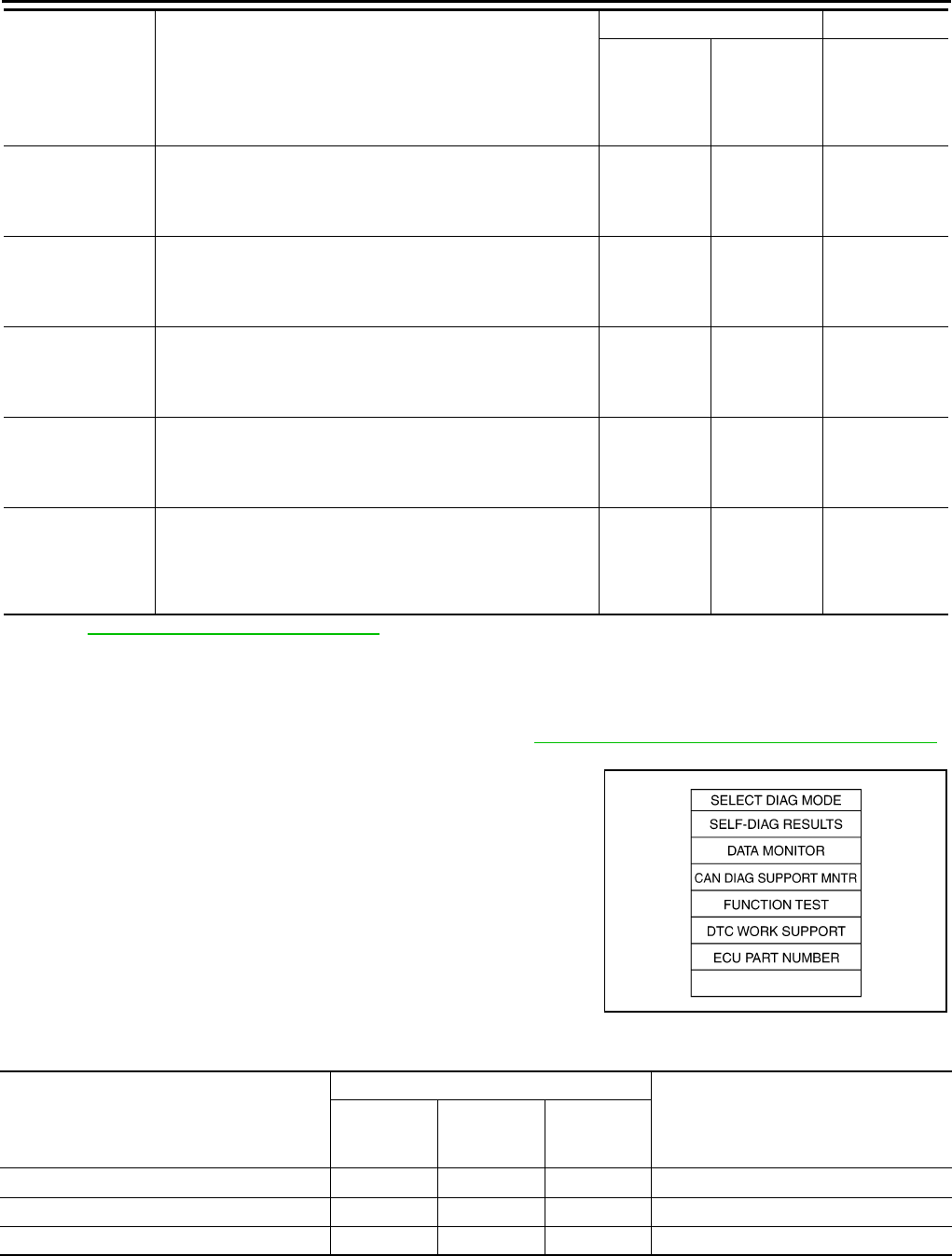
AT-96
TROUBLE DIAGNOSIS
*1: Refer to AT-41, "Malfunction Indicator Lamp (MIL)" .
*2: These malfunctions cannot be displayed MIL if another malfunction is assigned to MIL.
DATA MONITOR MODE
Operation Procedure
1. Perform “CONSULT-II SETTING PROCEDURE” Refer to AT-92, "CONSULT-II SETTING PROCEDURE" .
2. Touch “DATA MONITOR”.
NOTE:
When malfunction is detected, CONSULT-II performs
“REAL-TIME DIAGNOSIS”. Also, any malfunction detected
while in this mode will be displayed at real time.
Display Items List X: Standard, —: Not applicable
ATF PRES SW 1/
CIRC
●TCM detects that actual gear ratio is normal, and relation
between gear position and condition of ATF pressure
switch 1 is irregular during depressing accelerator pedal.
(Other than during shift change)
— P1841 —
ATF PRES SW 3/
CIRC
●TCM detects that actual gear ratio is normal, and relation
between gear position and condition of ATF pressure
switch 3 is irregular during depressing accelerator pedal.
(Other than during shift change)
— P1843 —
ATF PRES SW 5/
CIRC
●TCM detects that actual gear ratio is normal, and relation
between gear position and condition of ATF pressure
switch 5 is irregular during depressing accelerator pedal.
(Other than during shift change)
— P1845 —
ATF PRES SW 6/
CIRC
●TCM detects that actual gear ratio is normal, and relation
between gear position and condition of ATF pressure
switch 6 is irregular during depressing accelerator pedal.
(Other than during shift change)
— P1846 —
NO DTC IS
DETECTED FUR-
THER TESTING
MAY BE
REQUIRED
●No NG item has been detected. — X X
Items (CONSULT-
II screen terms) Malfunction is detected when...
TCM self-diagnosis OBD-II (DTC)
A/T CHECK
indicator
lamp
“A/T” with
CONSULT-II
MIL indicator
lamp*1,
“ENGINE” with
CONSULT-II or
GST
SCIA5304E
Monitored item (Unit)
Monitor Item Selection
Remarks
ECU INPUT
SIGNALS
MAIN SIG-
NALS
SELEC-
TION FROM
MENU
VHCL/S SE·A/T (km/h) X X X Revolution sensor
VHCL/S SE·MTR (km/h) X — X
ACCELE POSI (0.0/8) X — X Accelerator pedal position signal

TROUBLE DIAGNOSIS
AT-97
D
E
F
G
H
I
J
K
L
M
A
B
AT
THROTTLE POSI (0.0/8) X X X
Degree of opening for accelerator recog-
nized by the TCM
For fail-safe operation, the specific value
used for control is displayed.
BATTERY BOLT (V) X — X
ENGINE SPEED (rpm) X X X
TURBINE REV (rpm) X — X
ATF TEMP 1 (°C) — X X
ATF TEMP 2 (°C) — X X
OUTPUT REV (rpm) X X X
ATF TEMP SE 1 (V) X — X
ATF TEMP SE 2 (V) X — X
ATF PRES SW 1 (ON-OFF display) X X X (for FR/B solenoid)
ATF PRES SW 2 (ON-OFF display) X X X (for LC/B solenoid)
ATF PRES SW 3 (ON-OFF display) X X X (for I/C solenoid)
ATF PRES SW 5 (ON-OFF display) X X X (for D/C solenoid)
ATF PRES SW 6 (ON-OFF display) X X X (for HLR/C solenoid)
PNP SW 1 (ON-OFF display) X — X
PNP SW 2 (ON-OFF display) X — X
PNP SW 3 (ON-OFF display) X — X
PNP SW 4 (ON-OFF display) X — X
1 POSITION SW (ON-OFF display) X — X
ASCD·CRUISE (ON-OFF display) X — X
Not mounted but displayed.ASCD·OD CUT (ON-OFF display) X — X
OD CONT SW (ON-OFF display) X — X
MANU MODE SW (ON-OFF display) X — X
NON M-MODE SW (ON-OFF display) X — X
UP SW LEVER (ON-OFF display) X — X
DOWN SW LEVER (ON-OFF display) X — X
POWER SHIFT SW (ON-OFF display) X — X Not mounted but displayed.
CLSO THL POS (ON-OFF display) X — X Signal input with CAN communications
W/O THL POS (ON-OFF display) X — X Signal input with CAN communications
TCC SOLENOID (A) — X X
LINE PRES SOL (A) — X X
I/C SOLENOID (A) — X X
FR/B SOLENOID (A) — X X
D/C SOLENOID (A) — X X
HLR/C SOL (A) — X X
HOLD SW (ON-OFF display) X — X Not mounted but displayed.
BRAKE SW (ON-OFF display) X — X Stop lamp switch
GEAR — X X Gear position recognized by the TCM
updated after gear-shifting
GEAR RATIO — X X
Monitored item (Unit)
Monitor Item Selection
Remarks
ECU INPUT
SIGNALS
MAIN SIG-
NALS
SELEC-
TION FROM
MENU

AT-98
TROUBLE DIAGNOSIS
SLCTLVR POSI — X X
Selector lever position is recognized by
the TCM.
For fail safe operation, the specific value
used for control is displayed.
VEHICLE SPEED (km/h) — X X Vehicle speed recognized by the TCM.
TC SLIP SPEED (rpm) — X X Difference between engine speed and
torque converter input shaft speed
Voltage (V) — — X Displays the value measured by the volt-
age probe.
F SUN GW REV (rpm) — — X
F CARR GR REV (rpm) — — X
SFT UP ST SW — — X Not mounted but displayed.
SFT DWN ST SW — — X
ABS SIGNAL — — X
ACC OD CUT — — X
ACC SIGNAL — — X
TCS GR/P KEEP — — X
TCS SIGNAL 2 — — X
TCS SIGNAL 1 — — X
ON OFF SOL (ON-OFF display) — — X LC/B solenoid
TCC SOL MON — — X
L/P SOL MON — — X
I/C SL MON — — X
FR/B SOL MON — — X
D/C SOL MON — — X
HLR/C SOL MON — — X
ONOFF SOL MON — — X LC/B solenoid
P POSI IND — — X
R POSI IND — — X
N POSI IND — — X
D POSI IND — — X
4TH POSI IND — — X
3RD POSI IND — — X
2ND POSI IND — — X
1ST POSI IND — — X
M MODE IND — — X
POWER M LAMP — — X
F-SAFE IND/L — — X
ATF WARN LAMP — — X
BACK-UP LAMP — — X
STARTER RELAY — — X
PNP SW3 MON (ON-OFF display) — — X
C/VCLBID 1 — — X
C/VCLBID 2 — — X
Monitored item (Unit)
Monitor Item Selection
Remarks
ECU INPUT
SIGNALS
MAIN SIG-
NALS
SELEC-
TION FROM
MENU

TROUBLE DIAGNOSIS
AT-99
D
E
F
G
H
I
J
K
L
M
A
B
AT
C/VCLBID 3 — — X
UNIT CLB ID 1 — — X
UNIT CLB ID 2 — — X
UNIT CLB ID 3 — — X
TRGT GR RATIO — — X
TRG PRE TCC — — X
TRG PRE L/P — — X
TRG PRE I/C — — X
TRG PRE FR/B — — X
TRG PRE D/C — — X
TRG PRE HLR/C — — X
DRV CST JUDGE — — X
START RLY MON — — X
Next gear — — X
SHIFT MODE — — X
MANU GR POSI — — X
Frequency (Hz) — — X
The value measured by the pulse probe
is displayed.
DUTY·HI (high) (%) — — X
DUTY·LOW (low) (%) — — X
PLS WIDTH·HI (ms) — — X
PLS WIDTH·LOW (ms) — — X
Monitored item (Unit)
Monitor Item Selection
Remarks
ECU INPUT
SIGNALS
MAIN SIG-
NALS
SELEC-
TION FROM
MENU
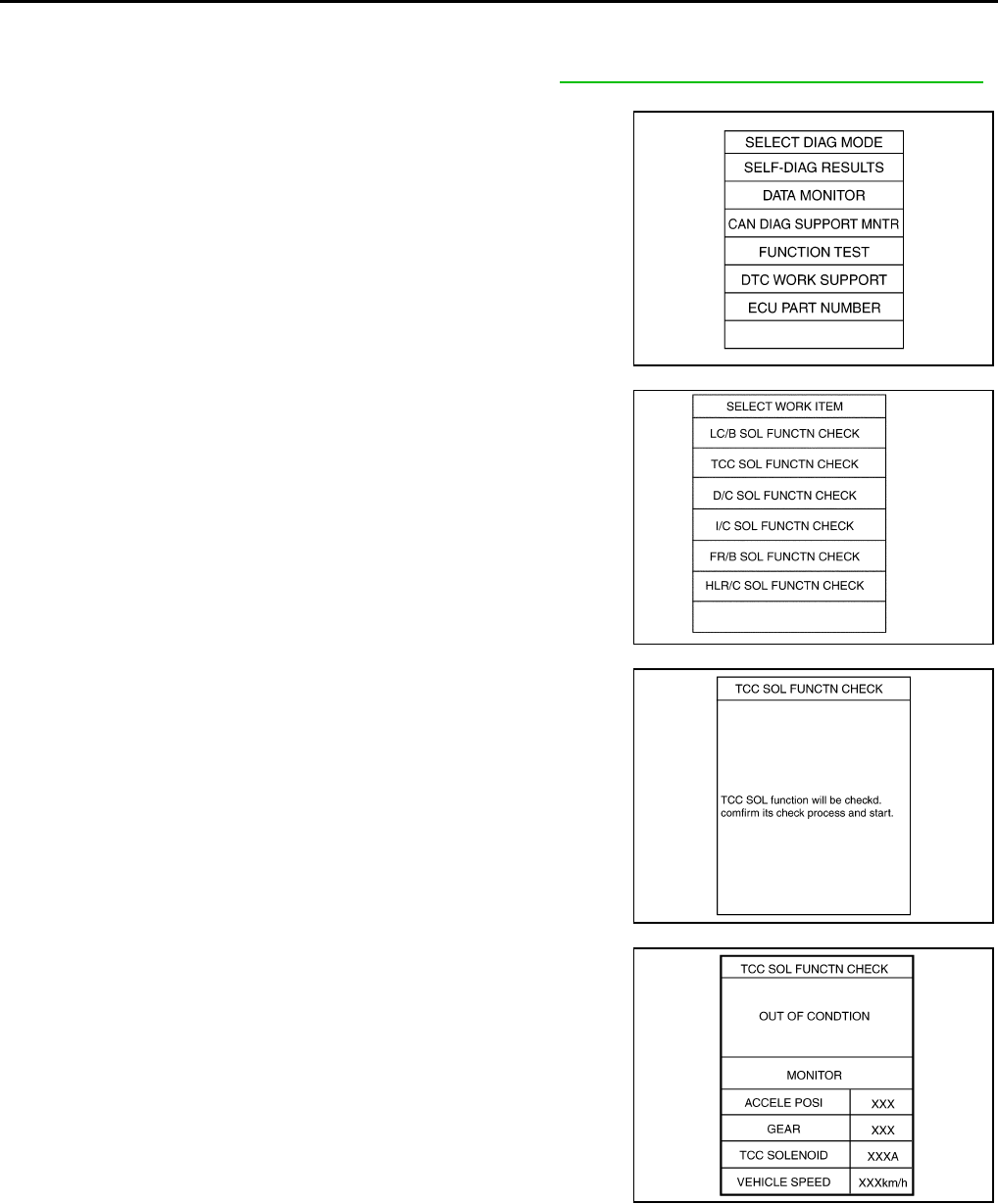
AT-100
TROUBLE DIAGNOSIS
DTC WORK SUPPORT MODE
Operation Procedure
1. Perform “CONSULT-II SETTING PROCEDURE” Refer to AT-92, "CONSULT-II SETTING PROCEDURE" .
2. Touch “DTC WORK SUPPORT”.
3. Touch select item menu.
4. Touch “START”.
5. Perform driving test according to “DTC CONFIRMATION PRO-
CEDURE” in “TROUBLE DIAGNOSIS FOR DTC”.
SCIA5304E
SCIA0512E
SCIA5159E
SCIA5160E
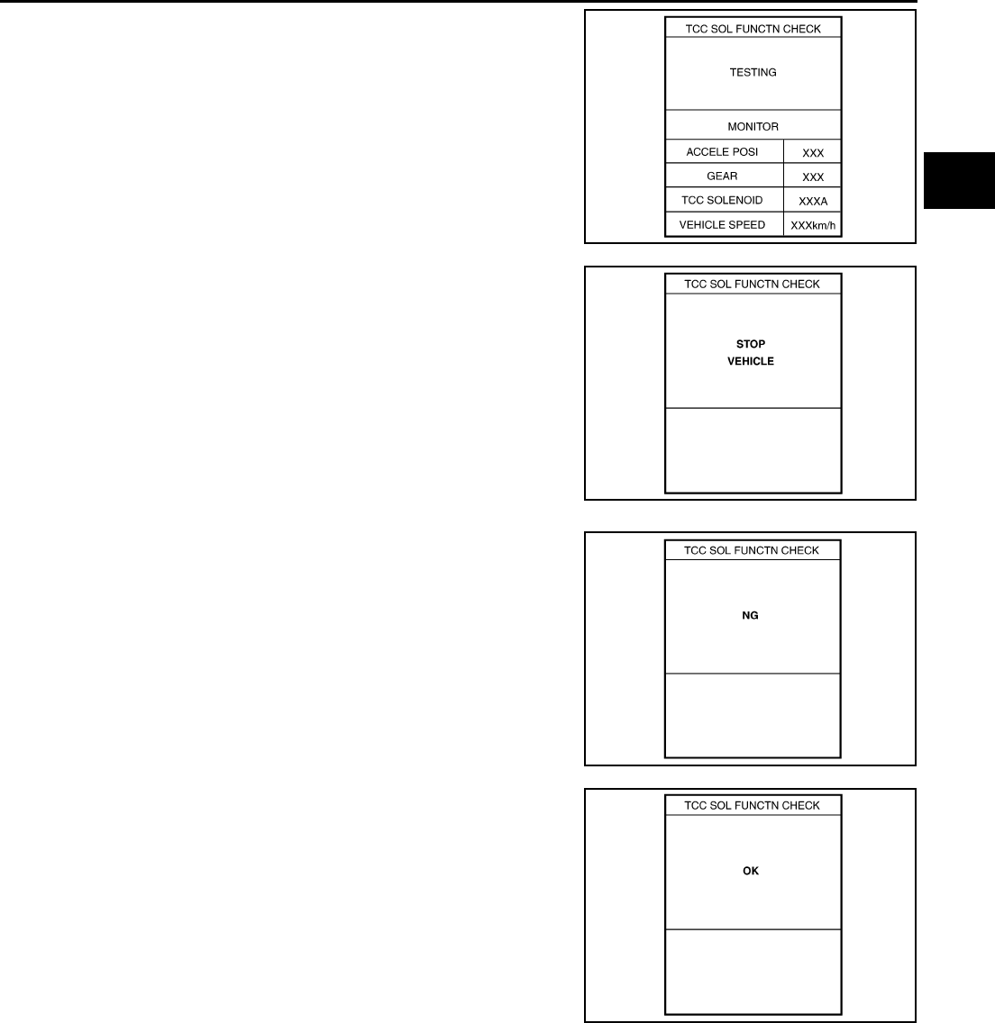
TROUBLE DIAGNOSIS
AT-101
D
E
F
G
H
I
J
K
L
M
A
B
AT
●When testing conditions are satisfied, CONSULT-II screen
changes from “OUT OF CONDITION” to “TESTING”.
6. Stop vehicle.
●If “NG” appears on the screen, malfunction may exist. Go
to “Diagnostic Procedure”.
7. Perform test drive to check gear shift feeling in accordance with
instructions displayed.
8. Touch “YES” or “NO”.
9. CONSULT-II procedure is ended.
SCIA5161E
SCIA5164E
SCIA5162E
SCIA5163E
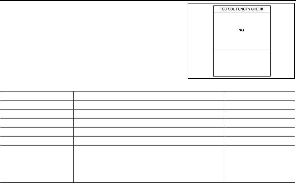
AT-102
TROUBLE DIAGNOSIS
●If “NG” appears on the screen, a malfunction may exist.
Go to “Diagnostic Procedure”.
Display Items List
*: Do not use, but displayed.
SCIA5162E
DTC work support item Description Check item
I/C SOL FUNCTN CHECK* — —
FR/B SOL FUNCTN CHECK* — —
D/C SOL FUNCTN CHECK* — —
HLR/C SOL FUNCTN CHECK* — —
LC/B SOL FUNCTN CHECK* — —
TCC SOL FUNCTN CHECK
Following items for “TCC solenoid function (lock-up) ” can be con-
firmed.
●Self-diagnosis status (whether the diagnosis is being conducted
or not)
●Self-diagnosis result (OK or NG)
●TCC solenoid valve
●Hydraulic control circuit

TROUBLE DIAGNOSIS
AT-103
D
E
F
G
H
I
J
K
L
M
A
B
AT
Diagnostic Procedure Without CONSULT-II ACS004IZ
OBD-II SELF-DIAGNOSTIC PROCEDURE (WITH GST)
Refer to EC-117, "Generic Scan Tool (GST) Function" .
OBD-II SELF-DIAGNOSTIC PROCEDURE (NO TOOLS)
Refer to EC-62, "Malfunction Indicator Lamp (MIL)" .
TCM SELF-DIAGNOSTIC PROCEDURE (NO TOOLS)
Description
In the unlikely event of a malfunction in the electrical system, when the ignition switch is switched “ON”,
the A/T CHECK indicator lamp lights up for 2 seconds, then flashes for 8 seconds. If there is no malfunction,
when the ignition switch is turned “ON”, the indicator lamp lights up for 2 seconds. As a method for locating the
suspect circuit, when the self-diagnostics start signal is input, the memory for the malfunction location is output
and the A/T CHECK indicator lamp flashes to display the corresponding DTC.
Diagnostic Procedure
1. CHECK A/T CHECK INDICATOR LAMP
1. Start the engine with selector lever in “P” position. Warm engine to normal operating temperature.
2. Turn ignition switch ON and OFF at least twice, then leave it in the OFF.
3. Wait 10 seconds.
4. Turn ignition switch ON. (Do not start engine.)
Does A/T CHECK indicator lamp come on for about 2 seconds?
YES >> GO TO 2.
NO >> GO TO AT-248, "A/T Check Indicator Lamp Does Not Come On" .
2. JUDGEMENT PROCEDURE STEP 1
1. Turn ignition switch OFF.
2. Push shift lock release button.
3. Move selector lever from “P” to “D” position.
4. Release accelerator pedal. (Set the closed throttle position signal “ON”.)
5. Depress brake pedal. (Stop lamp switch signal “ON”.)
6. Turn ignition switch ON. (Do not start engine.)
7. Wait 3 seconds.
8. Move the selector lever to the Manual shift gate side. (Manual mode switch “ON”.)
9. Release brake pedal. (Stop lamp switch signal “OFF”.)
10. Move the selector lever to “D” position. (Manual mode switch “OFF”.)
11. Depress brake pedal. (Stop lamp switch signal “ON”.)
12. Release brake pedal. (Stop lamp switch signal “OFF”.)
13. Depress accelerator pedal fully and release it.
>> GO TO 3.
3. CHECK SELF-DIAGNOSIS CODE
Check A/T CHECK indicator lamp.
Refer to AT-104, "Judgement Self-diagnosis Code" .
If the system does not go into self-diagnostics. Refer to AT-244, "PARK/NEUTRAL POSITION, MANUAL
MODE, BRAKE AND THROTTLE POSITION SWITCH CIRCUIT" .
>> DIAGNOSIS END
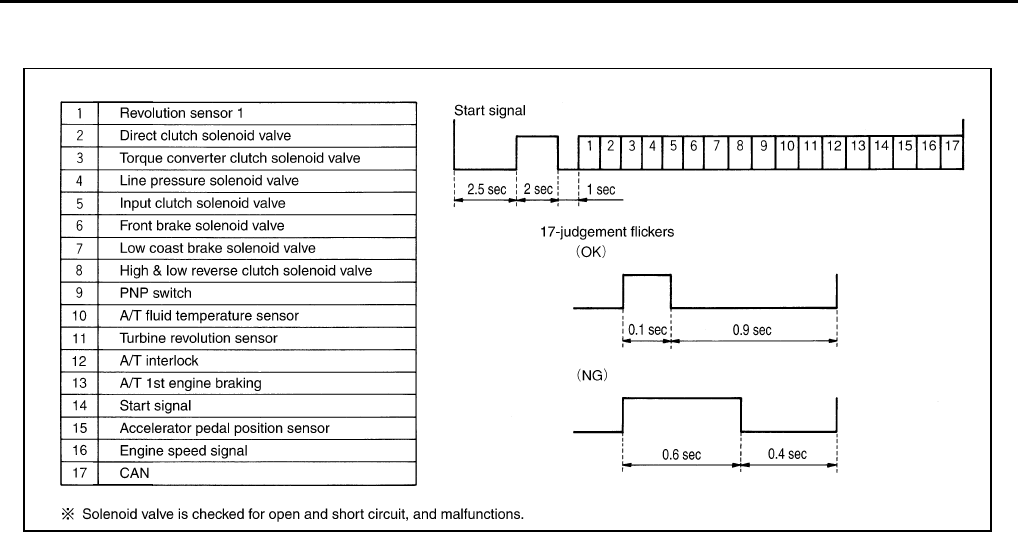
AT-104
TROUBLE DIAGNOSIS
Judgement Self-diagnosis Code
If there is a malfunction, the lamp lights up for the time corresponding to the suspect circuit.
Erase Self-diagnosis
●In order to make it easier to find the cause of hard-to-duplicate malfunctions, malfunction information is
stored into the control unit as necessary during use by the user. This memory is not erased no matter how
many times the ignition switch is turned ON and OFF.
●However, this information is erased by turning ignition switch “OFF” after executing self-diagnostics or by
erasing the memory using the CONSULT-II.
SCIA0497E
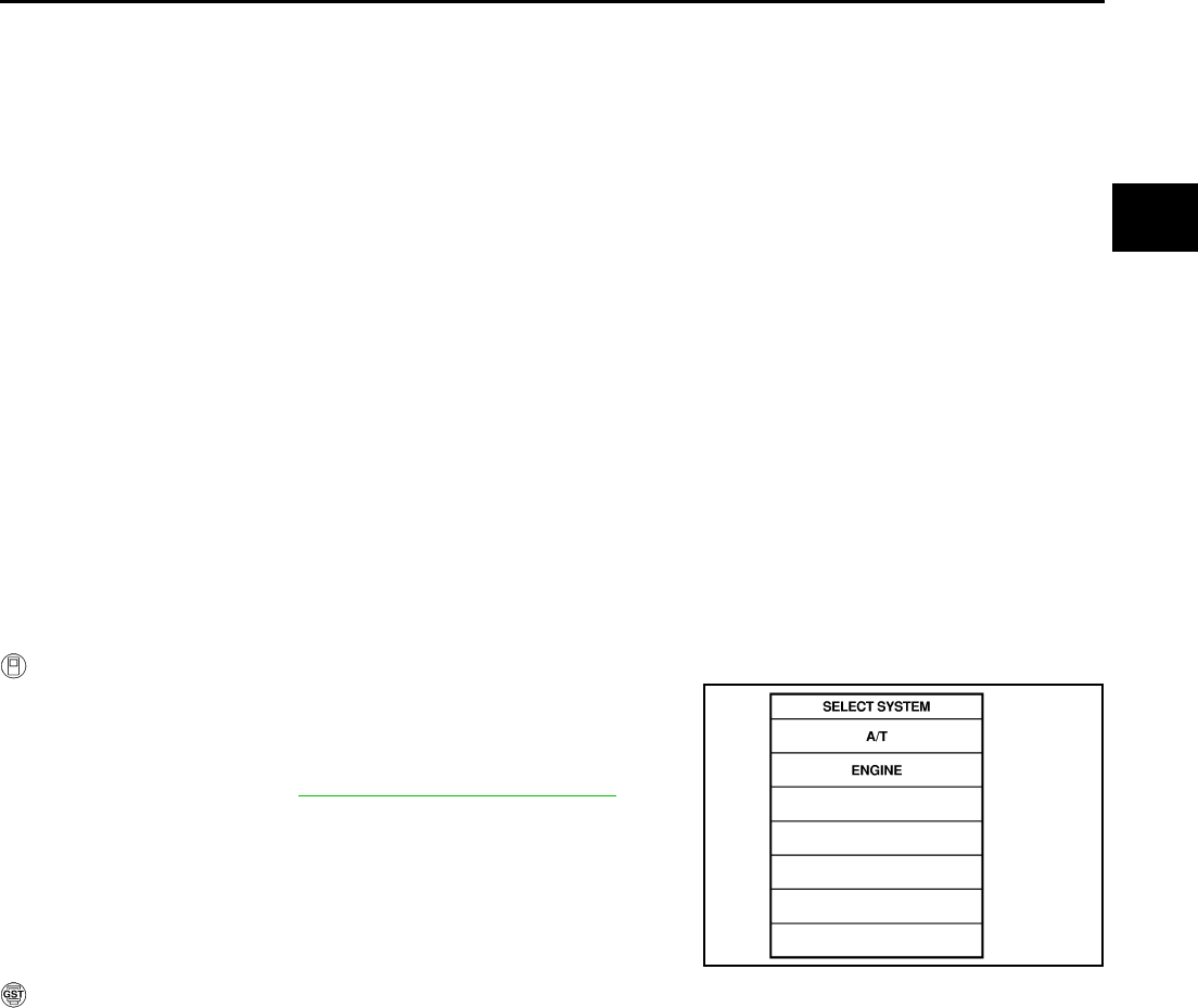
DTC U1000 CAN COMMUNICATION LINE
AT-105
D
E
F
G
H
I
J
K
L
M
A
B
AT
DTC U1000 CAN COMMUNICATION LINE PFP:23710
Description ACS00098
CAN (Controller Area Network) is a serial communication line for real time application. It is an on-vehicle mul-
tiplex communication line with high data communication speed and excellent malfunction detection ability.
Many electronic control units are equipped onto a vehicle, and each control unit shares information and links
with other control units during operation (not independent). In CAN communication, control units are con-
nected with 2 communication lines (CAN H line, CAN L line) allowing a high rate of information transmission
with less wiring. Each control unit transmits/receives data but selectively reads required data only.
On Board Diagnosis Logic ACS00099
●This is an OBD-II self-diagnostic item.
●Diagnostic trouble code “CAN COMM CIRCUIT” with CONSULT-II or U1000 without CONSULT-II is
detected when TCM cannot communicate to other control units.
Possible Cause ACS0009A
Harness or connectors
(CAN communication line is open or shorted.)
DTC Confirmation Procedure ACS0009B
NOTE:
If “DTC Confirmation Procedure” has been previously conducted, always turn ignition switch “OFF”
and wait at least 10 seconds before conducting the next test.
After the repair, perform the following procedure to confirm the malfunction is eliminated.
WITH CONSULT-II
1. Turn ignition switch ON position. (Do not start engine.)
2. Select “DATA MONITOR” mode for “ENGINE” with CONSULT-II.
3. Start engine and wait for at least 6 seconds.
4. If DTC is detected, go to AT-107, "Diagnostic Procedure" .
WITH GST
Follow the procedure “WITH CONSULT-II”.
SAT014K
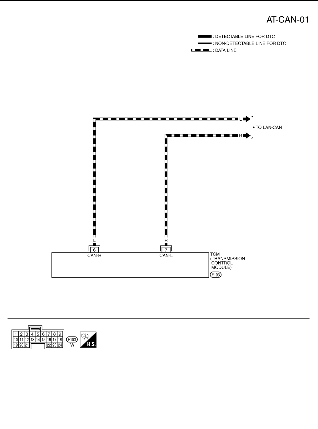
AT-106
DTC U1000 CAN COMMUNICATION LINE
Wiring Diagram — AT — CAN ACS0009C
TCWT0054E
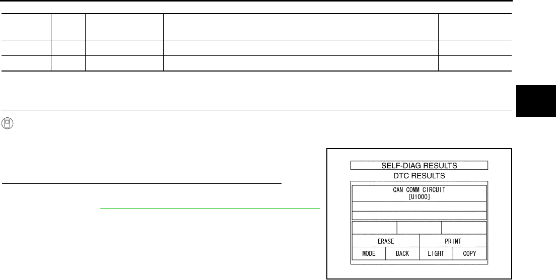
DTC U1000 CAN COMMUNICATION LINE
AT-107
D
E
F
G
H
I
J
K
L
M
A
B
AT
TCM terminal and Data are reference value.
Diagnostic Procedure ACS0009D
1. CHECK CAN COMMUNICATION CIRCUIT
With CONSULT-II
1. Turn ignition switch ON and start engine.
2. Select “SELF-DIAG RESULTS” mode for “A/T” with CONSULT-
II.
Is any malfunction of the “CAN COMM CIRCUIT” indicated?
YES >> Print out CONSULT-II screen, GO TO LAN section.
Refer to LAN-2, "Precautions When Using CONSULT-II"
.
NO >> INSPECTION END
Terminal
No.
Wire
color Item Condition Data (Approx.)
6 L CAN H – –
7 R CAN L – –
PCIA0061E
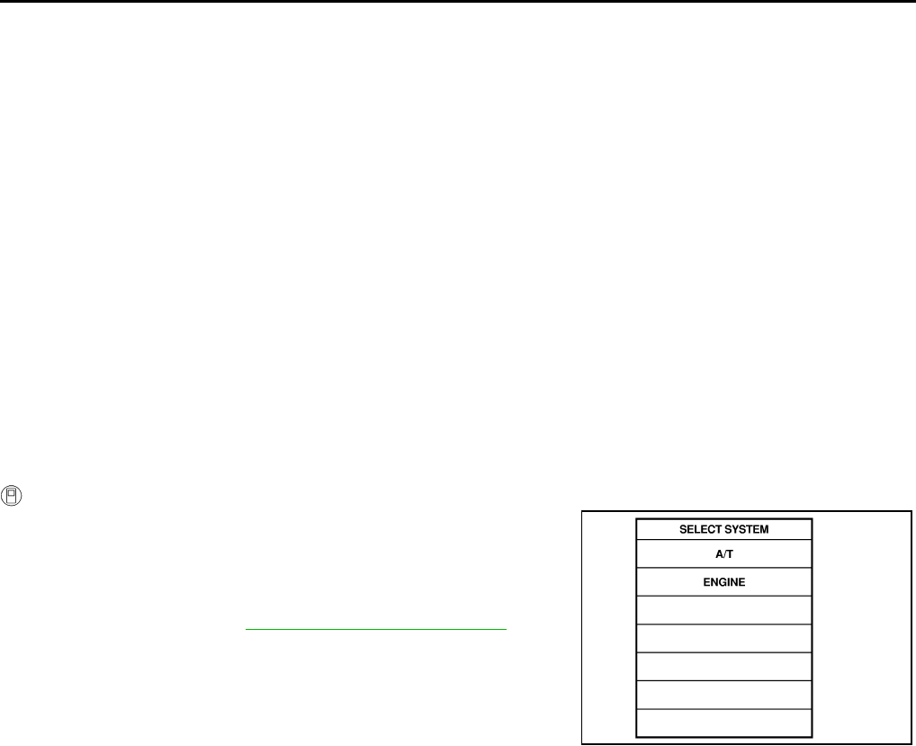
AT-108
DTC P0615 START SIGNAL CIRCUIT
DTC P0615 START SIGNAL CIRCUIT PFP:25230
Description ACS0009E
Prohibits cranking other at “P” or “N” position.
On Board Diagnosis Logic ACS0009F
●This is not an OBD-II self-diagnostic item.
●Diagnostic trouble code “STARTER RELAY/CIRC” with CONSULT-II or 14th judgement flicker without
CONSULT-II is detected when detects as irregular when switched “ON” other than at “P” or “N” position.
(Or when switched “OFF” at “P” or “N” position).
Possible Cause ACS0009G
●Harness or connectors
(The starter relay and TCM circuit is open or shorted.)
●Starter relay circuit
DTC Confirmation Procedure ACS0009H
NOTE:
If “DTC Confirmation Procedure” has been previously conducted, always turn ignition switch “OFF”
and wait at least 10 seconds before conducting the next test.
After the repair, perform the following procedure to confirm the malfunction is eliminated.
WITH CONSULT-II
1. Turn ignition switch ON. (Do not start engine.)
2. Select “DATA MONITOR” mode for “A/T” with CONSULT-II.
3. Start engine.
4. Vehicle start for at least 2 consecutive seconds.
5. If DTC is detected, go to AT-110, "Diagnostic Procedure" .
SAT014K
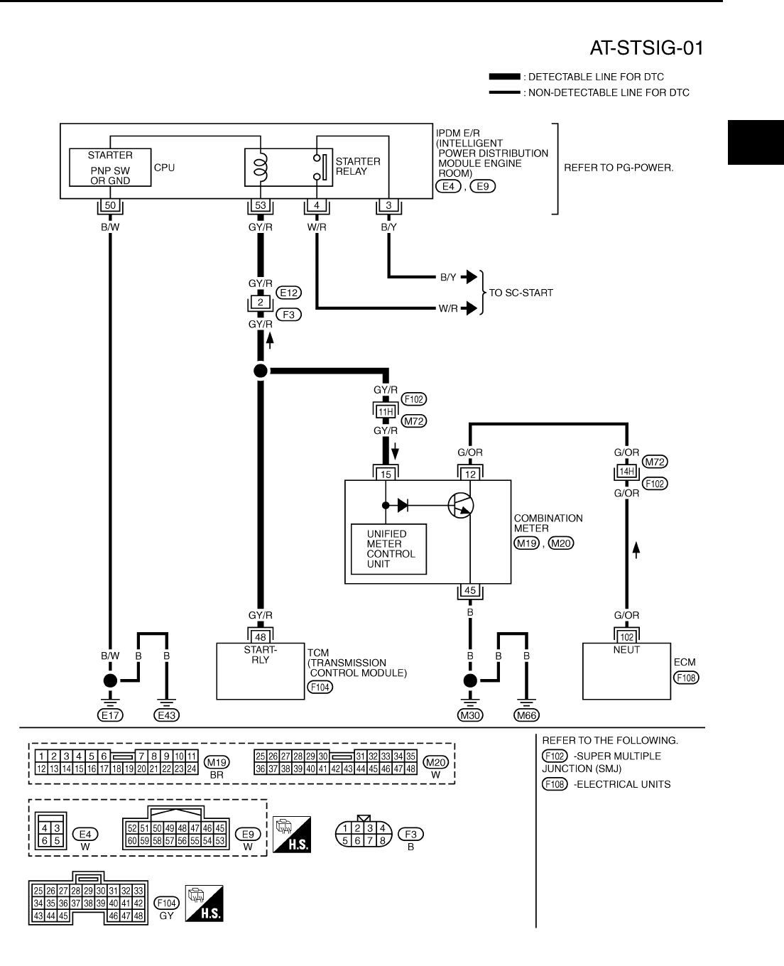
DTC P0615 START SIGNAL CIRCUIT
AT-109
D
E
F
G
H
I
J
K
L
M
A
B
AT
Wiring Diagram — AT — STSIG ACS0009I
TCWT0219E
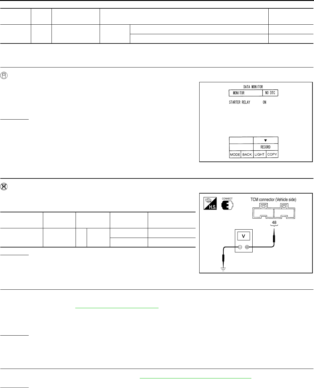
AT-110
DTC P0615 START SIGNAL CIRCUIT
TCM terminal and Data are reference value. Measured between each terminals 5, 14, 24 and 46 (TCM ground).
Diagnostic Procedure ACS0009J
1. CHECK STARTER RELAY (WITH CONSULT-II)
With CONSULT-II
1. Turn ignition switch ON. (Do not start engine.)
2. Select “SELECTION FROM MENU” in “DATA MONITOR” mode
for “A/T” with CONSULT-II and check monitor “STARTER
RELAY” ON/OFF.
OK or NG
OK >> GO TO 4.
NG >> GO TO 3.
2. CHECK STARTER RELAY (WITHOUT CONSULT-II)
Without CONSULT-II
1. Turn ignition switch ON. (Do not start engine.)
2. Check the voltage between the TCM connector and ground.
OK or NG
OK >> GO TO 4.
NG >> GO TO 3.
3. DETECT MALFUNCTIONING ITEM
Check the following items:
●Starter relay, Refer to SC-9, "STARTING SYSTEM" .
●Disconnections or short-circuits in the harness between TCM and the IPDM E/R
●Disconnections or short-circuits in the harness between TCM and the combination meter
OK or NG
OK >> GO TO 4.
NG >> Repair or replace damaged parts.
4. CHECK DTC
Perform “DTC confirmation Procedure”. Refer to AT-108, "DTC Confirmation Procedure" .
OK or NG
OK >> INSPECTION END
NG >> GO TO 5.
Terminal
No.
Wire
color Item Condition Data (Approx.)
48 GY/R Starter relay IGN ON Selector lever in “N”,“P” position. Battery voltage
Selector lever in other position. 0V
PCIA0056E
Item Connector
No. Terminal No. Shift position Voltage (Approx.)
Starter relay F104 48 Ground N and P Battery voltage
R and D 0V
PCIA0060E

DTC P0615 START SIGNAL CIRCUIT
AT-111
D
E
F
G
H
I
J
K
L
M
A
B
AT
5. PERFORM TCM INSPECTION
1. Perform TCM input/output signal inspection. Refer to AT-89, "TCM Input/Output Signal Reference Values"
.
2. If NG, recheck TCM pin terminals for damage or loose connection with harness connector.
OK or NG
OK >> INSPECTION END
NG >> Repair or replace damaged parts.
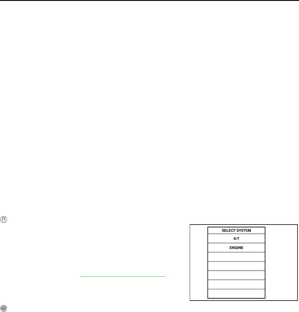
AT-112
DTC P0705 PARK/NEUTRAL POSITION SWITCH
DTC P0705 PARK/NEUTRAL POSITION SWITCH PFP:32006
Description ACS0009K
●The park/neutral position (PNP) switch includes a transmission position switch.
●The transmission range switch detects the selector lever position and sends a signal to the TCM.
On Board Diagnosis Logic ACS0009L
●This is an OBD-II self-diagnostic item.
●Diagnostic trouble code “PNP SW/CIRC” with CONSULT-II or P0705 without CONSULT-II is detected
under the following conditions.
–When TCM does not receive the correct voltage signal from the PNP switch 1, 2, 3, 4 based on the gear
position.
–When monitor terminal of PNP switch 3 is disconnected.
–When no other position but “P” position is detected from “N” positions.
Possible Cause ACS0009M
●Harness or connectors
[The park/neutral position (PNP) switch 1, 2, 3, 4 and TCM circuit is open or shorted.]
●Park/neutral position (PNP) switch 1, 2, 3, 4
●Park/neutral position (PNP) switch 3 monitor terminal disconnected
DTC Confirmation Procedure ACS0009N
CAUTION:
Always drive vehicle at a safe speed.
NOTE:
If “DTC Confirmation Procedure” has been previously conducted, always turn ignition switch “OFF”
and wait at least 10 seconds before conducting the next test.
After the repair, perform the following procedure to confirm the malfunction is eliminated.
WITH CONSULT-II
1. Turn ignition switch ON. (Do not start engine.)
2. Select “DATA MONITOR” mode for “ENGINE” with CONSULT-II.
3. Start engine.
4. Drive vehicle and maintain the following conditions for at least 2
consecutive seconds.
THRTL POS SEN: More than 1.2V
5. If DTC is detected, go to AT-114, "Diagnostic Procedure" .
WITH GST
Follow the procedure “With CONSULT-II”.
SAT014K
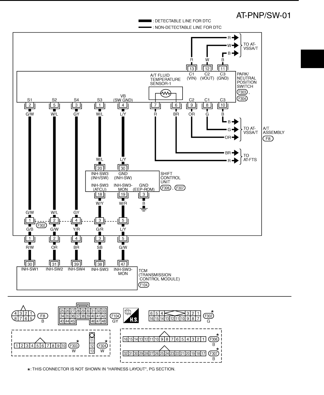
DTC P0705 PARK/NEUTRAL POSITION SWITCH
AT-113
D
E
F
G
H
I
J
K
L
M
A
B
AT
Wiring Diagram — AT — PNP/SW ACS0009O
TCWT0220E
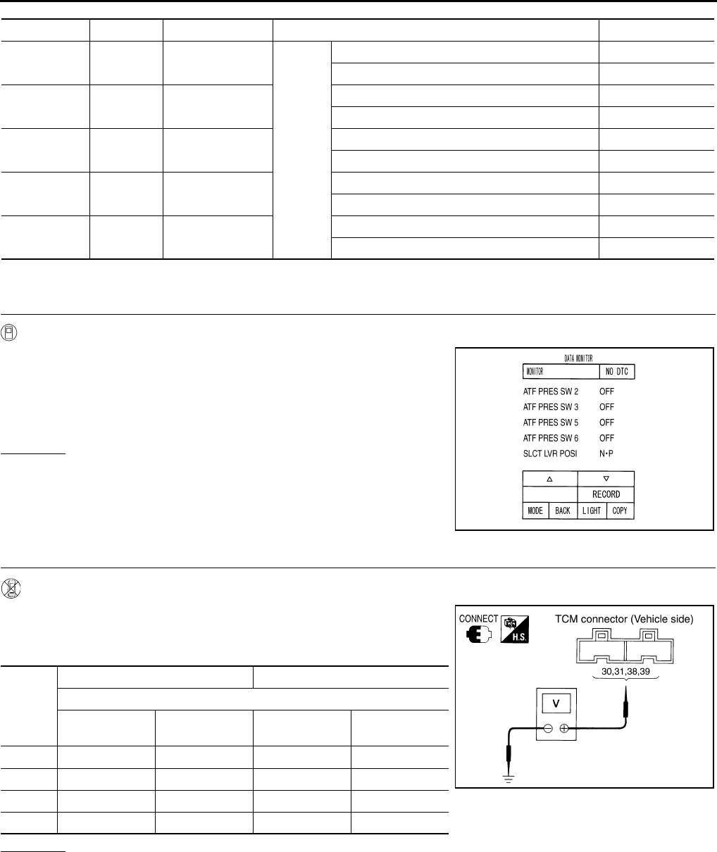
AT-114
DTC P0705 PARK/NEUTRAL POSITION SWITCH
TCM terminals and Data are reference value. Measured between each terminals 5, 14, 24 and 46 (TCM ground).
Diagnostic Procedure ACS0009P
1. CHECK PNP SWITCH CIRCUIT (WITH CONSULT-II)
With CONSULT-II
1. Turn ignition switch ON. (Do not start engine.)
2. Select “MAIN SIGNALS” in “DATA MONITOR” mode for “A/T”
with CONSULT-II.
3. Read out “N·P”, “R” and “D” position switches moving selector
lever to each position.
OK or NG
OK >> GO TO 5.
NG >> GO TO 3.
2. CHECK PNP SWITCH CIRCUIT (WITHOUT CONSULT-II)
Without CONSULT-II
1. Turn ignition switch ON. (Do not start engine.)
2. Selector lever to “P“, “R”, “N”, or “D” position to check the volt-
age between the TCM connector terminals and ground.
OK or NG
OK >> GO TO 5.
NG >> GO TO 3.
Terminal No. Wire color Item Condition Data (Approx.)
30 R/W PNP switch 1
IGN ON
Selector lever in “P” position. Battery voltage
Selector lever in “N” position. Less than 2.5V
31 OR PNP switch 2 Selector lever in “P” position. Battery voltage
Selector lever in “D” position. Less than 2.5V
38 SB PNP switch 3 Selector lever in “D” position. Battery voltage
Selector lever in “R” position. Less than 2.5V
39 BR PNP switch 4 Selector lever in “D” position. Less than 2.5V
Selector lever in “P” position. Battery voltage
47 G/W PNP switch 3
(monitor)
Selector lever in “D” position. Battery voltage
Selector lever in “R” position. Less than 2.5V
PCIA0034E
Shift
position
Connector No. F104
Terminal No. (Wire color)
30 (R/W) -
Ground
31 (OR) -
Ground
38 (SB) -
Ground
39 (BR) -
Ground
P Battery voltage Battery voltage – Battery voltage
R – – Less than 2.5V –
N Less than 2.5V – – –
D – Less than 2.5V Battery voltage Less than 2.5V
PCIA0035E
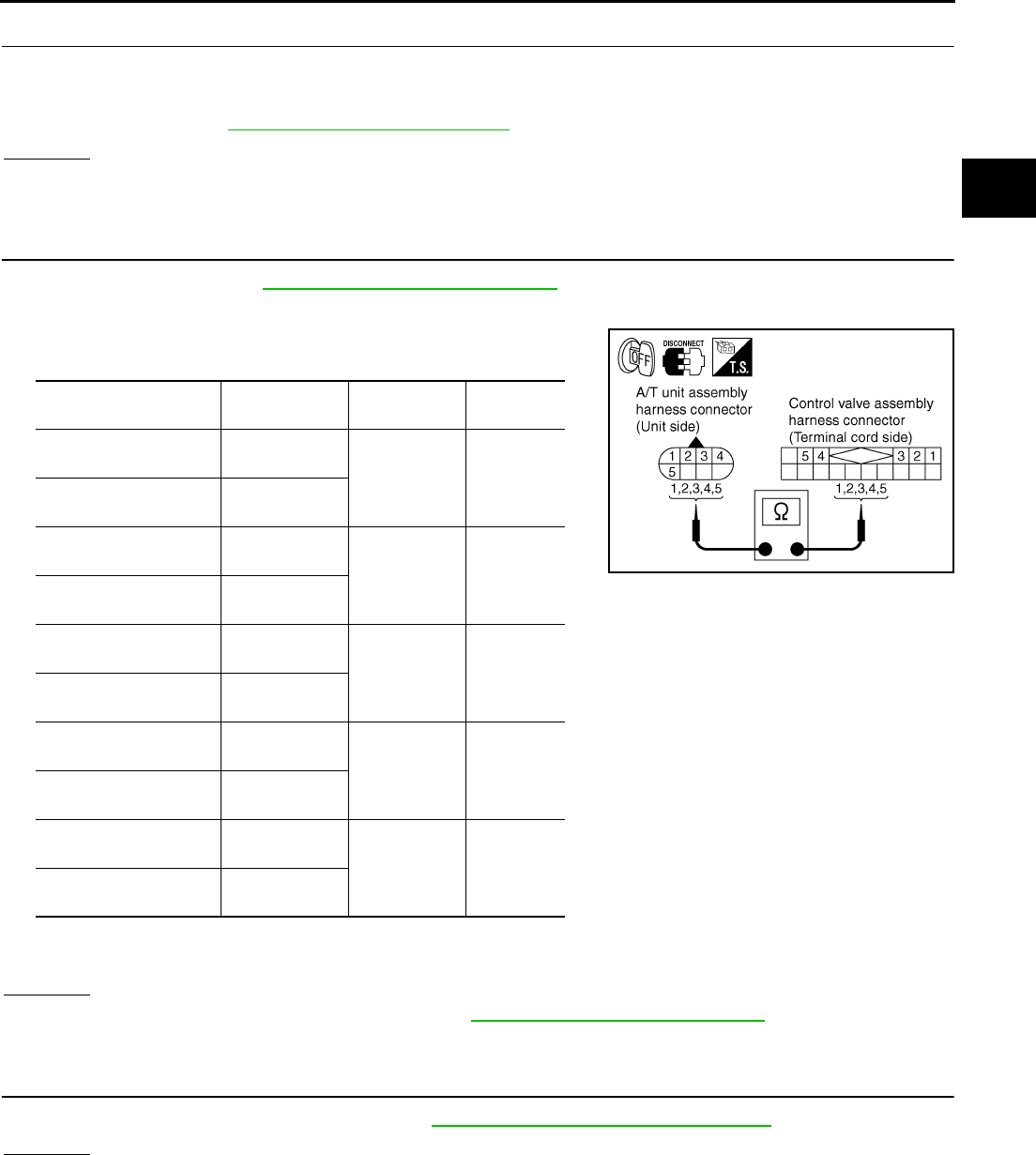
DTC P0705 PARK/NEUTRAL POSITION SWITCH
AT-115
D
E
F
G
H
I
J
K
L
M
A
B
AT
3. DETECT MALFUNCTIONING ITEM
Check the following items.
●Disconnection or short-circuit in the harness between TCM and A/T unit harness connector.
●PNP switch. Refer to AT-116, "Component Inspection" .
OK or NG
OK >> GO TO 4.
NG >> Repair or replace damaged parts.
4. CHECK TERMINAL CORD ASSEMBLY
1. Remove oil pan. Refer to AT-299, "Control Valve Assembly" .
2. Disconnect A/T unit assembly harness connector and control valve assembly harness connector.
3. Check continuity between A/T unit assembly harness connector
and control valve assembly harness connector.
4. If OK, check harness for short to ground and short to power.
5. Reinstall any part removed.
OK or NG
OK >> Replace control valve assembly. Refer to AT-299, "Control Valve Assembly" .
NG >> Repair open circuit or short to ground or short to power in harness or connectors.
5. CHECK DTC
Perform “DTC Confirmation Procedure”. Refer to AT-122, "DTC Confirmation Procedure" .
OK or NG
OK >> INSPECTION END
NG >> GO TO 6.
Item Connector No. Terminal No.
(Wire color) Continuity
A/T unit assembly har-
ness connector F8
1 (G/B) Yes
Control valve assembly
harness connector F302
A/T unit assembly har-
ness connector F8
2 (G/W) Yes
Control valve assembly
harness connector F302
A/T unit assembly har-
ness connector F8
3 (G/R) Yes
Control valve assembly
harness connector F302
A/T unit assembly har-
ness connector F8
4 (Y/R) Yes
Control valve assembly
harness connector F302
A/T unit assembly har-
ness connector F8
5 (L/Y) Yes
Control valve assembly
harness connector F302
SCIA3063E
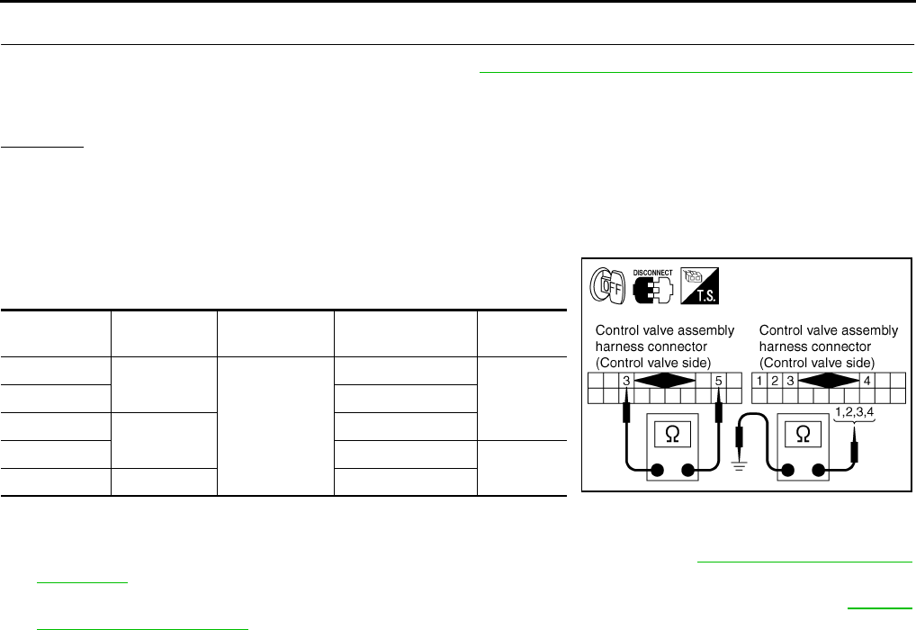
AT-116
DTC P0705 PARK/NEUTRAL POSITION SWITCH
6. PERFORM TCM INSPECTION
1. Perform TCM input/output signal inspection. Refer to AT-89, "TCM Input/Output Signal Reference Values"
.
2. If NG, recheck TCM pin terminals for damage or loose connection with harness connector.
OK or NG
OK >> INSPECTION END
NG >> Repair or replace damaged parts.
Component Inspection ACS0009Q
PNP SWITCH
1. Selector lever to various positions to check the continuity
between terminals on the PNP switch and ground.
2. If NG, check the continuity with the control linkage disconnected. (Refer to Step 1 above.)
3. If OK with the control linkage disconnected, adjust the control linkage. Refer to AT-289, "Adjustment of A/
T Position" .
4. If NG even when the control linkage is disconnected, replace the control valve assembly. Refer to AT-299,
"Control Valve Assembly" .
PNP SW Shift position Connector No. Terminal No.
(Wire color) Continuity
SW 1 P
F302
1 (G/W) - Ground
NoSW 2 2 (W/L) - Ground
SW 3 D3 (W/Y) - Ground
SW 4 4 (GY) - Ground Yes
SW 3 Monitor P, R, N, D 3 (W/Y) - 5 (W/R) SCIA3062E
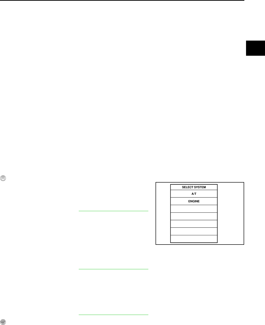
DTC P0720 VEHICLE SPEED SENSOR A/T (REVOLUTION SENSOR)
AT-117
D
E
F
G
H
I
J
K
L
M
A
B
AT
DTC P0720 VEHICLE SPEED SENSOR A/T (REVOLUTION SENSOR) PFP:32702
Description ACS0009R
The revolution sensor detects the revolution of the idler gear parking pawl lock gear and emits a pulse signal.
The pulse signal is sent to the TCM which converts it into vehicle speed.
On Board Diagnosis Logic ACS0009S
●This is an OBD-II self-diagnostic item.
●Diagnostic trouble code “VEH SPD SEN/CIR AT” with CONSULT-II or P0720 without CONSULT-II is
detected under the following conditions.
–When TCM does not receive the proper voltage signal from the sensor.
–After ignition switch is turned “ON”, irregular signal input from vehicle speed sensor MTR before the vehi-
cle starts moving.
Possible Cause ACS0009T
●Harness or connectors
(The sensor circuit is open or shorted.)
●Revolution sensor
●Vehicle speed sensor MTR
DTC Confirmation Procedure ACS0009U
CAUTION:
●Always drive vehicle at a safe speed.
●Be careful not to rev engine into the red zone on the tachometer.
NOTE:
If “DTC Confirmation Procedure” has been previously conducted, always turn ignition switch “OFF”
and wait at least 10 seconds before conducting the next test.
After the repair, perform the following procedure to confirm the malfunction is eliminated.
WITH CONSULT-II
1. Turn ignition switch ON. (Do not start engine.)
2. Select “DATA MONITOR” mode for “A/T” with CONSULT-II.
3. Drive vehicle and check for an increase of “VHCL/S SE·A/T”
value in response to “VHCL/S SE·MTR” value.
If the check result is NG, go to AT-119, "Diagnostic Procedure" .
If the check result is OK, go to following step.
4. Select “DATA MONITOR” mode for “ENGINE” with CONSULT-II.
5. Start engine and maintain the following conditions for at least 5
consecutive seconds.
VHCL SPEED SE: 30 km/h (19 MPH) or more
THRTL POS SEN: More than 1.0/8
Selector lever: “D” position
Driving location: Driving the vehicle uphill (increased engine load) will help maintain the driving
conditions required for this test.
If the check result is NG, go to AT-119, "Diagnostic Procedure" .
If the check result is OK, go to following step.
6. Maintain the following conditions for at least 5 consecutive seconds.
ENGINE SPEED: 3,500 rpm or more
THRTL POS SEN: More than 1.0/8
Selector lever: “D” position
Driving location: Driving the vehicle uphill (increased engine load) will help maintain the driving
conditions required for this test.
If the check result is NG, go to AT-119, "Diagnostic Procedure" .
WITH GST
Follow the procedure “With CONSULT-II”.
SAT014K
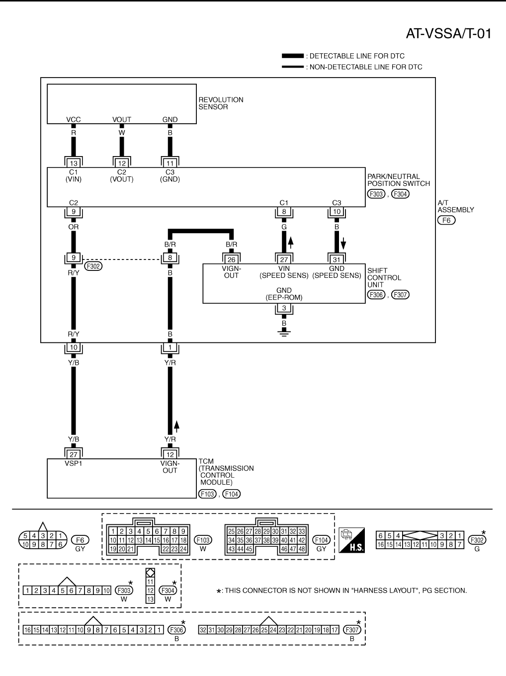
AT-118
DTC P0720 VEHICLE SPEED SENSOR A/T (REVOLUTION SENSOR)
Wiring Diagram — AT — VSSA/T ACS0009V
TCWT0221E
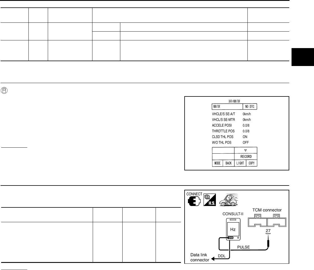
DTC P0720 VEHICLE SPEED SENSOR A/T (REVOLUTION SENSOR)
AT-119
D
E
F
G
H
I
J
K
L
M
A
B
AT
TCM terminals and Data are reference value. Measured between each terminals 5, 14, 24 and 46 (TCM ground).
Diagnostic Procedure ACS0009W
1. CHECK INPUT SIGNALS
With CONSULT-II
1. Turn ignition switch ON. (Do not start engine.)
2. Select “ECU INPUT SIGNALS” in “DATA MONITOR” mode for
“A/T” with CONSULT-II.
3. Start the engine.
4. Read out the value of “VHCL/S SE·A/T” while driving.
Check the value changes according to driving speed.
OK or NG
OK >> GO TO 6.
NG >> GO TO 3.
2. CHECK REVOLUTION SENSOR
1. Start the engine.
2. Check the pulse when vehicle cruises.
OK or NG
OK >> GO TO 6.
NG >> GO TO 3.
Terminal
No.
Wire
color Item Condition Data (Approx.)
12 Y/R Power supply
(out)
IGN ON – Battery voltage
IGN OFF – 0V
27 Y/B
Vehicle speed
sensor A/T (revo-
lution sensor)
When
vehicle
cruises
When moving at 20 km/h (12 MPH). 185 (Hz)
PCIA0033E
Condition Connector
No.
Terminal No.
(Wire color)
Data
(Approx.)
When moving at 20 km/h (12 MPH), use
the CONSULT-II pulse frequency mea-
suring function.
CAUTION:
Connect the data link connector to the
vehicle-side diagnosis connector.
F104 27 (Y/B) 185 (Hz)
PCIA0018E
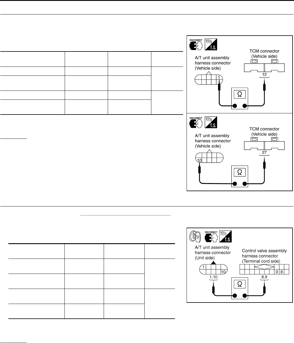
AT-120
DTC P0720 VEHICLE SPEED SENSOR A/T (REVOLUTION SENSOR)
3. CHECK HARNESS BETWEEN TCM AND A/T UNIT ASSEMBLY HARNESS CONNECTOR
1. Turn ignition switch OFF.
2. Disconnect TCM connector.
3. Check continuity between A/T unit assembly harness connector
and TCM connector.
4. If OK, check harness for short to ground and short to power.
5. Reinstall any part removed.
OK or NG
OK >> GO TO 4.
NG >> Repair open circuit or short to ground or short to power
in harness or connectors.
4. CHECK TERMINAL CORD ASSEMBLY
1. Remove oil pan. Refer to AT-299, "Control Valve Assembly" .
2. Disconnect A/T unit assembly harness connector and control valve assembly harness connector.
3. Check continuity between A/T unit assembly harness connector
and control valve assembly harness connector.
4. If OK, check harness for short to ground and short to power.
5. Reinstall any part removed.
OK or NG
OK >> GO TO 5.
NG >> Repair open circuit or short to ground or short to power in harness or connectors.
Item Connector No. Terminal No.
(Wire color) Continuity
TCM F103 12 (Y/R)
Yes
A/T unit assembly harness
connector F6 1 (Y/R)
TCM F104 27 (Y/B)
Yes
A/T unit assembly harness
connector F6 10 (Y/B)
SCIA3339E
Item Connector No. Terminal No.
(Wire color) Continuity
A/T unit assembly har-
ness connector F6 1 (B)
Yes
Control valve assem-
bly harness connector F302 8 (B)
A/T unit assembly har-
ness connector F6 10 (R/Y)
Yes
Control valve assem-
bly harness connector F302 9 (R/Y)
SCIA3064E

DTC P0720 VEHICLE SPEED SENSOR A/T (REVOLUTION SENSOR)
AT-121
D
E
F
G
H
I
J
K
L
M
A
B
AT
5. DETECT MALFUNCTION ITEMS
1. Check control valve assembly. Refer to AT-299, "Control Valve Assembly" .
2. Disassemble A/T. Refer to AT-325, "DISASSEMBLY" .
3. Check revolution sensor. Refer to AT-325, "DISASSEMBLY" .
OK or NG
OK >> GO TO 6.
NG >> Repair or replace damaged parts.
6. CHECK DTC
Perform “DTC Confirmation Procedure”. Refer to AT-117, "DTC Confirmation Procedure" .
OK or NG
OK >> INSPECTION END
NG >> GO TO 7.
7. PERFORM TCM INSPECTION
1. Perform TCM input/output signal inspection. Refer to AT-89, "TCM Input/Output Signal Reference Values"
.
2. If NG, recheck TCM pin terminals for damage or loose connection with harness connector.
OK or NG
OK >> INSPECTION END
NG >> Repair or replace damaged parts.
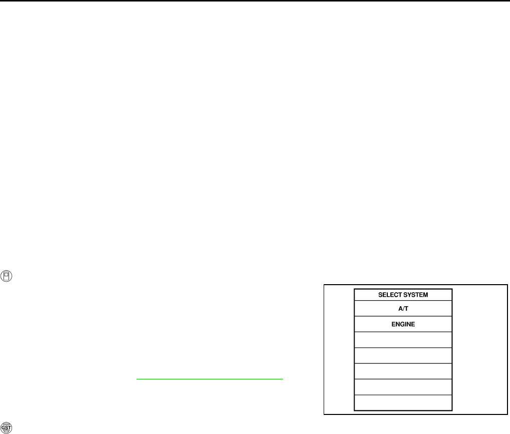
AT-122
DTC P0725 ENGINE SPEED SIGNAL
DTC P0725 ENGINE SPEED SIGNAL PFP:24825
Description ACS0009X
The engine speed signal is sent from the ECM to the TCM.
On Board Diagnosis Logic ACS0009Y
●This is an OBD-II self-diagnostic item.
●Diagnostic trouble code “ENGINE SPEED SIG” with CONSULT-II or P0725 without CONSULT-II is
detected when TCM does not receive the ignition signal from ECM during engine cranking or running.
Possible Cause ACS0009Z
Harness or connectors
(The ECM to the TCM circuit is open or shorted.)
DTC Confirmation Procedure ACS000A0
CAUTION:
Always drive vehicle at a safe speed.
NOTE:
If “DTC Confirmation Procedure” has been previously conducted, always turn ignition switch “OFF”
and wait at least 10 seconds before conducting the next test.
After the repair, perform the following procedure to confirm the malfunction is eliminated.
WITH CONSULT-II
1. Turn ignition switch ON and select “DATA MONITOR” mode for
“A/T” with CONSULT-II.
2. Start engine and maintain the following conditions for at least 10
consecutive seconds.
VHCL SPEED SE: 10 km/h (6 MPH) or more
ACCELE POSI: More than 1/8
Selector lever: “D” position
3. If DTC is detected, go to AT-123, "Diagnostic Procedure" .
WITH GST
Follow the procedure “With CONSULT-II”.
SAT014K
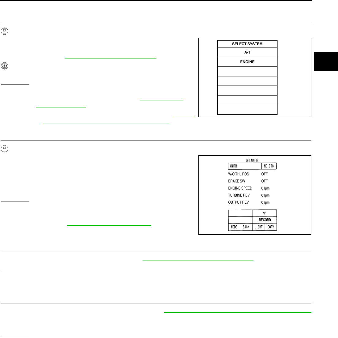
DTC P0725 ENGINE SPEED SIGNAL
AT-123
D
E
F
G
H
I
J
K
L
M
A
B
AT
Diagnostic Procedure ACS000A1
1. CHECK DTC WITH ECM
With CONSULT-II
1. Turn ignition switch to ON. (Do not start engine.)
2. Select “SELF-DIAG RESULTS” mode for “ENGINE” with CON-
SULT-II. Refer to EC-105, "CONSULT-II Function" .
With GST
Follow the procedure “With CONSULT-II”.
OK or NG
OK >> GO TO 2.
NG >> Check the DTC detected item, go to EC-105, "CON-
SULT-II Function" .
●If CAN communication line is detected, go to AT-105,
"DTC U1000 CAN COMMUNICATION LINE" .
2. CHECK DTC WITH TCM
With CONSULT-II
1. Start engine.
2. Select “ECU INPUT SIGNALS” in “DATA MONITOR” mode for
“A/T” with CONSULT-II.
3. While monitoring engine speed, check for engine speed change
corresponding to wide-open throttle position signal.
OK or NG
OK >> GO TO 3.
NG >> Check the ignition signal circuit.
●Refer to EC-583, "IGNITION SIGNAL" .
3. CHECK DTC
Perform “DTC Confirmation Procedure”. Refer to AT-122, "DTC Confirmation Procedure" .
OK or NG
OK >> INSPECTION END
NG >> GO TO 4.
4. PERFORM TCM INSPECTION
1. Perform TCM input/output signal inspection. Refer to AT-89, "TCM Input/Output Signal Reference Values"
.
2. If NG, recheck TCM pin terminals for damage or loose connection with harness connector.
OK or NG
OK >> INSPECTION END
NG >> Repair or replace damaged parts.
SAT014K
PCIA0041E
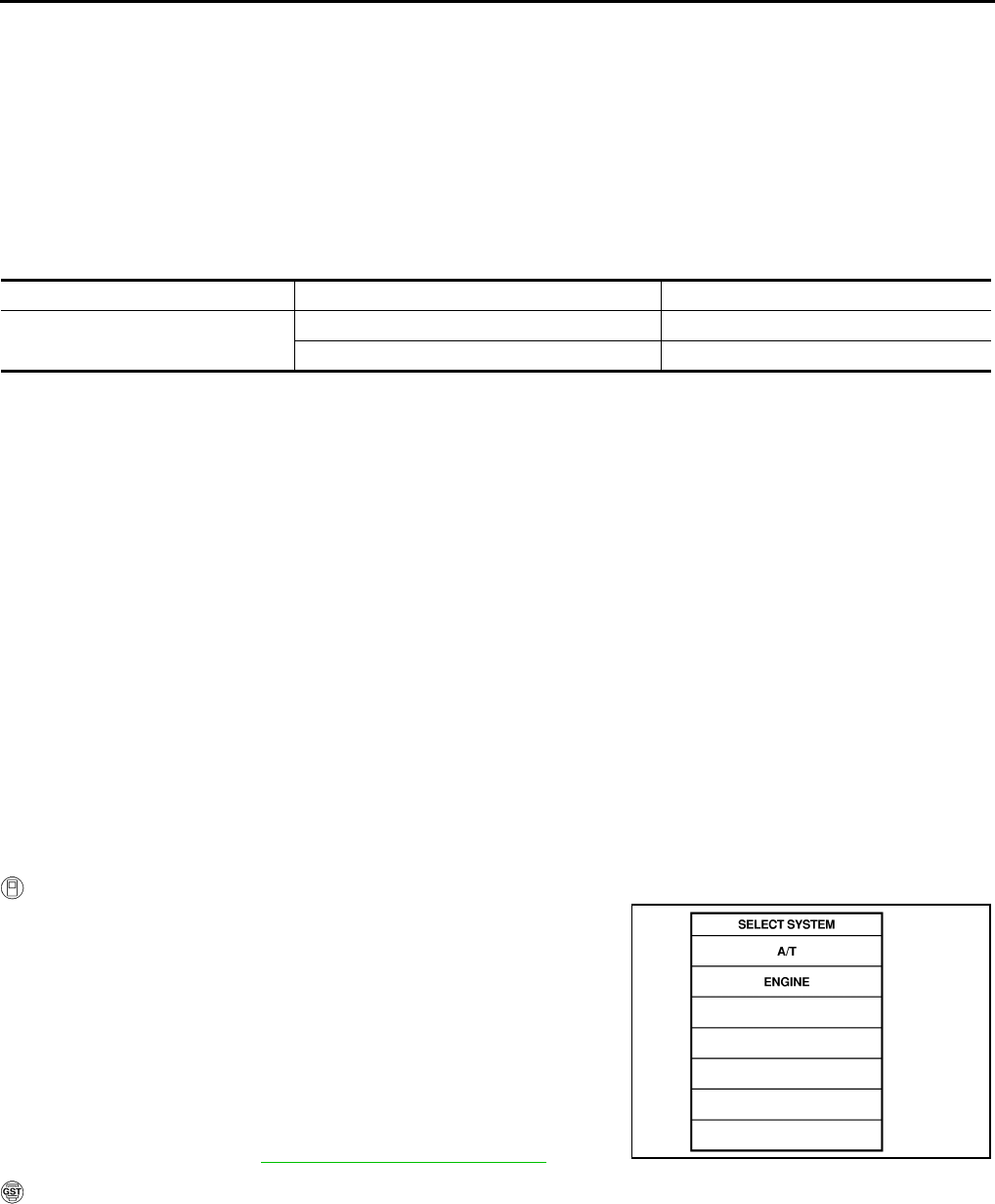
AT-124
DTC P0740 TORQUE CONVERTER CLUTCH SOLENOID VALVE
DTC P0740 TORQUE CONVERTER CLUTCH SOLENOID VALVE PFP:31940
Description ACS000A2
●The torque converter clutch solenoid valve is activated, with the gear in D4 , D5 by the TCM in response
to signals sent from the vehicle speed sensor and accelerator pedal position sensor (throttle position sen-
sor). Torque converter clutch piston operation will then be controlled.
●Lock-up operation, however, is prohibited when A/T fluid temperature is too low.
●When the accelerator pedal is depressed (less than 1/8) in lock-up condition, the engine speed should not
change abruptly. If there is a big jump in engine speed, there is no lock-up.
CONSULT-II Reference Value ACS001KW
On Board Diagnosis Logic ACS000A3
●This is an OBD-II self-diagnostic item.
●Diagnostic trouble code “TCC SOLENOID/CIRC” with CONSULT-II or P0740 without CONSULT-II is
detected under the following conditions.
–When TCM detects an improper voltage drop when it tries to operate the solenoid valve.
–When TCM detects as irregular by comparing target value with monitor value.
Possible Cause ACS000A4
●Torque converter clutch solenoid valve
●Harness or connectors
(The solenoid circuit is open or shorted.)
DTC Confirmation Procedure ACS000A5
CAUTION:
Always drive vehicle at a safe speed.
NOTE:
If “DTC Confirmation Procedure” has been previously conducted, always turn ignition switch “OFF”
and wait at least 10 seconds before conducting the next test.
After the repair, perform the following procedure to confirm the malfunction is eliminated.
WITH CONSULT-II
1. Turn ignition switch ON. (Do not start engine.)
2. Select “DATA MONITOR” mode for “ENGINE” with CONSULT-II.
3. Start engine and maintain the following conditions for at least 5
consecutive seconds.
VHCL SPEED SE: 80 km/h (50 MPH) or more
ACCELE POS: 0.5/8 - 1.0/8
SELECTOR LEVER: “D” position
Driving location: Driving the vehicle uphill (increased
engine load) will help maintain the driving conditions
required for this test.
4. If DTC is detected go to AT-126, "Diagnostic Procedure" .
WITH GST
Follow the procedure “With CONSULT-II”.
Item name Condition Display value (Approx.) (A)
TCC SOLENOID When perform slip lock-up 0.2 - 0.4
When perform lock-up 0.4 - 0.6
SAT014K
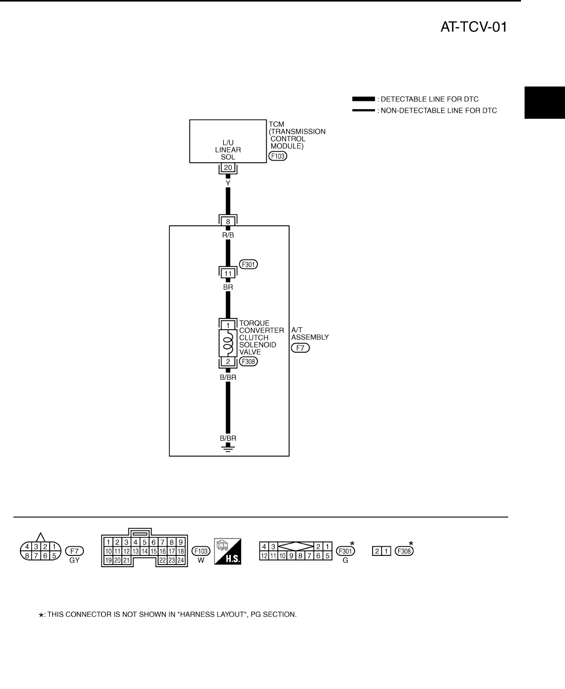
DTC P0740 TORQUE CONVERTER CLUTCH SOLENOID VALVE
AT-125
D
E
F
G
H
I
J
K
L
M
A
B
AT
Wiring Diagram — AT — TCV ACS000A6
TCM terminal and Data are reference value. Measured between each terminals 5, 14, 24 and 46 (TCM ground). TCWT0222E
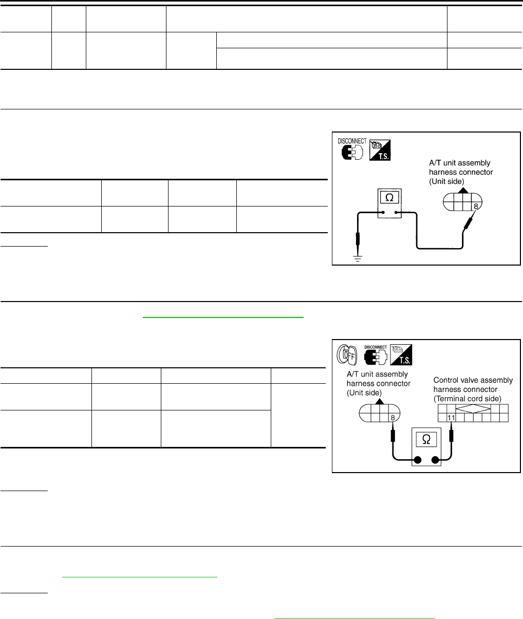
AT-126
DTC P0740 TORQUE CONVERTER CLUTCH SOLENOID VALVE
Diagnostic Procedure ACS000A7
1. CHECK TORQUE CONVERTER CLUTCH SOLENOID VALVE CIRCUIT
1. Turn ignition switch OFF.
2. Disconnect A/T unit assembly harness connector at the trans-
mission right side.
3. Check the resistance between terminal and ground.
OK or NG
OK >> GO TO 4.
NG >> GO TO 2.
2. CHECK TERMINAL CORD ASSEMBLY
1. Remove oil pan. Refer to AT-299, "Control Valve Assembly" .
2. Disconnect A/T unit assembly harness connector and control valve assembly harness connector.
3. Check continuity between A/T unit assembly harness connector
and control valve assembly harness connector.
4. If OK, check harness for short to ground and short to power.
5. Reinstall any part removed.
OK or NG
OK >> GO TO 3.
NG >> Repair open circuit or short to ground or short to power in harness or connectors.
3. CHECK VALVE RESISTANCE
Check valve resistance
●Refer to AT-128, "Component Inspection" .
OK or NG
OK >> GO TO 4.
NG >> Replace the control valve assembly. Refer to AT-299, "Control Valve Assembly" .
Terminal
No.
Wire
color Item Condition Data (Approx.)
20 Y TCC solenoid
valve
When
vehicle
cruises
When lock-up More than 2V
When not lock-up 0V
Solenoid valve Connector No. Terminal No.
(Wire color) Resistance (Approx.)
Torque converter clutch
solenoid valve F7 8 (Y) - Ground 3 - 9 Ω
SCIA1830E
Item Connector No. Terminal No. (Wire color) Continuity
A/T unit assembly
harness connector F7 8 (R/B)
Yes
Control valve assem-
bly harness connec-
tor
F301 11 (R/B)
SCIA3060E
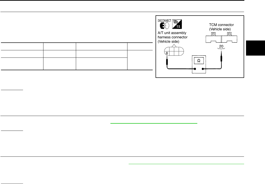
DTC P0740 TORQUE CONVERTER CLUTCH SOLENOID VALVE
AT-127
D
E
F
G
H
I
J
K
L
M
A
B
AT
4. CHECK POWER SOURCE CIRCUIT
1. Turn ignition switch OFF.
2. Disconnect TCM connector.
3. Check continuity between A/T unit assembly harness connector
and TCM connector.
4. If OK, check harness for short to ground and short to power.
5. Reinstall any part removed.
OK or NG
OK >> GO TO 5.
NG >> Repair open circuit or short to ground or short to power in harness or connectors.
5. CHECK DTC
Perform “DTC Confirmation Procedure”. Refer to AT-108, "DTC Confirmation Procedure" .
OK or NG
OK >> INSPECTION END
NG >> GO TO 6.
6. PERFORM TCM INSPECTION
1. Perform TCM input/output signal inspection. Refer to AT-89, "TCM Input/Output Signal Reference Values"
.
2. If NG, recheck TCM pin terminals for damage or loose connection with harness connector.
OK or NG
OK >> INSPECTION END
NG >> Repair or replace damaged parts.
Item Connector No. Terminal No. (Wire color) Continuity
TCM F103 20 (Y)
Yes
A/T unit assembly
harness connector F7 8 (Y)
SCIA1831E
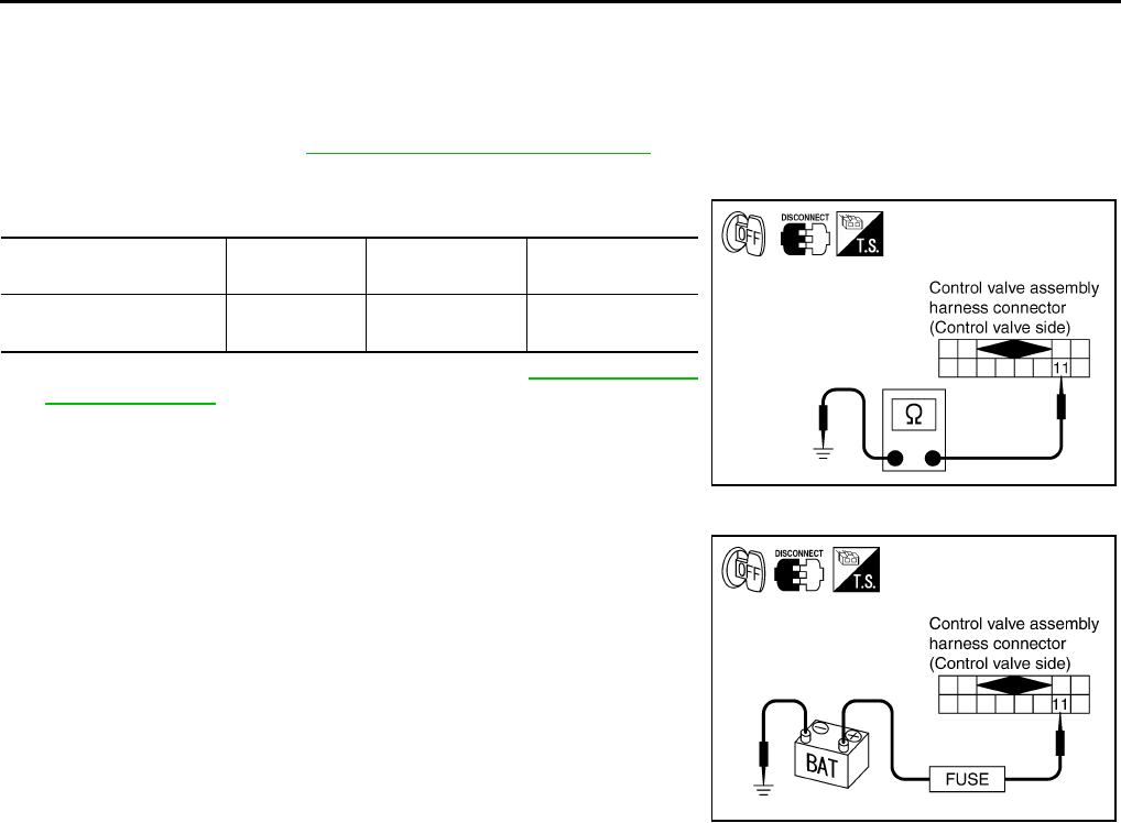
AT-128
DTC P0740 TORQUE CONVERTER CLUTCH SOLENOID VALVE
Component Inspection ACS004IA
TORQUE CONVERTER CLUTCH SOLENOID VALVE
Resistance check
1. Turn ignition switch OFF.
2. Remove oil pan. Refer to AT-299, "Control Valve Assembly" .
3. Disconnect control valve assembly harness connector.
4. Check resistance between terminal and ground.
5. If NG, replace control valve assembly. Refer to AT-299, "Control
Valve Assembly" .
Operation check
●Check solenoid valve by listening for its operating sound while
applying battery voltage to the terminal 11 and ground.
Solenoid Valve Connector No. Terminal No.
(Wire color)
Resistance (Ω)
(Approx.)
Torque converter clutch
solenoid valve F301 11 (BR) - Ground 3 - 9 Ω
SCIA3061E
SCIA3105E
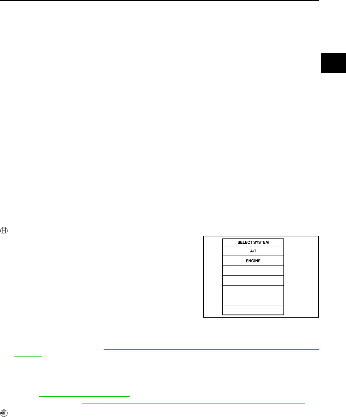
DTC P0744 A/T TCC S/V FUNCTION (LOCK-UP)
AT-129
D
E
F
G
H
I
J
K
L
M
A
B
AT
DTC P0744 A/T TCC S/V FUNCTION (LOCK-UP) PFP:31940
Description ACS000A8
This malfunction is detected when the A/T does not shift into 5th gear position or the torque converter clutch
does not lock-up as instructed by the TCM. This is not only caused by electrical malfunction (circuits open or
shorted) but also by mechanical malfunction such as control valve sticking, improper solenoid valve operation,
etc.
On Board Diagnosis Logic ACS000A9
●This is an OBD-II self-diagnostic item.
●Diagnostic trouble code “A/T TCC S/V FNCTN” with CONSULT-II or P0744 without CONSULT-II is
detected under the following conditions.
–When A/T cannot perform lock-up even if electrical circuit is good.
–When TCM detects as irregular by comparing difference value with slip rotation.
Possible Cause ACS000AA
●Harness or connectors
(The solenoid circuit is open or shorted.)
●Torque converter clutch solenoid valve
●Hydraulic control circuit
DTC Confirmation Procedure ACS000AB
CAUTION:
Always drive vehicle at a safe speed.
NOTE:
If “DTC Confirmation Procedure” has been previously conducted, always turn ignition switch “OFF”
and wait at least 10 seconds before conducting the next test.
After the repair, perform the following procedure to confirm the malfunction is eliminated.
WITH CONSULT-II
1. Start engine and select “DATA MONITOR” mode for “A/T” with
CONSULT-II.
2. Select “TCC S/V FNCTN CHECK” of “DTC WORK SUPPORT”
mode for “A/T” with CONSULT-II and touch “START”.
3. Accelerate vehicle to more than 80 km/h (50 MPH) and maintain
the following condition continuously until “TESTING” has turned
to “COMPLETE”. (It will take approximately 30 seconds after
“TESTING” shows.)
ACCELE POSI: More than 1.0/8 (at all times during step 4)
TCC SOLENOID: 0.4 - 0.6 A
Selector lever: “D” position
[Reference speed: Constant speed of more than 80 km/h (50
MPH)]
–Check that “GEAR” shows “5”.
–For shift schedule, refer to AT-377, "Vehicle Speed When Performing and Releasing Complete
Lock-up" .
–If “TESTING” does not appear on CONSULT-II for a long time, select “SELF-DIAG RESULTS”. In
case a 1st trip DTC other than P0744 is shown, refer to applicable “TROUBLE DIAGNOSIS FOR
DTC”.
4. Make sure that “OK” is displayed. (If “NG” is displayed, refer to “DIAGNOSTIC PROCEDURE”.)
Refer to AT-131, "Diagnostic Procedure" .
Refer to shift schedule, AT-377, "Vehicle Speed When Performing and Releasing Complete Lock-up" .
WITH GST
Follow the procedure “With CONSULT-II”.
SAT014K

AT-130
DTC P0744 A/T TCC S/V FUNCTION (LOCK-UP)
Wiring Diagram — AT — TCCSIG ACS000AC
TCWT0223E
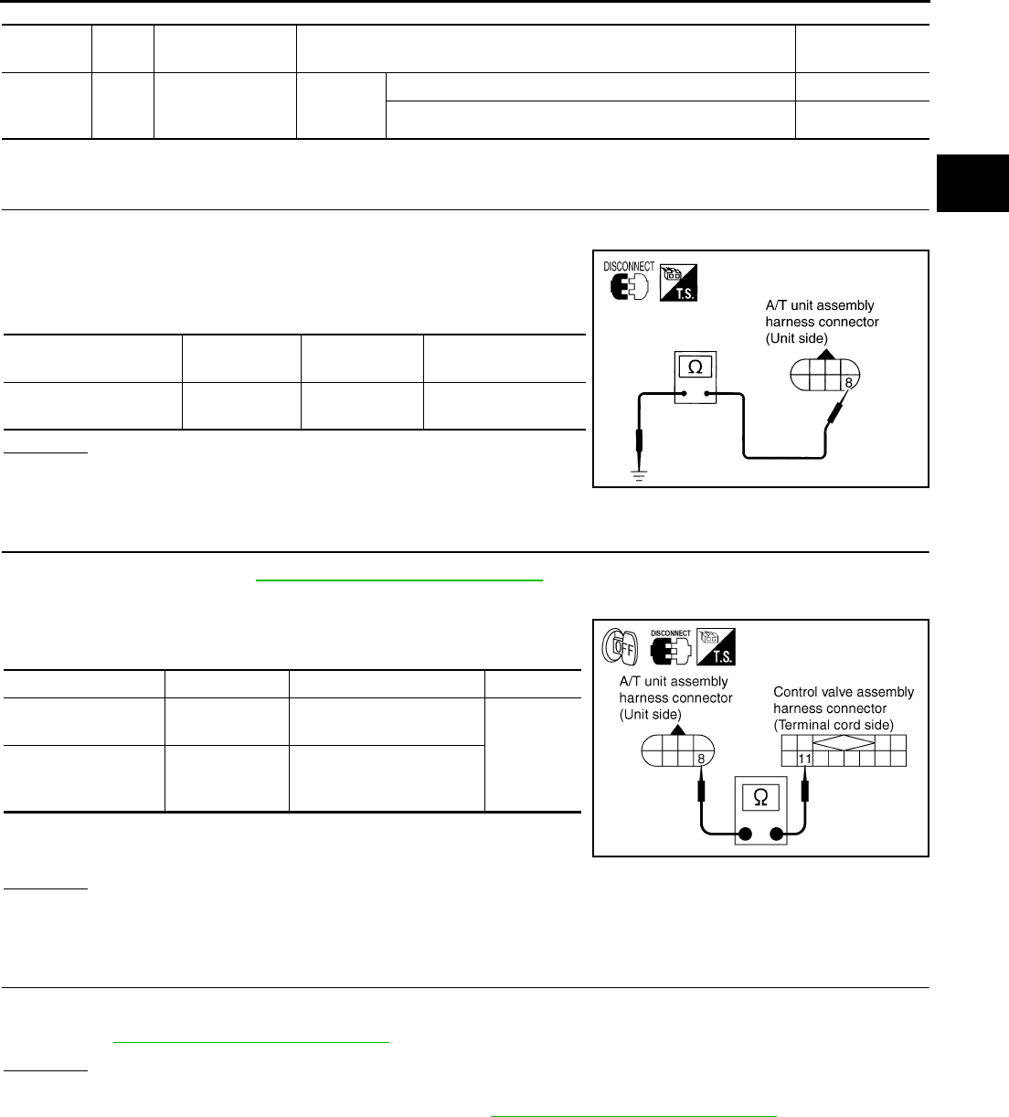
DTC P0744 A/T TCC S/V FUNCTION (LOCK-UP)
AT-131
D
E
F
G
H
I
J
K
L
M
A
B
AT
TCM terminal and Data are reference value. Measured between each terminals 5, 14, 24 and 46 (TCM ground).
Diagnostic Procedure ACS000AD
1. CHECK TORQUE CONVERTER CLUTCH SOLENOID VALVE CIRCUIT
1. Turn ignition switch OFF.
2. Disconnect A/T unit assembly harness connector at the trans-
mission right side.
3. Check the resistance between terminal and ground.
OK or NG
OK >> GO TO 4.
NG >> GO TO 2.
2. CHECK TERMINAL CORD ASSEMBLY
1. Remove oil pan. Refer to AT-299, "Control Valve Assembly" .
2. Disconnect A/T unit assembly harness connector and control valve assembly harness connector.
3. Check continuity between A/T unit assembly harness connector
and control valve assembly harness connector.
4. If OK, check harness for short to ground and short to power.
5. Reinstall any part removed.
OK or NG
OK >> GO TO 3.
NG >> Repair open circuit or short to ground or short to power in harness or connectors.
3. CHECK VALVE RESISTANCE
Check valve resistance
●Refer to AT-133, "Component Inspection" .
OK or NG
OK >> GO TO 5.
NG >> Replace the control valve assembly. Refer to AT-299, "Control Valve Assembly" .
Terminal
No.
Wire
color Item Condition Data (Approx.)
20 Y TCC solenoid
valve
When
vehicle
cruises
When lock-up More than 2V
When not lock-up 0V
Solenoid valve Connector No. Terminal No.
(Wire color) Resistance (Approx.)
Torque converter clutch
solenoid valve F7 8 (Y) - Ground 3 - 9 Ω
SCIA1830E
Item Connector No. Terminal No. (Wire color) Continuity
A/T unit assembly
harness connector F7 8 (R/B)
Yes
Control valve assem-
bly harness connec-
tor
F301 11 (R/B)
SCIA3060E

AT-132
DTC P0744 A/T TCC S/V FUNCTION (LOCK-UP)
4. CHECK POWER SOURCE CIRCUIT
1. Turn ignition switch OFF.
2. Disconnect TCM connector.
3. Check continuity between A/T unit assembly harness connector
and TCM connector.
4. If OK, check harness for short to ground and short to power.
5. Reinstall any part removed.
OK or NG
OK >> GO TO 5.
NG >> Repair open circuit or short to ground or short to power in harness or connectors.
5. CHECK DTC
Perform “DTC Confirmation Procedure”. Refer to AT-108, "DTC Confirmation Procedure" .
OK or NG
OK >> INSPECTION END
NG >> GO TO 6.
6. PERFORM TCM INSPECTION
1. Perform TCM input/output signal inspection. Refer to AT-89, "TCM Input/Output Signal Reference Values"
.
2. If NG, recheck TCM pin terminals for damage or loose connection with harness connector.
OK or NG
OK >> INSPECTION END
NG >> Repair or replace damaged parts.
Item Connector No. Terminal No. (Wire color) Continuity
TCM F103 20 (Y)
Yes
A/T unit assembly
harness connector F7 8 (Y)
SCIA1831E
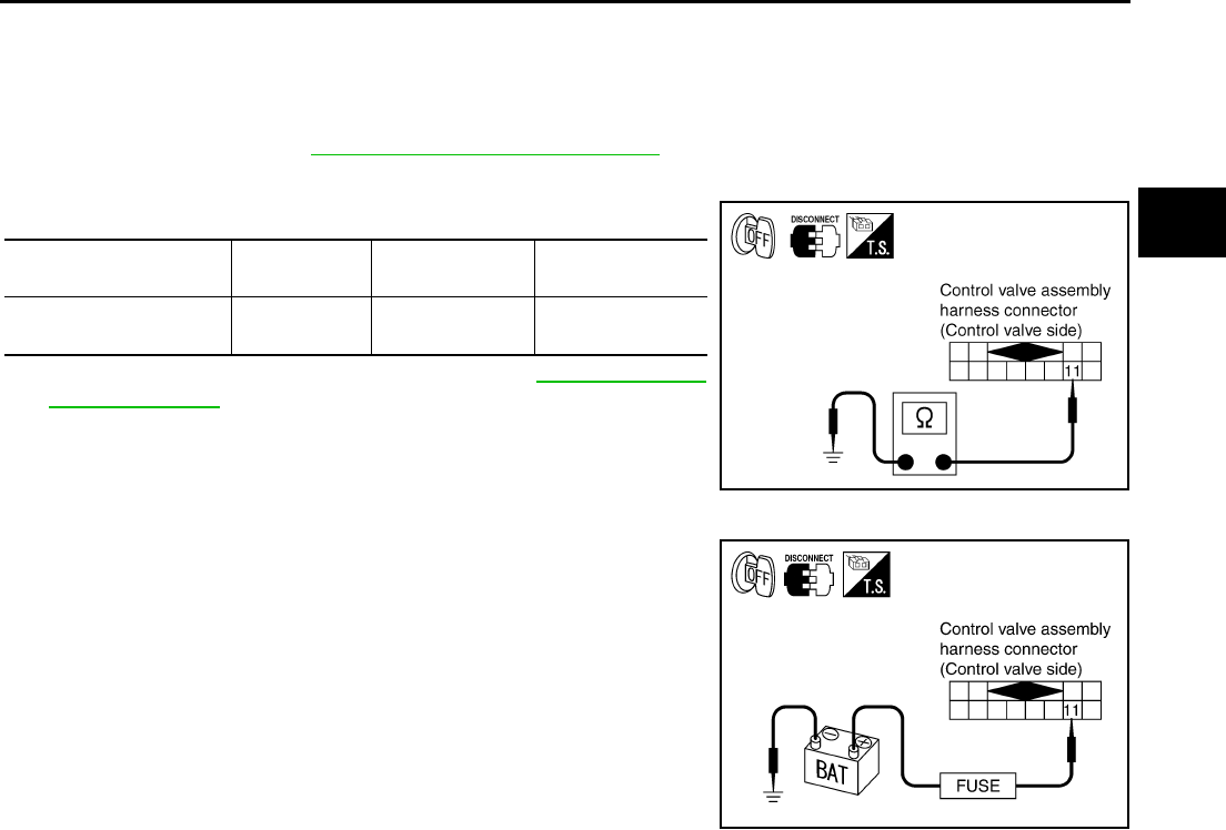
DTC P0744 A/T TCC S/V FUNCTION (LOCK-UP)
AT-133
D
E
F
G
H
I
J
K
L
M
A
B
AT
Component Inspection ACS004IB
TORQUE CONVERTER CLUTCH SOLENOID VALVE
Resistance check
1. Turn ignition switch OFF.
2. Remove oil pan. Refer to AT-299, "Control Valve Assembly" .
3. Disconnect control valve assembly harness connector.
4. Check resistance between terminal and ground.
5. If NG, replace control valve assembly. Refer to AT-299, "Control
Valve Assembly" .
Operation check
●Check solenoid valve by listening for its operating sound while
applying battery voltage to the terminal 11 and ground.
Solenoid Valve Connector No. Terminal No.
(Wire color)
Resistance (Ω)
(Approx.)
Torque converter clutch
solenoid valve F301 11 (BR) - Ground 3 - 9 Ω
SCIA3061E
SCIA3105E
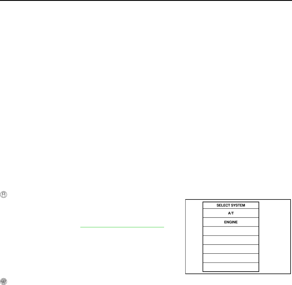
AT-134
DTC P0745 LINE PRESSURE SOLENOID VALVE
DTC P0745 LINE PRESSURE SOLENOID VALVE PFP:31940
Description ACS000AE
The line pressure solenoid valve regulates the oil pump discharge pressure to suit the driving condition in
response to a signal sent from the TCM.
The line pressure duty cycle value is not consistent when the closed throttle position signal is “ON”.
To confirm the line pressure duty cycle at low pressure, the accelerator (throttle) should be open until
the closed throttle position signal is “OFF”.
On Board Diagnosis Logic ACS000AF
●This is an OBD-II self-diagnostic item.
●Diagnostic trouble code “L/PRESS SOL/CIRC” with CONSULT-II or P0745 without CONSULT-II is
detected under the following conditions.
–When TCM detects an improper voltage drop when it tries to operate the solenoid valve.
–When TCM detects as irregular by comparing target value with monitor value.
Possible Cause ACS000AG
●Harness or connectors
(The solenoid circuit is open or shorted.)
●Line pressure solenoid valve
DTC Confirmation Procedure ACS000AH
NOTE:
If “DTC Confirmation Procedure” has been previously conducted, always turn ignition switch “OFF”
and wait at least 10 seconds before conducting the next test.
After the repair, perform the following procedure to confirm the malfunction is eliminated.
WITH CONSULT-II
1. Turn ignition switch ON and select “DATA MONITOR” mode for
“ENGINE” with CONSULT-II.
2. Engine start and wait at least 5 second.
3. If DTC is detected, go to “AT-136, "Diagnostic Procedure" .
WITH GST
Follow the procedure “With CONSULT-II”.
SAT014K
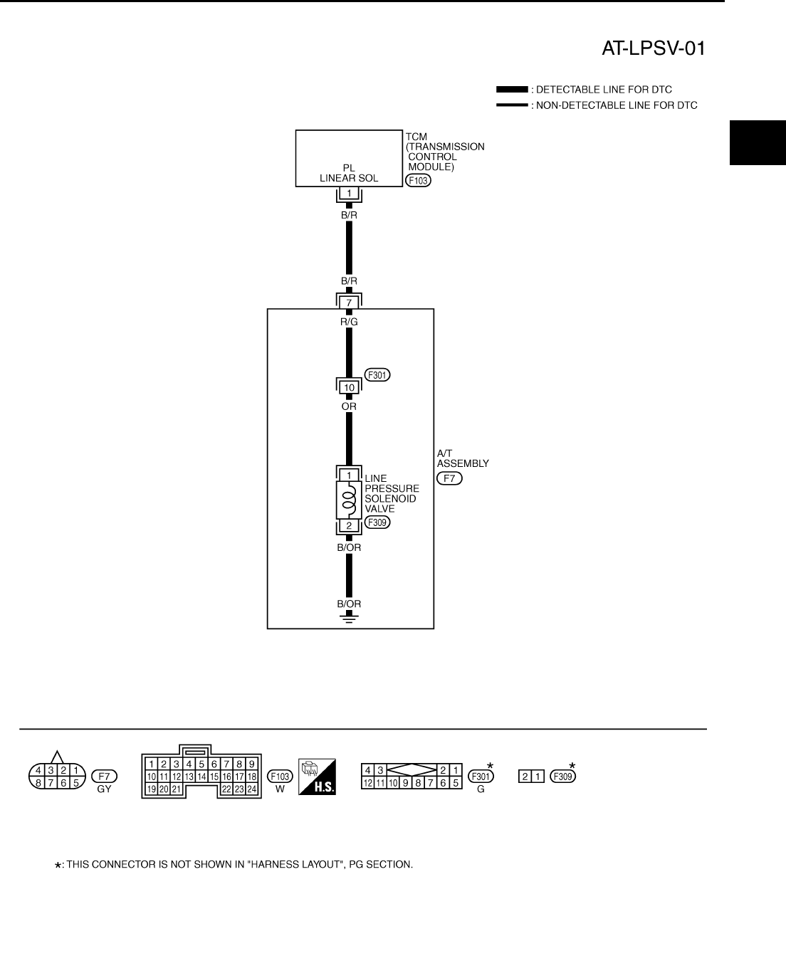
DTC P0745 LINE PRESSURE SOLENOID VALVE
AT-135
D
E
F
G
H
I
J
K
L
M
A
B
AT
Wiring Diagram — AT — LPSV ACS000AI
TCWT0224E
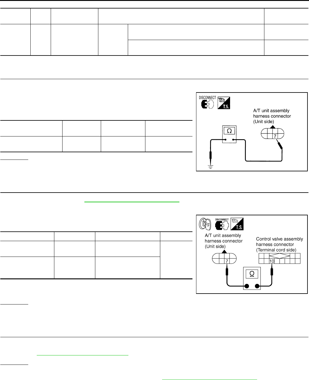
AT-136
DTC P0745 LINE PRESSURE SOLENOID VALVE
TCM terminal and Data are reference value. Measured between each terminals 5, 14, 24 and 46 (TCM ground).
Diagnostic Procedure ACS000AJ
1. CHECK LINE PRESSURE SOLENOID VALVE CIRCUIT
1. Turn ignition switch OFF.
2. Disconnect A/T unit assembly harness connector at the trans-
mission right side.
3. Check the resistance between terminal and ground.
OK or NG
OK >> GO TO 4.
NG >> GO TO 2.
2. CHECK TERMINAL CORD ASSEMBLY
1. Remove oil pan. Refer to AT-299, "Control Valve Assembly" .
2. Disconnect A/T unit assembly harness connector and control valve assembly harness connector.
3. Check continuity between A/T unit assembly harness connector
and control valve assembly harness connector.
4. If OK, check harness for short to ground and short to power.
5. Reinstall any part removed.
OK or NG
OK >> GO TO 3.
NG >> Repair open circuit or short to ground or short to power in harness or connectors.
3. CHECK VALVE RESISTANCE
Check valve resistance
●Refer to AT-138, "Component Inspection" .
OK or NG
OK >> GO TO 5.
NG >> Replace the control valve assembly. Refer to AT-299, "Control Valve Assembly" .
Terminal
No.
Wire
color Item Condition Data (Approx.)
1B/R
Line pressure
solenoid valve IGN ON
After warming up the engine, release your foot from the
accelerator pedal. 2V
After warming up the engine, press the accelerator pedal
all the way down. 0.7V
Solenoid valve Connector No. Terminal No.
(Wire color)
Resistance
(Approx.)
Line pressure solenoid
valve F7 7 (B/R) - Ground 3 - 9 Ω
SCIA1833E
Item Connector No. Terminal No. (Wire color) Continuity
A/T unit assembly
harness connector F7 7 (R/G)
Yes
Control valve assem-
bly harness connec-
tor
F301 10 (R/G)
SCIA3065E

DTC P0745 LINE PRESSURE SOLENOID VALVE
AT-137
D
E
F
G
H
I
J
K
L
M
A
B
AT
4. CHECK POWER SOURCE CIRCUIT
1. Turn ignition switch OFF.
2. Disconnect TCM connector.
3. Check continuity between A/T unit assembly harness connector
and TCM connector.
4. If OK, check harness for short to ground and short to power.
5. Reinstall any part removed.
OK or NG
OK >> GO TO 5.
NG >> Repair open circuit or short to ground or short to power in harness or connectors.
5. CHECK DTC
Perform “DTC Confirmation Procedure”. Refer to AT-108, "DTC Confirmation Procedure" .
OK or NG
OK >> INSPECTION END
NG >> GO TO 6.
6. PERFORM TCM INSPECTION
1. Perform TCM input/output signal inspection. Refer to AT-89, "TCM Input/Output Signal Reference Values"
.
2. If NG, recheck TCM pin terminals for damage or loose connection with harness connector.
OK or NG
OK >> INSPECTION END
NG >> Repair or replace damaged parts.
Item Connector No. Terminal No.
(Wire color) Continuity
TCM F103 1 (B/R)
Yes
A/T unit assembly harness
connector F7 7 (B/R)
SCIA1834E

AT-138
DTC P0745 LINE PRESSURE SOLENOID VALVE
Component Inspection ACS004IC
LINE PRESSURE SOLENOID VALVE
Resistance check
1. Turn ignition switch OFF.
2. Remove oil pan. Refer to AT-299, "Control Valve Assembly" .
3. Disconnect control valve assembly harness connector.
4. Check resistance between terminal and ground.
5. If NG, replace control valve assembly. Refer to AT-299, "Control
Valve Assembly" .
Operation check
●Check solenoid valve by listening for its operating sound while
applying battery voltage to the terminal 10 and ground.
Solenoid Valve Connector No. Terminal No.
(Wire color)
Resistance (Ω)
(Approx.)
Line pressure solenoid
valve F301 10 (OR) -
Ground 3 - 9 Ω
SCIA3066E
SCIA3067E
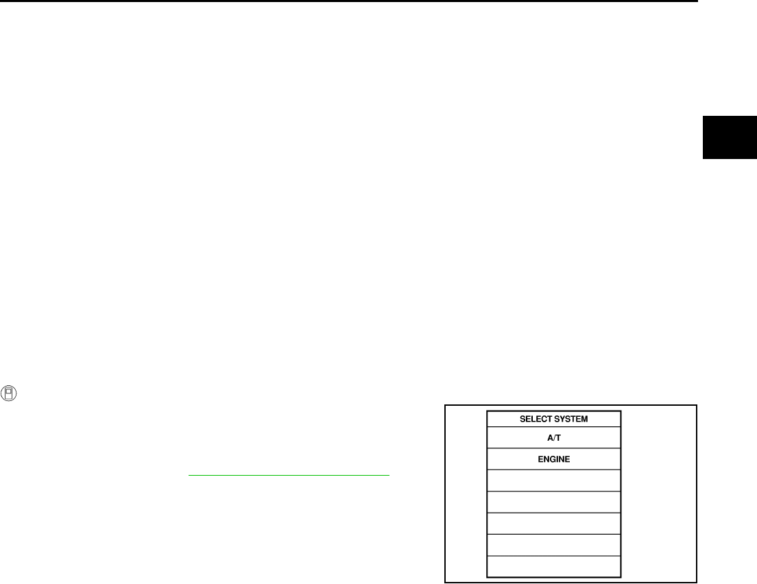
DTC P1701 TRANSMISSION CONTROL MODULE (POWER SUPPLY)
AT-139
D
E
F
G
H
I
J
K
L
M
A
B
AT
DTC P1701 TRANSMISSION CONTROL MODULE (POWER SUPPLY) PFP:31036
Description ACS000AK
When the power supply to the TCM is cut “OFF”, for example because the battery is removed, and the self-
diagnostics memory function stops, malfunction is detected.
On Board Diagnosis Logic ACS000AL
●This is not an OBD-II self-diagnostic item.
●Diagnostic trouble code “TCM-POWER SUPPLY” with CONSULT-II is detected when TCM does not
receive the voltage signal from the battery power supply.
●This is not a malfunction message. (Whenever shutting “OFF” a power supply to the TCM, this message
appears on the screen.)
Possible Cause ACS000AM
Harness or connectors
(Battery or ignition switch and TCM circuit is open or shorted.)
DTC Confirmation Procedure ACS000AN
NOTE:
If “DTC Confirmation Procedure” has been previously conducted, always turn ignition switch “OFF”
and wait at least 10 seconds before conducting the next test.
After the repair, perform the following procedure to confirm the malfunction is eliminated.
WITH CONSULT-II
1. Turn ignition switch ON. (Do not start engine.)
2. Select “DATA MONITOR” mode for “A/T” with CONSULT-II.
3. Wait for at least 2 consecutive seconds.
4. If DTC is detected, go to AT-142, "Diagnostic Procedure" .
SAT014K
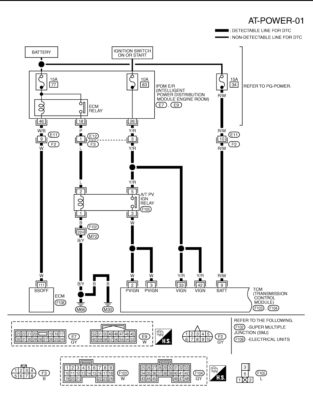
AT-140
DTC P1701 TRANSMISSION CONTROL MODULE (POWER SUPPLY)
Wiring Diagram — AT — POWER ACS000AO
TCWT0225E
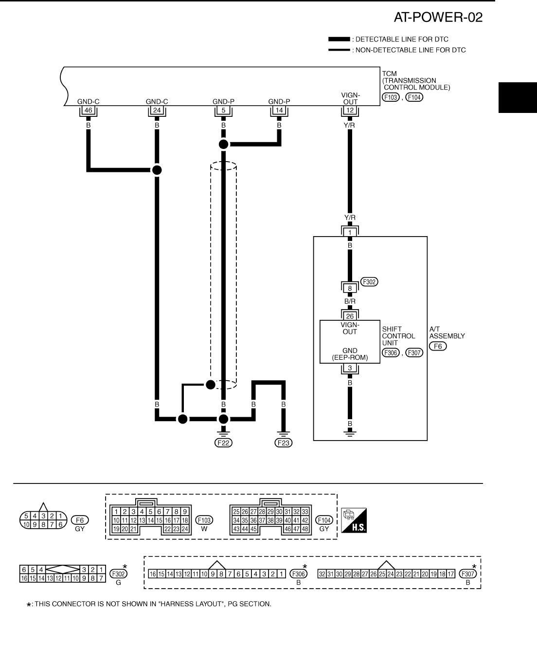
DTC P1701 TRANSMISSION CONTROL MODULE (POWER SUPPLY)
AT-141
D
E
F
G
H
I
J
K
L
M
A
B
AT
TCWT0226E
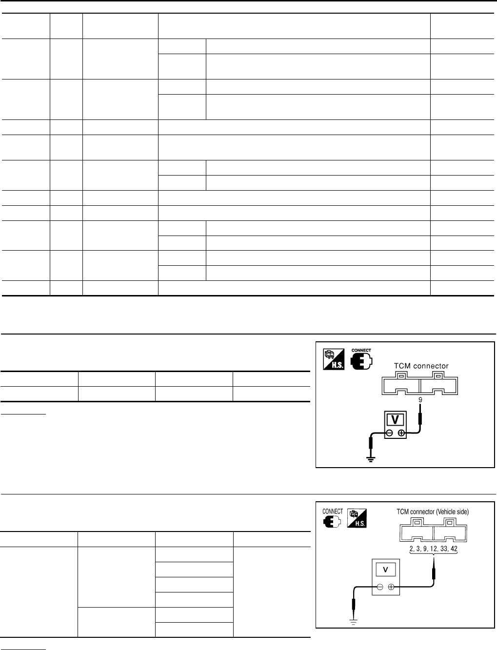
AT-142
DTC P1701 TRANSMISSION CONTROL MODULE (POWER SUPPLY)
TCM terminals and Data are reference value. Measured between each terminals 5, 14, 24 and 46 (TCM ground).
Diagnostic Procedure ACS000AP
1. CHECK TCM POWER SOURCE, STEP 1
1. Turn ignition switch OFF.
2. Check voltage between TCM terminal and ground.
OK or NG
OK >> GO TO 2.
NG >> GO TO 3.
2. CHECK TCM POWER SOURCE, STEP 2
1. Turn ignition switch ON. (Do not start engine.)
2. Check voltage between TCM terminal and ground.
OK or NG
OK >> GO TO 4.
NG >> GO TO 3.
Terminal
No.
Wire
color Item Condition Data (Approx.)
2 W Power supply
IGN ON – Battery voltage
IGN OFF Measure 3 seconds after switching “OFF” the ignition
switch. 0V
3 W Power supply
IGN ON – Battery voltage
IGN OFF Measure 3 seconds after switching “OFF” the ignition
switch. 0V
5 B Ground Always 0V
9R/W
Power supply
(Memory back-up) Always Battery voltage
12 Y/R Power supply
(out)
IGN ON – Battery voltage
IGN OFF – 0V
14 B Ground Always 0V
24 B Ground Always 0V
33 Y/R Power supply IGN ON – Battery voltage
IGN OFF – 0V
42 Y/R Power supply IGN ON – Battery voltage
IGN OFF – 0V
46 B Ground Always 0V
Item Connector No. Terminal No. Voltage
TCM F103 9 - Ground Battery voltage
SCIA1163E
Item Connector No. Terminal No. Voltage
TCM
F103
2 - Ground
Battery voltage
3 - Ground
9 - Ground
12 - Ground
F104 33 - Ground
42 - Ground PCIA0063E
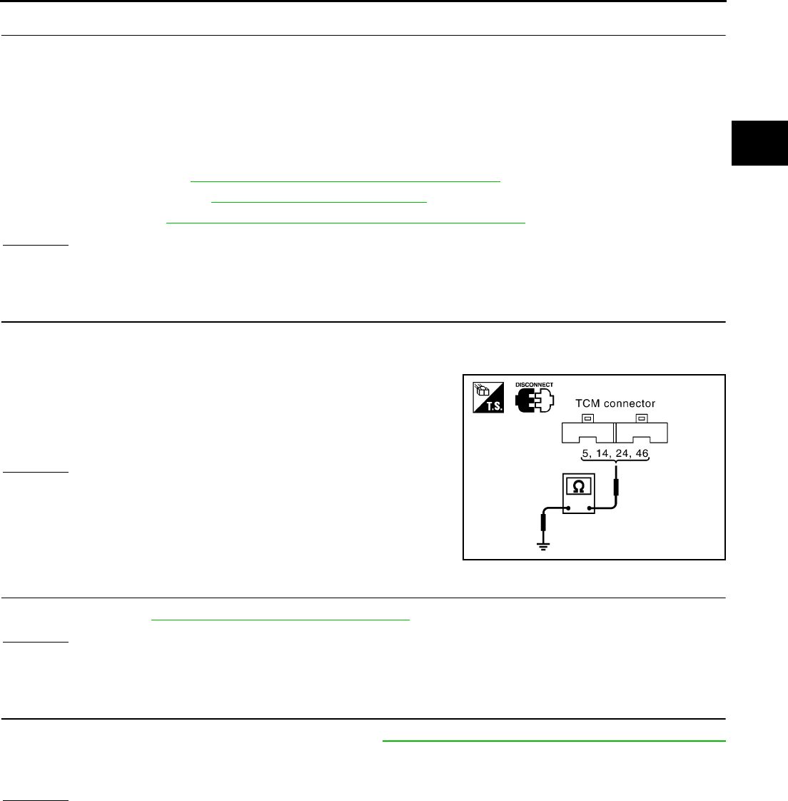
DTC P1701 TRANSMISSION CONTROL MODULE (POWER SUPPLY)
AT-143
D
E
F
G
H
I
J
K
L
M
A
B
AT
3. DETECT MALFUNCTIONING ITEM
Check the following items:
●Harness for short or open between battery and TCM terminal 9
●Harness for short or open between ignition switch and TCM terminals 2, 3, 33 and 42
●Harness for short or open between IPDM E/R terminal 33 and A/T PV IGN relay terminals 2
●Harness for short or open between A/T PV IGN relay terminal 1 and ground.
●15A fuse (No.34, located in the fuse and fusible link block) and 10A fuse (No. 71, located in the IPDM E/R)
●Ignition switch; Refer to PG-3, "POWER SUPPLY ROUTING CIRCUIT"
●A/T PV IGN relay; Refer to AT-144, "Component Inspection"
●ECM relay; Refer to EC-130, "POWER SUPPLY AND GROUND CIRCUIT" .
OK or NG
OK >> GO TO 4.
NG >> Repair or replace damaged parts.
4. CHECK TCM GROUND CIRCUIT
1. Turn ignition switch OFF.
2. Disconnect TCM harness connector.
3. Check continuity between TCM terminals 5, 14, 24, 46 and
ground.
If OK, check harness for short to ground and short to power.
OK or NG
OK >> GO TO 5.
NG >> Repair open circuit or short to ground or short to power
in harness or connectors.
5. CHECK DTC
Check again. Refer to AT-139, "DTC Confirmation Procedure" .
OK or NG
OK >> INSPECTION END
NG >> GO TO 6.
6. PERFORM TCM INSPECTION
1. Perform TCM input/output signal inspection. Refer to AT-89, "TCM Input/Output Signal Reference Values"
.
2. If NG, recheck TCM pin terminals for damage or loose connection with harness connector.
OK or NG
OK >> INSPECTION END
NG >> Repair or replace damaged parts.
Continuity should exist.
SCIA1161E
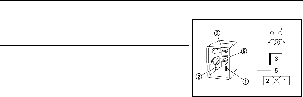
AT-144
DTC P1701 TRANSMISSION CONTROL MODULE (POWER SUPPLY)
Component Inspection ACS000GP
A/T PV IGN RELAY
1. Apply 12V direct current between A/T PV IGN relay terminals 1
and 2.
2. Check continuity between relay terminals 3 and 5.
3. If NG, replace A/T PV IGN relay.
Condition Continuity
12V direct current supply between
terminals 1 and 2 Yes
OFF No
SCIA1245E

DTC P1702 TRANSMISSION CONTROL MODULE (RAM)
AT-145
D
E
F
G
H
I
J
K
L
M
A
B
AT
DTC P1702 TRANSMISSION CONTROL MODULE (RAM) PFP:31036
Description ACS000AQ
The TCM consists of a microcomputer and connectors for signal
input and output and for power supply. The TCM controls the A/T.
On Board Diagnosis Logic ACS000AR
●This is not an OBD-II self-diagnostic item.
●Diagnostic trouble code “TCM·RAM” with CONSULT-II is detected when TCM memory RAM is malfunc-
tioning.
Possible Cause ACS000AS
TCM
DTC Confirmation Procedure ACS000AT
NOTE:
If “DTC Confirmation Procedure” has been previously conducted, always turn ignition switch “OFF”
and wait at least 10 seconds before conducting the next test.
After the repair, perform the following procedure to confirm the malfunction is eliminated.
WITH CONSULT-II
1. Turn ignition switch ON. (Do not start engine.)
2. Select “DATA MONITOR” mode for A/T with CONSULT-II.
3. Start engine.
4. Run engine for at least 2 consecutive seconds at idle speed.
5. If DTC is detected, go to AT-146, "Diagnostic Procedure" .
SCIA1287E
SAT014K

AT-146
DTC P1702 TRANSMISSION CONTROL MODULE (RAM)
Diagnostic Procedure ACS000AU
1. CHECK DTC
With CONSULT-II
1. Turn ignition switch ON. (Do not start engine.)
2. Select “SELF DIAG RESULTS” mode for “A/T” with CONSULT-
II.
3. Touch “ERASE”.
4. Turn ignition switch to “OFF” position and wait at least 10 sec-
onds.
5. Perform DTC confirmation procedure, AT-145, "DTC Confirma-
tion Procedure" .
Is the “TCM·RAM” displayed again?
YES >> Replace TCM.
NO >> INSPECTION END
SCIA5304E
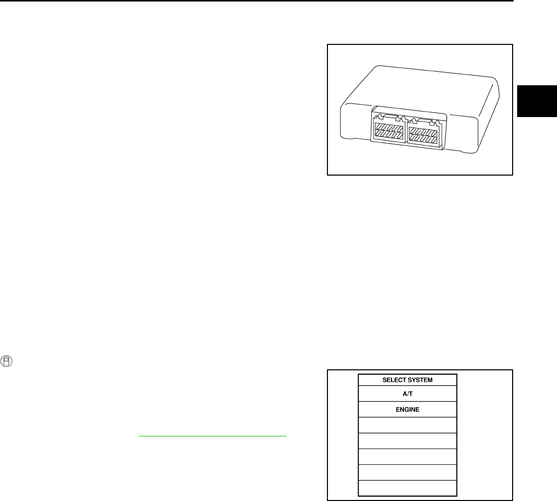
DTC P1703 TRANSMISSION CONTROL MODULE (ROM)
AT-147
D
E
F
G
H
I
J
K
L
M
A
B
AT
DTC P1703 TRANSMISSION CONTROL MODULE (ROM) PFP:31036
Description ACS000AV
The TCM consists of a microcomputer and connectors for signal
input and output and for power supply. The TCM controls the A/T.
On Board Diagnosis Logic ACS000AW
●This is not an OBD-II self-diagnostic item.
●Diagnostic trouble code “TCM·ROM” with CONSULT-II is detected when TCM memory ROM is malfunc-
tioning.
Possible Cause ACS000AX
TCM
DTC Confirmation Procedure ACS000AY
NOTE:
If “DTC Confirmation Procedure” has been previously conducted, always turn ignition switch “OFF”
and wait at least 10 seconds before conducting the next test.
After the repair, perform the following procedure to confirm the malfunction is eliminated.
WITH CONSULT-II
1. Turn ignition switch ON. (Do not start engine.)
2. Select “DATA MONITOR” mode for A/T with CONSULT-II.
3. Start engine.
4. Run engine for at least 2 consecutive seconds at idle speed.
5. If DTC is detected, go to AT-148, "Diagnostic Procedure" .
SCIA1287E
SAT014K
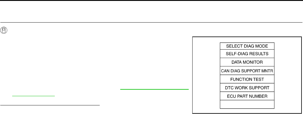
AT-148
DTC P1703 TRANSMISSION CONTROL MODULE (ROM)
Diagnostic Procedure ACS000AZ
1. CHECK DTC
With CONSULT-II
1. Turn ignition switch ON. (Do not start engine.)
2. Select “SELF DIAG RESULTS” mode for “A/T” with CONSULT-
II.
3. Touch “ERASE”.
4. Turn ignition switch to “OFF” position and wait at least 10 sec-
onds.
5. Perform DTC confirmation procedure, AT-147, "DTC Confirma-
tion Procedure" .
Is the “TCM·ROM” displayed again?
YES >> Replace TCM.
NO >> INSPECTION END
SCIA5304E

DTC P1704 TRANSMISSION CONTROL MODULE (EEPROM)
AT-149
D
E
F
G
H
I
J
K
L
M
A
B
AT
DTC P1704 TRANSMISSION CONTROL MODULE (EEPROM) PFP:31036
Description ACS000B0
The TCM consists of a microcomputer and connectors for signal
input and output and for power supply. The TCM controls the A/T.
On Board Diagnosis Logic ACS000B1
●This is not an OBD-II self-diagnostic item.
●Diagnostic trouble code “TCM·EEPROM” with CONSULT-II is detected when TCM memory EEPROM is
malfunctioning.
Possible Cause ACS000B2
TCM
DTC Confirmation Procedure ACS000B3
NOTE:
If “DTC Confirmation Procedure” has been previously conducted, always turn ignition switch “OFF”
and wait at least 10 seconds before conducting the next test.
After the repair, perform the following procedure to confirm the malfunction is eliminated.
WITH CONSULT-II
1. Turn ignition switch ON. (Do not start engine.)
2. Select “DATA MONITOR” mode for A/T with CONSULT-II.
3. Start engine.
4. Run engine for at least 2 consecutive seconds at idle speed.
5. If DTC is detected, go to AT-150, "Diagnostic Procedure" .
SCIA1287E
SAT014K
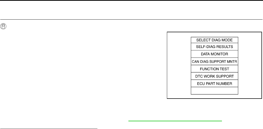
AT-150
DTC P1704 TRANSMISSION CONTROL MODULE (EEPROM)
Diagnostic Procedure ACS000B4
1. CHECK DTC
With CONSULT-II
1. Connect CONSULT-II to data link connector.
2. Turn ignition switch ON. Confirm that CONSULT-II turn ON.
3. Move select lever in “R” position.
4. Touch “START” on CONSULT-II.
5. Select “SELF-DIAG RESULTS” mode for “A/T” with CONSULT-
II.
6. Fully press the accelerator pedal (8/8 throttle), and hold it in the
fully open position. (This will set the closed throttle position sig-
nal to OFF.)
7. Touch “ERASE“ on CONSULT-II, and then touch “YES”.
8. Wait 3 seconds and then release the accelerator pedal.
9. Turn ignition switch OFF and wait at least 10 seconds.
10. Perform “DTC Confirmation Procedure”. Refer to AT-149, "DTC Confirmation Procedure" .
Is the “TCM·EEPROM” displayed again?
YES >> Replace TCM.
NO >> INSPECTION END
SCIA5304E
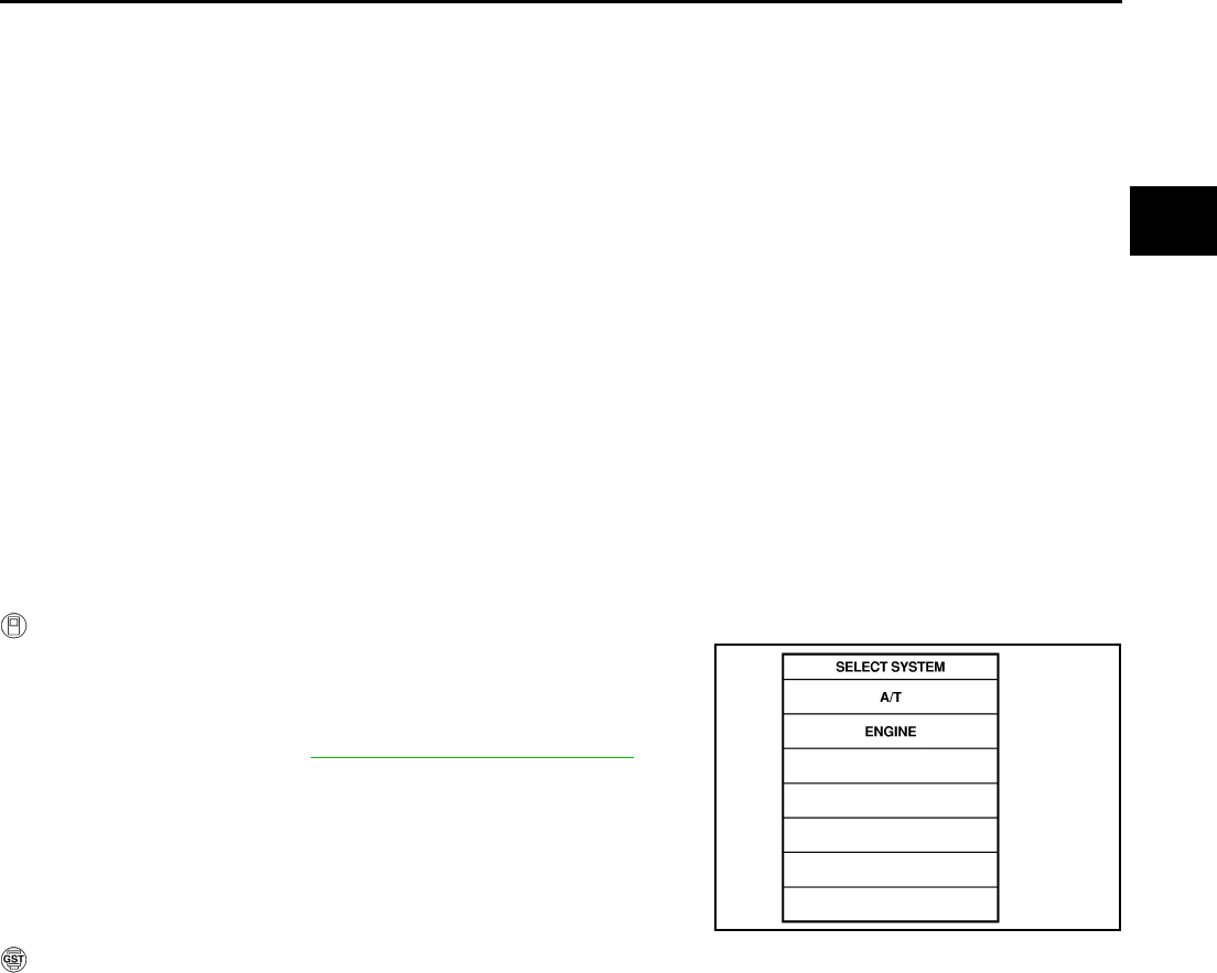
DTC P1705 THROTTLE POSITION SENSOR
AT-151
D
E
F
G
H
I
J
K
L
M
A
B
AT
DTC P1705 THROTTLE POSITION SENSOR PFP:22620
Description ACS000B5
Electric throttle control actuator consists of throttle control motor, accelerator pedal position sensor, throttle
position sensor, etc. The actuator sends a signal to the ECM, and ECM sends signals to TCM with CAN com-
munication.
On Board Diagnosis Logic ACS000B6
●This is an OBD-II self-diagnostic item.
●Diagnostic trouble code “TP SEN/CIRC A/T” with CONSULT-II or P1705 without CONSULT-II is detected
when TCM does not receive the proper accelerator pedal position signals (input by CAN communication)
from ECM.
Possible Cause ACS000B7
Harness or connectors
(The sensor circuit is open or shorted.)
DTC Confirmation Procedure ACS000B8
NOTE:
If “DTC Confirmation Procedure” has been previously conducted, always turn ignition switch “OFF”
and wait at least 10 seconds before conducting the next test.
After the repair, perform the following procedure to confirm the malfunction is eliminated.
WITH CONSULT-II
1. Turn ignition switch ON. (Do not start engine.)
2. Select “DATA MONITOR” mode for “A/T” with CONSULT-II.
3. Start engine and let it idle for 1 second.
4. If DTC is detected, go to “AT-152, "Diagnostic Procedure" .
WITH GST
Follow the procedure “With CONSULT-II”.
SAT014K
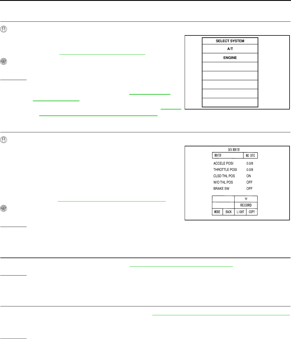
AT-152
DTC P1705 THROTTLE POSITION SENSOR
Diagnostic Procedure ACS000B9
1. CHECK DTC WITH ECM
With CONSULT-II
1. Turn ignition switch ON. (Do not start engine.)
2. Select “SELF-DIAG RESULTS” mode for “ENGINE” with CON-
SULT-II. Refer to EC-105, "CONSULT-II Function" .
With GST
Follow the procedure “With CONSULT-II”.
OK or NG
OK >> GO TO 2.
NG >> Check the DTC detected item.Go to EC-105, "CON-
SULT-II Function" .
●If CAN communication line is detected, go to AT-105,
"DTC U1000 CAN COMMUNICATION LINE" .
2. CHECK DTC WITH TCM
With CONSULT-II
1. Turn ignition switch ON. (Do not start engine.)
2. Select “ECU INPUT SIGNALS” in “DATA MONITOR” mode for
“A/T” with CONSULT-II.
3. Depress accelerator pedal and read out the value of “ACCLE
POS” and “THROTTLE POSI”.
Check engine speed changes according to throttle position.
4. Select “SELF-DIAG RESULTS” mode for “ENGINE” with CON-
SULT-II. Refer to EC-109, "SELF-DIAG RESULTS MODE" .
With GST
Follow the procedure “With CONSULT-II”.
OK or NG
OK >> GO TO 3.
NG >> Repair or replace damaged parts.
3. CHECK DTC
Perform “DTC confirmation Procedure”. Refer to AT-151, "DTC Confirmation Procedure" .
OK or NG
OK >> INSPECTION END
NG >> GO TO 4.
4. CHECK TCM INSPECTION
1. Perform TCM input/output signal inspection. Refer to AT-89, "TCM Input/Output Signal Reference Values"
.
2. If NG, recheck TCM pin terminals for damage or loose connection with harness connector.
OK or NG
OK >> INSPECTION END
NG >> Repair or replace damaged parts.
SAT014K
PCIA0070E
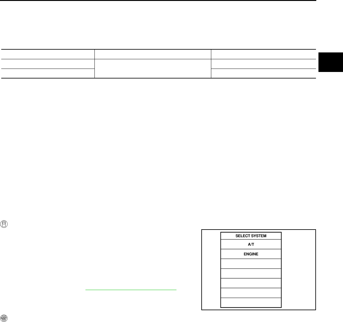
DTC P1710 A/T FLUID TEMPERATURE SENSOR CIRCUIT
AT-153
D
E
F
G
H
I
J
K
L
M
A
B
AT
DTC P1710 A/T FLUID TEMPERATURE SENSOR CIRCUIT PFP:31940
Description ACS000BA
The A/T fluid temperature sensor detects the A/T fluid temperature and sends a signal to the TCM.
CONSULT-II Reference Value ACS000G9
On Board Diagnosis Logic ACS000BB
●This is an OBD-II self-diagnostic item.
●Diagnostic trouble code “ATF TEMP SEN/CIRC” with CONSULT-II or P1710 (A/T), P0710 (ENGINE) with-
out CONSULT-II is detected when TCM receives an excessively low or high voltage from the sensor.
Possible Cause ACS000BC
●Harness or connectors
(The sensor circuit is open or shorted.)
●A/T fluid temperature sensors 1, 2
DTC Confirmation Procedure ACS000BD
CAUTION:
Always drive vehicle at a safe speed.
NOTE:
If “DTC Confirmation Procedure” has been previously conducted, always turn ignition switch “OFF”
and wait at least 10 seconds before conducting the next test.
After the repair, perform the following procedure to confirm the malfunction is eliminated.
WITH CONSULT-II
1. Turn ignition switch ON. (Do not start engine.)
2. Select “DATA MONITOR” mode for “ENGINE” with CONSULT-II.
3. Start engine and maintain the following conditions for at least 10
minutes (Total). (It is not necessary to maintain continuously.)
VHCL SPEED SE: 10 km/h (6 MPH) or more
THRTL POS SEN: More than 1.0/8
Selector lever: “D” position
4. If DTC is detected, go to AT-155, "Diagnostic Procedure" .
WITH GST
Follow the procedure “With CONSULT-II”.
Item name Condition Display value (Approx.) (V)
A/T fluid temperature sensor 1 0°C (32°F) - 20°C (68°F) - 80°C (176°F) 2.2 - 1.8 - 0.6
A/T fluid temperature sensor 2 2.2 - 1.7 - 0.45
SAT014K
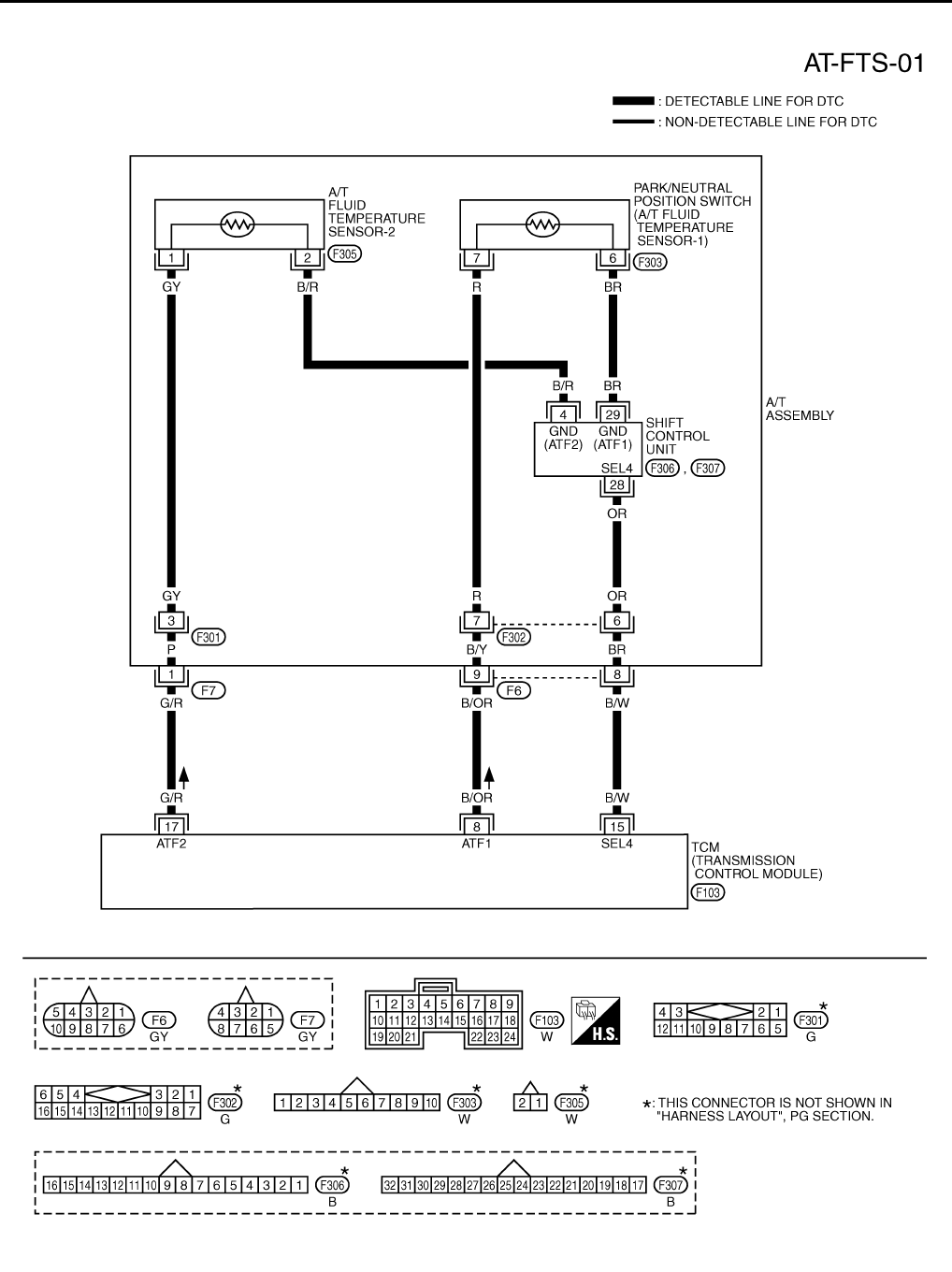
AT-154
DTC P1710 A/T FLUID TEMPERATURE SENSOR CIRCUIT
Wiring Diagram — AT — FTS ACS000BE
TCWT0227E
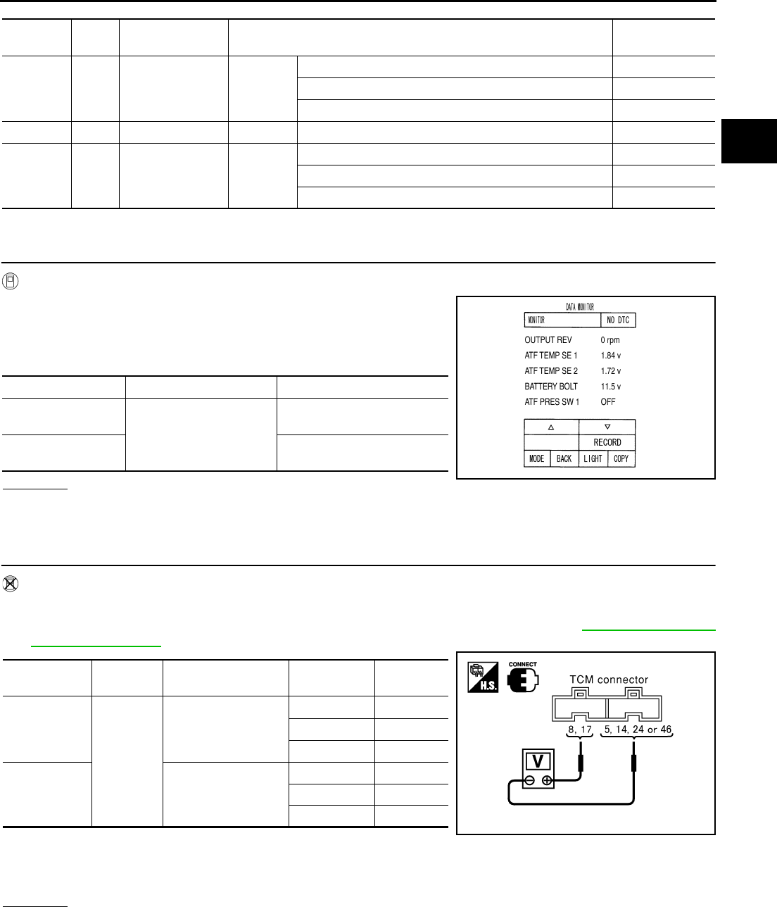
DTC P1710 A/T FLUID TEMPERATURE SENSOR CIRCUIT
AT-155
D
E
F
G
H
I
J
K
L
M
A
B
AT
TCM terminals and Data are reference value. Measured between each terminals 5, 14, 24 and 46 (TCM ground).
Diagnostic Procedure ACS000BF
1. CHECK INPUT SIGNALS (WITH CONSULT-II)
With CONSULT-II
1. Start engine.
2. Select “ECU INPUT SIGNALS” in “DATA MONITOR” mode for
“A/T” with CONSULT-II.
3. Read out the value of “ATF TEMP SE 1” or “ATF TEMP SE 2”.
OK or NG
OK >> GO TO 7.
NG >> GO TO 3.
2. CHECK INPUT SIGNALS (WITHOUT CONSULT-II)
Without CONSULT-II
1. Start engine.
2. Check voltage between TCM connector and ground while warming up A/T. Refer to AT-154, "Wiring Dia-
gram — AT — FTS" .
3. Turn ignition switch OFF.
4. Disconnect the TCM connector.
5. Check if there is continuity between the connector terminal and ground.
OK or NG
OK >> GO TO 7.
NG >> GO TO 3.
Terminal
No.
Wire
color Item Condition Data (Approx.)
8B/OR
A/T fluid tempera-
ture sensor 1 IGN ON
When ATF temperature 0°C (32°F) 2.2V
When ATF temperature 20°C (68°F) 1.8V
When ATF temperature 80°C (176°F) 0.6V
15 B/W SEL4 – – –
17 G/R A/T fluid tempera-
ture sensor 2 IGN ON
When ATF temperature about 0°C (32°F) 2.2V
When ATF temperature about 20°C (68°F) 1.7V
When ATF temperature about 80°C (176°F) 0.45V
Item name Condition °C (°F) Display value (Approx.) V
A/T fluid tempera-
ture sensor 1 0 (32) - 20 (68) - 80 (176)
2.2 - 1.8 - 0.6
A/T fluid tempera-
ture sensor 2 2.2 - 1.7 - 0.45
PCIA0039E
Name Connector
No. Terminal No. Temperature
°C (°F)
Voltage (V)
(Approx.)
A/T fluid tem-
perature sen-
sor 1
F103
8 (B/OR) - 5 (B), 14
(B), 24 (B) or 46 (B)
0 (32) 2.2
20 (68) 1.8
80 (176) 0.6
A/T fluid tem-
perature sen-
sor 2
17 (G/R) - 5 (B), 14
(B), 24 (B) or 46 (B)
0 (32) 2.2
20 (68) 1.7
80 (176) 0.45
SCIA1162E
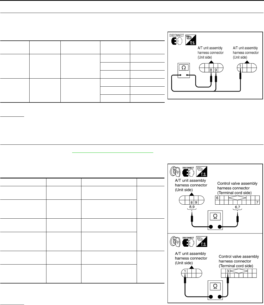
AT-156
DTC P1710 A/T FLUID TEMPERATURE SENSOR CIRCUIT
3. CHECK A/T FLUID TEMPERATURE SENSOR CIRCUIT
1. Turn ignition switch OFF.
2. Disconnect A/T unit assembly harness connector at the transmission right side.
3. Check the resistance between terminal and ground.
4. Reinstall any part removed.
OK or NG
OK >> GO TO 7.
NG >> GO TO 4.
4. CHECK TERMINAL CORD ASSEMBLY
1. Remove oil pan. Refer to AT-299, "Control Valve Assembly" .
2. Disconnect A/T unit assembly harness connector and control valve assembly harness connector.
3. Check continuity between A/T unit assembly harness connector
and control valve assembly harness connector.
4. If OK, check harness for short to ground and short to power.
5. Reinstall any part removed.
OK or NG
OK - 1 >> If A/T fluid temperature sensor 1 on step 3 is NG, replace the control valve assembly.
OK - 2 >> If A/T fluid temperature sensor 2 on step 3 is NG, GO TO 5.
NG >> Repair open circuit or short to ground or short to power in harness or connectors.
Name Connector
No.
Terminal No.
(Wire color)
Tempera-
ture °C (°F)
Resistance
(KΩ) (Approx.)
A/T fluid
temperature
sensor 1
F6 9 (B/OR) - 8(B/W)
0 (32) 15
20 (68) 6.5
80 (176) 0.9
A/T fluid
temperature
sensor 2
F7 1 (G/R) - 8(B/W)
0 (32) 10
20 (68) 4
80 (176) 0.5 SCIA3614E
Item Connector No. Terminal No. (Wire color) Continuity
A/T unit assembly
harness connector F6 8 (BR)
Yes
Control valve assem-
bly harness connec-
tor
F302 6 (BR)
A/T unit assembly
harness connector F6 9 (B/Y)
Yes
Control valve assem-
bly harness connec-
tor
F302 7 (B/Y))
A/T unit assembly
harness connector F7 1 (P)
Yes
Control valve assem-
bly harness connec-
tor
F301 3 (P)
SCIA3558E
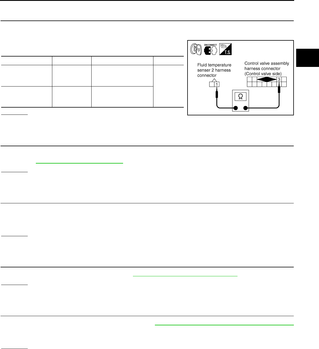
DTC P1710 A/T FLUID TEMPERATURE SENSOR CIRCUIT
AT-157
D
E
F
G
H
I
J
K
L
M
A
B
AT
5. CHECK HARNESS BETWEEN A/T FLUID TEMPERATURE SENSOR 2 AND CONTROL VALVE
ASSEMBLY
1. Disconnect A/T fluid temperature sensor 2 harness connector and control valve assembly harness con-
nector.
2. Check continuity between A/T fluid temperature sensor 2 har-
ness connector and control valve assembly harness connector.
OK or NG
OK >> GO TO 6.
NG >> Repair open circuit or short to ground or short to power in harness or connectors.
6. CHECK A/T FLUID TEMPERATURE SENSOR 2
Check A/T fluid temperature sensor 2.
●Refer to AT-158, "Component Inspection" .
OK or NG
OK >> GO TO 7.
NG >> Repair or replace damaged parts.
7. DETECT MALFUNCTIONING ITEM
Check the following items:
●Harness for short to ground or short to power or open between TCM and A/T unit assembly harness con-
nector.
OK or NG
OK >> GO TO 8.
NG >> Repair or replace damaged parts.
8. CHECK DTC
Perform “DTC Confirmation Procedure”. Refer to AT-153, "DTC Confirmation Procedure" .
OK or NG
OK >> INSPECTION END
NG >> GO TO 9.
9. PERFORM TCM INSPECTION
1. Perform TCM input/output signal inspection. Refer to AT-89, "TCM Input/Output Signal Reference Values"
.
2. If NG, recheck TCM pin terminals for damage or loose connection with harness connector.
OK or NG
OK >> INSPECTION END
NG >> Repair or replace damaged parts.
Item Connector No. Terminal No. (Wire color) Continuity
A/T fluid tempera-
ture sensor 2 har-
ness connector
F305 1 (GY)
Yes
Control valve assem-
bly harness connec-
tor
F301 3 (GY)
SCIA3069E
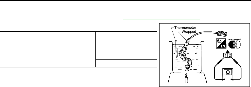
AT-158
DTC P1710 A/T FLUID TEMPERATURE SENSOR CIRCUIT
Component Inspection ACS004ID
A/T FLUID TEMPERATURE SENSOR 2
1. Remove A/T fluid temperature sensor 2. Refer to AT-299, "Control Valve Assembly" .
2. Check resistance between terminal 1 and 2.
Name Connector No. Terminal No.
(Wire color)
Tempera-
ture °C (°F)
Resistance
(KΩ) (Approx.)
A/T fluid
temperature
sensor 2
F305 1 (GY) - 2 (B/R)
0 (32) 10
20 (68) 4
80 (176) 0.5
SCIA3070E
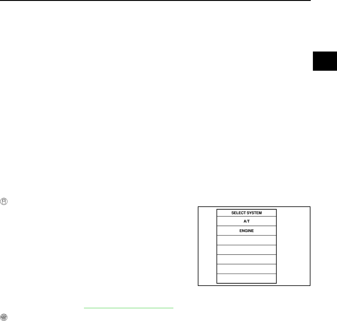
DTC P1716 TURBINE REVOLUTION SENSOR
AT-159
D
E
F
G
H
I
J
K
L
M
A
B
AT
DTC P1716 TURBINE REVOLUTION SENSOR PFP:31935
Description ACS000BH
The turbine revolution sensor detects input shaft rpm (revolutions per minute). It is located on the input side of
the automatic transmission. Monitors revolution of sensor 1 and sensor 2 for non-standard conditions.
On Board Diagnosis Logic ACS000BI
●This is an OBD-II self-diagnostic item.
●Diagnostic trouble code “TURBINE REV S/CIRC” with CONSULT-II or P1716 without CONSULT-II is
detected under the following conditions.
–When TCM does not receive the proper voltage signal from the sensor.
–When TCM detects an irregularity only at position of 4th gear for turbine revolution sensor 2.
Possible Cause ACS000BJ
●Harness or connectors
(The sensor circuit is open or shorted.)
●Turbine revolution sensor 1, 2
DTC Confirmation Procedure ACS000BK
CAUTION:
Always drive vehicle at a safe speed.
NOTE:
If “DTC Confirmation Procedure” has been previously conducted, always turn ignition switch “OFF”
and wait at least 10 seconds before conducting the next test.
After the repair, perform the following procedure to confirm the malfunction is eliminated.
WITH CONSULT-II
1. Turn ignition switch ON. (Do not start engine.)
2. Select “DATA MONITOR” mode for “A/T” with CONSULT-II.
3. Start engine and maintain the following conditions for at least 5
consecutive seconds.
VHCL SPEED SE: 40 km/h (25 MPH) or more
ENGINE SPEED: 1,500 rpm or more
ACCELE POS: 0.5/8 or more
Selector lever: “D” position
Gear position (Turbine revolution sensor 1): 4th or 5th posi-
tion
Gear position (Turbine revolution sensor 2): All position
Driving location: Driving the vehicle uphill (increased
engine load) will help maintain the driving conditions required for this test.
4. If DTC is detected, go to AT-161, "Diagnostic Procedure" .
WITH GST
Follow the procedure “With CONSULT-II”.
SAT014K
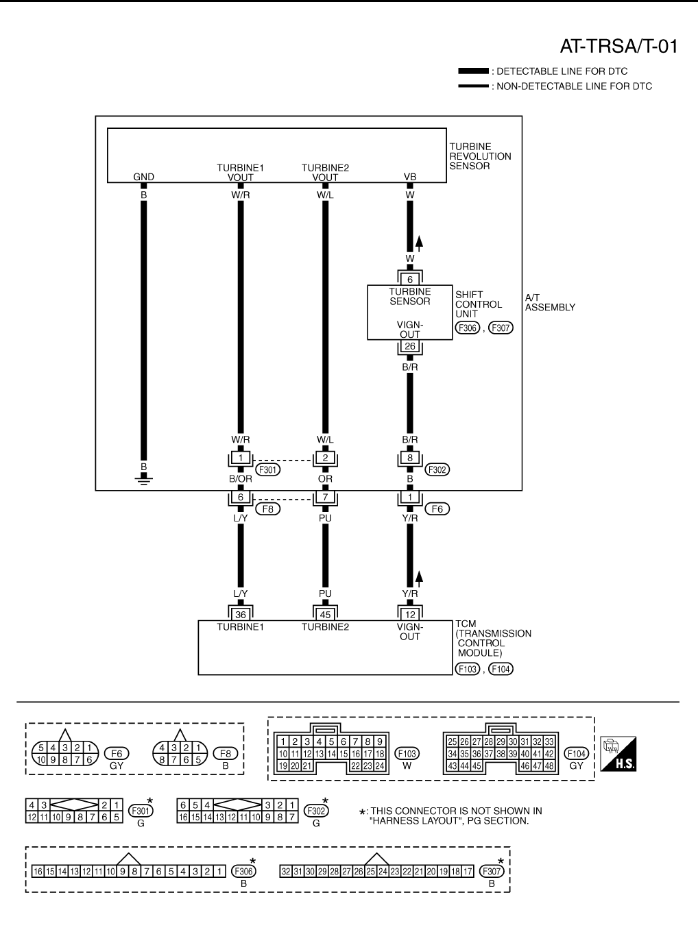
AT-160
DTC P1716 TURBINE REVOLUTION SENSOR
Wiring Diagram — AT — TRSA/T ACS000BL
TCWT0228E
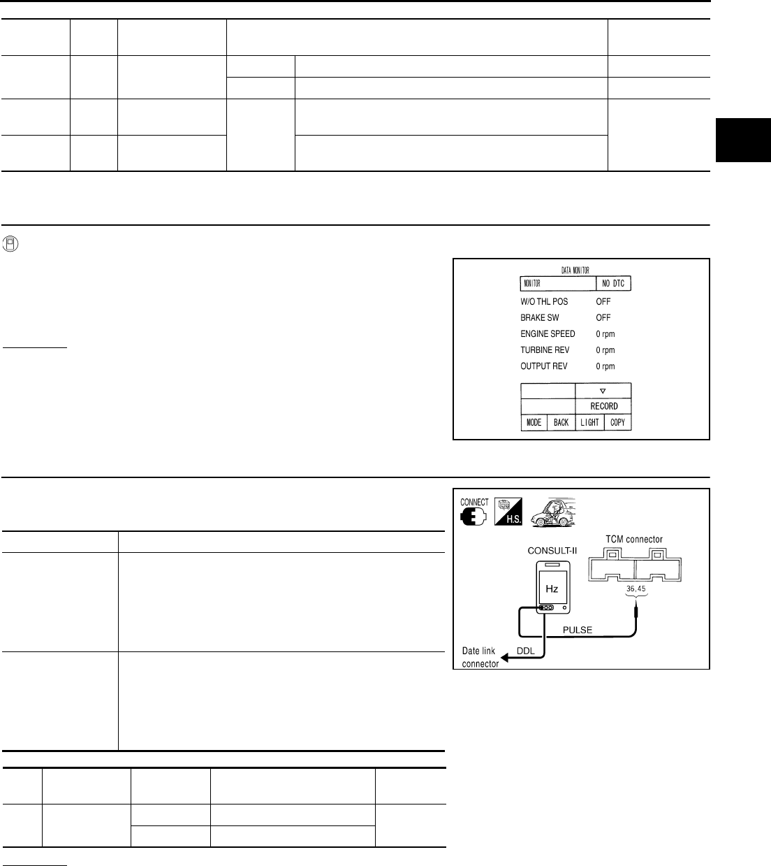
DTC P1716 TURBINE REVOLUTION SENSOR
AT-161
D
E
F
G
H
I
J
K
L
M
A
B
AT
TCM terminal and Data are reference value. Measured between each terminals 5, 14, 24 and 46 (TCM ground).
Diagnostic Procedure ACS000BM
1. CHECK INPUT SIGNALS
With CONSULT-II
1. Start engine.
2. Select “ECU INPUT SIGNALS” in “DATA MONITOR” mode for
“A/T” with CONSULT-II.
3. Vehicle start and read out the value of “TURBINE REV”.
OK or NG
OK >> GO TO 5.
NG >> GO TO 2.
2. CHECK TURBINE REVOLUTION SENSOR
1. Start engine.
2. Check the pulse when vehicle cruises.
OK or NG
OK >> GO TO 5.
NG >> GO TO 3.
Terminal
No.
Wire
color Item Condition Data (Approx.)
12 Y/R Power supply
(out)
IGN ON – Battery voltage
IGN OFF – 0V
36 L/Y Turbine revolution
sensor 1 When
vehicle
cruises
When running at 50 km/h (31 MPH) in 4th gear with the
closed throttle position signal “OFF”. 1.3 (kHz)
45 PU Turbine revolution
sensor 2
When moving at 20 km/h (12 MPH) in 1st gear with the
closed throttle position signal “OFF”.
PCIA0041E
Name Condition
Turbine revolution
sensor 1
When running at 50 km/h (31 MPH) in 4th gear with the
closed throttle position signal “OFF”, use the CONSULT-II
pulse frequency measuring function.
CAUTION:
Connect the data link connector to the vehicle-side diag-
nosis connector.
Turbine revolution
sensor 2
When moving at 20 km/h (12 MPH) in 1st gear with the
closed throttle position signal “OFF”, use the CONSULT-II
pulse frequency measuring function.
CAUTION:
Connect the data link connector to the vehicle-side diag-
nosis connector.
Item Connector No. Terminal No.
(Wire color) Name Data
(Approx.)
TCM F104 36 (L/Y) Turbine revolution sensor 1 1.3 (kHz)
45 (PU) Turbine revolution sensor 2
PCIA0042E
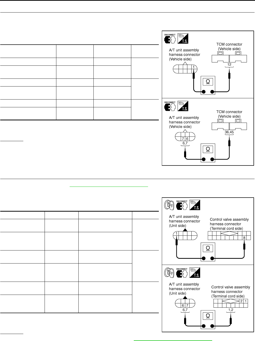
AT-162
DTC P1716 TURBINE REVOLUTION SENSOR
3. CHECK HARNESS BETWEEN TCM AND A/T UNIT ASSEMBLY HARNESS CONNECTOR
1. Turn ignition switch OFF.
2. Disconnect TCM connector.
3. Check continuity between A/T unit assembly harness connector
and TCM connector.
4. If OK, check harness for short to ground and short to power.
5. Reinstall any part removed.
OK or NG
OK >> GO TO 4.
NG >> Repair open circuit or short to ground or short to power
in harness or connectors.
4. CHECK TERMINAL CORD ASSEMBLY
1. Remove oil pan. Refer to AT-299, "Control Valve Assembly" .
2. Disconnect A/T unit assembly harness connector and control valve assembly harness connector.
3. Check continuity between A/T unit assembly harness connector
and control valve assembly harness connector.
4. If OK, check harness for short to ground and short to power.
5. Reinstall any part removed.
OK or NG
OK >> Replace the control valve assembly. Refer to AT-299, "Control Valve Assembly" .
NG >> Repair or replace damaged parts.
Item Connector No. Terminal No.
(Wire color) Continuity
TCM F103 12 (Y/R)
Yes
A/T unit assembly harness
connector F6 1 (Y/R)
TCM F104 36 (L/Y)
Yes
A/T unit assembly harness
connector F8 6 (L/Y)
TCM F104 45 (PU)
Yes
A/T unit assembly harness
connector F8 7 (PU)
SCIA3071E
Item Connector No. Terminal No. (Wire color) Continuity
A/T unit assembly
harness connector F6 1 (B)
Yes
Control valve assem-
bly harness connec-
tor
F302 8 (B)
A/T unit assembly
harness connector F8 6 (B/OR)
Yes
Control valve assem-
bly harness connec-
tor
F301 1 (B/OR)
A/T unit assembly
harness connector F8 7 (OR)
Yes
Control valve assem-
bly harness connec-
tor
F301 2 (OR)
SCIA3072E

DTC P1716 TURBINE REVOLUTION SENSOR
AT-163
D
E
F
G
H
I
J
K
L
M
A
B
AT
5. CHECK DTC
Perform “DTC Confirmation Procedure”. Refer to AT-108, "DTC Confirmation Procedure" .
OK or NG
OK >> INSPECTION END
NG >> GO TO 6.
6. PERFORM TCM INSPECTION
1. Perform TCM input/output signal inspection. Refer to AT-89, "TCM Input/Output Signal Reference Values"
.
2. If NG, recheck TCM pin terminals for damage or loose connection with harness connector.
OK or NG
OK >> INSPECTION END
NG >> Repair or replace damaged parts.
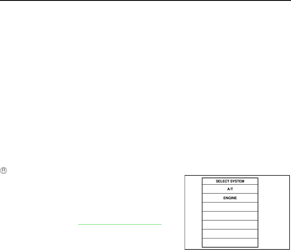
AT-164
DTC P1721 VEHICLE SPEED SENSOR MTR
DTC P1721 VEHICLE SPEED SENSOR MTR PFP:24814
Description ACS000BN
The vehicle speed sensor·MTR signal is transmitted from combination meter to TCM by CAN communication
line. The signal functions as an auxiliary device to the revolution sensor when it is malfunctioning. The TCM
will then use the vehicle speed sensor·MTR signal.
On Board Diagnosis Logic ACS000BO
●This is not an OBD-II self-diagnostic item.
●Diagnostic trouble code “VHE SPD SE·MTR” with CONSULT-II is detected when TCM does not receive
the proper vehicle speed sensor MTR signal (input by CAN communication) from combination meter.
Possible Cause ACS000BP
Harness or connectors
(The sensor circuit is open or shorted.)
DTC Confirmation Procedure ACS000BQ
CAUTION:
Always drive vehicle at a safe speed.
NOTE:
If “DTC Confirmation Procedure” has been previously conducted, always turn ignition switch “OFF”
and wait at least 10 seconds before conducting the next test.
After the repair, perform the following procedure to confirm the malfunction is eliminated.
WITH CONSULT-II
1. Turn ignition switch ON. (Do not start engine.)
2. Select “DATA MONITOR” mode for “A/T” with CONSULT-II.
3. Start engine and maintain the following conditions for at least 5
consecutive seconds.
ACCELE POS: 1/8 or less
VHCL SPEED SE: 30 km/h (17 MPH) or more
4. If DTC is detected, go to AT-165, "Diagnostic Procedure" .
SAT014K
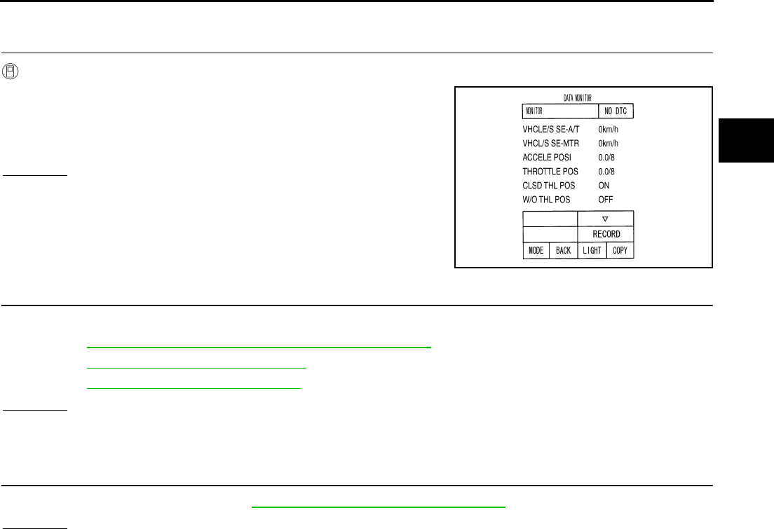
DTC P1721 VEHICLE SPEED SENSOR MTR
AT-165
D
E
F
G
H
I
J
K
L
M
A
B
AT
Diagnostic Procedure ACS000BR
1. CHECK INPUT SIGNALS
With CONSULT-II
1. Start engine.
2. Select “ECU INPUT SIGNALS” in “DATA MONITOR” mode for
“A/T” with CONSULT-II.
3. Drive vehicle and read out the value of “VHCL/S SE·MTR”.
OK or NG
OK >> GO TO 3.
NG >> GO TO 2.
2. CHECK DTC, STEP 1
Check following items.
1. Refer to AT-105, "DTC U1000 CAN COMMUNICATION LINE" .
2. Refer to BRC-24, "CONSULT-II Functions" .
3. Refer to DI-4, "COMBINATION METERS" .
OK or NG
OK >> INSPECTION END
NG >> If NG, recheck pin terminals for damage or loose connection with harness connector.
3. CHECK DTC, STEP 2
Perform DTC confirmation procedure. AT-164, "DTC Confirmation Procedure" .
OK or NG
OK >> INSPECTION END
NG >> If the system returns a malfunction, recheck pin terminals for damage or loose connection with
harness connector.
PCIA0033E
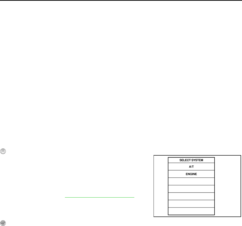
AT-166
DTC P1730 A/T INTERLOCK
DTC P1730 A/T INTERLOCK PFP:00000
Description ACS000BS
●Fail-safe function to detect interlock conditions.
●Fail-safe function to the transmission range switch detects the selector position and sends a signal to the
TCM.
On Board Diagnosis Logic ACS000BT
●This is an OBD-II self-diagnostic item.
●Diagnostic trouble code “A/T INTERLOCK” with CONSULT-II or P1730 without CONSULT-II is detected
when TCM does not receive the proper voltage signal from the sensor and switch.
●TCM monitors and compares gear position and conditions of each pressure switch when gear is steady.
Possible Cause ACS000BU
●Harness or connectors
(The solenoid and switch circuit is open or shorted.)
●Low coast brake solenoid valve
●ATF pressure switch 2
DTC Confirmation Procedure ACS000BV
NOTE:
If “DTC Confirmation Procedure” has been previously conducted, always turn ignition switch “OFF”
and wait at least 10 seconds before conducting the next test.
After the repair, perform the following procedure to confirm the malfunction is eliminated.
WITH CONSULT-II
1. Turn ignition switch ON. (Do not start engine.)
2. Select “DATA MONITOR” mode for “A/T” with CONSULT-II.
3. Start engine.
4. Drive vehicle and maintain the following conditions for at least 2
consecutive seconds.
Selector lever: “D” position
5. If DTC is detected, go to AT-171, "Diagnostic Procedure" .
WITH GST
Follow the procedure “With CONSULT-II”.
SAT014K
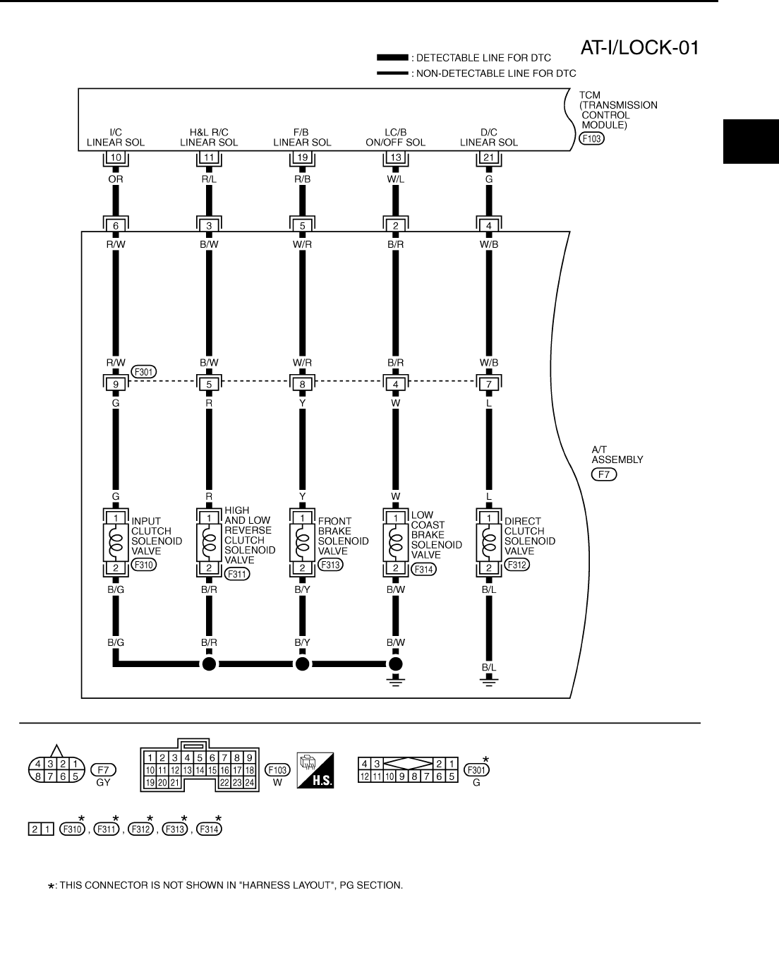
DTC P1730 A/T INTERLOCK
AT-167
D
E
F
G
H
I
J
K
L
M
A
B
AT
Wiring Diagram — AT — I/LOCK ACS000BW
TCWT0229E
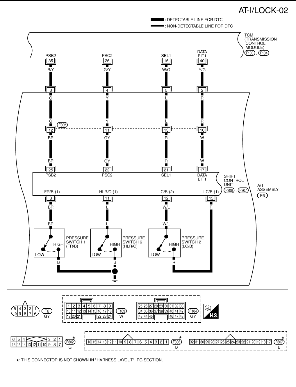
AT-168
DTC P1730 A/T INTERLOCK
TCWT0230E
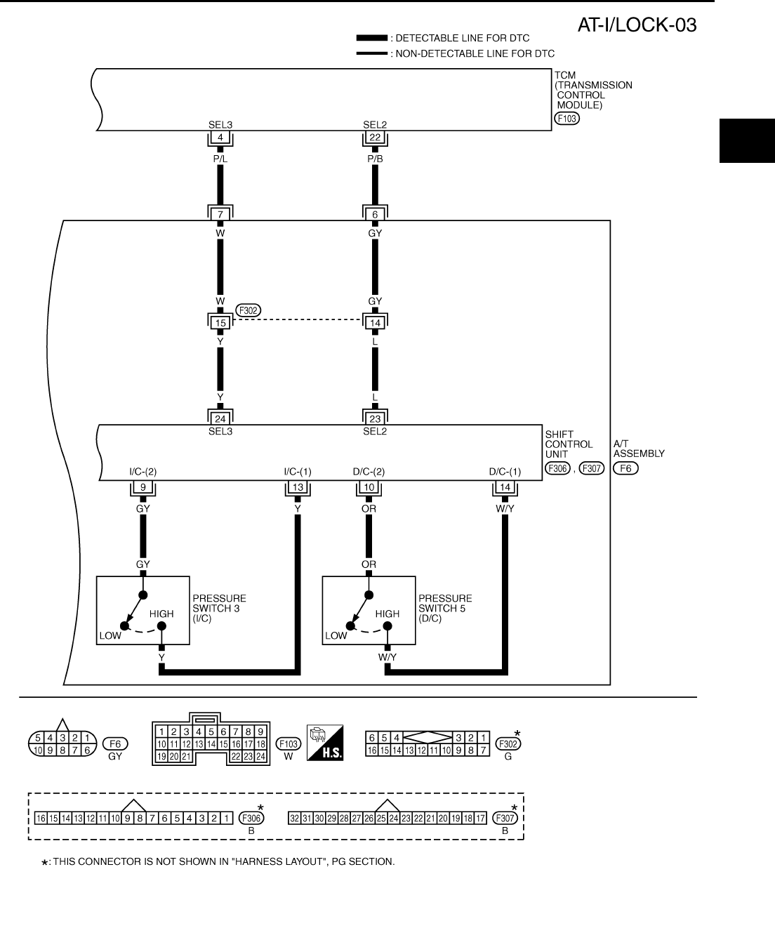
DTC P1730 A/T INTERLOCK
AT-169
D
E
F
G
H
I
J
K
L
M
A
B
AT
TCWT0231E

AT-170
DTC P1730 A/T INTERLOCK
TCM terminals and Data are reference value. Measured between each terminals 5, 14, 24 and 46 (TCM ground).
Terminal
No.
Wire
color Item Condition Data (Approx.)
4P/L
SEL3 (pressure
switch 3) –– –
10 OR Input clutch sole-
noid valve
When
vehicle
cruises
When the solenoid valve operating (in 1st gear, 2nd gear,
or 3rd gear) More than 2V
When the solenoid valve is not operating (4th gear or 5th
gear) 0V
11 R/L
High and low
reverse clutch
solenoid valve
When the solenoid valve operating [6 km/h (4MPH) or
faster in 1st gear or 2nd gear] More than 2V
When the solenoid valve is not operating [6 km/h (4MPH)
or slower in 1st gear or 3rd, 4th, or 5th gear] 0V
13 W/L Low coast brake
solenoid valve
When the solenoid valve is operating (when running in
M1-1 gear or M2-2 gear) Battery voltage
When the solenoid valve is not operating (when running in
“D”) 0V
16 W/G SEL1 (pressure
switch 2) –– –
19 R/B Front brake sole-
noid valve When
vehicle
cruises
When the solenoid valve is operating (other than 4th
gear) More than 2V
When the solenoid valve is not operating (4th gear) 0V
21 G Direct clutch sole-
noid valve
When the solenoid valve is operating (1st gear or 5th
gear) More than 2V
When the solenoid valve is not operating (2nd gear, 3rd
gear, or 4th gear) 0V
22 P/B SEL2 (pressure
switch 5) –– –
26 G/Y PSC2 (pressure
switch 6) When
vehicle
cruises
When high and low reverse clutch solenoid valve “ON”. 0V
When high and low reverse clutch solenoid valve “OFF”. Battery voltage
35 B/Y PSB2 (pressure
switch 1)
When front brake solenoid valve “OFF”. Battery voltage
When front brake solenoid valve“ ON”. 0V
40 Y/G DATA BIT1 – – –
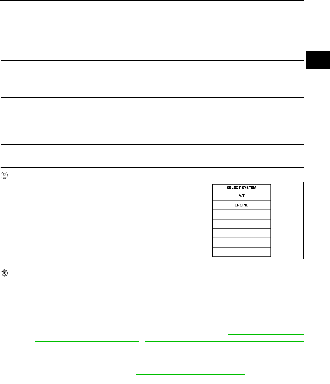
DTC P1730 A/T INTERLOCK
AT-171
D
E
F
G
H
I
J
K
L
M
A
B
AT
Judgement of A/T Interlock ACS000BX
When A/T Interlock is judged to be malfunctioning, the vehicle should be fixed in 2nd gear and should be set in
a condition in which it can travel.
When one of the following fastening patterns is detected, the fail-safe function in correspondence with the indi-
vidual pattern should be performed.
A/T INTERLOCK COUPLING PATTERN TABLE
●: NG, X: OK
Diagnostic Procedure ACS000BY
1. PERFORM SELF-DIAGNOSIS
With CONSULT-II
1. Drive vehicle.
2. Stop vehicle and turn ignition switch OFF.
3. Turn ignition switch ON. (Do not start engine.)
4. Select “SELF-DIAG RESULTS” mode for “A/T” with CONSULT-
II.
Without CONSULT-II
1. Drive vehicle.
2. Stop vehicle and turn ignition switch OFF.
3. Turn ignition switch ON. (Do not start engine.)
4. Perform self-diagnosis. Refer to AT-103, "TCM SELF-DIAGNOSTIC PROCEDURE (NO TOOLS)" .
OK or NG
OK >> GO TO 2.
NG >> Check low coast brake solenoid valve circuit and function. Refer to AT-215, "DTC P1772 LOW
COAST BRAKE SOLENOID VALVE" , AT-220, "DTC P1774 LOW COAST BRAKE SOLENOID
VALVE FUNCTION" .
2. CHECK DTC
Perform “DTC confirmation Procedure”. Refer to AT-166, "DTC Confirmation Procedure" .
OK or NG
OK >> INSPECTION END
NG >> GO TO 3.
Gear position
ATF pressure switch output
Fail-safe
function
Clutch pressure output pattern after fail-safe func-
tion
SW3
(I/C)
SW6
(HLR/
C)
SW5
(D/C)
SW1
(FR/B)
SW2
(LC/B) I/C HLR/C D/C FR/B LC/B L/U
A/T inter-
lock cou-
pling pattern
3rd – X X – ●Held in
2nd gear OFF OFF ON OFF OFF OFF
4th – X X – ●Held in
2nd gear OFF OFF ON OFF OFF OFF
5th X X – X ●Held in
2nd gear OFF OFF ON OFF OFF OFF
SAT014K

AT-172
DTC P1730 A/T INTERLOCK
3. PERFORM TCM INSPECTION
1. Perform TCM input/output signal inspection. Refer to AT-89, "TCM Input/Output Signal Reference Values"
.
2. If NG, recheck TCM pin terminals for damage or loose connection with harness connector.
OK or NG
OK >> INSPECTION END
NG >> Repair or replace damaged parts.
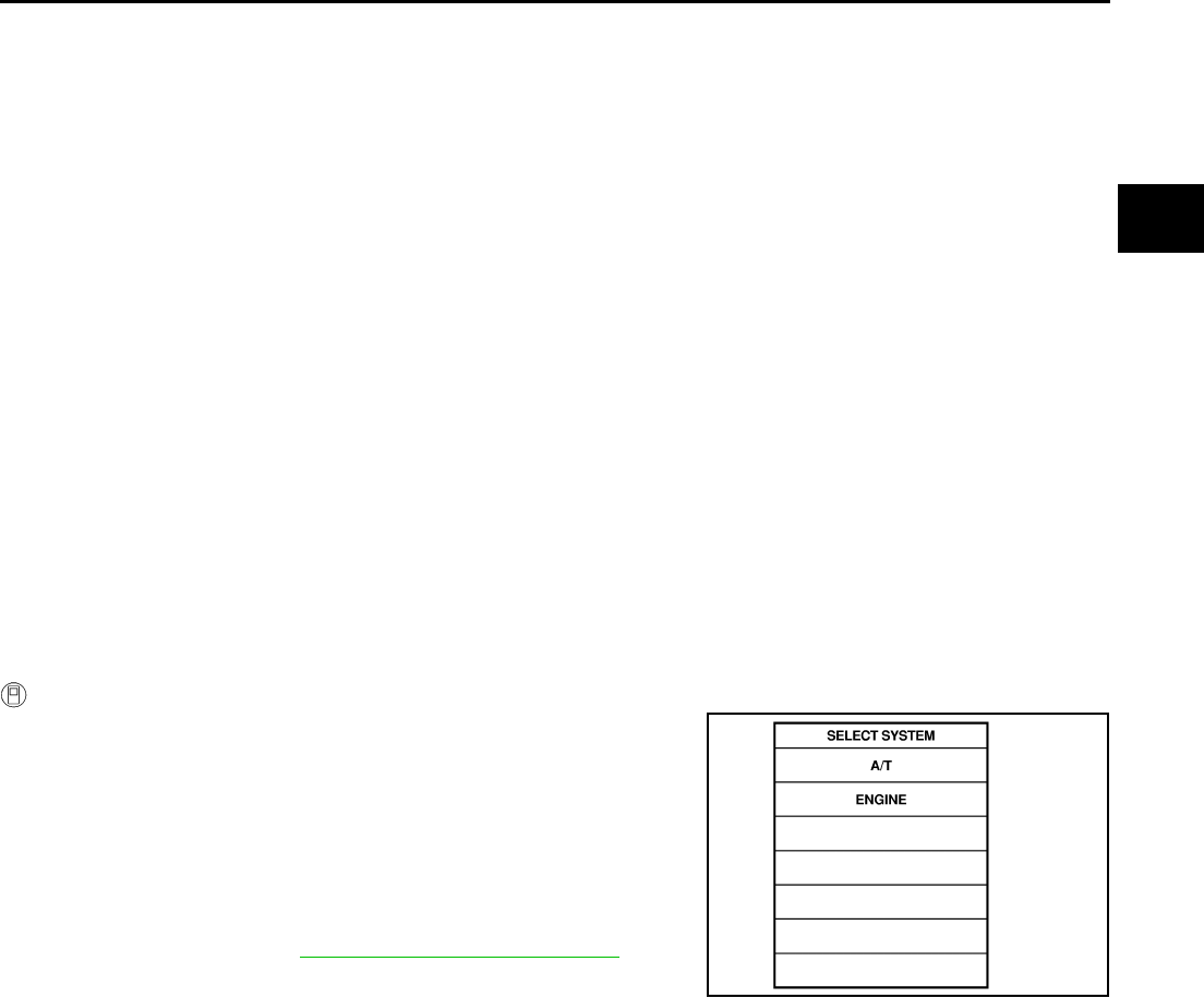
DTC P1731 A/T 1ST ENGINE BRAKING
AT-173
D
E
F
G
H
I
J
K
L
M
A
B
AT
DTC P1731 A/T 1ST ENGINE BRAKING PFP:00000
Description ACS000BZ
Fail-safe function to prevent sudden decrease in speed by engine brake other than at M1 position.
On Board Diagnosis Logic ACS000C0
●This is not an OBD-II self-diagnostic item.
●Diagnostic trouble code “A/T 1ST E/BRAKING” with CONSULT-II or 13th judgement flicker without CON-
SULT-II is detected under the following condition.
–When TCM does not receive the proper voltage signal from the sensor.
–When TCM monitors each pressure switch and solenoid monitor value, and detects as irregular when
engine brake of 1st gear acts other than at M1 position.
Possible Cause ACS000C1
●Harness or connectors
(The sensor circuit is open or shorted.)
●Low coast brake solenoid valve
●ATF pressure switch 2
DTC Confirmation Procedure ACS000C2
NOTE:
If “DTC Confirmation Procedure” has been previously conducted, always turn ignition switch “OFF”
and wait at least 10 seconds before conducting the next test.
After the repair, perform the following procedure to confirm the malfunction is eliminated.
WITH CONSULT-II
1. Turn ignition switch ON. (Do not start engine.)
2. Select “DATA MONITOR” mode for “A/T” with CONSULT-II.
3. Start engine.
4. Drive vehicle and maintain the following conditions for at least 2
consecutive seconds.
ENGINE SPEED: 1,200 rpm
Selector lever: “D” position
Gear position: 1st gear
5. If DTC is detected, go to AT-175, "Diagnostic Procedure" .
SAT014K
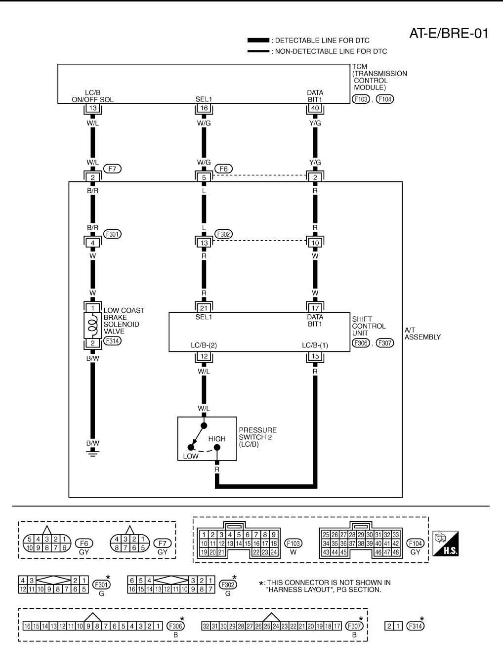
AT-174
DTC P1731 A/T 1ST ENGINE BRAKING
Wiring Diagram — AT — E/BRE ACS000C3
TCWT0232E
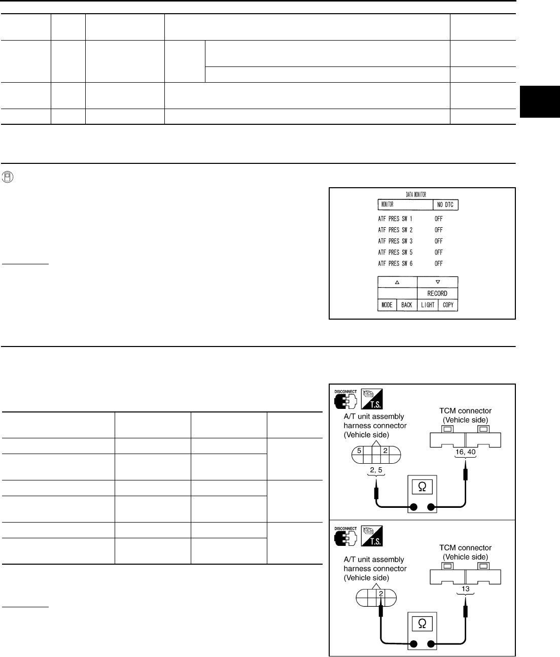
DTC P1731 A/T 1ST ENGINE BRAKING
AT-175
D
E
F
G
H
I
J
K
L
M
A
B
AT
TCM terminals and Data are reference value. Measured between each terminals 5, 14, 24 and 46 (TCM ground).
Diagnostic Procedure ACS000C4
1. CHECK INPUT SIGNALS
With CONSULT-II
1. Start engine.
2. Select “ECU INPUT SIGNALS” or “MAIN SIGNALS” in “DATA
MONITOR” mode for “A/T” with CONSULT-II.
3. Accelerate vehicle in the “D” position (1st gear), and confirm the
ON/OFF actuation of the “ATF PRES SW 2”.
OK or NG
OK >> GO TO 4.
NG >> GO TO 2.
2. CHECK HARNESS BETWEEN TCM AND A/T UNIT ASSEMBLY HARNESS CONNECTOR
1. Turn ignition switch OFF.
2. Disconnect TCM connector.
3. Check continuity between A/T unit assembly harness connector
and TCM connector.
4. If OK, check harness for short to ground and short to power.
5. Reinstall any part removed.
OK or NG
OK >> GO TO 3.
NG >> Repair open circuit or short to ground or short to power
in harness or connectors.
Terminal
No.
Wire
color Item Condition Data (Approx.)
13 W/L Low coast brake
solenoid valve
When
vehicle
cruises
When the solenoid valve is operating (when running in M1-1
speed or M2-2 speed) Battery voltage
When the solenoid valve is not operating (when running in “D”) 0V
16 W/G SEL1 (pressure
switch 2) ––
40 Y/G DATA BIT1 – –
PCIA0067E
Item Connector No. Terminal No.
(Wire color) Continuity
TCM F103 13 (W/L)
Yes
A/T unit assembly harness
connector F7 2 (W/L)
TCM F103 16 (W/G)
Yes
A/T unit assembly harness
connector F6 5 (W/G)
TCM F104 40 (Y/G)
Yes
A/T unit assembly harness
connector F6 2 (Y/G)
SCIA3095E
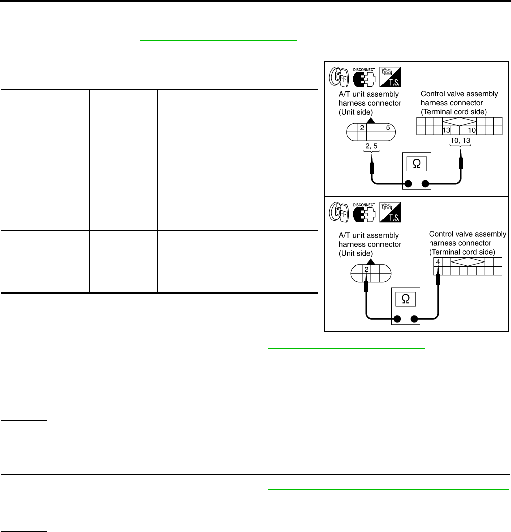
AT-176
DTC P1731 A/T 1ST ENGINE BRAKING
3. CHECK TERMINAL CORD ASSEMBLY
1. Remove oil pan. Refer to AT-299, "Control Valve Assembly" .
2. Disconnect A/T unit assembly harness connector and control valve assembly harness connector.
3. Check continuity between A/T unit assembly harness connector
and control valve assembly harness connector.
4. If OK, check harness for short to ground and short to power.
5. Reinstall any part removed.
OK or NG
OK >> Replace the control valve assembly. Refer to AT-299, "Control Valve Assembly" .
NG >> Repair open circuit or short to ground or short to power in harness or connectors.
4. CHECK DTC
Perform “DTC Confirmation Procedure”. Refer to AT-108, "DTC Confirmation Procedure" .
OK or NG
OK >> INSPECTION END
NG >> GO TO 5.
5. PERFORM TCM INSPECTION
1. Perform TCM input/output signal inspection. Refer to AT-89, "TCM Input/Output Signal Reference Values"
.
2. If NG, recheck TCM pin terminals for damage or loose connection with harness connector.
OK or NG
OK >> INSPECTION END
NG >> Repair or replace damaged parts.
Item Connector No. Terminal No. (Wire color) Continuity
A/T unit assembly
harness connector F6 2 (R)
Yes
Control valve assem-
bly harness connec-
tor
F302 10 (R)
A/T unit assembly
harness connector F6 5 (L)
Yes
Control valve assem-
bly harness connec-
tor
F302 13 (L)
A/T unit assembly
harness connector F7 2 (B/R)
Yes
Control valve assem-
bly harness connec-
tor
F301 4 (B/R)
SCIA3107E

DTC P1752 INPUT CLUTCH SOLENOID VALVE
AT-177
D
E
F
G
H
I
J
K
L
M
A
B
AT
DTC P1752 INPUT CLUTCH SOLENOID VALVE PFP:31940
Description ACS000C5
Input clutch solenoid valve is controlled by the TCM in response to signals sent from the PNP switch, vehicle
speed sensor and accelerator pedal position sensor (throttle position sensor). Gears will then be shifted to the
optimum position.
On Board Diagnosis Logic ACS000C6
●This is an OBD-II self-diagnostic item.
●Diagnostic trouble code “I/C SOLENOID/CIRC” with CONSULT-II or P1752 without CONSULT-II is
detected under the following conditions.
–When TCM detects an improper voltage drop when it tries to operate the solenoid valve.
–When TCM detects as irregular by comparing target value with monitor value.
Possible Cause ACS000C7
●Harness or connectors
(The solenoid circuit is open or shorted.)
●Input clutch solenoid valve
DTC Confirmation Procedure ACS000C8
CAUTION:
Always drive vehicle at a safe speed.
NOTE:
If “DTC Confirmation Procedure” has been previously conducted, always turn ignition switch “OFF”
and wait at least 10 seconds before conducting the next test.
After the repair, perform the following procedure to confirm the malfunction is eliminated.
WITH CONSULT-II
1. Turn ignition switch ON. (Do not start engine.)
2. Select “DATA MONITOR” mode for “A/T” with CONSULT-II.
3. Start engine.
4. Drive vehicle and maintain the following conditions for at least 5
consecutive seconds.
ACCELE POS: 1.5/8 - 2.0/8
Selector lever: “D” position
Gear position: 3rd Þ 4th Gear (I/C ON/OFF)
Driving location: Driving the vehicle uphill (increased
engine load) will help maintain the driving conditions
required for this test.
5. If DTC is detected go to “AT-179, "Diagnostic Procedure" .
WITH GST
Follow the procedure “With CONSULT-II”.
SAT014K
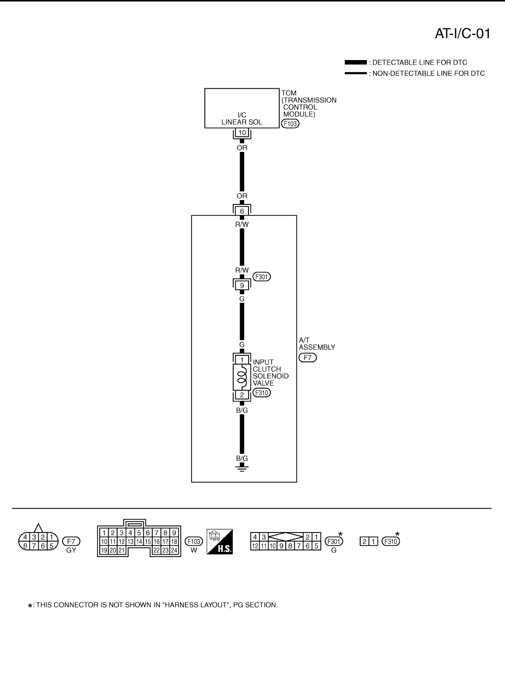
AT-178
DTC P1752 INPUT CLUTCH SOLENOID VALVE
Wiring Diagram — AT — I/C ACS000C9
TCWT0233E

DTC P1752 INPUT CLUTCH SOLENOID VALVE
AT-179
D
E
F
G
H
I
J
K
L
M
A
B
AT
TCM terminal and Data are reference value. Measured between each terminals 5, 14, 24 and 46 (TCM ground).
Diagnostic Procedure ACS000CA
1. CHECK INPUT CLUTCH SOLENOID VALVE CIRCUIT
1. Turn ignition switch OFF.
2. Disconnect A/T unit assembly harness connector at the trans-
mission right side.
3. Check the resistance between terminal and ground.
OK or NG
OK >> GO TO 4.
NG >> GO TO 2.
2. CHECK TERMINAL CORD ASSEMBLY
1. Remove oil pan. Refer to AT-299, "Control Valve Assembly" .
2. Disconnect A/T unit assembly harness connector and control valve assembly harness connector.
3. Check continuity between A/T unit assembly harness connector
and control valve assembly harness connector.
4. If OK, check harness for short to ground and short to power.
OK or NG
OK >> GO TO 3.
NG >> Repair open circuit or short to ground or short to power in harness or connectors.
3. CHECK VALVE RESISTANCE
Check valve resistance
●Refer to AT-181, "Component Inspection" .
OK or NG
OK >> GO TO 4.
NG >> Replace the control valve assembly. Refer to AT-299, "Control Valve Assembly" .
Terminal
No.
Wire
color Item Condition Data (Approx.)
10 OR Input clutch sole-
noid valve
When
vehicle
cruises
When the solenoid valve operating (in 1st gear, 2nd gear,
or 3rd gear) More than 2V
When the solenoid valve is not operating (4th gear or 5th
gear) 0V
Solenoid valve Connector
No.
Terminal No.
(Wire color) Resistance (Approx.)
Input clutch solenoid
valve F7 6 (OR) - Ground 3 - 9 Ω
SCIA1837E
Item Connector No. Terminal No. (Wire color) Continuity
A/T unit assembly
harness connector F7 6 (R/W)
Yes
Control valve assem-
bly harness connec-
tor
F301 9 (R/W)
SCIA3073E

AT-180
DTC P1752 INPUT CLUTCH SOLENOID VALVE
4. CHECK POWER SOURCE CIRCUIT
1. Turn ignition switch OFF.
2. Disconnect TCM connector.
3. Check continuity between A/T unit assembly harness connector
and TCM connector.
4. If OK, check harness for short to ground and short to power.
5. Reinstall any part removed.
OK or NG
OK >> GO TO 5.
NG >> Repair open circuit or short to ground or short to power in harness or connectors.
5. CHECK DTC
Perform “DTC Confirmation Procedure”. Refer to AT-108, "DTC Confirmation Procedure" .
OK or NG
OK >> INSPECTION END
NG >> Repair or replace damaged parts.
6. PERFORM TCM INSPECTION
1. Perform TCM input/output signal inspection. Refer to AT-89, "TCM Input/Output Signal Reference Values"
.
2. If NG, recheck TCM pin terminals for damage or loose connection with harness connector.
OK or NG
OK >> INSPECTION END
NG >> Repair or replace damaged parts.
Item Connector No. Terminal No.
(Wire color) Continuity
TCM F103 10 (OR)
Yes
A/T unit assembly harness
connector F7 6 (OR)
SCIA1838E

DTC P1752 INPUT CLUTCH SOLENOID VALVE
AT-181
D
E
F
G
H
I
J
K
L
M
A
B
AT
Component Inspection ACS004IE
INPUT CLUTCH SOLENOID VALVE
Resistance check
1. Turn ignition switch OFF.
2. Remove oil pan. Refer to AT-299, "Control Valve Assembly" .
3. Disconnect control valve assembly harness connector.
4. Check resistance between terminal and ground.
5. If NG, replace control valve assembly. Refer to AT-299, "Control
Valve Assembly" .
Operation check
●Check solenoid valve by listening for its operating sound while
applying battery voltage to the terminal 9 and ground.
Solenoid Valve Connector No. Terminal No.
(Wire color)
Resistance (Ω)
(Approx.)
Input clutch solenoid
valve F301 9 (G) - Ground 3 - 9 Ω
SCIA3074E
SCIA3108E
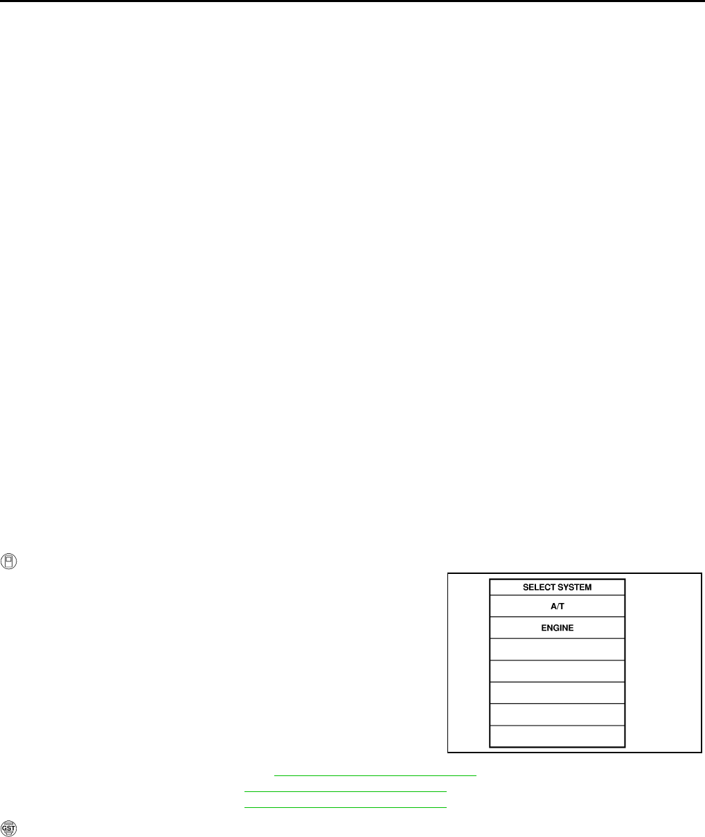
AT-182
DTC P1754 INPUT CLUTCH SOLENOID VALVE FUNCTION
DTC P1754 INPUT CLUTCH SOLENOID VALVE FUNCTION PFP:31940
Description ACS000CB
●Input clutch solenoid valve is controlled by the TCM in response to signals sent from the PNP switch, vehi-
cle speed sensor and accelerator pedal position sensor (throttle position sensor). Gears will then be
shifted to the optimum position.
●This is not only caused by electrical malfunction (circuits open or shorted) but also by mechanical mal-
function such as control valve sticking, improper solenoid valve operation.
On Board Diagnosis Logic ACS000CC
●This is an OBD-II self-diagnostic item.
●Diagnostic trouble code “I/C SOLENOID FNCTN” with CONSULT-II or P1754 without CONSULT-II is
detected under the following conditions.
–When TCM detects that actual gear ratio is irregular, and relation between gear position and condition of
ATF pressure switch 3 is irregular during depressing accelerator pedal. (Other than during shift change)
–When TCM detects that relation between gear position and condition of ATF pressure switch 3 is irregular
during releasing accelerator pedal. (Other than during shift change)
Possible Cause ACS000CD
●Harness or connectors
(The solenoid and switch circuits are open or shorted.)
●Input clutch solenoid valve
●ATF pressure switch 3
DTC Confirmation Procedure ACS000CE
CAUTION:
Always drive vehicle at a safe speed.
NOTE:
If “DTC Confirmation Procedure” has been previously conducted, always turn ignition switch “OFF”
and wait at least 10 seconds before conducting the next test.
After the repair, perform the following procedure to confirm the malfunction is eliminated.
WITH CONSULT-II
1. Start engine.
2. Accelerate vehicle to maintain the following condition.
ACCELE POSI: 1.5/8 - 2.0/8
Selector lever: “D” position
Gear position: 3rd Þ 4th Gear (I/C ON/OFF)
Driving location: Driving the vehicle uphill (increased
engine load) will help maintain the driving conditions
required for this test.
3. Perform step “2” again.
4. Turn ignition switch OFF, then perform step “1” to “3” again.
5. Check “SELF-DIAG RESULTS” mode for “A/T” with CONSULT-
II. If DTC (P1754) is detected, refer to AT-184, "Diagnostic Procedure" .
If DTC (P1752) is detected, go to AT-179, "Diagnostic Procedure" .
If DTC (P1843) is detected, go to AT-234, "Diagnostic Procedure" .
WITH GST
Follow the procedure “With CONSULT-II”.
SAT014K
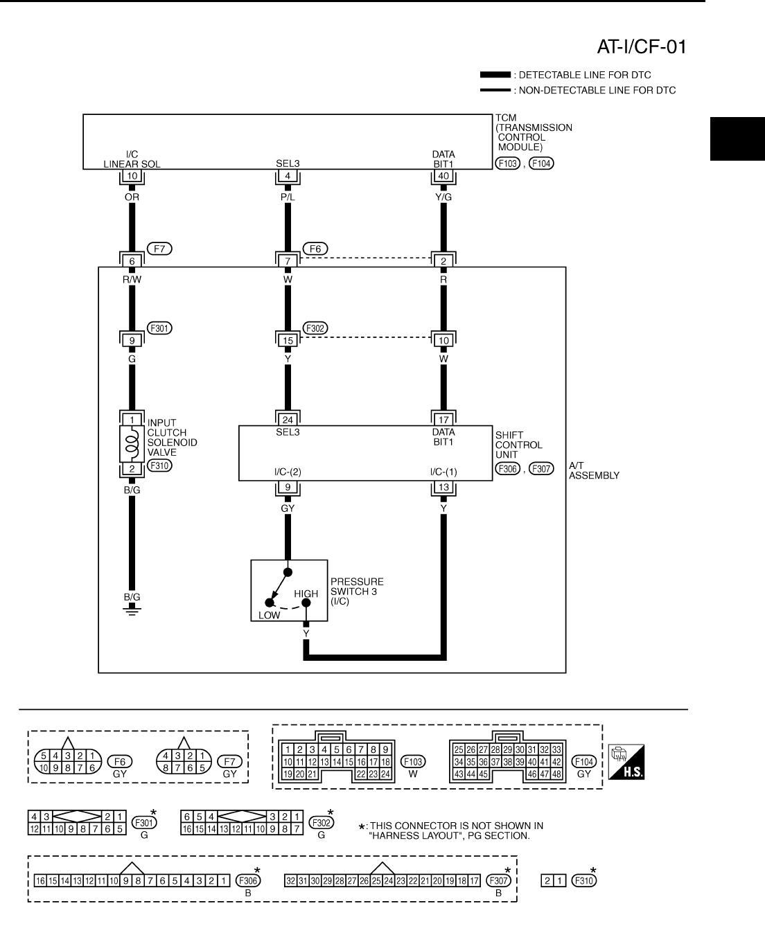
DTC P1754 INPUT CLUTCH SOLENOID VALVE FUNCTION
AT-183
D
E
F
G
H
I
J
K
L
M
A
B
AT
Wiring Diagram — AT — I/CF ACS000CF
TCWT0234E
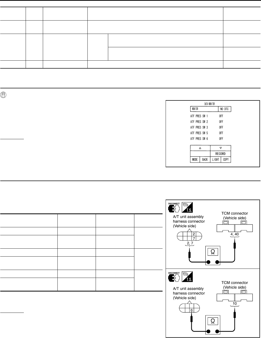
AT-184
DTC P1754 INPUT CLUTCH SOLENOID VALVE FUNCTION
TCM terminal and Data are reference value. Measured between each terminals 5, 14, 24 and 46 (TCM ground).
Diagnostic Procedure ACS000CG
1. CHECK INPUT SIGNALS
With CONSULT-II
1. Start engine.
2. Select “ECU INPUT SIGNALS” or “MAIN SIGNALS” in “DATA
MONITOR” mode for “A/T” with CONSULT-II.
3. Accelerate vehicle in the “D” position (3rd Þ 4th gear), and con-
firm the ON/OFF actuation of the “ATF PRES SW 3”.
OK or NG
OK >> GO TO 4.
NG >> GO TO 2.
2. CHECK HARNESS BETWEEN TCM AND A/T UNIT ASSEMBLY HARNESS CONNECTOR
1. Turn ignition switch OFF.
2. Disconnect TCM connector.
3. Check continuity between A/T unit assembly harness connector
and TCM connector.
4. If OK, check harness for short to ground and short to power.
5. Reinstall any part removed.
OK or NG
OK >> GO TO 3.
NG >> Repair open circuit or short to ground or short to power
in harness or connectors.
Terminal
No.
Wire
color Item Condition Data (Approx.)
4P/L
SEL3
(pressure switch 3) ––
10 OR Input clutch sole-
noid valve
When
vehicle
cruises
When the solenoid valve operating (in 1st gear, 2nd gear,
or 3rd gear) More than 2V
When the solenoid valve is not operating (4th gear or 5th
gear) 0V
40 Y/G DATA BIT1 – –
PCIA0067E
Item Connector No. Terminal No.
(Wire color) Continuity
TCM F103 4 (P/L)
Yes
A/T unit assembly harness
connector F6 7 (P/L)
TCM F104 40 (Y/G)
Yes
A/T unit assembly harness
connector F6 2 (Y/G)
TCM F103 10 (OR)
Yes
A/T unit assembly harness
connector F7 6 (OR)
SCIA3109E
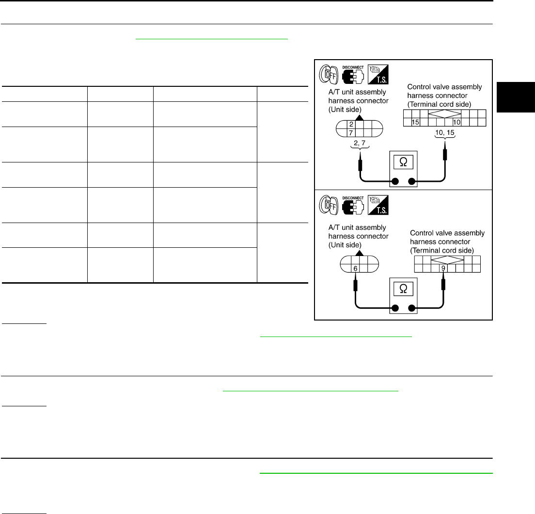
DTC P1754 INPUT CLUTCH SOLENOID VALVE FUNCTION
AT-185
D
E
F
G
H
I
J
K
L
M
A
B
AT
3. CHECK TERMINAL CORD ASSEMBLY
1. Remove oil pan. Refer to AT-299, "Control Valve Assembly" .
2. Disconnect A/T unit assembly harness connector and control valve assembly harness connector.
3. Check continuity between A/T unit assembly harness connector
and control valve assembly harness connector.
4. If OK, check harness for short to ground and short to power.
5. Reinstall any part removed.
OK or NG
OK >> Replace the control valve assembly. Refer to AT-299, "Control Valve Assembly" .
NG >> Repair open circuit or short to ground or short to power in harness or connectors.
4. CHECK DTC
Perform “DTC Confirmation Procedure”. Refer to AT-108, "DTC Confirmation Procedure" .
OK or NG
OK >> INSPECTION END
NG >> GO TO 5.
5. PERFORM TCM INSPECTION
1. Perform TCM input/output signal inspection. Refer to AT-89, "TCM Input/Output Signal Reference Values"
.
2. If NG, recheck TCM pin terminals for damage or loose connection with harness connector.
OK or NG
OK >> INSPECTION END
NG >> Repair or replace damaged parts.
Item Connector No. Terminal No. (Wire color) Continuity
A/T unit assembly
harness connector F6 2 (R)
Yes
Control valve assem-
bly harness connec-
tor
F302 10 (R)
A/T unit assembly
harness connector F6 7 (W)
Yes
Control valve assem-
bly harness connec-
tor
F302 15 (W)
A/T unit assembly
harness connector F7 6 (R/W)
Yes
Control valve assem-
bly harness connec-
tor
F301 9 (R/W)
SCIA3075E
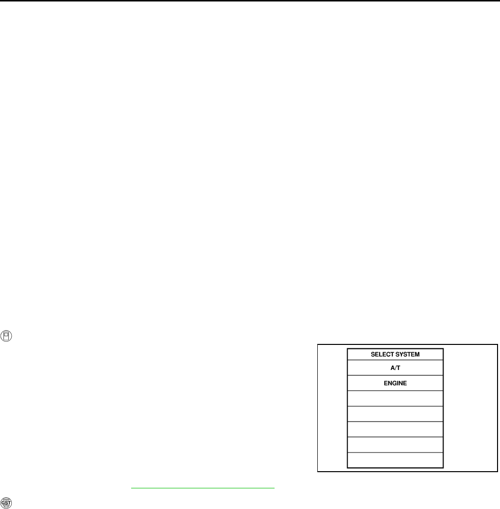
AT-186
DTC P1757 FRONT BRAKE SOLENOID VALVE
DTC P1757 FRONT BRAKE SOLENOID VALVE PFP:31940
Description ACS000CH
Front brake solenoid valve is controlled by the TCM in response to signals sent from the PNP switch, vehicle
speed sensor and accelerator pedal position sensor (throttle position sensor). Gears will then be shifted to the
optimum position.
On Board Diagnosis Logic ACS000CI
●This is an OBD-II self-diagnostic item.
●Diagnostic trouble code “FR/B SOLENOID/CIRC” with CONSULT-II or P1757 without CONSULT-II is
detected under the following conditions.
–When TCM detects an improper voltage drop when it tries to operate the solenoid valve.
–When TCM detects as irregular by comparing target value with monitor value.
Possible Cause ACS000CJ
●Harness or connectors
(The solenoid circuit is open or shorted.)
●Front brake solenoid valve
DTC Confirmation Procedure ACS000CK
CAUTION:
Always drive vehicle at a safe speed.
NOTE:
If “DTC Confirmation Procedure” has been previously conducted, always turn ignition switch “OFF”
and wait at least 10 seconds before conducting the next test.
After the repair, perform the following procedure to confirm the malfunction is eliminated.
WITH CONSULT-II
1. Turn ignition switch ON. (Do not start engine.)
2. Select “DATA MONITOR” mode for “A/T” with CONSULT-II.
3. Start engine.
4. Drive vehicle and maintain the following conditions for at least 5
consecutive seconds.
ACCELE POS: 1.5/8 - 2.0/8
Selector lever: “D” position
Gear position: 3rd Þ 4th Gear (FR/B ON/OFF)
Driving location: Driving the vehicle uphill (increased
engine load) will help maintain the driving conditions
required for this test.
5. If DTC is detected go to AT-188, "Diagnostic Procedure" .
WITH GST
Follow the procedure “With CONSULT-II”.
SAT014K
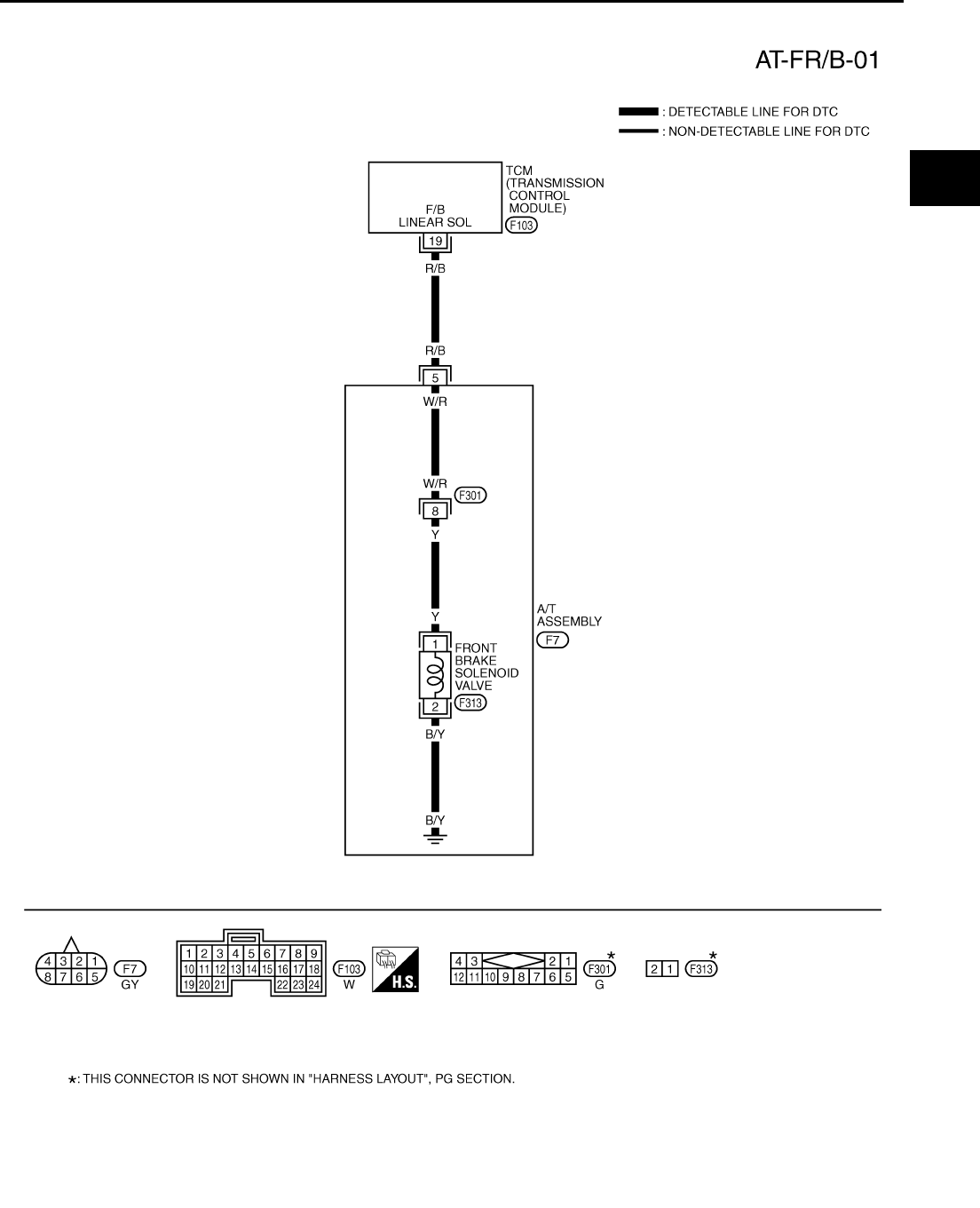
DTC P1757 FRONT BRAKE SOLENOID VALVE
AT-187
D
E
F
G
H
I
J
K
L
M
A
B
AT
Wiring Diagram — AT — FR/B ACS000CL
TCWT0235E
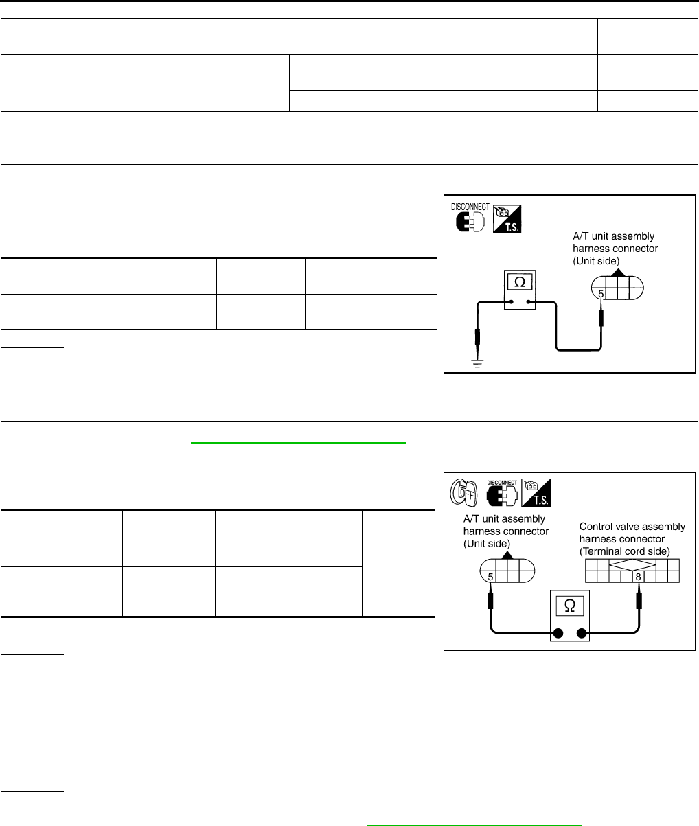
AT-188
DTC P1757 FRONT BRAKE SOLENOID VALVE
TCM terminal and Data are reference value. Measured between each terminals 5, 14, 24 and 46 (TCM ground).
Diagnostic Procedure ACS000CM
1. CHECK FRONT BRAKE SOLENOID VALVE CIRCUIT
1. Turn ignition switch OFF.
2. Disconnect A/T unit assembly harness connector at the trans-
mission right side.
3. Check the resistance between terminal and ground.
OK or NG
OK >> GO TO 4.
NG >> GO TO 2.
2. CHECK TERMINAL CORD ASSEMBLY
1. Remove oil pan. Refer to AT-299, "Control Valve Assembly" .
2. Disconnect A/T unit assembly harness connector and control valve assembly harness connector.
3. Check continuity between A/T unit assembly harness connector
and control valve assembly harness connector.
4. If OK, check harness for short to ground and short to power.
OK or NG
OK >> GO TO 3.
NG >> Repair open circuit or short to ground or short to power in harness or connectors.
3. CHECK VALVE RESISTANCE
Check valve resistance
●Refer to AT-190, "Component Inspection" .
OK or NG
OK >> GO TO 4.
NG >> Replace the control valve assembly. Refer to AT-299, "Control Valve Assembly" .
Terminal
No.
Wire
color Item Condition Data (Approx.)
19 R/B Front brake sole-
noid valve
When
vehicle
starts
When the solenoid valve is operating (other than 4th
gear) More than 2V
When the solenoid valve is not operating (4th gear) 0V
Solenoid valve Connector No. Terminal No.
(Wire color) Resistance (Approx.)
Front brake solenoid
valve F7 5 (R/B) -
Ground 3 - 9 Ω
SCIA1839E
Item Connector No. Terminal No. (Wire color) Continuity
A/T unit assembly
harness connector F7 5 (W/R)
Yes
Control valve assem-
bly harness connec-
tor
F301 8 (W/R)
SCIA3076E
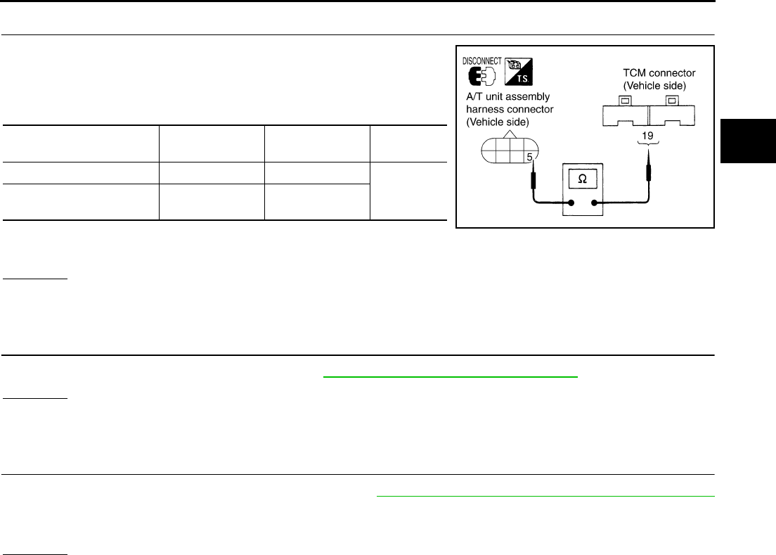
DTC P1757 FRONT BRAKE SOLENOID VALVE
AT-189
D
E
F
G
H
I
J
K
L
M
A
B
AT
4. CHECK POWER SOURCE CIRCUIT
1. Turn ignition switch OFF.
2. Disconnect TCM connector.
3. Check continuity between A/T unit assembly harness connector
and TCM connector.
4. If OK, check harness for short to ground and short to power.
5. Reinstall any part removed.
OK or NG
OK >> GO TO 5.
NG >> Repair open circuit or short to ground or short to power in harness or connectors.
5. CHECK DTC
Perform “DTC Confirmation Procedure”. Refer to AT-108, "DTC Confirmation Procedure" .
OK or NG
OK >> INSPECTION END
NG >> GO TO 6.
6. PERFORM TCM INSPECTION
1. Perform TCM input/output signal inspection. Refer to AT-89, "TCM Input/Output Signal Reference Values"
.
2. If NG, recheck TCM pin terminals for damage or loose connection with harness connector.
OK or NG
OK >> INSPECTION END
NG >> Repair or replace damaged parts.
Item Connector No. Terminal No.
(Wire color) Continuity
TCM F103 19 (R/B)
Yes
A/T unit assembly harness
connector F7 5 (R/B)
SCIA1840E
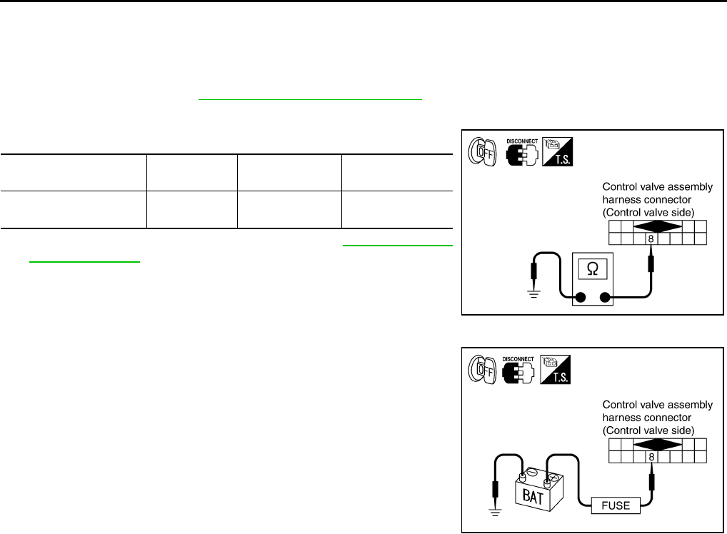
AT-190
DTC P1757 FRONT BRAKE SOLENOID VALVE
Component Inspection ACS004IF
FRONT BRAKE SOLENOID VALVE
Resistance check
1. Turn ignition switch OFF.
2. Remove oil pan. Refer to AT-299, "Control Valve Assembly" .
3. Disconnect control valve assembly harness connector.
4. Check resistance between terminal and ground.
5. If NG, replace control valve assembly. Refer to AT-299, "Control
Valve Assembly" .
Operation check
●Check solenoid valve by listening for its operating sound while
applying battery voltage to the terminal 8 and ground.
Solenoid Valve Connector No. Terminal No.
(Wire color)
Resistance (Ω)
(Approx.)
Front brake solenoid
valve F301 8 (Y) - Ground 3 - 9 Ω
SCIA3077E
SCIA3079E

DTC P1759 FRONT BRAKE SOLENOID VALVE FUNCTION
AT-191
D
E
F
G
H
I
J
K
L
M
A
B
AT
DTC P1759 FRONT BRAKE SOLENOID VALVE FUNCTION PFP:31940
Description ACS000CN
●Front brake solenoid valve is controlled by the TCM in response to signals sent from the PNP switch, vehi-
cle speed sensor and accelerator pedal position sensor (throttle position sensor). Gears will then be
shifted to the optimum position.
●This is not only caused by electrical malfunction (circuits open or shorted) but also by mechanical mal-
function such as control valve sticking, improper solenoid valve operation.
On Board Diagnosis Logic ACS000CO
●This is an OBD-II self-diagnostic item.
●Diagnostic trouble code “FR/B SOLENOID FNCT” with CONSULT-II or P1759 without CONSULT-II is
detected under the following conditions.
–When TCM detects that actual gear ratio is irregular, and relation between gear position and condition of
ATF pressure switch 1 is irregular during depressing accelerator pedal. (Other than during shift change)
–When TCM detects that relation between gear position and condition of ATF pressure switch 1 is irregular
during releasing accelerator pedal. (Other than during shift change)
Possible Cause ACS000CP
●Harness or connectors
(The solenoid and switch circuits are open or shorted.)
●Front brake solenoid valve
●ATF pressure switch 1
DTC Confirmation Procedure ACS000CQ
CAUTION:
Always drive vehicle at a safe speed.
NOTE:
If “DTC Confirmation Procedure” has been previously conducted, always turn ignition switch “OFF”
and wait at least 10 seconds before conducting the next test.
After the repair, perform the following procedure to confirm the malfunction is eliminated.
WITH CONSULT-II
1. Start engine.
2. Accelerate vehicle to maintain the following condition.
ACCELE POS: 1.5/8 - 2.0/8
Selector lever: “D” position
Gear position: 3rd Þ 4th Gear (FR/B ON/OFF)
Driving location: Driving the vehicle uphill (increased
engine load) will help maintain the driving conditions
required for this test.
3. Perform step “2” again.
4. Turn ignition switch OFF, then perform step “1” to “3” again.
5. Check “SELF-DIAG RESULTS” mode for “A/T” with CONSULT-
II. If DTC (P1759) is detected, refer to AT-193, "Diagnostic Procedure" .
If DTC (P1757) is detected, go to AT-188, "Diagnostic Procedure" .
If DTC (P1841) is detected, go to AT-230, "Diagnostic Procedure" .
WITH GST
Follow the procedure “With CONSULT-II”.
SAT014K
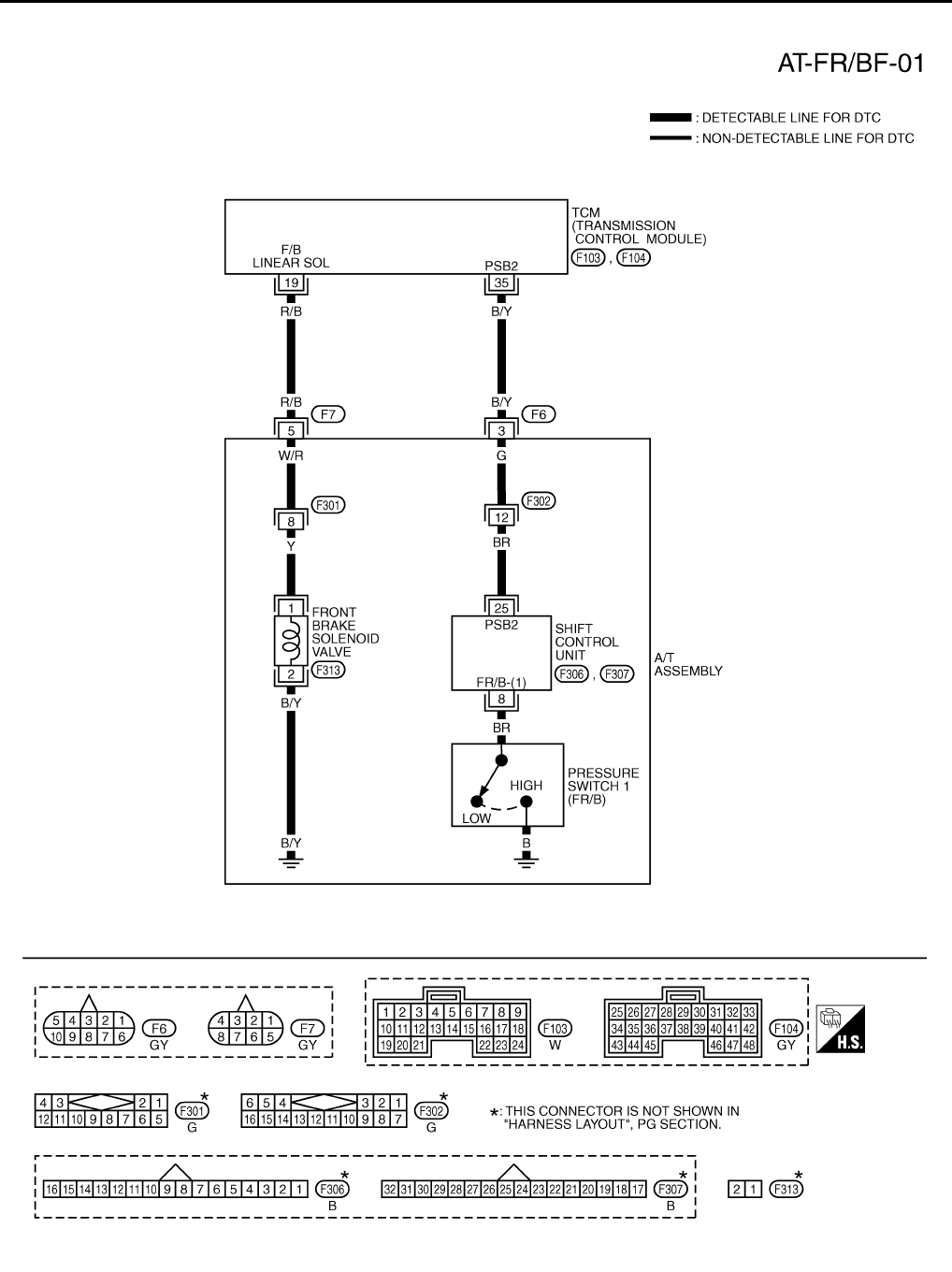
AT-192
DTC P1759 FRONT BRAKE SOLENOID VALVE FUNCTION
Wiring Diagram — AT — FR/BF ACS000CR
TCWT0236E
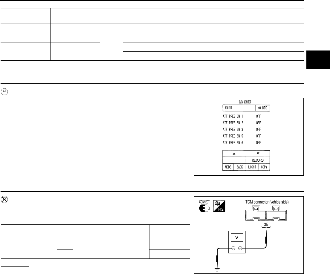
DTC P1759 FRONT BRAKE SOLENOID VALVE FUNCTION
AT-193
D
E
F
G
H
I
J
K
L
M
A
B
AT
TCM terminal and Data are reference value. Measured between each terminals 5, 14, 24 and 46 (TCM ground).
Diagnostic Procedure ACS000CS
1. INPUT SIGNALS (WITH CONSULT-II)
With CONSULT-II
1. Start engine.
2. Select “ECU INPUT SIGNALS” or “MAIN SIGNALS” in “DATA
MONITOR” mode for “A/T” with CONSULT-II.
3. Accelerate vehicle in the “D” position (3rd Þ 4th gear), and con-
firm the ON/OFF actuation of the “ATF PRES SW 1”.
OK or NG
OK >> GO TO 5.
NG >> GO TO 3.
2. INPUT SIGNALS (WITHOUT CONSULT-II)
Without CONSULT-II
1. Start engine.
2. Accelerate vehicle in the “D” position (3rd Þ 4th gear).
OK or NG
OK >> GO TO 5.
NG >> GO TO 3.
Terminal
No.
Wire
color Item Condition Data (Approx.)
19 R/B Front brake sole-
noid valve When
vehicle
cruises
When the solenoid valve is operating (other than 4th gear) More than 2V
When the solenoid valve is not operating (4th gear) 0V
35 B/Y PSB2
(pressure switch 1)
When front brake solenoid valve “OFF”. Battery voltage
When front brake solenoid valve“ ON”. 0V
PCIA0067E
Solenoid valve Connector
No.
Terminal No.
(Wire color) Voltage
Front brake solenoid
valve
OFF F104 35 (B/Y) - Ground Battery voltage
ON Approx. 0 V
PCIA0066E
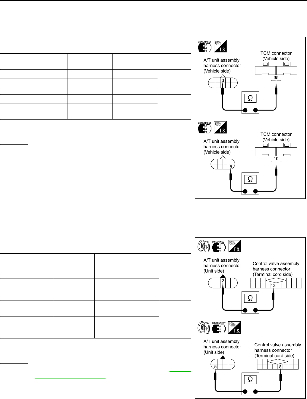
AT-194
DTC P1759 FRONT BRAKE SOLENOID VALVE FUNCTION
3. CHECK HARNESS BETWEEN TCM AND A/T UNIT ASSEMBLY HARNESS CONNECTOR
1. Turn ignition switch OFF.
2. Disconnect TCM connector.
3. Check continuity between A/T unit assembly harness connector
and TCM connector.
4. If OK, check harness for short to ground and short to power.
5. Reinstall any part removed.
OK or NG
OK >> GO TO 4.
NG >> Repair open circuit or short to ground or short to power
in harness or connectors.
4. CHECK TERMINAL CORD ASSEMBLY
1. Remove oil pan. Refer to AT-299, "Control Valve Assembly" .
2. Disconnect A/T unit assembly harness connector and control valve assembly harness connector.
3. Check continuity between A/T unit assembly harness connector
and control valve assembly harness connector.
4. If OK, check harness for short to ground and short to power.
5. Reinstall any part removed.
OK or NG
OK >> Replace the control valve assembly. Refer to AT-299,
"Control Valve Assembly" .
NG >> Repair open circuit or short to ground or short to power
in harness or connectors.
Item Connector No. Terminal No.
(Wire color) Continuity
TCM F104 35 (B/Y)
Yes
A/T unit assembly harness
connector F6 3 (B/Y)
TCM F103 19 (R/B)
Yes
A/T unit assembly harness
connector F7 5 (R/B)
SCIA3080E
Item Connector No. Terminal No. (Wire color) Continuity
A/T unit assembly
harness connector F6 3 (G)
Yes
Control valve assem-
bly harness connec-
tor
F302 12 (G)
A/T unit assembly
harness connector F7 5 (W/R)
Yes
Control valve assem-
bly harness connec-
tor
F301 8 (W/R)
SCIA3081E

DTC P1759 FRONT BRAKE SOLENOID VALVE FUNCTION
AT-195
D
E
F
G
H
I
J
K
L
M
A
B
AT
5. CHECK DTC
Perform “DTC Confirmation Procedure”. Refer to AT-108, "DTC Confirmation Procedure" .
OK or NG
OK >> INSPECTION END
NG >> GO TO 6.
6. PERFORM TCM INSPECTION
1. Perform TCM input/output signal inspection. Refer to AT-89, "TCM Input/Output Signal Reference Values"
.
2. If NG, recheck TCM pin terminals for damage or loose connection with harness connector.
OK or NG
OK >> INSPECTION END
NG >> Repair or replace damaged parts.
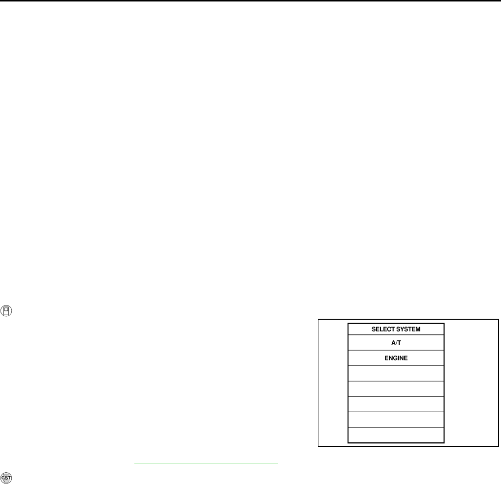
AT-196
DTC P1762 DIRECT CLUTCH SOLENOID VALVE
DTC P1762 DIRECT CLUTCH SOLENOID VALVE PFP:31940
Description ACS000CT
Direct clutch solenoid valve is controlled by the TCM in response to signals sent from the PNP switch, vehicle
speed sensor and accelerator pedal position sensor (throttle position sensor). Gears will then be shifted to the
optimum position.
On Board Diagnosis Logic ACS000CU
●This is an OBD-II self-diagnostic item.
●Diagnostic trouble code “D/C SOLENOID/CIRC” with CONSULT-II or P1762 without CONSULT-II is
detected under the following conditions.
–When TCM detects an improper voltage drop when it tries to operate the solenoid valve.
–When TCM detects as irregular by comparing target value with monitor value.
Possible Cause ACS000CV
●Harness or connectors
(The solenoid circuit is open or shorted.)
●Direct clutch solenoid valve
DTC Confirmation Procedure ACS000CW
NOTE:
If “DTC Confirmation Procedure” has been previously conducted, always turn ignition switch “OFF”
and wait at least 10 seconds before conducting the next test.
After the repair, perform the following procedure to confirm the malfunction is eliminated.
WITH CONSULT-II
1. Turn ignition switch ON. (Do not start engine.)
2. Select “DATA MONITOR” mode for “A/T” with CONSULT-II.
3. Start engine.
4. Drive vehicle and maintain the following conditions for at least 5
consecutive seconds.
ACCELE POS: 1.5/8 - 2.0/8
Selector lever: “D” position
Gear position: 1st Þ 2nd Gear (D/C ON/OFF)
Driving location: Driving the vehicle uphill (increased
engine load) will help maintain the driving conditions
required for this test.
5. If DTC is detected, go to AT-198, "Diagnostic Procedure" .
WITH GST
Follow the procedure “With CONSULT-II”.
SAT014K

DTC P1762 DIRECT CLUTCH SOLENOID VALVE
AT-197
D
E
F
G
H
I
J
K
L
M
A
B
AT
Wiring Diagram — AT — D/C ACS000CX
TCWT0237E
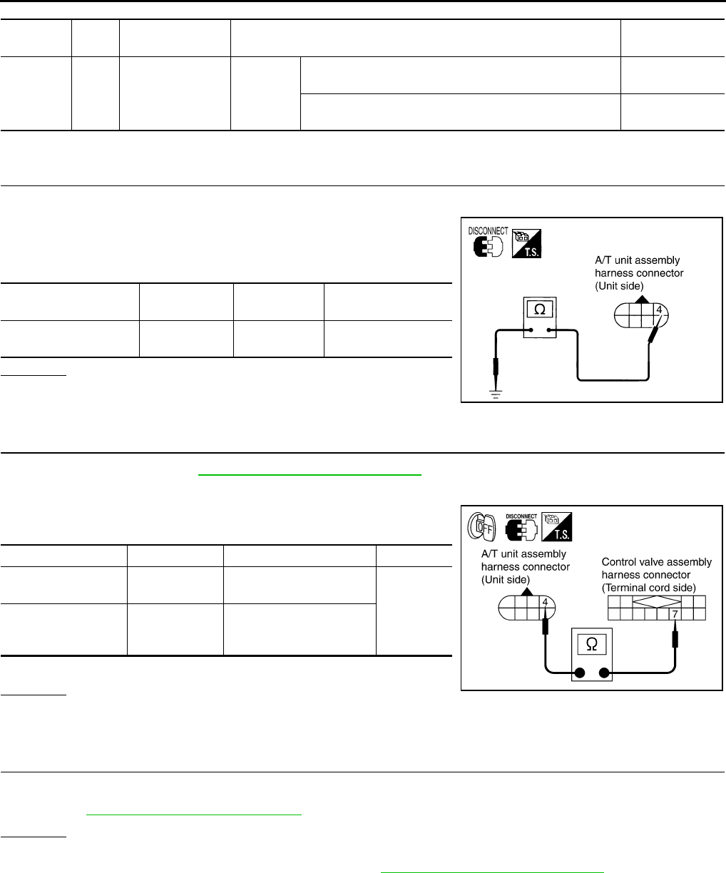
AT-198
DTC P1762 DIRECT CLUTCH SOLENOID VALVE
TCM terminal and Data are reference value. Measured between each terminals 5, 14, 24 and 46 (TCM ground).
Diagnostic Procedure ACS000CY
1. CHECK DIRECT CLUTCH SOLENOID VALVE CIRCUIT
1. Turn ignition switch OFF.
2. Disconnect A/T unit assembly harness connector at the trans-
mission right side.
3. Check the resistance between terminal and ground.
OK or NG
OK >> GO TO 4.
NG >> GO TO 2.
2. CHECK TERMINAL CORD ASSEMBLY
1. Remove oil pan. Refer to AT-299, "Control Valve Assembly" .
2. Disconnect A/T unit assembly harness connector and control valve assembly harness connector.
3. Check continuity between A/T unit assembly harness connector
and control valve assembly harness connector.
4. If OK, check harness for short to ground and short to power.
OK or NG
OK >> GO TO 3.
NG >> Repair open circuit or short to ground or short to power in harness or connectors.
3. CHECK VALVE RESISTANCE
Check valve resistance
●Refer to AT-200, "Component Inspection" .
OK or NG
OK >> GO TO 4.
NG >> Replace the control valve assembly. Refer to AT-299, "Control Valve Assembly" .
Terminal
No.
Wire
color Item Condition Data (Approx.)
21 G Direct clutch sole-
noid valve
When
vehicle
cruises
When the solenoid valve is operating (1st gear or 5th
gear) More than 2V
When the solenoid valve is not operating (2nd gear, 3rd
gear, or 4th gear) 0V
Solenoid valve Connector No. Terminal No.
(Wire color) Resistance (Approx.)
Direct clutch solenoid
valve F7 4 (G) - Ground 3 - 9 Ω
SCIA1841E
Item Connector No. Terminal No. (Wire color) Continuity
A/T unit assembly
harness connector F7 4 (W/B)
Yes
Control valve assem-
bly harness connec-
tor
F301 7 (W/B)
SCIA3082E
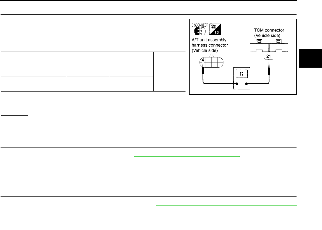
DTC P1762 DIRECT CLUTCH SOLENOID VALVE
AT-199
D
E
F
G
H
I
J
K
L
M
A
B
AT
4. CHECK POWER SOURCE CIRCUIT
1. Turn ignition switch OFF.
2. Disconnect TCM connector.
3. Check continuity between A/T unit assembly harness connector
and TCM connector.
4. If OK, check harness for short to ground and short to power.
5. Reinstall any part removed.
OK or NG
OK >> GO TO 5.
NG >> Repair open circuit or short to ground or short to power in harness or connectors.
5. CHECK DTC
Perform “DTC Confirmation Procedure”. Refer to AT-108, "DTC Confirmation Procedure" .
OK or NG
OK >> INSPECTION END
NG >> GO TO 6.
6. PERFORM TCM INSPECTION
1. Perform TCM input/output signal inspection. Refer to AT-89, "TCM Input/Output Signal Reference Values"
.
2. If NG, recheck TCM pin terminals for damage or loose connection with harness connector.
OK or NG
OK >> INSPECTION END
NG >> Repair or replace damaged parts.
Item Connector No. Terminal No.
(Wire color) Continuity
TCM F103 21 (G)
Yes
A/T unit assembly harness
connector F7 4 (G)
SCIA1842E
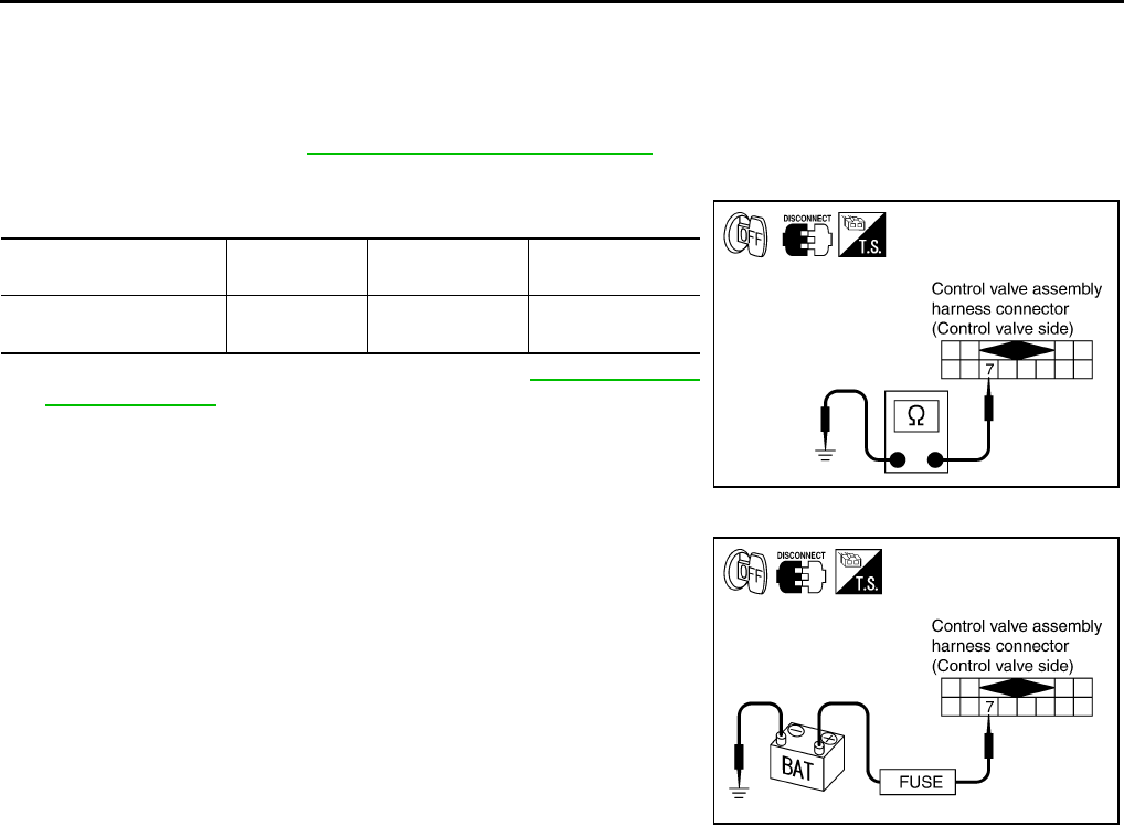
AT-200
DTC P1762 DIRECT CLUTCH SOLENOID VALVE
Component Inspection ACS004IG
DIRECT CLUTCH SOLENOID VALVE
Resistance check
1. Turn ignition switch OFF.
2. Remove oil pan. Refer to AT-299, "Control Valve Assembly" .
3. Disconnect control valve assembly harness connector.
4. Check resistance between terminal and ground.
5. If NG, replace control valve assembly. Refer to AT-299, "Control
Valve Assembly" .
Operation check
●Check solenoid valve by listening for its operating sound while
applying battery voltage to the terminal 7 and ground.
Solenoid Valve Connector No. Terminal No.
(Wire color)
Resistance (Ω)
(Approx.)
Direct clutch solenoid
valve F301 7 (L) - Ground 3 - 9 Ω
SCIA3083E
SCIA3084E
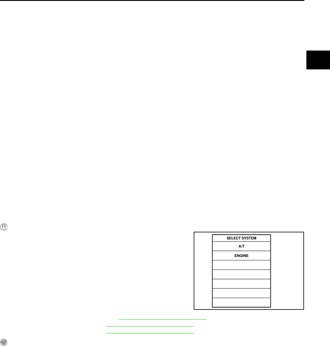
DTC P1764 DIRECT CLUTCH SOLENOID VALVE FUNCTION
AT-201
D
E
F
G
H
I
J
K
L
M
A
B
AT
DTC P1764 DIRECT CLUTCH SOLENOID VALVE FUNCTION PFP:31940
Description ACS000CZ
●Direct clutch solenoid valve is controlled by the TCM in response to signals sent from the PNP switch,
vehicle speed sensor and accelerator pedal position sensor (throttle position sensor). Gears will then be
shifted to the optimum position.
●This is not only caused by electrical malfunction (circuits open or shorted) but also by mechanical mal-
function such as control valve sticking, improper solenoid valve operation.
On Board Diagnosis Logic ACS000D0
●This is an OBD-II self-diagnostic item.
●Diagnostic trouble code “D/C SOLENOID FNCTN” with CONSULT-II or P1764 without CONSULT-II is
detected under the following conditions.
–When TCM detects that actual gear ratio is irregular, and relation between gear position and condition of
ATF pressure switch 5 is irregular during depressing accelerator pedal. (Other than during shift change)
–When TCM detects that relation between gear position and condition of ATF pressure switch 5 is irregular
during releasing accelerator pedal. (Other than during shift change)
Possible Cause ACS000D1
●Harness or connectors
(The solenoid and switch circuits are open or shorted.)
●Direct clutch solenoid valve
●ATF pressure switch 5
DTC Confirmation Procedure ACS000D2
NOTE:
If “DTC Confirmation Procedure” has been previously conducted, always turn ignition switch “OFF”
and wait at least 10 seconds before conducting the next test.
After the repair, perform the following procedure to confirm the malfunction is eliminated.
WITH CONSULT-II
1. Start engine.
2. Accelerate vehicle to maintain the following condition.
ACCELE POS: 1.5/8 - 2.0/8
Selector lever: “D” position
Gear position: 1st Þ 2nd Gear (D/C ON/OFF)
Driving location: Driving the vehicle uphill (increased
engine load) will help maintain the driving conditions
required for this test.
3. Perform step “2” again.
4. Turn ignition switch OFF, then perform step “1” to “3” again.
5. Check “SELF-DIAG RESULTS” mode for “A/T” with CONSULT-
II. If DTC (P1764) is detected, refer to AT-203, "Diagnostic Procedure" .
If DTC (P1762) is detected, go to AT-198, "Diagnostic Procedure" .
If DTC (P1845) is detected, go to AT-238, "Diagnostic Procedure" .
WITH GST
Follow the procedure “With CONSULT-II”.
SAT014K
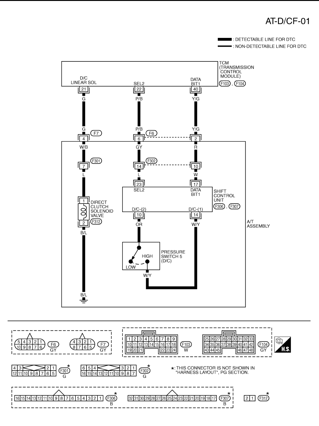
AT-202
DTC P1764 DIRECT CLUTCH SOLENOID VALVE FUNCTION
Wiring Diagram — AT — D/CF ACS000D3
TCWT0238E
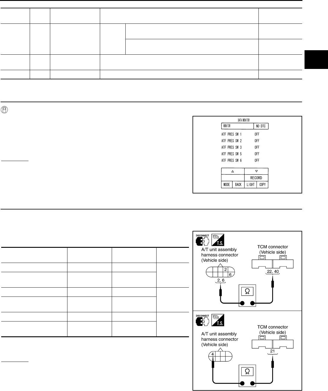
DTC P1764 DIRECT CLUTCH SOLENOID VALVE FUNCTION
AT-203
D
E
F
G
H
I
J
K
L
M
A
B
AT
TCM terminals and Data are reference value. Measured between each terminals 5, 14, 24 and 46 (TCM ground).
Diagnostic Procedure ACS000D4
1. CHECK INPUT SIGNALS
With CONSULT-II
1. Start engine.
2. Select “ECU INPUT SIGNALS” or “MAIN SIGNALS” in “DATA
MONITOR” mode for “A/T” with CONSULT-II.
3. Accelerate vehicle in the “D” position (1st Þ 2nd gear), and con-
firm the ON/OFF actuation of the “ATF PRES SW 5”.
OK or NG
OK >> GO TO 4.
NG >> GO TO 2.
2. CHECK HARNESS BETWEEN TCM AND A/T UNIT ASSEMBLY HARNESS CONNECTOR
1. Turn ignition switch OFF.
2. Disconnect TCM connector.
3. Check continuity between A/T unit assembly harness connector
and TCM connector.
4. If OK, check harness for short to ground and short to power.
5. Reinstall any part removed.
OK or NG
OK >> GO TO 3.
NG >> Repair open circuit or short to ground or short to power
in harness or connectors.
Terminal
No.
Wire
color Item Condition Data (Approx.)
21 G Direct clutch sole-
noid valve
When
vehicle
cruises
When the solenoid valve is operating (1st gear or 5th
gear) More than 2V
When the solenoid valve is not operating (2nd gear, 3rd
gear, or 4th gear) 0V
22 P/B SEL2
(pressure switch 5) ––
40 Y/G DATA BIT1 – –
PCIA0067E
Item Connector No. Terminal No.
(Wire color) Continuity
TCM F103 22 (P/B)
Yes
A/T unit assembly harness
connector F6 6 (P/B)
TCM F104 40 (Y/G)
Yes
A/T unit assembly harness
connector F6 2 (Y/G)
TCM F103 21 (G)
Yes
A/T unit assembly harness
connector F7 4 (G)
SCIA3086E
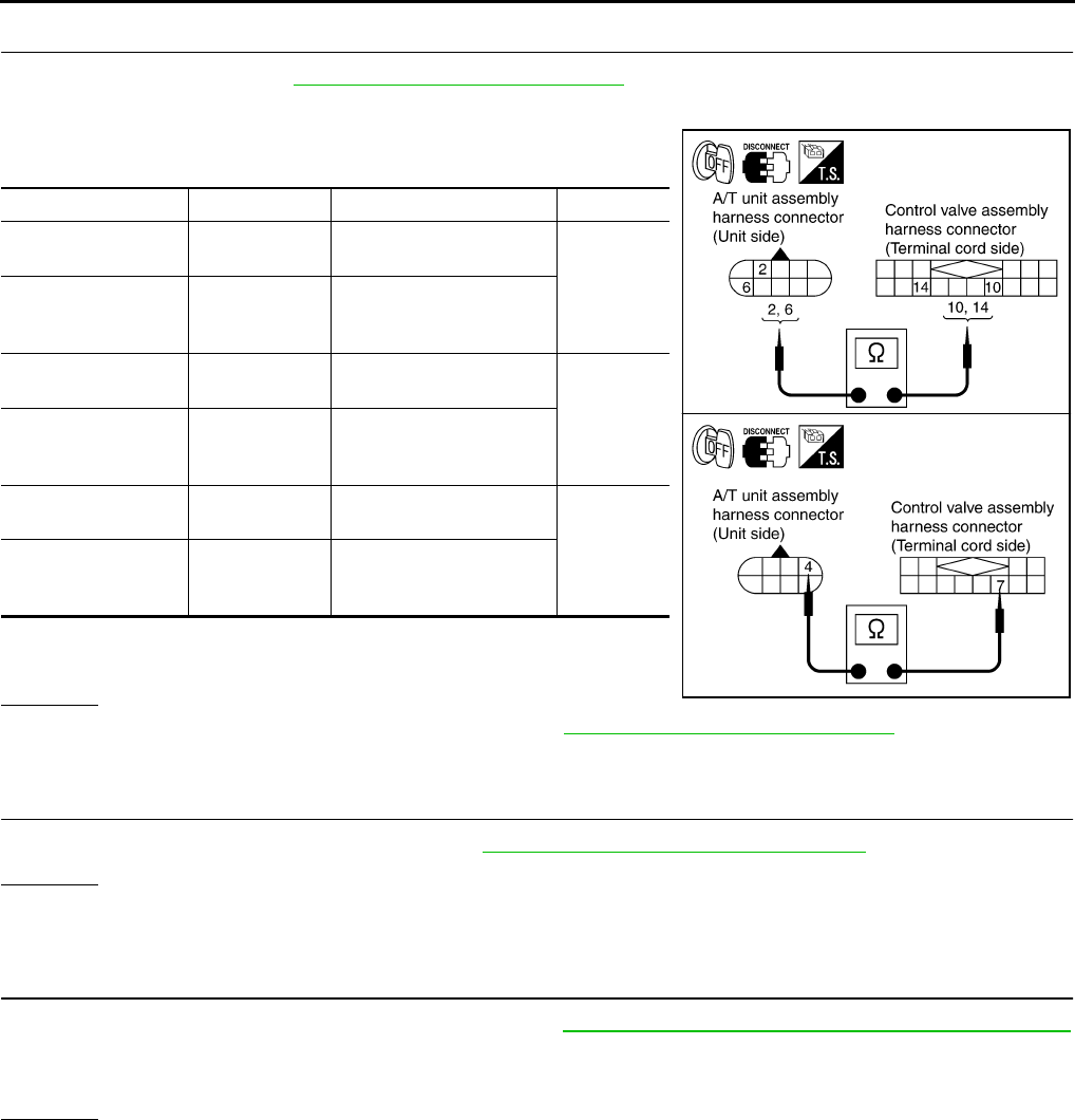
AT-204
DTC P1764 DIRECT CLUTCH SOLENOID VALVE FUNCTION
3. CHECK TERMINAL CORD ASSEMBLY
1. Remove oil pan. Refer to AT-299, "Control Valve Assembly" .
2. Disconnect A/T unit assembly harness connector and control valve assembly harness connector.
3. Check continuity between A/T unit assembly harness connector
and control valve assembly harness connector.
4. If OK, check harness for short to ground and short to power.
5. Reinstall any part removed.
OK or NG
OK >> Replace the control valve assembly. Refer to AT-299, "Control Valve Assembly" .
NG >> Repair open circuit or short to ground or short to power in harness or connectors.
4. CHECK DTC
Perform “DTC Confirmation Procedure”. Refer to AT-108, "DTC Confirmation Procedure" .
OK or NG
OK >> INSPECTION END
NG >> GO TO 5.
5. PERFORM TCM INSPECTION
1. Perform TCM input/output signal inspection. Refer to AT-89, "TCM Input/Output Signal Reference Values"
.
2. If NG, recheck TCM pin terminals for damage or loose connection with harness connector.
OK or NG
OK >> INSPECTION END
NG >> Repair or replace damaged parts.
Item Connector No. Terminal No. (Wire color) Continuity
A/T unit assembly
harness connector F6 2 (R)
Yes
Control valve assem-
bly harness connec-
tor
F302 10 (R)
A/T unit assembly
harness connector F6 6 (GY)
Yes
Control valve assem-
bly harness connec-
tor
F302 14 (GY)
A/T unit assembly
harness connector F7 4 (W/B)
Yes
Control valve assem-
bly harness connec-
tor
F301 7 (W/B)
SCIA3085E
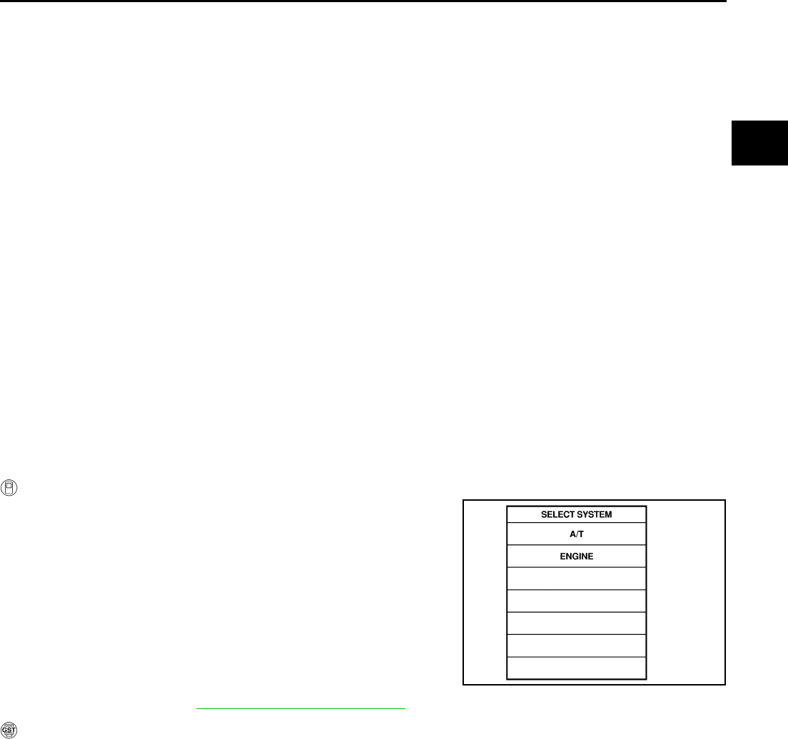
DTC P1767 HIGH AND LOW REVERSE CLUTCH SOLENOID VALVE
AT-205
D
E
F
G
H
I
J
K
L
M
A
B
AT
DTC P1767 HIGH AND LOW REVERSE CLUTCH SOLENOID VALVE PFP:31940
Description ACS000D5
High and low reverse clutch solenoid valve is controlled by the TCM in response to signals sent from the PNP
switch, vehicle speed sensor and accelerator pedal position sensor (throttle position sensor). Gears will then
be shifted to the optimum position.
On Board Diagnosis Logic ACS000D6
●This is an OBD-II self-diagnostic item.
●Diagnostic trouble code “HLR/C SOL/CIRC” with CONSULT-II or P1767 without CONSULT-II is detected
under the following conditions.
–When TCM detects an improper voltage drop when it tries to operate the solenoid valve.
–When TCM detects as irregular by comparing target value with monitor value.
Possible Cause ACS000D7
●Harness or connectors
(The solenoid circuit is open or shorted.)
●High and low reverse clutch solenoid valve
DTC Confirmation Procedure ACS000D8
CAUTION:
Always drive vehicle at a safe speed.
NOTE:
If “DTC Confirmation Procedure” has been previously conducted, always turn ignition switch “OFF”
and wait at least 10 seconds before conducting the next test.
After the repair, perform the following procedure to confirm the malfunction is eliminated.
WITH CONSULT-II
1. Turn ignition switch ON. (Do not start engine.)
2. Select “DATA MONITOR” mode for “A/T” with CONSULT-II.
3. Start engine.
4. Drive vehicle and maintain the following conditions for at least 5
consecutive seconds.
ACCELE POS: 1.5/8 - 2.0/8
Selector lever: “D” position
Gear position: 2nd Þ 3rd Gear (HLR/C ON/OFF)
Driving location: Driving the vehicle uphill (increased
engine load) will help maintain the driving conditions
required for this test.
5. If DTC is detected, go to AT-207, "Diagnostic Procedure" .
WITH GST
Follow the procedure “With CONSULT-II”.
SAT014K

AT-206
DTC P1767 HIGH AND LOW REVERSE CLUTCH SOLENOID VALVE
Wiring Diagram — AT — HLR/C ACS000D9
TCWT0239E
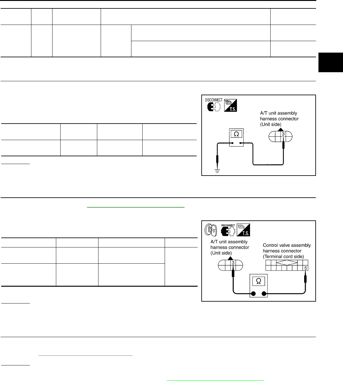
DTC P1767 HIGH AND LOW REVERSE CLUTCH SOLENOID VALVE
AT-207
D
E
F
G
H
I
J
K
L
M
A
B
AT
TCM terminal and Data are reference value. Measured between each terminals 5, 14, 24 and 46 (TCM ground).
Diagnostic Procedure ACS000DA
1. CHECK HIGH AND LOW REVERSE CLUTCH SOLENOID VALVE CIRCUIT
1. Turn ignition switch OFF.
2. Disconnect A/T unit assembly harness connector at the trans-
mission right side.
3. Check the resistance between terminal and ground.
OK or NG
OK >> GO TO 4.
NG >> GO TO 2.
2. CHECK TERMINAL CORD ASSEMBLY
1. Remove oil pan. Refer to AT-299, "Control Valve Assembly" .
2. Disconnect A/T unit assembly harness connector and control valve assembly harness connector.
3. Check continuity between A/T unit assembly harness connector
and control valve assembly harness connector.
4. If OK, check harness for short to ground and short to power.
OK or NG
OK >> GO TO 3.
NG >> Repair open circuit or short to ground or short to power in harness or connectors.
3. CHECK VALVE RESISTANCE
Check valve resistance
●Refer to AT-209, "Component Inspection" .
OK or NG
OK >> GO TO 4.
NG >> Replace the control valve assembly. Refer to AT-299, "Control Valve Assembly" .
Terminal
No.
Wire
color Item Condition Data (Approx.)
11 R/L
High and low
reverse clutch
solenoid valve
When
vehicle
cruises
When the solenoid valve operating [6 km/h (4 MPH) or
faster in 1st gear or 2nd gear] More than 2V
When the solenoid valve is not operating [6 km/h (4 MPH)
or slower in 1st gear or 3rd, 4th, or 5th gear] 0V
Solenoid valve Connector
No.
Terminal No.
(Wire color) Resistance (Approx.)
High and low reverse
clutch solenoid valve F7 3 (R/L) - Ground 3 - 9 Ω
SCIA1843E
Item Connector No. Terminal No. (Wire color) Continuity
A/T unit assembly
harness connector F7 3 (B/W)
Yes
Control valve assem-
bly harness connec-
tor
F301 5 (B/W)
SCIA3087E

AT-208
DTC P1767 HIGH AND LOW REVERSE CLUTCH SOLENOID VALVE
4. CHECK POWER SOURCE CIRCUIT
1. Turn ignition switch OFF.
2. Disconnect TCM connector.
3. Check continuity between A/T unit assembly harness connector
and TCM connector.
4. If OK, check harness for short to ground and short to power.
5. Reinstall any part removed.
OK or NG
OK >> GO TO 5.
NG >> Repair open circuit or short to ground or short to power in harness or connectors.
5. CHECK DTC
Perform “DTC Confirmation Procedure”. Refer to AT-108, "DTC Confirmation Procedure" .
OK or NG
OK >> INSPECTION END
NG >> GO TO 6.
6. PERFORM TCM INSPECTION
1. Perform TCM input/output signal inspection. Refer to AT-89, "TCM Input/Output Signal Reference Values"
.
2. If NG, recheck TCM pin terminals for damage or loose connection with harness connector.
OK or NG
OK >> INSPECTION END
NG >> Repair or replace damaged parts.
Item Connector No. Terminal No.
(Wire color) Continuity
TCM F103 11 (R/L)
Yes
A/T unit assembly harness
connector F7 3 (R/L)
SCIA1844E
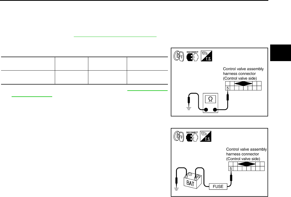
DTC P1767 HIGH AND LOW REVERSE CLUTCH SOLENOID VALVE
AT-209
D
E
F
G
H
I
J
K
L
M
A
B
AT
Component Inspection ACS004IH
HIGH AND LOW REVERSE CLUTCH SOLENOID VALVE
Resistance check
1. Turn ignition switch OFF.
2. Remove oil pan. Refer to AT-299, "Control Valve Assembly" .
3. Disconnect control valve assembly harness connector.
4. Check resistance between terminal and ground.
5. If NG, replace control valve assembly. Refer to AT-299, "Control
Valve Assembly" .
Operation check
●Check solenoid valve by listening for its operating sound while
applying battery voltage to the terminal 5 and ground.
Solenoid Valve Connector No. Terminal No.
(Wire color)
Resistance (Ω)
(Approx.)
High and low reverse
clutch solenoid valve F301 5 (R) - Ground 3 - 9 Ω
SCIA3088E
SCIA3089E

AT-210
DTC P1769 HIGH AND LOW REVERSE CLUTCH SOLENOID VALVE FUNCTION
DTC P1769 HIGH AND LOW REVERSE CLUTCH SOLENOID VALVE FUNCTION
PFP:31940
Description ACS000DB
●High and low reverse clutch solenoid valve is controlled by the TCM in response to signals sent from the
PNP switch, vehicle speed sensor and accelerator pedal position sensor (throttle position sensor). Gears
will then be shifted to the optimum position.
●This is not only caused by electrical malfunction (circuits open or shorted) but also by mechanical mal-
function such as control valve sticking, improper solenoid valve operation.
On Board Diagnosis Logic ACS000DC
●This is an OBD-II self-diagnostic item.
●Diagnostic trouble code “HLR/C SOL FNCTN” with CONSULT-II or P1769 without CONSULT-II is
detected under the following conditions.
–When TCM detects that actual gear ratio is irregular, and relation between gear position and condition of
ATF pressure switch 6 is irregular during depressing accelerator pedal. (Other than during shift change)
–When TCM detects that relation between gear position and condition of ATF pressure switch 6 is irregular
during releasing accelerator pedal. (Other than during shift change)
Possible Cause ACS000DD
●Harness or connectors
(The solenoid and switch circuits are open or shorted.)
●High and low reverse clutch solenoid valve
●ATF pressure switch 6
DTC Confirmation Procedure ACS000DE
CAUTION:
Always drive vehicle at a safe speed.
NOTE:
If “DTC Confirmation Procedure” has been previously conducted, always turn ignition switch “OFF”
and wait at least 10 seconds before conducting the next test.
After the repair, perform the following procedure to confirm the malfunction is eliminated.
WITH CONSULT-II
1. Start engine.
2. Accelerate vehicle to maintain the following condition.
ACCELE POS: 1.5/8 - 2.0/8
Selector lever: “D” position
Gear position: 2nd Þ 3rd Gear (HLR/C ON/OFF)
Driving location: Driving the vehicle uphill (increased
engine load) will help maintain the driving conditions
required for this test.
3. Perform step “2” again.
4. Turn ignition switch OFF, then perform step “1” to “3” again.
5. Check “SELF-DIAG RESULTS” mode for “A/T” with CONSULT-
II. If DTC (P1769) is detected, refer to AT-212, "Diagnostic Procedure" .
If DTC (P1767) is detected, go to AT-207, "Diagnostic Procedure" .
If DTC (P1846) is detected, go to AT-242, "Diagnostic Procedure" .
WITH GST
Follow the procedure “With CONSULT-II”.
SAT014K
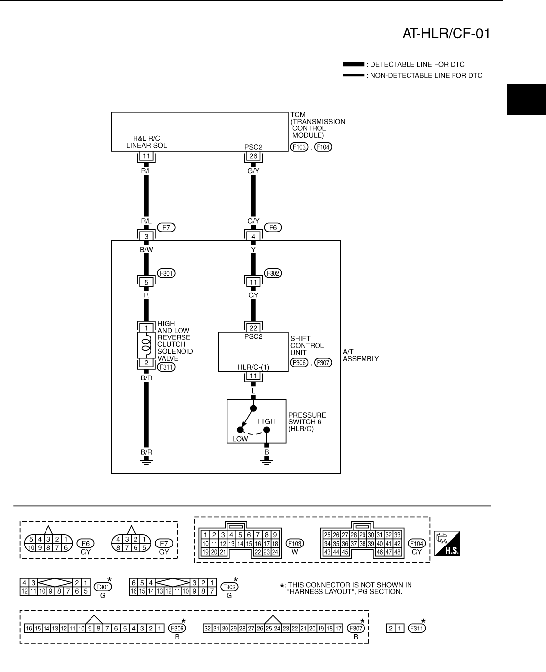
DTC P1769 HIGH AND LOW REVERSE CLUTCH SOLENOID VALVE FUNCTION
AT-211
D
E
F
G
H
I
J
K
L
M
A
B
AT
Wiring Diagram — AT — HLR/CF ACS000DF
TCWT0240E
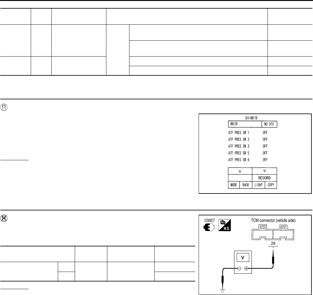
AT-212
DTC P1769 HIGH AND LOW REVERSE CLUTCH SOLENOID VALVE FUNCTION
TCM terminal and Data are reference value. Measured between each terminals 5,14,24 and 46 (TCM ground).
Diagnostic Procedure ACS000DG
1. CHECK INPUT SIGNALS (WITH CONSULT-II)
With CONSULT-II
1. Start engine.
2. Select “ECU INPUT SIGNALS” or “MAIN SIGNALS” in “DATA
MONITOR” mode for “A/T” with CONSULT-II.
3. Accelerate vehicle in the “D” position (2nd Þ 3rd gear), and con-
firm the ON/OFF actuation of the “ATF PRES SW 6”.
OK or NG
OK >> GO TO 5.
NG >> GO TO 3.
2. CHECK INPUT SIGNALS (WITHOUT CONSULT-II)
Without CONSULT-II
1. Start engine.
2. Accelerate vehicle in the “D” position (2nd Þ 3rd gear).
OK or NG
OK >> GO TO 5.
NG >> GO TO 3.
Terminal
No.
Wire
color Item Condition Data (Approx.)
11 R/L High and low reverse
clutch solenoid valve When
vehicle
cruises
When the solenoid valve operating [6 km/h (4 MPH) or
faster in 1st gear or 2nd gear] More than 2V
When the solenoid valve is not operating [6 km/h (4 MPH)
or slower in 1st gear or 3rd, 4th, or 5th gear] 0V
26 G/Y PSC2
(pressure switch 6)
When high and low reverse clutch solenoid valve “ON”. 0V
When high and low reverse clutch solenoid valve “OFF”. Battery voltage
PCIA0067E
Solenoid valve Connector
No.
Terminal No.
(Wire color) Voltage
High and low reverse
clutch solenoid valve
OFF F104 26 (G/Y) - Ground Battery voltage
ON Approx. 0 V
PCIA0068E
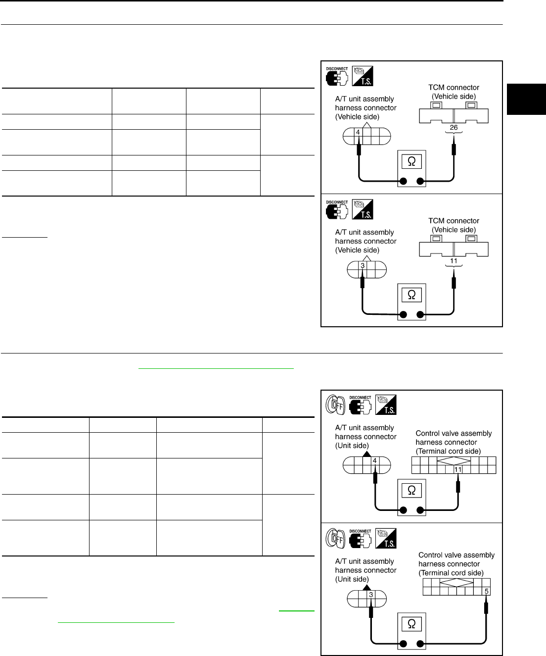
DTC P1769 HIGH AND LOW REVERSE CLUTCH SOLENOID VALVE FUNCTION
AT-213
D
E
F
G
H
I
J
K
L
M
A
B
AT
3. CHECK HARNESS BETWEEN TCM AND A/T UNIT ASSEMBLY HARNESS CONNECTOR
1. Turn ignition switch OFF.
2. Disconnect TCM connector.
3. Check continuity between A/T unit assembly harness connector
and TCM connector.
4. If OK, check harness for short to ground and short to power.
5. Reinstall any part removed.
OK or NG
OK >> GO TO 3.
NG >> Repair open circuit or short to ground or short to power
in harness or connectors.
4. CHECK TERMINAL CORD ASSEMBLY
1. Remove oil pan. Refer to AT-299, "Control Valve Assembly" .
2. Disconnect A/T unit assembly harness connector and control valve assembly harness connector.
3. Check continuity between A/T unit assembly harness connector
and control valve assembly harness connector.
4. If OK, check harness for short to ground and short to power.
5. Reinstall any part removed.
OK or NG
OK >> Replace the control valve assembly. Refer to AT-299,
"Control Valve Assembly" .
NG >> Repair open circuit or short to ground or short to power
in harness or connectors.
Item Connector No. Terminal No.
(Wire color) Continuity
TCM F104 26 (G/Y)
Yes
A/T unit assembly harness
connector F6 4 (G/Y)
TCM F103 11 (R/L)
Yes
A/T unit assembly harness
connector F7 3 (R/L)
SCIA3090E
Item Connector No. Terminal No. (Wire color) Continuity
A/T unit assembly
harness connector F6 4 (Y)
Yes
Control valve assem-
bly harness connec-
tor
F302 11 (Y)
A/T unit assembly
harness connector F7 3 (B/W)
Yes
Control valve assem-
bly harness connec-
tor
F301 5 (B/W)
SCIA3091E

AT-214
DTC P1769 HIGH AND LOW REVERSE CLUTCH SOLENOID VALVE FUNCTION
5. CHECK DTC
Perform “DTC Confirmation Procedure”. Refer to AT-108, "DTC Confirmation Procedure" .
OK or NG
OK >> INSPECTION END
NG >> GO TO 6.
6. PERFORM TCM INSPECTION
1. Perform TCM input/output signal inspection. Refer to AT-89, "TCM Input/Output Signal Reference Values"
.
2. If NG, recheck TCM pin terminals for damage or loose connection with harness connector.
OK or NG
OK >> INSPECTION END
NG >> Repair or replace damaged parts.
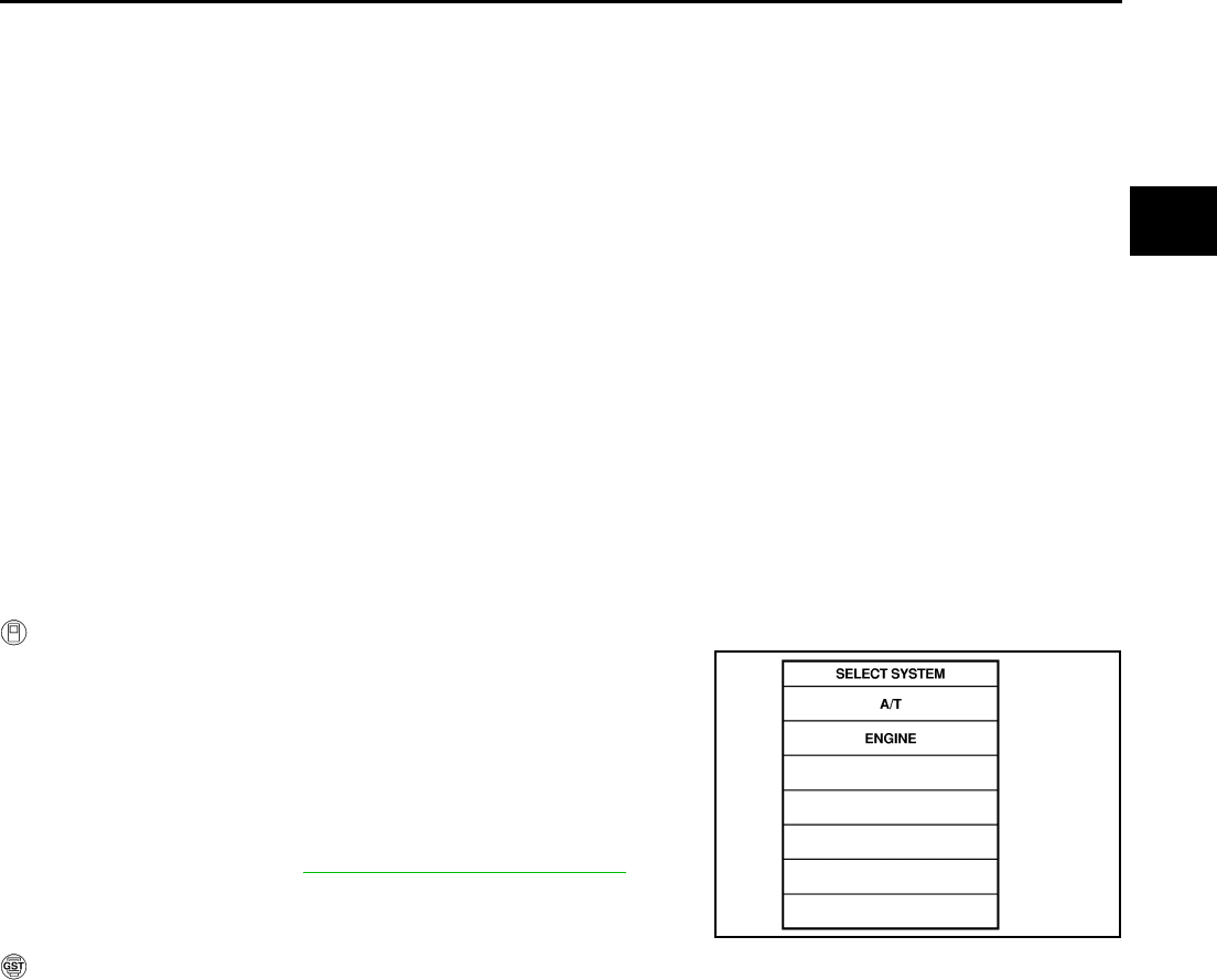
DTC P1772 LOW COAST BRAKE SOLENOID VALVE
AT-215
D
E
F
G
H
I
J
K
L
M
A
B
AT
DTC P1772 LOW COAST BRAKE SOLENOID VALVE PFP:31940
Description ACS000DH
Low coast brake solenoid valve is turned “ON” or “OFF” by the TCM in response to signals sent from the PNP
switch, vehicle speed sensor and accelerator pedal position sensor (throttle position sensor). Gears will then
be shifted to the optimum position.
On Board Diagnosis Logic ACS000DI
●This is an OBD-II self-diagnostic item.
●Diagnostic trouble code “LC/B SOLENOID/CIRC” with CONSULT-II or P1772 without CONSULT-II is
detected when TCM detects an improper voltage drop when it tries to operate the solenoid valve.
Possible Cause ACS000DJ
●Harness or connectors
(The solenoid circuit is open or shorted.)
●Low coast brake solenoid valve
DTC Confirmation Procedure ACS000DK
NOTE:
If “DTC Confirmation Procedure” has been previously conducted, always turn ignition switch “OFF”
and wait at least 10 seconds before conducting the next test.
After the repair, perform the following procedure to confirm the malfunction is eliminated.
WITH CONSULT-II
1. Turn ignition switch ON. (Do not start engine.)
2. Select “DATA MONITOR” mode for “A/T” with CONSULT-II.
3. Start engine.
4. Drive vehicle and maintain the following conditions for at least 5
consecutive seconds.
Selector lever: “M” position
Gear position: “M1-1st” or “M2-2nd” gear (LC/B ON/OFF)
5. If DTC is detected, go to AT-217, "Diagnostic Procedure" .
WITH GST
Follow the procedure “With CONSULT-II”.
SAT014K
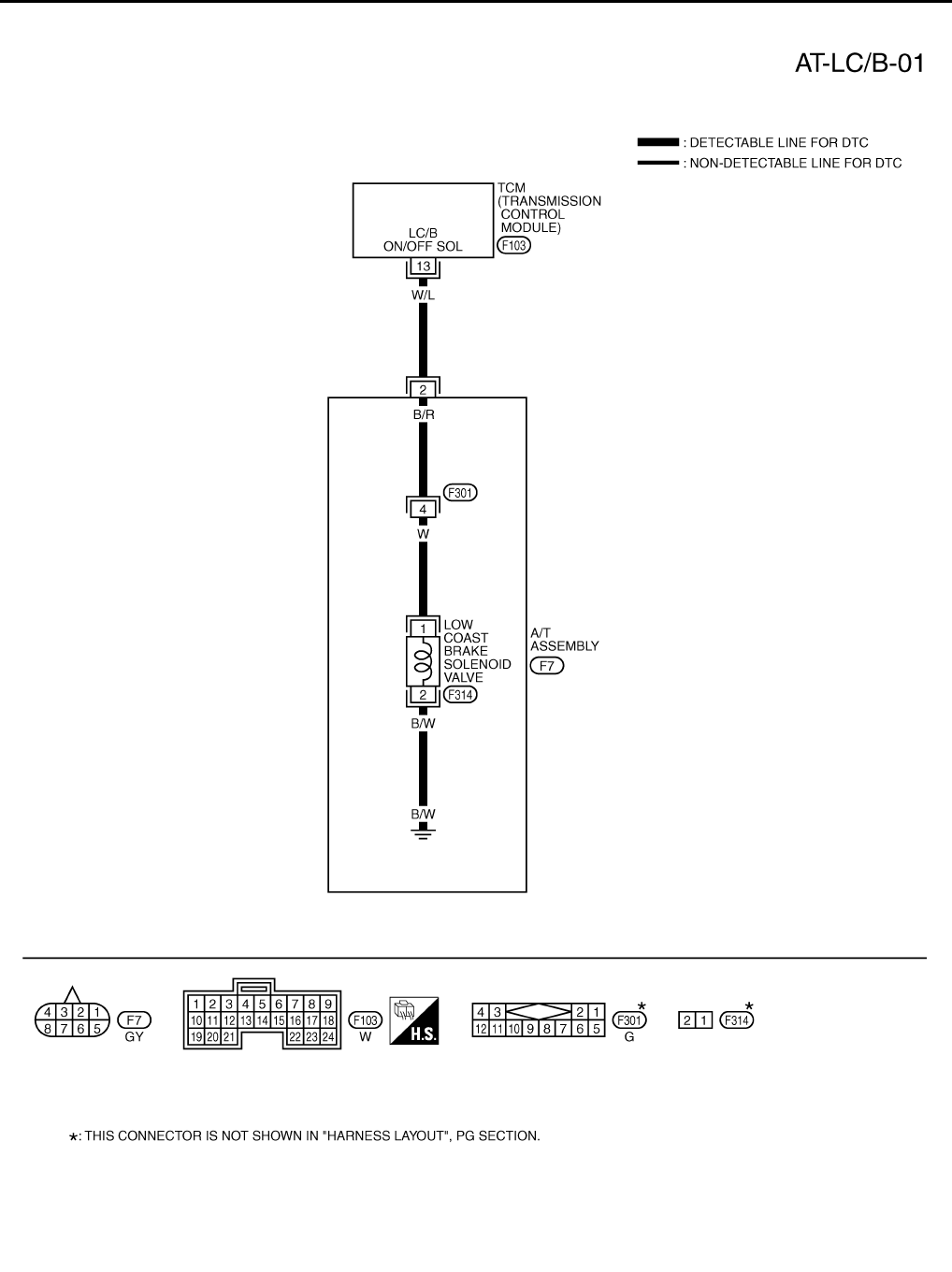
AT-216
DTC P1772 LOW COAST BRAKE SOLENOID VALVE
Wiring Diagram — AT — LC/B ACS000DL
TCWT0241E
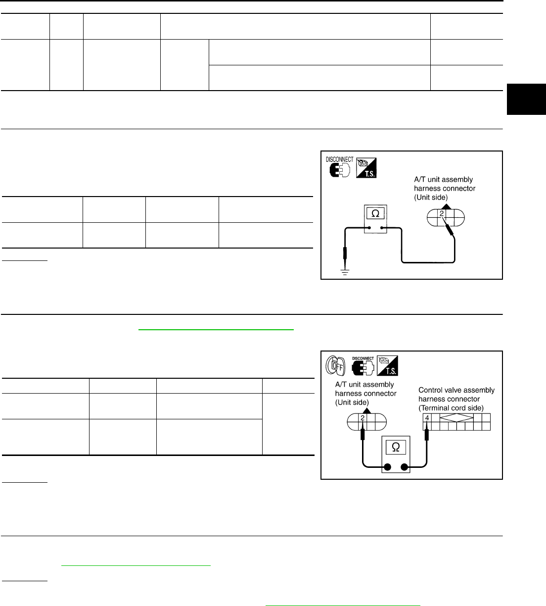
DTC P1772 LOW COAST BRAKE SOLENOID VALVE
AT-217
D
E
F
G
H
I
J
K
L
M
A
B
AT
TCM terminal and Data are reference value. Measured between each terminals 5, 14, 24 and 46 (TCM ground).
Diagnostic Procedure ACS000DM
1. CHECK LOW COAST BRAKE SOLENOID VALVE CIRCUIT
1. Turn ignition switch OFF.
2. Disconnect A/T unit assembly harness connector at the trans-
mission right side.
3. Check the resistance between terminal and ground.
OK or NG
OK >> GO TO 4.
NG >> GO TO 2.
2. CHECK TERMINAL CORD ASSEMBLY
1. Remove oil pan. Refer to AT-299, "Control Valve Assembly" .
2. Disconnect A/T unit assembly harness connector and control valve assembly harness connector.
3. Check continuity between A/T unit assembly harness connector
and control valve assembly harness connector.
4. If OK, check harness for short to ground and short to power.
OK or NG
OK >> GO TO 3.
NG >> Repair open circuit or short to ground or short to power in harness or connectors.
3. CHECK VALVE RESISTANCE
Check valve resistance
●Refer to AT-219, "Component Inspection" .
OK or NG
OK >> GO TO 4.
NG >> Replace the control valve assembly. Refer to AT-299, "Control Valve Assembly" .
Terminal
No.
Wire
color Item Condition Data (Approx.)
13 W/L Low coast brake
solenoid valve
When
vehicle
cruises
When the solenoid valve is operating (when running in
M1-1 gear or M2-2 gear) Battery voltage
When the solenoid valve is not operating (when running in
“D”) 0V
Solenoid valve Connector No. Terminal No.
(Wire color) Resistance (Approx.)
Low coast brake
solenoid valve F7 2 (W/L) - Ground 20 - 40 Ω
SCIA1835E
Item Connector No. Terminal No. (Wire color) Continuity
A/T unit assembly
harness connector F7 2 (B/R)
Yes
Control valve assem-
bly harness connec-
tor
F301 4 (B/R)
SCIA3092E
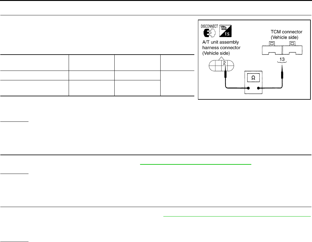
AT-218
DTC P1772 LOW COAST BRAKE SOLENOID VALVE
4. CHECK POWER SOURCE CIRCUIT
1. Turn ignition switch OFF.
2. Disconnect TCM connector.
3. Check continuity between A/T unit assembly harness connector
and TCM connector.
4. If OK, check harness for short to ground and short to power.
5. Reinstall any part removed.
OK or NG
OK >> GO TO 5.
NG >> Repair open circuit or short to ground or short to power in harness or connectors.
5. CHECK DTC
Perform “DTC Confirmation Procedure”. Refer to AT-108, "DTC Confirmation Procedure" .
OK or NG
OK >> INSPECTION END
NG >> GO TO 6.
6. PERFORM TCM INSPECTION
1. Perform TCM input/output signal inspection. Refer to AT-89, "TCM Input/Output Signal Reference Values"
.
2. If NG, recheck TCM pin terminals for damage or loose connection with harness connector.
OK or NG
OK >> INSPECTION END
NG >> Repair or replace damaged parts.
Item Connector No. Terminal No.
(Wire color) Continuity
TCM F103 13 (W/L)
Yes
A/T unit assembly harness
connector F7 2 (W/L)
SCIA1836E

DTC P1772 LOW COAST BRAKE SOLENOID VALVE
AT-219
D
E
F
G
H
I
J
K
L
M
A
B
AT
Component Inspection ACS004II
LOW COAST BRAKE SOLENOID VALVE
Resistance check
1. Turn ignition switch OFF.
2. Remove oil pan. Refer to AT-299, "Control Valve Assembly" .
3. Disconnect control valve assembly harness connector.
4. Check resistance between terminal and ground.
5. If NG, replace control valve assembly. Refer to AT-299, "Control
Valve Assembly" .
Operation check
●Check solenoid valve by listening for its operating sound while
applying battery voltage to the terminal 4 and ground.
Solenoid Valve Connector No. Terminal No.
(Wire color)
Resistance (Ω)
(Approx.)
Low coast brake sole-
noid valve F301 4 (W) - Ground 20 - 40 Ω
SCIA3093E
SCIA3094E
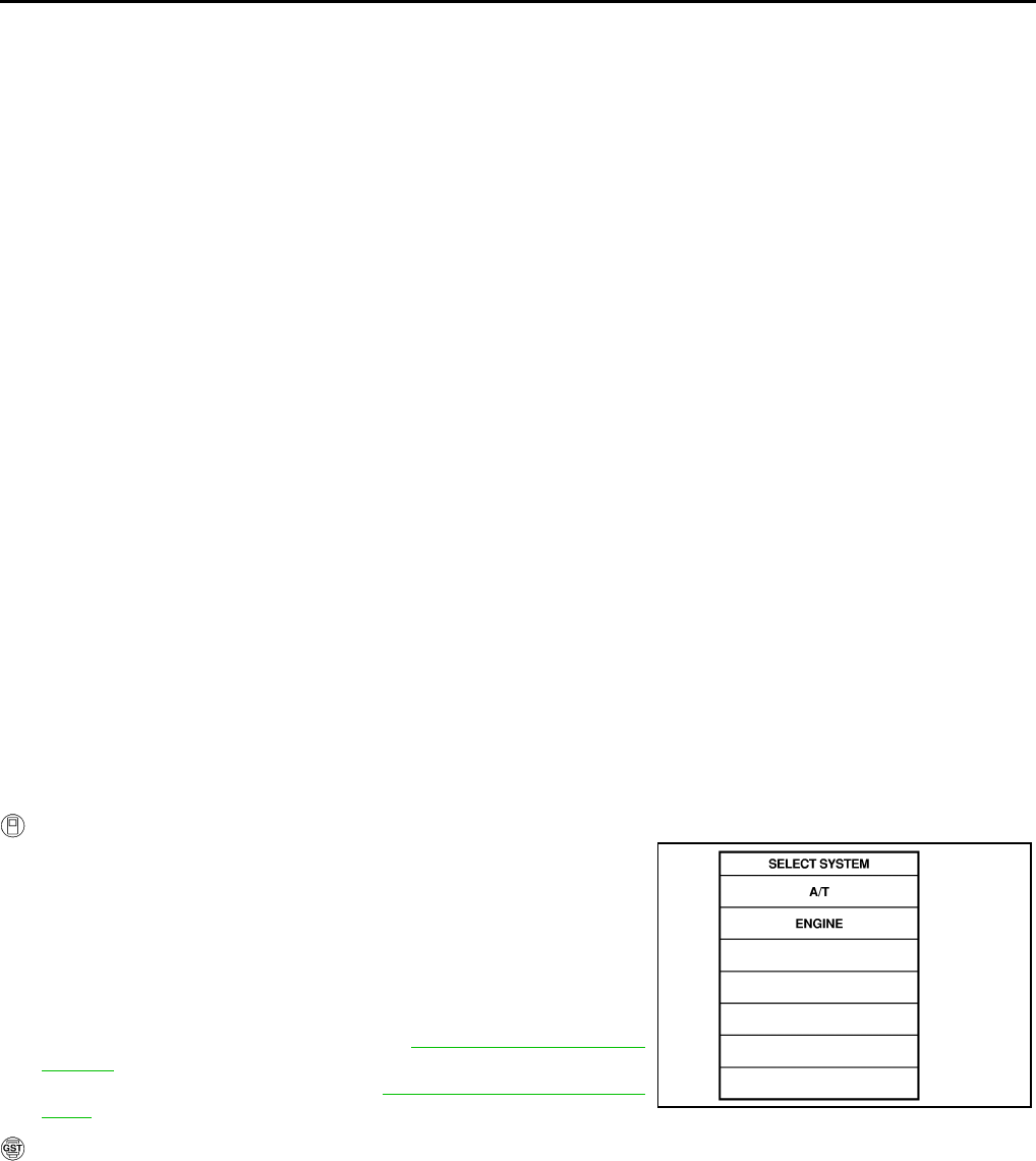
AT-220
DTC P1774 LOW COAST BRAKE SOLENOID VALVE FUNCTION
DTC P1774 LOW COAST BRAKE SOLENOID VALVE FUNCTION PFP:31940
Description ACS000DN
●Low coast brake solenoid valve is turned “ON” or “OFF” by the TCM in response to signals sent from the
PNP switch, vehicle speed sensor and accelerator pedal position sensor (throttle position sensor). Gears
will then be shifted to the optimum position.
●This is not only caused by electrical malfunction (circuits open or shorted) but also by mechanical mal-
function such as control valve sticking, improper solenoid valve operation.
On Board Diagnosis Logic ACS000DO
●This is an OBD-II self-diagnostic item.
●Diagnostic trouble code “LC/B SOLENOID FNCT” with CONSULT-II or P1774 without CONSULT-II is
detected under the following conditions.
–When TCM detects that actual gear ratio is irregular, and relation between gear position and condition of
ATF pressure switch 2 is irregular during depressing accelerator pedal. (Other than during shift change)
–When TCM detects that relation between gear position and condition of ATF pressure switch 2 is irregular
during releasing accelerator pedal. (Other than during shift change)
Possible Cause ACS000DP
●Harness or connectors
(The solenoid and switch circuits are open or shorted.)
●Low coast brake solenoid valve
●ATF pressure switch 2
DTC Confirmation Procedure ACS000DQ
CAUTION:
Always drive vehicle at a safe speed.
NOTE:
If “DTC Confirmation Procedure” has been previously conducted, always turn ignition switch “OFF”
and wait at least 10 seconds before conducting the next test.
After the repair, perform the following procedure to confirm the malfunction is eliminated.
WITH CONSULT-II
1. Start engine.
2. Accelerate vehicle to maintain the following condition.
Selector lever: “M” position
Gear position: “M1-1st” or “M2-2nd” gear (LC/B ON/OFF)
3. Perform step “2” again.
4. Turn ignition switch OFF, then perform step “1” to “3” again.
5. Check “SELF-DIAG RESULTS” mode for “A/T” with CONSULT-
II. If DTC (P1774) is detected, refer to AT-222, "Diagnostic Pro-
cedure" .
If DTC (P1772) is detected, go to AT-217, "Diagnostic Proce-
dure" .
WITH GST
Follow the procedure “With CONSULT-II”.
SAT014K
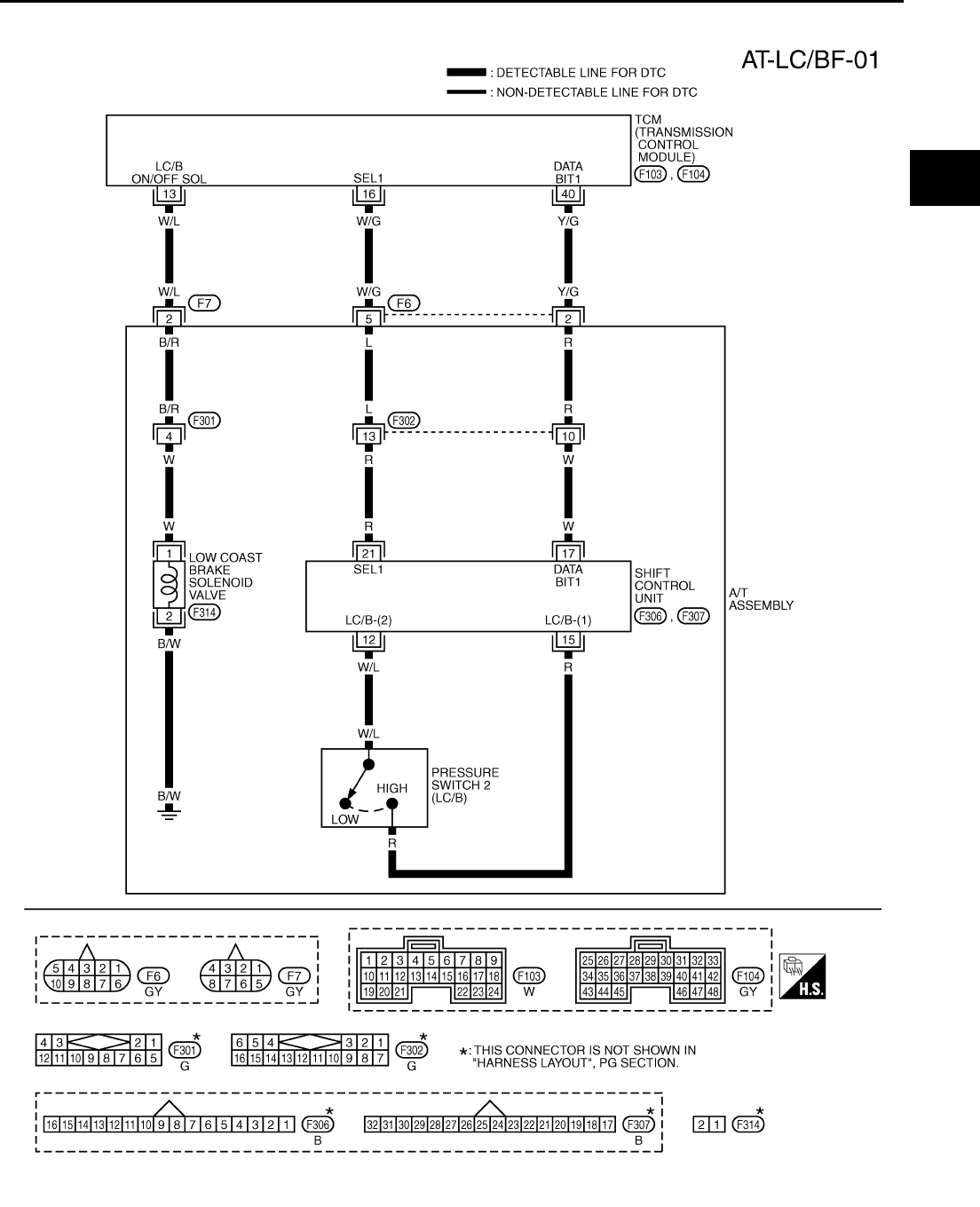
DTC P1774 LOW COAST BRAKE SOLENOID VALVE FUNCTION
AT-221
D
E
F
G
H
I
J
K
L
M
A
B
AT
Wiring Diagram — AT — LC/BF ACS000DR
TCWT0242E
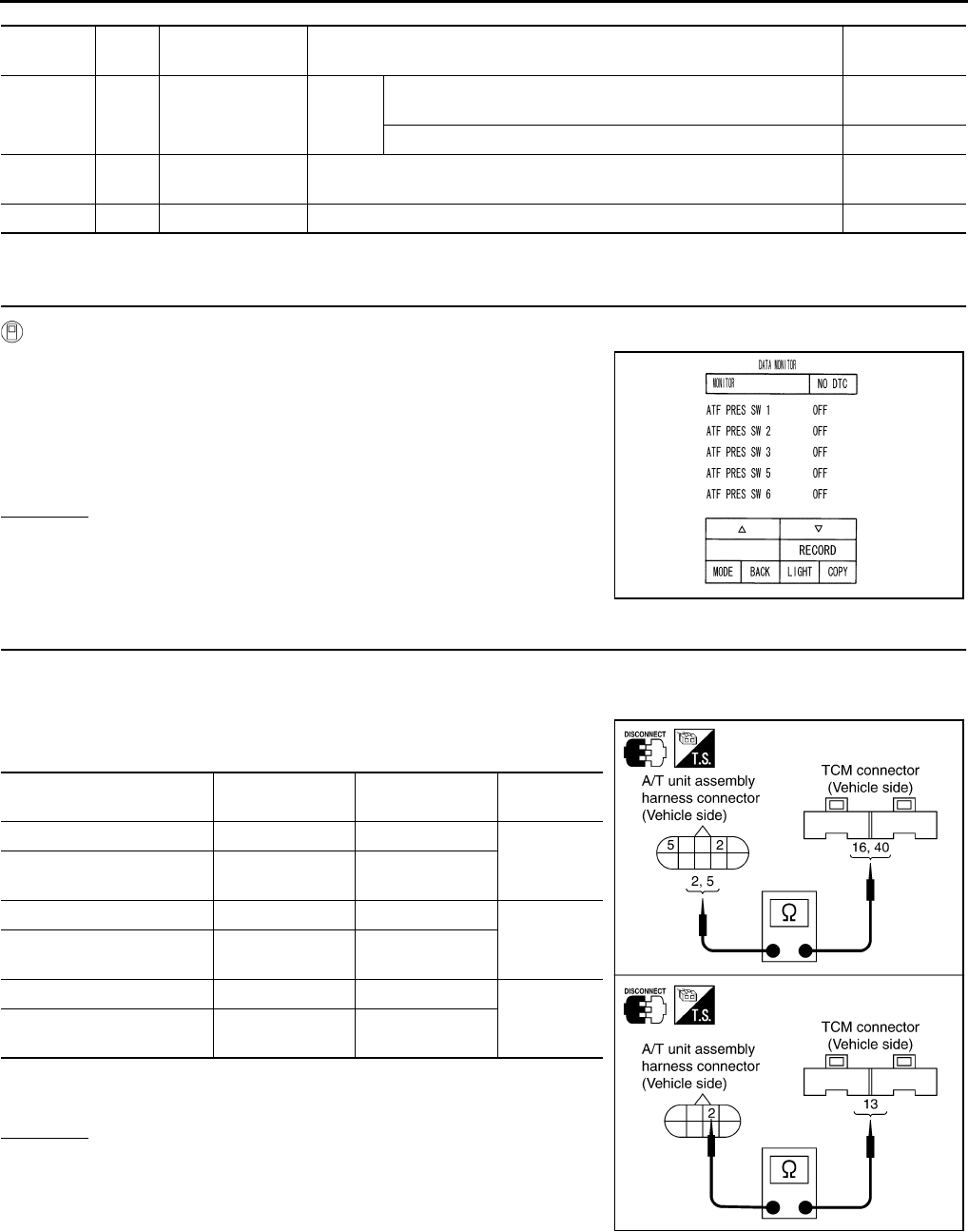
AT-222
DTC P1774 LOW COAST BRAKE SOLENOID VALVE FUNCTION
TCM terminals and Data are reference value. Measured between each terminals 5, 14, 24 and 46 (TCM ground).
Diagnostic Procedure ACS000DS
1. CHECK INPUT SIGNALS
With CONSULT-II
1. Start engine.
2. Select “ECU INPUT SIGNALS” or “MAIN SIGNALS” in “DATA
MONITOR” mode for “A/T” with CONSULT-II.
3. Accelerate vehicle in the manual mode (“M1-1st” or “M2-2nd”
gear), and confirm the ON/OFF actuation of the “ATF PRES SW
2”.
OK or NG
OK >> GO TO 4.
NG >> GO TO 2.
2. CHECK HARNESS BETWEEN TCM AND A/T UNIT ASSEMBLY HARNESS CONNECTOR
1. Turn ignition switch OFF.
2. Disconnect TCM connector.
3. Check continuity between A/T unit assembly harness connector
and TCM connector.
4. If OK, check harness for short to ground and short to power.
5. Reinstall any part removed.
OK or NG
OK >> GO TO 3.
NG >> Repair open circuit or short to ground or short to power
in harness or connectors.
Terminal
No.
Wire
color Item Condition Data (Approx.)
13 W/L Low coast brake
solenoid valve
When
vehicle
cruises
When the solenoid valve is operating (when running in M1-1
gear or M2-2 gear) Battery voltage
When the solenoid valve is not operating (when running in “D”) 0V
16 W/G SEL1 (pressure
switch 2) ––
40 Y/G DATA BIT1 – –
PCIA0067E
Item Connector No. Terminal No.
(Wire color) Continuity
TCM F103 16 (W/G)
Yes
A/T unit assembly harness
connector F6 5 (W/G)
TCM F104 40 (Y/G)
Yes
A/T unit assembly harness
connector F6 2 (Y/G)
TCM F103 13 (W/L)
Yes
A/T unit assembly harness
connector F7 2 (W/L)
SCIA3095E
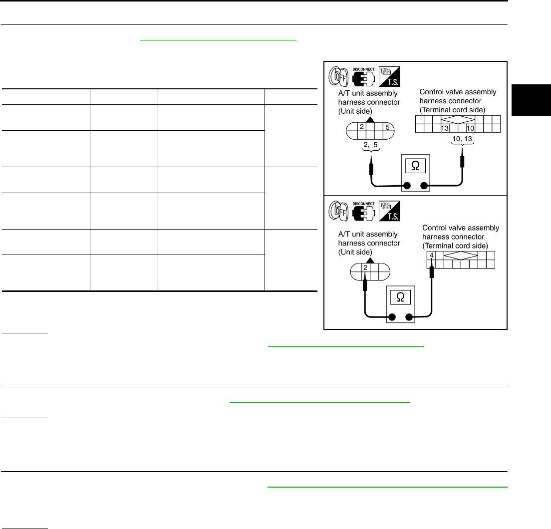
DTC P1774 LOW COAST BRAKE SOLENOID VALVE FUNCTION
AT-223
D
E
F
G
H
I
J
K
L
M
A
B
AT
3. CHECK TERMINAL CORD ASSEMBLY
1. Remove oil pan. Refer to AT-299, "Control Valve Assembly" .
2. Disconnect A/T unit assembly harness connector and control valve assembly harness connector.
3. Check continuity between A/T unit assembly harness connector
and control valve assembly harness connector.
4. If OK, check harness for short to ground and short to power.
5. Reinstall any part removed.
OK or NG
OK >> Replace the control valve assembly. Refer to AT-299, "Control Valve Assembly" .
NG >> Repair open circuit or short to ground or short to power in harness or connectors.
4. CHECK DTC
Perform “DTC Confirmation Procedure”. Refer to AT-108, "DTC Confirmation Procedure" .
OK or NG
OK >> INSPECTION END
NG >> GO TO 5.
5. PERFORM TCM INSPECTION
1. Perform TCM input/output signal inspection. Refer to AT-89, "TCM Input/Output Signal Reference Values"
.
2. If NG, recheck TCM pin terminals for damage or loose connection with harness connector.
OK or NG
OK >> INSPECTION END
NG >> Repair or replace damaged parts.
Item Connector No. Terminal No. (Wire color) Continuity
A/T unit assembly
harness connector F6 2 (R)
Yes
Control valve assem-
bly harness connec-
tor
F302 10 (R)
A/T unit assembly
harness connector F6 5 (L)
Yes
Control valve assem-
bly harness connec-
tor
F302 13 (L)
A/T unit assembly
harness connector F7 2 (B/R)
Yes
Control valve assem-
bly harness connec-
tor
F301 4 (B/R)
SCIA3096E
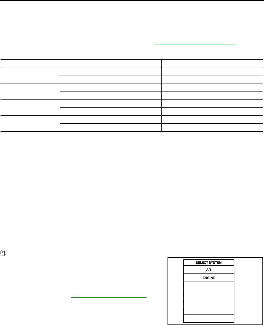
AT-224
DTC P1815 MANUAL MODE SWITCH
DTC P1815 MANUAL MODE SWITCH PFP:34901
Description ACS000DT
Manual mode switch is installed in A/T device. It sends manual mode switch, shift up and shift down switch
signals to TCM.
TCM sends the switch signals to combination meter. By CAN communication line. Then manual mode switch
position is indicated on the A/T indicator. For inspection, refer to AT-227, "Position Indicator Lamp" .
CONSULT-II Reference Value in Data Monitor Mode ACS000DU
On Board Diagnosis Logic ACS000DV
●This is not an OBD-II self-diagnostic item.
●Diagnostic trouble code “MANU MODE SW/CIR” with CONSULT-II is detected when TCM monitors Man-
ual mode, Non manual mode, Up or Down switch signal, and detects as irregular when impossible input
pattern occurs 1 second or more.
Possible Cause ACS000DW
●Harness or connectors
(These switches circuit is open or shorted.)
●Mode select switch (Built into A/T control device)
●Position select switch (Built into A/T control device)
DTC Confirmation Procedure ACS000DX
NOTE:
If “DTC Confirmation Procedure” has been previously conducted, always turn ignition switch “OFF”
and wait at least 10 seconds before conducting the next test.
After the repair, perform the following procedure to confirm the malfunction is eliminated.
WITH CONSULT-II
1. Turn ignition switch ON. (Do not start engine.)
2. Select “DATA MONITOR” mode for “A/T” with CONSULT-II.
3. Move selector lever to “M” position.
4. Start engine and drive vehicle for at least 2 consecutive sec-
onds.
5. If DTC is detected, go to AT-226, "Diagnostic Procedure" .
Monitor Item Condition Reference Value
MANU MODE SW Manual shift gate position (neutral) ON
Other than the above OFF
NON M-MODE SW Manual shift gate position OFF
Other than the above ON
UP SW LEVER Select lever: + side ON
Other than the above OFF
DOWN SW LEVER Select lever: - side ON
Other than the above OFF
SAT014K
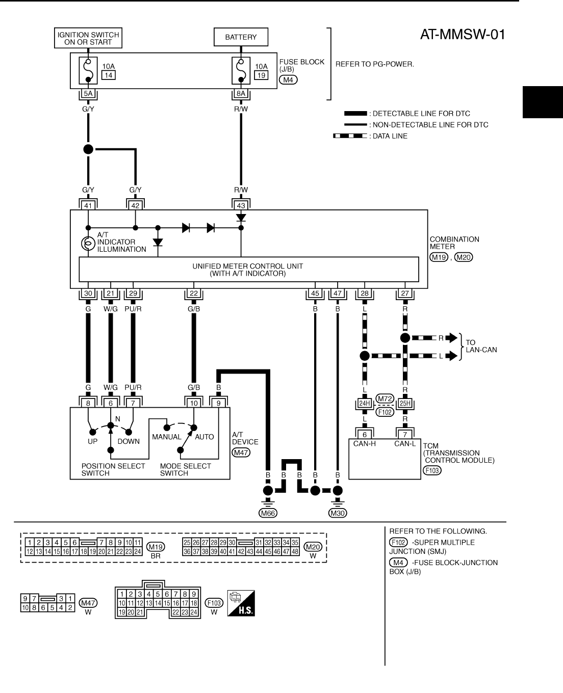
DTC P1815 MANUAL MODE SWITCH
AT-225
D
E
F
G
H
I
J
K
L
M
A
B
AT
Wiring Diagram — AT — MMSW ACS000DY
TCWT0243E
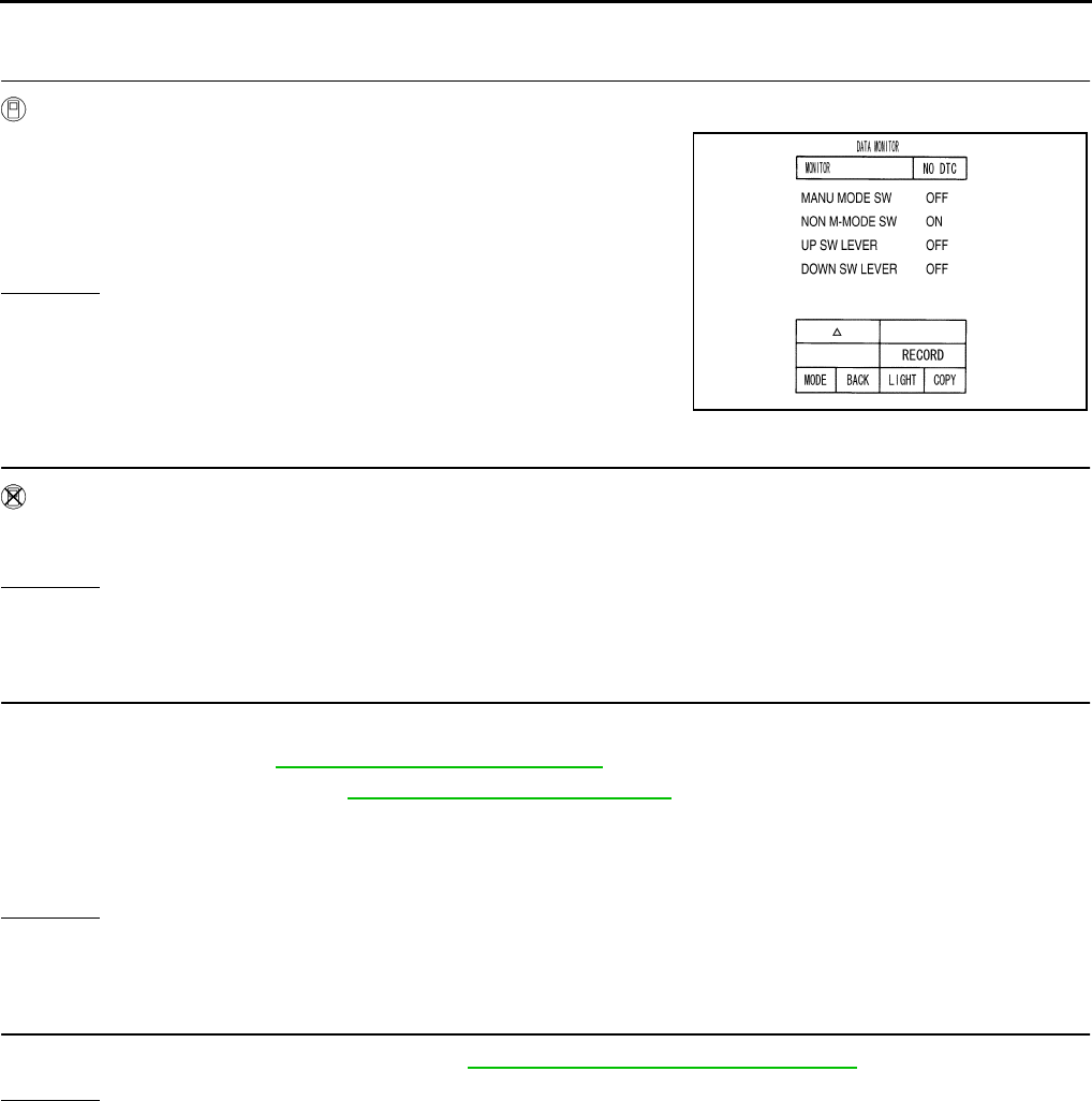
AT-226
DTC P1815 MANUAL MODE SWITCH
Diagnostic Procedure ACS000DZ
1. CHECK MANUAL MODE SWITCH CIRCUIT (WITH CONSULT-II)
With CONSULT-II
1. Turn ignition switch ON. (Do not start engine.)
2. Select “ECU INPUT SIGNALS” in “DATA MONITOR” mode for
“A/T” with CONSULT-II.
3. Read out ON/OFF switching action of the “MANU MODE SW”,
“NON M-MODE SW”, “UP SW LEVER”, “DOWN SW LEVER”.
OK or NG
OK >> GO TO 4.
NG >> GO TO 3.
2. CHECK MANUAL MODE SWITCH CIRCUIT (WITHOUT CONSULT-II)
Without CONSULT-II
Drive vehicle in the manual mode, and confirm that the actual gear position and the meter's indication of the
position mutually coincide when the selector lever is shifted to the “+ (up)” or “- (down)” side (1st ⇔ 5th gear).
OK or NG
OK >> GO TO 4.
NG >> GO TO 3.
3. DETECT MALFUNCTIONING ITEM
Check the following items.
●Power supply. Refer to DI-4, "COMBINATION METERS" .
●Manual mode switch. Refer to AT-227, "Component Inspection" .
●Pin terminals for damage or loose connection with harness connector.
●Open circuit or short to ground or short to power in harness or connector for A/T device (manual mode
switch).
OK or NG
OK >> GO TO 4
NG >> Repair or replace damaged parts.
4. CHECK DTC
Perform DTC confirmation procedure. Refer to AT-224, "DTC Confirmation Procedure" .
OK or NG
OK >> INSPECTION END
NG >> Replace the control device assembly.
PCIA0064E
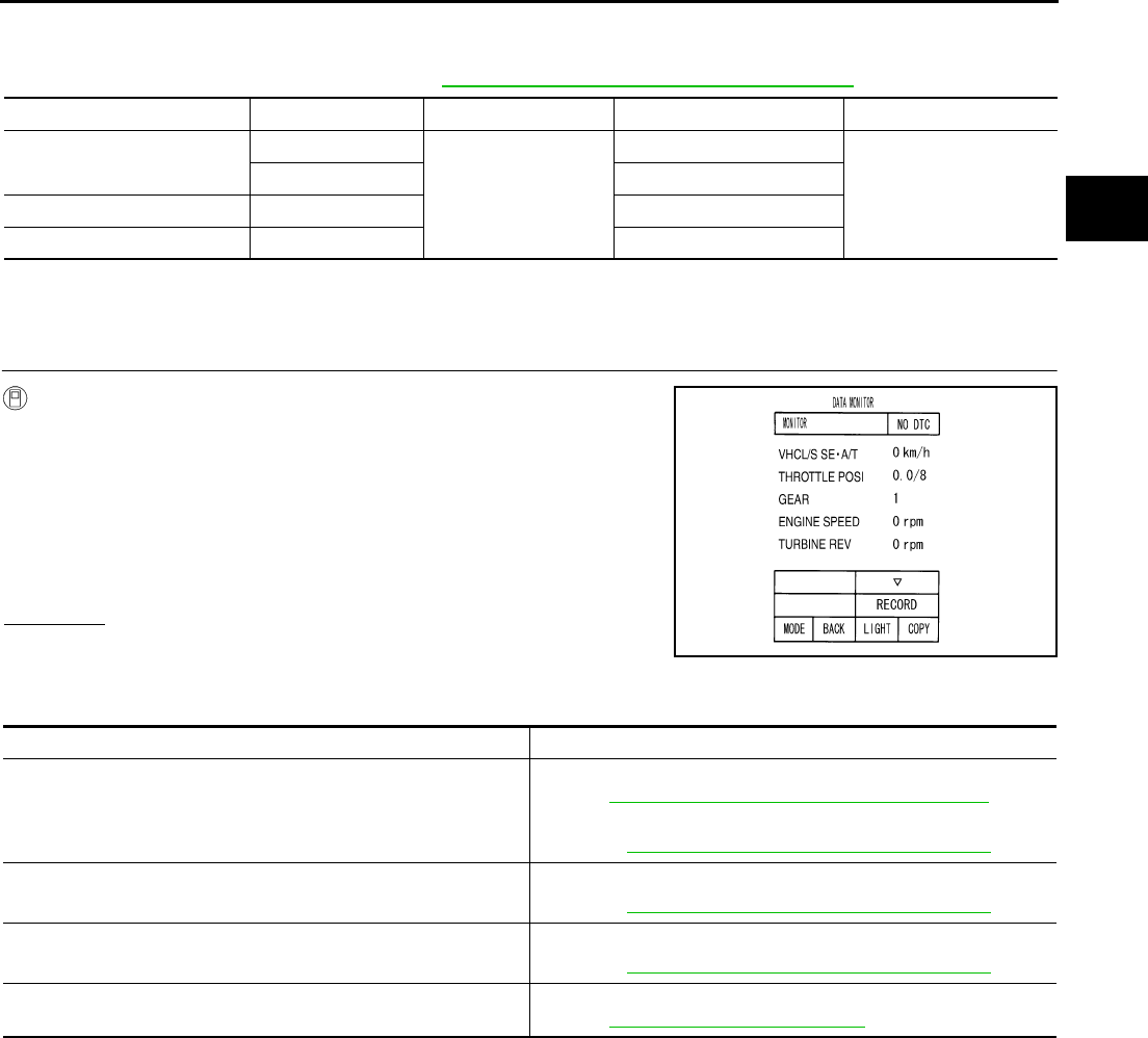
DTC P1815 MANUAL MODE SWITCH
AT-227
D
E
F
G
H
I
J
K
L
M
A
B
AT
Component Inspection ACS000E0
MANUAL MODE SWITCH
Check continuity between terminals. Refer to AT-225, "Wiring Diagram — AT — MMSW" .
Position Indicator Lamp ACS000E1
DIAGNOSTIC PROCEDURE
1. CHECK INPUT SIGNALS
With CONSULT-II
1. Start engine.
2. Select “MAIN SIGNALS” in “DATA MONITOR” mode for A/T with
CONSULT-II and read out the value of “GEAR”.
3. Drive vehicle in the manual mode, and confirm that the actual
gear position and the meter's indication of the position mutually
coincide when the select lever is shifted to the “+ (up)” or “-
(down)” side (1st ⇔ 5th gear).
OK or NG
OK >> INSPECTION END
NG >> Check the following items.
Position indicator lamp symptom chart
Item Position Connector No. Terminal No. (Unit side) Continuity
Manual mode (select) switch Auto
M47
9 - 10
Yes
Manual 6 - 9
UP switch Up 8 - 9
DOWN switch Down 7 - 9
PCIA0065E
Items Presumed location of trouble
The actual gear position does not change, or shifting into the
manual mode is not possible (no gear shifting in the manual mode
possible).
The position indicator lamp is not indicated.
Manual mode switch
Refer to AT-224, "DTC P1815 MANUAL MODE SWITCH" .
A/T main system (Fail-safe function actuated)
●Refer to AT-92, "CONSULT-II SETTING PROCEDURE" .
The actual gear position changes, but the position indicator lamp
is not indicated.
Execute the self-diagnosis function.
●Refer to AT-92, "CONSULT-II SETTING PROCEDURE" .
The actual gear position and the indication on the position indica-
tor lamp do not coincide.
Execute the self-diagnosis function.
●Refer to AT-92, "CONSULT-II SETTING PROCEDURE" .
Only a specific position or positions is/are not indicated on the
position indicator lamp.
Check the meter control unit.
Refer to DI-4, "COMBINATION METERS" .

AT-228
DTC P1841 ATF PRESSURE SWITCH 1
DTC P1841 ATF PRESSURE SWITCH 1 PFP:25240
Description ACS000E2
Fail-safe function to detect front brake clutch solenoid valve condition.
On Board Diagnosis Logic ACS000E3
●This is not an OBD-II self-diagnostic item.
●Diagnostic trouble code “ATF PRES SW 1/CIRC” with CONSULT-II is detected, when TCM detects that
actual gear ratio is normal, and relation between gear position and condition of ATF pressure switch 1 is
irregular during depressing accelerator pedal. (Other than during shift change)
Possible Cause ACS000E4
●ATF pressure switch 1
●Harness or connectors
(The switch circuit is open or shorted.)
DTC Confirmation Procedure ACS000E5
CAUTION:
Always drive vehicle at a safe speed.
NOTE:
If “DTC Confirmation Procedure” has been previously conducted, always turn ignition switch “OFF”
and wait at least 10 seconds before conducting the next test.
After the repair, perform the following procedure to confirm the malfunction is eliminated.
WITH CONSULT-II
1. Start engine.
2. Accelerate vehicle to maintain the following condition.
ACCELE POS: 1.5/8 - 2.0/8
Selector lever: “D” position
Gear position: 3rd Þ 4th Gear (FR/B ON/OFF)
Driving location: Driving the vehicle uphill (increased
engine load) will help maintain the driving conditions
required for this test.
3. Perform step “2” again.
4. Turn ignition switch OFF, then perform step “1” to “3” again.
5. Check “SELF-DIAG RESULTS” mode for “A/T” with CONSULT-
II.
If DTC (P1841) is detected, go to AT-230, "Diagnostic Procedure" .
If DTC (P1757) is detected, go to AT-188, "Diagnostic Procedure" .
SAT014K
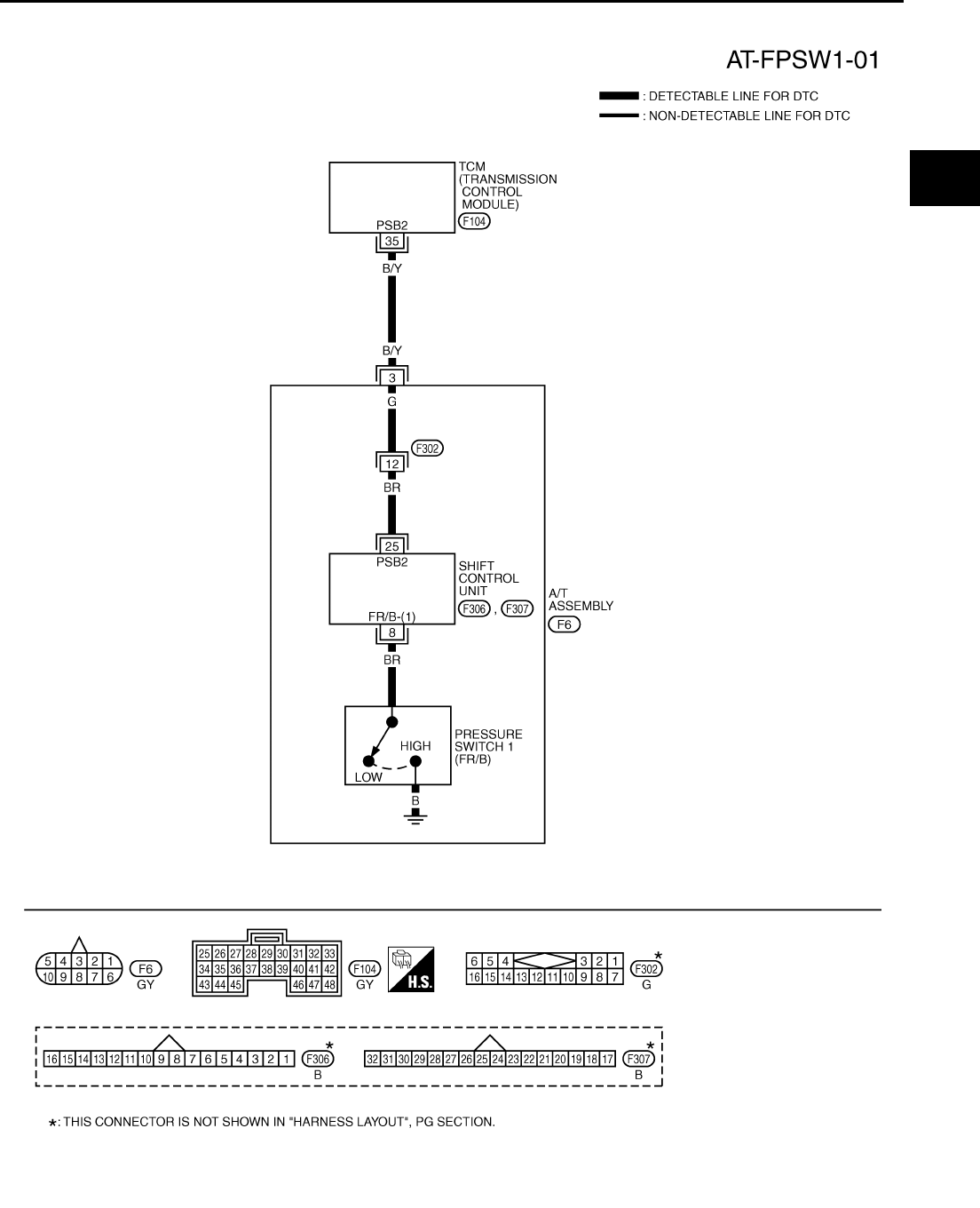
DTC P1841 ATF PRESSURE SWITCH 1
AT-229
D
E
F
G
H
I
J
K
L
M
A
B
AT
Wiring Diagram — AT — FPSW1 ACS000E6
TCWT0244E

AT-230
DTC P1841 ATF PRESSURE SWITCH 1
TCM terminal and Data are reference value. Measured between each terminals 5, 14, 24 and 46 (TCM ground).
Diagnostic Procedure ACS000E7
1. CHECK INPUT SIGNALS (WITH CONSULT-II)
With CONSULT-II
1. Start engine.
2. Select “ECU INPUT SIGNALS” or “MAIN SIGNALS” in “DATA
MONITOR” mode for “A/T” with CONSULT-II.
3. Accelerate vehicle in the “D” position (3rd Þ 4th gear), and con-
firm the ON/OFF actuation of the “ATF PRES SW 1”.
OK or NG
OK >> GO TO 5.
NG >> GO TO 3.
2. CHECK INPUT SIGNALS (WITHOUT CONSULT-II)
Without CONSULT-II
1. Start engine.
2. Accelerate vehicle in the “D” position (3rd Þ 4th gear).
OK or NG
OK >> GO TO 5.
NG >> GO TO 3.
3. CHECK POWER SOURCE CIRCUIT
1. Turn ignition switch OFF.
2. Disconnect TCM connector.
3. Check continuity between A/T unit assembly harness connector
and TCM connector.
4. If OK, check harness for short to ground and short to power.
5. Reinstall any part removed.
OK or NG
OK >> GO TO 4.
NG >> Repair open circuit or short to ground or short to power in harness or connectors.
Terminal
No.
Wire
color Item Condition Data (Approx.)
35 B/Y PSB2 (pressure
switch 1)
When
vehicle
starts
When front brake solenoid valve “OFF”. Battery voltage
When front brake solenoid valve“ ON”. 0V
PCIA0067E
Solenoid valve Connector
No.
Terminal No.
(Wire color) Voltage
Front brake solenoid
valve
OFF F104 35 (B/Y) - Ground Battery voltage
ON Approx. 0 V
PCIA0066E
Item Connector No. Terminal No.
(Wire color) Continuity
TCM F104 35 (B/Y)
Yes
A/T unit assembly harness
connector F6 3 (B/Y)
SCIA3097E

DTC P1841 ATF PRESSURE SWITCH 1
AT-231
D
E
F
G
H
I
J
K
L
M
A
B
AT
4. CHECK TERMINAL CORD ASSEMBLY
1. Remove oil pan. Refer to AT-299, "Control Valve Assembly" .
2. Disconnect A/T unit assembly harness connector and control valve assembly harness connector.
3. Check continuity between A/T unit assembly harness connector
and control valve assembly harness connector.
4. If OK, check harness for short to ground and short to power.
OK or NG
OK >> Replace control valve assembly. Refer to AT-299, "Control Valve Assembly" .
NG >> Repair open circuit or short to ground or short to power in harness or connectors.
5. CHECK DTC
Perform DTC confirmation procedure. Refer to AT-108, "DTC Confirmation Procedure" .
OK or NG
OK >> INSPECTION END
NG >> GO TO 6.
6. PERFORM TCM INSPECTION
1. Perform TCM input/output signal inspection. Refer to AT-89, "TCM Input/Output Signal Reference Values"
.
2. If NG, recheck TCM pin terminals for damage or loose connection with harness connector.
OK or NG
OK >> Replace control valve assembly. Refer to AT-299, "Control Valve Assembly" .
NG >> Repair or replace damaged parts.
Item Connector No. Terminal No. (Wire color) Continuity
A/T unit assembly
harness connector F6 3 (G)
Yes
Control valve assem-
bly harness connec-
tor
F302 12 (G)
SCIA3098E

AT-232
DTC P1843 ATF PRESSURE SWITCH 3
DTC P1843 ATF PRESSURE SWITCH 3 PFP:25240
Description ACS000E8
Fail-safe function to detect input clutch solenoid valve condition.
On Board Diagnosis Logic ACS000E9
●This is not an OBD-II self-diagnostic item.
●Diagnostic trouble code “ATF PRES SW 3/CIRC” with CONSULT-II is detected, when TCM detects that
actual gear ratio is normal, and relation between gear position and condition of ATF pressure switch 3 is
irregular during depressing accelerator pedal. (Other than during shift change)
Possible Cause ACS000EA
●ATF pressure switch 3
●Harness or connectors
(The switch circuit is open or shorted.)
DTC Confirmation Procedure ACS000EB
CAUTION:
Always drive vehicle at a safe speed.
NOTE:
If “DTC Confirmation Procedure” has been previously conducted, always turn ignition switch “OFF”
and wait at least 10 seconds before conducting the next test.
After the repair, perform the following procedure to confirm the malfunction is eliminated.
WITH CONSULT-II
1. Start engine.
2. Accelerate vehicle to maintain the following condition.
ACCELE POS: 1.5/8 - 2.0/8
Selector lever: “D” position
Gear position: 3rd Þ 4th Gear (I/C ON/OFF)
Driving location: Driving the vehicle uphill (increased
engine load) will help maintain the driving conditions
required for this test.
3. Perform step “2” again.
4. Turn ignition switch OFF, then perform step “1” to “3” again.
5. Check “SELF-DIAG RESULTS” mode for “A/T” with CONSULT-
II.
If DTC (P1843) is detected, go to AT-234, "Diagnostic Procedure" .
If DTC (P1752) is detected, go to AT-179, "Diagnostic Procedure" .
SAT014K
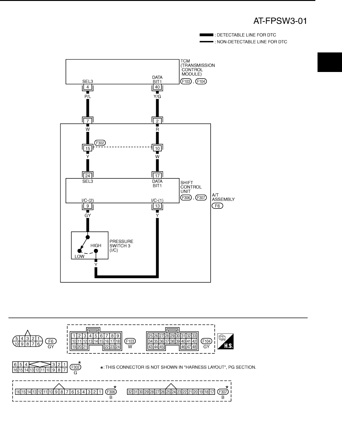
DTC P1843 ATF PRESSURE SWITCH 3
AT-233
D
E
F
G
H
I
J
K
L
M
A
B
AT
Wiring Diagram — AT — FPSW3 ACS000EC
TCWT0245E
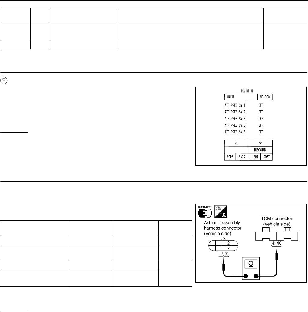
AT-234
DTC P1843 ATF PRESSURE SWITCH 3
TCM terminals and Data are reference value. Measured between each terminals 5, 14, 24 and 46 (TCM ground).
Diagnostic Procedure ACS000ED
1. CHECK INPUT SIGNALS
With CONSULT-II
1. Start engine.
2. Select “ECU INPUT SIGNALS” or “MAIN SIGNALS” in “DATA
MONITOR” mode for “A/T” with CONSULT-II.
3. Accelerate vehicle in the “D” position (3rd Þ 4th gear), and con-
firm the ON/OFF actuation of the “ATF PRES SW 3”.
OK or NG
OK >> GO TO 4.
NG >> GO TO 2.
2. CHECK HARNESS BETWEEN TCM AND A/T UNIT ASSEMBLY HARNESS CONNECTOR
1. Turn ignition switch OFF.
2. Disconnect TCM connector.
3. Check continuity between A/T unit assembly harness connector
and TCM connector.
4. If OK, check harness for short to ground and short to power.
5. Reinstall any part removed.
OK or NG
OK >> GO TO 3.
NG >> Repair open circuit or short to ground or short to power in harness or connectors.
Terminal
No.
Wire
color Item Condition Data (Approx.)
4P/L
SEL3
(pressure switch 3) ––
40 Y/G DATA BIT1 – –
PCIA0067E
Item Connector No. Terminal No.
(Wire color) Continuity
TCM F103 4 (P/L)
Yes
A/T unit assembly harness
connector F6 7 (P/L)
TCM F104 40 (Y/G)
Yes
A/T unit assembly harness
connector F6 2 (Y/G) SCIA3099E
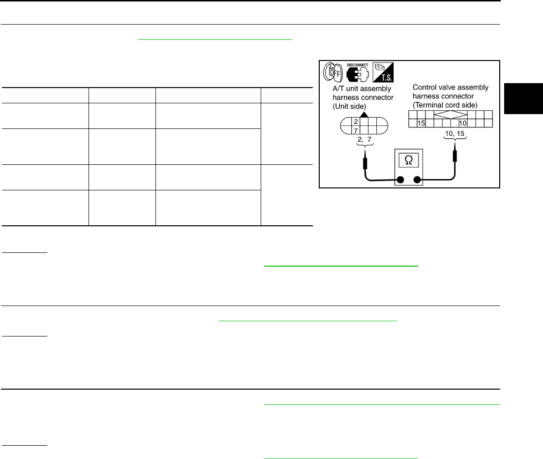
DTC P1843 ATF PRESSURE SWITCH 3
AT-235
D
E
F
G
H
I
J
K
L
M
A
B
AT
3. CHECK TERMINAL CORD ASSEMBLY
1. Remove oil pan. Refer to AT-299, "Control Valve Assembly" .
2. Disconnect A/T unit assembly harness connector and control valve assembly harness connector.
3. Check continuity between A/T unit assembly harness connector
and control valve assembly harness connector.
4. If OK, check harness for short to ground and short to power.
OK or NG
OK >> Replace the control valve assembly. Refer to AT-299, "Control Valve Assembly" .
NG >> Repair open circuit or short to ground or short to power in harness or connectors.
4. CHECK DTC
Perform DTC confirmation procedure. Refer to AT-108, "DTC Confirmation Procedure" .
OK or NG
OK >> INSPECTION END
NG >> GO TO 5.
5. PERFORM TCM INSPECTION
1. Perform TCM input/output signal inspection. Refer to AT-89, "TCM Input/Output Signal Reference Values"
.
2. If NG, recheck TCM pin terminals for damage or loose connection with harness connector.
OK or NG
OK >> Replace the control valve assembly. Refer to AT-299, "Control Valve Assembly" .
NG >> Repair or replace damaged parts.
Item Connector No. Terminal No. (Wire color) Continuity
A/T unit assembly
harness connector F6 2 (R)
Yes
Control valve assem-
bly harness connec-
tor
F302 10 (R)
A/T unit assembly
harness connector F6 7 (W)
Yes
Control valve assem-
bly harness connec-
tor
F302 15 (W)
SCIA3100E
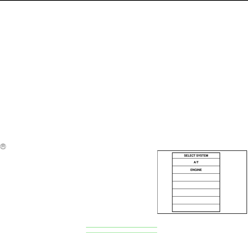
AT-236
DTC P1845 ATF PRESSURE SWITCH 5
DTC P1845 ATF PRESSURE SWITCH 5 PFP:25240
Description ACS000EE
Fail-safe function to detect direct clutch solenoid valve condition.
On Board Diagnosis Logic ACS000EF
●This is not an OBD-II self-diagnostic item.
●Diagnostic trouble code “ATF PRES SW 5/CIRC” with CONSULT-II is detected, when TCM detects that
actual gear ratio is normal, and relation between gear position and condition of ATF pressure switch 5 is
irregular during depressing accelerator pedal. (Other than during shift change)
Possible Cause ACS000EG
●ATF pressure switch 5
●Harness or connectors
(The switch circuit is open or shorted.)
DTC Confirmation Procedure ACS000EH
CAUTION:
Always drive vehicle at a safe speed.
NOTE:
If “DTC Confirmation Procedure” has been previously conducted, always turn ignition switch “OFF”
and wait at least 10 seconds before conducting the next test.
After the repair, perform the following procedure to confirm the malfunction is eliminated.
WITH CONSULT-II
1. Start engine.
2. Accelerate vehicle to maintain the following condition.
ACCELE POS: 1.5/8 - 2.0/8
Selector lever: “D” position
Gear position: 1st Þ 2nd Gear (D/C ON/OFF)
Driving location: Driving the vehicle uphill (increased
engine load) will help maintain the driving conditions
required for this test.
3. Perform step “2” again.
4. Turn ignition switch OFF, then perform step “1” to “3” again.
5. Check “SELF-DIAG RESULTS” mode for “A/T” with CONSULT-
II.
If DTC (P1845) is detected, go to AT-238, "Diagnostic Procedure" .
If DTC (P1762) is detected, go to AT-198, "Diagnostic Procedure" .
SAT014K

DTC P1845 ATF PRESSURE SWITCH 5
AT-237
D
E
F
G
H
I
J
K
L
M
A
B
AT
Wiring Diagram — AT — FPSW5 ACS000EI
TCWT0246E

AT-238
DTC P1845 ATF PRESSURE SWITCH 5
TCM terminals and Data are reference value. Measured between each terminals 5, 14, 24 and 46 (TCM ground).
Diagnostic Procedure ACS000EJ
1. CHECK INPUT SIGNALS
With CONSULT-II
1. Start engine.
2. Select “ECU INPUT SIGNALS” or “MAIN SIGNALS” in “DATA
MONITOR” mode for “A/T” with CONSULT-II.
3. Accelerate vehicle in the “D” position (1st Þ 2nd gear), and con-
firm the ON/OFF actuation of the “ATF PRES SW 5”.
OK or NG
OK >> GO TO 3.
NG >> GO TO 2.
2. CHECK HARNESS BETWEEN TCM AND A/T UNIT ASSEMBLY HARNESS CONNECTOR
1. Turn ignition switch OFF.
2. Disconnect TCM connector.
3. Check continuity between A/T unit assembly harness connector
and TCM connector.
4. If OK, check harness for short to ground and short to power.
5. Reinstall any part removed.
OK or NG
OK >> GO TO 3.
NG >> Repair open circuit or short to ground or short to power in harness or connectors.
Terminal
No.
Wire
color Item Condition Data (Approx.)
22 P/B SEL2
(pressure switch 5) ––
40 Y/G DATA BIT1 – –
PCIA0067E
Item Connector No. Terminal No.
(Wire color) Continuity
TCM F103 22 (P/B)
Yes
A/T unit assembly harness
connector F6 6 (P/B)
TCM F104 40 (Y/G)
Yes
A/T unit assembly harness
connector F6 2 (Y/G) SCIA3101E

DTC P1845 ATF PRESSURE SWITCH 5
AT-239
D
E
F
G
H
I
J
K
L
M
A
B
AT
3. CHECK TERMINAL CORD ASSEMBLY
1. Remove oil pan. Refer to AT-299, "Control Valve Assembly" .
2. Disconnect A/T unit assembly harness connector and control valve assembly harness connector.
3. Check continuity between A/T unit assembly harness connector
and control valve assembly harness connector.
4. If OK, check harness for short to ground and short to power.
OK or NG
OK >> Replace the control valve assembly. Refer to AT-299, "Control Valve Assembly" .
NG >> Repair open circuit or short to ground or short to power in harness or connectors.
4. CHECK DTC
Perform DTC confirmation procedure. Refer to AT-108, "DTC Confirmation Procedure" .
OK or NG
OK >> INSPECTION END
NG >> GO TO 3.
5. PERFORM TCM INSPECTION
1. Perform TCM input/output signal inspection. Refer to AT-89, "TCM Input/Output Signal Reference Values"
.
2. If NG, recheck TCM pin terminals for damage or loose connection with harness connector.
OK or NG
OK >> Replace the control valve assembly. Refer to AT-299, "Control Valve Assembly" .
NG >> Repair or replace damaged parts.
Item Connector No. Terminal No. (Wire color) Continuity
A/T unit assembly
harness connector F6 2 (R)
Yes
Control valve assem-
bly harness connec-
tor
F302 10 (R)
A/T unit assembly
harness connector F6 6 (GY)
Yes
Control valve assem-
bly harness connec-
tor
F302 14 (GY)
SCIA3102E

AT-240
DTC P1846 ATF PRESSURE SWITCH 6
DTC P1846 ATF PRESSURE SWITCH 6 PFP:25240
Description ACS000EK
Fail-safe function to detect high and low reverse clutch solenoid valve condition.
On Board Diagnosis Logic ACS000EL
●This is not an OBD-II self-diagnostic item.
●Diagnostic trouble code “ATF PRES SW 6/CIRC” with CONSULT-II is detected, when TCM detects that
actual gear ratio is normal, and relation between gear position and condition of ATF pressure switch 6 is
irregular during depressing accelerator pedal. (Other than during shift change)
Possible Cause ACS000EM
●ATF pressure switch 6
●Harness or connectors
(The switch circuit is open or shorted.)
DTC Confirmation Procedure ACS000EN
CAUTION:
Always drive vehicle at a safe speed.
NOTE:
If “DTC Confirmation Procedure” has been previously conducted, always turn ignition switch “OFF”
and wait at least 10 seconds before conducting the next test.
After the repair, perform the following procedure to confirm the malfunction is eliminated.
WITH CONSULT-II
1. Start engine.
2. Accelerate vehicle to maintain the following condition.
ACCELE POS: 1.5/8 - 2.0/8
Selector lever: “D” position
Gear position: 2nd Þ 3rd Gear (HLR/C ON/OFF)
Driving location: Driving the vehicle uphill (increased
engine load) will help maintain the driving conditions
required for this test.
3. Perform step “2” again.
4. Turn ignition switch OFF, then perform step “1” to “3” again.
5. Check “SELF-DIAG RESULTS” mode for “A/T” with CONSULT-
II.
If DTC (P1846) is detected, go to AT-242, "Diagnostic Procedure" .
If DTC (P1767) is detected, go to AT-207, "Diagnostic Procedure" .
SAT014K

DTC P1846 ATF PRESSURE SWITCH 6
AT-241
D
E
F
G
H
I
J
K
L
M
A
B
AT
Wiring Diagram — AT — FPSW6 ACS000EO
TCWT0247E
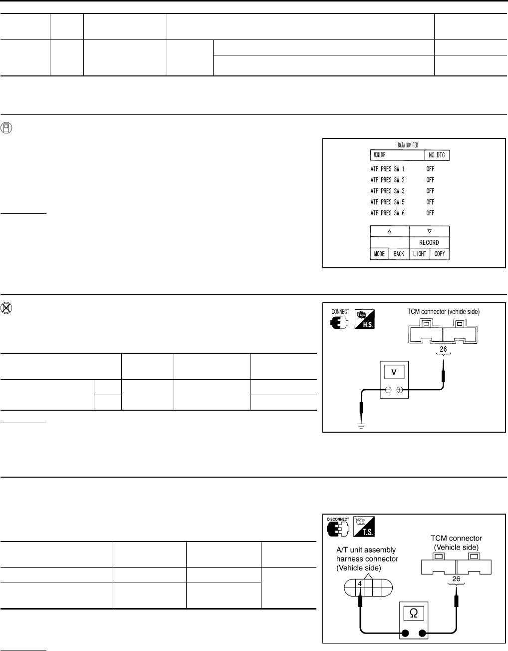
AT-242
DTC P1846 ATF PRESSURE SWITCH 6
TCM terminal and Data are reference value. Measured between each terminals 5,14,24 and 46 (TCM ground).
Diagnostic Procedure ACS000EP
1. CHECK INPUT SIGNALS (WITH CONSULT-II)
With CONSULT-II
1. Start engine.
2. Select “ECU INPUT SIGNALS” or “MAIN SIGNALS” in “DATA
MONITOR” mode for “A/T” with CONSULT-II.
3. Accelerate vehicle in the “D” position (2nd Þ 3rd gear), and con-
firm the ON/OFF actuation of the “ATF PRES SW 6”.
OK or NG
OK >> GO TO 5.
NG >> GO TO 3.
2. CHECK INPUT SIGNALS (WITHOUT CONSULT-II)
Without CONSULT-II
1. Start engine.
2. Accelerate vehicle in the “D” position (2nd Þ 3rd gear).
OK or NG
OK >> GO TO 5.
NG >> GO TO 3.
3. CHECK POWER SOURCE CIRCUIT
1. Turn ignition switch OFF.
2. Disconnect TCM connector.
3. Check continuity between A/T unit assembly harness connector
and TCM connector.
4. If OK, check harness for short to ground and short to power.
5. Reinstall any part removed.
OK or NG
OK >> GO TO 4.
NG >> Repair open circuit or short to ground or short to power in harness or connectors.
Terminal
No.
Wire
color Item Condition Data (Approx.)
26 G/Y PSC2
(pressure switch 6)
When
vehicle
cruises
When high and low reverse clutch solenoid valve “ON”. 0V
When high and low reverse clutch solenoid valve “OFF”. Battery voltage
PCIA0067E
Solenoid valve Connector
No.
Terminal No.
(Wire color) Voltage
High and low reverse
clutch solenoid valve
OFF F104 26 (G/Y) - Ground Battery voltage
ON Approx. 0 V
PCIA0068E
Item Connector No. Terminal No.
(Wire color) Continuity
TCM F104 26 (G/Y)
Yes
A/T unit assembly harness
connector F6 4 (G/Y)
SCIA3103E
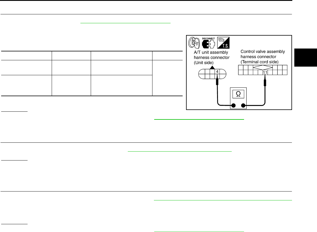
DTC P1846 ATF PRESSURE SWITCH 6
AT-243
D
E
F
G
H
I
J
K
L
M
A
B
AT
4. CHECK TERMINAL CORD ASSEMBLY
1. Remove oil pan. Refer to AT-299, "Control Valve Assembly" .
2. Disconnect A/T unit assembly harness connector and control valve assembly harness connector.
3. Check continuity between A/T unit assembly harness connector
and control valve assembly harness connector.
4. If OK, check harness for short to ground and short to power.
OK or NG
OK >> Replace the control valve assembly. Refer to AT-299, "Control Valve Assembly" .
NG >> Repair open circuit or short to ground or short to power in harness or connectors.
5. CHECK DTC
Perform DTC confirmation procedure. Refer to AT-108, "DTC Confirmation Procedure" .
OK or NG
OK >> INSPECTION END
NG >> GO TO 6.
6. PERFORM TCM INSPECTION
1. Perform TCM input/output signal inspection. Refer to AT-89, "TCM Input/Output Signal Reference Values"
.
2. If NG, recheck TCM pin terminals for damage or loose connection with harness connector.
OK or NG
OK >> Replace the control valve assembly. Refer to AT-299, "Control Valve Assembly" .
NG >> Repair or replace damaged parts.
Item Connector No. Terminal No. (Wire color) Continuity
A/T unit assembly
harness connector F6 4 (Y)
Yes
Control valve assem-
bly harness connec-
tor
F302 11 (Y)
SCIA3104E
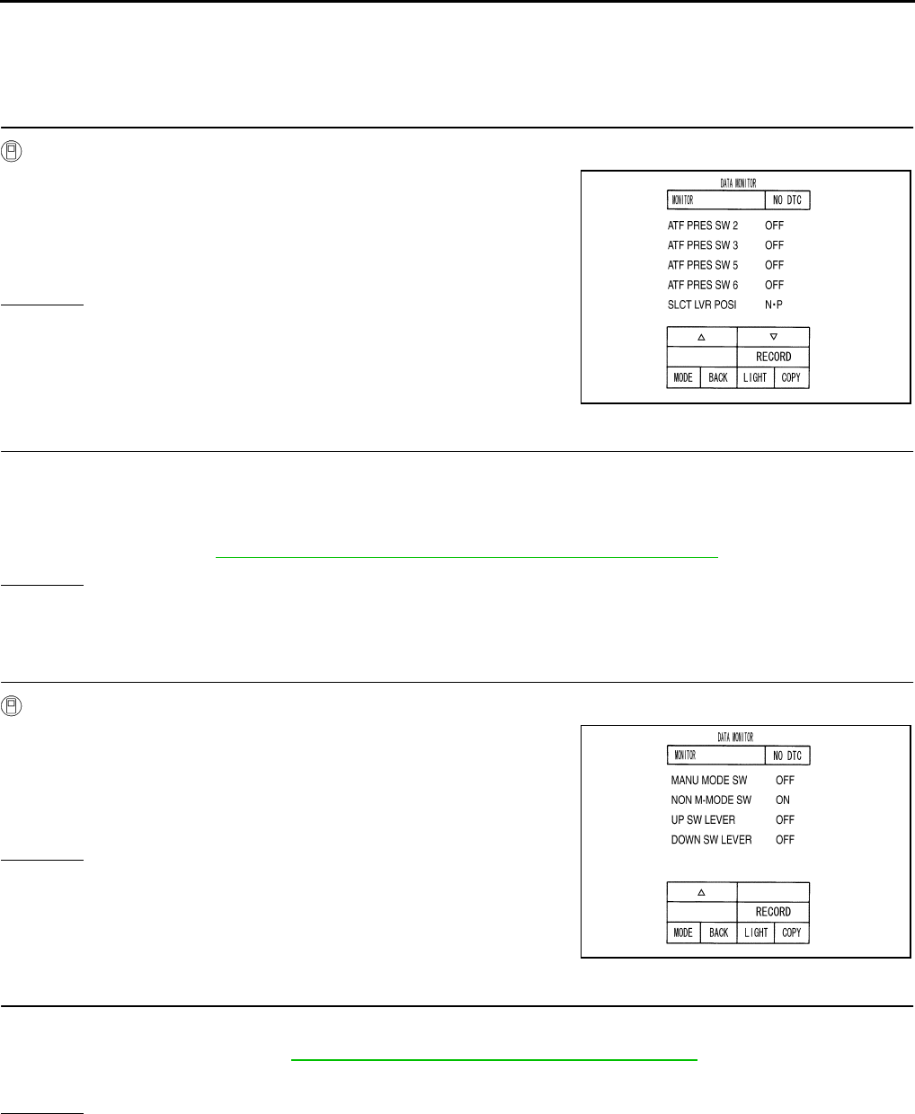
AT-244
PARK/NEUTRAL POSITION, MANUAL MODE, BRAKE AND THROTTLE POSI-
TION SWITCH CIRCUIT
PARK/NEUTRAL POSITION, MANUAL MODE, BRAKE AND THROTTLE POSI-
TION SWITCH CIRCUIT PFP:31918
Diagnostic Procedure ACS000EQ
1. CHECK PNP SWITCH CIRCUIT
With CONSULT-II
1. Turn ignition switch ON. (Do not start engine.)
2. Select “MAIN SIGNALS” in “DATA MONITOR” mode for “A/T”
with CONSULT-II.
3. Read out “N·P”, “R” and “D” position switches moving selector
lever to each position.
OK or NG
OK >> GO TO 3.
NG >> GO TO 2.
2. DETECT MALFUNCTIONING ITEM
Check the following items.
●Disconnection or short-circuit in the harness between TCM and PNP switch 1, 2, 3, 4.
●Disconnection or short-circuit in the harness between the PNP switch 3 monitor and TCM.
●PNP switch. Refer to AT-112, "DTC P0705 PARK/NEUTRAL POSITION SWITCH" .
OK or NG
OK >> GO TO 3.
NG >> Repair or replace damaged parts.
3. CHECK MANUAL MODE SWITCH CIRCUIT
With CONSULT-II
1. Turn ignition switch ON. (Do not start engine.)
2. Select “ECU INPUT SIGNALS” in “DATA MONITOR” mode for
“A/T” with CONSULT-II.
3. Read out ON/OFF switching action of the “MANU MODE SW”,
“NON M-MODE SW”, “UP SW LEVER”, “DOWN SW LEVER”.
OK or NG
OK >> GO TO 5.
NG >> GO TO 4.
4. DETECT MALFUNCTIONING ITEM
Check the following items.
●Manual mode switch. Refer to AT-224, "DTC P1815 MANUAL MODE SWITCH" .
●Check the connector housing for missing, loosening, bending or falling down of any terminal.
OK or NG
OK >> GO TO 5.
NG >> Repair or replace damaged parts.
PCIA0034E
PCIA0064E
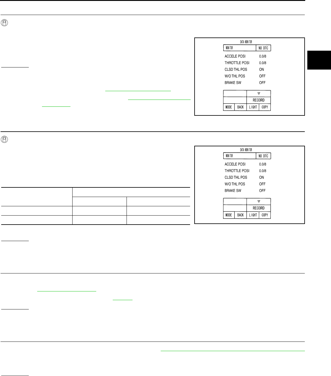
PARK/NEUTRAL POSITION, MANUAL MODE, BRAKE AND THROTTLE POSI-
TION SWITCH CIRCUIT
AT-245
D
E
F
G
H
I
J
K
L
M
A
B
AT
5. CHECK BRAKE SWITCH CIRCUIT
With CONSULT-II
1. Turn ignition switch ON. (Do not start engine.)
2. Select “ECU INPUT SIGNALS” in “DATA MONITOR” mode for
“A/T” with CONSULT-II.
3. Read out ON/OFF switching action of the “BRAKE SW”.
OK or NG
OK >> GO TO 6.
NG >> Check the following items.
●Brake switch. Refer to BR-6, "BRAKE PEDAL" .
●Combination meter. Refer to DI-4, "COMBINATION
METERS" .
6. CHECK THROTTLE POSITION SIGNAL CIRCUIT
With CONSULT-II
1. Turn ignition switch ON. (Do not start engine.)
2. Select “ECU INPUT SIGNALS” in “DATA MONITOR” mode for
“A/T” with CONSULT-II.
3. Depress accelerator pedal and read out the value of “CLSD THL
POS” and “W/O THL POS”.
4. Perform the self-diagnosis for “ENGINE” with CONSULT-II.
OK or NG
OK >> GO TO 7.
NG >> Repair or replace damaged parts.
7. CHECK DTC
Perform SELF-DIAGNOSTIC PROCEDURE.
●Refer to AT-92, "CONSULT-II" .
●CAN Communication Line. Refer to AT-105 .
OK or NG
OK >> INSPECTION END
NG >> GO TO 8.
8. PERFORM TCM INSPECTION
1. Perform TCM input/output signal inspection. Refer to AT-89, "TCM Input/Output Signal Reference Values"
.
2. If NG, recheck TCM pin terminals for damage or loose connection with harness connector.
OK or NG
OK >> INSPECTION END
NG >> Repair or replace damaged parts.
PCIA0070E
Accelerator pedal operation Monitor item
CLSD THL POS W/O THL POS
Released ON OFF
Fully depressed OFF ON PCIA0070E
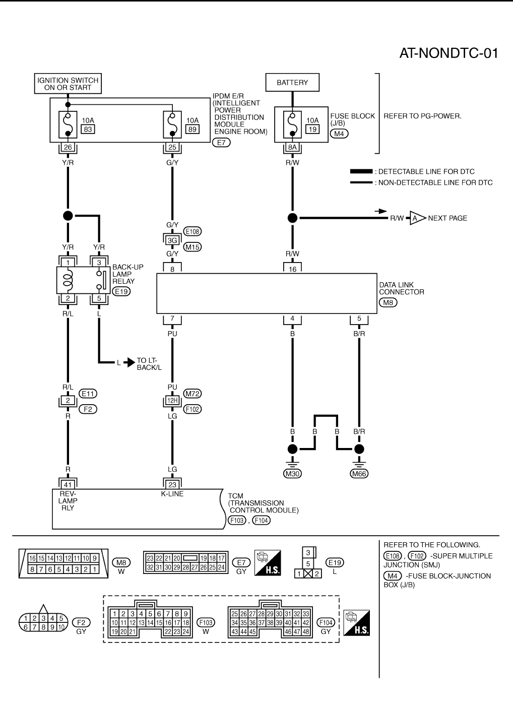
AT-246
TROUBLE DIAGNOSIS FOR SYMPTOMS
TROUBLE DIAGNOSIS FOR SYMPTOMS PFP:00007
Wiring Diagram — AT — NONDTC ACS000ER
TCWT0248E
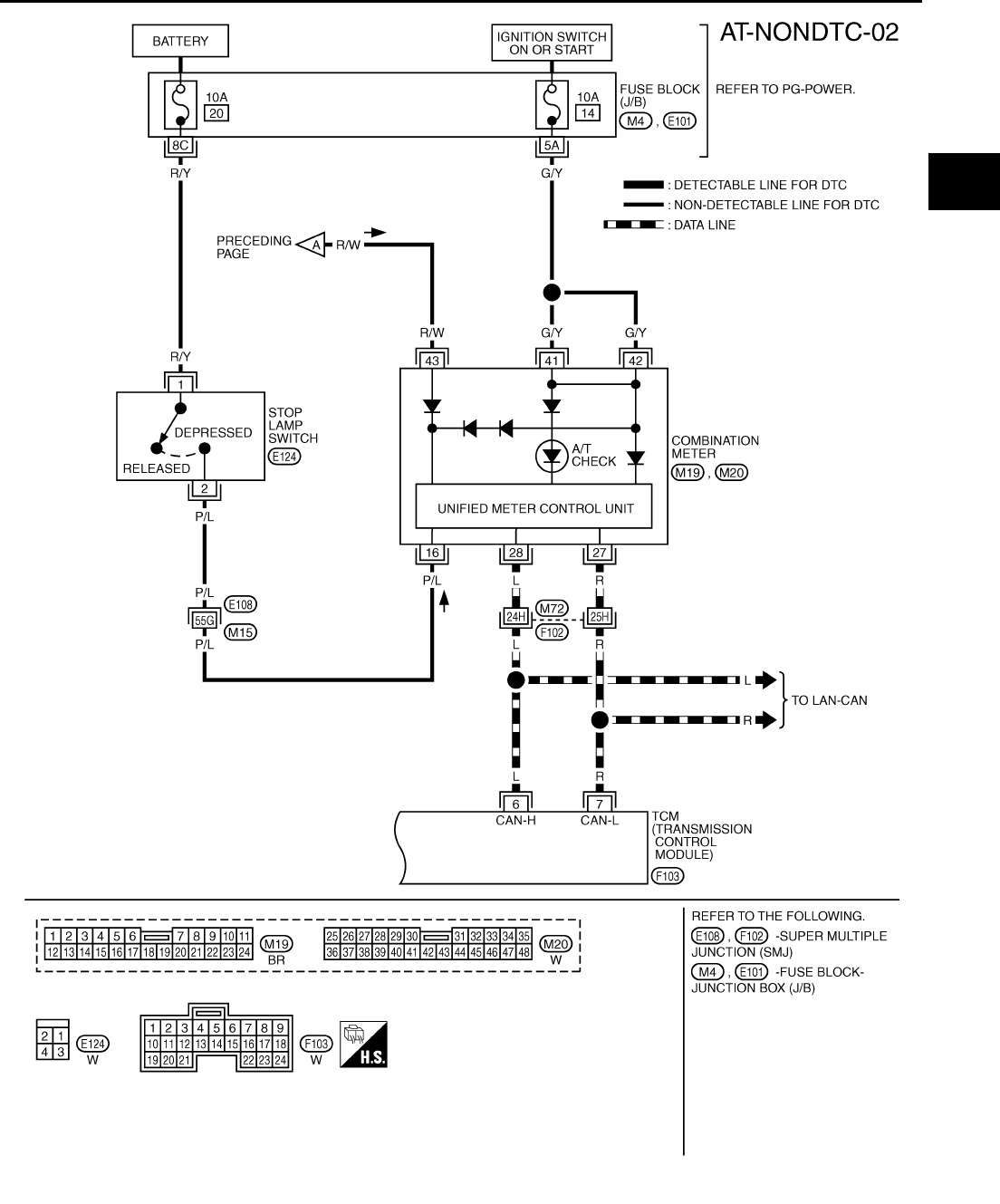
TROUBLE DIAGNOSIS FOR SYMPTOMS
AT-247
D
E
F
G
H
I
J
K
L
M
A
B
AT
TCWT0249E
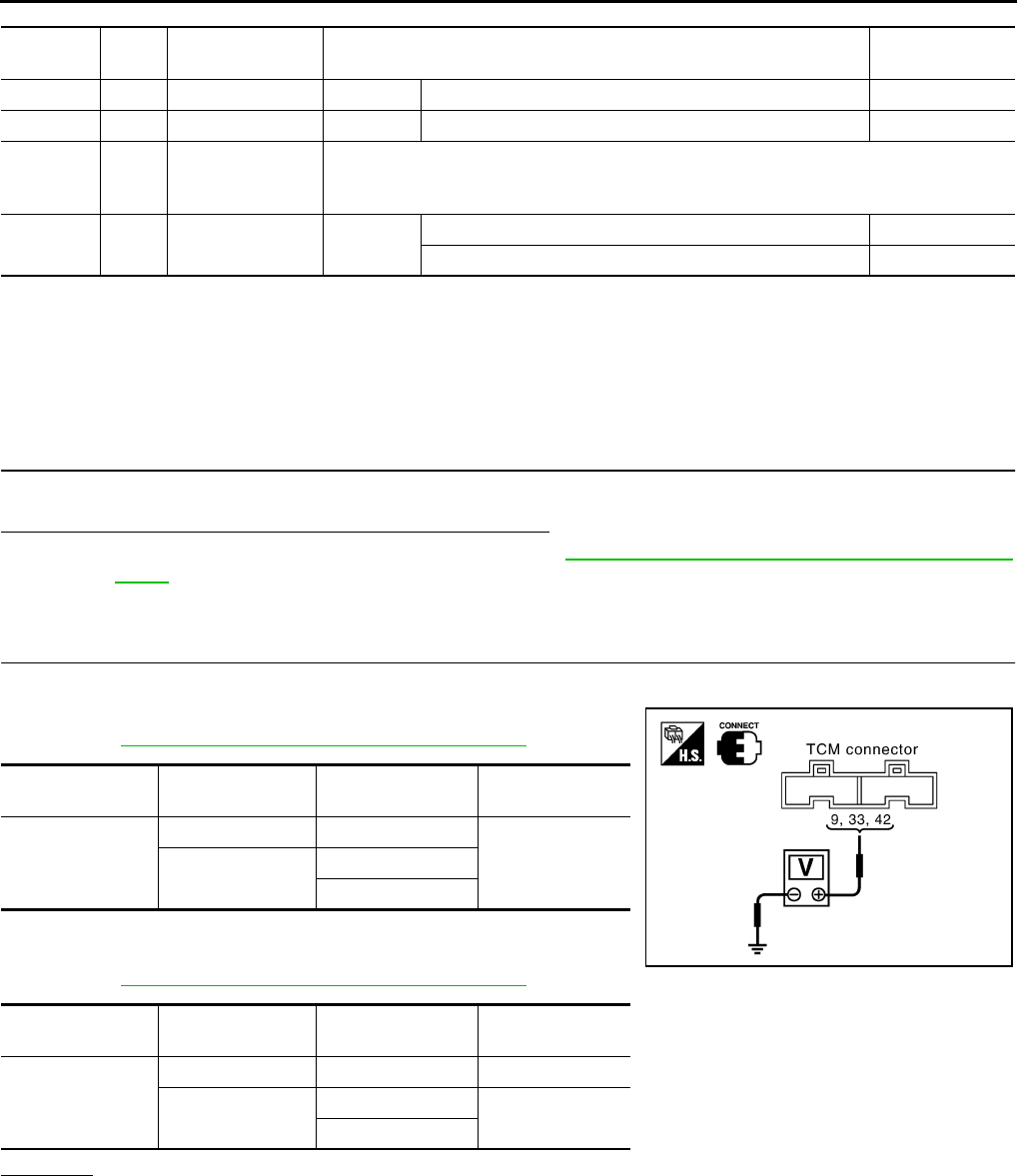
AT-248
TROUBLE DIAGNOSIS FOR SYMPTOMS
TCM terminal and Data are reference value. Measured between each terminals 5, 14, 24 and 46 (TCM ground).
A/T Check Indicator Lamp Does Not Come On ACS0029M
SYMPTOM:
A/T CHECK indicator lamp does 1not come on for about 2 seconds when turning ignition switch to
“ON”.
DIAGNOSTIC PROCEDURE
1. CHECK CAN COMMUNICATION LINE
Execute the self-diagnosis.
Do the self-diagnosis results indicate CAN communication?
YES >> Check the CAN communication line. Refer to AT-105, "DTC U1000 CAN COMMUNICATION
LINE" .
NO >> GO TO 2.
2. CHECK TCM POWER SOURCE
1. Turn ignition switch ON. (Do not start engine.)
2. Check voltage between TCM connector terminals and ground.
Refer to AT-140, "Wiring Diagram — AT — POWER" .
3. Turn ignition switch OFF.
4. Check voltage between TCM connector terminals and ground.
Refer to AT-140, "Wiring Diagram — AT — POWER" .
OK or NG
OK >> GO TO 4.
NG >> GO TO 3.
Terminal
No.
Wire
color Item Condition Data (Approx.)
6 L CAN-H – – –
7 R CAN-L – – –
23 PU
K-line
(CONSULT-II sig-
nal)
The terminal is connected to the Data link connector for CONSULT-II.
41 R/L BACK-UP LAMP
relay IGN ON Selector lever in “R” position. 0V
Selector lever in other position. Battery voltage
Item Connector No. Terminal No.
(Wire color) Voltage
TCM
F103 9 (R/W) - Ground
Battery voltage
F104 33 (Y/R) - Ground
42 (Y/R) - Ground
Item Connector No. Terminal No.
(Wire color) Voltage
TCM
F103 9 (R/W) - Ground Battery voltage
F104 33 (Y/R) - Ground 0V
42 (Y/R) - Ground
SCIA1672E
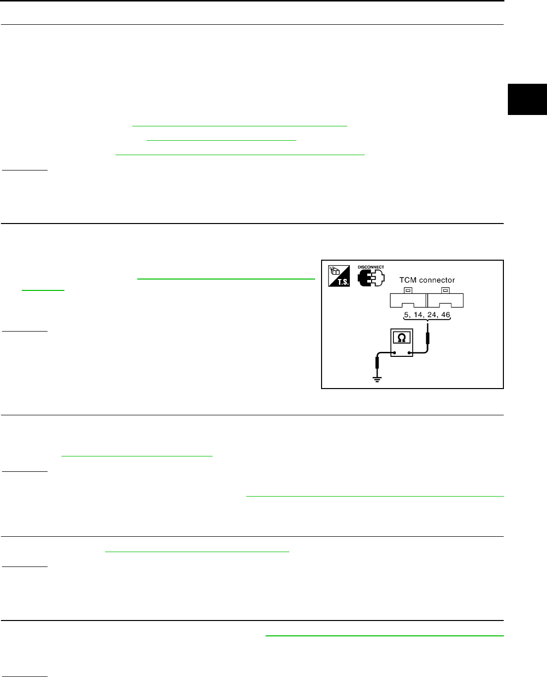
TROUBLE DIAGNOSIS FOR SYMPTOMS
AT-249
D
E
F
G
H
I
J
K
L
M
A
B
AT
3. DETECT MALFUNCTIONING ITEM
Check the following items:
●Harness for short or open between battery and TCM terminal 9
●Harness for short or open between ignition switch and TCM terminals 2, 3, 33 and 42
●Harness for short or open between IPDM E/R terminal 33 and A/T PV IGN relay terminals 2
●Harness for short or open between A/T PV IGN relay terminal 1 and ground.
●15A fuse (No.34, located in the fuse and fusible link block) and 10A fuse (No. 71, located in the IPDM E/R)
●Ignition switch; Refer to PG-3, "POWER SUPPLY ROUTING CIRCUIT" .
●A/T PV IGN relay; Refer to AT-144, "Component Inspection" .
●ECM relay; Refer to EC-130, "POWER SUPPLY AND GROUND CIRCUIT" .
OK or NG
OK >> GO TO 4.
NG >> Repair or replace damaged parts.
4. CHECK TCM GROUND CIRCUIT
1. Turn ignition switch OFF.
2. Disconnect the TCM connector.
3. Check continuity between terminals 5 (B), 14 (B), 24 (B), 46 (B)
and ground. Refer to AT-140, "Wiring Diagram — AT —
POWER" .
4. If OK, check the harness for short-circuit to ground or the power
source.
OK or NG
OK >> GO TO 5.
NG >> Repair the short-circuit(s) in the harness or connector to
ground or the power source.
5. CHECK A/T CHECK INDICATOR LAMP CIRCUIT
1. Turn ignition switch OFF.
2. Check the combination meter.
Refer to DI-4, "COMBINATION METERS" .
OK or NG
OK >> GO TO 6.
NG >> Replace the combination meter. Refer to DI-16, "Removal and Installation for Combination Meter"
.
6. CHECK SYMPTOM
Check again. Refer to AT-55, "Check Before Engine is Started" .
OK or NG
OK >> INSPECTION END
NG >> GO TO 7.
7. PERFORM TCM INSPECTION
1. Perform TCM input/output signal inspection. Refer to AT-89, "TCM Input/Output Signal Reference Values"
.
2. If NG, recheck TCM pin terminals for damage or loose connection with harness connector.
OK or NG
OK >> INSPECTION END
NG >> Repair or replace damaged parts.
SCIA1161E
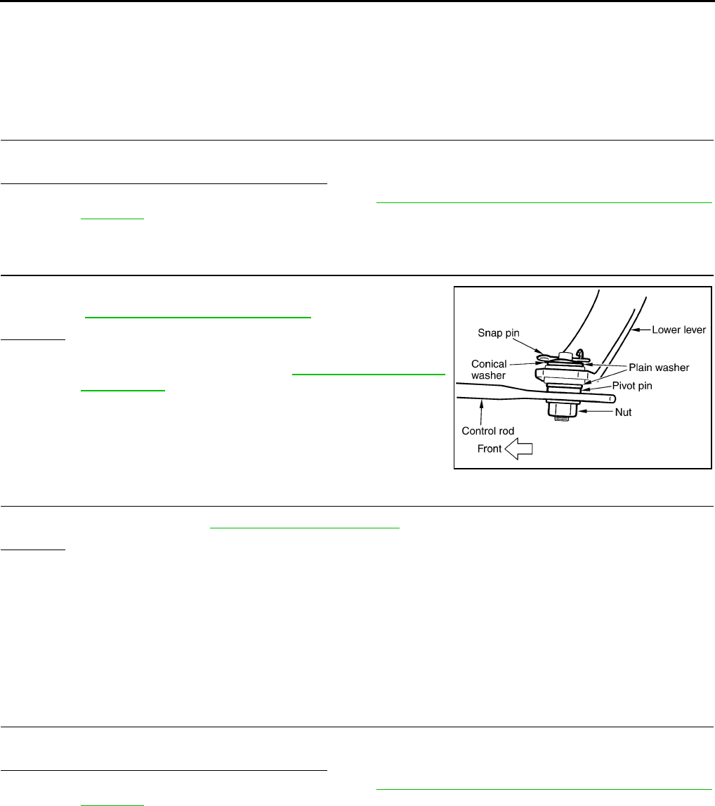
AT-250
TROUBLE DIAGNOSIS FOR SYMPTOMS
Engine Cannot Be Started In “P” or “N” Position ACS0029N
SYMPTOM:
●Engine cannot be started with selector lever in “P” or “N” position.
●Engine can be started with selector lever in “D”or “R” position.
DIAGNOSTIC PROCEDURE
1. CHECK PNP SWITCH CIRCUIT
Execute self-diagnosis.
Do the self-diagnosis results indicate PNP switch?
YES >> Check the malfunctioning system. Refer to AT-112, "DTC P0705 PARK/NEUTRAL POSITION
SWITCH" .
NO >> GO TO 2.
2. CHECK CONTROL LINKAGE
Check the control linkage.
●Refer to AT-289, "Checking of A/T Position" .
OK or NG
OK >> GO TO 3.
NG >> Adjust control linkage. Refer to AT-289, "Adjustment of
A/T Position" .
3. CHECK STARTING SYSTEM
Check starting system. Refer to SC-9, "STARTING SYSTEM" .
OK or NG
OK >> INSPECTION END
NG >> Repair or replace damaged parts.
In “P” Position, Vehicle Moves When Pushed ACS0029O
SYMPTOM:
Even though the selector lever is set in the “P” position, the parking mechanism is not actuated,
allowing the vehicle to be moved when it is pushed.
DIAGNOSTIC PROCEDURE
1. CHECK PNP SWITCH CIRCUIT
Execute self-diagnosis.
Do the self-diagnosis results indicate PNP switch?
YES >> Check the malfunctioning system. Refer to AT-112, "DTC P0705 PARK/NEUTRAL POSITION
SWITCH" .
NO >> GO TO 2.
SCIA1904E
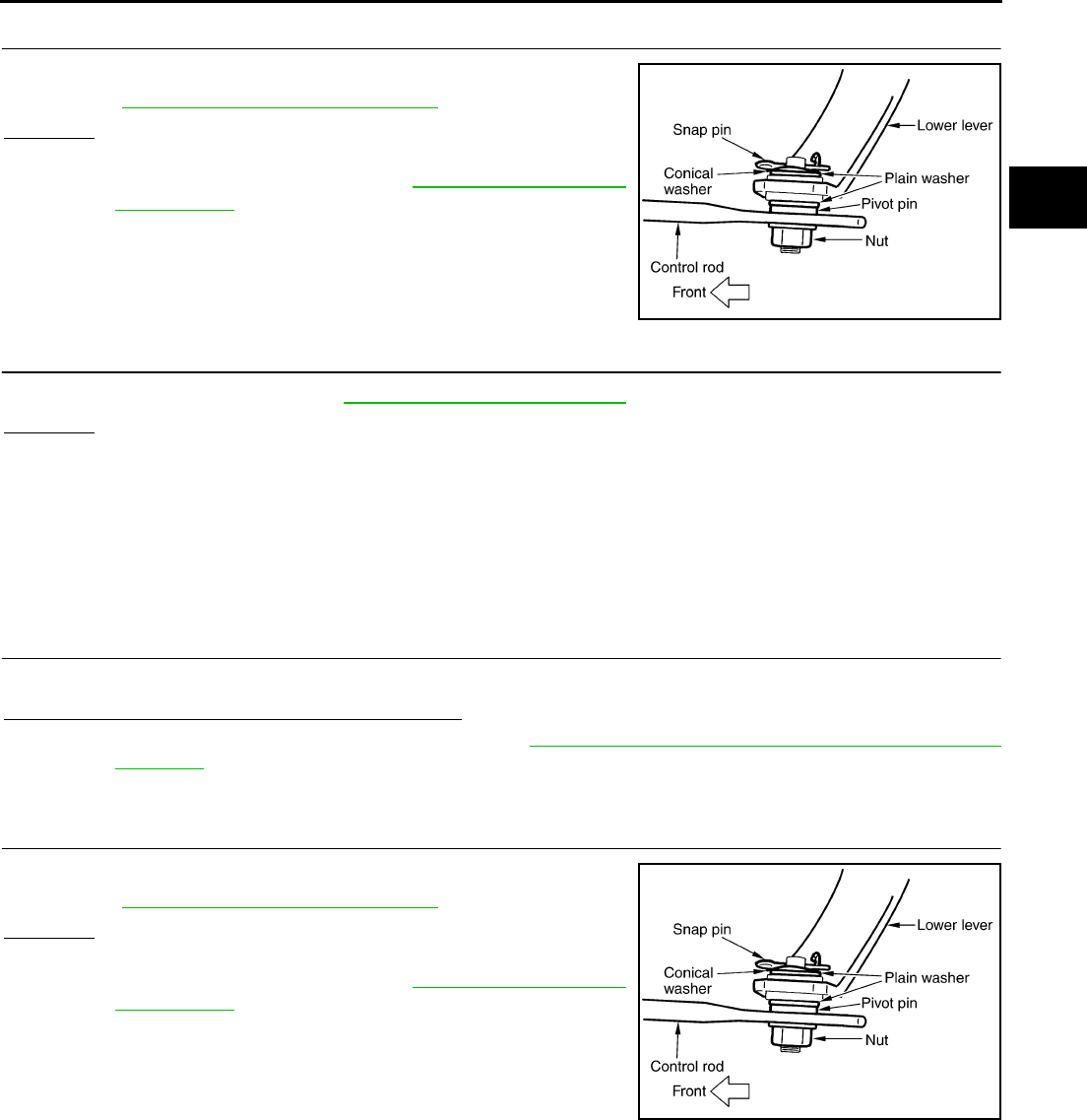
TROUBLE DIAGNOSIS FOR SYMPTOMS
AT-251
D
E
F
G
H
I
J
K
L
M
A
B
AT
2. CHECK CONTROL LINKAGE
Check the control linkage.
●Refer to AT-289, "Checking of A/T Position" .
OK or NG
OK >> GO TO 3.
NG >> Adjust control linkage. Refer to AT-289, "Adjustment of
A/T Position" .
3. CHECK PARKING COMPONENTS
Check parking components. Refer to AT-307, "Parking Components" .
OK or NG
OK >> INSPECTION END
NG >> Repair or replace damaged parts.
In “N” Position, Vehicle Moves ACS0029P
SYMPTOM:
Vehicle moves forward or backward when selecting “N” position.
DIAGNOSTIC PROCEDURE
1. CHECK PNP SWITCH CIRCUIT
Execute self-diagnosis.
Do the self-diagnosis results indicate PNP switch?
YES >> Check the malfunctioning system. Refer to AT-112, "DTC P0705 PARK/NEUTRAL POSITION
SWITCH" .
NO >> GO TO 2.
2. CHECK CONTROL LINKAGE
Check the control linkage.
●Refer to AT-289, "Checking of A/T Position" .
OK or NG
OK >> GO TO 3.
NG >> Adjust control linkage. Refer to AT-289, "Adjustment of
A/T Position" .
SCIA1904E
SCIA1904E
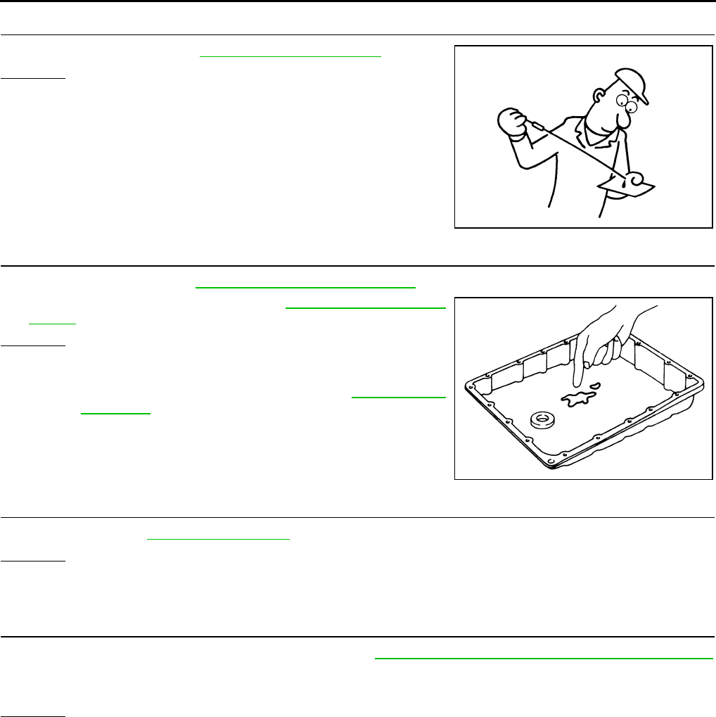
AT-252
TROUBLE DIAGNOSIS FOR SYMPTOMS
3. CHECK A/T FLUID LEVEL
Check A/T fluid level. Refer to AT-13, "Checking A/T Fluid" .
OK or NG
OK >> GO TO 4.
NG >> Refill ATF.
4. CHECK A/T FLUID CONDITION
1. Remove oil pan. Refer to AT-299, "Control Valve Assembly" .
2. Check A/T fluid condition. Refer to AT-51, "Fluid Condition
Check" .
OK or NG
OK >> GO TO 5.
NG >> Check the malfunction items. If any items are damaged,
repair or replace damaged parts. Refer to AT-62, "Symp-
tom Chart" (Symptom No.67).
5. CHECK SYMPTOM
Check again. Refer to AT-55, "Check at Idle" .
OK or NG
OK >> INSPECTION END
NG >> GO TO 6.
6. PERFORM TCM INSPECTION
1. Perform TCM input/output signal inspection. Refer to AT-89, "TCM Input/Output Signal Reference Values"
.
2. If NG, recheck TCM pin terminals for damage or loose connection with harness connector.
OK or NG
OK >> INSPECTION END
NG >> Repair or replace damaged parts.
SAT638A
SAT171B
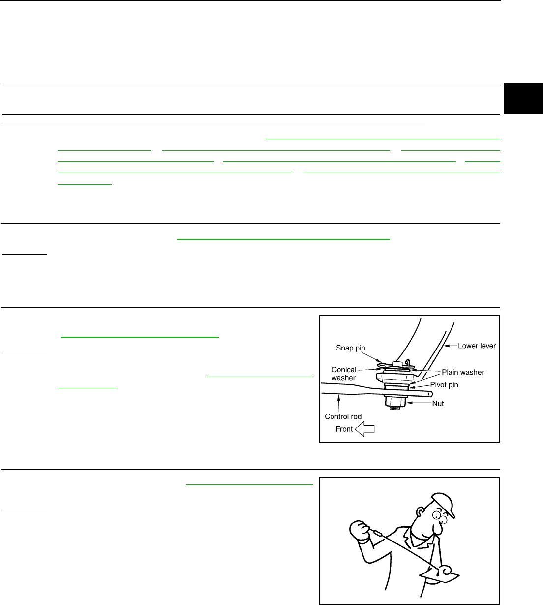
TROUBLE DIAGNOSIS FOR SYMPTOMS
AT-253
D
E
F
G
H
I
J
K
L
M
A
B
AT
Large Shock (“N” to “D” Position) ACS0029Q
SYMPTOM:
A noticeable shock occurs when the selector lever is shifted from the “N” to “D” position.
DIAGNOSTIC PROCEDURE
1. CHECK SELF-DIAGNOSTIC RESULTS
Execute self-diagnosis.
Do the self-diagnostic results indicate A/T fluid temperature sensor, engine speed signal, accelerator pedal
position sensor, ATF pressure switch 1, front brake solenoid valve, CAN communication line?
YES >> Check the malfunctioning system. Refer to AT-153, "DTC P1710 A/T FLUID TEMPERATURE
SENSOR CIRCUIT" , AT-122, "DTC P0725 ENGINE SPEED SIGNAL" , AT-151, "DTC P1705
THROTTLE POSITION SENSOR" , AT-228, "DTC P1841 ATF PRESSURE SWITCH 1" , AT-186,
"DTC P1757 FRONT BRAKE SOLENOID VALVE" , AT-105, "DTC U1000 CAN COMMUNICA-
TION LINE" .
NO >> GO TO 2.
2. ENGINE IDLE SPEED
Check the engine idle speed. Refer to EC-30, "Idle Speed and Ignition Timing Check" .
OK or NG
OK >> GO TO 3.
NG >> Repair.
3. CHECK CONTROL LINKAGE
Check the control linkage.
●Refer to AT-289, "Checking of A/T Position" .
OK or NG
OK >> GO TO 4.
NG >> Adjust control linkage. Refer to AT-289, "Adjustment of
A/T Position" .
4. CHECK A/T FLUID LEVEL
Check the A/T fluid level again. Refer to AT-13, "Checking A/T Fluid"
.
OK or NG
OK >> GO TO 5.
NG >> Refill ATF.
SCIA1904E
SAT638A
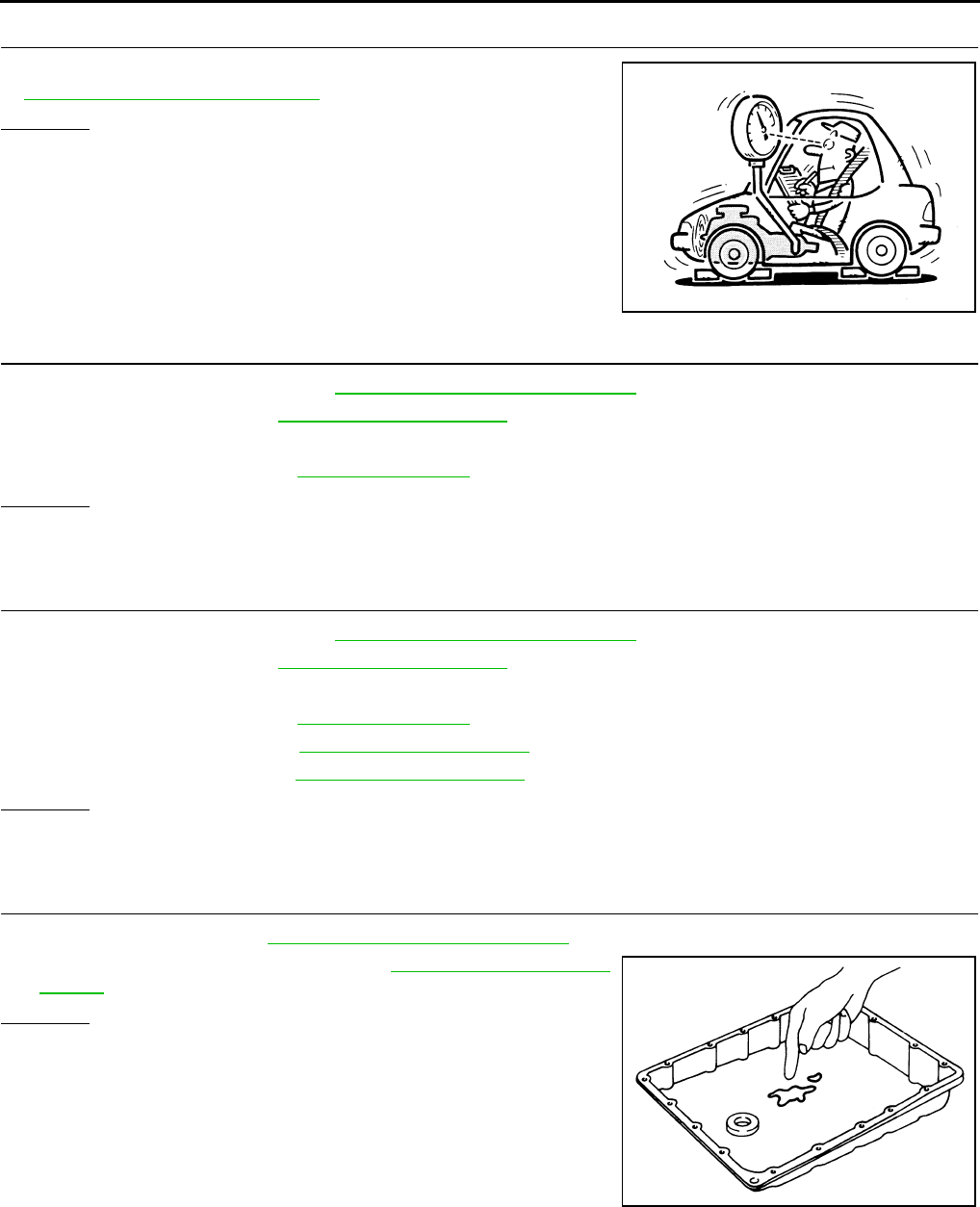
AT-254
TROUBLE DIAGNOSIS FOR SYMPTOMS
5. CHECK LINE PRESSURE
Check line pressure at idle with selector lever in “D” position. Refer
to AT-52, "LINE PRESSURE TEST" .
OK or NG
OK >> GO TO 8.
NG - 1 >> Line pressure high: GO TO 6.
NG - 2 >> Line pressure low: GO TO 7.
6. DETECT MALFUNCTIONING ITEM
1. Control valve assembly. Refer to AT-299, "Control Valve Assembly" .
2. Disassemble A/T. Refer to AT-325, "DISASSEMBLY" .
3. Check the following items:
–Oil pump assembly. Refer to AT-339, "Oil Pump" .
OK or NG
OK >> GO TO 8.
NG >> Repair or replace damaged parts.
7. DETECT MALFUNCTIONING ITEM
1. Control valve assembly. Refer to AT-299, "Control Valve Assembly" .
2. Disassemble A/T. Refer to AT-325, "DISASSEMBLY" .
3. Check the following items:
–Oil pump assembly. Refer to AT-339, "Oil Pump" .
–Power train system. Refer to AT-325, "DISASSEMBLY" .
–Transmission case. Refer to AT-325, "DISASSEMBLY" .
OK or NG
OK >> GO TO 8.
NG >> Repair or replace damaged parts.
8. CHECK A/T FLUID CONDITION
1. Remove oil pan. Refer to AT-299, "Control Valve Assembly" .
2. Check A/T fluid condition. Refer to AT-51, "Fluid Condition
Check" .
OK or NG
OK >> GO TO 10.
NG >> GO TO 9.
SAT494G
SAT171B
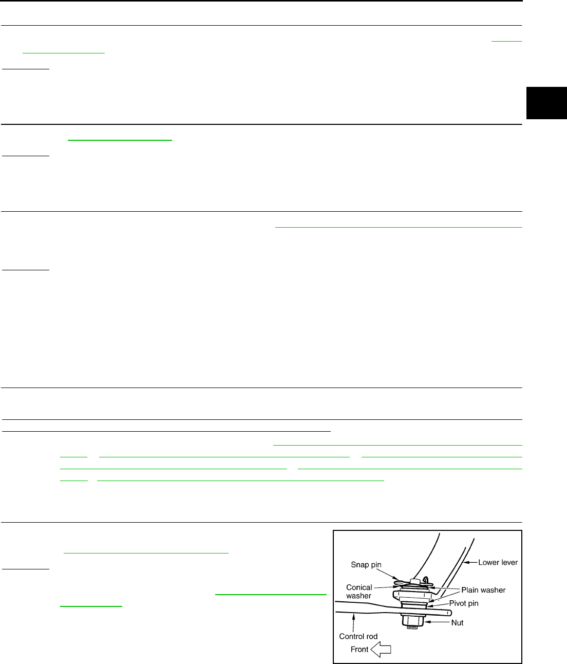
TROUBLE DIAGNOSIS FOR SYMPTOMS
AT-255
D
E
F
G
H
I
J
K
L
M
A
B
AT
9. DETECT MALFUNCTIONING ITEM
●Check the malfunction items. If any items are damaged, repair or replace damaged parts. Refer to AT-62,
"Symptom Chart" (Symptom No.1).
OK or NG
OK >> GO TO 10.
NG >> Repair or replace damaged parts.
10. CHECK SYMPTOM
Check again. AT-55, "Check at Idle" .
OK or NG
OK >> INSPECTION END
NG >> GO TO 11.
11. PERFORM TCM INSPECTION
1. Perform TCM input/output signal inspection. Refer to AT-89, "TCM Input/Output Signal Reference Values"
.
2. If NG, recheck TCM pin terminals for damage or loose connection with harness connector.
OK or NG
OK >> INSPECTION END
NG >> Repair or replace damaged parts.
Vehicle Does Not Creep Backward In “R” Position ACS0029R
SYMPTOM:
The vehicle does not creep in the “R” position. Or an extreme lack of acceleration is observed.
DIAGNOSTIC PROCEDURE
1. CHECK SELF-DIAGNOSTIC RESULTS
Execute self-diagnosis.
Do the self-diagnostic results indicate accelerator pedal position sensor, ATF pressure switch 6, high and low
reverse clutch solenoid valve, CAN communication line, PNP switch?
YES >> Check the malfunctioning system. Refer to AT-151, "DTC P1705 THROTTLE POSITION SEN-
SOR" , AT-240, "DTC P1846 ATF PRESSURE SWITCH 6" , AT-205, "DTC P1767 HIGH AND
LOW REVERSE CLUTCH SOLENOID VALVE" , AT-105, "DTC U1000 CAN COMMUNICATION
LINE" , AT-112, "DTC P0705 PARK/NEUTRAL POSITION SWITCH" .
NO >> GO TO 2.
2. CHECK CONTROL LINKAGE
Check the control linkage.
●Refer to AT-289, "Checking of A/T Position" .
OK or NG
OK >> GO TO 3.
NG >> Adjust control linkage. Refer to AT-289, "Adjustment of
A/T Position" .
SCIA1904E
AT-256
TROUBLE DIAGNOSIS FOR SYMPTOMS
3. CHECK A/T FLUID LEVEL
Check A/T fluid level again. Refer to AT-13, "Checking A/T Fluid" .
OK or NG
OK >> GO TO 4.
NG >> Refill ATF.
4. CHECK STALL TEST
Check stall revolution with selector lever in “M” and “R” positions.
Refer to AT-51, "STALL TEST" .
OK or NG
OK >> GO TO 5.
OK in “M” position, NG in “R” position>>1.Disassemble A/T. Refer
to AT-325, "DISASSEMBLY" .
2. Check the following items. If any items are damaged,
repair or replace damaged parts.
–Reverse brake
NG in both “M” and “R” positions>>GO TO 7.
5. CHECK LINE PRESSURE
Check the line pressure with the engine idling. Refer to AT-52, "LINE
PRESSURE TEST" .
OK or NG
OK >> GO TO 8.
NG - 1 >> Line pressure high. GO TO 6.
NG - 2 >> Line pressure low. GO TO 7.
6. DETECT MALFUNCTIONING ITEM
1. Control valve assembly. Refer to AT-299, "Control Valve Assembly" .
2. Disassemble A/T. Refer to AT-325, "DISASSEMBLY" .
3. Check the following items:
–Oil pump assembly. Refer to AT-339, "Oil Pump" .
OK or NG
OK >> GO TO 8.
NG >> Repair or replace damaged parts.
SAT638A
SAT493G
SAT494G
TROUBLE DIAGNOSIS FOR SYMPTOMS
AT-257
D
E
F
G
H
I
J
K
L
M
A
B
AT
7. DETECT MALFUNCTIONING ITEM
1. Control valve assembly. Refer to AT-299, "Control Valve Assembly" .
2. Disassemble A/T. Refer to AT-325, "DISASSEMBLY" .
3. Check the following items:
–Oil pump assembly. Refer to AT-339, "Oil Pump" .
–Power train system. Refer to AT-325, "DISASSEMBLY" .
–Transmission case. Refer to AT-325, "DISASSEMBLY" .
OK or NG
OK >> GO TO 8.
NG >> Repair or replace damaged parts.
8. CHECK A/T FLUID CONDITION
1. Remove oil pan. Refer to AT-299, "Control Valve Assembly" .
2. Check A/T fluid condition. Refer to AT-51, "Fluid Condition
Check" .
OK or NG
OK >> GO TO 10.
NG >> GO TO 9.
9. DETECT MALFUNCTIONING ITEM
●Check the malfunction items. If any items are damaged, repair or replace damaged parts. Refer to AT-62,
"Symptom Chart" (Symptom No.43).
OK or NG
OK >> GO TO 10.
NG >> Repair or replace damaged parts.
10. CHECK SYMPTOM
Check again. Refer to AT-55, "Check at Idle" .
OK or NG
OK >> INSPECTION END
NG >> GO TO 11.
11. PERFORM TCM INSPECTION
1. Perform TCM input/output signal inspection. Refer to AT-89, "TCM Input/Output Signal Reference Values"
.
2. If NG, recheck TCM pin terminals for damage or loose connection with harness connector.
OK or NG
OK >> INSPECTION END
NG >> Repair or replace damaged parts.
SAT171B
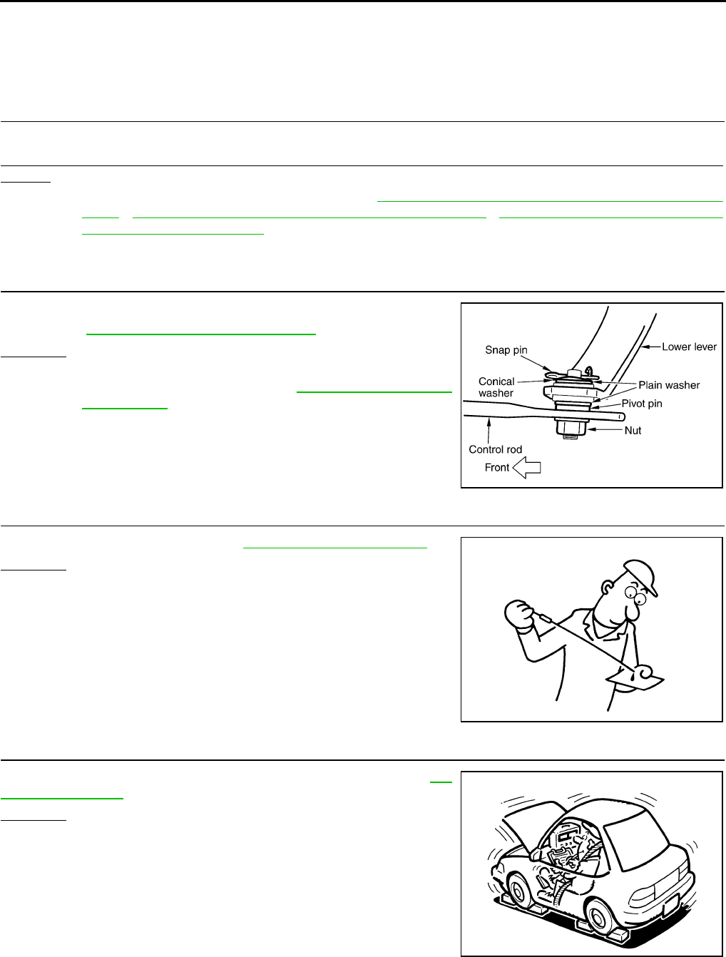
AT-258
TROUBLE DIAGNOSIS FOR SYMPTOMS
Vehicle Does Not Creep Forward In “D” Position ACS0029S
SYMPTOM:
Vehicle does not creep forward when selecting “D” position.
DIAGNOSTIC PROCEDURE
1. CHECK SELF-DIAGNOSTIC RESULTS
Execute self-diagnosis.
Do the self-diagnostic results indicate accelerator pedal position sensor, CAN communication line, PNP
switch?
YES >> Check the malfunctioning system. Refer to AT-151, "DTC P1705 THROTTLE POSITION SEN-
SOR" , AT-105, "DTC U1000 CAN COMMUNICATION LINE" , AT-112, "DTC P0705 PARK/NEU-
TRAL POSITION SWITCH" .
NO >> GO TO 2.
2. CHECK CONTROL LINKAGE
Check the control linkage.
●Refer to AT-289, "Checking of A/T Position" .
OK or NG
OK >> GO TO 3.
NG >> Adjust control linkage. Refer to AT-289, "Adjustment of
A/T Position" .
3. CHECK A/T FLUID LEVEL
Check A/T fluid level again. Refer to AT-13, "Checking A/T Fluid" .
OK or NG
OK >> GO TO 4.
NG >> Refill ATF.
4. CHECK STALL TEST
Check stall revolution with selector lever in “D” position. Refer to AT-
51, "STALL TEST" .
OK or NG
OK >> GO TO 5.
NG >> GO TO 7.
SCIA1904E
SAT638A
SAT493G
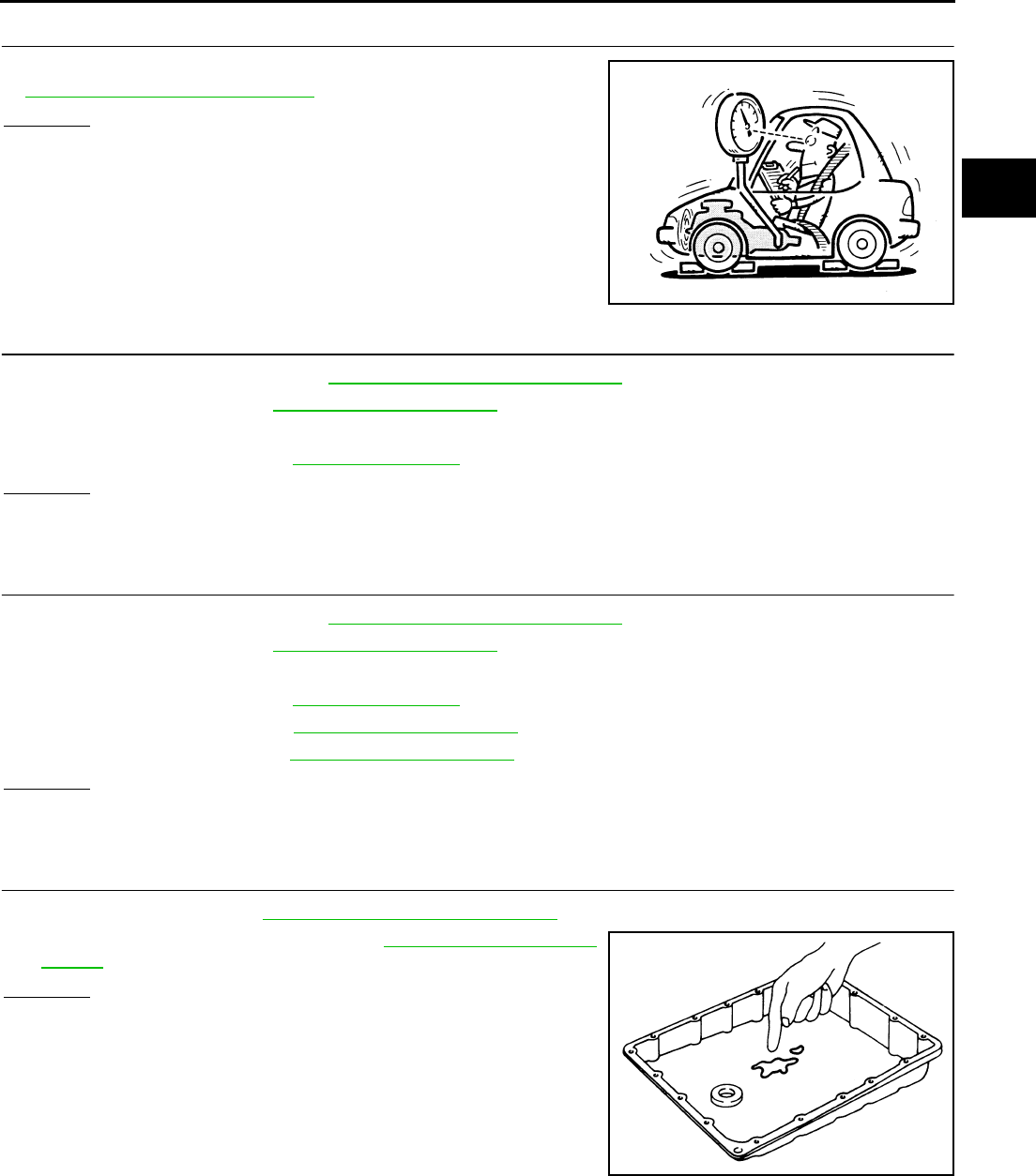
TROUBLE DIAGNOSIS FOR SYMPTOMS
AT-259
D
E
F
G
H
I
J
K
L
M
A
B
AT
5. CHECK LINE PRESSURE
Check line pressure at idle with selector lever in “D” position. Refer
to AT-52, "LINE PRESSURE TEST" .
OK or NG
OK >> GO TO 8.
NG - 1 >> Line pressure high. GO TO 6.
NG - 2 >> Line pressure low. GO TO 7.
6. DETECT MALFUNCTIONING ITEM
1. Control valve assembly. Refer to AT-299, "Control Valve Assembly" .
2. Disassemble A/T. Refer to AT-325, "DISASSEMBLY" .
3. Check the following items:
–Oil pump assembly. Refer to AT-339, "Oil Pump" .
OK or NG
OK >> GO TO 8.
NG >> Repair or replace damaged parts.
7. DETECT MALFUNCTIONING ITEM
1. Control valve assembly. Refer to AT-299, "Control Valve Assembly" .
2. Disassemble A/T. Refer to AT-325, "DISASSEMBLY" .
3. Check the following items:
–Oil pump assembly. Refer to AT-339, "Oil Pump" .
–Power train system. Refer to AT-325, "DISASSEMBLY" .
–Transmission case. Refer to AT-325, "DISASSEMBLY" .
OK or NG
OK >> GO TO 8.
NG >> Repair or replace damaged parts.
8. CHECK A/T FLUID CONDITION
1. Remove oil pan. Refer to AT-299, "Control Valve Assembly" .
2. Check A/T fluid condition. Refer to AT-51, "Fluid Condition
Check" .
OK or NG
OK >> GO TO 10.
NG >> GO TO 9.
SAT494G
SAT171B

AT-260
TROUBLE DIAGNOSIS FOR SYMPTOMS
9. DETECT MALFUNCTIONING ITEM
●Check the malfunction items. If any items are damaged, repair or replace damaged parts. Refer to AT-62,
"Symptom Chart" (Symptom No.43).
OK or NG
OK >> GO TO 10.
NG >> Repair or replace damaged parts.
10. CHECK SYMPTOM
Check again. Refer to AT-55, "Check at Idle" .
OK or NG
OK >> INSPECTION END
NG >> GO TO 11.
11. PERFORM TCM INSPECTION
1. Perform TCM input/output signal inspection. Refer to AT-89, "TCM Input/Output Signal Reference Values"
.
2. If NG, recheck TCM pin terminals for damage or loose connection with harness connector.
OK or NG
OK >> INSPECTION END
NG >> Repair or replace damaged parts.
Vehicle Cannot Be Started From D1ACS0029T
SYMPTOM:
Vehicle cannot be started from D1 on cruise test - Part 1.
DIAGNOSTIC PROCEDURE
1. CONFIRM THE SYMPTOM
Check if vehicle creeps in “R” position.
OK or NG
OK >> GO TO 2.
NG >> Refer to AT-255, "Vehicle Does Not Creep Backward In “R” Position" .
2. CHECK SELF-DIAGNOSTIC RESULTS
Execute self-diagnosis.
Is any malfunction detected by self-diagnostic results?
YES >> Check the malfunctioning system.
NO >> GO TO 3.
3. CHECK ACCELERATOR POSITION (APP) SENSOR
Check accelerator pedal position (APP) sensor. Refer to AT-151, "DTC P1705 THROTTLE POSITION SEN-
SOR" .
OK or NG
OK >> GO TO 4.
NG >> Repair or replace accelerator pedal position (APP) sensor.
TROUBLE DIAGNOSIS FOR SYMPTOMS
AT-261
D
E
F
G
H
I
J
K
L
M
A
B
AT
4. CHECK A/T FLUID LEVEL
Check A/T fluid level again. Refer to AT-13, "Checking A/T Fluid" .
OK or NG
OK >> GO TO 5.
NG >> Refill ATF.
5. CHECK LINE PRESSURE
Check line pressure at the engine stall point. Refer to AT-52, "LINE
PRESSURE TEST" .
OK or NG
OK >> GO TO 8.
NG - 1 >> Line pressure high. GO TO 6.
NG - 2 >> Line pressure low. GO TO 7.
6. DETECT MALFUNCTIONING ITEM
1. Control valve assembly. Refer to AT-299, "Control Valve Assembly" .
2. Disassemble A/T. Refer to AT-325, "DISASSEMBLY" .
3. Check the following items:
–Oil pump assembly. Refer to AT-339, "Oil Pump" .
OK or NG
OK >> GO TO 8.
NG >> Repair or replace damaged parts.
7. DETECT MALFUNCTIONING ITEM
1. Control valve assembly. Refer to AT-299, "Control Valve Assembly" .
2. Disassemble A/T. Refer to AT-325, "DISASSEMBLY" .
3. Check the following items:
–Oil pump assembly. Refer to AT-339, "Oil Pump" .
–Power train system. Refer to AT-325, "DISASSEMBLY" .
–Transmission case. Refer to AT-325, "DISASSEMBLY" .
OK or NG
OK >> GO TO 8.
NG >> Repair or replace damaged parts.
SAT638A
SAT494G
AT-262
TROUBLE DIAGNOSIS FOR SYMPTOMS
8. CHECK A/T FLUID CONDITION
1. Remove oil pan. Refer to AT-299, "Control Valve Assembly" .
2. Check A/T fluid condition. Refer to AT-51, "Fluid Condition
Check" .
OK or NG
OK >> GO TO 9.
NG >> GO TO 12.
9. DETECT MALFUNCTIONING ITEM
●Check the malfunction items. If any items are damaged, repair or replace damaged parts. Refer to AT-62,
"Symptom Chart" (Symptom No.23).
OK or NG
OK >> GO TO 10.
NG >> Repair or replace damaged parts.
10. CHECK SYMPTOM
Check again. Refer to AT-56, "Cruise Test - Part 1" , AT-58, "Cruise Test - Part 2" .
OK or NG
OK >> INSPECTION END
NG >> GO TO 11.
11. PERFORM TCM INSPECTION
1. Perform TCM input/output signal inspection. Refer to AT-89, "TCM Input/Output Signal Reference Values"
.
2. If NG, recheck TCM pin terminals for damage or loose connection with harness connector.
OK or NG
OK >> INSPECTION END
NG >> Repair or replace damaged parts.
12. DETECT MALFUNCTIONING ITEM
●Check the malfunction items. If any items are damaged, repair or replace damaged parts. Refer to AT-62,
"Symptom Chart" (Symptom No.23).
OK or NG
OK >> GO TO 10.
NG >> Repair or replace damaged parts.
SAT171B
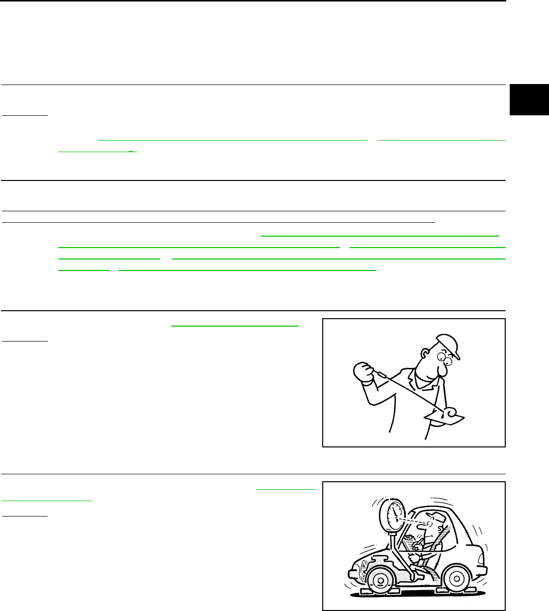
TROUBLE DIAGNOSIS FOR SYMPTOMS
AT-263
D
E
F
G
H
I
J
K
L
M
A
B
AT
A/T Does Not Shift: D1 → D2ACS0029U
SYMPTOM:
The vehicle does not shift-up from the D1 to D2 gear at the specified speed.
DIAGNOSTIC PROCEDURE
1. CONFIRM THE SYMPTOM
Check if vehicle creeps forward in “D” position” and vehicle can be started from D1.
OK or NG
OK >> GO TO 2.
NG >> Refer to AT-258, "Vehicle Does Not Creep Forward In “D” Position" , AT-260, "Vehicle Cannot Be
Started From D1" .
2. CHECK SELF-DIAGNOSTIC RESULTS
Execute self-diagnosis.
Do the self-diagnostic results indicate ATF pressure switch 5, direct clutch solenoid valve, accelerator pedal
position sensor, vehicle speed sensor A/T (revolution sensor) and vehicle speed sensor MTR?
YES >> Check the malfunctioning system. Refer to AT-236, "DTC P1845 ATF PRESSURE SWITCH 5" ,
AT-196, "DTC P1762 DIRECT CLUTCH SOLENOID VALVE" , AT-151, "DTC P1705 THROTTLE
POSITION SENSOR" , AT-117, "DTC P0720 VEHICLE SPEED SENSOR A/T (REVOLUTION
SENSOR)" , AT-164, "DTC P1721 VEHICLE SPEED SENSOR MTR" .
NO >> GO TO 3.
3. CHECK A/T FLUID LEVEL
Check A/T fluid level again. Refer to AT-13, "Checking A/T Fluid" .
OK or NG
OK >> GO TO 4.
NG >> Refill ATF.
4. CHECK LINE PRESSURE
Check line pressure at the engine stall point. Refer to AT-52, "LINE
PRESSURE TEST" .
OK or NG
OK >> GO TO 7.
NG - 1 >> Line pressure high. GO TO 5.
NG - 2 >> Line pressure low. GO TO 6.
SAT638A
SAT494G
AT-264
TROUBLE DIAGNOSIS FOR SYMPTOMS
5. DETECT MALFUNCTIONING ITEM
1. Control valve assembly. Refer to AT-299, "Control Valve Assembly" .
2. Disassemble A/T. Refer to AT-325, "DISASSEMBLY" .
3. Check the following items:
–Oil pump assembly. Refer to AT-339, "Oil Pump" .
OK or NG
OK >> GO TO 7.
NG >> Repair or replace damaged parts.
6. DETECT MALFUNCTIONING ITEM
1. Control valve assembly. Refer to AT-299, "Control Valve Assembly" .
2. Disassemble A/T. Refer to AT-325, "DISASSEMBLY" .
3. Check the following items:
–Oil pump assembly. Refer to AT-339, "Oil Pump" .
–Power train system. Refer to AT-325, "DISASSEMBLY" .
–Transmission case. Refer to AT-325, "DISASSEMBLY" .
OK or NG
OK >> GO TO 7.
NG >> Repair or replace damaged parts.
7. CHECK A/T FLUID CONDITION
1. Remove oil pan. Refer to AT-299, "Control Valve Assembly" .
2. Check A/T fluid condition. Refer to AT-51, "Fluid Condition
Check" .
OK or NG
OK >> GO TO 8.
NG >> GO TO 11.
8. DETECT MALFUNCTIONING ITEM
●Check the malfunction items. If any items are damaged, repair or replace damaged parts. Refer to AT-62,
"Symptom Chart" (Symptom No.10).
OK or NG
OK >> GO TO 9.
NG >> Repair or replace damaged parts.
9. CHECK SYMPTOM
Check again. Refer to AT-56, "Cruise Test - Part 1" , AT-58, "Cruise Test - Part 2" .
OK or NG
OK >> INSPECTION END
NG >> GO TO 10.
SAT171B
TROUBLE DIAGNOSIS FOR SYMPTOMS
AT-265
D
E
F
G
H
I
J
K
L
M
A
B
AT
10. PERFORM TCM INSPECTION
1. Perform TCM input/output signal inspection. Refer to AT-89, "TCM Input/Output Signal Reference Values"
.
2. If NG, recheck TCM pin terminals for damage or loose connection with harness connector.
OK or NG
OK >> INSPECTION END
NG >> Repair or replace damaged parts.
11. DETECT MALFUNCTIONING ITEM
●Check the malfunction items. If any items are damaged, repair or replace damaged parts. Refer to AT-62,
"Symptom Chart" (Symptom No.10).
OK or NG
OK >> GO TO 9.
NG >> Repair or replace damaged parts.
A/T Does Not Shift: D2 → D3ACS0029V
SYMPTOM:
The vehicle does not shift-up from D2 to D3 gear at the specified speed.
DIAGNOSTIC PROCEDURE
1. CONFIRM THE SYMPTOM
Check if vehicle creeps forward in “D” position” and vehicle can be started from D1.
OK or NG
OK >> GO TO 2.
NG >> Refer to AT-258, "Vehicle Does Not Creep Forward In “D” Position" , AT-260, "Vehicle Cannot Be
Started From D1" .
2. CHECK SELF-DIAGNOSTIC RESULTS
Execute self-diagnosis.
Do the self-diagnostic results indicate ATF pressure switch 6, high and low reverse clutch solenoid valve,
accelerator pedal position sensor, vehicle speed sensor A/T (revolution sensor) and vehicle speed sensor
MTR?
YES >> Check the malfunctioning system. Refer to AT-240, "DTC P1846 ATF PRESSURE SWITCH 6" ,
AT-205, "DTC P1767 HIGH AND LOW REVERSE CLUTCH SOLENOID VALVE" , AT-151, "DTC
P1705 THROTTLE POSITION SENSOR" , AT-117, "DTC P0720 VEHICLE SPEED SENSOR A/T
(REVOLUTION SENSOR)" , AT-164, "DTC P1721 VEHICLE SPEED SENSOR MTR" .
NO >> GO TO 3.
3. CHECK A/T FLUID LEVEL
Check A/T fluid level again. Refer to AT-13, "Checking A/T Fluid" .
OK or NG
OK >> GO TO 4.
NG >> Refill ATF.
SAT638A
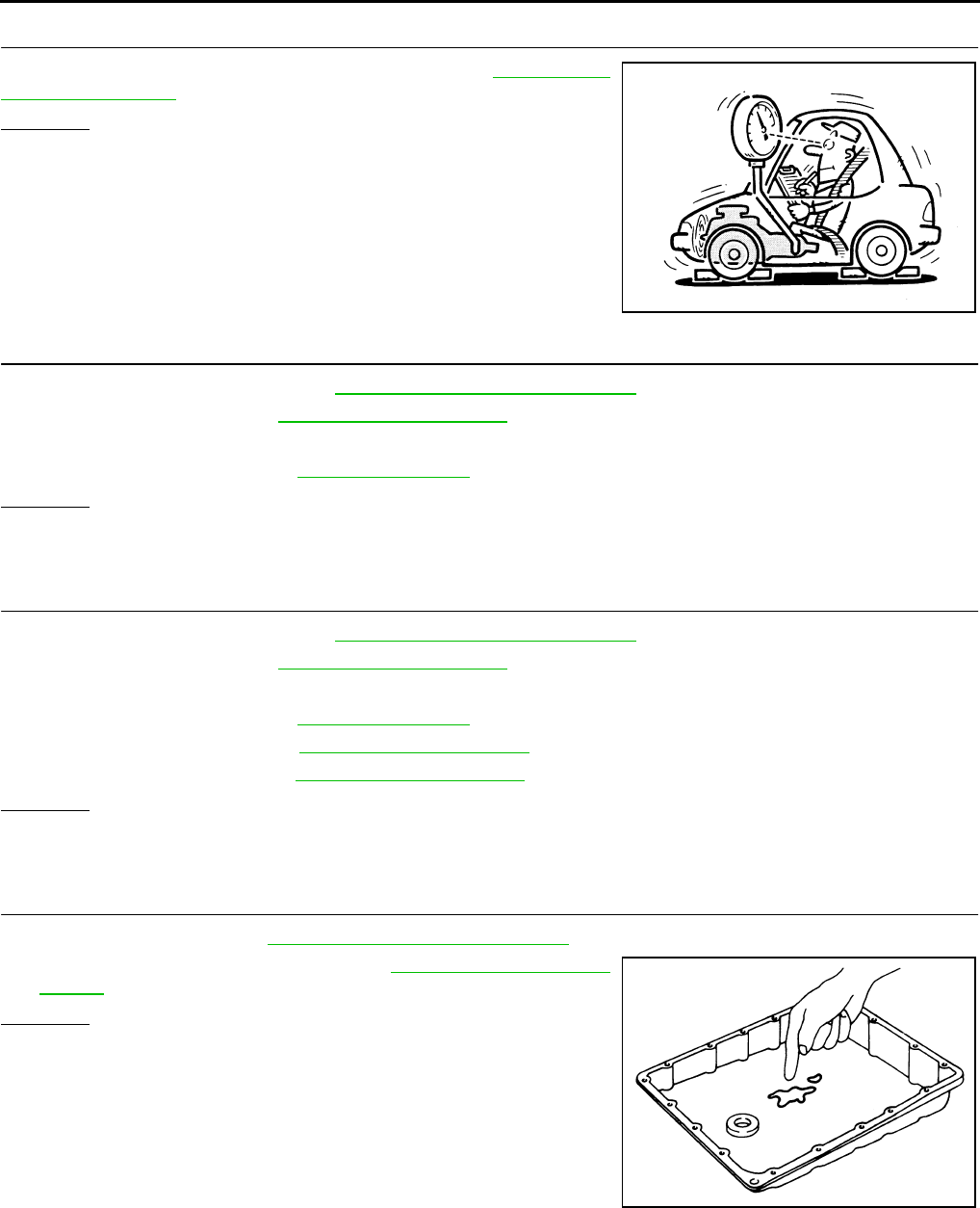
AT-266
TROUBLE DIAGNOSIS FOR SYMPTOMS
4. CHECK LINE PRESSURE
Check line pressure at the engine stall point. Refer to AT-52, "LINE
PRESSURE TEST" .
OK or NG
OK >> GO TO 7.
NG - 1 >> Line pressure high. GO TO 5.
NG - 2 >> Line pressure low. GO TO 6.
5. DETECT MALFUNCTIONING ITEM
1. Control valve assembly. Refer to AT-299, "Control Valve Assembly" .
2. Disassemble A/T. Refer to AT-325, "DISASSEMBLY" .
3. Check the following items:
–Oil pump assembly. Refer to AT-339, "Oil Pump" .
OK or NG
OK >> GO TO 7.
NG >> Repair or replace damaged parts.
6. DETECT MALFUNCTIONING ITEM
1. Control valve assembly. Refer to AT-299, "Control Valve Assembly" .
2. Disassemble A/T. Refer to AT-325, "DISASSEMBLY" .
3. Check the following items:
–Oil pump assembly. Refer to AT-339, "Oil Pump" .
–Power train system. Refer to AT-325, "DISASSEMBLY" .
–Transmission case. Refer to AT-325, "DISASSEMBLY" .
OK or NG
OK >> GO TO 7.
NG >> Repair or replace damaged parts.
7. CHECK A/T FLUID CONDITION
1. Remove oil pan. Refer to AT-299, "Control Valve Assembly" .
2. Check A/T fluid condition. Refer to AT-51, "Fluid Condition
Check" .
OK or NG
OK >> GO TO 8.
NG >> GO TO 11.
SAT494G
SAT171B

TROUBLE DIAGNOSIS FOR SYMPTOMS
AT-267
D
E
F
G
H
I
J
K
L
M
A
B
AT
8. DETECT MALFUNCTIONING ITEM
●Check the malfunction items. If any items are damaged, repair or replace damaged parts. Refer to AT-62,
"Symptom Chart" (Symptom No.11).
OK or NG
OK >> GO TO 9.
NG >> Repair or replace damaged parts.
9. CHECK SYMPTOM
Check again. Refer to AT-56, "Cruise Test - Part 1" , AT-58, "Cruise Test - Part 2" .
OK or NG
OK >> INSPECTION END
NG >> GO TO 10.
10. PERFORM TCM INSPECTION
1. Perform TCM input/output signal inspection. Refer to AT-89, "TCM Input/Output Signal Reference Values"
.
2. If NG, recheck TCM pin terminals for damage or loose connection with harness connector.
OK or NG
OK >> INSPECTION END
NG >> Repair or replace damaged parts.
11. DETECT MALFUNCTIONING ITEM
●Check the malfunction items. If any items are damaged, repair or replace damaged parts. Refer to AT-62,
"Symptom Chart" (Symptom No.11).
OK or NG
OK >> GO TO 9.
NG >> Repair or replace damaged parts.
A/T Does Not Shift: D3 → D4ACS0029W
SYMPTOM:
●The vehicle does not shift-up from the D3 to D4 gear at the specified speed.
●The vehicle does not shift-up from the D3 to D4 gear unless A/T is warmed up.
DIAGNOSTIC PROCEDURE
1. CONFIRM THE SYMPTOM
Check if vehicle creeps forward in “D” position” and vehicle can be started from D1.
OK or NG
OK >> GO TO 2.
NG >> Refer to AT-258, "Vehicle Does Not Creep Forward In “D” Position" , AT-260, "Vehicle Cannot Be
Started From D1" .
2. CHECK SELF-DIAGNOSTIC RESULTS
Execute self-diagnosis.
Do the self-diagnostic results indicate ATF pressure switch 1, ATF pressure switch 3, front brake solenoid
valve, input clutch solenoid valve, accelerator pedal position sensor, vehicle speed sensor A/T (revolution sen-
sor) and vehicle speed sensor MTR?
YES >> Check the malfunctioning system. Refer to AT-228, "DTC P1841 ATF PRESSURE SWITCH 1" ,
AT-232, "DTC P1843 ATF PRESSURE SWITCH 3" , AT-177, "DTC P1752 INPUT CLUTCH
SOLENOID VALVE" , AT-186, "DTC P1757 FRONT BRAKE SOLENOID VALVE" , AT-151, "DTC
P1705 THROTTLE POSITION SENSOR" , AT-117, "DTC P0720 VEHICLE SPEED SENSOR A/T
(REVOLUTION SENSOR)" , AT-164, "DTC P1721 VEHICLE SPEED SENSOR MTR" .
NO >> GO TO 3.
AT-268
TROUBLE DIAGNOSIS FOR SYMPTOMS
3. CHECK A/T FLUID LEVEL
Check A/T fluid level again. Refer to AT-13, "Checking A/T Fluid" .
OK or NG
OK >> GO TO 4.
NG >> Refill ATF.
4. CHECK LINE PRESSURE
Check line pressure at the engine stall point. Refer to AT-52, "LINE
PRESSURE TEST" .
OK or NG
OK >> GO TO 7.
NG - 1 >> Line pressure high. GO TO 5.
NG - 2 >> Line pressure low. GO TO 6.
5. DETECT MALFUNCTIONING ITEM
1. Control valve assembly. Refer to AT-299, "Control Valve Assembly" .
2. Disassemble A/T. Refer to AT-325, "DISASSEMBLY" .
3. Check the following items:
–Oil pump assembly. Refer to AT-339, "Oil Pump" .
OK or NG
OK >> GO TO 7.
NG >> Repair or replace damaged parts.
6. DETECT MALFUNCTIONING ITEM
1. Control valve assembly. Refer to AT-299, "Control Valve Assembly" .
2. Disassemble A/T. Refer to AT-325, "DISASSEMBLY" .
3. Check the following items:
–Oil pump assembly. Refer to AT-339, "Oil Pump" .
–Power train system. Refer to AT-325, "DISASSEMBLY" .
–Transmission case. Refer to AT-325, "DISASSEMBLY" .
OK or NG
OK >> GO TO 7.
NG >> Repair or replace damaged parts.
SAT638A
SAT494G
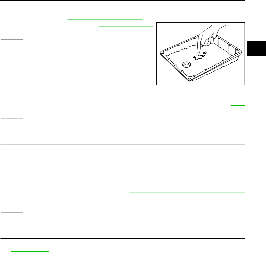
TROUBLE DIAGNOSIS FOR SYMPTOMS
AT-269
D
E
F
G
H
I
J
K
L
M
A
B
AT
7. CHECK A/T FLUID CONDITION
1. Remove oil pan. Refer to AT-299, "Control Valve Assembly" .
2. Check A/T fluid condition. Refer to AT-51, "Fluid Condition
Check" .
OK or NG
OK >> GO TO 8.
NG >> GO TO 11.
8. DETECT MALFUNCTIONING ITEM
●Check the malfunction items. If any items are damaged, repair or replace damaged parts. Refer to AT-62,
"Symptom Chart" (Symptom No.12).
OK or NG
OK >> GO TO 9.
NG >> Repair or replace damaged parts.
9. CHECK SYMPTOM
Check again. Refer to AT-56, "Cruise Test - Part 1" , AT-58, "Cruise Test - Part 2" .
OK or NG
OK >> INSPECTION END
NG >> GO TO 10.
10. PERFORM TCM INSPECTION
1. Perform TCM input/output signal inspection. Refer to AT-89, "TCM Input/Output Signal Reference Values"
.
2. If NG, recheck TCM pin terminals for damage or loose connection with harness connector.
OK or NG
OK >> INSPECTION END
NG >> Repair or replace damaged parts.
11. DETECT MALFUNCTIONING ITEM
●Check the malfunction items. If any items are damaged, repair or replace damaged parts. Refer to AT-62,
"Symptom Chart" (Symptom No.12).
OK or NG
OK >> GO TO 9.
NG >> Repair or replace damaged parts.
SAT171B
AT-270
TROUBLE DIAGNOSIS FOR SYMPTOMS
A/T Does Not Shift: D4 → D5ACS0029X
SYMPTOM:
●The vehicle does not shift-up from the D4 to D5 gear at the specified speed.
●The vehicle does not shift-up from the D4 to D5 gear unless A/T is warmed up.
DIAGNOSTIC PROCEDURE
1. CONFIRM THE SYMPTOM
Check if vehicle creeps forward in “D” position” and vehicle can be started from D1.
OK or NG
OK >> GO TO 2.
NG >> Refer to AT-258, "Vehicle Does Not Creep Forward In “D” Position" , AT-260, "Vehicle Cannot Be
Started From D1" .
2. CHECK SELF-DIAGNOSTIC RESULTS
Execute self-diagnosis.
Do the self-diagnostic results indicate ATF pressure switch 1, ATF pressure switch 5, front brake solenoid
valve, direct clutch solenoid valve, accelerator pedal position sensor, turbine revolution sensor, vehicle speed
sensor A/T (revolution sensor) and vehicle speed sensor MTR?
YES >> Check the malfunctioning system. Refer to AT-228, "DTC P1841 ATF PRESSURE SWITCH 1" ,
AT-236, "DTC P1845 ATF PRESSURE SWITCH 5" , AT-186, "DTC P1757 FRONT BRAKE
SOLENOID VALVE" , AT-196, "DTC P1762 DIRECT CLUTCH SOLENOID VALVE" , AT-151,
"DTC P1705 THROTTLE POSITION SENSOR" , AT-159, "DTC P1716 TURBINE REVOLUTION
SENSOR" , AT-117, "DTC P0720 VEHICLE SPEED SENSOR A/T (REVOLUTION SENSOR)" ,
AT-164, "DTC P1721 VEHICLE SPEED SENSOR MTR" .
NO >> GO TO 3.
3. CHECK A/T FLUID LEVEL
Check A/T fluid level again. Refer to AT-13, "Checking A/T Fluid" .
OK or NG
OK >> GO TO 4.
NG >> Refill ATF.
4. CHECK LINE PRESSURE
Check line pressure at the engine stall point. Refer to AT-52, "LINE
PRESSURE TEST" .
OK or NG
OK >> GO TO 7.
NG - 1 >> Line pressure high. GO TO 5.
NG - 2 >> Line pressure low. GO TO 6.
SAT638A
SAT494G
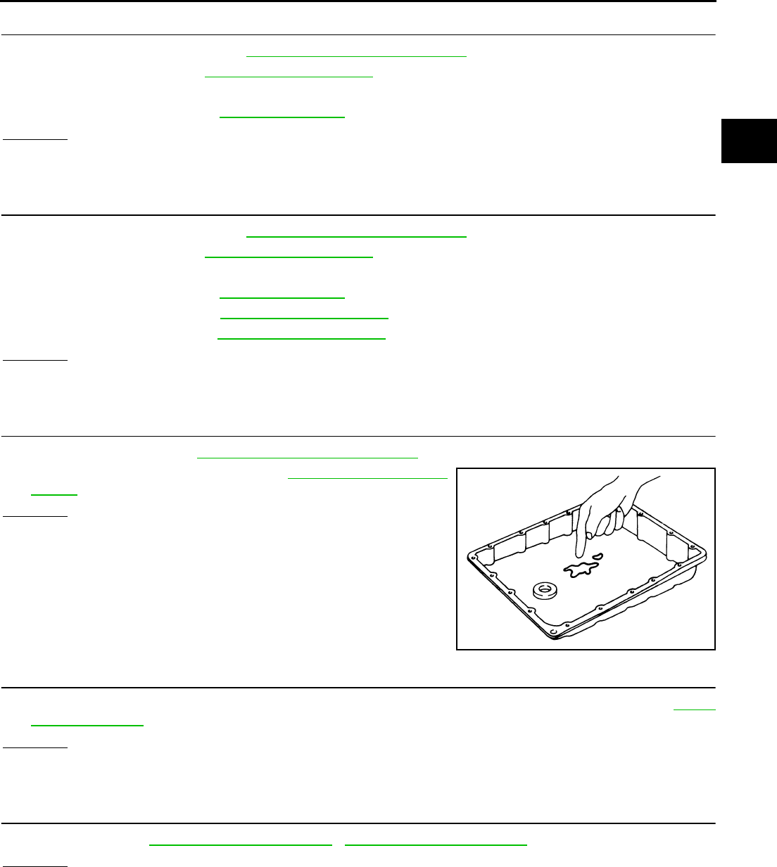
TROUBLE DIAGNOSIS FOR SYMPTOMS
AT-271
D
E
F
G
H
I
J
K
L
M
A
B
AT
5. DETECT MALFUNCTIONING ITEM
1. Control valve assembly. Refer to AT-299, "Control Valve Assembly" .
2. Disassemble A/T. Refer to AT-325, "DISASSEMBLY" .
3. Check the following items:
–Oil pump assembly. Refer to AT-339, "Oil Pump" .
OK or NG
OK >> GO TO 7.
NG >> Repair or replace damaged parts.
6. DETECT MALFUNCTIONING ITEM
1. Control valve assembly. Refer to AT-299, "Control Valve Assembly" .
2. Disassemble A/T. Refer to AT-325, "DISASSEMBLY" .
3. Check the following items:
–Oil pump assembly. Refer to AT-339, "Oil Pump" .
–Power train system. Refer to AT-325, "DISASSEMBLY" .
–Transmission case. Refer to AT-325, "DISASSEMBLY" .
OK or NG
OK >> GO TO 7.
NG >> Repair or replace damaged parts.
7. CHECK A/T FLUID CONDITION
1. Remove oil pan. Refer to AT-299, "Control Valve Assembly" .
2. Check A/T fluid condition. Refer to AT-51, "Fluid Condition
Check" .
OK or NG
OK >> GO TO 8.
NG >> GO TO 11.
8. DETECT MALFUNCTIONING ITEM
●Check the malfunction items. If any items are damaged, repair or replace damaged parts. Refer to AT-62,
"Symptom Chart" (Symptom No.13).
OK or NG
OK >> GO TO 9.
NG >> Repair or replace damaged parts.
9. CHECK SYMPTOM
Check again. Refer to AT-56, "Cruise Test - Part 1" , AT-58, "Cruise Test - Part 2" .
OK or NG
OK >> INSPECTION END
NG >> GO TO 10.
SAT171B
AT-272
TROUBLE DIAGNOSIS FOR SYMPTOMS
10. PERFORM TCM INSPECTION
1. Perform TCM input/output signal inspection. Refer to AT-89, "TCM Input/Output Signal Reference Values"
.
2. If NG, recheck TCM pin terminals for damage or loose connection with harness connector.
OK or NG
OK >> INSPECTION END
NG >> Repair or replace damaged parts.
11. DETECT MALFUNCTIONING ITEM
●Check the malfunction items. If any items are damaged, repair or replace damaged parts. Refer to AT-62,
"Symptom Chart" (Symptom No.13).
OK or NG
OK >> GO TO 9.
NG >> Repair or replace damaged parts.
A/T Does Not Perform Lock-up ACS0029Y
SYMPTOM:
A/T does not perform lock-up at the specified speed.
DIAGNOSTIC PROCEDURE
1. CHECK SELF-DIAGNOSTIC RESULTS
Execute self-diagnosis.
Do the self-diagnostic results indicate torque converter clutch solenoid valve, engine speed signal, turbine rev-
olution sensor, accelerator pedal position sensor, CAN communication?
YES >> Check the malfunctioning system. Refer to AT-124, "DTC P0740 TORQUE CONVERTER
CLUTCH SOLENOID VALVE" , AT-122, "DTC P0725 ENGINE SPEED SIGNAL" , AT-159, "DTC
P1716 TURBINE REVOLUTION SENSOR" , AT-151, "DTC P1705 THROTTLE POSITION SEN-
SOR" , AT-105, "DTC U1000 CAN COMMUNICATION LINE" .
NO >> GO TO 2.
2. CHECK A/T FLUID LEVEL
Check A/T fluid level again. Refer to AT-13, "Checking A/T Fluid" .
OK or NG
OK >> GO TO 3.
NG >> Refill ATF.
SAT638A
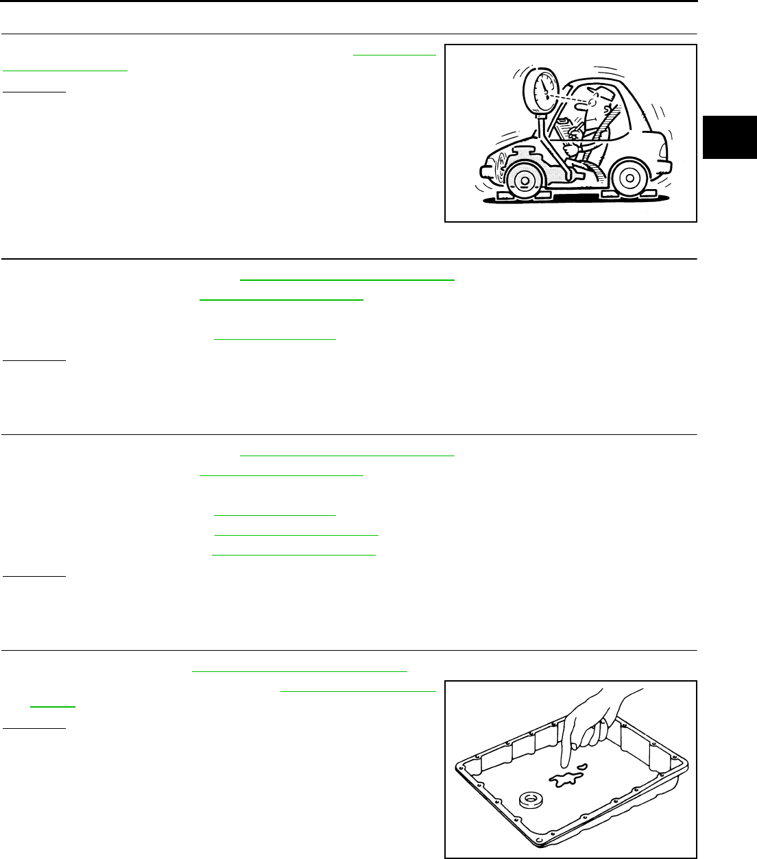
TROUBLE DIAGNOSIS FOR SYMPTOMS
AT-273
D
E
F
G
H
I
J
K
L
M
A
B
AT
3. CHECK LINE PRESSURE
Check line pressure at the engine stall point. Refer to AT-52, "LINE
PRESSURE TEST" .
OK or NG
OK >> GO TO 6.
NG - 1 >> Line pressure high. GO TO 4.
NG - 2 >> Line pressure low. GO TO 5.
4. DETECT MALFUNCTIONING ITEM
1. Control valve assembly. Refer to AT-299, "Control Valve Assembly" .
2. Disassemble A/T. Refer to AT-325, "DISASSEMBLY" .
3. Check the following items:
–Oil pump assembly. Refer to AT-339, "Oil Pump" .
OK or NG
OK >> GO TO 7.
NG >> Repair or replace damaged parts.
5. DETECT MALFUNCTIONING ITEM
1. Control valve assembly. Refer to AT-299, "Control Valve Assembly" .
2. Disassemble A/T. Refer to AT-325, "DISASSEMBLY" .
3. Check the following items:
–Oil pump assembly. Refer to AT-339, "Oil Pump" .
–Power train system. Refer to AT-325, "DISASSEMBLY" .
–Transmission case. Refer to AT-325, "DISASSEMBLY" .
OK or NG
OK >> GO TO 7.
NG >> Repair or replace damaged parts.
6. CHECK A/T FLUID CONDITION
1. Remove oil pan. Refer to AT-299, "Control Valve Assembly" .
2. Check A/T fluid condition. Refer to AT-51, "Fluid Condition
Check" .
OK or NG
OK >> GO TO 7.
NG >> GO TO 10.
SAT494G
SAT171B

AT-274
TROUBLE DIAGNOSIS FOR SYMPTOMS
7. DETECT MALFUNCTIONING ITEM
●Check the malfunction items. If any items are damaged, repair or replace damaged parts. Refer to AT-62,
"Symptom Chart" (Symptom No.24).
OK or NG
OK >> GO TO 8.
NG >> Repair or replace damaged parts.
8. CHECK SYMPTOM
Check again. Refer to AT-56, "Cruise Test - Part 1" .
OK or NG
OK >> INSPECTION END
NG >> GO TO 9.
9. PERFORM TCM INSPECTION
1. Perform TCM input/output signal inspection. Refer to AT-89, "TCM Input/Output Signal Reference Values"
.
2. If NG, recheck TCM pin terminals for damage or loose connection with harness connector.
OK or NG
OK >> INSPECTION END
NG >> Repair or replace damaged parts.
10. DETECT MALFUNCTIONING ITEM
●Check the malfunction items. If any items are damaged, repair or replace damaged parts. Refer to AT-62,
"Symptom Chart" (Symptom No.24).
OK or NG
OK >> GO TO 8.
NG >> Repair or replace damaged parts.
A/T Does Not Hold Lock-up Condition ACS0029Z
SYMPTOM:
The lock-up condition cannot be maintained for more than 30 seconds.
DIAGNOSTIC PROCEDURE
1. CHECK SELF-DIAGNOSTIC RESULTS
Execute self-diagnosis.
Do the self-diagnostic results indicate torque converter clutch solenoid valve, engine speed signal, turbine rev-
olution sensor, CAN communication?
YES >> Check the malfunctioning system. Refer to AT-124, "DTC P0740 TORQUE CONVERTER
CLUTCH SOLENOID VALVE" , AT-122, "DTC P0725 ENGINE SPEED SIGNAL" , AT-159, "DTC
P1716 TURBINE REVOLUTION SENSOR" , AT-105, "DTC U1000 CAN COMMUNICATION
LINE" .
NO >> GO TO 2.
TROUBLE DIAGNOSIS FOR SYMPTOMS
AT-275
D
E
F
G
H
I
J
K
L
M
A
B
AT
2. CHECK A/T FLUID LEVEL
Check A/T fluid level again. Refer to AT-13, "Checking A/T Fluid" .
OK or NG
OK >> GO TO 3.
NG >> Refill ATF.
3. CHECK A/T FLUID CONDITION
1. Remove oil pan. Refer to AT-299, "Control Valve Assembly" .
2. Check A/T fluid condition. Refer to AT-51, "Fluid Condition
Check" .
OK or NG
OK >> GO TO 4.
NG >> GO TO 7.
4. DETECT MALFUNCTIONING ITEM
●Check the malfunction items. If any items are damaged, repair or replace damaged parts. Refer to AT-62,
"Symptom Chart" (Symptom No.25).
OK or NG
OK >> GO TO 5.
NG >> Repair or replace damaged parts.
5. CHECK SYMPTOM
Check again. Refer to AT-56, "Cruise Test - Part 1" .
OK or NG
OK >> INSPECTION END
NG >> GO TO 6.
6. PERFORM TCM INSPECTION
1. Perform TCM input/output signal inspection. Refer to AT-89, "TCM Input/Output Signal Reference Values"
.
2. If NG, recheck TCM pin terminals for damage or loose connection with harness connector.
OK or NG
OK >> INSPECTION END
NG >> Repair or replace damaged parts.
SAT638A
SAT171B

AT-276
TROUBLE DIAGNOSIS FOR SYMPTOMS
7. DETECT MALFUNCTIONING ITEM
●Check the malfunction items. If any items are damaged, repair or replace damaged parts. Refer to AT-62,
"Symptom Chart" (Symptom No.25).
OK or NG
OK >> GO TO 5.
NG >> Repair or replace damaged parts.
Lock-up Is Not Released ACS002A0
SYMPTOM:
The lock-up condition cannot be cancelled even after releasing the accelerator pedal.
DIAGNOSTIC PROCEDURE
1. CHECK SELF-DIAGNOSTIC RESULTS
Execute self-diagnosis.
Do the self-diagnostic results indicate torque converter clutch solenoid valve, engine speed signal, turbine rev-
olution sensor, CAN communication?
YES >> Check the malfunctioning system. Refer to AT-124, "DTC P0740 TORQUE CONVERTER
CLUTCH SOLENOID VALVE" , AT-122, "DTC P0725 ENGINE SPEED SIGNAL" , AT-159, "DTC
P1716 TURBINE REVOLUTION SENSOR" , AT-105, "DTC U1000 CAN COMMUNICATION
LINE" .
NO >> GO TO 2.
2. CHECK SYMPTOM
Check again. Refer to AT-56, "Cruise Test - Part 1" .
OK or NG
OK >> INSPECTION END
NG >> GO TO 3.
3. PERFORM TCM INSPECTION
1. Perform TCM input/output signal inspection. Refer to AT-89, "TCM Input/Output Signal Reference Values"
.
2. If NG, recheck TCM pin terminals for damage or loose connection with harness connector.
OK or NG
OK >> INSPECTION END
NG >> Repair or replace damaged parts.
Engine Speed Does Not Return To Idle ACS002A1
SYMPTOM:
When a shift-down is performed, the engine speed does not smoothly return to the idling speed.
DIAGNOSTIC PROCEDURE
1. CHECK A/T FLUID LEVEL
Check A/T fluid level again. Refer to AT-13, "Checking A/T Fluid" .
OK or NG
OK >> GO TO 2.
NG >> Refill ATF.
TROUBLE DIAGNOSIS FOR SYMPTOMS
AT-277
D
E
F
G
H
I
J
K
L
M
A
B
AT
2. CHECK SELF-DIAGNOSTIC RESULTS
Execute self-diagnosis.
Do the self-diagnostic results indicate front brake solenoid valve, direct clutch solenoid valve, ATF pressure
switch 1, ATF pressure switch 5, accelerator pedal position sensor, vehicle speed sensor A/T (revolution sen-
sor) and vehicle speed sensor MTR?
YES >> Check the malfunctioning system. Refer to AT-186, "DTC P1757 FRONT BRAKE SOLENOID
VALVE" , AT-196, "DTC P1762 DIRECT CLUTCH SOLENOID VALVE" , AT-228, "DTC P1841 ATF
PRESSURE SWITCH 1" , AT-236, "DTC P1845 ATF PRESSURE SWITCH 5" , AT-151, "DTC
P1705 THROTTLE POSITION SENSOR" , AT-117, "DTC P0720 VEHICLE SPEED SENSOR A/T
(REVOLUTION SENSOR)" , AT-164, "DTC P1721 VEHICLE SPEED SENSOR MTR" .
NO >> GO TO 3.
3. CHECK A/T FLUID CONDITION
1. Remove oil pan. Refer to AT-299, "Control Valve Assembly" .
2. Check A/T fluid condition. Refer to AT-51, "Fluid Condition
Check" .
OK or NG
OK >> GO TO 4.
NG >> GO TO 7.
4. DETECT MALFUNCTIONING ITEM
●Check the malfunction items. If any items are damaged, repair or replace damaged parts. Refer to AT-62,
"Symptom Chart" (Symptom No.72).
OK or NG
OK >> GO TO 5.
NG >> Repair or replace damaged parts.
5. CHECK SYMPTOM
Check again. AT-56, "Cruise Test - Part 1" .
OK or NG
OK >> INSPECTION END
NG >> GO TO 6.
6. PERFORM TCM INSPECTION
1. Perform TCM input/output signal inspection. Refer to AT-89, "TCM Input/Output Signal Reference Values"
.
2. If NG, recheck TCM pin terminals for damage or loose connection with harness connector.
OK or NG
OK >> INSPECTION END
NG >> Repair or replace damaged parts.
SAT171B
AT-278
TROUBLE DIAGNOSIS FOR SYMPTOMS
7. DETECT MALFUNCTIONING ITEM
●Check the malfunction items. If any items are damaged, repair or replace damaged parts. Refer to AT-62,
"Symptom Chart" (Symptom No.72).
OK or NG
OK >> GO TO 5.
NG >> Repair or replace damaged parts.
Cannot Be Changed to Manual Mode ACS002A2
SYMPTOM:
Does not change to manual mode when manual shift gate is used.
DIAGNOSTIC PROCEDURE
1. MANUAL MODE SWITCH
Check the manual mode switch. Refer to AT-224, "DTC P1815 MANUAL MODE SWITCH" .
OK or NG
OK >> GO TO 2.
NG >> Repair or replace damaged parts.
2. CHECK SELF-DIAGNOSTIC RESULTS
Execute self-diagnosis.
Do the self-diagnostic results indicate turbine revolution sensor?
YES >> Check the malfunctioning system. Refer to AT-159, "DTC P1716 TURBINE REVOLUTION SEN-
SOR" .
NO >> INSPECTION END
A/T Does Not Shift: 5th gear → 4th gear ACS002A3
SYMPTOM:
When shifted from 5M to 4M position in manual mode, does not downshift from 5th to 4th gear.
DIAGNOSTIC PROCEDURE
1. CHECK SELF-DIAGNOSTIC RESULTS
Execute self-diagnosis.
Do the self-diagnostic results indicate PNP switch, ATF pressure switch 1?
YES >> Check the malfunctioning system. Refer to AT-112, "DTC P0705 PARK/NEUTRAL POSITION
SWITCH" , AT-228, "DTC P1841 ATF PRESSURE SWITCH 1" .
NO >> GO TO 2.
2. CHECK A/T FLUID LEVEL
Check A/T fluid level again. Refer to AT-13, "Checking A/T Fluid" .
OK or NG
OK >> GO TO 3.
NG >> Refill ATF.
SAT638A
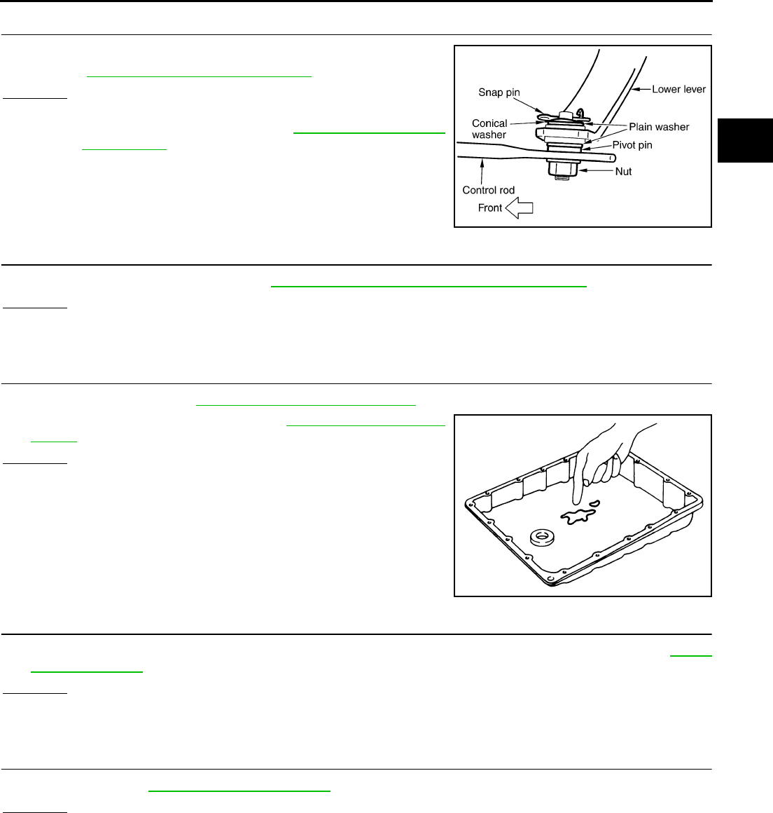
TROUBLE DIAGNOSIS FOR SYMPTOMS
AT-279
D
E
F
G
H
I
J
K
L
M
A
B
AT
3. CHECK CONTROL LINKAGE
Check the control linkage.
●Refer to AT-289, "Checking of A/T Position" .
OK or NG
OK >> GO TO 4.
NG >> Adjust control linkage. Refer to AT-289, "Adjustment of
A/T Position" .
4. MANUAL MODE SWITCH
Check the manual mode switch. Refer to AT-224, "DTC P1815 MANUAL MODE SWITCH" .
OK or NG
OK >> GO TO 5.
NG >> Repair or replace damaged parts.
5. CHECK A/T FLUID CONDITION
1. Remove oil pan. Refer to AT-299, "Control Valve Assembly" .
2. Check A/T fluid condition. Refer to AT-51, "Fluid Condition
Check" .
OK or NG
OK >> GO TO 6.
NG >> GO TO 9.
6. DETECT MALFUNCTIONING ITEM
●Check the malfunction items. If any items are damaged, repair or replace damaged parts. Refer to AT-62,
"Symptom Chart" (Symptom No.14).
OK or NG
OK >> GO TO 7.
NG >> Repair or replace damaged parts.
7. CHECK SYMPTOM
Check again. Refer to AT-59, "Cruise Test - Part 3" .
OK or NG
OK >> INSPECTION END
NG >> GO TO 8.
SCIA1904E
SAT171B
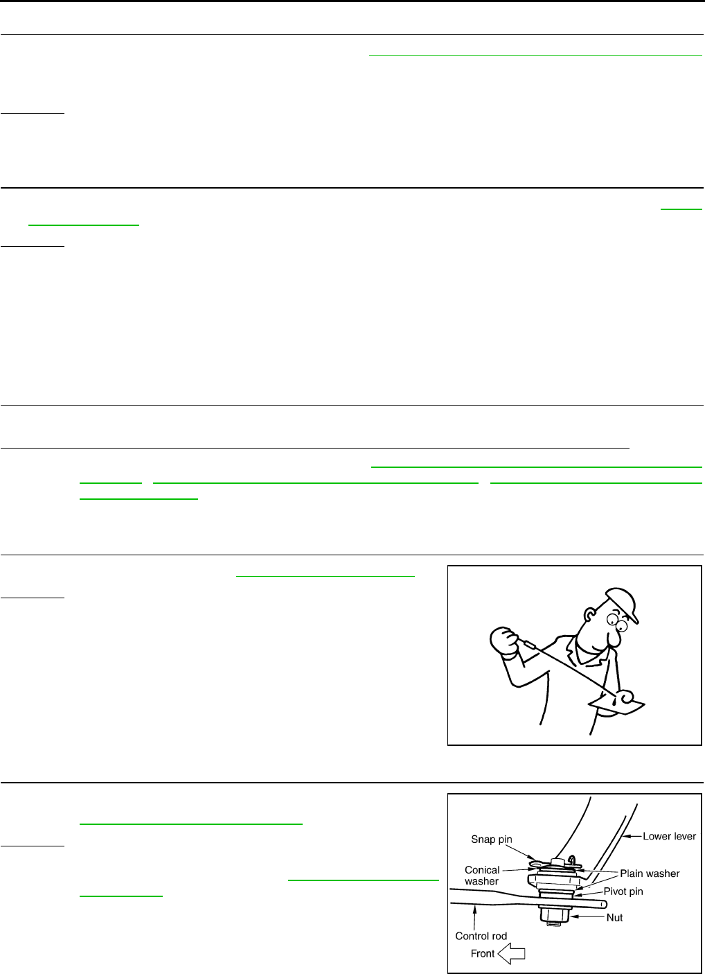
AT-280
TROUBLE DIAGNOSIS FOR SYMPTOMS
8. PERFORM TCM INSPECTION
1. Perform TCM input/output signal inspection. Refer to AT-89, "TCM Input/Output Signal Reference Values"
.
2. If NG, recheck TCM pin terminals for damage or loose connection with harness connector.
OK or NG
OK >> INSPECTION END
NG >> Repair or replace damaged parts.
9. DETECT MALFUNCTIONING ITEM
●Check the malfunction items. If any items are damaged, repair or replace damaged parts. Refer to AT-62,
"Symptom Chart" (Symptom No.14).
OK or NG
OK >> GO TO 7.
NG >> Repair or replace damaged parts.
A/T Does Not Shift: 4th gear → 3rd gear ACS002A4
SYMPTOM:
When shifted from 4M to 3M position in manual mode, does not downshift from 4th to 3rd gear.
DIAGNOSTIC PROCEDURE
1. CHECK SELF-DIAGNOSTIC RESULTS
Execute self-diagnosis.
Do the self-diagnostic results indicate PNP switch, ATF pressure switch 1, ATF pressure switch 3?
YES >> Check the malfunctioning system. Refer to AT-112, "DTC P0705 PARK/NEUTRAL POSITION
SWITCH" , AT-228, "DTC P1841 ATF PRESSURE SWITCH 1" , AT-232, "DTC P1843 ATF PRES-
SURE SWITCH 3" .
NO >> GO TO 2.
2. CHECK A/T FLUID LEVEL
Check A/T fluid level again. Refer to AT-13, "Checking A/T Fluid" .
OK or NG
OK >> GO TO 3.
NG >> Refill ATF.
3. CHECK CONTROL LINKAGE
Check the control linkage.
●Refer toAT-289, "Checking of A/T Position" .
OK or NG
OK >> GO TO 4.
NG >> Adjust control linkage. Refer to AT-289, "Adjustment of
A/T Position" .
SAT638A
SCIA1904E
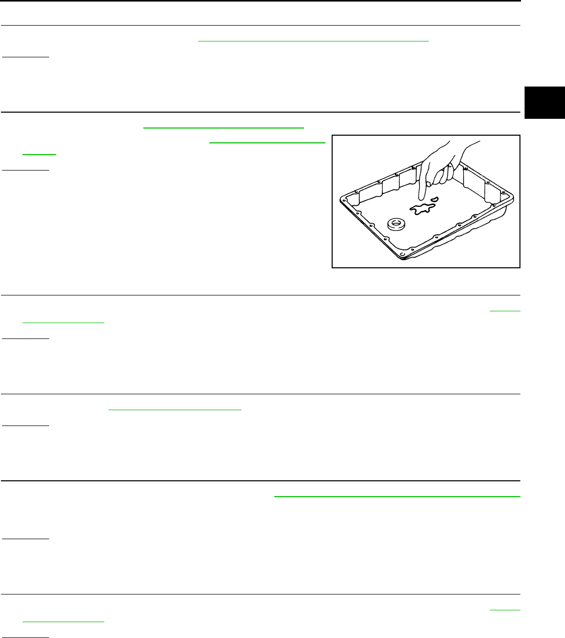
TROUBLE DIAGNOSIS FOR SYMPTOMS
AT-281
D
E
F
G
H
I
J
K
L
M
A
B
AT
4. MANUAL MODE SWITCH
Check the manual mode switch. Refer to AT-224, "DTC P1815 MANUAL MODE SWITCH" .
OK or NG
OK >> GO TO 5.
NG >> Repair or replace damaged parts.
5. CHECK A/T FLUID CONDITION
1. Remove oil pan. Refer to AT-299, "Control Valve Assembly" .
2. Check A/T fluid condition. Refer to AT-51, "Fluid Condition
Check" .
OK or NG
OK >> GO TO 6.
NG >> GO TO 9.
6. DETECT MALFUNCTIONING ITEM
●Check the malfunction items. If any items are damaged, repair or replace damaged parts. Refer to AT-62,
"Symptom Chart" (Symptom No.15).
OK or NG
OK >> GO TO 7.
NG >> Repair or replace damaged parts.
7. CHECK SYMPTOM
Check again. Refer to AT-59, "Cruise Test - Part 3" .
OK or NG
OK >> INSPECTION END
NG >> GO TO 8.
8. PERFORM TCM INSPECTION
1. Perform TCM input/output signal inspection. Refer to AT-89, "TCM Input/Output Signal Reference Values"
.
2. If NG, recheck TCM pin terminals for damage or loose connection with harness connector.
OK or NG
OK >> INSPECTION END
NG >> Repair or replace damaged parts.
9. DETECT MALFUNCTIONING ITEM
●Check the malfunction items. If any items are damaged, repair or replace damaged parts. Refer to AT-62,
"Symptom Chart" (Symptom No.15).
OK or NG
OK >> GO TO 7.
NG >> Repair or replace damaged parts.
SAT171B

AT-282
TROUBLE DIAGNOSIS FOR SYMPTOMS
A/T Does Not Shift: 3rd gear → 2nd gear ACS002A5
SYMPTOM:
When shifted from 3M to 2M position in manual mode, does not downshift from 3rd to 2nd gear.
DIAGNOSTIC PROCEDURE
1. CHECK SELF-DIAGNOSTIC RESULTS
Execute self-diagnosis.
Do the self-diagnostic results indicate PNP switch, ATF pressure switch 6?
YES >> Check the malfunctioning system. Refer to AT-112, "DTC P0705 PARK/NEUTRAL POSITION
SWITCH" , AT-240, "DTC P1846 ATF PRESSURE SWITCH 6" .
NO >> GO TO 2.
2. CHECK A/T FLUID LEVEL
Check A/T fluid level again. Refer to AT-13, "Checking A/T Fluid" .
OK or NG
OK >> GO TO 3.
NG >> Refill ATF.
3. CHECK CONTROL LINKAGE
Check the control linkage.
●Refer to AT-289, "Checking of A/T Position" .
OK or NG
OK >> GO TO 4.
NG >> Adjust control linkage. Refer to AT-289, "Adjustment of
A/T Position" .
4. MANUAL MODE SWITCH
Check the manual mode switch. Refer to AT-224, "DTC P1815 MANUAL MODE SWITCH" .
OK or NG
OK >> GO TO 5.
NG >> Repair or replace damaged parts.
SAT638A
SCIA1904E
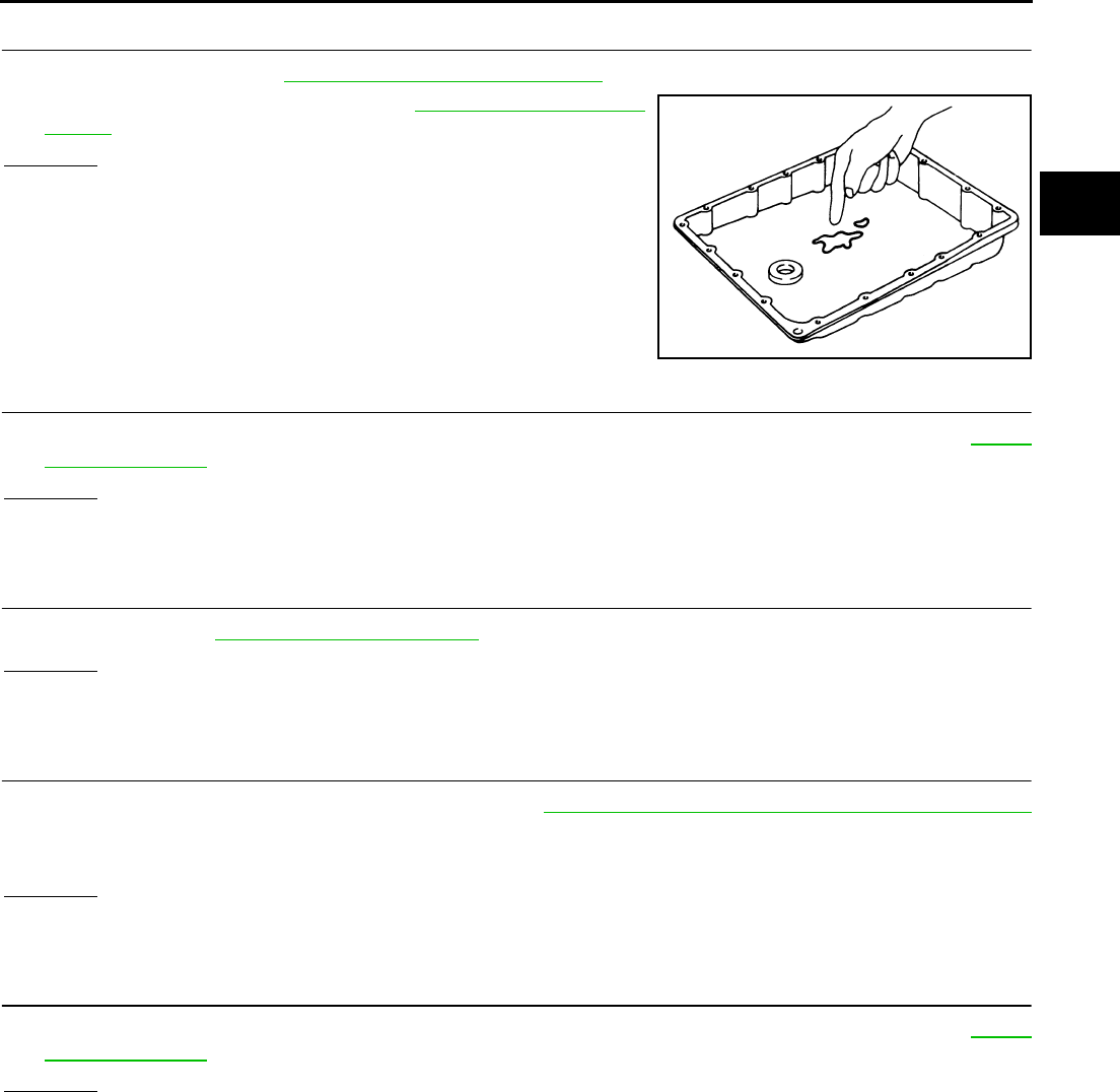
TROUBLE DIAGNOSIS FOR SYMPTOMS
AT-283
D
E
F
G
H
I
J
K
L
M
A
B
AT
5. CHECK A/T FLUID CONDITION
1. Remove oil pan. Refer to AT-299, "Control Valve Assembly" .
2. Check A/T fluid condition. Refer to AT-51, "Fluid Condition
Check" .
OK or NG
OK >> GO TO 6.
NG >> GO TO 9.
6. DETECT MALFUNCTIONING ITEM
●Check the malfunction items. If any items are damaged, repair or replace damaged parts. Refer to AT-62,
"Symptom Chart" (Symptom No.16).
OK or NG
OK >> GO TO 7.
NG >> Repair or replace damaged parts.
7. CHECK SYMPTOM
Check again. Refer to AT-59, "Cruise Test - Part 3" .
OK or NG
OK >> INSPECTION END
NG >> GO TO 8.
8. PERFORM TCM INSPECTION
1. Perform TCM input/output signal inspection. Refer to AT-89, "TCM Input/Output Signal Reference Values"
.
2. If NG, recheck TCM pin terminals for damage or loose connection with harness connector.
OK or NG
OK >> INSPECTION END
NG >> Repair or replace damaged parts.
9. DETECT MALFUNCTIONING ITEM
●Check the malfunction items. If any items are damaged, repair or replace damaged parts. Refer to AT-62,
"Symptom Chart" (Symptom No.16).
OK or NG
OK >> GO TO 7.
NG >> Repair or replace damaged parts.
SAT171B

AT-284
TROUBLE DIAGNOSIS FOR SYMPTOMS
A/T Does Not Shift: 2nd gear → 1st gear ACS002A6
SYMPTOM:
When shifted from 2M to 1M position in manual mode, does not downshift from 2nd to 1st gear.
DIAGNOSTIC PROCEDURE
1. CHECK SELF-DIAGNOSTIC RESULTS
Execute self-diagnosis.
Do the self-diagnostic results indicate PNP switch, ATF pressure switch 5?
YES >> Check the malfunctioning system. Refer to AT-112, "DTC P0705 PARK/NEUTRAL POSITION
SWITCH" , AT-236, "DTC P1845 ATF PRESSURE SWITCH 5" .
NO >> GO TO 2.
2. CHECK A/T FLUID LEVEL
Check A/T fluid level again. Refer to AT-13, "Checking A/T Fluid" .
OK or NG
OK >> GO TO 3.
NG >> Refill ATF.
3. CHECK CONTROL LINKAGE
Check the control linkage.
●Refer to AT-289, "Checking of A/T Position" .
OK or NG
OK >> GO TO 4.
NG >> Adjust control linkage. Refer to AT-289, "Adjustment of
A/T Position" .
4. MANUAL MODE SWITCH
Check the manual mode switch. Refer to AT-224, "DTC P1815 MANUAL MODE SWITCH" .
OK or NG
OK >> GO TO 5.
NG >> Repair or replace damaged parts.
SAT638A
SCIA1904E

TROUBLE DIAGNOSIS FOR SYMPTOMS
AT-285
D
E
F
G
H
I
J
K
L
M
A
B
AT
5. CHECK A/T FLUID CONDITION
1. Remove oil pan. Refer to AT-299, "Control Valve Assembly" .
2. Check A/T fluid condition. Refer to AT-51, "Fluid Condition
Check" .
OK or NG
OK >> GO TO 6.
NG >> GO TO 9.
6. DETECT MALFUNCTIONING ITEM
●Check the malfunction items. If any items are damaged, repair or replace damaged parts. Refer to AT-62,
"Symptom Chart" (Symptom No.17).
OK or NG
OK >> GO TO 7.
NG >> Repair or replace damaged parts.
7. CHECK SYMPTOM
Check again. Refer to AT-59, "Cruise Test - Part 3" .
OK or NG
OK >> INSPECTION END
NG >> GO TO 8.
8. PERFORM TCM INSPECTION
1. Perform TCM input/output signal inspection. Refer to AT-89, "TCM Input/Output Signal Reference Values"
.
2. If NG, recheck TCM pin terminals for damage or loose connection with harness connector.
OK or NG
OK >> INSPECTION END
NG >> Repair or replace damaged parts.
9. DETECT MALFUNCTIONING ITEM
●Check the malfunction items. If any items are damaged, repair or replace damaged parts. Refer to AT-62,
"Symptom Chart" (Symptom No.17).
OK or NG
OK >> GO TO 7.
NG >> Repair or replace damaged parts.
SAT171B
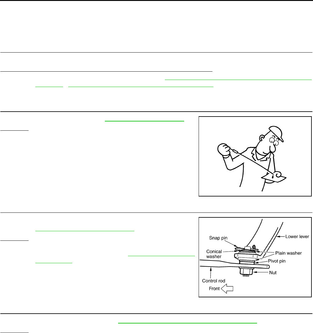
AT-286
TROUBLE DIAGNOSIS FOR SYMPTOMS
Vehicle Does Not Decelerate By Engine Brake ACS002A7
SYMPTOM:
No engine brake is applied when the gear is shifted from the D2 to D1.
DIAGNOSTIC PROCEDURE
1. CHECK SELF-DIAGNOSTIC RESULTS
Execute self-diagnosis.
Do the self-diagnostic results indicate PNP switch, ATF pressure switch 5?
YES >> Check the malfunctioning system. Refer to AT-112, "DTC P0705 PARK/NEUTRAL POSITION
SWITCH" , AT-236, "DTC P1845 ATF PRESSURE SWITCH 5" .
NO >> GO TO 2.
2. CHECK A/T FLUID LEVEL
Check A/T fluid level again. Refer to AT-13, "Checking A/T Fluid" .
OK or NG
OK >> GO TO 3.
NG >> Refill ATF.
3. CHECK CONTROL LINKAGE
Check the control linkage.
●Refer toAT-289, "Checking of A/T Position" .
OK or NG
OK >> GO TO 4.
NG >> Adjust control linkage. Refer to AT-289, "Adjustment of
A/T Position" .
4. MANUAL MODE SWITCH
Check the manual mode switch. Refer to AT-224, "DTC P1815 MANUAL MODE SWITCH" .
OK or NG
OK >> GO TO 5.
NG >> Repair or replace damaged parts.
SAT638A
SCIA1904E

TROUBLE DIAGNOSIS FOR SYMPTOMS
AT-287
D
E
F
G
H
I
J
K
L
M
A
B
AT
5. CHECK A/T FLUID CONDITION
1. Remove oil pan. Refer to AT-299, "Control Valve Assembly" .
2. Check A/T fluid condition. Refer to AT-51, "Fluid Condition
Check" .
OK or NG
OK >> GO TO 6.
NG >> GO TO 9.
6. DETECT MALFUNCTIONING ITEM
●Check the malfunction items. If any items are damaged, repair or replace damaged parts. Refer to AT-62,
"Symptom Chart" (Symptom No.58).
OK or NG
OK >> GO TO 7.
NG >> Repair or replace damaged parts.
7. CHECK SYMPTOM
Check again. Refer to AT-59, "Cruise Test - Part 3" .
OK or NG
OK >> INSPECTION END
NG >> GO TO 8.
8. PERFORM TCM INSPECTION
1. Perform TCM input/output signal inspection. Refer to AT-89, "TCM Input/Output Signal Reference Values"
.
2. If NG, recheck TCM pin terminals for damage or loose connection with harness connector.
OK or NG
OK >> INSPECTION END
NG >> Repair or replace damaged parts.
9. DETECT MALFUNCTIONING ITEM
●Check the malfunction items. If any items are damaged, repair or replace damaged parts. Refer to AT-62,
"Symptom Chart" (Symptom No.58).
OK or NG
OK >> GO TO 7.
NG >> Repair or replace damaged parts.
SAT171B
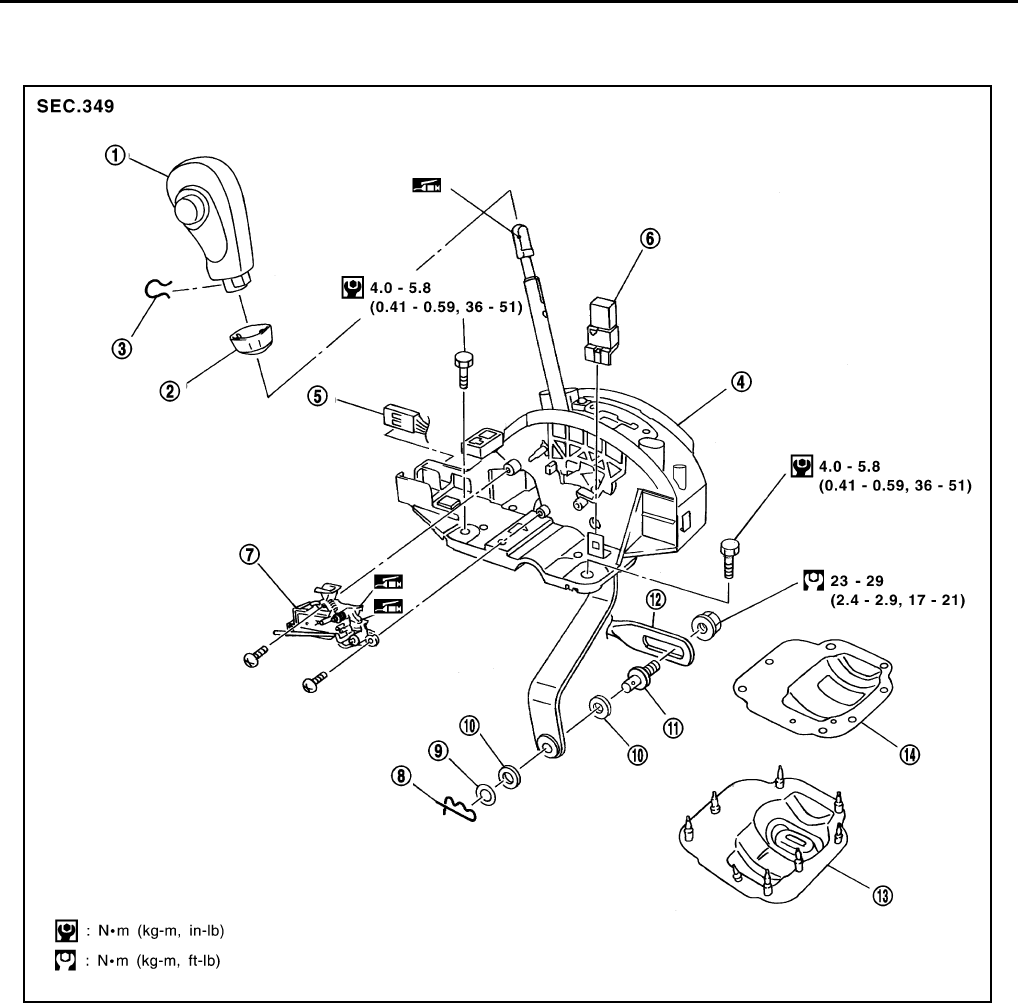
AT-288
SHIFT CONTROL SYSTEM
SHIFT CONTROL SYSTEM PFP:34901
Control Device Removal and Installation ACS000GG
1. Select lever knob 2. Knob cover 3. Lock pin
4. Control device assembly 5. A/T device harness connector 6. Shift lock relay
7. Shift lock solenoid and park position
switch assembly
8. Snap pin 9. Conical washer
10. Plain washer 11. Pivot pin 12. Control rod
13. Dust cover 14. Dust cover plate
SCIA3433E
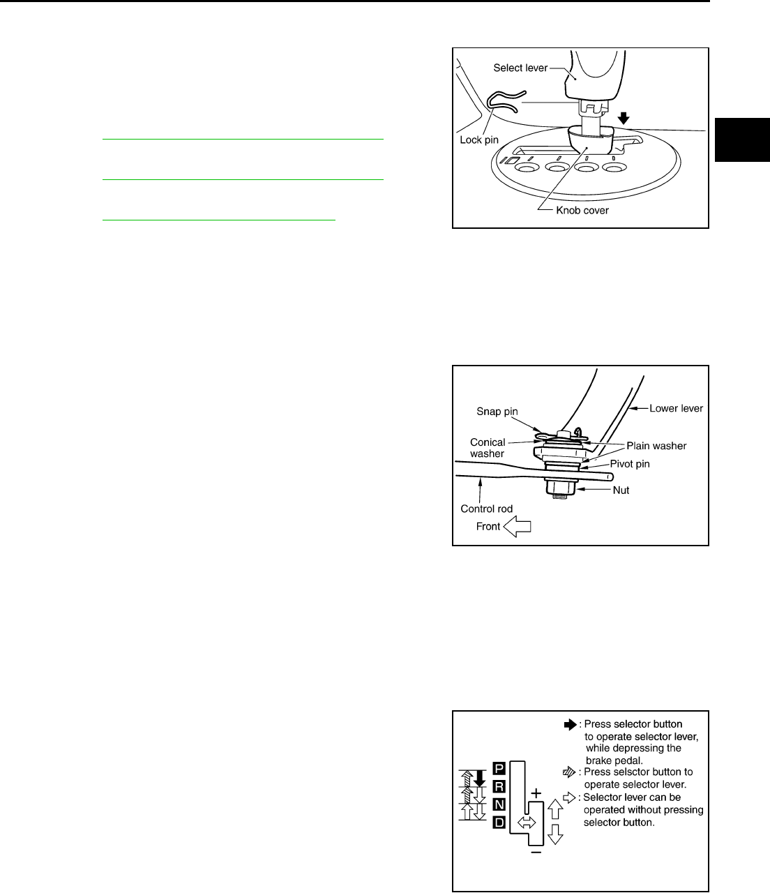
SHIFT CONTROL SYSTEM
AT-289
D
E
F
G
H
I
J
K
L
M
A
B
AT
REMOVAL
1. Disconnect lower lever of control device and control rod.
2. Remove knob cover below select lever downward.
3. Pull lock pin out of select lever knob.
4. Remove select lever knob.
5. Remove console finisher.
●Refer to IP-10, "INSTRUMENT PANEL ASSEMBLY" .
6. Remove center console.
●Refer to IP-10, "INSTRUMENT PANEL ASSEMBLY" .
7. Remove key interlock cable from control device.
●Refer to AT-296, "KEY INTERLOCK CABLE" .
8. Disconnect A/T device harness connector.
9. Remove control device assembly.
INSTALLATION
Install in reverse order of removal. Be careful of the following:
●After installation is completed, adjust and check A/T position.
Adjustment of A/T Position ACS000GH
1. Loosen nut of pivot pin.
2. Place PNP switch and select lever in “P” position.
3. While pressing lower lever toward rear of vehicle (in “P” position
direction), tighten nut to specified torque.
Checking of A/T Position ACS000GJ
1. Place select lever in “P” position, and turn ignition switch ON (engine stop).
2. Check that select lever can be shifted to other than “P” position when brake pedal is depressed. Also
check that select lever can be shifted from “P” position only when brake pedal is depressed.
3. Move the select lever and check for excessive effort, sticking, noise or rattle.
4. Confirm the select lever stops at each position with the feel of engagement when it is moved through all
the positions. Check whether or not the actual position the select lever is in matches the position shown
by the shift position indicator and the transmission body.
5. The method of operating the lever to individual positions cor-
rectly should be as shown in the figure.
6. When selector button is pressed in “P”, “R”, or “N” position with-
out applying forward/backward force to select lever, check but-
ton operation for sticking.
7. Confirm the back-up lamps illuminate only when lever is placed
in the “R” position. Confirm the back-up lamps does not illumi-
nate when select lever is in the “P” or “N” position with the lever
pushed against the “R” position.
8. Confirm the engine can only be started with the select lever in
the “P” and “N” positions. And confirm that the engine can be
started when the select lever is being moved back and front in
the “P” position.
9. Check that transmission is locked completely in “P” position.
10. When select lever is set to manual shift gate, check that manual mode is displayed on combination meter.
SCIA1226E
SCIA1904E
SCIA3906E

AT-290
SHIFT CONTROL SYSTEM
Shift select lever to “+” and “-” sides, and check that set shift position changes. (Only while a car is operat-
ing)
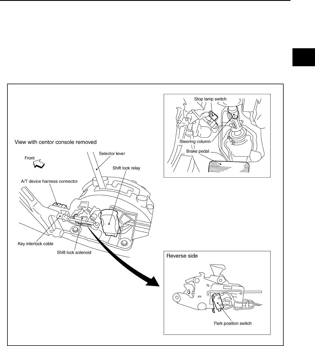
A/T SHIFT LOCK SYSTEM
AT-291
D
E
F
G
H
I
J
K
L
M
A
B
AT
A/T SHIFT LOCK SYSTEM PFP:34950
Description ACS000GK
●The mechanical key interlock mechanism also operates as a shift lock:
With the ignition switch turned to ON, the selector lever cannot be shifted from “P” (parking) to any other
position unless the brake pedal is depressed.
With the key removed, the selector lever cannot be shifted from “P” to any other position.
The key cannot be removed unless the selector lever is placed in “P”.
●The shift lock and key interlock mechanisms are controlled by the ON-OFF operation of the shift lock sole-
noid and by the operation of the rotator and slider located inside the key cylinder.
Shift Lock System Electrical Parts Location ACS000GL
SCIA4996E
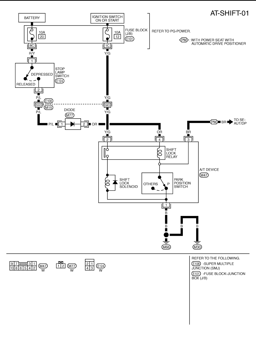
AT-292
A/T SHIFT LOCK SYSTEM
Wiring Diagram — AT — SHIFT ACS000GM
TCWT0250E
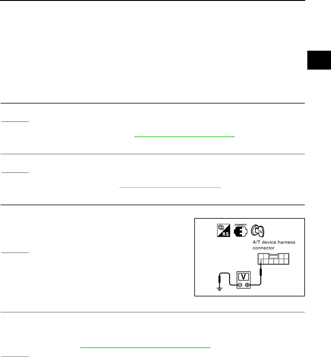
A/T SHIFT LOCK SYSTEM
AT-293
D
E
F
G
H
I
J
K
L
M
A
B
AT
Diagnostic Procedure ACS000GN
SYMPTOM 1:
●Selector lever cannot be moved from “P” position with key in ON position and brake pedal
applied.
●Selector lever can be moved from “P” position with key in ON position and brake pedal released.
●Selector lever can be moved from “P” position when key is removed from key cylinder.
SYMPTOM 2:
●Ignition key cannot be removed when selector lever is set to “P” position.
●Ignition key can be removed when selector lever is set to any position except “P”.
1. CHECK KEY INTERLOCK CABLE
Check key interlock cable for damage.
OK or NG
OK >> GO TO 2.
NG >> Repair key interlock cable. Refer to AT-296, "KEY INTERLOCK CABLE" .
2. CHECK SELECTOR LEVER POSITION
Check selector lever position for damage.
OK or NG
OK >> GO TO 3.
NG >> Check selector lever. Refer to AT-289, "Adjustment of A/T Position" .
3. CHECK POWER SOURCE
1. Turn ignition switch ON. (Do not start engine.)
2. Check voltage between A/T device harness connector M47 ter-
minal 2 (Y/G) and ground.
OK or NG
OK >> GO TO 5.
NG >> GO TO 4.
4. DETECT MALFUNCTIONING ITEM
Check the following items:
1. Harness for short or open between ignition switch and A/T device harness terminal 2
2. 10A fuse [No.12, located in the fuse block (J/B)]
3. Ignition switch (Refer to PG-3, "POWER SUPPLY ROUTING CIRCUIT" .)
OK or NG
OK >> GO TO 5.
NG >> Repair or replace damaged parts.
Voltage: Battery voltage
SCIA1214E
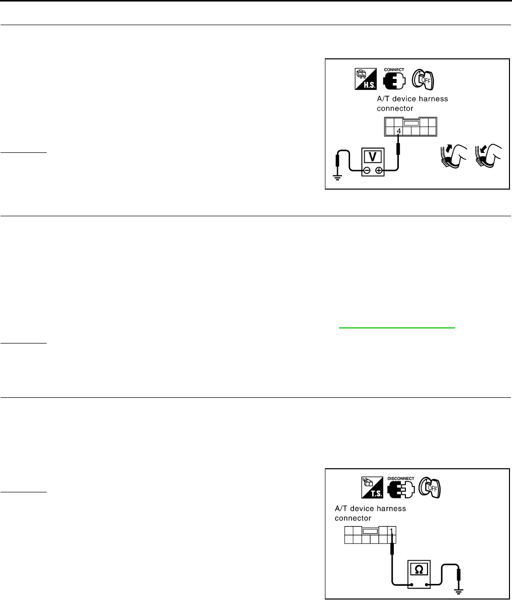
AT-294
A/T SHIFT LOCK SYSTEM
5. CHECK INPUT SIGNAL A/T DEVICE
Turn ignition switch OFF.
●Check voltage between A/T device harness connector M47 terminal 4 (OR) and ground.
OK or NG
OK >> GO TO 7.
NG >> GO TO 6.
6. DETECT MALFUNCTIONING ITEM
Check the following items:
1. Harness for short or open between battery and stop lamp switch harness connector 1
2. Harness for short or open between stop lamp switch harness connector 2 and A/T device harness con-
nector 4
3. 10A fuse [No.20, located in the fuse block (J/B)]
4. Stop lamp switch
–Check continuity between stop lamp switch harness connector terminals 1 (R/Y) and 2 (P/L).
Check stop lamp switch after adjusting brake pedal — refer to BR-6, "BRAKE PEDAL" .
OK or NG
OK >> GO TO 7.
NG >> Repair or replace damaged parts.
7. CHECK GROUND CIRCUIT
1. Turn ignition switch OFF.
2. Disconnect A/T device harness connector.
3. Check continuity between A/T device harness connector terminal 1 (B) and ground.
If OK, check harness for short to ground and short to power.
OK or NG
OK >> GO TO 8.
NG >> Repair open circuit or short to ground or short to power
in harness or connectors.
Voltage:
Brake pedal depressed:
Battery voltage
Brake pedal released:
0V
SCIA1215E
Continuity should exist.
SCIA1217E
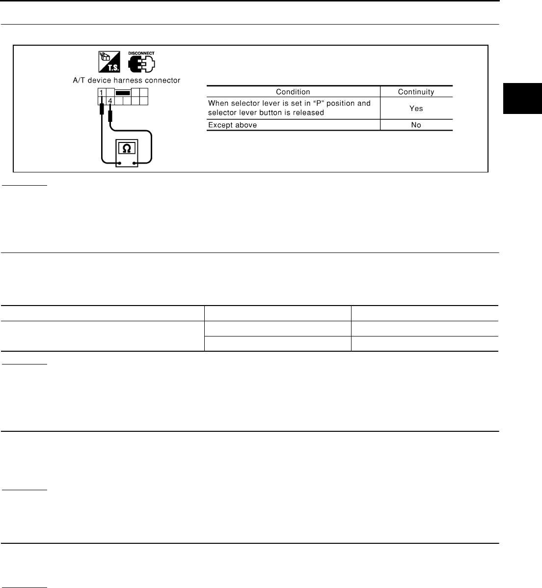
A/T SHIFT LOCK SYSTEM
AT-295
D
E
F
G
H
I
J
K
L
M
A
B
AT
8. CHECK PARK POSITION SWITCH AND RELAY CIRCUIT (COIL SIDE)
Check continuity between A/T device harness connector terminals 1 (B) and 4 (OR).
OK or NG
OK >> GO TO 9.
NG >> ●Replace park position switch or relay.
●Repair open circuit or short to ground or short to power in harness or connectors.
9. CHECK SHIFT LOCK SOLENOID AND RELAY CIRCUIT (POINT SIDE)
1. Connect A/T device harness connector.
2. Turn ignition switch ON. (Do not start engine.)
3. Check shift lock solenoid and relay operation.
OK or NG
OK >> GO TO 10.
NG >> ●Replace shift lock solenoid or relay.
●Repair open circuit or short to ground or short to power in harness or connectors.
10. CHECK SHIFT LOCK OPERATION
1. Connect A/T device harness connector.
2. Turn ignition switch from OFF to ON. (Do not start engine.)
3. Recheck shift lock operation.
OK or NG
OK >> INSPECTION END
NG >> GO TO 11.
11. CHECK A/T DEVICE INSPECTION
1. Perform A/T device input/output signal inspection test.
2. If NG, recheck harness connector connection.
OK or NG
OK >> INSPECTION END
NG >> Repair or replace damaged parts.
SCIA1218E
Condition Brake pedal Operation
When ignition switch is turned to “ON” position and
selector lever is set in “P” position.
Depressed Yes
Released No
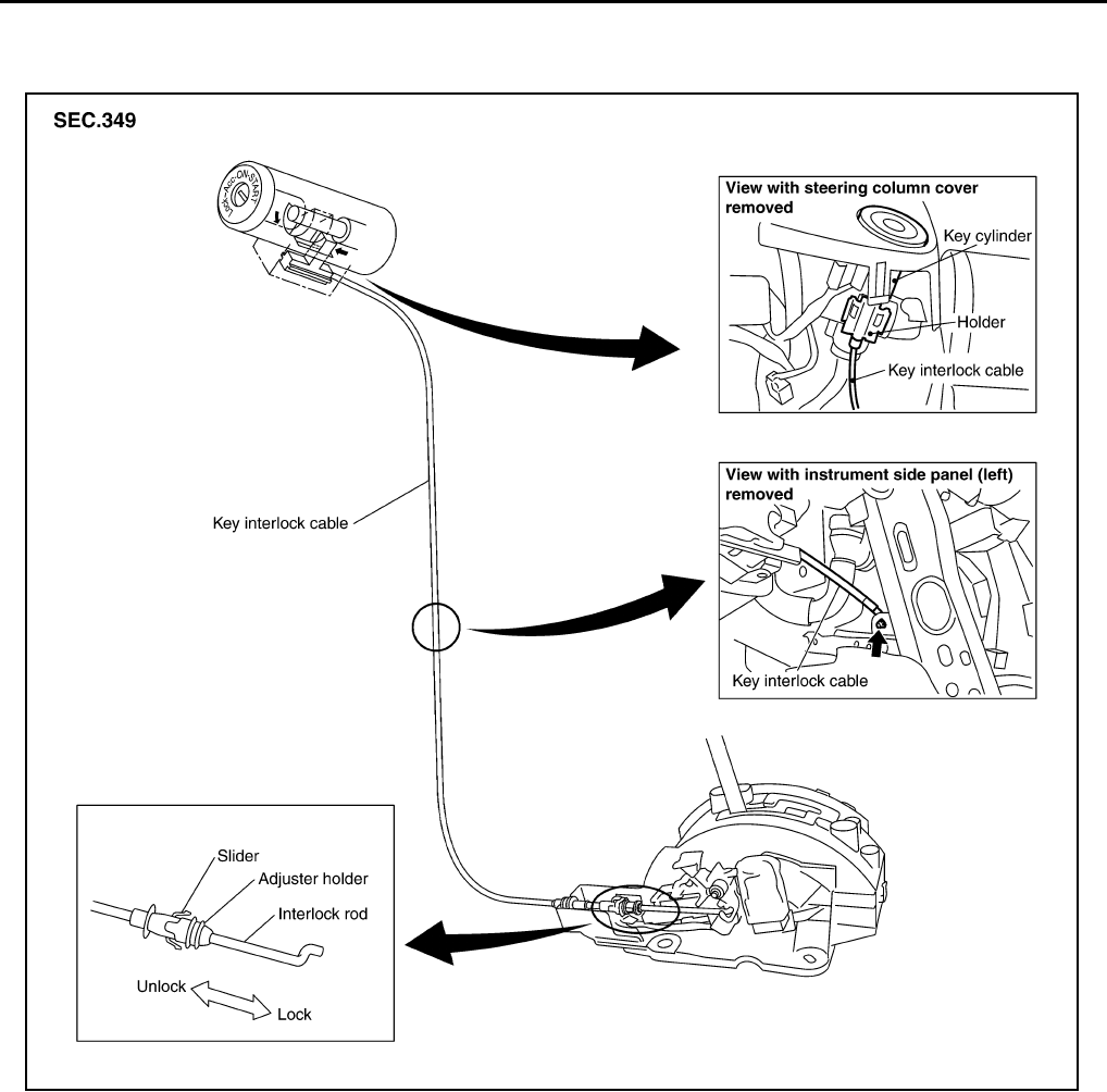
AT-296
KEY INTERLOCK CABLE
KEY INTERLOCK CABLE PFP:34908
Components ACS000GD
CAUTION:
●Install key interlock cable in such a way that it will not be damaged by sharp bends, twists or inter-
ference with adjacent parts.
●After installing key interlock cable to control device, make sure that casing cap and bracket are
firmly secured in their positions. If casing cap be removed with an external load of less than 39 N
(4.0 kg, 8.8 lb), replace key interlock cable with new one.
SCIA1229E
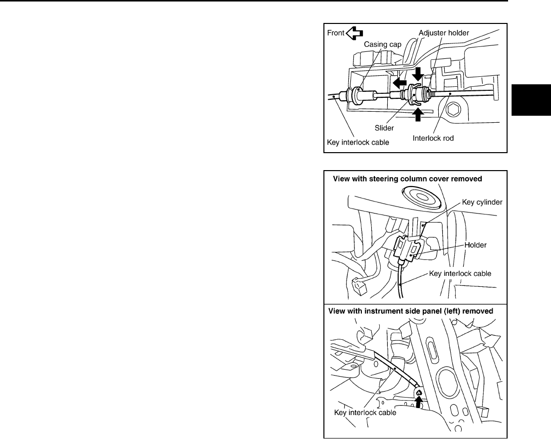
KEY INTERLOCK CABLE
AT-297
D
E
F
G
H
I
J
K
L
M
A
B
AT
Removal ACS000GE
1. Unlock slider by squeezing lock tabs on slider from adjuster
holder.
2. Remove casing cap from bracket of control device and remove
interlock rod from cable.
3. Remove holder from key cylinder and remove key interlock
cable.
SCIA1230E
SCIA1231E
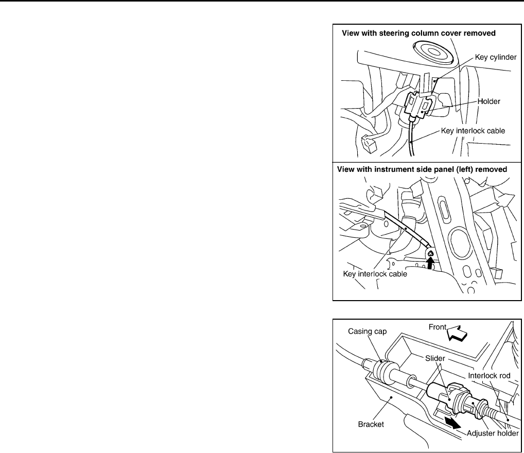
AT-298
KEY INTERLOCK CABLE
Installation ACS000GF
1. Set key interlock cable to key cylinder and install holder.
2. Clamp cable and fix to control cable with band.
3. Turn ignition key to lock position.
4. Set selector lever to P position.
5. Insert interlock rod into adjuster holder.
6. Install casing cap to bracket.
7. Move slider in order to fix adjuster holder to interlock rod.
CAUTION:
Do not touch any adjacent parts of key interlock cable when
slider is being held.
Insert slider into key interlock rod straightly.
SCIA1231E
SCIA1232E
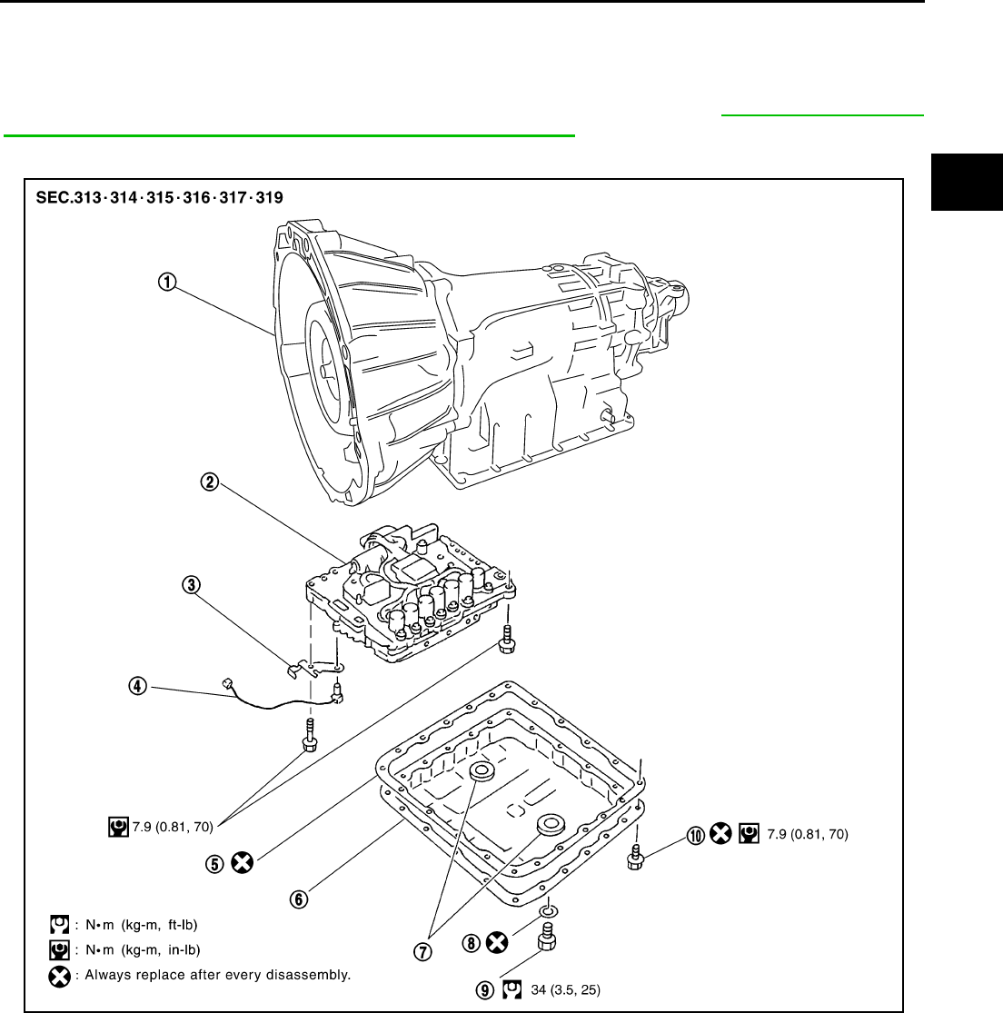
ON-VEHICLE SERVICE
AT-299
D
E
F
G
H
I
J
K
L
M
A
B
AT
ON-VEHICLE SERVICE PFP:00000
Control Valve Assembly ACS004IW
CAUTION:
When replacing the control valve assembly, erase EEP ROM in TCM. Refer to AT-8, "Precautions for
TCM, A/T Assembly and Control Valve Assembly Replacement" .
COMPONENTS
REMOVAL
1. Disconnect the negative battery terminal.
2. Disconnect heated oxygen sensor 2 harness connector.
3. Drain ATF through drain plug.
1. Transmission 2. Control valve assembly 3. Bracket
4. A/T fluid temperature sensor 2 5. Oil pan gasket 6. Oil pan
7. Magnet 8. Drain plug gasket 9. Drain plug
10. Oil pan mounting bolt
SCIA3441E
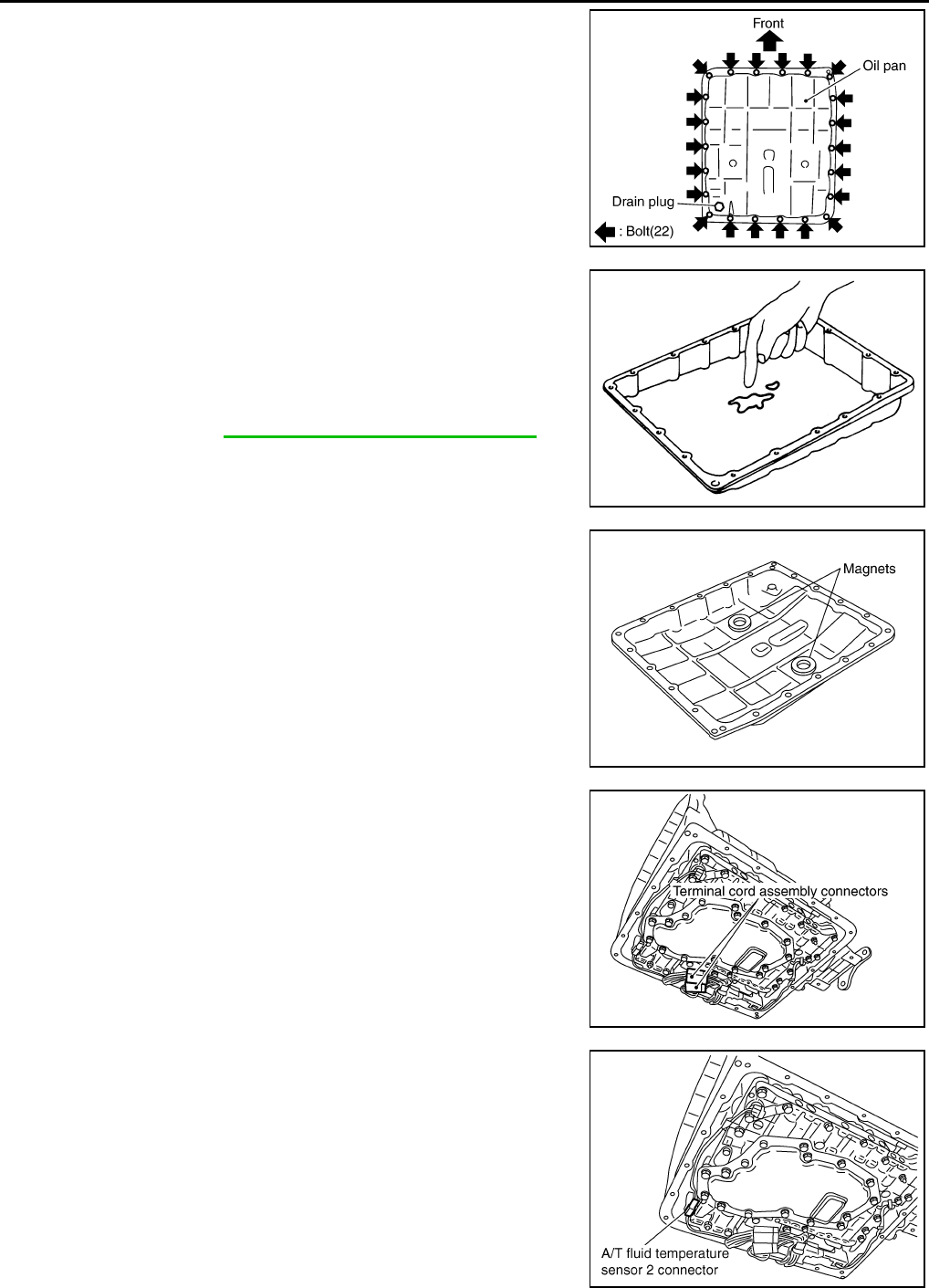
AT-300
ON-VEHICLE SERVICE
4. Remove oil pan and oil pan gasket.
5. Check foreign materials in oil pan to help determine causes of
malfunction. If the A/T fluid is very dark, smells burned, or con-
tains foreign particles, the frictional material (clutches, band)
may need replacement. A tacky film that will not wipe clean indi-
cates varnish build up. Varnish can cause valves, servo, and
clutches to stick and can inhibit pump pressure.
●If frictional material is detected, perform A/T fluid cooler
cleaning. Refer to AT-15, "A/T Fluid Cooler Cleaning".
6. Remove magnets from oil pan.
7. Disconnect terminal cord assembly connectors.
CAUTION:
Be careful not to damage connector.
8. Disconnect A/T fluid temperature sensor 2 connector.
CAUTION:
Be careful not to damage connector.
SCIA2308E
SCIA5199E
SCIA5200E
SCIA3976E
SCIA4967E
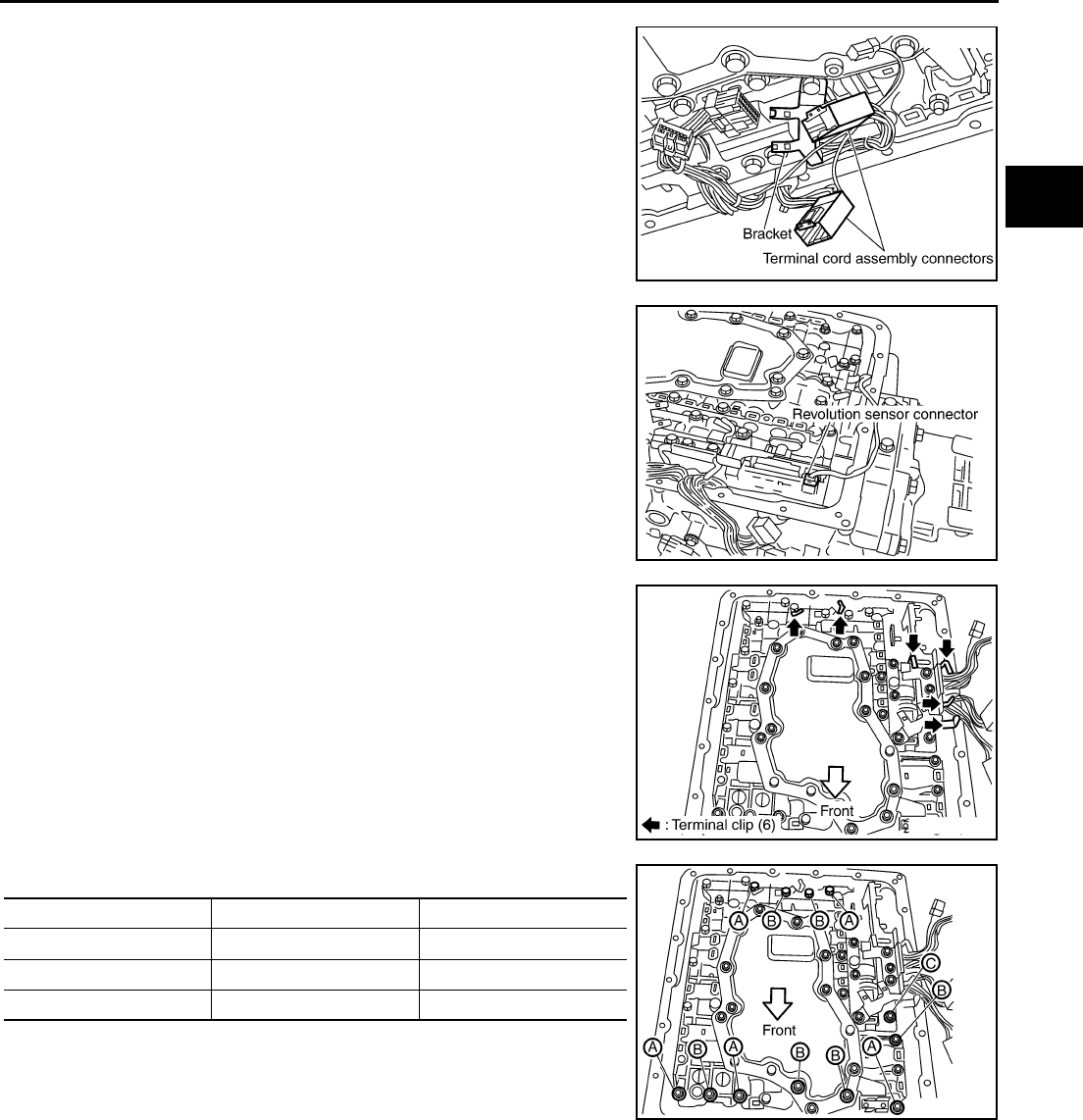
ON-VEHICLE SERVICE
AT-301
D
E
F
G
H
I
J
K
L
M
A
B
AT
9. Remove terminal cord assembly connectors from bracket.
CAUTION:
Be careful not to damage connector.
10. Disconnect revolution sensor connector.
CAUTION:
Be careful not to damage connector.
11. Straighten terminal clips to free terminal cord assembly and rev-
olution sensor harness then remove terminal clips.
CAUTION:
Hang down terminal cord assembly and revolution sensor
harness toward outside so as not to disturb removal of con-
trol valve assembly.
12. Remove bolts A, B and C from control valve assembly.
SCIA3977E
SCIA2313E
SCIA2314E
Bolt symbol Length mm (in) Number of bolts
A 42 (1.65) 5
B 55 (2.17) 6
C 40 (1.57) 1
SCIA2312E
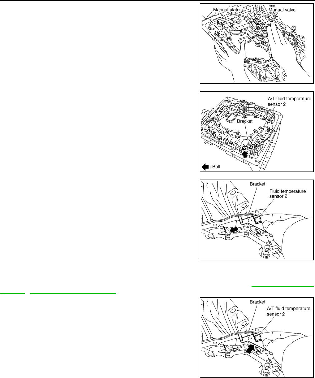
AT-302
ON-VEHICLE SERVICE
13. Remove control valve assembly from transmission case.
CAUTION:
When removing, be careful with the manual valve notch and
manual plate height. Remove it vertically.
14. Remove A/T fluid temperature sensor 2 with bracket from con-
trol valve assembly.
15. Remove bracket from A/T fluid temperature sensor 2.
INSTALLATION
CAUTION:
After completing installation, check A/T fluid leakage and A/T fluid level. Refer to AT-13, "Changing A/
T Fluid" , AT-13, "Checking A/T Fluid" .
1. Install A/T fluid temperature sensor 2 in bracket.
SCIA3984E
SCIA5126E
SCIA2583E
SCIA5128E
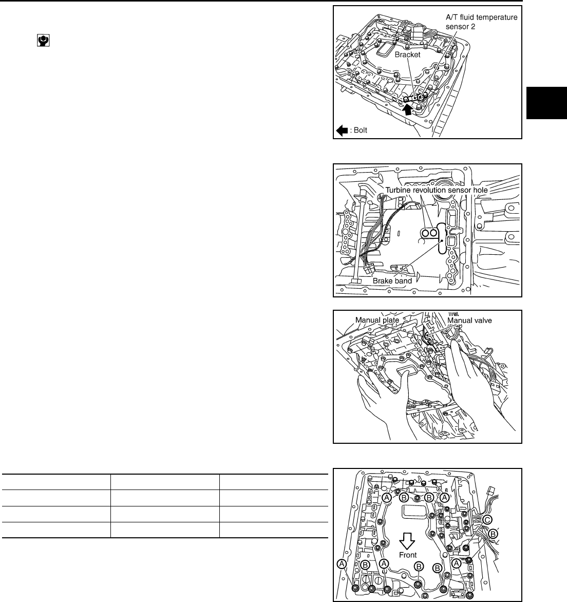
ON-VEHICLE SERVICE
AT-303
D
E
F
G
H
I
J
K
L
M
A
B
AT
2. Install A/T fluid temperature sensor 2 in control valve assembly.
(With bracket.)
3. Install control valve assembly.
a. Install control valve assembly in transmission case.
CAUTION:
●Make sure that turbine sensor securely installs turbine
sensor hole.
●Hang down terminal cord assembly and revolution sen-
sor harness toward outside so as not to disturb installa-
tion of control valve assembly.
●Assemble it so that manual valve cutout is engaged with
manual plate projection.
b. Install bolts A, B and C in control valve assembly.
: 7.9 N·m (0.81 kg-m, 70 in-lb)
SCIA5126E
SCIA2479E
SCIA3984E
Bolt symbol Length mm (in) Number of bolts
A 42 (1.65) 5
B 55 (2.17) 6
C 40 (1.57) 1
SCIA2312E
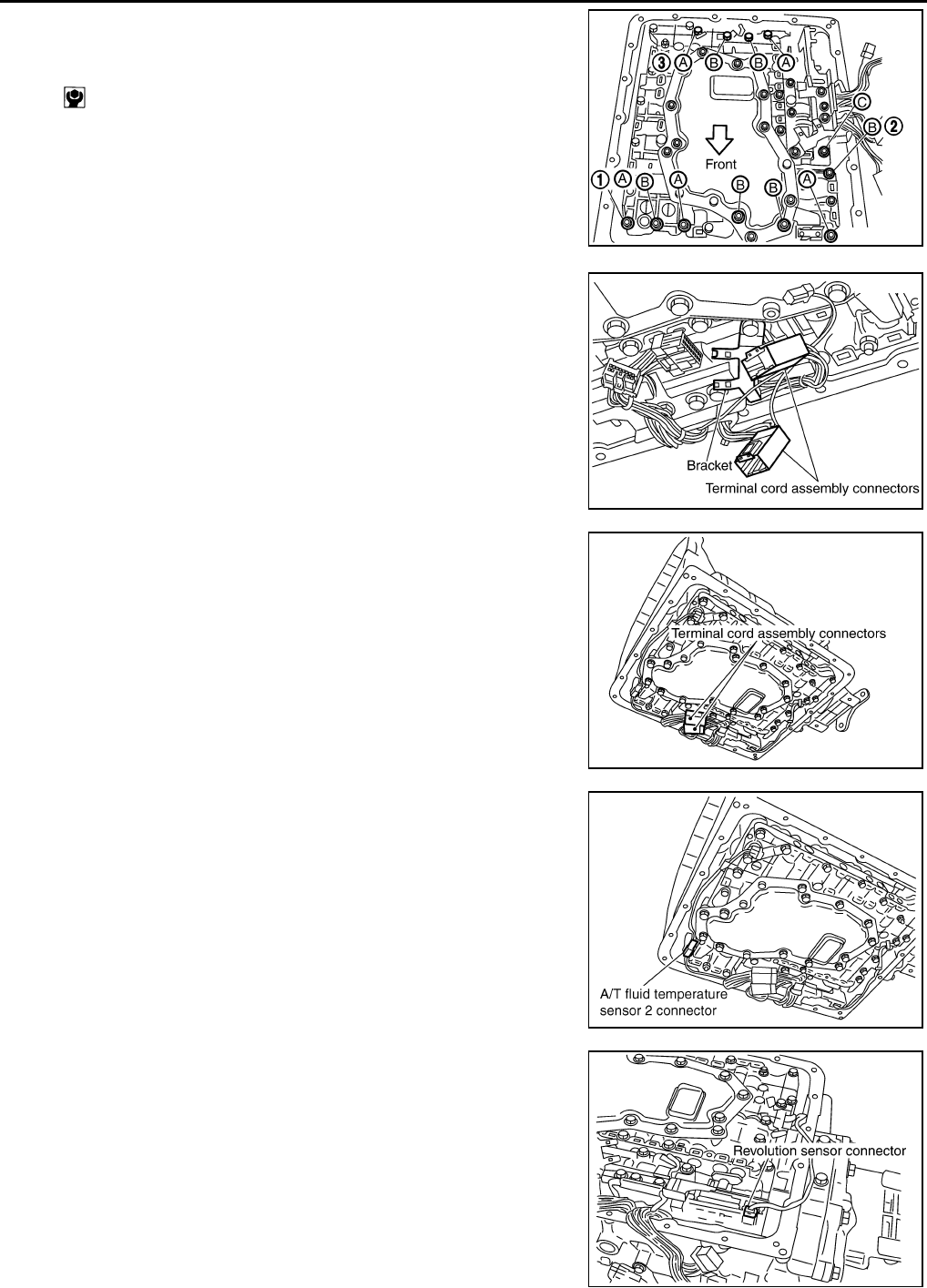
AT-304
ON-VEHICLE SERVICE
c. Tighten bolt 1, 2 and 3 temporarily to prevent dislocation. After
that tighten them in order (1 → 2 → 3), and then tighten other
bolts.
4. Install terminal cord assembly connectors in bracket.
5. Connect terminal cord assembly connectors.
6. Connect A/T fluid temperature sensor 2 connector.
7. Connect revolution sensor connector.
: 7.9 N·m (0.81 kg-m, 70 in-lb)
SCIA3170E
SCIA3977E
SCIA3976E
SCIA4967E
SCIA2313E
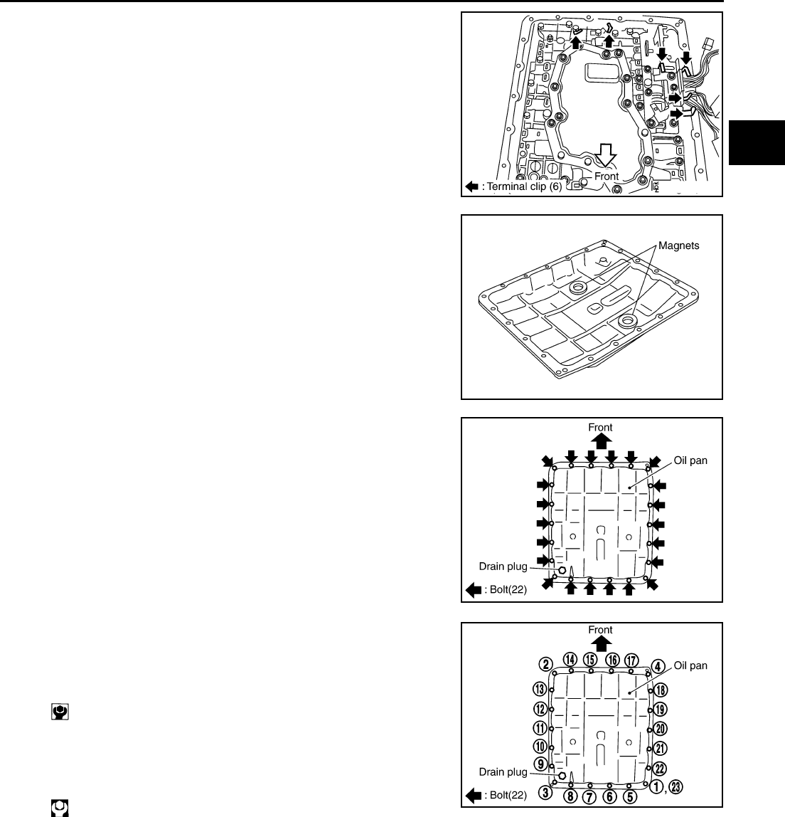
ON-VEHICLE SERVICE
AT-305
D
E
F
G
H
I
J
K
L
M
A
B
AT
8. Securely fasten terminal harness with clip.
9. Install magnets in oil pan.
10. Install oil pan in transmission case.
a. Install oil pan gasket in oil pan.
CAUTION:
●Do not reuse oil pan gasket.
●Install it in the direction to align hole positions.
b. Install oil pan (with oil pan gasket) in transmission case.
CAUTION:
●Install it so that drain plug comes to the position as
shown in the figure.
●Be careful not to pinch harnesses.
c. Tighten oil pan mounting bolts to the specified torque in numeri-
cal order shown in the figure after temporarily tightening them.
CAUTION:
Do not reuse oil pan mounting bolts.
11. Install drain plug in oil pan.
CAUTION:
Do not reuse drain plug gasket.
12. Pour ATF into transmission assembly.
13. Connect heated oxygen sensor 2 harness connector.
14. Connect the negative battery terminal.
SCIA2314E
SCIA5200E
SCIA2308E
: 7.9 N·m (0.81 kg-m, 70 in-lb)
: 34 N·m (3.5 kg-m, 25 ft-lb) SCIA2492E
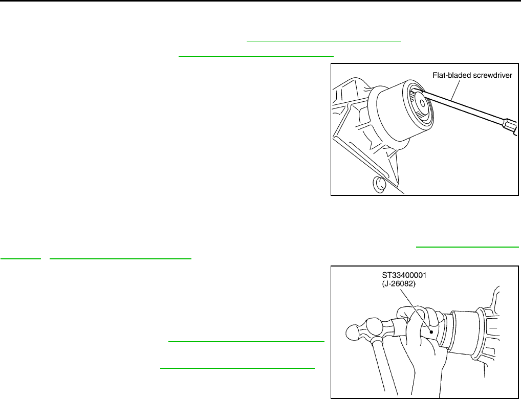
AT-306
ON-VEHICLE SERVICE
Rear Oil Seal ACS004K1
REMOVAL
1. Remove exhaust tube with power tool. Refer to EX-3, "Removal and Installation" .
2. Remove propeller shaft. Refer to PR-4, "Removal and Installation" .
3. Remove rear oil seal using a flat-bladed screwdriver.
CAUTION:
Be careful not to scratch rear extension assembly.
INSTALLATION
CAUTION:
After completing installation, check A/T fluid leakage and A/T fluid level. Refer to AT-13, "Changing A/
T Fluid" , AT-13, "Checking A/T Fluid" .
1. As shown below, use a drift to drive rear oil seal into the rear
extension until it is flush.
CAUTION:
●Apply ATF to rear oil seal.
●Do not reuse rear oil seal
2. Install propeller shaft. Refer to PR-4, "Removal and Installation"
.
3. Install exhaust tube. Refer to EX-3, "Removal and Installation" .
SCIA3428E
SCIA5310E
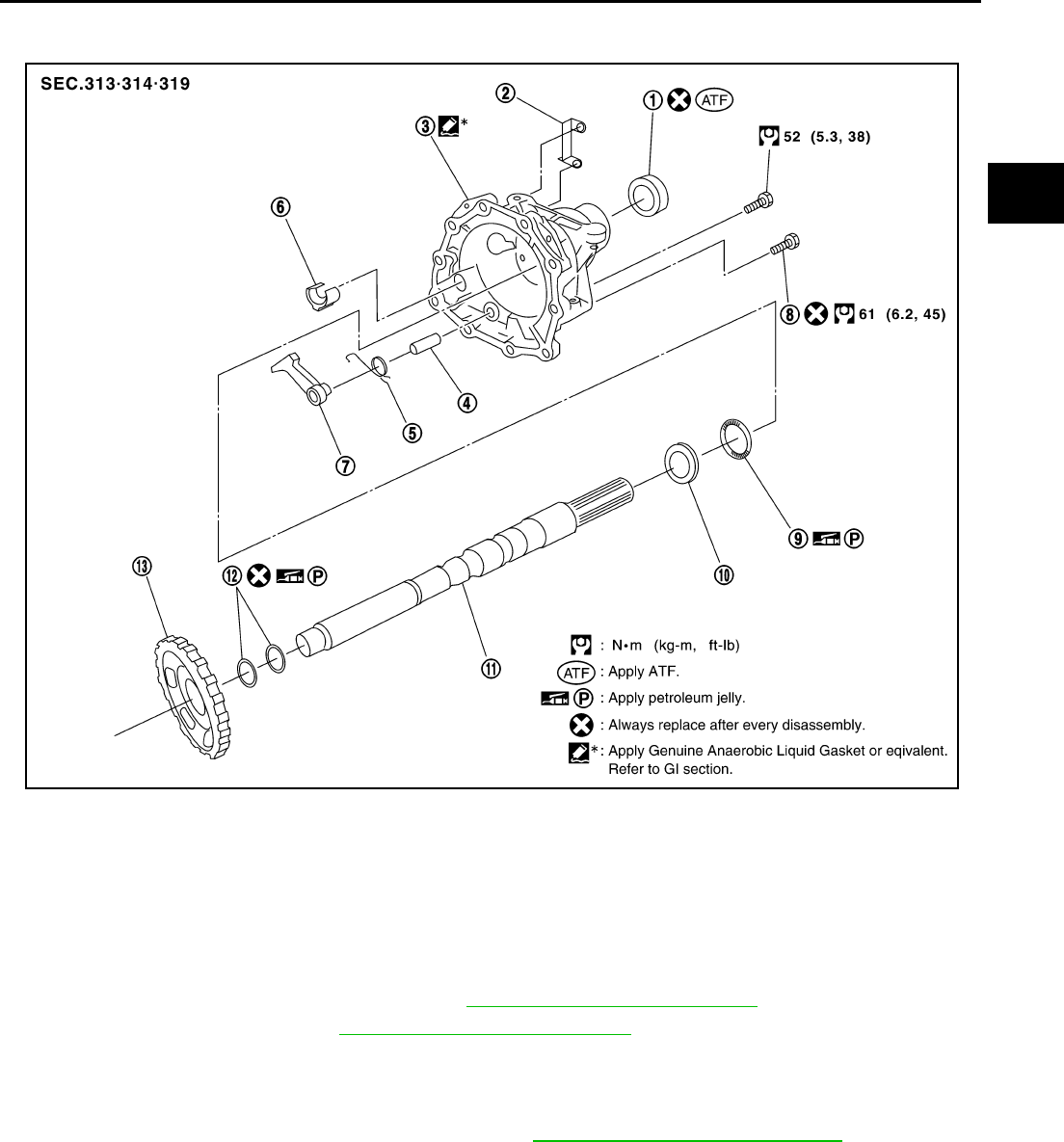
ON-VEHICLE SERVICE
AT-307
D
E
F
G
H
I
J
K
L
M
A
B
AT
Parking Components ACS004K2
COMPONENTS
REMOVAL
1. Drain ATF through drain plug.
2. Remove exhaust tube with power tool. Refer to EX-3, "Removal and Installation" .
3. Remove propeller shaft. Refer to PR-4, "Removal and Installation" .
4. Support transmission assembly with a transmission jack.
CAUTION:
When setting transmission jack, be careful not to allow it to collide against the drain plug.
5. Remove engine rear member with power tool. Refer to AT-314, "Removal and Installation" .
1. Rear oil seal 2. Terminal bracket 3. Rear extension
4. Pawl shaft 5. Return spring 6. Parking actuator support
7. Parking pawl 8. Self-sealing bolt 9. Needle bearing
10. Bearing race 11. Output shaft 12. Seal ring
13. Parking gear
SCIA5001E
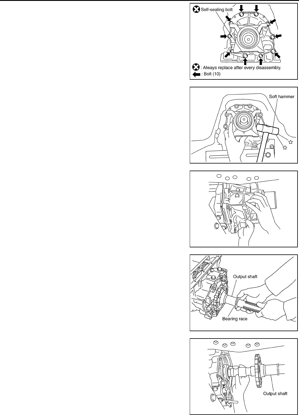
AT-308
ON-VEHICLE SERVICE
6. Remove tightening bolts for rear extension assembly.
7. Tap rear extension assembly with soft hammer.
8. Remove rear extension assembly from transmission case.
9. Remove bearing race from output shaft.
10. Remove output shaft from transmission case.
SCIA3426E
SCIA3432E
SCIA3431E
SCIA5245E
SCIA5246E
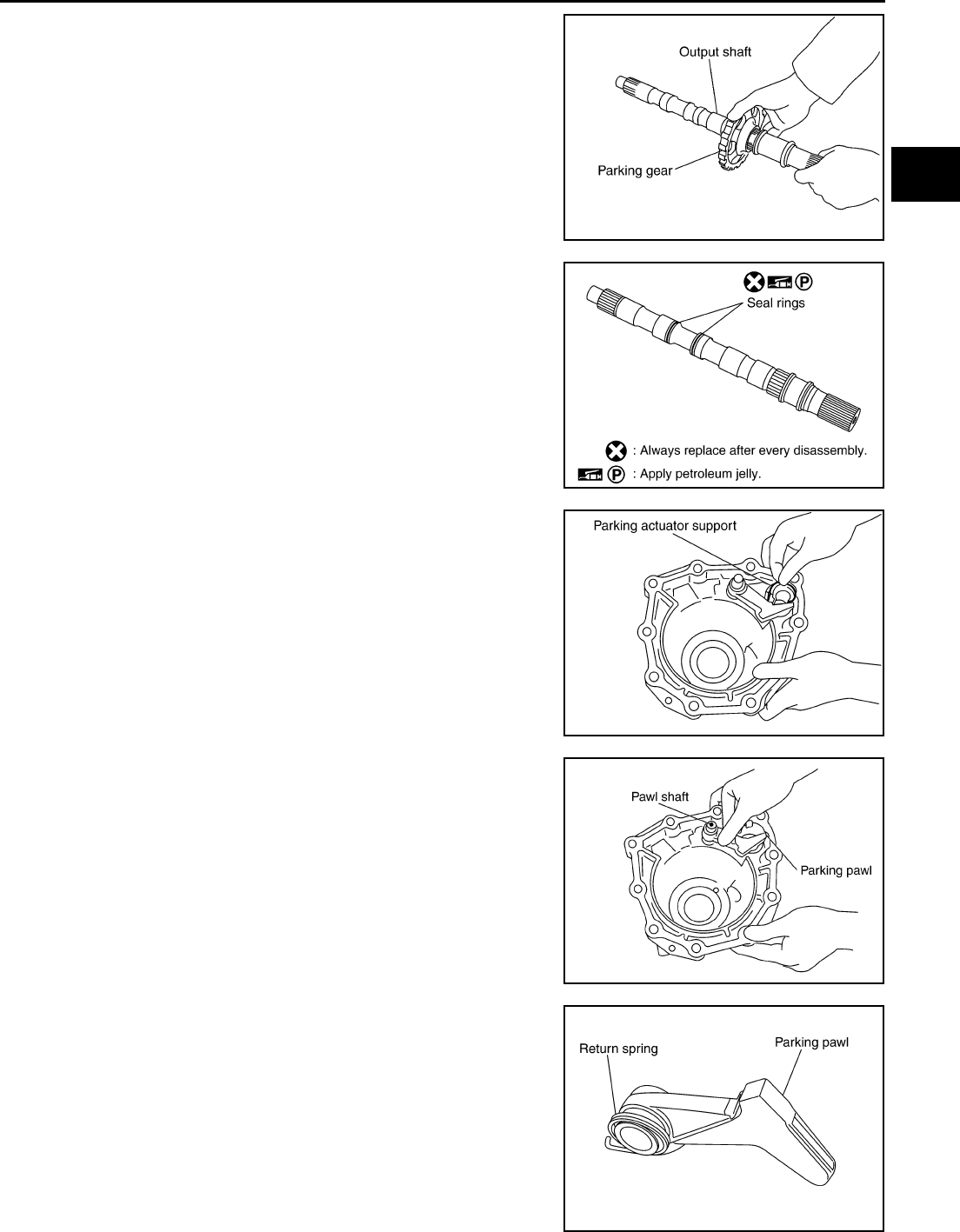
ON-VEHICLE SERVICE
AT-309
D
E
F
G
H
I
J
K
L
M
A
B
AT
11. Remove parking gear from output shaft.
12. Remove seal rings from output shaft.
13. Remove needle bearing from rear extension.
14. Remove parking actuator support from rear extension assembly.
15. Remove parking pawl, pawl shaft and return spring from rear
extension.
16. Remove return spring from parking pawl.
SCIA5247E
SCIA5209E
SCIA3423E
SCIA3424E
SCIA2445E
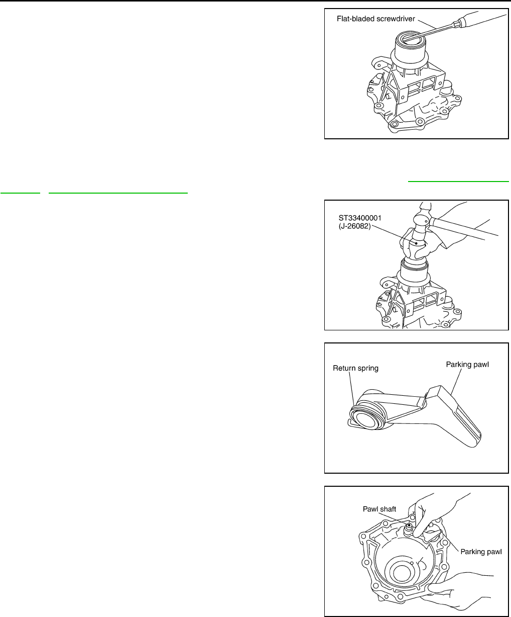
AT-310
ON-VEHICLE SERVICE
17. Remove rear oil seal from rear extension.
CAUTION:
Be careful not to scratch rear extension.
INSTALLATION
CAUTION:
After completing installation, check A/T fluid leakage and A/T fluid level. Refer to AT-13, "Changing A/
T Fluid" , AT-13, "Checking A/T Fluid" .
1. As shown below, use a drift to drive rear oil seal into the rear
extension until it is flush.
CAUTION:
●Apply ATF to rear oil seal.
●Do not reuse rear oil seal.
2. Install return spring in parking pawl.
3. Install parking pawl and pawl shaft in rear extension.
SCIA3524E
SCIA5311E
SCIA2445E
SCIA3424E
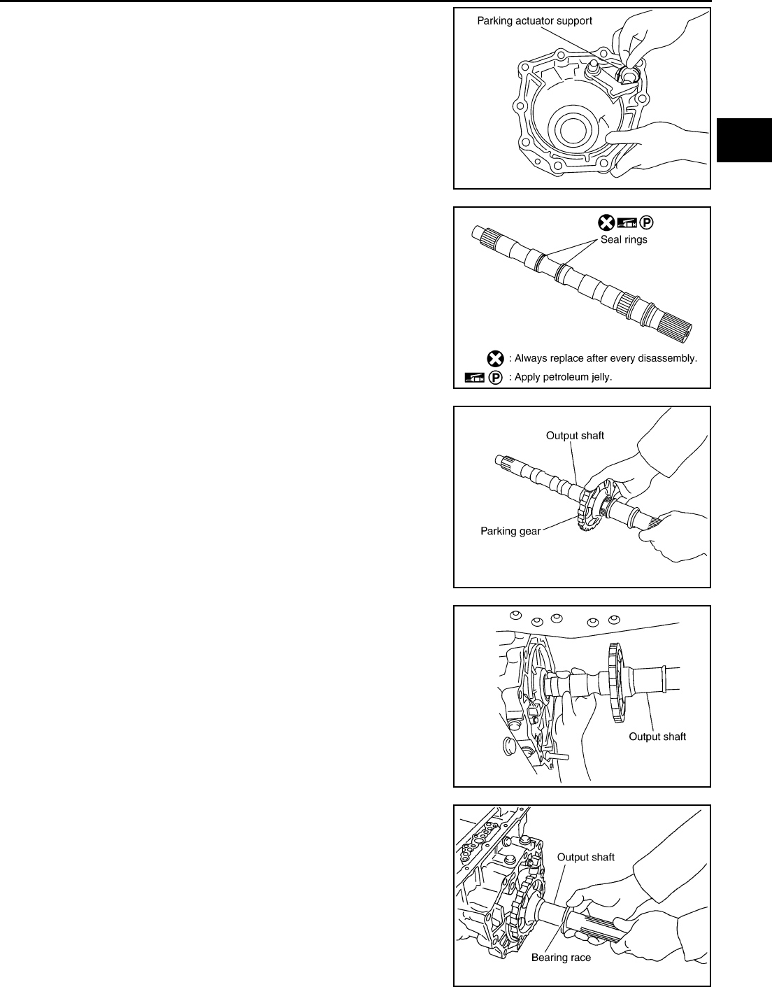
ON-VEHICLE SERVICE
AT-311
D
E
F
G
H
I
J
K
L
M
A
B
AT
4. Install parking actuator support in rear extension.
5. Install needle bearing in rear extension.
CAUTION:
Apply petroleum jelly to needle bearing.
6. Install seal rings in out put shaft.
CAUTION:
●Do not reuse seal rings.
●Apply petroleum jelly to seal rings.
7. Install parking gear in output shaft
8. Install output shaft in transmission case.
9. Install bearing race in output shaft.
SCIA3423E
SCIA5209E
SCIA5247E
SCIA5246E
SCIA5245E
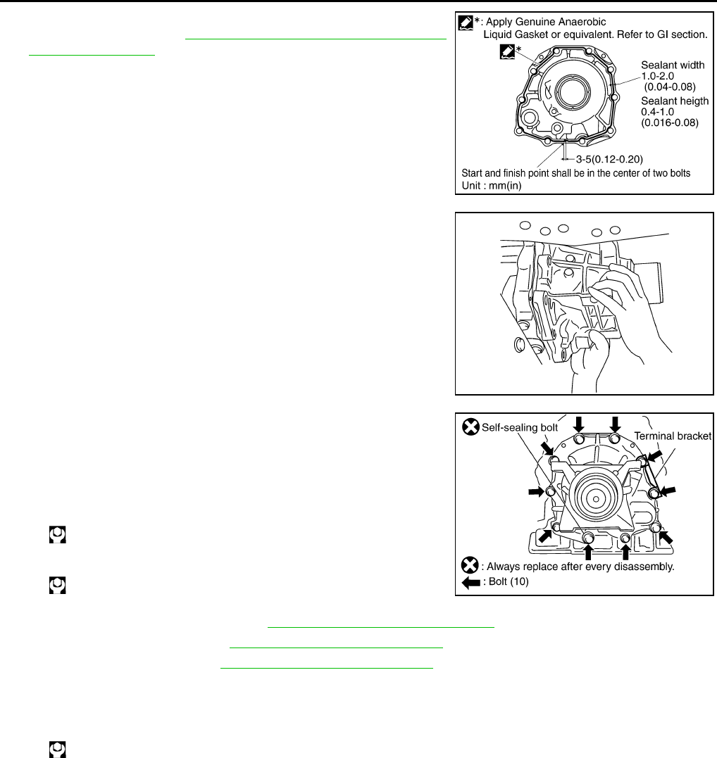
AT-312
ON-VEHICLE SERVICE
10. Apply recommended sealant (Genuine Anaerobic Liquid Gasket
or equivalent. Refer to GI-45, "Recommended Chemical Prod-
ucts and Sealants" .) to rear extension assembly as shown in
illustration.
CAUTION:
Complete remove all moisture, oil and old sealant, etc.
From the transmission case and rear extension assembly.
11. Install rear extension assembly in transmission case.
12. Tighten rear extension assembly mounting bolts to specified
torque. (Because terminal bracket is tightened together with rear
extension assembly before procedure 11)
CAUTION:
Do not reuse self–sealing bolt.
13. Install engine rear member. Refer to AT-314, "Removal and Installation" .
14. Install propeller shaft. Refer to PR-4, "Removal and Installation"
15. Install exhaust tube. Refer to EX-3, "Removal and Installation" .
16. Install drain plug in oil pan.
CAUTION:
Do not reuse drain plug gasket.
17. Pour ATF into transmission assembly.
SCIA5212E
SCIA3431E
Rear extension mounting bolt
: 52 N·m (5.3 Kg-m, 38 ft-lb)
Self-sealing bolt
: 61 N·m (6.2 Kg-m, 45 ft-lb) SCIA5428E
: 34 N·m (3.5 kg-m, 25 ft-lb)
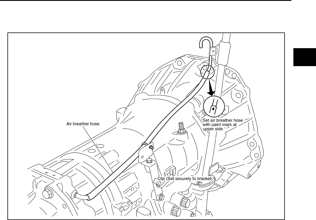
AIR BREATHER HOSE
AT-313
D
E
F
G
H
I
J
K
L
M
A
B
AT
AIR BREATHER HOSE PFP:31098
Removal and Installation ACS000FM
Refer to the figure below for air breather hose removal and installation procedure.
CAUTION:
●When installing an air breather hose, be careful not to be crushed or blocked by folding or bend-
ing the hose.
●When inserting a hose to the transmission tube, be sure to insert it fully until its end reaches the
tube bend R portion.
SCIA4778E
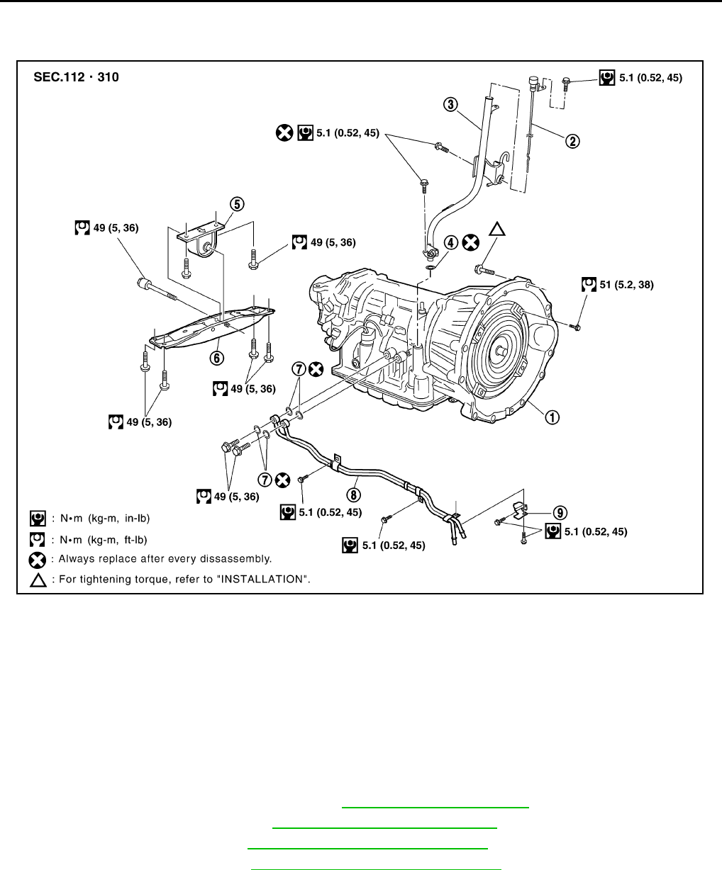
AT-314
TRANSMISSION ASSEMBLY
TRANSMISSION ASSEMBLY PFP:31020
Removal and Installation ACS000FN
REMOVAL
CAUTION:
When removing the A/T assembly from engine, first remove the crankshaft position sensor (POS) from
the A/T assembly.
Be careful not to damage sensor edge.
1. Disconnect the negative battery terminal.
2. Remove engine under cover with power tool.
3. Remove exhaust tube with power tool. Refer to EX-3, "EXHAUST SYSTEM" .
4. Remove three way catalyst. Refer to EM-25, "Removal and Installation" .
5. Remove propeller shaft. Refer to PR-4, "REAR PROPELLER SHAFT" .
6. Remove A/T control rod. Refer to AT-288, "SHIFT CONTROL SYSTEM" .
7. Disconnect A/T solenoid valve harness connectors.
1. Transmission assembly 2. A/T fluid level gauge 3. A/T fluid charging pipe
4. O-ring 5. Insulator 6. Engine rear member
7. Copper washer 8. Fluid cooler tube 9. Bracket
SCIA3940E
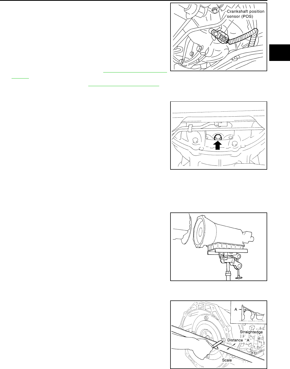
TRANSMISSION ASSEMBLY
AT-315
D
E
F
G
H
I
J
K
L
M
A
B
AT
8. Remove crankshaft position sensor (POS) from A/T assembly.
CAUTION:
●Do not subject it to impact by dropping or hitting it.
●Do not disassemble.
●Do not allow metal filings, etc., to get on the sensor's
front edge magnetic area.
●Do not place in an area affected by magnetism.
9. Remove fluid cooler tube and A/T fluid charging pipe.
10. Plug up openings such as the fluid charging pipe hole, etc.
11. Remove air breather hose. Refer to AT-313, "AIR BREATHER
HOSE" .
12. Remove starter motor. Refer to SC-9, "STARTING SYSTEM" .
13. Remove dust cover from converter housing part.
14. Turn crankshaft, and remove the four tightening bolts for drive
plate and torque converter.
CAUTION:
When turning crankshaft, turn it clockwise as viewed from
the front of the engine.
15. Support A/T assembly with a transmission jack.
CAUTION:
When setting the transmission jack, be careful not to allow it to collide against the drain plug.
16. Remove engine rear member with power tool.
17. Remove bolts fixing A/T assembly to engine with power tool.
18. Remove A/T assembly from vehicle with a transmission jack.
●Secure torque converter to prevent it from dropping.
●Secure A/T assembly to a transmission jack.
INSPECTION
Installation and Inspection of Torque Converter
●After inserting a torque converter to a transmission, be sure to
check dimension “A” to ensure it is within the reference value
limit.
SCIA0861E
ATA1292D
SCIA0499E
Dimension “A”: 25.0 mm (0.98 in) or more
SAT017B
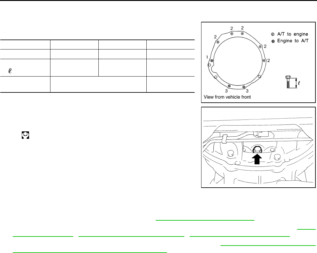
AT-316
TRANSMISSION ASSEMBLY
INSTALLATION
Install the removed parts in the reverse order of the removal, while paying attention to the following work.
●When installing transmission to the engine, attach the fixing
bolts in accordance with the following standard.
●Align the positions of tightening bolts for drive plate with those of
the torque converter, and temporarily tighten the bolts. Then,
tighten the bolts with the specified torque.
CAUTION:
●When turning crankshaft, turn it clockwise as viewed
from the front of the engine.
●When tightening the tightening bolts for the torque con-
verter after fixing the crankshaft pulley bolts, be sure to
confirm the tightening torque of the crankshaft pulley
mounting bolts.
●After converter is installed to drive plate, rotate crankshaft several turns and check to be sure
that transmission rotates freely without binding.
●Install crankshaft position sensor (POS). Refer to EM-29, "Removal and Installation" .
●After completing installation, check fluid leakage, fluid level, and the positions of A/T. Refer to AT-13,
"Changing A/T Fluid" , AT-289, "Adjustment of A/T Position" , AT-289, "Checking of A/T Position" .
●When replacing the A/T assembly, erase EEP ROM in TCM. Refer to AT-8, "Precautions for TCM, A/T
Assembly and Control Valve Assembly Replacement" .
Bolt No. 1 2 3
Number of bolts 1 5 2
Bolt length
“ ”mm (in) 55 (2.17) 65 (2.56) 35 (1.38)
Tightening torque
N·m (kg-m, ft-lb)
75
(7.7, 55)
47
(4.8, 35)
: 51 N·m (5.2 kg-m, 38 ft-lb)
SCIA0903E
ATA1292D
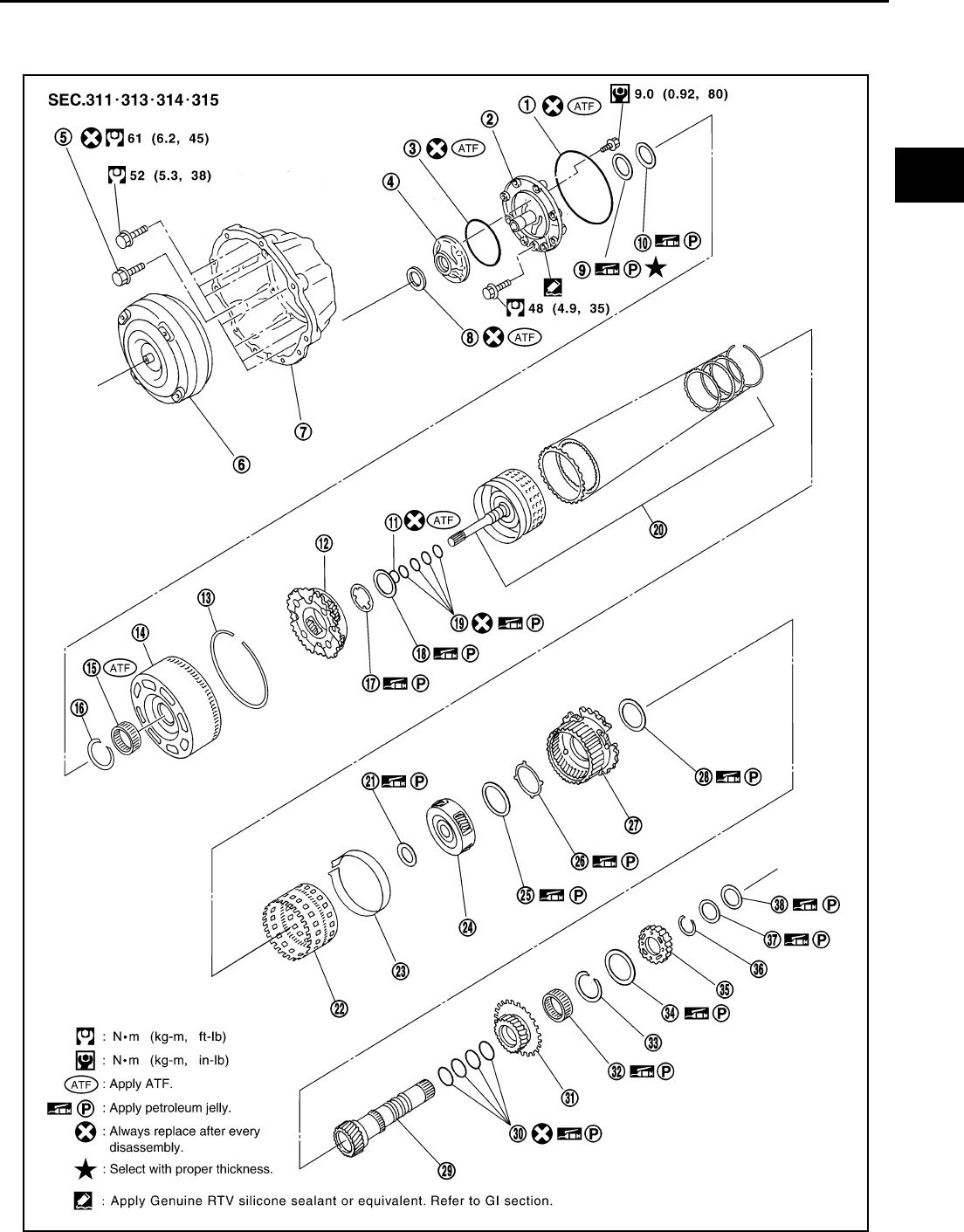
OVERHAUL
AT-317
D
E
F
G
H
I
J
K
L
M
A
B
AT
OVERHAUL PFP:00000
Components ACS004IJ
SCIA5430E

AT-318
OVERHAUL
1. O-ring 2. Oil pump cover 3. O-ring
4. Oil pump housing 5. Self-sealing bolt 6. Torque converter
7. Converter housing 8. Oil pump housing oil seal 9. Bearing race
10. Needle bearing 11. O-ring 12. Front carrier assembly
13. Snap ring 14. Front sun gear 15. 3rd one-way clutch
16. Snap ring 17. Bearing race 18. Needle bearing
19. Seal ring 20. Input clutch assembly 21. Needle bearing
22. Rear internal gear 23. Brake band 24. Mid carrier assembly
25. Needle bearing 26. Bearing race 27. Rear carrier assembly
28. Needle bearing 29. Mid sun gear 30. Seal ring
31. Rear sun gear 32. 1st one-way clutch 33. Snap ring
34. Needle bearing 35. High and low reverse clutch hub 36. Snap ring
37. Bearing race 38. Needle bearing
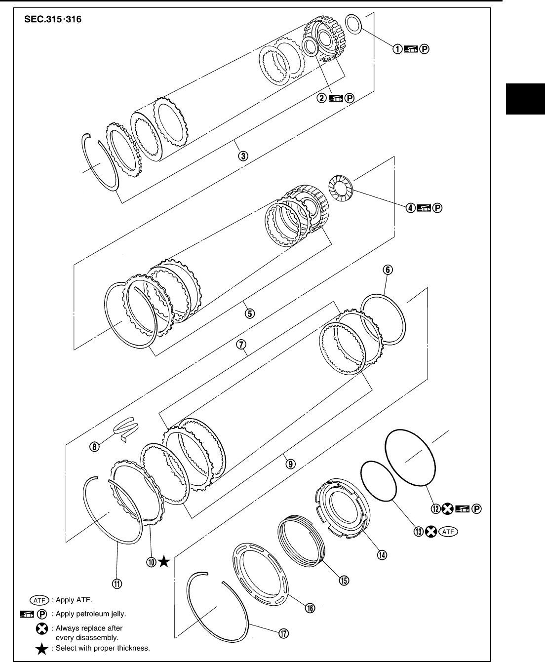
OVERHAUL
AT-319
D
E
F
G
H
I
J
K
L
M
A
B
AT
1. Needle bearing 2. Bearing race 3. High and low reverse clutch assem-
bly
4. Needle bearing 5. Direct clutch assembly 6. Reverse brake dish plate
SCIA5043E

AT-320
OVERHAUL
7. Reverse brake driven plate 8. N-spring 9. Reverse brake drive plate
10. Reverse brake retaining plate 11. Snap ring 12. Lip seal
13. D-ring 14. Reverse brake piston 15. Return spring
16. Spring retainer 17. Snap ring
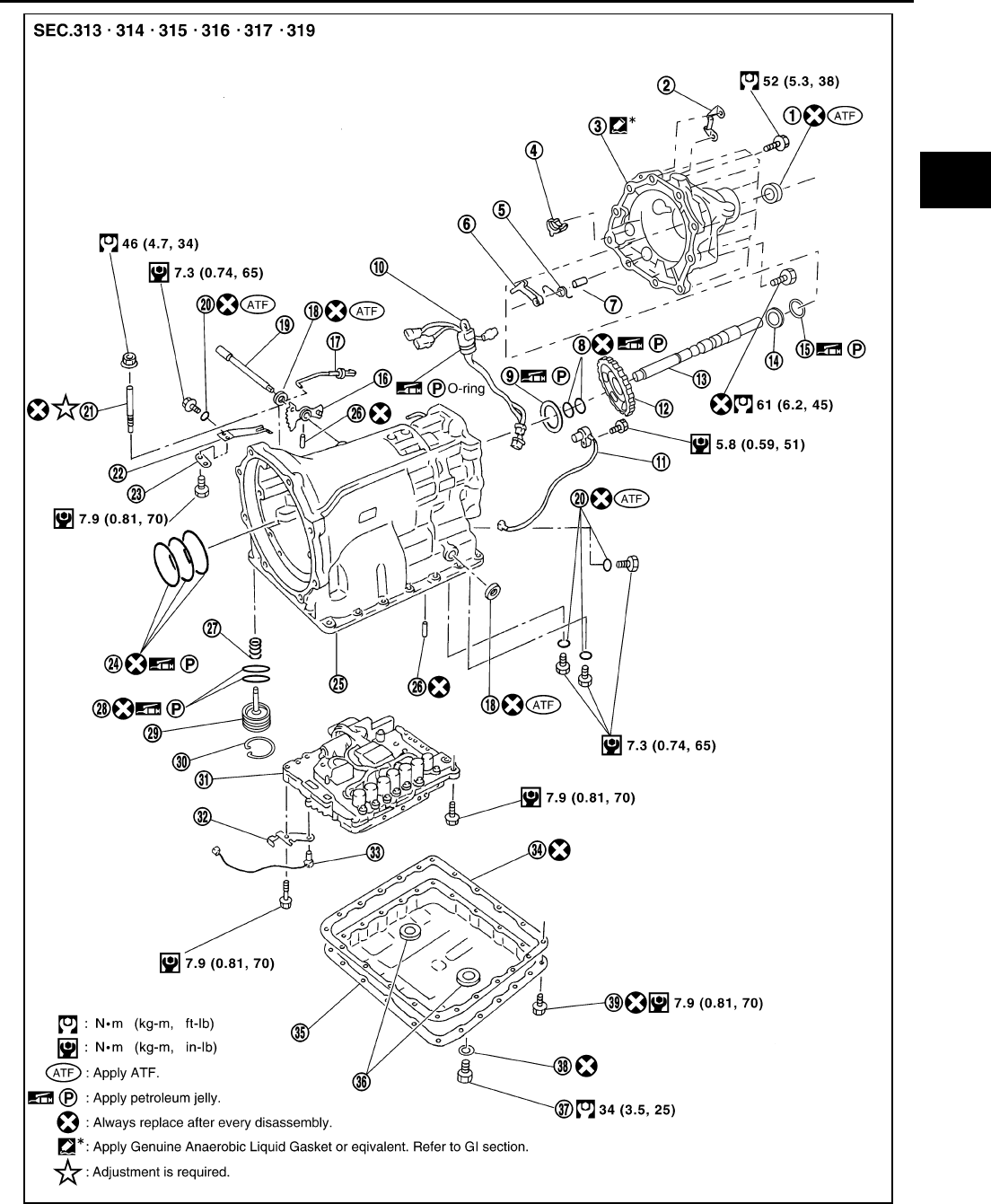
OVERHAUL
AT-321
D
E
F
G
H
I
J
K
L
M
A
B
AT
1. Rear oil seal 2. Terminal bracket 3. Rear extension
4. Parking actuator support 5. Return spring 6. Parking pawl
7. Pawl shaft 8. Seal ring 9. Needle bearing
SCIA5438E

AT-322
OVERHAUL
10. Terminal cord assembly 11. Revolution sensor 12. Parking gear
13. Output shaft 14. Bearing race 15. Needle bearing
16. Manual plate 17. Parking rod 18. Manual shaft oil seal
19. Manual shaft 20. O-ring 21. Band servo anchor end pin
22. Detent spring 23. Spacer 24. Seal ring
25. Transmission case 26. Retaining pin 27. Return spring
28. O-ring 29. Servo assembly 30. Snap ring
31. Control valve assembly 32. Bracket 33. A/T fluid temperature sensor 2
34. Oil pan gasket 35. Oil pan 36. Magnet
37. Drain plug 38. Drain plug gasket 39. Oil pan mounting bolt
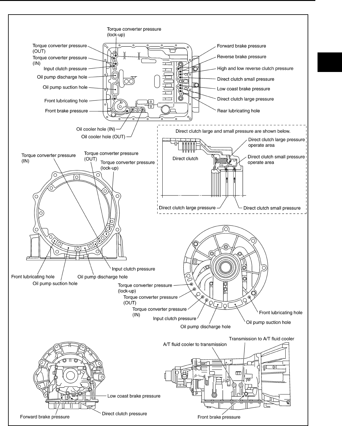
OVERHAUL
AT-323
D
E
F
G
H
I
J
K
L
M
A
B
AT
Oil Channel ACS004IK
SCIA5009E
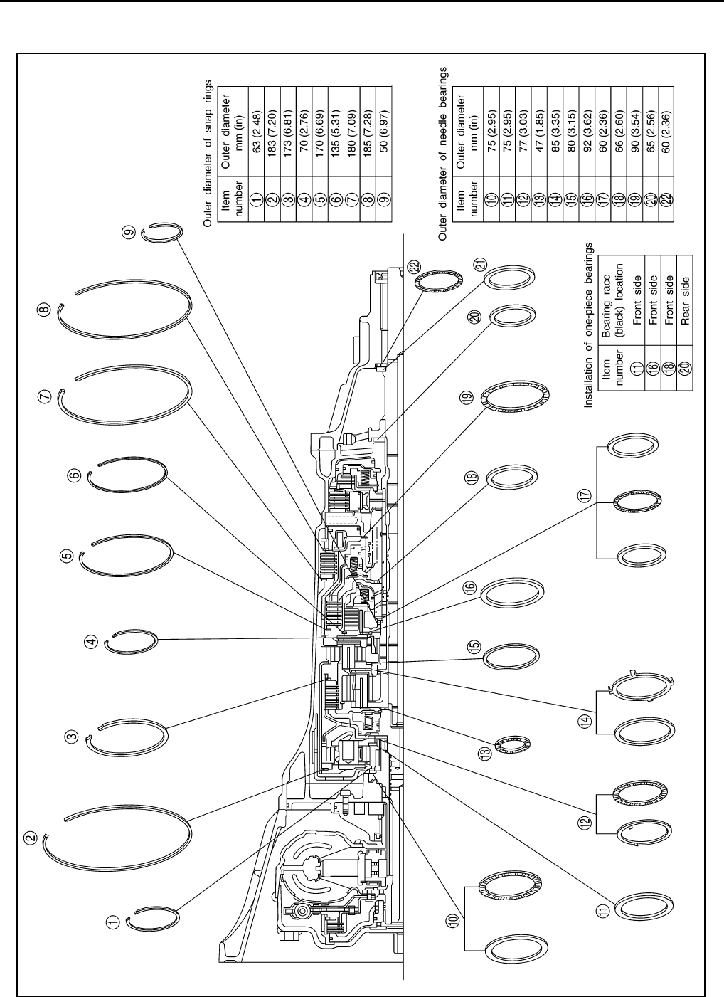
AT-324
OVERHAUL
Locations of Adjusting Shims, Needle Bearings, Thrust Washers and Snap
Rings ACS004IL
SCIA5431E
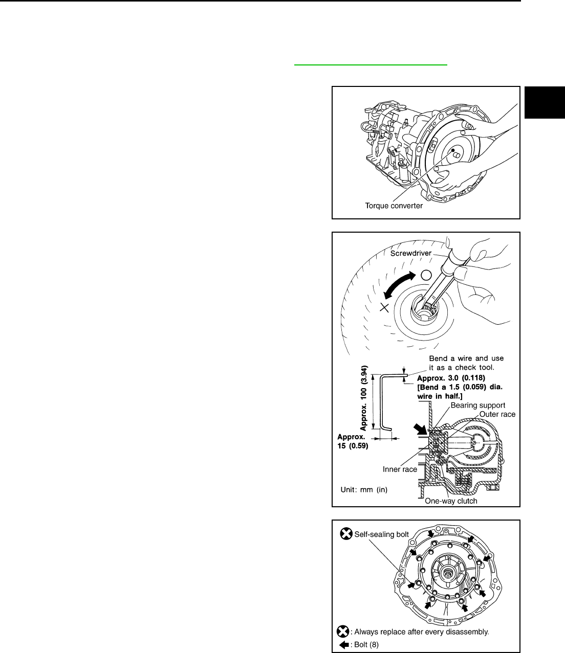
DISASSEMBLY
AT-325
D
E
F
G
H
I
J
K
L
M
A
B
AT
DISASSEMBLY PFP:31020
Disassembly ACS004M8
CAUTION:
Do not disassemble parts behind Drum Support. Refer to AT-18, "Cross-Sectional View" .
1. Drain ATF through drain plug.
2. Remove torque converter by holding it firmly and turing while
pulling straight out.
3. Check torque converter one-way clutch using check tool as
shown at figure.
a. Insert check tool into the groove of bearing support built into
one-way clutch outer race.
b. When fixing bearing support with check tool, rotate one- way
clutch spline using screwdriver.
c. Check that inner race rotates clockwise only. If not, replace
torque converter assembly.
4. Remove converter housing from transmission case.
CAUTION:
Be careful not to scratch converter housing.
SCIA2297E
SCIA3171E
SCIA3427E
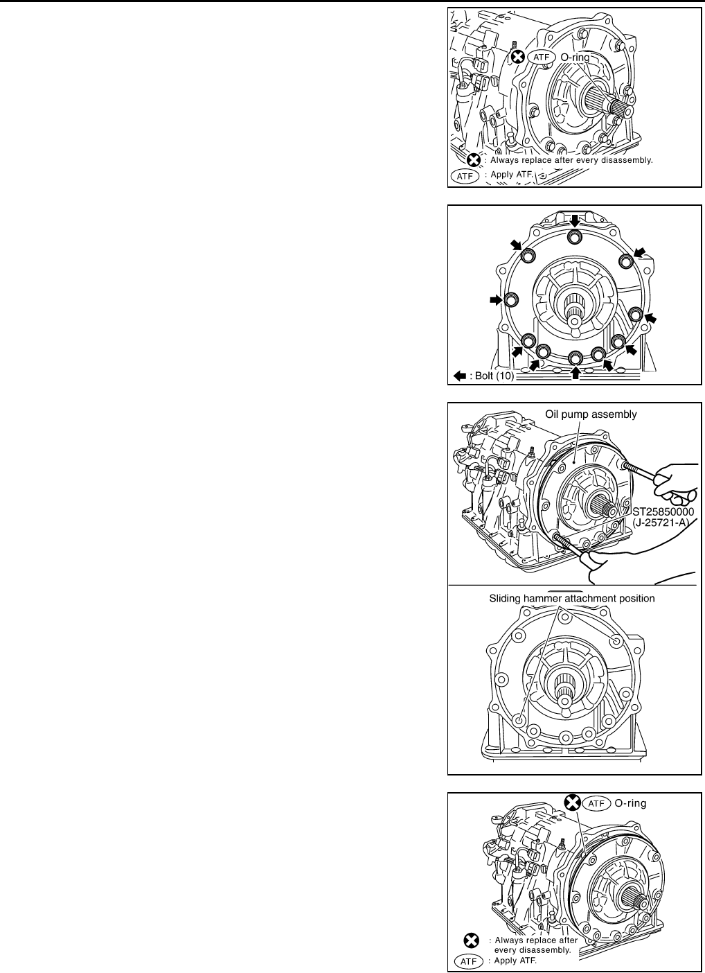
AT-326
DISASSEMBLY
5. Remove O-ring from input clutch assembly.
6. Remove tightening bolts for oil pump assembly and transmis-
sion case.
7. Attach sliding hammer to oil pump assembly and extract it
evenly from transmission case.
CAUTION:
●Fully tighten sliding hammer screw.
●Make sure that bearing race is installed to the oil pump
assembly edge surface.
8. Remove O-ring from oil pump assembly.
SCIA2299E
SCIA2300E
SCIA5312E
SCIA3417E
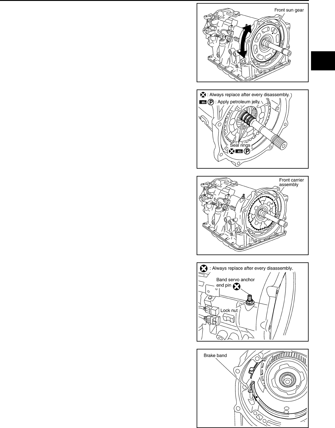
DISASSEMBLY
AT-327
D
E
F
G
H
I
J
K
L
M
A
B
AT
9. Remove bearing race, needle bearing and front sun gear from
transmission case.
NOTE:
Remove front sun gear by rotating left and right.
10. Remove seal rings from input clutch assembly.
11. Remove front carrier assembly from transmission case. (With
input clutch assembly and rear internal gear.)
CAUTION:
Be careful to remove it with needle bearing.
12. Loosen lock nut and remove band servo anchor end pin from
transmission case.
13. Remove brake band from transmission case.
SCIA3418E
SCIA2470E
SCIA3419E
SCIA2579E
SCIA2580E
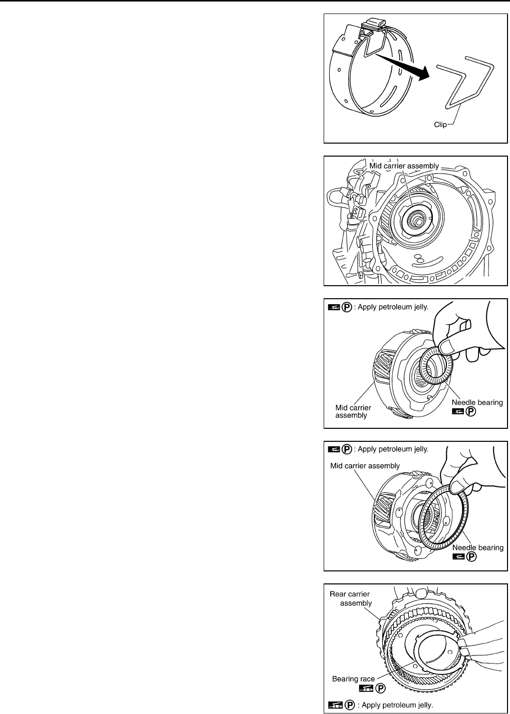
AT-328
DISASSEMBLY
●To prevent brake linings from cracking or peeling, do not
stretch the flexible band unnecessarily. When removing
the brake band, always secure it with a clip as shown in
the figure at left.
Leave the clip in position after removing the brake band.
●Check brake band facing for damage, cracks, wear or
burns.
14. Remove mid carrier assembly and rear carrier assembly as a
unit.
15. Remove mid carrier assembly from rear carrier assembly.
16. Remove needle bearing (front side) from mid carrier assembly.
17. Remove needle bearing (rear side) from mid carrier assembly.
18. Remove bearing race from rear carrier assembly.
SAT655
SCIA2304E
SCIA2805E
SCIA2804E
SCIA5175E
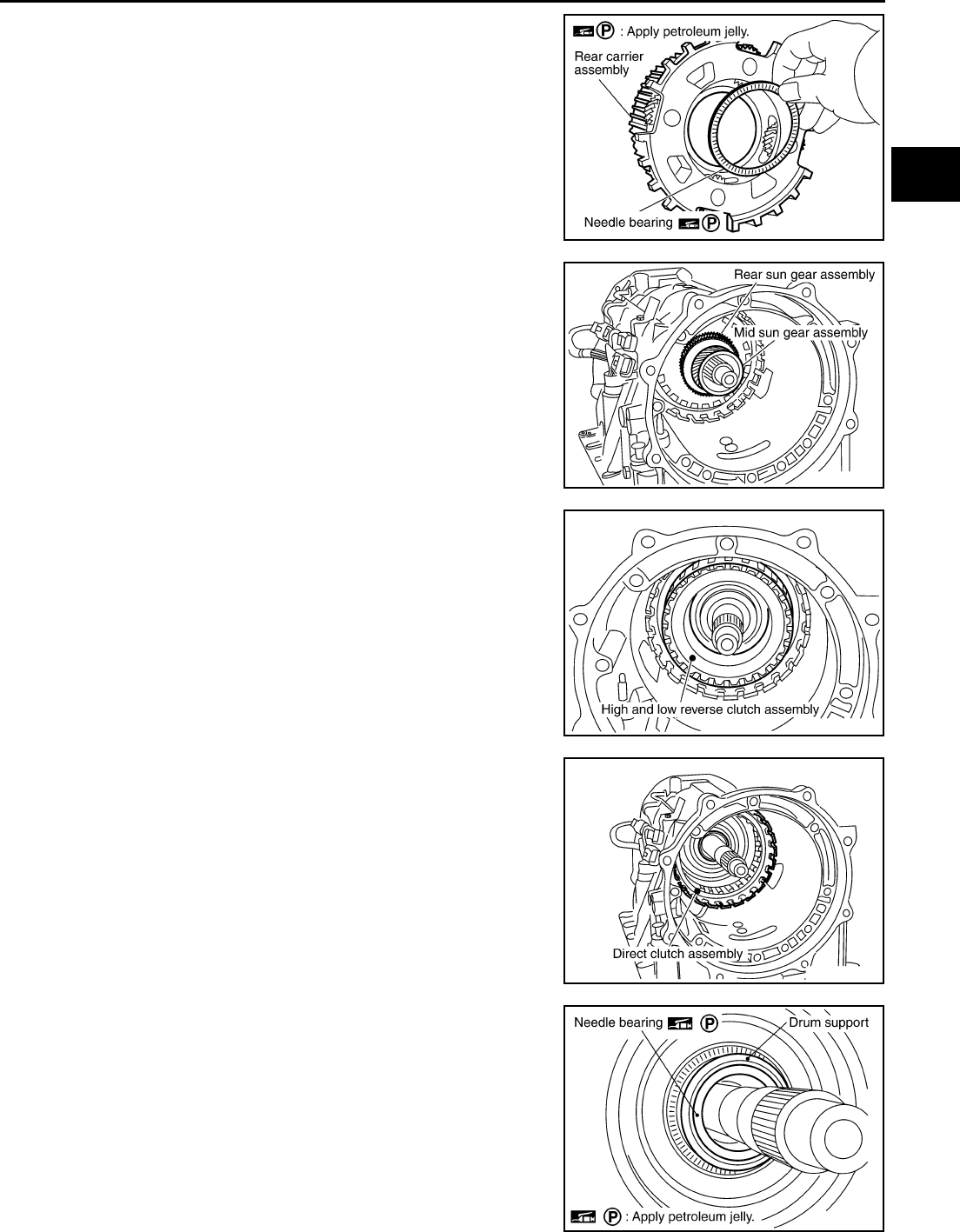
DISASSEMBLY
AT-329
D
E
F
G
H
I
J
K
L
M
A
B
AT
19. Remove needle bearing from rear carrier assembly.
20. Remove mid sun gear assembly, rear sun gear assembly and
high and low reverse clutch hub as a unit.
CAUTION:
Be careful to remove then with bearing race and needle
bearing.
21. Remove high and low reverse clutch assembly from transmis-
sion case.
CAUTION:
Make sure that needle bearing is installed to the high and
low reverse clutch assembly edge surface.
22. Remove direct clutch assembly from transmission case.
23. Remove needle bearing from drum support edge surface.
SCIA2803E
SCIA2305E
SCIA2306E
SCIA2307E
SCIA5198E
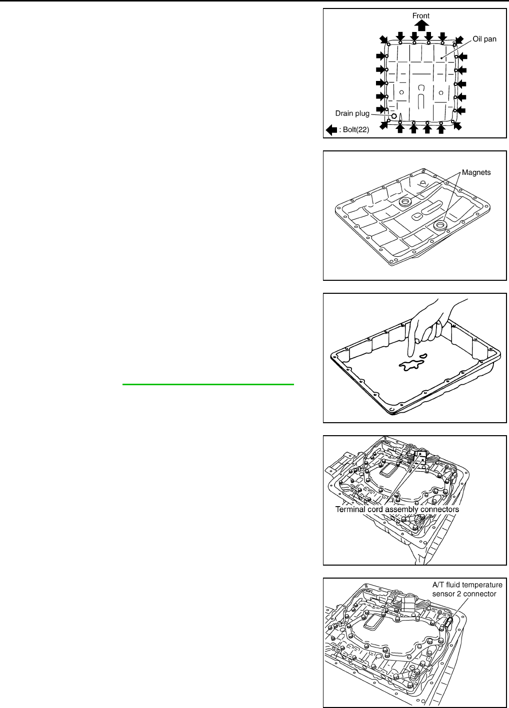
AT-330
DISASSEMBLY
24. Remove oil pan and oil pan gasket.
25. Remove magnets from oil pan.
26. Check foreign materials in oil pan to help determine causes of
malfunction. If the A/T fluid is very dark, smells burned, or con-
tains foreign particles, the frictional material (clutches, band)
may need replacement. A tacky film that will not wipe clean indi-
cates varnish build up. Varnish can cause valves, servo, and
clutches to stick and can inhibit pump pressure.
●If frictional material is detected, perform A/T fluid cooler
cleaning. Refer to AT-15, "A/T Fluid Cooler Cleaning".
27. Disconnect terminal cord assembly connectors.
CAUTION:
Be careful not to damage connector.
28. Disconnect A/T fluid temperature sensor 2 connector.
CAUTION:
Be careful not to damage connector.
SCIA2308E
SCIA5200E
SCIA5199E
SCIA3412E
SCIA5129E
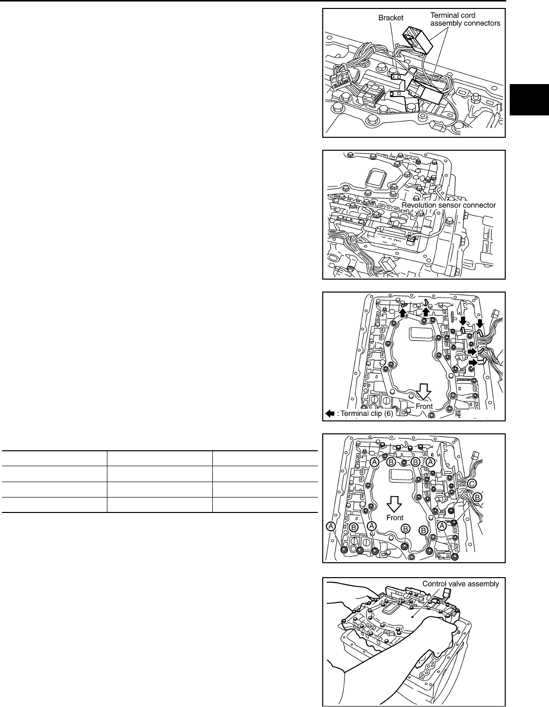
DISASSEMBLY
AT-331
D
E
F
G
H
I
J
K
L
M
A
B
AT
29. Remove terminal cord assembly connectors from bracket.
CAUTION:
Be careful not to damage connector.
30. Disconnect revolution sensor connector.
CAUTION:
Be careful not to damage connector.
31. Straighten terminal clips to free terminal cord assembly and rev-
olution sensor harness then remove terminal clips.
CAUTION:
Hang down terminal cord assembly and revolution sensor
harness toward outside so as not to disturb removal of con-
trol valve assembly.
32. Remove bolts A, B and C from control valve assembly.
33. Remove control valve assembly from transmission case.
CAUTION:
When removing, be careful with the manual valve notch and
manual plate height.Remove it vertically.
SCIA2584E
SCIA2313E
SCIA2314E
Bolt symbol Length mm (in) Number of bolts
A 42 (1.65) 5
B 55 (2.17) 6
C 40 (1.57) 1
SCIA2312E
SCIA2315E
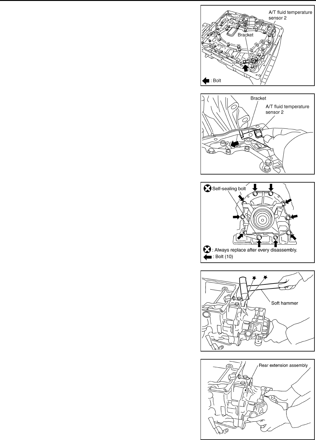
AT-332
DISASSEMBLY
34. Remove A/T fluid temperature sensor 2 with bracket from con-
trol valve assembly.
35. Remove bracket from A/T fluid temperature sensor 2.
36. Remove tightening bolts for rear extension assembly and trans-
mission case.
37. Tap rear extension assembly with soft hammer.
38. Remove rear extension assembly from transmission case.
SCIA5126E
SCIA5127E
SCIA3426E
SCIA3420E
SCIA3421E
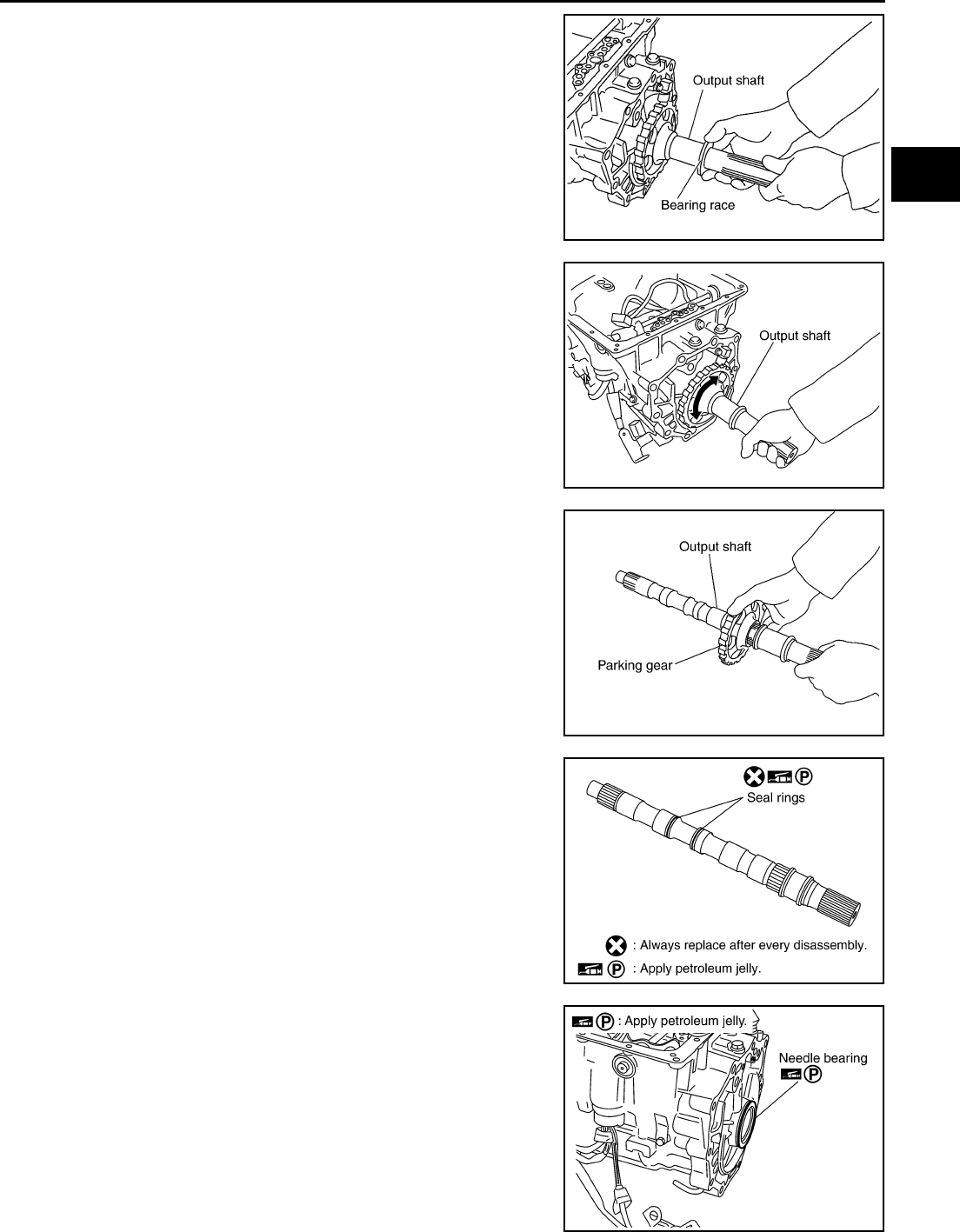
DISASSEMBLY
AT-333
D
E
F
G
H
I
J
K
L
M
A
B
AT
39. Remove bearing race from output shaft.
40. Remove output shaft from transmission case by rotating left and
right.
41. Remove parking gear from output shaft.
42. Remove seal rings from output shaft.
43. Remove needle bearing from transmission case.
SCIA5245E
SCIA3422E
SCIA5247E
SCIA5209E
SCIA2440E
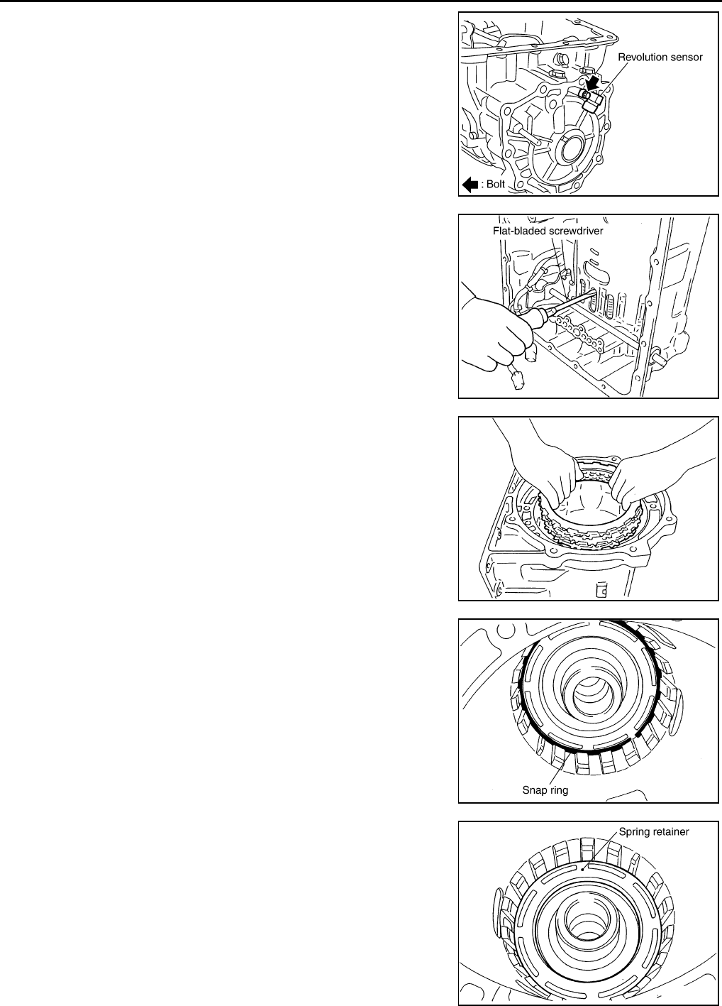
AT-334
DISASSEMBLY
44. Remove revolution sensor from transmission case.
CAUTION:
●Do not subject it to impact by dropping or hitting it.
●Do not disassemble.
●Do not allow metal filings, etc., to get on the sensor's
front edge magnetic area.
●Do not place in an area affected by magnetism.
45. Remove reverse brake snap ring (fixing plate) using 2 flat-
bladed screwdrivers.
NOTE:
Press out snap ring from the transmission case oil pan side gap
using a flat-bladed screwdriver, and remove it using another
screwdriver.
46. Remove reverse brake retaining plate, drive plates, driven
plates and dish plate from transmission case.
CAUTION:
Be careful to remove it with N-spring.
47. Remove snap ring (fixing spring retainer) using a flat-bladed
screwdriver.
48. Remove spring retainer and return spring from transmission
case.
SCIA2320E
SCIA2321E
SCIA2322E
SCIA2323E
SCIA2324E
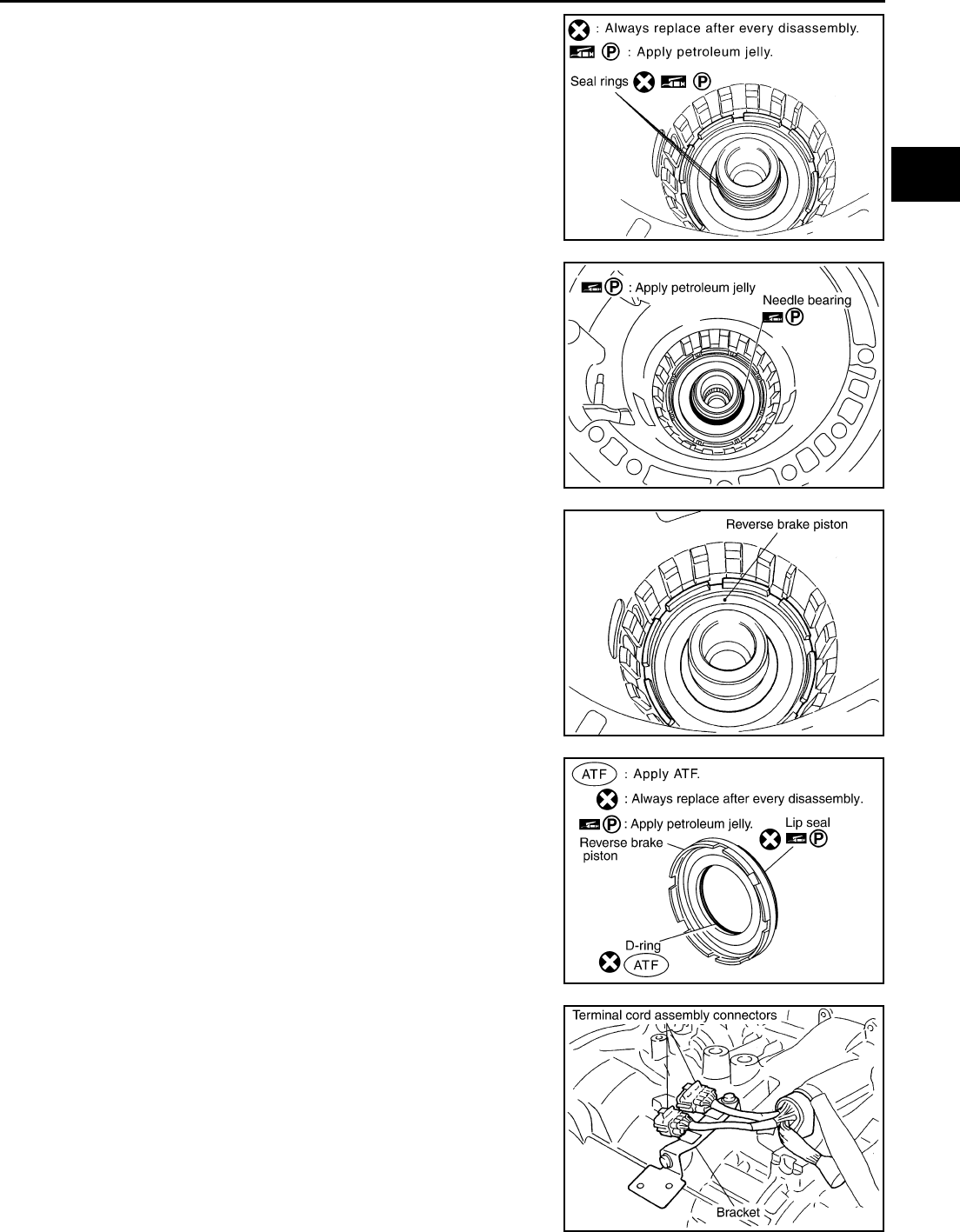
DISASSEMBLY
AT-335
D
E
F
G
H
I
J
K
L
M
A
B
AT
49. Remove seal rings from drum support.
50. Remove needle bearing from drum support edge surface.
51. Remove reverse brake piston from transmission case.
52. Remove lip seal and D-ring from reverse brake piston.
53. Remove terminal cord assembly connectors from bracket.
CAUTION:
Be careful not to damage connector.
SCIA3333E
SCIA2796E
SCIA2325E
SCIA2795E
SCIA2326E
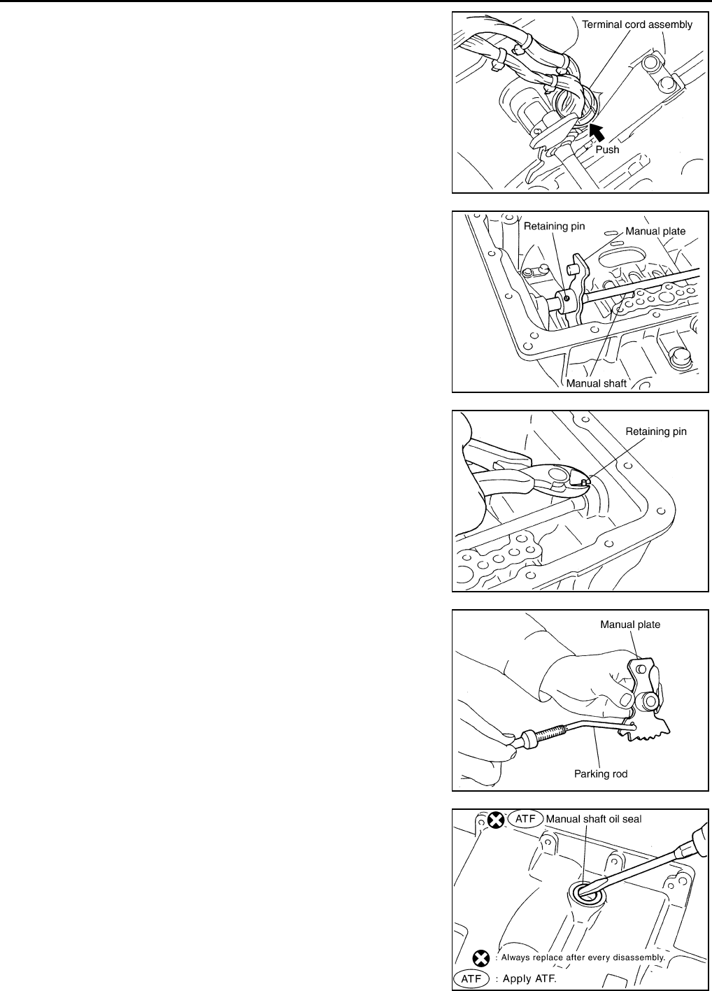
AT-336
DISASSEMBLY
54. Remove terminal cord assembly from transmission case.
55. Use a pin punch (4mm dia. commercial service tool) to knock
out retaining pin.
56. Remove manual shaft retaining pin with nippers.
57. Remove manual plate (with parking rod) from manual shaft.
58. Remove parking rod from manual plate.
59. Remove manual shaft from transmission case.
60. Remove manual shaft oil seals using a flat-bladed screwdriver.
CAUTION:
Be careful not to scratch transmission case.
SCIA2327E
SCIA2328E
SCIA2329E
SCIA5220E
SCIA2331E
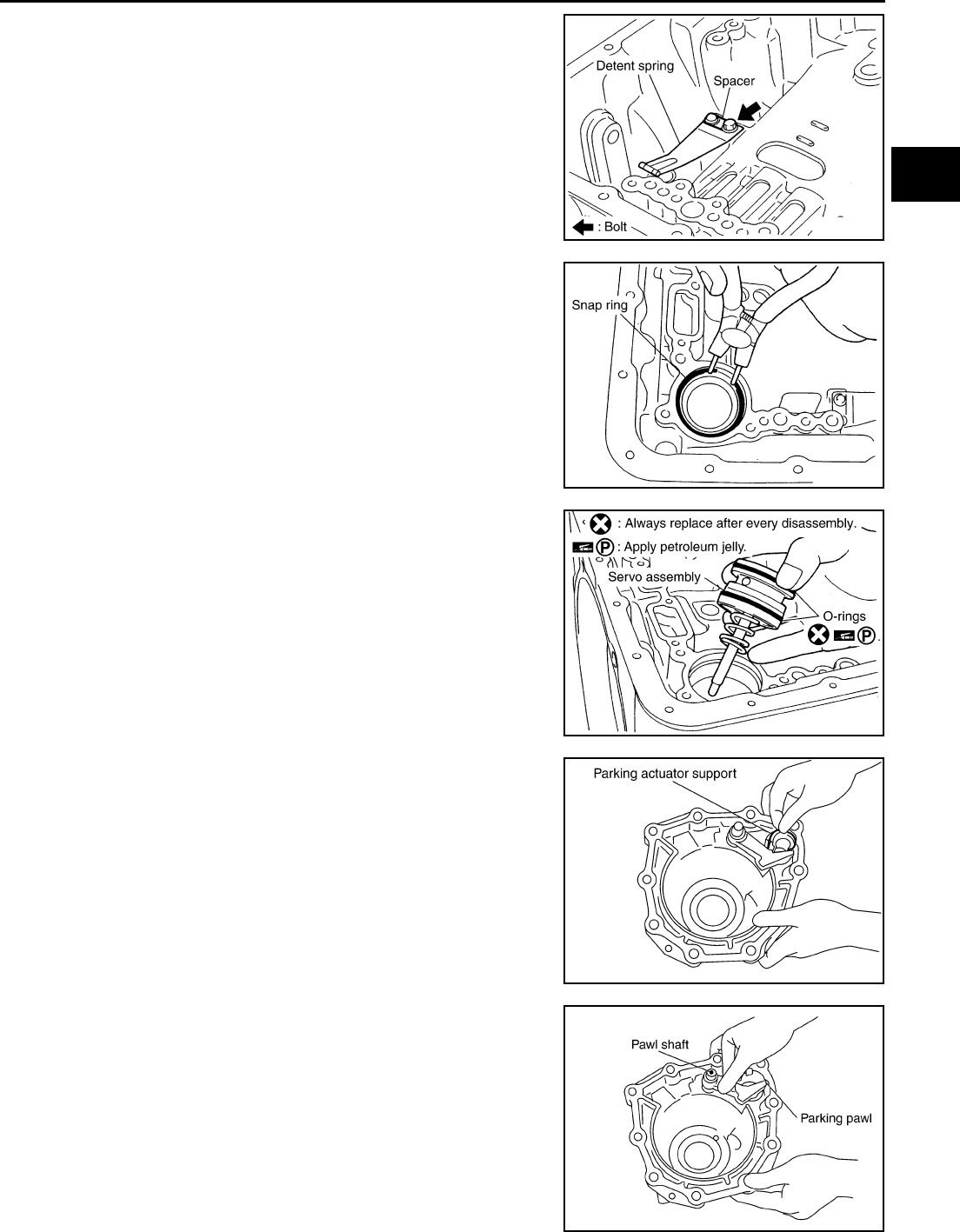
DISASSEMBLY
AT-337
D
E
F
G
H
I
J
K
L
M
A
B
AT
61. Remove detent spring and spacer from transmission case.
62. Using snap ring pliers, remove snap ring from transmission
case.
63. Remove servo assembly (with return spring) from transmission
case.
64. Remove return spring from servo assembly.
65. Remove O-rings from servo assembly.
66. Remove parking actuator support from rear extension.
67. Remove parking pawl, pawl shaft and return spring from rear
extension.
SCIA5248E
SCIA2333E
SCIA2334E
SCIA3423E
SCIA3424E
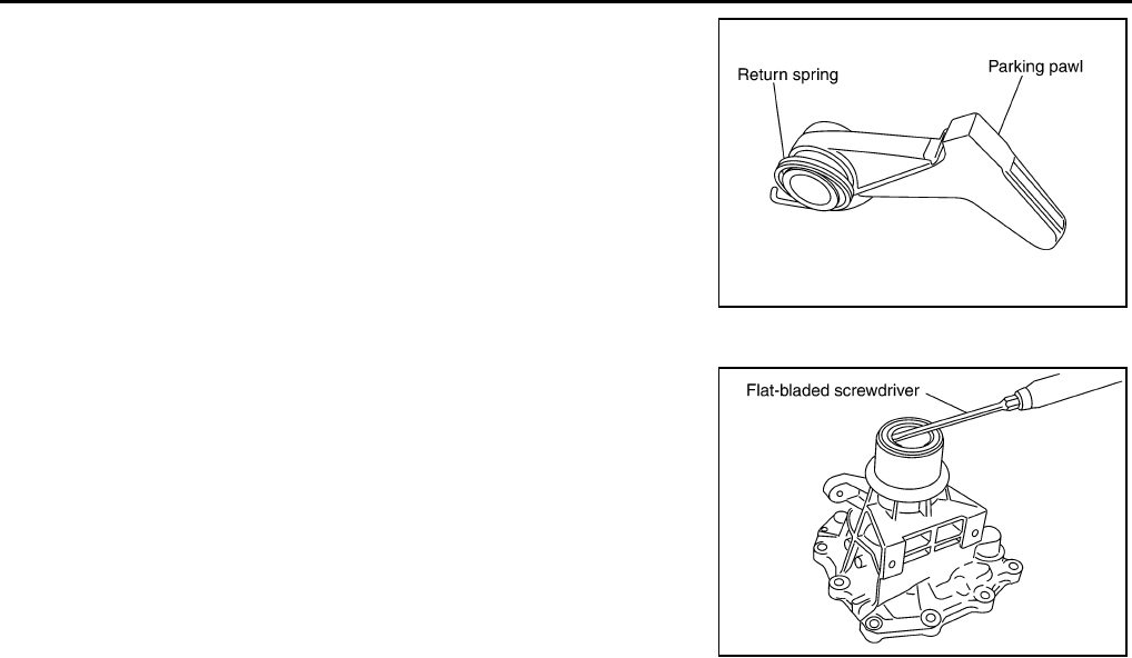
AT-338
DISASSEMBLY
68. Remove return spring from parking pawl.
69. Remove needle bearing from rear extension.
70. Remove rear oil seal from rear extension.
CAUTION:
Be careful not to scratch rear extension.
SCIA2445E
SCIA3524E
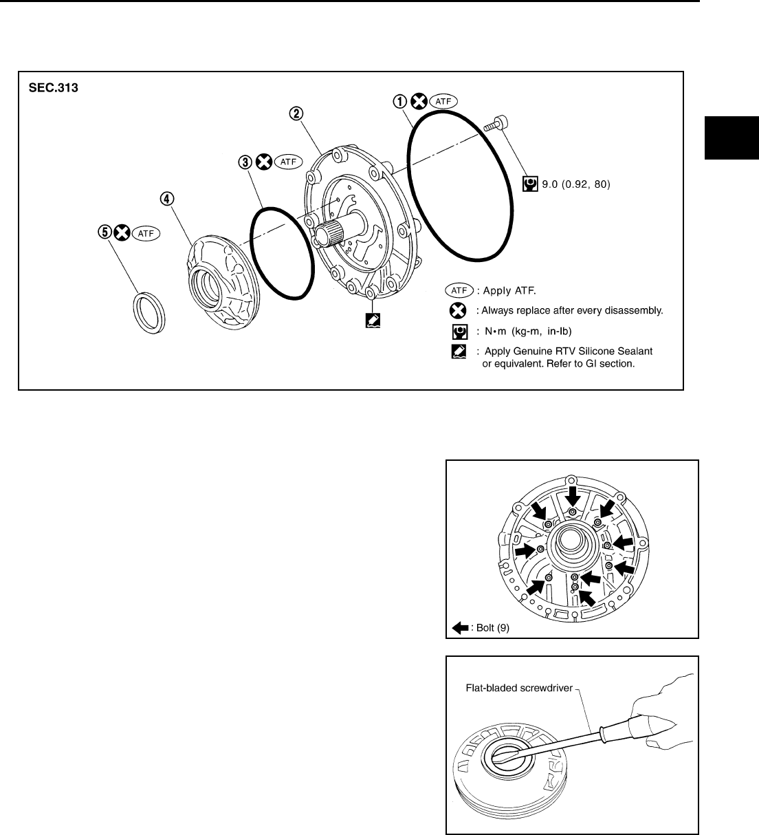
REPAIR FOR COMPONENT PARTS
AT-339
D
E
F
G
H
I
J
K
L
M
A
B
AT
REPAIR FOR COMPONENT PARTS PFP:00000
Oil Pump ACS004IN
COMPONENTS
DISASSEMBLY
1. Remove oil pump housing from oil pump cover.
2. Remove oil pump housing oil seal using a flat-bladed screw-
driver.
CAUTION:
Be careful not to scratch oil pump housing.
1. O-ring 2. Oil pump cover 3. O-ring
4. Oil pump housing 5. Oil pump housing oil seal
SCIA5323E
SCIA2836E
SCIA2840E
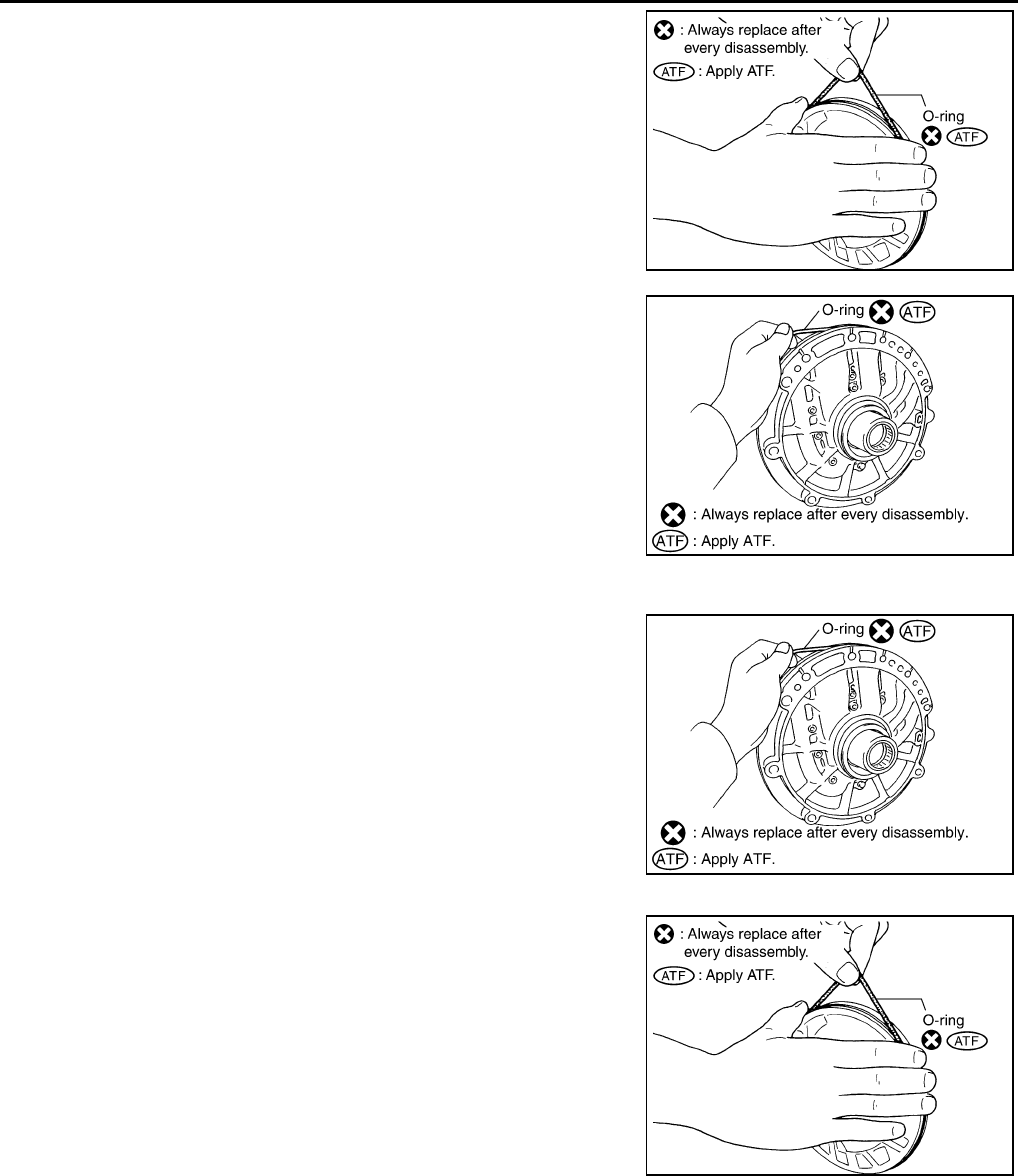
AT-340
REPAIR FOR COMPONENT PARTS
3. Remove O-ring from oil pump housing.
4. Remove O-ring from oil pump cover.
ASSEMBLY
1. Install O-ring in oil pump cover.
CAUTION:
●Do not reuse O-ring.
●Apply ATF to O-ring.
2. Install O-ring in oil pump housing.
CAUTION:
●Do not reuse O-ring.
●Apply ATF to O-ring.
SCIA2841E
SCIA2837E
SCIA2837E
SCIA2841E
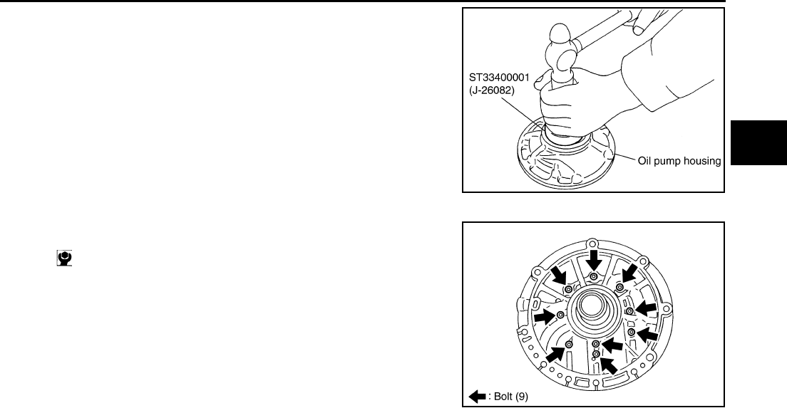
REPAIR FOR COMPONENT PARTS
AT-341
D
E
F
G
H
I
J
K
L
M
A
B
AT
3. Using a drift, install oil pump housing oil seal to the oil pump
housing until is flush.
CAUTION:
●Do not reuse oil pump housing oil seal.
●Apply ATF to oil pump housing oil seal.
4. Install oil pump housing in oil pump cover.
SCIA5313E
: 9.0 N·m (0.92 kg-m, 80 in-lb.)
SCIA2836E
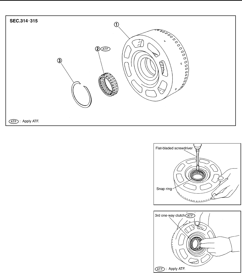
AT-342
REPAIR FOR COMPONENT PARTS
Front Sun Gear, 3rd One-Way Clutch ACS004IO
COMPONENTS
DISASSEMBLY
1. Using a flat-bladed screwdriver, remove snap ring from front sun
gear.
2. Remove 3rd one-way clutch from front sun gear.
INSPECTION
3rd One-way Clutch
●Check frictional surface for wear or damage.
CAUTION:
If necessary, replace the 3rd one-way clutch.
Front Sun Gear Snap Ring
●Check for deformation, fatigue or damage.
1. Front sun gear 2. 3rd one-way clutch 3. Snap ring
SCIA3114E
SCIA3110E
SCIA3111E
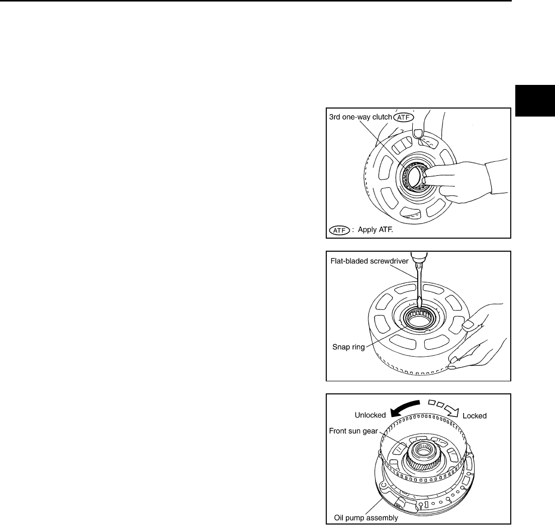
REPAIR FOR COMPONENT PARTS
AT-343
D
E
F
G
H
I
J
K
L
M
A
B
AT
CAUTION:
If necessary, replace the snap ring.
Front Sun Gear
●Check for deformation, fatigue or damage.
CAUTION:
If necessary, replace the front sun gear.
ASSEMBLY
1. Install 3rd one-way clutch in front sun gear.
CAUTION:
Apply ATF to 3rd one-way clutch.
2. Using a flat-bladed screwdriver, install snap ring in front sun
gear.
3. Check operation of 3rd one-way clutch.
a. Hold oil pump assembly and turn front sun gear.
b. Check 3rd one-way clutch for correct locking and unlocking
directions.
CAUTION:
If not as shown in illustration, check installation direction of
3rd one-way clutch.
SCIA3111E
SCIA3110E
SCIA3131E
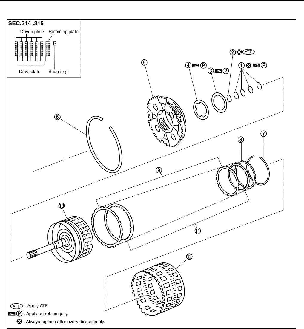
AT-344
REPAIR FOR COMPONENT PARTS
Front Carrier, Input Clutch, Rear Internal Gear ACS004IP
COMPONENTS
1. Seal ring 2. O-ring 3. Needle bearing
4. Bearing race 5. Front carrier assembly 6. Snap ring
7. Snap ring 8. Retaining plate 9. Driven plate
10. Input clutch drum 11. Drive plate 12. Rear internal gear
SCIA5432E
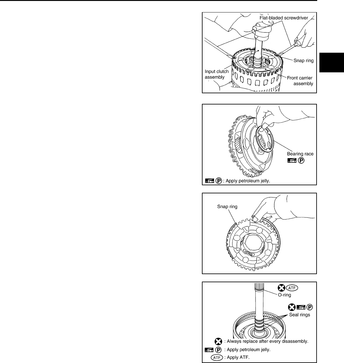
REPAIR FOR COMPONENT PARTS
AT-345
D
E
F
G
H
I
J
K
L
M
A
B
AT
DISASSEMBLY
1. Compress snap ring using 2 flat-bladed screwdrivers.
2. Remove front carrier assembly and input clutch assembly from
rear internal gear.
3. Remove front carrier assembly from input clutch assembly.
a. Remove bearing race from front carrier assembly.
b. Remove snap ring from front carrier assembly.
CAUTION:
Do not expand snap ring excessively.
4. Disassemble input clutch assembly.
a. Remove O-ring and seal rings from input clutch assembly.
SCIA5339E
SCIA2847E
SCIA5476E
SCIA5235E
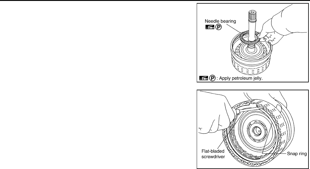
AT-346
REPAIR FOR COMPONENT PARTS
b. Remove needle bearing from input clutch assembly.
c. Using a flat-bladed screwdriver, remove snap ring from input
clutch drum.
d. Remove drive plates, driven plates and retaining plate from input
clutch drum.
INSPECTION
Front Carrier Snap Ring
●Check for deformation, fatigue or damage.
CAUTION:
If necessary, replace the snap ring.
Input Clutch Snap Ring
●Check for deformation, fatigue or damage.
CAUTION:
If necessary, replace the input clutch assembly.
Input Clutch Drum
●Check for deformation, fatigue or damage or burns.
CAUTION:
If necessary, replace the input clutch assembly.
Input Clutch Drive Plates
●Check facing for burns, cracks or damage.
CAUTION:
If necessary, replace the input clutch assembly.
Input Clutch Retaining Plate and Driven Plates
●Check facing for burns, cracks or damage.
CAUTION:
If necessary, replace the input clutch assembly.
Front Carrier
●Check for deformation, fatigue or damage.
CAUTION:
If necessary, replace the front carrier assembly.
Rear Internal Gear
●Check for deformation, fatigue or damage.
CAUTION:
If necessary, replace the rear internal gear assembly.
SCIA2853E
SCIA2864E
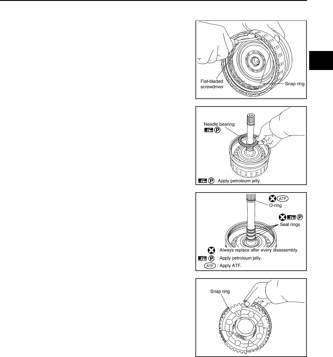
REPAIR FOR COMPONENT PARTS
AT-347
D
E
F
G
H
I
J
K
L
M
A
B
AT
ASSEMBLY
1. Install input clutch.
a. Install drive plates, driven plates and retaining plate in input
clutch drum.
CAUTION:
Take care with order of plates.
b. Using a flat-bladed screwdriver, install snap ring in input clutch
drum.
c. Install needle bearing in input clutch assembly.
CAUTION:
Apply petroleum jelly to needle bearing.
d. Install O-ring and seal rings in input clutch assembly.
CAUTION:
●Do not reuse O-ring and seal rings.
●Apply ATF to O-ring.
●Apply petroleum jelly to seal rings.
2. Install front carrier assembly.
a. Install snap ring to front carrier assembly.
CAUTION:
Do not expand snap ring excessively.
SCIA2864E
SCIA2853E
SCIA5235E
SCIA5476E
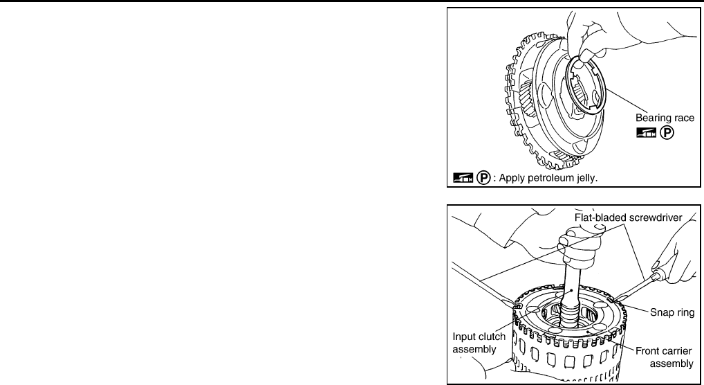
AT-348
REPAIR FOR COMPONENT PARTS
b. Install bearing race in front carrier assembly.
CAUTION:
Apply petroleum jelly to bearing race.
c. Install front carrier assembly to input clutch assembly.
3. Compress snap ring using 2 flat-bladed screwdrivers.
4. Install front carrier assembly and input clutch assembly to rear
internal gear.
SCIA2847E
SCIA5339E
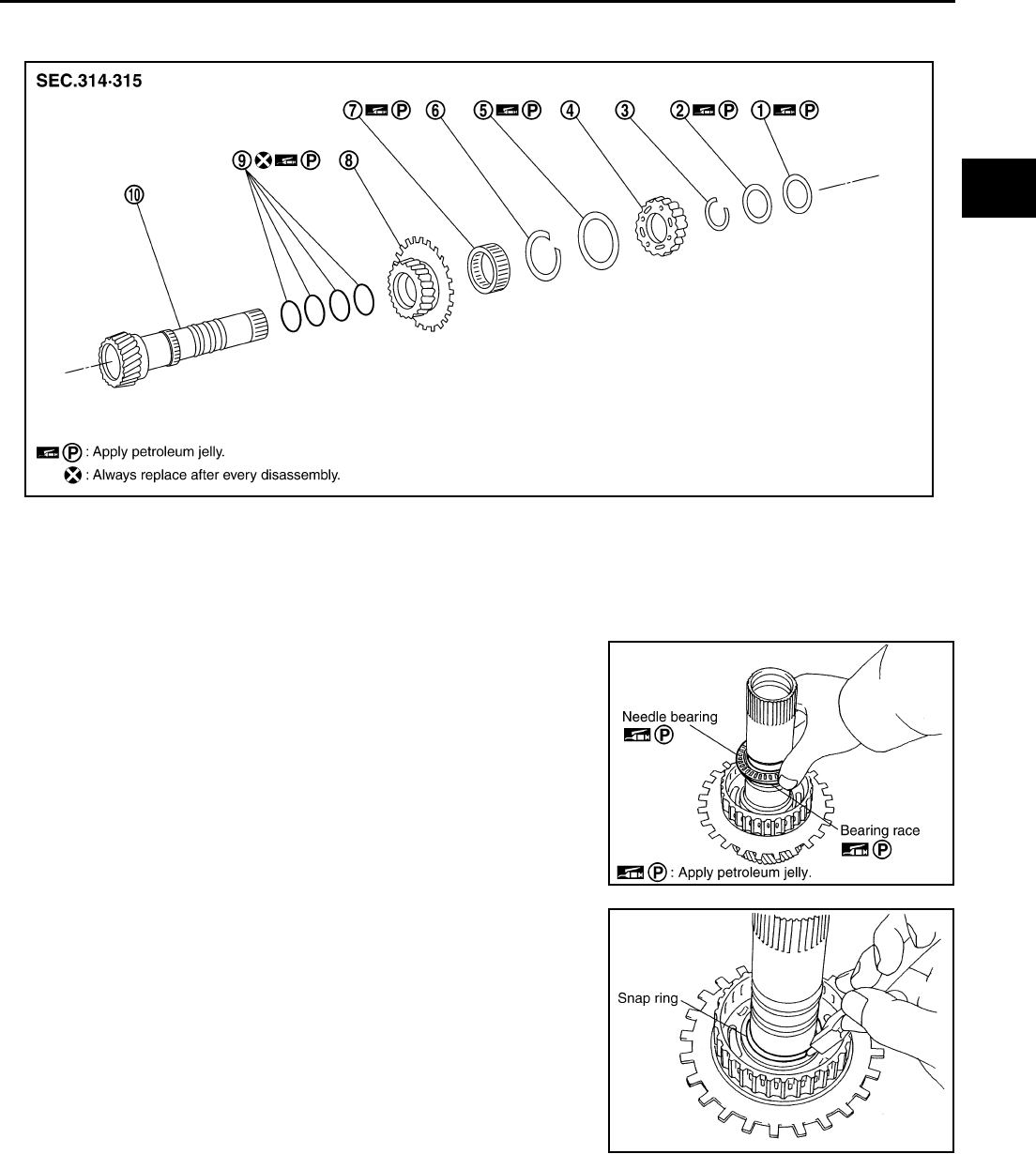
REPAIR FOR COMPONENT PARTS
AT-349
D
E
F
G
H
I
J
K
L
M
A
B
AT
Mid Sun Gear, Rear Sun Gear, High and Low Reverse Clutch Hub ACS004IQ
COMPONENTS
DISASSEMBLY
1. Remove needle bearing and bearing race.
2. Using a snap ring pliers, remove snap ring from high and low
reverse clutch hub.
CAUTION:
Do not expand snap ring excessively.
1. Needle bearing 2. Bearing race 3. Snap ring
4. High and low reverse clutch hub 5. Needle bearing 6. Snap ring
7. 1st one-way clutch 8. Rear sun gear 9. Seal ring
10. Mid sun gear
SCIA2851E
SCIA2854E
SCIA2855E
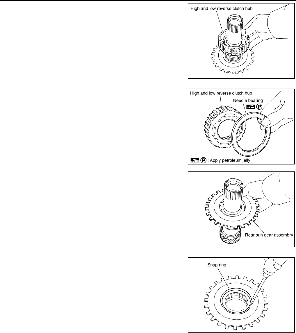
AT-350
REPAIR FOR COMPONENT PARTS
3. Remove high and low reverse clutch hub from mid sun gear
assembly.
a. Remove needle bearing from high and low reverse clutch hub.
4. Remove rear sun gear assembly from mid sun gear assembly.
a. Using a flat-bladed screwdriver, remove snap ring from rear sun
gear.
SCIA2856E
SCIA2857E
SCIA2858E
SCIA2859E
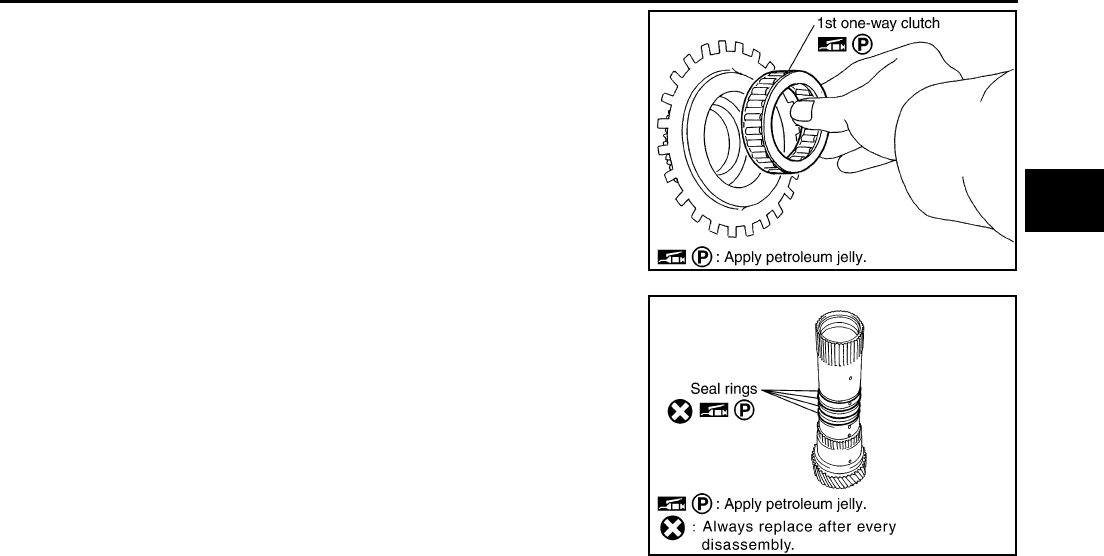
REPAIR FOR COMPONENT PARTS
AT-351
D
E
F
G
H
I
J
K
L
M
A
B
AT
b. Remove 1st one-way clutch from rear sun gear.
5. Remove seal rings from mid sun gear.
INSPECTION
High and Low Reverse Clutch Hub Snap Ring, Rear Sun Gear Snap Ring
●Check for deformation, fatigue or damage.
CAUTION:
If necessary, replace the snap ring.
1st One-way Clutch
●Check frictional surface for wear or damage.
CAUTION:
If necessary, replace the 1st one-way clutch.
Mid Sun Gear
●Check for deformation, fatigue or damage.
CAUTION:
Replace mid sun gear assembly and high and low reverse clutch assembly as a set if necessary.
Rear Sun Gear
●Check for deformation, fatigue or damage.
CAUTION:
If necessary, replace the rear sun gear.
High and Low Reverse Clutch Hub
●Check for deformation, fatigue or damage.
CAUTION:
If necessary, replace the high and low reverse clutch hub.
SCIA4633E
SCIA2861E
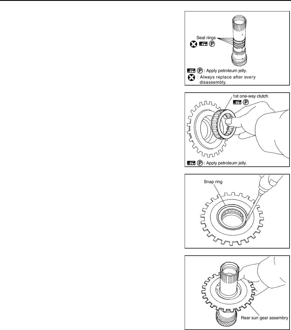
AT-352
REPAIR FOR COMPONENT PARTS
ASSEMBLY
1. Install seal rings from mid sun gear.
CAUTION:
●Do not reuse seal rings.
●Apply petroleum jelly to seal rings.
2. Install 1st one-way clutch in rear sun gear.
CAUTION:
Apply petroleum jelly to 1st one-way clutch.
3. Using a flat-bladed screwdriver, install snap ring in rear sun
gear.
4. Install rear sun gear assembly in mid sun gear assembly.
SCIA2861E
SCIA4633E
SCIA2859E
SCIA2858E
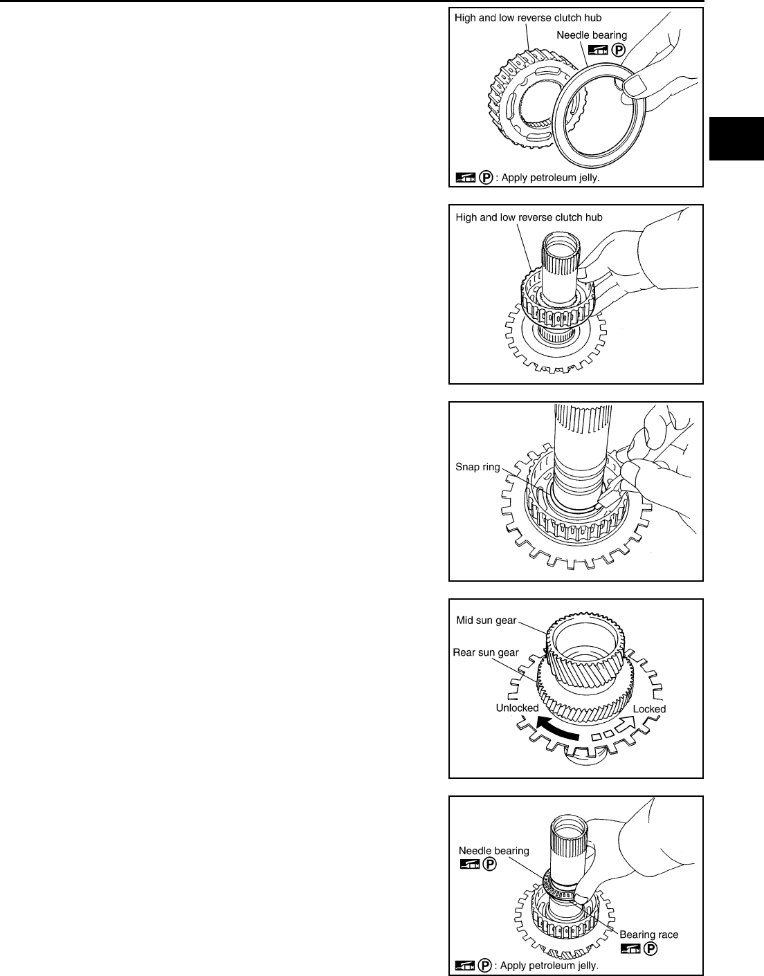
REPAIR FOR COMPONENT PARTS
AT-353
D
E
F
G
H
I
J
K
L
M
A
B
AT
5. Install needle bearing in high and low reverse clutch hub.
CAUTION:
Apply petroleum jelly to needle bearing.
6. Install high and low reverse clutch hub in mid sun gear assem-
bly.
7. Using a snap ring pliers, install snap ring in high and low reverse
clutch hub.
CAUTION:
Do not expand snap ring excessively.
8. Check operation of 1st one-way clutch.
a. Hold mid sun gear and turn rear sun gear.
b. Check 1st one-way clutch for correct locking and unlocking
directions.
CAUTION:
If not as shown in illustration, check installation direction of
1st one-way clutch.
9. Install needle bearing and bearing race.
CAUTION:
Apply petroleum jelly to needle bearing and bearing race.
SCIA2857E
SCIA2856E
SCIA2855E
SCIA3132E
SCIA2854E
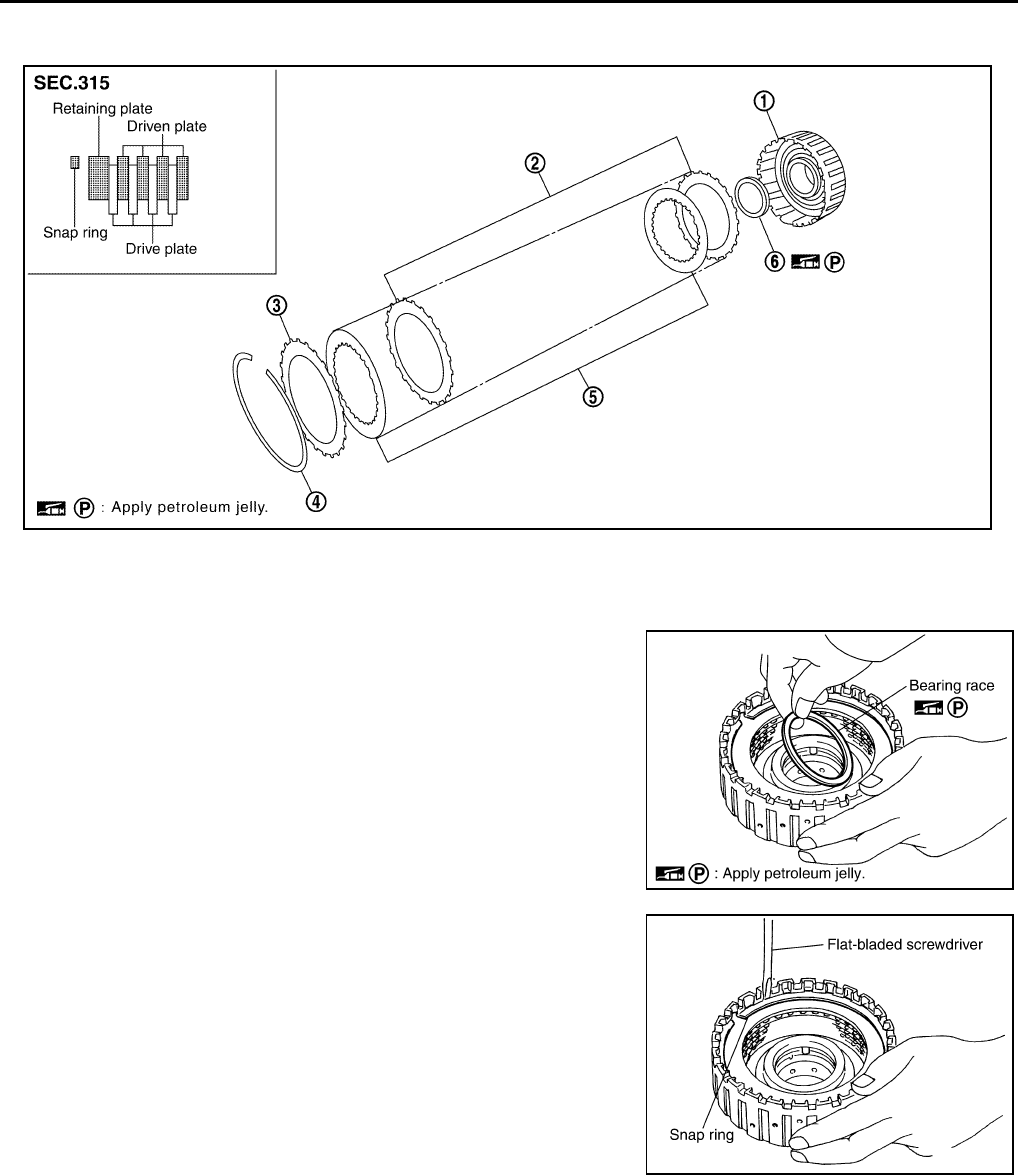
AT-354
REPAIR FOR COMPONENT PARTS
High and Low Reverse Clutch ACS004IR
COMPONENTS
DISASSEMBLY
1. Remove bearing race from high and low reverse clutch drum.
2. Using a flat-bladed screwdriver, remove snap ring from high and
low reverse clutch drum.
3. Remove drive plates, driven plates and retaining plate from high
and low reverse clutch drum.
INSPECTION
●Check the following, and replace high and low reverse clutch assembly if necessary.
High and Low Reverse Clutch Snap Ring
●Check for deformation, fatigue or damage.
High and Low Reverse Clutch Drive Plates
●Check facing for burns, cracks or damage.
1. High and low reverse clutch drum 2. Driven plate 3. Retaining plate
4. Snap ring 5. Drive plate 6. Bearing race
SCIA5045E
SCIA5215E
SCIA2868E
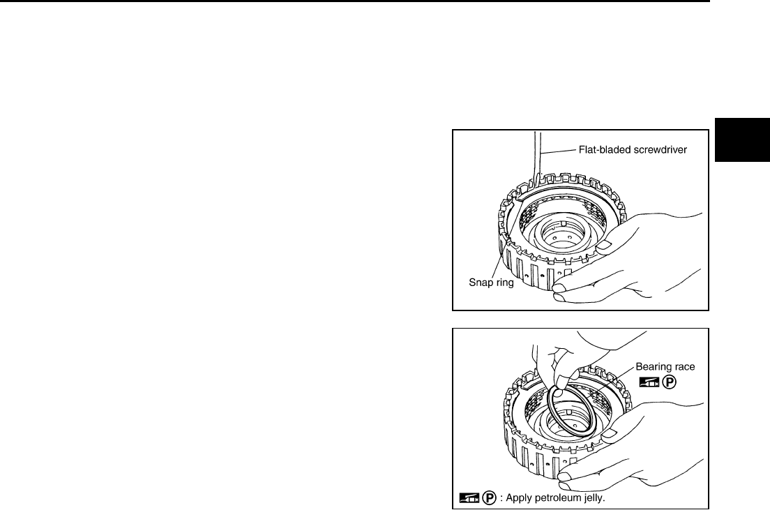
REPAIR FOR COMPONENT PARTS
AT-355
D
E
F
G
H
I
J
K
L
M
A
B
AT
High and Low Reverse Clutch Retaining Plate and Driven Plates
●Check facing for burns, cracks or damage.
ASSEMBLY
1. Install drive plates, driven plates and retaining plate in high and low reverse clutch drum.
CAUTION:
Take care with order of plates.
2. Using a flat-bladed screwdriver, install snap ring in high and low
reverse clutch drum.
3. Install bearing race to high and low reverse clutch drum.
CAUTION:
Apply petroleum jelly to bearing race.
SCIA2868E
SCIA5215E
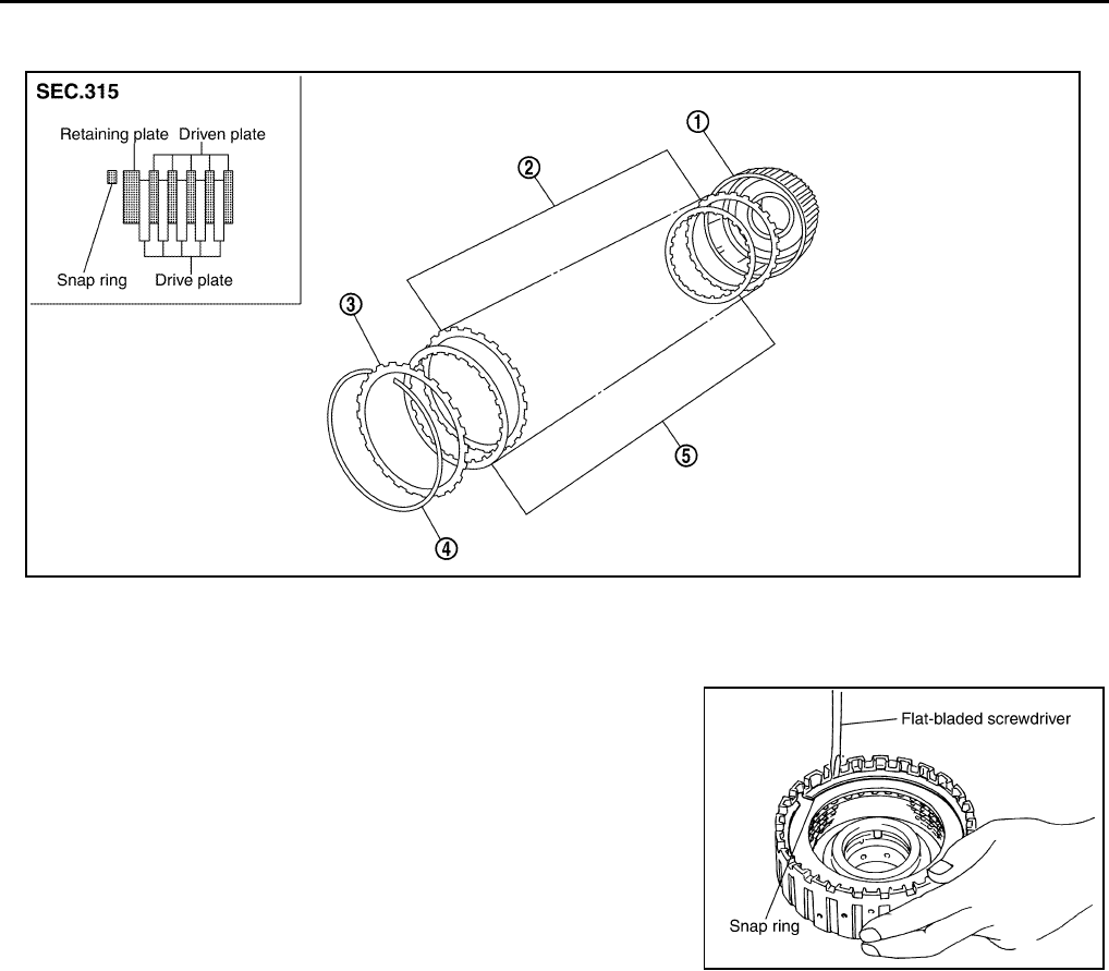
AT-356
REPAIR FOR COMPONENT PARTS
Direct Clutch ACS004IS
COMPONENTS
DISASSEMBLY
1. Using a flat-bladed screwdriver, remove snap ring from direct
clutch drum.
2. Remove drive plates, driven plates and retaining plate from
direct clutch drum.
INSPECTION
●Check the following, and replace direct clutch assembly if necessary.
Direct Clutch Snap Ring
●Check for deformation, fatigue or damage.
Direct Clutch Drive Plates
●Check facing for burns, cracks or damage.
Direct Clutch Retaining Plate and Driven Plates
●Check facing for burns, cracks or damage.
1. Direct clutch drum 2. Driven plate 3. Retaining plate
4. Snap ring 5. Drive plate
SCIA5046E
SCIA2868E
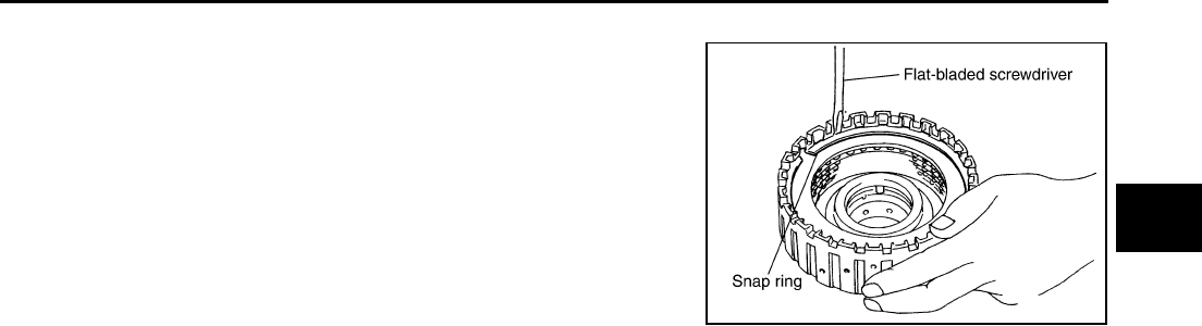
REPAIR FOR COMPONENT PARTS
AT-357
D
E
F
G
H
I
J
K
L
M
A
B
AT
ASSEMBLY
1. Install drive plates, driven plates and retaining plate in direct
clutch drum.
CAUTION:
Take care with order of plates.
2. Using a flat-bladed screwdriver, install snap ring in direct clutch
drum.
SCIA2868E
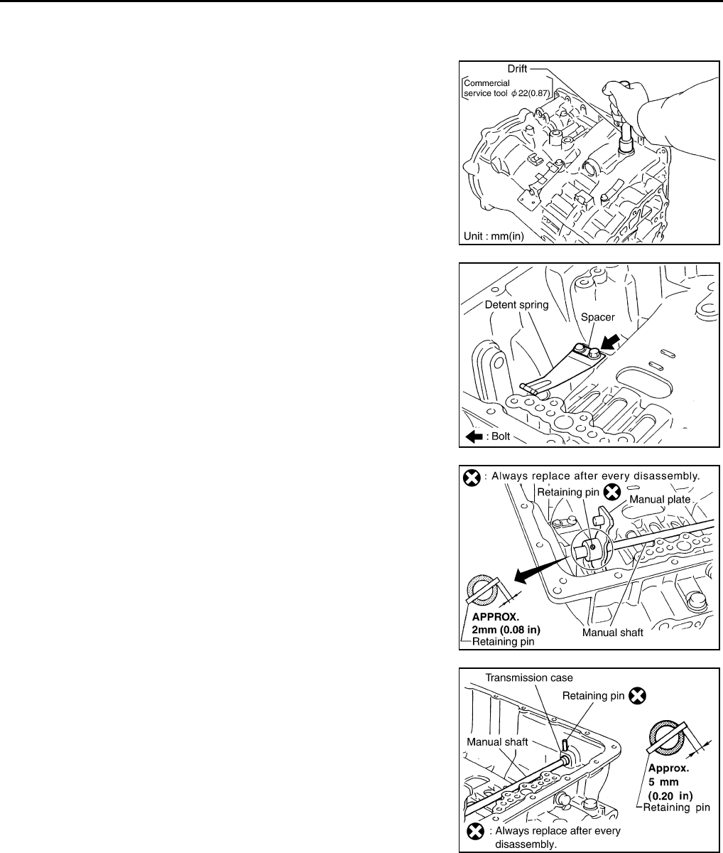
AT-358
ASSEMBLY
ASSEMBLY PFP:00000
Assembly (1) ACS004M9
1. As shown below, use a drift [commercial service tool φ22 mm
(0.87 in)] to drive manual shaft oil seals into the transmission
case until it is flush.
CAUTION:
●Apply ATF to manual shaft oil seals.
●Do not reuse manual shaft oil seals.
2. Install detent spring and spacer in transmission case.
3. Assemble manual shaft, manual plate, and parking rod after
installing manual shaft to transmission case.
4. Install retaining pin into the manual plate and manual shaft.
a. Fit pinhole of the manual plate to pinhole of the manual shaft
with a pin punch.
b. Use a hammer to tap the retaining pin into the manual plate.
CAUTION:
●Drive retaining pin to 2±0.5 mm over the manual
plate.
●Do not reuse retaining pin.
5. Install retaining pin into the transmission case and manual shaft.
a. Fit pinhole of the transmission case to pinhole of the manual
shaft with a pin punch.
b. Use a hammer to tap the retaining pin into the transmission
case.
CAUTION:
●Drive retaining pin to 5±1 mm over the transmis-
sion case.
●Do not reuse retaining pin.
SCIA5259E
SCIA5248E
SCIA5297E
SCIA2427E
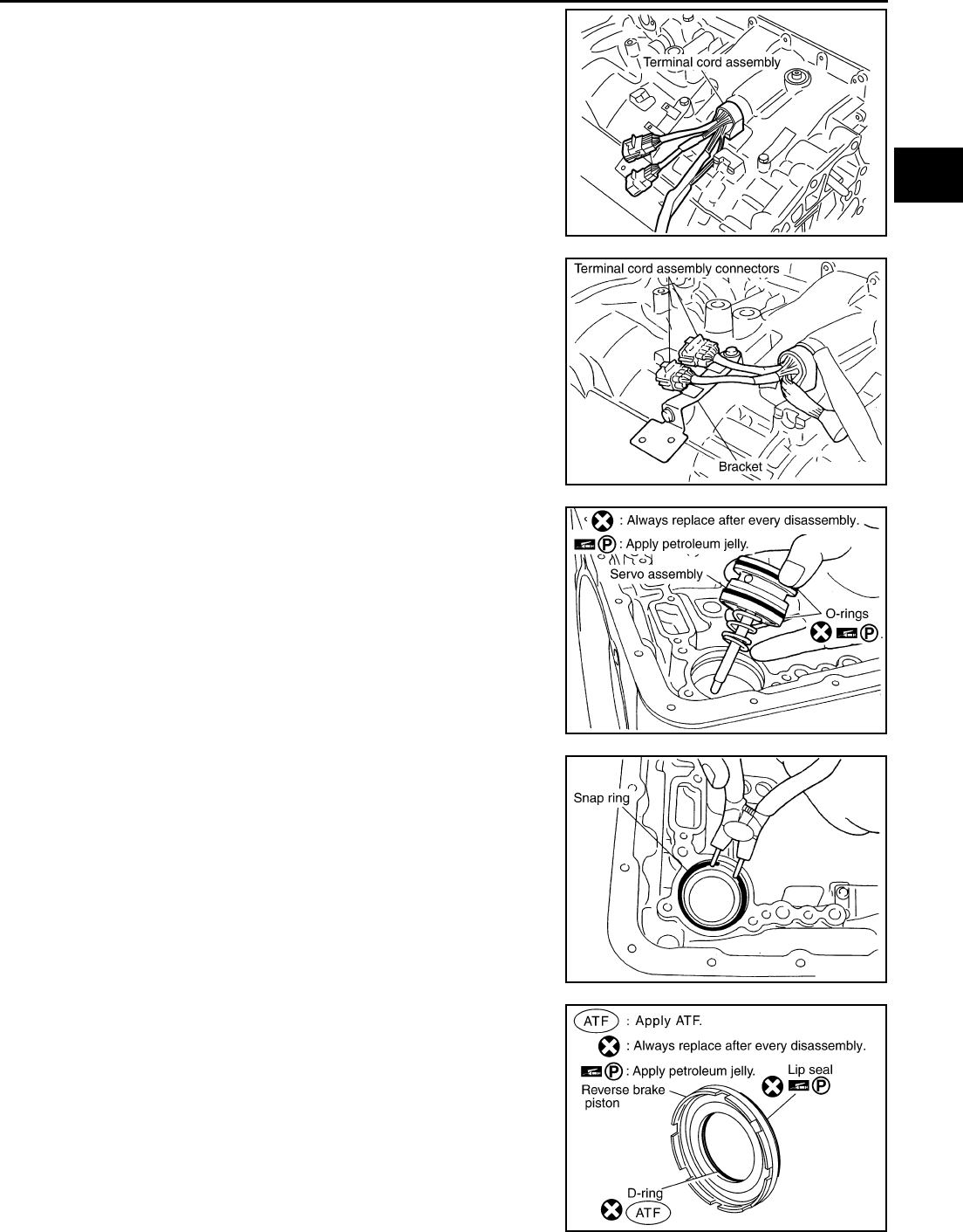
ASSEMBLY
AT-359
D
E
F
G
H
I
J
K
L
M
A
B
AT
6. Install terminal cord assembly in transmission case.
CAUTION:
Apply petroleum jelly to O-ring.
7. Install terminal cord assembly connectors in bracket.
8. Install O-rings in servo assembly.
CAUTION:
Do not reuse O-rings.
Apply petroleum jelly to O-rings.
9. Install return spring in servo assembly.
10. Install servo assembly in transmission case.
11. Using snap ring pliers, install snap ring in transmission case.
12. Install lip seal and D-ring in reverse brake piston.
CAUTION:
●Do not reuse lip seal and D-ring.
●Apply petroleum jelly to lip seal.
●Apply ATF to D-ring.
SCIA2428E
SCIA2326E
SCIA2334E
SCIA2333E
SCIA2795E
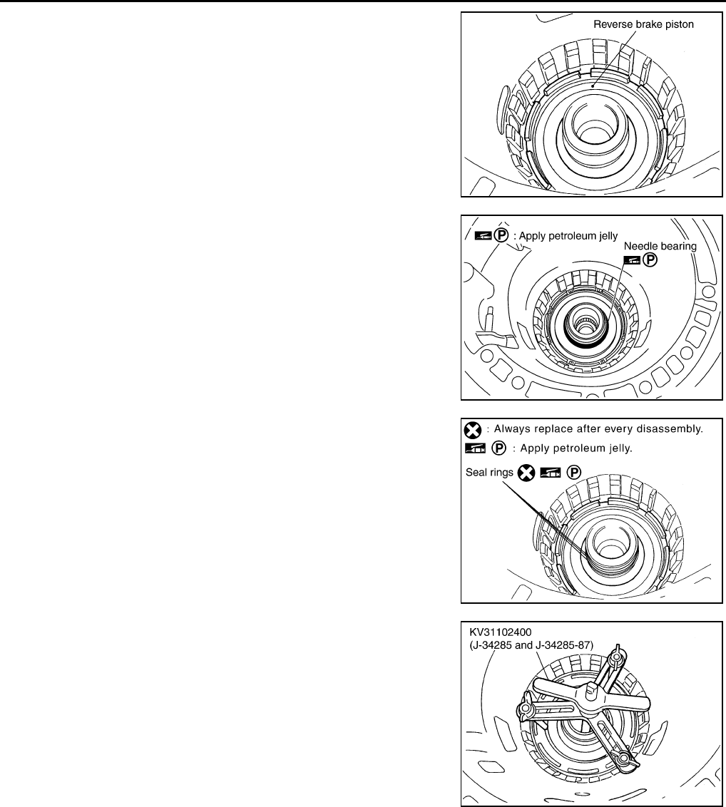
AT-360
ASSEMBLY
13. Install reverse brake piston in transmission case.
14. Install needle bearing in transmission case.
CAUTION:
Apply petroleum jelly to needle bearing.
15. Install seal rings in drum support.
CAUTION:
●Do not reuse seal rings.
●Apply petroleum jelly to seal rings.
16. After installing the return spring and spring retainer in transmis-
sion case, use a clutch spring compressor to install snap ring in
transmission case.
CAUTION:
Securely assemble them using a flat-bladed screwdriver so
that snap ring tension is slightly weak.
SCIA2325E
SCIA2796E
SCIA3333E
SCIA5314E
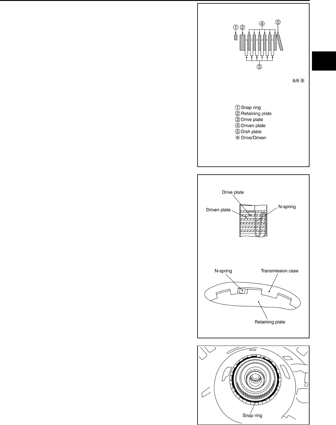
ASSEMBLY
AT-361
D
E
F
G
H
I
J
K
L
M
A
B
AT
17. Install reverse brake retaining plate, drive plates, driven plates
and dish plate in transmission case.
CAUTION:
Take care with order of plates.
18. Assemble N-spring.
19. Install snap ring in transmission case.
SCIA5250E
SCIA3179E
SCIA2439E
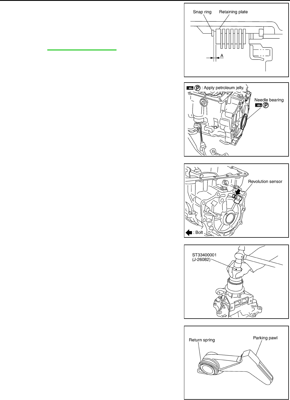
AT-362
ASSEMBLY
20. Measure clearance between retaining plate and snap ring. If not
within specified clearance, select proper retaining plate.
21. Install needle bearing in transmission case.
CAUTION:
Apply petroleum jelly to needle bearing.
22. Install revolution sensor in transmission case.
CAUTION:
●Do not subject it to impact by dropping or hitting it.
●Do not disassemble.
●Do not allow metal filings, etc., to get on the sensor's
front edge magnetic area.
●Do not place in an area affected by magnetism.
23. As shown below, use a drift to drive rear oil seal into the rear
extension until it is flush.
CAUTION:
●Apply ATF to rear oil seal.
●Do not reuse rear oil seal.
24. Install return spring in parking pawl.
Specified clearance “A”:
Standard: 0.7 - 1.1mm (0.028 - 0.043 in)
Retaining plate:
Refer to AT-378, "Reverse Brake" .
SCIA3129E
SCIA2440E
SCIA2320E
SCIA5311E
SCIA2445E
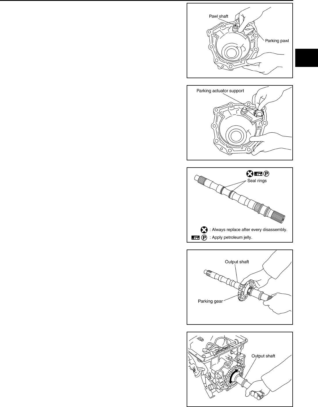
ASSEMBLY
AT-363
D
E
F
G
H
I
J
K
L
M
A
B
AT
25. Install parking pawl and pawl shaft in rear extension.
26. Install parking actuator support in rear extension.
27. Install needle bearing in rear extension.
CAUTION:
Apply petroleum jelly to needle bearing.
28. Install seal rings in output shaft.
CAUTION:
●Do not reuse seal rings.
●Apply petroleum jelly to seal rings.
29. Install parking gear in output shaft.
30. Install output shaft in transmission case.
CAUTION:
Be careful not to mistake front for rear because both sides
looks similar. (Thinner end is front side.)
SCIA3424E
SCIA3423E
SCIA5209E
SCIA5247E
SCIA3422E
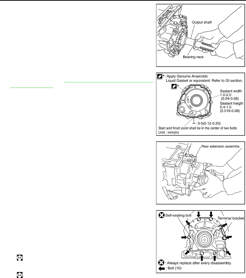
AT-364
ASSEMBLY
31. Install bearing race in output shaft.
32. Apply recommended sealant (Genuine Anaerobic Liquid Gasket
or equivalent. Refer to GI-45, "Recommended Chemical Prod-
ucts and Sealants" .) to rear extension assembly as shown in
illustration.
CAUTION:
Complete remove all moisture, oil and old sealant, etc.
From the transmission case and rear extension mounting
surfaces.
33. Install rear extension assembly in transmission case.
34. Tighten rear extension assembly mounting bolts to specified
torque. (Because terminal bracket is tightened together with out-
put shaft & companion flange, it should be installed before pro-
cedure 33.)
CAUTION:
Do not reuse self-sealing bolt.
SCIA5245E
SCIA5212E
SCIA3421E
Rear extension assembly mounting bolt:
: 52 N·m (5.3 kg-m, 38 ft-lb)
Self-sealing bolt:
: 61 N·m (6.2 kg-m, 45 ft-lb) SCIA5428E
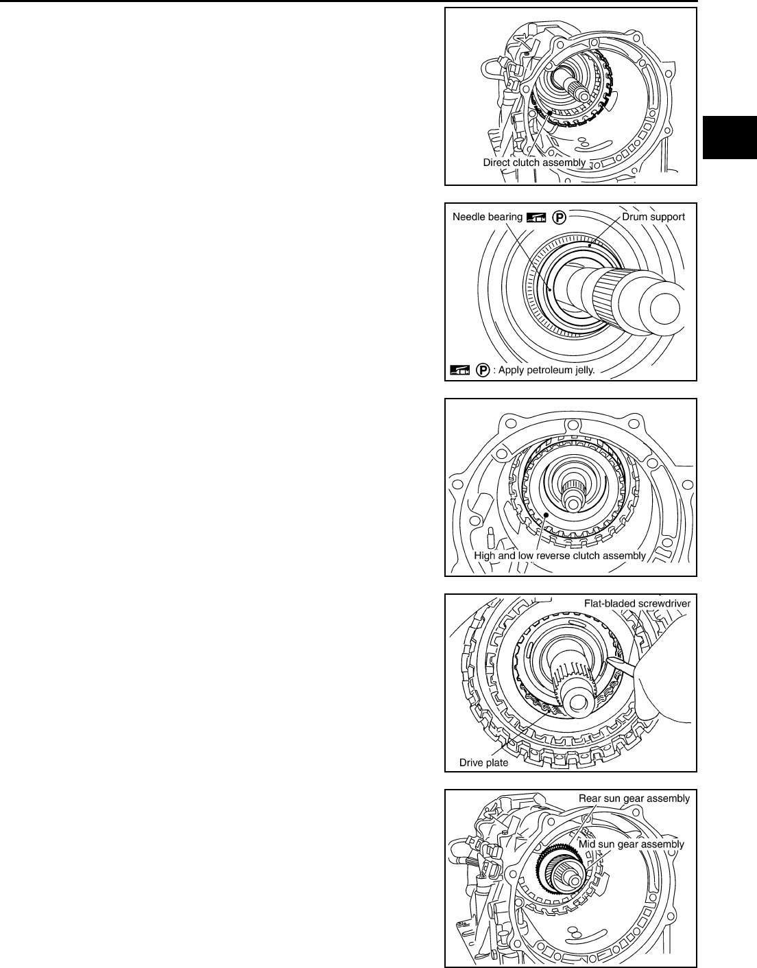
ASSEMBLY
AT-365
D
E
F
G
H
I
J
K
L
M
A
B
AT
35. Install direct clutch assembly in reverse brake.
CAUTION:
Make sure that drum support edge surface and direct clutch
inner boss edge surface come to almost same place.
36. Install needle bearing in drum support edge surface.
CAUTION:
Apply petroleum jelly to needle bearing.
37. Install high and low reverse clutch assembly in direct clutch
assembly.
CAUTION:
Be sure to replace high and low reverse clutch and mid sun
gear as a set.
38. Using a flat-bladed screwdriver, range the drive plates.
39. Install high and low reverse clutch hub, mid sun gear assembly
and rear sun gear assembly as a unit.
SCIA2307E
SCIA5198E
SCIA2306E
SCIA3169E
SCIA2305E
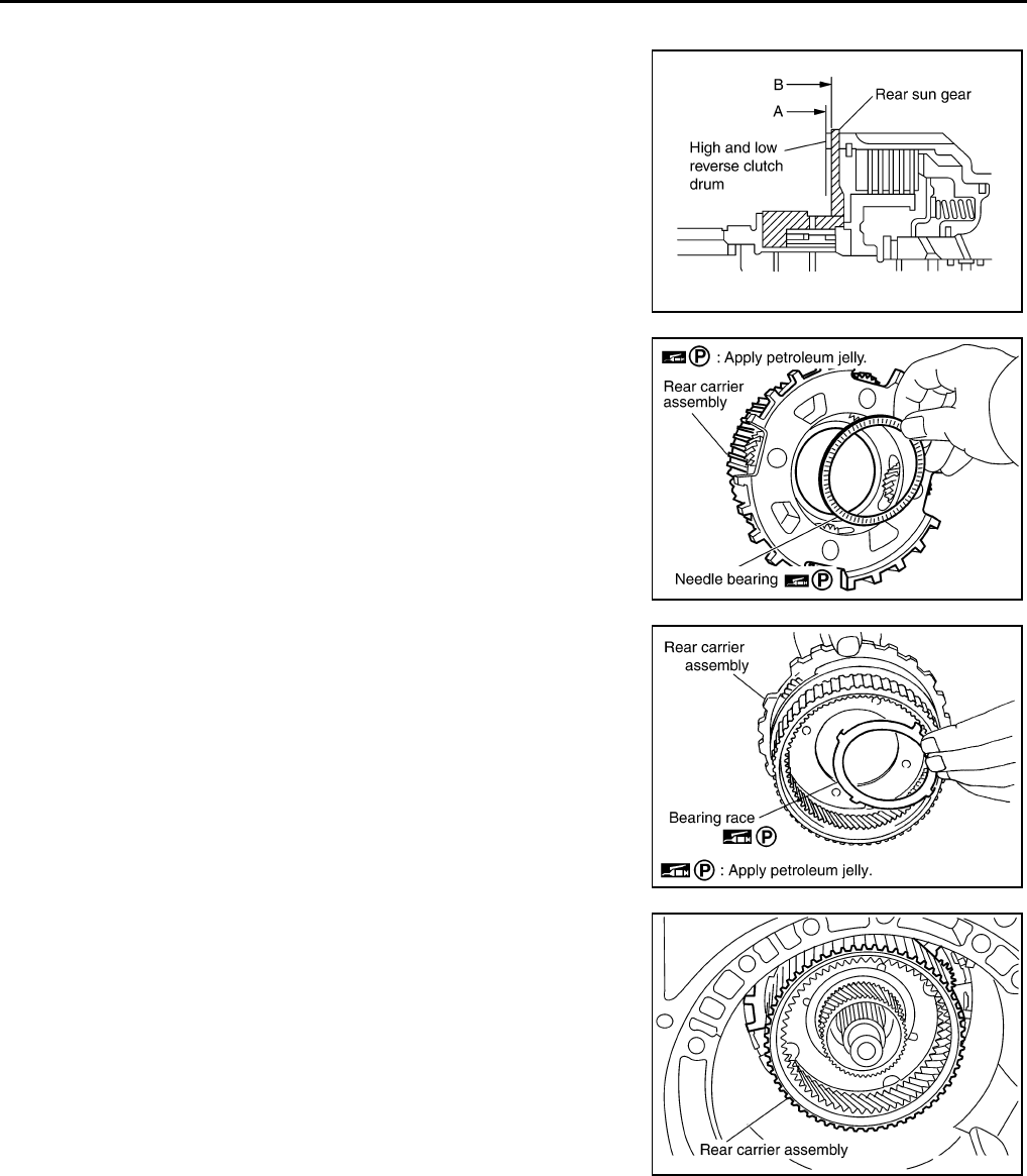
AT-366
ASSEMBLY
CAUTION:
Check that portion A of high and low reverse clutch drum
protrudes approximately 2 mm (0.08 in) beyond portion B of
rear sun gear.
40. Install needle bearing in rear carrier assembly.
CAUTION:
Apply petroleum jelly to needle bearing.
41. Install bearing race in rear carrier assembly.
CAUTION:
Apply petroleum jelly to bearing race.
42. Install rear carrier assembly in direct clutch drum.
SCIA3130E
SCIA2803E
SCIA5175E
SCIA2462E
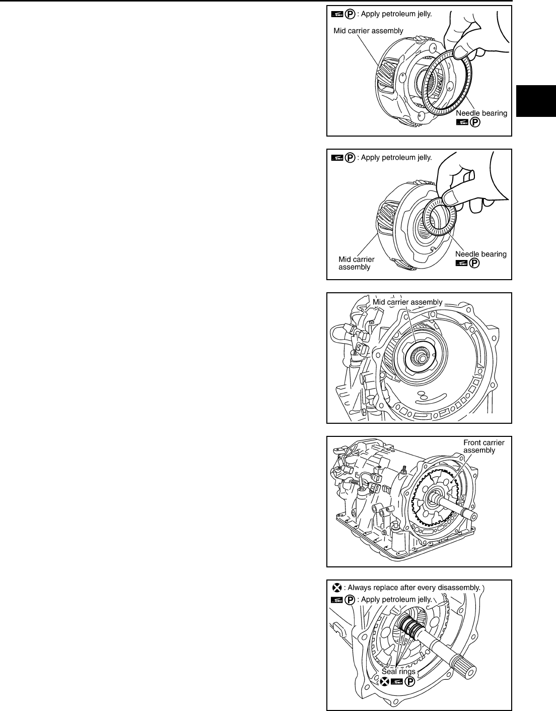
ASSEMBLY
AT-367
D
E
F
G
H
I
J
K
L
M
A
B
AT
43. Install needle bearing (rear side) in mid carrier assembly.
CAUTION:
Apply petroleum jelly to needle bearing.
44. Install needle bearing (front side) in mid carrier assembly.
CAUTION:
Apply petroleum jelly to needle bearing.
45. Install mid carrier assembly in rear carrier assembly.
46. Install front carrier assembly (with input clutch assembly and
rear internal gear) to rear carrier assembly.
47. Install seal rings in input clutch assembly.
CAUTION:
●Do not reuse seal rings.
●Apply petroleum jelly to seal rings.
SCIA2804E
SCIA2805E
SCIA2304E
SCIA3419E
SCIA2470E
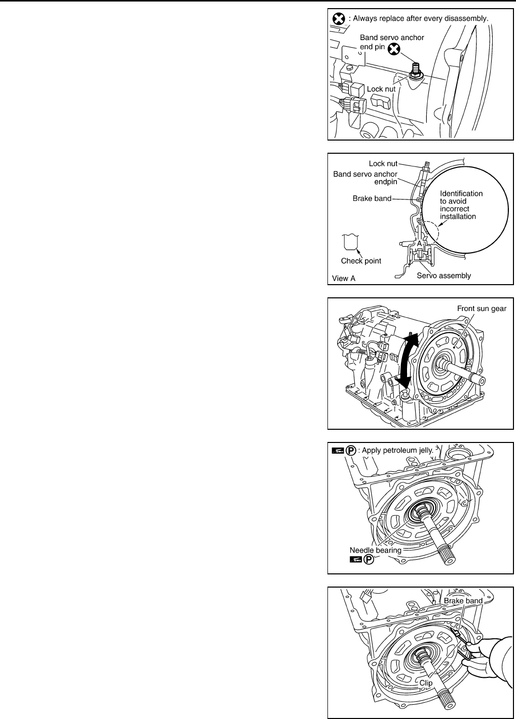
AT-368
ASSEMBLY
48. Install band servo anchor end pin and lock nut in transmission
case.
CAUTION:
Do not reuse band servo anchor end pin.
49. Install brake band in transmission case.
CAUTION:
Assemble it so that identification to avoid incorrect installa-
tion faces servo side.
50. Install front sun gear in transmission case.
CAUTION:
Apply ATF to front sun gear bearing and 3rd one-way clutch
end bearing.
51. Install needle bearing in front sun gear.
CAUTION:
Apply petroleum jelly to needle bearing.
52. Adjust brake band tilting using clips so that brake band contacts
front sun gear drum evenly.
SCIA2579E
SCIA5498E
SCIA3418E
SCIA2808E
SCIA2473E
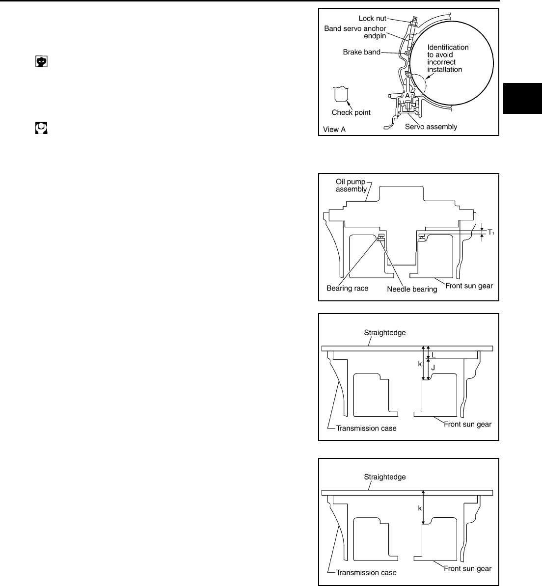
ASSEMBLY
AT-369
D
E
F
G
H
I
J
K
L
M
A
B
AT
53. Adjust brake band.
a. Loosen lock nut.
b. Tighten band servo anchor end pin to specified torque.
c. Back of band servo anchor end pin three turns.
d. While band servo anchor end pin, tighten lock nut to specified
torque.
Adjustment ACS004MA
TOTAL END PLAY
●Measure clearance between front sun gear and needle bearing
for oil pump cover.
●Select proper thickness of bearing race so that end play is within
specifications.
1. Measure dimensions “K” and “L” and then calculate dimension
“J”.
a. Measure dimension “K”.
: 5.0 N·m (0.51 kg-m, 44 in-lb)
: 46 N·m (4.7 kg-m, 34 ft-lb) SCIA5498E
SCIA2810E
SCIA5350E
SCIA5351E
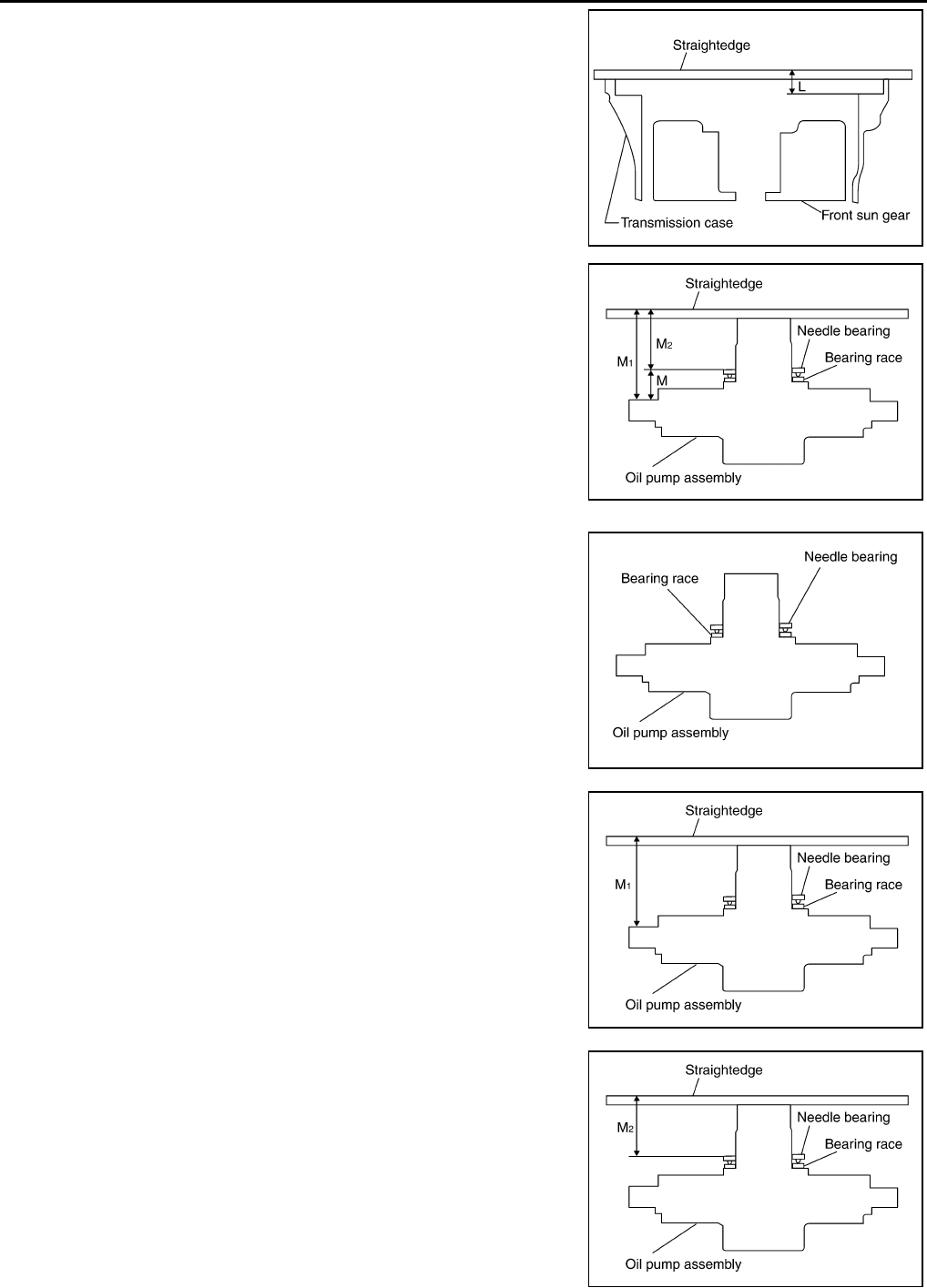
AT-370
ASSEMBLY
b. Measure dimension “L”.
c. Calculate dimension “J”.
2. Measure dimensions “M1 ” and “M2 ” and then calculate dimen-
sion “M”.
a. Place bearing race and needle bearing on oil pump assembly.
b. Measure thickness of straightedge “M1 ”.
c. Measure thickness of straightedge “M2 ”.
“J”: Distance between oil pump fitting surface of
transmission case and needle bearing mating surface
of front sun gear.
J = K – L
SCIA5352E
SCIA3125E
SCIA3124E
SCIA3126E
SCIA3127E
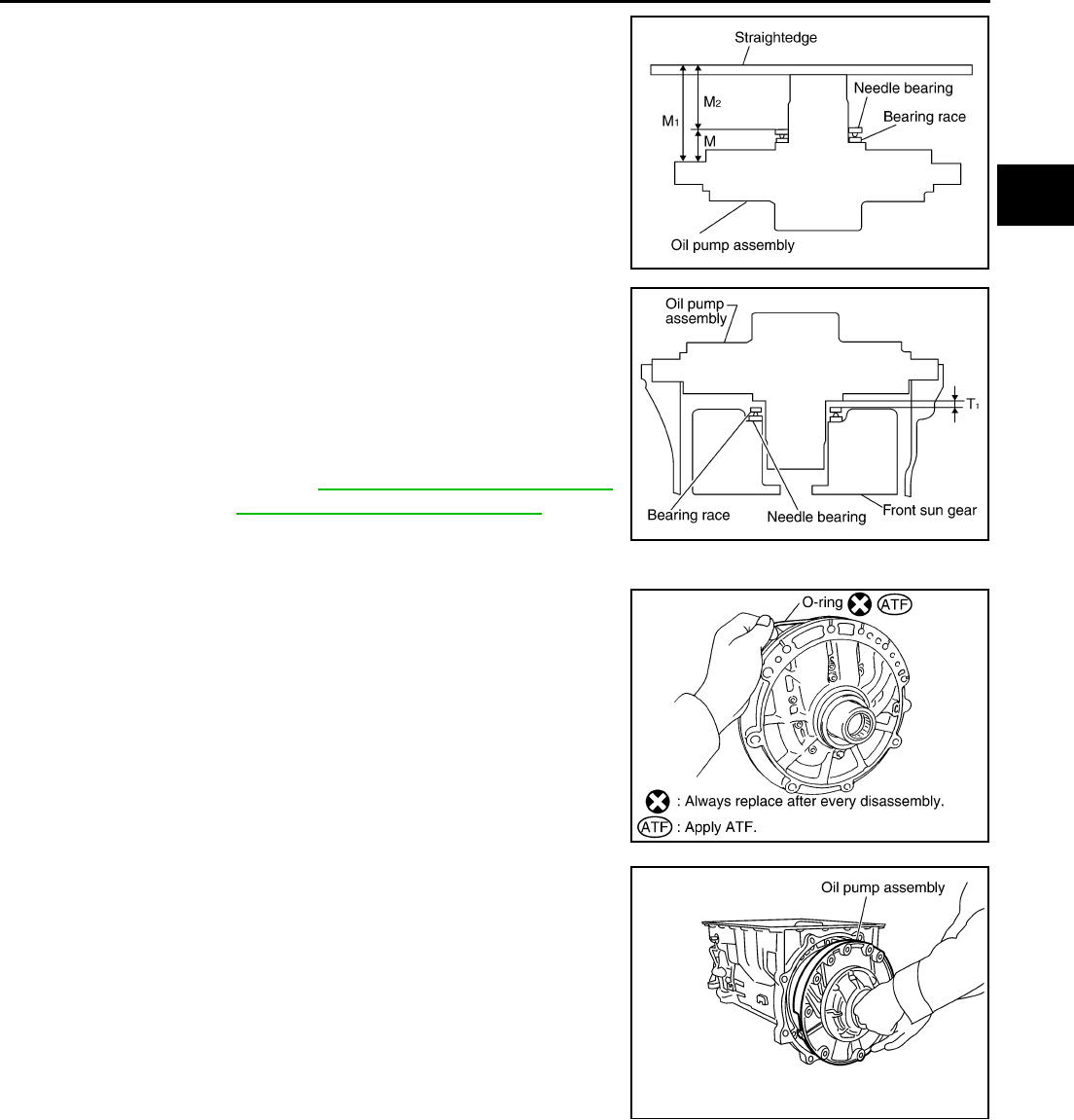
ASSEMBLY
AT-371
D
E
F
G
H
I
J
K
L
M
A
B
AT
d. Calculate dimension “M”.
3. Adjust total end play “T1 ”.
●Select proper thickness of bearing race so that total end play
is within specifications.
Assembly (2) ACS004MB
1. Install O-ring in oil pump assembly.
CAUTION:
●Do not reuse O-ring.
●Apply ATF to O-ring.
2. Install bearing race in oil pump assembly.
CAUTION:
Apply petroleum jelly to bearing race.
3. Install oil pump assembly in transmission case.
CAUTION:
Apply ATF to oil pump bush.
“M”: Distance between transmission case fitting sur-
face of oil pump and needle bearing on oil pump.
M = M1 – M2
SCIA3125E
T1 = J – M
Total end play “T1 ”:
0.25 - 0.55 mm (0.0098 - 0.0217 in)
Bearing races: Refer to AT-379, "BEARING RACE FOR
ADJUSTING TOTAL END PLAY" .
SCIA2810E
SCIA2837E
SCIA2811E
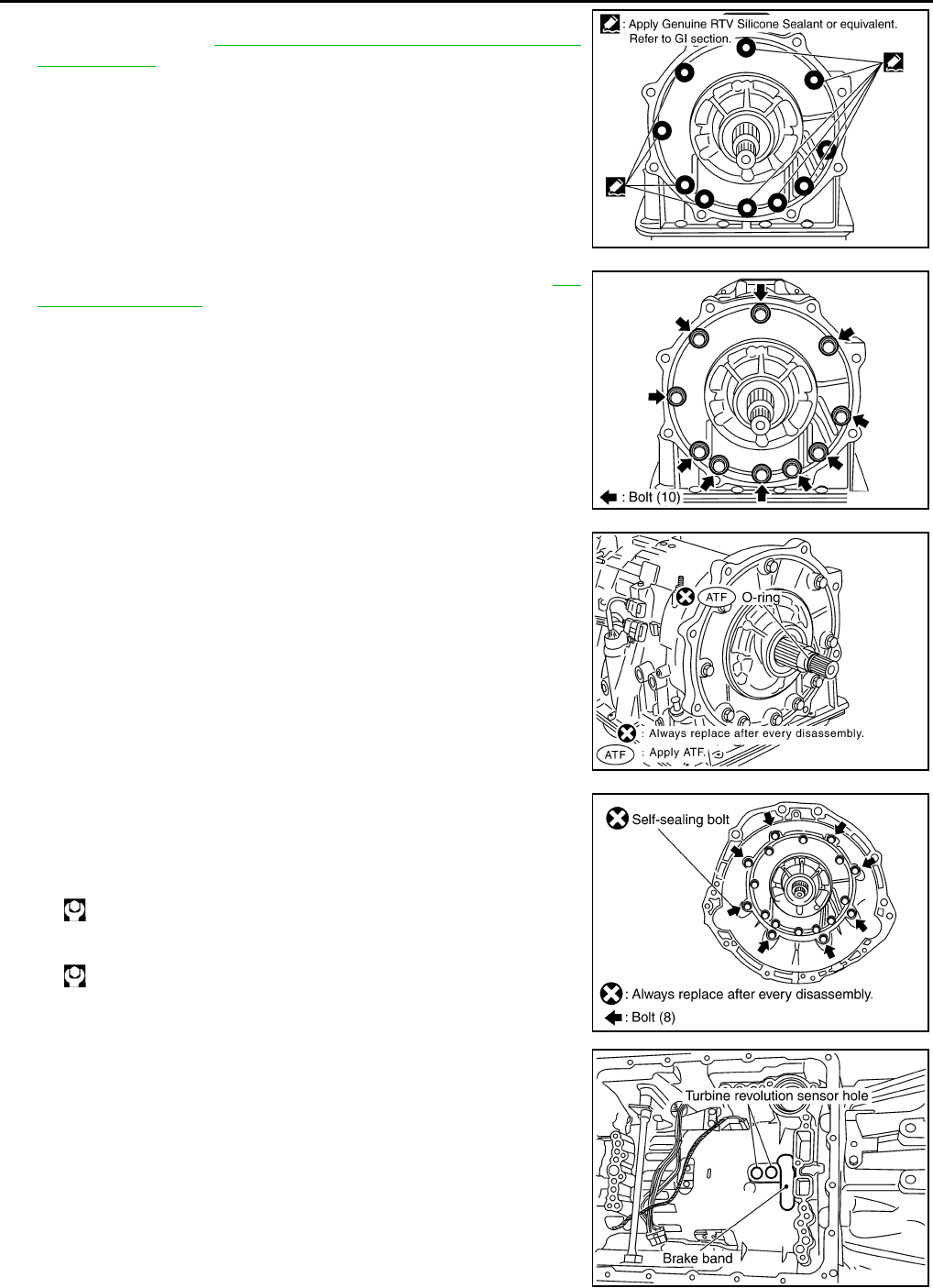
AT-372
ASSEMBLY
4. Apply recommended sealant (Genuine RTV Silicone Sealant or
equivalent. Refer to GI-45, "Recommended Chemical Products
and Sealants" .) to oil pump assembly as shown in illustration.
CAUTION:
Complete remove all moisture, oil and old sealant, etc.
From the oil pump mounting bolts and oil pump mounting
bolt mounting surfaces.
5. Tighten oil pump mounting bolts to specified torque. Refer to AT-
317, "Components" .
CAUTION:
Apply ATF to oil pump bushing.
6. Install O-ring in input clutch assembly.
CAUTION:
●Do not reuse O-ring.
●Apply ATF to O-ring.
7. Install converter housing in transmission case.
CAUTION:
Do not reuse self-sealing bolt.
8. Make sure that brake band does not close turbine revolution
sensor hole.
SCIA5321E
SCIA2300E
SCIA2299E
Converter housing mounting bolt:
: 52 N·m (5.3 kg-m, 38 ft-lb)
Self-sealing bolt:
: 61 N·m (6.2 kg-m, 45 ft-lb)
SCIA3427E
SCIA2479E
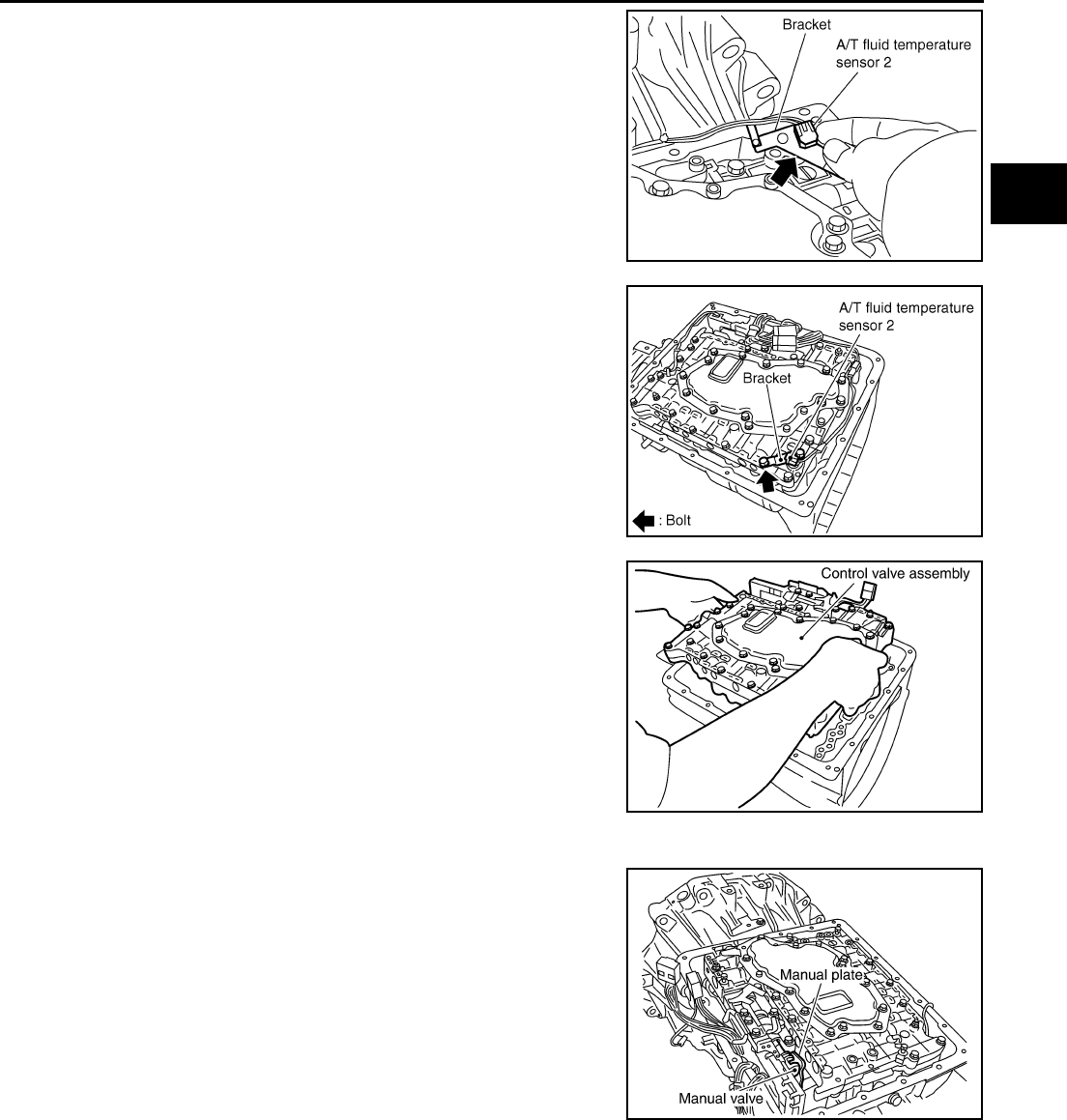
ASSEMBLY
AT-373
D
E
F
G
H
I
J
K
L
M
A
B
AT
9. Install A/T fluid temperature sensor 2 in bracket.
10. Install A/T fluid temperature sensor 2 (with bracket) in control
valve assembly.
11. Install control valve assembly.
a. Install control valve assembly in transmission case.
CAUTION:
●Hang down terminal cord assembly and revolution sen-
sor harness toward outside so as not to disturb installa-
tion of control valve assembly.
●Make sure that turbine sensor securely installs turbine
sensor hole.
●Assemble it so that manual valve cutout is engaged with
manual plate projection.
SCIA5128E
SCIA5126E
SCIA2315E
SCIA2812E
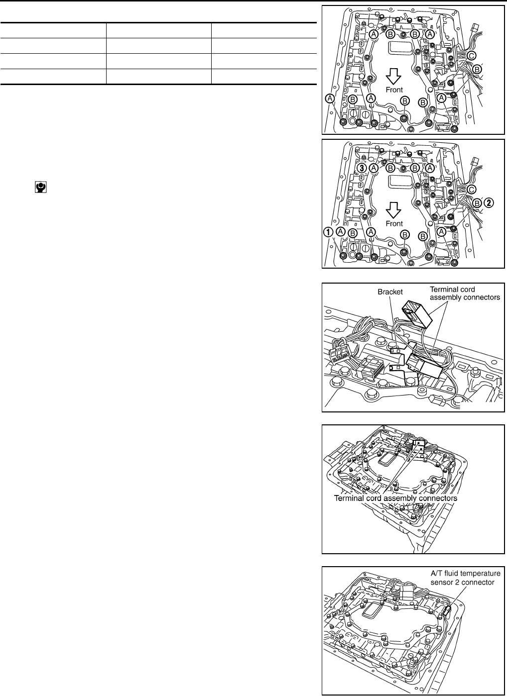
AT-374
ASSEMBLY
b. Install bolts A, B and C in control valve assembly.
c. Tighten bolt 1, 2 and 3 temporarily to prevent dislocation. After
that tighten them in order (1 → 2 → 3), and then tighten other
bolts.
12. Install terminal cord assembly connectors in bracket.
13. Connect terminal cord assembly connectors.
14. Connect A/T fluid temperature sensor 2 connector.
Bolt symbol Length mm (in) Number of bolts
A 42 (1.65) 5
B 55 (2.17) 6
C 40 (1.57) 1
: 7.9 N·m (0.81 kg-m, 70 in-lb)
SCIA2312E
SCIA3170E
SCIA2584E
SCIA3412E
SCIA5129E
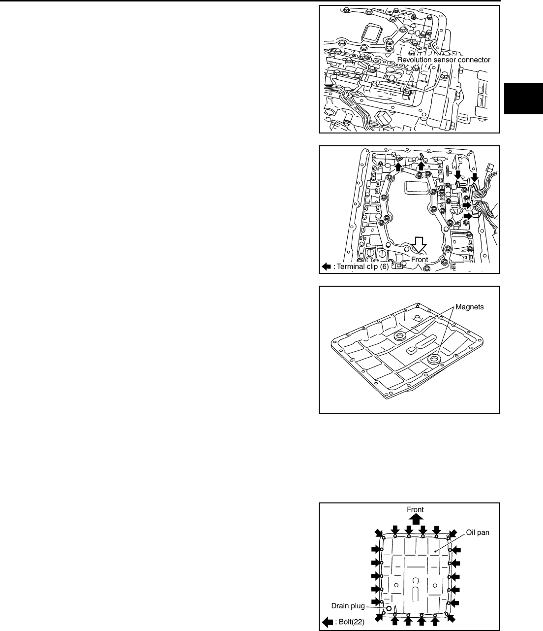
ASSEMBLY
AT-375
D
E
F
G
H
I
J
K
L
M
A
B
AT
15. Connect revolution sensor connector.
16. Securely fasten terminal harness with terminal clips.
17. Install magnets in oil pan.
18. Install oil pan in transmission case.
a. Install oil pan gasket in oil pan.
CAUTION:
●Do not reuse oil pan gasket.
●Install it in the direction to align hole positions.
b. Install oil pan (with oil pan gasket) in transmission case.
CAUTION:
●Install it so that drain plug comes to the position as
shown in the figure.
●Be careful not to pinch harnesses.
SCIA2313E
SCIA2314E
SCIA5200E
SCIA2308E

AT-376
ASSEMBLY
c. Tighten oil pan mounting bolts to the specified torque in numeri-
cal order shown in the figure after temporarily tightening them.
CAUTION:
Do not reuse oil pan mounting bolts.
19. Install drain plug in oil pan.
CAUTION:
Do not reuse drain plug gasket.
20. Install torque converter.
a. Pour ATF into torque converter.
●Approximately 2 liter (2-1/8 US qt, 1-3/4 Imp qt) of fluid is
required for a new torque converter.
●When reusing old torque converter, add the same amount
of fluid as was drained.
b. Install torque converter while aligning notches of torque con-
verter with notches of oil pump.
c. Measure distance “A” to check that torque converter is in proper
position.
: 7.9 N·m (0.81 kg-m, 70 in-lb)
: 34 N·m (3.5 kg-m, 25 ft-lb) SCIA2492E
SAT428DA
SCIA2297E
Distance “A”:
25.0 mm (0.98 in) or more
SAT017B
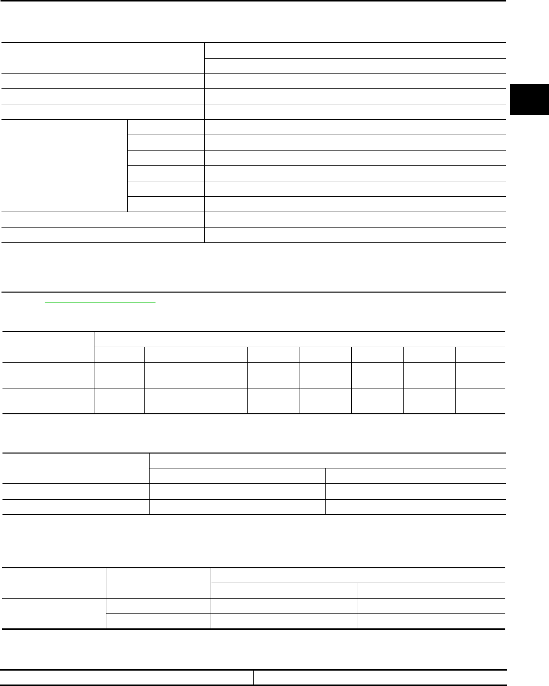
SERVICE DATA AND SPECIFICATIONS (SDS)
AT-377
D
E
F
G
H
I
J
K
L
M
A
B
AT
SERVICE DATA AND SPECIFICATIONS (SDS) PFP:00030
General Specifications ACS000FO
*1: Refer toMA-9, "Fluids and Lubricants" .
Vehicle Speed When Shifting Gears ACS000FP
●At half throttle, the accelerator opening is 4/8 of the full opening.
Vehicle Speed When Performing and Releasing Complete Lock-up ACS000FQ
●At closed throttle, the accelerator opening is less than 1/8 condition.
●At half throttle, the accelerator opening is 4/8 of the full opening.
Vehicle Speed When Performing and Releasing Slip Lock-up ACS000FR
●At closed throttle, the accelerator opening is less than 1/8 condition.
Stall Speed ACS000FS
Applied model VQ35DE engine
2WD
Automatic transmission model RE5R05A
Transmission model code number 91X17
Stall torque ratio 2.0: 1
Transmission gear ratio
1st 3.540
2nd 2.264
3rd 1.417
4th 1.000
5th 0.834
Reverse 2.370
Recommended fluid Genuine Nissan Matic J ATF*1
Fluid capacity 10.3 liter (10-7/8 US qt, 9-1/8 Imp qt)
CAUTION:
●Use only Genuine Nissan Matic J ATF. Do not mix with other fluid.
●Using automatic transmission fluid other than Genuine Nissan Matic J ATF will deteriorate in driveability and automatic
transmission durability, and may damage the automatic transmission, which is not covered by the warranty.
Throttle position Vehicle speed km/h (MPH)
D1 →D2D2 →D3D3 →D4D4 →D5D5 →D4D4 →D3D3 →D2D2 →D1
Full throttle 58 - 62
(36 - 39)
90 - 98
(56 - 61)
135 - 145
(84 - 90)
201 - 211
(125 - 131)
197 - 207
(122 - 129)
123 - 133
(76 - 83)
76 - 84
(47 - 52)
37 - 41
(23 - 25)
Half throttle 46 - 50
(29 - 31)
71 - 79
(44 - 49)
107 - 117
(66 - 73)
135 - 145
(84 - 90)
88 - 98
(55 - 61)
63 - 73
(39 - 45)
29 - 37
(18 - 23)
11 - 15
(7 - 9)
Throttle position Vehicle speed km/h (MPH)
Lock-up “ON” Lock-up “OFF”
Closed throttle 56 - 64 (35 - 40) 53 - 61 (33 - 38)
Half throttle 168 - 176 (104 - 109) 131 - 139 (81 - 86)
Throttle position Gear position Vehicle speed km/h (MPH)
Slip lock-up “ON” Slip lock-up “OFF”
Closed throttle 4th 37 - 45 (23 - 28) 34 - 42 (21 - 26)
5th 44 - 52 (27 - 32) 41 - 49 (25 - 30)
Stall speed 2,600 - 2,900 rpm
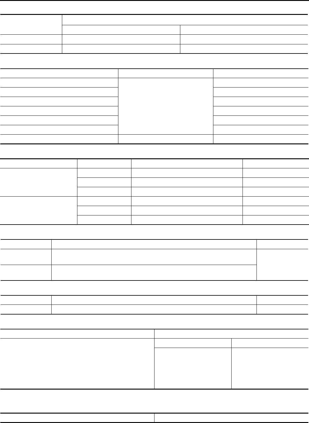
AT-378
SERVICE DATA AND SPECIFICATIONS (SDS)
Line Pressure ACS000FT
Solenoid Valves ACS000FU
A/T Fluid Temperature Sensor ACS000FV
Turbine Revolution Sensor ACS000FW
Vehicle Speed Sensor A/T (Revolution Sensor) ACS000FX
Reverse Brake ACS004IX
*: Always check with the Parts Department for the latest parts information.
Total End Play ACS004IY
Engine speed Line pressure kPa (kg/cm2 , psi)
R position D, M positions
idle speed 392 - 441 (4.0 - 4.5, 57 - 64) 373 - 422 (3.8 - 4.3, 54 - 61)
stall speed 1,700 - 1,890 (17.3 - 19.3, 247 - 274) 1,310 - 1,500 (13.3 - 15.3, 190 - 218)
Name Resistance (Approx.) (Ω) Terminal No.
Line pressure solenoid valve
3 - 9
7
Torque converter clutch solenoid valve 8
Input clutch solenoid valve 6
High & low reverse clutch solenoid valve 3
Front brake solenoid valve 5
Direct clutch solenoid valve 4
Low coast brake solenoid valve 20 - 40 2
Name Condition CONSULT-II “DATA MONITOR” (Approx.) (V) Resistance (Approx.) (kΩ)
A/T fluid temperature sensor 1
0°C (32°F) 2.2 15
20°C (68°F) 1.8 6.5
80°C (176°F) 0.6 0.9
A/T fluid temperature sensor 2
0°C (32°F) 2.2 10
20°C (68°F) 1.7 4
80°C (176°F) 0.45 0.5
Name Condition Data (Approx.)
Turbine revolution
sensor 1
When running at 50 km/h (31 MPH) in 4th speed with the closed throttle position switch
“OFF”. 1.3 (kHz)
Turbine revolution
sensor 2
When moving at 20 km/h (12 MPH) in 1st speed with the closed throttle position switch
“OFF”.
Name Condition Data (Approx.)
Revolution sensor When moving at 20 km/h (12 MPH). 185 (Hz)
Model code number 91X17
Thickness of retaining plates
Thickness mm (in) Part number*
4.2 (0.165)
4.4 (0.173)
4.6 (0.181)
4.8 (0.189)
5.0 (0.197)
5.2 (0.205)
31667 90X14
31667 90X15
31667 90X16
31667 90X17
31667 90X18
31667 90X19
Total end play mm (in) 0.25 - 0.55 (0.0098 - 0.0217)

SERVICE DATA AND SPECIFICATIONS (SDS)
AT-379
D
E
F
G
H
I
J
K
L
M
A
B
AT
BEARING RACE FOR ADJUSTING TOTAL END PLAY
*: Always check with the Parts Department for the latest parts information.
Thickness mm (in) Part number*
1.2 (0.047)
1.4 (0.055)
1.6 (0.063)
1.8 (0.071)
2.0 (0.079)
31435 90X02
31435 90X03
31435 90X04
31435 90X05
31435 90X06

AT-380
SERVICE DATA AND SPECIFICATIONS (SDS)
