ATC
User Manual: atc
Open the PDF directly: View PDF ![]() .
.
Page Count: 174 [warning: Documents this large are best viewed by clicking the View PDF Link!]
- QUICK REFERENCE INDEX
- Table of Contents
- PRECAUTIONS
- Precautions for Supplemental Restraint System (SRS) “AIR BAG” and “SEAT BELT PRE-TENSIONER”
- Precautions for Working with HFC-134a (R-134a)
- General Refrigerant Precautions
- Lubricant Precautions
- Precautions for Refrigerant Connection
- Precautions for Servicing Compressor
- Precautions for Service Equipment
- Precautions for Leak Detection Dye
- Wiring Diagrams and Trouble Diagnosis
- PREPARATION
- REFRIGERATION SYSTEM
- LUBRICANT
- AIR CONDITIONER CONTROL
- Description of Air Conditioner LAN Control System
- System Construction
- Description of Control System
- Control Operation
- DISPLAY SCREEN
- AUTO SWITCH
- TEMPERATURE SWITCH (POTENTIO TEMPERATURE CONTROL) (DRIVER SIDE)
- TEMPERATURE SWITCH (POTENTIO TEMPERATURE CONTROL) (PASSENGER SIDE)
- RECIRCULATION (REC) SWITCH
- FRESH (FRE) SWITCH
- DEFROSTER (DEF) SWITCH
- REAR WINDOW DEFOGGER SWITCH
- OFF SWITCH
- A/C SWITCH
- MODE SWITCH
- FAN SWITCH
- DUAL SWITCH (WITH LEFT AND RIGHT VENTILATION TEMPERATURE SEPARATELY CONTROL SYSTEM)
- Fail-safe Function
- Discharge Air Flow
- System Description
- CAN Communication System Description
- CAN Communication Unit
- TROUBLE DIAGNOSIS
- CONSULT-II
- How to Perform Trouble Diagnosis for Quick and Accurate Repair
- Component Parts and Harness Connector Location
- Schematic
- Wiring Diagram —A/C—
- Auto Amp. Terminals and Reference Value
- Self-diagnosis Function
- Operational Check
- Power Supply and Ground Circuit for Auto Amp.
- LAN System Circuit
- Mode Door Motor Circuit
- Air Mix Door Motor Circuit
- Air Mix Door Motor PBR Circuit
- Intake Door Motor Circuit
- Blower Motor Circuit
- Magnet Clutch Circuit
- Insufficient Cooling
- Insufficient Heating
- Noise
- Self-diagnosis
- Memory Function
- Ambient Sensor Circuit
- In-vehicle Sensor Circuit
- Sunload Sensor Circuit
- Intake Sensor Circuit
- CONTROLLER
- AUTO AMP
- AMBIENT SENSOR
- IN-VEHICLE SENSOR
- SUNLOAD SENSOR
- INTAKE SENSOR
- BLOWER UNIT
- BLOWER MOTOR
- INTAKE DOOR MOTOR
- HEATER & COOLING UNIT ASSEMBLY
- MODE DOOR MOTOR
- AIR MIX DOOR MOTOR
- HEATER CORE
- DUCTS AND GRILLES
- REFRIGERANT LINES
- HFC-134a (R-134a) Service Procedure
- Components
- Removal and Installation of Compressor
- Removal and Installation of
- Removal and Installation of Low-pressure Flexible Hose
- Removal and Installation of High-pressure Flexible Hose
- Removal and Installation of Low-pressure Pipe 1 (Engine Compartment)
- Removal and Installation of High-pressure Pipe 1 and 2 (Engine Compartment)
- Removal and Installation of Low-pressure Pipe 2 and High-pressure Pipe 3
- Removal and Installation of Liquid Tank
- Removal and Installation of Condenser
- Removal and Installation of Refrigerant Pressure Sensor
- Removal and Installation of Evaporator
- Removal and Installation of Expansion Valve
- Checking for Refrigerant Leaks
- Checking System for Leaks Using the Fluorescent Leak Detector
- Dye Injection
- Electronic Refrigerant Leak Detector
- SERVICE DATA AND SPECIFICATIONS (SDS)
- JOINT CONNECTOR (J/C)
- ELECTRICAL UNITS
- SUPER MULTIPLE JUNCTION (SMJ)
- FUSE BLOCK - JUNCTION BOX (J/B)
- FUSE, FUSIBLE LINK AND RELAY BOX
- PRECAUTIONS

ATC-1
AUTOMATIC AIR CONDITIONER
J AIR CONDITIONER
CONTENTS
C
D
E
F
G
H
I
K
L
M
SECTION ATC A
B
ATC
Revision; 2004 April 2003 FX
AUTOMATIC AIR CONDITIONER
PRECAUTIONS .......................................................... 5
Precautions for Supplemental Restraint System
(SRS) “AIR BAG” and “SEAT BELT PRE-TEN-
SIONER” .................................................................. 5
Precautions for Working with HFC-134a (R-134a) ..... 5
CONTAMINATED REFRIGERANT ....................... 5
General Refrigerant Precautions .............................. 7
Lubricant Precautions .............................................. 7
Precautions for Refrigerant Connection ................... 8
ABOUT ONE-TOUCH JOINT ................................ 8
FEATURES OF NEW TYPE REFRIGERANT
CONNECTION .................................................... 10
O-RING AND REFRIGERANT CONNECTION ....11
Precautions for Servicing Compressor ................... 13
Precautions for Service Equipment ........................ 13
RECOVERY/RECYCLING EQUIPMENT ............ 13
ELECTRONIC LEAK DETECTOR ...................... 13
VACUUM PUMP ................................................. 14
MANIFOLD GAUGE SET .................................... 14
SERVICE HOSES ............................................... 14
SERVICE COUPLERS ........................................ 15
REFRIGERANT WEIGHT SCALE ...................... 15
CALIBRATING ACR4 WEIGHT SCALE .............. 15
CHARGING CYLINDER ...................................... 15
Precautions for Leak Detection Dye ....................... 16
IDENTIFICATION ................................................ 16
IDENTIFICATION LABEL FOR VEHICLE ........... 16
Wiring Diagrams and Trouble Diagnosis ................ 16
PREPARATION ......................................................... 17
Special Service Tools ............................................. 17
HFC-134a (R-134a) Service Tools and Equipment ... 18
Commercial Service Tools ...................................... 20
REFRIGERATION SYSTEM ..................................... 21
Refrigerant Cycle ................................................... 21
REFRIGERANT FLOW ....................................... 21
FREEZE PROTECTION ..................................... 21
Refrigerant System Protection ............................... 21
REFRIGERANT PRESSURE SENSOR ............. 21
PRESSURE RELIEF VALVE ............................... 21
V-6 Variable Displacement Compressor ................. 22
GENERAL INFORMATION ................................. 22
DESCRIPTION .................................................... 23
Component Layout ................................................. 26
LUBRICANT .............................................................. 27
Maintenance of Lubricant Quantity in Compressor ... 27
LUBRICANT ........................................................ 27
LUBRICANT RETURN OPERATION .................. 27
LUBRICANT ADJUSTING PROCEDURE FOR
COMPONENTS REPLACEMENT EXCEPT
COMPRESSOR .................................................. 28
LUBRICANT ADJUSTING PROCEDURE FOR
COMPRESSOR REPLACEMENT ....................... 29
AIR CONDITIONER CONTROL ............................... 30
Description of Air Conditioner LAN Control System ... 30
System Construction .............................................. 30
OPERATION ........................................................ 30
TRANSMISSION DATA AND TRANSMISSION
ORDER ............................................................... 31
AIR MIX DOOR CONTROL (AUTOMATIC TEM-
PERATURE CONTROL) ..................................... 32
FAN SPEED CONTROL ...................................... 32
INTAKE DOOR CONTROL ................................. 32
OUTLET DOOR CONTROL ................................ 32
MAGNET CLUTCH CONTROL ........................... 32
SELF-DIAGNOSTIC SYSTEM ............................ 32
Description of Control System ................................ 33
Control Operation ................................................... 33
DISPLAY SCREEN .............................................. 34
AUTO SWITCH ................................................... 34
TEMPERATURE SWITCH (POTENTIO TEM-
PERATURE CONTROL) (DRIVER SIDE) ........... 34
TEMPERATURE SWITCH (POTENTIO TEM-
PERATURE CONTROL) (PASSENGER SIDE) ... 34
RECIRCULATION (REC) SWITCH ..................... 34
FRESH (FRE) SWITCH ...................................... 34
DEFROSTER (DEF) SWITCH ............................. 34
REAR WINDOW DEFOGGER SWITCH ............. 34
OFF SWITCH ...................................................... 34
A/C SWITCH ....................................................... 34
MODE SWITCH .................................................. 34

ATC-2
Revision; 2004 April 2003 FX
FAN SWITCH ...................................................... 34
DUAL SWITCH (WITH LEFT AND RIGHT VEN-
TILATION TEMPERATURE SEPARATELY
CONTROL SYSTEM) .......................................... 34
Fail-safe Function ................................................... 35
Discharge Air Flow ................................................. 36
System Description ................................................. 37
SWITCHES AND THEIR CONTROL FUNCTION ... 37
CAN Communication System Description .............. 38
CAN Communication Unit ....................................... 38
TYPE 1/TYPE2 .................................................... 39
TYPE 3 ................................................................ 42
TYPE 4/TYPE5 .................................................... 45
TYPE 6 ................................................................ 48
TROUBLE DIAGNOSIS ............................................ 52
CONSULT-II ............................................................ 52
CONSULT-II BASIC OPERATION ....................... 52
DATA MONITOR .................................................. 53
How to Perform Trouble Diagnosis for Quick and
Accurate Repair ...................................................... 54
WORK FLOW ...................................................... 54
SYMPTOM TABLE .............................................. 54
Component Parts and Harness Connector Location ... 56
ENGINE COMPARTMENT .................................. 56
PASSENGER COMPARTMENT .......................... 57
Schematic ............................................................... 58
Wiring Diagram —A/C— ......................................... 59
Auto Amp. Terminals and Reference Value ............ 64
PIN CONNECTOR TERMINAL LAYOUT ............ 64
TERMINALS AND REFERENCE VALUE FOR
UNIFIED METER AND A/C AMP. ........................ 64
Self-diagnosis Function .......................................... 66
DESCRIPTION .................................................... 66
FUNCTION CONFIRMATION PROCEDURE ...... 67
AUXILIARY MECHANISM: TEMPERATURE
SETTING TRIMMER ........................................... 73
AUXILIARY MECHANISM: FOOT POSITION
SETTING TRIMMER ........................................... 74
AUXILIARY MECHANISM: INLET PORT MEM-
ORY FUNCTION ................................................. 74
Operational Check .................................................. 75
CHECKING MEMORY FUNCTION ..................... 75
CHECKING BLOWER ......................................... 75
CHECKING DISCHARGE AIR ............................ 75
CHECKING RECIRCULATION ............................ 76
CHECKING TEMPERATURE DECREASE ......... 76
CHECKING TEMPERATURE INCREASE .......... 76
CHECK A/C SWITCH .......................................... 76
CHECKING AUTO MODE ................................... 77
Power Supply and Ground Circuit for Auto Amp. ... 77
INSPECTION FLOW ........................................... 77
COMPONENT DESCRIPTION ............................ 78
DIAGNOSTIC PROCEDURE FOR A/C SYSTEM ... 78
LAN System Circuit ................................................ 80
DIAGNOSTIC PROCEDURE FOR LAN CIR-
CUIT .................................................................... 80
Mode Door Motor Circuit ........................................ 83
INSPECTION FLOW ........................................... 83
SYSTEM DESCRIPTION .................................... 84
COMPONENT DESCRIPTION ............................85
DIAGNOSTIC PROCEDURE FOR MODE
DOOR MOTOR ....................................................85
Air Mix Door Motor Circuit .......................................86
INSPECTION FLOW ............................................86
SYSTEM DESCRIPTION .....................................87
COMPONENT DESCRIPTION ............................88
DIAGNOSTIC PROCEDURE FOR AIR MIX
DOOR ..................................................................88
Air Mix Door Motor PBR Circuit ..............................88
DIAGNOSTIC PROCEDURE FOR AIR MIX
DOOR PBR ..........................................................88
Intake Door Motor Circuit ........................................89
INSPECTION FLOW ............................................89
SYSTEM DESCRIPTION .....................................90
COMPONENT DESCRIPTION ............................91
DIAGNOSTIC PROCEDURE FOR INTAKE
DOOR MOTOR ....................................................91
Blower Motor Circuit ................................................92
INSPECTION FLOW ............................................92
SYSTEM DESCRIPTION .....................................93
COMPONENT DESCRIPTION ............................94
DIAGNOSTIC PROCEDURE FOR BLOWER
MOTOR ................................................................94
COMPONENT INSPECTION ...............................97
Magnet Clutch Circuit ..............................................98
INSPECTION FLOW ............................................98
SYSTEM DESCRIPTION .....................................99
DIAGNOSTIC PROCEDURE FOR MAGNET
CLUTCH ..............................................................99
COMPONENT INSPECTION .............................103
Insufficient Cooling ................................................104
INSPECTION FLOW ..........................................104
PERFORMANCE TEST DIAGNOSES ..............105
PERFORMANCE CHART ..................................107
TROUBLE DIAGNOSIS FOR UNUSUAL PRES-
SURE .................................................................108
DIAGNOSTIC PROCEDURE FOR INSUFFI-
CIENT COOLING ...............................................110
Insufficient Heating ...............................................112
INSPECTION FLOW ..........................................112
Noise .....................................................................113
INSPECTION FLOW ..........................................113
Self-diagnosis .......................................................114
INSPECTION FLOW ..........................................114
Memory Function ..................................................115
INSPECTION FLOW ..........................................115
Ambient Sensor Circuit .........................................116
COMPONENT DESCRIPTION ..........................116
AMBIENT TEMPERATURE INPUT PROCESS .116
DIAGNOSTIC PROCEDURE FOR AMBIENT
SENSOR ............................................................116
COMPONENT INSPECTION .............................118
In-vehicle Sensor Circuit .......................................119
COMPONENT DESCRIPTION ..........................119
DIAGNOSTIC PROCEDURE FOR IN-VEHICLE
SENSOR ............................................................120
COMPONENT INSPECTION .............................121
Sunload Sensor Circuit .........................................122

ATC-3
C
D
E
F
G
H
I
K
L
M
A
B
ATC
Revision; 2004 April 2003 FX
COMPONENT DESCRIPTION ......................... 122
SUNLOAD INPUT PROCESS .......................... 122
DIAGNOSTIC PROCEDURE FOR SUNLOAD
SENSOR ........................................................... 122
COMPONENT INSPECTION ............................ 124
Intake Sensor Circuit ............................................ 125
COMPONENT DESCRIPTION ......................... 125
DIAGNOSTIC PROCEDURE FOR INTAKE SEN-
SOR .................................................................. 125
COMPONENT INSPECTION ............................ 126
CONTROLLER ....................................................... 127
Removal and Installation of A/C and AV Switch ... 127
REMOVAL ......................................................... 127
INSTALLATION ................................................. 127
AUTO AMP ............................................................. 128
Removal and Installation of Unified Meter and A/C
Amp. ..................................................................... 128
REMOVAL ......................................................... 128
INSTALLATION ................................................. 128
AMBIENT SENSOR ................................................ 129
Removal and Installation ...................................... 129
REMOVAL ......................................................... 129
INSTALLATION ................................................. 129
IN-VEHICLE SENSOR ............................................ 130
Removal and Installation ...................................... 130
REMOVAL ......................................................... 130
INSTALLATION ................................................. 130
SUNLOAD SENSOR .............................................. 131
Removal and Installation ...................................... 131
REMOVAL ......................................................... 131
INSTALLATION ................................................. 131
INTAKE SENSOR ................................................... 132
Removal and Installation ...................................... 132
REMOVAL ......................................................... 132
INSTALLATION ................................................. 133
BLOWER UNIT ....................................................... 134
Removal and Installation ...................................... 134
REMOVAL ......................................................... 134
INSTALLATION ................................................. 134
Disassembly and Assembly ................................. 135
BLOWER MOTOR .................................................. 136
Removal and Installation ...................................... 136
REMOVAL ......................................................... 136
INSTALLATION ................................................. 136
INTAKE DOOR MOTOR ......................................... 137
Removal and Installation ...................................... 137
REMOVAL ......................................................... 137
INSTALLATION ................................................. 137
HEATER & COOLING UNIT ASSEMBLY .............. 138
Removal and Installation ...................................... 138
REMOVAL ......................................................... 138
INSTALLATION ................................................. 139
Disassembly and Assembly ................................. 140
MODE DOOR MOTOR ........................................... 142
Removal and Installation ...................................... 142
REMOVAL ......................................................... 142
INSTALLATION ................................................. 142
AIR MIX DOOR MOTOR .........................................143
Removal and Installation ......................................143
REMOVAL .........................................................143
INSTALLATION .................................................143
HEATER CORE .......................................................144
Removal and Installation ......................................144
REMOVAL .........................................................144
INSTALLATION .................................................144
DUCTS AND GRILLES ...........................................145
Removal and Installation ......................................145
REMOVAL .........................................................145
INSTALLATION .................................................148
REFRIGERANT LINES ...........................................149
HFC-134a (R-134a) Service Procedure ...............149
SETTING OF SERVICE TOOLS AND EQUIP-
MENT ................................................................149
Components .........................................................151
VK45DE .............................................................151
VQ35DE ............................................................152
Removal and Installation of Compressor ..............152
REMOVAL .........................................................152
INSTALLATION .................................................154
Removal and Installation of Compressor Clutch ..155
REMOVAL .........................................................155
INSTALLATION .................................................157
Removal and Installation of Low-pressure Flexible
Hose .....................................................................159
REMOVAL .........................................................159
INSTALLATION .................................................160
Removal and Installation of High-pressure Flexible
Hose .....................................................................160
REMOVAL .........................................................160
INSTALLATION .................................................161
Removal and Installation of Low-pressure Pipe 1
(Engine Compartment) .........................................161
REMOVAL .........................................................161
INSTALLATION .................................................162
Removal and Installation of High-pressure Pipe 1
and 2 (Engine Compartment) ...............................162
REMOVAL .........................................................162
INSTALLATION .................................................163
Removal and Installation of Low-pressure Pipe 2
and High-pressure Pipe 3 .....................................163
REMOVAL .........................................................163
INSTALLATION .................................................164
Removal and Installation of Liquid Tank ...............165
REMOVAL .........................................................165
INSTALLATION .................................................165
Removal and Installation of Condenser ................166
REMOVAL .........................................................166
INSTALLATION .................................................166
Removal and Installation of Refrigerant Pressure
Sensor ..................................................................167
REMOVAL .........................................................167
INSTALLATION .................................................167
Removal and Installation of Evaporator ................167
REMOVAL .........................................................167
INSTALLATION .................................................167
Removal and Installation of Expansion Valve .......169

ATC-4
Revision; 2004 April 2003 FX
REMOVAL .........................................................169
INSTALLATION ..................................................169
Checking for Refrigerant Leaks ............................170
Checking System for Leaks Using the Fluorescent
Leak Detector .......................................................170
Dye Injection .........................................................170
Electronic Refrigerant Leak Detector ....................171
PRECAUTIONS FOR HANDLING LEAK
DETECTOR .......................................................171
CHECKING PROCEDURE ................................172
SERVICE DATA AND SPECIFICATIONS (SDS) ....174
Compressor ..........................................................174
Lubricant ...............................................................174
Refrigerant ............................................................174
Engine Idling Speed ..............................................174
Belt Tension ..........................................................174

PRECAUTIONS
ATC-5
C
D
E
F
G
H
I
K
L
M
A
B
ATC
Revision; 2004 April 2003 FX
PRECAUTIONS PFP:00001
Precautions for Supplemental Restraint System (SRS) “AIR BAG” and “SEAT
BELT PRE-TENSIONER” AJS001BM
The Supplemental Restraint System such as “AIR BAG” and “SEAT BELT PRE-TENSIONER”, used along
with a front seat belt, helps to reduce the risk or severity of injury to the driver and front passenger for certain
types of collision. This system includes seat belt switch inputs and dual stage front air bag modules. The SRS
system uses the seat belt switches to determine the front air bag deployment, and may only deploy one front
air bag, depending on the severity of a collision and whether the front occupants are belted or unbelted.
Information necessary to service the system safely is included in the SRS and SB section of this Service Man-
ual.
WARNING:
●To avoid rendering the SRS inoperative, which could increase the risk of personal injury or death
in the event of a collision which would result in air bag inflation, all maintenance must be per-
formed by an authorized NISSAN/INFINITI dealer.
●Improper maintenance, including incorrect removal and installation of the SRS, can lead to per-
sonal injury caused by unintentional activation of the system. For removal of Spiral Cable and Air
Bag Module, see the SRS section.
●Do not use electrical test equipment on any circuit related to the SRS unless instructed to in this
Service Manual. SRS wiring harnesses can be identified by yellow and/or orange harnesses or
harness connectors.
Precautions for Working with HFC-134a (R-134a) AJS0013V
WARNING:
●CFC-12 (R-12) refrigerant and HFC-134a (R-134a) refrigerant are not compatible. If the refrigerants
are mixed and compressor malfunction is likely to occur, refer to “CONTAMINATED REFRIGER-
ANT” below. To determine the purity of HFC-134a (R-134a) in the vehicle and recovery tank, use
Refrigerant Recovery/Recycling Recharging equipment (ACR4) (J-39500-INF) and Refrigerant
Identifier.
●Use only specified lubricant for the HFC-134a (R-134a) A/C system and HFC-134a (R-134a) compo-
nents. If lubricant other than that specified is used, compressor malfunction is likely to occur.
●The specified HFC-134a (R-134a) lubricant rapidly absorbs moisture from the atmosphere. The fol-
lowing handling precautions must be observed:
–When removing refrigerant components from a vehicle, immediately cap (seal) the component to
minimize the entry of moisture from the atmosphere.
–When installing refrigerant components to a vehicle, do not remove the caps (unseal) until just
before connecting the components. Connect all refrigerant loop components as quickly as possi-
ble to minimize the entry of moisture into system.
–Only use the specified lubricant from a sealed container. Immediately reseal containers of lubri-
cant. Without proper sealing, lubricant will become moisture saturated and should not be used.
–Avoid breathing A/C refrigerant and lubricant vapor or mist. Exposure may irritate eyes, nose and
throat. Remove HFC-134a (R-134a) from the A/C system, using certified service equipment meet-
ing requirements of SAE J2210 [HFC-134a (R-134a) recycling equipment], or J2209 [HFC-134a (R-
134a) recovery equipment]. If accidental system discharge occurs, ventilate work area before
resuming service. Additional health and safety information may be obtained from refrigerant and
lubricant manufacturers.
–Do not allow lubricant (Nissan A/C System Oil Type S) to come in contact with styrofoam parts.
Damage may result.
CONTAMINATED REFRIGERANT
If a refrigerant other than pure HFC-134a ( R-134a) is identified in a vehicle, your options are:
●Explain to the customer that environmental regulations prohibit the release of contaminated refrigerant
into the atmosphere.
●Explain that recovery of the contaminated refrigerant could damage your service equipment and refriger-
ant supply.
●Suggest the customer return the vehicle to the location of previous service where the contamination may
have occurred.

ATC-6
PRECAUTIONS
Revision; 2004 April 2003 FX
●If you choose to perform the repair, recover the refrigerant using only dedicated equipment and contain-
ers. Do not recover contaminated refrigerant into your existing service equipment. If your facility
does not have dedicated recovery equipment, you may contact a local refrigerant product retailer for avail-
able service. This refrigerant must be disposed of in accordance with all federal and local regulations. In
addition, replacement of all refrigerant system components on the vehicle is recommended.
●If the vehicle is within the warranty period, the air conditioner warranty is void. Please contact Nissan Cus-
tomer Affairs for further assistance.

PRECAUTIONS
ATC-7
C
D
E
F
G
H
I
K
L
M
A
B
ATC
Revision; 2004 April 2003 FX
General Refrigerant Precautions AJS0013W
WARNING:
●Do not release refrigerant into the air. Use approved recovery/recycling equipment to capture the
refrigerant every time an air conditioning system is discharged.
●Always wear eye and hand protection (goggles and gloves) when working with any refrigerant or
air conditioning system.
●Do not store or heat refrigerant containers above 52°C (125°F).
●Do not heat a refrigerant container with an open flame; if container warming is required, place the
bottom of the container in a warm pail of water.
●Do not intentionally drop, puncture, or incinerate refrigerant containers.
●Keep refrigerant away from open flames: poisonous gas will be produced if refrigerant burns.
●Refrigerant will displace oxygen, therefore be certain to work in well ventilated areas to prevent
suffocation.
●Do not pressure test or leak test HFC-134a (R-134a) service equipment and/or vehicle air condi-
tioning systems with compressed air during repair. Some mixtures of air and HFC-134a (R-134a)
have been shown to be combustible at elevated pressures. These mixtures, if ignited, may cause
injury or property damage. Additional health and safety information may be obtained from refriger-
ant manufacturers.
Lubricant Precautions AJS0013X
●Use only specified lubricant for the HFC-134a (R-134a) A/C system and HFC-134a (R-134a) components.
If lubricant other than that specified is used, compressor malfunction is likely to occur.
●The specified HFC-134a (R-134a) lubricant rapidly absorbs moisture from the atmosphere. The following
handling precautions must be observed:
–When removing refrigerant components from a vehicle, immediately cap (seal) the component to minimize
the entry of moisture from the atmosphere.
–When installing refrigerant components to a vehicle, do not remove the caps (unseal) until just before con-
necting the components. Connect all refrigerant loop components as quickly as possible to minimize the
entry of moisture into system.
–Only use the specified lubricant from a sealed container. Immediately reseal containers of lubricant. With-
out proper sealing, lubricant will become moisture saturated and should not be used.
●Avoid breathing A/C refrigerant and lubricant vapor or mist. Exposure may irritate eyes, nose and throat.
Remove HFC-134a (R-134a) from the A/C system, using certified service equipment meeting require-
ments of SAE J2210 [HFC-134a (R-134a) recycling equipment], or J2209 [HFC-134a (R-134a) recovery
equipment]. If accidental system discharge occurs, ventilate work area before resuming service. Addi-
tional health and safety information may be obtained from refrigerant and lubricant manufacturers.
●Do not allow lubricant (Nissan A/C System Oil Type S) to come in contact with styrofoam parts. Damage
may result.

ATC-8
PRECAUTIONS
Revision; 2004 April 2003 FX
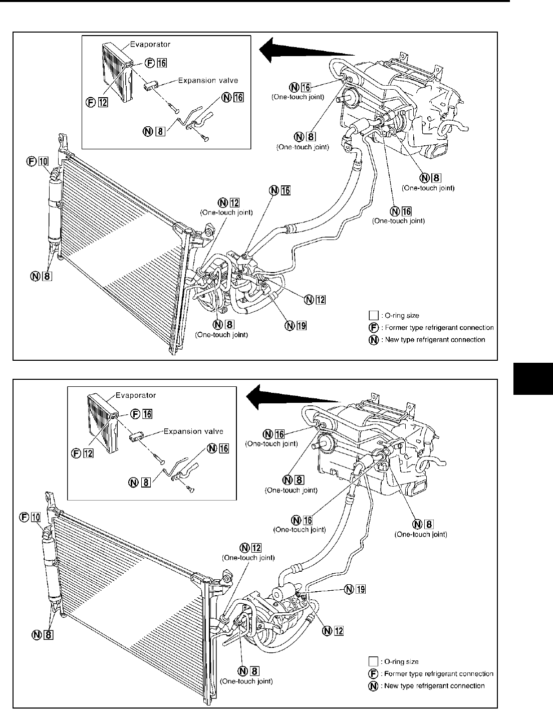
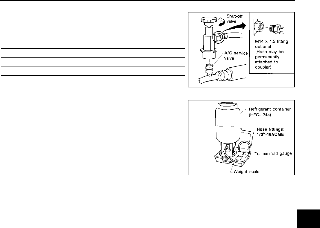
Precautions for Refrigerant Connection AJS0013Y
A new type refrigerant connection has been introduced to all refrigerant lines except the following location.
●Expansion valve to evaporator
●Refrigerant pressure sensor to condenser
ABOUT ONE-TOUCH JOINT
Description
●One-touch joints are pipe joints which do not require tools during piping connection.
●Unlike conventional connection methods using union nuts and flanges, controlling tightening torque at
connection point is not necessary.
●When removing a pipe joint, use a disconnector.
COMPONENT PARTS
FUNCTIONS OF COMPONENT PARTS
NOTE:
●Garter spring cannot be removed from cage of male-side piping.
●Indicator ring remains near piping connection point, however, this is not a malfunction. (This is to check
piping connection during factory assembly.)
Pipe (Male side) ●Retains O-rings.
●Retains garter spring in cage.
Garter spring Anchors female side piping.
Indicator ring When connection is made properly, this is ejected from male-side piping. (This part is no longer neces-
sary after connection.)
O-ring Seals connection point. (Not reusable)
Pipe (Female side) ●Seals connection by compressing O-rings.
●Anchors piping connection using flare and garter spring.
RJIA0970E

PRECAUTIONS
ATC-9
C
D
E
F
G
H
I
K
L
M
A
B
ATC
Revision; 2004 April 2003 FX
REMOVAL
1. Clean piping connection point, and set a disconnector.
2. Slide disconnector in axial direction of piping, and stretch garter spring with tapered point of disconnector.
3. Slide disconnector farther so that inside diameter of garter spring becomes larger than outside diameter of
female-side piping flare. Then male-side piping can be disconnected.
INSTALLATION
1. Clean piping connection points, and insert male-side piping into female-side piping.
2. Push inserted male-side piping harder so that female-side piping flare stretches garter spring.
3. If inside diameter of garter spring becomes larger than outside diameter of female-side piping flare, garter
spring seats on flare. Then, it fits in between male-side piping cage and female-side piping flare to anchor
piping connection point.
NOTICE:
When garter spring seats on flare, and fits in between male-side piping cage and female-side piping flare,
it clicks.
CAUTION:
●Female-side piping connection point is thin. So, when inserting male-side piping, take care not
to deform female-side piping. Slowly insert it in axial direction.
●Insert piping securely until a click is heard.
SJIA0106E
SJIA0107E

ATC-10
PRECAUTIONS
Revision; 2004 April 2003 FX
●After piping connection is completed, pull male-side piping by hand to make sure connection
does not come loose.
NOTE:
One-touch joint connection is used in points below.
●Low-pressure pipe 1 to low-pressure pipe 2 (O-ring size: 16)
●High-pressure pipe 1 to high-pressure pipe 2 (O-ring size: 8)
●High-pressure pipe 2 to high-pressure pipe 3 (O-ring size: 8)
●Low-pressure flexible hose to low-pressure pipe 1 (O-ring size: 16)
●Condenser to high-pressure flexible hose (O-ring size: 12)
●Condenser to high-pressure pipe 1 (O-ring size: 8)
FEATURES OF NEW TYPE REFRIGERANT CONNECTION
●The O-ring has been relocated. It has also been provided with a groove for proper installation. This elimi-
nates the chance of the O-ring being caught in, or damaged by, the mating part. The sealing direction of
the O-ring is now set vertically in relation to the contacting surface of the mating part to improve sealing
characteristics.
●The reaction force of the O-ring will not occur in the direction that causes the joint to pull out, thereby facil-
itating piping connections.
SHA815E
PRECAUTIONS
ATC-11
C
D
E
F
G
H
I
K
L
M
A
B
ATC
Revision; 2004 April 2003 FX
O-RING AND REFRIGERANT CONNECTION
VK45DE
VQ35DE
RJIA1954E
RJIA1955E

ATC-12
PRECAUTIONS
Revision; 2004 April 2003 FX
CAUTION:
The new and former refrigerant connections use different O-ring configurations. Do not confuse O-
rings since they are not interchangeable. If a wrong O-ring is installed, refrigerant will leak at, or
around, the connection.
O-Ring Part Numbers and Specifications
WARNING:
Make sure all refrigerant is discharged into the recycling equipment and the pressure in the system is
less than atmospheric pressure. Then gradually loosen the discharge side hose fitting and remove it.
CAUTION:
When replacing or cleaning refrigerant cycle components, observe the following.
●When the compressor is removed, store it in the same position as it is when mounted on the car.
Malfunction to do so will cause lubricant to enter the low-pressure chamber.
●When connecting tubes, always use a torque wrench and a back-up wrench.
●After disconnecting tubes, immediately plug all openings to prevent entry of dirt and moisture.
●When installing an air conditioner in the vehicle, connect the pipes as the final stage of the opera-
tion. Do not remove the seal caps of pipes and other components until just before required for
connection.
●Allow components stored in cool areas to warm to working area temperature before removing seal
caps. This prevents condensation from forming inside A/C components.
●Thoroughly remove moisture from the refrigeration system before charging the refrigerant.
●Always replace used O-rings.
●When connecting tube, apply lubricant to circle of the O-rings shown in illustration. Be careful not
to apply lubricant to threaded portion.
Lubricant name: Nissan A/C System Oil Type S
Part number: KLH00-PAGS0
●O-ring must be closely attached to dented portion of tube.
●When replacing the O-ring, be careful not to damage O-ring and tube.
●Connect tube until you hear it click, then tighten the nut or bolt by hand until snug. Make sure that
the O-ring is installed to tube correctly.
Connection type Piping connection point Part number QTY O-ring size
New
Low-pressure pipe 1 to low-pressure pipe 2 (One-touch joint) 92473 N8221 2 16
Low-pressure pipe 2 to expansion valve 92473 N8210 1 16
High-pressure pipe 1 to high-pressure pipe 2 (One-touch joint) 92471 N8221 2 8
High-pressure pipe 3 to expansion valve 92471 N8210 1 8
High-pressure pipe 2 to high-pressure pipe 3 (One-touch joint) 92471 N8221 2 8
Condenser to high-pressure flexible hose (One-touch joint) 92472 N8221 2 12
Condenser to high-pressure pipe 1 (One-touch joint) 92471 N8221 2 8
Low-pressure flexible hose to low-pressure pipe 1 (One-touch
joint) 92473 N8221 2 16
Compressor to low-pressure flexible hose 92474 N8210 1 19
Compressor to high-pressure flexible hose 92472 N8210 1 12
Liquid tank to condenser pipe Inlet 92471 N8210 18
Outlet 1
Former
Refrigerant pressure sensor to condenser J2476 89956 1 10
Expansion valve to evaporator Inlet 92475 71L00 1 12
Outlet 92475 72L00 1 16

PRECAUTIONS
ATC-13
C
D
E
F
G
H
I
K
L
M
A
B
ATC
Revision; 2004 April 2003 FX
●After connecting line, perform leak test and make sure that there is no leakage from connections.
When the gas leaking point is found, disconnect that line and replace the O-ring. Then tighten con-
nections of seal seat to the specified torque.
Precautions for Servicing Compressor AJS0013Z
●Plug all openings to prevent moisture and foreign matter from entering.
●When the compressor is removed, store it in the same position as it is when mounted on the car.
●When replacing or repairing compressor, follow “Maintenance of Lubricant Quantity in Compres-
sor” exactly. Refer to ATC-27, "Maintenance of Lubricant Quantity in Compressor" .
●Keep friction surfaces between clutch and pulley clean. If the surface is contaminated, with lubri-
cant, wipe it off by using a clean waste cloth moistened with thinner.
●After compressor service operation, turn the compressor shaft by hand more than five turns in
both directions. This will equally distribute lubricant inside the compressor. After the compressor
is installed, let the engine idle and operate the compressor for one hour.
●After replacing the compressor magnet clutch, apply voltage to the new one and check for usual
operation.
Precautions for Service Equipment AJS00140
RECOVERY/RECYCLING EQUIPMENT
Be certain to follow the manufacturers instructions for machine operation and machine maintenance. Never
introduce any refrigerant other than that specified into the machine.
ELECTRONIC LEAK DETECTOR
Be certain to follow the manufacturer′s instructions for tester operation and tester maintenance.
RHA861F

ATC-14
PRECAUTIONS
Revision; 2004 April 2003 FX
VACUUM PUMP
The lubricant contained inside the vacuum pump is not compatible
with the specified lubricant for HFC-134a (R-134a) A/C systems.
The vent side of the vacuum pump is exposed to atmospheric pres-
sure. So the vacuum pump lubricant may migrate out of the pump
into the service hose. This is possible when the pump is switched off
after evacuation (vacuuming) and hose is connected to it.
To prevent this migration, use a manual valve placed near the hose-
to-pump connection, as follows.
●Usually vacuum pumps have a manual isolator valve as part of
the pump. Close this valve to isolate the service hose from the
pump.
●For pumps without an isolator, use a hose equipped with a man-
ual shut-off valve near the pump end. Close the valve to isolate
the hose from the pump.
●If the hose has an automatic shut-off valve, disconnect the hose
from the pump. As long as the hose is connected, the valve is
open and lubricating oil may migrate.
Some one-way valves open when vacuum is applied and close
under a no vacuum condition. Such valves may restrict the pump′s
ability to pull a deep vacuum and are not recommended.
MANIFOLD GAUGE SET
Be certain that the gauge face indicates HFC-134a (R-134a or
134a). Be sure the gauge set has 1/2″-16 ACME threaded connec-
tions for service hoses. Confirm the set has been used only with
refrigerant HFC-134a (R-134a) and specified lubricants.
SERVICE HOSES
Be certain that the service hoses display the markings described
(colored hose with black stripe). All hoses must include positive shut
-off devices (either manual or automatic) near the end of the hoses
opposite the manifold gauge.
RHA270DA
SHA533D
RHA272D
PRECAUTIONS
ATC-15
C
D
E
F
G
H
I
K
L
M
A
B
ATC
Revision; 2004 April 2003 FX
SERVICE COUPLERS
Never attempt to connect HFC-134a (R-134a) service couplers to an
CFC-12 (R-12) A/C system. The HFC-134a (R-134a) couplers will
not properly connect to the CFC-12 (R-12) system. However, if an
improper connection is attempted, discharging and contamination
may occur.
REFRIGERANT WEIGHT SCALE
Verify that no refrigerant other than HFC-134a (R-134a) and speci-
fied lubricants have been used with the scale. If the scale controls
refrigerant flow electronically, the hose fitting must be 1/2″ -16
ACME.
CALIBRATING ACR4 WEIGHT SCALE
Calibrate the scale every three months.
To calibrate the weight scale on the ACR4 (J-39500-INF):
1. Press Shift/Reset and Enter at the same time.
2. Press 8787 . “A1 ” will be displayed.
3. Remove all weight from the scale.
4. Press 0 , then press Enter . “0.00 ” will be displayed and change to “A2 ”.
5. Place a known weight (dumbbell or similar weight), between 4.5 and 8.6 kg (10 and 19 lb.) on the center
of the weight scale.
6. Enter the known weight using four digits. (Example 10 lb. = 10.00, 10.5 lb. = 10.50)
7. Press Enter — the display returns to the vacuum mode.
8. Press Shift/Reset and Enter at the same time.
9. Press 6 — the known weight on the scale is displayed.
10. Remove the known weight from the scale. “0.00 ” will be displayed.
11. Press Shift/Reset to return the ACR4 to the program mode.
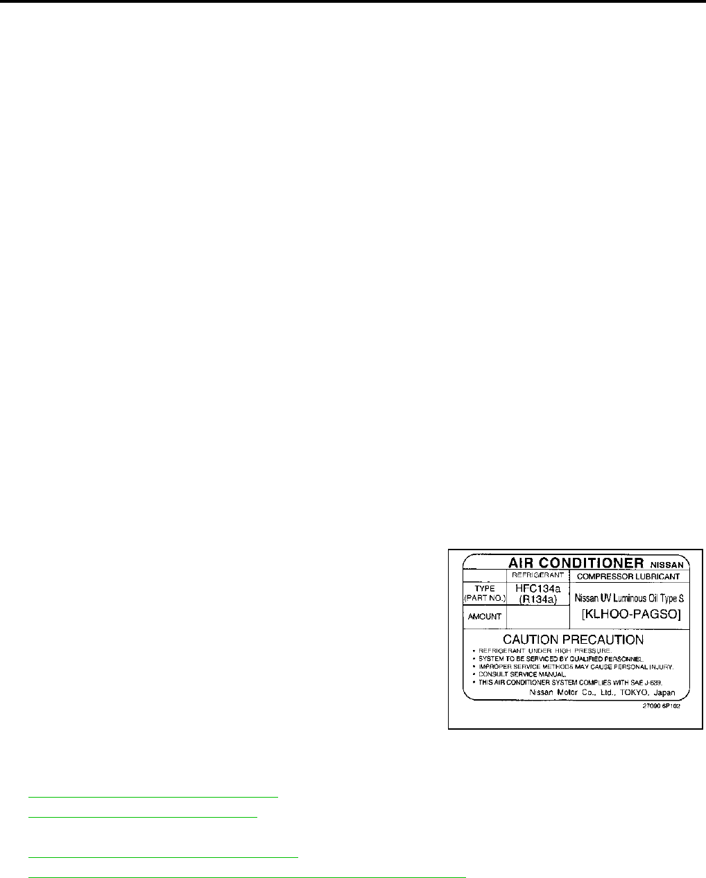
CHARGING CYLINDER
Using a charging cylinder is not recommended. Refrigerant may be vented into air from cylinder′s top valve
when filling the cylinder with refrigerant. Also, the accuracy of the cylinder is generally less than that of an
electronic scale or of quality recycle/recharge equipment.
Shut-off valve rotation A/C service valve
Clockwise Open
Counterclockwise Close
RHA273D
RHA274D
ATC-16
PRECAUTIONS
Revision; 2004 April 2003 FX
Precautions for Leak Detection Dye AJS00141
●The A/C system contains a fluorescent leak detection dye used for locating refrigerant leaks. An ultraviolet
(UV) lamp is required to illuminate the dye when inspecting for leaks.
●Always wear fluorescence enhancing UV safety goggles to protect your eyes and enhance the visibility of
the fluorescent dye.
●The fluorescent dye leak detector is not a replacement for an electronic refrigerant leak detector. The fluo-
rescent dye leak detector should be used in conjunction with an electronic refrigerant leak detector to (J-
41995) pin-point refrigerant leaks.
●For your safety and your customer′s satisfaction, read and follow all manufacture′s operating instructions
and precautions prior to performing the work.
●A compressor shaft seal should not be repaired because of dye seepage. The compressor shaft seal
should only be repaired after confirming the leak with an electronic refrigerant leak detector (J-41995).
●Always remove any remaining dye from the leak area after repairs are complete to avoid a misdiagnosis
during a future service.
●Do not allow dye to come into contact with painted body panels or interior components. If dye is spilled,
clean immediately with the approved dye cleaner. Fluorescent dye left on a surface for an extended period
of time cannot be removed.
●Do not spray the fluorescent dye cleaning agent on hot surfaces (engine exhaust manifold, etc.).
●Do not use more than one refrigerant dye bottle (1/4 ounce /7.4 cc) per A/C system.
●Leak detection dyes for HFC-134a (R-134a) and CFC-12 (R-12) A/C systems are different. Do not use
HFC-134a (R-134a) leak detection dye in CFC-12 (R-12) A/C system or CFC-12 (R-12) leak detector dye
in HFC-134a (R-134a) A/C systems or A/C system damage may result.
●The fluorescent properties of the dye will remain for over three (3) years unless a compressor malfunction
occurs.
IDENTIFICATION
NOTE:
Vehicles with factory installed fluorescent dye have a green label.
Vehicles without factory installed fluorescent dye have a blue label.
IDENTIFICATION LABEL FOR VEHICLE
Vehicles with factory installed fluorescent dye have this identification
label on the front side of hood.
Wiring Diagrams and Trouble Diagnosis AJS00142
When you read wiring diagrams, refer to the following:
●GI-15, "How to Read Wiring Diagrams" in GI section.
●PG-4, "Wiring Diagram - POWER -" in PG section.
When you perform trouble diagnosis, refer to the following:
●GI-11, "How to Follow Trouble Diagnoses" in GI section.
●GI-27, "How to Perform Efficient Diagnosis for an Electrical Incident" in GI section.
SHA436FA

PREPARATION
ATC-17
C
D
E
F
G
H
I
K
L
M
A
B
ATC
Revision; 2004 April 2003 FX
PREPARATION PFP:00002
Special Service Tools AJS00143
The actual shapes of Kent-Moore tools may differ from those of special service tools illustrated here.
Tool number
(Kent-Moore No.)
Tool name
Description
KV99106100
(J-41260)
Clutch disc wrench
Removing shaft nut and clutch disc
KV99232340
(J-38874)
or
KV992T0001
( - )
Clutch disc puller
Removing clutch disc
KV99106200
(J-41261)
Pulley installer
Installing pulley
92530 89908 (for high-pressure
pipe 1)
( - )
92530 89912 (for high-pressure
flexible hose)
( - )
92530 89916 (for low-pressure
pipe 1 and low-pressure flexible
hose)
( - )
Disconnector tool set
(J-45815)
Disconnect one-touch joint connection
S-NT232
RJIA0194E
S-NT376
S-NT235
SJIA0285E

ATC-18
PREPARATION
Revision; 2004 April 2003 FX
HFC-134a (R-134a) Service Tools and Equipment AJS00144
Never mix HFC-134a (R-134a) refrigerant and/or its specified lubricant with CFC-12 (R-12) refrigerant and/or
its lubricant.
Separate and non-interchangeable service equipment must be used for handling each type of refrigerant/lubri-
cant.
Refrigerant container fittings, service hose fittings and service equipment fittings (equipment which handles
refrigerant and/or lubricant) are different between CFC-12 (R-12) and HFC-134a (R-134a). This is to avoid
mixed use of the refrigerants/lubricant.
Adapters that convert one size fitting to another must never be used: refrigerant/lubricant contamination will
occur and compressor malfunction will result.
Tool number
(Kent-Moore No.)
Tool name
Description
HFC-134a (R-134a) refrigerant
Container color: Light blue
Container marking: HFC-134a (R-
134a)
Fitting size: Thread size
●Large container 1/2″ -16 ACME
KLH00-PAGS0
( - )
Nissan A/C System Oil Type S
(DH-PS)
Type: Poly alkylene glycol oil (PAG),
type S (DH-PS)
Application: HFC-134a (R-134a)
swash plate compressors (Nissan
only)
Lubricity: 40 m (1.4 US fl oz., 1.4
Imp fl oz.)
(J-39500-INF)
Recovery/Recycling/
Recharging equipment (ACR4)
Function: Refrigerant Recovery and
Recycling and Recharging
(J-41995)
Electrical leak detector
Power supply:
●DC 12V (Cigarette lighter)
S-NT196
S-NT197
RJIA0195E
AHA281A

PREPARATION
ATC-19
C
D
E
F
G
H
I
K
L
M
A
B
ATC
Revision; 2004 April 2003 FX
(J-43926)
Refrigerant dye leak detection kit
Kit includes:
(J-42220)
UV lamp and UV safety goggles
(J-41459)
Refrigerant dye injector
(J-41447)
HFC-134a (R-134a) Fluorescent
leak detection dye
(Box of 24, 1/4 ounce bottles)
(J-43872)
Refrigerant dye cleaner
Power supply:
DC 12V (Battery terminal)
(J-42220)
UV lamp and UV safety goggles
Power supply: DC 12V (Battery
terminal)
For checking refrigerant leak when
fluorescent dye is installed in A/C
system
Includes: UV lamp and UV safety
goggles
(J-41447)
HFC-134a (R-134a) Fluorescent
leak detection dye
(Box of 24, 1/4 ounce bottles)
Application: For HFC-134a (R-134a)
PAG oil
Container: 1/4 ounce (7.4 cc) bottle
(Includes self-adhesive dye
identification labels for affixing to
vehicle after charging system with
dye.)
(J-41459)
HFC-134a (R-134a) Dye injector
Use with J-41447, 1/4 ounce
bottle
For injecting 1/4 ounce of fluorescent
leak detection dye into A/C system
(J-43872)
Refrigerant dye cleaner For cleaning dye spills
(J-39183)
Manifold gauge set (with hoses
and couplers)
Identification:
●The gauge face indicates HFC-134a
(R-134a).
Fitting size: Thread size
●1/2″ -16 ACME
Tool number
(Kent-Moore No.)
Tool name
Description
ZHA200H
SHA438F
SHA439F
SHA440F
SHA441F
RJIA0196E
ATC-20
PREPARATION
Revision; 2004 April 2003 FX
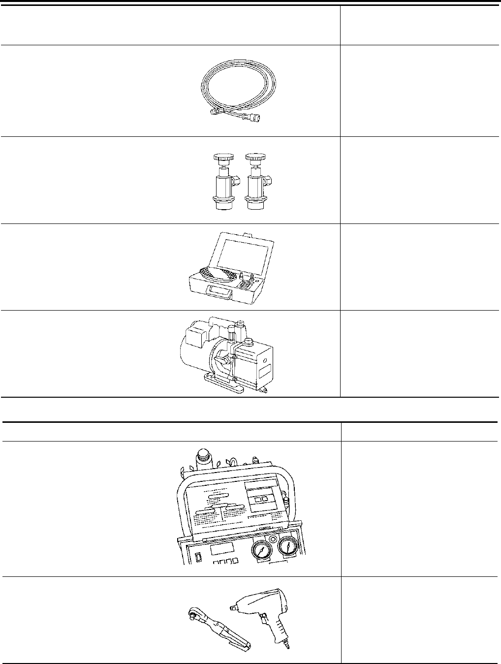
Commercial Service Tools AJS00145
Service hoses
●High-pressure side hose
(J-39501-72)
●Low-pressure side hose
(J-39502-72)
●Utility hose
(J-39476-72)
Hose color:
●Low hose: Blue with black stripe
●High hose: Red with black stripe
●Utility hose: Yellow with black stripe
or green with black stripe
Hose fitting to gauge:
●1/2″ -16 ACME
Service couplers
●High-pressure side coupler
(J-39500-20)
●Low-pressure side coupler
(J-39500-24)
Hose fitting to service hose:
●M14 x 1.5 fitting is optional or
permanently attached.
(J-39650)
Refrigerant weight scale
For measuring of refrigerant
Fitting size: Thread size
●1/2″ -16 ACME
(J-39649)
Vacuum pump
(Including the isolator valve)
Capacity:
●Air displacement: 4 CFM
●Micron rating: 20 microns
●Oil capacity: 482 g (17 oz.)
Fitting size: Thread size
●1/2″ -16 ACME
Tool number
(Kent-Moore No.)
Tool name
Description
S-NT201
S-NT202
S-NT200
S-NT203
Tool name Description
Refrigerant identifier equipment Checking for refrigerant purity and
system contamination
Power tool Loosening bolts and nuts
RJIA0197E
PBIC0190E

REFRIGERATION SYSTEM
ATC-21
C
D
E
F
G
H
I
K
L
M
A
B
ATC
Revision; 2004 April 2003 FX
REFRIGERATION SYSTEM PFP:KA990
Refrigerant Cycle AJS00146
REFRIGERANT FLOW
The refrigerant flows in the standard pattern, that is, through the compressor, the condenser with liquid tank,
through the evaporator, and back to the compressor. The refrigerant evaporation through the evaporator coil is
controlled by an externally equalized expansion valve, located inside the evaporator case.
FREEZE PROTECTION
Under usual operating conditions, when the A/C is switched on, the compressor runs continuously, and the
evaporator pressure, and therefore, temperature is controlled by the compressor to prevent freeze up.
Refrigerant System Protection AJS00147
REFRIGERANT PRESSURE SENSOR
The refrigerant system is protected against excessively high- or low-pressure by the refrigerant pressure sen-
sor, located on the condenser. If the system pressure rises above, or falls below the specifications, the refrig-
erant pressure sensor detects the pressure inside the refrigerant line and sends the voltage signal to the ECM.
ECM makes the A/C relay go OFF and stops the compressor when pressure on the high-pressure side
detected by refrigerant pressure sensor is over about 2,746 kPa (28 kg/cm2 , 398 psi), or below about 134 kPa
(1.4 kg/cm2 , 20 psi).
PRESSURE RELIEF VALVE
The refrigerant system is also protected by a pressure relief valve, located in the rear head of the compressor.
When the pressure of refrigerant in the system increases to an unusual level [more than 3,727 kPa (38 kg/cm2
, 540 psi)], the release port on the pressure relief valve automatically opens and releases refrigerant into the
atmosphere.
RJIA0849E

ATC-22
REFRIGERATION SYSTEM
Revision; 2004 April 2003 FX
V-6 Variable Displacement Compressor AJS001BE
GENERAL INFORMATION
1. The V-6 variable compressor differs from previous units. The vent temperatures of the V-6 variable com-
pressor do not drop too far below 5°C (41°F) when:
Evaporator intake air temperature is less than 20°C (68°F).
Engine is running at speeds less than 1,500 rpm.
This is because the V-6 compressor provides a means of “capacity” control.
2. The V-6 variable compressor provides refrigerant control under varying conditions. During cold winters, it
may not produce high refrigerant pressure discharge (compared to previous units) when used with air
conditioning systems.
3. A “clanking” sound may occasionally be heard during refrigerant charge. The sound indicates that the tilt
angle of the wobble (swash) plate has changed and is not a malfunction.
4. For air conditioning systems with the V-6 compressor, the clutch remains engaged unless: the system
main switch, fan switch or ignition switch is turned OFF. When ambient (outside) temperatures are low or
when the amount of refrigerant is insufficient, the clutch is disengaged to protect the compressor.

REFRIGERATION SYSTEM
ATC-23
C
D
E
F
G
H
I
K
L
M
A
B
ATC
Revision; 2004 April 2003 FX
DESCRIPTION
General
The variable compressor is basically a swash plate type that changes piston stroke in response to the required
cooling capacity.
The tilt of the wobble (swash) plate allows the piston′s stroke to change so that refrigerant discharge can be
continuously changed from 14.5 to 184 cm3 (0.885 to 11.228 cu. in).
RJIA1260E
ATC-24
REFRIGERATION SYSTEM
Revision; 2004 April 2003 FX
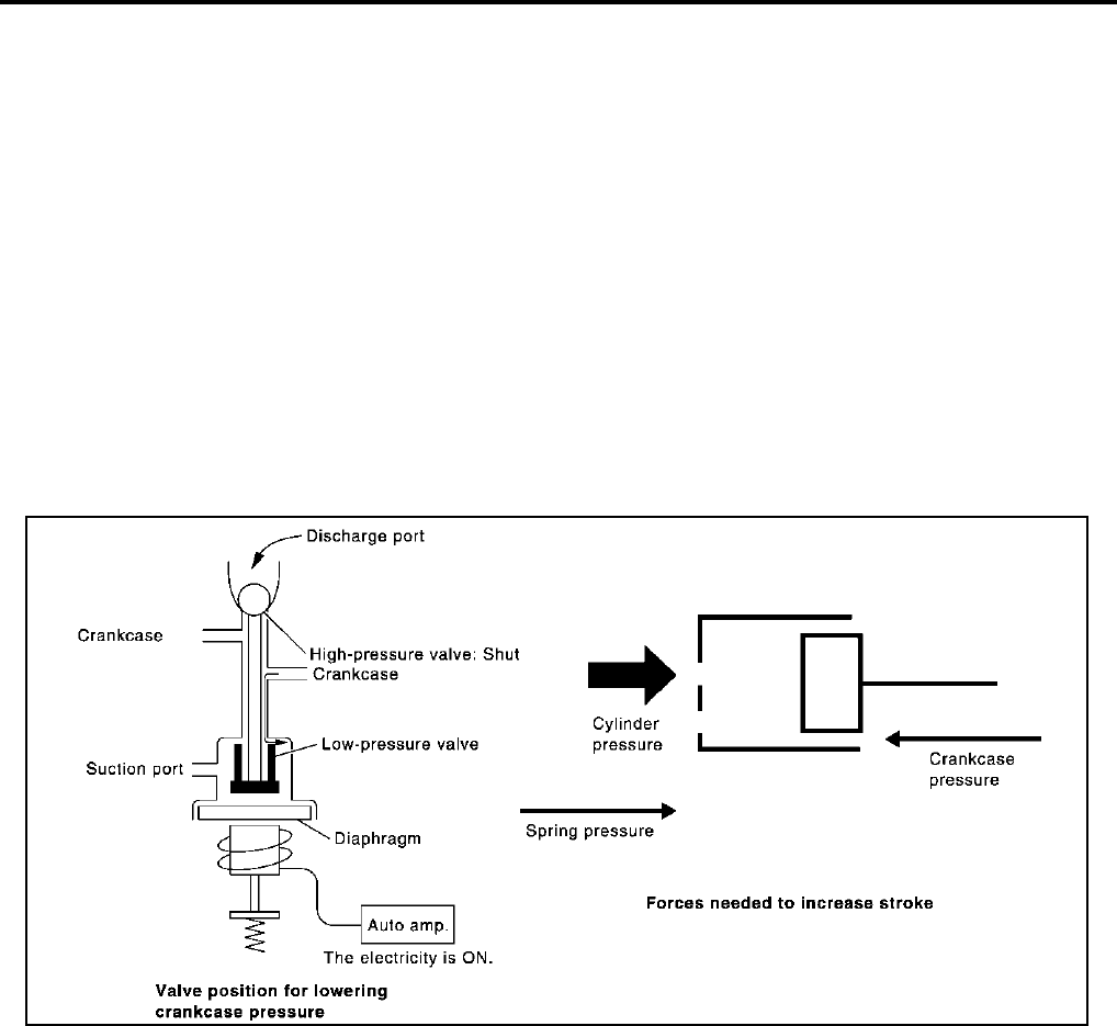
Operation
1. Operation Control Valve
–By changing high-pressure valve lift amount, built-in compressor control valve executes the following:
• Controls high-pressure valve discharge amount.
• Changes crankcase pressure in compressor.
• Changes angle of wobble (swash) plate.
–Amount of high-pressure valve loft is determined by factors below.
• Low-pressure applied to diaphragm
• Spring load of set spring
• Balance of magnetic force generated in magnet coil
–Electronic control valve (ECV) magnet coil receives electric signal (duty control) from auto amplifier. Then,
magnetic force generated by electric current is changed to control high-pressure valve lift amount.
2. Maximum Cooling
High-pressure valve is closed by magnetic force generated by electric signal sent from automatic ampli-
fier. At this time, cylinder moves full stroke due to pressure balance between inside crankcase (Pc) and
suction line (Ps).
Under this condition, the wobble (swash) plate is set to the maximum stroke position.
3. Capacity Control
When no electric signal is sent from automatic amplifier (current: OFF), high-pressure valve is opened by
spring force.
Since suction pressure is low, it makes the suction port close and the discharge port open. Thus, crank-
case pressure becomes high as high-pressure enters the crankcase.
–The force acts around the journal pin near the wobble (swash) plate, and is generated by the pressure dif-
ference before and behind the piston.
–The drive lug and journal pin are located where the piston generates the highest pressure. Piston pres-
sure is between suction pressure Ps and discharge pressure Pd, which is near suction pressure Ps. If
crankcase pressure Pc rises due to capacity control, the force around the journal pin makes the wobble
(swash) plate angle decrease and also the piston stroke decrease. In other words, crankcase pressure
RJIA0851E

REFRIGERATION SYSTEM
ATC-25
C
D
E
F
G
H
I
K
L
M
A
B
ATC
Revision; 2004 April 2003 FX
increase triggers pressure difference between the piston and the crankcase. The pressure difference
changes the angle of the wobble (swash) plate.
RJIA0852E

ATC-26
REFRIGERATION SYSTEM
Revision; 2004 April 2003 FX
Component Layout AJS00148
RJIA1956E

LUBRICANT
ATC-27
C
D
E
F
G
H
I
K
L
M
A
B
ATC
Revision; 2004 April 2003 FX
LUBRICANT PFP:KLG00
Maintenance of Lubricant Quantity in Compressor AJS00149
The lubricant in the compressor circulates through the system with the refrigerant. Add lubricant to compres-
sor when replacing any component or after a large gas leakage occurred. It is important to maintain the speci-
fied amount.
If lubricant quantity is not maintained properly, the following malfunctions may result:
●Lack of lubricant: May lead to a seized compressor
●Excessive lubricant: Inadequate cooling (thermal exchange interference)
LUBRICANT
LUBRICANT RETURN OPERATION
Adjust the lubricant quantity according to the test group shown below.
1. CHECK LUBRICANT RETURN OPERATION
Can lubricant return operation be performed?
●A/C system works properly.
●There is no evidence of a large amount of lubricant leakage.
YES or NO
YES >> GO TO 2.
NO >> GO TO 3.
2. PERFORM LUBRICANT RETURN OPERATION, PROCEEDING AS FOLLOWS:
1. Start engine, and set the following conditions:
–Test condition
Engine speed: Idling to 1,200 rpm
A/C switch: ON
Blower speed: Max. position
Temp. control: Optional [Set so that intake air temperature is 25 to 30°C (77 to 86°F).]
Intake position: Recirculation (REC)
2. Perform lubricant return operation for about 10 minutes.
3. Stop engine.
CAUTION:
If excessive lubricant leakage is noted, do not perform the lubricant return operation.
>> GO TO 3.
3. CHECK COMPRESSOR
Should the compressor be replaced?
YES >> GO TO ATC-29, "LUBRICANT ADJUSTING PROCEDURE FOR COMPRESSOR REPLACE-
MENT" .
NO >> GO TO 4.
Name : NISSAN A/C System Oil Type S
Part number : KLH00-PAGS0

ATC-28
LUBRICANT
Revision; 2004 April 2003 FX
4. CHECK ANY PART
Is there any part to be replaced? (Evaporator, condenser, liquid tank or in case there is evidence of a large
amount of lubricant leakage.)
YES >> GO TO ATC-28, "LUBRICANT ADJUSTING PROCEDURE FOR COMPONENTS REPLACE-
MENT EXCEPT COMPRESSOR" .
NO >> Carry out the A/C performance test.
LUBRICANT ADJUSTING PROCEDURE FOR COMPONENTS REPLACEMENT EXCEPT COM-
PRESSOR
After replacing any of the following major components, add the correct amount of lubricant to the system.
Amount of lubricant to be added
*1: If refrigerant leak is small, no addition of lubricant is needed.
Part replaced
Lubricant to be added to system
Remarks
Amount of lubricant
m (US fl oz., Imp fl oz.)
Evaporator 75 (2.5, 2.6) -
Condenser 35 (1.2, 1.2) -
Liquid tank 10 (0.3, 0.4) -
In case of refrigerant leak 30 (1.0, 1.1) Large leak
- Small leak *1

LUBRICANT
ATC-29
C
D
E
F
G
H
I
K
L
M
A
B
ATC
Revision; 2004 April 2003 FX
LUBRICANT ADJUSTING PROCEDURE FOR COMPRESSOR REPLACEMENT
1. Before connecting ACR4 to vehicle, check ACR4 gauges. No refrigerant pressure should be displayed. If
NG, recover refrigerant from equipment lines.
2. Connect ACR4 to vehicle. Confirm refrigerant purity in supply tank using ACR4 and refrigerant identifier. If
NG, refer to ATC-5, "CONTAMINATED REFRIGERANT" .
3. Confirm refrigerant purity in vehicle A/C system using ACR4 and refrigerant identifier. If NG, refer to ATC-
5, "CONTAMINATED REFRIGERANT" .
4. Discharge refrigerant into the refrigerant recovery/recycling equipment. Measure lubricant discharged into
the recovery/recycling equipment.
5. Drain the lubricant from the old (removed) compressor into a graduated container and recover the amount
of lubricant drained.
6. Drain the lubricant from the new compressor into a separate, clean container.
7. Measure an amount of new lubricant installed equal to amount drained from old compressor. Add this
lubricant to new compressor through the suction port opening.
8. Measure an amount of new lubricant equal to the amount recovered during discharging. Add this lubricant
to new compressor through the suction port opening.
9. If the liquid tank also needs to be replaced, add an additional 5 m (0.2 US fl oz., 0.2 Imp fl oz.) of lubri-
cant at this time.
Do not add this 5 m (0.2 US fl oz., 0.2 Imp fl oz.) of lubricant if only replacing the compressor.
RHA065DD

ATC-30
AIR CONDITIONER CONTROL
Revision; 2004 April 2003 FX
AIR CONDITIONER CONTROL PFP:27500
Description of Air Conditioner LAN Control System AJS0014A
The LAN (Local Area Network) system consists of unified meter and A/C amp., mode door motor, air mix door
motor and intake door motor.
A configuration of these components is shown in the diagram below.
System Construction AJS0014B
A small network is constructed between the unified meter and A/C amp., air mix door motor, mode door motor
and intake door motor. The unified meter and A/C amp. and motors are connected by data transmission lines
and motor power supply lines. The LAN network is built through the ground circuits of the each door motor.
Addresses, motor opening angle signals, motor stop signals and error checking messages are all transmitted
through the data transmission lines connecting the unified meter and A/C amp. and each door motor.
The following functions are contained in LCUs built into the air mix door motor, mode door motor and intake
door motor.
●Address
●Motor opening angle signals
●Data transmission
●Motor stop and drive decision
●Opening angle sensor (PBR function)
●Comparison
●Decision (Unified meter and A/C amp. indicated value and motor opening angle comparison)
OPERATION
The unified meter and A/C amp. receives data from each of the sensors. The unified meter and A/C amp.
sends mode door, air mix door and intake door opening angle data to the mode door motor LCU, air mix door
motor LCU and intake door motor LCU.
The mode door motor, air mix door motor and intake door motor read their respective signals according to the
address signal. Opening angle indication signals received from the unified meter and A/C amp. and each of
the motor position sensors are compared by the LCUs in each motor with the existing decision and opening
angles. Subsequently, HOT/COLD, DEFROST/VENT or FRESH/RECIRCULATION operation is selected. The
new selection data is returned to the unified meter and A/C amp.
SJIA0262E
RJIA1747E

AIR CONDITIONER CONTROL
ATC-31
C
D
E
F
G
H
I
K
L
M
A
B
ATC
Revision; 2004 April 2003 FX
TRANSMISSION DATA AND TRANSMISSION ORDER
Unified meter and A/C amp. data is transmitted consecutively to each of the door motors following the form
shown in figure below.
Start: Initial compulsory signal sent to each of the door motors.
Address: Data sent from the unified meter and A/C amp. is selected according to data-based decisions made
by the air mix door motor, mode door motor and intake door motor.
If the addresses are identical, the opening angle data and error check signals are received by the door motor
LCUs. The LCUs then make the appropriate error decision. If the opening angle data is usual, door control
begins.
If an error exists, the received data is rejected and corrected data received. Finally, door control is based upon
the corrected opening angle data.
Opening angle:
Data that shows the indicated door opening angle of each door motor.
Error check:
Procedure by which sent and received data is checked for errors. Error data is then compiled. The error check
prevents corrupted data from being used by the air mix door motor, mode door motor and intake door motor.
Error data can be related to the following symptoms.
●Unusual electrical frequency
●Poor electrical connections
●Signal leakage from transmission lines
●Signal level fluctuation
Stop signal:
At the end of each transmission, a stop operation, in-operation, or internal error message is delivered to the
unified meter and A/C amp. This completes one data transmission and control cycle.
RJIA1748E
RJIA1749E

ATC-32
AIR CONDITIONER CONTROL
Revision; 2004 April 2003 FX
AIR MIX DOOR CONTROL (AUTOMATIC TEMPERATURE CONTROL)
The air mix door is automatically controlled so that in-vehicle temperature is maintained at a predetermined
value by: The temperature setting, ambient temperature, in-vehicle temperature and amount of sunload.
FAN SPEED CONTROL
Blower speed is automatically controlled based on temperature setting, ambient temperature, in-vehicle tem-
perature, intake temperature, amount of sunload and air mix door position.
When pressing AUTO switch, the blower motor starts to gradually increase air flow volume.
When engine coolant temperature is low, the blower motor operation is delayed to prevent cool air from flow-
ing.
INTAKE DOOR CONTROL
The intake doors are automatically controlled by: The temperature setting, ambient temperature, in-vehicle
temperature, intake temperature, amount of sunload and ON-OFF operation of the compressor.
OUTLET DOOR CONTROL
The outlet door is automatically controlled by: The temperature setting, ambient temperature, in-vehicle tem-
perature, intake temperature and amount of sunload.
MAGNET CLUTCH CONTROL
When A/C switch or DEF switch is pressed, unified meter and A/C amp. inputs compressor ON signal to BCM.
BCM sends compressor ON signal to ECM, via CAN communication line.
ECM judges whether compressor can be turned ON, based on each sensor status (refrigerant-pressure sen-
sor signal, throttle angle, etc.). If it judges compressor can be turned ON, it sends compressor ON signal to
IPDM E/R, via CAN communication line.
Upon receipt of compressor ON signal from ECM, IPDM E/R turns air conditioner relay ON to operate com-
pressor.
When sending compressor ON signal to IPDM E/R via CAN communication line, ECM simultaneously sends
compressor feedback signal to unified meter and A/C amp. via CAN communication line.
Unified meter and A/C amp, then, uses input compressor feedback signal to control air inlet.
SELF-DIAGNOSTIC SYSTEM
The self-diagnostic system is built into the unified meter and A/C amp. to quickly locate the cause of symp-
toms.
RJIA1957E

AIR CONDITIONER CONTROL
ATC-33
C
D
E
F
G
H
I
K
L
M
A
B
ATC
Revision; 2004 April 2003 FX
Description of Control System AJS0014C
The control system consists of input sensors, switches, the unified meter and A/C amp. (microcomputer) and
outputs.
The relationship of these components is shown in the figure below:
Control Operation AJS0014D
RJIA1958E
RJIA1959E

ATC-34
AIR CONDITIONER CONTROL
Revision; 2004 April 2003 FX
DISPLAY SCREEN
Displays the operational status of the system.
AUTO SWITCH
●The compressor, intake doors, air mix doors, outlet doors and blower speed are automatically controlled
so that the in-vehicle temperature will reach, and be maintained at the set temperature selected by the
operator.
●When pressing AUTO switch, air inlet, air outlet, fan speed, and discharge air temperature are automati-
cally controlled.
TEMPERATURE SWITCH (POTENTIO TEMPERATURE CONTROL) (DRIVER SIDE)
Increases or decreases the set temperature.
TEMPERATURE SWITCH (POTENTIO TEMPERATURE CONTROL) (PASSENGER SIDE)
●Increases or decreases the set temperature.
●When the temperature switch is pressed, the dual switch indicator will automatically illuminate.
RECIRCULATION (REC) SWITCH
●When REC switch is ON, REC switch indicator turns ON, and air inlet is fixed to REC.
●When REC switch is ON and is pressed for approximately 1.5 seconds or longer, REC and FRE switch
indicators blink twice. Then, automatic control mode is entered. Inlet status is displayed even during auto-
matically controlled.
●When FRE switch is turned ON, or when compressor is turned from ON to OFF, REC switch is automati-
cally turned OFF (fixed to FRE mode). REC mode can be re-entered by pressing REC switch again.
●REC switch is not operated when DEF switch is turned ON, or at the D/F position.
FRESH (FRE) SWITCH
●When FRE switch is ON, FRE switch indicator turns ON, and air inlet is fixed to FRE.
●When FRE switch is ON and is pressed for approximately 1.5 seconds or longer, REC and FRE switch
indicators blink twice. Then, automatic control mode is entered. Inlet status is displayed even during auto-
matically controlled.
●When REC switch is turned ON, FRE switch is automatically turned OFF (fixed to REC mode). FRE mode
can be re-entered by pressing FRE switch again.
DEFROSTER (DEF) SWITCH
Positions the air outlet doors to the defrost position. Also positions the intake doors to the fresh air position.
REAR WINDOW DEFOGGER SWITCH
When illumination is ON, rear window is defogged.
OFF SWITCH
The compressor and blower are OFF, the intake doors are set to the fresh air position, and the air outlet doors
are set to the foot (75% foot and 25% defrost) position.
A/C SWITCH
The compressor is ON or OFF.
(Pressing the A/C switch when the AUTO switch is ON will turn off the A/C switch and compressor.)
MODE SWITCH
Controls the air discharge outlets.
FAN SWITCH
Manually control the blower speed. Seven speeds are available for manual control (as shown on the display
screen).
DUAL SWITCH (WITH LEFT AND RIGHT VENTILATION TEMPERATURE SEPARATELY CON-
TROL SYSTEM)
●When the DUAL switch indicator is not illuminated and the DUAL switch is pressed, the driver-side setting
temperature and passenger-side setting temperature can each be set independently.
●When the DUAL switch indicator is illuminated and the DUAL switch is pressed, the driver-side setting
temperature is applied to both sides.

AIR CONDITIONER CONTROL
ATC-35
C
D
E
F
G
H
I
K
L
M
A
B
ATC
Revision; 2004 April 2003 FX
Fail-safe Function AJS0014E
●If a communication error exists between unified meter and A/C amp. and A/C and Audio controller for 30
seconds or longer, air conditioner is controlled under following conditions:
–Compressor: ON
–Air outlet: AUTO
–Air inlet: FRE (Fresh)
–Blower fan speed: AUTO
–Set temperature: Setting before communication error occurs.

ATC-36
AIR CONDITIONER CONTROL
Revision; 2004 April 2003 FX
Discharge Air Flow AJS0014F
RJIA1960E
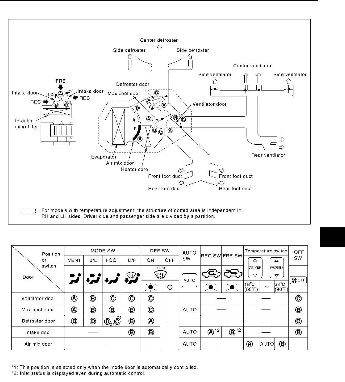
AIR CONDITIONER CONTROL
ATC-37
C
D
E
F
G
H
I
K
L
M
A
B
ATC
Revision; 2004 April 2003 FX
System Description AJS0014G
SWITCHES AND THEIR CONTROL FUNCTION
RJIA1961E
RJIA1962E

ATC-38
AIR CONDITIONER CONTROL
Revision; 2004 April 2003 FX
CAN Communication System Description AJS0014H
CAN (Controller Area Network) is a serial communication line for real time application. It is an on-vehicle mul-
tiplex communication line with high data communication speed and excellent error detection ability. Many elec-
tronic control units are equipped onto a vehicle, and each control unit shares information and links with other
control units during operation (not independent). In CAN communication, control units are connected with 2
communication lines (CAN H line, CAN L line) allowing a high rate of information transmission with less wiring.
Each control unit transmits/receives data but selectively reads required data only.
CAN Communication Unit AJS001C4
×: Applicable
Body type Wagon
Axle 2WD AWD
Engine VQ35DE VQ35DE/VK45DE
Transmission A/T
Brake control VDC
Navigation system ××
Low tire pressure warning system ××
ICC system ××
Intelligent Key system ××
Automatic drive positioner ×× ××
CAN communication unit
ECM ××××××
TCM ××××××
Display unit ×× ××
Display control unit ××
Low tire pressure warning control unit ××
AWD control unit ×××
ICC unit ××
Intelligent Key unit ××
Data link connector ××××××
BCM ××××××
Steering angle sensor ××××××
Unified meter and A/C amp. ××××××
ICC sensor ××
ABS actuator and electric unit (control unit) ××××××
Driver seat control unit ×× ××
IPDM E/R ××××××
CAN communication type ATC-39, "TYPE 1/
TYPE2"
ATC-42,
"TYPE 3"
ATC-45, "TYPE 4/
TYPE5"
ATC-48,
"TYPE 6"
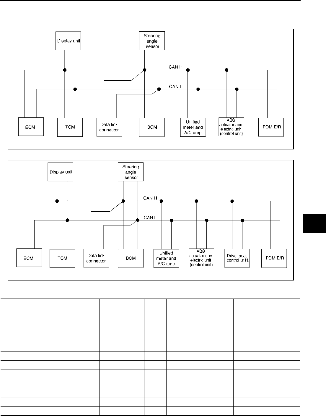
AIR CONDITIONER CONTROL
ATC-39
C
D
E
F
G
H
I
K
L
M
A
B
ATC
Revision; 2004 April 2003 FX
TYPE 1/TYPE2
System Diagram
●Type1
●Type2
Input/output Signal Chart T: Transmit R: Receive
SKIA6171E
SKIA6172E
Signals ECM TCM
Dis-
play
unit
BCM
Steer-
ing
angle
sensor
Unified
meter
and A/
C amp.
ABS
actua-
tor and
electric
unit
(con-
trol
unit)
Driver
seat
control
unit
IPDM
E/R
Engine speed signal T R R R R
Engine status signal T R
Engine coolant temperature signal T R R
A/T self-diagnosis signal R T
Accelerator pedal position signal T R R
Closed throttle position signal T R
Wide open throttle position signal T R

ATC-40
AIR CONDITIONER CONTROL
Revision; 2004 April 2003 FX
Battery voltage signal T R
Key switch signal T R
Ignition switch signal T R R
P range signal T R R
Stop lamp switch signal R T
ABS operation signal R T
TCS operation signal R T
VDC operation signal R T
Fuel consumption monitor signal T R R
Input shaft revolution signal R T
Output shaft revolution signal R T
A/C switch signal R T
A/C compressor request signal T R
A/C relay status signal R T
A/C compressor feedback signal T R
Blower fan motor switch signal R T
A/C control signal TR
RT
Cooling fan speed request signal T R
Cooling fan speed signal R T
Position light request signal R T R R
Low beam request signal T R
Low beam status signal R T
High beam request signal T R R
High beam status signal R T
Front fog light request signal T R
Day time running light request signal T R
Turn LED burnout status signal R T
Vehicle speed signal RT
RRRR T R
Sleep wake up signal T R R R
Door switch signal R T R R R
Turn indicator signal T R
Key fob ID signal T R
Key fob door unlock signal T R
Oil pressure switch signal RT
TR
Buzzer output signal T R
Fuel level sensor signal R T
Fuel level low warning signal R T
Signals ECM TCM
Dis-
play
unit
BCM
Steer-
ing
angle
sensor
Unified
meter
and A/
C amp.
ABS
actua-
tor and
electric
unit
(con-
trol
unit)
Driver
seat
control
unit
IPDM
E/R

AIR CONDITIONER CONTROL
ATC-41
C
D
E
F
G
H
I
K
L
M
A
B
ATC
Revision; 2004 April 2003 FX
ASCD operation signal T R
ASCD OD cancel request T R
Front wiper request signal T R
Front wiper stop position signal R T
Rear window defogger switch signal T R
Rear window defogger control signal R R R T
Hood switch signal R T
Theft warning horn request signal T R
Horn chirp signal T R
Steering angle sensor signal T R
ABS warning lamp signal RT
VDC OFF indicator lamp signal R T
SLIP indicator lamp signal RT
Brake warning lamp signal RT
System setting signal T R R
A/T CHECK indicator lamp signal T R
A/T position indicator lamp signal T R
A/T shift schedule change demand signal R T
Manual mode signal R T
Not manual mode signal R T
Manual mode shift up signal R T
Manual mode shift down signal R T
Manual mode indicator signal T R
Distance to empty signal R T
Hand brake switch R T
Signals ECM TCM
Dis-
play
unit
BCM
Steer-
ing
angle
sensor
Unified
meter
and A/
C amp.
ABS
actua-
tor and
electric
unit
(con-
trol
unit)
Driver
seat
control
unit
IPDM
E/R

ATC-42
AIR CONDITIONER CONTROL
Revision; 2004 April 2003 FX
TYPE 3
System Diagram
●Type3
Input/output Signal Chart T: Transmit R: Receive
SKIA6173E
Signals ECM TCM
Dis-
play
con-
trol
unit
Low
tire
pres-
sure
warn-
ing
con-
trol
unit
ICC
unit
Intelli-
gent
Key
unit
BCM
Steeri
ng
angle
sen-
sor
Uni-
fied
meter
and
A/C
amp.
ICC
sen-
sor
ABS
actu-
ator
and
elec-
tric
unit
(con-
trol
unit)
Driver
seat
con-
trol
unit
IPDM
E/R
Engine speed signal T R R R R R
Engine status signal T R
Engine coolant tempera-
ture signal TR R R
A/T self-diagnosis signal R T
Accelerator pedal posi-
tion signal TR R R
Closed throttle position
signal TR R
Wide open throttle posi-
tion signal TR
Battery voltage signal T R
Key switch signal T R
Ignition switch signal T R R
P range signal T R R R
Stop lamp switch signal R T
ABS operation signal R R T
TCS operation signal R R T
VDC operation signal R R T
Fuel consumption moni-
tor signal TR R

AIR CONDITIONER CONTROL
ATC-43
C
D
E
F
G
H
I
K
L
M
A
B
ATC
Revision; 2004 April 2003 FX
Input shaft revolution sig-
nal RT R
Output shaft revolution
signal RT R
A/C switch signal R T
A/C compressor request
signal T R
A/C relay status signal R T
A/C compressor feed-
back signal TR
Blower fan motor switch
signal RT
A/C control signal TR
RT
Cooling fan speed signal R T
Position light request sig-
nal RTRR
Low beam request signal T R
Low beam status signal R T
High beam request sig-
nal TR R
High beam status signal R T
Front fog light request
signal TR
Day time running light
request signal TR
Turn LED burnout status
signal RT
Vehicle speed signal RRT
RRRR RR TR R
Sleep wake up signal TR RR
TR
Door switch signal R R T R R R
Turn indicator signal T R
Key fob ID signal T R
Key fob door unlock sig-
nal TR
Oil pressure switch sig-
nal
RT
TR
Buzzer output signal
TR
TR
TR
Signals ECM TCM
Dis-
play
con-
trol
unit
Low
tire
pres-
sure
warn-
ing
con-
trol
unit
ICC
unit
Intelli-
gent
Key
unit
BCM
Steeri
ng
angle
sen-
sor
Uni-
fied
meter
and
A/C
amp.
ICC
sen-
sor
ABS
actu-
ator
and
elec-
tric
unit
(con-
trol
unit)
Driver
seat
con-
trol
unit
IPDM
E/R

ATC-44
AIR CONDITIONER CONTROL
Revision; 2004 April 2003 FX
Fuel level sensor signal R T
Fuel level low warning
signal RT
ICC operation signal R T
Front wiper request sig-
nal RT R
Front wiper stop position
signal RT
Rear window defogger
switch signal TR
Rear window defogger
control signal RR R T
Hood switch signal R T
Theft warning horn
request signal TR
Horn chirp signal T R
Steering angle sensor
signal TR
Tire pressure signal T R
Tire pressure data signal R T
ABS warning lamp signal R R T
VDC OFF indicator lamp
signal RRT
SLIP indicator lamp sig-
nal RT
Brake warning lamp sig-
nal RT
System setting signal T R R
Distance to empty signal R T
Hand brake switch signal R T
Door lock/unlock request
signal TR
Door lock/unlock status
signal RT
Starter permission signal T R
Back door open request
signal TR
Power window open
request signal TR
Alarm request signal T R
Key warning signal T R
ICC sensor signal R T
ICC warning lamp signal T R
Signals ECM TCM
Dis-
play
con-
trol
unit
Low
tire
pres-
sure
warn-
ing
con-
trol
unit
ICC
unit
Intelli-
gent
Key
unit
BCM
Steeri
ng
angle
sen-
sor
Uni-
fied
meter
and
A/C
amp.
ICC
sen-
sor
ABS
actu-
ator
and
elec-
tric
unit
(con-
trol
unit)
Driver
seat
con-
trol
unit
IPDM
E/R

AIR CONDITIONER CONTROL
ATC-45
C
D
E
F
G
H
I
K
L
M
A
B
ATC
Revision; 2004 April 2003 FX
TYPE 4/TYPE5
System Diagram
●Type4
ICC system display sig-
nal TR
Current gear position sig-
nal TR R
Steering switch signal T R
ASCD operation signal T R
ASCD OD cancel
request TR
ICC OD cancel request R R T
A/T CHECK indicator
lamp signal TR
A/T position indicator
lamp signal TR
A/T shift schedule
change demand signal R T
Manual mode signal R T
Not manual mode signal R T
Manual mode shift up
signal RT
Manual mode shift down
signal RT
Manual mode indicator
signal TR R
Ignition knob switch sig-
nal TR
Signals ECM TCM
Dis-
play
con-
trol
unit
Low
tire
pres-
sure
warn-
ing
con-
trol
unit
ICC
unit
Intelli-
gent
Key
unit
BCM
Steeri
ng
angle
sen-
sor
Uni-
fied
meter
and
A/C
amp.
ICC
sen-
sor
ABS
actu-
ator
and
elec-
tric
unit
(con-
trol
unit)
Driver
seat
con-
trol
unit
IPDM
E/R
SKIA6174E

ATC-46
AIR CONDITIONER CONTROL
Revision; 2004 April 2003 FX
●Type5
Input/output Signal Chart T: Transmit R: Receive
SKIA6175E
Signals ECM TCM
Dis-
play
unit
AWD
con-
trol
unit
BCM
Steer-
ing
angle
sensor
Uni-
fied
meter
and A/
C
amp.
ABS
actua-
tor
and
elec-
tric
unit
(con-
trol
unit)
Driver
seat
con-
trol
unit
IPDM
E/R
A/T self-diagnosis signal R T
ABS operation signal R R T
TCS operation signal R T
VDC operation signal R R T
Stop lamp switch signal R R T
Battery voltage signal T R
Key switch signal T R
Ignition switch signal T R R
P range signal T R R
Closed throttle position signal T R
Wide open throttle position signal T R
Engine speed signal T R R R R R
Engine status signal T R
Engine coolant temperature signal T R R
Accelerator pedal position signal T R R R
Fuel consumption monitor signal T R R
Input shaft revolution signal R T
Output shaft revolution signal R T
A/C switch signal R T
A/C compressor request signal T R
A/C relay status signal R T
A/C compressor feedback signal T R

AIR CONDITIONER CONTROL
ATC-47
C
D
E
F
G
H
I
K
L
M
A
B
ATC
Revision; 2004 April 2003 FX
Blower fan motor switch signal R T
A/C control signal TR
RT
Cooling fan speed signal R T
Position light request signal R T R R
Low beam request signal T R
Low beam status signal R T
High beam request signal T R R
High beam status signal R T
Front fog light request signal T R
Day time running light request signal T R
Turn LED burnout status signal R T
Vehicle speed signal RT
RRR R T R
Sleep wake up signal T R R R
Door switch signal R T R R R
Turn indicator signal T R
Key fob ID signal T R
Key fob door unlock signal T R
Oil pressure switch signal RT
TR
Buzzer output signal T R
Fuel level sensor signal R T
Fuel level low warning signal R T
Front wiper request signal T R
Front wiper stop position signal R T
Rear window defogger switch signal T R
Rear window defogger control signal R R R T
Hood switch signal R T
Theft warning horn request signal T R
Horn chirp signal T R
Steering angle sensor signal T R
ABS warning lamp signal RT
VDC OFF indicator lamp signal R T
SLIP indicator lamp signal RT
Brake warning lamp signal RT
System setting signal T R R
AWD warning lamp signal T R
Signals ECM TCM
Dis-
play
unit
AWD
con-
trol
unit
BCM
Steer-
ing
angle
sensor
Uni-
fied
meter
and A/
C
amp.
ABS
actua-
tor
and
elec-
tric
unit
(con-
trol
unit)
Driver
seat
con-
trol
unit
IPDM
E/R

ATC-48
AIR CONDITIONER CONTROL
Revision; 2004 April 2003 FX
TYPE 6
System Diagram
●Type6
AWD lock indicator lamp signal T R
Distance to empty signal R T
Hand brake switch signal R R T
ASCD operation signal T R
ASCD OD cancel request T R
A/T CHECK indicator lamp signal T R
A/T position indicator lamp signal T R
A/T shift schedule change demand signal R T
Manual mode signal R T
Not manual mode signal R T
Manual mode shift up signal R T
Manual mode shift down signal R T
Manual mode indicator signal T R
Signals ECM TCM
Dis-
play
unit
AWD
con-
trol
unit
BCM
Steer-
ing
angle
sensor
Uni-
fied
meter
and A/
C
amp.
ABS
actua-
tor
and
elec-
tric
unit
(con-
trol
unit)
Driver
seat
con-
trol
unit
IPDM
E/R
SKIA6176E

AIR CONDITIONER CONTROL
ATC-49
C
D
E
F
G
H
I
K
L
M
A
B
ATC
Revision; 2004 April 2003 FX
Input/output Signal Chart T: Transmit R: Receive
Signals ECM TCM
Dis-
play
con-
trol
unit
Low
tire
pres-
sure
warn
ing
con-
trol
unit
AWD
con-
trol
unit
ICC
unit
Intel-
ligen
t Key
unit
BCM
Stee
ring
angl
e
sen-
sor
Uni-
fied
mete
r and
A/C
amp.
ICC
sen-
sor
ABS
actu-
ator
and
elec-
tric
unit
(con-
trol
unit)
Driv
er
seat
con-
trol
unit
IPD
M E/
R
A/T self-diagnosis signal R T
ABS operation signal R R R T
TCS operation signal R R T
VDC operation signal R R R R T
Stop lamp switch signal R R T
Battery voltage signal T R
Key switch signal T R
Ignition switch signal T R R
P range signal T R R R
Closed throttle position sig-
nal TR R
Wide open throttle position
signal TR
Engine speed signal T R R R R R R
Engine status signal T R
Engine coolant temperature
signal TRRR
Accelerator pedal position
signal TR RR R
Fuel consumption monitor
signal TR R
A/T self-diagnosis signal R T
Input shaft revolution signal R T R
Output shaft revolution sig-
nal RT R
A/C switch signal R T
A/C compressor request
signal T R
A/C relay status signal R T
A/C compressor feedback
signal TR
Blower fan motor switch sig-
nal RT
A/C control signal TR
RT
Cooling fan speed signal R T
Position light request signal R T R R
Low beam request signal T R
Low beam status signal R T
High beam request signal T R R

ATC-50
AIR CONDITIONER CONTROL
Revision; 2004 April 2003 FX
High beam status signal R T
Front fog light request sig-
nal TR
Day time running light
request signal TR
Turn LED burnout status
signal RT
Vehicle speed signal RRT
RRRR RR TR R
Sleep wake up signal TR RR
TR
Door switch signal R R T R R R
Key fob ID signal T R
Key fob door unlock signal T R
Oil pressure switch signal RT
TR
Buzzer output signal
TR
TR
TR
Fuel level sensor signal R T
Fuel level low warning sig-
nal RT
ICC operation signal R T
Front wiper request signal R T R
Front wiper stop position
signal RT
Rear window defogger
switch signal TR
Rear window defogger con-
trol signal RR R T
Hood switch signal R T
Theft warning horn request
signal TR
Horn chirp signal T R
Steering angle sensor signal T R
Tire pressure signal T R
Tire pressure data signal R T
ABS warning lamp signal R R T
VDC OFF indicator lamp
signal RRT
SLIP indicator lamp signal RT
Signals ECM TCM
Dis-
play
con-
trol
unit
Low
tire
pres-
sure
warn
ing
con-
trol
unit
AWD
con-
trol
unit
ICC
unit
Intel-
ligen
t Key
unit
BCM
Stee
ring
angl
e
sen-
sor
Uni-
fied
mete
r and
A/C
amp.
ICC
sen-
sor
ABS
actu-
ator
and
elec-
tric
unit
(con-
trol
unit)
Driv
er
seat
con-
trol
unit
IPD
M E/
R

AIR CONDITIONER CONTROL
ATC-51
C
D
E
F
G
H
I
K
L
M
A
B
ATC
Revision; 2004 April 2003 FX
Brake warning lamp signal RT
System setting signal T R R
AWD warning lamp signal T R
AWD lock indicator lamp
signal TR
Distance to empty signal R T
Hand brake switch signal R R T
Door lock/unlock request
signal TR
Door lock/unlock status sig-
nal RT
Starter permission signal T R
Back door open request sig-
nal TR
Power window open request
signal TR
Alarm request signal T R
Key warning signal T R
ICC sensor signal R T
ICC warning lamp signal T R
ICC system display signal T R
Current gear position signal T R R
Steering switch signal T R
ASCD operation signal T R
ASCD OD cancel request T R
ICC OD cancel request R R T
A/T CHECK indicator lamp
signal TR
A/T position indicator lamp
signal TR
A/T shift schedule change
demand signal R T
Manual mode signal R T
Not manual mode signal R T
Manual mode shift up signal R T
Manual mode shift down
signal RT
Manual mode indicator sig-
nal TR
Ignition knob switch signal T R
Signals ECM TCM
Dis-
play
con-
trol
unit
Low
tire
pres-
sure
warn
ing
con-
trol
unit
AWD
con-
trol
unit
ICC
unit
Intel-
ligen
t Key
unit
BCM
Stee
ring
angl
e
sen-
sor
Uni-
fied
mete
r and
A/C
amp.
ICC
sen-
sor
ABS
actu-
ator
and
elec-
tric
unit
(con-
trol
unit)
Driv
er
seat
con-
trol
unit
IPD
M E/
R

ATC-52
TROUBLE DIAGNOSIS
Revision; 2004 April 2003 FX
TROUBLE DIAGNOSIS PFP:00004
CONSULT-II AJS0014J
CONSULT-II executes the following functions by combining data reception and command transmission via the
communication line from BCM data monitor display.
CONSULT-II BASIC OPERATION
CAUTION:
If CONSULT-II is used with no connection of CONSULT-II CONVERTER, malfunctions might be
detected in self-diagnosis depending on control unit which carry out CAN communication.
1. With the ignition switch OFF, connect CONSULT-II and CON-
SULT-II CONVERTER to the data link connector, then turn the
ignition switch ON.
2. Touch “START (NISSAN BASED VHCL)”.
3. Touch “BCM” on “SELECT SYSTEM” screen. If “BCM” is not
indicated, go to GI-40, "CONSULT-II Data Link Connector (DLC)
Circuit" .
System part Check item, diagnosis mode Description
BCM Data monitor Displays BCM input data in real time.
PBIB1503E
SKIA3098E
SKIA5036E

TROUBLE DIAGNOSIS
ATC-53
C
D
E
F
G
H
I
K
L
M
A
B
ATC
Revision; 2004 April 2003 FX
DATA MONITOR
Operation Procedure
1. Touch “AIR CONDITIONER” on “SELECT TEST ITEM” screen.
2. Touch “DATA MONITOR” on “SELECT DIAG MODE” screen.
3. Touch either “ALL SIGNALS” or “SELECTION FROM MENU” on
“DATA MONITOR” screen.
4. Touch “START”.
5. When “SELECTION FROM MENU” is selected, touch items to
be monitored. When “ALL SIGNALS” is selected, all the items
will be monitored.
6. Touch “RECORD” while monitoring, then the status of the moni-
tored item can be recorded. To stop recording, touch “STOP”.
Display Item List
SJIA0303E
SJIA0304E
All signals Monitors all the items.
Selection from menu Selects and monitors the individual item selected.
RJIA1111E
Monitor item name “operation or
unit” Contents
IGN ON SW “ON/OFF” Displays “IGN Position (ON)/OFF, ACC Position (OFF)” status as judged from ignition switch signal.
FAN ON SIG “ON/OFF” Displays “FAN (ON)/FAN (OFF)” status as judged from blower fan motor switch signal.
AIR COND SW “ON/OFF” Displays “COMP (ON)/COMP (OFF)” status as judged from air conditioner switch signal.
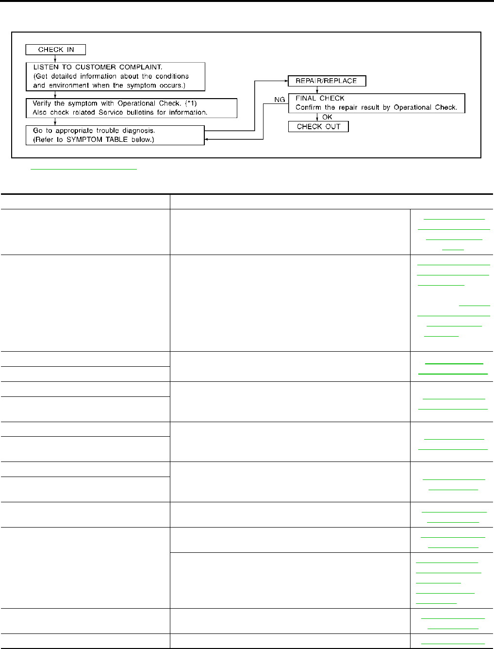
ATC-54
TROUBLE DIAGNOSIS
Revision; 2004 April 2003 FX
How to Perform Trouble Diagnosis for Quick and Accurate Repair AJS0014K
WORK FLOW
SYMPTOM TABLE
*1 ATC-75, "Operational Check"
SHA900E
Symptom Reference Page
A/C system does not come on. Go to Trouble Diagnosis Procedure for A/C System.
ATC-77, "Power
Supply and Ground
Circuit for Auto
Amp."
A/C system cannot be controlled. ●Go to Integrated Display System.
●Go to Navigation System.
AV-89, "A/C and AV
Switch Self-Diagno-
sis Function" (With-
out navigation
system) or AV-170,
"A/C and AV Switch
Self-Diagnosis
Function" (With
navigation system)
Air outlet does not change. Go to Trouble Diagnosis Procedure for Mode Door Motor. (LAN) ATC-83, "Mode
Door Motor Circuit"
Mode door motor does not operate normally.
Discharge air temperature does not change. Go to Trouble Diagnosis Procedure for Air Mix Door Motor.
(LAN)
ATC-86, "Air Mix
Door Motor Circuit"
Air mix door motor does not operate nor-
mally.
Intake door does not change.
Go to Trouble Diagnosis Procedure for Intake Door Motor. (LAN) ATC-89, "Intake
Door Motor Circuit"
Intake door motor does not operate nor-
mally.
Blower motor operation is malfunctioning.
Go to Trouble Diagnosis Procedure for Blower Motor. ATC-92, "Blower
Motor Circuit"
Blower motor operation is malfunctioning
under out of starting fan speed control.
Magnet clutch does not engage. Go to Trouble Diagnosis Procedure for Magnet Clutch. ATC-98, "Magnet
Clutch Circuit"
Insufficient cooling
Go to Trouble Diagnosis Procedure for Insufficient Cooling. ATC-104, "Insuffi-
cient Cooling"
Go to Diagnostic Procedure for Insufficient Cooling.
ATC-110, "DIAG-
NOSTIC PROCE-
DURE FOR
INSUFFICIENT
COOLING"
Insufficient heating Go to Trouble Diagnosis Procedure for Insufficient Heating. ATC-112, "Insuffi-
cient Heating"
Noise Go to Trouble Diagnosis Procedure for Noise. ATC-113, "Noise"
TROUBLE DIAGNOSIS
ATC-55
C
D
E
F
G
H
I
K
L
M
A
B
ATC
Revision; 2004 April 2003 FX
Self-diagnosis cannot be performed. Go to Trouble Diagnosis Procedure for Self-diagnosis. ATC-114, "Self-diag-
nosis"
Memory function does not operate. Go to Trouble Diagnosis Procedure for Memory Function. ATC-115, "Memory
Function"
Symptom Reference Page
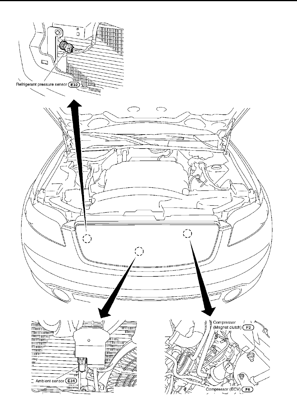
ATC-56
TROUBLE DIAGNOSIS
Revision; 2004 April 2003 FX
Component Parts and Harness Connector Location AJS0014L
ENGINE COMPARTMENT
RJIA1963E
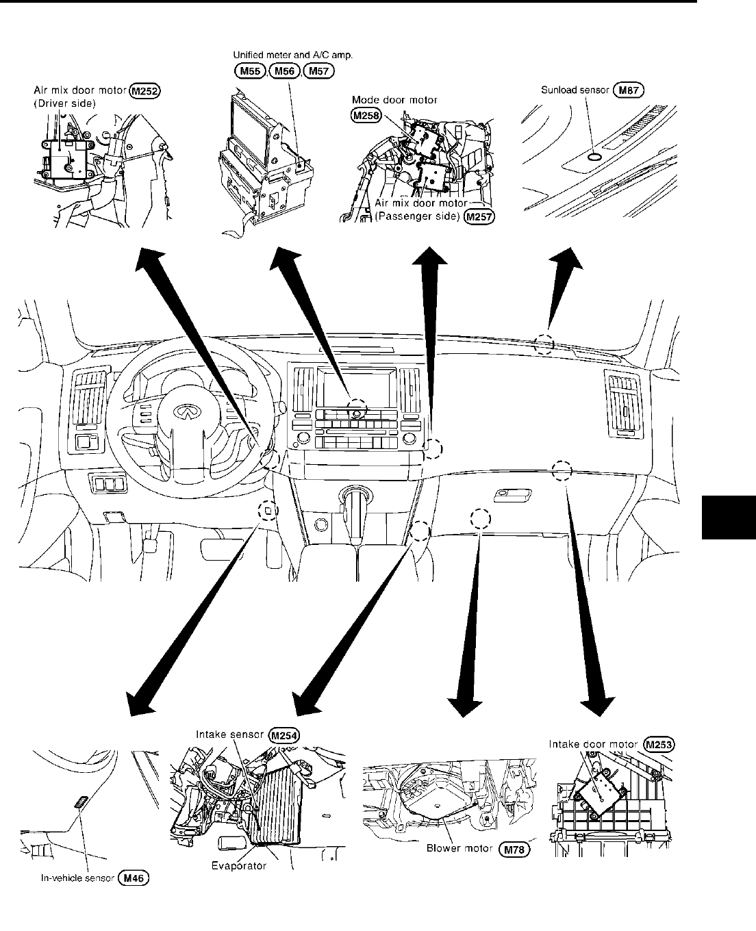
TROUBLE DIAGNOSIS
ATC-57
C
D
E
F
G
H
I
K
L
M
A
B
ATC
Revision; 2004 April 2003 FX
PASSENGER COMPARTMENT
RJIA1964E
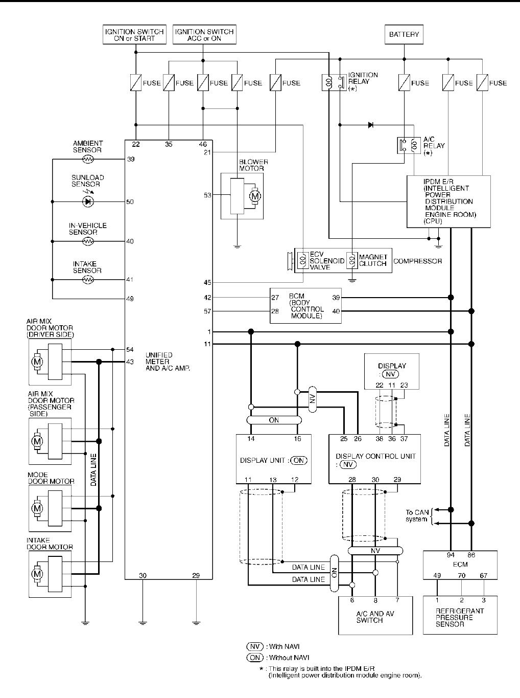
ATC-58
TROUBLE DIAGNOSIS
Revision; 2004 April 2003 FX
Schematic AJS0014M
TJWM0051E
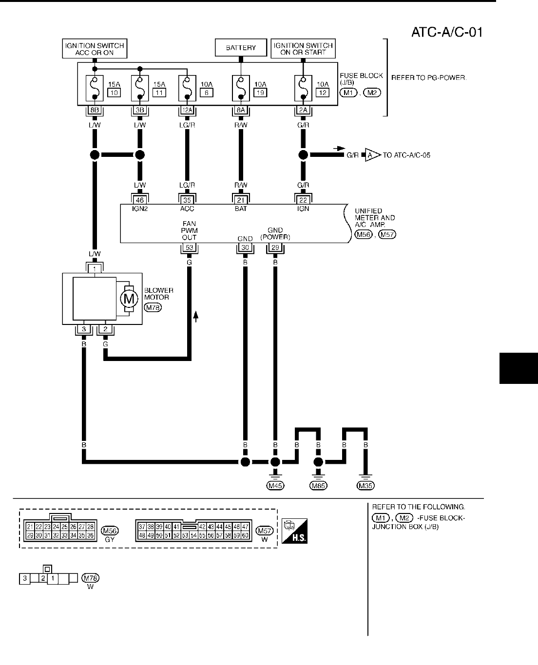
TROUBLE DIAGNOSIS
ATC-59
C
D
E
F
G
H
I
K
L
M
A
B
ATC
Revision; 2004 April 2003 FX
Wiring Diagram —A/C— AJS0014N
TJWM0052E

ATC-60
TROUBLE DIAGNOSIS
Revision; 2004 April 2003 FX
TJWM0053E

TROUBLE DIAGNOSIS
ATC-61
C
D
E
F
G
H
I
K
L
M
A
B
ATC
Revision; 2004 April 2003 FX
TJWM0054E
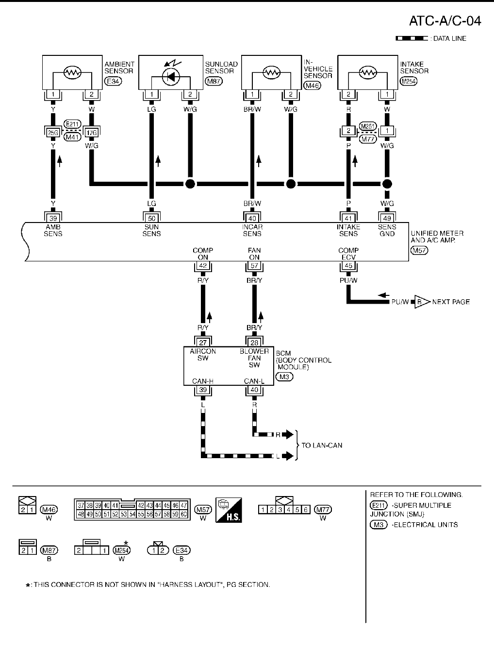
ATC-62
TROUBLE DIAGNOSIS
Revision; 2004 April 2003 FX
TJWM0055E

TROUBLE DIAGNOSIS
ATC-63
C
D
E
F
G
H
I
K
L
M
A
B
ATC
Revision; 2004 April 2003 FX
TJWM0056E
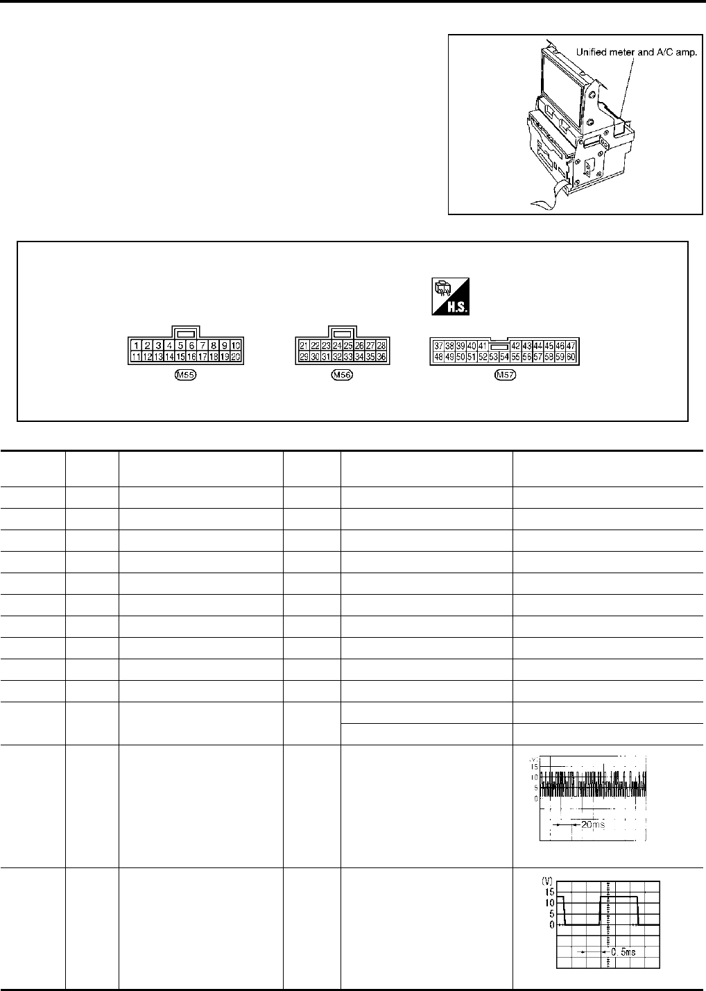
ATC-64
TROUBLE DIAGNOSIS
Revision; 2004 April 2003 FX
Auto Amp. Terminals and Reference Value AJS0014O
Measure voltage between each terminal and ground by following
Terminals and Reference Value for unified meter and A/C amp.
PIN CONNECTOR TERMINAL LAYOUT
TERMINALS AND REFERENCE VALUE FOR UNIFIED METER AND A/C AMP.
RJIA1965E
RJIA1966E
Terminal
No.
Wire
color Item Ignition
switch Condition Voltage
(V)
1 L CAN H - - -
11 R CAN L - - -
21 R/W Power supply for BATT OFF - Battery voltage
22 G/R Power supply for IGN ON - Battery voltage
29 B Ground (Power) ON - Approx. 0
30 B Ground ON - Approx. 0
35 LG/R Power supply for ACC ON - Battery voltage
39 Y Ambient sensor - - -
40 BR/W In-vehicle sensor - - -
41 P Intake sensor - - -
42 R/Y Compressor ON signal ON A/C switch: ON Approx. 0
A/C switch: OFF Approx. 5
43 G/B A/C LAN signal ON -
45 PU/W ECV (Electric Control Valve)
signal ON -
HAK0652D
RJIA1606E

TROUBLE DIAGNOSIS
ATC-65
C
D
E
F
G
H
I
K
L
M
A
B
ATC
Revision; 2004 April 2003 FX
46 L/W Power supply for IGN2 ON - Battery voltage
49 W/G Sensor ground ON - Approx. 0
50 LG Sunload sensor - - -
53 G Blower motor control signal ACC or
ON Blower speed: 1st step
54 Y/R Power supply for each door
motor ON - Battery voltage
57 BR/Y Blower motor ON signal ACC or
ON
A/C switch: ON (Blower motor
operate) Approx. 0
A/C switch: OFF Approx. 5
Terminal
No.
Wire
color Item Ignition
switch Condition Voltage
(V)
SJIA0116J
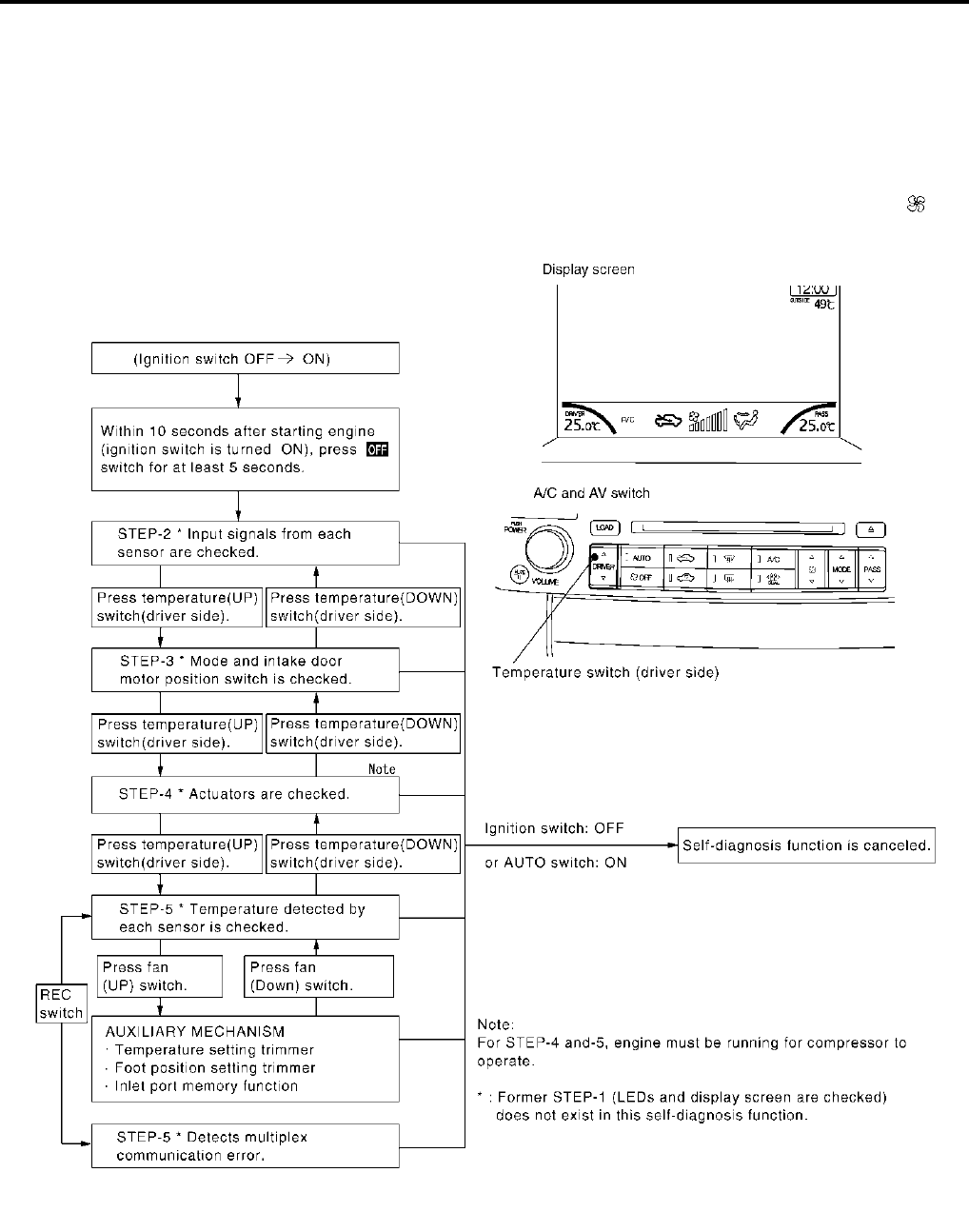
ATC-66
TROUBLE DIAGNOSIS
Revision; 2004 April 2003 FX
Self-diagnosis Function AJS0014P
DESCRIPTION
The self-diagnostic system diagnoses sensors, door motors, blower motor, etc. by system line. Refer to appli-
cable sections (items) for details. Shifting from usual control to the self-diagnostic system is accomplished by
starting the engine (turning the ignition switch ON) and pressing “OFF” switch for at least 5 seconds. The
“OFF” switch must be pressed within 10 seconds after starting the engine (ignition switch is turned ON). This
system will be canceled by either pressing AUTO switch or turning the ignition switch OFF. Shifting from one
step to another is accomplished by means of pressing temperature switch (driver side), as required.
Additionally shifting from STEP-5 to AUXILIARY MECHANISM is accomplished by means of pressing (fan)
switch (UP).
RJIA1967E

TROUBLE DIAGNOSIS
ATC-67
C
D
E
F
G
H
I
K
L
M
A
B
ATC
Revision; 2004 April 2003 FX
FUNCTION CONFIRMATION PROCEDURE
1. SET IN SELF-DIAGNOSTIC MODE
1. Turn ignition switch ON.
2. Set in self-diagnostic mode as follows. Within 10 seconds after starting engine (ignition switch is turned
ON.), press OFF switch for at least 5 seconds.
CAUTION:
●If battery voltage drops below 12V during diagnosis STEP-3, actuator speed becomes slower and
as a result, the system may generate an error even when operation is usual. To avoid this, start
engine before performing this diagnosis.
●Former STEP-1 (LEDs and display screen are checked) does not exist in this self-diagnosis func-
tion.
>> GO TO 2.
2. STEP-2: SENSOR CIRCUITS ARE CHECKED FOR OPEN OR SHORT CIRCUIT
Does code No. 20 appear on the display?
YES >> GO TO 3.
NO >> GO TO 13.
3. CHECK TO ADVANCE SELF-DIAGNOSIS STEP-3
Press temperature (UP) switch (driver side).
Advance to self-diagnosis STEP-3?
YES >> GO TO 4.
NO >> 1. Malfunctioning temperature switch.
2. Replace A/C and AV switch.
4. CHECK TO RETURN SELF-DIAGNOSIS STEP-2
Press temperature (DOWN) switch (driver side).
Return to self-diagnosis STEP-2?
YES >> GO TO 5.
NO >> 1. Malfunctioning temperature switch.
2. Replace A/C and AV switch.
RJIA0219E

ATC-68
TROUBLE DIAGNOSIS
Revision; 2004 April 2003 FX
5. STEP-3: MODE DOOR AND INTAKE DOOR POSITIONS ARE CHECKED
Press temperature (UP) switch (driver side).
Does code No. 30 appear on the display?
YES >> GO TO 6.
NO >> GO TO 14.
6. STEP-4: OPERATION OF EACH DOOR MOTOR IS CHECKED
1. Press temperature (UP) switch (driver side).
2. Press DEF switch. Code No. of each door motor test is indicated
on the display.
>> GO TO 7.
RJIA0220E
RJIA1968E

TROUBLE DIAGNOSIS
ATC-69
C
D
E
F
G
H
I
K
L
M
A
B
ATC
Revision; 2004 April 2003 FX
7. CHECK ACTUATORS
Refer to the following chart and confirm discharge air flow, air tem-
perature, blower motor voltage and compressor operation.
Checks must be made visually, by listening to any noise, or by touching air outlets with your hand, etc. for
improper operation.
*1: FOOT position during automatic control. Refer to ATC-74, "AUXILIARY MECHANISM: FOOT POSITION
SETTING TRIMMER" .
OK or NG
OK >> GO TO 8.
NG >> ●Air outlet does not change.
Go to Mode Door Motor Circuit. Refer to ATC-83, "Mode Door Motor Circuit" .
●Intake door does not change.
Go to Intake Door Motor Circuit. Refer to ATC-89, "Intake Door Motor Circuit" .
●Blower motor operation is malfunctioning.
Go to Blower Motor Circuit. Refer to ATC-92, "Blower Motor Circuit" .
●Magnet clutch does not engage.
Go to Magnet Clutch Circuit. Refer to ATC-98, "Magnet Clutch Circuit" .
●Discharge air temperature does not change.
Go to Air Mix Door Motor Circuit. Refer to ATC-86, "Air Mix Door Motor Circuit" .
8. STEP-5: TEMPERATURE OF EACH SENSOR IS CHECKED
1. Press temperature (UP) switch (driver side).
2. Code No. 51 appears on the display.
>> GO TO 9.
SJIA0302E
41 42 43 44 45 46
Mode door position VENT B/L 1 B/L 2 FOOT*1 D/F DEF
Intake door position REC REC 20%FRE FRE FRE FRE
Air mix door position FULL COLD FULL COLD FULL HOT FULL HOT FULL HOT FULL HOT
Blower fan duty ratio 37% 91% 65% 65% 65% 91%
Compressor ON ON OFF OFF ON ON
Electronic control
valve (ECV) duty
ratio
100% 100% 0% 0% 50% 100%
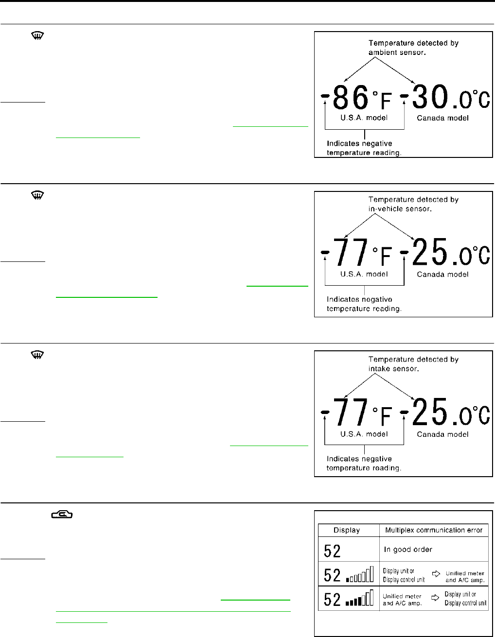
ATC-70
TROUBLE DIAGNOSIS
Revision; 2004 April 2003 FX
9. CHECK AMBIENT SENSOR
Press (DEF) switch one time. Temperature detected by ambient
sensor is indicated on the display.
NOTE:
If temperature shown on display greatly differs from actual tempera-
ture, check sensor circuit first, then inspect sensor.
OK or NG
OK >> GO TO 10.
NG >> Go to Ambient Sensor Circuit. Refer to ATC-116, "Ambi-
ent Sensor Circuit" .
10. CHECK IN-VEHICLE SENSOR
Press (DEF) switch a second time. Temperature detected by in-
vehicle sensor is indicated on the display.
NOTE:
If temperature shown on display greatly differs from actual tempera-
ture, check sensor circuit first, then inspect sensor.
OK or NG
OK >> GO TO 11.
NG >> Go to In-vehicle Sensor Circuit. Refer to ATC-119, "In-
vehicle Sensor Circuit" .
11. CHECK INTAKE SENSOR
Press (DEF) switch a third time. Temperature detected by intake
sensor is indicated on the display.
NOTE:
If temperature shown on display greatly differs from actual tempera-
ture, check sensor circuit first, then inspect sensor.
OK or NG
OK >> GO TO 12.
NG >> Go to Intake Sensor Circuit. Refer to ATC-125, "Intake
Sensor Circuit" .
12. CHECK CAN COMMUNICATION ERROR
1. Press (REC) switch.
2. CAN communication error between unified meter and A/C amp.
and DISPLAY UNIT or DISPLAY CONTROL UNIT is detected.
OK or NG
OK >> 1. Turn ignition switch OFF or AUTO switch ON.
2. INSPECTION END
NG >> Go to CAN communication. Refer to BCS-27, "CAN
Communication Inspection Using CONSULT-II (Self-
Diagnosis)" .
●Unified meter and A/C amp. - DISPLAY UNIT
●Unified meter and A/C amp. - DISPLAY CONTROL UNIT
RJIA0223E
RJIA1271E
RJIA1272E
RJIA1969E
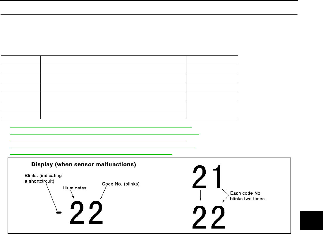
TROUBLE DIAGNOSIS
ATC-71
C
D
E
F
G
H
I
K
L
M
A
B
ATC
Revision; 2004 April 2003 FX
13. CHECK MALFUNCTIONING SENSOR
Refer to the following chart for malfunctioning code No.
(If two or more sensors malfunction, corresponding code Nos. blink respectively twice.)
*1: Perform self-diagnosis STEP-2 under sunshine.
When performing indoors, aim a light (more than 60W) at sunload sensor, otherwise Code No. 25 will indicate
despite that sunload sensor is functioning properly.
*2: ATC-116, "DIAGNOSTIC PROCEDURE FOR AMBIENT SENSOR" .
*3: ATC-120, "DIAGNOSTIC PROCEDURE FOR IN-VEHICLE SENSOR" .
*4: ATC-125, "DIAGNOSTIC PROCEDURE FOR INTAKE SENSOR" .
*5: ATC-122, "DIAGNOSTIC PROCEDURE FOR SUNLOAD SENSOR" .
*6: ATC-80, "DIAGNOSTIC PROCEDURE FOR LAN CIRCUIT" .
>> INSPECTION END
Code No. Malfunctioning sensor (Including circuits) Reference page
21 / −21 Ambient sensor *2
22 / −22 In-vehicle sensor *3
24 / −24 Intake sensor *4
25 / −25 Sunload sensor *1 *5
26 / −26 Air mix door motor PBR (Driver side) *6
27 / −27 Air mix door motor PBR (Passenger side)
RJIA0227E

ATC-72
TROUBLE DIAGNOSIS
Revision; 2004 April 2003 FX
14. CHECK MALFUNCTIONING DOOR MOTOR POSITION SWITCH
Mode or (and) intake door motor PBR (s) is (are) malfunctioning.
(If two or more mode or intake doors are out of order, corresponding code numbers blink respectively twice.)
*1: If mode door motor harness connector is disconnected, the following display pattern will appear.
31→32→33→34→35→36→Return to 31
*2: If intake door motor harness connector is disconnected, the following display pattern will appear.
37→38→39→Return to 37
*3: FOOT position during automatic control. Refer to ATC-74, "AUXILIARY MECHANISM: FOOT POSITION
SETTING TRIMMER" .
*4:ATC-83, "Mode Door Motor Circuit" .
*5:ATC-89, "Intake Door Motor Circuit" .
>> INSPECTION END
Code No. *1 *2 Mode or intake door position Reference page
31 VENT
Mode door motor *4
32 B/L 1
33 B/L 2
34 FOOT*3
35 D/F
36 DEF
37 FRE
Intake door motor *538 20% FRE
39 REC
RJIA0228E

TROUBLE DIAGNOSIS
ATC-73
C
D
E
F
G
H
I
K
L
M
A
B
ATC
Revision; 2004 April 2003 FX
AUXILIARY MECHANISM: TEMPERATURE SETTING TRIMMER
The trimmer compensates for differences in range of ±3°C (±6°F) between temperature setting (displayed dig-
itally) and temperature felt by driver.
Operating procedures for this trimmer are as follows:
●Begin Self-diagnosis STEP-5 mode. Refer to ATC-66, "Self-diagnosis Function" .
●Press fan (UP) switch to set system in auxiliary mode.
●Display shows 61 in auxiliary mechanism. It takes approximately 3 seconds.
●Press temperature switch (driver side) as desired. Temperature will change at a rate of 0.5°C (1.0°F) each
time a switch is pressed.
CAUTION:
A decimal point is not indicated when the display shows “°C”.
When battery cable is disconnected, trimmer operation is canceled. Temperature set becomes that of initial
condition, i.e. 0°C (0°F).
RJIA1970E
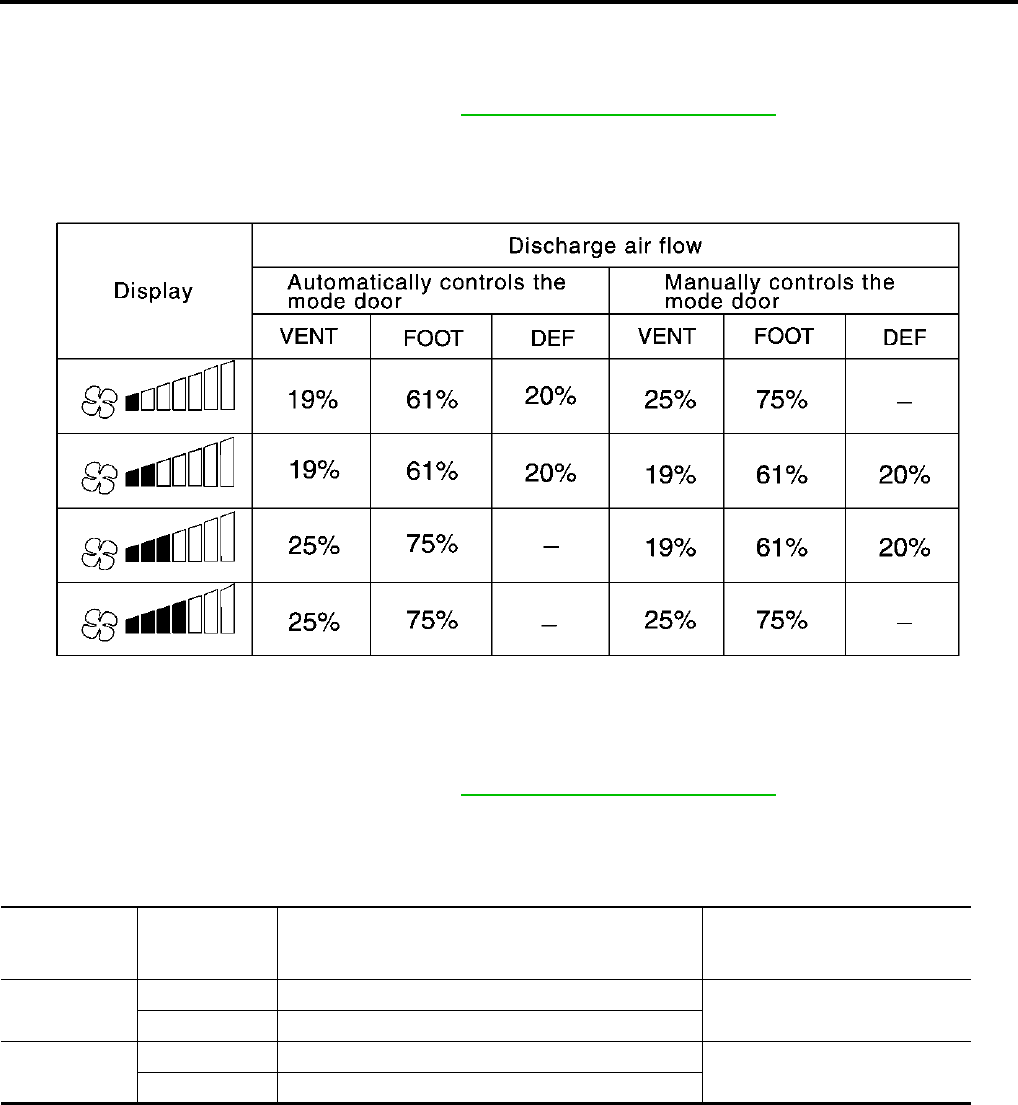
ATC-74
TROUBLE DIAGNOSIS
Revision; 2004 April 2003 FX
AUXILIARY MECHANISM: FOOT POSITION SETTING TRIMMER
Wind distribution ratio in FOOT mode can be set.
Operating procedures for this trimmer are as follows:
●Begin Self-diagnosis STEP-5 mode. Refer to ATC-66, "Self-diagnosis Function" .
●Press fan (UP) switch to set system in auxiliary mode.
●Display shows 61 in auxiliary mechanism. It takes approximately 3 seconds.
●Press the mode switch as desired.
AUXILIARY MECHANISM: INLET PORT MEMORY FUNCTION
When ignition key is turned from OFF to ON, inlet port can be set to AUTO or manual.
Operating procedures for this trimmer are as follows:
●Begin Self-diagnosis STEP-5 mode. Refer to ATC-66, "Self-diagnosis Function" .
●Press fan (UP) switch to set system in auxiliary mode.
●Display shows 61 in auxiliary mechanism. It takes approximately 3 seconds.
●Press the recirculation (REC) and fresh (FRE) switch as desired.
RJIA1971E
Switch
LED status of
REC/FRE
switch
Setting status Setting changeover method
REC ON Manual REC status is memorized. (Initial setting) REC SW: ON
OFF AUTO control
FRE ON Manual FRE status is memorized. FRE SW: ON
OFF AUTO control (Initial setting)

TROUBLE DIAGNOSIS
ATC-75
C
D
E
F
G
H
I
K
L
M
A
B
ATC
Revision; 2004 April 2003 FX
Operational Check AJS0014Q
The purpose of the operational check is to confirm that the system operates properly.
CHECKING MEMORY FUNCTION
1. Set the temperature to 32°C (90°F).
2. Press OFF switch.
3. Turn ignition switch OFF.
4. Turn ignition switch ON.
5. Press the AUTO switch.
6. Confirm that the set temperature remains at previous tempera-
ture.
7. Press OFF switch.
If NG, go to trouble diagnosis procedure for ATC-115, "Memory
Function" .
If OK, continue with next check.
CHECKING BLOWER
1. Press fan (UP) switch. Blower should operate on low speed. The
fan symbol should have one blade lit.
2. Press fan (UP) switch again, and continue checking blower
speed and fan symbol until all speeds are checked.
3. Leave blower on MAX speed.
If NG, go to trouble diagnosis procedure for ATC-94, "DIAGNOSTIC
PROCEDURE FOR BLOWER MOTOR" .
If OK, continue with next check.
CHECKING DISCHARGE AIR
1. Press MODE switch and DEF switch.
2. Each position indicator should change shape.
3. Confirm that discharge air comes out according to the air distri-
bution table. Refer to ATC-36, "Discharge Air Flow" .
If NG, go to trouble diagnosis procedure for ATC-83, "Mode Door
Motor Circuit" .
If OK, continue with next check.
NOTE:
Confirm that the compressor clutch is engaged (sound or visual
inspection) and intake door position is at FRESH when the DEF or
D/F is selected.
Conditions : Engine running and at usual operating temperature
RJIA1972E
RJIA1973E
RJIA1974E
SJIA0302E

ATC-76
TROUBLE DIAGNOSIS
Revision; 2004 April 2003 FX
CHECKING RECIRCULATION
1. Press recirculation (REC) switch one time. Recirculation indica-
tor should illuminate.
2. Press fresh (FRE) switch one time. Fresh indicator should illumi-
nate.
3. Listen for intake door position change (you should hear blower
sound change slightly).
If NG, go to trouble diagnosis procedure for ATC-89, "Intake Door
Motor Circuit" .
If OK, continue with next check.
NOTE:
Confirm that the compressor clutch is engaged (sound or visual
inspection) and intake door position is at FRESH when the DEF or D/F is selected.
CHECKING TEMPERATURE DECREASE
1. Press temperature (DOWN) switch (driver side) until 18°C
(60°F) is displayed.
2. Check for cold air at discharge air outlets.
If NG, go to trouble diagnosis procedure for ATC-104, "Insufficient
Cooling" .
If OK, continue with next check.
CHECKING TEMPERATURE INCREASE
1. Press temperature (UP) switch (driver side) until 32°C (90°F) is
displayed.
2. Check for hot air at discharge air outlets.
If NG, go to trouble diagnosis procedure for ATC-112, "Insufficient
Heating" .
If OK, continue with next check.
CHECK A/C SWITCH
1. Press AUTO switch and A/C switch.
2. A/C switch indicator will turn ON.
●Confirm that the compressor clutch engages (sound or visual
inspection).
If NG, go to trouble diagnosis procedure for ATC-98, "Magnet Clutch
Circuit" .
If OK, continue with next check.
RJIA1978E
RJIA1976E
RJIA1977E
RJIA1975E
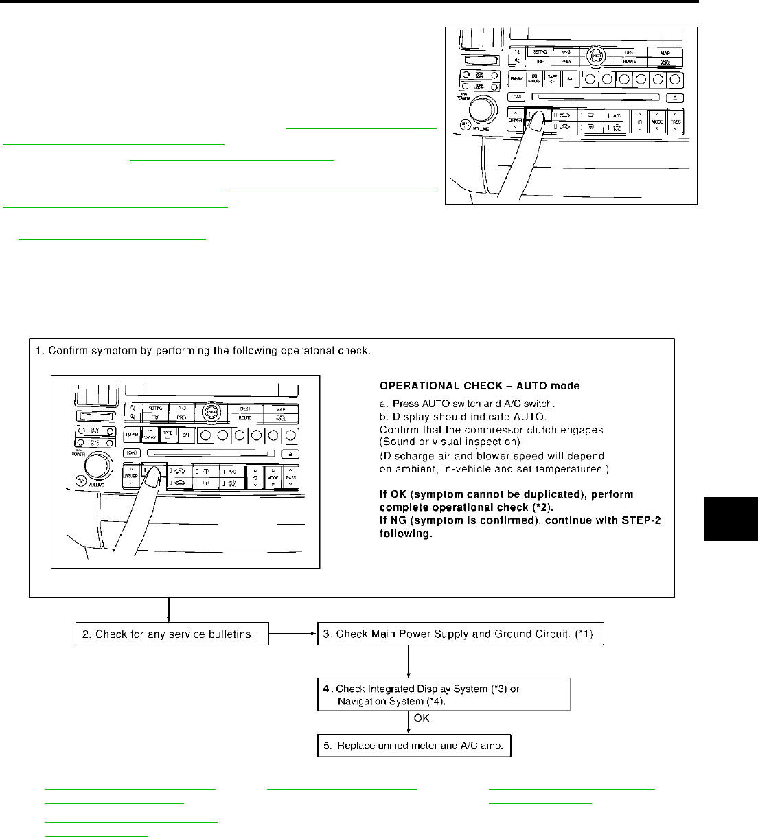
TROUBLE DIAGNOSIS
ATC-77
C
D
E
F
G
H
I
K
L
M
A
B
ATC
Revision; 2004 April 2003 FX
CHECKING AUTO MODE
1. Press AUTO switch and A/C switch.
2. Display should indicate AUTO.
●Confirm that the compressor clutch engages (sound or visual
inspection). (Discharge air and blower speed will depend on
ambient, in-vehicle, and set temperatures.)
If NG, go to trouble diagnosis procedure for ATC-77, "Power Supply
and Ground Circuit for Auto Amp." , then if necessary, trouble diag-
nosis procedure for ATC-98, "Magnet Clutch Circuit" .
If all operational checks are OK (symptom cannot be duplicated), go
to malfunction Simulation Tests in GI-27, "How to Perform Efficient
Diagnosis for an Electrical Incident" and perform tests as outlined to
simulate driving conditions environment. If symptom appears, refer
to ATC-54, "SYMPTOM TABLE" and perform applicable trouble diagnosis procedures.
Power Supply and Ground Circuit for Auto Amp. AJS001BF
SYMPTOM: A/C system does not come on.
INSPECTION FLOW
RJIA1979E
*1 ATC-78, "DIAGNOSTIC PROCE-
DURE FOR A/C SYSTEM".
*2 ATC-75, "Operational Check".*3AV-89, "A/C and AV Switch Self-
Diagnosis Function".
*4 AV-170, "A/C and AV Switch Self-
Diagnosis Function".
RJIA1980E
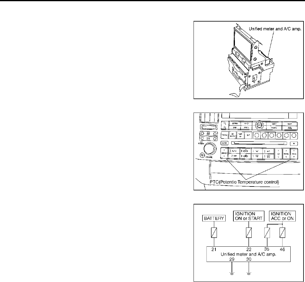
ATC-78
TROUBLE DIAGNOSIS
Revision; 2004 April 2003 FX
COMPONENT DESCRIPTION
Unified Meter and A/C Amp. (Automatic Amplifier)
The unified meter and A/C amp. has a built-in microcomputer which
processes information sent from various sensors needed for air con-
ditioner operation. The air mix door motor, mode door motor, intake
door motor, blower motor and compressor are then controlled.
The unified meter and A/C amp. is unitized with control mechanisms.
When the various switches and temperature switch are operated,
data is input to the unified meter and A/C amp. from the DISPLAY
UNIT/DISPLAY CONTROL UNIT using CAN communication.
Self-diagnostic functions are also built into unified meter and A/C
amp. to provide quick check of malfunctions in the auto air condi-
tioner system.
Potentio Temperature Control (PTC)
The PTC is built into the A/C and AV switch. It can be set at an inter-
val of 0.5°C (1.0°F) in the 18°C (60°F) to 32°C (90°F) temperature
range by pressing temperature switch. The set temperature is dis-
played.
DIAGNOSTIC PROCEDURE FOR A/C SYSTEM
SYMPTOM: A/C system does not come on.
RJIA1965E
RJIA1982E
RJIA1983E
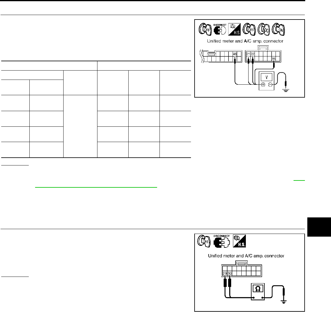
TROUBLE DIAGNOSIS
ATC-79
C
D
E
F
G
H
I
K
L
M
A
B
ATC
Revision; 2004 April 2003 FX
1. CHECK POWER SUPPLY CIRCUIT FOR UNIFIED METER AND A/C AMP.
1. Disconnect unified meter and A/C amp. connector.
2. Check voltage between unified meter and A/C amp. harness
connector M56 terminals 21 (R/W), 22 (G/R) and 35 (LG/R), uni-
fied meter and A/C amp. harness connector M57 terminal 46 (L/
W) and ground.
OK or NG
OK >> GO TO 2.
NG >> Check 10A and 15A fuses [Nos. 6, 10, 11, 12 and 19, located in the fuse block (J/B)]. Refer to PG-
98, "FUSE BLOCK - JUNCTION BOX (J/B)" .
●If fuses are OK, check harness for open circuit. Repair or replace as necessary.
●If fuses are NG, replace fuse and check harness for short circuit. Repair or replace as neces-
sary.
2. CHECK GROUND CIRCUIT FOR UNIFIED METER AND A/C AMP.
1. Turn ignition switch OFF.
2. Check continuity between unified meter and A/C amp. harness
connector M56 terminal 29 (B), 30 (B) and ground.
OK or NG
OK >> Replace unified meter and A/C amp.
NG >> Repair harness or connector.
Terminals Ignition switch position
(+)
(-) OFF ACC ON
Auto amp.
connector
Terminal No.
(wire color)
M56 21 (R/W)
Ground
Battery
voltage
Battery
voltage
Battery
voltage
M56 22 (G/R) Approx. 0V Approx. 0V Battery
voltage
M56 35 (LG/R) Approx. 0V Battery
voltage
Battery
voltage
M57 46 (L/W) Approx. 0V Battery
voltage
Battery
voltage
RJIA1984E
29, 30 – Ground : Continuity should exist.
RJIA1985E

ATC-80
TROUBLE DIAGNOSIS
Revision; 2004 April 2003 FX
LAN System Circuit AJS0014S
SYMPTOM: Mode door motor, intake door motor and/or air mix door motor(s) does not operate normally.
DIAGNOSTIC PROCEDURE FOR LAN CIRCUIT
1. CHECK POWER SUPPLY FOR UNIFIED METER AND A/C AMP.
1. Turn ignition switch ON.
2. Check voltage between unified meter and A/C amp. harness
connector M57 terminal 54 (Y/R) and ground.
OK or NG
OK >> GO TO 2.
NG >> Replace unified meter and A/C amp.
2. CHECK SIGNAL FOR UNIFIED METER AND A/C AMP.
Confirm A/C LAN signal between unified meter and A/C amp. har-
ness connector M57 terminal 43 (G/B) and ground using an oscillo-
scope.
OK or NG
OK >> GO TO 3.
NG >> Replace unified meter and A/C amp.
RJIA1775E
54 – Ground : Battery voltage
RJIA1986E
Terminals
Voltage
(+)
(−)
Auto amp.
connector
Terminal No.
(wire color)
M57 43 (G/B) Ground
RJIA1987E
HAK0652D
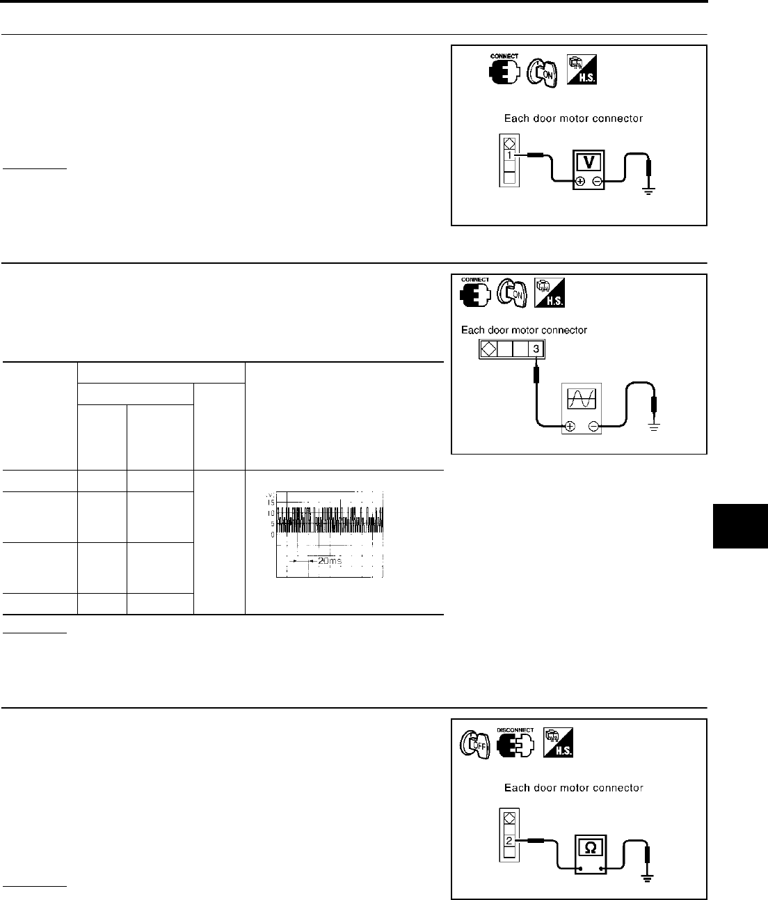
TROUBLE DIAGNOSIS
ATC-81
C
D
E
F
G
H
I
K
L
M
A
B
ATC
Revision; 2004 April 2003 FX
3. CHECK POWER SUPPLY FOR MOTOR
Check voltage between mode door motor harness connector M258
terminal 1 (G), driver side air mix door motor harness connector
M252 terminal 1 (G), passenger side air mix door motor harness
connector M257 terminal 1 (G), intake door motor harness connector
M253 terminal 1 (G) and ground.
OK or NG
OK >> GO TO 4.
NG >> Repair harness or connector.
4. CHECK SIGNAL FOR MOTOR
Confirm A/C LAN signal between mode door motor harness connec-
tor M258 terminal 3 (L), driver side air mix door motor harness con-
nector M252 terminal 3 (L), passenger side air mix door motor
harness connector M257 terminal 3 (L), intake door motor harness
connector M253 terminal 3 (G/B) and ground using an oscilloscope.
OK or NG
OK >> GO TO 5.
NG >> Repair harness or connector.
5. CHECK MOTOR GROUND CIRCUIT
1. Turn ignition switch OFF.
2. Disconnect door motor connector.
3. Check continuity between mode door motor harness connector
M258 terminal 2 (B), driver side air mix door motor harness con-
nector M252 terminal 2 (B), passenger side air mix door motor
harness connector M257 terminal 2 (B), intake door motor har-
ness connector M253 terminal 2 (B) and ground.
OK or NG
OK >> GO TO 6.
NG >> Repair harness or connector.
1 – Ground : Battery voltage
RJIA1988E
Door motor
Terminals
Voltage
(+)
(−)
Con-
nector
Terminal
No.
(wire
color)
Mode M258 3 (L)
Ground
Air mix
(Driver
side)
M252 3 (L)
Air mix
(Passen-
ger side)
M257 3 (L)
Intake M253 3 (L)
RJIA1989E
HAK0652D
2 – Ground : Continuity should exist.
RJIA1990E

ATC-82
TROUBLE DIAGNOSIS
Revision; 2004 April 2003 FX
6. CHECK MOTOR OPERATION
Disconnect and reconnect the motor connector and confirm the motor operation.
OK or NG
OK >> (Return to operate normally.)
●Poor contact in motor connector
NG >> (Does not operate normally.)
●GO TO 7.
7. CHECK MODE DOOR MOTOR OPERATION
1. Disconnect mode door motor and air mix door motor (driver side, passenger side) connector.
2. Reconnect mode door motor connector and confirm the mode door motor operation.
OK or NG
OK >> (Mode door motor operates normally.)
●GO TO 8.
NG >> (Mode door motor does not operate normally.)
●Replace mode door motor.
8. CHECK AIR MIX DOOR MOTOR OPERATION
1. Disconnect mode door motor connector.
2. Reconnect air mix door motor connector (driver side, passenger side) and confirm the air mix door motor
operation.
OK or NG
OK >> (Air mix door motor operates normally.)
●GO TO 9.
NG >> (Air mix door motor does not operate normally.)
●GO TO 10.
9. CHECK INTAKE DOOR MOTOR OPERATION
1. Disconnect air mix door motor connector (driver side, passenger side).
2. Reconnect intake door motor connector and confirm the intake door motor operation.
OK or NG
OK >> (Intake door motor operates normally.)
●Replace unified meter and A/C amp.
NG >> (Intake door motor does not operate normally.)
●Replace intake door motor.
10. CHECK AIR MIX DOOR MOTOR OPERATION
1. Disconnect air mix door motor (driver side) connector.
2. Confirm the air mix door motor (passenger side) operation.
OK or NG
OK >> (Air mix door motor operates normally.)
●Replace driver side air mix door motor.
NG >> (Air mix door motor does not operate normally.)
●Replace passenger side air mix door motor.

TROUBLE DIAGNOSIS
ATC-83
C
D
E
F
G
H
I
K
L
M
A
B
ATC
Revision; 2004 April 2003 FX
Mode Door Motor Circuit AJS0014T
SYMPTOM:
●Air outlet does not change.
●Mode door motor does not operate normally.
INSPECTION FLOW
*1 ATC-36, "Discharge Air Flow".*2ATC-75, "Operational Check".*3ATC-125, "Intake Sensor Circuit"
*4 ATC-67, "FUNCTION CONFIRMA-
TION PROCEDURE", see No. 4 to 6.
*5 ATC-116, "Ambient Sensor Circuit".*6 ATC-119, "In-vehicle Sensor Cir-
cuit".
*7 ATC-122, "Sunload Sensor Circuit".*8ATC-86, "Air Mix Door Motor Cir-
cuit".
*9 ATC-67, "FUNCTION CONFIRMA-
TION PROCEDURE", see No. 13.
*10 ATC-80, "DIAGNOSTIC PROCE-
DURE FOR LAN CIRCUIT".
*11 ATC-142, "MODE DOOR MOTOR".*12ATC-54, "SYMPTOM TABLE".
RJIA1991E
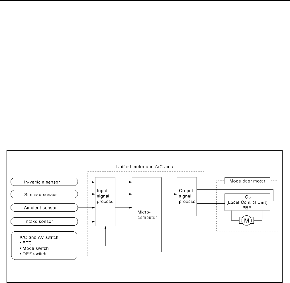
ATC-84
TROUBLE DIAGNOSIS
Revision; 2004 April 2003 FX
SYSTEM DESCRIPTION
Component Parts
Mode door control system components are:
●Unified meter and A/C amp.
●Mode door motor (LCU)
●A/C LAN system (PBR built-in mode door motor and air mix door motor)
●In-vehicle sensor
●Ambient sensor
●Sunload sensor
●Intake sensor
System Operation
The unified meter and A/C amp. receives data from each of the sensors. The unified meter and A/C amp.
sends air mix door, mode door and intake door opening angle data to the air mix door motor LCU, mode door
motor LCU and intake door motor LCU.
The air mix door motor, mode door motor and intake door motor read their respective signals according to the
address signal. Opening angle indication signals received from the unified meter and A/C amp. and each of
the motor position sensors are compared by the LCUs in each motor with the existing decision and opening
angles. Subsequently, HOT/COLD or DEFROST/VENT or FRESH/RECIRCULATION operation is selected.
The new selection data is returned to the unified meter and A/C amp.
RJIA1777E

TROUBLE DIAGNOSIS
ATC-85
C
D
E
F
G
H
I
K
L
M
A
B
ATC
Revision; 2004 April 2003 FX
Mode Door Control Specification
COMPONENT DESCRIPTION
Mode Door Motor
The mode door motor is attached to the heater & cooling unit. It
rotates so that air is discharged from the outlet set by the unified
meter and A/C amp. Motor rotation is conveyed to a link which acti-
vates the mode door.
DIAGNOSTIC PROCEDURE FOR MODE DOOR MOTOR
SYMPTOM: Mode door motor does not operate normally.
Perform diagnostic procedure for ATC-80, "DIAGNOSTIC PROCEDURE FOR LAN CIRCUIT" .
RJIA1778E
RJIA0890E

ATC-86
TROUBLE DIAGNOSIS
Revision; 2004 April 2003 FX
Air Mix Door Motor Circuit AJS0014U
SYMPTOM:
●Discharge air temperature does not change.
●Air mix door motor does not operate.
INSPECTION FLOW
*1 ATC-67, "FUNCTION CONFIRMA-
TION PROCEDURE", see No. 4 to 6.
*2 ATC-116, "Ambient Sensor Circuit".*3 ATC-119, "In-vehicle Sensor Cir-
cuit".
*4 ATC-122, "Sunload Sensor Circuit"*5 ATC-88, "Air Mix Door Motor PBR
Circuit".
*6 ATC-67, "FUNCTION CONFIRMA-
TION PROCEDURE", see No. 13.
*7 ATC-80, "LAN System Circuit".*8ATC-88, "COMPONENT DESCRIP-
TION".
*9 ATC-143, "AIR MIX DOOR
MOTOR".
*10 ATC-75, "Operational Check".*11ATC-54, "SYMPTOM TABLE".*12ATC-125, "Intake Sensor Circuit".
RJIA1992E
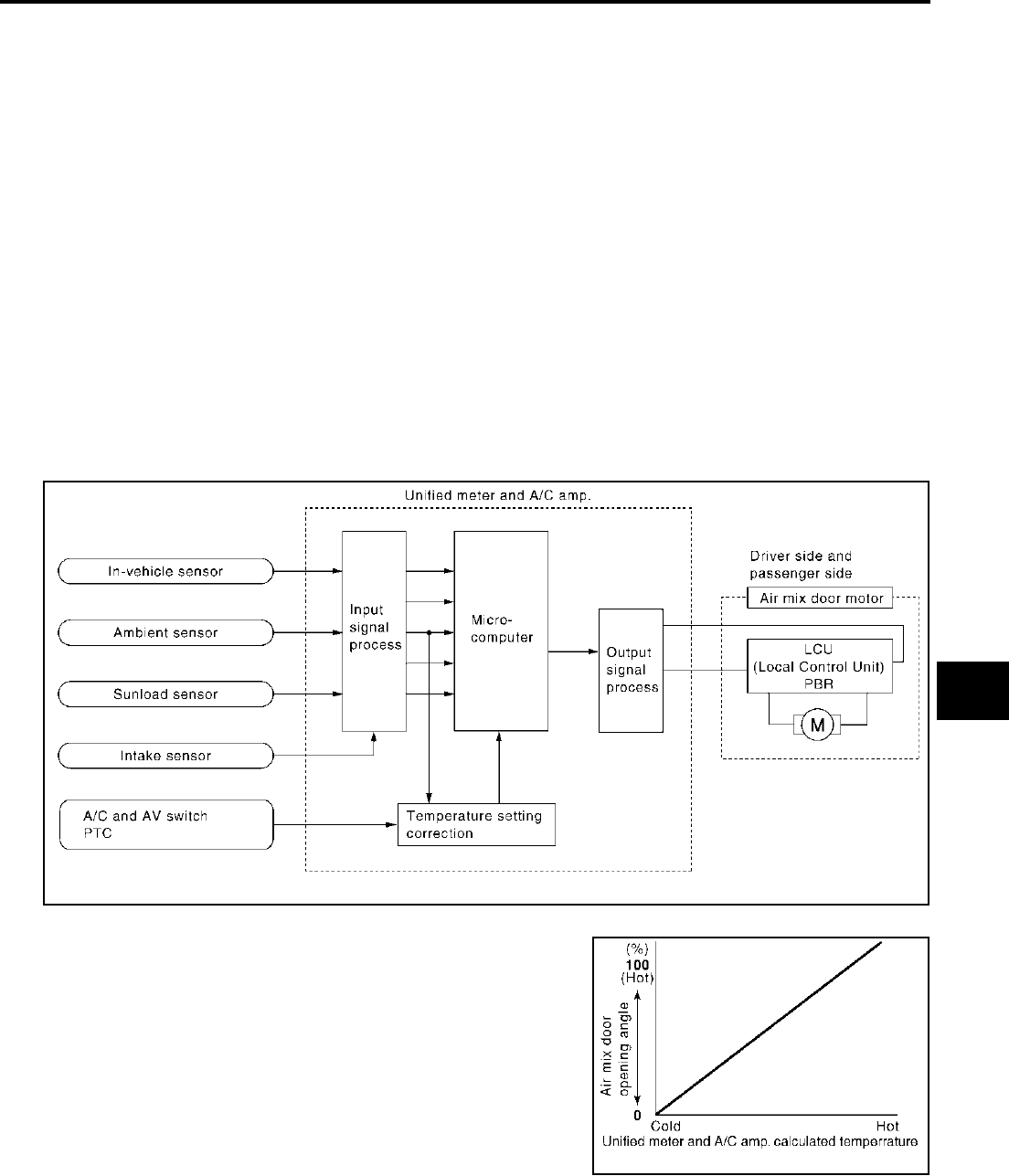
TROUBLE DIAGNOSIS
ATC-87
C
D
E
F
G
H
I
K
L
M
A
B
ATC
Revision; 2004 April 2003 FX
SYSTEM DESCRIPTION
Component Parts
Air mix door control system components are:
●Unified meter and A/C amp.
●Air mix door motor (LCU)
●A/C LAN system (PBR built-in mode door motor and air mix door motor)
●In-vehicle sensor
●Ambient sensor
●Sunload sensor
●Intake sensor
System Operation
The unified meter and A/C amp. receives data from each of the sensors. The unified meter and A/C amp.
sends air mix door, mode door and intake door motor opening angle data to the air mix door motor LCU, mode
door motor LCU and intake door motor LCU.
The air mix door motor, mode door motor and intake door motor read their respective signals according to the
address signal. Opening angle indication signals received from the unified meter and A/C amp. and each of
the motor position sensors are compared by the LCUs in each motor with the existing decision and opening
angles. Subsequently, HOT/COLD or DEFROST/VENT or FRESH/RECIRCULATION operation is selected.
The new selection data is returned to the unified meter and A/C amp.
Air Mix Door Control Specification
RJIA1781E
RJIA1782E
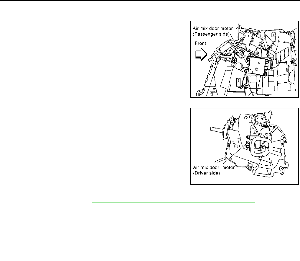
ATC-88
TROUBLE DIAGNOSIS
Revision; 2004 April 2003 FX
COMPONENT DESCRIPTION
Air Mix Door Motor
The air mix door motor is attached to the heater & cooling unit. It
rotates so that the air mix door is opened or closed to a position set
by the unified meter and A/C amp. Motor rotation is then conveyed
through a shaft and the air mix door position is then fed back to the
unified meter and A/C amp. by PBR built-in air mix door motor.
DIAGNOSTIC PROCEDURE FOR AIR MIX DOOR
Perform diagnostic procedure for ATC-80, "DIAGNOSTIC PROCEDURE FOR LAN CIRCUIT" .
Air Mix Door Motor PBR Circuit AJS0014V
SYMPTOM:
●Discharge air temperature does not change.
●PBR circuit is open or shorted.
DIAGNOSTIC PROCEDURE FOR AIR MIX DOOR PBR
Perform diagnostic procedure for ATC-80, "DIAGNOSTIC PROCEDURE FOR LAN CIRCUIT" .
RJIA0893E
RJIA0894E

TROUBLE DIAGNOSIS
ATC-89
C
D
E
F
G
H
I
K
L
M
A
B
ATC
Revision; 2004 April 2003 FX
Intake Door Motor Circuit AJS0014W
SYMPTOM:
●Intake door does not change.
●Intake door motor does not operate normally.
INSPECTION FLOW
*1 ATC-67, "FUNCTION CONFIRMA-
TION PROCEDURE", see No. 4 to 6.
*2 ATC-116, "Ambient Sensor Circuit".*3 ATC-119, "In-vehicle Sensor Circuit".
*4 ATC-122, "Sunload Sensor Circuit".*5ATC-88, "Air Mix Door Motor PBR
Circuit".
*6 ATC-67, "FUNCTION CONFIRMA-
TION PROCEDURE", see No. 13.
*7 ATC-80, "LAN System Circuit".*8ATC-137, "INTAKE DOOR
MOTOR".
*9 ATC-75, "Operational Check".
*10 ATC-54, "SYMPTOM TABLE".*11ATC-125, "Intake Sensor Circuit".
RJIA1993E

ATC-90
TROUBLE DIAGNOSIS
Revision; 2004 April 2003 FX
SYSTEM DESCRIPTION
Component Parts
Intake door control system components are:
●Unified meter and A/C amp.
●Intake door motor (LCU)
●A/C LAN system (PBR built-in mode motor and air mix door motor)
●In-vehicle sensor
●Ambient sensor
●Sunload sensor
●Intake sensor
System Operation
The intake door control determines intake door position based on the ambient temperature, the intake air tem-
perature and the in-vehicle temperature. When the DEFROST, or OFF switches are pushed or A/C switch is
OFF, the unified meter and A/C amp. sets the intake door at the FRESH position.
Intake Door Control Specification
RJIA1786E
RJIA1787E

TROUBLE DIAGNOSIS
ATC-91
C
D
E
F
G
H
I
K
L
M
A
B
ATC
Revision; 2004 April 2003 FX
COMPONENT DESCRIPTION
Intake Door Motor
The intake door motor is attached to the intake unit. It rotates so that
air is drawn from inlets set by the unified meter and A/C amp. Motor
rotation is conveyed to a lever which activates the intake door.
DIAGNOSTIC PROCEDURE FOR INTAKE DOOR MOTOR
SYMPTOM: Intake door motor does not operate normally.
Perform diagnostic procedure for ATC-80, "DIAGNOSTIC PROCEDURE FOR LAN CIRCUIT" .
RJIA0897E

ATC-92
TROUBLE DIAGNOSIS
Revision; 2004 April 2003 FX
Blower Motor Circuit AJS0014X
SYMPTOM:
●Blower motor operation is malfunctioning.
●Blower motor operation is malfunctioning under out of starting fan speed control.
INSPECTION FLOW
*1 ATC-75, "Operational Check".*2ATC-125, "Intake Sensor Circuit".*3ATC-67, "FUNCTION CONFIRMA-
TION PROCEDURE", see No.4.
*4 ATC-67, "FUNCTION CONFIRMA-
TION PROCEDURE", see No.6.
*5 ATC-67, "FUNCTION CONFIRMA-
TION PROCEDURE", see No.13.
*6 ATC-94, "DIAGNOSTIC PROCE-
DURE FOR BLOWER MOTOR".
*7 ATC-54, "SYMPTOM TABLE".*8ATC-116, "Ambient Sensor Circuit".*9ATC-119, "In-vehicle Sensor Circuit".
*10 ATC-122, "Sunload Sensor Circuit".*11EC-197, "DTC P0117, P0118 ECT
SENSOR" (VQ35DE) or EC-845,
"DTC P0117, P0118 ECT SEN-
SOR" (VK45DE).
RJIA1994E
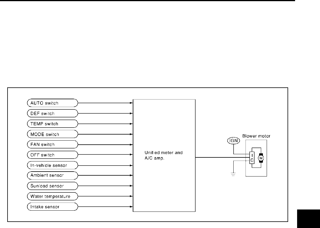
TROUBLE DIAGNOSIS
ATC-93
C
D
E
F
G
H
I
K
L
M
A
B
ATC
Revision; 2004 April 2003 FX
SYSTEM DESCRIPTION
Component Parts
Fan speed control system components are:
●Unified meter and A/C amp.
●A/C LAN system (PBR built-in mode door motor and air mix door motor)
●In-vehicle sensor
●Ambient sensor
●Sunload sensor
●Intake sensor
System Operation
Automatic Mode
In the automatic mode, the blower motor speed is calculated by the unified meter and A/C amp. based on
input from the PBR, in-vehicle sensor, sunload sensor, intake sensor and ambient sensor.
When the air flow is increased, the duty ratio of the blower fan motor′s drive signal is changed at 8%/sec. to
prevent a sudden increase in air flow.
In addition to manual air flow control and the usual automatic air flow control, starting air flow control, low
water temperature starting control and high passenger compartment temperature starting control are avail-
able.
RJIA1995E
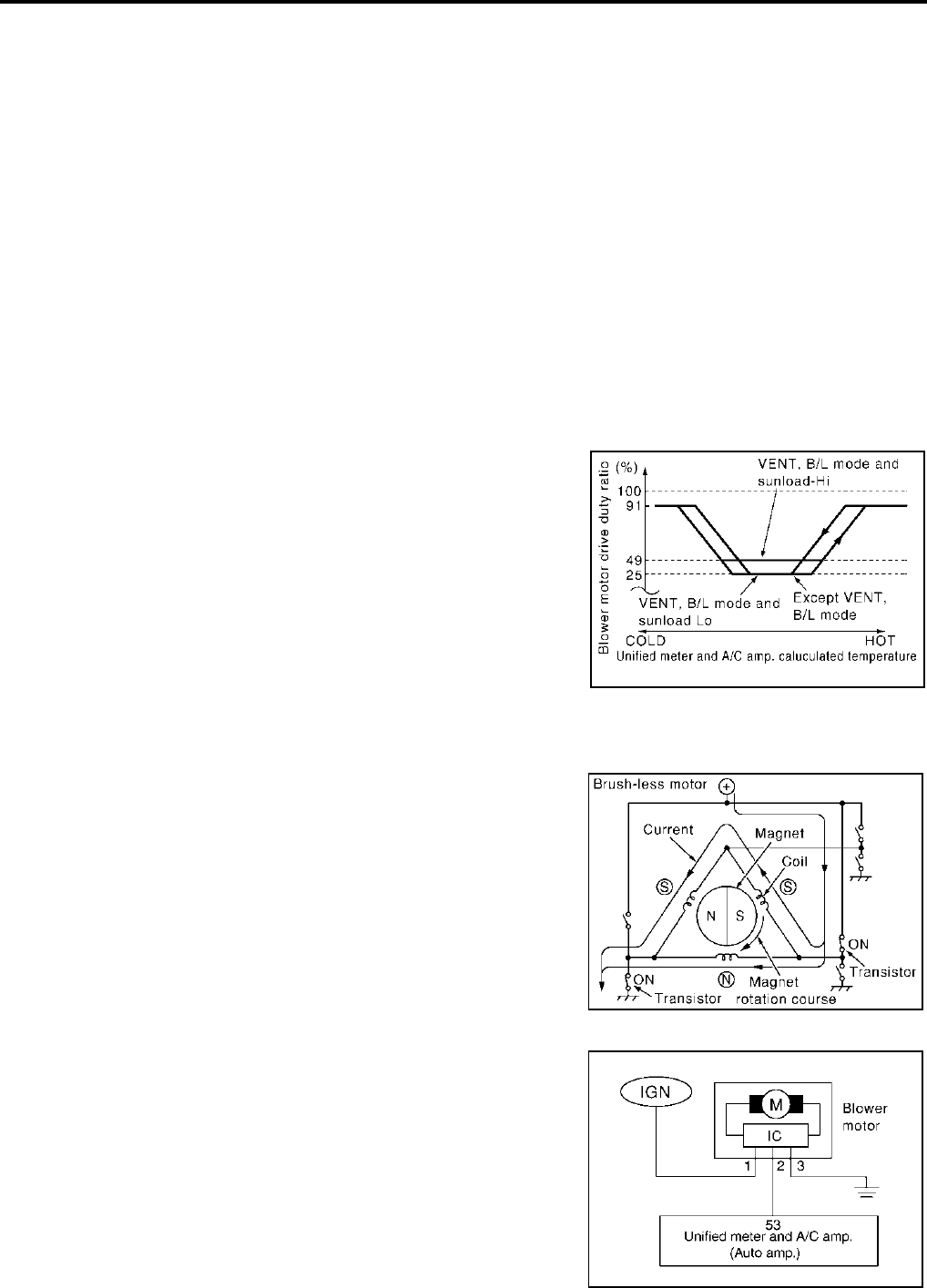
ATC-94
TROUBLE DIAGNOSIS
Revision; 2004 April 2003 FX
Starting Fan Speed Control
Start Up From COLD SOAK Condition (Automatic mode)
In a cold start up condition where the engine coolant temperature is below 56°C (133°F), the blower will not
operate for a short period of time (up to 150 seconds). The exact start delay time varies depending on the
ambient and engine coolant temperature.
In the most extreme case (very low ambient) the blower starting delay will be 150 seconds as described
above. After this delay, the blower will operate at low speed until the engine coolant temperature rises above
56°C (133°F), at which time the blower speed will increase to the objective speed.
Start Up From Usual or HOT SOAK Condition (Automatic mode)
The blower will begin operation momentarily after the AUTO switch is pushed. The blower speed will gradually
rise to the objective speed over a time period of 3 seconds or less (actual time depends on the objective
blower speed).
Blower Speed Compensation
Sunload
When the in-vehicle temperature and the set temperature are very close, the blower will be operating at low
speed. The low speed will vary depending on the sunload. During conditions of low or no sunload, the blower
low speed is usual low speed (duty ratio 25%). During high sunload conditions, the display and A/C auto amp.
causes the blower speed to increase (duty ratio 49%).
Fan Speed Control Specification
COMPONENT DESCRIPTION
Brush-less Motor
The blower motor utilizes a brush-less motor with a rotating magnet.
Quietness is improved over previous motors where the brush was
the point of contact and the coil rotated.
DIAGNOSTIC PROCEDURE FOR BLOWER MOTOR
SYMPTOM: Blower motor operation is malfunctioning under starting
fan speed control.
RJIA1996E
ZHA152H
SJIA0266E
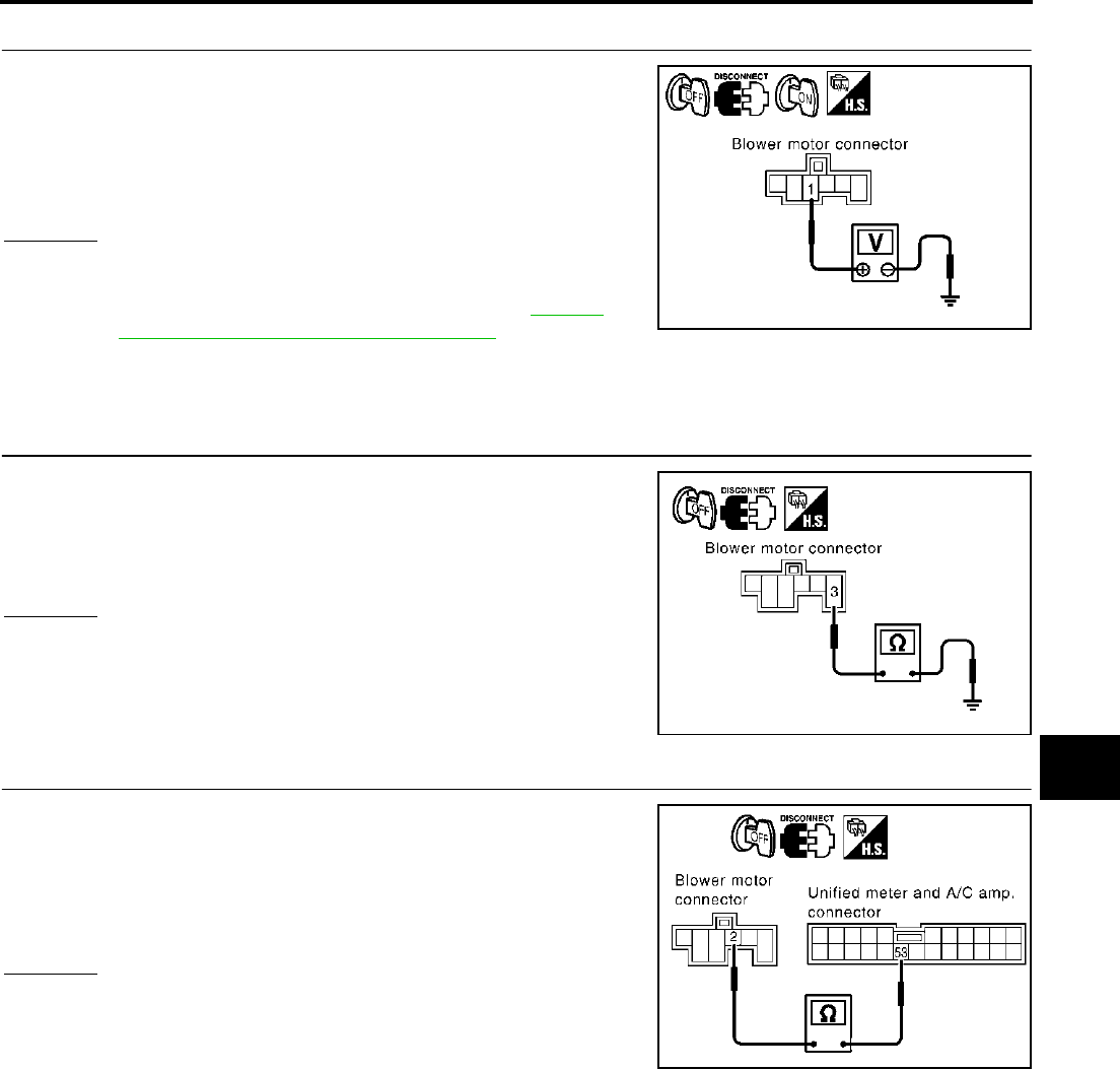
TROUBLE DIAGNOSIS
ATC-95
C
D
E
F
G
H
I
K
L
M
A
B
ATC
Revision; 2004 April 2003 FX
1. CHECK POWER SUPPLY FOR BLOWER MOTOR
1. Disconnect blower motor connector.
2. Turn ignition switch ON.
3. Check voltage between blower motor harness connector M78
terminal 1 (L/W) and ground.
OK or NG
OK >> GO TO 2.
NG >> Check power supply circuit and 15A fuses [Nos. 10 and
11, located in the fuse block (J/B)]. Refer to PG-98,
"FUSE BLOCK - JUNCTION BOX (J/B)" .
●If OK, check for open circuit in wiring harness. Repair or replace as necessary.
●If NG, replace fuse and check wiring harness for short circuit. Repair or replace as necessary.
2. CHECK BLOWER MOTOR GROUND CIRCUIT
1. Turn ignition switch OFF.
2. Check continuity between blower motor harness connector M78
terminal 3 (B) and ground.
OK or NG
OK >> GO TO 3.
NG >> Repair harness or connector.
3. CHECK CIRCUIT CONTINUITY BETWEEN BLOWER MOTOR AND UNIFIED METER AND A/C AMP.
1. Disconnect unified meter and A/C amp. connector.
2. Check continuity between blower motor harness connector M78
terminal 2 (G) and unified meter and A/C amp. harness connec-
tor M57 terminal 53 (G).
OK or NG
OK >> GO TO 4.
NG >> Repair harness or connector.
1 – Ground : Battery voltage
RJIA1997E
3 – Ground : Continuity should exist.
RJIA1998E
2 – 53 : Continuity should exist.
RJIA1999E
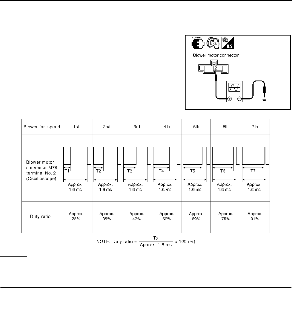
ATC-96
TROUBLE DIAGNOSIS
Revision; 2004 April 2003 FX
4. CHECK UNIFIED METER AND A/C AMP. OUTPUT SIGNAL
1. Reconnect blower motor connector and unified meter and A/C amp. connector.
2. Turn ignition switch ON.
3. Vary the fan speed between Lo and Hi and confirm the duty
ratios between blower motor harness connector M78 terminal 2
(G) and ground using an oscilloscope. Usual No. 2 terminal
drive signal duty ratios are shown in the table below.
OK or NG
OK >> GO TO 5.
NG >> Replace unified meter and A/C amp.
5. CHECK BLOWER MOTOR DRIVE SIGNAL
If the fan air flow does not change, usual No. 2 (G) terminal drive signal duty ratios are shown in the table
above.
OK or NG
OK >> Replace blower motor.
NG >> INSPECTION END
RJIA2000E
RJIA2001E
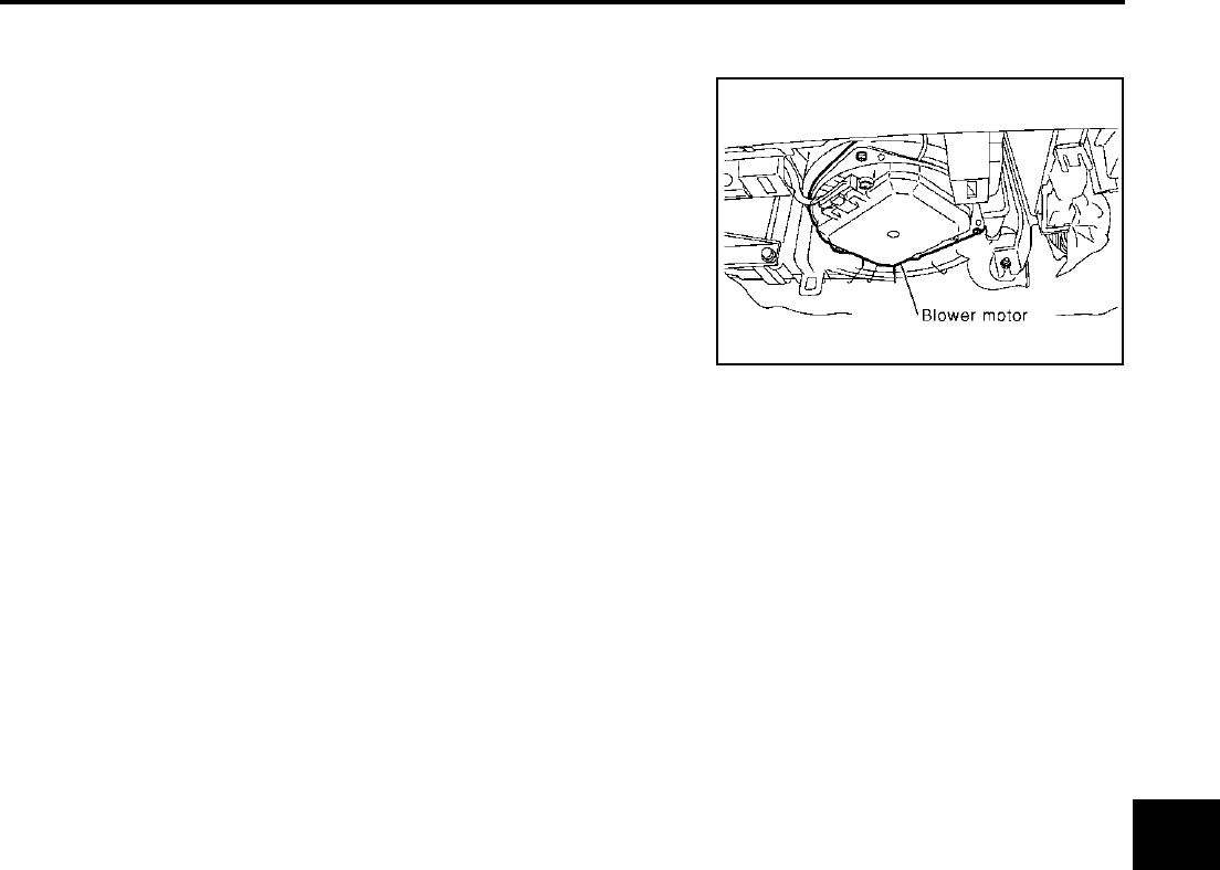
TROUBLE DIAGNOSIS
ATC-97
C
D
E
F
G
H
I
K
L
M
A
B
ATC
Revision; 2004 April 2003 FX
COMPONENT INSPECTION
Blower Motor
Confirm smooth rotation of the blower motor.
●Ensure that there are no foreign particles inside the blower unit.
RJIA0905E
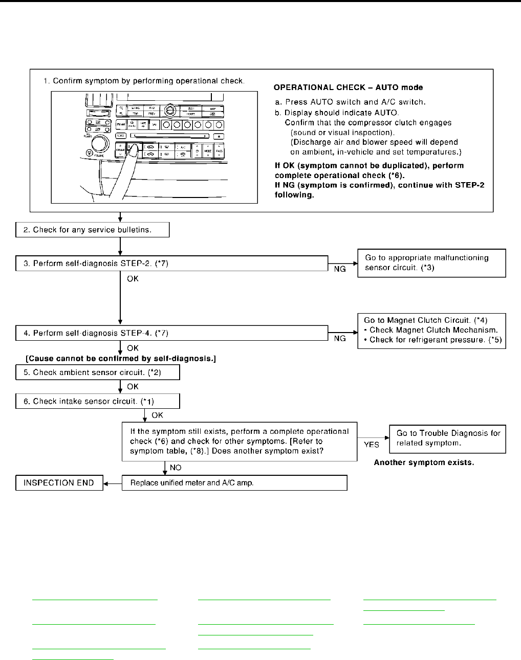
ATC-98
TROUBLE DIAGNOSIS
Revision; 2004 April 2003 FX
Magnet Clutch Circuit AJS0014Y
SYMPTOM: Magnet clutch does not engage.
INSPECTION FLOW
*1 ATC-125, "Intake Sensor Circuit".*2ATC-116, "Ambient Sensor Circuit".*3ATC-67, "FUNCTION CONFIRMA-
TION PROCEDURE", see No. 13.
*4 ATC-98, "Magnet Clutch Circuit".*5ATC-108, "TROUBLE DIAGNOSIS
FOR UNUSUAL PRESSURE".
*6 ATC-75, "Operational Check".
*7 ATC-67, "FUNCTION CONFIRMA-
TION PROCEDURE", see No. 4 to 6.
*8 ATC-54, "SYMPTOM TABLE".
RJIA2002E
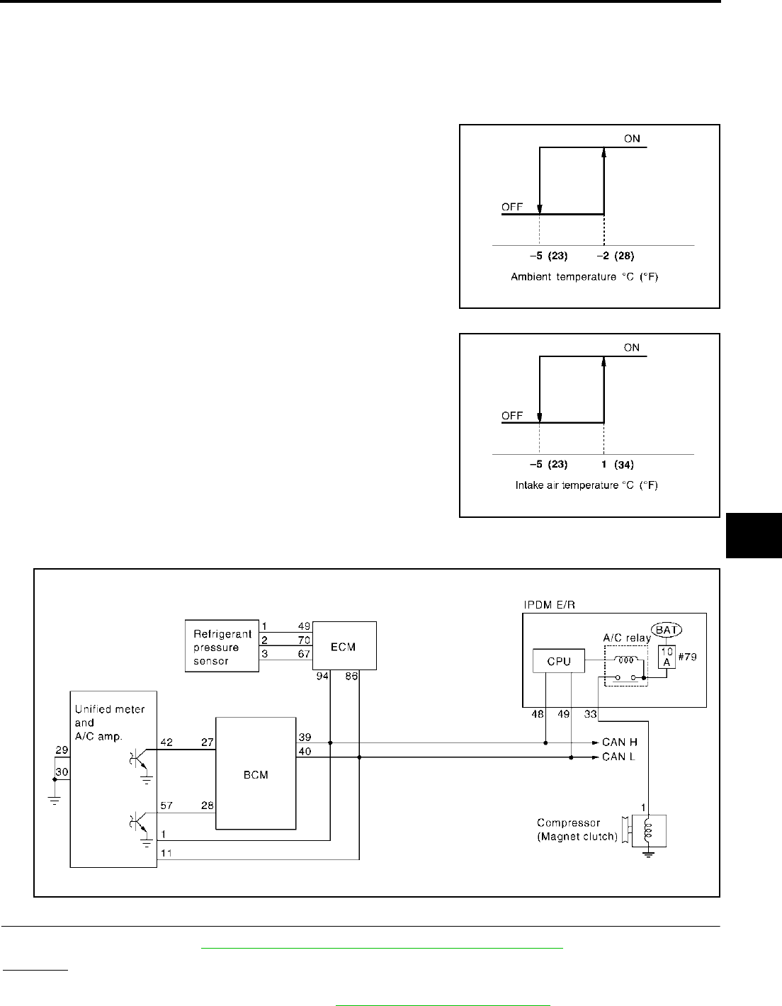
TROUBLE DIAGNOSIS
ATC-99
C
D
E
F
G
H
I
K
L
M
A
B
ATC
Revision; 2004 April 2003 FX
SYSTEM DESCRIPTION
Unified meter and A/C amp. controls compressor operation by ambient temperature, intake air temperature
and signal from ECM.
Low Temperature Protection Control
Unified meter and A/C amp. will turn the compressor ON or OFF as determined by a signal detected by ambi-
ent sensor and intake sensor.
When ambient temperature is higher than −2°C (28°F), the compres-
sor turns ON. The compressor turns OFF when ambient temperature
is lower than −5°C (23°F).
When intake air temperature is higher than 1°C (34°F), the compres-
sor turns ON. The compressor turns OFF when intake air tempera-
ture is lower than −5°C (23°F).
DIAGNOSTIC PROCEDURE FOR MAGNET CLUTCH
SYMPTOM: Magnet clutch does not engage when A/C switch is ON.
1. CHECK INTAKE SENSOR CIRCUIT
Check intake sensor. Refer to ATC-67, "FUNCTION CONFIRMATION PROCEDURE" , see No. 11.
OK or NG
OK >> GO TO 2.
NG >> Malfunctioning intake sensor: Refer to ATC-125, "Intake Sensor Circuit" .
RHA094GB
SJIA0267E
RJIA2003E
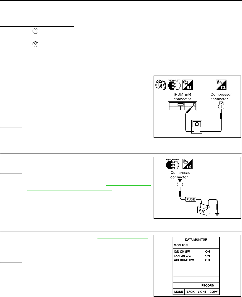
ATC-100
TROUBLE DIAGNOSIS
Revision; 2004 April 2003 FX
2. PERFORM AUTO ACTIVE TEST
Refer to PG-39, "Auto Active Test" .
Does the magnet clutch operate?
YES >> ●WITH CONSULT-II
GO TO 5.
●WITHOUT CONSULT-II
GO TO 6.
NO >> Check 10A fuse (No. 79, located in IPDM E/R), and GO TO 3.
3. CHECK CIRCUIT CONTINUITY BETWEEN IPDM E/R AND COMPRESSOR
1. Turn ignition switch OFF.
2. Disconnect IPDM E/R connector and compressor (magnet
clutch) connector.
3. Check continuity between IPDM E/R harness connector E8 ter-
minal 33 (L) and compressor harness connector F2 terminal 1
(L).
OK or NG
OK >> GO TO 4.
NG >> Repair harness or connector.
4. CHECK MAGNET CLUTCH CIRCUIT
Check for operation sound when applying battery voltage direct cur-
rent to terminal.
OK or NG
OK >> Replace IPDM E/R.
NG >> Replace magnet clutch. Refer to ATC-155, "Removal
and Installation of Compressor Clutch" .
5. CHECK BCM INPUT (COMPRESSOR ON) SIGNAL
Check compressor ON/OFF signal. Refer to ATC-52, "CONSULT-II" .
OK or NG
OK >> GO TO 8.
NG >> GO TO 6.
33 – 1 : Continuity should exist.
RJIA2004E
RJIA2005E
A/C SW ON : AIR COND SW ON
A/C SW OFF : AIR COND SW OFF
RJIA1111E
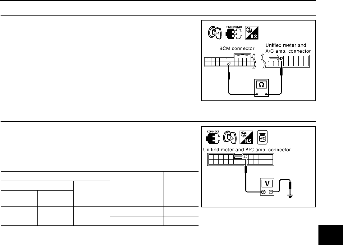
TROUBLE DIAGNOSIS
ATC-101
C
D
E
F
G
H
I
K
L
M
A
B
ATC
Revision; 2004 April 2003 FX
6. CHECK CIRCUIT CONTINUITY BETWEEN BCM AND UNIFIED METER AND A/C AMP.
1. Turn ignition switch OFF.
2. Disconnect BCM connector and unified meter and A/C amp.
connector.
3. Check continuity between BCM harness connector M3 terminal
27 (R/Y) and unified meter and A/C amp. harness connector
M57 terminal 42 (R/Y).
OK or NG
OK >> GO TO 7.
NG >> Repair harness or connector.
7. CHECK VOLTAGE FOR UNIFIED METER AND A/C AMP. (COMPRESSOR ON SIGNAL)
1. Reconnect BCM connector and unified meter and A/C amp.
connector.
2. Turn ignition switch ON.
3. Check voltage between unified meter and A/C amp. harness
connector M57 terminal 42 (R/Y) and ground.
OK or NG
OK >> GO TO 8.
NG-1 >> If the voltage is approx. 5V when A/C switch is ON: Replace unified meter and A/C amp.
NG-2 >> If the voltage is approx. 0V when A/C switch is OFF: Replace BCM.
27 – 42 : Continuity should exist.
RJIA2006E
Terminals
Condition Voltage
(+)
(−)
Auto amp.
connector
Terminal No.
(wire color)
M57 42 (R/Y) Ground A/C switch: ON Approx. 0V
A/C switch: OFF Approx. 5V
RJIA2007E
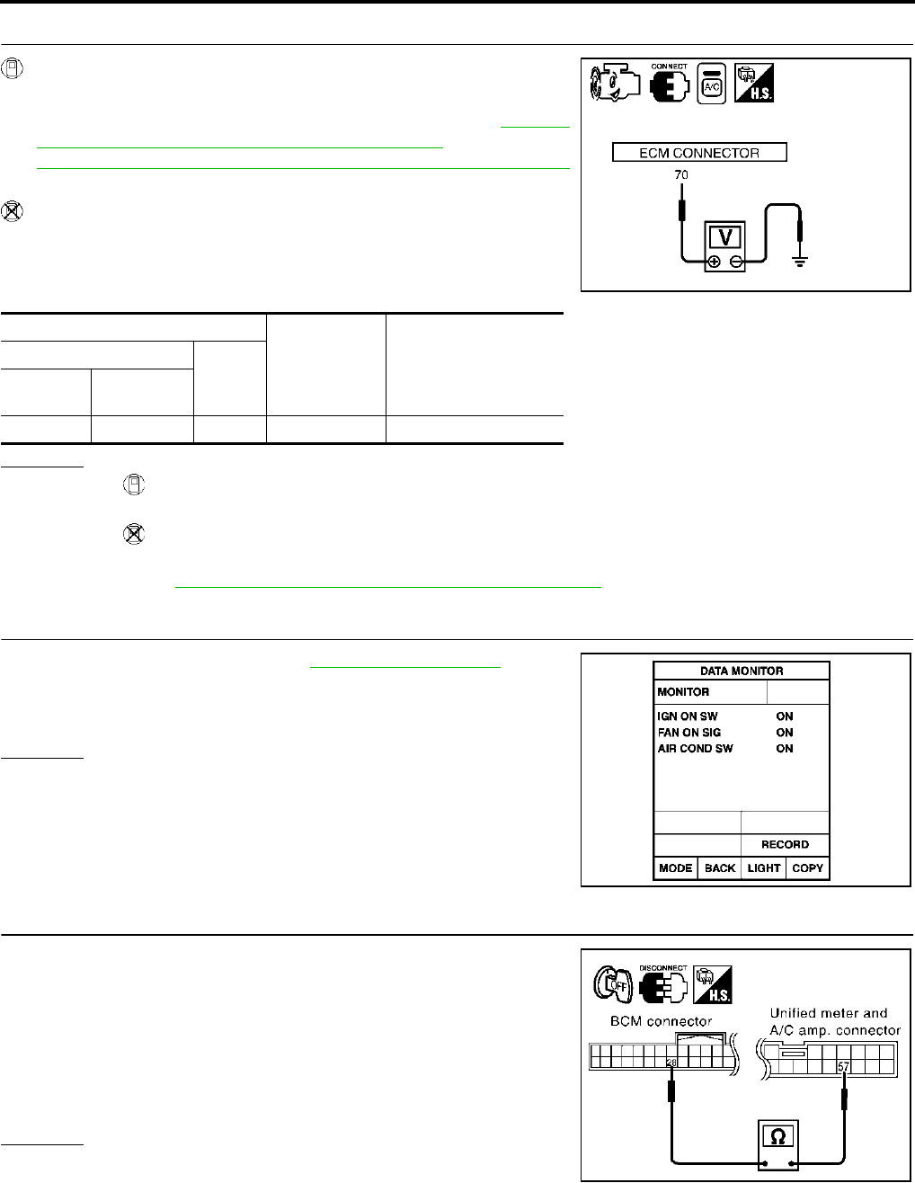
ATC-102
TROUBLE DIAGNOSIS
Revision; 2004 April 2003 FX
8. CHECK REFRIGERANT PRESSURE SENSOR
WITH CONSULT-II
1. Start the engine.
2. Check voltage of refrigerant pressure sensor. Refer to EC-138,
"CONSULT-II Reference Value in Data Monitor" (VQ35DE) or
EC-780, "CONSULT-II Reference Value in Data Monitor"
(VK45DE).
WITHOUT CONSULT-II
1. Start the engine.
2. Check voltage between ECM harness connector F101 terminal
70 (L/R) and ground.
OK or NG
OK >> ●WITH CONSULT-II
GO TO 9.
●WITHOUT CONSULT-II
GO TO 10.
NG >> Refer to EC-1288, "REFRIGERANT PRESSURE SENSOR" .
9. CHECK BCM INPUT (FAN ON) SIGNAL
Check FAN ON/OFF signal. Refer to ATC-52, "CONSULT-II" .
OK or NG
OK >> GO TO 12.
NG >> GO TO 10.
10. CHECK CIRCUIT CONTINUITY BETWEEN BCM AND UNIFIED METER AND A/C AMP.
1. Turn ignition switch OFF.
2. Disconnect BCM connector and unified meter and A/C amp.
connector.
3. Check continuity between BCM harness connector M3 terminal
28 (BR/Y) and unified meter and A/C amp. harness connector
M57 terminal 57 (BR/Y).
OK or NG
OK >> GO TO 11.
NG >> Repair harness or connector.
Terminals
Condition Voltage
(+)
(−)
ECM con-
nector
Terminal No.
(wire color)
F101 70 (L/R) Ground A/C switch: ON Approx. 0.36 - 3.88V
RJIA2008E
FAN SW ON :FAN ON SIG ON
FAN SW OFF :FAN ON SIG OFF
RJIA1111E
28 – 57 : Continuity should exist.
RJIA2009E
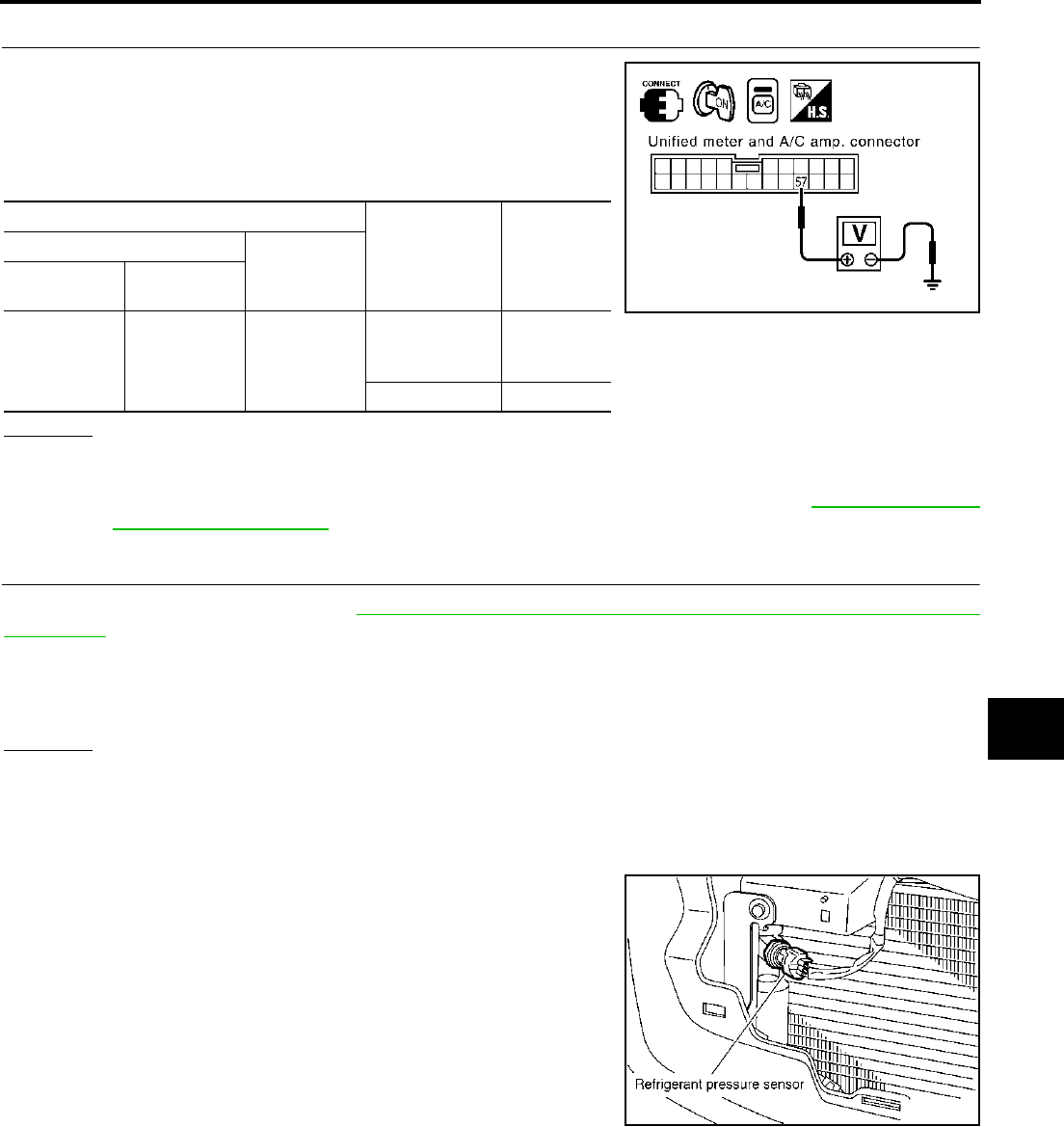
TROUBLE DIAGNOSIS
ATC-103
C
D
E
F
G
H
I
K
L
M
A
B
ATC
Revision; 2004 April 2003 FX
11. CHECK VOLTAGE FOR UNIFIED METER AND A/C AMP. (FAN ON SIGNAL)
1. Reconnect BCM connector and unified meter and A/C amp.
connector.
2. Turn ignition switch ON.
3. Check voltage between unified meter and A/C amp. harness
connector M57 terminal 57 (BR/Y) and ground.
OK or NG
OK >> GO TO 12.
NG-1 >> If the voltage is approx. 5V when blower motor is ON: Replace unified meter and A/C amp.
NG-2 >> If the voltage is approx. 0V when blower motor is OFF: Replace BCM. Refer to BCS-28, "Removal
and Installation of BCM" .
12. CHECK CAN COMMUNICATION
Check CAN communication. Refer to BCS-27, "CAN Communication Inspection Using CONSULT-II (Self-
Diagnosis)" .
●BCM – ECM
●ECM – IPDM E/R
●ECM – Unified meter and A/C amp.
OK or NG
OK >> INSPECTION END
NG >> Repair or replace malfunctioning part(s).
COMPONENT INSPECTION
Refrigerant Pressure Sensor
The refrigerant pressure sensor is attached to the condenser.
Terminals
Condition Voltage
(+)
(-)
Auto amp.
connector
Terminal No.
(wire color)
M57 57 (BR/Y) Ground
A/C switch: ON
Blower motor
operates
Approx. 0V
A/C switch: OFF Approx. 5V
RJIA2010E
RJIA2011E
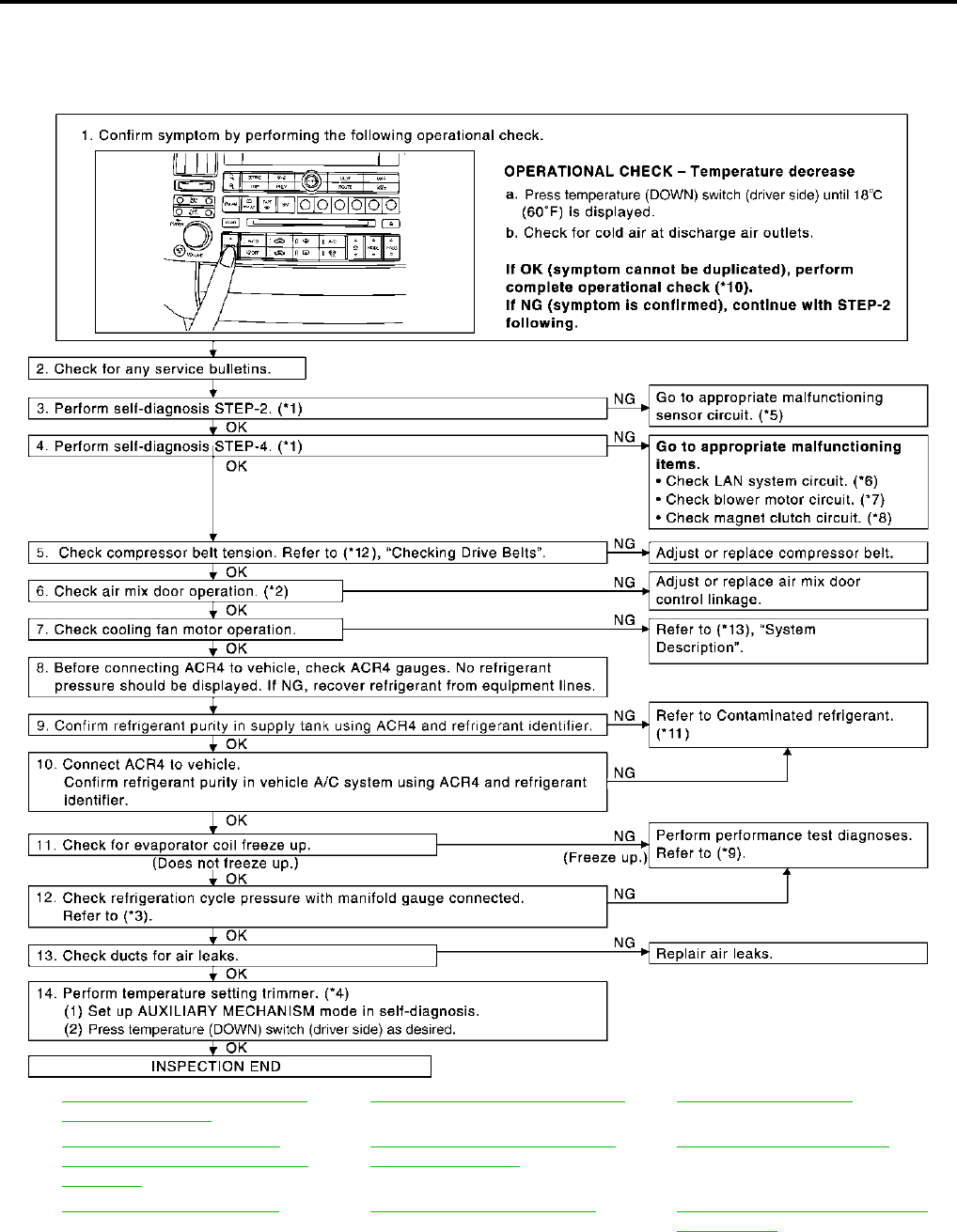
ATC-104
TROUBLE DIAGNOSIS
Revision; 2004 April 2003 FX
Insufficient Cooling AJS0014Z
SYMPTOM: Insufficient cooling
INSPECTION FLOW
*1 ATC-67, "FUNCTION CONFIRMA-
TION PROCEDURE", see No. 4 to 6.
*2 ATC-86, "Air Mix Door Motor Circuit".*3 ATC-107, "Test Reading".
*4 ATC-73, "AUXILIARY MECHA-
NISM: TEMPERATURE SETTING
TRIMMER".
*5 ATC-67, "FUNCTION CONFIRMA-
TION PROCEDURE", see No. 13.
*6 ATC-80, "LAN System Circuit".
*7 ATC-92, "Blower Motor Circuit".*8ATC-98, "Magnet Clutch Circuit".*9ATC-105, "PERFORMANCE TEST
DIAGNOSES".
RJIA2012E
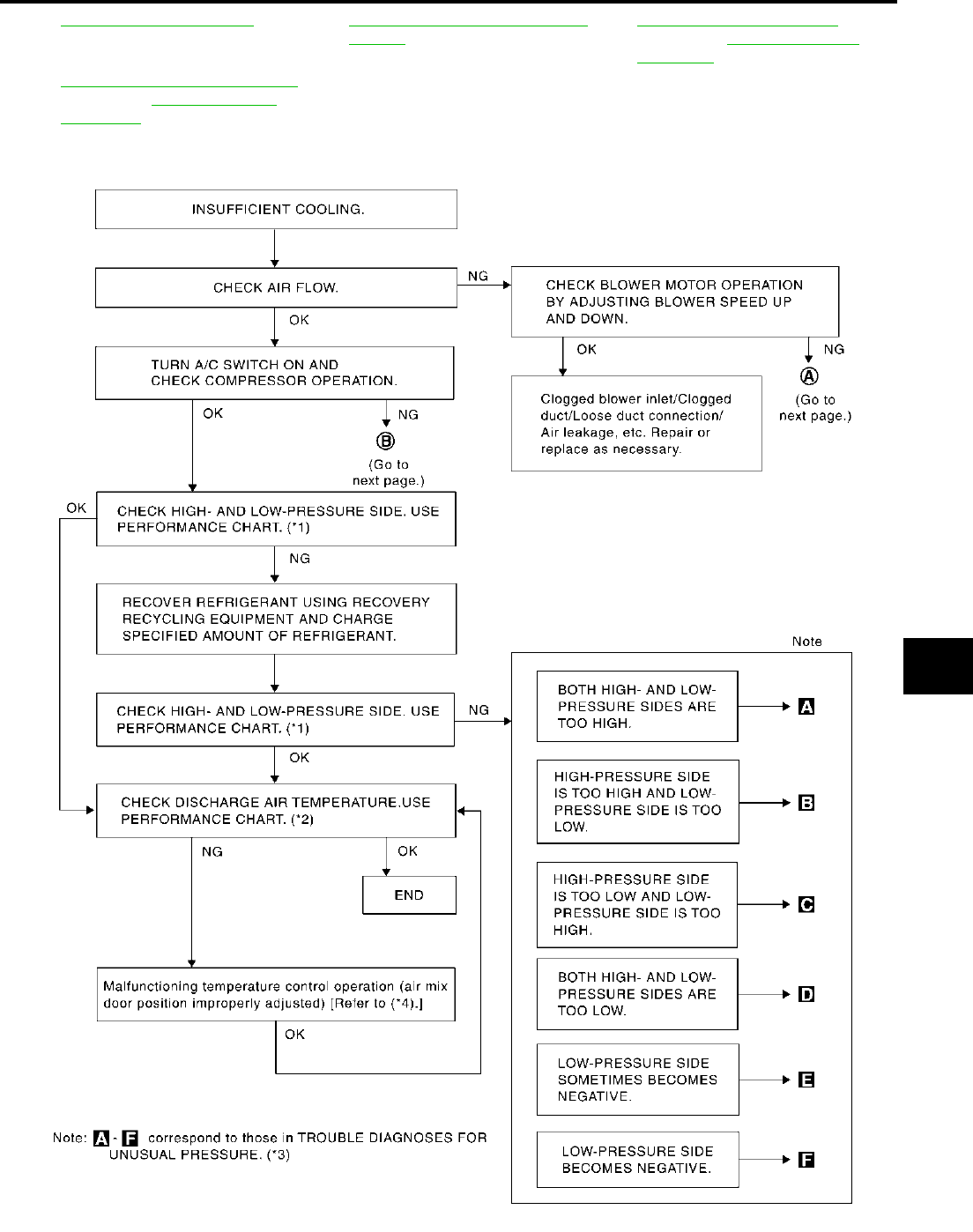
TROUBLE DIAGNOSIS
ATC-105
C
D
E
F
G
H
I
K
L
M
A
B
ATC
Revision; 2004 April 2003 FX
PERFORMANCE TEST DIAGNOSES
*10 ATC-75, "Operational Check".*11ATC-5, "CONTAMINATED REFRIG-
ERANT"
*12 EM-15, "Checking Drive Belts"
(VQ35DE) or EM-167, "Checking
Drive Belts" (VK45DE).
*13 EC-480, "SYSTEM DESCRIPTION"
(VQ35DE) or EC-1142, "System
Description" (VK45DE).
RJIA1601E
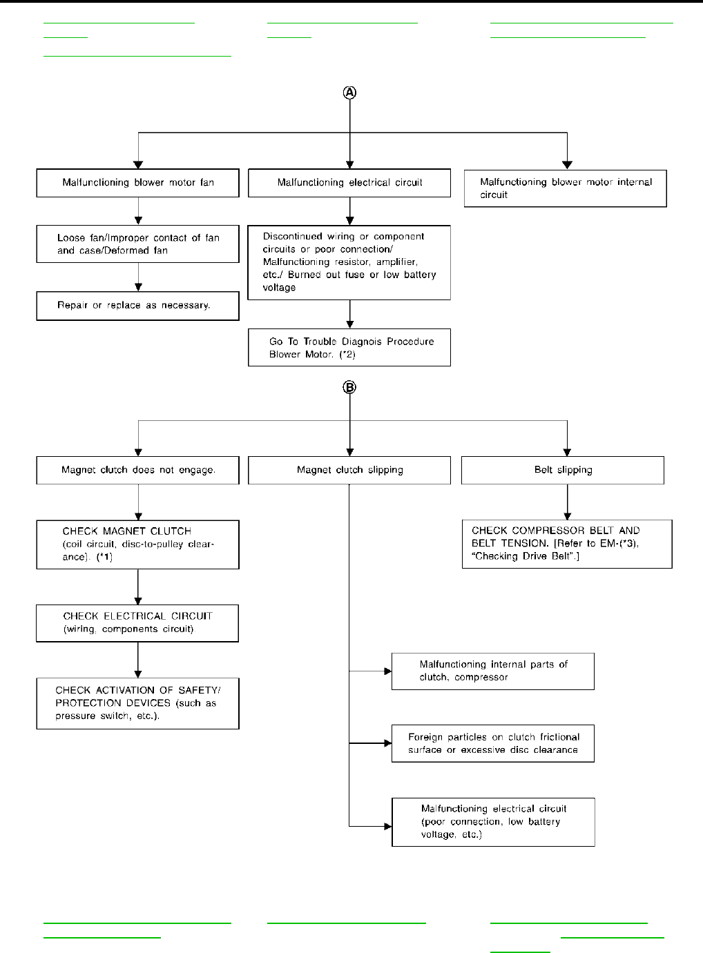
ATC-106
TROUBLE DIAGNOSIS
Revision; 2004 April 2003 FX
*1 ATC-107, "PERFORMANCE
CHART".
*2 ATC-107, "PERFORMANCE
CHART".
*3 ATC-108, "TROUBLE DIAGNOSIS
FOR UNUSUAL PRESSURE".
*4 ATC-86, "Air Mix Door Motor Circuit".
*1 ATC-155, "Removal and Installation
of Compressor Clutch".
*2 ATC-92, "Blower Motor Circuit".*3EM-15, "Checking Drive Belts"
(VQ35DE) or EM-167, "Checking
Drive Belts" (VK45DE).
RJIA1595E
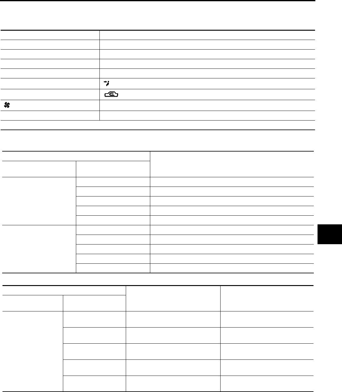
TROUBLE DIAGNOSIS
ATC-107
C
D
E
F
G
H
I
K
L
M
A
B
ATC
Revision; 2004 April 2003 FX
PERFORMANCE CHART
Test Condition
Testing must be performed as follows:
Test Reading
Recirculating-to-discharge Air Temperature Table
Ambient Air Temperature-to-operating Pressure Table
Vehicle location Indoors or in the shade (in a well-ventilated place)
Doors Closed
Door window Open
Hood Open
TEMP. Max. COLD
Mode switch (Ventilation) set
Recirculation (REC) switch (Recirculation) set
Fan (blower) speed Max. speed set
Engine speed Idle speed
Operate the air conditioning system for 10 minutes before taking measurements.
Inside air (Recirculating air) at blower assembly inlet Discharge air temperature at center ventilator
°C (°F)
Relative humidity
%
Air temperature
°C (°F)
50 - 60
20 (68) 11.2 - 13.2 (52 - 56)
25 (77) 12.2 - 14.8 (54 - 59)
30 (86) 15.5 - 18.6 (60 - 65)
35 (95) 21.0 - 24.5 (70 - 76)
40 (104) 28.7 - 32.6 (84 - 91)
60 - 70
20 (68) 13.2 - 15.2 (56 - 59)
25 (77) 14.8 - 17.3 (59 - 63)
30 (86) 18.6 - 21.6 (65 - 71)
35 (95) 24.5 - 28.0 (76 - 82)
40 (104) 32.6 - 36.5 (91 - 98)
Ambient air High-pressure (Discharge side)
kPa (kg/cm2 , psi)
Low-pressure (Suction side)
kPa (kg/cm2 , psi)
Relative humidity
%
Air temperature
°C (°F)
50 - 70
20 (68) 961 - 1,167
(9.8 - 11.9, 139 - 169)
216 - 265
(2.2 - 2.7, 31 - 38)
25 (77) 1,108 - 1,353
(11.3 - 13.8, 161 - 196)
230 - 281
(2.3 - 2.9, 33 - 41)
30 (86) 1,275 - 1,549
(13.0 - 15.8, 185 - 225)
261 - 320
(2.7 - 3.3, 38 - 46)
35 (95) 1,549 - 1,893
(15.8 - 19.3, 225 - 274)
297 - 364
(3.0 - 3.7, 43 - 53)
40 (104) 1,814 - 2,216
(18.5 - 22.6, 263 - 321)
357 - 435
(3.6 - 4.4, 52 - 63)
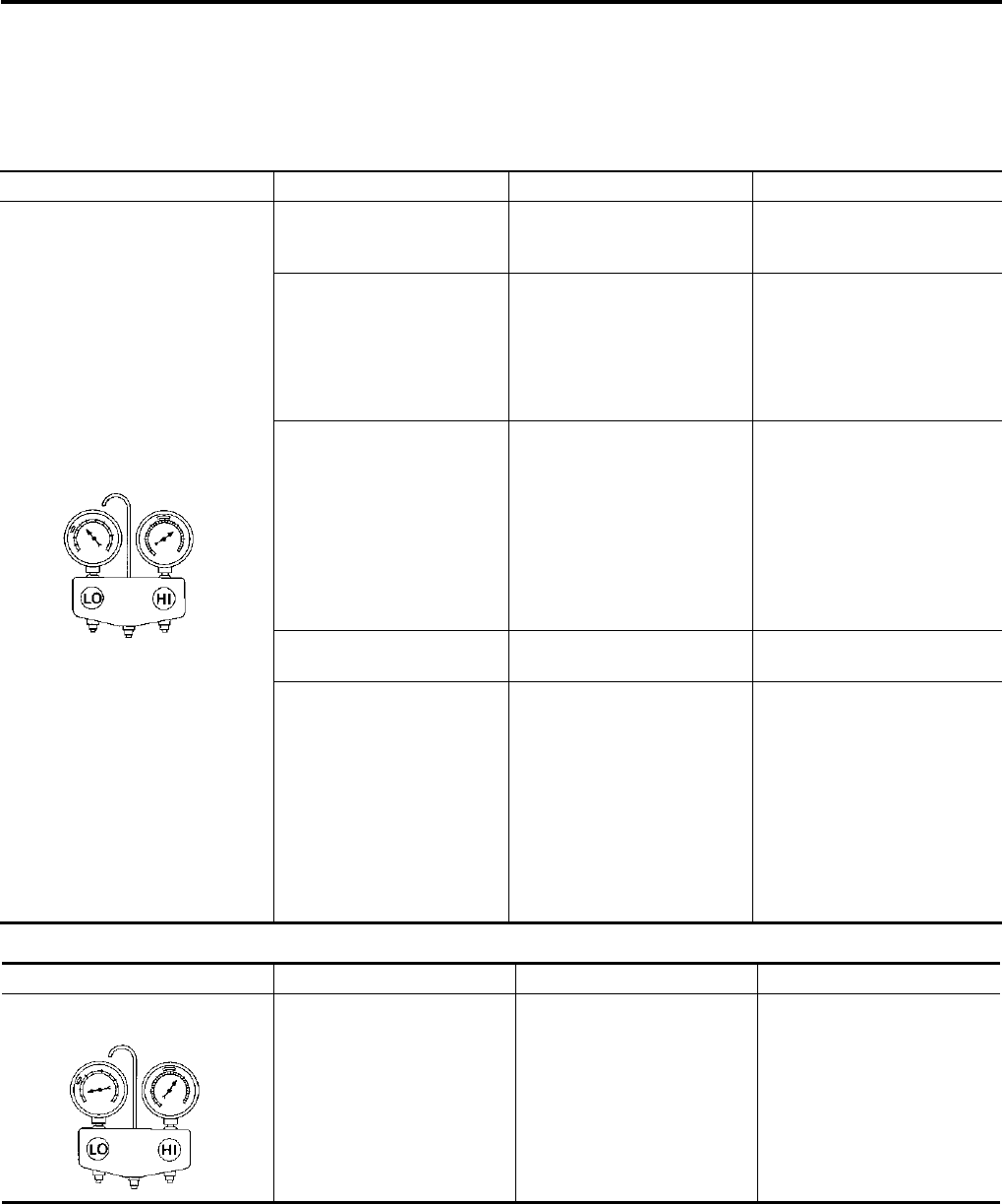
ATC-108
TROUBLE DIAGNOSIS
Revision; 2004 April 2003 FX
TROUBLE DIAGNOSIS FOR UNUSUAL PRESSURE
Whenever system′s high and/or low side pressure is unusual, diagnose using a manifold gauge. The marker
above the gauge scale in the following tables indicates the standard (usual) pressure range. Since the stan-
dard (usual) pressure, however, differs from vehicle to vehicle, refer to above table (Ambient air temperature-
to-operating pressure table).
Both High- and Low-pressure Sides are Too High
High-pressure Side is Too High and Low-pressure Side is Too Low
Gauge indication Refrigerant cycle Probable cause Corrective action
Both high- and low-pressure sides
are too high.
Pressure is reduced soon
after water is splashed on
condenser.
Excessive refrigerant charge
in refrigeration cycle
Reduce refrigerant until speci-
fied pressure is obtained.
Air suction by cooling fan is
insufficient.
Insufficient condenser cooling
performance
↓
1. Condenser fins are clogged.
2. Improper fan rotation of
cooling fan
●Clean condenser.
●Check and repair cooling fan
as necessary.
●Low-pressure pipe is not
cold.
●When compressor is
stopped high-pressure
value quickly drops by
approximately 196 kPa (2
kg/cm2 , 28 psi). It then
decreases gradually there-
after.
Poor heat exchange in con-
denser
(After compressor operation
stops, high pressure
decreases too slowly.)
↓
Air in refrigeration cycle
Evacuate repeatedly and
recharge system.
Engine tends to overheat. Engine cooling systems mal-
function.
Check and repair each engine
cooling system.
●An area of the low-pres-
sure pipe is colder than
areas near the evaporator
outlet.
●Plates are sometimes cov-
ered with frost.
●Excessive liquid refrigerant
on low-pressure side
●Excessive refrigerant dis-
charge flow
●Expansion valve is open a
little compared with the
specification.
↓
Improper expansion valve
adjustment
Replace expansion valve.
AC359A
Gauge indication Refrigerant cycle Probable cause Corrective action
High-pressure side is too high and
low-pressure side is too low.
Upper side of condenser and
high-pressure side are hot,
however, liquid tank is not so
hot.
High-pressure tube or parts
located between compressor
and condenser are clogged or
crushed.
●Check and repair or replace
malfunctioning parts.
●Check lubricant for contami-
nation.
AC360A
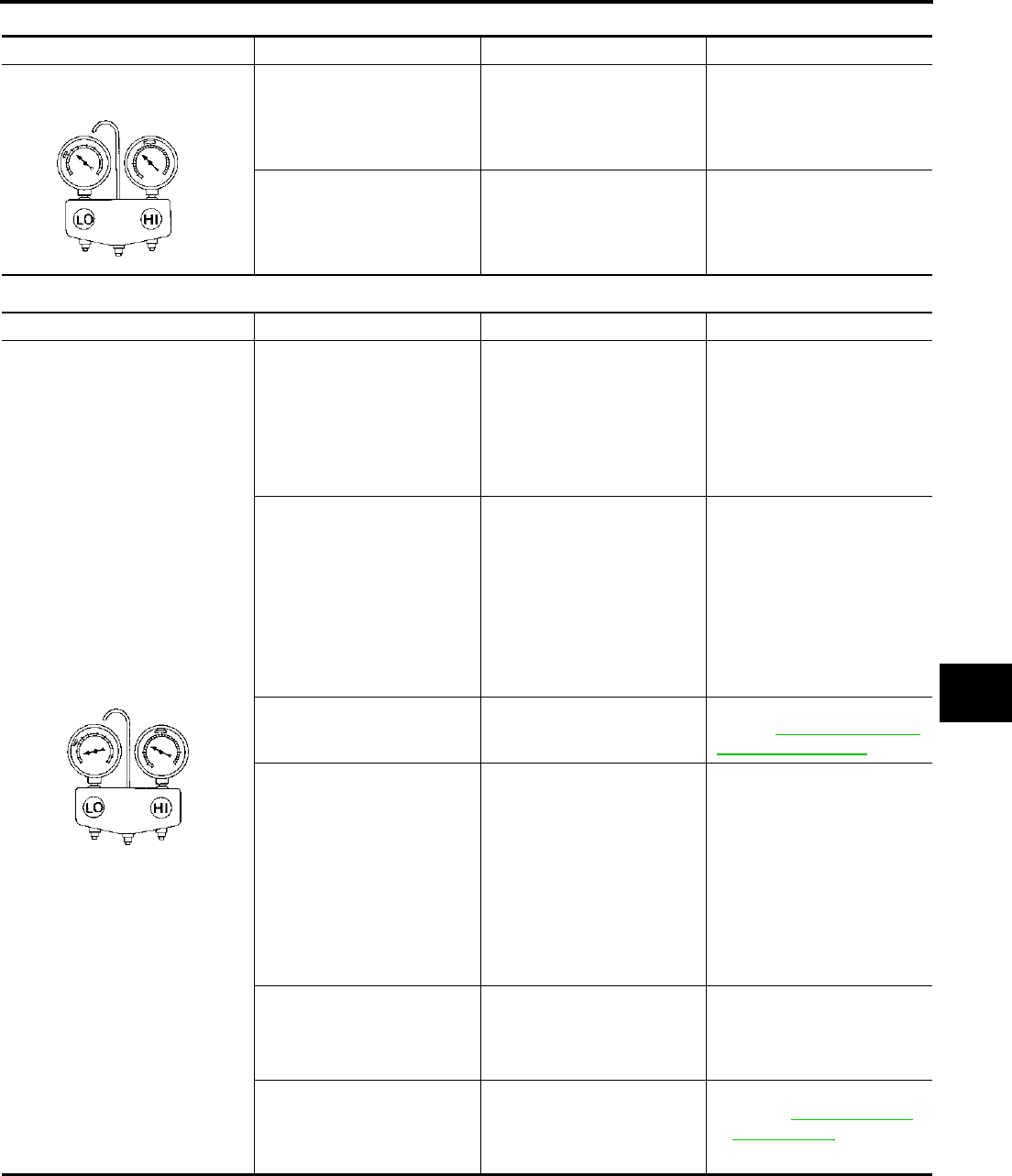
TROUBLE DIAGNOSIS
ATC-109
C
D
E
F
G
H
I
K
L
M
A
B
ATC
Revision; 2004 April 2003 FX
High-pressure Side is Too Low and Low-pressure Side is Too High
Both High- and Low-pressure Sides are Too Low
Gauge indication Refrigerant cycle Probable cause Corrective action
High-pressure side is too low and
low-pressure side is too high. High- and low-pressure sides
become equal soon after com-
pressor operation stops.
Compressor pressure opera-
tion is improper.
↓
Damaged inside compressor
packings
Replace compressor.
No temperature difference
between high- and low-pres-
sure sides
Compressor pressure opera-
tion is improper.
↓
Damaged inside compressor
packings.
Replace compressor.
AC356A
Gauge indication Refrigerant cycle Probable cause Corrective action
Both high- and low-pressure sides
are too low.
●There is a big temperature
difference between receiver
drier outlet and inlet. Outlet
temperature is extremely
low.
●Liquid tank inlet and expan-
sion valve are frosted.
Liquid tank inside is slightly
clogged.
●Replace liquid tank.
●Check lubricant for contami-
nation.
●Temperature of expansion
valve inlet is extremely low
as compared with areas
near liquid tank.
●Expansion valve inlet may
be frosted.
●Temperature difference
occurs somewhere in high-
pressure side.
High-pressure pipe located
between receiver drier and
expansion valve is clogged.
●Check and repair malfunc-
tioning parts.
●Check lubricant for contami-
nation.
Expansion valve and liquid
tank are warm or only cool
when touched.
Low refrigerant charge
↓
Leaking fittings or components
Check refrigerant for leaks.
Refer to ATC-170, "Checking
for Refrigerant Leaks" .
There is a big temperature dif-
ference between expansion
valve inlet and outlet while the
valve itself is frosted.
Expansion valve closes a little
compared with the specifica-
tion.
↓
1. Improper expansion valve
adjustment
2.Malfunctioning expansion
valve
3. Outlet and inlet may be
clogged.
●Remove foreign particles by
using compressed air.
●Check lubricant for contami-
nation.
An area of the low-pressure
pipe is colder than areas near
the evaporator outlet.
Low-pressure pipe is clogged
or crushed.
●Check and repair malfunc-
tioning parts.
●Check lubricant for contami-
nation.
Air flow volume is not enough
or is too low. Evaporator is frozen.
●Check intake sensor circuit.
Refer to ATC-125, "Intake
Sensor Circuit" .
●Replace compressor.
AC353A
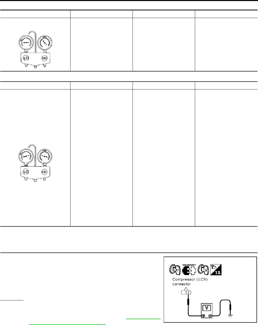
ATC-110
TROUBLE DIAGNOSIS
Revision; 2004 April 2003 FX
Low-pressure Side Sometimes Becomes Negative
Low-pressure Side Becomes Negative
DIAGNOSTIC PROCEDURE FOR INSUFFICIENT COOLING
SYMPTOM: Insufficient cooling
1. CHECK POWER SUPPLY FOR ECV (ELECTRONIC CONTROL VALVE)
1. Disconnect compressor (ECV) connector.
2. Turn ignition switch ON.
3. Check voltage between compressor harness connector F6 ter-
minal 2 (G) and ground.
OK or NG
OK >> GO TO 2.
NG >> Check power supply circuit and 10A fuse [No. 12,
located in the fuse block (J/B)]. Refer to PG-98, "FUSE
BLOCK - JUNCTION BOX (J/B)" .
Gauge indication Refrigerant cycle Probable cause Corrective action
Low-pressure side sometimes
becomes negative. ●Air conditioning system
does not function and does
not cyclically cool the com-
partment air.
●The system constantly func-
tions for a certain period of
time after compressor is
stopped and restarted.
Refrigerant does not dis-
charge cyclically.
↓
Moisture is frozen at expan-
sion valve outlet and inlet.
↓
Water is mixed with refriger-
ant.
●Drain water from refrigerant
or replace refrigerant.
●Replace liquid tank.
AC354A
Gauge indication Refrigerant cycle Probable cause Corrective action
Low-pressure side becomes nega-
tive.
Liquid tank or front/rear side of
expansion valve′s pipe is
frosted or dewed.
High-pressure side is closed
and refrigerant does not flow.
↓
Expansion valve or liquid tank
is frosted.
Leave the system at rest until
no frost is present. Start it
again to check whether or not
the malfunction is caused by
water or foreign particles.
●If water is the cause, initially
cooling is okay. Then the
water freezes causing a
blockage. Drain water from
refrigerant or replace refrig-
erant.
●If due to foreign particles,
remove expansion valve
and remove the particles
with dry and compressed air
(not shop air).
●If either of the above meth-
ods cannot correct the mal-
function, replace expansion
valve.
●Replace liquid tank.
●Check lubricant for contami-
nation.
AC362A
2 – ground : Battery voltage
RJIA2294E
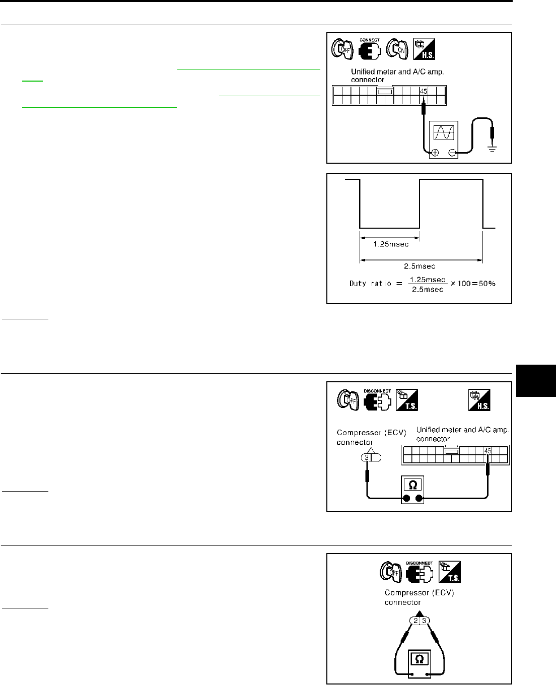
TROUBLE DIAGNOSIS
ATC-111
C
D
E
F
G
H
I
K
L
M
A
B
ATC
Revision; 2004 April 2003 FX
2. CHECK ECV CONTROL SIGNAL
1. Turn ignition switch OFF.
2. Reconnect compressor (ECV) connector.
3. Perform self-diagnosis. Refer to ATC-66, "Self-diagnosis Func-
tion" .
4. Set in self-diagnosis STEP-45. Refer to ATC-67, "FUNCTION
CONFIRMATION PROCEDURE" .
5. Confirm the unified meter and A/C amp. harness connector M57
terminal 45 (PU/W) duty ratio using an oscilloscope.
OK or NG
OK >> Replace compressor.
NG >> GO TO 3.
3. CHECK CIRCUIT CONTINUITY BETWEEN ECV AND UNIFIED METER AND A/C AMP.
1. Turn ignition switch OFF.
2. Disconnect compressor (ECV) and unified meter and A/C amp.
connector.
3. Check continuity between compressor (ECV) harness connector
F6 terminal 3 (PU) and unified meter and A/C amp. harness
connector M57 terminal 45 (PU/W).
OK or NG
OK >> GO TO 4.
NG >> Repair harness or connector.
4. CHECK ECV
Check continuity between compressor (ECV) connector F6 terminals
2 and 3.
OK or NG
OK >> Replace unified meter and A/C amp.
NG >> Replace compressor.
RJIA2295E
RJIA1475E
3 – 45 : Continuity should exist.
RJIA2296E
2 – 3 : Continuity should exist.
RJIA2297E
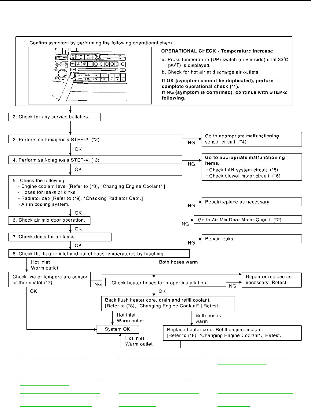
ATC-112
TROUBLE DIAGNOSIS
Revision; 2004 April 2003 FX
Insufficient Heating AJS00150
SYMPTOM: Insufficient heating
INSPECTION FLOW
*1 ATC-75, "Operational Check".*2ATC-86, "Air Mix Door Motor Circuit".*3 ATC-67, "FUNCTION CONFIRMA-
TION PROCEDURE", see No. 4 to
6.
*4 ATC-67, "FUNCTION CONFIRMA-
TION PROCEDURE", see No. 13.
*5 ATC-80, "LAN System Circuit".*6ATC-92, "Blower Motor Circuit".
*7 EC-197, "DTC P0117, P0118 ECT
SENSOR" (VQ35DE) or EC-845,
"DTC P0117, P0118 ECT SEN-
SOR" (VK45DE).
*8 CO-11, "Changing Engine Coolant"
(VQ35DE) or CO-35, "Changing
Engine Coolant" (VK45DE).
*9 CO-15, "Checking Radiator Cap"
(VQ35DE) or CO-40, "Checking
Radiator Cap" (VK45DE).
RJIA2013E
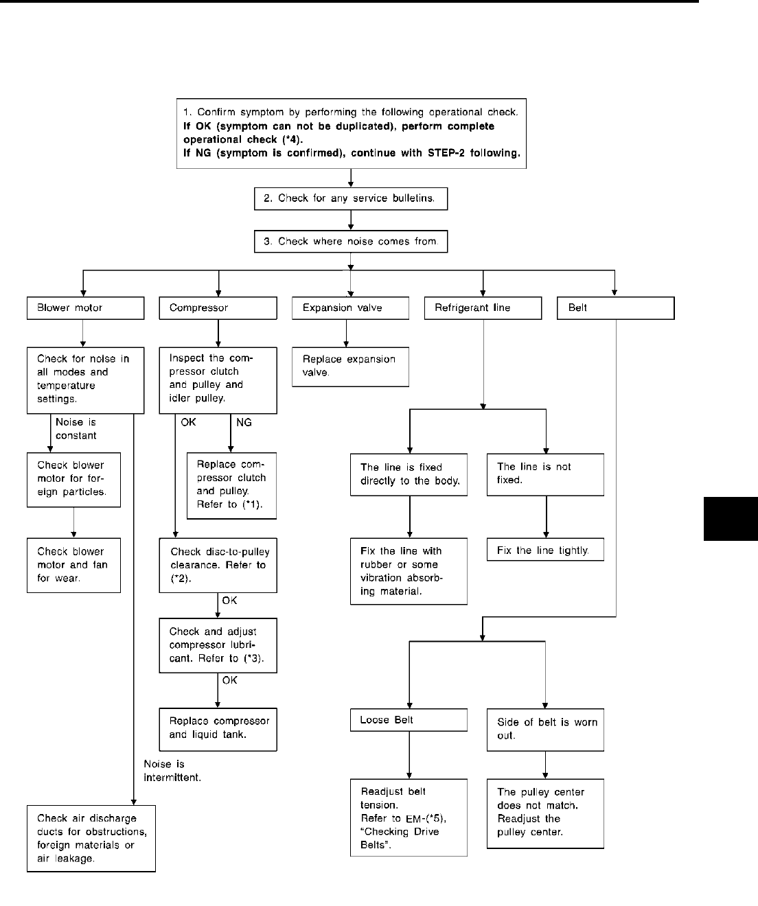
TROUBLE DIAGNOSIS
ATC-113
C
D
E
F
G
H
I
K
L
M
A
B
ATC
Revision; 2004 April 2003 FX
Noise AJS00151
SYMPTOM: Noise
INSPECTION FLOW
RJIA1596E
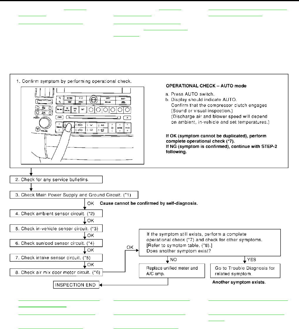
ATC-114
TROUBLE DIAGNOSIS
Revision; 2004 April 2003 FX
Self-diagnosis AJS00152
SYMPTOM: Self-diagnosis cannot be performed.
INSPECTION FLOW
*1 Compressor Clutch, ATC-155,
"REMOVAL" .
*2 Compressor Clutch, ATC-157,
"INSTALLATION" .
*3 ATC-27, "Maintenance of Lubricant
Quantity in Compressor".
*4 ATC-75, "Operational Check".*5EM-15, "Checking Drive Belts"
(VQ35DE) or EM-167, "Checking
Drive Belts" (VK45DE).
*1 ATC-77, "Power Supply and Ground
Circuit for Auto Amp.".
*2 ATC-116, "Ambient Sensor Circuit".*3ATC-119, "In-vehicle Sensor Circuit".
*4 ATC-122, "Sunload Sensor Circuit".*5ATC-125, "Intake Sensor Circuit".*6ATC-88, "Air Mix Door Motor PBR
Circuit".
*7 ATC-75, "Operational Check".*8ATC-54, "SYMPTOM TABLE".
RJIA2014E

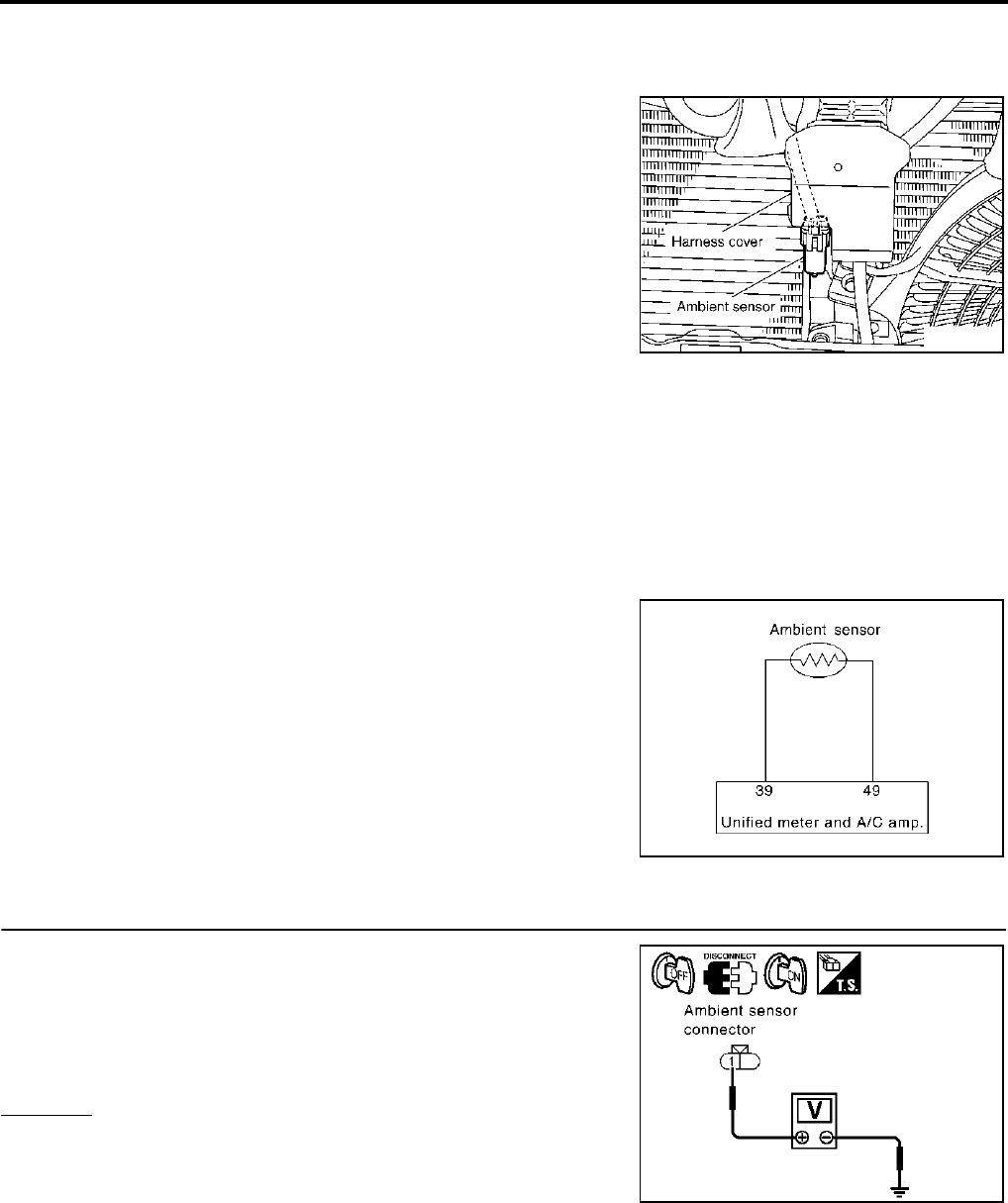
ATC-116
TROUBLE DIAGNOSIS
Revision; 2004 April 2003 FX
Ambient Sensor Circuit AJS00154
COMPONENT DESCRIPTION
Ambient Sensor
The ambient sensor is attached on the hood lock stay. It detects
ambient temperature and converts it into a resistance value which is
then input into the unified meter and A/C amp.
AMBIENT TEMPERATURE INPUT PROCESS
The unified meter and A/C amp. includes a processing circuit for the ambient sensor input. However, when the
temperature detected by the ambient sensor increases quickly, the processing circuit retards the unified meter
and A/C amp. function. It only allows the unified meter and A/C amp. to recognize an ambient temperature
increase of 0.33°C (0.6°F) per 100 seconds.
As an example, consider stopping for a cup of coffee after high speed driving. Although the actual ambient
temperature has not changed, the temperature detected by the ambient sensor will increase. This is because
the heat from the engine compartment can radiate to the front grille area, location of the ambient sensor.
DIAGNOSTIC PROCEDURE FOR AMBIENT SENSOR
SYMPTOM: Ambient sensor circuit is open or shorted. (21 or − 21 is
indicated on unified meter and A/C amp. As a result of performing
Self-diagnosis STEP-2.)
1. CHECK VOLTAGE BETWEEN AMBIENT SENSOR AND GROUND
1. Disconnect ambient sensor connector.
2. Turn ignition switch ON.
3. Check voltage between ambient sensor harness connector E34
terminal 1 (Y) and ground.
OK or NG
OK >> GO TO 2.
NG >> GO TO 4.
RJIA2016E
RJIA1461E
1 – Ground : Approx. 5V
RJIA2017E
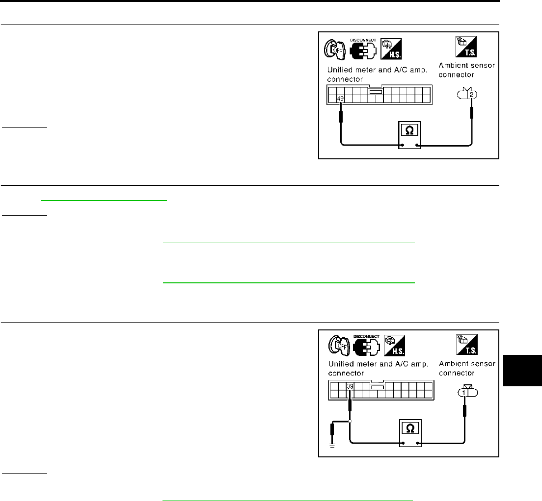
TROUBLE DIAGNOSIS
ATC-117
C
D
E
F
G
H
I
K
L
M
A
B
ATC
Revision; 2004 April 2003 FX
2. CHECK CIRCUIT CONTINUITY BETWEEN AMBIENT SENSOR AND UNIFIED METER AND A/C AMP.
1. Turn ignition switch OFF.
2. Disconnect unified meter and A/C amp. connector.
3. Check continuity between ambient sensor harness connector
E34 terminal 2 (W) and unified meter and A/C amp. harness
connector M57 terminal 49 (W/G).
OK or NG
OK >> GO TO 3.
NG >> Repair harness or connector.
3. CHECK AMBIENT SENSOR
Refer to ATC-118, "Ambient Sensor" .
OK or NG
OK >> 1. Replace unified meter and A/C amp.
2. Go to self-diagnosis ATC-67, "FUNCTION CONFIRMATION PROCEDURE" and perform self-
diagnosis STEP-2. Confirm that code No. 20 is displayed.
NG >> 1. Replace ambient sensor.
2. Go to self-diagnosis ATC-67, "FUNCTION CONFIRMATION PROCEDURE" and perform self-
diagnosis STEP-2. Confirm that code No. 20 is displayed.
4. CHECK CIRCUIT CONTINUITY BETWEEN AMBIENT SENSOR AND UNIFIED METER AND A/C AMP.
1. Turn ignition switch OFF.
2. Disconnect unified meter and A/C amp. connector.
3. Check continuity between ambient sensor harness connector
E34 terminal 1 (Y) and unified meter and A/C amp. harness con-
nector M57 terminal 39 (Y).
4. Check continuity between ambient sensor harness connector
E34 terminal 1 (Y) and ground.
OK or NG
OK >> 1. Replace unified meter and A/C amp.
2. Go to self-diagnosis ATC-67, "FUNCTION CONFIRMATION PROCEDURE" and perform self-
diagnosis STEP -2. Confirm that code No. 20 is displayed.
NG >> Repair harness or connector.
2 – 49 : Continuity should exist.
RJIA2018E
1 – 39 : Continuity should exist.
1 – Ground : Continuity should not exist. RJIA2019E
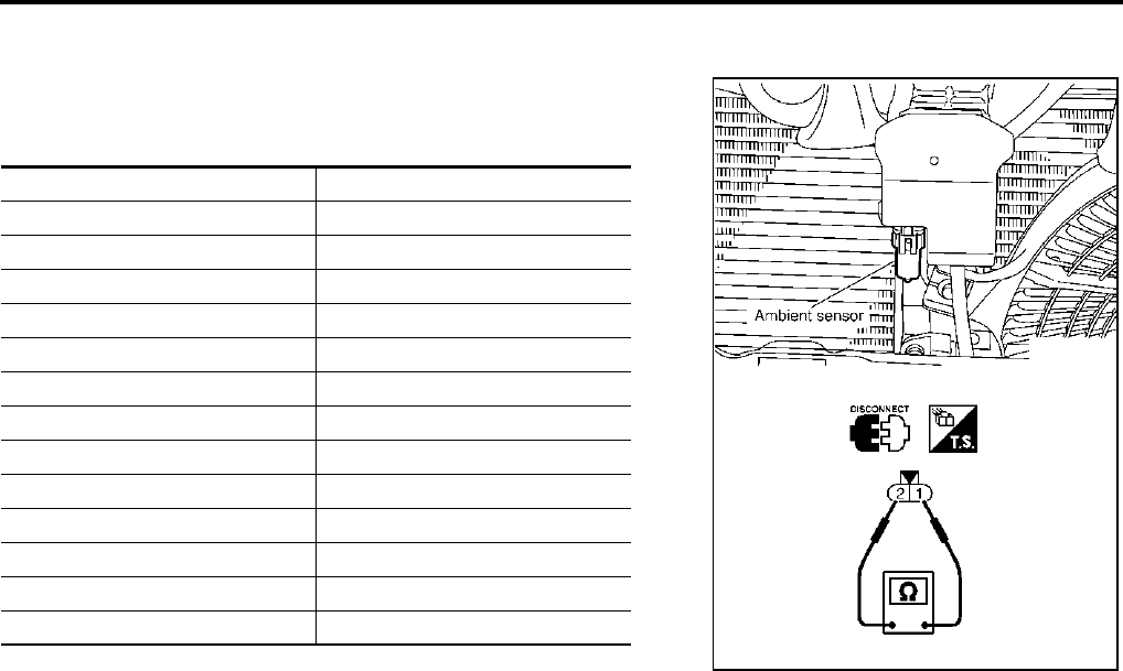
ATC-118
TROUBLE DIAGNOSIS
Revision; 2004 April 2003 FX
COMPONENT INSPECTION
Ambient Sensor
After disconnecting ambient sensor connector, measure resistance
between terminals 2 and 1 at sensor harness side, using the table
below.
If NG, replace ambient sensor.
Temperature °C (°F) Resistance kΩ
−15 (5) 12.73
−10 (14) 9.92
−5 (23) 7.80
0 (32) 6.19
5 (41) 4.95
10 (50) 3.99
15 (59) 3.24
20 (68) 2.65
25 (77) 2.19
30 (86) 1.81
35 (95) 1.51
40 (104) 1.27
45 (113) 1.07
RJIA2020E
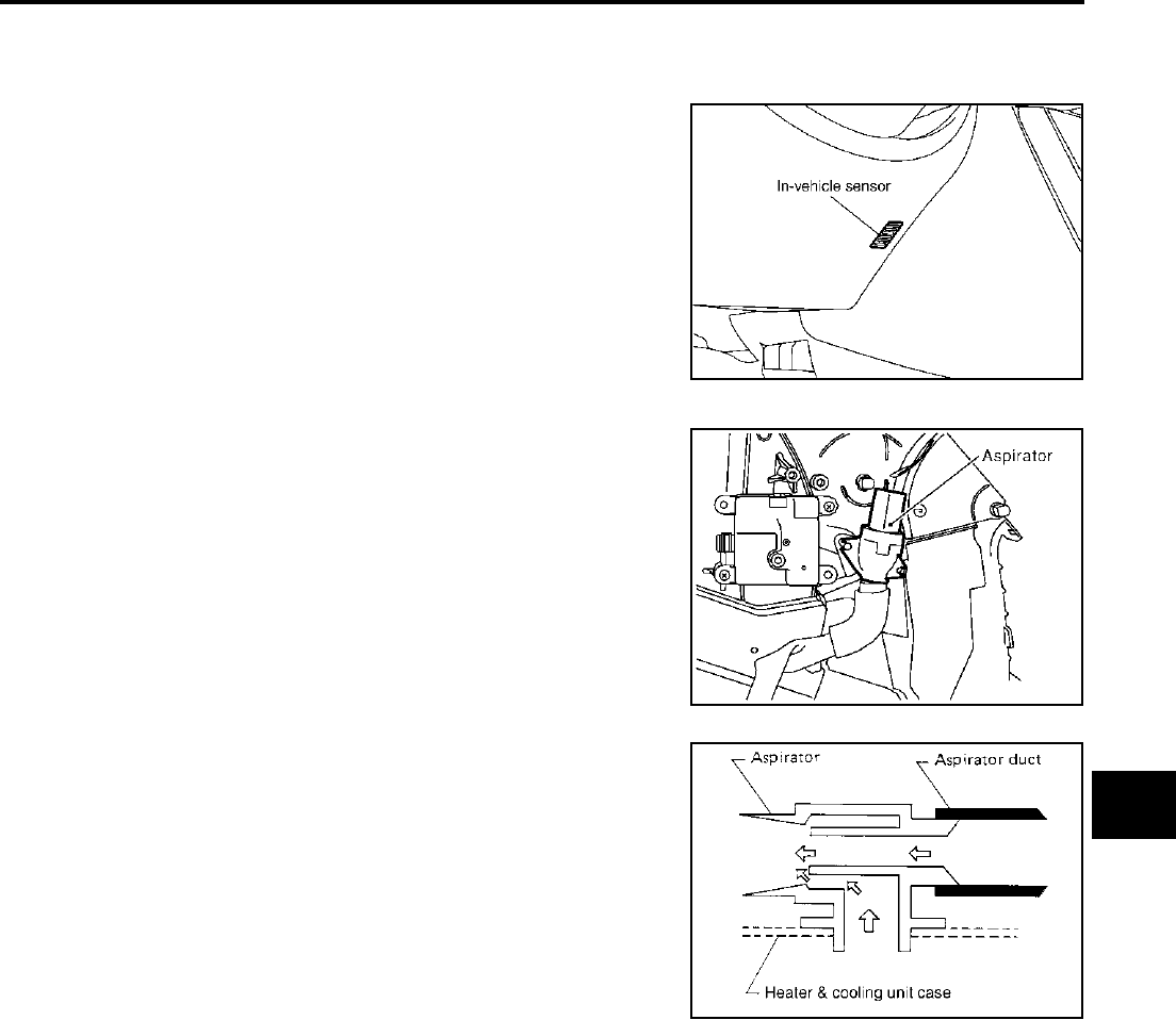
TROUBLE DIAGNOSIS
ATC-119
C
D
E
F
G
H
I
K
L
M
A
B
ATC
Revision; 2004 April 2003 FX
In-vehicle Sensor Circuit AJS00155
COMPONENT DESCRIPTION
In-vehicle Sensor
The in-vehicle sensor is located on instrument driver lower panel. It
converts variations in temperature of compartment air drawn from
the aspirator into a resistance value. It is then input into the unified
meter and A/C amp.
Aspirator
The aspirator is located on driver′s side of heater & cooling unit. It
produces vacuum pressure due to air discharged from the heater &
cooling unit, continuously taking compartment air in the aspirator.
RJIA2021E
RJIA0921E
RJIA1804E
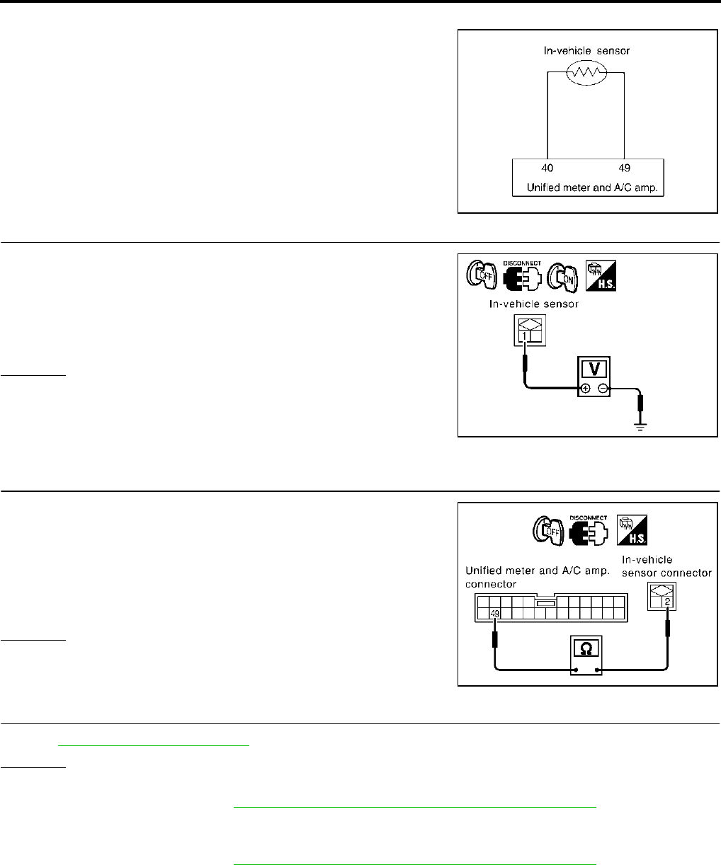
ATC-120
TROUBLE DIAGNOSIS
Revision; 2004 April 2003 FX
DIAGNOSTIC PROCEDURE FOR IN-VEHICLE SENSOR
SYMPTOM: In-vehicle sensor circuit is open or shorted. (22 or −22 is
indicated on unified meter and A/C amp. as a result of performing
Self-diagnosis STEP-2.)
1. CHECK VOLTAGE BETWEEN IN-VEHICLE SENSOR AND GROUND
1. Disconnect in-vehicle sensor connector.
2. Turn ignition switch ON.
3. Check voltage between in-vehicle sensor harness connector
M46 terminal 1 (BR/W) and ground.
OK or NG
OK >> GO TO 2.
NG >> GO TO 4.
2. CHECK CIRCUIT CONTINUITY BETWEEN IN-VEHICLE SENSOR AND UNIFIED METER AND A/C
AMP.
1. Turn ignition switch OFF.
2. Disconnect unified meter and A/C amp. connector.
3. Check continuity between in-vehicle sensor harness connector
M46 terminal 2 (W/G) and unified meter and A/C amp. harness
connector M57 terminal 49 (W/G).
OK or NG
OK >> GO TO 3.
NG >> Repair harness or connector.
3. CHECK IN-VEHICLE SENSOR
Refer to ATC-121, "In-vehicle Sensor" .
OK or NG
OK >> 1. Replace unified meter and A/C amp.
2. Go to self-diagnosis ATC-67, "FUNCTION CONFIRMATION PROCEDURE" and perform self-
diagnosis STEP-2. Confirm that code No. 20 is displayed.
NG >> 1. Replace in-vehicle sensor.
2. Go to self-diagnosis ATC-67, "FUNCTION CONFIRMATION PROCEDURE" and perform self-
diagnosis STEP-2. Confirm that code No. 20 is displayed.
RJIA1452E
1 – Ground : Approx. 5V
RJIA2022E
2 – 49 : Continuity should exist.
RJIA2023E
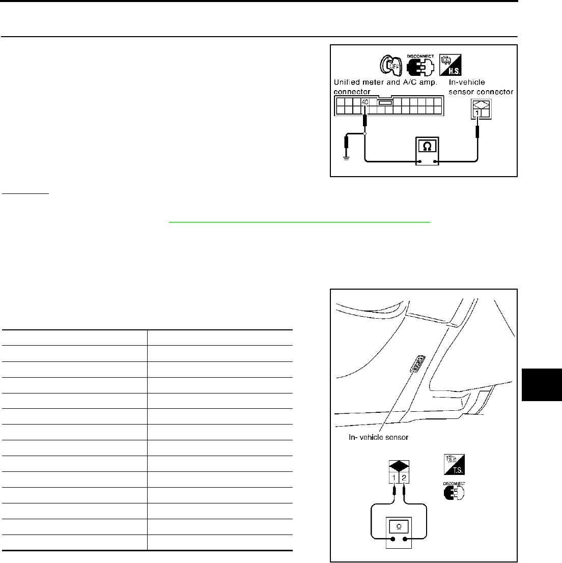
TROUBLE DIAGNOSIS
ATC-121
C
D
E
F
G
H
I
K
L
M
A
B
ATC
Revision; 2004 April 2003 FX
4. CHECK CIRCUIT CONTINUITY BETWEEN IN-VEHICLE SENSOR AND UNIFIED METER AND A/C
AMP.
1. Turn ignition switch OFF.
2. Disconnect unified meter and A/C amp. connector.
3. Check continuity between in-vehicle sensor harness connector
M46 terminal 1 (BR/W) and unified meter and A/C amp. harness
connector M57 terminal 40 (BR/W).
4. Check continuity between in-vehicle sensor harness connector
M46 terminal 1 (BR/W) and ground.
OK or NG
OK >> 1. Replace unified meter and A/C amp.
2. Go to self-diagnosis ATC-67, "FUNCTION CONFIRMATION PROCEDURE" and perform self-
diagnosis STEP-2. Confirm that code No. 20 is displayed.
NG >> Repair harness or connector.
COMPONENT INSPECTION
In-vehicle Sensor
After disconnecting in-vehicle sensor connector, measure resistance
between terminals 1 and 2 at sensor harness side, using the table
below.
If NG, replace in-vehicle sensor.
1 – 40 : Continuity should exist.
1 – Ground : Continuity should not exist. RJIA2024E
Temperature °C (°F) Resistance kΩ
−15 (5) 12.73
−10 (14) 9.92
−5 (23) 7.80
0 (32) 6.19
5 (41) 4.95
10 (50) 3.99
15 (59) 3.24
20 (68) 2.65
25 (77) 2.19
30 (86) 1.81
35 (95) 1.51
40 (104) 1.27
45 (113) 1.07
RJIA2025E
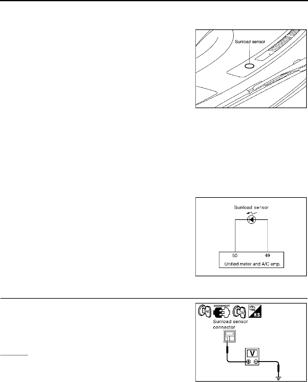
ATC-122
TROUBLE DIAGNOSIS
Revision; 2004 April 2003 FX
Sunload Sensor Circuit AJS00156
COMPONENT DESCRIPTION
Sunload Sensor
The sunload sensor is located on the passenger side front defroster
grille. It detects sunload entering through windshield by means of a
photo diode. The sensor converts the sunload into a current value
which is then input into the unified meter and A/C amp.
SUNLOAD INPUT PROCESS
The unified meter and A/C amp. also includes a processing circuit which averages the variations in detected
sunload over a period of time. This prevents drastic swings in the ATC system operation due to small or quick
variations in detected sunload.
For example, consider driving along a road bordered by an occasional group of large trees. The sunload
detected by the sunload sensor will vary whenever the trees obstruct the sunlight. The processing circuit aver-
ages the detected sunload over a period of time, so that the (insignificant) effect of the trees momentarily
obstructing the sunlight does not cause any change in the ATC system operation. On the other hand, shortly
after entering a long tunnel, the system will recognize the change in sunload, and the system will react accord-
ingly.
DIAGNOSTIC PROCEDURE FOR SUNLOAD SENSOR
SYMPTOM: Sunload sensor circuit is open or shorted. (25 or −25 is
indicated on unified meter and A/C amp. as a result of performing
Self-diagnosis STEP-2.)
1. CHECK VOLTAGE BETWEEN SUNLOAD SENSOR AND GROUND
1. Disconnect sunload sensor connector.
2. Turn ignition switch ON.
3. Check voltage between sunload sensor harness connector M87
terminal 1 (LG) and ground.
OK or NG
OK >> GO TO 2.
NG >> GO TO 4.
RJIA2026E
RJIA1455E
1 – Ground : Approx. 5V
RJIA2027E
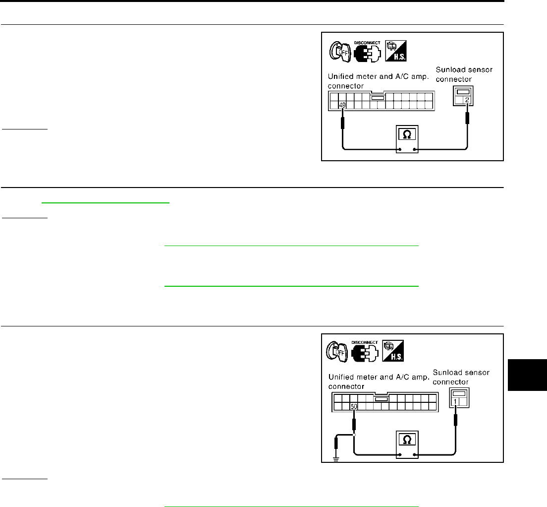
TROUBLE DIAGNOSIS
ATC-123
C
D
E
F
G
H
I
K
L
M
A
B
ATC
Revision; 2004 April 2003 FX
2. CHECK CIRCUIT CONTINUITY BETWEEN SUNLOAD SENSOR AND UNIFIED METER AND A/C AMP.
1. Turn ignition switch OFF.
2. Disconnect unified meter and A/C amp. connector.
3. Check continuity between sunload sensor harness connector
M87 terminal 2 (W/G) and unified meter and A/C amp. harness
connector M57 terminal 49 (W/G).
OK or NG
OK >> GO TO 3.
NG >> Repair harness or connector.
3. CHECK SUNLOAD SENSOR
Refer to ATC-124, "Sunload Sensor" .
OK or NG
OK >> 1. Replace unified meter and A/C amp.
2. Go to self-diagnosis ATC-67, "FUNCTION CONFIRMATION PROCEDURE" and perform self-
diagnosis STEP-2. Confirm that code No. 20 is displayed.
NG >> 1. Replace sunload sensor.
2. Go to self-diagnosis ATC-67, "FUNCTION CONFIRMATION PROCEDURE" and perform self-
diagnosis STEP-2. Confirm that code No. 20 is displayed.
4. CHECK CIRCUIT CONTINUITY BETWEEN SUNLOAD SENSOR AND UNIFIED METER AND A/C AMP.
1. Turn ignition switch OFF.
2. Disconnect unified meter and A/C amp. connector.
3. Check continuity between sunload sensor harness connector
M87 terminal 1 (LG) and display and A/C auto amp. harness
connector M57 terminal 50 (LG).
4. Check continuity between sunload sensor harness connector
M87 terminal 1 (LG) and ground.
OK or NG
OK >> 1. Replace unified meter and A/C amp.
2. Go to self-diagnosis ATC-67, "FUNCTION CONFIRMATION PROCEDURE" and perform self-
diagnosis STEP-2. Confirm that code No. 20 is displayed.
NG >> Repair harness or connector.
2 – 49 : Continuity should exist.
RJIA2028E
1 – 50 : Continuity should exist.
1 – Ground : Continuity should not exist. RJIA2029E
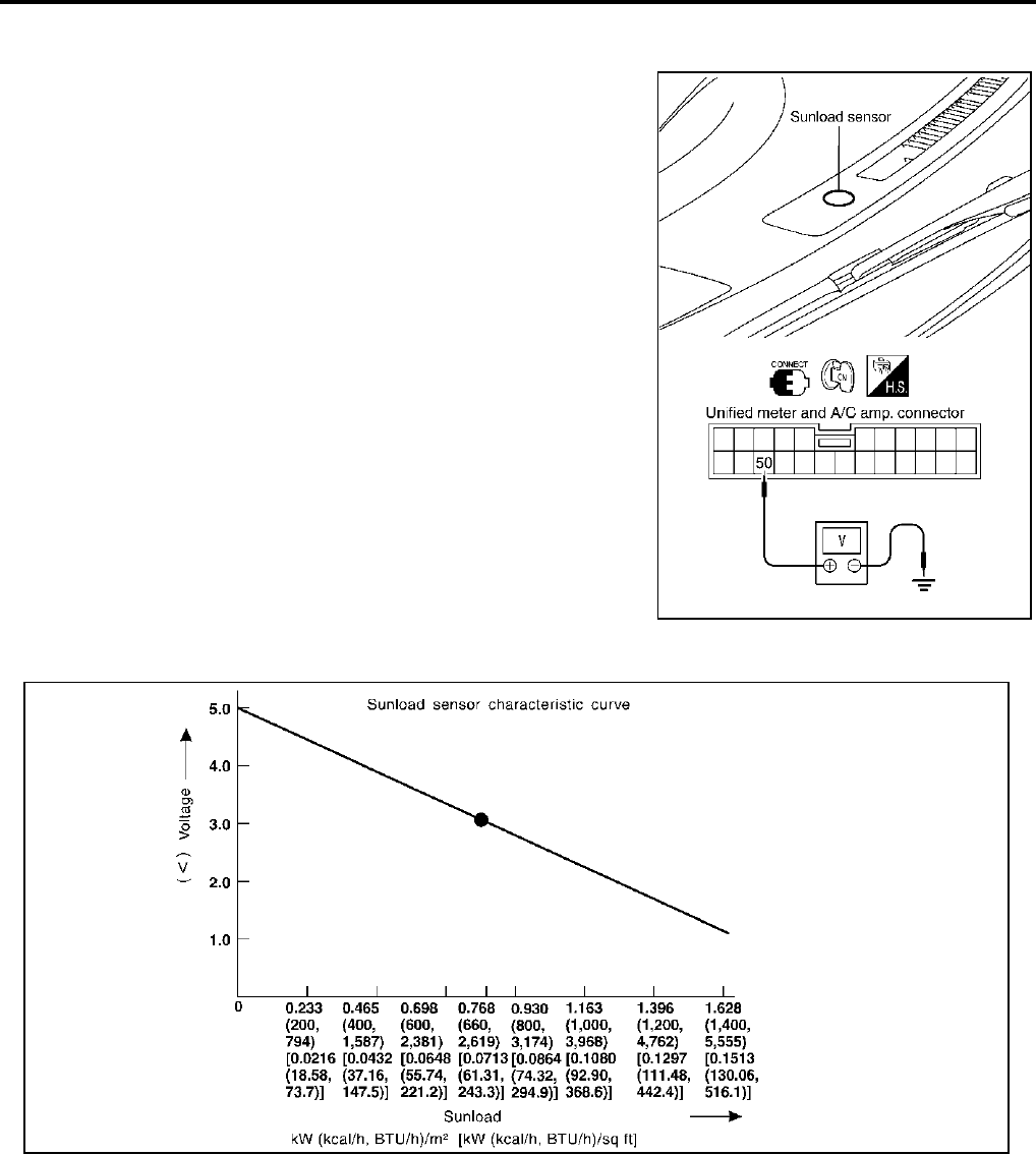
ATC-124
TROUBLE DIAGNOSIS
Revision; 2004 April 2003 FX
COMPONENT INSPECTION
Sunload Sensor
Measure voltage between unified meter and A/C amp. harness con-
nector M57 terminal 50 (LG) and ground.
If NG, replace sunload sensor.
●When checking sunload sensor, select a place where sun shines directly on it.
RJIA2030E
SHA930E
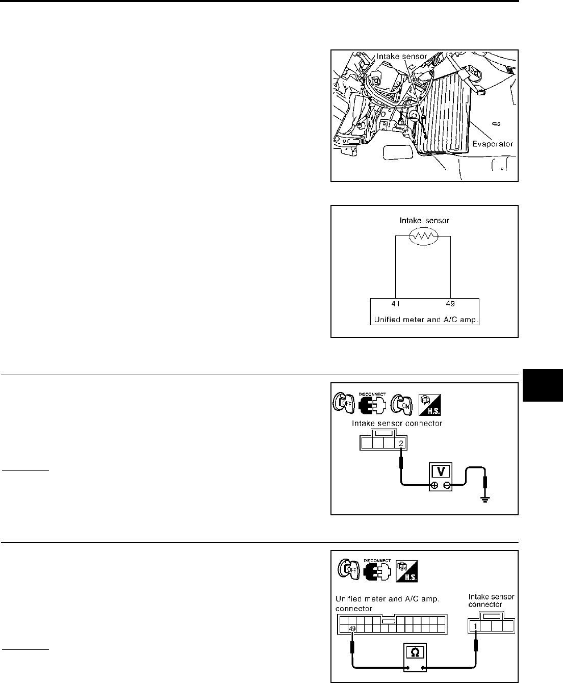
TROUBLE DIAGNOSIS
ATC-125
C
D
E
F
G
H
I
K
L
M
A
B
ATC
Revision; 2004 April 2003 FX
Intake Sensor Circuit AJS00157
COMPONENT DESCRIPTION
Intake Sensor
The intake sensor is located on the heater & cooling unit. It converts
temperature of air after it passes through the evaporator into a resis-
tance value which is then input to the unified meter and A/C amp.
DIAGNOSTIC PROCEDURE FOR INTAKE SENSOR
SYMPTOM: Intake sensor circuit is open or shorted. (24 or −24 is
indicated on unified meter and A/C amp. as a result of performing
Self-diagnosis STEP-2.)
1. CHECK VOLTAGE BETWEEN INTAKE SENSOR AND GROUND
1. Disconnect intake sensor connector.
2. Turn ignition switch ON.
3. Check voltage between intake sensor harness connector M254
terminal 2 (R) and ground.
OK or NG
OK >> GO TO 2.
NG >> GO TO 4.
2. CHECK CIRCUIT CONTINUITY BETWEEN INTAKE SENSOR AND UNIFIED METER AND A/C AMP.
1. Turn ignition switch OFF.
2. Disconnect unified meter and A/C amp. connector.
3. Check continuity between intake sensor harness connector
M254 terminal 1 (W) and unified meter and A/C amp. harness
connector M57 terminal 49 (W/G).
OK or NG
OK >> GO TO 3.
NG >> Repair harness or connector.
RJIA0928E
RJIA1458E
2 – Ground : Approx. 5V
RJIA2031E
1 – 49 : Continuity should exist.
RJIA2032E
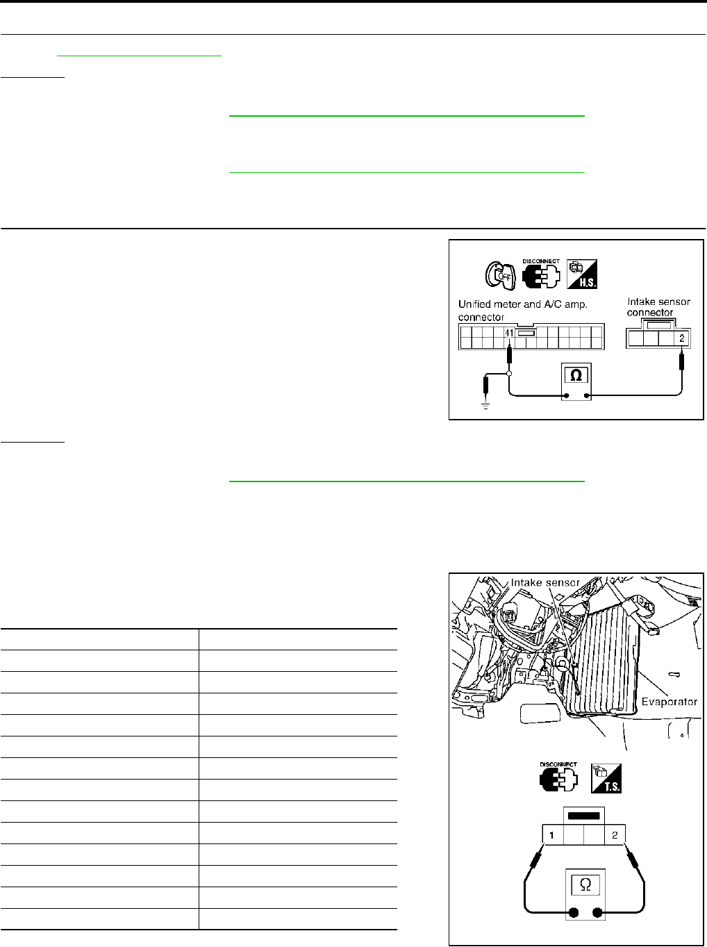
ATC-126
TROUBLE DIAGNOSIS
Revision; 2004 April 2003 FX
3. CHECK INTAKE SENSOR
Refer to ATC-126, "Intake Sensor" .
OK or NG
OK >> 1. Replace unified meter and A/C amp.
2. Go to self-diagnosis ATC-67, "FUNCTION CONFIRMATION PROCEDURE" and perform self-
diagnosis STEP-2. Confirm that code No. 20 is displayed.
NG >> 1. Replace intake sensor.
2. Go to self-diagnosis ATC-67, "FUNCTION CONFIRMATION PROCEDURE" and perform self-
diagnosis STEP-2. Confirm that code No. 20 is displayed.
4. CHECK CIRCUIT CONTINUITY BETWEEN INTAKE SENSOR AND UNIFIED METER AND A/C AMP.
1. Turn ignition switch OFF.
2. Disconnect unified meter and A/C amp. connector.
3. Check continuity between intake sensor harness connector
M254 terminal 2 (R) and unified meter and A/C amp. harness
connector M57 terminal 41 (P).
4. Check continuity between intake sensor harness connector
M254 terminal 2 (R) and ground.
OK or NG
OK >> 1. Replace unified meter and A/C amp.
2. Go to self-diagnosis ATC-67, "FUNCTION CONFIRMATION PROCEDURE" and perform self-
diagnosis STEP-2. Confirm that code No. 20 is displayed.
NG >> Repair harness or connector.
COMPONENT INSPECTION
Intake Sensor
After disconnecting intake sensor connector, measure resistance
between terminals 1 and 2 at sensor harness side, using the table
below.
If NG, replace intake sensor.
2 – 41 : Continuity should exist.
2 – Ground : Continuity should not exist. RJIA2033E
Temperature °C (°F) Resistance kΩ
−15 (5) 12.34
−10 (14) 9.62
−5 (23) 7.56
0 (32) 6.00
5 (41) 4.80
10 (50) 3.87
15 (59) 3.15
20 (68) 2.57
25 (77) 2.12
30 (86) 1.76
35 (95) 1.47
40 (104) 1.23
45 (113) 1.04
RJIA2034E

CONTROLLER
ATC-127
C
D
E
F
G
H
I
K
L
M
A
B
ATC
Revision; 2004 April 2003 FX
CONTROLLER PFP:27500
Removal and Installation of A/C and AV Switch AJS001BN
REMOVAL
Refer to AV-43, "Removal and Installation for A/C and AV Switch" .
INSTALLATION
Installation is basically the reverse order of removal.
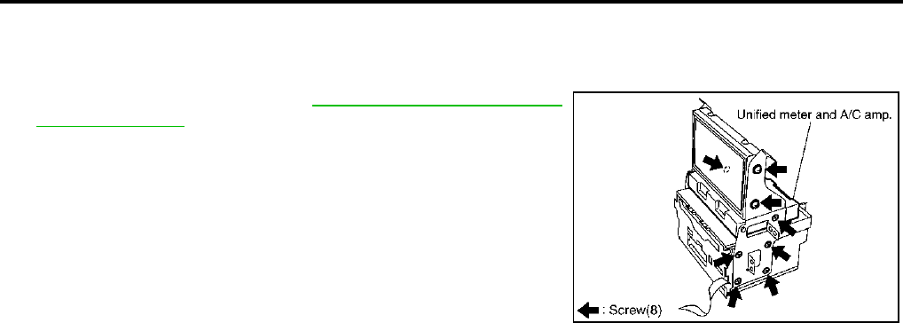
ATC-128
AUTO AMP
Revision; 2004 April 2003 FX
AUTO AMP PFP:27760
Removal and Installation of Unified Meter and A/C Amp. AJS00159
REMOVAL
1. Remove the audio unit. Refer to AV-42, "Removal and Installa-
tion of Audio Unit" .
2. Remove the fixing screws, then remove the unified meter and A/
C amp.
INSTALLATION
Installation is basically the reverse order of removal.
RJIA2035E
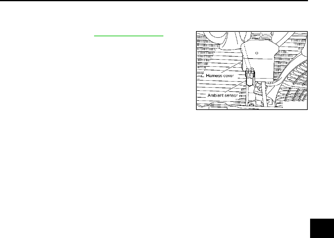
AMBIENT SENSOR
ATC-129
C
D
E
F
G
H
I
K
L
M
A
B
ATC
Revision; 2004 April 2003 FX
AMBIENT SENSOR PFP:27722
Removal and Installation AJS0015A
REMOVAL
1. Remove front grille. Refer to EI-23, "FRONT GRILLE" .
2. Disconnect ambient sensor connector, then remove it.
INSTALLATION
Installation is basically the reverse order of removal.
RJIA2016E
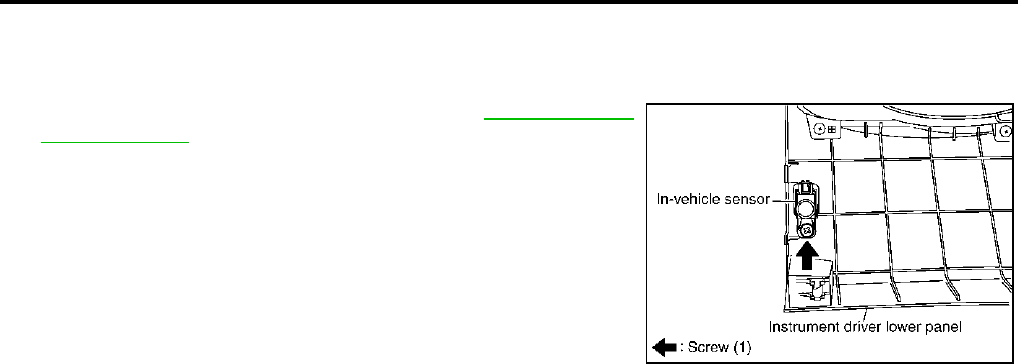
ATC-130
IN-VEHICLE SENSOR
Revision; 2004 April 2003 FX
IN-VEHICLE SENSOR PFP:27720
Removal and Installation AJS0015B
REMOVAL
1. Remove instrument driver lower panel. Refer to IP-11, "Removal
and Installation" .
2. Remove in-vehicle sensor.
INSTALLATION
Installation is basically the reverse order of removal.
RJIA2036E
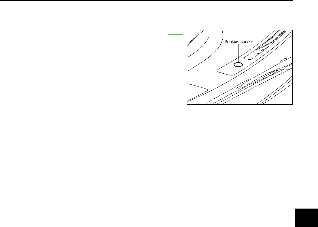
SUNLOAD SENSOR
ATC-131
C
D
E
F
G
H
I
K
L
M
A
B
ATC
Revision; 2004 April 2003 FX
SUNLOAD SENSOR PFP:27721
Removal and Installation AJS0015C
REMOVAL
1. Remove front defroster grille (right side). Refer to IP-11,
"Removal and Installation" .
2. Disconnect sunload sensor connector, then remove sunload
sensor.
INSTALLATION
Installation is basically the reverse order of removal.
RJIA2026E
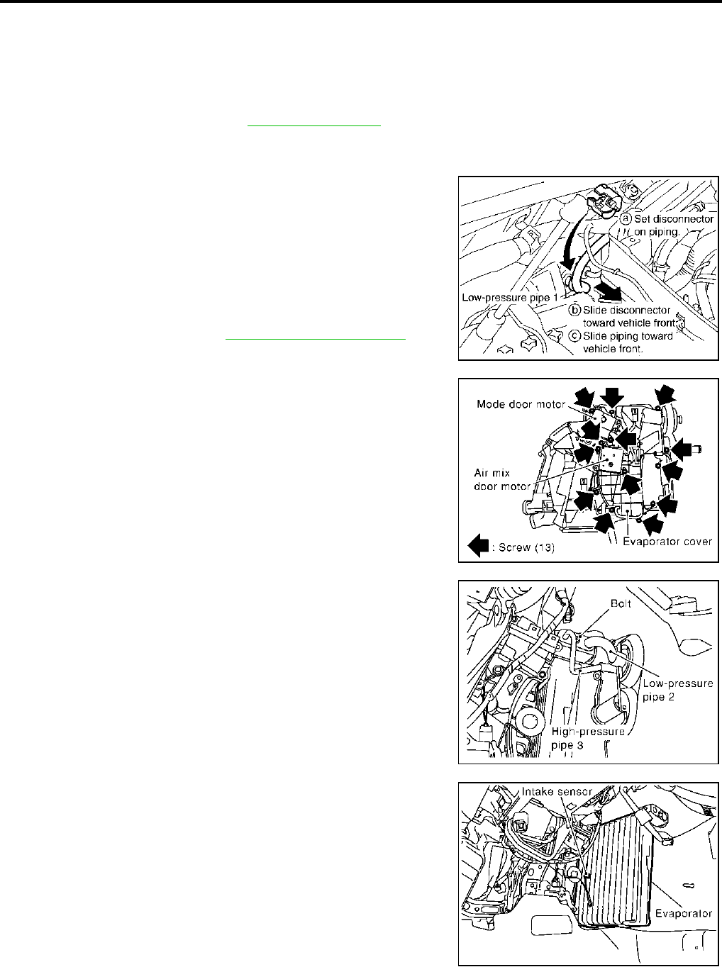
ATC-132
INTAKE SENSOR
Revision; 2004 April 2003 FX
INTAKE SENSOR PFP:27723
Removal and Installation AJS0015D
REMOVAL
1. Set the temperature at 18°C (60°F), and then disconnect the battery negative cable.
2. Use a refrigerant collecting equipment (for HFC-134a) to discharge refrigerant.
3. Remove cowl top cover. Refer to EI-24, "COWL TOP" .
4. Remove high-pressure pipe 2 mounting clip.
5. Remove low-pressure flexible hose bracket mounting bolts.
6. Disconnect evaporator-side one-touch joints.
a. Set a disconnector (High-pressure side: 92530-89908, Low-
pressure side: 92530-89916) on A/C piping.
b. Slide a disconnector toward vehicle front until it clicks.
c. Slide A/C piping toward vehicle front and disconnect it.
CAUTION:
Seal connection opening of piping with a cap or vinyl tape
to avoid exposure to atmosphere.
7. Remove blower unit. Refer to ATC-134, "BLOWER UNIT" .
8. Remove air mix door motor (Passenger side), mode door motor
and evaporator cover.
9. Remove the mounting bolt, then remove the low-pressure pipe 2
and high-pressure pipe 3.
CAUTION:
Seal connection opening of piping with a cap or vinyl tape
to avoid exposure to atmosphere.
10. Slide the evaporator to passenger side, then remove the intake
sensor.
RJIA2037E
RJIA0940E
RJIA2038E
RJIA0928E

INTAKE SENSOR
ATC-133
C
D
E
F
G
H
I
K
L
M
A
B
ATC
Revision; 2004 April 2003 FX
INSTALLATION
Installation is basically the reverse order of removal.
CAUTION:
●Replace O-rings for A/C piping with new ones. Before installing, apply compressor oil to them.
●Connection point for female-side piping is thin. So, when inserting male-side piping, take care not
to deform female-side piping. Slowly insert in axial direction.
●Insert one-touch joint connection point securely until it clicks.
●After piping has been connected, pull male-side piping by hand to make sure piping does not
come off.
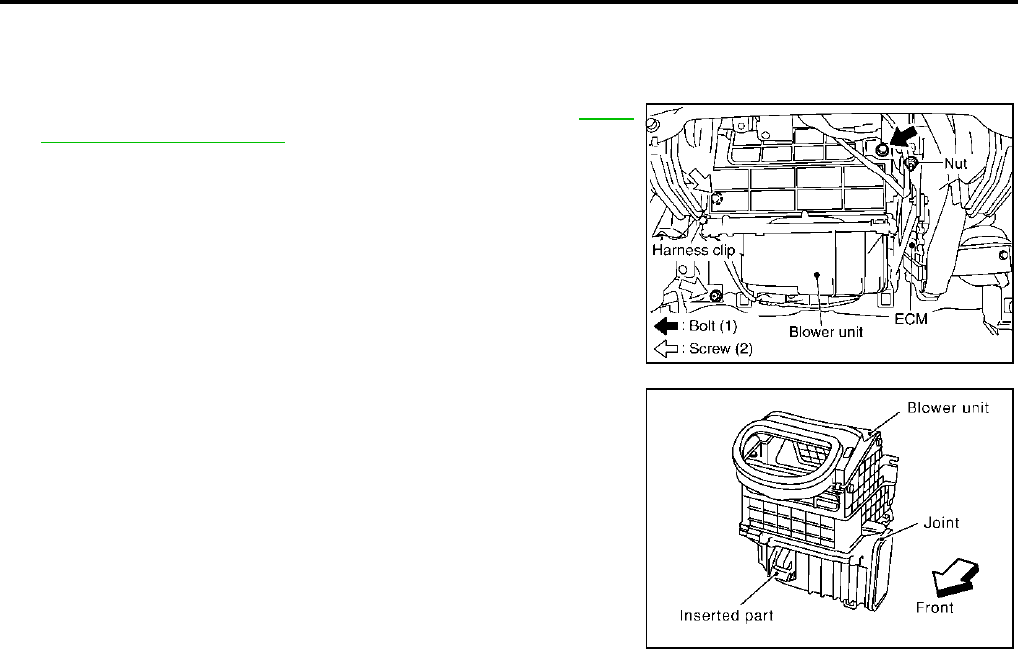
ATC-134
BLOWER UNIT
Revision; 2004 April 2003 FX
BLOWER UNIT PFP:27200
Removal and Installation AJS0015E
REMOVAL
1. Remove instrument passenger lower panel. Refer to IP-11,
"Removal and Installation" .
2. Remove ECM with bracket attached.
3. Disconnect intake door motor connector and blower fan motor
connector.
4. Remove harness clip from blower unit.
5. Remove mounting bolt and screws (2), from blower unit.
CAUTION:
Move blower unit rightward, and remove locating pin (1)
and joint. Then remove blower unit downward.
6. Remove blower unit.
INSTALLATION
Installation is basically the reverse order of removal.
CAUTION:
Make sure locating pin (1) and joint are securely inserted.
RJIA2039E
RJIA0943E
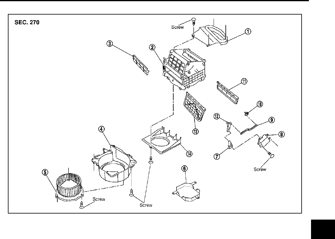
BLOWER UNIT
ATC-135
C
D
E
F
G
H
I
K
L
M
A
B
ATC
Revision; 2004 April 2003 FX
Disassembly and Assembly AJS0015F
1. Adapter 2. Intake upper case 3. Filter cover
4. Intake lower case 5. Blower fan motor assembly 6. Motor cover
7. Intake door lever 2 8. Intake door motor 9. Intake door link
10. Intake door lever 3 11. Intake door 2 12. Intake door lever 1
13. Intake door 1 14. Intake bell mouth
RJIA2240E
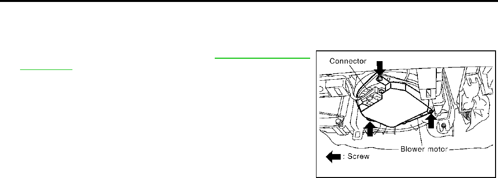
ATC-136
BLOWER MOTOR
Revision; 2004 April 2003 FX
BLOWER MOTOR PFP:27226
Removal and Installation AJS0015G
REMOVAL
1. Remove instrument lower cover. Refer to IP-11, "Removal and
Installation" .
2. Disconnect blower motor connector.
3. Remove screws from blower motor, then remove it.
INSTALLATION
Installation is basically the reverse order of removal.
RJIA2239E
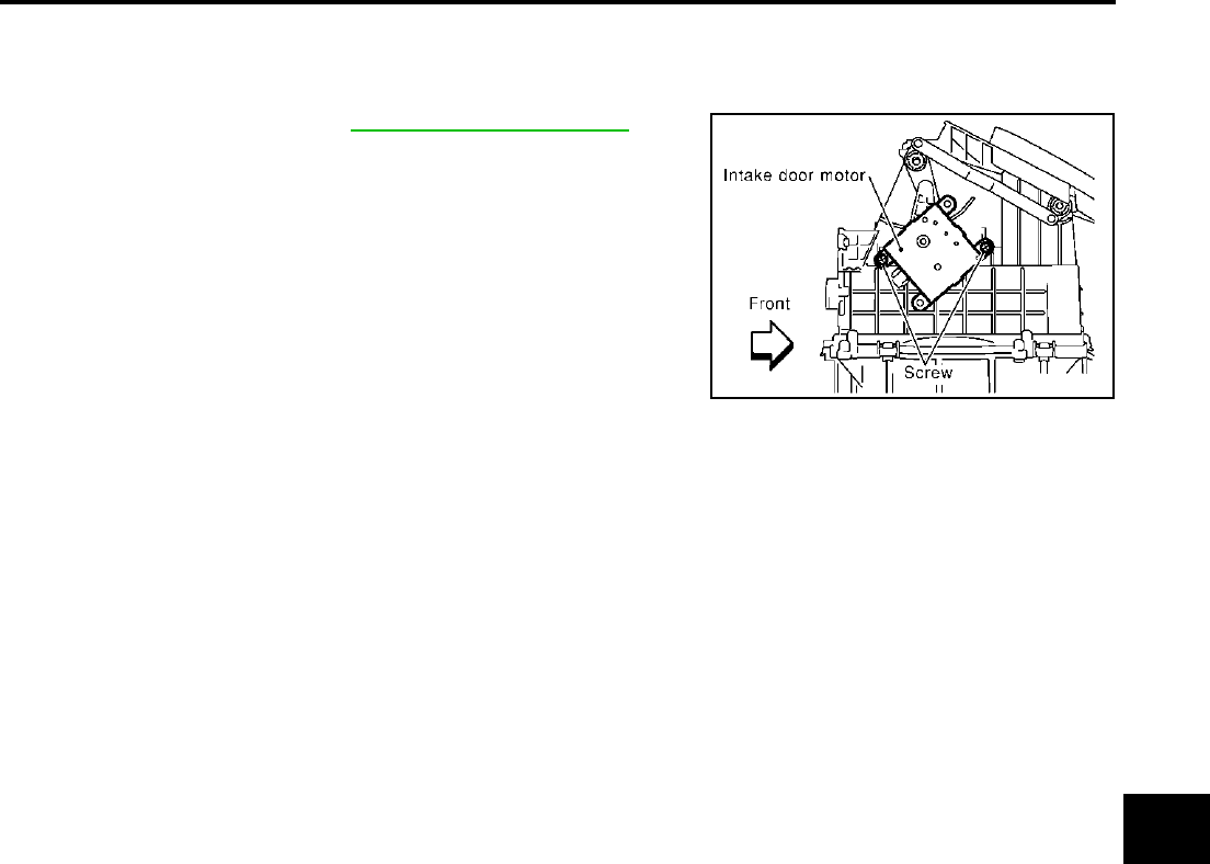
INTAKE DOOR MOTOR
ATC-137
C
D
E
F
G
H
I
K
L
M
A
B
ATC
Revision; 2004 April 2003 FX
INTAKE DOOR MOTOR PFP:27730
Removal and Installation AJS0015H
REMOVAL
1. Remove blower unit. Refer to ATC-134, "BLOWER UNIT" .
2. Remove intake door motor from the blower unit.
INSTALLATION
Installation is basically the reverse order of removal.
RJIA0947E
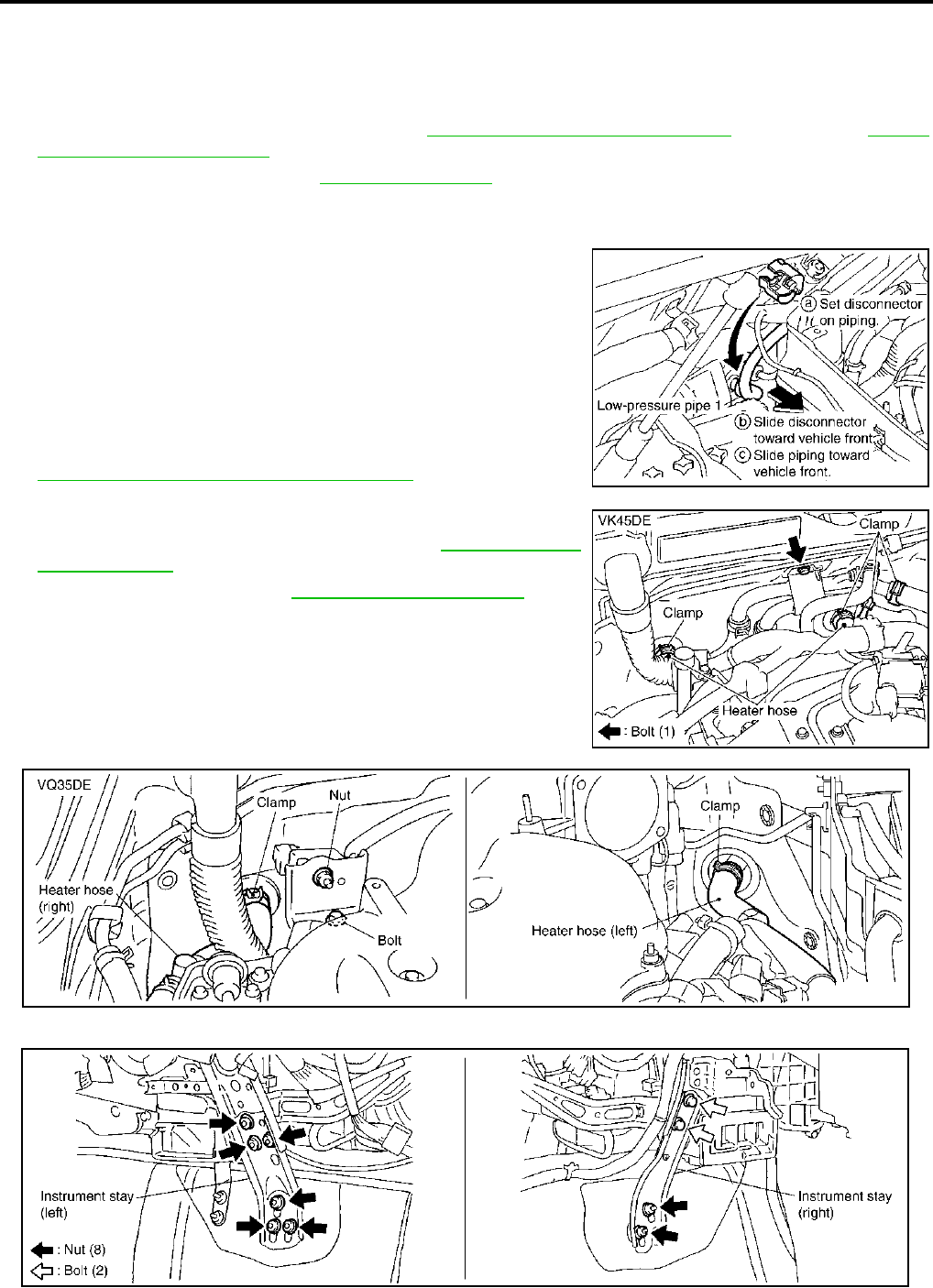
ATC-138
HEATER & COOLING UNIT ASSEMBLY
Revision; 2004 April 2003 FX
HEATER & COOLING UNIT ASSEMBLY PFP:27110
Removal and Installation AJS0015J
REMOVAL
1. Use a refrigerant collecting equipment (for HFC-134a) to discharge refrigerant.
2. Drain coolant from cooling system. Refer to CO-11, "Changing Engine Coolant" (VQ35DE) or CO-35,
"Changing Engine Coolant" (VK45DE).
3. Remove cowl top cover. Refer to EI-24, "COWL TOP" .
4. Remove high-pressure pipe 2 mounting clip.
5. Remove low-pressure flexible hose bracket mounting bolts.
6. Disconnect evaporator-side one touch joint.
a. Set a disconnector (High-pressure side: 92530-89908, Low-
pressure side: 92530-89916) on A/C piping.
b. Slide a disconnector toward vehicle front until it clicks.
c. Slide A/C piping toward vehicle front and disconnect it.
CAUTION:
Seal connection opening of piping with a cap or vinyl tape
to avoid exposure to atmosphere.
7. Remove electronic control throttle assembly (VQ35DE). Refer to
EM-19, "INTAKE MANIFOLD COLLECTOR" .
8. Disconnect two heater hoses from heater core.
9. Remove instrument panel assembly. Refer to IP-11, "Removal
and Installation" .
10. Remove blower unit. Refer to ATC-134, "BLOWER UNIT" .
11. Remove instrument stays (driver side and passenger side).
RJIA2037E
RJIA2041E
RJIA2077E
RJIA2042E
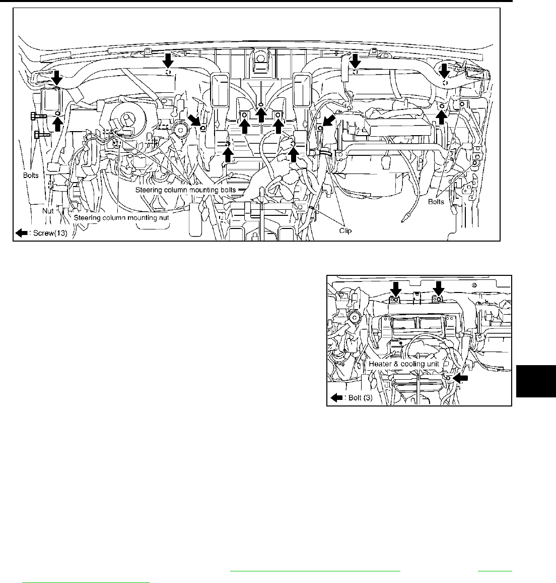
HEATER & COOLING UNIT ASSEMBLY
ATC-139
C
D
E
F
G
H
I
K
L
M
A
B
ATC
Revision; 2004 April 2003 FX
12. Remove ventilator ducts, defroster nozzle and ducts.
13. Remove steering member mounting bolts, nut and harness clips.
14. Remove mounting screws from heater & cooling unit.
15. Disconnect drain hose.
16. Remove the steering member, and then remove heater & cool-
ing unit.
INSTALLATION
Installation is basically the reverse order of removal.
CAUTION:
●Replace O-rings for A/C piping with new one, then apply compressor oil to it when installing it.
●Connection point for female-side piping is thin. So, when inserting male-side piping, take care not
to deform female-side piping. Slowly insert in axial direction.
●Insert one-touch joint connection point securely until it clicks.
●After piping has been connected, pull male-side piping by hand to check that piping does not
come off.
●When recharging refrigerant, check for leaks.
NOTE:
●When filling radiator with coolant, refer to CO-11, "Changing Engine Coolant" (VQ35DE) or CO-35,
"Changing Engine Coolant" (VK45DE).
●Recharge the refrigerant.
RJIA2043E
RJIA2044E
Heater & cooling unit mounting bolt
Tightening torque : 6.8 N·m (0.69 kg-m, 60 in - lb)
Steering member mounting nut and bolt
Tightening torque : 12 N·m (1.2 kg-m, 9 ft - lb)
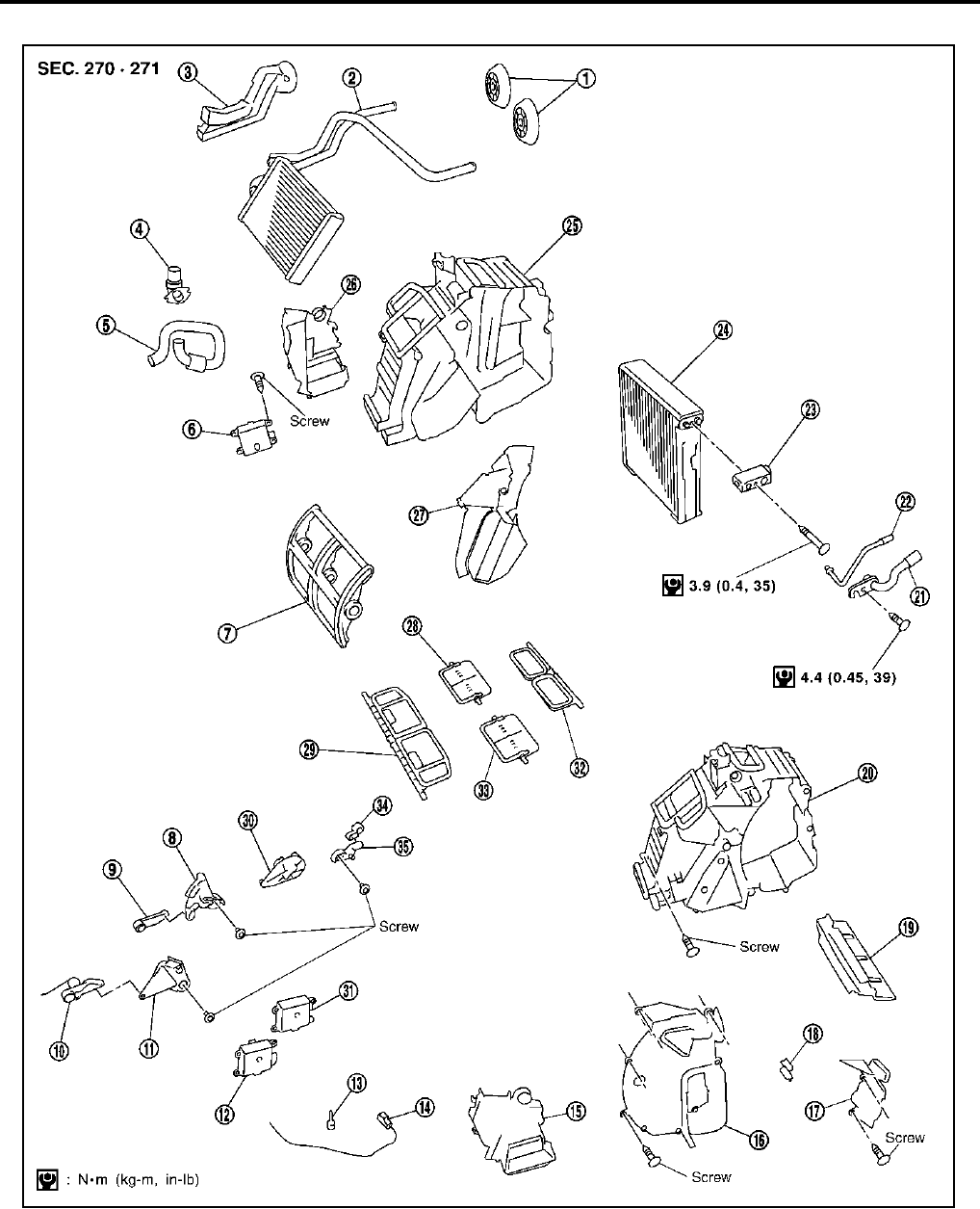
ATC-140
HEATER & COOLING UNIT ASSEMBLY
Revision; 2004 April 2003 FX
Disassembly and Assembly AJS0015K
1. Heater pipe grommet 2. Heater core 3. Heater pipe cover
4. Aspirator 5. Aspirator hose 6. Air mix door motor (driver side)
7. Air mix door (slide door) 8. Max. cool door link 9. Max. cool door lever
10. Ventilator door lever 11. Ventilator door link 12. Air mix door motor (passenger side)
13. Intake sensor bracket 14. Intake sensor 15. Foot duct (right)
16. Evaporator cover 17. Evaporator cover adaptor 18. Heater pipe bracket
RJIA2045E

HEATER & COOLING UNIT ASSEMBLY
ATC-141
C
D
E
F
G
H
I
K
L
M
A
B
ATC
Revision; 2004 April 2003 FX
19. Insulator 20. Heater case (right) 21. Low-pressure pipe 2
22. High-pressure pipe 3 23. Expansion valve 24. Evaporator
25. Heater case (left) 26. Foot duct (left) 27. Center case
28. Max. cool door (left) 29. Ventilator door 30. Side link
31. Mode door motor 32. Defroster door 33. Max. cool door (right)
34. Defroster door lever 35. Defroster door link
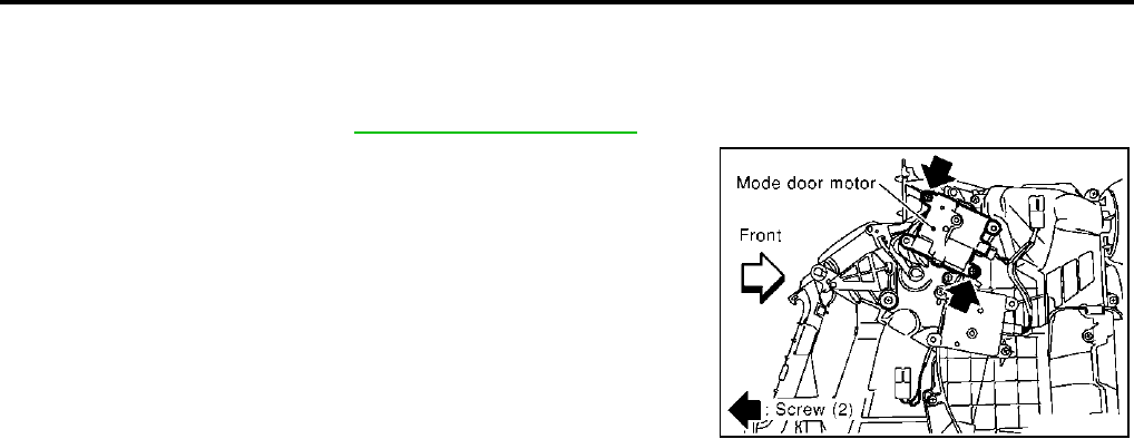
ATC-142
MODE DOOR MOTOR
Revision; 2004 April 2003 FX
MODE DOOR MOTOR PFP:27731
Removal and Installation AJS0015L
REMOVAL
1. Remove blower unit. Refer to ATC-134, "BLOWER UNIT" .
2. Remove mounting screws from mode door motor.
3. Disconnect mode door connector, and then remove mode door
motor.
INSTALLATION
Installation is basically the reverse order of removal.
RJIA0954E
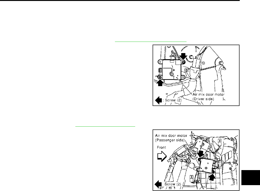
AIR MIX DOOR MOTOR
ATC-143
C
D
E
F
G
H
I
K
L
M
A
B
ATC
Revision; 2004 April 2003 FX
AIR MIX DOOR MOTOR PFP:27732
Removal and Installation AJS0015M
REMOVAL
Driver Side
1. Set the temperature at 18°C (60°F), and then disconnect the battery negative cable.
2. Remove instrument lower driver panel. Refer to IP-11, "Removal and Installation" .
3. Remove air mix door motor.
4. Disconnect air mix door motor connector.
Passenger Side
1. Set the temperature at 18°C (60°F), and then disconnect the battery negative cable.
2. Remove blower unit. Refer to ATC-134, "BLOWER UNIT" .
3. Remove air mix door motor.
4. Disconnect air mix door motor connector.
INSTALLATION
Installation is basically the reverse order of removal.
RJIA0956E
RJIA0955E
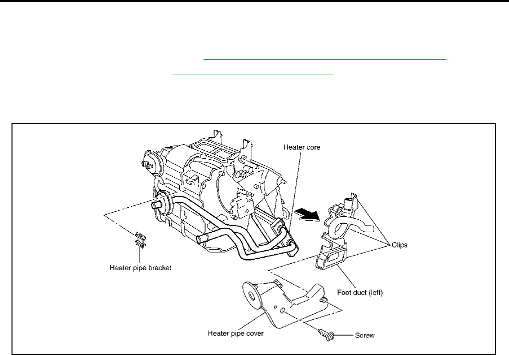
ATC-144
HEATER CORE
Revision; 2004 April 2003 FX
HEATER CORE PFP:27140
Removal and Installation AJS0015N
REMOVAL
1. Remove heater & cooling unit. Refer to ATC-138, "HEATER & COOLING UNIT ASSEMBLY" .
2. Remove foot duct (left). Refer to ATC-148, "Removal of Foot Ducts" .
3. Remove heater pipe cover.
4. Remove heater pipe support and heater pipe grommet.
5. Slide heater core to driver side.
INSTALLATION
Installation is basically the reverse order of removal.
RJIA2046E
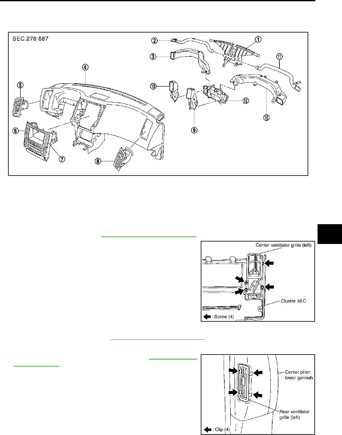
DUCTS AND GRILLES
ATC-145
C
D
E
F
G
H
I
K
L
M
A
B
ATC
Revision; 2004 April 2003 FX
DUCTS AND GRILLES PFP:27860
Removal and Installation AJS0015O
REMOVAL
Removal of Center Ventilator Grille
1. Remove cluster lid C. Refer to IP-11, "Removal and Installation" .
2. Remove center ventilator grille.
Removal of Side Ventilation
1. Remove side ventilation. Refer to IP-11, "Removal and Installation" .
Removal of Rear Ventilator Grille
1. Remove center pillar lower garnish. Refer to EI-37, "Removal
and Installation" .
2. Remove mounting clips, then remove rear ventilator grille.
1. Defroster nozzle 2. Side defroster duct (left) 3. Side ventilator duct (left)
4. Instrument panel 5. Side ventilation (left) 6. Center ventilator grille (left)
7. Center ventilator grille (right) 8. Side ventilation (right) 9. Center ventilator duct (right)
10. Side ventilator duct (right) 11. Side defroster duct (right) 12. Center ventilator duct
13. Center ventilator duct (left)
RJIA2047E
RJIA2048E
RJIA2050E
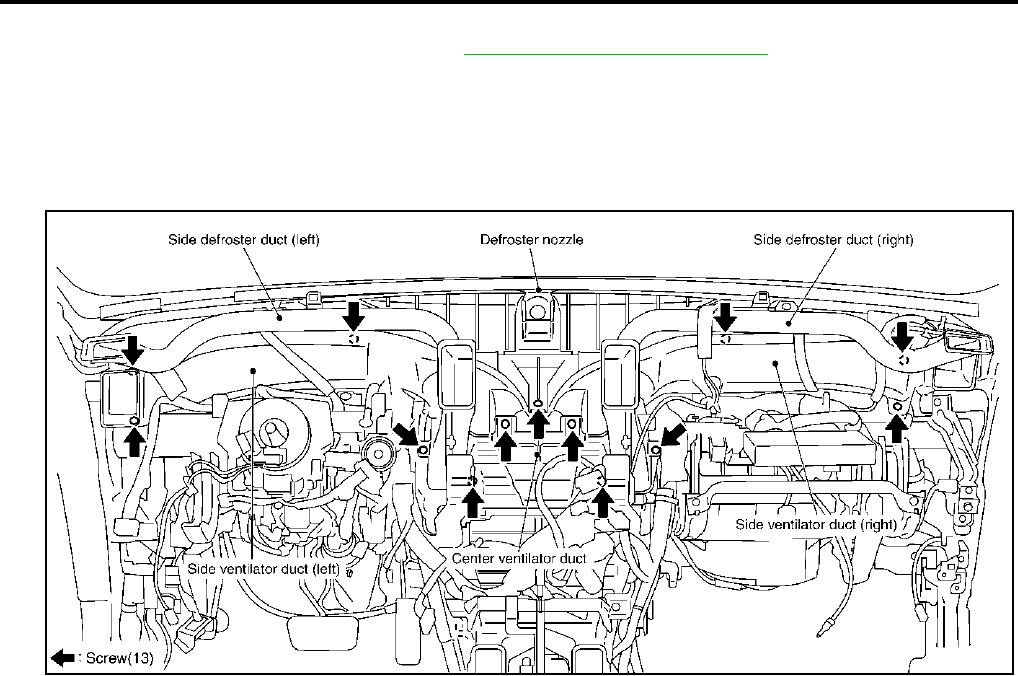
ATC-146
DUCTS AND GRILLES
Revision; 2004 April 2003 FX
Removal of Defroster Nozzle, Ducts and Ventilator Ducts
1. Remove instrument panel assembly. Refer to IP-11, "Removal and Installation" .
2. Remove side defroster ducts, using power tools.
3. Remove defroster nozzle, using power tools.
4. Remove center ventilator duct (right and left).
5. Remove side ventilator ducts.
6. Remove center ventilator duct.
RJIA2051E
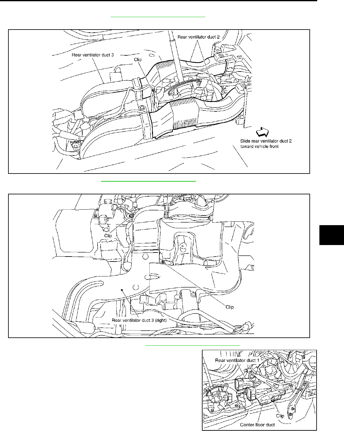
DUCTS AND GRILLES
ATC-147
C
D
E
F
G
H
I
K
L
M
A
B
ATC
Revision; 2004 April 2003 FX
Removal of Rear Ventilator Ducts
1. Remove center console. Refer to IP-11, "Removal and Installation" .
2. Slide rear ventilator duct 2 toward vehicle front, then remove it.
3. Remove floor carpet. Refer to EI-40, "Removal and Installation" .
4. Remove rear ventilator duct 3 mounting clips, then remove rear ventilator duct 3.
5. Remove instrument panel assembly. Refer to IP-11, "Removal and Installation" .
6. Remove rear ventilator duct 1 with center floor duct attached.
7. Remove rear ventilator duct 1 from center floor duct.
RJIA2052E
RJIA2053E
RJIA2054E
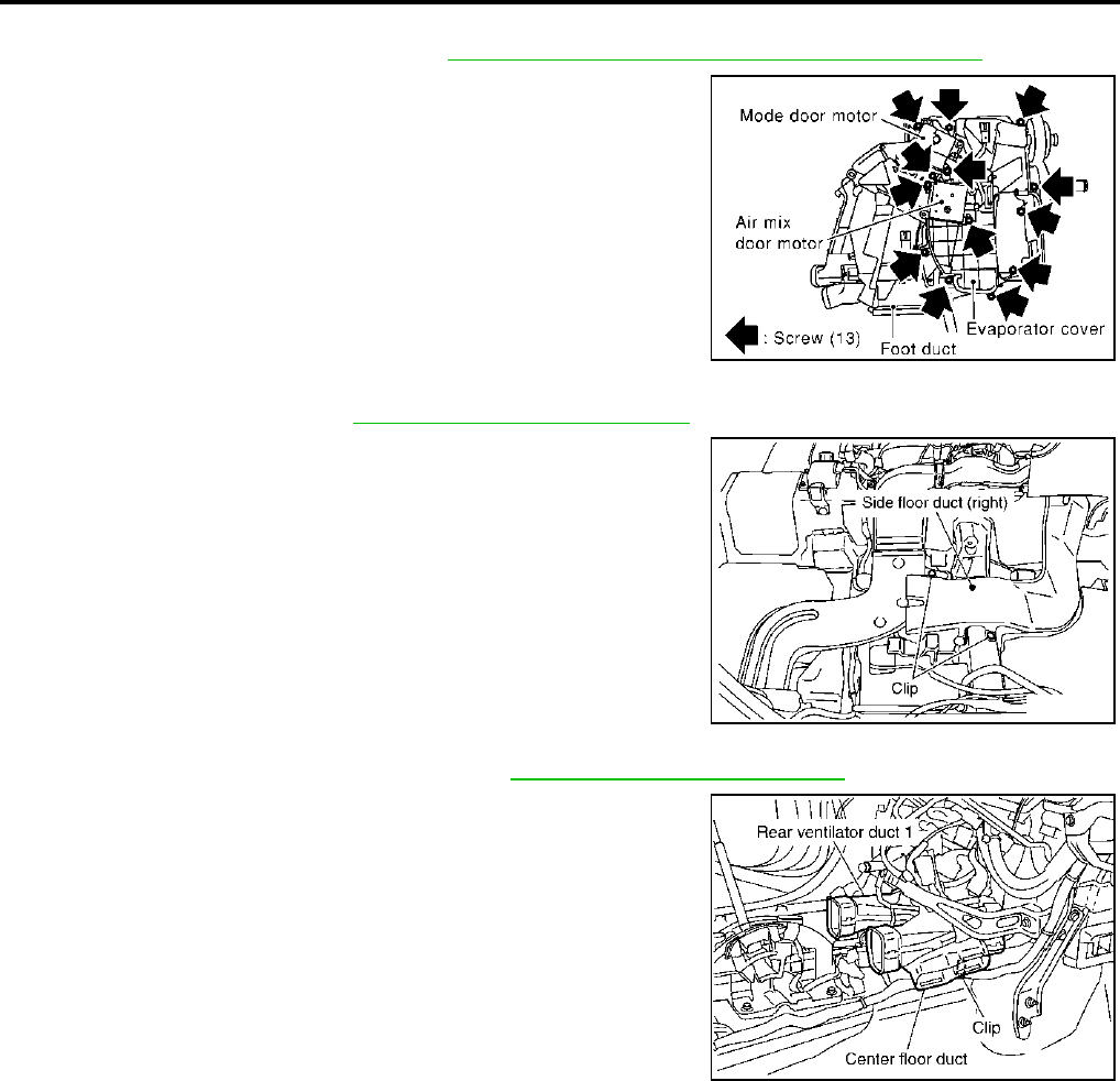
ATC-148
DUCTS AND GRILLES
Revision; 2004 April 2003 FX
Removal of Foot Ducts
1. Remove heater & cooling unit. Refer to ATC-138, "HEATER & COOLING UNIT ASSEMBLY" .
2. Remove evaporator cover, and then remove foot duct (passen-
ger side).
Removal of Floor Ducts
1. Remove floor carpet. Refer to EI-40, "Removal and Installation" .
2. Remove mounting clips from side floor ducts.
3. Remove side floor ducts.
4. Remove instrument panel assembly. Refer to IP-11, "Removal and Installation" .
5. Remove center floor duct with rear ventilator duct 1 attached.
6. Remove center floor duct from rear ventilator duct 1.
INSTALLATION
Installation is basically the reverse order of removal.
RJIA0962E
RJIA2055E
RJIA2054E
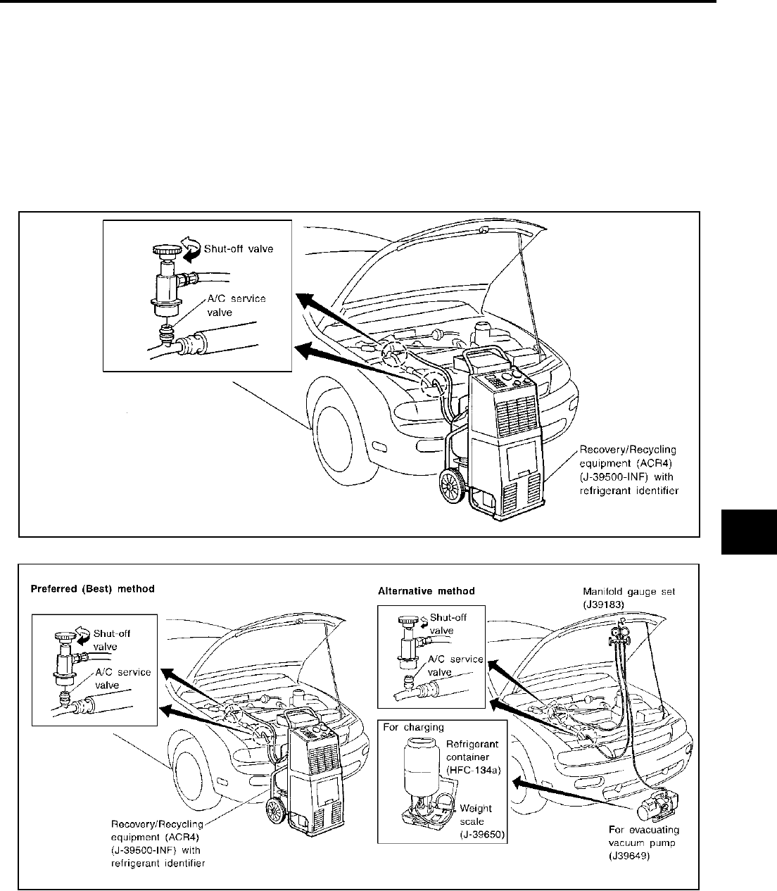
REFRIGERANT LINES
ATC-149
C
D
E
F
G
H
I
K
L
M
A
B
ATC
Revision; 2004 April 2003 FX
REFRIGERANT LINES PFP:92600
HFC-134a (R-134a) Service Procedure AJS0015P
SETTING OF SERVICE TOOLS AND EQUIPMENT
Discharging Refrigerant
WARNING:
Avoid breathing A/C refrigerant and lubricant vapor or mist. Exposure may irritate eyes, nose and
throat. Remove HFC-134a (R-134a) from A/C system using certified service equipment meeting
requirements of SAE J2210 [HFC-134a (R-134a) recycling equipment] or J2201 [HFC-134a (R-134a)
recovery equipment]. If accidental system discharge occurs, ventilate work area before resuming ser-
vice. Additional health and safety information may be obtained from refrigerant and lubricant manu-
facturers.
Evacuating System and Charging Refrigerant
SHA179FD
SHA180FD


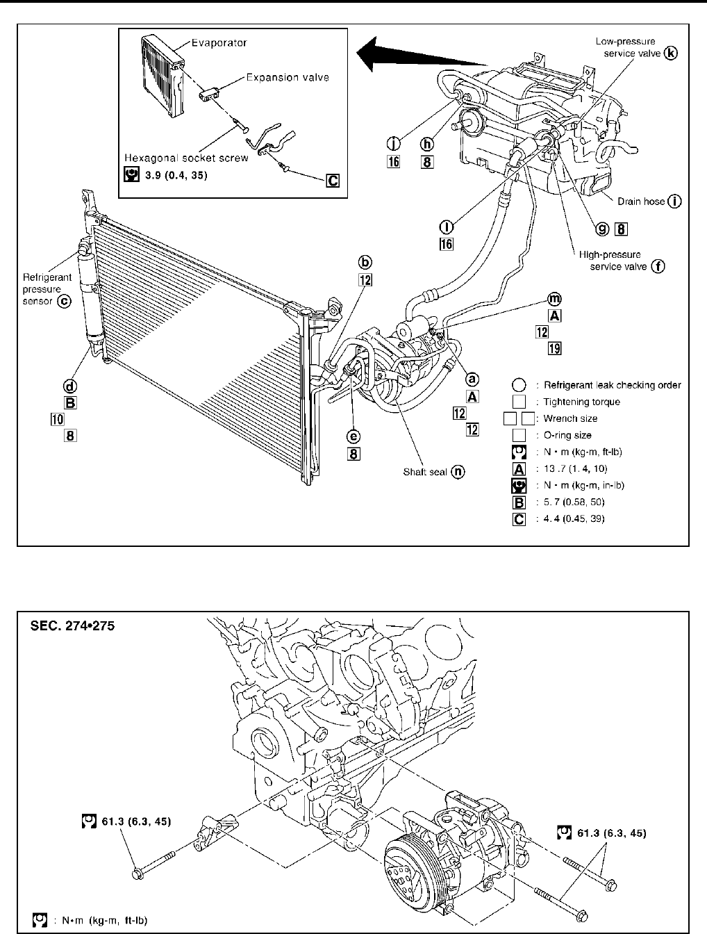
ATC-152
REFRIGERANT LINES
Revision; 2004 April 2003 FX
VQ35DE
Removal and Installation of Compressor AJS0015R
REMOVAL
VK45DE
RJIA2057E
RJIA2244E
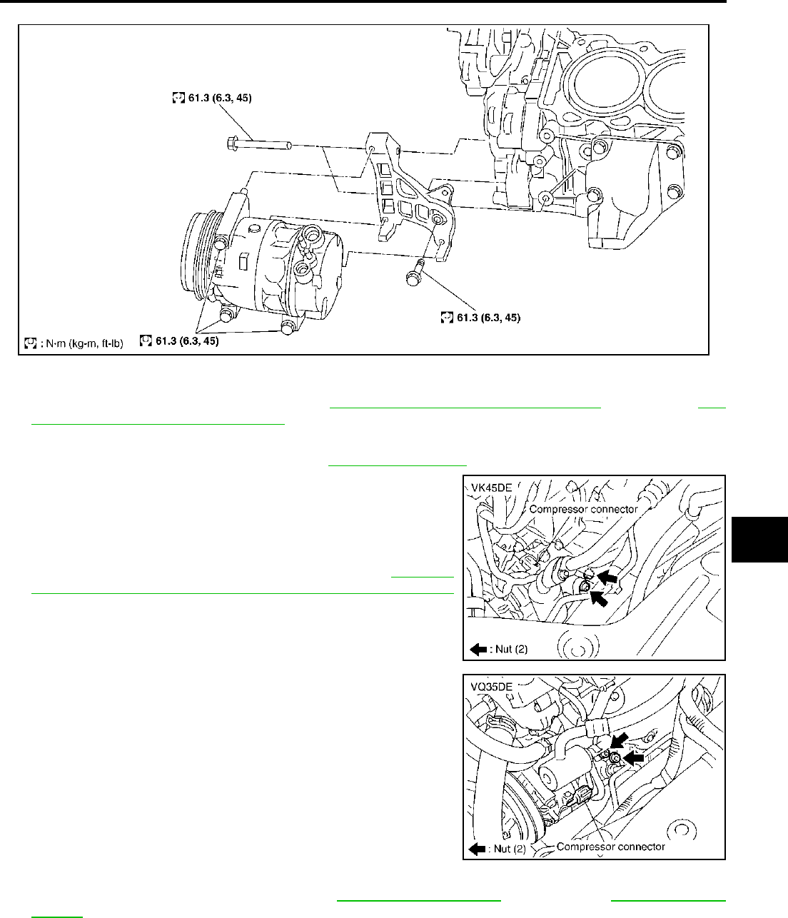
REFRIGERANT LINES
ATC-153
C
D
E
F
G
H
I
K
L
M
A
B
ATC
Revision; 2004 April 2003 FX
VQ35DE
1. Use a refrigerant collecting equipment (for HFC-134a) to discharge the refrigerant.
2. Remove the air cleaner and air duct. Refer to EM-17, "AIR CLEANER AND AIR DUCT" (VQ35DE) or EM-
170, "AIR CLEANER AND AIR DUCT" (VK45DE).
3. Remove front engine undercover, using power tools.
4. Remove cooling fan shroud (lower). Refer to CO-38, "RADIATOR" (VK45DE).
5. Remove mounting nuts from low-pressure flexible hose and
high-pressure flexible hose.
CAUTION:
Cap or wrap the joint of the pipe with suitable material such
as vinyl tape to avoid the entry of air.
6. Remove high-pressure flexible hose. Refer to ATC-160,
"Removal and Installation of High-pressure Flexible Hose"
(VK45DE).
7. Disconnect compressor (magnet clutch and ECV) connectors.
8. Remove the A/C compressor belt. Refer to EM-15, "DRIVE BELTS" (VQ35DE) or EM-167, "DRIVE
BELTS" (VK45DE).
9. Remove mounting bolt from radiator hose bracket (VK45DE).
RJIA2245E
RJIA2058E
RJIA2059E
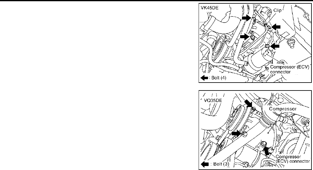
ATC-154
REFRIGERANT LINES
Revision; 2004 April 2003 FX
10. Remove mounting bolts from compressor, using power tools.
11. Remove compressor from downward (VK45DE).
12. Remove compressor from downward (VQ35DE).
INSTALLATION
Installation is basically the reverse order of removal.
CAUTION:
●Replace the O-ring of the low-pressure flexible hose, high-pressure pipe and high-pressure flexi-
ble hose with a new one, then apply compressor oil to it when installing it.
●When recharging refrigerant, check for leaks.
RJIA2060E
RJIA2061E
Bolts mounting the idler pulley bracket
Tightening torque : 28.0 N·m (2.9 kg-m, 21 ft-lb)
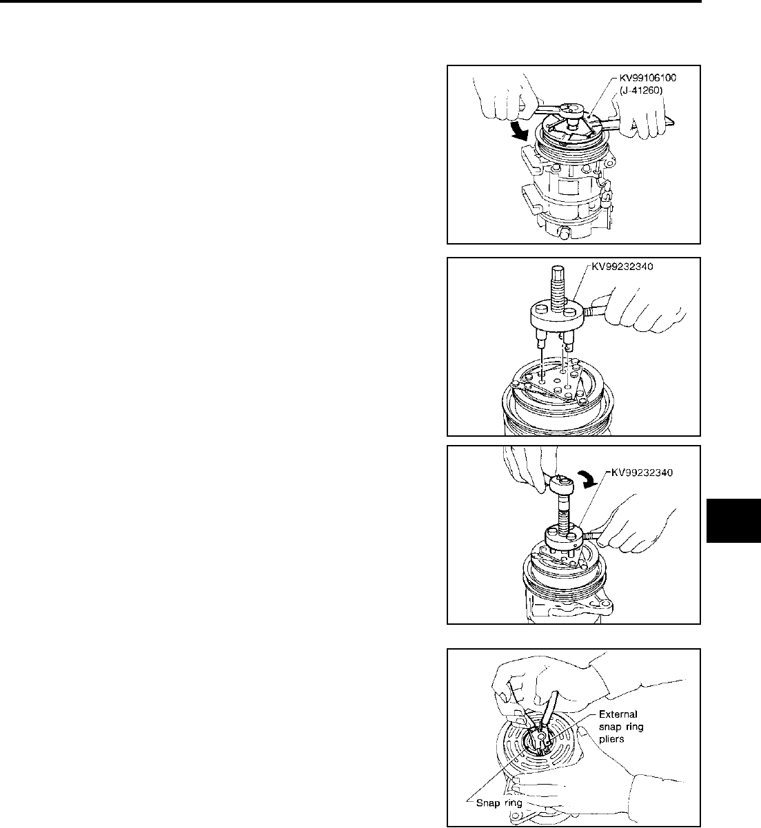
REFRIGERANT LINES
ATC-155
C
D
E
F
G
H
I
K
L
M
A
B
ATC
Revision; 2004 April 2003 FX
Removal and Installation of Compressor Clutch AJS001C8
REMOVAL
Overhaul
1. When removing center bolt, hold clutch disc with wrench.
2. Remove the clutch disc using the clutch disc puller.
3. Remove the snap ring using external snap ring pliers.
RHA136EB
RHA399FA
RHA124FA
RHA138E
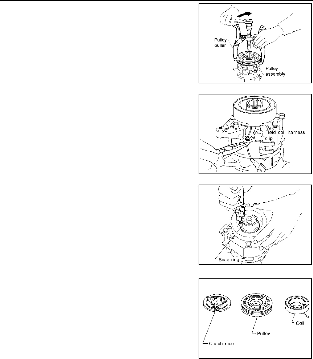
ATC-156
REFRIGERANT LINES
Revision; 2004 April 2003 FX
4. Position the center pulley puller on the end of the drive shaft,
and remove the pulley assembly using any commercially avail-
able pulley puller.
To prevent the pulley groove from being deformed, the puller
claws should be positioned into the edge of the pulley assembly.
5. Remove the field coil harness clip using a pair of pliers.
6. Remove the snap ring using external snap ring pliers.
Inspection
Clutch disc
If the contact surface shows signs of damage due to excessive heat,
replace clutch disc and pulley.
Pulley
Check the appearance of the pulley assembly. If the contact surface
of pulley sows signs of excessive grooving, replace clutch disc and
pulley. The contact surfaces of the pulley assembly should be
cleaned with a suitable solvent before reinstallation.
Coil
Check coil for loose connection or cracked insulation.
RHA139E
RHA125F
RHA145E
RHA126F
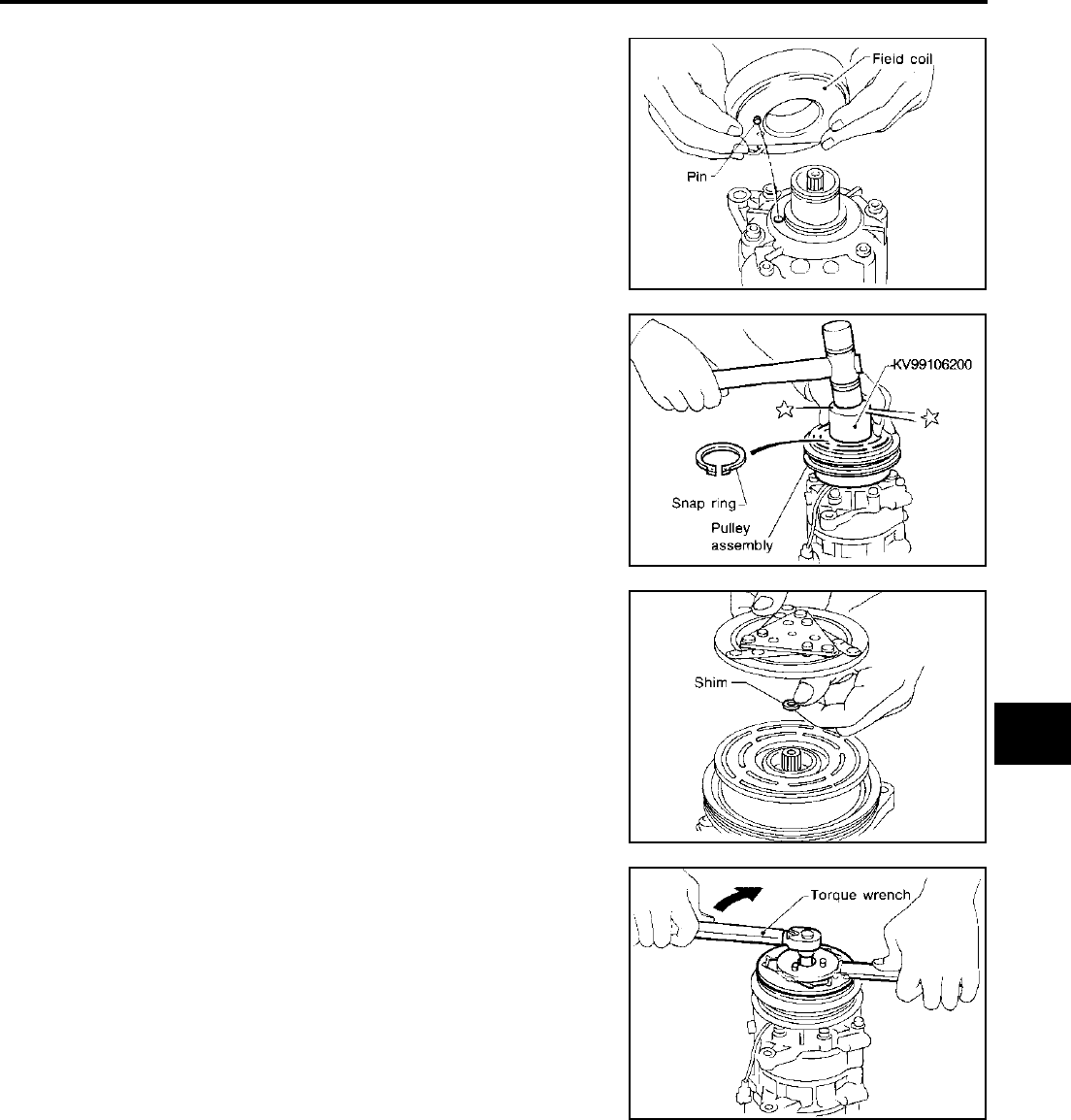
REFRIGERANT LINES
ATC-157
C
D
E
F
G
H
I
K
L
M
A
B
ATC
Revision; 2004 April 2003 FX
INSTALLATION
1. Install the field coil.
Be sure to align the coil′s pin with the hole in the compressor′s
front head.
2. Install the field coil harness clip using a screwdriver.
3. Install the pulley assembly using the installer and a hand press,
and then install the snap ring using snap ring pliers.
4. Install the clutch disc on the drive shaft, together with the original
shim(s). Press the clutch disc down by hand.
5. Using the holder to prevent clutch disc rotation, tighten the bolt
to 14 N·m (1.4 kg-m, 10 ft-lb) torque.
After tightening the bolt, make sure the pulley rotates smoothly.
RHA142E
RHA143E
RHA127F
RHA086E
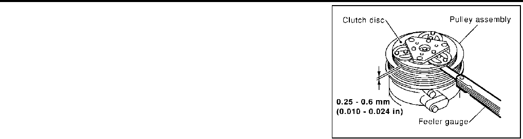
ATC-158
REFRIGERANT LINES
Revision; 2004 April 2003 FX
6. Check clearance around the entire periphery of clutch disc.
If the specified clearance is not obtained, replace adjusting
spacer and readjust.
Break-in Operation
When replacing compressor clutch assembly, always carry out the break-in operation. This is done by engag-
ing and disengaging the clutch about thirty times. Break-in operation raises the level of transmitted torque.
Disc to pulley clear-
ance : 0.25 - 0.6 mm (0.010 - 0.024 in)
RJIA0965E
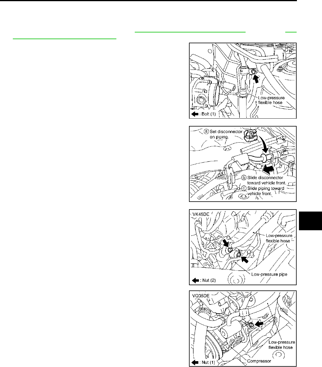
REFRIGERANT LINES
ATC-159
C
D
E
F
G
H
I
K
L
M
A
B
ATC
Revision; 2004 April 2003 FX
Removal and Installation of Low-pressure Flexible Hose AJS001BG
REMOVAL
1. Use a refrigerant collecting equipment (for HFC-134a) to discharge the refrigerant.
2. Remove the air cleaner and air duct. Refer to EM-17, "AIR CLEANER AND AIR DUCT" (VQ35DE) or EM-
170, "AIR CLEANER AND AIR DUCT" (VK45DE).
3. Remove mounting bolt for low-pressure flexible hose bracket.
4. Disconnect one-touch joint between low-pressure flexible hose
and low-pressure pipe 1.
a. Set a disconnector (92530-89916) on A/C piping.
b. Slide a disconnector toward vehicle front until it clicks.
c. Slide A/C piping toward vehicle front and disconnect it.
5. Remove mounting nut from low-pressure flexible hose.
6. Remove low-pressure flexible hose.
CAUTION:
Cap or wrap the joint of the pipe with suitable material such
as vinyl tape to avoid the entry of air.
7. Remove low-pressure pipe (VK45DE).
RJIA2062E
RJIA2069E
RJIA2063E
RJIA2064E
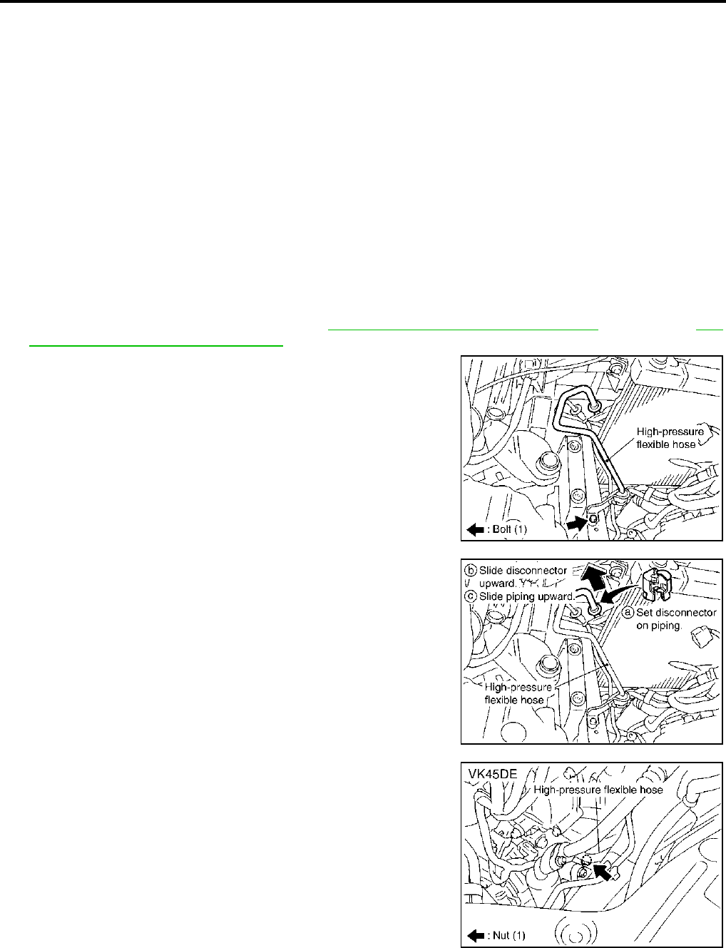
ATC-160
REFRIGERANT LINES
Revision; 2004 April 2003 FX
INSTALLATION
Installation is basically the reverse order of removal.
CAUTION:
●Replace O-rings for A/C piping with new one, then apply compressor oil to it when installing it.
●Connection point for female-side piping is thin. So, when inserting male-side piping, take care not
to deform female-side piping. Slowly insert in axial direction.
●Insert one-touch joint connection point securely until it clicks.
●After piping has been connected, pull male-side piping by hand to check that piping does not
come off.
●When recharging refrigerant, check for leaks.
Removal and Installation of High-pressure Flexible Hose AJS0015U
REMOVAL
1. Use a refrigerant collecting equipment (for HFC-134a) to discharge the refrigerant.
2. Remove the air cleaner and air duct. Refer to EM-17, "AIR CLEANER AND AIR DUCT" (VQ35DE) or EM-
170, "AIR CLEANER AND AIR DUCT" (VK45DE).
3. Remove mounting bolt for high-pressure flexible hose bracket.
4. Disconnect one-touch joint between high-pressure flexible hose
and condenser.
a. Set a disconnector (92530-89912) on A/C piping.
b. Slide a disconnector upward until it clicks.
c. Slide A/C piping upward and disconnect it.
CAUTION:
Cap or wrap the joint of the pipe with suitable material such
as vinyl tape to avoid the entry of air.
5. Remove mounting nut for high-pressure flexible hose (compres-
sor side), and then remove high-pressure flexible hose.
CAUTION:
Cap or wrap the joint of the pipe with suitable material such
as vinyl tape to avoid the entry of air.
Bolt mounting the low-pressure flexible hose bracket
Tightening torque : 5.5 N·m (0.56 kg-m, 49 in-lb)
RJIA2065E
RJIA2066E
RJIA2067E
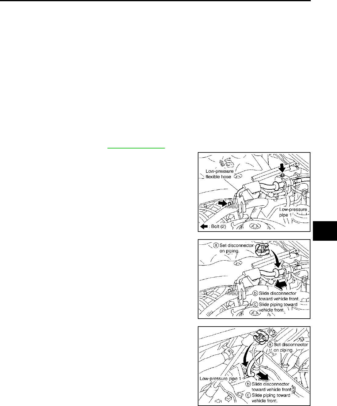
REFRIGERANT LINES
ATC-161
C
D
E
F
G
H
I
K
L
M
A
B
ATC
Revision; 2004 April 2003 FX
INSTALLATION
Installation is basically the reverse order of removal.
CAUTION:
●Replace the O-ring of the high-pressure flexible hose with a new one, then apply compressor oil to
it when installing it.
●Connection point for female-side piping is thin. So, when inserting male-side piping, take care not
to deform female-side piping. Slowly insert in axial direction.
●Insert one-touch joint connection point securely until it clicks.
●After piping has been connected, pull male-side piping by hand to make sure piping does not
come off.
●When recharging refrigerant, check for leaks.
Removal and Installation of Low-pressure Pipe 1 (Engine Compartment) AJS0015V
REMOVAL
1. Use a refrigerant collecting equipment (for HFC-134a) to discharge the refrigerant.
2. Remove cowl top cover. Refer to EI-24, "COWL TOP" .
3. Remove mounting bolt for low-pressure pipe 1 bracket and low-
pressure flexible hose bracket.
4. Disconnect one-touch joints.
a. Set a disconnector (92530-89916) on A/C piping.
b. Slide a disconnector toward vehicle front until it clicks.
c. Slide A/C piping toward vehicle front and disconnect it.
5. Remove low-pressure pipe 1.
CAUTION:
Cap or wrap the joint of the pipe with suitable material such
as vinyl tape to avoid the entry of air.
Bolt mounting the high-pressure flexible hose bracket
Tightening torque : 5.5 N·m (0.56 kg-m, 49 in-lb)
RJIA2068E
RJIA2069E
RJIA2037E
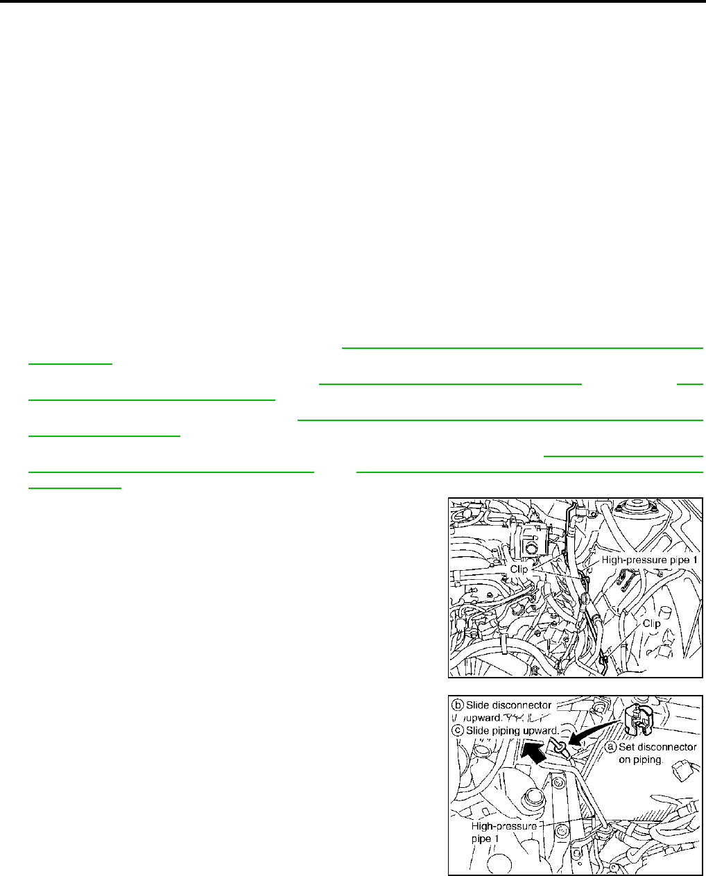
ATC-162
REFRIGERANT LINES
Revision; 2004 April 2003 FX
INSTALLATION
Installation is basically the reverse order of removal.
CAUTION:
●Replace the O-ring of the high-pressure flexible hose with a new one, then apply compressor oil to
it when installing it.
●Connection point for female-side piping is thin. So, when inserting male-side piping, take care not
to deform female-side piping. Slowly insert in axial direction.
●Insert one-touch joint connection point securely until it clicks.
●After piping has been connected, pull male-side piping by hand to make sure piping does not
come off.
●When recharging refrigerant, check for leaks.
Removal and Installation of High-pressure Pipe 1 and 2 (Engine Compartment)
AJS001BH
REMOVAL
1. Use a refrigerant collecting equipment (for HFC-134a) to discharge the refrigerant.
2. Remove front wiper motor and linkage. Refer to WW-44, "Removal and Installation of Front Wiper Motor
and Linkage" .
3. Remove the air cleaner and air duct. Refer to EM-17, "AIR CLEANER AND AIR DUCT" (VQ35DE) or EM-
170, "AIR CLEANER AND AIR DUCT" (VK45DE).
4. Remove low-pressure pipe 1. Refer to ATC-161, "Removal and Installation of Low-pressure Pipe 1
(Engine Compartment)" .
5. Remove high-pressure flexible hose and low-pressure flexible hose. Refer to ATC-160, "Removal and
Installation of High-pressure Flexible Hose" and ATC-159, "Removal and Installation of Low-pressure
Flexible Hose" .
6. Remove high-pressure pipe 1 and 2 from clips.
7. Disconnect one-touch joint between condenser and high-pres-
sure pipe 1.
a. Set a disconnector (92530-89908) on A/C piping.
b. Slide a disconnector upward until it clicks.
c. Slide A/C piping upward and disconnect it.
CAUTION:
Cap or wrap the joint of the pipe with suitable material such
as vinyl tape to avoid the entry of air.
Bolts mounting the low-pressure pipe 1 bracket and low-pressure flexible hose bracket
Tightening torque : 5.5 N·m (0.56 kg-m, 49 in-lb)
RJIA2070E
RJIA2071E
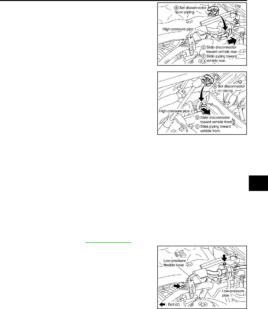
REFRIGERANT LINES
ATC-163
C
D
E
F
G
H
I
K
L
M
A
B
ATC
Revision; 2004 April 2003 FX
8. Disconnect one-touch joint between high-pressure pipe 1 and 2.
a. Set a disconnector (92530-89908) on A/C piping.
b. Slide a disconnector toward vehicle rear until it clicks.
c. Slide A/C piping toward vehicle rear and disconnect it.
CAUTION:
Cap or wrap the joint of the pipe with suitable material such
as vinyl tape to avoid the entry of air.
9. Remove high-pressure pipe 1.
10. Disconnect one-touch joint between high-pressure pipe 2 and 3.
a. Set a disconnector (92530-89908) on A/C piping.
b. Slide a disconnector toward vehicle front until it clicks.
c. Slide A/C piping toward vehicle front and disconnect it.
11. Remove the high-pressure pipe 2.
CAUTION:
Cap or wrap the joint of the pipe with suitable material such
as vinyl tape to avoid the entry of air.
INSTALLATION
Installation is basically the reverse order of removal.
CAUTION:
●Replace the O-ring of the high-pressure pipe with a new one, then apply compressor oil to it when
installing it.
●Connection point for female-side piping is thin. So, when inserting male-side piping, take care not
to deform female-side piping. Slowly insert in axial direction.
●Insert one-touch joint connection point securely until it clicks.
●After piping has been connected, pull male-side piping by hand to make sure piping does not
come off.
●When recharging refrigerant, check for leaks.
Removal and Installation of Low-pressure Pipe 2 and High-pressure Pipe 3 AJS001BI
REMOVAL
1. Set the temperature at 18°C (60°F), and then disconnect the battery negative cable.
2. Use a refrigerant collecting equipment (for HFC-134a) to discharge the refrigerant.
3. Remove cowl top cover. Refer to EI-24, "COWL TOP" .
4. Remove mounting bolts for low-pressure pipe 1 bracket and low-
pressure flexible hose bracket.
RJIA2072E
RJIA2073E
RJIA2068E
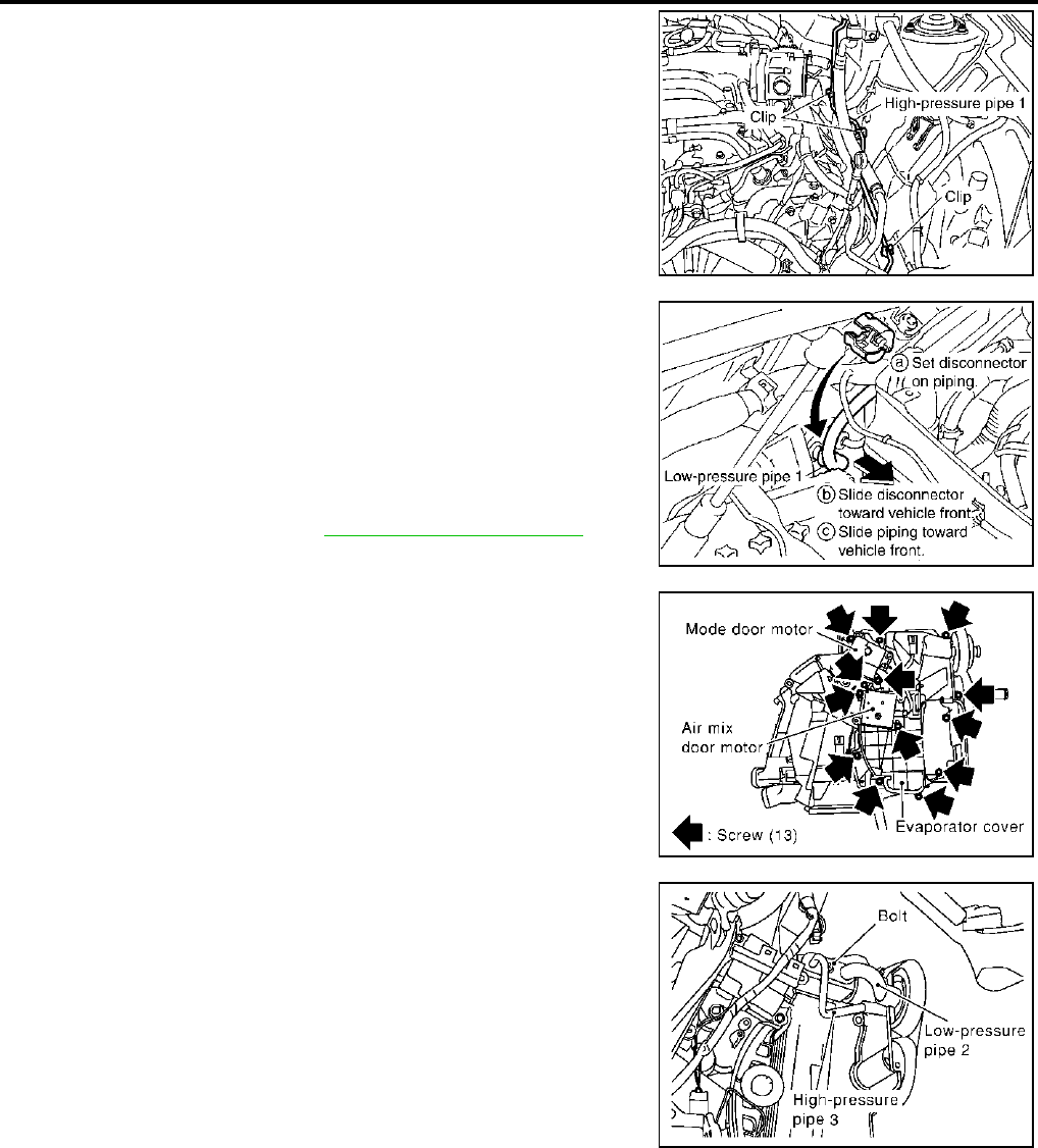
ATC-164
REFRIGERANT LINES
Revision; 2004 April 2003 FX
5. Remove high-pressure pipe 1 from vehicle clips.
6. Disconnect one-touch joints.
a. Set a disconnector (High-pressure side: 92530-89908, Low-
pressure side: 92530-89916) on A/C piping.
b. Slide a disconnector toward vehicle front until it clicks.
c. Slide A/C piping toward vehicle front and disconnect it.
CAUTION:
Cap or wrap the joint of the pipe with suitable material such
as vinyl tape to avoid the entry of air.
7. Remove blower unit. Refer to ATC-134, "BLOWER UNIT" .
8. Remove air mix door motor (passenger side), mode door motor
and evaporator cover.
9. Remove mounting bolt, then, remove low-pressure pipe 2 and
high-pressure pipe 3.
CAUTION:
Cap or wrap the joint of the pipe with suitable material such
as vinyl tape to avoid the entry of air.
INSTALLATION
Installation is basically the reverse order of removal.
CAUTION:
●Replace O-rings for A/C piping with new ones, then apply compressor oil to it when installing it.
●Connection point for female-side piping is thin. So, when inserting male-side piping, take care not
to deform female-side piping. Slowly insert in axial direction.
●Insert one-touch joint connection point securely until it clicks.
●After piping has been connected, pull male-side piping by hand to make sure piping does not
come off.
●When recharging refrigerant, check for leaks.
RJIA2070E
RJIA2037E
RJIA0940E
RJIA2038E
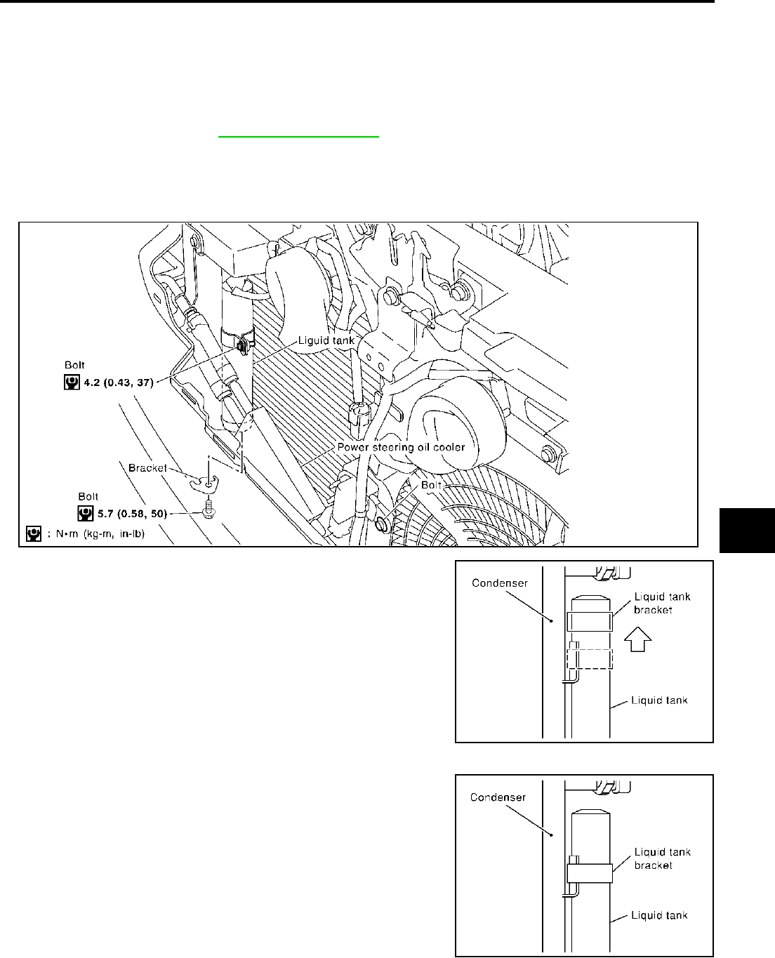
REFRIGERANT LINES
ATC-165
C
D
E
F
G
H
I
K
L
M
A
B
ATC
Revision; 2004 April 2003 FX
Removal and Installation of Liquid Tank AJS0015Y
REMOVAL
1. Use a refrigerant collecting equipment (for HFC-134a) to discharge the refrigerant.
2. Remove front grille. Refer to EI-23, "FRONT GRILLE" .
3. Clean liquid tank and its surrounding area, and remove dirt and rust from tank.
CAUTION:
Be sure to clean carefully.
4. Remove mounting bolts for liquid tank and power steering oil cooler.
5. Lift liquid tank upwards. Remove bracket from protruding part of
condenser.
6. Slide liquid tank upward, then remove liquid tank.
INSTALLATION
Install liquid tank, and then install liquid tank bracket on condenser.
CAUTION:
●Make sure liquid tank bracket is securely installed at protru-
sion of condenser. (Make sure liquid tank bracket does not
move to a position below center of liquid tank.)
●Replace O-rings for A/C piping with new ones, then apply
compressor oil to it when installing it.
●When recharging refrigerant, check for leaks.
Bolts mounting low-pressure pipe 1 bracket and low-pressure flexible hose bracket
Tightening torque : 5.5 N·m (0.56 kg-m, 49 in-lb)
RJIA2074E
RJIA0672E
RJIA0673E
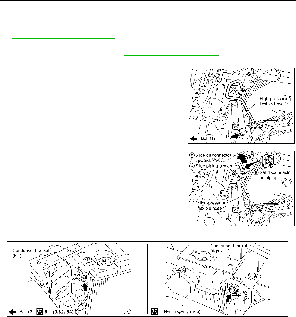
ATC-166
REFRIGERANT LINES
Revision; 2004 April 2003 FX
Removal and Installation of Condenser AJS0015Z
REMOVAL
1. Use a refrigerant collecting equipment (for HFC-134a) to discharge the refrigerant.
2. Remove the air cleaner and air duct. Refer to EM-17, "AIR CLEANER AND AIR DUCT" (VQ35DE) or EM-
170, "AIR CLEANER AND AIR DUCT" (VK45DE).
3. Remove engine undercover, using power tools.
4. Drain engine coolant (VK45DE). Refer to CO-35, "Changing Engine Coolant" .
5. Remove cooling fan shroud after removing radiator upper hose (VK45DE). Refer to CO-38, "RADIATOR" .
6. Remove mounting bolt for high-pressure flexible hose bracket.
7. Disconnect high-pressure flexible hose and high-pressure pipe
1 from condenser.
a. Set a disconnector (Condenser outlet: 92530-89908, Condenser
inlet: 92530-89912) on A/C piping.
b. Slide a disconnector upward until it clicks.
c. Slide A/C piping upward and disconnect it.
CAUTION:
Cap or wrap the joint of the pipe with suitable material such
as vinyl tape to avoid the entry of air.
8. Remove mounting bolts for condenser.
9. Remove radiator upper mount, move radiator and condenser to the engine side.
10. Remove condenser.
CAUTION:
Be careful not to damage the core surface of the condenser and the radiator.
INSTALLATION
Installation is basically the reverse order of removal.
CAUTION:
●Replace O-rings for A/C piping with new ones, then apply compressor oil to it when installing it.
●Connection point for female-side piping is thin. So, when inserting male-side piping, take care not
to deform female-side piping. Slowly insert in axial direction.
●Insert one-touch joint connection point securely until it clicks.
RJIA2065E
RJIA2066E
RJIA2075E
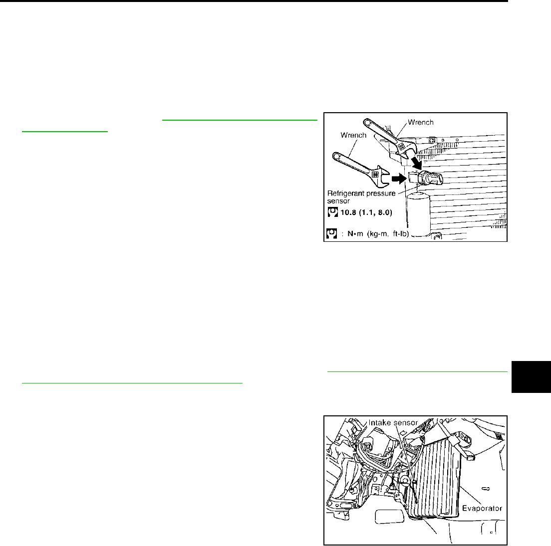
REFRIGERANT LINES
ATC-167
C
D
E
F
G
H
I
K
L
M
A
B
ATC
Revision; 2004 April 2003 FX
●After piping has been connected, pull male-side piping by hand to make sure piping does not
come off.
●When recharging refrigerant, check for leaks.
Removal and Installation of Refrigerant Pressure Sensor AJS00160
REMOVAL
1. Remove condenser. Refer to ATC-166, "Removal and Installa-
tion of Condenser" .
2. Remove refrigerant pressure sensor from condenser.
CAUTION:
When working, be careful not to damage the condenser
fins.
INSTALLATION
Installation is basically the reverse order of removal.
CAUTION:
Apply compressor oil to the O-ring of the refrigerant pressure sensor when installing it.
Removal and Installation of Evaporator AJS001BJ
REMOVAL
1. Set the temperature at 18°C (60°F), and then disconnect the battery negative cable.
2. Using a refrigerant collecting equipment (for HFC-134a) to discharge the refrigerant.
3. Remove low-pressure pipe 2 and high-pressure pipe 3. Refer to ATC-163, "Removal and Installation of
Low-pressure Pipe 2 and High-pressure Pipe 3" .
CAUTION:
Cap or wrap the joint of the pipe with suitable material such as vinyl tape to avoid the entry of air.
4. Slide evaporator, then remove it from heater & cooling unit.
5. Remove intake sensor from evaporator, then remove evapora-
tor.
INSTALLATION
Installation is basically the reverse order of removal.
CAUTION:
●Replace O-rings for A/C piping with new ones, then apply compressor oil to it when installing it.
●Connection point for female-side piping is thin. So, when inserting male-side piping, take care not
to deform female-side piping. Slowly insert in axial direction.
●Insert one-touch joint connection point securely until it clicks.
●After piping has been connected, pull male-side piping by hand to make sure piping does not
come off.
●The O-rings are different from low-pressure pipe 1 (high-pressure pipe 2) and low-pressure pipe 2
(high-pressure pipe 3).
●Mark the mounting position of the intake sensor bracket.
Bolt mounting the high-pressure flexible hose bracket
Tightening torque : 5.5 N·m (0.56 kg-m, 49 in-lb)
RJIA2076E
RJIA0928E

ATC-168
REFRIGERANT LINES
Revision; 2004 April 2003 FX
●When recharging refrigerant, check for leaks.
Bolt mounting low-pressure pipe 1 bracket
Tightening torque : 5.5 N·m (0.56 kg-m, 49 in-lb)
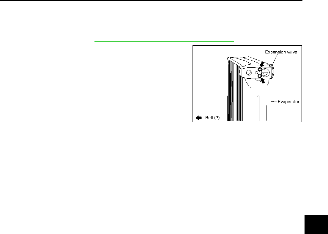
REFRIGERANT LINES
ATC-169
C
D
E
F
G
H
I
K
L
M
A
B
ATC
Revision; 2004 April 2003 FX
Removal and Installation of Expansion Valve AJS001BK
REMOVAL
1. Set the temperature at 18°C (60°F), and then disconnect the battery negative cable.
2. Using a refrigerant collecting equipment (for HFC-134a) to discharge the refrigerant.
3. Remove evaporator. Refer to ATC-167, "Removal and Installation of Evaporator" .
4. Remove mounting bolts for expansion valve, then remove
expansion valve.
INSTALLATION
Installation is basically the reverse order of removal.
CAUTION:
●Replace O-rings with new ones, then apply compressor oil to them when installing them.
●The O-rings are different from low-pressure pipe 1 (high-pressure pipe 2) and low-pressure pipe 2
(high-pressure pipe 3).
●When recharging refrigerant, check for leaks.
RJIA1864E
Bolts mounting expansion valve
Tightening torque : 3.9N·m (0.4 kg-m, 35 in-lb)

ATC-170
REFRIGERANT LINES
Revision; 2004 April 2003 FX
Checking for Refrigerant Leaks AJS00163
Perform a visual inspection of all refrigeration parts, fittings, hoses and components for signs of A/C lubricant
leakage, damage and corrosion. A/C lubricant leakage may indicate an area of refrigerant leakage. Allow
extra inspection time in these areas when using either an electronic refrigerant leak detector or fluorescent
dye leak detector.
If dye is observed, confirm the leak with an electronic refrigerant leak detector. It is possible a prior leak was
repaired and not properly cleaned.
When searching for leaks, do not stop when one leak is found but continue to check for additional leaks at all
system components and connections.
When searching for refrigerant leaks using an electronic leak detector, move the probe along the suspected
leak area at 1 to 2 inches per second and no further than 1/4 inch from the component.
CAUTION:
Moving the electronic leak detector probe slower and closer to the suspected leak area will improve
the chances of finding a leak.
Checking System for Leaks Using the Fluorescent Leak Detector AJS00164
1. Check A/C system for leaks using the UV lamp and safety goggles (J-42220) in a low sunlight area (area
without windows preferable). Illuminate all components, fittings and lines. The dye will appear as a bright
green/yellow area at the point of leakage. Fluorescent dye observed at the evaporator drain opening indi-
cates an evaporator core assembly (tubes, core or expansion valve) leak.
2. If the suspected area is difficult to see, use an adjustable mirror or wipe the area with a clean shop rag or
cloth, with the UV lamp for dye residue.
3. After the leak is repaired, remove any residual dye using dye cleaner (J-43872) to prevent future misdiag-
nosis.
4. Perform a system performance check and verify the leak repair with an approved electronic refrigerant
leak detector.
NOTE:
Other gases in the work area or substances on the A/C components, for example, anti-freeze, windshield
washer fluid, solvents and lubricants, may falsely trigger the leak detector. Make sure the surfaces to be
checked are clean.
Clean with a dry cloth or blow off with shop air.
Do not allow the sensor tip of the detector to contact with any substance. This can also cause false readings
and may damage the detector.
Dye Injection AJS00165
(This procedure is only necessary when recharging the system or when the compressor has seized and was
replaced.)
1. Check A/C system static (at rest) pressure. Pressure must be at least 345 kPa (3.52 kg/cm2 , 50 psi).
2. Pour one bottle (1/4 ounce / 7.4 cc) of the A/C refrigerant dye into the injector tool (J-41459).
3. Connect the injector tool to the A/C Low-pressure side service fitting.
4. Start engine and switch A/C ON.
5. When the A/C operating (compressor running), inject one bottle (1/4 ounce / 7.4 cc) of fluorescent dye
through the low-pressure service valve using dye injector tool J-41459 (refer to the manufacture′s operat-
ing instructions).
6. With the engine still running, disconnect the injector tool from the service fitting.
CAUTION:
Be careful the A/C system or replacing a component, pour the dye directly into the open system con-
nection and proceed with the service procedures.
7. Operate the A/C system for a minimum of 20 minutes to mix the dye with the system oil. Depending on the
leak size, operating conditions and location of the leak, it may take from minutes to days for the dye to
penetrate a leak and become visible.
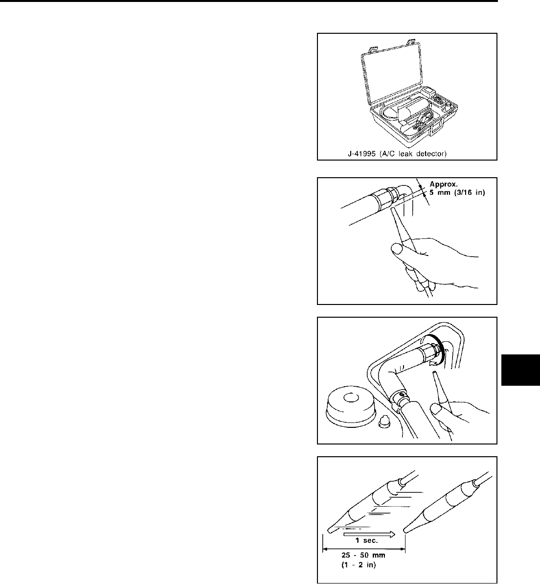
REFRIGERANT LINES
ATC-171
C
D
E
F
G
H
I
K
L
M
A
B
ATC
Revision; 2004 April 2003 FX
Electronic Refrigerant Leak Detector AJS00166
PRECAUTIONS FOR HANDLING LEAK DETECTOR
When performing a refrigerant leak check, use a J-41995 A/C leak
detector or equivalent. Ensure that the instrument is calibrated and
set properly per the operating instructions.
The leak detector is a delicate device. In order to use the leak detec-
tor properly, read the operating instructions and perform any speci-
fied maintenance.
1. Position probe approximately 5 mm (3/16 in) away from point to
be checked.
2. When testing, circle each fitting completely with probe.
3. Move probe along component approximately 25 to 50 mm (1 to
2 in)/sec.
SHA196FA
SHA707EA
SHA706E
SHA708EA

ATC-172
REFRIGERANT LINES
Revision; 2004 April 2003 FX
CHECKING PROCEDURE
To prevent inaccurate or false readings, make sure there is no refrigerant vapor, shop chemicals, or cigarette
smoke in the vicinity of the vehicle. Perform the leak test in calm area (low air/wind movement) so that the
leaking refrigerant is not dispersed.
1. Turn engine OFF.
2. Connect a suitable A/C manifold gauge set to the A/C service ports.
3. Check if the A/C refrigerant pressure is at least 345 kPa (3.52 kg/cm2 , 50 psi) above 16°C (61°F). If less
than specification, recover/evacuate and recharge the system with the specified amount of refrigerant.
NOTE:
At temperatures below 16°C (61°F), leaks may not be detected since the system may not reach 345 kPa
(3.52 kg/cm2 , 50 psi).
4. Perform the leak test from the high side (compressor discharge a to evaporator inlet h) to the low side
[evaporator drain hose h to shaft seal o (VK45DE) or n (VQ35DE)]. Refer to ATC-151, "Components" .
Perform a leak check for the following areas carefully. Clean the component to be checked and move the
leak detected probe completely around the connection/component.
Compressor
Check the fitting of high- and low-pressure hoses, relief valve and shaft seal.
Liquid tank
Check the refrigerant connection.
Service valves
Check all around the service valves. Ensure service valve caps are secured on the service valves (to pre-
vent leaks).
NOTE:
After removing A/C manifold gauge set from service valves, wipe any residue from valves to prevent any
false readings by leak detector.
Cooling unit (Evaporator)
With engine OFF, turn blower fan on “High” for at least 15 seconds to dissipate any refrigerant trace in the
cooling unit. Wait a minimum of 10 minutes accumulation time (refer to the manufacturer′s recommended
procedure for actual wait time) before inserting the leak detector probe into the drain hose.
Keep the probe inserted for at least 10 seconds. Use caution not to contaminate the probe tip with water
or dirt that may be in the drain hose.
5. If a leak detector detects a leak, verify at least once by blowing compressed air into area of suspected
leak, then repeat check as outlined above.
6. Do not stop when one leak is found. Continue to check for additional leaks at all system components.
If no leaks are found, perform steps 7-10.
7. Start engine.
8. Set the heater A/C control as follows;
a. A/C switch: ON
b. Face mode
c. Intake position: Recirculation
d. Max cold temperature
e. Fan speed: High
9. Run engine at 1,500 rpm for at least 2 minutes.
10. Turn engine off and perform leak check again following steps 4 through 6 above.
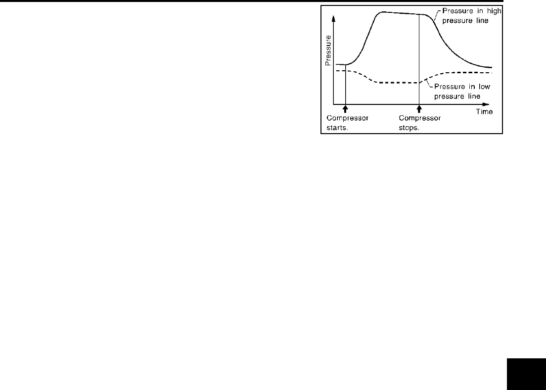
REFRIGERANT LINES
ATC-173
C
D
E
F
G
H
I
K
L
M
A
B
ATC
Revision; 2004 April 2003 FX
Refrigerant leaks should be checked immediately after stopping
the engine. Begin with the leak detector at the compressor. The
pressure on the high pressure side will gradually drop after
refrigerant circulation stops and pressure on the low pressure
side will gradually rise, as shown in the graph. Some leaks are
more easily detected when pressure is high.
11. Before connecting ACR4 to vehicle, check ACR4 gauges. No refrigerant pressure should be displayed. If
pressure is displayed, recover refrigerant from equipment lines and then check refrigerant purity.
12. Confirm refrigerant purity in supply tank using ACR4 and refrigerant identifier.
13. Confirm refrigerant purity in vehicle A/C system using ACR4 and refrigerant identifier.
14. Discharge A/C system using approved refrigerant recovery equipment. Repair the leaking fitting or com-
ponent as necessary.
15. Evacuate and recharge A/C system and perform the leak test to confirm no refrigerant leaks.
16. Perform A/C performance test to ensure system works properly.
SHA839E

ATC-174
SERVICE DATA AND SPECIFICATIONS (SDS)
Revision; 2004 April 2003 FX
SERVICE DATA AND SPECIFICATIONS (SDS) PFP:00030
Compressor AJS00167
Lubricant AJS00168
Refrigerant AJS00169
Engine Idling Speed AJS0016A
Refer to EC-50, "Idle Speed and Ignition Timing Check" (VQ35DE) or EC-691, "Idle Speed and Ignition Tim-
ing Check" (VK45DE).
Belt Tension AJS0016B
Refer to EM-15, "DRIVE BELTS" (VQ35DE) or EM-167, "DRIVE BELTS" (VK45DE).
Model Calsonic Kansei make V-6
Type V-6 variable displacement
Displacement
cm3 (cu in)/rev
Max. 184 (11.228)
Min. 14.5 (0.885)
Cylinder bore × stroke
mm (in) 37 (1.46) × [2.3 - 28.6 (0.091 - 1.126)]
Direction of rotation Clockwise (viewed from drive end)
Drive belt Poly V
Model Calsonic Kansei make V-6
Name Nissan A/C System Oil Type S (DH-PS)
Part number KLH00-PAGS0
Capacity
m (US fl oz, lmp fl oz)
Total in system 180 (6.0, 6.3)
Compressor (Service part) charg-
ing amount 180 (6.0, 6.3)
Type HFC-134a (R-134a)
Capacity
kg (lb) 0.55 (1.21)
