Ayan_IV_manual Ayan IV Manual
User Manual: ayan_IV_manual
Open the PDF directly: View PDF ![]() .
.
Page Count: 24
Revision: 01 8/25/2016 Page 1
INSTALLATION AND OPERATIONAL
MAINTENANCE MANUAL
IN ROW SYSTEMS
CKC AYAN IV SERIES 2 TO 5 TON
IN ROW COOLING
COMPU-AIRE, INC.
8176 BYRON ROAD, WHITTIER, CA 90606
PHONE: (562) 945-8971 FAX: (562) 696-0724
Website: ww.compu-aire.com Email: cs@compu-aire.com
ISO 9001-2008 REGISTERED COMPANY

Revision: 01 8/25/2016 Page 2
TABLE OF CONTENTS
SAFETY INSTRUCTIONS ................................................................................................................... 3
GENERAL ......................................................................................................................................... 4
TRANSPORTATION MODE ............................................................................................................... 4
IMPORTANT – READ BEFORE INSTALLING ...................................................................................... 5
LOCATING THE UNIT .................................................................................................................... 5
ELECTRICAL DATA: ....................................................................................................................... 6
NAMEPLATE DATA ....................................................................................................................... 6
CHILLED WATER COOLING COIL ................................................................................................. 6
CHILLED WATER VALVE .............................................................................................................. 6
CONDENSATE DRAINS ................................................................................................................. 6
CONDENSATE PUMP ................................................................................................................... 6
CONTROL PANEL.......................................................................................................................... 7
CHILLED WATER UNITS (CKC) ...................................................................................................... 7
TECHNICAL DATA ............................................................................................................................ 8
INSTALLATION ............................................................................................................................... 10
UTILITY CONNECTIONS .............................................................................................................. 10
SETTING OF THE UNIT ............................................................................................................... 10
AIR FLOW ................................................................................................................................... 10
CONNECTIONS ........................................................................................................................... 10
STRUCTURAL SUPPORT ................................................................................................................. 11
ELECTRICAL SUPPORT ................................................................................................................... 11
CONDENSATE DRAIN CONNECTION.............................................................................................. 11
WATER CONNECTIONS .................................................................................................................. 11
REFERENCE .................................................................................................................................... 19
TABLE OF FIGURES
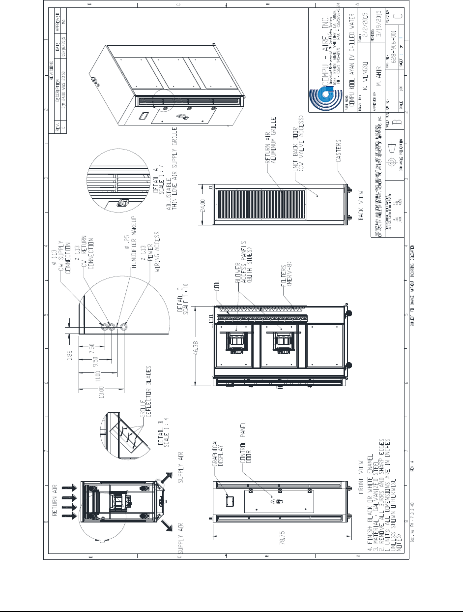
Figure 1 - System layout ................................................................................................................ 12
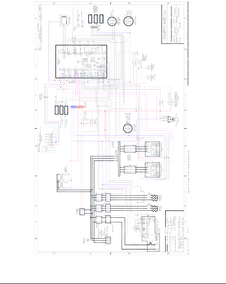
Figure 2 - General wiring diagram ................................................................................................ 13
Figure 3 - Ayan iv inrow cooling .................................................................................................... 14
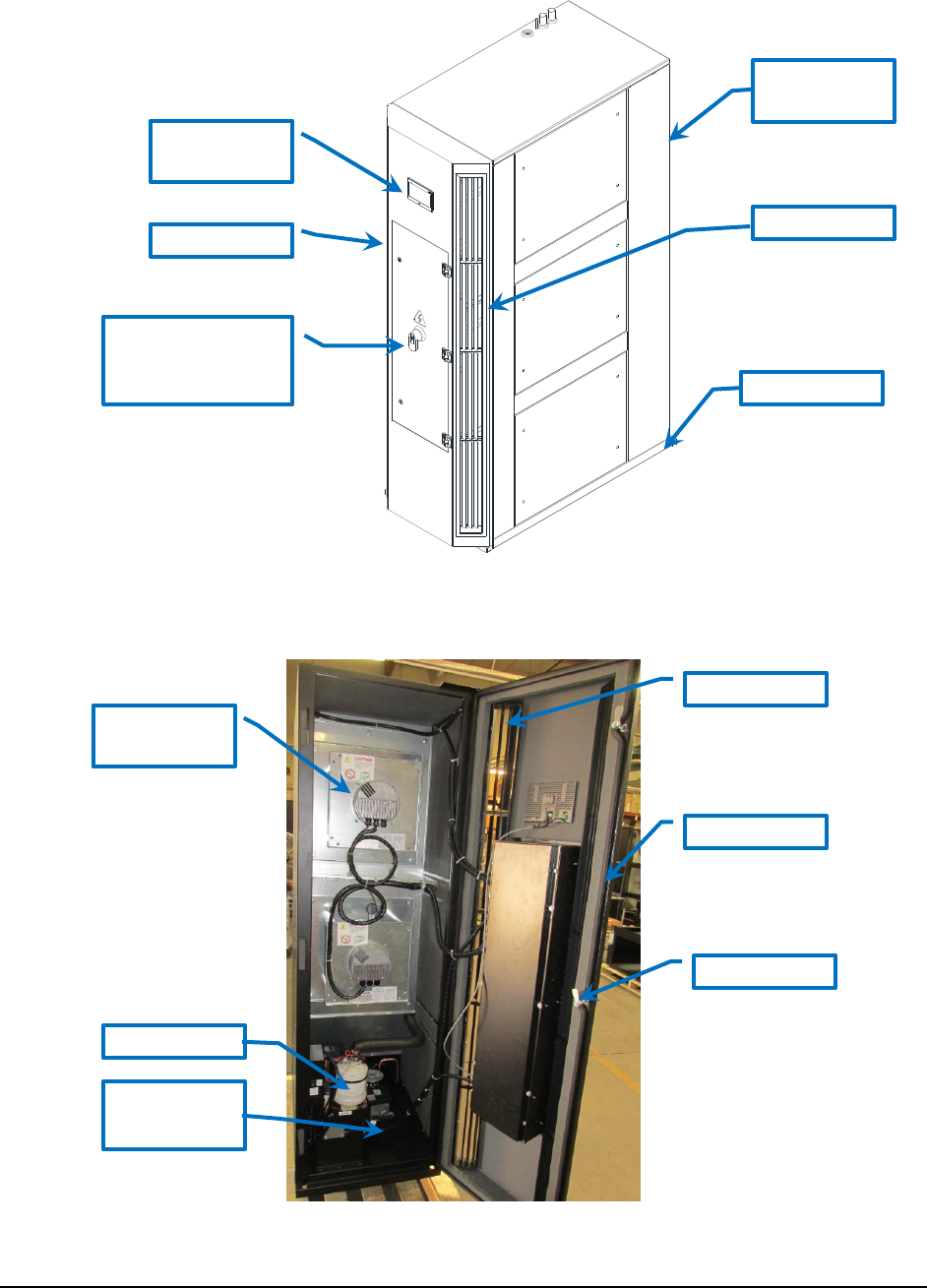
Figure 4 - Front view ..................................................................................................................... 14
Figure 5 - Back view ...................................................................................................................... 15
Figure 6 - Control Panel ................................................................................................................ 15

Revision: 01 8/25/2016 Page 3
SAFETY INSTRUCTIONS
Only qualified personnel should install and service this equipment. The installation, start-up,
and servicing of heating, ventilating, and air conditioning equipment can be hazardous and
requires specific knowledge and training. Improperly installed, adjusted or altered equipment
by unqualified personnel could result in serious damage and/or death. When working on the
equipment, observe all precautions in this literature and on the tags, stickers, and labels that
are attached to the equipment as well as all local codes and safety requirements.
This user’s manual contains important safety instructions that should be followed to properly
install and maintain Compu-Aire system Compu Kool Chilled Water In Row series. Read this
manual thoroughly before attempting to install or operate this unit. Store this manual at safe
place for future reference.
Adhere to all warnings, cautions and safety instructions on the unit and in this manual. Follow
all local codes and safety requirements to install and service this unit.
WARNING
Installation and service of this equipment should be done by qualified personnel who
have been specially trained and qualified in the installation of specific HVAC equipment.
Improper installation could result in unaccountable loss or damage. Compu Kool Chilled Water
In Row series equipment requires a permanent power connection from an isolated circuit
breaker. Customer must provide earth ground to the unit per NEC, CEC and local codes as
applicable.
• Risk of high speed moving parts can cause injury or death.
• Risk of heavy unit falling over
• Risk of hot surfaces, sharp edges, splinters and exposed fasteners can cause injury
WARNING
High voltage danger!
Arc flash and electric shock hazard.
Disconnect main power supply from the feeder before working on this unit. Proceed with
caution and always wear protective equipment per NFPA 70E before working within electrical
control panel. Failure to comply can cause serious injury or death.
WARNING
Evaporator unit requires drain connections and water supply.
Do not locate these connections above any equipment that could
sustain water damage.

Revision: 01 8/25/2016 Page 4
NOTICE
• Improper storage can cause unit damage. Keep the unit upright and store it indoor.
Protect the unit from dampness, freezing temperatures and contact damage.
• Risk of overhead interference. The unit may be too tall to fit through a doorway.
Measure the unit and doorway heights and follow the installation plans to verify clearances
prior to moving the unit.
• Risk of clogged or leaking drain lines. Drain line must be inspected and maintained to
ensure that drain water runs freely through the drain system. Improper installation, application
and service practices can result in water leakage from the unit. Water leakage can cause severe
property damage and loss of critical data center equipment. Suitable leak detection system
shall be installed for the unit and water supply lines to minimize the damage.
• Risk of leaking unit coil/or piping due to freezing and/or corrosion can cause equipment
and building damage. Use proper antifreeze and inhibitors to prevent freezing and premature
coil corrosion. If required, the water or water/glycol solution shall be analyzed every six months
to determine the pattern of inhibitor depletion.
GENERAL
The Compu-Aire Compu-Kool series is a complete environmental control system, factory wired,
tested, and specially designed to provide temperature, humidity, and dust control for computer
room installations.
The unit as shipped from the factory includes a EC fan or blower/motor package, chilled water
coil, control valve, reheat and humidifier (if applicable), electrical control package, controller
display, and other specified special options.
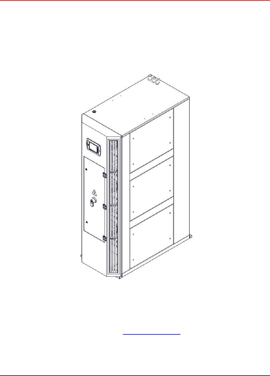
The AYAN IV Series captures high temperature air from the rear of the equipment (hot aisle)
and discharges conditioned air from the front of the equipment (cold aisle). All service access is
from the front or rear of the equipment. Operator controls are located on the front of the
equipment. The equipment comes completely factory assembled, piped, and wired.
TRANSPORTATION MODE
Visual inspection of the outer casing provides a simple indication of possible internal damage to
the equipment. Move the unit to the installation site in the upright position. FILE A CLAIM
WITH THE SHIPPING COMPANY IF THE SHIPMENT IS DAMAGED OR INCOMPLETE. FREIGHT
DAMAGE CLAIMS ARE THE RESPONSIBILITY OF THE RECEIVER.
Optional articles such as jack stand parts, condensate pump, and remote control panel are
packed inside the unit.

Revision: 01 8/25/2016 Page 5
IMPORTANT – READ BEFORE INSTALLING
Check the power supply. Voltage, frequency and phase must correspond to that specified on
the unit nameplate. The power supply must be able to handle the additional load imposed by
this equipment.
LOCATING THE UNIT
Consult local building codes and National Code for special installation requirements. When
installing the unit, allow sufficient space for air flow clearance, wiring and servicing the unit.
Front side and rear side should have a minimum clearance of 36 inches for servicing.
The unit you have received is very special. It is specifically designed for Computer Room
applications. Please read the following INSTRUCTIONS prior to working on the equipment.

Revision: 01 8/25/2016 Page 6
ELECTRICAL DATA:
208v, 3 phase, 60 Hz, 460v, 3 phase, 60 Hz, 208v, 1 phase, 60 Hz, 575v, 3 phase, 60 Hz, 3 phase,
60 Hz, or 415/380v, 3 phase, 50 Hz.
Please check the voltage.
NAMEPLATE DATA
Refer to the unit name plate. It indicates all the electrical data for the unit. LOCAL ELECTRICAL
CODES OR ANY OTHER APPLICABLE CODES MUST BE COMPLIED WITH PRIOR TO WORKING IN
THE UNIT.
Check you unit for the kind of reheat it has. For type C and D piping connections are required.
Make sure shut off valves are provided external to the unit.
CHILLED WATER COOLING COIL
The equipment is supplied with a chilled water coil that is constructed with seamless copper
tubes that are mechanically bond corrugated aluminum fins. The coils are tested and cleaned
prior to installation at the factory. The equipment is supplied with a stainless steel condensate
drain pan with a built in condensate pump.
CHILLED WATER VALVE
The equipment comes with a factory piped 2-way pressure independent modulating control
valve. The pressure independent valve regulates the water flow eliminating the need for
balancing valves. The pressure independent control valve combines a differential pressure
regulator with a 2-way control valve to supply a specific flow for each degree of ball opening
regardless of system pressure fluctuations.
CONDENSATE DRAINS
An internal p-trap condensate drain is provided and connected to the condensate water pump
mounted in the unit.
CONDENSATE PUMP
(Optional): When provided it is mount on the unit or shipped separately. To avoid any flooding
problems provide a separate power source. WIRE THE PUMP TO SHUT THE SYSTEM OFF IN
CASE OF OVERFLOW OR PUMP FAILURE. A SYSTEM CUT OFF TERMINAL IS PROVIDED IN THE
UNIT.

Revision: 01 8/25/2016 Page 7
CONTROL PANEL
This is for the air cooled condenser which is shipped from COMPU-AIRE with the air
conditioner. This control panel is to be filed installed and wired in the field. MAKE SURE TO
PROPERLY HOOK UP THE SENSOR CONNECTION TO THE SCR CONTROLLER WHICH ARE TO BE
MADE IN THE FIELD
FOR UNITS EQUIPPED WITH LOW AMBIE4NT CONTROL BELOW 0°F: A head pressure control
valve for each refrigeration circuit is provided and is shipped with the Computer Room air
Conditioner for a FIELD installation on the air cooled condenser. An appropriate control panel
for with fan cycling control is also supplied for field installation on the air cooled condenser.
CHILLED WATER UNITS (CKC)
These units are factory piped with a a two way or three way water regulating valve. These
systems are designed for working pressure of 150 psig. Higher pressure- Refer to nameplate.

Revision: 01 8/25/2016 Page 8
TECHNICAL DATA
AYAN IV-IN ROW COOLING SYSTEM
UNIT MODEL: CKC-534-IR
COOLING CAPACITY: At 95°F DB, 67.9°F WB; 23% RH - Entering Air Temp.
Total Capacity BTU/HR: 150,100
Sensible Capacity-BTU/HR: 140,700
Leaving Coil 56° FBD;53.5° FWB
CHILLED WATER COIL DATA - Aluminum Fins, 3/8" OD Copper tubing
Face Area-Sq. Ft. 8
Rows/FPI 4/12
CHILLED WATER DATA–At 45°F Entering Water Temp.; 55°F Leaving Water Temp.
GPM 30
Pressure Drop: Ft of Water (coil) 24.6
BACKWARD INCLINED DIRECT DRIVE PLENUM FANS:
Quantity 2
CFM 3,325
External Static Pressure (Inch of Water) 0”
E.C MOTOR
kW/Fan 1.41
Qty. 2
REHEAT-Electric
Capacity-BTU/Hr 20,470
K.W. 6
Stages 1
HUMIDIFIER-Steam Generating
K.W. 1.7
Capacity-Pounds/Hr 5
ELECTRICAL DATA - @ 460V/3Ph/60Hz
Full Load Amps (FLA) 12.5
Min. Circuit Ampacity (MCA) 15.6
Max. Recomm. Fuse Size (MFS) 20A

Revision: 01 8/25/2016 Page 9
PIPING DATA- All Connections are Copper O.D.
Condensate Drains 3/4”
Chilled Water Supply 1-1/8”
Chilled Water Return 1-1/8”
PHYSICAL DATA
Length 24.00”
Width 46.38”
Height 78.75”
Unit Weight (Lbs.) 550

Revision: 01 8/25/2016 Page 10
INSTALLATION
Prior to placing the unit make sure proper a clearance are available:
Front 36”
Rear 36”
UTILITY CONNECTIONS
Electrical connection access for the unit is located on the left front of the top panel and piping
connection could be brought from the rear top panel of the unit. Provide isolation shut off
valves for all pipes external to the unit.
SETTING OF THE UNIT
Locate the unit so the desired clearances are provided, paying special attention to floor height
for downflow units. Make sure that piping under floor does not interfere with the discharge air
of the unit.
Unit must be level:
For proper operation the units must be level.
When installing the unit, allow sufficient space for air flow clearance, wiring and servicing the
equipment.
The AYAN IV equipment is designed to be located in a row of server racks between the IT server
racks adjacent to the heat load. The front supply grilles provide conditioned air to the adjacent
IT equipment on the cold aisle side of the IT equipment. The return air intake is in the hot aisle.
It is recommended the AYAN IV equipment be positioned in the server row for optimum air
circulation. Care must be taken to avoid any air bypass between cold aisle and hot aisle. Close
off any empty server slot and send unit bottom to the floor.
Typically the optimum location is next to the highest heat load in the row of server racks. This
will minimize hot spots.
If the AYAN IV equipment is placed at the end of the row of server racks, there must be an air
barrier to prevent the conditioned supply air from being drawn back into the hot aisle side
bypassing the IT equipment.
AIR FLOW
The return air is drawn through the back of the unit and discharged into the room through the
front of the unit.
CONNECTIONS
In connecting the unit, five items must be addressed. They are
1. Structural Support
2. Electrical Supply
3. Condensate Drain Connection

Revision: 01 8/25/2016 Page 11
STRUCTURAL SUPPORT
The unit can be installed directly on the floor or on the raised floor without the need for any
special support. The floor should be level.
ELECTRICAL SUPPORT
A fused disconnect of a HVAC approved circuit breaker must be field provided and installed per
the National Electric Code. There is access to the unit for electrical connection through the unit
bottom or the lower portion of the unit back. Be sure unit is properly grounded.
A fused disconnect must be provided for the air cooled condenser for air cooled condenser for
air cooled units and dry fluid cooler for the glycol cooled units.
CONDENSATE DRAIN CONNECTION
An internal p-trap is provided on drain pan and connected to the condensate water pump
located below the supply air blowers and the pump can be accessed from the front of the unit.
The pump will be active when the pump detect water condensation and pump the water
condensation out from the condensate line located rear top panel of the unit. Field install must
connect the condensate line to building drain system properly according to the building
guidelines. See Figure 4 - Front view for location of the condensate water pump.
WATER CONNECTIONS
For water cooled units where water supply shall be either city water or cooling tower. Provide
a shut off valve in supply and return line for isolation.
ELECTRICAL CONNECTIONS: The power supply to the air cooled condenser must be brought
through a fused disconnect of a proper handle the electrical requirement of the condenser.
Control panel is factory supple and is packaged separately. This panel is to be field mounted.
Revision: 01 8/25/2016 Page 12
FIGURE 1 SYSTEM LAYOUT
Revision: 01 8/25/2016 Page 13
Wiring Diagram
FIGURE 2 GENERAL WIRING DIAGRAM
628-457-151
COMPU-KOOL AYAN-IV
MCP SYSTEM 2200+
MAIN
ALARM
ANALOG1
MAIN
ALARM
ANALOG1
CA-9362
Revision: 01 8/25/2016 Page 14
FIGURE 3 - AYAN IV INROW COOLING
FIGURE 4 - FRONT VIEW
Return Air
Inlet
Leveling Feet
Graphical
Display
Supply Air
Supply Air
Plug Fan
EC Motor
Electrical Control
Box Panel
Supply Grille
Locking latch
Humidifier
Condensate
Pump
Front Door
Revision: 01 8/25/2016 Page 15
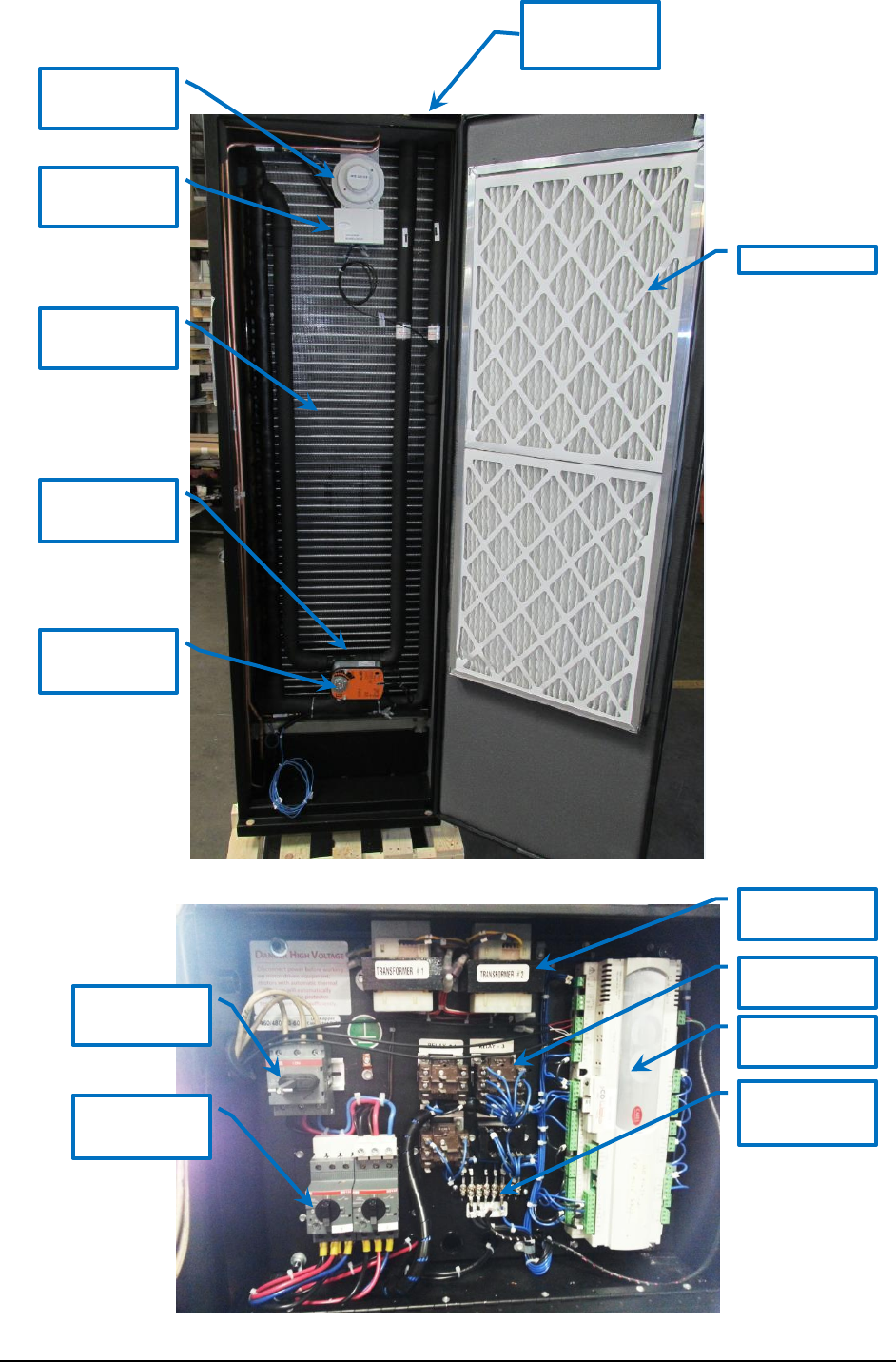
FIGURE 5 - BACK VIEW
FIGURE 6 - CONTROL PANEL
Disconnect
Switch
Motor
Overload
Protector
Transformer
Aux Relay
Controller
Terminal
Block
Chilled Water
Coil
Chilled Water
Valve
Chilled Water
Actuator
Piping
Connections
Filter
Smoke
Detector
Temp/Hum
Sensor

Revision: 01 8/25/2016 Page 16
START-UP AND TEST PROCEDURE
A. With all power to unit off- Check that ALL WIRING IS CORRECT.
Check that properly sized fuses are installed in the disconnect switch. Correct fuse size
and minimum circuit ampacity are listed on the unit nameplate. Now, check the wiring
connections in the Main Control Panel to see if they are tight. It is best that this be
checked prior to operating the machine. After checking, close the Main Control Panel
cover and proceed as follows:
Microprocessor Control Panel – With the system switch in the “OFF” position, apply
power to the unit. The “Power ON” light should illuminate.
B. Check for Correct Phasing
The equipment should now be checked for correct phasing required to make the blower
motor turn in the correct directions. For this test it is necessary to open the right side
doors of the unit to observe the blower and blower motor. Now, momentarily switch
the system switch to the “ON” position and then back to “OFF”. The blower motor with
have started and it is therefore possible to determine rotation. On Compu-Aire units,
the blower should be rotating in a CLOCKWISE direction. Heaters and humidifiers are
not affected by phasing.

Revision: 01 8/25/2016 Page 17
GENERAL MAINTENANCE
General maintenance must be performed in regular intervals to provide continued operation of
the entire unit. The maintenance intervals must be determined site specifically. Use the
maintenance checklist at the end of this manual when performing maintenance. Typically, air
filters should be replaced no less than two times per year.
The filters should be checked and changed periodically. When they become dirty, an alarm is
activated the filter pressure switch. If the filters are dirty, they must be changed for efficient
operation of your system. To check the alarm indicator, cover approximately 75% of the return
air opening; the alarm should energize. If the alarm energizes prematurely or does not energize
when it should, adjust the filter switch. All doors to machine should remain closed before
determining whether an adjustment is necessary. Spare filters should be kept in stock. Filters
should be checked monthly and replaced if necessary.
The maintenance intervals must be determined site specifically. Use the maintenance checklist
provided if available when performing maintenance. In order to ensure that the system runs
trouble free for many years, a follow-up maintenance program (consisting of a minimum of two
inspections per year) should be set up. A qualified service mechanic should carry out this semi-
annual inspection. The main power supply must be disconnected and locked off to avoid
accidental startup of the equipment.
(1) Check electrical components and tighten any loose connections.
(2) Check all wiring and electrical insulators.
(3) Check contactors to ensure proper operation and contact point for wear.
(4) Check that fan motors (if applicable) are operational, ensure fan blades are tight and all
mounting bolts are tight.
(5) Ensure that the condenser surface (if applicable) is cleaned and free of dirt and debris.
(6) Check the operation of the control system. Make certain that all of the safety controls are
operational and functioning properly.
(7) Check chilled water valve system. Make sure that all mechanical joints and flare nuts are
tight.
Service Parts Availability
Genuine replacement service parts should be used whenever possible. Parts may be obtained
by contacting your local sales representative or authorized distributor. Contact us 562.945.8971

Revision: 01 8/25/2016 Page 18
TROUBLESHOOTING GUIDE
Complaint
Problem
Symptom
Action
1.
Chilled water valve is
not opening because of
loose or broken wiring.
Display shows chilled
water cooling is on or
economy cooling is on
but, the valve is closed.
Test for 24VAC at valve
motor. Check continuity
between chilled water
pins connection of the
microprocessor
controller and valve
motor. If no voltage,
replace microprocessor
setting. (refer to
supplied controller
manual-by other)
2. System does
not humidify
or does not do
so sufficiently.
Control parameters are
not set correctly or set
as expected.
System seems to
function okay
otherwise.
Refer to controller
setting and check that
all control parameters
are set correctly.
Loose or broken wiring
in low voltage circuits or
bad microprocessor
board.
Display shows
humidification
operating but, the
humidifier is not on.
Test for 24VAC at pin
connetion on controller.
If no voltage, check
wiring back to system.
3. System is on
but, no-thing
is operating.
The blower is
off.
No air flow, fire stat,
water on floor or smoke
detector alarm is
activated.
The display shows one
or more of these alarms
and the Alarm LED is on.
The system is
automatic-ally shut
down if any of these
conditions occur.
Determine what the
cause is and remedy.
Then, press the Reset
button on the
controller.
4. System does
not run.
No 24VAC supply
voltage.
Power LED is not on.
Check circuit breaker in
system 24VAC circuit
and reset if necessary.
Check System cutout
switch. Test for 24VAC
at pins 1 and 2 of
controller.
TABLE 1 TROUBLESHOOTING GUIDE

Revision: 01 8/25/2016 Page 19
REFERENCE
8167 Byron Rd., Whittier, CA 90606
PH (562) 945-8971 FAX (562) 696-0724
STANDARD ONE YEAR WARRANTY
Job
Name:
Job No.
Date:
We warranty this Compu-Aire, Inc. computer room unit to be free from defects in material and workmanship; our obligation being
limited to repairing or replacing at our factory any part (except as noted below) within one year from the date of shipment to the
original purchaser. Parts to be returned to us PREPAID. Proof of start-up date must be submitted to the factory.
This warranty is effective only if the unit has been installed in accordance with our instructions and connected to proper and adequate
electric, water and drain services, correctly dehydrated and placed into operation by a competent service representative.
Fan motor compressor warranty is covered by original manufacturer’s warranty and any repair or replacement should be made by the
local authorized service facility as listed the telephone book.
Maintenance and service such as replacing filters, humidifier cylinder, infra-red lamps, float valve assemblies, belts, cleaning,
lubrication, calibration and adjusting are NOT INCLUDED in this warranty.
Replacement or repair parts shall be shipped from the factory pre-paid and invoiced for the full amount. Upon receipt of warranteed
parts within 30 days with prepayment of the component and which our inspection discloses the parts are defective, and show no signs
of misuse, alterations, or abuse, full credit will be issued.
Compu-Aire, Inc. does not assume any responsibility for the labor expense for changing defective parts or replacement of any
refrigerant or other cooling medium such as glycol etc.
All parts and goods are thoroughly inspected and packed to meet the requirements of railroad freight classifications bureaus, and
under standard shippers risk, when they leave our factory. SHOULD GOODS ARRIVE DAMAGED, call the agents attention to
damage, and have same noted on freight bill. For concealed damage, demand immediate inspection from agent of the shipping
company and insist on a notation being made on freight bill.
Purchaser-User
Model Number
Serial Number
Serial Number
Serial Number
Serial Number

Revision: 01 8/25/2016 Page 20
FIELD TEST PLANS
THIS FORM MUST BE COMPLETED FOR EACH UNIT AND SENT BACK TO COMPU-AIRE.
TEST DATE START: TEST DATE COMPLETE
COMPANY PERFORMING TESTING:
ADDRESS:
PHONE NUMBER: FAX NO:
EMAIL:
TECHNICIAN’S NAME:
TECHNICIAN PHONE NO:
PROJECT NAME:
PROJECT ADDRESS:
CUSTOMER CONTACT:
UNIT MODEL:
UNIT SERIAL NO:
VOLTAGE:
UNIT TYPE:
CHILLED WATER AIR HANDLER
UNIT EQUIPPED WITH:
TYPE OF HUMIDIFIER:
HUMIDIFIER SN#: CYLINDER # KW:
TYPE OF HEAT: KW:
TYPE OF CHILLED WATER VONTROL VALVE:
CONDENSATE PUMP SN#:
FIELD CHECK
UNIT ALIGNMENT AND SECURELY MOUNTED
DOOR ALIGNMENT
NUTS FOR TIGHTNESS

Revision: 01 8/25/2016 Page 21
WIRES FOR CONNECTION TIGHTNESS
UNIT GROUND CONNECTED
HIGH AND LOW VOLTAGE WIRING CONDITION FOR ANY DAMAGE
EC FAN MOTOR ASSEMBLY
SMOKE DETECTOR
REMOTE SENSORS
CONDENSATE PUMP MOUNT
PIPING AND VALVE SUPPORTS AND AVOID ANY RUBBING PIPES
INSULATION (CHECK ALL PIPING, C.W. VALVES)
CONDENSATE DRAIN TRAP
ISOLATION VALVES INSTALLED
STRAINER INSTALLED
SUPPLY AND RETURN AIR CLERANCE AND AIR DISTRIBUTION
HUMIDIFIER WATER LINES FLUSHED
HUMIDIFIER CYLINDER IS SECURED
CHILLED WATER VALVES IS SECURED
SET CONTROLS to test operation:
TEMPERATURE SET POINT
HUMIDISTAT SETPOINT
HI LOW TEMPERATURE AND HUMIDITY SET POINTS
(NOTE ANY CHANGES MADE TO THE CONTROLLER SETTINGS)
UNIT POWER SUPPLY: Test Voltage
LINE VOLTAGE: L1-L2: L2-L3: L1-L3:
CONTROL VOLTAGE AT CONTROLLER: ___________
evap fan #1
MOTOR HP/KW: F.L.A: VOLTAGE:
MODEL # ___________________________________________________________________
AMP DRAW: L1 L2 L3
CONTROL INPUT SIGNAL MIN/MAX: VDC
evap fan #2
MOTOR HP/KW: F.L.A: VOLTAGE:
MODEL # ___________________________________________________________________
AMP DRAW: L1 L2 L3
CONTROL INPUT SIGNAL MIN/MAX: VDC
evap fan #3
MOTOR HP/KW: F.L.A: VOLTAGE:
MODEL # ___________________________________________________________________
AMP DRAW: L1 L2 L3
CONTROL INPUT SIGNAL MIN/MAX: VDC
evap fan #4
MOTOR HP/KW: F.L.A: VOLTAGE:
MODEL # ___________________________________________________________________

Revision: 01 8/25/2016 Page 22
AMP DRAW: L1 L2 L3
CONTROL INPUT SIGNAL MIN/MAX: VDC
evap fan #5
MOTOR HP/KW: F.L.A: VOLTAGE:
MODEL # ___________________________________________________________________
AMP DRAW: L1 L2 L3
CONTROL INPUT SIGNAL MIN/MAX: VDC
evap fan #6
MOTOR HP/KW: F.L.A: VOLTAGE:
MODEL # ___________________________________________________________________
AMP DRAW: L1 L2 L3
CONTROL INPUT SIGNAL MIN/MAX: VDC
REHEAT
TYPE: ELECTRIC: NO. OF STAGES: __________
HEATER AMP DRAW:
STAGE 1: L1: L2: L3:
STAGE 2: L1: L2: L3:
Humidifier
AMP DRAW: L1: ___ L2: L3:
VERIFY FILL VALVE OPERATION: ____________________
DRAIN VALVE OPERATION: ___________________________
CONDITION in 100% cooling TEST mode
SUPPLY AIR TEMPERATURE: °F RETURN AIR TEMPERATURE:
RETURN
RETURN AIR HUMIDITY: ____%
C.W. SUPPLY TEMPERATURE: _____________ ° F C.W. RETURN TEMPERATURE: _____________
° F
CHILLED WATER
WATER IN TEMP: °F WATER OUT TEMP: °F
CHILLED WATER VALVE PRT NUMBER:
______________________________________________________________________
CHILLED WATER VALVE OPERATION: MIN/MAX: VDC RANGE
Automatic Controls
CONTROLLER MODEL:
SOFTWARE REVISION: REVISION DATE:
CHECK ALL ALARMS
CALIBRATE SENSORS AS NEEDED
VERIFY POINTS LIST WITH CONTROLS CONTRACTOR
VERIFY OPERATION OF LONWORKS COMMUNICATION CARD WITH BMS
CHECK ALL ANALOG OUT PUTS

Revision: 01 8/25/2016 Page 23
CHECK ALL DIGITAL OUT PUTS
Alarm set points
TEMPERATURE: HIGH: ___ LOW:
HUMIDITY: HIGH: ___ LOW:
(NOTE ANY CHANGES MADE TO THE CONTROLLER SETTINGS)
Condensate Pump
WET TEST: ___
TECHNICIAN COMMENTS
NOTE ALL READINGS AND ANY ADJUSTMENT MADE AT THE JOB SITE:
ANY VISUAL DAMAGE:

Revision: 01 8/25/2016 Page 24
Technical Support/ Service
Website
www.compu-aire.com
Location
Compu-Aire, Inc.
8167 Byron Road
Whittier, California 90606
United States of America
+1 (562) 945-8971 (Phone)
+1 (562) 696-0724 (Fax)
While every precaution has been taken to ensure the accuracy
and completeness of this literature, Compu-Aire assumes no
responsibility and disclaims all liability for damages resulting from use of
this information or for any errors or omissions.
© 2014 Compu-Aire, Inc
All rights reserved throughout the world. Specifications subject to change
without notice.
