Panasonic DMP BD60/BD80 BD60
User Manual: DMP-BD60
Open the PDF directly: View PDF ![]() .
.
Page Count: 7

Panasonic DMP-BD60/BD80
Region switching guide
With the mod. chip fitted the player will automatically play DVD's from all regions (1-6),
but for Blu-ray disc playback the region must be manually selected.
Blu-ray Region switching is done using the player's original remote control while the
player is in standby mode, by pressing the following buttons:
'1' : Select Blu-ray region 'A'
'2' : Select Blu-ray region 'B'
'3' : Select Blu-ray region 'C'
When the player is powered up out of standby mode the new Blu-ray region will be
active. The selected Blu-ray region will remain active until the player is disconnected
from mains power or a new region is selected while the player is in standby mode.
Note that the player must fully enter standby mode to allow the mod. chip to change the
Blu-ray region, therefore the player's "Quick Start" mode (which keeps the player fully
powered up even in standby mode) must be disabled when changing Blu-ray regions.
Blu-ray region switching is possible with any remote channel setting, 1, 2 or 3.
Panasonic DMP-BD60/BD80
Mod. chip fitting guide
Warning: Modifying your player will invalidate any existing warranty. The mod. chip is
difficult to fit, requiring soldering of small surface mount components and therefore
fitting should only be carried out by those with the appropriate experience. A low power
(15-25W) soldering iron with very small tip is essential. If you don't have the required
tools and experience do not attempt to fit the mod. chip as it's very likely that you will
damage your player.
Please read this guide fully before starting to fit the mod. chip.
Before opening the player ensure that all cables are completely disconnected from it.
Double check that the mains cable is disconnected.
To open the player remove the 7 fixing screws, 2 from left side, 2 from right side and 3
from the rear. The top cover can now be lifted off.
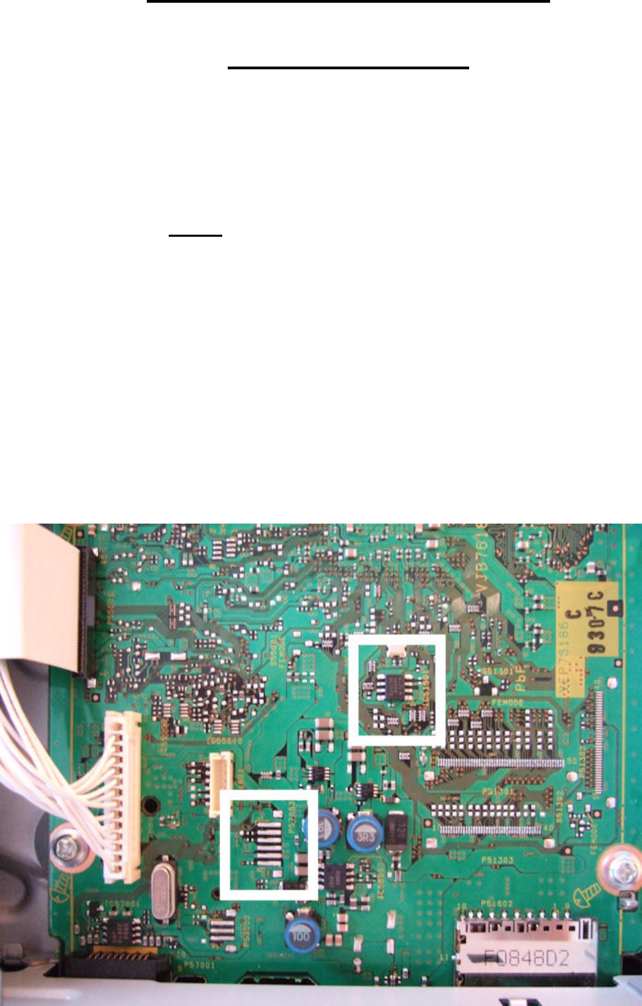
The main board is on the right side and the image below shows the areas where the mod.
chip will be connected to it.
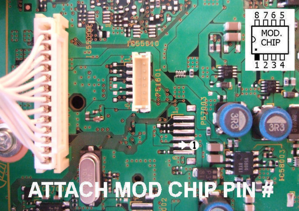
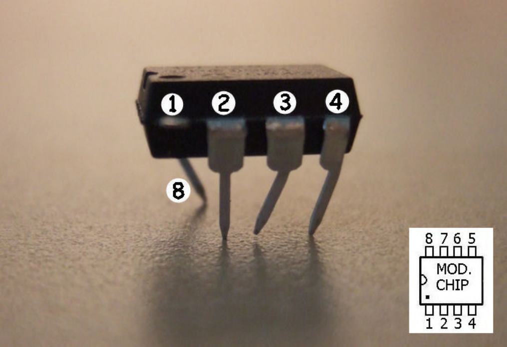
6 pins on the mod. chip are used in total, #1, #2, #3, #4 and #8 connect to the main board
and #5 to the rear of the front panel.
Mod. chip pin #1 should be connected to the 2nd bottom of the 6 long solder pads, as
shown.
Mod. chip pins #2, #3, #4 and #8 should be connected to the small 8 pin chip as shown.
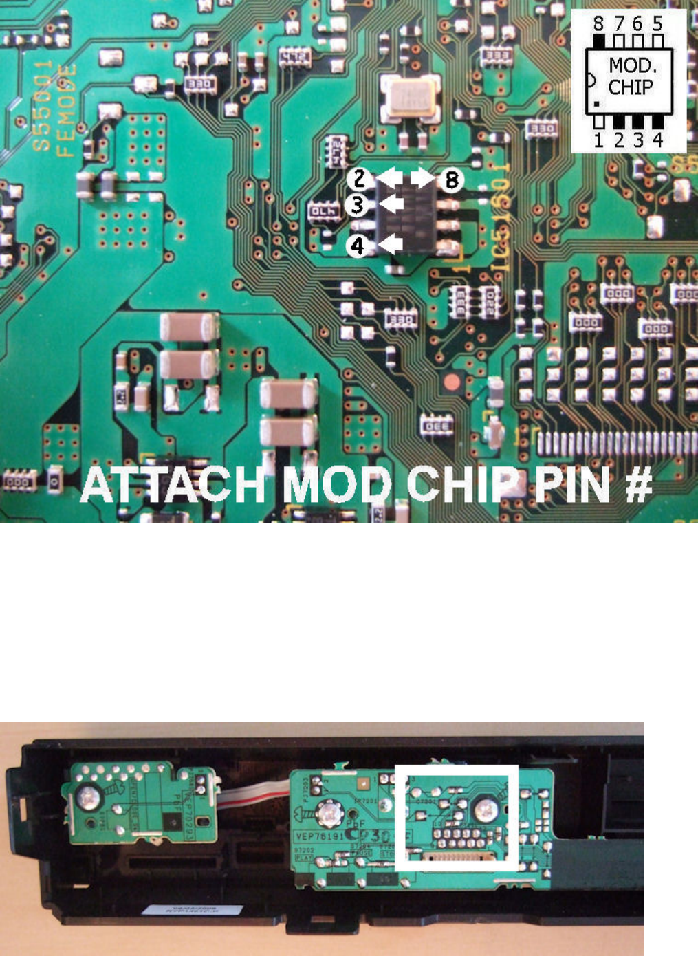
For access to the connection point for mod. chip pin #5 the front panel of the player has to
be removed. To remove the front panel, look for the 7 plastic clips holding it in place, 1
left, 1 right, 2 top and 3 bottom. Carefully unclip them from one side, then the other and
the front panel should pull free.
With the front panel removed you can now see the area where mod. chip pin #5 will be
connected.
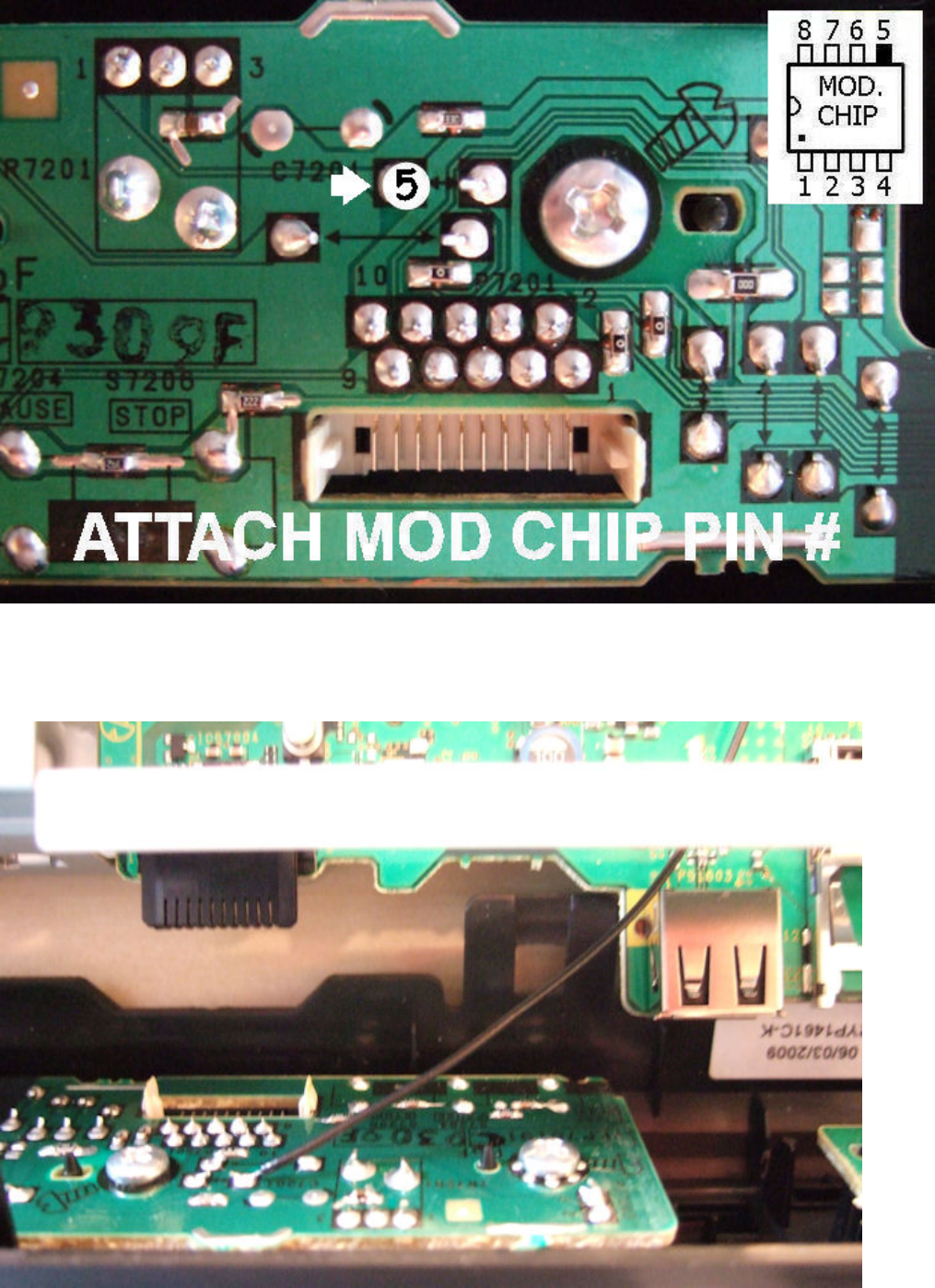
Connect pin #5 to the point on the front panel PCB shown below.
Bring the wire for mod. chip pin #5 in under the metal plate at the front of the player,
ensuring that it doesn't block the connector shown at the left side.
When re-fitting the front panel check that all 7 plastic clips are fully in place, otherwise
the electrical connectors may not contact correctly.
Pins #1 and #5 should be connected with wires, however for the pins that connect to the 8
pin chip on the main board (#2, #3, #4 and #8) it's possible to either connect them with
wires or to "piggy-back" the mod. chip on top of the 8 pin chip on the board. If you
connect all the pins with wires then the mod. chip must be wrapped in insulation tape and
secured in a safe position, so the "piggy-back" option is quicker and only requires 2 wires
for pins #1 and #5.
To "piggy-back" the mod. chip, bend pins #2, #3, #4 and #8 inwards against the body of
the mod. chip and then #3, #4 and #8 as shown below. Trim pins #1 and #5 and
trim/remove the unused pins #6 and #7.
Bend the pins into position and then hold it against the chip on the board to make sure
they are lined up correctly. Once all the pins are lined up solder pin #8 first, then you can
carefully position the mod. chip by rotating it slightly and solder pins #2, #3 and #4.
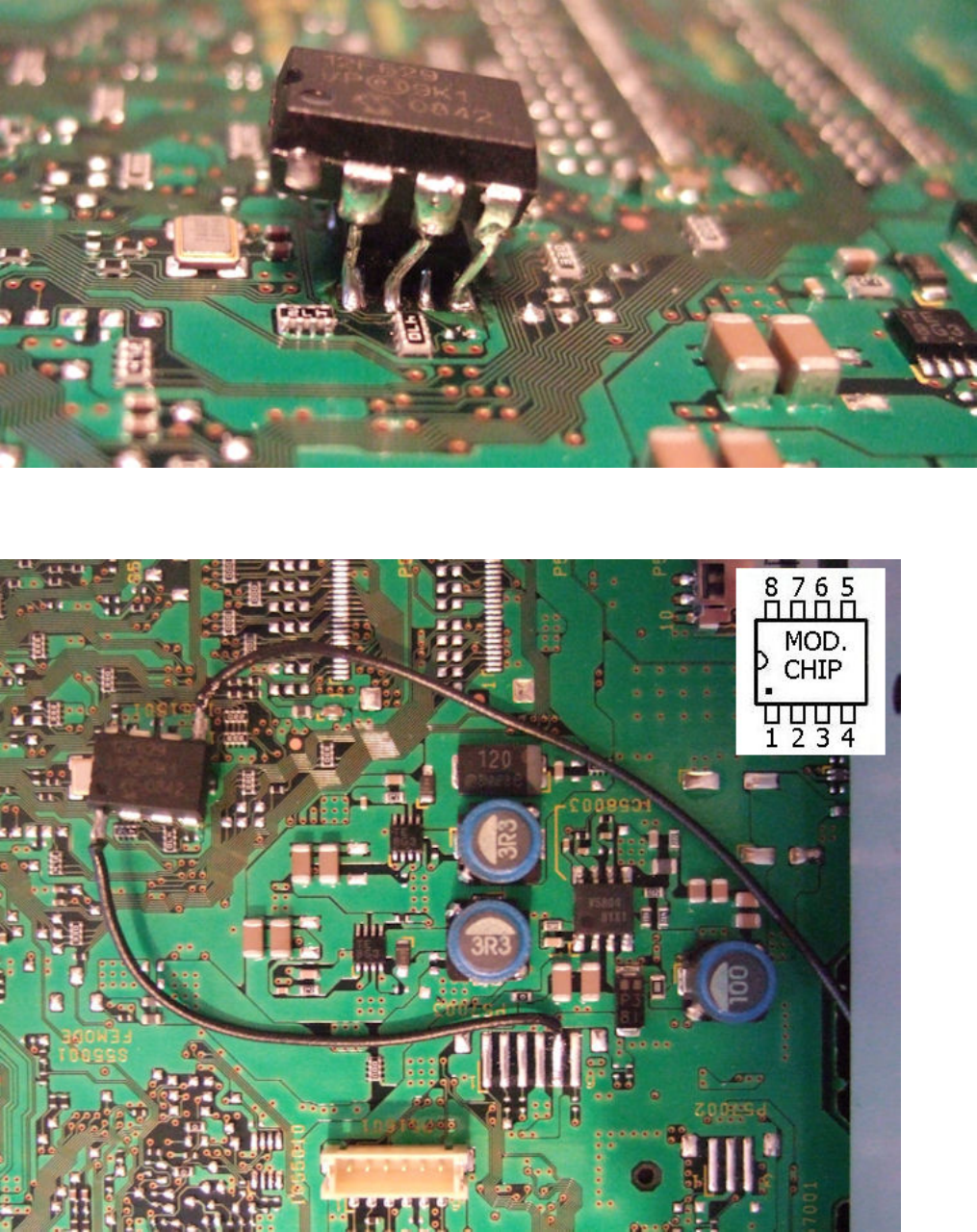
It should then look similar to the image below.
And the full install should look like this, with the wires for pins #1 and #5 in place.
If you're not confident with the "piggy-back" fitting method just use wires to connect all 6
pins of the mod. chip.
