E4 WM5 Y427A00_0 Bil24225793
User Manual: bil24225793
Open the PDF directly: View PDF ![]() .
.
Page Count: 4

E4
E4E4
E4
-
--
-
WM5
WM5WM5
WM5
-
--
-
Y427A00
Y427A00Y427A00
Y427A00
MOUNTINGI
MOUNTINGIMOUNTINGI
MOUNTINGI
N
NN
N
STRUCTION
STRUCTIONSTRUCTION
STRUCTION
created: 08.21.12 E4-WM5-Y427A00_0 page 1 of 4 latest revision:
IMPORTANT!
PLEASE READ ALL INSTRUCTIONS FIRST!
If in doubt, please contact your local BILSTEIN dealer or our sales department before installation.
When replacing other brands, BILSTEIN shock absorbers should always be installed as a set. Installation
of shock absorbers, struts and cartridges requires special tools and expert knowledge. Accordingly,
installation of all BILSTEIN products must be performed by a qualified suspension specialist.
Always use a chassis hoist for the installation of BILSTEIN products, and make certain that the raised
vehicle is securely attached to the hoist to prevent the vehicle from slipping, falling, or moving during the
installation process.
If you choose to install any BILSTEIN product without the necessary special tools, expertise or
chassis hoist, you may subject yourself to the risk of serious bodily injury or death. If you elect not
to use a chassis hoist, at least make sure the vehicle is on level ground, that all tires on the ground during
installation are blocked to prevent movement, that at least two tires are on the ground at all times, and
that adequately secured safety stands (jack stands) are used to support the chassis. NEVER get under
the vehicle until you have checked to make sure all of these things are done.
All BILSTEIN products must only be used for the specific, intended application as indicated in the
application guide. Any use of any BILSTEIN product other than for its intended use may result in
serious bodily injury or death.
BILSTEIN suspension products are gas-filled and are highly pressurized. Never place any BILSTEIN
product in a vise or use a clamp on any BILSTEIN product; never apply heat near any BILSTEIN product,
and never attempt to open or repair any BILSTEIN product, in order to prevent serious bodily injury or
death. Any attempt to misuse, misapply, modify, or tamper with any BILSTEIN suspension product voids
any warranty and may result in serious bodily injury or death.
Do not use impact tools for loosening or tightening fasteners, because this may destroy the screw
threads. Self-locking nuts must only be used once!
Reuse original equipment components only if they are in good condition, otherwise replace them with new
components. Never remove the slight film of oil on the piston rod and seal.
All mounting fasteners for shocks and struts must be securely tightened before tension is placed on the
suspension system.
After installing any BILSTEIN product, the suspension caster and camber must be checked and/or
adjusted to comply with the vehicle manufacturer’s specifications. Also, the (load dependent) brake
compensator and the anti-lock brake system must be checked and/or reset to comply with the vehicle
manufacturer’s specifications. Also the headlight aim must be checked and adjusted.
Be sure to properly dispose of all old parts.

E4
E4E4
E4
-
--
-
WM5
WM5WM5
WM5
-
--
-
Y427A00
Y427A00Y427A00
Y427A00
MOUNTINGI
MOUNTINGIMOUNTINGI
MOUNTINGI
N
NN
N
STRUCTION
STRUCTIONSTRUCTION
STRUCTION
created: 08.21.12 E4-WM5-Y427A00_0 page 2 of 4 latest revision:
CAUTION!!
Before disassembling the front suspension, refer to the vehicle manufacturer’s Service
Manual for proper procedures. The coil spring is preloaded and must be compressed
with an appropriate spring compressor to release the load before the upper mount is
disassembled. Failure to follow the vehicle manufacturer’s procedures may cause
serious injury or death, and may damage the vehicle.
Instructions for shock absorber removal and installation:
1. Remove the existing front shock absorber assembly from the vehicle following all
procedures in the vehicle manufacturer’s service manual.
2. Disassemble the upper mount, spring, and jounce bumper from the shock absorber
following all procedures in the vehicle manufacturer’s service manual.
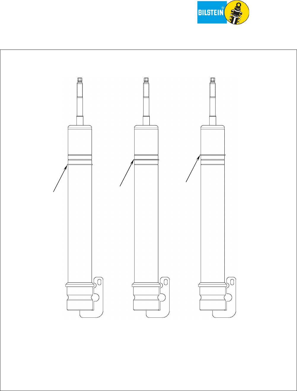
3. If you would like to increase the vehicle lift height to more than ¾-inch above stock, move
the circlip on the new Bilstein shock absorber to the desired ride height location**. Refer to
Figure 1 on the following page for circlip positions and resulting lift heights. Use appropriate
circlip pliers to move the circlip. Ensure that the circlip is fully seated in the groove after
moving it. You should be able to rotate it manually in the groove.
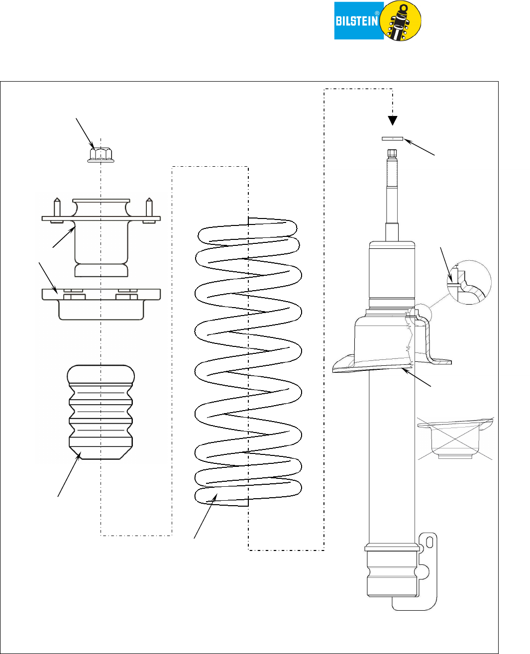
4. Refer to Figure 2 on page 4 for the order in which the shock absorber assembly components
should be installed.
5. Install the new Bilstein spring seat onto the new shock absorber as shown in Figure 2.
Ensure that the spring seat is not upside-down and that the groove inside the spring seat fits
over the circlip on the shock body (see detail view).
6. Slide the new Bilstein washer over the mount stem until it seats against the shoulder on the
piston rod.
7. Place the OEM jounce bumper over the piston rod.
8. Re-install the OEM coil spring and OEM upper mount components in reverse order of
removal in accordance with the vehicle manufacturer’s Service Manual. Use the new Bilstein
lock nut to secure the upper mount.
9. Torque the lock nut to 26 N·m (19 lb·ft)
10. Install the complete shock assembly on the vehicle following all procedures in the vehicle
manufacturer’s service manual.
E4
E4E4
E4
-
--
-
WM5
WM5WM5
WM5
-
--
-
Y427A00
Y427A00Y427A00
Y427A00
MOUNTINGI
MOUNTINGIMOUNTINGI
MOUNTINGI
N
NN
N
STRUCTION
STRUCTIONSTRUCTION
STRUCTION
created: 08.21.12 E4-WM5-Y427A00_0 page 3 of 4 latest revision:
R
ide
heights indicated are typical.
Actual ride height is influenced by which factory suspension the
vehicle is equipped with and its condition, optional equipment and accessories on your vehicle, and
other vehicle modifications such as replacement coil springs, wheel and tire combinations, etc.
Modifying/lifting the suspension to your vehicle may raise its center of gravity and may make it more
susceptible to loss of control and/or rollover, which may result in serious injury or death. We strongly
recommend that you offset the loss of rollover resistance as much as possible by increasing tire track
width, and that you equip the vehicle with a functional roll bar and cage system. Wear seat belts and
shoulder harnesses at all times and avoid situations where a side rollover may occur.
1.5” (38mm)
AVERAGE LIFT
2” (51mm)
AVERAGE LIFT
**Please note that the stock ride height position is not an option on this shock absorber.
It is intended for a lifted configuration only.
Figure
1
: Circlip positions and resulting lift height
0.75” (19mm)
AVERAGE LIFT
E4
E4E4
E4
-
--
-
WM5
WM5WM5
WM5
-
--
-
Y427A00
Y427A00Y427A00
Y427A00
MOUNTINGI
MOUNTINGIMOUNTINGI
MOUNTINGI
N
NN
N
STRUCTION
STRUCTIONSTRUCTION
STRUCTION
created: 08.21.12 E4-WM5-Y427A00_0 page 4 of 4 latest revision:
Figure
2
: Installation order of shock absorber
assembly
components
OEM coil
spring
OEM jounce
bumper
OEM upper
mount
Bilstein
locknut
Bilstein
spring seat
circlip
Bilstein
washer
detail view
DO NOT
INVERT
SPRING
SEAT
!
