Product Detail Manual BL
User Manual: bl
Open the PDF directly: View PDF ![]() .
.
Page Count: 282 [warning: Documents this large are best viewed by clicking the View PDF Link!]
- QUICK REFERENCE INDEX
- Table of Contents
- PRECAUTIONS
- PREPARATION
- SQUEAK AND RATTLE TROUBLE DIAGNOSES
- HOOD
- POWER DOOR LOCK SYSTEM
- Component Parts and Harness Connector Location
- System Description
- Schematic
- Wiring Diagram — D/LOCK —
- Terminals and Reference Value for BCM
- Work Flow
- CONSULT–II Function (BCM)
- Trouble Diagnoses Symptom Chart
- BCM Power Supply and Ground Circuit Check
- Door Switch Check (Without Automatic Back Door System)
- Door Switch Check (With Automatic Back Door System)
- Key Switch (Insert) Check
- Door Lock/Unlock Switch Check
- Front Door Lock Assembly LH (Actuator) Check
- Front Door Lock Actuator RH Check
- Door Lock Actuator Check (Sliding Door)
- Back Door Lock Actuator Check (Without Automatic Back Door)
- Front Door Lock Assembly LH (Key Cylinder Switch) Check
- REMOTE KEYLESS ENTRY SYSTEM
- Component Parts and Harness Connector Location
- System Description
- INPUTS
- OPERATION PROCEDURE
- Remote Control Entry Functions
- Auto Lock Function
- Remote Control Auto Sliding Door Function (Vehicles With Automatic Sliding Door System)
- Active Check Function
- Remote Control Entry Operation
- Remote Control Auto Sliding Door Operation
- Active Check Function
- Hazard and Horn Reminder
- Interior Lamp Operation
- Panic Alarm Operation
- Keyless Power Window Down (open) Operation
- CAN Communication System Description
- Schematic
- Wiring Diagram — KEYLES —
- Terminals and Reference Value for BCM
- Terminals and Reference Value for IPDM E/R
- CONSULT-II Function (BCM)
- CONSULT-II Inspection Procedure
- CONSULT-II Application Items
- Trouble Diagnosis Procedure
- Pre-Diagnosis Inspection
- Trouble Diagnoses
- Key Switch (insert) Check
- Door Switch Check (Without Automatic Back Door System)
- Door Switch Check (With Automatic Back Door System)
- Keyfob Battery and Function Check
- Remote Keyless Entry Receiver System Check
- ACC Power Check
- IPDM E/R Operation Check
- Check Hazard Function
- Check Horn Function
- Check Headlamp Function
- Check Map Lamp and Ignition Keyhole Illumination Function
- ID Code Entry Procedure
- Keyfob Battery Replacement
- VEHICLE SECURITY (THEFT WARNING) SYSTEM
- Component Parts and Harness Connector Location
- System Description
- CAN Communication System Description
- Schematic
- Wiring Diagram — VEHSEC —
- Terminals and Reference Value for BCM
- Terminals and Reference Value for IPDM E/R
- CONSULT-II Function (BCM)
- Trouble Diagnosis
- Preliminary Check
- Symptom Chart
- Diagnostic Procedure 1
- Diagnostic Procedure 2
- Diagnostic Procedure 3
- Diagnostic Procedure 4
- Diagnostic Procedure 5
- Diagnostic Procedure 6
- AUTOMATIC SLIDING DOOR SYSTEM
- Component Parts and Harness Connector Location
- System Description
- OPERATION DESCRIPTION
- Automatic Door Main Switch Operation (Fully Closed Æ Fully Open Operation)
- Remote Keyless Entry Switch Operation (Fully Closed Æ Fully Open Operation)
- Sliding Door Open/Close Switch Operation (Fully Closed Æ Fully Open Operation)
- Automatic Door Main Switch Operation (Fully Open Æ Fully Closed Operation)
- Remote Keyless Entry Operation (Fully Open Æ Fully Closed Operation)
- Power Assist Function
- Sliding Door Power Assist Operation (Fully Closed Æ Fully Open Operation)
- Sliding Door Power Assist Operation (Fully Open Æ Fully Closed Operation)
- Anti-Pinch Function
- Intermittent Clutch Control Function
- Precautions
- Auto Sliding Door Operation Enable Conditions
- Control When Handle Open/Closed When Operating Enable Conditions Not Yet Met
- Control When Operating Enable Conditions No Longer Met
- Warning Chime Active Conditions
- Reverse Conditions
- Operation Chart
- Initialization Mode
- SLIDING DOOR INITIALIZATION PROCEDURE
- SLIDING DOOR LATCH AUTO CLOSURE FUNCTION DESCRIPTION
- SLIDING DOOR LATCH AUTO CLOSURE OPERATION DESCRIPTION
- OPERATION DESCRIPTION
- Schematic
- Wiring Diagram — S/CLOS —
- Terminals and Reference Value for Sliding Door Control Unit RH
- Terminals and Reference Value for Sliding Door Control Unit LH
- Terminals and Reference Value for Sliding Door Latch Control Unit
- Terminals and Reference Value for BCM
- Trouble Diagnosis Procedure
- Self-Diagnosis Procedures
- Diagnosis Chart
- Auto Sliding Door Power Supply and Ground Circuit Inspection
- Automatic Door Main Switch System Inspection
- Sliding Door Open/Close Switch System Inspection
- Sliding Door Motor System Inspection
- Magnetic Clutch Line Check
- Sliding Door Encoder System Inspection
- Sliding Door Remote Control Switch System Inspection
- Child Lockout Switch System Inspection
- Latch Release Actuator System Inspection
- Warning Chime System Inspection
- Half-Latch Switch System Inspection
- Full-Latch Switch System Inspection
- Neutral Switch System Inspection
- Cinch Latch Motor System Inspection
- AUTOMATIC BACK DOOR SYSTEM
- Component Parts and Harness Connector Location
- System Description
- OPERATION DESCRIPTION
- Automatic Door Main Switch Operation (Fully Closed Æ Fully Open Operation)
- Remote Keyless Entry Operation (Fully Closed Æ Fully Open Operation)
- Back Door Handle Switch Operation (Fully Closed Æ Fully Open Operation)
- Automatic Door Main Switch Operation (Fully Open Æ Fully Closed Operation)
- Remote Keyless Entry Operation (Fully Open Æ Fully Closed Operation)
- Back Door Close Switch Operation (Fully Open Æ Fully Closed Operation)
- Anti-Pinch Function
- Gas Stay Check
- Warning Functions
- Auto Back Door Operation Enable Conditions
- Control When Handle Pulled When Operating Enable Conditions Not Yet Met
- Control When Operating Enable Conditions No Longer Met
- Warning Chime Active Conditions
- Reverse Conditions
- OPERATION DESCRIPTION
- Schematic
- Wiring Diagram — B/CLOS —
- Terminals and Reference Value for Back Door Control Unit
- Terminals and Reference Value for BCM
- Trouble Diagnosis Procedure
- Self-Diagnosis Procedures
- Diagnosis Chart
- Back Door Control Unit Power Supply and Ground Circuit Inspection
- Automatic Door Main Switch System Inspection
- Back Door Close Switch System Inspection
- Pinch Strip System Inspection
- Back Door Warning Chime System Inspection
- Half-Latch Switch System Inspection
- Open Switch System Inspection
- Close Switch System Inspection
- Back Door Handle Switch System Inspection
- Cinch Latch Motor System Inspection
- DOOR
- FRONT DOOR LOCK
- SLIDE DOOR LOCK
- BACK DOOR LOCK
- FUEL FILLER LID OPENER
- NVIS (NISSAN Vehicle Immobilizer System-NATS)
- Component Parts and Harness Connector Location
- System Description
- System Composition
- ECM Re-communicating Function
- Wiring Diagram — NATS —
- Terminals and Reference Value for BCM
- CONSULT-II
- Work Flow
- Trouble Diagnoses
- Diagnostic Procedure 1
- Diagnostic Procedure 2
- Diagnostic Procedure 3
- Diagnostic Procedure 4
- Diagnostic Procedure 5
- Diagnostic Procedure 6
- How to Replace NATS Antenna Amp.
- HOMELINK UNIVERSAL TRANSCEIVER
- BODY REPAIR
- POWER SUPPLY ROUTING CIRCUIT
- ELECTRICAL UNITS
- SUPER MULTIPLE JUNCTION (SMJ)
- FUSE BLOCK-JUNCTION BOX (J/B)
- FUSE AND FUSIBLE LINK BOX

BL-1
BODY, LOCK & SECURITY SYSTEM
I BODY
CONTENTS
C
D
E
F
G
H
J
K
L
M
SECTION
A
B
BL
Revision: July 2006 2006 Quest
PRECAUTIONS .......................................................... 5
Precautions for Supplemental Restraint System
(SRS) “AIR BAG” and “SEAT BELT PRE-TEN-
SIONER” .................................................................. 5
Precautions for work ................................................ 5
PREPARATION ........................................................... 6
Special Service Tool ................................................. 6
Commercial Service Tool ......................................... 6
SQUEAK AND RATTLE TROUBLE DIAGNOSES ..... 7
Work Flow ................................................................ 7
CUSTOMER INTERVIEW ..................................... 7
DUPLICATE THE NOISE AND TEST DRIVE ....... 8
CHECK RELATED SERVICE BULLETINS ........... 8
LOCATE THE NOISE AND IDENTIFY THE
ROOT CAUSE ...................................................... 8
REPAIR THE CAUSE ........................................... 8
CONFIRM THE REPAIR ....................................... 9
Generic Squeak and Rattle Troubleshooting ........... 9
INSTRUMENT PANEL .......................................... 9
CENTER CONSOLE ............................................. 9
DOORS ................................................................. 9
TRUNK ................................................................ 10
SUNROOF/HEADLINING ................................... 10
OVERHEAD CONSOLE (FRONT AND REAR) ... 10
SEATS ................................................................. 10
UNDERHOOD ..................................................... 10
Diagnostic Worksheet .............................................11
HOOD ....................................................................... 13
Fitting Adjustment .................................................. 13
CLEARANCE AND SURFACE HEIGHT
ADJUSTMENT .................................................... 14
HOOD LOCK ADJUSTMENT ............................. 14
Removal and Installation of Hood Assembly .......... 15
Removal and Installation of Hood Lock Control ..... 16
REMOVAL ........................................................... 16
INSTALLATION ................................................... 17
Hood Lock Control Inspection ................................ 17
POWER DOOR LOCK SYSTEM .............................. 18
Component Parts and Harness Connector Location ... 18
System Description ................................................ 19
WITHOUT AUTOMATIC SLIDING DOOR SYS-
TEM AND AUTOMATIC BACK DOOR SYSTEM ... 19
WITH AUTOMATIC SLIDING DOOR SYSTEM
AND AUTOMATIC BACK DOOR SYSTEM ......... 20
OUTLINE ............................................................. 21
Schematic ............................................................... 22
WITHOUT AUTOMATIC SLIDING DOOR SYS-
TEM AND AUTOMATIC BACK DOOR SYSTEM ... 22
WITH RIGHT HAND AUTOMATIC SLIDING
DOOR SYSTEM AND AUTOMATIC BACK
DOOR SYSTEM .................................................. 23
WITH RIGHT AND LEFT HAND AUTOMATIC
SLIDING DOOR SYSTEM AND AUTOMATIC
BACK DOOR SYSTEM ....................................... 24
Wiring Diagram — D/LOCK — ............................... 25
WITHOUT AUTOMATIC SLIDING DOOR SYS-
TEM AND AUTOMATIC BACK DOOR SYSTEM ... 25
WITH RIGHT HAND AUTOMATIC SLIDING
DOOR SYSTEM AND AUTOMATIC BACK
DOOR SYSTEM .................................................. 29
WITH RIGHT AND LEFT HAND AUTO SLIDE
DOOR CLOSURE AND AUTOMATIC BACK
DOOR SYSTEM .................................................. 33
Terminals and Reference Value for BCM ............... 37
Work Flow ............................................................... 37
CONSULT–II Function (BCM) ................................ 38
CONSULT–II INSPECTION PROCEDURE ......... 38
DATA MONITOR ................................................. 39
ACTIVE TEST ..................................................... 40
Trouble Diagnoses Symptom Chart ....................... 40
BCM Power Supply and Ground Circuit Check ...... 40
Door Switch Check (Without Automatic Back Door
System) .................................................................. 42
Door Switch Check (With Automatic Back Door Sys-
tem) ........................................................................ 44
Key Switch (Insert) Check ...................................... 46
Door Lock/Unlock Switch Check ............................ 47
Front Door Lock Assembly LH (Actuator) Check .... 49
Front Door Lock Actuator RH Check ...................... 50
Door Lock Actuator Check (Sliding Door) ............... 51

BL-2
Revision: July 2006 2006 Quest
Back Door Lock Actuator Check (Without Automatic
Back Door) .............................................................. 52
Front Door Lock Assembly LH (Key Cylinder Switch)
Check ..................................................................... 53
REMOTE KEYLESS ENTRY SYSTEM .....................55
Component Parts and Harness Connector Location ... 55
System Description ................................................. 56
INPUTS ............................................................... 56
OPERATION PROCEDURE ................................ 57
CAN Communication System Description .............. 60
Schematic ............................................................... 61
Wiring Diagram — KEYLES — ............................... 62
............................................................................. 62
............................................................................. 63
............................................................................. 64
Terminals and Reference Value for BCM ................ 65
Terminals and Reference Value for IPDM E/R ........ 66
CONSULT-II Function (BCM) .................................. 66
CONSULT-II Inspection Procedure ......................... 67
“MULTI REMOTE ENT” ....................................... 67
CONSULT-II Application Items ............................... 68
“MULTI REMOTE ENT” ....................................... 68
Trouble Diagnosis Procedure ................................. 70
Pre-Diagnosis Inspection ........................................ 70
BCM POWER SUPPLY AND GROUND CIRCUIT
INSPECTION ....................................................... 70
Trouble Diagnoses .................................................. 71
SYMPTOM CHART ............................................. 71
Key Switch (insert) Check ...................................... 73
Door Switch Check (Without Automatic Back Door
System) .................................................................. 74
Door Switch Check (With Automatic Back Door Sys-
tem) ........................................................................ 76
Keyfob Battery and Function Check ....................... 78
Remote Keyless Entry Receiver System Check ..... 80
ACC Power Check .................................................. 81
IPDM E/R Operation Check .................................... 82
Check Hazard Function .......................................... 83
Check Horn Function .............................................. 83
Check Headlamp Function ..................................... 83
Check Map Lamp and Ignition Keyhole Illumination
Function .................................................................. 83
ID Code Entry Procedure ....................................... 84
KEYFOB ID SET UP WITH CONSULT-II ............ 84
KEYFOB ID SET UP WITHOUT CONSULT-II ..... 86
Keyfob Battery Replacement .................................. 87
VEHICLE SECURITY (THEFT WARNING) SYSTEM ...88
Component Parts and Harness Connector Location ... 88
System Description ................................................. 89
DESCRIPTION .................................................... 89
POWER SUPPLY AND GROUND CIRCUIT ....... 90
INITIAL CONDITION TO ACTIVATE THE SYS-
TEM ..................................................................... 90
VEHICLE SECURITY SYSTEM ALARM OPER-
ATION .................................................................. 90
VEHICLE SECURITY SYSTEM DEACTIVATION ... 91
PANIC ALARM OPERATION ............................... 91
CAN Communication System Description .............. 91
Schematic ............................................................... 92
Wiring Diagram — VEHSEC — ..............................93
.............................................................................93
.............................................................................94
.............................................................................95
.............................................................................96
.............................................................................97
Terminals and Reference Value for BCM ................98
Terminals and Reference Value for IPDM E/R ........98
CONSULT-II Function (BCM) ..................................99
CONSULT-II INSPECTION PROCEDURE ..........99
CONSULT-II APPLICATION ITEM .....................100
Trouble Diagnosis .................................................101
WORK FLOW ....................................................101
Preliminary Check .................................................102
Symptom Chart .....................................................103
Diagnostic Procedure 1 .........................................104
Diagnostic Procedure 2 .........................................108
Diagnostic Procedure 3 .........................................110
Diagnostic Procedure 4 .........................................112
Diagnostic Procedure 5 .........................................112
Diagnostic Procedure 6 .........................................112
AUTOMATIC SLIDING DOOR SYSTEM .................113
Component Parts and Harness Connector Location .113
System Description ...............................................114
OPERATION DESCRIPTION ............................114
SLIDING DOOR INITIALIZATION PROCEDURE .120
SLIDING DOOR LATCH AUTO CLOSURE
FUNCTION DESCRIPTION ...............................121
SLIDING DOOR LATCH AUTO CLOSURE
OPERATION DESCRIPTION ............................121
Schematic .............................................................122
WITH RIGHT HAND SLIDE DOOR AUTO CLO-
SURE SYSTEM .................................................122
WITH RIGHT AND LEFT HAND SLIDE DOOR
AUTO CLOSURE SYSTEM ...............................123
Wiring Diagram — S/CLOS — ..............................125
WITH RIGHT HAND SLIDE DOOR AUTO CLO-
SURE SYSTEM .................................................125
WITH RIGHT AND LEFT HAND SLIDE DOOR
AUTO CLOSURE SYSTEM ...............................130
Terminals and Reference Value for Sliding Door
Control Unit RH .....................................................140
Terminals and Reference Value for Sliding Door
Control Unit LH .....................................................142
Terminals and Reference Value for Sliding Door
Latch Control Unit .................................................144
Terminals and Reference Value for BCM ..............145
Trouble Diagnosis Procedure ................................146
Self-Diagnosis Procedures ...................................146
INPUT SIGNAL CHECK MODE .........................146
OPERATING CHECK MODE .............................146
Diagnosis Chart ....................................................148
Auto Sliding Door Power Supply and Ground Circuit
Inspection ..............................................................149
Automatic Door Main Switch System Inspection ..149
Sliding Door Open/Close Switch System Inspection .150
Sliding Door Motor System Inspection ..................151
Magnetic Clutch Line Check .................................152
Sliding Door Encoder System Inspection ..............152

BL-3
C
D
E
F
G
H
J
K
L
M
A
B
BL
Revision: July 2006 2006 Quest
Sliding Door Remote Control Switch System
Inspection ............................................................. 154
Child Lockout Switch System Inspection ............. 155
Latch Release Actuator System Inspection ......... 156
Warning Chime System Inspection ...................... 157
Half-Latch Switch System Inspection ................... 157
Full-Latch Switch System Inspection ................... 158
Neutral Switch System Inspection ........................ 159
Cinch Latch Motor System Inspection .................. 160
AUTOMATIC BACK DOOR SYSTEM .................... 162
Component Parts and Harness Connector Location . 162
System Description .............................................. 162
OPERATION DESCRIPTION ............................ 163
Schematic ............................................................ 168
Wiring Diagram — B/CLOS — ............................. 169
Terminals and Reference Value for Back Door Con-
trol Unit ................................................................. 174
Terminals and Reference Value for BCM ............. 176
Trouble Diagnosis Procedure ............................... 177
Self-Diagnosis Procedures ................................... 177
INPUT SIGNAL CHECK MODE ........................ 177
OPERATING CHECK MODE ............................ 177
Diagnosis Chart .................................................... 179
Back Door Control Unit Power Supply and Ground
Circuit Inspection .................................................. 179
Automatic Door Main Switch System Inspection .. 180
Back Door Close Switch System Inspection ........ 181
Pinch Strip System Inspection .............................. 182
Back Door Warning Chime System Inspection .... 183
Half-Latch Switch System Inspection ................... 184
Open Switch System Inspection .......................... 185
Close Switch System Inspection .......................... 186
Back Door Handle Switch System Inspection ...... 187
Cinch Latch Motor System Inspection .................. 188
DOOR ..................................................................... 190
Fitting Adjustment ................................................ 190
FRONT DOOR .................................................. 190
SLIDE DOOR .................................................... 191
BACK DOOR ..................................................... 192
Removal and Installation ...................................... 193
FRONT DOOR .................................................. 193
SLIDE DOOR .................................................... 195
BACK DOOR ..................................................... 196
FRONT DOOR LOCK ............................................. 197
Component Structure ........................................... 197
Removal and Installation ...................................... 197
Disassembly and Assembly ................................. 199
DOOR KEY CYLINDER ASSEMBLY ................ 199
SLIDE DOOR LOCK ............................................... 200
Removal and Installation ...................................... 200
OUTSIDE HANDLE ........................................... 200
SLIDING DOOR LOCK ASSEMBLY ................. 202
SLIDING DOOR CABLE ASSEMBLY AND
MOTOR ............................................................. 203
BACK DOOR LOCK ............................................... 204
Component Structure ........................................... 204
Back Door Latch ................................................... 205
REMOVAL ......................................................... 206
INSTALLATION .................................................206
Back Door Power Lift Assembly ...........................206
REMOVAL .........................................................206
INSTALLATION .................................................207
FUEL FILLER LID OPENER ...................................208
Wiring Diagram — F/LID — ..................................208
REMOVAL .........................................................209
INSTALLATION .................................................209
NVIS(NISSAN VEHICLE IMMOBILIZER SYSTEM-
NATS) ......................................................................210
Component Parts and Harness Connector Location .210
System Description ...............................................211
System Composition .............................................211
ECM Re-communicating Function ........................212
Wiring Diagram — NATS — .................................213
Terminals and Reference Value for BCM .............214
CONSULT-II ..........................................................214
CONSULT-II INSPECTION PROCEDURE ........214
CONSULT-II DIAGNOSTIC TEST MODE FUNC-
TION ..................................................................215
HOW TO READ SELF-DIAGNOSTIC RESULTS .216
NVIS (NATS) SELF-DIAGNOSTIC RESULTS
ITEM CHART .....................................................216
Work Flow .............................................................217
Trouble Diagnoses ...............................................218
SYMPTOM MATRIX CHART 1 ..........................218
SYMPTOM MATRIX CHART 2 ..........................219
DIAGNOSTIC SYSTEM DIAGRAM ...................219
Diagnostic Procedure 1 ........................................220
Diagnostic Procedure 2 ........................................221
Diagnostic Procedure 3 ........................................222
Diagnostic Procedure 4 ........................................223
Diagnostic Procedure 5 ........................................224
Diagnostic Procedure 6 ........................................227
How to Replace NATS Antenna Amp. ..................228
HOMELINK UNIVERSAL TRANSCEIVER .............229
Wiring Diagram — TRNSCV — ............................229
Trouble Diagnoses ...............................................230
DIAGNOSTIC PROCEDURE ............................230
BODY REPAIR ........................................................232
Body Exterior Paint Color .....................................232
Body Component Parts ........................................233
UNDERBODY COMPONENT PARTS ..............233
BODY COMPONENT PARTS ...........................235
Corrosion Protection .............................................237
DESCRIPTION ..................................................237
ANTI-CORROSIVE WAX ..................................238
UNDERCOATING ..............................................239
Body Sealing ........................................................240
DESCRIPTION ..................................................240
Body Construction ................................................243
BODY CONSTRUCTION ..................................243
Body Alignment ....................................................244
BODY CENTER MARKS ...................................244
PANEL PARTS MATCHING MARKS .................246
DESCRIPTION ..................................................248
ENGINE COMPARTMENT ................................249
UNDERBODY ...................................................251
PASSENGER COMPARTMENT .......................253

BL-4
Revision: July 2006 2006 Quest
REAR BODY .....................................................256
Handling Precautions for Plastics .........................258
HANDLING PRECAUTIONS FOR PLASTICS ..258
LOCATION OF PLASTIC PARTS ......................259
Precautions in Repairing High Strength Steel .......261
HIGH STRENGTH STEEL (HSS) USED IN NIS-
SAN VEHICLES ................................................261
Foam Repair .........................................................263
URETHANE FOAM APPLICATIONS .................263
FILL PROCEDURES .........................................263
Replacement Operations ......................................264
DESCRIPTION ..................................................264
HOODLEDGE ....................................................267
FRONT SIDE MEMBER ....................................268
FRONT SIDE MEMBER (PARTIAL REPLACE-
MENT) ................................................................270
FRONT PILLAR .................................................271
CENTER PILLAR ...............................................274
OUTER SILL ......................................................277
REAR FENDER .................................................278
REAR PANEL ....................................................279
REAR FLOOR REAR .........................................280
REAR SIDE MEMBER EXTENSION .................281

PRECAUTIONS
BL-5
C
D
E
F
G
H
J
K
L
M
A
B
BL
Revision: July 2006 2006 Quest
PRECAUTIONS PFP:00001
Precautions for Supplemental Restraint System (SRS) “AIR BAG” and “SEAT
BELT PRE-TENSIONER”
EIS007CY
The Supplemental Restraint System such as “AIR BAG” and “SEAT BELT PRE-TENSIONER”, used along
with a front seat belt, helps to reduce the risk or severity of injury to the driver and front passenger for certain
types of collision. This system includes seat belt switch inputs and dual stage front air bag modules. The SRS
system uses the seat belt switches to determine the front air bag deployment, and may only deploy one front
air bag, depending on the severity of a collision and whether the front occupants are belted or unbelted.
Information necessary to service the system safely is included in the SRS and SB section of this Service Man-
ual.
WARNING:
●To avoid rendering the SRS inoperative, which could increase the risk of personal injury or death
in the event of a collision which would result in air bag inflation, all maintenance must be per-
formed by an authorized NISSAN/INFINITI dealer.
●Improper maintenance, including incorrect removal and installation of the SRS, can lead to per-
sonal injury caused by unintentional activation of the system. For removal of Spiral Cable and Air
Bag Module, see the SRS section.
●Do not use electrical test equipment on any circuit related to the SRS unless instructed to in this
Service Manual. SRS wiring harnesses can be identified by yellow and/or orange harnesses or
harness connectors.
Precautions for work
EIS007CZ
●After removing and installing the opening/closing parts, be sure to carry out fitting adjustments to check
their operation.
●Check the lubrication level, damage, and wear of each part. If necessary, grease or replace it.
BL-6
PREPARATION
Revision: July 2006 2006 Quest
PREPARATION PFP:00002
Special Service Tool
EIS007D1
The actual shapes of Kent-Moore tools may differ from those of special service tools illustrated here.
Commercial Service Tool
EIS007D2
Tool number
(Kent-Moore No.)
Tool name
Description
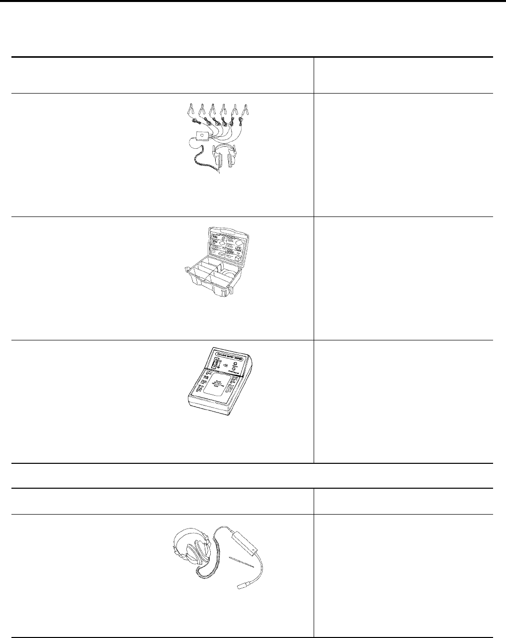
—
(J-39570)
Chassis ear
Locating the noise
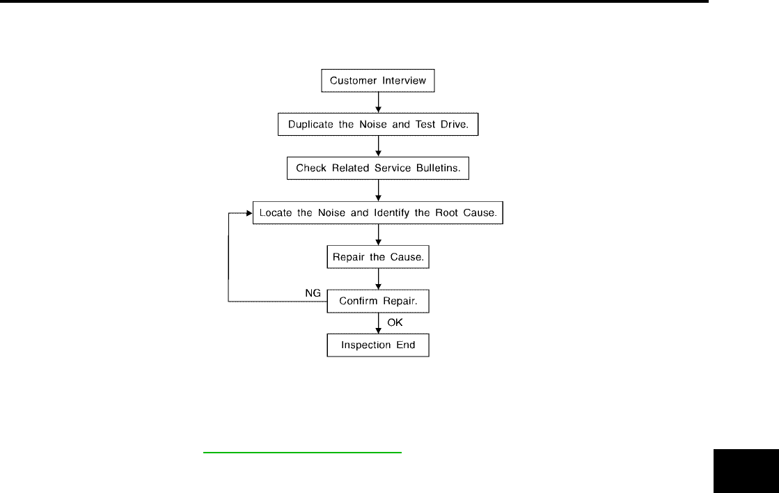
—
(J-43980)
NISSAN Squeak and Rat-
tle Kit
Repairing the cause of noise
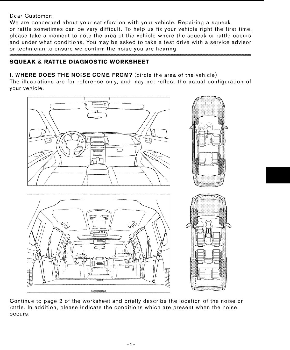
—
(J-43241)
Remote Keyless Entry
Tester
Used to test keyfobs
SIIA0993E
SIIA0994E
LEL946A
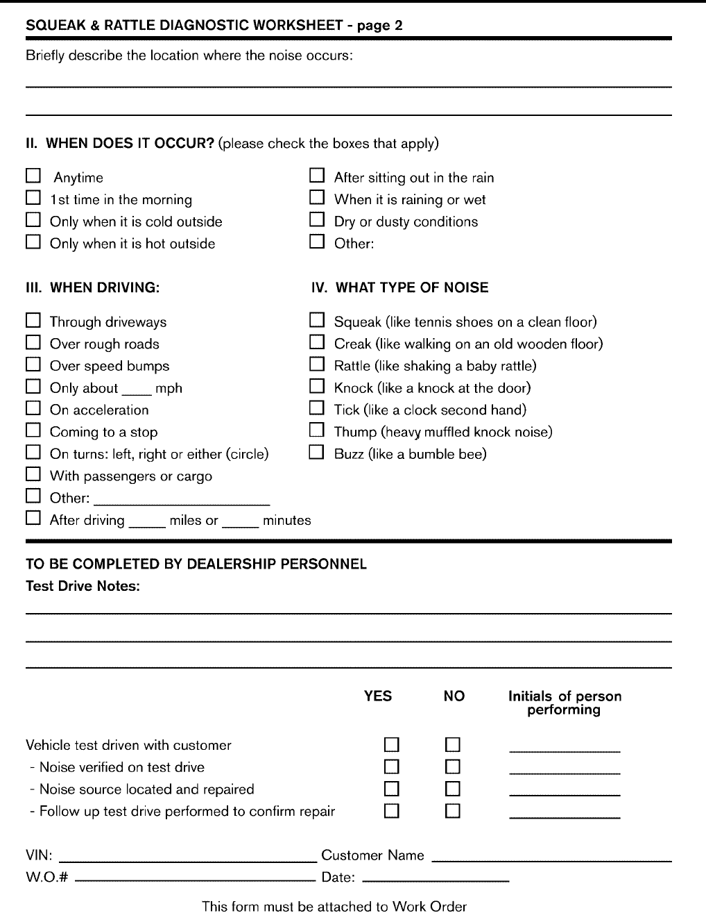
(Kent-Moore No.)
Tool name Description
(J-39565)
Engine ear
Locating the noise
SIIA0995E
SQUEAK AND RATTLE TROUBLE DIAGNOSES
BL-7
C
D
E
F
G
H
J
K
L
M
A
B
BL
Revision: July 2006 2006 Quest
SQUEAK AND RATTLE TROUBLE DIAGNOSES PFP:00000
Work Flow
EIS007D3
CUSTOMER INTERVIEW
Interview the customer if possible, to determine the conditions that exist when the noise occurs. Use the Diag-
nostic Worksheet during the interview to document the facts and conditions when the noise occurs and any
customer's comments; refer to BL-11, "Diagnostic Worksheet" . This information is necessary to duplicate the
conditions that exist when the noise occurs.
●The customer may not be able to provide a detailed description or the location of the noise. Attempt to
obtain all the facts and conditions that exist when the noise occurs (or does not occur).
●If there is more than one noise in the vehicle, be sure to diagnose and repair the noise that the customer
is concerned about. This can be accomplished by test driving the vehicle with the customer.
●After identifying the type of noise, isolate the noise in terms of its characteristics. The noise characteristics
are provided so the customer, service adviser and technician are all speaking the same language when
defining the noise.
●Squeak —(Like tennis shoes on a clean floor)
Squeak characteristics include the light contact/fast movement/brought on by road conditions/hard sur-
faces = higher pitch noise/softer surfaces = lower pitch noises/edge to surface = chirping.
●Creak—(Like walking on an old wooden floor)
Creak characteristics include firm contact/slow movement/twisting with a rotational movement/pitch
dependent on materials/often brought on by activity.
●Rattle—(Like shaking a baby rattle)
Rattle characteristics include the fast repeated contact/vibration or similar movement/loose parts/missing
clip or fastener/incorrect clearance.
●Knock —(Like a knock on a door)
Knock characteristics include hollow sounding/sometimes repeating/often brought on by driver action.
●Tick—(Like a clock second hand)
Tick characteristics include gentle contacting of light materials/loose components/can be caused by driver
action or road conditions.
●Thump—(Heavy, muffled knock noise)
Thump characteristics include softer knock/dead sound often brought on by activity.
●Buzz—(Like a bumble bee)
Buzz characteristics include high frequency rattle/firm contact.
●Often the degree of acceptable noise level will vary depending upon the person. A noise that you may
judge as acceptable may be very irritating to the customer.
●Weather conditions, especially humidity and temperature, may have a great effect on noise level.
SBT842

BL-8
SQUEAK AND RATTLE TROUBLE DIAGNOSES
Revision: July 2006 2006 Quest
DUPLICATE THE NOISE AND TEST DRIVE
If possible, drive the vehicle with the customer until the noise is duplicated. Note any additional information on
the Diagnostic Worksheet regarding the conditions or location of the noise. This information can be used to
duplicate the same conditions when you confirm the repair.
If the noise can be duplicated easily during the test drive, to help identify the source of the noise, try to dupli-
cate the noise with the vehicle stopped by doing one or all of the following:
1) Close a door.
2) Tap or push/pull around the area where the noise appears to be coming from.
3) Rev the engine.
4) Use a floor jack to recreate vehicle “twist”.
5) At idle, apply engine load (electrical load, half-clutch on M/T model, drive position on A/T model).
6) Raise the vehicle on a hoist and hit a tire with a rubber hammer.
●Drive the vehicle and attempt to duplicate the conditions the customer states exist when the noise occurs.
●If it is difficult to duplicate the noise, drive the vehicle slowly on an undulating or rough road to stress the
vehicle body.
CHECK RELATED SERVICE BULLETINS
After verifying the customer concern or symptom, check ASIST for Technical Service Bulletins (TSBs) related
to that concern or symptom.
If a TSB relates to the symptom, follow the procedure to repair the noise.
LOCATE THE NOISE AND IDENTIFY THE ROOT CAUSE
1. Narrow down the noise to a general area.To help pinpoint the source of the noise, use a listening tool
(Chassis Ear: J-39570, Engine Ear: J-39565 and mechanic's stethoscope).
2. Narrow down the noise to a more specific area and identify the cause of the noise by:
●removing the components in the area that you suspect the noise is coming from.
Do not use too much force when removing clips and fasteners, otherwise clips and fasteners can be bro-
ken or lost during the repair, resulting in the creation of new noise.
●tapping or pushing/pulling the component that you suspect is causing the noise.
Do not tap or push/pull the component with excessive force, otherwise the noise will be eliminated only
temporarily.
●feeling for a vibration with your hand by touching the component(s) that you suspect is (are) causing the
noise.
●placing a piece of paper between components that you suspect are causing the noise.
●looking for loose components and contact marks.
Refer to BL-9, "Generic Squeak and Rattle Troubleshooting" .
REPAIR THE CAUSE
●If the cause is a loose component, tighten the component securely.
●If the cause is insufficient clearance between components:
–separate components by repositioning or loosening and retightening the component, if possible.
–insulate components with a suitable insulator such as urethane pads, foam blocks, felt cloth tape or ure-
thane tape. A NISSAN Squeak and Rattle Kit (J-43980) is available through your authorized NISSAN
Parts Department.
CAUTION:
Do not use excessive force as many components are constructed of plastic and may be damaged.
Always check with the Parts Department for the latest parts information.
The following materials are contained in the NISSAN Squeak and Rattle Kit (J-43980). Each item can be
ordered separately as needed.
URETHANE PADS [1.5 mm (0.059 in) thick]
Insulates connectors, harness, etc.
76268-9E005: 100×135 mm (3.94×5.31 in)/76884-71L01: 60×85 mm (2.36×3.35 in)/76884-71L02: 15×25
mm (0.59×0.98 in)
INSULATOR (Foam blocks)
Insulates components from contact. Can be used to fill space behind a panel.
73982-9E000: 45 mm (1.77 in) thick, 50×50 mm (1.97×1.97 in)/73982-50Y00: 10 mm (0.39 in) thick,
50×50 mm (1.97×1.97 in)
INSULATOR (Light foam block)

SQUEAK AND RATTLE TROUBLE DIAGNOSES
BL-9
C
D
E
F
G
H
J
K
L
M
A
B
BL
Revision: July 2006 2006 Quest
80845-71L00: 30 mm (1.18 in) thick, 30×50 mm (1.18×1.97 in)
FELT CLOTH TAPE
Used to insulate where movement does not occur. Ideal for instrument panel applications.
68370-4B000: 15×25 mm (0.59×0.98 in) pad/68239-13E00: 5 mm (0.20 in) wide tape roll. The following mate-
rials not found in the kit can also be used to repair squeaks and rattles.
UHMW (TEFLON) TAPE
Insulates where slight movement is present. Ideal for instrument panel applications.
SILICONE GREASE
Used instead of UHMW tape that will be visible or not fit.
Note: Will only last a few months.
SILICONE SPRAY
Use when grease cannot be applied.
DUCT TAPE
Use to eliminate movement.
CONFIRM THE REPAIR
Confirm that the cause of a noise is repaired by test driving the vehicle. Operate the vehicle under the same
conditions as when the noise originally occurred. Refer to the notes on the Diagnostic Worksheet.
Generic Squeak and Rattle Troubleshooting
EIS007D4
Refer to Table of Contents for specific component removal and installation information.
INSTRUMENT PANEL
Most incidents are caused by contact and movement between:
1. The cluster lid A and instrument panel
2. Acrylic lens and combination meter housing
3. Instrument panel to front pillar garnish
4. Instrument panel to windshield
5. Instrument panel mounting pins
6. Wiring harnesses behind the combination meter
7. A/C defroster duct and duct joint
These incidents can usually be located by tapping or moving the components to duplicate the noise or by
pressing on the components while driving to stop the noise. Most of these incidents can be repaired by apply-
ing felt cloth tape or silicone spray (in hard to reach areas). Urethane pads can be used to insulate wiring har-
ness.
CAUTION:
Do not use silicone spray to isolate a squeak or rattle. If you saturate the area with silicone, you will
not be able to recheck the repair.
CENTER CONSOLE
Components to pay attention to include:
1. Shifter assembly cover to finisher
2. A/C control unit and cluster lid C
3. Wiring harnesses behind audio and A/C control unit
The instrument panel repair and isolation procedures also apply to the center console.
DOORS
Pay attention to the:
1. Finisher and inner panel making a slapping noise
2. Inside handle escutcheon to door finisher
3. Wiring harnesses tapping
4. Door striker out of alignment causing a popping noise on starts and stops
Tapping or moving the components or pressing on them while driving to duplicate the conditions can isolate
many of these incidents. You can usually insulate the areas with felt cloth tape or insulator foam blocks from
the NISSAN Squeak and Rattle Kit (J-43980) to repair the noise.

BL-10
SQUEAK AND RATTLE TROUBLE DIAGNOSES
Revision: July 2006 2006 Quest
TRUNK
Trunk noises are often caused by a loose jack or loose items put into the trunk by the owner.
In addition look for:
1. Trunk lid bumpers out of adjustment
2. Trunk lid striker out of adjustment
3. The trunk lid torsion bars knocking together
4. A loose license plate or bracket
Most of these incidents can be repaired by adjusting, securing or insulating the item(s) or component(s) caus-
ing the noise.
SUNROOF/HEADLINING
Noises in the sunroof/headlining area can often be traced to one of the following:
1. Sunroof lid, rail, linkage or seals making a rattle or light knocking noise
2. Sun visor shaft shaking in the holder
3. Front or rear windshield touching headliner and squeaking
Again, pressing on the components to stop the noise while duplicating the conditions can isolate most of these
incidents. Repairs usually consist of insulating with felt cloth tape.
OVERHEAD CONSOLE (FRONT AND REAR)
Overhead console noises are often caused by the console panel clips not being engaged correctly. Most of
these incidents are repaired by pushing up on the console at the clip locations until the clips engage.
In addition look for:
1. Loose harness or harness connectors.
2. Front console map/reading lamp lense loose.
3. Loose screws at console attachment points.
SEATS
When isolating seat noise it's important to note the position the seat is in and the load placed on the seat when
the noise is present. These conditions should be duplicated when verifying and isolating the cause of the
noise.
Cause of seat noise include:
1. Headrest rods and holder
2. A squeak between the seat pad cushion and frame
3. The rear seatback lock and bracket
These noises can be isolated by moving or pressing on the suspected components while duplicating the con-
ditions under which the noise occurs. Most of these incidents can be repaired by repositioning the component
or applying urethane tape to the contact area.
UNDERHOOD
Some interior noise may be caused by components under the hood or on the engine wall. The noise is then
transmitted into the passenger compartment.
Causes of transmitted underhood noise include:
1. Any component mounted to the engine wall
2. Components that pass through the engine wall
3. Engine wall mounts and connectors
4. Loose radiator mounting pins
5. Hood bumpers out of adjustment
6. Hood striker out of adjustment
These noises can be difficult to isolate since they cannot be reached from the interior of the vehicle. The best
method is to secure, move or insulate one component at a time and test drive the vehicle. Also, engine RPM
or load can be changed to isolate the noise. Repairs can usually be made by moving, adjusting, securing, or
insulating the component causing the noise.
SQUEAK AND RATTLE TROUBLE DIAGNOSES
BL-11
C
D
E
F
G
H
J
K
L
M
A
B
BL
Revision: July 2006 2006 Quest
Diagnostic Worksheet
EIS007D5
LAIA0072E
BL-12
SQUEAK AND RATTLE TROUBLE DIAGNOSES
Revision: July 2006 2006 Quest
LAIA0071E
HOOD
BL-13
C
D
E
F
G
H
J
K
L
M
A
B
BL
Revision: July 2006 2006 Quest
HOOD PFP:F5100
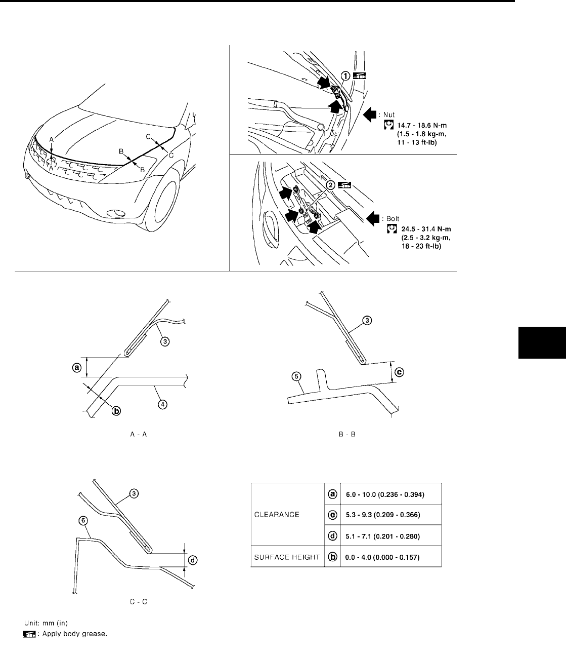
Fitting Adjustment
EIS007D6
1. Hood hinge 2. Hood lock assembly 3. Hood assembly
4. Front grille 5. Headlamp 6. Front fender
LIIA0880E
BL-14
HOOD
Revision: July 2006 2006 Quest
CLEARANCE AND SURFACE HEIGHT ADJUSTMENT
1. Remove the hood lock assembly and adjust the height by rotating the bumper rubber until the hood clear-
ance of hood and fender becomes 1 mm (0.04 in) lower than fitting standard dimension.
2. Temporarily tighten the hood lock, and position it by engaging it with the hood striker. Check the lock and
striker for looseness, and tighten the lock bolt to the specified torque.
3. Adjust the clearance and surface height of hood and fender according to the fitting standard dimension by
rotating right and left bumper rubbers.
CAUTION:
Adjust right/left gap between hood and each part to the following specification.
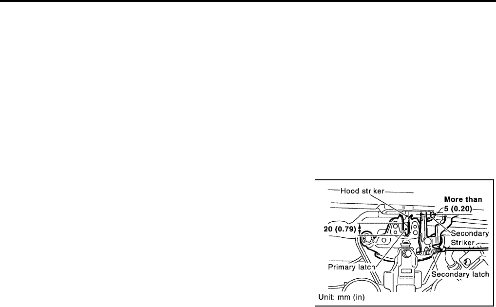
HOOD LOCK ADJUSTMENT
1. Move the hood lock to the left or right so that striker center is vertically aligned with hood lock center
(when viewed from vehicle front).
2. Make sure the secondary latch is properly engaged with the sec-
ondary striker with hood's own weight by dropping it from
approx. 200 mm (7.87 in) height or by pressing it lightly approx.
3 kg (29 N, 7lb).
CAUTION:
Do not drop the hood from 300 mm (11.81 in) height or
higher.
3. After adjusting hood lock, tighten the lock bolts to the specified
torque.
Hood and headlamp (B–B) : Less than 2.0 mm
PIIA3806E
HOOD
BL-15
C
D
E
F
G
H
J
K
L
M
A
B
BL
Revision: July 2006 2006 Quest
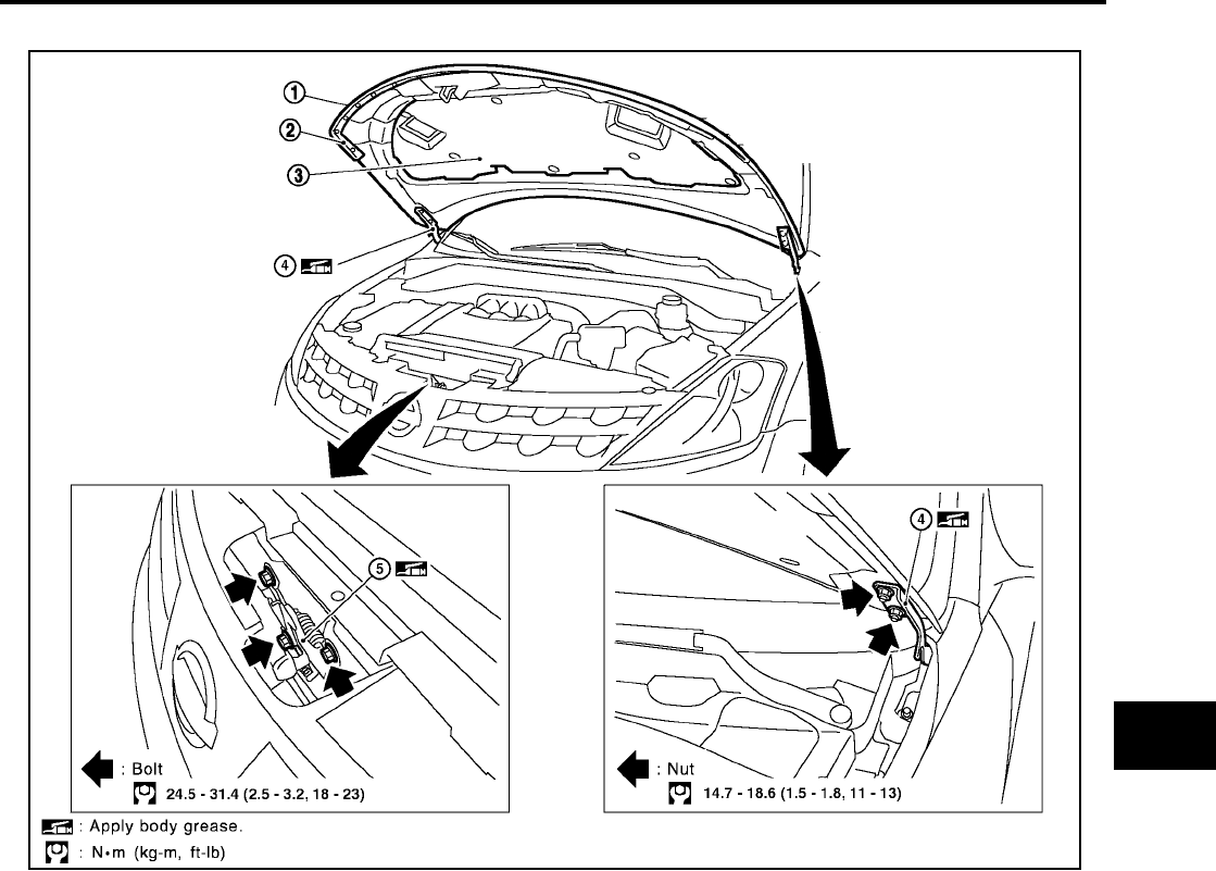
Removal and Installation of Hood Assembly
EIS007D7
1. Support the hood by the striker with a suitable tool to prevent it from falling.
2. Remove the hinge nuts on the hood to remove the hood assembly.
CAUTION:
Operate with two workers, because of its heavy weight.
3. Installation is in the reverse order of removal.
1. Hood assembly 2. Hood front sealing rubber 3. Hood insulator
4. Hood hinge 5. Hood lock assembly
LIIA0881E
BL-16
HOOD
Revision: July 2006 2006 Quest
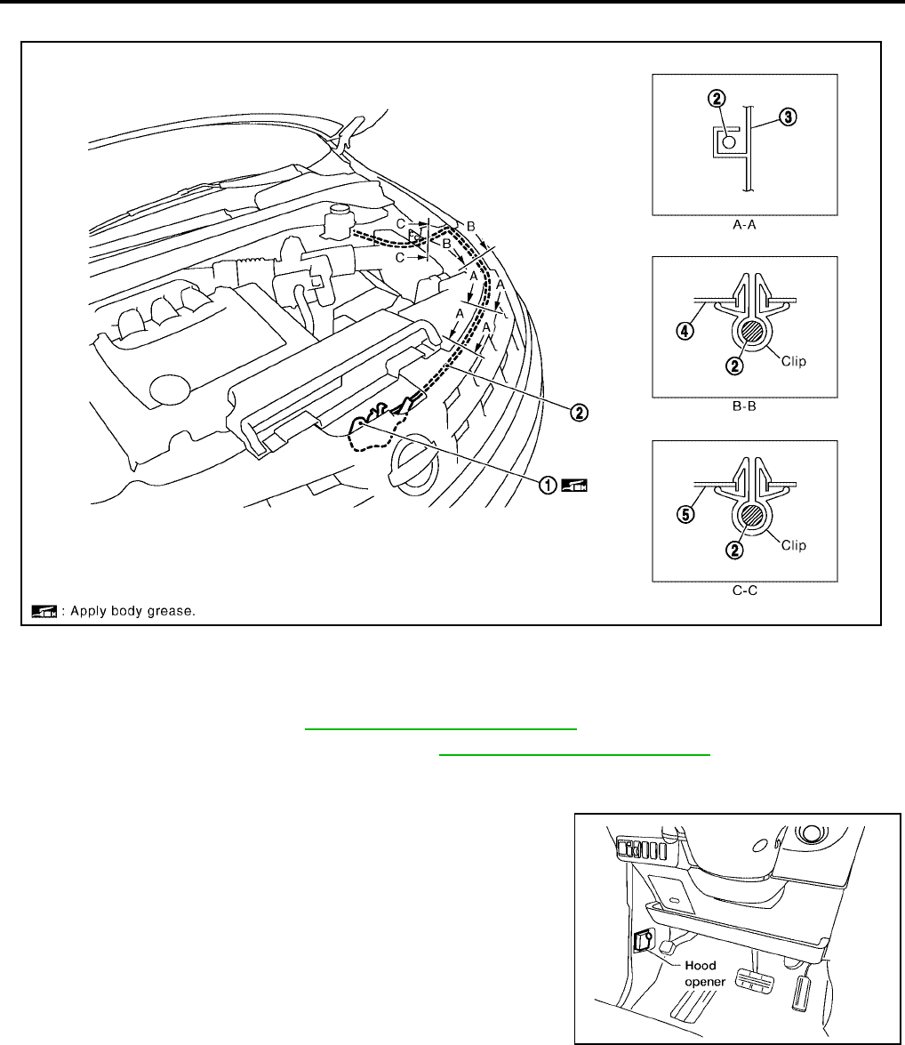
Removal and Installation of Hood Lock Control
EIS007D8
REMOVAL
1. Remove the front grille. Refer to EI-18, "Removal and Installation" .
2. Remove the front fender protector (LH). Refer to EI-22, "Removal and Installation" .
3. Disconnect the hood lock cable from the hood lock, and unclip it from the radiator core support upper and
hoodledge.
4. Remove the bolt and the hood opener.
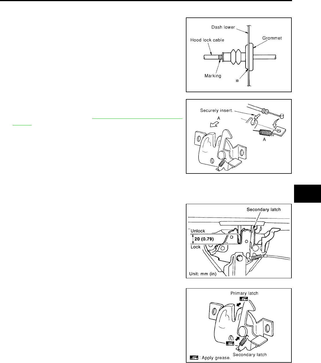
5. Remove the grommet on the dash lower panel, and pull the
hood lock cable toward the passenger room.
CAUTION:
While pulling, be careful not to damage the outside of the
hood lock cable.
1. Hood lock assembly 2. Hood lock cable 3. Radiator core support side
4. Hood ledge reinforce upper 5. Hood ledge upper
LIIA0883E
LIIA1544E
HOOD
BL-17
C
D
E
F
G
H
J
K
L
M
A
B
BL
Revision: July 2006 2006 Quest
INSTALLATION
1. Pull the hood lock cable through the dash lower panel hole to the engine room.
Be careful not to bend the cable too much, keeping the radius
100mm (3.94 in) or more.
2. Make sure the cable is not offset from the positioning grommet,
and push the grommet into the panel hole securely.
3. Apply the sealant to the grommet (at * mark) properly.
4. Install the cable securely to the lock.
5. After installing, check the hood lock adjustment and hood
opener operation. Refer to BL-14, "HOOD LOCK ADJUST-
MENT" .
Hood Lock Control Inspection
EIS007D9
CAUTION:
If the hood lock cable is bent or deformed, replace it.
1. Make sure the secondary latch is properly engaged with the sec-
ondary striker with hood's own weight by dropping it from
approx. 200 mm (7.87 in) height.
2. While operating the hood opener, carefully make sure the front
end of the hood is raised by approx. 20 mm (0.79 in). Also make
sure the hood opener returns to the original position.
3. Check the hood lock lubrication condition. If necessary, apply
“body grease” to the points shown in the figure.
PIIA0173E
PIIA0174E
PIIA1086E
PIIA0176E
BL-18
POWER DOOR LOCK SYSTEM
Revision: July 2006 2006 Quest
POWER DOOR LOCK SYSTEM PFP:24814
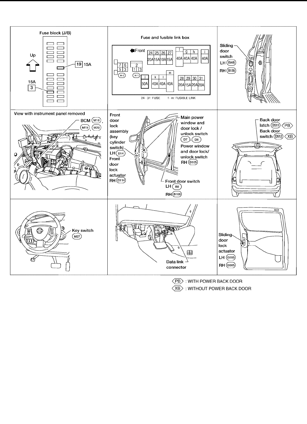
Component Parts and Harness Connector Location
EIS007DA
LIIA1899E

POWER DOOR LOCK SYSTEM
BL-19
C
D
E
F
G
H
J
K
L
M
A
B
BL
Revision: July 2006 2006 Quest
System Description
EIS007DB
WITHOUT AUTOMATIC SLIDING DOOR SYSTEM AND AUTOMATIC BACK DOOR SYSTEM
Power is supplied at all times
●through 50A fusible link (letter j, located in the fuse and fusible link box)
●to BCM terminal 55 and
●through 15A fuse [No. 3, located in the fuse block (J/B)]
●to BCM terminal 42
●through 15A fuse [No. 19, located in the fuse block (J/B)]
●to key switch terminal 1.
With ignition key inserted, power is supplied
●through key switch terminal 2
●to BCM terminal 37.
Ground is supplied to terminal 52 of BCM through body grounds M57, M61 and M79.
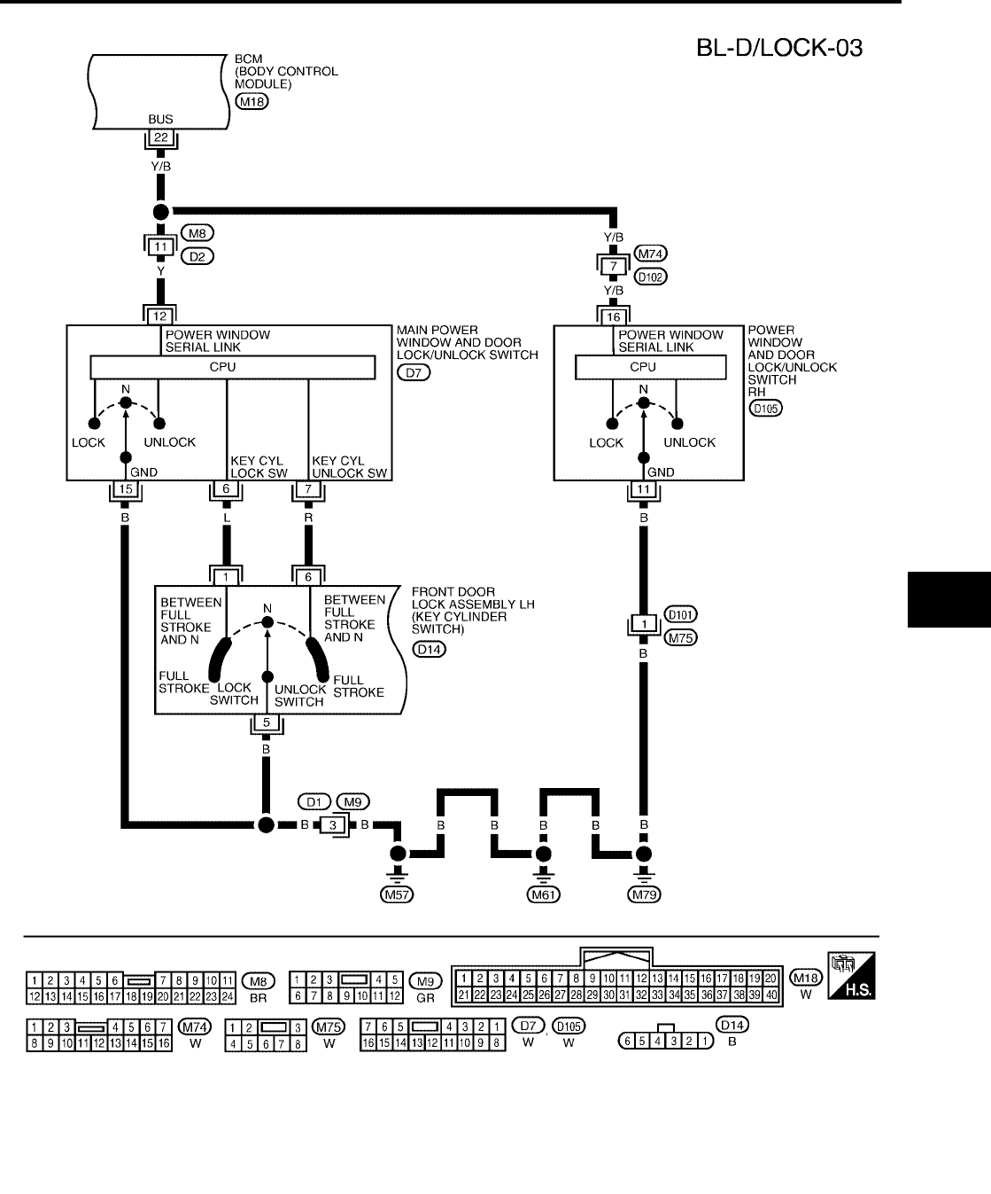
When the door is locked or unlocked with main power window and door lock/unlock switch, ground is supplied
●to CPU of main power window and door lock/unlock switch
●through main power window and door lock/unlock switch terminal 15
●through grounds M57, M61 and M79.
Then main power window and door lock/unlock switch operation signal is supplied
●to BCM terminal 22
●through main power window and door lock/unlock switch terminal 12.
When the door is locked or unlocked with power window and door lock/unlock switch RH, ground is supplied
●to CPU of power window and door lock/unlock switch RH
●through power window and door lock/unlock switch RH terminal 11
●through grounds M57, M61 and M79.
Then power window and door lock/unlock switch RH operation signal is supplied
●to BCM terminal 22
●through power window and door lock/unlock switch RH terminal 16.
When the door is locked with front door lock assembly LH (key cylinder switch), ground is supplied
●to main power window and door lock/unlock switch terminal 6
●through front door lock assembly LH (key cylinder switch) terminals 1 and 5
●through grounds M57, M61 and M79.
Then front door lock assembly LH (key cylinder switch) operation signal is supplied
●to BCM terminal 22
●through main power window and door lock/unlock switch terminal 12.
When the door is unlocked with front door lock assembly LH (key cylinder switch), ground is supplied
●to main power window and door lock/unlock switch terminal 7
●through front door lock assembly LH (key cylinder switch) terminals 6 and 5
●through grounds M57, M61 and M79.
Then front door lock assembly LH (key cylinder switch) operation signal is supplied
●to BCM terminal 22
●through main power window and door lock/unlock switch terminal 12.
BCM is connected to main power window and door lock/unlock switch and power window and door lock/unlock
switch RH through the power window serial link.
When the front door switch LH is ON (door is open), ground is supplied
●to BCM terminal 62
●through front door switch LH terminal 1
●through front door switch LH case ground.
When the front door switch RH is ON (door is open), ground is supplied
●to BCM terminal 12

BL-20
POWER DOOR LOCK SYSTEM
Revision: July 2006 2006 Quest
●through front door switch RH terminal 1
●through front door switch RH case ground.
When the sliding door switch LH is ON (door is open), ground is supplied
●to BCM terminal 63
●through sliding door switch LH terminal 1
●through sliding door switch LH case ground.
When the sliding door switch RH is ON (door is open), ground is supplied
●to BCM terminal 13
●through sliding door switch RH terminal 1
●through sliding door switch RH case ground.
When the back door switch is ON (door is open), ground is supplied
●to BCM terminal 58
●through back door switch terminal 1
●through back door switch terminal 3
●through grounds D403 and D404.
WITH AUTOMATIC SLIDING DOOR SYSTEM AND AUTOMATIC BACK DOOR SYSTEM
Power is supplied at all times
●through 50A fusible link (letter j, located in the fuse and fusible link box)
●to BCM terminal 55 and
●through 15A fuse [No. 3, located in the fuse block (J/B)]
●to BCM terminal 42
●through 15A fuse [No. 19, located in the fuse block (J/B)]
●to key switch terminal 1.
With ignition key inserted, power is supplied
●through key switch terminal 2
●to BCM terminal 37.
Ground is supplied to terminal 52 of BCM through body grounds M57, M61 and M79.
When the door is locked or unlocked with main power window and door lock/unlock switch, ground is supplied
●to CPU of main power window and door lock/unlock switch
●through main power window and door lock/unlock switch terminal 17
●through grounds M57, M61 and M79.
Then main power window and door lock/unlock switch operation signal is supplied
●to BCM terminal 22
●through main power window and door lock/unlock switch terminal 14.
When the door is locked or unlocked with power window and door lock/unlock switch RH, ground is supplied
●to CPU of power window and door lock/unlock switch RH
●through power window and door lock/unlock switch RH terminal 11
●through grounds M57, M61 and M79.
Then power window and door lock/unlock switch RH operation signal is supplied
●to BCM terminal 22
●through power window and door lock/unlock switch RH terminal 16.
When the door is locked with front door lock assembly LH (key cylinder switch), ground is supplied
●to main power window and door lock/unlock switch terminal 4
●through front door lock assembly LH (key cylinder switch) terminals 1 and 5
●through grounds M57, M61 and M79.
Then the front door lock assembly LH (key cylinder switch) operation signal is supplied
●to BCM terminal 22
●through main power window and door lock/unlock switch terminal 14.
When the door is unlocked with front door lock assembly LH (key cylinder switch), ground is supplied

POWER DOOR LOCK SYSTEM
BL-21
C
D
E
F
G
H
J
K
L
M
A
B
BL
Revision: July 2006 2006 Quest
●to main power window and door lock/unlock switch terminal 6
●through front door lock assembly LH (key cylinder switch) terminals 6 and 5
●through grounds M57, M61 and M79.
Then front door lock assembly LH (key cylinder switch) operation signal is supplied
●to BCM terminal 22
●through main power window and door lock/unlock switch terminal 14.
BCM is connected to main power window and door lock/unlock switch and power window and door lock/unlock
switch RH through a serial link.
When the front door switch LH is ON (door is open), ground is supplied
●to BCM terminal 62
●through front door switch LH terminal 1
●through front door switch LH case ground.
When the front door switch RH is ON (door is open), ground is supplied
●to BCM terminal 12
●through front door switch RH terminal 1
●through front door switch RH case ground.
When the sliding door switch LH is ON (door is open), ground is supplied
●to BCM terminal 63
●through sliding door switch LH terminal 1
●through sliding door switch LH case ground.
When the sliding door switch RH is ON (door is open), ground is supplied
●to BCM terminal 13
●through sliding door switch RH terminal 1
●through sliding door switch RH case ground.
When the back door switch (built into back door latch) is ON (door is open), ground is supplied
●to BCM terminal 58
●through back door latch (door ajar switch) assembly terminal 7
●through back door latch assembly terminal 8
●through grounds D403 and D404.
OUTLINE
Functions available by operating the door lock and unlock switches on driver's door and pas-
senger's door
●Interlocked with the locking operation of door lock and unlock switch, door lock actuators of all doors are
locked.
●Interlocked with the unlocking operation of door lock and unlock switch, door lock actuators of all doors
are unlocked.
Functions available by operating the front door lock assembly LH (key cylinder switch)
●Interlocked with the locking operation of door key cylinder, door lock actuators of all doors are locked.
●When door key cylinder is unlocked, front door lock assembly LH (actuator) is unlocked.
●When door key cylinder is unlocked for the second time within 5 seconds after the first operation, door
lock actuators on all doors are unlocked.
Key reminder door system
When door lock and unlock switch is operated to lock doors with ignition key in key cylinder and any door
open, all door lock actuators are locked and then unlocked.
BL-22
POWER DOOR LOCK SYSTEM
Revision: July 2006 2006 Quest
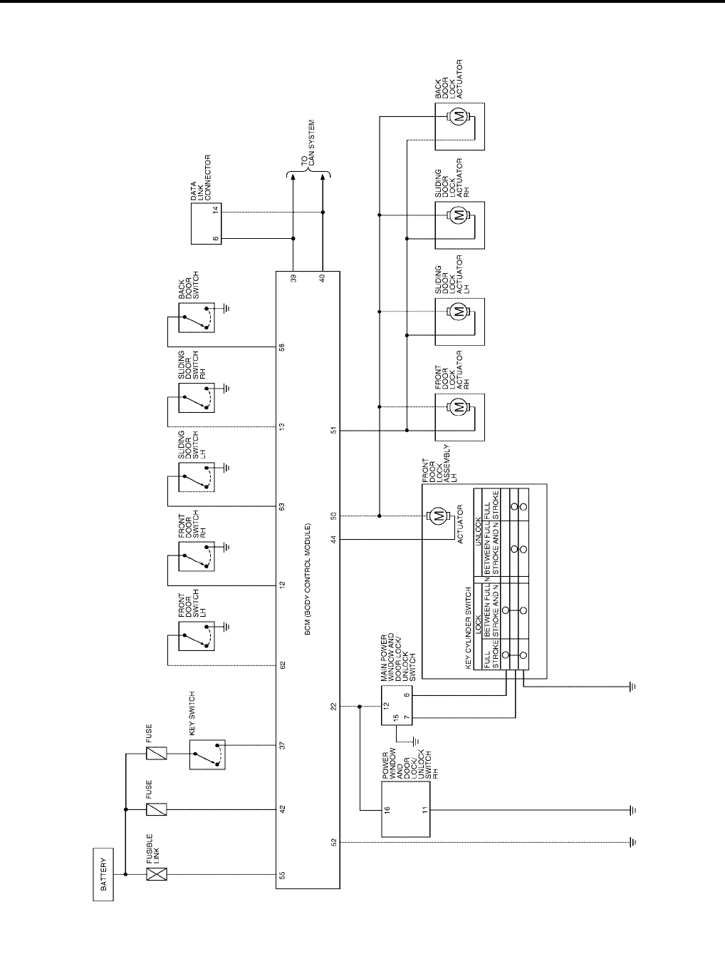
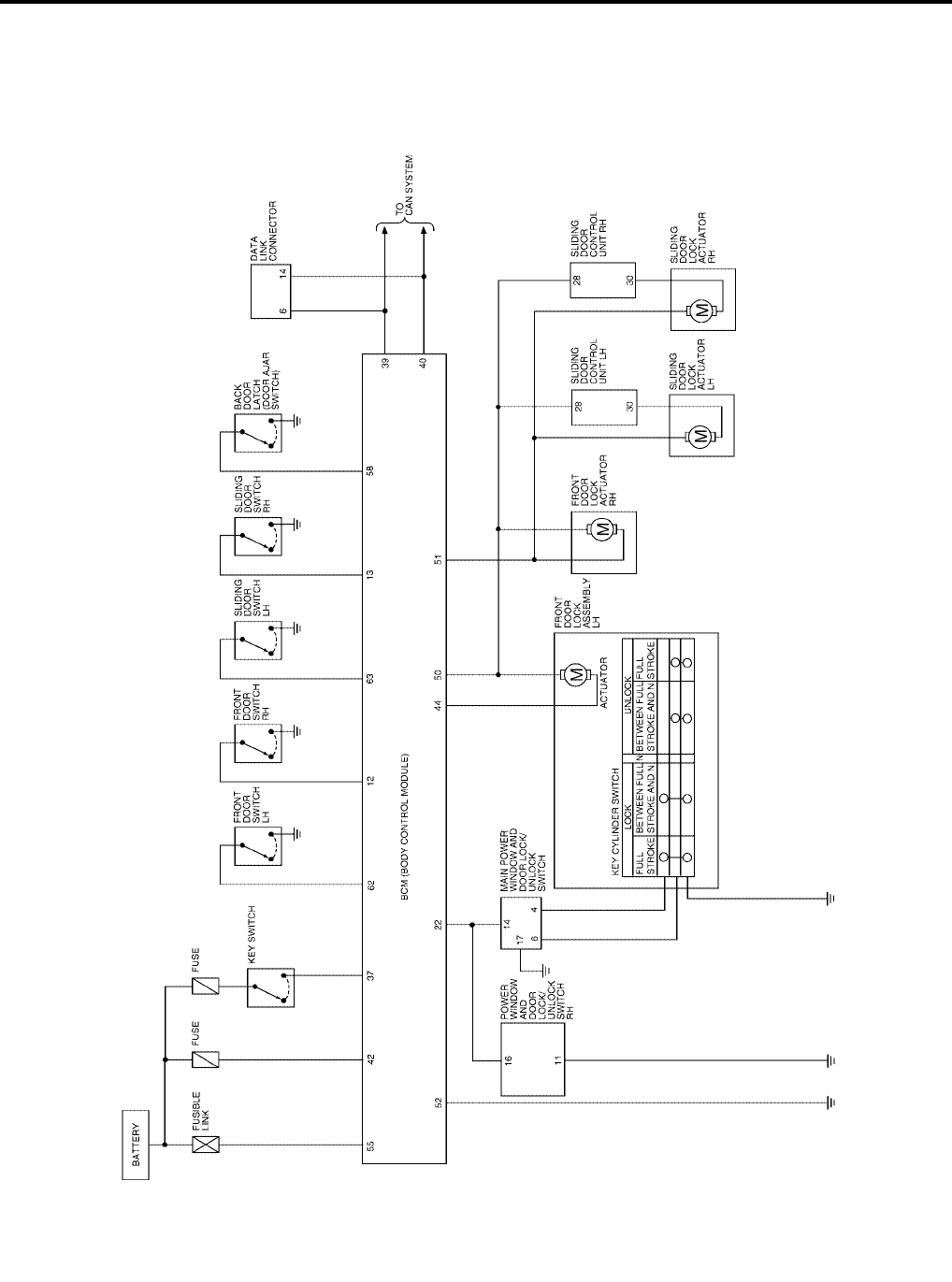
Schematic
EIS007DC
WITHOUT AUTOMATIC SLIDING DOOR SYSTEM AND AUTOMATIC BACK DOOR SYSTEM
WIWA1108E
POWER DOOR LOCK SYSTEM
BL-23
C
D
E
F
G
H
J
K
L
M
A
B
BL
Revision: July 2006 2006 Quest
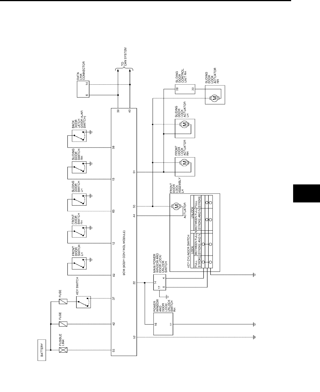
WITH RIGHT HAND AUTOMATIC SLIDING DOOR SYSTEM AND AUTOMATIC BACK DOOR
SYSTEM
WIWA1109E
BL-24
POWER DOOR LOCK SYSTEM
Revision: July 2006 2006 Quest
WITH RIGHT AND LEFT HAND AUTOMATIC SLIDING DOOR SYSTEM AND AUTOMATIC BACK
DOOR SYSTEM
WIWA1110E
POWER DOOR LOCK SYSTEM
BL-25
C
D
E
F
G
H
J
K
L
M
A
B
BL
Revision: July 2006 2006 Quest
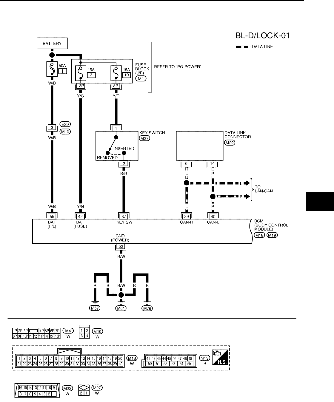
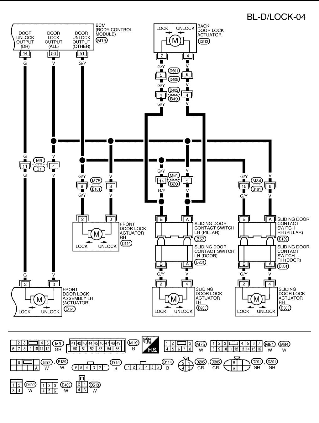
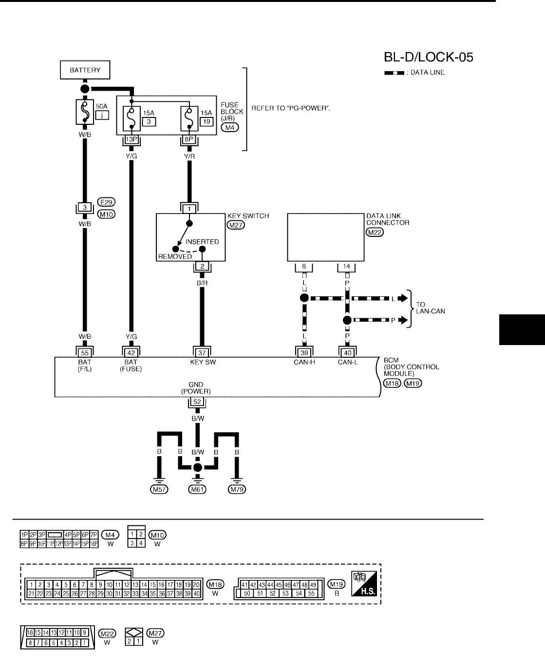
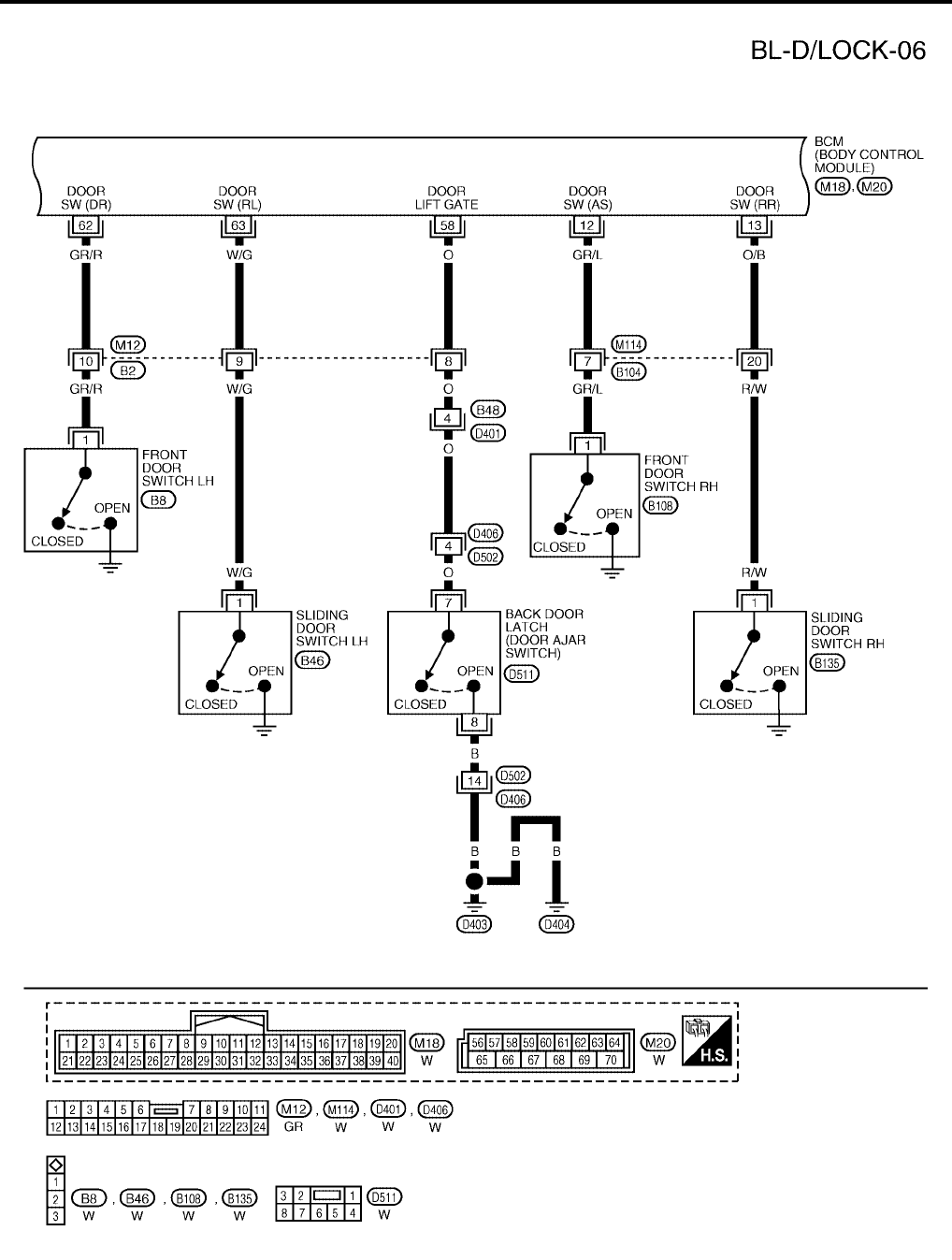
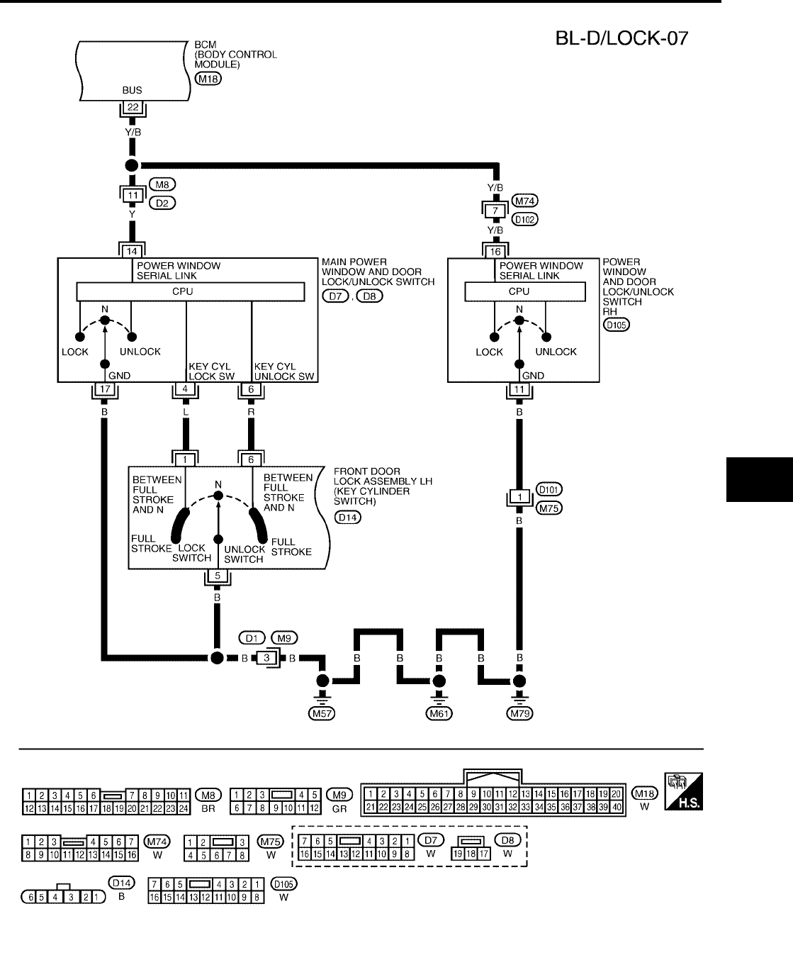
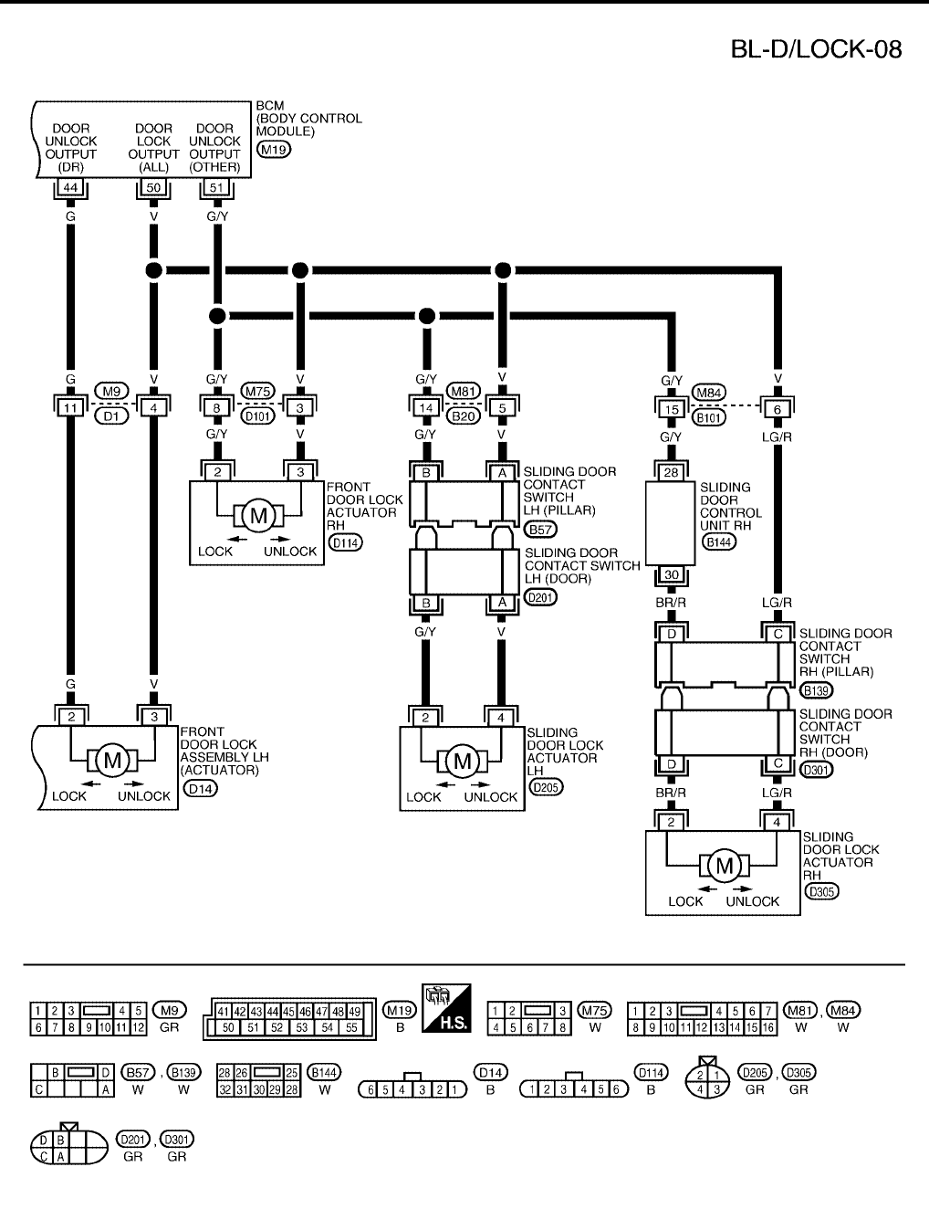
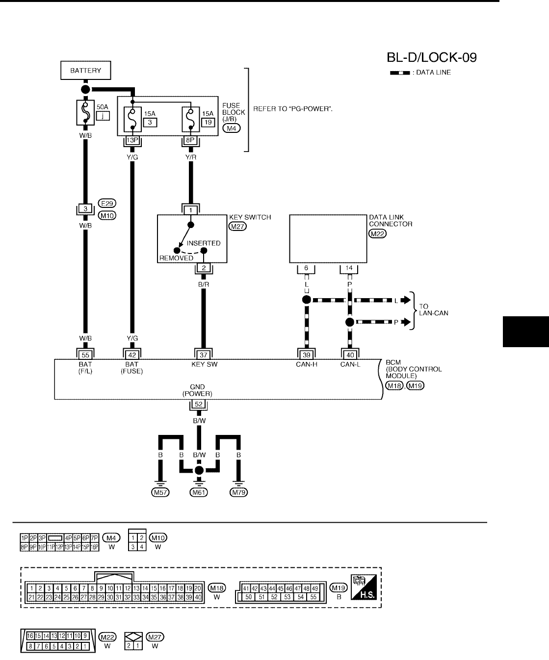
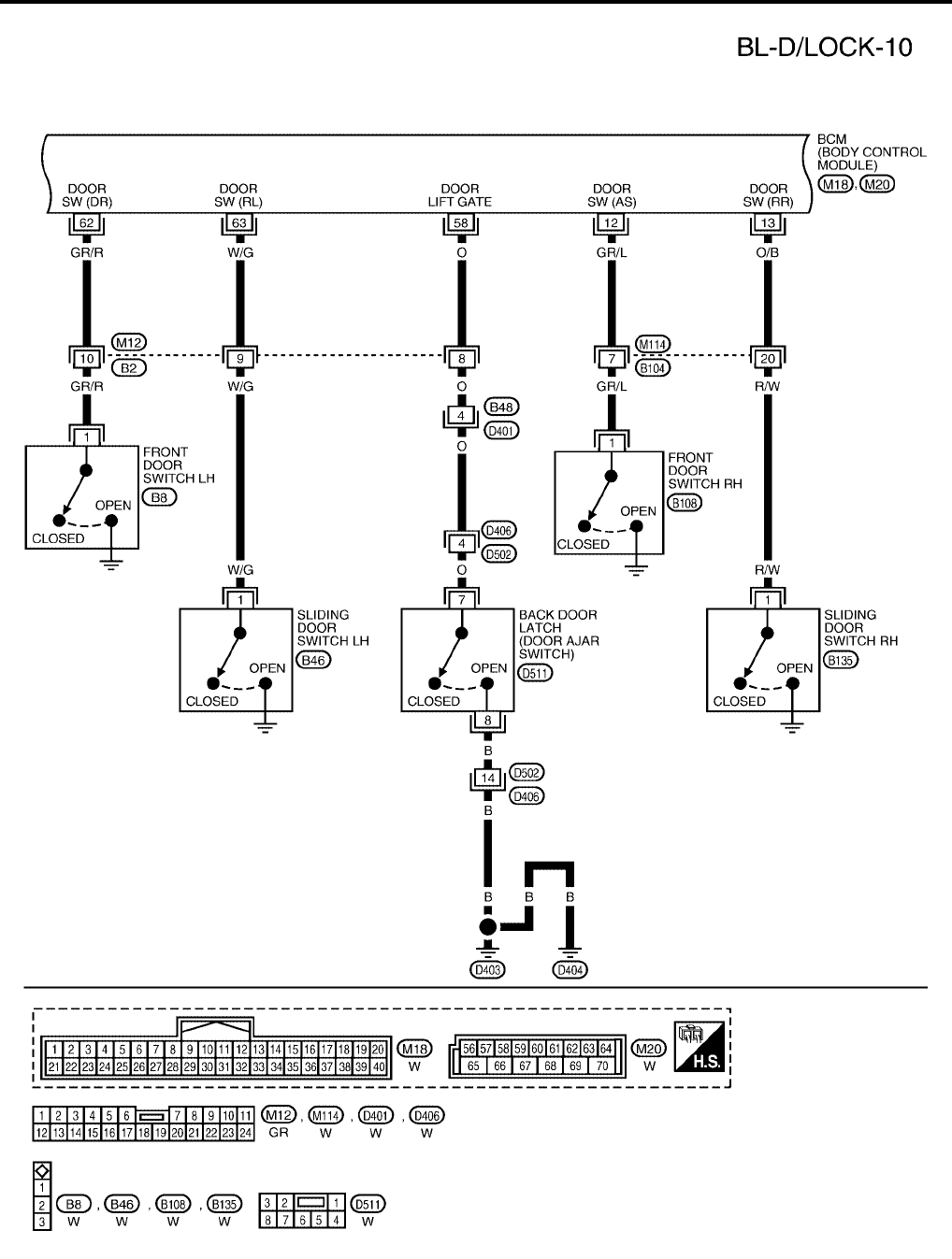
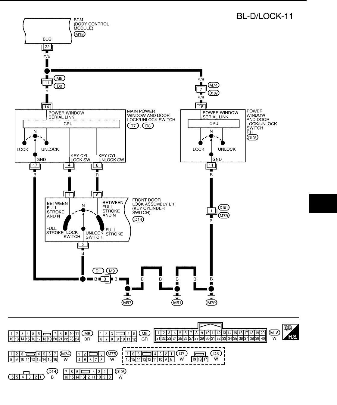
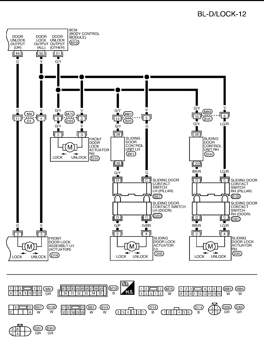
Wiring Diagram — D/LOCK —
EIS007DD
WITHOUT AUTOMATIC SLIDING DOOR SYSTEM AND AUTOMATIC BACK DOOR SYSTEM
WIWA0483E
BL-26
POWER DOOR LOCK SYSTEM
Revision: July 2006 2006 Quest
WIWA1111E
POWER DOOR LOCK SYSTEM
BL-27
C
D
E
F
G
H
J
K
L
M
A
B
BL
Revision: July 2006 2006 Quest
WIWA1112E
BL-28
POWER DOOR LOCK SYSTEM
Revision: July 2006 2006 Quest
WIWA1113E
POWER DOOR LOCK SYSTEM
BL-29
C
D
E
F
G
H
J
K
L
M
A
B
BL
Revision: July 2006 2006 Quest
WITH RIGHT HAND AUTOMATIC SLIDING DOOR SYSTEM AND AUTOMATIC BACK DOOR
SYSTEM
WIWA0487E
BL-30
POWER DOOR LOCK SYSTEM
Revision: July 2006 2006 Quest
WIWA0488E
POWER DOOR LOCK SYSTEM
BL-31
C
D
E
F
G
H
J
K
L
M
A
B
BL
Revision: July 2006 2006 Quest
WIWA1114E
BL-32
POWER DOOR LOCK SYSTEM
Revision: July 2006 2006 Quest
WIWA1246E
POWER DOOR LOCK SYSTEM
BL-33
C
D
E
F
G
H
J
K
L
M
A
B
BL
Revision: July 2006 2006 Quest
WITH RIGHT AND LEFT HAND AUTO SLIDE DOOR CLOSURE AND AUTOMATIC BACK DOOR
SYSTEM
WIWA0491E
BL-34
POWER DOOR LOCK SYSTEM
Revision: July 2006 2006 Quest
WIWA1247E
POWER DOOR LOCK SYSTEM
BL-35
C
D
E
F
G
H
J
K
L
M
A
B
BL
Revision: July 2006 2006 Quest
WIWA1115E
BL-36
POWER DOOR LOCK SYSTEM
Revision: July 2006 2006 Quest
WIWA1248E
POWER DOOR LOCK SYSTEM
BL-37
C
D
E
F
G
H
J
K
L
M
A
B
BL
Revision: July 2006 2006 Quest
Terminals and Reference Value for BCM
EIS007DE
Work Flow
EIS007DF
1. Check the symptom and customer's requests.
2. Understand the outline of system. Refer to BL-19, "System Description" .
3. According to the trouble diagnosis chart, repair or replace the cause of the malfunction. Refer to BL-40,
"Trouble Diagnoses Symptom Chart" .
4. Does power door lock system operate normally? OK: GO TO 5, NG: GO TO 3.
5. Inspection End.
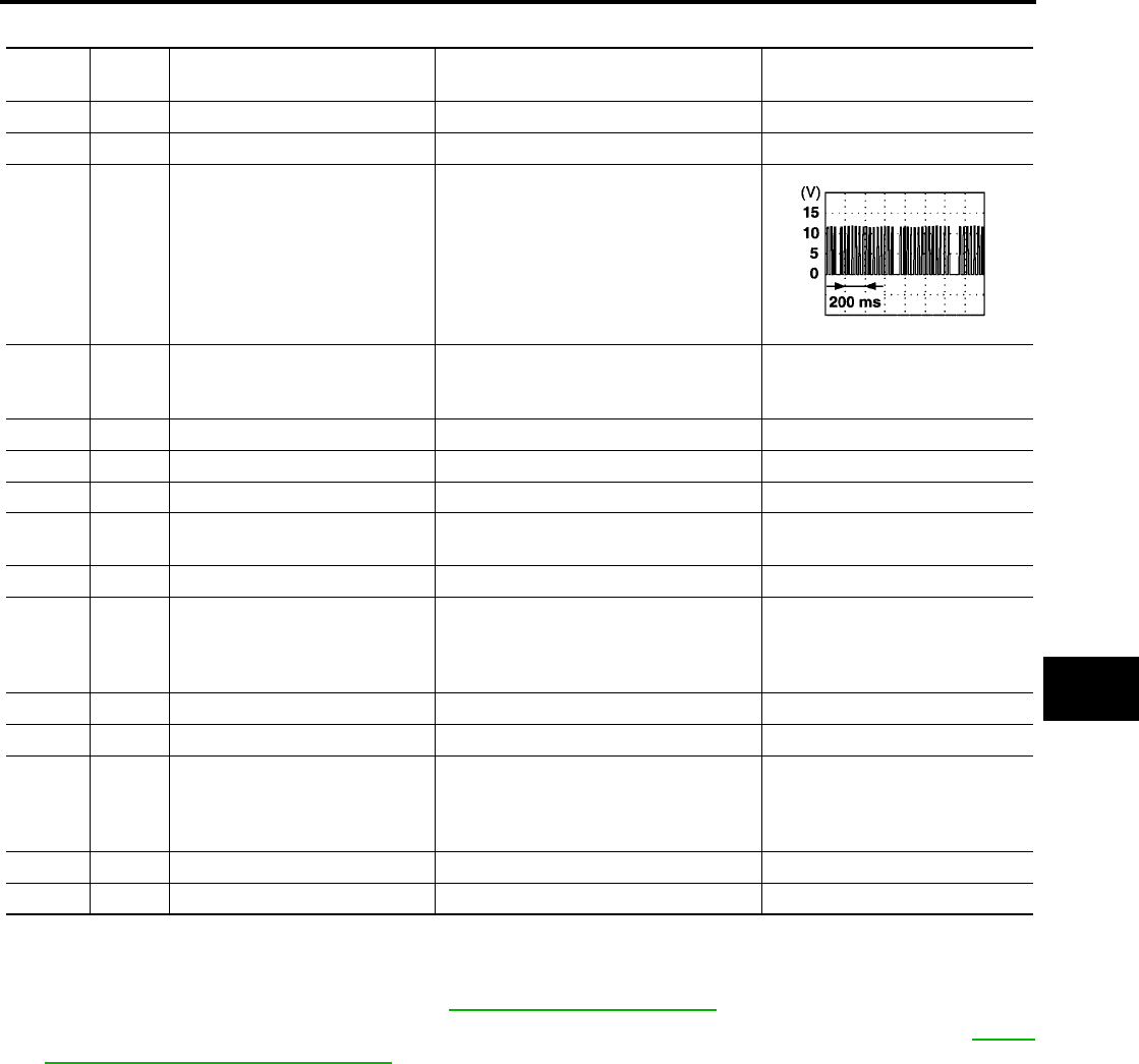
Terminal Wire
Color Item Condition Voltage (V)
(Approx.)
12 GR/L Front door switch RH Door open (ON) → Door closed (OFF) 0 → Battery voltage
13 O/B Sliding door switch RH Door open (ON) → Door closed (OFF) 0 → Battery voltage
22 Y/B Bus When ignition switch is ON or power
window timer operates
37 B/R Key switch (insert)
Key inserted in IGN key cylinder (ON) →
Key removed from IGN key cylinder
(OFF)
Battery voltage → 0
39 L CAN-H ——
40 P CAN-L ——
42 Y/G Battery power supply —Battery voltage
44 G Front door lock assembly LH
(actuator) (unlock)
Driver door lock knob
(locked → unlocked) 0 → Battery voltage for 300 ms
50 V All door lock actuator (lock) Driver door lock knob (neutral → lock) 0 → Battery voltage for 300 ms
51 G/Y
Front door lock actuator RH,
sliding door lock actuators LH/
RH and back door lock actuator
(unlock)
Door lock and unlock switch (locked →
unlocked) 0 → Battery voltage for 300 ms
52 B/W Ground ——
55 W/B Battery power supply —Battery voltage
58 O
Back door switch (without auto-
matic back door system) or back
door latch actuator (with auto-
matic back door system)
Door open (ON) → Door close (OFF) 0 → Battery voltage
62 GR/R Front door switch LH Door open (ON) → Door close (OFF) 0 → Battery voltage
63 W/G Sliding door switch LH Door open (ON) → Door close (OFF) 0 → Battery voltage
PIIA2344E
BL-38
POWER DOOR LOCK SYSTEM
Revision: July 2006 2006 Quest
CONSULT–II Function (BCM)
EIS007DG
CONSULT-II can display each diagnostic item using the diagnostic test modes shown following.
CONSULT–II INSPECTION PROCEDURE
"DOOR LOCK"
CAUTION:
If CONSULT-II is used with no connection of CONSULT-II CONVERTER, malfunctions might be
detected in self-diagnosis depending on control unit which carries out CAN communication.
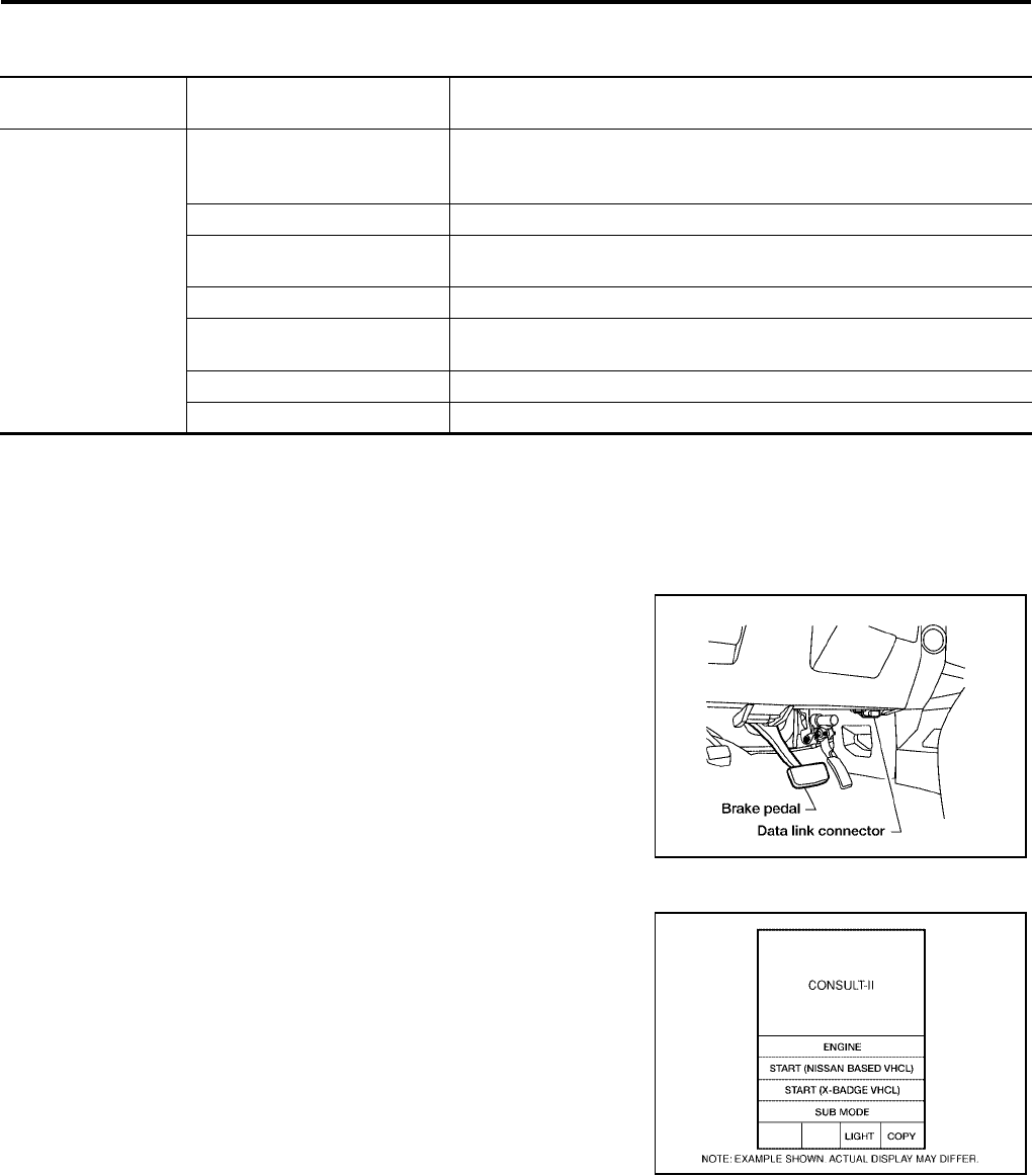
1. Turn ignition switch OFF.
2. Connect CONSULT-II and CONSULT-II CONVERTER to the
data link connector.
3. Turn ignition switch ON.
4. Touch “START (NISSAN BASED VHCL)”.
BCM
diagnostic test item Diagnostic mode Description
Inspection by part
WORK SUPPORT
Supports inspections and adjustments. Commands are transmitted to the
BCM for setting the status suitable for required operation, input/output sig-
nals are received from the BCM and received date is displayed.
DATA MONITOR Displays BCM input/output data in real time.
ACTIVE TEST Operation of electrical loads can be checked by sending drive signal to
them.
SELF-DIAG RESULTS Displays BCM self-diagnosis results.
CAN DIAG SUPPORT MNTR The result of transmit/receive diagnosis of CAN communication can be
read.
ECU PART NUMBER BCM part number can be read.
CONFIGURATION Performs BCM configuration read/write functions.
BBIA0369E
BCIA0029E
POWER DOOR LOCK SYSTEM
BL-39
C
D
E
F
G
H
J
K
L
M
A
B
BL
Revision: July 2006 2006 Quest
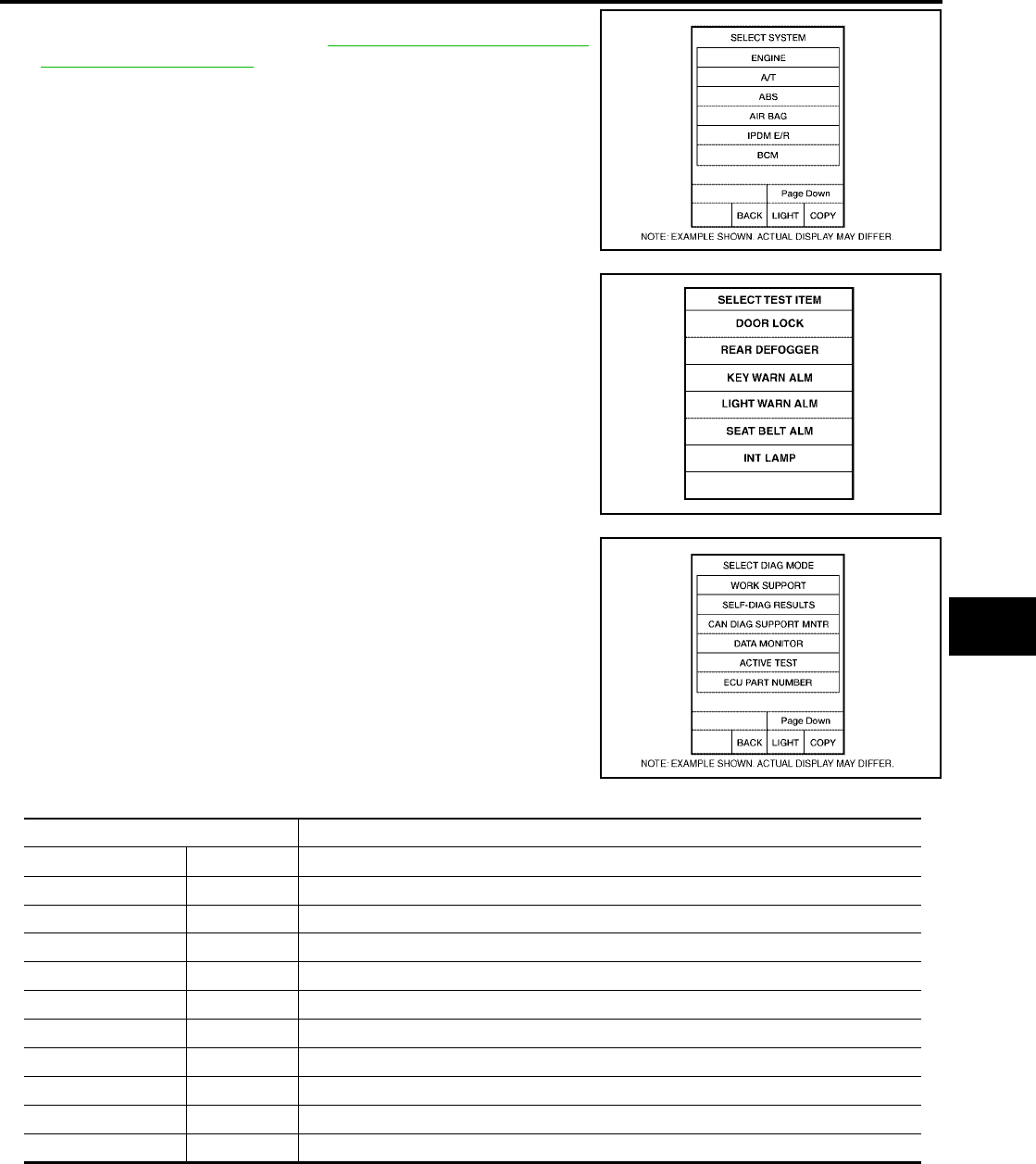
5. Touch “BCM”.
If "BCM" is not indicated, refer to GI-38, "CONSULT-II Data Link
Connector (DLC) Circuit" .
6. Touch “DOOR LOCK”.
7. Select diagnosis mode.
“DATA MONITOR” and “ACTIVE TEST” are available.
DATA MONITOR
BCIA0030E
LIIA0153E
BCIA0031E
Monitor item "OPERATION" Content
KEY ON SW "ON/OFF" Indicates [ON/OFF] condition of key switch.
CDL LOCK SW "ON/OFF" Indicates [ON/OFF] condition of lock signal from lock/unlock switch LH and RH.
CDL UNLOCK SW "ON/OFF" Indicates [ON/OFF] condition of unlock signal from lock/unlock switch LH and RH.
KEY CYL LK-SW "ON/OFF" Indicates [ON/OFF] condition of lock signal from key cylinder.
KEY CYL UN-SW "ON/OFF" Indicates [ON/OFF] condition of unlock signal from key cylinder.
IGN ON SW "ON/OFF" Indicates [ON/OFF] condition of ignition switch.
DOOR SW–DR "ON/OFF" Indicates [ON/OFF] condition of front door switch LH.
DOOR SW–AS "ON/OFF" Indicates [ON/OFF] condition of front door switch RH.
DOOR SW–RR "ON/OFF" Indicates [ON/OFF] condition of sliding door switch RH.
DOOR SW–RL "ON/OFF" Indicates [ON/OFF] condition of sliding door switch LH.
BACK DOOR SW "ON/OFF" Indicates [ON/OFF] condition of back door switch.

BL-40
POWER DOOR LOCK SYSTEM
Revision: July 2006 2006 Quest
ACTIVE TEST
Trouble Diagnoses Symptom Chart
EIS007DH
BCM Power Supply and Ground Circuit Check
EIS007DI
1. CHECK FUSE AND FUSIBLE LINK
Check the following BCM fuse and fusible link.
NOTE:
Refer to BL-18, "Component Parts and Harness Connector Location" .
OK or NG
OK >> GO TO 2.
NG >> If fuse is blown, be sure to eliminate cause of problem before installing new fuse. Refer to PG-4,
"POWER SUPPLY ROUTING CIRCUIT" .
Test item Content
ALL LOCK/UNLOCK This test is able to check all door lock actuators lock operation. These actuators lock when
"ON" on CONSULT–II screen is touched.
DR UNLOCK This test is able to check front door lock assembly LH (actuator) unlock operation.These actu-
ators lock when "ON" on CONSULT–II screen is touched.
OTHER UNLOCK This test is able to check door lock actuators [except front door lock assembly LH (actuator)]
unlock operation.These actuators unlock when "ON" on CONSULT–II screen is touched.
Symptom Repair order Refer to page
Key reminder door function does not operate
properly.
1. Door switch check BL-42
2. Key switch (Insert) check BL-46
3. Replace BCM. BCS-20
Power door lock does not operate with door lock
and unlock switch on main power window and
door lock/unlock switch or power window and
door lock/unlock switch RH.
1. Door lock/unlock switch check BL-47
Front door lock assembly LH (actuator) does not
operate. 1. Front door lock assembly LH (actuator) check BL-49
Specific door lock actuator does not operate.
1. Door lock actuator check (Front LH) BL-49
2. Door lock actuator check (Front RH) BL-50
3. Door lock actuator check (Sliding door) BL-51
4. Back door lock actuator check (Without auto-
matic back door system) BL-52
5. Back door lock actuator check (With automatic
back door system) BL-177
Power door lock does not operate with front door
lock assembly LH (key cylinder switch) operation.
1. Front door lock assembly LH (key cylinder
switch) check BL-53
2. Replace BCM. BCS-20
Power door lock does not operate.
1. BCM power supply and ground circuit check BL-40
2. Door lock/unlock switch check BL-47
3. Replace BCM. BCS-20
Component Parts Terminal No. (SIGNAL) Ampere No. Location
BCM 42 (BAT power supply) 15A 3 Fuse block (J/B)
BCM 55 (BAT power supply) 50A jFuse and fusible link box
POWER DOOR LOCK SYSTEM
BL-41
C
D
E
F
G
H
J
K
L
M
A
B
BL
Revision: July 2006 2006 Quest
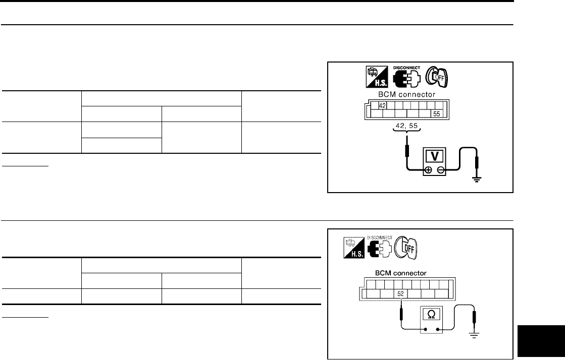
2. CHECK POWER SUPPLY CIRCUIT
1. Turn ignition switch OFF.
2. Disconnect BCM.
3. Check voltage between BCM connector M19 terminals 42, 55
and ground.
OK or NG
OK >> GO TO 3.
NG >> Repair or replace harness.
3. CHECK GROUND CIRCUIT
Check continuity between BCM connector M19 terminal 52 and
ground.
OK or NG
OK >> Power supply and ground circuits are OK.
NG >> Repair or replace harness.
Connector Terminals Voltage (V)
(Approx.)
(+) (-)
M19 42 Ground Battery voltage
55
PIIA6374E
Connector Terminals Continuity
(+) (-)
M19 52 Ground Yes
WKIA2973E
BL-42
POWER DOOR LOCK SYSTEM
Revision: July 2006 2006 Quest
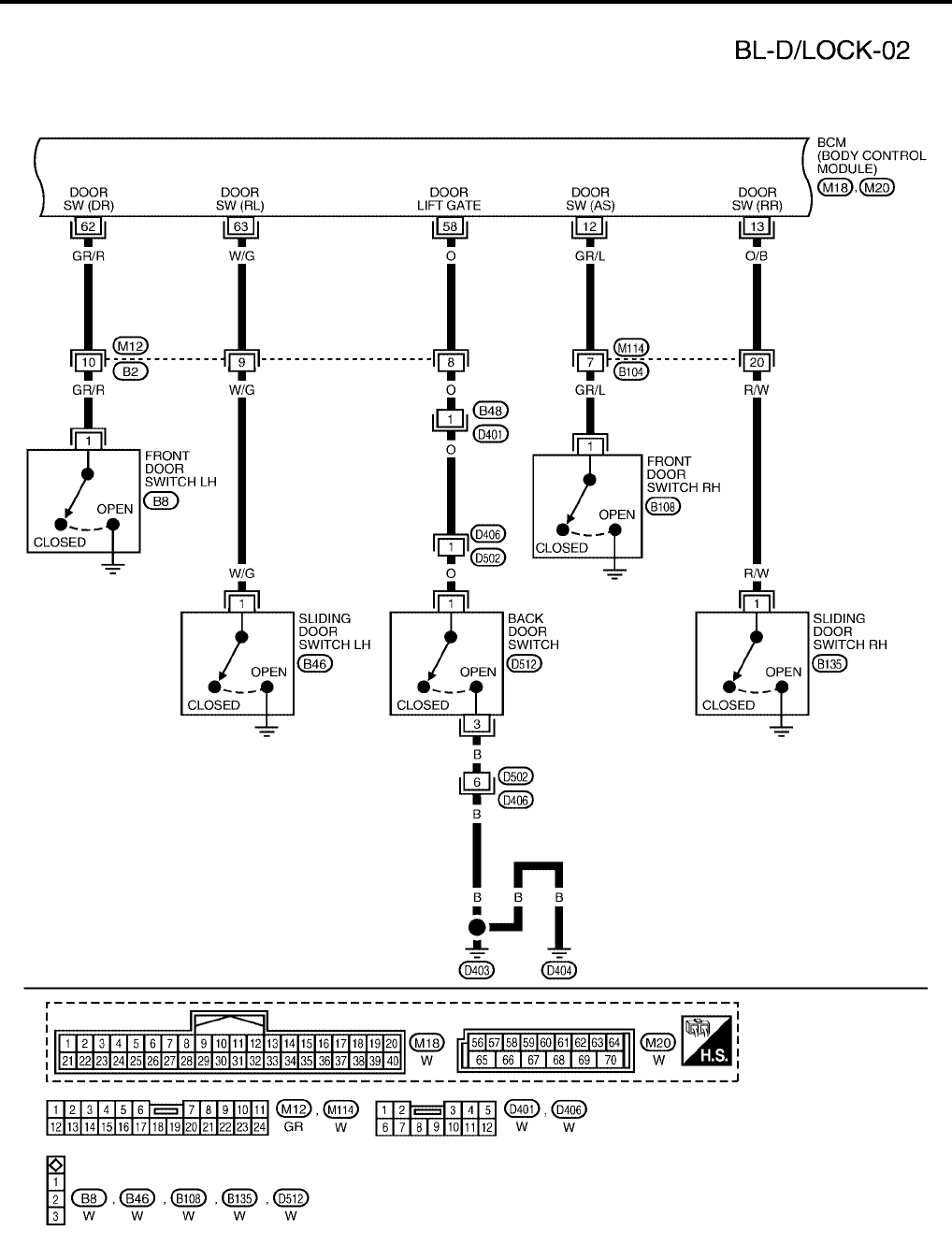
Door Switch Check (Without Automatic Back Door System)
EIS007DJ
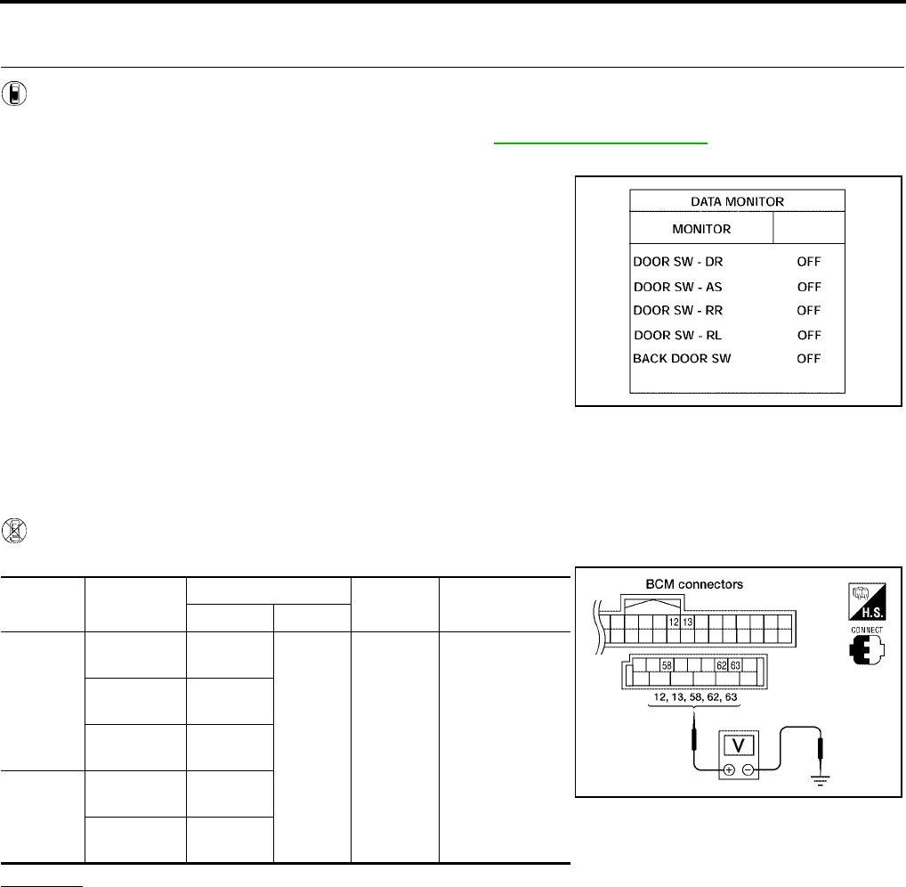
1. CHECK DOOR SWITCHES INPUT SIGNAL
With CONSULT-II
Check door switches ("DOOR SW-DR", "DOOR SW-AS", "DOOR SW-RL", "DOOR SW-RR", "BACK DOOR
SW") in DATA MONITOR mode with CONSULT–II. Refer to BL-39, "DATA MONITOR" .
●When doors are open:
●When doors are closed:
Without CONSULT-II
Check voltage between BCM connector M18 or M20 terminals 12, 13, 58, 62, 63 and ground.
OK or NG
OK >> Door switch circuit is OK.
NG >> GO TO 2.
DOOR SW-DR : ON
DOOR SW-AS : ON
DOOR SW-RR : ON
DOOR SW-RL : ON
BACK DOOR SW : ON
DOOR SW-DR : OFF
DOOR SW-AS : OFF
DOOR SW-RR : OFF
DOOR SW-RL : OFF
BACK DOOR SW : OFF
LIIA0665E
Connec-
tor Item Terminals Condition Voltage (V)
(Approx.)
( + ) ( – )
M20
Back door
switch 58
Ground
Open
↓
Closed
0
↓
Battery voltage
Front door
switch LH 62
Sliding door
switch LH 63
M18
Front door
switch RH 12
Sliding door
switch RH 13
LIIA0666E

POWER DOOR LOCK SYSTEM
BL-43
C
D
E
F
G
H
J
K
L
M
A
B
BL
Revision: July 2006 2006 Quest
2. CHECK DOOR SWITCH CIRCUIT
1. Turn ignition switch OFF.
2. Disconnect door switch and BCM.
3. Check continuity between door switch connector (B) B8 (Front LH), B108 (Front RH), B46 (Sliding LH),
B135 (Sliding RH) or D512 (Back) terminal 1 and BCM connector (A) M18, M20 terminals 12, 13, 58, 62
and 63.
4. Check continuity between door switch connector (B) B8 (Front
LH), B108 (Front RH), B46 (Sliding LH), B135 (Sliding RH) or
D512 (Back) terminal 1 and ground.
OK or NG
OK >> GO TO 3.
NG >> Repair or replace harness.
3. CHECK DOOR SWITCHES
FRONT AND SLIDING DOORS
Check continuity between front or sliding door switch terminal 1 and
exposed metal of switch while pressing and releasing switch.
BACK DOOR
Check continuity between back door switch terminals 1 and 3 while
pressing and releasing switch.
OK or NG
OK >> (Front and sliding doors) Switch circuit is OK.
OK >> (Back door) GO TO 4.
NG >> Replace door switch.
1 - 12 : Continuity should exist.
1 - 13 : Continuity should exist.
1 - 58 : Continuity should exist.
1 - 62 : Continuity should exist.
1 - 63 : Continuity should exist.
1 - Ground : Continuity should not exist. WIIA0781E
Door switch is released : Continuity should exist.
Door switch is pushed : Continuity should not exist.
WIIA0782E
Door switch is released : Continuity should exist.
Door switch is pushed : Continuity should not exist.
WIIA0783E
BL-44
POWER DOOR LOCK SYSTEM
Revision: July 2006 2006 Quest
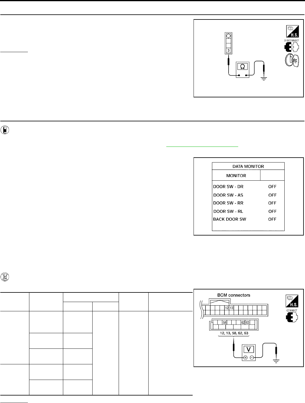
4. CHECK BACK DOOR SWITCH GROUND
Check continuity between back door switch connector terminal 3 and
ground.
OK or NG
OK >> Back door switch circuit is OK.
NG >> Repair or replace harness.
Door Switch Check (With Automatic Back Door System)
EIS007DK
1. CHECK DOOR SWITCHES INPUT SIGNAL
With CONSULT-II
Check door switches ("DOOR SW-DR", "DOOR SW-AS", "DOOR SW-RL", "DOOR SW-RR", "BACK DOOR
SW") in DATA MONITOR mode with CONSULT–II. Refer to BL-39, "DATA MONITOR" .
●When doors are open:
●When doors are closed:
Without CONSULT-II
Check voltage between BCM connector M18 or M20 terminals 12, 13, 58, 62, 63 and ground.
OK or NG
OK >> Door switch is OK.
NG >> GO TO 2.
3 - Ground : Continuity should exist.
WIIA0791E
DOOR SW-DR : ON
DOOR SW-AS : ON
DOOR SW-RR : ON
DOOR SW-RL : ON
BACK DOOR SW : ON
DOOR SW-DR : OFF
DOOR SW-AS : OFF
DOOR SW-RR : OFF
DOOR SW-RL : OFF
BACK DOOR SW : OFF
LIIA0665E
Connector Item Terminals Condition Voltage (V)
(Approx.)
( + ) ( – )
M20
Back door
latch (door
ajar switch)
58
Ground
Open
↓
Closed
0
↓
Battery voltage
Front door
switch LH 62
Sliding door
switch LH 63
M18
Front door
switch RH 12
Sliding door
switch RH 13
LIIA0666E

POWER DOOR LOCK SYSTEM
BL-45
C
D
E
F
G
H
J
K
L
M
A
B
BL
Revision: July 2006 2006 Quest
2. CHECK DOOR SWITCH CIRCUIT
1. Turn ignition switch OFF.
2. Disconnect door switch and BCM.
3. Check continuity between door switch connector (B) B8 (Front LH), B108 (Front RH), B46 (Sliding LH),
B135 (Sliding RH) terminal 1 or back door latch (door ajar switch) connector (C) D511 terminal 7 and BCM
connector (A) M18, M20 terminals 12, 13, 58, 62 and 63
4. Check continuity between door switch connector (B) B8 (Front
LH), B108 (Front RH), B46 (Sliding LH), B135 (Sliding RH) ter-
minal 1 or back door latch (door ajar switch) connector (C) D511
terminal 7 and ground.
OK or NG
OK >> GO TO 3.
NG >> Repair or replace harness.
3. CHECK DOOR SWITCHES
FRONT AND SLIDING DOORS
Check continuity between front or sliding door switch terminal 1 and
exposed metal of switch while pressing and releasing switch.
BACK DOOR
Check continuity between back door latch (door ajar switch) connec-
tor D511 terminals 7 and 8 while pressing (closing back door) and
releasing (opening back door) switch.
OK or NG
OK >> (Front and sliding doors) Switch circuit is OK.
OK >> (Back door) GO TO 4.
NG >> Replace door switch.
1 - 62 : Continuity should exist.
1 - 12 : Continuity should exist.
1 - 63 : Continuity should exist.
1 - 13 : Continuity should exist.
7 - 58 : Continuity should exist.
1 - Ground : Continuity should not exist.
7 - Ground : Continuity should not exist.
WIIA0784E
Door switch is released : Continuity should exist.
Door switch is pushed : Continuity should not exist.
WIIA0782E
When back door is open : Continuity should exist.
When back door is closed : Continuity should not exist.
WIIA0811E
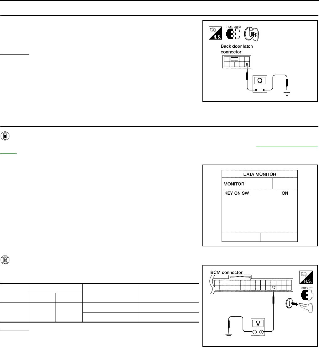
BL-46
POWER DOOR LOCK SYSTEM
Revision: July 2006 2006 Quest
4. CHECK BACK DOOR SWITCH GROUND
Check continuity between back door latch (door ajar switch) connec-
tor terminal 8 and ground.
OK or NG
OK >> Back door switch circuit is OK.
NG >> Repair or replace harness.
Key Switch (Insert) Check
EIS007DL
1. CHECK KEY SWITCH INPUT SIGNAL
With CONSULT-II
Check key switch "KEY ON SW" in DATA MONITOR mode with CONSULT–II. Refer to BL-39, "DATA MONI-
TOR" .
●When key is inserted to ignition key cylinder:
●When key is removed from ignition key cylinder:
Without CONSULT-II
Check voltage between BCM connector M18 terminal 37 and
ground.
OK or NG
OK >> Key switch (insert) circuit is OK.
NG >> GO TO 2.
8 - Ground : Continuity should exist.
LIIA0828E
KEY ON SW : ON
KEY ON SW : OFF
LIIA0169E
Connec-
tor
Terminal Condition Voltage (V)
(Approx.)
( + ) ( – )
M18 37 Ground Key is inserted. Battery voltage
Key is removed. 0
LIIA0567E
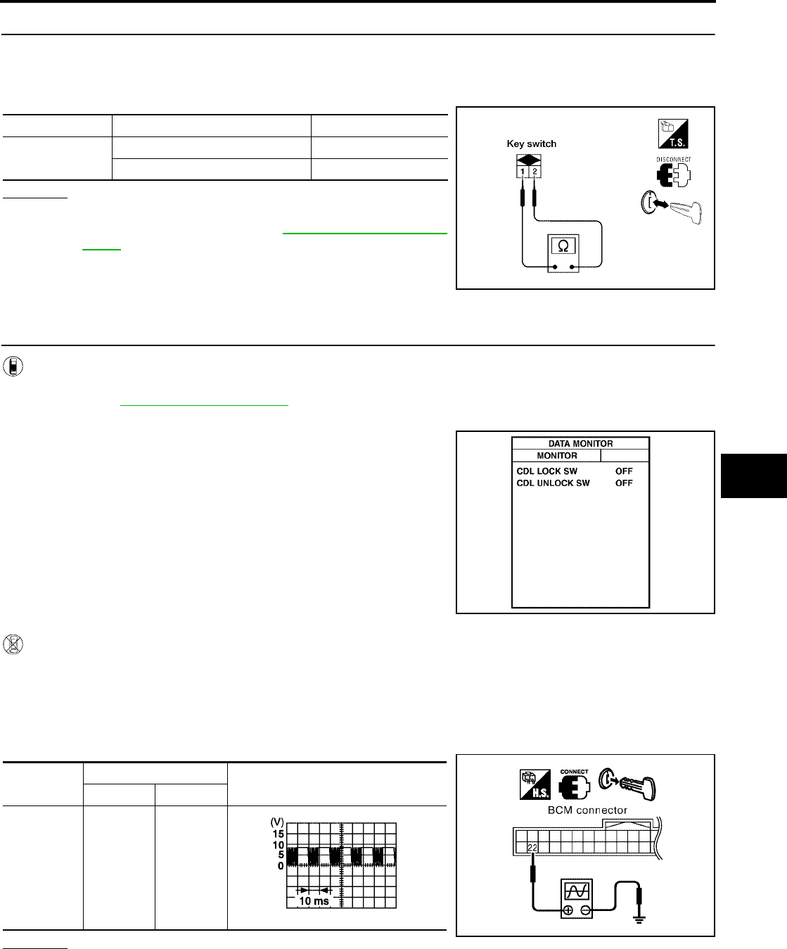
POWER DOOR LOCK SYSTEM
BL-47
C
D
E
F
G
H
J
K
L
M
A
B
BL
Revision: July 2006 2006 Quest
2. CHECK KEY SWITCH (INSERT)
1. Turn ignition switch OFF.
2. Disconnect key switch.
3. Check continuity between key switch terminals 1, 2.
OK or NG
OK >> Repair or replace harness.
NG >> Replace key switch. Refer to PS-9, "STEERING COL-
UMN" .
Door Lock/Unlock Switch Check
EIS007DM
1. CHECK DOOR LOCK/UNLOCK SWITCH INPUT SIGNAL
With CONSULT-II
Check door lock/unlock switch ("CDL LOCK SW", "CDL UNLOCK SW") in DATA MONITOR mode in CON-
SULT–II. Refer to BL-39, "DATA MONITOR" .
●When door lock/unlock switch is turned to LOCK:
●When door lock/unlock switch is turned to UNLOCK:
Without CONSULT-II
1. Remove key from ignition key cylinder.
2. Check the signal between BCM connector M18 terminal 22 and ground with oscilloscope when door lock/
unlock switch is turned to LOCK or UNLOCK.
3. Make sure the signals which are shown in the figure below can be detected during 10 seconds just after
the door lock/unlock switch is turned to LOCK or UNLOCK.
OK or NG
OK >> Door lock and unlock switch circuit is OK.
NG >> GO TO 2.
Terminals Condition Continuity
1 – 2 Key is inserted. Yes
Key is removed. No
LIIA1906E
CDL LOCK SW : ON
CDL UNLOCK SW : ON
PIIA6538E
Connector Terminal Voltage (V)
(Approx.)
( + ) ( – )
M18 22 Ground
PIIA6379E
PIIA1297E
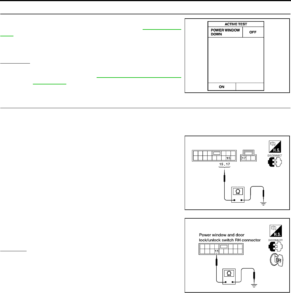
BL-48
POWER DOOR LOCK SYSTEM
Revision: July 2006 2006 Quest
2. CHECK BCM OUTPUT SIGNAL
Check ("POWER WINDOW DOWN") in ACTIVE TEST mode for
"MULTI REMOTE ENT" with CONSULT–II. Refer to BL-68, "Active
Test" .
YES or NO
YES >> GO TO 3.
NO >> Replace BCM. Refer to BCS-20, "Removal and Installa-
tion of BCM" .
3. CHECK DOOR LOCK/UNLOCK SWITCH GROUND HARNESS
1. Turn ignition switch OFF.
2. Disconnect main power window and door lock/unlock switch or power window and door lock/unlock switch
RH.
3. Check continuity between main power window and door lock/
unlock switch connector D7 terminal 15 (without automatic back
door system) or D8 terminal 17 (with automatic back door sys-
tem) and ground.
4. Check continuity between power window and door lock/unlock
switch RH connector D105 terminal 11 and ground.
OK or NG
OK >> GO TO 4.
NG >> Repair or replace harness.
When "ACTIVE TEST" is performed, are the front win-
dows lowered?
PIIA3080E
15 - Ground : Continuity should exist.
17 - Ground : Continuity should exist.
WIIA0812E
11 - Ground : Continuity should exist.
LIIA1270E
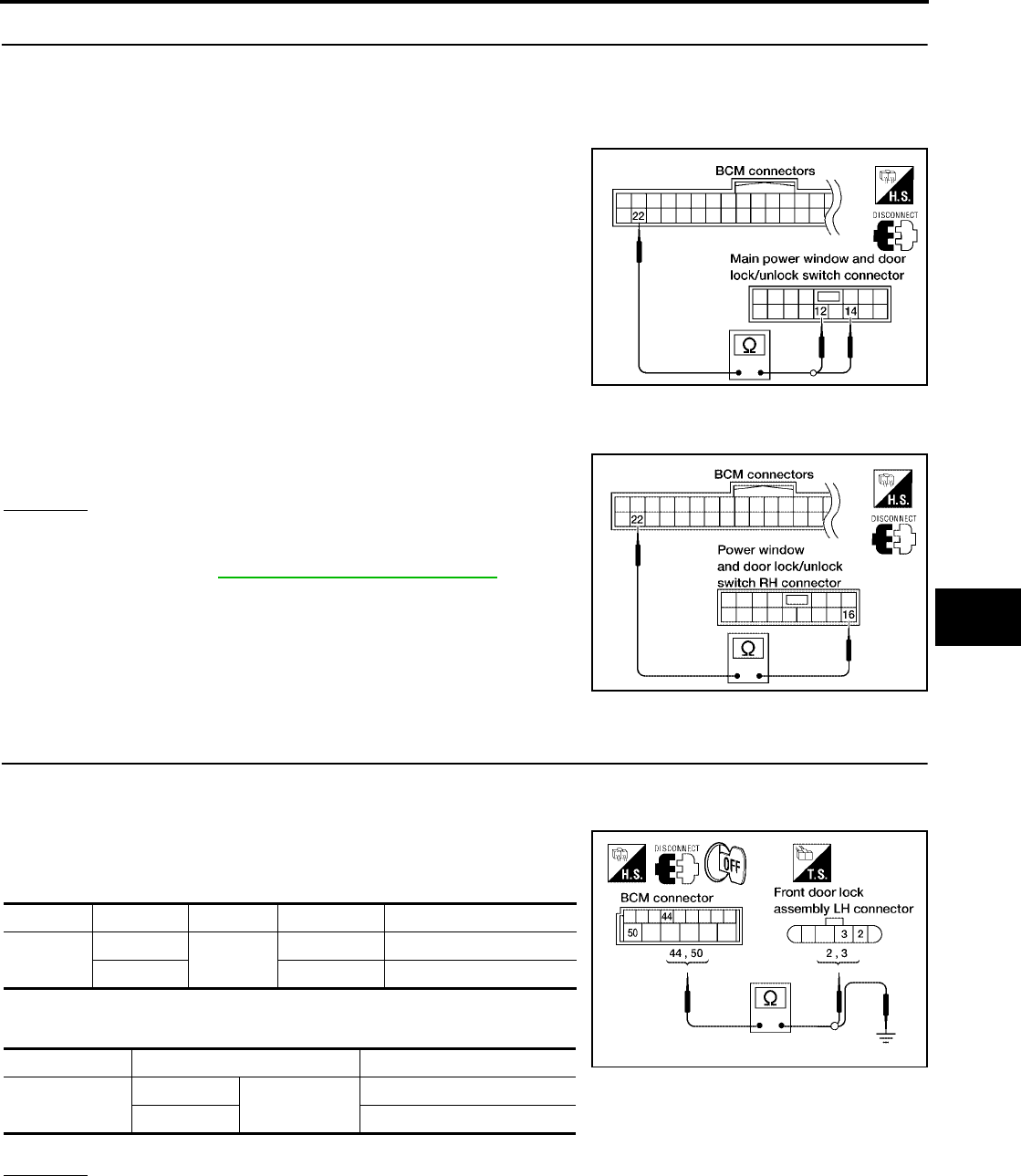
POWER DOOR LOCK SYSTEM
BL-49
C
D
E
F
G
H
J
K
L
M
A
B
BL
Revision: July 2006 2006 Quest
4. CHECK POWER WINDOW SERIAL LINK CIRCUIT
1. Disconnect BCM.
2. Check continuity between BCM connector M18 terminal 22 and main power window and door lock/unlock
switch connector D7 terminal 12 (without automatic back door system) or terminal 14 (with automatic back
door system).
3. Check continuity between BCM connector M18 terminal 22 and power window and door lock/unlock
switch RH connector D105 terminal 16.
OK or NG
OK >> Replace main power window and door lock/unlock
switch or power window and door lock/unlock switch
RH. Refer to EI-29, "Removal and Installation" .
NG >> Repair or replace harness.
Front Door Lock Assembly LH (Actuator) Check
EIS007DN
1. CHECK FRONT DOOR LOCK ASSEMBLY LH (ACTUATOR) HARNESS
1. Turn ignition switch OFF.
2. Disconnect BCM and front door lock assembly LH (actuator).
3. Check continuity between BCM connector M19 terminals 44, 50
and front door lock assembly LH (actuator) connector D14 termi-
nals 2, 3.
4. Check continuity between BCM connector M19 terminals 44, 50
and body ground.
OK or NG
OK >> Go to 2.
NG >> Repair or replace harness.
22 - 12 : Continuity should exist.
22 - 14 : Continuity should exist.
LIIA1903E
22 - 16 : Continuity should exist.
LIIA1271E
Connector Terminals Connector Terminals Continuity
M19 44 D14 2Yes
50 3 Yes
Connector Terminals Continuity
M19 44 Ground No
50 No
WIIA0372E
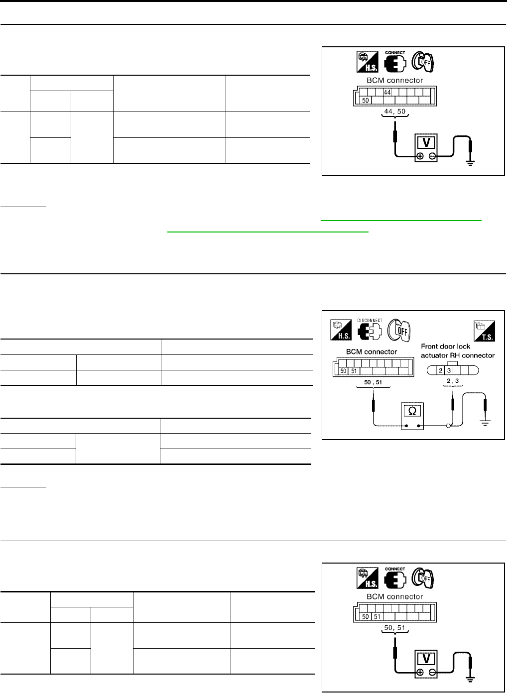
BL-50
POWER DOOR LOCK SYSTEM
Revision: July 2006 2006 Quest
2. CHECK FRONT DOOR LOCK ASSEMBLY LH (ACTUATOR) SIGNAL
1. Reconnect BCM.
2. Check voltage between BCM connector M19 terminals 44, 50
and ground.
OK or NG
OK >> Replace front door lock assembly LH (actuator). Refer to BL-197, "Removal and Installation" .
NG >> Replace BCM. Refer to BCS-20, "Removal and Installation of BCM" .
Front Door Lock Actuator RH Check
EIS007DO
1. CHECK DOOR LOCK ACTUATOR HARNESS
1. Turn ignition switch OFF.
2. Disconnect BCM and front door lock actuator RH.
3. Check continuity between BCM connector M19 terminals 50, 51
and front door lock actuator RH connector D114 terminals 2, 3.
4. Check continuity between BCM connector M19 terminals 50, 51
and body ground.
OK or NG
OK >> GO TO 2.
NG >> Repair or replace harness.
2. CHECK DOOR LOCK ACTUATOR SIGNAL
1. Reconnect BCM.
2. Check voltage between BCM connector M19 terminals 50, 51
and ground.
Con-
nec-
tor
Terminals
Condition Voltage (V)
(Approx.)
(+) (-)
M19
44
Ground
Driver door lock/unlock
switch is turned to UNLOCK
0 → Battery voltage
for 300 ms
50 Driver door lock/unlock
switch is turned to LOCK
0 → Battery voltage
for 300 ms
PIIA6383E
Terminals Continuity
50 3 Yes
51 2 Yes
Terminals Continuity
50 Ground No
51 No
LIIA1920E
Connector Terminals Condition Voltage (V)
(Approx.)
(+) (-)
M19
50
Ground
Door lock/unlock switch
is turned to LOCK
0 → Battery voltage
for 300 ms
51 Door lock/unlock switch
is turned to UNLOCK
0 → Battery voltage
for 300 ms
PIIA6385E
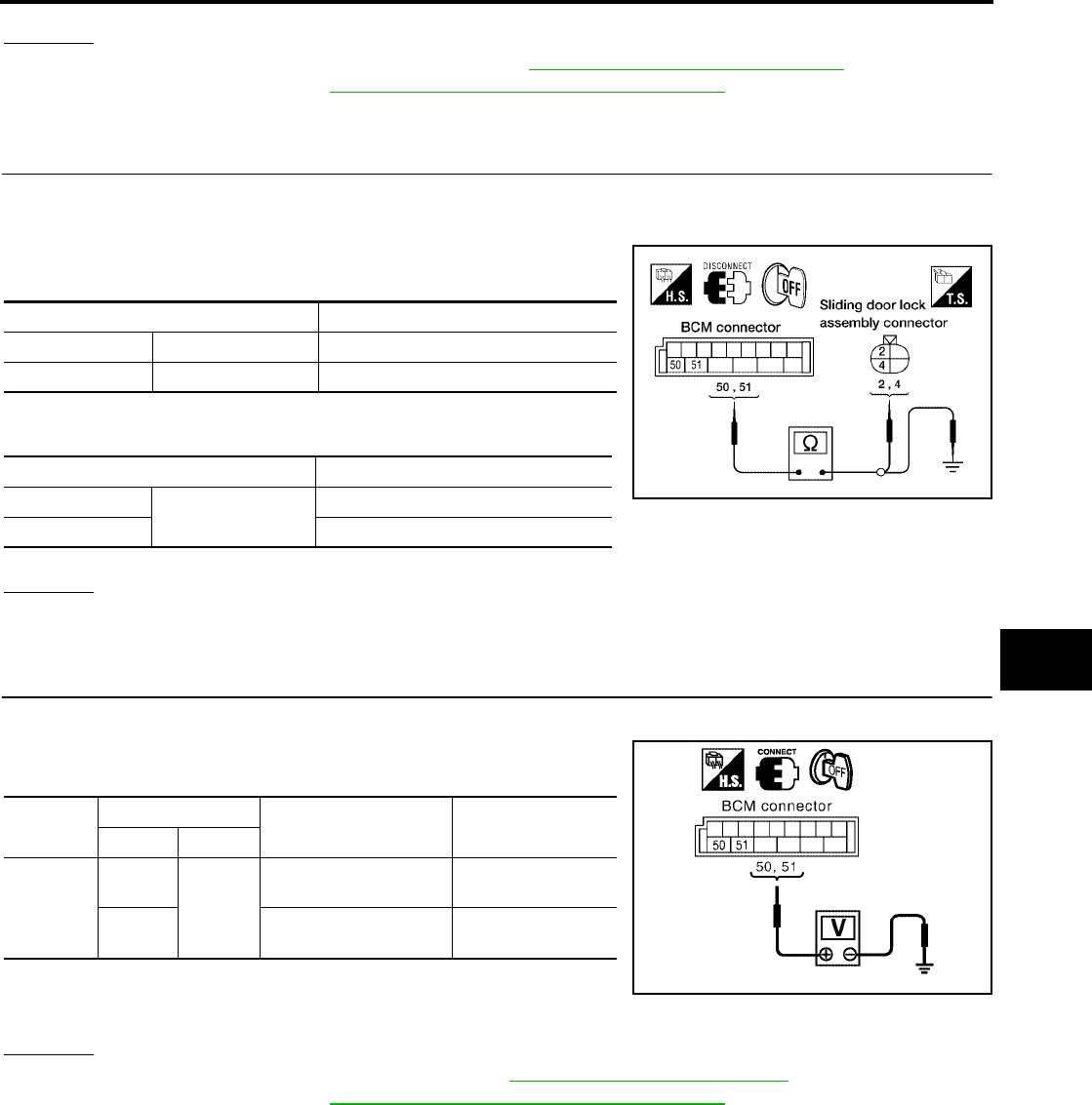
POWER DOOR LOCK SYSTEM
BL-51
C
D
E
F
G
H
J
K
L
M
A
B
BL
Revision: July 2006 2006 Quest
OK or NG
OK >> Replace front door lock actuator RH. Refer to BL-197, "Removal and Installation" .
NG >> Replace BCM. Refer to BCS-20, "Removal and Installation of BCM" .
Door Lock Actuator Check (Sliding Door)
EIS007DP
1. CHECK DOOR LOCK ACTUATOR HARNESS
1. Turn ignition switch OFF.
2. Disconnect BCM and each door lock actuator.
3. Check continuity between BCM connector M19 terminals 50, 51
and sliding door lock actuator connector terminals 2, 4.
4. Check continuity between BCM connector M19 terminals 50, 51
and body ground.
OK or NG
OK >> GO TO 2.
NG >> Repair or replace harness.
2. CHECK DOOR LOCK ACTUATOR SIGNAL
1. Reconnect BCM.
2. Check voltage between BCM connector M19 terminals 50, 51
and ground.
OK or NG
OK >> Replace sliding door lock actuator. Refer to BL-200, "SLIDE DOOR LOCK" .
NG >> Replace BCM. Refer to BCS-20, "Removal and Installation of BCM" .
Terminal Continuity
50 4 Yes
51 2 Yes
Terminals Continuity
50 Ground No
51 No
LIIA1905E
Connector Terminals Condition Voltage (V)
(Approx.)
(+) (-)
M19
50
Ground
Door lock/unlock switch
is turned to LOCK
0 → Battery voltage
for 300 ms
51 Door lock/unlock switch
is turned to UNLOCK
0 → Battery voltage
for 300 ms
PIIA6385E
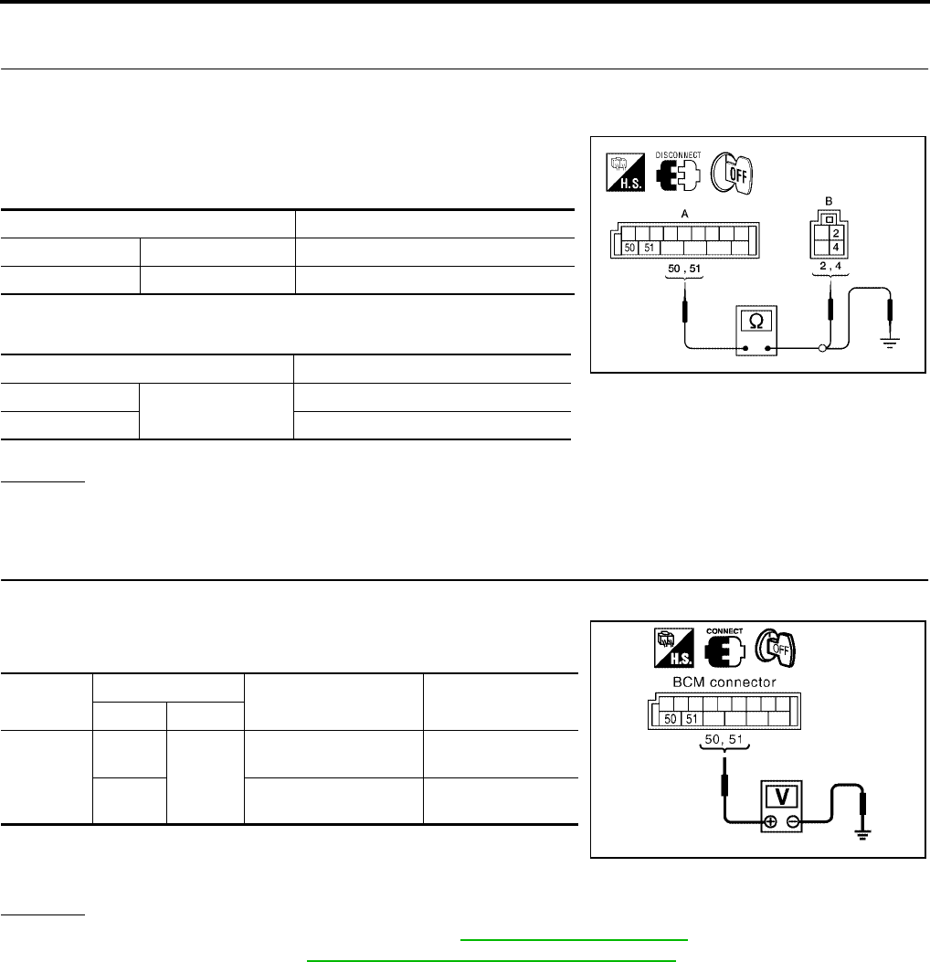
BL-52
POWER DOOR LOCK SYSTEM
Revision: July 2006 2006 Quest
Back Door Lock Actuator Check (Without Automatic Back Door)
EIS007NJ
1. CHECK BACK DOOR LOCK ACTUATOR HARNESS
1. Turn ignition switch OFF.
2. Disconnect BCM and back door lock actuator.
3. Check continuity between BCM connector (A) M19 terminals 50,
51 and back door lock actuator connector (B) D513 terminals 2,
4.
4. Check continuity between BCM connector (A) M19 terminals 50,
51 and body ground.
OK or NG
OK >> GO TO 2.
NG >> Repair or replace harness.
2. CHECK DOOR LOCK ACTUATOR SIGNAL
1. Reconnect BCM.
2. Check voltage between BCM connector M19 terminals 50, 51
and ground.
OK or NG
OK >> Replace back door lock actuator. Refer to BL-205, "Back Door Latch" .
NG >> Replace BCM. Refer to BCS-20, "Removal and Installation of BCM" .
Terminals Continuity
50 4 Yes
51 2 Yes
Terminals Continuity
50 Ground No
51 No
WIIA0815E
Connector Terminals Condition Voltage (V)
(Approx.)
(+) (-)
M19
50
Ground
Door lock/unlock switch
is turned to LOCK
0 → Battery voltage
for 300 ms
51 Door lock/unlock switch
is turned to UNLOCK
0 → Battery voltage
for 300 ms
PIIA6385E
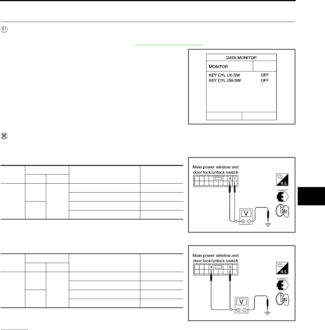
POWER DOOR LOCK SYSTEM
BL-53
C
D
E
F
G
H
J
K
L
M
A
B
BL
Revision: July 2006 2006 Quest
Front Door Lock Assembly LH (Key Cylinder Switch) Check
EIS007DQ
1. CHECK DOOR KEY CYLINDER SWITCH LH
With CONSULT-II
Check front door lock assembly LH (key cylinder switch) ("KEY CYL LK-SW") and ("KEY CYL UN-SW) in
DATA MONITOR mode in CONSULT–II. Refer to BL-39, "DATA MONITOR" .
●When key inserted in front key cylinder is turned to LOCK:
●When key inserted in front key cylinder is turned to UNLOCK:
Without CONSULT-II
Check voltage between main power window and door lock/unlock switch connector D7 terminals 6, 7 (without
automatic sliding door system) or terminals 4, 6 (with automatic sliding door system) and ground.
Without Automatic Sliding Door System
With Automatic Sliding Door System
OK or NG
OK >> Front door lock assembly LH (key cylinder switch) signal is OK.
NG >> GO TO 2.
KEY CYL LK-SW : ON
KEY CYL UN-SW : ON
LIIA0188E
Connec-
tor
Terminals Condition Voltage (V)
(Approx.)
( + ) ( – )
D7
6
Ground
Neutral/Unlock 5
Lock 0
7Neutral/Lock 5
Unlock 0
LIIA0867E
Connec-
tor
Terminals Condition Voltage (V)
(Approx.)
( + ) ( – )
D7
4
Ground
Neutral/Unlock 5
Lock 0
6Neutral/Lock 5
Unlock 0
LIIA0566E
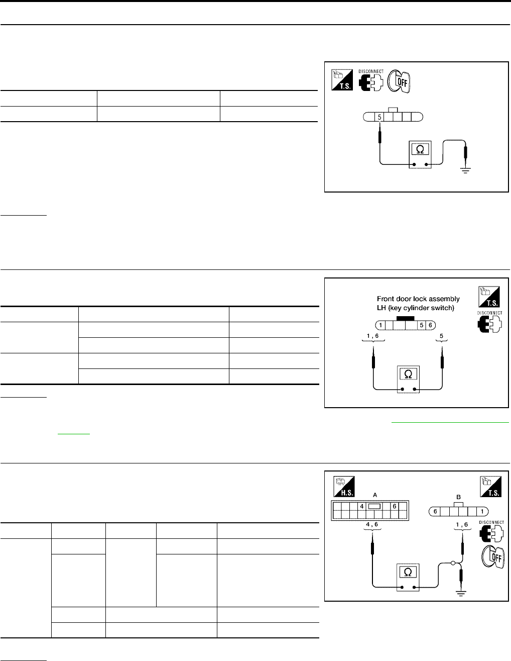
BL-54
POWER DOOR LOCK SYSTEM
Revision: July 2006 2006 Quest
2. CHECK DOOR KEY CYLINDER SWITCH LH GROUND HARNESS
1. Turn ignition switch OFF.
2. Disconnect front door lock assembly LH (key cylinder switch).
3. Check continuity between front door lock assembly LH (key cyl-
inder switch) connector D14 terminal 5 and body ground.
OK or NG
OK >> GO TO 3.
NG >> Repair or replace harness.
3. CHECK DOOR KEY CYLINDER SWITCH LH
Check continuity between front door lock assembly LH (key cylinder
switch) terminals.
OK or NG
OK >> GO TO 4.
NG >> Replace front door lock assembly LH (key cylinder switch). Refer to BL-197, "FRONT DOOR
LOCK" .
4. CHECK DOOR KEY CYLINDER HARNESS
Check continuity between main power window and door lock/unlock
switch connector (A) D7 terminals 4, 6 and front door lock assembly
LH (key cylinder switch) connector (B) D14 terminals 1, 6 and body
ground.
OK or NG
OK >> Replace main power window and door lock/unlock switch.
NG >> Repair or replace harness.
Connector Terminals Continuity
D14 5 – Ground Yes
WIIA0813E
Terminals Condition Continuity
1 – 5 Key is turned to UNLOCK or neutral. No
Key is turned to LOCK. Yes
5 – 6 Key is turned to LOCK or neutral. No
Key is turned to UNLOCK. Yes
LIIA1573E
Connector Terminals Connector Terminals Continuity
A: Main
power win-
dow and
door lock/
unlock
switch
4B: Front
door lock
assembly
LH (key
cylinder
switch)
1Yes
66Yes
4Ground No
6Ground No
WIIA0814E
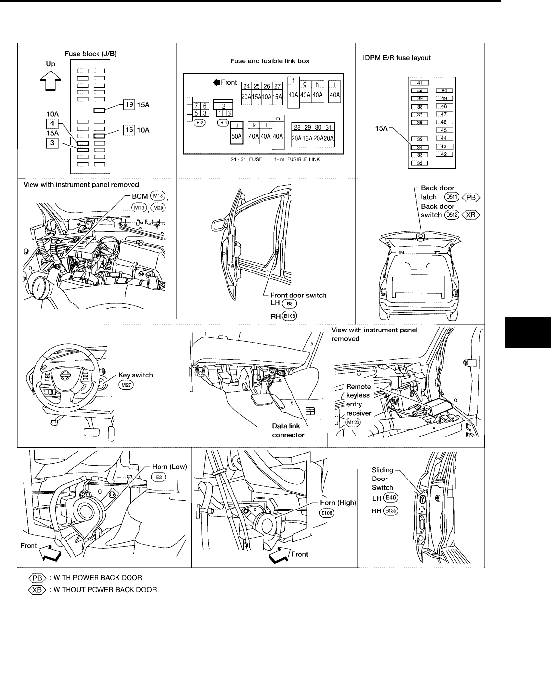
REMOTE KEYLESS ENTRY SYSTEM
BL-55
C
D
E
F
G
H
J
K
L
M
A
B
BL
Revision: July 2006 2006 Quest
REMOTE KEYLESS ENTRY SYSTEM PFP:28596
Component Parts and Harness Connector Location
EIS007DR
LIIA1904E

BL-56
REMOTE KEYLESS ENTRY SYSTEM
Revision: July 2006 2006 Quest
System Description
EIS007DS
INPUTS
Power is supplied at all times
●to BCM terminal 55
●through 50A fusible link (letter j , located in the fuse and fusible link box).
●to BCM terminal 42
●through 15A fuse [No. 3, located in the fuse block (J/B)].
When the ignition key is inserted in the ignition cylinder, power is supplied
●to BCM terminal 37
●through key switch terminals 1 and 2
●through 15A fuse [No. 19, located in the fuse block (J/B)].
When the ignition switch is in ACC or ON, power is supplied
●to BCM terminal 11
●through 10A fuse [No. 4, located in the fuse block (J/B)].
When the ignition switch is in ON or START, power is supplied
●to BCM terminal 38
●through 10A fuse [No. 16, located in the fuse block (J/B)].
When the front door switch LH is ON (door is OPEN), ground is supplied
●to BCM terminal 62
●through front door switch LH terminal 1
●through front door switch LH case ground.
When the front door switch RH is ON (door is OPEN), ground is supplied
●to BCM terminal 12
●through front door switch RH terminal 1
●through front door switch RH case ground.
When the sliding door switch LH is ON (door is OPEN), ground is supplied
●to BCM terminal 63
●through sliding door switch LH terminal 1
●through sliding door switch LH case ground.
When the sliding door switch RH is ON (door is OPEN), ground is supplied
●to BCM terminal 13
●through sliding door switch RH terminal 1
●through sliding door switch RH case ground.
When the back door switch is ON (door is OPEN), ground is supplied
●to BCM terminal 58
●through back door switch terminal 1 (without power back door) or,
●through back door latch terminal 7 (with power back door)
●through back door switch terminal 3 (without power back door)
●through back door latch terminal 8 (with power back door)
●through body grounds D403 and D404.
Keyfob signal is supplied to BCM from the remote keyless entry receiver.
The remote keyless entry system controls operation of the
●power door lock
●sliding door opener (with automatic sliding door system)
●back door opener (with power back door)
●interior lamp and step lamps
●panic alarm
●hazard and horn reminder
●keyless power window down (open)

REMOTE KEYLESS ENTRY SYSTEM
BL-57
C
D
E
F
G
H
J
K
L
M
A
B
BL
Revision: July 2006 2006 Quest
●auto door lock operation
OPERATION PROCEDURE
●When the keyfob is operated, the signal from the keyfob is sent and the remote keyless entry receiver
receives the signal and sends it to the BCM. The BCM only locks/unlocks the doors if the ID number
matches. (Remote control entry functions)
●Using the keyfob, the transmitter sends radio waves to the remote keyless entry receiver, which then
sends the received waves to the BCM. Only if the ID number matches does the BCM lock/unlock the
doors. (Remote control door function)
●Unless the key is inserted into the ignition key cylinder or one of the doors is opened within 1 minute after
the UNLOCK switch on the keyfob is pressed, all the doors are automatically locked. (Auto lock function)
●When a door is locked or unlocked, the vehicle turn signal lamps flash and the horn sounds to verify oper-
ation. (Active check function)
●When the key is in the ignition key cylinder (when the key switch is ON) and one of the doors is open, the
door lock function does not work even when the door lock is operated with the keyfob.
●Keyfob ID set up is available.
●If a keyfob is lost, a new keyfob can be set up. A maximum of 5 IDs can be set up.
Remote Control Entry Functions
Operation Description
●When a button on the keyfob is operated, the signal is sent from the keyfob and received by the remote
keyless entry receiver.
●The received signal is sent to the BCM and compared with the registered ID number.
●If the ID number matches, the BCM sends the lock/unlock signal to each door lock actuator.
●When the door lock actuators receive this signal, each operates to lock/unlock its door.
●BCM locks all doors with input of LOCK signal from keyfob.
●When an UNLOCK signal is sent from keyfob once, driver's door will be unlocked.
●Then, if an UNLOCK signal is sent from keyfob again within 5 seconds, all other doors will be unlocked.
Remote control entry operation conditions
Auto Lock Function
Operation Description
●Unless the key is inserted into the ignition key cylinder, one of the doors is opened, or the keyfob is oper-
ated within 1 minute after a door lock is unlocked by keyfob operation, all the doors are automatically
locked.
The 1 minute timer count is executed by the BCM and after 1 minute, the BCM sends the lock signal to all
doors.
Lock operations are the same as for the remote control entry function.
Remote Control Auto Sliding Door Function (Vehicles With Automatic Sliding Door System)
Switching from all closed to all open
●When a button on the keyfob is operated, the signal is sent from the keyfob and received by the remote
keyless entry receiver.
●The received signal is sent to the BCM and compared with the registered ID number.
●If the ID number matches, the BCM sends the sliding door open signal to the sliding door control unit.
●When the sliding door control unit receives the sliding door open signal, if the remote control auto sliding
door operation enable conditions are met, the warning chime is sounded and the sliding door unlock sig-
nal is sent to the sliding door latch control unit.
●When the sliding door latch control unit receives the sliding door unlock signal, it operates the release
actuator and unlocks the door lock.
Keyfob operation Operation condition
Door lock operation (locking) ●With key removed (key switch: OFF)
●Closing all doors (door switch: OFF)
Door lock operation (unlocking) With key removed (key switch: OFF)

BL-58
REMOTE KEYLESS ENTRY SYSTEM
Revision: July 2006 2006 Quest
●The sliding door control unit operates the magnetic clutch and the sliding door motor to slide the sliding
door in the open direction (At this time, speed control, input reverse, and overload reverse control are exe-
cuted.)
●When the sliding door is opened to the fully open position, the full-open lock engages, the full-open posi-
tion is detected with the rotation sensor, the sliding door motor is stopped and the magnetic clutch is con-
trolled ON → half clutch → OFF.
●This is held by locking the sliding door at the full open position.
Full open → full closed operation
●When a button of the keyfob is operated, the signal is sent from the keyfob and received by the remote
keyless entry receiver.
●The received signal is sent to the BCM and compared with the registered ID number.
●If the ID number matches, the BCM sends the sliding door close request signal to the sliding door control
unit.
●When the sliding door control unit receives the sliding door close request signal, if the remote control auto
sliding door operation enable conditions are met, the warning chime is sounded and the sliding door full
open unlock signal is sent to the sliding door latch control unit and the full open lock is unlocked.
●The sliding door control unit operates the magnetic clutch and the sliding door motor to slide the sliding
door in the close direction. (At this time, the sliding door control unit executes speed control, input reverse,
and overload reverse control.)
●When the sliding door comes to the half-latch state, the sliding door latch control unit detects the half-latch
state through half-latch switch operation. The sliding door latch control unit uses communication to send
the half-latch status to the sliding door control unit.
●When the sliding door control unit receives the signal, it switches OFF the sliding door motor and controls
the magnetic clutch ON → half clutch.
●When the sliding door auto closure operates and the full latch is detected, the magnetic clutch is con-
trolled half clutch → OFF and when the sliding door auto closure operation ends, the door is fully closed.
Operation condition
For the auto sliding door system operation enable conditions, refer to BL-114, "System Description" .
Active Check Function
Operation Description
When a door is locked or unlocked by keyfob operation, the vehicle turn signals flash and the horn sounds to
verify operation.
●When a button on the keyfob is operated, the signal is sent from the remote controller and received by the
keyless remote entry receiver.
●The received signal is sent to the BCM and compared with the registered ID number.
●If the ID number matches, the BCM sends the turn signal flashing and horn signal to the IPDM E/R.
●The IPDM E/R flashes the turn signal lamps and sounds the horn for each keyfob operation.
Operating function of hazard and horn reminder
Remote Control Entry Operation
Operation is possible when any of the following operating conditions are met.
●When a button on the keyfob is operated, the signal is sent from the keyfob and received by the remote
keyless entry receiver.
Keyfob operation Operation condition
Sliding door open operation With key removed (key switch: OFF)
Sliding door close operation With key removed (key switch: OFF)
C mode S mode
Keyfob operation Lock Unlock Lock Unlock
Hazard warning lamp
flash Twice Once Twice —
Horn sound Once ———

REMOTE KEYLESS ENTRY SYSTEM
BL-59
C
D
E
F
G
H
J
K
L
M
A
B
BL
Revision: July 2006 2006 Quest
●The received signal is sent from remote keyless entry receiver terminal 2 to BCM terminal 20 and com-
pared with the registered ID number.
●If the ID number matches, the BCM sends the lock/unlock signal to the door lock actuator LH.
When the door lock signal is received,
●The BCM supplies voltage from terminal 50 to front door lock assembly LH (actuator) terminal 3 and the
front door LH lock is locked
When the door unlock signal is received,
●The BCM supplies voltage from terminal 44 to front door lock assembly LH (actuator) terminal 2 and the
front door LH is unlocked.
The front door lock assembly LH (actuator) operation detects the lock/unlock operation of the driver door lock
with the status detection switch built into the front door lock assembly (actuator).
When the BCM receives the door lock signal,
●The BCM supplies voltage from terminal 50 to all door lock actuator terminals 3 (front RH), 4 [sliding RH
and LH, back (without power back door)] and locks the doors.
When the BCM receives the door unlock signal,
●The BCM supplies voltage from terminal 51 to all door lock actuator terminals 2 and unlocks the doors.
When the sliding door control unit receives the door lock signal (same operation for both left and right sliding),
●It supplies voltage from sliding door control unit terminal 25 to sliding door lock actuator terminal 4 and
locks the sliding doors.
When the sliding door control unit receives the door unlock signal (same operation for both left and right slid-
ing),
●It supplies voltage from sliding door control unit terminal 28 to sliding door lock actuator terminal 2 and
unlocks the sliding doors.
When the back door control unit receives the door lock signal,
●It stops the supply of voltage to the back door closure motor and stops the back door open operation.
When the back door control unit receives the door unlock signal,
●The supply of voltage to the back door closure motor goes on standby and operation of the back door
opener switch enables operation.
Remote Control Auto Sliding Door Operation
For explanation of remote control auto sliding door operation, refer to BL-114, "System Description" .
Active Check Function
When a door is locked or unlocked by keyfob operation, the turn signal lamps are flashed and the horn sounds
to verify operation.
●When a button on the keyfob is operated, the signal is sent from the keyfob and received by the remote
keyless entry receiver.
●The received signal is sent from the remote keyless entry receiver terminal 2 to BCM terminal 20 and
compared with the registered ID number.
●If the ID number matches, the BCM sends the turn signal flash signal to the IPDM E/R.
●The IPDM E/R supplies voltage, turning on each turn signal lamp.
Hazard and Horn Reminder
BCM output to IPDM E/R for horn reminder signal as DATA LINE (CAN-H line and CAN-L line).
The hazard and horn reminder has C mode (horn chirp mode) and S mode (non-horn chirp mode).
How to change hazard and horn reminder mode
With CONSULT-II
Hazard and horn reminder can be changed using “WORK SUPPORT” mode in “MULTI ANSWER BACK SET".
Without CONSULT-II
Refer to Owner's Manual for instructions.
Interior Lamp Operation
When the following input signals are both supplied:
●all door switches are in the OFF position. (when all the doors are closed);
●lamps on demand switch is in DOOR position.

BL-60
REMOTE KEYLESS ENTRY SYSTEM
Revision: July 2006 2006 Quest
Remote keyless entry system turns on interior lamp and ignition keyhole illumination (for 30 seconds) with
input of UNLOCK signal from keyfob.
For detailed description, refer to LT-139, "ROOM LAMP TIMER OPERATION" .
Panic Alarm Operation
When key switch is OFF (when ignition key is not inserted in key cylinder), remote keyless entry system turns
on and off horn and headlamp intermittently with input of PANIC ALARM signal from keyfob.
The alarm automatically turns off after 25 seconds or when BCM receives any signal from keyfob.
Keyless Power Window Down (open) Operation
When keyfob unlock switch is turned ON with ignition switch OFF, and the switch is detected to be on continu-
ously for more than 1 second, the driver's door and passenger's door power windows are simultaneously
opened.
Power window is operated to open and the operation continues as long as the keyfob unlock switch is
pressed.
CAN Communication System Description
EIS007DT
Refer to LAN-24, "CAN COMMUNICATION" .
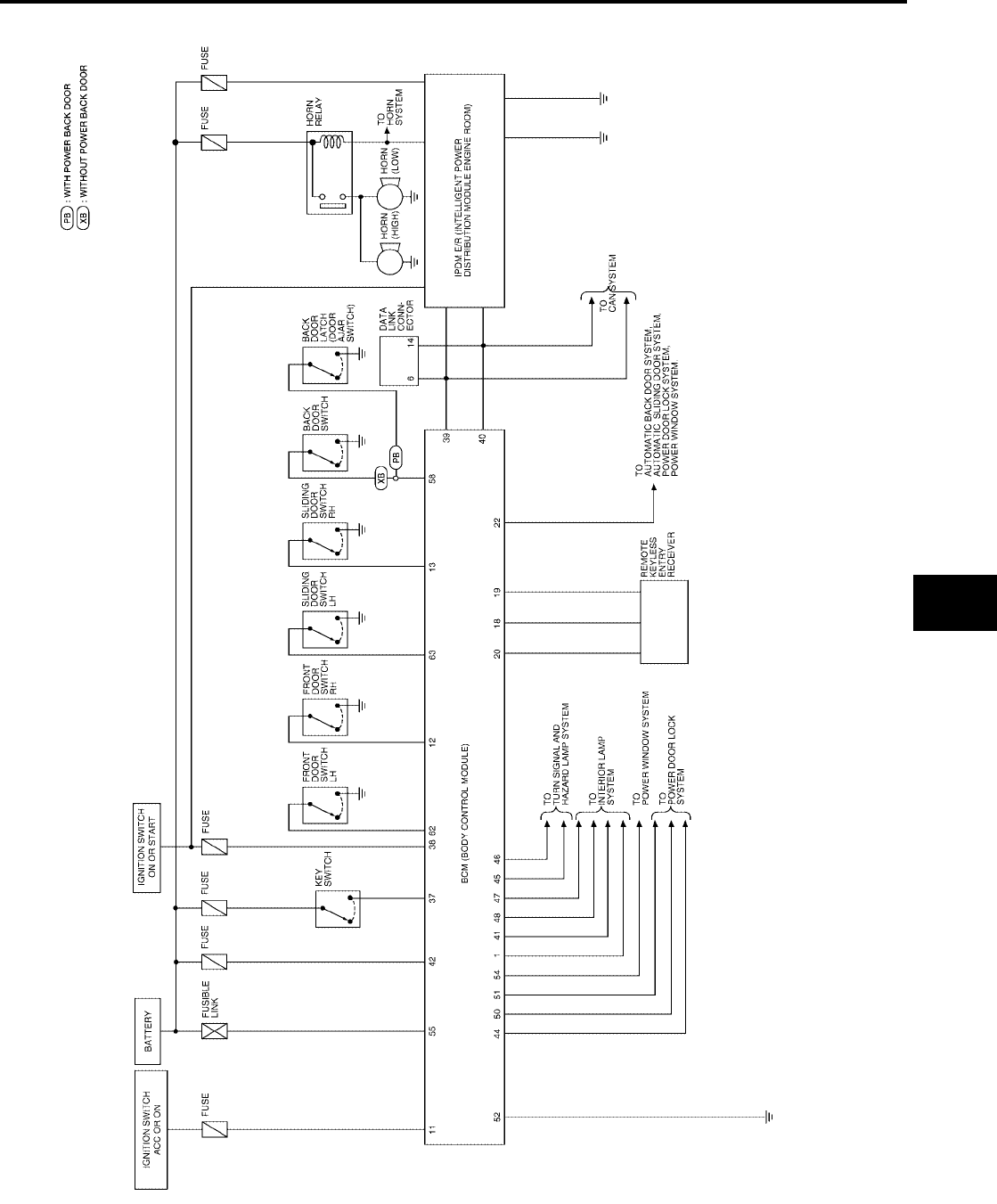
REMOTE KEYLESS ENTRY SYSTEM
BL-61
C
D
E
F
G
H
J
K
L
M
A
B
BL
Revision: July 2006 2006 Quest
Schematic
EIS007DU
WIWA1116E
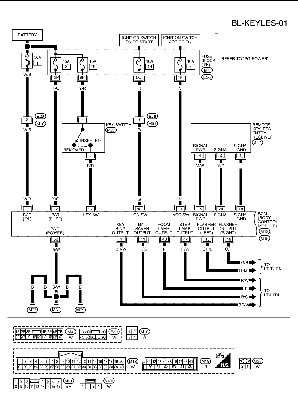
BL-62
REMOTE KEYLESS ENTRY SYSTEM
Revision: July 2006 2006 Quest
Wiring Diagram — KEYLES —
EIS007DV
WIWA1117E
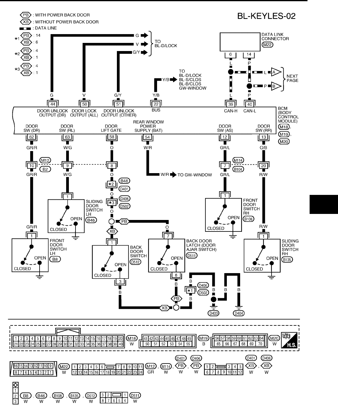
REMOTE KEYLESS ENTRY SYSTEM
BL-63
C
D
E
F
G
H
J
K
L
M
A
B
BL
Revision: July 2006 2006 Quest
WIWA1118E
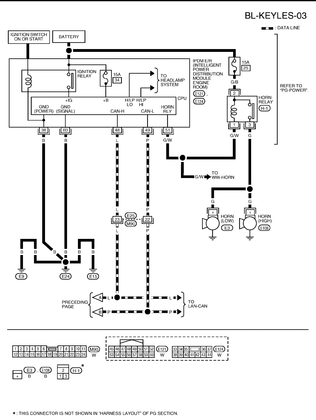
BL-64
REMOTE KEYLESS ENTRY SYSTEM
Revision: July 2006 2006 Quest
WIWA1119E
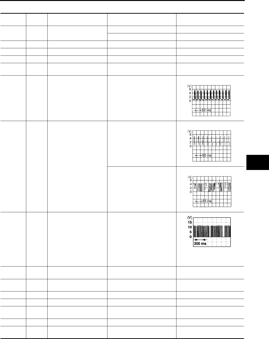
REMOTE KEYLESS ENTRY SYSTEM
BL-65
C
D
E
F
G
H
J
K
L
M
A
B
BL
Revision: July 2006 2006 Quest
Terminals and Reference Value for BCM
EIS007DW
Terminal Wire
Color Item Condition Voltage (V)
(Approx.)
1 BR/W Ignition key illumination Key ring illumination ON 0
Key ring illumination OFF Battery voltage
11 V Ignition switch (ACC or ON) Ignition switch (ACC or ON position) Battery voltage
12 GR/L Front door switch RH Door close (OFF) → Open (ON) Battery voltage → 0
13 O/B Sliding door switch RH Door close (OFF) → Open (ON) Battery voltage → 0
18 P Remote keyless entry receiver
(Ground) —0
19 V/W Remote keyless entry receiver
(Power supply) —
20 Y/G Remote keyless entry receiver
signal (Signal)
Stand-by (keyfob buttons released)
When remote keyless entry receiver
receives signal from keyfob (keyfob
buttons pressed)
22 Y/B Bus When ignition switch is ON or power
window timer operates
37 B/R Key switch Key inserted in IGN key cylinder →
Key removed from IGN key cylinder Battery voltage → 0
38 G Ignition switch (ON or START) Ignition switch (ON or START posi-
tion) Battery voltage
39 L CAN-H ——
40 P CAN-L ——
41 R/G Battery saver
(Interior lamp)
Battery saver does operated →
Does not operated (ON → OFF) Battery voltage → 0
42 Y/G Battery power supply —Battery voltage
44 G Driver door lock actuator Door lock/unlock switch
(Neutral → Unlock) 0 → Battery voltage for 300 ms
LIIA1893E
LIIA1894E
LIIA1895E

BL-66
REMOTE KEYLESS ENTRY SYSTEM
Revision: July 2006 2006 Quest
●*1: when hazard reminder is ON.
●*2: when lamps on demand switch is in "DOOR" position.
Terminals and Reference Value for IPDM E/R
EIS007DX
*: when horn reminder is ON.
CONSULT-II Function (BCM)
EIS007DY
CONSULT-II can display each diagnostic item using the diagnostic test modes shown following.
45 GR/L Turn signal LH When doors are locked or unlocked
using keyfob (OFF → ON) *1 0 → Battery voltage
46 G/R Turn signal RH When doors are locked or unlocked
using keyfob (OFF → ON) *1 0 → Battery voltage
47 R/W Step lamp LH and RH Step lamp ON 0
Step lamp OFF Battery voltage
48 P Room lamp Room lamp ON *2 Battery voltage
Room Lamp OFF *2 0
50 V Door lock actuators Door lock/unlock switch
(Neutral → Lock) 0 → Battery voltage for 300 ms
51 G/Y Passenger and rear doors lock
actuator
Door lock/unlock switch
(Neutral → Unlock) 0 → Battery voltage for 300 ms
52 B/W Ground —0
54 W/R Power window power source —Battery voltage
55 W/B Battery power supply —Battery voltage
58 O Back door switch Door close (OFF) → Open (ON) Battery voltage → 0
62 GR/R Front door switch LH Door close (OFF) → Open (ON) Battery voltage → 0
63 W/G Sliding door switch LH Door close (OFF) → Open (ON) Battery voltage → 0
Terminal Wire
Color Item Condition Voltage (V)
(Approx.)
Terminal Wire
Color Item Condition Voltage (V)
(Approx.)
38 B Ground —0
48 L CAN-H ——
49 P CAN-L ——
51 G/W Horn relay When doors locks are operated
using keyfob (OFF → ON) * Battery voltage → 0
60 B Ground —0
BCM
diagnostic test item Diagnostic mode Description
Inspection by part
WORK SUPPORT
Supports inspections and adjustments. Commands are transmitted to the
BCM for setting the status suitable for required operation, input/output sig-
nals are received from the BCM and received date is displayed.
DATA MONITOR Displays BCM input/output data in real time.
ACTIVE TEST Operation of electrical loads can be checked by sending drive signal to
them.
SELF-DIAG RESULTS Displays BCM self-diagnosis results.
CAN DIAG SUPPORT MNTR The result of transmit/receive diagnosis of CAN communication can be
read.
ECU PART NUMBER BCM part number can be read.
CONFIGURATION Performs BCM configuration read/write functions.
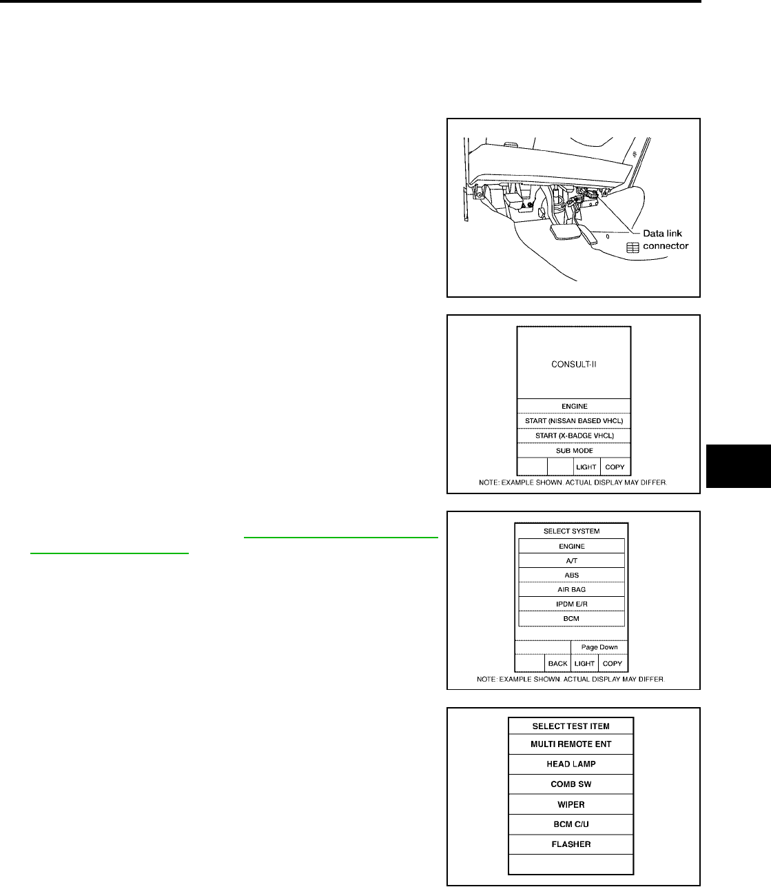
REMOTE KEYLESS ENTRY SYSTEM
BL-67
C
D
E
F
G
H
J
K
L
M
A
B
BL
Revision: July 2006 2006 Quest
CONSULT-II Inspection Procedure
EIS007DZ
“MULTI REMOTE ENT”
CAUTION:
If CONSULT-II is used with no connection of CONSULT-II CONVERTER, malfunctions might be
detected in self-diagnosis depending on control unit which carries out CAN communication.
1. Turn ignition switch OFF.
2. Connect CONSULT-II and CONSULT-II CONVERTER to the
data link connector.
3. Turn ignition switch ON.
4. Touch “START (NISSAN BASED VHCL)”.
5. Touch “BCM”.
If "BCM" is not indicated, refer to GI-38, "CONSULT-II Data Link
Connector (DLC) Circuit" .
6. Touch “MULTI REMOTE ENT”.
BBIA0336E
BCIA0029E
BCIA0030E
LIIA0194E

BL-68
REMOTE KEYLESS ENTRY SYSTEM
Revision: July 2006 2006 Quest
7. Select diagnosis mode.
“DATA MONITOR”, “ACTIVE TEST” and “WORK SUPPORT”
are available.
CONSULT-II Application Items
EIS007E0
“MULTI REMOTE ENT”
Data Monitor
Active Test
BCIA0031E
Monitored Item Description
ACC ON SW Indicates [ON/OFF] condition of ignition switch in ACC position.
DOOR SW-AS Indicates [ON/OFF] condition of front door switch RH.
DOOR SW-DR Indicates [ON/OFF] condition of front door switch LH.
DOOR SW-RL Indicates [ON/OFF] condition of sliding door switch LH.
DOOR SW-RR Indicates [ON/OFF] condition of sliding door switch RH.
IGN ON SW Indicates [ON/OFF] condition of ignition switch in ON position.
KEY CYL LK-SW Indicates [ON/OFF] condition of lock signal from door key cylinder switch.
KEY CYL UN-SW Indicates [ON/OFF] condition of unlock signal from door key cylinder switch.
KEYLESS LOCK Indicates [ON/OFF] condition of remote locking signal.
KEYLESS PANIC Indicates [ON/OFF] condition of panic signal from keyfob.
KEYLESS PSD Indicates [ON/OFF] condition when keyfob sliding door button is pushed (with RH power door only).
KEYLESS PSD L Indicates [ON/OFF] condition when keyfob left sliding door button is pushed (with LH and RH power doors).
KEYLESS PSD R Indicates [ON/OFF] condition when keyfob right sliding door button is pushed (with LH and RH power doors).
KEYLESS UNLOCK Indicates [ON/OFF] condition of remote unlocking signal.
KEY ON SW Indicates [ON/OFF] condition of key switch.
LK BUTTON/SIG Indicates [ON/OFF] condition of lock signal from keyfob.
LK/UN BTN ON Indicates [ON/OFF] condition of lock/unlock signal at the same time from keyfob.
LOCK SW DR/AS Indicates [ON/OFF] condition of lock signal from lock/unlock switch.
PANIC BTN Indicates [ON/OFF] condition of panic signal from keyfob.
RKE KEEP UNLK Indicates [ON/OFF] condition. Keep pushing UNLOCK, turns to ON 3 seconds after UNLOCK button is pushed.
RKE LCK-UNLCK Indicates [ON/OFF] condition when keyfob LOCK and UNLOCK buttons are pushed at the same time.
UN BUTTON/SIG Indicates [ON/OFF] condition of unlock signal from keyfob.
UNLK SW DR/AS Indicates [ON/OFF] condition of unlock signal from lock/unlock switch.
UN BUTTON ON Indicates [ON/OFF] condition of unlock signal from keyfob.
Test Item Description
INT ILLUM This test is able to check interior lamp illumination operation. The interior lamp illumination is turned
on when “ON” on CONSULT-II screen is touched.
IGN ILLUM This test is able to check ignition keyhole illumination operation. The ignition keyhole illumination is
turned on when “ON” on CONSULT-II screen is touched.
FLASHER RIGHT(CAN) This test is able to check right hazard reminder operation. The right hazard lamp turns on when
“ON” on CONSULT-II screen is touched.
FLASHER LEFT(CAN) This test is able to check left hazard reminder operation. The left hazard lamp turns on when “ON”
on CONSULT-II screen is touched.

REMOTE KEYLESS ENTRY SYSTEM
BL-69
C
D
E
F
G
H
J
K
L
M
A
B
BL
Revision: July 2006 2006 Quest
Work Support
Hazard and horn reminder mode
Auto locking function mode
Panic alarm operation mode
Trunk lid open operation mode
Keyless power window down operation mode
HORN This test is able to check panic alarm and horn reminder operations. The alarm activates for 0.5 sec-
onds after “ON” on CONSULT-II screen is touched.
HEAD LAMP (HI) This test is able to check headlamps panic alarm operation. The headlamp illuminates for 0.5 sec-
onds after “ON” on CONSULT-II screen is touched.
POWER WINDOW DOWN This test is able to check power window down operation. The windows are lowered when “ON” on
CONSULT-II screen is touched.
TRUNK/BACK DOOR This test is able to check back door actuator operation. The back door is unlocked when “ON” on
CONSULT-II screen is touched.
Test Item Description
Test Item Description
REMO CONT ID REGIST keyfob ID code can be registered.
REMO CONT ID ERASUR keyfob ID code can be erased.
REMO CONT ID CONFIR It can be checked whether keyfob ID code is registered or not in this mode.
HORN CHIRP SET Horn reminder mode can be changed in this mode. The horn reminder mode will be changed when
"CHANGE SETT" on CONSULT-II screen is touched.
HAZARD LAMP SET Hazard reminder mode can be changed in this mode. The hazard reminder mode will be changed
when "CHANGE SETT" on CONSULT-II screen is touched.
MULTI ANSWER BACK SET Hazard and horn reminder mode can be changed in this mode. The reminder mode will be changed
when “CHANG SETT” on CONSULT-II screen is touched.
AUTO LOCK SET Auto locking function mode can be changed in this mode. The function mode will be changed when
"CHANG SETT" on CONSULT-II screen is touched.
PANIC ALRM SET Panic alarm operation mode can be changed in this mode. The operation mode will be changed
when "CHANG SETT" on CONSULT-II screen is touched.
TRUNK OPEN SET Back door opener operation mode can be changed in this mode. The operation mode will be
changed when "CHANG SETT" on CONSULT-II screen is touched.
PW DOWN SET Keyless power window down (open) operation mode can be changed in this mode. The operation
mode will be changed when "CHANG SETT" on CONSULT-II screen is touched.
MODE 1
(C mode)
MODE 2
(S mode) MODE 3 MODE 4 MODE 5 MODE 6
Keyfob
operation Lock Unlock Lock Unlock Lock Unlock Lock Unlock Lock Unlock Lock Unlock
Hazard warning
lamp flash Twice Once Twice ———Twice Once Twice ——Once
Horn sound Once ———————Once —Once —
MODE 1 MODE 2 MODE 3
Auto locking function 5 minutes Nothing 1 minute
MODE 1 MODE 2 MODE 3
Keyfob operation 0.5 seconds Nothing 1.5 seconds
MODE 1 MODE 2 MODE 3
Keyfob operation 0.5 seconds Nothing 1.5 seconds
MODE 1MODE 2MODE 3
Keyfob operation 3 seconds Nothing 5 seconds

BL-70
REMOTE KEYLESS ENTRY SYSTEM
Revision: July 2006 2006 Quest
Trouble Diagnosis Procedure
EIS007E1
1. Check the symptom and customer's requests.
2. Understand outline of system. Refer to BL-56, "System Description" .
3. Confirm system operation.
●Check that the power door lock system operates normally. Refer to BL-18, "POWER DOOR LOCK
SYSTEM" .
●Check that the automatic sliding door system operates normally. Refer to BL-113, "AUTOMATIC SLID-
ING DOOR SYSTEM" .
●Check that the automatic back door system operates normally. Refer to BL-162, "AUTOMATIC BACK
DOOR SYSTEM" .
4. Perform pre-diagnosis inspection. Refer to BL-70, "Pre-Diagnosis Inspection" .
5. Refer to trouble diagnosis chart by symptom, repair or replace any malfunctioning parts. Refer to BL-71,
"Trouble Diagnoses" .
6. Inspection End.
Pre-Diagnosis Inspection
EIS007E2
BCM POWER SUPPLY AND GROUND CIRCUIT INSPECTION
1. FUSE INSPECTION
Check the following fuses and fusible link in the fuse block (J/B) and fuse and fusible link box.
OK or NG
OK >> GO TO 2.
NG >> If fuse is blown, be sure to eliminate cause of problem before installing new fuse. Refer to PG-4,
"POWER SUPPLY ROUTING CIRCUIT" .
2. POWER SUPPLY CIRCUIT INSPECTION
Disconnect BCM connector, and connect vehicle-side connector terminals shown below to positive probe and
body ground to negative probe. Measure voltage.
OK or NG
OK >> GO TO 3.
NG >> Repair or replace harness.
3. GROUND CIRCUIT INSPECTION
Check continuity between BCM vehicle-side connector and body ground.
OK or NG
OK >> Power supply and ground circuits are normal.
NG >> Repair or replace harness.
Unit Terminal No. Signal name No. Location
BCM
55 Battery power supply jFuse and fusible link box
42 Battery power supply 3 Fuse block (J/B)
11 ACC power supply 4 Fuse block (J/B)
38 IGN power supply 16 Fuse block (J/B)
Unit Terminal No. Signal name Ignition switch Voltage
BCM
55 Battery power supply OFF Battery voltage
42 Battery power supply OFF Battery voltage
11 ACC power supply ACC Battery voltage
38 IGN power supply ON Battery voltage
Unit Terminal No. Signal name Ignition switch Continuity
BCM 52 Ground OFF Yes

REMOTE KEYLESS ENTRY SYSTEM
BL-71
C
D
E
F
G
H
J
K
L
M
A
B
BL
Revision: July 2006 2006 Quest
Trouble Diagnoses
EIS007E3
SYMPTOM CHART
NOTE:
●Always check the "Trouble Diagnosis Procedure" before troubleshooting. Refer to BL-70, "Trouble Diag-
nosis Procedure" .
●Always check keyfob battery before replacing keyfob. Refer to BL-78, "Keyfob Battery and Function
Check" .
●The panic alarm operation and trunk lid opener operation of remote keyless entry system do not activate
with the ignition key inserted in the ignition key cylinder.
●Use Remote Keyless Entry Tester J-43241 (follow instructions on tester) to check operation of keyfob
before replacing keyfob.
Symptom Diagnoses/service procedure Reference
page
All functions of remote keyless entry system do not
operate.
1. Keyfob battery and function check (use Remote Keyless Entry
Tester J-43241).
NOTE:
If the result of keyfob function check is OK, keyfob is not malfunc-
tioning.
BL-78
2. Check BCM and remote keyless entry receiver. BL-80
The new ID of keyfob cannot be entered.
1. Keyfob battery and function check (use Remote Keyless Entry
Tester J-43241).
NOTE:
If the result of keyfob function check is OK, keyfob is not malfunc-
tioning.
BL-78
2. Key switch (insert) check. BL-73
3a. Door switch check (without automatic back door system). BL-74
3b. Door switch check (with automatic back door system). BL-76
4. ACC power check. BL-81
5. Replace BCM. BCS-20
Door lock or unlock does not function.
(If the power door lock system does not operate
manually, check power door lock system. Refer to
BL-18, "POWER DOOR LOCK SYSTEM" .)
1. Keyfob battery and function check (use Remote Keyless Entry
Tester J-43241).
NOTE:
If the result of keyfob function check is OK, keyfob is not malfunc-
tioning.
BL-78
2. Replace BCM. BCS-20
Hazard and horn reminder does not activate prop-
erly when pressing lock or unlock button of keyfob.
1. Check hazard and horn reminder mode with CONSULT-II.
NOTE:
Hazard and horn reminder mode can be changed.
First check the hazard and horn reminder mode setting.
BL-68
2a. Door switch check (without automatic back door system). BL-74
2b. Door switch check (with automatic back door system). BL-76
3. Replace BCM. BCS-20
Hazard reminder does not activate properly when
pressing lock or unlock button of keyfob.
(Horn reminder OK)
1. Check hazard reminder mode with CONSULT-II.
NOTE:
Hazard reminder mode can be changed.
First check the hazard reminder mode setting.
BL-68
2. Check hazard function with hazard switch. BL-83
3. Replace BCM. BCS-20

BL-72
REMOTE KEYLESS ENTRY SYSTEM
Revision: July 2006 2006 Quest
Horn reminder does not activate properly when
pressing lock or unlock button of keyfob.
(Hazard reminder OK)
1. Check horn reminder mode with CONSULT-II.
NOTE:
Horn reminder mode can be changed.
First check the horn reminder mode setting.
BL-68
2. Check horn function with horn switch. WW-51
3. IPDM E/R operation check. BL-82
4. Replace BCM. BCS-20
Sliding door open/close operation is not carried out
with keyfob operation.
(The automatic sliding door system is normal.)
1. Keyfob battery and function check (use Remote Keyless Entry
Tester J-43241).
NOTE:
If the result of keyfob function check is OK, keyfob is not malfunc-
tioning.
BL-78
2. Key switch (insert) check. BL-73
3. Remote keyless entry receiver system check. BL-80
4. Replace BCM. BCS-20
Room lamp, ignition keyhole illumination and step
lamp operation do not activate properly.
1. Room lamp operation check. BL-83
2. Ignition keyhole illumination operation check. BL-83
3. Step lamp operation check. LT-137
4a. Door switch check (without automatic back door). BL-74
4b. Door switch check (with automatic back door). BL-76
5. Replace BCM. BCS-20
Panic alarm (horn and headlamp) does not activate
when panic alarm button is continuously pressed.
1. Keyfob battery and function check (use Remote Keyless Entry
Tester J-43241).
NOTE:
If the result of keyfob function check is OK, keyfob is not malfunc-
tioning.
BL-78
2. Key switch (insert) check. BL-73
3. Replace BCM. BCS-20
Auto door lock operation does not activate properly.
(All other remote keyless entry functions OK.)
1. Check auto door lock operation mode with CONSULT-II.
NOTE:
Auto door lock operation mode can be changed.
First check the auto door lock operation mode setting.
BL-69
2. Replace BCM. BCS-20
Keyless power window down (open) operation does
not activate properly.
(All other remote keyless entry functions OK.)
1. Check power window down operation mode with CONSULT-II.
NOTE:
Power window down operation mode can be changed.
First check the power window down operation mode setting.
BL-69
2. Check power window function with switch. GW-17
3. Replace BCM. BCS-20
Symptom Diagnoses/service procedure Reference
page
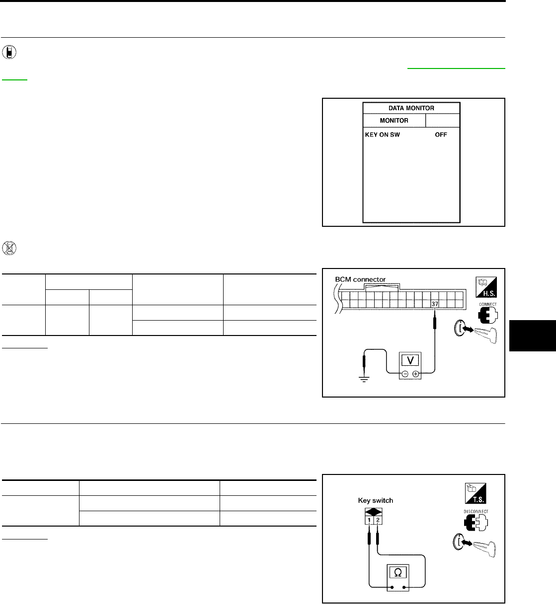
REMOTE KEYLESS ENTRY SYSTEM
BL-73
C
D
E
F
G
H
J
K
L
M
A
B
BL
Revision: July 2006 2006 Quest
Key Switch (insert) Check
EIS007E4
1. CHECK KEY SWITCH INPUT SIGNAL
With CONSULT-II
Check key switch "KEY ON SW" in DATA MONITOR mode with CONSULT–II. Refer to BL-39, "DATA MONI-
TOR" .
●When key is inserted to ignition key cylinder:
●When key is removed from ignition key cylinder:
Without CONSULT-II
Check voltage between BCM connector M18 terminal 37 and ground.
OK or NG
OK >> Key switch (insert) circuit is OK.
NG >> GO TO 2.
2. CHECK KEY SWITCH (INSERT)
1. Turn ignition switch OFF.
2. Disconnect key switch.
3. Check continuity between key switch terminals 1, 2.
OK or NG
OK >> Repair or replace harness.
NG >> Replace key switch.
KEY ON SW : ON
KEY ON SW : OFF
PIIA6470E
Connec-
tor
Terminal Condition Voltage (V)
(Approx.)
( + ) ( – )
M18 37 Ground Key is inserted. Battery voltage
Key is removed. 0
LIIA0567E
Terminals Condition Continuity
1 – 2 Key is inserted. Yes
Key is removed. No
LIIA1906E

BL-74
REMOTE KEYLESS ENTRY SYSTEM
Revision: July 2006 2006 Quest
Door Switch Check (Without Automatic Back Door System)
EIS007E5
1. CHECK DOOR SWITCHES INPUT SIGNAL
With CONSULT-II
Check door switches ("DOOR SW-DR", "DOOR SW-AS", "DOOR SW-RL", "DOOR SW-RR", "BACK DOOR
SW") in DATA MONITOR mode with CONSULT–II. Refer to BL-39, "DATA MONITOR" .
●When doors are open:
●When doors are closed:
Without CONSULT-II
Check voltage between BCM connector M18 or M20 terminals 12, 13, 58, 62, 63 and ground.
OK or NG
OK >> Door switch circuit is OK.
NG >> GO TO 2.
DOOR SW-DR : ON
DOOR SW-AS : ON
DOOR SW-RR : ON
DOOR SW-RL : ON
BACK DOOR SW : ON
DOOR SW-DR : OFF
DOOR SW-AS : OFF
DOOR SW-RR : OFF
DOOR SW-RL : OFF
BACK DOOR SW : OFF
LIIA0665E
Connec-
tor Item Terminals Condition Voltage (V)
(Approx.)
( + ) ( – )
M20
Back door
switch 58
Ground
Open
↓
Closed
0
↓
Battery voltage
Front door
switch LH 62
Sliding door
switch LH 63
M18
Front door
switch RH 12
Sliding door
switch RH 13
LIIA0666E
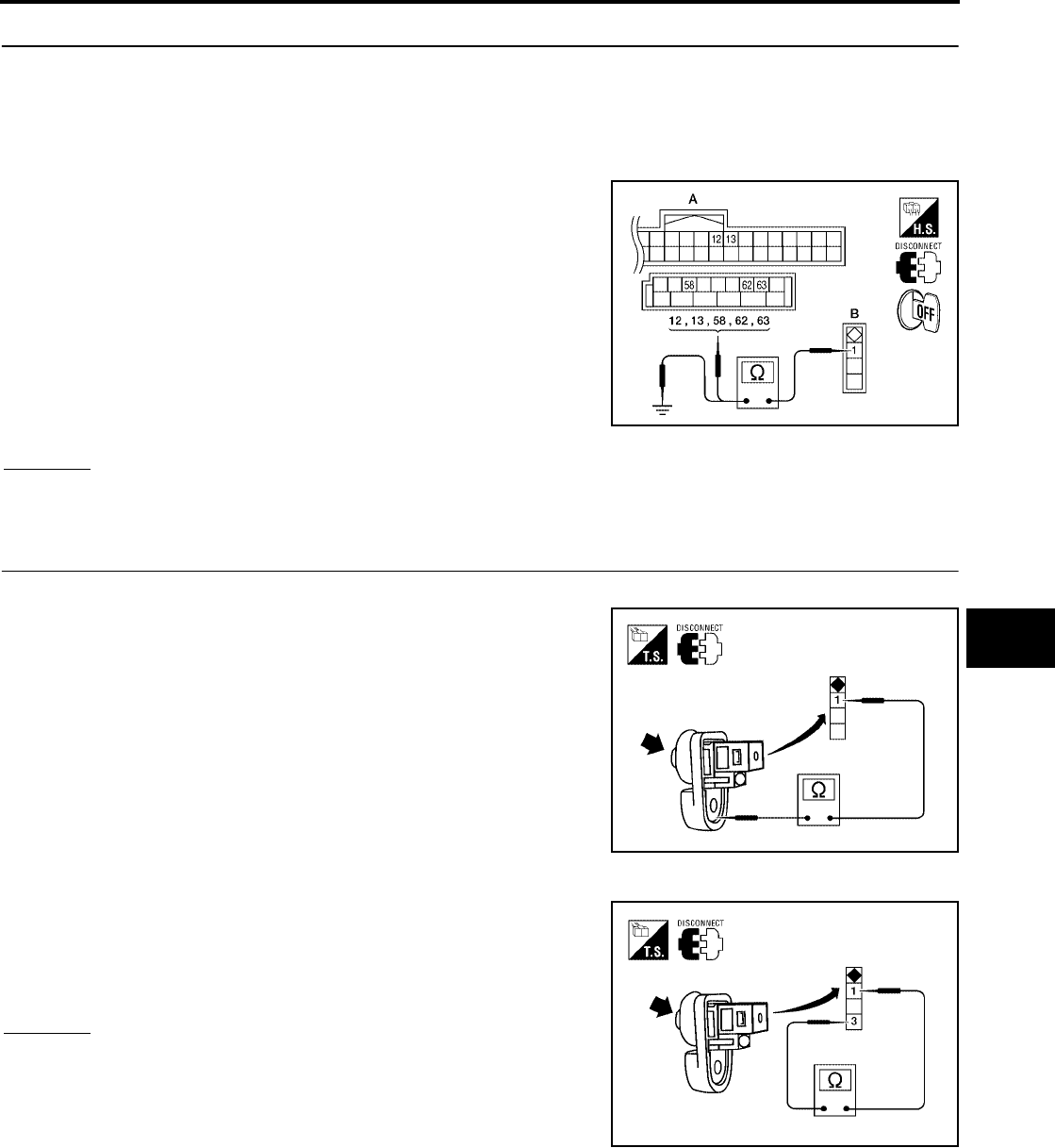
REMOTE KEYLESS ENTRY SYSTEM
BL-75
C
D
E
F
G
H
J
K
L
M
A
B
BL
Revision: July 2006 2006 Quest
2. CHECK DOOR SWITCH CIRCUIT
1. Turn ignition switch OFF.
2. Disconnect door switch and BCM.
3. Check continuity between door switch connector (B) B8 (Front LH), B108 (Front RH), B46 (Sliding LH),
B135 (Sliding RH) or D512 (Back) terminal 1 and BCM connector (A) M18, M20 terminals 12, 13, 58, 62
and 63.
4. Check continuity between door switch connector (B) B8 (Front
LH), B108 (Front RH), B46 (Sliding LH), B135 (Sliding RH) or
D512 (Back) terminal 1 and ground.
OK or NG
OK >> GO TO 3.
NG >> Repair or replace harness.
3. CHECK DOOR SWITCHES
FRONT AND REAR DOORS
Check continuity between front or rear door switch terminal 1 and
exposed metal of switch while pressing and releasing switch.
BACK DOOR
Check continuity between back door switch terminals 1 and 3 while
pressing and releasing switch.
OK or NG
OK >> (Front and rear doors) Switch circuit is OK.
OK >> (Back door) GO TO 4.
NG >> Replace door switch.
1 - 12 : Continuity should exist.
1 - 13 : Continuity should exist.
1 - 58 : Continuity should exist.
1 - 62 : Continuity should exist.
1 - 63 : Continuity should exist.
1 - Ground : Continuity should not exist. WIIA0781E
Door switch is released : Continuity should exist.
Door switch is pushed : Continuity should not exist.
WIIA0782E
Door switch is released : Continuity should exist.
Door switch is pushed : Continuity should not exist.
WIIA0783E
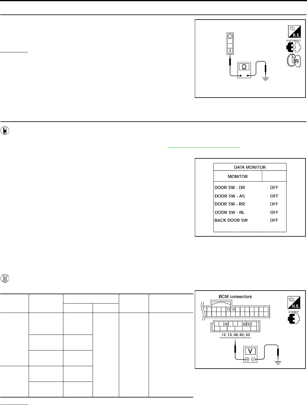
BL-76
REMOTE KEYLESS ENTRY SYSTEM
Revision: July 2006 2006 Quest
4. CHECK BACK DOOR SWITCH GROUND
Check continuity between back door switch connector terminal 3 and
ground.
OK or NG
OK >> Back door switch circuit is OK.
NG >> Repair or replace harness.
Door Switch Check (With Automatic Back Door System)
EIS007E6
1. CHECK DOOR SWITCHES INPUT SIGNAL
With CONSULT-II
Check door switches ("DOOR SW-DR", "DOOR SW-AS", "DOOR SW-RL", "DOOR SW-RR", "BACK DOOR
SW") in DATA MONITOR mode with CONSULT–II. Refer to BL-39, "DATA MONITOR" .
●When doors are open:
●When doors are closed:
Without CONSULT-II
Check voltage between BCM connector M18 or M20 terminals 12, 13, 58, 62, 63 and ground.
OK or NG
OK >> Door switch circuit is OK.
NG >> GO TO 2.
3 - Ground : Continuity should exist.
WIIA0791E
DOOR SW-DR : ON
DOOR SW-AS : ON
DOOR SW-RR : ON
DOOR SW-RL : ON
BACK DOOR SW : ON
DOOR SW-DR : OFF
DOOR SW-AS : OFF
DOOR SW-RR : OFF
DOOR SW-RL : OFF
BACK DOOR SW : OFF
LIIA0665E
Connec-
tor Item Terminals Condition Voltage (V)
(Approx.)
( + ) ( – )
M20
Back door
latch (door
ajar switch)
58
Ground
Open
↓
Closed
0
↓
Battery voltage
Front door
switch LH 62
Sliding door
switch LH 63
M18
Front door
switch RH 12
Sliding door
switch RH 13
LIIA0666E
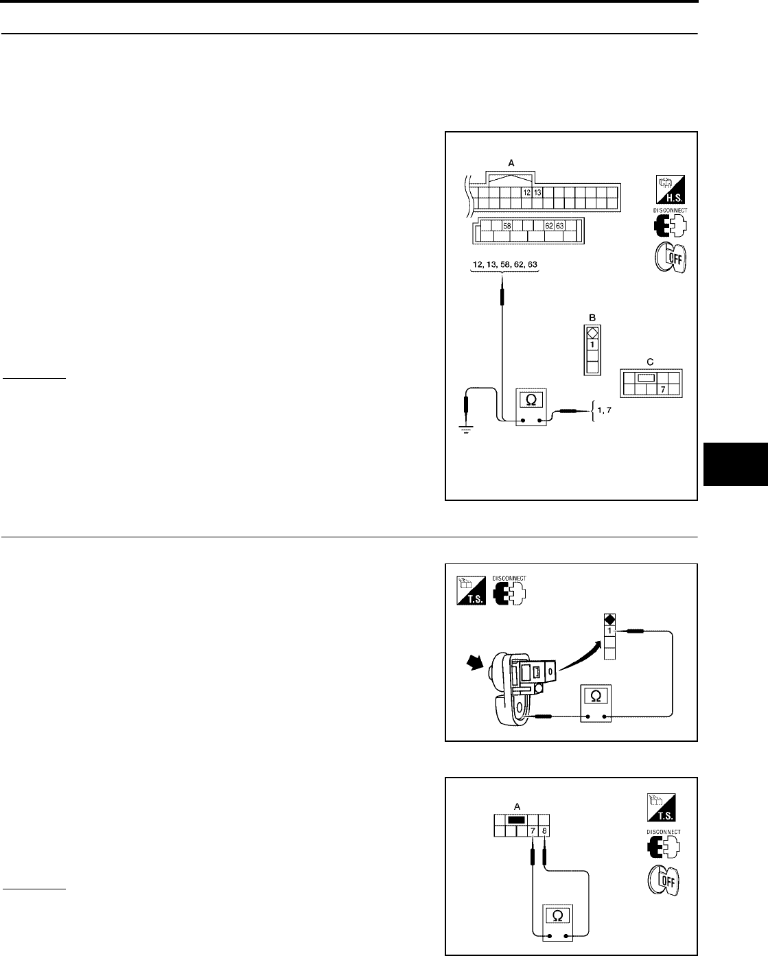
REMOTE KEYLESS ENTRY SYSTEM
BL-77
C
D
E
F
G
H
J
K
L
M
A
B
BL
Revision: July 2006 2006 Quest
2. CHECK DOOR SWITCH CIRCUIT
1. Turn ignition switch OFF.
2. Disconnect door switch and BCM.
3. Check continuity between door switch connector (B) B8 (Front LH), B108 (Front RH), B46 (Sliding LH),
B135 (Sliding RH) terminal 1 or back door latch (door ajar switch) connector (C) D511 terminal 7 and BCM
connector (A) M18, M20 terminals 12, 13, 58, 62 and 63
4. Check continuity between door switch connector (B) B8 (Front
LH), B108 (Front RH), B46 (Sliding LH), B135 (Sliding RH) ter-
minal 1 or back door latch (door ajar switch) connector (C) D511
terminal 7 and ground.
OK or NG
OK >> GO TO 3.
NG >> Repair or replace harness.
3. CHECK DOOR SWITCHES
FRONT AND REAR DOORS
Check continuity between front or rear door switch terminal 1 and
exposed metal of switch while pressing and releasing switch.
BACK DOOR
Check continuity between back door latch connector (A) D511 termi-
nals 7 and 8 while pressing (closing back door) and releasing (open-
ing back door) switch.
OK or NG
OK >> (Front and rear doors) Switch circuit is OK.
OK >> (Back door) GO TO 4.
NG >> Replace door switch.
1 - 62 : Continuity should exist.
1 - 12 : Continuity should exist.
1 - 63 : Continuity should exist.
1 - 13 : Continuity should exist.
7 - 58 : Continuity should exist.
1 - Ground : Continuity should not exist.
7 - Ground : Continuity should not exist.
WIIA0784E
Door switch is released : Continuity should exist.
Door switch is pushed : Continuity should not exist.
WIIA0782E
When back door is open : Continuity should exist.
When back door is closed : Continuity should not exist.
WIIA0752E
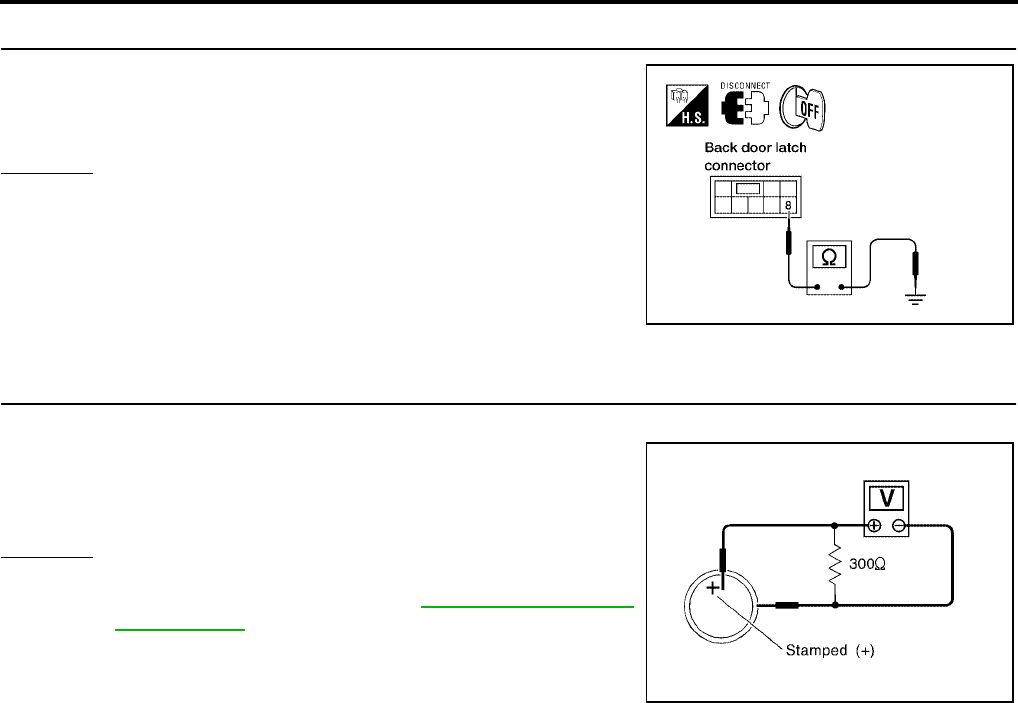
BL-78
REMOTE KEYLESS ENTRY SYSTEM
Revision: July 2006 2006 Quest
4. CHECK BACK DOOR SWITCH GROUND
Check continuity between back door latch connector terminal 8 and
ground.
OK or NG
OK >> Back door switch circuit is OK.
NG >> Repair or replace harness.
Keyfob Battery and Function Check
EIS007E7
1. CHECK KEYFOB BATTERY
Remove battery and measure voltage across battery positive and negative terminals, (+) and (−).
NOTE:
Keyfob does not function if battery is not set correctly.
OK or NG
OK >> GO TO 2.
NG >> Replace keyfob battery. Refer to BL-87, "Keyfob Battery
Replacement" .
8 - Ground : Continuity should exist.
LIIA0828E
Voltage : 2.5V - 3.0V
SEL237W
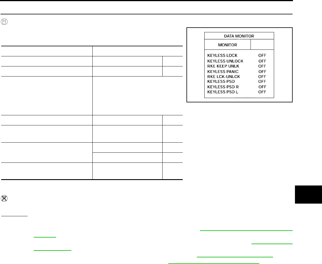
REMOTE KEYLESS ENTRY SYSTEM
BL-79
C
D
E
F
G
H
J
K
L
M
A
B
BL
Revision: July 2006 2006 Quest
2. CHECK KEYFOB FUNCTION
With CONSULT-II
Check keyfob function in “DATA MONITOR” mode with CONSULT-II.
When pushing each button of keyfob, the corresponding monitor item should
be turned as follows.
*1: With auto sliding door RH
*2: With auto sliding door RH and LH
Without CONSULT-II
Check keyfob function using Remote Keyless Entry Tester J-43241.
OK or NG
OK >> WITH CONSULT-II: Keyfob, remote keyless entry receiver and wiring harness between BCM and
remote keyless entry receiver are OK. Replace BCM. Refer to BCS-20, "Removal and Installation
of BCM" .
OK >> WITHOUT CONSULT-II: Keyfob is OK. Further inspection is necessary. Refer to BL-71, "SYMP-
TOM CHART" .
NG >> WITH CONSULT-II: Further inspection is necessary. Refer to BL-71, "SYMPTOM CHART" .
NG >> WITHOUT CONSULT-II: Replace keyfob. Refer to BL-84, "ID Code Entry Procedure" .
Condition Monitor item
Pushing LOCK KEYLESS LOCK : ON
Pushing UNLOCK KEYLESS UNLOCK : ON
Keep pushing UNLOCK
RKE KEEP UNLK
turns to ON 3 seconds
after UNLOCK button
is pushed.
Pushing PANIC KEYLESS PANIC : ON
Pushing LOCK and UNLOCK
at the same time RKE LCK-UNLCK : ON
Pushing SLID DOOR RH
OPEN
KEYLESS PSD *1 : ON
KEYLESS PSD R *2 : ON
Pushing SLID DOOR LH
OPEN KEYLESS PSD L *2 : ON
LIIA0852E
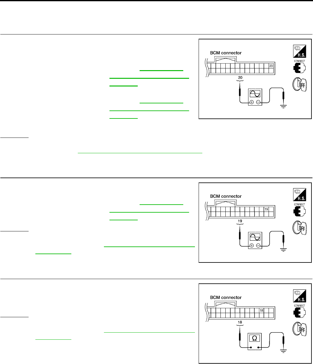
BL-80
REMOTE KEYLESS ENTRY SYSTEM
Revision: July 2006 2006 Quest
Remote Keyless Entry Receiver System Check
EIS007E8
1. REMOTE KEYLESS ENTRY RECEIVER SIGNAL
Check signal voltage waveform between BCM connector M18 termi-
nal 20 and ground using an oscilloscope.
OK or NG
OK >> Remote keyless entry receiver signal power supply, ground and signal circuits are OK. Replace
BCM. Refer to BCS-20, "Removal and Installation of BCM" .
NG >> GO TO 2.
2. REMOTE KEYLESS ENTRY RECEIVER POWER SUPPLY INSPECTION
Check signal voltage waveform between BCM connector M18 termi-
nal 19 and ground using an oscilloscope.
OK or NG
OK >> GO TO 3.
NG >> Replace BCM. Refer to BCS-20, "Removal and Installa-
tion of BCM" .
3. REMOTE KEYLESS ENTRY RECEIVER GROUND CIRCUIT INSPECTION (BCM)
Check continuity between BCM connector M18 terminal 18 and
ground.
OK or NG
OK >> GO TO 4.
NG >> Replace BCM. Refer to BCS-20, "Removal and Installa-
tion of BCM" .
Condition:
Keyfob buttons released : Refer to BL-65, "Termi-
nals and Reference Value
for BCM" .
Keyfob buttons pressed : Refer to BL-65, "Termi-
nals and Reference Value
for BCM" . LIIA1275E
19 - Ground : Refer to BL-65, "Termi-
nals and Reference Value
for BCM" .
WIIA0433E
18 - Ground : Continuity should exist.
WIIA0434E
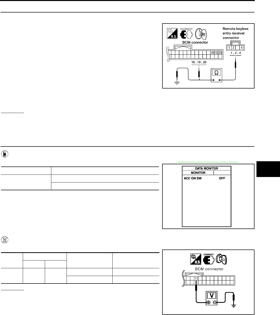
REMOTE KEYLESS ENTRY SYSTEM
BL-81
C
D
E
F
G
H
J
K
L
M
A
B
BL
Revision: July 2006 2006 Quest
4. HARNESS INSPECTION BETWEEN BCM AND REMOTE KEYLESS ENTRY RECEIVER
1. Disconnect remote keyless entry receiver and BCM connectors.
2. Check continuity between remote keyless entry receiver con-
nector M120 terminals 1, 2, 4 and BCM connector M18 termi-
nals 18, 19, 20.
3. Check continuity between remote keyless entry receiver termi-
nals 1, 2 and 4 and ground.
OK or NG
OK >> Replace remote keyless entry receiver.
NG >> Repair or replace the harness between the remote keyless entry receiver and BCM.
ACC Power Check
EIS007E9
1. CHECK ACC POWER
With CONSULT-II
Check "ACC ON SW" in DATA MONITOR mode with CONSULT–II. Refer to BL-39, "DATA MONITOR" .
Without CONSULT-II
Check voltage between BCM connector M18 terminal 11 and ground.
OK or NG
OK >> ACC power circuit is OK.
NG >> Check the following:
●10A fuse [No. 4, located in fuse block (J/B)]
●Harness for open or short.
1 - 18 : Continuity should exist.
2 - 20 : Continuity should exist.
4 - 19 : Continuity should exist.
1 - Ground : Continuity should not exist.
2 - Ground : Continuity should not exist.
4 - Ground : Continuity should not exist.
WIIA0308E
Monitor Item Condition
ACC ON SW Ignition switch position is ACC : ON
Ignition switch position is OFF : OFF
PIIA3367E
Connec-
tor
Terminal Condition Voltage (V)
(Approx.)
( + ) ( – )
M18 11 Ground ACC or ON Battery voltage
OFF 0
PIIA7002E
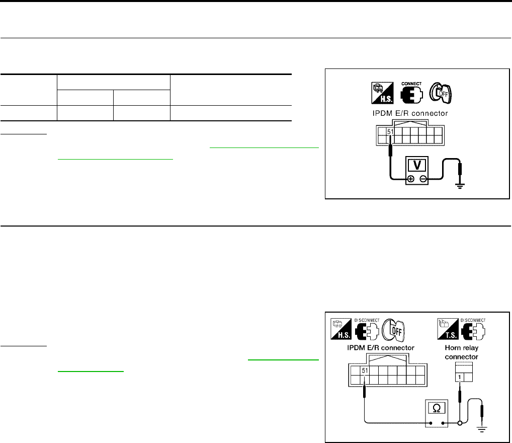
BL-82
REMOTE KEYLESS ENTRY SYSTEM
Revision: July 2006 2006 Quest
IPDM E/R Operation Check
EIS007EA
1. CHECK IPDM E/R INPUT VOLTAGE
Check voltage between IPDM E/R connector E121 terminal 51 and ground.
OK or NG
OK >> Replace IPDM E/R. Refer to PG-29, "Removal and
Installation of IPDM E/R" .
NG >> GO TO 2.
2. CHECK IPDM E/R INPUT VOLTAGE
1. Turn ignition switch OFF.
2. Disconnect IPDM E/R and horn relay.
3. Check continuity between IPDM E/R connector E121 terminal 51 and horn relay connector H-1 terminal 1.
4. Check continuity between IPDM E/R connector E121 terminal 51 and ground.
OK or NG
OK >> Further inspection is necessary. Refer to BL-71, "SYMP-
TOM CHART" .
NG >> Repair or replace harness.
Connector Terminal Voltage (V)
(Approx.)
( + ) ( – )
E121 51 Ground Battery voltage
PIIA6403E
51 - 1 :Continuity should exist.
51 - Ground :Continuity should not exist.
LIIA2171E

REMOTE KEYLESS ENTRY SYSTEM
BL-83
C
D
E
F
G
H
J
K
L
M
A
B
BL
Revision: July 2006 2006 Quest
Check Hazard Function
EIS007EB
1. CHECK HAZARD WARNING LAMP
Does hazard indicator flash with hazard switch?
Yes or No
Yes >> Hazard warning lamp circuit is OK.
No >> Check hazard indicator. Refer toLT-71, "TURN SIGNAL AND HAZARD WARNING LAMPS" .
Check Horn Function
EIS007EC
First, perform the "SELF-DIAG RESULTS" in "BCM" with CONSULT-II, then perform the trouble diagnosis of
malfunction system indicated in "SELF-DIAG RESULTS" of "BCM".
1. CHECK HORN FUNCTION
Does horn sound with horn switch?
Yes or No
Yes >> Horn circuit is OK.
No >> Check horn circuit. Refer to WW-51, "HORN" .
Check Headlamp Function
EIS007ED
First, perform the "SELF-DIAG RESULTS" in "BCM" with CONSULT-II, then perform the trouble diagnosis of
malfunction system indicated in "SELF-DIAG RESULTS" of "BCM".
1. CHECK HEADLAMP OPERATION
Does headlamp come on when turning lighting switch ON?
Yes or No
Yes >> Headlamp operation circuit is OK.
No >> Check headlamp circuit. Refer to LT-5, "HEADLAMP (FOR USA)" .
Check Map Lamp and Ignition Keyhole Illumination Function
EIS007EE
1. CHECK MAP LAMP AND IGNITION KEYHOLE ILLUMINATION FUNCTION
When lamps on demand switch is in DOOR position, open the front door LH or RH.
OK or NG
OK >> System is OK.
NG >> Check ignition keyhole illumination circuit. Refer to LT-162, "ILLUMINATION" .
Map lamp and ignition keyhole illumination should illuminate.
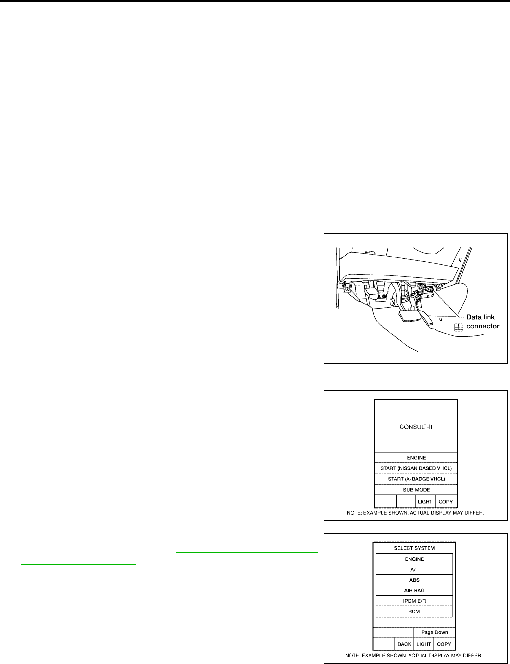
BL-84
REMOTE KEYLESS ENTRY SYSTEM
Revision: July 2006 2006 Quest
ID Code Entry Procedure
EIS007EF
KEYFOB ID SET UP WITH CONSULT-II
NOTE:
●If a keyfob is lost, the ID code of the lost keyfob must be erased to prevent unauthorized use. A
specific ID code can be erased with CONSULT-II. However, when the ID code of a lost keyfob is not
known, all controller ID codes should be erased. After all ID codes are erased, the ID codes of all
remaining and/or new keyfobs must be re-registered.
●When registering an additional keyfob, the existing ID codes in memory may or may not be erased.
If five ID codes are stored in memory when an additional code is registered, only the oldest code is
erased. If less than five codes are stored in memory when an additional code is registered, the
new ID code is added and no ID codes are erased.
●Entry of a maximum of five ID codes is allowed. When more than five codes are entered, the oldest
ID code will be erased.
●Even if the same ID code that is already in memory is input, the same ID code can be entered. The
code is counted as an additional code.
CAUTION:
If CONSULT-II is used with no connection of CONSULT-II CONVERTER, malfunctions might be
detected in self-diagnosis depending on control unit which carries on CAN communication.
1. Turn ignition switch OFF.
2. Connect CONSULT-II and CONSULT-II CONVERTER to the
data link connector.
3. Turn ignition switch ON.
4. Touch “START (NISSAN BASED VHCL)”.
5. Touch “BCM”.
If "BCM" is not indicated, refer to GI-38, "CONSULT-II Data Link
Connector (DLC) Circuit" .
BBIA0336E
BCIA0029E
BCIA0030E
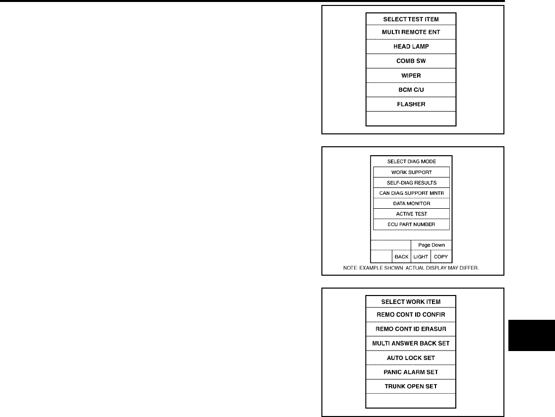
REMOTE KEYLESS ENTRY SYSTEM
BL-85
C
D
E
F
G
H
J
K
L
M
A
B
BL
Revision: July 2006 2006 Quest
6. Touch “MULTI REMOTE ENT”.
7. Touch “WORK SUPPORT”.
8. The items below can be set up.
●“REMO CONT ID CONFIR”
Use this mode to confirm if a keyfob ID code is registered or
not.
●“REMO CONT ID REGIST”
Use this mode to register a keyfob ID code.
NOTE:
Register the ID code when keyfob or BCM is replaced, or
when additional keyfob is required.
●“REMO CONT ID ERASUR”
Use this mode to erase a keyfob ID code.
LIIA0194E
BCIA0031E
LIIA0207E
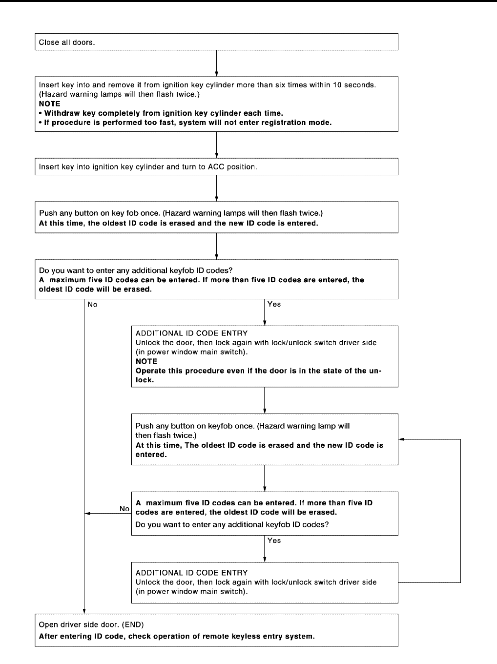
BL-86
REMOTE KEYLESS ENTRY SYSTEM
Revision: July 2006 2006 Quest
KEYFOB ID SET UP WITHOUT CONSULT-II
LIIA1670E
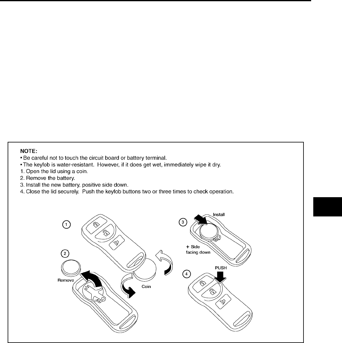
REMOTE KEYLESS ENTRY SYSTEM
BL-87
C
D
E
F
G
H
J
K
L
M
A
B
BL
Revision: July 2006 2006 Quest
NOTE:
●If a keyfob is lost, the ID code of the lost keyfob must be erased to prevent unauthorized use. A specific ID
code can be erased with CONSULT-II. However, when the ID code of a lost keyfob is not known, all con-
troller ID codes should be erased. After all ID codes are erased, the ID codes of all remaining and/or new
keyfobs must be re-registered.
To erase all ID codes in memory, register one ID code (keyfob) five times. After all ID codes are erased,
the ID codes of all remaining and/or new keyfobs must be re-registered.
●When registering an additional keyfob, the existing ID codes in memory may or may not be erased. If five
ID codes are stored in memory, when an additional code is registered, only the oldest code is erased. If
less than five ID codes are stored in memory, when an additional ID code is registered, the new ID code is
added and no ID codes are erased.
●If you need to activate more than two additional new keyfobs, repeat the procedure “Additional ID code
entry” for each new keyfob.
●Entry of maximum five ID codes is allowed. When more than five ID codes are entered, the oldest ID code
will be erased.
●Even if same ID code that is already in the memory is input, the same ID code can be entered. The code
is counted as an additional code.
Keyfob Battery Replacement
EIS007EG
LIIA1514E
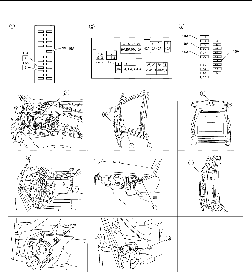
BL-88
VEHICLE SECURITY (THEFT WARNING) SYSTEM
Revision: July 2006 2006 Quest
VEHICLE SECURITY (THEFT WARNING) SYSTEM PFP:28491
Component Parts and Harness Connector Location
EIS007EH
LIIA2340E
1. Fuse block (J/B) 2. Fuse and fusible link box 3. IPDM E/R fuse layout
4. BCM M18, M19, M20
(view with instrument panel removed)
5. Front door lock assembly LH D14
(key cylinder switch)
6. Main power window and door lock/
unlock switch LH D7, D8
Power window and door lock/unlock
switch RH D105
7. Front door switch
LH B8
RH B108
8. Back door latch (door ajar switch) D511
(with power back door)
Back door switch D512
(without power back door)
9. IPDM E/R E124
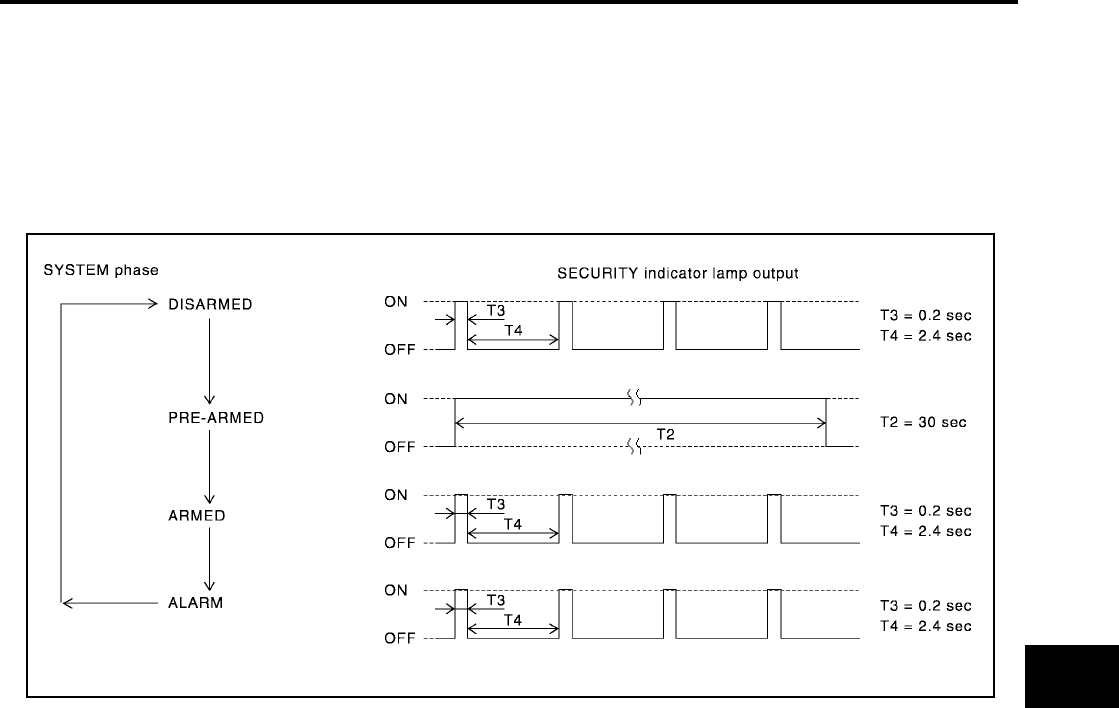
VEHICLE SECURITY (THEFT WARNING) SYSTEM
BL-89
C
D
E
F
G
H
J
K
L
M
A
B
BL
Revision: July 2006 2006 Quest
System Description
EIS007EI
DESCRIPTION
Operation Flow
Setting the vehicle security system
Initial condition
●Ignition switch is OFF.
Disarmed phase
●When the vehicle is being driven or when doors are open, the vehicle security system is set in the dis-
armed phase on the assumption that the owner is inside or near the vehicle.
Pre-armed phase and armed phase
●There are three conditions to enable the vehicle security system to turn into the "pre-armed" phase and
transition into armed phase. The initial requirements are that hood, glass hatch and all doors must be
closed (ignition key removed) for the transition to take place. Those three conditions are:
1. Locking vehicle with either front power door lock switch before exiting vehicle and closing all doors.
2. Using keyfob to lock already closed doors after leaving the vehicle.
3. Using driver key cylinder switch to lock already closed doors after leaving the vehicle.
●Upon any of the above three steps taking place, the security indicator lamp illuminates for 30 seconds,
then the system automatically shifts into the "armed" phase.
Canceling the set vehicle security system
When one of the following operations is performed, the armed phase is canceled.
1. Unlock the front doors with the key or the keyfob.
2. Open the back door with the keyfob. When the back door is closed after opening the back door with the
keyfob, the system returns to the armed phase.
3. Open the sliding door(s) with the keyfob. With the sliding door(s) closed after opening the sliding door(s)
with the keyfob, the system returns to the armed phase.
Activating the alarm operation of the vehicle security system
Make sure the system is in the armed phase.
When one of the following operations is performed, the system sounds the horns and flashes the head-lamps
for about 50 seconds.
10. Data link connector M22 11. Sliding door switch
LH B46
RH B135
12. Horn (low) E3
13. Horn (high) E108
PIIA1367E

BL-90
VEHICLE SECURITY (THEFT WARNING) SYSTEM
Revision: July 2006 2006 Quest
1. Any door is opened before unlocking door with key or keyfob.
2. Door is unlocked without using key or keyfob.
3. Back door is opened without using keyfob.
4. Sliding door(s) opened without using keyfob.
POWER SUPPLY AND GROUND CIRCUIT
Power is supplied at all times
●through 10A fuse [No.19, located in the fuse block (J/B)]
●to combination meter (security indicator lamp) terminal 31
●through 50A fusible link (letter j , located in the fuse and fusible link box)
●to BCM terminal 55.
●through 15A fuse [No. 3, located in the fuse block (J/B)]
●to BCM terminal 42.
●through 15A fuse (No. 25, located in the fuse and fusible link box)
●to horn relay terminal 2.
●through 15A fuse (No. 34, located in the IPDM E/R),
●to IPDM E/R internal CPU.
With the ignition switch in the ACC or ON position, power is supplied
●through 10A fuse [No. 4, located in the fuse block (J/B)]
●to BCM terminal 11.
Ground is supplied
●to BCM terminal 52
●through body grounds M57, M61 and M79 and
●to IPDM E/R terminals 38 and 60
●through body ground E9, E15 and E24.
INITIAL CONDITION TO ACTIVATE THE SYSTEM
The operation of the vehicle security system is controlled by the doors.
To activate the vehicle security system, BCM must receive signals indicating the doors are closed and locked.
When a door is open, BCM terminal 12, 13, 58, 62 or 63 receives a ground signal from each door switch.
When front door LH is unlocked, BCM terminal 22 receives a signal from terminal 12 (without power back
door) or terminal 14 (with power back door) of main power window and door lock/unlock switch.
When front door RH is unlocked, BCM terminal 22 receives a signal from terminal 16 of power window and
door lock/unlock switch RH.
When the back door is open, BCM terminal 58 receives a ground signal
●from terminal 1 (without power back door) of the back door switch or terminal 7 (with power back door) of
the back door latch (door ajar switch)
●through body grounds D403 and D404.
VEHICLE SECURITY SYSTEM ALARM OPERATION
The vehicle security system is triggered by
●opening a door
●unlocking door without using the key or keyfob.
The vehicle security system will be triggered once the system is in armed phase,
●when BCM receives a ground signal at terminals 12, 13, 62, 63 (door switch), or terminal 58 (back door
switch).
Power is supplied at all times
●to horn relay terminal 2
●through 15A fuse (No. 25, located in fuse and fusible link box).
When the vehicle security system is triggered, ground is supplied intermittently
●from IPDM E/R terminal 51
●to headlamp high relay and
●to horn relay terminal 1.

VEHICLE SECURITY (THEFT WARNING) SYSTEM
BL-91
C
D
E
F
G
H
J
K
L
M
A
B
BL
Revision: July 2006 2006 Quest
The headlamps flash and the horn sounds intermittently.
The alarm automatically turns off after 50 seconds, but will reactivate if the vehicle is tampered with again.
VEHICLE SECURITY SYSTEM DEACTIVATION
To deactivate the vehicle security system, a door must be unlocked with the key or keyfob.
When the key is used to unlock a door, BCM terminal 22 receives signal
●from terminal 12 (without power back door) or terminal 14 (with power back door) of the main power win-
dow and door lock/unlock switch.
When the BCM receives either one of these signals or unlock signal from keyfob or key cylinder switch, the
vehicle security system is deactivated. (Disarmed phase)
PANIC ALARM OPERATION
Remote keyless entry system may or may not operate vehicle security system (horn and headlamps) as
required.
When the remote keyless entry system is triggered, ground is supplied intermittently
●from IPDM E/R terminal 51
●to headlamp high relay and
●to horn relay terminal 1.
The headlamp flashes and the horn sounds intermittently.
The alarm automatically turns off after 25 seconds or when BCM receives any signal from keyfob.
CAN Communication System Description
EIS007EJ
Refer to LAN-24, "CAN COMMUNICATION" .
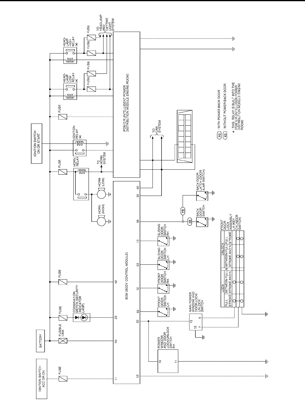
BL-92
VEHICLE SECURITY (THEFT WARNING) SYSTEM
Revision: July 2006 2006 Quest
Schematic
EIS007EK
WIWA1120E
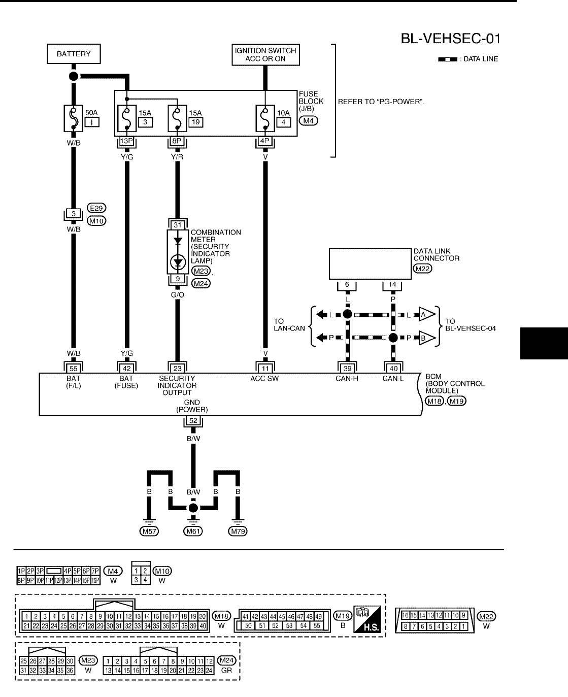
VEHICLE SECURITY (THEFT WARNING) SYSTEM
BL-93
C
D
E
F
G
H
J
K
L
M
A
B
BL
Revision: July 2006 2006 Quest
Wiring Diagram — VEHSEC —
EIS007EL
WIWA1121E
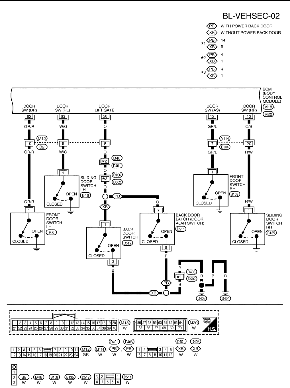
BL-94
VEHICLE SECURITY (THEFT WARNING) SYSTEM
Revision: July 2006 2006 Quest
WIWA1122E
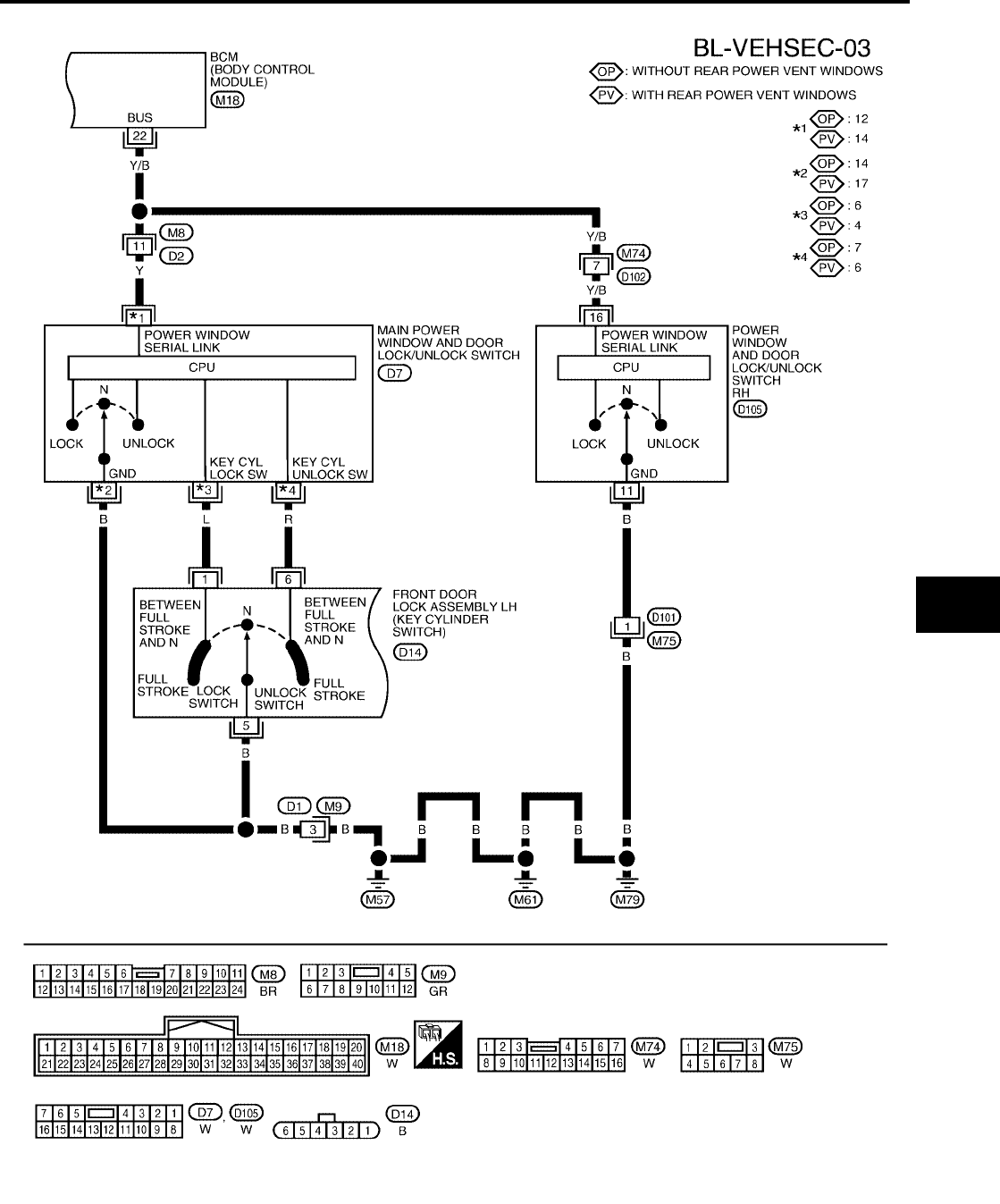
VEHICLE SECURITY (THEFT WARNING) SYSTEM
BL-95
C
D
E
F
G
H
J
K
L
M
A
B
BL
Revision: July 2006 2006 Quest
WIWA1249E
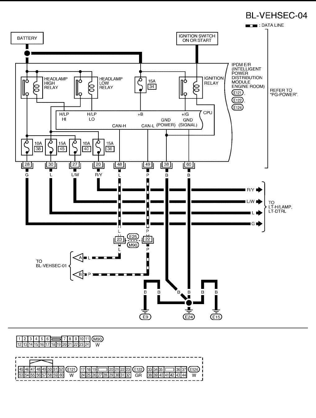
BL-96
VEHICLE SECURITY (THEFT WARNING) SYSTEM
Revision: July 2006 2006 Quest
WIWA1123E
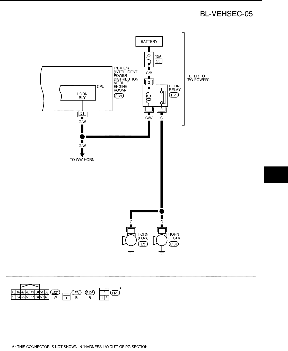
VEHICLE SECURITY (THEFT WARNING) SYSTEM
BL-97
C
D
E
F
G
H
J
K
L
M
A
B
BL
Revision: July 2006 2006 Quest
WIWA1124E

BL-98
VEHICLE SECURITY (THEFT WARNING) SYSTEM
Revision: July 2006 2006 Quest
Terminals and Reference Value for BCM
EIS007EM
Terminals and Reference Value for IPDM E/R
EIS007EN
*1: when horn reminder is ON.
Terminal Wire
Color Item Condition Voltage (V)
(Approx.)
11 V Ignition switch (ACC or ON) Ignition switch (ACC or ON position) Battery voltage
12 GR/L Front door switch RH Door closed (OFF) → Open (ON) Battery voltage → 0
13 O/B Sliding door switch RH Door closed (OFF) → Open (ON) Battery voltage → 0
22 Y/B Bus When ignition switch is ON or power
window timer operates
23 G/O Combination meter (security
indicator lamp)
Goes off → Illuminates (Every 3
seconds) Battery voltage → 0
39 L CAN-H ——
40 P CAN-L ——
42 Y/G Battery power supply — Battery voltage → 0
52 B/W Ground —0
55 W/B Battery power supply —Battery voltage
58 O Back door switch Door closed (OFF) → Open (ON) Battery voltage → 0
62 GR/R Front door switch LH Door closed (OFF) → Open (ON) Battery voltage → 0
63 W/G Sliding door switch LH Door closed (OFF) → Open (ON) Battery voltage → 0
PIIA2344E
Terminal Wire
Color Item Condition Voltage (V)
(Approx.)
20 R/Y Headlamp low (RH) Ignition
SW ON
Lighting
switch
2ND posi-
tion
OFF 0V
ON Battery voltage
27 L/W Headlamp high (RH) Ignition
SW ON
Lighting
switch
HIGH or
PASS
position
OFF 0V
ON Battery voltage
28 G Headlamp high (LH) Ignition
SW ON
Lighting
switch
HIGH or
PASS
position
OFF 0V
ON Battery voltage
30 L Headlamp low (LH) Ignition
SW ON
Lighting
switch
2ND posi-
tion
OFF 0V
ON Battery voltage
38 B Ground —0
48 L CAN-H ——
49 P CAN-L ——
51 G/W Horn relay When doors locks are operated
using key fob (OFF → ON) *1 Battery voltage → 0
60 B Ground —0
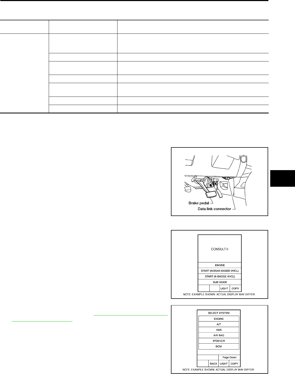
VEHICLE SECURITY (THEFT WARNING) SYSTEM
BL-99
C
D
E
F
G
H
J
K
L
M
A
B
BL
Revision: July 2006 2006 Quest
CONSULT-II Function (BCM)
EIS007EO
CONSULT-II can display each diagnostic item using the diagnostic test modes shown following.
CONSULT-II INSPECTION PROCEDURE
CAUTION:
If CONSULT-II is used with no connection of CONSULT-II CONVERTER, malfunctions might be
detected in self-diagnosis depending on control unit which carries out CAN communication.
1. Turn ignition switch OFF.
2. Connect CONSULT-II and CONSULT-II CONVERTER to the
data link connector.
3. Turn ignition switch ON.
4. Touch “START (NISSAN BASED VHCL)".
5. Touch “BCM”.
If "BCM" is not indicated, refer to GI-38, "CONSULT-II Data Link
Connector (DLC) Circuit" .
BCM
diagnostic test item Diagnostic mode Description
Inspection by part
WORK SUPPORT
Supports inspections and adjustments. Commands are transmitted to the
BCM for setting the status suitable for required operation, input/output sig-
nals are received from the BCM and received date is displayed.
DATA MONITOR Displays BCM input/output data in real time.
ACTIVE TEST Operation of electrical loads can be checked by sending drive signal to
them.
SELF-DIAG RESULTS Displays BCM self-diagnosis results.
CAN DIAG SUPPORT MNTR The result of transmit/receive diagnosis of CAN communication can be
read.
ECU PART NUMBER BCM part number can be read.
CONFIGURATION Performs BCM configuration read/write functions.
BBIA0369E
BCIA0029E
BCIA0030E
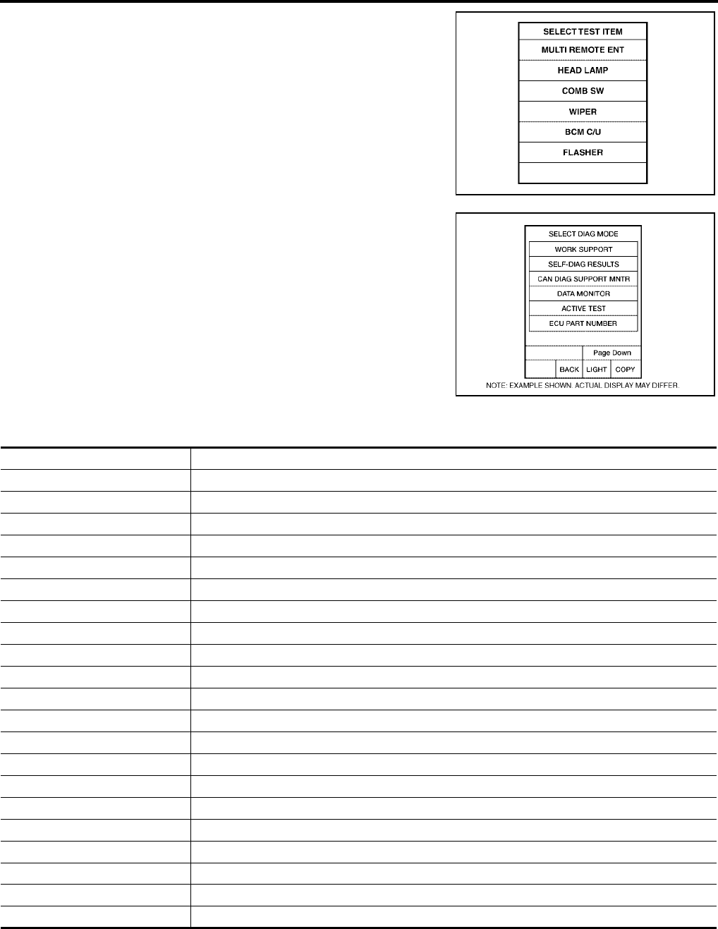
BL-100
VEHICLE SECURITY (THEFT WARNING) SYSTEM
Revision: July 2006 2006 Quest
6. Touch “THEFT ALM” on the "SELECT TEST ITEM" screen.
7. Select diagnosis mode.
“DATA MONITOR”, “ACTIVE TEST” and “WORK SUPPORT”
are available.
CONSULT-II APPLICATION ITEM
Data Monitor
LIIA0194E
BCIA0031E
Monitored Item Description
IGN ON SW Indicates [ON/OFF] condition of ignition switch in ON position.
ACC ON SW Indicates [ON/OFF] condition of ignition switch in ACC position.
KEYLESS LOCK Indicates [ON/OFF] condition of lock signal from keyfob.
KEYLESS UNLOCK Indicates [ON/OFF] condition of unlock signal from keyfob.
KEYLESS TRUNK Indicates [ON/OFF] condition of power back door open signal from keyfob.
KEYLESS PSD R Indicates [ON/OFF] condition of power sliding door LH signal from keyfob.
KEYLESS PSD L Indicates [ON/OFF] condition of power sliding door RH signal from keyfob.
KEYLESS PBD Indicates [ON/OFF] condition of power back door close signal from keyfob.
TRNK OPNR SW Indicates [ON/OFF] condition of power back door switch.
TRNK CYL SW OFF (not equipped)
TRNK OPN MNTR Indicates [ON/OFF] condition of power back door position.
HOOD SW OFF (not equipped)
DOOR SW-DR Indicates [ON/OFF] condition of front door switch LH.
DOOR SW-AS Indicates [ON/OFF] condition of front door switch RH.
DOOR SW-RR Indicates [ON/OFF] condition of rear door switch RH.
DOOR SW-RL Indicates [ON/OFF] condition of rear door switch LH.
BACK DOOR SW Indicates [ON/OFF] condition of back door switch.
KEY CYL LK-SW Indicates [ON/OFF] condition of lock signal from door key cylinder switch.
KEY CYL UN-SW Indicates [ON/OFF] condition of unlock signal from door key cylinder switch.
CDL LOCK SW Indicates [ON/OFF] condition of lock signal from lock/unlock switch.
CDL UNLOCK SW Indicates [ON/OFF] condition of unlock signal from lock/unlock switch.
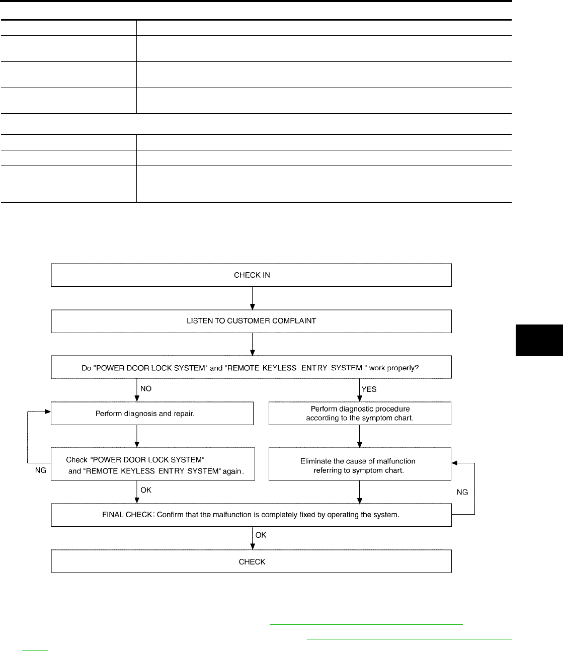
VEHICLE SECURITY (THEFT WARNING) SYSTEM
BL-101
C
D
E
F
G
H
J
K
L
M
A
B
BL
Revision: July 2006 2006 Quest
Active Test
Work Support
Trouble Diagnosis
EIS007EP
WORK FLOW
●“POWER DOOR LOCK SYSTEM” Diagnosis refer to BL-18, "POWER DOOR LOCK SYSTEM" .
●“REMOTE KEYLESS ENTRY SYSTEM” Diagnosis refer to BL-55, "REMOTE KEYLESS ENTRY SYS-
TEM" .
Test Item Description
THEFT IND This test is able to check security indicator lamp operation. The lamp will be turned on when “ON”
on CONSULT-II screen is touched.
HEADLAMP (HI) This test is able to check vehicle security lamp operation. The high beam headlamps will be acti-
vated for 0.5 seconds after “ON” on CONSULT-II screen is touched.
VEHICLE SECURITY HORN This test is able to check vehicle security horn operation. The horns will be activated for 0.5 sec-
onds after “ON” on CONSULT-II screen is touched.
Test Item Description
SECURITY ALARM SET This mode can confirm and change security alarm ON-OFF setting.
THEFT ALM TRG
The switch which triggered vehicle security alarm is recorded. This mode is able to confirm and
erase the record of vehicle security alarm. The trigger data can be erased by touching “CLEAR”
on CONSULT-II screen.
WIIA0599E
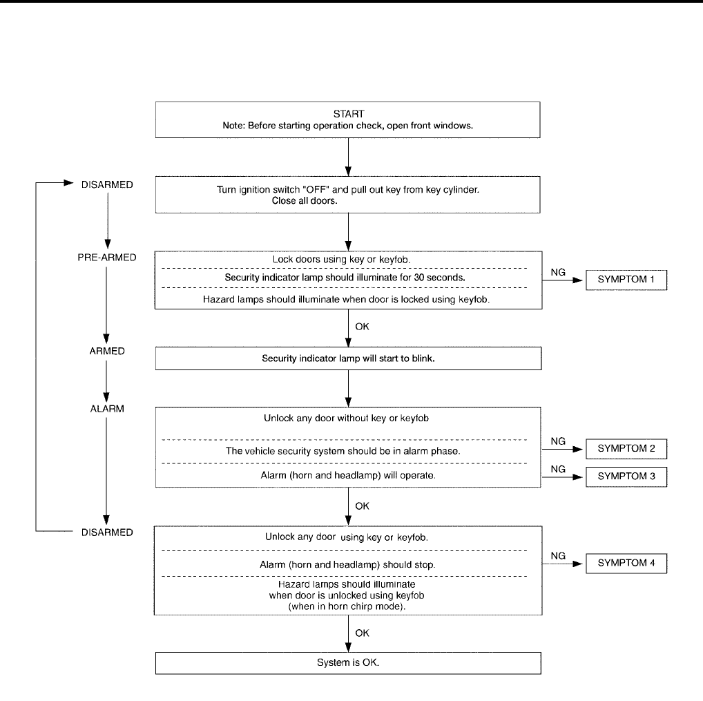
BL-102
VEHICLE SECURITY (THEFT WARNING) SYSTEM
Revision: July 2006 2006 Quest
Preliminary Check
EIS007EQ
The system operation is canceled by turning ignition switch to ACC at any step between START and ARMED
in the following flow chart.
After performing preliminary check, go to symptom chart.
WIIA0627E

VEHICLE SECURITY (THEFT WARNING) SYSTEM
BL-103
C
D
E
F
G
H
J
K
L
M
A
B
BL
Revision: July 2006 2006 Quest
Symptom Chart
EIS007ER
*1: Make sure the system is in the armed phase.
PROCEDURE Diagnostic procedure
SYMPTOM
1
Vehicle security
system cannot be
set by ····
AII items
Diagnostic Procedure 1
Refer to BL-104, "Diagnostic Procedure 1" .
If the above systems are “OK”, replace BCM.
Lock/unlock switch
Diagnostic Procedure 6
Refer to BL-112, "Diagnostic Procedure 6" .
If the above systems are “OK”, check main power window and door lock/
unlock switch.
Door outside key
Diagnostic Procedure 3
Refer to BL-110, "Diagnostic Procedure 3" .
If the above systems are “OK”, check main power window and door lock/
unlock switch.
Security indicator does not turn “ON”.
Diagnostic Procedure 2
Refer to BL-108, "Diagnostic Procedure 2" .
If the above systems are “OK”, replace BCM.
2
*1 Vehicle secu-
rity system does
not alarm when
····
Any door is opened.
Diagnostic Procedure 1
Refer to BL-104, "Diagnostic Procedure 1" .
If the above systems are “OK”, replace BCM.
3
Vehicle security
alarm does not
activate.
Horn alarm
Diagnostic Procedure 4
Refer to BL-112, "Diagnostic Procedure 4" .
If the above systems are “OK”, check horn system.
Refer to WW-51, "HORN" .
Headlamp alarm
Diagnostic Procedure 5
Refer to BL-112, "Diagnostic Procedure 5" .
If the above systems are “OK”, replace BCM.
4
Vehicle security
system cannot be
canceled by ····
Door outside key
Diagnostic Procedure 3
Refer to BL-110, "Diagnostic Procedure 3" .
If the above systems are “OK”, check main power window and door lock/
unlock switch.
Keyfob Check remote keyless entry function.
If the above systems are “OK”, replace BCM.
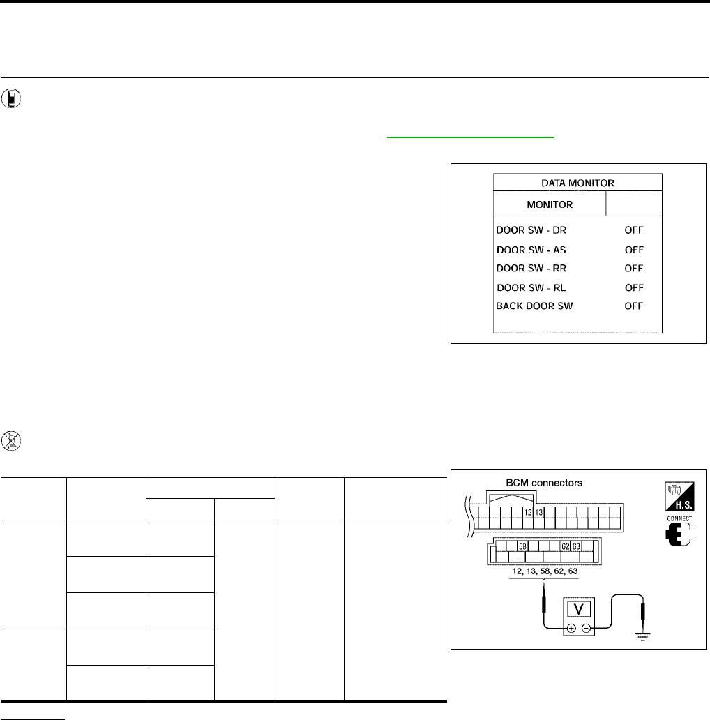
BL-104
VEHICLE SECURITY (THEFT WARNING) SYSTEM
Revision: July 2006 2006 Quest
Diagnostic Procedure 1
EIS007ES
Door Switch Check (Without Automatic Back Door System)
1. CHECK DOOR SWITCHES INPUT SIGNAL
With CONSULT-II
Check door switches ("DOOR SW-DR", "DOOR SW-AS", "DOOR SW-RL", "DOOR SW-RR", "BACK DOOR
SW") in DATA MONITOR mode with CONSULT–II. Refer to BL-39, "DATA MONITOR" .
●When doors are open:
●When doors are closed:
Without CONSULT-II
Check voltage between BCM connector M18 or M20 terminals 12, 13, 58, 62, 63 and ground.
OK or NG
OK >> Door switch circuit is OK.
NG >> GO TO 2.
DOOR SW-DR : ON
DOOR SW-AS : ON
DOOR SW-RR : ON
DOOR SW-RL : ON
BACK DOOR SW : ON
DOOR SW-DR : OFF
DOOR SW-AS : OFF
DOOR SW-RR : OFF
DOOR SW-RL : OFF
BACK DOOR SW : OFF
LIIA0665E
Connec-
tor Item Terminals Condition Voltage (V)
(Approx.)
( + ) ( – )
M20
Back door
switch 58
Ground
Open
↓
Closed
0
↓
Battery voltage
Front door
switch LH 62
Sliding door
switch LH 63
M18
Front door
switch RH 12
Sliding door
switch RH 13
LIIA0666E

VEHICLE SECURITY (THEFT WARNING) SYSTEM
BL-105
C
D
E
F
G
H
J
K
L
M
A
B
BL
Revision: July 2006 2006 Quest
2. CHECK DOOR SWITCH CIRCUIT
1. Turn ignition switch OFF.
2. Disconnect door switch and BCM.
3. Check continuity between door switch connector (B) B8 (Front LH), B108 (Front RH), B46 (Sliding LH),
B135 (Sliding RH) or D512 (Back) terminal 1 and BCM connector (A) M18, M20 terminals 12, 13, 58, 62
and 63.
4. Check continuity between door switch connector (B) B8 (Front
LH), B108 (Front RH), B46 (Sliding LH), B135 (Sliding RH) or
D512 (Back) terminal 1 and ground.
OK or NG
OK >> GO TO 3.
NG >> Repair or replace harness.
3. CHECK DOOR SWITCHES
FRONT AND REAR DOORS
Check continuity between front or rear door switch terminal 1 and
exposed metal of switch while pressing and releasing switch.
BACK DOOR
Check continuity between back door switch terminals 1 and 3 while
pressing and releasing switch.
OK or NG
OK >> (Front and rear doors) Switch circuit is OK.
OK >> (Back door) GO TO 4.
NG >> Replace door switch.
1 - 12 : Continuity should exist.
1 - 13 : Continuity should exist.
1 - 58 : Continuity should exist.
1 - 62 : Continuity should exist.
1 - 63 : Continuity should exist.
1 - Ground : Continuity should not exist. WIIA0781E
Door switch is released : Continuity should exist.
Door switch is pushed : Continuity should not exist.
WIIA0782E
Door switch is released : Continuity should exist.
Door switch is pushed : Continuity should not exist.
WIIA0783E
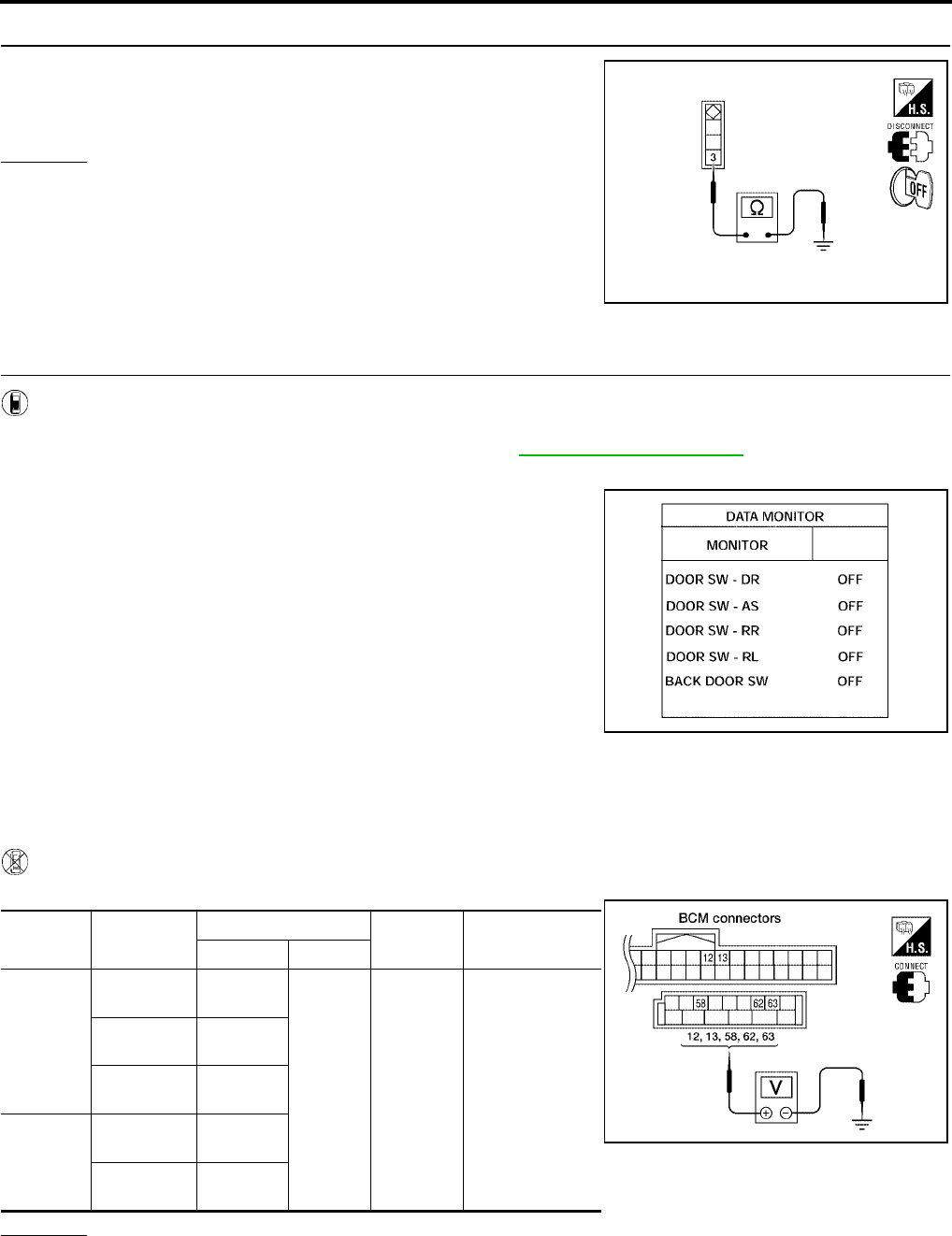
BL-106
VEHICLE SECURITY (THEFT WARNING) SYSTEM
Revision: July 2006 2006 Quest
4. CHECK BACK DOOR SWITCH GROUND
Check continuity between back door switch connector terminal 3 and
ground.
OK or NG
OK >> Back door switch circuit is OK.
NG >> Repair or replace harness.
Door Switch Check (With Automatic Back Door System)
1. CHECK DOOR SWITCHES INPUT SIGNAL
With CONSULT-II
Check door switches ("DOOR SW-DR", "DOOR SW-AS", "DOOR SW-RL", "DOOR SW-RR", "BACK DOOR
SW") in DATA MONITOR mode with CONSULT–II. Refer to BL-39, "DATA MONITOR" .
●When doors are open:
●When doors are closed:
Without CONSULT-II
Check voltage between BCM connector M18 or M20 terminals 12, 13, 58, 62, 63 and ground.
OK or NG
OK >> Door switch is OK.
NG >> GO TO 2.
3 - Ground : Continuity should exist.
WIIA0791E
DOOR SW-DR : ON
DOOR SW-AS : ON
DOOR SW-RR : ON
DOOR SW-RL : ON
BACK DOOR SW : ON
DOOR SW-DR : OFF
DOOR SW-AS : OFF
DOOR SW-RR : OFF
DOOR SW-RL : OFF
BACK DOOR SW : OFF
LIIA0665E
Connector Item Terminals Condition Voltage (V)
(Approx.)
( + ) ( – )
M20
Back door
latch 58
Ground
Open
↓
Closed
0
↓
Battery voltage
Front door
switch LH 62
Sliding door
switch LH 63
M18
Front door
switch RH 12
Sliding door
switch RH 13
LIIA0666E

VEHICLE SECURITY (THEFT WARNING) SYSTEM
BL-107
C
D
E
F
G
H
J
K
L
M
A
B
BL
Revision: July 2006 2006 Quest
2. CHECK DOOR SWITCH CIRCUIT
1. Turn ignition switch OFF.
2. Disconnect door switch and BCM.
3. Check continuity between door switch connector (B) B8 (Front LH), B108 (Front RH), B46 (Sliding LH),
B135 (Sliding RH) terminal 1 or back door latch (door ajar switch) connector (C) D511 terminal 7 and BCM
connector (A) M18, M20 terminals 12, 13, 58, 62 and 63
4. Check continuity between door switch connector (B) B8 (Front
LH), B108 (Front RH), B46 (Sliding LH), B135 (Sliding RH) ter-
minal 1 or back door latch (door ajar switch) connector (C) D511
terminal 7 and ground.
OK or NG
OK >> GO TO 3.
NG >> Repair or replace harness.
3. CHECK DOOR SWITCHES
FRONT AND REAR DOORS
Check continuity between front or rear door switch terminal 1 and
exposed metal of switch while pressing and releasing switch.
BACK DOOR
Check continuity between back door latch connector (A) D511 termi-
nals 7 and 8 while pressing (closing back door) and releasing (open-
ing back door) switch.
OK or NG
OK >> (Front and rear doors) Switch circuit is OK.
OK >> (Back door) GO TO 4.
NG >> Replace door switch.
1 - 62 : Continuity should exist.
1 - 12 : Continuity should exist.
1 - 63 : Continuity should exist.
1 - 13 : Continuity should exist.
7 - 58 : Continuity should exist.
1 - Ground : Continuity should not exist.
7 - Ground : Continuity should not exist.
WIIA0784E
Door switch is released : Continuity should exist.
Door switch is pushed : Continuity should not exist.
WIIA0782E
When back door is open : Continuity should exist.
When back door is closed : Continuity should not exist.
WIIA0752E
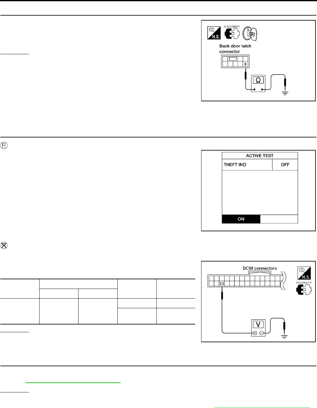
BL-108
VEHICLE SECURITY (THEFT WARNING) SYSTEM
Revision: July 2006 2006 Quest
4. CHECK BACK DOOR SWITCH GROUND
Check continuity between back door latch connector terminal 8 and
ground.
OK or NG
OK >> Back door switch circuit is OK.
NG >> Repair or replace harness.
Diagnostic Procedure 2
EIS007ET
SECURITY INDICATOR LAMP CHECK
1. SECURITY INDICATOR LAMP ACTIVE TEST
With CONSULT-II
Check "THEFT IND” in "ACTIVE TEST" mode with CONSULT-II.
Without CONSULT-II
1. Disconnect BCM.
2. Check voltage between BCM harness connector M18 terminal
23 and ground.
OK or NG
OK >> Security indicator lamp is OK.
NG >> GO TO 2.
2. SECURITY INDICATOR LAMP CHECK
Check indicator lamp condition.
Refer to DI-5, "COMBINATION METERS" .
OK or NG
OK >> GO TO 3.
NG >> Replace combination meter (security indicator lamp). Refer to IP-10, "Removal and Installation" .
8 - Ground : Continuity should exist.
LIIA0828E
LIIA0044E
Connector Terminal Condition Voltage (V)
(Approx.)
(+) (-)
M18 23 Ground
ON 0
OFF Battery volt-
age
LIIA0523E
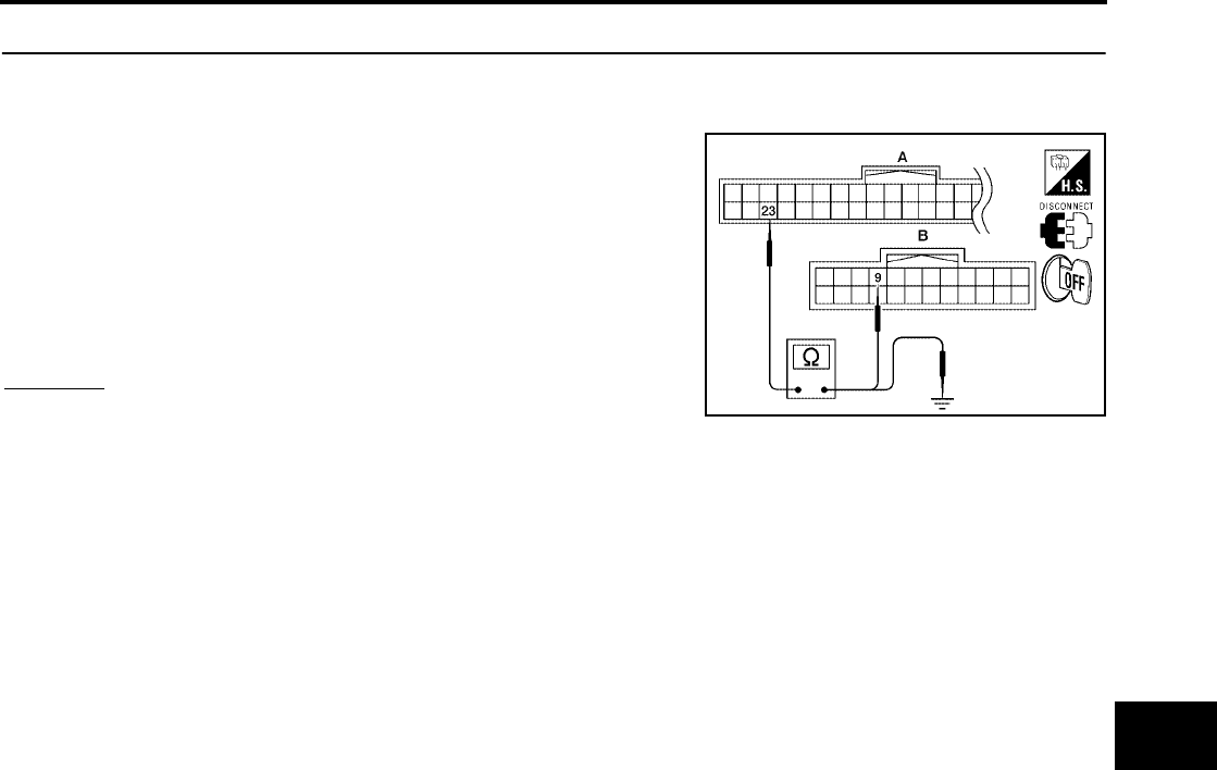
VEHICLE SECURITY (THEFT WARNING) SYSTEM
BL-109
C
D
E
F
G
H
J
K
L
M
A
B
BL
Revision: July 2006 2006 Quest
3. CHECK HARNESS CONTINUITY
1. Turn ignition switch OFF.
2. Disconnect BCM and security indicator lamp connector.
3. Check continuity between BCM connector (A) M18 terminal 23
and combination meter (security indicator lamp) connector (B)
M24 terminal 9.
4. Check continuity between BCM connector (A) M18 terminal 23
and ground.
OK or NG
OK >> Check the following:
●10A fuse [No. 19, located in fuse block (J/B)]
●Harness for open or short between security indicator lamp and fuse
NG >> Repair or replace harness.
23 - 9 : Continuity should exist.
23 - Ground : Continuity should not exist.
WIIA0785E
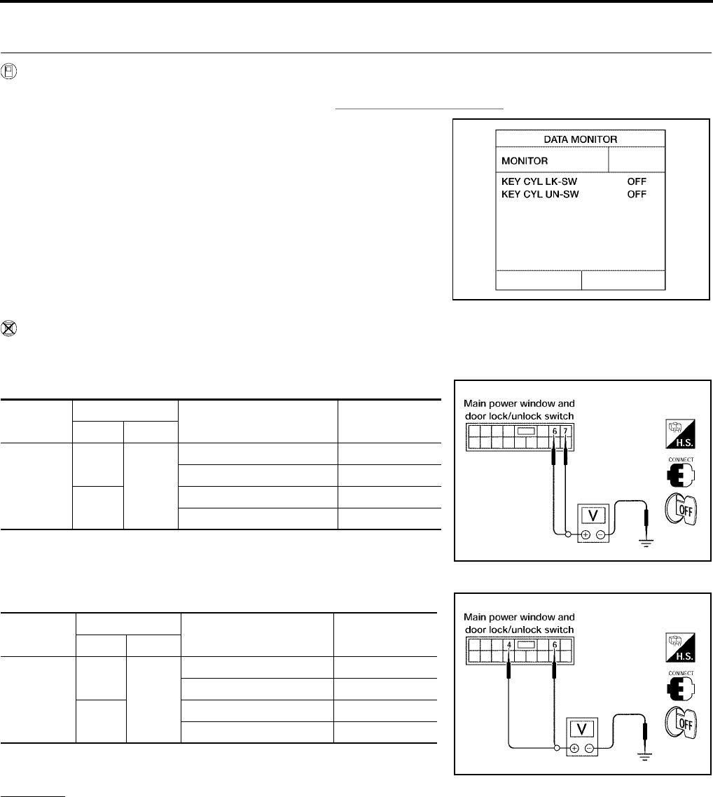
BL-110
VEHICLE SECURITY (THEFT WARNING) SYSTEM
Revision: July 2006 2006 Quest
Diagnostic Procedure 3
EIS007EU
1. CHECK FRONT DOOR LOCK ASSEMBLY LH (KEY CYLINDER SWITCH)
With CONSULT-II
Check front door lock assembly LH (key cylinder switch) ("KEY CYL LK-SW") and ("KEY CYL UN-SW) in
DATA MONITOR mode with CONSULT–II. Refer to BL-39, "DATA MONITOR" .
●When key inserted in left front door key cylinder is turned to
LOCK:
●When key inserted in left front key cylinder is turned to
UNLOCK:
Without CONSULT-II
Check voltage between main power window and door lock/unlock switch connector D7 terminals 6, 7 (without
power vent windows) or terminals 4, 6 (with power vent windows) and ground.
Without Power Vent Windows
With Power Vent Windows
OK or NG
OK >> Key cylinder switch signal is OK.
NG >> GO TO 2.
KEY CYL LK-SW : ON
KEY CYL UN-SW : ON
LIIA0188E
Connector Terminals Condition of left front key
cylinder
Voltage (V)
(Approx.)
( + ) ( – )
D7
6
Ground
Neutral/Unlock 5
Lock 0
7Neutral/Lock 5
Unlock 0
LIIA0867E
Connector Terminals Condition of left front key
cylinder
Voltage (V)
(Approx.)
( + ) ( – )
D7
4
Ground
Neutral/Unlock 5
Lock 0
6Neutral/Lock 5
Unlock 0
LIIA0566E
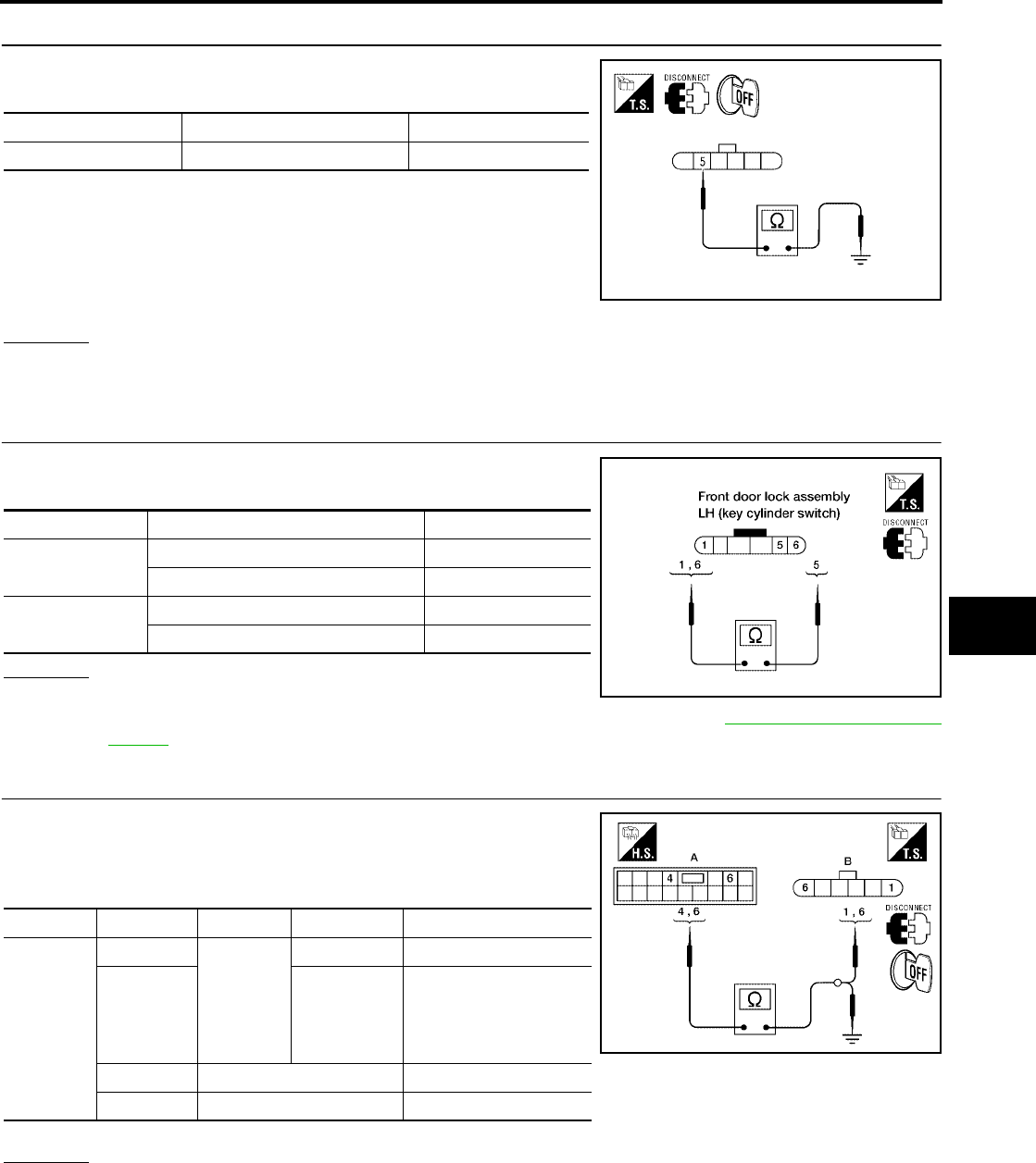
VEHICLE SECURITY (THEFT WARNING) SYSTEM
BL-111
C
D
E
F
G
H
J
K
L
M
A
B
BL
Revision: July 2006 2006 Quest
2. CHECK DOOR KEY CYLINDER SWITCH LH GROUND HARNESS
Check continuity between front door lock assembly LH (key cylinder
switch) connector D14 terminal 5 and body ground.
OK or NG
OK >> GO TO 3.
NG >> Repair or replace harness.
3. CHECK DOOR KEY CYLINDER SWITCH LH
Check continuity between front door lock assembly LH (key cylinder
switch) terminals.
OK or NG
OK >> GO TO 4.
NG >> Replace front door lock assembly LH (key cylinder switch). Refer to BL-197, "FRONT DOOR
LOCK" .
4. CHECK DOOR KEY CYLINDER HARNESS
Check continuity between main power window and door lock/unlock
switch connector (A) D7 terminals 4, 6 and front door lock assembly
LH (key cylinder switch) connector (B) D14 terminals 1, 6 and body
ground.
OK or NG
OK >> Replace main power window and door lock/unlock switch.
NG >> Repair or replace harness.
Connector Terminals Continuity
D14 5 – Ground Yes
WIIA0813E
Terminals Condition Continuity
1 – 5 Key is turned to UNLOCK or neutral. No
Key is turned to LOCK. Yes
5 – 6 Key is turned to LOCK or neutral. No
Key is turned to UNLOCK. Yes
LIIA1573E
Connector Terminals Connector Terminals Continuity
A: Main
power win-
dow and
door lock/
unlock
switch
4B: Front
door lock
assembly
LH (key
cylinder
switch)
1Yes
66Yes
4 Ground No
6 Ground No
WIIA0814E

BL-112
VEHICLE SECURITY (THEFT WARNING) SYSTEM
Revision: July 2006 2006 Quest
Diagnostic Procedure 4
EIS007EV
VEHICLE SECURITY HORN ALARM CHECK
1. CHECK HORN OPERATION
Check if horn sounds with horn switch.
Does horn operate?
Yes >> Check harness for open or short between IPDM E/R and horn relay.
No >> Check horn circuit. Refer to WW-51, "HORN" .
Diagnostic Procedure 5
EIS007EW
VEHICLE SECURITY HEADLAMP ALARM CHECK
1. CHECK VEHICLE SECURITY HEADLAMP ALARM OPERATION
Check if headlamps operate with lighting switch.
Do headlamps come on when turning switch ON?
Yes >> Headlamp alarm is OK.
No >> Check headlamp system. Refer to LT-5, "HEADLAMP (FOR USA)" or LT-32, "HEADLAMP (FOR
CANADA) - DAYTIME LIGHT SYSTEM -" .
Diagnostic Procedure 6
EIS007EX
DOOR LOCK/UNLOCK SWITCH CHECK
1. CHECK DOOR LOCK/UNLOCK SWITCH INPUT SIGNAL
Check if power door lock operates with door lock/unlock switch.
Do doors lock/unlock when using each door lock/unlock switch?
Yes >> Door lock/unlock switch is OK.
No >> Refer to BL-18, "POWER DOOR LOCK SYSTEM" .
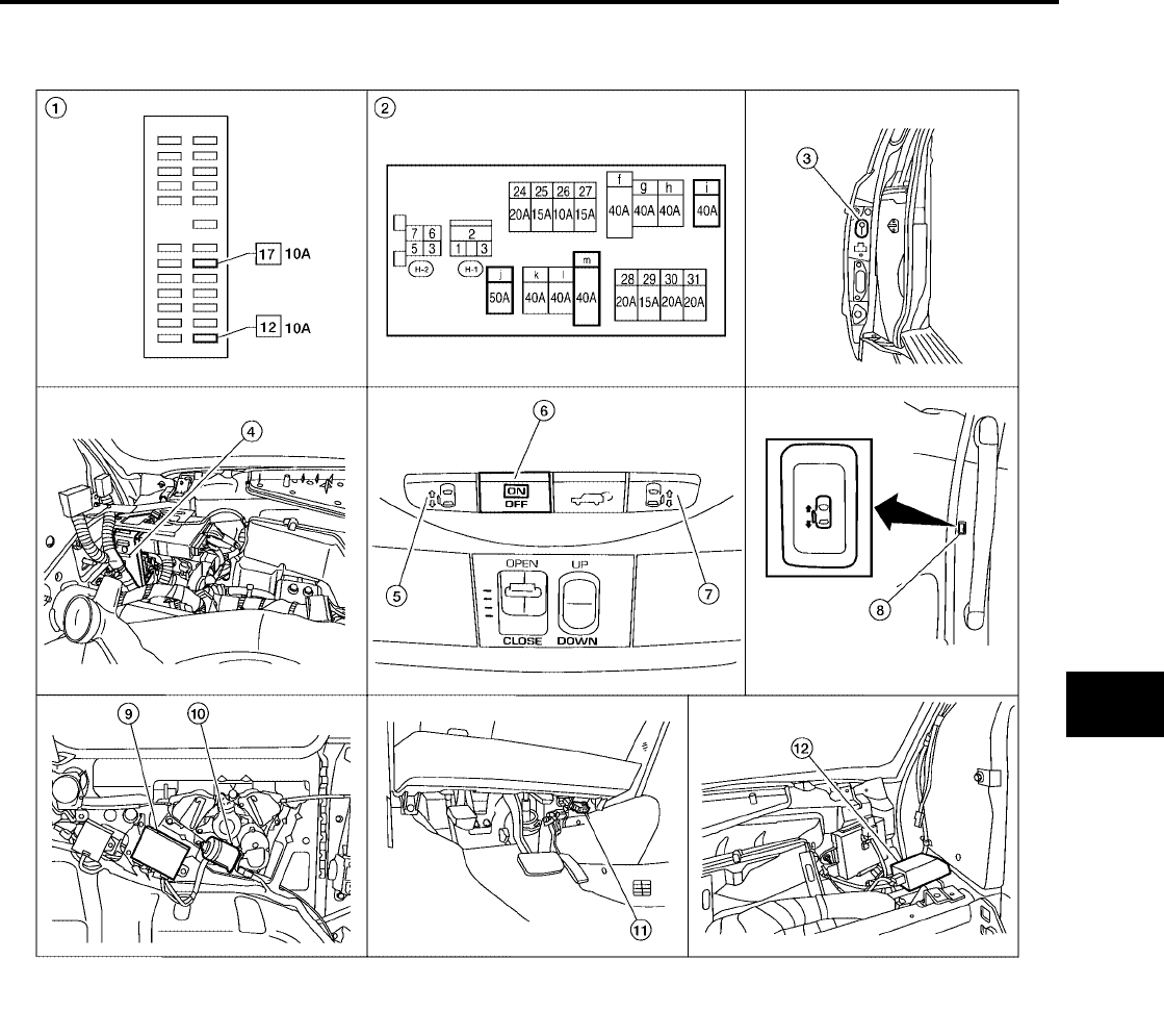
AUTOMATIC SLIDING DOOR SYSTEM
BL-113
C
D
E
F
G
H
J
K
L
M
A
B
BL
Revision: July 2006 2006 Quest
AUTOMATIC SLIDING DOOR SYSTEM PFP:28572
Component Parts and Harness Connector Location
EIS007EY
LIIA2335E
1. Fuse block (J/B) 2. Fuse and fusible link box 3. Sliding door switch
LH B46
RH B135
4. BCM M18, M19, M20
(view with instrument panel removed)
5. Sliding door open/close switch LH 6. Automatic door main switch R10
7. Sliding door open/close switch RH 8. Sliding door open/close switch
LH B58
RH B140
9. Sliding door control unit
LH B60, B61, B501 (left rear body)
RH B143, B144, B401 (right rear body)
10. Sliding door motor assembly
LH B59 (left rear body)
RH B145 (right rear body)
11. Data link connector 12. Remote keyless entry receiver M120
(view with instrument panel removed)

BL-114
AUTOMATIC SLIDING DOOR SYSTEM
Revision: July 2006 2006 Quest
System Description
EIS007EZ
●It is possible to automatically open/close the sliding doors with automatic main door switch, remote key-
less entry controller, or sliding door open/close switch.
●It is possible to switch the sliding doors between auto and manual operation by switching the automatic
main door switch ON/OFF.
OPERATION DESCRIPTION
Automatic Door Main Switch Operation (Fully Closed → Fully Open Operation)
●When the automatic door main switch is pressed, sliding door control unit terminal 15 receives the signal.
●The sliding door control unit checks the automatic transaxle selector lever (A/T device) position through
terminal 18, vehicle speed through terminal 7 and battery voltage.
●For automatic sliding door LH, fuel lid door status is checked through sliding door control unit terminal 13.
●Door lock status is checked through terminal 3. If the door is locked, the sliding door control unit will
unlock the door through terminal 30.
●When the sliding door control unit receives the signal, if the auto sliding door operating enable conditions
are met, it sends the unlock signal to the sliding door latch control unit.
●When the sliding door latch control unit receives the signal, it supplies voltage from terminal 10 to operate
the release actuator and unlatches the door lock.
●The sliding door control unit supplies power from terminal 33 and supplies power from terminal 34 to the
magnetic clutch to operate the sliding door motor and slide the sliding door in the open direction. (At this
time, it also executes speed control, input reverse, and overload reverse control.)
●When the sliding door is opened to the full-open position, the full-open position is detected by the encoder
(built into the sliding door motor assembly), and the sliding door control unit switches the sliding door
motor OFF and controls the magnetic clutch ON → half clutch → OFF.
●The sliding door is mechanically held in the fully open position by the checker.
Remote Keyless Entry Switch Operation (Fully Closed → Fully Open Operation)
●When the remote keyless entry switch is pressed for at lease 0.5 seconds, sliding door control unit termi-
nal 7 receives the signal.
●The sliding door control unit checks the automatic transaxle selector lever (A/T device) position through
terminal 18, vehicle speed through terminal 7 and battery voltage.
●For automatic sliding door LH, fuel lid door status is checked through sliding door control unit terminal 13.
●Door lock status is checked through terminal 3, if the door is locked, the sliding door control unit will unlock
the door through terminal 30.
●When the sliding door control unit receives the signal, if the auto sliding door operating enable conditions
are met, it sends the unlock signal to the sliding door latch control unit.
●When the sliding door latch control unit receives the signal, it supplies voltage from terminal 10 to operate
the release actuator and unlatches the door lock.
●The sliding door control unit supplies power from terminal 33 and supplies power from terminal 34 to the
magnetic clutch to operate the sliding door motor and slide the sliding door in the open direction. (At this
time, it also executes speed control, input reverse, and overload reverse control.)
●When the sliding door is opened to the full-open position, the full-open position is detected by the encoder
(built into the sliding door motor assembly), and the sliding door control unit switches the sliding door
motor OFF and controls the magnetic clutch ON → half clutch → OFF.
●The sliding door is mechanically held in the fully open position by the checker.
Sliding Door Open/Close Switch Operation (Fully Closed → Fully Open Operation)
●When the sliding door open/close switch is pressed, sliding door control unit terminal 2 receives the sig-
nal.
●The sliding door control unit checks the automatic transaxle selector lever (A/T device) position through
terminal 18, vehicle speed through terminal 7 and battery voltage.
●For automatic sliding door LH, fuel lid door status is checked through sliding door control unit terminal 13.
●When the sliding door control unit receives the signal, if the auto sliding door operating enable conditions
are met, including automatic door main switch in the ON position, doors in the unlock position and the
child lock switch in the OFF position, it sends the unlock signal to the sliding door latch control unit.

AUTOMATIC SLIDING DOOR SYSTEM
BL-115
C
D
E
F
G
H
J
K
L
M
A
B
BL
Revision: July 2006 2006 Quest
●When the sliding door latch control unit receives the signal, it supplies voltage from terminal 10 to operate
the release actuator and unlatches the door lock.
●The sliding door control unit supplies power from terminal 33 and supplies power from terminal 34 to the
magnetic clutch to operate the sliding door motor and slide the sliding door in the open direction. (At this
time, it also executes speed control, input reverse, and overload reverse control.)
●When the sliding door is opened to the full-open position, the full-open position is detected by the encoder
(built into the sliding door motor assembly), and the sliding door control unit switches the sliding door
motor OFF and controls the magnetic clutch ON → half clutch → OFF.
●The sliding door is mechanically held in the fully open position by the checker.
Automatic Door Main Switch Operation (Fully Open → Fully Closed Operation)
●When the automatic door main switch is pressed, the sliding door control unit terminal 15 receives the sig-
nal.
●When the sliding door control unit receives the signal, if the auto sliding door operating enable conditions
are met, it operates the sliding door motor.
●The sliding door control unit supplies power from terminal 36 and supplies power from terminal 34 to the
magnetic clutch to operate the sliding door motor and slide the sliding door in the close direction. (At this
time, it also executes speed control, input reverse, and overload reverse control.)
●When the sliding door reaches the half-latch state, the half-latch switch closes and the sliding door control
unit detects the signal through terminal 5.
●When the sliding door control unit receives the signal, it switches OFF the sliding door motor and sends
the latch command through terminal 26 to the sliding door latch control unit terminal 6.
●When the sliding door auto closure operates the cinch latch motor and the full-latch switch detects this,
sliding door latch control unit terminal 7 receives the signal and reverses the latch motor to the neutral
position.
●The siding door auto closure operation ends when the door is fully closed. The sliding door remains
unlocked.
Remote Keyless Entry Operation (Fully Open → Fully Closed Operation)
●When the remote keyless entry switch is pressed for at least 0.5 seconds, the sliding door control unit ter-
minal 7 receives the signal.
●When the sliding door control unit receives the signal, if the auto sliding door operating enable conditions
are met, it operates the sliding door motor.
●The sliding door control unit supplies power from terminal 36 and supplies power from terminal 34 to the
magnetic clutch to operate the sliding door motor and slide the sliding door in the close direction. (At this
time, it also executes speed control, input reverse, and overload reverse control.)
●When the sliding door reaches the half-latch state, the half-latch switch closes and the sliding door control
unit detects the signal through terminal 5.
●When the sliding door control unit receives the signal, it switches OFF the sliding door motor and sends
the latch command through terminal 26 to the sliding door latch control unit terminal 6.
●When the sliding door auto closure operates the cinch latch motor and the full-latch switch detects this,
sliding door latch control unit terminal 7 receives the signal and reverses the latch motor to the neutral
position.
●The sliding door auto closure operation ends when the door is fully closed. The sliding door remains
unlocked.
Power Assist Function
●When the sliding door is pushed or pulled from any position, operations switch to the auto open/close
function.
●The automatic door main switch must be in the ON position.
Sliding Door Power Assist Operation (Fully Closed → Fully Open Operation)
●For automatic sliding door LH, fuel lid door status is checked through sliding door control unit terminal 13.
●The sliding door control unit checks the automatic transaxle selector lever (A/T device) position through
terminal 18, vehicle speed through terminal 7 and battery voltage.

BL-116
AUTOMATIC SLIDING DOOR SYSTEM
Revision: July 2006 2006 Quest
●When the sliding door control unit detects motion through terminals 4 and 17, if the auto sliding door oper-
ating enable conditions are met, it applies power to terminals 33 and 34 to operate the door in the open
direction.
●The sliding door control unit supplies power from terminal 33 and supplies power from terminal 34 to the
magnetic clutch to operate the sliding door motor and slide the sliding door in the open direction. (At this
time, it also executes speed control, input reverse, and overload reverse control.)
●When the sliding door is opened to the full-open position, the full-open position is detected by the encoder
(built into the sliding door motor assembly), and the sliding door control unit switches the sliding door
motor OFF and controls the magnetic clutch ON → half clutch → OFF.
●The sliding door is mechanically held in the fully open position by the checker.
Sliding Door Power Assist Operation (Fully Open → Fully Closed Operation)
●When the handle is pulled or the door is moved in the closed direction, sliding door control unit initiates
the power assist close operation.
●The sliding door control unit supplies power from terminal 36 and supplies power from terminal 34 to the
magnetic clutch to operate the sliding door motor and slide the sliding door in the close direction. (At this
time, it also executes speed control, input reverse, and overload reverse control.)
●When the sliding door reaches the half-latch state, the half-latch switch closes and the sliding door control
unit detects the signal through terminal 5.
●When the sliding door control unit receives the signal, it switches OFF the sliding door motor and sends
the latch command through terminal 26 to the sliding door latch control unit terminal 6.
●When the sliding door auto closure operates the cinch latch motor and the full-latch switch detects this,
sliding door latch control unit terminal 7 receives the signal and reverses the latch motor to the neutral
position.
●The siding door auto closure operation ends when the door is fully closed. The sliding door remains
unlocked.
Anti-Pinch Function
●During auto open/close operation, if pinching of an object is detected, the sliding door reverses direction
to prevent pinching by moving to the full open or close position.
Intermittent Clutch Control Function
●During automatic operation, if the door is stopped midway, for example due to the automatic door main
switch being switched to OFF or a system error, the clutch is intermittently turned ON → OFF to prevent
sudden opening or closing. Intermittent clutch control ends after 6 seconds or when no door motion is
detected. If the vehicle is on level ground, intermittent clutch control is executed for 1/2 second.
Precautions
●Check and inspect operation of the remote control auto sliding door system on level ground.
Auto Sliding Door Operation Enable Conditions
Operation Automatic door main switch or
remote keyless entry Sliding door open/close switch Power assist
Operating
direction
Fully closed →
open
Fully open
→ closed
Fully closed →
open
Fully open →
closed
Fully closed →
open
Fully open →
closed
Main switch —ON
Vehicle stop
condition
Automatic trans-
mission selector
lever in P position
and vehicle speed
signal is less than 2
km/h
—
Automatic trans-
mission selector
lever in P position
and vehicle speed
signal is less than 2
km/h
—
Automatic trans-
mission selector
lever in P position
and vehicle speed
signal is less than 2
km/h
—
Door lock knob
state —Unlock (if door is
fully closed) —
Battery voltage Approx. 11V or more About 9V min. (operates with warning
chime for low voltage of 9 - 11V)

AUTOMATIC SLIDING DOOR SYSTEM
BL-117
C
D
E
F
G
H
J
K
L
M
A
B
BL
Revision: July 2006 2006 Quest
Control When Handle Open/Closed When Operating Enable Conditions Not Yet Met
Control When Operating Enable Conditions No Longer Met
Warning Chime Active Conditions
The warning chime uses two types of audio warnings, a friendly chime and a warning chime. The friendly
chime consists of dings lasting 0.66 seconds each immediately followed by the next ding. The warning chime
consists of beeps lasting 0.33 seconds with a pause of 0.33 seconds between each beep.
Items Operation condition Not met case Control
Main switch ON OFF
Manual mode (Power operation
is available with automatic door
main switch and remote key-
less entry)
A/T selector lever P position P position Other Power close operation
Voltage drop 9V or more 9 - 6V
Stopped while constrained
(clutch is engaged and warn-
ing chime sounds)
6 - 0V Manual mode
Description Operation Condition
Main switch turned OFF during power open
or close
Warning chime active and clutch intermit-
tent mode
→ Shift to manual mode
(Recovery to power mode when main
switch turned ON or door fully closed)
→ Shift to manual mode
A/T selector lever P position
Warning chime active continuously (0.66
second dings) and one-way operation con-
tinues if closing
Warning chime active continuously (0.33
second beep followed by 0.33 second
pause) and one-way operation continues if
opening. Warning chime remains on after
completing open function.
Stop continued
Voltage drop 11 - 9V
One-way operation continued (equivalent
to the case of starting voltage ← 11V for
handle operation with warning chime
active)
Normal operation
Voltage drop 9 - micro reset V
Motor stopped (clutch ON) → stop contin-
ued while still constrained → (Switching
the main switch OFF shifts operation to
intermittent mode.)
→ Shift to manual mode unless voltages
returns to >9 V within 5 seconds
Voltage drop below micro reset V
(Clutch hold not possible voltage)
●Stop continued while still constrained
(Clutch ON circuit) Clutch is released
when micro reset occurs
●The clutch force is weak, so there is slip-
ping on hills, etc.
→ Shift to manual mode
Operation status Operation or conditions Warning chime pattern
When reverse operation starts When reverse operation detected Friendly chime
1.33 seconds, 2 dings
During power close When vehicle not in P position Friendly chime
Continuous
During power open or close Obstacle is detected Warning chime
2 seconds, 3 beeps
During power open When vehicle not in P position or vehi-
cle is moving at greater than 2 km/h
Warning chime
Continuous until vehicle is shifted to P position
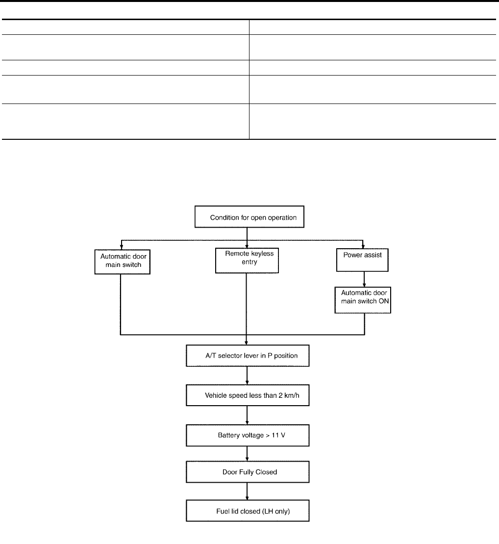
BL-118
AUTOMATIC SLIDING DOOR SYSTEM
Revision: July 2006 2006 Quest
Reverse Conditions
Operation Chart
●Open operation from fully closed
Type Control
Automatic door main switch, remote keyless entry or sliding door
open/close switch operation Both open/close directions
Detection method Operation speed and motor current change direction
Non-reversed area ●Between full open and approx. 45 mm (near full-open lock)
●Closure operation area
Number of times reverse allowed
A maximum of one obstacle is allowed during an open or close
operation. If a second obstacle is detected, the door will enter
manual mode.
LIIA0748E
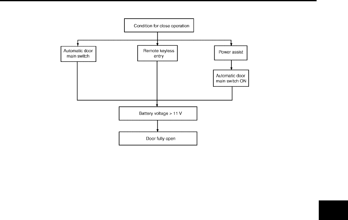
AUTOMATIC SLIDING DOOR SYSTEM
BL-119
C
D
E
F
G
H
J
K
L
M
A
B
BL
Revision: July 2006 2006 Quest
●Close operation from fully open
LIIA1628E
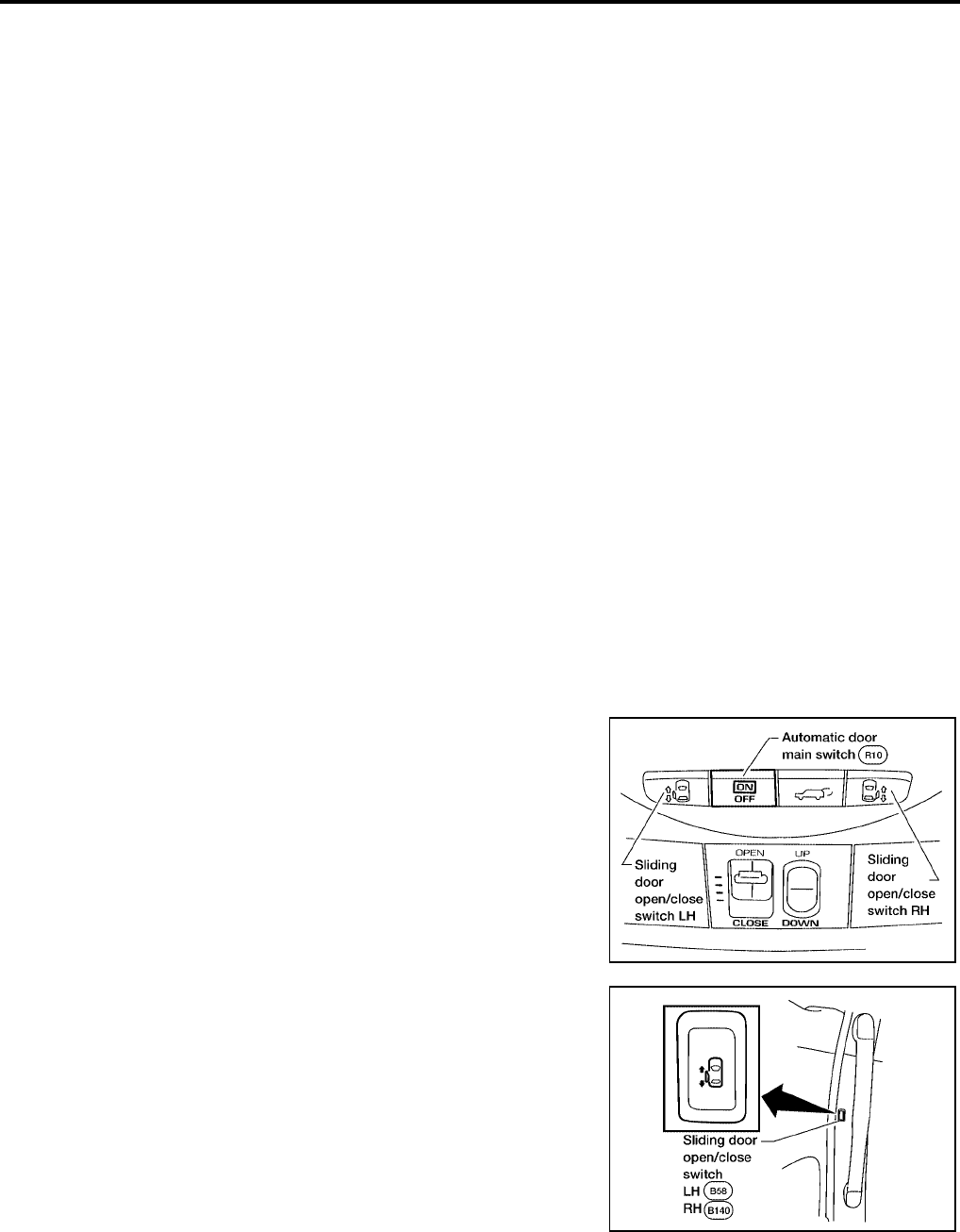
BL-120
AUTOMATIC SLIDING DOOR SYSTEM
Revision: July 2006 2006 Quest
Initialization Mode
Initialization mode is used to set the default values of door full open position and normal motor current.
It is necessary to complete initialization and reset the default settings under any of the following circum-
stances:
●Sliding door control unit is replaced.
●Sliding door motor is replaced.
●Sliding door is adjusted.
●Sliding door panel is replaced or repaired.
●Body panel near sliding door is replaced or repaired.
●Any sliding door roller is replaced or adjusted.
●Any sliding door striker is replaced or adjusted.
●Any sliding door dovetail is replaced or adjusted.
●Sliding door lock assembly is replaced.
●Rear rail is replaced.
●Sliding door weatherstrip is replaced.
●Sliding door contact switch is replaced or adjusted.
●When the battery is first connected, the sliding door control unit is automatically set to the initialization
mode.
The sliding door control unit may be manually set to initialization mode by performing the following procedure:
SLIDING DOOR INITIALIZATION PROCEDURE
NOTE:
While in initialization mode, only the overhead sliding door open/close switches are enabled. Remote keyless
entry, door pillar switch and power assist functions are disabled. Each of the power sliding doors must be ini-
tialized individually. The following procedure can be repeated for each power sliding door needing initializa-
tion.
1. Open the sliding door being initialized.
2. Turn ignition switch ON.
3. Turn the Automatic Door Main Switch OFF.
4. Within 3 seconds after step 3, press the door pillar Sliding Door
Open/Close Switch of the door being initialized 10 times within
10 seconds.
5. Within 3 seconds after step 4, turn ignition switch OFF then ON.
●You should hear three sliding door warning chimes.
●The three chimes indicate the sliding door control unit has entered initialization mode.
LIIA2178E
LIIA2179E

AUTOMATIC SLIDING DOOR SYSTEM
BL-121
C
D
E
F
G
H
J
K
L
M
A
B
BL
Revision: July 2006 2006 Quest
●Normal door functions are disabled during initialization.
6. Turn the Automatic Door Main Switch ON.
7. Press and HOLD the overhead Sliding Door Open/Close Switch
of the door being initialized until the door completely closes and
stops, then release the switch.
8. Press and HOLD the same overhead Sliding Door Open/Close Switch of the door being initialized again
until the door completely opens and stops, then release the switch.
9. Press and HOLD the same overhead Sliding Door Open/Close Switch of the door being initialized again
until the door completely closes and stops, then release the switch.
10. Turn ignition switch OFF.
The power sliding door initialization process is complete. The above procedure may be repeated for the other
power sliding door (if equipped).
SLIDING DOOR LATCH AUTO CLOSURE FUNCTION DESCRIPTION
●If the sliding door is ajar (with lock and striker engaged), the motor automatically retracts the door to fully
close it.
●During auto-close operation, if the exterior/interior handle is operated, the retraction mechanism is
mechanically cancelled, and the door can open/close.
SLIDING DOOR LATCH AUTO CLOSURE OPERATION DESCRIPTION
●If the sliding door is ajar, sliding door latch control unit terminal 8 receives the signal, supplies power from
terminal 3 to cinch latch motor terminals 1, grounds sliding door latch control unit terminal 9 from terminal
2, and rotates the cinch latch motor in the close direction.
●When the motor rotates, the cable is retracted and the close lever rotated.
●Pressed by the rotated close lever, the latch rotates and pulls in the door until it is fully latched.
●When the sliding door is fully latched, sliding door latch control unit terminal 7 receives the signal, supplies
power from terminal 9 to cinch latch motor terminal 2, grounds sliding door control unit terminals 3 from
terminal 1, and rotates the closure motor in the open direction.
●Then, when the neutral switch is pressed and the signal is received by sliding door latch control unit termi-
nal 1, it stops the cinch latch motor and stops with the door fully closed.
LIIA2178E
LIIA2178E
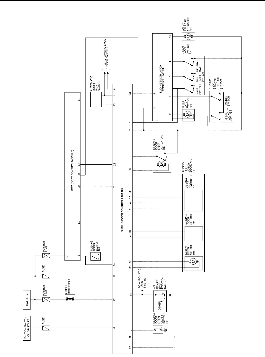
BL-122
AUTOMATIC SLIDING DOOR SYSTEM
Revision: July 2006 2006 Quest
Schematic
EIS007F0
WITH RIGHT HAND SLIDE DOOR AUTO CLOSURE SYSTEM
WIWA1125E
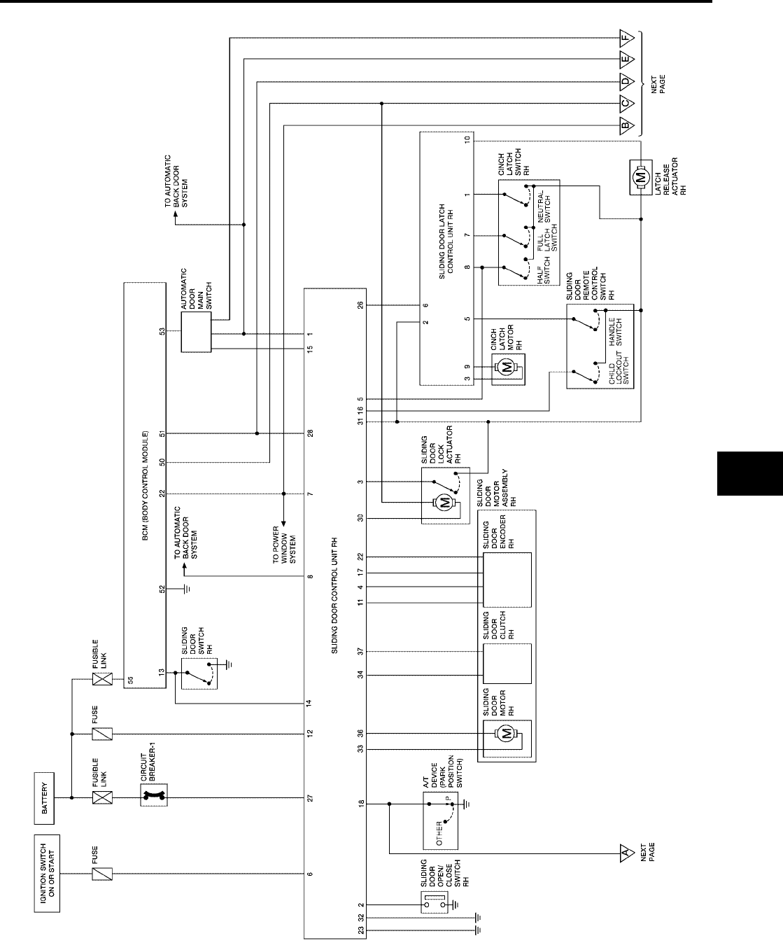
AUTOMATIC SLIDING DOOR SYSTEM
BL-123
C
D
E
F
G
H
J
K
L
M
A
B
BL
Revision: July 2006 2006 Quest
WITH RIGHT AND LEFT HAND SLIDE DOOR AUTO CLOSURE SYSTEM
WIWA1126E

BL-124
AUTOMATIC SLIDING DOOR SYSTEM
Revision: July 2006 2006 Quest
WIWA1250E
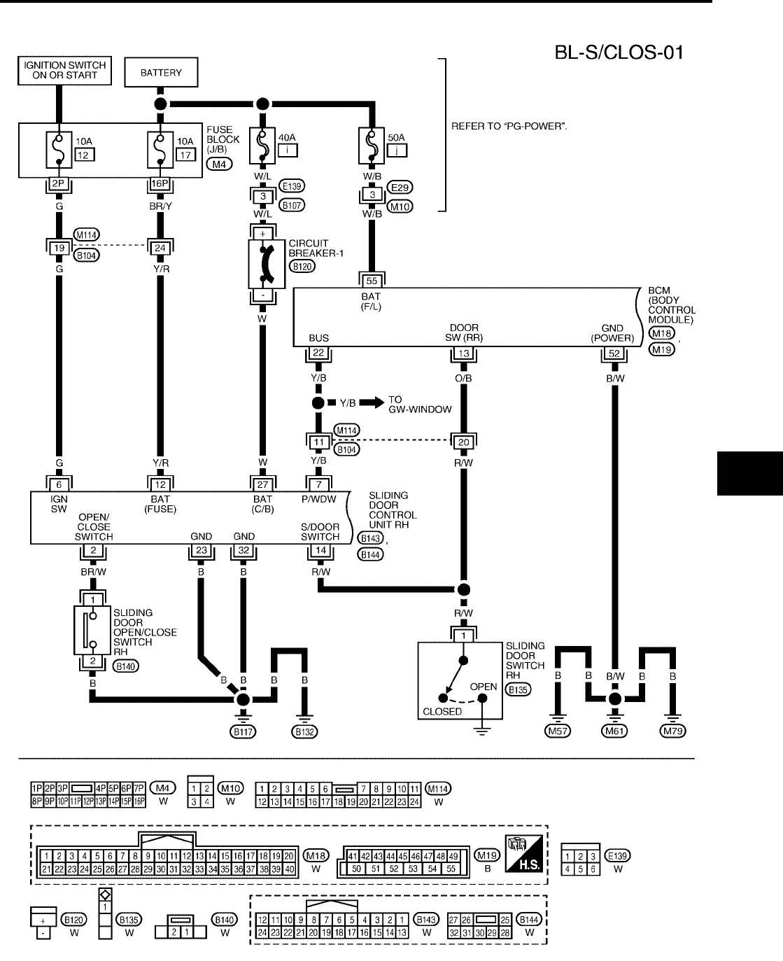
AUTOMATIC SLIDING DOOR SYSTEM
BL-125
C
D
E
F
G
H
J
K
L
M
A
B
BL
Revision: July 2006 2006 Quest
Wiring Diagram — S/CLOS —
EIS007F1
WITH RIGHT HAND SLIDE DOOR AUTO CLOSURE SYSTEM
WIWA1127E
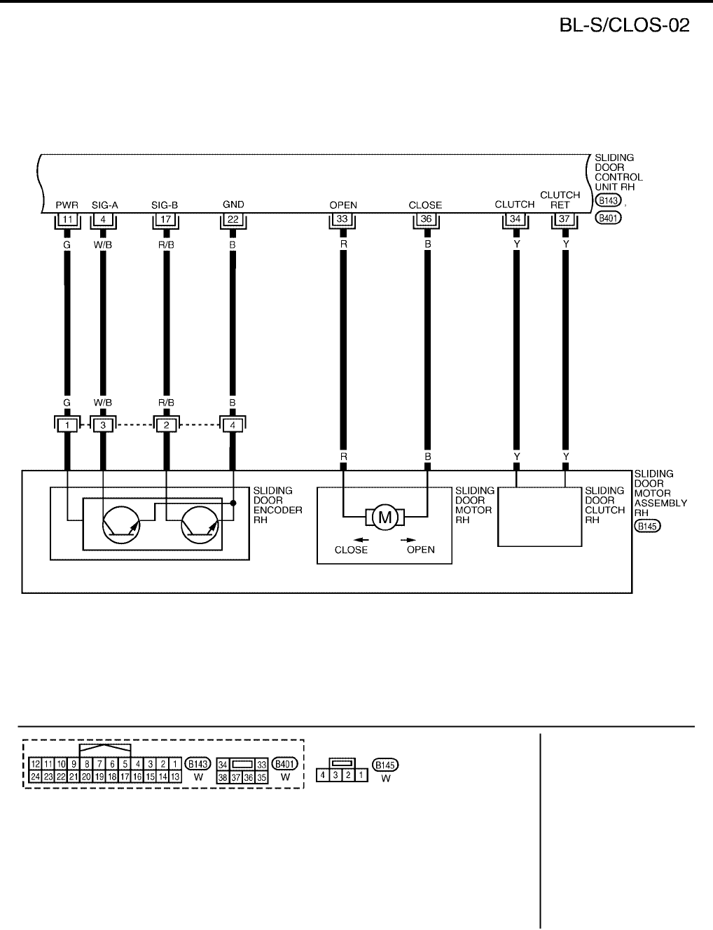
BL-126
AUTOMATIC SLIDING DOOR SYSTEM
Revision: July 2006 2006 Quest
WIWA1220E
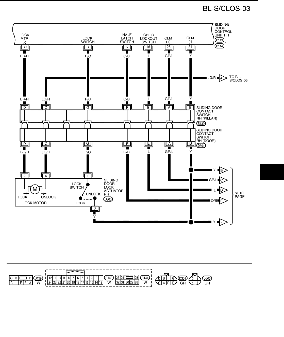
AUTOMATIC SLIDING DOOR SYSTEM
BL-127
C
D
E
F
G
H
J
K
L
M
A
B
BL
Revision: July 2006 2006 Quest
WIWA1251E
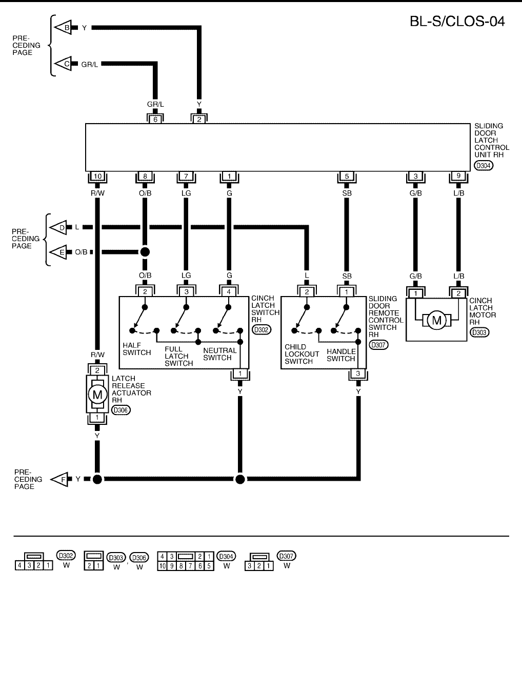
BL-128
AUTOMATIC SLIDING DOOR SYSTEM
Revision: July 2006 2006 Quest
WIWA1128E
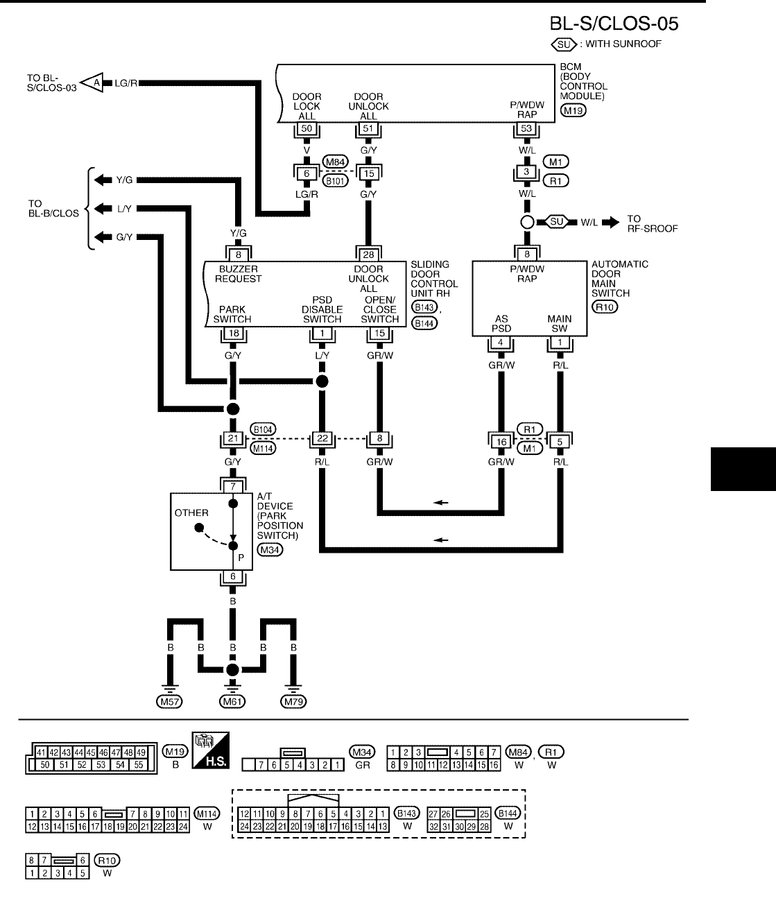
AUTOMATIC SLIDING DOOR SYSTEM
BL-129
C
D
E
F
G
H
J
K
L
M
A
B
BL
Revision: July 2006 2006 Quest
WIWA1129E
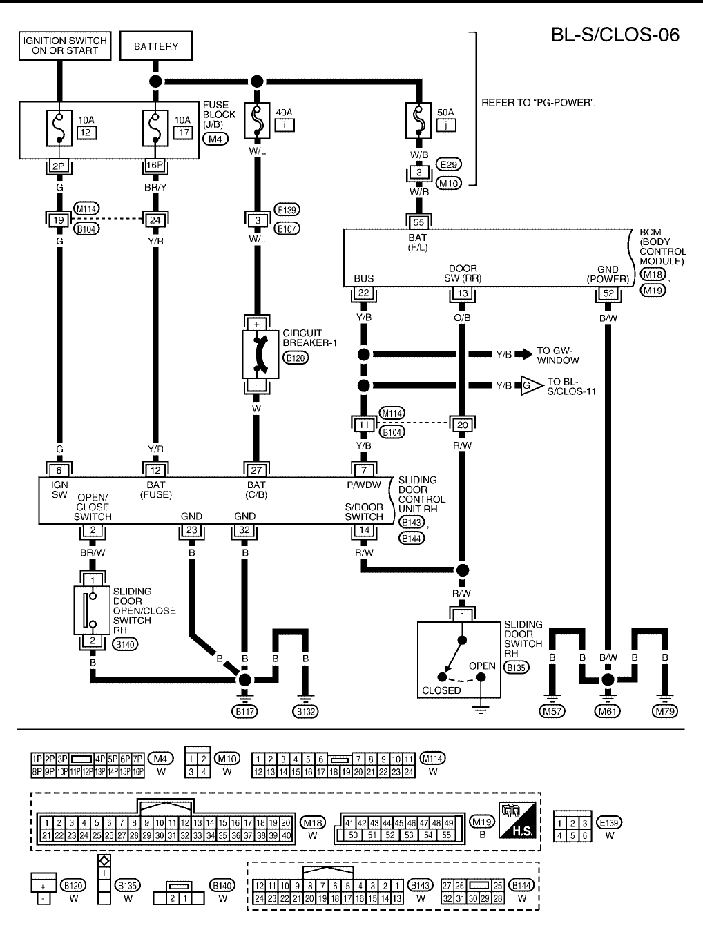
BL-130
AUTOMATIC SLIDING DOOR SYSTEM
Revision: July 2006 2006 Quest
WITH RIGHT AND LEFT HAND SLIDE DOOR AUTO CLOSURE SYSTEM
WIWA1130E
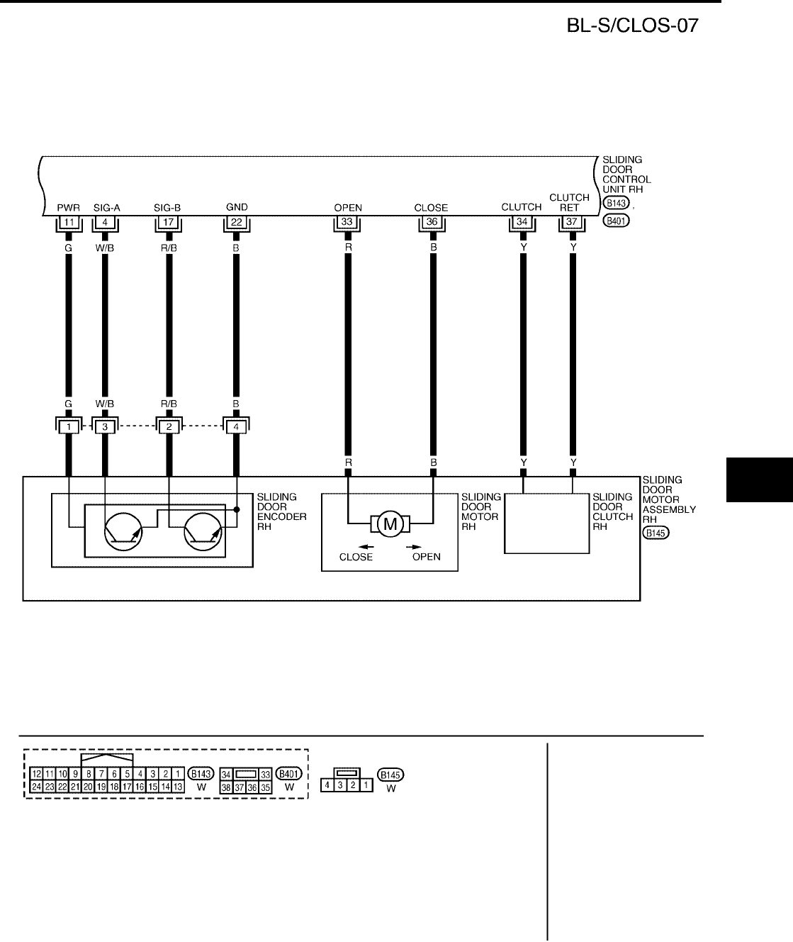
AUTOMATIC SLIDING DOOR SYSTEM
BL-131
C
D
E
F
G
H
J
K
L
M
A
B
BL
Revision: July 2006 2006 Quest
WIWA1218E
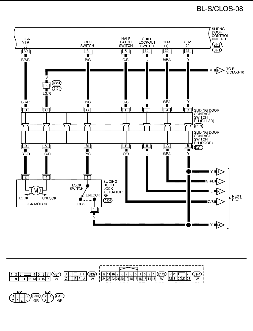
BL-132
AUTOMATIC SLIDING DOOR SYSTEM
Revision: July 2006 2006 Quest
WIWA1252E
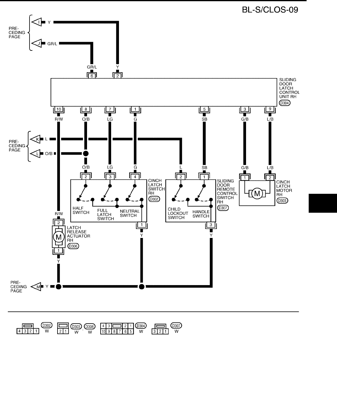
AUTOMATIC SLIDING DOOR SYSTEM
BL-133
C
D
E
F
G
H
J
K
L
M
A
B
BL
Revision: July 2006 2006 Quest
WIWA1131E
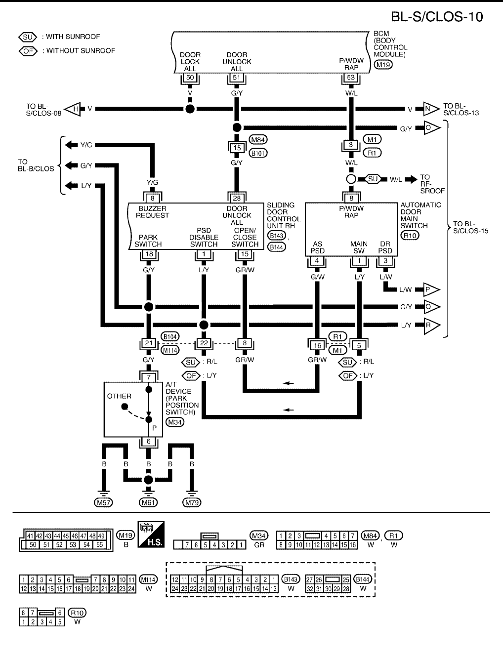
BL-134
AUTOMATIC SLIDING DOOR SYSTEM
Revision: July 2006 2006 Quest
WIWA1132E
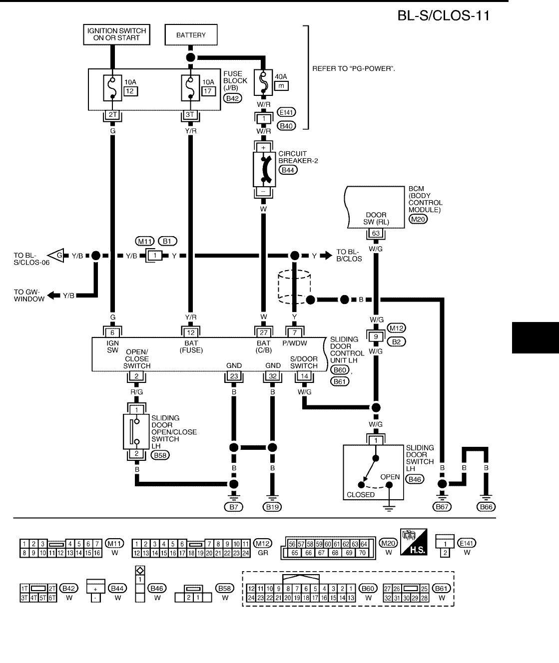
AUTOMATIC SLIDING DOOR SYSTEM
BL-135
C
D
E
F
G
H
J
K
L
M
A
B
BL
Revision: July 2006 2006 Quest
WIWA1133E
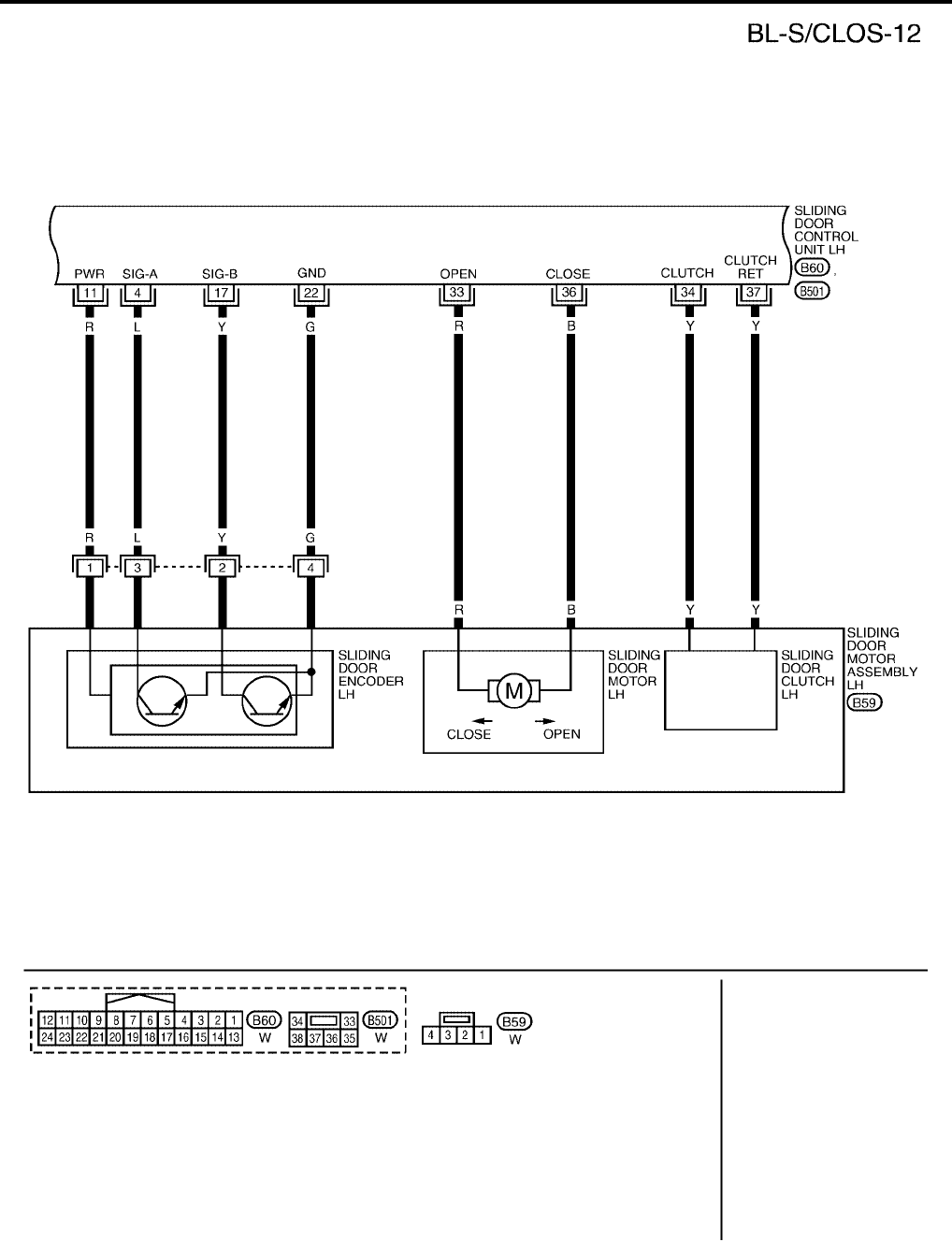
BL-136
AUTOMATIC SLIDING DOOR SYSTEM
Revision: July 2006 2006 Quest
WIWA1219E
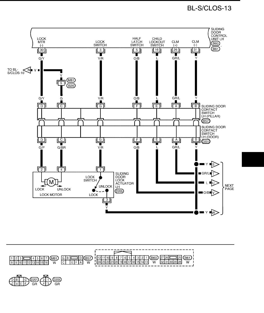
AUTOMATIC SLIDING DOOR SYSTEM
BL-137
C
D
E
F
G
H
J
K
L
M
A
B
BL
Revision: July 2006 2006 Quest
WIWA1253E
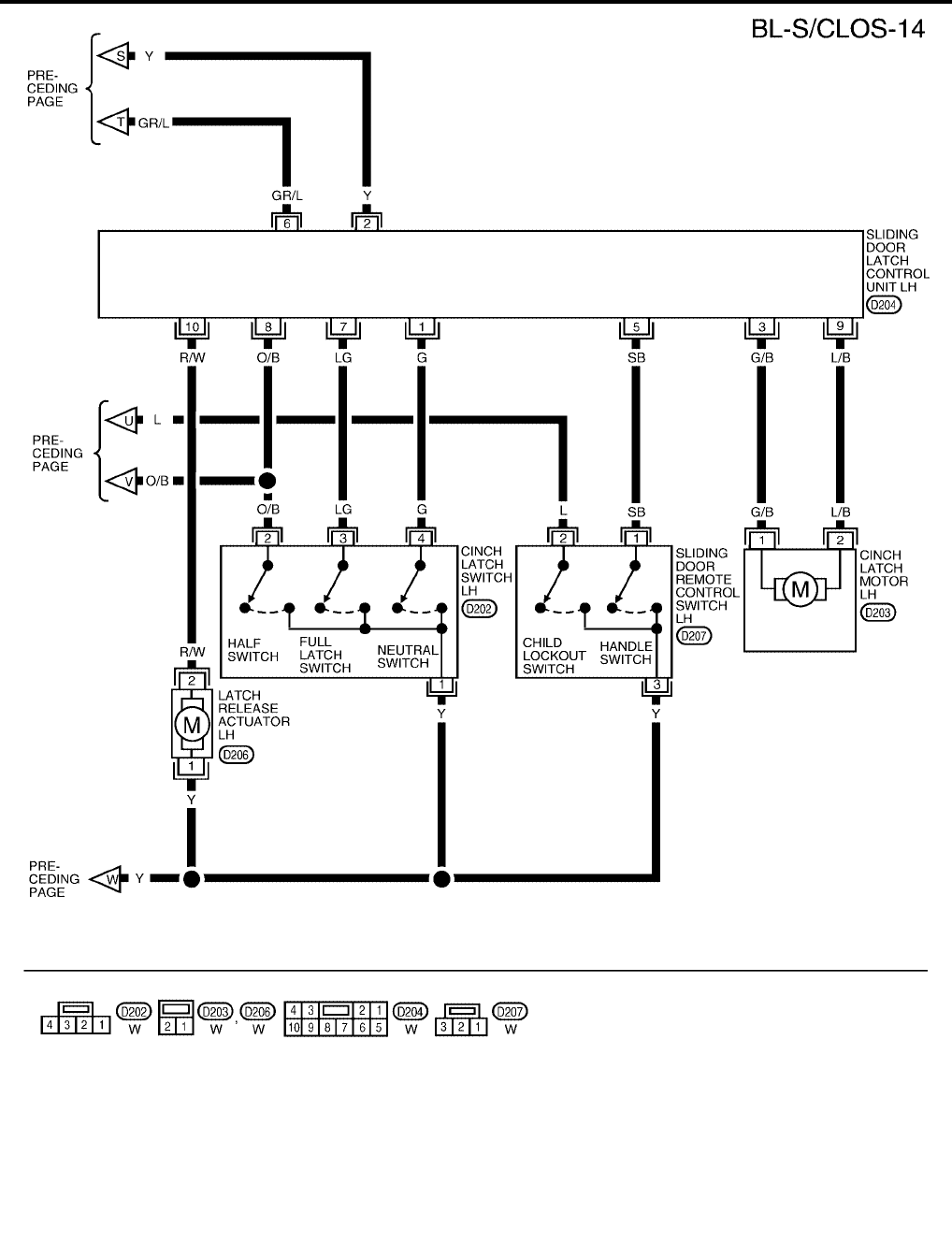
BL-138
AUTOMATIC SLIDING DOOR SYSTEM
Revision: July 2006 2006 Quest
WIWA1134E
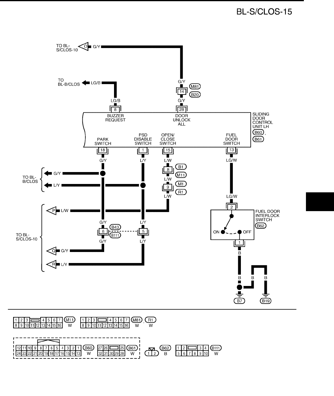
AUTOMATIC SLIDING DOOR SYSTEM
BL-139
C
D
E
F
G
H
J
K
L
M
A
B
BL
Revision: July 2006 2006 Quest
WIWA1254E
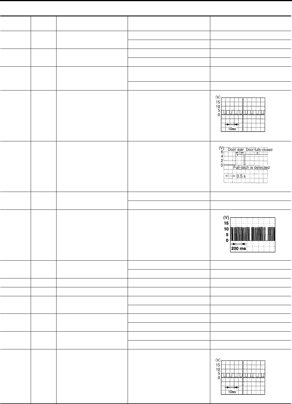
BL-140
AUTOMATIC SLIDING DOOR SYSTEM
Revision: July 2006 2006 Quest
Terminals and Reference Value for Sliding Door Control Unit RH
EIS007F2
Terminal Wire
Color Item Condition Voltage (V)
(Approx.)
1L/Y
Automatic door main switch
ON/OFF switch
Automatic door main switch ON 0
Automatic door main switch OFF 5
2 BR/W Sliding door open/close switch Sliding door open/close switch ON 0
Sliding door open/close switch OFF 5
3P/G
Sliding door lock/unlock actua-
tor unlock output signal
Power door lock switch
door unlock operation 0 → Battery voltage → 0
Other than above 0
4 W/B Encoder pulse signal A Sliding door (motor active)
5 O/B Half-latch switch Sliding door
Fully open → half → fully closed
6 G Ignition switch Ignition switch ON Battery voltage
Ignition switch OFF 0
7 Y/B Power window serial link When ignition switch is ON or power
window timer operates
8 Y/G Warning chime output signal Warning chime ON 0
Warning chime OFF Battery voltage
11 G Encoder power supply —9
12 Y/R Battery power supply —Battery voltage
14 R/W Sliding door switch OPEN 0
CLOSED 5
15 GR/W Automatic door main switch ON 0
OFF 5
16 L Child lockout switch ACTIVE 5
INACTIVE 0
17 R/B Encoder pulse signal B Sliding door (motor active)
Battery voltage
PIIA1060E
PIIA2169E
PIIA2344E
PIIA1060E
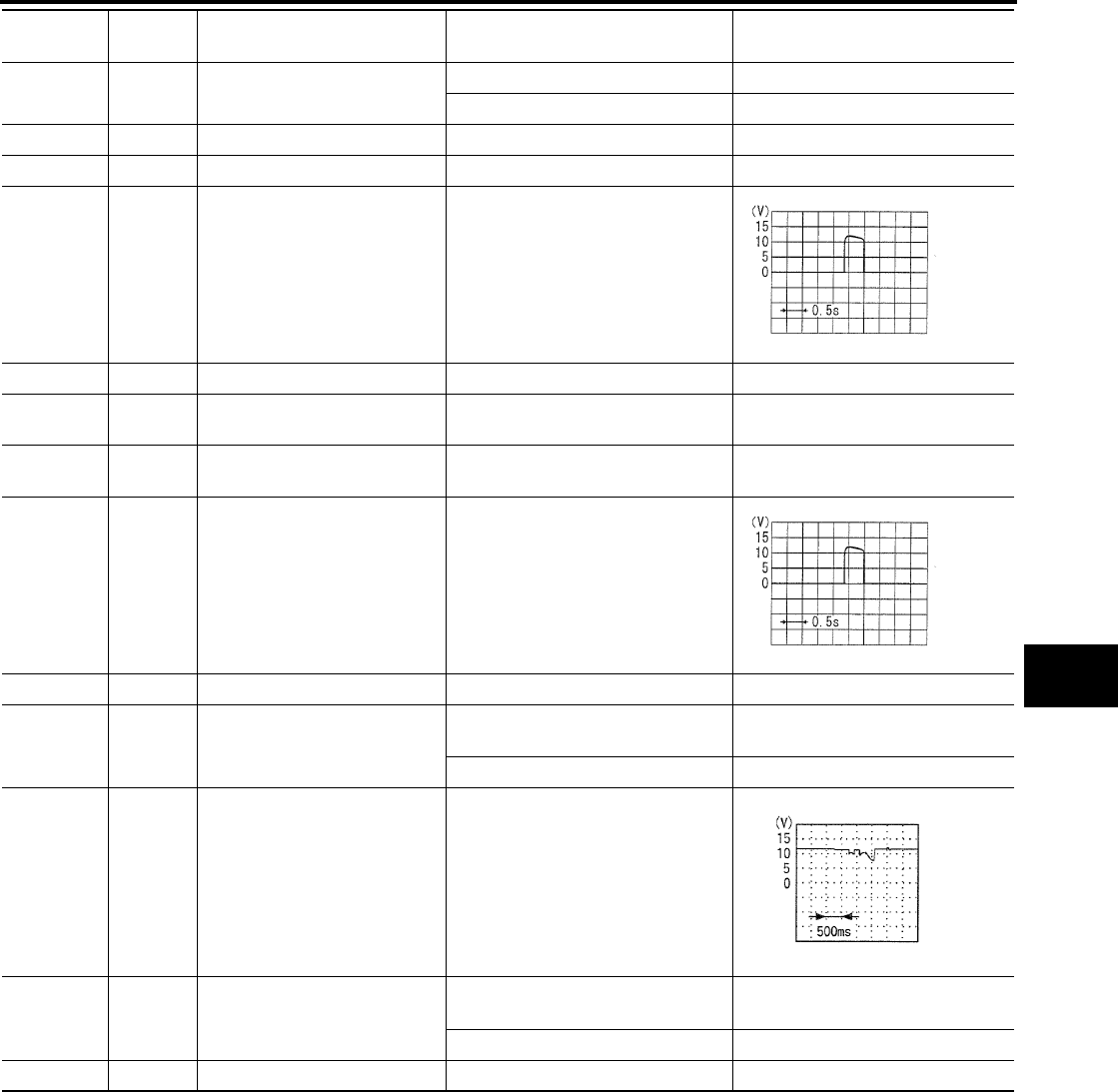
AUTOMATIC SLIDING DOOR SYSTEM
BL-141
C
D
E
F
G
H
J
K
L
M
A
B
BL
Revision: July 2006 2006 Quest
18 G/Y A/T device (park position
switch)
P position 0
Other than above 5
22 B Encoder ground ——
23 B Ground ——
26 GR/L Closure motor
CLOSE output signal
Sliding door
Fully open → half → fully closed
27 W Battery power supply —Battery voltage
28 G/Y Door unlock input Door lock & unlock switch
(Neutral → Unlock) 0 → Battery voltage
30 BR/R Sliding door lock motor unlock
signal
Door lock
(Neutral → Unlock) 0 → Battery voltage
31 Y Closure motor
RETURN output signal
Sliding door
Fully open→ half → fully closed
32 B Ground ——
33 R Sliding door motor
OPEN output signal
Sliding door auto OPEN operation
(motor active) Battery voltage
Other than above 0
34 Y Magnetic clutch power supply Auto sliding door
(motor active)
Battery voltage → 0
36 B Sliding door motor
CLOSE output signal
Sliding door auto CLOSE operation
(motor active) Battery voltage
Other than above 0
37 Y Magnetic clutch ground — —
Terminal Wire
Color Item Condition Voltage (V)
(Approx.)
SIIA1480E
SIIA1480E
PIIA1798E
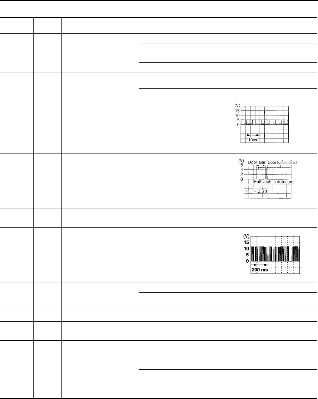
BL-142
AUTOMATIC SLIDING DOOR SYSTEM
Revision: July 2006 2006 Quest
Terminals and Reference Value for Sliding Door Control Unit LH
EIS007F3
Terminal Wire
Color Item Condition Voltage (V)
(Approx.)
1L/Y
Automatic door main switch
ON/OFF switch
Automatic door main switch ON 0
Automatic door main switch OFF 5
2 R/G Sliding door open/close switch Sliding door open/close switch ON 0
Sliding door open/close switch OFF 5
3Y/R
Sliding door lock/unlock actua-
tor unlock output signal
Power door lock switch
door unlock operation 0 → Battery voltage → 0
Other than above 0
4 L Encoder pulse signal A Sliding door (motor active)
5 O/B Half-latch switch Sliding door
Fully open → half → fully closed
6 G Ignition switch Ignition switch ON Battery voltage
Ignition switch OFF 0
7 Y Power window serial link When ignition switch is ON or power
window timer operates
8 LG/B Warning chime output signal Warning chime ON 0
Warning chime OFF Battery voltage
11 R Encoder power supply —9
12 Y/R Battery power supply —Battery voltage
13 LG/W Fuel door interlock switch Fuel door closed 0
Fuel door open 5
14 W/G Sliding door switch OPEN 0
CLOSED 5
15 L/W Automatic door main switch ON 0
OFF 5
16 L Child lockout switch ACTIVE 5
INACTIVE 0
PIIA1060E
PIIA2169E
PIIA2344E
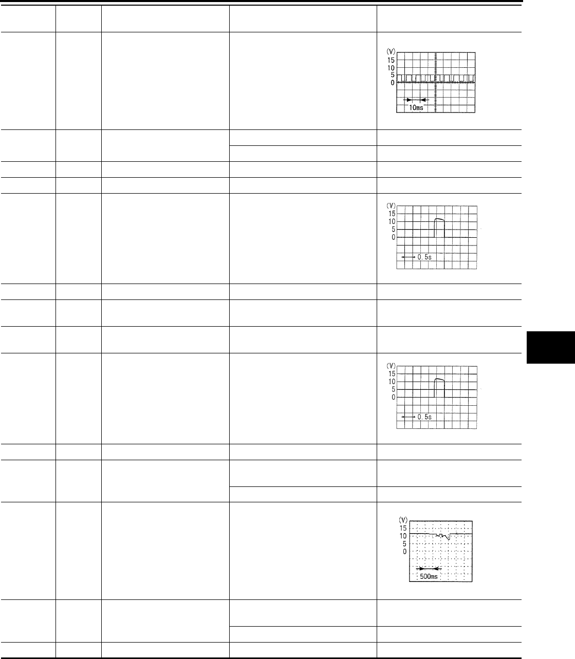
AUTOMATIC SLIDING DOOR SYSTEM
BL-143
C
D
E
F
G
H
J
K
L
M
A
B
BL
Revision: July 2006 2006 Quest
17 Y Encoder pulse signal B Sliding door (motor active)
Battery voltage
18 G/Y A/T device (park position
switch)
P position 0
Other than above 5
22 G Encoder ground ——
23 B Ground ——
26 GR/L Closure motor
CLOSE output signal
Sliding door
Fully open → half → fully closed
27 W Battery power supply —Battery voltage
28 G/Y Door unlock input Door lock & unlock switch
(Neutral → Unlock) 0 → Battery voltage
30 G/Y Sliding door lock motor unlock
signal
Door lock
(Neutral → Unlock) 0 → Battery voltage
31 Y Closure motor
RETURN output signal
Sliding door
Fully open→ half → fully closed
32 B Ground ——
33 R Sliding door motor
OPEN output signal
Sliding door auto OPEN operation
(motor active) Battery voltage
Other than above 0
34 Y Magnetic clutch power supply Auto sliding door
(Motor active)
Battery voltage → 0
36 B Sliding door motor
CLOSE output signal
Sliding door auto CLOSE operation
(motor active) Battery voltage
Other than above 0
37 Y Magnetic clutch ground — —
Terminal Wire
Color Item Condition Voltage (V)
(Approx.)
PIIA1060E
SIIA1480E
SIIA1480E
PIIA1798E
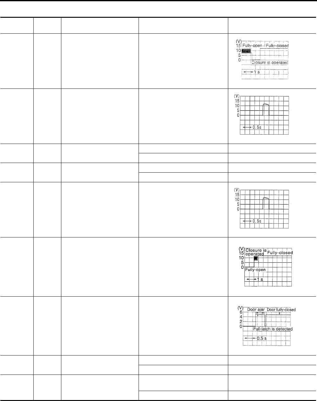
BL-144
AUTOMATIC SLIDING DOOR SYSTEM
Revision: July 2006 2006 Quest
Terminals and Reference Value for Sliding Door Latch Control Unit
EIS007F4
Terminal Wire
Color Item Condition Voltage (V)
(Approx.)
1 G Neutral switch signal Sliding door
Fully open→ half → fully closed
2Y
Cinch latch motor RETURN
signal
Sliding door
Fully open→ half → fully closed
3 G/B Cinch latch motor CLOSE out-
put
Latch Open (ON) → Close (OFF) Battery voltage → 0
Other than above 0
5 SB Handle switch (open) signal Handle operation 0
Other than above 5
6GR/L
Cinch latch motor CLOSE sig-
nal
Sliding door
Fully open→ half → fully closed
7 LG Full-latch switch signal Sliding door
Fully open→ half → fully closed
8 O/B Half-latch switch signal Sliding door
Fully open→ half → fully closed
9L/B
Cinch latch motor OPEN out-
put
Latch Close (OFF) → Open (ON) Battery voltage → 0
Other than above 0
10 R/W Latch release actuator output
Latch
(Lock → Unlock) Battery voltage → 0
Other than above 0
PIIA2170E
SIIA1480E
SIIA1480E
PIIA2171E
PIIA2169E

AUTOMATIC SLIDING DOOR SYSTEM
BL-145
C
D
E
F
G
H
J
K
L
M
A
B
BL
Revision: July 2006 2006 Quest
Terminals and Reference Value for BCM
EIS007F5
*: with LH slide door auto closure system.
Terminal Wire
Color Item Condition Voltage (V)
(Approx.)
13 O/B Sliding door switch RH Door Close (OFF) → Open (ON) Battery voltage → 0
22 Y/B Bus When ignition switch is ON or power
window timer operates
50 V Door lock actuators Door lock & unlock switch
(Neutral → Lock) 0 → Battery voltage
51 G/Y Passenger and sliding doors
lock actuator
Door lock & unlock switch
(Neutral → Unlock) 0 → Battery voltage
52 B/W Ground —0
53 W/L Power window power source —Battery voltage
55 W/B Battery power supply —Battery voltage
63* W/G Sliding door switch LH Door Close (OFF) → Open (ON) Battery voltage → 0
PIIA2344E

BL-146
AUTOMATIC SLIDING DOOR SYSTEM
Revision: July 2006 2006 Quest
Trouble Diagnosis Procedure
EIS007F6
1. Check the symptom and customer's requests.
2. Understand outline of system. Refer to BL-114, "System Description" .
3. Confirm system operation.
4. Perform self-diagnosis procedures. Refer to BL-146, "Self-Diagnosis Procedures" .
5. Refer to diagnosis chart by symptom, repair or replace any malfunctioning parts. Refer to BL-148, "Diag-
nosis Chart" .
6. Inspection End.
Self-Diagnosis Procedures
EIS007F7
INPUT SIGNAL CHECK MODE
Input signal check mode allows testing of switch input signal to the sliding door control unit.
To activate input signal check mode on the automatic sliding door, perform the following steps:
1. Turn ignition switch OFF.
2. Turn automatic door main switch OFF (system cancelled).
3. Place A/T selector lever in P position.
4. Confirm fuel door closed (with LH sliding door).
5. Open sliding door RH or LH manually.
6. Have an assistant press and hold the sliding door open/close switch RH or LH.
7. While the assistant continues to hold the sliding door open/close switch RH or LH, turn ignition switch ON
(DO NOT start engine).
8. After approximately 5 seconds, the back door warning chime will sound for 0.5 seconds.
9. Release the sliding door open/close switch RH or LH.
10. Within 8 seconds of the back door warning chime sounding, press and hold the automatic door main slid-
ing door open/close switch RH or LH.
11. After approximately 5 seconds, the back door warning chime will sound for 1 second.
12. Release the automatic door main sliding door open/close switch RH or LH.
13. The input signal check mode is now initialized.
The input signal check mode can test the following inputs. The back door warning chime will sound for approx-
imately 0.5 seconds each time a switch signal input occurs. Use this test when one of these inputs is not
responding during normal automatic sliding door operation.
*Back door warning chime should sound as soon as vehicle moves.
Turn ignition switch OFF to end input signal check mode.
OPERATING CHECK MODE
Operating check mode allows self-diagnosis of the automatic sliding door system.
To activate operating check mode on the automatic sliding door, perform the following steps:
1. Turn ignition switch OFF.
2. Turn automatic door main switch OFF (system cancelled).
Switch signal Operation Refer to
Automatic door main switch OFF → ON BL-149
Automatic door main sliding door open/close switch RH or LH OFF → ON BL-149
Sliding door open/close switch RH or LH OFF → ON BL-150
Sliding door switch RH or LH OFF (door closed) → ON (door open) BL-76
A/T device (park position switch) P position → other than P position SE-76
Fuel door interlock switch OFF (fuel door closed) → ON (fuel door open) BL-208
Sliding door lock/unlock signal LOCK → UNLOCK BL-154
Vehicle speed* Vehicle speed BL-55
Remote keyless entry signal Keyfob switch OFF → ON BL-80
Door lock/unlock signal LOCK → UNLOCK BL-76

AUTOMATIC SLIDING DOOR SYSTEM
BL-147
C
D
E
F
G
H
J
K
L
M
A
B
BL
Revision: July 2006 2006 Quest
3. Place A/T selector lever in P position.
4. Open sliding door RH or LH manually.
5. Have an assistant press and hold the sliding door open/close switch RH or LH.
6. While the assistant continues to hold the sliding door open/close switch RH or LH, turn ignition switch ON
(DO NOT start engine).
7. After approximately 5 seconds, the back door warning chime will sound for 0.5 seconds.
8. Release the sliding door open/close switch RH or LH.
9. Within 8 seconds of the back door warning chime sounding, press the automatic door main sliding door
open/close switch RH or LH 5 times in rapid succession.
10. After approximately 5 seconds, the back door warning chime will sound for 1 second.
11. Release the automatic door main sliding door open/close switch RH or LH.
12. Immediately close the sliding door RH or LH manually.
13. Turn automatic door main switch ON.
14. Open and close the back door with the automatic door main sliding door open/close switch RH or LH to
activate operating check mode.
Self-diagnosis results are indicated by the back door warning chime.
Turn ignition switch OFF to end input signal check mode.
Back door warning chime order Back door warning chime length
Start self-diagnosis 1.5 seconds
OK NG
1. Operating conditions diagnosis 0.5 seconds 0.2 seconds
2. Sliding door encoder diagnosis 0.5 seconds 0.2 seconds
3. Sliding door clutch diagnosis 0.5 seconds 0.2 seconds
4. Sliding door motor diagnosis 0.5 seconds 0.2 seconds
5. Cinch latch motor diagnosis 0.5 seconds 0.2 seconds
Restart self-diagnosis 1.5 seconds
Item NG Result Refer to
1. Operating conditions diagnosis result
One of the following operating conditions no
longer met: ignition switch ON, automatic door
main switch ON, A/T selector lever in P posi-
tion
—
2. Sliding door encoder diagnosis result Sensor diagnosis/short, pulse signal, pulse
signal direction BL-152
3. Sliding door clutch diagnosis result Sliding door clutch does not operate BL-152
4. Sliding door motor diagnosis result Sliding door motor does not operate (no oper-
ating current) BL-151
5. Cinch latch motor diagnosis result Cinch latch motor does not operate (no oper-
ating current) BL-160

BL-148
AUTOMATIC SLIDING DOOR SYSTEM
Revision: July 2006 2006 Quest
Diagnosis Chart
EIS007F8
Symptom Suspect systems Refer to
Automatic operations are not executed from the sliding door fully
closed or fully open position.
(Auto open/close operations from a position midway through
automatic operation, power assist, and auto closure operate nor-
mally.)
Latch release actuator system inspection BL-156
Automatic operations are not carried out together with open/close
operations.
(Manual operations are normal.)
Automatic door main switch system inspection BL-149
Sliding door open/close switch system inspec-
tion BL-150
Magnetic clutch line check BL-152
Auto sliding door power supply and ground cir-
cuit system inspection. BL-149
Power window serial link. Power window main switch BL-145
Stops midway through sliding door open/close operations, power
assist does not operate. Encoder system inspection BL-152
Warning chime does not sound. Warning chime system inspection BL-157
During auto closing operations, if obstruction is detected, the
door does not operate in reverse. Encoder system inspection BL-152
During cinching operations, the door does not operate in reverse
if the sliding door handle is operated. Handle switch system BL-154
Child lockout system does not operate. Child lockout switch system inspection BL-155
When the keyfob is operated, the sliding door does not operate
automatically. Remote keyless entry system inspection BL-55
Auto closure does not operate.
Half-latch switch system BL-157
Cinch latch motor system BL-160
Handle switch system BL-154
Contact switch —
The sliding door does not open.
(Closure motor rotation is not reversed.)
Neutral switch system BL-159
Full-latch switch BL-158
Handle switch system BL-154
Door switch BL-44
Auto closure operation works, but the sliding door is not fully
closed.
Full-latch switch system BL-158
Handle switch system BL-154
Cinch latch motor system BL-160
Sliding door latch assembly mechanism dam-
aged or worn. BL-156
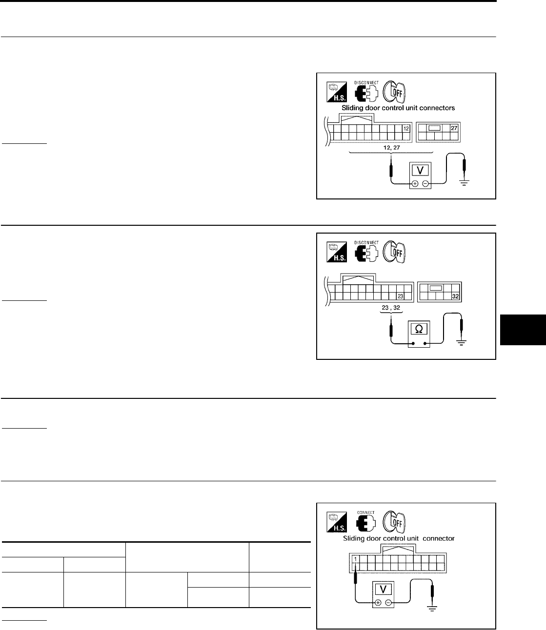
AUTOMATIC SLIDING DOOR SYSTEM
BL-149
C
D
E
F
G
H
J
K
L
M
A
B
BL
Revision: July 2006 2006 Quest
Auto Sliding Door Power Supply and Ground Circuit Inspection
EIS007F9
1. AUTO SLIDING DOOR POWER SUPPLY CIRCUIT INSPECTION
1. Turn ignition switch OFF.
2. Disconnect sliding door control unit.
3. Check voltage between sliding door control unit connectors B60,
B61 (LH) or B143, B144 (RH) terminals 12, 27 and ground.
OK or NG
OK >> GO TO 2.
NG >> Repair the sliding door control unit power supply circuit.
2. AUTO SLIDING DOOR GROUND CIRCUIT INSPECTION
Check continuity between sliding door control unit connectors B60,
B61 (LH) or B143, B144 (RH) terminals 23, 32 and ground.
OK or NG
OK >> Ground circuit is OK.
NG >> Repair or replace harness.
Automatic Door Main Switch System Inspection
EIS007FA
1. AUTOMATIC DOOR MAIN SWITCH FUNCTION INSPECTION
Check automatic door main switch using switch operation.
OK or NG
OK >> Automatic door main switch is OK.
NG >> GO TO 2.
2. AUTOMATIC DOOR MAIN SWITCH SIGNAL INSPECTION
1. Turn ignition switch OFF.
2. While operating the automatic door main switch, check voltage
between sliding door control unit connector B60 (LH) or B143
(RH) terminal 1 and ground.
OK or NG
OK >> Automatic door main switch is OK.
NG >> GO TO 3.
12 - Ground : Approx. battery voltage
27 - Ground : Approx. battery voltage
LIIA0751E
23 - Ground : Continuity should exist.
32 - Ground : Continuity should exist.
WIIA0816E
Terminal Measuring condition Voltage (V)
(Approx.)
( + ) ( - )
1 Ground
Automatic
door main
switch
ON 0
OFF 5
LIIA0753E
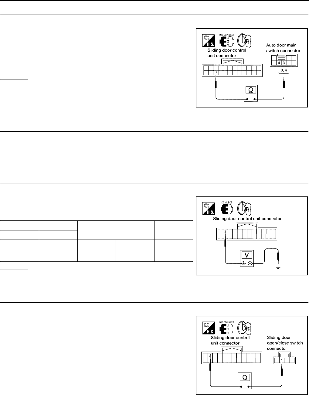
BL-150
AUTOMATIC SLIDING DOOR SYSTEM
Revision: July 2006 2006 Quest
3. AUTOMATIC DOOR MAIN SWITCH CIRCUIT INSPECTION
1. Disconnect automatic door main switch and sliding door control unit.
2. Check continuity between automatic door main switch connector
R10 terminals 3 (LH) or 4 (RH) and sliding door control unit con-
nector B60 (LH) or B143 (RH) terminal 15.
OK or NG
OK >> Replace automatic door main switch.
NG >> Repair or replace harness.
Sliding Door Open/Close Switch System Inspection
EIS007FB
1. SLIDING DOOR OPEN/CLOSE SWITCH FUNCTION INSPECTION
Check sliding door open/close switch using switch operation.
OK or NG
OK >> Sliding door open/close switch is OK.
NG >> GO TO 2.
2. SLIDING DOOR OPEN/CLOSE SWITCH SIGNAL INSPECTION
1. Turn ignition switch OFF.
2. While operating the sliding door open/close switch, check volt-
age between sliding door control unit connector B60 (LH) or
B143 (RH) terminal 2 and ground.
OK or NG
OK >> Sliding door open/close switch is OK.
NG >> GO TO 3.
3. SLIDING DOOR OPEN/CLOSE SWITCH CIRCUIT INSPECTION
1. Disconnect sliding door open/close switch and sliding door control unit.
2. Check continuity between sliding door open/close switch con-
nector B58 (LH) or B140 (RH) terminal 1 and sliding door control
unit connector B60 (LH) or B143 (RH) terminal 2.
OK or NG
OK >> GO TO 4.
NG >> Repair or replace harness.
3 - 15 : Continuity should exist.
4 - 15 : Continuity should exist.
LIIA0754E
Terminal Measuring condition Voltage (V)
(Approx.)
( + ) ( - )
2 Ground
Automatic
door main
switch
ON 0
OFF 5
LIIA0755E
1 - 2 : Continuity should exist.
LIIA1635E
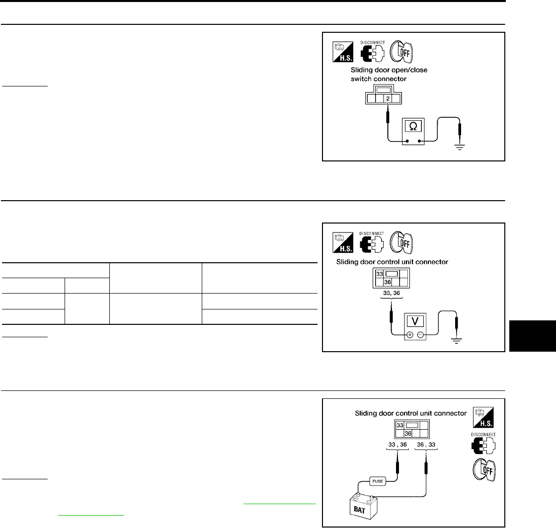
AUTOMATIC SLIDING DOOR SYSTEM
BL-151
C
D
E
F
G
H
J
K
L
M
A
B
BL
Revision: July 2006 2006 Quest
4. SLIDING DOOR OPEN/CLOSE SWITCH GROUND INSPECTION
Check continuity between sliding door open/close switch connector
B58 (LH) or B140 (RH) terminal 2 and ground.
OK or NG
OK >> Replace the sliding door open/close switch.
NG >> Repair or replace harness.
Sliding Door Motor System Inspection
EIS007FC
1. SLIDING DOOR MOTOR SIGNAL INSPECTION
1. Turn ignition switch OFF.
2. Operate the sliding door fully open → fully closed and check
voltage between sliding door control unit connector B501 (LH) or
B401 (RH) terminals 33, 36 and ground.
OK or NG
OK >> GO TO 2.
NG >> Replace sliding door control unit.
2. SLIDING DOOR MOTOR OPERATION INSPECTION
Connect battery power to terminals 33 and 36 on the sliding door
control unit connector B501 (LH) or B401 (RH) and check motor
operation.
OK or NG
OK >> Motor is OK.
NG >> Replace the sliding door motor. Refer to BL-200, "SLIDE
DOOR LOCK" .
2 - Ground : Continuity should exist.
LIIA0758E
Terminal Measuring condition Voltage (V)
(Approx.)
( + ) ( - )
33 Ground Fully open → half →
fully closed
0
36 0 → Battery voltage → 0
LIIA0761E
33 (+) - 36 (-) : It operates.
33 (-) - 36 (+) : It operates. (Reverse rotation)
WIIA0379E
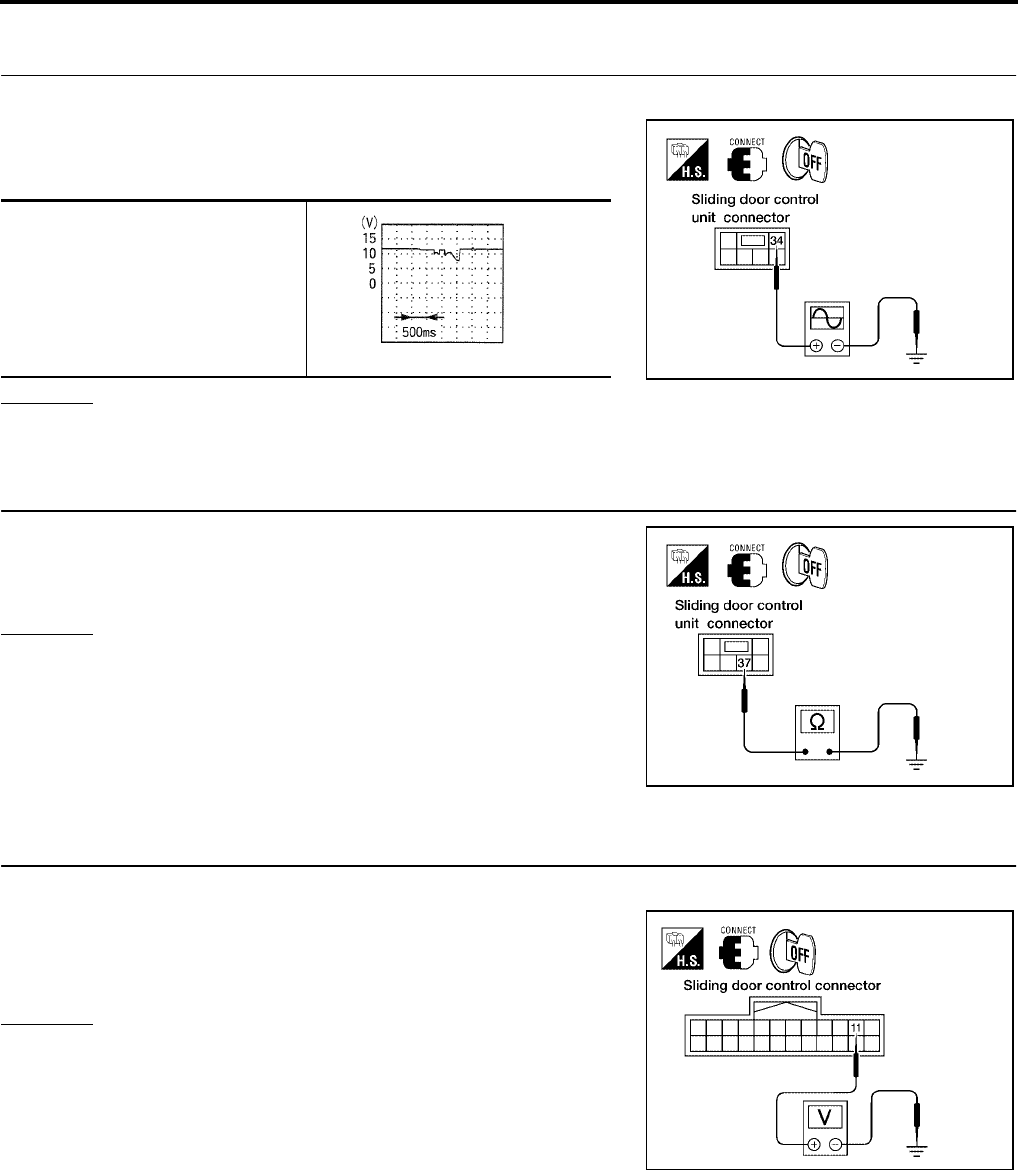
BL-152
AUTOMATIC SLIDING DOOR SYSTEM
Revision: July 2006 2006 Quest
Magnetic Clutch Line Check
EIS007FD
1. MAGNETIC CLUTCH SIGNAL INSPECTION
1. Turn ignition switch OFF.
2. Operate the sliding door and check voltage waveform between
sliding door control unit connector B501 (LH) or B401 (RH) ter-
minal 34 and ground using an oscilloscope.
OK or NG
OK >> GO TO 2.
NG >> Replace sliding door control unit.
2. MAGNETIC CLUTCH GROUND CIRCUIT INSPECTION
Check continuity between sliding door control unit connector B501
(LH) or B401 (RH) terminal 37 and ground.
OK or NG
OK >> Clutch circuit is OK.
NG >> Repair or replace harness.
Sliding Door Encoder System Inspection
EIS007FE
1. SLIDING DOOR ENCODER POWER SUPPLY CIRCUIT INSPECTION
1. Turn ignition switch OFF.
2. Check voltage between sliding door control unit connector B60
(LH) or B143 (RH) terminal 11 and ground.
OK or NG
OK >> GO TO 3.
NG >> GO TO 2.
34 - Ground
LIIA0762E
PIIA1798E
37 - Ground : Continuity should exist.
LIIA0763E
11 - Ground : Approx. 9V
LIIA0764E
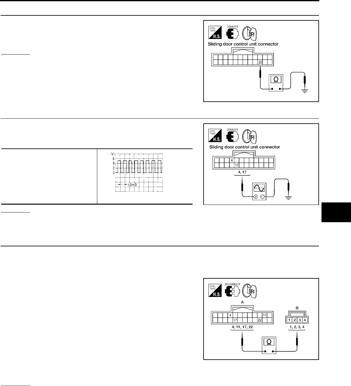
AUTOMATIC SLIDING DOOR SYSTEM
BL-153
C
D
E
F
G
H
J
K
L
M
A
B
BL
Revision: July 2006 2006 Quest
2. SLIDING DOOR ENCODER GROUND CIRCUIT INSPECTION
Check continuity between sliding door control unit connector B60
(LH) or B143 (RH) terminal 22 and ground.
OK or NG
OK >> GO TO 4.
NG >> Replace sliding door control unit.
3. ENCODER (POSITION) SIGNAL INSPECTION
Operate the sliding door and check voltage waveform between slid-
ing door control unit connector B60 (LH) or B143 (RH) terminals 4,
17 and ground using an oscilloscope.
OK or NG
OK >> GO TO 4.
NG >> Replace sliding door encoder.
4. SLIDING DOOR ENCODER CIRCUIT INSPECTION
1. Disconnect sliding door control unit and sliding door motor assembly.
2. Check continuity between sliding door control unit connector B60 (LH) or B143 (RH) (A) terminals 4, 11,
17, 22 and sliding door motor assembly connector B59 (LH) or B145 (RH) (B) terminals 1, 2, 3, 4.
Sliding Door RH
Sliding Door LH
OK or NG
OK >> Sliding door encoder circuit is OK.
NG >> Repair or replace harness.
22 - Ground : Continuity should exist.
LIIA0765E
4 - Ground
17 - Ground
LIIA0766E
OCC3383D
4 - 3 : Continuity should exist.
11 - 1 : Continuity should exist.
17 - 2 : Continuity should exist.
22 - 4 : Continuity should exist.
4 - 2 : Continuity should exist.
11 - 1 : Continuity should exist.
17 - 3 : Continuity should exist.
22 - 4 : Continuity should exist.
WIIA0817E
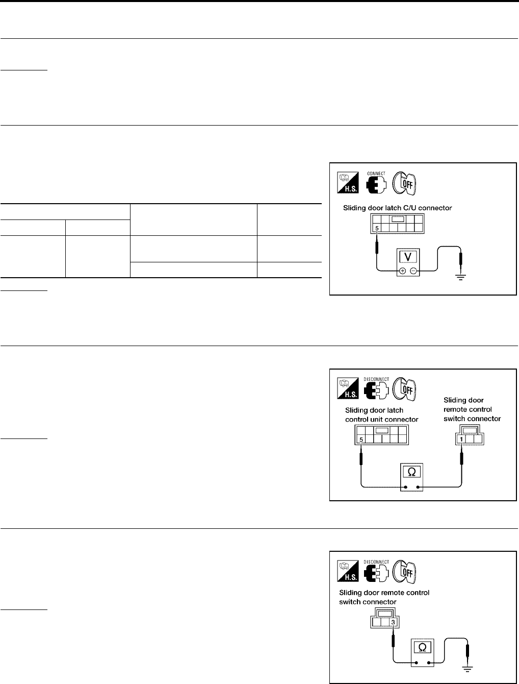
BL-154
AUTOMATIC SLIDING DOOR SYSTEM
Revision: July 2006 2006 Quest
Sliding Door Remote Control Switch System Inspection
EIS007FF
1. SLIDING DOOR REMOTE CONTROL SWITCH FUNCTION INSPECTION
Check sliding door remote control switch operation.
OK or NG
OK >> Sliding door remote control switch is OK.
NG >> GO TO 2.
2. SLIDING DOOR REMOTE CONTROL SWITCH SIGNAL INSPECTION
1. Turn ignition switch OFF.
2. Close the sliding door.
3. While operating the sliding door remote control switch, check
voltage between sliding door latch control unit connector D204
(LH) or D304 (RH) terminal 5 and ground.
OK or NG
OK >> Sliding door remote control switch is OK.
NG >> GO TO 3.
3. SLIDING DOOR REMOTE CONTROL SWITCH CIRCUIT INSPECTION
1. Disconnect sliding door remote control switch and sliding door latch control unit.
2. Check continuity between sliding door remote control switch
connector D207 (LH) or D307 (RH) terminal 1 and sliding door
latch control unit connector D204 (LH) or D304 (RH) terminal 5.
OK or NG
OK >> GO TO 4.
NG >> Repair or replace harness.
4. SLIDING DOOR REMOTE CONTROL SWITCH GROUND INSPECTION
1. Close the sliding door.
2. Check continuity between sliding door remote control switch
connector D207 (LH) or D307 (RH) terminal 3 and ground.
OK or NG
OK >> Replace the sliding door remote control switch.
NG >> Repair or replace harness.
Terminal Measuring condition Voltage (V)
(Approx.)
( + ) ( - )
5 Ground
Sliding door handle open direc-
tion operation 0
Other than above 5
LIIA0769E
1 - 5 : Continuity should exist.
LIIA0770E
3 - Ground : Continuity should exist.
LIIA0771E
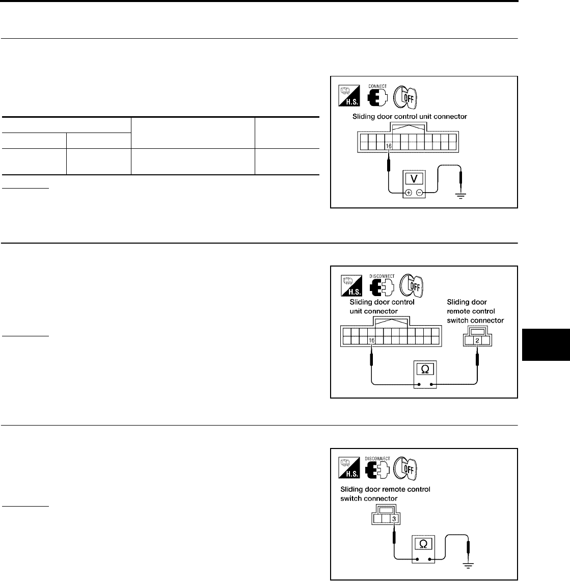
AUTOMATIC SLIDING DOOR SYSTEM
BL-155
C
D
E
F
G
H
J
K
L
M
A
B
BL
Revision: July 2006 2006 Quest
Child Lockout Switch System Inspection
EIS007FG
1. CHILD LOCKOUT SWITCH SIGNAL INSPECTION
1. Turn ignition switch OFF.
2. Set child lockout switch in LOCK position and close door.
3. While operating the sliding door in the open direction, check
voltage between sliding door control unit connector B60 (LH) or
B143 (RH) terminal 16 and ground.
OK or NG
OK >> Switch is OK.
NG >> GO TO 2.
2. CHILD LOCKOUT SWITCH CIRCUIT INSPECTION
1. Disconnect sliding door remote control switch and sliding door control unit.
2. Check continuity between sliding door remote control switch
connector D207 (LH) or D307 (RH) terminal 2 and sliding door
control unit connector D204 (LH) or D304 (RH) terminal 16.
OK or NG
OK >> GO TO 3.
NG >> Repair or replace harness.
3. CHILD LOCKOUT SWITCH GROUND INSPECTION
1. Close the sliding door.
2. Check continuity between sliding door remote control switch
connector D207 (LH) or D307 (RH) terminal 3 and ground.
OK or NG
OK >> Replace the sliding door remote control switch.
NG >> Repair or replace harness.
Terminal Measuring condition Voltage (V)
(Approx.)
( + ) ( - )
16 Ground Sliding door handle in the
open direction 0
LIIA0773E
2 - 16 : Continuity should exist.
LIIA0774E
3 - Ground : Continuity should exist.
LIIA0771E
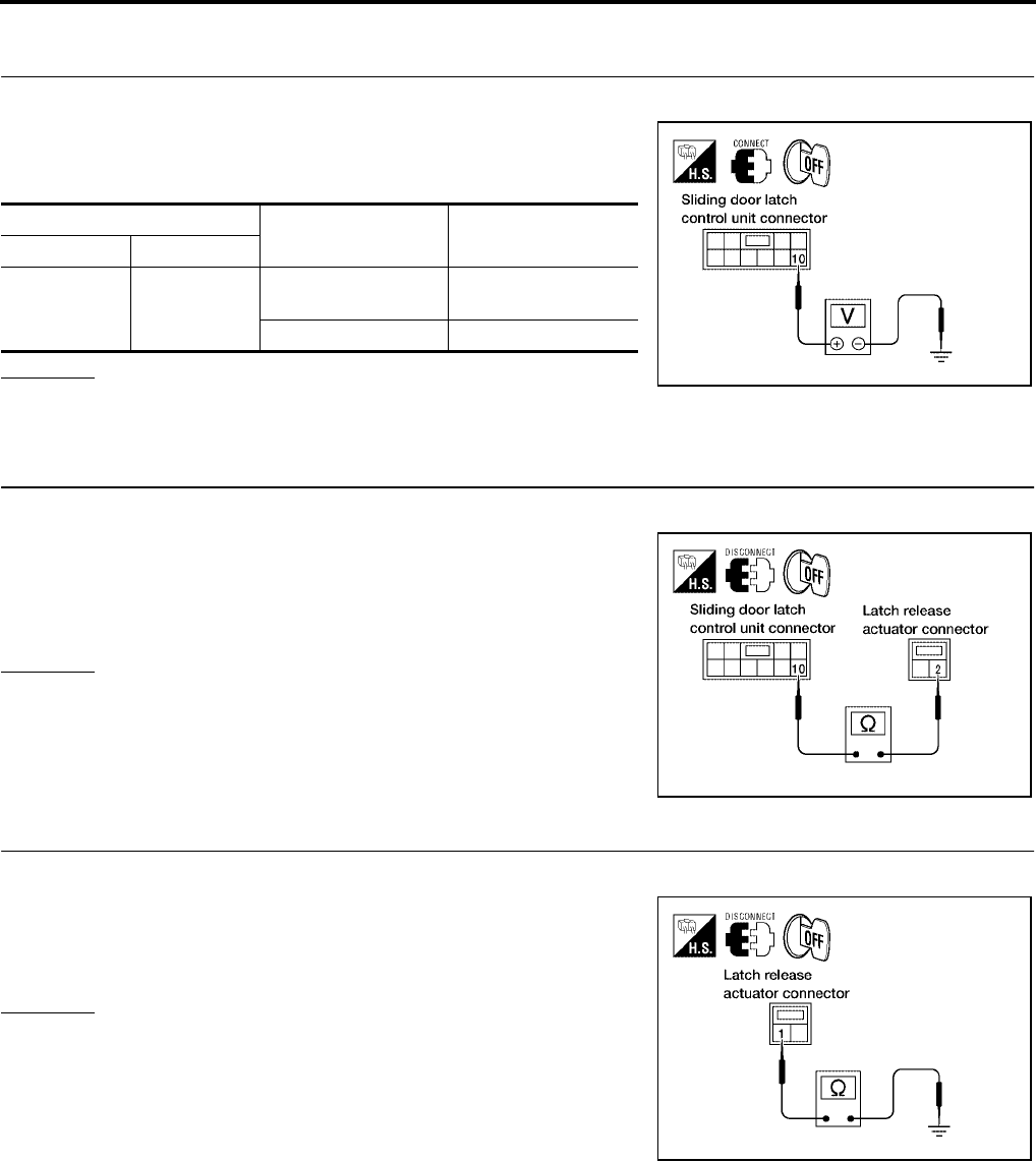
BL-156
AUTOMATIC SLIDING DOOR SYSTEM
Revision: July 2006 2006 Quest
Latch Release Actuator System Inspection
EIS007FH
1. LATCH RELEASE ACTUATOR SIGNAL INSPECTION
1. Turn ignition switch OFF.
2. While operating the sliding door, check voltage between sliding
door latch control unit connector D204 (LH) or D304 (RH) termi-
nal 10 and ground.
OK or NG
OK >> Latch release actuator is OK.
NG >> GO TO 2.
2. LATCH RELEASE ACTUATOR CIRCUIT INSPECTION
1. Disconnect latch release actuator and sliding door latch control unit.
2. Check continuity between latch release actuator connector
D206 (LH) or D306 (RH) terminal 2 and sliding door latch control
unit connector D204 (LH) or D304 (RH) terminal 10.
OK or NG
OK >> GO TO 3.
NG >> Repair or replace harness.
3. LATCH RELEASE ACTUATOR GROUND INSPECTION
1. Close the sliding door.
2. Check continuity between latch release actuator connector
D206 (LH) or D306 (RH) terminal 1 and ground.
OK or NG
OK >> Replace the latch release actuator.
NG >> Repair or replace harness.
Terminals Measuring condition Voltage (V)
(Approx.)
( + ) ( - )
10 Ground
Latch release actua-
tor operation Battery voltage
Other than above 0
LIIA0776E
2 - 10 : Continuity should exist.
WIIA0380E
1 - Ground : Continuity should exist.
LIIA1637E
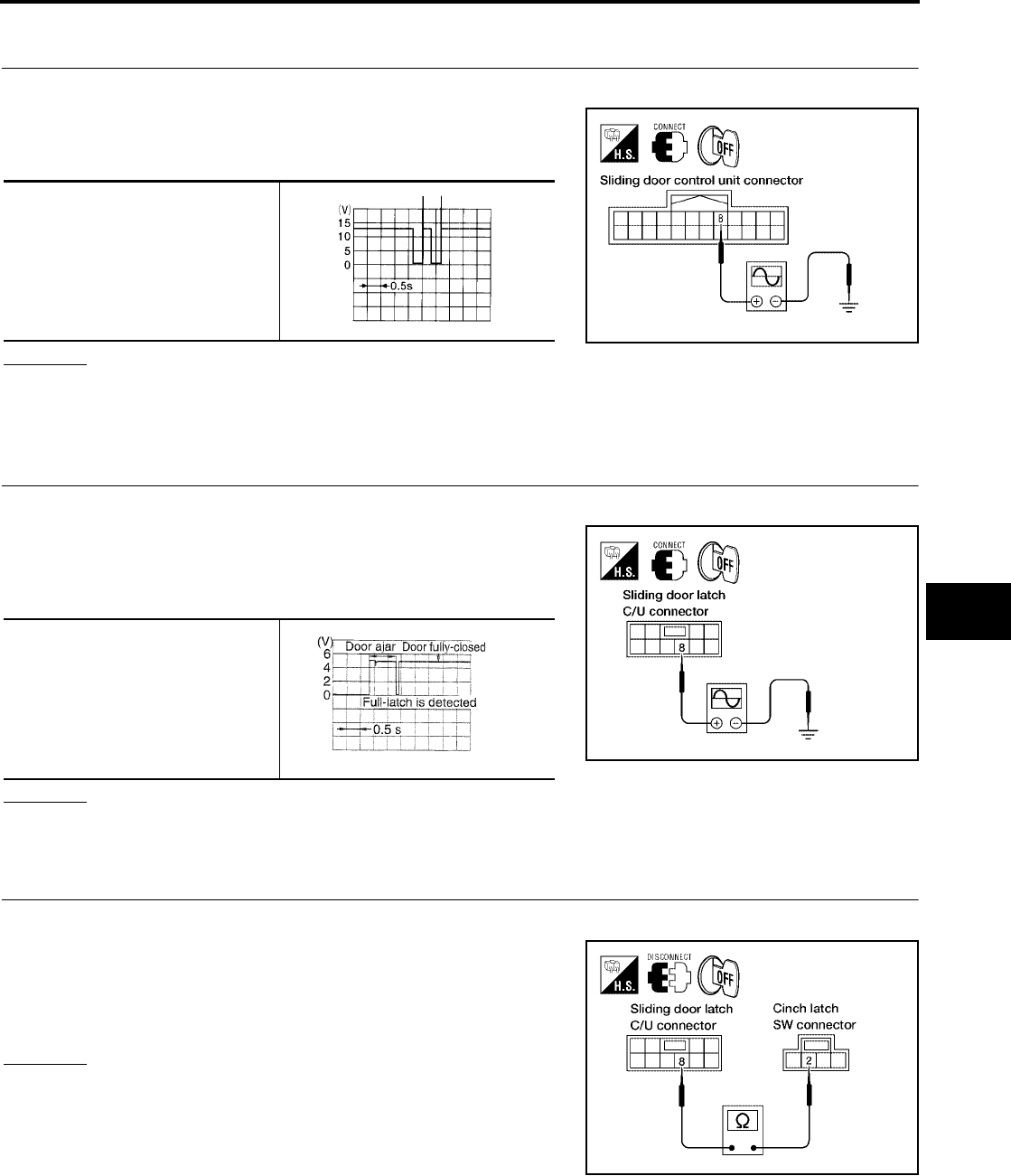
AUTOMATIC SLIDING DOOR SYSTEM
BL-157
C
D
E
F
G
H
J
K
L
M
A
B
BL
Revision: July 2006 2006 Quest
Warning Chime System Inspection
EIS007FI
1. WARNING CHIME OUTPUT SIGNAL INSPECTION
1. Turn ignition switch OFF.
2. Operate the sliding door and check voltage waveform between
sliding door control unit connector B60 (LH) or B143 (RH) termi-
nal 8 and ground using an oscilloscope.
OK or NG
OK >> Warning chime system is OK.
NG >> Replace sliding door control unit.
Half-Latch Switch System Inspection
EIS007FJ
1. HALF-LATCH SWITCH SIGNAL INSPECTION
1. Turn ignition switch OFF.
2. While fully opening and closing the sliding door, check voltage
waveform between sliding door latch control unit connector
D204 (LH) or D304 (RH) terminal 8 and ground using an oscillo-
scope.
OK or NG
OK >> Half-latch switch is OK.
NG >> GO TO 2.
2. HALF-LATCH SWITCH CIRCUIT INSPECTION
1. Disconnect cinch latch switch and sliding door latch control unit.
2. Check continuity between cinch latch switch connector D202
(LH) or D302 (RH) terminal 2 and sliding door latch control unit
connector D204 (LH) or D304 (RH) terminal 8.
OK or NG
OK >> GO TO 3.
NG >> Repair or replace harness.
8 - Ground
LIIA1911E
ELN0505D
8 - Ground
LIIA0781E
PIIA2169E
2 - 8 : Continuity should exist.
LIIA1638E
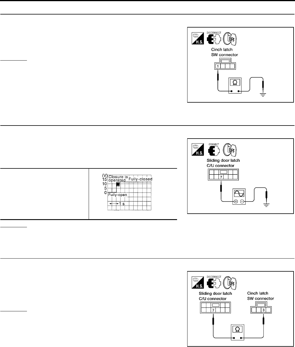
BL-158
AUTOMATIC SLIDING DOOR SYSTEM
Revision: July 2006 2006 Quest
3. HALF-LATCH SWITCH GROUND INSPECTION
1. Close the sliding door.
2. Check continuity between cinch latch switch connector D202
(LH) or D302 (RH) terminal 1 and ground.
OK or NG
OK >> Replace the cinch latch switch.
NG >> Repair or replace harness.
Full-Latch Switch System Inspection
EIS007FK
1. FULL-LATCH SWITCH SIGNAL INSPECTION
1. Turn ignition switch OFF.
2. While fully closing and opening the sliding door, check voltage
waveform between sliding door latch control unit connector
D204 (LH) or D304 (RH) terminal 7 and ground using an oscillo-
scope.
OK or NG
OK >> Full-latch switch is OK.
NG >> GO TO 2.
2. FULL-LATCH SWITCH CIRCUIT INSPECTION
1. Disconnect cinch latch switch and sliding door latch control unit.
2. Check continuity between cinch latch switch connector D202
(LH) or D302 (RH) terminal 3 and sliding door latch control unit
connector D204 (LH) or D304 (RH) terminal 7.
OK or NG
OK >> GO TO 3.
NG >> Repair or replace harness.
1 - Ground : Continuity should exist.
LIIA0783E
7 - Ground
LIIA0785E
PIIA2171E
3 - 7 : Continuity should exist.
LIIA0786E
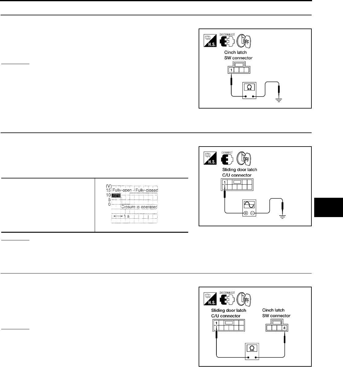
AUTOMATIC SLIDING DOOR SYSTEM
BL-159
C
D
E
F
G
H
J
K
L
M
A
B
BL
Revision: July 2006 2006 Quest
3. FULL-LATCH SWITCH GROUND INSPECTION
1. Close the sliding door.
2. Check continuity between cinch latch switch connector D202
(LH) or D302 (RH) terminal 1 and ground.
OK or NG
OK >> Replace the cinch latch switch.
NG >> Repair or replace harness.
Neutral Switch System Inspection
EIS007FL
1. NEUTRAL SWITCH SIGNAL INSPECTION
1. Turn ignition switch OFF.
2. While fully opening and closing the sliding door, check voltage
waveform between sliding door latch control unit connector
D204 (LH) or D304 (RH) terminal 1 and ground using an oscillo-
scope.
OK or NG
OK >> Neutral switch is OK.
NG >> GO TO 2.
2. NEUTRAL SWITCH CIRCUIT INSPECTION
1. Disconnect cinch latch switch and sliding door latch control unit.
2. Check continuity between cinch latch switch connector D202
(LH) or D302 (RH) terminal 4 and sliding door latch control unit
connector D204 (LH) or D304 (RH) terminal 1.
OK or NG
OK >> GO TO 3.
NG >> Repair or replace harness.
1 - Ground : Continuity should exist.
LIIA0783E
1 - Ground
LIIA1639E
PIIA2170E
4 - 1 : Continuity should exist.
LIIA0789E
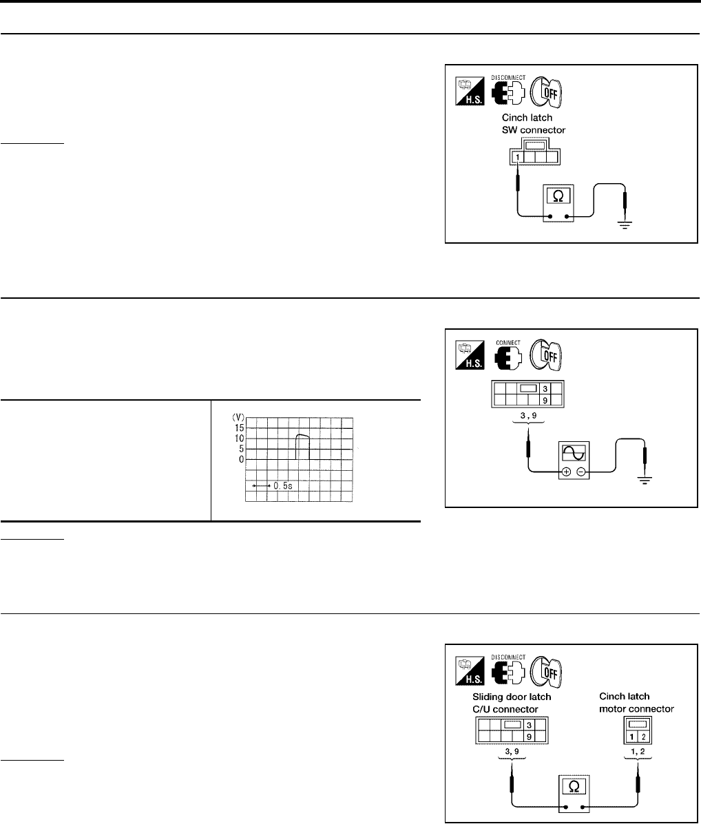
BL-160
AUTOMATIC SLIDING DOOR SYSTEM
Revision: July 2006 2006 Quest
3. NEUTRAL SWITCH GROUND INSPECTION
1. Close the sliding door.
2. Check continuity between cinch latch switch connector D202
(LH) or D302 (RH) terminal 1 and ground.
OK or NG
OK >> Replace the cinch latch switch.
NG >> Repair or replace harness.
Cinch Latch Motor System Inspection
EIS007FM
1. CINCH LATCH MOTOR SIGNAL INSPECTION
1. Turn ignition switch OFF.
2. While fully opening and closing the sliding door, check voltage
waveform between sliding door latch control unit connector
D204 (LH) or D304 (RH) terminals 3, 9 and ground using an
oscilloscope.
OK or NG
OK >> GO TO 2.
NG >> Replace the sliding door latch control unit.
2. CINCH LATCH MOTOR CIRCUIT INSPECTION
1. Disconnect cinch latch switch and sliding door latch control unit.
2. Check continuity between cinch latch motor connector D203
(LH) or D303 (RH) terminals 1, 2 and sliding door latch control
unit connector D204 (LH) or D304 (RH) terminals 3, 9.
OK or NG
OK >> GO TO 3.
NG >> Repair or replace harness.
1 - Ground : Continuity should exist.
LIIA0783E
3 - Ground
9 - Ground
WIIA0818E
SIIA1480E
1 - 3 : Continuity should exist.
2 - 9 : Continuity should exist.
LIIA0791E

AUTOMATIC SLIDING DOOR SYSTEM
BL-161
C
D
E
F
G
H
J
K
L
M
A
B
BL
Revision: July 2006 2006 Quest
3. CINCH LATCH MOTOR OPERATION INSPECTION
Connect battery power to terminals 1 and 2 on the cinch latch motor
and check motor operation.
OK or NG
OK >> Motor is OK.
NG >> Replace the cinch latch motor.
1 (+) - 2 (-) : It operates.
1 (-) - 2 (+) : It operates. (Reverse rotation)
LIIA1913E
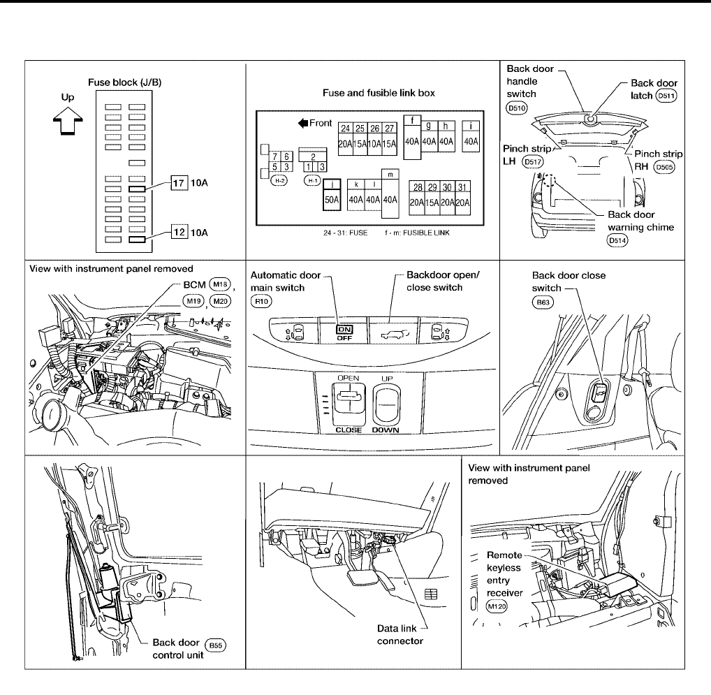
BL-162
AUTOMATIC BACK DOOR SYSTEM
Revision: July 2006 2006 Quest
AUTOMATIC BACK DOOR SYSTEM PFP:82580
Component Parts and Harness Connector Location
EIS007FN
System Description
EIS007FO
NOTE:
The automatic back door system must be initialized by fully closing the back door anytime the battery or the
back door control unit has been disconnected.
The automatic back door system consists of a one piece unit that combines the back door control unit along
with the back door motor, back door clutch and the back door encoder. The back door latch contains a lock
function that can control the two functions of automatic back door latch closure and electrical opener with a
single motor when the back door is closed to the halfway state.
●Back door auto closure
When the back door is closed to the half-way state (half-latch) position, the motor drives to rotate the latch
lever and pull it in from half latched to full latched and automatically close the door.
●Power back door
With the back door closed, press the automatic door main switch or press the remote keyless entry but-
ton, or pull the back door handle with the back door unlocked, the back door latch motor drives the open
LIIA1914E

AUTOMATIC BACK DOOR SYSTEM
BL-163
C
D
E
F
G
H
J
K
L
M
A
B
BL
Revision: July 2006 2006 Quest
the locking plate and releases the latch. The back door motor then raises the door to the full open posi-
tion.
With the back door open, press the automatic door main switch, remote keyless entry button or the back
door close switch, the back door motor closes the door to the half-latch state. The back door latch motor
then drives the latch to the full close position.
On an open or close signal, the hazard lamps will flash 3 times and the warning chime will sound 3 dings
lasting a total of 2 seconds.
OPERATION DESCRIPTION
Automatic Door Main Switch Operation (Fully Closed → Fully Open Operation)
●When the automatic door main switch is pressed, back door control unit terminal 23 receives the signal.
●The back door control unit checks the automatic transaxle select lever (A/T device) position through termi-
nal 18, vehicle speed through terminal 21 and battery voltage.
●When the back door control unit receives the signal, if the auto back door operating enable conditions are
met, it sends a signal through terminal 6 and grounds terminal 9 to sound the warning chime, sends a sig-
nal to the BCM through terminal 4 to flash the hazard lamps and sends the unlock signal to the back door
latch.
●When the back door latch receives the signal, it supplies voltage from terminal 12 to operate the release
actuator and releases the door lock.
●The back door control unit supplies power to the magnetic clutch and the back door motor and moves the
back door in the open direction. (At this time, it also executes speed control, input reverse, and overload
reverse control.)
●When the back door is opened to the full-open position, the full-open position is detected by the encoder,
and the back door control unit switches the back door motor OFF and the magnetic clutch is pulsed and
then turned OFF.
●The back door is held in the fully open position by the gas stays.
Remote Keyless Entry Operation (Fully Closed → Fully Open Operation)
●When the remote keyless entry button is pressed for at least 0.5 seconds, back door control unit terminal
21 receives the signal.
●The back door control unit checks the automatic transaxle select lever (A/T device) position through termi-
nal 18, vehicle speed through terminal 21 and battery voltage.
●When the back door control unit receives the signal, if the auto back door operating enable conditions are
met, it sends a signal through terminal 6 and grounds terminal 9 to sound the warning chime, sends a sig-
nal to the BCM through terminal 4 to flash the hazard lamps and sends the unlock signal to the back door
latch.
●When the back door latch receives the signal, it supplies voltage from terminal 12 to operate the release
actuator and releases the door lock.
●The back door control unit supplies power to the magnetic clutch and the back door motor and moves the
back door in the open direction. (At this time, it also executes speed control, input reverse, and overload
reverse control.)
●When the back door is opened to the full-open position, the full-open position is detected by the encoder,
and the back door control unit switches the back door motor OFF and the magnetic clutch is pulsed and
then turned OFF.
●The back door is held in the fully open position by the gas stays.
Back Door Handle Switch Operation (Fully Closed → Fully Open Operation)
●When the back door is unlocked and the back door handle is pulled, back door control unit terminal 26
receives the signal.
●The back door control unit checks the automatic transaxle select lever (A/T device) position through termi-
nal 18, vehicle speed through terminal 21 and battery voltage and automatic door main switch position
through terminal 13.
●When the back door control unit receives the signal, if the auto back door operating enable conditions are
met, it sends a signal through terminal 6 and grounds terminal 9 to sound the warning chime, sends a sig-
nal to the BCM through terminal 4 to flash the hazard lamps and sends the unlock signal to the back door
latch.

BL-164
AUTOMATIC BACK DOOR SYSTEM
Revision: July 2006 2006 Quest
●When the back door latch receives the signal, it supplies voltage from terminal 12 to operate the release
actuator and releases the door lock.
●The back door control unit supplies power to the magnetic clutch and the back door motor and moves the
back door in the open direction. (At this time, it also executes speed control, input reverse, and overload
reverse control.)
●When the back door is opened to the full-open position, the full-open position is detected by the encoder,
and the back door control unit switches the back door motor OFF and the magnetic clutch is pulsed and
then turned OFF.
●The back door is held in the fully open position by the gas stays.
Automatic Door Main Switch Operation (Fully Open → Fully Closed Operation)
●When the automatic door main switch is pressed, the back door control unit terminal 23 receives the sig-
nal.
●The back door control units checks battery voltage.
●When the back door control unit receives the signal, if the auto back door operating enable conditions are
met, it sends a signal through terminal 6 and grounds terminal 9 to sound the warning chime and sends a
signal to the BCM through terminal 4 to flash the hazard lamps.
●The back door control unit supplies power to the magnetic clutch and the back door motor and move the
back door in the close direction. (At this time, it also executes speed control, input reverse, and overload
reverse control.)
●When the back door reaches the half-latch state, the half-latch switch detects this and the signal is sent to
the back door control unit terminal 22.
●When the back door control unit receives the signal, it switches OFF the back door motor and the mag-
netic clutch.
●When the cinch latch motor operates and the close switch detects this and the back door control unit ter-
minal 14 receives the signal from back door latch terminal 5.
●When the back door latch operates and full close is detected through terminal 14 of the back door control
unit, the back door auto closure operation ends and the door is fully closed.
Remote Keyless Entry Operation (Fully Open → Fully Closed Operation)
●When the remote keyless entry switch is pressed for at least 0.5 seconds, the back door control unit termi-
nal 21 receives the signal.
●The back door control units checks battery voltage.
●When the back door control unit receives the signal, if the auto back door operating enable conditions are
met, it sends a signal through terminal 6 and grounds terminal 9 to sound the warning chime and sends a
signal to the BCM through terminal 4 to flash the hazard lamps.
●The back door control unit supplies power to the magnetic clutch and the back door motor and move the
back door in the close direction. (At this time, it also executes speed control, input reverse, and overload
reverse control.)
●When the back door reaches the half-latch state, the half-latch switch detects this and the signal is sent to
the back door control unit terminal 22.
●When the back door control unit receives the signal, it switches OFF the back door motor and the mag-
netic clutch.
●When the cinch latch motor operates and the close switch detects this and the back door control unit ter-
minal 14 receives the signal from back door latch terminal 5.
●When the back door latch operates and full close is detected through terminal 14 of the back door control
unit, the back door auto closure operation ends and the door is fully closed.
Back Door Close Switch Operation (Fully Open → Fully Closed Operation)
●When the back door close switch is pressed with the automatic main door switch ON, the back door con-
trol unit terminal 8 receives the signal.
●The back door control units checks battery voltage.
●When the back door control unit receives the signal, if the auto back door operating enable conditions are
met, it sends a signal through terminal 6 and grounds terminal 9 to sound the warning chime and sends a
signal to the BCM through terminal 4 to flash the hazard lamps.

AUTOMATIC BACK DOOR SYSTEM
BL-165
C
D
E
F
G
H
J
K
L
M
A
B
BL
Revision: July 2006 2006 Quest
●The back door control unit supplies power to the magnetic clutch and the back door motor and move the
back door in the close direction. (At this time, it also executes speed control, input reverse, and overload
reverse control.)
●When the back door reaches the half-latch state, the half-latch switch detects this and the signal is sent to
the back door control unit terminal 22.
●When the back door control unit receives the signal, it switches OFF the back door motor and the mag-
netic clutch.
●When the cinch latch motor operates and the close switch detects this and the back door control unit ter-
minal 14 receives the signal from back door latch terminal 5.
●When the back door latch operates and full close is detected through terminal 14 of the back door control
unit, the back door auto closure operation ends and the door is fully closed.
Anti-Pinch Function
●During auto operation, if an object is detected in the door's path, the back door operates in the reverse
direction to prevent pinching.
●During auto close operation, if an object is detected by the pinch strips in the door's path, the back door
operates in the open direction until it is fully open.
●During auto cinch latch operation, if an object is detected by the pinch strips in the door's path, the back
door operates depending on the automatic door main switch position. If the automatic door main switch is
in the ON position, the back door operates in the open direction until it is fully open. If the automatic door
main switch is in the OFF position, the back door will reverse only until the latch is fully released.
Gas Stay Check
●During each power open operation, the back door control unit monitors motor current draw to determine if
the gas stays are functioning properly.
●If a failure of the gas stays is detected, the back door control unit will close the back door while sounding
the warning chime.
Warning Functions
●The warning chime is sounded according to the back door operating state, operations, and conditions.
Auto Back Door Operation Enable Conditions
Operation Automatic door main
switch Remote keyless entry Back door handle switch Back door close switch
Operating
direction
Fully closed
→ open
Fully open
→ closed
Fully closed
→ open
Fully open
→ closed
Fully closed
→ open
Fully open
→ closed
Fully closed →
open
Fully open
→ closed
Main switch ON
Vehicle stop
condition
A/T selector
lever in P
position and
vehicle
speed less
than 2 km/h
—
A/T selector
lever in P
position and
vehicle
speed less
than 2 km/h
—
A/T selector
lever in P
position and
vehicle speed
less than 2
km/h
——
Battery volt-
age Approx. 11V or more
Approx. 11V (operates with
warning chime for low voltage
of 9 - 11V)

BL-166
AUTOMATIC BACK DOOR SYSTEM
Revision: July 2006 2006 Quest
Control When Handle Pulled When Operating Enable Conditions Not Yet Met
Control When Operating Enable Conditions No Longer Met
Warning Chime Active Conditions
The warning chime uses two types of audio warnings, a friendly chime and a warning chime. The friendly
chime consists of dings lasting 0.66 seconds each immediately followed by the next ding. The warning chime
consists of beeps lasting 0.33 seconds with a pause of 0.33 seconds between each beep.
Items Operation condition Not met case Control
Main switch ON OFF Manual mode (after finishing
open/close operation if active)
A/T selector lever P position P position Other than P position Power close operation only
Voltage drop 11V or more
11 > V > 9
Power operation will continue
but will not begin from full close
position
9 > V > reset voltage Power operation will stop and
warning chime will sound
Reset voltage > V No power function available
Handle switch Normal Error No operation
Description Operation Full open stop
Main switch turned OFF
Warning chime active
→ Shift to manual mode after full open or
close operation is complete
(Recovery to power mode when main
switch turned ON or door fully closed)
→ Shift to manual mode
A/T selector lever P position
Warning chime active and one-way opera-
tion continuous
(Warning chime inactive and door fully
open or fully closed or operating conditions
recovered)
Stop continued
Voltage drop 11 - 9V
One-way operation continued (equivalent
to the case of starting voltage ← 11V for
handle operation with warning chime
active)
Not allowed
Voltage drop 6 - 4V
(Microcomputer reset voltage - clutch hold
voltage)
●Motor stopped
●Control not possible because microcom-
puter being reset
Control not possible because microcom-
puter being reset
Operation status Operation or conditions Warning chime pattern
When auto operation starts Automatic door main switch operation Friendly chime
2 seconds, 3 dings
Back door handle switch operation
Back door close switch operation
When reverse operation starts
When reverse request is detected from
automatic door main switch, remote
keyless entry or back door close switch
Friendly chime
1.3 seconds, 2 dings
When obstacle is detected Warning chime
2 seconds, 3 beeps
Operating at low voltage When operating with handle Warning chime
2 seconds, 3 beeps
A/T selector lever not in P position
Back door close operation Friendly chime
Continuous dings
Back door open operation Warning chime
Continuous beeps

AUTOMATIC BACK DOOR SYSTEM
BL-167
C
D
E
F
G
H
J
K
L
M
A
B
BL
Revision: July 2006 2006 Quest
Reverse Conditions
Type Overload reverse
Operation covered Both directions
Detection method Operation speed and motor current change direction
Pinch strips during back door close operation
Non-reversed area
●For about 0.5 seconds immediately after drive motor operation
starts
●Between full open and approx. 7° from full open
●Closure operation area
Number of times reverse allowed
One reversal is allowed (if a second obstacle is detected during a
power open or close operation, the door reverts to manual
mode).
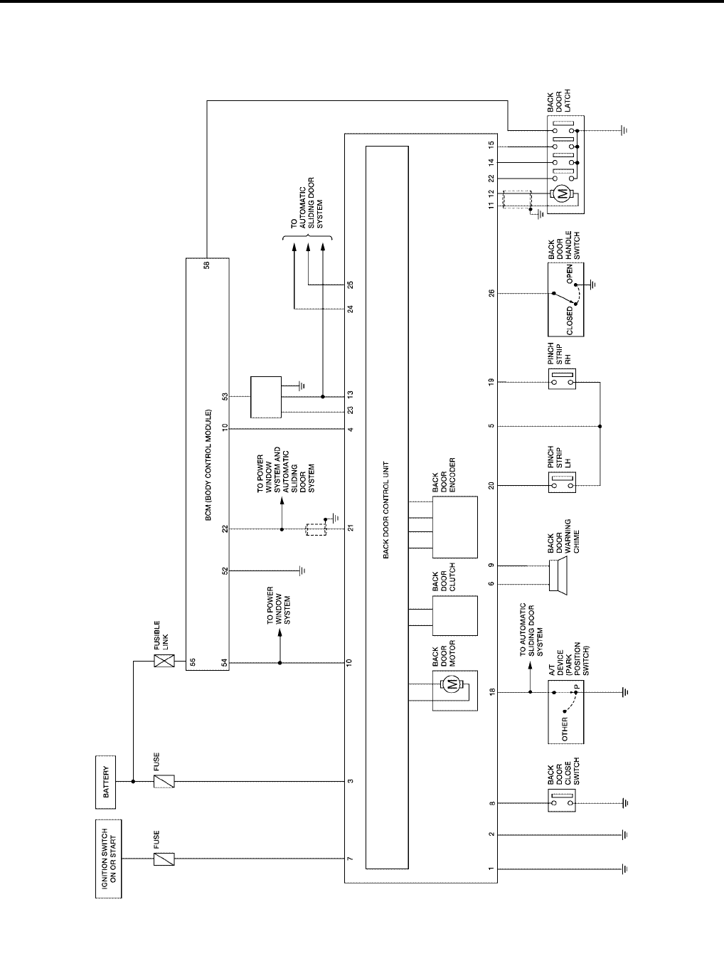
BL-168
AUTOMATIC BACK DOOR SYSTEM
Revision: July 2006 2006 Quest
Schematic
EIS007FP
WIWA1135E
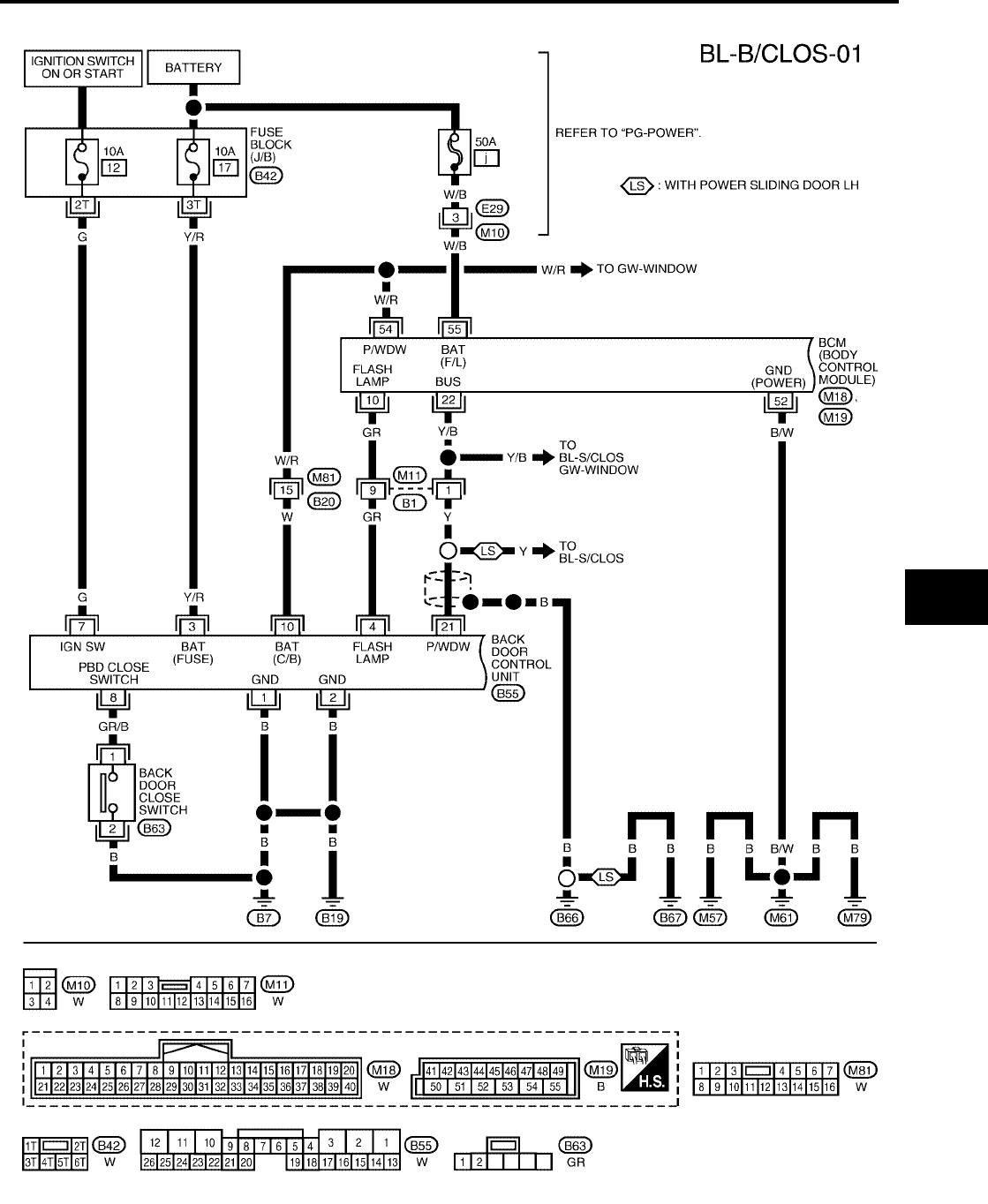
AUTOMATIC BACK DOOR SYSTEM
BL-169
C
D
E
F
G
H
J
K
L
M
A
B
BL
Revision: July 2006 2006 Quest
Wiring Diagram — B/CLOS —
EIS007FQ
WIWA1136E
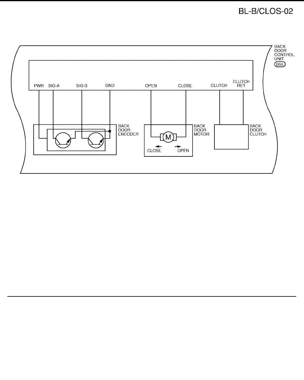
BL-170
AUTOMATIC BACK DOOR SYSTEM
Revision: July 2006 2006 Quest
WIWA0512E
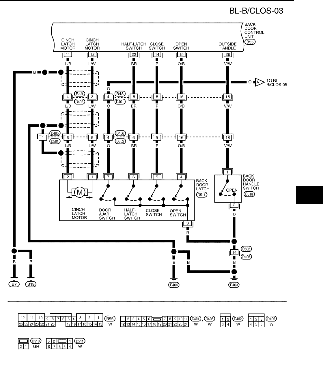
AUTOMATIC BACK DOOR SYSTEM
BL-171
C
D
E
F
G
H
J
K
L
M
A
B
BL
Revision: July 2006 2006 Quest
WIWA1137E
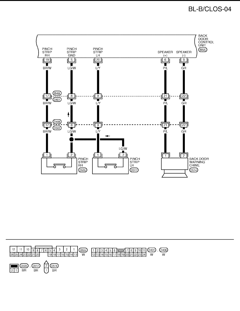
BL-172
AUTOMATIC BACK DOOR SYSTEM
Revision: July 2006 2006 Quest
WIWA0514E
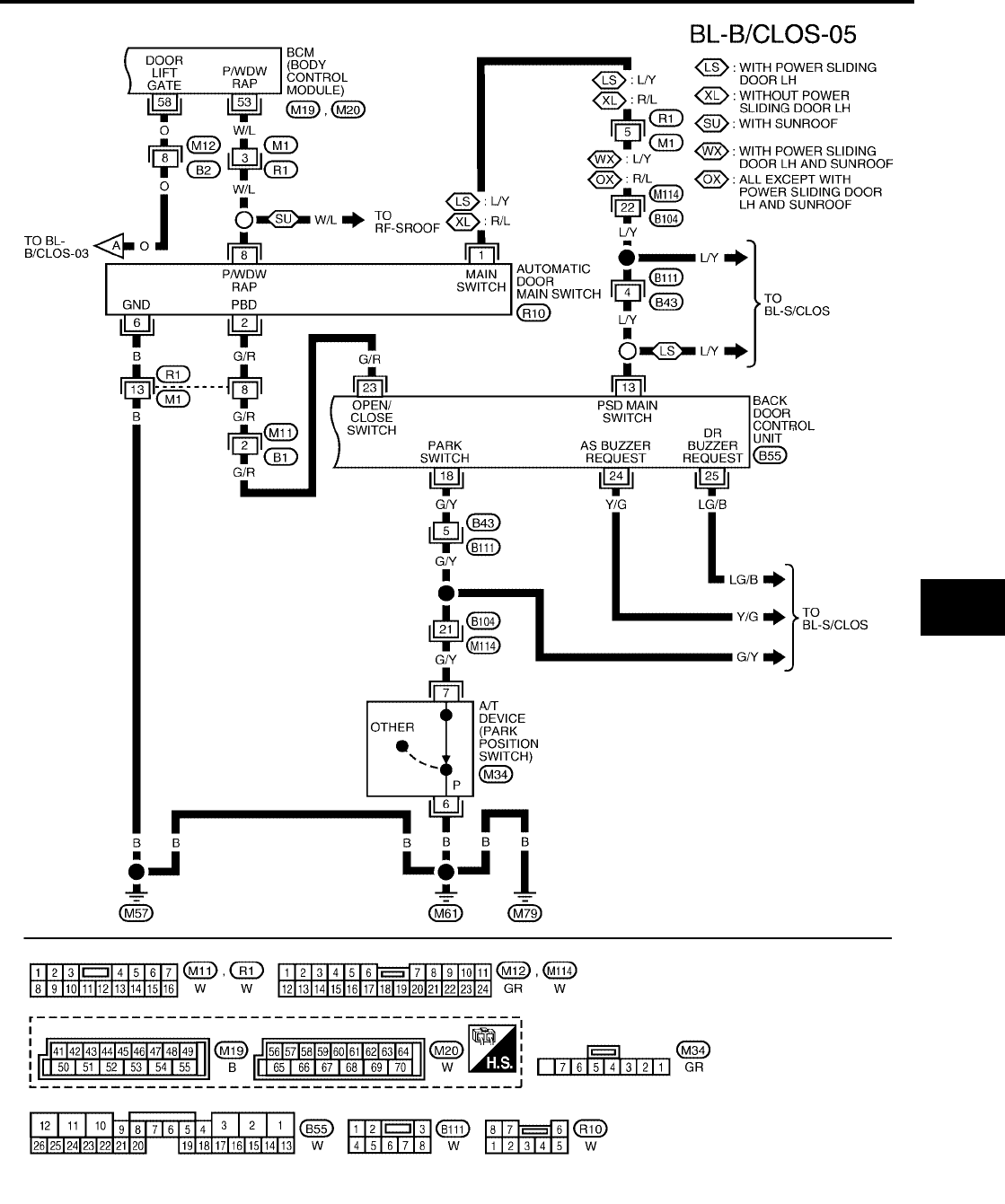
AUTOMATIC BACK DOOR SYSTEM
BL-173
C
D
E
F
G
H
J
K
L
M
A
B
BL
Revision: July 2006 2006 Quest
WIWA1138E
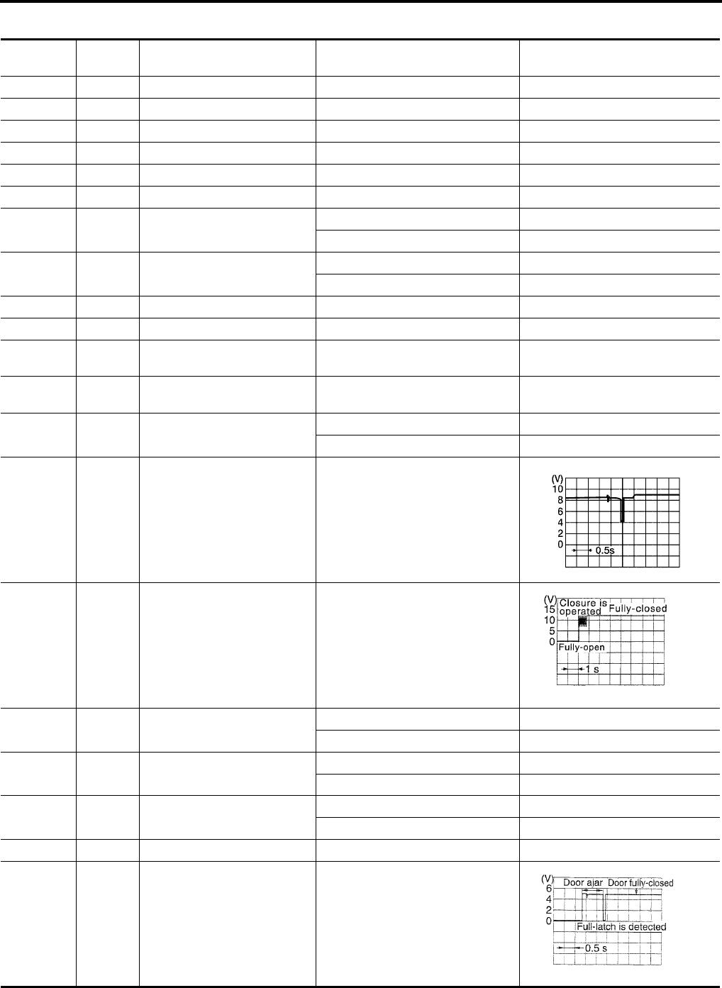
BL-174
AUTOMATIC BACK DOOR SYSTEM
Revision: July 2006 2006 Quest
Terminals and Reference Value for Back Door Control Unit
EIS007FR
Terminal Wire
Color Item Condition Voltage (V)
(Approx.)
1 B Ground ——
2 B Ground ——
3 Y/R Battery power supply —Battery voltage
4 GR Hazard lamp output Back door motor active 5
5 LG/W Pinch strip ground ——
6 P/L Warning chime output Back door motor active 12
7 G Ignition switch Ignition switch ON Battery voltage
Ignition switch OFF 0
8 GR/B Back door close switch Back door close switch ON 0
Back door close switch OFF Battery voltage
9 GR Warning chime ground ——
10 W Battery power —Battery voltage
11 L/B Cinch latch motor
CLOSE output Back door close operation Battery voltage
12 L/W Cinch latch motor
RETURN output Back door open operation Battery voltage
13 L/Y Automatic door main switch
ON/OFF switch
Automatic door main switch ON 0
Automatic door main switch OFF 5
14 P Close switch signal While fully opening back door
15 O/B Open switch signal While fully closing back door
18 G/Y A/T device (park position
switch)
P or N position (Ignition is ON) 0
Other than above (Ignition is ON) 9
19 BR/W Pinch strip RH Detecting obstruction 0
Other than above 4
20 L/Y Pinch strip LH Detecting obstruction 0
Other than above 4
21 Y Power window serial link ——
22 BR Half-latch switch Back door close operation
WIIA1047E
PIIA2171E
PIIA2169E

AUTOMATIC BACK DOOR SYSTEM
BL-175
C
D
E
F
G
H
J
K
L
M
A
B
BL
Revision: July 2006 2006 Quest
23 G/R Automatic door main switch ON 0
OFF 5
24 Y/G Sliding door RH warning chime
request
Sliding door active 0
Other than above 5
25 LG/B Sliding door LH warning chime
request
Sliding door active 0
Other than above 5
26 V/W Back door handle switch signal Handle operation 0
Other than above Battery voltage
Terminal Wire
Color Item Condition Voltage (V)
(Approx.)
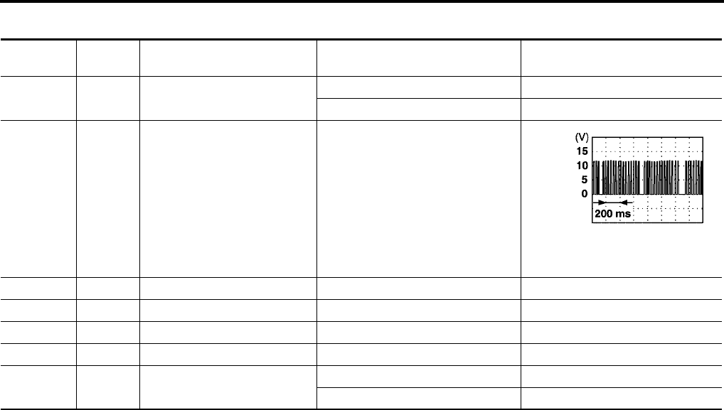
BL-176
AUTOMATIC BACK DOOR SYSTEM
Revision: July 2006 2006 Quest
Terminals and Reference Value for BCM
EIS007FS
Terminal Wire
Color Item Condition Voltage (V)
(Approx.)
10 GR Hazard lamp flash input Back door active 0
Other 5
22 Y/B Bus —
52 B/W Ground —0
53 W/L Power window power source —Battery voltage
54 W/R Power window (RAP) —Battery voltage
55 W/B Battery power supply —Battery voltage
58 O Back door switch Open 0
Closed 5

AUTOMATIC BACK DOOR SYSTEM
BL-177
C
D
E
F
G
H
J
K
L
M
A
B
BL
Revision: July 2006 2006 Quest
Trouble Diagnosis Procedure
EIS007FT
1. Check the symptom and customer's requests.
2. Understand outline of system. Refer to BL-162, "System Description" .
3. Confirm system operation.
4. Perform self-diagnosis procedures. Refer to BL-177, "Self-Diagnosis Procedures" .
5. Refer to diagnosis chart by symptom, repair or replace any malfunctioning parts. Refer to BL-179, "Diag-
nosis Chart" .
6. Inspection End.
Self-Diagnosis Procedures
EIS007FU
INPUT SIGNAL CHECK MODE
Input signal check mode allows testing of switch input signal to the back door control unit.
To activate input signal check mode on the automatic sliding door, perform the following steps:
1. Turn ignition switch OFF.
2. Turn automatic door main switch OFF (system cancelled).
3. Place A/T selector lever in P position.
4. Using the inside emergency release lever, open the back door.
5. Have an assistant press and hold the back door close switch.
6. While the assistant continues to hold the back door close switch, turn ignition switch ON (DO NOT start
engine).
7. After approximately 5 seconds, the back door warning chime will sound for 0.5 seconds.
8. Release the back door close switch RH or LH.
9. Within 8 seconds of the back door warning chime sounding, press and hold the automatic door main back
door open/close switch.
10. After approximately 5 seconds, the back door warning chime will sound for 1 second.
11. Release the automatic door main back door open/close switch.
12. The input signal check mode is now initialized.
The input signal check mode can test the following inputs. The back door warning chime will sound for approx-
imately 0.5 seconds each time a switch signal input occurs. Use this test when one of these inputs is not
responding during normal automatic sliding door operation.
*Back door warning chime should sound as soon as vehicle moves.
Turn ignition switch OFF to end input signal check mode.
OPERATING CHECK MODE
Operating check mode allows self-diagnosis of the automatic back door system.
To activate operating check mode on the automatic back door, perform the following steps:
1. Turn ignition switch OFF.
2. Turn automatic door main switch OFF (system cancelled).
3. Place A/T selector lever in P position.
Switch signal Operation Refer to
Automatic door main switch OFF → ON BL-180
Automatic door main back door open/close switch OFF → ON BL-180
Back door close switch OFF → ON BL-181
Back door handle switch OFF → ON BL-187
A/T device (park position switch) P position → other than P position SE-76
Vehicle speed* Vehicle speed —
Remote keyless entry signal Keyfob switch OFF → ON BL-80
Door lock/unlock signal LOCK → UNLOCK BL-47
Pinch strip LH signal OFF → ON BL-182
Pinch strip RH signal OFF → ON BL-182

BL-178
AUTOMATIC BACK DOOR SYSTEM
Revision: July 2006 2006 Quest
4. Using the inside emergency release lever, open the back door.
5. Have an assistant press and hold the back door close switch.
6. While the assistant continues to hold the back door close switch, turn ignition switch ON (DO NOT start
engine).
7. After approximately 5 seconds, the back door warning chime will sound for 0.5 seconds.
8. Release the back door close switch.
9. Within 8 seconds of the back door warning chime sounding, press the automatic door main back door
open/close switch 5 times in rapid succession.
10. After approximately 5 seconds, the back door warning chime will sound for 1 second.
11. Release the automatic door main back door open/close switch.
12. Immediately close the back door manually.
13. Turn automatic door main switch ON.
14. Open and close the back door with the automatic door main back door open/close switch to activate oper-
ating check mode.
Self-diagnosis results are indicated by the back door warning chime.
Turn ignition switch OFF to end input signal check mode.
Back door warning chime order Back door warning chime length
Start self-diagnosis 1.5 seconds
OK NG
1. Operating conditions diagnosis 0.5 seconds 0.2 seconds
2. Back door encoder diagnosis 0.5 seconds 0.2 seconds
3. Back door clutch diagnosis 0.5 seconds 0.2 seconds
4. Back door motor diagnosis 0.5 seconds 0.2 seconds
5. Cinch latch motor diagnosis 0.5 seconds 0.2 seconds
Restart self-diagnosis 1.5 seconds
Item NG Result Refer to
1. Operating conditions diagnosis result
One of the following operating conditions no
longer met: ignition switch ON, automatic door
main switch ON, A/T selector lever in P posi-
tion
—
2. Back door encoder diagnosis result Sensor diagnosis/short, pulse signal, pulse
signal direction BL-179
3. Back door clutch diagnosis result Back door clutch does not operate BL-184
4. Back door motor diagnosis result Back door motor does not operate (no operat-
ing current) BL-179
5. Cinch latch motor diagnosis result Cinch latch motor does not operate (no oper-
ating current) BL-188
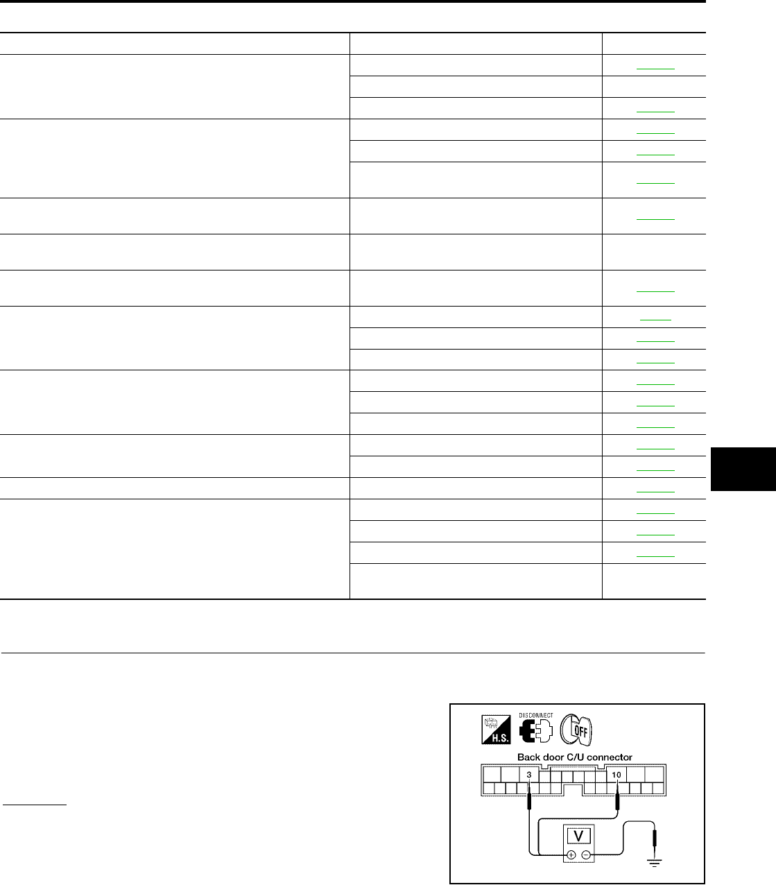
AUTOMATIC BACK DOOR SYSTEM
BL-179
C
D
E
F
G
H
J
K
L
M
A
B
BL
Revision: July 2006 2006 Quest
Diagnosis Chart
EIS007FV
Back Door Control Unit Power Supply and Ground Circuit Inspection
EIS007FW
1. BACK DOOR CONTROL UNIT POWER SUPPLY CIRCUIT INSPECTION
1. Turn ignition switch OFF.
2. Disconnect back door control unit.
3. Check voltage between back door control unit connector B55
terminals 3, 10 and ground.
OK or NG
OK >> GO TO 2.
NG >> Repair or replace harness.
Symptom Suspect systems Refer to
Automatic operations are not executed from the back door fully
closed or fully open position.
(Auto closure operates normally.)
Automatic door main switch system inspection BL-180
A/T device (park position switch) —
Pinch strip system inspection BL-182
Automatic operations are not carried out together with open/close
operations.
(Manual operations are normal.)
Automatic door main switch system inspection BL-180
Back door close switch system inspection BL-181
Back door control unit power supply and
ground circuit system inspection. BL-179
The auto closure function does not operate.
(Stops at the halfway position for auto closing operations.) Pinch strip system inspection BL-182
During auto closing operations, if obstruction is detected, the
door does not operate in reverse. Back door motor assembly —
During close or cinch operations, the door does not operate in
reverse if the back door handle is operated. Handle switch system BL-187
When the keyfob is operated, the back door does not operate
automatically.
Remote keyless entry system inspection BL-55
Power window serial link BL-176
Pinch strip system inspection BL-182
Auto closure does not operate.
Half-latch switch system BL-184
Cinch latch motor system BL-188
Handle switch system BL-187
The back door does not open.
(Closure motor rotation is not reversed.)
Open switch system BL-185
Handle switch system BL-187
Warning chime does not sound. Back door warning chime system BL-183
Auto closure operation works, but the back door is not fully
closed.
Close switch system BL-186
Handle switch system BL-187
Cinch latch motor system BL-188
Back door latch assembly mechanism dam-
aged or worn. —
3 - Ground : Approx. battery voltage
10 - Ground : Approx. battery voltage
WIIA0567E
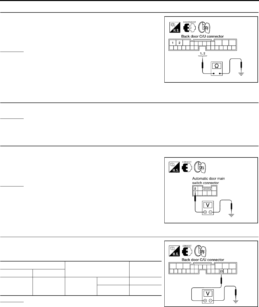
BL-180
AUTOMATIC BACK DOOR SYSTEM
Revision: July 2006 2006 Quest
2. BACK DOOR CONTROL UNIT GROUND CIRCUIT INSPECTION
Check continuity between back door control unit connector B55 ter-
minals 1, 2 and ground.
OK or NG
OK >> Ground circuit is OK.
NG >> Repair or replace harness.
Automatic Door Main Switch System Inspection
EIS007FX
1. AUTOMATIC DOOR MAIN SWITCH FUNCTION INSPECTION
Check automatic door main switch using switch operation.
OK or NG
OK >> Automatic door main switch is OK.
NG >> GO TO 2.
2. AUTOMATIC DOOR MAIN SWITCH POWER SUPPLY CIRCUIT INSPECTION
1. Turn ignition switch OFF.
2. Check voltage between automatic door main switch connector
R10 terminal 8 and ground.
OK or NG
OK >> GO TO 3.
NG >> Repair or replace harness.
3. AUTOMATIC DOOR MAIN SWITCH SIGNAL INSPECTION
While operating the automatic door main switch, check voltage
between back door control unit connector B55 terminal 23 and
ground.
OK or NG
OK >> Switch is OK.
NG >> GO TO 4.
1 - Ground : Continuity should exist.
2 - Ground : Continuity should exist.
LIIA0801E
8 - Ground : Approx. battery voltage
LIIA0857E
Terminals Measuring condition Voltage (V)
(Approx.)
( + ) ( - )
23 Ground
Automatic
door main
switch
ON 0
OFF 5
LIIA0802E
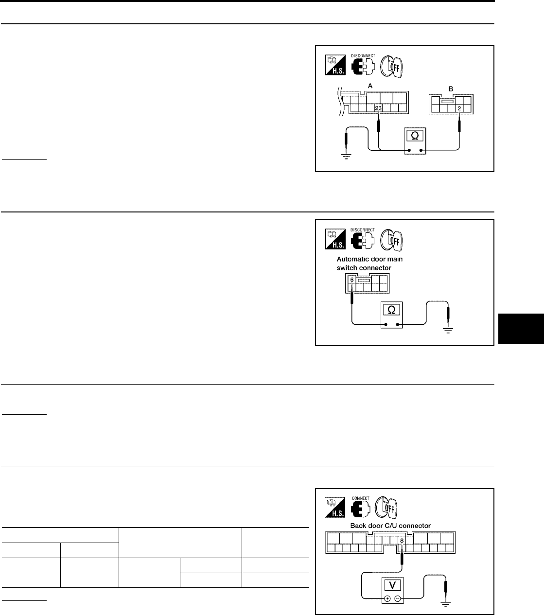
AUTOMATIC BACK DOOR SYSTEM
BL-181
C
D
E
F
G
H
J
K
L
M
A
B
BL
Revision: July 2006 2006 Quest
4. AUTOMATIC DOOR MAIN SWITCH CIRCUIT INSPECTION
1. Disconnect automatic door main switch and back door control unit.
2. Check continuity between automatic door main switch connector
(B) R10 terminal 2 and back door control unit connector (A) B55
terminal 23.
3. Check continuity between automatic door main switch connector
(B) R10 terminal 2 and ground.
OK or NG
OK >> GO TO 5.
NG >> Repair or replace harness.
5. AUTOMATIC DOOR MAIN SWITCH GROUND INSPECTION
Check continuity between automatic door main switch connector ter-
minal 6 and ground.
OK or NG
OK >> Replace the automatic door main switch.
NG >> Repair or replace harness.
Back Door Close Switch System Inspection
EIS007FY
1. BACK DOOR CLOSE SWITCH FUNCTION INSPECTION
Check back door close switch using switch operation.
OK or NG
OK >> Back door close switch is OK.
NG >> GO TO 2.
2. BACK DOOR CLOSE SWITCH SIGNAL INSPECTION
1. Turn ignition switch OFF.
2. While operating the back door close switch, check voltage
between back door control unit connector B55 terminal 8 and
ground.
OK or NG
OK >> Switch is OK.
NG >> GO TO 3.
2 - 23 : Continuity should exist.
2 - Ground : Continuity should not exist.
WIIA0786E
6 - Ground : Continuity should exist.
LIIA0804E
Terminals Position of back door close
switch
Voltage (V)
(Approx.)
( + ) ( - )
8 Ground Momentary
close position
ON 0
OFF Battery voltage
LIIA0805E
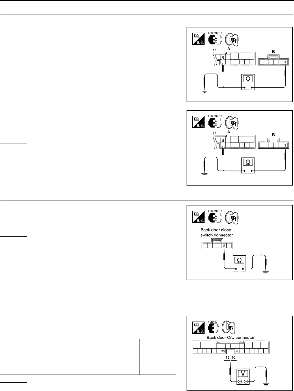
BL-182
AUTOMATIC BACK DOOR SYSTEM
Revision: July 2006 2006 Quest
3. BACK DOOR CLOSE SWITCH CIRCUIT INSPECTION
1. Disconnect back door close switch and back door control unit.
2. Check continuity between back door close switch connector (B)
B63 terminal 1 and back door control unit connector (A) B55 ter-
minal 8.
3. Check continuity between back door close switch connector (B)
B63 terminal 1 and ground.
OK or NG
OK >> GO TO 4.
NG >> Repair or replace harness.
4. BACK DOOR CLOSE SWITCH GROUND INSPECTION
Check continuity between back door close switch connector B63 ter-
minal 2 and ground.
OK or NG
OK >> Replace the back door close switch.
NG >> Repair or replace harness.
Pinch Strip System Inspection
EIS007FZ
1. PINCH STRIP SIGNAL INSPECTION
1. Turn ignition switch OFF.
2. While operating the pinch strip, check voltage between back
door control unit connector B55 terminals 19 (RH), 20 (LH) and
ground.
OK or NG
OK >> Switch is OK.
NG >> GO TO 2.
1 - 8 : Continuity should exist.
WIIA0787E
1 - Ground : Continuity should not exist.
WIIA0787E
2 - Ground : Continuity should exist.
LIIA0807E
Terminals Measuring condition Voltage (V)
(Approx.)
( + ) ( - )
19
20 Ground Pinch strip operation 0
Other 4
LIIA0811E
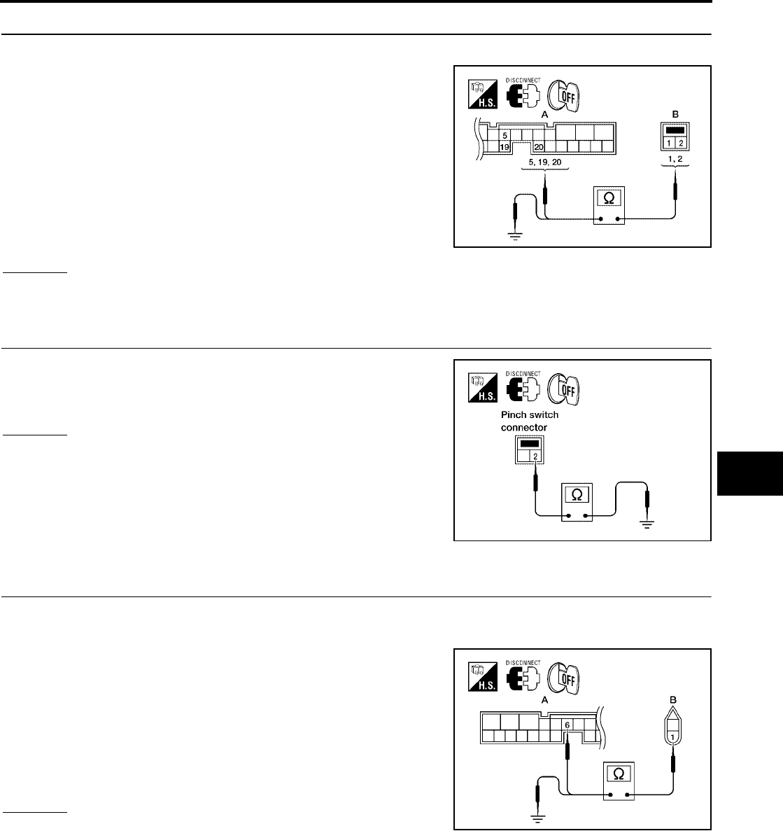
AUTOMATIC BACK DOOR SYSTEM
BL-183
C
D
E
F
G
H
J
K
L
M
A
B
BL
Revision: July 2006 2006 Quest
2. PINCH STRIP CIRCUIT INSPECTION
1. Disconnect pinch strip and back door control unit.
2. Check continuity between pinch strip connector (B) D505 (RH),
D517 (LH) terminals 1, 2 and back door control unit connector
(A) B55 terminals 5, 19 (RH), 20 (LH).
3. Check continuity between pinch strip connector (B) D505 (RH),
D517 (LH) terminal 1and ground.
OK or NG
OK >> GO TO 3.
NG >> Repair or replace harness.
3. PINCH STRIP GROUND INSPECTION
Check continuity between pinch strip connector terminal 2 and
ground.
OK or NG
OK >> Replace the pinch strip.
NG >> Repair or replace harness.
Back Door Warning Chime System Inspection
EIS007G0
1. BACK DOOR WARNING CHIME CIRCUIT INSPECTION
1. Turn ignition switch OFF.
2. Disconnect back door warning chime and back door control unit.
3. Check continuity between back door warning chime connector
(B) D514 terminal 1 and back door control unit connector (A)
B55 terminal 6.
4. Check continuity between back door warning chime connector
(B) D514 terminal 1 and ground.
OK or NG
OK >> GO TO 2.
NG >> Repair or replace harness.
1 - 19 : Continuity should exist.
1 - 20 : Continuity should exist.
2 - 5 : Continuity should exist.
1 - Ground : Continuity should not exist. LIIA2257E
2 - Ground : Continuity should exist.
LIIA0817E
1 - 6 : Continuity should exist.
1 - Ground : Continuity should not exist.
LIIA2258E
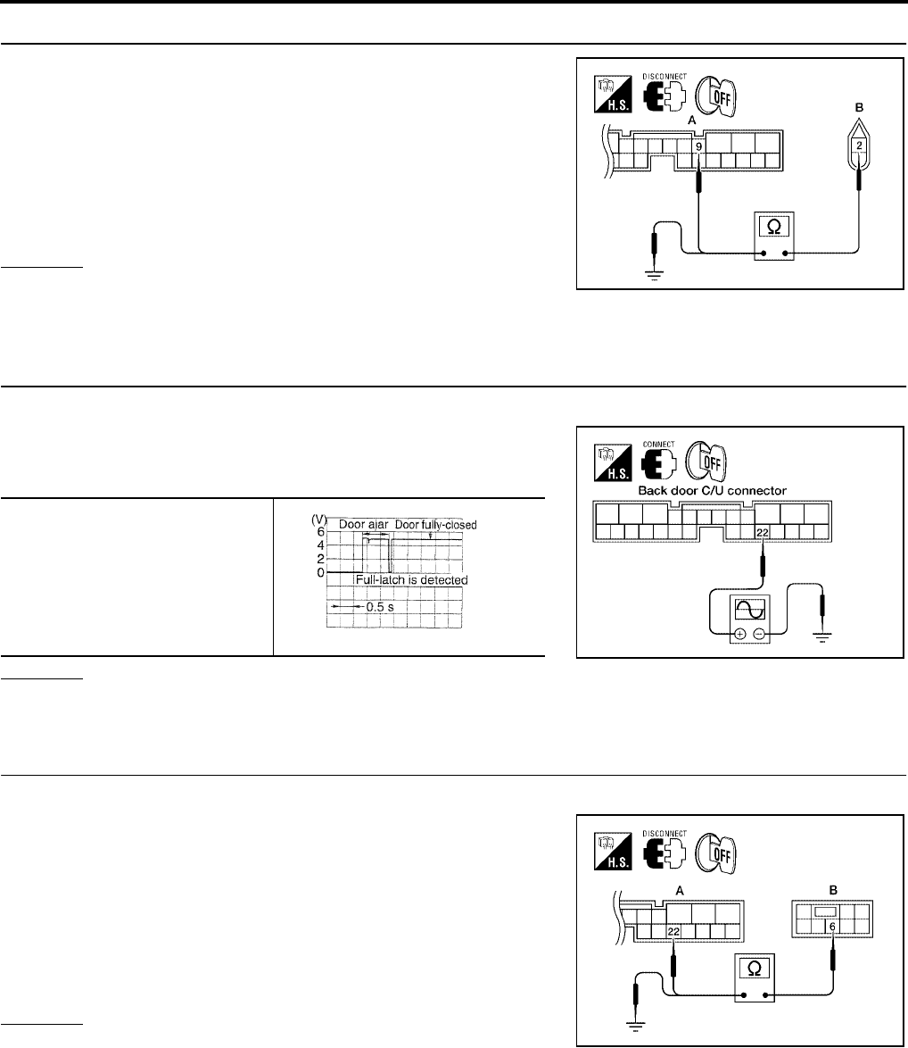
BL-184
AUTOMATIC BACK DOOR SYSTEM
Revision: July 2006 2006 Quest
2. BACK DOOR WARNING CHIME CIRCUIT INSPECTION
1. Check continuity between back door warning chime connector
(B) D514 terminal 2 and back door control unit connector (A)
B55 terminal 9.
2. Check continuity between back door warning chime connector
(B) D514 terminal 2 and ground.
OK or NG
OK >> Replace warning chime.
NG >> Repair or replace harness.
Half-Latch Switch System Inspection
EIS007G1
1. HALF-LATCH SWITCH SIGNAL INSPECTION
1. Turn ignition switch OFF.
2. While fully opening and closing the sliding door, check voltage
waveform between back door control unit connector B55 termi-
nal 22 and ground using an oscilloscope.
OK or NG
OK >> Half-latch switch is OK.
NG >> GO TO 2.
2. HALF-LATCH SWITCH CIRCUIT INSPECTION
1. Disconnect back door latch switch and back control unit.
2. Check continuity between back door latch (half-latch switch)
connector (B) D511 terminal 6 and back door control unit con-
nector (A) B55 terminal 22.
3. Check continuity between back door latch (half-latch switch)
connector (B) D511 terminal 6 and ground.
OK or NG
OK >> GO TO 3.
NG >> Repair or replace harness.
2 - 9 : Continuity should exist.
2 - Ground : Continuity should not exist.
WIIA0819E
22 - Ground
LIIA0826E
PIIA2169E
6 - 22 : Continuity should exist.
6 - Ground : Continuity should not exist.
LIIA2259E
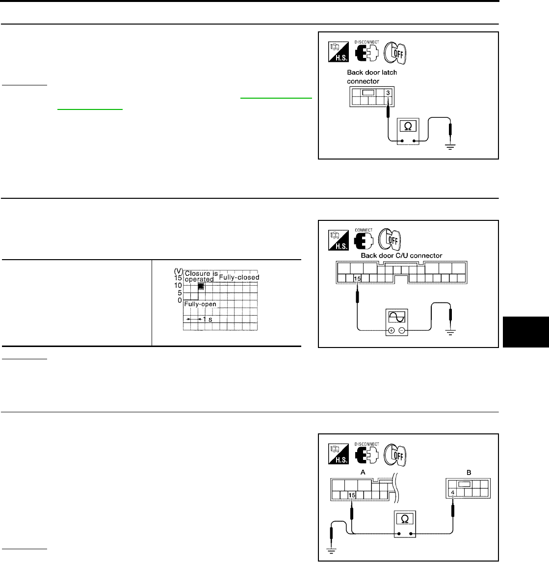
AUTOMATIC BACK DOOR SYSTEM
BL-185
C
D
E
F
G
H
J
K
L
M
A
B
BL
Revision: July 2006 2006 Quest
3. HALF-LATCH SWITCH GROUND INSPECTION
Check continuity between back door latch (half-latch switch) connec-
tor D511 terminal 3 and ground.
OK or NG
OK >> Replace the back door latch. Refer to BL-204, "BACK
DOOR LOCK" .
NG >> Repair or replace harness.
Open Switch System Inspection
EIS007G2
1. OPEN SWITCH SIGNAL INSPECTION
1. Turn ignition switch OFF.
2. While fully closing and opening the back door, check voltage
waveform between back door control unit connector B55 termi-
nal 15 and ground using an oscilloscope.
OK or NG
OK >> Open switch is OK.
NG >> GO TO 2.
2. OPEN SWITCH CIRCUIT INSPECTION
1. Disconnect back door latch and back door control unit.
2. Check continuity between back door latch (open switch) connec-
tor (B) D511 terminal 4 and back door control unit connector (A)
B55 terminal 15.
3. Check continuity between back door latch (open switch) connec-
tor (B) D511 terminal 4 and ground.
OK or NG
OK >> GO TO 3.
NG >> Repair or replace harness.
3 - Ground : Continuity should exist.
LIIA1922E
15 - Ground
LIIA0829E
PIIA2171E
4 - 15 : Continuity should exist.
4 - Ground : Continuity should not exist.
LIIA2260E
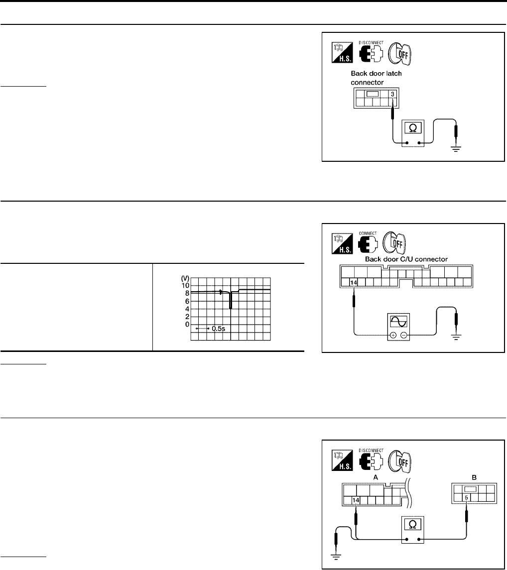
BL-186
AUTOMATIC BACK DOOR SYSTEM
Revision: July 2006 2006 Quest
3. OPEN SWITCH GROUND INSPECTION
Check continuity between back door latch (open switch) connector
D511 terminal 3 and ground.
OK or NG
OK >> Replace the back door latch.
NG >> Repair or replace harness.
Close Switch System Inspection
EIS007G3
1. CLOSE SWITCH SIGNAL INSPECTION
1. Turn ignition switch OFF.
2. While fully opening and closing the back door, check voltage
waveform between back door control unit connector B55 termi-
nal 14 and ground using an oscilloscope.
OK or NG
OK >> Close switch is OK.
NG >> GO TO 2.
2. CLOSE SWITCH CIRCUIT INSPECTION
1. Disconnect back door latch and back door control unit.
2. Check continuity between back door latch (close switch) con-
nector (B) D511 terminal 5 and back door control unit connector
(A) B55 terminal 14.
3. Check continuity between back door latch (close switch) con-
nector (B) D511 terminal 5 and ground.
OK or NG
OK >> GO TO 3.
NG >> Repair or replace harness.
3 - Ground : Continuity should exist.
LIIA1922E
14 - Ground
LIIA0831E
WIIA1047E
5 - 14 : Continuity should exist.
5 - Ground : Continuity should not exist.
LIIA2261E
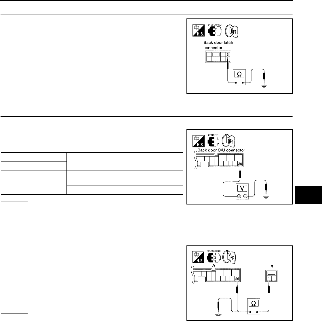
AUTOMATIC BACK DOOR SYSTEM
BL-187
C
D
E
F
G
H
J
K
L
M
A
B
BL
Revision: July 2006 2006 Quest
3. CLOSE SWITCH GROUND INSPECTION
Check continuity between back door latch (close switch) connector
D511 terminal 3 and ground.
OK or NG
OK >> Replace the back door latch.
NG >> Repair or replace harness.
Back Door Handle Switch System Inspection
EIS007G4
1. BACK DOOR HANDLE SWITCH SIGNAL INSPECTION
1. Turn ignition switch OFF.
2. While operating the back door handle switch, check voltage
between back door control unit connector B55 terminal 26 and
ground.
OK or NG
OK >> Back door handle switch circuit is OK.
NG >> GO TO 2.
2. BACK DOOR HANDLE SWITCH CIRCUIT INSPECTION
1. Disconnect back door handle switch and back door control unit.
2. Check continuity between back door handle switch connector
(B) D510 terminal 1 and back door control unit connector (A)
B55 terminal 26.
3. Check continuity between back door handle switch connector
(B) D510 terminal 1 and ground.
OK or NG
OK >> GO TO 4.
NG >> Repair or replace harness.
3 - Ground : Continuity should exist.
LIIA1922E
Terminal Measuring condition Voltage (V)
(Approx.)
( + ) ( - )
26 Ground
Pull the back door handle
switch (ON) 0
Other (OFF) Battery voltage
LIIA0833E
1 - 26 : Continuity should exist.
1 - Ground : Continuity should not exist.
WIIA0788E
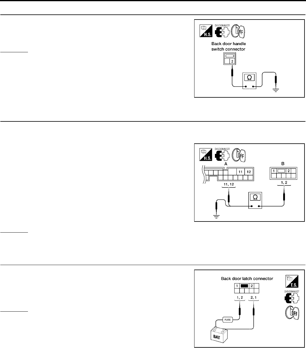
BL-188
AUTOMATIC BACK DOOR SYSTEM
Revision: July 2006 2006 Quest
3. BACK DOOR HANDLE SWITCH GROUND INSPECTION
Check continuity between back door handle switch connector D510
terminal 2 and ground.
OK or NG
OK >> Replace the back door handle switch.
NG >> Repair or replace harness.
Cinch Latch Motor System Inspection
EIS007G5
1. CINCH LATCH MOTOR CIRCUIT INSPECTION
1. Turn ignition switch OFF.
2. Disconnect back door latch and back door control unit.
3. Check continuity between back door latch (cinch latch motor)
connector (B) D511 terminals 1, 2 and back door control unit
connector (A) B55 terminals 11, 12.
4. Check continuity between back door latch (cinch latch motor)
connector (B) D511 terminals 1, 2 and ground.
OK or NG
OK >> GO TO 2.
NG >> Repair or replace harness.
2. CINCH LATCH MOTOR OPERATION INSPECTION
Connect battery power to terminals 1 and 2 on the back door latch
connector and check motor operation.
OK or NG
OK >> GO TO 3.
NG >> Replace the back door latch.
2 - Ground : Continuity should exist.
LIIA0835E
1 - 12 : Continuity should exist.
2 - 11 : Continuity should exist.
1 - Ground : Continuity should not exist.
2 - Ground : Continuity should not exist. LIIA2263E
1 (+) - 2 (-) : It operates.
1 (-) - 2 (+) : It operates. (Reverse rotation)
LIIA0838E

AUTOMATIC BACK DOOR SYSTEM
BL-189
C
D
E
F
G
H
J
K
L
M
A
B
BL
Revision: July 2006 2006 Quest
3. CINCH LATCH MOTOR SIGNAL INSPECTION
1. Reconnect back door latch and back door control unit.
2. While fully opening and closing the back door, check voltage
waveform between back door control unit connector B55 termi-
nals 11, 12 and ground using an oscilloscope.
OK or NG
OK >> Cinch latch motor circuit is OK.
NG >> Replace the back door control unit.
11 - Ground
12 - Ground Battery voltage
LIIA2397E
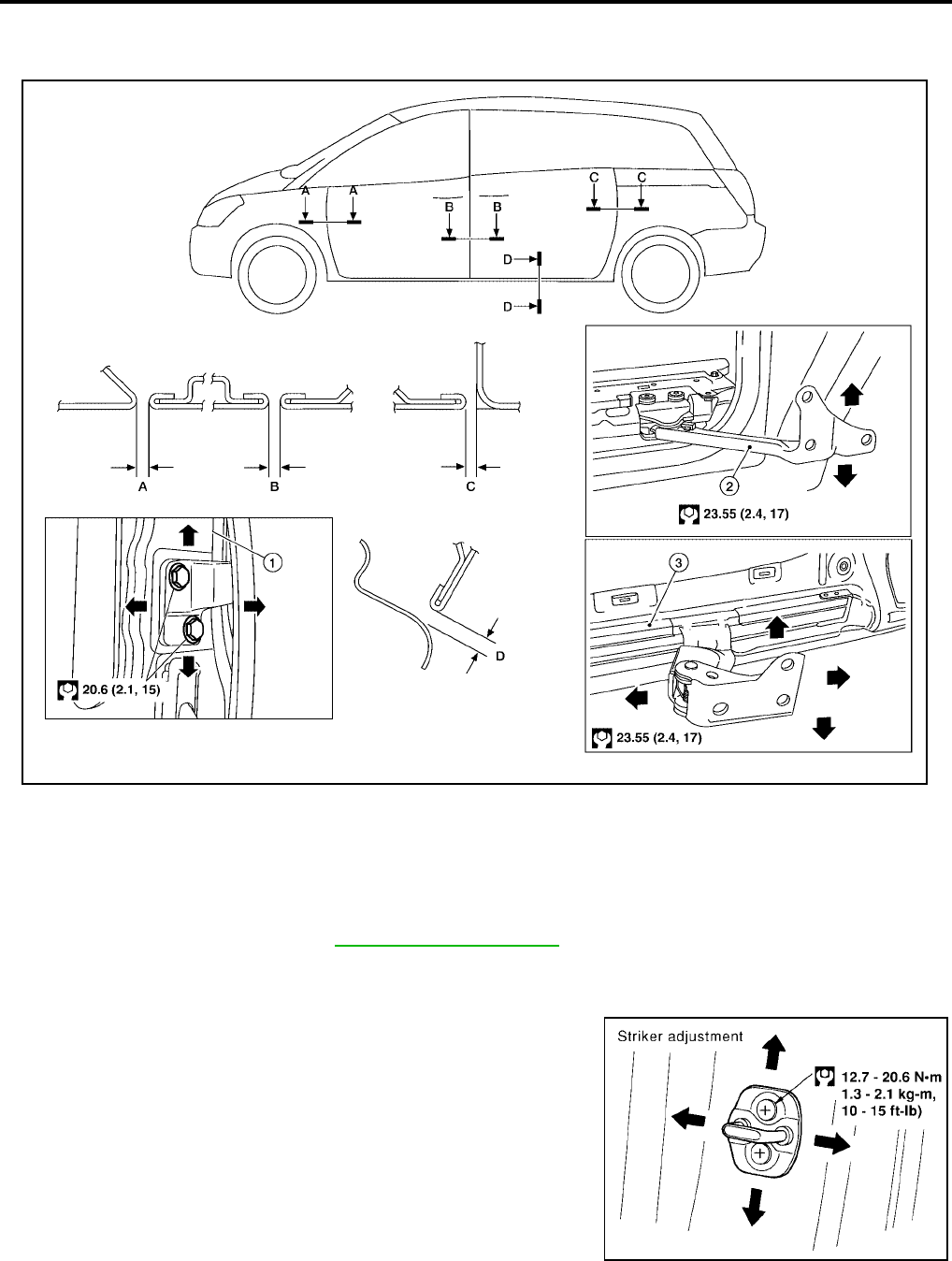
BL-190
DOOR
Revision: July 2006 2006 Quest
DOOR PFP:80100
Fitting Adjustment
EIS007G6
FRONT DOOR
Longitudinal clearance and surface height adjustment at front end
1. Remove the front fender. Refer to EI-21, "FRONT FENDER" .
2. Loosen the hinge nuts or bolts and adjust as needed.
Striker Adjustment
1. Adjust the striker so that it becomes parallel with the lock inser-
tion direction.
A. 4.5 ± 1.0 mm (0.177 ± 0.039 in) B. 4.5 ± 1.0 mm (0.177 ± 0.039 in) C. 4.5 ± 1.0 mm (0.177 ± 0.039 in)
D. 4.5 ± 1.0 mm (0.177 ± 0.039 in) 1. Front door hinge pillar 2. Lower roller assembly
3. Waist rail
WIIA0847E
LIIA0113E
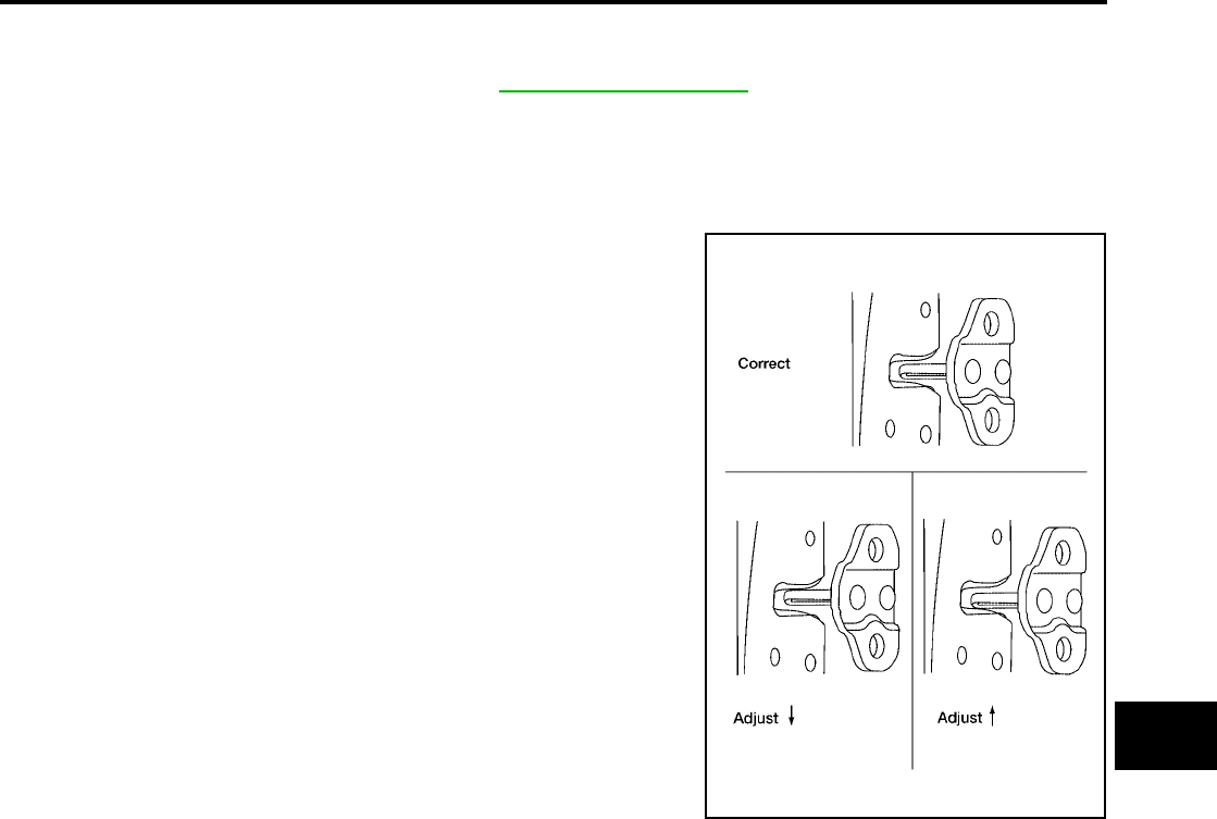
DOOR
BL-191
C
D
E
F
G
H
J
K
L
M
A
B
BL
Revision: July 2006 2006 Quest
SLIDE DOOR
Longitudinal clearance, surface height and outboard adjustment at front end
1. Remove the sliding door trim panel. Refer to EI-30, "SLIDING DOOR" .
2. Accessing from inside the vehicle, loosen the nuts. Open the sliding door and adjust as needed.
Striker Adjustment
NOTE:
Turn OFF automatic sliding door system, if equipped.
1. Inspect the door latch-to-striker clearance for the front and rear
strikers.
●Slowly open and close the sliding door.
●Confirm the strikers meet the latches correctly.
●Adjust striker height up or down as needed.
2. Slightly loosen the door strikers, upper and lower dovetails, and
contact switch.
NOTE:
Loosened parts should not move on their own.
3. Open and close the door three or four times to allow the strikers
and contact switch to align themselves.
4. Carefully tighten all loosened parts using care not to move the
parts .
5. Open and close door three or four times to confirm smooth
latching.
LIIA1645E
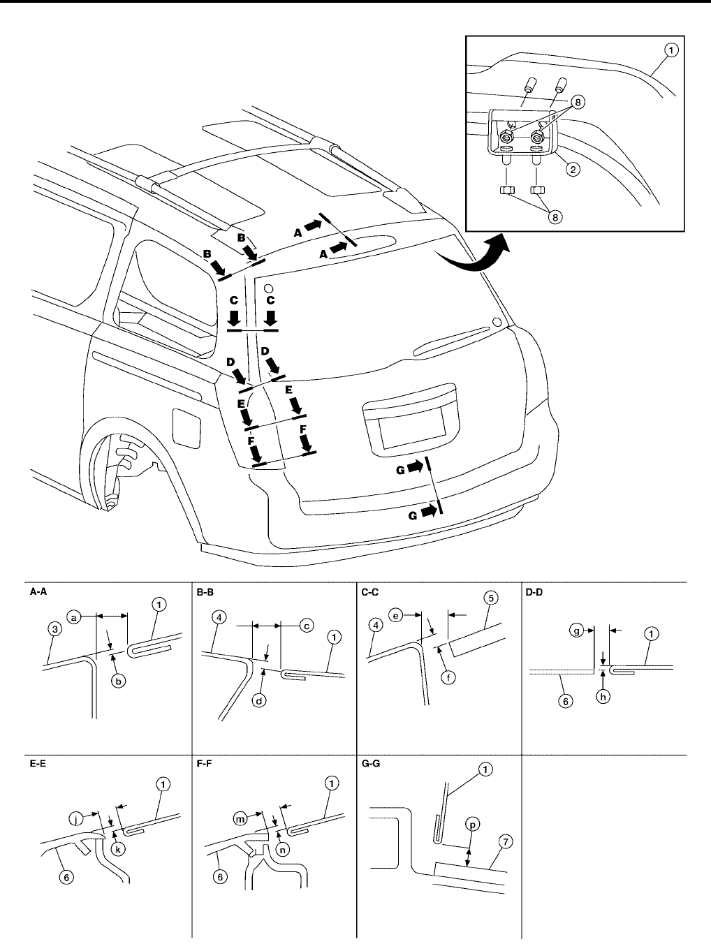
BL-192
DOOR
Revision: July 2006 2006 Quest
BACK DOOR
1. Back door 2. Back door hinge RH & LH 3. Roof
4. Body side outer 5. Back door glass 6. Rear combination lamp
WIIA0848E
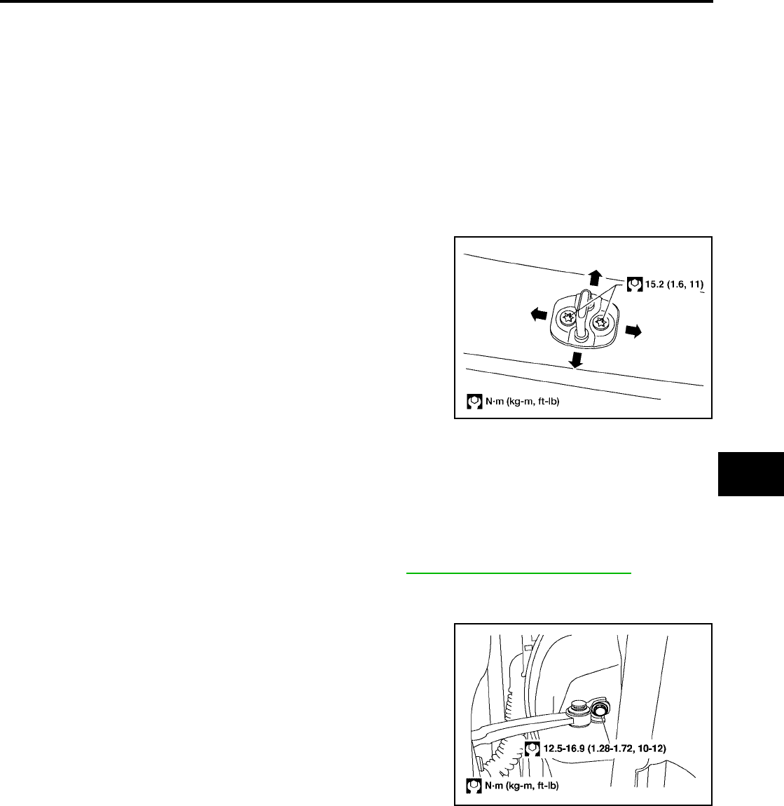
DOOR
BL-193
C
D
E
F
G
H
J
K
L
M
A
B
BL
Revision: July 2006 2006 Quest
Longitudinal clearance, surface height and outboard adjustment at front end
1. Open and support the back door.
2. Slightly loosen the hinge nuts.
3. Reposition the door as necessary and tighten the nuts.
4. Confirm the adjustment. Repeat as necessary to obtain the desired fit.
Striker Adjustment
1. Adjust the striker so that it becomes parallel with the lock inser-
tion direction.
Removal and Installation
EIS007G7
FRONT DOOR
CAUTION:
●When removing and installing the door assembly, support the door with a jack and shop cloth to
protect the door and body.
●When removing and installing door assembly, be sure to carry out the fitting adjustment.
●Check the hinge rotating part for poor lubrication. If necessary, apply "body grease".
1. Remove the door window and module assembly. Refer to GW-82, "Removal and Installation" .
2. Remove the door harness.
3. Remove the check link cover.
4. Remove the check link bolt from the hinge pillar.
7. Rear bumper fascia 8. 17 N·m (1.7 Kg·m, 13 ft-lb) a. 10.0 mm ( 0.4in)
b. 2.5 mm (0.10 in) c. 6.8 mm (0.27 in) d. 0.8 mm (0.03 in)
e. 6.5 mm (0.26 in) f. 2.8 mm (0.11 in) g. 6.7 mm (0.26 in)
h. 1.4 mm (0.06 in) j. 6.2 mm (0.24 in) k. 0.4 mm (0.02 in)
m. 6.2 mm (0.24 in) n. 0.4 mm (0.02 in) p. 6.1 mm (0.24 in)
LIIA1733E
LIIA0423E
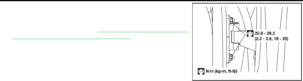
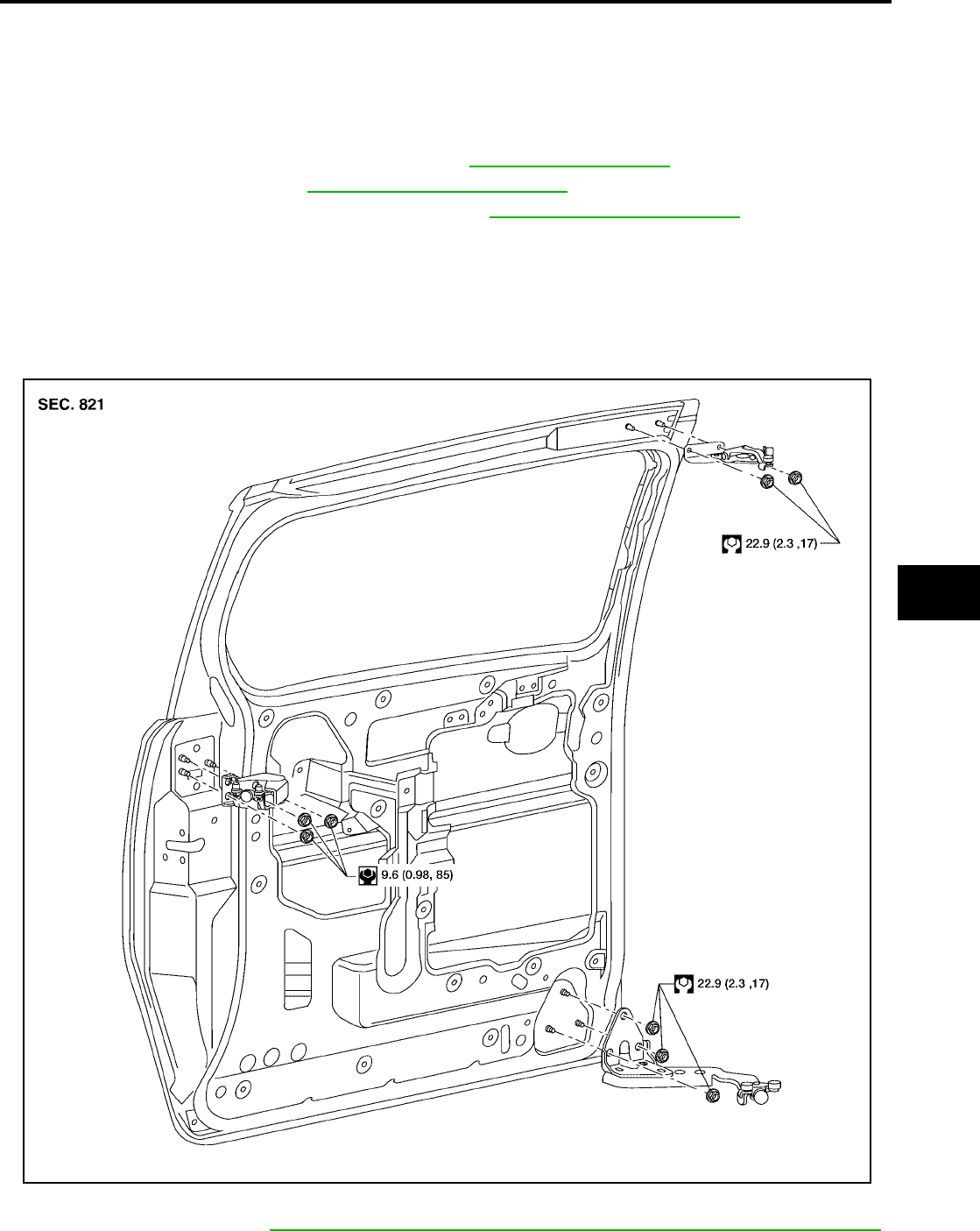
DOOR
BL-195
C
D
E
F
G
H
J
K
L
M
A
B
BL
Revision: July 2006 2006 Quest
SLIDE DOOR
CAUTION:
●When removing and installing the door assembly, support the door with a jack and shop cloth to
protect the door and body.
●When removing and installing door assembly, be sure to carry out the fitting adjustment.
●Check the hinge rotating part for poor lubrication. If necessary, apply "body grease".
1. Remove the upper and lower door finishers. Refer to EI-30, "SLIDING DOOR" .
2. Remove the door glass. Refer to GW-86, "SLIDE DOOR GLASS" .
3. Remove the door lock and handle assemblies. Refer to BL-200, "SLIDE DOOR LOCK" .
4. Remove the upper and lower male dovetail assemblies.
5. Remove the door wiring harness.
6. Remove the door.
●Disconnect the rear slide door guide.
●Remove the lower hinge bracket.
●Remove the upper hinge bracket.
Installation is in the reverse order of removal.
●Align the front door. Refer to BL-190, "Longitudinal clearance and surface height adjustment at front end" .
WIIA0830E
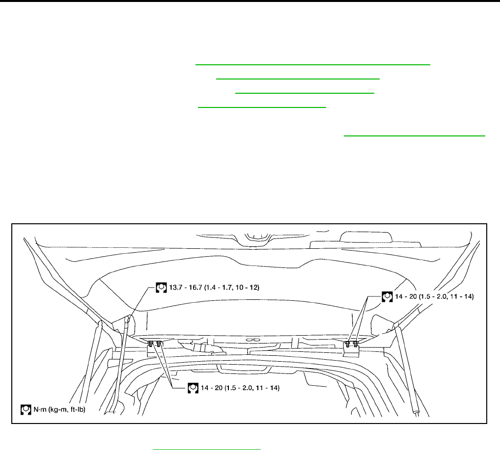
BL-196
DOOR
Revision: July 2006 2006 Quest
BACK DOOR
WARNING:
Always support back door when removing or replacing back door stays. Power back door opener will
not support back door with back door stays removed.
1. Remove the back door glass. Refer to GW-13, "REAR WINDOW GLASS AND MOLDING" .
2. Remove the license lamp finisher. Refer to EI-23, "LICENSE LAMP FINISHER" .
3. Remove the back door lock assembly. Refer to BL-204, "BACK DOOR LOCK" .
4. Remove the rear wiper motor. Refer to WW-45, "Rear Wiper Motor" .
5. Remove the back door wire harness.
6. Remove the rear washer nozzle and hose from the back door. Refer to WW-47, "Rear Washer Nozzle" .
CAUTION:
Two technicians should be used to avoid damaging the back door during removal.
7. Support the back door with a suitable tool.
8. Disconnect the power back door lift arm from the door.
9. Remove the back door stays.
10. Remove the door side nuts and the back door assembly.
Installation is in the reverse order of removal.
●Align the back door. Refer to BL-192, "BACK DOOR" .
LIIA1878E
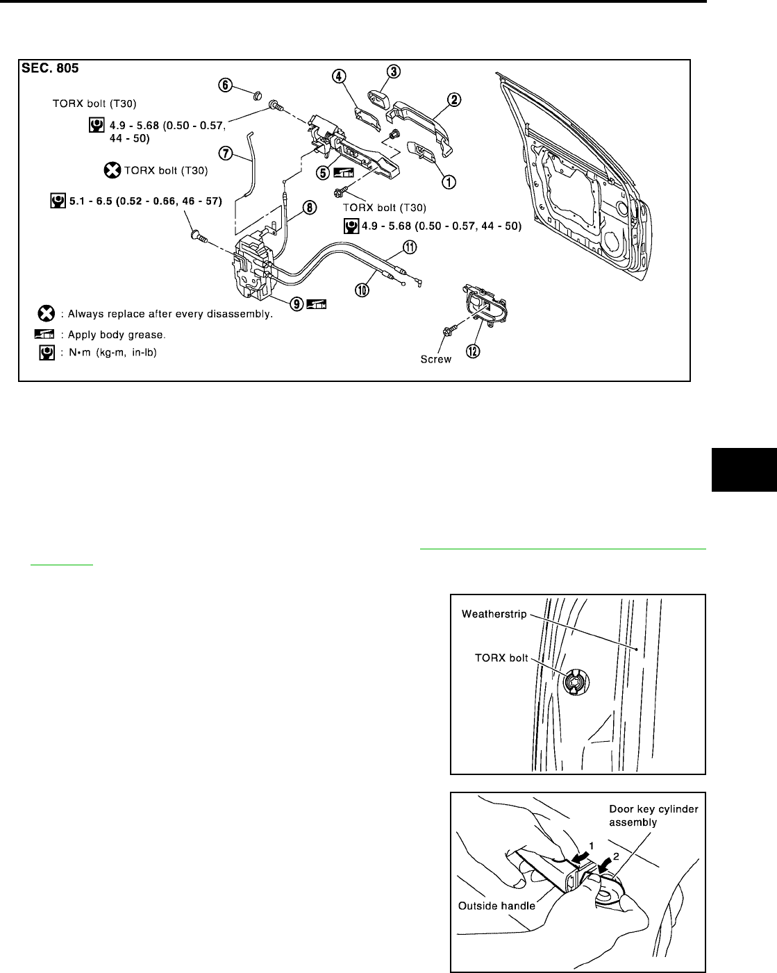
FRONT DOOR LOCK
BL-197
C
D
E
F
G
H
J
K
L
M
A
B
BL
Revision: July 2006 2006 Quest
FRONT DOOR LOCK PFP:80502
Component Structure
EIS007G8
Removal and Installation
EIS007WN
1. Remove the front door window regulator assembly. Refer to GW-82, "FRONT DOOR GLASS AND REG-
ULATOR" .
2. Remove the front door window rear glass run.
3. Remove the grommet, and remove door key cylinder assembly
(driver side) or outside handle escutcheon (passenger side)
bolts (TORX T30) from grommet hole.
4. While pulling the outside handle, remove door key cylinder
assembly or escutcheon.
1. Front gasket 2. Outside handle 3. Door key cylinder assembly (Driver
side)
Outside handle escutcheon (Pas-
senger side)
4. Rear gasket 5. Outside handle bracket 6. Grommet
7. Key cylinder rod (Driver side only) 8. Outside handle cable 9. Door lock assembly
10. Inside handle cable 11. Lock knob cable 12. Inside handle
WIIA0541E
PIIA3553E
PIIA3554E
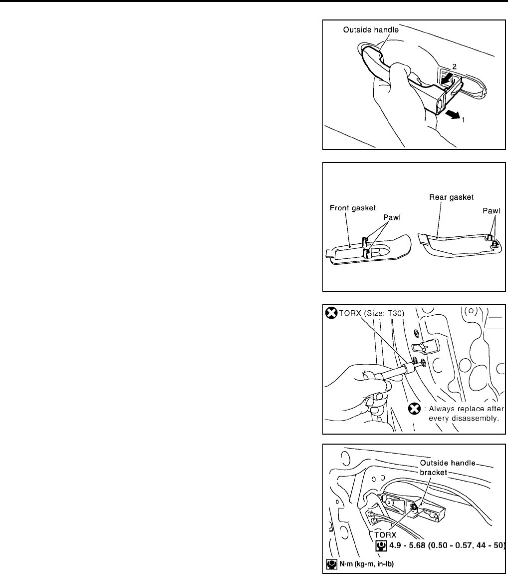
BL-198
FRONT DOOR LOCK
Revision: July 2006 2006 Quest
5. Separate the key cylinder rod from the door key cylinder assembly (if equipped).
6. While pulling outside handle, slide toward rear of vehicle to
remove.
7. Remove the front and rear gaskets.
8. Remove the TORX bolts (T30) and the door lock assembly.
9. Remove the TORX bolt (T30) from the outside handle bracket.
LIIA0532E
PIIA3557E
Door lock assembly bolts : 5.3 Nm (0.54 kg-m, 47 in-lb)
PIIA1090E
WIIA0542E
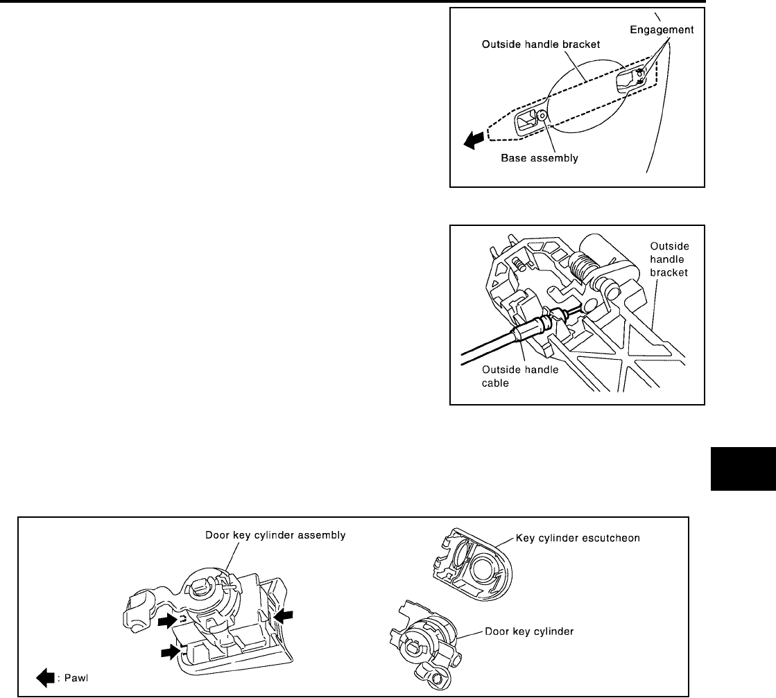
FRONT DOOR LOCK
BL-199
C
D
E
F
G
H
J
K
L
M
A
B
BL
Revision: July 2006 2006 Quest
10. While pulling the outside handle bracket, slide it toward the rear
of the vehicle to remove it and the door lock assembly.
11. Disconnect the door lock actuator electrical connector.
12. Separate the outside handle cable connection from the outside
handle bracket.
Installation is in the reverse order of removal.
CAUTION:
To install each rod, be sure to rotate the rod holder until a click is felt.
Disassembly and Assembly
EIS007GA
DOOR KEY CYLINDER ASSEMBLY
Remove the key cylinder escutcheon pawl and remove the door key cylinder.
PIIA3558E
PIIA5059E
PIIA4136E
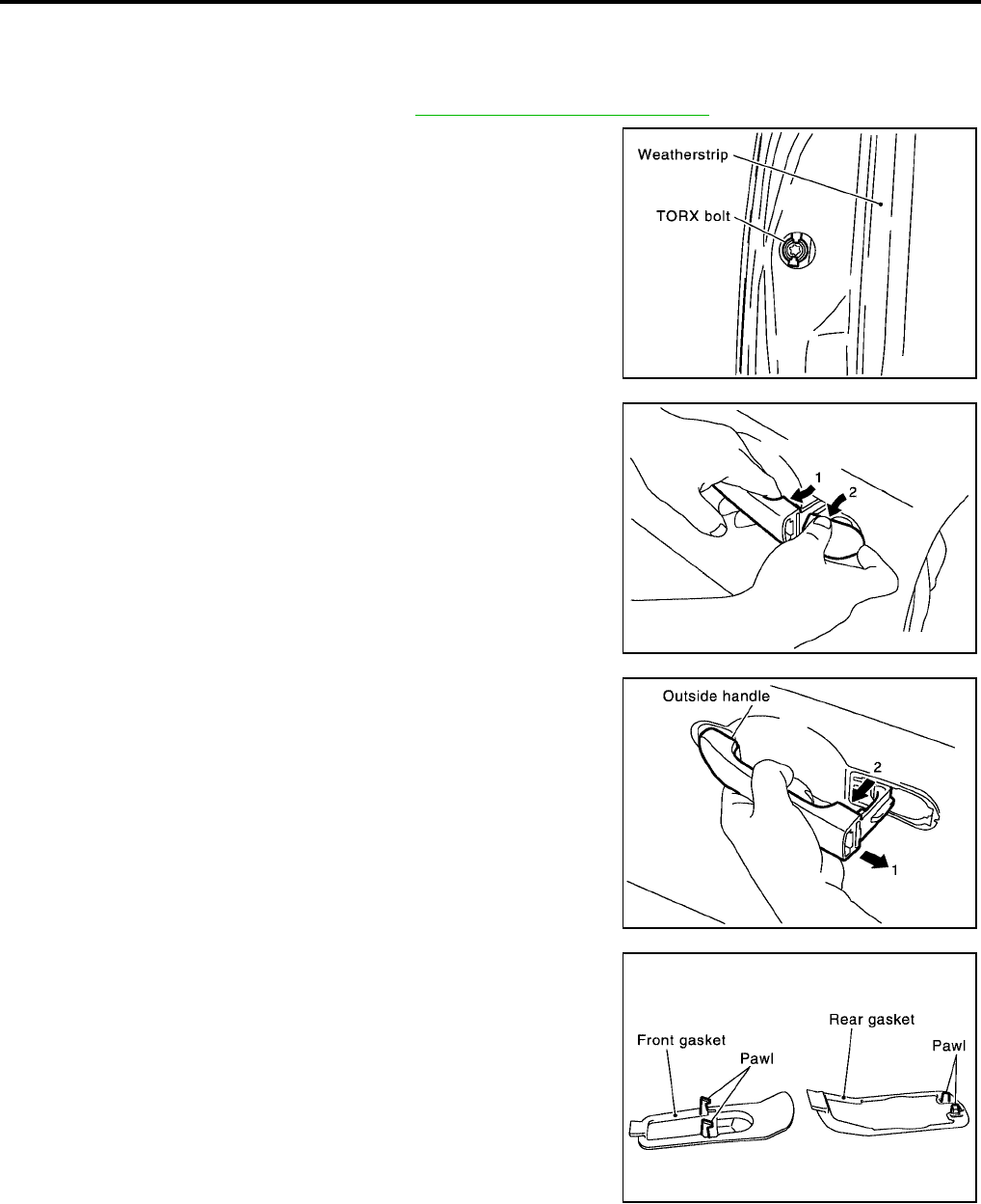
BL-200
SLIDE DOOR LOCK
Revision: July 2006 2006 Quest
SLIDE DOOR LOCK PFP:82504
Removal and Installation
EIS007GB
OUTSIDE HANDLE
1. Remove the sliding door finisher. Refer to EI-29, "Removal and Installation" .
2. Remove the grommet, and the outside handle escutcheon bolt
(TORX T30) from grommet hole.
3. While 1) pulling the outside handle, 2) remove outside handle
escutcheon.
4. While 1) pulling outside handle, 2) slide toward rear of vehicle to
remove.
5. Remove the front gasket and rear gasket.
PIIA3553E
WIIA0851E
LIIA0532E
PIIA3557E
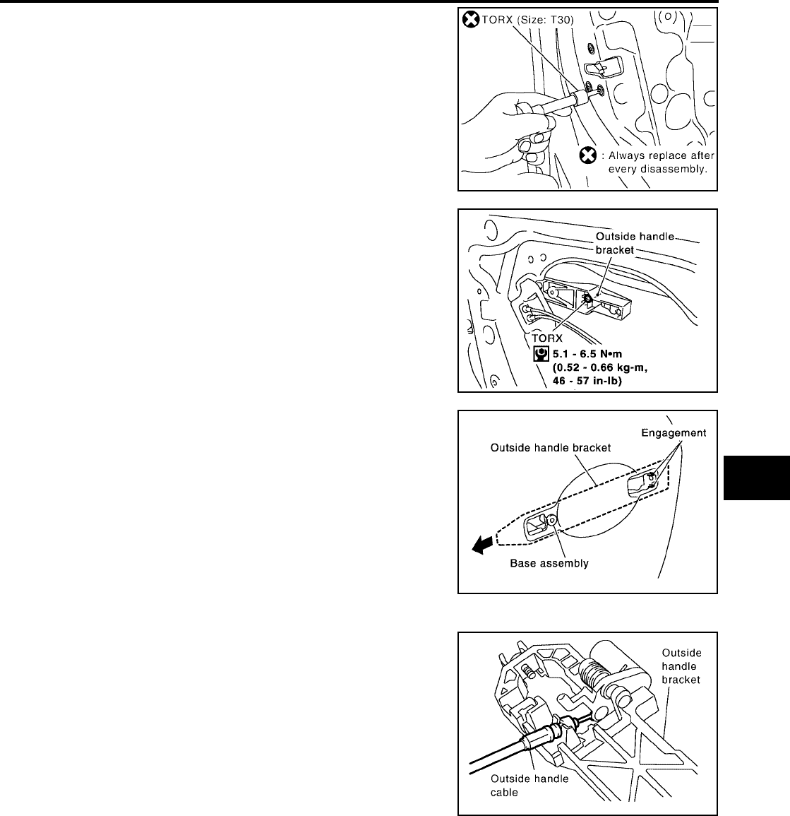
SLIDE DOOR LOCK
BL-201
C
D
E
F
G
H
J
K
L
M
A
B
BL
Revision: July 2006 2006 Quest
6. Remove the TORX bolts (T30), remove the door lock assembly.
7. Remove the TORX bolt (T30), and remove the outside handle
bracket.
8. While pulling outside handle, slide toward rear of vehicle to
remove outside handle and door lock assembly.
9. Disconnect the door lock actuator connector.
10. Separate outside handle cable from the outside handle bracket.
Installation is in the reverse order of removal.
PIIA1090E
PIIA3556E
PIIA3558E
PIIA5059E
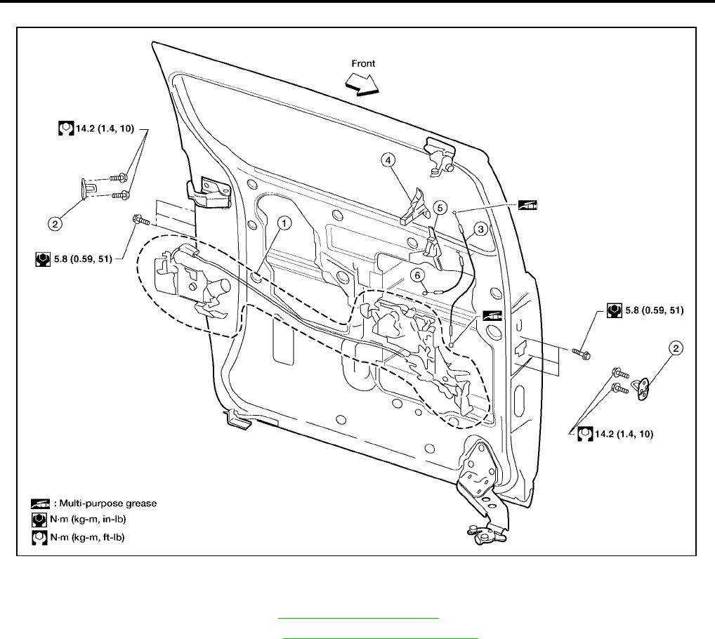
BL-202
SLIDE DOOR LOCK
Revision: July 2006 2006 Quest
SLIDING DOOR LOCK ASSEMBLY
1. Remove sliding door finisher. Refer to EI-30, "SLIDING DOOR" .
2. Remove exterior door handle. Refer to BL-200, "OUTSIDE HANDLE" .
3. Disconnect sliding door lock assembly electrical connectors.
4. Remove sliding door lock assembly.
●Remove screws from front and rear latches.
Installation is in the reverse order of removal.
1. Sliding door lock assembly 2. Striker 3. Sliding door inside handle cable
4. Sliding door inside handle 5. Sliding door inside lock 6. Sliding door inside lock cable
LIIA1634E
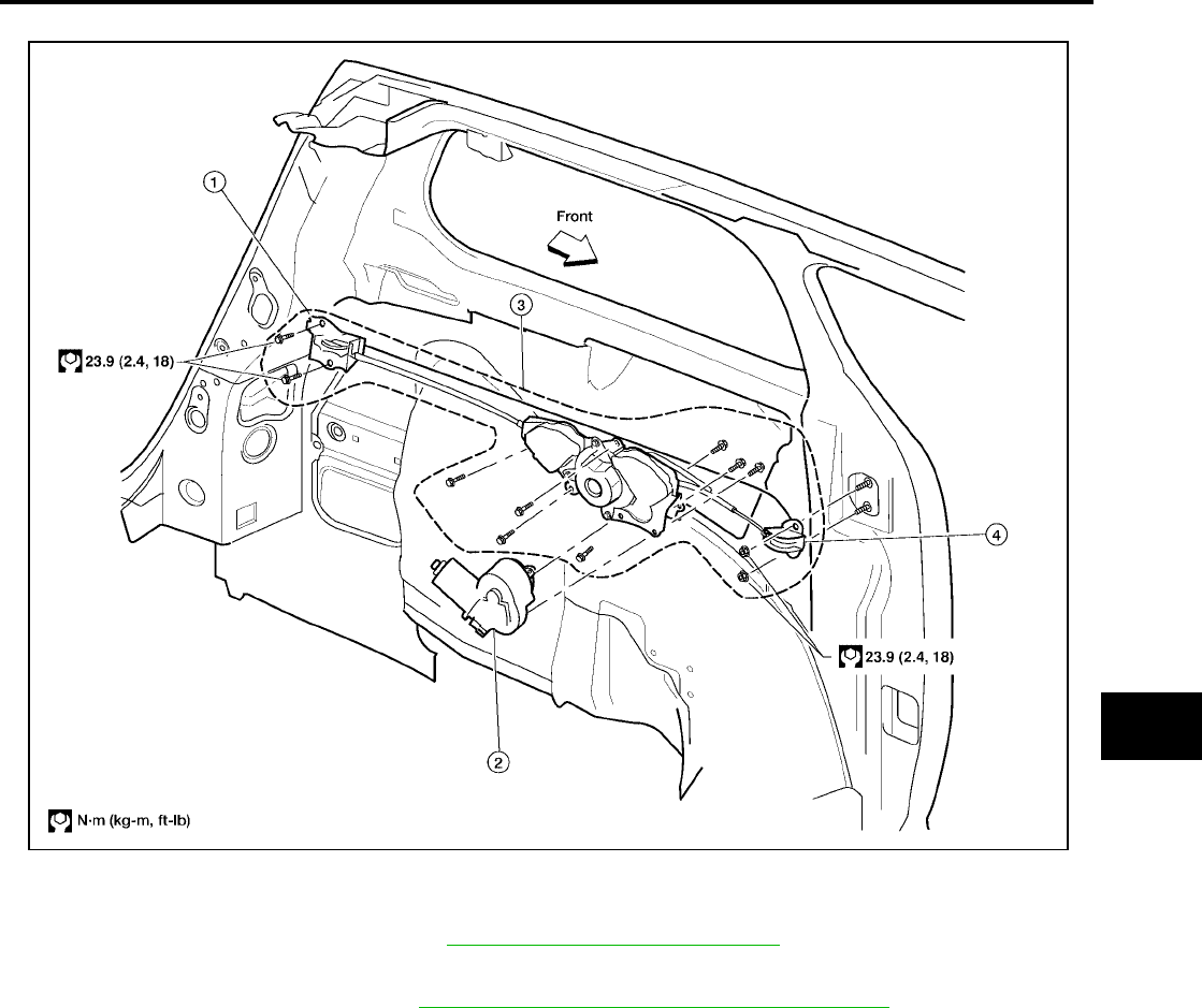
SLIDE DOOR LOCK
BL-203
C
D
E
F
G
H
J
K
L
M
A
B
BL
Revision: July 2006 2006 Quest
SLIDING DOOR CABLE ASSEMBLY AND MOTOR
1. Remove sliding door rail cover. Refer to EI-27, "SIDE GUARD MOLDING" .
2. Disconnect slide door cables.
3. Remove luggage lower trim. Refer to EI-36, "REAR LOWER FINISHER ASSEMBLY" .
4. Disconnect sliding door motor electrical connector.
5. Remove sliding door link rollers.
6. Remove sliding door cable and motor assembly.
7. Remove sliding door motor from sliding door cable assembly.
Installation is in the reverse order of removal.
1. Rear roller 2. Sliding door motor 3. Sliding door cable assembly
4. Front roller
LIIA1633E
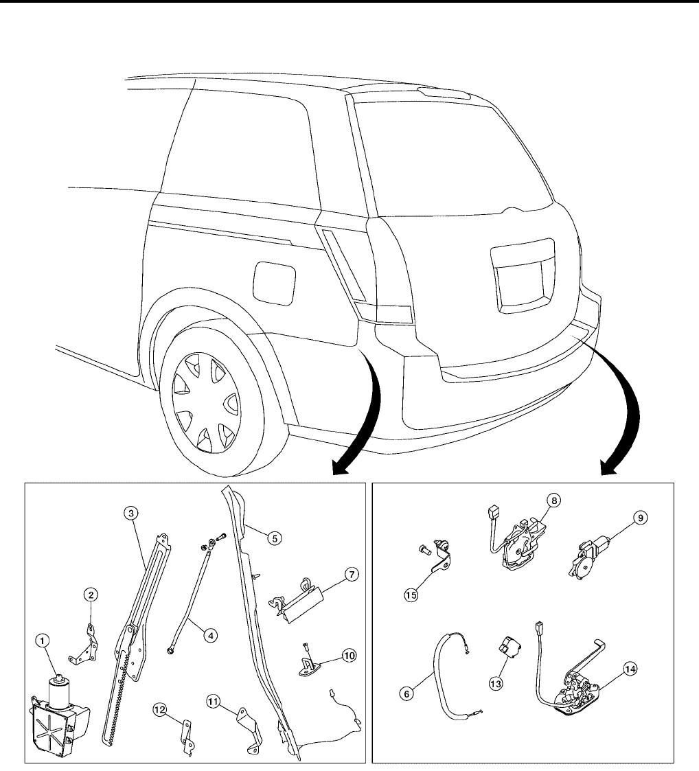
BL-204
BACK DOOR LOCK
Revision: July 2006 2006 Quest
BACK DOOR LOCK PFP:90504
Component Structure
EIS007GC
1. Back door motor assembly 2. Back door motor assembly bracket 3. Back door motor gear assembly
4. Back door closure rod 5. Pinch strip 6. Back door latch release cable
7. Back door handle 8. Power back door latch assembly 9. Power back door latch cinch motor
10. Back door striker 11. Dovetail (door side) 12. Dovetail (body side)
13. Back door opener actuator assem-
bly
14. Lower back door lock assembly 15. Back door lock bracket
WIIA0369E
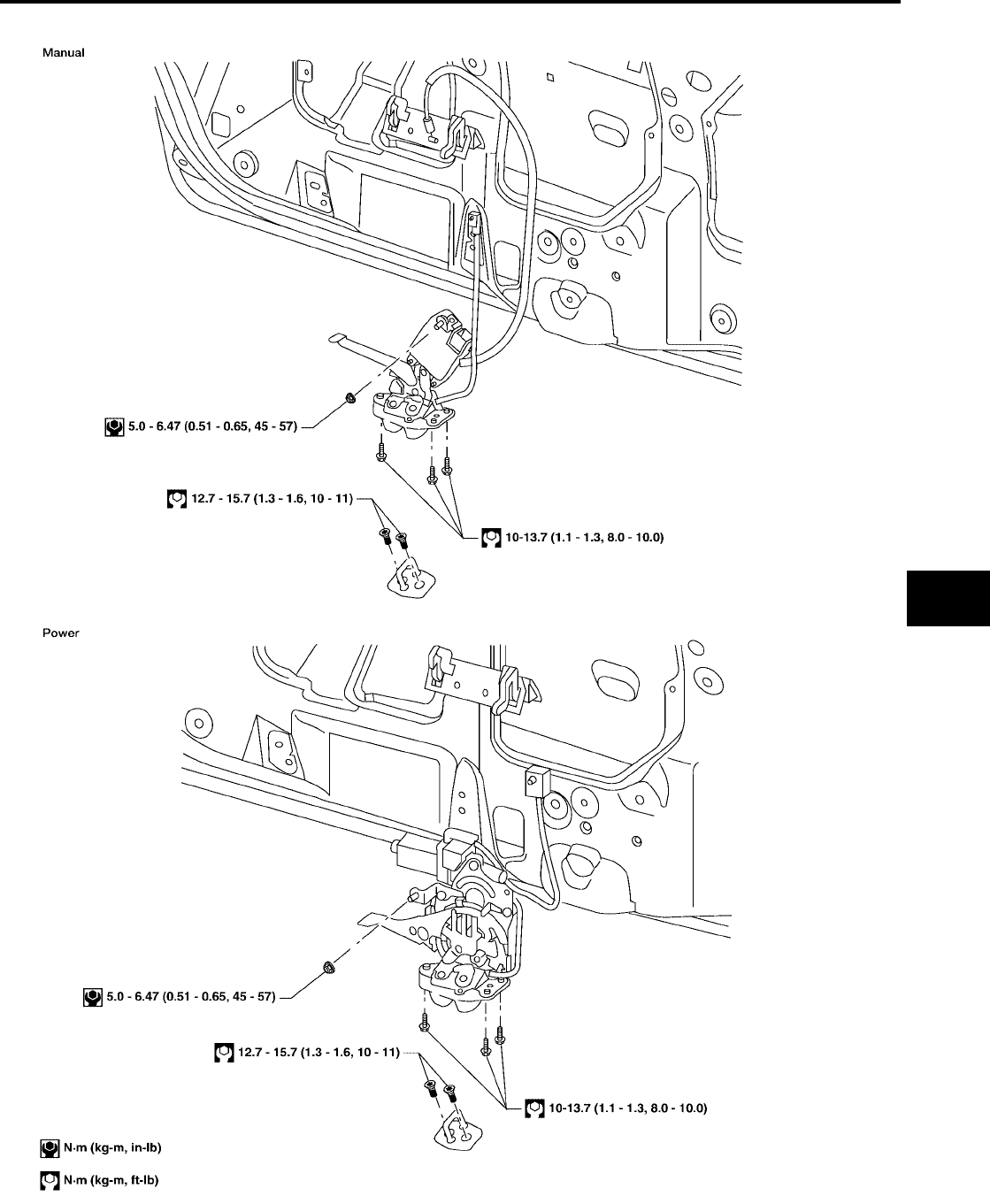
BACK DOOR LOCK
BL-205
C
D
E
F
G
H
J
K
L
M
A
B
BL
Revision: July 2006 2006 Quest
Back Door Latch
EIS007GD
LIIA1867E
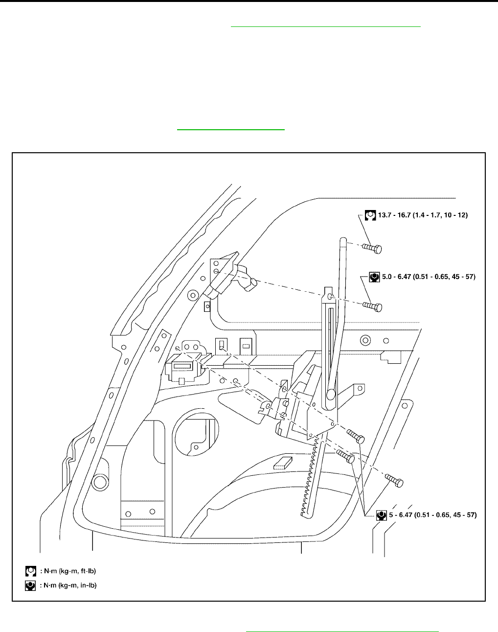
BL-206
BACK DOOR LOCK
Revision: July 2006 2006 Quest
REMOVAL
1. Remove the back door lower finisher. Refer to EI-36, "BACK DOOR LOWER FINISHER"
2. Remove the weather seal.
3. On manual doors, disconnect the back door latch release cable.
4. For power doors, disconnect the cinch motor electrical connector.
5. Remove the back door latch assembly (power door) or the back door lock assembly (manual door).
INSTALLATION
Installation is in the reverse order of removal.
●Align the back door latch. Refer to BL-192, "BACK DOOR" .
Back Door Power Lift Assembly
EIS007GE
REMOVAL
1. Remove the LH rear pillar upper finisher. Refer to EI-36, "REAR PILLAR UPPER FINISHER" .
2. Remove the closure rod to door bolt.
3. Remove the back door motor gear assembly.
4. Remove the back door motor.
●Disconnect the electrical connector.
LIIA1868E

BACK DOOR LOCK
BL-207
C
D
E
F
G
H
J
K
L
M
A
B
BL
Revision: July 2006 2006 Quest
INSTALLATION
Installation is in the reverse order of removal.
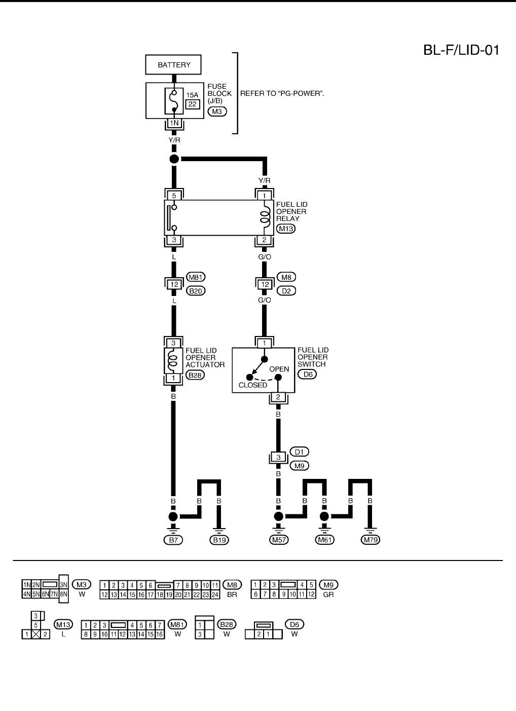
BL-208
FUEL FILLER LID OPENER
Revision: July 2006 2006 Quest
FUEL FILLER LID OPENER PFP:78820
Wiring Diagram — F/LID —
EIS007GF
WIWA1139E
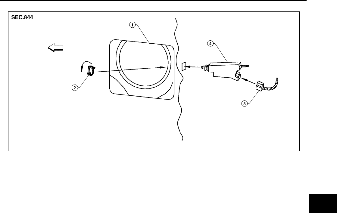
FUEL FILLER LID OPENER
BL-209
C
D
E
F
G
H
J
K
L
M
A
B
BL
Revision: July 2006 2006 Quest
REMOVAL
1. Remove LH rear lower finisher. Refer to EI-36, "REAR LOWER FINISHER ASSEMBLY" .
2. Open fuel filler lid.
3. Disconnect fuel filler lid opener actuator electrical connector.
4. Remove lock ring and fuel filler lid opener actuator.
●Turn lock ring 1/4 turn counter-clockwise to remove.
INSTALLATION
Installation is in the reverse order of removal.
1. Fuel filler lid opening (LH rear fender) 2. Lock ring 3. Electrical connector
4. Fuel filler lid opener actuator
LIIA2272E
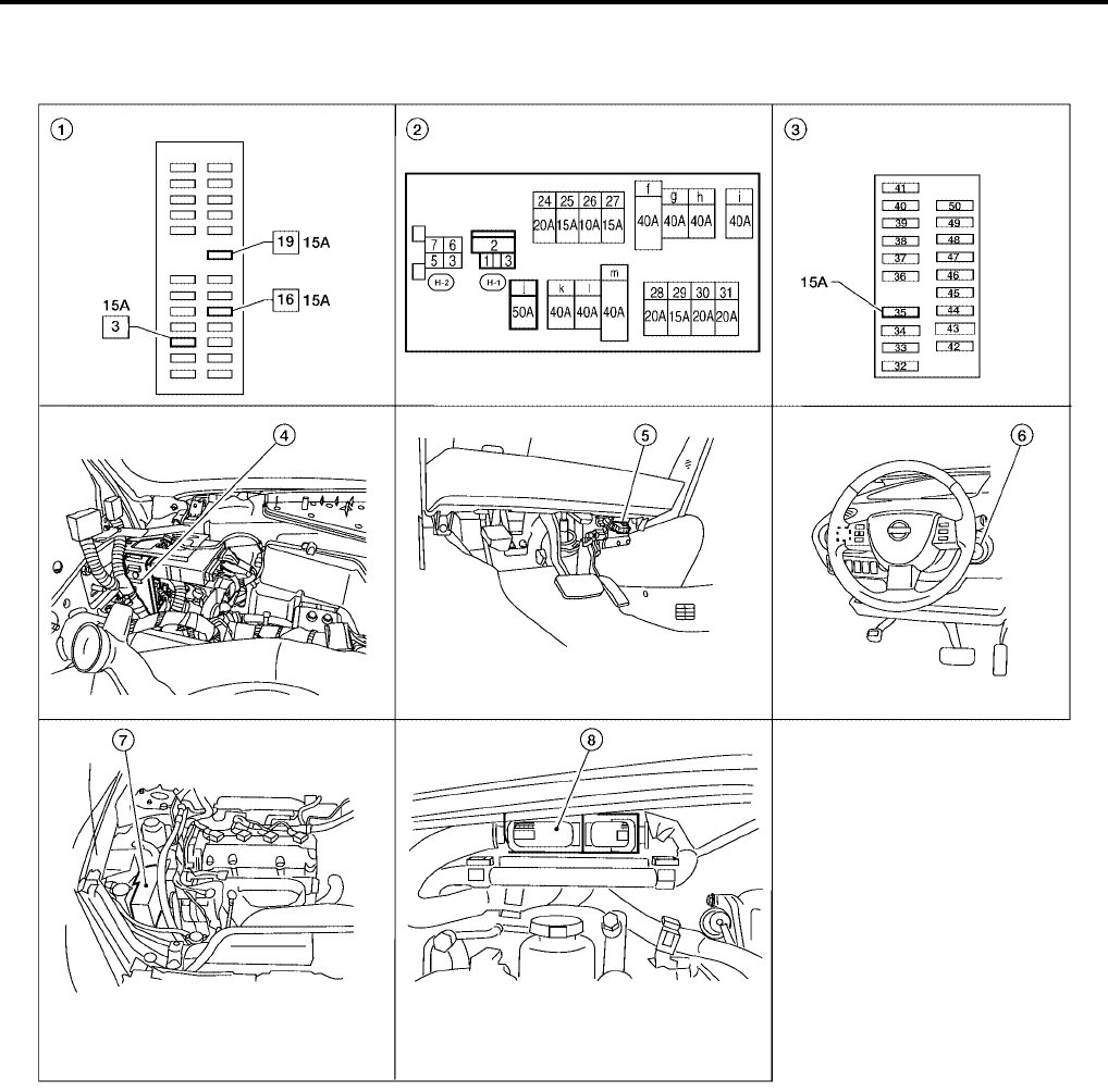
BL-210
NVIS(NISSAN VEHICLE IMMOBILIZER SYSTEM-NATS)
Revision: July 2006 2006 Quest
NVIS(NISSAN VEHICLE IMMOBILIZER SYSTEM-NATS) PFP:28591
Component Parts and Harness Connector Location
EIS007GG
1. Fuse block (J/B) 2. Fuse and fusible link box 3. IPDM E/R fuse layout
4. BCM M18, M19, M20
view with instrument panel removed
5. Data link connector 6. NATS antenna amplifier M21
7. IPDM E/R E124 8. ECM E16
LIIA2306E
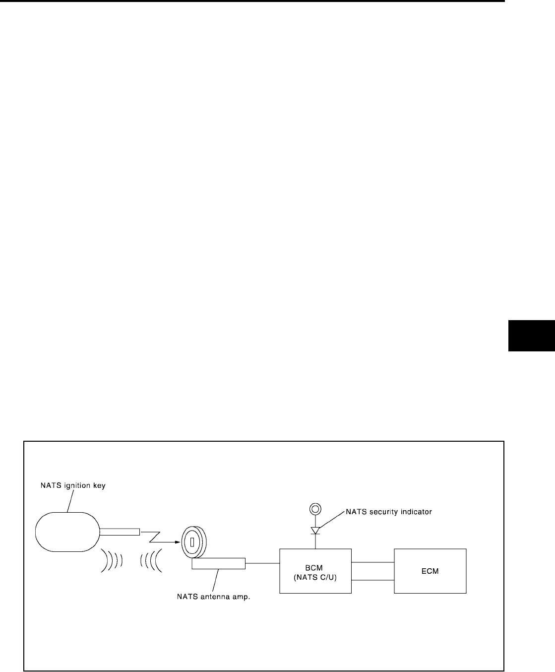
NVIS(NISSAN VEHICLE IMMOBILIZER SYSTEM-NATS)
BL-211
C
D
E
F
G
H
J
K
L
M
A
B
BL
Revision: July 2006 2006 Quest
System Description
EIS007GH
NVIS (Nissan Vehicle Immobilizer System-NATS) has the following immobilizer functions:
●Since only NVIS (NATS) ignition keys, whose IDs have been registered into the ECM and BCM, allow the
engine to run, operation of a stolen vehicle without a NVIS (NATS) registered key is prevented by NVIS
(NATS).
NVIS (NATS) will immobilize the engine if someone tries to start it without the registered key of NVIS
(NATS).
●All of the originally supplied ignition key IDs have been NVIS (NATS) registered.
If requested by the vehicle owner, a maximum of five key IDs can be registered into the NVIS (NATS)
components.
●The security indicator blinks when the ignition switch is in OFF or ACC position. NVIS (NATS) warns out-
siders that the vehicle is equipped with the anti-theft system.
●When NVIS (NATS) detects a malfunction, the security indicator lamp lights up while ignition key is in the
ON position.
●NVIS (NATS) trouble diagnoses, system initialization and additional registration of other NVIS (NATS)
ignition key IDs must be carried out using CONSULT-II hardware and CONSULT-II NVIS (NATS) software.
When NVIS (NATS) initialization has been completed, the ID of the inserted ignition key is automatically
NVIS (NATS) registered. Then, if necessary, additional registration of other NVIS (NATS) ignition key IDs
can be carried out.
Regarding the procedures of NVIS (NATS) initialization and NVIS (NATS) ignition key ID registration, refer
to CONSULT-II Operation Manual NATS-IVIS/NVIS.
●When servicing a malfunction of the NVIS (NATS) (indicated by lighting up of Security Indicator
Lamp) or registering another NVIS (NATS) ignition key ID, it may be necessary to re-register origi-
nal key identification. Therefore, be sure to receive ALL KEYS from vehicle owner.
System Composition
EIS007GI
The immobilizer function of the NVIS (NATS) consists of the following:
●NATS ignition key
●NATS antenna amp. located in the ignition key cylinder
●Body control module (BCM)
●Engine control module (ECM)
●Security indicator
NOTE:
The communication between ECM and BCM uses the CAN communication system.
PIIA1121E

BL-212
NVIS(NISSAN VEHICLE IMMOBILIZER SYSTEM-NATS)
Revision: July 2006 2006 Quest
ECM Re-communicating Function
EIS007GJ
The following procedure can automatically perform re-communication of ECM and BCM, but only when the
ECM has been replaced with a new one which has never been energized on-board.
(In this step, initialization procedure by CONSULT-II is not necessary).
NOTE:
●When registering new Key IDs or replacing the ECM other than brand new, refer to CONSULT-II
Operation Manual NATS-IVIS/NVIS.
●If multiple keys are attached to the key holder, separate them before work.
●Distinguish keys with unregistered key ID from those with registered ID.
1. Install ECM.
2. Using a registered key (*1), turn ignition switch to ON.
*1: To perform this step, use the key that has been used before performing ECM replacement.
3. Maintain ignition switch in ON position for at least 5 seconds.
4. Turn ignition switch to OFF.
5. Start engine.
If engine can be started, procedure is completed.
If engine cannot be started, refer to CONSULT-II Operation Manual NATS-IVIS/NVIS and initialize control
unit.
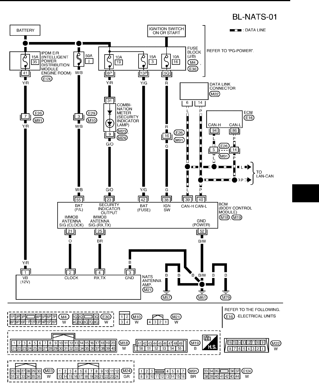
NVIS(NISSAN VEHICLE IMMOBILIZER SYSTEM-NATS)
BL-213
C
D
E
F
G
H
J
K
L
M
A
B
BL
Revision: July 2006 2006 Quest
Wiring Diagram — NATS —
EIS007GK
WIWA1140E
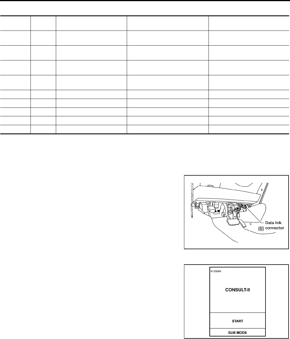
BL-214
NVIS(NISSAN VEHICLE IMMOBILIZER SYSTEM-NATS)
Revision: July 2006 2006 Quest
Terminals and Reference Value for BCM
EIS007GL
CONSULT-II
EIS007GM
CONSULT-II INSPECTION PROCEDURE
CAUTION:
If CONSULT-II is used with no connection of CONSULT-II CONVERTER, malfunctions might be
detected in self-diagnosis depending on control unit which carries out CAN communication.
1. Turn ignition switch OFF.
2. Insert NVIS (NATS) program card into CONSULT-II.
3. Connect CONSULT-II and CONSULT-II CONVERTER to data
link connector.
4. Turn ignition switch ON.
5. Touch “START”.
Terminal Wire
Color Item Condition Voltage (V)
(Approx.)
21 O NATS antenna amp. Ignition switch (OFF → ON) Just after turning ignition switch
ON: Pointer of tester should move.
23 G/O Security indicator lamp Goes OFF → illuminates (Every 2.4
seconds) Battery voltage → 0
25 BR NATS antenna amp. Ignition switch (OFF → ON) Just after turning ignition switch
ON: Pointer of tester should move.
38 G Ignition switch (ON or START) Ignition switch (ON or START posi-
tion) Battery voltage
39 L CAN-H ——
40 P CAN-L ——
42 Y/G Power source (Fuse) —Battery voltage
52 B/W Ground —0
55 W/B Battery power supply —Battery voltage
Program card : NATS (AEN04A-1) or later
BBIA0336E
PBR455D
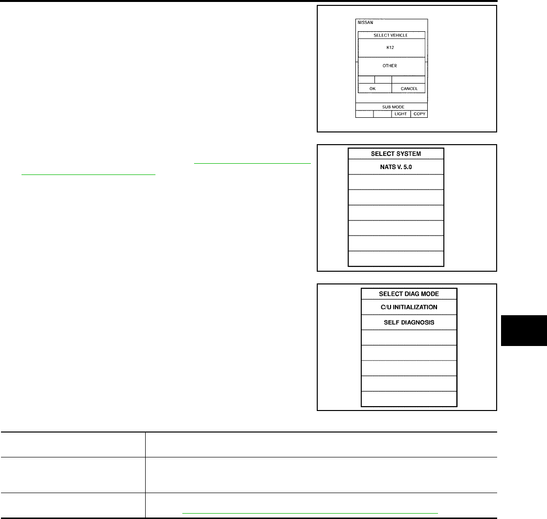
NVIS(NISSAN VEHICLE IMMOBILIZER SYSTEM-NATS)
BL-215
C
D
E
F
G
H
J
K
L
M
A
B
BL
Revision: July 2006 2006 Quest
6. Touch "OTHER".
7. Select “NATS V.5.0”.
If “NATS V5.0” is not indicated, go to GI-38, "CONSULT-II Data
Link Connector (DLC) Circuit" .
8. Perform each diagnostic test mode according to each service
procedure.
For further information, see the CONSULT-II Operation Manual
NATS-IVIS/NVIS.
CONSULT-II DIAGNOSTIC TEST MODE FUNCTION
NOTE:
●When any initialization is performed, all IDs previously registered will be erased and all NATS ignition keys
must be registered again.
●The engine cannot be started with an unregistered key. In this case, the system will show “DIFFERENCE
OF KEY” or “LOCK MODE” as a self-diagnostic result on the CONSULT-II screen.
●In rare case, “CHAIN OF ECM-IMMU” might be stored as a self-diagnostic result during key registration
procedure, even if the system is not malfunctioning.
LIIA0556E
SEL027X
SEL728W
CONSULT-II DIAGNOSTIC TEST
MODE Description
C/U INITIALIZATION
When replacing any of the following components, C/U initialization and re-registration of all
NATS ignition keys are necessary.
[(NATS ignition key/ BCM/ ECM]
SELF-DIAG RESULTS Detected items (screen terms) are as shown in the chart.
Refer to BL-216, "NVIS (NATS) SELF-DIAGNOSTIC RESULTS ITEM CHART" .
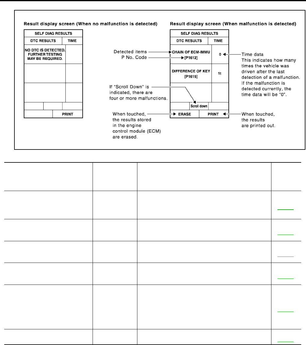
BL-216
NVIS(NISSAN VEHICLE IMMOBILIZER SYSTEM-NATS)
Revision: July 2006 2006 Quest
HOW TO READ SELF-DIAGNOSTIC RESULTS
NVIS (NATS) SELF-DIAGNOSTIC RESULTS ITEM CHART
PIIA1124E
Detected items
[NVIS (NATS) program card screen
terms]
P No. Code
(Self-diagnostic
result of
“ENGINE”)
Malfunction is detected when..... Reference
page
CHAIN OF ECM-IMMU
[P1612]
NATS MAL-
FUNCTION
P1612
Communication impossible between ECM and BCM
In rare case, “CHAIN OF ECM-IMMU” might be stored
during key registration procedure, even if the system is
not malfunctioning.
Refer to
BL-220 .
DIFFERENCE OF KEY
[P1615]
NATS MAL-
FUNCTION
P1615
BCM can receive the key ID signal but the result of ID
verification between key ID and BCM is NG.
Refer to
BL-221 .
CHAIN OF IMMU-KEY
[P1614]
NATS MAL-
FUNCTION
P1614
BCM cannot receive the key ID signal. Refer to
BL-224 .
ID DISCORD, IMM-ECM
[P1611]
NATS MAL-
FUNCTION
P1611
The result of ID verification between BCM and ECM is
NG. System initialization is required.
Refer to
BL-222 .
LOCK MODE
[P1610]
NATS MAL-
FUNCTION
P1610
When the starting operation is carried out five or more
times consecutively under the following conditions, NVIS
(NATS) will shift the mode to one which prevents the
engine from being started.
●Unregistered ignition key is used.
●BCM or ECM’s malfunctioning.
Refer to
BL-223 .
DON'T ERASE BEFORE CHECK-
ING ENG DIAG —All engine trouble codes except NVIS (NATS) trouble
code has been detected in ECM.
Refer to
BL-217 .
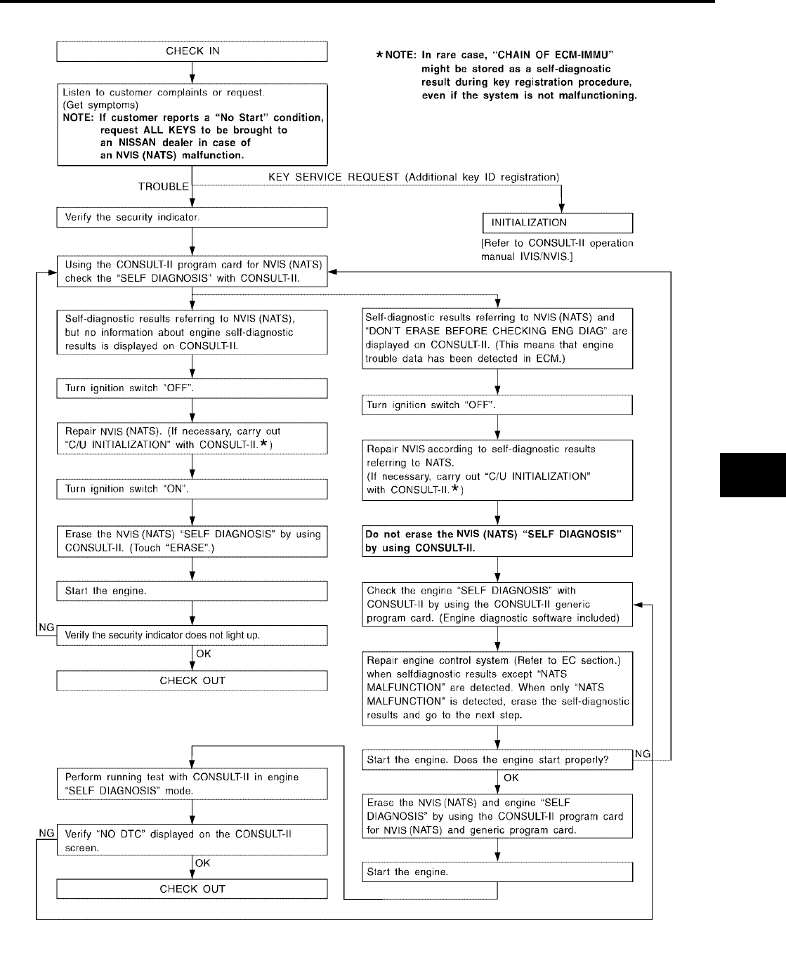
NVIS(NISSAN VEHICLE IMMOBILIZER SYSTEM-NATS)
BL-217
C
D
E
F
G
H
J
K
L
M
A
B
BL
Revision: July 2006 2006 Quest
Work Flow
EIS007GN
LIIA1152E

BL-218
NVIS(NISSAN VEHICLE IMMOBILIZER SYSTEM-NATS)
Revision: July 2006 2006 Quest
Trouble Diagnoses
EIS007GO
SYMPTOM MATRIX CHART 1
Self-diagnosis related item
*: When NVIS (NATS) detects a malfunction, the security indicator lights up while ignition key is in the “ON” position.
Symptom
Displayed “SELF-DIAG
RESULTS” on CON-
SULT-II screen.
Diagnostic Procedure
(Reference page)
System
(Malfunctioning part or
mode)
Reference Part No. Of
Illustration On System
Diagram
●Security indicator
lighting up*
●Engine cannot be
started
CHAIN OF ECM-IMMU
[P1612]
PROCEDURE 1
(BL-220 )
In rare case, “CHAIN OF
ECM-IMMU” might be
stored during key regis-
tration procedure, even if
the system is not mal-
functioning.
—
Open circuit in battery
voltage line of BCM cir-
cuit
C1
Open circuit in ignition
line of BCM circuit C2
Open circuit in ground
line of BCM circuit C3
Open or short circuit
between BCM and ECM
communication line
C4
ECM B
BCM A
DIFFERENCE OF KEY
[P1615]
PROCEDURE 2
(BL-221 )
Unregistered key D
BCM A
CHAIN OF IMMU-KEY
[P1614]
PROCEDURE 5
(BL-224 )
Malfunction of key ID
chip E5
Communication line
between ANT/ AMP and
BCM:
Open circuit or short cir-
cuit of battery voltage
line or ground line
E1
E3, E4
Open circuit in power
source line of ANT/ AMP
circuit
E3
Open circuit in ground
line of ANT/ AMP circuit E4
NATS antenna amp. E6
BCM A
ID DISCORD, IMM-ECM
[P1611]
PROCEDURE 3
(BL-222 )
System initialization has
not yet been completed. F
ECM B
LOCK MODE
[P1610]
PROCEDURE 4
(BL-223 ) LOCK MODE D
Security indicator light-
ing up*
DON'T ERASE
BEFORE CHECKING
ENG DIAG
WORK FLOW
(BL-217 )
Engine trouble data and
NVIS (NATS) trouble
data have been detected
in ECM
—
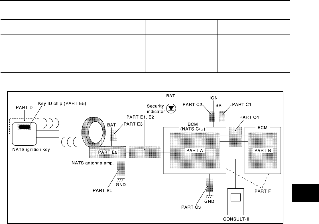
NVIS(NISSAN VEHICLE IMMOBILIZER SYSTEM-NATS)
BL-219
C
D
E
F
G
H
J
K
L
M
A
B
BL
Revision: July 2006 2006 Quest
SYMPTOM MATRIX CHART 2
Non self-diagnosis related item
*: CONSULT-II self-diagnostic results display screen “no malfunction is detected”.
DIAGNOSTIC SYSTEM DIAGRAM
Symptom Diagnostic Procedure
(Reference page)
System
(Malfunctioning part or mode)
Reference Part No. Of Illustra-
tion On System Diagram
Security indicator does not light
up*.
PROCEDURE 6
(BL-227 )
Combination meter (security
indictor lamp) E2
Open circuit between Fuse and
BCM C1, C2
BCM A
WIIA0550E
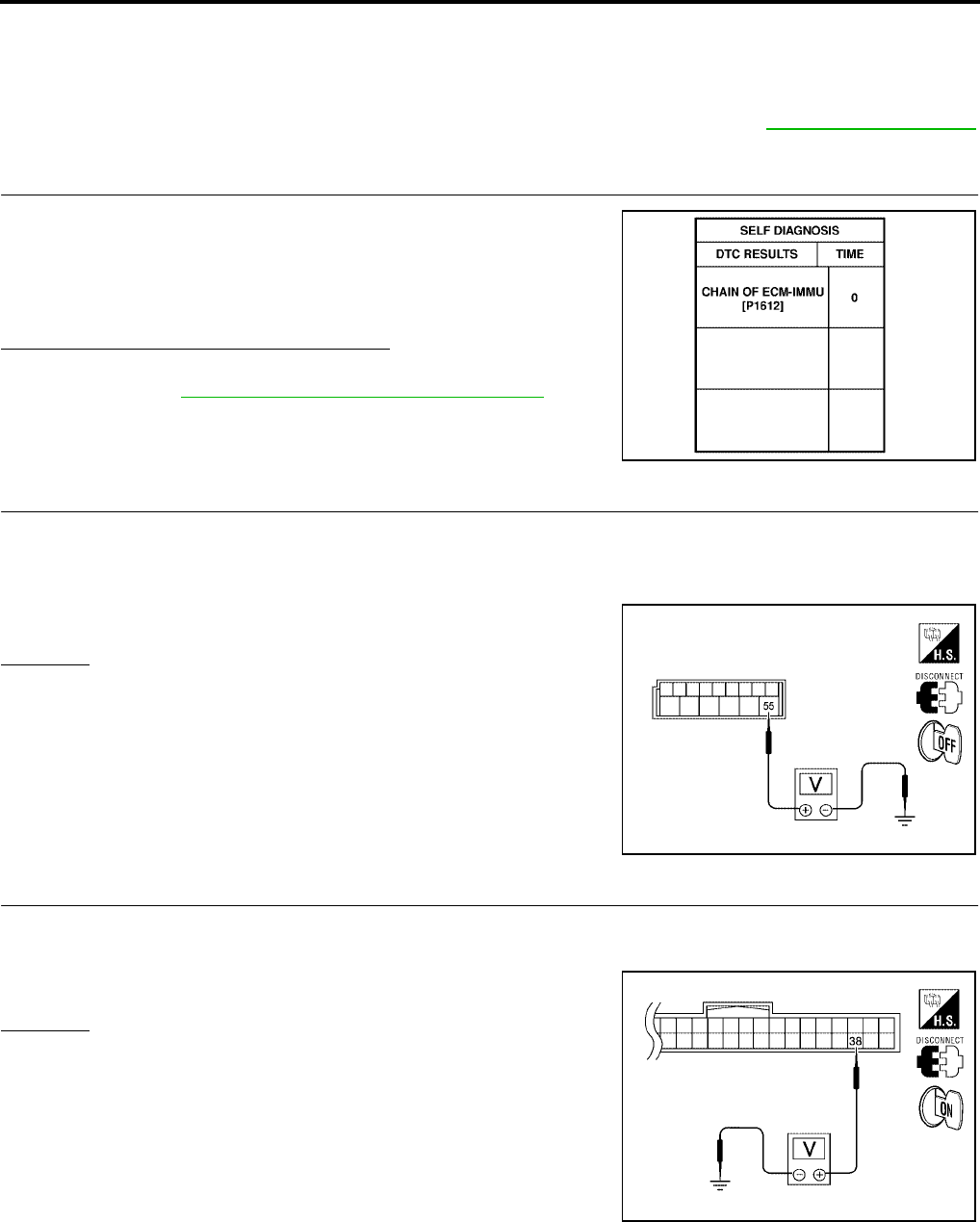
BL-220
NVIS(NISSAN VEHICLE IMMOBILIZER SYSTEM-NATS)
Revision: July 2006 2006 Quest
Diagnostic Procedure 1
EIS007GP
Self-diagnostic results:
“CHAIN OF ECM-IMMU” displayed on CONSULT-II screen
First perform the “SELF-DIAG RESULTS” in “BCM” with CONSULT-II, then perform the trouble diagno-
sis of malfunction system indicated “SELF-DIAG RESULTS” of “BCM”. Refer to BL-214, "CONSULT-II"
.
1. CONFIRM SELF-DIAGNOSTIC RESULTS
Confirm SELF-DIAGNOSTIC RESULTS “CHAIN OF ECM-IMMU”
displayed on CONSULT-II screen.
NOTE:
In rare case, “CHAIN OF ECM-IMMU” might be stored during key
registration procedure, even if the system is not malfunctioning.
Is CONSULT-II screen displayed as above?
Yes >> GO TO 2.
No >> GO TO BL-218, "SYMPTOM MATRIX CHART 1" .
2. CHECK POWER SUPPLY CIRCUIT FOR BCM
1. Turn ignition switch OFF.
2. Disconnect BCM.
3. Check voltage between BCM connector M19 terminal 55 and ground.
OK or NG
OK >> GO TO 3.
NG >> Check the following:
●50A fusible link (letter j , located in fuse and fusible
link box).
●Harness for open or short between fuse and BCM
connector. Ref. part No. C1
3. CHECK IGN SW. ON SIGNAL
1. Turn ignition switch ON.
2. Check voltage between BCM connector M18 terminal 38 and ground.
OK or NG
OK >> GO TO 4.
NG >> Check the following:
●10A fuse [No. 16, located in the fuse block (J/B)].
●Harness for open or short between fuse and BCM
connector. Ref. part No. C2
PIIA1260E
55 – Ground : Battery voltage
WIIA0820E
38 – Ground : Battery voltage
WIIA0821E
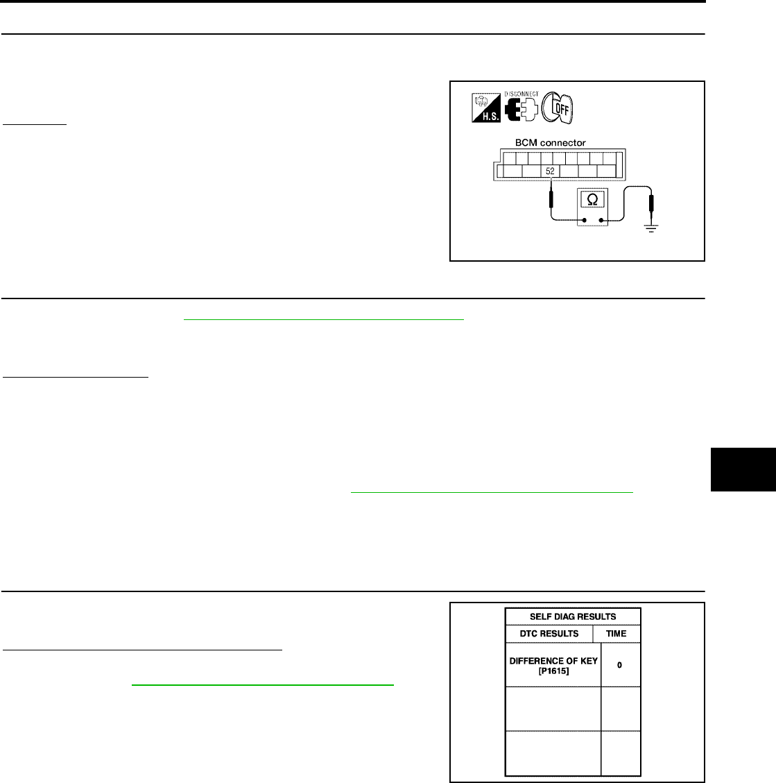
NVIS(NISSAN VEHICLE IMMOBILIZER SYSTEM-NATS)
BL-221
C
D
E
F
G
H
J
K
L
M
A
B
BL
Revision: July 2006 2006 Quest
4. CHECK GROUND CIRCUIT FOR BCM
1. Turn ignition switch OFF.
2. Check continuity between BCM connector M19 terminal 52 and ground.
OK or NG
OK >> GO TO 5.
NG >> Repair or replace harness. Ref. part No. C3
5. REPLACE BCM
1. Replace BCM. Refer to BCS-20, "Removal and Installation of BCM" .Ref. part No. A
2. Perform initialization with CONSULT-II.
For initialization, refer to “CONSULT-II Operation Manual NATS-IVIS/NVIS”.
Does the engine start?
Yes >> BCM is malfunctioning.
No >> ●ECM is malfunctioning.
●Replace ECM. Ref. part No. B
●Perform initialization or re-communicating function.
●For initialization, refer to “CONSULT-II Operation Manual NATS-IVIS/NVIS”.
●For re-communicating function, refer to BL-212, "ECM Re-communicating Function" .
Diagnostic Procedure 2
EIS007GQ
Self-diagnostic results:
“DIFFERENCE OF KEY” displayed on CONSULT-II screen
1. CONFIRM SELF-DIAGNOSTIC RESULTS
Confirm SELF-DIAGNOSTIC RESULTS “DIFFERENCE OF KEY”
displayed on CONSULT-II screen.
Is CONSULT-II screen displayed as above?
Yes >> GO TO 2.
No >> GO TO BL-218, "SYMPTOM MATRIX CHART 1" .
52 – Ground : Continuity should exist.
WKIA2973E
PIIA1261E
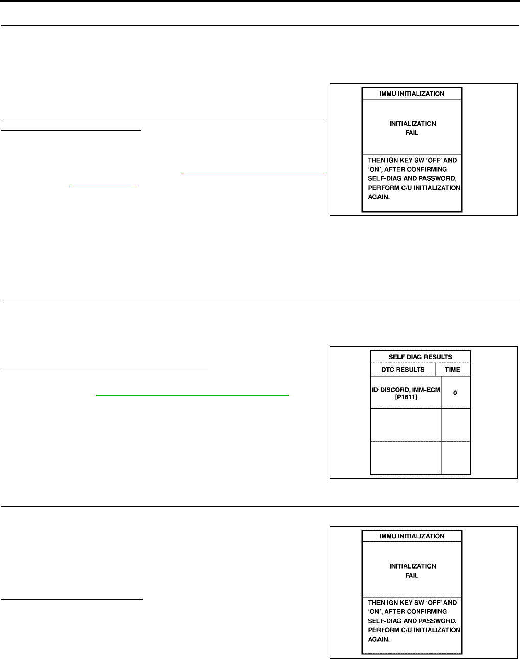
BL-222
NVIS(NISSAN VEHICLE IMMOBILIZER SYSTEM-NATS)
Revision: July 2006 2006 Quest
2. PERFORM INITIALIZATION WITH CONSULT-II
Perform initialization with CONSULT-II. Re-register all NATS ignition key IDs.
For initialization and registration of NATS ignition key IDs, refer to “CONSULT-II Operation Manual NATS-IVIS/
NVIS”.
NOTE:
If the initialization is not completed or malfunctions, CONSULT-II
shows message on the screen.
Can the system be initialized and can the engine be started with re-
registered NATS ignition key?
Yes >> ●Ignition key ID was unregistered. Ref. part No. D
No >> ●BCM is malfunctioning.
●Replace BCM. Refer to BCS-20, "Removal and Instal-
lation of BCM" . Ref. part No. A
●Perform initialization with CONSULT-II.
●For initialization, refer to “CONSULT-II Operation
Manual NATS-IVIS/NVIS”.
Diagnostic Procedure 3
EIS007GR
Self-diagnostic results:
“ID DISCORD, IMM-ECM” displayed on CONSULT-II screen
1. CONFIRM SELF-DIAGNOSTIC RESULTS
Confirm SELF-DIAGNOSTIC RESULTS “ID DISCORD, IMM-ECM” displayed on CONSULT-II screen.
NOTE:
“ID DISCORD IMM-ECM”:
Registered ID of BCM is in discord with that of ECM.
Is CONSULT-II screen displayed as shown?
Yes >> GO TO 2.
No >> GO TO BL-218, "SYMPTOM MATRIX CHART 1" .
2. PERFORM INITIALIZATION WITH CONSULT-II
Perform initialization with CONSULT-II. Re-register all NATS ignition key IDs.
For initialization, refer to “CONSULT-II Operation Manual NATS-
IVIS/NVIS”.
NOTE:
If the initialization is not completed or malfunctions, CONSULT-II
shows message on the screen.
Can the system be initialized?
Yes >> ●Start engine. (END)
●System initialization had not been completed. Ref.
part No. F
No >> ●ECM is malfunctioning.
●Replace ECM. Ref. part No. B
●Perform initialization with CONSULT-II.
For initialization, refer to “CONSULT-II Operation Manual NATS-IVIS/NVIS”.
SEL297W
PIIA1262E
SEL297W
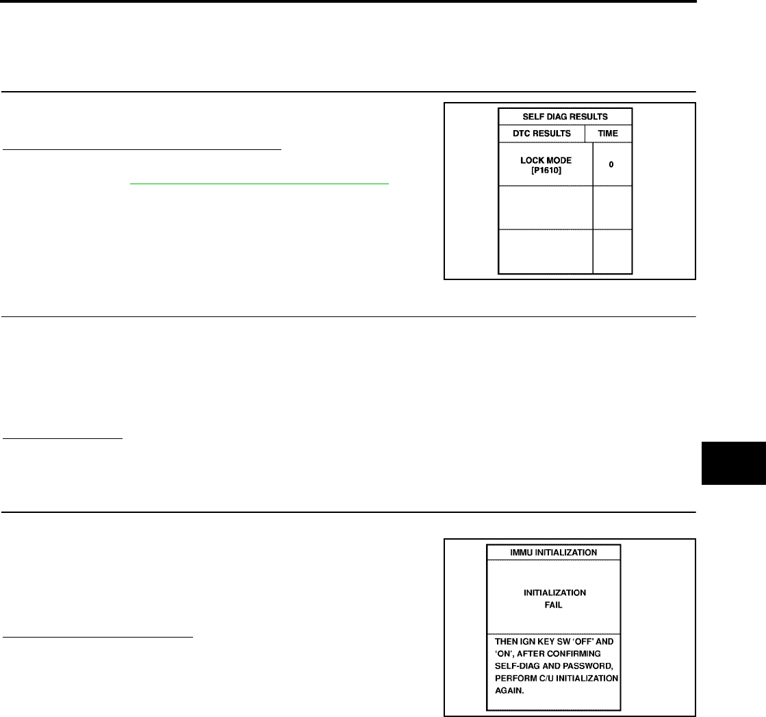
NVIS(NISSAN VEHICLE IMMOBILIZER SYSTEM-NATS)
BL-223
C
D
E
F
G
H
J
K
L
M
A
B
BL
Revision: July 2006 2006 Quest
Diagnostic Procedure 4
EIS007GS
Self-diagnostic results:
“LOCK MODE” displayed on CONSULT-II screen
1. CONFIRM SELF-DIAGNOSTIC RESULTS
Confirm SELF-DIAGNOSTIC RESULTS “LOCK MODE” is displayed
on CONSULT-II screen.
Is CONSULT-II screen displayed as shown?
Yes >> GO TO 2.
No >> GO TO BL-218, "SYMPTOM MATRIX CHART 1" .
2. ESCAPE FROM LOCK MODE
1. Turn ignition switch OFF.
2. Turn ignition switch ON with registered key. (Do not start engine.) Wait 5 seconds.
3. Return the key to OFF position. Wait 5 seconds.
4. Repeat steps 2 and 3 twice (total of three cycles).
5. Start the engine.
Does engine start?
Yes >> System is OK (Now system is escaped from “LOCK MODE”).
No >> GO TO 3.
3. PERFORM INITIALIZATION WITH CONSULT-II
Perform initialization with CONSULT-II.
For initialization, refer to “CONSULT-II Operation Manual NATS-
IVIS/NVIS”.
NOTE:
If the initialization is not completed or malfunctions, CONSULT-II
shows the message on the screen.
Can the system be initialized?
Yes >> System is OK.
No >> GO TO 4.
PIIA1264E
SEL297W
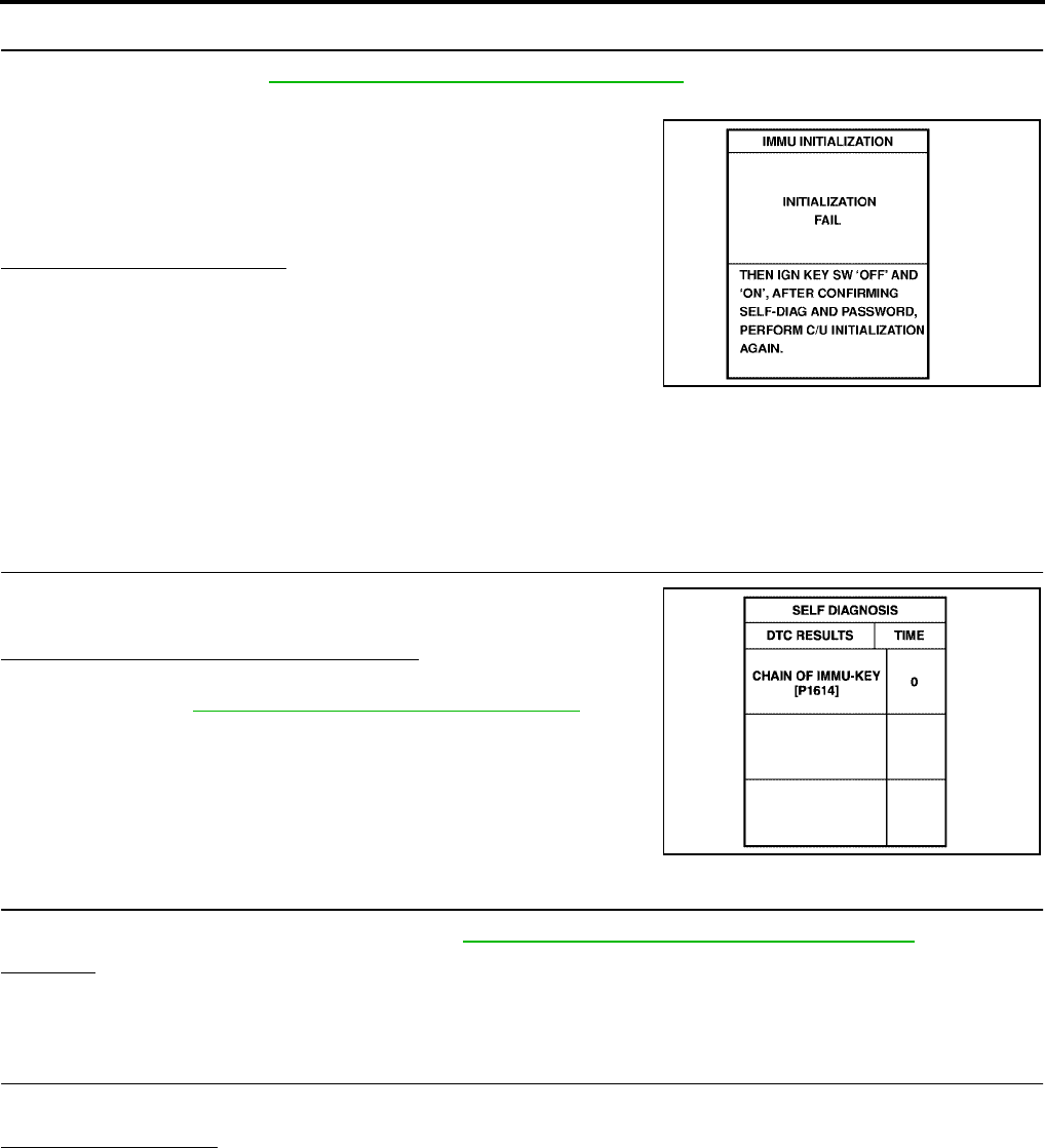
BL-224
NVIS(NISSAN VEHICLE IMMOBILIZER SYSTEM-NATS)
Revision: July 2006 2006 Quest
4. PERFORM INITIALIZATION WITH CONSULT-II AGAIN
1. Replace BCM. Refer to BCS-20, "Removal and Installation of BCM" .
2. Perform initialization with CONSULT-II.
For initialization, refer to “CONSULT-II Operation Manual NATS-
IVIS/NVIS”.
NOTE:
If the initialization is not completed or malfunctions, CONSULT-II
shows the message on the screen.
Can the system be initialized?
Yes >> System is OK. BCM is malfunctioning. Ref. part No. A
No >> ●ECM is malfunctioning.
●Replace ECM. Ref. part No. B
●Perform initialization with CONSULT-II.
For initialization, refer to “CONSULT-II Operation
Manual NATS-IVIS/NVIS”.
Diagnostic Procedure 5
EIS007GT
Self-diagnostic results:
“CHAIN OF IMMU-KEY” displayed on CONSULT-II screen
1. CONFIRM SELF-DIAGNOSTIC RESULTS
Confirm SELF-DIAGNOSTIC RESULTS “CHAIN OF IMMU-KEY”
displayed on CONSULT-II screen.
Is CONSULT-II screen displayed as shown?
Yes >> GO TO 2.
No >> GO TO BL-218, "SYMPTOM MATRIX CHART 1" .
2. CHECK NATS ANTENNA AMP. INSTALLATION
Check NATS antenna amp. installation. Refer to BL-228, "How to Replace NATS Antenna Amp." .
OK or NG
OK >> GO TO 3.
NG >> Reinstall NATS antenna amp. correctly.
3. CHECK NVIS (NATS) IGNITION KEY ID CHIP
Start engine with another registered NATS ignition key.
Does the engine start?
Yes >> ●Ignition key ID chip is malfunctioning.
●Replace the ignition key.
Ref. part No. E5
●Perform initialization with CONSULT-II.
For initialization, refer to “CONSULT-II Operation Manual NATS-IVIS/NVIS”.
No >> GO TO 4.
SEL297W
PIIA1263E
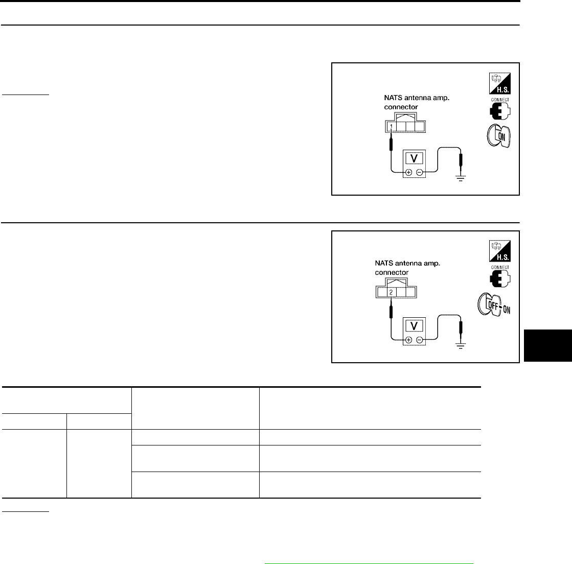
NVIS(NISSAN VEHICLE IMMOBILIZER SYSTEM-NATS)
BL-225
C
D
E
F
G
H
J
K
L
M
A
B
BL
Revision: July 2006 2006 Quest
4. CHECK POWER SUPPLY FOR NATS ANTENNA AMP.
1. Turn ignition switch ON.
2. Check voltage between NATS antenna amp. connector M21 terminal 1 and ground.
OK or NG
OK >> GO TO 5.
NG >> Repair or replace fuse or harness. Ref. part No. E3
5. CHECK NATS ANTENNA AMP. SIGNAL LINE- 1
Check voltage between NATS antenna amp. connector M21 terminal
2 and ground with analog tester.
OK or NG
OK >> GO TO 6.
NG >> ●Repair or replace harness.
NOTE:
If harness is OK, replace BCM. Refer to BCS-20, "Removal and Installation of BCM" . perform
initialization with CONSULT-II. For initialization, refer to “CONSULT-II Operation Manual NATS-
IVIS/NVIS”.
1 – Ground : Battery voltage
LIIA1641E
LIIA1642E
Connector terminals
(wire colors) Position of ignition key cylinder Voltage (V)
(Approx.)
( + ) ( - )
2 Ground
Before inserting ignition key Battery voltage
After inserting ignition key Pointer of tester should move for approx. 30 seconds,
then return to battery voltage
Just after turning ignition
switch ON
Pointer of tester should move for approx. 1 second,
then return to battery voltage
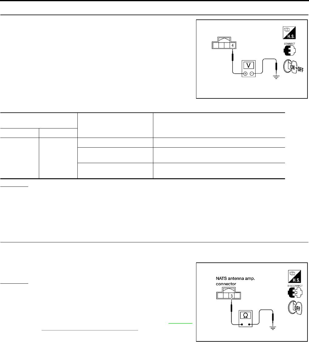
BL-226
NVIS(NISSAN VEHICLE IMMOBILIZER SYSTEM-NATS)
Revision: July 2006 2006 Quest
6. CHECK NATS ANTENNA AMP. SIGNAL LINE- 2
Check voltage between NATS antenna amp. connector M21 terminal
4 and ground with analog tester.
OK or NG
OK >> GO TO 7.
NG >> ●Repair or replace harness.
NOTE:
If harness is OK, replace BCM, perform initialization with CONSULT-II. For initialization, refer to
“CONSULT-II Operation Manual NATS-IVIS/NVIS”.
7. CHECK NATS ANTENNA AMP. GROUND LINE CIRCUIT
1. Turn ignition switch OFF.
2. Check continuity between NATS antenna amp. connector M21 terminal 3 and ground.
OK or NG
OK >> ●NATS antenna amp. is malfunctioning.
Ref. part No. E6
NG >> ●Repair or replace harness.
NOTE:
If harness is OK, replace BCM. Refer to BCS-20,
"Removal and Installation of BCM" . Perform initializa-
tion with CONSULT-II. For initialization, refer to “CON-
SULT-II Operation Manual NATS-IVIS/NVIS”.
WIIA0822E
Connector terminals
(wire colors) Position of ignition key cylinder Voltage (V)
(Approx.)
( + ) ( - )
4 Ground
Before inserting ignition key Battery voltage
After inserting ignition key Pointer of tester should move for approx. 30 seconds,
then return to battery voltage
Just after turning ignition
switch ON
Pointer of tester should move for approx. 1 second,
then return to battery voltage
3 – Ground : Continuity should exist.
LIIA1283E
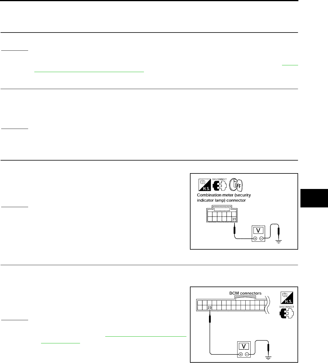
NVIS(NISSAN VEHICLE IMMOBILIZER SYSTEM-NATS)
BL-227
C
D
E
F
G
H
J
K
L
M
A
B
BL
Revision: July 2006 2006 Quest
Diagnostic Procedure 6
EIS007GU
“SECURITY INDICATOR LAMP DOES NOT LIGHT UP”
1. CHECK FUSE
Check 10A fuse [No.19, located in the fuse block (J/B)].
OK or NG
OK >> GO TO 2.
NG >> If fuse is blown, be sure to eliminate cause of problem before installing new fuse. Refer to PG-4,
"POWER SUPPLY ROUTING CIRCUIT" .
2. CHECK SECURITY INDICATOR LAMP
1. Start engine and turn ignition switch OFF.
2. Check the security indicator lamp lights up.
OK or NG
OK >> Inspection End.
NG >> GO TO 3.
3. CHECK SECURITY INDICATOR LAMP POWER SUPPLY CIRCUIT
1. Disconnect combination meter (security indicator lamp).
2. Check voltage between security indicator lamp connector M23
terminal 31 and ground.
OK or NG
OK >> GO TO 4.
NG >> Repair or replace harness.
4. CHECK BCM (NATS CONTROL UNIT) FUNCTION
1. Connect combination meter (security indicator lamp).
2. Disconnect BCM.
3. Check voltage between BCM connector M18 terminal 23 and
ground.
OK or NG
OK >> BCM is malfunctioning.
●Replace BCM. Refer to BCS-20, "Removal and Instal-
lation of BCM" . Ref. part No. A
●Perform initialization with CONSULT-II.
●For initialization, refer to “CONSULT-II Operation
Manual NATS-IVIS/NVIS”.
NG >> Check the following:
●Harness for open or short between security indicator lamp and BCM (NATS control unit).
●Indicator lamp condition.
Security indicator lamp should light up.
31 – Ground : Battery voltage
LIIA0840E
23 – Ground : Battery voltage
LIIA0523E
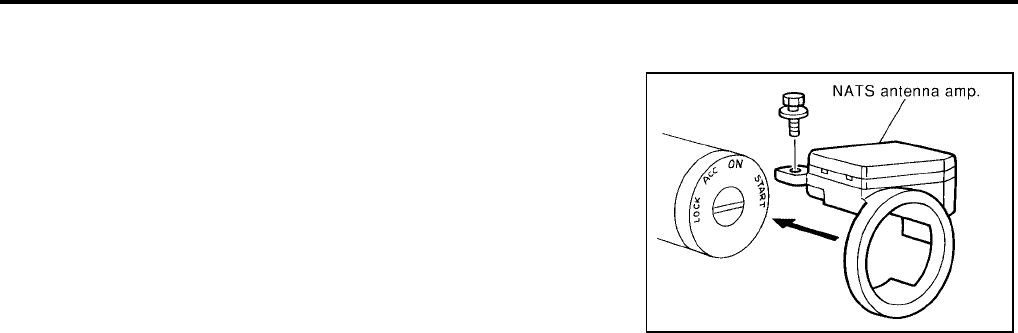
BL-228
NVIS(NISSAN VEHICLE IMMOBILIZER SYSTEM-NATS)
Revision: July 2006 2006 Quest
How to Replace NATS Antenna Amp.
EIS007GV
NOTE:
●If NATS antenna amp. is not installed correctly, NVIS (NATS)
system will not operate properly and SELF-DIAG RESULTS
on CONSULT-II screen will show “LOCK MODE” or “CHAIN
OF IMMU-KEY”.
●Initialization is not necessary when only NATS antenna
amp. is replaced with a new one.
SIIA1683E
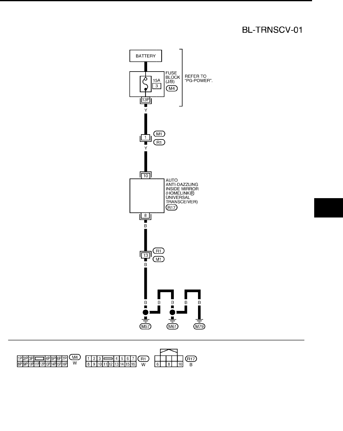
HOMELINK UNIVERSAL TRANSCEIVER
BL-229
C
D
E
F
G
H
J
K
L
M
A
B
BL
Revision: July 2006 2006 Quest
HOMELINK UNIVERSAL TRANSCEIVER PFP:96401
Wiring Diagram — TRNSCV —
EIS007WO
WIWA1141E
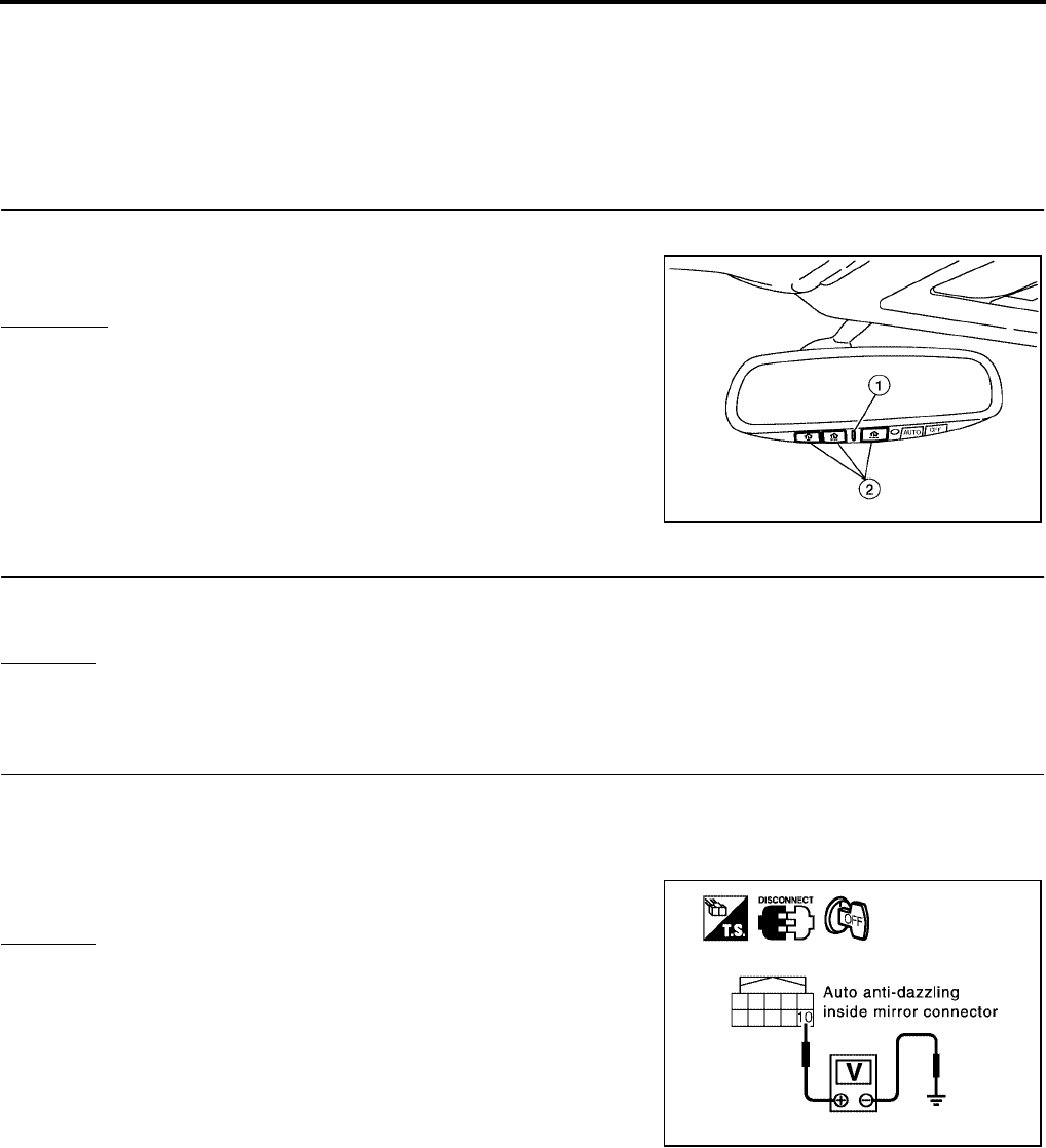
BL-230
HOMELINK UNIVERSAL TRANSCEIVER
Revision: July 2006 2006 Quest
Trouble Diagnoses
EIS007WP
DIAGNOSTIC PROCEDURE
SYMPTOM: Transmitter does not activate receiver.
Before conducting the procedure given below, make sure that system receiver (garage door opener, etc.)
operates with original, hand-held transmitter. If NG, receiver or hand-held transmitter is malfunctioning, not
vehicle related.
1. ILLUMINATION CHECK
1. Turn ignition switch OFF.
2. Does red light (1) of transmitter illuminate when any of the three
transmitter buttons (2) is pressed?
YES or NO
YES >> GO TO 2.
NO >> GO TO 3.
2. TRANSMITTER CHECK
Check transmitter with Tool*.
*:For details, refer to Technical Service Bulletin.
OK or NG
OK >> Receiver or hand-held transmitter malfunction, not vehicle related.
NG >> Replace auto anti-dazzling inside mirror (homelink universal transceiver).
3. POWER SUPPLY CHECK
1. Turn ignition switch OFF.
2. Disconnect auto anti-dazzling inside mirror (homelink universal transceiver) connector.
3. Check voltage between auto anti-dazzling inside mirror connector R17 terminal 10 and ground.
OK or NG
OK >> GO TO 4.
NG >> Check the following:
●15A fuse [No. 3, located in the fuse block (J/B)].
●Harness for open or short between fuse and auto
anti-dazzling inside mirror (homelink universal trans-
ceiver).
WIIA0789E
10 - Ground : Battery voltage
LIIA0839E
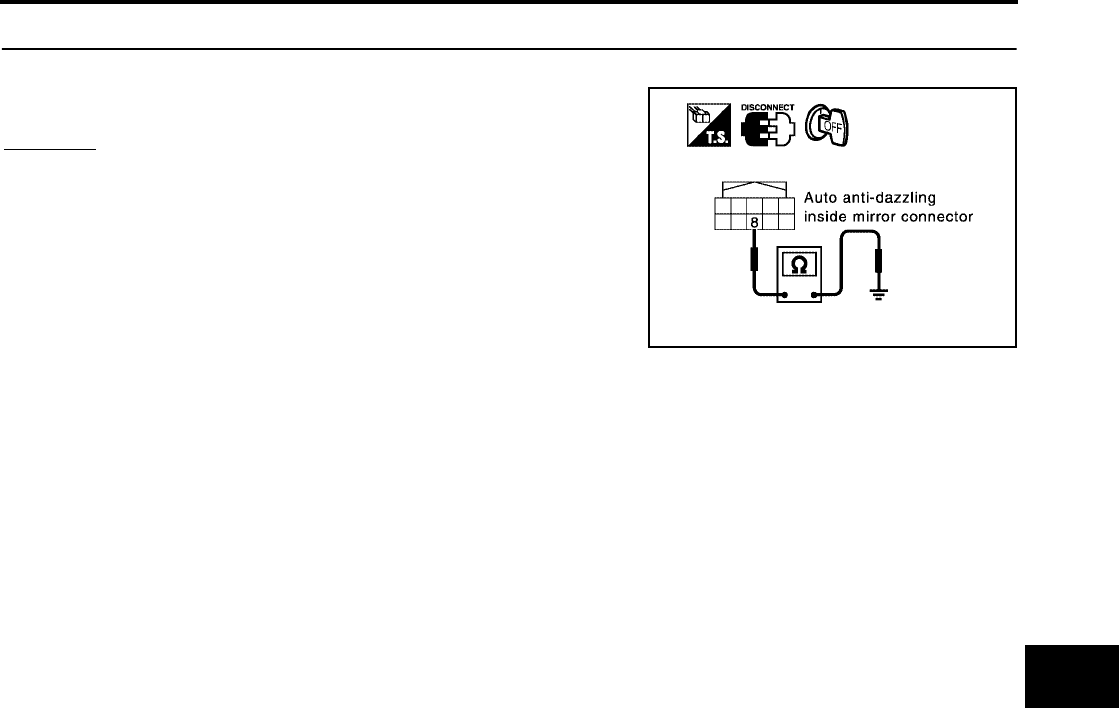
HOMELINK UNIVERSAL TRANSCEIVER
BL-231
C
D
E
F
G
H
J
K
L
M
A
B
BL
Revision: July 2006 2006 Quest
4. GROUND CIRCUIT CHECK
Check continuity between auto anti-dazzling inside mirror connector R17 terminal 8 and body ground.
OK or NG
OK >> Replace auto anti-dazzling inside mirror (homelink uni-
versal transceiver).
NG >> Repair or replace harness.
8 - Ground : Continuity should exist.
PIIA2368E
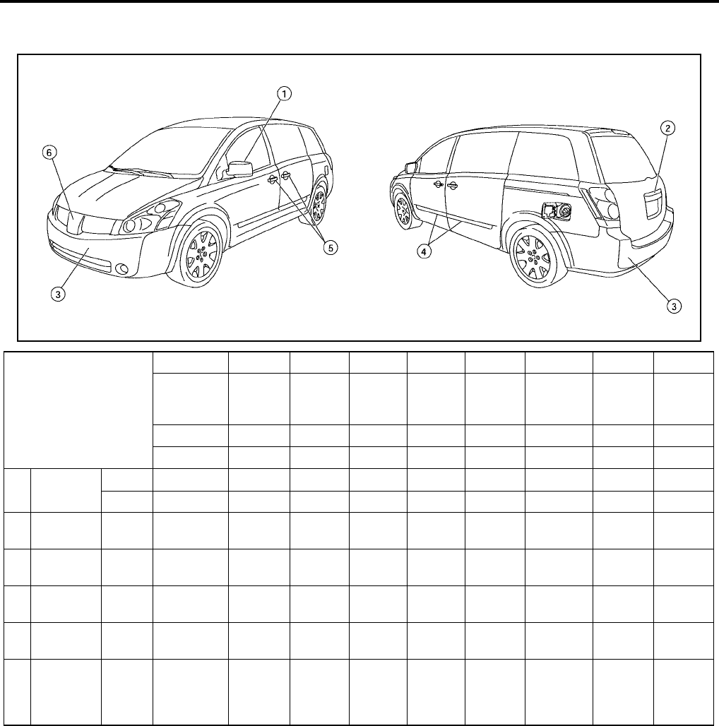
BL-232
BODY REPAIR
Revision: July 2006 2006 Quest
BODY REPAIR PFP:60100
Body Exterior Paint Color
EIS007GY
M: Metallic; 2S: 2-Coat Solid, 2P: 2-Coat Pearl; 3P: 3-Coat Pearl; t: New Cross Linking Clear Coat
LIIA0797E
Component
Color code A15 BW9 C12 G10 K11 K12 J20 Q11
Description Red
Brawn
Majestic
Blue
Coral
Sand
Galaxy
Black Smoke Silver Mist Jade
Nordic
White
Pearl
Paint type M M M M M M M 3P
Clear coat t t t t t t t t
1Outside
mirror
Body Body color A15 BW9 C12 G10 K11 K12 J20 Q11
Base Black AG01 AG01 AG01 AG01 AG01 AG01 AG01 AG01
2Lift gate
Finisher Body color A15 BW9 C12 G10 K11 K12 J20 Q11
3Bumper
fascia Body Body color A15 BW9 C12 G10 K11 K12 J20 Q11
4 Side guard
molding Body Body color A15 BW9 C12 G10 K11 K12 J20 Q11
5Outside
handle Body color A15 BW9 C12 G10 K11 K12 J20 Q11
6Radiator
grille Center
Chromium-
plate
+Smoke
Clear
Cr+HFM
09
Cr+HFM
09
Cr+HFM
09
Cr+HFM
09
Cr+HFM
09
Cr+HFM
09
Cr+HFM
09
Cr+HFM
09
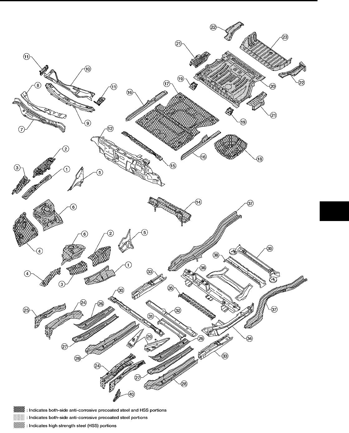
BODY REPAIR
BL-233
C
D
E
F
G
H
J
K
L
M
A
B
BL
Revision: July 2006 2006 Quest
Body Component Parts
EIS007GZ
UNDERBODY COMPONENT PARTS
WIIA0535E

BL-234
BODY REPAIR
Revision: July 2006 2006 Quest
1. Hoodledge upper RH/LH 21. Rear side floor rear RH/LH
2. Rear hoodledge reinforcement RH/LH 22. Rear floor rear
3. Hoodledge reinforcement 23. Front side member RH/LH
4. Lower front hoodledge RH/LH 24. Front side member closing plate RH/LH
5. Side cowl top RH/LH 25. Front side member extension reinforcement RH/LH
6. Rear lower hoodledge RH/LH 26. Front side member reinforcement RH/LH
7. Upper dash 27. Front side member front extension RH/LH
8. Front cowl top 28. Inner front side member assembly RH/LH
9. Center cowl top 29. Floor center member assembly
10. Cowl top extension 30. Outer 3rd seat mounting bracket
11. Cowl top extension bracket RH/LH 31. Center 1st cross member assembly
12. Lower dash 32. Front side member rear extension RH/LH
13. Dash lower cross member 33. Lower guide rail assembly RH/LH
14. 2nd cross member assembly 34. 4th cab moulting cross member
15. Inner sill RH/LH 35. Rear seat cross member
16. Front floor 36. Rear side member RH/LH
17. Center front floor 37. Center rear seat cross member
18. 2nd seat mounting bracket assembly RH/LH 38. 2nd rear cross member
19 Front floor rear 39. Front hook RH/LH
20. Rear floor step RH/LH
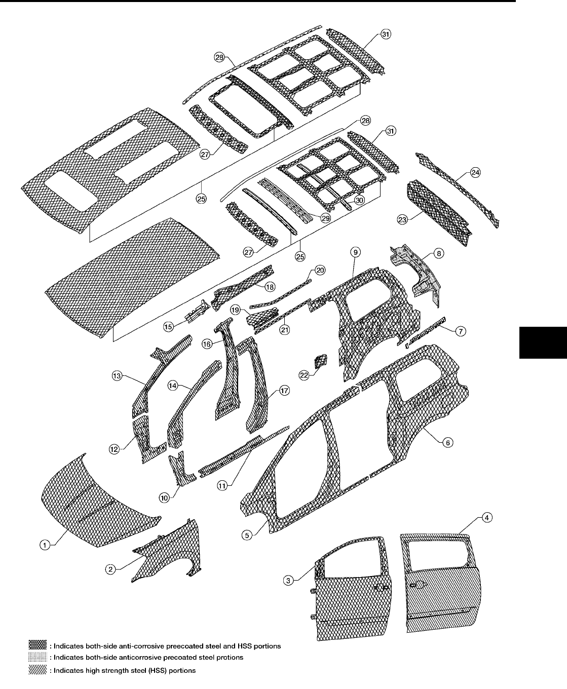
BODY REPAIR
BL-235
C
D
E
F
G
H
J
K
L
M
A
B
BL
Revision: July 2006 2006 Quest
BODY COMPONENT PARTS
WIIA0366E

BL-236
BODY REPAIR
Revision: July 2006 2006 Quest
1. Hood 17. Center pillar reinforcement
2. Front fender (RH&LH) 18. Inner roof side rail
3. Front door assembly 19. Upper guide rail
4. Slide door assembly 20. Upper guide rail
5. Body side outer 21. Roof drip rail
6. Rear fender 22. Waist rail guide
7. Body side outer reinforcement 23. Back panel assembly
8. Back pillar reinforcement 24. Back panel assembly
9. Inner side panel 25. Standard roof assembly
10. Front pillar lower hinge brace 26. Roof assembly with sunroof
11. Outer sill reinforcement 27. Front roof rail
12. Inner lower front pillar 28. Roof side molding assembly
13. Inner upper front pillar 29. Roof bow No. 2
14. Upper hinge pillar brace assembly 30. Rear roof bow
15. Inner roof rail reinforcement 31. Rear roof rail
16. Inner center pillar
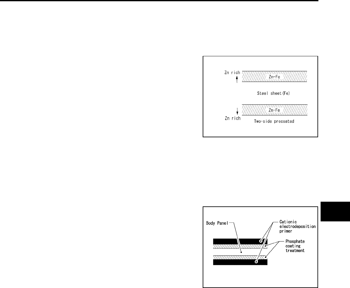
BODY REPAIR
BL-237
C
D
E
F
G
H
J
K
L
M
A
B
BL
Revision: July 2006 2006 Quest
Corrosion Protection
EIS007H0
DESCRIPTION
To provide improved corrosion prevention, the following anti-corrosive measures have been implemented in
NISSAN production plants. When repairing or replacing body panels, it is necessary to use the same anti-cor-
rosive measures.
ANTI-CORROSIVE PRECOATED STEEL (GALVANNEALED STEEL)
To improve repairability and corrosion resistance, a new type of anti-
corrosive precoated steel sheet has been adopted replacing conven-
tional zinc-coated steel sheet.
Galvannealed steel is electroplated and heated to form Zinc-iron
alloy, which provides excellent and long term corrosion resistance
with cationic electrode position primer.
Nissan Genuine Service Parts are fabricated from galvannealed steel. Therefore, it is recommended that
GENUINE NISSAN PARTS or equivalent be used for panel replacement to maintain the anti-corrosive perfor-
mance built into the vehicle at the factory.
PHOSPHATE COATING TREATMENT AND CATIONIC ELECTRODEPOSITION PRIMER
A phosphate coating treatment and a cationic electrode position primer, which provide excellent corrosion pro-
tection, are employed on all body components.
CAUTION:
Confine paint removal during welding operations to an absolute
minimum.
Nissan Genuine Service Parts are also treated in the same manner. Therefore, it is recommended that GENU-
INE NISSAN PARTS or equivalent be used for panel replacement to maintain anti-corrosive performance built
into the vehicle at the factory.
PIIA0093E
PIIA0095E
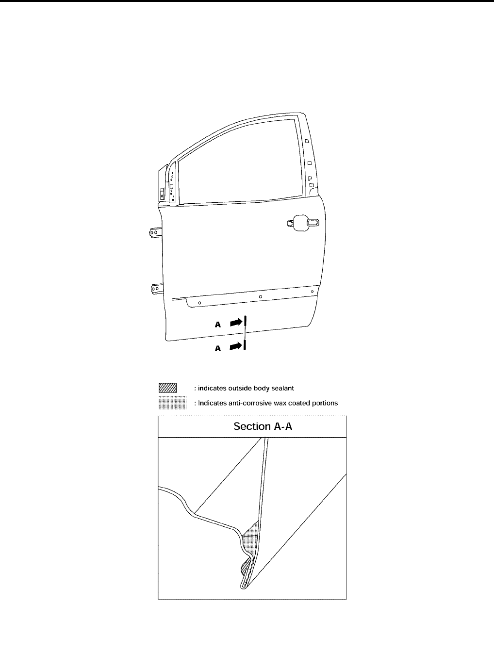
BL-238
BODY REPAIR
Revision: July 2006 2006 Quest
ANTI-CORROSIVE WAX
To improve corrosion resistance, anti-corrosive wax is applied inside the body sill and inside other closed sec-
tions. Accordingly, when replacing these parts, be sure to apply anti-corrosive wax to the appropriate areas of
the new parts. Select an excellent anti-corrosive wax which will penetrate after application and has a long shelf
life.
LIIA0810E
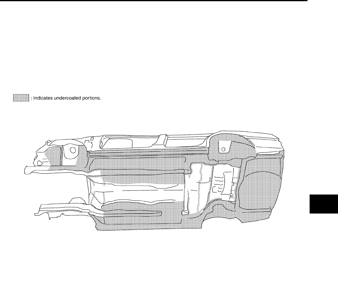
BODY REPAIR
BL-239
C
D
E
F
G
H
J
K
L
M
A
B
BL
Revision: July 2006 2006 Quest
UNDERCOATING
The underside of the floor and wheelhouse are undercoated to prevent rust, vibration, noise and stone chip-
ping. Therefore, when such a panel is replaced or repaired, apply undercoating to that part. Use an undercoat-
ing which is rust preventive, soundproof, vibration-proof, shock-resistant, adhesive, and durable.
Precautions in undercoating
1. Do not apply undercoating to any place unless specified (such as the areas above the muffler and three
way catalyst which are subjected to heat).
2. Do not undercoat the exhaust pipe or other parts which become hot.
3. Do not undercoat rotating parts.
4. Apply bitumen wax after applying undercoating.
LIIA0129E
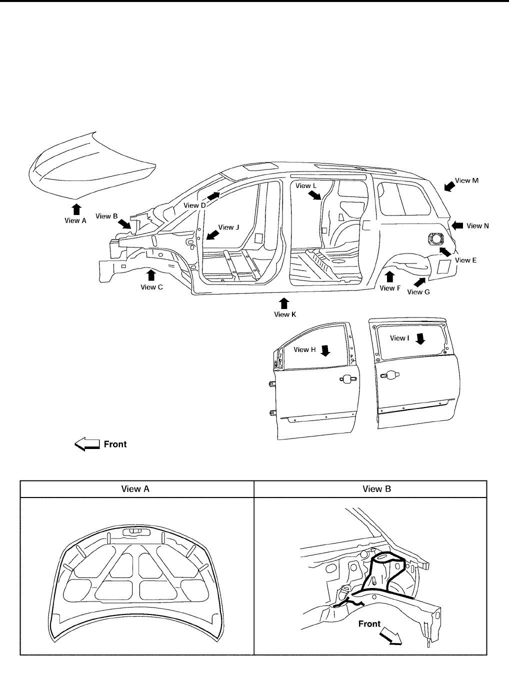
BL-240
BODY REPAIR
Revision: July 2006 2006 Quest
Body Sealing
EIS007H1
DESCRIPTION
The following figure shows the areas which are sealed at the factory. Sealant which has been applied to these
areas should be smooth and free from cuts or gaps. Care should be taken not to apply an excess amount of
sealant and not to allow other unaffected parts to come into contact with the sealant.
LIIA0812E
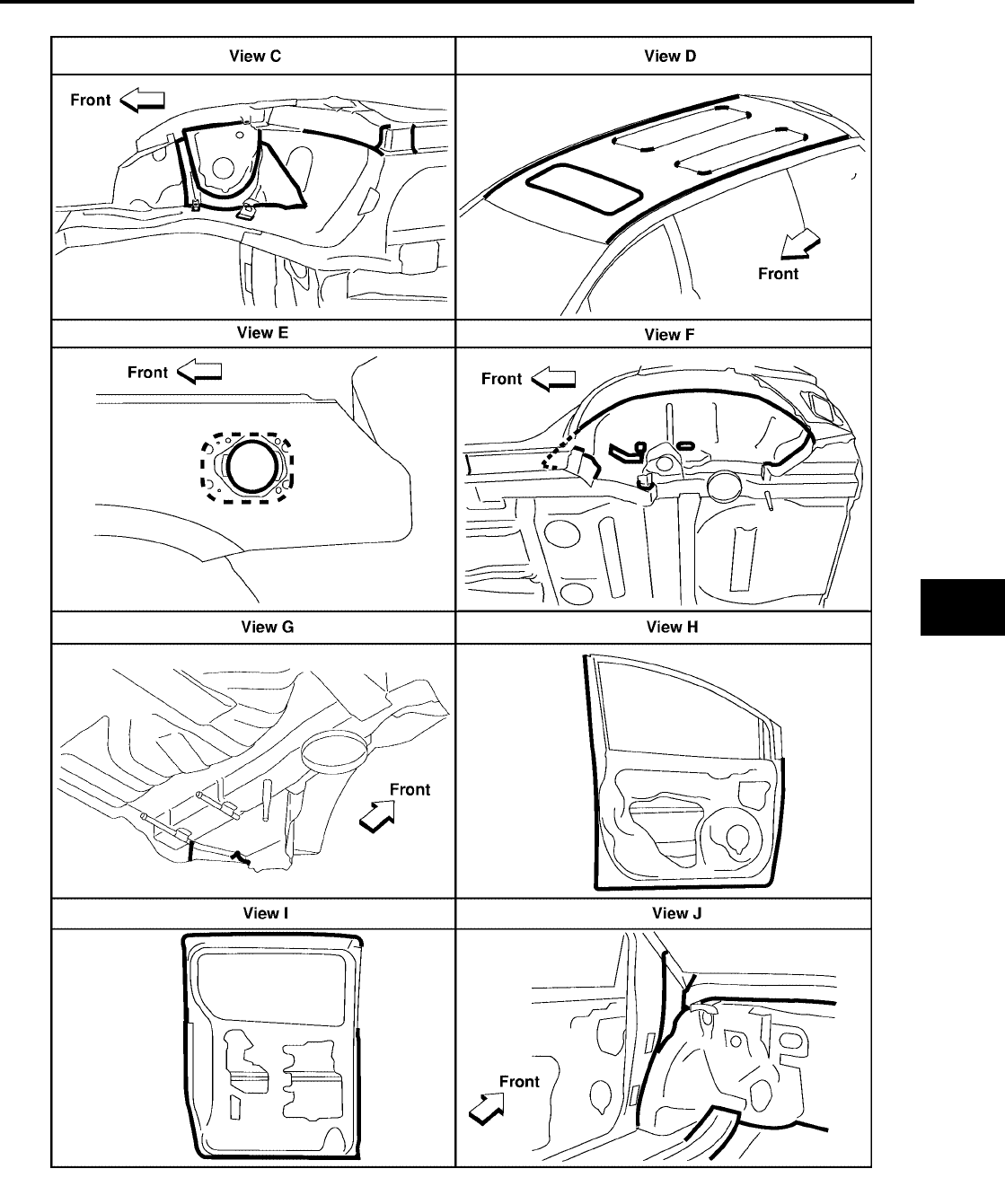
BODY REPAIR
BL-241
C
D
E
F
G
H
J
K
L
M
A
B
BL
Revision: July 2006 2006 Quest
WIIA0368E
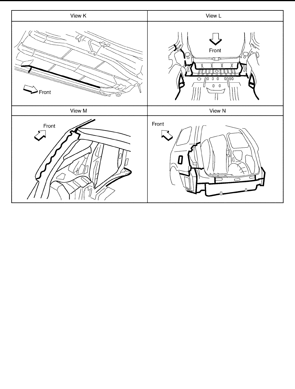
BL-242
BODY REPAIR
Revision: July 2006 2006 Quest
LIIA0816E
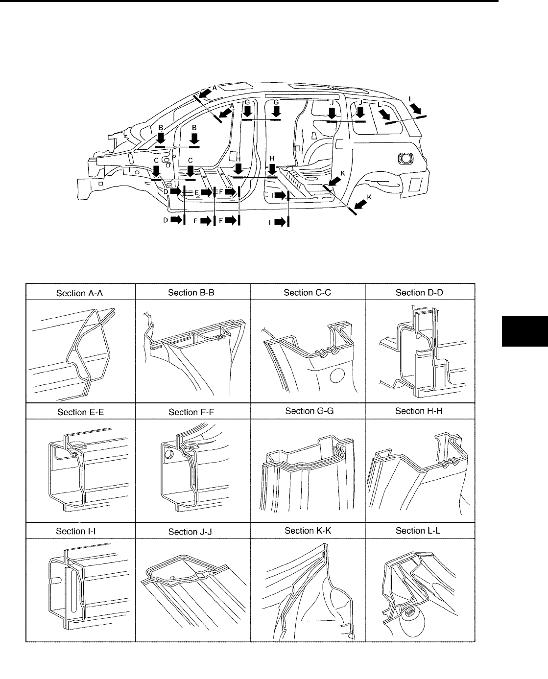
BODY REPAIR
BL-243
C
D
E
F
G
H
J
K
L
M
A
B
BL
Revision: July 2006 2006 Quest
Body Construction
EIS007H2
BODY CONSTRUCTION
LIIA0818E

BL-244
BODY REPAIR
Revision: July 2006 2006 Quest
Body Alignment
EIS007H3
BODY CENTER MARKS
A mark has been placed on each part of the body to indicate the vehicle center. When repairing parts dam-
aged by an accident which might affect the vehicle frame (members, pillars, etc.), more accurate and effective
repair will be possible by using these marks together with body alignment specifications.
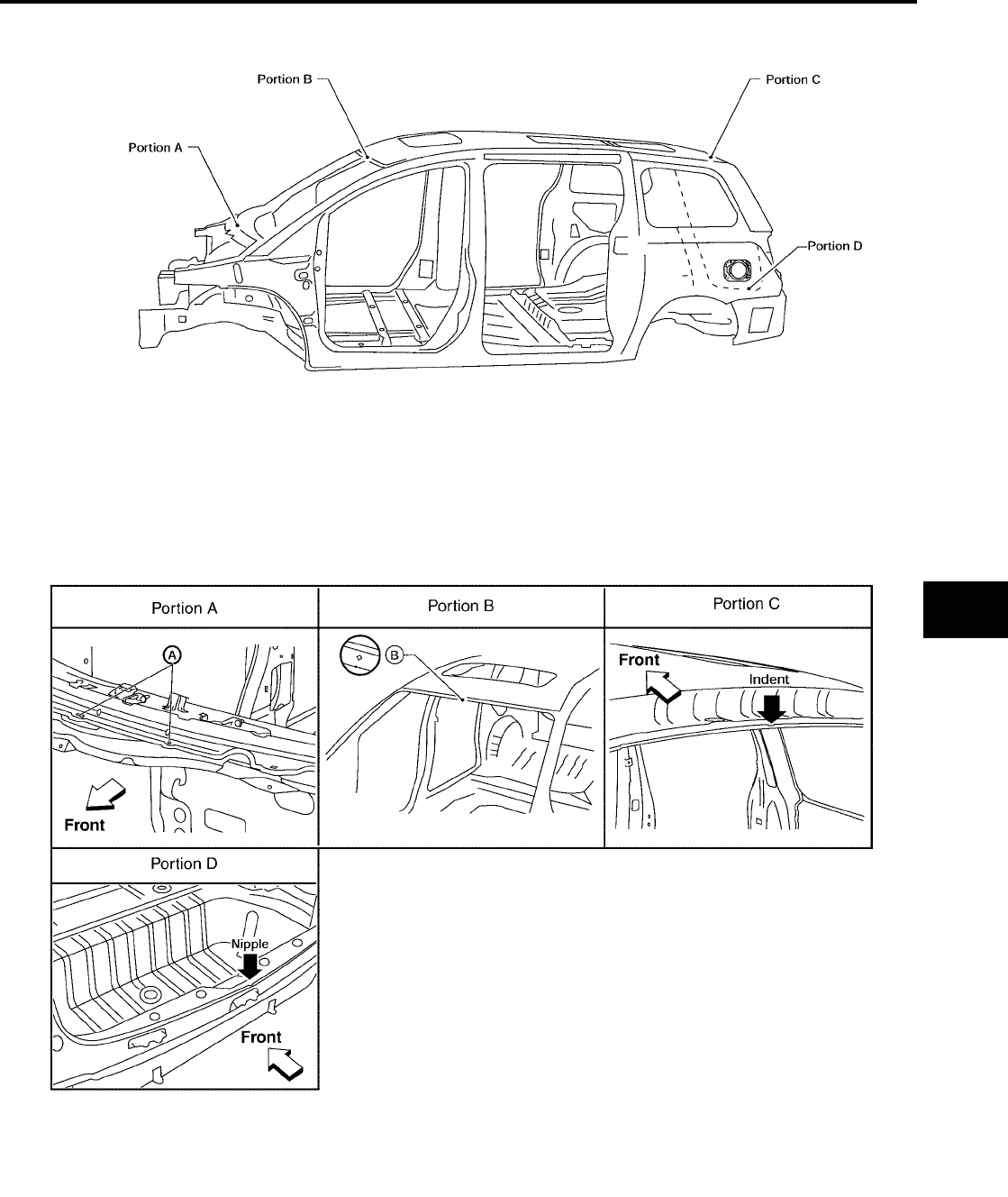
BODY REPAIR
BL-245
C
D
E
F
G
H
J
K
L
M
A
B
BL
Revision: July 2006 2006 Quest
LIIA0819E

BL-246
BODY REPAIR
Revision: July 2006 2006 Quest
PANEL PARTS MATCHING MARKS
A mark has been placed on each body panel to indicate the parts matching positions. When repairing parts
damaged by an accident which might affect the vehicle structure (members, pillars, etc.), more accurate and
effective repair will be possible by using these marks together with body alignment specifications.
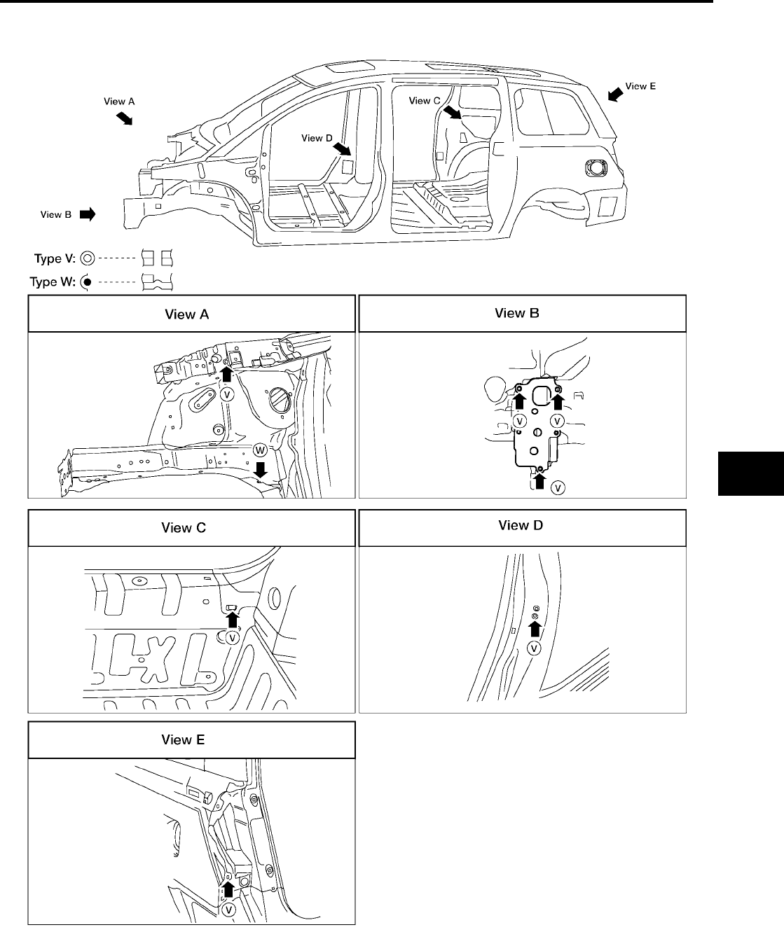
BODY REPAIR
BL-247
C
D
E
F
G
H
J
K
L
M
A
B
BL
Revision: July 2006 2006 Quest
WIIA0364E
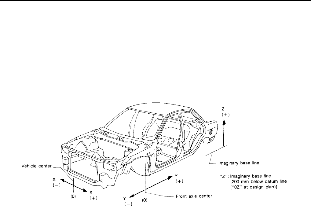
BL-248
BODY REPAIR
Revision: July 2006 2006 Quest
DESCRIPTION
●All dimensions indicated in the figures are actual.
●When using a tracking gauge, adjust both pointers to equal length. Then check the pointers and gauge
itself to make sure there is no free play.
●When a measuring tape is used, check to be sure there is no elongation, twisting or bending.
●Measurements should be taken at the center of the mounting holes.
●An asterisk (*) following the value at the measuring point indicates that the measuring point on the other
side is symmetrically the same value.
●The coordinates of the measurement points are the distances measured from the standard line of "X", "Y"
and "Z".
PIIA0104E
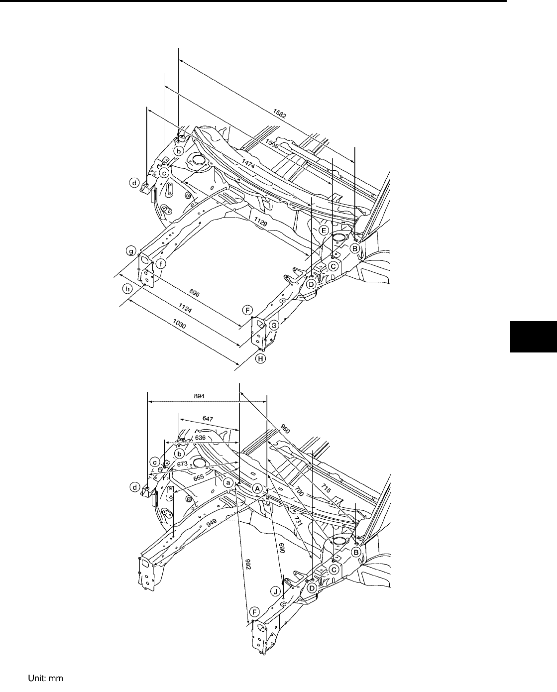
BODY REPAIR
BL-249
C
D
E
F
G
H
J
K
L
M
A
B
BL
Revision: July 2006 2006 Quest
ENGINE COMPARTMENT
MEASUREMENT
WIIA0536E
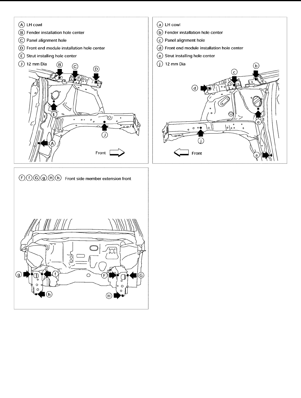
BL-250
BODY REPAIR
Revision: July 2006 2006 Quest
MEASUREMENT POINTS
LIIA0860E
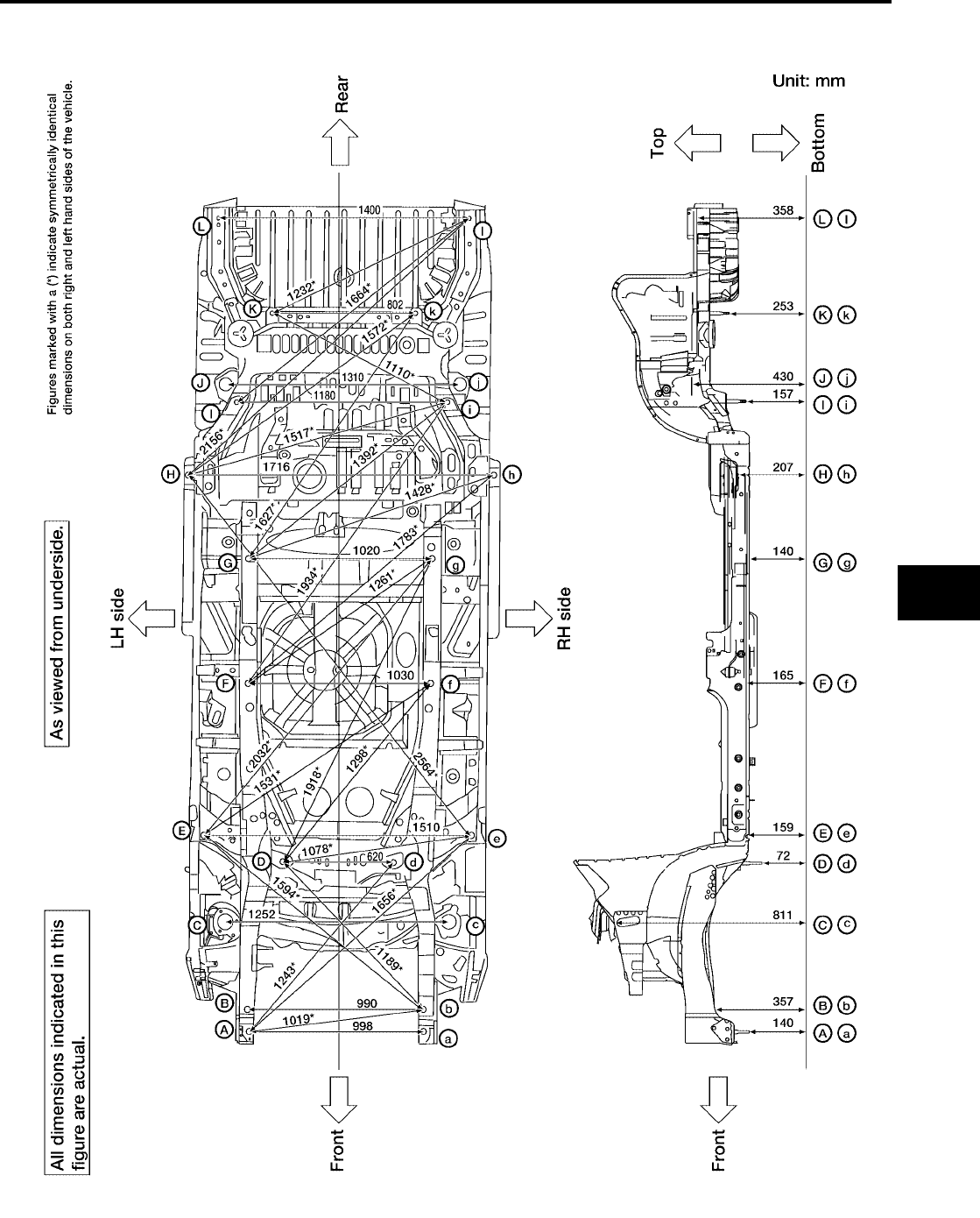
BODY REPAIR
BL-251
C
D
E
F
G
H
J
K
L
M
A
B
BL
Revision: July 2006 2006 Quest
UNDERBODY
MEASUREMENT
WIIA0358E
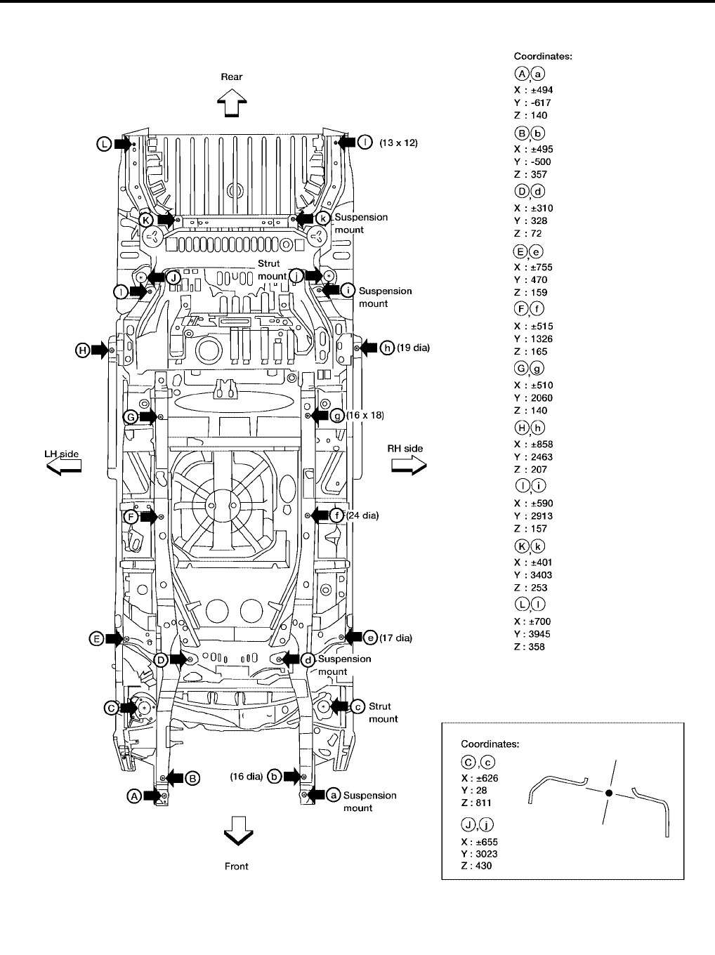
BL-252
BODY REPAIR
Revision: July 2006 2006 Quest
MEASUREMENT POINTS
WIIA0359E
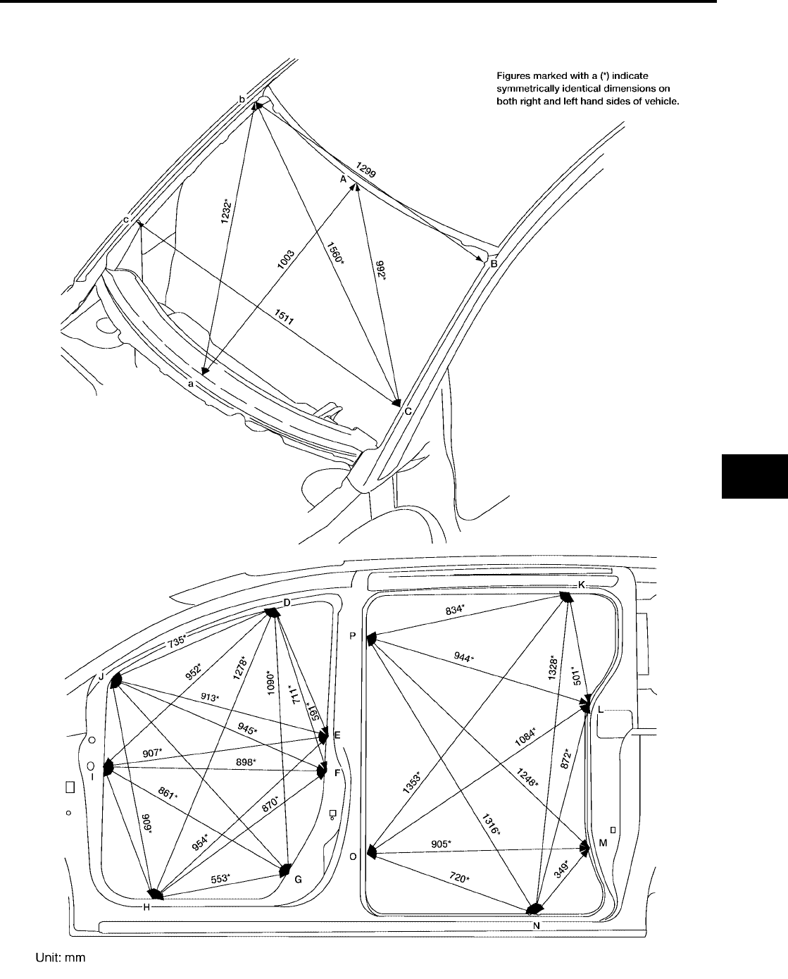
BODY REPAIR
BL-253
C
D
E
F
G
H
J
K
L
M
A
B
BL
Revision: July 2006 2006 Quest
PASSENGER COMPARTMENT
MEASUREMENT
WIIA0537E
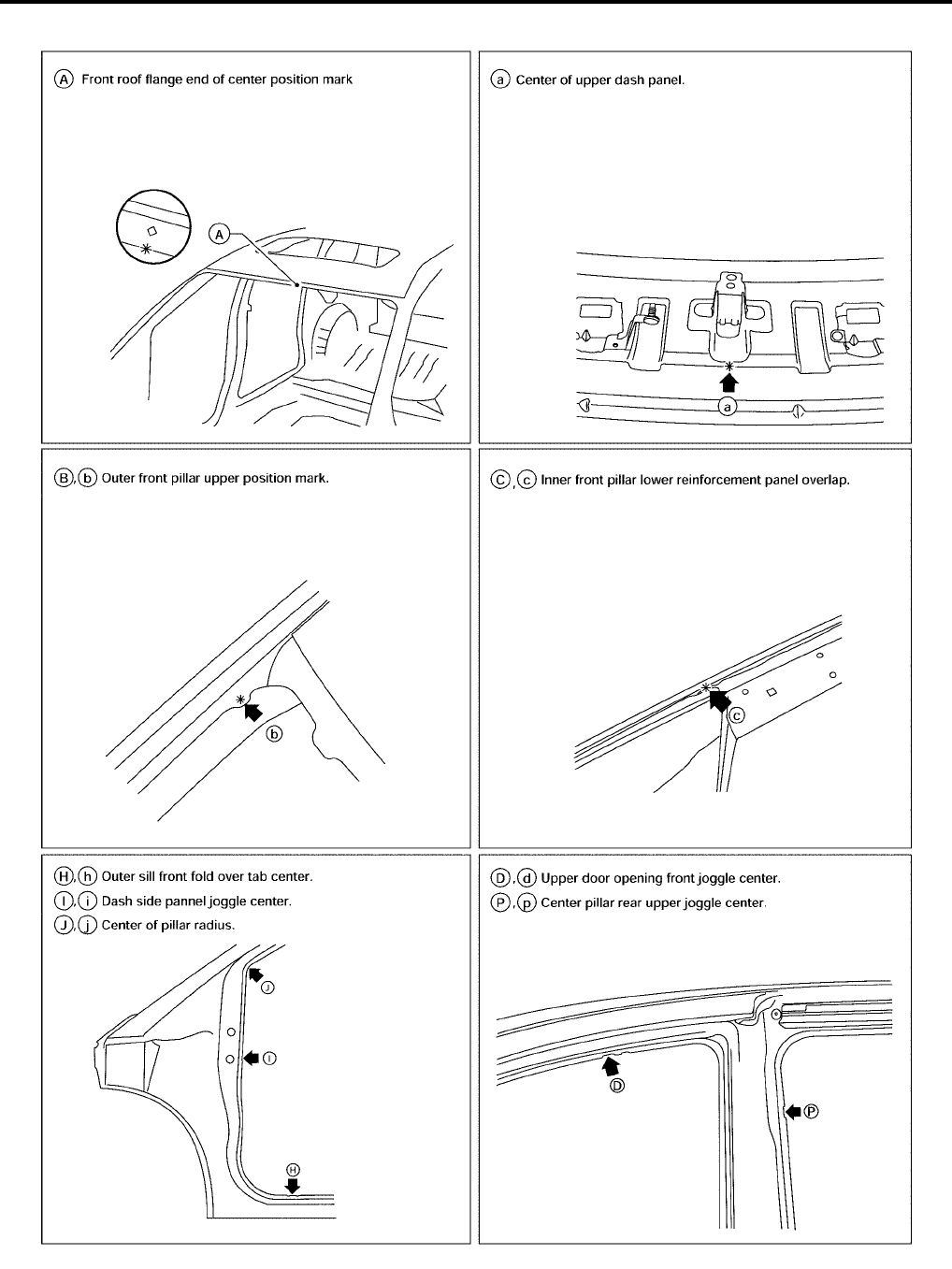
BL-254
BODY REPAIR
Revision: July 2006 2006 Quest
MEASUREMENT POINTS
LIIA0862E
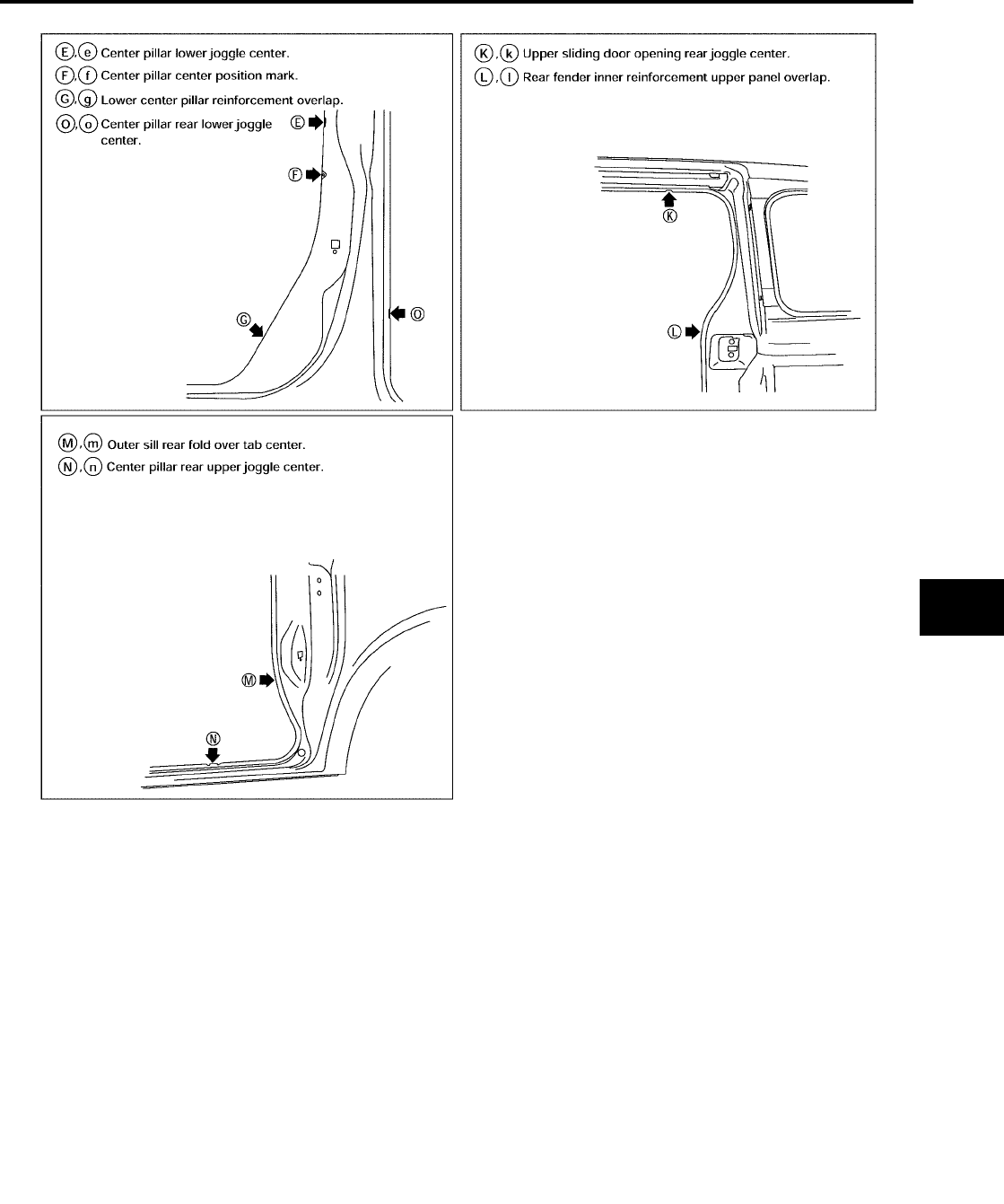
BODY REPAIR
BL-255
C
D
E
F
G
H
J
K
L
M
A
B
BL
Revision: July 2006 2006 Quest
LIIA0903E
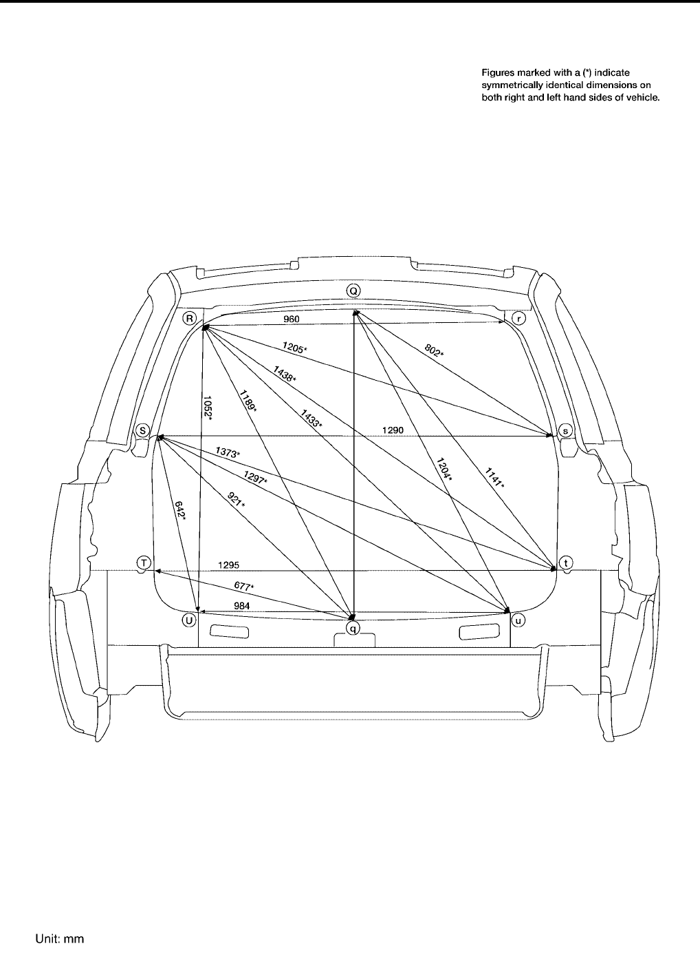
BL-256
BODY REPAIR
Revision: July 2006 2006 Quest
REAR BODY
MEASUREMENT
WIIA0539E
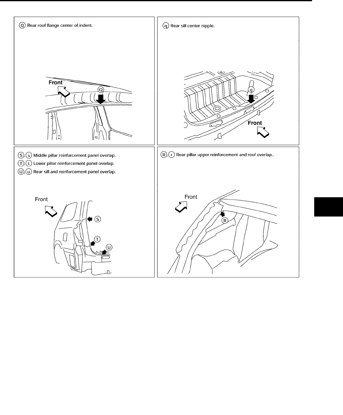
BODY REPAIR
BL-257
C
D
E
F
G
H
J
K
L
M
A
B
BL
Revision: July 2006 2006 Quest
MEASUREMENT POINTS
LIIA0864E

BL-258
BODY REPAIR
Revision: July 2006 2006 Quest
Handling Precautions for Plastics
EIS007H4
HANDLING PRECAUTIONS FOR PLASTICS
1. When repairing and painting a portion of the body adjacent to plastic parts, consider their characteristics
(influence of heat and solvent) and remove them if necessary or take suitable measures to protect them.
2. Plastic parts should be repaired and painted using methods suiting the materials, characteristics.
Abbre-
viation Material name
Heat resisting
temperature
°C (°F)
Resistance to gasoline and
solvents Other cautions
PE Polyethylene 60 (140)
Gasoline and most solvents are
harmless if applied for a very
short time (wipe up quickly).
Flammable
PVC Polyvinyl Chloride 80 (176) Same as above. Poison gas is emitted
when burned.
EPM/
EPDM
Ethylene Propylene (Diene) rub-
ber 80 (176) Same as above. Flammable
TPO/
TPR
Thermoplastic Olefine/
Thermoplastic Rubber 80 (176) Same as above. Flammable
PP Polypropylene 90 (194) Same as above. Flammable, avoid bat-
tery acid.
UP Polyester thermoset 90 (194) Same as above. Flammable
PS Polystyrene 80 (176) Avoid solvents. Flammable
ABS Acrylonitrile Butadiene Styrene
resin 80 (176) Avoid gasoline and solvents.
AES Acrylonitrile Ethylene Styrene 80 (176) Same as above.
PMMA Polymethyl Methacrylate 85 (185) Same as above.
AAS Acrylonitrile Acrylic Styrene 85 (185) Same as above.
AS Acrylonitrile Styrene 85 (185) Same as above.
EVA Polyvinyl Ethyl Acetate 90 (194) Same as above.
ASA Acrylonitrile Styrene Acrylate 100 (222) Same as above. Flammable
PPO/
PPE
Polyphenylene Oxide/
Polyphenylene Ether 110 (230) Same as above.
PC Polycarbonate 120 (248) Same as above.
PAR Polyacrylate 180 (356) Same as above.
L-
LDPE Lenear Low Density PE 45 (100) Gasoline and most solvents are
harmless. Flammable
PUR Polyurethane 90 (194) Same as above.
TPU Thermoplastic Urethane 110 (230) Same as above.
PPC Polypropylene Composite 115 (239) Same as above. Flammable
POM Polyacetal 120 (248) Same as above. Avoid battery acid.
PBT+P
C
Polybutylene Terephtha-
late+Polycarbonate 120 (248) Same as above. Flammable
PA Polyamide (Nylon) 140 (284) Same as above. Avoid immersing in wa-
ter.
PBT Polybutylene Terephthalate 140 (284) Same as above.
FRP Fiber Reinforced Plastics 170 (338) Same as above. Avoid battery acid.
PET Polyethylene Terephthalate 180 (356) Same as above.
PEI Polyetherimide 200 (392) Same as above.
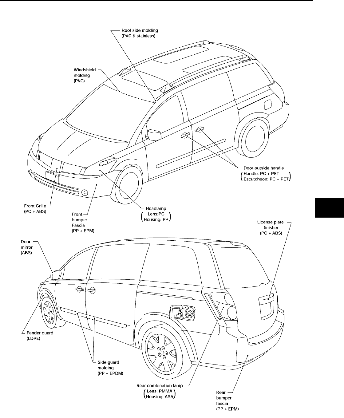
BODY REPAIR
BL-259
C
D
E
F
G
H
J
K
L
M
A
B
BL
Revision: July 2006 2006 Quest
LOCATION OF PLASTIC PARTS
LIIA0824E
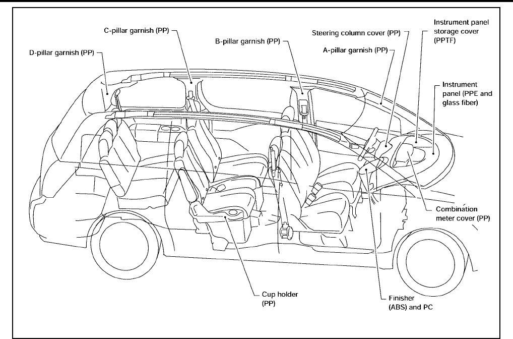
BL-260
BODY REPAIR
Revision: July 2006 2006 Quest
LIIA0825E
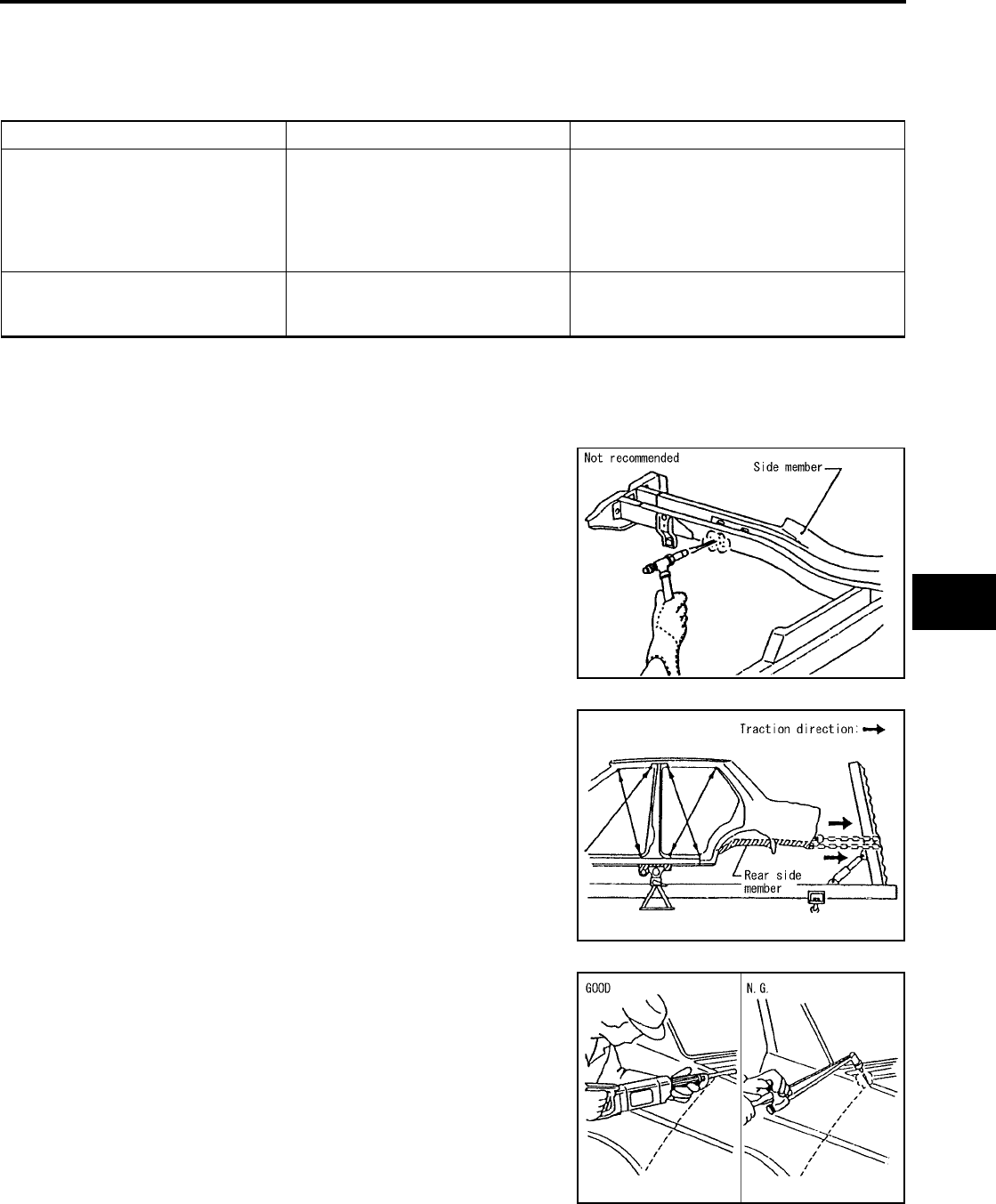
BODY REPAIR
BL-261
C
D
E
F
G
H
J
K
L
M
A
B
BL
Revision: July 2006 2006 Quest
Precautions in Repairing High Strength Steel
EIS007H5
High strength steel is used for body panels in order to reduce vehicle weight.
Accordingly, precautions in repairing automotive bodies made of high strength steel are described below:
HIGH STRENGTH STEEL (HSS) USED IN NISSAN VEHICLES
SP130 is the most commonly used HSS.
SP150 HSS is used only on parts that require much more strength.
Read the following precautions when repairing HSS:
1. Additional points to consider
●The repair of reinforcements (such as side members) by heat-
ing is not recommended since it may weaken the component.
When heating is unavoidable, do not heat HSS parts above
550°C (1,022°F).
Verify heating temperature with a thermometer.
(Crayon-type and other similar type thermometer are appro-
priate.)
●When straightening body panels, use caution in pulling any
HSS panel. Because HSS is very strong, pulling may cause
deformation in adjacent portions of the body. In this case,
increase the number of measuring points, and carefully pull
the HSS panel.
●When cutting HSS panels, avoid gas (torch) cutting if possi-
ble. Instead, use a saw to avoid weakening surrounding areas
due to heat. If gas (torch) cutting is unavoidable, allow a mini-
mum margin of 50 mm (1.97in).
Tensile strength Nissan/Infiniti designation Major applicable parts
373 N/mm2
(38kg/mm2 ,54klb/sq in) SP130
●Front side member assembly
●Upper hoodledge
●Upper pillar hinge brace assembly
●Rear side member extension
●Other reinforcements
785-981 N/mm2
(80-100kg/mm2
114-142klb/sq in)
SP150 ●Front bumper reinforcement
●Rear bumper reinforcement
PIIA0115E
PIIA0116E
PIIA0117E
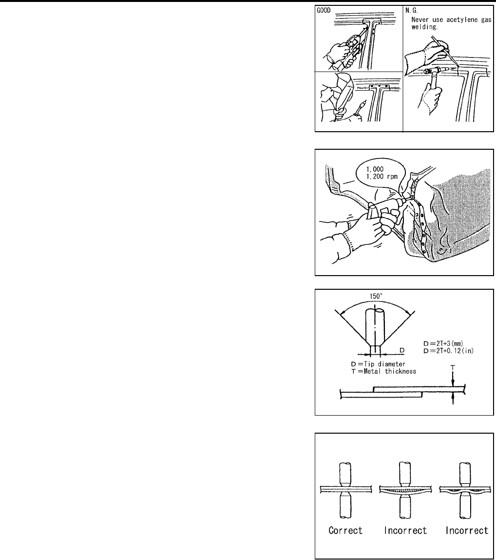
BL-262
BODY REPAIR
Revision: July 2006 2006 Quest
●When welding HSS panels, use spot welding whenever possi-
ble in order to minimize weakening surrounding areas due to
heat.
If spot welding is impossible, use M.I.G. welding. Do not use
gas (torch) welding because it is inferior in welding strength.
●The spot weld on HSS panels is harder than that of an ordi-
nary steel panel.
Therefore, when cutting spot welds on a HSS panel, use a
low speed high torque drill (1,000 to 1,200 rpm) to increase
drill bit durability and facilitate the operation.
●SP150 HSS panels with a tensile strength of 785 to 981 N/
mm2 (80 to 100 kg/mm2 , 114 to 142 klb/sq in), used as rein-
forcement in the door guard beams, is too strong to repair.
When these HSS parts are damaged, the outer panels also
sustain substantial damage; therefore, the assembly parts
must be replaced.
2. Precautions in spot welding HSS
This work should be performed under standard working condi-
tions. Always note the following when spot welding HSS:
●The electrode tip diameter must be sized properly according
to the metal thickness.
●The panel surfaces must fit flush to each other, leaving no
gaps.
PIIA0144E
PIIA0145E
PIIA0146E
PIIA0147E
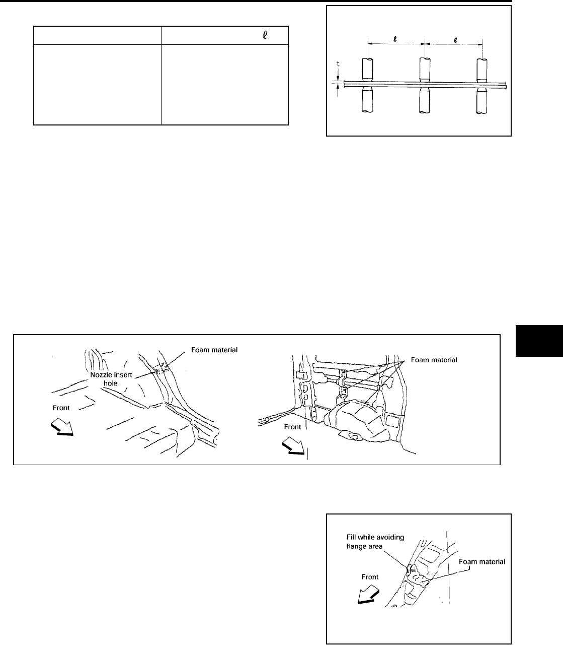
BODY REPAIR
BL-263
C
D
E
F
G
H
J
K
L
M
A
B
BL
Revision: July 2006 2006 Quest
●Follow the specifications for the proper welding pitch. Unit:mm
Foam Repair
EIS007H6
During factory body assembly, foam insulators are installed in certain body panels and locations around the
vehicle. Use the following procedure(s) to replace any factory-installed foam insulators.
URETHANE FOAM APPLICATIONS
Use commercially available spray foam for sealant (foam material) repair of material used on vehicle. Read
instructions on product for fill procedures.
FILL PROCEDURES
1. Fill procedures after installation of service part.
–Remove foam material remaining on vehicle side.
–Clean area in which foam was removed.
–Install service part.
–Insert nozzle into hole near fill area and fill foam material or fill in enough to close gap with the service
part.
2. Fill procedures before installation of service part.
–Remove foam material remaining on vehicle side.
–Clean area in which foam was removed.
–Fill foam material on wheelhouse outer side.
NOTE:
Fill in enough to close gap with service part while avoiding
flange area.
–Install service part.
NOTE:
Refer to label for information on working times.
Thickness (t) Minimum pitch ( )
0.6 (0.024)
0.8 (0.031)
1.0 (0.039)
1.2 (0.047)
1.6 (0.063)
1.8 (0.071)
10 (0.39) or over
12 (0.47) or over
18 (0.71) or over
20 (0.79) or over
27 (1.06) or over
31 (1.22) or over
PIIA0148E
LIIA1081E
LIIA1082E

BL-264
BODY REPAIR
Revision: July 2006 2006 Quest
Replacement Operations
EIS007H7
DESCRIPTION
This section is prepared for technicians who have attained a high level of skill and experience in repairing col-
lision-damaged vehicles and also use modern service tools and equipment. Persons unfamiliar with body
repair techniques should not attempt to repair collision-damaged vehicles by using this section.
Technicians are also encouraged to read Body Repair Manual (Fundamentals) in order to ensure that the orig-
inal functions and quality of the vehicle can be maintained. The Body Repair Manual (Fundamentals) contains
additional information, including cautions and warnings, that are not including in this manual. Technicians
should refer to both manuals to ensure proper repairs.
Please note that this information is prepared for worldwide usage, and as such, certain procedures may not
apply in some regions or countries.
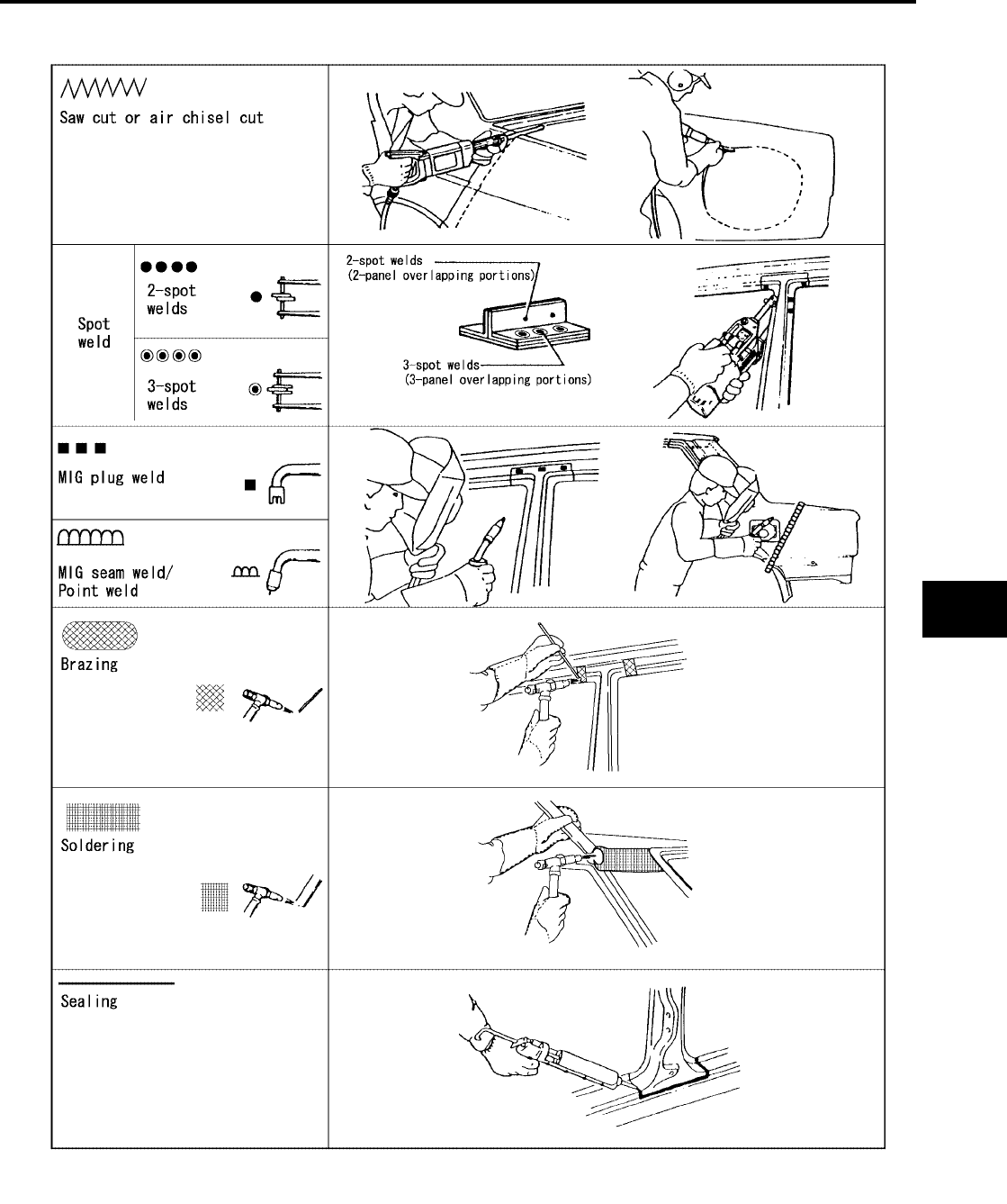
BODY REPAIR
BL-265
C
D
E
F
G
H
J
K
L
M
A
B
BL
Revision: July 2006 2006 Quest
The symbols used in this section for cutting and welding / brazing operations are shown below.
PIIA0149E
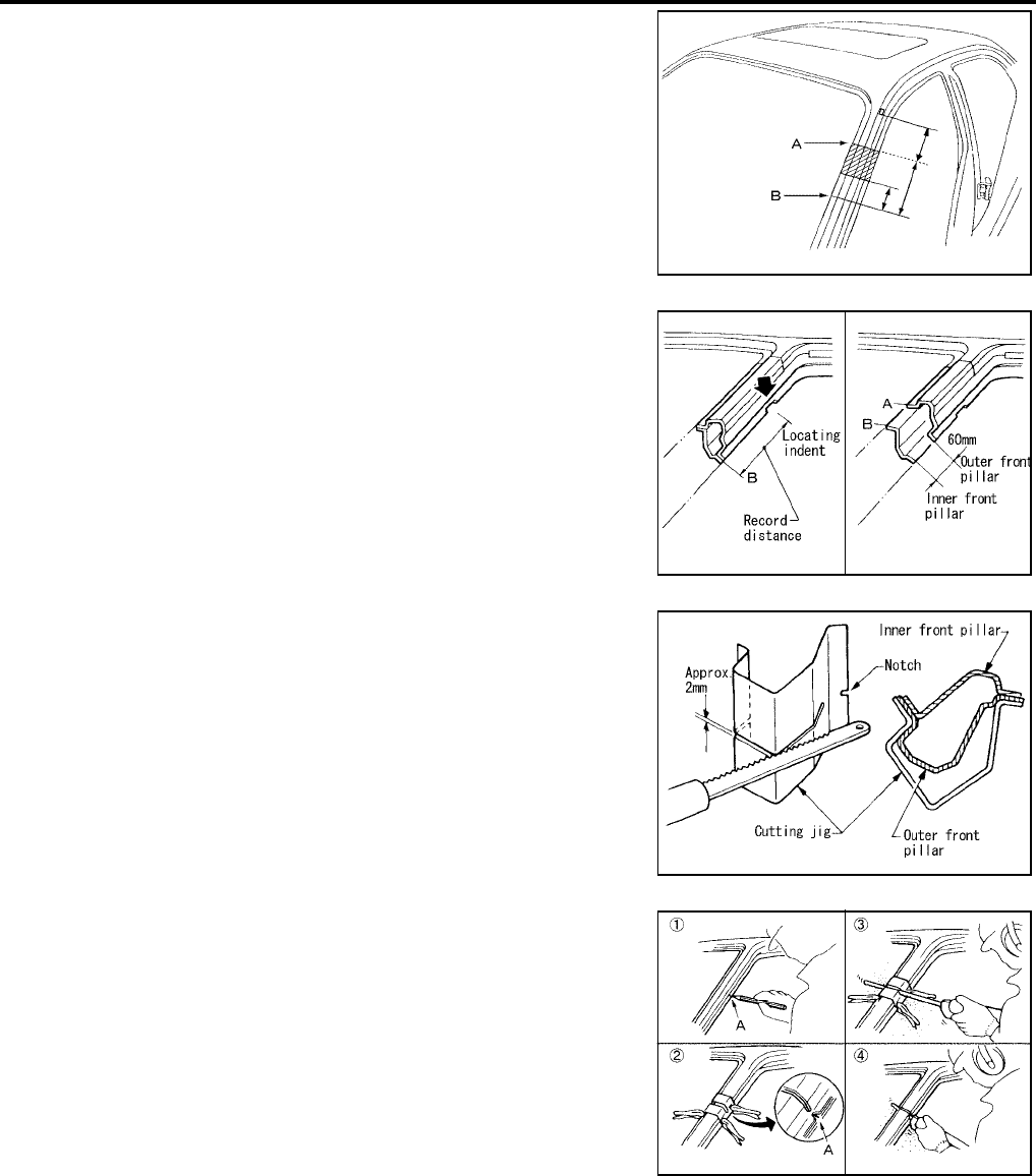
BL-266
BODY REPAIR
Revision: July 2006 2006 Quest
●Front pillar butt joint can be determined anywhere within shaded
area as shown in the figure. The best location for the butt joint is
at position A due to the construction of the vehicle. Refer to the
front pillar section.
●Determine cutting position and record distance from the locating
indent. Use this distance when cutting the service part. Cut outer
front pillar over 60 mm above inner front pillar cut position.
●Prepare a cutting jig to make outer pillar easier to cut. Also, this
will permit service part to be accurately cut at joint position.
●An example of cutting operation using a cutting jig is as follows.
1. Mark cutting lines.
A: Cut position of outer pillar
B: Cut position of inner pillar
2. Align cutting line with notch on jig. Clamp jig to pillar.
3. Cut outer pillar along groove of jig. (At position A)
4. Remove jig and cut remaining portions.
5. Cut inner pillar at position B in same manner.
PIIA0150E
PIIA0151E
PIIA0152E
PIIA0153E
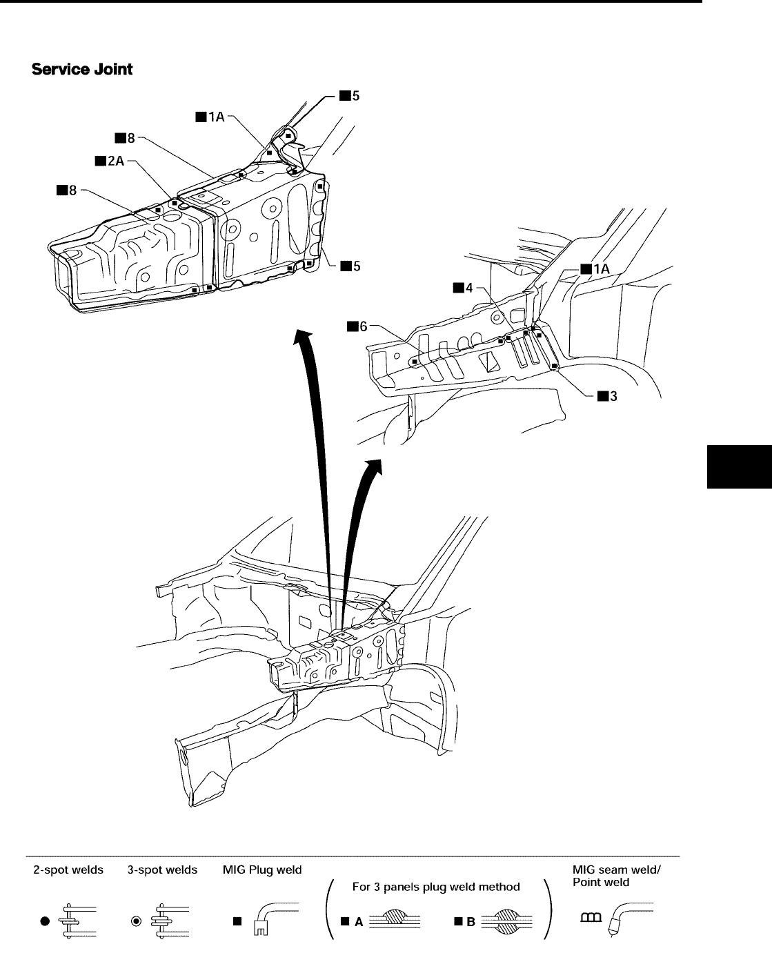
BODY REPAIR
BL-267
C
D
E
F
G
H
J
K
L
M
A
B
BL
Revision: July 2006 2006 Quest
HOODLEDGE
●Work after radiator core support has been removed.
LIIA0866E
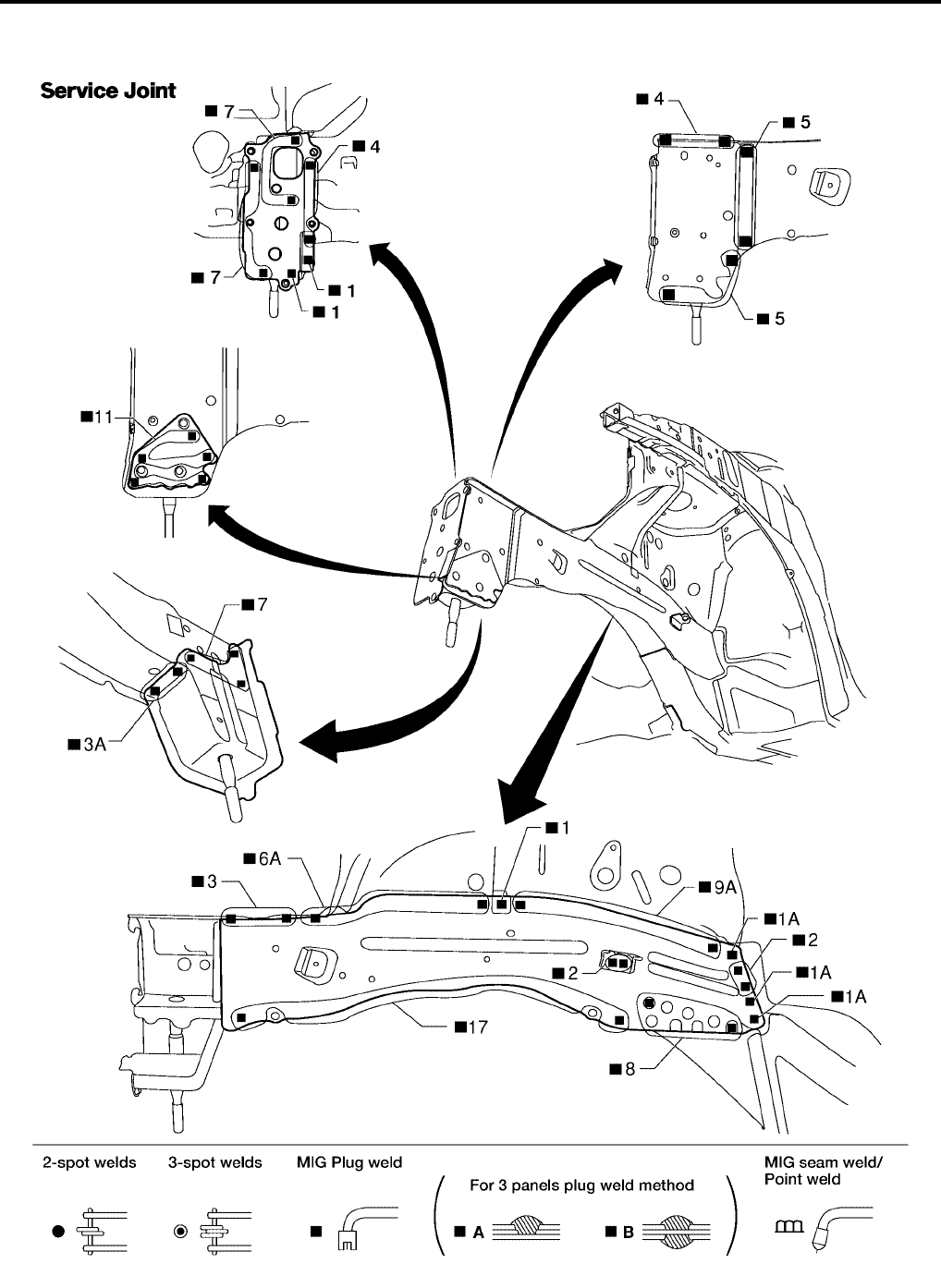
BL-268
BODY REPAIR
Revision: July 2006 2006 Quest
FRONT SIDE MEMBER
●Work after hoodledge and radiator core support have been removed.
WIIA0360E
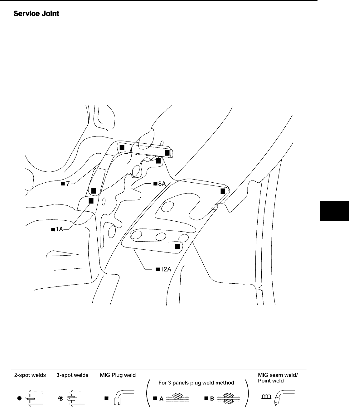
BODY REPAIR
BL-269
C
D
E
F
G
H
J
K
L
M
A
B
BL
Revision: July 2006 2006 Quest
LIIA0869E
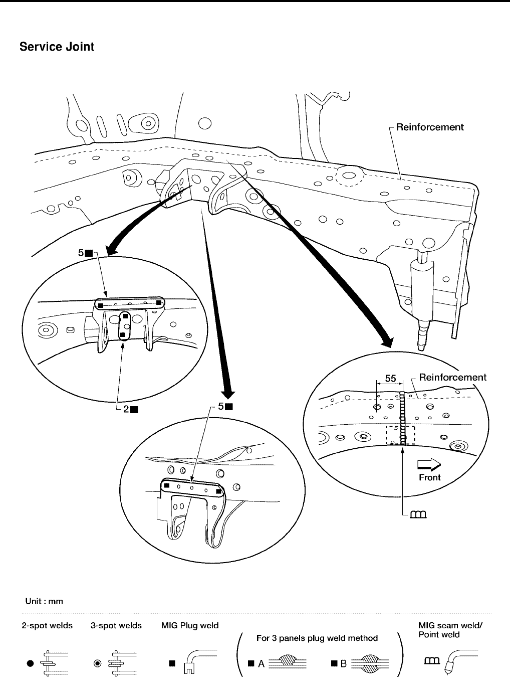
BL-270
BODY REPAIR
Revision: July 2006 2006 Quest
FRONT SIDE MEMBER (PARTIAL REPLACEMENT)
●Work after radiator core support has been removed.
WIIA0361E
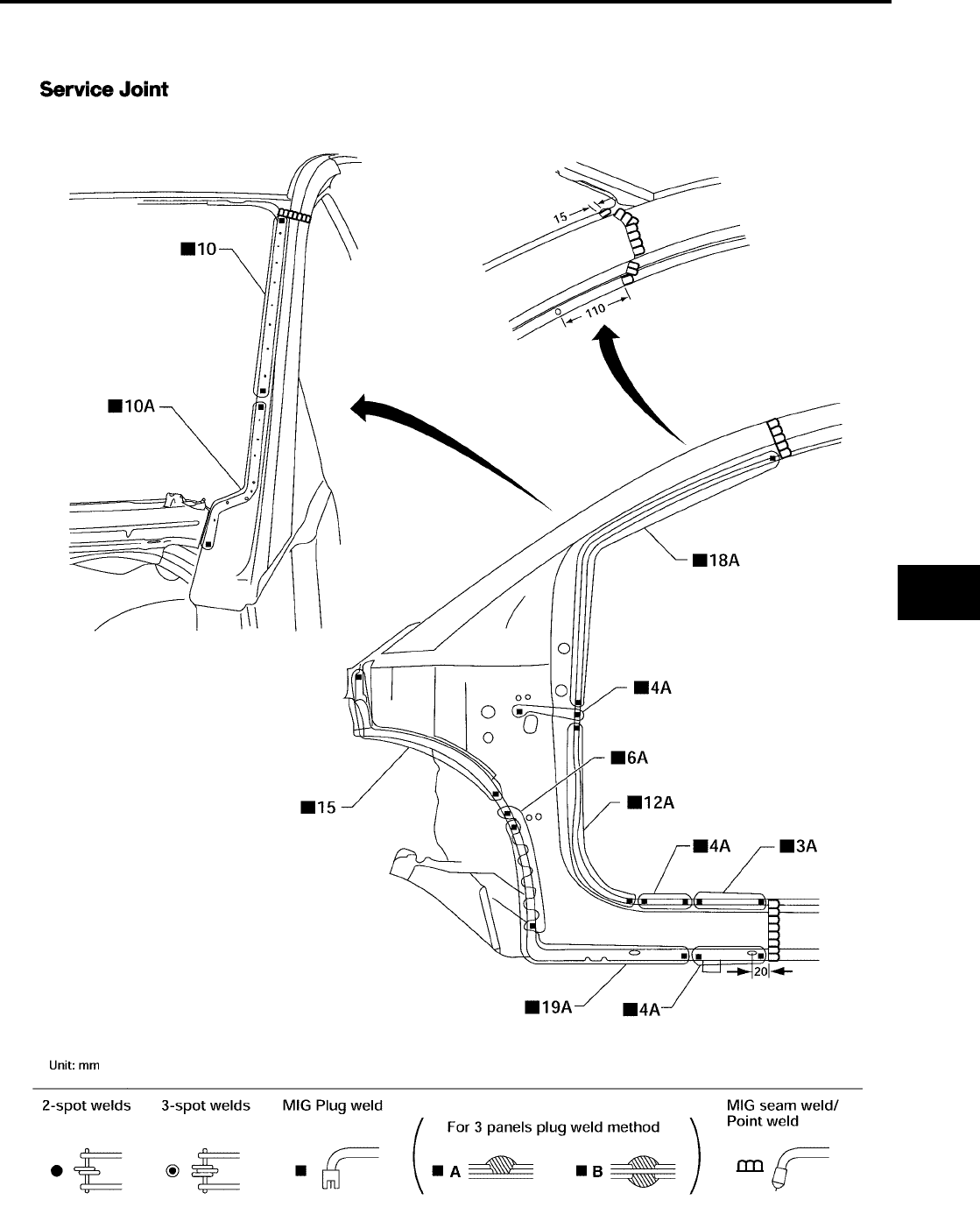
BODY REPAIR
BL-271
C
D
E
F
G
H
J
K
L
M
A
B
BL
Revision: July 2006 2006 Quest
FRONT PILLAR
●Work after rear hoodledge reinforcement has been removed.
LIIA0870E
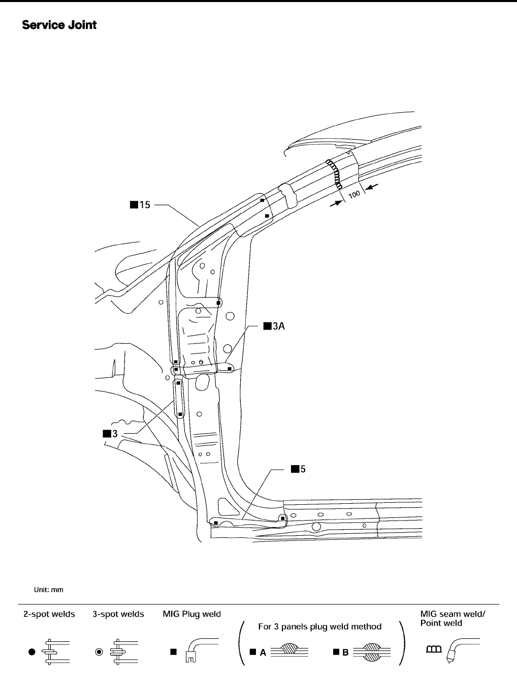
BL-272
BODY REPAIR
Revision: July 2006 2006 Quest
LIIA0871E
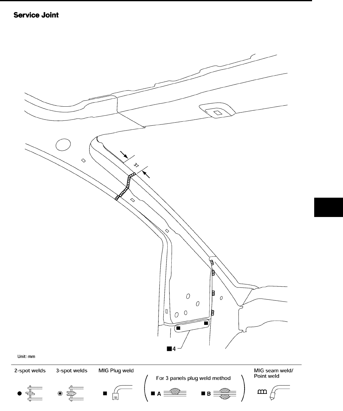
BODY REPAIR
BL-273
C
D
E
F
G
H
J
K
L
M
A
B
BL
Revision: July 2006 2006 Quest
LIIA0872E
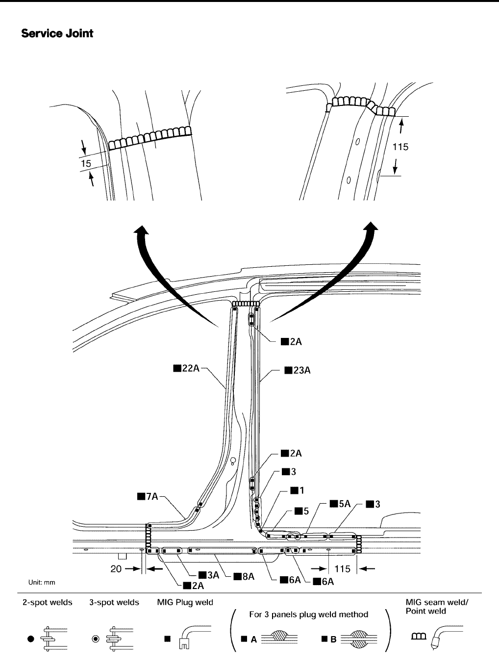
BL-274
BODY REPAIR
Revision: July 2006 2006 Quest
CENTER PILLAR
LIIA0873E
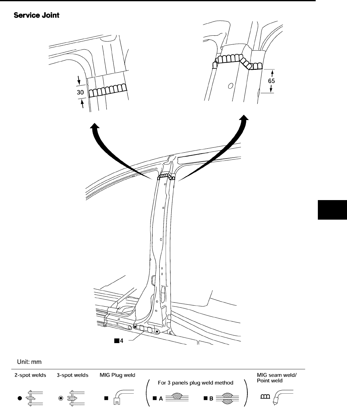
BODY REPAIR
BL-275
C
D
E
F
G
H
J
K
L
M
A
B
BL
Revision: July 2006 2006 Quest
LIIA0874E
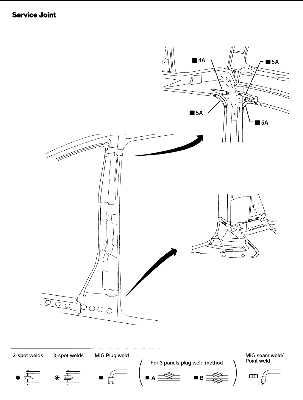
BL-276
BODY REPAIR
Revision: July 2006 2006 Quest
LIIA0904E
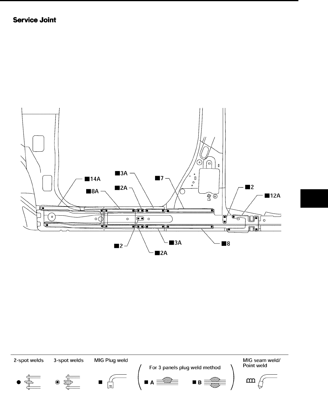
BODY REPAIR
BL-277
C
D
E
F
G
H
J
K
L
M
A
B
BL
Revision: July 2006 2006 Quest
OUTER SILL
LIIA0875E
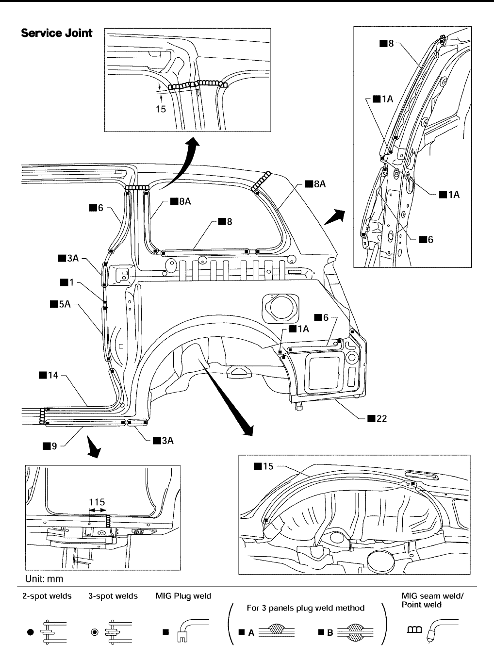
BL-278
BODY REPAIR
Revision: July 2006 2006 Quest
REAR FENDER
LIIA0876E
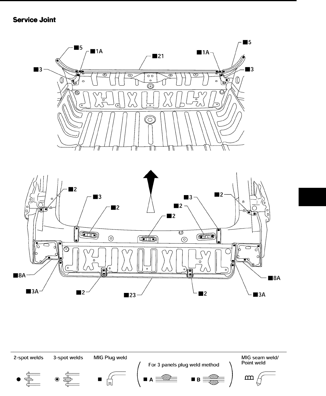
BODY REPAIR
BL-279
C
D
E
F
G
H
J
K
L
M
A
B
BL
Revision: July 2006 2006 Quest
REAR PANEL
LIIA0877E
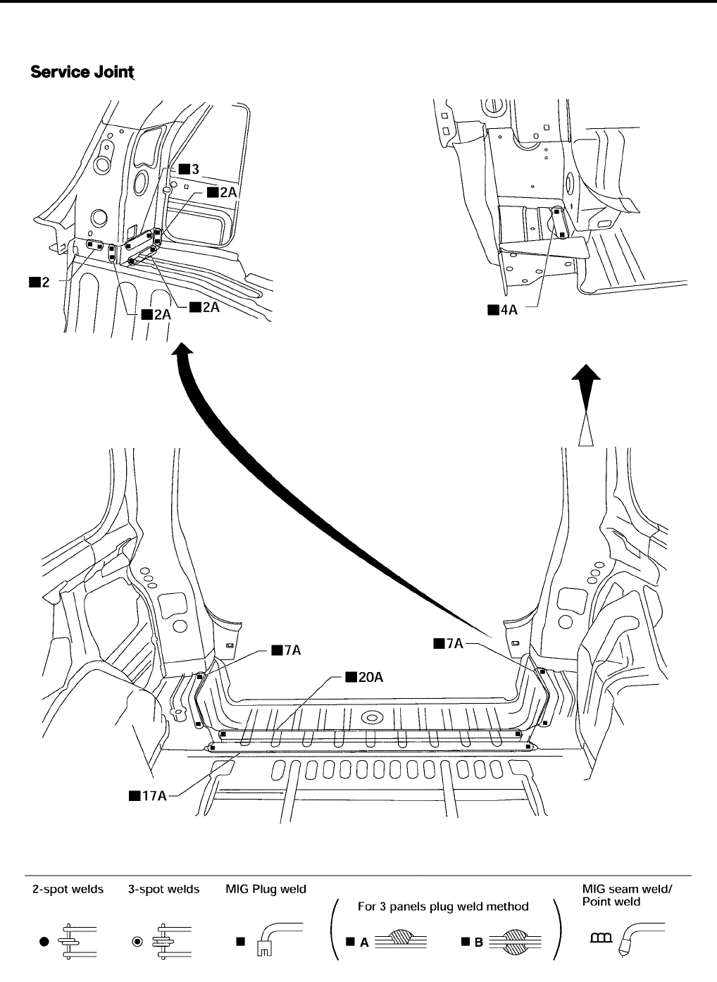
BL-280
BODY REPAIR
Revision: July 2006 2006 Quest
REAR FLOOR REAR
●Work after rear panel has been removed.
LIIA0878E
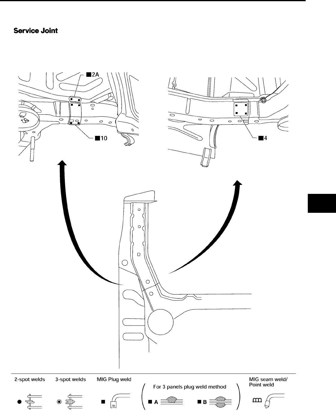
BODY REPAIR
BL-281
C
D
E
F
G
H
J
K
L
M
A
B
BL
Revision: July 2006 2006 Quest
REAR SIDE MEMBER EXTENSION
●Work after rear panel and rear end crossmember have been removed.
LIIA0879E

BL-282
BODY REPAIR
Revision: July 2006 2006 Quest
