Bootloader Generator User's Guide User
User Manual:
Open the PDF directly: View PDF ![]() .
.
Page Count: 45
- Trademarks
- Table of Contents
- Preface
- Revision History
- Chapter 1. Overview
- Chapter 2. Options, Parts and Pieces
- 2.1 Communication Method
- 2.2 Verification of Bootload Integrity
- 2.3 Self Protection
- 2.4 IO Pin Indicator
- 2.5 Enable Read Flash
- 2.6 Enable Read/Write EEData
- 2.7 Encryption
- Figure 2-1: Check Reset Vector Address
- Figure 2-2: Nonvolatile State Variable
- Figure 2-3: Calculate Checksum on Start-up
- Figure 2-4: Listen for COM Port Activity
- Figure 2-5: IO Pin Set Start-up UML Sequence
- Chapter 3. Hex File
- Chapter 4. MCC Bootloader Generator
- Chapter 5. Merge Bootloader with the Application
- Chapter 6. Bootloader Host Application
- Chapter 7. Bootloader Protocol
- Worldwide Sales

2015-2016 Microchip Technology Inc. DS40001779B
Bootloader Generator
User’s Guide

DS40001779B-page 2 2015-2016 Microchip Technology Inc.
Information contained in this publication regarding device
applications and the like is provided only for your convenience
and may be superseded by updates. It is your responsibility to
ensure that your application meets with your specifications.
MICROCHIP MAKES NO REPRESENTATIONS OR
WARRANTIES OF ANY KIND WHETHER EXPRESS OR
IMPLIED, WRITTEN OR ORAL, STATUTORY OR
OTHERWISE, RELATED TO THE INFORMATION,
INCLUDING BUT NOT LIMITED TO ITS CONDITION,
QUALITY, PERFORMANCE, MERCHANTABILITY OR
FITNESS FOR PURPOSE. Microchip disclaims all liability
arising from this information and its use. Use of Microchip
devices in life support and/or safety applications is entirely at
the buyer’s risk, and the buyer agrees to defend, indemnify and
hold harmless Microchip from any and all damages, claims,
suits, or expenses resulting from such use. No licenses are
conveyed, implicitly or otherwise, under any Microchip
intellectual property rights unless otherwise stated.
Note the following details of the code protection feature on Microchip devices:
• Microchip products meet the specification contained in their particular Microchip Data Sheet.
• Microchip believes that its family of products is one of the most secure families of its kind on the market today, when used in the
intended manner and under normal conditions.
• There are dishonest and possibly illegal methods used to breach the code protection feature. All of these methods, to our
knowledge, require using the Microchip products in a manner outside the operating specifications contained in Microchip’s Data
Sheets. Most likely, the person doing so is engaged in theft of intellectual property.
• Microchip is willing to work with the customer who is concerned about the integrity of their code.
• Neither Microchip nor any other semiconductor manufacturer can guarantee the security of their code. Code protection does not
mean that we are guaranteeing the product as “unbreakable.”
Code protection is constantly evolving. We at Microchip are committed to continuously improving the code protection features of our
products. Attempts to break Microchip’s code protection feature may be a violation of the Digital Millennium Copyright Act. If such acts
allow unauthorized access to your software or other copyrighted work, you may have a right to sue for relief under that Act.
Microchip received ISO/TS-16949:2009 certification for its worldwide
headquarters, design and wafer fabrication facilities in Chandler and
Tempe, Arizona; Gresham, Oregon and design centers in California
and India. The Company’s quality system processes and procedures
are for its PIC® MCUs and dsPIC® DSCs, KEELOQ® code hopping
devices, Serial EEPROMs, microperipherals, nonvolatile memory and
analog products. In addition, Microchip’s quality system for the design
and manufacture of development systems is ISO 9001:2000 certified.
QUALITY MANAGEMENT S
YSTEM
CERTIFIED BY DNV
== ISO/TS 16949 ==
Trademarks
The Microchip name and logo, the Microchip logo, AnyRate, AVR,
AVR logo, AVR Freaks, BeaconThings, BitCloud, CryptoMemory,
CryptoRF, dsPIC, FlashFlex, flexPWR, Heldo, JukeBlox, KEELOQ,
KEELOQ logo, Kleer, LANCheck, LINK MD, maXStylus,
maXTouch, MediaLB, megaAVR, MOST, MOST logo, MPLAB,
OptoLyzer, PIC, picoPower, PICSTART, PIC32 logo, Prochip
Designer, QTouch, RightTouch, SAM-BA, SpyNIC, SST, SST
Logo, SuperFlash, tinyAVR, UNI/O, and XMEGA are registered
trademarks of Microchip Technology Incorporated in the U.S.A.
and other countries.
ClockWorks, The Embedded Control Solutions Company,
EtherSynch, Hyper Speed Control, HyperLight Load, IntelliMOS,
mTouch, Precision Edge, and Quiet-Wire are registered
trademarks of Microchip Technology Incorporated in the U.S.A.
Adjacent Key Suppression, AKS, Analog-for-the-Digital Age, Any
Capacitor, AnyIn, AnyOut, BodyCom, chipKIT, chipKIT logo,
CodeGuard, CryptoAuthentication, CryptoCompanion,
CryptoController, dsPICDEM, dsPICDEM.net, Dynamic Average
Matching, DAM, ECAN, EtherGREEN, In-Circuit Serial
Programming, ICSP, Inter-Chip Connectivity, JitterBlocker,
KleerNet, KleerNet logo, Mindi, MiWi, motorBench, MPASM, MPF,
MPLAB Certified logo, MPLIB, MPLINK, MultiTRAK, NetDetach,
Omniscient Code Generation, PICDEM, PICDEM.net, PICkit,
PICtail, PureSilicon, QMatrix, RightTouch logo, REAL ICE, Ripple
Blocker, SAM-ICE, Serial Quad I/O, SMART-I.S., SQI,
SuperSwitcher, SuperSwitcher II, Total Endurance, TSHARC,
USBCheck, VariSense, ViewSpan, WiperLock, Wireless DNA, and
ZENA are trademarks of Microchip Technology Incorporated in the
U.S.A. and other countries.
SQTP is a service mark of Microchip Technology Incorporated in
the U.S.A.
Silicon Storage Technology is a registered trademark of Microchip
Technology Inc. in other countries.
GestIC is a registered trademark of Microchip Technology
Germany II GmbH & Co. KG, a subsidiary of Microchip Technology
Inc., in other countries.
All other trademarks mentioned herein are property of their
respective companies.
© 2015-2016, Microchip Technology Incorporated, All Rights
Reserved.
ISBN: 978-1-5224-1205-2

BOOTLOADER GENERATOR
USER’S GUIDE
2015-2016 Microchip Technology Inc. DS40001779B-page 3
Table of Contents
Preface ........................................................................................................................... 5
Chapter 1. Overview
1.1 Bootloader Overview ...................................................................................... 9
1.2 Bootloader Requirements ............................................................................... 9
Chapter 2. Options, Parts and Pieces
2.1 Communication Method ............................................................................... 15
2.2 Verification of Bootload Integrity ................................................................... 16
2.3 Self Protection .............................................................................................. 16
2.4 IO Pin Indicator ............................................................................................. 16
2.5 Enable Read Flash ....................................................................................... 16
2.6 Enable Read/Write EEData .......................................................................... 16
2.7 Encryption .................................................................................................... 16
Chapter 3. Hex File
3.1 Intel® Hex File Format .................................................................................. 19
3.2 PIC16F1XXX Interpretations ........................................................................ 19
3.3 PIC18 Interpretations ................................................................................... 20
Chapter 4. MCC Bootloader Generator
4.1 Generate Bootloader .................................................................................... 21
Chapter 5. Merge Bootloader with the Application
5.1 MPLAB X Project configurations .................................................................. 25
5.1.1 End – Application Project Configurations .................................................. 27
Chapter 6. Bootloader Host Application
6.1 Overall Working Strategy ............................................................................. 31
6.2 Prerequisites ................................................................................................ 32
6.3 Detailed Steps .............................................................................................. 32
6.4 Menu Bar Options ........................................................................................ 35
6.5 Troubleshooting ............................................................................................ 36
6.6 External Dependencies ................................................................................ 36
6.7 The Host Application .................................................................................... 36
Chapter 7. Bootloader Protocol
7.1 Command set ............................................................................................... 37
7.2 The Host Application .................................................................................... 38
7.3 Additional commands ................................................................................... 41
Worldwide Sales and Service ....................................................................................45

Bootloader Generator User’s Guide
DS40001779B-page 4 2015-2016 Microchip Technology Inc.
NOTES:

BOOTLOADER GENERATOR
USER’S GUIDE
2015-2016 Microchip Technology Inc. DS40001779B-page 5
Preface
INTRODUCTION
This chapter contains general information that will be useful to know before using the
Bootloader Generator. Items discussed in this chapter include:
• Document Layout
• Conventions Used in this Guide
• Warranty Registration
• Recommended Reading
• The Microchip Website
• Development Systems Customer Change Notification Service
• Customer Support
• Revision History
DOCUMENT LAYOUT
This document describes how to use the Bootloader Generator software library through
MCC to produce code for application integration, along with use of MPLAB® X and the
Unified Bootloader Application. The document is organized as follows:
• Chapter 1. “Overview”
• Chapter 2. “Options, Parts and Pieces”
• Chapter 3. “Hex File”
• Chapter 4. “MCC Bootloader Generator”
•Chapter 5. “Merge Bootloader with the Application”
• Chapter 6. “Bootloader Host Application”
•Chapter 7. “Bootloader Protocol”
NOTICE TO CUSTOMERS
All documentation becomes dated, and this manual is no exception. Microchip tools and
documentation are constantly evolving to meet customer needs, so some actual dialogs
and/or tool descriptions may differ from those in this document. Please refer to our website
(www.microchip.com) to obtain the latest documentation available.
Documents are identified with a “DS” number. This number is located on the bottom of each
page, in front of the page number. The numbering convention for the DS number is
“DSXXXXXA”, where “XXXXX” is the document number and “A” is the revision level of the
document.
For the most up-to-date information on development tools, see the MPLAB® IDE online help.
Select the Help menu, and then Topics to open a list of available online help files.
Bootloader Generator User’s Guide
DS40001779B-page 6 2015-2016 Microchip Technology Inc.
CONVENTIONS USED IN THIS GUIDE
This manual uses the following documentation conventions:
DOCUMENTATION CONVENTIONS
Description Represents Examples
Arial font:
Italic characters Referenced books MPLAB® IDE User’s Guide
Emphasized text ...is the only compiler...
Initial caps A window the Output window
A dialog the Settings dialog
A menu selection select Enable Programmer
Quotes A field name in a window or
dialog
“Save project before build”
Underlined, italic text with
right angle bracket
A menu path File>Save
Bold characters A dialog button Click OK
A tab Click the Power tab
N‘Rnnnn A number in verilog format,
where N is the total number of
digits, R is the radix and n is a
digit.
4‘b0010, 2‘hF1
Text in angle brackets < > A key on the keyboard Press <Enter>, <F1>
Courier New font:
Plain Courier New Sample source code #define START
Filenames autoexec.bat
File paths c:\mcc18\h
Keywords _asm, _endasm, static
Command-line options -Opa+, -Opa-
Bit values 0, 1
Constants 0xFF, ‘A’
Italic Courier New A variable argument file.o, where file can be
any valid filename
Square brackets [ ] Optional arguments mcc18 [options] file
[options]
Curly brackets and pipe
character: { | }
Choice of mutually exclusive
arguments; an OR selection
errorlevel {0|1}
Ellipses... Replaces repeated text var_name [,
var_name...]
Represents code supplied by
user
void main (void)
{ ...
}

Preface
2015-2016 Microchip Technology Inc. DS40001779B-page 7
WARRANTY REGISTRATION
Please complete the enclosed Warranty Registration Card and mail it promptly.
Sending in the Warranty Registration Card entitles users to receive new product
updates. Interim software releases are available at the Microchip website.
RECOMMENDED READING
This user’s guide describes how to use Bootloader Generator MCC software library,
and Unified Bootloader host application. Other useful documents are listed below. The
following Microchip documents are available and recommended as supplemental ref-
erence resources.
Release Notes for MPLAB ICD 3 In-Circuit Debugger
For the latest information on using Bootloader Generator, read the “Readme for
Bootloader Generator.htm” file (an HTML file) in the Readmes subdirectory of
the MPLAB IDE installation directory. The release notes (Readme) contains update
information and known issues that may not be included in this user’s guide.
THE MICROCHIP WEBSITE
Microchip provides online support via our website at www.microchip.com. This website
is used as a means to make files and information easily available to customers. Acces-
sible by using your favorite Internet browser, the website contains the following infor-
mation:
•Product Support – Data sheets and errata, application notes and sample
programs, design resources, user’s guides and hardware support documents,
latest software releases and archived software
•General Technical Support – Frequently Asked Questions (FAQs), technical
support requests, online discussion groups, Microchip consultant program
member listing
•Business of Microchip – Product selector and ordering guides, latest Microchip
press releases, listing of seminars and events, listings of Microchip sales offices,
distributors and factory representatives
DEVELOPMENT SYSTEMS CUSTOMER CHANGE NOTIFICATION SERVICE
Microchip’s customer notification service helps keep customers current on Microchip
products. Subscribers will receive e-mail notification whenever there are changes,
updates, revisions or errata related to a specified product family or development tool of
interest.
To register, access the Microchip website at www.microchip.com, click on Customer
Change Notification and follow the registration instructions.
The Development Systems product group categories are:
•Compilers – The latest information on Microchip C compilers, assemblers, linkers
and other language tools. These include all MPLAB C compilers; all MPLAB
assemblers (including MPASM™ assembler); all MPLAB linkers (including
MPLINK™ object linker); and all MPLAB librarians (including MPLIB™ object
librarian).
•Emulators – The latest information on Microchip in-circuit emulators.This
includes the MPLAB REAL ICE™ and MPLAB ICE 2000 in-circuit emulators.
•In-Circuit Debuggers – The latest information on the Microchip in-circuit
debuggers. This includes MPLAB ICD 3 in-circuit debuggers and PICkit™ 3
debug express.

Bootloader Generator User’s Guide
DS40001779B-page 8 2015-2016 Microchip Technology Inc.
•MPLAB® IDE – The latest information on Microchip MPLAB IDE, the Windows®
Integrated Development Environment for development systems tools. This list is
focused on the MPLAB IDE, MPLAB IDE Project Manager, MPLAB Editor and
MPLAB SIM simulator, as well as general editing and debugging features.
•Programmers – The latest information on Microchip programmers. These include
production programmers such as MPLAB REAL ICE in-circuit emulator, MPLAB
ICD 3 in-circuit debugger and MPLAB PM3 device programmers. Also included
are nonproduction development programmers such as PICSTART® Plus and
PICkit 2 and 3.
CUSTOMER SUPPORT
Users of Microchip products can receive assistance through several channels:
• Distributor or Representative
• Local Sales Office
• Field Application Engineer (FAE)
• Technical Support
Customers should contact their distributor, representative or field application engineer
(FAE) for support. Local sales offices are also available to help customers. A listing of
sales offices and locations is included in the back of this document.
Technical support is available through the website at:
http://www.microchip.com/support.
REVISION HISTORY
Revision A (October, 2016)
This is the initial release of this document.
Revision B (December, 2016)
Updated chapters 1 and 2; Added chapters 4-7, replacing former ones.
BOOTLOADER GENERATOR
USER’S GUIDE
2015-2016 Microchip Technology Inc. DS40001779B-page 9
Chapter 1. Overview
1.1 BOOTLOADER OVERVIEW
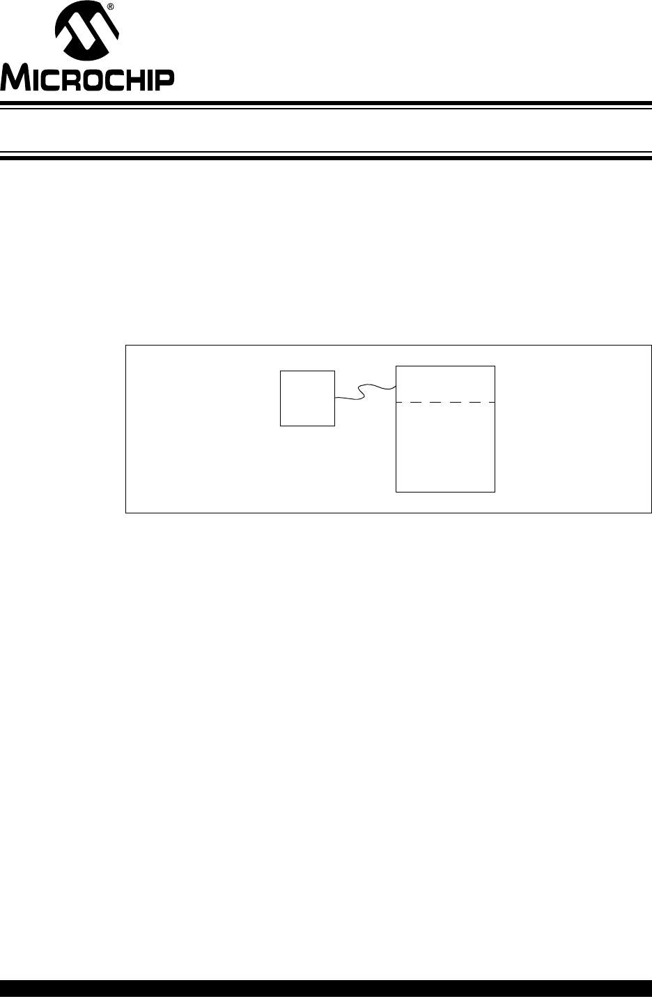
Integration of bootloader support in a product consists of three parts (see Figure 1-1):
• Host Application – Utility used to process End Application memory space and
firmware version
• Device Bootloader – Dedicated firmware responsible for managing End
Application on device
• Device End Application – Products operational application firmware.
FIGURE 1-1: BOOTLOADER UNIVERSE
The host application is responsible for loading the new hex file, and send it to the
bootloader through supported command syntax. The end application is required to be
aware of the bootloader, and must understand how to return control to the bootloader
upon request, or configured events. The bootloader by default is generated to run upon
start-up, and confirms if a valid application is loaded. If a valid application is present,
control is relinquished, otherwise operation will remain within the bootloader. This is
further explained in Chapter 5. “Bootloader Host Application”.
The host application used to manage the bootload process can be Microchip’s Unified
Bootloader Application, a custom made stand-alone application, or a separate external
Microcontroller device. Either way, the end purpose remains the same; updating the
end application firmware version through use of the Bootloader and supported
commands. This user’s guide describes one form of implementation, using the
Bootloader Generator MCC software library to produce code which supports proper
command syntax for interaction with Unified Bootloader host Application.
It will describe how to configure an end-application to be aware of boot-loading
possibility which transfers control back to the Bootloader under a trigging condition.
1.2 BOOTLOADER REQUIREMENTS
The main requirements for the generated bootloader code are:
• Determine if a valid end-application is loaded
• Communicate/Execute supported Commands
• Erase/Rewrite end-application memory space
• Transfer control to end application
Bootloader
End
Application
Host

Bootloader Generator User’s Guide
DS40001779B-page 10 2015-2016 Microchip Technology Inc.
A few additional features may be optionally required:
• Ensure Erase/Write address are outside bootloader program memory range
• Allow the host to read the program memory*
• Detect corrupted end-application code and recover gracefully
Note: Some developers see the Read Program command as a possible security
hole and typically wish to omit functionality.

BOOTLOADER GENERATOR
USER’S GUIDE
2015-2016 Microchip Technology Inc. DS40001779B-page 11
Chapter 2. Options, Parts and Pieces
There are many choices to consider when implementing a bootloader. Some key
questions to consider are:
• How does the bootloader decide if a valid application is loaded?
• How are commands communicated between bootloader and host application?
• Is the ability to Read/Write EE Data memory supported by the bootloader?
• When does the bootloader relinquish control to the end-application?
• How will the end-application restore control to the bootloader when required?
There are several ways to decide if a valid application is loaded. For example, “AN851
– A Flash Bootloader for PIC16 and PIC18 Devices” (DS00851) inspects the instruction
written to the end-application’s new Reset vector. If the contents of the Reset vector is
the erased value (0x3FFF; MOVWI [-1] FSR1), the bootloader assumes the rest of
memory is erased, that no valid end-application is loaded, and remains in bootloader
operation. For this type of implementation it is recommended that instructions written
to the end-application’s new Reset Vector location be written last to ensure full boot-
loader of firmware was successful. (see Figure 2-1).
Bootloader Generator User’s Guide
DS40001779B-page 12 2015-2016 Microchip Technology Inc.
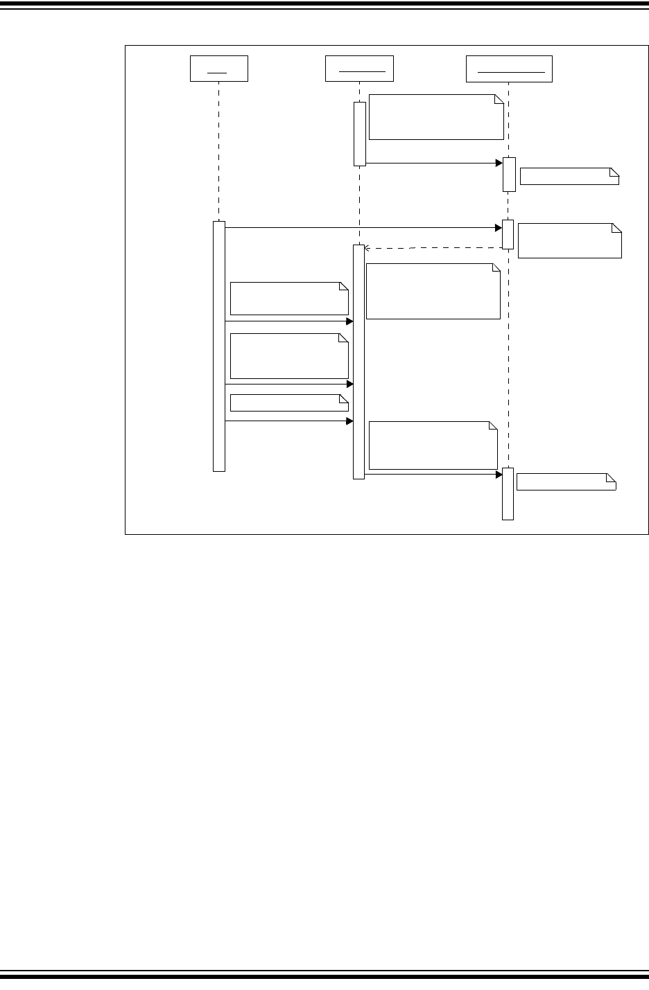
FIGURE 2-1: CHECK RESET VECTOR ADDRESS
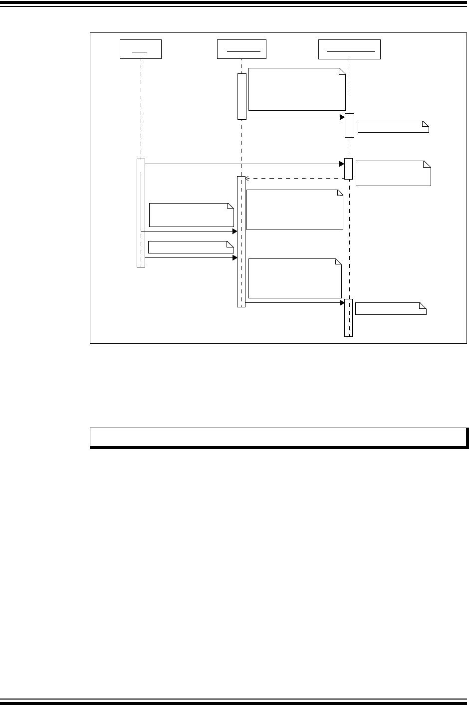
Another method involves use of a state variable stored in nonvolatile memory; this
location is known by both bootloader and end-application. The bootloader on start-up
will inspect the value for a specific value representing a “valid application” code. Values
used do not matter, but should be consistent and known by both bootloader and
end-application firmware.
The state variable at a minimal must support three states:
• Erased/Blank
• End-Application Valid
• Bootload requested
Example steps for this process are as follows (see Figure 2-2):
1. Host communicates to end-application a “Bootloader Request”.
2. End-application sets the nonvolatile memory variable to indicate a requested
bootload operation, and resets the device.
3. On start-up the bootloader inspect the value and finding a “Bootloader
Requested” state or erased value, stays within bootloader operation.
4. The host application issues Erase command request over the end-application
code range.
5. The host application loads the new firmware hex file, and issues Write command
request in sections until the full end-application is updated.
6. Host calculates a checksum value of the hex file, then issues a Calculate
Checksum command request to the bootloader for comparison.
Host Bootloader End Application
On Reset the bootloader
checks the new Reset vector.
If non-blank, it transfers control
to the end application
End application runs
End application clears
the new Reset vector
and resets device.
Switch to bootloader
Host sends commands to
erase application area
and write new application.
On Reset, the bootloader
instruction as
checks the new Reset vector
and interprets the
0x00
bootload requested.
Host requests checksum
of application area and
compares with its own
calculated checksum.
Host resets device.
On Reset, bootload checks
the new Reset vector is
non-blank, which indicates
application good.
End application runs.
Options, Parts and Pieces
2015-2016 Microchip Technology Inc. DS40001779B-page 13
7. If the two match, the host application writes a “Application Valid” state value into
the nonvolatile memory location.
8. The host application issues a Reset command to bootloader.
9. After start-up the bootloader inspects the nonvolatile memory location finding
“Application Valid” value, and relinquishes control to the end-application.
FIGURE 2-2: NONVOLATILE STATE VARIABLE
Some project designs have a requirement to check application validity on each
start-up. A way to achieve this would be to calculate a checksum of the application area
and compare it to a pre-calculated value (see Figure 2-3). XC8 includes a tool that can
do the pre-calculation over full or a range of code space, and then store the value in a
specified location in the generated hex file. See Appendix B. “How to Calculate and
Embed a Checksum Using XC8” for additional details on this process.
Host Bootloader End Application
On Reset the bootloader
checks the
state variable;
Control transfers
End application sets
state variable to “bootload
Switch to bootloader
Host sends commands to
erase application area
and write new application.
On Reset, the bootloader
checks the state variable;
Host requests checksum
of application area and
compares with its own
calculated checksum.
Host sets state variable to
On Reset, bootload checks
the state variable; indicates
application good.
indicates application good.
to end application.
requested”
and resets device.
indicates bootload requested.
“Application good” and
resets device.
Bootloader Generator User’s Guide
DS40001779B-page 14 2015-2016 Microchip Technology Inc.
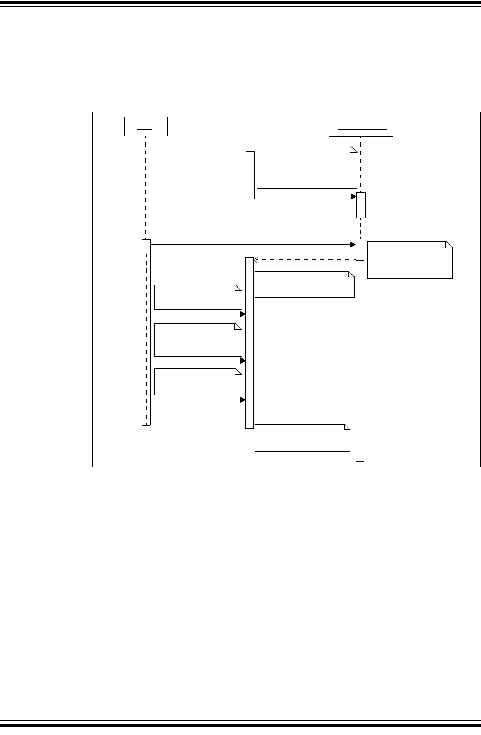
FIGURE 2-3: CALCULATE CHECKSUM ON START-UP
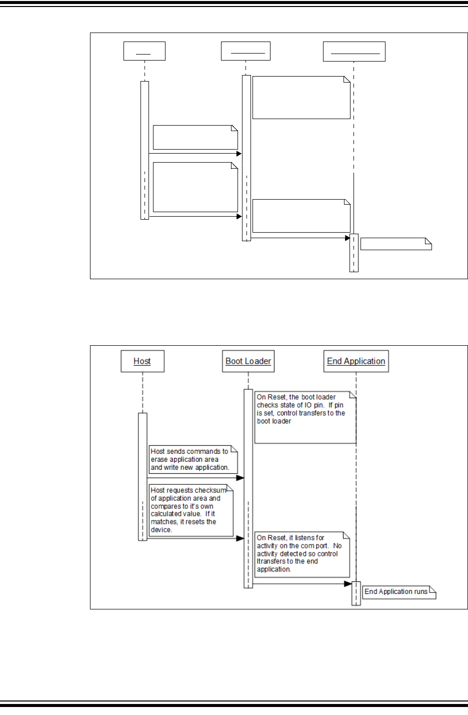
If the end-device does not normally connect to the host device, it is possible to modify
the bootloader so that upon power-on the communication bus is monitored. On
start-up, the bootloader would listen for any activity, if detected, the bootloader will
remain in control instead of relinquishing to the end-application. However, if after a
configured length of time no activity is observed, the end application is granted control
by the bootloader (see Figure 2-4).
Host Bootloader End Application
On Reset the bootloader
checks a checksum of the
End application runs
End application clears
the pre-calculated value
Switch to bootloader
Host sends commands to
erase application area
and write new application.
On Reset, the bootloader
Host resets device.
On Reset, the bootloader
End application runs.
application area. If it matches a
pre-calculated value, control
transfers to the end application.
and resets the device.
calculates the checksum of
the application area which fails
the now cleared pre-calculated
value and runs the bootloader.
application area. If it matches
a pre-calculated value, control
transfers to the end application.
calculates a checksum of the
Note: This method is not supported as of publication time.
Options, Parts and Pieces
2015-2016 Microchip Technology Inc. DS40001779B-page 15
FIGURE 2-4: LISTEN FOR COM PORT ACTIVITY
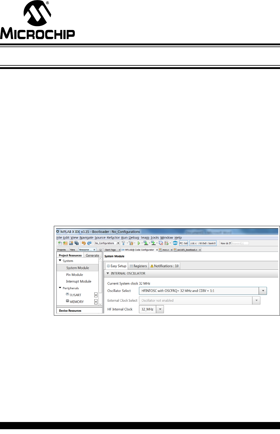
In addition to one of the above bootload entry methods, it may be beneficial to have a
means to force the bootloader to run notwithstanding the state of the primary entry
method. The bootloader supports checking the state of an IO line for this purpose.
FIGURE 2-5: IO PIN SET START-UP UML SEQUENCE
2.1 COMMUNICATION METHOD
Currently, the Bootloader Generator MCC software library only supports generation of
UART supported code. However, in the future additional communication protocols such
as I2C, SPI and USB will be added.
Host Bootloader End Application
On Reset the bootloader
Host sends commands to
erase application area
and write new application.
Host requests checksum
of application area and
compares to its own
calculated value. If it
On Reset, it listens for
End application runs.
listens on COM port. If activity
detected within a second or two,
control transfers to the
bootloader.
matches, it resets
the device. activity on the COM port. No
activity detected, so control
transfers to the end application.

Bootloader Generator User’s Guide
DS40001779B-page 16 2015-2016 Microchip Technology Inc.
At this time the host Unified Bootloader Application is capable of supporting UART and
I2C protocol communication.
2.2 VERIFICATION OF BOOTLOAD INTEGRITY
It is prudent following the bootload to verify that the program memory accurately rep-
resents the application code.
If read program memory is supported, the host application may read back the memory
and compare it to the original file.
The bootloader itself includes a command that calculates a 16-bit checksum of the
end-application memory space. The host can then compare this to its own calculated
checksum, and confirm that the write was successful.
2.3 SELF PROTECTION
The bootloader should protect itself from accidental over-write. Therefore, attempts to
write into the memory where the bootloader resides should be prevented. PIC®
microcontrollers have two methods to ensure this: hardware and software.
Write-protect Configuration bits can selectively write-protect various regions of the
program memory. The advantage to hardware protection is a smaller code footprint.
The downside is that the block size is fixed and may leave memory wasted.
The address protection can also be accomplished in software. Code can check the
destination address of each Write/Erase command. If the address range conflicts with
the bootloader region, the command request is rejected. The software requires a little
more code space, but it has the advantage of additional flexibility. For example, special
bootloader code could be written to allow the original bootloader to be replaced with an
updated version in case a bug emerges after production has already occurred/begun.
This is not possible if protected via hardware through the write-protect Configuration bit
is set.
2.4 IO PIN INDICATOR
Use of an IO pin indicator is an option available to use a dedicated pin to show when if
the device is in bootloader or end-application operation. Form of indication may vary
depending upon the product design specification. The IO pin indicator can be simple,
such as a LED used to indicate state, or as a signal connected to another device in the
product circuit.
2.5 ENABLE READ FLASH
The ability to read the hex file back can represent a possible security hole for some
products. As a result, the Read Flash command is optional. However, it can be used to
verify the bootload by reading back the end-application memory space.
The Unified Bootloader Application does not currently support the ability to readback
Flash for end-application load verification.
2.6 ENABLE READ/WRITE EEData
Read/Write EE Data commands are optional during code generation. Some devices do
not have EE Data memory, so code space can be saved by omitting these commands.

Options, Parts and Pieces
2015-2016 Microchip Technology Inc. DS40001779B-page 17
2.7 ENCRYPTION
It is possible to encrypt the data which is sent to the device. In order for this encryption
to be effective, a robust key management system is required to be in place.
No encryption methods are supported at this time. Customers who wish to implement
an encryption scheme in their bootloader should contact Microchip for support in this
regard.

Bootloader Generator User’s Guide
DS40001779B-page 18 2015-2016 Microchip Technology Inc.
NOTES:

BOOTLOADER GENERATOR
USER’S GUIDE
2015-2016 Microchip Technology Inc. DS40001779B-page 19
Chapter 3. Hex File
3.1 INTEL® HEX FILE FORMAT
EXAMPLE 3-1: HEX FILE RECORD FORMAT
3.2 PIC16F1XXX INTERPRETATIONS
The Intel® hex file is byte-oriented, while the PIC16 is word-oriented. The address in
the hex file line is a byte address and must be divided by two to get the word address.
As shown in Example 3-1 above, the address is 0x0F90. The word address is half that,
0x07C8.
Also, the word data is stored low byte first (little endian). Thus, the first two bytes make
up the word at the first address. In Example 3-1 the bytes are 0x0E and 0x10; the word
stored at 0x07C8 is 0x100E.
Each PIC device has several different memory regions:
• Program memory is stored at its natural word address
• ID locations are at Word Address 0x8000 through 0x8003
• Configuration Words at Word Address 0x8007 and 0x8008
• EEData is encoded at Word Address 0xF000
EEData only uses the low-order byte of each two-byte pair.
EXAMPLE 3-2: EE DATA ENCODED IN PIC16F1XXX HEX FILE
The first record sets the upper 16 bits of address to 0x0001.
The second record sets the lower 16 bits of the address. The resulting 32-bit address
is 0x0001E000. When divided by two, the PIC16F1XXX address of 0xF000 is obtained.
Only the low order byte of each pair is used for EEData. In this case, EEData address
0 would get 0x08, address one would get 0x09, address two would get 0x0A, etc.
:BBAAAATTHHHH……………………………………………………………………HHCC
:100F90000E1022000E1023000C1121000C1524004D
: Record Start Character
BB two digit byte count specifying the number of data bytes in
this record.
AAAA Four digit starting address of this data record
TT Two digit record type
00 = data record
01 = End of File record
02 = Segment Address Record
04 = Extended Linear Address record
HH Data Bytes
CC Two digit checksum calculated as 2’s complement of all
preceding bytes in data record except the colon.
:020000040001F9
:10E00000080009000A000B000C000D000E000F00B4

Bootloader Generator User’s Guide
DS40001779B-page 20 2015-2016 Microchip Technology Inc.
3.3 PIC18 INTERPRETATIONS
PIC18F devices are byte-oriented, so the address on the line does not need any
correction. EEData is encoded in the hex file at 0xF00000 and one byte per address
(no skipped bytes as with the PIC16F1XXX devices).
BOOTLOADER GENERATOR
USER’S GUIDE
2015-2016 Microchip Technology Inc. DS40001779B-page 21
Chapter 4. MCC Bootloader Generator
The Bootloader Generator is used to produce a separate project which will later be
merged with the end-application. This user’s guide will describe how to generate a new
bootloader project according to operational requirements and later, how to merge with
the end-application.
4.1 GENERATE BOOTLOADER
The bootloader generator is now fully integrated with MCC Libraries. To the maximum
extent possible, the bootloader leverages MCC for configuration and peripheral usage.
Thus, in addition to selecting the bootloader library, it is also required to select the
memory and supported communications “Peripherals”.
Here are the steps to generate a bootloader using MCC:
1. First create a bootloader project and select your device.
2. Select XC8 as the build tool (MCC generates XC8 C code).
3. Start MCC.
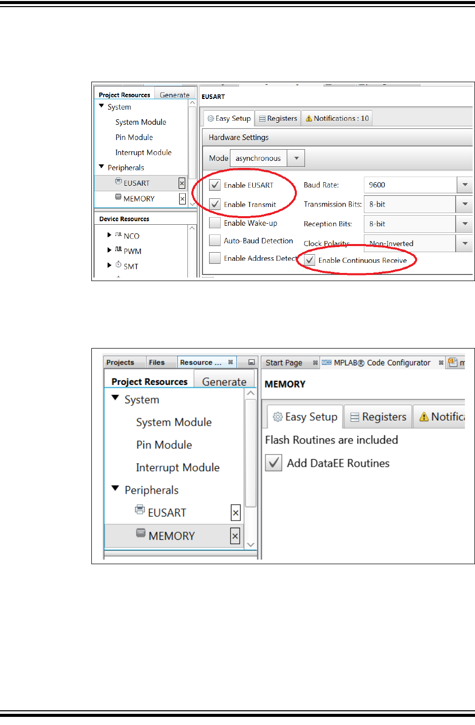
4. In the System Module, configure the oscillator. In general, faster is better for
more reliable communications. For this example, the PIC16F18855 is selected,
and configured to use the 32 MHz internal oscillator.
FIGURE 4-1: OSCILLATOR SELECTION
Bootloader Generator User’s Guide
DS40001779B-page 22 2015-2016 Microchip Technology Inc.
5. Select EUSART. Check “Enable EUSART”, “Enable Transmit” and “Enable
Continuous Receive”. The baud rate does not matter because the bootloader
code auto-bauds to detect the incoming baud rate.
FIGURE 4-2: EUSART CONFIGURATION
6. Select the Memory Peripheral. Nothing further needs to be configured. This will
include a memory.h file which has #defines that specify how big the Flash
memory is, write latches and erase row size.
FIGURE 4-3: MEMORY PERIPHERAL
MCC Bootloader Generator
2015-2016 Microchip Technology Inc. DS40001779B-page 23
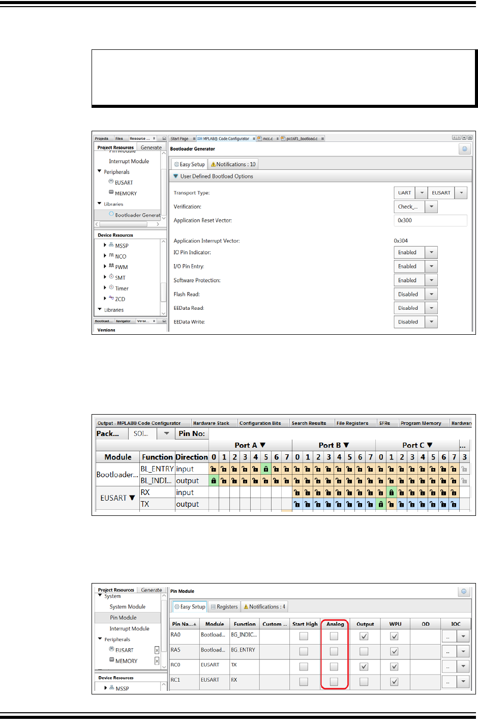
7. Select the Bootloader Generator library. Configure the bootloader for the desired
operation.
FIGURE 4-4: BOOTLOADER GENERATOR
8. Open the Pin Manager Grid View. Configure pin selections for the bootloader
operation behavior. As shown below, the lab RA0 is used for the Bootloader
Indication pin (output), RA5 is the Bootloader entry pin (input), Tx and Rx are on
RC0 and RC1.
FIGURE 4-5: PIN MANAGER GRID VIEW
9. Select Pin Module from the Project Resources, “System” option. Configure
applicable pins to be digital by deselecting the analog check box option on all
pins used.
FIGURE 4-6: CONFIGURE PINS AS DIGITAL
Note: The Reset vector must be aligned to the beginning of an erase row. The
Erase command erases the entire row. The bootloader needs to make sure
it does not erase any part of the bootloader, so any Erase command not
starting on a row boundary will be disallowed.
Bootloader Generator User’s Guide
DS40001779B-page 24 2015-2016 Microchip Technology Inc.
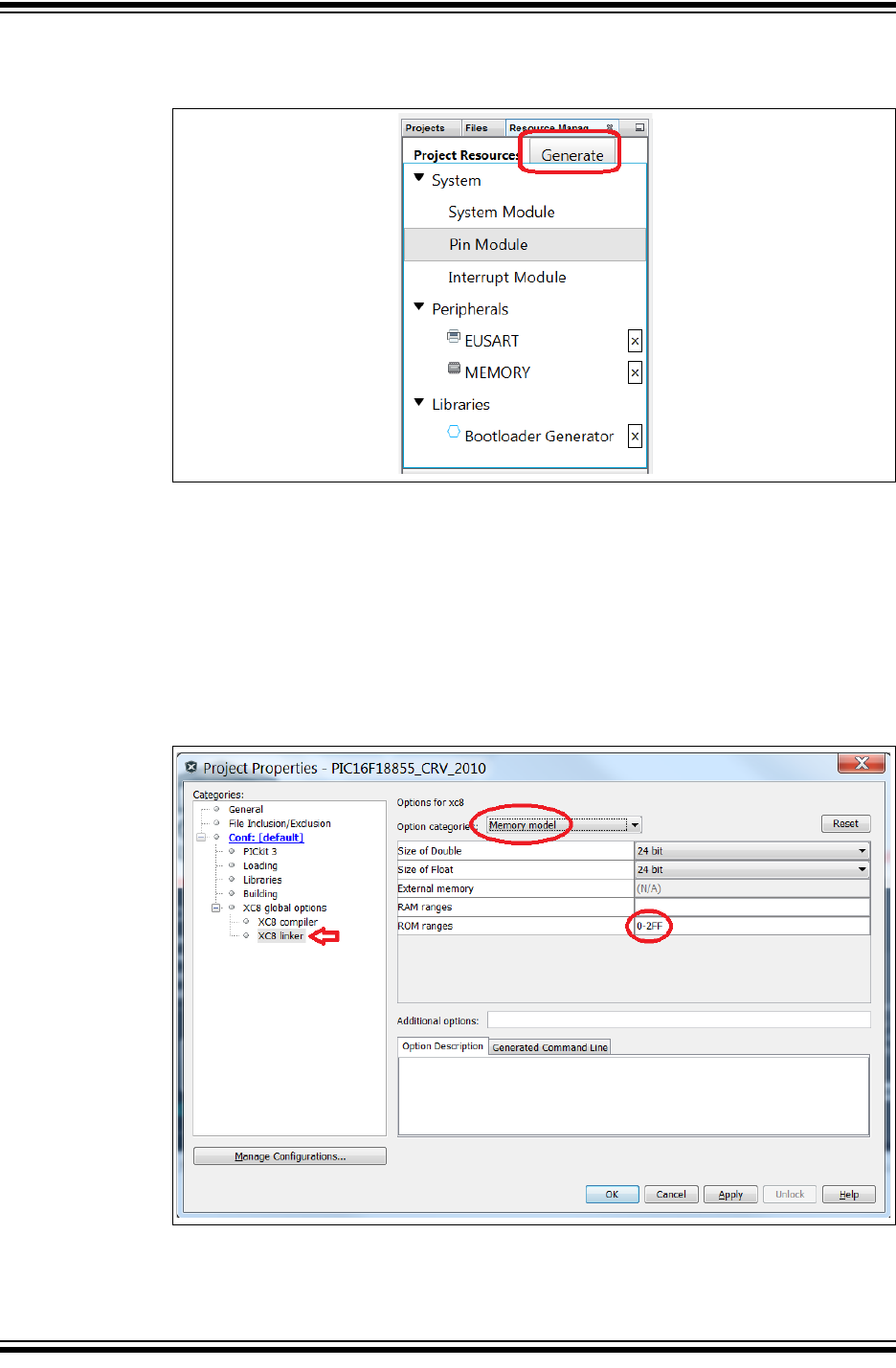
10. Press Generate button.
FIGURE 4-7: GENERATE BOOTLOADER
11. For the final step, configure to only build within a specified memory space. Open
the Project Properties window; this can be done by right clicking on a project and
selecting properties. Select XC8 Linker, under the XC8 global options. Select
“Memory Model” under the Option Categories combo box. For example, entering
the value of 0-2FF would restrict the generated code to the first 0x300 words of
ROM when compiling project code. Refer to code size for appropriate ROM
reservation size. To best understand the required ROM range, after a successful
build of the Bootloader project, refer to the “PIC Memory Views” --> “Program
Memory”; or at the Window --> “Dashboard”, Memory Section.
FIGURE 4-8: LIMIT ROM RANGE
12. The bootloader should now be ready to build and test.
At this time only the EUSART is supported as a peripheral. MSSP and USB
support will be added in the future.
BOOTLOADER GENERATOR
USER’S GUIDE
2015-2016 Microchip Technology Inc. DS40001779B-page 25
Chapter 5. Merge Bootloader with the Application
5.1 MPLAB X PROJECT CONFIGURATIONS
The MPLAB X IDE allows for a project to be built in many different configurations.
Merging projects into a single unified hex file is very useful when going to production,
or debugging interactions between application and bootloader.
The bootloader needs to have Configuration Words declarations when programmed
stand-alone or during the development purposes; however, if Configuration Words do
not match when attempting to merge with the end application, the linker will give a
“(944) data conflict error at...” This occurs when it tries to put two different values into
a location. This most often occurs when the Configuration Words are included both in
the bootloader and end application. Thus it is advantageous to have a means to have
them included while developing, but omitted when incorporating with the end applica-
tion.
MPLAB X project configurations provide a solution to this issue. A project configuration
can be created which includes Configuration Word in the stand-alone bootloader
project compilation, while another can omit the settings from the bootloader project
build, allowing the merged end application settings to be used for both projects. The
first is useful when debugging, or learning bootloader operation while the second is
useful during end application development building a production ready unified hex file.
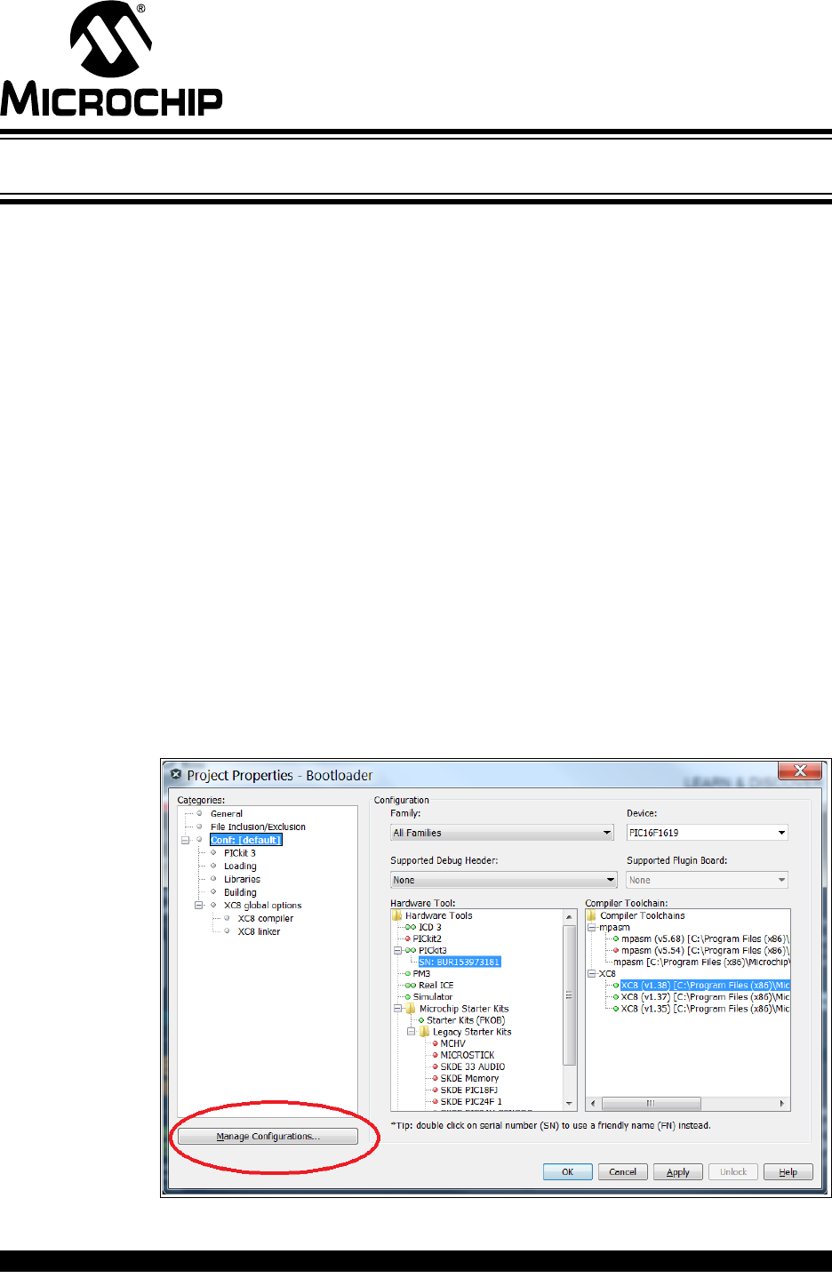
Here is how to create the two bootloader project configurations:
1. Open the Project Properties window.
2. Click on the Manage Configurations button.
FIGURE 5-1: MANAGE CONFIGURATIONS
Bootloader Generator User’s Guide
DS40001779B-page 26 2015-2016 Microchip Technology Inc.
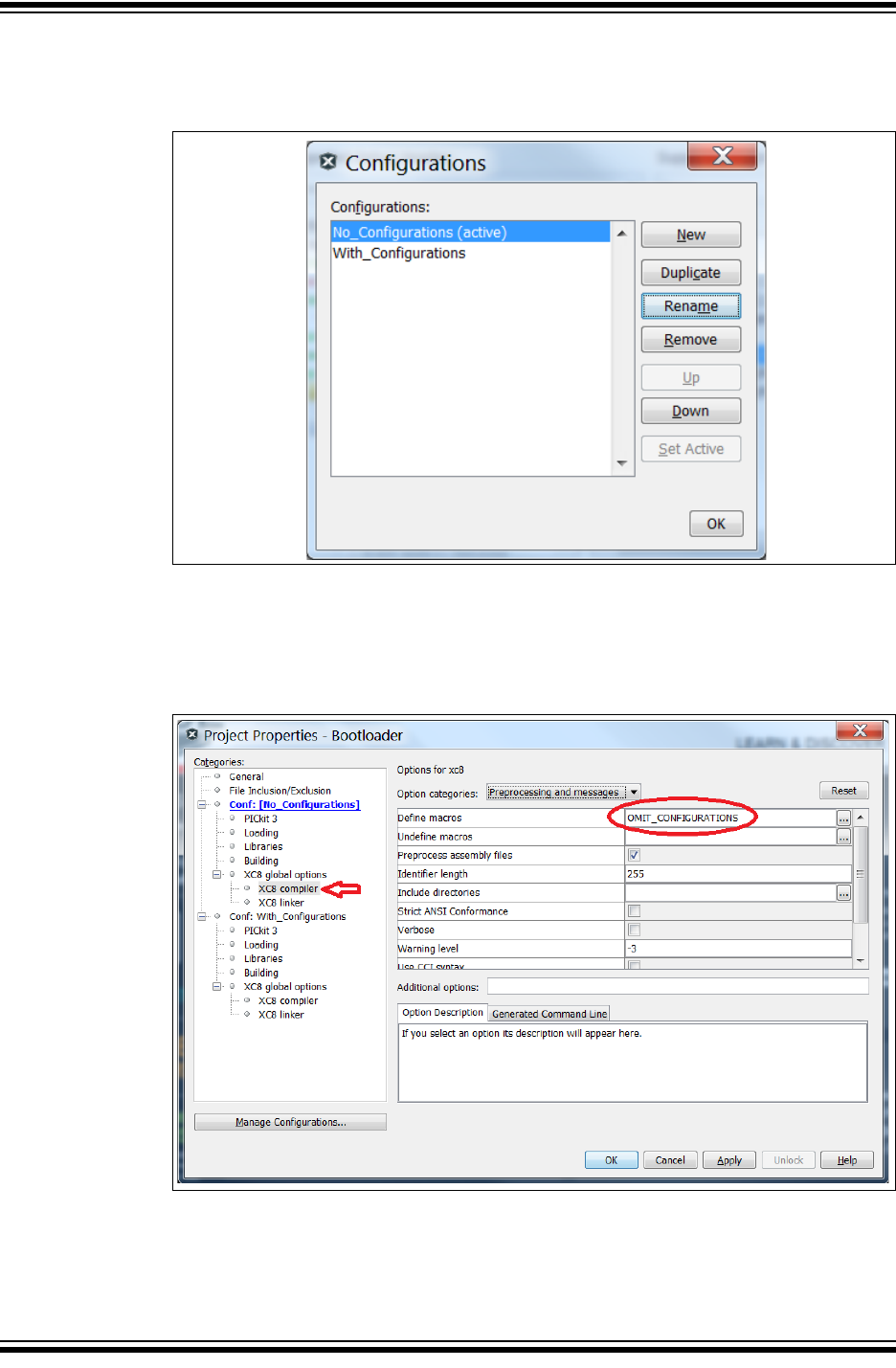
3. Duplicate the “default” project configuration; rename one to With_Configurations,
and the other No_Configurations.
FIGURE 5-2: BOOTLOADER CONFIGURATIONS
4. From the Conf: [No Configurations] select the “XC8 Compiler” under “XC8 global
options”. The first field is labeled as “Define a macros”, double click inside the
blank field or press on the icon. Add the Text, “OMIT_CONFIGURATIONS” to the
field.
FIGURE 5-3: #define OMIT_CONFIGURATIONS

Merge Bootloader with the Application
2015-2016 Microchip Technology Inc. DS40001779B-page 27
5. Go to the generated MCC.C source file where Configuration bits are defined for
the bootloader project.
6. Add a #ifdef OMIT_CONFIGURATIONS/#else/#endif around the Configuration
Words as shown below:
EXAMPLE 5-1: #ifdef OMIT_CONFIGURATIONS
Using OMIT instead of INCLUDE means the Configuration bits will be generated by
default. This is to great advantage when merging the bootloader with the application.
5.2 END – APPLICATION PROJECT CONFIGURATIONS
There are three configurations useful for the end application when being combined with
the generated bootloader:
“Stand-Alone” is the normal configuration where the end-application begins at the start
of program memory. This configuration is useful when beginning initial development, or
doing debugging without interference from the bootloader.
“Offset” configuration shifts the end-application to start at the defined offset location in
the devices program memory. This configuration is done to reserve the beginning of the
bootloader. This is the configuration used when developing incremental updates to the
end-application which are intended to be bootloaded on to the device.
“Combined” is the final configuration, and is used to merge the offset end-application
project with the bootloader included into a single unified hex file. This is the code that
would be initially programmed into the device at the factory.
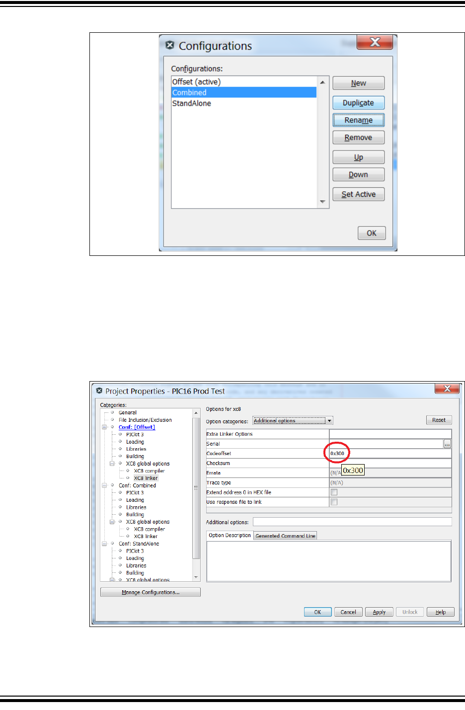
MPLAB X makes it easy to set up and switch between these configurations. As done
with the bootloader configurations, go to the Project Properties window, then manage
configurations. Duplicate the default configuration twice, rename one to Stand-Alone,
another to Offset and the third to Combined.
#ifdef OMIT_CONFIGURATIONS
#info "Configuration bits are not generated with the code. If you
need them switch to the 'WITH_CONFIGURATIONS' Configuration."
#else
#info "Configuration bits are generated with the code. If you get a
linker
CONFIG1
#pragma config FOSC = INTOSC // Oscillator Selection Bits->INTOSC
oscillator: I/O function on CLKIN pin
#pragma config PWRTE = OFF // Power-up Timer Enable->PWRT
disabled
#pragma config MCLRE = ON // MCLR Pin Function Select->MCLR/VPP
pin function is MCLR
…
#endif
Bootloader Generator User’s Guide
DS40001779B-page 28 2015-2016 Microchip Technology Inc.
FIGURE 5-4: END APPLICATION PROJECT CONFIGURATIONS
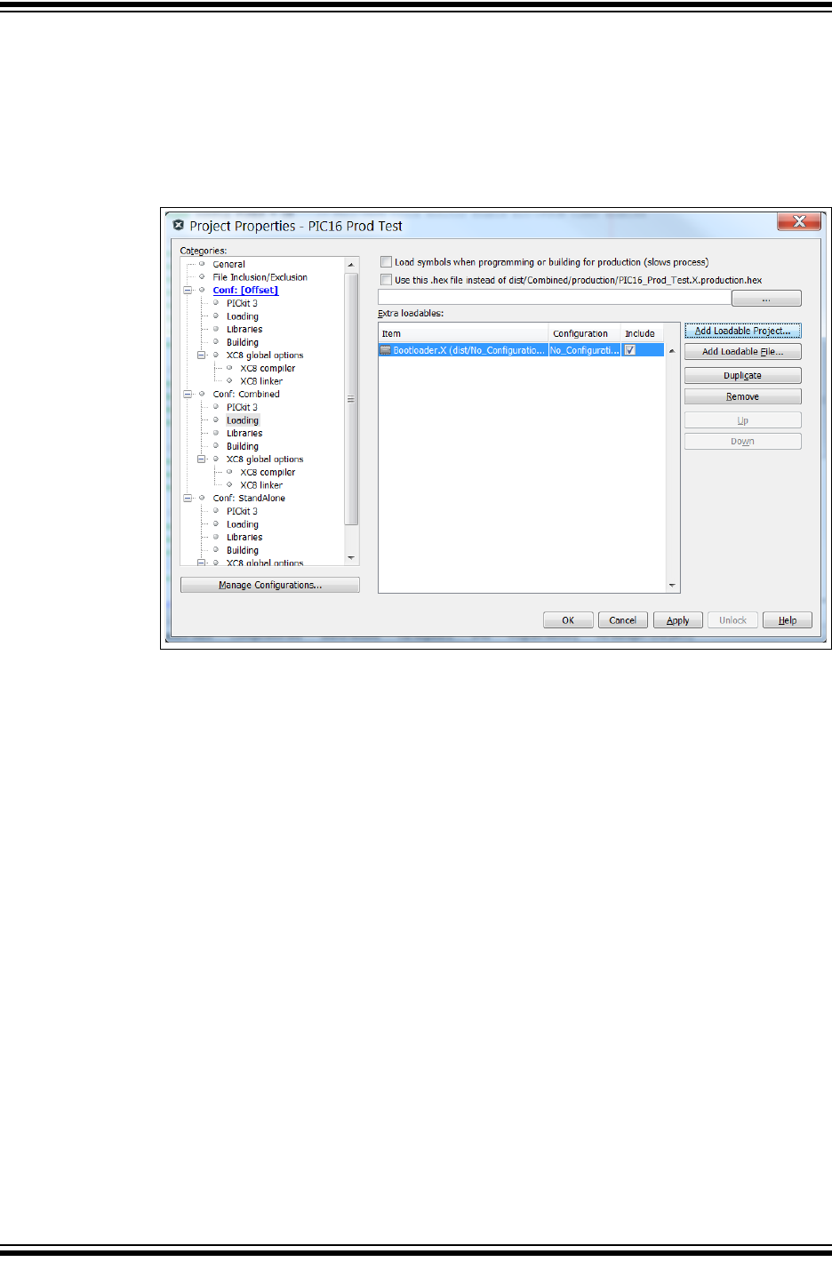
From Conf: [Offset] select “XC8 Linker” under “XC8 global options”. Select the
“Additional Options” from the “Option categories” combo box. Enter into the
”Codeoffset” field the program memory Flash value where the application will start
while leaving room to not occupy the bootloader code space. This will automatically
remap the Reset, and interrupt vectors to appropriate locations, respectively. For
example, a value of 0x300 on a PIC16 will offset the Reset Vector to 0x300 and
Interrupt Service Routine to 0x304; on a PIC18 Interrupt Service Routines would be
located at 0x308 and 0x318. Apply the same offset to the “Combined” configuration.
FIGURE 5-5: CODE OFFSET
Merge Bootloader with the Application
2015-2016 Microchip Technology Inc. DS40001779B-page 29
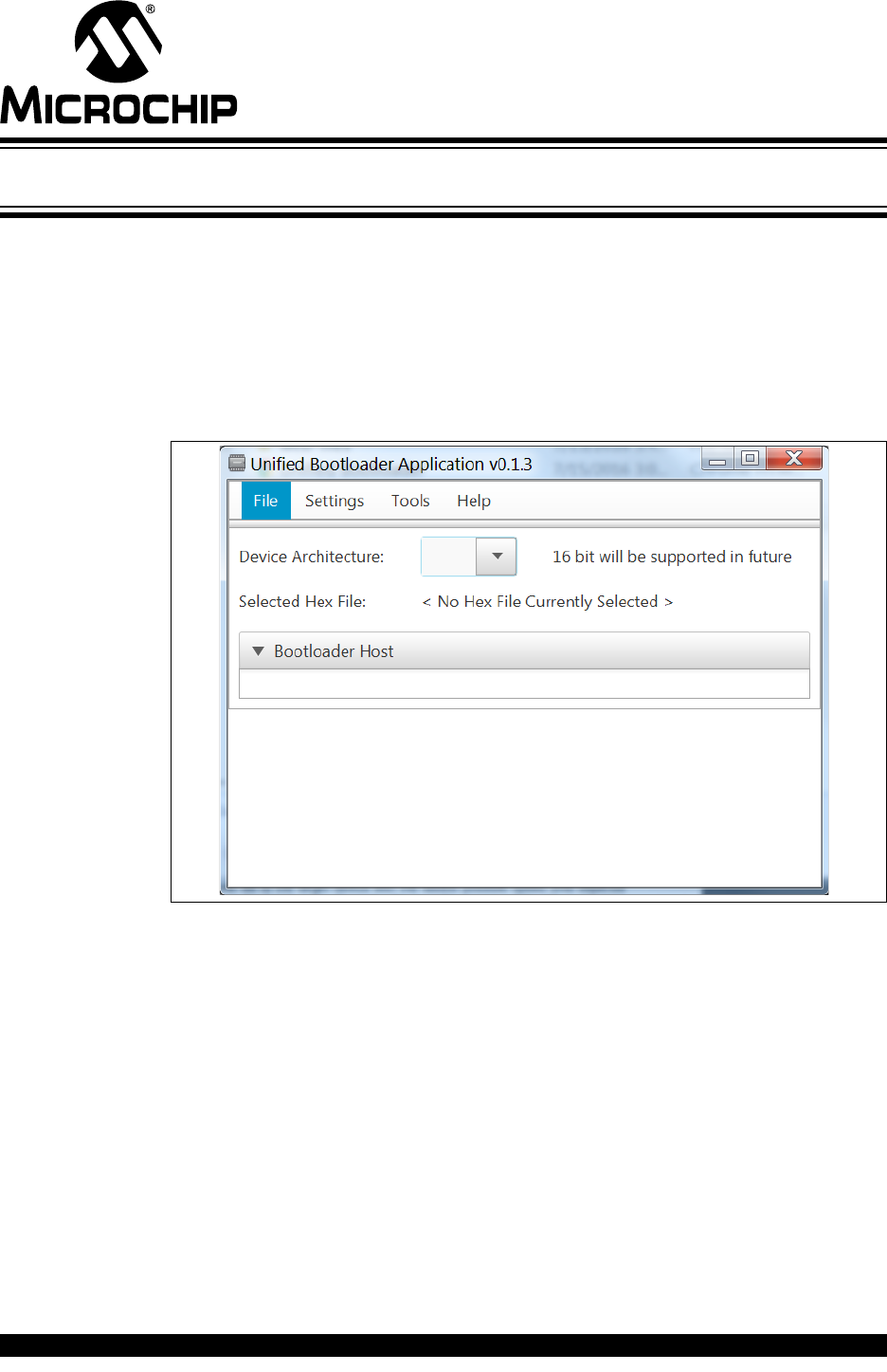
From the Conf: [Combined] configuration selected, select the “Loading” option within
the combined configuration. Click the “Add Loadable Project” push button. Navigate
to the bootloader project directory and add it as a loadable project. Select the No_Con-
figurations option under the “Configuration” column; clicking in this column will supply
a combo box of configuration options for the loaded project. Confirm the “Include”
check box is toggled only for the [Combined] configuration and click apply.
FIGURE 5-6: MERGE BOOTLOADER WITH END APPLICATION
The application is now ready to be built in any of the three configurations.

Bootloader Generator User’s Guide
DS40001779B-page 30 2015-2016 Microchip Technology Inc.
NOTES:
BOOTLOADER GENERATOR
USER’S GUIDE
2015-2016 Microchip Technology Inc. DS40001779B-page 31
Chapter 6. Bootloader Host Application
The bootloader host application is responsible for transferring an embedded
application program (the .hex file) from the host machine (development host) to a
target device (a device running the embedded application). It talks to the bootloader
present on the target device by sending appropriate commands, and it transfers data
(the embedded application program) using UART communication. It can be used to
program the Flash memory for PIC16 and PIC18 devices. EEPROM writes are also
supported.
FIGURE 6-1: BOOTLOADER HOST APPLICATION
6.1 OVERALL WORKING STRATEGY
The application requires the user to select the device family and the COM port used for
communication. Once this is selected, the user has to configure the program memory
and offset values on the GUI screen. As soon as the user clicks the Program Device
button, the application prompts the user to select a .hex file, after which it tries to write
(transfer) the file to the target device with the fastest possible speed (this depends
massively on the baud rate). Once the file is written successfully, the application
calculates a checksum over the entire .hex file and verifies data integrity. A checksum
match resets the target device and the embedded application program starts to
execute.
In case of a communication failure, the application retries three times after which it
relinquishes control over the COM port and stops the communication giving an error.
Bootloader Generator User’s Guide
DS40001779B-page 32 2015-2016 Microchip Technology Inc.
6.2 PREREQUISITES
Make sure that the MPLAB X IDE or MPLAB communication libraries are installed on
the machine. If any problems arise while starting the application, try re-installing
MPLAB X.
The values to be entered in the text fields for the “Program Memory size” and
“Bootloader offset” must be in hex format. By default, the application is set to have an
offset of 300 (hex) with program memory size as 4000 (hex).
Version 1.0 of the application performs “Program Memory and EEPROM” writes only
with UART interface.
6.3 DETAILED STEPS
As soon as the application is launched, there are several inputs that need to be
provided, as listed below.
1. Select the device architecture to bootload.
FIGURE 6-2: COM PORT SELECTION
2. Pick the device family (PIC16 or PIC18) from the other drop-down menu (see
Figure 6-3).
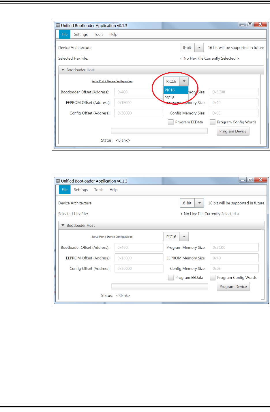
Bootloader Host Application
2015-2016 Microchip Technology Inc. DS40001779B-page 33
FIGURE 6-3: DEVICE FAMILY SELECTION
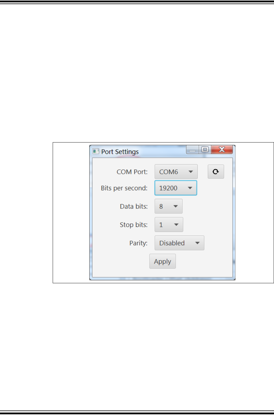
3. Select and configure the COM port.
FIGURE 6-4: BOOTLOADER OFFSET CONFIGURATION
4. Set the program memory size depending on the target device (see Figure 6-5).
Be aware that the program memory size is the number of locations. For example,
if the target device has program memory starting from 0-3FFF, then 4000 should
be entered in the text field. The size of every location depends on the target
device. Some devices have word-addressable Flash and others have it
byte-addressable.
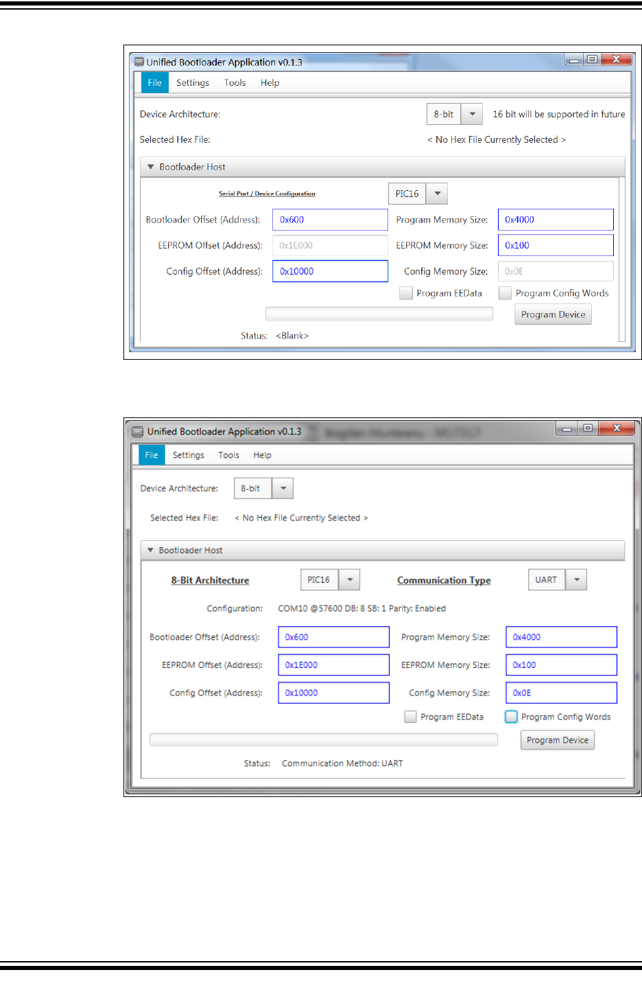
Bootloader Generator User’s Guide
DS40001779B-page 34 2015-2016 Microchip Technology Inc.
FIGURE 6-5: PROGRAM MEMORY SIZE CONFIGURATION
5. Click the Program Device button (see Figure 6-6 through Figure 6-8).
FIGURE 6-6: CONNECTING TO THE TARGET DEVICE
6. Select the File then Open/Load file to select the hex file to load.
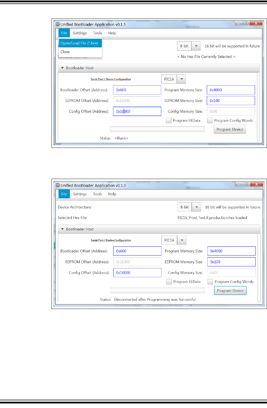
Bootloader Host Application
2015-2016 Microchip Technology Inc. DS40001779B-page 35
FIGURE 6-7: DISPLAYING A FILE CHOOSER DIALOG
7. Once the device is programmed, the bootloader will disconnect from the COM
port.
FIGURE 6-8: DEVICE PROGRAMMED
6.4 MENU BAR OPTIONS
There are additional options that can be used if needed. The Program Device button
should take care of connecting to the target device and popping up a file selection
dialog. However, if the user wants to connect or load the file externally, options have
been provided in the menu. If the user needs to close the application, this can be done
under the menu.
Ensure that the Console window is pulled up when programming a device. This window
will provide step-by-step visibility into the bootloading process.
Bootloader Generator User’s Guide
DS40001779B-page 36 2015-2016 Microchip Technology Inc.
6.5 TROUBLESHOOTING
If the application fails to connect, close the application, unplug the target device, plug
it back in and start the application again. If the device is connected while the application
is running, click the Refresh option under the menu to pull up the COM port. Pull up
the Console window to check the nature of the error. There is a status label above the
progress bar which displays messages appropriately.
6.6 EXTERNAL DEPENDENCIES
The application uses a hex file parser and MPLAB X communication to parse and store
the hex file to be programmed and to communicate to the target device, respectively.
Both of these are provided in the form of libraries (.jar) with the application.
Another common reason for the lack of communications is that one or more of the
comms line has analog functions enabled. (See Figure 4-6 “Disable Analog”). At this
point it may be easier just to change the ANSEL registers in the code.
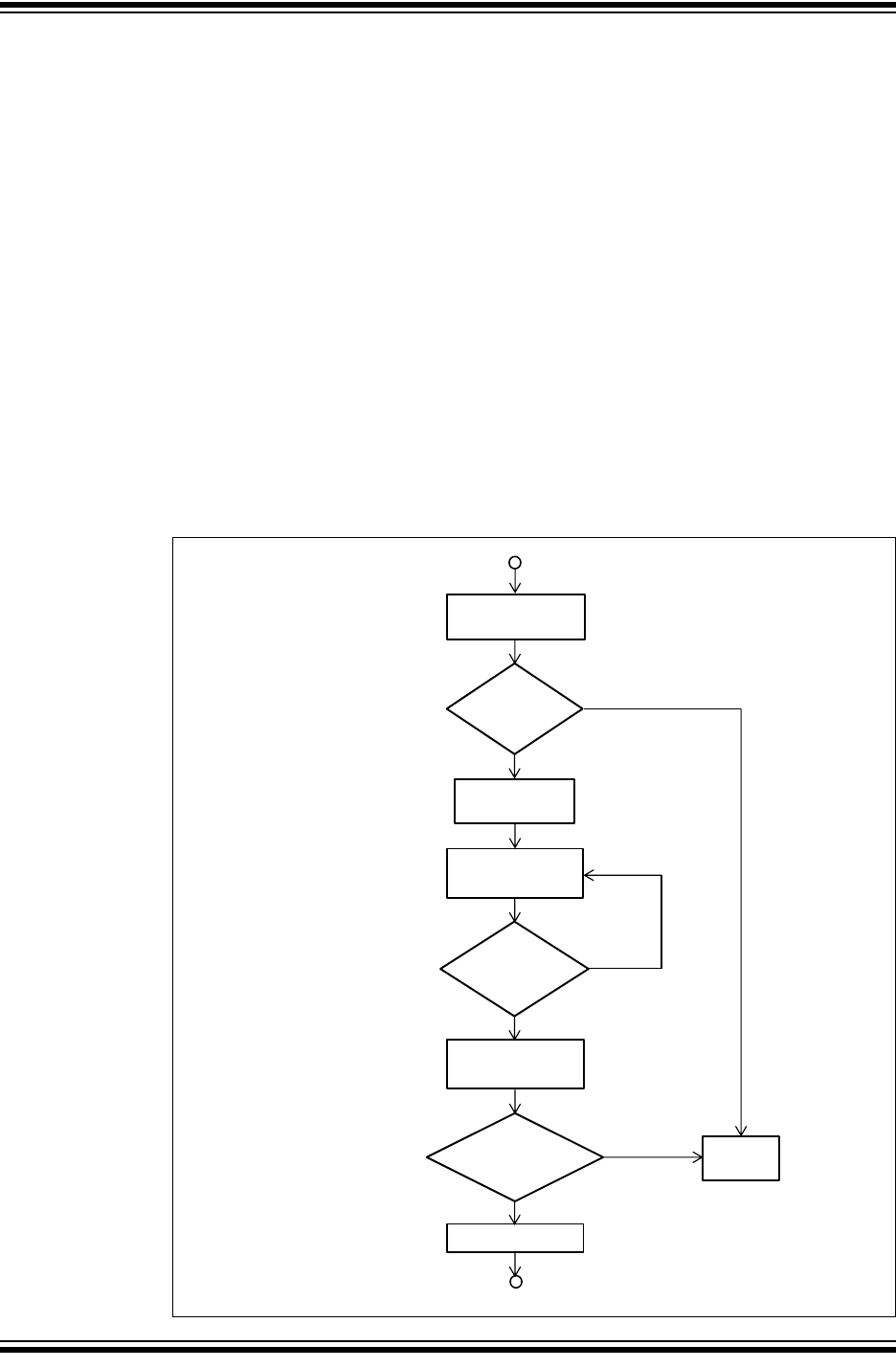
6.7 THE HOST APPLICATION
Here is the process used to bootload a device:
FIGURE 6-9: DEVICE BOOTLOAD PROCESS
Last Line
Sent?SE
Send GetVersion
Command
Success
?
Abort
Bootload
No
Erase Application
Area
Yes
Write a line to
memory
No
Request Checksum
of App Area
Reset Device
Checksums
Match?SEN
Yes
Yes
No
BOOTLOADER GENERATOR
USER’S GUIDE
2015-2016 Microchip Technology Inc. DS40001779B-page 37
Chapter 7. Bootloader Protocol
7.1 COMMAND SET
It is important to note that the success status code returned by the bootloader upon
reception of a command only implies it met the proper format, and the bootloader code
accomplished execution. Write commands are not read back and compared with the
RAM copy. This could be custom added after generation, but has been intentionally
omitted in favor of small and lite code. It is recommended that the host keep a running
checksum as the device is programmed. After completion of the entire write, issuing
the Calculate Checksum command [0x08] request the bootloader code to calculate a
checksum over the specific application area and return the value for comparison with
the host’s expected result.
TABLE 7-1: COMMAND LIST
Hex
Value Command Description
0 Read Version Confirms Communication and Exchanges Bootloader Version
Info
1 Read Flash Reads Program Memory range as specified
2 Write Flash Writes Program Memory range as specified
3 Erase Flash Erases Program Memory range as specified
4 Read EE Data Reads EEPROM Memory range as specified
5 Write EE Data Writes EEPROM Memory range as specified
6 Read Config Reads current Configuration Words programmed values
7 Write Config* Writes Configuration Words reprogramming over stored values
8 Calculate Checksum Calculates and returns computed Checksum over Memory
Range
9 Reset Device Informs the Bootloader to do a software Reset
Note: Most PIC16F1 devices can only change Configuration Words via an
external programmer, not via a bootloader.

Bootloader Generator User’s Guide
DS40001779B-page 38 2015-2016 Microchip Technology Inc.
7.2 THE HOST APPLICATION
Command Descriptions:
All commands sent to the bootloader device contain at minimal [9] bytes. General
format is described below:
[AutoBaud(1)] [Command] [Data Length(2)] [Unlock Sequence(3)] [Address(4)]
[Data(5)]
Notes*:
1. Required only for EUSART
2. [2] Bytes – [Low] [High]
3. [0x55] [0xAA] for Write and Erase commands, [0x00] [0x00] for non-write
4. [4] Bytes – [Low] [High] [Upper] [Extended]
5. [0 – 64] Bytes – Based upon [Data Length]
All command examples for a PIC18F25K50:
Return Code Values:
• [0x01] – Command Successful
• [0xFF] – Command Unsupported
• [0Xfe] – Address Error
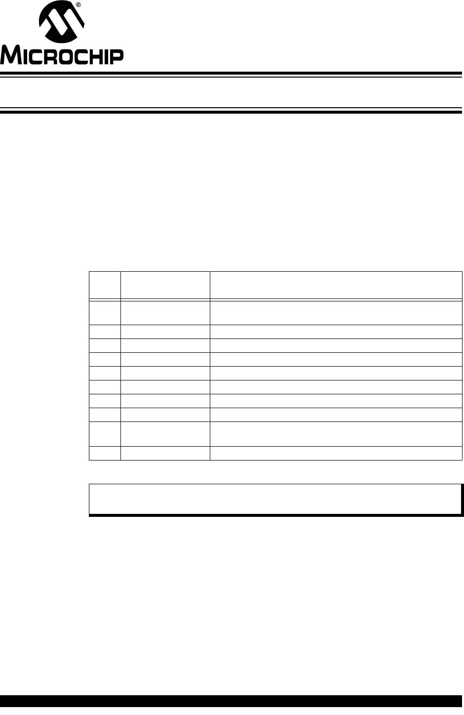
Get Version: [0x00]
Establishes communication with the device and returns useful information such as:
• bootloader version
• Max Packet size
• Device ID
• Erase row size
• Write latch size
•Config words
Tx to device: 0x00 0x00 0x00 0x00 0x00 0x00 0x00 0x00 0x00
Description: Request bootloader version information.
Rx from device:
Command string: 0x00 0x00 0x00 0x00 0x00 0x00 0x00 0x00 0x00
Bootloader Version: 0x06 0x00
Max Packet size:0x00 0x01 (0x100)
Not Used: 0x00 0x00
Device ID:0xA1 0x5C
Not Used:0x00 0x00
Erase Row Size:0x40
Write Latches:0x40
Config Words:0x00 0x28 0x5F 0x3C
Bootloader Protocol
2015-2016 Microchip Technology Inc. DS40001779B-page 39
FIGURE 7-1: REQUEST VERSION COMMAND
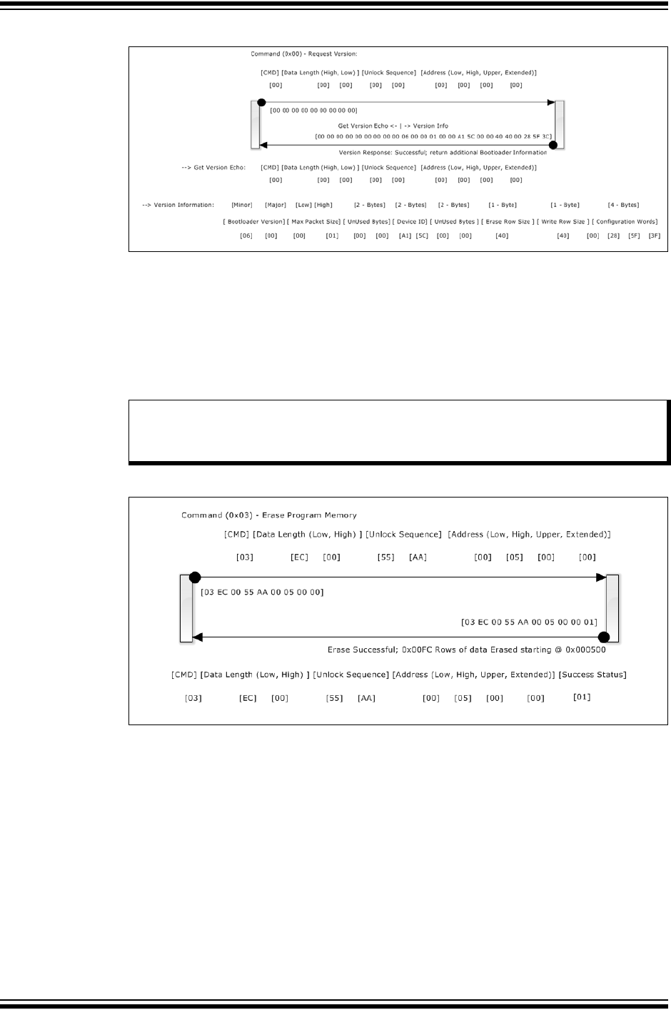
Erase Flash: [0x03]
Tx to device: 0x03 0xEC 0x00 0x55 0xAA 0x00 0x05 0x00 0x00
Erase 0xEC rows starting at 0x500.
Rx from Device:
Command String:0x03 0xEC 0x00 0x55 0xAA 0x00 0x05 0x00 0x00
Success Code:0x01
FIGURE 7-2: ERASE FLASH COMMAND
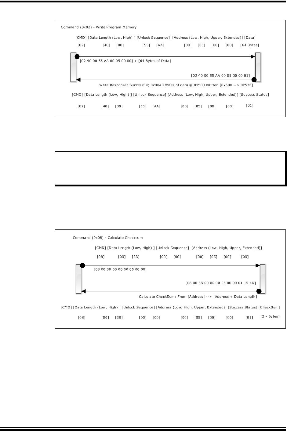
Write Flash Memory:
Tx to Device: 0x02 0x40 0x00 0x55 0xAA 0x00 0x05 0x00 0x00 {64 bytes of data to be
written}
Description: Write (0x40 bytes starting at address 0x500)
Rx from Device:
Command String:0x02 0x40 0x00 0x55 0xAA 0x00 0x05 0x00 0x00
Success Code:0x01
Note: The erase address must be aligned to the first address of an erase row. Any
attempt to erase with an address not at the beginning of a row will be
rejected with an address error code.
Bootloader Generator User’s Guide
DS40001779B-page 40 2015-2016 Microchip Technology Inc.
FIGURE 7-3: WRITE PROGRAM MEMORY COMMAND
Calculate Checksum: [0x08]
Tx to Device: 0x08 0x00 0x3B 0x00 0x00 0x00 0x05 0x00 0x00
Description: Calculate checksum from 0x500 to 0x3FFF.
Rx from Device:
Command String:0x08 0x00 0x3B 0x00 0x00 0x00 0x05 0x00 0x00
Checksum:0x15 0x4D
FIGURE 7-4: CALCULATE CHECKSUM COMMAND
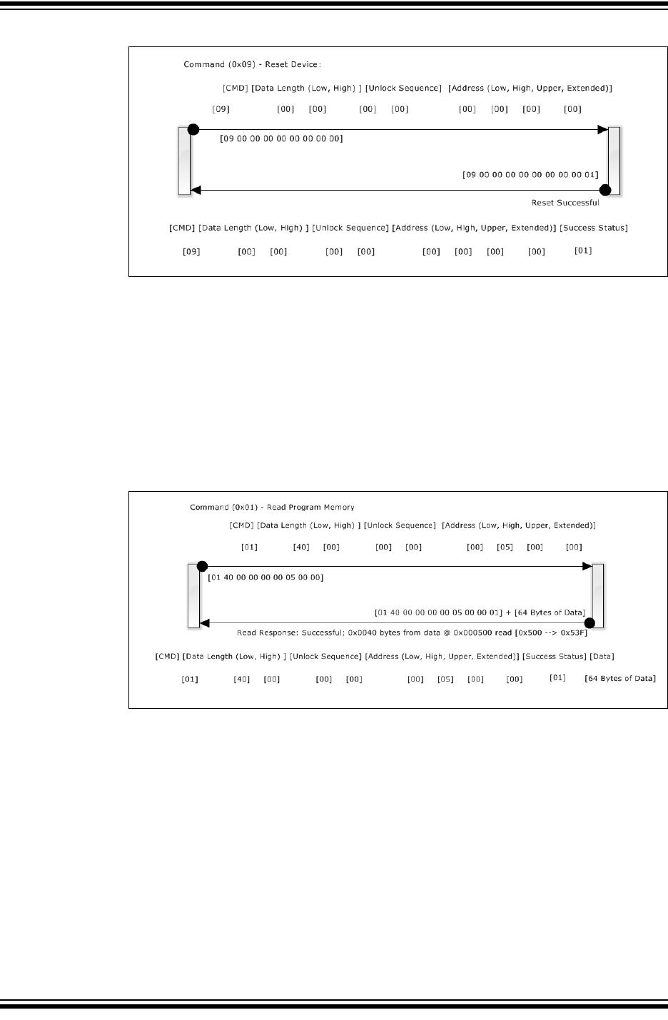
Reset Device: [0x09]
Tx: to Device: 0x09 0x00 0x00 0x00 0x00 0x00 0x00 0x00 0x00
Description: Allows bootloader to process a soft-reset on the device.
Rx from Device
Command String:0x09 0x00 0x00 0x00 0x00 0x00 0x00 0x00 0x00
Success Code:0x01
Note: It is recommended the host program calculates an independent checksum
as the hex file is written to the device. This can later be compared to the
checksums calculated on the device and supply confidence the memory
array was correctly written.
Bootloader Protocol
2015-2016 Microchip Technology Inc. DS40001779B-page 41
FIGURE 7-5: RESET DEVICE COMMAND
7.3 ADDITIONAL COMMANDS
Read Flash: [0x01]
Tx to Device: 0x01 0x40 0x00 0x00 0x00 0x00 0x05 0x00 0x00
Description: Read 0x40 bytes starting at address 0x500.
Rx from Device:
Command String:0x01 0x40 0x00 0x00 0x00 0x00 0x05 0x00 0x00
Flash Memory:{ 64 bytes from Flash program memory from 0x500-0x53F}
FIGURE 7-6: READ FLASH COMMAND
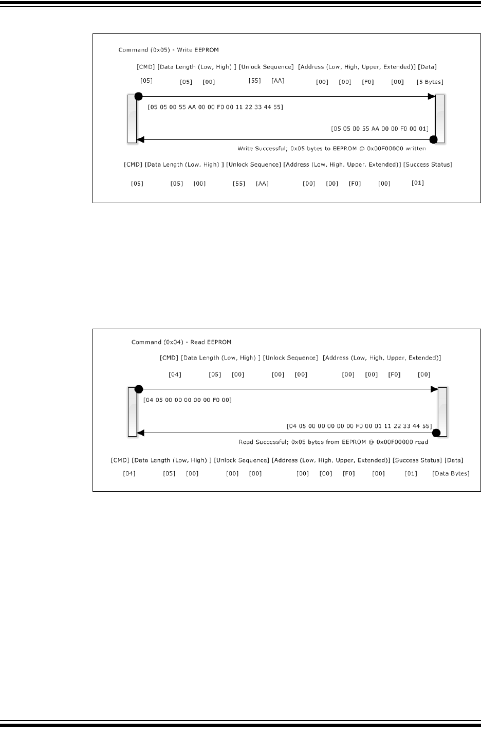
Write EE Data: [0x05]
Tx to Device: 0x05 0x05 0x00 0x55 0xAA 0x00 0x00 0xF0 0x00 0x11 0x22 0x33 0x44
0x55
Description: Writes 0x05 bytes to EE Data starting at address 0x00F00000
Command String: 0x04 0x5 0x00 0x55 0xAA 0x00 0x00 0xF0 0x00
Success Code:0x01
Bootloader Generator User’s Guide
DS40001779B-page 42 2015-2016 Microchip Technology Inc.
FIGURE 7-7: WRITE EEPROM COMMAND
Read EE Data: [0x04]
Tx to Device: 0x04 0x05 0x00 0x00 0x00 0x00 0x00 0xF0 0x00
Description: Read five bytes from EE Data starting at address 0x00F00000.
Rx from device:
Command String:0x04 0x05 0x00 0x00 0x00 0x00 0x00 0xF0 0x00
Returned Data:0x11 0x22 0x33 0x44 0x55
FIGURE 7-8: READ EEPROM COMMAND
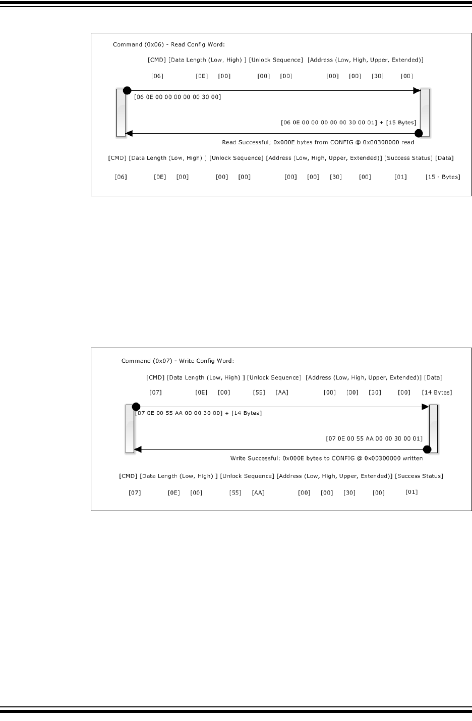
Read Config Words: [0x06]
Tx to Device: 0x06 0x0E 0x00 0x00 0x00 0x00 0x00 0x30 0x00
Description: Read 14 bytes from Config Words (mapped at 0x00300000).
Rx from Device:
Command String: 0x06 0x0E 0x00 0x00 0x00 0x00 0x00 0x30 0x00
Returned Data:{14 bytes representing Config bytes from 0x300000-30000E}
Bootloader Protocol
2015-2016 Microchip Technology Inc. DS40001779B-page 43
FIGURE 7-9: READ CONFIG COMMAND
Write Config Words: [0x07]
Tx to Device: 0x07 0x0E 0x00 0x55 0xAA 0x00 0x00 0x30 0x00 {14 additional bytes to
be programmed to Config bytes}
Description: Write 14 bytes from Config Words (mapped at 0x00300000).
Rx from Device:
Command String: 0x07 0x0E 0x00 0x55 0xAA 0x00 0x00 0x30 0x00
Returned Data:0x07 0x0E 0x00 0x55 0xAA 0x00 0x00 0x30 0x00
Success Code: 0x01
FIGURE 7-10: WRITE CONFIG COMMAND
Switching between Application and bootloader:
There are two methods for switching from the device‘s end-application back to
bootloader:
• Jump to the Reset vector
• Reset the device
Resetting the device has the advantage that it clears the stack, reducing the chance for
a Stack Overflow. However, if the MCU is engaged in some activity that cannot be
stopped for the Reset, a jump to the Reset vector is another choice. Also, newer MCUs
allow stack access under program control so extraneous stack levels can be manually
popped before transferring control back to the user application.
The simplest method to switch control from the end-application to the bootloader is to
execute a goto back to the top of the bootloader code. There must also be a means to
indicate to the bootloader not to relinquish control to the end-application.

Bootloader Generator User’s Guide
DS40001779B-page 44 2015-2016 Microchip Technology Inc.
Another way is to have the end-application invalidate the “application valid” indicator
checked by the bootloader upon start-up, then reset the device. The normal start-up
checks will return no valid application when loaded, and continue to run the bootloader
application. This method has the additional benefits of resetting the call stack and also
that it will continue to run the bootloader until a valid application has been re-loaded,
even if a previous bootload process was interrupted.
However, this method is not always possible. For example, if the MCU is running a
process which cannot be stopped during operation, such as running an active power
supply consumed by the device, the method of executing a goto back to the bootloader
vector should be used.

2015-2016 Microchip Technology Inc. DS40001779B-page 45
AMERICAS
Corporate Office
2355 West Chandler Blvd.
Chandler, AZ 85224-6199
Tel: 480-792-7200
Fax: 480-792-7277
Technical Support:
http://www.microchip.com/
support
Web Address:
www.microchip.com
Atlanta
Duluth, GA
Tel: 678-957-9614
Fax: 678-957-1455
Austin, TX
Tel: 512-257-3370
Boston
Westborough, MA
Tel: 774-760-0087
Fax: 774-760-0088
Chicago
Itasca, IL
Tel: 630-285-0071
Fax: 630-285-0075
Dallas
Addison, TX
Tel: 972-818-7423
Fax: 972-818-2924
Detroit
Novi, MI
Tel: 248-848-4000
Houston, TX
Tel: 281-894-5983
Indianapolis
Noblesville, IN
Tel: 317-773-8323
Fax: 317-773-5453
Tel: 317-536-2380
Los Angeles
Mission Viejo, CA
Tel: 949-462-9523
Fax: 949-462-9608
Tel: 951-273-7800
Raleigh, NC
Tel: 919-844-7510
New York, NY
Tel: 631-435-6000
San Jose, CA
Tel: 408-735-9110
Tel: 408-436-4270
Canada - Toronto
Tel: 905-695-1980
Fax: 905-695-2078
ASIA/PACIFIC
Asia Pacific Office
Suites 3707-14, 37th Floor
Tower 6, The Gateway
Harbour City, Kowloon
Hong Kong
Tel: 852-2943-5100
Fax: 852-2401-3431
Australia - Sydney
Tel: 61-2-9868-6733
Fax: 61-2-9868-6755
China - Beijing
Tel: 86-10-8569-7000
Fax: 86-10-8528-2104
China - Chengdu
Tel: 86-28-8665-5511
Fax: 86-28-8665-7889
China - Chongqing
Tel: 86-23-8980-9588
Fax: 86-23-8980-9500
China - Dongguan
Tel: 86-769-8702-9880
China - Guangzhou
Tel: 86-20-8755-8029
China - Hangzhou
Tel: 86-571-8792-8115
Fax: 86-571-8792-8116
China - Hong Kong SAR
Tel: 852-2943-5100
Fax: 852-2401-3431
China - Nanjing
Tel: 86-25-8473-2460
Fax: 86-25-8473-2470
China - Qingdao
Tel: 86-532-8502-7355
Fax: 86-532-8502-7205
China - Shanghai
Tel: 86-21-3326-8000
Fax: 86-21-3326-8021
China - Shenyang
Tel: 86-24-2334-2829
Fax: 86-24-2334-2393
China - Shenzhen
Tel: 86-755-8864-2200
Fax: 86-755-8203-1760
China - Wuhan
Tel: 86-27-5980-5300
Fax: 86-27-5980-5118
China - Xian
Tel: 86-29-8833-7252
Fax: 86-29-8833-7256
ASIA/PACIFIC
China - Xiamen
Tel: 86-592-2388138
Fax: 86-592-2388130
China - Zhuhai
Tel: 86-756-3210040
Fax: 86-756-3210049
India - Bangalore
Tel: 91-80-3090-4444
Fax: 91-80-3090-4123
India - New Delhi
Tel: 91-11-4160-8631
Fax: 91-11-4160-8632
India - Pune
Tel: 91-20-3019-1500
Japan - Osaka
Tel: 81-6-6152-7160
Fax: 81-6-6152-9310
Japan - Tokyo
Tel: 81-3-6880- 3770
Fax: 81-3-6880-3771
Korea - Daegu
Tel: 82-53-744-4301
Fax: 82-53-744-4302
Korea - Seoul
Tel: 82-2-554-7200
Fax: 82-2-558-5932 or
82-2-558-5934
Malaysia - Kuala Lumpur
Tel: 60-3-6201-9857
Fax: 60-3-6201-9859
Malaysia - Penang
Tel: 60-4-227-8870
Fax: 60-4-227-4068
Philippines - Manila
Tel: 63-2-634-9065
Fax: 63-2-634-9069
Singapore
Tel: 65-6334-8870
Fax: 65-6334-8850
Taiwan - Hsin Chu
Tel: 886-3-5778-366
Fax: 886-3-5770-955
Taiwan - Kaohsiung
Tel: 886-7-213-7830
Taiwan - Taipei
Tel: 886-2-2508-8600
Fax: 886-2-2508-0102
Thailand - Bangkok
Tel: 66-2-694-1351
Fax: 66-2-694-1350
EUROPE
Austria - Wels
Tel: 43-7242-2244-39
Fax: 43-7242-2244-393
Denmark - Copenhagen
Tel: 45-4450-2828
Fax: 45-4485-2829
Finland - Espoo
Tel: 358-9-4520-820
France - Paris
Tel: 33-1-69-53-63-20
Fax: 33-1-69-30-90-79
France - Saint Cloud
Tel: 33-1-30-60-70-00
Germany - Garching
Tel: 49-8931-9700
Germany - Haan
Tel: 49-2129-3766400
Germany - Heilbronn
Tel: 49-7131-67-3636
Germany - Karlsruhe
Tel: 49-721-625370
Germany - Munich
Tel: 49-89-627-144-0
Fax: 49-89-627-144-44
Germany - Rosenheim
Tel: 49-8031-354-560
Israel - Ra’anana
Tel: 972-9-744-7705
Italy - Milan
Tel: 39-0331-742611
Fax: 39-0331-466781
Italy - Padova
Tel: 39-049-7625286
Netherlands - Drunen
Tel: 31-416-690399
Fax: 31-416-690340
Norway - Trondheim
Tel: 47-7289-7561
Poland - Warsaw
Tel: 48-22-3325737
Romania - Bucharest
Tel: 40-21-407-87-50
Spain - Madrid
Tel: 34-91-708-08-90
Fax: 34-91-708-08-91
Sweden - Gothenberg
Tel: 46-31-704-60-40
Sweden - Stockholm
Tel: 46-8-5090-4654
UK - Wokingham
Tel: 44-118-921-5800
Fax: 44-118-921-5820
Worldwide Sales and Service
11/07/16
