Bsl Hardware Guide
User Manual:
Open the PDF directly: View PDF ![]() .
.
Page Count: 157 [warning: Documents this large are best viewed by clicking the View PDF Link!]
- BSL HARDWARE GUIDE
- MP36-MP35-MP45
- MP ACQUISITION UNITS
- SYMBOLS — MP36/35 OR MP45
- Safety
- EMC
- Types of Input Devices
- Simple Sensor Connectors
- Front Panel
- Electrode Check
- Input Ports
- Status Indicators
- Back Panel
- Analog Out Port – Low Voltage Stimulator
- USB Connection
- Headphone Output
- I/O Port (MP36/35 ONLY)
- Trigger Input (MP36/35 Only)
- DC Input (MP36/35 Only)
- Fuse Holder (MP36/35 Only)
- Power Switch (MP36/35 Only)
- Cleaning Procedures
- MP36/35/45 Specifications
- MP Unit Pin-outs
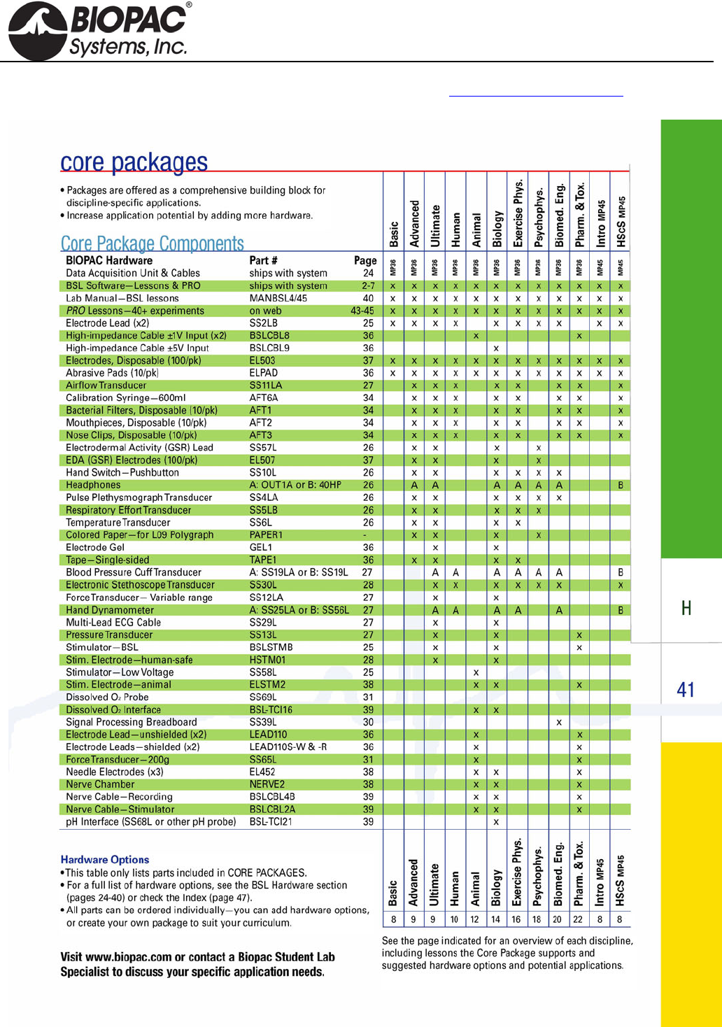
- Core Packages
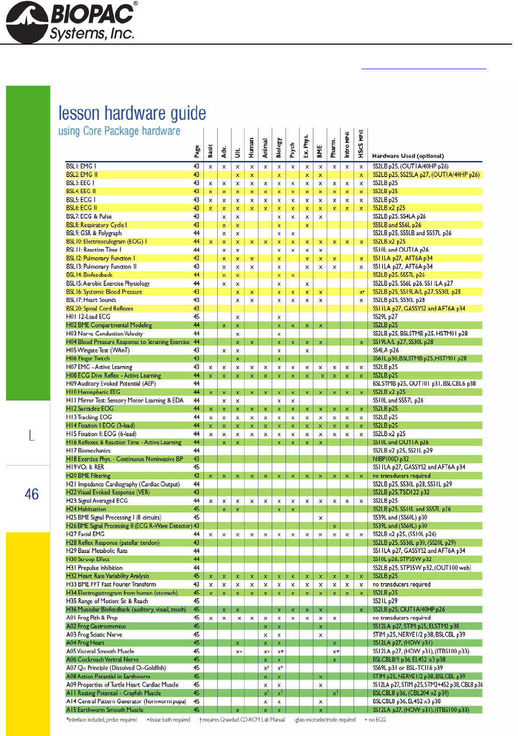
- Lesson Hardware Guide
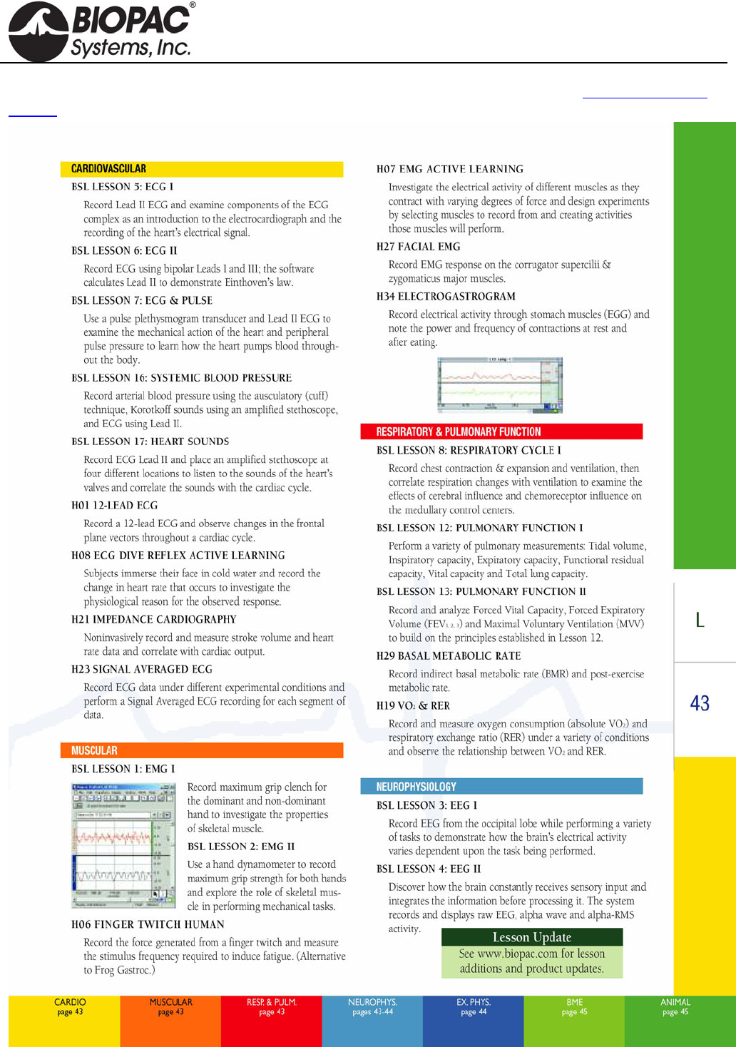
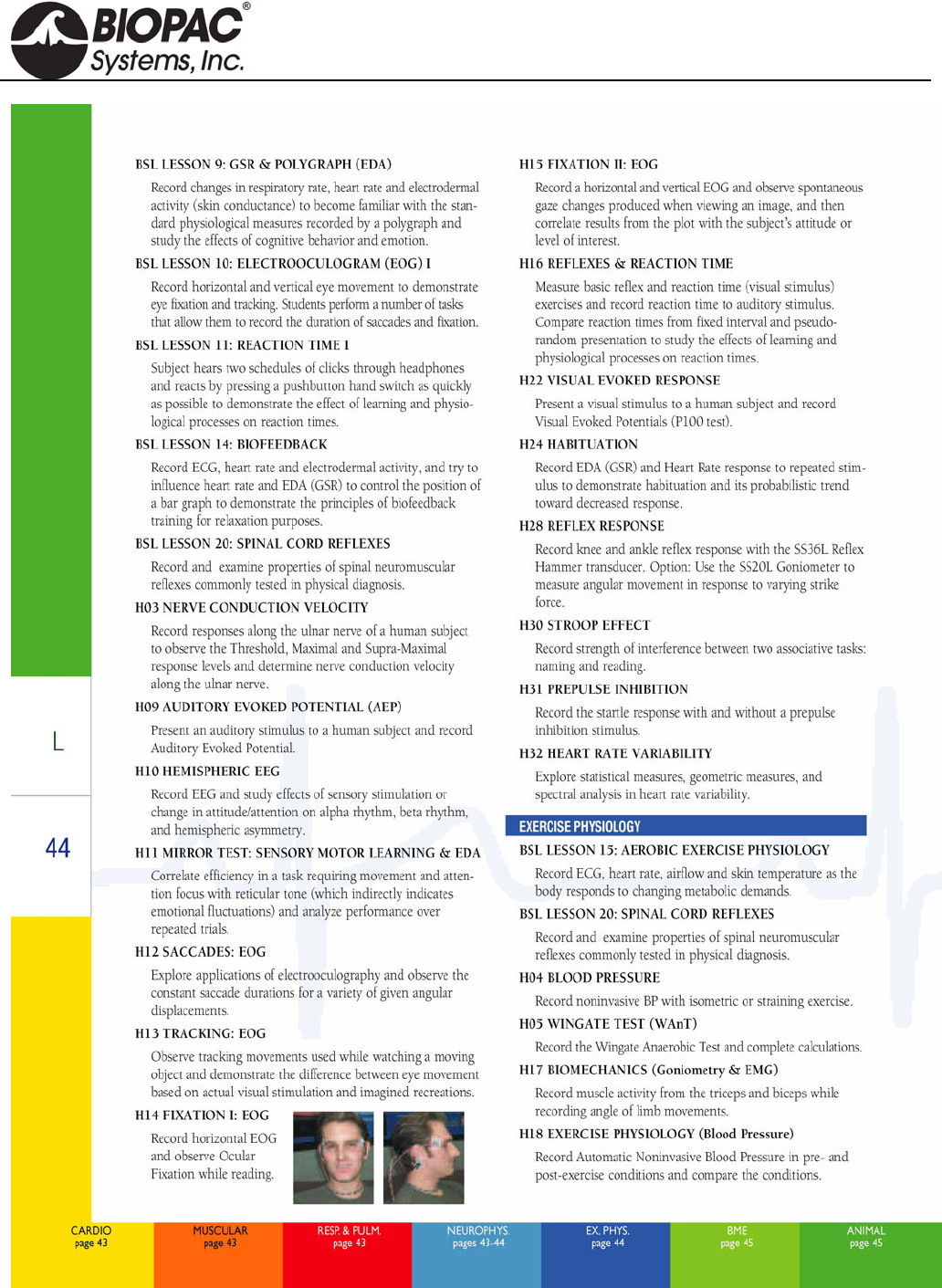
- Lesson Descriptions
- MP ACQUISITION UNITS
- Stimulators MP3X
- SS1LA
- SS2L
- SS3LA
- Pulse Transducer
- SS5LB
- SS6L-SS18L Temp
- SS10L
- Pneumotach Handheld
- Medium-flow Pneumotach Transducer
- Normal Measurement Connections
- Data Processing
- Calibration for Medium-flow Pneumotachs
- Syringe Calibration
- Mathematical Calibration
- SS11LA to MP3X Connection
- Rough Calibration (MP3X)
- Using the Calibration Syringe
- Recording with the Airflow Transducer
- RX117 Replacement Airflow Head
- MRI Usage Declarations for TSD117-MRI
- SS11LA & TSD117 Technical Specifications
- SS12LA
- SS13L
- SS14L
- Contact Microphone
- BP Transducers
- SS20L-SS24L Goniometers
- Attachment to the Subject
- Warnings
- Maintenance & Service
- Calibration
- Specifications
- Overview of the BIOPAC Goniometer Series
- Sign Conventions
- WRIST – Goniometer TSD130A/SS20L/SS20/BN-GON-110-XDCR
- Articular Complex of the Foot – Goniometer TSD130A/SS20L/SS20/BN-GON-110-XDCR
- ELBOW – Goniometer TSD130B/SS21L/SS21/BN-GON-150-XDCR
- HIP – Goniometer TSD130B/SS21L/SS21//BN-GON-150-XDCR
- KNEE – Goniometer TSD130B/SS21L/SS21/BN-GON-150-XDCR
- FOREARM PRONATION /SUPINATION – Torsiometer TSD130C/SS22L/SS22/BN-TOR-110-XDCR or TSD130D/SS23L/SS23/BN-TOR-150-XDCR
- SS25LA
- Accelerometers
- Heel-Toe Strike
- SS29L
- SS30L
- SS31L
- SS36L
- SS39L
- SS40L-42L Differential Pressure
- SS43L
- Pneumotach 100 Series
- Pneumotach 200 Series
- SS53L-SS55L Switches
- SS56L
- SS57L
- SS60L
- SS61L
- SS62L
- SS63L-SS66L Force Transducers
- SS67L
- SS68L
- SS69L
- SS9L-SS70L-SS71L
- AFT Series
- AFT SERIES AIRFLOW & GAS ANALYSIS ACCESSORIES
- Disposable Bacterial Filters
- Mouthpieces
- Noseclip
- Calibration Syringes
- Tubing for Airflow
- Facemasks, Facemask Accessories
- AFT11 Couplers
- AFT15 Mixing Chambers
- Gas Sampling Interface Kits
- AFT T-Valves
- AFT24 Head Support
- Tubing for Gas Sampling
- Part Summary for Typical Airflow / Gas Analysis Applications
- Pulmonary Function
- Exercise Physiology
- AFT SERIES AIRFLOW & GAS ANALYSIS ACCESSORIES
- BSL-TCI
- BSLCBL Series
- CBL200 Series
- CBLUSB
- HSTM01
- EL120
- EL160
- EL250 Series
- EL350 Series
- EL450 Series
- EL500 Series
- EL650 Series
- ELSTM Series
- Electrode Accessories
- Electrode Leads
- GASCAL-GASREG
- GASSYS2
- HDW Series
- Micromanipulator
- NIBP100D
- NIBP200A-NIBP250
- Nerve Chambers
- OUT Series
- OUT1 Headphones
- OUT1 Specifications
- OUT1A
- OUT1A Specifications
- OUT2 BNC (M) Output Adapter
- OUT2 Specifications
- OUT100
- OUT100 Specifications
- OUT101 Tubephone
- OUT101 Specifications
- Calibration for Auditory Brainstem Response Studies
- OUT102 Piezo Audio Transducer
- OUT102 Specifications
- OUT103 LED Cable
- MP150 and UIM100C Setup
- MP36R Setup - Additional Items Required
- Calibration
- 40HP Monaural Headphones
- 40HP Specifications
- Power Supplies
- BAT100A
- SS-KIT
- SuperLab for MP3X
- Tissue Bath Stations
- Circulator
- SS25LA.pdf

01.06.2014
BSL HARDWARE GUIDE
The BSL Hardware Guide describes how to connect and setup various signal electrodes, transducers and other devices
for use with the Biopac Student Lab System using an MP acquisition unit and includes sections that detail different
applications and uses for the Biopac Student Lab PRO System.
info@biopac.com
support@biopac.com
www.biopac.com
BIOPAC Hardware | MP36/35/45 | Page 1 - 11 Updated: 12.23.2013
MP ACQUISITION UNITS
MP36/35 Four Channel Data Acquisition System
MP45 Two Channel Data Acquisition System
This document covers the following information for the MP36/MP35/MP45 Data Acquisition Systems:
Symbols – page 1
Compliance/Safety – page 1
Input devices/Sensor Connections – pages 1-2
Front and Back Panels – pages 2-4
Specifications – page 5
Pin-Out Diagrams – page 6
BSL System Core Packages – page 7
Lesson Hardware Guide – page 8
BSL Lesson Descriptions – pages 9-11
The MP data acquisition unit is the heart of all Core Packages. The MP Unit has an internal microprocessor to
control data acquisition and communication with the computer. The MP Unit takes incoming signals and converts
them into digital signals that can be processed with the computer. There are analog input channels (four on
MP36/35 units, two on MP45), one of which can be used as a trigger input. The MP Unit must be connected to the
computer and electrodes, transducers, and/or I/O devices must be connected to the MP Unit. Users are suggested
to take a few minutes to become familiar with the MP Unit prior to making any connections.
Symbols — MP36/35 or MP45
Symbol Description Explanation
Type BF Equipment Classification
Attention Consult accompanying documents
On (partial) Turns MP36/35 on assuming AC300A power
adapter is powered by the mains
Off (partial) Turns MP36/35 off if but AC300A power
adapter remains powered by the mains
Direct current Direct current output
USB USB port
COMPLIANCE
Safety
The MP36/35/45 satisfies the Medical Safety Test Standards affiliated with IEC60601-1. The MP36/35/45 is
designated as Class I Type BF medical equipment
EMC
The MP36/35/45 satisfies the Medical Electromagnetic Compatibility (EMC) Test Standards affiliated with
IEC60601-1-2.
Types of Input Devices
There are three types of devices that connect to the MP36/35 and MP45: electrodes, transducers, and I/O devices.
Electrodes are relatively simple instruments that attach to the surface of the skin and pick up electrical
signals in the body.
HARDWARE GUIDE
info@biopac.com
support@biopac.com
www.biopac.com
BIOPAC Hardware | MP36/35/45 | Page 2 - 11 Updated: 12.23.2013
Transducers, on the other hand, convert a physical signal into a proportional electrical signal.
Input/Output devices (I/O for short) are specialized devices like pushbutton switches and headphones.
Simple Sensor Connectors
Regardless of the type of device connected, every sensor or I/O device connects to the MP36/35 using a “Simple
Sensor” connector. Simple Sensor connectors are designed to plug only one way into the MP unit—no need to
worry about plugging things in upside down or into the wrong socket!
Electrodes, transducers, and the pushbutton switch all connect to the channel input ports on the front
panel of the MP36/35 and MP45.
Headphones and the stimulator connect to the “Analog out” port on the back panel of the MP36/35 and to
the headphone jack on the top of the MP45.
MP36/35 only: A digital device may connect to the “I/O Port” on the back panel
MP36/35 only: A trigger device may be connected to the “Trigger” port on the back panel.
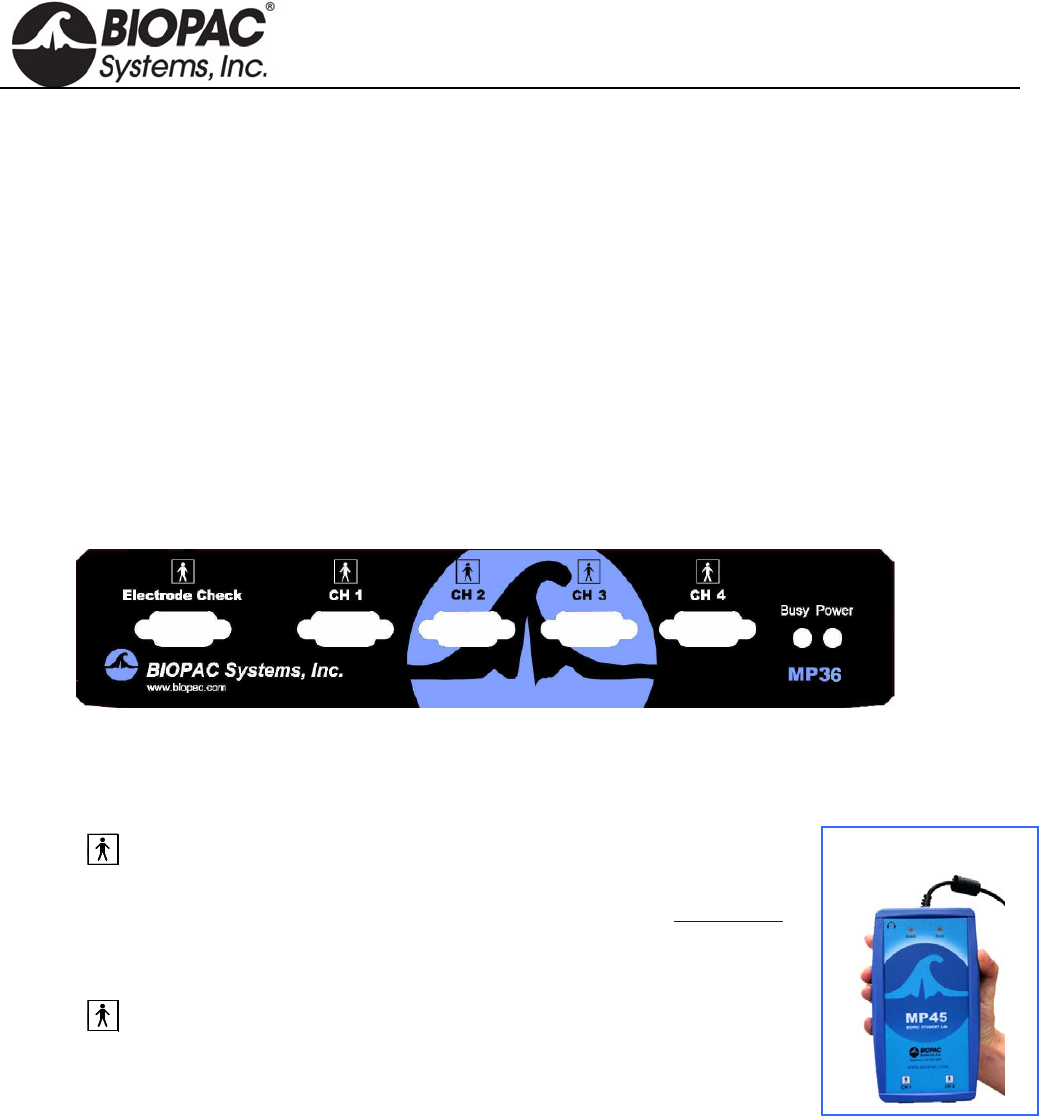
Front Panel
Front Panel, MP36/35
The front panel of the MP36/35 has an electrode check port, four analog input ports, and two status indicators.
Electrode Check
The Electrode Check port is a diagnostic tool used with the BSL PRO
software to determine if the electrodes are properly attached to the subject.
The MP45 does not have an Electrode Check port. Use BIOPAC’s EL-CHECK
standalone electrode impedance checker to measure electrode/skin contact.
MP45 is
CH 1 and CH 2 only.
Input Ports: CH 1, CH 2, CH 3, and CH 4
The 9-pin female analog input ports on the MP acquisition unit are referred
to as Channels. There are four on the front of MP36/35 Units and two on the
MP45. The Biopac Student Lab Lessons software will always check to see that
the proper sensors are connected to the appropriate channel.
Status Indicators
Busy—indicator is activated when the MP36/35 is acquiring data and also during the first few seconds
after the MP36/35 is powered on to indicate that a self-test is in progress. (When the MP36/35 passes the
power-on test, the Busy light will turn off.)
Power—status indicator is illuminated when the MP36/35 is turned on.
Ready—status indicator is illuminated when the MP45 is plugged in and communicating.
HARDWARE GUIDE
info@biopac.com
support@biopac.com
www.biopac.com
BIOPAC Hardware | MP36/35/45 | Page 3 - 11 Updated: 12.23.2013
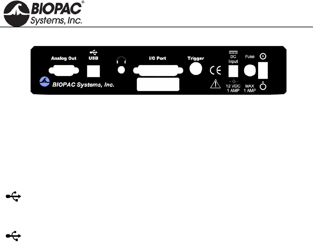
Back Panel
Back Panel, MP36/35
The back panel of the MP36/35 has an analog output port, a USB port, an I/O Port, a Trigger Port, a DC input, a
fuse holder, a power switch, and the unit’s serial number.
The back panel of the MP45 has a USB cable and headphone port.
Analog Out Port – Low Voltage Stimulator
There is one 9-pin male “D” analog output port on the back of the MP36/35 that allows signals to be amplified
and sent out to devices such as headphones. On the MP36, Analog Out is built-in low voltage stimulator.
Not available for MP45.
USB Connection
The MP36/35 connects to the computer via a USB Port, located just below the word USB.
Uses a standard USB connector.
Should only be used to connect the MP36/35 to a PC or Macintosh.
The MP45 USB cable is a full-speed USB connector and should only be used to connect the MP45 to a
PC or Mac USB port.
Headphone Output
Accepts a standard (1/4” or 6.3mm) stereo headphone jack; functional for MP36 and MP45 only.
I/O Port (MP36/35 only)
Accepts a DB 25 Female connector.
Input/Output port used to connect digital devices to the MP36/35.
Trigger Input (MP36/35 only)
Accepts a male BNC connector.
Input port used to send trigger signals from another device to the MP36/35.
MP system external trigger inputs are TTL compatible—this means that one needs to send the external
trigger input 0 volts for a TTL low and 5 volts for a TTL high.
The external trigger inputs are equipped with internal pull-up resistors—this means that they
automatically sit at TTL high, if left unattached.
This is a common and helpful implementation, because all one requires to implement an external
trigger is to pull the external trigger input low.
This implementation is typically performed with an external switch placed between the external
trigger input and ground.
When the switch is closed the external trigger input is pulled to TTL low.
When the switch is opened the external trigger input is pulled back (by the internal pull-
up resistor) to TTL high.
HARDWARE GUIDE

info@biopac.com
support@biopac.com
www.biopac.com
BIOPAC Hardware | MP36/35/45 | Page 4 - 11 Updated: 12.23.2013
To sync several MP systems together, so that one external trigger can start all the MP systems
simultaneously:
1. Connect all the MP systems grounds together.
2. Connect all the MP systems external trigger inputs together.
3. Place a switch between any MP system external trigger input and ground.
When the switch is pressed, all the MP systems that are connected together will be triggered
simultaneously.
DC Input (MP36/35 only)
Use the DC Input to connect a battery, AC/DC converter or other power supply to the MP36/35.
The power supply requirements for the MP36/35 are 12 VDC @ 1 Amp. Only use the AC300A
power adapter with the MP36/35. The AC300A is a 12 VDC @ 1.25 Amp power supply adapter that can
connect to any mains rated as 100-250 VAC @ 50/60Hz, 40VA.
The receptacle is configured to accept a “+” (positive) input in the center of the connector and a “-”
(negative) input on the connector housing.
Fuse Holder (MP36/35 only)
The fuse holder contains a fast-blow fuse that helps protect the MP36/35 from shorts on its power, analog, and
digital I/O lines. The MP36/35 uses a 1.0 amp fast-blow fuse.
To remove the fuse, use a screwdriver to remove the fuse cover located below the word Fuse.
Power Switch (MP36/35 only)
ON position — powers up the MP Unit OFF position — cuts the flow of power
Cleaning Procedures
Before cleaning, be sure to unplug the power supply from the MP36/35 or unplug the MP45 USB cable from the
computer. To clean the MP36/35, use a damp, soft cloth. Abrasive cleaners are not recommended as they might
damage the housing. Do not immerse the MP36/35 or any of its components in water (or any other fluid) or
expose to extreme temperatures as this can damage the unit.
HARDWARE GUIDE

info@biopac.com
support@biopac.com
www.biopac.com
BIOPAC Hardware | MP36/35/45 | Page 5 - 11 Updated: 12.23.2013
MP36/35/45 Specifications
Analog Inputs Front panel DSUB 9f labeled “CH #”
Number of Channels: Isolated human-safe universal input amplifiers
MP36: 4 Channels MP45: 2 Channels
A/D Sampling Resolution: MP36: 24-bit MP45: 16-bit
Gain Ranges: 5x to 50,000x (13 steps)
Input Voltage Range: Adjustable from ± 200 µV to ± 2 V
MP36 ± 10 V with SS70L
Signal to Noise Ratio MP36: > 89 dB min MP45: > 75 dB min
Input Noise Voltage: 9 nV rms /sqrt (Hz) and 0.1 µV rms noise (0.1 Hz to 35 Hz) - nominal
Input Noise Current: 100 fA rms /sqrt (Hz) and 10 pA p-p noise (0.1 Hz to 10 Hz) - nominal
CMRR: 85 dB minimum
Filters: Programmable analog and digital (IIR) filters;
automatic or user-adjustable
Analog Output
± 1 V output
Headphone jack: 3.5 mm stereo jack connection
Sample Rate: MP36: 100,000 samples/sec each channel
MP45: 48,000 samples/sec each channel
Serial Interface Type: USB
Certification: Complies with IEC60601-1
EMC complies with IEC60601-1-2
CE Marked
Dimensions/Weight: MP36: 7 cm x 29 cm x 25 cm / 1.4 kg
MP45: 3 cm x 18 cm x 10 cm / 0.3 kg
Additional Specs MP36 Only
Analog Output: Back panel DUSB 9m labeled “Analog Out”
Voltage Output: Range -10 V to +10 V Resolution: 16-bits
Pulse Output: Width: variable, 50 µsec – 100 msec
Repetition: variable. 100 µsec – 5 seconds
Pulse Level: Adjustable from -10 V to +10 V
With BSLSTMB Stimulator: 0 – 100 V
Input Triggering Options
External Trigger: Back panel BNC labeled “Trigger”
TTL positive or negative edge
Analog Trigger: Any Input channel (front panel “CH1 – CH4”)
Digital Trigger: Any of the eight input lines (back panel DSUB 25m)
Electrode Check: Impedance Range 0-1 M
(Checks Impedance between Vin+ and GND, Vin- and GND)
(See www.biopac.com for detailed specifications)
HARDWARE GUIDE
info@biopac.com
support@biopac.com
www.biopac.com
BIOPAC Hardware | MP36/35/45 | Page 6 - 11 Updated: 12.23.2013
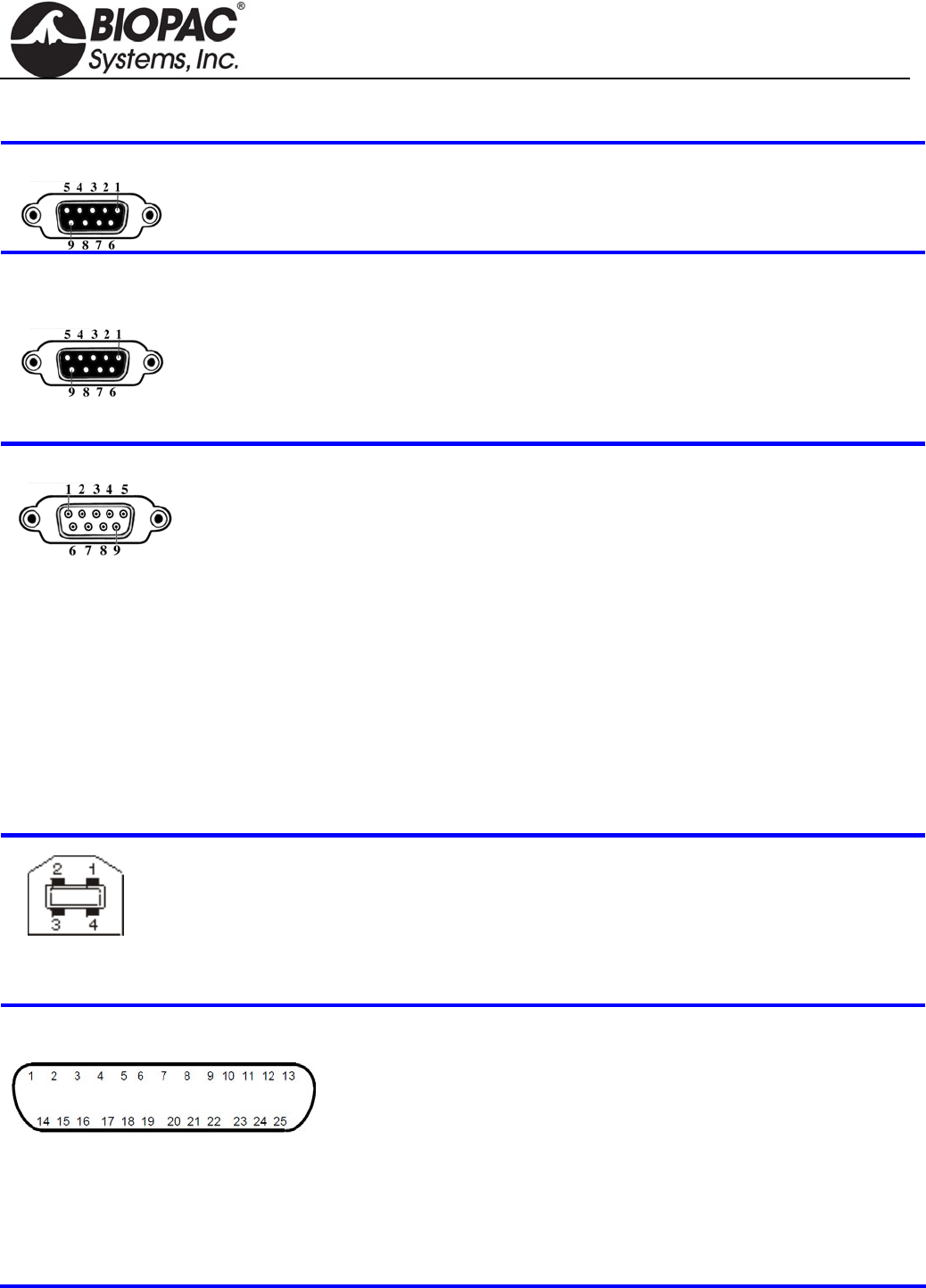
MP Unit Pin-outs
Electrode Check — MP36/35 Front
9-PIN FEMALE DSUB
Pin
2 Vin+ Electrode connection
3 GND
4 Vin- Electrode connection
MP Input — Front
CH 1, CH 2, CH 3, CH 4
9 PIN FEMALE DSUB
(1 of 4 for MP36/35 or 1 of 2 for MP45)
Pin MP36 and MP35 or MP45
1 Shield drive Shield drive
2 Vin+ Vin+
3 GND GND
4 Vin Vin
5 Shield drive Shield drive
6 +5 V (100 mA max aggregate) +5 V (50 mA max)
7 ID resistor lead 1; I2C SCL ID resistor lead 1 (+5 V)
8 ID resistor lead 2; I2C SDA ID resistor lead 2
9 5 V (100 mA max aggregate) 5 V (50 mA max)
MP Analog Output — MP36/35 Back
9 PIN MALE DSUB
Pin MP36 and MP35
1 Buffered analog or pulse output
A.C. coupled (1,000 uF)
Analog range: +/- 2.048 V
Pulse range: 0 to 2.048 V
2 MP36 Low voltage stimulator
MP35 Pulse or CH data
Buffered, D.C. coupled
Z out = 50 Ω
Range: MP36 -10 V to +10 V
MP35 0 V to +4.096 V
3 GND
4 +5 V (100mA max.)
5 Buffered pulse output
Z out = 1 kΩ
Range: 0 to 5 V
6 +12 V (100 mA max)
7 I2C SCL – Do not connect
8 I2C SDA
9 Monitor – Do not connect
Connector — Back
MP36/35
Pin MP36 or MP35
1 +5 N/C
2 -Data clock
3 Data + RX+
4 GND Ground
5 n/a TX-
6 n/a RX-
7 n/a N/C
8 n/a TX+
MP UNIT PIN OUTS continued
I/O Port — MP36 or MP35 Back
DSUB 25 (male)
Note: BSL v 3.7.0 does not support
Pins 7, 9, 18, 19, 20 and 21.
† Digital Input are 0-5 V with 100 K ohm
pullups to 5 V on board
Pin MP36 or MP35 only
1 Digital Output 1 0-5 V 8 ma 14 Digital Output 5
2 Digital Output 2 0-5 V 8 ma 15 Digital Output 6
3 Digital Output 3 0-5 V 8 ma 16 Digital Output 7
4 Digital Output 4 0-5 V 8 ma 17 Digital Output 8
5 GND Unisolated 18 Analog Input, Right
6 GND Unisolated 1 VRMS, centered at 0 V
7 RS-232-RX 19 Analog Input, Left
8 +5 V Unisolated/fused 1 VRMS, centered at 0 V
9 I2C-SDA 3.3. V 20 RS-232-TX 0-5 V
10 Digital Input 1† 0-5 V 21 I2C-SCL 3.3 V
11 Digital Input 2† 0-5 V 22 Digital Input 5
12 Digital Input 3† 0-5 V 23 Digital Input 6
13 Digital Input 4† 0-5 V 24 Digital Input 7
25 Digital Input 8
HARDWARE GUIDE
info@biopac.com
support@biopac.com
www.biopac.com
BIOPAC Hardware | MP36/35/45 | Page 8 - 11 Updated: 12.23.2013
NOTE: This“Lesson Hardware Guide” table refers to page numbering from the Biopac Student Lab Catalog. See
the catalog for information contained in any of these page references.
HARDWARE GUIDE
info@biopac.com
support@biopac.com
www.biopac.com
BIOPAC Hardware | MP36/35/45 | Page 9 - 11 Updated: 12.23.2013
NOTE: The following three pages of lesson descriptions refer to page numbering from the Biopac Student Lab
Catalog. See the catalog for information contained in any of these page references.
HARDWARE GUIDE
info@biopac.com
support@biopac.com
www.biopac.com
BIOPAC Hardware | MP36/35/45 | Page 10 - 11 Updated: 12.23.2013
HARDWARE GUIDE
info@biopac.com
support@biopac.com
www.biopac.com
BIOPAC Hardware | MP36/35/45 | Page 11 - 11 Updated: 12.23.2013
HARDWARE GUIDE
info@biopac.com
support@biopac.com
www.biopac.com
BIOPAC Hardware | STIMULATORS MP3X | Page 1 - 9 Updated: 2.27.2013
BSL STIMULATORS
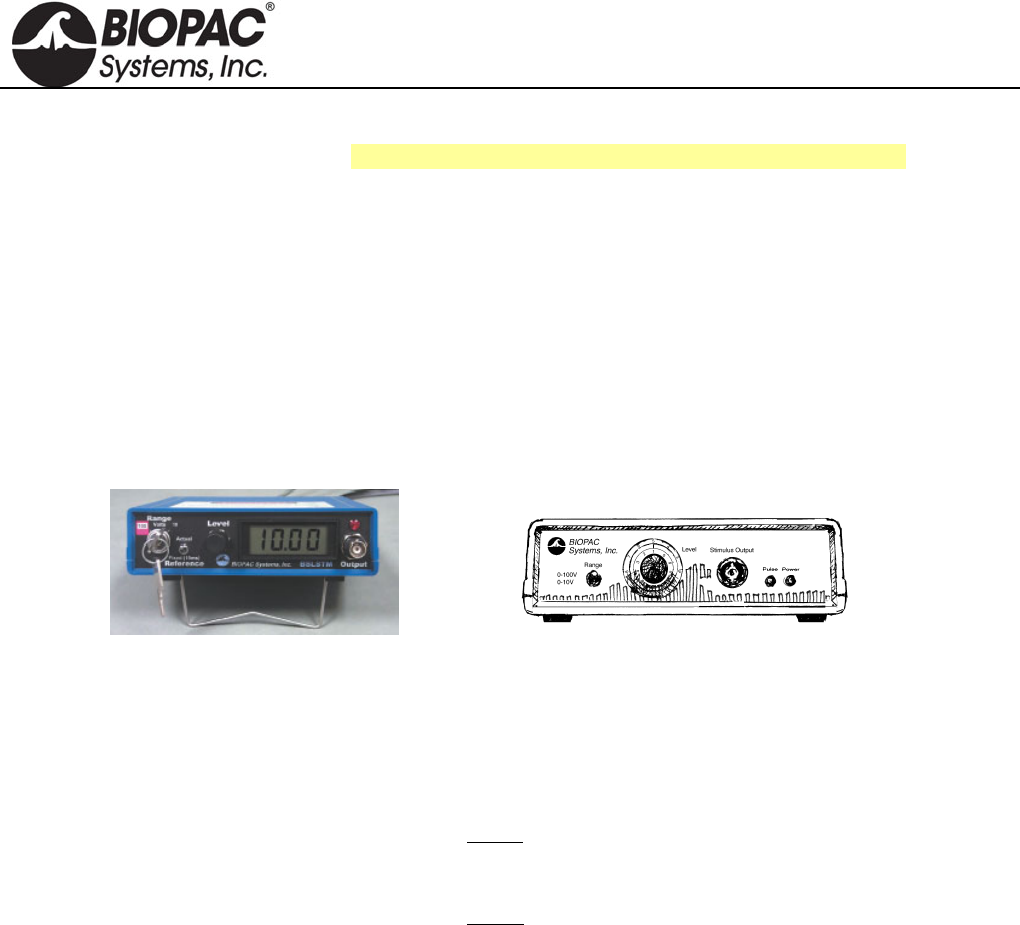
Modular Stimulators (0-100 V): Low Voltage Stimulator/Adapter:
BSLSTMB for MP36/36R/35 OUT3 Output Adapter for built-in Stimulator (MP36 only)
BSLSTMA for MP30 SS58L Low Voltage Stimulator (MP35 only)
See also: HSTM01, ELSTM1, ELSTM2, EL300S and EL400 electrodes.
BSLSTMB
BSLSTMA
Lab set up note
Placing the BSLSTMA/B unit too close to
MP3X hardware can result in data distortion
of the BSLSTMA/B pulse width signal; the
distortion is more apparent at higher sampling
rates.
NEVER set the BSLSTMA/B atop an
MP3X
Position the BSLSTMA/B away from the
MP3X to reduce the signal distortion
Note The older “BSLSTM” uses dial reading and a flip range switch. The same guidelines and
cautions described here apply, except when noted.
The BSLSTM Stimulator works in conjunction with the Biopac Student Lab System to allow precise stimulus
pulse outputting. Use the BSLSTM and the BSL PRO to perform a wide array of measurements, such as:
Twitch sub-threshold & threshold Muscle tension/length vs. force Fatigue
Maximum twitch responses Tetanic contraction Velocity
Single twitch, summation Nerve conduction
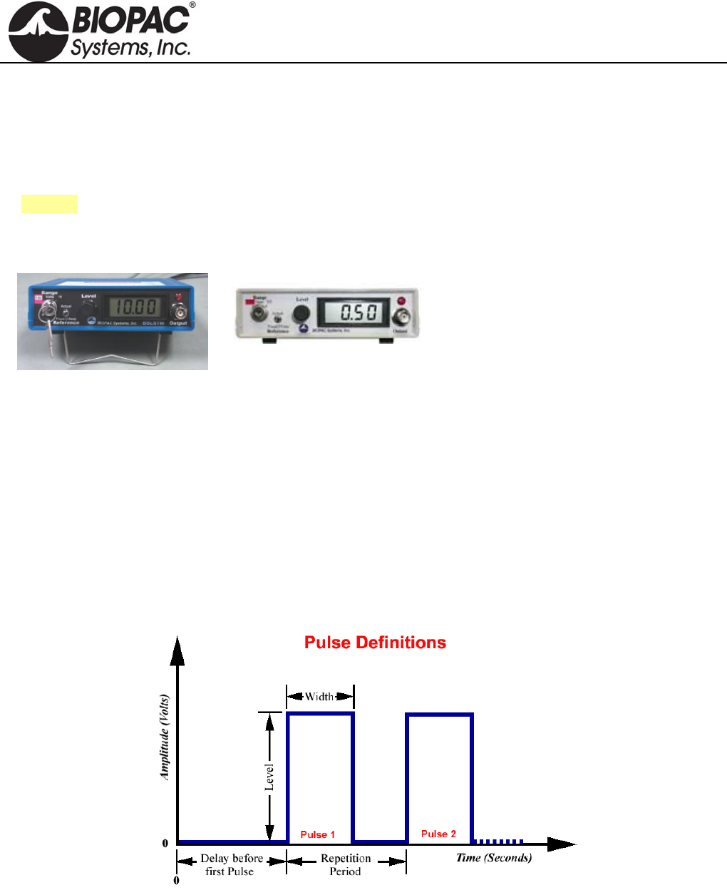
STIMULATOR PULSE DEFINITIONS
Pulse width The time that the pulse is in the non-zero or active state.
Delay before first pulse The initial delay from the start of acquisition to the start of the first pulse.
Repetition period The time between pulses, as measured from the start of one pulse to the start
of the next pulse. This is the inverse of the Pulse rate.
Pulse rate The number of pulses that occur in a one-second interval, expressed in Hz.
The Pulse rate relates to the Pulse period as follows:
HARDWARE GUIDE
info@biopac.com
support@biopac.com
www.biopac.com
BIOPAC Hardware | STIMULATORS MP3X | Page 2 - 9 Updated: 2.27.2013
Also called —
Pulse frequency
Repetition rate
Events per second
Pulse rate (Hz) = 1000 / Repetition period (milliseconds)
Pulse Repetition Use when referring to either Pulse rate or Pulse period.
Pulse level The amplitude of the pulse, expressed in Volts.
The output of the BSLSTM is 0 Volts when the pulse is not active.
Number of pulses The number of successive pulses that will be sent out at the selected Pulse
Width, Pulse Rate, or Pulse Period, and Pulse Level.
FRONT PANEL TERMINOLOGY
BSLSTMA/B — Digital Display & Keyed Switch BSLSTM — Dial Reading & Flip Switch
Range control Establishes the stimulus pulse output level range in Volts (0-10 Volts or 0-100 Volts).
BSLSTMA/B key control: Turn right to select a range of 0-10 Volts.
Turn left to select a range of 0-100 Volts.
Remove the key for added safety and control.
BSLSTM switch control: Flip down to select a range of 0-10 Volts.
Flip up to select a range of 0-100 Volts.
If the Range is changed before recording begins, the Preset must also be
changed (under the “Setup channels” option of the MP3X menu) in order to
maintain direct Level recordings.
If the Range is changed during recording, the user should manually enter a
software marker to note the change (by holding down F9 on a PC or Esc key on
a Mac). The pulse Level could then be determined by (mentally) moving the
decimal place to the right or left, depending on how the Range was changed.
Reference BSLSTMA/B only: Refers to the pulse width of the signal on the Reference Output (on
the back panel).
Actual reflects the actual output width.
Fixed (15 ms) establishes a pulse width of 15 ms, regardless of the actual
pulse width.
The Reference control only affects the pulse width; in either case, the pulse level reflects
the actual output level.
Level Level is used in conjunction with Range to set the stimulus pulse output level.
BSLSTMA/B digital display: Turn the Level control (right to increase, left to decrease)
to establish the desired Level, as indicated on the digital display.
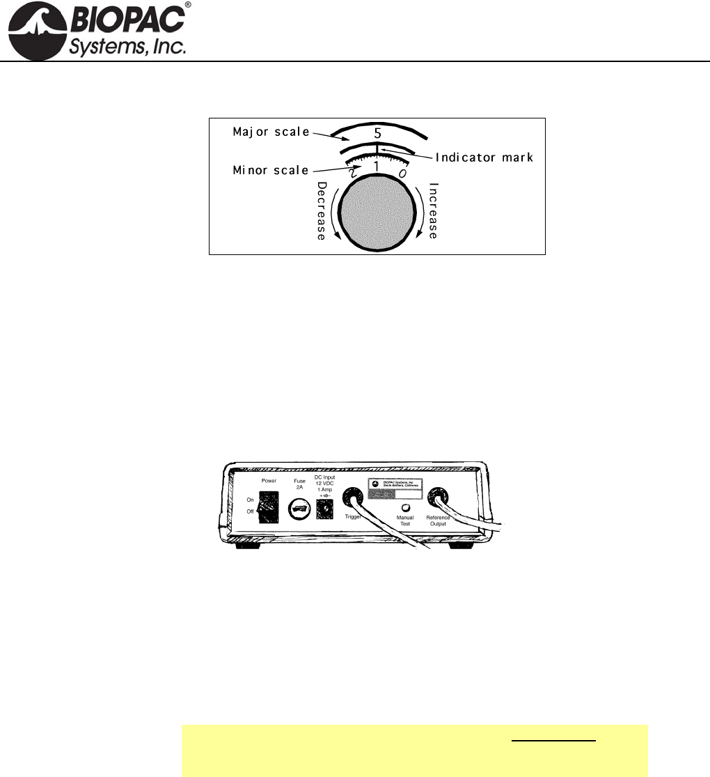
BSLSTM knob dial: The Level knob has a “Major scale” and a “Minor scale” which
indicate the voltage level as shown below:
Range switch Major scale Minor scale
0-10V Volts Volt / 10
0-100V Volts x 10 Volts
Turning the Level knob clockwise increases the voltage level, and turning it
counterclockwise decreases the voltage. In the following close-up of the Level knob, the
HARDWARE GUIDE
info@biopac.com
support@biopac.com
www.biopac.com
BIOPAC Hardware | STIMULATORS MP3X | Page 3 - 9 Updated: 2.27.2013
level reads 5.1 Volts (Range 0-10V) or 51 Volts (Range 0-100V).
As shown in the following diagram, the indicator mark is between the two dials.
Close-up of “Level” adjustment knob
Stimulus output Stimulus pulse output for connection to external electrodes or other devices. This is a
standard BNC style connector.
Pulse indicator LED flashes when the stimulus pulse is active: BSLSTMA/B = red. BSLSTM = green.
Power indicator Activated when the DC adapter is plugged in and the power switch on the back panel is
turned ON.
BSLSTMA/B: The LCD display is activated.
BSLSTM: LED indicator lights green
BACK PANEL TERMINOLOGY
Power switch Rocker switch for turning the BSLSTM power ON and OFF.
Fuse holder If the fuse blows and must be replaced, use a screwdriver to open (counterclockwise) and
close (clockwise) the fuse cap.
DC Input Socket for BIOPAC DC adapter.
Trigger cable Connects to the Analog Out connector on the back of the MP3X acquisition unit. The
MP3X sends the Pulse width and Pulse rate information via this cable.
Manual Test
button Used to diagnose problems with the BSLSTM stimulator unit.
When the Trigger and Reference Output cables are disconnected from
the MP3X , the Manual Test button can be used to initiate a stimulus with
a fixed pulse width of 2.5 milliseconds.
Reference Output
Cable
The stimulus marker output is labeled Reference Output on the back panel of the
BSLSTM. This output cable connects to any of the four channel inputs (CH1, CH 2, CH
3, or CH 4) on the front of the MP3X acquisition unit. The output cable carries the
stimulator marker pulse to the MP3X. The marker pulse has a fixed pulse width 15ms
and is generated each time the stimulator generates a pulse.
BSLSTMA/B: Use the front panel Reference switch to select Actual or Fixed.
BSLSTM has a fixed pulse width of 15ms, selected so that the MP30 can capture the
pulse with a sample rate as low as 100 samples per second.
If the BSL PRO software has been setup correctly, the amplitude of this marker will
reflect the Level knob setting on the BSLSTM. See the Range switch section for
information on how this reading can be affected.
HARDWARE GUIDE
info@biopac.com
support@biopac.com
www.biopac.com
BIOPAC Hardware | STIMULATORS MP3X | Page 4 - 9 Updated: 2.27.2013
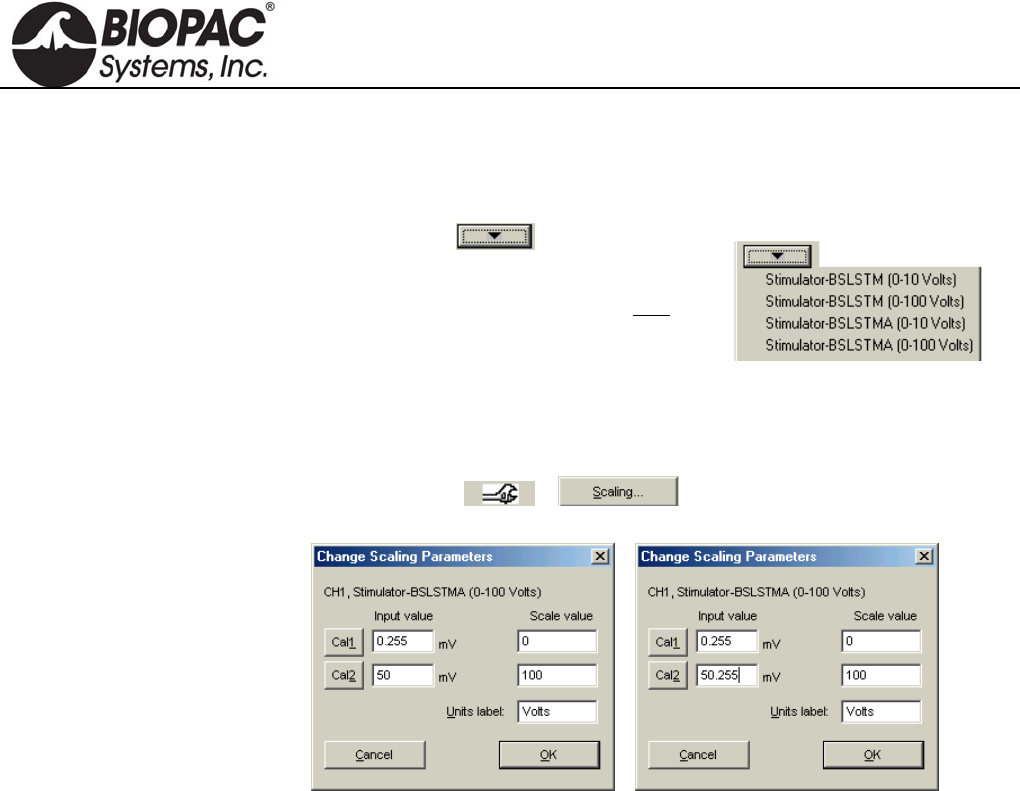
Calibration
The “Reference Output” signal from the BSLSTM must be calibrated to ensure accurate
results.
1. Choose the correct Preset (via MP3X
menu > Setup Channels).
For example, if using the BSLSTMA/B,
don’t choose a “BSLSTM...” Preset. Also,
make sure the Preset matches the Voltage
Range that will be used (0-10V, or 0-100V).
2. With stimulator connected and ON, turn the Level control counter-clockwise
until the display reads 0 (or as close to 0 as possible).
3. Get into the Scaling window for the Reference Output channel (via MP3X menu
> Setup Channels > > ).
4. Press the Cal1 button to get the signal representing 0V out of the stimulator.
5. Add the Input value found with Cal1 to the Input Value displayed for Cal2.
For example, if “Cal1” is pressed and provides an Input Value of .255 mV,
add the number .255 mV to the existing 50 mV and manually enter the total
value of 50.255 mV for Cal2 Input Value.
Note: Even if the Cal1 Input Value is negative, it must still be “added” to the
number for Cal2 (which essentially subtracts it) to arrive at the proper value.
6. Click OK to close out of the Scaling window and then close out of the Setup
Channel window. The system is now ready to record.
7. Optional: Save the setup as a Graph Template to save these new scale settings.
As long as neither the MP3X nor stimulator changes, the calibration should not
need to be repeated.
HARDWARE GUIDE
info@biopac.com
support@biopac.com
www.biopac.com
BIOPAC Hardware | STIMULATORS MP3X | Page 5 - 9 Updated: 2.27.2013
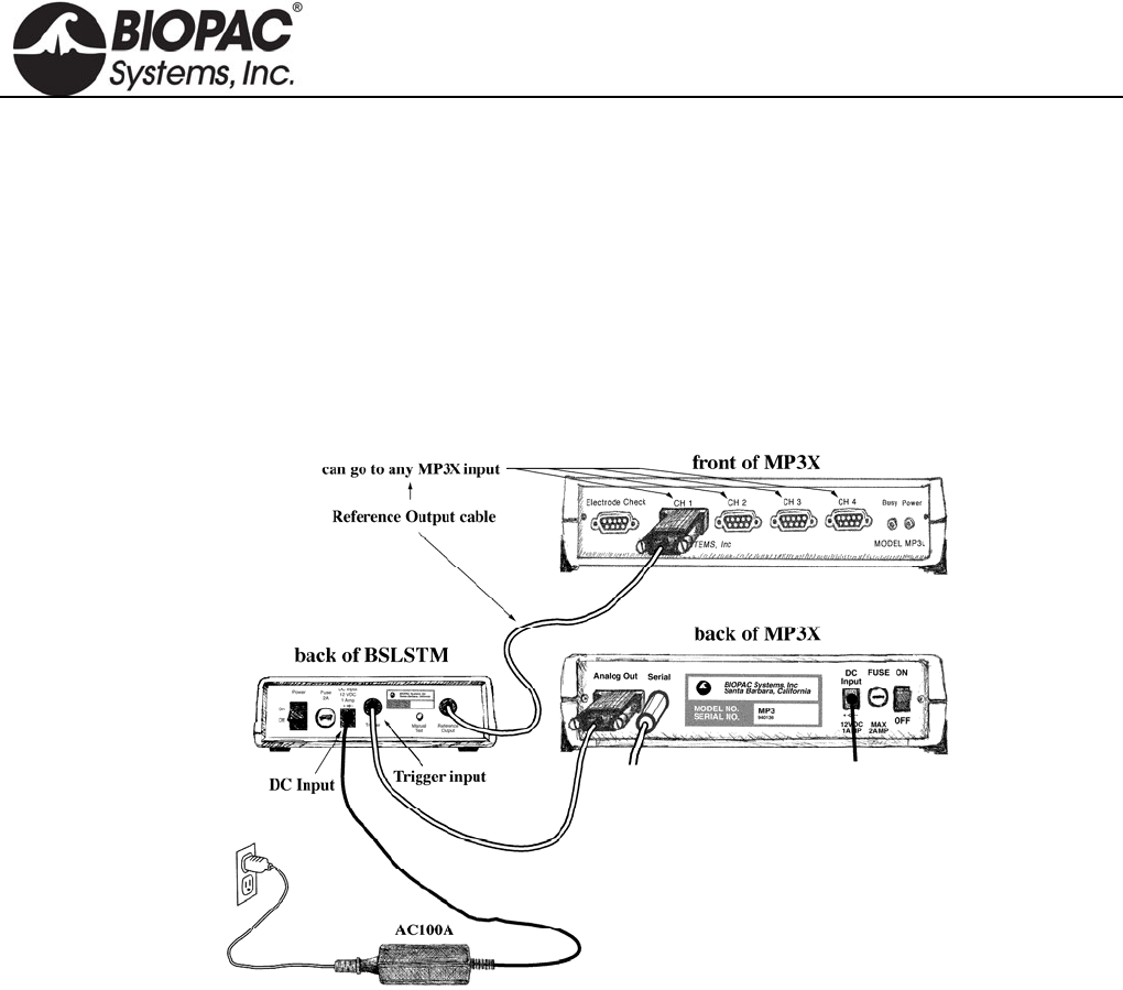
CONNECTING THE BSLSTM TO THE MP3X
1) Turn the MP3X unit OFF.
2) Confirm that Power switch on the back of the BSLSTM is in the OFF position.
3) Set the Range on the front of the BSLSTM to 0-10V.
4) Set the Level to 1 Volt.
BSLSTM: 1 Volt is set when the Major Scale (top number) is 1 and the Minor Scale (lower number)
is 0.
5) Plug the Trigger cable (female DB9 connector) from the back of the BSLSTM into the Analog Out port
(DB9 Male connector) on the back of the MP3X.
6) Plug the Reference Output cable (Male DB9 connector) from the back of the BSLSTM into an open
channel input port (DB9 female connectors: CH 1, CH 2, CH 3, or CH 4) on the front of the MP3X.
7) Plug the 12 Volt DC adapter into the wall.
8) Mate the DC output connector on the end of the adapter cable to the DC Input socket on the back of the
BSLSTM.
Make sure the connector is pressed in completely.
9) Plug the stimulator electrode assembly into the BNC connector on the front of the stimulator, labeled
Output on the BSLSTMA/B and Stimulus Output on the BSLSTM.
10) Place the BSLSTMA/B unit away from the MP3X. Placing the BSLSTMA/B too close to MP3X
hardware can result in data distortion of the BSLSTMA/B pulse width signal; the distortion is more
apparent at higher sampling rates.
NEVER set the BSLSTMA/B atop an MP3X.
Position the BSLSTMA/B away from the MP3X to reduce the signal distortion.
HARDWARE GUIDE

info@biopac.com
support@biopac.com
www.biopac.com
BIOPAC Hardware | STIMULATORS MP3X | Page 6 - 9 Updated: 2.27.2013
BSLSTMA/B SPECIFICATIONS (This new unit uses digital display and a keyed range switch)
Pulse width
Controlled by: Computer, with lockable width limit
Range: .049 – 100 milliseconds
Resolution: 2 microseconds
Accuracy: 5% (Can be improved to better than 2% using the “Correction factor” in the
“Stimulator Preferences’ window.)
Correction factor Range: 0 - 150 microseconds
Average value: 60 microseconds
Pulse Repetition
Controlled by: Computer
Pattern: Selectable (1-254 pulses) or continuous
Range—No Load: 5 seconds - .499 milliseconds Period (.2 - 3,333 Hz Rate)
Range—Load: 2 K Ohm load
0 - 10 Volt Range: 5 seconds to the following minimum repetition period:
100 ms P.W. 300 ms
10 ms P.W. 30 ms
1 ms P.W. 3 ms
0 - 100 Volt Range: 5 seconds to the following minimum repetition period:
100 ms P.W. 100 Volts: 1 second
50 Volts: 300 ms
10 ms P.W. 100 Volts: 400 ms
50 Volts: 30 ms
1 ms P.W. 100 Volts: 4 ms
50 Volts: 3 ms
Limits: User adjustable lower and upper rate limits
Resolution: 2 microseconds
Accuracy: Better than 2%
Initial Pulse Delay
Time range: None or .5 - 100 milliseconds
Resolution: 2 microseconds
Pulse level
Control: Manual (10 turn potentiometer)
Range (selectable with K
e
Switch):
Range 1: .025 - 10 Volts
Range 2: .12 - 100 Volts
Infinite (potentiometer adjustable) range
Accuracy: 5% accuracy to digital readout
Reference Output Correlates to actual pulse output (Requires Calibration)
Pulse width: Fixed (15 millisecond) or Direct (follows actual pulse output)
Amplitude: 0 - 50 mV correlates to 0 - 10V actual output or 0 - 100V actual output.
Manual Test Pulse (Button on back panel)
Note: Will only function when “Trigger” cable is not connected to the MP3X.
Pulse Width: 1 millisecond
Stimulator isolation
Volts: 2,000 Volts DC (HI POT test)
Capacitance coupling: 60pF
Power requirements 12 Volts DC adapter (included), 1 Amp
Fuse 250V, 2A, fast blow
Fuse Dimensions: 1.25” length .25” diameter
Module Weight 610 grams
Module Dimensions 16 cm x 16 cm x 5 cm
HARDWARE GUIDE

info@biopac.com
support@biopac.com
www.biopac.com
BIOPAC Hardware | STIMULATORS MP3X | Page 7 - 9 Updated: 2.27.2013
BSLSTM SPECIFICATIONS (This older unit uses dial reading and a flip range switch)
Pulse width
Controlled by: Computer, with lockable width limit
Range: .2 – 100 milliseconds
Resolution: 2 microseconds
Accuracy: 5% (Can be improved to better than 2% using the “Correction factor” in the
“Stimulator Preferences’ window.)
Correction factor Range: 0 - 150 microseconds
Average value: 110 microseconds
Pulse Repetition
Controlled by: Computer
Pattern: Selectable (1-254 pulses) or continuous
Range—No Load: 5 seconds - .3 milliseconds Period (.2 - 3,333 Hz Rate)
Range—Load: 2 K Ohm load
0 - 10 Volt Range: 5 seconds to the following minimum repetition period:
100 ms P.W. 150 ms
10 ms P.W. 10.1 ms
1 ms P.W. 1.1 ms
0 - 100 Volt Range: 5 seconds to the following minimum repetition period:
100 ms P.W. 100 Volts: beyond functional limits
50 Volts: 250 ms
10 ms P.W. 100 Volts: 200 ms
50 Volts: 150 ms
1 ms P.W. 100 Volts: 20 ms
50 Volts: 2.5 ms
Limits: User adjustable lower and upper rate limits
Resolution: 2 microseconds
Accuracy: Better than 2%
Initial Pulse Delay
Time range: None or .5 - 100 milliseconds
Resolution: 2 microseconds
Pulse level
Controlled by: Manually (10 turn potentiometer)
Range (switchable): Range 1: .025 - 10 Volts
Range 2: .15 - 100 Volts
Infinite (potentiometer adjustable) range
Accuracy: 5% accuracy to dial indicator
Reference Output Correlates to actual pulse output (Requires Calibration)
Pulse width: 15 millisecond fixed pulse width
Amplitude: 0 - 10 mV correlates to 0 – 10V actual output or 0 – 100V actual output
Manual Test Pulse (Button on back panel)
Note: Will only function when “Trigger” cable is not connected to the MP3X.
Pulse Width: 2.5 - 3 milliseconds
Stimulator isolation
Volts: 2,000 Volts DC (HI POT test)
Capacitance
coupling:
60pF
Power requirements 12 Volts DC adapter (included), 1 Amp
Fuse 250V, 2A, fast blow
Dimensions: 1.25” length .25” diameter
Module Weight 610 grams
Module Dimensions 16 cm x 16 cm x 5 cm
HARDWARE GUIDE
info@biopac.com
support@biopac.com
www.biopac.com
BIOPAC Hardware | STIMULATORS MP3X | Page 8 - 9 Updated: 2.27.2013
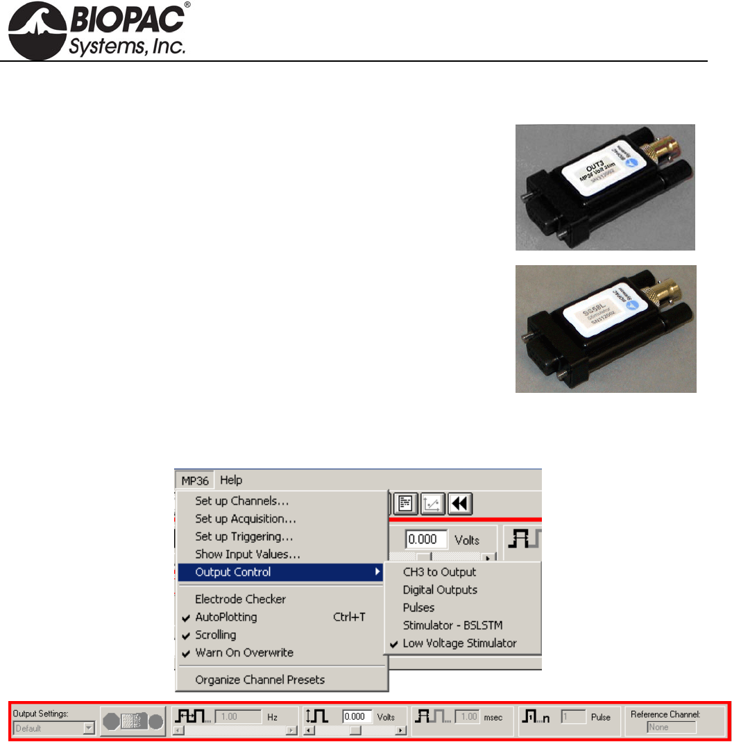
LOW VOLTAGE STIMULATOR
OUT3
The MP36 includes a built-in low voltage stimulator—just use the Analog Out
port.
For connection to BIOPAC electrodes, add the OUT3 BNC Adapter.
SS58L
The MP35 uses the SS58L Low Voltage Stimulator to the Analog Out port.
Connect any electrode or lead with a BNC connector (such as needle electrodes or clip leads) for direct
stimulation of animal or tissue preps. Control the stimulus with the Output Control option of the BSL PRO
software. Output can be monitored directly on the computer without any external cable.
Interface options: Nerve chambers — use BSLCBL3A or BSLCBL4B
Stimulation electrodes — use ELSTM2
Clip leads — use BSLCBL7, BSLCBL11, or BSLCBL12
Pulse level: -10 V to + 10 V, software adjustable in 5 mV increments
Pulse width: 0.05-100 milliseconds
Pulse repetition: 5 seconds-0.1 millisecond (0.2-10,000 Hz)
Power: No additional power required
HARDWARE GUIDE

info@biopac.com
support@biopac.com
www.biopac.com
BIOPAC Hardware | STIMULATORS MP3X | Page 9 - 9 Updated: 2.27.2013
STIMULATOR ELECTRODE GUIDELINES
— PLEASE READ —
It is very important to follow the electrode placement guidelines when connecting stimulator electrodes from the
BSLSTM to a subject. The BSLSTM can output lethal levels of energy!
Always set the Level to “0” Volts prior to connecting the stimulator electrodes to the subject.
Increase the Level adjustment slowly until a response is noted.
Never increase the Level more than necessary to obtain the desired response.
The BSLSTM should only be used under direct supervision of an Instructor.
Never place any stimulator leads in the mouth or any other body orifice.
To prevent a “Ground loop,” the Ground of the stimulator electrode and the Ground of the measuring
electrode(s) must always be connected to the same location.
Use the HSTM01 Human Stimulation Electrode for human stimulation.
To prevent a current path that goes across or through the heart, the stimulator electrodes and the measuring
electrodes should always be in close proximity.
For example, if making measurements on an arm, the stimulator electrodes and measuring electrodes —
including the ground electrodes — must be on the same arm. Any other electrodes or transducers that
make electrical contact with the body should not be connected while the stimulator is connected.
HARDWARE GUIDE
info@biopac.com
support@biopac.com
www.biopac.com
BIOPAC Hardware | SS1LA | Page 1 - 1 Updated: 12.13.2012
SS1LA SHIELDED ELECTRODE ADAPTER
The fully-shielded electrode interface cable permits high resolution
recording of biopotential signals. The 3-meter adapter cable accepts
standard Touchproof connectors. Use this lead adapter with:
LEAD120 for EL120 contact post electrodes or
EL250 series reusable Ag-AgCl electrodes or
EL450 series needle electrodes or
LEAD110 series shielded and unshielded leads
SS1LA SPECIFICATIONS
Cable length 3-meter
Termination standard Touchproof connectors
Note: The SS1L is a 3-meter electrode adapter for older style 2 mm pin connections. To convert 2 mm pin
connections to Touchproof 1.5 mm connections, use CBL201.
HARDWARE GUIDE

info@biopac.com
support@biopac.com
www.biopac.com
Biopac Hardware | SS2L | Page 1 - 1 Updated: 12.19.2013
SS2L ELECTRODE LEAD SET
“SS2L” is used to reference SS2L, SS2LA, or SS2LB lead sets;
SS2LB is recognized by current release BSL Lessons.
This fully shielded cable assembly permits high-resolution
recording of biopotentials. Each lead set has three pinch leads
designed to snap directly onto standard disposable electrodes
(such as the EL500 series electrodes). Each pinch lead is 1
meter long and terminates in a yoke connected to a 2-meter
cable.
This is the general-purpose electrode cable used for almost all applications requiring the use of electrodes. These
cables are used to connect the disposable electrodes that are placed on the surface of the skin to the MP3X/4X
unit. Depending on where electrodes are placed, they can measure muscle contraction, heartbeats, or even
brainwaves.
One end of the SS2L cable has a Smart Sensor connector on it that connects to the MP3X/4X and the other end
splits into three smaller cables. Each end of the smaller cables is fitted with a pinch connector that clamps onto
electrodes.
SS2L and SS2LA are discontinued products. SS2LB is the current product offering.
SS2L SPECIFICATIONS
Cable Length: 2 meters
Connector Type: 9 Pin DIN
HARDWARE GUIDE

info@biopac.com
support@biopac.com
www.biopac.com
BIOPAC Hardware | SS3LA | Page 1 - 2 Updated: 7.16.2012
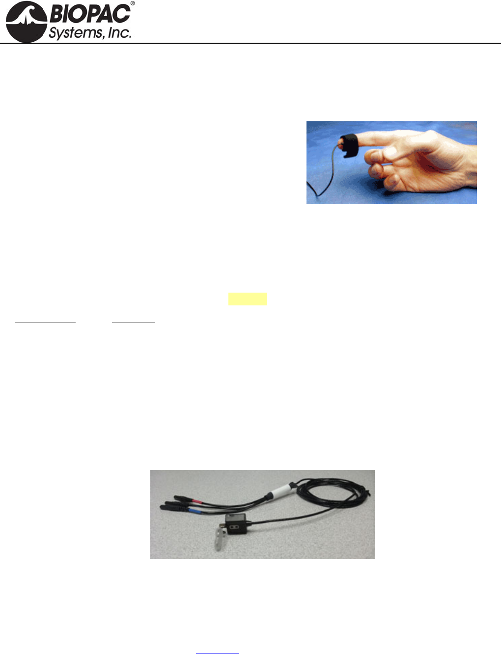
SS3LA EDA (ELECTRODERMAL ACTIVITY) TRANSDUCER
The SS3LA transducer connects to a single MP3X input channel to record electrodermal
activity (skin conductance or, with proper setup, skin resistance). Two Ag-AgCl electrodes are
mounted in individual, ergonomically designed, polyurethane housings for improved contact.
They attach to the fingers by a Velcro strap or can be taped to any other part of the body. The
electrodes have a 6 mm contact area with a 1.6 mm cavity to accommodate electrode gel
(GEL1, GEL101, or the preferred recording gel). The non-polarizable electrodes are shielded to minimize noise
interference and improve recordings. These electrodes are different from standard SS2L electrodes in that they
have built-in, reusable electrodes on the end, the electrodes are specially designed to fit around the tip of a
person’s finger, and the electrodes measure only one type of signal—the EDA.
See the SS57L EDA (GSR) Lead for a disposable electrode option
USAGE RECOMMENDATIONS
Setup - There must be good electrical connections between the skin and the electrodes for EDA to work properly.
Gel - When using GEL101 isotonic gel it is important that the gel has a chance to be absorbed and make good
contact before recording begins. Accordingly:
1. Apply GEL101 to the skin at the point of electrode contact and rub it in.
2. Fill the SS3LA electrode cavity with GEL101.
3. Attach the SS3LA electrode to the subject.
4. Wait 5 minutes (minimum) before starting to record data.
Presets - BSL PRO software includes two EDA presets:
Electrodermal Activity (EDA), 0 - 35 Hz; requires calibration—see details below
Electrodermal Activity (EDA) Change; no calibration required
To calibrate the SS3LA using the Electrodermal Activity (EDA), 0 - 35 Hz preset:
1. Prepare two 1% calibration resistors; 100 kiloohm and 1 megaohm. Insulate the resistor using clear
tape such that when held, the fingers will not directly contact the resistor leads.
2. Place the 1 megaohm resistor such that one resistor lead contacts one electrode pad and the other
resistor lead contacts the opposite electrode pad.
3. From the Scaling dialog box, set the Cal1 Scale value to “1” and click Cal1.
4. Repeat step 2 using the 100 kiloohm resistor.
5. From the Scaling dialog box, set the Cal2 Scale value to “10” and click Cal2.
Gain - verify the Gain setting of the SS3LA:
1. From the Scaling dialog box, set the Cal1 Scale to "0" and click Cal1.
2. Set the Cal2 Scale to 5Mho/V and the Input voltage to 1 V, and then close out of the Scaling dialog box.
3. Insulate a 100 kiloohm resistor and place it from electrode pad to electrode pad (resistor must be insulated
from fingers).
4. Perform measurement with electrode-resistor setup.
BSL PRO should produce a reading of 10 microsiemens (older presets may use micromhos units
label).
*SCR - Use an Expression calculation channel to take reciprocal of conductance, and then apply proper scaling.
Tip
To detect a good signal, subjects should have a little sweat on their hands (not a lot, but
enough so that their hands are not completely smooth or cold). If subjects wash their
hands just prior to the recording or if they have been sitting in a cold room, then they
must do something to activate the sweat glands before beginning calibration or
recording. If subjects begin with colder hands, the scale will be diminished and the signal
will be easily saturated once they “warm up” during the lesson.
HARDWARE GUIDE

info@biopac.com
support@biopac.com
www.biopac.com
BIOPAC Hardware | SS3LA | Page 2 - 2 Updated: 7.16.2012
SS3LA SPECIFICATIONS
Electrode Type: Ag/AgCl, shielded Weight: 4.5 grams
Range: .1 – 100 siemens (normal human range is 1 – 20 siemens) Cable Length: 2 meters
Surface Area: 6mm contact area Connector Type: 9 Pin DIN
Gel Cavity Area 1.66 mm Sterilizable: Yes (contact BIOPAC)
Dimensions: 16 mm (long) 17 mm (wide) 8 mm (high)
CLEANING THE SS3LA TRANSDUCER
Do not leave GEL in the cavity after use. The electrode cavity must be left clean and dry. If GEL is left in the cavity,
it will act as insulation preventing electrical contact with the skin, and the Ag-AgCl electrode disk could degrade
quickly with time because the electrode surface is somewhat porous to promote good conductivity to the GEL.
To clean the reusable SS3LA, use a cotton swab or toothbrush with tap water.
Use any lab cleaner with pumice (such as Ajax) with a cotton swab or toothbrush to remove any dark residue from
the electrode surface.
Use Hydrogen Peroxide solution (2-3%) to brighten electrode surface (optional) or to sterilize the electrode. Do not
place the electrode in solution, but simply clean the electrode surface using a cotton swab. Dry the electrode off
completely before storage.
HARDWARE GUIDE
info@biopac.com
support@biopac.com
www.biopac.com
MP Research System | Pulse Transducers | Page 1 - 2 Updated: 12.3.2012
PULSE PHOTOPLETHYSMOGRAM TRANSDUCERS
TSD200 for MP150/MP100 System
SS4LA for MP3X and MP45 System
The TSD200/SS4LA consist of a matched infrared emitter and
photo diode, which transmits changes in blood density (caused by
varying blood pressure) in specific body locations. When the
TSD200 is attached to the skin, the infrared light is modulated by
blood pulsing through the tissue below. The modulated, reflected
light results in small changes in the resistance of the photo resistor,
which yields a proportional change in voltage output.
The TSD200/SS4LA includes a shielded 2-meter cable and a stretchable Velcro® strap for easy attachment to the
fingers, or it can be taped to other body parts. The TSD200/SS4LA can also be placed on other body locations by
employing ADD208 adhesive disks to hold the transducer in place. Use the TSD200C ear clip transducer for easy
attachment to the ear.
Place the transducer around the finger and adjust the Velcro® closure to provide only slight tension. Blood
density readings can vary considerably depending on transducer location and tension changes.
The TSD200 connects to the PPG100C as follows (See also: PPG100C for a diagram):
TSD200 Lead PPG100C
Red lead +VSUP
Black lead GND
Purple or Blue lead INPUT
The SS4LA plugs directly into the MP3x or MP45.
CALIBRATION
The TSD200/SS4LA does not require calibration.
TSD200C PHOTOELECTRIC PULSE PLETHYSMOGRAPH WITH EARCLIP
The photodetector operates via incident photons, from an IR transmitter, impacting an IR detector. The incident
photons result in a proportional passage of electrons in the detector. The IR detector operates like a photon-
controlled current source. The transducer incorporates an appropriate clipping range, with linearity insured for
arbitrarily low levels of reflected light. For the expected magnitude of incident infrared light, the photodetector
operates in a linear fashion. Situations have not been encountered where the detector is operating non-linearly
(near saturation).
The TSD200C transducer operates with the PPG100C amplifier to record the pulse pressure waveform. The
TSD200C consists of a matched infrared emitter and photo diode, which transmits changes in infrared reflectance
resulting from varying blood flow. The ergonomic housing design improves contact with the subject and helps
reduce motion artifact. The TSD200C is primarily designed for ear attachment and comes with a shielded 3-meter
cable and ear clip.
HARDWARE GUIDE

info@biopac.com
support@biopac.com
www.biopac.com
MP Research System | Pulse Transducers | Page 2 - 2 Updated: 12.3.2012
TSD200/200C/SS4LA SPECIFICATIONS
Emitter/Detector Wavelength: 860 nm 60 nm
Optical Low Pass Filter Cutoff Wavelength: 800 nm
Note The operational range of the emitter and detector fall within the
wavelength range of 800 nm to 920 nm. The filter is placed over the
receiver, the filter of 800 nm is an optical lowpass, so wavelengths
longer than 800 nm will pass thru.
Nominal Output: 20 mV (peak-peak)
Power: 6 VDC Excitation @ 5 mA
Sterilizable: Yes (Contact BIOPAC for details)
Weight: 4.5 g
Dimensions (L x W x H): 16 mm x 17 mm x 8 mm
Attachment: Velcro strap
Cable: 3 m, shielded
Interface: PPG100C
TEL100C Compatibility: SS4A
NOTE THE TSD200A EAR CLIP TRANSDUCER WAS DISCONTINUED IN AUGUST OF 2008.
HARDWARE GUIDE

info@biopac.com
support@biopac.com
www.biopac.com
BIOPAC Hardware | SS5LB | Page 1 - 1 Updated: 7.16.2012
SS5LB RESPIRATORY EFFORT TRANSDUCER
The SS5LB transducer is used to record respiration via chest or abdomen expansion and contraction. This
transducer is useful for determining how deeply someone is breathing and for calculating the person’s breathing
rate or respiration rate. The transducer is a strain assembly that measures the change in thoracic or abdominal
circumference. The strap presents minimal resistance to movement and is extremely unobtrusive.
Due to its novel construction, the SS5LB can measure extremely slow respiration patterns with no loss in signal
amplitude while maintaining excellent linearity and minimal hysteresis. The respiratory effort transducer has a 2-
meter flexible lightweight cable. The center plastic housing protects the delicate sensor within.
The transducer is attached by a fully adjustable nylon strap, which allows the transducer to fit almost any
circumference.
To attach the nylon belt to the transducer, thread the strap through the corresponding slots on the sensor assembly.
Place the transducer around the body at the level of maximum respiratory expansion (generally about 5cm below
the armpits). At maximum expiration, adjust the strap so there is slight tension to hold the strap around the chest.
SS5LB SPECIFICATIONS
Response: T rue DC
Circumference Range: 9 cm – 130 cm (Can be increased with a longer nylon strap)
Dimensions: 95 mm (long) 47mm (wide) 15mm (thick)
Weight: 9 grams
Sterilizable: Yes (contact BIOPAC for details)
Variable Resistance Output: 50-150 K
Cable Length: 2 meters (flexible, lightweight)
Connector Type: 9 Pin DIN
HARDWARE GUIDE
info@biopac.com
support@biopac.com
www.biopac.com
BIOPAC Hardware | SS6L – SS18L | Page 1 - 2 Updated: 2.26.2013
TEMPERATURE TRANSDUCERS
SS6L: Fast Response
SS7L: Waterproof Probe
SS8L: Liquid Immersion Probe
SS18L Digit Surface
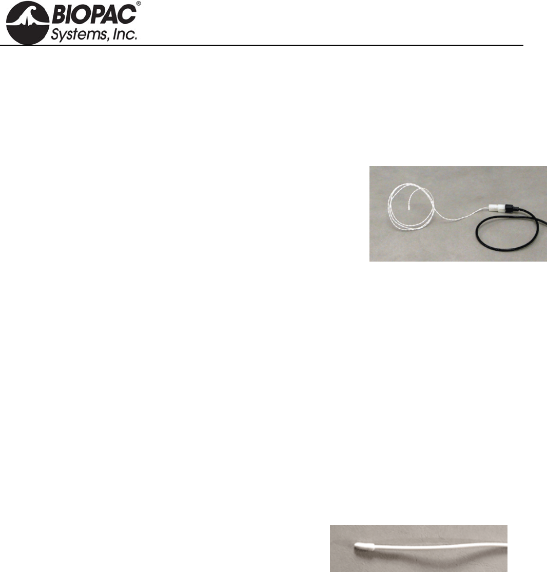
SS6L TEMPERATURE TRANSDUCER
The SS6L is a small fast-response thermistor used to measure small variations
in temperature, either on the skin surface or in exhaled airflow. The recorded
temperature changes during breathing can be used to indicate respiration rate.
Attach the SS6L to the skin surface with Surgical Tape (TAPE1).
RX202A Sensor (white) shown at right with transducer connector (black);
ships as sensor only.
This is a replacement sensor for
TSD202A for MP research systems
SS6L for BSL education systems
SS6 for telemetry/wireless systems
The sensor snaps onto the "SS" transducer connector for connection to a BIOPAC data acquisition system.
SS6L SPECIFICATIONS
Response time: 0.6 sec
Nominal resistance: 2252 @ 25°C
Maximum operating temperature: 100°C
Accuracy and Interchangeability: ±0.1°C
Connector Type: 9 Pin DIN
Compatibility: YSI® series 400 temperature probes
Cable Length: 2 meters (flexible, lightweight)
Sterilizable: Yes (contact BIOPAC for details)
Dimensions: 5m 1.7m
SS7L WATERPROOF PROBE
Use this vinyl probe for core (oral/rectal) temperature recordings.
SS7L SPECIFICATIONS
Response time: 1.1 sec
Max operating temp: 60°C
Accuracy & Interchangeability: ±0.2°C
Compatibility: YSI(r) series 400
Dimensions: 9.8 mm x 3.3
Cable: 3 meters
HARDWARE GUIDE
info@biopac.com
support@biopac.com
www.biopac.com
BIOPAC Hardware | SS6L – SS18L | Page 2 - 2 Updated: 2.26.2013
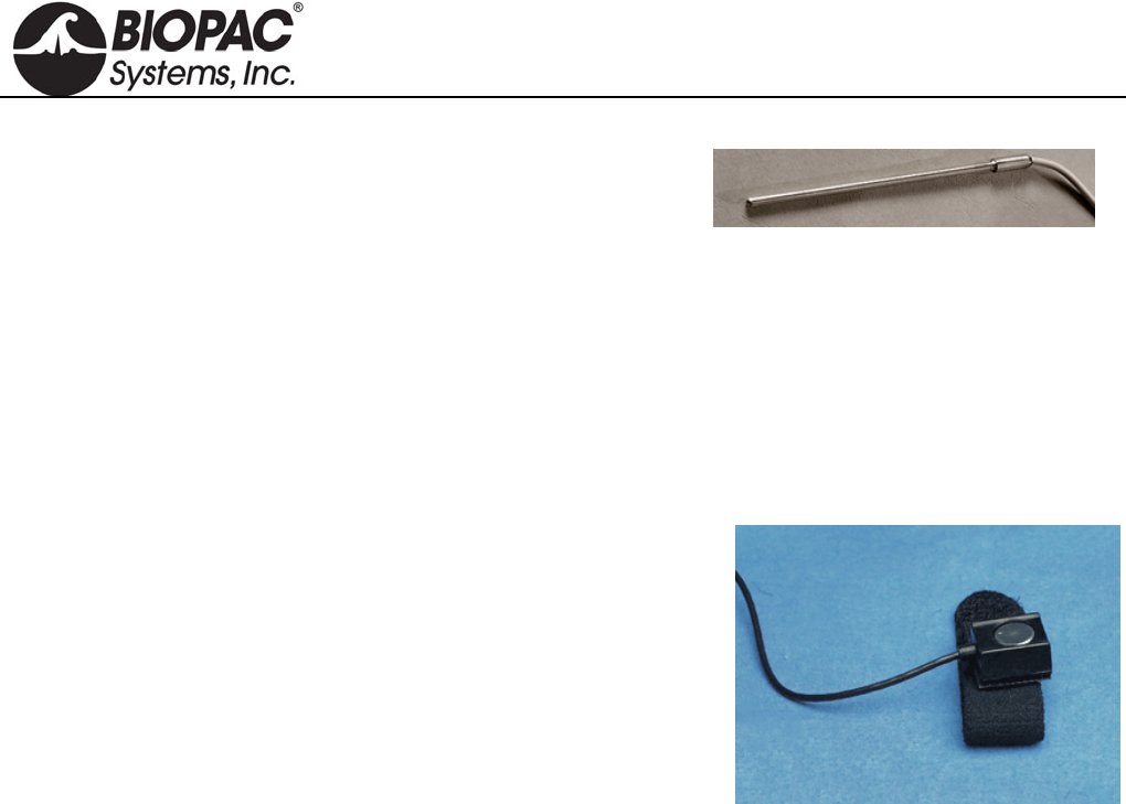
SS8L LIQUID IMMERSION PROBE
Use this stainless steel probe for dry or wet bath temperature
measurements.
SS8L SPECIFICATIONS
Response time: 3.6 sec
Max operating temp: 60°C
Accuracy & Interchangeability: ±0.2°C
Compatibility: YSI(r) series 400
Dimensions: 4 mm X 115 mm
Cable: 3 meters
SS18LA DIGIT SURFACE TEMPERATURE TRANSDUCER
The SS18LA is designed to record skin temperature of the fingers or
toes. The probe contains a surface temperature sensing element encased
in a polyurethane housing that conforms to curved skin surfaces and
includes a Velcro strap for easy attachment.
SS18L SPECIFICATIONS
Response time: 1.1 sec
Size
with housing: 16 mm (long) x 17 mm (wide) x 8 mm (high)
sensor only: 10 mm sensing diameter, 1.4 mm sensor thickness
Interface: MP3X
Nominal Resistance: 2252 ohms at 25°C (sensor only)
Maximum operating temperature: 60°C (when used with MP3X)
Accuracy and Interchangeability: 0.2°C (after calibration)
Cable Length: 3 meters
Compatibility: YSI series 400 temperature probes (sensor only)
Sterilizable: Yes (contact BIOPAC for details)
HARDWARE GUIDE

info@biopac.com
support@biopac.com
www.biopac.com
BIOPAC Hardware | SS10L | Page 1 - 1 Updated: 7.1.2013
SS10L PUSHBUTTON HAND SWITCH
The SS10L pushbutton hand switch is used for remote event marking or for
psychophysiological response tests. This easy to hold pushbutton switch is very rugged and
reliable, and makes it simple to mark events during recording. When data from the button
is displayed on the screen, it normally reads 0 Volts, and when the button is pressed it
reads +5 mV.
SS10L SPECIFICATIONS
Cable Length: 2 meters
Connector Type: 9 Pin DIN to MP36/35 front panel input
HARDWARE GUIDE
info@biopac.com
support@biopac.com
www.biopac.com
BIOPAC Hardware | SS11LA & TSD117 | Page 1 - 7 Updated: 12.2.2013
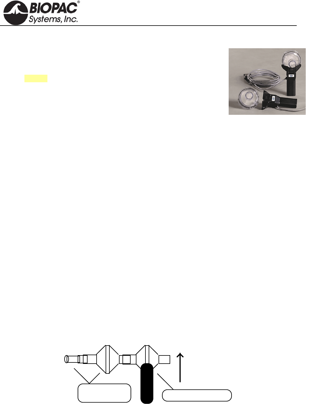
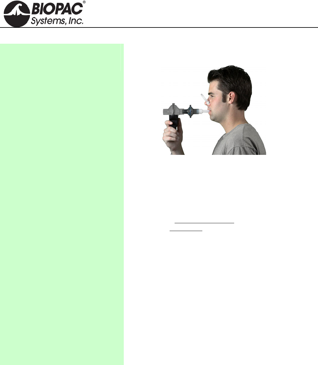
MEDIUM-FLOW PNEUMOTACH TRANSDUCER
SS11LA for MP3X and MP45 System
TSD117 & TSD117-MRI for MP150/MP100 System
RX117 Replacement Airflow Head
See also: AFT series of accessories for airflow and gas analysis
These medium-flow airflow transducers are designed to measure human subject
respiratory, bi-directional airflow (liters/sec) and can be used to measure respiratory
flow in a wide range of tests and conditions relating to airflow and lung volume.
Volume measurements are obtained by integrating the airflow signal. The airflow
transducer is lightweight, easily held in one hand, and has a removable head for
sterilization and replacement. For reasons of hygiene, it is important that only one
person use each disposable mouthpiece and disposable filter.
The SS11LA/TSD117 airflow transducers include an optically clear detachable flow
head (RX117) for easy cleaning and inspection. As the detachable flow head is snapped into the transducer
handle, the flow head plugs directly into an integral, precision low-differential pressure transducer. Accordingly,
the transducers will output an electrical signal proportional to respiratory flow. Use with the AFT22 Non-
Rebreathing “T” valve for low dead space requirements.
SS11LA needs 5-10 minutes to
warm up; during this time, the
baseline offset changes slightly.
The transducers connect to industry standard bacteriological filter AFT1 with disposable mouthpiece AFT2 or
AFT13 filter and mouthpiece with AFT11H coupler. The RX117 detachable flow head can be cold sterilized,
autoclaved (220 F max), or placed in a dishwasher.
For airflow and lung volume measurements, use the airflow transducer with the AFT2 mouthpiece and
the AFT1 bacterial filter.
For measurements of expired gases, use the airflow transducer with the AFT22 non-rebreathing T valve
with AFT10 facemask and the AFT15A or AFT15B mixing chambers.
All connections can be performed with AFT12 (22mm ID) tubing and AFT11 series couplers.
Please note the following:
a) The bacterial filter and mouthpiece are disposable and are “one per person” items. Please use a new
disposable filter and mouthpiece each time a different person is to be breathing through the airflow
transducer.
b) For more effective calibration, use a bacterial filter between the calibration syringe and the airflow
transducer.
Normal Measurement Connections
SSLA plugs directly into the MP3X or MP45 unit
TSD117 plugs directly into the DA100C amplifier module
TSD117-MRI plugs into MECMRI-DA cable to DA100C amplifier module
Air Flow Transducer
Mouthpiece and
Bacterial Filter
Vertical
Orientation
For the most accurate lung volume recording, be sure to use a noseclip to prevent airflow through the nose. Also,
be sure not to remove the airflow transducer assembly from the mouth during the recording. All air leaving or
entering the lungs must pass through the airflow transducer during the lung volume measurement.
HARDWARE GUIDE
info@biopac.com
support@biopac.com
www.biopac.com
BIOPAC Hardware | SS11LA & TSD117 | Page 2 - 7 Updated: 12.2.2013
Use the following measurement procedure for determining lung volume:
1. Breathe normally for 3 cycles (start on inspire)
2. Inspire as deeply as possible
3. Return to normal breathing for 3 cycles
4. Expire as deeply as possible
5. Return to normal breathing (end on expire)
Data Processing
When integrating the collected data to determine lung volume, it’s important to integrate from the starting point of
the first inspire, to the end point of the last expire. Before integration, the mean of the selected (airflow) data must
be determined and then subtracted from the record. This process insures that the integral will have the same
starting and ending point.
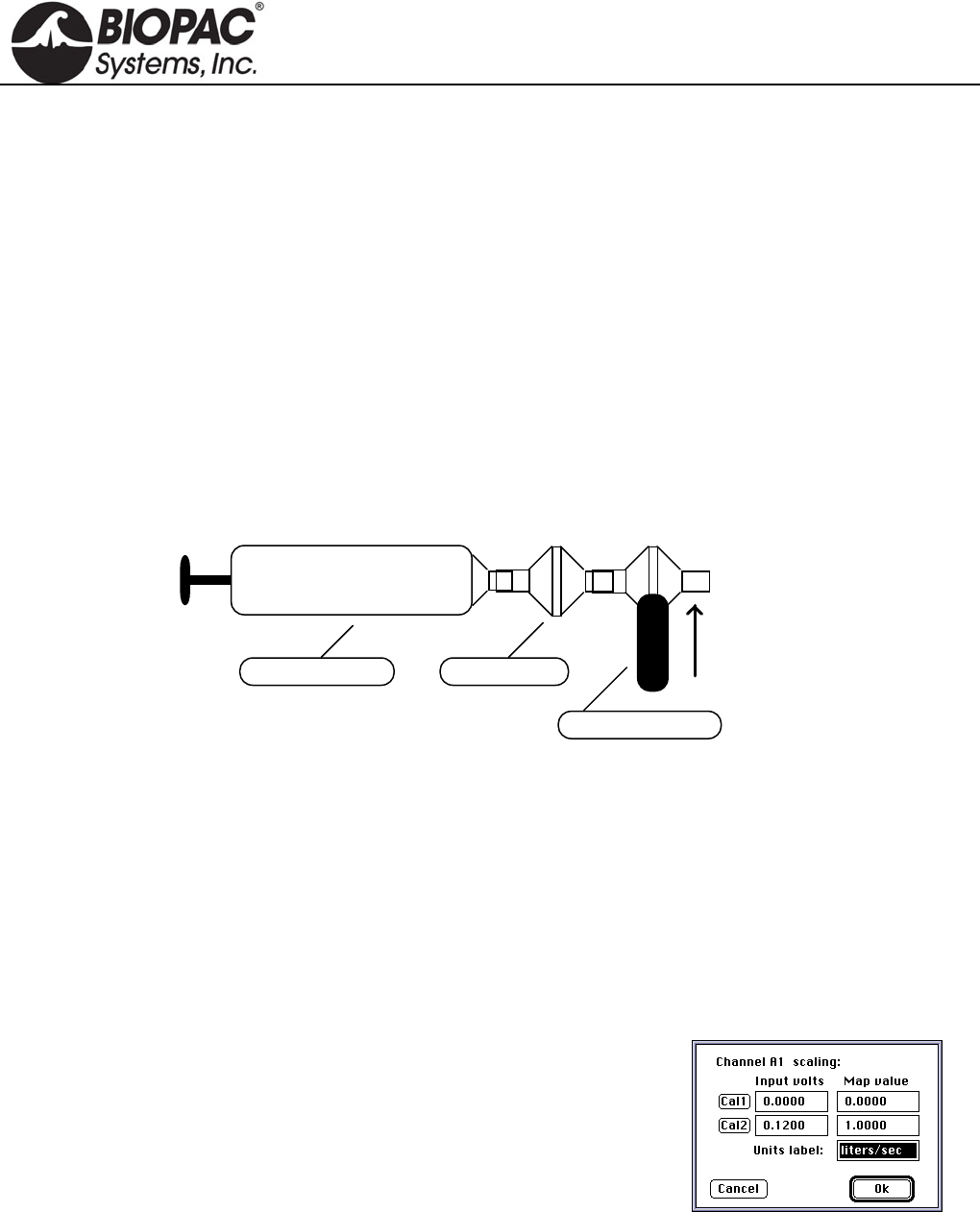
Calibration For Medium-Flow Pneumotachs
1. Syringe Calibration
Calibration Syringe
Air Flow Transducer
Vertical
Orientation
Bacterial Filter
After the calibration process, please remove the calibration syringe and attach a new bacterial filter and
mouthpiece to the airflow transducer.
It’s very important that each individual use his/her own mouthpiece and bacterial filter.
Place the narrow end of the bacterial filter and mouthpiece assembly into either side of the airflow transducer.
Airflow data can now be recorded. For best results, hold the airflow transducer vertically.
2. Mathematical Calibration
The transducer can be roughly calibrated without using the calibration syringe. Using the transducer’s nominal
output of 60µV per liter/sec (normalized to 1 volt excitation), the following calibration factors can be entered in
the software Scaling window.
Scaling Factors for Rough Calibration of the airflow transducer
The following equation illustrates why 0.12 volts maps to 1.00 liter/sec:
Calibration Constant • Amp Gain • Amp Excitation = Scale Factor
Thus
60 µV/[liter/sec] • 1000 • 2 Volts = 0.12 V / [liter/sec]
Data can now be collected directly. Prior to analyzing the data, remember that there will always be some offset
recorded in the case of zero flow.
Note: With the TSD117 and MP150/100 system, it’s possible to largely trim this offset out, using the ZERO
potentiometer on the DA100 amplifier, but some residual will always remain.
HARDWARE GUIDE
info@biopac.com
support@biopac.com
www.biopac.com
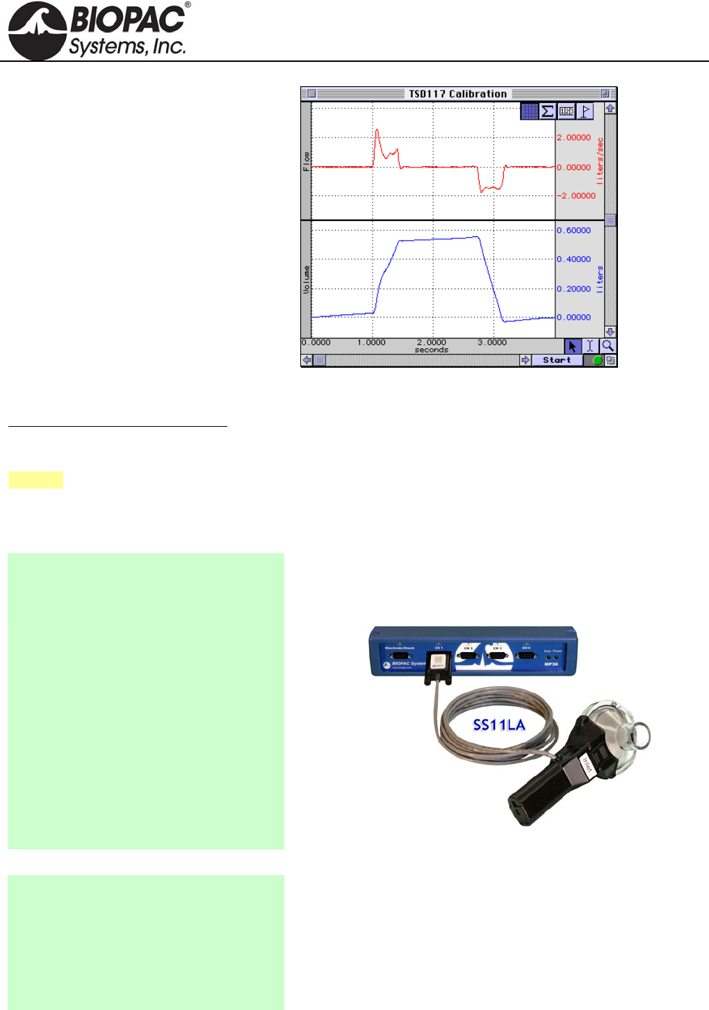
BIOPAC Hardware | SS11LA & TSD117 | Page 3 - 7 Updated: 12.2.2013
To remove residual offset after the flow data
has been collected, select a portion of the
baseline (zero flow reading) and calculate
the mean value using the popup
measurements. Subtract this mean value
from the raw data to obtain a mean
corrected flow signal.
Now, the integral of the mean can be
calculated as shown in this graph
In this case, a 600ml-calibration syringe was
used to check the rough calibration of the
airflow transducer. The rough calibration
indicates a syringe volume of about 550ml,
so this method may only be expected to be
accurate within ±10% of the real reading.
Flow Measurement and Volume Calculation
To achieve a more exact calibration, start with the above scaling factors and then boost or drop them slightly as
indicated by the rough calibration. In this case, if the map value correlating to 0.12 volts were boosted about 10%
to 1.10 (from 1.0 liters/sec), the resulting calibration would be fairly accurate.
See also: DA100C Calibration options.
>>> All Instructions also apply to the older airflow transducer — model SS11L with non-removable head <<<
SS11LA To MP3X Connection
1. Make sure the BIOPAC MP3X unit is
turned OFF.
Note: Turn the MP3X power off even
if the software is running.
Note: SS11LA to MP connection instructions also apply to 2-
channel MP45 hardware.
2. The airflow transducer (SS11LA) can
be plugged into any input channel on
the MP3X.
3. After the transducer is plugged in
securely, turn the MP3X power ON.
SS11LA to MP3X connection
Rough Calibration (MP3X)
1. Pull down the MP3X menu.
2. Click Setup channels.
3. Select the Analog channel that the
SS11LA transducer is plugged into and
activate it by clicking in the Acquire,
Plot and Values boxes.
The SS11LA can be roughly calibrated without using the AFT6
calibration syringe. The SS11LA has a nominal output of 60 µV per
liter/sec, which is then scaled to account for the amplifier excitation.
For the MP3X, this is factory set to 5 Volts. Therefore:
60 V/[liter/sec] · 5 = 300V / [liter/sec].
HARDWARE GUIDE
info@biopac.com
support@biopac.com
www.biopac.com
BIOPAC Hardware | SS11LA & TSD117 | Page 4 - 7 Updated: 12.2.2013
4. Pull down the Presets pop-up menu and
select Airflow.
5. Click on the View/Change Parameters
button.
6. Click on the Scaling button.
7. Click on Cal1: Leave the Input value
reading and enter 0 for the Scale value.
8. For Cal2 Input Value, add 300µV (or
.3 mV) to the Cal1 Input Value. For
Cal2 Scale value, enter 1.
9. Click OK for each window to exit
Channel Setup.
Note: Add 300µV to the Cal1 Input Value for Cal2.
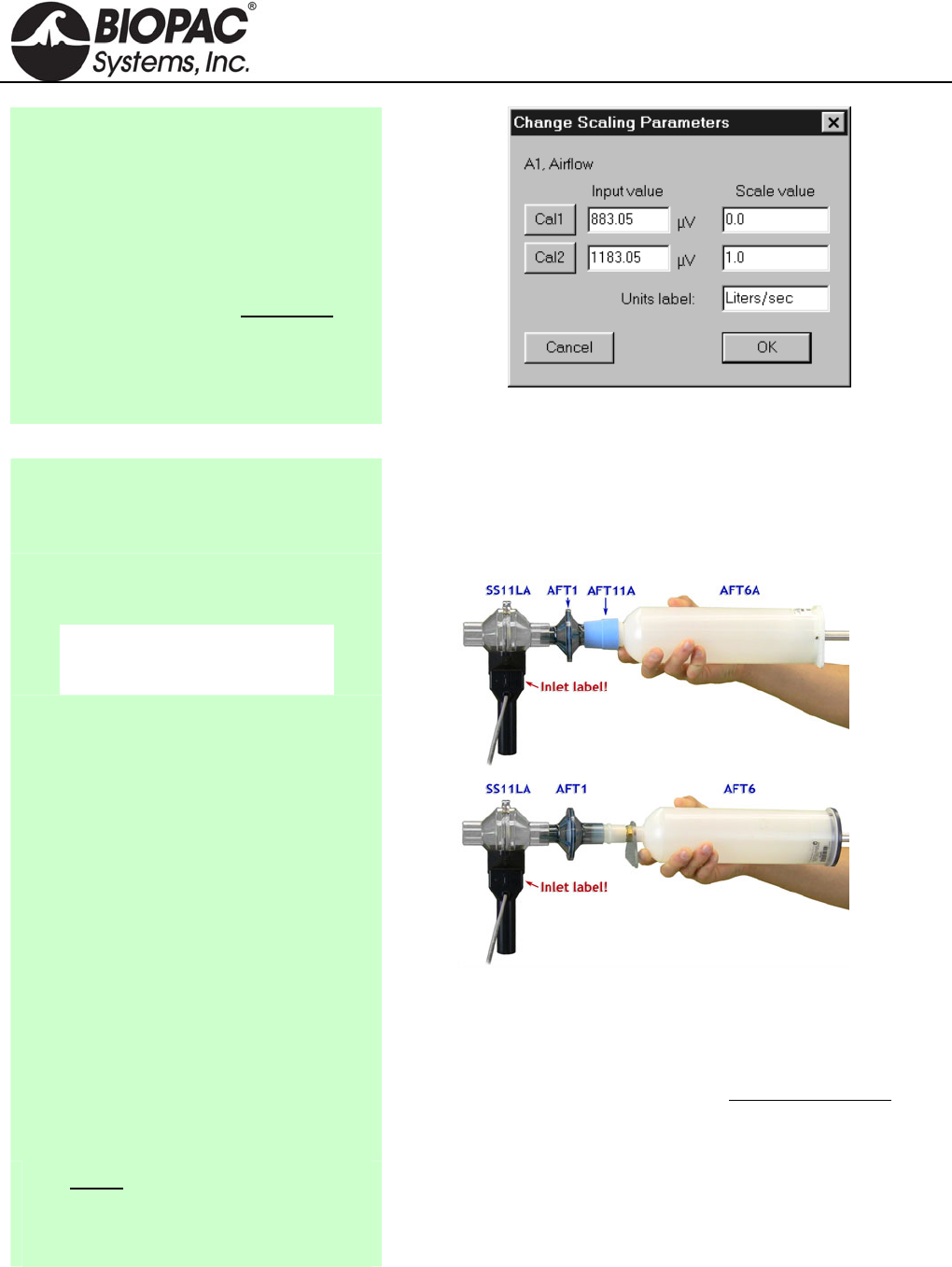
Using the Calibration Syringe
1. Place a filter onto the end of the
calibration syringe. The filter is necessary for calibration because it forces the air
to move smoothly through the transducer. This assembly can
be left connected for future use. The filter only needs to be
replaced if the paper inside the filter tears.
2. Insert the Calibration Syringe/Filter
Assembly into the airflow transducer.
IMPORTANT!
Always insert on the
side labeled “Inlet.”
Calibration Syringe into airflow transducer
Insert syringe assembly so that the transducer cable exits on
the left, as shown above.
If using an older SS11L transducer with non-removable
head, insert syringe assembly into the larger diameter port.
IMPORTANT: If the lab sterilizes the airflow heads after
each use, make sure a clean head is installed now.
Never hold onto the airflow
transducer handle when using the
Calibration Syringe or the syringe
tip may break.
The Airflow Transducer is sensitive to gravity so it needs to be
held upright throughout the calibration and recording.
HARDWARE GUIDE
info@biopac.com
support@biopac.com
www.biopac.com
BIOPAC Hardware | SS11LA & TSD117 | Page 5 - 7 Updated: 12.2.2013
Proper handling of the Calibration Syringe Assembly
3. Pump the plunger several times
before the recording. Always pull
and push the plunger all the way
until it stops when using the
syringe. This assures that the full
volume of air (0.6 liter) flows in and
out of the airflow transducer.
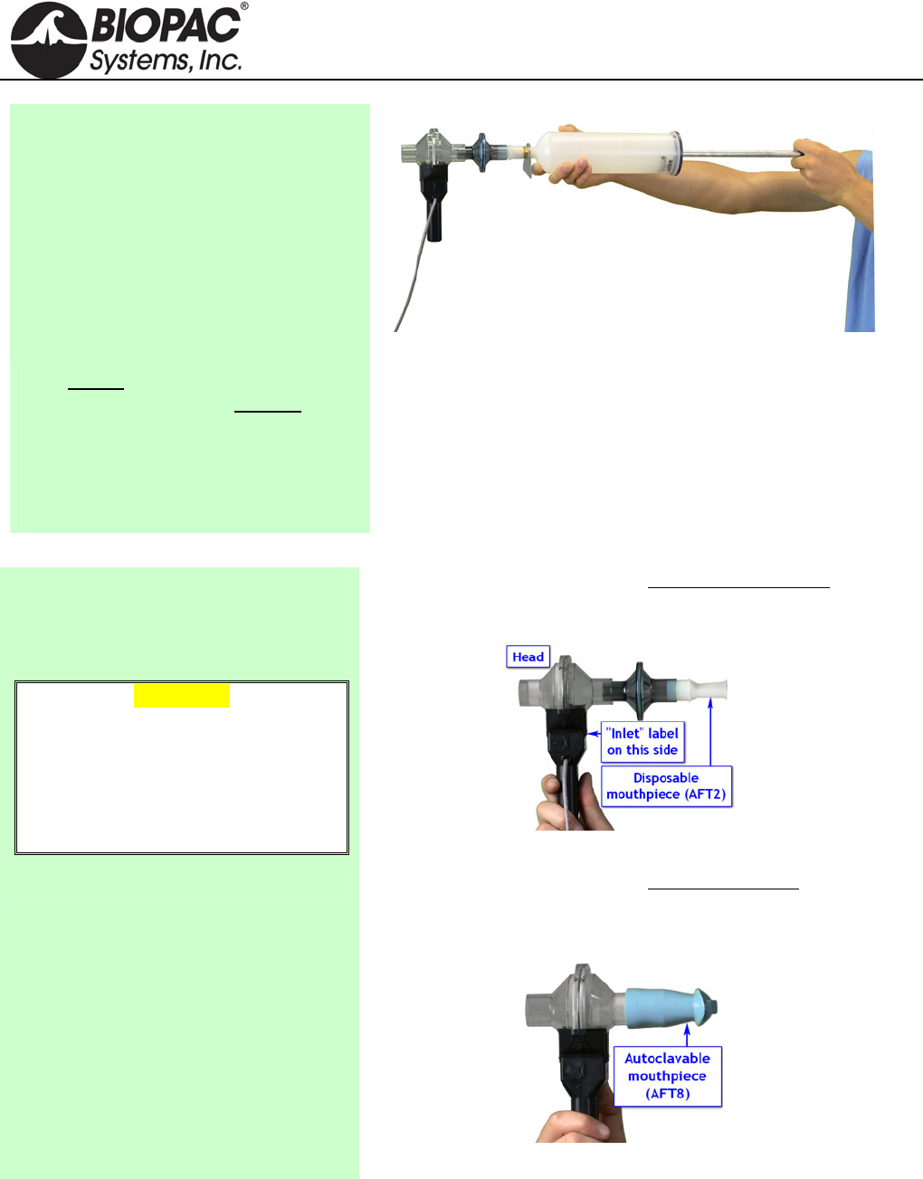
Recording with the Airflow Transducer
1) Attach the appropriate filter and
mouthpiece on the side labeled Inlet.
WARNING
The bacterial filter and mouthpiece are
disposable and are “one per person”
items. Please use a new disposable
filter and mouthpiece each time a
different person is to be breathing
through the airflow transducer.
If using SS11LA transducer and not sterilizing the head
after each use, insert a filter and mouthpiece into the
airflow transducer on the side labeled “Inlet.”
SS11LA with unsterilized head
If using SS11LA transducer and sterilizing the head after
each use, insert a disposable mouthpiece (BIOPAC AFT2)
or a sterilizable mouthpiece (BIOPAC AFT8) into the
airflow transducer on the side labeled “Inlet.”
SS11LA with sterilized head
HARDWARE GUIDE
info@biopac.com
support@biopac.com
www.biopac.com
BIOPAC Hardware | SS11LA & TSD117 | Page 6 - 7 Updated: 12.2.2013
2) Breathe through the airflow
transducer, following the proper
procedure defined to the right.
Hints for obtaining optimal data:
a) Keep the Airflow Transducer upright at all times.
b) Always insert on and breathe through the side of the
SS11LA airflow transducer labeled “Inlet.”
c) Always use a nose clip when breathing through the
airflow transducer and secure a tight seal with the mouth
so that air can only escape through the airflow
transducer.
d) Always begin breathing normally through the airflow
transducer prior to the beginning of the recording and
continue past the end of the recording.
e) If starting the recording on an inhale, try to end on an
exhale, and vice-versa. This is not absolutely critical,
but will increase the accuracy of Airflow to Volume
calculations.
f) The Subject must try to expand the thoracic cavity to its
largest volume during maximal inspiratory efforts. (The
Subject should wear loose clothing so clothing does not
inhibit chest expansion.)
g) During recording of FEV, the Subject should attempt to
exhale as quickly as possible into the mouthpiece.
h) During recording of MVV, the Subject should attempt
to exhale and inhale as quickly and deeply as possible.
Breathing rates should be faster than 60 breaths/minute
or greater than 1 breath/second for the best results. The
breathing needs to be maintained for 12-15 seconds.
HARDWARE GUIDE
info@biopac.com
support@biopac.com
www.biopac.com
BIOPAC Hardware | SS11LA & TSD117 | Page 7 - 7 Updated: 12.2.2013
RX117 Replacement Airflow Head
The RX117 is a sterilizable airflow head for the TSD117 and SS11LA pneumotach
transducers. The material used in the flow head is polycarbonate and the screen is Stainless
Steel. To reduce the cost of disposable items, use the RX117 with the AFT8 sterilizable
mouthpiece. (22mm ID/30mm OD). Multiple RX117 heads help eliminate equipment
downtime during cleaning procedures.
Recommended sterilization: cold sterilization (i.e., Cidex®) or autoclave. If autoclaved,
RX117 Airflow Heads should be cleaned at the lowest autoclave temperature setting. The life
cycle will be about 10-20 cycles, depending upon temperature used.
MRI Usage Declarations for TSD117-MRI Medium Flow Pneumotach Transducer
MRI Usage: MR Conditional
Condition: The TSD117-MRI with RX117 head is used outside the bore in the MRI Chamber Room
and AFT7-L tubing is connected to reach the subject.
Components: Polyvinyl Chloride (PVC) Plastic, Polycarbonate Clear Plastic, Acrylonitrile Butadiene
Styrene (ABS) Thermo-molded, Plastic, Polymer thick film device (rigid substrate,
printed semi-conductor), Copper clad fiberglass lamination (PCB material), Stainless
steel screen (type 316L), Stainless steel machine screws/nuts, tinned copper wire,
Silicone elastomer, PVDF (Kynar) heat shrink tubing
SS11LA & TSD117 Technical Specifications
TRANSDUCER: TSD117 TSD117-MRI SS11LA
Interface: DA100C MECMRI-DA to DA100C MP36/35/30/45
Flow Rate: ±300 Liters/min (±5 liters/sec) 10 liters/sec (highest linearity (±5 liters/sec)
Nominal Output: 60 µV/[liters/sec] (normalized to 1 V
excitation) 60 µV/[liters/sec]
¼” 25 TPI mounting nut: Standard camera mount --------
Cable Length: 10 m, shielded 2 m, shielded
RX117 SPECS:
Flow Head Construction: Clear Acrylic
Flow Bore (Ports): 22 mm (ID), 29 mm (OD)
Flow Head Dimensions: 82.5 mm (diameter) x 101.5 mm (length)
Flow Head Weight: 80 g
Handle Weight: 85 g
Handle Dimensions: 127 mm (length) x 23 mm (thick) x 35 mm (wide)
Handle Construction: Black ABS
Dead Space: 93 ml
HARDWARE GUIDE
info@biopac.com
support@biopac.com
www.biopac.com
BIOPAC Hardware | SS12LA | Page 1 - 3 Updated: 3.21.2013
See also: Force Transducer Tension Adjuster (HDW100A)
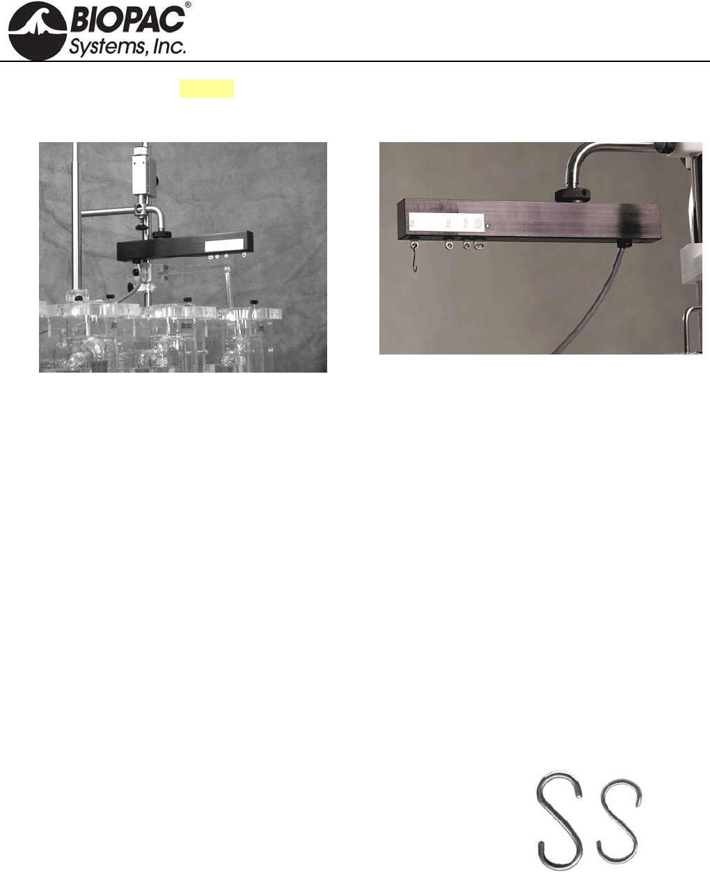
SS12LA VARIABLE RANGE FORCE TRANSDUCER
SS12LA Sample Setup
SS12LA Variable Range Force Transducer
Force transducers are devices capable of transforming a force into a proportional electrical signal. The SS12LA
variable range force transducer element is a cantilever beam load cell incorporating a thin-film strain gauge.
Because the strain elements have been photolithographically etched directly on the strain beam, these transducers
are rugged while maintaining low non-linearity and hysteresis. Drift with time and temperature is also minimized,
because the strain elements track extremely well, due to the deposition method and the elements’ close physical
proximity. The SS12LA also incorporates impact and drop shock protection to insure against rough laboratory
handling.
Forces are transmitted back to the beam via a lever arm to insure accurate force measurements. Changing the
attachment point changes the full scale range of the force transducer from 50g to 1000g. The beam and lever arm
are mounted in a sealed aluminum enclosure that includes a 3/8" diameter mounting rod for holding the transducer
in a large variety of orientations. The SS12LA comes equipped with a 2-meter cable and plugs directly into the
MP3X module.
The SS12LA mounting rod can be screwed into the transducer body in three different locations, two on the top
and one on the end surfaces of the transducer. The mounting rod can be placed in any angle relative to the
transducer orientation. The SS12LA can be used in any axis and can be easily mounted in any standard
measurement fixture, including pharmacological setups, muscle tissue baths and organ chambers.
The SS12LA has 5 different attachment points that determine the effective range of the force transducer. These
ranges are 50g, 100g, 200g, 500g and 1,000g. The point closest to the end is the 50g attachment point, while the
point closest to the middle is the 1,000g attachment point.
Two S-hooks are provided with the SS12LA; one has a .032" diameter
wire and the other has a .051" diameter wire. The smaller hook is to be
used for the 50g, 100g and 200g ranges. The larger hook is intended for
the 500g and 1000g ranges. The larger hook is intentionally a tight fit to
generate a downward pull vector. To further increase proper readings,
keep the unit level and align anything that hangs off the hook straight
beneath it rather than at a sideways angle.
SS12LA S-hooks
HARDWARE GUIDE

info@biopac.com
support@biopac.com
www.biopac.com
BIOPAC Hardware | SS12LA | Page 2 - 3 Updated: 3.21.2013
SS12LA SPECIFICATIONS*
Lever Arm Position
(hook ring) Full Scale Range
(FSR) 10Hz Noise 1Hz Noise
50 grams 50 grams 2.5 mg 1 mg
100 grams 100 grams 5 mg 2 mg
200 grams 200 grams 10 mg 4 mg
500 grams 500 grams 25 mg 10 mg
1000 grams 1000 grams 50 mg 20 mg
Sensitivity 1mV/V (for 5V excitation, output is 5mV at full scale)
Temperature Range -10°C to 70°C
Thermal Zero Shift* <±0.03% FSR/°C
Thermal Range Shift* <0.03% Reading/°C
Excitation Voltage 5 VDC
Nonlinearity* <±0.025% FSR*
Hysteresis* <±0.05% FSR*
Non-repeatability* <±0.05% FSR*
30-Minute Creep* <±0.05% FSR*
Dimensions 19mm (wide) 25mm (thick) 190mm (long)
Weight (with mounting rod) 300g
Cable length 3 meters
Materials Aluminum: hook rings
Anodized aluminum: housing
Stainless Steel: attachment arm
* These parameters assume the transducer is set for a 50g range. For all other range
settings, force measurements from 10% to 90% full scale are linear to ±1.0%.
CALIBRATION
The SS12LA is easily calibrated using weights of known mass. Ideally, calibration should be performed with
weights that encompass the range of the forces expected during measurement and should cover at least 20% of the
full scale range of the transducer. When calibrating for maximum range on the force transducer, use weights that
correspond to 10% and 90% of the full scale range for best overall performance.
FORCE TRANSDUCER CALIBRATION
Calibrating a force transducer is a two step process. The first step involves finding the optimal Gain setting for the
transducer and the second step is the actual calibration.
1) To find the optimal Gain setting:
a) Start with the software Preset for the force range desired.
To set the Presets: MP3X menu > Setup Channels > Analog Presets > “Force (range)”
b) Load the transducer with the maximum expected weight.
c) Collect data for a few seconds at these settings.
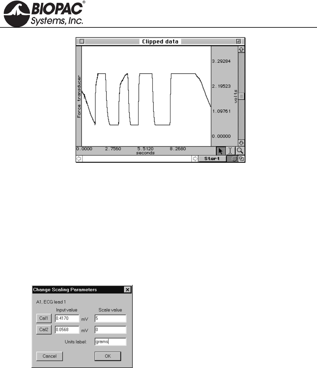
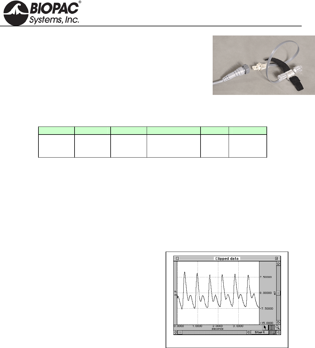
d) Inspect the sample data; look for data that is “railed” or “clipped.” This occurs when the input signal
(times the gain setting) is too large relative to the maximum input range. An example of clipped data
follows.
HARDWARE GUIDE
info@biopac.com
support@biopac.com
www.biopac.com
BIOPAC Hardware | SS12LA | Page 3 - 3 Updated: 3.21.2013
Gain set too high — Clipped Force data
e) If the signal is clipped, decrease the Gain setting by one step (e.g., from x5000 to x2500) and collect new
data at the lower gain setting.
To access the Gain setting: MP3X menu > Setup Channels > Force preset channel > View/Change
Parameters icon > Gain pull-down menu
f) Repeat this procedure until the signal no longer appears “clipped.”
Once an optimal gain setting for the transducer has been established, this same gain setting can be used for
other similar transducers and similar measurements.
2) The next step is to actually calibrate the transducer, which means mapping the input signal to more
meaningful units (such as grams). To do this:
a) Access the Channel scaling dialog box (MP3X menu > Setup Channels > Force preset channel >
View/Change Parameters icon > Scaling button).
Note:
In this sample dialog, a weight of 5 grams
was placed on the transducer and the Cal
1 button was pressed.
The transducer weight was then removed
and Cal 2 was pressed.
b) Place the maximum expected weight or force on the transducer.
c) Click on the Cal 1 button in the Channel scaling window.
A voltage value will be automatically entered in the corresponding Input value box.
d) Remove all weight or force from the transducer.
e) Click on the Cal 2 button in the same scaling window.
A voltage value will be automatically entered in the corresponding Input value box.
The transducer will be calibrated to the set values the next time an acquisition is started.
HARDWARE GUIDE
info@biopac.com
support@biopac.com
www.biopac.com
BIOPAC Hardware | SS13L – RX104A | Page 1 - 3 Updated: 1.31.2013
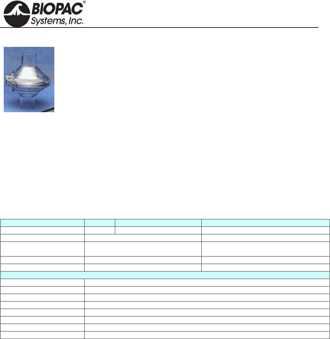
SS13L PRESSURE TRANSDUCER
The SS13L pressure transducer is used to measure direct arterial or venous
blood pressure in animals or to record pressure changes within a closed
system such as an organ or tissue bath system. Connect to the tubing via the
standard rotating Luer-lok fittings. This assembly consists of a disposable
transducer with a 30cm cable that attaches to a reusable 3-meter cable that is
designed to interface with the MP3X. The transducer is supplied non-sterile
but can be cold sterilized.
Note: The SS13L Pressure transducer is not intended for use with humans.
Typical software settings for the blood pressure transducer are described in the table below:
Filter 1 Filter 2 Filter 3 Hardware filter Gain Coupling
Low pass
66.5 Hz
Q = 0.5
Low pass
38.5 Hz
Q = 1.0
Band Stop
60 Hz
Q = 5
1 KHz
100
(preset) DC
These settings are automatically applied when the Pressure preset is selected, but settings can be adjusted if
necessary.
PRESSURE TRANSDUCER CALIBRATION
Calibrating a blood pressure transducer is a two step process. The first step involves finding the optimal gain
setting for the transducer and the second step is the actual calibration.
1) To find the optimal gain setting:
a) Start with the software Presets (in this case, a gain of 100)
To set the Presets: MP3X menu > Setup channels > Analog Presets > select “Pressure”
b) Bring the transducer to the approximate maximum and minimum expected pressures.
Gain set too high — Clipped BP data
c) Collect data for a few seconds at these settings.
d) Inspect the sample data; look for data that is
“railed” or “clipped.” This occurs when the input
signal (times the gain setting) is too large relative to
the maximum input range. An example of clipped
data is shown at right.
e) If the signal is clipped, decrease the gain setting by
one step (e.g., from x5000 to x2500) and collect
new data at the lower gain setting.
To access the Gain setting: MP3X menu >
Setup channels > Pressure preset channel >
View/Change Parameters icon > Gain pull-
down menu
f) Repeat this procedure until the signal no longer appears “clipped.”
Once an optimal gain setting for the transducer has been established, this same gain setting can be used for
other similar transducers and similar measurements.
2) The next step is to actually calibrate the transducer, which means mapping the input signal to more
meaningful units (such as mmHg). To do this:
a) Access the Channel scaling dialog box (MP3X menu > Setup Channels > Pressure Preset channel >
View/Change Parameters icon > Scaling button).
HARDWARE GUIDE

info@biopac.com
support@biopac.com
www.biopac.com
BIOPAC Hardware | SS13L – RX104A | Page 2 - 3 Updated: 1.31.2013
Note:
In this sample dialog, the transducer was
brought to a pressure of 50 mmHg and the Cal
1 button was pressed.
The transducer was then brought to a pressure
of 180 mmHg, and Cal 2 was pressed.
b) Bring the transducer to the lowest expected pressure.
c) Click on the Cal 1 button in the Channel scaling window.
A voltage value will be automatically entered in the corresponding Input value box.
d) Bring the transducer to the highest expected pressure.
e) Click on the Cal 2 button in the same scaling window.
A voltage value will be automatically entered in the corresponding Input value box.
The software will now interpolate between these two calibration points to give accurate measurements in mmHg.
SS13L PRESSURE TRANSDUCER SPECIFICATIONS
Operational pressure: -50 mmHg to +300 mmHg
Overpressure: -500 mmHg to + 4000 mmHg
Sensitivity: 25 V/VmmHg (at 5 VDC excitation)
Accuracy: ± 1.5% of reading or ± 1.0 mmHg (whichever is greater)
Operating temperature: 10° C to 40° C
Storage temperature: -30° C to +60° C
Volume displacement: 0.04 mm per 100 mmHg
Leakage current: 10 A RMS @ 115 VAC 50 Hz
Dynamic response: 100 Hz
Unbalance: 50 mmHg max
Connection Ports: male Luer and female Luer
(sensors shipped prior to summer 2010 were male Luer on both sides)
Eight-hour drift: 1 mmHg after 5-minute warm-up
Isolation: <= 5 leakage at 120 VAC/60 Hz
Defibrillation: Withstands 5 charges of 400 joules in 5 minutes across a load
Combined effects of
sensitivity, linearity and
hysteresis: 1 mmHg (nominal)
Transducer cable: 30cm
Interface cable: 3 meters
Transducer dimensions: 67mm long X 25mm wide
Weight: 11.5 grams
HARDWARE GUIDE
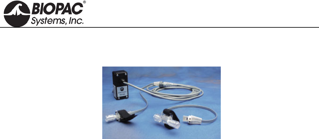
info@biopac.com
support@biopac.com
www.biopac.com
BIOPAC Hardware | SS13L – RX104A | Page 3 - 3 Updated: 1.31.2013
RX104A REPLACEMENT ELEMENT
The RX104A is a replacement element for the SS13L Pressure Transducer. It does not include the Smart Sensor
connector and cable.
HARDWARE GUIDE

info@biopac.com
support@biopac.com
www.biopac.com
BIOPAC Hardware | SS14L | Page 1 - 1 Updated: 2.8.2013
See also: Tension Adjuster (HDW100A)
SS14L DISPLACEMENT TRANSDUCER
For use in recording very slight movements in a range of physiological
preparations, the SS14L incorporates a semi-isotonic strain gauge and a stainless
steel lever that can be mounted in any position.
SS14L SPECIFICATIONS
Sensitivity Range: 1mm to 100mm
Strain Gauge: 500 ohm silicon
Lever Length: 27cm
Support Rod Length: 15cm
Cable Length: 3 meters
Interface: MP3X
HARDWARE GUIDE
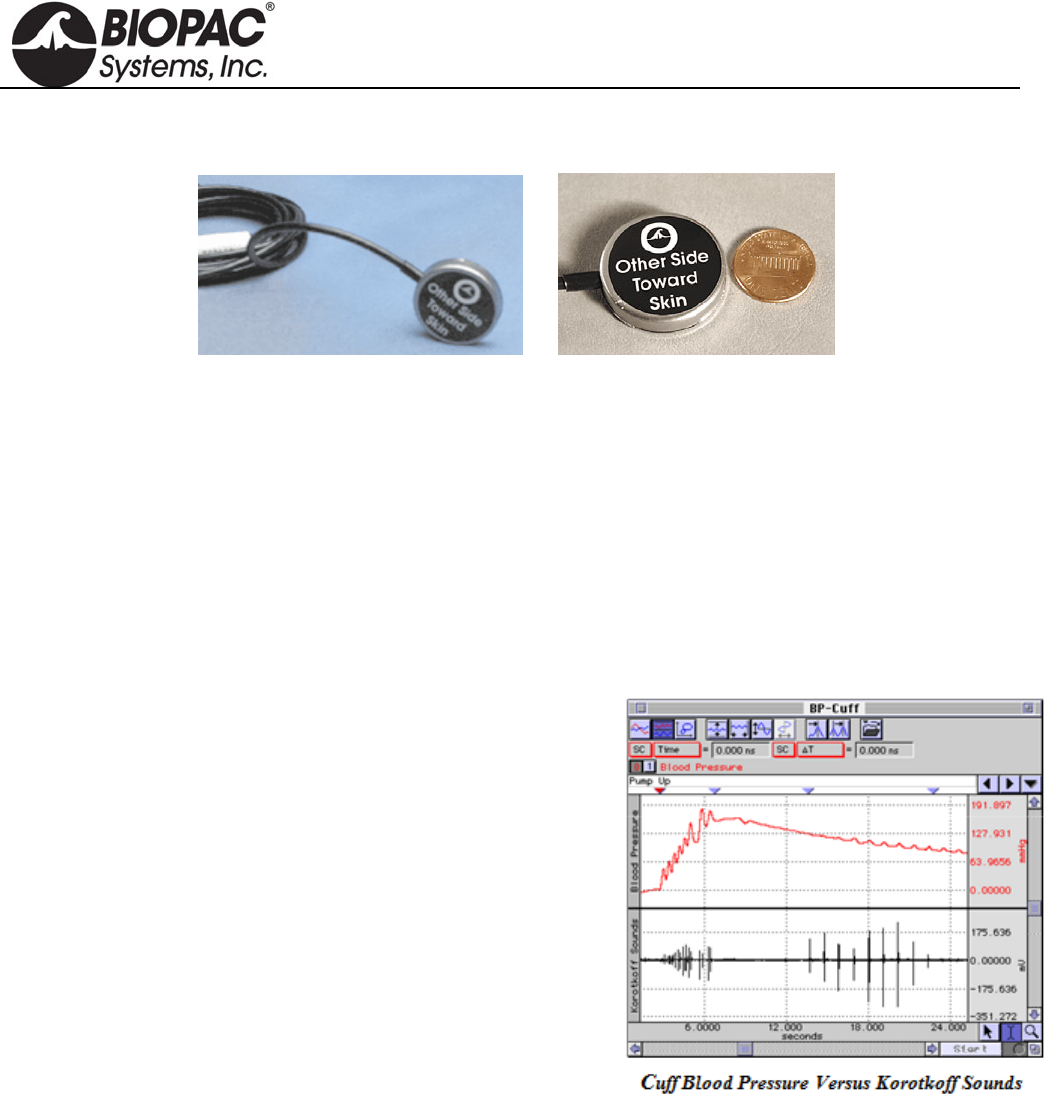
info@biopac.com
support@biopac.com
www.biopac.com
MP Research System | Contact Microphones | Page 1 - 1 Updated: 3.21.2013
TSD108 AND SS17L PHYSIOLOGICAL SOUNDS TRANSDUCER (CONTACT MICROPHONE)
The physiological sounds transducer connects to the DA100C amplifier (TSD108) or the MP3x/4x hardware
(SS17L). The transducer can be used with the Noninvasive Blood Pressure Cuff or as a stand-alone device. If
used with the cuff, Korotkoff sounds can be recorded for easy determination of systolic and diastolic blood
pressure. When used on its own, it can record a variety of acoustical signals, including heart sounds and sounds
associated with rubbing or grinding (e.g., Bruxism). The acoustical transducer element is a Piezo-electric ceramic
disk that is bonded to the interior of a circular metallic housing.
Grounding Note When using this transducer with the EBI100C module, do not connect the GROUND pin of
the TSD108 to the DA100C module. Doing so will cause inaccurate impedance measures,
because the TSD108 contact surface is tied to the isolated ground. An alternative is to
insulate the TSD108 from the skin surface by using a latex balloon or some other non-
conductive barrier. If the latter procedure is followed, the GROUND pin may be attached to
the DA100 module.
TSD108: Korotkoff signal is recorded by a DA100C
amplifier set to AC, 5000 Hz LP and a gain of 50 to 200.
SS17L: To record the Korotkoff signal, select SS17L
preset from MP3x/MP4x > Set Up Channels menu.
The signal for the physiological sounds transducer is usually
further conditioned by the software. In a calculation channel, the
signal can be bandpass filtered from 50 to 200 Hz. The sampling
rate for the entire recording needs to be about 500 Hz, assuming
the physiological sounds transducer is used.
TSD108/SS17L SPECIFICATIONS
Frequency Response: 35 Hz to 3500 Hz
Housing: Stainless Steel
Sterilizable: Yes (contact BIOPAC for details)
Noise: 5µV rms – (500 Hz - 3500 Hz)
Output: 2V (p-p) maximum
Weight: 9 g
Dimensions: 29 mm diameter, 6 mm thick
Cable Length: 3 m
Interface: DA100C (TSD108), MP3x (SS17L)
Calibration: None required
TEL100C Compatibility: SS17
HARDWARE GUIDE
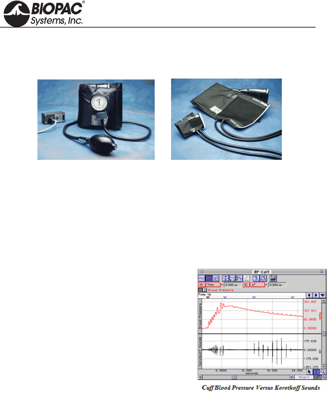
info@biopac.com
support@biopac.com
www.biopac.com
BIOPAC Hardware | Blood Pressure Cuff | Page 1 - 4 Updated: 3.28.2013
BLOOD PRESSURE CUFF AND TRANSDUCER
TSD120 for MP150/MP100 System
RX120 Series Cuff for TSD120
SS19L/LA for MP3x & MP45 System
TSD120 RX120A and RX120F cuff options
BLOOD PRESSURE MEASUREMENT
The most common form of indirect blood pressure measurement employs a pressure cuff, pump and pressure
transducer. This complete assembly is commonly referred to as a sphygmomanometer.
Typically, the cuff is wrapped around the upper arm and is inflated to a pressure exceeding that of the brachial
artery. This amount of pressure collapses the artery and stops the flow of blood to the arm. The pressure of the
cuff is slowly reduced as the pressure transducer monitors the pressure in the cuff. As the pressure drops, it will
eventually match the systolic (peak) arterial pressure. At this point, the blood is able to “squirt” through the
brachial artery. This squirting results in turbulence that creates the Korotkoff sounds. The cuff pressure continues
to drop, and the pressure eventually matches the diastolic pressure of the artery. At that point, the Korotkoff
sounds stop completely, because the blood is now flowing unrestricted through the artery.
SETUP
The graph at right illustrates a typical recording using the
TSD120/SS19L.
TSD120: Pressure signal is recorded via a DA100C
amplifier set to DC, 10Hz LP and a gain of 200.
SS19L/LA: To record the pressure signal, Select SS19L/LA
preset from the MP3x/MP4x > Set Up Channels menu.
RECORDING
As the cuff is wrapped around the upper arm of the subject, be sure
to place the physiological sounds transducer underneath the blood
pressure cuff, directly over the brachial artery. Transducer
placement is very important to get the best possible recordings of
Korotkoff sounds. Finish wrapping the cuff around the upper arm
and secure it with the Velcro® seal. Now, start inflating the cuff with
the pump bulb.
The pressure trace shows the hand pump driving the cuff pressure up to about 150 mmHg. Then the cuff pressure
is slowly released by adjusting the pump bulb deflation orifice. Notice that the Korotkoff sounds begin appearing
when the cuff pressure drops to about 125 mmHg (bottom trace). As the pressure continues to drop, the Korotkoff
sounds eventually disappear, at about 85 mmHg. The systolic pressure would be identified at 125 mmHg and the
diastolic pressure would be 85 mmHg.
HARDWARE GUIDE
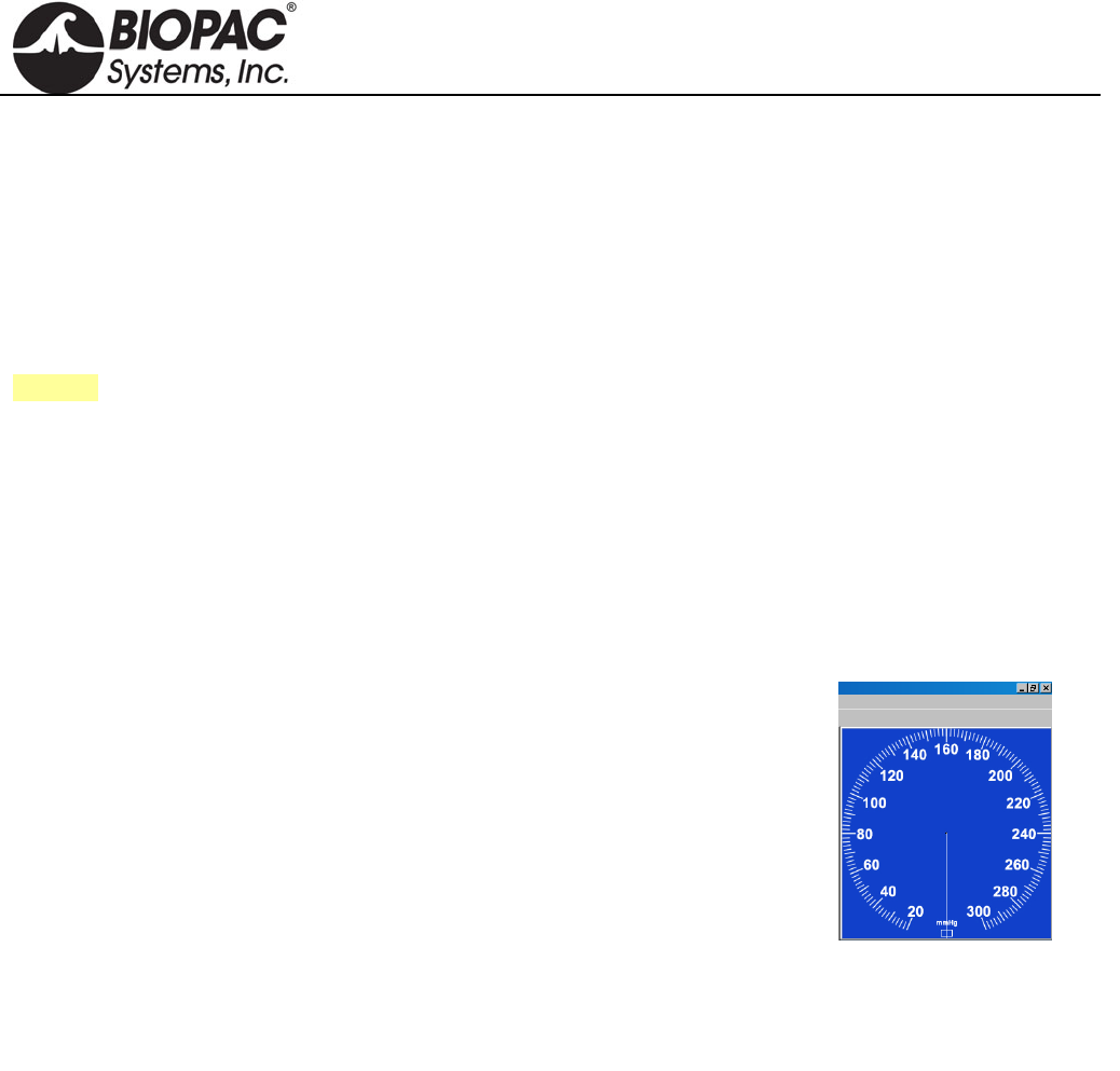
info@biopac.com
support@biopac.com
www.biopac.com
BIOPAC Hardware | Blood Pressure Cuff | Page 2 - 4 Updated: 3.28.2013
CALIBRATION
A) TSD120
The TSD120’s built-in pressure transducer will require an initial calibration prior to use. To calibrate the
transducer, wrap the cuff into a roll and begin to inflate the cuff slowly with the pump bulb. The pressure change
will be noticeable on the mechanical indicator. Set the cuff pressure to one lower pressure (typically 20 mmHg)
and then one higher pressure (typically 100 mmHg). In this manner the pressure transducer can be calibrated
using the standard procedure in the SCALING dialog (in AcqKnowledge). To use the cuff at a future date, simply
save the calibration settings in a stored file.
See also: DA100C Calibration options.
B) SS19L
The built-in pressure transducer of the SS19L/LA requires an initial calibration prior to use. To calibrate the
transducer, wrap the cuff into a roll and begin to inflate the cuff slowly with the pump bulb. Notice the pressure
change on the mechanical indicator. Set the cuff pressure to one lower pressure (typically 20 mmHg) and then one
higher pressure (typically 100 mmHg). In this manner the pressure transducer can be calibrated using the standard
procedure in the Scaling dialog box of the BSL PRO software. To use the cuff at a future date, simply save the
calibration settings as a New Channel Preset or in a graph template or data file.
C) SS19LA
SS19LA uses an on-screen gauge display only and does not include a gauge.
Gauge color can be set under Lesson Preferences.
NOTE: The SS19LA is not
compatible with MP45 Systems
(USB chip conflict). Use SS19L
with MP45 Systems.
BSL 3.7.7
1. With cuff deflated, connect the SS19LA to the desired MP unit input
channel.
2. Set the input channel preset to Blood Pressure Cuff SS19LA (MP > Set
Up Channels > SS19LA preset)
3. Click on “View/Change Parameters” > “Scaling”.
4. Click the CAL 1 button
5. Add the CAL 1 input value to the CAL 2 input value.
6. Click OK and close dialogs.
BSL 4
1. Repeat steps 1 and 2 from above.
2. Click “Setup” > “Scaling”.
3. Click the CAL 2 button
4. Add the CAL 2 input value to the CAL 1 input value and click OK.
HARDWARE GUIDE
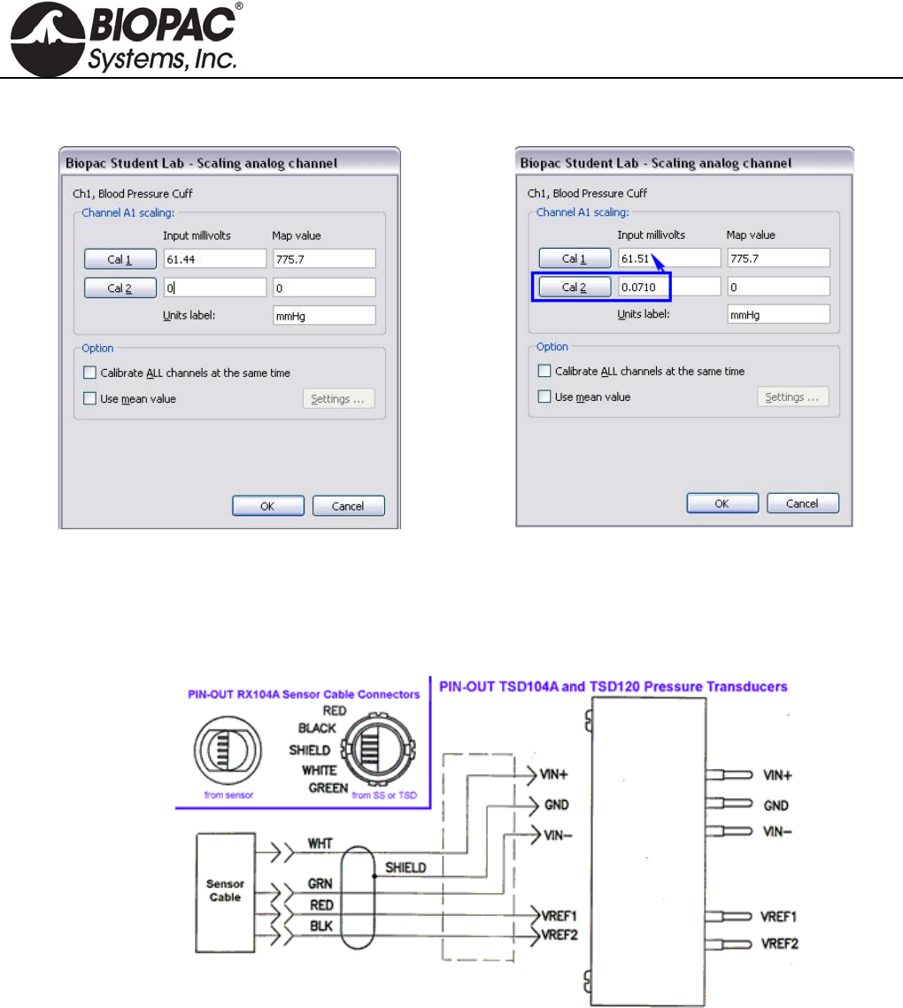
info@biopac.com
support@biopac.com
www.biopac.com
BIOPAC Hardware | Blood Pressure Cuff | Page 3 - 4 Updated: 3.28.2013
Example in BSL 4 – initial scaling dialog:
Clicking CAL 2 results in an Input value of 0.071 mV.
Adding 0.071 to the initial value of 61.44 results in an
adjusted CAL 1 value of 61.51 mV. (Your result may
vary slightly from the example).
IMPORTANT: CAL 1 and CAL 2 values are reversed between BSL 3.7.7 and BSL 4.
BLOOD PRESSURE CUFF SPECIFICATIONS
Pressure range: 20 mmHg to 300 mmHg
Manometer accuracy: ±3 mmHg
Output: 5 µV/mmHg (normalized to 1V excitation)
Cuff circumference range: 25.4 cm to 40.6 cm (as shipped with RX120 d; cuff is switchable)
Cuff Dimensions: 14.5cm (wide) x 54cm (long)
Weight: 350 grams
Cable Length: 3 meters, shielded
Interface:
TSD120 DA100C
SS19L/LA MP3x/4x
HARDWARE GUIDE

info@biopac.com
support@biopac.com
www.biopac.com
BIOPAC Hardware | Blood Pressure Cuff | Page 4 - 4 Updated: 3.28.2013
RX120 SERIES BLOOD PRESSURE CUFFS
The RX120 series are optional blood pressure cuffs, of varying sizes, which can be quickly and easily swapped in
and out of the noninvasive blood pressure cuff transducer. Use a single transducer and substitute one cuff for
another to accommodate a wide range in limb circumferences.
RX120 SPECIFICATIONS
Cuff Circumference Width Length
Range (cm) (cm) (cm)
RX120A 9.5-13.5 5.2 18.5
RX120B 13.0-19.0 7.5 26.1
RX120C 18.4-26.7 10.5 34.2
RX120 d 25.4-40.6 14.5 54.0
RX120E 34.3-50.8 17.6 63.3
RX120F 40.6-66.0 21.0 82.5
HARDWARE GUIDE
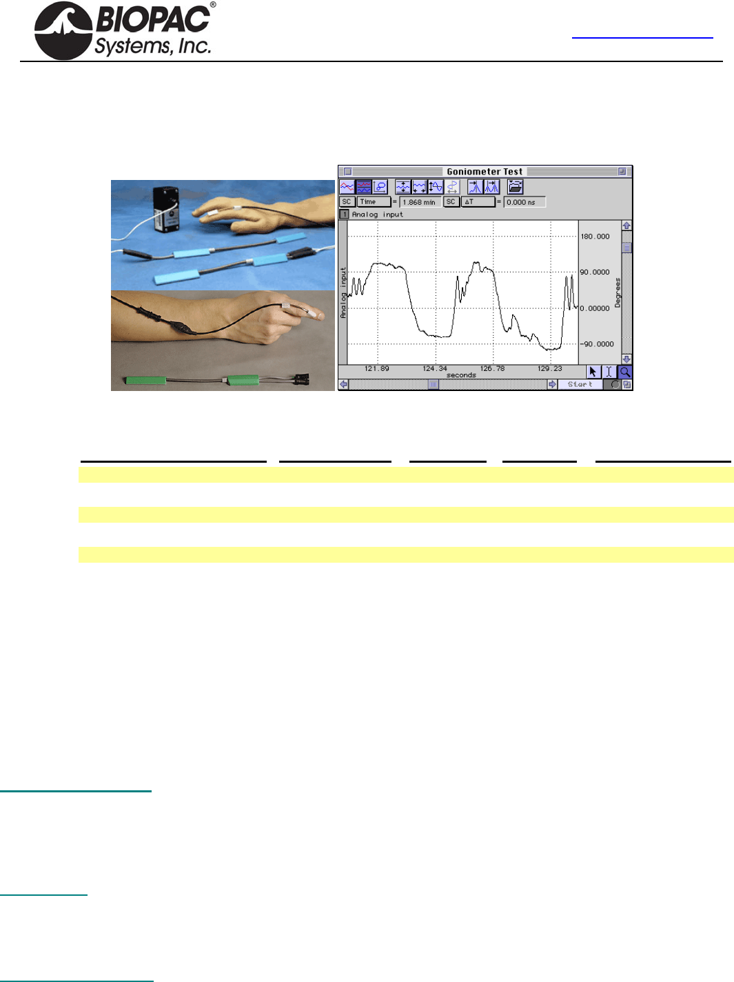
info@biopac.com
support@biopac.com
www.biopac.com
BIOPAC Hardware | Gonio-Torsio | Page 1 - 9 Updated: 11.21.2013
Goniometers & Torsiometers
TSD130 Series BN-GON-XDCR Series
SS20L-SS24L BN-TOR-XDCR Series
SS20-SS24 BN-GON-F-XDCR
In the example above, the TSD130A was connected directly to a DA100C amplifier,
the DA100C gain was set to 1,000, and AcqKnowledge was used to calibrate the
signal to provide angular measurements from approximately +90° to -90°.
Transducer MP1XX (DA100C) MP3X/MP45 TEL100C BN-GONIO
Twin-axis Goniometer 110 TSD130A S20L SS20 BN-GON-110-XDCR
Twin-axis Goniometer 150 TSD130B S21L SS21 BN-GON-150-XDCR
Torsiometer 110 TSD130C S22L SS22 BN-TOR-110-XDCR
Torsiometer 150 TSD130D S23L SS23 BN-TOR-150-XDCR
Single-axis Goniometer 35 TSD130E S24L SS24 BN-GON-F-XDCR
BIOPAC Goniometers and Torsiometers are designed for the measurement of limb angular movement. Goniometers
transform angular position into a proportional electrical signal. Goniometers incorporate gauge elements that measure
bending strain along or around a particular axis.
BIOPAC goniometers are unobtrusive and lightweight, and can be attached to the body surface using double-sided
surgical tape (and can be further secured with single sided tape). The goniometers have a telescopic endblock that
compensates for changes in distance between the two mounting points as the limb moves. The gauge mechanism allows
for accurate measurement of polycentric joints. All sensors connect directly to the BIOPAC Acquisition Unit as part of an
MP or BSL System. Activity data can be displayed and recorded, leaving the subject to move freely in the normal
environment.
The bending strain is proportional to the sum total angular shift along the axis. Because the bending force is extremely
small, the output signal is uniquely a proportional function of the angular shift.
Twin-axis Goniometers Dual output devices that can measure angular rotation about two orthogonal planes
simultaneously. Goniometers provide outputs to simultaneously measure around two
orthogonally rotational axes (e.g. wrist flexion/extension and radial/ulnar deviations).
—wrist or ankle use TSD130A/SS20L/SS20/BN-GON-110-XDCR
—elbow, knee or shoulder use TSD130B/SS21L/SS21/BN-GON-150-XDCR
Torsiometers Measure angular twisting (as on the torso, spine or neck) as opposed to bending. Torsiometers
measure rotation about a single axis (e.g. forearm pronation/supination).
—neck use TSD130C/SS22L/SS22/BN-TOR-110-XDCR
—along the torso or spine use TSD130D/SS23L/SS23/BN-TOR-150-XDCR
Single-axis Goniometer Measures the angle in one plane only; designed to measure digit joint movement.
—fingers, thumb or toes use TSD130E/SS24L/SS24/BN-GON-F-XDCR
HARDWARE GUIDE

info@biopac.com
support@biopac.com
www.biopac.com
BIOPAC Hardware | Gonio-Torsio | Page 2 - 9 Updated: 11.21.2013
ATTACHMENT TO THE SUBJECT
Various combinations of display and recording instrumentation have been carefully developed fulfilling the requirements
of specific research applications. Due to the wide range of applications, one method of attachment cannot be
recommended. Experience has proven that standard medical adhesive tape is an excellent adhesion method in the majority
of cases. Single-sided and double-sided medical tape (such as BIOPAC TAPE1 or TAPE2) should be used for the best
results.
1. Attach pieces of double-sided tape to the underside of the goniometer endblocks.
2. Stick the tape to the subject and allow for the telescoping of the goniometer. The goniometer should be fully
extended when the joint is fully flexed.
3. Press the two endblocks firmly onto the subject and ensure that the goniometer is lying over the top of the
joint. When the joint is extended, the goniometer may present an “oxbow.”
4. For additional security, pass a single wrap of single-sided medical tape around each endblock.
5. Secure the cable and connector leaving the goniometer with tape to ensure that they do not pull and detach the
goniometer.
For accurate results from long recordings
Employ double-sided adhesive between the endblocks and skin, and place single-sided adhesive tape over the top of the
endblocks. No tape should come into contact with the spring. The connection lead should also be taped down near the
goniometer.
For applications where quick or rapid movements are involved
Fit a “sock” bandage over the whole sensor and interconnect lead. This does not apply to the finger goniometer
(TSD130E/SS24L/SS24/BN-GON-F-XDCR), which has a different working mechanism.
When the goniometer is mounted across the joint, the center of rotation of the sensor measuring element may not coincide
with the center of rotation of the joint (for example, when measuring flexion /extension of the wrist). As the joint moves
through a determined angle, the relative linear distance between the two mounting positions will change.
To compensate for this, all sensors are fitted with a telescopic endblock that permits changes in linear displacement
between the two endblocks along axis ZZ without the measuring element becoming over-stretched or buckled.
In the free or unstretched position, the distance between the two endblocks is L1.
If a light force is applied, pushing the endblocks away from each other, this length will increase to a maximum of L2.
When the light force is removed, the distance between the two endblocks will automatically return to L1.
This creates several advantages: accuracy is improved; sensors can be worn comfortably and undetected under normal
clothing; the tendency for the position of the sensors to move relative to the underlying skeletal structure is reduced.
HARDWARE GUIDE

info@biopac.com
support@biopac.com
www.biopac.com
BIOPAC Hardware | Gonio-Torsio | Page 3 - 9 Updated: 11.21.2013
If a light force is now applied, pushing the two endblocks linearly towards each other, the only way the distance L1 can
decrease in length is if the measuring element buckles.
Buckling is detrimental to the accuracy of the goniometer and torsiometer sensors, so attachment instructions are
provided for the most commonly measured joints (on page 8), to ensure that it does not occur in practice.
There is no universal rule governing which size of sensor is most suitable for a particular joint; this depends on the size of
the subject.
In general, the sensor must be capable of reaching across the joint so that the two endblocks can be mounted where the
least movement occurs between the skin and the underlying skeletal structure. In certain circumstances, more than one
size of sensor will be appropriate.
WARNINGS
1. Take care to handle the goniometer and torsiometer sensors as instructed. Mishandling may result in inaccurate
data, reduced equipment life, or even failure.
2. Observe the minimum bend radius value for each goniometer and torsiometer at all times, particularly when
attaching and removing the sensors from the subject. Failure to do this will result in reduced equipment life or
failure.
3. Never remove the goniometer from the subject by pulling on the measurement element and/or protective spring.
Remove the endblocks individually and carefully, making sure not to exceed the minimum permissible bend
radius, particularly where the measuring element enters the endblocks.
4. Take care when mounting goniometers to ensure that the measurement element always forms a “simple” bend
shape. Accuracy will be reduced if an “oxbow” shape occurs in the element.
5. Do not bend the finger goniometer more than ±20° in the Y-Y Plane or reduced equipment life and/or failure may
result.
6. Do not exceed rotations of ± 90° about ZZ. Exceeding the torsiometer range may result in a reduction of the life
of the unit or failure.
7. Disconnect the transducers from the BIOPAC Acquisition Unit before cleaning or disinfecting goniometers and
torsiometers.
MAINTENANCE & SERVICE
No periodic maintenance is required to ensure the correct functioning of the sensors.
The sensors contain no user serviceable components.
If the sensor fails, it should be returned to BIOPAC Systems, Inc.
Please request a Return Merchandise Authorization (RMA) number before returning the sensor and include a
description of what has been observed and what instrumentation was in use at the time of sensor failure in the
return package.
Calibration
When using all goniometers and torsiometers, the minimum value of bend radius must be observed at all times,
particularly when attaching and removing the sensors from the subject. Failure to do this will result in reduced unit life
or failure.
The sensors have been designed to be as light as possible and the operating force to be a minimum. This permits free
movement of the joint without influence by the sensors. The sensors measure the angle subtended between the
endblocks. Use the software calibration features (under Setup Channels) to calibrate any of the BIOPAC series
goniometers.
Each goniometer requires a DA100C amplifier, BN-GONIO or MP3X/45 analog input per rotational axis. Accordingly, the
twin axis goniometers will need two DA100C amplifiers, one BN-GONIO or two MP3X/45 analog channels to
simultaneously measure both rotational axes. The recommended excitation voltage is +5 VDC.
1. Place goniometer with care to verify that limb/joint/torso attachment will not result in over stretch at the limits
of limb/joint/torso movement.
2. Put body in the first position, which brackets one end of range of movement. Press CAL 1.
3. Put body in the second position, which brackets The other end of range of movement. Press CAL 2.
HARDWARE GUIDE
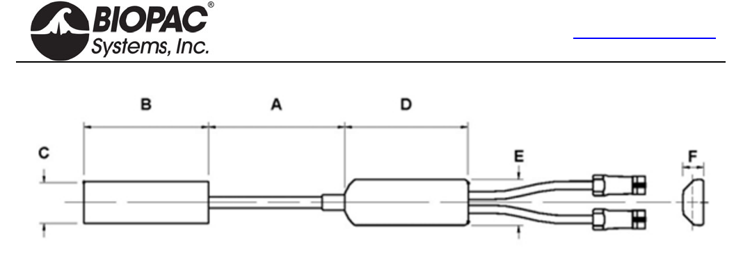
info@biopac.com
support@biopac.com
www.biopac.com
BIOPAC Hardware | Gonio-Torsio | Page 4 - 9 Updated: 11.21.2013
Specifications
Part #
MP1XX via DA100C TSD130A TSD130B TSD130C TSD130D TSD130E
Telemetry TEL100C SS20 SS21 SS22 SS23 SS24
MP36/36R/35/30/45 SS20L SS21L SS22L SS23L SS24L
BioNomadix via BN-GONIO BN-GON-110-
XDCR BN-GON-150-
XDCR BN-TOR-110-
XDCR BN-TOR-150-
XDCR BN-GON-F-
XDCR
Number of channels 2 2 1 1 1
Measuring range ±150 ±150 ±150 ±150 ±150
Dimensions mm
A. Maximum 110 150 110 170 35
A. Minimum 70 100 70 115 30
B. 60 70 60 70 18
C. 18 18 18 18 8
D. 54 54 54 54 15
E. 20 20 20 20 8
F. 9 9 9 9 5
Bend radius (mm) – min. 18 18 18 18 3
Weight (g) 23 25 22 23 8
Crosstalk1 ±5% ±5% N/A N/A N/A
Nominal Output 5 µV/degree normalized to 1 V excitation
Temperature Zero Drift 0.15 degrees angle / C
Cable length 6 m for TSD130 Series/SS20L-24L/BN-GON/BN-TOR, 1.8 m for SS20-24,
Endblock height Cable end 9.4 mm, distal end 8.2 mm
Transducer type Strain gauge
Life2 600,000 cycles minimum
Accuracy ±2 measured over 90 from neutral position
Repeatability Better than ±1
Analog resolution Infinite
Operating temp range +0 to +40 C
Storage temp range -20 C to +50 C
Operating/Storage
humidity range 30% to 75%
Atmospheric pressure range
Operation 700hPa to 1060hPa
Storage 500hPa to 1060hPa
1 Specification of crosstalk for all Biometrics twin-axis SG series of goniometers is measured over ±60. i.e., if a joint is
moved through 60 from the neutral position in one plane without movement in the orthogonal plane, then the sensor
output in the orthogonal plane may change by a maximum ±3.
2 Life test results have been collected by cycling the sensors through movements that would happen during everyday use.
For example, placing a sensor on an adult elbow and moving from the neutral position to maximum flexion and back to the
neutral position, the unit will function for a minimum of 600,000 cycles.
HARDWARE GUIDE
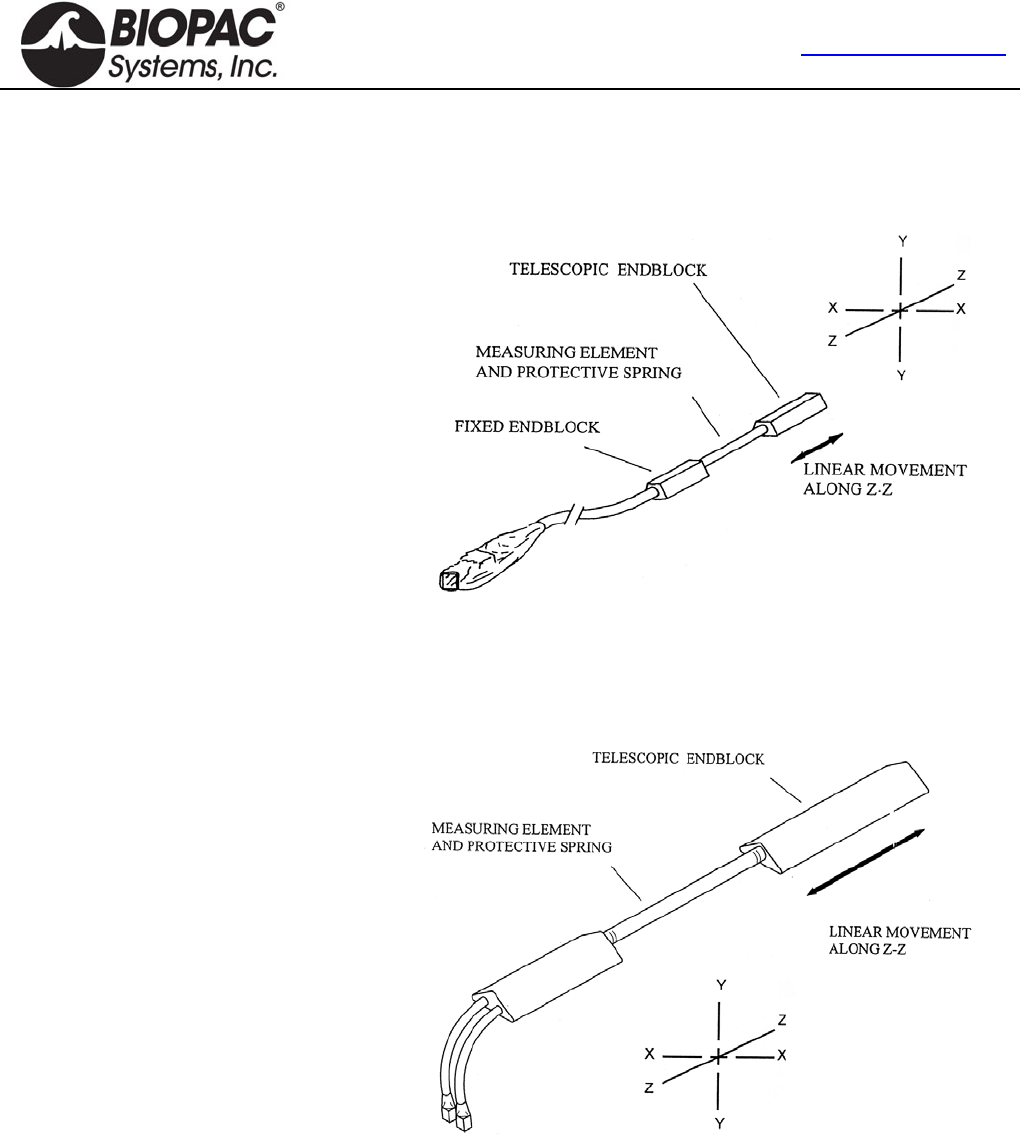
info@biopac.com
support@biopac.com
www.biopac.com
BIOPAC Hardware | Gonio-Torsio | Page 5 - 9 Updated: 11.21.2013
OVERVIEW OF THE BIOPAC GONIOMETER SERIES
As with all measuring equipment, to correctly interpret the data, understanding the working principles (i.e., what the
sensor measures) before use is helpful. BIOPAC Systems, Inc. manufactures three types of sensors:
1.
The single axis finger goniometer
permits the measurement of angles in
one plane.
Angles are measured when rotating one
endblock relative to the other about axis
X-X.
The goniometer is not designed to
measure rotations about Y-Y. Any
attempt to bend the unit in this way
more than ± 20 from the neutral position
will result in a reduction of the life of
the unit or failure.
The goniometer does not measure rotations about axis Z-Z,
though this movement is permitted without reduced life or
damage occurring. This goniometer is designed primarily for
the measurement of finger and toe flexion/extension.
2.
The twin axis goniometers permit the
simultaneous measurement of angles in
two planes, e.g. wrist flexion / extension
and radial / ulnar deviation. Rotation of
one endblock relative to the other about
axis X-X is measured using the gray
plug. Similarly, rotation of one
endblock relative to the other about axis
Y-Y is measured using the blue marked
plug.
Assuming the goniometer is mounted correctly (as outlined here), the outputs of the two channels are
independent of linear displacements along axis Z-Z.
It should be noted that rotation of one endblock relative to the other around axis Z-Z cannot be measured.
These goniometers function in the same way, and differ only in size.
HARDWARE GUIDE
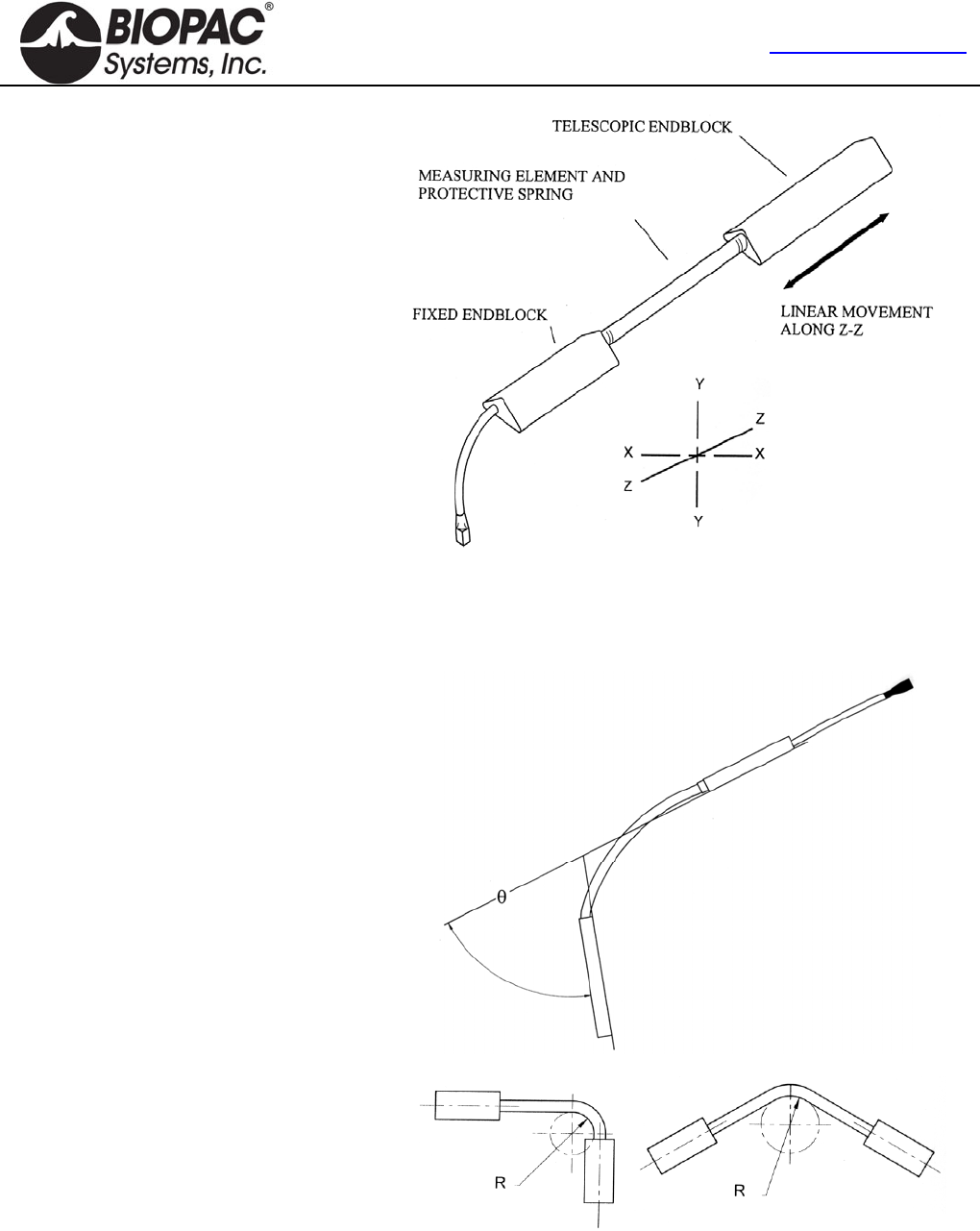
info@biopac.com
support@biopac.com
www.biopac.com
BIOPAC Hardware | Gonio-Torsio | Page 6 - 9 Updated: 11.21.2013
3.
The single axis torsiometers permit the
measurement of rotation in one plane,
e.g. forearm pronation/supination.
Axial rotation of one endblock relative
to the other along axis Z-Z is measured
from the gray plug.
If the torsiometer is bent in planes X-X
or Y-Y, the output remains constant.
All torsiometers function in the same
way, and difference only in size.
WARNING!
Torsiometers measure rotations about ZZ in the range ± 90°.
Exceeding the range may result in a reduction of the life of the
unit or failure.
The working mechanism is the same for
all three types of sensors. There is a
composite wire between the two
endblocks that has a series of strain
inside the protective spring gauges
mounted around the circumference. As
the angle between the two ends changes,
the change in strain along the length of
the wire is measured and this is equated
to an angle. The design is such that only
angular displacements are measured.
If the two ends move linearly relative to
each other, within the limits of telescopic
endblock, without changing the relative
angles between them, then the outputs
remain constant.
The amount of strain induced in the
gauges is inversely proportional to the
bend radius that the beam is bent around.
If the stated minimum permissible bend
radius is exceeded then unit life will be
reduced or, in severe cases, failure may
result.
HARDWARE GUIDE

info@biopac.com
support@biopac.com
www.biopac.com
BIOPAC Hardware | Gonio-Torsio | Page 7 - 9 Updated: 11.21.2013
SIGN CONVENTIONS
The sign convention for certain joints will differ, depending which side of the body the sensor is attached to. The
following figures show sign conventions for the most common joints.
HARDWARE GUIDE

info@biopac.com
support@biopac.com
www.biopac.com
BIOPAC Hardware | Gonio-Torsio | Page 8 - 9 Updated: 11.21.2013
WRIST – Goniometer TSD130A/SS20L/SS20/BN-GON-110-XDCR
Attach the telescopic endblock to the back of the hand, with the center axis of
the hand and endblock coincident (top of figure — viewed in the frontal plane).
While fully flexing the wrist (middle and bottom of figure), extend the
goniometer to Position 2 (as shown on page 2) and attach the fixed endblock to
the forearm so that when viewed from the dorsal plane, the axes of the forearm
and endblock are coincident. The wrist may now be flexed or extended,
abducted or adducted, with the goniometer freely sliding between Positions 1
and 2. Measurement of flexion/extension is obtained from the gray plug, and
abduction/adduction is obtained from the blue plug.
ARTICULAR COMPLEX OF THE FOOT – Goniometer TSD130A/SS20L/SS20/BN-GON-110-XDCR
Attach the telescopic endblock to the back of the heel.
Extend the ankle to the maximum extension anticipated during measurement,
and attach the fixed endblock to the posterior of the leg, with the goniometer in
Position 1 (maximum length, as shown on page 2) so that the axes of the leg
endblock are coincident.
Flexion/extension of the ankle may now be monitored using the gray plug and
pronation/supination using the blue marked plug.
ELBOW – Goniometer TSD130B/SS21L/SS21/BN-GON-150-XDCR
Attach the telescopic endblock to the forearm with the center axis of the
endblock coincident with the center axis of the forearm. With the elbow fully
extended, move the goniometer to Position 2 (maximum length, as shown on
page 2) and attach the fixed endblocks to the upper arm, with the center of the
endblock and the center axis of the upper arm coincident.
Now the elbow may be fully extended with the telescopic endblock freely
sliding between Positions 1 and 2. Measurement of flexion/extension is
obtained from the blue marked plug, and the gray plug is redundant. Note that
the telescopic endblock is mounted on the half of the forearm nearest to the
elbow joint. Movements of pronation and supination may be made and will
affect the measurement of flexion/extension by a small amount.
HIP – Goniometer TSD130B/SS21L/SS21//BN-GON-150-XDCR
Attach the fixed endblock to the side of the trunk in the pelvic region. With the
limb in the position of reference, extend the goniometer to Position 2
(maximum length, as shown on page 2) and attach the telescopic endblock to
the thigh, so that axes of the thigh and endblock coincide (when viewed in the
sagittal plane, as shown).
The thigh may now be flexed or extended, abducted or adducted, with the
goniometer sliding freely between Positions 1 and 2. Measurements of
flexion/extension are obtained from the blue marked, and abduction/adduction
from the gray plug.
HARDWARE GUIDE

info@biopac.com
support@biopac.com
www.biopac.com
BIOPAC Hardware | Gonio-Torsio | Page 9 - 9 Updated: 11.21.2013
KNEE – Goniometer TSD130B/SS21L/SS21/BN-GON-150-XDCR
Mount the telescopic endblock laterally on the leg so the axes of the leg and
endblock coincide, when viewed in the sagittal plane. With the leg fully
extended in the position of reference, extend the goniometer to Position 2
(maximum length, as shown on page 2) and attach the fixed endblock to the
thigh so the axes of the thigh and endblock coincide.
The knee may now be flexed or extended with the goniometer freely sliding
between Positions 1 and 2. Measurements of flexion/extension may be
monitored using the blue marked plug and varus/valgus may be monitored
using the gray plug.
FOREARM PRONATION /SUPINATION – Torsiometer TSD130C/SS22L/SS22/BN-TOR-110-XDCR or
TSD130D/SS23L/SS23/BN-TOR-150-XDCR
Attach the two endblocks of the torsiometer to the forearm, with the slider
mechanism approximately midway between the two extremes.
Measurements of pronation/supination may now be made from the gray plug.
Movements of wrist flexion/extension or radial/ulnar deviation will not affect
the output.
FINGERS AND TOES –Goniometer TSD130E/SS24L/SS24/BN-
GON-F-XDCR
The single axis goniometer is intended for use on fingers and toes. Angles
are measured by rotating one endblock relative to the other about axis X-
X (as shown on page 2).
The goniometer is not designed to measure rotations about Y-Y. Any attempt to bend the unit in this way more than
+/-20° from the neutral position will result in reduced unit life or failure. The goniometer does not measure rotations
about the axis Z-Z.
The unit is designed to fit over the joint to be measured and has extremely high flexibility to ensure the instrument does
not interfere with normal joint movement. One endblock is attached either side of the joint.
Unlike other BIOPAC Goniometers and Torisometers, and “Z” series sensors, an “oxbow” shape is permitted in the
measuring element. This is not detrimental to the results and does not reduce life of sensor. Care should be taken,
however, that the minimum bend radius is not exceeded.
HARDWARE GUIDE
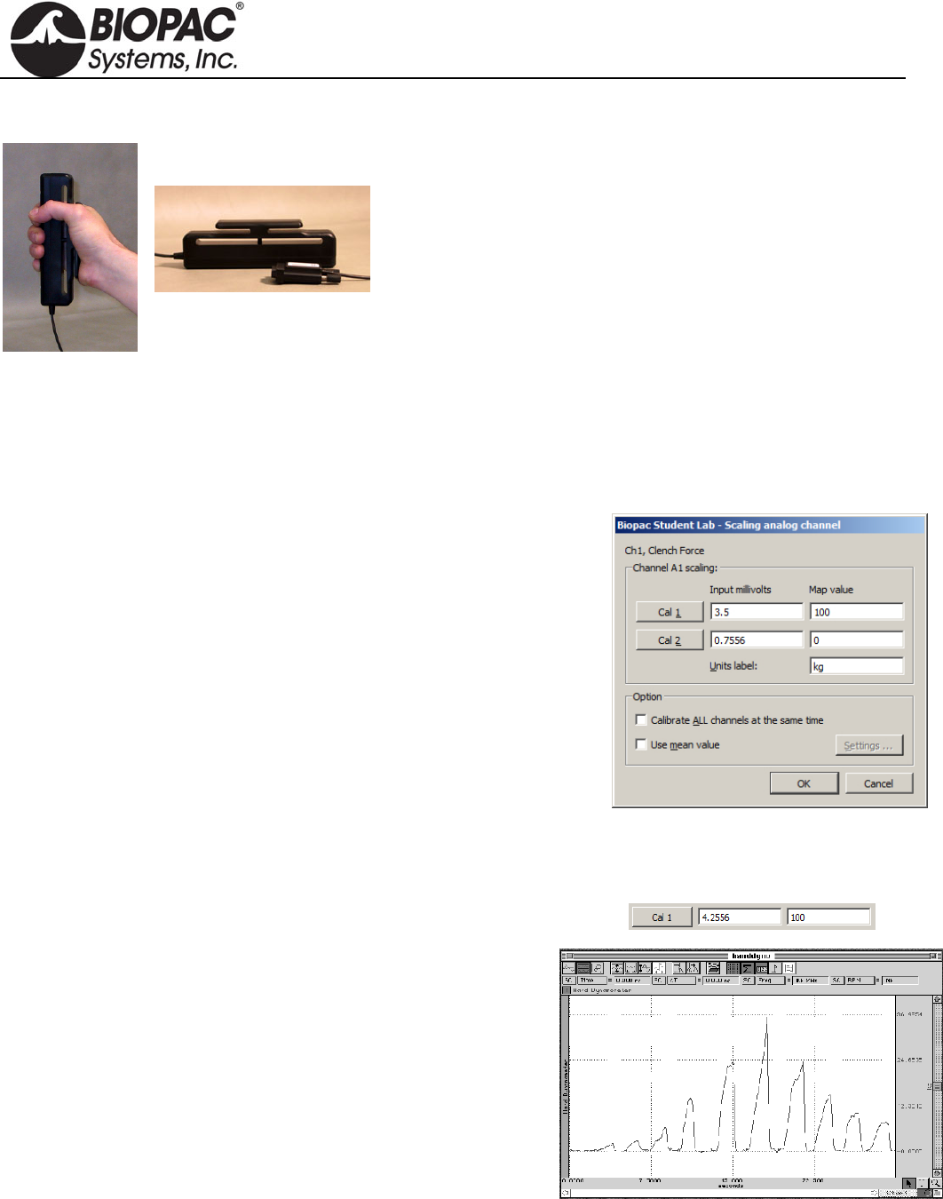
info@biopac.com
support@biopac.com
www.biopac.com
BIOPAC Hardware | SS25LA | Page 1 - 2 Updated: 8.12.2013
SS25LA HAND DYNAMOMETER
Use the hand dynamometer to measure grip force—use in isolation
or combine with EMG recordings for in-depth studies of muscular
activity. The lightweight, ergonomically designed transducer
provides direct readings in kilograms or pounds. The simple
calibration procedure makes this device easy to use for precise force
measurements, and the isometric design improves experiment
repeatability and accuracy. The SS25LA is a basic unit, designed for
student lessons; it can also be used in the MRI, with proper module
setup, since it employs plastics in the spring constant.
The highest performance dynamometer is TSD121C, which employs
a four terminal, laser-trimmed, wheatstone bridge built onto
metal elements.
Hardware Setup
Connect the SS25LA Simple Sensor to a CH input on the front panel of an MP3X unit.
Proper grip: Place the palm across the shorter bar and wrap fingers to center the force.
Scaling — Software Setup for the MP3X
1) Select Set Up Channels under the MP3X menu and enable
one analog channel.
2) Select the desired Clench Force Preset (kg or lbs, the example to the
right is shown in units of kg.)
3) Click on the Setup button.
4) Click on the Scaling button to activate a dialog box similar to the one
shown at right.
5) In the Map value column, note the default scaling of “0” for Cal2 and
“100” for Cal1. These represent 0 and 100 kilograms, respectively.
6) Place the SS25LA on a flat surface.
7) Click the Cal2 button to obtain an initial calibration reading. A value similar to the above example “0.7556”
will appear.
8) To obtain the Cal1 input value, add the Cal2 input value to the default Cal1 3.5 mV per 100 kg value.
(In this example, this value would be 0.7556 mV + 3.5 mV = 4.2556 mV.)
NOTE: The above instructions are for BSL 4 and higher. In
BSL 3.7.7 and earlier, placement of the CAL1 and
CAL2 scale values are reversed.
Calibration Confirmation
a) Click “Start” to begin data acquisition.
b) Place the SS25LA on a flat surface and then place a known
weight on the uppermost portion of the grip.
c) Review the data to confirm that the known weight is reflected
accurately in the data (sample at right).
d) Adjust the Scaling parameters and repeat steps a-c as necessary.
HARDWARE GUIDE

info@biopac.com
support@biopac.com
www.biopac.com
BIOPAC Hardware | SS25LA | Page 2 - 2 Updated: 8.12.2013
SS25LA Specifications
Isometric Range: 0-90 Kg
Dimensions: 17.78 cm (long) x 5.59 cm (wide) x 2.59 cm (thick)
Nominal Output: 13.2 µV/kg for 1 V excitation
Max excitation for MP36/36R is 5 V, for nominal output 66 µV/kg
Rated Output: 100 kg
Linearity: 8%
Sensitivity: 0.75 kg
Weight: 323 grams
Cable Length: 3 meters
HARDWARE GUIDE
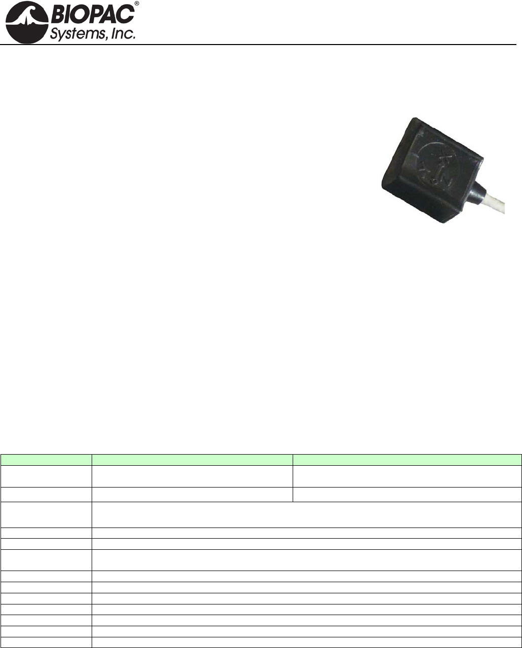
info@biopac.com
support@biopac.com
www.biopac.com
BIOPAC Hardware | Accelerometers | Page 1 - 3 Updated: 11.19.2013
Tri-axial accelerometer
uses 3 channel inputs
TRI-AXIAL ACCELEROMETERS
SS26LB, TSD109C2 and TSD109C2-MRI (±5 g)
SS27L and TSD109F (±50 g)
BN-ACCL3
Tri-Axial Accelerometers connect directly to BIOPAC hardware and
require no additional amplification. They provide three outputs, each
simultaneously measuring acceleration in the X, Y, and Z directions.
They are the same size and can be used on any part of the body or on
external equipment. The pliable and unobtrusive design conforms readily
to body contours. They come with a Velcro® strap for easy attachment.
• ±5 g accelerometers are optimal for measuring accelerations
when performing slow movements, such as walking.
• ±50 g accelerometers are optimal for measuring quick
movements, such as swinging a tennis racket.
The transducers can be used on any part of the body or attached to external equipment. The pliable and
unobtrusive design conforms readily to body contours and includes a Velcro strap for easy attachment. The
frequency response extends from DC to 500 Hz. The accelerometers are extremely accurate and can easily be
calibrated by simply changing their orientation in three-dimensional space, so that gravity (G=1) acts only upon
the desired axis.
MRI Use (TSD109C2): MR Conditional
Condition: Trace metallic parts do not make contact to the subject; must be used with MRI cables provided.
Equipment
• The SS26LB/SS27L accelerometers connect to the MP36/35 Data Acquisition Unit.
• The TSD109 series accelerometers connect to the HLT100C High Level Transducer module.
• The TSD109C2-MRI is intended for MRI use and ships with a longer (10 m) cable, plus an MECMRI-
HLT (2 m) interface cable and filter set (MRIFIF).
Accelerometer Specifications (SSL/TSD)
SS26LB / TSD109C2/TSD109C2-MRI
SS27L / TSD109F
Range (Output):
±5G
(400 mV/G; 1 mV/G; 0 G is at 5 mV DC)
±50G
(40 mV/G; 100 mV/G; 0 G is at 5 mV DC)
Noise: 0.5 mG/SQRT(Hz rms) 6.6 mG/SQRT(Hz rms)
Interface:
MP36/35 Data Acquisition Unit (SS26LB, SS27L)
HLT100C High Level Transducer Module (TSD109F, TSD109C2, TSD109C2-MRI)
Bandwidth:
DC - 500 Hz (-3dB)
Nonlinearity:
0.2% of Full Scale
Transverse axis
sensitivity:
±2%
Alignment error:
±1°
Package:
Compliant silicone housing
Dimensions:
33mm (long) x 28mm (wide, at base) x 19mm (high)
Weight:
17 grams
Power:
+5V @ 25 mA (via TEL100)
Sterilizable:
Yes (contact BIOPAC for details)
Cable length:
3 meters (10 meters for TSD109C2-MRI)
NOTE: The SS26LA was discontinued in September of 2013.
Hardware Setup
The accelerometers have three output connectors, one each for the X, Y, and Z axes. Each output connector must
be connected to an MP3X input channel (SS26LB/SS27L,) or to the appropriate HLT100C input channel
(TSD109 series). For example, connect the X-axis to channel 1, Y-axis to channel 2, and Z-axis to channel 3.
HARDWARE GUIDE
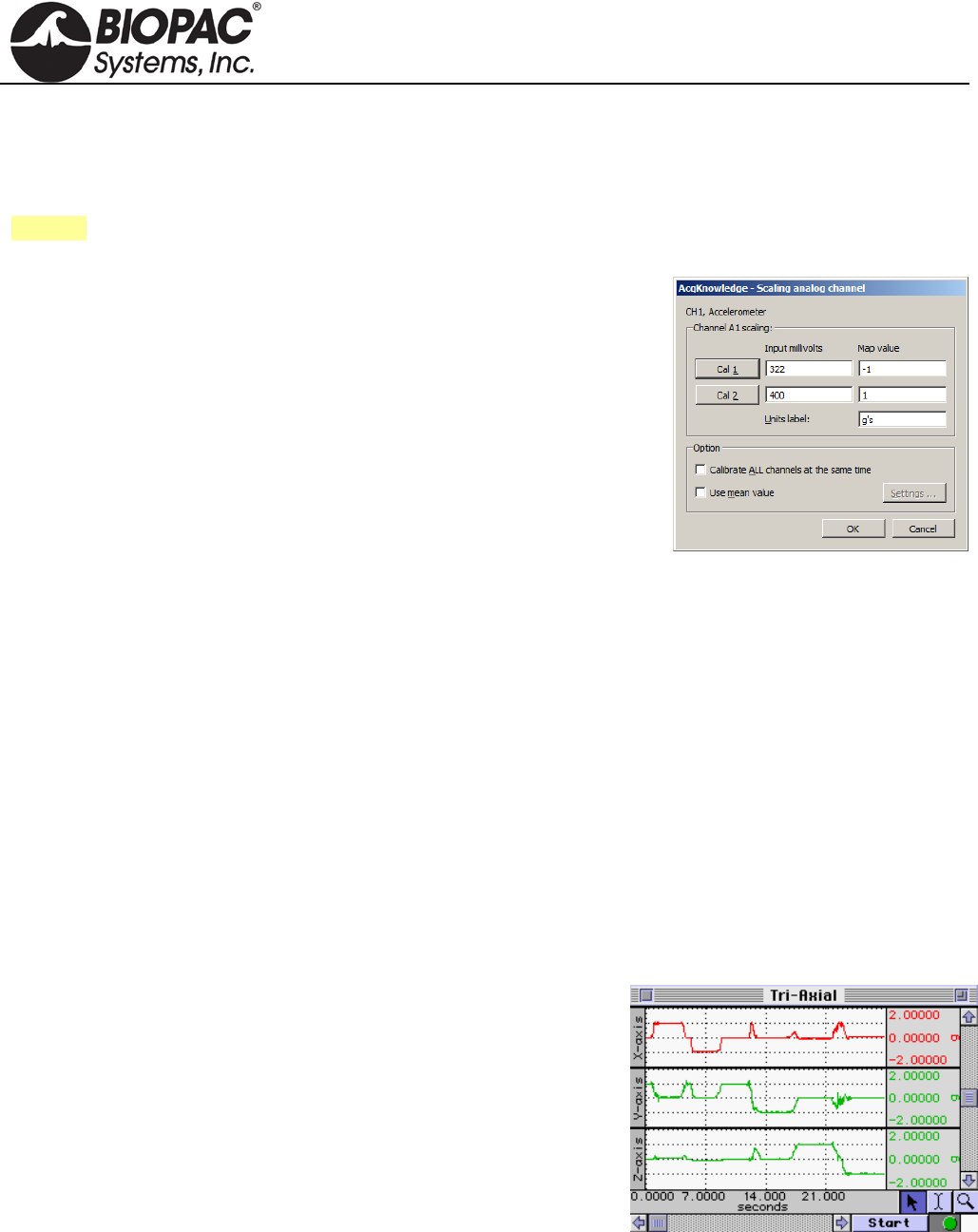
info@biopac.com
support@biopac.com
www.biopac.com
BIOPAC Hardware | Accelerometers | Page 2 - 3 Updated: 11.19.2013
IMPORTANT
Make sure the selected channel is not already assigned to any other BIOPAC module; up to 5
Accelerometers can be used with a single MP System. If contention exists, the channel data will
be corrupted.
See also: Setup notes for external devices and channel contention issues.
Software Setup
SS26LB/SS27L:
a) Select MP3X > Set Up Channels > Setup and enable three analog
channels, one for each axis
b) For each channel, select the appropriate Accelerometer Preset (5g or
50g) from the Preset list.
c) Click on Setup and then click on Scaling:
d) In the Scale value fields, enter the scaling factors required, 1 for Cal1
and –1 for Cal2.
e) Enter “g” for the Units label, as shown. (This unit should appear by
default in Accelerometer presets.)
f) Take the accelerometer and rest it in the upright position on the tabletop.
g) Calibrate the device by rotating it through 180° and taking a calibration reading at each point.
h) To calibrate the Y-axis, start with the transducer sitting on the table, face up, and click CAL1. Rotate the
transducer 180°, so that it is now sitting upside down, and click the CAL2 button. This procedure must be
followed for each axis. A label on the front of the transducer displays the X- and Y-axes. The Z-axis rotates
from the end with the label and the end with the cable.
TSD109 Series:
a) Select MP150 > Set Up Channels > Add New Module.
b) Choose HLT100C-A1 from the module type list and click “Add”.
c) Choose TSD109C (5g) or TSD109F (50g) from the transducer list and click “OK”.
d) Follow the onscreen calibration dialogs.
e) Repeat steps a-d for channels A2 (Y-Axis) and A3 (Z-axis).
Testing Calibration
To see if the calibration is correct:
a) Start acquiring data (for the test procedure, a sample rate of 50
samples per second should be used)
b) Rotate the accelerometer 180° through each axis.
c) Set the vertical scale to 1 and the midpoint to 0 for all channels.
d) Repeat the calibration procedure (by rotating the transducer 180°)
through each axis.
e) Visually confirm the correct calibration.
The screen shot above shows a tri-axial accelerometer being rotated through each axis. Channel 1 (X-axis) shows
the signal moving from 1g to -1g as the transducer is rotated. Likewise, Channel 2 (Y-axis) shows the same
phenomenon as previously described. Finally, Channel 3 (Z-axis) has also been tested and the
calibration confirmed.
HARDWARE GUIDE
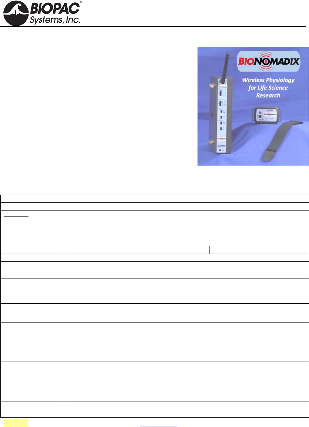
info@biopac.com
support@biopac.com
www.biopac.com
BIOPAC Hardware | Accelerometers | Page 3 - 3 Updated: 11.19.2013
BIONOMADIX WIRELESS ACCELEROMETER
The BioNomadix wireless Tri-axial Accelerometer (BN-ACCL3) is a
broad spectrum acceleration measurement system. The transmitter can
be attached to any part of the subject's body to measure three-axis
acceleration associated with movement in that particular location.
The system comes factory preset to support an operational range of
±16 G, with a maximum system bandwidth of 400 Hz. Ranges can be
set to as low as ±2 G with bandwidths as low as 3 Hz.
The system can also be configured to act as a "tap detector," detect
either single or double taps. In this mode, the system can act as an
event recorder for self-report. When "double-tapped," for example, the
system will output a pulse to precisely mark the time location of the
observed event.
In Acceleration measurement mode, the BN-ACCL3 will output X, Y
and Z acceleration values on three associated channels. The system is
very well suited for mobile applications. The system can measure the acceleration of gravity (static) for tilt-
sensing and can also measure very fast-changing, dynamic acceleration resulting from rapid movement or impact.
BN-ACCL3 Specifications
See also: Tri-Axial Accelerometer Data Analysis – App Note 266
BioNomadix BN-ACCL3
Signal type: G (X, Y, Z)
Bandlimits Max:
Factory preset:
Filter Options:
Alternative signal:
±2, ±4, ±8 or ±16 G
± 16 G at 400 Hz LP
DC to 3.13 Hz LP up to 400 Hz LP (in power of 2 steps)
Tap Event Mark Mode (replaces G)
Noise (resolution): X: 5 mg rms, Y: 6 mg rms, Z: 9 mg (rms) (±2 G scale at 400 Hz LP)
Signal range: Selectable: ±2, ±4, ±8 or ±16 G
Output Voltage range: ±10 V (receiver output)
Transmitter type & rate Type: Ultra-low power, 2.4 GHz bi-directional digital RF transmitter
Rate: 2,000 Hz (between transmitter and receiver)
Delay Large fixed component (12.5 ms) and small variable component (±0.5 ms)
Operational range: 10 meters (line-of-sight) typical in standard laboratory setups. See also: Operational Range and
Characteristics.
Operational temp: 5-45° C
Operational humidity: 95% non-condensing
Transmitter Battery:
Charger:
BioNomadix transmitters use an L-ion battery: full charge takes approx. 1 hour to provide maximum
operating time.
A battery charger is included with each module pair. See BN-CHARGER for charge time and
recharge cycle details.
Operating time: 72-90 hours
Receiver Power: Use with an MP Research System or with isolated power supply IPS100C for 3rd-party data
acquisition system.
Included strap: 33 cm - BN-STRAP33
Size & Weight: Transmitter (approx.): 6 cm x 4 cm x 2 cm; 54 grams; Receiver (approx.): 4 cm x 11 cm x 19 cm;
380 grams
Input: Attach BioNomadix transmitter to subject – no additional hardware input required; sensor is internal
to transmitter.
HARDWARE GUIDE

info@biopac.com
support@biopac.com
www.biopac.com
BIOPAC Hardware | Heel-Toe Strike Transducer | Page 1 - 1 Updated: 10.8.2013
HEEL-TOE STRIKE TRANSDUCERS
SS28LA
TSD111A
SS28A
BN-STRIKE-XDCR
Use this transducer to record heel and toe strike activity as the subject
walks. The heel/toe strike data is recorded as a single channel; the heel
strike generates a negative deflection and the toe strike results in a
positive deflection. Two force sensitive resistors (FSR) attach to the sole
of a shoe; use two transducers to record from both feet.
HEEL-TOE STRIKE SPECIFICATIONS
Nominal Output Range: -1 to +1 V
Nominal Contact Force: 200 g to indicate heel/toe strike
Attachment: TAPE1, TAPE2, Vinyl Electrical or Duct Tape
FSR Dimensions: 18.3 mm (dia) x 0.36 mm (thick) and 30 cm pigtail lead
FSR Active Area: 12.7 mm (dia)
Cable Length: 7.6 m
Cable Length – BN-STRIKE-XDCR: 30 cm
Interface: SS28LA MP36/35 System
TSD111A HLT100C
SS28A TEL100C
BN-STRIKE-XDCR BN-STRIKE
RX111 REPLACEMENT HEEL-TOE STRIKE SENSOR
Replacement strike sensor for Heel/Toe Strike transducers.
Note: Heel/Toe Strike Transducers without the "A" suffix in the part number (SS28L/TSD111) do not
have a replaceable sensor. Check the part number or check the cable for a removable sensor
connector before ordering this replacement.
HARDWARE GUIDE

info@biopac.com
support@biopac.com
www.biopac.com
BIOPAC Hardware | SS29L | Page 1 - 1 Updated: 7.16.2012
SS29L MULTI-LEAD ECG CABLE
The SS29L Multi-Lead ECG Cable permits high-
resolution ECG recordings. This multi-lead set can
simultaneously record Leads I, II, III, aVR, aVL,
aVF, plus one precordial chest lead V(1-6). A 12-
Lead ECG recording can be obtained by alternating
the chest lead electrode from position V1 through
V6. The cable terminates in three Smart Sensors that
connect to the MP3X.
SS29L SPECIFICATIONS
Input Cable Length: 2 meters
Electrode Lead Length: 1 meter
Internal connection: Built-in Wilson terminal
Electrode interface: Connects to standard snap-connector disposable electrodes (EL503)
HARDWARE GUIDE

info@biopac.com
support@biopac.com
www.biopac.com
BIOPAC Hardware | SS30L | Page 1 - 1 Updated: 7.16.2012
SS30L ELECTRONIC STETHOSCOPE TRANSDUCER
The SS30L stethoscope was developed to teach the standard procedure for listening to heart sounds and Korotkoff
sounds with a “normal” stethoscope, and record simultaneous sound data. A microphone in the SS30L records
sound as it is heard and the BSL software displays the sound wave during and after recording (a variety of
acoustical signals can be recorded). If ECG is also recorded, the timing of the heart sounds with the ECG can be
correlated. The SS30L can be used with the SS19L Blood Pressure Cuff to record Korotkoff sounds for easy
determination of systolic and diastolic blood pressure. With this combination, it is easy to obtain very accurate
and repeatable results — usually within 10% of those determined by direct measurement.
No calibration required, just select a Stethoscope Preset
(Heart or Korotkoff Sounds)
See also: Biopac Student Lab Lesson 16 Blood Pressure and Lesson 17 Heart Sounds.
SS30L SPECIFICATIONS
Microphone Bandwidth: 20-100 Hz (does not impact acoustical bandwidth, used for data viewing)
Stethoscope Length:
From Y to acoustic sensor point: 57 cm
From Y to ears: 21 cm
Microphone Cable length: 3 meters
HARDWARE GUIDE

info@biopac.com
support@biopac.com
www.biopac.com
BIOPAC Hardware | SS31L | Page 1 - 1 Updated: 7.17.2012
SS31L NONINVASIVE CARDIAC OUTPUT SENSOR
The SS31L records the parameters associated with Cardiac Output
measurements. The SS31L incorporates a precision high-frequency
current source, which injects a very small (400µA rms) current
through the measurement tissue volume defined by the placement of a
set of current source electrodes. A separate set of monitoring
electrodes then measures the voltage developed across the tissue
volume. Because the current is constant, the voltage measured is
proportional to the characteristics of the biological impedance of the
tissue volume.
Use the SS31L to measure changes in Cardiac Output under a variety of conditions: laying down, sitting
up, standing up, and post-exercise.
Use on stationary subjects; the SS31L is sensitive to motion artifact.
See BSL PRO Lesson H21 Impedance Cardiography for sample SS31L setup and data.
HARDWARE GUIDE
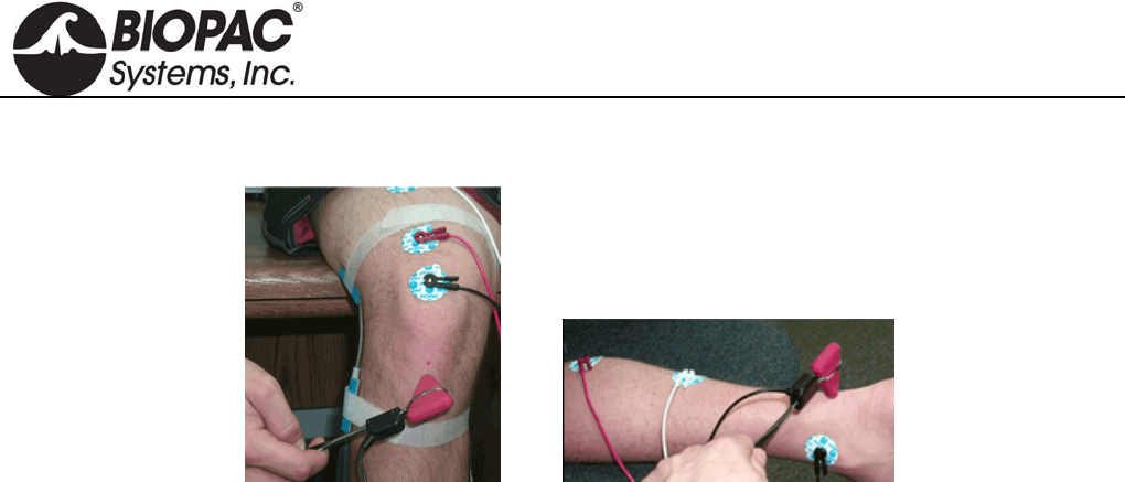
info@biopac.com
support@biopac.com
www.biopac.com
BIOPAC Hardware | SS36L | Page 1 - 1 Updated: 7.17.2012
SS36L REFLEX HAMMER
This is a classic reflex hammer with a transducer attached to perform reflex measurements. It uses a Taylor
Hammer—the most common type of reflex hammer used by doctors and nurses—and incorporates electronics to
record the time and the relative strength of the impact. Being able to measure the strength of impact allows
students to take threshold measurements; that is, they can measure how much of an impact is needed to elicit a
response. The hammer only sends a response when contact is made with the subject. See Lessons L20, H16, H28.
HARDWARE GUIDE
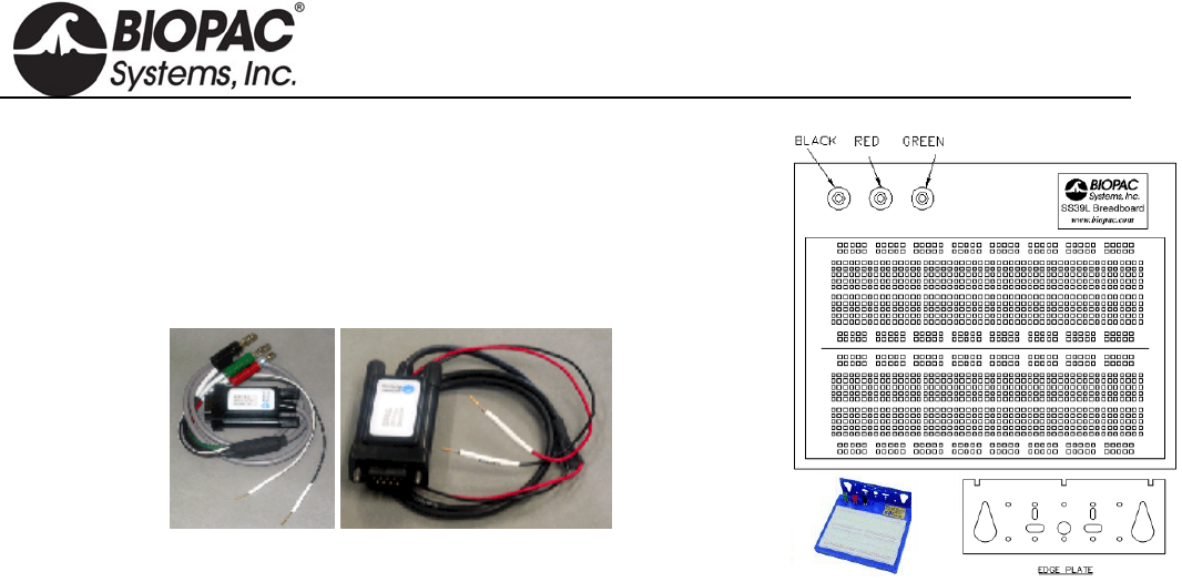
info@biopac.com
support@biopac.com
www.biopac.com
BIOPAC Hardware | SS39L | Page 1 - 1 Updated: 2.27.2013
SS39L BREADBOARD
The Bioengineering Breadboard Lab consists of circuitry hardware and
eight projects (with schematics and design notes) that demonstrate a very
important subset of circuit design for recording and processing physiological
signals. Students will use the MP36/35 and BSL PRO software to evaluate
their designs. See Lessons H25, H26.
Circuitry Hardware
Breadboard
Signal/Power Cable
o 3 x Power Plugs: Green -5 V, Black GND, Red +5 V
o 2 x Signal Wires: White – Signal, Black – GND
o Built-in automatically resettable fuse
Signal Cable (SS60L)
o 2 x Signal Wires: Red – Signal, Black – GND
Electrode Lead Interface
o BSL-TC122: SS2L to SS39L
Accessory Kit (BSL-BMEACC)
o Capacitors, diodes, resistors, jumper wires, and other circuit-building components
Project Book includes schematics for:
Lab 1: Square Wave Oscillator
Lab 2: Instrumentation Amplifier
Lab 3: High Pass Active Filter
Lab 4: Active Gain Block and Low Pass Filter
Lab 5: Notch Filter for 50/60 Hz Rejection
Lab 6: QRS Detection: Band Pass Filter
Lab 7: QRS Detection: Absolute Value Circuit
Lab 8: QRS Detection: Low Pass Filter and Overall System Test
HARDWARE GUIDE

info@biopac.com
support@biopac.com
www.biopac.com
BIOPAC Hardware | SS40L – SS42L | Page 1 - 1 Updated: 7.17.2012
SS40L – 42L DIFFERENTIAL PRESSURE TRANSDUCER
SS40L ±2.5cm H2O
SS41L ±12.5cm H2O
SS42L ±25cm H2O
The SS40L-SS42L series differential pressure transducers are designed for low
range pressure monitoring. The transducers plug directly into the MP3X general-
purpose differential amplifier. The differential pressure ports are located on the front
of the transducers and are easily connected to breathing circuits, pneumotachs or plethysmograph boxes. These
transducers are very useful for interfacing a variety of small animal pneumotachs or plethysmographs to the MP
System. The transducers are extremely sensitive and come in three ranges to suit a number of different
applications. RX137 flow heads connect to the SS41L differential pressure transducer via standard 4mm ID
tubing. Included with each SS45L-SS52L.
SS40L – 42L SPECIFICATIONS
Voltage output (normalized to 1 volt excitation)
SS40L: 330 µV/cm H2O
SS41L: 130 µV/cm H2O
SS42L: 65 µV/cm H2O
Warm-up Drift: ±50µV
Stability: ±100µV
Dynamic Response: 100Hz
Connection Ports/ID tubing Accepted: 3mm to 4.5mm
Dimensions: (high) x (wide) x (deep): 8.3cm x 3.8cm x 3.2cm
Weight: 76 grams
Operating Temperature (compensated): 0 to +50 °C
HARDWARE GUIDE

info@biopac.com
support@biopac.com
www.biopac.com
BIOPAC Hardware | SS43L | Page 1 - 1 Updated: 2.12.2013
SS43L VARIABLE ASSESSMENT (PSYCH) TRANSDUCER
Use this handheld, slide control transducer to record subjective responses to
a variety of different stimuli. Use multiple transducers to allow several
people to simultaneously answer the same question or otherwise respond to
stimuli. Easily customize the response scale by inserting the parameters into
the scale sleeve on the front of the unit.
SS43L SPECIFICATIONS
Scale Output Range: 0-5 V
Scale Resolution: Infinitely adjustable
Slide Control Length: 10 cm
Dimensions: 4cm (high) x 11cm (deep) x 19cm (wide)
Weight: 230 grams
Cable Length: 7.6 meters
HARDWARE GUIDE
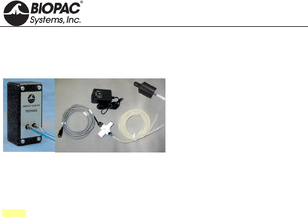
info@biopac.com
support@biopac.com
www.biopac.com
BIOPAC Hardware | Pneumotach 100 Series | Page 1 - 2 Updated: 12.2.2013
PNEUMOTACH AIRFLOW TRANSDUCERS
TSD137 SERIES FOR MP150/MP100 SYSTEM
SS46L-SS52L SERIES FOR MP3X AND MP45 SYSTEM
RX137 SERIES REPLACEMENT FLOW HEADS
The TSD137/SS46L-SS52L series pneumotachs
can be used to perform a variety of small animal
and human pulmonary measurements relating to
airflow, lung volume and expired gas analysis.
These pneumotach transducers consist of a low
flow, pneumotach airflow head (RX137B through
RX137H and SS46L through SS52L) coupled to a
precision, highly sensitive, differential pressure
transducer (TSD160A or SS40L).
The pneumotachs will connect directly to a
breathing circuit or plethysmogram chamber. For airflow and lung volume measurements, connect a short airflow
cannula to the RX137 series flow head. All pneumotachs are equipped with an internal heating element and
AC137A 6-volt power supply.
TSD160
SS40L
RX137 Series
RX137A
MRI Usage (TSD137): MR Conditional
Condition: Tested to 3T: Contains ferrous material – must be clamped down in the safe MRI
operating area.
See also: DA100C Calibration options.
RX137 SERIES REPLACEMENT AIRFLOW HEADS (SHOWN ABOVE)
For TSD137 & SS46L-SS52L Series Pneumotachs
The RX137 series are airflow heads for the TSD137 and SS46L-52L series pneumotach transducers. The RX137
heads can be mixed and matched with any of the TSD137 and SS46L-SS52L series pneumotachs. Switching one
head for another when using a single pneumotach can accommodate a wide range in flows. RX137 heads connect
to the TSD160A or SS40L differential pressure transducer via standard 3mm or 4mm ID tubing. Multiple RX137
heads help eliminate equipment downtime during cleaning procedures.
PNEUMOTACH AIRFLOW TRANSDUCER CALIBRATION
Connect tubing between the calibration syringe and the transducer, then follow the procedure for
TSD117/SS11LA but move the calibration syringe plunger at a reduced velocity due to the very high sensitivity to
flow of the TSD137/SS46L-SS52L series. Each of the TSD137/SS46L-SS52L series is factory calibrated to a
known flow level, as indicated on the transducer.
FLOW HEAD CLEANING & DISINFECTION
IMPORTANT:
RX137 series airflow heads are manufactured with a very thin layer of synthetic resin, so they should
never be cleaned with an organic solvent. We recommend cleaners such as Hydro-Merfen at the
concentration used for medical material, or Gluterex.
Before using the airflow head, be sure it is dry.
Never heat the airflow head higher than 50 C.
1. Submerge the airflow head in a disinfectant solution for approximately one hour.
2. Rinse the airflow head with distilled or de-mineralized water.
3. Use compressed air or another compressed gas [pressure up to 5kg / cm2 (5 bar)] to drive any
remaining water out of the airflow head.
4. Allow the airflow head to dry completely in ambient air (or continue using compressed air if time
requires it).
HARDWARE GUIDE

info@biopac.com
support@biopac.com
www.biopac.com
BIOPAC Hardware | Pneumotach 100 Series | Page 2 - 2 Updated: 12.2.2013
TSD/RX137 & SS46L-SS52L SERIES SPECIFICATIONS
Part# DA100C
TSD160/SS40L
MP36/35/30/45
TSD137B
RX137B1
SS46L
TSD137C
RX137C1
SS47L
TSD137D
RX137D1
SS48L
TSD137E
RX137E1
SS49L
TSD137F
RX137F1
SS50L
TSD137G
RX137G1
SS51L
TSD137H
RX137H1
SS52L
Range (ml/sec): ±50 ±83 ±166 ±583 ±1565 ±2666 ±13333
Dead Space (cc): 0.8 0.9 2.0 4.0 18.15 13.87 80.0
Nominal Output
(µV [ml/sec]):
15.40 5.78 2.10 0.924 1.155 0.4815 0.1925
Flow Ports ID/OD (mm): 6.0 - 7.0 6.0 - 7.0 9.0 - 10.0 10.0 - 11.0 17.0 - 22.0 14.0 - 24.6 43.0 - 45.0
RX Head Length (mm): 75 75 75 60 60 60 60
RX Head Weight
(grams): 90 90 100 60 100 150 250
Approx. Size: Mouse Rat/Guinea Pig Cat/Rabbit Small Dog Medium Dog Large Dog Adult Human
Approx. Weight: 50 g 350 g 750 g 5.5 kg 15 kg 25 kg --
Nominal Output: TSD137B, C, H = normalized to 1 V excitation
TSD137D, E, F, G & SS46L-52L = normalized to 5 V excitation
Tubing Length: 1.8 m (to TSD160A/SS40L)
HARDWARE GUIDE
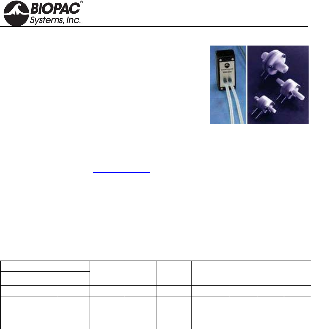
info@biopac.com
support@biopac.com
www.biopac.com
BIOPAC Hardware | Pneumotach 200 Series | Page 1 - 1 Updated: 12.2.2013
PNEUMOTACH 200 SERIES AIRFLOW TRANSDUCERS
These flow transducers are designed for humans and animals ranging in
size from mice to medium-sized dogs. They include a detachable flow
head (RX237B through H) and a differential pressure transducer
(TSD160A or SS40L).
AVAILABLE FLOW RATES
17 ml/sec Mouse/Rat
167 ml/sec Cat/Rabbit
1.67 L/sec Medium Dog
16.7 L/sec Human
Lightweight and robust
Linear and direction sensitive
Twin, non kink silicone tubing
Economical, sensitive and robust
Easily cleaned, disinfected or sterilized
For cleaning instructions, see the Cleaning Guidelines.
MRI Usage: MR Conditional
Condition: Animal use only. Contains ferrous material – must be clamped down in the safe MRI
operating area.
RX237 SERIES REPLACEMENT AIRFLOW HEADS
For TSD237 and SSLA Series Pneumotachs
Detachable flow heads in are machined from acetal to give good stability with low weight and have found
application in pediatrics and in the respiration measurement of animals such as dogs, cats, rats and mice.
TSD/SSLA/RX237 SERIES SPECIFICATIONS
BIOPAC Part #
Transducer Flowhead
Flowhead
Type
Dead
Space
(ml)
Linear
Range
L/min
Approx.
Flow for
10mm WG
Tube
(OD
mm)
Length
(mm) Weight
(gm)
TSD237B/SS46LA RX237B F1L 0.6 ± 1 1.2 L/min 5 40 14
TSD237D/SS48LA RX237D F10L 2 ± 10 12 L/min 8 54 22
TSD237F/SS50LA RX237F F100L 9 ± 100 90 L/min 16 54 38
TSD237H RX237H F1000L 320 ± 1000 550 L/min 29.5 198 230
Note: One of the problems historically encountered with pneumotachographs is condensation from expired air.
This can be prevented by fitting a non-return valve and measuring only inspiration or alternatively by
heating the flowhead, but viscosity errors may arise (from which in the first few breaths especially)
preheat the inspired air most uncomfortably. In this range of flow heads, the problem is approached
from a fresh angle. By mounting fine stainless steel gauze in plastic rings, thermal inertia is greatly
reduced. The gauze therefore rapidly equilibrates in temperature with passing air and condensation is
minimal.
HARDWARE GUIDE

info@biopac.com
support@biopac.com
www.biopac.com
BIOPAC Hardware | SS53L – SS55L | Page 1 - 1 Updated: 7.1.2013
SS53L – SS55L DIGITAL SWITCH SERIES
Use for remote even marking or to externally trigger
data acquisition for psychophysiological response tests
Monitor switch data as a digital input channel.
Connects to the digital input on the MP36/35 only.
SS53L Hand switch
See Lessons H11, H16, H24, H27, H30.
SS54L Foot switch
See Lessons H11, H16, H24, H27, H30.
Switch Type: Pushbutton: ON - OFF
Dimensions: 69mm (wide), 90mm (long), 26mm (high)
Cable Length: 1.8 meters
Connector Type: DSUB 25f
SS55L Eight-channel Marker Box
See Lessons H11, H16, H24, H27, H30.
Independently mark events, or provide responses, on
up to eight channels simultaneously. Assign separate
digital channels as event markers for individual
analog input channels. Easily customize the response
scale by inserting the parameters into the scale
sleeve on the front of the unit.
Switch Type: Pushbutton: ON - OFF
Dimensions: 19cm (wide), 11cm (deep), 4cm (high)
Cable Length: 3 meters
Connector Type: DSUB 25f
HARDWARE GUIDE
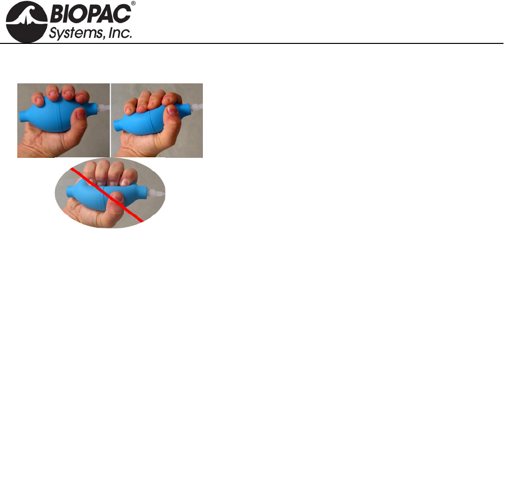
info@biopac.com
support@biopac.com
www.biopac.com
BIOPAC Hardware | SS56L | Page 1 - 1 Updated: 2.12.2013
SS56L HAND CLENCH FORCE BULB
SS56L measures proportionality of bulb pressure to clench
force in “kgf/m^2” units (a pressure unit). This measure is
accurate for the relative measures recorded in BSL Lesson 2
Electromyography (EMG) II. SS56L is recognized by current
release BSL Lessons.
SPECIFICATIONS
Pressure Range: BSL: 0 to 10,546 Kgf/m^2
AcqKnowledge: 0 to 1.0546 Kg-f/cm^2 0 to 15 psi
Accuracy: ±3%
Output: BSL: 0.58 mV/100 Kgf/m^2
AcqKnowledge: 0.58 mV/0.01 Kg-f/cm^2 4.1 mV/psi
Bulb Diameter: 5.8 cm
Bulb Length: 11.1 cm
Tubing Length: 3 meters
Weight: 108 g
Optional BSL PRO Presets:
Clench Force - kpa (SS56L) - input value 20.48 mv scales to 34.47 kpa
Clench Force - psi (SS56L) - input value 61.44 mv scales to 15 psi
HARDWARE GUIDE

info@biopac.com
support@biopac.com
www.biopac.com
BIOPAC Hardware | SS57L | Page 1 - 1 Updated: 1.31.2013
SS57L EDA LEAD FOR DISPOSABLE SETUPS
Snaps to two EL507 disposable EDA (isotonic gel) electrodes. This
disposable setup is an alternative to the reusable SS3LA EDA (GSR)
Transducer.
Range: 0.1-100 µMho (normal human range is 1-20 µMho)
Excitation: 0.5 V DC
Pinch Leads: Red (+), Black (GND)
HARDWARE GUIDE

info@biopac.com
support@biopac.com
www.biopac.com
BIOPAC Hardware | SS60L | Page 1 - 1 Updated: 7.17.2012
SS60L SIGNAL CABLE FOR SS39L BREADBOARD
Use this signal cable to add signal inputs to the SS39L Signal Processing Breadboard, which ships with one
combination power/signal cable.
HARDWARE GUIDE
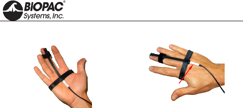
info@biopac.com
support@biopac.com
www.biopac.com
BIOPAC Hardware | SS61L | Page 1 - 1 Updated: 2.12.2013
SS61L FINGER TWITCH TRANSDUCER
Palmar attachment recommended: “UP” label facing out “UP” label toward skin for posterior (dorsal) attachment
Use this transducer to record finger twitch responses from human subjects receiving electrical stimulation (using
the HSTM01). The transducer conforms to the shape of the finger and attaches via a Velcro® strap and tape.
SPECIFICATIONS
Transducer Dimensions: 14.6 cm (long), 0.50 cm (wide)
Weight: 6 grams
Maximum Bend: 180 (can be fully curled)
HARDWARE GUIDE
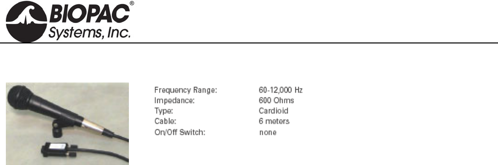
info@biopac.com
support@biopac.com
www.biopac.com
BIOPAC Hardware | SS62L | Page 1 - 1 Updated: 7.17.2012
SS62L SPEECH FREQUENCY MICROPHONE
Use this precision microphone for speech
frequency analysis and other acoustic
studies. For use with the MP36/35 only,
requires continuous high-speed sample
rate.
HARDWARE GUIDE

info@biopac.com
support@biopac.com
www.biopac.com
BIOPAC Hardware | SS63L – SS66L | Page 1 - 1 Updated: 7.17.2012
SS63L – SS66L FORCE TRANSDUCER SERIES
SS63L Force Transducer - 50 g
SS64L Force Transducer - 100 g
SS65L Force Transducer – 200 g
SS66L Force Transducer - 500 g
SS63L – SS66L SPECIFICATIONS
Noise: with 10 Hz LP filter: 2.5 mg
with 1 Hz LP Filter: 1.0 mg
Temperature: -10°C to 70°C
Mounting rod: 9.5 mm (diameter), variable orientation
Weight: 250 g
Dimensions (L x W x Thick): 100 mm x 19 mm x 25 mm
HARDWARE GUIDE
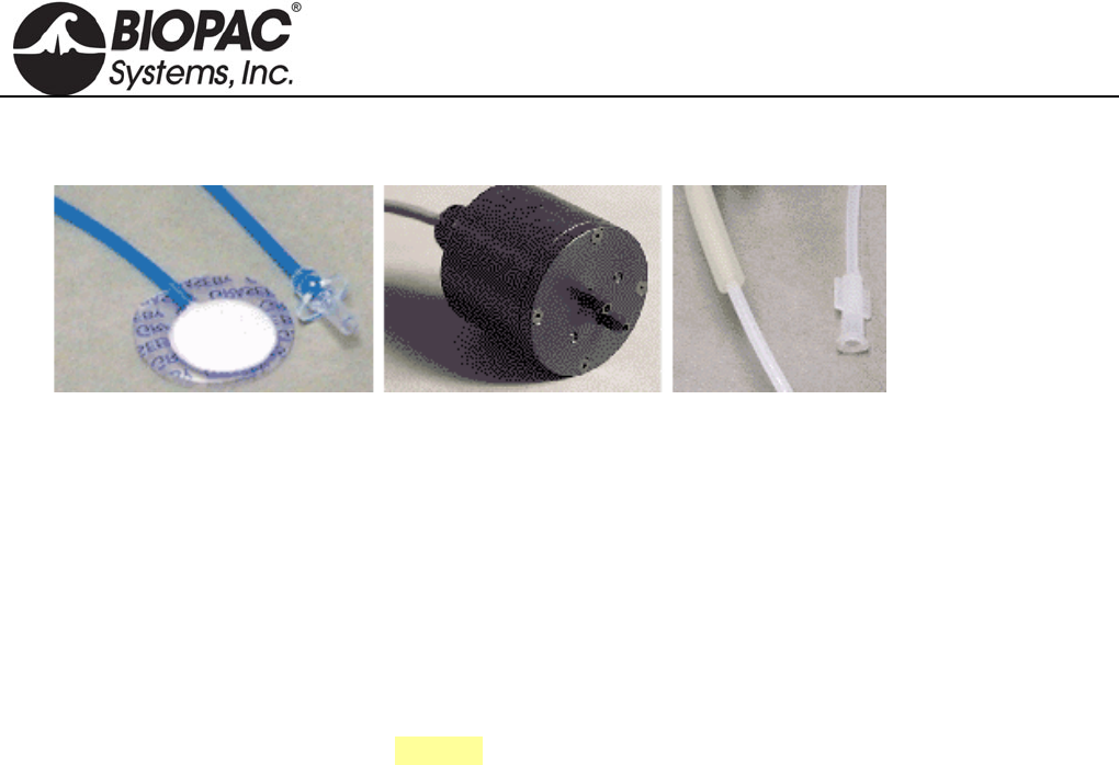
info@biopac.com
support@biopac.com
www.biopac.com
BIOPAC Hardware | SS67L – RX110 | Page 1 - 1 Updated: 1.31.2013
SS67L PRESSURE PAD/RESPIRATION TRANSDUCER
The SS67L consists of an SS41L differential pressure transducer, RX110 pressure pad, and tubing.
The multipurpose pressure pad/respiration transducer can be used to:
1. Noninvasively measure respiration—from a small mouse to a human.
2. Measure small pressing forces (like pinching fingers together) for Parkinson's evaluations.
3. Measure human smiling (with the sensor on the cheekbone).
4. Measure pulse when placed close to the heart.
5. Measure spacing and pressure between teeth coming together.
See RX110 for sensor specifications.
See also: MRI Compatibility Notes
RX110 PRESSURE PAD
The RX110 is a self-inflating pressure pad connected to tubing terminating in a Luer male connector. The RX110
pressure pad is included with the SS67L Pressure Pad/Respiration Transducer. The RX110 sensor can be used
many times, but may eventually need to be replaced because it is a sensitive pressure pad and may become
damaged with rough use. Use TAPE1 or other single-sided adhesive to affix to the subject.
RX110 SPECIFICATIONS
Sensor Pad Diameter: 20 mm
Sensor Pad Thickness: 3.18 mm
Sensor Tubing Diameter: 2.2 mm
Sensor Tubing Length: 1 m use BIOPAC tubing M106 for extra length
Sensor Tubing ID: 1.6 mm
Tubing Termination: Luer male
HARDWARE GUIDE

info@biopac.com
support@biopac.com
www.biopac.com
BIOPAC Hardware | SS68L | Page 1 - 1 Updated: 3.25.2013
SS68L PH PROBE TRANSDUCER
The SS68L probe transducer can measure pH within the range of 0-14.
The electrode provides approximately a single digit pH value change for every 5 mV
change in the electrode reading, either positive or negative depending on whether the
pH is above 7 or below it.
A neutral buffer solution of pH 7 will read about 0mV.
A solution with a pH of 10 will read about –15 mV.
A solution with a pH of 3 will read about 20 mV.
The SS68L pH Transducer includes a double-junction pH Probe and an interface to the Biopac Student Lab MP
unit.
Order probe only as RXPROBE01
To use the BSL with an existing (BNC terminated) pH probe, order the interface only as BSL-TCI21.
SS68L SPECIFICATIONS
Type: Double junction
Refillable: Yes
Body: Glass
Length: 3.25m
Weight: 3.5 ounces
Diameter: 1.2cm
HARDWARE GUIDE
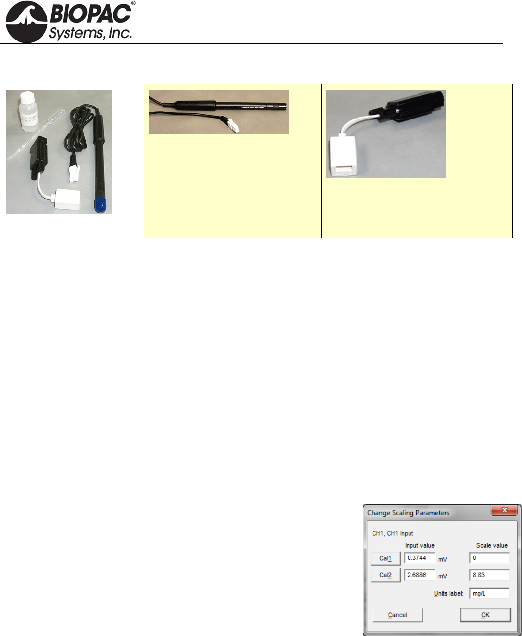
info@biopac.com
support@biopac.com
www.biopac.com
BIOPAC Hardware | SS69L | Page 1 - 4 Updated: 3.28.2013
SS69L DISSOLVED OXYGEN PROBE TRANSDUCER
SS69L Components
Order probe only as RXPROBE02
Order interface only as BSL-TCI16
The SS69L transducer measures dissolved oxygen. The SS69L includes a dissolved oxygen probe and an
interface to the BSL MP36/MP35 or MP30 unit.
See BSL PRO Lesson #A07 Fish Respiration and Q10.
Components Dissolved O2 probe Sodium Sulfate calibration standard (2.0 M Na2SO3)
Replacement membrane cap Dissolved O2 electrode filling solution
Calibration bottle & pipette Polishing strips
Interface Use with BIOPAC BSL-TCI16 Transducer Connector to record with a BIOPAC data acquisition
unit.
Usage There are four steps to using the Dissolved O2 probe:
1. Setup
2. Warm-up
3. Calibration — optional
4. Recording
1. Setup
a. Remove and discard the blue protective cap from the tip of the
probe.
b. Unscrew the membrane cap from the tip of the probe.
c. Use a pipette to fill the membrane cap with 1 mL of the Electrode
Filling Solution.
d. Carefully thread the membrane cap back onto the electrode.
e. Place the probe into a beaker filled with about 100 mL of distilled
water.
2. Warm-up
a. Insert the BT connector on the RXPROBEO2 into the BSL-TCI16
transducer connector.
b. Connect the BSL-TCI16 transducer connector to the MP data acquisition unit.
c. Turn the MP unit ON and wait 10 minutes for the probe to warm up.
The probe must stay connected to the interface at all times to keep it warmed up. If the probe
is disconnected for more than a few minutes, the warm-up routine will need to be repeated.
HARDWARE GUIDE

info@biopac.com
support@biopac.com
www.biopac.com
BIOPAC Hardware | SS69L | Page 2 - 4 Updated: 3.28.2013
3. Calibration — optional
Calibration is optional. To measure relative change, probe calibration is not essential. To
improve accuracy for discrete measurements, probe calibration is recommended.
a. Zero-Oxygen (CAL 1)
i) Launch the BIOPAC software and generate the scaling dialog for the probe channel.
(Select MP menu > Set Up Channels > View/Change Parameters > Scaling Button.)
ii) Enter 0 for CAL 1 Scale value.
iii) Remove the probe from the water and place the tip of the probe into the Sodium Sulfite
calibration solution. IMPORTANT: No air bubbles can be trapped below the tip of the probe
or the calibration will be distorted. If the voltage does not rapidly decrease, tap the side of the
bottle with the probe to dislodge any bubbles.
iv) When the voltage stabilizes (~1 minute), press the CAL 1 button. The Input value result
should be in the 0.2 - 0.5 mV range.
b. Saturated Dissolved O2 (CAL 2)
i) Rinse the probe with distilled water and gently blot dry.
ii) Unscrew the lid of the calibration bottle and slide the grommet approx. 12 mm (1/2”) onto the
probe body.
iii) Add water to the bottle to the depth of about 6 mm (1/4”) and screw the bottle into the cap.
IMPORTANT: Do not touch the membrane or get it wet during this step.
iv) Keep the probe in the position for about one minute and then press the CAL 2 button. The
Input value result should be above 2 mV.
v) Enter a Saturated Dissolved O2 value (in units of mg/L) from Table 1 as the CAL 2 scale
value, based on the current barometric pressure and air pressure values. If necessary, use
Table 2 to estimate the air pressure at the altitude. (To calibrate and monitor using Percent
Saturation, use the conversion formula on the next page.)
HARDWARE GUIDE

info@biopac.com
support@biopac.com
www.biopac.com
BIOPAC Hardware | SS69L | Page 3 - 4 Updated: 3.28.2013
TABLE 1
Dissolved O2 (mg/L) in air-saturated distilled water (at various temp. & pressure)
770
mm 760
mm 750
mm 740
mm 730
mm 720
mm 710
mm 700
mm 690
mm 680
mm 670
mm 660
mm 650
mm
0C 14.76 14.59 14.38 14.19 13.00 13.80 13.61 13.42 13.23 13.04 12.84 12.65 12.46
1C 14.38 14.19 14.00 13.82 13.63 13.44 13.26 13.07 12.88 12.70 12.51 12.32 12.14
2C 14.01 13.82 13.64 13.46 13.28 13.10 12.92 12.73 12.55 12.37 12.19 12.01 11.82
3C 13.65 13.47 13.29 13.12 12.94 12.76 12.59 12.41 12.23 12.05 11.88 11.70 11.52
4C 13.31 13.13 12.96 12.79 12.61 12.44 12.27 12.10 11.92 11.75 11.58 11.40 11.23
5C 12.97 12.81 12.64 12.47 12.30 12.13 11.96 11.80 11.63 11.46 11.29 11.12 10.95
6C 12.66 12.49 12.33 12.16 12.00 11.83 11.67 11.51 11.34 11.18 11.01 10.85 10.68
7C 12.35 12.19 12.03 11.87 11.71 11.55 11.39 11.23 11.07 10.91 10.75 10.59 10.42
8C 12.05 11.90 11.74 11.58 11.43 11.27 11.11 10.96 10.80 10.65 10.49 10.33 10.18
9C 11.77 11.62 11.46 11.31 11.16 11.01 10.85 10.70 10.55 10.39 10.24 10.09 9.94
10C 11.50 11.35 11.20 11.05 10.90 10.75 10.60 10.45 10.30 10.15 10.00 9.86 9.71
11C 11.24 11.09 10.94 10.80 10.65 10.51 10.36 10.21 10.07 9.92 9.78 9.63 9.48
12C 10.98 10.84 10.70 10.56 10.41 10.27 10.13 9.99 9.84 9.70 9.56 9.41 9.27
13C 10.74 10.60 10.46 10.32 10.18 10.04 9.90 9.77 9.63 9.49 9.35 9.21 9.07
14C 10.51 10.37 10.24 10.10 9.96 9.83 9.69 9.55 9.42 9.28 9.14 9.01 8.87
15C 10.29 10.15 10.02 9.88 9.75 9.62 9.48 9.35 9.22 9.08 8.95 8.82 8.68
16C 10.07 9.94 9.81 9.68 9.55 9.42 9.29 9.15 9.02 8.89 8.76 8.63 8.50
17C 9.86 9.74 9.61 9.48 9.35 9.22 9.10 8.97 8.84 8.71 8.58 8.45 8.33
18C 9.67 9.54 9.41 9.29 9.16 9.04 8.91 8.79 8.66 8.54 8.41 8.28 8.16
19C 9.47 9.35 9.23 9.11 8.98 8.86 8.74 8.61 8.49 8.37 8.24 8.12 8.00
20C 9.29 9.17 9.05 8.93 8.81 8.69 8.57 8.45 8.33 8.20 8.08 7.96 7.84
21C 9.11 9.00 8.88 8.76 8.64 8.52 8.40 8.28 8.17 8.05 7.93 7.81 7.69
22C 8.94 8.83 8.71 8.59 8.48 8.36 8.25 8.13 8.01 7.90 7.78 7.67 7.55
23C 8.78 8.66 8.55 8.44 8.32 8.21 8.09 7.98 7.87 7.75 7.64 7.52 7.41
24C 8.62 8.51 8.40 8.28 8.17 8.06 7.95 7.84 7.72 7.61 7.50 7.39 7.28
25C 8.47 8.36 8.25 8.14 8.03 7.92 7.81 7.70 7.59 7.48 7.37 7.26 7.15
26C 8.32 8.21 8.10 7.99 7.78 7.78 7.67 7.56 7.45 7.35 7.24 7.13 7.02
27C 8.17 8.07 7.96 7.86 7.75 7.64 7.54 7.43 7.33 7.22 7.11 7.01 6.90
28C 8.04 7.93 7.83 7.72 7.62 7.51 7.41 7.30 7.20 7.10 6.99 6.89 6.78
29C 7.90 7.80 7.69 7.59 7.49 7.39 7.28 7.18 7.08 6.98 6.87 6.77 6.67
30C 7.77 7.67 7.57 7.47 7.36 7.26 7.16 7.06 6.96 6.86 6.76 6.66 6.56
31C 7.64 7.54 7.44 7.34 7.24 7.14 7.04 6.94 6.85 6.75 6.65 6.55 6.45
32C 7.51 7.42 7.32 7.22 7.12 7.03 6.93 6.83 6.73 6.63 6.54 6.44 6.34
33C 7.39 7.29 7.20 7.10 7.01 6.91 6.81 6.72 6.62 6.53 6.43 6.33 6.24
34C 7.27 7.17 7.08 6.98 6.89 6.80 6.70 6.61 6.51 6.42 6.32 6.23 6.13
35C 7.15 7.05 6.96 6.87 6.78 6.68 6.59 6.50 6.40 6.31 6.22 6.13 6.03
TABLE 2
Elevation barometric pressure (based on barometric air pressure of 760 mmHg at sea level)
Elev.
(feet) Pressure
(mmHg) Elev.
(feet) Pressure
(mmHg) Elev.
(feet) Pressure
(mmHg) Elev.
(feet) Pressure
(mmHg)
0 760 1500 720 3000 683 4500 647
250 753 1750 714 3250 677 4750 641
500 746 2000 708 3500 671 5000 635
750 739 2250 702 3750 665 5250 629
1000 733 2500 695 4000 659 5500 624
1250 727 2750 689 4250 653 5750 618
HARDWARE GUIDE

info@biopac.com
support@biopac.com
www.biopac.com
BIOPAC Hardware | SS69L | Page 4 - 4 Updated: 3.28.2013
CONVERSION FORMULA FOR % SATURATION
Set CAL 1 Input to 0% and CAL 2 Input to 100%, and then use the following formula to enter the Values:
% Saturation = (actual DO2 result / Saturated DO2 value from Table 1) x 100
For example, if the probe result is 6.1 mg/L at a temperature of 20ºC and a pressure of 740 mmHg, the
corresponding Table 1 value is 8.93 mg/L, so % Saturation = ( 6.1 / 8.93) x 100 = 68%
Recording
c. Place the tip of the probe into the sample to be measured. Submerge the tip about 4-6 cm (2”).
d. Gently stir the probe in the sample. IMPORTANT: Keep stirring the probe in the sample—water
must always be flowing past the probe tip for accurate measurements. As the probe measures the
concentration of dissolved oxygen, it removes oxygen from the water at the junction of the probe
membrane. If the probe is left still in calm water, reported dissolved O2 measurements will appear to
be dropping.
Storage
< 24 hours: Store the probe with the membrane end submerged in about 3 cm (1”) cm of distilled water
> 24 hours: Remove the membrane cap, rinse the inside and outside of the cap with distilled water,
and then shake the membrane cap dry. Rinse the exposed anode and cathode inner elements, and then blot
dry with a lab wipe. Reinstall the membrane cap loosely onto the electrode body for storage—do not
tighten.
Polishing
The anode or cathode inner elements become discolored or appear corroded, use the polishing strips
provided (once a year is generally sufficient). Contact BIOPAC for polishing details if necessary.
HARDWARE GUIDE
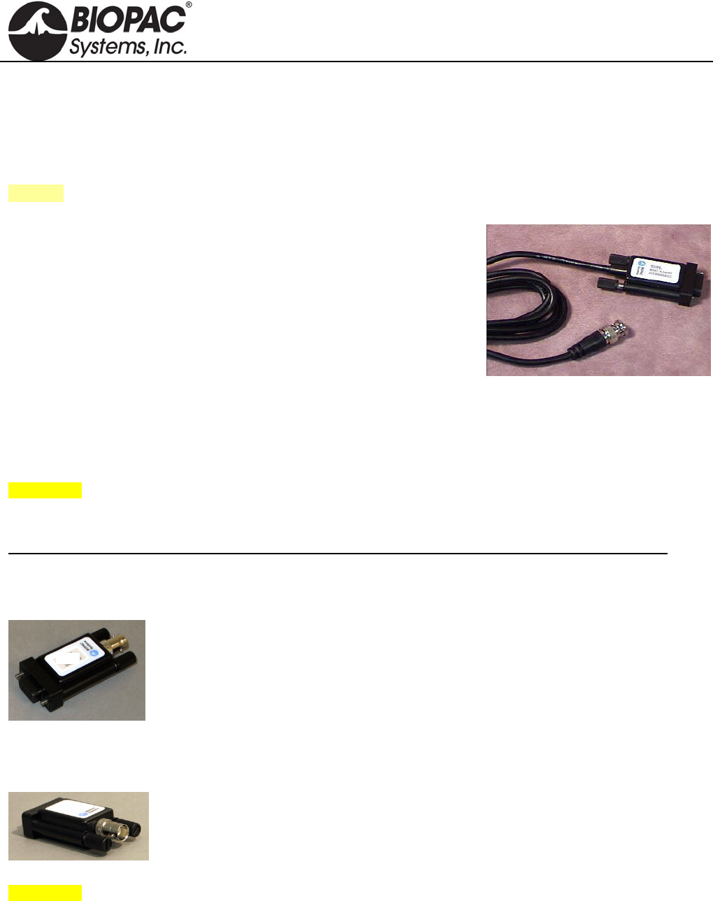
info@biopac.com
support@biopac.com
www.biopac.com
BIOPAC Hardware | BNC INPUT ADAPTERS | Page 1 - 1 Updated: 1.6.2014
INPUT ADAPTERS
SS9LA Unisolated BNC Input Adapter
SS70L Isolated BNC Input Adapter
SS71L Isolated BNC Input Adapter – MP30
See also: OUT2 BNC Output Adapter
SS9LA UNISOLATED BNC INPUT ADAPTER
This unisolated input adapter is for MP36, MP36R, MP35, and MP45
Systems only. Use to send signals from other devices (other chart
recorders, amplifiers and signal generators) to be recorded by a Biopac
Student Lab System or a Research System with AcqKnowledge.
SS9LA has a built-in divide by 10 attenuation which provides a ±20 V
input range on MP36 or MP36R and a ±10 V input range on MP35 or
MP45. The 2-meter cable terminates in a male BNC for easy connections.
SS9LA SPECIFICATIONS
Cable length: 2 meter
Connector type: BNC
Signal range: ±20 V (MP36/MP36R)
±10 V (MP35/MP45)
WARNING! Never connect the SS9LA BNC Input Adapter to an MP3X unit if electrodes from other channels are
connected to human subjects – this may void the electrical isolation (one un-isolated channel input voids the
isolation of all channel inputs).
This cable is not compatible with MP30 systems; contact BIOPAC for unisolated adapter options for MP30.
This cable replaces the SS9L, effective January 2014.
SS70L ISOLATED BNC INPUT ADAPTER FOR MP36/MP35
This BNC adapter is required when connecting un-isolated third party devices (i.e.
amplifiers, chart recorders or signal generators), while electrodes, attached to human
Subjects are connected to other input channels.
SS71L ISOLATED BNC INPUT ADAPTER FOR MP30
This BNC adapter is required when connecting un-isolated third party devices (i.e.
amplifiers, chart recorders or signal generators), while electrodes, attached to human
Subjects are connected to other input channels.
WARNING! Since all MP inputs share a common isolated ground, connecting an un-isolated device to any
channel voids the isolation for all channels and exposes the Subject to possible shock hazards.
SS70L – SS71L SPECIFICATIONS
Connector type: BNC
Signal range: ±10V
HARDWARE GUIDE
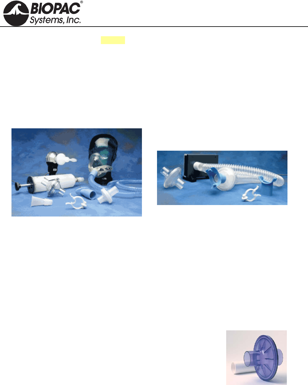
info@biopac.com
support@biopac.com
www.biopac.com
BIOPAC Hardware | AFT Series | Page 1 - 7 Updated: 12.3.2013
See also: Student Accessory Pack BSL-ACCPACK
AFT SERIES AIRFLOW & GAS ANALYSIS ACCESSORIES
Includes the following airflow accessories:
AFT1 AFT9 AFT11E AFT15 AFT26
AFT2 AFT10 AFT11F AFT20 AFT30
AFT3 AFT10S AFT11G AFT21 AFT31
AFT4 AFT11A AFT11H AFT22 AFT35
AFT6A AFT11B AFT11I AFT23
AFT7 AFT11C AFT12 AFT24
ATF8 AFT11D AFT13 AFT25
DISPOSABLE BACTERIAL FILTERS
MRI Use: MR Safe
AFT1/4/13 Bacterial Filter Components: Polycarbonate Clear Plastic
AFT1 Disposable Bacterial Filter Available in Packs of 10 or 250
Designed to remove airborne bacteria. Pore Size: Virus Filtration Efficiency (VFE): 3.1 micron;
Bacterial Filtration Efficiency (BFE): 2.8 micron. Use between the SS11LA or TSD117 and the AFT2.
22 mm ID/OD.
AFT4 Disposable Bacterial Filter
Designed to remove airborne bacteria; for use with the TSD107B, AFT4, or other 35 mm breathing
circuits, connects between the AFT7 and the AFT9. (35 mm ID/35 mm OD)
AFT13 Disposable Pulmonary Function Filter and Mouthpiece Available in packs of 10 or 250
Eliminate cross-contamination concerns with this bacteriological filter
with disposable plastic-coated paper mouthpiece to protect subjects
and equipment. These exceed all recommended performance standards
with 99.9% bacterial filtration efficiency and 99.9% viral filtration
efficiency. They feature low resistance and minimal dead space (45 ml
when measured without tube fittings). These surpass published ATS
recommendations for flow resistance in pulmonary function
instrumentation, which suggest resistance should be below 1.5 cm
H2O/L/sec at flow rates less than 12 liters/sec. Port: 30 mm OD.
HARDWARE GUIDE
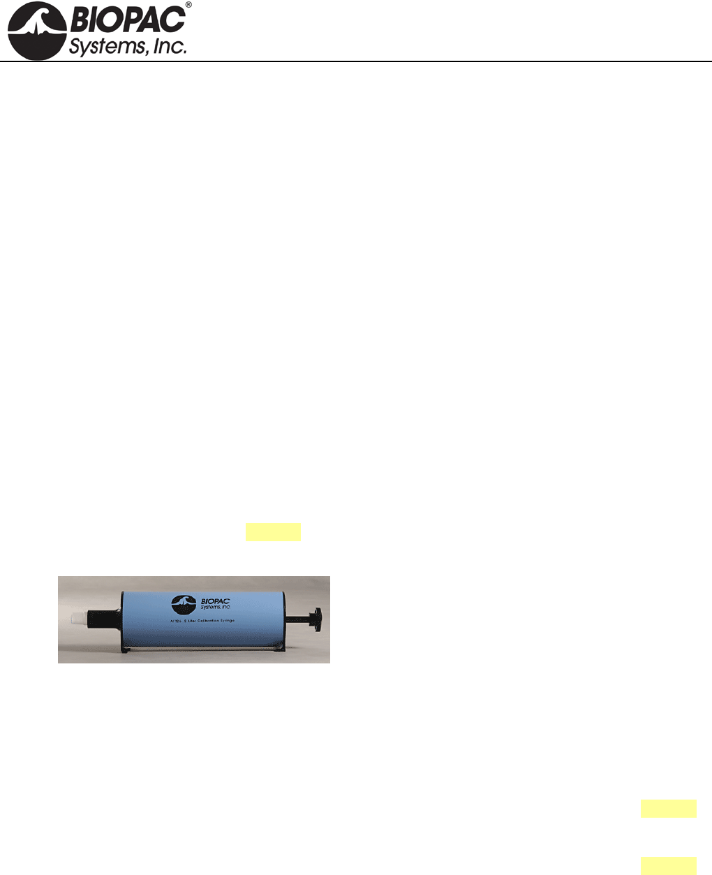
info@biopac.com
support@biopac.com
www.biopac.com
BIOPAC Hardware | AFT Series | Page 2 - 7 Updated: 12.3.2013
MOUTHPIECES
MRI Use: MR Safe
AFT Mouthpiece Components: Polyethylene EVA Copolymer, Thermoplastic Rubber,
Polycarbonate Plastic
AFT2 Disposable Mouthpiece Available in Packs of 10 or 250
22 mm OD; connects to the SS11LA or TSD117 via the AFT1.
AFT8 Autoclavable Mouthpiece Available in Packs of 1 or 10
30 mm ID; interfaces with the SS11LA or TSD117 and reduces the cost of disposable parts.
• RX117 Replacement Sterilizable Airflow Head: 22 mm ID/30 mm OD; autoclavable transducer
head for the TSD117; can be used with the AFT8 to reduce the cost of disposable items.
AFT9 Reusable Mouthpiece Available in Packs of 1 or 10
35 mm ID; designed to connect to the TSD107B or other 35 mm breathing circuits with the AFT7 via
the AFT4. (Also connects to the AFT21 Non-rebreathing T Valve.)
NOSECLIP
MRI Use: MR Safe
AFT Noseclip Components: Thermoplastic Rubber, Polyvinyl Chloride (PVC) Plastic,
Polyurethane Foam Plastic
AFT3 Disposable Noseclip Available in Packs of 10 or 250
Gently squeezes the nostrils shut while using the SS11LA or TSD117 Airflow Transducer.
CALIBRATION SYRINGES
AFT6A Calibration Syringe
0.6 liter calibration syringe. See also: AFT26 2.0 liter Calibration Syringe
AFT26 Calibration Syringe (2.0 liter)
The AFT26 is a 2.0 Liter Calibration Syringe for the
SS11LA or TSD117 Airflow Transducer. The AFT26
Calibration Syringe is certified to have a 2-liter volume that
meets or exceeds an accuracy ± 1% of the total
displacement volume. The increased size and accuracy of
this 2.0 liter calibration syringe provide a wider calibration
range than the AFT6A for advanced studies. A coupler is included and can be reordered as AFT11I if it
is inadvertently discarded when an airflow accessory is removed.
TUBING FOR AIRFLOW
MRI Use: MR Safe
AFT7/7L/12 Tubing Components: Polyethylene EVA Copolymer
AFT7 Smooth Bore Tubing
1 m length, 35 mm ID; connects to the TSD107B, AFT4, or other 35 mm breathing circuits. See also:
AFT part guide for additional applications.
AFT7L Smooth Bore Tubing
3 m length, 35 mm ID; connects to the TSD107B, AFT4, or other 35 mm breathing circuits. See also:
AFT part guide for additional applications.
AFT12 Tubing (22mm)
Smooth bore tubing for use in 22mm breathing circuits. (1.8 meter length, 22 mm ID)
HARDWARE GUIDE
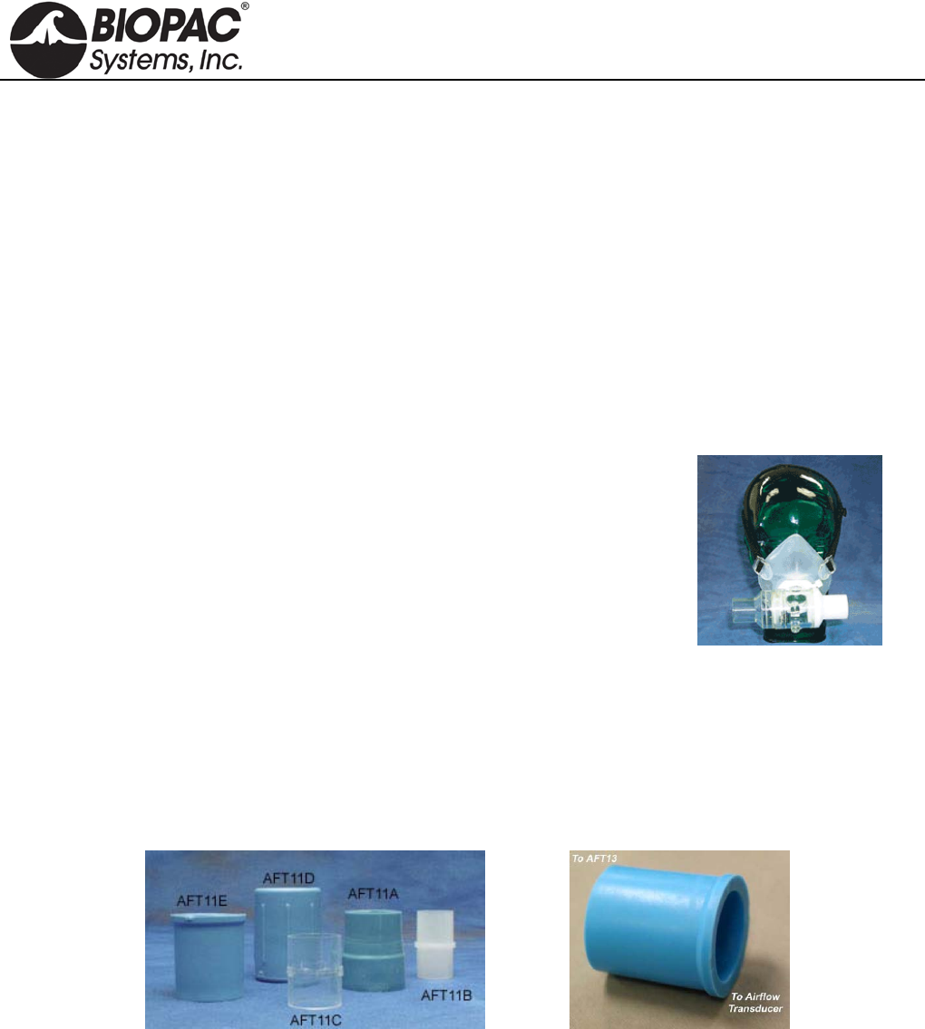
info@biopac.com
support@biopac.com
www.biopac.com
BIOPAC Hardware | AFT Series | Page 3 - 7 Updated: 12.3.2013
FACEMASKS, FACEMASK ACCESSORIES
AFT10 Disposable Adult Facemask
These mouthpieces connect to 22 mm breathing circuits. Connects directly to the AFT1, AFT22 non-
rebreathing T-valve, or SS11LA/TSD117 airflow transducer (via AFT11B coupler). Includes hook-ring
to secure AFT10S adjustable head strap. (22 mm ID/25 mm OD)
MRI Use: MR Safe
AFT10 Facemask Components: Thermoplastic Elastomer, Polyvinyl Chloride (PVC) Plastic
AFT10S Adjustable Head Strap
This fully adjustable latex head strap holds the AFT10 disposable facemask securely to the subject’s
head. Use one or more straps to securely fasten the mask.
MRI Use: MR Safe
AFT10S Head Strap Components: Latex Rubber
AFT25 Facemask with Valve
This adult facemask with integral non-rebreathing T valve is a high
performance, very low dead space, low airflow resistance mask and
valve; suitable for high airflow applications (e.g. exercise physiology).
The AFT25 incorporates two gas sampling ports (female Luer) for
interfacing with the AFT20 Gas Sampling Kit. All ports are 35 mm OD,
28 mm ID
MRI Use: MR Safe
AFT25 Facemask Components: Mask: Thermoplastic Elastomer, Valve:
Acetal Plastic, Acrylic Plastic,, Aluminum (nickel plated silver,) Elastomer, Nylon, Thermoplastic
Polyester, Polycarbonate Plastic, Silicone Rubber, Stainless Steel, Polysulfone Plastic
Headgear: Fabric with Velcro straps
COUPLERS
MRI Use: MR Safe
AFT11 Series Coupler Components: Thermoplastic Rubber, Polyvinyl Chloride (PVC) Plastic,
Polycarbonate Clear Plastic, Acrylonitrile Butadiene Styrene (ABS) Thermo-molded, Plastic
AFT11A Flexible AFT11D Flexible AFT11H Flexible
AFT11B Rigid AFT11E Flexible AFT11I Flexible (for AFT26)
AFT11C Rigid AFT11F Rigid
These couplers are very useful for connecting up a variety of airflow port IDs and ODs to transducers, tubing and
calibration syringes. Pick an AFT11 Series coupler that matches the port sizes to be interfaced.
HARDWARE GUIDE
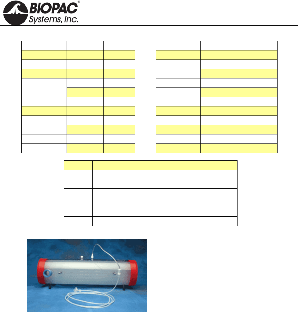
info@biopac.com
support@biopac.com
www.biopac.com
BIOPAC Hardware | AFT Series | Page 4 - 7 Updated: 12.3.2013
AFT11 Series Coupler Guide
Item 1 Item 2 Coupler Item 1 Item 2 Coupler
15 mm OD 22 mm ID AFT11B 25 mm ID 25 mm ID AFT11C
20 mm OD 22 mm ID AFT11B 25-30 mm OD 25-30 mm OD AFT11A
22 mm ID 15 mm OD AFT11B 28-35 mm ID AFT11A
20 mm OD AFT11B 28-35 mm ID 25-30 mm OD AFT11A
22 mm ID AFT11B 35 mm ID AFT11A
22 mm OD AFT11I 34-37 mm ID 41-47 mm ID AFT11F
22 mm OD 22 mm ID AFT11C 35 mm ID 28-35 mm ID AFT11A
22 mm OD AFT11C 38 mm ID AFT11E
25 mm ID AFT11C 35-38 mm ID 22-25 mm OD AFT11E
22-25 mm OD 22 mm OD AFT11E 35-38 mm OD 35-38 mm OD AFT11D
25 mm ID AFT11E 35 mm OD 28.6 mm OD AFT11H
Coupler Size Interface
AFT11A 25 mm OD/35 mm ID AFT6A to AFT1
AFT11B 15 mm OD/22 mm ID AFT10 to SS11LA
AFT11E 22 mm OD/35 mm ID AFT7 to AFT22/25
AFT11F 35 mm OD/45 mm OD SS52L to GASSYS2
AFT11H 35 mm OD/28.6 mm ID AFT13 to SS11LA
AFT11I 22 mm OD/22 mm ID AFT26 replacement coupler
AFT15 MIXING CHAMBERS
AFT15A/B mixing chambers incorporate dual baffles
and flexible connection ports capable of interfacing with
35 mm or 22 mm breathing circuits.
Two female Luer connection ports are provided between
the baffles for the simultaneous monitoring of O2 and
CO2 concentrations.
AFT15A shown with AFT20 (not included)
AFT15A — 5 Liter
Use for demanding expired gas analysis measurements
(e.g. VO2 or RER measurements).
Dimensions: 13 cm (dia) x 47 cm (long) Coupling Ports: 35 mm OD, 25 mm ID
AFT15B — 8 Liter
Use for very high volume and rate expired gas analysis measurements (e.g. VO2 or RER
measurements).
Dimensions: 13 cm (dia) x 73 cm (long) Coupling Ports: 35 mm OD, 25 mm ID
GAS SAMPLING INTERFACE KITS
AFT20
Use to interface the CO2100C and the O2100C modules with the TSD107B or TSD117 Airflow
Transducer breathing circuits.
Includes: 1.8 meters of 1.5 mm inner diameter semi-flexible polyethylene tubing with M/F Luer
connector; 30cm Nafion® water vapor permeable tubing with M/F Luer connector; 5 micron filter with
M/F Luer connector; M/F Luer to female Luer “Y” connector.
HARDWARE GUIDE

info@biopac.com
support@biopac.com
www.biopac.com
BIOPAC Hardware | AFT Series | Page 5 - 7 Updated: 12.3.2013
The AFT20 connects the CO2100C or O2100C directly to the sampling port of a mixing chamber. The
AFT20 also permits sampling connections to the Non-rebreathing “T” Valves (AFT21 or AFT22).
MRI Use: MR Safe
AFT20 Gas Sampling Kit Components: Tubing: 1.8 m of 1.5 mm diameter polyethylene tubing with
M/F Luer; Tubing: 30 cm Nafion water vapor permeable tubing with M/F Luer connector; Y-
connector: Acrylonitrile butadiene styrene (ABS) polycarbonate
AFT31-MRI
This 3.175 mm ID tubing is 10 meters long with male and female Luer
lock and "Y" connector interfaces to the AFT21 T-valve, AFT25
facemask, or AFT15 mixing chamber gas sampling ports to connect
them to the CO2100C module and/or the O2100C module. To use both
CO2100C and O2100C modules simultaneously, a “Y” connector gas
sampling interface adapter is included.
MRI Use: MR Safe
AFT31-MRI Gas Sampling Kit Components: Polyethylene, Polyvinyl Chloride Plastic,
Polycarbonate Clear Plastic
ID/OD: 3.175 mm (1/8") / 6.35 mm (1/4") Type: Crack-Resistant Polyethylene Tubing
Maximum Pressure: 358 psi @ 70º F Material: Linear Low Density Polyethylene
Operating Temperature Range: -100° to +175° F Wall Thickness: 1.588 (1/16")
“Y” connector: 1 x male to 2 x female Bend Radius: 2"
Length: 10 m Durometer: 95A (Firm)
AFT35-MRI
The Airflow Subject Interface Kit for MRI will allow two configurations with minimal clearance from
mouth to fMRI cage:
Low clearance - 6 cm: use right-angle coupler with mouthpiece and noseclip
Standard clearance - 12 cm: use right-angle coupler with facemask
The AFT35-MRI assembly includes a high-flow, non-rebreathing T valve with right-angle interface to
separate inspired flow from expired flow. Use assembly to perform the following airflow and lung
volume tests in an fMRI:
• End Tidal CO2
• VO2 max
• Breath-by-breath Air Flow
• Breath-by-breath Volume
• Metabolic Studies
The subject breathes into a right angle port that connects to the T valve. The inspire port is directly open
to the chamber room, so there is very low inspired resistance, and the T value expired port connects
directly to 35 mm ID tubing (such as AFT7L).
The AFT35-MRI assembly includes a 35 mm OD T valve (AFT23), mouthpiece (AFT9), facemask
with strap, noseclips, right-angle connector, and couplers.
The AFT35-MRI will connect to one or more lengths of AFT7L tubing, for ultimate connection to
AFT15 Gas sampling chambers, as well as a TSD117-MRI air flow transducer.
MRI Use: MR Safe
AFT35-MRI Components: Polyvinyl Chloride (PVC) plastic, Polyethylene EVA Copolymer,
Thermoplastic Rubber, Polycarbonate Plastic, Acrylic Plastic, Elasotomer, Paper, Latex Rubber,
Polyurethane Foam Plastic, Acrylonitrile Butadiene Styrene (ABS) Thermo-molded
HARDWARE GUIDE
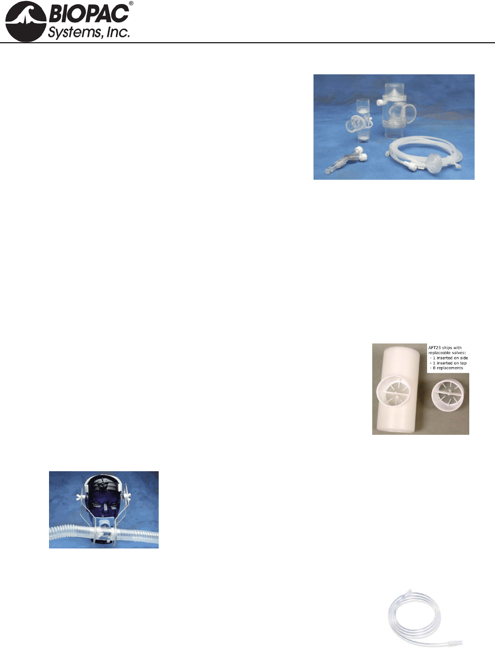
info@biopac.com
support@biopac.com
www.biopac.com
BIOPAC Hardware | AFT Series | Page 6 - 7 Updated: 12.3.2013
AFT T-VALVES
AFT21 Non-Rebreathing “T” Valve: Female, 35 mm
High performance, very low dead space, low airflow
resistance valve, suitable for high airflow applications (e.g.
exercise physiology). The non-rebreathing “T” valve
incorporates a Female Luer connector gas sampling port
for interfacing with the AFT20. All ports are 35 mm OD,
30 mm ID.
Includes: 35 mm OD coupler
Requires: AFT4, AFT7, and AFT9 for proper operation. AFT22 (top left), AFT21 (top right)
AFT20 (bottom)
AFT22 Non-Rebreathing “T” Valve: Male, 22 mm
Very low dead space valve, suitable for low to medium airflow applications. The non-rebreathing “T”
valve incorporates a Male Luer connector gas sampling port for interfacing with the AFT20. Coupler
ports are 22 mm OD fittings. Common port incorporates a 15 mm ID connection. Dead space 20 cc.
Resistance: 0.29 cmH2O at 5 liter per minute flow, 0.65 cmH2O at 10 liter per minute. Single subject
disposable item – do not autoclave. Includes: 22 mm OD coupler
Requires: AFT1 and AFT2 for proper operation.
Includes: 22 mm OD coupler Requires: AFT1 and AFT2 for proper operation.
MRI Use: MR Safe
AFT21/22 T-Valve Components: Acrylic Plastic, Elasotomer, Polycarbonate Clear Plastic
AFT23 Non-Rebreathing T-Valve, 35 mm
The AFT23 is a disposable paper mouthpiece featuring a one-way valve
for pulmonary function measurements (expiratory only). It provides low
air resistance, adds cross-contamination protection, and is strong and
durable. It ships with eight extra valves. Mouthpiece OD: 35 mm. Fits
AFT13 pulmonary function filter & mouthpiece set.
MRI Use: MR Safe
AFT23 T-Valve Components: Acrylic Plastic, Elasotomer, Paper
AFT24 HEAD SUPPORT
The AFT24 head support is used when breathing directly into the AFT21
non-rebreathing T valve for exercise physiology measurements. The AFT21
is secured directly in front of the subject and minimizes the strain associated
with the weight of valves and tubing.
TUBING FOR GAS SAMPLING
AFT30 Series Tubing and M/F Luer Locks
Use this semi-flexible 1.5 mm tubing with male and female Luer locks to
interface with the RX110 self-inflating pressure pad, TSD114
response/hand force pump bulb, or gas sampling ports on AFT15 mixing
chambers, CO2100C module, or O2100C module. See AFT31-MRI for gas
sampling in the MRI.
AFT30: 1.8 m AFT30-L: 4 m AFT30-XL: 10 m
The length of tubing will add a delay of less than 50 msec to the sensing of the waveform peak.
MRI Use: MR Safe
AFT30 Series Gas Sampling Kit Components: 1.5 mm diameter polyethylene tubing with M/F Luer
HARDWARE GUIDE

info@biopac.com
support@biopac.com
www.biopac.com
BIOPAC Hardware | AFT Series | Page 7 - 7 Updated: 12.3.2013
PART SUMMARY FOR TYPICAL AIRFLOW / GAS ANALYSIS APPLICATIONS
PULMONARY FUNCTION
High Flow Med. Flow Low Flow Very Low Flow
Part # Exercising
human Resting human Child, Pig, Dog Small Animals
AFT2 Mouthpiece X
AFT3 Noseclip X X
AFT6A Calibration Syringe X X X
AFT7/7L Tubing X (2)
AFT9 Mouthpiece X
AFT21 T Valve X
AFT24 Head Support X (optional)
AC137 In-line Transformer
DA100C Amplifier X (2) X X X
TSD107B Pneumotach (High) X (2) X
TSD117 Pneumotach (Med.) X
TSD127 Pneumotach (Low) X
TSD137 A-E Pneumotachs (Very Low) X (by size)
Part Options: AFT25 = AFT21 + AFT9 + AFT3 + optional AFT24
AFT2 + AFT3 = AFT0 + AFT11B
EXERCISE PHYSIOLOGY
Mixed Expiratory Gases Breath-by-Breath
High Flow Med. Flow High Flow Med. Flow Low Flow
Part # Exercising
human Resting
human Exercising
human Resting human Dog
AFT6A Calibration Syringe X X X X X
AFT7 Tubing X (2) X
AFT10 Facemask X X
AFT10S Head Strap X X
AFT11 Series Couplers X (3)* X X (2)**
AFT12 Tubing X (2) X
AFT15A Mixing Chamber X X
AFT20 Interface Kit X (2) X (2) X (2) X X (2)
AFT22 T Valve X X X
AFT25 Facemask w/Valve X X
DA100C Amplifier X X X X X
CO2100C CO2 Module X X X X X
O2100C O2 Module X X X X X
TSD107B Pneumotach (High) X X
TSD117 Pneumotach (Med.) X X
TSD127 Pneumotach (Low) X
Part Options: AFT25 = AFT21 + AFT9 + AFT3 + optional AFT24 * use 2 AFT11B and 1 AFT11C
AFT10 + AFT10S = AFT2 + AFT3 + AFT11C ** use 1 AFT11B and 1 AFT11C
See also: AFT coupler guide for additional applications.
HARDWARE GUIDE

info@biopac.com
support@biopac.com
www.biopac.com
BIOPAC Hardware | BSL-TCI | Page 1 - 3 Updated: 1.31.2013
TRANSDUCER CONNECTOR INTERFACES (TCI)
BSL-TCI0 Interface Grass
BSL-TCI1 Interface Beckman 5 pin
BSL-TCI2 Interface WPI
BSL-TCI3 Interface Lafayette
BSL-TCI4 Interface Honeywell
BSL-TCI5 Interface Mod Phone
BSL-TCI6 Interface Beckman
BSL-TCI7 Interface Nihon Koden
BSL-TCI8 Interface Narco 7
BSL-TCI9 Interface Fukuda
BSL-TCI10 Interface Gould: discontinued
BSL-TCI11 Interface Hugo Sachs
BSL-TCI12 Interface Thornton
BSL-TCI13 Interface MP30 to Piezo
BSL-TCI14 Interface 1/4 phono
BSL-TCI15 Interface 5-pin DIN Vernier
BSL-TCI16 Interface BT connector, Vernier
BSL-TCI17 Interface 5-pin Intellitool
BSL-TCI18 Interface 2 mm Hg Strain
BSL-TCI19 Interface 6-pin Intellitool
BSL-TCI20 Interface 3.5 mm Intellitool
BSL-TCI21 Interface BNC pH probe
BSL-TCI22 Interface SS2L to SS39L
See also: SS-KIT-IN BSL/SS Custom Input Kit
SS-KIT-OUT BSL/SS Custom Output Kit
BSL-TCI PIN-OUTS
BSL-TCI0
BSL-TCI4
BSL-TCI1
BSL-TCI5
BSL-TCI2
BSL-TCI6
HARDWARE GUIDE
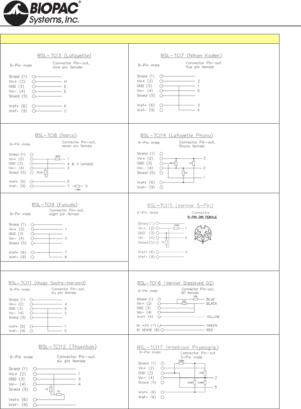
info@biopac.com
support@biopac.com
www.biopac.com
BIOPAC Hardware | BSL-TCI | Page 2 - 3 Updated: 1.31.2013
BSL-TCI PIN-OUTS
BSL-TCI3
BSL-TCI7
BSL-TCI8
BSL-TCI14
BSL-TCI9
BSL-TCI10 Gould 12-pin: discontinued
BSL-TCI15
BSL-TCI11
BSL-TCI16
BSL-TCI12
BSL-TCI17
HARDWARE GUIDE
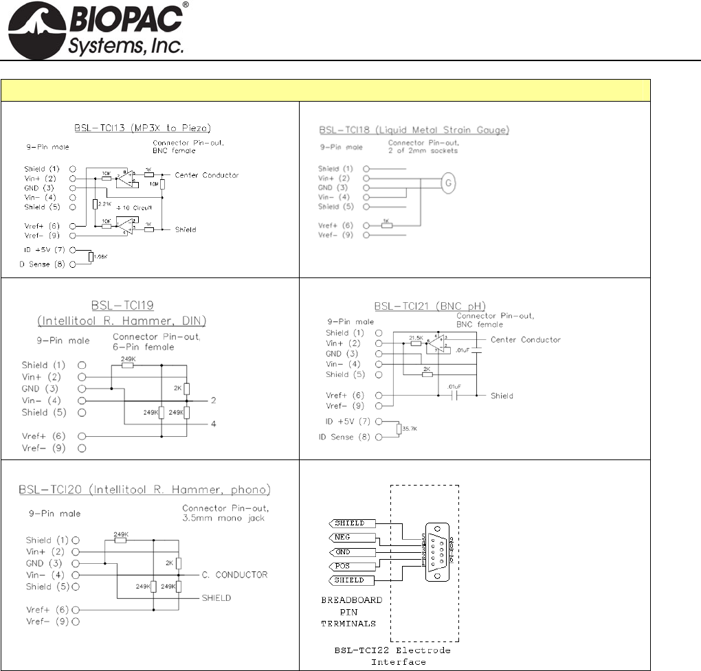
info@biopac.com
support@biopac.com
www.biopac.com
BIOPAC Hardware | BSL-TCI | Page 3 - 3 Updated: 1.31.2013
BSL-TCI PIN-OUTS
BSL-TCI13
BSL-TCI18
BSL-TCI19
BSL-TCI21
BSL-TCI20
BSL-TCI22
HARDWARE GUIDE
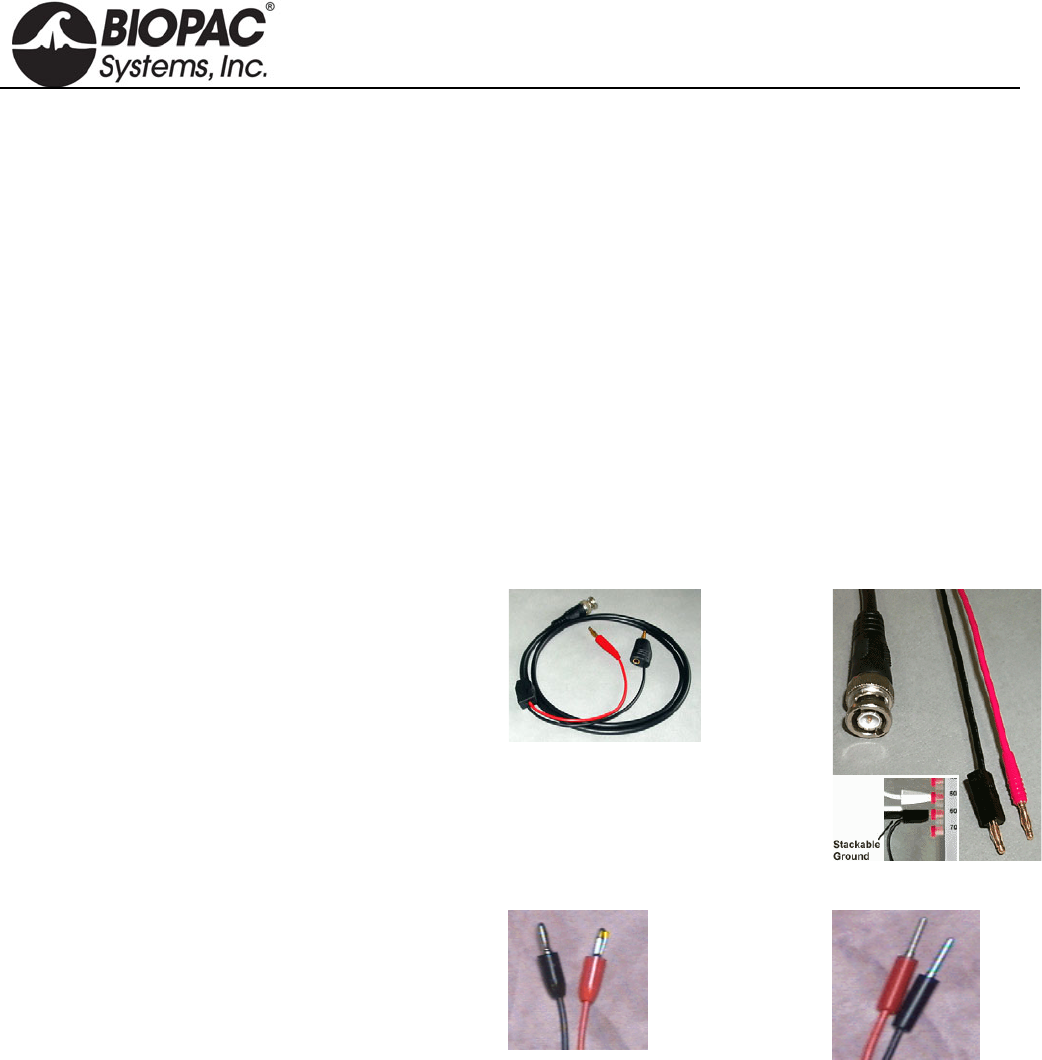
info@biopac.com
support@biopac.com
www.biopac.com
BIOPAC Hardware | BSLCBL SERIES | Page 1 - 2 Updated: 3.29.2013
BSLCBL CABLE SERIES
BSLCBL1A: Stimulator to Nerve Chamber – Banana Plug
BSLCBL2A: Stimulator to Nerve Chamber – 2 mm Pin Plugs
BSLCBL3A: Nerve Chamber to BSL – Banana Plugs
BSLCBL4B: Nerve Chamber to BSL – 2 mm Pin Plugs
BSLCBL5: 3.5 mm Phone Plug
BSLCBL6: Stimulator to Output – 3.5 mm Mono Phone Jack
BSLCBL7: Stimulator to Electrode – BNC to 2x Alligator
BSLCBL11: Stimulator to Electrode – BNC to 2x Electronic Test Clip (spring-loaded)
BSLCBL12: Stimulator to Electrode – BNC to 2x Toothless Alligator
BSLCBL8/9: High Impedance – 1.5 mm Touchproof
BSLCBL14: MP36/35 Input Adapter for Research Amplifiers
INTERFACE CABLES
Stimulator to Nerve Chamber
Interface the BSL Stimulator with nerve conduction
chambers. A BNC connector interfaces with the
stimulator and two plugs attach to the nerve chamber.
Gold-plated
Stackable ground
1.2 meter.
BSLCBL1A
Banana Plugs
BSLCBL2A
2mm Pin Plugs
Nerve Chamber to Biopac Student Lab
Interface nerve conduction chambers with the Biopac
Student Lab System; use to record the signals coming
from the nerve. A BSL DSub 9 connector interfaces
with the Biopac Student Lab MP3X unit and two
plugs attach to the nerve chamber.
1.2 meter
BSLCBL3A
Banana Plugs
BSLCBL4B
2mm Pin Plugs
BSLCBL3A/4B SPECS
Gain: 1/10 (divide by 10)
Input Impedance (Common-Mode): 5e11 Ohms (500 GigaOhm)
Common-Mode Rejection: 90 dB Typical
Input Bias Current: 3pA Typical, 100 pA
Maximum Voltage Noise: 1.3 µV p-p
Voltage Noise Density: nV /SQRT(Hz)
Current Noise Density: 0.01 pA /SQRT(Hz)
HARDWARE GUIDE
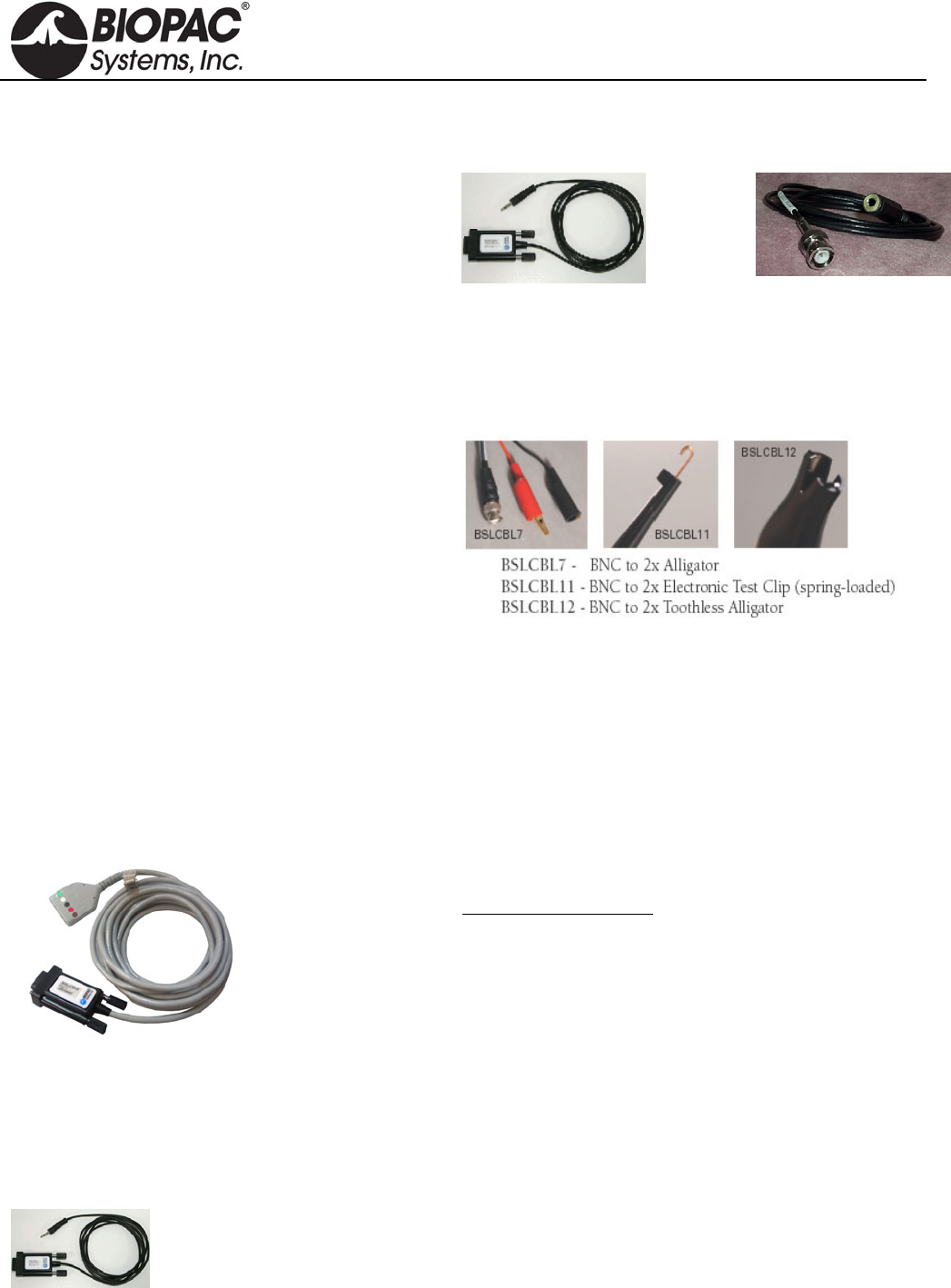
info@biopac.com
support@biopac.com
www.biopac.com
BIOPAC Hardware | BSLCBL SERIES | Page 2 - 2 Updated: 3.29.2013
3.5 mm Phone Plug Adapter
Use BSLSBL5, 1.7 meters (included with TSD122).
The cable has a built-in attenuation of 1/200, which
translates 10 V to 50 mV.
Stimulator to Output
Use BSLCBL6 to interface the BSL Stimulator with
3.5 mm Mono Phone Jack outputs, like the OUT100
Headphones or the OUT101 Tubephone set for
auditory stimulation. Required for Auditory Evoked
Response experiments. Use with OUT3 for MP36
built-in low voltage stim.
1.3 meter
BSLCBL5
3.5 mm Phone Plug
BSLCBL6
3.5 mm Mono Phone Jack
Stimulator to Electrode
BSLCBL7,
BSLCBL11, and
BSLCBL12
Use these clip leads to interface stimulating electrodes, or to
connect directly with animal preparations. Each 1-meter cable
has two clips And terminates with one BNC connector to
interface with the BSLSTM, SS58L Stimulator, or OUT3 for
MP36 low volt stimulator and silver or platinum wire
electrodes.
High-impedance cables
BSLCBL8 and
BSLCBL9
These fully-shielded, high-impedance electrode interface
cables permit high resolution recording of biopotential signals
using reusable electrodes. The adapter terminates with
standard 1.5mm Touchproof electrode connectors to interface
reusable electrodes (EL250, EL350, and EL450 series).
BSLCBL8/9 Specifications
Input Range: BSLCBL8: MP36/36R: ±2 V, MP35: ±1 V, MP30:
±70 mV, MP45: ±2 V
BSLCBL9: MP36/36R: ±3.8 V, MP35: ±3.8 V,
MP30: ±700 mV, MP45: ±3.8 V
Input Impedance: 500mGigaOhm (Common-Mode)
Input Bias Current: 3pA Typical, 100 pA Maximum
Voltage Noise: 1.3 µV p-p
Current Noise Density: 0.01 pA /SQRT(Hz)
Cable length: 2 meters
Interface: MP3X (DSub9)
MP36/35 Input Adapter for Research Amplifiers
BSLCBL14
3.5mm phone plug adapter to MP36/35 Input (DSUB 9m)
Use to interface equipment that outputs high-level voltage
signals, such as BIOPAC research amplifiers via the IPS100C
Isolated Power Supply or UIM100C universal interface.
The cable has a built-in attenuation of 1/10, which translates
10 V to 1V.
HARDWARE GUIDE

info@biopac.com
support@biopac.com
www.biopac.com
BIOPAC Hardware | CBL200 Series | Page 1 - 2 Updated: 2.28.2013
CBL200 SERIES LEAD CONNECTOR CONVERSION CABLES
See also: Guide to External Device Interfaces for connections to common devices
CBL200 10 cm, 2 mm pin
to 1.5 mm socket Converts a 2 mm pin electrode or transducer lead to a Touchproof socket
(1.5 mm ID), for connection to any of the 100C-series Biopotential or
Transducer amplifiers or STMISO series modules. One CBL200 is
required for each Touchproof socket.
CBL201 10 cm, 1.5 mm
socket to 2 mm
pin
Converts a Touchproof (1.5 mm ID) socket electrode or transducer lead to
an old-style 2mm pin, for connection to any of the 100B-series
Biopotential or Transducer amplifier modules. Also used to connect a
ground electrode lead (e.g. LEAD110A) to the UIM100C module
(required when using the TSD150 active electrodes). One CBL201 is
required for each Touchproof socket. For MP36/35/45 Systems CBL201 is
used to update older model SS1L Shielded Lead Adapters.
CBL202 2 mm Male pins
to 6.3 mm (¼)
mono phone jack
Adapts transducers with a 6.3 mm (¼) mono phone plug to the DA100C.
CBL203 1.5 mm Female to
6.3 mm (¼)
mono phone jack
Adapts temperature transducers with a 6.3 mm mono phone plug to the
SKT100C.
CBL204 25 cm,
Touchproof “Y”
adapter
Connects multiple electrode sites to a single amplifier input or stimulator
output. The CBL204 plugs into any 100C-series biopotential amplifier
input or STMISO series output and provides two sockets to connect to
electrode leads terminating in Touchproof sockets. Plug multiple CBL204s
together to reference 3 or more electrode leads to the same input or output.
For MP36/35/45 Systems, use to connect a glass microelectrode to
multiple electrode sites (such as Vin- and GND from BSLCBL8/9 High-
Impedance Cables).
CBL205 1.5 mm AC-
Coupled
electrode lead
adapter
USE CBL205 when more than one
ground is required while recording
electrodermal activity (e.g., galvanic skin response). One end of the
adapter plugs into the ground on the amplifier and the other end accepts
the electrode lead.
To record GSR with other biopotential signals (ECG, EEG, EOG, EGG,
EMG, ERS), BIOPAC recommends using CBL205 connected to one
ground on any of the biopotential amplifiers. The subject will be grounded
through the Vin- of the GSR electrodes, but in some cases it is necessary
to have more than one ground; in such cases, use CBL205 to prevent
ground loops.
For example, if—while recording a biopotential and GSR— the
GSR electrode is removed during a stage of the experiment, to
maintain a ground for the biopotential and avoid ground loops:
1. Connect the Vin- lead of the GSR as ground.
2. Connect an AC-coupled ground to the biopotential amplifier.
CBL205
HARDWARE GUIDE
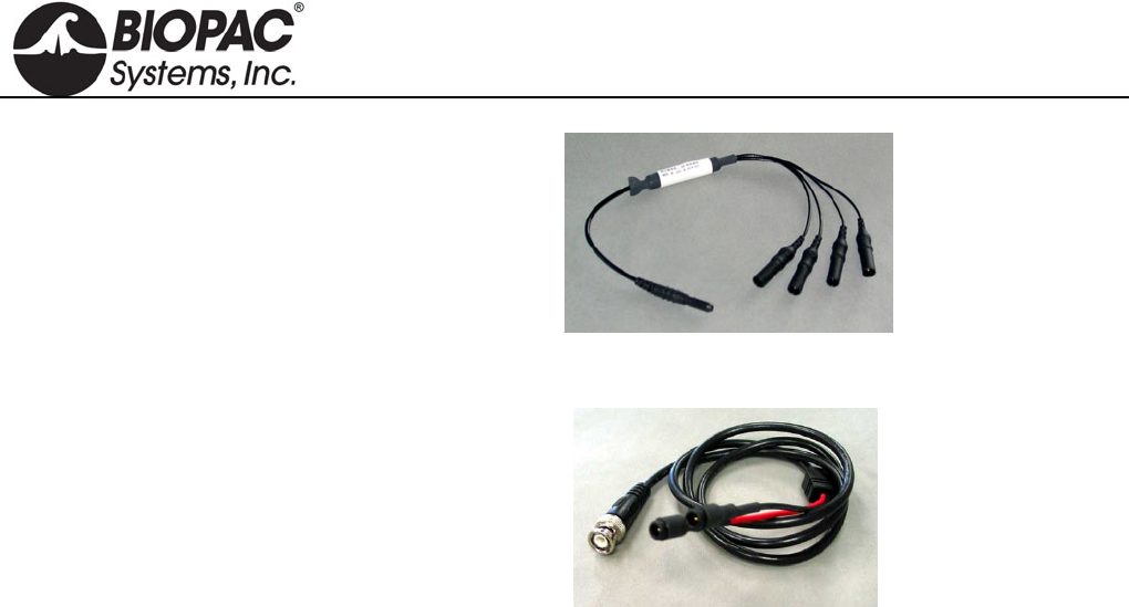
info@biopac.com
support@biopac.com
www.biopac.com
BIOPAC Hardware | CBL200 Series | Page 2 - 2 Updated: 2.28.2013
CBL206 Lead junction
TPF to 4X TPM
Reference four electrodes from one. Connect via the MEC110C to the
NICO100C and EBI100C cardiac output amplifier modules
CBL207 1 m,
BNC (m) to 2 x
1.5 mm TP (m).
Use with
Touchproof (f) electrodes
STM200 Unipolar Pulse Stimulator Module
MECMRI-STIMISO cable/filter system to connect to the STM200
in the MRI control room
HARDWARE GUIDE

info@biopac.com
support@biopac.com
www.biopac.com
BIOPAC Hardware | CBLUSB | Page 1 - 1 Updated: 1.30.2013
CBLUSB
USB CABLE
2.5 meter replacement USB cable connects the MP3X to a USB port. Includes and
provides EMI protection to maintain BSL Systems certified safety rating (CE,
EMC).
HARDWARE GUIDE
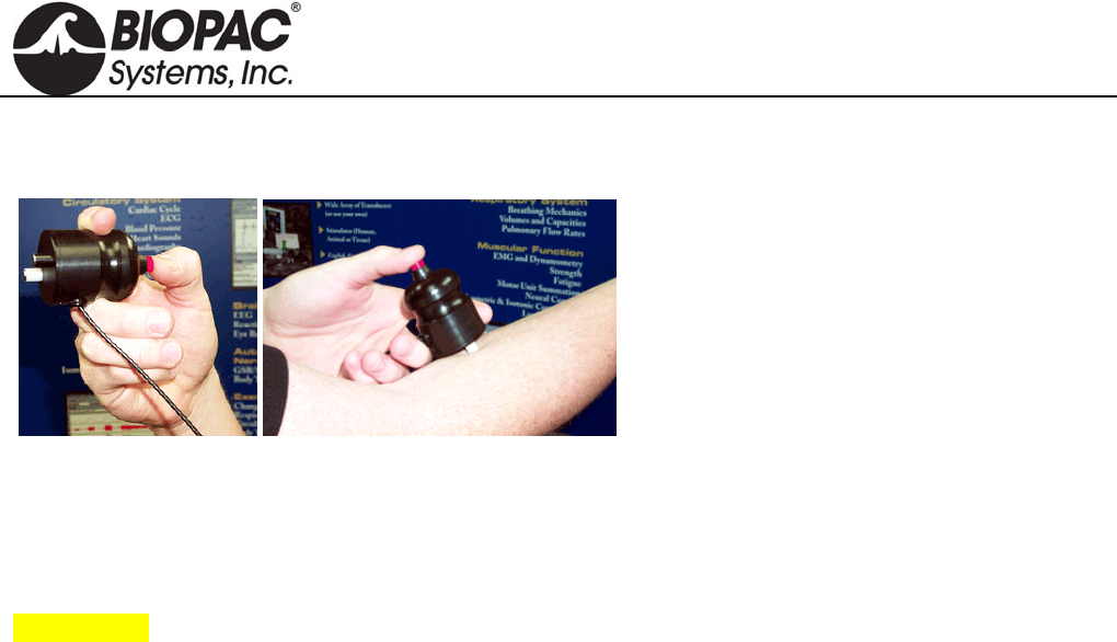
info@biopac.com
support@biopac.com
www.biopac.com
BIOPAC Hardware | HSTM01 | Page 1 - 1 Updated: 7.16.2012
HSTM01 HANDHELD HUMAN-SAFE STIMULATING PROBE
IMPORTANT!
BIOPAC HSTM Series Probes must be used when
stimulating humans. HSTM probes have current-limiting
features, enhanced isolation and a user-operated “dead man”
switch for optimum safety
WARNING!
Even with the HSTM probe, users must never create an
electrical path across the heart (i.e. touching an active tip in
each hand while the switch is engaged) and it should never
be used on subjects with pacemakers.
The HSTM01 handheld human-safe stimulating
probe provides a superior degree of safety and
comfort when using the Biopac Student Lab
Stimulator for human stimulation. The
ergonomic design allows the subject to focus on
electrode placement instead of worrying about
holding the electrode. The subject controls the
stimulus presentation by activating the red safety
switch. To stop the stimulus at any time, the
subject simply removes his/her thumb from the
switch and the electrode shuts off. The electrode
is terminated in a BNC connector that interfaces
with the BSLSTMA.
HSTM01 SPECIFICATIONS
Safety Switch: Yes
Lead Length: 3 m
Connector Type: BNC
Interface: BSLSTMA
HARDWARE GUIDE
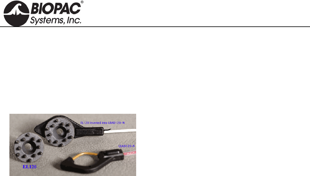
info@biopac.com
support@biopac.com
www.biopac.com
BIOPAC Hardware | EL120 | Page 1 - 1 Updated: 2.28.2013
ELECTRODES
In selecting the application site for any style of electrode, care should be taken that:
1) Electrode site is dry and free of excessive hair.
2) Electrode is not placed over scar tissue or on an area of established erythema or with a lesion of any kind.
3) Skin is properly prepared. (Prepare the skin at the electrode site. Use the ELPAD to lightly abrade the skin
surface. Use a brisk dry rub to prepare the application site. Avoid excessive abrasion of the skin surface.)
EL120
The EL120 electrode has contact posts designed to improve
contact through fur or hair. The 12 posts create a 10 mm
contact area. The posts are 2mm deep to push through fur/hair
to provide good contact with the skin surface.
Shipped in packs of 10.
Silver-silver chloride (Ag-AgCl) electrodes provide accurate and clear transmission of surface biopotentials and
are useful for recording all surface biopotentials on animals and human EEG.
Notes:
It is not necessary to use an EL120 for the ground; a generic electrode can be used for ground.
Requires one LEAD120 per electrode.
HARDWARE GUIDE
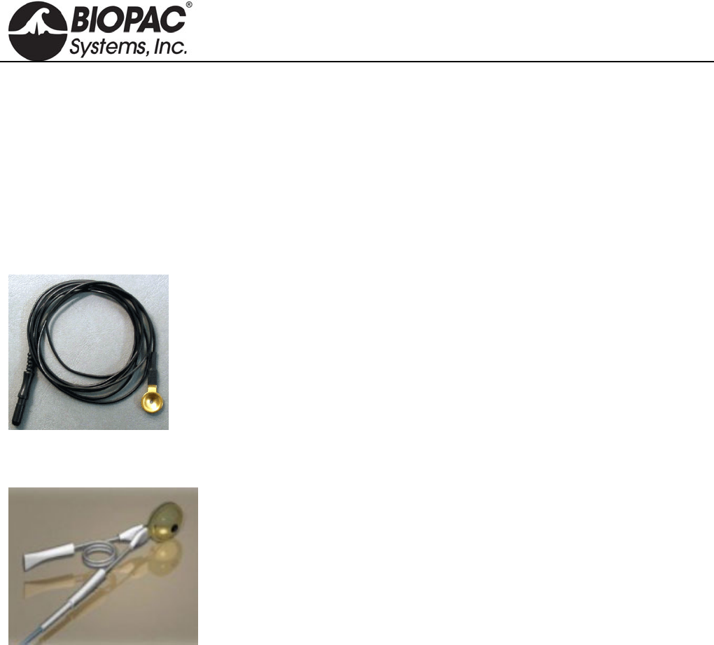
info@biopac.com
support@biopac.com
www.biopac.com
BIOPAC Hardware | EL160 Series | Page 1 - 1 Updated: 3.20.2013
ELECTRODES
In selecting the application site for any style of electrode, care should be taken that:
1) Electrode site is dry and free of excessive hair.
2) Electrode is not placed over scar tissue or on an area of established erythema or with a lesion of any kind.
3) Skin is properly prepared. (Prepare the skin at the electrode site. Use the ELPAD to lightly abrade the skin
surface. Use a brisk dry rub to prepare the application site. Avoid excessive abrasion of the skin surface.)
EL160 GOLD CUP
Reusable gold cup electrode with 10 mm cup diameter and 1.2 m cable.
One electrode per package.
EL160 with black cable
EL160-R with red cable
EL160-W with white cable
The leadwire terminates in a standard Touchproof connector. Use with MEC Series
Module Extension Cables for MP Research Systems or SS1LA Touchproof Electrode
Lead Adapter for BSL Systems.
EL160-EAR – EAR CLIP ELECTRODES
This pair of gold-plated ear clip electrodes has 1.2 meter Teflon-insulated
leadwires ending in standard Touchproof connectors.
EL160-EAR SPECIFICATIONS
Electrodes: two
Material: Au Cup (gold plated discs)
Style: Ear Clip Electrodes
Leadwires: 1.2 meter Teflon-insulated leadwires
Connector: leadwires terminate in standard Touchproof connectors
Non-sterile
Reusable
HARDWARE GUIDE
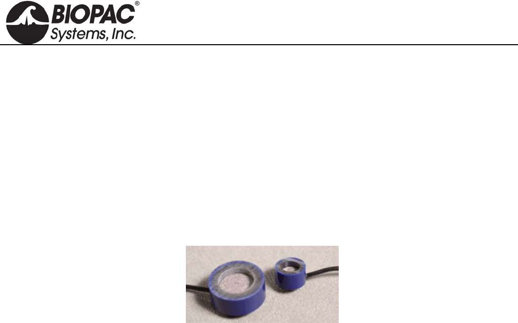
info@biopac.com
support@biopac.com
www.biopac.com
BIOPAC Hardware | EL250 SERIES | Page 1 - 2 Updated: 11.4.2013
ELECTRODES
In selecting the application site for any style of electrode, care should be taken that:
1) Electrode site is dry and free of excessive hair.
2) Electrode is not placed over scar tissue or on an area of established erythema or with a lesion of any kind.
3) Skin is properly prepared. (Prepare the skin at the electrode site. Use the ELPAD to lightly abrade the skin
surface. Use a brisk dry rub to prepare the application site. Avoid excessive abrasion of the skin surface.)
EL250 Series Reusable Ag-AgCI Electrodes
Surface biopotentials can be accurately and clearly transmitted with silver-silver chloride electrodes. EL250
Series reusable electrodes are permanently connected to 1-meter leads and terminate in standard 1.5 mm female
Touchproof sockets for direct connection to the SS1L shielded electrode lead adapter. Use shielded electrode
leads for minimal interference. The unshielded electrode leads work best as ground electrodes. Typically, one
biopotential input requires two shielded electrodes for signal inputs and one unshielded electrode for ground.
EL254 Ag-AgCl Unshielded Electrode, 7.2 mm diameter housing, 4 mm contact area, includes 1 m lead
terminated with a 1.5 mm female Touchproof socket for connection to the SS1L.
EL254S Ag-AgCl Shielded Electrode, 7.2 mm diameter housing, 4 mm contact area, includes 1 meter lead
terminated with two 1.5 mm female Touchproof sockets for connection to the SS1L. The gray lead
plug is for the electrode contact; the black lead pin plug is for the lead shield.
EL258 Ag-AgCl Unshielded Electrode, 12.5 mm diameter housing, 8 mm contact area, includes 1 meter lead
terminated with a 1.5 mm female Touchproof socket for connection to the SS1L.
EL258S Ag-AgCl Shielded Electrode, 12.5 mm diameter housing, 8 mm contact area, includes 1 meter lead
terminated with two 1.5 mm female Touchproof sockets for connection to the SS1L. The gray lead
plug is for the electrode contact; the black lead pin plug is for the lead shield.
EL258H Features a 2 mm gel injection hole, useful for EEG monitoring; use as both recording and reference
electrodes. 12.5 mm diameter housing, 8 mm contact area, 1 m lead terminated with 1.5 mm female
Touchproof socket for connection to the SS1L.
EL250 Series Radiotranslucent Ag-AgCI Recording Electrodes (Animals Only)
MRI Use: MR Conditional (tested to 9T)
Condition: For use with animals only, due to possible heating hazards associated with incomplete
filling of gel reservoir with electrode gel.
EL254RT/258RT Components:
Electrode: Ag/AgCI Lead wire: Carbon
Enclosure: Epoxy Wire insulation: PVC
EL254RT Silver-silver chloride (Ag-AgC1) electrodes provide accurate and clear transmission of surface
biopotentials. Reusable electrodes are permanently connected to robust and pliable leadwires. The
leadwires terminate in standard Touchproof connectors for interfacing to 100C series Biopotential
modules or extension cables. 7.2 mm diameter housing, 4 mm contact area, includes 1.5 m lead
terminated with a 1.5 mm female Touchproof socket for connection to the SS1L.
EL258RT As described above for EL254RT but with larger dimensions. 12.5 mm diameter housing, 8 mm
contact area, includes 1.5 m lead terminated with 1.5 mm female Touchproof socket for connection to
the SS1L.
HARDWARE GUIDE

info@biopac.com
support@biopac.com
www.biopac.com
BIOPAC Hardware | EL250 SERIES | Page 2 - 2 Updated: 11.4.2013
All EL250 Series electrodes require adhesive disks (ADD200 series) and recording gel
(GEL1 or the preferred recording gel). See the Electrode Accessories section for further
description.
Instructions for EL250 Series Electrodes
1) Store electrodes in clean, dry area.
2) After use, clean electrode with cold to tepid water
a) DO NOT use hot water.
b) Cotton swabs are suggested.
3) The electrodes should be completely dry before returning to storage.
4) DO NOT allow the electrodes to come in contact with each other during storage (adverse reaction could take
place).
Electrodes may form a brown coating if they have not been used regularly. This should be removed by
gently polishing the surface of the electrode element with non-metallic material. Wiping with mild
ammonium hydroxide will also remove this coating. Rinse with water and store the electrode in a clean,
dry container.
5) Remove an appropriate size electrode washer (ADD204, ADD208, or ADD212) from its waxed paper strip
and carefully apply the washer to the electrode so the center hole of the washer is directly over the electrode
cavity.
6) Fill the cavity with electrode gel (GEL100). No air bubbles should be present in the cavity.
7) Remove the white backing from the washer to expose the second adhesive side.
8) Place electrode on prepared skin area and smooth the washer into place.
9) Apply a few drops of electrode gel to fingertip and rub the exposed side of the adhesive washer (around the
electrode) to rid its surface of adhesive quality.
HARDWARE GUIDE
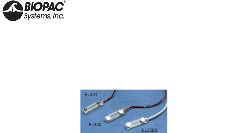
info@biopac.com
support@biopac.com
www.biopac.com
BIOPAC Hardware | EL350 SERIES | Page 1 - 1 Updated: 12.2.2013
ELECTRODES
In selecting the application site for any style of electrode, care should be taken that:
1) Electrode site is dry and free of excessive hair.
2) Electrode is not placed over scar tissue or on an area of established erythema or with a lesion of any kind.
3) Skin is properly prepared. (Prepare the skin at the electrode site. Use the ELPAD to lightly abrade the skin
surface. Use a brisk dry rub to prepare the application site. Avoid excessive abrasion of the skin surface.)
EL350 SERIES BAR LEAD ELECTRODES
Bar lead electrodes are recommended when applying a stimulus during nerve conduction, somatosensory or
muscle twitch recordings with human subjects. Two concave tin electrode disks are placed 30mm apart in a
watertight acrylic bar.
EL350 unshielded bar lead electrode for use with the STMISO.
EL350S shielded bar lead electrode for biopotential recordings.
EL351 convex bar lead electrode for stimulating
EL350 SPECIFICATIONS
Electrode space: 30mm
Lead length: 61cm
Connector type: BNC
Interface: BSLSTM Stimulator or SS58L Low Voltage Stimulator
HARDWARE GUIDE
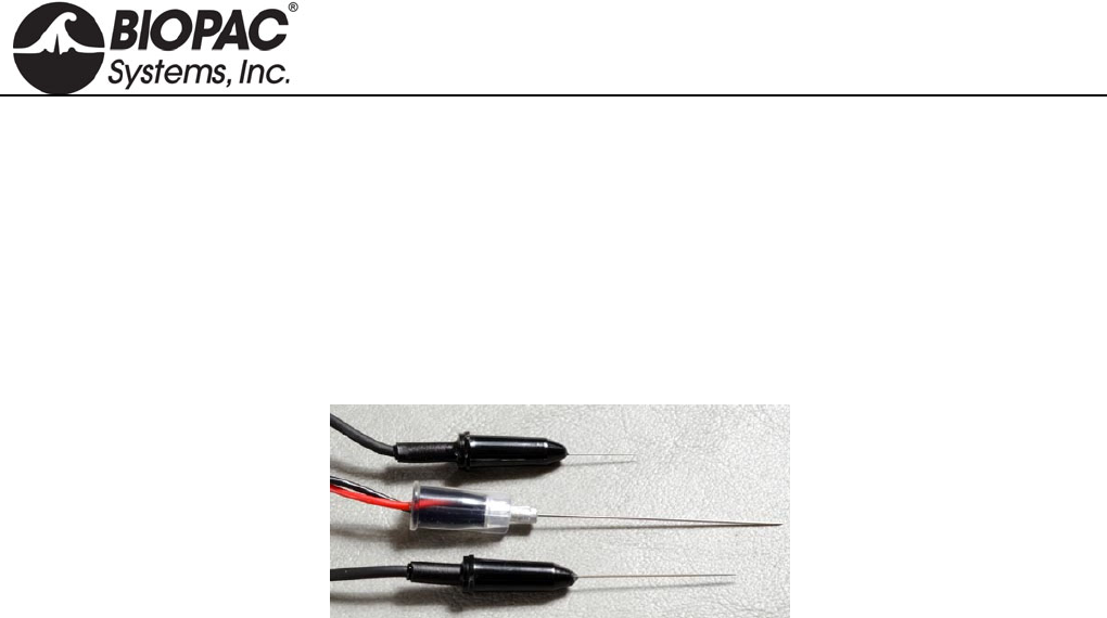
info@biopac.com
support@biopac.com
www.biopac.com
BIOPAC Hardware | EL450 SERIES | Page 1 - 1 Updated: 12.2.2013
ELECTRODES
In selecting the application site for any style of electrode, care should be taken that:
1) Electrode site is dry and free of excessive hair.
2) Electrode is not placed over scar tissue or on an area of established erythema or with a lesion of any kind.
3) Skin is properly prepared. (Prepare the skin at the electrode site. Use the ELPAD to lightly abrade the skin
surface. Use a brisk dry rub to prepare the application site. Avoid excessive abrasion of the skin surface.)
EL450 SERIES NEEDLE ELECTRODES
Use for stimulation or recording in animal subjects and tissue preparations. The 28-gauge stainless steel needles
are Teflon-coated, with flexible cable terminating in 1.5 mm Touchproof connectors. The coating prevents the
needle from making contact with the subject except at the very tip of the needle, which is exposed. For
applications that require better contact between the electrode and the subject to record a good signal, abrade the
needle to remove the Teflon coating.
Needle electrodes are shipped non-sterile, so pre-sterilization is required.
EL450 Unipolar: 2.5 cm (long) x 300µm (dia); 61 cm lead
A pair of EL450 electrodes is suitable for either recording or stimulation.
EL451 Bipolar: 3.0cm (long) x 460µm (dia); 91cm lead
Use when recording from a single site, as in studies of single muscle fibers.
EL452 Unipolar, uncoated: 1.5cm (long) x 300µm (dia); 61 cm lead
HARDWARE GUIDE
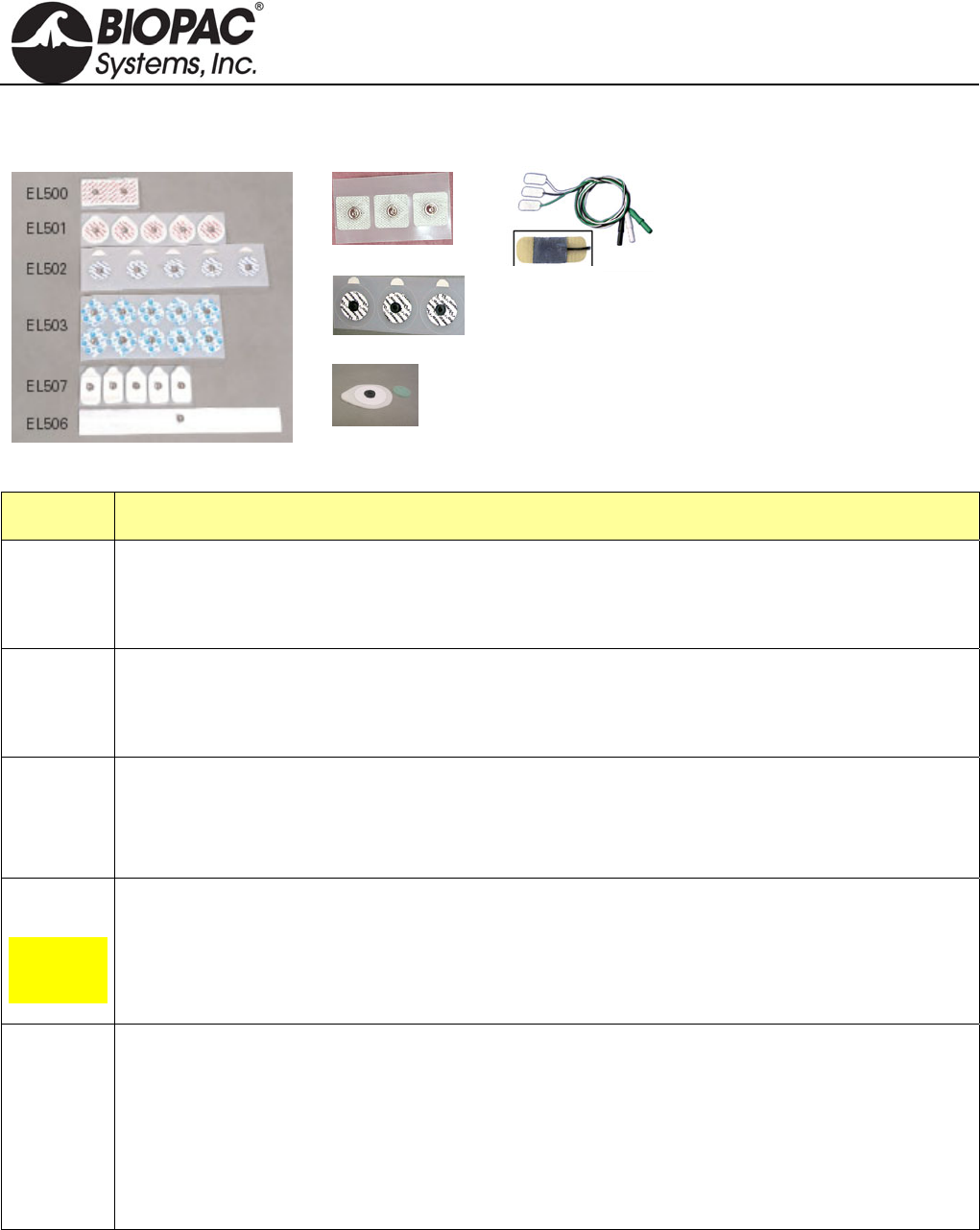
info@biopac.com
support@biopac.com
www.biopac.com
BIOPAC Hardware | EL500 SERIES | Page 1 - 3 Updated: 11.4.2013
EL500 SERIES DISPOSABLE ELECTRODES
EL504
EL508
EL509
The EL500 Series snap
electrodes provide the same
signal transmission as
BIOPAC’s reusable
electrodes, with added
convenience and hygiene.
Each peel-and-stick
electrode is pre-gelled and
designed for one use only.
Use disposable snap
electrodes with BIOPAC’s
SS2L electrode lead set.
EL510
Part Ag-AgCl Adhesive/Disposable Electrode Type
EL500 Paired electrodes: Use for general-purpose EMG measurements, nerve conduction measurements,
and cardiac output.
41mm spacing (center to center) on 4mm x 82mm x 1.5mm foam
EL501 Small stress test electrodes: Use for short-term recordings where the subject may be in motion or
when electrodes should be closely placed, as for multi-channel ECG, EGG, EMG or EOG.
38mm diameter mounted on 1.5mm thick foam with strong adhesive
EL502 Small pre-gelled electrodes Most appropriate for long-term biopotential measurement recording
sessions, these pre-gelled electrodes have a 10 mm contact area on a 41mm (dia) backing that
resists moisture. The electrodes include a hypoallergenic adhesive solid gel that adheres well to the
skin but leaves no residue when removed.
EL503
General-
purpose
electrode
Ag-AgCl Adhesive/Disposable Electrode, 35mm diameter vinyl tape, 10 mm contact area, gel.
These economical, pre-gelled electrodes are most suitable for short-term recordings. These
electrodes have a 10 mm contact area on a 41mm (dia) backing that allows close electrode
placement where necessary, with a slightly less firm adhesive for “ouchless” removal. The
electrodes incorporate hypoallergenic liquid gel and are high chloride for quick, accurate readings.
EL504 Cloth base, 2.5 cm square electrodes. Particularly useful for applications on non-conforming
surfaces, such as the face for EMG or fingers for nerve conduction studies.
The adhesive solid gel ensures good contact, and the silver-silver chloride (Ag-AgCl) electrodes
provide accurate and clear transmission of surface biopotentials. Use these comfortable and
conforming electrodes in EMG, nerve conduction, ECG, sleep studies, exercise physiology, etc.
The latex-free, hypoallergenic electrode adheres well and is repositionable and suitable for long
term use without irritation.
HARDWARE GUIDE

info@biopac.com
support@biopac.com
www.biopac.com
BIOPAC Hardware | EL500 SERIES | Page 2 - 3 Updated: 11.4.2013
Part Ag-AgCl Adhesive/Disposable Electrode Type
EL506
Alternative
for band
electrodes
This unique disposable strip electrode is designed for bioimpedance applications. The electrode is
silver laminated on medical grade cloth, with industry-standard medical grade adhesive, medium
tackiness. The silver-silver chloride (Ag-AgCl) electrode provides accurate and clear transmission
of surface biopotentials and is latex free.
Strip length: 254mm
Conductive element width: 6.35mm
Adhesive width: 23.5mm
Advantages of the Strip Electrode:
Combines the convenience of standard snap (spot) electrodes with the signal to noise,
equipotential and current diffusion performance of band electrodes
Less obtrusive than band electrodes--easier for subjects to move and breathe
Ergonomic advantages of snap (spot) electrodes
Diffuses currents similarly to band electrodes (reduces current density)
Provides voltage measurements through a well-defined equipotential plane
Adjustable size—cut the 25cm strip to the desired size without affecting signal transmission
Snap lead connection
Peel-and-stick convenience
Disposable
EL507 Designed for electrodermal activity studies and are pre-gelled with isotonic gel. The latex-free,
MRI-compatible electrodes conform and adhere well.
Wet Gel: 0.5% Chloride Salt
Contact area: 1 cm
Size: 2.5 cm x 4.5 cm
Snap: Stainless Steel
Backing: Foam
EL508 These disposable, radiotranslucent electrodes are pre-gelled.
Use with LEAD108. (See MRI use information for EL508 and EL509 below.)
EL509 These disposable, radiotranslucent dry electrodes have no shelf-life limitation and are ideal for
EDA/GSR applications. Use with LEAD108 and electrode gel—GEL101 recommended for
EDA/GSR.
To add gel:
1. Fill back cavity (adhesive side) with gel.
2. Add a drop of gel to the sponge pad.
3. Place the sponge pad into the cavity.
4. Press firmly to clear air pockets.
Circular contact area diameter: 1 cm
Backing: 25 mm x 44 mm
MRI Use: MR Conditional
Condition: Carbon-filled plastic snap will not interfere with imaging; tested 3T-9T.
EL508/509 Components: Substrate: Tape with medical grade adhesive, Label: Bi-Oriented
Polypropylene (BOPP) or Vinyl, Stud: 40% Carbon-filled ABS plastic,
Eyelet: 20% glass-filled ABS plastic coated with Ag/AgCi, Reticulated
foam: Polyester-polyurethane, Gel: 10% chloride-liquid gel (EL508)
HARDWARE GUIDE
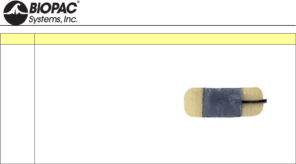
info@biopac.com
support@biopac.com
www.biopac.com
BIOPAC Hardware | EL500 SERIES | Page 3 - 3 Updated: 11.4.2013
Part Ag-AgCl Adhesive/Disposable Electrode Type
EL510 EL510 is a disposable RT electrode set of three electrodes with hydrogel centers and hydrocolloid
ends that terminate in Touchproof leads. Each box includes 20 sets of 3 electrodes.
Pre-wired
Safely secures to limbs without a strap that
could reduce circulation.
Gentle hydrocolloid ends and hydrogel
adhesives.
Long lasting and easy to use, even under high
humidity.
Radiolucent materials allow for x-ray
wherever they are positioned
Latex, phthalate/DEHP, BPA free.
Electrodes are 25 mm x 10 mm with a 10 mm x 10 mm gelled contact area, and the micro-lead
cables are 58 cm.
HARDWARE GUIDE

info@biopac.com
support@biopac.com
www.biopac.com
BIOPAC Hardware | EL650 SERIES | Page 1 - 1 Updated: 12.2.2013
ELECTRODES
In selecting the application site for any style of electrode, care should be taken that:
1) Electrode site is dry and free of excessive hair.
2) Electrode is not placed over scar tissue or on an area of established erythema or with a lesion of any kind.
3) Skin is properly prepared. (Prepare the skin at the electrode site. Use the ELPAD to lightly abrade the skin
surface. Use a brisk dry rub to prepare the application site. Avoid excessive abrasion of the skin surface.)
EL650 SERIES REUSABLE SNAP ELECTRODES
EL654 This is a reusable Ag-AgCl snap electrode with a 4 mm diameter.
EL658 This is a reusable Ag-AgCl snap electrode with a 8 mm diameter.
Use with ADD204 adhesive collars and interface with LEAD110S Series snap electrode leads or
BioNomadix electrode lead sets.
EL654/658 SPECIFICATIONS
Sensor diameter: 4 mm Ag-AgCl (EL654,) 8 mm Ag-AgCl (EL658)
Housing diameter: 13 mm
Overall height: 6 mm (EL654,) 8 mm (EL658)
Gel cavity: 2 mm deep
Snap: 1 mm thick Ag-AgCl sintered sensor element mounted in an epoxy housing; all parts are firmly
encapsulated with epoxy, resulting in a tough, durable waterproof assembly
How to Clean Reusable Electrodes
1. Do not leave GEL in the cavity after use. If GEL is left in cavity, the Ag-AgCl electrode disk could degrade
quickly with time because the electrode surface is somewhat porous to promote good conductivity to the
GEL.
2. To clean the reusable electrode, use a cotton swab or toothbrush with tap water.
3. Use any lab cleaner with pumice (such as Ajax) with cotton swab or toothbrush to remove any dark
residue from electrode surface.
4. Use Hydrogen Peroxide solution (2-3%) to brighten electrode surface (optional) or to sterilize electrode.
Do not place the electrode in solution, but simply clean the electrode surface using a cotton swab.
5. Dry electrode off completely before storage.
HARDWARE GUIDE
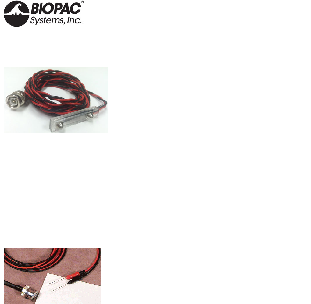
info@biopac.com
support@biopac.com
www.biopac.com
BIOPAC Hardware | ELSTM Series | Page 1 - 1 Updated: 5.14.2013
ELSTM1 UNSHIELDED STIMULATING BAR ELECTRODE
The ELSTM1 Unshielded Stimulation Bar Electrode for Research Systems has a BNC connector that will
interface with either the STM200 or the STMISOLA.
ELSTM1 SPECIFICATIONS
Bar Length: 4 cm
Spacing between contacts: 3 cm
Electrode Contact Diameter: 1 cm
Cable Length: 2 m
ELSTM2 UNSHIELDED NEEDLE ELECTRODES
Recommended for use when applying a stimulus to animal subjects and tissue preparations. The dual stainless
steel needles are Teflon coated. The coating prevents the needle from making contact with the subject except at
the very tip of the needle, which is exposed. For applications that require better contact between the electrode and
the subject to record a good signal, abrade the needle to remove the Teflon coating. Needle electrodes are shipped
non-sterile, so pre-sterilization is required.
ELSTM2 SPECIFICATIONS
Needle Length: 2.5 cm
Needle Diameter: 0.3 mm
Cable length: 2.5 m
Connector type: BNC
Interface: BSLSTM Stimulator or SS58L for MP35 or OUT3 for MP36
HARDWARE GUIDE

info@biopac.com
support@biopac.com
www.biopac.com
BIOPAC Hardware | Electrode Accessories | Page 1 - 3 Updated: 10.29.2013
ELECTRODE ACCESSORIES & GELS
Abrasive Pads
Before applying electrodes, abrade the skin lightly with an ELPAD (above left) to remove non-conductive skin
cells and sensitize skin for optimal adhesion. Each ELPAD package contains 10 abrasive pads.
Adhesive
Use adhesive tape for attaching Active Electrodes and other devices. Use the preferred tape or BIOPAC’s
adhesive tape: TAPE1 single-sided; TAPE2 double-sided. (Above center)
Adhesive Disks
ADD200 series double-sided adhesive collars are used to hold reusable electrodes (EL254/8RT) firmly on the
skin surface. (Above right)
ADD204 19 mm outside diameter, use with EL254 and EL254S
ADD208 22 mm outside diameter, use with EL258 and EL258S
MRI Use: MR Safe
ADD204/208 Adhesive Disks Components:
Disks: 3M hypoallergenic medical tape – Acrylic polymer
Electrode Gels
GEL1 & GEL100 Non-irritating, hypo-allergenic gel used as a conductant with the EL250 series reusable
electrodes. GEL1 = 50 g; GEL100 = 250 g
MRI Use: MR Conditional
Condition: Max MR field strength 3T
GEL100 Components:
Water, Sodium Chloride, Propylene Glycol, Mineral Oil, Glyceryl
MonostearatePolyoxyethelene Stearate, Stearyl Alcohol, Calcium Chloride, Potassium
Chloride, Methylparaben, Butylparaben, Propyl Paraben
GEL101 Non-irritating, isotonic gel is primarily used as a conductant for the TSD203 electrodermal
response electrodes. Each tube contains 114 g (~4 ounces).
GEL101 is 0.5% Saline in a neutral base and is the appropriate GEL to use for GSR, EDA,
EDR, SCR, and SCL. This electrode paste has an approximate molarity of 0.05M NaCl and is
0.5% Saline; the Saline concentration is adjusted to obtain a final paste molarity of 0.05M
NaCl. This particular molarity is in line with the recommendation made by Fowles (1981).
Psychophysiology, 18, 232-239
MRI Use: MR Conditional
Condition: Max MR field strength 3T
GEL101 Components:
Cetyl Alcohol #697313, Glycerol Monostearate, Lanolin, USP Anhydrous, Dimenthicon
Silicone TBF9-1000, Water, purified USP Sodium Chloride, Sodium Lauryl Sulfate,
Sorbitol, 70 USP, Methylparaben, Propylparaben, Quaternium-15
HARDWARE GUIDE

info@biopac.com
support@biopac.com
www.biopac.com
BIOPAC Hardware | Electrode Accessories | Page 2 - 3 Updated: 10.29.2013
GEL104 Electrode Gel - salt free - 250 g (8.5 oz). SPECTRA 360® electrode gel.The only salt-free
and chloride-free electrically conductive gel, recommended for all electromedical procedures.
Salt-free characteristics make it particularly suitable for long-term applications. Spectra 360
differs significantly from all other electrically conductive media...it works by wetting the
skin, thereby reducing skin resistance.
Salt-free, no sodium ion transfer
Non-irritating, hypoallergenic, bacteriostatic
Product of choice for conductive rubber/carbon electrodes
Product of choice for ECG and TENS
Non-gritty STAY-WET® formula allows for prolonged use without re-
application
MRI Use: MR Conditional
Condition: Max MR field strength 3T
GEL104 Salt-Free Components:
Water, Propylene Glycol, Mineral Oil, Glyceryl Monostearate, Polyoxyethelene Stearate,
Stearyl Alcohol, Methylparaben, Butylparaben, Propyl Paraben
GEL102 Ten20 Conductive Gel 114 g (~4 ounces). This gel is abrasive and should be used with care
not to overabrade the skin. It is not recommended for use with current inducing electrodes,
such as defibrillator or neuro-stimulating equipment. Not to be used on patients with a history
of skin allergies to cosmetics and lotions. Topical use only.
ECG:Apply gel to entire electrode site with gauze pad. Rub into skin lightly. Rub off
excess with clean gauze pad. Apply proper electrode gel and electrode.
EEG:Apply gel to electrode site on scalp with cotton swab. Rub lightly. Apply electrode
paste and electrode over the gel. Wash skin promptly after use.
GEL103 Tensive Adhesive Gel, 33 ml. Conductive adhesive gel. This safe, non-flammable, odorless
gel is recommended for TENS, EMG, EEG, and similar protocols.
Eliminates tape and tape irritation
Conductive immediately, no need to wait
Non-flammable, no solvent odor
Best adhesive gel available
Hypoallergenic, bacteriostatic, non-irritating
Water soluble, easily removed with water
Coban Wrap
Self-adhesive Coban™ wrap can be used to hold electrodes, VMG transducers and fNIR sensors on a subject.
4 inch x 5 yard (fully stretched) (100 mm x 4.5 m)
Latex free self-adherent wrap
Nonsterile
Tan
HARDWARE GUIDE
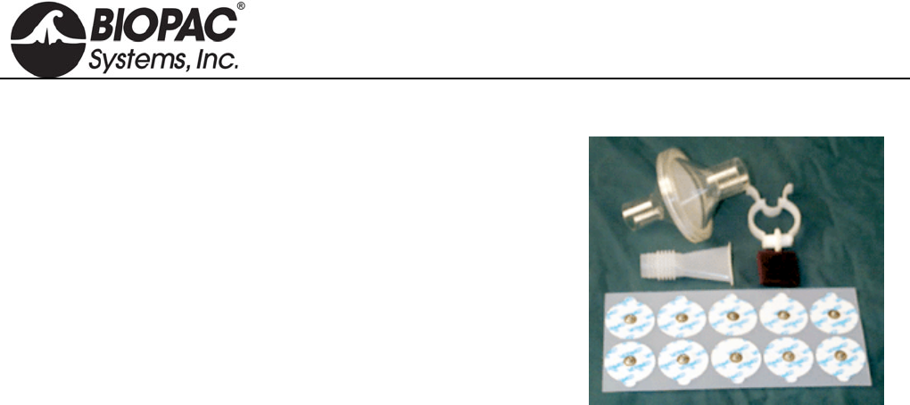
info@biopac.com
support@biopac.com
www.biopac.com
BIOPAC Hardware | Electrode Accessories | Page 3 - 3 Updated: 10.29.2013
BSL-ACCPACK
The BSL Accessory Pack includes the consumable items to run 16
BSL Lessons.
Make students accountable for their own lab equipment and reduce the
burden on department budgets. School bookstores can purchase the
BSL Accessory Packs and sell them to students. Includes:
60 x EL503 Disposable Electrodes
10 x EL507 Disposable EDA (GSR) Electrodes (ten electrodes total)
1 x AFT1 Disposable Bacterial Filter
1 x AFT2 Disposable Mouthpiece
1 x AFT3 Noseclip
8 x ELPAD Abrasive Pads
HARDWARE GUIDE
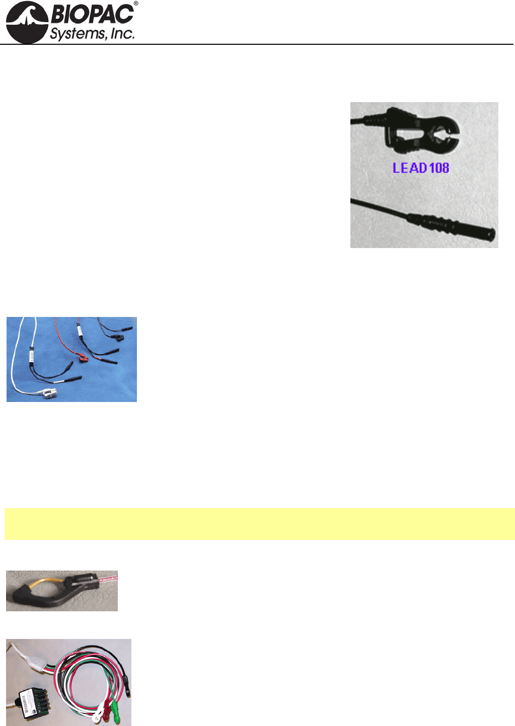
info@biopac.com
support@biopac.com
www.biopac.com
BIOPAC Hardware | ELECTRODE LEADS | Page 1 - 2 Updated: 12.2.2013
ELECTRODE LEADS
LEAD108 SERIES — MRI-CONDITIONAL/RADIOTRANSLUCENT LEADS FOR EL508/EL509
Use the LEAD108 series with EL508 MRI-conditional, radiotranslucent
electrodes and EL509 disposable radiotranslucent dry electrodes. All
LEAD108 Series terminate in 1.5 mm female Touchproof sockets.
MRI Usage: MR Conditional
Condition: Tested 3T-9T
Lead108 Components: Polyvinyl chloride (PVC) plastic, carbon
fiber leadwire, tinned copper connectors (Touchproof socket),
electrode clip (carbon filled ABS plastic)
SPECIFICATIONS
Construction: Carbon fiber leadwire and electrode snap
Leadwire Diameter: 1.5 mm
Leadwire Resistance: 156 Ohms/meter
Leadwire Length: LEAD108 1.8 m, LEAD108A 3.6 m, LEAD108B 15 cm, LEAD108C 30cm
LEAD110 SERIES — ELECTRODE LEADS
The LEAD110 Series, for use with disposable and other snap connector
electrodes, are pinch leads for easy connection between the EL500-series snap
electrodes and any BIOPAC biopotential amplifier or the GND terminal on the
back of the UIM100C. Leads terminate in standard 1.5 mm Touchproof connector
and connect to BIOPAC modules or to a Modular Extension Cable (MEC series).
LEAD TYPE LENGTH USAGE NOTE
LEAD110 Unshielded 1 m Works best as a ground electrode
LEAD110A Unshielded 3 m Works best with ground or reference electrodes
LEAD110S-R Shielded; red 1 m Use with recording electrodes for minimal noise interference. White lead
plug is for electrode contact; black lead pin plug is for lead shield.
LEAD110S-W Shielded; white 1 m Use with recording electrodes for minimal noise interference. White lead
plug is for electrode contact; black lead pin plug is for lead shield.
See also: TSD155C Multi-lead ECG Cable
WT100C Wilson Terminal (virtual reference)
LEAD120 LEAD FOR EL120
This 1-meter lead with Touchproof connector works exclusively with the reusable
EL120 electrode. Snap the electrode into place and then plug the lead in with the
Touchproof connector. White—LEAD120-W Red—LEAD120-R
LEAD130 SHIELDED LEAD ASSEMBLY
LEAD130 Shielded Lead Assembly is for use with the EBI100C Electrical
Bioimpedance Module or the NICO100C Noninvasive Cardiac Output Module. The
shielded lead assembly terminates with an adapter that plugs into the front of the
amplifier module and includes four leads:
White = I+ Red = Vin+ Green = Vin- Black = I- (GND)
HARDWARE GUIDE
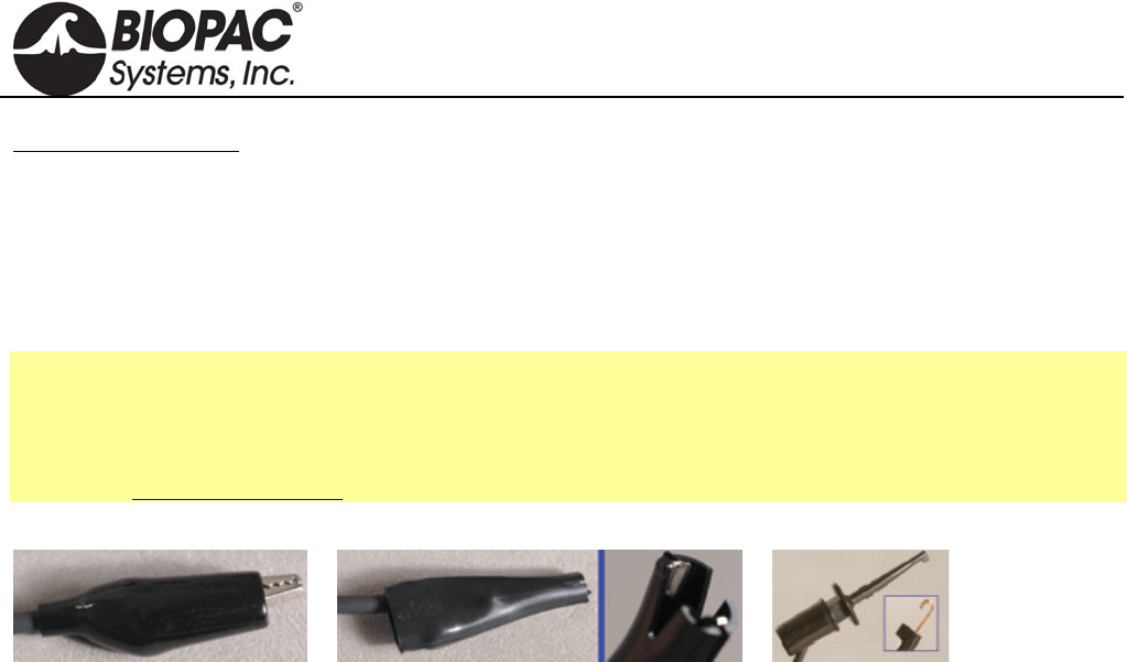
info@biopac.com
support@biopac.com
www.biopac.com
BIOPAC Hardware | ELECTRODE LEADS | Page 2 - 2 Updated: 12.2.2013
Important Usage Notes:
If using multiple biopotential modules, do not connect the ground (GND) for the other modules — establish
one ground per subject.
If using a GSR100C Electrodermal Response Amplifier with the EBI100C or the NICO100C, please note
that the black I- (GND) connection will shunt current from the GSR100C excitation source. Accordingly,
GSR100C measurement values will be shifted somewhat higher in absolute conductance, and should be
used for relative measures only.
See also: EBI100C Electrical Bioimpedance Module
NICO100C Noninvasive Cardiac Output Module
EL506 Bioimpedance Strip Electrode and EL500 Series Disposable Electrodes
Application Note 215 - Noninvasive Cardiac Ouput - NICO100C and LEAD130.
LEAD140 SERIES CLIP LEADS
LEAD140 Series clip leads have a 1 m black cable and a Touchproof connector, and require the SS1LA interface.
LEAD140 Alligator clip with teeth, 40 mm: Use this fully-insulated, unshielded lead to connect fine wire
electrodes, including irregular surfaces. There is ferrous metal in the clip.
LEAD141 Alligator clip with smooth (flat) clamp, 40 mm: Use this fully-insulated, unshielded lead to connect to
fine wire electrodes without damage, including arbitrarily small electrode wires. There is ferrous
metal in the clip.
LEAD142 Retractable clip lead with copper extension contacts, 3.5 mm: Use this unshielded lead to connect to
fine wire electrodes up to 1 mm diameter. There is non-ferrous copper alloy in the clip.
MRI Usage: MR Conditional
Condition: Tested 3T-9T (LEAD142 only)
HARDWARE GUIDE
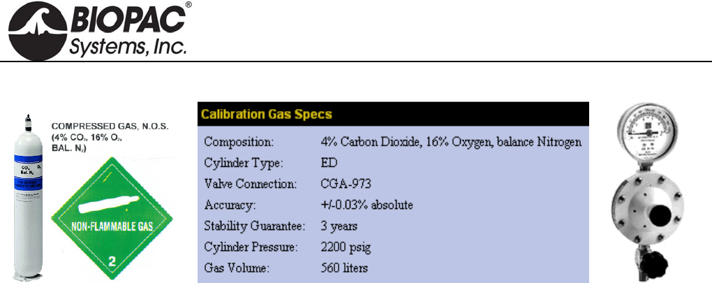
info@biopac.com
support@biopac.com
www.biopac.com
BIOPAC Hardware | GASCAL – GASREG | Page 1 - 1 Updated: 3.20.2013
GASCAL CALIBRATION GAS AND GASREG REGULATOR
Use the single stage, non-corrosive, general-purpose GASREG regulator with the GASCAL Calibration Gas
Cylinder. Single-stage pressure regulators reduce the cylinder pressure to the delivery or outlet pressure in one
step, and are generally good for short duration applications.
This regulator is used to inject calibration gases into the GASSYS2 or AFT15 chambers to create the secondary
calibration points for a proper gas calibration of O2 and CO2 sensors.
The initial case (for the primary calibration points) is the chamber flooded with ambient air (20.95%
Oxygen, 0.04% Carbon Dioxide and balance Nitrogen).
The secondary case (for the secondary calibration points) is using the GASCAL with GASREG to inject a
calibrated gas mixture into the chamber.
The chamber will be flooded with this mixture from GASCAL. GASCAL is a tank containing 4% carbon
dioxide, 16% oxygen and balance (80%) nitrogen.
Use 3.2 mm ID tubing to run from GASREG output to the chamber and seal the 3.2 mm ID tube to the input port
of the chamber, during calibration.
Wait for the chamber to be flooded, typically about 1-2 minutes.
Put regulator at 10 psi and open up the flow valve.
After flooding, then largely close the flow valve, but keep some small flow during the calibration of secondary
point, to maintain positive pressure in the chamber.
The chamber needs to be flooded prior to attempting to calibrate for secondary points.
After secondary calibration, shut down the tank by closing the main valve.
GASCAL Cylinder Recycling Program available.
Call 1-800-457-0809 to receive instructions for returning a cylinder; delivery paid by sender and
recycling covered by manufacturer.
HARDWARE GUIDE
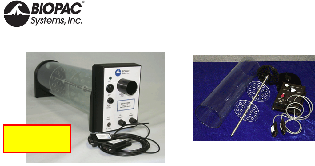
info@biopac.com
support@biopac.com
www.biopac.com
BIOPAC Hardware | GASSYS2 | Page 1 - 4 Updated: 8.7.2013
GASSYS2-EA/EB AND GASSYS2-RA/RB O2 & CO2 GAS ANALYSIS SYSTEM
GASSYS2 modules measure expired O2 and CO2 concentrations. When the subject inspires, air is drawn into the
GASSYS2 through an airflow transducer. The SS11 (GASSYS2 EA/EB) or TSD107B (GASSYS2 RA/RB)
airflow transducer is placed on the inspiration side to eliminate any effects associated with expired air humidity.
When the subject expires, air is directed to the GASSYS2 module. The GASSYS2 is designed to work with
saturated expired air.
Modular assembly makes
complete cleaning easy!
See the AFT series of
accessories for airflow
and gas analysis.
Obtain real-time Oxygen Consumption (VO2) and Respiratory Exchange Ratio (RER) measurements using the
MP System with a GASSYS2 module and some airflow accessories. The GASSYS2 connects directly to the
MP36 System (GASSYS EA/EB) or via the UIM100C (GASSYS RA/RB) and requires two channels.
The non-rebreathing T-valve directs only expired air to the GASSYS2. Because only expired air is directed to the
module, the system acts to average respiratory outflows. This averaging effect causes the CO2 and O2
concentrations to vary in accordance to the mean values resident in a few expired breaths.
Two chamber sizes are available for the GASSYS2. Each chamber assembly includes the chamber casing and rod.
The chambers work exactly the same way and are interchangeable on the module base. Use the smaller chamber
size for small children/medium sized animals.
5-liter chamber — included in the GASSYS2-EA/RA; order chamber only as RX-GASA
1.7-liter chamber — included in the GASSYS2-EB/RB; order chamber only as RX-GASB
The GASSYS2 also includes AFT7 tubing, AFT11E Coupler, AFT22 Non-rebreathing T-Valve, and a
power supply.
GASSYS2 Specs
O2 sensor: Warm-up: 10 minutes. Response time 10-90%: 30 sec. Accuracy: ±1% FSR*.
Zirconia solid electrolyte with a 0.1-25% sensing range. It runs hot, which helps burn off humidity.
*FSR = Full Scale Reading
Expected O2 sensor
lifespan (in years): [5,256/(number of hours used per year)]*5
If used for 10 hours per week or 520 total hours in a year, O2 sensor lifespan would
be [5,256/520]* 5 = 50.5 years
CO2 sensor: Warm-up: 2 minutes. Response time: < 120 seconds for a 90% step change. Uses a humidity-
repellant (hydrophobic) membrane and has a sensing range of 0-5%. It uses non-dispersive infrared
diffusion with single-beam IR and a self-calibrating algorithm. It also runs hot, which burns off
humidity.
Calibration: GASSYS2 sensors are factory calibrated prior to shipping.
Power Supply: 12 V DC @ 1 amp (AC300A) wall adapter for serial numbers ending 200 or older.
HARDWARE GUIDE
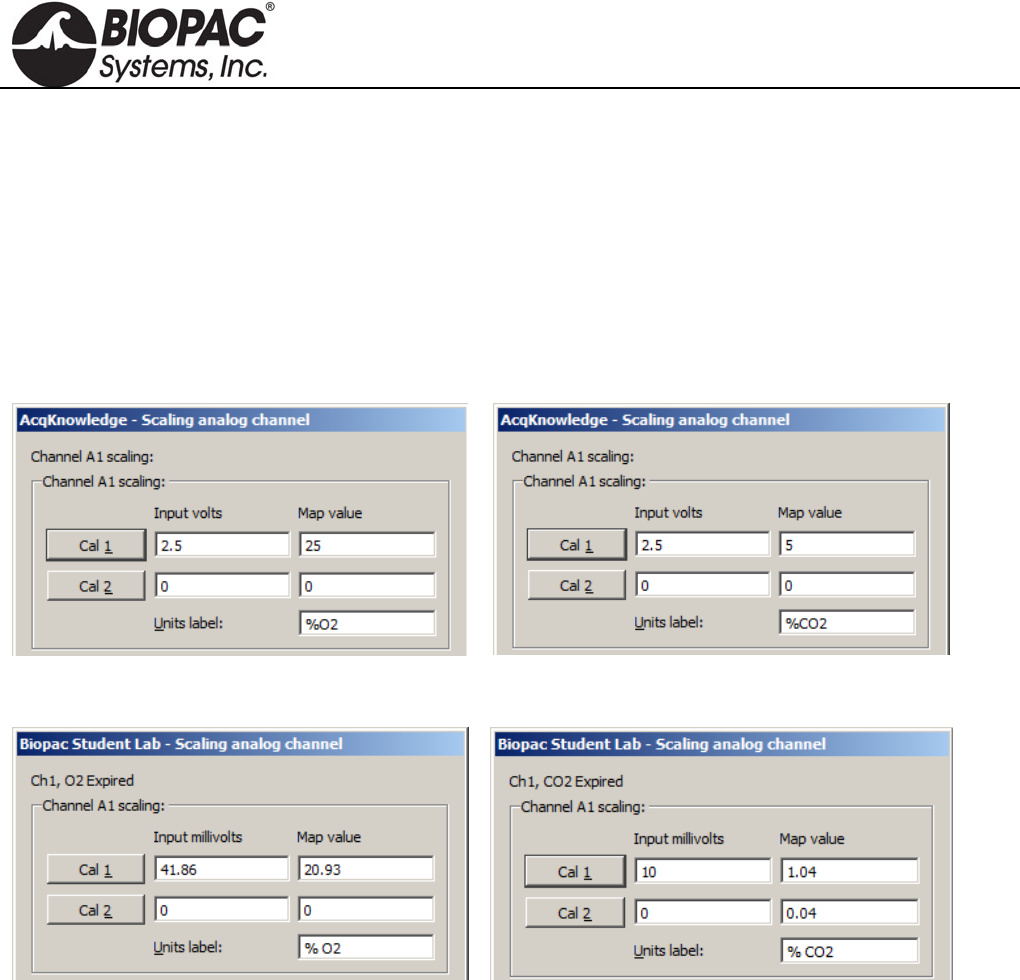
info@biopac.com
support@biopac.com
www.biopac.com
BIOPAC Hardware | GASSYS2 | Page 2 - 4 Updated: 8.7.2013
Dimensions/Weight 1.7-liter chamber 5-liter chamber
Length: 22 cm 55 cm
Height: 18 cm 18 cm
Width: 14 cm 14 cm
Weight: 1.38 kg 1.96 kg
GASSYS2 Software Scaling Defaults
AcqKnowledge Software
Default %O2 Scaling
Default %CO2 Scaling
BSL PRO Software
Default %O2 Scaling
Default %CO2 Scaling
Calibration Procedure
The GASSYS2 scaling parameters are factory-set to a “ballpark” default, but in order to achieve accurate
measurements, these values must be re-calibrated in the AcqKnowledge or BSL PRO software using the
following steps.
1. Flood the mixing chamber with fresh (ambient) air. (20.93% O2, 0.04% CO2) This can be accomplished
by attaching the calibration syringe to the mouthpiece and cycling fresh air into the mixing chamber.
2. Monitor the gas concentration levels using AcqKnowledge or BSL PRO software. When the levels appear
stabilized at ambient, obtain the first calibration point. (CAL 1)
3. Flood the chamber with the gas mixture using BIOPAC’s GASCAL and GASREG. The recommended
concentration is 16% O2, 4% CO2 and 80% nitrogen (N2).
4. When the levels appear stabilized, obtain the second calibration point. (CAL 2)
HARDWARE GUIDE
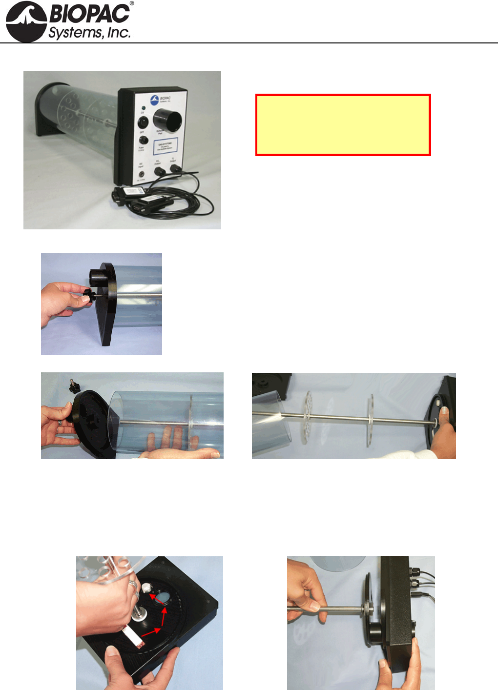
info@biopac.com
support@biopac.com
www.biopac.com
BIOPAC Hardware | GASSYS2 | Page 3 - 4 Updated: 8.7.2013
Cleaning the BIOPAC GASSYS2
Note: Never clean the sensor base
of the device. The two sensors, a
screen and a copper-colored gas
detector, are highly sensitive.
1) Unscrew the top knob attachment.
2) Remove the plastic lid from the flow chamber.
3) Gently pull the clear cylinder off the sensor base.
4) Detach the metal standing rod and its lower base attachment by holding the third of the standing rod
nearest the base of the module and unscrewing the rod in a counter-clockwise motion.
a. Depress the rod by applying pressure at the base – this unlocks the rod’s position and
allows movement.
b. Unscrew the rod in a counter-clockwise motion.
HARDWARE GUIDE
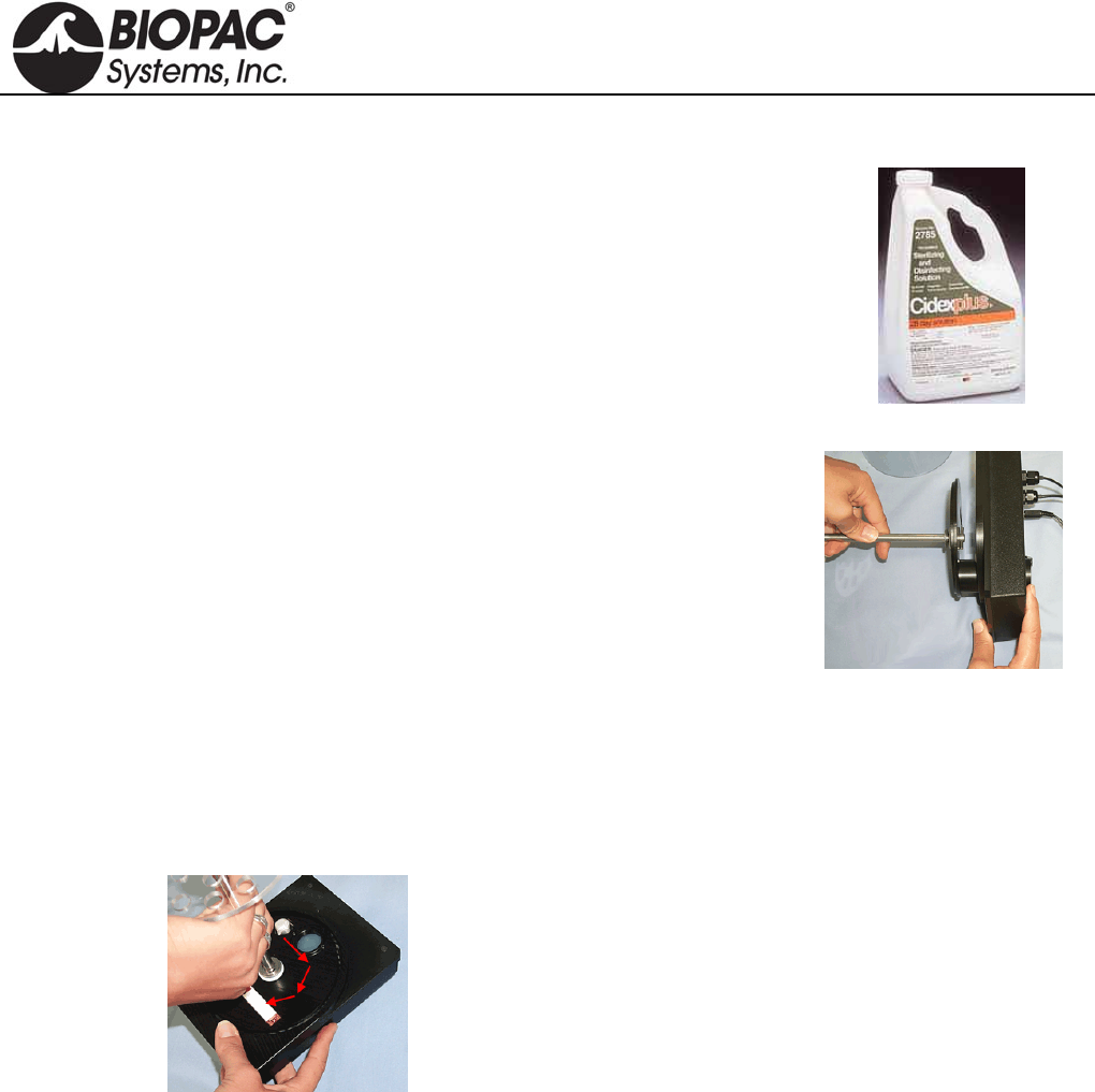
info@biopac.com
support@biopac.com
www.biopac.com
BIOPAC Hardware | GASSYS2 | Page 4 - 4 Updated: 8.7.2013
5) Remove the chamber stand (gently pull back the chamber stand from the electronics base).
6) Clean the flow chamber with one of two methods:
a. Use a soft cloth and Cidex Plus Sterilizing and Disinfecting Solution
cleanser. Spray a light mist of Cidex cleanser on the parts of the device
to be cleaned, and wipe the pieces with a dry rag. It is important never to
get Cidex near the sensors of the device.
Other cleansers should not be substituted for Cidex – non-Cidex
cleansers might damage or abrade the flow chamber pieces.
b. Heating the components in an autoclave sterilizing oven.
7) After cleaning reattach the platformed-standing rod to the electronics base.
a. Align the exhaust tube at the bottom of the rod stand with the
exhaust port on the electronics base and insert securely.
b. Gently ease the rod stand back into its appropriate position on the
electronics base. The sensors are very delicate—slowly lower the
plastic base of the standing rod to the electronics base to make sure
that the openings in the standing rod base correspond with the
appropriate sensors.
8) Locate the latch opening for the security screw and align it with the screw, and then press the base of the
standing rod to the sensor base.
a. Revolve the rod until the lower screw drops into its opening. When the screw meets its opening, it
should drop into the hole.
b. Depress the rod by applying pressure on the lower third of the piece and rotate it in a clockwise
motion until it locks into position.
9) Ease the clear cylinder back onto the device and lay its lower edge in the track on the electronics base.
10) Re-attach the plastic top to the clear cylinder.
11) Lock the plastic top into place by screwing in the security knob.
HARDWARE GUIDE
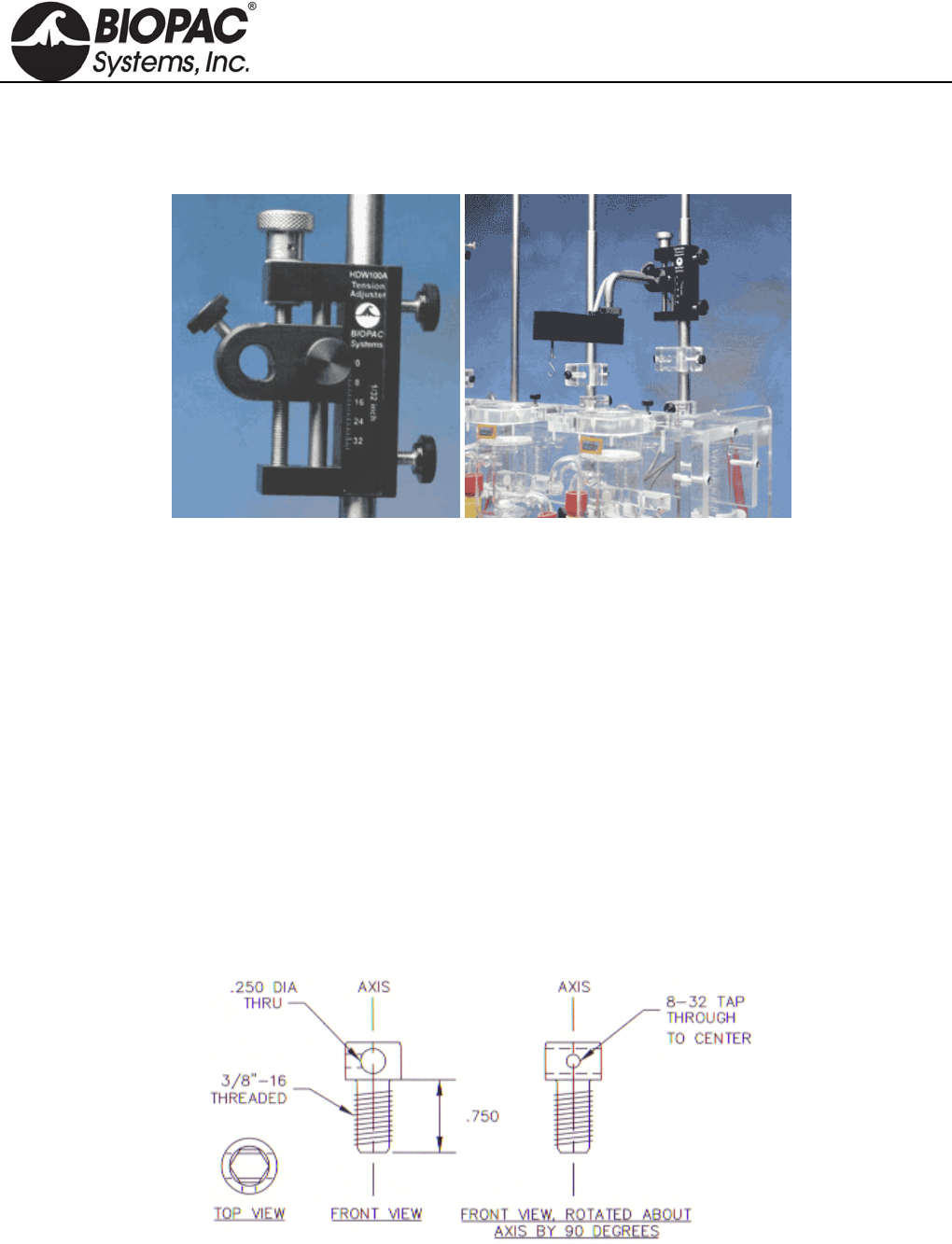
info@biopac.com
support@biopac.com
www.biopac.com
BIOPAC Hardware | TENSION ADJUSTERS | Page 1 - 1 Updated: 3.20.2013
TENSION ADJUSTERS
HDW100A TENSION ADJUSTER
HDW200A 3RD-PARTY TENSION ADJUSTER ADAPTER
HDW100A and TSD125/SS12LA
The HDW100A tension adjuster operates with the TSD105A, TSD125, SS12LA force transducers and SS14L
displacement transducer. The rugged design and stability of the mounting allow for fine position control. The
position adjuster is located on the top for easy access and smooth operation. Vertical scales are provided for both
metric and standard units. The HDW100A slides directly onto vertical rod laboratory stands and force transducers
are clamped into the unit horizontally.
HDW100A SPECIFICATIONS
Travel Range: 25mm
Resolution: 0.0025mm per degree rotation
Stand Clamp: 13.25mm ID
Transducer Clamp 11mm ID
Weight: 140 grams
Dimensions: 93mm (high) x 19mm (thick) x 74mm (deep)
HDW200 ADAPTER FOR 3RD-PARTY TENSION ADJUSTERS
This adapter allows 3rd-party tension adjusters to interface with BIOPAC Force Transducers.
Fits any tension adjuster with an arm diameter of 6.35 mm (1/4") or less, such as “riser” style tension
adjusters from Lafayette and Wards.
HARDWARE GUIDE
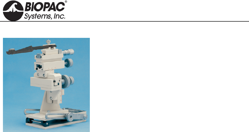
info@biopac.com
support@biopac.com
www.biopac.com
BIOPAC Hardware | Micromanipulator | Page 1 - 1 Updated: 2.6.2013
MICROMANIPULATOR
This manual micromanipulator is a reliable, durable, and economical
solution for high-precision experiments.
Vernier scales allow readings to 0.1 mm
X-axis fine control allows readings to 10 µm
Includes tilting base
Includes standard 12 mm clamp
Includes 14 cm electrode holder
All control knobs project to the rear, so units can be tightly
grouped.
Control Travel Range Resolution
X-axis fine 10 mm 0.01 mm
X-axis 35 mm 0.1 mm
Y-axis 25 mm 0.1 mm
Z-axis 25 mm 0.1 mm
Weight: 1.4 kg (3 lbs.)
Specify left- or right-handed unit when ordering.
MANIPULATOR-R Right-handed
MANIPULATOR-L Left-handed
HARDWARE GUIDE

info@biopac.com
support@biopac.com
www.biopac.com
BIOPAC Hardware | NIBP100D | Page 1 - 3 Updated: 2.12.2013
NIBP100D NONINVASIVE BLOOD PRESSURE SYSTEM
The NIBP100D is a stand-alone noninvasive blood pressure monitoring system
that provides a continuous, beat-to-beat, blood pressure signal recorded from
the fingers of a subject. Uses a double finger cuff sensor that is comfortable for
the subject to wear and easy to place on the hand– three included cuff sensors
fit small to large fingers. The system outputs a continuous blood pressure
waveform that is similar to a direct arterial pressure waveform. Monitor
displays values for systolic, diastolic, mean blood pressure, and heart rate.
Add BSL-TCI5 to use with an MP36 System.
NIBP100D System includes:
Blood Pressure Module with external mains power and interface cables
Finger cuff sensors (3): small 10-18 mm, medium 18-24 mm, and large 24-28 mm
BP cuffs for calibration (4): xs 12-19 cm, small 17-25 cm, medium 23-33 cm, and large 31-40 cm
Finger cuff sensors are a consumable item and typically last ~12 months based on 3-4 hours/week.
Order additional finger cuffs as RXNIBPDFINGER-L, RXNIBPDFINGER-M, or RXNIBPDFINGER-S.
See also: BSL PRO Lesson H18 Exercise Physiology
The NIBP100D Noninvasive Blood Pressure Monitoring System is suitable for small children (~6 years) to large
adults
Click the "Resources" tab above for the NIBP100D User Manual with complete specifications and NIBP100D
Calibration.
SPECIFICATIONS
Double Cuff Finger Sensor
Finger cuff sensors are a consumable item and typically last ~12 months based on 3-4 hours/week. Order
additional or replacement finger cuffs as RXNIBPDFINGER-L, RXNIBPDFINGER-M, or RXNIBPDFINGER-S.
Large 24 - 28 mm, dark red
Medium 18 - 24 mm, dark blue
Small 10 - 18 mm, light blue
Blood Pressure Cuffs (Latex free)
Child (12 – 19 cm) works starting at 20 kg (44 lbs), age 6 years
Small Adult (17 – 25 cm)
Adult (23 – 33 cm)
Large Adult (31 – 40 cm)
NIBP100D Continuous Noninvasive Arterial Pressure
Parameter classification:
Sys, Dia, Mean [mmHg]
Pulse [bpm]
Measuring range:
Sys: 40 - 250 mmHg (5.3 – 33.3 kPa)
Dia: 30 - 210 mmHg (4 - 28 kPa)
Mean: 35 - 230 mmHg (4 – 30.6 kPa)
Heart rate indication range 20-200 bpm
Accuracy ±5 mmHg (0.6 kPa)
HARDWARE GUIDE

info@biopac.com
support@biopac.com
www.biopac.com
BIOPAC Hardware | NIBP100D | Page 2 - 3 Updated: 2.12.2013
Display resolution: 1 mmHg (0.1 kPa)
Inflation pressure:
Typ.: 120 mmHg (16 kPa)
Min.: 30 mmHg (4 kPa)
Max.: 300 ±10 mmHg (41.3 kPa ±1.3 kPa)
Excess pressure limit:
300 ±10 mmHg (40 kPa ±1.3 kPa)
Response time: < 3 sec.
Deflation time: < 15 sec
Protection against electric shock: Type BF
Interface
MP150/100 to DA100C via TCI105 (sold separately)
MP36 via BSL-TCI5 (sold separately)
Output
Sensor bridge voltage: 2 - 10 V (external monitor)
Sensitivity: 5 µV/V/mmHg
BP Wave Out: CNAP™ transducer cable 0.3m; connector RJ11 6P4C (e.g. Abbott IBP catheter)
Maximum delay of analog out signal: 80 msec
Means the BP waveform may be delayed with respect to other waveforms acquired by the MP150
unit, such as ECG, by max 80 msec
NIBP100D Monitor
Dimensions: 280 x 270 x 250 mm (11 x 10.6 x 9.8 in.)
Weight: 7.5 Kg (16.6 lbs) including components and accessories necessary for operability of device
Battery Sealed lead gel, operating time = 2 hours (fully charged battery, normal conditions)
Electrical Properties
Nominal voltage: 18 VDC ±10%
Nominal current: 3 A
Operability: No time-limit if powered by external mains adapter, at least 2 h if on battery-operation (fully
charged battery)
External Mains Adapter
Nominal voltage: 100 – 240 VAC
Power frequency: ~50/60 Hz
Power output: 18 V, 3.3 A
Safety class: Class II with functional earth
Earth leakage current: < 500 µA
Note—Electric and magnetic fields may interfere with the functional reliability of the device, so avoid using the
CNAP™ Monitor 500 close to devices emitting powerful electromagnetic fields, e.g. x-ray equipment, diathermy
applications or magnetic resonance tomographs.
HARDWARE GUIDE

info@biopac.com
support@biopac.com
www.biopac.com
BIOPAC Hardware | NIBP100D | Page 3 - 3 Updated: 2.12.2013
Hyperbaric/Hypobaric Chamber Setup
1. Cuff controller and CNAP monitor must be in the same chamber with the same"pressure" environment as
both are equipped with pressure sensor for surrounding pressure.
2. Pressure must be increased / decreased continuously rather than abruptly.
3. Hypobaric: take measures against overheating of the device as conventional cooling is limited (dim
CNAP display low; do not restrict airflow through case).
4. No draught on cuff.
5. Hand on heart level in steady position.
HARDWARE GUIDE
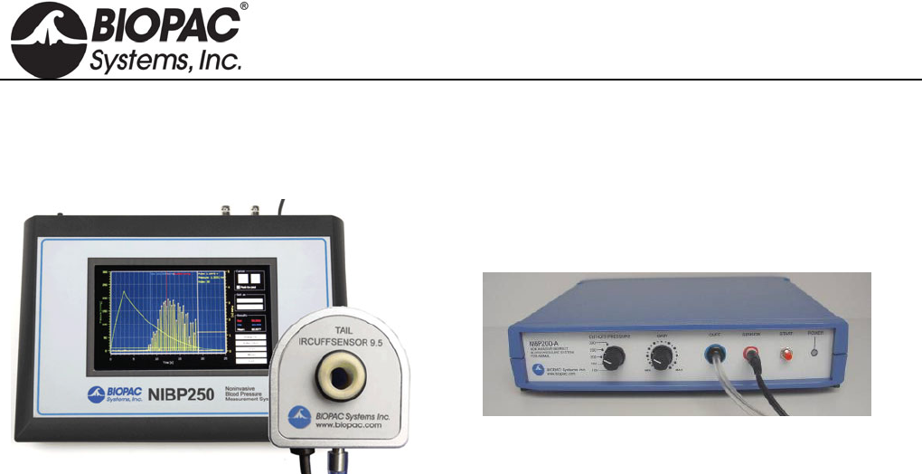
info@biopac.com
support@biopac.com
www.biopac.com
BIOPAC Hardware | NIBP Systems | Page 1 - 8 Updated: 6.7.2013
NON-INVASIVE SMALL ANIMAL TAIL BLOOD PRESSURE SYSTEMS
NIBP250 Blood Pressure Amplifier
NIBP200A Blood Pressure System
NIBP Amplifiers with built-in pump automatically inflate the tail cuff to occlude the vessel in the tail of a rat or
similar small animal, and then slowly deflate the cuff when the inflation point is reached, providing a linear drop
in pressure. A single control starts both the inflation and deflation cycles, making the system very operator-
friendly. Amplifiers have two analog outputs for pressure and pulse waveforms, plus gain adjustment to amplify
or attenuate the pulse signal. Systolic, diastolic, and mean BP values.
NIBP250 Touchscreen LCD controls and displays data for local analysis and storage. Use as a stand-
alone system or interface to BIOPAC or third-party A/D hardware. USB 1.1 compatible flash memory
port and SD card slot.
NIBP200A Amplifier for use with Tail Cuff Sensor
Systems include:
Amplifier order NIBP250 or NIBP200A
One tail cuff sensor (request size):
RXTCUFSENSOR9.5 = 9.5mm, 100-220 g
RXTCUFSENSOR11 = 11 mm, 200-280 g
RXTCUFSENSOR13 = 13 mm, 250-350 g
One small animal restrainer:
RXRESTRAINER-MICE, 10-25 g (mice)
RXRESTRAINER-S, 70-150 g (small rat)
RXRESTRAINER-M, 150-200 g (medium rat)
RXRESTRAINER-L, 250-350 g (large rat)
Optional MRI-compatible sensors available – add to an existing NIBP200A system
RXCUFSEN9.5-MRI = 9.5 mm, 100-220 g
RXCUFSEN11-MRI = 11 mm, 200-280 g
RXCUFSEN13-MRI = 13 mm, 250-350 g
Analog outputs: pressure 0-3 V DC, Pulse 0-4 V DC
Output cables: pressure cable and pulse cable
Interface cables: to BIOPAC or third-party A/D hardware
User’s Manual
Optional Tail Heater: TAILHEATA 110 V or TAILHEATB 220 V
HARDWARE GUIDE
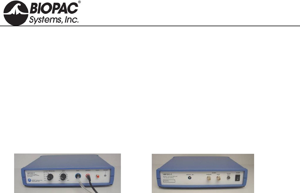
info@biopac.com
support@biopac.com
www.biopac.com
BIOPAC Hardware | NIBP Systems | Page 2 - 8 Updated: 6.7.2013
SPECIFICATIONS
Cut-off Pressure Range: 100 – 300 mmHg (adjustable by 1mmHg steps)
Pressure Accuracy: 300 mmHg Full Scale 1%
Pressure Sensitivity: 0.1 mmHg
Pressure Signal output: 300 mmHg/3 Volt DC
Pulse Gain Levels: x1, x2, x4, x5, x8, x16, x32 (adjustable)
Pulse Signal Output: 0- 4 Volt DC
Pulse Display: Pulse intensity is displayed on A2, derived from plethysmographic measure The
tail sensor detects blood flow and pulse intensity is increased or decreased,
depending on the flow ratio.
LCD Display: 7” 800x480 TFT (NIBP250)
User Interface: Resistive Touch Panel (NIBP250)
Analog outputs: Two BNC connectors for uncalibrated pressure and pulse signals
Triggers: Two BNC connectors for TTL Compatible trigger in and out signals
Power Supply: 12 Volt 2 Amp – External
NIBP200A/NIBP250 SYSTEM CONNECTIONS
NIBP200A Front Panel NIBP200A Rear Panel
1. Connect the CBL150-Pre cable
a. BNC to the PRESSURE output on the back panel of the unit.
b. Other end to A1 on the front of the UIM100C unit
2. Connect the CBL150-Pls cable
a. BNC to the PULSE output on the back panel of the unit.
b. Other end to A2 on the front of the UIM100C unit.
3. Connect the IRSENSOR
a. Black cord to the sensor input on the front panel of the NIBP200A (back panel on NIBP250).
b. Tubing in the cuff on the front panel of the NIBP200A (back panel on NIBP250).
4. Connect the power
a. AC300 adapter to the 12V DC input on the back panel of the NIBP200A.
b. AC300 to Mains power.
5. Switch the POWER on.
HARDWARE GUIDE
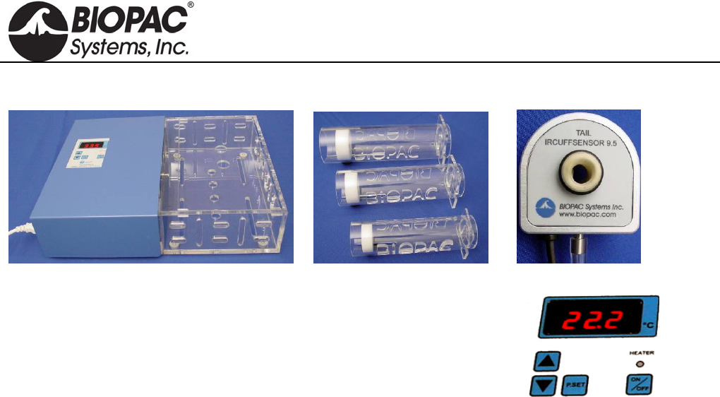
info@biopac.com
support@biopac.com
www.biopac.com
BIOPAC Hardware | NIBP Systems | Page 3 - 8 Updated: 6.7.2013
ANIMAL PREPARATION
Optional Heating Chamber Restrainer Animal Holders Tail Cuff/Sensor
1. Turn the Animal Heating Chamber on.
2. Set the temperature value (press and hold P.Set and then press the up or
down arrow to reach the desired value).
For accurate noninvasive blood pressure measurement, the animal or
its tail should be warmed to 32°C.
3. Press the Heater button to start heating to the selected temperature value.
4. Place the animal inside the RESTRAINER “Animal Holder” (select the suitable size for the animal
volume).
Leave the tail outside.
Adjust the length to obtain a position where the animal has limited movement.
5. Place the RESTRAINER (with the animal) in the heating section of the Animal Heating Chamber.
6. Wait approximately 30 minutes for the animal to reach the selected temperature.
7. Remove the RESTRAINER from the Animal Heating Chamber.
8. Connect the IRSENSOR to the tail of the animal inside the RESTRAINER.
9. Check if the sensor just fits to the tail. The sensor should be between the mid point of tail and tail end
(spinal column). To achieve this, a suitable sensor should be selected.
10. Wait for the animal to relax and become inactive before starting measurements.
TIP Before starting the experiment, to condition the animal, put the animal inside the holder several
times a day and repeat the heating each time.
HARDWARE GUIDE
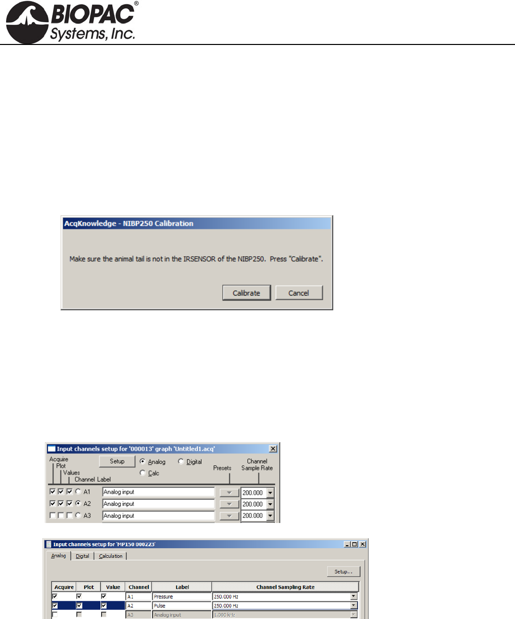
info@biopac.com
support@biopac.com
www.biopac.com
BIOPAC Hardware | NIBP Systems | Page 4 - 8 Updated: 6.7.2013
SOFTWARE SETUP (AcqKnowledge 4.1 and higher)
1. Launch AcqKnowledge
2. Select the “Create/Record a new experiment” option.
3. Select MP150 > Set Up Channels > “Add New Module...”
a. From the new module list, select UIM100C-A1 (or whichever channel CBL150-PRE pressure
cable is connected to) and click “Add.”
b. From the UIM100C Transducer list, select “NIBP200A – Small Animal Tail BP, Pressure” or
“NIBP250 – Small Animal Tail BP, Pressure” and click OK.
c. Click “Calibrate” in the resulting Calibration dialog.
4. Repeat “Add New Module…” portion of Step 3.
a. From the new module list, select UIM100C-A2 (or whichever channel CBL150-PLS pulse cable
is connected to) and click “Add.”
b. From the UIM100C Transducer list, select “NIBP200A – Small Animal Tail BP, Pulse” or
“NIBP250 – Small Animal Tail, Pulse” and click OK.
SOFTWARE SETUP (AcqKnowledge 4.0 and earlier)
1. Launch the BIOPAC software.
2. Choose MP menu > Set up Channels.
or
3. Enable analog inputs A1 and A2 to Acquire Data, Plot on Screen and Enable Value Display.
If desired, enter channel Labels: A1 Pressure and A2 Pulse
4. Calibrate for the pressure measurement of IRSENSOR.
a. Select A1 (Pressure) and click Setup and establish these settings:
HARDWARE GUIDE
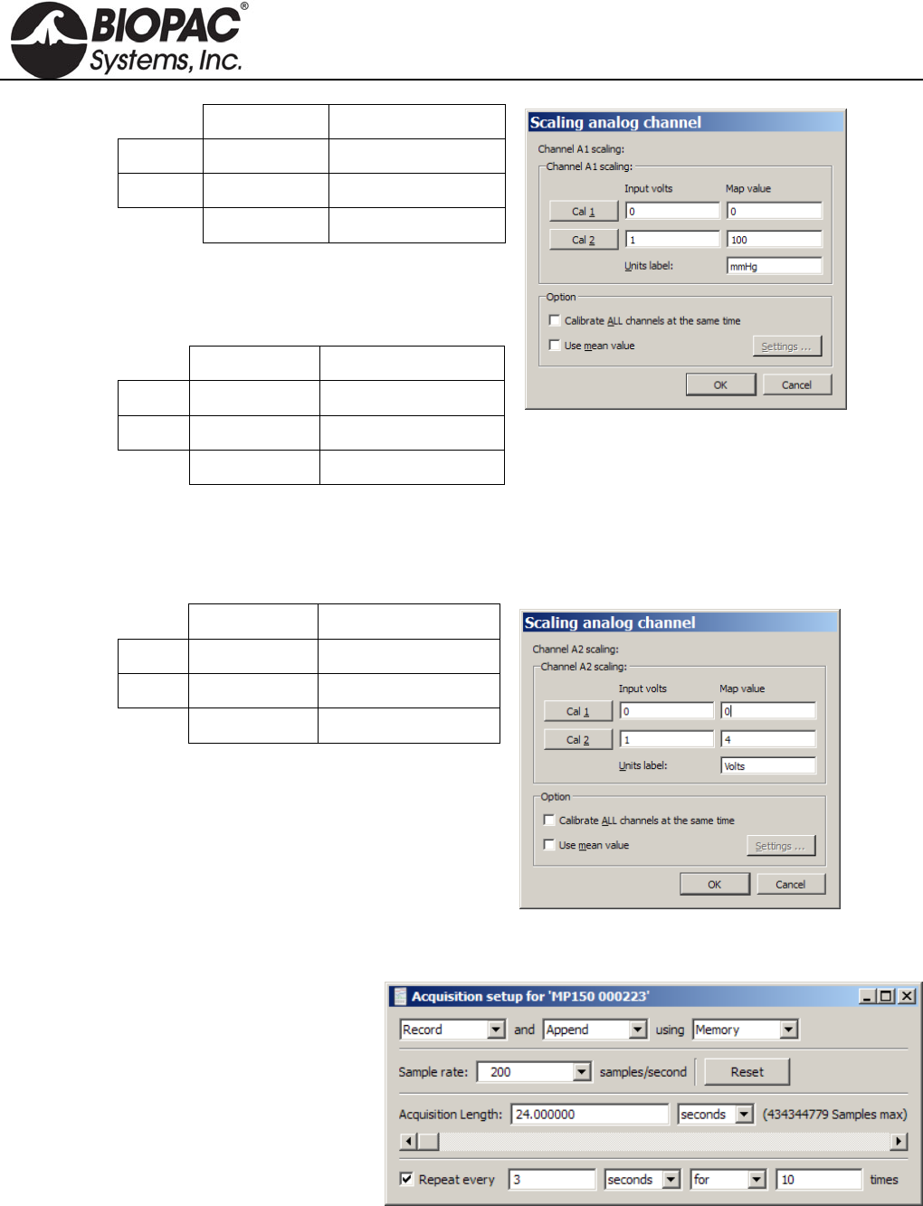
info@biopac.com
support@biopac.com
www.biopac.com
BIOPAC Hardware | NIBP Systems | Page 5 - 8 Updated: 6.7.2013
Input volts Scale (Map) value
Cal 1 0 0
Cal 2 1 100
Units Label: mmHg
The scaling must be adjusted as the cut-off
pressure switch settings are changed. If the
pressure switch is set to 300 mmHg, then the
settings should be:
Input volts Scale (Map) value
Cal 1 0 0
Cal 2 3 300
Units Label: mmHg
b. Click OK as needed to close out of A1 setup.
5. Calibrate for the pulse measurement of IRSENSOR.
a. Ensure that the tail is not inside the IRSENSOR and it is empty, and the sensor resides freely.
b. Select A2 (Pulse) and click Setup and establish these settings:
Input volts Scale (Map) value
Cal 1 0 0
Cal 2 1 4
Units Label: Volts
c. Click OK as needed to close out of A2 setup and the Setup Channels dialog.
6. Choose MP menu > Set up Acquisition and establish the following settings.
Mode = Record and Append to
Memory
Sample Rate = 200
samples/second
Total Length = 24 seconds
Repeat = every 3 seconds for 10
times
7. Close out of Set up Acquisition.
8. Choose MP menu > Setup Trigger and establish the following settings.
HARDWARE GUIDE
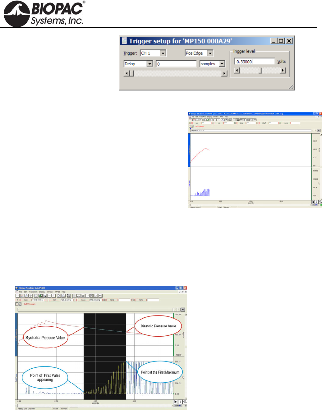
info@biopac.com
support@biopac.com
www.biopac.com
BIOPAC Hardware | NIBP Systems | Page 6 - 8 Updated: 6.7.2013
Source = CH 1
Pos Edge
Trigger Level = 0.33
(based on 1 V ≈ 100 mmHg)
Delay = 0
9. Close out of Set up Triggering.
RECORDING
1. Confirm that the animal is ready and that the
IRSENSOR is attached to the tail.
2. Click “Start” in the BIOPAC software window.
3. Press START button on the front panel of NIBP200A.
IRSENSOR will pump up the Cuff automatically.
When the Cuff Pressure on A1 reaches 30 mmHg,
the cuff pressure and tail pulse signals will be
generated.
The recording will stop automatically after 24
seconds.
4. Press START to continue with the next measurement
and repeat as necessary.
5. Choose File > Save or Save as when done.
TIP A generally accepted application is that for each animal, 10 measurements are recorded and
mean values are calculated. In the append mode, 10 consecutive measurements can be made
in the same file.
NIBP200A ANALYSIS
Calculation of Systolic, Diastolic and Mean.
1. Click the Calculation Label.
2. Select from the list Max , Min, Mean for three different Labels.
3. Select Channel 1 as channel option.
4. Select cursor ‘I’ from the cursor option on the bottom right of the screen.
HARDWARE GUIDE
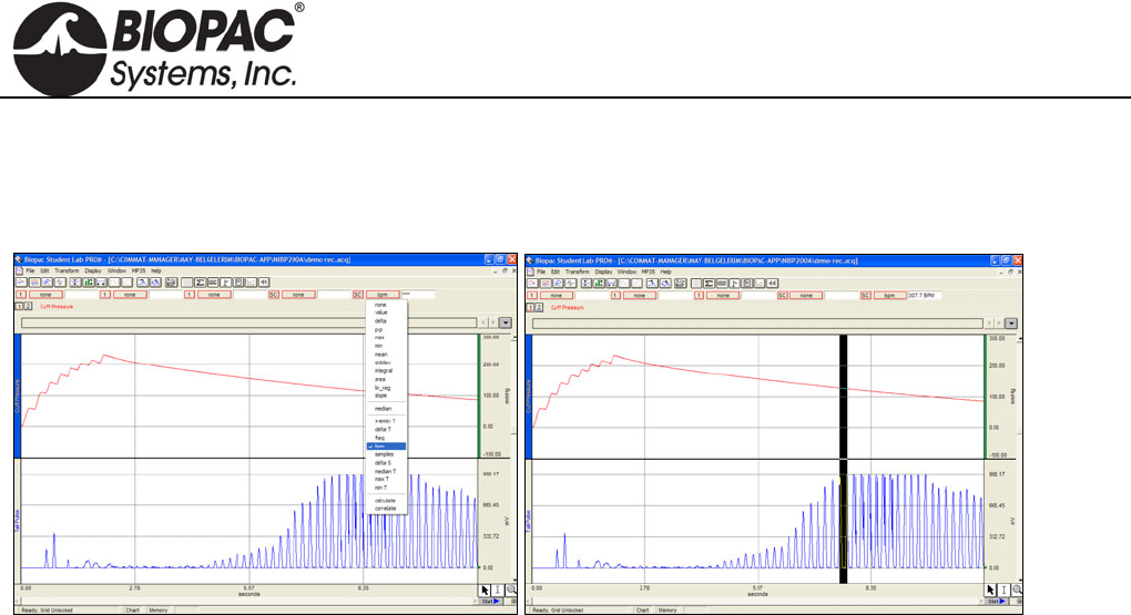
info@biopac.com
support@biopac.com
www.biopac.com
BIOPAC Hardware | NIBP Systems | Page 7 - 8 Updated: 6.7.2013
5. On the graphical display, starting from the point of first pulse, select an area to the maximum.
6. Review the results for Max (Systolic), Min (Diastolic), and Mean measurements.
Calculation of BPM Heart
1. Set a measurement for BPM.
2. Use the I-beam cursor to select the maximum points of the peaks of the CH2 pulse waveform.
3. Review the results for BPM (Heart Rate value) for each peak.
NIBP250 QUICK GUIDE
PREPARE
- With unit turned off, attach the sensor and cuff connectors.
- Turn on unit and wait for the Main Screen to appear.
- Prepare the animal and attach sensor-cuff to tail.
ACQUIRE
- When preparation is complete: Press the “Start” button on the Main Screen. The button label changes to “Stop”
and you can halt the acquisition at any time.
- When the acquisition starts, the unit automatically closes the leakage valve and begins inflating the cuff.
- After pressure reaches the maximum level, the pump stops and opens the leakage valve to release the pressure.
- After the pressure is fully released, the acquisition stops.
NIBP250 ANALYSIS
The NIBP250’s automated peak detection system marks the peak of each pulse with a white cross, and is enabled
by selecting the "Peak by peak" option on the Main Screen. This feature makes it easier to identify the individual
pulses. To determine the systolic and diastolic values:
1. Select the "Peak by peak" box on the main screen.
2. Use the right (or left) cursor button to locate the first pulse's white cross and press the "Systolic" button.
(You may also place the cursor using the touch screen.) The system will record and display the systolic
blood pressure value.
3. Use the cursor button (or touch screen) to move to the pulse with the highest peak and then press the
"Diastolic" button. The system will record and display the diastolic blood pressure value..
You may change your cursor peak positions at anytime during the analysis.
After measurement is complete, press the Save button under “Results.” An automatically generated result code
will be displayed at the top of the results section.
For analysis in BIOPAC AcqKnowledge or BSL PRO software, see previous page for NIBP200A.
HARDWARE GUIDE

info@biopac.com
support@biopac.com
www.biopac.com
BIOPAC Hardware | NIBP Systems | Page 8 - 8 Updated: 6.7.2013
SAVE RESULTS
- Previously saved results can be displayed by pressing the “Load” button under “Results.”
- Placing the cursor on a desired measurement and pressing OK will load the recorded pressure, pulse curves and
previously calculated results.
- After loading is complete, you can easily evaluate the results and re-analyze any measurements.
TURN OFF
- Before turning off the unit, be sure that the current measurement was saved.
- Power off the unit by switching the power button on the back
TROUBLESHOOTING
Tail Pulse signals are not regular.
The animal may be under stress, resulting in excessive tail movement. Remove the animal from the
RESTRAINER holder until it calms down before continuing with the experiment.
The tail may not be sufficiently warmed or cooled down. Put the animal in the Tail Heater Chamber
and repeat the heating process. Make sure the tail temperature is 32 C.
Tail Cuff sizing may be incorrect. Check Table 5 on the following page for sizing descriptions.
Tail Cuff Sensor position may be incorrect. Try re-attaching the sensor in a different location on the
tail. The optimal location is between the mid-point of tail and base of tail (spinal column).
Compressor is working continuously.
Immediately turn off the NIBP system.
Remove the Tubing from the Cuff connector on the panel of NIBP system
Turn the system back on.
Close the air outlet by pressing the finger on the Cuff output and press the “Start” button. The
compressor will work for a few seconds and stop (please inform BIOPAC if the Compressor does not
stop). The pressure chart should be viewable on the screen.
If the Compressor stops automatically, it means that the system is working normally.
There is leakage in the tubing connections and Cuff of the IRSENSOR.
Make sure the tubing is securely attached.
HARDWARE GUIDE
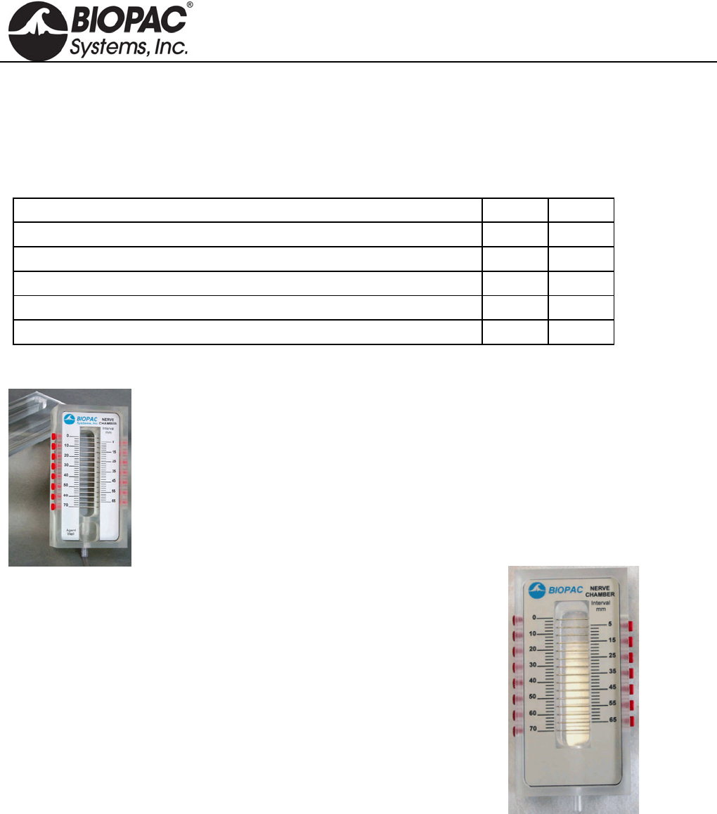
info@biopac.com
support@biopac.com
www.biopac.com
BIOPAC Hardware | Nerve Chambers | Page 1 - 2 Updated: 3.27.2013
NERVE CHAMBERS: NERVE1 AND NERVE2
These acrylic, desktop Nerve Chambers have 15 stainless steel pins for recording and stimulating a variety of
different nerve preparations. Each stainless steel pin is spaced 5mm apart to provide a variety of recording and
stimulating configurations. The sockets accept 2 mm pin plugs.
NERVE1 and NERVE2 Comparison
Feature NERVE1 NERVE2
Deep Reservoir (35mL)—contain Ringers or other solutions x x
Drain—facilitate extended viability of the preparation. x x
Agent Well — add compounds (ether, dry ice, etc.) 1.4cm x 2cm x 2cm (h x w x l) x x
Lid—enclose the preparation. 50mm thick x --
Valve & hose—flush and drain options x --
NERVE1 – WITH AGENT WELL AND LID
NERVE1 chamber includes:
Deep Reservoir (35 mL) for containing Ringers or other solutions
Drain (with valve & hose) to facilitate extended viability of the preparation
Agent Well for adding compounds (such as ether or dry ice)
Lid to enclose the preparation when the protocol requires it.
NERVE2 – STANDARD NERVE CHAMBER
NERVE1 chamber includes:
Deep Reservoir (35mL) for containing Ringers or other solutions.
Drain (with valve & hose) to facilitate extended viability of your
preparation.
NERVE CHAMBER SPECIFICATIONS (NERVE1/NERVE2)
Pins: 15, stainless steel
Spacing: 5 mm
Sockets: accepts 2 mm pin plugs
Reservoir: holds 35 mL (or use drain/valve)
Dimensions: 4.5 cm x 7 cm x 14 cm (H x W x L)
Agent well: (NERVE1 only) 1.4 cm x 2 cm x 2 cm (H x W x L) NERVE2
Lid: (NERVE1 only) 50 mm thick
Related components:
STM100C Stimulator Module
STMISO Series Stimulator Modules
MCE100C Micro-electrode Amplifier
ERS100C Evoked Response Amplifier
EMG100C Electromyogram Amplifier
HARDWARE GUIDE

info@biopac.com
support@biopac.com
www.biopac.com
BIOPAC Hardware | Nerve Chambers | Page 2 - 2 Updated: 3.27.2013
NERVE CHAMBER CONNECTIONS
To connect the Nerve Chamber to MP-series Biopotential amplifiers (MCE100C, ERS100C, or EMG100C),
use three JUMP100 connectors and three CBL200 adapter cables. Optionally, for additional lead length, use one
MEC110C extension cable.
1. Plug the three JUMP100s into the desired points of the Nerve Chamber.
2. Connect the free ends of the JUMP100s to the mating ends of the CBL200s.
3. Then connect the free ends of the CBL200s to the Biopotential amplifier inputs. For additional lead
length, plug the MEC110C into the Biopotential amplifier and plug the free ends of the CBL200s into the
free end of the MEC110C.
To connect the Nerve Chamber to the STM100C Stimulator, use one CBL106 and one CBL102.
1. Plug the red and black leads (2mm pins) of the CBL106 into the desired points of the Nerve Chamber.
2. Connect the free end (Female BNC) of the CBL106 to the mating end (Male BNC) of the CBL102.
3. Then insert the free end of the CBL102 (3.5mm phone plug) into the 50 Ohm output of the STM100C.
Note: If the STM100C Stimulator is used with a Biopotential amplifier on the same nerve—which is nearly
always the case—make sure that the black lead of the CBL106 (stimulation negative) is connected to the
same pin as the ground lead going to the Biopotential amplifier. This is easy to do because the design of
the JUMP100 allows stacking connections.
HARDWARE GUIDE
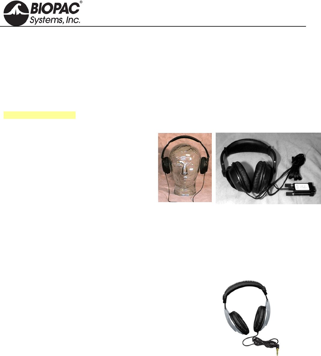
info@biopac.com
support@biopac.com
www.biopac.com
BIOPAC Hardware | OUT SERIES | Page 1 - 4 Updated: 1.6.2014
OUT SERIES
OUT1 High Fidelity Headphones
OUT1A Ultra-Wide Frequency Response Headphones
OUT2 BNC Output Adapter
OUT100 Monaural Headphones
OUT101 Tubephone
OUT102 Piezo Audio Transducer
OUT103 LED Cable
40HP Monaural Headphones
For OUT3, see Stimulators
OUT1 HEADPHONES
These wide response high-fidelity headphones are used
for auditory stimulus (short tones or clicks) or to listen
to physiological signals (like EMG) directly. The
Headphones are comfortable and lightweight (3 ounces)
and include a 2-meter cable so the Subject can be seated
a comfortable distance from the acquisition unit.
Unlike other Smart Sensors that connect to the MP3X,
the OUT1 connects to the “Analog out” port on the
back panel of the MP3X.
OUT1 SPECIFICATIONS
Cable Length: 2 meters
Connector Type: 9 Pin DIN (female)
OUT1A
These ultra-wide frequency response headphones connect directly to the headphone port on the MP36 or MP36R
data acquisition unit.
Features of these multi-purpose headphones include:
High dynamic range
High-resolution capsule
1/8" connector plus 1/4" adapter included
Single-sided cord
Oval-shaped ear cups
Comfortable headband
High-quality components and exceptionally rugged construction
OUT1A SPECIFICATIONS
Connector: 1/8" TRS connector plus 1/4" TRS adapter
Interface: MP36 or MP36R (not compatible with other MP units)
Frequency response: 20 Hz - 20 kHz
Max. power handling: 100 mW
Impedance: 32 Ohm
Sensitivity: 105 dB @ 1 kHz
Cord length: 2 meters
Dimensions: 11-3/4" x 9-3/4" x 8-1/4"
HARDWARE GUIDE
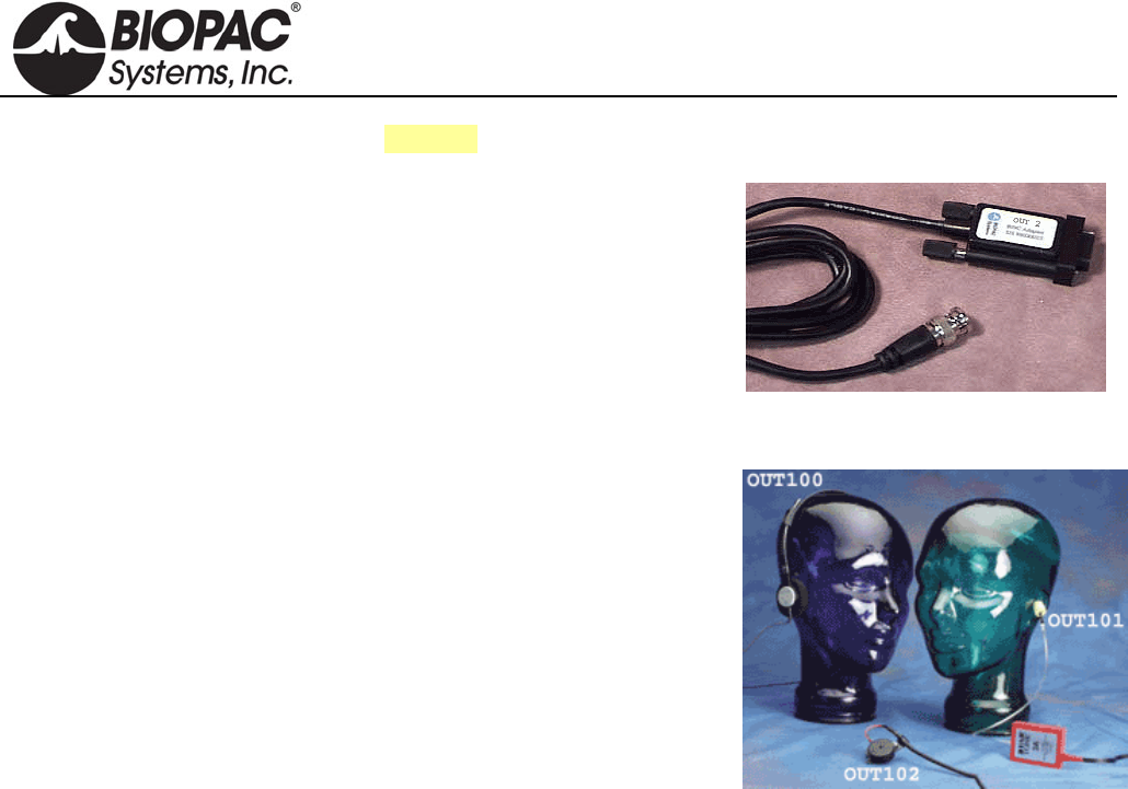
info@biopac.com
support@biopac.com
www.biopac.com
BIOPAC Hardware | OUT SERIES | Page 2 - 4 Updated: 1.6.2014
See also: SS9LA BNC Input Adapter
OUT2 BNC (M) OUTPUT ADAPTER
This BNC adapter is designed to output signals from the MP3X unit to
other devices (such as external amplified speakers and scopes). This 2-
meter adapter cable terminates in a male BNC for easy connections.
OUT2 SPECIFICATIONS
Cable Length: 2 meters
Connector Type: BNC (male)
OUT100
These monaural headphones can be used with the STM100C stimulator
module to deliver a tone signal while recording data for startle response
or other stimulus-response studies. The headphones can also be used to
listen to raw signals (such as EMG), piped through the STM100C from
an amplifier output. The OUT100 is a wide response, high efficiency
headphone, weighing 85 grams and is equipped with a 1.8 meter cord
terminated in a 6.3 mm (1/4") phone plug.
OUT100 SPECIFICATIONS
Weight: 85 grams
Connector Type: 6.3 mm (1/4")
Cable length: 1.8 meter
Speaker: 28 mm dia 32 ohm dynamic Mylaar
Impedance: 16 Ohm @ 1.0 kHz
Power Handling: 100 mW max
Frequency response: 20 Hz - 20 kHz
Average SPL: 108 dB ± 4 dB
Adapter (included): 1/4" mono adapter plug
OUT101 TUBEPHONE
OUT101 Components: one Tubephone, plastic tube and 50 foam ear inserts
Use the OUT101 tubephone to deliver clicks and tones in auditory evoked response applications (i.e. ABR).
The tubephone design consists of a monaural acoustic transducer attached to a short, flexible, plastic tube, which
fits into the subject’s ear with the aid of a foam tip.
Use of the tubephone reduces ambient noise and bone conduction problems, which can interfere with auditory
response recordings. Furthermore, because the Tubephone provides a 1 msec acoustic signal delay (due to plastic
tube), it automatically separates true response from electromagnetic artifact resulting from speaker activation.
OUT101E Replacement Foam Ear Inserts: pkg. of 50
OUT101T Replacement Plastic Tubes: pkg. of 4
HARDWARE GUIDE

info@biopac.com
support@biopac.com
www.biopac.com
BIOPAC Hardware | OUT SERIES | Page 3 - 4 Updated: 1.6.2014
MP36 and MP36R interface options:
• BSL System stimulator (model BSLSTM): use BSLCBL6 and Radio Shack P/N 274-047 ¼" to 1/8"
phono adapter
• BSL MP36 data acquisition unit Analog Out port: use OUT3 plus BSLCBL6 and Radio Shack P/N 274-
047 ¼" to 1/8" phono adapter
• MP36 headphone port: use Radio Shack P/N 274-047 ¼" to 1/8" phono adapter; note—volume may not
reach the same levels as the Analog Out port
OUT101 SPECIFICATIONS
Response: Compares to TDH-39, 49 or 50 audiometric headphones
Acoustic signal delay: 1 msec
Dimensions: 3.8cm (wide) x 5cm (high) x 1cm (thick)
Cable termination: 6.3mm (1/4") phone plug
Cable length: 1.8 meter
Cable clip: Yes; clip attaches to fabric or fixtures
CALIBRATION FOR AUDITORY BRAINSTEM RESPONSE STUDIES
To calibrate the OUT101 Tubephone, use an Etymotic ER-7C Probe Microphone—this microphone provides a
calibrated output voltage which is a function of applied Sound Pressure Level (SPL). The sensitivity is 50
mV/Pascal (-46 dB re: 1 V/uBar): 0 dB SPL = 0 dBuV. Place the Probe Microphone insert tube in the auditory
canal prior to the insertion of the OUT101 foam tip.
The OUT101 Tubephone sound delivery tube and the Probe Microphone sound input tube will then be exposed to
the same auditory chamber. Accordingly, the SPL is recorded, via the Probe Microphone, simultaneously with
applied auditory stimulus from the OUT101 Tubephone.
OUT102 PIEZO AUDIO TRANSDUCER
The OUT102 piezo transducer is typically connected directly to the STM100C stimulator module. When the
stimulator module output rises above 1.5 volts, the piezo indicator will emit a constant audible signal (3.0 kHz @
80 dB). Accordingly, the device is very useful for providing an audible stimulus, or alarm, when a physiological
signal passes a certain threshold. As such, the OUT102 makes an excellent audible BPM indicator for ECG, blood
pressure or respiration signals. The device can also be used to indicate when temperature or other slowly moving
variable (e.g. electrodermal response) passes a certain threshold. The threshold for the OUT102 is determined by
adjusting the amplitude control on the STM100C module. The specific Biopotential or Transducer amplifier
signal monitored can be recorded while simultaneously directed through the STM100C module. The OUT102
also connects directly to the UIM100C digital I/O ports for operation with Control Channel outputs. The OUT102
measures 2.5cm (dia) x 1cm (high) and comes equipped with a 1.8m cable terminated in a 3.5mm phone plug. An
adapter is included for connecting the OUT102 to the UIM100C digital I/O ports.
OUT102 SPECIFICATIONS
Dimensions: 2.5cm (dia) x 1cm (high)
Cable Length: 1.8 meter
Connector Type: 3.5 mm phone plug + adapter for the UIM100C digital I/O ports
HARDWARE GUIDE
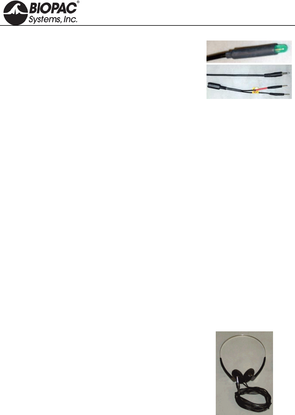
info@biopac.com
support@biopac.com
www.biopac.com
BIOPAC Hardware | OUT SERIES | Page 4 - 4 Updated: 1.6.2014
OUT103 LED CABLE
Use this LED cable to synchronize a light flash. The 3 meter cable
makes it easy to use the LED for a variety of protocols. Terminates
for connection to Analog OUT 0/1 and includes adapter for
connection to Digital I/O. Media synchronization - Windows only -
AcqKnowledge 4.1 and above
MP150 AND UIM100C SETUP
a. Connect the OUT103 2 mm pin adapter to the 3.5 mm plug on the OUT103 cable.
b. Connect the red OUT103 2 mm pin to a Digital I/O channel on the rear of the UIM100C and the
black pin to GND D on the rear of the UIM100C.
c. Use MP150 > Set Up Channels to acquire and plot the Digital I/O channel the OUT103 is connected
to.
d. Set MP150 > Show Manual Control
Set for ‘Output’.
Enable the 'Set immediately' option.
Click the Digital I/O channel the OUT103 was connected to to toggle between 0 and 1.
If necessary, click the 'Set' button to update the manual control and output a digital pulse.
MP36R SETUP - ADDITIONAL ITEMS REQUIRED
a. Connect an OUT3 (BNC adapter) to the 'Analog Out' port on the rear of the MP36R.
b. Connect a BSLCBL6 (interface cable: BNC to 3.5 mm) to the OUT3.
c. Connect the OUT103 3.5 mm plug to the BSLCBL6 3.5 mm socket.
d. Set MP36 > Output Control 'Low Voltage Stim' option
Set Pulse width to 100 msec.
Set Pulse level to 5 volts – set Reference Channel to any digital channel.
Click the D’ON’ button to output a digital pulse.
CALIBRATION
The OUT series does not require calibration.
40HP MONAURAL HEADPHONES
These monaural headphones are used with Biopac Science Lab MP40 and
Biopac Student Lab MP45 for stimulus response experiments and to listen
to EMG signals. The 40HP is a wide-response, high-efficiency headphone.
40HP SPECIFICATIONS
Cable Length: 5 meters
Connector Type: 3.5 mm phone plug
HARDWARE GUIDE
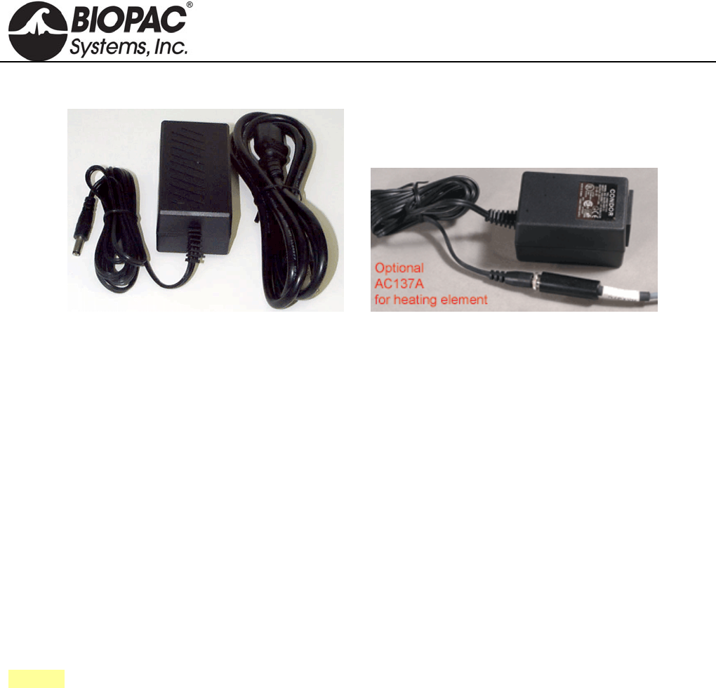
info@biopac.com
support@biopac.com
www.biopac.com
BIOPAC Hardware | In-line Power Supplies | Page 1 - 1 Updated: 12.19.2013
IN-LINE POWER SUPPLIES
AC150A Power Supply AC137A Power Supply
All AC series in-line power supplies are CE marked for the EC Low Voltage Directive and EMC Directive, and
all have UL and TUV approval. The units have standard IEC power input plugs and operate over mains power
ratings of 100-240 VAC, 50-60 Hz. Each includes a USA or EURO power cord. (ACCORD US/EURO,
ACCORD-HUS Hospital Grade)
AC101A ±12 volt, +5 volt, 1 amp Connects the LDF100C to the AC mains wall outlet. One supply is
included with each LDF100C module.
AC137A +6 volt, 1.5 amp Powers the heating element for any of the TSD137 series pneumotachs.
AC150A +12 volt, 4.17 amp Connects the MP150 System to the AC mains wall outlet. One supply
is included with each MP150 Starter system.
AC300A +12 volt, 1.25 amp Connects the MP or GASSYSTEM2 to mains wall outlet. One supply
is included with MP36/35 system, MP100 or GASSYSTEM2.
See also: IPS100C Isolated Power Supply
HARDWARE GUIDE
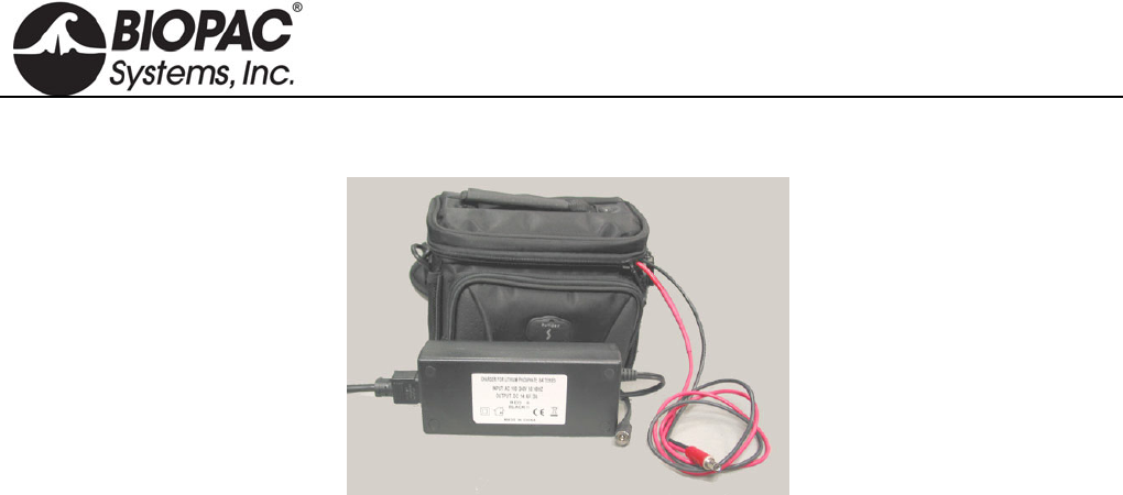
info@biopac.com
support@biopac.com
www.biopac.com
BIOPAC Hardware | BAT100A | Page 1 - 2 Updated: 3.1.2013
BAT100A RECHARGEABLE BATTERY PACK
BAT100A with Recharger
The BAT100A is a high energy density and lightweight battery pack designed to operate MP150 or MP3X
Systems. A universal input voltage 3 amp battery charger is also included. The battery pack is lightweight and
comes with a supplied carrying case with integral shoulder strap. The carrying case holds battery pack, charger
and all associated cords.
The BAT100A chemistry is Lithium Iron Phosphate (LiFePO4). A key advantage over other lithium-ion batteries
is the superior thermal and chemical stability, which provides better safety characteristics than other lithium-ion
batteries with different cathode materials. Due to the significantly stronger bonds between oxygen atoms in the
phosphate, oxygen is not readily released, and as a result, lithium iron phosphate cells are virtually incombustible
in the event of mishandling during charge or discharge, and can handle high temperatures without decomposing.
Ships as USA or EURO version based on delivery address.
BAT100A replaces BAT100 effective June 2011.
Operation
1. Only charge the BAT100A (12 v @ 15 AH LiFePO4) using the included charger.
2. Discontinue use of the BAT100A when the performance of the MP System begins to deteriorate.
Charging the Battery Pack
1. When the BAT100A is being charged, the charger will indicate a RED charging LED.
2. When the BAT100A is fully charged, the charger will indicate a GREEN charging LED.
Storage
1. Store the Battery Pack in a fully charged condition.
2. Store the Battery Pack in a cool place (normal room temperature or lower).
HARDWARE GUIDE

info@biopac.com
support@biopac.com
www.biopac.com
BIOPAC Hardware | BAT100A | Page 2 - 2 Updated: 3.1.2013
BAT100A BATTERY PACK SPECIFICATIONS
Battery
Chemistry: LiFePO 4 (Lithium Iron Phosphate)
Output Capacity: 12V @ 15 amp-hours
Working Output Voltage Range: 13.2 V – 12 V
Output Connector: DC Barrel Plug (5.5 mm OD, 2.1 mm ID – Center positive)
Operating Time: MP3X with 4 sensors: 26 hours nominal
MP150 with 4 modules: 16 hours nominal
Charge Time: 5 hours (nominal)
Recharge Cycles: (number of cycles to 80% of original capacity): 1500 (typical minimum)
Operating Temperature Range: 0° C to 45° C
Storage Temperature Range: -20° C to 60° C
Weight: 2.45 kg
Dimensions: (includes carrying case) 14cm (high) x 19cm (wide) x 14cm (deep)
Battery Charger (For BAT100A only)
Maximum Nominal Charge Voltage: 14.4 V @ 3.0 amps (Charges at 3 amps to 14.4 V, then potentiostatic at
14.4 V until current is less than 0.5 amps)
Input: 120/240 VAC @ 50/60 Hz (USA or EURO power cord)
Output Connector: DC Barrel Socket (5.5 mm OD, 2.1 mm ID – Center positive)
Operating Temperature Range: 0° C to 45° C
Storage Temperature Range: -20° C to 60° C
Weight: 285 grams
Dimensions: 3.8cm (high) x 6.4cm (wide) x 15cm (long)
HARDWARE GUIDE
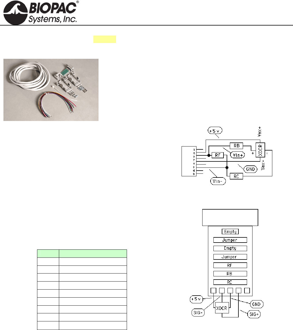
info@biopac.com
support@biopac.com
www.biopac.com
BIOPAC Hardware | SS-KIT | Page 1 - 3 Updated: 3.28.2013
See also: TCI series of available interfaces
SS-KIT-IN TRANSDUCER CONNECTOR INTERFACE KIT - INPUT
This kit is for users who wish to adapt their own transducers to the Biopac
Student Lab PRO System. The kit comes with a Smart Sensor connector,
cable and components to properly interface with the transducers. The kit
will allow quarter, half or full bridge transducers (pressure, force, strain,
acceleration, sound, etc.) to be connected to the system.
SS-KIT-IN COMMENTS AND SUGGESTIONS
1) Be careful of consumption.
The bridge circuit should be designed so no more than
5mA are used to power the bridge. If the bridge takes
more than 5mA, try reducing the voltage across the
bridge by using series resistors or other kinds of
regulators.
2) Be careful of signal amplitude.
The signal input (conditioned by the bridge) should
provide a signal no greater than ±50 mV between pins 2
and 4 on the 9 Pin D Male connector. If this voltage
exceeds 50 mV (of either polarity), the input amplifier
stages will saturate.
PIN Description
1 Shield
2 Vin+
3 Ground
4 Vin-
5 Shield
6 +5 volts (ref)
7 No Connection
8 No Connection
9 -5 volts (ref)
9 Pin D Male connector pin-outs
Schematic
Printed circuit board layout
HARDWARE GUIDE
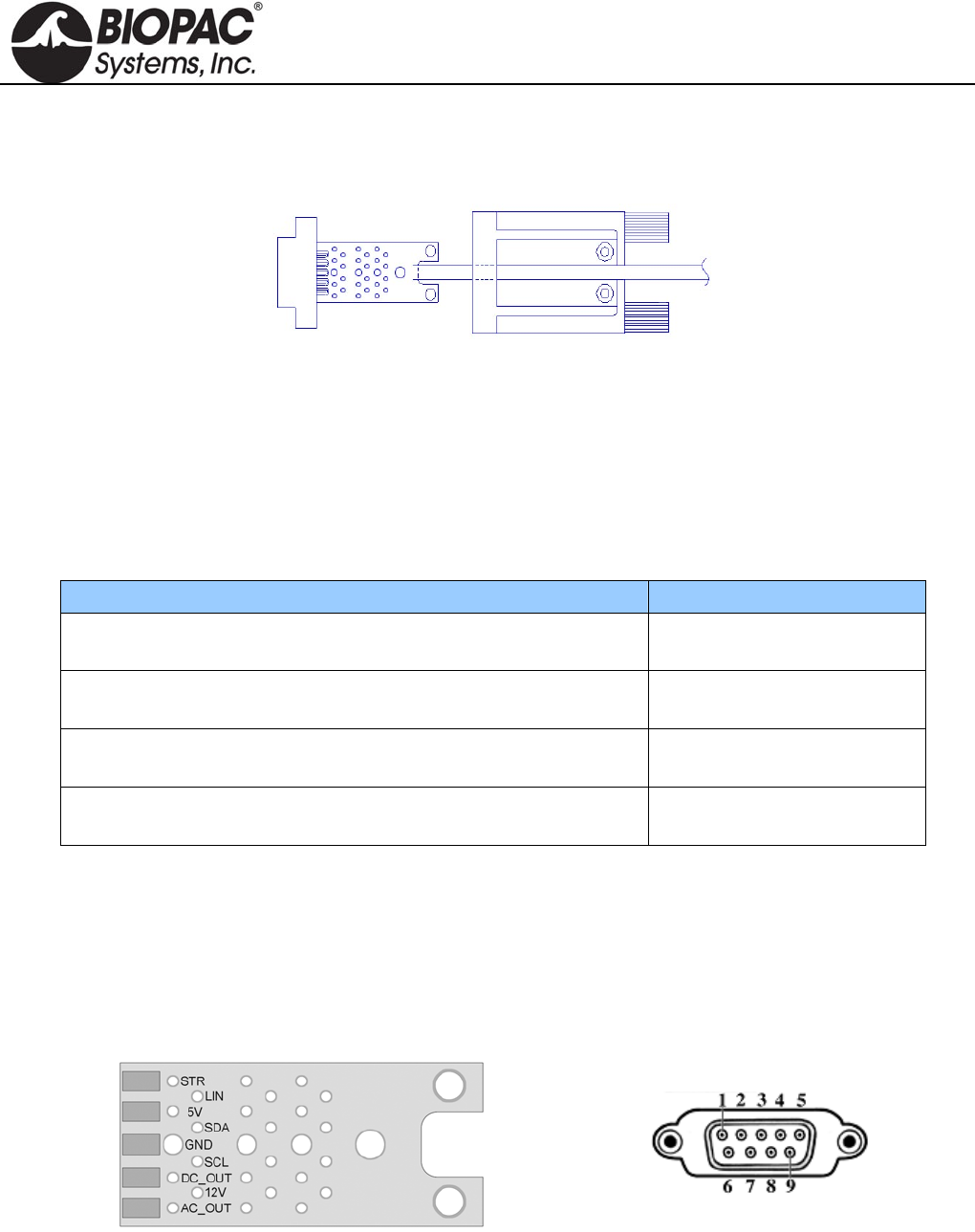
info@biopac.com
support@biopac.com
www.biopac.com
BIOPAC Hardware | SS-KIT | Page 2 - 3 Updated: 3.28.2013
SS-KIT-OUT TRANSDUCER CONNECTOR INTERFACE KIT - OUTPUT
SS-KIT-OUT GUIDE
The SS-KIT-OUT allows custom cables to be made that connect to pins on the Analog Out port. Typical uses are:
1. Synchronizing 3rd party equipment to the MP3X’s start of acquisition.
2. Listening to pulses (“clicks”) or tones with headphones which can be used for reaction time studies.
3. Controlling audio or visual stimulus device (Audio tone, LED or Strobe flash, etc.).
4. Listening to input signals such as EMG via headphones or an audio amp./speaker.
Typical Analog Out connections include:
Analog Out Function MP36/MP35 and MP30
Listening to pulses (“Clicks”) via headphones or audio amp./speakers Headphone “+”: pin 1
Headphones “-“: pin 3
Headphones for listening to analog signals (EMG, etc) Headphone “+”: pin 1
Headphones “-“: pin 3
Driving output LED’s
To limit LED current, put resistor in series with pin 2.
“+”: pin 2
“-“: pin 3
Synchronizing to 3rd party equipment Out “+”: pin 5
Out “-“: pin 3
The “Analog Out” port on the back panel of the MP36/MP35 or MP30 (MP3X) can output pulses (digital) or
analog voltage levels, or it can pipe out analog signals from one of the input channels. The port is controlled
through one of the Output Control Panels in the Biopac Student Lab (BSL) PRO software, which is described in
the BSL PRO manual.
The following diagrams and table show the pin-outs of the “Analog Out” port on the back of the MP3X and the
Printed Circuit Board (PCB) layout of the SS-KIT-OUT. Each pin is accessible on the PCB and can be located by
the label shown in the table.
9 PIN MALE DSUB
Back Panel—MP36/MP35 or MP30
SS-KIT-OUT PCB ANALOG OUT PORT
HARDWARE GUIDE
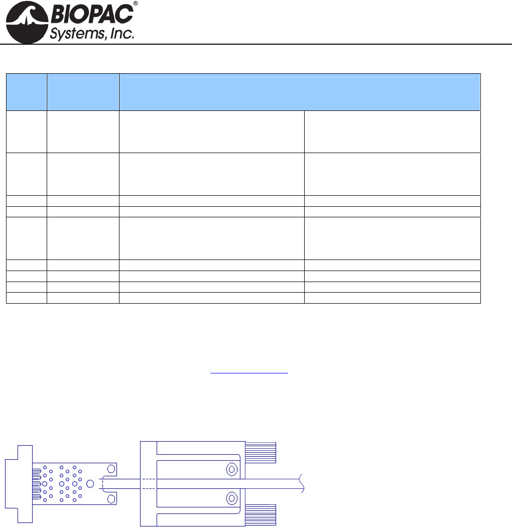
info@biopac.com
support@biopac.com
www.biopac.com
BIOPAC Hardware | SS-KIT | Page 3 - 3 Updated: 3.28.2013
SS-KIT-OUT SPECIFICATIONS
PIN LABEL
on PCB
PIN FUNCTION
MP36/MP35 MP30
1 AC_OUT Buffered analog or pulse output
A.C. coupled (1,000 uF)
Analog range: +/- 2.048 V
Pulse range: 0 to 2.048V
Buffered analog or pulse output
A.C. coupled (2,200 uF)
Analog range: +/- 2.5 V
Pulse range: 0 to 2.5V
2 DC_OUT Buffered analog or pulse output
D.C. coupled
Z out = 50
Range: 0 to 4.096 V
Buffered analog or pulse output
D.C. coupled
Z out = 50
Range: 0 to 5 V
3 GND Ground Ground
4 5V +5 V (100mA max.) +7.5 V (100 mA max.)
5 STR Buffered pulse output
Z out = 1 k
Range: 0 to 5 V
Un-buffered analog or pulse output (D.C.
coupled)
Z out = 1 k
Range: 0 to 5 V
6 12V +12 V (100 mA max) Not used
7 SCL
I2C SCL Do not connect! Not used
8 SDA
I2C SDA Do not connect! Not used
9 LIN
Monitor Do not connect! Not Used
Notes Pins 1 and 2 For the MP36/MP35, pins 1 and 2 can output analog or pulses when using MP3X
firmware revision 1.26.037.030 or greater. When run under previous firmware, pins 1
and 2 can only be used for analog output. To identify the firmware revision, launch the
BSL PRO software and check the Help > About Biopac Student Lab dialog. See the
Support section at www.biopac.com for upgrade information.
Pins 3, 4 and 6 The Power supply pins (3, 4 and 6) can be used for external circuits as long as the load
current does not exceed 100 mV.
ASSEMBLY NOTES
The PCB assembly fits into the thumb
screw housing as shown. Two screws attach
the PCB to the housing and hold the strain
relief in place. The strain relief is used to
prevent the cable and attached wires from
pulling off the SS-KIT-OUT PCB. It is a
good idea to place the strain relief over the
cable prior to soldering the wires to the
PCB so that it only has to be slid on a small distance. If the strain relief fits too tightly around the cable, use water
to wet the cable, allowing the strain relief to slide. Place the strain relief such that the case cover pinches and
holds the cable. The stick on panel is used to cover the screws and protect the label.
HARDWARE GUIDE
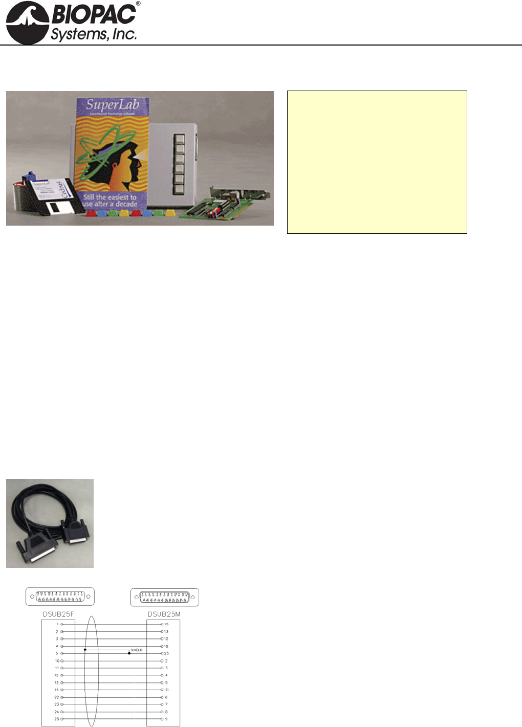
info@biopac.com
support@biopac.com
www.biopac.com
BIOPAC Hardware | SUPERLAB for MP3X | Page 1 - 2 Updated: 2.12.2013
STIMULUS PRESENTATION
STP35W SUPERLAB SYSTEM FOR MP36/35 See STP30W to use with a BSL MP30
STP35W Components
SuperLab Software
Digital I/O Card
STP35 Interface Cable
Support Pack for Digital I/O Card
Six-button Response Box
Pushbutton Keycap Color Kit
The STP35W is a stand-alone system that measures subject responses to visual or auditory stimuli. It can present
visual stimuli on a computer screen, or auditory stimuli via headphones or speakers, and simultaneously (1ms
resolution) send trigger signals to an MP36/35 System for data synchronization and collection purposes.
For performing accurate (1 ms resolution) reaction time measurements, the STP35W includes a six-pushbutton
response box. For measuring physiological responses to stimuli, the STP35W includes an optically isolated
interface, permitting up to three synchronization signals (input) between the STP35W and the MP36/35 System.
The SuperLab software can be used to change the placement of visual stimuli on the screen, change the screen's
background color, choose from a variety of input and timing options, and provide feedback to subjects based on
either response or reaction time. Different trigger channels can be paired to different visual or auditory stimuli to
perform sophisticated evoked response averaging tests (e.g. P300).
See BSL PRO Lesson H30 Stroop Effect for details of the classic psychology experiment and a sample of
how SuperLab works with the BSL System.
NOTE: Second PC required. The synchronization signal(s) coming from the STP35W can be directed to a BSL
MP36/35 System running on a PC or a Macintosh, but it's not possible to run the STP35W on the same computer
as the BSL MP36/35 System. The STP35W requires that the SuperLab software and a Digital I/O card (PCI slot
required) be placed on a second computer.
STP35 MP36/35 TO SUPERLAB
For users who already have SuperLab and an MP3X unit,
the STP35 Interface Cable can be used to connect the two
systems. The STP35 cable interfaces with the I/O port of
the rear of the MP36/35 unit.
STP35A MP36/35 TO PARALLEL
MP36 or MP35 to E-Prime, Direct RT, MediaLab,
Inquisit, and other systems that connect via the parallel
port.
HARDWARE GUIDE
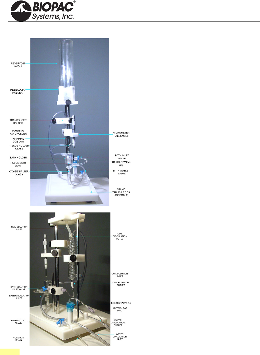
info@biopac.com
support@biopac.com
www.biopac.com
BIOPAC Hardware | Tissue Bath Stations | Page 1 - 2 Updated: 3.22.2013
TISSUE BATH 1, 2, 4, 8 TISSUE BATH STATIONS
The Tissue Bath Station is completely modular, and can
be purchased in multiples of one unit. The System
includes all of the glassware, tubing, reservoir, tissue
hooks and mounting accessories, force transducer and
micrometer tension adjuster.
The ergonomic design of the station allows the tissue bath
to be lowered away from the tissue holder so that
mounting of the tissue preparation is very easy. The taps
for filling and draining the bath are mounted on the tubing
to avoid the risk of accidental bath breakage. The entire
station is mounted on a convenient base stand, which
creates a sturdy platform for the experiment. The unique
design makes it easy to add or remove stations to provide
the optimal solution for the requirements.
When a system is ordered, the size of the tissue bath and
heating coil must be specified.
Each Tissue Bath station includes:
1 Reservoir
1 Reservoir Holder
1 Transducer Holder
1 Warming Coil Holder
1 Warming Coil (specify 5 ml, 10 ml, 20 ml, or 30 ml
size)
1 Tissue Holder (glass; left)
1 Tissue Holder (stainless steel; right)
2 Triangle Tissue Holder (stainless steel)
2 Tissue Clip (stainless steel)
1 Bath Holder
1 Tissue Bath (specify 5 ml, 10 ml, 20 ml size)
1 Oxygen Filter (glass)
1 Micrometer Assembly
1 Mount Accessories Kit
1 Base Station with Support Rods
1 TSD125 Force Transducer (specify TSD125 model
C, D, E or F)
See also: BIOPAC Circulators, or use an existing system.
HARDWARE GUIDE
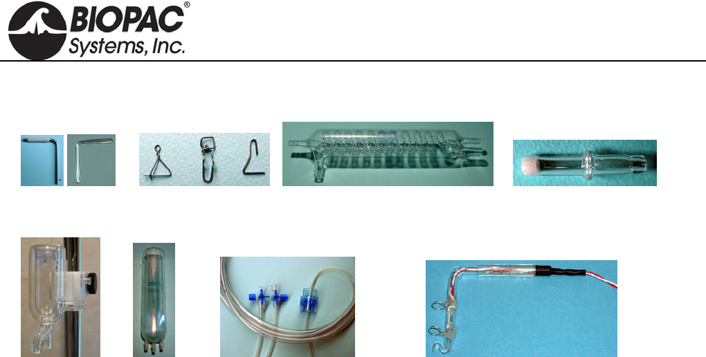
info@biopac.com
support@biopac.com
www.biopac.com
BIOPAC Hardware | Tissue Bath Stations | Page 2 - 2 Updated: 3.22.2013
TISSUE BATH ACCESSORIES / REORDER PARTS
Tissue Holders Tissue Clips Warming Coil Oxygen Filter
Tissue Bath Reservoir Mount Accessories Field Stimulation Electrode
RXHOLDER-S Tissue Holder (stainless steel)
RXHOLDER-G Tissue Holder (glass)
RXHOLDER-TR Triangle Tissue Holder (stainless)
RXCLIP Tissue Clip (stainless steel)
RXCLIP-TRI Triangle Tissue Clip for Rings
(stainless steel)
RXWARMING Replacement Warming Reservoir
400 ml
RXCOIL Warming Coil
RXO2FILTER Oxygen Filter (glass)
RXBATH Tissue Bath (5 ml, 10 ml, 20 ml)
RXRESERVOIR Reservoir 1000ml
RXMOUNT Mount Accessories Kit
STIMHOLDER Field Stimulation Electrode for
use with STM100C
BSLSTIMHLD Field Stimulation Electrode with
BNC cable termination for use with
BSL Stimulator
TISSUE BATH ACCESSORIES
SPECIFICATIONS
1 x Tissue Holder—stainless steel; 15 mm high x 9
mm wide; reorder as RXHOLDER-TR
1 x Tissue Holder—glass; 67.46 mm high x 57.85
mm wide; reorder as RXHOLDER-G;
1 x Tissue Holder —stainless steel; 77.34 mm high x
55.06 mm wide; reorder as RXHOLDER-S
2 x Tissue Clip—stainless steel; 15 mm high x 5 mm
wide: reorder as RXCLIP
2 x Triangle Tissue Clip—stainless steel; 15 mm high
x 12 mm wide; reorder as RXCLIP-TRI
1 x Replacement Warming Reservoir 400 ml: reorder
as RXWARMING
1 x Integrated heater—1,600 ml volume,
programmable temp. 20° - 44° C
1 x Circulator pump—15 W; 500 ml/min
1 x Warming Coil; reorder as RXCOIL
1 x Oxygen Filter; reorder as RX02FILTER
1 x Bath —reorder as RXBATH5 (5 ml,) RXBATH10
(10 ml,) RXBATH20 (20 ml)
1 x Reservoir—1000 ml; reorder as RXRESERVOIR
Mount Accessories Kit; reorder as RXMOUNT
Field Stimulation Electrode; reorder as STIMHOLDER
for STM100C, BSLSTIMHLD for BSL Stimulator
1 x Micrometer-transducer assembly
1 x 3 way Rotary Valve
1 x Power Supply – 110V/60 Hz or 220V/50 Hz
HARDWARE GUIDE
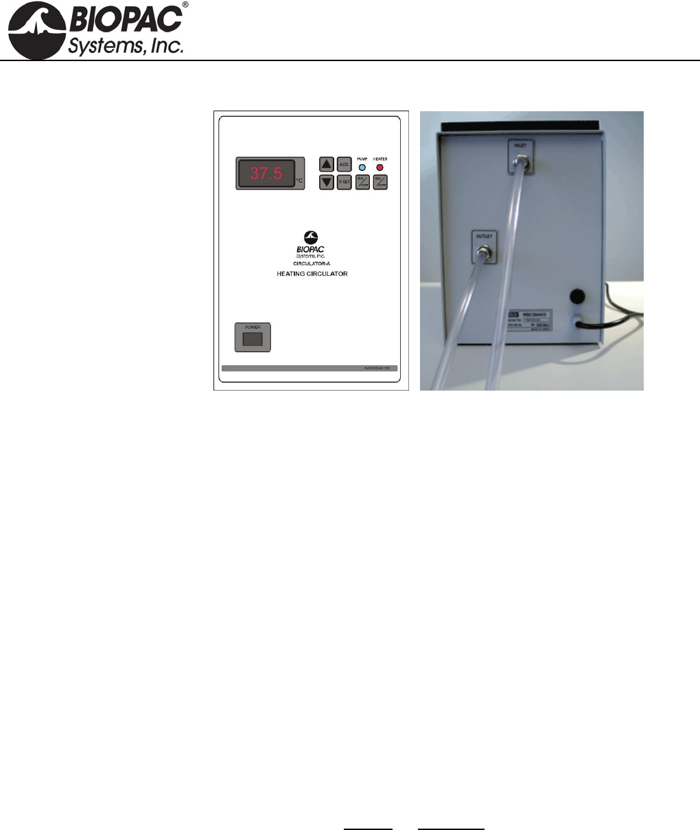
info@biopac.com
support@biopac.com
www.biopac.com
BIOPAC Hardware | ITBS Circulator | Page 1 - 3 Updated: 2.6.2013
CIRCULATOR A/B HEATING CIRCULATORS
Heating circulators are used
with Tissue Bath Stations and
include a digital temperature
display and the following
controls:
Preset
Temperature
Power
Heater
Circulation
Inlet and Outlet ports are on
the back, along with the
power cord.
Circulator A:
110 V, 60 Hz
Circulator B:
220 V, 50 Hz
CIRCULATOR SETUP AND USAGE GUIDE
BIOPAC Heating Circulators will maintain
water temperature at a preset value in the
range 300C to 450C and circulate the water
through tissue baths.
Heating circulators include a digital temperature
display and the following controls:
Preset
Temperature
Power
Heater
Circulation
CALIBRATION
Although the offset value for the temperature sensor
is factory-calibrated, the user can calibrate the
controller’s internal temperature sensor. To calibrate
the sensor:
1. Install a calibrated reference thermometer in
the bath.
2. Adjust the offset value to zero.
3. Adjust the preset value to an appropriate
temperature.
4. Once the bath reaches the preset value and
stabilizes, calculate the offset value by
noting the difference between the reference
thermometer value and the preset value.
5. Enter this value as an offset.
ERROR CODES
Display Indication
Lo Water in the bath is not enough or
the bath is empty.
Sen Microprocessor cannot
communicate with the temperature
sensor.
HARDWARE GUIDE

info@biopac.com
support@biopac.com
www.biopac.com
BIOPAC Hardware | ITBS Circulator | Page 2 - 3 Updated: 2.6.2013
CIRCULATOR SETUP & USAGE GUIDELINES
1. Connect a hose from the INLET on the back of the circulator to the tissue bath OUTPUT.
For more than one tissue bath, connect the tissue baths serially.
2. Connect a hose from the OUTLET on the back of the circulator to the tissue bath INPUT.
3. Fill the stainless steel water bath with 4.5 liters of water.
A buzzer sound warning will be emitted if there is not enough water in the bath when the Circulator is
powered on. See Error Codes above.
4. Place the glass lid on the bath to close.
5. Plug the power cord from the back of the Circulator to a power source.
6. Press the POWER key to turn on the circulator.
7. To see the preset temperature value, press the P.SET key.
To change the preset temperature value, hold down the P.SET key and, at the same time, repeatedly
press the UP or DOWN arrow keys to increase or decrease the preset value.
8. To see the acceleration value of the Circulator, press the ACC key.
To change the preset acceleration value, hold down the ACC key and, at the same time, repeatedly
press the UP or DOWN arrow keys to increase or decrease the preset value. The higher values for
acceleration indicate more rapid heating.
9. To see the offset temperature value, press the ACC and P.SET keys at the same time.
This is a factory-calibrated value. To calibrate the temperature sensor, see Calibration above.
All preset values are written to non-volatile memory.
10. Press the PUMP ON/OFF key to start the circulation pump.
Check that the blue Pump Status LED is ON. The pump should begin circulating water.
11. Check that the water goes out of the circulator and flows through the waterway of the tissue bath(s).
With initial setup, some air may remain in the circulator pump. See Troubleshooting below.
12. Press the P.SET button and confirm the set value of the desired temperature.
13. Press the HEATER ON/OFF key to turn on the heater.
Check that the red Heater Status LED is ON.
Check that the Heater Display LED is on to confirm that the heater inside the bath is working.
Circulator will maintain the preset temperature of water in the bath; variations of +/-0.20C are
acceptable.
14. Check the water level periodically and add water to the bath if the level drops below 4 liters.
Caution: Over time, the water level inside the bath may decrease. Do not operate the circulator with
less than 4 liters of water in the bath.
15. To turn the PUMP and HEATER on and off individually, press their respective ON/OFF keys.
16. To stop operation, press ON/OFF keys.
Power down equipment in the following order: PUMP, HEATER, POWER.
HARDWARE GUIDE

info@biopac.com
support@biopac.com
www.biopac.com
BIOPAC Hardware | ITBS Circulator | Page 3 - 3 Updated: 2.6.2013
TROUBLESHOOTING
There is no water circulation or very little.
1. Check the hose connections and be sure they are connected to the correct positions.
2. Check that the hoses are not bent or twisted (which might impede the flow of water).
3. Confirm that there is at least 4 liters of water in the bath.
There is some air in the waterway.
To remove the air:
1. Press the PUMP ON/OFF key to OFF stop the circulator pump.
2. Disconnect the hose from the INPUT of tissue bath. (Leave other end connected to the Circulator
OUTLET.)
3. Put the end of the hose in a bucket to catch the water flow.
4. Press the PUMP ON/OFF to ON to start the circulator pump.
5. Operate the circulator pump for a few 1-2 second cycles.
6. Press the PUMP ON/OFF key to OFF stop the circulator pump.
7. Reconnect the hose to the INPUT of the tissue bath.
8. Press the PUMP ON/OFF to ON to start the circulator pump and continue with normal operation.
TECHNICAL SPECIFICATIONS
Temperature Range: 300C to 440C
Reading Sensitivity: 0.10C
Display: 3 digit (LED Display)
Water Bath Volume: 4.5 liters (Stainless Steel)
Circulation Flow: 2 liter/min.
Heater Resistance: 1000 Watt
Circulation Pump: 110 V 100W Plastic Head
Supply Voltage:
CIRCULATA: 110 Volt 60 Hz (1000 Watt)
CIRCULATB: 220 V 50 Hz (1100 Watt)
Inlet/Outlet OD 8.5mm, ID 6.3mm Tubing
Temperature Offset Range: 00C to 1.20C
Acceleration Levels: 0 to 5
HARDWARE GUIDE
