Building Instructions
User Manual:
Open the PDF directly: View PDF ![]() .
.
Page Count: 6
Mousecam – a head-mounted camera system for
freely moving mice
Step-by-step building instructions
Arne F. Meyer and Jasper Poort
Last updated: November 7, 2018
1 Description
This document contains step-by-step building instructions for the head-mounted camera system
described in:
Meyer AF∗, Poort J∗, O’Keefe J, Sahani M, Linden JF. A head-mounted camera sys-
tem integrates detailed behavioral monitoring with multichannel electrophysiology in
freely moving mice. Neuron, Volume 100, p46-60, 2018.
(∗These authors contributed equally to this work)
If you are using the camera system in your work please cite the above paper.
Remarks: If you are looking for a different variant of the design or want to contribute modified
and/or new designs, you can find all files in the mousecam github repository. Please use the
issue tracker to report problems with building the camera system and create pull requests for
improved/new designs.
Software: This guide describes the construction of the head-mounted camera system hard-
ware. Running the system, synchronizing it with neural recordings, and extracting pupil position
and other variables requires software. Examples include:
•Custom camera software for the Raspberry Pi (RPi), which also integrates with the open-
ephys plugin-GUI. As this software uses zeromq (with bindings for many programming lan-
guages) for communication between the recording computer and the RPi, it can easily be
extended/adapted to other systems.
•A Python package with functions to do pupil tracking, body tracking, image registration, and
estimation of head orientation from accelerometer data.
•Code (including open-ephys plugin) for controlling common inertia measurement unit (IMU)
sensors and synchronizing movement data with neural recordings is available here.
•A Python package for behavioural scoring (including GUI for manual annotation) can be
found here.
Detailed installation instructions can be found in the README.md files of the different reposito-
ries.
1
2 Parts required for building the camera system
Part Supplier/item Weight(g) Cost Comment
Camera sensor Adafruit 1937 0.51 £33.00 incl. suspended
cable
Camera holder see 3.1 0.27 n/a
Mirror holder see 3.1 0.07 n/a
IR mirror Qioptiq Calflex-X 0.15 £4.00 cut to 7 mm x 7 mm
21 G steel cannula Coopers Needle Works 0.04 £0.10 cut to 20 mm
IR LED Vishay VSMB2943GX01 0.016 £0.74
Resistor (150–200Ω) Farnell Multicomp 0.01 £0.17 package 3216
2 x 36 G wire Alpha Wire 2936 2 x 0.01 £0.10 50 mm
2 x female gold pin RS Components 481-500 2 x 0.05 £0.90 cut solder pot
Miniature connector Omnetics A79007-001 0.09 £50.00 cut thru-hole tails
Preci-Dip connector 852-10-008-10-001101 0.14 alternative to
A79007-001
Table 1: Parts required for building the miniature head-mounted camera system. Weights
were measured using a calibrated micro scale (Satorius CPA225D, Germany). Prices for steel
cannula, mirror tiles, and wires were estimated without taking the cost of tools (e.g., glass cutter)
into account. 3D printed parts were printed using a commercially available printer (Ultimaker 2+,
the Netherlands) and PLA material (colorfabb, the Netherlands). Gray rows indicate alternative
parts.
2
3 Construction of the camera system
Warning
Perform these steps at your own risk and take all reasonable safety precautions.
Some safety tips are listed but these are not meant to be exhaustive.
3.1 Custom parts: camera and mirror holders
Required tools and parts:
•3D printer (e.g. Ultimaker 2)
•3D printing material (e.g. Velleman PLA3B1)
•file, scalpel or other small knife
•camera holder STL file: cam_holder.stl
•mirror holder STL file: mirror_holder.stl
Use the software for your 3D printer (e.g., Cura for Ulti-
maker) to convert the STL files to a format your printer un-
derstands. After printing clean up parts with file or scapel;
try to fit camera into holder (fit should be tight); and file
side clips until camera fits in holder.
Depending on the printer it might be useful to modify the
designs such that minimal filing/cutting is required after
printing. The source files (in OpenSCAD format) are avail-
able in the mousecam repository in the same directory as
the STL files.
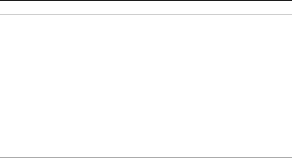
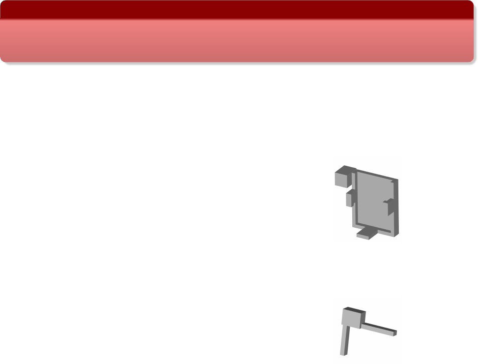
Camera holder
Mirror holder
3.2 Assembling of the camera system
Note: construction of the camera system requires some off-the-shelf parts. We provide example
parts (supplier/item) as used in the above paper but other parts might work as well.
Required parts and tools:
•Camera and mirror holders (see 3.1)
•21 G steel cannula (e.g., Coopers Needle Works). We successfully used thin-walled steel
cannulas but other cannulas (e.g., a 21 G syringe needle after cutting the tip) will also work.
•Infrared (IR) mirror (e.g., Qioptiq Calflex-X)
•Small IR LED (e.g., Vishay VSMB2943GX01)
•Small resistor, 150–200 Ω(e.g., Farnell Multicomp, package 3216)
•2 x 30–36 AWG wire (e.g., Alpha Wire 2936); length ≈5 cm
•Miniature connectors for connecting the camera system to the implant/skull (e.g., Omnetics
A79007-001/A79010-001 or 8-pin Mill-Max connectors)
3
•optional: 2 x female gold pin (e.g., RS Components 481-500)
•Dremel (e.g. Proxxon D-54518) with cutting disc (e.g. wheel no. 409) and 0.8 mm drill bit
(DU68.10)
•glass cutter; most glass cutters should work. We successfully used this one.
•2 combination pliers; if available 1 self-locking hemostat pliers
•A length measuring device (e.g., ruler or caliper)
•A thin and straight solid object, e.g., a metal ruler, for guiding glass cutter
Steps:
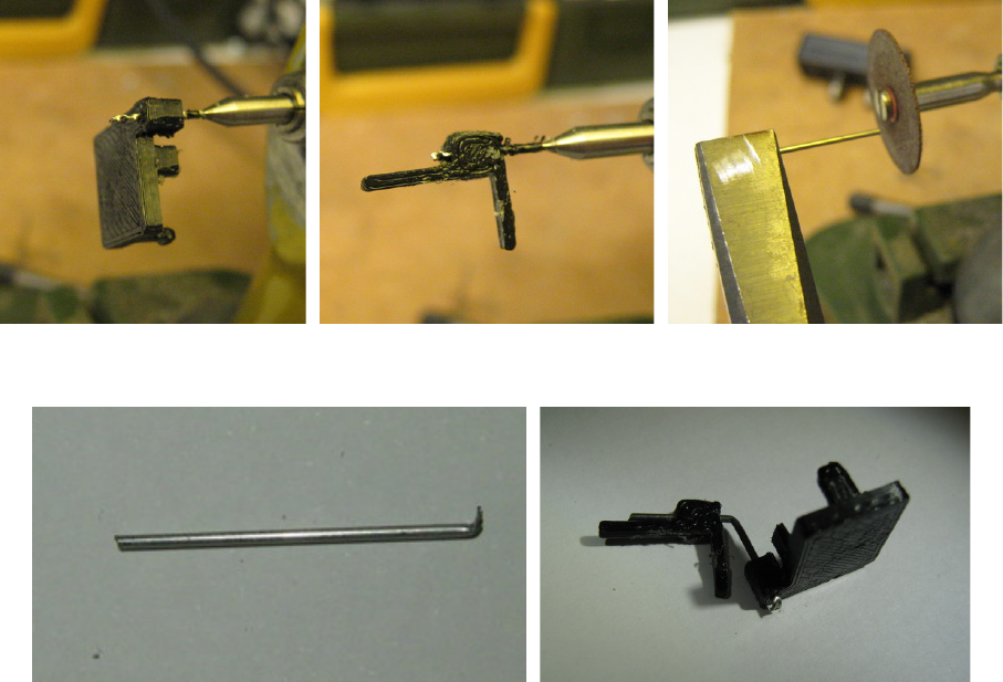
1. Drill hole in the camera holder with Dremel and 0.8 mm drill bit (Figure 1a). Use hemostat
or other pliers (not shown in photo) to hold the camera holder while drilling.
2. Drill hole in the mirror holder (holding it with pliers) using Dremel and 0.8 mm drill bit (Fig-
ure 1b).
3. Cut cannula (21 G) to ≈2 cm with cutting disc on Dremel (Figure 1c). Use safety glasses
and hold both ends with pliers. Bend with second pliers at one of the ends to give sharp
bent tip (Figure 1d). The bent tip will be fixed with a drop of epoxy to the back of the camera
holder later on to prevent the mirror holder from rotating around the axis of the cannula.
4. Push cannula from the back of the camera holder through the hole until the back of the
camera holder hits the bent tip of the cannula.
5. Bend cannula in the middle (≈1 cm) by about ≈60◦using pliers. See Figure 1e for a
camera holder with mirror holder and bent cannula.
6. To cut the infrared (IR) mirror (e.g. Qioptiq Calflex-X 25 x 25 mm), first mark desired size
(e.g., 7 x 7 mm for a relatively large field-of-view including eye and whiskers) with a remov-
able marker. Score with glass cutter (along a thin solid object, e.g., a metal ruler) along one
side of mirror. Break off scored line by holding both sides with pliers and carefully moving
one pair up or down (wearing safety glasses). The mirror packing paper, a lens cleaning
tissue, or some thin rubber sheet can be used to protect the mirror. Note: breaking glass is
tricky and may occasionally result in a jagged edge; repeat until edge is satisfactory. Glue
sharp side against mirror holder and cover outside with super glue or epoxy if necessary. It
is also possible to use a file to get rid of sharp edges.
7. Glue cut mirror tile to 3D printed mirror holder. A very thin layer of super glue (e.g., Loctite
Power Flex Gel) is sufficient to permanently fix the mirror to the mirror holder.
8. Put a very thin layer of super glue onto the cannula and gently push the cannula into the
hole in the mirror holder. This will secure the mirror, but will still allow for positioning the
mirror later on during calibration (see 5).
9. Attach LED with a tiny drop of super glue to the bottom of the camera holder.
10. Solder a current-limiting resistor to the anode (+) of the LED (unless it is simpler to solder
the LED closer to the power source). The value of the resistor depends on the LED and
the power source (there are plenty of on-line tools, e.g., this one, to calculate the resistor
value). Secure LED and resistor using a thin layer of (transparent) epoxy.
4
11. Solder two thin wires (30–36 AWG) to the cathode (-) of the LED and the resistor. The
length of the wire depends on the distance between the camera holder and the LED power
source. For the Intan headstage used in the paper about 5 cm wires were long enough.
Moreover, in order to quickly connect/disconnect the wires to/from the power source during
experiments it might be useful to use miniature gold pins and sockets. Cut away the solder
pots, solder the wires to the pin sockets and secure the wires with a tiny drop of epoxy.
Finally, solder the corresponding pins to the power source (e.g., the solder holes of the
Intan headstage).
12. Fix connector (e.g., Omnetics A79007-001 after cutting away solder tails) using super glue
to the back of the camera holder. See Figure S1 in the paper for an example of a fully
assembled camera system with connector.
(a) Camera holder (b) Mirror holder (c) Cutting of cannula
(d) Cut cannula with bend (e) Camera and mirror holder with cannula
Figure 1: Building of custom parts.
4 Implantation instructions
See paper for details on surgery. The counterpart of the miniature connector on the camera
holder (e.g., Omnetics A79010-001 connector) can be fixed to the implant/microscope or directly
onto the skull using strong dental cement (e.g., C&B Superbond, Sun Medical, Japan), so the
camera holder can be easily and securely connected to the animal. The position and angle of the
connector can be tested during surgery. However, it is possible to make finer adjustments later
on by positioning the mirror (see 5). Therefore it is useful to be able to head-fix the mouse after
it is fully recovered from surgery (e.g., in a recording set-up).
5
5 Calibration
The easiest method is to head-fix the mouse and adjust the position of the mirror and the angle of
the cannula while monitoring video images using the head-mounted camera. If the mirror holder
is not tight enough (i.e. the mirror is slowly moving due to gravity) it is possible to add a very thin
layer of super glue around the cannula to increase friction. This allows the mirror to be adjusted
but it will stay in the right position. Once the mirror has been adjusted such that the camera shows
the desired field of view, carefully take off the camera holder (without touching the mirror), and
secure the mirror holder using strong epoxy (e.g., Araldite Steel). Do not glue the mirror holder
while the camera system is on the head of the mouse! The LED angle may also need to be
adjusted. It is also possible to calibrate the camera in a freely moving mouse, e.g., by restraining
the mouse by hand, but this requires experience and is not recommended for those new to the
camera system. Another option is to briefly anaesthetize the animal for adjusting the mirror.
6
