HP StorageWorks Modular Smart Array 1500 Cs Maintenance And Service Guide C00139951
User Manual: 1500 cs
Open the PDF directly: View PDF ![]() .
.
Page Count: 102 [warning: Documents this large are best viewed by clicking the View PDF Link!]
- hp StorageWorks Modular Smart Array 1500 cs Maintenance and Service Guide
- Notice
- Contents
- About This Guide
- 1 Illustrated Parts Catalog
- 2 Removal and Replacement Procedures
- 3 Diagnostics
- 4 Connectors and Indicators
- A Regulatory Compliance Notices
- B Electrostatic Discharge
- C Specifications
- Index

Maintenance and
Service Guide
hp StorageWorks
Modular Smart Array 1500 cs
First Edition (April 2004)
Part Number: 356606-001
This guide provides procedures and diagnostics needed for the maintenance and troubleshooting of the
Modular Smart Array 1500 Controller Shelf (MSA1500 cs).
© Copyright 2003-2004 Hewlett-Packard Development Company, L.P.
Hewlett-Packard Company makes no warranty of any kind with regard to this material, including, but not limited to, the implied
warranties of merchantability and fitness for a particular purpose. Hewlett-Packard shall not be liable for errors contained herein or for
incidental or consequential damages in connection with the furnishing, performance, or use of this material.
This document contains proprietary information, which is protected by copyright. No part of this document may be photocopied,
reproduced, or translated into another language without the prior written consent of Hewlett-Packard. The information contained in this
document is subject to change without notice. The only warranties for HP products and services are set forth in the express warranty
statements accompanying such products and services. Nothing herein should be construed as constituting an additional warranty. HP
shall not be liable for technical or editorial errors or omissions contained herein.
Compaq Computer Corporation is a wholly-owned subsidiary of Hewlett-Packard Company.
Adobe® and Acrobat® are trademarks of Adobe Systems Incorporated.
Intel® and Celeron® are U.S. registered trademarks of Intel Corporation.
Intel® and Itanium® are trademarks or registered trademarks of Intel Corporation in the U.S. and other countries and are used under
license.
Intel® Itanium™ Processor Family is a trademark in the U.S. and other countries and is used under license.
Microsoft®, MS-DOS®, MS Windows®, Windows®, and Windows NT® are U.S. registered trademarks of Microsoft Corporation.
Oracle® is a registered U.S. trademark of Oracle Corporation, Redwood City, California.
UNIX® is a registered trademark of The Open Group.
Hewlett-Packard Company shall not be liable for technical or editorial errors or omissions contained herein. The information is provided
“as is” without warranty of any kind and is subject to change without notice. The warranties for Hewlett-Packard Company products are
set forth in the express limited warranty statements for such products. Nothing herein should be construed as constituting an additional
warranty.
Modular Smart Array 1500 cs Maintenance and Service Guide
First Edition (April 2004)
Part Number: 356606-001

3Modular Smart Array 1500 cs Maintenance and Service Guide
Contents
Contents
About this Guide. . . . . . . . . . . . . . . . . . . . . . . . . . . . . . . . . . . . . . . . . . . . . . . . . . . . . . . . . . . . . . . 7
Overview. . . . . . . . . . . . . . . . . . . . . . . . . . . . . . . . . . . . . . . . . . . . . . . . . . . . . . . . . . . . . . . . . . . . . . . . . . . . . . . .9
Intended audience. . . . . . . . . . . . . . . . . . . . . . . . . . . . . . . . . . . . . . . . . . . . . . . . . . . . . . . . . . . . . . . . . . . . . .9
Prerequisites . . . . . . . . . . . . . . . . . . . . . . . . . . . . . . . . . . . . . . . . . . . . . . . . . . . . . . . . . . . . . . . . . . . . . . . . . .9
Related documentation. . . . . . . . . . . . . . . . . . . . . . . . . . . . . . . . . . . . . . . . . . . . . . . . . . . . . . . . . . . . . . . . . .9
Conventions . . . . . . . . . . . . . . . . . . . . . . . . . . . . . . . . . . . . . . . . . . . . . . . . . . . . . . . . . . . . . . . . . . . . . . . . . . . .10
Document conventions. . . . . . . . . . . . . . . . . . . . . . . . . . . . . . . . . . . . . . . . . . . . . . . . . . . . . . . . . . . . . . . . .10
Text symbols . . . . . . . . . . . . . . . . . . . . . . . . . . . . . . . . . . . . . . . . . . . . . . . . . . . . . . . . . . . . . . . . . . . . . . . .10
Equipment symbols . . . . . . . . . . . . . . . . . . . . . . . . . . . . . . . . . . . . . . . . . . . . . . . . . . . . . . . . . . . . . . . . . . .11
Rack stability . . . . . . . . . . . . . . . . . . . . . . . . . . . . . . . . . . . . . . . . . . . . . . . . . . . . . . . . . . . . . . . . . . . . . . . . . . .12
Getting help . . . . . . . . . . . . . . . . . . . . . . . . . . . . . . . . . . . . . . . . . . . . . . . . . . . . . . . . . . . . . . . . . . . . . . . . . . . .12
HP technical support . . . . . . . . . . . . . . . . . . . . . . . . . . . . . . . . . . . . . . . . . . . . . . . . . . . . . . . . . . . . . . . . . .12
HP storage web site . . . . . . . . . . . . . . . . . . . . . . . . . . . . . . . . . . . . . . . . . . . . . . . . . . . . . . . . . . . . . . . . . . .12
HP authorized reseller . . . . . . . . . . . . . . . . . . . . . . . . . . . . . . . . . . . . . . . . . . . . . . . . . . . . . . . . . . . . . . . . .13
1 Illustrated Parts Catalog . . . . . . . . . . . . . . . . . . . . . . . . . . . . . . . . . . . . . . . . . . . . . . . . . . . . . . . . 15
MSA1500 cs mechanical parts and system components exploded view . . . . . . . . . . . . . . . . . . . . . . . . . . . . . .16
2 Removal and Replacement Procedures. . . . . . . . . . . . . . . . . . . . . . . . . . . . . . . . . . . . . . . . . . . . . . 19
Preparation procedures . . . . . . . . . . . . . . . . . . . . . . . . . . . . . . . . . . . . . . . . . . . . . . . . . . . . . . . . . . . . . . . . . . . .20
Hot-pluggable parts . . . . . . . . . . . . . . . . . . . . . . . . . . . . . . . . . . . . . . . . . . . . . . . . . . . . . . . . . . . . . . . . . . .20
Non-hot-pluggable parts. . . . . . . . . . . . . . . . . . . . . . . . . . . . . . . . . . . . . . . . . . . . . . . . . . . . . . . . . . . . . . . .20
Powering down the MSA1500 cs. . . . . . . . . . . . . . . . . . . . . . . . . . . . . . . . . . . . . . . . . . . . . . . . . . . . . . . . .21
Rack warnings . . . . . . . . . . . . . . . . . . . . . . . . . . . . . . . . . . . . . . . . . . . . . . . . . . . . . . . . . . . . . . . . . . . . . . .22
Device warnings and precautions. . . . . . . . . . . . . . . . . . . . . . . . . . . . . . . . . . . . . . . . . . . . . . . . . . . . . . . . .23
Connecting the power. . . . . . . . . . . . . . . . . . . . . . . . . . . . . . . . . . . . . . . . . . . . . . . . . . . . . . . . . . . . . . . . . . . . .24
Applying power . . . . . . . . . . . . . . . . . . . . . . . . . . . . . . . . . . . . . . . . . . . . . . . . . . . . . . . . . . . . . . . . . . . . . . . . .25
MSA1000 Controller . . . . . . . . . . . . . . . . . . . . . . . . . . . . . . . . . . . . . . . . . . . . . . . . . . . . . . . . . . . . . . . . . . . . .25
Verifying component failure . . . . . . . . . . . . . . . . . . . . . . . . . . . . . . . . . . . . . . . . . . . . . . . . . . . . . . . . . . . .25
Replacing the MSA1000 Controller. . . . . . . . . . . . . . . . . . . . . . . . . . . . . . . . . . . . . . . . . . . . . . . . . . . . . . .27
Replacing the MSA1000 Controller cache . . . . . . . . . . . . . . . . . . . . . . . . . . . . . . . . . . . . . . . . . . . . . . . . .29
Replacing the controller cache battery pack . . . . . . . . . . . . . . . . . . . . . . . . . . . . . . . . . . . . . . . . . . . . . . . .32
Hot-plug power supply . . . . . . . . . . . . . . . . . . . . . . . . . . . . . . . . . . . . . . . . . . . . . . . . . . . . . . . . . . . . . . . . . . . .35
Replacing a power supply . . . . . . . . . . . . . . . . . . . . . . . . . . . . . . . . . . . . . . . . . . . . . . . . . . . . . . . . . . . . . .35
Verifying component failure . . . . . . . . . . . . . . . . . . . . . . . . . . . . . . . . . . . . . . . . . . . . . . . . . . . . . . . . .35
Verifying the replacement . . . . . . . . . . . . . . . . . . . . . . . . . . . . . . . . . . . . . . . . . . . . . . . . . . . . . . . . . . .37
Hot-plug fan module. . . . . . . . . . . . . . . . . . . . . . . . . . . . . . . . . . . . . . . . . . . . . . . . . . . . . . . . . . . . . . . . . . . . . .37

Contents
4 Modular Smart Array 1500 cs Maintenance and Service Guide
Replacing a fan module . . . . . . . . . . . . . . . . . . . . . . . . . . . . . . . . . . . . . . . . . . . . . . . . . . . . . . . . . . . . . . . .37
Verifying component failure . . . . . . . . . . . . . . . . . . . . . . . . . . . . . . . . . . . . . . . . . . . . . . . . . . . . . . . . .37
Verifying the Replacement . . . . . . . . . . . . . . . . . . . . . . . . . . . . . . . . . . . . . . . . . . . . . . . . . . . . . . . . . .39
SCSI I/O module. . . . . . . . . . . . . . . . . . . . . . . . . . . . . . . . . . . . . . . . . . . . . . . . . . . . . . . . . . . . . . . . . . . . . . . . .39
Replacing a SCSI I/O module . . . . . . . . . . . . . . . . . . . . . . . . . . . . . . . . . . . . . . . . . . . . . . . . . . . . . . . . . . .39
Verifying component failure . . . . . . . . . . . . . . . . . . . . . . . . . . . . . . . . . . . . . . . . . . . . . . . . . . . . . . . . .39
Verifying the replacement . . . . . . . . . . . . . . . . . . . . . . . . . . . . . . . . . . . . . . . . . . . . . . . . . . . . . . . . . . .41
Fibre Channel I/O module . . . . . . . . . . . . . . . . . . . . . . . . . . . . . . . . . . . . . . . . . . . . . . . . . . . . . . . . . . . . . . . . .41
Replacing a Fibre Channel I/O module . . . . . . . . . . . . . . . . . . . . . . . . . . . . . . . . . . . . . . . . . . . . . . . . . . . .41
Verifying component failure . . . . . . . . . . . . . . . . . . . . . . . . . . . . . . . . . . . . . . . . . . . . . . . . . . . . . . . . .41
Verifying the replacement . . . . . . . . . . . . . . . . . . . . . . . . . . . . . . . . . . . . . . . . . . . . . . . . . . . . . . . . . . .43
2-Gb Small Form Factor Pluggable (SFP) transceiver. . . . . . . . . . . . . . . . . . . . . . . . . . . . . . . . . . . . . . . . . . . .43
Replacing a SFP transceiver. . . . . . . . . . . . . . . . . . . . . . . . . . . . . . . . . . . . . . . . . . . . . . . . . . . . . . . . . . . . .43
Laser precautions. . . . . . . . . . . . . . . . . . . . . . . . . . . . . . . . . . . . . . . . . . . . . . . . . . . . . . . . . . . . . . . . . .43
Replacing the power switch assembly . . . . . . . . . . . . . . . . . . . . . . . . . . . . . . . . . . . . . . . . . . . . . . . . . . . . . . . .46
Verifying the replacement . . . . . . . . . . . . . . . . . . . . . . . . . . . . . . . . . . . . . . . . . . . . . . . . . . . . . . . . . . .49
Replacing a MSA1500 cs 2U chassis . . . . . . . . . . . . . . . . . . . . . . . . . . . . . . . . . . . . . . . . . . . . . . . . . . . . . . . . .49
Fibre Channel I/O cables . . . . . . . . . . . . . . . . . . . . . . . . . . . . . . . . . . . . . . . . . . . . . . . . . . . . . . . . . . . . . . . . . .50
Multi-Mode Fibre Channel I/O cable. . . . . . . . . . . . . . . . . . . . . . . . . . . . . . . . . . . . . . . . . . . . . . . . . . . . . .50
3 Diagnostics. . . . . . . . . . . . . . . . . . . . . . . . . . . . . . . . . . . . . . . . . . . . . . . . . . . . . . . . . . . . . . . . . . 51
Overview. . . . . . . . . . . . . . . . . . . . . . . . . . . . . . . . . . . . . . . . . . . . . . . . . . . . . . . . . . . . . . . . . . . . . . . . . . . . . . .51
MSA1000 Controller indicators . . . . . . . . . . . . . . . . . . . . . . . . . . . . . . . . . . . . . . . . . . . . . . . . . . . . . . . . . . . .52
MSA1000 Controller display . . . . . . . . . . . . . . . . . . . . . . . . . . . . . . . . . . . . . . . . . . . . . . . . . . . . . . . . . . . . . . .53
Controller display messages . . . . . . . . . . . . . . . . . . . . . . . . . . . . . . . . . . . . . . . . . . . . . . . . . . . . . . . . . . . . . . . .54
Error messages. . . . . . . . . . . . . . . . . . . . . . . . . . . . . . . . . . . . . . . . . . . . . . . . . . . . . . . . . . . . . . . . . . . .54
Informational messages. . . . . . . . . . . . . . . . . . . . . . . . . . . . . . . . . . . . . . . . . . . . . . . . . . . . . . . . . . . . .54
User input messages . . . . . . . . . . . . . . . . . . . . . . . . . . . . . . . . . . . . . . . . . . . . . . . . . . . . . . . . . . . . . . .54
Scrolling. . . . . . . . . . . . . . . . . . . . . . . . . . . . . . . . . . . . . . . . . . . . . . . . . . . . . . . . . . . . . . . . . . . . . . . . . . . .54
Deleting messages . . . . . . . . . . . . . . . . . . . . . . . . . . . . . . . . . . . . . . . . . . . . . . . . . . . . . . . . . . . . . . . . . . . .55
Redundancy link light . . . . . . . . . . . . . . . . . . . . . . . . . . . . . . . . . . . . . . . . . . . . . . . . . . . . . . . . . . . . . . . . .55
LCD Message Descriptions . . . . . . . . . . . . . . . . . . . . . . . . . . . . . . . . . . . . . . . . . . . . . . . . . . . . . . . . . . . . . . . .56
Recovery ROM and ROM cloning. . . . . . . . . . . . . . . . . . . . . . . . . . . . . . . . . . . . . . . . . . . . . . . . . . . . . . . . . . .76
Recovery ROM . . . . . . . . . . . . . . . . . . . . . . . . . . . . . . . . . . . . . . . . . . . . . . . . . . . . . . . . . . . . . . . . . . . . . .76
ROM cloning . . . . . . . . . . . . . . . . . . . . . . . . . . . . . . . . . . . . . . . . . . . . . . . . . . . . . . . . . . . . . . . . . . . . . . . .76
4 Connectors and Indicators . . . . . . . . . . . . . . . . . . . . . . . . . . . . . . . . . . . . . . . . . . . . . . . . . . . . . . . 77
Overview. . . . . . . . . . . . . . . . . . . . . . . . . . . . . . . . . . . . . . . . . . . . . . . . . . . . . . . . . . . . . . . . . . . . . . . . . . . . . . .77
Front and rear views . . . . . . . . . . . . . . . . . . . . . . . . . . . . . . . . . . . . . . . . . . . . . . . . . . . . . . . . . . . . . . . . . . . . . .77
Front view . . . . . . . . . . . . . . . . . . . . . . . . . . . . . . . . . . . . . . . . . . . . . . . . . . . . . . . . . . . . . . . . . . . . . . . . . .78
Rear view . . . . . . . . . . . . . . . . . . . . . . . . . . . . . . . . . . . . . . . . . . . . . . . . . . . . . . . . . . . . . . . . . . . . . . . . . . .79
Slot diagram label. . . . . . . . . . . . . . . . . . . . . . . . . . . . . . . . . . . . . . . . . . . . . . . . . . . . . . . . . . . . . . . . . . . . . . . .80
Connectors . . . . . . . . . . . . . . . . . . . . . . . . . . . . . . . . . . . . . . . . . . . . . . . . . . . . . . . . . . . . . . . . . . . . . . . . . . . . .81
SCSI I/O module connectors . . . . . . . . . . . . . . . . . . . . . . . . . . . . . . . . . . . . . . . . . . . . . . . . . . . . . . . . . . . .81
Indicators . . . . . . . . . . . . . . . . . . . . . . . . . . . . . . . . . . . . . . . . . . . . . . . . . . . . . . . . . . . . . . . . . . . . . . . . . . . . . .82
Interpreting component indicators . . . . . . . . . . . . . . . . . . . . . . . . . . . . . . . . . . . . . . . . . . . . . . . . . . . . . . . .82
Enclosure status indicators. . . . . . . . . . . . . . . . . . . . . . . . . . . . . . . . . . . . . . . . . . . . . . . . . . . . . . . . . . . . . .82
Power supply . . . . . . . . . . . . . . . . . . . . . . . . . . . . . . . . . . . . . . . . . . . . . . . . . . . . . . . . . . . . . . . . . . . . . . . .83
Fan module. . . . . . . . . . . . . . . . . . . . . . . . . . . . . . . . . . . . . . . . . . . . . . . . . . . . . . . . . . . . . . . . . . . . . . . . . .84
SCSI I/O module . . . . . . . . . . . . . . . . . . . . . . . . . . . . . . . . . . . . . . . . . . . . . . . . . . . . . . . . . . . . . . . . . . . . .85

Contents
5Modular Smart Array 1500 cs Maintenance and Service Guide
Fibre Channel I/O module . . . . . . . . . . . . . . . . . . . . . . . . . . . . . . . . . . . . . . . . . . . . . . . . . . . . . . . . . . . . . .86
MSA1000 Controller indicators. . . . . . . . . . . . . . . . . . . . . . . . . . . . . . . . . . . . . . . . . . . . . . . . . . . . . . . . . .87
A Regulatory Compliance Notices . . . . . . . . . . . . . . . . . . . . . . . . . . . . . . . . . . . . . . . . . . . . . . . . . . . 89
Regulatory Compliance identification numbers. . . . . . . . . . . . . . . . . . . . . . . . . . . . . . . . . . . . . . . . . . . . . .89
Federal Communications Commission notice . . . . . . . . . . . . . . . . . . . . . . . . . . . . . . . . . . . . . . . . . . . . . . .89
Modifications. . . . . . . . . . . . . . . . . . . . . . . . . . . . . . . . . . . . . . . . . . . . . . . . . . . . . . . . . . . . . . . . . . . . .89
Cables . . . . . . . . . . . . . . . . . . . . . . . . . . . . . . . . . . . . . . . . . . . . . . . . . . . . . . . . . . . . . . . . . . . . . . . . . .89
Canadian notice (Avis Canadien). . . . . . . . . . . . . . . . . . . . . . . . . . . . . . . . . . . . . . . . . . . . . . . . . . . . . . . . .89
European Union notice. . . . . . . . . . . . . . . . . . . . . . . . . . . . . . . . . . . . . . . . . . . . . . . . . . . . . . . . . . . . . . . . .90
Japanese notice. . . . . . . . . . . . . . . . . . . . . . . . . . . . . . . . . . . . . . . . . . . . . . . . . . . . . . . . . . . . . . . . . . . . . . .90
BSMI notice . . . . . . . . . . . . . . . . . . . . . . . . . . . . . . . . . . . . . . . . . . . . . . . . . . . . . . . . . . . . . . . . . . . . . . . . .91
Laser compliance . . . . . . . . . . . . . . . . . . . . . . . . . . . . . . . . . . . . . . . . . . . . . . . . . . . . . . . . . . . . . . . . . . . . .91
Battery replacement notice. . . . . . . . . . . . . . . . . . . . . . . . . . . . . . . . . . . . . . . . . . . . . . . . . . . . . . . . . . . . . .92
B Electrostatic Discharge. . . . . . . . . . . . . . . . . . . . . . . . . . . . . . . . . . . . . . . . . . . . . . . . . . . . . . . . . . 93
Grounding methods . . . . . . . . . . . . . . . . . . . . . . . . . . . . . . . . . . . . . . . . . . . . . . . . . . . . . . . . . . . . . . . . . . . . . .94
C Specifications . . . . . . . . . . . . . . . . . . . . . . . . . . . . . . . . . . . . . . . . . . . . . . . . . . . . . . . . . . . . . . . . 95
MSA1500 cs chassis. . . . . . . . . . . . . . . . . . . . . . . . . . . . . . . . . . . . . . . . . . . . . . . . . . . . . . . . . . . . . . . . . . . . . .96
Power supply . . . . . . . . . . . . . . . . . . . . . . . . . . . . . . . . . . . . . . . . . . . . . . . . . . . . . . . . . . . . . . . . . . . . . . . . . . .96
SCSI I/O module. . . . . . . . . . . . . . . . . . . . . . . . . . . . . . . . . . . . . . . . . . . . . . . . . . . . . . . . . . . . . . . . . . . . . . . . .97
Fibre Channel I/O module . . . . . . . . . . . . . . . . . . . . . . . . . . . . . . . . . . . . . . . . . . . . . . . . . . . . . . . . . . . . . . . . .97
Fan module . . . . . . . . . . . . . . . . . . . . . . . . . . . . . . . . . . . . . . . . . . . . . . . . . . . . . . . . . . . . . . . . . . . . . . . . . . . . .97
Index . . . . . . . . . . . . . . . . . . . . . . . . . . . . . . . . . . . . . . . . . . . . . . . . . . . . . . . . . . . . . . . . . . . . . . 99


7Modular Smart Array 1500 cs Maintenance and Service Guide
About This Guide
About this Guide
About this Guide
This maintenance and service guide provides information to help you:
■Service the MSA1500 cs
■Troubleshoot the MSA1500 cs
■Reference the MSA1500 cs
WARNING: To reduce the risk of personal injury from electric shock and hazardous energy
levels, only authorized service technicians should attempt to repair this equipment. Improper
repairs can create conditions that are hazardous.
WARNING: Only authorized technicians trained by HP should attempt to repair this
equipment. All troubleshooting and repair procedures are detailed to allow only
subassembly/module-level repair. Because of the complexity of the individual boards and
subassemblies, no one should attempt to make repairs at the component level or to make
modifications to any printed wiring board. Improper repairs can create a safety hazard.
WARNING: To reduce the risk of personal injury from electric shock and hazardous energy
levels, do not exceed the level of repairs specified in these procedures. Because of the
complexity of the individual boards and subassemblies, do not attempt to make repairs at
the component level or to make modifications to any printed wiring board. Improper repairs
can create conditions that are hazardous.
WARNING: To reduce the risk of electric shock or damage to the equipment:
■Disconnect power from the system by unplugging all power cords from the power
supplies.
■Do not disable the power cord grounding plug. The grounding plug is an important
safety feature.
■Plug the power cord into a grounded (earthed) electrical outlet that is easily accessible at
all times.

About this Guide
8 Modular Smart Array 1500 cs Maintenance and Service Guide
Caution: To properly ventilate the system, you must provide at least 7.6 cm (3.0 in.) of
clearance at the front and back of the server.
Caution: The computer is designed to be electrically grounded (earthed). To ensure proper
operation, plug the AC power cord into a properly grounded AC outlet only.
Note: Any indications of component replacement or printed wiring board modifications may void
any warranty.
“About This Guide” topics include:
■Overview, page 9
■Conventions, page 10
■Rack stability, page 12
■Getting help, page 12

About this Guide
9Modular Smart Array 1500 cs Maintenance and Service Guide
Overview
This section covers the following topics:
■Intended audience
■Prerequisites
■Related documentation
Intended audience
This book is intended for use by system administrators and technicians who are experienced
with the following:
■SAN management
■Network administration
■Network installation
Prerequisites
Before you service the MSA1500 cs, make sure you consider the items below.
■Knowledge of operation system
■Knowledge of related hardware/software
■Previous version of the product/firmware
Related documentation
In addition to this guide, HP provides corresponding information:
■HP StorageWorks MSA1500 cs Configuration Overview
This poster illustrates common MSA1500 cs deployments and includes a checklist and
worksheet for you complete, to help ensure that you have all of the items needed for your
MSA1500 cs installation.
The poster is a companion piece to this Installation Guide.
■
HP StorageWorks Modular Smart Array 1500 cs Installation Guide
This guide contains basic information about installing the MSA1500 cs.
■Command Line Interface Reference Guide
This guide contains information about using the CLI.
■
HP StorageWorks Modular Smart Array 1000 Controller Reference Guide
This guide defines MSA1000 Controller display messages and discusses other controller
reference information.
■
HP Array Configuration Utility User Guide
This guide contains information about using the ACU.
Access the ACU web site to obtain the latest version of the guide at
http://h18000.www1.hp.com/products/servers/proliantstorage/software-management/
acumatrix/index.html
About this Guide
10 Modular Smart Array 1500 cs Maintenance and Service Guide
These documents, and others, such as white papers and release notes, are available on the
Technical Documents page of the MSA1500 cs web site at:
http://www.hp.com/go/msa1500cs
.
Conventions
Conventions consist of the following:
■Document conventions
■Text symbols
■Equipment symbols
Document conventions
This document follows the conventions in Table 1.
Text symbols
The following symbols may be found in the text of this guide. They have the following
meanings:
WARNING: Text set off in this manner indicates that failure to follow directions in the
warning could result in bodily harm or death.
Caution: Text set off in this manner indicates that failure to follow directions could result in
damage to equipment or data.
Tip: Text in a tip provides additional help to readers by providing nonessential or optional
techniques, procedures, or shortcuts.
Table 1: Document Conventions
Convention Element
Blue text: Figure 1 Cross-reference links
Bold Menu items, buttons, and key, tab, and box
names
Italics
Text emphasis and document titles in body text
Monospace font User input, commands, code, file and
directory names, and system responses (output
and messages)
Monospace, italic font Command-line and code variables
Blue underlined sans serif font text
(
http://www.hp.com
)Web site addresses
About this Guide
11Modular Smart Array 1500 cs Maintenance and Service Guide
Note: Text set off in this manner presents commentary, sidelights, or interesting points of
information.
Equipment symbols
The following equipment symbols may be found on hardware for which this guide pertains.
They have the following meanings:
Any enclosed surface or area of the equipment marked with these symbols indicates
the presence of electrical shock hazards. Enclosed area contains no operator
serviceable parts.
WARNING: To reduce the risk of personal injury from electrical shock hazards, do
not open this enclosure.
Any RJ-45 receptacle marked with these symbols indicates a network interface
connection.
WARNING: To reduce the risk of electrical shock, fire, or damage to the equipment,
do not plug telephone or telecommunications connectors into this receptacle.
Any surface or area of the equipment marked with these symbols indicates the
presence of a hot surface or hot component. Contact with this surface could result in
injury.
WARNING: To reduce the risk of personal injury from a hot component, allow the
surface to cool before touching.
Power supplies or systems marked with these symbols indicate the presence of
multiple sources of power.
WARNING: To reduce the risk of personal injury from electrical shock, remove
all power cords to completely disconnect power from the power supplies and
systems.
Any product or assembly marked with these symbols indicates that the component
exceeds the recommended weight for one individual to handle safely.
WARNING: To reduce the risk of personal injury or damage to the equipment,
observe local occupational health and safety requirements and guidelines for
manually handling material.

About this Guide
12 Modular Smart Array 1500 cs Maintenance and Service Guide
Rack stability
Rack stability protects personnel and equipment.
WARNING: To reduce the risk of personal injury or damage to the equipment, be sure that:
■The leveling jacks are extended to the floor.
■The full weight of the rack rests on the leveling jacks.
■In single rack installations, the stabilizing feet are attached to the rack.
■In multiple rack installations, the racks are coupled.
■Only one rack component is extended at any time. A rack may become unstable if more
than one rack component is extended for any reason.
Getting help
If you still have a question after reading this guide, contact an HP authorized service provider
or access our web site:
http://www.hp.com.
HP call centers use product and serial numbers to validate warranty entitlement. Most HP
products can provide product number, serial number and firmware revision electronically
through the use of supplied management or diagnostic utilities, eliminating the need to
physically inspect or remove products from installed enclosures. To provide timely service you
may be directed by HP to run these utilities to gather required entitlement information.
HP technical support
Telephone numbers for worldwide technical support are listed on the following HP web site:
http://www.hp.com/support/
. From this web site, select the country of origin.
Note: For continuous quality improvement, calls may be recorded or monitored.
Be sure to have the following information available before calling:
■Technical support registration number (if applicable)
■Product serial numbers
■Product model names and numbers
■Applicable error messages
■Operating system type and revision level
■Detailed, specific questions
HP storage web site
The HP web site has the latest information on this product, as well as the latest drivers. Access
storage at:
http://www.hp.com/country/us/eng/prodserv/storage.html
. From this web site,
select the appropriate product or solution.

About this Guide
13Modular Smart Array 1500 cs Maintenance and Service Guide
HP authorized reseller
For the name of your nearest HP authorized reseller:
■In the United States, call 1-800-345-1518
■In Canada, call 1-800-263-5868
■Elsewhere, see the HP web site for locations and telephone numbers:
http://www.hp.com
.


Illustrated Parts Catalog
16 Modular Smart Array 1500 cs Maintenance and Service Guide
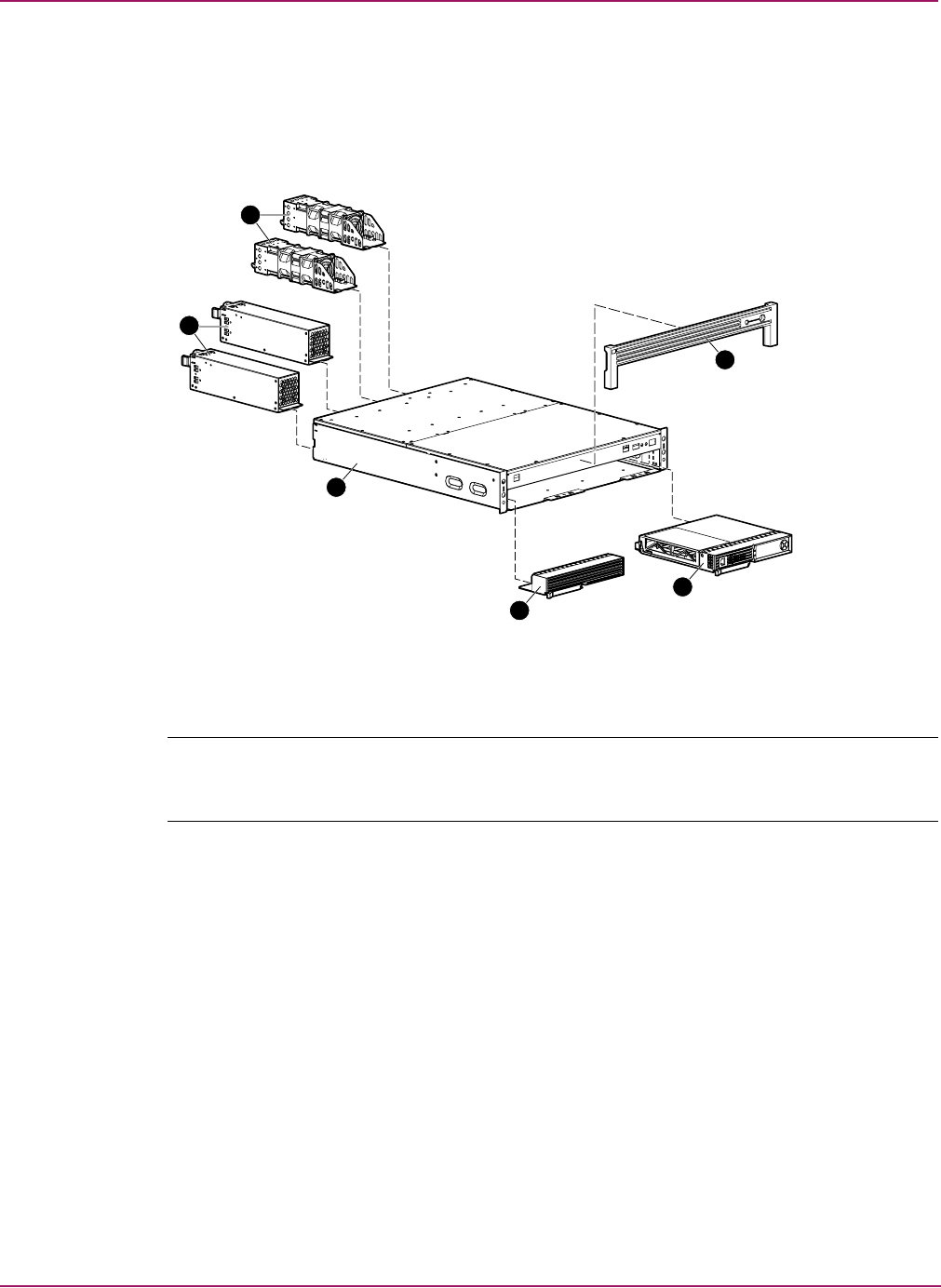
MSA1500 cs mechanical parts and system components exploded view
Figure 1: MSA1500 cs mechanical parts and system components exploded view
Note: The MSA1500 cs can support up to 96 SATA drives with the addition of 8 SATA expansion
enclosures, or 56 SCSI drives with the addition of 4 SCSI expansion enclosures. The MSA1500 cs
contains no internal drives.
4
6
5
3
2
1
Illustrated Parts Catalog
17Modular Smart Array 1500 cs Maintenance and Service Guide
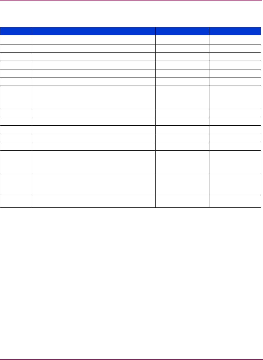
Table 2: MSA1500 cs Mechanical Parts and System Components Spare Parts List
Item Description Spare Part Number Hot-pluggable
Chassis
3Chassis, 2U 70-41211-S1 N
4Bezel 70-41220-S1 n/a
5Controller blank 229208-001 n/a
System Components
AC power cord (2) (not shown) 187335-001 N
Power cords: (not shown)
SPT-2 IEC-C13 IEC-C14
SPT-2 IEC-C13 IEC-C14
202974-001
202973-001
n/a
Boards
6MSA1000 Controller 229203-001 Y
Miscellaneous
1Fan module 349798-001 Y
2Power supply 349800-001 Y
Optical cables: (not shown)
1-Gb to 2-Gb connection
2-Gb to 2-Gb connection
263894-(001-007)
263895-(001-007)
n/a
Cache module with battery (Bd, Dimm, Sdram,
128 mb, with battery)
(not shown)
171387-001 N
SFP transceiver (Transceiver, 650mm, Fc, 2 gb, Htplg)
(not shown) 229204-001 Y


19Modular Smart Array 1500 cs Maintenance and Service Guide
2
Removal and Replacement
Procedures
This chapter provides subassembly/module-level removal and replacement procedures for the
MSA1500 cs. After completing all necessary removal and replacement procedures, run the
Diagnostics software described in Chapter 3, Diagnostics to verify that all components operate
properly.
WARNING: To reduce the risk of personal injury or damage to the equipment, observe all
warnings and cautions throughout this chapter.
WARNING: To reduce the risk of personal injury or damage to the equipment, the
installation of options other than hotplug power devices should be performed only by
individuals who are qualified in servicing computer equipment and trained to deal with
products capable of producing hazardous energy levels.
To service the MSA1500 cs, the following tools are recommended:
■4-mm flat-blade screwdriver (for SCSI cables)
■#2 phillips screwdriver (for 2U chassis)
Removal and Replacement Procedures
20 Modular Smart Array 1500 cs Maintenance and Service Guide
Preparation procedures
System power to the MSA1500 cs does not shut off completely with the power switch. The
two positions of the front panel power switch should be considered as ON and STANDBY,
rather than ON and OFF. The STANDBY position removes power from most of the electronics
and the drives, but portions of the power supply and some internal circuitry remain active. To
remove all power from the system, you must disconnect the power cord from the storage
system. In systems with multiple power supplies, you must disconnect all the power cords to
remove power completely from the system.
WARNING: To reduce the risk of electric shock or damage to the equipment, disconnect
power from the storage system by unplugging all power cords from either the electrical
outlet or the MSA1500 cs.
Note: Before removing any serviceable part, determine whether the part is hot-pluggable or
non-hot-pluggable. Hot-pluggable devices in the MSA1500 cs include the fan modules, power
supplies, I/O modules and the MSA1000 controllers.
Hot-pluggable parts
If the part is hot-pluggable, a power shutdown of the device in not required for replacement of
the part. Hot-pluggable devices in the MSA1500 cs include the power supplies, fan modules,
SCSI I/O modules, Fibre Channel I/O modules, and MSA1000 Controllers.
WARNING: Before replacing a hot-pluggable component ensure that steps have been
taken to prevent loss of data.
Non-hot-pluggable parts
If the part is non-hot-pluggable, the MSA1500 cs must be powered down. Non-hot-pluggable
parts include the 2U chassis, and the power switch.
WARNING: To reduce the risk of personal injury or damage to the equipment, the
installation of options other than hot-plug power devices should be performed only by
individuals who are qualified in servicing computer equipment and trained to deal with
products capable of producing hazardous energy levels.
Removal and Replacement Procedures
21Modular Smart Array 1500 cs Maintenance and Service Guide
Powering down the MSA1500 cs
Before beginning any of the removal and replacement procedures for non-hot-pluggable
devices, do the following:
1. Hold down the Power On/Standby switch for five seconds.
Note: powering down the unit places the device in standby mode that disables the main
power supply output and provides only auxiliary power (+5V) to the device.
2. Verify that the Power On/Standby switch power LED indicator is Green/Off and that the
fans are off.
3. Disconnect all power cords from the AC outlets, and then from the device.
WARNING: To reduce the risk of injury from electric shock, remove all power
cords to completely disconnect power from the system.
4. Disconnect all external peripheral devices from the MSA1500 cs.
WARNING: To reduce the risk of personal injury or damage to the equipment,
observe local occupational health and safety requirements and guidelines for
manually handling material.
Removal and Replacement Procedures
22 Modular Smart Array 1500 cs Maintenance and Service Guide
Rack warnings
WARNING: To reduce the risk of personal injury or damage to the equipment:
■Observe local occupational safety requirements and guidelines for heavy equipment
handling.
■Obtain adequate assistance to lift and stabilize the product during installation or
removal.
■Remove all pluggable power supplies and modules to reduce the weight of the product.
■Always load the heaviest item first, and load the rack from the bottom up. This makes the
rack “bottom-heavy” and helps prevent the rack from becoming unstable.
■Extend the leveling jacks to the floor.
■Rest the full weight of the rack on the leveling jacks.
■Attach the stabilizing feet to the rack if it is a single-rack installation.
■The racks are coupled in multiple-rack installations.
■Fully extend the bottom stabilizers on the equipment. Be sure that the equipment is
properly supported/braced when installing options and boards.
■Be careful when sliding the unit into the rack. The slide rails could pinch your fingertips.
■Ensure that the rack is adequately stabilized before extending a component outside the
rack. Extend only one component at a time. A rack may become unstable if more than
one component is extended for any reason.
■Do not attempt to move a fully loaded equipment rack. Remove equipment from the rack
before moving the rack.
■At least two people are needed to safely unload the rack from the pallet. An empty 42U
rack weighs 115 kg (253 lb), is over 2.1 meters (7 ft) tall, and may become unstable
when being moved on its casters. Do not stand in front of the rack as it rolls down the
ramp from the pallet; handle it from the sides. Stabilize the device by keeping the unit on
the rails.
WARNING: Because the rack allows stacking of computer components on a vertical rather
than horizontal plane, ensure that precautions have been taken to provide for rack stability
and safety. It is important to follow these precautions providing for rack stability and safety,
and to protect both personnel and property. Heed all cautions and warnings throughout the
installation instructions provided with the device.
Removal and Replacement Procedures
23Modular Smart Array 1500 cs Maintenance and Service Guide
Device warnings and precautions
WARNING: The installation of internal options and service of this product should be
performed by individuals who are knowledgeable about the procedures, precautions, and
hazards associated with equipment containing hazardous energy levels.
WARNING: To reduce the risk of electric shock or damage to the equipment:
■Allow the product to cool before removing covers and touching internal components.
■Do not disable the power cord grounding plug. The grounding plug is an important
safety feature.
■Plug the power cord into a grounded (earthed) electrical outlet that is easily accessible at
all times.
■Disconnect power from the device by unplugging the power cord from either the
electrical outlet or the device.
■Do not use conductive tools that could bridge live parts.
■Remove all watches, rings, or loose jewelry when working in hot-plug areas of an
energized device.
-Or-
■The device should be installed in a controlled access location where only qualified
personnel have access to the device.
■Power down the equipment and disconnect power to all AC power cords before
removing any access covers for non-hot-pluggable areas.
■Do not replace non-hot-pluggable components while power is applied to the product.
First, shut down the product and disconnect all AC power cords.
■Do not exceed the level of repair specified in the procedures in the product
documentation. All troubleshooting and repair procedures are detailed to allow only
subassembly or module-level repair. Because of the complexity of the individual boards
and subassemblies, do not attempt to make repairs at the component level or to make
modifications to any printed wiring board. Improper repairs can create a safety hazard.
■Verify that the AC power supply branch circuit that provides power to the rack is not
overloaded. Not overloading AC power to the rack power supply circuit reduces the risk
of personal injury, fire, or damage to the equipment. The total rack load should not
exceed 80 percent of the branch circuit rating. Consult the electrical authority having
jurisdiction over your facility wiring and installation requirements.
Caution: Protect the installed solution from power fluctuations and temporary interruptions
with a regulating Uninterruptible Power Supply (UPS). This device protects the hardware
from damage caused by power surges and voltage spikes, and keeps the system in
operation during a power failure.
Removal and Replacement Procedures
24 Modular Smart Array 1500 cs Maintenance and Service Guide
Connecting the power
It is strongly recommended to use the power cord that is shipped with your MSA1500 cs. If
using a different power cord your power cord should be approved for use in your country. The
power cord must be rated for the product and for the voltage and current marked on the
electrical ratings label of the product. The voltage and current rating of the cord should be
greater than the voltage and current rating marked on the product. In addition, the diameter of
the wire must be a minimum of 1.02 mm² or 18 AWG. If you are using 18 AWG, your
maximum length may be up to 3.65 meters.
A power cord should be routed so that it is not likely to be walked on or pinched by items
placed upon it or against it. Particular attention should be paid to the plug, electrical outlet, and
the point where the cord exits from the product.
After all hardware components are installed and the unit is in place, the power can be
connected.
1. Plug the AC power cord into the MSA1500 cs. The power supply automatically senses the
input voltage. It is not necessary to select the correct main voltage.
WARNING: To reduce the risk of electric shock or damage to the equipment:
■Do not disable the power cord’s grounding plug. The grounding plug is an important
safety feature.
■Plug the power cord into a grounded (earthed) electrical outlet that is easily accessible at
all times.
■Disconnect power from the storage system by unplugging all power cords from the
storage system.
2. Plug the AC power cord into a nearby, grounded outlet.
3. Plug the second AC power cord into the redundant power supply.
4. Plug the second AC power cord into a grounded outlet nearby.
Removal and Replacement Procedures
25Modular Smart Array 1500 cs Maintenance and Service Guide
Applying power
Before applying power to the MSA1500 cs all components of the storage system must be
installed and connected to the supported interconnect options
The MSA1500 cs components must be powered up in the following order:
1. Storage Enclosures—Power on all storage expansion enclosures.
2. MSA1500 cs—Power the MSA1500 cs on with the power switch located in the far-right
lower area of the front panel. After powering on, wait until the message “MSA1000
Startup Complete” appears on your display. This process may take up to two
minutes.
3. Server(s)—Ensure that the servers that are attached to the MSA1500 cs are powered on.
MSA1000 Controller
Verifying component failure
Before replacing the controller, cache module, or batteries, use the following methods to verify
the component failure.
Note: Record any failure indicators for reference purposes.
■Check the controller idle heartbeat LED 1. If the LED is not blinking, it indicates a
failure.
■Check the controller fault LED 2. If the LED is on, it indicates a failure.
Figure 2: Controller indicators
■Check the LCD for one of the error messages listed in Table 3.
Table 3: Controller Error Messages
No. Message
03 CRITICAL LOCK-UP DETECTED. CODE=<n>h
50 REDUNDANCY FAILED OUT OF MEMORY
51 REDUNDANCY FAILED I/O REQUEST ERROR
52 REDUNDANCY FAILED PCI BUS ERROR
53 REDUNDANCY FAILED NO SECOND CONTROLLER
12
Removal and Replacement Procedures
26 Modular Smart Array 1500 cs Maintenance and Service Guide
■Remove the controller, wait 10 seconds, and then reinsert it, ensuring that it is fully seated
in the chassis. If this does not resolve the issue, continue with the replacement procedures.
Caution: Before replacing any component including those that are hot-pluggable, ensure
that steps have been taken to minimize downtime and prevent loss of data.
54 REDUNDANCY FAILED CACHE DIMMS MISMATCH
60 NO CACHE MODULE FOUND
66 CACHE HARDWARE FAILED AND DISABLED
73 CACHE HARDWARE BATTERIES MISSING
204 ARRAY CONTROLLER DISABLED
305 ROM CLONING FAILED
308 FIRMWARE FLASH FAILED
501 PCI SUBSYSTEM HARDWARE FAILURE
502 PCI BRIDGE ASIC SELF TEST FAILURE
513 UNCORRECTED ECC MEMORY ERROR SEEN
515 FIBRE DEVICE HARDWARE FAILURE
516 FIBRE SUBSYSTEM LINK FAILURE
Table 3: Controller Error Messages
No. Message
Removal and Replacement Procedures
27Modular Smart Array 1500 cs Maintenance and Service Guide
Replacing the MSA1000 Controller
The following steps detail how to replace a failed MSA1000 Controller.
Note: Before replacing your controller, follow these guidelines: If your system is equipped with a
single controller, and this controller fails, it is recommended that the old cache module be migrated
to a new controller. This is done to complete the disk writes that may have been trapped in the
controller’s cache. If an expand process is occurring, a dual controller system will transition into a
non-redundant state. If a controller failure occurs during an expand process, it is required that the
old cache module be migrated to the replacement controller to complete the expand process. If this is
not done, the array contents will be invalid.
Note: The MSA1000 Controller is hot-pluggable and the unit does not need to be powered down
in order to replace them.
1. Complete the preparation procedures. See the “Preparation procedures” on page 20 of this
chapter.
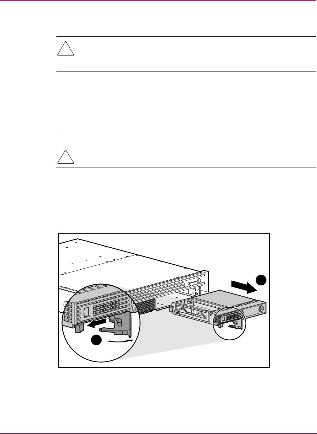
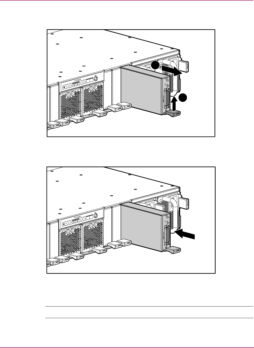
2. Press the controller thumb latch and pull the latch handle toward you 1.
3. Remove the MSA1000 Controller by pulling it straight out of the chassis 2.
Figure 3: Removing the MSA1000 Controller
2
1
Removal and Replacement Procedures
28 Modular Smart Array 1500 cs Maintenance and Service Guide
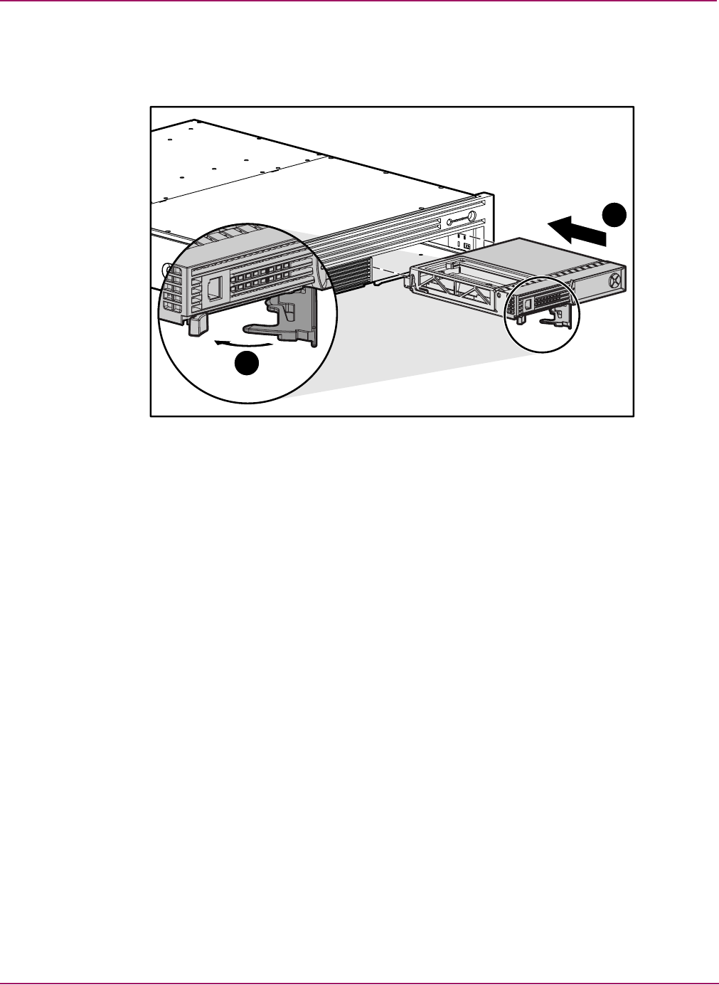
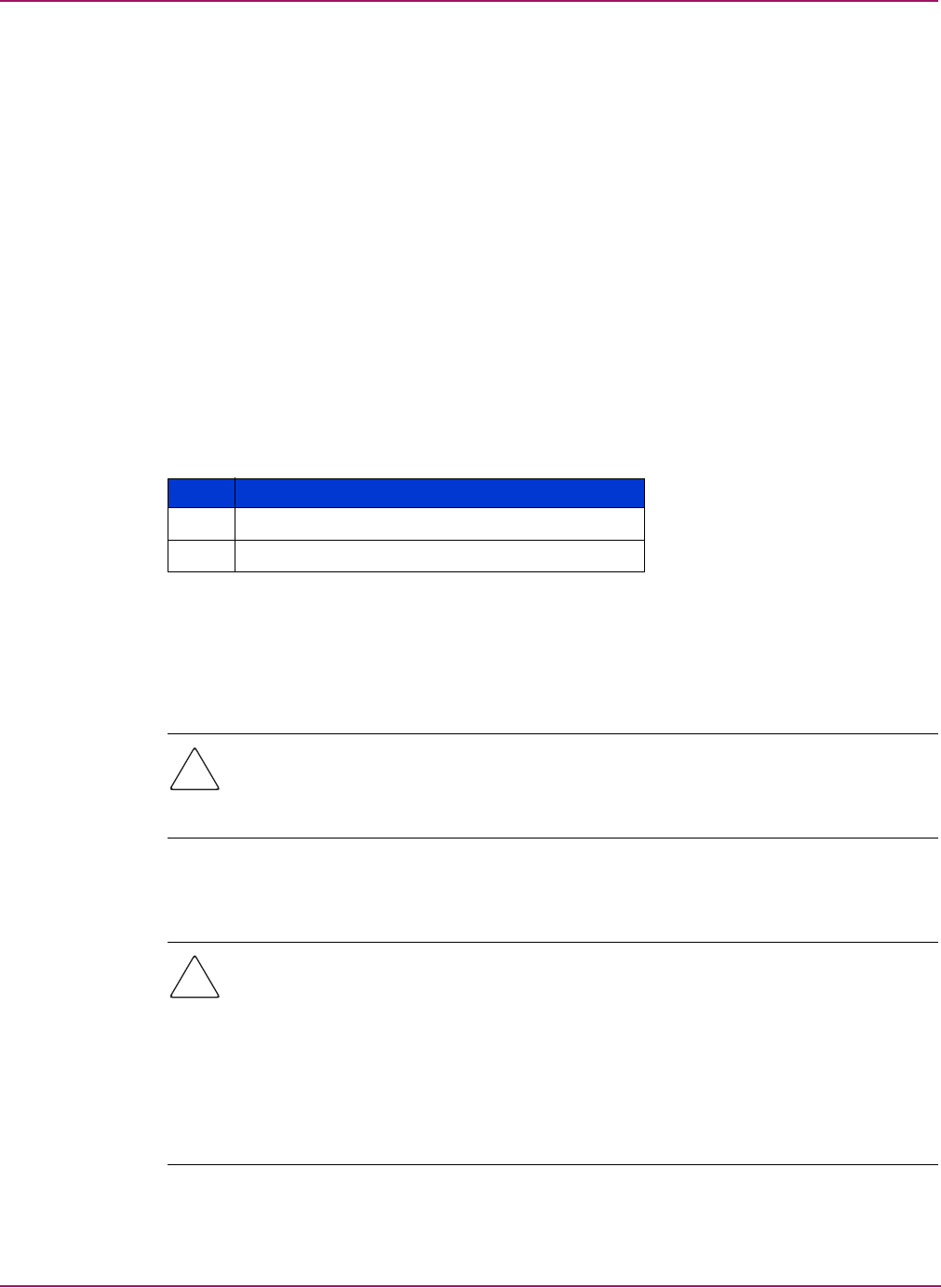
4. Insert the replacement controller into the chassis.
5. Push the controller in as far as it will go 1 and press the latch inward until it is flush
against the front panel 2.
Figure 4: Installing the replacement controller
1
2
Removal and Replacement Procedures
29Modular Smart Array 1500 cs Maintenance and Service Guide
Replacing the MSA1000 Controller cache
Caution: It is important to follow these instructions when replacing components in the
MSA1000. If the procedure is done improperly, it is possible to lose data or damage
equipment. Refer to the “Preparation Procedures” section of this chapter for important
information on using the proper procedures.
Note: If your system is equipped with a single controller, and you must replace the controller cache,
you must power down the system first. If your system is equipped with two controllers, and you want
to replace a failed cache module with another of the same size, you can replace the module while
the system is running. If your system is equipped with two controllers, and you are replacing the
cache module with a module of a different size, you must power down the system first, and then
change the cache module on both controllers at the same time.
Caution: Before replacing any component including those that are hot-pluggable, ensure
that steps have been taken to minimize downtime and prevent loss of data.
1. Complete the preparation procedures. See the “Preparation procedures” on page 20 of this
chapter.
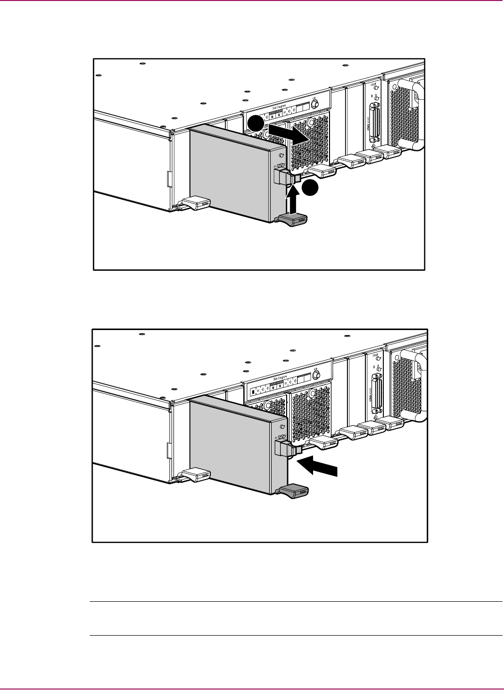
2. Press the thumb latch on the controller and pull the latch handle towards you 1. See
“Removing the controller” on page 29.
3. Remove the MSA1000 Controller by pulling it straight out of the chassis 2.
Figure 5: Removing the controller
2
1
Removal and Replacement Procedures
30 Modular Smart Array 1500 cs Maintenance and Service Guide
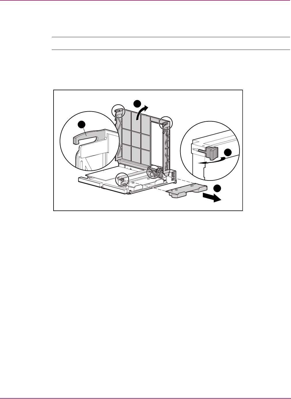
4. As illustrated in Figure 6, unlatch the controller cover clips 1 on the rear of the controller
and then raise the cover 2.
Note: The controller in Figure 6 has been rotated so the side and rear of the controller are visible.
5. Simultaneously unlatch the clips that are holding the MSA1000 Controller cache in
place 3.
6. Carefully pull the cache away from the controller board 4.
Figure 6: Removing the cache module
1
2
3
4
Removal and Replacement Procedures
31Modular Smart Array 1500 cs Maintenance and Service Guide
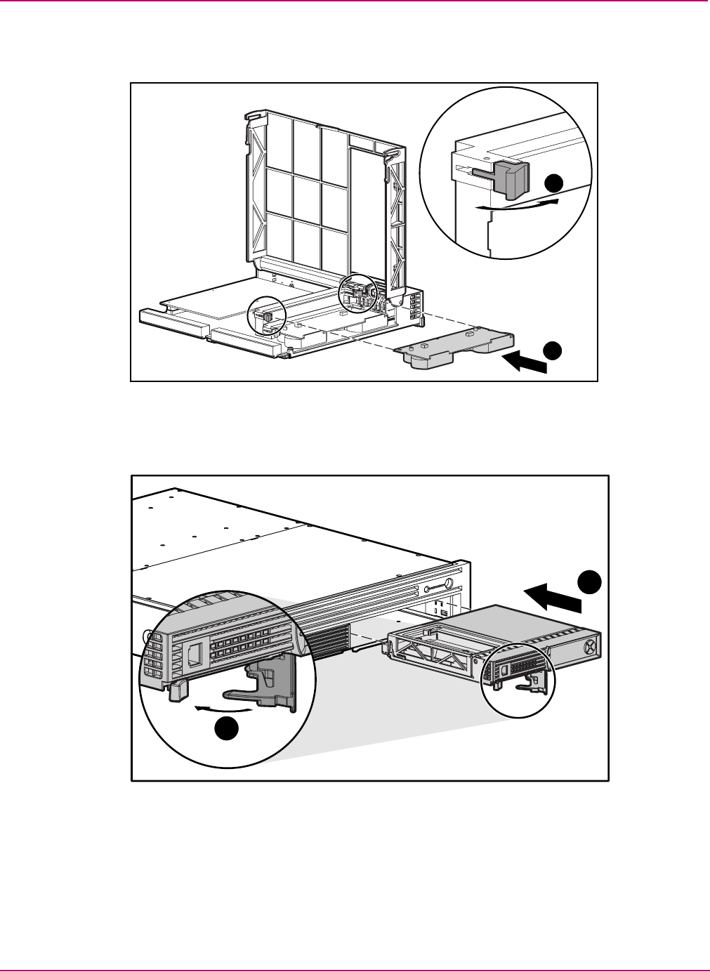
7. Install the new MSA1000 Controller cache by sliding the new MSA1000 Controller cache
into the controller 1. Be sure the side latches are fully engaged 2. See Figure 7.
Figure 7: Installing the cache module
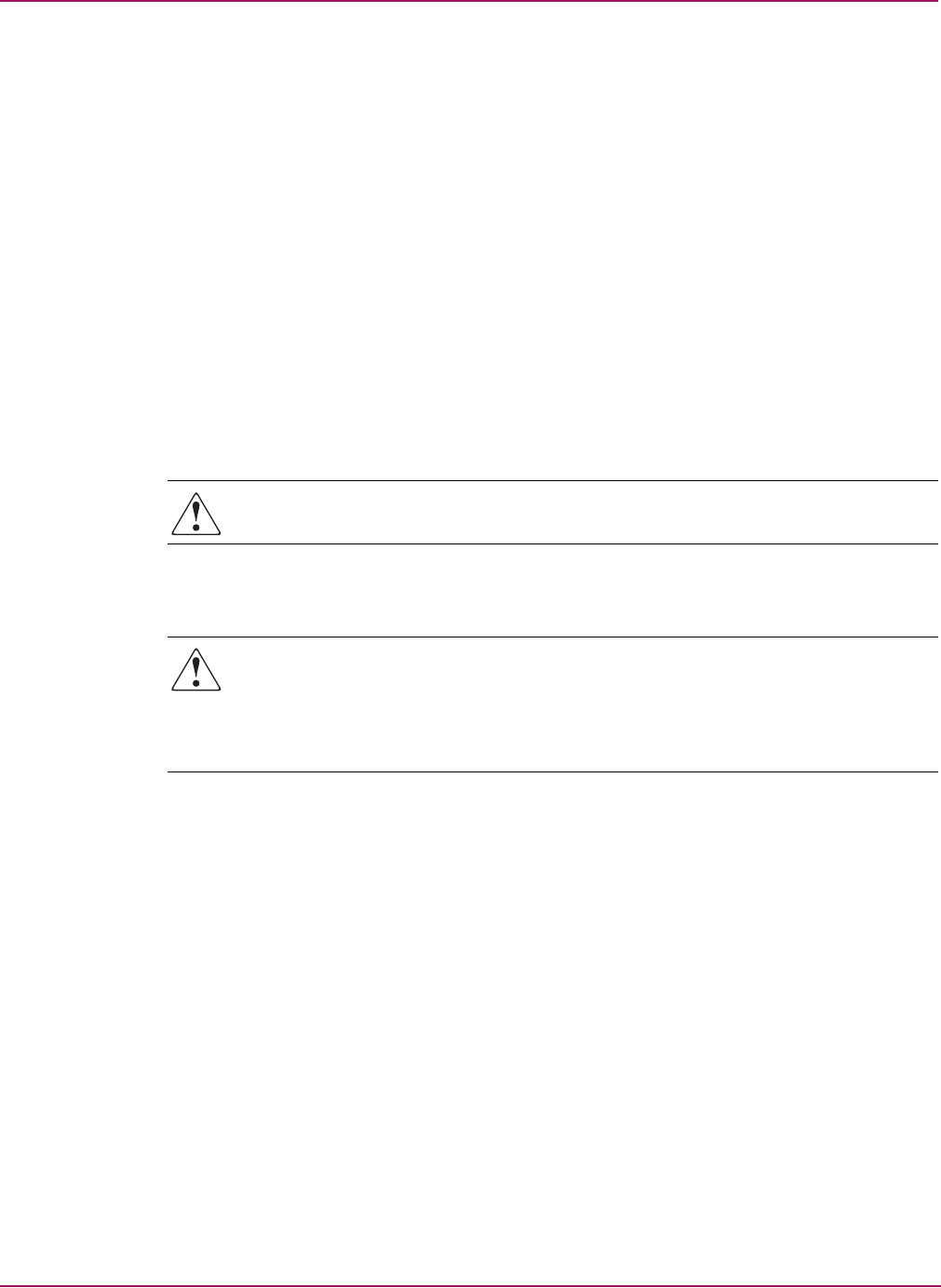
8. Push the controller in as far as it will go 1; press the latch inward until it is flush against
the front panel 2. See Figure 8.
Figure 8: Installing the controller
1
2
1
2
Removal and Replacement Procedures
32 Modular Smart Array 1500 cs Maintenance and Service Guide
Replacing the controller cache battery pack
WARNING: There is a risk of explosion, fire, or personal injury if the battery pack is
replaced incorrectly or mistreated. To reduce the risk:
■Do not attempt to recharge the battery outside of the controller.
■Do not expose to water, or to temperatures higher than 60°C.
■Do not abuse, disassemble, crush, puncture, short external contacts, or dispose of in fire
or water.
■Replace only with the spare designated for this product.
■Cache module battery disposal should comply with local regulations. Alternatively,
return them by established parts return methods to Hewlett- Packard Corporation for
disposal.
Caution: It is important to follow these instructions when replacing components in the
MSA1000. If the procedure is done improperly, it is possible to lose data or damage
equipment. Refer to “Preparation procedures” of this chapter for important information on
using the proper procedures.
To remove the old NiMH battery pack:
1. Remove the MSA1000 Controller cache, as instructed in the previous section, “Replacing
the MSA1000 Controller cache.”
2. Push down on the bottom clip of the battery pack, attached near the lower corner of the
cache module.
See Figure 9.
Figure 9: Bottom clip on battery pack
Removal and Replacement Procedures
33Modular Smart Array 1500 cs Maintenance and Service Guide
3. Swing the battery pack away from the cache module to about a 30-degree angle.
Figure 10: Angling the battery pack
4. Lift the pack upward to unhook the top of the battery pack.
Figure 11: Removing the battery pack
5. Repeat for the second battery on this cache module.
Wait about 15 seconds after removing the old battery packs to allow the battery charge
monitor to reset.
Removal and Replacement Procedures
34 Modular Smart Array 1500 cs Maintenance and Service Guide
6. Install the new NiMH battery pack by hooking the top of the battery pack to the top of the
cache module with the pack held at a 30-degree angle to the plane of the cache module
board.
See Figure 12 for an illustration.
Figure 12: Installing the battery pack
7. After the pack is hooked in position, swing the pack downward making sure the bottom
clip and two pegs line up with the holes in the cache module.
8. Make sure that the top hook 1 and bottom clip 2 on the battery pack are securely attached
to the cache module.
Figure 13: Securing the battery pack
9. Installation of the new battery is complete.
1
2
Removal and Replacement Procedures
35Modular Smart Array 1500 cs Maintenance and Service Guide
Hot-plug power supply
The power supplies for the MSA1500 cs are hot-pluggable and the unit does not need to be
powered down to replace one.
Replacing a power supply
Verifying component failure
Before replacing the power supply use the following methods to verify the component failure.
■Check the controller LCD for the error message listed in Table 4.
■The power supply indicator on the rear of the module is flashing amber.
■The system has power but the power supply indicator on the rear of the module is off.
Caution: Before replacing any component including those that are hot-pluggable, ensure
that steps have been taken to minimize downtime and prevent loss of data. Removing a
power supply significantly changes the airflow within the MSA1500 cs. To avoid possible
overheating, always replace the power supply immediately. After removal of a power
supply, the system will power down automatically if the internal temperature exceeds
acceptable limits.
1. Complete the preparation procedures. See the “Preparation procedures” on page 20.
2. Disconnect the AC power cord from the failed power supply.
Table 4: Power Supply LCD Error Message
No. Message
409 STORAGE BOX #<n> POWER SUPPLY FAILED
Removal and Replacement Procedures
36 Modular Smart Array 1500 cs Maintenance and Service Guide
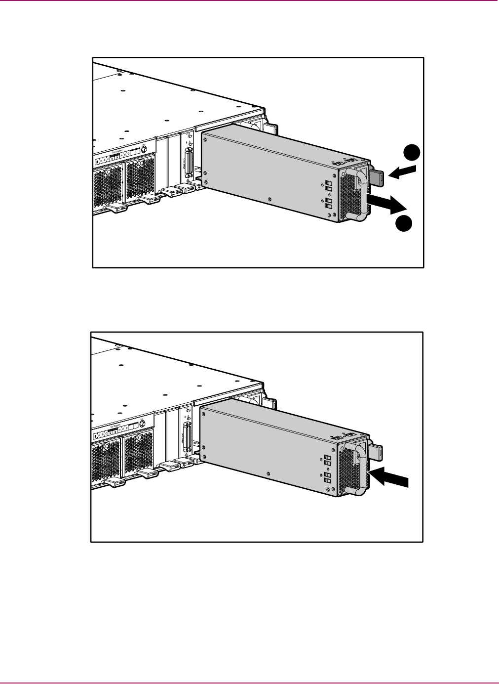
3. While pushing the power supply port-colored module latch 1, pull the power supply out
of the enclosure 2.
Figure 14: Removing the power supply
4. Install the replacement supply by lifting up on the power supply module latch and pushing
in the base until the assembly is fully seated in the enclosure.
Figure 15: Installing the replacement power supply
1
2
Removal and Replacement Procedures
37Modular Smart Array 1500 cs Maintenance and Service Guide
Verifying the replacement
After replacing the failed power supply verify that:
■Check the controller LCD for the message listed in Table 5.
■The power supply indicator on the rear of the module is solid green.
Hot-plug fan module
The fan modules for the MSA1500 cs are hot-pluggable and the unit does not need to be
powered down to replace one.
Replacing a fan module
Verifying component failure
Before replacing the fan module use the following methods to verify the component failure.
■Check the controller LCD for the error message listed in Table 6.
■The system fault indicator on the enclosure is amber.
■The fan module indicator on the rear of the module is flashing amber.
Caution: Before replacing any component including those that are hot-pluggable, ensure
that steps have been taken to minimize downtime and prevent loss of data. Removing a fan
module significantly changes the cooling within the enclosure. To avoid possible
overheating, always replace the fan module immediately. After removal of a fan module,
the system will power down automatically if the internal temperature exceeds acceptable
limits.
To replace the fan module:
1. Complete the preparation procedures. See the “Preparation procedures” on page 20.
Table 5: Power Supply LCD Verifcation Message
No. Message
408 STORAGE BOX #<n> POWER SUPPLY OK
Table 6: Fan Module LCD Error Message
No. Message
401 STORAGE BOX #<n> FAN FAILED
Removal and Replacement Procedures
38 Modular Smart Array 1500 cs Maintenance and Service Guide
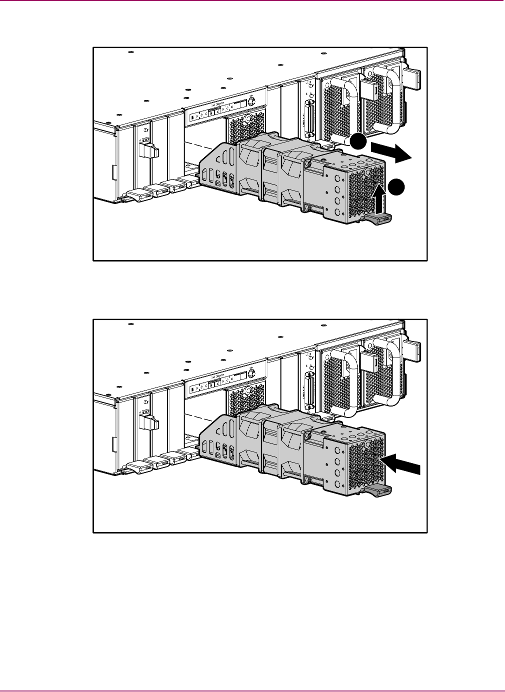
2. Lift the port-colored fan module latch 1 and pull the fan module out of the enclosure 2.
Figure 16: Removing the fan module
To install a fan module, slide it into the bay until it clicks into place.
Figure 17: Installing the fan module
2
1
Removal and Replacement Procedures
39Modular Smart Array 1500 cs Maintenance and Service Guide
Verifying the Replacement
After replacing the failed fan module verify that:
■The controller LCD for the message listed in Table 7.
■The system fault indicator on the enclosure is off.
■The heartbeat LED is flashing green.
■The fan module indicator on the rear of the module is solid green.
SCSI I/O module
Replacing a SCSI I/O module
Verifying component failure
Before replacing the SCSI I/O module use the following methods to verify the component
failure.
■Check the controller LCD for one of the error messages listed in Table 8.
■The status LED is not illuminated or is flashing amber.
Caution: Before replacing any component including those that are hot-pluggable, ensure
that steps have been taken to minimize downtime and prevent loss of data. Removing a
SCSI I/O module significantly changes the airflow within the enclosure. To avoid possible
overheating, always replace the SCSI I/O module as soon as possible. After removal of a
SCSI I/O module, the system will power down automatically if the internal temperature
exceeds acceptable limits.
1. Complete the preparation procedures. See the “Preparation procedures” on page 20.
Note: Before removing the SCSI I/O module, label all cables. This ensures their reconnection in the
correct configuration.
2. Disconnect all SCSI cables from the SCSI I/O module.
Table 7: Fan Module LCD Verifcation Message
No. Message
400 STORAGE BOX #<n> FAN OK
Table 8: SCSI I/O LCD Error Messages
No. Message
23 SCSI SUBSYSTEM HARDWARE FAILURE
412 STORAGE BOX #<n> EMU NOT RESPONDING
Removal and Replacement Procedures
40 Modular Smart Array 1500 cs Maintenance and Service Guide
3. Lift the port-colored SCSI I/O module latch 1 and pull the SCSI I/O module out of the
enclosure 2.
Figure 18: Removing the SCSI I/O module
4. Slide the SCSI I/O module into the bay until it clicks into place.
Figure 19: Installing the SCSI I/O module
5. Reconnect all SCSI cables.
Note: Make sure that all of the SCSI connectors are fastened tighly.
2
1
Removal and Replacement Procedures
41Modular Smart Array 1500 cs Maintenance and Service Guide
Verifying the replacement
After replacing the failed SCSI I/O module verify that:
■No error messages are displayed on the controller LCD.
■The status LED is solid green.Returning the failed component.
Fibre Channel I/O module
Replacing a Fibre Channel I/O module
Verifying component failure
Before replacing the Fibre Channel I/O module use the following methods to verify the
component failure.
■Check the controller LCD for one of the error messages listed in Table 9.
■The status LED on the rear of the Fibre Channel I/O module is not illuminated or is
flashing amber.
■The 1-GB LED is flashing amber.
■The 2-GB LED is flashing amber.
Caution: Before replacing any component including those that are hot-pluggable, ensure
that steps have been taken to minimize downtime and prevent loss of data. Removing an
Fibre Channel I/O module significantly changes the airflow within the enclosure. To avoid
possible overheating, always replace the I/O module as soon as possible.
1. Complete the preparation procedures. See the “Preparation procedures” on page 20.
Caution: Use appropriate precautions when handling Fibre Channel cables:
■Touching the end of a Fibre Channel cable will either damage the cable or cause
performance problems, including intermittent difficulties accessing the storage.
■Whenever a Fibre Channel cable is not connected, replace the protective covers on the
ends of the cable.
■Make certain that the Fibre Channel cables are installed and supported so that no
excess weight is placed on the connectors. This prevents damage to the connector and
cable. Excess cable should be loosely coiled and tied out of the way, being careful not to
coil the cable in a tight loop with a bend radius of less than 3 inches (7.62 cm).
2. Disconect the fibre cable from the Fibre Channel I/O module.
Table 9: Fibre Channel I/O Module LCD Error Messages
No. Message
515 FIBRE DEVICE HARDWARE FAILURE
516 FIBRE SUBSYSTEM LINK FAILURE
Removal and Replacement Procedures
42 Modular Smart Array 1500 cs Maintenance and Service Guide
3. Lift the port-colored Fibre Channel I/O module latch 1 and pull the I/O module out of the
enclosure 2.
Figure 20: Removing the Fibre Channel I/O module
4. Slide it into the bay until the module clicks into place.
Figure 21: Installing the Fibre Channel I/O module
5. Move the SFP transceiver to the new Fibre Channel I/O module
Note: For instructions on replacing the SFP transceiver see “Replacing a SFP transceiver” on
page 43.
2
1
Removal and Replacement Procedures
43Modular Smart Array 1500 cs Maintenance and Service Guide
Verifying the replacement
After replacing the failed Fibre Channel I/O module verify that:
■No error messages are displayed on the LCD.
■The status LED is solid green.
■The 1-GB LED is solid green.
■The 1-GB LED is solid green.
2-Gb Small Form Factor Pluggable (SFP) transceiver
Replacing a SFP transceiver
If a transceiver fails, follow this procedure to replace the failed transceiver. It is not necessary
to power down the system.
Caution: Before replacing a hot-pluggable component ensure that steps have been taken to
prevent loss of data.
Laser precautions
WARNING: To reduce the risk of injury from laser radiation or damage to the equipment,
observe the following precautions:
■Do not open any panels, operate controls, make adjustments, or perform procedures to
a laser device other than those specified herein.
■Do not stare into the laser beam when panels are open.
1. Press the release clip on the bottom of the cable connector to remove the Fibre Channel
I/O cable from the back of the failed transceiver.
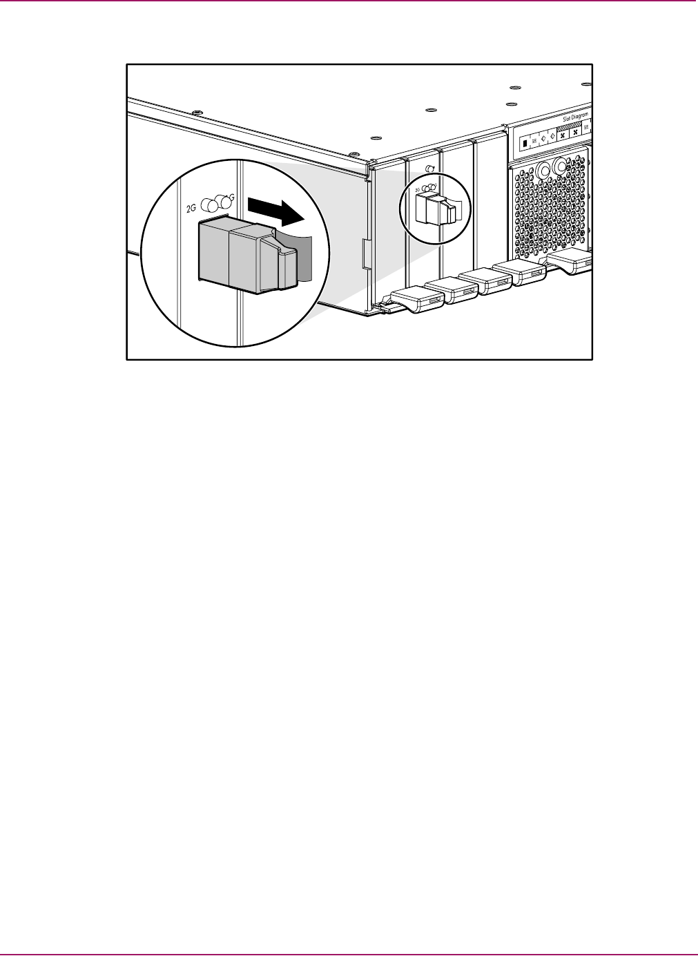
Removal and Replacement Procedures
44 Modular Smart Array 1500 cs Maintenance and Service Guide
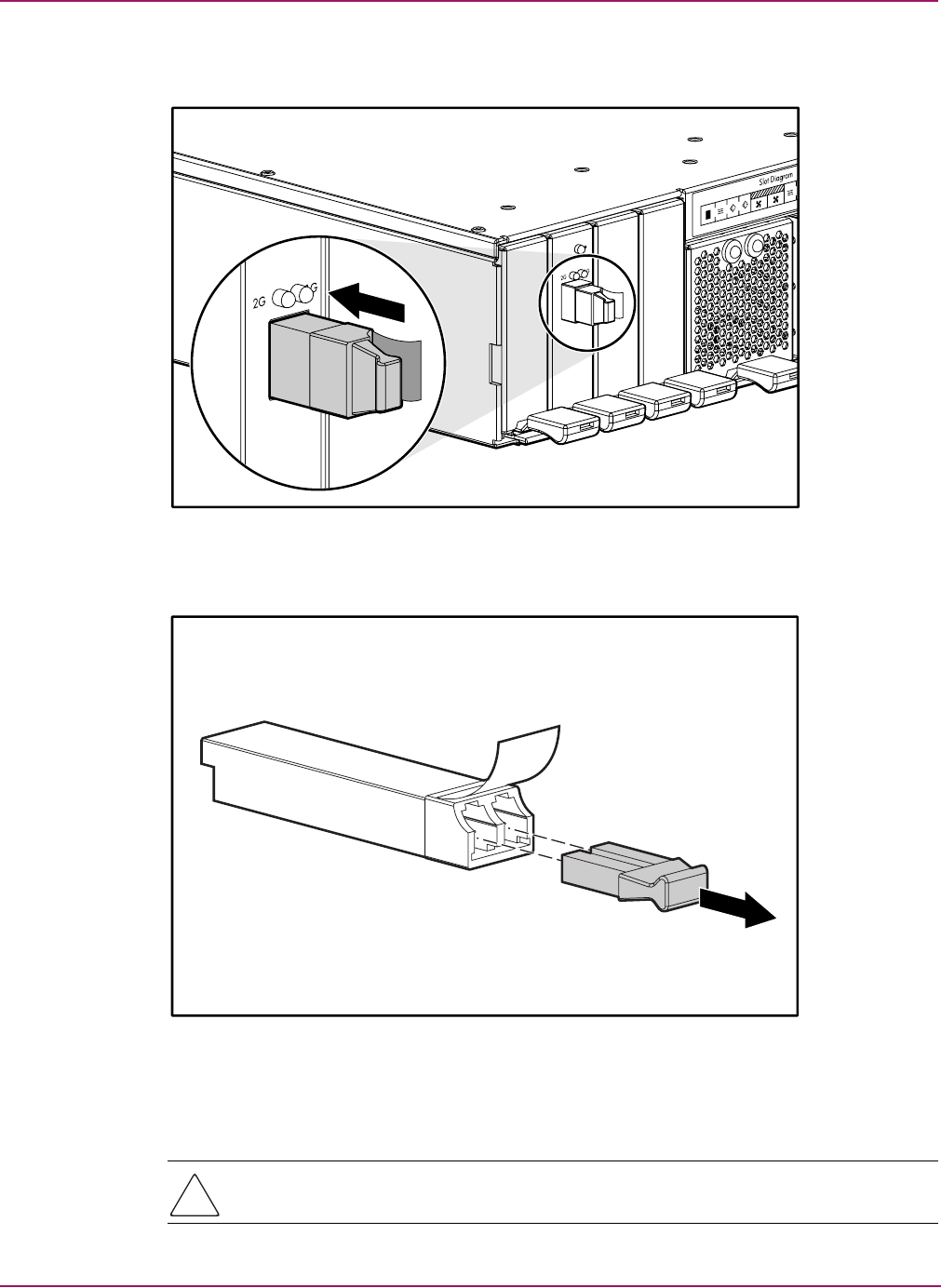
2. Pull the release tab on the transceiver and pull the transceiver straight out of the device.
Figure 22: Removing the failed SFP
Removal and Replacement Procedures
45Modular Smart Array 1500 cs Maintenance and Service Guide
3. With the plastic tab facing to the right, insert the replacement transceiver straight into the
device.
Figure 23: Installing a new SFP
4. Remove the dust cover from the SFP.
Figure 24: Removing the dust cover from the SFP
5. Insert the Fibre Channel I/O cable with the clip side to the left into the transceiver. The
cable should snap into place.
Caution: To reduce the risk of damage to the equipment, do not use excessive force when
inserting the transceiver.
Removal and Replacement Procedures
46 Modular Smart Array 1500 cs Maintenance and Service Guide
Replacing the power switch assembly
The power switch assembly not hot-pluggable and the MSA1500 cs must be powered down
and disconnected before the component can be replaced. For instruction on powering down the
MSA1500 cs, refer to “Powering down the MSA1500 cs” on page 21.
To replace the power switch assembly:
1. Power down the MSA1500 cs.
Note: Before disconnecting any cables, label them so that they can reconnected to the same
connectors when the power switch assembly replacement is complete.
2. Disconnect the power cables from the MSA1500 cs.
3. Disconnect the fibre cable from the MSA1500 cs.
4. Disconnect the SCSI cables from the MSA1500 cs.
5. Remove the MSA1500CS from the rack.
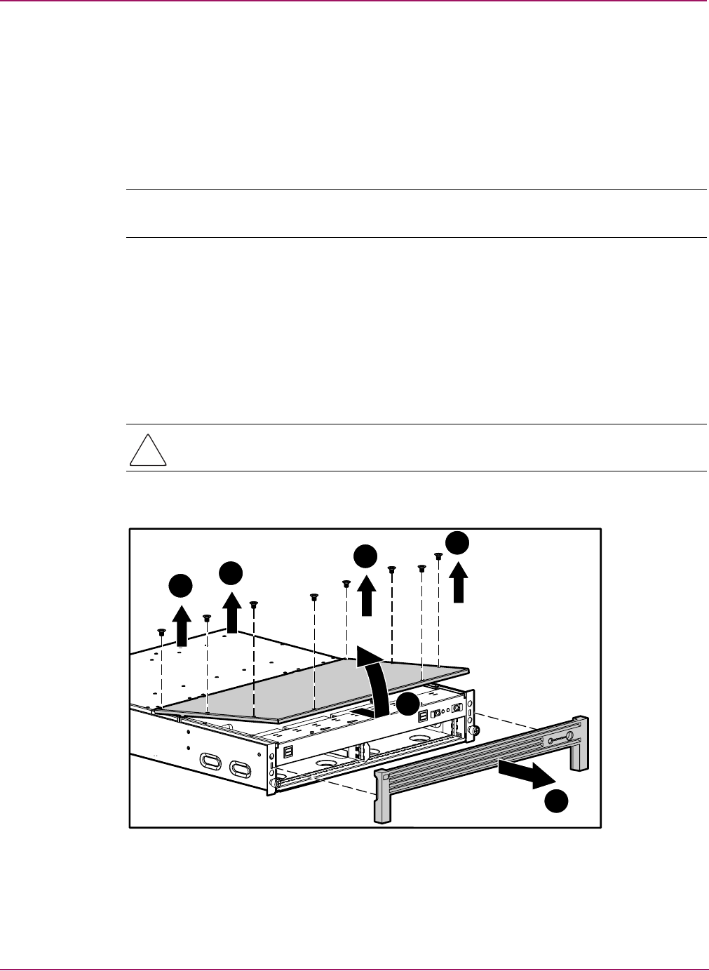
6. Remove the bezel 1 as shown in Figure 25.
7. Remove the eight screws securing the top cover to the chassis 2.
Caution: Before opening the MSA1500 cs, review the electrostatic discharge information
contained in Appendix B, Electrostatic Discharge.
8. Lift the front of the top cover and remove it from the chassis 3, as shown in Figure 25.
Figure 25: Removing the top cover
3
22
1
22
Removal and Replacement Procedures
47Modular Smart Array 1500 cs Maintenance and Service Guide
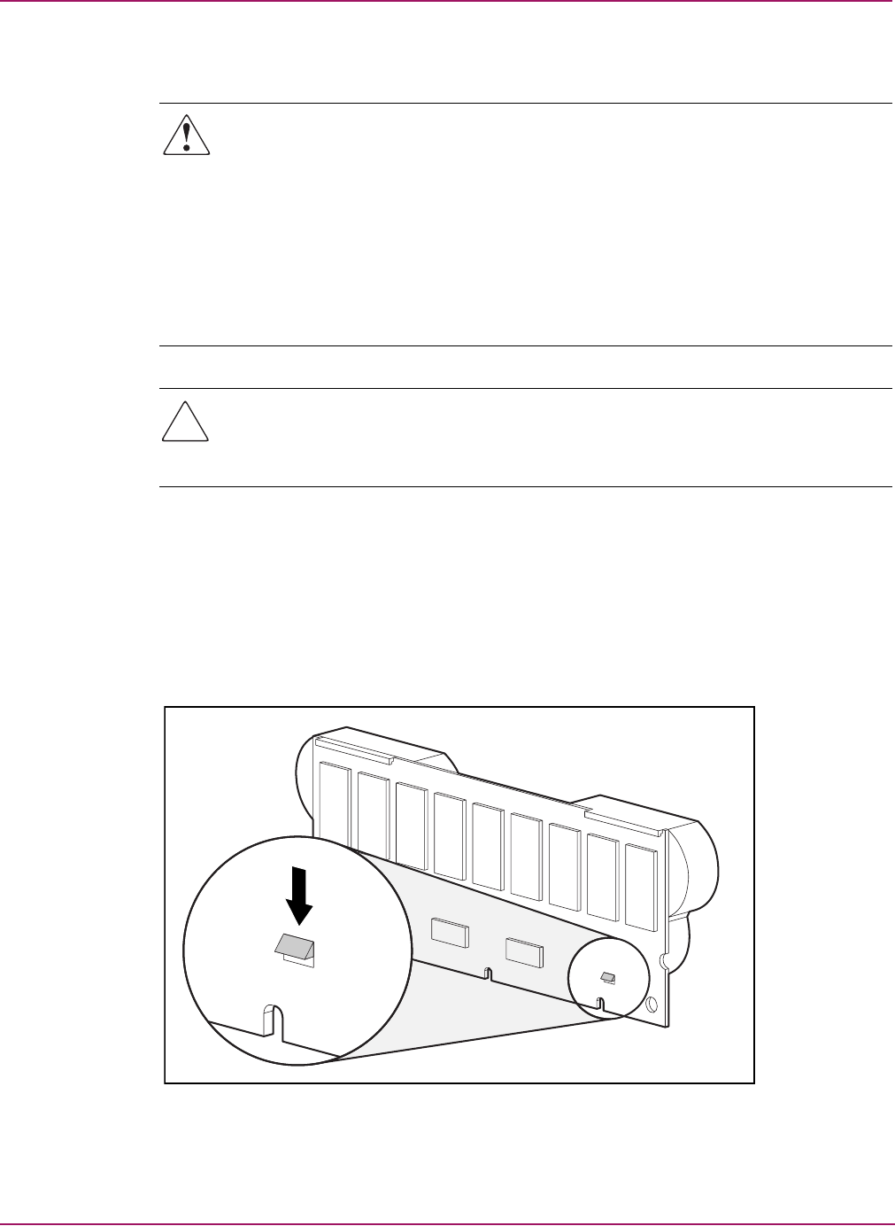
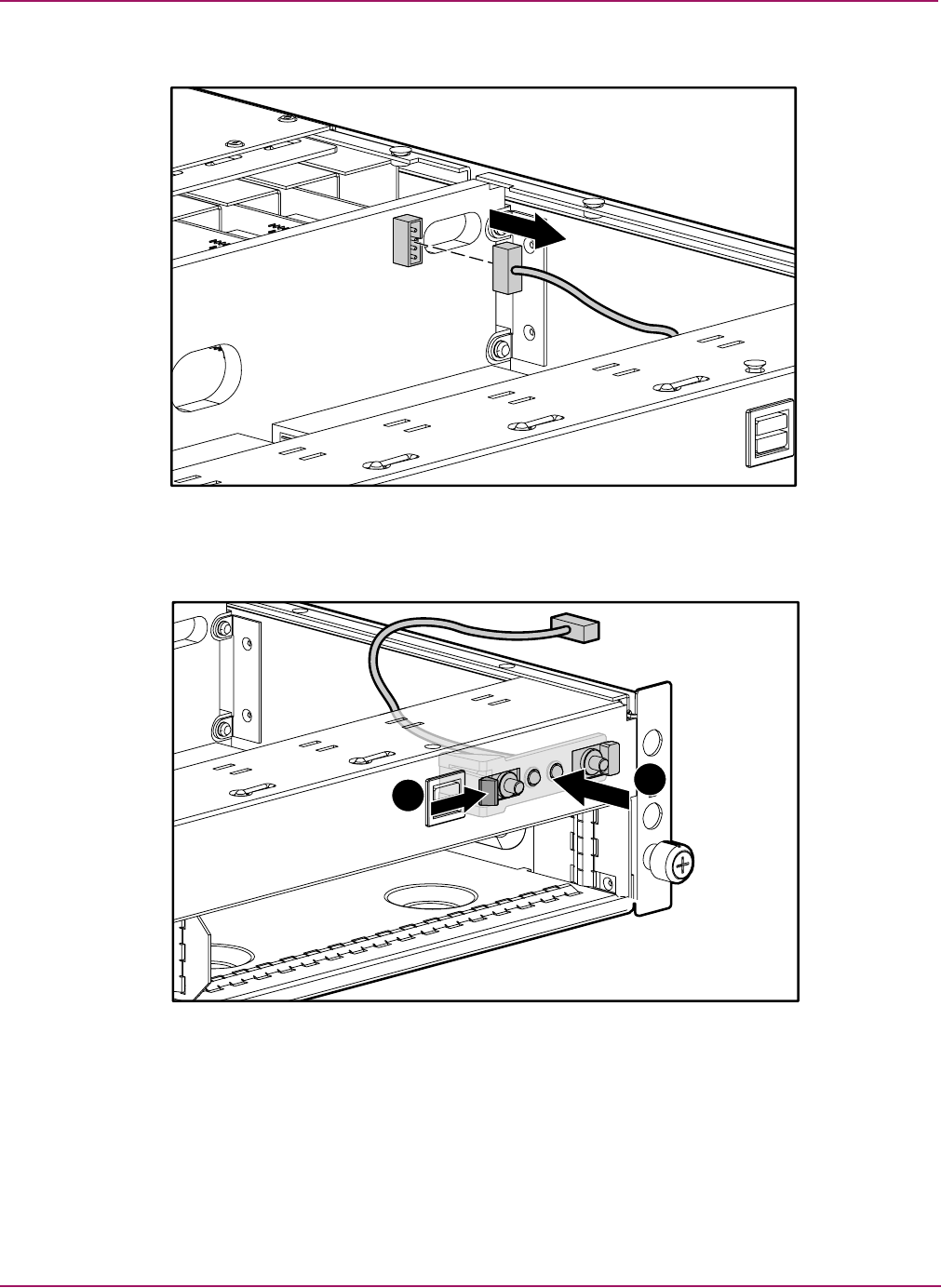
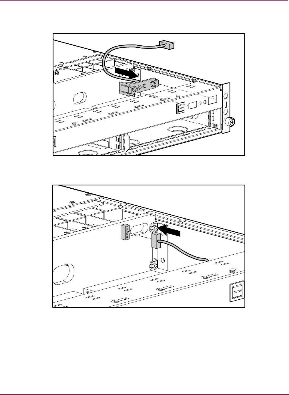
9. Unplug the power switch cable from the midplane, as shown in Figure 26.
Figure 26: Unplugging the power switch cable
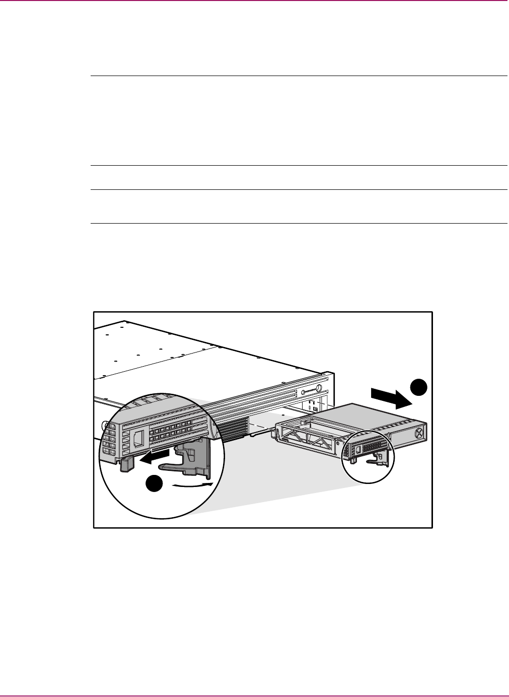
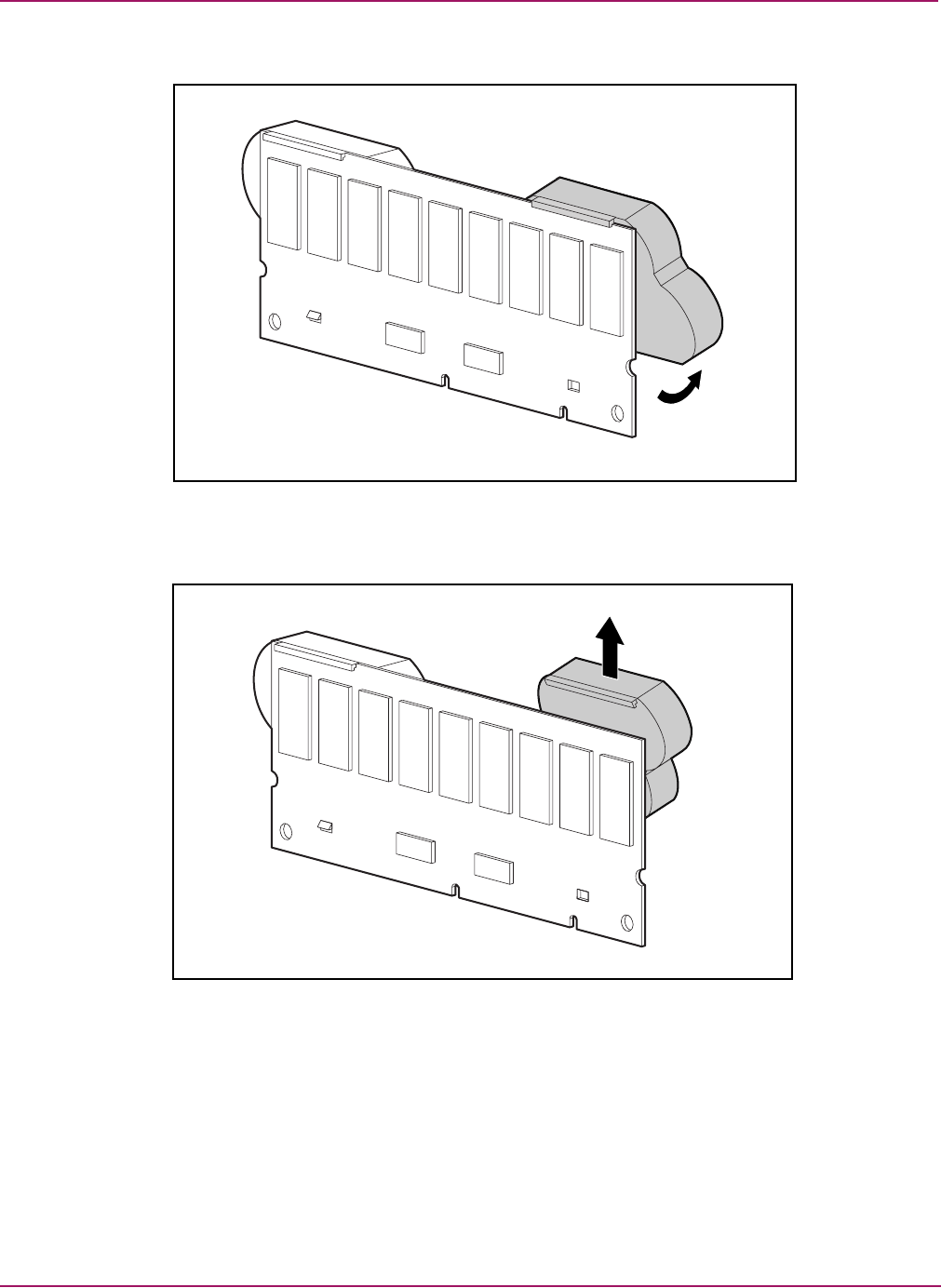
10. Press the release tab on the left side of the power switch assembly1 and then push the
power switch assembly back to remove it 2, as shown in Figure 27.
Figure 27: Removing the power switch assembly
12
Removal and Replacement Procedures
48 Modular Smart Array 1500 cs Maintenance and Service Guide
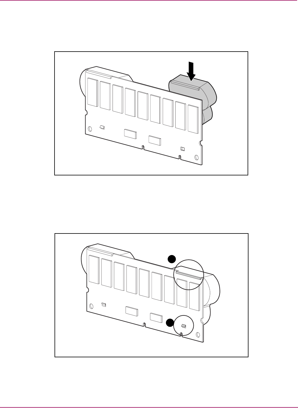
11. Insert the new power switch assembly into the front panel and push into its seated position,
as shown in Figure 28.
Figure 28: Reseating the power switch assembly
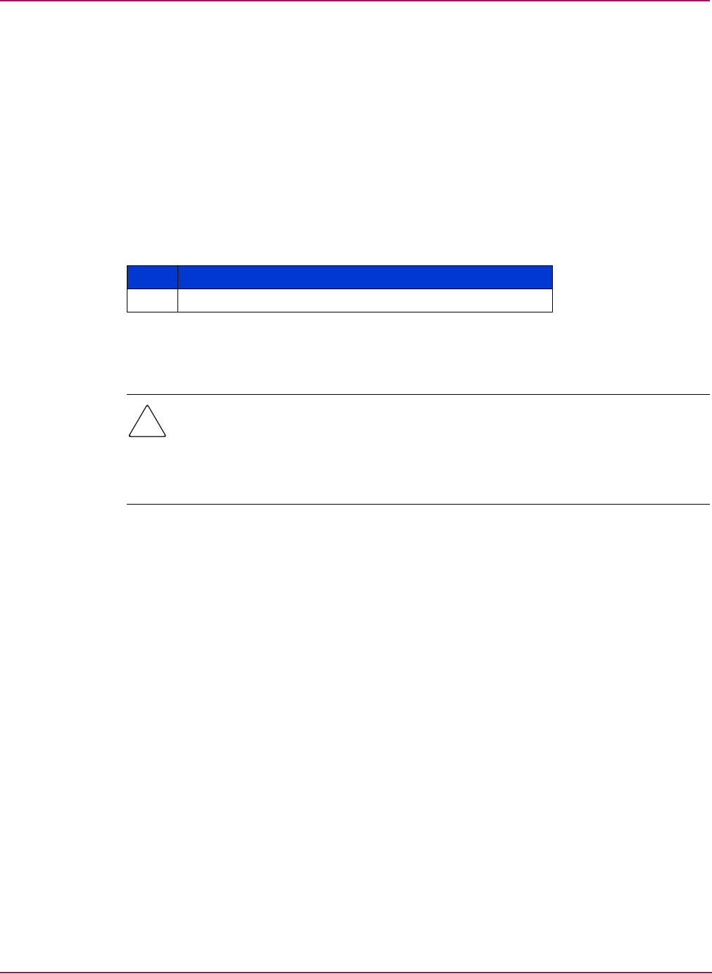
12. Connect the end of the power switch cable to the midplane as shown in Figure 29.
Figure 29: Connecting the power switch cable
13. Replace the top cover and fasten using the screws that were removed in step 7.
14. Replace the bezel.
15. Reinstall the MSA1500 cs in the rack.
16. Reconnect the SCSI, fiber, and power cables.
17. Power on the MSA1500 cs.

Removal and Replacement Procedures
49Modular Smart Array 1500 cs Maintenance and Service Guide
Verifying the replacement
After replacing the failed power switch assembly verify that the power LED is illuminated.
Replacing a MSA1500 cs 2U chassis
In the event of a chassis failure, a new chassis must be ordered. All original component parts
of the MSA1500 cs can be reinstalled to their respective locations in the new chassis. The
MSA1500 cs must be powered down and disconnected before the chassis can be replaced. For
instruction on powering down the MSA1500 cs, refer to “Powering down the MSA1500 cs” on
page 21.
Note: Before disconnecting any cables and components, label them so that they can reinstalled in
the same position when the chassis replacement is complete.
The parts that will be removed and then reinstalled include:
■MSA1000 Controllers
For instructions on reinstalling the MSA1000 Controller, refer to “Replacing the
MSA1000 Controller” on page 27.
■Hot-pluggable power supplies
For instructions on reinstalling the power supplies, refer to “Replacing a power supply” on
page 35.
■Fan modules
For instructions on reinstalling the fan modules, refer to “Replacing a fan module” on
page 37.
■SCSI I/O modules
For instructions on reinstalling the SCSI I/O modules, refer to “Replacing a SCSI I/O
module” on page 39.
■Fibre Channel I/O modules
For instructions on reinstalling the Fibre Channel I/O modules, refer to “Replacing a Fibre
Channel I/O module” on page 41.
■Slot and controller blanks
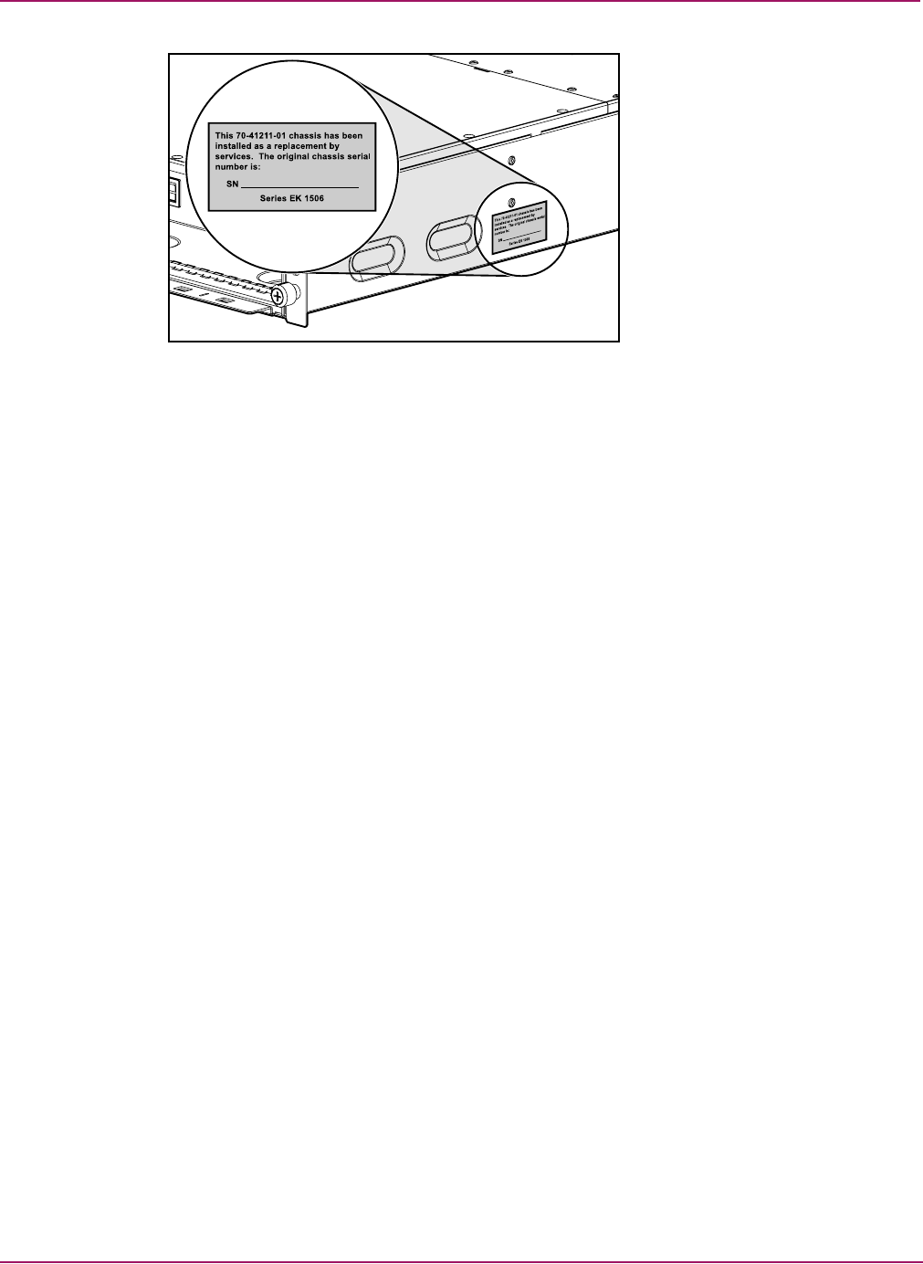
When finished, write the serial number, shown on the original chassis, on the label of the
replacement chassis, located in the area shown in Figure 30.
Removal and Replacement Procedures
50 Modular Smart Array 1500 cs Maintenance and Service Guide
Figure 30: Replacement chassis serial numer label location
Fibre Channel I/O cables
Multi-Mode Fibre Channel I/O cable
Multi-mode Fibre Channel I/O cables are capable of supporting distances of 2 m to 500 m
(6.56168 ft to 1640.42 ft) at 1-Gb and 300 m at 2-Gb. These cables are for use with Short-wave
transceivers only. To ease the installation of the HP StorageWorks MSA1500 cs, multi-mode
Fibre Channel I/O cable option kits are available from HP. Each kit contains a multi-mode
Fibre Channel I/O cable with a connector attached to each end.
The available 1-Gb to 2-Gb connection cable options are:
■2-meter multi-mode Fibre Channel I/O cable option kit (part number 221691-B21)
■5-meter multi-mode Fibre Channel I/O cable option kit (part number 221691-B22)
■15-meter multi-mode Fibre Channel I/O cable option kit (part number 221691-B23)
Available 2-Gb to 2-Gb connection cable options are:
■2-meter multi-mode Fibre Channel I/O cable option kit (part number 221692-B21)
■5-meter multi-mode Fibre Channel I/O cable option kit (part number 221692-B22)
■15-meter multi-mode Fibre Channel I/O cable option kit (part number 221692-B23)
To customize your system with multi-mode Fibre Channel I/O cable at distances greater than
15 meters, contact an independent Fibre Channel I/O cable supplier.
If you use an existing 62.5-micron cable, you must obtain a 62.5-micron jumper from an
independent source. A 50-micron cable cannot be spliced with a 62.5-micron cable.

Diagnostics
52 Modular Smart Array 1500 cs Maintenance and Service Guide
MSA1000 Controller indicators
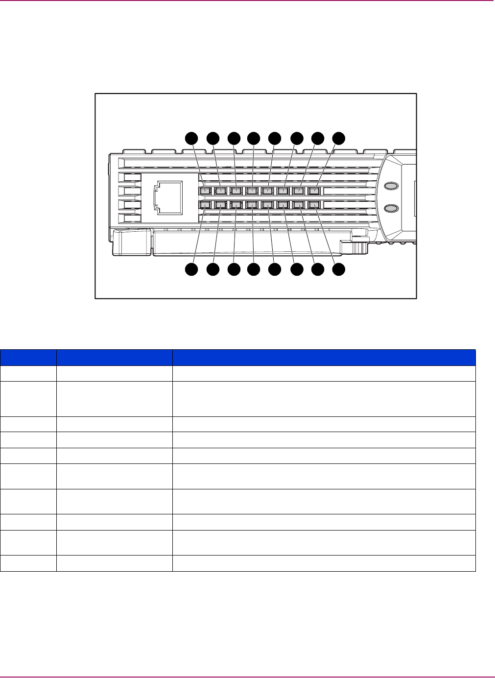
During normal runtime, the MSA1000 Controller has 16 indicators that indicate activity or
malfunction of the controller. They are labeled 1-16, as shown in the following figure. The
table that follows describes the purpose and function of each indicator.
Figure 31: MSA1000 Controller indicators
7 8654321
10 9111213141516
Table 10: MSA1000 Controller Indicator Descriptions
Indicator Function Description
1Drive failure ON = A configured hard drive has failed in the array
2Cache activity ON = Cache active
OFF = No cache activity
Blinking = Cache transfer pending
3SCSI Bus 1 active ON = Indicates requests are outstanding on the second SCSI bus
4SCSI Bus 0 active ON = Indicates requests are outstanding on the first SCSI bus
5Logical I/O active ON = Currently processing logical requests from the Host Adapter
6Direct Memory Access
(DMA) active ON = DMA transfers are active
7Active/Standby ON=Controller is active
OFF=Controller is in standby
8Idle heartbeat Indicates the array controller is idle and functioning
9-qBusy status ON = Indicates this array controller is idle
OFF = Indicates this array controller is operating at full capacity
w-yFibre Channel IDs
Diagnostics
53Modular Smart Array 1500 cs Maintenance and Service Guide
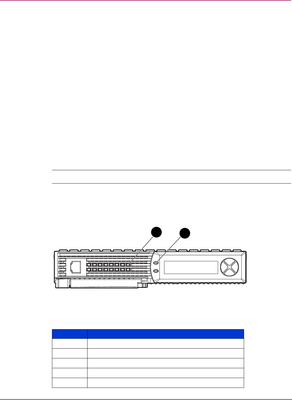
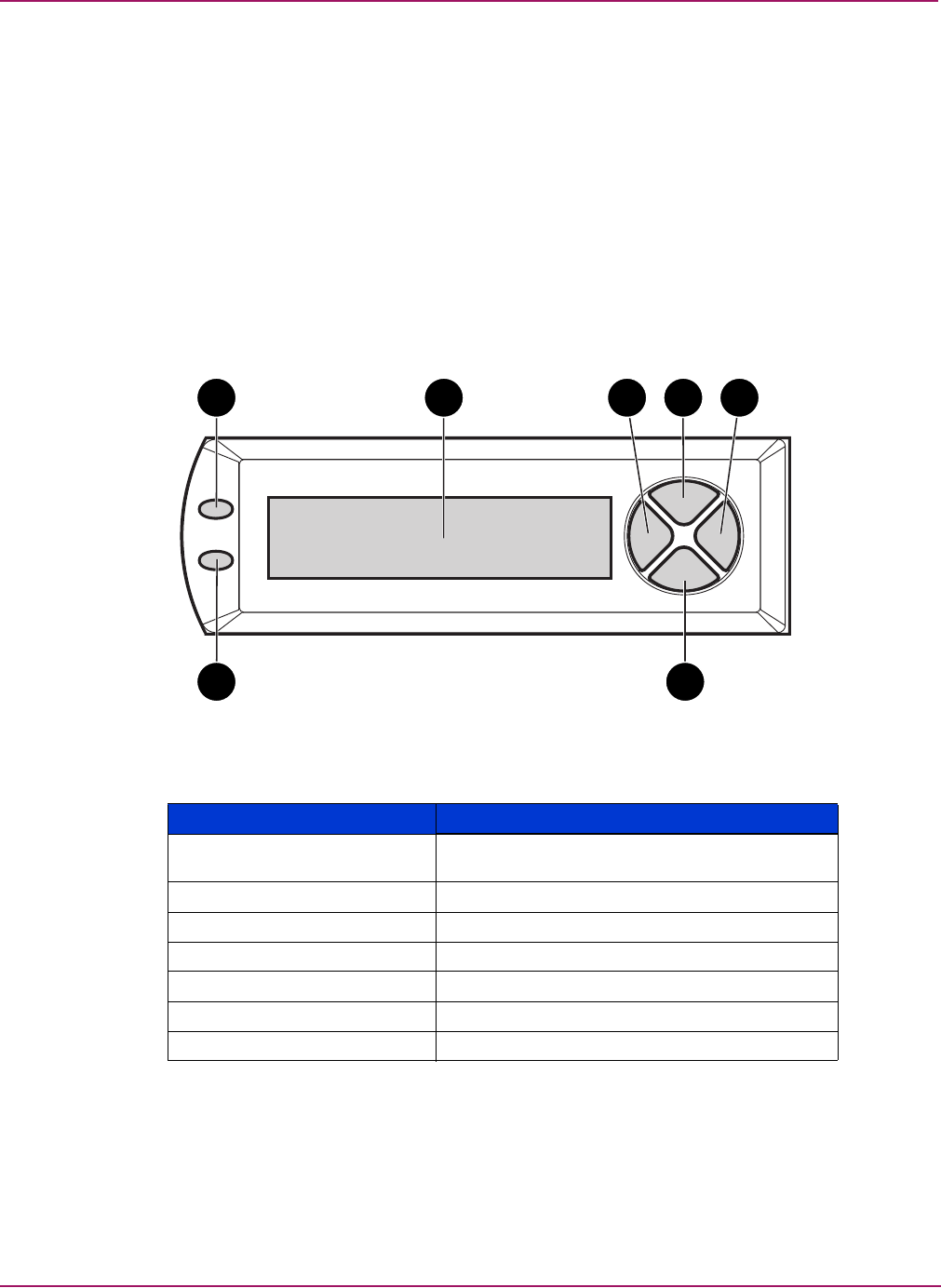
MSA1000 Controller display
Each array controller in a MSA1500 cs contains an integrated Liquid Crystal Display (LCD).
This module is used for displaying informational and error messages, showing the status of the
module, and for providing user input when required. Traditional Power-On Self-Test (POST)
messages issued by PCI-based array controllers have been combined with runtime event
notification messages to create a new set of controller display messages.
The display module consists of the following components:
■A two line, twenty column display text display window
■Four navigation buttons arranged in a circular “pie” shape
■Two status indicator lights
Figure 32: Controller display
\
Controller Display Description
1Fault indicator (amber) (indicates a component
failure or external enclosure failure)
2Display
3Left navigation button
4Up navigation button
5Right navigation button
6Down navigation button
7Redundancy Link indicator (green)
1 2 3 4 5
67

Diagnostics
54 Modular Smart Array 1500 cs Maintenance and Service Guide
Controller display messages
The display module is capable of holding up to 100 messages. After this maximum size is
reached, older messages are removed to make room for newer ones. Messages can be of three
types: error, informational, and user input.
The display message may specify a box number. The following box numbers are defined.
■Box 1 is the MSA1500 cs chassis.
■Box 2 is the storage enclosure attached to SCSI port A of the MSA1500 cs.
■Box 3 is the storage enclosure attached to SCSI port B of the MSA1500 cs.
Error messages
Error messages indicate that a problem has occurred and may require user action to correct it.
A complete list of possible messages and their meanings is contained in this chapter.
An amber indicator to the left of the LCD display is turned on when an error message is
currently displayed. This indicator is turned on if an error message was sent to the display
module but has not been viewed because non-error type messages were sent to the display
module afterwards. By scrolling backward and viewing all error messages, the indicator will
reset and light when currently on an error message.
Informational messages
Informational messages indicate non-critical changes in the system that are provided as
feedback to the user. A complete list of possible messages and their meanings is contained in
this chapter.
The amber indicator to the left of the LCD display is off whenever an informational message is
currently being viewed unless an unviewed error message was previously sent to the display
module. By scrolling backward and viewing all error messages, the indicator will return to
only lighting up when currently on an error message.
User input messages
User input messages indicate that the system has encountered a situation that allows user
input. The user can select from a number of choices. If the user does not select one of the
choices in a set amount of time, the system will select the default setting. These user input
messages will only occur during system power on and not during run time. A complete list of
possible messages and their meanings is contained in this chapter.
The amber indicator to the left of the display text display window will blink on and off when a
user input message is currently being viewed and is available for input. If the user has not
provided input within the time-out period, the message will remain but the indicator will stop
blinking.
Scrolling
Older messages can be viewed by scrolling backward using the up navigation button (with the
up arrow on it). Messages that are more recent can be viewed by scrolling forward using the
down navigation button (with the down arrow on it). The last message can be viewed by
pressing the left navigation button. When a new message is sent to the LCD, the display shows
that message and ignores any previous scrolling position. This new message is now the most
recent message available.

Diagnostics
55Modular Smart Array 1500 cs Maintenance and Service Guide
Deleting messages
The currently displayed message can be deleted from the display module by pressing the left
navigation button and the right navigation button at the same time.
Redundancy link light
There is a green indicator to the left of the LCD display that is lit when two array controllers
are inserted into the MSA1500 cs with controller redundancy enabled. The indicator is not lit
if only one array controller is inserted or if the array controllers are not redundant due to some
type of failure.
Note: You must have redundant cables connected to enable redundancy.

Diagnostics
56 Modular Smart Array 1500 cs Maintenance and Service Guide
LCD Message Descriptions
The following table contains the defined messages and their components.
Table 11: LCD Message Descriptions
Message Type Description Action
00 ARRAY CONTROLLER
FIRMWARE VER
<version>
Informational Displays the current version
of the firmware running on
the array controller.
01 MSA1000 STARTUP
COMPLETE Informational The array controller has
completed its power on
sequence and is now
operational.
02 ENABLE VOLUME
<n>? ‘<’=NO,
‘>’=YES
User Input An issue has been found
with a configured volume
that may result in data loss.
The exact nature of the
issue will be detailed in a
previous display message.
Selecting the
no
option will
result in the volume being
disabled so the user can
attempt to fix the issue.
Selecting the
yes
option
will result in the volume
being enabled regardless
of the issue.
03 CRITICAL LOCK-UP
DETECTED. CODE=<n>h Error A critical error has been
detected by the array
controller firmware. In
order to prevent any
possible data loss, the
firmware has entered a
lock-up state. The code
contains engineering
specific information about
the lock-up condition. HP
support should be
contacted.
Remove the failing array
controller, wait 10 seconds,
and then reinsert it insuring
that it is fully seated in the
chassis.
Should the issue persist
contact HP support.
04 ENABLE VOLUMES ?
‘<’=NO, ‘>’=YES User Input An issue has been found
with all of the configured
volumes that may result in
data loss. The exact nature
of the issue will be detailed
in a previous display
message.
An issue has been found
with all of the configured
volumes that may result in
data loss. The exact nature
of the issue will be detailed
in a previous display
message.
05 SYSTEM NAME:
<name> Informational Displays the user assigned
name for the MSA1500 cs
system. This name can be
assigned using the Array
Configuration Utility
(ACU).
06 RESTARTING
SYSTEM Informational Indicates that the system
has been reset and is being
restarted.
20 INITIALIZING
SCSI SUBSYSTEM Informational The SCSI subsystem is
being initialized as part of
the power on sequence.
21 SCANNING FOR
SCSI DEVICES Informational The firmware is searching
for SCSI devices attached
to the system as part of the
power on sequence.

Diagnostics
57Modular Smart Array 1500 cs Maintenance and Service Guide
22 INITIALIZING
SCSI DEVICES Informational The firmware is initializing
all SCSI devices attached to
the system as part of the
power on sequence.
23 SCSI SUBSYSTEM
HARDWARE FAILURE Error The SCSI subsystem on
MSA1000 has experienced
a hardware failure and is
not operating correctly. The
array controller has halted
itself and cannot continue.
Contact HP support.
24 BAD SCSI BUS
MODE NON-LVD DEVICE
FOUND
Error The MSA1000 does not
support SCSI Single Ended
(SE) devices, it only
supports SCSI Low Voltage
Differential (LVD) devices.
The MSA1500 cs should
be powered off and then
all SCSI devices attached to
it should be examined. Any
SE devices found should be
removed and replaced with
LVD devices.
30 I2C READ FAILURE
<I2C device name> Error The MSA1500 cs has a
number of internal devices
that are accessed via an
I2C hardware bus. One of
these devices failed when
attempting to read from it.
Certain I2C devices are
considered critical and will
result in a failure of the
array controller while
others may result in some
loss of functionality (such
as lost display messages).
Should the issue persist
contact HP support.
31 I2C WRITE
FAILURE <I2C device
name>
Error The MSA1500 cs has a
number of internal devices
that are accessed via an
I2C hardware bus. One of
these devices failed when
attempting to write to it.
Certain I2C devices are
considered critical and will
result in a failure of the
array controller while
others may result in some
loss of functionality (such
as lost display messages).
Should the issue persist
contact HP support.
32 CHASSIS NVRAM
CONTENTS CORRUPTED Error The MSA1000 has
non-volatile memory on it
that contains required
information which is
needed to operate. This
non-volatile memory
appears to be corrupted
and the information is not
valid. The MSA1000
cannot continue to operate
and will halt.
Contact HP support.
40 BEGIN REDUNDANCY
SUPPORT Informational The array controllers are
attempting to enter
redundant mode.
Table 11: LCD Message Descriptions
Message Type Description Action

Diagnostics
58 Modular Smart Array 1500 cs Maintenance and Service Guide
41 REDUNDANCY
ACTIVE ACTIVE
CONTROLLER
Informational The array controllers are
now in redundant mode
and this array controller is
active which means that it
is allowed to access the
configured volumes on the
MSA1000.
42 REDUNDANCY
ACTIVE STANDBY
CONTROLLER
Informational The array controllers are
now in redundant mode
and this array controller is
standby
which means that
it can be made
active
should the current
active
array controller fail,
assuming you have all
cables, and I/O modules
installed.
43 REDUNDANCY
FAILED HARDWARE
FAILURE
Error While either attempting to
enter redundant mode or
already operating in
redundant mode, one of
the array controllers
encountered a hardware
failure on the
communication channel
between the two array
controllers. Redundancy is
disabled at this time.
If the MSA1000 is currently
involved in host I/O,
remove the
standby
array
controller, wait 10 seconds,
and then reinsert it insuring
that it is fully seated in the
chassis.
If this does not resolve the
issue then wait until
down-time is available.
Power off the MSA1500 cs,
remove both array
controllers and reinsert
them insuring they are fully
seated in the chassis.
Should the issue persist
contact HP support.
44 REDUNDANCY
FAILED MISMATCH
HARDWARE
Error Both array controllers must
contain the same hardware
for them to successfully
enter redundant mode. The
current array controllers do
not contain the same
hardware, possibly
because one has an
attached fibre daughter
card and the other does
not.
If the MSA1000 is currently
involved in host I/O,
remove the
standby
array
controller, add or remove
the fibre daughter card as
needed, wait 10 seconds,
and then reinsert it insuring
that it is fully seated in the
chassis.
If this does not resolve the
issue then wait until
down-time is available.
Power off the MSA1500 cs,
remove both array
controllers, add or remove
fibre daughter cards as
needed on both, and
reinsert them insuring they
are fully seated in the
chassis.
Should the issue persist
contact HP support.
Table 11: LCD Message Descriptions
Message Type Description Action

Diagnostics
59Modular Smart Array 1500 cs Maintenance and Service Guide
45 REDUNDANCY
FAILED MISMATCH
FIRMWARE
Error Both array controllers must
be running the same
version of firmware for
them to successfully enter
redundant mode. A
process called firmware
cloning that attempts to
make them both the same
firmware level has failed.
Manually update the
firmware on the older array
controller.
47 REDUNDANCY
FAILED CACHE SIZE
MISMATCH
Error Both array controllers must
have the same size of
cache memory for them to
successfully enter
redundant mode.
If the MSA1000 is currently
involved in host I/O,
remove the
standby
array
controller, add or remove
cache memory as needed,
wait 10 seconds, and then
reinsert it insuring that it is
fully seated in the chassis.
If this does not resolve the
issue then wait until
down-time is available.
Power off the MSA1500 cs,
remove both array
controllers, add or remove
cache memory as needed
on both, and reinsert them
insuring they are fully
seated in the chassis.
Should the issue persist
contact HP support.
48 REDUNDANCY
HALTED FIRMWARE
CLONED
Informational Both array controllers must
be running the same
version of firmware for
them to successfully enter
redundant mode. A
process called firmware
cloning has been
successfully completed in
order to make them both
the same firmware level.
The
standby
array
controller will now be
restarted automatically so
they can attempt to achieve
redundancy again.
Table 11: LCD Message Descriptions
Message Type Description Action

Diagnostics
60 Modular Smart Array 1500 cs Maintenance and Service Guide
49 REDUNDANCY
FAILED FIRMWARE
LOCKUP
Error While either attempting to
enter redundant mode or
already operating in
redundant mode, one of
the array controllers
encountered a critical
condition resulting in a
firmware lockup.
Redundancy is disabled at
this time.
If the MSA1000 is currently
involved in host I/O,
remove the
standby
array
controller, wait 10 seconds,
and then reinsert it insuring
that it is fully seated in the
chassis.
If this does not resolve the
issue then wait until
down-time is available.
Power off the MSA1500 cs,
remove both array
controllers, and reinsert
them insuring they are fully
seated in the chassis.
Should the issue persist
contact HP support.
50 REDUNDANCY
FAILED OUT OF
MEMORY
Error While either attempting to
enter redundant mode or
already operating in
redundant mode, one of
the array controllers failed
to allocate required
memory. Redundancy is
disabled at this time.
If the MSA1000 is currently
involved in host I/O,
remove the
standby
array
controller, wait 10 seconds,
and then reinsert it insuring
that it is fully seated in the
chassis.
If this does not resolve the
issue then you wait until
down-time is available.
Power off the MSA1500 cs,
remove both array
controllers, and reinsert
them insuring they are fully
seated in the chassis.
Should the issue persist
contact HP support.
51 REDUNDANCY
FAILED I/O REQUEST
ERROR
Error While either attempting to
enter redundant mode or
already operating in
redundant mode, one of
the array controllers
encountered an error while
sending I/O between the
two array controllers over
the communication channel
between them. Redundancy
is disabled at this time.
If the MSA1000 is currently
involved in host I/O,
remove the
standby
array
controller, wait 10 seconds,
and then reinsert it insuring
that it is fully seated in the
chassis.
If this does not resolve the
issue then wait until
down-time is available.
Power off the MSA1500 cs,
remove both array
controllers, and reinsert
them insuring they are fully
seated in the chassis.
Should the issue persist
contact HP support.
Table 11: LCD Message Descriptions
Message Type Description Action

Diagnostics
61Modular Smart Array 1500 cs Maintenance and Service Guide
52 REDUNDANCY
FAILED PCI BUS
ERROR
Error While either attempting to
enter redundant mode or
already operating in
redundant mode, one of
the array controllers
encountered a PCI bus
error on the communication
channel used between the
two array controllers.
Redundancy is disabled at
this time.
If the MSA1000 is currently
involved in host I/O,
remove the
standby
array
controller, wait 10 seconds,
and then reinsert it insuring
that it is fully seated in the
chassis.
If this does not resolve the
issue then wait until
down-time is available.
Power off the MSA1500 cs,
remove both array
controllers, and reinsert
them insuring they are fully
seated in the chassis.
Should the issue persist
contact HP support.
53 REDUNDANCY
FAILED NO SECOND
CONTROLLER
Error While operating in
redundant mode, one of
the array controllers was
removed. Redundancy is
disabled at this time.
Reinsert the missing array
controller insuring that it is
fully seated in the chassis.
54 REDUNDANCY
FAILED CACHE DIMMS
MISMATCH
Error The cache memory
modules on two different
controllers are not the same
size. All cache memory
modules must be the same
size for redundancy to
operate.
Remove the array controller
that has been halted,
replace the cache modules
with the appropriately
sized ones, wait 10
seconds, and then reinsert
the array controller
insuring that it is fully
seated in the chassis.
60 NO CACHE MODULE
FOUND Error The array controller
requires at least one cache
module in order to operate.
Either there is not one
present or it has failed.
Remove the failed array
controller, either add a
cache module or replace
the failed one, wait 10
seconds, and then reinsert
it insuring that it is fully
seated in the chassis.
Should the issue persist
contact HP support.
61 DUAL CACHE
MODULE SIZE
MISMATCH
Error The array controller has
two cache modules
attached but they are of
different sizes. Both cache
modules must be the same
size.
Remove the failed array
controller, replace one of
the cache modules with a
different one that is of the
correct size, wait 10
seconds, and then reinsert
it, insuring that it is fully
seated in the chassis.
62 CACHE MODULE
#<n> <n>MB Informational Displays the size of the
cache module inserted into
the respective cache
module slot.
Table 11: LCD Message Descriptions
Message Type Description Action

Diagnostics
62 Modular Smart Array 1500 cs Maintenance and Service Guide
63 VALID CACHE DATA
FOUND AT POWER-UP Informational Valid host data was found
in the battery backed cache
memory at power up. This
data has been flushed to
the drives.
64 CACHE DATA LOST
BATTERY DEAD Error The battery on the cache
memory was no longer
charged. If there was data
in the cache memory then it
has been lost.
65 CACHE HARDWARE
ENABLED Informational The cache hardware had
been temporarily disabled
but is now enabled again.
This may have been due to
insufficient charge on the
batteries that have now
charged up to capacity.
66 CACHE HARDWARE
FAILED AND DISABLED Error The cache memory has
experienced a hardware
failure.
If the failure has occurred
on the
standby
array
controller, then remove the
standby
array controller,
replace the cache modules,
wait 10 seconds, and then
reinsert the array controller
insuring that it is fully
seated in the chassis.
If the failure has occurred
on the
active
array
controller, then wait until
downtime is available.
Power off the MSA1500 cs,
remove the array controller,
replace the cache modules,
and reinsert the array
controller insuring it is fully
seated in the chassis.
Should the issue persist
contact HP support
67 CACHE HARDWARE
TEMPORARILY
DISABLED
Informational The cache memory
hardware has temporarily
been disabled typically
because either the battery
is not charged up or a
capacity expansion
operation is occurring. The
cache will automatically be
enabled once the condition
has been corrected.
68 OBSOLETE CACHE
DATA DELETED Informational Old data that no longer
belongs to any current
configured volumes was
found in the cache memory
at power up. This data has
been deleted. This typically
happens if cache modules
are moved between array
controllers.
Table 11: LCD Message Descriptions
Message Type Description Action

Diagnostics
63Modular Smart Array 1500 cs Maintenance and Service Guide
69 CACHE BATTERIES
LOW, RECHARGING Informational The batteries on the cache
module are low and are
being recharged.
70 CACHE DISABLED
NO CONFIGURATION Informational The cache has not been
configured and therefore is
disabled. The cache can be
configured by using the
Array Configuration Utility
(ACU).
71 SYSTEM HALTED
FOR CACHE ERROR Error This message is generated
if the user chooses to
ignore a critical cache error
condition. It is always
preceded by message #72
(although message #72 is
removed from the LCD
display once it has
accepted user input).
The
no
option will cause
the array controller to halt
itself, providing the user an
opportunity to resolve the
issue. Selecting the
yes
option will result in the
cache data being erased.
Operation of the array
controller will continue
normally.
Table 11: LCD Message Descriptions
Message Type Description Action

Diagnostics
64 Modular Smart Array 1500 cs Maintenance and Service Guide
72 CACHE ERROR <n>
IGNORE? <=NO >=YES User Input During power up, data was
found in the cache that
could not be flushed to the
drives. The reason is either
because the data does not
belong to this array
controller (the cache board
was moved from a different
array controller) or the
cache data is partial (the
rest of the data is in
another cache board that
was removed from the
array controller). This error
could occur if cache
boards are moved
improperly.
The
no
option will cause
the array controller to halt
itself, providing the user an
opportunity to resolve the
issue. Selecting the
yes
option will result in the
cache data being erased.
Operation of the array
controller will continue
normally.
Error
1.1
and
1.2
: There is
only one cache board in
the array controller at
present but it was
previously configured with
a second cache board that
is now missing (dual cache
module configuration).
Error
2.1
and
2.2
: A
second cache board that
contained valid data was
removed from its original
array controller and added
to this array controller
(dual cache module
configuration). Error
2.3
: A
cache board that
contained valid data was
removed from its original
array controller and added
to this array controller
(single cache module
configuration). Return all
cache boards to their
original array controllers.
Power up the systems
without allowing any host
I/O and wait for the cache
data to be written to the
drives. This will take a few
minutes after the systems
have finished the power on
sequence. The systems can
be powered off and cache
boards moved to their new
locations.
Table 11: LCD Message Descriptions
Message Type Description Action

Diagnostics
65Modular Smart Array 1500 cs Maintenance and Service Guide
73 CACHE HARDWARE
BATTERIES MISSING Error The cache memory does
not have its required
batteries attached to it.
If the failure has occurred
on the
standby
array
controller, then remove the
standby
array controller,
replace the cache modules,
wait 10 seconds, and then
reinsert the array controller
insuring that it is fully
seated in the chassis.
If the failure has occurred
on the
active
array
controller, then wait until
down-time is available.
Power off the MSA1500 cs,
remove the array controller,
replace the cache modules,
and reinsert the array
controller insuring it is fully
seated in the chassis.
Should the issue persist
contact HP support.
80 REPLACEMENT
DRIVE FOUND BOX
#<n> BAY <n>
Informational A SCSI drive that was
previously missing or failed
has now been replaced
with a working SCSI drive.
81 SMART DRIVE
ALERT BOX #<n>, BAY
<n>
Informational A SCSI drive may be close
to failing. This was
determined either by the
drive firmware itself using
SMART technology or by
the array controller using
monitor and performance
testing.
The drive should be
replaced as soon as
possible.
84 DRIVE FAILURE
BOX #<n>, BAY <n>
84
Error A SCSI drive in one of the
storage enclosures attached
to it has failed. If the drive
was part of a configured
volume, then the state of
the volume will depend on
the fault tolerance used.
The drive should be
replaced as soon as
possible.
85 BAD DRIVE
FRMWARE BOX #<n>,
BAY <n>
Error A SCSI drive has been
detected that has known,
bad firmware on it.
Continued usage of this
drive could result in drive
failure, decreased
performance or data loss.
Either the drive firmware
should be updated or the
drive should be replaced
as soon as possible.
Table 11: LCD Message Descriptions
Message Type Description Action

Diagnostics
66 Modular Smart Array 1500 cs Maintenance and Service Guide
86 DRIVE POSITION
CHANGE DETECTED Informational The SCSI drives that make
up a configured volume
have been physically
moved within an attached
storage enclosure. The
array controller has
updated its configuration
information accordingly.
87 DRIVE POSITION
CHANGE INVALID Informational The SCSI drives that make
up a configured volume
have been physically
moved in such a way that
the array controller can no
longer access the
configured volume.
The MSA1500 cs should
be powered off and the
drives restored to their
original positions.
100 VOLUME #<n>
STATE OK Informational The configured volume has
returned to its normal
operating state. This
typically occurs after a
rebuild operation has
completed.
101 VOLUME #<n>
STATE FAILED Error The configured volume has
been failed because too
many SCSI drives that it is
composed of have failed
exceeding the fault
tolerance level. The data on
the configured volume is no
longer available.
102 VOLUME #<n>
STATE INTERIM
RECOVERY
Informational The array controller has
failed one or more SCSI
drives that the configured
volume is composed of but
no data loss has occurred
because fault tolerance is
allowing the data to be
recovered.
The failed drives should be
replaced as soon as
possible following the
guidelines in the
Recovering from Hard
Drive Failure
(Appendix E)
section in this guide.
103 VOLUME #<n>
STATE REBUILDING Informational The configured volume is
rebuilding data on a SCSI
drive that replaced a
previously failed drive.
104 VOLUME #<n>
STATE DISABLED Error The configured volume has
been disabled because too
many of the SCSI drives
that it is composed of are
missing.
Power off the MSA1500 cs
and then all attached
storage enclosures. Unplug
and reinsert all SCSI drives
insuring they are fully
seated in their bays. Check
the cables connecting the
MSA1500 cs to any
attached storage
enclosures. Power on the
attached storage
enclosures and then the
MSA1500 cs.
Table 11: LCD Message Descriptions
Message Type Description Action

Diagnostics
67Modular Smart Array 1500 cs Maintenance and Service Guide
105 VOLUME #<n>
STATE EXPANSION
ACTIVE
Informational The configured volume is
currently performing a
volume expansion
operation.
106 VOLUME #<n>
STATE WAITING TO
REBUILD
Informational The configured volume is
waiting to start rebuilding
data on a SCSI drive that
replaces a previously failed
drive. The rebuild may not
have started yet because
the array controller is
already performing a
rebuild on another
configured volume.
107 VOLUME #<n>
STATE WAITING TO
EXPAND
Informational The configured volume is
waiting to start a volume
expansion operation. The
expansion may have not
started yet because another
configured volume is
undergoing expansion or a
rebuild is occurring on the
configured volume.
108 VOLUME #<n>
STATE MISSING
DRIVES
Error The configured volume is
missing too many of the
SCSI drives that it is
composed of making it
unusable. The volume will
be disabled.
Power off the MSA1500 cs
and then all attached
storage enclosures. Unplug
and reinsert all SCSI drives
insuring they are fully
seated in their bays. Check
the cables connecting the
MSA1500 cs to any
attached storage
enclosures. Power on the
attached storage
enclosures and then the
MSA1500 cs.
109 VOLUME #<n>
STATE WRONG DRIVE
REPLACED
Error The configured volume
appears to have had
known, good SCSI drives
replaced instead of known,
failed drives.
The MSA1500 cs should
be powered off and the
good drives should be
restored while the failed
drives should be replaced.
110 VOLUME #<n>
EXPANSION DISABLED Informational The volume expansion
operation on the
configured volume has
been disabled. This may be
because a rebuild
operation is ongoing,
another expansion is
already running, or the
cache memory is disabled
due to a low battery. The
expansion will start once
the condition has been
cleared.
Table 11: LCD Message Descriptions
Message Type Description Action

Diagnostics
68 Modular Smart Array 1500 cs Maintenance and Service Guide
111 VOLUME #<n>
INITIALIZING PARITY Informational The array controller is
calculating and storing
parity information for the
configured volume and
therefore performance may
be lower until it completes.
112 VOLUME #<n>
REBUILD FAILURE Error The rebuild operation on
the configured volume has
failed.
If the volume is still
operating in regenerative
mode, remove the new
SCSI drive that was added
as a replacement for the
original failed drive and
replace it with a different
new drive.
113 VOLUME #<n>
EXPANSION FAILURE Error The volume expansion
operation on the
configured volume has
failed.
Run the Array
Configuration Utility (ACU)
and use it to determine the
state of the volume. If the
volume is still operational
then it is possible to
reattempt the operation.
114 VOLUME #<n>
STATE DELETED Informational The configured volume has
been deleted and is no
longer available. Volumes
are deleted by using the
Array Configuration Utility
(ACU).
120 CONFIGURED
VOLUMES <n> Informational The specified number of
configured volumes were
detected at power up.
121 NO VOLUMES
DETECTED Informational No configured volumes
were detected at power up. If there are supposed to be
configured volumes, power
off the MSA1500 cs and
then all attached storage
enclosures. Unplug and
reinsert all SCSI drives
insuring they are fully
seated in their bays. Check
the cables connecting the
MSA1500 cs to any
attached storage
enclosures. Power on the
attached storage
enclosures and then the
MSA1500 cs.
122 NEW VOLUME(S)
DETECTED Informational Configured volumes from
another array controller
were migrated to this array
controller. The
configuration information
has been updated.
Table 11: LCD Message Descriptions
Message Type Description Action

Diagnostics
69Modular Smart Array 1500 cs Maintenance and Service Guide
123 TOO MANY
VOLUMES DETECTED Error The array controller only
supports a maximum of 32
configured volumes. More
volumes then that were
detected at power up. This
typically occurs when
migrating a set of volumes
from one array controller to
a different array controller
that already has configured
volumes on it. The migrated
volumes have not been
added.
Remove the migrated drives
and run the Array
Configuration Utility
(ACU). Delete any
unneeded volumes until the
number of existing volumes
plus the number of
migrated volumes is 32 or
less. Add the migrated
drives back.
125 ACCESS CONTROL
CONFLICT DETECTED Error A set of volumes have been
migrated from one array
controller to a different
array controller that
already has configured
volumes on it. The migrated
volumes have access
controls defined for them
that conflicts with the
existing configuration. The
access controls has been
modified so as to allow the
migration to proceed.
Run the Array
Configuration Utility (ACU)
to check the new access
controls and modify them if
needed.
126 ACCESS CONTROL
RESOURCES EXCEEDED Error A set of volumes have been
migrated from one array
controller to a different
array controllers that
already has configured
volumes on it. The migrated
volumes have access
controls defined for them
that conflicts with the
existing configuration. The
access controls has been
modified so as to allow the
migration to proceed.
Run the Array
Configuration Utility (ACU)
to check the new access
controls and modify them if
needed.
201 ARRAY
CONTROLLER
TEMPERATURE OK
Informational The temperature sensor on
the array controller
indicates that the
temperature which was
previously exceeding the
normal operating range is
now back within the range.
202 ARRAY
CONTROLLER
OVERHEATING
Error The temperature sensor on
the array controller
indicates that the array
controller is starting to
exceed the normal
operating range.
Check all MSA1500 cs
fans and insure they are
operating. Any failed fans
should be replaced. If only
one array controller is
inserted, insure that there
are cover plates installed in
the empty array controller
bay and the fibre bay of
the MSA1500 cs chassis.
Table 11: LCD Message Descriptions
Message Type Description Action

Diagnostics
70 Modular Smart Array 1500 cs Maintenance and Service Guide
203 ARRAY
CONTROLLER
OVERHEATED
Error The temperature sensor on
the array controller
indicates that the array
controller has exceeded the
safe operating range.
The MSA1500 cs should
be powered off as soon as
possible to avoid hardware
failure.
Check all MSA1500 cs
fans and insure they are
operating. Any failed fans
should be replaced. If only
one array controller is
inserted, insure that there
are cover plates installed in
the empty array controller
bay and the fibre bay of
the MSA1500 cs chassis.
204 ARRAY
CONTROLLER DISABLED Error The array controller has
been disabled due to a
redundancy failure.
Remove the failed array
controller, wait 10 seconds,
and then reinsert the array
controller insuring that it is
fully seated in the chassis.
Should the issue persist
contact HP support.
205 ARRAY
CONTROLLER
RESTARTING
Informational The array controller has
completed firmware
cloning and will be
restarted automatically.
300 RECOVERY ROM
AUTOFLASH STARTED Informational Indicates that the array
controller has detected that
the firmware’s backup
recovery ROM image is
invalid and is copying the
current active firmware
image into the backup
recovery ROM.
301 RECOVERY ROM
AUTOFLASH DONE Informational Indicates that the array
controller has successfully
completed the process of
copying the current active
firmware image into the
backup recovery ROM.
302 RECOVERY ROM
AUTOFLASH FAILED Error Indicates that the array
controller failed to copy the
current active firmware
image into the backup
recovery ROM. Recovery
ROM support is disabled.
Remove the failing
array
controller, wait 10 seconds,
and then reinsert the array
controller insuring that it is
fully seated in the chassis.
The ROM autoflash process
will be attempted again.
Should the issue persist
contact HP support.
Table 11: LCD Message Descriptions
Message Type Description Action

Diagnostics
71Modular Smart Array 1500 cs Maintenance and Service Guide
303 ROM CLONING
STARTED Informational Indicates that the two array
controllers in a MSA1500
cs do not have the same
version of firmware on
them. Therefore, one array
controller’s version of the
firmware will be copied on
to the other array
controller. Both controllers
must be running the same
version of firmware in order
for controller redundancy
to operate.
If both array controllers are
in the power up sequence,
then the most recent version
of firmware will be used.
If one array controller has
already completed the
power up sequence and is
now
active
, then its version
of firmware will be used
even if less recent.
304 ROM CLONING
DONE Informational Indicates that the two array
controllers in a MSA1500
cs have finished copying
one array controller’s
version of firmware to the
other array controller. Both
controllers must be running
the same version of
firmware in order for
controller redundancy to
operate.
305 ROM CLONING
FAILED Error Indicates that the two array
controllers in a MSA1500
cs failed to copy one array
controller’s version of
firmware to the other array
controller. Both controllers
must be running the same
version of firmware in order
for controller redundancy
to operate.
Remove the
standby
array
controller, wait 10 seconds,
and then reinsert the array
controller insuring that it is
fully seated in the chassis.
The ROM cloning process
will be attempted again.
Should the issue persist
contact HP support.
306 FIRMWARE FLASH
STARTED Informational Indicates that the array
controller in the MSA1500
cs has started the firmware
flash process. Do not turn
off power to the system until
it has completed. This could
take several minutes.
307 FIRMWARE FLASH
DONE Informational Indicates that the array
controller in the MSA1500
cs has completed the
firmware flash process. It is
now safe to turn off power
to the system.
Table 11: LCD Message Descriptions
Message Type Description Action

Diagnostics
72 Modular Smart Array 1500 cs Maintenance and Service Guide
308 FIRMWARE FLASH
FAILED Error Indicates that the array
controller in the MSA1500
cs has failed the firmware
flash process.
Attempt the flash process
again.
Should the issue persist,
contact HP support.
312 FIRMWARE FLASH
STARTED ON BOX ?? Informational Indicates that the SATA
storage enclosure assigned
to the referenced box
number has started the
firmware flash process. Do
not turn off the power to the
system until it has
completed. This could take
five minutes.
313 FIRMWARE FLASH
DONE ON BOX ?? Informational Indicates that the SATA
storage enclosure assigned
to the referenced box
number has completed the
firmware flash process. It is
now safe to turn off power
to the system.
314 FIRMWARE FLASH
FAILED ON BOX ?? Error Indicates that the SATA
storage enclosure assigned
to the referenced box
number has failed the
firmware flash process.
Attempt the flash process
again. Should the issue
persist, contact HP support.
400 STORAGE BOX
#<n> FAN OK Informational The specified storage
enclosure indicates that one
of its fans which previously
had been failed or
degraded is now operating
normally.
401 STORAGE BOX
#<n> FAN FAILED Error The specified storage
enclosure indicates that one
of its fans has failed. The
storage enclosure and any
devices in it may now be
susceptible to overheating
if corrective action is not
taken.
Check all fans and insure
they are operating. Any
failed fans should be
replaced.
402 STORAGE BOX
#<n> FAN DEGRADED Error The specified storage
enclosure indicates that one
of its fans is not operating
at full efficiency. The fan
may eventually fail.
Check all fans and insure
they are operating. Any
failed fans should be
replaced.
403 STORAGE BOX
#<n> FAN HOT
INSERTED
Informational The specified storage
enclosure indicates that a
fan has been added.
404 STORAGE BOX
#<n> FAN HOT
REMOVED
Informational The specified storage
enclosure indicates that a
fan has been removed.
Table 11: LCD Message Descriptions
Message Type Description Action

Diagnostics
73Modular Smart Array 1500 cs Maintenance and Service Guide
405 STORAGE BOX
#<n> TEMPERATURE OK Informational The temperature sensor in
the storage enclosure
indicates that the
temperature is now back in
the normal operating
range.
406 STORAGE BOX
#<n> OVERHEATING Error The temperature sensor in
the storage enclosure
indicates that the enclosure
is starting to exceed the
normal operating range.
Check all fans and insure
they are operating. Any
failed fans should be
replaced. Insure that there
are drive blank cartridges
in any empty drive bays in
the enclosure. If the
enclosure is a MSA1500 cs
and only one array
controller is inserted, insure
that there are cover plates
installed in the empty array
controller bay and the fibre
bay in the chassis.
407 STORAGE BOX
#<n> OVERHEATED Error The temperature sensor in
the storage enclosure
indicates that the enclosure
has exceeded the safe
operating range.
The MSA1500 cs should
be powered off as soon as
possible and immediately
after that, the enclosure
should be powered off, to
avoid hardware failure.
Check all fans and insure
they are operating. Any
failed fans should be
replaced. Insure that there
are drive blank cartridges
in any empty drive bays in
the enclosure. If the
enclosure is a MSA1500 cs
and only one array
controller is inserted, insure
that there are cover plates
installed in the empty array
controller bay and the fibre
bay in the chassis.
408 STORAGE BOX
#<n> POWER SUPPLY
OK
Informational The specified storage
enclosure indicates that one
of its power supplies which
previously had been failed
is now operating normally.
409 STORAGE BOX
#<n> POWER SUPPLY
FAILED
Error The specified storage
enclosure indicates that one
of its power supplies has
failed.
Check all power supplies
and insure they are
operating. Any failed
power supplies should be
replaced.
410 STORAGE BOX
#<n> POWER SUPPLY
ADDED
Informational The specified storage
enclosure indicates that a
power supply has been
added.
Table 11: LCD Message Descriptions
Message Type Description Action

Diagnostics
74 Modular Smart Array 1500 cs Maintenance and Service Guide
411 STORAGE BOX
#<n> POWER SUPPLY
REMOVED
Informational The specified storage
enclosure indicates that a
power supply has been
removed.
412 STORAGE BOX
#<n> EMU NOT
RESPONDING
Error The specified storage
enclosure is not responding
to commands.
Insure the storage box is
powered on. Insure all
cables are connected
securely. Power of the
MSA1500 cs and the
storage box. Power on the
storage box first and then
the MSA1500 cs.
Should the issue persist,
contact HP support.
415 STORAGE BOX #2
OR #3 HOT ADDED Informational A HP StorageWorks SCSI
expansion storage
enclosure has been
hot-added to the
MSA1500 cs.
500 INITIALIZING
PCI SUBSYSTEM Informational The array controller’s PCI
subsystem is being
initialized as part of the
power up sequence.
501 PCI SUBSYSTEM
HARDWARE FAILURE Error The array controller’s PCI
subsystem has encountered
a critical error during the
power up sequence.
Remove the failed array
controller, wait 10 seconds,
and then reinsert the array
controller insuring that it is
fully seated in the chassis.
Should the issue persist
contact HP support.
502 PCI BRIDGE ASIC
SELF TEST FAILURE Error The array controller’s PCI
bridge ASIC has
encountered a critical error
during the power up
sequence.
Remove the failed array
controller, wait 10 seconds,
and then reinsert the array
controller insuring that it is
fully seated in the chassis.
Should the issue persist
contact HP support.
510 INITIALIZING
FIBRE SUBSYSTEM Informational The array controller’s fibre
subsystem is being
initialized as part of the
power up sequence.
513 UNCORRECTED ECC
MEMORY ERROR SEEN Error The array controller has
detected an uncorrectable
error in the ECC memory
on the memory cache
board.
Remove the failed array
controller and replace the
memory cache board with
a new one.
Table 11: LCD Message Descriptions
Message Type Description Action

Diagnostics
75Modular Smart Array 1500 cs Maintenance and Service Guide
515 FIBRE DEVICE
HARDWARE FAILURE Error The fibre device that is
installed in the MSA1500
cs fibre bay was not
recognized by the array
controller.
Verify the fibre device is
supported by the
MSA1500 cs by checking
the documentation that
came with it. If it is
supported then remove the
fibre device, wait one
minute and then reinsert it
insuring it is fully seated in
the chassis. Wait one
minute and check the LCD
to see if a new copy of this
error message is created.
The service indicator LED
on the back of the switch
should turn solid green if
the device is operating
normally. The service
indicator LED will flash
amber if it has failed
again.
Should the issue persist,
contact HP support.
516 FIBRE SUSBYSTEM
LINK FAILURE Error There is no active fibre
connection to this
MSA1000 array controller
(Laser OFF).
If the Fibre connection is a
direct-connect from an
HBA to the MSA1500 cs,
this message is expected
when the server is powered
off or restarted.
Power on the server and
load the HBA drivers.
If the status does not
change to OK, check
cables, fibre bay board,
SFP, and HBA.
517 FIBRE SUBSYSTEM
LINK OK Informational There is an active fibre
connection to this
MSA1000 array controller
(Laser On).
This message is only
displayed when preceded
by message 516.
518 PERSISTENT MEM
ENABLED Informational Global variables such as
system prompts and profile
information remain
persistent in cache over
power cycles of the
MSA1500 cs.
This message is displayed
each time the MSA1500 cs
is powered up.
Table 11: LCD Message Descriptions
Message Type Description Action

Diagnostics
76 Modular Smart Array 1500 cs Maintenance and Service Guide
Recovery ROM and ROM cloning
Recovery ROM
Each MSA1000 Controller contains ROM (Read-Only Memory), which holds the firmware
that operates the controller. The Recovery ROM feature stores two complete firmware images
in the ROM: one active image and one backup image. When the controller is powering up, it
checks both firmware images to ensure they are valid. If either is not, the valid image will be
copied on top of the invalid image to correct it. This is referred to as auto-flashing. All of this
functionality is done automatically by the controller and does not require any user
intervention.
ROM cloning
In order for a MSA1500 cs to operate in a redundant controller configuration, it must contain
two controllers that are executing the same version of firmware. During power up (or if an
optional controller is hot-plugged while the MSA1500 cs is already operating) the firmware
versions on both controllers are compared. If they are not the same, then the ROM Cloning
feature will attempt to copy one version of firmware onto the other controller. After the copy
has been completed, the controller that was modified will be automatically reset. Once the
reset controller has powered up the two controllers should then start redundant operation. All
of this functionality is done automatically by the controllers and does not require any user
intervention. On initial power up, the controller in the right slot is considered the primary
controller and the version of firmware on that controller is cloned. If a failed controller is
replaced, the controller still in operation is considered the primary controller and the version
on that controller is cloned.
There is the possibility that a specific version of firmware may not be compatible with certain
hardware revisions of a controller. In this scenario, the most recent firmware version that is
compatible with both controllers will be copied to the controller with the incompatible
firmware version. However, if the controller that is updated is already operating and
processing I/O, then it will not be reset. The MSA1500 cs will not enter redundant operation
and an appropriate message will be shown on the display. After the MSA1500 cs has been
shutdown and powered back on, the controllers will then be able to enter redundant operation.
On a subsequent power cycle, both controllers will enter redundant mode.

77Modular Smart Array 1500 cs Maintenance and Service Guide
4
Connectors and Indicators
Overview
This chapter provides figures and tables showing front and rear views and the locations of
connectors and indicators on various parts of the HP StorageWorks MSA1500 cs.
Front and rear views
This section contains figures and information about the front and rear views of the
MSA1500 cs.
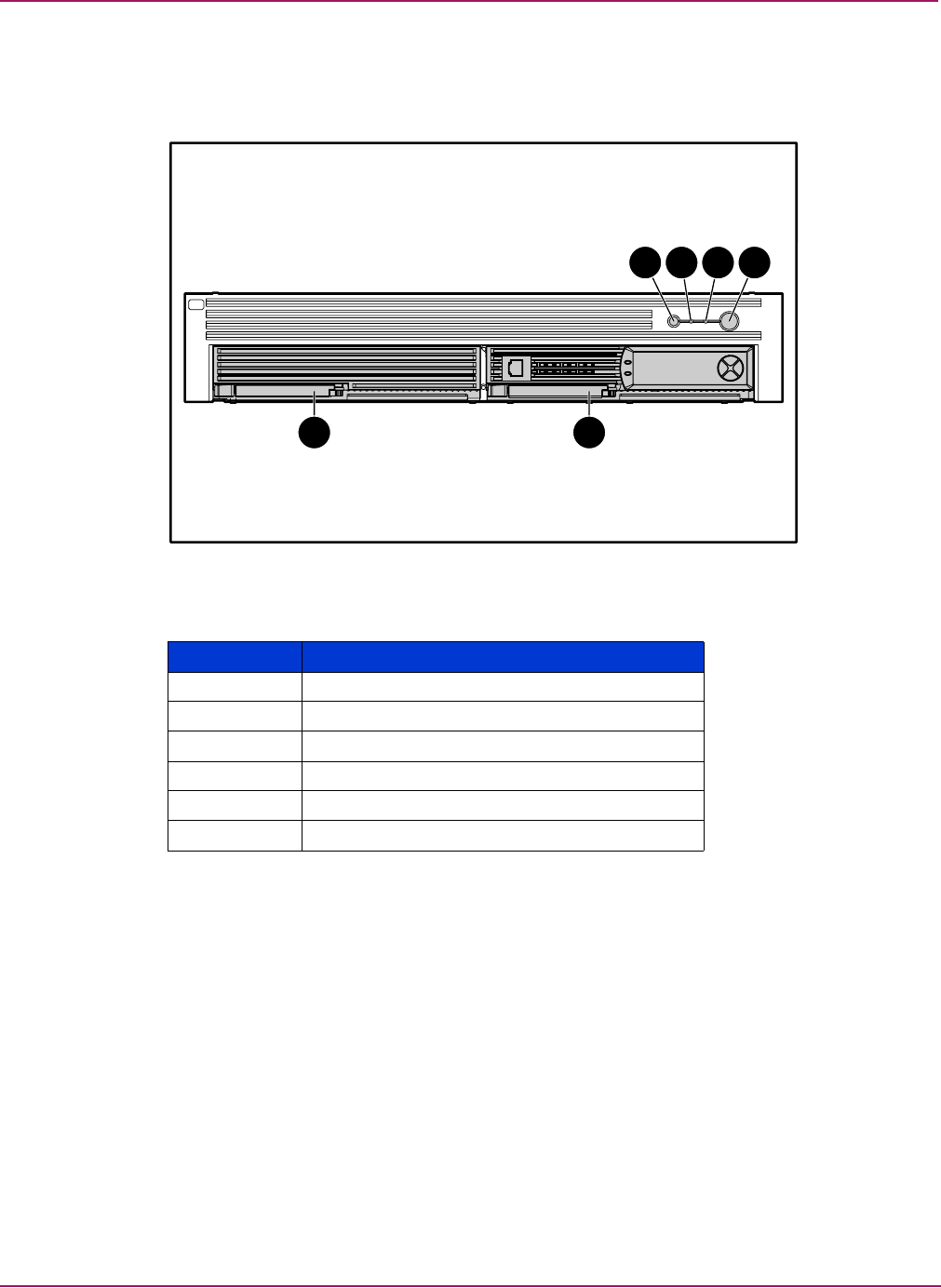
Connectors and Indicators
78 Modular Smart Array 1500 cs Maintenance and Service Guide
Front view
The front view is displayed in Figure 33.
Figure 33: Front view
Table 12: MSA1500 cs Front View
Item Description
1Unit ID button (blue)
2System fault indicator (amber)
3Heartbeat LED (blinking green)
4Power button (green or amber)
5MSA1000 Controller
6Controller blank
1
5 6
2 3 4
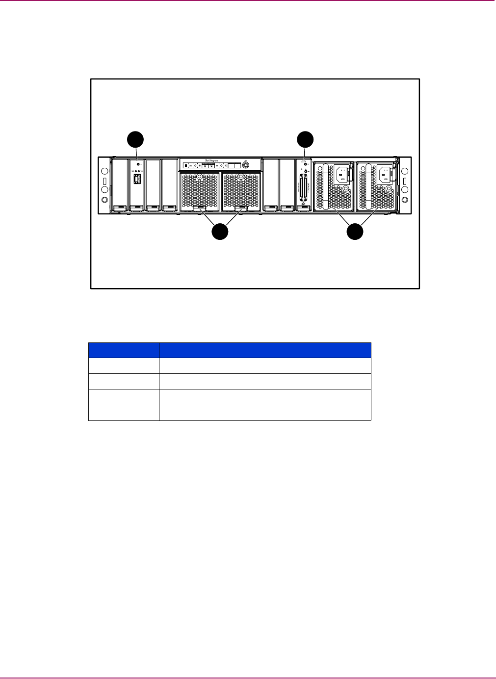
Connectors and Indicators
79Modular Smart Array 1500 cs Maintenance and Service Guide
Rear view
The features and accessible components on the rear panel of the standard configuration are
shown in Figure 34.
Figure 34: Rear view
Table 13: MSA1500 cs Rear View
Item Description
1Fibre Channel I/O module
2SCSI I/O module
3Fan modules
4Power supplies
1 2
3 4
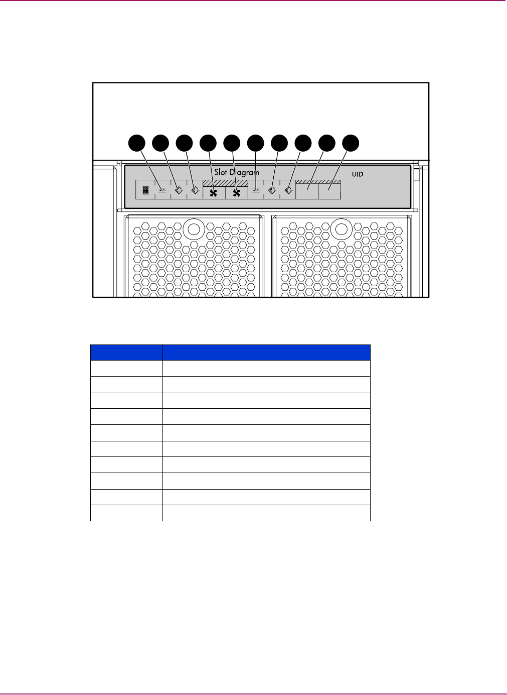
Connectors and Indicators
80 Modular Smart Array 1500 cs Maintenance and Service Guide
Slot diagram label
A slot diagram label is located on the rear of the MSA1500 cs. The label denotes the proper
component for each slot. The label is shown in Figure 35.
Figure 35: Slot diagram label
Table 14: Slot Diagram Label
Item Description
1Fibre Channel I/O module
2SCSI I/O module (bus 3)
3SCSI I/O module (bus 2)
4Fan module
5Fan module
6Fibre Channel I/O module
7SCSI I/O module (bus 1)
8SCSI I/O module (bus 0)
9Power supply
-Power supply
1 3 4 5 6 7 8 9 10
1
PS 1PS 2
0
52
1
12
63
2
74
5
8
2
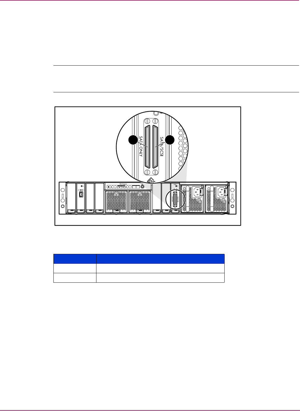
Connectors and Indicators
81Modular Smart Array 1500 cs Maintenance and Service Guide
Connectors
SCSI I/O module connectors
The connectors located on the rear of the SCSI I/O module are shown in figure Figure 36.
Note: Two SATA storage enclosures can be connected to a single SCSI I/O module. Only one SCSI
storage enclosure can be connected to SCSI I/O module. When connecting a SCSI storage
enclosure, use SCSI port B.
Figure 36: SCSI I/O module connectors
Table 15: SCSI I/O Module Connectors
Item Description
1SCSI Port B
2SCSI Port A
1 2
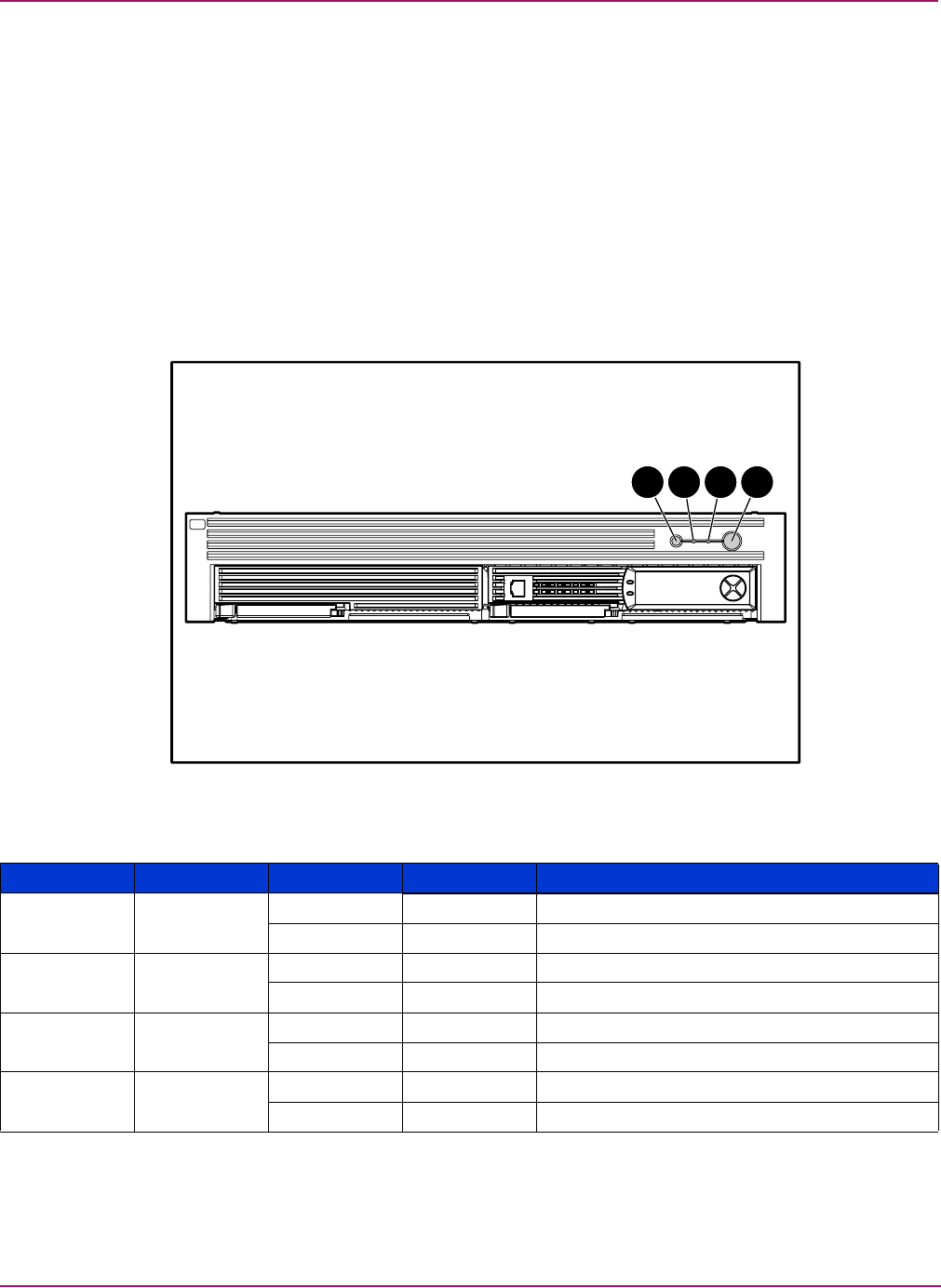
Connectors and Indicators
82 Modular Smart Array 1500 cs Maintenance and Service Guide
Indicators
The MSA1500 cs is equipped with a series of indicators. The following sections list the
indicators.
Interpreting component indicators
If the fault indicator on any of the MSA1500 cs components is amber, determine the reason for
this alert by examining the component indicators to see if any indicates a fault.
Enclosure status indicators
The Enclosure Status indicators are found on the MSA1500 cs, as show in Figure 37.
Figure 37: Enclosure status indicators
1 2 3 4
Table 16: Enclosure Status Indicators
Number Indicator Condition Color Meaning
1UID On Blue Unit being identified
Off Normal
2System fault On Amber Fan module cannot access controllers
Off Normal
3Heartbeat Flashing Green Normal/Fan modules are accessing controllers
Off Power off or fault
4Power On Green Power on
Off Amber Power off
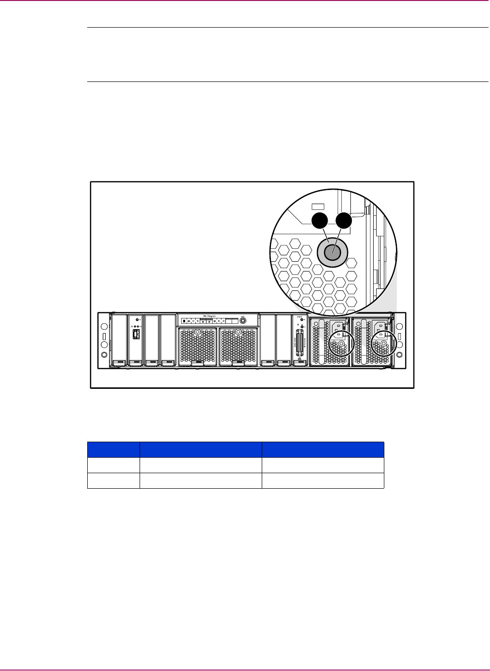
Connectors and Indicators
83Modular Smart Array 1500 cs Maintenance and Service Guide
Note: The system power in the MSA1500 cs does not shut off completely with the power switch.
STANDBY removes power from most of the electronics and the drives, but portions of the power
supply and some internal circuitry remain active. To remove the power completely, disconnect all
power cords from the equipment.
Power supply
The power supply uses a single bi-color LED to indicate status. This LED can be illuminated
with either a green or amber color. The green indicator on the power supply assembly is on
when the power supply is operational. When the power supply experiences a fault, the power
supply indicator turns amber. If the power supply indicator is off, AC power is not present.
Figure 38: Power supply indicators
Table 17: Power Supply Indicators
Number Condition Meaning
1Solid green/off Power on/power off
2Flashing amber Fault
21
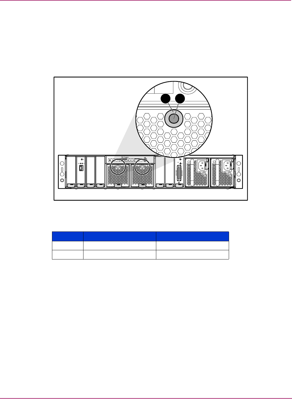
Connectors and Indicators
84 Modular Smart Array 1500 cs Maintenance and Service Guide
Fan module
The fan modules cool the enclosure by circulating air through the enclosure and elements. The
rate at which air moves (the air flow) determines the amount of cooling.
The fan module uses a single bi-color LED to indicate status. This LED can be illuminated
with either a green or amber color. The green indicator on the fan module assembly is on when
the fan module is operational. When the fan module experiences a fault, the fan module
indicator turns amber.
Figure 39: Fan module indicators
Table 18: Fan Module Indicators
Number Condition Meaning
1Solid green Power on
2Flashing amber Fault
1 2
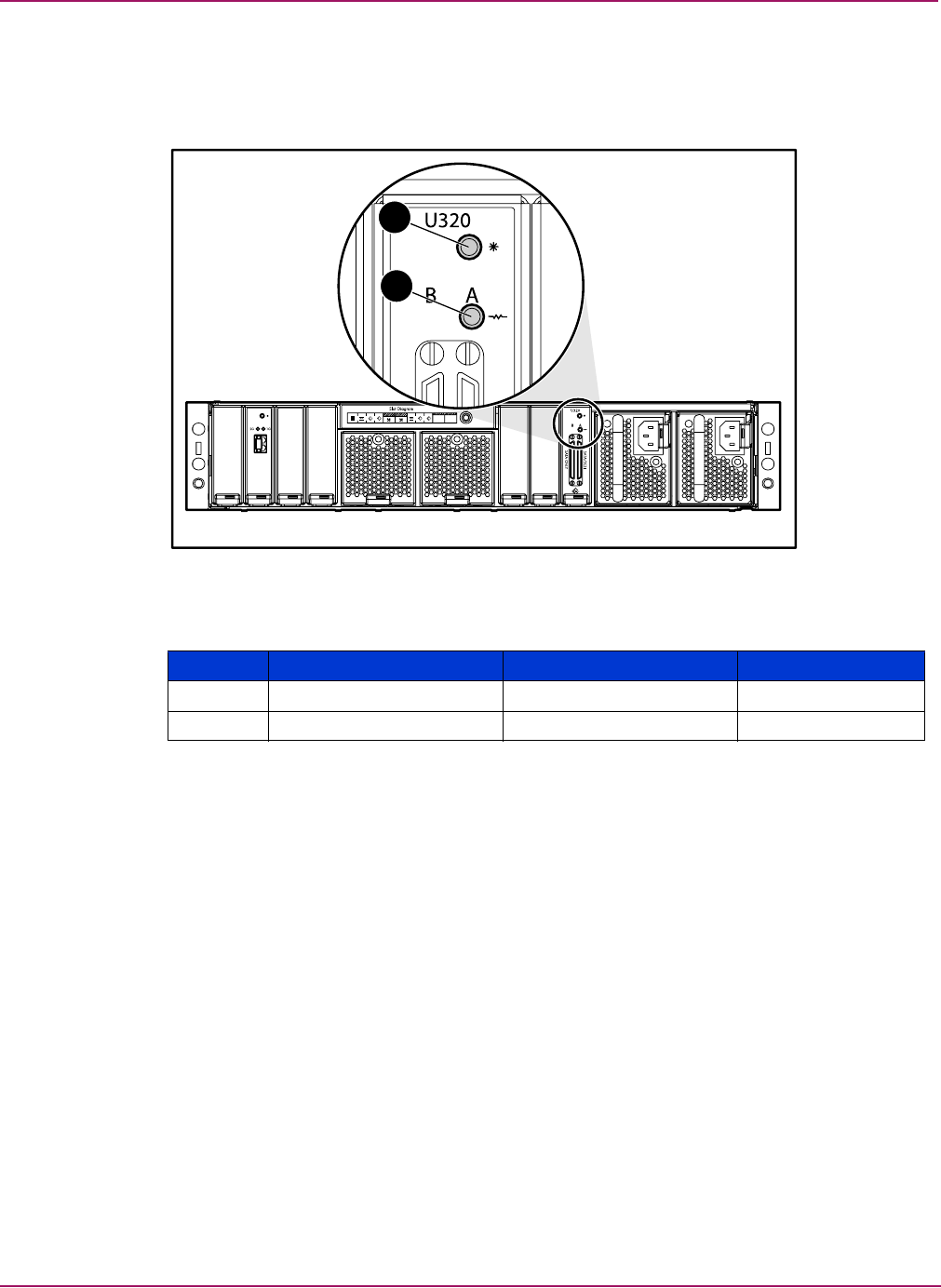
Connectors and Indicators
85Modular Smart Array 1500 cs Maintenance and Service Guide
SCSI I/O module
The SCSI I/O module has two indicators. Figure 40 and Table 19 describe the locations and
meanings of the indicators.
Figure 40: SCSI I/Omodule indicators
1
2
Table 19: SCSI I/O Module Indicators
Number Indicator Condition Meaning
1Status Solid green Power on
2SCSI port A Flashing green Activity
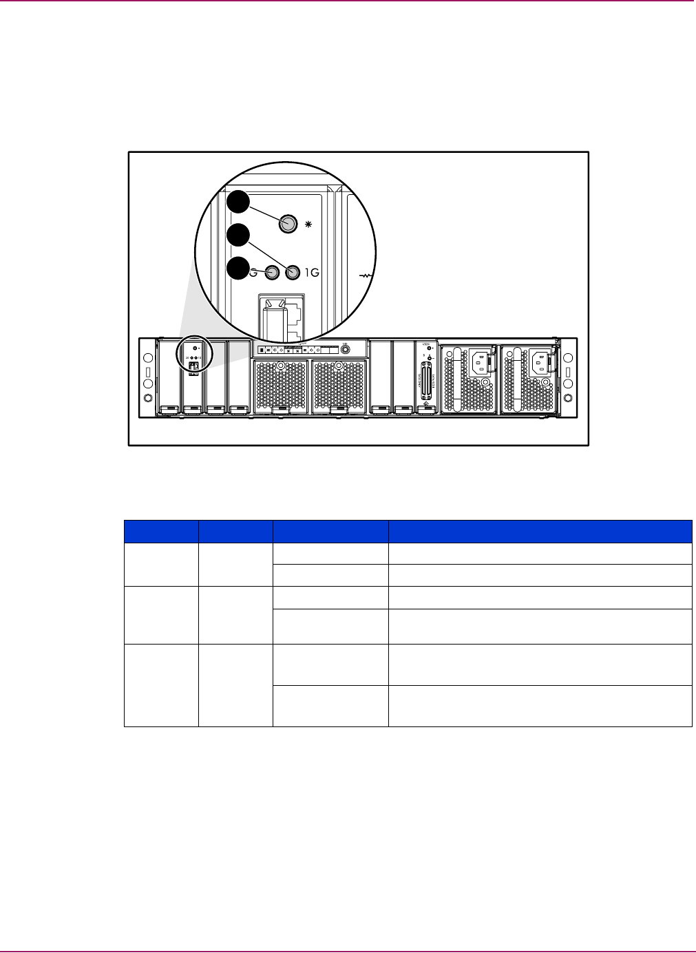
Connectors and Indicators
86 Modular Smart Array 1500 cs Maintenance and Service Guide
Fibre Channel I/O module
The Fibre Channel I/O module three bi-color LEDs to indicate status. These LEDs can be
illuminated with either a green or amber color. Figure 41 and Table 20 describe the locations
and meanings of the indicators.
Two flashing amber lights indicate that the controller is not present.
Figure 41: Fibre Channel I/O module indicators
Table 20: Fibre Channel I/O Module Indicators
1
2
3
Number Indicator Condition Meaning
1Status Solid green Power on
Flashing amber A link to the controller is no longer present.
21-Gb Solid green Port has auto negotiated to a good 1-Gb link.
Flashing amber Transceiver is either not plugged in or a link is no
longer present.
32-Gb Solid green Port has auto negotiated to a good 2-Gb link.
Flashing amber Transceiver is either not plugged in or a link is no
longer present.
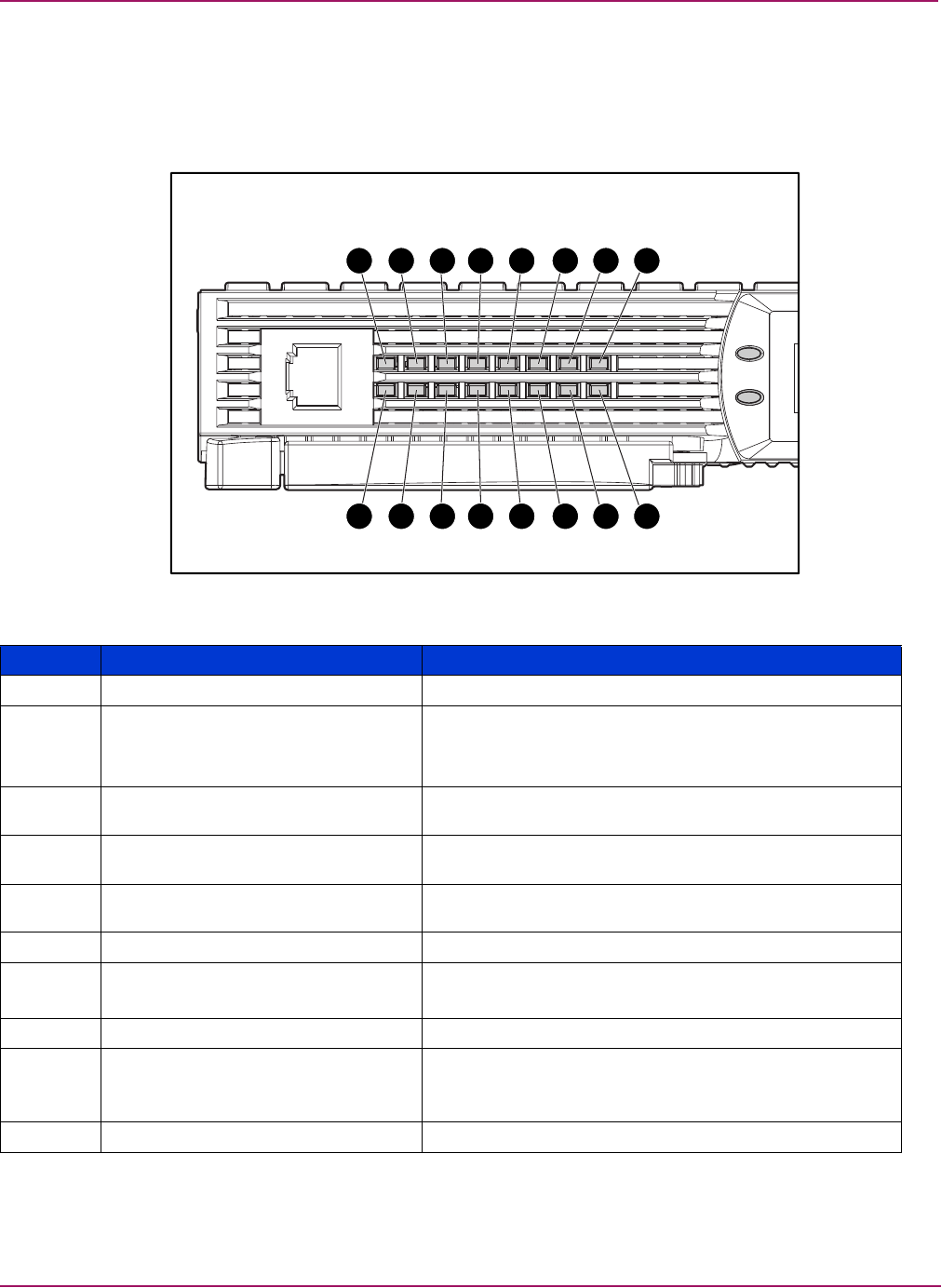
Connectors and Indicators
87Modular Smart Array 1500 cs Maintenance and Service Guide
MSA1000 Controller indicators
During normal runtime, the MSA1000 Controller has 16 indicators that indicate activity or
malfunction of the controller. They are labeled 1-16. Figure 42 and Table 21 describe the
purpose and function of each indicator.
Figure 42: MSA1000 Controller indicators
7 8654321
10 9111213141516
Table 21: MSA1000 Controller Indicator Descriptions
Indicator Function Description
1Drive failure ON = A configured hard drive has failed in the array
2Cache Activity ON = Cache active
OFF = No cache activity
Blinking = Cache transfer pending
3SCSI Bus 1 active ON = Indicates requests are outstanding on the second
SCSI bus
4SCSI Bus 0 active ON = Indicates requests are outstanding on the first SCSI
bus
5Logical I/O active ON = Currently processing logical requests from the Host
Adapter
6Direct Memory Access (DMA) active ON = DMA transfers are active
7Active/Standby ON=Controller is active
OFF=Controller is in standby
8Idle Heartbeat Indicates the Array Controller is idle and functioning
9-qBusy status ON = Indicates this Array Controller is idle
OFF = Indicates this Array Controller is operating at full
capacity
w-yFibre Channel IDs


89Modular Smart Array 1500 cs Maintenance and Service Guide
A
Regulatory Compliance Notices
Regulatory Compliance identification numbers
For the purpose of regulatory compliance certifications and identification, your
HP StorageWorks MSA1000 is assigned an HP Series number. The Storage System Series
number can be found on the product label, along with the required approval markings and
information. The product label is located on the right side of the chassis. When requesting
certification information for this product, always refer to this Series number. This Series
number should not be confused with the marketing name or model number for your Storage
System.
Federal Communications Commission notice
This equipment has been tested and found to comply with the limits for a Class A digital
device, pursuant to Part 15 of the FCC Rules. These limits are designed to provide reasonable
protection against harmful interference when the equipment is operated in a commercial
environment. This equipment generates, uses, and can radiate radio frequency energy and, if
not installed and used in accordance with the instructions, may cause harmful interference to
radio communications. Operation of this equipment in a residential area is likely to cause
harmful interference, in which case the user will be required to correct the interference at
personal expense.
Modifications
The FCC requires the user to be notified that any changes or modifications made to this device
that are not expressly approved by Hewlett-Packard Company may void the user's authority to
operate the equipment.
Cables
Connections to this device must be made with shielded cables with metallic RFI/EMI
connector hoods in order to comply with FCC Rules and Regulations.
Canadian notice (Avis Canadien)
This Class A digital apparatus meets all requirements of the Canadian
Interference-Causing Equipment Regulations.
Cet appareil numérique de la classe A respecte toutes les exigences du Règlement sur le
matériel brouilleur du Canada.
Regulatory Compliance Notices
90 Modular Smart Array 1500 cs Maintenance and Service Guide
European Union notice
Products with the CE Marking comply with both the EMC Directive (89/336/EEC) and the
Low Voltage Directive (73/23/EEC) issued by the Commission of the European Community.
Compliance with these directives implies conformity to the following European Norms (in
brackets are the equivalent international standards):
■EN55022 (CISPR 22) - Electromagnetic Interference
■EN50082-1 (IEC801-2, IEC801-3, IEC801-4) - Electromagnetic Immunity
■EN60950 (IEC950) - Product Safety
Japanese notice
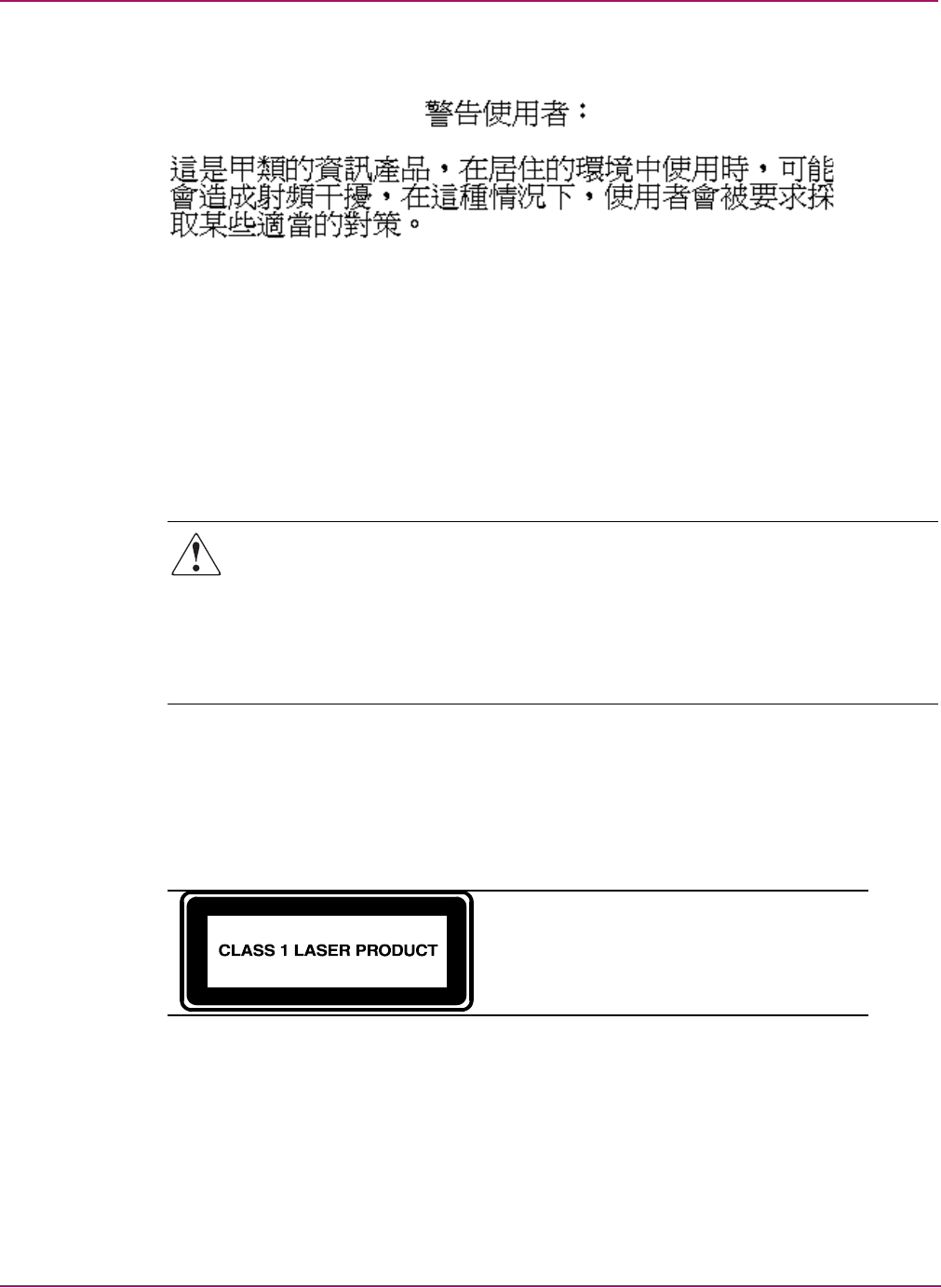
Regulatory Compliance Notices
91Modular Smart Array 1500 cs Maintenance and Service Guide
BSMI notice
Laser compliance
The SFP Module contains a laser diode of either gallium aluminum arsenide (GaALAs)
emitting in the wavelength range of 770-860 nm, or indium gallium arsenide phosphide
(InGaAsP) emitting in the wavelength range of 1270-1355 nm. All HP systems equipped with
a laser device comply with safety standards, including International Electrotechnical
Commission (IEC) 825. With specific regard to the laser, the equipment complies with laser
product performance standards set by government agencies as a Class 1 laser product. The
product does not emit hazardous laser radiation.
WARNING: Use of controls or adjustments or performance of procedures other than those
specified herein or in the laser product’s installation guide may result in hazardous
radiation exposure. To reduce the risk of exposure to hazardous radiation:
■Do not try to open the unit enclosure. There are no user-serviceable components inside.
■Do not operate controls, make adjustments, or perform procedures to the laser device
other than those specified herein.
■Allow only HP Authorized Service technicians to repair the unit.
The Center for Devices and Radiological Health (CDRH) of the U.S. Food and Drug
Administration implemented regulations for laser products on August 2, 1976. These
regulations apply to laser products manufactured from August 1, 1976. Compliance is
mandatory for products marketed in the United States. This device is classified as a Class 1
laser product as defined by IEC 825.
This indicates that the product is classified as a
CLASS 1 LASER PRODUCT.
Regulatory Compliance Notices
92 Modular Smart Array 1500 cs Maintenance and Service Guide
Battery replacement notice
Your MSA1000 is provided with Nickel Metal Hydride batteries. There is a danger of
explosion and risk of personal injury if the array is incorrectly replaced or mistreated. Replace
only with the HP spare designated for this product. For more information about battery
replacement or proper disposal, contact your HP Authorized Reseller or your Authorized
Service Provider.
WARNING: Your Accelerator Array contains Nickel Metal Hydride batteries. There is risk
of fire and burns if the battery pack is not handled properly. To reduce the risk of personal
injury:
■Do not attempt to recharge the battery.
■Do not expose to temperatures higher than 60o C.
■Do not disassemble, crush, puncture, short external contacts, or dispose of in fire or
water.
■Replace only with HP spare designated for this product.
Caution: Batteries, battery packs, and accumulators should not be disposed of together
with the general household waste. In order to forward them to recycling or proper disposal,
please use the public collection system or return them to HP, your authorized HP Partners, or
their agents.

93Modular Smart Array 1500 cs Maintenance and Service Guide
B
Electrostatic Discharge
To prevent damage to the system, be aware of the precautions you need to follow when setting
up the system or handling parts. A discharge of static electricity from a finger or other
conductor may damage system boards or other static-sensitive devices. This type of damage
may reduce the life expectancy of the device.
To prevent electrostatic damage, observe the following precautions:
■Avoid hand contact by transporting and storing products in static-safe containers.
■Keep electrostatic-sensitive parts in their containers until they arrive at static-free
workstations.
■Place parts on a grounded surface before removing them from their containers.
■Avoid touching pins, leads, or circuitry.
■Always make sure you are properly grounded when touching a static-sensitive component
or assembly.

Electrostatic Discharge
94 Modular Smart Array 1500 cs Maintenance and Service Guide
Grounding methods
There are several methods for grounding. Use one or more of the following methods when
handling or installing electrostatic-sensitive parts:
■Use a wrist strap connected by a ground cord to a grounded workstation or computer
chassis. Wrist straps are flexible straps with a minimum of 1 megohm ± 10 percent
resistance in the ground cords. To provide proper ground, wear the strap snug against the
skin.
■Use heel straps, toe straps, or boot straps at standing workstations. Wear the straps on both
feet when standing on conductive floors or dissipating floor mats.
■Use conductive field service tools.
■Use a portable field service kit with a folding static-dissipating work mat.
If you do not have any of the suggested equipment for proper grounding, have an Authorized
HP Reseller install the part.
Note: For more information on static electricity, or assistance with product installation, contact your
HP Authorized Reseller.

95Modular Smart Array 1500 cs Maintenance and Service Guide
C
Specifications
This chapter provides operating and performance specifications for the HP StorageWorks
MSA1500 cs. The sections in this chapter are:
■MSA1500 cs chassis
■Memory
■Power supply
■SCSI I/O module
■Fibre Channel I/O module
■Fan module
Note: For information on all supported components and their part numbers, see Chapter 1,
“Illustrated Parts Catalog.”
Specifications
96 Modular Smart Array 1500 cs Maintenance and Service Guide
MSA1500 cs chassis
Power supply
Table 22: System Unit Specifications
Item Description
Height 8.79 cm (3.46 in)
Width 48.41 cm (19.06 in)
Depth 61.77 cm (24.32 in)
Weight 24.95 kg (55lbs)
Input power requirements
Rated input voltage 100 - 240 VAC
Rated input frequency 47 – 63 Hz
Rated input current 6.4A Max, 1A typical
Input Power (max) 400W Max, 95W typical
Temperature range
Operating 10× to 35× C (derated 1×C per 1000
feet of elevation to 10000 ft.); (50× to
95× F)
Shipping -30× to 50× C (-22× to 122× F)
Relative humidity (noncondensing)
Operating 10% to 90%
Non-operating up to 95%
Maximum wet-bulb temperature
Long term storage 29×C (84.2×F)
Short term storage 30×C (86×F)
*Input Power and Heat Dissipation specifications are maximum values and apply to
worst-case conditions at full rated power supply load. The power/heat dissipation
for your installation will vary depending on the equipment configuration.
Table 23: MSA1500 cs System Unit Power Supply Specifications
Item Description
Height 7.7 cm (3.0 in)
Width 6.4 cm (2.5 in)
Depth 32.0 cm (12.6 in)
Weight 1.80 kg (3.96 lbs)
Specifications
97Modular Smart Array 1500 cs Maintenance and Service Guide
SCSI I/O module
Fibre Channel I/O module
Fan module
Table 24: SCSI I/O Module Specifications
Item Description
Height 8.13 cm (3.2 in)
Width 2.34 cm (0.92 in)
Depth 37.14 cm (14.62 in)
Weight 0.46 kg (1.01lbs)
Table 25: Fibre Channel I/O Module Specifications
Item Description
Height 8.13 cm (3.2 in)
Width 2.34 cm (0.92 in)
Depth 37.14 cm (14.62 in)
Weight 0.44 kg (.96lbs)
Table 26: Fan Module Specifications
Item Description
Height 6.0 cm ( in)
Width 6.0 cm ( in)
Depth 26.8 cm (10.6 in)
Weight 0.50 kg (1.10 lbs)


99Modular Smart Array 1500 cs Maintenance and Service Guide
Index
Index
Index
A
AC
circuit overload, warning 23
power cord part number 17
array
accelerator batteries, installing 32
audience 9
authorized reseller, HP 13
B
batteries
replacement notice 92
replacing 32
warnings 32
C
cables
1-Gb to 2-Gb connection, part number 17
2-Gb to 2-Gb connection, part number 17
customizing 50
distances supported 50
multi-mode 50
option kits 50
part numbers 50
VHDCI, part number 17
cache
module, part number 17
component level repairs, warning 23
connectors
SCSI I/O module 81
controller
blank, part number 17
ejector levers 27
failure 27
latches 27, 28
part number 17
removing 27
replacing 27
securing 28
Controller display
box numbering 54
components 53
deleting messages 55
error messages 54
informational messages 54
message types 54
redundancy link light 55
user input messages 54
Controller display messages
access control conflict detected 69
access control resources exceeded 69
array Controller disabled 70
array Controller overheated 70
array Controller overheating 69
array Controller restarting 70
array Controller temperature ok 69
bad drive firmware box, bay 65
bad SCSI bus mode non-lvd device found 57
begin redundancy support 57
cache batteries low recharging 63
cache data lost battery dead 62
cache disabled no configuration 63
cache error 64
cache hardware batteries missing 65
cache hardware enabled 62
cache hardware temporarily disabled 62
cache module size 61
chassis nvram contents corrupted 57
configured volumes 68
critical lockup detected 56
drive failure box, bay 65
drive position change detected 66
drive position change invalid 66
dual cache module size mismatch 61
enable volume 56
enable volumes 56
firmware flash done 71
firmware flash done on SATA storage enclosure 72
firmware flash failed 72

Index
100 Modular Smart Array 1500 cs Maintenance and Service Guide
firmware flash failed on SATA enclosure 72
firmware flash started 71
firmware flash started on SATA enclosure 72
firmware version 56
initializing fibre subsystem 74
initializing PCI subsystem 74
initializing SCSI devices 57
initializing SCSI subsystem 56
new volume(s) detected 68
no cache module found 61
no volumes detected 68
obsolete cache data deleted 62
PCI bridge ASIC self-test failure 74
PCI subsystem hardware failure 74
read failure 57
recovery ROM autoflash done 70
recovery ROM autoflash failed 70
recovery ROM autoflash started 70
redundancy active active Controller 58
redundancy active standby Controller 58
redundancy failed cache DIMMS mismatch 61
redundancy failed cache size mismatch 59
redundancy failed firmware lockup 60
redundancy failed hardware failure 58
redundancy failed I/O request error 60
redundancy failed mismatch firmware 59
redundancy failed mismatch hardware 58
redundancy failed no second Controller 61
redundancy failed out of memory 60
redundancy failed PCI bus error 61
redundancy halted firmware cloned 59
replacement drive found box 65
restarting system 56
ROM cloning done 71
ROM cloning failed 71
ROM cloning started 71
scanning for SCSI devices 56
SCSI subsystem hardware failure 57
smart drive alert box 65
startup complete 56
storage box 72
storage box EMU not responding 74
storage box fan failed 72
storage box fan hot inserted 72
storage box fan hot removed 72
storage box overheated 73
storage box overheating 73
storage box power supply added 73
storage box power supply failed 73
storage box power supply ok 73
storage box power supply removed 74
storage box temperature ok 73
storage fan degraded 72
system halted for cache error 63
system name 56
too many volumes detected 69
uncorrected ECC memory error seen 74
valid cache data found at power-up 62
volume expansion disabled 67
volume expansion failure 68
volume initializing parity 68
volume rebuild failure 68
volume state deleted 68
volume state disabled 66
volume state expansion active 67
volume state failed 66
volume state ok 66
volume state rebuilding 66
volume state waiting to expand 67
volume state waiting to rebuild 67
volume state wrong drive replaced 67
volumestate interim recovery 66
volumestate missing drives 67
write failure 57
conventions
document 10
equipment symbols 11
text symbols 10
D
device preparation
rack warnings 22
removing power 21
device, unloading from pallet 22
document
conventions 10
prerequisites 9
related documentation 9
E
electric shock hazard, warning 23
electrostatic discharge 93
equipment damage, warning 23
equipment symbols 11
F
fan module
indicators 84
FCC notice 89
fibre channel I/O module
indicators 86
G
getting help 12
grounding methods 94

Index
101Modular Smart Array 1500 cs Maintenance and Service Guide
H
help, obtaining 12
hot-pluggable parts, MSA1500 cs 20
HP
authorized reseller 13
storage web site 12
technical support 12
I
illustrated parts breakdown 15
illustrated parts breakdown, MSA1500 cs 15
indicators
component 82
controller 87
enclosure status 82
fan module 84
fibre channel I/O module 86
power supplies/blower assemblies 83
SCSI I/O module 85
installing
batteries 32
L
loading rack, warning 22
M
MSA1000 Controller
cache module, part number 17
ejector levers 29
indicators 52, 87
latches 29
MSA1500 cs
AC power cord, part number 17
boot order 25
cables, 1-Gb to 2-Gb connection, part number 17
cables, 2-Gb to 2-Gb connection, part number 17
cables, VHDCI, part number 17
controller blank, part number 17
controller, part number 17
illustrated parts breakdown and spare parts list 15
power switch assembly, part number 17
SFP transceiver board, part number 17
VHDCI cables, part number 17
N
non-hot-pluggable
devices, removing 21
non-hot-pluggable parts, MSA1500 cs 20
P
panels
front 25
part numbers
AC power cord 17
cables, 1-Gb to 2-Gb connection 17
cables, 2-Gb to 2-Gb connection 17
cables, VHDCI 17
cache module 17
controller 17
controller blank 17
power switch assembly 17
SFP transceiver board 17
VHDCI cables 17
parts
hot-pluggable, MSA1500 cs 20
non-hot-pluggable, MSA1500 cs 20
personal injury, warning 19
power
applying 25
connecting 24
standby 20
switch 25
switch, position 20
system 20
power cords 24
disconnecting 20
MSA1500 cs 24
power supply
indicators 83
removing power from 20
power switch
assembly, part number 17
preparation procedures 20
rack warnings 22
prerequisites 9
Q
qualified service personnel, warning 19
R
rack stability, warning 12, 22
rack warnings 22
recovery ROM 76
regulatory compliance identification numbers 89
regulatory compliance notices 89
related documentation 9
removing from rack, warning 22
replacing
batteries 32
S
SCSI I/O module
indicators 85
SFP
transceiver board, part number 17
spare parts list 15

Index
102 Modular Smart Array 1500 cs Maintenance and Service Guide
specifications, overview 95
switch
power 20
switches
power 25
symbols in text 10
symbols on equipment 11
system unit specifications
maximum wet-bulb temperature 96
server temperature 96
T
technical support, HP 12
text symbols 10
tools
required for servicing 19
V
VHDCI cables, part number 17
views, front and rear 77
W
warning
rack stability 12
symbols on equipment 11
warnings
AC circuit overload 23
component level repairs 23
electric shock hazard 23
equipment damage 23
loading rack 22
personal injury 19
qualified service personnel 20
rack stability 22
removing device from rack 22
web sites
HP storage 12
