+P4VP MX Front Matter +c1538_P4VP C1538 P4VP
User Manual: +c1538_P4VP-MX
Open the PDF directly: View PDF ![]() .
.
Page Count: 62

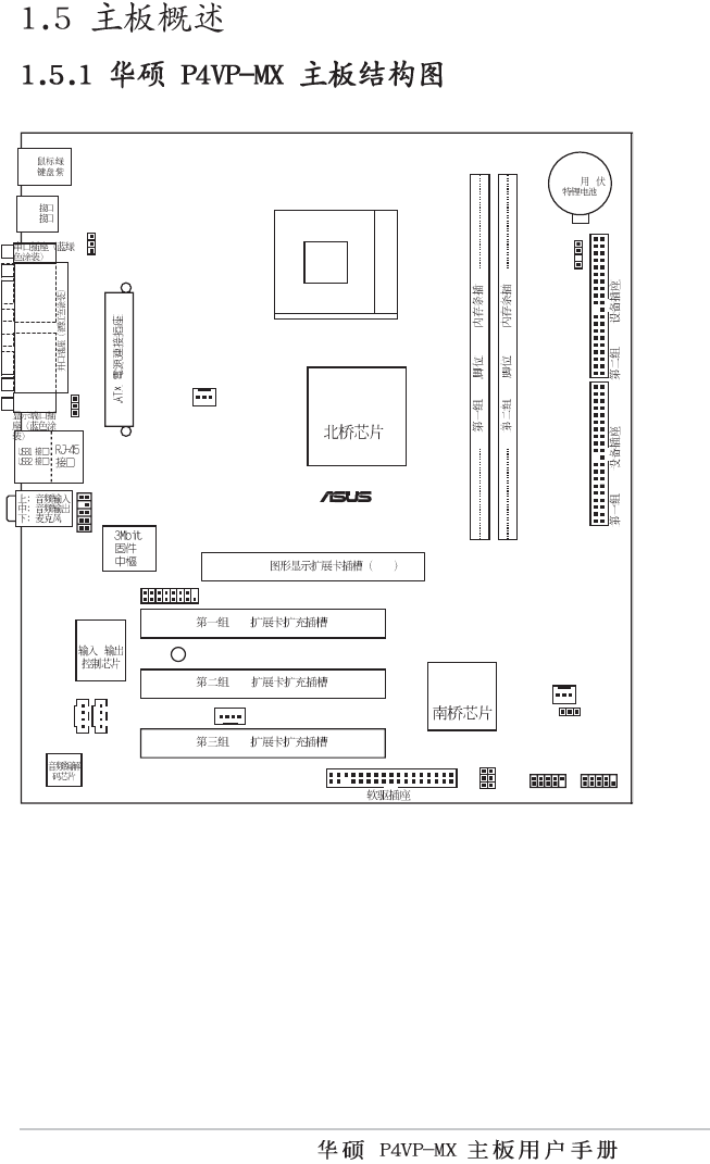
Motherboard
®
P4VP-MX
ii
C1538
© 2004
iii
iv

v
•
•
•
•
•
•
•
•
•
•
•
•
vi
•
•
•

vii
™
Jumper Fre
e
(Default)
23
Jumper Mode
12
viii
ix
® ®
®
®
®
x

1-1
1-2
1-3
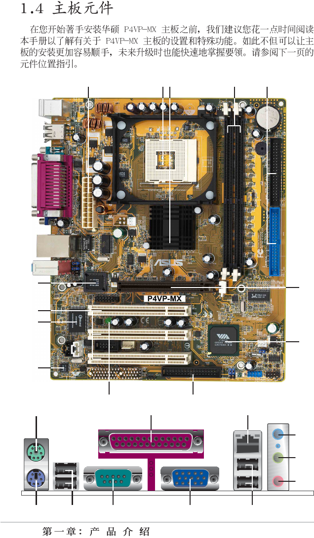
1-4
23 4
13
12
11
1
8
7
10
6
5
9
14 15
24 23 20
1
7
1
8
1
9
16
2122
1-5
1-6
1-7
0 1 2 3
CD1
CPU_FAN1
AUX1
USB56
P4VP-MX
®
AUDIO1
CHA_FAN1
Socket 478
LED1
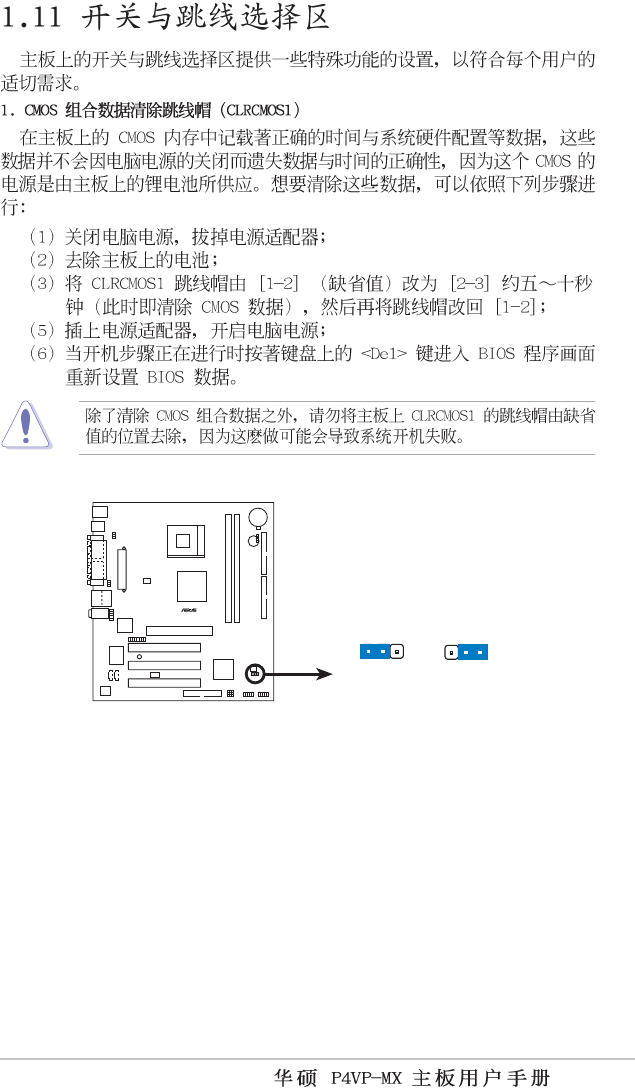
CLRCMOS1
PANEL1
VGA
GAME1
USBPWR56
PLED1
USBPWR12
USBPWR34
SPEAKER1
MODEM1
PS/2 ( )
PS/2 ( )
PCI
PCI
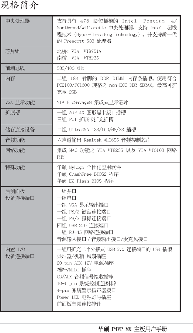
AGP 4X 1.5V
VIA
VT8751A
184 DDR
IDE IDE
VIA
VT8235
PCI
CR2032
CMOS 3
Super I/O
/
184 DDR
USB3
USB4
1-8
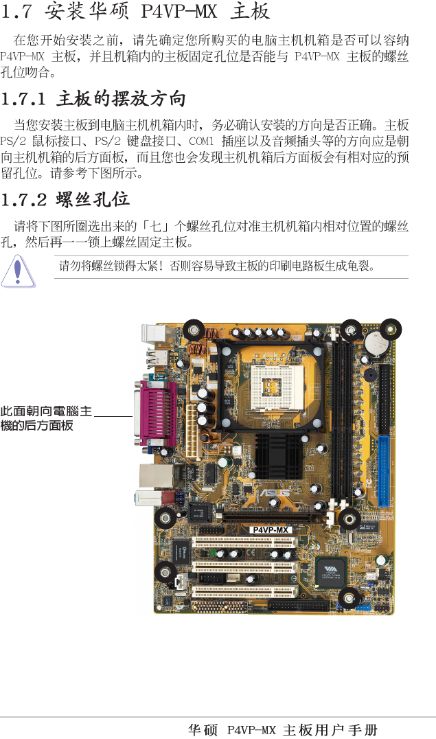
P4VP-MX
®
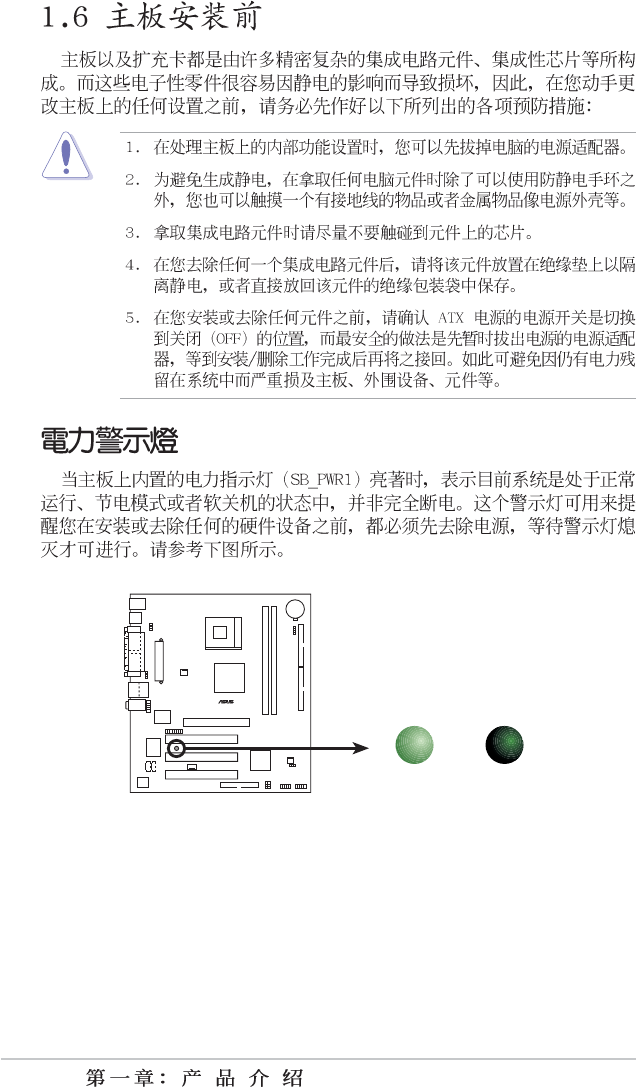
P4VP-MX Onboard LED
ON OFF
Standby
Power Powere
d
Off
LED1
1-9
1-10
P4VP-MX
®
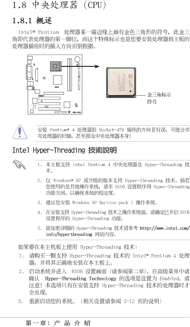
P4VP-MX Socket 478
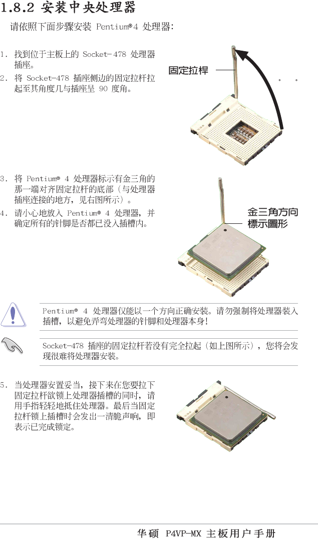
1-11
90 - 10
0
1-12
P4VP-MX
®
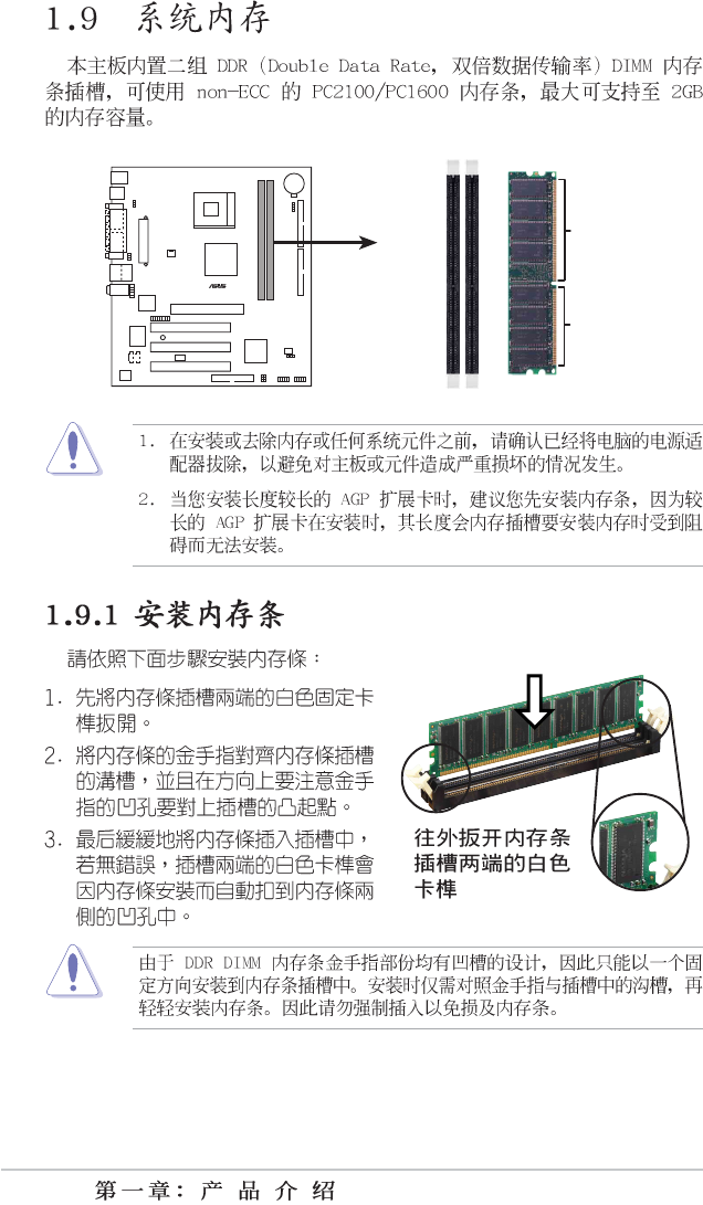
P4VP-MX 184-Pin DDR DIMM Sockets
80 Pins
104 Pin
s
1-13
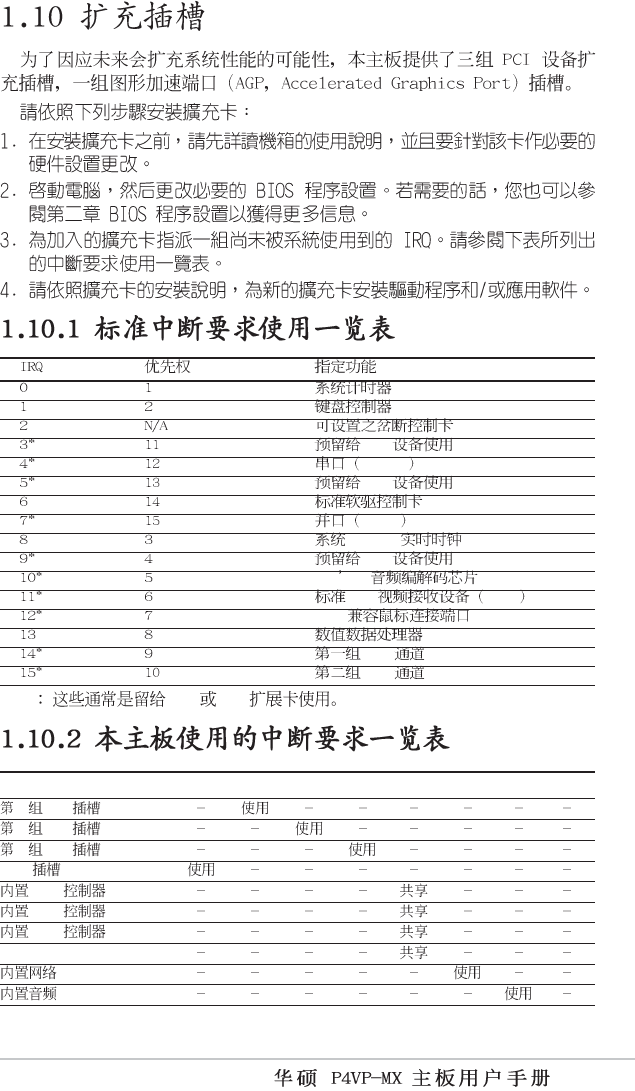
PCI
COM 1
PCI
LPT 1
CMOS/
PCI
AC 97
PCI VGA
PS/2
IDE
IDE
* ISA PCI
ABCDEFGH
1 PCI
2 PCI
3 PCI
AGP
USB HC0
USB HC1
USB HC3
EHCI
1-14
P4VP-MX
®
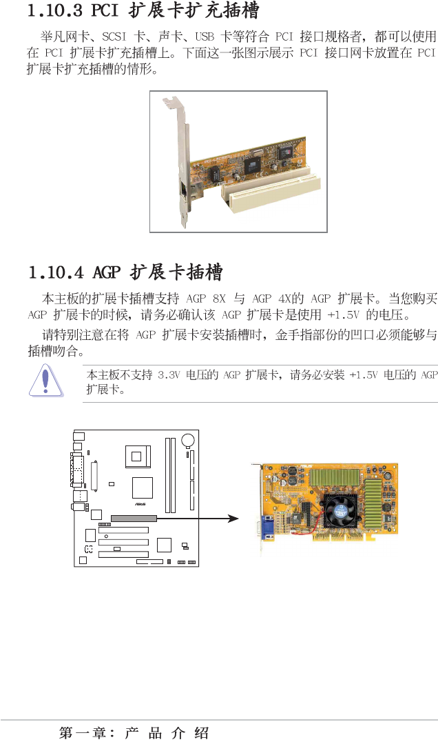
P4VP-MX Accelerated Graphics Port (AGP )
1-15
P4VP-MX
®
P4VP-MX Clear RTC RAM Setting
CLRTC1
Normal Clear CMOS
(Default)
12 23
1-16
P4VP-MX
®
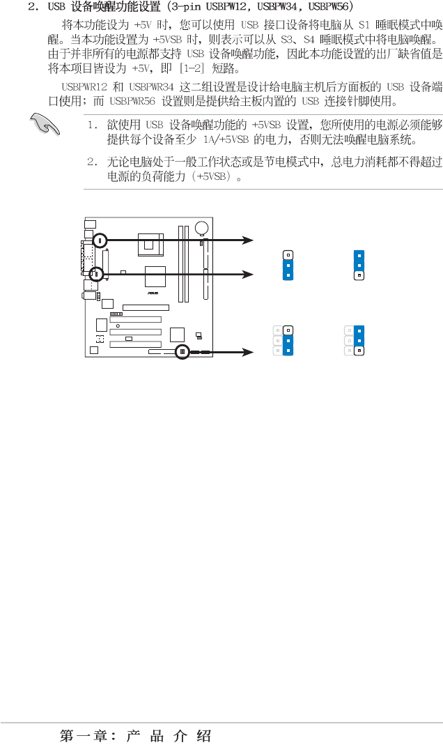
P4VP-MX USB Device Wake Up
USBPWR56
+5VS
B
3
2
1
2
+5V
+5VS
B
3
2
1
2
+5V
USBPWR12
USBPWR34
(Default)
(Default)
1-17
P4VP-MX
®
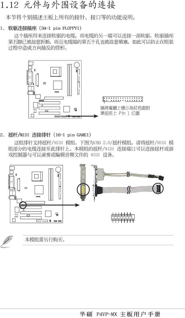
P4VP-MX Floppy Disk Drive Connector
FLOPPY1
P4VP-MX
®
P4VP-MX Smartcard
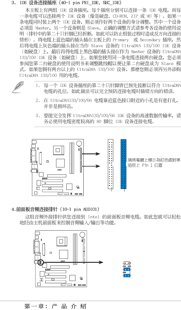
GAME1
+5V +5V
J2B1
J2CX
MIDI_OUT
J2CY
J2B2
MIDI_IN
J1B1
J1CX
GND
GND
J1CY
J1B2
+5V
1-18
P4VP-MX
®
P4VP-MX IDE Connectors
SEC_IDE
PIN 1
PRI_IDE
PIN 1
P4VP-MX
®
P4VP-MX Front Panel Audio Connector
AUDIO1
BLINE_OUT_L
MIC2
Line out_R
Line out_L
BLINE_OUT_R
NC
MICPWR +5VA
AGND
1-19
P4VP-MX
®
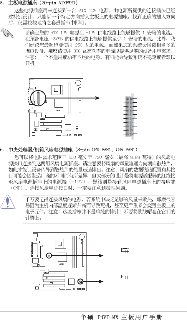
P4VP-MX ATX Power Connector
ATXPWR1
+3.3VDC
-12.0VD
C
COM
PS_ON#
COM
COM
COM
-5.0VDC
+5.0VDC
+5.0VDC
PWR_OK
+12.0VDC
+3.3VDC
+3.3VDC
COM
+5.0VDC
COM
+5.0VDC
COM
+5VSB
P4VP-MX
®
P4VP-MX 12-Volt Cooling Fan Power
CPU_FAN
1
GND
Rotation
+12V
CHA_FAN
1
GND
Rotation
+12V
1-20
P4VP-MX
®
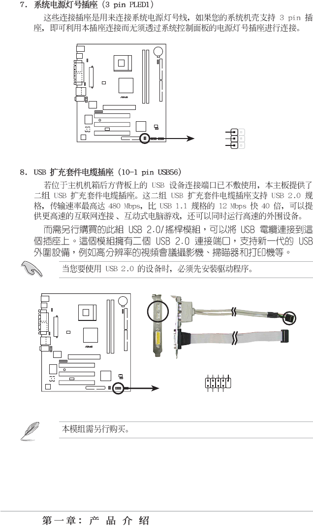
P4VP-MX USB Header
USB56
USB+5V
USB_P4-
USB_P4+
GND
NC
USB+5V
USB_P5-
USB_P5+
GND
1
P4VP-MX
®
P4VP-MX Power LED
PLED1
1
PLED-
NC
PLED+
1-21
P4VP-MX
®
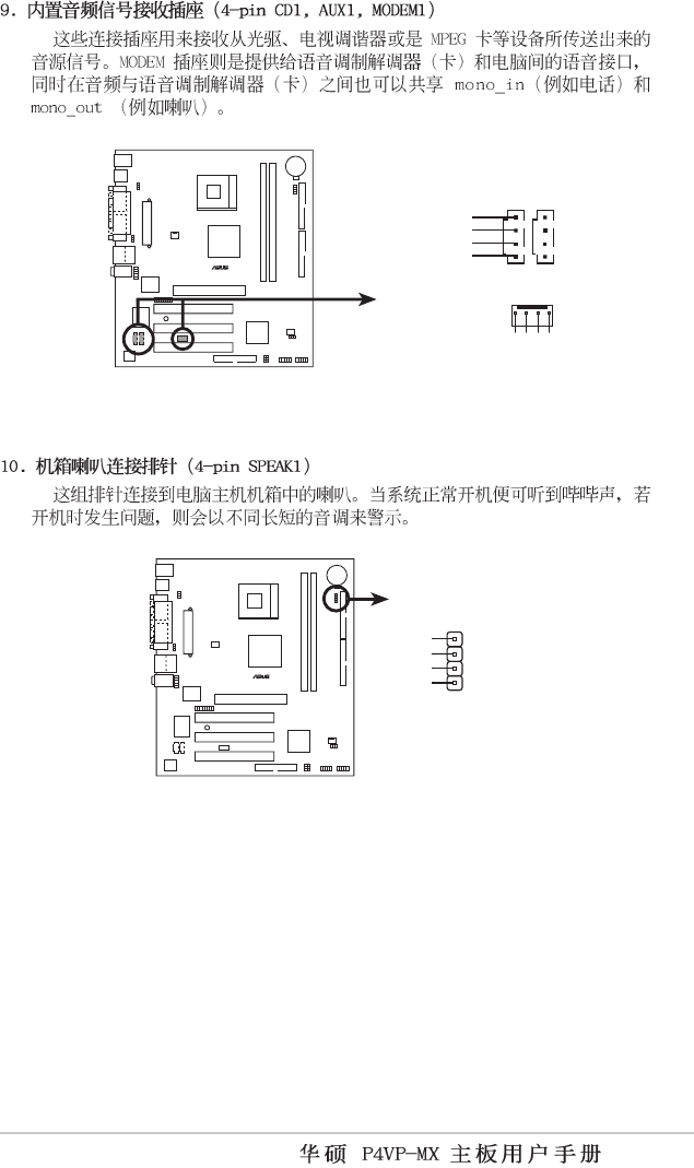
P4VP-MX Internal Audio Connectors
CD1(Black)
Right Audio Channel
Left Audio Channel
Ground
Ground
AUX1(White
)
MODEM1
Modem-In
Ground
Modem-Out
Ground
P4VP-MX
®
P4VP-MX Speaker Out Connector
+5V
1
SPEAKER
1
GND
Speak Out
GND
1-22
P4VP-MX
®
P4VP-MX Front Panel Audio Connector
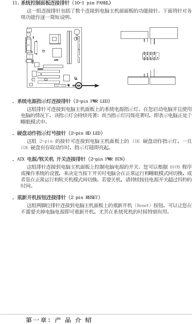
PANEL1
PLED-
PWR
PLED+
Ground
GNDReset
IDE_LED+
IDE_LED-
Power LED
Reset SW
ATX Power
Switch*
IDE_LED
*
Requires an ATX power supply
.

2-1
2-2
2-3
A:\>afudos /iP4VPMX.ROM
AMI Firmware Update Utility - Version 1.10
Copyright (C) 2002 American Megatrends, Inc. All rights reserved.
Reading file ..... done
Erasing flash .... done
Writing flash .... 0x0008CC00 (9%)
A:\>afudos /iP4VPMX.ROM
AMI Firmware Update Utility - Version 1.10
Copyright (C) 2002 American Megatrends, Inc. All rights reserved.
Reading file ..... done
Erasing flash .... done
Writing flash .... 0x0008CC00 (9%)
Verifying flash .. done
A:\>
2-4
[BIOS Information in File]
BIOS Version: P4VP-MX Boot Block
WARNING! Continue to update the BIOS (Y/N)? _
Flash Memory: SST 49LF004
1. Update Main BIOS area (Y/N)? _
ASUS EZ Flash V1.00
Copyrig ht (C) 20 02, AS UST eK C OMP UTER I NC.
[Onboar d B IOS In format ion ]
BIOS Ve rsi on : ASUS P4V P-M X A CPI BI OS Revi sio n 1 001 Be ta
003
BIOS Mo del : P4VP- MX
BIOS Bu ilt Da te : 06/03 /03
Please Ent er Fil e Name fo r NE W B IOS: _
*Note: EZ Fla sh wil l copy fil e f rom A:\, Pre ss [ES C] t o r ebo ot
2-5
Bad BIOS checksum. Starting BIOS recovery...
Checking for floppy...
Bad BIOS checksum. Starting BIOS recovery...
Checking for floppy...
2-6
2-7
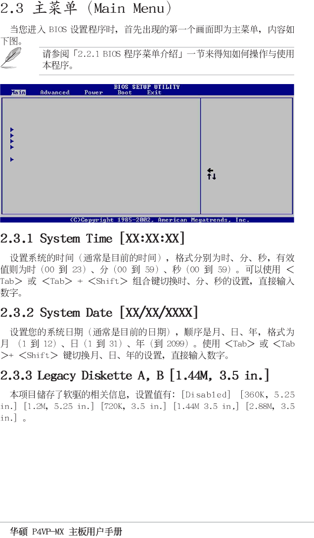
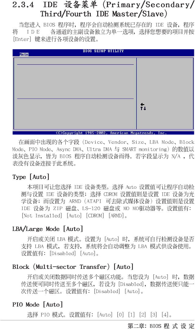
System Time [11:10:19]
System Date [Thu 05/27/2003]
Legacy Diskette A [1.44M, 3.5 in]
Primary IDE Master :[ST320413A]
Primary IDE Slave :[ASUS CD-S340]
Secondary IDE Master :[Not Detected]
Secondary IDE Slave :[Not Detected]
System Information
Use [ENTER], [TAB]
or [SHIFT-TAB] to
select a field.
Use [+] or [-] to
configure system time.
Select Screen
Select Item
+- Change Field
Tab Select Field
F1 General Help
F10 Save and Exit
ESC Exit
2-8
Select Screen
Select Item
+- Change Option
F1 General Help
F10 Save and Exit
ESC Exit
Plug and Play OS [No]
PCI Latency Timer [64]
Allocate IRQ to PCI VGA [Yes]
IRQ3 [Available]
IRQ4 [Available]
IRQ5 [Available]
IRQ7 [Available]
IRQ9 [Available]
IRQ10 [Available]
IRQ11 [Available]
IRQ14 [Available]
IRQ15 [Available]
Advanced PCI/PnP settings
WARNING: Setting wrong values in the sections below
may cause system to malfunction.
NO: Lets the BIOS
configure all the
devices in the system.
YES: Lets the
operating system
configure Plug and
Play (PnP) devices not
required for boot if
your system has a Plug
and Play operating
system.
System Time [11:10:19]
System Date [Thu 05/27/2003]
Legacy Diskette A [1.44M, 3.5 in]
Primary IDE Master :[ST320413A]
Primary IDE Slave :[ASUS CD-S340]
Secondary IDE Master :[Not Detected]
Secondary IDE Slave :[Not Detected]
System Information
Use [ENTER], [TAB]
or [SHIFT-TAB] to
select a field.
Use [+] or [-] to
configure system time.
Select Screen
Select Item
+- Change Field
Tab Select Field
F1 General Help
F10 Save and Exit
ESC Exit
2-9
System Time [11:10:19]
System Date [Thu 05/27/2003]
Legacy Diskette A [1.44M, 3.5 in]
Primary IDE Master :[ST320413A]
Primary IDE Slave :[ASUS CD-S340]
Secondary IDE Master :[Not Detected]
Secondary IDE Slave :[Not Detected]
System Information
Use [ENTER], [TAB]
or [SHIFT-TAB] to
select a field.
Use [+] or [-] to
configure system time.
Select Screen
Select Item
+- Change Field
Tab Select Field
F1 General Help
F10 Save and Exit
ESC Exit
2-10
Device : Hard Disk
Vendor : ST320413A
Size : 20.0GB
LBA Mode : Supported
Block Mode : 16 Sectors
PIO Mode : 4
Async DMA : MultiWord DMA-2
SMART Monitoring: Supported
Select the type
of device connected
to the system.
Primary IDE Master
Select Screen
Select Item
+- Change Option
F1 General Help
F10 Save and Exit
ESC Exit
Type
LBA/Large Mode
Block (Multi-sector Transfer)
PIO Mode
DMA Mode
Smart Monitoring
32Bit Data Transfer
[Auto]
[Auto]
[Auto]
[Auto]
[Auto]
[Auto]
[Disabled]
2-11
Select Screen
Select Item
+- Change Option
F1 General Help
F10 Save and Exit
ESC Exit
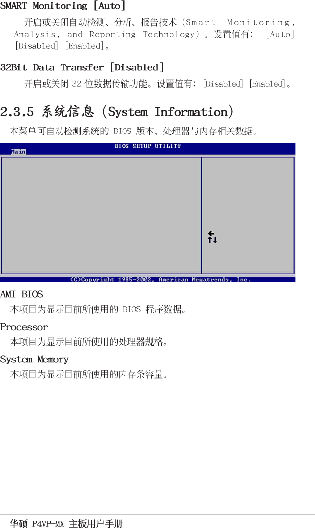
AMI BIOS
Version : 08.00.09
Build Date : 07/07/03
Processor
Type : Intel(R) Pentium(R) 4 CPU 1500MHz
Speed : 1500 MHz
Count : 1
System Memory
Size : 256MB
2-12
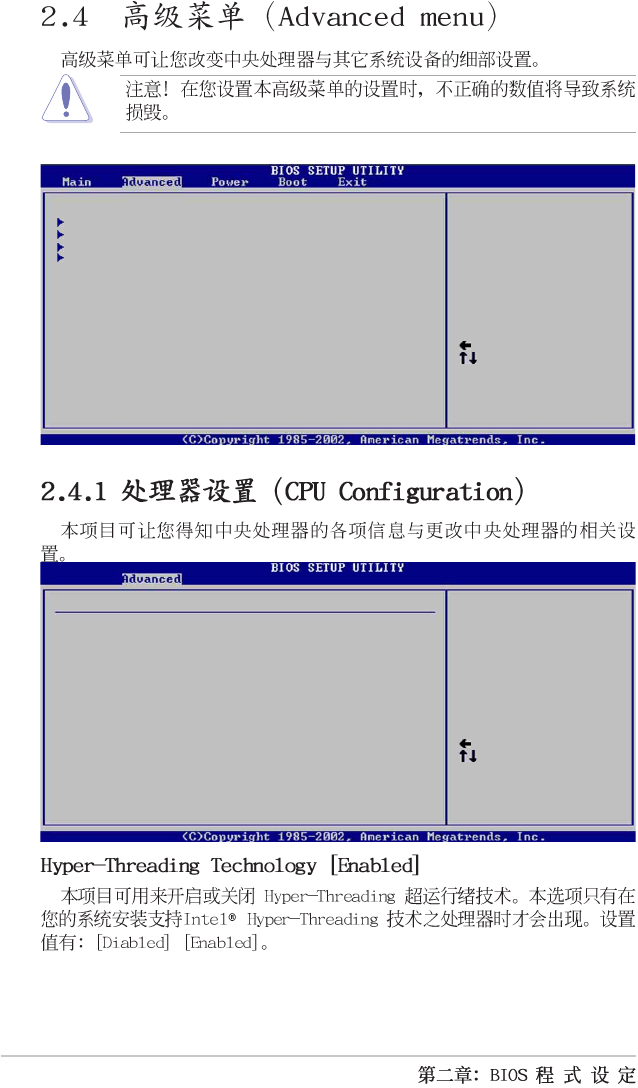
CPU Configuration
Chipset
Onboard Devices Configuration
PCI PnP
Configure CPU.
Select Screen
Select Item
Enter Go to Sub-screen
F1 General Help
F10 Save and Exit
ESC Exit
Select Screen
Select Item
+- Change Option
F1 General Help
F10 Save and Exit
ESC Exit
Manufacturer : Intel(R)
Brand String : Intel(R) Pentium(R) 4 CPU 1500MHz
Frequency : 1500MHz
Ratio Status : Locked
Ratio Actual Value : 15
Configure advanced CPU settings
2-13
Select Screen
Select Item
+- Change Option
F1 General Help
F10 Save and Exit
ESC Exit
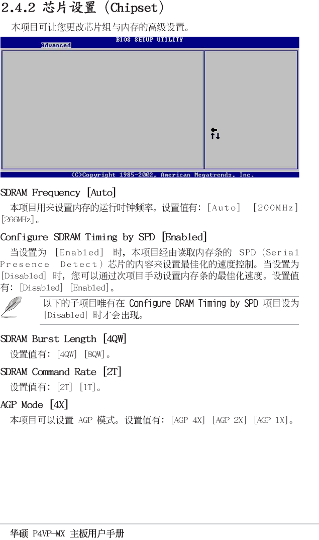
******** DRAM Timing ********
SDRAM Frequency [Auto]
Configure SDRAM Timing by SPD [Enabled]
SDRAM Burst Length [4QW]
SDRAM Command Rate [2T]
AGP Mode [AGP 1X]
Graphics Aperture Size [64MB]
Integrated AGP [Enabled/16MB]
Primary Graphics Adapter [PCI]
AddOn/Onboard AGP Display Card [Auto]
USB 2.0 Controller [Enabled]
2-14
2-15
Select Screen
Select Item
+- Change Option
F1 General Help
F10 Save and Exit
ESC Exit
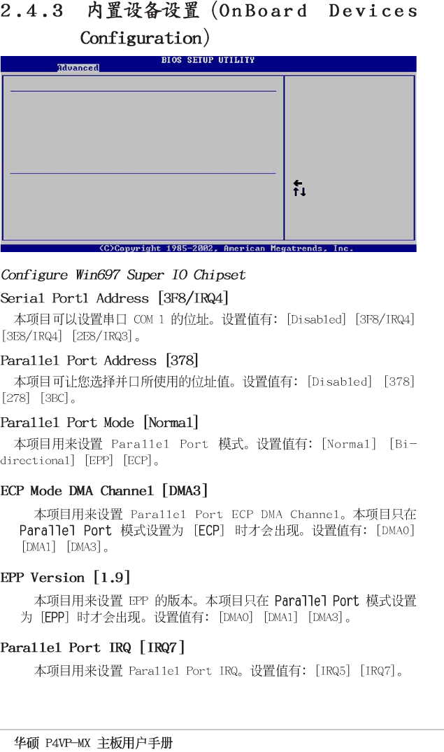
Serial Port1 Address [3F8/IRQ4]
Parallel Port Address [378]
Parallel Port Mode [Normal]
Parallel Port IRQ [IRQ7]
Onboard Game Port [Disabled]
Onboard MIDI Port [Disabled]
Configure Win697 Super IO Chipset
Configure South Bridge Chipset
OnBoard LAN [Enabled]
OnBoard LAN Boot ROM [Enabled]
OnBoard AC’97 Audio [Disabled]
2-16
2-17
Select Screen
Select Item
+- Change Option
F1 General Help
F10 Save and Exit
ESC Exit
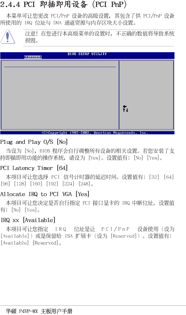
Plug and Play OS [No]
PCI Latency Timer [64]
Allocate IRQ to PCI VGA [Yes]
IRQ3 [Available]
IRQ4 [Available]
IRQ5 [Available]
IRQ7 [Available]
IRQ9 [Available]
IRQ10 [Available]
IRQ11 [Available]
IRQ14 [Available]
IRQ15 [Available]
Advanced PCI/PnP settings
WARNING: Setting wrong values in the sections below
may cause system to malfunction.
NO: Lets the BIOS
configure all the
devices in the system.
YES: Lets the
operating system
configure Plug and
Play (PnP) devices not
required for boot if
your system has a Plug
and Play operating
system.
2-18
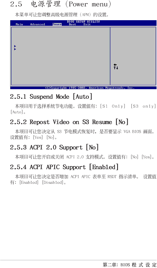
Suspend Mode [Auto]
Repost Video on S3 Resume [Yes]
ACPI 2.0 Support [No]
ACPI APIC Support [Enabled]
APM Configuration
Hardware Monitor
Configure CPU.
Select Screen
Select Item
Enter Go to Sub-screen
F1 General Help
F10 Save and Exit
ESC Exit
2-19
Select Screen
Select Item
+- Change Option
F1 General Help
F10 Save and Exit
ESC Exit
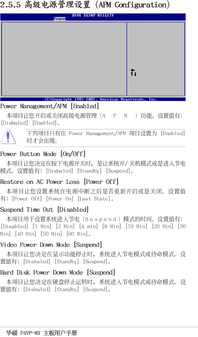
Power Management/APM [Enabled]
Power Button Mode [On/Off]
Restore on AC Power Loss [Power Off]
Suspend Time Out [Disabled]
Video Power Down Mode [Suspend]
Hard Disk Power Down Mode [Suspend]
Power On Ring [Disabled]
Power On Lan [Disabled]
Power On PME# [Disabled]
Power On KBC [Disabled]
Power On PS/2 Mouse [Disabled]
Power On RTC Alarm [Disabled]
2-20
2-21
Select Screen
Select Item
+- Change Option
F1 General Help
F10 Save and Exit
ESC Exit
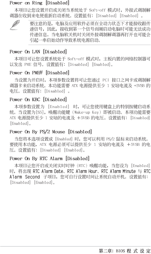
CPU Temperature [45°C/113°F]
MB Temperature [40°C/104°F]
CPU Fan Speed [3479RPM]
Chassis Fan Speed [N/A]
VCORE Voltage [1.744V]
3.3V Voltage [3.360V]
5V Voltage [4.919V]
12V Voltage [12.032V]
Hardware Monitor CPU temperature
2-22
Select Screen
Select Item
+- Change Option
F1 General Help
F10 Save and Exit
ESC Exit
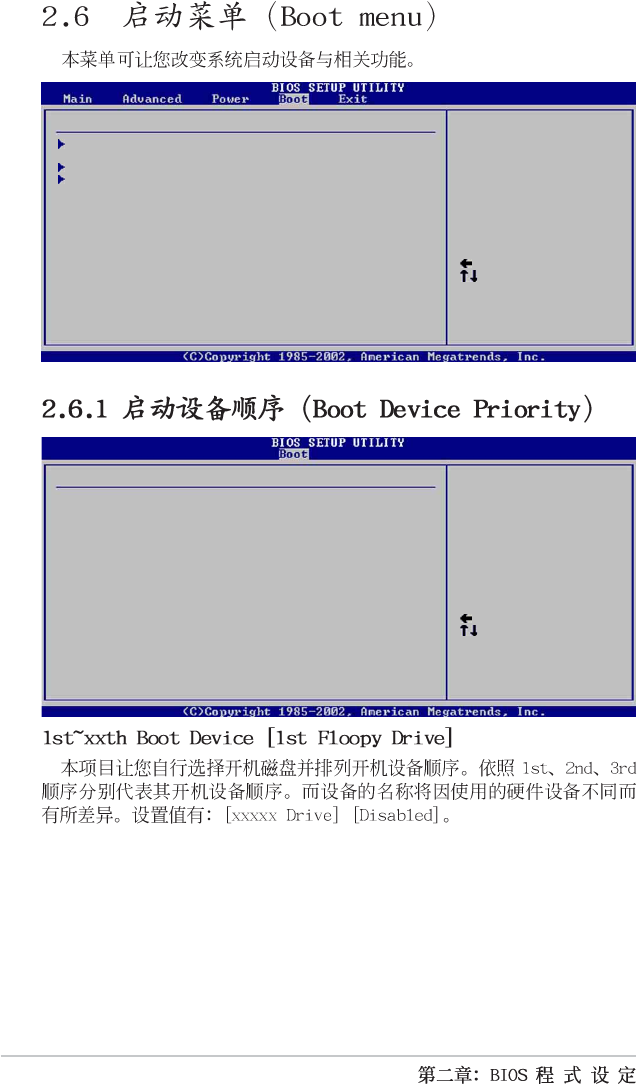
1st Boot Device [1st Floppy Drive]
2nd Boot Device [PM-ST330620A]
3rd Boot Device [SM-ASUS CD-S360]
Boot Device Priority Specifies the boot
sequence from the
available devices.
A device enclosed in
parenthesis has been
disabled in the
corresponding type
menu.
Boot Device Priority
Boot Settings Configuration
Security
Specifies the Boot
Device Priority
sequence.
Boot Settings
Select Screen
Select Item
Enter Go to Sub-screen
F1 General Help
F10 Save and Exit
ESC Exit
2-23
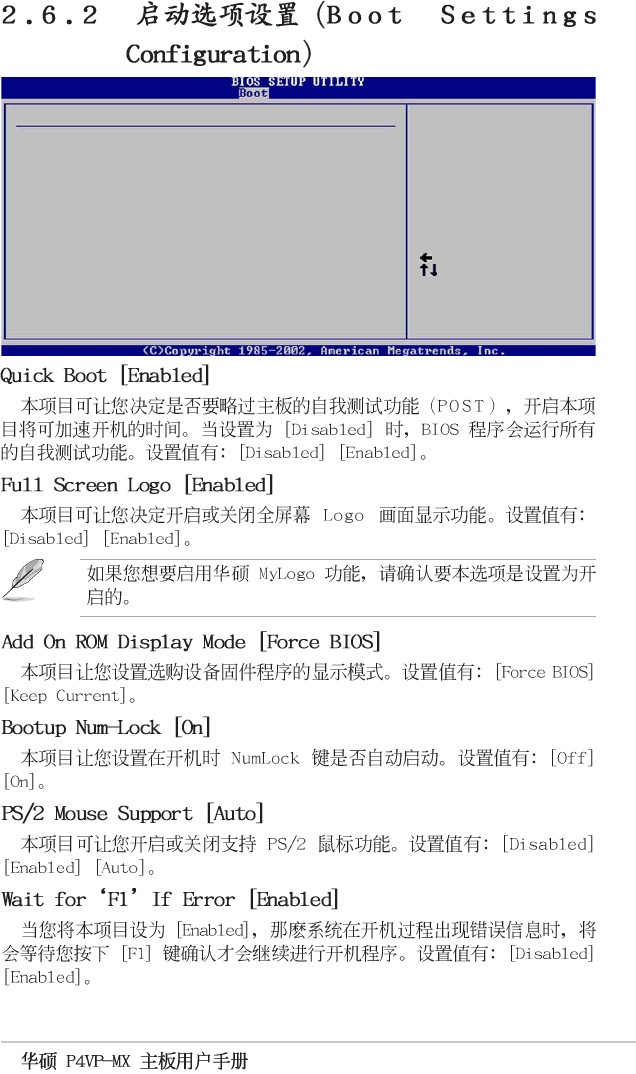
Quick Boot [Enabled]
Full Screen Logo [Enabled]
Add On ROM Display Mode [Force BIOS]
Bootup Num-Lock [On]
PS/2 Mouse Support [Auto]
Wait for ‘F1’ If Error [Enabled]
Hit ‘DEL’ Message Display [Enabled]
Interrupt 19 Capture [Disabled]
Select Screen
Select Item
+- Change Option
F1 General Help
F10 Save and Exit
ESC Exit
Boot Settings Configuration Allows BIOS to skip
certain tests while
booting. This will
decrease the time
needed to boot the
system.
2-24
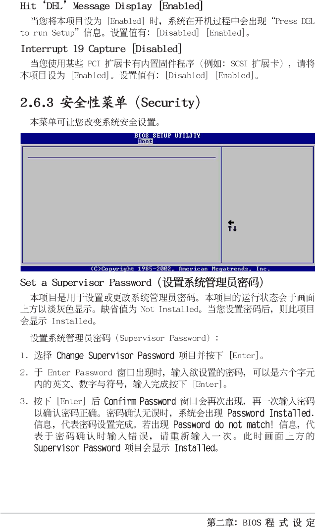
Supervisor Password Installed
User Password Not Installed
Change Supervisor Password
Change User Password
Clear User Password
Boot Sector Virus Protection [Disabled]
Select Screen
Select Item
+- Change Option
F1 General Help
F10 Save and Exit
ESC Exit
Security Settings <Enter> to change
password.
<Enter> again to
disable password.
2-25
2-26
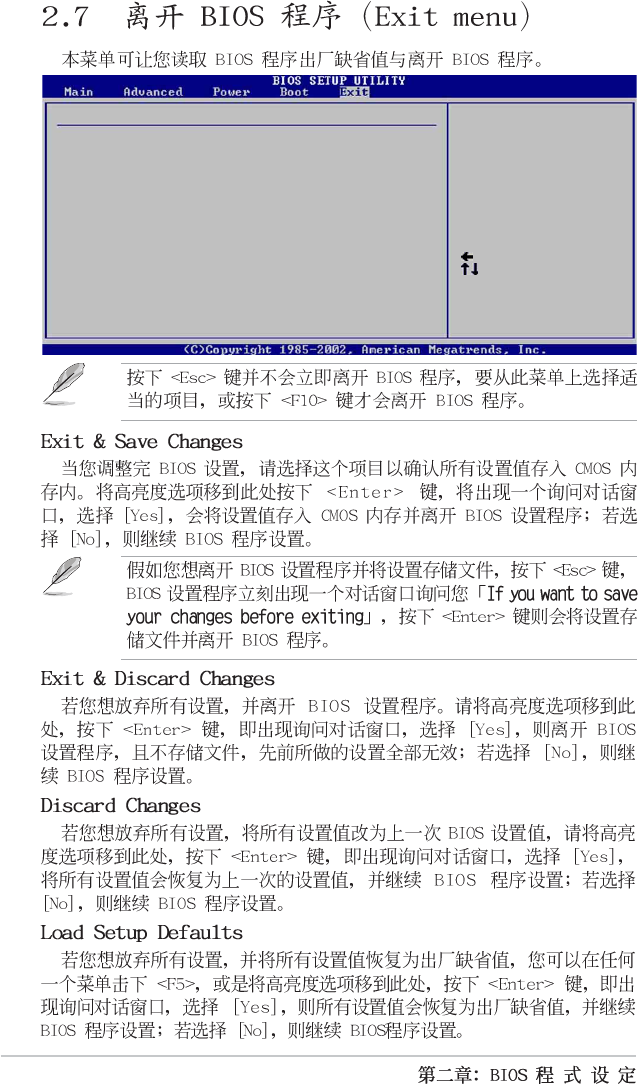
Exit & Save Changes
Exit & Discard Changes
Discard Changes
Load Setup Defaults
Exit system setup
after saving the
changes.
F10 key can be used
for this operation.
Exit Options
Select Screen
Select Item
Enter Go to Sub-screen
F1 General Help
F10 Save and Exit
ESC Exit

3-1
3-2
3-3
3-4
