Cad Proj Manual
User Manual:
Open the PDF directly: View PDF ![]() .
.
Page Count: 60

DRAFT
Cloud Application Development Project Manual
Embry-Riddle MSSA Faculty
January 3, 2019
DRAFT
Contents
Preface v
0 Introduction 1
0.1 Overview ............................................... 1
0.2 Inception ............................................... 1
0.2.1 Preliminaryresearch..................................... 1
0.2.2 Projectexploration...................................... 1
0.3 Data.................................................. 2
0.3.1 Requirements......................................... 2
0.3.2 Conceptualdesign ...................................... 2
0.3.3 Logicaldesign......................................... 2
0.3.4 Physicaldesign........................................ 2
0.3.5 Implementation........................................ 2
0.3.6 Presentation ......................................... 3
0.4 Logic.................................................. 3
0.4.1 Requirements......................................... 3
0.4.2 Analysis............................................ 3
0.4.3 Design............................................. 3
0.4.4 Implementation Iteration 1 . . . . . . . . . . . . . . . . . . . . . . . . . . . . . . . . . 3
0.4.5 Testing ............................................ 3
0.4.6 Implementation Iteration 2 . . . . . . . . . . . . . . . . . . . . . . . . . . . . . . . . . 3
0.4.7 Implementation Iteration 3 . . . . . . . . . . . . . . . . . . . . . . . . . . . . . . . . . 3
0.5 Finalprojectpresentation...................................... 4
0.6 WrapUp ............................................... 4
I Inception 5
1 Project Inception 6
1.1 Preliminaryresearch ......................................... 6
1.2 Deliverable .............................................. 7
1.3 VersionControl............................................ 7
1.4 Markdown............................................... 8
2 Project Selection 9
2.1 Projectselection ........................................... 9
2.2 Deliverable .............................................. 9
2.3 DistributedVersionControl..................................... 10
2.4 Markdown............................................... 10
ii

DRAFT
CONTENTS CONTENTS
II Data 11
3 Requirements 12
3.1 Introduction to database requirements . . . . . . . . . . . . . . . . . . . . . . . . . . . . . . . 12
3.2 Deliverable .............................................. 12
3.3 SoftwareLifeCycle.......................................... 12
3.4 SoftwareDevelopmentCycle..................................... 13
3.5 SoftwareProcessModels....................................... 13
4 Conceptual Design - Analysis 14
4.1 ConceptualDesign .......................................... 14
4.2 Deliverable .............................................. 14
4.3 Entities ................................................ 14
5 Logical Design 16
5.1 DatabaseLogicalDesign....................................... 16
5.2 Deliverable .............................................. 16
5.3 Normalization and integrity constraints . . . . . . . . . . . . . . . . . . . . . . . . . . . . . . 16
5.4 ThoughtExercise........................................... 17
6 Physical Design 18
6.1 DatabasePhysicalDesign ...................................... 18
6.2 Deliverable .............................................. 18
6.3 Database objects and constraints . . . . . . . . . . . . . . . . . . . . . . . . . . . . . . . . . . 18
7 Implementation 20
8 Database Presentation 21
8.1 DatabasePresentation........................................ 21
8.2 Deliverable .............................................. 21
8.3 SoftwareDevelopmentCycle..................................... 21
8.4 Object Oriented Development Principles . . . . . . . . . . . . . . . . . . . . . . . . . . . . . . 22
III Logic 23
9 Requirements 24
9.1 RequirementsPhase ......................................... 25
9.2 RequirementsGathering....................................... 25
9.3 What is Requirements Elicitation? . . . . . . . . . . . . . . . . . . . . . . . . . . . . . . . . . 26
9.3.1 What Techniques Can Be Used? . . . . . . . . . . . . . . . . . . . . . . . . . . . . . . 26
9.3.2 How Should the Information Be Captured? . . . . . . . . . . . . . . . . . . . . . . . . 27
9.3.3 WhatPitfallsExists? .................................... 27
9.4 Deliverable .............................................. 27
10 Analysis 28
10.1RequirementsAnalysis........................................ 28
10.2Deliverable .............................................. 29
11 Design 30
11.1ProgramDesign............................................ 30
11.2Projectdesign............................................. 31
11.3DiscussionTopics........................................... 31
11.4Deliverables.............................................. 32
Page iii, Revised on January 3, 2019 by Charles Carter

DRAFT
CONTENTS CONTENTS
12 Implementation 33
12.1ProgramImplementation ...................................... 33
12.2Deliverables.............................................. 33
13 Testing 34
13.1Testing ................................................ 34
13.2Principlesoftesting ......................................... 34
13.3Testdrivendevelopment....................................... 34
13.4Deliverables.............................................. 34
14 Interface Design 35
14.1 User Interface Design Process . . . . . . . . . . . . . . . . . . . . . . . . . . . . . . . . . . . . 35
14.2 User Interface Design Activities . . . . . . . . . . . . . . . . . . . . . . . . . . . . . . . . . . . 36
14.3Deliverable–Prototype ....................................... 37
15 placeholder 38
15.1 User Interface Design Process . . . . . . . . . . . . . . . . . . . . . . . . . . . . . . . . . . . . 38
15.2Deliverable–Wireframe....................................... 39
IV Final Presentation 40
16 Final Presentation 41
16.1ProjectPresentation ......................................... 41
16.2Deliverable .............................................. 41
A Installing git 42
B Poor Man’s Console MVC 51
B.1 SheAin’taComputerLady..................................... 51
B.2 GatheringRequirements....................................... 51
B.3 ModelingtheDomain ........................................ 52
B.4 WhatsintheLady’sHead? ..................................... 52
B.5 Implementing a Visit Calendar . . . . . . . . . . . . . . . . . . . . . . . . . . . . . . . . . . . 52
B.6 Controller............................................... 52
B.7 Model ................................................. 53
B.8 View.................................................. 53
B.9 ConclusionandNextSteps ..................................... 54
Last note 55
Page iv, Revised on January 3, 2019 by Charles Carter

DRAFT
Preface
The MSSA curriculum consists of four different technologies. They are:
C# programming
T-SQL Query Fundamentals
ASP.NET MVC web app development
Azure clould app development
These four technologies give students a real proficiency in cutting edge technology and prepare students
to enter the workforce. However, they make no attempt to teach students how to develop applications. For
example, a real ability to develop applications requires an awareness of the following, among other things:
the software life cycle
the software process
program logic and design
patterns and object oriented analysis
version control
unit testing
The purpose of this project is two fold. First, it gives the students experience in putting their skills to
work creating an application from scratch. Second, it introduces the skills necessary to develop applications
but which are not specifically covered by the curriculum. As a side effect, it allows students to build a
portfolio demonstrating their skills to prospective employers. It in no way attempts comprehensive coverage
of any aspect of application development or software engineering. Instead, it is very much a work in progress
which is designed to introduce students to application development from an integrated perspective.
The project in outline consists of four parts. Part One consists of researching and choosing a project
and making a presentation summarizing their chosen project. Part Two develops a database supporting
their project. Part Three includes the design and implementation of their project. Part Four, the final part,
consists of the project presentation.
v
DRAFT
Chapter 0
Introduction
0.1 Overview
The MSSS Cloud Application Development project consists of a project summarized in table 1 and detailed
in this manual. This consists of four phases: inception, data component, logic component, and interface
component. The two purposes of the projects are to (1) give students the opportunity to reflect on what
they are learning and apply the material to a “real world” project, and (2) allow them to construct a portfolio
that they can use for the purpose of gaining employment as an application developer.
0.2 Inception
The first two weeks of the MSSA program will consist of the selection of the project. Students are not
expected to have the technical skills necessary to begin the project, but are expected to have a layman’s
grasp of software applications and an interest in some knowledge domain that they can leverage throughout
their course.
0.2.1 Preliminary research
Students will begin thinking about the kind of project they would want to showcase for their project. They
should list the specific functionalities of their chosen kind of project, and so some preliminary investigation
toward implementing the project. All projects should include a data component, a logical component, and
an interface component. The deliverable should be a five paragraph document listing several specific projects
they would be interested in doing, and a short description of the characteristics of each project. See chapter
1 for more information.
0.2.2 Project exploration
Students will select one project from their list to focus on for their project They should make a formal
investigation of the requirements of the project. If possible, they should identify similar applications that
have been written. There are two deliverables, a written paper‘and an oral presentation (with an optional
slide deck). The project proposal should contain a sufficient description of the project that would allow
construction of the project to begin, including a discussion of the supporting database, the program code,
and the user interface. See chapter 2 for more information.
1
DRAFT
0.3. DATA CHAPTER 0. INTRODUCTION
Chapter Phase Topic Deliverables
Ch. 1 Inception Project exploration 5 paragraph writeup
Ch. 2 Inception Project selection an oral and written presentation
Ch. 3 Data Requirements an Information Flow Diagram and requirements list
Ch. 4 Data Database conceptual design Entity Relationship Diagram
Ch. 5 Data Logical design of database logical database diagram
Ch. 6 Data Physical design of database physical database diagram
Ch. 7 Data Implementation SQL source listing
Ch. 8 Data Presentation an oral and written presentation
Ch. 9 Logic Requirements informal requirements list
Ch. 10 Logic Analysis Software Requirements Specification
Ch. 11 Logic Design UML diagrams
Ch. 12 Logic Implementation Iteration 1 C# source listing
Ch. 13 Logic Testing C# source listing
Ch. 14 Logic Implementation Iteration 2 C# source listing
Ch. ?? Logic Implementation Iteration 3 C# source listing
Ch. 16 Final Project Presentation oral and written presentation
Table 1: Project schedule
0.3 Data
This phase concentrates on using persistent data using a relational database (SQL Server). The outcome of
this phase will be a fully functional database.
0.3.1 Requirements
Every database stores data according to some requirements. In this step, students will collect as many of
their data requirements as possible. The deliverable is a simple list of data requirements in a plain text or
Markdown file. The requirements should be as complete and as detailed as possible. See chapter 3 for more
information.
0.3.2 Conceptual design
Students will discover the nature of conceptual database design. The deliverable will be an entity-relationship
diagram (ERD) showing the conceptual design of their project database. See chapter 4 for more information.
0.3.3 Logical design
Students will discover the nature of logical database design. The deliverable will be an database diagram
showing the logical design of their project database. See chapter 5 for more information.
0.3.4 Physical design
Students will discover the nature of physical database design. The deliverable will be an database diagram
showing the physical design of their project database. See chapter 6 for more information.
0.3.5 Implementation
Students will write a SQL source listing implementing their database. The deliverable will be the SQL source
listing. See chapter 7 for more information.
Page 2, Revised on January 3, 2019 by Charles Carter

DRAFT
0.4. LOGIC CHAPTER 0. INTRODUCTION
0.3.6 Presentation
Presentation: students will prepare a slide presentation and make an oral presentation of the database to
the class. Deliverables include the slide presentation and (optionally) a video of their oral presentation. See
chapter 8 for more information.
0.4 Logic
The logic component includes the business rules for the application. This should be accessible from a console
interface. It should be a fully functional version of their implemented project.
0.4.1 Requirements
Students will create a list of application requirements. These generally consist of the functional requirements
of their project. This list should be as exhaustiive and complete as possible. The requirements list provides
the foundation of the application, in the sense that you cannot build an appication if you do know know
what kid of appication you are buildin.
0.4.2 Analysis
Students will create a software requirements specification (SRS) of the functional requirements of their
project. (The project does not include non-functional requirements.) The deliverable will be the project
SRS.
0.4.3 Design
Students will create appropriate design artifacts. These will include a class diagram, a component diagram,
a system sequence diagram, and other documents as necessary (e.g., data flow diagrams, state models, etc.)
The deliverable will be a collection of design diagrams.
0.4.4 Implementation Iteration 1
Students will implement the logic component of their project. The deliverable will be the source code listings
of their implementation. These will not include auxilliary files, such as container folders, configuration files,
etc.
0.4.5 Testing
Students will write automated tests for their application using both white box and black box techniques.
All test code should be automated. The deliverable will be the source listiong for the test suite.
0.4.6 Implementation Iteration 2
Students will implement the logic component of their project. The deliverable will be the source code listings
of their implementation. These will not include auxilliary files, such as container folders, configuration files,
etc.
0.4.7 Implementation Iteration 3
Students will implement the logic component of their project. The deliverable will be the source code listings
of their implementation. These will not include auxilliary files, such as container folders, configuration files,
etc.
Page 3, Revised on January 3, 2019 by Charles Carter

DRAFT
0.5. FINAL PROJECT PRESENTATION CHAPTER 0. INTRODUCTION
0.5 Final project presentation
Presentation: students will prepare a slide presentation and make an oral presentation of the user interface
to the class. Deliverables include the slide presentation and a video of their oral presentation.
0.6 Wrap Up
The instructor’s obligation throughout the project is to provide guidance for each phase. For example,
during the Data phase, he should discuss the database design process including normal forms and integrity
constraints. During the Logic phase, he should discuss iterative, incremental processes and UML. During
the Interface, he should discuss principles of user interface design.
Instructors should use the project as an opportunity to add value to the curriculum by exposing the
students to topics not expressly included in the curriculum, such as version control, software engineering,
software quality control (testing), security, design patterns, and so on. This should be at the instructor’s
discretion.
The project is a supplement to the official curriculum. As such, it should enhance the student’s experience,
and not detract from it by overloading the student with an amount of work that is impossible to do.
The emphasis is on understanding the topics presented and building a portfolio, not building a completely
functional application.
Page 4, Revised on January 3, 2019 by Charles Carter
DRAFT
Part I
Inception
5
DRAFT
Chapter 1
Project Inception
1.1 Preliminary research
Students will begin thinking about the kind of project they would want to showcase for their portfolio.
They should think about the specific functionalities of their chosen kind of project, and some preliminary
investigation toward implementing the project. All projects should include a data component and an interface
component. The deliverable should be a document listing several specific projects they would be interested
in doing, and a short description of the characteristics of each project.
You may choose your own project. Here is a list of sample projects for you to consider.
Testing system This is an application for automatic testing, similar to the Microsoft certification tests.
It generates tests, allows students to take the tests, grades the tests, and reports the scores.
School system This may consist of a student module, an instructor module, a curriculum module, and
provides for the assignment of instructors to classes, students to classes, course management, student
management, an d instructor management. As example would be the CSU student information system.
Electronic learning system This may consist of a collection of courses. Each course may allow for tests,
quizzes, exercises, research papers, discussions, etc. As example would be Cougarview.
An auction system. This my consist of a sellers module, a bidders module, a purchase module, and
provide for different kinds of sales (i.e., open bidding, bidding with reserve, buy now, etc.). It would
include user registrations and appropriate databases of auctions, transactions, etc. An example would
be eBay.
Messaging system This would include user registrations, posting messages, sending messages, composing
groups, and similar functionality. An example would be Twitter.
Encyclopedia This would include editor registrations, posting entries, editing entries, search functions,
analytical functions, and similar functionality. An example would be Wikipedia.
Electronic voting system This would include voter registrations, candidate qualification, casting ballots
with appropriate authentication, and calculation of results. An example would be the current voting
system in Georgia.
Networking system This would include user registrations, posting employment data, school data, certi-
fication data, allow the posting of jobs, etc. An example would be LinkedIn.
Online store This would implement the display of merchandise, a shopping cart, a payment module, and
inventory control mechanism, etc. An example would be Amazon.
Database GUI This would implement a graphical front end to a database. Modules would (1) create or
drop databases, (2) create, drop, and alter tables, (3) insert, update, or delete data, and (4) run simple
queries. An example would be TOAD.
6

DRAFT
1.2. DELIVERABLE CHAPTER 1. PROJECT INCEPTION
Organization system This might include member registration, a member directory, an event calender,
a newsletter, a photo album, a FAQ, or other functions suitable for organizations. Examples would
include a social organization, a service organization, a band or orchestra, a church, an athletic team,
etc.
Automated teller machine This might include customer authentication, checking account status, accep-
tance of deposits, and dispensing cash.
A strategy game At a minimum, this would consist of a user interface, a data source, and a logic engine
implementing the game rules.
1.2 Deliverable
Your deliverable will be a five paragraph (or more) paper of three or four proposed projects. Your description
of each proposed project should contain enough information so that readers can understand the nature of
the project. You may also give examples of similar, existing implementations.
The format of the paper will eventually use Markdown. For now, please write your paper either in
Markdown or in plain ASCII text with no formatting, perhaps using Notepad++, Microsoft Notepad or a
similar application. In general, your papers should consist of a short introduction, a short conclusion, and a
body containing the substance of your discussion. For this paper, structure it like this:
1. A first paragraph or two as the introduction introducing yourself and stating your personal objectives
for your project.
2. The body of your paper as follows:
(a) A paragraph or two describing your first reviewed project, and how that project will help you
accomplish your personal objectives.
(b) A paragraph or two describing your second reviewed project, and how that project will help you
accomplish your personal objectives.
(c) A paragraph or two describing your third reviewed project, and how that project will help you
accomplish your personal objectives.
(d) (optional) A paragraph or two describing your fourth reviewed project, and how that project will
help you accomplish your personal objectives.
3. A final paragraph or two as the conclusion reflecting on how you will achieve your personal objectives
by building the project.
Your paper should have a title, author, and date. The subdivisions of your paper should have appropriate
section and subsection headings.
1.3 Version Control
The topic for this week will be version using the Git Version Control System. The following will be covered.
The rationale for version control in software development
Installation of the Git SCM software
The command git config for the user name, user email, and core editor
The command git init
The command git add with the appropriate arguments
The command git status
The command git commit with the appropriate arguments
The command git log
Page 7, Revised on January 3, 2019 by Charles Carter

DRAFT
1.4. MARKDOWN CHAPTER 1. PROJECT INCEPTION
1.4 Markdown
Markdown is a very simple, human readable, formatting system. A Markdown document is a simple text
document, with no binary codes or special formatting instructions. It contains only printable characters,
such as alphabetical characters, punctuation, and digits. The file extension is .md. This is half of all the
Markdown you will need to know. You can pick up the other half just as easily.
Headings
Paragraphs
Itemized lists
Enumerated lists
Rules
Page 8, Revised on January 3, 2019 by Charles Carter
DRAFT
Chapter 2
Project Selection
2.1 Project selection
Students will select one project from their list to focus on for their project They should make a formal
investigation of the requirements of the project. If possible, they should identify similar applications that
have been written. The deliverable is a six to eight paragraph project proposal. The project proposal should
contain a sufficient description of the project that would allow construction of the project to begin.
2.2 Deliverable
You have two deliverabes for this step, an oral presentation and a written paper. Your oral persentation
should be no longer than five minutes, and should cover the same topics as the written paper. It should be
short and succienct, but it should cover all topics adequately. You may use a slide presentation if desired.
Your written deliverable will be a six to eight paragraph discussion of your proposed project. Your
proposal should begin with a short introduction and conclude with a short conclusion. It should include
discussions of the purpose of the software, an overall description of the high-level functional requirements of
the software (that is, what the software will actually do), a survey of the relevant literature available that
will assist you in completing your project, a short discussion of similar software, and a brief discussion of
your project plan. Your writeup is not limited to two pages, and can include other sections that you feel
will help the reader in understanding your proposal.
The format of the paper will eventually use Markdown. For now, please write your paper either in Mark-
down or in plain ASCII text with no formatting, perhaps using Microsoft Notepad or a similar application.
In general, your papers should consist of a short introduction, a short conclusion, and a body containing the
substance of your discussion. For this paper, structure it like this:
1. A first paragraph or two briefly introducing yourself and stating how your chosen project will accomplish
your personal objectives.
2. A paragraph or two describing the data phase of your project. This should include a general description
of the kinds of information your database will contain.
3. A paragraph or two describing the programming phase of your project. This should include a general
description of the processing necessary to accomplish your objectives.
4. A paragraph or two describing the interface your project will present to the users. Focus on the
functionality, not things such as layout, color, font, and so on.
5. A final paragraph or two reflecting on how you will actually go about building your project. This does
not need to be in detail, but a general plan of actiob.
9
DRAFT
2.3. DISTRIBUTED VERSION CONTROL CHAPTER 2. PROJECT SELECTION
2.3 Distributed Version Control
The topic for this week will be version control using the Github Distributed remote repository. The following
will be covered.
The rationale for distributed version control in software development
Signing up for a Github account
Creating your first remote repository
The command git remote add with the appropriate arguments
The command git remote -v
The command git push with the appropriate arguments
a.gitignore file
aREADME.md file
2.4 Markdown
Markdown is a very simple, human readable, formatting system. A Markdown document is a simple text
document, with no binary codes or special formatting instructions. It contains only printable characters,
such as alphabetical characters, punctuation, and digits. The file extension is .md. This is half of all the
Markdown you will need to know. You can pick up the other half just as easily.
Emphasis
Hyperlinks
Images
HTML elements
Source listings
Page 10, Revised on January 3, 2019 by Charles Carter
DRAFT
Part II
Data
11

DRAFT
Chapter 3
Requirements
3.1 Introduction to database requirements
The purpose of a database generally is to store data. Databases can be of various kinds, such as a filing
cabinet, a list written on a sheet of paper, a wall of sticky notes, and so on. In this project, we will use
a relational database, also know as a SQL database. A relational database is a mathmatical model of the
world, and as such it is extremely limited. However it has great power, stemming from rigorous mathmatics,
and is enormously popular in the business world.
Adatabase requirements document usually is an extensive document covering a multitude of topics. You
can search the internet for examples, and see a number of different templates. We will not be doing this.
The purpose of the requirements stage in this project is merely to collect a more or less complete list of the
data your project will need to function.
How do you accomplish this task? For an existing project, the developer will review all the paper the
organization collects and see what information those documents contain. For people, information might in-
clude the name, address, ID number, telephone number, username, password, etc. For products, information
might include the product name, the model number, the serial number of individual items, the supplier, the
expiration date, etc. For military units, imformation might include the unit designation, the parent unit,
subordinate units, tables of organization and equipment, etc.
One good way to do this is to go through your project in your mind, exercising all the functionality you
can think of, and write down every single piece of information you will need to exercise than functionality.
If your application is a messaging app, you will need the name and IP address of the sender, the name and
IP address of the reciever, the data and text of the message, etc. For an auction app, you will need the
name and contact information of the seller, the name and contact information of all bidders, the description
of the item, and a way to keep track of the bids. Use your imagination!!! This document will be absolutely
essential in order to complete the next step, the conceptual design.
3.2 Deliverable
Your deliverable can be as simple as a list, composed of sublists divided appropriately, written in Markdown,
and posted to your Github account. If you have the time and energy, you can make it as complete as you
would like, following the template of your choice. The ultimate grading criterion will be the completeness of
your list, not the formality.
3.3 Software Life Cycle
A brief introduction to the software life cycle:
Inception
Elaboration
12
DRAFT
3.4. SOFTWARE DEVELOPMENT CYCLE CHAPTER 3. REQUIREMENTS
Construction
Transition
Maintenance
End of life
3.4 Software Development Cycle
A brief introduction to software development workflows:
Requirements
Analysis
Design
Implementation
Testing
3.5 Software Process Models
A brief introduction to software process models:
Incremental development
Iterative development
Spiral models
Waterfall
Rational Unified Process
Agile processes
Page 13, Revised on January 3, 2019 by Charles Carter

DRAFT
Chapter 4
Conceptual Design - Analysis
4.1 Database Conceptual Design
Typically, a database project consists of five or six phases: requirements engineering, conceptual design
(analysis), logical design, physical design, implementation, and testing. For the CAD project, we will only
cover requirements, conceptual design, logical design, physical design, and implementation. We will not
cover requirements engineering generally nor testing. We do not cover the requirements engineerinng phase
because, presumably, since you are your own client/customer, you will already know your requirements. We
do cover testing, but not in the database phase of the project. During the later phases of the project, you
will be able to test your database design and revise it as necessary.
Generally, the conceptual design phase of a database project requires developers to break down the prob-
lem domain into relevant objects, called entities, and identify the relationship between objects. For example,
a school might have courses, teachers, and students: teachers teach courses, students enroll in courses, and
teachers grade students. The entities are TEACHER, STUDENT, and COURSE. The relationships are
TEACH, ENROLL IN, and GRADE.
For this week’s assignment, you will prepare a conceptual design of your project database and create an
entity-relationship diagram. This process requires you to identify the entities that your project deals with
and the relationship between the entities. This process also requires you to identify important attributes
of your entities, and (if necessary) of your relationships. Examples of important attributes for STUDENT
would be ID and NAME, and for COURSE would be CRN and TITLE.
We will also discuss the Dia Diagram Editor, https://sourceforge.net/projects/dia-installer/.
4.2 Deliverable
Your deliverable is an Entity Relationship Diagram (ERD). Your ERD is an image, and you should prepare
it in some graphical format. The preferred format is PDF, but other image formats are acceptable, such as
SVG, JPEG, GIF, PNG, EPS, etc.
4.3 Entities, Relationships, and Attributes
The following topics will be discussed:
What is conceptual database design
What is an entity
What is a weak entity
What is an entity attribute
What is a relationship
14

DRAFT
4.3. ENTITIES CHAPTER 4. CONCEPTUAL DESIGN - ANALYSIS
What is a relationship type
What is a relationship degree
What is a relationship attribute
What is a candidate key
What is a super key
Page 15, Revised on January 3, 2019 by Charles Carter

DRAFT
Chapter 5
Logical Design
5.1 Database Logical Design
Typically, a database project consists of five or six phases: requirements engineering, conceptual design
(analysis), logical design, physical design, implementation, and testing. For the CAD project, we will only
cover requirements, conceptual design, logical design, physical design, and implementation. We will not
cover requirements engineering nor testing. We do not cover the requirements phase because, presumably,
since you are your own client/customer, you will already know your requirements. We do cover testing, but
not in the database phase of the project. During the later phases of the project, you will be able to test your
database design and revise it as necessary.
Generally, the logical design phase of a database project requires developers to decompose the entities
identified by the conceptual design and create a logical schema. This means that the entities become tables
(relations), and the attributes are expanded and identified as fields. During this process, the database is
normalized and integirity constraints are realized. Logical design is much more of an art than a science, and
is notoriously difficult.
For this week’s assignment, you will prepare a logical design of your project database and create a database
diagram. This process requires you to identify the relations (tables), that you normalize your database, and
that you specify all fields (attributes) of your tables.
5.2 Deliverable
Your deliverable is an Database Diagram. Your database diagram is an image, and you should prepare it in
some graphical format. The preferred format is PDF, but other image formats are acceptable, such as SVG,
JPEG, GIF, PNG, EPS, etc.
5.3 Normalization and integrity constraints
The following topics will be discussed:
What is first normal form
What is second normal form
What is third normal form
What is entity integrity
What is domain integrity
What is referential integrity
What is logical (business) integrity
16

DRAFT
5.4. THOUGHT EXERCISE CHAPTER 5. LOGICAL DESIGN
5.4 Thought Exercise
You are given an assignment to build a database that models student enrollments in courses. In your
conceptual design phase, you identify two entities, students and courses, and one relationship, [Students]
Enroll in [Courses]. In your first attempt, you see immediately that your database is not in first
normal form in that multiple students enroll in the same course and multiple students enroll in the same
course. It’s not in second normal form because student attributes do not depend on the course primary key,
and course attributes depend do not on the student primary key. You see that it also (probably) is not in
third normal form because some non-key attributes uniquely identify other non-key attributes.
Complete a logical design of this problem. We will discuss this in class. In my solution to this exercise,
I designed five different tables. You may or may not have the same number of tables in your solution.
Page 17, Revised on January 3, 2019 by Charles Carter

DRAFT
Chapter 6
Physical Design
6.1 Database Physical Design
Typically, a database project consists of five or six phases: requirements engineering, conceptual design
(analysis), logical design, physical design, implementation, and testing. For the CAD project, we will only
cover conceptual design, logical design, physical design, and implementation. We will not cover requirements
engineering nor testing. We do not cover the requirements phase because, presumably, since you are your
own client/customer, you will already know your requirements. We do cover testing, but not in the database
phase of the project. During the later phases of the project, you will be able to test your database design
and revise it as necessary.
Physical design targets a particular relational database management system, such as SQL Server or
SQLite. Logical designs target an abstract database, but physical designs must be specific to the particular
database system. All elements must be specified, such as the constraints we will discuss. You should be able
to hand your physical design to a SQL programmer, and he should be able to write the implementation code
without reference to anything other than your physical design.
For this week’s assignment, you will prepare a physical design of your project database and create a
database diagram. This process requires you to create tables, create columns, specify
6.2 Deliverable
Your deliverable is a Database Diagram. Your database diagram is an image, and you should prepare it in
some graphical format. The preferred format is PDF, but other image formats are acceptable, such as SVG,
JPEG, GIF, PNG, EPS, etc.
6.3 Database objects and constraints
The following topics will be discussed:
What is are column level constraints and table level constraints
What is a primary key
What is a foreigh key
What are insert, delete, and update anomolies
What is a nullability constraint
What is a uniqueness constraint
What is a datatype
18

DRAFT
6.3. DATABASE OBJECTS AND CONSTRAINTS CHAPTER 6. PHYSICAL DESIGN
What is an index
What is an enumeration
What is a check constraint
Page 19, Revised on January 3, 2019 by Charles Carter
DRAFT
Chapter 7
Implementation
Database Implementation
Your assignment is to implement the database you designed in your last deliverable. You should create a
new database, define your tables, and fully implement the tables. You should also insert a sufficient amount
of data into your tables to allow for testing, and develop a sufficient number of queries to test your database.
Your deliverable is a SQL file containing your implementation code. You should also deliver a TXT file
containing the results of the execution of your SQL file.
20

DRAFT
Chapter 8
Database Presentation
8.1 Database Presentation
For this week’s assignment, you will prepare and deliver a short oral presentation and a written paper. In
your presentation, you should (1) introduce yourself, (2) give a short summary of your project, (3) discuss
the information architecture of your project, and (4) discuss the design and implementation of your database.
You can use the deliverables from the last four weeks as building blocks for your presentation.
8.2 Deliverable
You have two deliverables, one written and one oral. You should first prepare your written presentation. The
format of the paper will use Markdown. Your paper should have a title, author, and date. The subdivisions
of your paper should have appropriate section and subsection headings.
The second deliverable is an oral presentation, This should be short, not more than five minutes. Op-
tionally, you may make a video of your presentation using your compputer. If your laptop did not come with
video software, VSDC is free and works well.
Upload your written presentation to Github. You may upload your video presentation to your project
account in Linkedin or another appropriate platform.
8.3 Software Development Cycle
A brief review to software development workflows:
Requirements
–requirements engineering
–collaboration with stakeholders
–use cases (user stories)
Analysis
–functional requirements
–non-functional requirements
–Software Requirements Specification (SRS)
Design
–Unified Modeling Language (UML)
–static design diagrams
21

DRAFT
8.4. OBJECT ORIENTED DEVELOPMENT PRINCIPLESCHAPTER 8. DATABASE PRESENTATION
–dynamic design diagrams
Implementation
Testing
8.4 Object Oriented Development Principles
A brief review to software development principles for OOAD:
Single responsibility principle (SRP): This principle states that software component (function, class or
module) should focus on one unique tasks (have only one responsibility).
Open/closed principle (OCP): This principle states that software entities should be designed with the
application growth (new code) in mind (be open to extension), but the application growth should
require the smaller amount of changes to the existing code as possible (be closed for modification).
Liskov substitution principle (LSP): This principle states that we should be able to replace a class in a
program with another class as long as both classes implement the same interface. After replacing the
class no other changes should be required and the program should continue to work as it did originally.
Interface segregation principle (ISP): This principle states that we should split interfaces which are very
large (general-purpose interfaces) into smaller and more specific ones (many client-specific interfaces)
so that clients will only have to know about the methods that are of interest to them.
Dependency inversion principle (DIP): This principle states that entities should depend on abstractions
(interfaces) as opposed to depend on concretion (classes).
Page 22, Revised on January 3, 2019 by Charles Carter
DRAFT
Part III
Logic
23
DRAFT
Chapter 9
Requirements
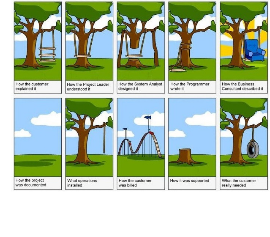
Figure 9.1: Different views of requirements
With over 70% of project failures being attributed to requirements gathering, why are we still using the
same techniques and expecting different results? Requirements need to be discovered before they can be
gathered and this requires a robust approach to analyzing the business needs.1
1Stieglitz, C. (2012). Beginning at the endrequirements gathering lessons from a flowchart junkie. Paper presented at
PMI Global Congress 2012North America, Vancouver, British Columbia, Canada. Newtown Square, PA: Project Management
Institute.
24

DRAFT
9.1. REQUIREMENTS PHASE CHAPTER 9. REQUIREMENTS
9.1 Requirements Phase
The Cloud Application Development Project consists of four parts, an inception part, the database part,
the prgram development (logic) part, and the interface part. All these parts can be considered integral to
software development, but they are approached differently. Last week, we concluded the database portion
of the project. This week, we begin five week looking specifically at programming development. We can call
this software emngineering in a narrow sense.
The discipline of software engineering includes various workflows in building software applications. These
workflows are the same as engineering workflows in other engineering disclipines, such as civil and automotive
engineering. These workflows consists of the following:
Requirements Gathering
Requirements Analysis
Program Design
Program Implementation
Application Testing
Software engineers use many different processes, among them waterfall, the Rational Unified Process, and
various agile processes, including Scrum and Kanban. Different processes order and emphasize the workflows
differently, but despite their differences, all processes use the same workflows. The process we will use in
this project is a modified version of Extreme Programming (XP). If you are interested in XP, you can read
about it offline.
9.2 Requirements Gathering
Requirements gathering is probably the most important activity to be performed in delivering an information
solution. There is no one perfect means for identifying and gathering requirements. The most appropriate
methods will vary from project to project. Some commonly used methods include:2
Interviews
Storyboarding
Use cases
Questionaires
Brainstorming
Prototyping
Use cases can be especially valuable since they provide specific scenarios of how the solution is intended
to be used and by whom. These use cases can then provide a direct basis for testing the delivered solution.
Following are some things to keep in mind when gathering requirements:
Identify and involve a representative set of stakeholders (don’t lose sight of all of the players)
Seek breadth before depth (get the big picture before deep diving)
Iterate and clarify (as more requirements surface they will evolve)
Prioritize (separate the must-haves from the nice-to-haves)
Use the stakeholder’s terminology (you’re doing an information solution not a technical solution)
2https://its.unl.edu/bestpractices/requirements-gathering
Page 25, Revised on January 3, 2019 by Charles Carter

DRAFT
9.3. WHAT IS REQUIREMENTS ELICITATION? CHAPTER 9. REQUIREMENTS
Employ KISS (keep it simple but be thorough)
Realize that you will never get a complete set of requirements up-front; some won’t surface until the
stakeholders have pieces of the solution that they can see and touch (be careful of scope creep)
Remember goals and objectives are not requirements (they are just as important though)
Requirements and constraints should drive the solution not the other way around
9.3 What is Requirements Elicitation?
Requirements elicitation (also known as Requirements Gathering or Capture) is the process of generating
a list of requirements (functional, system, technical, etc.) from the various stakeholders (customers, users,
vendors, IT staff, etc.) that will be used as the basis for the formal Requirements Definition.
The process is not as straightforward as just asking the stakeholders what they want they system to
do, as in many cases, they are not aware of all the possibilities that exist, and may be limited by their
immersion in the current state. For example asking people in the 19th Century for their requirements for a
self-propelled vehicle, would have just resulted in the specification for a faster horse-drawn carriage rather
than an automobile. Beware the old adage, “it’s everything I asked for, but not what I need”!3
9.3.1 What Techniques Can Be Used?
Interviews - These are an invaluable tool at the beginning of the process for getting background information
on the business problems and understanding a current-world perspective of what the system being
proposed needs to do. You need to make sure that your interviews cover a diverse cross-section of
different stakeholders, so that the requirements are not skewed towards one particular function or area.
Questionnaires - One of the challenges with interviews is that you will only get the information that
the person is consciously aware of. Sometimes there are latent requirements and features that are
better obtained through questionnaires. By using carefully chosen, probing questions (based on the
information captured in prior interviews), you can drill-down on specific areas that the stakeholders
don’t know are important, but can be critical to the eventual design of the system.
User Observation - One of the best ways to determine the features of a system, that does not result in
“paving the cowpath” (i.e. building a slightly improved version of the current state) is to observe
users actually performing their daily tasks, and ideally recording the actions and activities that take
place. By understanding the holistic context of how they perform the tasks, you can write requirements
that will reinvent the processes rather than just automating them, and will ensure that usability is
paramount.
Workshops - Once you have the broad set of potential requirements defined, you will need to reconcile
divergent opinions and contrasting views to ensure that the system will meet the needs of all users and
not just the most vocal group. Workshops are a crucial tool that can be used to validate the initial
requirements, generate additional detail, gain consensus and capture the constraining assumptions.
Brainstorming - This is a powerful activity, which can be performed either in the context of a workshow
or on its own. By considering different parts of the system and considering “what-if” scenarios, or
“blue-sky” ideas, you can break out of the context of the current-state and consider visionary ideas for
the future. Tools such as whiteboards or mind-mapping software can be very helpful in this phase.
Role Playing - In situations where the requirements depend heavily on different types of user, formal role-
playing (where different people take on the roles of different users in the system/process) can be a good
way of understanding how the different parts of the system need to work to support the integrated
processes (e.g in an ERP system).
3https://www.inflectra.com/ideas/topic/requirements-gathering.aspx
Page 26, Revised on January 3, 2019 by Charles Carter

DRAFT
9.4. DELIVERABLE CHAPTER 9. REQUIREMENTS
Use Cases and Scenarios - Once you have the high-level functional requirements defined, it is useful to
develop different use-cases and scenarios that can be used to validate the functionality in different
situations, and to discover any special exception or boundary cases that need to be considered.
Prototyping - There is truth to the saying ”I don’t know what I want, but I know that I don’t want that!”.
Often stakeholders won’t have a clear idea about what the requirements are, but if you put together
several different prototypes of what the future could be, they will know which parts they like. You can
then synthesize the different favored parts of the prototypes to reverse-engineer the requirements.
9.3.2 How Should the Information Be Captured?
There are many different ways to capture the information, from a simple Word document, spreadsheet or
presentation to sophisticated modelling diagrams. We recommend that the initial high-level brainstorming
and requirements discovery be done on a whiteboard to foster collaboration. Once the initial ideas have
crystallized, we recommend using a formal Requirements Management System to record the information
from the whiteboard and drill-down the functional requirements in smaller focus-groups to arrive at the
use-cases and system requirements.
9.3.3 What Pitfalls Exists?
The biggest risk is that by asking existing users or stakeholders to help define the requirements, you will
get a requirements specification that is unduly influenced by the current ways of doing business. Therefore
we recommend that you ensure that sufficient third-party research into industry-wide trends and usability
research (e.g. observation) is done to ensure that the requirements take into account future opportunities as
well as current problems.
9.4 Deliverable
Your deliverable will be a document detailing several use case stories for your project. Your document will
be written using markdown and posted to your Github account. You may also submit use case diagrams
but these are optional.
For further information on use cases, see the following:
https://www.usability.gov/how-to-and-tools/methods/use-cases.html
http://www.gatherspace.com/static/use_case_example.html
https://www.uml-diagrams.org/use-case-diagrams-examples.html
http://tynerblain.com/blog/2007/04/09/sample-use-case-example/
Page 27, Revised on January 3, 2019 by Charles Carter

DRAFT
Chapter 10
Analysis
10.1 Requirements Analysis
The discipline of software engineering includes various workflows in building software applications. These
workflows are the same as engineering workflows in other engineering disclipines, such as civil and automotive
engineering. These workflows consists of the following:
Requirements Gathering
Requirements Analysis
Program Design
Program Implementation
Application Testing
Software engineers use many different processes, among them waterfall, the Rational Unified Process, and
various agile processes, including Scrum and Kanban. Different processes order and emphasize the workflows
differently, but despite their differences, all processes use the same workflows. Ideally, in this course we would
use an iterative, incremental process, but unfortunately, 18 weeks is too short to do that. The process we will
use in this project is a waterfall process. That is, we start ot the “top” of the waterfall with requirements ,
and “fall” down through analysis, design, implementation, and testing.
In the last step, we looked at the requirements workflow. In gathering requirements, developers try
to understand the tasks that the application is to model. Developers engage in many different kinds of
activities, such as reviewing paper files and other business documents, interviews with employees and other
stakeholders, observation, and so on. The object of the requirements phase is to discover what it is that
the software should actually do. The requirements workflow is incredibly important. After all, how can you
build an application if you do not know what it will do? In fact, the largest number of software defects are
failures in requirements. We build error-prone software because we fail to understand what it’s supposed to
do.
In ths step, we will do the analysis workflow. The object of analysis is to develop a software requirements
specification (SRS) from the requirements. A SRS is a formal written document that derives directly from
the requirements and addressed to software designers. Generally, requirements can be seen as functional and
non-functional requirements. Functional requirements consist of discrete objectives stating exactly what
the software will do. Non-functional requirements consist of other requirements, such as machine capability,
availability and uptime, GUI requirements, and other requirements that are necessary for the software to
perform but do not describe the functions that the software should perform. In this project, we will only
consider fumctional requirements.
We will base our discussion on IEEE Std 830-1998, IEEE Recommended Practice for Software Require-
ments Specifications, June 25, 1998. This document has been superseded, but purchase is required for the
current version. You can find copies of Std 830-1998 freely available. From the introduction of Std 830-1998:
28

DRAFT
10.2. DELIVERABLE CHAPTER 10. ANALYSIS
This recommended practice describes recommended approaches for the specification of software
requirements. It is based on a model in which the result of the software requirements specication
process is an unambiguous and complete specification document. It should help
1. Software customers to accurately describe what they wish to obtain;
2. Software suppliers to understand exactly what the customer wants;
3. Individuals to accomplish the following goals:
(a) Develop a standard software requirements specification (SRS) outline for their own or-
ganizations;
(b) Define the format and content of their specific software requirements specifications;
(c) Develop additional local supporting items such as an SRS quality checklist, or an SRS
writer’s handbook.
We will focus our study on sections 4.3, Characteristics of a good SRS, and 5.3, Specific requirements (Section
3 of the SRS). Section 4.3 sets forth the charictics of a good SRS. An SRS should be
a) Correct;
b) Unambiguous;
c) Complete;
d) Consistent;
e) Ranked for importance and/or stability;
f) Veriable;
g) Modiable;
h) Traceable.
Section 5.3 sets forth the specific requirements of an SRS, covering:
a) Specific requirements should be stated in conformance with all the characteristics described in 4.3.
b) Specific requirements should be cross-referenced to earlier documents that relate.
c) All requirements should be uniquely identiable.
d) Careful attention should be given to organizing the requirements to maximize readability
Specific requirements include external interfaces, functions, performance requirements, logical database
requirements, design constraints, standards compliance, software system attributes, reliability, availability,
security, maintainability, portability, organization, modes, user classes, objects, features, stimuli, response,
and hierarchy. For this class, we will focus primarily on functions, user classes, and objects.
10.2 Deliverable
You deliverable is a formal SRS, written using Markdown formatting. You should upload your SRS to your
project account in Github.
Page 29, Revised on January 3, 2019 by Charles Carter

DRAFT
Chapter 11
Design
11.1 Program Design
The discipline of software engineering includes various workflows in building software applications. These
workflows are the same as engineering workflows in other engineering disclipines, such as civil and automotive
engineering. These workflows consists of the following:
Requirements Gathering
Requirements Analysis
Program Design
Program Implementation
Application Testing
For this deliverable, we will focus on software design. The design of software is by far the most difficult
phase of software development. It’s equal parts both science and art. This can be seen in the development
of various programming paradigms since the advent of stored program computers. Programming paradigms
include procedural (imperative) programming, functional programming, object oriented programming, event
driven programming, declarative programming, and many others. In this class, we will focus only on object
oriented programming.
The object of software design is to develop a series of design documents, software design descriptions
(Software Design Descriptions) from the software requirements specification (SRS). Design documents can
take various forms — for our purposes we will use graphics as design documents. We will will focus on the
Unified Modeling Language (UML) documents, with one exception. We will base our discussion on IEEE Std
1016-2009, IEEE Standard for Information Technology — Systems Design — Software Design Descriptions,
July 20, 2009. This document has been superseded, but purchase is required for the current version. You
can find copies of Std 1016-2009 freely available. From the introduction:
SDDs play a pivotal role in the development and maintenance of software systems. During
its lifetime, an SDD is used by acquirers, project managers, quality assurance staff, configuration
managers, software designers, programmers, testers, and maintainers. Each of these stakehold-
ers has unique needs, both in terms of required design information and optimal organization of
that information. Hence, a design description contains the design information needed by those
stakeholders. . . . The standard specifies that an SDD be organized into a number of design
views. Each view addresses a specific set of design concerns of the stakeholders. Each design view
is prescribed by a design viewpoint. A viewpoint identifies the design concerns to be focused upon
within its view and selects the design languages used to record that design view. The standard
establishes a common set of viewpoints for design views, as a starting point for the preparation
of an SDD, and a generic capability for defining new design viewpoints thereby expanding the
expressiveness of an SDD for its stakeholders.
30

DRAFT
11.2. PROJECT DESIGN CHAPTER 11. DESIGN
We will focus our study on section 5, Design Viewpoints.
1. Introduction
2. Context viewpoint
3. Composition viewpoint
4. Logical viewpoint
5. Dependency viewpoint
6. Information viewpoint
7. Patterns use viewpoint
8. Interface viewpoint
9. Structure viewpoint
10. Interaction viewpoint
11. State dynamics viewpoint
12. Algorithm viewpoint
13. Resource viewpoint
11.2 Project design
In this project, we have several predetermined design constraints. The most important is that of object
oriented anaysis and design. We are using a object-oriented language, C#, and this fact alone dictates
that we use object-oriented techniques and principles in building the application. Almost as important is
that of the model-view-controller design pattern. The use of design patterns is essential for object oriented
technology.1
In your design, you will have three kinds of classes: Model classes, which represent the data used by
ytour application, View classes, which represent user iteraction, and Controller classes, which represent the
program logic and business rules. To simplify building the project, we will start by building a very simple
console application. As we progress, you will use ASP.NET to build an application with a graphical usr
interface. For an example of a simple console application implementing MVC, please see appendix B.
11.3 Discussion Topics
Theoretically, one team composes the SRS and hands it off to the design team. The design team (in
theory) works only from the SRS and creates a series of design documents. The design team hands the
design documents off to the implementation, which implements the software working only from the design
documents. The design team thus has a double responsibility: it must decompose the software requirements
into a set of drawings (and other documents) that completely express all the functional requirements, and it
must prepare the SDD so that it may be implemented completely and unambiguously. Needless to say, this
is a very difficult task.
We will discuss three of the most used programming paradigms in use today, procedural (imperative)
programming, functional programming, and object oriented programming. We will look at the different ways
they express delivering instructions to the computer, their advantages, and their differences.
We will discuss four kinds of UML diagrams: (1) class diagrams, (2) state diagrams, (3) system sequence
diagrams, and (4) component diagrams. We will also discuss data flow diagrams (DFD), which are not part
of UML.
1The “bible” of design patterns is Design Patterns: Elements of Reusable Object-Oriented Software, by Erich Gamma,
Richard Helm, John Vlissides, Ralph Johnson. At some point in your career as a developer, you will read this book.
Page 31, Revised on January 3, 2019 by Charles Carter

DRAFT
11.4. DELIVERABLES CHAPTER 11. DESIGN
11.4 Deliverables
You deliverable is a set of images in PDF format, including a class diagram, a state diagram, and a component
diagram.
Page 32, Revised on January 3, 2019 by Charles Carter

DRAFT
Chapter 12
Implementation
12.1 Program Implementation
Working from your design, you will implement a significant subset of your project. Your implementation
should focus primarily on the data component and the processing component. We will focus on user interfaces
during the last phase of the project.
In order to simplify the project, we will not address a graphical user inter-
face in this phase. You application must be built as a console application.
In the next phase, we will adapt your project to a graphical user interface
using the MVC design pattern.
It is commonly said that a graphical user interface contributes 80 percent of the complexity to an appli-
cation, but only 20 percent of the functionality. You will experience this as you begin to develop graphical
applications. However, this course is not a user interface design course, but an application development
course. As such, it’s essential to focus obn functionality. Graphical user interfaces are important, but
functionality is much more important.
12.2 Deliverables
Your assignment is to implement a subset of the requirements you have previously identified. You are not
expected to implement the entire project. You deliverable is a set of C# class files.
33
DRAFT
Chapter 13
Testing
13.1 Testing
For this deliverable, we will focus on application testing. We will survey the following topics
1. unit tests
2. integration tests
3. regression tests
4. acceptance tests
Perhaps the key concept is this: Testing is not complete until it is automated. We will consider primarily
usit tests, how you should conduct unit tests, and how you should automate unit tests.
13.2 Principles of testing
Discussion text to be added.
13.3 Test driven development
Discussion text to be added.
13.4 Deliverables
You deliverable is a set of C# class files implementing a serieso of automated tests.
34

DRAFT
Chapter 14
Interface Design
14.1 User Interface Design Process
The design process for user interfaces is somewhat similar to the design process for applications. In both cases,
developers must identify requirements, define a requirements specification, design the interface, implement
the interface, and test the interface. However, the work of a design engineer depends a great deal on graphical
design skills, and most developers of user interfaces have much more in common with graphical artists than
software developers. This week, we will consider the process of user interface design. Next week we will con
sider the principles of interface design.
The user interface design process may be broken down into the following phases. As with software
development processes, developers have different development models. However, all models include these
phases:
requirements engineering
requirements analysis
information architecture design
construction of wireframes
construction of prototypes
implmentation
testing
For this project, we will combine the wireframe, a prototype, and mockup steps. Next week, we will
implement the user interface. Presumably, since this is your project, you have a pretty concrete idea about
the requirements of the interface and the information architecture.
Agraphical user interface denotes a human-computer interface (HCI), whereby humans give commands
to computers by means of a point-and-click mechanism rather than by typing commands into a command
prompt. The interface works by translating the actions of the human into commands that the application
recognizes. This is an important point that cannot be missed: a graphical interface is only another means
of issueing commands to a computer. As such, it cannot do more that the API of the software provides, and
typically provides far less.
What is a wireframe? A wireframe is a model containing the essential elements of a system, with all
external characteristics as to style and color removed. The wireframe represents the functionality of a system.
For example, a wireframe of a new model of an automobile is just, literally, a “wire frame.” We can see
the engine compartment, the passenger compartment, the cargo compartment, the engine, transmission, and
steering components, and the shape and size of the car. We can’t see the exterior features, design elements,
35

DRAFT
14.2. USER INTERFACE DESIGN ACTIVITIES CHAPTER 14. INTERFACE DESIGN
color, etc. In the same way, a wireframe of a user interface contains just the basics, with nothing to distract
the developers. The function of the wireframe is simply to nail down the kinds of controls the interface
contains. Many times, wireframes of user interfaces are realized by images: drawings, photographs, or other
pictorial representations.
What is a prototype? A prototype can be though of as a wireframe with actions. The controls “work”
in some sense. Users can type text into textboxes, select items from a drop down list, select files from a file
explorer, push radio buttons, click submit buttons, etc. The purpose of a prototype is the exploration of the
kinds of actions a user makes with the interface. Prototypes are usually realized by code that compiles and
runs, but does not interact with any system. As example might be an HTML file that can be opened in a
browser, that the user can explore, but that does not actually do anything.
What is a mockup? A mockup can be thought of as a prototype with style and design. What are the
colors used? What fonts wil be used? What font sizes will the textual elements be? How will the interface
be laid out? What are the accessibility issues? Mockups are generally realized by image files.
14.2 User Interface Design Activities
Users, UX and context
identification of ways of the products application
identification of the general target audiences (TA) attributes
identification of usability goals of the TA
identification of users roles vs. goals, ranking of goals importance for users
identification of functionality options necessary for meeting TA goals and objectives; ranking of func-
tionality attributes dependant on how well they help to reach goals
comparative analysis of functionality and content vs. competitors products
consideration of business and functionality-related limitations
choice of the optimal products interfaces enabling to reach the key business goals of the project
The final document: usability analysis outlining potential user capabilities of the product vs. The initial
business and functional requirements and limitations
Navigation and structure
designing scenarios outlining the user-product interaction in order to reach the goals (applicable to the
chosen interface options and user roles)
ranking of scenarios by importance, relying on usage frequency and users roles
development of the information architecture and structure and navigation interface design providing
optimal functionality, content and user interaction scenarios
The final document: the UI-structure outlining the pattern of products interface and the path the user
follows while browsing the website (in accordance with the user scenarios and roles)
Layout design
layout design of the structures pages, which are to feature on a screen. Such design meets requirements
towards navigation, functional, graphic and text elements of the screen forms of the pages. The
requirements in question, in their turn, meet the standards of usability checklists
The final document: the UI-design featuring a catalogue of the key screen interface forms and requirements
to location, priority, form and content of information, graphical and functional elements
Page 36, Revised on January 3, 2019 by Charles Carter
DRAFT
14.3. DELIVERABLE – PROTOTYPE CHAPTER 14. INTERFACE DESIGN
Visual interface design
designing of creative visual elements of the interface to meet the brand-book standards and the corpo-
rate identity. This includes: style, color, fonts, graphic solutions (read more...)
design of association icons and graphic symbols
general design of the key screen forms of the key screen forms of the compositional design
The final document: the GUI-design outlining visual standards of information, graphic and functional inter-
face elements
Preparing of prototype
creation of interactive model of the product enabling to make a full-scale investigation and evaluate
the products usability, since the prototype fully imitates the future product (read more...)
The final document: the products prototype, which fully reflects features and usability of the future product
(in terms of the user interface)
User testing
recruitment of respondents
the research set-up (defining of the research hypothesis, design of user scenarios etc.)
conduction of testing and recording of the results
the results analysis
provision of report with recommendations on the way to eliminate weak points and problem zones
The final document: report on user testing
UI Specification
preparation of the document User Interface Specification outlining standards of the structural, compo-
sitional and visual design of the product taking into account recommendations based on the usability
testing results
revision of the prototype relying on recommendations based on usability testing
The final document: Specification of the products UI
14.3 Deliverable – Prototype
You deliverable is a set of source files representing views of each functionality your application will provide
to the user. These files may be C# files, .cshtml files, or plain HTML files.
Page 37, Revised on January 3, 2019 by Charles Carter

DRAFT
Chapter 15
placeholder
15.1 User Interface Design Process
The design process for user interfaces is somewhat similar to the design process for applications. In both cases,
developers must identify requirements, define a requirements specification, design the interface, implement
the interface, and test the interface. However, the work of a design engineer depends a great deal on graphical
design skills, and most developers of user interfaces have much more in common with graphical artists than
software developers. This week, we will consider the process of user interface design. Next week we will con
sider the principles of interface design.
The user interface design process may be broken down into the following phases. As with software
development processes, developers have different development models. However, all models include these
phases:
requirements engineering
requirements analysis
information architecture design
construction of wireframes
construction of prototypes‘
implmentation
testing
For this project, we will only work through a wireframe, a prototype, a mockup, and the implementation
phase. Presumably, since this is your project, you have a pretty concrete idea about the requirements of the
interface and the information architecture.
Agraphical user interface denotes a human-computer interface (HCI), whereby humans give commands
to computers by means of a point-and-click mechanism rather than by typing commands into a command
prompt. The interface works by translating the actions of the human into commands that the application
recognizes. This is an important point that cannot be missed: a graphical interface is only another means
of issueing commands to a computer. As such, it cannot do more that the API of the software provides, and
typically provides far less.
What is a wireframe? A wireframe is a model containing the essential elements of a system, with all
external characteristics as to style and color removed. The wireframe represents the functionality of a system.
For example, a wireframe of a new model of an automobile is just, literally, a “wire frame.” We can see
the engine compartment, the passenger compartment, the cargo compartment, the engine, transmission, and
steering components, and the shape and size of the car. We can’t see the exterior features, design elements,
38

DRAFT
15.2. DELIVERABLE – WIREFRAME CHAPTER 15. PLACEHOLDER
color, etc. In the same way, a wireframe of a user interface contains just the basics, with nothing to distract
the developers. The function of the wireframe is simply to nail down the kinds of controls the interface
contains. Many times, wireframes of user interfaces are realized by images: drawings, photographs, or other
pictorial representations.
What is a prototype? A prototype can be though of as a wireframe with actions. The controls “workj”
in some sense. Users can type text into textboxes, select items from a drop down list, select files from a file
explorer, push radio buttons, click submit buttons, etc. The purpose of a prototype is the exploration of the
kinds of actions a user makes with the interface. Prototypes are usually realized by code that compiles and
runs, but does not interact with any system. As example might be an HTML file that can be opened in a
browser, that the user can explore, but that does not actually do anything.
What is a mockup? A mockup can be thought of as a prototype with style and design. What are the
colors used? What fonts wil be used? What font sizes will the textual elements be? How will the interface
be laid out? What are the accessibility issues? Mockups are generally realized by image files.
15.2 Deliverable – Wireframe
You deliverable is a set of image files representing a wireframe of each functionality your application will
provide to the user. For example, if your application provides secure access, you might have (1) a splash
page), (2) a new user registration page, (3) a user login page, and (4) a home page for logged in users. You
may also include pages for recovery of usernames, the resetting of passwords, etc. If your application is
an e-commerce application, your wireframe might depict a product listing (without product information, of
course).
Page 39, Revised on January 3, 2019 by Charles Carter
DRAFT
Part IV
Final Presentation
40
DRAFT
Chapter 16
Final Presentation
16.1 Project Presentation
For this week’s assignment, you will prepare and deliveer an oral presentation and a written presentation. In
your presentation, you should (1) introduce yourself, (2) give a short summary of your project, (3) discuss the
implementation of your project from a layered point of view, i.e., data, business rules, and user interface, (4)
discuss the process you used in building your application, and (5) conclude your presentation in any manner
you deem suitable. Remember, this presentation is the capstone of your project, and will be the presentation
prospective employers will pay the most attention to. You should do your best to present yourself and your
project in the most favorable light possible.
16.2 Deliverable
You have two deliverables, one written and one oral. You should first prepare your written presentation. The
format of the paper will use Markdown. Your paper should have a title, author, and date. The subdivisions
of your paper should have appropriate section and subsection headings. You should upload both your written
presentation to your project account in Github.
The second deliverable is an oral presentation. This will be assessed as a major part of your fial project
grade.
41
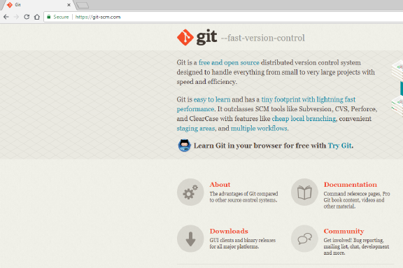
DRAFT
Appendix A
Installing git
This will contain instructions to install the git version control system.
Figure A.1:
42
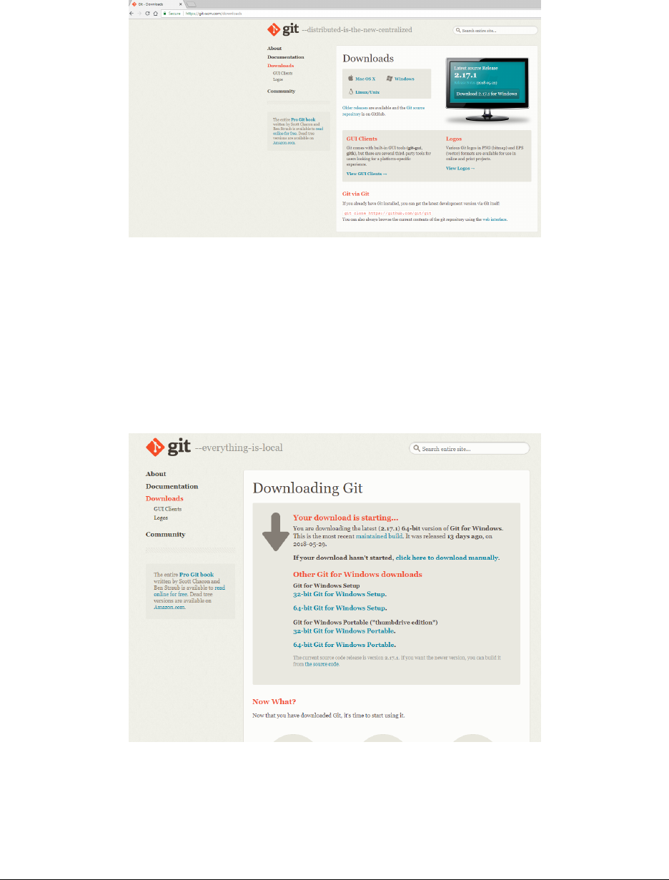
DRAFT
APPENDIX A. INSTALLING GIT
Figure A.2:
Figure A.3:
Page 43, Revised on January 3, 2019 by Charles Carter
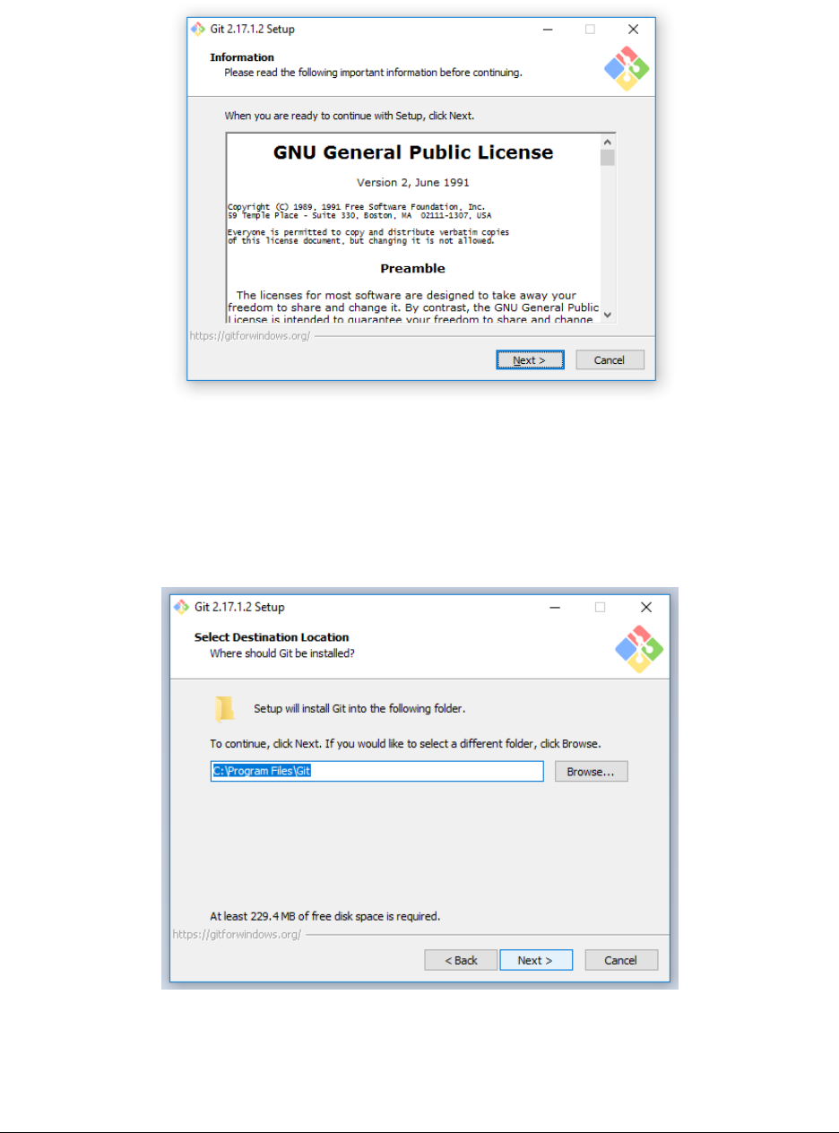
DRAFT
APPENDIX A. INSTALLING GIT
Figure A.4:
Figure A.5:
Page 44, Revised on January 3, 2019 by Charles Carter
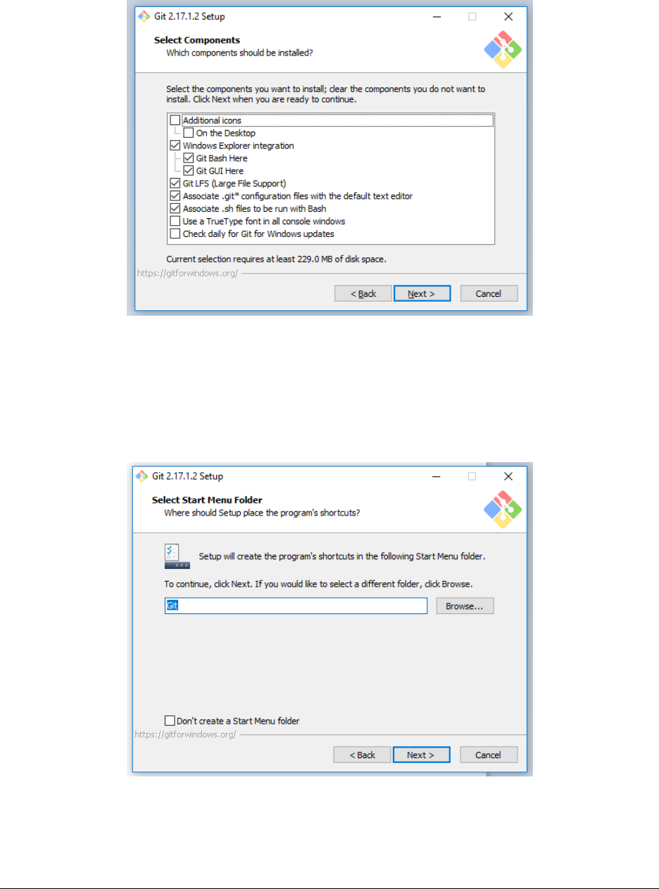
DRAFT
APPENDIX A. INSTALLING GIT
Figure A.6:
Figure A.7:
Page 45, Revised on January 3, 2019 by Charles Carter
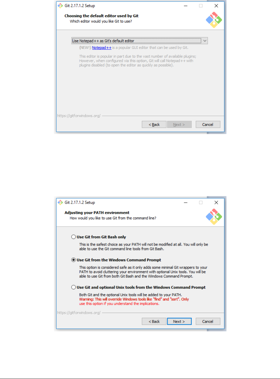
DRAFT
APPENDIX A. INSTALLING GIT
Figure A.8:
Figure A.9:
Page 46, Revised on January 3, 2019 by Charles Carter
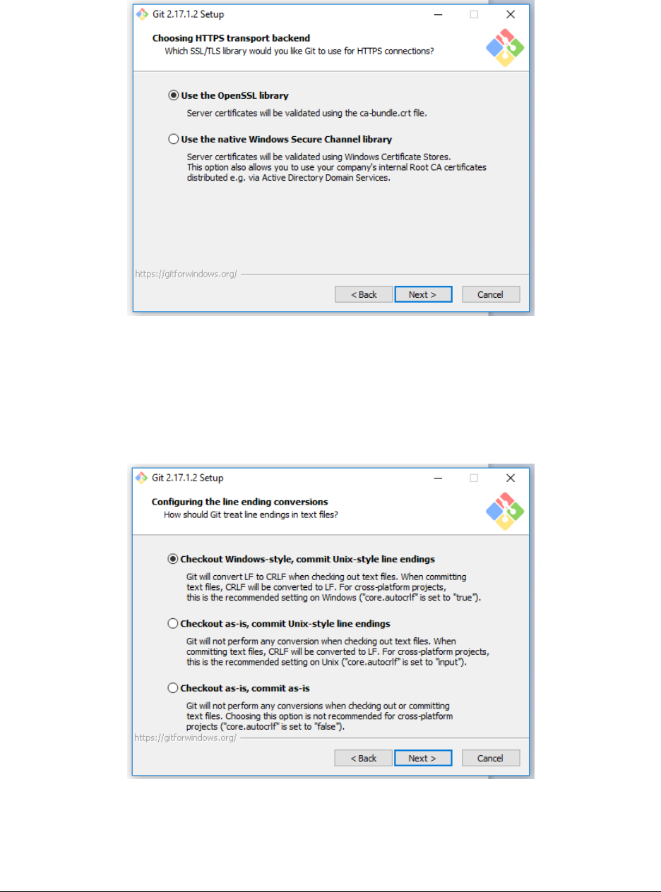
DRAFT
APPENDIX A. INSTALLING GIT
Figure A.10:
Figure A.11:
Page 47, Revised on January 3, 2019 by Charles Carter
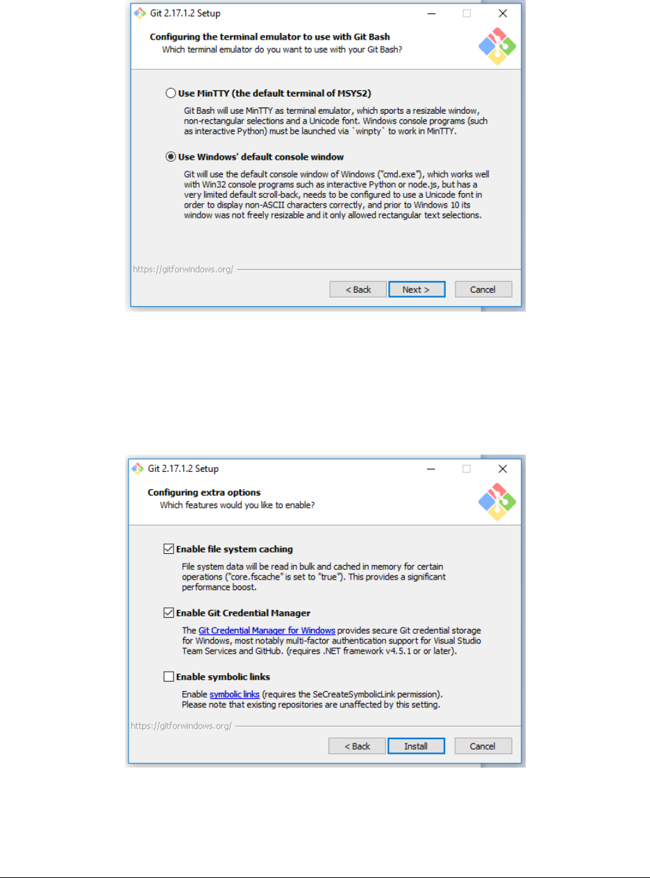
DRAFT
APPENDIX A. INSTALLING GIT
Figure A.12:
Figure A.13:
Page 48, Revised on January 3, 2019 by Charles Carter
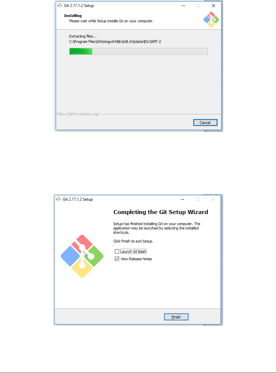
DRAFT
APPENDIX A. INSTALLING GIT
Figure A.14:
Figure A.15:
Page 49, Revised on January 3, 2019 by Charles Carter
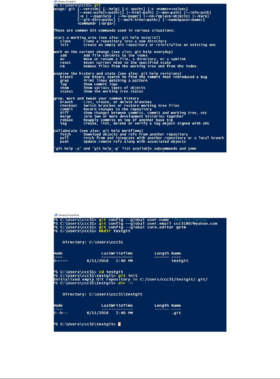
DRAFT
APPENDIX A. INSTALLING GIT
Figure A.16:
Figure A.17:
Page 50, Revised on January 3, 2019 by Charles Carter
DRAFT
Appendix B
Poor Man’s Console MVC
by Grzegorz Ziemonski,
Apr. 21, 2017,
Source: https://dzone.com/articles/poor-mans-console-mvc
Note: This implementation uses the Java programming language, not C#.
As MVC has gotten more muddled, it’s important to remember that there should be a clear connection
between controllers and concepts.
After two posts of pure theory about the MVC Pattern Language, I was looking to provide some practical
examples. The technical part is easy everybody already knows how to implement that in various ways, but
I couldnt figure out how to show the whole mental models part of it. In the end, I came up with what follows
an MVC Pet Clinic in the console!
As we learned in the previous posts, on the idea level, MVC is most concerned with understanding the
users way of thinking. Therefore, we wont jump straight into code here. Instead, well visit a real pet clinic
on the outskirts of your town and watch our user at work.
B.1 She Ain’t a Computer Lady
The clinic that hired you is actually a small office that consists of a few rooms, the most important being
the visiting room. The old lady that runs the place has no computer at the moment and you keep wondering
why does she want to pay so much money for dedicated software. After a while, you conclude that this is
exactly the kind of person who needs a dedicated piece of software. If you tried to give her the Springs Pet
Clinic and call it a day, she’d be totally lost in it. You need to create a habitable environment for her, as
she’ll be learning both using the computer and your program at the same time.
B.2 Gathering Requirements
Instead of acting like an idiot and asking the old lady for the requirements directly, you sit quietly and watch
her work for a few hours. This gives you a pretty good idea of her workflow.
She keeps track of all her visits inside a calendar. When somebody calls to schedule a visit, she asks
about the persons name, pet names and preferred visit time. Then, when both sides agree on the time of
the visit, she notes it down in her calendar.
When the visit time comes, the old lady takes out pets files, which contain all important information
about their health history. Then she takes care of the pet itself. Not much interesting stuff here. She makes
the same youre so lovely face every time and solves all kinds of problems from a pet being actually sick
to being moody and not wanting to play with its owner (sigh). After she finishes the care-taking stuff,
she sits down and writes a short summary of the visit. The summary consists of two parts course and
recommendations. She always writes down two copies one for the owner and one to put in the pets file.
51

DRAFT
B.3. MODELING THE DOMAIN APPENDIX B. POOR MAN’S CONSOLE MVC
B.3 Modeling the Domain
You tried talking to the woman about the veterinary domain but it seems that talking to her about abstract
terms and relationships is as productive as talking with you about Malaysian poetry of the 19th century.
Luckily, the concepts behind scheduling a visit seem easy enough to create the first prototype without
creating an advanced domain model. You start off with something like this:
B.4 Whats in the Lady’s Head?
As we said before, simply creating a CRUD for visits, pets, and owners is not enough. We want better than
this. Therefore, we have to look for things that will make the user instantly familiar with our software;
something that improves his workflow instead of completely turning it around. In the case of our vet lady,
these things would be the visit calendar and the pet files.
The physical calendar that the lady uses looks like a big notebook in which every two pages represent a
single week. When a visit is scheduled, she notes things down using a specific format: hour goes first, then
the owners name and the pets in the end.
The pet files are cardboard folders containing all of the summaries from the previous visits and occasion-
ally some other medical documentation. The old lady keeps them in a desks locker, sorted alphabetically so
that she can find the right one faster when the visit starts.
B.5 Implementing a Visit Calendar
The visit calendar will become a business object in our system. Since there will be quite a lot console
printing and input parsing, well separate it into the famous MVC triplet: model, view, and controller. This
triplet should work together to give the lady a feeling that shes working with her old calendar, just that the
calendar is now computerized. Therefore, well keep the weekly grouping of visits and allow her to switch
the weeks like shed be flipping pages in her old calendar. Well also print the visit information in a format
similar to the one she used in her old calendar. I did some basic implementation, lets take a look at it.
B.6 Controller
So far our controller recognizes three commands: next and previous, which change the calendars week, and
add, which allows for adding a visit to the calendar:
Listing B.1: The Controller
1public class VisitCalendarController implements Controller {
2// field, c-tor
3public boolean execute(String command) {
4if ("next".equals(command)) {
5visitCalendar.nextWeek();
6return true;
7}
8if ("previous".equals(command)) {
9visitCalendar.previousWeek();
10 return true;
11 }
12 if (command.startsWith("add")) {
13 parseAdd(command);
14 return true;
15 }
16 return false;
17 }
18 // parseAdd method
19 }
Page 52, Revised on January 3, 2019 by Charles Carter

DRAFT
B.7. MODEL APPENDIX B. POOR MAN’S CONSOLE MVC
B.7 Model
The model is responsible for holding the information about the currently selected week and allows manipu-
lating the underlying visits. By the means of changed() method, it lets the view know whenever something
changes in the calendar:
Listing B.2: The Model
1public class VisitCalendar extends Model {
2static final DayOfWeek[] OPEN_DAYS = {MONDAY, TUESDAY, WEDNESDAY, THURSDAY, FRIDAY, SATURDAY
};
3private Week currentWeek;
4private Visits visits;
5// c-tor
6Week getCurrentWeek() {
7return currentWeek;
8}
9void nextWeek() {
10 this.currentWeek = currentWeek.next();
11 changed();
12 }
13 void previousWeek() {
14 this.currentWeek = currentWeek.previous();
15 changed();
16 }
17 List<Visit> visitsOn(DayOfWeek day) {
18 return visits.on(currentWeek.get(day));
19 }
20 void addVisit(DayOfWeek dayOfWeek, LocalTime time, String ownerName, String[] petNames) {
21 // stuff
22 changed();
23 }
24 }
B.8 View
The view displays weekly visits in a format similar to the one already used by the vet lady and accepts users
commands:
Listing B.3: The View
1public class VisitCalendarView implements View {
2// fields, c-tor
3public void modelChanged() {
4show();
5}
6public void show() {
7show(visitCalendar.getCurrentWeek());
8for (DayOfWeek day : VisitCalendar.OPEN_DAYS)
9show(day);
10 askForCommand();
11 }
12 private void show(Week week) {
13 System.out.println(week.getStart() + " - " + week.getEnd());
14 }
15 private void show(DayOfWeek day) {
16 System.out.println(day + ":");
17 show(visitCalendar.visitsOn(day));
18 }
19 private void show(List<Visit> visitsOnDay) {
20 if (visitsOnDay.isEmpty()) {
21 System.out.println("No visits!");
22 } else {
23 visitsOnDay.forEach(this::show);
24 }
Page 53, Revised on January 3, 2019 by Charles Carter

DRAFT
B.9. CONCLUSION AND NEXT STEPS APPENDIX B. POOR MAN’S CONSOLE MVC
25 }
26 private void show(Visit visit) {
27 System.out.println(visit.getTime() + ": " + visit.getOwnerName());
28 System.out.println("Pets: " + visit.getPetNames());
29 }
30 private void askForCommand() {
31 try (Scanner scanner = new Scanner(System.in)) {
32 String command;
33 do {
34 command = scanner.nextLine();
35 } while (!controller.execute(command));
36 }
37 }
38 }
B.9 Conclusion and Next Steps
Thats everything I did in this prototype so far. The whole source code is available here.1As you probably
noticed, theres no technical rocket science in there and not even any new concept at the first glance. I think
the most important thing about this example is that the user is communicating directly with the business
objects. Shes not talking to some generic VisitController, which talks to some generic VisitService. Instead,
were exposing her to communication with an object she already knows the VisitCalendar.
In the next post, I’ll try to move our visit calendar to the web and we’ll see how the concept of business
objects plays with so-called Web MVC frameworks like Spring MVC. If I have enough time (which is unlikely,
but possible), I’ll try to add the second business object to the system the pet files. Obviously, if someone
from the readership wants to try their strengths in doing that, pull requests are welcome!
1https://github.com/tidyjava/console-mvc-pet-clinic
Page 54, Revised on January 3, 2019 by Charles Carter
DRAFT
Last note
The last word.
55
