CALDON LEFM 280CiRN Liquid Ultrasonic Flowmeter Data Sheet
User Manual: Resource Library
Open the PDF directly: View PDF ![]() .
.
Page Count: 7
APPLICATIONS
■ Custody transfer
■ Check or allocation metering
■ Leak detection/line balance
■ Heavy oil installations
BENEFITS
■ Reliable and long-term stability
■ Smaller prover size
FEATURES
■ Insensitivity to swirl
■ Electronics can be integrally or
remote mounted
■ Available in 6- to 40-in sizes
■ ± 0.10% linearity over the nominal
flow range
■ No limit on operating Reynolds number
■ OIML R 117-1 Edition 2007 (E); Accuracy
Class 0.3
■ Third generation (G3) electronics
Measuring oils with high viscosity and/or in low flow conditions may involve operating at Reynolds
numbers below 10,000. Ultrasonic flowmeter performance has traditionally been degraded for
Reynolds numbers below 10,000 because the liquid velocity profile erratically switches between
laminar and turbulent characteristics.
Cameron has developed a new ultrasonic flowmeter design with a reduced bore and a special nozzle
shaped entry in which the liquid velocity profile is stabilized by forces much larger than the forces
imposed by fluid viscosity. The meter design stabilizes the flow profile while preventing boundary
layer separation under all operating conditions, greatly improving performance.
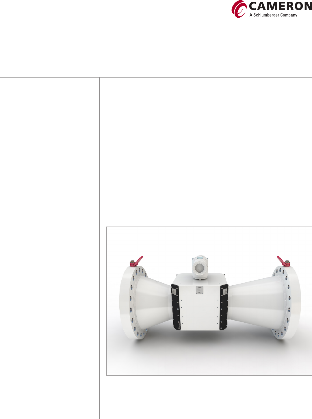
The CALDON* LEFM 280CiRN Series eight-path reduced nozzle liquid ultrasonic flowmeter provides
the highest possible performance and has an excellent success rate of achieving a data spread of
0.05% in five prover runs.
Meter construction
The CALDON LEFM 280CiRN meter body is designed and manufactured in accordance with ASME
B31.3 Process Piping Code or the Pressure Equipment Directive (PED) 97/23/EC and is suitable
for handling pressurized liquid hydrocarbons. It has 16 piezoelectric transducer modules (typically
1.0MHz or 1.6 MHz) forming four chordal paths. These are mounted in pressure containing housings
and can be replaced while the meter body is under operating pressure. Ingress protection rating for
transmitter and meter body is IP66 (NEMA 4/4x).
CALDON LEFM 280CiRN
Ultrasonic flowmeters
CALDON LEFM 280CiRN ultrasonic flowmeter
CALDON LEFM 280CiRN
Sizes, Maximum Flow Rates and K-factors,
Based on a Maximum Inlet Velocity of 25 ft/s [7.62 m/s]
Size,
in DN Nominal maximum flow,
bbl/h [m³/h] K-factor,
P/bbl [P/m³]
6150 3,210 [510] 2,000 [12,600]
8200 5,660 [900] 2,000 [12,600]
10 250 8,870 [1,410] 1,000 [6,300]
12 300 12,710 [2,020] 500 [3,150]
14 350 15,100 [2,400] 350 [2,200]
16 400 19,910 [3,165] 350 [2,200]
18 450 25,540 [4,060] 250 [1,570]
20 500 31,075 [4,940] 200 [1,000]
Standard End Connections and Maximum Working Pressure†
ANSI B16.5 raised face Stainless steel Carbon steel
Class 150 275 psi [19.0 bar] 285 psi [19.6 bar]
Class 300 720 psi [49.6 bar] 740 psi [51.1 bar]
Class 600 1,440 psi [99.3 bar] 1,480 psi [102.1 bar]
Class 900 2,160 psi [148.2 bar] 2,220 psi [153.2 bar]
Class 1500 3,600 psi [248.2 bar] 3,705 psi [255.3 bar]
† Maximum working pressure at −20–100degF [−29–38degC]
Standard Materials of Construction
Meter body Stainless steel Carbon steel
Flanges Stainless steel Carbon steel
Body Cast or forged stainless steel Cast or forged carbon steel
Manifold covers Stainless steel or aluminum Aluminum
Transducer housings Stainless steel 316 stainless steel or Inconel
Junction boxes (remote transmitter) Copper-free aluminum or optional cast stainless steel
Compact transmitter enclosure Standard Optional
Copper-free aluminum Stainless steel
Consult Cameron for other material options.
Size,
in DN Nominal maximum flow,
bbl/h [m³/h] K-factor,
P/bbl [P/m³]
24 600 45,230 [7,190] 150 [940]
26 650 54,665 [8,690] 100 [630]
28 700 63,690 [10,125] 100 [630]
30 750 73,540 [11,690] 85 [530]
32 800 83,760 [13,315] 85 [530]
34 850 95,145 [15,125] 60 [380]
36 900 106,940 [17,000] 60 [380]
Consult Cameron for other sizes. K-factor is based on ~ 1.1 KHz output at maximum nominal rate. Other K-factors
can be programmed but should be between 4 Hz and 10 KHz output at all operating flow rates. Meters are
typically sized for a 15:1 flow range (from maximum flow) for sizes 4–8 in, 10:1 for sizes 10 in and larger.

CALDON LEFM 280CiRN
General Specifications
Electronics
Power requirements—DC power
Voltage 24 VDC (18–30 VDC)
Current draw 0.25 A at 24 VDC
Power consumption 6 W
Power requirements—AC power
Voltages 120 (60 Hz) /230 (50 Hz) VAC
Voltage range 108–253 VAC
Frequency range 47–63 Hz
Current draw 0.14A
Power consumption 7.3 W
Relative humidity 0–95%
Operating temperature −58–158 degF [−50–70 degC]
Local display 400 pixel × 240 pixel LCD showing flow, diagnostics data, and alarms
Remote mounting electronics from meter 328 ft [100 m]
Analog inputs (three) 4–20 mA configured for pressure, temperature, or other
RTD input Meter body temperature
Analog outputs (two) 4–20 mA (max load 650 Ohms)
Digital outputs
Flow Four pulse output channels
Programmable K-factor
Programmable configuration:
1. Dual frequency set-up, 50/50 duty cycle
Channel B lags channel A by 90° for forward flow
Channel B leads channel A by 90° for reverse flow
2. Frequency and direction, 0 duty cycle
Channel B indicates flow direction
Forward flow = 0
Reverse flow = High (5 VDC or 12 VDC)
3. Alternating, forward flow frequency on
Channel A only reverse flow frequency
On channel B only 50/50 duty cycle
Alarm status Four outputs, 0–5 VDC or 0–12 VDC selectable
(0volts = alarm)
Communication Three serial
Ethernet or fiber modem
Meter Body
Relative humidity 0–95%
Operating temperature
Stainless steel −58–284 degF [−50–140 degC]
Low-temperature carbon steel −50–284 degF [−46–140 degC]
See Electrical Safety Approvals for specific approval limits.
Compliance with NACE MR0175 is available
CALDON LEFM 280CiRN
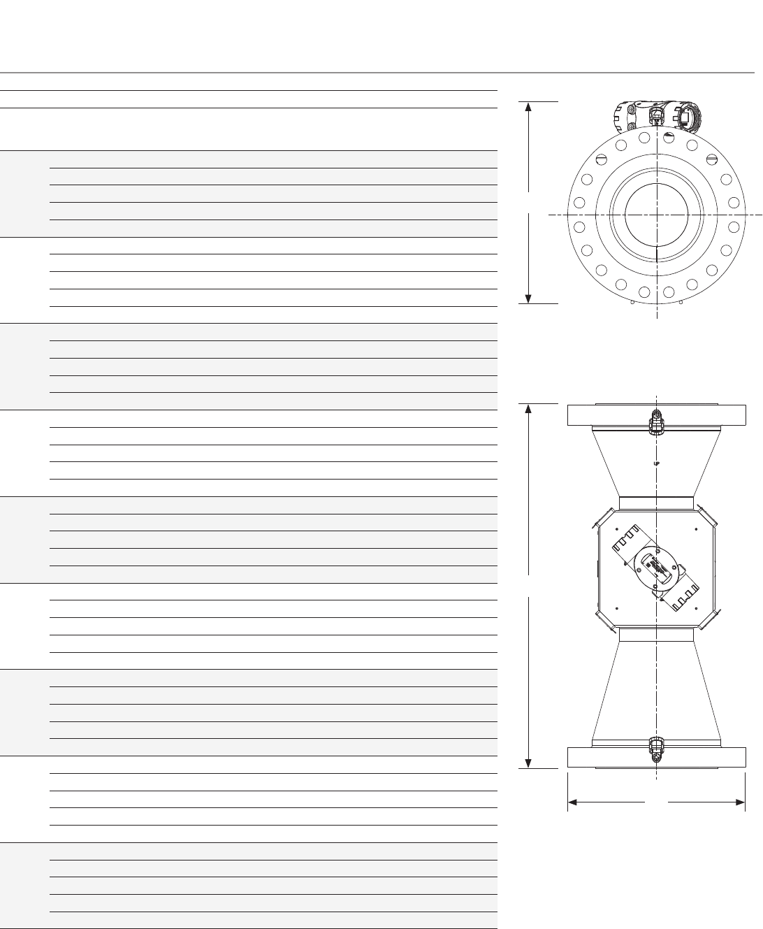
Dimension and Weights for LEFM 280CiRN (Integral Manifold) with Compact Transmitter
Pipe
size,
in [DN]
ANSI
class Length (L),
in [mm] Max width (W)†
(including manifolds and
sunshield), in [mm]
Height (H),
in [mm] Assembled meter
weight with Xmtr‡,
lbm [kg]
6 [150] 150 20.2 [513] 17.7 [450] 29.52 [749.8] 382 [173]
300 20.9 [532] 17.7 [450] 29.52 [749.8] 433 [196]
600 21.7 [551] 17.7 [450] 29.52 [749.8] 523 [237]
900 22.2 [564] 17.7 [450] 30.12 [765.1] 606 [275]
1500 22.4 [570] 17.7 [450] 29.54 [750.3] 726 [329]
8 [200] 150 22.3 [567] 17.7 [450] 35.92 [912.3] 587 [266]
300 23.1 [586] 17.7 [450] 35.92 [912.3] 665 [302]
600 23.8 [605] 17.7 [450] 35.92 [912.3] 813 [369]
900 24.8 [630] 18.5 [470] 36.40 [924.7] 1,005 [456]
1500 25.1 [637] 19.0 [483] 34.98 [888.5] 1,193 [541]
10 [250] 150 23.6 [598] 17.7 [450] 40.28 [1,023.1] 659 [299]
300 24.3 [618] 17.7 [450] 40.28 [1,023.1] 781 [354]
600 25.6 [649] 20.0 [508] 40.28 [1,023.1] 1,053 [478]
900 26.3 [668] 21.5 [546] 41.19 [1,046.1] 1,290 [585]
1500 27.1 [687] 23.0 [584] 39.87 [1,012.6] 1,713 [777]
12 [300] 150 26.3 [668] 19.0 [483] 46.11 [1,171.2] 997 [452]
300 27.1 [687] 20.5 [521] 46.11 [1,171.2] 1,150 [522]
600 27.8 [706] 22.0 [559] 46.11 [1,171.2] 1,488 [675]
900 28.8 [732] 24.0 [610] 47.07 [1,195.7] 1,882 [854]
1500 30.1 [764] 26.5 [673] 45.21 [1,148.5] 2,687 [1,219]
14 [350] 150 28.2 [716] 21.0 [533] 50.21 [1,275.4] 1,363 [618]
300 29.2 [741] 23.0 [584] 50.21 [1,275.4] 1,628 [738]
600 29.6 [751] 23.8 [603] 50.21 [1,275.4] 1,959 [889]
900 30.3 [770] 25.3 [641] 51.23 [1,301.1] 2,433 [1,104]
1500 32.4 [824] 29.5 [749] 50.59 [1,285.0] 3,724 [1,689]
16 [400] 150 29.4 [748] 23.5 [597] 55.37 [1,406.5] 1,521 [690]
300 30.4 [773] 25.5 [648] 55.37 [1,406.5] 1,855 [841]
600 31.2 [792] 27.0 [686] 55.37 [1,406.5] 2,388 [1,083]
900 31.6 [802] 27.8 [705] 57.05 [1,449.1] 2,867 [1,300]
1500 33.9 [862] 32.5 [826] 54.10 [1,374.0] 4,539 [2,059]
18 [450] 150 31.4 [799] 25.0 [635] 61.63 [1,565.4] 1,993 [904]
300 32.9 [837] 28.0 [711] 61.63 [1,565.4] 2,451 [1,112]
600 33.6 [852] 29.3 [743] 61.63 [1,564.4] 3,184 [1,444]
900 34.4 [875] 31.0 [787] 62.98 [1,599.8] 4,034 [1,830]
1500 36.9 [938] 36.0 [914] 60.12 [1,526.9] 6,145 [2,787]
20 [500] 150 33.4 [849] 27.5 [699] 65.93 [1,674.7] 2,416 [1,096]
300 34.9 [887] 30.5 [775] 65.93 [1,674.7] 3,953 [1,793]
600 35.7 [906] 32.0 [813] 65.93 [1,674.7] 4,018 [1,823]
900 36.6 [929] 33.8 [857] 67.70 [1,719.5] 5,017 [2,276]
1500 39.1 [992] 38.8 [984] 63.98 [1,625.1] 7,546 [3,423]
24 [600] 150 36.9 [938] 32.0 [813] 77.11 [1,958.6] 3,357 [1,523]
300 38.9 [989] 36.0 [914] 77.11 [1,958.6] 4,274 [1,939]
600 39.4 [1,002] 37.0 [940] 77.11 [1,958.6] 5,879 [2,667]
900 41.4 [1,053] 41.0 [1,041] 78.88 [2,003.6] 8,336 [3,781]
1500 46.0 [1,168] 46.0 [1,168] 74.42 [1,890.2] 1,1759 [5,334]
† On sizes up to 10-in Class 600 the sun shield is widest; on larger sizes the flange is the widest.
‡ Consult Cameron for weights of cast or other meter construction.
16-in
×
10-in LEFM 280CiRN ultrasonic flowmeter,
side view.
H
W
L
16
×
10-in LEFM 280CiRN ultrasonic flowmeter,
top view.
CALDON LEFM 280CiRN
General Performance
Application High viscosity oils and or low flow rates that can create Reynolds numbers less than 10,000; any application involving in situ calibration of the
meter using a pipe prover or small volume prover (SVP).
Linearity ± 0.10% over the nominal 15:1 flow range for each size meter.
Repeatability/uncertainty 0.02%; calibrated per API MPMS Chapter 5.8 Table B-1 to achieve a meter factor uncertainty of ± 0.027%.
Sizes 6–36 in (nominal pipe size).
Long term stability Meter factor is unaffected by usage.
Flow range 15:1 based on nominal maximum flow rate above.
Custody transfer approval OIML R 117-1 Edition 2007 (E); Accuracy Class 0.3.
Pressure loss Approximately 5 psi at maximum flow (diffuser recovers 70% of the velocity head differential).
Water in oil The meter can operate on water in oil content as high as 50% provided the water in oil are well mixed, typically at velocities above 6.5 ft/s
[2.5 m/s]. Meter operation may be affected if the water and oil phases separate or are not well mixed. Contact Cameron for further advise on
high water-cut applications.
Viscosity Maximum allowable viscosity is based on the meter size and the maximum allowable signal strength/attenuation. Consult Cameron for fluid
viscosity greater than 1,000 cSt.
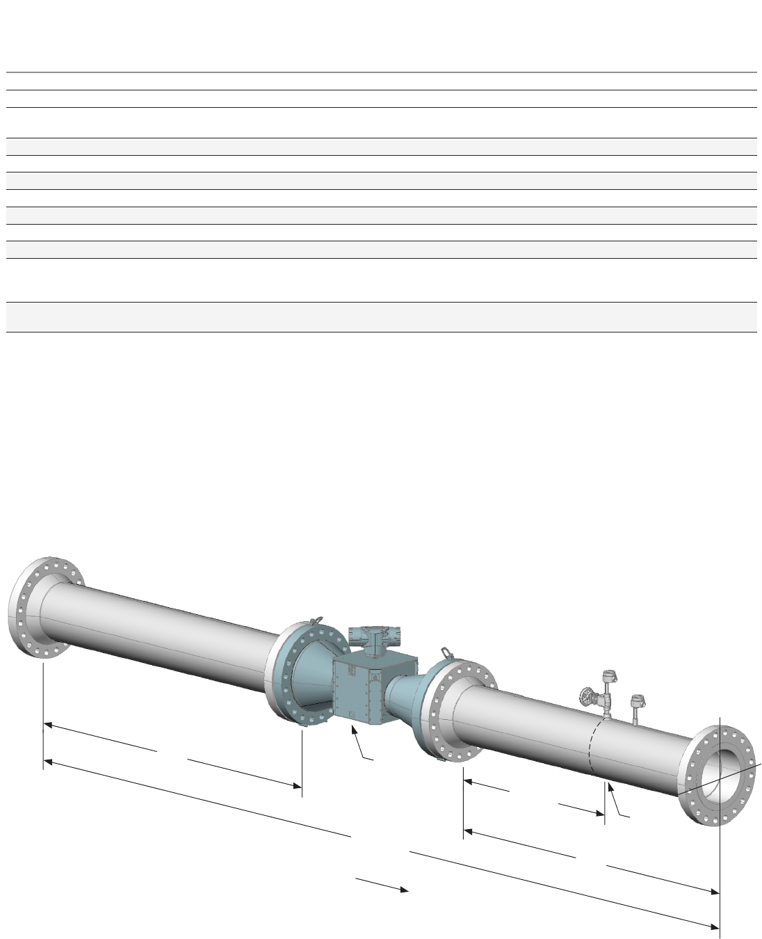
Installation
In order to limit uncertainty caused by hydraulic effects, it is recommended that the installation of the LEFM 280CiRN flowmeter
comply with the following guidelines. The adjoining straight pipe should be of the same schedule as the meter. Temperature elements
and pressure connections should be located downstream of the meter. The LEFM280CiRN flowmeter does not normally require the
use of a flow conditioning element. An uninterrupted upstream pipe five pipe diameters in length is adequate in most applications.
In situations where there is a constriction upstream of the meter that
is smaller than the diameter of the meter run piping (such as a reduced
bore valve), it is recommended that this be separated from the meter by a
pipe at least 10 pipe diameters in length. Downstream of the meter there
should be an uninterrupted pipe at least three pipe diameters in length.
For application specific recommendations or more detailed installation
guidance, please consult Cameron.
Flow
Meter Edge of
sock-o-let
Pressure
Temperature
~5D ~5D
3D Min.
Meter run
CALDON LEFM 280CiRN ultrasonic rendered meter run
CALDON LEFM 280CiRN
Meeting the challenge
Getting the results
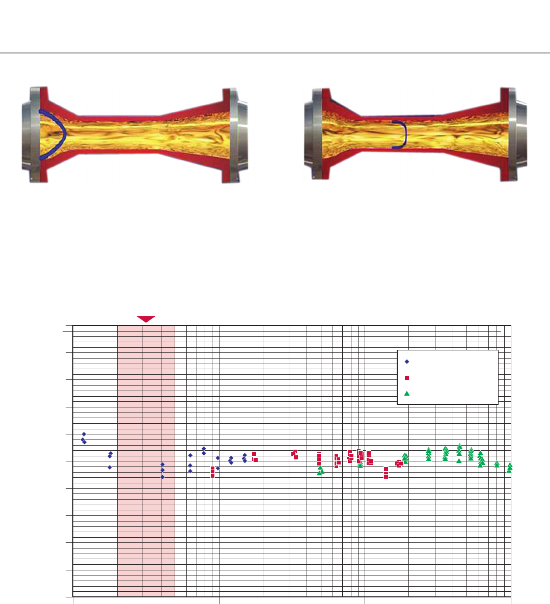
The graph above is a plot of meter factor versus Reynolds number for a 16-in LEFM 280CiRN reduced bore ultrasonic flowmeter calibrated using three oils.
The reduced bore design maintains performance from turbulent flow, through the transition range, and down into laminar flow. This data was taken over a
25:1 range in flow rate which equated to a 1000:1 range in Reynolds number.
1,000
0.9900
0.9920
0.9940
0.9960
0.9980
1.0000
1.0020
1.0040
1.0060
1.0080
1.0100
10,000
Reynolds number
Laminar to turbulent transition
Meter factor
100,000
1,000,000
Drakeol 32, 20 degC
Drakeol 5, 20 degC
Exxsol D80, 20 degC
The above cutaway views of a reduced bore ultrasonic flow meter illustrate how transition flow velocity profiles at the inlet (left), which can change
erratically between laminar and turbulent characteristics at any given flow rate, are stabilized by the forces in the throat of the meter (right). This greatly
improves short term repeatability of the reduced bore design compared to a full bore design for transition flow.
CALDON LEFM 280CiRN
*Mark of Schlumberger
Other company, product, and service names
are the properties of their respective owners.
Copyright © 2016 Schlumberger. All rights reserved. MS-1029—ML309 Rev 2
cameron.slb.com/ultrasonicmeter
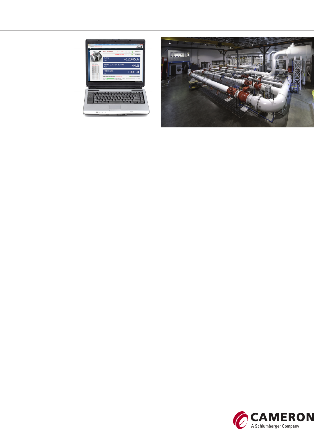
LEFM SystemLink G3
The LEFM SystemLink G3 user
interface software technology
allows access to real-time
diagnostic data, historical data,
and event logs from a G3 ultrasonic
flowmeter by using an Ethernet/
fiber optic modem connection.
Historical data and event logs are
stored within the G3 transmitter,
thus allowing for later retrieval—
giving operators ability to monitor
and analyze critical diagnostics,
helping prevent unplanned downtime.
LEFM SystemLink G3 features:
Health overview report show the current meter status as well as meter
process measurements including flow rate, temperature, and pressure
■ Detailed charts and graphs present the meter diagnostic information
in an easy-to-understand format with alarm limits that help
identify issues
■ User defined reference points are built using the meter's stored
data. These reference points allow the user to graphically compare
current meter performance against user defined reference points. For
example, current performance can be compared against calibration or
commissioning data.
■ Export data as both predefined PDF reports or to customer defined
Excel spreadsheets.
Calibration lab
The Cameron Hydrocarbon Calibration Laboratory is a state-of-the-art
facility located in Pittsburgh, PA. Every Caldon LEFM 200 series ultrasonic
flowmeter is calibrated in this laboratory using up to three oils. The
ability to use multiple oils allows calibration over a Reynolds number
range that includes that of the customer's application. This ensures meter
performance will be unaffected by changes in flow rate and viscosity once
the meter is installed.
