C:\wswin\docs\cats\CATS MAN Cats Manual
User Manual:
Open the PDF directly: View PDF ![]() .
.
Page Count: 28

CATSTM User's Manual
Aug 1, 2000
PRAGMATIC COMMUNICATIONS SYSTEMS, INC.

Table of Contents
Introduction
Description 3
......................................................................................
Features 4
.........................................................................................
Installation 10...............................................................................
Rear Panel diagrams 11........................................................................
IR detector / emitter 14..........................................................................
A/V connections 15...............................................................................
CAT5 cable 16....................................................................................
Power 17...........................................................................................
IR remote 18......................................................................................
Operation 19.................................................................................
Router command set 21.........................................................................
Receiver/Transmitter command set 23.......................................................
Appendix:
CAT 5 wiring 26..................................................................................
Troubleshooting Hints 27.......................................................................
Page 2
CATS
TM
User's Manual

Technology
for
Home
Theater
The CATSTM system: A very high performance broadcast quality audio/video distri-
bution system on category 5 wires.
Description
Pragmatic Communications Systems, Inc., proudly announces a new standard which
overcomes the problems inherent with today's heavy gauge cables and traditional
video distribution delivery systems. The CATSTM Audio/Video system is a very high
performance system for the distribution of broadcast quality video signals on inex-
pensive category 3 or category 5 wires, based on PCSi's proprietary Bandwidth Do-
main Signal Processing (BDSPTM) technology. This proprietary BDSPTM technology
enables transmission of the highest quality audio/video signals up to 1000 ft. on a
standard category 5 or un-shielded twisted pair wires without any loss in the perfor-
mance, dynamic range, or quality.
The state-of-the-art BDSPTM technology completely eliminates any ground loops,
noise pick-up, or hum at the end of the transmission distance. It also provides for su-
perb video reproduction, and a very high resolution to fine details in the picture qual-
ity, achieved by the high bandwidth signal transmission.
The CATSTM A/V system is the ultimate in audio/video signal distribution. Up to 16
receivers can be daisy-chained or tapped on to the category 5 wires. The CATSTM sys-
tem transmitter accepts audio/video signals from any high quality source, such as a
DVD player or DSS receiver, and transmits it on the category 5 wires. The CATSTM
system receiver recovers the signal from the category 5 wires and superbly repro-
duces the original audio/video signals utilizing the BDSPTM technology.
There are numerous advantages of the CATSTM system. First, it allows the multi-
point distribution and broadcasting of video signals to any location within 1000 ft. on
a category 5 wire. Up to 16 receivers can be connected in parallel or daisy-chained to-
gether on a single wire within the coverage area to provide a complete omnipresent
network. The range can be extended to many miles or many receivers beyond 16
units by configuring a simple repeater system.
Another advantage is that there are no user adjustments or alignment needed, re-
Page 3
CATS
TM
User's Manual

gardless of the distance. The signal quality does not change with distance. The re-
ceiver reproduces the same high quality audio/video output at any point along the
transmission distance. It is truly a plug-and-play system, with the added conve-
nience of easy-to-use Category 5 wiring.
The applications of CATSTM are endless. It can be used for Home Theater audio/video
distribution, broadcast TV video distribution, CCTV, perimeter monitoring, prison
system, airport security, school campuses, hospitals, etc.
For most residential applications, the CATSTM system is supplied as a fully integrated
system capable of handling both audio and video signals. For industrial or other spe-
cial applications, the CATSTM system is also available as a CATSTM Video-only sys-
tem, and a CATSTM Audio-only system.
The Model CATSTM-8BY8TAV is a switcher/router for multi-source, multi-zone distri-
bution of CATSTM signals to 8 different zones. Any input can be routed to any and all
zones, independent of how the other zones are set. Each zone output can be daisy-
chained to multiple CATSTM receivers and each zone driver is capable of driving 1000
ft. of category 5 cable. Programming and control is via serial (RS-232) input / output
connection. Zone selection is also possible through remote control from the zones.
The IR commands from the remote CATSTM receivers are interpreted by the
switcher/router micro-controller and zone selection is achieved. Independent IR LED
drivers are available for source equipment control.
Features
Audio/Video distribution over low-cost un-shielded twisted pair wires
Up to 1000 ft. distance (audio and video)
Up to 5000 ft. distance (audio only)
Up to 16 receivers for multi-point distribution
CD-quality stereo audio signals
> 6 MHz video bandwidth for high-resolution, DVD-quality video
Receiver has option for volume up/down/mute control
Optional IR control system controls receiver and remote sources
Optional RS-232 or RS-485 interfaces available
Features (with switcher/router)
8 source inputs (from CATSTM transmitters)
8 zone outputs (to CATSTM receivers)
Full-matrix switch to connect any input to any zone
Router is easily controlled from remote locations via IR or other control system
Compatible with standard home control systems: Crestron, Niles, Phast/AMX,
SmartLinc, Xantech
Page 4
CATS
TM
User's Manual

Advantages
Eliminates ground-loops, noise pickup, and hum
DVD quality video reproduction
Much higher quality than long-distance coax
Uses low-cost, multi-function category 5 cable
No adjustment or alignment necessary 0 to 1000 ft.
Superior quality over multi-bundled coax and long runs of speaker cables
Can use existing (or pre-wired) cables -- no need to run new cables!
Each room can independently select any video and audio source
Applications
Home Theater audio/video distribution
Remote video extension to bedroom or den
Send DVD, laser disc, VCR, or DSS output to remote rooms
Broadcast studio video distribution
Video extension for remote monitors
CCTV and security video distribution
Video delivery between buildings
Remote camera video monitoring
Page 5
CATS
TM
User's Manual
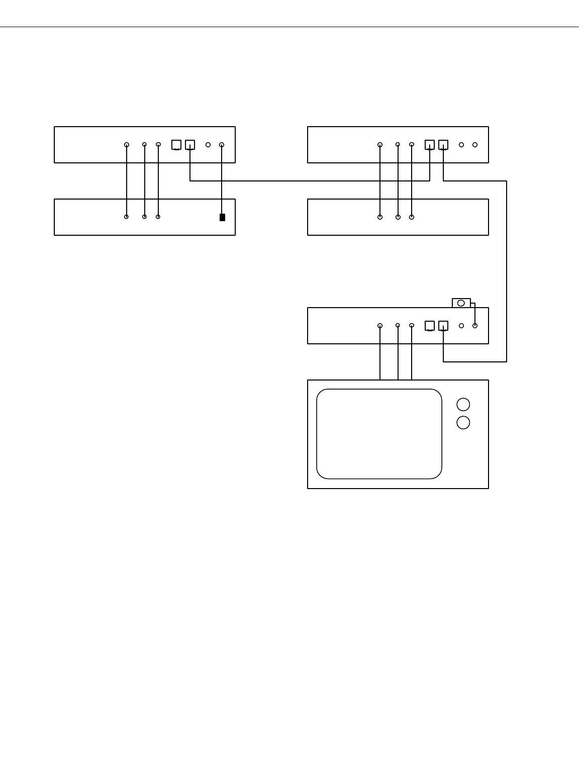
Single-source, Multi-point A/V distribution
This example shows a single A/V source being distributed to one or more destina-
tions. The A/V source could be a DSS receiver, DVD player, CD player, security cam-
era, or any other A/V source. At each destination, the CATSTM receiver decodes the
signals from the CAT 5 cable, and provides audio/video outputs for the user. If multi-
ple receivers are being used, they are easily daisy-chained together.
Page 6
CATS
TM
User's Manual
Pragmatic Communications Systems, Inc.
Sunnyvale, CA USA
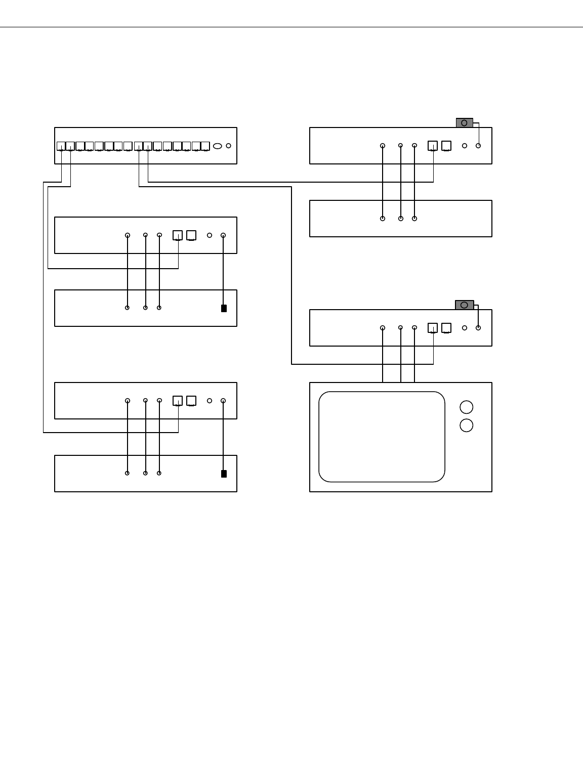
Multi-source, Multi-zone A/V distribution
This example shows multiple A/V sources being distributed to one or more destina-
tions through the CATSTM 8x8 router. Each A/V source could be a DSS receiver, DVD
player, CD player, security camera, or any other A/V source. At each destination, the
CATSTM receiver decodes the signals from the CAT 5 cable, and provides audio/video
outputs for the user. The IR control system provides full control of the router and the
source equipment from the remote location. Although this drawing only shows two
sources and two zones, the router is capable of handling up to 8 sources and up to 8
zones.
Page 7
CATS
TM
User's Manual
Pragmatic Communications Systems, Inc.
Sunnyvale, CA USA
Pragmatic Communications Systems, Inc.
Sunnyvale, CA USA
Pragmatic Communications Systems, Inc.
Pragmatic Communications Systems, Inc.
Sunnyvale, CA USA
CATS 8x8 Router

Transmitter with local source inputs
This example shows a CATSTM transmitter, with two local inputs, and one local out-
put. The local output may select between either of the two inputs. The remote re-
ceiver may select between either of the two inputs as well, independent of which input
has been selected for the local display.
Page 8
CATS
TM
User's Manual
TV or A/V display
Pragmatic Communications Systems, Inc.
Sunnyvale, CA USA
CATS transmitter
DVD
A/V Source
VCR
A/V Source
To Receiver
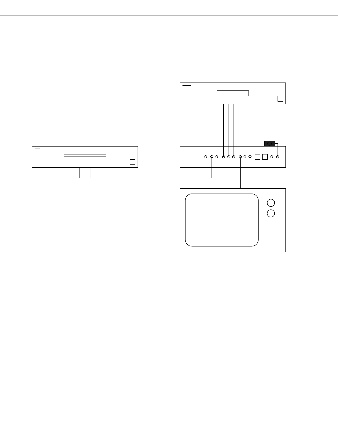
Receiver with local source inputs
This example shows a CATSTM receiver with two local inputs. The receiver has three
choices for what to display: from the transmitter, or from either of the two local in-
puts. This configuration has the advantage that all audio controls such as volume
up/down/mute are handled by the receiver in a consistent manner.
Page 9
CATS
TM
User's Manual
TV or A/V display
Pragmatic Communications Systems, Inc.
Sunnyvale, CA USA
CATS receiver
DVD
A/V Source
VCR
A/V Source
From transmitter

Quick Installation
Note: The following pages detail each step of the installation process. Here is an
overview of the installation process:
1.) Connect an IR emitter module to each transmitter unit.
2.) Connect an IR detector module to each receiver unit.
3.) Connect the A/V sources to each transmitter unit.
4.) Connect the A/V outputs from each receiver unit.
5.) Connect the CAT 5 cable to all units.
6.) Connect the power modules to all units.
7.) Setup the IR remote.
8.) System is now fully operational.
Page 10
CATS
TM
User's Manual
Important!
ð All connections should be made with the power turned OFF!

Transmitter Rear Panel
The transmitter is identified by the letter "T" on the rear panel. Each of the connec-
tors on the transmitter are as follows:
Power Input: Accepts 15VDC input from supplied transformer.
R / L: In units equipped with a built-in power amp, these are the Right and Left out-
puts from the power amplifier.
RS-232: RS-232 connector
LED (IR Output): Stereo mini-jack connector provides the IR output signal to drive
the IR emitter.
IR input: Stereo mini-jack accepts IR input from IR detector module.
Audio Inputs: These two inputs accept standard "line-level" stereo audio signals
from the A/V source. Right and Left channels are as indicated.
Audio Output: This is the local audio output. Either input source can be selected.
Video Input: These two inputs accept a standard 1-volt p-p video input signal from
the A/V source.
Video Output: This is the local video output.
CAT 5 connectors: These two connectors provide the output signal to drive the
CAT 5 cable. Standard RJ-45 connectors are used. Two outputs are provided to
make it easier to connect to multiple receivers. For cable pair usage, refer to the Ap-
plication Note on page 26.
Page 11
CATS
TM
User's Manual
Pragmatic Communications Systems, Inc. Sunnyvale, CA USA
Video
Audio
RL
Cat 5 Cat 5
IR
T
VideoVideo
15V DC RL
+-+-
LEDRS-232
Audio
RL
Audio
RL
In 1 In 2 Out In 1 In 2 Out
Receiver Rear Panel
The receiver is identified by the letter "R" on the rear panel. Each of the connectors
on the receiver are as follows:
Power Input: Accepts 15VDC input from supplied transformer.
R / L: In units equipped with a built-in power amp, these are the Right and Left out-
puts from the power amplifier.
RS-232: RS-232 connector
LED (IR Output): Stereo mini-jack connector provides the IR output signal to drive
the IR emitter.
IR input: Stereo mini-jack accepts IR input from IR detector module.
Audio Inputs: These two inputs accept standard "line-level" stereo audio signals
from the A/V source. Right and Left channels are as indicated.
Audio Output: This is the local audio output. Either input source can be selected.
Video Input: These two inputs accept a standard 1-volt p-p video input signal from
the A/V source.
Video Output: This is the local video output.
CAT 5 connectors: These two connectors provide the output signal to drive the
CAT 5 cable. Standard RJ-45 connectors are used. Two outputs are provided to
make it easier to connect to multiple receivers. For cable pair usage, refer to the Ap-
plication Note on page 26.
Page 12
CATS
TM
User's Manual
Pragmatic Communications Systems, Inc. Sunnyvale, CA USA
Video
Audio
RL
Cat 5 Cat 5
IR
VideoVideo
15V DC RL
+-+-
LEDRS-232
Audio
RL
Audio
RL
In 1 In 2 Out In 1 In 2 Out
R
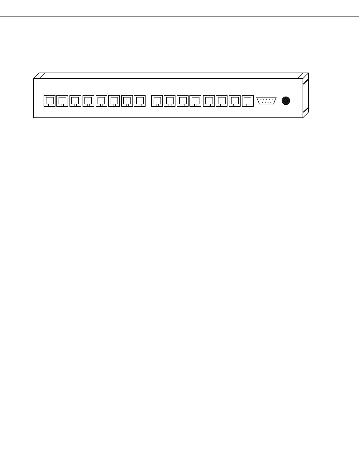
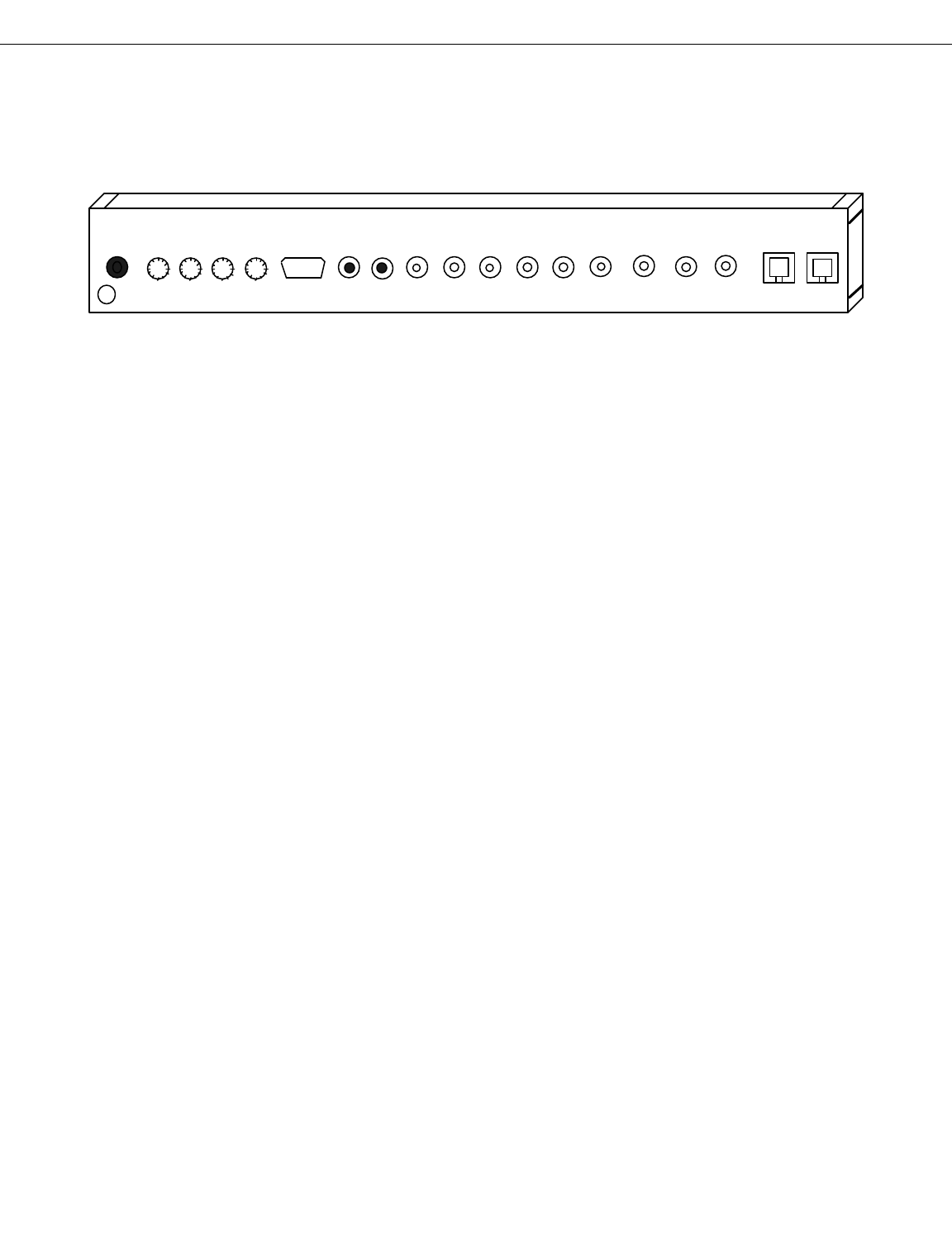
Router Rear Panel
The CATSTM 8x8 router has a set of 8 RJ-45 connectors for the input signals, and a set
of 8 RJ-45 connectors for the output signals. Each input accepts an encoded signal
from the CATSTM transmitter unit. Each output provides an encoded output signal to
drive up to 1000 feet of CAT 5 cable, and connect to the CATSTM receiver in each zone.
The RS-232 connector allows for external equipment to control the router. Refer to
the Application Note on page 21 for the command set.
Power Input: Accepts the 9 VAC power input from the supplied transformer. Im-
portant: make sure that the router is only connected to the proper AC supply, and
not a DC supply for the transmitter or receiver.
Page 13
CATS
TM
User's Manual
Pragmatic Communications Systems, Inc.
Sunnyvale, CA USA
Power
9 VACRS-232
Inputs
1 2 3 4 5 6 7 8 1 2 3 4 5 6 7 8
Outputs
IR detector / emitter Installation
Connect an IR emitter module to each transmitter unit. The IR emitter is connected
by a stereo mini jack which is located to the right of the power connector on the rear
panel.
The IR emitter should be located or attached so that it will operate the source equip-
ment.
Connect the IR detector module that came with the system to each receiver unit
and/or each transmitter unit as needed. The IR detector module is connected by a
stereo mini jack which is located to the right of the power connector on the rear panel.
Important! Do not attempt to connect an IR detector module to an LED output, nor
connect an IR emitter module to a IR detector input. Permanent damage to the
equipment may occur.
The IR detector module should be located such that it has an unobstructed view of the
room where the remote will be used. Best results are obtained if the IR detector is lo-
cated away from interfering sources such as florescent lamps, or shielded from being
directly illuminated by them.
Note: IR detectors from Xantech and others are not compatible with the CATSTM sys-
tem. Do not attempt to connect an unapproved IR detector to the system, as perma-
nent damage to the equipment may occur.
Page 14
CATS
TM
User's Manual
Important!
Always have the power turned OFF prior to connecting or disconnecting the
IR detector or emitter module.
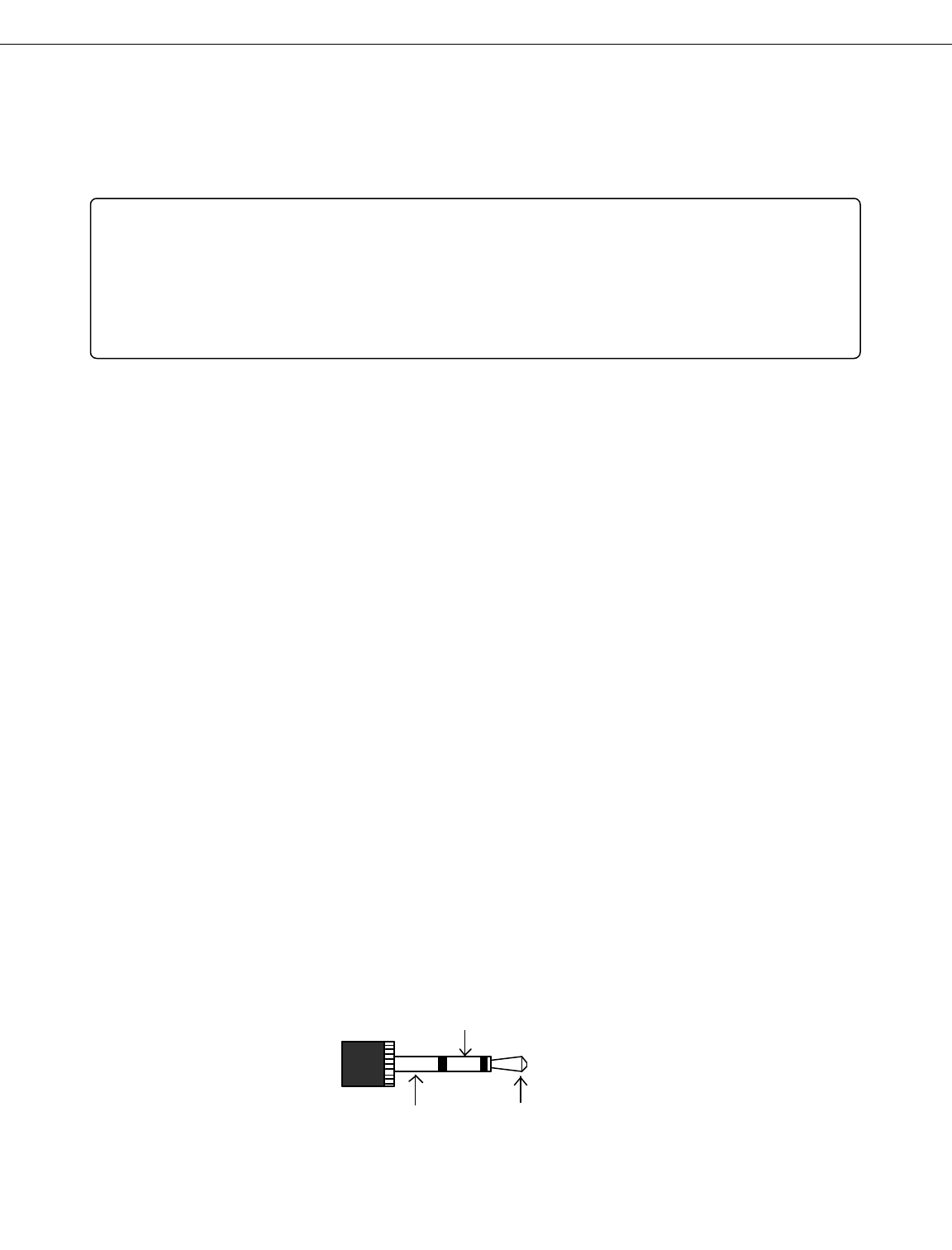
Center = IR signal
Ring = GND Tip = +5v
IR connector:

Audio / Video connections
The transmitter unit is configured to accept standard audio/video signals from a wide
variety of sources, such as DVD players, Laser disk players, DSS receivers, CD play-
ers, VCRs, and other equipment.
The stereo audio inputs accept standard "line level" audio levels.
The video input accepts standard 1 volt p-p video levels.
Important! Do not connect any audio / video source that does not conform to stan-
dard "line level" signals!
Do not exceed 3 VRms into the "line level" audio inputs. Some high-end equipment may
have higher signal levels. These should be attenuated or severe audio distortion may
occur.
The receiver unit is configured to output standard "line level" audio levels at the
stereo audio outputs, and standard 1 volt p-p video levels at the video output.
Page 15
CATS
TM
User's Manual

CAT 5 cable
Connection of the CAT 5 cable is very straightforward. The rear panels of each trans-
mitter, receiver, and router contain sockets for the RJ-45 connectors. Simply plug in
each RJ-45 connector into the appropriate socket to connect the units together into
the desired topology.
Each transmitter contains two identical outputs so that it is capable of driving multi-
ple receivers. The RJ-45 connector may be plugged into either output.
Each receiver contains two connectors to allow for multiple receivers to be easily
daisy-chained together. Connect the primary CAT 5 cable from the transmitter into
one socket. As needed, connect a daisy-chain cable from the other socket to the next
receiver. Up to 16 receivers may be daisy-chained together in this way, provided that
the total cable length is not too great, depending on the application, as each receiver
added will cut down on the maximum length.
Although the system will work in a daisy-chain configuration, that is intended for in-
dustrial or other special applications where there needs to be multiple displays for the
same source. For Home Theater applications, it is strongly recommended that for
new designs and new construction, all the wires be home-run in a star configuration
for maximum upgrade potential in the future.
The rear panel of the router has 8 input connections and 8 output connections. Con-
nect each RJ-45 connector from each transmitter unit to the appropriate input con-
nector of the router. Likewise, connect each RJ-45 connector from each receiver unit
to the appropriate output connector of the router.
It doesn't matter what type of source is connected to each input of the router, but the
chosen connections need to be clearly documented in a system application diagram so
that the user will know what the actual connections are. Pragmatic has made the fol-
lowing suggestions as to how the input sources may be assigned:
Router Inputs:
1 = DSS
2 = DVD / LD
3 = VCR1
4 = VCR2 or other
5 = CD / Mini-Disc
6 = Tuner
7 = V. Aux
8 = DAT/Tape/DCC
Page 16
CATS
TM
User's Manual

Power connections
Each unit is supplied with a "wall-wart" style UL-approved transformer to supply the
appropriate power for the unit. Important! Do not attempt to use any transformer
other than a Pragmatic supplied or approved transformer. Use of any improper
transformer may damage the unit.
The transmitter and receiver units are both designed to use a 15 VDC transformer
with 500 mA or greater capacity. Plug the power connector of the supplied trans-
former into the power receptacle on the rear panel of the transmitter and receiver.
Receivers with a built-in Power Amplifier use a 13.8 VDC transformer at 1.7 A or
greater capacity.
The router is designed to use a 9 VAC transformer (@ 1000 mA typical) for its supply.
It is extremely important to use only the proper AC transformer for the router.
Likewise, it is extremely important to make sure that the AC transformer for the
router is not used for the transmitter or receiver, to prevent permanent damage to
the units.
Page 17
CATS
TM
User's Manual

IR Remote Setup
This section only applies if the optional IR control system was purchased with the
system. In this case, an "RCA SystemLink 3" universal remote and IR detector mod-
ule for the receiver is included with the system.
The receiver responds to three different IR commands: Volume Up, Volume Down,
and Mute. There is no setup required on the remote, because the volume control com-
mands use the default settings (TV mode, code=000).
The router uses the same remote as the receiver for source input selection and con-
trol. The remote needs to be setup in "Cable" mode, code=034 . To do this, press and
hold the "Code Search" button until the red LED stays lit. Then, press the "Cable"
button to select the mode. Then enter in the code value, 034. After the third digit, the
LED turns off and the remote returns to the operational mode. This will setup the re-
mote to control the router.
Note: Selecting "Cable mode" on the remote to control the router does not affect the
volume control commands for the receiver. The volume up/down/mute keys on the re-
mote are not affected by the "Cable mode" selection which changes the operation of
the numeric keys. Thus, the remote is fully able to control both the router and re-
ceiver, without even having to change the mode selection function.
If the user desires to control the router and receiver using a learning remote, such as
the Marantz RC-2000 or similar, then follow that remote's instructions to transfer the
control codes from the RCA remote to the learning remote.
Transmitter: The transmitter uses the same IR code setup as the receiver for all local
control: volume/up/down/mute and local source select. If the transmitter has multi-
ple source inputs, then the remote also needs to be setup in "Cable" mode, code=014.
This code set only controls the transmitter from the destination location, through the
receiver. The commands used are simply "1" or "2" to select the desired source input.
Page 18
CATS
TM
User's Manual

Operation: Local Inputs
Each transmitter and receiver is equipped with two local inputs. On the transmitter,
either local input may be selected through to the local output. Selection is either with
the IR remote, simply press "1" or "2", or by an RS-232 command. Independently of
which input is selected for local output, either input may be selected for output
through the CAT-5 cable. Selection is done either from the remote location with the
IR remote, simply press "1" or "2" with the proper mode selected, or by an RS-232 com-
mand. The volume up/down/mute commands only affect the local outputs; the signals
being sent through the CAT-5 cable are not affected by local commands.
The receiver has three choices for its A/V output: from the transmitter, or either of
the two local inputs:
0 = from transmitter
1 = Local input 1 (Main)
2 = Local input 2 (Aux)
Selection is either with the IR remote, simply press "0", "1", or "2", or by an RS-232
command.
Page 19
CATS
TM
User's Manual

Operation: Router
The CATSTM 8x8 router is very easy to use: Press one of the numeric keys on the sup-
plied remote (RCA Model RCU300T) to select the input for a given zone. For exam-
ple, if a DVD player is connected to input 2 of the router, then press "2" on the remote
to select the DVD player and send its output to the CATSTM receiver in that zone.
When using a Marantz RC-2000 or similar learning remote, the menu keys can be la-
belled for "DVD," "CD," and other devices, so that each device can be selected by sim-
ply pressing the appropriate menu key.
All-mode switching: The router also has the ability to switch all outputs (zones) to
a given input with a single command. This is done by pressing the "Memo" (or Menu)
key on the remote, then the number or device to select. For example, if the CD player
is on input number 5, then press "Memo" - "CD" (or "Memo" - "5") to select the CD
player for all zones. Note: Since the RCA remote lacks a "Menu" key, use the "Prev
Ch" key to select this function.
There are two special cases for the All-mode switching. Press "Memo" - "0" to return
the system to the previous settings. Press "Memo" - "9" to set the system for 1-to-1
connections; that is, connect output 1 to input 1, output 2 to input 2, and so on.
Page 20
CATS
TM
User's Manual

Router RS-232 Command Set
The router has an RS-232 port so that it may be controlled by an outside control sys-
tem, either in addition to or in replacement of the IR control from the remote loca-
tions. These RS-232 commands only control the router; receiver units are controlled
by IR commands as previously described.
RS-232 Interface
The RS-232 interface is set up for a direct connection from a COM port from the com-
puter. The communications parameters are: 9600-8-N-1.
The commands are all simple single-letter ASCII commands. This allows the router
to be controlled by either a "Dumb Terminal" program on the computer, or any other
control program. The system can also be controlled by an entertainment system con-
troller, such as AMX, Crestron, or other.
Command Set
R = Reset
The Reset command will reset the router to the power-up condition.
D = Display status
The Display status command displays the status of all output connections. For exam-
ple:
Output: 12345678
Input: 57286314
This display shows that output (or zone) #1 is being driven by input source #5, output
#2 is being driven by input source #7, etc.
C = connect
The connect command allows for the selection of which input is to be connected to a
given output. The first prompt is for the output, or zone number, and the second
prompt is for the input source number. For example:
Page 21
CATS
TM
User's Manual

Connect
Output=7
Input=2
This command causes output #7 to be connected to input source #2. The display com-
mand is automatically executed after the connect command. Note: The above exam-
ple shows the full prompts as seen when operating the router from a dumb terminal.
When operating the router from a control program, the prompts can be ignored, and
the connect command is executed by just sending the command and parameters. For
example, to connect output #7 to input source #2 as above, the command is:
C72
"=" = non-verbose display status
The "=" command is similar to the Display status command, except that the header is
omitted. Only the actual source connections are returned, as a list of eight numbers,
in order by zone or output number. For example:
=57286314
This shows that output or zone #1 is being driven by input source #5, and that output
#6 is being driven by input source #3, because input source #3 is listed sixth in the
list.
The intention here is that the "D" command should be used by a person when operat-
ing the router from a "Dumb Terminal" program, while the "=" command is better
suited for a computer program to retrieve the connection settings directly without
having to wade through the extraneous header from the "D" command.
? = help
The "?" command will display a help screen of the above command list.
Page 22
CATS
TM
User's Manual

Receiver/Transmitter RS-232 Command Set
Command Summary:
D = Display status
V = Volume control
M = Mute control
S = Source selection
R = Remote Source selection
U = User configuration
General
These commands are designed to be used by either a "terminal emulation" program,
or a control program which is capable of issuing these commands.
All commands are single letters. Some commands need parameters, as noted.
Command Descriptions:
D = Display status
The Display command is used to display the status of the device.
V = Volume control
v+ = volume up
v- = volume down
v## = volume set
The volume control command needs one of three parameters, as shown. The v+ com-
mand increases the volume until the maximum limit. The v- command decreases the
volume until the lower limit. The v## command sets the volume to the specified
value. The value must be two digits (in hex) and must be between 1B hex (minimum
Page 23
CATS
TM
User's Manual

volume) and 3F hex (maximum volume.) The value of 3C hex sets the volume for
line-out mode.
M = Mute control
m+ = Mute ON
m- = Mute OFF
The m+ command sets the mute ON (no audio.) The m- command sets the mute OFF
(normal, audio on.)
S = Source selection
s# where # is a single digit defined below.
This command is used for the local source input selection. For the receiver, there are
three choices:
0 = (from Tx)
1 = Main
2 = Aux
For the transmitter, there are two choices:
1 = Main
2 = Aux
R = Remote Source selection
r# where # is a single digit defined below.
Note: This command is only applicable to the transmitter.
This command selects which of the two inputs are sent to the receiver. The selected
input sent to the receiver is totally independent from the selected input for the local
output.
1 = Main
2 = Aux
This command is the same as the remote source selection command available
Page 24
CATS
TM
User's Manual

through the IR remote.
U = User configuration
Note: This command is only applicable to the transmitter.
This command allows the user to enter in the source labels used by the receiver to dis-
play the type of source selected. For example, if the Main input has been set to "DSS"
and the Aux input set to "VCR", then the receiver can display which input has been
selected by name.
The prompts are very easy to follow. First, the system will display the current set-
tings for reference. Then, the following prompt will appear:
Enter 1 for Main, 2 for Aux, or Esc to exit:
Enter in the desired choice for which selection to change. Then, enter in the new
value for the source label at the prompt. Each source label may be up to 16 charac-
ters.
Page 25
CATS
TM
User's Manual

Ethernet Color code for CAT-5
1. WHT/OR
2. OR
3. WHT/GRN
4. BLU
5. WHT/BLU
6. GRN
7. WHT/BRN
8. BRN
Twisted
Pairs Pragmatic CATS assignment
4-5 IR data
3-6 Audio and Video signals
1-2 Reserved.
7-8 Reserved.
Note: It is VERY important that the Audio and Video signals be connected properly
to a PAIR of wires in order to maintain signal integrity.
In other words, if the cable connections are such that the Audio and Video signals are
using two wires taken from DIFFERENT pairs, then the system will not function
properly. It is not good enough just to have DC continuity for the signal path; the sig-
nal path MUST be over a proper twisted-pair in order for the system to function.
Page 26
CATS
TM
User's Manual

Troubleshooting Hints
Symptom: No audio or video at outputs.
Possible causes:
1.) It has been our experience that almost all problems encountered are due to im-
proper connections at either the input signals, the output signals, or the CAT-5
wiring. Therefore, the first step is always to review all of the connections, and make
sure that all input/output connections are correct, as well as making sure that all of
the equipment has the proper power applied, and make sure that the blue power
LEDs on the front are illuminated. For the CAT-5 wiring, refer to the preceeding sec-
tion, and ensure that all color codes and crimping connections are correct.
2.) For systems that include a router, make sure that the router has the proper input
selected. If possible, connect a computer to the RS-232 port, and verify that the in-
put/output settings are as intended. Use an RJ-45 female-to-female coupler to bypass
the router and verify that all of the cable connections are correct.
Symptom: Audio works, but no video.
Possible causes:
1.) Because the audio and video signals use separate input and output connections,
the most likely cause is that one of these connections is not correct, on either the
transmitter (check video input) or receiver end (check video output).
2.) Verify that the cable length has not exceeded the 1000 foot limit. Since the audio
signals will travel farther than the video signals, the video signal will be lost first if
the cable length is excessive.
3.) In rare cases, problems with the CAT-5 wiring may allow the audio signals to
pass, but not the video signals. Refer to the preceeding section, and verify that the
CAT-5 wiring is correct.
Symptom: Video works, but no audio.
Possible causes:
1.) As above, the most likely cause is that one of the audio connections at either the
transmitter or receiver end is not correct.
2.) The volume setting in the receiver may be set too low. Use the supplied remote to
increase the volume level to an appropriate setting.
Page 27
CATS
TM
User's Manual

3.) Make sure that the router has the proper input selected.
Symptom: IR control doesn't work.
Possible causes:
1.) Check the batteries in the remote. Check to make sure the remote is set to the
proper mode and that the proper device code has been set.
2.) Make sure that the detector module has been installed properly, and that it is not
being overwhelmed by florescent lights.
Symptom: IR controls the receiver, but not the router.
Possible causes:
1.) Because the router uses a different device setting than the receiver, make sure
that the proper device code has been set into the remote for "Cable" mode, and that
the "Cable" mode has been selected.
2.) Since the IR commands are sent on a different pair of wires than the audio and
video signals, problems with the CAT-5 wiring could prevent the IR signals from
working even though the audio and video work fine. Therefore, verify that all CAT-5
wiring and connections are correct for the IR signals.
Page 28
CATS
TM
User's Manual
