Chapter 1 Ch1
User Manual: Chapter 1 Terminator I/O MODBUS Base Controller User Manual
Open the PDF directly: View PDF ![]() .
.
Page Count: 6

1
Introduction 1
In This Chapter. . . .
— Manual Overview
— Introduction to MODBUS
— Terminator I/O System
— T1K–MODBUS Base Controller

Introduction
Installation and
Safety Guidelines
1–2 Introduction
Manual Overview
This manual describes the installation and
operation of the Terminator I/O MODBUS
Base Controller (T1K–MODBUS).
The following manuals are essential to the proper use of your Terminator I/O
MODBUS Base Controller.
•Terminator Installation and I/O Manual part number T1K–INST–M
This manual contains very important information, including a complete
I/O Module Memory Map. The Memory Map is crucial in designing and
implementing a Terminator I/O system.
•The PLC User Manual (if PLC is used as master).
•The MODBUS Master manual (if other than PLC is used as master).
If you have a working knowledge of MODBUS networks, and the PLC or PC which
you are using, this manual will help you configure and install your T1K–MODBUS
Base Controller.
We strive to make our manuals the best in the industry and rely on your feedback in
reaching our goal. If you cannot find the solution to your particular application, or, if
for any reason you need additional technical assistance, please call us at
770–844–4200.
Our technical support team is glad to work with you in answering your questions.
They are available weekdays from 9:00 a.m. to 6:00 p.m. Eastern Time. We also
encourage you to visit our website where you can find technical and nontechnical
information about our products and our company.
www.automationdirect.com
The Purpose of
this Manual
Supplemental
Manuals
Who Should Read
this Manual
Technical Support

Introduction Installation and
Safety Guidelines
1–3
Introduction
The contents of this user manual are as follows:
Chapter Title What’s covered
Introduction introduces MODBUS and describes both the Terminator
I/O System and the T1K–MODBUS Base Controller
T1K–MODBUS
Specifications
provides module specifications, dip switch settings, port
pin–outs and wiring information.
MODBUS RTU Functions
and Addressing Modes
provides MODBUS RTU functions supported and use
with DirectLogic PLCs, or MODBUS 584/984 modes.
Using T1K–MODBUS
Setup Tool
explains how to configure the MODBUS port using the
Setup Tool.
Additional reference information for the T1K–MODBUS is available in the following
appendices.
Appendix Title What’s covered
I/O Module
Hot Swap explains the T1K–MODBUS I/O module Hot Swap feature
and the Enable/Disable Outputs switch.
Analog Output Module
Configuration uses a memory map to explain how to configure an analog
output module.
The “note pad” icon in the left–hand margin indicates a special note.
The “exclamation mark” icon in the left-hand margin indicates a warning or caution.
These are very important because the information may help you prevent serious
personal injury or equipment damage.
The “light bulb” icon in the left-hand margin indicates a tip or shortcut.
Manual Layout
1
2
3
4
Appendices
A
B
Symbols Used

Introduction
Installation and
Safety Guidelines
1–4 Introduction
Introduction to MODBUS
MODBUS RTU (Remote Terminal Unit) Protocol is a messaging structure used to
establish master–slave communications between intelligent devices. When a
MODBUS master sends a message to a MODBUS slave, the message contains the
address of the slave, the function, the data and a check sum. The slave’s response
message contains fields confirming the master’s request, any data requested and
an error–checking field.
A typical MODBUS RTU frame consists of the following fields:
ADDRESS FUNCTION DATA CHECKSUM
The address field of a message contains 8 bits. Valid slave addresses are in the
range of 0– 247 decimal. The individual slave devices are set in the range of 1 – 247
decimal (address 0 is the broadcast to all slaves address). The master specifies a
slave by placing the slave address in the address field of the message. When the
slave responds, it places its own address in the address field to identify to the master
which slave is responding.
The function code field of a message contains 8 bits. Valid function codes are in the
range of 1 – 255 decimal. The function code instructs the slave what kind of action to
take. Some examples are to read the status of a group of discrete inputs; to read the
data in a group of registers; to write to an output coil or a group of registers; or to read
the diagnostic status of a slave.
When a slave responds to the master, it uses the function code field to indicate either
a normal response or that some type of error has occurred. For a normal response,
the slave echoes the original function code. In an error condition, the slave echoes
the original function code with its MSB set to a logic 1.
The data field is constructed using sets of two hexadecimal digits in the range of 00
to FF. According to the network’s serial transmission mode, these digits can be made
of a pair of ASCII characters or from one RTU character.
The data field also contains additional information that the slave uses to execute the
action defined by the function code. This can include internal addresses, quantity of
items to be handled, etc.
The data field of a response from a slave to a master contains the data requested if
no error occurs. If an error occurs, the field contains an exception code that the
master uses to determine the next action to be taken. The data field can be
nonexistent in certain types of messages.
The checksum field is used for error checking. Standard MODBUS serial networks
use two types of error checking.
Parity checking (even or odd) totals the number of logical 1 bits in the data field and
sets the parity bit to a 0 or 1 representing an odd or even total of logical 1 bits. Cyclical
Redundancy Check (CRC) checks the entire message and is applied regardless of
any parity check method used. The CRC field consists of two bytes, creating a 16 bit
binary value. The CRC is calculated in the transmitting device and is recalculated
and compared by the receiving device.
Both the character check and the message frame check are generated in the master
device and applied to the message before transmission. The slave device checks
each character and the entire message frame during receipt.
Introduction Installation and
Safety Guidelines
1–5
Introduction
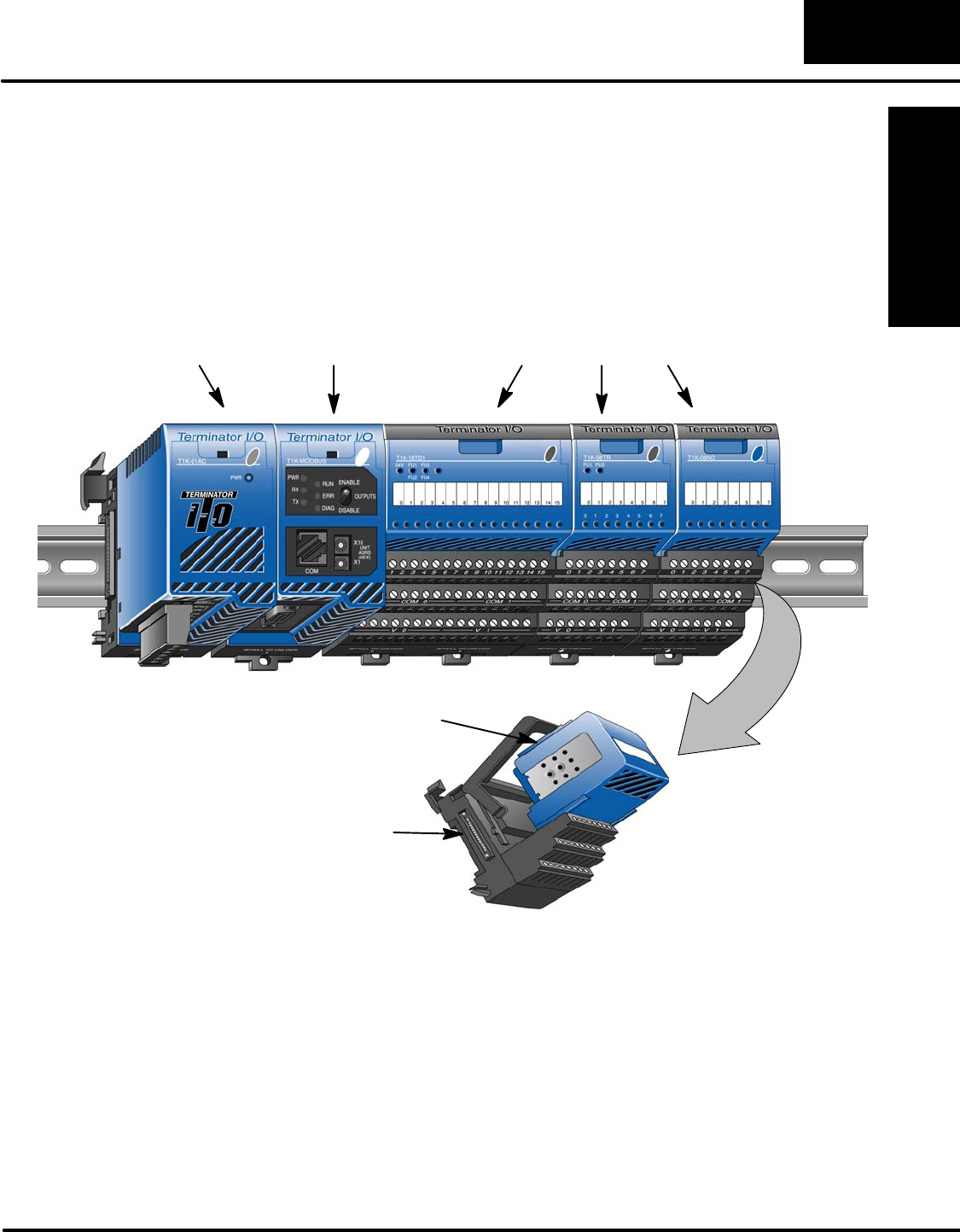
Terminator I/O System
Terminator I/O is a modular system which combines the functions of terminal blocks
and I/O modules for distributed I/O. Each Terminator I/O system has the following
components: a Power Supply, a Base Controller, and one or more I/O Modules and
I/O bases.
Power Supply
MODBUS
Base
Controller I/O Modules
I/O Base
I/O Module
Introduction
Installation and
Safety Guidelines
1–6 Introduction
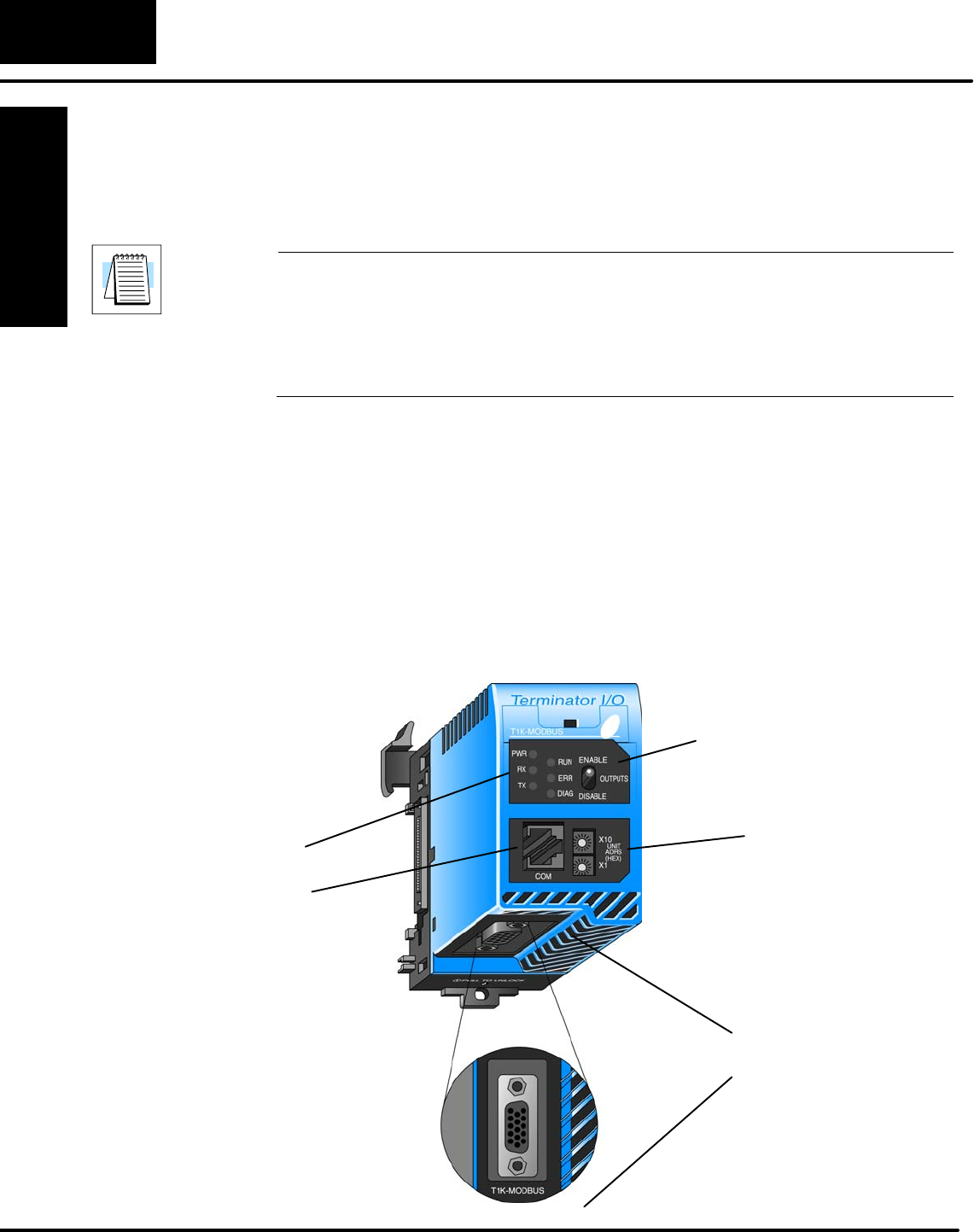
T1K–MODBUS Base Controller
The T1K–MODBUS Base Controller is a slave module that functions as a controller
for Terminator I/O on a MODBUS network.
Note: It is recommended to use the T1K–MODBUS Base Controller in a “scan
based” (polled) control system rather than in an “event–driven” control system. As a
slave, the Base Controller does not have the ability to report an error condition to the
MODBUS network master. Thus, polling a slave on a regular basis will detect a slave
error condition promptly, whereas an event–driven control system will not detect a
slave error condition until the next event is addressed to a slave in error.
The Base Controller has the following features:
•Status LEDs
•MODBUS Port
•Serial Port (RJ12)
•Unit Address Switches
•Output Enable/Disable Switch
•DIP Switch (located on right side of unit)
Status LEDs
Unit Rotary
Address
Switches
Output
Enable/Disable
Switch
RJ12
Serial Port
MODBUS Port
MODBUS Base
Controller Features
