Chapter 1 Ch1
User Manual: Chapter 1 OP 1500/1510 Manual
Open the PDF directly: View PDF ![]() .
.
Page Count: 9

1
1
Getting Started
In This Chapter. . . .
— Introduction
— OP-1500/OP-1510 Overview
— Frequently Asked Questions
Getting Started
1–2 Getting Started
Introduction
This User Manual provides user information on panel installation, panel
configuration, and programming the OPĆ1500 and OPĆ1510. The purpose of this
manual is to teach concept and programming techniques which may be applied
while implementing the OptiMater panels. The example programming figures within
Chapter 3 “Understanding the Features” use
Direct
LOGICt program references
for training purposes. Example programs for other PLC models and products are
located in the Appendix B–D of this manual. Complete example programs are
provided for
Direct
LOGIC and Allen-Bradley PLCs.
OP-1500 OP-1510
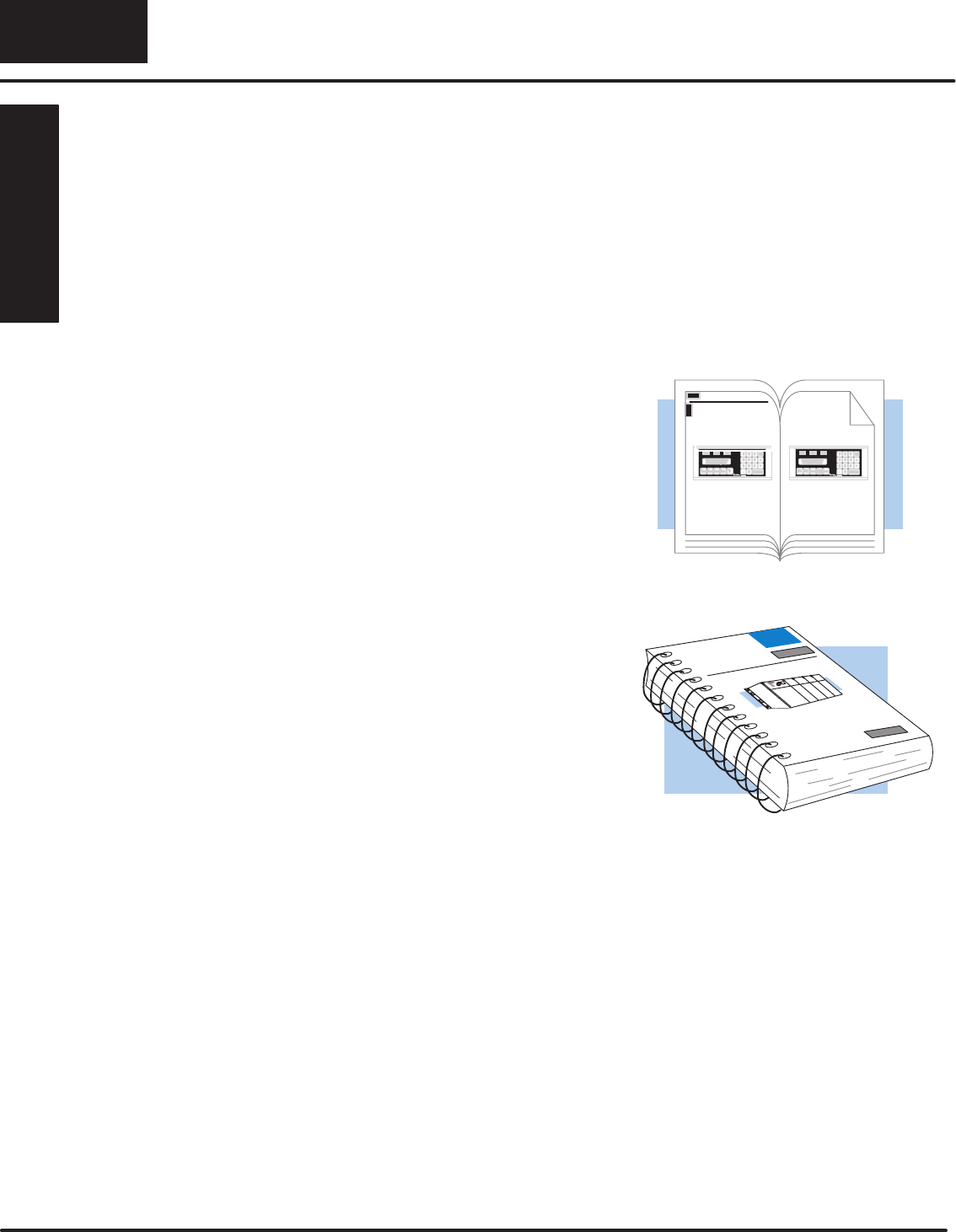
How to
Use the
Inside this manual you will learn about
planning, implementing, and utilizing the
OptiMate OPĆ1500 and OPĆ1510
products. This manual’s contents
discuss aspects of both OP-panels
regardless of which PLC product you are
connecting. Also included are
application examples to improve the
learning process and working knowledge
with the OptiMate units.
The OPĆ1500 and OPĆ1510
Operator panels may be
reconfigured to exchange data
with your programmable
controller.
Reference the appropriate PLC/CPU
User Manuals for the commands and
address references required for your
system. If you are using a
Direct
LOGIC
PLC product, you will want to keep the
Direct
SOFT User Manual handy while
programming your system. For
other
PLC brands you must reference their
User manuals to properly program the
ladder logic required to operate the
OP-panels.
For Multi-Panel applications utilizing the
OPĆ9001 Communications Master
please refer to the OPĆ9001 User Manual
(Part Number OP–9001–M).
After completely reading this manual, if you are not successful with implementing the
OPĆ1500 or OPĆ1510, you may call PLC
Direct
at (800) 633-0405, Monday through
Friday from 9:00 A.M. to 6:00 P.M. Eastern Standard Time. Our technical support
group will work with you in answering your application questions. If you have a
comment or question about our products, services, or manuals which we provide,
please fill out and return the suggestions card included with this manual.
The Purpose of
this Manual
Contents of the
Manual
Supplemental
Manuals
Technical
Assistance
Getting Started
1–3
Getting Started
This table provides an overall description of the topics covered within this manual.
Getting Started
Introduces the physical and functional characteristics. Discusses the
pushbuttons, lamps, LCD display and OPĆ1500 and OP-1510
characteristics. Also provides introduction to planning your system.
Installation and
Specifications
Shows how to prepare for system installation, including specifications, and
mounting instructions. Includes connecting cables part numbers and
specifications.
Understanding the
Basics
Detailed description of feature and functions available with OPĆ1500 and
OPĆ1510. Teaches concept of how the data is exchanged between the OP
and PLC. Also discusses the meaning of the Status and Control register
bits used for asynchronous communications control.
Configuring Your Panel
Information on the differences between the DOS and Windows versions of
OPEditor.The OP–WINEDIT for windows contains Help windows which will
assist with configuring the OP-1500 and OP-1510.
Maintenance and
Troubleshooting
Aid for diagnostics and maintenance of your OptiMate panel(s). Includes
tips on isolating communications faults by use of LED status.
Additional examples and reference information:
Application Worksheets
Application Worksheets for planning and creating OP–1500 and OP–1510
programs. These worksheets help define and implement the OP-panel
pushbuttons, lamps, and messages.
Complete Application
Examples
Appendices B,C, and D provide complete example programs for using
OP-panel standard functions and features. These examples will include
compatible ladder logic for implementing pushbuttons, lamps, and
messages using the
Direct
LOGIC
compatibles
and Allen-Bradley
SLC5/03, SLC5/04 and Micrologic PLCs.
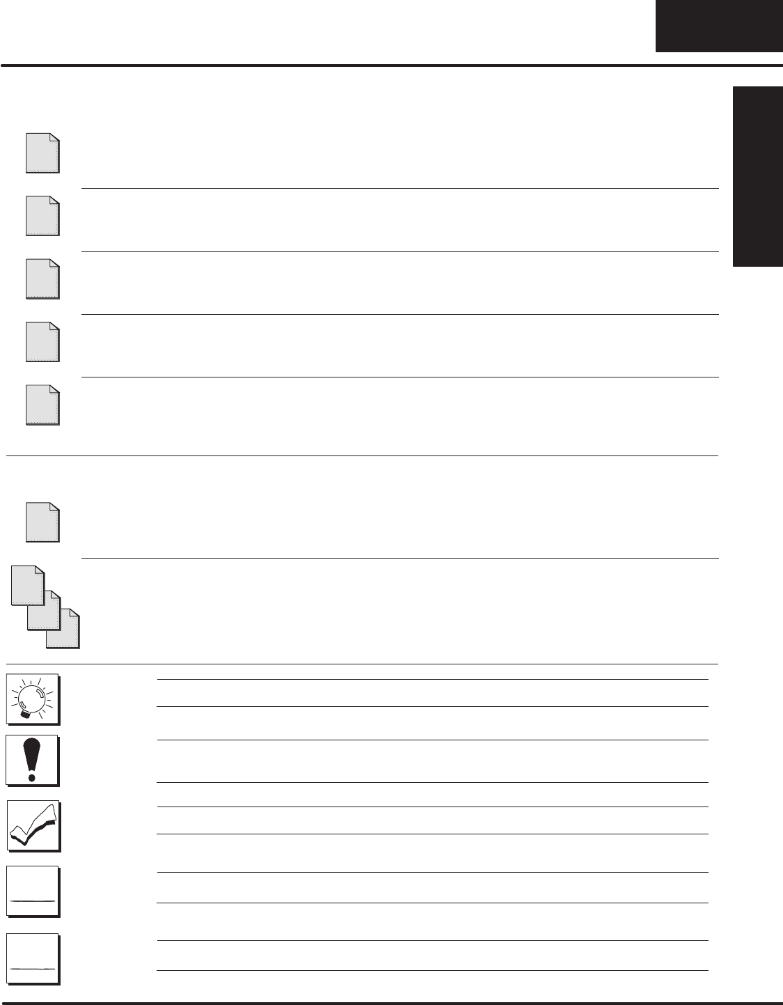
TIP: Information marked by this symbol indicates helpful hints about current topic.
WARNING: These markers warn you about specific concerns which may need to be
addressed where there is a safety risk.
NOTE: This marker provides information which is important to check out.
Direct
LOGIC
PLCs : Denotes information specific to
Direct
LOGIC PLCs.
OTHER
PLC’S
: Denotes information specific to
OTHER
PLCs.
Chapters
1
2
3
4
5
Appendices
A
D
C
B
PLC
Direct
LOGIC
PLC
OTHER
Getting Started
1–4 Getting Started
OPĆ1500/OPĆ1510 Overview
Let’s look at the OPĆ1500 and OPĆ1510 operator panels and their individually
supported features. As you continue through this manual, try to relate the examples
to your Operator Panel application. Use the
Application Worksheet
located in
Appendix A, which will be helpful during the design and configuration stages of your
system.
To help implement the OPĆ1500 and OPĆ1510 you should plan your system with all
operator interface requirements in mind. All aspects of implementing the OP-panels
are covered in the beginning chapters. It is important to read and understand all
topics discussed before installing, configuring and programming your application.
Backlit LCD Display
with 2 lines, 20 characters each.
Plan your System
Getting Started
1–5
Getting Started
The OP-1500 and OP-1510 Operator panels provide a man-machine interface to
your PLC automation system. These panels are
not
designed for applications which
demand large amounts of operator data entry. The OP-1500 and OP-1510 have
very similar characteristics, but provide slightly different functionality. The OP-panel
features such as lamps, pushbuttons, and messages are all discussed throughout
this manual.
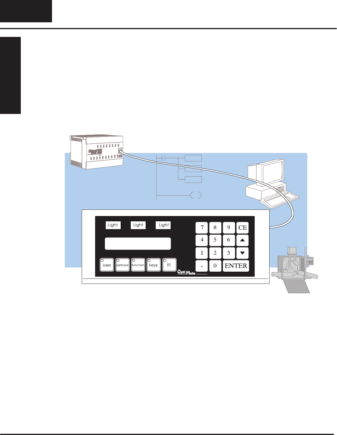
The Operator panels communicate with your PLC using either RS-232 or RS-422
serial communication. Details on configuration software and programming your
operator panel are covered in later chapters. Your application requires either a
Single or Multi-panel configuration. You may network up to 31 panels to a single
PLC. For multi-panel systems, the OP–9001 Communication Master must be used.
For applications demanding large amounts of operator interface data or require
information to be graphically displayed, we recommend using PC software such as
Wonderware, LABview, Intellution etc. Please refer to our PLC
Direct
product catalog
or contact one of our sales representatives for your Operator Interface solutions.
Many applications require Operator panel pushbuttons for controlling the machine
or process. These pushbuttons are used for input signals to the PLC which start and
stop a machine or process. The OP–1500 has five user configured pushbuttons and
the OP–1510 has two user configured pushbuttons. You may create custom text
labels describing the pushbuttons within your application. The following figures
show the pushbutton layouts for the OP-1500 and OP-1510.
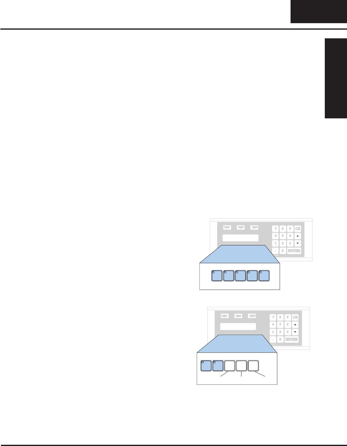
The OP-1500 contains five sealed
membrane pushbuttons located on the
lower left portion of the panel. All five
pushbuttons may be freely defined for
discrete input signals to the PLC.
Configure these pushbuttons as
momentary or alternating to best fit your
operator interface application.
OP–1500
Pushbuttons
F1 F2 F3 F4 F5
The OP-1510 contains two
user-defined pushbuttons. These two
pushbuttons may be configured as
momentary or alternating type signals.
The other three pushbuttons support the
multi-layered Menu functions. The Menu
pushbuttons allow you to perform the
Menu operations and are clearly labeled
Menu, Clear/Abort, and Select. F1 F2
OP–1510
Menu Clear/Abort Select
General Panel
Information
About the
Pushbuttons
Getting Started
1–6 Getting Started
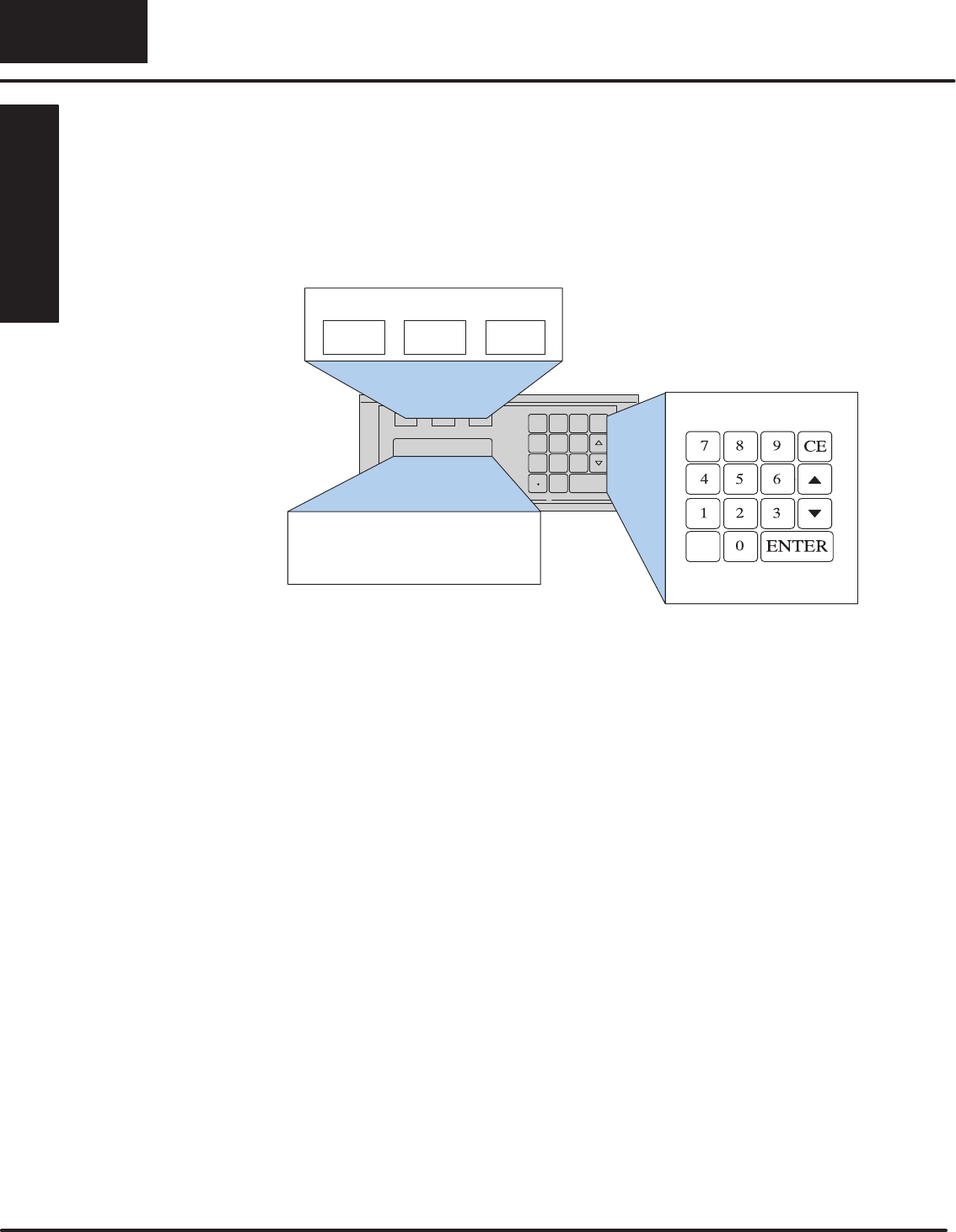
The OPĆ1500 and OPĆ1510 both feature a LCD display window. The LCD window
supports two message lines which can display up to 20 characters each. The
messages must be entered using configuration software which is referred to as
OPEditor. Up to 160 messages may be configured and stored in the Operator panel.
The message control type may be static text, dynamic, or interactive. The PLC logic
program controls which messages are displayed. Details on how to implement and
use the different types of messages are covered in later chapters.
OP-1500/OP-1510
Lamp1 Lamp2 Lamp3
Entry Keypad
Backlit LCD Display with 2
lines, 20 characters each.
You may enter numeric values using the sealed membrane numeric keypad.
Interactive messages are used to enter new setpoints using the keypad. During data
entry, the keys labeled Enter, CE, Y (arrow-up), and B (arrow-down), are also used to
assist operator data entry functions. Use of Interactive messages are discussed in
later sections of this manual.
The OPĆ1500 and OPĆ1510 each contain three annunciator lamps located above the
LCD message window. From left to right these lamps are colored green, yellow, and
red and may be labeled to fit your application. The lamps are turned on, off, and
flashed through your ladder logic program.
LCD Display
Window
Keypad Entry
Annunciator
Lamps
Getting Started
1–7
Getting Started
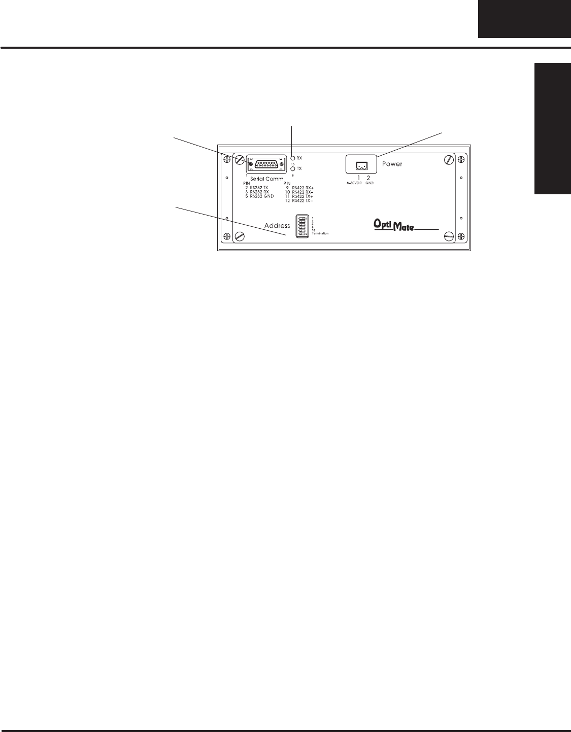
The back side of the OPĆ1500 and OPĆ1510 are typical in physical and functional
characteristics. The panels both contain a serial port with transmit and receive
LEDs, a power receptacle, and an address block with a termination switch.
DIP Switch
Serial Port Power Receptacle
RX/TX LED’s
The serial communications port is a 15-pin, female D-shell connector, which
supports using RSĆ232 or RSĆ422 interface wiring. This port is used for
communications between the OPĆpanel and PLC, as well as for programming your
panel configurations. In the case of a Multi-panel application, this port may be
connected to the OptiMate OPĆ9001 Communications Master.
The block style connector, also located on the back of the panel, is used to connect
an external 24VDC power supply. This block style connector with screw terminals is
provided with each panel and allows plug-in connection to the power receptacle.
The address switch is for setting the panel address number (0-30) or selecting the
panel configuration mode (address No. 31). The address block contains six switches
which are discussed in Chapter 2, Installation and Specifications.
The back of the OP-panel must be accessible for maintenance and programming
purposes. For door mount installations allow minimum 5-inch depth behind the door
for OP-panel clearance. This will include the 2-3 inches required for communications
connector and cable. The next chapter discusses mounting specifications and
cutout dimensions. Please refer to the Maintenance and Troubleshooting chapter in
this manual for tips and techniques on troubleshooting.
Back-Panel Layout
Serial
Communications
Port
Power Receptacle
Address Block
Access the Back
Panel

Getting Started
1–8 Getting Started
Frequently Asked Questions
Q. What’s new in this Second Edition Rev. A User’s Manual?
A. The Second Edition OP–1500 and OP–1510 manual is divided into chapters for
quick reference to information. This manual will help you understand and use
features for both operator panels. Application Worksheets and programming
examples are provided within the manual Appendices. It also defines the use of new
Status bits (Up/Down arrows and Enter key bits).
Q. What is required to get started using the OP-1500 and OP-1510 in my application?
A. You must read this manual and understand the OP-panel requirements and
application concepts. You must have programming knowledge for the PLC product
you’re using, the PLC serial communications capabilities which are available, as
well as hook-up and connecting cable data. You should ensure the serial port,
cables, and protocol parameters are properly chosen for the Optimate panel
configuration you are programming.
Q. What’s different between the OP-1500 and OP-1510 operator panels?
A. The OP-panels support typical features such as messages, pushbuttons, and
lamps with exception the OP–1510 panel allows menu/sub-menu options. This
menu/sub-menu feature is well-suited for systems which require extensive operator
entry of setpoints and variable type data. The menu features occupy three
pushbuttons to be used for handling the menu operations. Once again, you want to
consider using the OP–1510 panel for applications which demand data entry of
multiple variables or selection of multiple functions.
Q. How do I configure the OP-1500 and OP-1510 operator panels?
A. Using the OP-WINEDIT configuration software available from PLC
Direct.
This
OPEditor software allows you to configure the OP-panels in a Microsoft Windows
environment. You may configure your programs offline, upload, and/or download
them to all your OptiMate panels. The OP-WINEDIT software is provided with
installation documentation and Help screens.
Q. Can the OP-1500 and OP-1510 be used with other PLC products?
A. Yes. The Optimate units do support Allen-Bradley SLC 5/03, SLC 5/04,
Micrologix, Modicon (MODBUS) and GE (CCM/SNP) PLCs. These applications are
configured unique to that network and serial communication specifications
supported with each different PLC product.
Q. Can I connect more than one OP-panel to one PLC/CPU?
A. Yes, this is referred to as a Multi-Panel application. You may network up to 31
panels to communicate using RS-422 multi-drop communications between the
OP-panels and OP-9001 Communications Master unit. Also, if your CPU has
secondary ports, you may connect a single panel to each available serial port.

Getting Started
1–9
Getting Started
Q. Will the OP-panels support graphics, animation, or color operator display screens?
A. No, the OP–panels which support display capabilities allow numeric data variable
display, and some panels in addition will allow text message display on the 2-line
20-character LCD display window.
Q. Are the OP–panels compatible with the DL105 and other PLC products?
A. Yes, the OP-panels manufacturer date codes are located on the rear of the units.
OP-panels manufactured from October 1996 or later contain firmware which is
compatible with
Direct
LOGIC PLCs, Allen-Bradley SLC 5/03, SLC 5/04, Modicon,
and Micrologix PLCs. OP-panels manufactured from October 1996 or later contain
firmware version. For upgrade information contact your PLC
Direct
representative
for details.
Q. Are OP–600 series panels compatible with the OP–9001 Master Controller applications?
A. Yes, the OP–9001 units manufacturer date codes are located on the rear of the
unit. OP–9001 units which are date coded from May 1997 or later contain firmware
which is compatible with all OptiMate OP–1000 and OP–600 series panels. This
firmware version is labeled on the IC chip and should be minimum of V2.4 or greater.
For upgrade information contact your PLC
Direct
representative for details.
Q. Will the OP–600 series OP-panels support Allen-Bradley, MicroLogix, GE, or Modicon PLC
applications?
A. No, the reduced size and cost of the OptiMate OP–600 series panels will not allow
these panels to support all PLC types, as can the OP–1000 series panels.
*Supports all
Direct
LOGIC PLCs.
