Ptw82a1.tmp Ch2
User Manual: ch2
Open the PDF directly: View PDF ![]() .
.
Page Count: 22

TC 23-11
CHAPTER 2
MECHANICAL TRAINING
Section I. DISASSEMBLY AND ASSEMBLY
6. General.
a.
The purpose of mechanical
training is to give the operator a knowledge of
the basic functioning, controls, and adjustable
parts of the Starlight Scope so that he will under-
stand its operation and be able to properly care
for it.
b.
The operator is authorized to disassemble
the Starlight Scope
only
to the extent described
in paragraph 7.
c.
Even though detail disassembly is not
authorized, this should not preclude teaching the
operator the nomenclature of the component
parts and accessories.
d.
The Starlight Scope should be disassembled
and assembled only when necessary for instruction
or maintenance.
7. Disassembly.
Caution:
Before releasing the shipping con-
tainer's latches, turn the core of the relief valve
as instructed on the side of the shipping container.
This valve will release any internal pressure in
the shipping container that may have built up
during storage or shipment.
a. Shipping Container.
(1)
(2)
(3)
Place the shipping container flat on the
ground or table and raise the latches to
remove the lid from the bottom of the
container.
Remove the Starlight Scope and acces-
sories from the container.
The top and bottom foam contour liners
are force-fitted into the shipping con-
tainer. There are no screws or bolts
holding them in place. The liners are
removed by forcefully pulling them from
the shipping container.
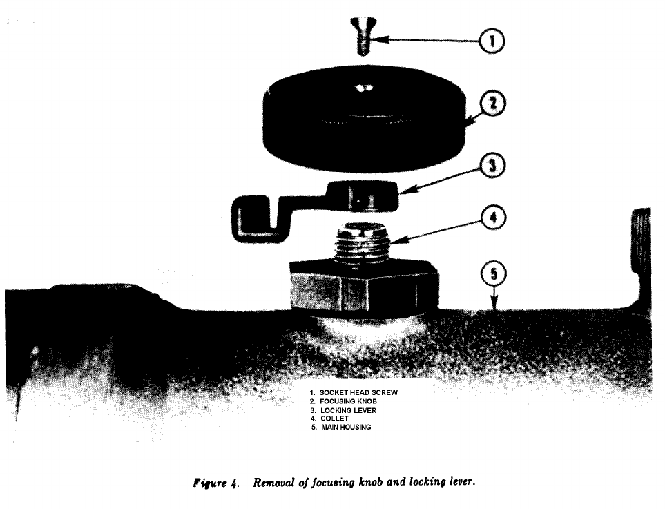
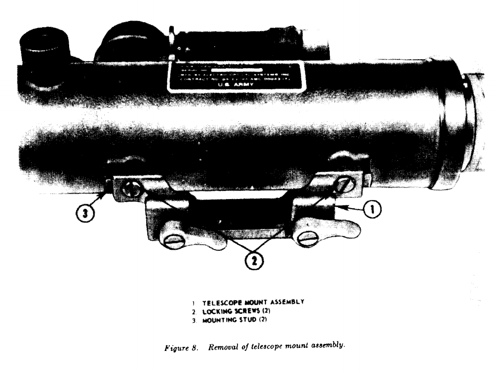
b. Starlight Scope.
The operator is authorized
to remove the objective lens cap, focusing knob
and locking lever, azimuth and elevation adjust-
ment knobs, battery cap, rubber eyeshield, and
the telescope mount assembly.
(1)
(2)
(3)
(4)
(5)
(6)
(7)
The objective lens focusing knob is re-
moved by using the allen wrench and
unscrewing the socket head screw located
in the center of the knob. Lift the knob
from the collet (fig. 4).
Remove the locking lever from the collet
by turning counterclockwise (fig. 4).
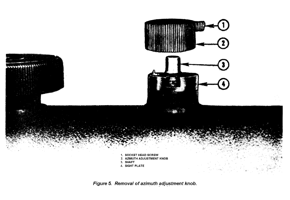
The azimuth adjustment knob is removed
by using the allen wrench to loosen the
socket head screw located on the side of
the knob. Lift the knob from the sight
plate (fig. 5).
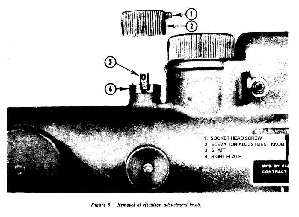
The elevation adjustment knob is re-
moved as described in (3) above (fig. 6).
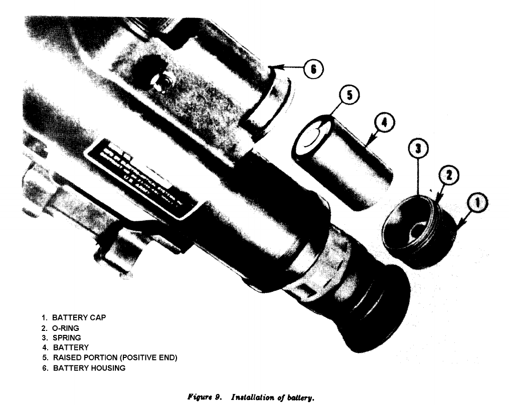
Remove the battery cap from the battery
housing by turning in a counterclockwise
direction (fig. 9).
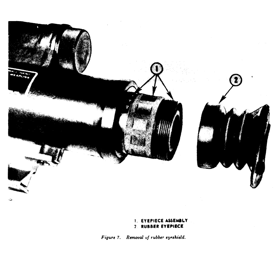
The rubber eyeshield is removed by
forcefully pulling it from the eyepiece
assembly (fig. 7).
Remove the two locking screws which
secure the telescope mount assembly to
the main housing (fig. 8).
Note.
A screwdriver is required for this
operation.
8. Assembly.
The sequence in which the dis-
assembled parts are assembled is not important;
however, during training the operator should use
the reverse procedure of disassembly.
a. Starlight Scope.
Aline the telescope mount assembly with
the mounting studs on the base of the
main housing and secure with the two
locking screws.
11
(1)
TC 23-11
(2)
(3)
(4)
(5)
Replace the rubber eyeshield on the
(6) Seat the focusing knob onto the collet
eyepiece assembly.
and secure with the socket head screw.
Replace the battery cap on the battery
b. Shipping Container.
housing.
(1)
Position the elevation and azimuth ad-
justment knobs onto the sight plate and
secure by tightening the socket head
screws.
Replace the locking lever to the collet
(2)
and turn until finger tight. Unthread
the locking lever ½-turn to provide the
(3)
required movement for locking and un-
locking action.
Insert foam liners in top and bottom of
shipping container.
Make certain the
cutouts in the top and bottom match so
that the lid will close when the Starlight
Scope and accessories are installed.
Replace the Starlight Scope and acces-
sories in the shipping container.
Aline the lid with the bottom of the
shipping container and secure with latch
and latch clasps.
12
TC 23-11
13
TC 23-11
14
TC 23-11
15
TC 23-11
16
TC 23-11
Section II. OPERATION AND FUNCTIONING
9. Operation. a. General. The Starlight
Scope, although designed to function under the
most rugged conditions, is a precision electro-
(2)
optical instrument and must be handled carefully.
b. Precautions.
To prevent damage to the
equipment and injury to himself, the operator
should observe the following safety precautions:
(1)
The contents of the mercury battery are
highly irritable to the eyes and oral and
nasal tissues; therefore, caution must be
exercised when handling and discarding
(3)
the batteries. To prevent explosion, the
battery should not be disposed of by
fire. Batteries should be disposed of by
burying, or dumping them into a large
body of water.
When the image intensifier tube is in-
advertently exposed to intense light, it
will automatically cut off to prevent
burning out the tube and to protect the
operator’s eye. Continuous exposure of
an activated tube to intense light should
be avoided.
The Starlight Scope should never be
aimed directly at the sun (image intensi-
fier tube ON or OFF) since it will result
in a complete failure of the tube.
17
TC 23-11
When operating the Starlight Scope, care
must be taken in the viewing procedure.
If the rubber eyeshield is not positioned
around the eye and against the face,
visible light emitted from the eyepiece
assembly will “leak” around the eye-
shield, illuminating the operator’s face.
c. Preoperational Inspection.
Open the shipping container as described
in paragraph 7a(l) and remove the
Starlight Scope.
Visually inspect all external parts, sur-
faces, and threads for dust, cracks, chips,
or other damage.
Visually examine the
objective lens assembly and eyepiece
assembly for lens fogging or other signs
of moisture.
Operate the focusing and
adjustment knobs to determine their
operability.
Check the telescope mount assembly to
insure it is secured to the main housing.
Inspect lock knobs for freedom of move-
ment. Examine guide groove for burrs,
cracks, or any other damage that would
prevent mounting.
During daylight operations, insure the
lens cap is properly positioned over the
objective lens assembly.
d. Installation of Battery.
Insure control switch is in OFF (center)
position.
Remove. battery cap as described in
paragraph 7
b
(5).
Insert battery, positive end first, into the
battery housing (fig. 9). To identify
the positive end, note the (+) or (–)
markings on opposite ends of the battery.
Should it be necessary to install a
battery during the hours of darkness,
the positive end can readily be identified
by feeling for the “raised portion”
located on the positive end of the
battery.
Replace the battery caps as instructed in
paragraph 8
a
(3).
e. Operational Sequence.
A definite sequence
should be used when placing the Starlight Scope
in operation. This sequence should be continu-
ously stressed with the new operator until it
become second nature and automatic. To place
(4)
(1)
(2)
(1)
(2)
(3)
(4)
(3)
(4)
the Starlight Scope in operation during the hours
of daylight (the lens cap must be positioned over
the objective lens) or darkness:
Position the rubber eyeshield around
the eye so as to prevent the visible light
emitted from the eyepiece assembly
from illuminating other areas of the face.
Move the control switch to the ON
(passive reticle) position. If the reticle
pattern is not visible, move and hold
the control switch in the reticle CHARGE
position. Normally, a 5-second charge
is sufficient to activate the reticle.
Return control switch to the ON position.
Focus the eyepiece assembly by rotating
the eyepiece focus ring until the reticle
pattern is sharp and clear.
Point the Starlight Scope at a distant
target.
After insuring the objective lens
focusing knob locking lever is in the unlocked
position,
rotate the focusing knob until
the image being viewed is clear and
sharp. To retain a clear and sharp
image, the operator must make an
objective lens focal adjustment whenever
the range between the Starlight Scope
and the target changes.
After operation, return the control switch
to the OFF position and remove the
rubber eyeshield from the eye.
Caution:
When removing the “non-
secure” rubber eyeshield from the eye,
the operator must exercise care to pre-
vent the visible light from illuminating
his face or l portion of his body. When
the Starlight Scope is turned off, visible
light will continue to be emitted from the
eyepiece assembly for a few moments.
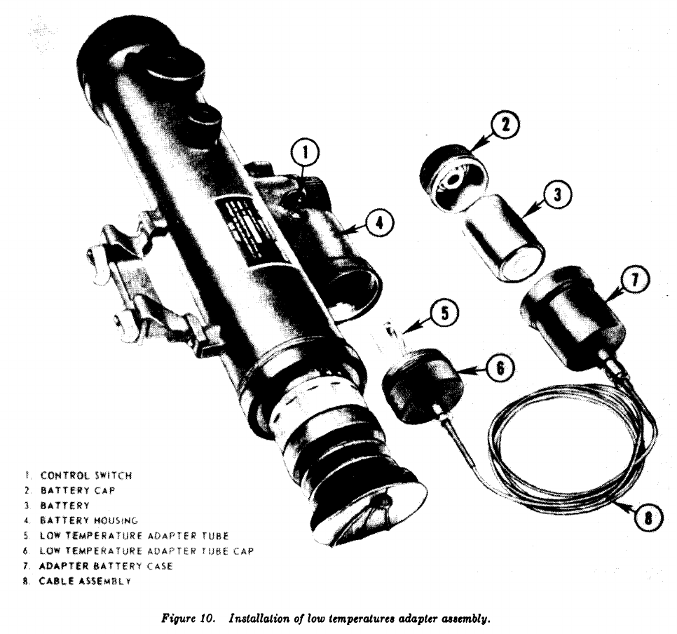
f. Extreme Cold.
A low temperature adapter
assembly is provided as a special accessory to the
Starlight Scope to permit operation in tempera-
tures as low as –65° F. The assembly is installed
(fig. 10) to the Starlight Scope as follows:
Insure the control switch is in the OFF
position.
Remove the battery cap and battery
from the battery housing.
Insert the low temperature adapter tube
into the battery housing and turn the
tube cap clockwise until secured.
(5)
(1)
(2)
(3)
(4)
(1)
(2)
(3)
18
TC 23-11
(4)
(5)
(6)
Insert the battery, positive end first,
into the adapter battery case.
Secure
with the buttery cap from the Starlight
Scope.
The battery and adapter buttery case
are carried inside the operator’s clothing
for protection against extreme low
temperatures.
Once the low temperature adapter as-
sembly has been installed, the Starlight
Scope is operated in the normal manner.
The lenses may have a tendency to fog
and frost up in cold weather and will
require frequent clearing. The operator
should avoid breathing into the rubber
eyeshield as this will increase the fogging
and frosting of the eyelens.
g. Extreme Heat.
The Starlight Scope is de-
signed for operation without damage at tempera-
tures up to +125° F.
h. Dusty or Sandy Conditions.
The lens will
require frequent cleaning when the Starlight
Scope is operated in dusty or sandy areas. The
operator should first remove most of the accumu-
19
TC 23-11
lated dust or sand with the lens cleaning brush,
then use the lens tissue for thorough cleaning
of the lenses.
i. Rainy or Humid Conditions.
The Starlight
Scope is capable of satisfactory operation in
rainy or humid conditions.
Caution:
To prevent corrosion or deteriora-
tion, thoroughly dry all parts of the Starlight
Scope after exposure to rain or high humidity.
10. Functioning.
For reasons of clarity and to
preclude discussions of a classified nature, only
the basic functioning of the Starlight Scope is
described in this training circular.
a. Power Supply.
When the control switch
is moved to the ON position, the 6.75-volt battery
furnishes power to the oscillator. The oscillator
receives this 6,75 voltage and increases it to
2,800 volts. The increased voltage is transmitted
to the multiplier plate of the image intensifier
tube. The multiplier plate insures that each
stage of the three-stage image intensifier tube
receives the required voltage for operation.
b. Objective Lens Assembly.
The objective lens
assembly, utilizing the ambient light of the night
sky, focuses an image of the scene being viewed onto
the front face (cathode) of the image intensifier
tube. Under nighttime illumination conditions,
this image is very dim and not visible to the
naked eye.
c. Image Intensifier Tube.
The image inten-
sifier tube receives the dim image and transmits
it to the screen (anode) at the rear of the tube.
In so doing, the brightness of the image is amplified
to such a degree it can be seen with the naked eye.
d. Eyepiece Assembly.
The eyepiece magnifies
and focuses the image, enabling the operator to
view the amplified image displayed on the anode
of the image intensifier tube.
e. Sight Reticle.
The sight reticle pattern (fig. 3)
is composed of eight reticle beads. Positioned
in the center of each bead is a small dot of phos-
phor. The phosphor, when subjected to radia-
tion, gives off light.
The intensity of light
radiation striking the phosphor determines the use
of the PASSIVE or CHARGED reticle.
(1)
(2)
When the control switch is moved to the
ON passive reticle position, light radia-
tion from the night sky entering the
Starlight Scope through the objective
lens strikes the phosphor dots causing
them to illuminate. Under moonlight
rind/or starlight conditions, light radia-
tion is intense enough to illuminate the
phosphor dots.
When operating the Starlight Scope
under low light level conditions (no
moonlight or starlight), the intensity of
light may not be sufficient to activate
the phosphor dote.
To compensate for
this, the operator moves the control
switch to the reticle CHARGE position,
turning on the sight reticle lamps. The
intensity of light emitted by the lamp is
sufficient to charge the phosphor dots.
It may be necessary to maintain the
reticle CHARGE position of the control
switch for a few seconds to provide an
adequate charge to the phosphor dote
(switch is spring loaded and auto-
matically returns to the OFF position
when pressure is released). After charg-
ing, the control switch must be manually
returned to the ON position to resume
operation.
Caution:
When charging the reticle,
the operator should insure the lens cap
is positioned over the objective lens to
prevent the visible light, emitted by the
sight reticle lamp, from being detected.
20
TC 23-11
Section III. INSTALLATION
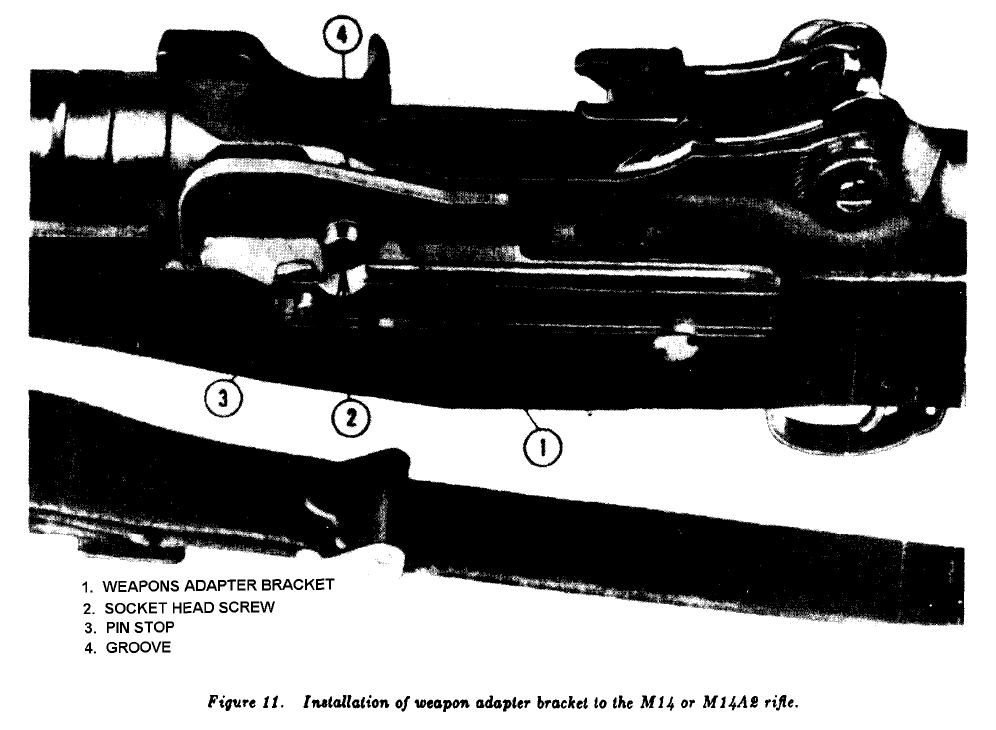
18. Weapons Adapter Brackets.
a. M414 or
M14A2 Rifle.
Aline the weapon adapter bracket
with the groove and screw recess on the left side
of the receiver (fig. 11). Secure the bracket to
the receiver by tightening the socket head screw
of the bracket with the allen wrench.
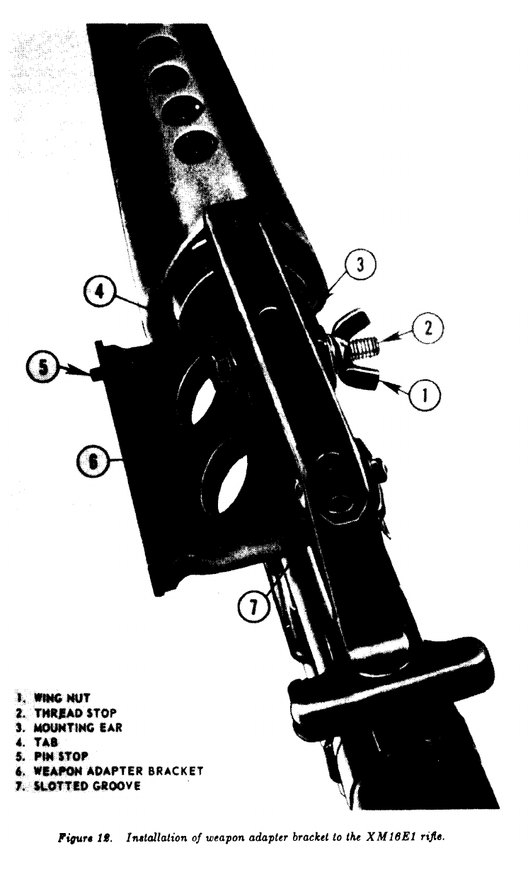
b. XM16E1 Rifle.
Unthread the wingnut to
the threadstop on the screw of the weapon adapter
bracket (fig. 12). Pull tab away from the bracket
and slide the mounting ear under the carrying
handle of the rifle. Position the slotted groove
in the hose of the bracket over the top of the
receiver group inside the opening of the carrying
handle. Firmly tighten the wingnut until the
tab is pulled tightly against the carrying handle
and bracket.
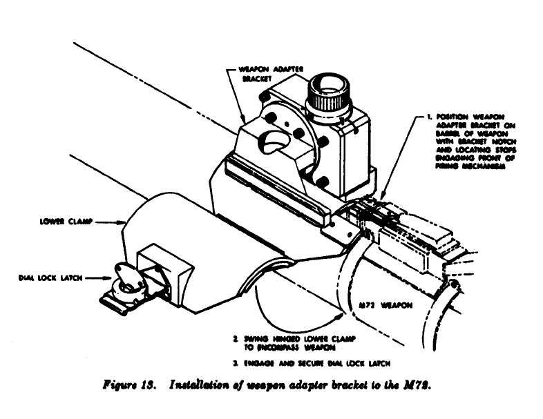
c. M72 Light Antitank Weapon.
Position the
weapon adapter bracket on the tube of the weapon
so that the bracket notch and location stops engage
the front of the firing mechanism. Swing the
hinged lower clamp around the bottom of the tube,
and engage and secure the dial lock latch (fig. 13).
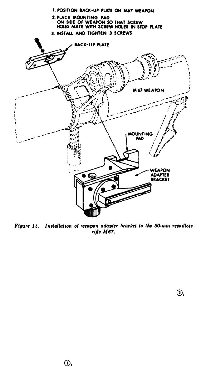
d. 90-mm Recoilless Rifle M67.
Position the
backup plate of weapon adapter bracket against
the inside of the M103 sight mounting bracket
(fig. 14). Place the mounting pad of the bracket
against the left side of the M103 sight mounting
bracket so that the screw holes in the mounting
pad mate with the screw holes in the backup
plate. Install and tighten the three socket head
screws with the allen wrench.
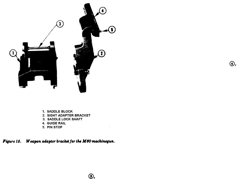
e. M60 Machinegun.
The weapon adapter
bracket for the M60 machinegun consists of n
saddle block and a sight, adopter bracket (fig. 15).
21
TC 23-11
22
TC 23-11
23
TC 23-11
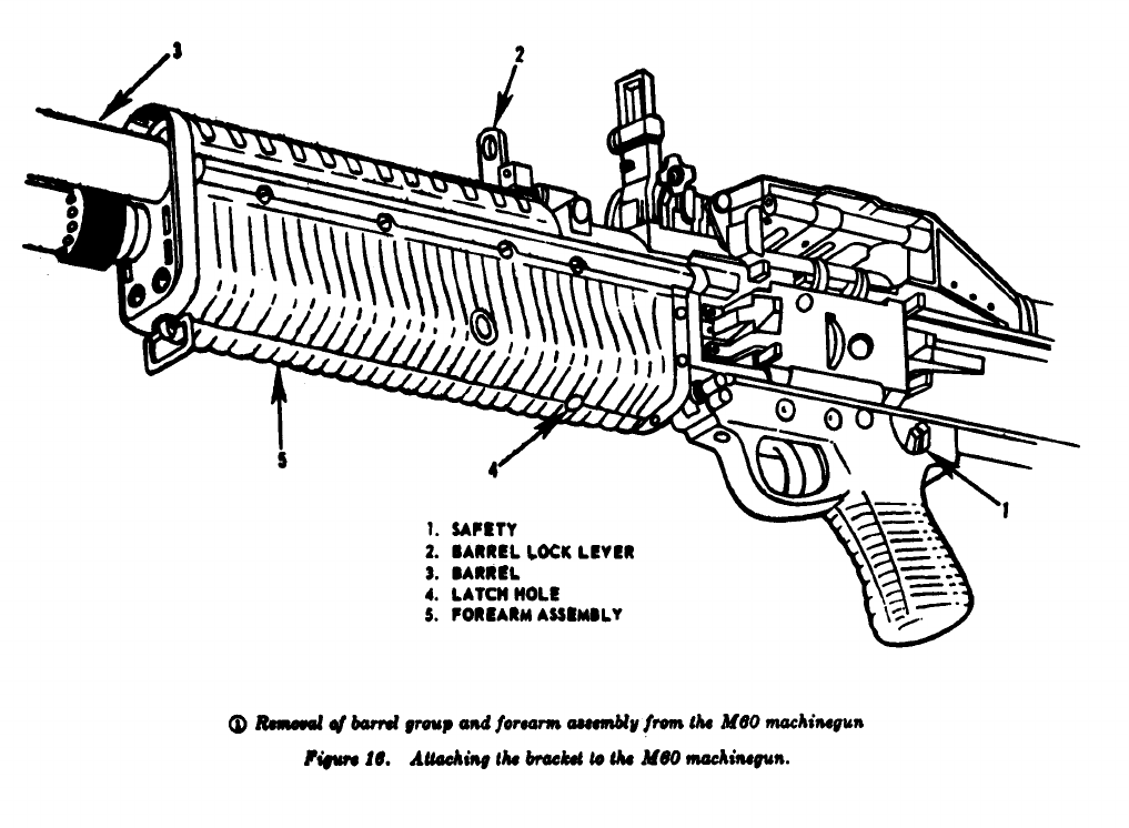
To install the saddle block to the M60 machinegun,
refer to figure 16 and mount as follows:
Clear the M60 machinegun as outlined
in FM 23-67.
Remove barrel group (1, fig. 16).
(4)
Cock the weapon.
Place safety (1) on the SAFE position.
Raise barrel lock lever (2).
Pu11 barrel group (3) straight forward
(4).
(1)
(2)
(a)
(b)
(c)
(d)
(3)
and remove.
Caution:
With the barrel group re-
moved, do not allow the bolt to go
forward as this will cause damage to the
cam roller on the bolt.
Apply pressure to the cartridge,
releasing the forearm latch; raise the
rear of the forearm assembly slightly and
remove it to the front (5).
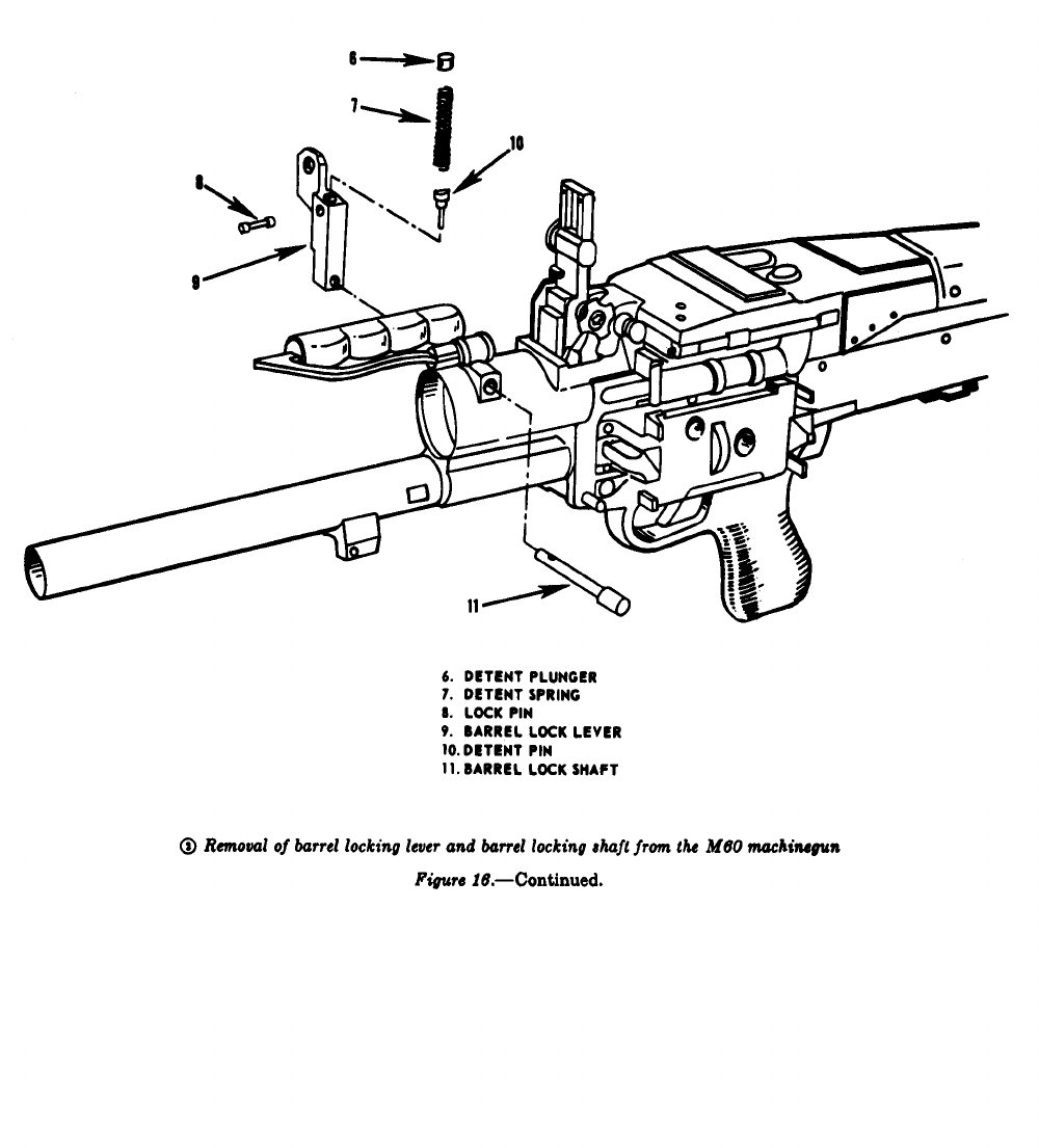
Remove barrel lock lever and barrel
locking shaft ( fig. 16).
Caution:
The detent plunger (6) and
detent spring (7) are under spring ten-
sion. Before removing lock pin (8),
place hand over top of barrel lock lever
(9) to prevent loss of parts upon removal
of lock pin. Insure barrel lock lever is
in vertical position.
Remove forearm assembly (
fig. 16).
Remove lock pin (8), detent pin (1O),
Insert nose of cartridge into the latch
detent spring (7), and plunger (6)
hole in the bottom of forearm assembly
from barrel lock lever (9).
(a)
24
TC 23-11
(6)
Withdraw barrel lock shrift (11) from
left side of receiver group and remove
barrel lock lever.
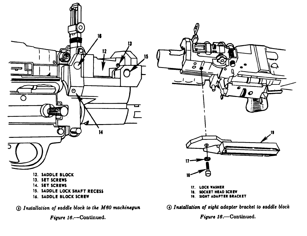
Installation of saddle block (
(b)
(5)
fig. 16).
(a)
(b)
(c)
Loosen four set screws (13) and (14)
(two set screws are located on each
side of the saddle block). Remove
saddle lock shaft from saddle block
(15).
Place saddle block in position
on
weapon (12), insuring the half moon
recess on left side of the saddle block
is seated under the windage knob or
the rear sight.
Replace barrel lock lever and insert
saddle lock shaft (from the left side
of the machinegun) into its recess in
the saddle block (15). Insure the half
moon cut on the saddle lock shaft is
positioned down when replacing the
shaft.
(d)
(e)
Reassemble barrel lock lever (reverse
procedure given
in paragraph (4)
above) onto the saddle lock shaft.
Tighten four set screws (13) and (14)
and tighten saddle block screw (16).
Note. Since the saddle block will not
interfere with normal operation of the
machinegun, it should not be removed aftcr
installation. Install the sight adaptcr bracket
whenever the Starlight Scope is to be used.
Sight adapter bracket installation (
fig. 16).
(a)
(b)
(c)
Plato sight adapter bracket (19) in
place against saddle block (12).
Install and tighten lock washer (17) and
screw (18) through sight adapter
bracket into saddle block.
Replace forearm assembly and barrel
group by reversing procedure given in
(2) and (3) above.
f. 40-mm Grenade Launcher M79.
The weapon
adapter bracket for the M79 is not being produced
currently. A discussion of the correct mounting
procedures is withheld pending receipt and testing
of the item.
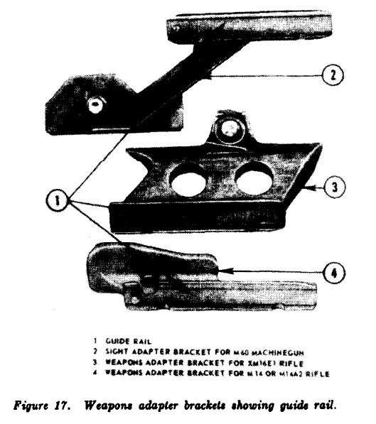
12. Starlight Scope.
a. General.
Regardless
of which weapon the Starlight Scope is employed
with, the procedure for mounting to the weapons
adapter brackets are the same. Each weapon
adapter bracket has an identical guide rail (fig.
17)
which mates with the telescope mount assembly
of the Starlight Scope.
b. Mounting.
The Starlight Scope is mounted
to the weapon adapter bracket as follows:
(1)
(2)
(3)
Rotate lock knobs of the telescope
mount assembly forward (toward ob-
jective lens) until they come to stop
on the pins Iocated on the assembly,
Slide the telescope mount assembly onto
the guide rail of the weapons adapter
bracket from the rear until positioned
against the pin stop of the guide rail.
The Starlight Scope is locked to the
weapons adapter bracket by rotating
the two locking knobs of the telescope
mount assembly in a rearward direction.
25
TC 23-11
26
TC 23-11
27
TC 23-11
28
TC 23-11
Section IV. MAINTENANCE, TROUBLESHOOTING, AND DESTRUCTION
13. General.
This section contains information
on maintenance, troubleshooting, and destruction.
The discussion on maintenance is confined to that
information necessary for the operator to main-
tain the Starlight Scope. For information con-
cerning organizational and higher echelons of
maintenance see TM 11-1090-268–15.
14. Tools and Equipment.
The wrenches,
batteries, and other accessories contained in the
shipping container, with the exception of a screw-
driver, provide the tools and equipment necessary
for operator maintenance. A screwdriver is re-
quired to disassemble the telescope mount as-
sembly from the main housing.
15. Care and Cleaning.
a. General.
To insure
the Starlight, Scope is ready for operation at all
times, inspect it systematically to discover and
correct defects before serious damage or failure
results.
Note defects during operation and insure
appropriate corrective action is taken upon
completion of operations. All defects, deficiencies,
and corrective action taken will be recorded on
DA Form 2404 (Equipment Inspection and
Maintenance Worksheet) at the earliest oppor-
tunity.
b. Special Instructions.
(1)
(2)
(3)
Clean exposed glass surfaces of the
objective lens and eyepiece lens by
removing loose dirt with the lens brush
and then clean the glass surfaces with
lens tissue. Dampen lens tissue with
water if necessary (distilled water if
available).
Clean all exposed metal surfaces on the
Starlight Scope and low temperature
adapter assembly with a cloth. Dampen
cloth with water if necessary.
No lubricating materials are required
by the operator for maintenance of the
Starlight Scope.
.
c. Daily Preventive Maintenance.
The operator
must perform
the following daily preventive
maintenance services:
Inspect and service the shipping container
(1)
29
TC 23-11
for dirt, dents, holes, damaged latches,
latch clasps, missing parts, identification
and instruction plates, and for movability
of pressure relief valve. If unservice-
able, replace the shipping container.
Remove the Starlight Scope and acces-
sories from the shipping container and
inspect top and bottom liners for tears,
dirt accumulation, and water-soaked
condition. Remove loose dirt with a
soft brush and clean with a damp cloth.
Remove wet liners and allow to dry.
Replace liners if damaged.
Inspect and service canvas carrying case
for holes, tears, dirt, and water-soaked
condition. If damaged or mildewed, re-
place canvas carrying case.
Inspect and service main housing of
Starlight Scope for dents, cracks, and
loose or missing parts. Tighten loose
parts and report missing parts or
damaged main housing to organizational
maintenance.
Inspect and service objective and eyepiece
lenses for dirt, dust, cracks, scratches,
and signs of fogginess or moisture. If
lenses are scratched, cracked, and foggi-
ness or moisture appears to be within
the objective or eyepiece assembly,
report condition to organizational main-
tenance.
Inspect objective lens focus knob and
locking lever for dirt, free operation,
positive locking action, or damage.
Remove
only
the focus knob and locking
lever if dirty or damaged. Clean the
focus knob and locking lever and reas-
semble to the collet. Replace damaged
knob or lever and reassemble. Report
faulty operation of focus knob or locking
lever to organizational maintenance.
Inspect the azimuth and elevation adjust-
ment knobs for dirt, damage, and
freedom of operation. Remove
only
the
azimuth or elevation adjustment knobs
if dirty or damaged. Clean dirty knob
and reassemble. Replace damaged knob
and reassemble. Report faulty opera-
tion to organizational maintenance.
Inspect battery for corrosion, leakage, or
(9)
(2)
(10)
(3) (11)
(4)
(5)
other damage.
Dispose of a defective
battery.
Remove battery cap from battery housing
and inspect and service for dirt, cracks,
dents, and damaged battery spring or
O-ring. Replace damaged battery cap,
spring, or O-ring. Install new battery
and reassemble battery cap.
Inspect exterior of oscillator cap for
dirt, cracks, and dents.
Do not
remove
oscillator cap from oscillator housing.
Clean outside surfaces only. Report
damaged oscillator cap to organizational
maintenance.
Although the operator is not authorized
to remove the oscillator cap, it is possible
to check the functioning of the oscillator.
Move the control switch to the ON
position and listen for operating hum
which is audible if oscillator is working.
If operating hum cannot be heard,
report condition to organizational
maintenance.
With control switch in the ON position,
look into the eyepiece and inspect for
operation of the image intensifier tube.
Do not attempt removal of the image tube
from the main housing.
Return control
switch to the OFF position.
Report
all failures or malfunctions of image tube
to organizational maintenance.
Inspect telescope mount assembly for
cracks, breaks, dents, dirt, and oper-
ability of locking knobs. Service and
replace as required,
Inspect rubber eyeshield for dirt, oil,
cracks, flexibility, and other damage.
Remove eyeshield if dirty or damaged.
Clean with a clean, wet cloth. Replace
damaged eyeshield and assemble new
eyeshield onto the eyepiece assembly.
Insuring the control switch is in the
OFF position, remove the lens cap and
inspect for dirt, obstructed holes, cracks,
or other damage.
Clean with wet cloth
and reassemble to objective lens as-
sembly, Replace damaged lens cap and
reassemble.
16. Troubleshooting.
This paragraph provides
information useful in diagnosing and correcting
(12)
(6)
(13)
(14)
(7) (15)
(8)
30
TC 23-11
unsatisfactory operation or failure of the Starlight
site the probable cause. Since the operator is
Scope. Each trouble symptom stated is followed
limited to only minor corrective actions, most
by a list of probable causes of the trouble. The corrective measures will be performed at orga-
possible remedy recommended is described oppo- nizational or higher support levels.
TROUBLESHOOTING GUIDE
(1)
(2)
(3)
Probable cause
a. Objective Lens Will Not Focus.
Damaged eccentric shaft. . . . . . . . . . . . .
Damaged focus knob. . . . . . . . . . . . . .
Damaged objective lens assembly. . . . . . . . .
b. Eyepiece Assembly Will Not Focus.
Damaged eyepiece focus ring
. . . . . . . . . .
Dirt or sand accumulated around focus
ring.
(1)
(2)
(3)
(1)
(1)
(2)
(2)
c. Weak or No Illumination of Imaae Intensifier Tube.
(1)
(2)
(3)
(4)
(5)
(6)
(7)
(1)
(2)
(3)
(4)
(5)
(6)
(7)
(8)
(9)
Weak or defective battery . . . . . . . . .
Defective oscillator
. . . . . . . . . . . . . . . . . .
Defective image intensifier tube.
. . . . . . . . .
Defective control switch
. . . . . . . . . .
Loose battery cap
. . . . . . . . . . . . . . . . . . . . . . . . .
Defective battery cap spring
. . . . . . . . .
Defective oscillator cap and/or assembly
d. Image Blurred.
Objective lens dirty or fogged . . . . . . .
Eyepiece lens dirty or fogged
. . . . . . .
Objective lens out of focus
. . . . . . . .
Eyepiece out of focus
. . . . . . . . . . . .
Weak battery
. . . . . . . . .. . . . . . . . . . . .
Defective oscillator
. . . . . . . . . . . . . . . . . .
Defective image intensifier tube . . . .
. . . . .
Defective objective lens assembly
. . . . . . . . .
Defective eyepiece assembly . . . . . . . .
. . . . . . .
e. Focusing Knob Will Not Rotate.
Dirt or sand accumulated around
focusing knob.
Locking lever dammed . . . . . . . . . . . . . . .
Collet damaged . . . . . . . . . . . . . . . . . . . . .
f. Control Switch Will Not Detent.
Defective control switch . . . . . . . . .
Possible remedy
Report to organizational maintenance.
Replace focus knob.
Report to organizational maintenance.
Report to organizational maintenance.
Clean area around focus ring.
(1)
(2)
(3)
(4)
(5)
(6)
(7)
(1)
(2)
(3)
(4)
(5)
(6)
(7)
(8)
(9)
Replace battery.
Report to organizational maintenance.
Report to organizational maintenance.
Report to organizational maintenance.
Tighten battery cap.
Replace battery cap spring.
Report to organizational maintenance.
Clean lens.
Clean lens.
Adjust by rotating focus knob.
Adjust by rotating eyepiece focus ring.
Replace battery.
Report to organizational maintenance.
Report to organizational maintenance.
Report to organizational maintenance.
Report to organizational maintenance.
Clean focusing knob.
Replace locking lever.
Report to organizational maintenance.
Report to organizational maintenance.
(1)
(1)
(2)
(3)
(2)
(3)
(1)
(1)
(1)
(2)
(1)
(2)
g. Elevation or Azimuth Adjustment Knob Will Not Rotate.
Dirt or sand accumulated around knob. . . .
Defective adjustment assembly . . . . . . . .
Report to organizational maintenance.
h. Reticle Will Not Adjust.
Defective azimuth or elevation adjust-
Report to organizational maintenance.
ment knob assembly.
(1)
(1)
31
TC 23-11
(1)
(2)
(3)
Defective reticle lamp . . . . . . . .
Defective power switch . . . . . . .
Weak or defective battery . . . . .
(1)
(2)
(3)
TROUBLESHOOTING GUIDE—Continued
Probable cause Possible remedy
i. Reticle Lamp Will Not Illuminate.
Report to organizational maintenance.
Report to organizational maintenance.
Replace battery.
j. Low Temperature Adapter Assembly Will Not Operate.
(1)
(2)
(3)
Wrong polarity
-
of battery in adapter . . . . . . .
battery case.
Defective or weak battery . . . . . . . .
Defective cable assembly . . . . . . . .
k. Starlight Scope Will Not Mount on Weapon.
Dirt or sand between mounting grooves. . . . . .
Telescope mount assembly damaged. . . . . . . .
Damaged weapn adapter bracket . . . .
(1)
(2)
(3)
(1)
(2)
(3)
(4)
(1)
(2)
(3)
Damaged lock knobs . . . . . . . . . . . . .
17. Destruction To Prevent Enemy Use.
a.
(4)
General.
(1)
(2)
Destruction of the Starlight Scope and
related material, when subject to capture
or abandonment in the combat zone, will
be undertaken by the using unit when,
in the judgment of the unit commander,
such action is necessary in accordance
with the unit’s mission, or policy estab-
lished by the commander concerned. If
at all possible, the Starlight Scope should
be evacuated.
When the commander concerned con-
(a)
(b)
(c)
siders it necessary, he orders the Star-
light Scope’s destruction to prevent one
or more of the following:
Capture by the enemy.
Abandonment in the combat zone.
To deprive enemy intelligence agencies
knowledge of its existence, functioning,
or exact specifications.
b. Principles of Destruction.
Destruction should be as complete as
possible within limitations of time and
equipment. In any event, the most
important parts are destroyed or evacu-
ated.
The same essential parts are
destroyed or evacuated in all units to
prevent the enemy from constructing
c.
Reverse position of battery.
Replace battery.
Report to organizational maintenance.
Clean telescope mount assembly.
Replace telescope mount assembly.
Replace weapon adapter bracket.
Replace telescope mount assembly.
(2)
(3)
(4)
one complete Starlight Scope from several
damaged ones.
Personnel are trained in the prescribed
methods of destruction.
The issue and use of special equipment,
such as incendiary grenades, are com-
mand decisions and depend on the
tactical situation.
Methods described are listed in the order
of their effectiveness. Follow the se-
quence in which the steps are given.
Methods of Destruction.
(1)
(2)
Destruction by burning.
Stand the Star-
light Scope on end, preferably in a hole,
with the objective lens up. Position a
thermate grenade on the objective lens
and pull the pin.
Insure that the grenade
has destroyed the optics and image
intensifier tube.
Destruction by weapons fire.
Place the
Starlight Scope on end, preferably in a
hole, with the objective lens up. Fire
one or more rounds into the Starlight
Scope through the objective lens. Insure
that the round(s) penetrates completely
through the objective lens, reticle lens,
image intensifier tube, and the eyepiece
assembly.
(1)
32
