Chapter 3 Ch3
User Manual: Chapter 3 OP1224 Manual
Open the PDF directly: View PDF ![]() .
.
Page Count: 9

Installing the Panel
8
OP--1224 User Manual, Rev. D
Installing the Panel
In this section, you will be given all of the information you need to install the panel.
Before actually installing the OP-1224 panel, it may be helpful to examine the
specifications and make sure that the requirements of your application are met.
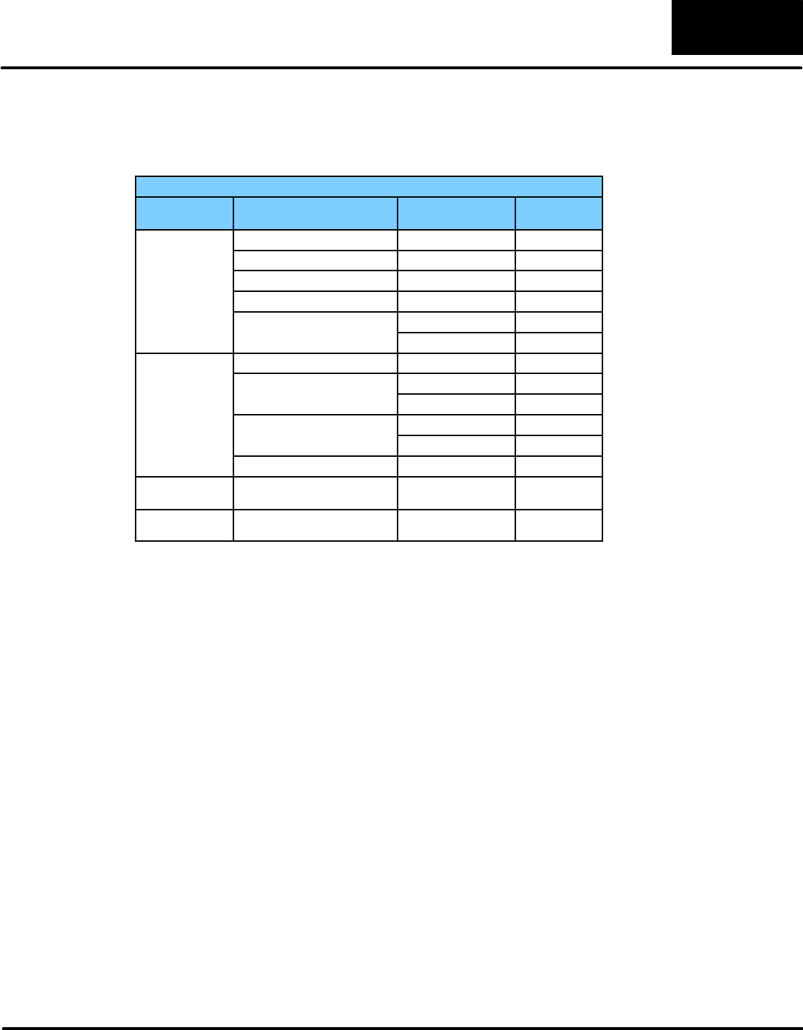
Panel Specifications:
Weight 22 ounces...................................
Panel Fasteners Four 6x32 threaded studs..........................
NEMA Rating NEMA 4.............................
Operating Temperature 0°to 50°C....................
Storage Temperature --20°to 80°C......................
Operating Humidity 5 to 95% (non-condensing)........................
Air Composition No corrosive gases permitted...........................
Power Budget Requirement 4 VA @ 8 -- 30 VDC......
240 mA @ 12 VDC (all LEDs OFF)
310 mA @ 12 VDC (all LEDs ON)
120 mA @ 24 VDC (all LEDs OFF)
155 mA @ 24 VDC (all LEDs ON)
Power Connector Removable Terminal Block.........................
2 position
Absolute Maximum Voltage 32 VDC.................
Diagnostics Power On, CPU...............................
Communication Link RS232 or RS422......................
4800, 9600 and 19200* baud
15 pin female D type connector
*Only 4800 and 9600 baud will work
with Allen-Bradley PLCs.
Physical
Specifications
Environmental
Specifications
Operating
Specifications
Installing the Panel 99
OP--1224 User Manual, Rev. D
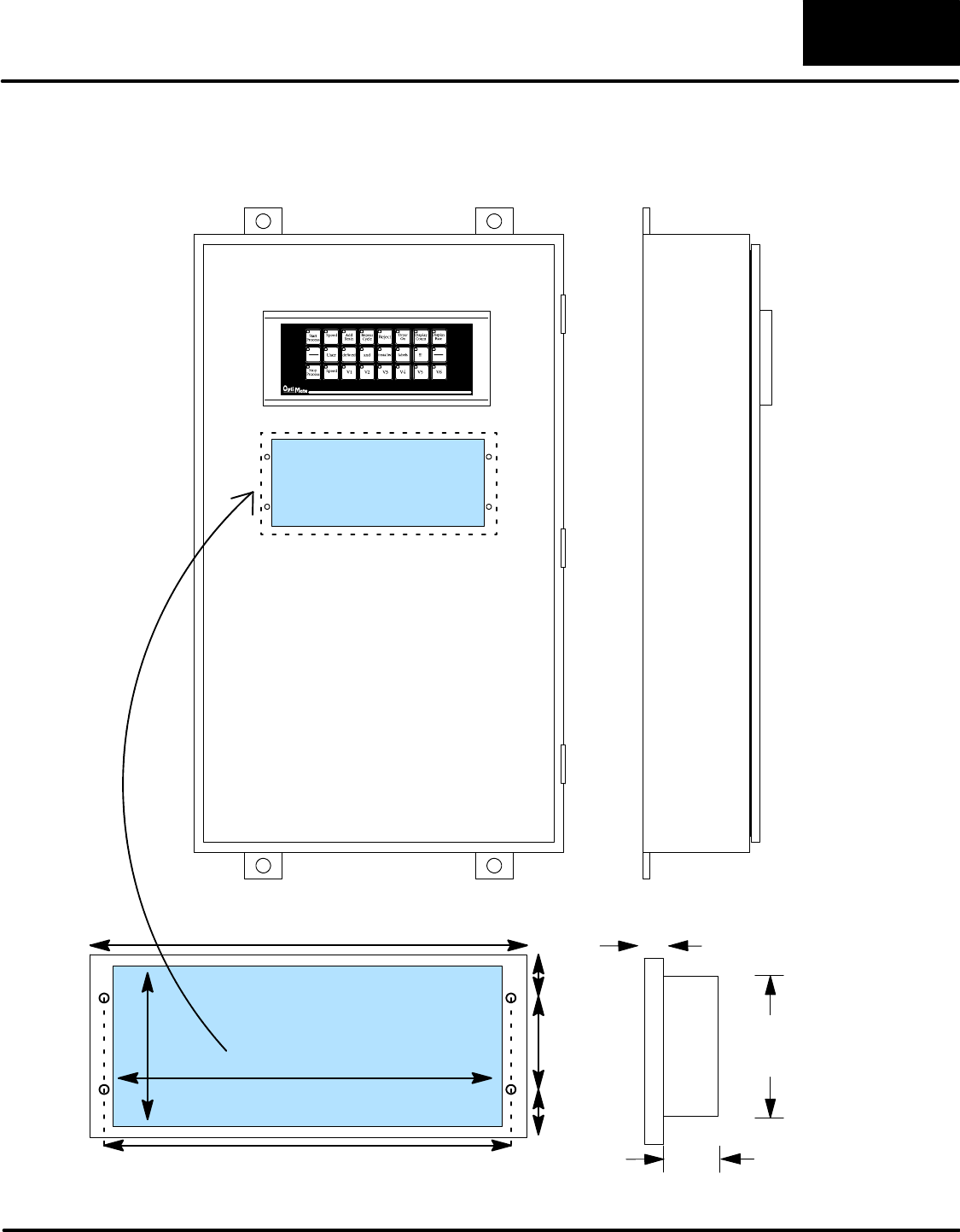
Dimensions for Mounting
3.50 8.40
2.00
8.85
9.50
1.00
1.00
Example panel mounting
Dimensions in Inches
Cutout Area
0.5”
1.75”
3.5”
Installing the Panel
10
OP--1224 User Manual, Rev. D
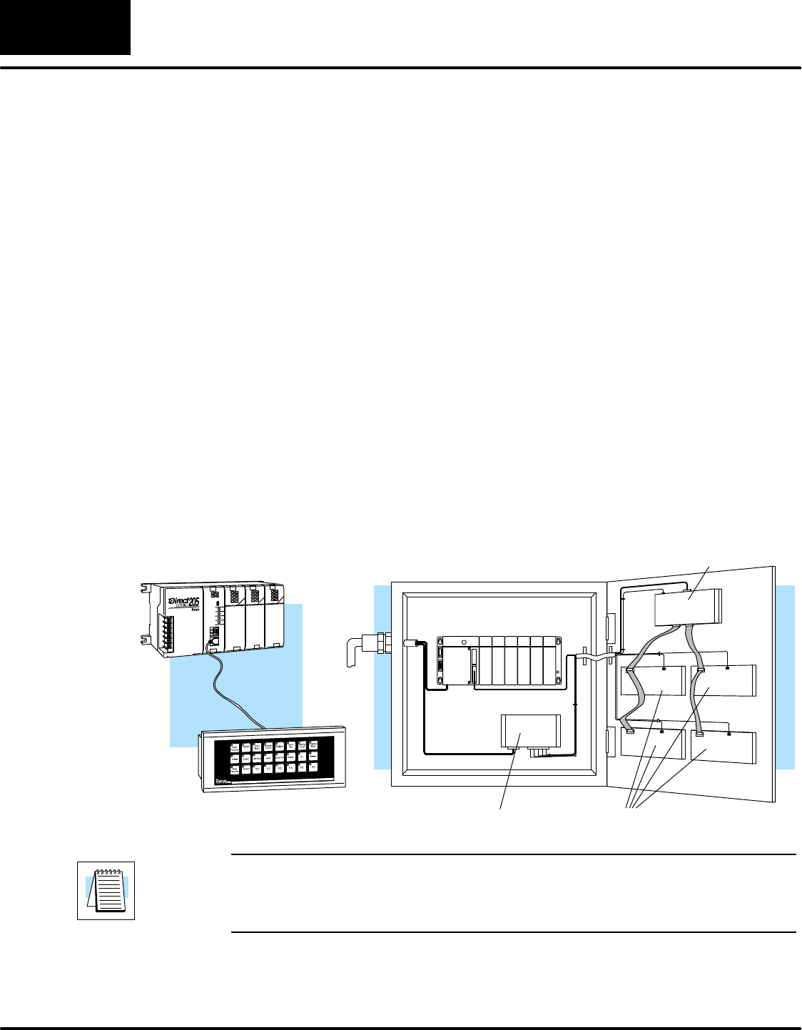
Power and Cabling Requirements
The communication cable requirements will depend on your particular application.
There are two types of configuration possibilities: point-to-point (a single operator
interface connected to a PLC) and multi-drop (multiple operator interfaces
connected to a PLC).
DPoint-to-Point -- If only one operator interface will be connected to one PLC,
then just choose the appropriate cables from the chart on Pages 12 and 13.
DMulti-drop -- By using an OptiMate OP--9001 Communications Master,
multiple Optimate units can be connected to a single PLC. Up to 31 individual
units can be connected in a daisy-chain fashion to the OP--9001.
Communications are via RS422 between the OP--9001 and the operator
interfaces. When using a quality shielded cable, a total distance of up to 4000
feet between the OP--9001 and the last operator interface unit in the chain
can be achieved. If the distance 30 feet or less, a ribbon cable with
easy-to-install crimp-on ribbon connectors can be used.
OP-9001
Power Supply OP-panels
DL405 CPU Base
Power
Source
1. Point-to-Point
A single cable connection from
the PLC to the panel gives you
access to the PLC’s data regis-
ters and ladder logic.
2. Multi-drop
Multiple OP-panels can be interfaced to a single PLC.
This requires the use of the OP-9001 Communications
Master. With the Communication Master, up to 31
panels can be interfaced to a single CPU port. Each can
be programmed for entirely different functions. Panels
can be distributed up to 4000 feet* from the OP-9001.
NOTE: Please read and follow the cabling requirements in the OP-9001 User
Manual (OP-9001-M) when using multiple panels. Failure to follow the guidelines of
the User Manual may affect the integrity of the RS422 link, resulting in
communication errors.
What Are Your
Application Needs?
Installing the Panel 1111
OP--1224 User Manual, Rev. D
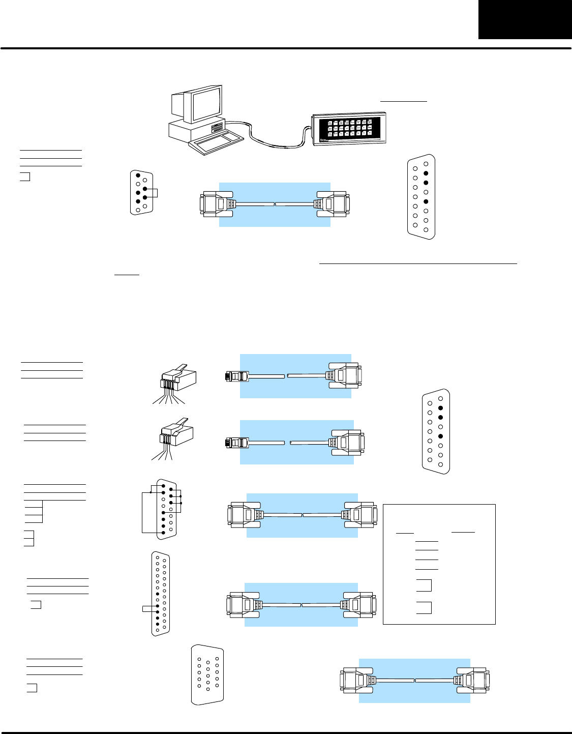
The OP-ACBL--1 is used to connect your OP-1224 panel to your computer for programming.
OP-ACBL--1
You must have this cable to configure the panel.
Computer Panel
1= not used
2= Dout
3= Din
4= not used
5= 0V
6= not used
7= not used
8= not used
9= not used
10= not used
11= not used
12= not used
13= not used
14= not used
15= not used
5= 0V
4= not used
3= Dout
2= Din
1= not used
9=not used
8= CTS
7= RTS
6=not used
DB9 DB15
33
22 55
7
8
1
15
1
9
The OP-ACBL--1 (shown above) is also used to connect Allen-Bradley SLC 5/03 and 5/04
PLCs to an OP-1224 panel. Since the OP-1224 is compatible with all of the DirectLOGIC and
compatible CPUs, your cabling requirements wll vary depending on the CPU type you are
using. Refer to the table on the next page for matching the proper cable to your PLC. Pin
diagrams refer to the ends of the cables and not the communication ports.
OP-2CBL
OP-3CBL
OP-4CBL--1
OP-4CBL--2
See the next page for matching your PLC to the correct cable.
1234
PLC
Panel
345621
1= 0V
2= not used
3= Din
4= Dout
5= not used
6= not used
1= Din
2= Dout
3= not used
4= 0V
8= YOM
7= CTS
6= not used
5= not used
4= On-line
3= Din
2= Dout
1= YOP
8= not used
7= 0V
6= not used
5= CTS
4= RTS
3= Din
2= Dout
1= not used
1= not used
2= Dout
3=Din
4= not used
5= 0V
6= not used
7= not used
8= not used
9= not used
10= not used
11= not used
12= not used
13= not used
14= not used
15= not used
13= not used
12= not used
11= not used
10= not used
9= not used 21= not used
20= not used
19= not used
18= not used
17= not used
16= not used
15= not used
14= not used
25= not used
24= not used
23= not used
22= not used
RJ12
RJ11
RJ12 (PLC) DB15
43
23
RJ11 (PLC)
23
21
DB15
54
DB15 (PLC)
23
23
DB15
54
RJ12
RJ11 DB15
DB9
DB15
DB15DB25
DB15
13
14
15
1
7
8
DB25 (PLC)
23
23 57
4
5
DB15
51
(6P6C)
(4P4C)
1
25
1
15
RS422 Pinout
Din +
Din --
Dout +
Dout --
RTS+
CTS+
RTS--
CTS--
= Dout+
= Dout --
=Din--
=Din+
PLC Panel
11
12
9
10
15= tied (0V)
14= tied (0V)
13= tied (0V)
12= not used
11= not used
10= not used
9= not used
1
15
O P -- 2 C B L -- 1
8= not used
7= 0V
6= not used
5= CTS
4= RTS
3= RXD
2= TXD
1= not used
15-pin (PLC)
23
23
DB15
57
DB15
15-pin
15= not used
14= not used
13= not used
12= not used
11= not used
10= not used
9= not used
4
5
Programming Cable
PLC to Panel Cable
Installing the Panel
12
OP--1224 User Manual, Rev. D
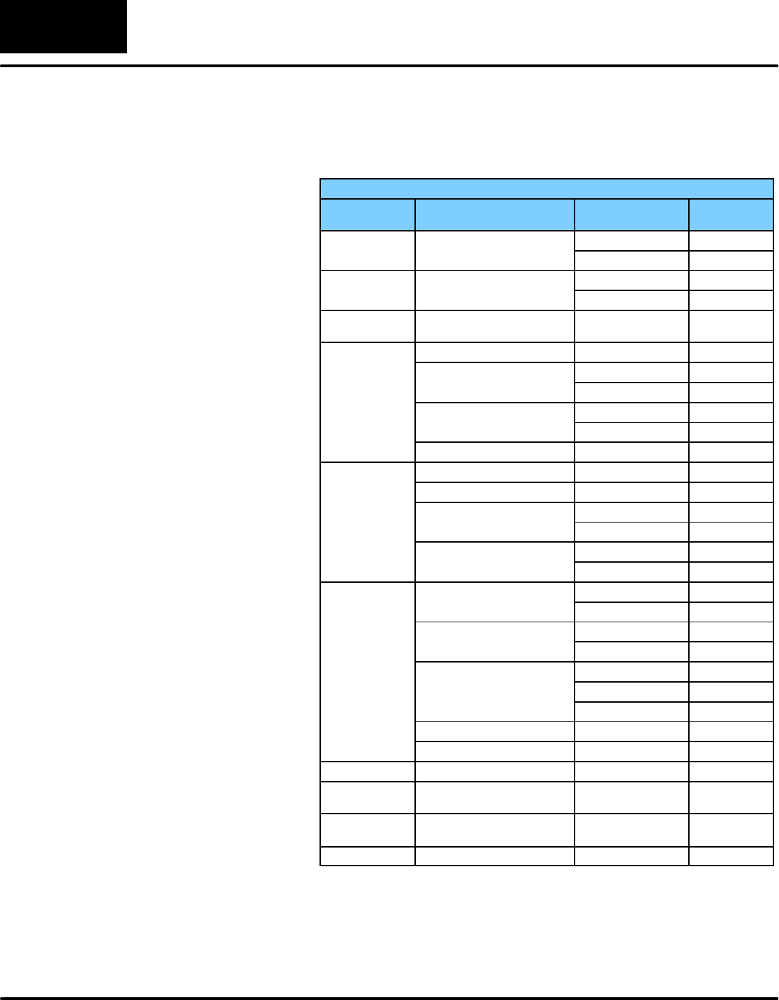
Choosing the Proper Connecting Cables
OptiMate Cables
F
a
m
i
l
y
CPU
P
o
r
t
C
a
b
l
e
F
am
i
l
y
C
P
U
(or other device)
P
ort
C
a
b
l
e
DirectLOGIC
D
L
0
5
:
D
0
-
-
0
5
Port 1 (RJ12) OP-2CBL
DL05
D
L
0
5:
D
0
--
0
5Port 2 (RJ12) OP-2CBL
DirectLOGIC
D
L
0
6
:
D
0
-
-
0
6
Port 1 (RJ12) OP-2CBL
DL06
D
L
0
6
:
D
0
--
0
6
Port 2 (15 pin) OP-2CBL--1
DirectLOGIC
DL105 DL105: F1--130 One port (RJ12) OP--2CBL
D2--230 One port (RJ12) OP--2CBL
D
2
-
-
2
4
0
Top port (RJ12) OP--2CBL
D
i
rec
t
LOGIC
D
2
--
2
4
0
Bottom port (RJ12) OP--2CBL
D
i
r
e
c
t
L
O
G
I
C
DL205 D2--250--1 Top port (RJ12) OP--2CBL
D2--260 Bottom port (15 pin) O P -- 2 C B L -- 1
D2--DCM (module) Only one (25 pin) O P -- 4 C B L -- 2
D3--330 Requires DCU* O P -- 4 C B L -- 2
D3--330P Requires DCU* OP-4CBL--2
D
i
rec
t
LOGIC
D
3
-
-
3
4
0
Top port (RJ11) OP-3CBL
D
i
r
e
c
t
L
O
G
I
C
DL305
D
3
--
3
4
0
Bottom port (RJ11) OP-3CBL
D
3
-
-
3
5
0
Top port OP-2CBL
D
3
--
3
5
0
Bottom port OP-4CBL--2
D
4
-
-
4
3
0
Top port (15-pin) OP-4CBL--1
D
4--4
3
0
Bottom port (25-pin) OP-4CBL--2
D
4
-
-
4
4
0
Top port (15-pin) OP-4CBL--1
D
i
t
L
O
G
I
C
D
4--44
0
Bottom port (25-pin) OP-4CBL--2
DirectLOGIC
DL405 Phone Jack (RJ12) OP-2CBL
D
L
4
0
5
D4--450 Top port (15-pin) OP-4CBL--1
Bottom port (25-pin) OP-4CBL--2
D4--DCM (module) One port (25-pin) OP-4CBL--2
Slice I/O panels One port (15-pin) OP-4CBL--1
GE®Series 1 IC610CPU105, 106 Requires DCU* OP-4CBL--2
GE®Series
90/30 All models (311--351) RS422 serial port Not available
GE®Fanuct
Series 90 Micro All models RS422 serial port Not available
MODICON ModBus RS45 OP--MCBL--1
OptiMate Panel Cables
Depending on which PLC you are
using, you may require as many
as two cables--one to connect the
panel to a personal computer for
configuration; and one to
connect the panel to the PLC.
Here are the requirements:
DOP-ACBL-1: all units require this
cable for configuration. This isa 9-pin
male to 15-pin male cable that
connects your personal computer to
the OptiMate unit. (This cable is also
used to connect an OptiMate panel to
the Allen-Bradley SLC--500 PLC.
DCPU Cables: You will also need the
appropriate cable to connect your
CPU to the OptiMate unit. Use the
chart shown to the right to choose the
correct communications cable.
DOP-ACBL-2: The8PinMini--DINisa
non standard connector used for the
Micrologix 1000. We recommend
using the OP--ACBL--2 cable and
modifying the length for any
applications between 6.56 -- 50 ft.
OP--9001 Cable Connectors
If you’re planning to use multiple
panels and an OP--9001, then
you’ll need to build your own
custom cables. Since the proper
cable choice really depends on
your application, we offer the
following connectors.
DOP--CMCON--1 — pack of 4 ribbon
cable connectors.
DOP--CMCON--2 — pack of 4
solder-type connectors.
For electrically noisy environments,
we recommend a good shielded
cable, such as Belden 9729 or
equivalent. This type of cable will
require the solder-type connectors.
If you’re going 30 feet or less, you
can use ribbon cable. For ribbon
cable, we recommend Belden
9L28015 or 3M 3365/15.
Installing the Panel 1313
OP--1224 User Manual, Rev. D
OptiMate Cables (cont’d)
F
a
m
i
l
y
CPU
P
o
r
t
C
a
b
l
e
F
am
i
l
y
C
P
U
(or other device)
P
ort
C
a
b
l
e
325--07, PPX:325--07 Requires DCU* OP-4CBL--2
330--37, PPX:330--37 Requires DCU* OP-4CBL--2
TI305t/
S
I
M
A
T
I
C
®325S--07 (or 325 w/ Stage Kt) Requires DCU* OP-4CBL--2
S
IM
A
TI
C
®
TI305t330S--37, PPX:330S--37 Requires DCU* OP-4CBL--2
T
I
3
0
5
3
3
5
-
-
3
7
P
P
X
:
3
3
5
-
-
3
7
Phone Jacks (RJ11) OP-3CBL
3
3
5--
3
7,
P
P
X
:
3
3
5--
3
7If DCU is used* OP-4CBL--2
425--CPU, PPX:425--CPU ** One port (15-pin) OP-CBL--1
4
3
0
-
-
C
P
U
P
P
X
:
4
3
0
-
-
C
P
U
Top port (15-pin) OP-4CBL--1
TI405t/
S
I
M
A
T
I
C
®
4
3
0
--
C
P
U
,
P
P
X
:4
3
0
--
C
P
U
Bottom port (25-pin) OP-4CBL--2
S
IM
A
TI
C
®
TI405t
4
3
5
-
-
C
P
U
P
P
X
:
4
3
5
-
-
C
P
U
*
*
Top port (15-pin) OP-4CBL--1
T
I
4
0
5
4
3
5--
C
P
U
,
P
P
X
:4
3
5--
C
P
U
*
*
Bottom port (25-pin) OP-4CBL--2
Smart SlicetI/O panels One port (15-pin) OP-4CBL--1
Allen-Bradley
SLC500 5/03
5/04 Bottom port OP-ACBL--1
Allen--Bradley Micrologix1000/1200/1500 One port (8--pin Mini
Din) OP-ACBL--2
* requires RS232 Data Communications Unit (D3--232--DCU)
** also DC versions
Installing the Panel
14
OP--1224 User Manual, Rev. D
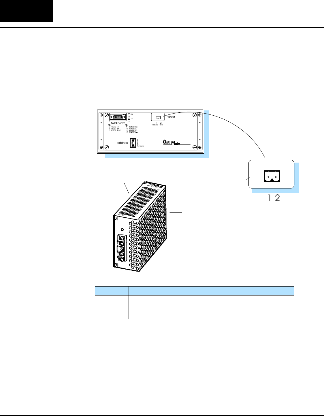
Connecting a Power Supply
The OP-1224 panel can operate on DC voltages between 8 and 30 VDC rated at 4 watts.
Connect the panel to a power supply (within the required voltage range and wattage) using
the terminal block connector supplied. The connector is polarized to prevent reversing the
connections. The male receptacle on the rear of the panel will only connect in one way with
the female connector that is supplied with your OP-1224 panel. Pin 1 is the positive
connection, while Pin 2 is the negative, or ground, connection.
You must use an external power supply that can
deliver voltages in the 8 to 30 VDC range, and
can supply 4 watts of power.
Install the female connector to a
cable for attachment to your power
supply.
Shop for a power supply at www.Automationdirect.com
+GND
A two-prong male connector
is on the rear of the unit.
Your OP-panel is shipped
with the female connector.
Model Current Consumed at 12VDC
OP-1224 0.24A (all LEDs OFF)
0.31A (all LEDs ON)
0.12A (all LEDs OFF)
0.16A (all LEDs ON)
Current Consumed at 24VDC
Power Supply
Connections
Installing the Panel 1515
OP--1224 User Manual, Rev. D
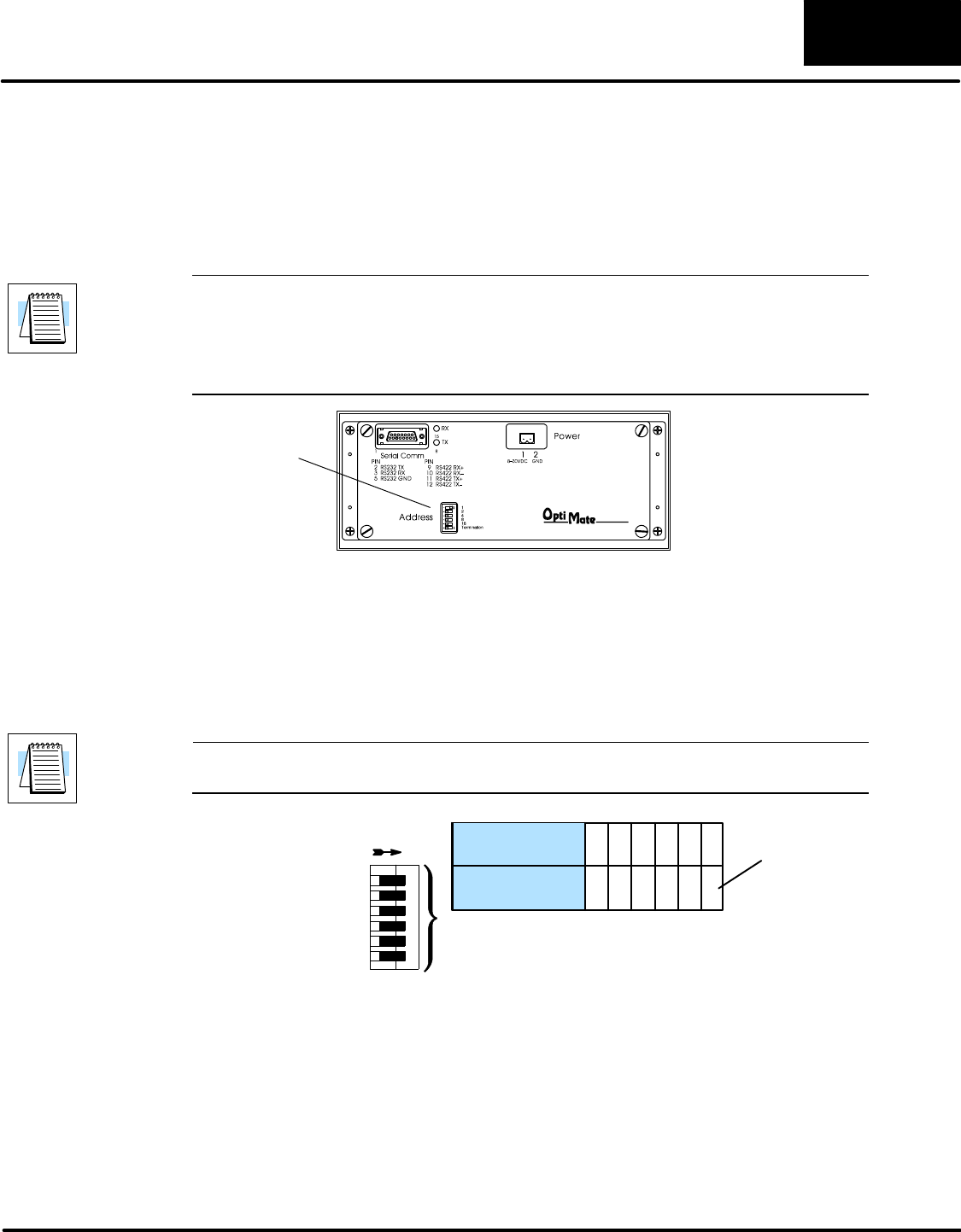
Configure the Panel to Work with the CPU
A 6-position DIP switch on the rear of the OP-1224 allows you to assign a hardware Aaddress
to your panel. Each panel must have a unique address. You can use any addressbetween0
and 30 when communicating between a panel and a PLC or the OP-9001 Master
Communications panel. Address 31, however, is reserved. See the note that follows.
NOTE: You must use Address No. 31 when you are using the OP--WINEDIT software to
download to the OP-1224 panel. No other address will work for the configuration process. In
a similar manner, if you are connecting more that one OP-panel to a single CPU (through an
OP-9001), then the OP-9001 needs to know which set of configuration parameters belong to
which OP-panel. You do this by assigning an address in the range of 0 to 30 to each panel
connected. Each panel must have a different address.
DIP Switch Rear View
To set the address on the OP-1224, simply set the apppropriate switches on the dip switch to
the desired address. The figure below shows the binary weighting of each switch position.
Notice that it is in decimal format.To select address 14 for example, you would press switches
2, 3 and 4 down to the right, and switches 1, 3 and 5 to the left (2 + 4+ 8 = 14). Any address
between 0 and 30 is valid for the OptiMate-to-CPU (or to OP9001) communications. Address
31, however selects the configuration mode. Use this mode when you connect your personal
computer to the panel for configuration. To select address 31, turn switches 1 through 5 ON.
NOTE: When the dip switches are changed, the OP-1224 must be power cycled before the
new settings will take effect.
123456
ON = ENABLE OFF = DISABLE
Switch
On SW1 Position 123456
Address Value 12 4816T
Termination
Resistor.
(See text
below.)
Switch position 6 enables or disables an internal termination resistor. The OptiMate panels
communicate via an RS232 or RS422 communcations network. If you are using a single
panel that will be located less than 50 feet from the CPU, then you can use RS232 and are not
required to use a termination resistor (i.e. switch position 6 is turned OFF).
If a panel will be located more than 50 feet from the CPU or you want to use multiple panels,
you must use RS422. For single panel installations, this means that switch 6 must be
enabled (ON). For multi-drop installations, this means the last panel only must have switch
6 enabled (ON). All other panels must have switch 6 disabled (OFF). A more detailed
description of multiple panel installations is given in the OP-9001-M User Manual.
Assigning an
Address to the
OP-1224
How to Set the
Address
The Termination
Resistor
Installing the Panel
16
OP--1224 User Manual, Rev. D
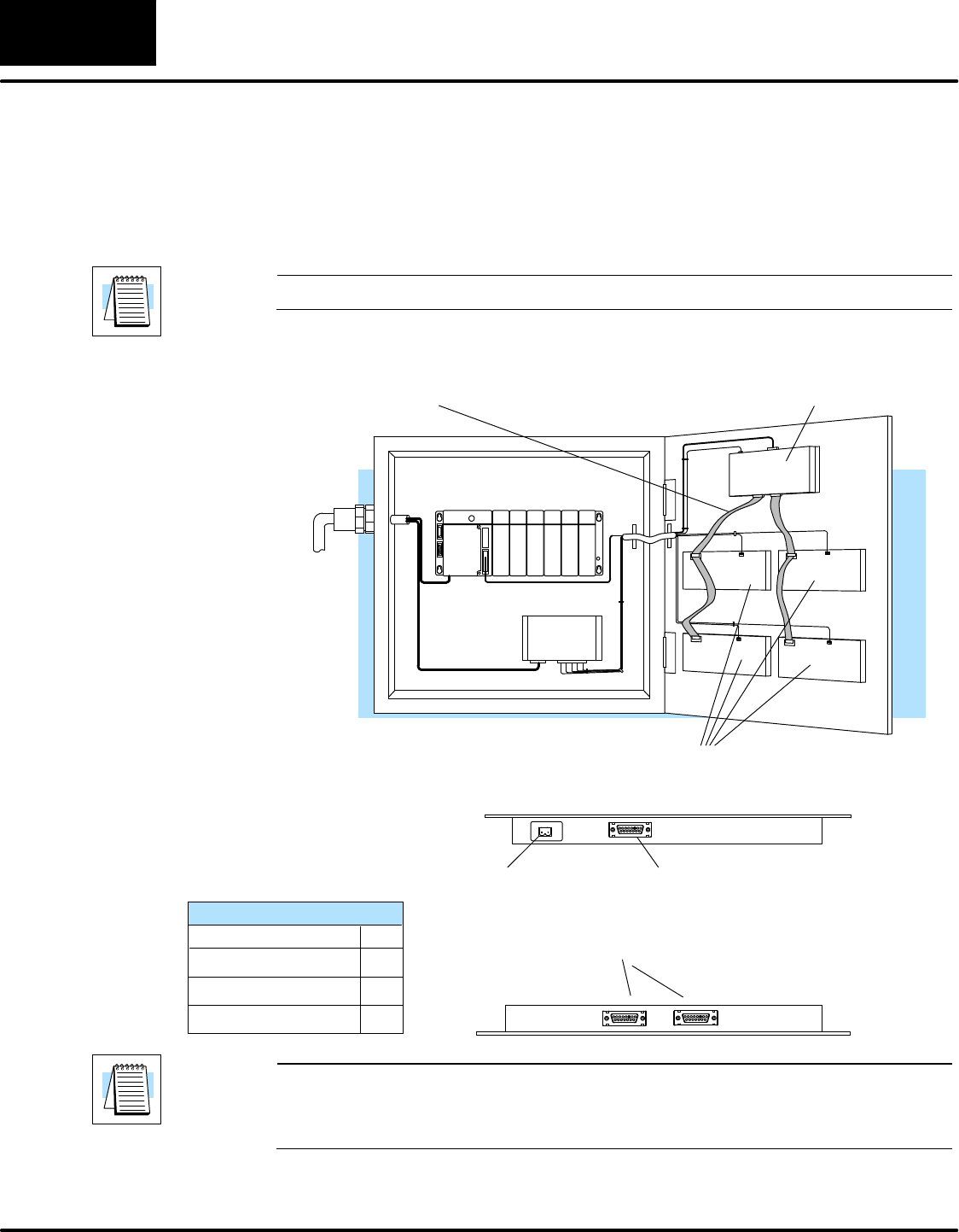
Using the OP-9001 to Connect Multiple Panels
The addition of the OP-9001 Communications Master panel will allow the connection of up to
31 OptiMate panels from one useable CPU port of the PLC. Shown beloware the connection
requirements. For specifics of the OP-9001 panel itself, refer to the Communications Master
User Manual (OP-9001--M).
NOTE: The OP-9001 must be used in a multiple panel configuration.
Power
Source
OP-panels
OP-9001
Ribbon cable with DB15 male connectors attached.
Panels can be connected directly to the OP-9001 ports
or be daisy-chained to other OP-panels.
PLC
Power Supply
Power supply receptacle.
Same as the one on the
OP-1224. See Page 15.
DB15 for connecting to the PLC.
See chart on Page 13 for selection
of the proper cable.
Two DB15 ports for RS422 connection to any OP-panel.
Belden 9279 Specifications
No. twisted pairs
Nom. Impedance (ohms)
2
100
Nom. Capacitance (pF/m) 41.0
Wire Gauge (AWG) 24
NOTE: Panels can be located as far away as 4000 feet from the OP-9001 when using
shielded cable (Belden 9729 or equivalent). Flat ribbon connections can be used for a
distance of 30 feet maximum. For ribbon cable, Belden 9L28015 or 3M 3365/15 is
recommended.
