Chapter 6 Ch6
User Manual: Chapter 6 DURApulse GS4 AC Drives User Manual
Open the PDF directly: View PDF ![]() .
.
Page Count: 32

Page 6–1
DURApUlse GS4 AC Drive User Manual – 1st Ed, RevB - 11/17/2017
Maintenance and troubleshooting 6
6
6
chapter
chapter
chapter
Table of ConTenTs
Maintenance and Inspections � � � � � � � � � � � � � � � � � � � � � � � � � � � � � � � � � � � � �6–2
Monthly Inspection � � � � � � � � � � � � � � � � � � � � � � � � � � � � � � � � � � � � � � � � � � � � � � 6–2
Annual Inspection � � � � � � � � � � � � � � � � � � � � � � � � � � � � � � � � � � � � � � � � � � � � � � � 6–2
Recharge Capacitors (for drives not in service) � � � � � � � � � � � � � � � � � � � � � � � � � � � � � � � 6–3
Recommended Inspection Schedules � � � � � � � � � � � � � � � � � � � � � � � � � � � � � � � � � � � � 6–4
Troubleshooting � � � � � � � � � � � � � � � � � � � � � � � � � � � � � � � � � � � � � � � � � � � � �6–8
Warning Codes� � � � � � � � � � � � � � � � � � � � � � � � � � � � � � � � � � � � � � � � � � � � � � � � � 6–8
Fault Codes� � � � � � � � � � � � � � � � � � � � � � � � � � � � � � � � � � � � � � � � � � � � � � � � � � �6–16
Typical AC Drive Problems and Solutions � � � � � � � � � � � � � � � � � � � � � � � � � � � � � � 6–26
Grease and Dirt Problems� � � � � � � � � � � � � � � � � � � � � � � � � � � � � � � � � � � � � � � � � � �6–26
Fiber Dust Problem � � � � � � � � � � � � � � � � � � � � � � � � � � � � � � � � � � � � � � � � � � � � � �6–27
Corrosion Problem� � � � � � � � � � � � � � � � � � � � � � � � � � � � � � � � � � � � � � � � � � � � � � �6–28
Industrial Dust Problem � � � � � � � � � � � � � � � � � � � � � � � � � � � � � � � � � � � � � � � � � � � �6–29
Wiring and Installation Problem � � � � � � � � � � � � � � � � � � � � � � � � � � � � � � � � � � � � � � �6–30
Digital Input/Output Terminal Problems� � � � � � � � � � � � � � � � � � � � � � � � � � � � � � � � � � �6–31

Page 6–2 DURApUlse GS4 AC Drive User Manual – 1st Ed, RevB - 11/17/2017
Chapter 6: Maintenance and Troubleshooting
Maintenance and inspections
Modern AC drives are based on solid state electronics technology, including ICs, resistors,
capacitors, transistors, cooling fans, relays, etc. These components have a limited life under
normal operation. Preventive maintenance is required to operate the GS4 drive in its optimal
condition, and to ensure a long life. We recommend that a qualified technician perform a regular
inspection of the GS4 drive. Some items should be checked once a month, and some items should
be checked yearly.
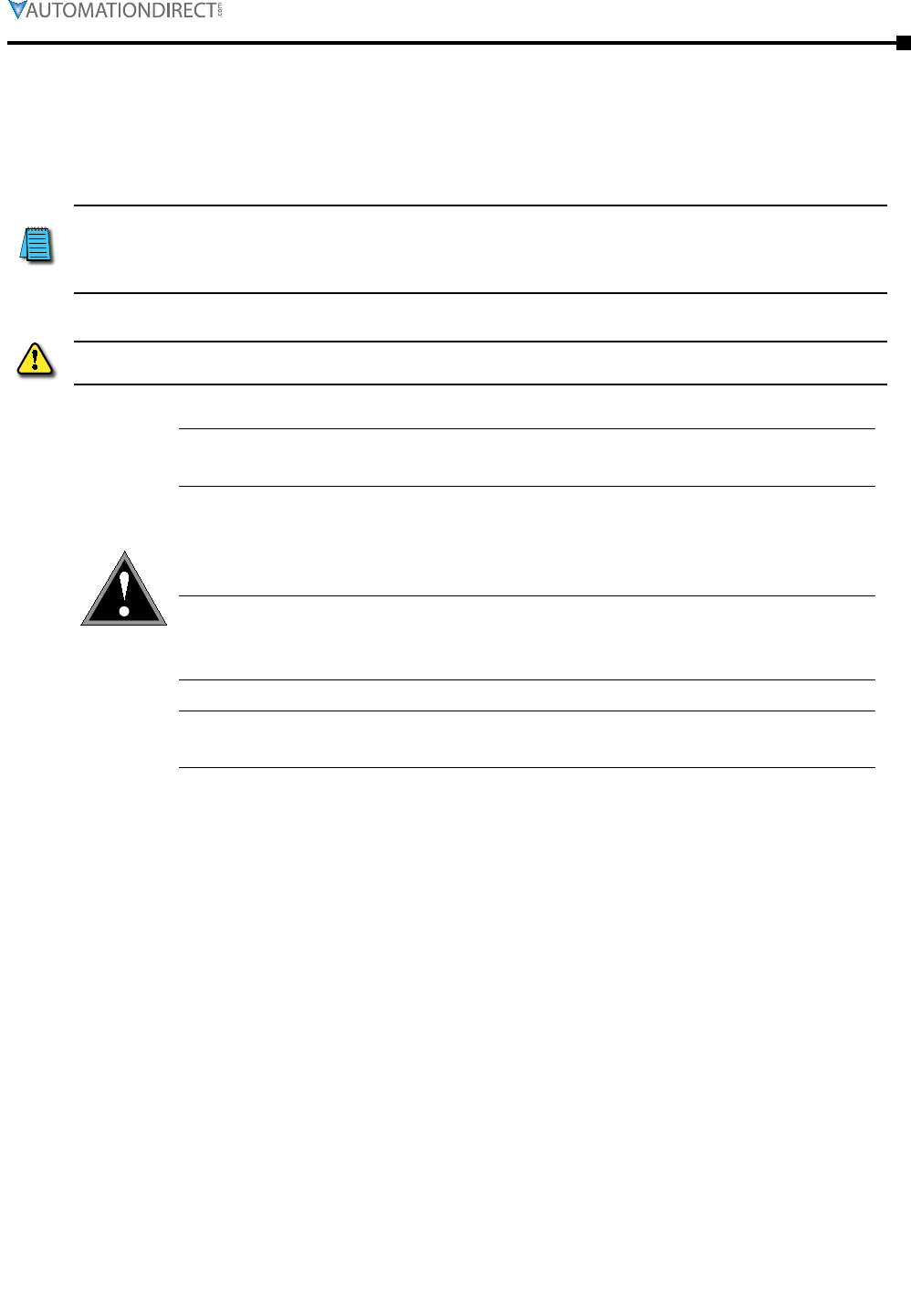
NOTE: All inspections should be accomplished with Safety in mind with due and required caution.
Some of these Inspection items may require the Drive to be powered down, while others may
require power to be applied. Proper safety precautions including the use of PPE are/may be
required. Please review cautionary statements in each section
Monthly InspectIon
Check the following items at least once a month.
1)
Make sure the motors are operating as expected�
2)
Make sure the drive installation environment is normal�
3)
Make sure the enclosure and drive cooling systems are operating as expected�
4)
Check for irregular vibrations or sounds during operation�
5)
Make sure the motors are not overheating during operation�
6)
Check the input voltage to the
GS4
drive and make sure the voltage is within the operating
range� Check the voltage with a voltmeter�
AnnuAl InspectIon
Check the following items once annually.
1)
Check the torque of the GS4 power and control terminal screws and tighten if necessary�
They may loosen due to vibration or changing temperatures�
2)
Make sure the conductors and insulators are not corroded or damaged�
3)
Check the resistance of cable insulation with a megohmmeter�
4)
Clean off any dust and dirt with a vacuum cleaner� Pay special attention to cleaning the
ventilation ports and PCBs� Always keep these areas clean� Accumulation of dust and dirt in
these areas can cause unforeseen failures�
5)
Recharge the capacitors of any drive that is in storage or is otherwise unused�
Chapter 6: Maintenance and Troubleshooting
Page 6–3
DURApUlse GS4 AC Drive User Manual – 1st Ed, RevB - 11/17/2017
RechARge cApAcItoRs (foR dRIves not In seRvIce)
Recharge the DC link before using any drive that has not been operated within a year:
1)
Disconnect the motor from the drive�
2)
Apply input power to the drive for 2 hours�
If the drive is stored or is otherwise unused for more than a year, the drive’s internal DC link
capacitors should be recharged before use. Otherwise, the capacitors may be damaged when the
drive starts to operate. We recommend recharging the capacitors of any unused drive at least
once per year.
Disconnect Ac power AnD ensure thAt the internAl cApAcitors hAve fully DischArgeD before
inspecting the gs4 Drive! wAit At leAst two minutes After All DisplAy lAmps hAve turneD off.
CAUTION
☑Wait 5 seconds after a fault has been cleared before performing reset
via keypad or input terminal.
☑When the power is off after 5 minutes for ≤ 30hp models and 10
minutes for ≥ 40hp models, please confirm that the capacitors have
fully discharged by measuring the voltage between + and -. The
voltage between + and - should be less than 25VDC.
☑Only qualified personnel can install, wire and maintain drives.
Please take off any metal objects, such as watches and rings, before
operation. And only insulated tools are allowed.
☑Never reassemble internal components or wiring.
☑Make sure that installation environment complies with regulations
without abnormal noise, vibration and smell.
Page 6–4 DURApUlse GS4 AC Drive User Manual – 1st Ed, RevB - 11/17/2017
Chapter 6: Maintenance and Troubleshooting
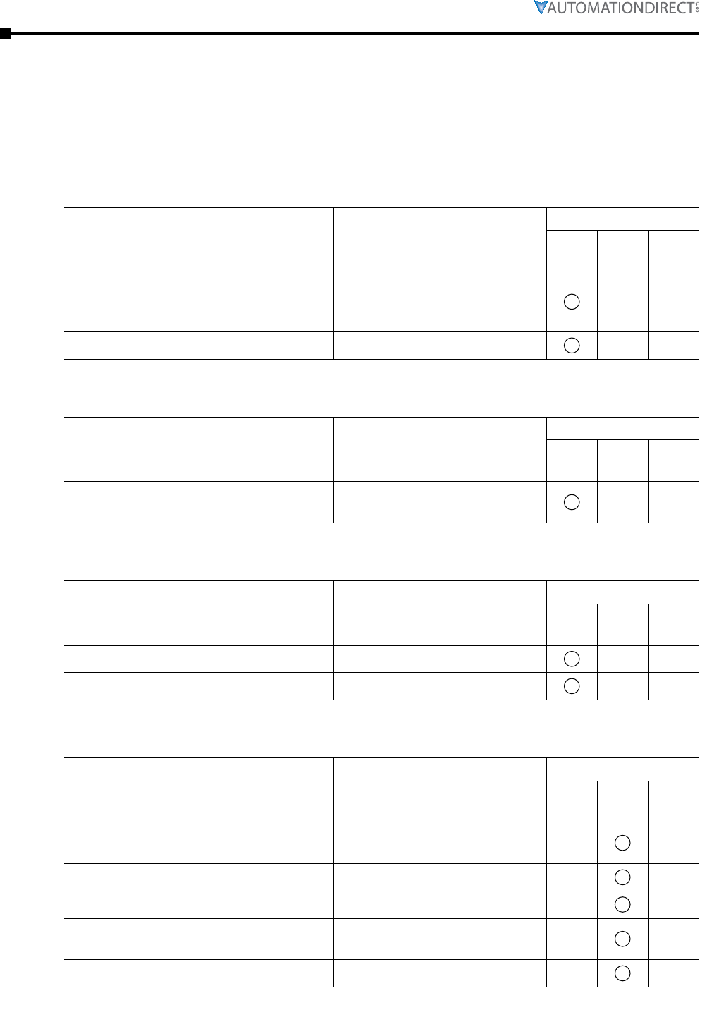
RecoMMended InspectIon schedules
Before the check-up, always turn off the AC input power and remove the cover. Wait at least
10 minutes after all display lamps have gone out, and then confirm that the capacitors have
fully discharged by measuring the voltage between DC+ and DC-. The voltage between DC+ and
DC-should be less than 25VDC.
Ambient environment
Check Items Methods and Criteria
Maintenance Period
Daily Half
Year
One
Year
Check the ambient temperature,
humidity, vibration and see if there are
any dust, gas, oil or water drops
Visual inspection and
measurement with equipment
with standard specification
If there are any dangerous objects Visual inspection
Voltage
Check Items Methods and Criteria
Maintenance Period
Daily Half
Year
One
Year
Check if the voltage of main circuit and
control circuit is correct
Measure with multimeter with
standard specification
Digital Keypad Display
Check Items Methods and Criteria
Maintenance Period
Daily Half
Year
One
Year
Is the display clear for reading Visual inspection
Any missing characters Visual inspection
Mechanical parts
Check Items Methods and Criteria
Maintenance Period
Daily Half
Year
One
Year
If there is any abnormal sound or
vibration Visual and audible inspection
If there are any loose screws Tighten the screws
If any part is deformed or damaged Visual inspection
If there is any color change due to
overheating Visual inspection
If there is any dust or dirt Visual inspection
Chapter 6: Maintenance and Troubleshooting
Page 6–5
DURApUlse GS4 AC Drive User Manual – 1st Ed, RevB - 11/17/2017
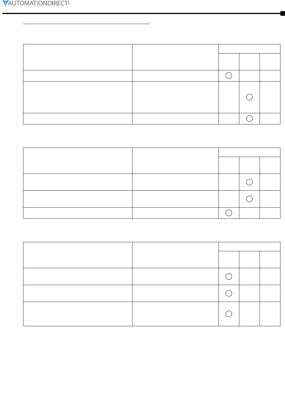
Recommended Inspection Schedules (continued)
Main circuit
Check Items Methods and Criteria
Maintenance Period
Daily Half
Year
One
Year
If there are any loose or missing screws Tighten or replace the screw
If any drive or wiring insulation is
deformed, cracked, damaged or has
changed color due to overheating or
aging
Visual inspection
NOTE: Ignore any color
change of copper plate
If there is any dust or dirt Visual inspection
Terminals and wiring of main circuit
Check Items Methods and Criteria
Maintenance Period
Daily Half
Year
One
Year
If the terminal color or the placement
has changed due to overheating Visual inspection
If the wiring insulation is damaged or
there has been a color change Visual inspection
If there is any damage Visual inspection
DC capacity of main circuit
Check Items Methods and Criteria
Maintenance Period
Daily Half
Year
One
Year
If there is any liquid leaking, color
change, crack or deformation Visual inspection
If the capacitor safety vent is bulging or
inflated. Visual inspection
Measure static capacity when required
(if drive overloads/faults during normal
operation)
Measure with multimeter with
standard specification
Page 6–6 DURApUlse GS4 AC Drive User Manual – 1st Ed, RevB - 11/17/2017
Chapter 6: Maintenance and Troubleshooting
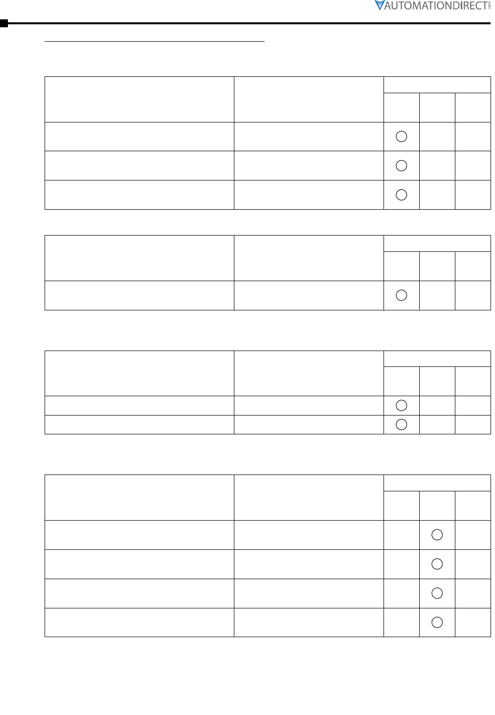
Recommended Inspection Schedules (continued)
Resistor of main circuit
Check Items Methods and Criteria
Maintenance Period
Daily Half
Year
One
Year
If there is any peculiar smell or
insulation cracks due to overheating Visual inspection, smell
If there is any disconnection or
discoloration Visual inspection
If the connection is damaged Measure with a multimeter
with standard specifications
Transformer and reactor of main circuit
Check Items Methods and Criteria
Maintenance Period
Daily Half
Year
One
Year
If there is any abnormal vibration or
peculiar smell
Visual, audible inspection and
smell
Magnetic contactor and relay of main circuit
Check Items Methods and Criteria
Maintenance Period
Daily Half
Year
One
Year
If there are any loose screws Visual and audible inspection
If the contact works correctly Visual inspection
Printed circuit board and connector of main circuit
Check Items Methods and Criteria
Maintenance Period
Daily Half
Year
One
Year
If there are any loose screws and
connectors
Tighten the screws and press
the connectors firmly in place
If there is any peculiar smell and/or
color change Visual and smell inspection
If there is any crack, damage,
deformation or corrosion Visual inspection
If there is any liquid leakage or
deformation in capacity Visual inspection
Chapter 6: Maintenance and Troubleshooting
Page 6–7
DURApUlse GS4 AC Drive User Manual – 1st Ed, RevB - 11/17/2017
Recommended Inspection Schedules (continued)
Cooling fan of cooling system
Check Items Methods and Criteria
Maintenance Period
Daily Half
Year
One
Year
If there is any abnormal sound or
vibration
Visual, audible inspection and
turn the fan with hand (turn off
the power before operation) to
see if it rotates smoothly
If there is any loose screw Tighten the screw
If there is any color change due to
overheating Change the fan
Ventilation channel of cooling system
Check Items Methods and Criteria
Maintenance Period
Daily Half
Year
One
Year
If there is any obstruction in the heat
sink, air intake or air outlet Visual inspection
Please use a clean lint free cloth for cleaning and use a dust cleaner to remove dust when
necessary.

Page 6–8 DURApUlse GS4 AC Drive User Manual – 1st Ed, RevB - 11/17/2017
Chapter 6: Maintenance and Troubleshooting
troubleshooting
WARnIng codes
The GS4 drive has a comprehensive diagnostic system that includes several different warning
codes. The most common warning codes can be read on the digital keypad display.
LOCAL ①Display error signal type
①Warning ②Abbreviated error code
The code is displayed as shown on GS4-KPD
②CE1
③Comm. Error 1 ③Display error description
Warning Codes
Display on GS4-KPD Keypad
Warning
Code in
2108h
Active
Warning
Descriptions
n/a 0 No error
LOCAL
Warning
CE1
Comm. Error 1
1
Modbus function code error
This error is generated if any command code other than
0x03, 0x06, 0x08 or 0x10 is seen�
LOCAL
Warning
CE2
Comm. Error 2
2 Address of Modbus data error
LOCAL
Warning
CE3
Comm. Error 3
3 Modbus data error
LOCAL
Warning
CE4
Comm. Error 4
4 Modbus communication error
LOCAL
Warning
CE10
Comm. Error 10
5 Modbus transmission time-out
LOCAL
Warning
CP10
Keypad Time Out
6 Keypad transmission time-out
(continued next page)

Chapter 6: Maintenance and Troubleshooting
Page 6–9
DURApUlse GS4 AC Drive User Manual – 1st Ed, RevB - 11/17/2017
Warning Codes (continued)
Display on GS4-KPD Keypad
Warning
Code in
2108h
Active
Warning
Descriptions
LOCAL
Warning
SE1
Save Error 1
7
Keypad COPY error 1
Keypad transfer (check) error, including communication delays, communication
error (keypad received error FF86) and parameter value error�
P9�06 must be set to 1 for a keypad to drive copy�
LOCAL
Warning
SE2
Save Error 2
8Keypad COPY error 2
Keypad transfer (check) done, parameter write error
LOCAL
Warning
oH1
Over heat 1 warn
9 IGBT over-heating warning
LOCAL
Warning
oH2
Over heat 2 warn
10 Capacitor over-heating warning
LOCAL
Warning
PID
PID FBK Error
11 PID feedback error
LOCAL
Warning
ANL
Analog Loss
12
AIx 4~20mA Signal Loss
AI1 or AI2 signal drops below 4mA when P4�05 or P4�06 are set to 1 (4~20mA)�
Enabled with P4�63 and P4�64 (AIx 4~20mA Loss Detection)�
LOCAL
Warning
uC
Under Current
13 Low current
LOCAL
Warning
AUE
Auto-tune Error
14 Auto tuning error
n/a 15~18 reserved
(continued next page)

Page 6–10 DURApUlse GS4 AC Drive User Manual – 1st Ed, RevB - 11/17/2017
Chapter 6: Maintenance and Troubleshooting
Warning Codes (continued)
Display on GS4-KPD Keypad
Warning
Code in
2108h
Active
Warning
Descriptions
LOCAL
Warning
PHL
Phase Loss Warn
19 Input phase Loss
LOCAL
Warning
ot1
Over Torque 1
20 Over torque 1
LOCAL
Warning
ot2
Over Torque 2
21 Over torque 2
LOCAL
Warning
oH3
Motor Over Heat
22 Motor over-heating
LOCAL
Warning
c.c.
cc Warn
23 Current clamp warning
LOCAL
Warning
oSL
Over Slip Warn
24 Over Slip
LOCAL
Warning
tUn
Auto tuning
25 Auto tuning processing
n/a 26~27 reserved
LOCAL
Warning
OPHL
Output PHL Warn
28 Output phase loss
n/a 29 reserved
(continued next page)

Chapter 6: Maintenance and Troubleshooting
Page 6–11
DURApUlse GS4 AC Drive User Manual – 1st Ed, RevB - 11/17/2017
Warning Codes (continued)
Display on GS4-KPD Keypad
Warning
Code in
2108h
Active
Warning
Descriptions
LOCAL
Warning
SE3
CopyEn/Model Err
30
Keypad COPY error 3
P9�06 is not set to 1 before the copy function is started�
If COPYing from Keypad to VFD (AC drive), make sure P9�06 Parameter Copy is
set to 1 before copying�
n/a 31~46 reserved
LOCAL
Warning
PLrA
RTC Adjust
47 The Real Time Clock has been adjusted�
n/a 48 reserved
LOCAL
Warning
PLrt
Keypad RTC TOut
49 Keypad Real Time Clock timout
Turn power on and off after making sure that the keypad is securely connected�
LOCAL
Warning
PLod
PLC Out of Range
50 Drive PLC requesting register address or block of addresses that is out of range
or does not exist�
LOCAL
Warning
PLSv
Save mem defect
51 Save error of PLC download
LOCAL
Warning
PLdA
Data defect
52 Data error during PLC operation
LOCAL
Warning
PLFn
Function defect
53
Function code of PLC download error
(occurs on PLC register overflow� Also occurs if the PLC is set to RUN, and there
is no program installed)
LOCAL
Warning
PLor
Buf overflow
54 PLC register overflow
(continued next page)

Page 6–12 DURApUlse GS4 AC Drive User Manual – 1st Ed, RevB - 11/17/2017
Chapter 6: Maintenance and Troubleshooting
Warning Codes (continued)
Display on GS4-KPD Keypad
Warning
Code in
2108h
Active
Warning
Descriptions
LOCAL
Warning
PLFF
Function defect
55 Function code of PLC operation error
LOCAL
Warning
PLSn
Check sum error
56 PLC checksum error
LOCAL
Warning
PLEd
No end command
57 PLC end command is missing
n/a 58 reserved
LOCAL
Warning
PLdF
Download fail
59 PLC download fail
LOCAL
Warning
PLSF
Scan time fail
60 PLC scan time exceed
n/a 61~69 reserved
LOCAL
Warning
ECid
ExCom ID failed
70 Duplicate MAC ID error
Node address setting error
LOCAL
Warning
ECLv
ExCom pwr loss
71 Low voltage of communication card
LOCAL
Warning
ECtt
ExCom Test Mode
72 Communication card in test mode
(continued next page)

Chapter 6: Maintenance and Troubleshooting
Page 6–13
DURApUlse GS4 AC Drive User Manual – 1st Ed, RevB - 11/17/2017
Warning Codes (continued)
Display on GS4-KPD Keypad
Warning
Code in
2108h
Active
Warning
Descriptions
LOCAL
Warning
ECbF
ExCom Bus off
73 ExCom Bus off
LOCAL
Warning
ECnP
ExCom No power
74 ExCom No power
LOCAL
Warning
ECFF
ExCom Facty def
75 Factory default setting error
LOCAL
Warning
ECif
ExCom Inner err
76 Serious internal error
LOCAL
Warning
ECio
ExCom IONet brk
77 IO connection break
LOCAL
Warning
ECPP
ExCom Pr data
78 ExCom Pr data
LOCAL
Warning
ECPi
ExCom Conf data
79 ExCom Conf data
LOCAL
Warning
ECEF
ExCom Link fail
80
Ethernet Link fail� If a communications card is installed but not connected to an
active network, this warning will appear� Please connect to valid network link�
Reset card to default and/or re-flash comm card firmware if problem persists�
(continued next page)

Page 6–14 DURApUlse GS4 AC Drive User Manual – 1st Ed, RevB - 11/17/2017
Chapter 6: Maintenance and Troubleshooting
Warning Codes (continued)
Display on GS4-KPD Keypad
Warning
Code in
2108h
Active
Warning
Descriptions
LOCAL
Warning
ECto
ExCom Inr T-out
81 Communication time-out for communication card and drive
LOCAL
Warning
ECCS
ExCom Inr CRC
82 Check sum error for communication card and drive
LOCAL
Warning
ECrF
ExCom Rtn def
83 Communication card returns to default setting
LOCAL
Warning
ECo0
ExCom MTCP over
84 Modbus TCP exceeded maximum communication value
LOCAL
Warning
ECo1
ExCom EIP over
85 EtherNet/IP exceeded maximum communication value
LOCAL
Warning
ECiP
ExCom IP fail
86 IP fail
n/a 87 reserved
LOCAL
Warning
ECbY
ExCom Busy
88 Communication card busy
LOCAL
Warning
ECCb
ExCom Card brk
89
Loss of communication between Communication Card and GS4 drive�
To recover:
Power down the drive and remove all communication cables� Remove and re-
seat the comm card� Do not reconnect any comm cables� Power up the drive� If
the ECCb fault still exists, replace the comm card�
(continued next page)

Chapter 6: Maintenance and Troubleshooting
Page 6–15
DURApUlse GS4 AC Drive User Manual – 1st Ed, RevB - 11/17/2017
Warning Codes (continued)
Display on GS4-KPD Keypad
Warning
Code in
2108h
Active
Warning
Descriptions
LOCAL
Warning
WdCPLP
Copy PLC Pass
90 Copy PLC password error
LOCAL
Warning
RdCPL0
Copy PLC Mode
91 Copy PLC read mode error
LOCAL
Warning
WtCPL1
Copy PLC Mode
92 Copy PLC write mode error
LOCAL
Warning
CPLv
Copy PLC Version
93 Copy PLC version error
LOCAL
Warning
CPLS
Copy PLC Size
94 Copy PLC capacity size error
LOCAL
Warning
CPLF
Copy PLC Func
95
Copy PLC: Disable PLC functions to copy
Warning Code 95 could also show up as ERR7 if the
PLC is in STOP mode. Disable the PLC before copying.
LOCAL
Warning
CPLt
Copy PLC TimeOut
96 Copy PLC time-out
Resettable only by cycling power to the drive
LOCAL
Warning
CD10
Card TimeOut
97 Ethernet communication has not been received from the external controller
(within the Ethernet Timeout window)�

Page 6–16 DURApUlse GS4 AC Drive User Manual – 1st Ed, RevB - 11/17/2017
Chapter 6: Maintenance and Troubleshooting
fAult codes
The GS4 drive has a comprehensive fault diagnostic system that include a variety of fault
messages. When a fault is detected, the GS4 drive will shut down in order to protect internal
components. The following faults are displayed as shown on the GS4 digital keypad display.
LOCAL ①Display error signal type
①Fault ②Abbreviate error code
The code is displayed as shown on GS4-KPD
②ocA
③OC at Accel ③Display error description
Gaps in the fault ID numbers below are set aside as “reserved” faults for possible future use.
Should your GS4 drive repeatedly display a reserved fault, please note the fault ID number and
contact AutomationDirect technical support.
Fault Codes
Display on GS4-KPD Kepad
Fault Code
in Status
Monitor 1
Fault Description Corrective Action
Can be
Bypassed
in Fire
Mode
(Yes / no)
n/a 0 no error none needed n/a
LOCAL
Fault
ocA
OC at Accel
1
Over-current
during acceleration
(Output current
exceeds
triple rated
current during
acceleration�)
1) Short circuit at motor output: Check for
possible poor insulation at the output�
2) Acceleration Time too short: Increase the
Acceleration Time�
3) GS4 drive output power is too small: Replace
the GS4 drive with the next higher power
model�
Yes
LOCAL
Fault
ocd
OC at decel
2
Over-current
during
deceleration
(Output current
exceeds
triple rated
current during
deceleration�)
1) Short circuit at motor output: Check for
possible poor insulation at the output�
2) Deceleration Time too short: Increase the
Deceleration Time�
3) GS4 drive output power is too small: Replace
the GS4 drive with the next higher power
model�
Yes
LOCAL
Fault
ocn
OC at Speed
3
Over-current
during steady state
operation (Output
current exceeds
triple rated current
during constant
speed�)
1) Short circuit at motor output: Check for
possible poor insulation at the output�
2) Sudden increase in motor loading: Check for
possible motor stall�
3) GS4 drive output power is too small: Replace
the GS4 drive with the next higher power
model�
Yes
LOCAL
Fault
GFF
Ground Fault
4 Ground fault
W hen (one of) the output terminal(s) is
grounded, short-circuit current is more than
50% of the GS4 drive rated current, the GS4
drive power module may be damaged�
N OTE: The short-circuit protection is provided
for AC motor drive protection; not for
protecting the user�
1) Check the wiring connections between the
GS4 drive and motor for possible short
circuits, also to ground�
2) Check whether the IGBT power module is
damaged�
3) Check for possible poor insulation at the
output�
Yes
(continued next page)

Chapter 6: Maintenance and Troubleshooting
Page 6–17
DURApUlse GS4 AC Drive User Manual – 1st Ed, RevB - 11/17/2017
Fault Name
Fault Code
in Status
Monitor 1
Fault
Descriptions Corrective Actions
Can be
Bypassed
in Fire
Mode
(Yes / no)
LOCAL
Fault
occ
IGBT Short Ckt
5
Short-circuit is
detected between
upper bridge and
lower bridge of the
IGBT module
Replace the drive� If still under warranty, please
contact AutomationDirect Returns Department� Yes
LOCAL
Fault
ocS
OC at Stop
6Hardware failure in
current detection
Replace the drive� If still under warranty, please
contact AutomationDirect Returns Department� Yes
LOCAL
Fault
ovA
OV at Accel
7
DC BUS over-
voltage during
acceleration (230V:
DC 450V;
460V: DC 900V)
1) Check if the input voltage falls within the
rated GS4 drive input voltage range�
2) Check for possible voltage transients�
Yes
LOCAL
Fault
ovd
OV at Decel
8
DC BUS over-
voltage during
deceleration (230V:
DC 450V; 460V: DC
900V)
1) Check if the input voltage falls within the
rated GS4 drive input voltage range�
2) Check for possible voltage transients�
3) If DC BUS over-voltage due to regenerative
voltage, please increase the Deceleration
Time or add an optional brake resistor�
Yes
LOCAL
Fault
ovn
OV at Speed
9
DC BUS over-
voltage at constant
speed
(230V: DC 450V;
460V: DC 900V)
1) Check if the input voltage falls within the
rated GS4 drive input voltage range�
2) Check for possible voltage transients� Yes
LOCAL
Fault
ovS
OV at Stop
10 Hardware failure in
voltage detection�
1) Check if the input voltage falls within the
rated GS4 drive input voltage range�
2) Check for possible voltage transients�
Yes
LOCAL
Fault
LvA
LV at Accel
11
DC BUS voltage
is less than P6�35
during acceleration
1) Check if the input voltage is normal�
2) Check for possible sudden load� no
LOCAL
Fault
Lvd
LV at Decel
12
DC BUS voltage
is less than
P6�35 during
deceleration
1) Check if the input voltage is normal�
2) Check for possible sudden load� no
(continued next page)

Page 6–18 DURApUlse GS4 AC Drive User Manual – 1st Ed, RevB - 11/17/2017
Chapter 6: Maintenance and Troubleshooting
Fault Name
Fault Code
in Status
Monitor 1
Fault
Descriptions Corrective Actions
Can be
Bypassed
in Fire
Mode
(Yes / no)
LOCAL
Fault
Lvn
LV at Speed
13
DC BUS voltage is
less than P6�35 in
constant speed
1) Check if the input voltage is normal.
2) Check for possible sudden load. no
LOCAL
Fault
LvS
LV at Stop
14
DC BUS voltage is
less than P6�35 at
stop
1) Check if the input voltage is normal
2) Check for possible sudden load no
LOCAL
Fault
OrP
Input Phase loss
15 Output Ripple /
Phase Loss
Check Power Source Input if all 3 input phases
are connected without loose contacts� For
models 40hp and above, please check if the fuse
for the AC input circuit is blown�
Yes
LOCAL
Fault
oH1
IGBT Over Heat
16
IGBT overheating
IGBT temperature
exceeds protection
level
1) Ensure that the ambient temperature falls
within the specified temperature range.
2) Make sure that the ventilation holes are
not obstructed.
3) Remove any foreign objects from the
heatsinks and check for possible dirty heat
sink fins.
4) Check the fan and clean it.
5) Provide enough spacing for adequate
ventilation.
Yes
LOCAL
Fault
oH2
Cap Over Heat
17
Heatsink
overheating
Capacitance
temperature
exceeds cause
heatsink
overheating�
1) Ensure that the ambient temperature falls
within the specified temperature range.
2) Make sure heat sink is not obstructed.
Check if the fan is operating
3) Check if there is enough ventilation
clearance for the GS4 drive.
Yes
LOCAL
Fault
tH1o
Thermister1 Open
18 IGBT Hardware
Error
Internal drive error� Replace the drive�
If still under warranty, please contact
AutomationDirect Returns Department�
Yes
LOCAL
Fault
tH2o
Thermister2 Open
19 Capacitor
Hardware Error
Internal drive error� Replace the drive�
If still under warranty, please contact
AutomationDirect Returns Department�
Yes
LOCAL
Fault
PWR
Power Reset Off
20 Power Loss (Power
Down)
Check for loose input power connections�
Restore line power� no
(continued next page)

Chapter 6: Maintenance and Troubleshooting
Page 6–19
DURApUlse GS4 AC Drive User Manual – 1st Ed, RevB - 11/17/2017
Fault Name
Fault Code
in Status
Monitor 1
Fault
Descriptions Corrective Actions
Can be
Bypassed
in Fire
Mode
(Yes / no)
LOCAL
Fault
oL
Overload
21
Overload
The GS4 drive
detects excessive
drive output
current�
1) Check if the motor is overloaded.
2) Use the next higher HP drive model. no
LOCAL
Fault
EoL1
Mtr1 Thermal OL
22 Electronic thermal
relay 1 protection
1) Check the setting of electronics thermal
relay (P6.01)
2) Use the next higher HP drive model.
no
LOCAL
Fault
EoL2
Mtr2 Thermal OL
23 Electronic thermal
relay 2 protection
1) Check the setting of electronics thermal
relay (P6.03)
2) Use the next higher HP drive model.
no
LOCAL
Fault
oH3
Mtr Overheat-PTC
24
Motor overheating
The GS4 drive
detecting internal
temperature
exceeds the setting
of P6�40 (PTC level)
1) Make sure that the motor is not
obstructed.
2) Ensure that the ambient temperature falls
within the specified temperature range.
3) Use the next higher HP drive model.
Yes
n/a 25 reserved n/a n/a
LOCAL
Fault
ot1
Over Torque 1
26
These two fault
codes will be
displayed when
output current
exceeds the over-
torque detection
level (P6�15 or
P6�18) and exceeds
over-torque
detection (P6�16 or
P6�19) and it is set
to 2 or 4 in P6�14
or P6�17�
1) Check whether the motor is overloaded.
2) Check whether motor rated current setting
(P0.01) is suitable
3) Use the next higher HP drive model.
no
LOCAL
Fault
ot2
Over Torque 2
27 no
LOCAL
Fault
uC
Under Current
28
Low current
detection
(uC does not cause
drive to stop if in
Fire Mode)
Check P6�52, P6�53, P6�54� no
n/a 29 reserved n/a n/a
LOCAL
Fault
cF1
EEPROM Write Err
30
Internal EEPROM
can not be
programmed�
1) Reset to factory settings.
2) Replace the drive. If still under warranty,
please contact AutomationDirect Returns
Department.
no
(continued next page)

Page 6–20 DURApUlse GS4 AC Drive User Manual – 1st Ed, RevB - 11/17/2017
Chapter 6: Maintenance and Troubleshooting
Fault Name
Fault Code
in Status
Monitor 1
Fault
Descriptions Corrective Actions
Can be
Bypassed
in Fire
Mode
(Yes / no)
LOCAL
Fault
cF2
EEPROM Read Err
31 Internal EEPROM
can not be read�
1) Reset to factory settings.
2) Replace the drive. If still under warranty,
please contact AutomationDirect Returns
Department.
no
n/a 32 reserved n/a n/a
LOCAL
Fault
cd1
Amp Err: U Phase
33 U-phase error
Power cycle the drive allowing the capacitor
bank to discharge�
Should this fault be consistently displayed, the
drive is most likely damaged and needs repair or
replacement�
no
LOCAL
Fault
cd2
Amp Err: V Phase
34 V-phase error
Power cycle the drive allowing the capacitor
bank to discharge�
Should this fault be consistently displayed, the
drive is most likely damaged and needs repair or
replacement�
no
LOCAL
Fault
cd3
Amp Err: W Phase
35 W-phase error
Power cycle the drive allowing the capacitor
bank to discharge�
Should this fault be consistently displayed, the
drive is most likely damaged and needs repair or
replacement�
no
LOCAL
Fault
Hd0
CC HW Error
36 CC
(current clamp)
Power cycle the drive allowing the capacitor
bank to discharge�
Should this fault be consistently displayed, the
drive is most likely damaged and needs repair or
replacement�
no
LOCAL
Fault
Hd1
OC HW Error
37 OC hardware error
Power cycle the drive allowing the capacitor
bank to discharge�
Should this fault be consistently displayed, the
drive is most likely damaged and needs repair or
replacement�
no
LOCAL
Fault
Hd2
OV HW Error
38 OV hardware error
Power cycle the drive allowing the capacitor
bank to discharge�
Should this fault be consistently displayed, the
drive is most likely damaged and needs repair or
replacement�
no
LOCAL
Fault
Hd3
OCC HW Error
39 OCC hardware
error
Power cycle the drive allowing the capacitor
bank to discharge�
Should this fault be consistently displayed, the
drive is most likely damaged and needs repair or
replacement�
no
(continued next page)

Chapter 6: Maintenance and Troubleshooting
Page 6–21
DURApUlse GS4 AC Drive User Manual – 1st Ed, RevB - 11/17/2017
Fault Name
Fault Code
in Status
Monitor 1
Fault
Descriptions Corrective Actions
Can be
Bypassed
in Fire
Mode
(Yes / no)
LOCAL
Fault
AUE
Auto Tuning Err
40 Auto tuning error 1) Check cabling between drive and motor
2) Try again� no
LOCAL
Fault
AFE
PID Fbk Loss
41 PID loss (ACI) 1) Check the wiring of the PID feedback�
2) Check the PID parameters settings� no
n/a 42~47 reserved n/a n/a
LOCAL
Fault
ACE
Analog Loss Err
48 Analog Signal Loss
Error (4~20mA)
1) Check the 4~20mA signal wiring (AI1 or AI2)�
2) Check if the analog signal is less than 4mA�
NOTE:
P4�63 or P4�64 must be set to 3 to enable the
Analog Loss Fault�
This fault can be temporarily bypassed by
switching Local/Remote Mode�
(The Fault is active only if the drive is actively
looking for the analog signal)�
no
LOCAL
Fault
EF
External Fault
49 External Fault
1) Input EF (N�O�) on external terminal is closed
to GND� Output U, V, W will be turned off�
2) Press Reset after fault has been cleared�
no
LOCAL
Fault
EF1
Emergency Stop
50 Emergency stop
1) When the multi-function input terminals DI1
to DI6 are set to emergency stop, the GS4
drive stops output U, V, W and the motor
coasts to stop�
2 Press RESET after fault has been cleared�
no
LOCAL
Fault
bb
Base Block
51 External Base Block
1) When the external input terminal (B.B) is
active, the GS4 drive output will be turned
off.
2) Deactivate the external input terminal
(B.B) to operate the GS4 drive again.
no
LOCAL
Fault
Pcod
Password Error
52 Password is locked
Keypad will be locked� Power cycle the drive
then re-enter the correct password� See P8�06
and P8�07�
no
LOCAL
Fault
ccod
SW Code Lock
53 Software version
error
The firmware version is corrupt�
Please re-download the firmware� no
(continued next page)

Page 6–22 DURApUlse GS4 AC Drive User Manual – 1st Ed, RevB - 11/17/2017
Chapter 6: Maintenance and Troubleshooting
Fault Name
Fault Code
in Status
Monitor 1
Fault
Descriptions Corrective Actions
Can be
Bypassed
in Fire
Mode
(Yes / no)
LOCAL
Fault
CE1
PC Cmd Error
54 Illegal function
code
Check if the function code is correct (function
code must be 03, 06, 10, 63)� no
LOCAL
Fault
CE2
PC Address Error
55 Illegal data address
(00H to 254H) Check if the communication address is correct� no
LOCAL
Fault
CE3
PC Data Error
56 Illegal data value Check if the data value exceeds max/min value� no
LOCAL
Fault
CE4
PC Slave Fault
57 Data is written to
read-only address
Check to see if the correct communication
address is being utilized� no
LOCAL
Fault
CE10
PC TimeOut
58
Modbus
transmission time-
out
For a CE10 Fault to be displayed, the User must
first have enabled the communication time out
detection (P9�03 is not 3 and P9�05 is not 0)�
Should the drive not receive a message from the
host computer (such as PC, HMI, PLC…) for the
time set in P9�05 the drive will trigger the CE10
fault�
Corrective action is to restore the
communication between the host computer and
the drive with messaging set lower/faster than
the time set in P9�05�
no
LOCAL
Fault
CP10
Keypad Timeout
59
Keypad
transmission time-
out
For a CP10 Fault to be displayed the User
must first enable the communication time out
detection (P8�13 is not 3 and P8�14 is not 0)�
Should the drive not receive a message from
Keypad for the time set in P8�14, the Drive will
trigger the CP10 fault�
Corrective action is to restore the
communication between Keypad and the drive�
Typical use for this parameter is for Remote
Keypad use and monitoring of healthy Keypad
to Drive communication�
no
LOCAL
Fault
bF
Braking Fault
60 Brake resistor fault
If the fault code is still displayed on the keypad
after pressing “RESET” key, please return to the
factory�
no
(continued next page)

Chapter 6: Maintenance and Troubleshooting
Page 6–23
DURApUlse GS4 AC Drive User Manual – 1st Ed, RevB - 11/17/2017
Fault Name
Fault Code
in Status
Monitor 1
Fault
Descriptions Corrective Actions
Can be
Bypassed
in Fire
Mode
(Yes / no)
LOCAL
Fault
ydc
Y-Delta Connect
61
Y-connection/Δ-
connection switch
error
1) Check the wiring of the Y-connection/Δ-
connection.
2) Check the parameters settings.
no
LOCAL
Fault
dEb
DEB Error
62
When P6�61 is
not set to 0 and
momentary power
is turned off, it will
display dEb during
accel/decel stop�
1) Set P6.61 to 0.
2) Check if input power is stable. no
LOCAL
Fault
oSL
Over Slip Error
63
It will be displayed
when slip exceeds
P2�26 setting and
time exceeds P2�27
setting�
1) Check if motor parameter is correct (please
decrease the load if overload).
2) Check the settings of P2.26 and P2.27.
no
LOCAL
Fault
ryF
Emag SwitchError
64
Electric valve
switch error when
executing Soft
Start�
(This warning is
for frames E and
higher frame of
GS4 drives)
Do not disconnect RST when drive is still
operating� no
n/a 65~71 reserved n/a n/a
LOCAL
Fault
STL1
STO Loss 1
72 STL1 STO1~SCM1 internal hardware detect error�
(See Appendix E for corrective action�) no
LOCAL
Fault
S1
ES1 E-Stop
73 Emergency stop
for external safety
Fault S1 is generated upon a loss of the E-Stop
input at ES1�
The corrective action is to restore the E-Stop
input to the drive at ES1�
no
LOCAL
Fault
Fire
In Fire Mode
74 In Fire mode
Fire fault is due to the multi-function input set
as 40 or 41 and that DI is ON�
For some installations, particularly exhaust fan
operation where smoke is detected and requires
evacuation, it is highly desired for the drive to
run the fan as long as is needed to exhaust that
smoke�
Yes
n/a 75 reserved n/a n/a
LOCAL
Fault
STO
STO
76 STO
Safety Torque Off function active�
(See appendix E for corrective action�)
If unknown STO faults occur, the onboard +24V
might be getting shorted (+24V to DCM)�
no
(continued next page)

Page 6–24 DURApUlse GS4 AC Drive User Manual – 1st Ed, RevB - 11/17/2017
Chapter 6: Maintenance and Troubleshooting
Fault Name
Fault Code
in Status
Monitor 1
Fault
Descriptions Corrective Actions
Can be
Bypassed
in Fire
Mode
(Yes / no)
LOCAL
Fault
STL2
STO Loss 2
77 STL2 STO2~SCM2 internal hardware detect error�
(See appendix E for corrective action�) no
LOCAL
Fault
STL3
STO Loss 3
78 STL3
STO1~SCM1 and STO2~SCM2 internal hardware
detect error�
(See appendix E for corrective action�)
no
LOCAL
Fault
Uoc
U Phase Short
79 Phase U short circuit Yes
LOCAL
Fault
Voc
V Phase Short
80 Phase V short circuit Yes
LOCAL
Fault
Woc
W Phase Short
81 Phase W short circuit Yes
LOCAL
Fault
UPHL
U Phase Loss
82 Output phase loss
(Phase U)
Check to insure that the motor cable is properly
connected to the drive� Yes
LOCAL
Fault
VPHL
V Phase Loss
83 Output phase loss
(Phase V)
Check to insure that the motor cable is properly
connected to the drive� Yes
LOCAL
Fault
WPHL
W Phase Loss
84 Output phase loss
(Phase W)
Check to insure that the motor cable is properly
connected to the drive� Yes
n/a 85~89 reserved n/a n/a
(continued next page)

Chapter 6: Maintenance and Troubleshooting
Page 6–25
DURApUlse GS4 AC Drive User Manual – 1st Ed, RevB - 11/17/2017
Fault Name
Fault Code
in Status
Monitor 1
Fault
Descriptions Corrective Actions
Can be
Bypassed
in Fire
Mode
(Yes / no)
LOCAL
Fault
FStp
PLC Force Stop
90
If the GS4 drive is running in PLC mode, parameter P3�00 is equal to
1, 3 or 5, and Remote Operation is selected; or parameter P3�01 is
equal to 1, 3, or 5, and Local operation is selected, the drive can be
forced to stop by pressing the STOP key on the keypad�
no
n/a 91~96 reserved n/a n/a
LOCAL
Fault
CD10
Card TimeOut
97
Ethernet
communication
has not been
received from the
external controller
(within the
Ethernet Timeout
window)�
Initiate Ethernet communications from the
master controller again, or Disable checking for
Ethernet Timeout in P9�94�
n/a 98 reserved n/a n/a
LOCAL
Fault
TRAP
CPU Command Err
99 CPU trap error Should a CPU Trap error fault persist, please
send the drive back to the factory for evaluation� no
n/a 100~111 reserved n/a n/a
Page 6–26 DURApUlse GS4 AC Drive User Manual – 1st Ed, RevB - 11/17/2017
Chapter 6: Maintenance and Troubleshooting
typical ac drive probleMs and solutions
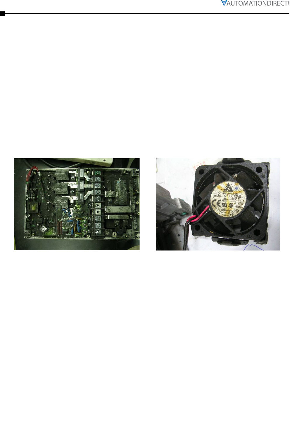
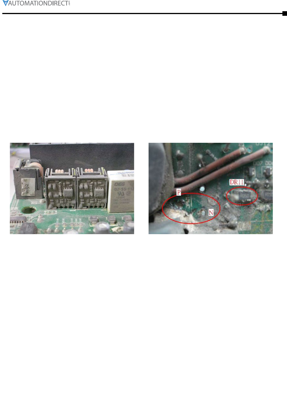
gReAse And dIRt pRobleMs
In those industries where grease and dirt are common. Please be aware of the possible damage
that grease, oil, and dirt, may cause to your GS4 drive:
1)
Electronic components that silt up with greasy oil may cause the drive to burn out or even
explode�
2)
Most greasy dirt contains corrosive substances that may damage the drive�
Solution:
Install the GS4 drive in a suitable enclosure to protect it from grease and dirt. Clean and remove
grease and dirt regularly to prevent damage of the drive.
Chapter 6: Maintenance and Troubleshooting
Page 6–27
DURApUlse GS4 AC Drive User Manual – 1st Ed, RevB - 11/17/2017
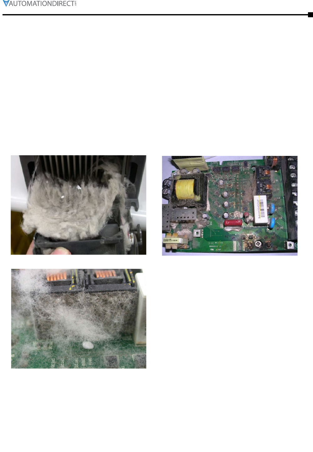
fIbeR dust pRobleM
Problems related to fiber dust are typical in the textile industry. Please be aware of the possible
damage that fiber dust may cause to your GS4 drive:
1)
Fiber dust that accumulates or adheres to the fans will result in poor ventilation and cause
overheating problems�
2)
Textile plant environments with high humidity levels may experience GS4 drive failure or
damage as a result of wet fiber dust adhering to components within the drive�
Solution:
Install the GS4 drive in a suitable enclosure to protect it from fiber dust. Clean and remove fiber
dust regularly to prevent damage to the drive.
Page 6–28 DURApUlse GS4 AC Drive User Manual – 1st Ed, RevB - 11/17/2017
Chapter 6: Maintenance and Troubleshooting
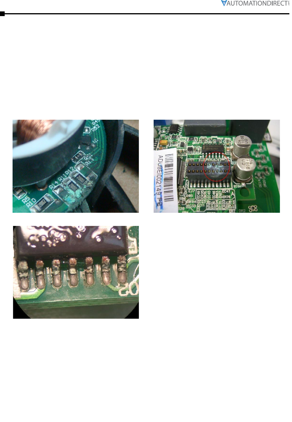
coRRosIon pRobleM
Corrosion problems may occur if any fluids or liquid in vapor form flows into the GS4 drive. Please
be aware of the damage that corrosion may cause to your drive.
•
Corrosion of internal components may cause the GS4 drive to malfunction and possibly explode�
Solution:
Install the GS4 drive in a suitable enclosure to protect it from fluids. Clean the drive regularly to
prevent corrosion.
Chapter 6: Maintenance and Troubleshooting
Page 6–29
DURApUlse GS4 AC Drive User Manual – 1st Ed, RevB - 11/17/2017
IndustRIAl dust pRobleM
Serious industrial dust pollution frequently occurs in stone processing plants, flour mills, cement
plants, and so on. Please be particularly aware of any metal dust, filings or if metalized vapor is
present as these may cause damage to your drives:
1)
Dust accumulating on electronic components may cause overheating problems and shorten the
service life of the drive�
2)
Conductive dust may damage the circuit board and may cause the drive to explode�
Solution:
Install the GS4 drive in a suitable enclosure and protect it from dust. Clean the cabinet and
ventilation filter regularly for good ventilation.
Page 6–30 DURApUlse GS4 AC Drive User Manual – 1st Ed, RevB - 11/17/2017
Chapter 6: Maintenance and Troubleshooting
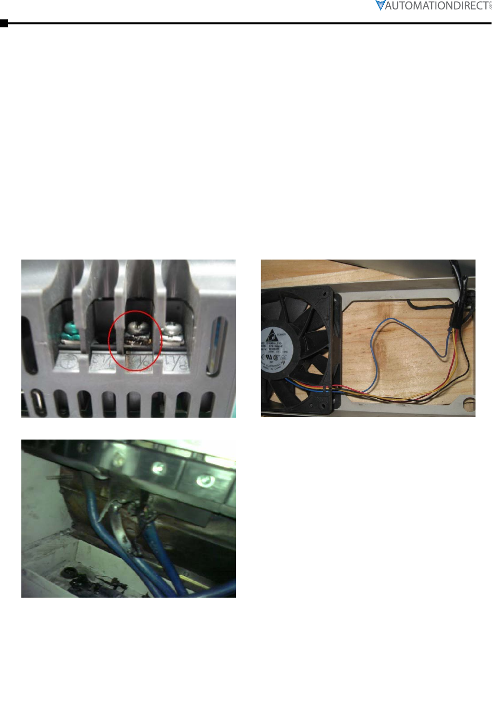
WIRIng And InstAllAtIon pRobleM
When wiring the GS4 drive, the most common problems are connection to the wrong terminal or
poor wiring practice. Please be aware of the possible damage that poor wiring practice may cause
to your GS4 drive:
1)
Screw terminals where the wire is not fully inserted or the terminal screw is not adequately
tightened may result in sparking or high temperature due to a high resistance connection�
2)
If circuit boards in the GS4 drive have been modified, components on the affected boards may
have been damaged�
Solution:
Inspect all power and control terminal connections in the GS4 drive to ensure adequate wire
insertion. Do not attempt to disassemble or repair control boards in the GS4 drive.
Chapter 6: Maintenance and Troubleshooting
Page 6–31
DURApUlse GS4 AC Drive User Manual – 1st Ed, RevB - 11/17/2017
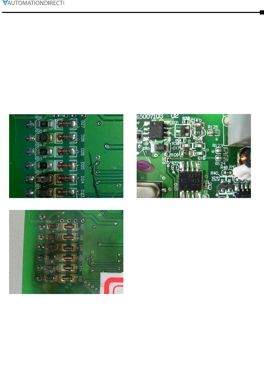
dIgItAl Input/output teRMInAl pRobleMs
Problems with digital I/O are usually the result of improper termination, or failure to segregate
control wiring from power wiring. This may result in errant signals due to induced voltage,
capacitive coupling or electrical noise. Incorrect voltage levels applied to the digital I/O terminals
can damage the I/O circuitry of the drive.
•
Input/Output circuit may burn out when the terminal usage exceeds its limit�
Solution:
Refer to the user manual for multi-function input output terminals usage and follow the specified
voltage and current. DO NOT exceed the specification limits.

Page 6–32 DURApUlse GS4 AC Drive User Manual – 1st Ed, RevB - 11/17/2017
Chapter 6: Maintenance and Troubleshooting
BLANK
PAG E
