BRX User Manual, 2nd Edition Chapter 8 Ch8
User Manual: Chapter 8 BRX Do-more Platform User Manual and Inserts
Open the PDF directly: View PDF ![]() .
.
Page Count: 42
- Overview
- Module Types
- Wiring Termination Options
- General Specifications
- Dimensional Information
- Module Installation
- Module Configuration
- Analog Tips and Troubleshooting
- BX-08AD-1 Analog Current Sinking Input
- BX-08AD-2B Analog Voltage Input
- BX-04THM Thermocouple Input
- BX-08DA-1 Analog Current Source Output
- BX-08DA-2B Analog Voltage Output
- Search�������������
- Save File����������������
- Print this PDF���������������������
- E-mail this PDF����������������������

Chapter
Chapter
Chapter
8
8
8
BRX AnAlog I/o
EXpAnsIon ModulEs
In This Chapter...
Overview .................................................................................................................... 8-2
Module Types ............................................................................................................ 8-2
Wiring Termination Options ..................................................................................... 8-4
Terminal Block Connectors .................................................................................... 8-4
ZIPLink Wiring System ........................................................................................... 8-5
General Specifications ............................................................................................... 8-6
Dimensional Information .......................................................................................... 8-6
Module Installation.................................................................................................... 8-7
Module Configuration ............................................................................................... 8-8
Analog Tips and Troubleshooting ............................................................................. 8-9
General Tips for Analog Circuits ............................................................................ 8-9
Reducing Electrical Noise ..................................................................................... 8-10
Current Module Tips and Troubleshooting ......................................................... 8-12
Voltage Module Tips and Troubleshooting ......................................................... 8-14
Temperature (Thermocouple) Module Tips and Troubleshooting..................... 8-15
BX-08AD-1 Analog Current Sinking Input .............................................................. 8-16
BX-08AD-2B Analog Voltage Input ......................................................................... 8-21
BX-04THM Thermocouple Input ............................................................................. 8-26
BX-08DA-1 Analog Current Source Output ............................................................ 8-32
BX-08DA-2B Analog Voltage Output ...................................................................... 8-37
Chapter 8: BRX Analog I/O Expansion Modules
BRX User Manual, 2nd Edition
8-2
1
2
3
4
5
6
7
8
9
10
11
12
13
14
15
A
B
C
D
Overview
One of the unique features of the BRX platform is its ability to easily expand its capability to fit
your application solution. One of the ways the BRX platform can do this is by using expansion
modules that conveniently “snap-on” to the side of any BRX MPU.
The analog expansion modules give you the ability to add additional analog I/O as needed and
are identified as an input module, output module or temperature input module. On the front
panel of the analog I/O expansion modules a color scheme and a symbol are used to denote the
module type. Analog modules are available in 8-point current inputs/outputs, 8-point unipolar
or bipolar voltage inputs/outputs, and 4-point thermocouple input modules.
Module Types
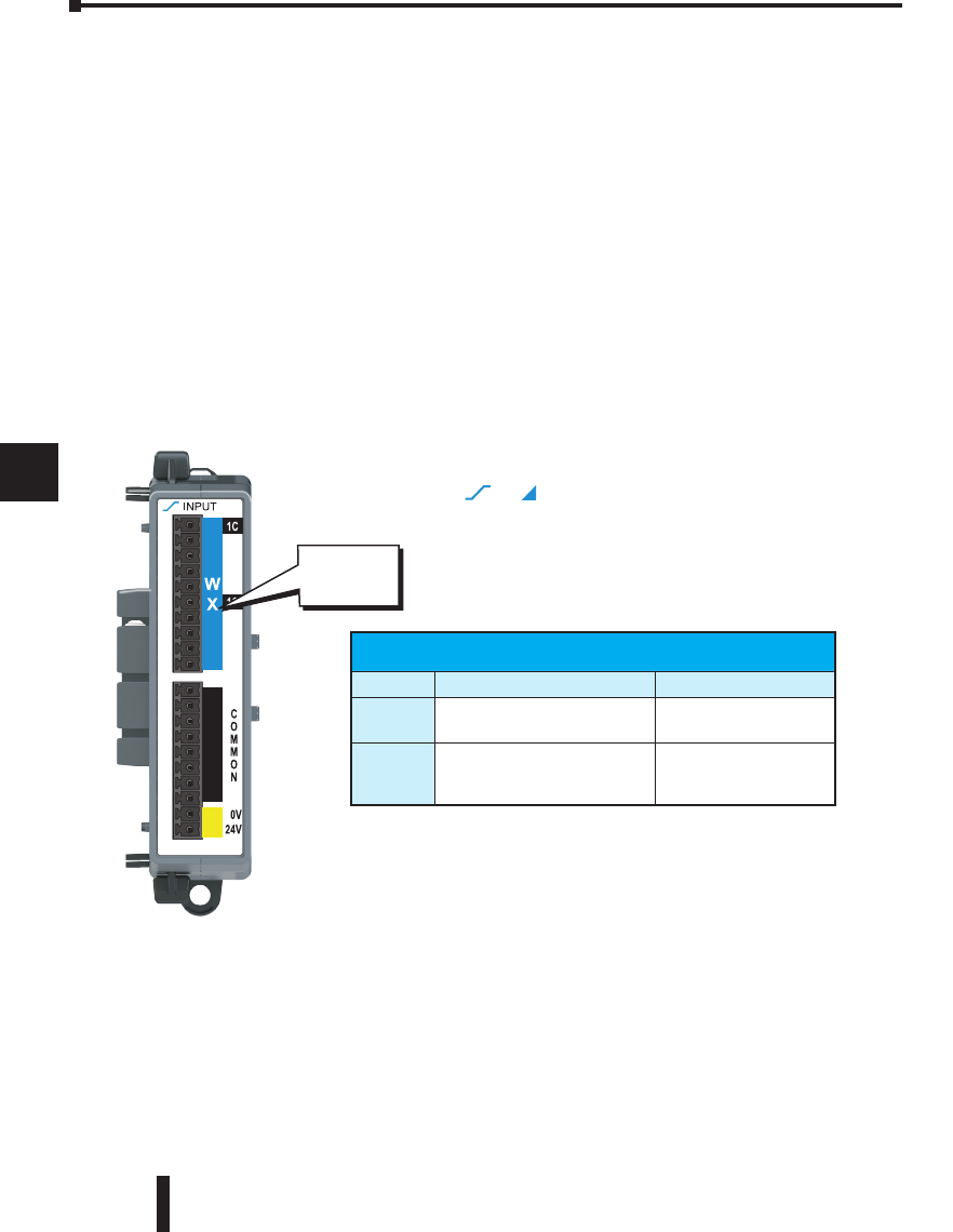
Analog Input Modules
Two (2) analog input modules are available, with current or voltage inputs.
Analog input module faceplates have a blue terminal bar to distinguish them as
inputs, with symbols or to signify current or voltage, respectively. Listed
in the table below are the different types of input modules available.
I0+
I1+
I2+
I3+
I4+
I5+
I6+
I7+
BX-08AD-1
Blue Label
for Input
Analog Input Modules
Identifier Input Type 8-Point
AD-1 Current Sink
0–20mA, 4–20mA BX-08AD-1
AD-2B Voltage
±10VDC, ±5VDC,
0–5VDC, 0–10VDC
BX-08AD-2B
Chapter 8: BRX Analog I/O Expansion Modules
8-3
BRX User Manual, 2nd Edition
1
2
3
4
5
6
7
8
9
10
11
12
13
14
15
A
B
C
D
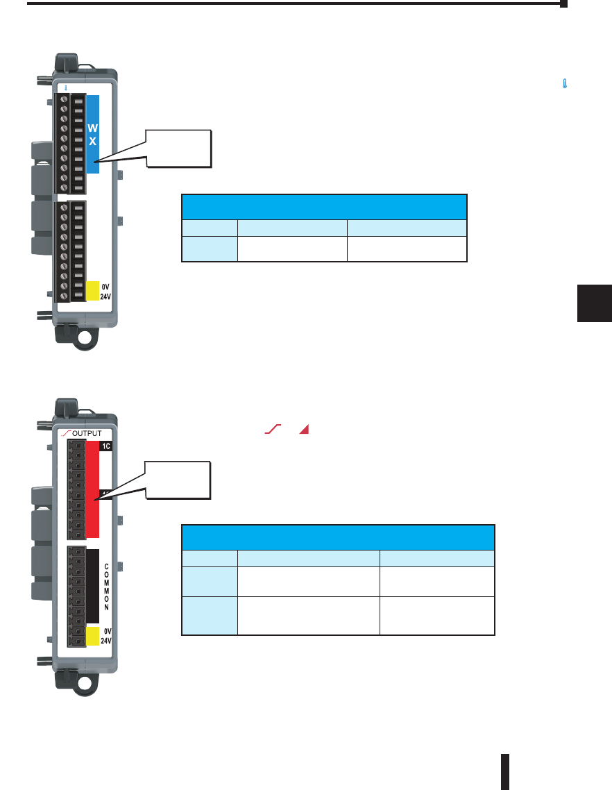
Temperature Input Module
A temperature input module is available with thermocouple inputs. The
temperature input module can also be configured for millivolt-level voltage
inputs. Temperature module faceplates have a blue terminal bar and symbol
for easy distinction from other module types. The table below shows the
temperature input module and its input type.
Analog Output Modules
Two (2) analog output modules are available, in current and voltage outputs.
Analog output module faceplates have a red terminal bar to distinguish them as
outputs, with symbols or to signify current or voltage, respectively. Listed
in the table below are the different types of output modules available.
TC0+
TC3-
TC3+
TC2-
TC2+
TC1-
TC1+
TC0-
INPUT
BX-04THM
Blue Label
for Input
Temperature Input Module
Identifier Type 4-Point
THM Thermocouple BX-04THM
W
Y
I0+
I1+
I2+
I3+
I4+
I5+
I6+
I7+
BX-08DA-1
Red Label
for Output
Analog Output Modules
Identifier Type 8-Point
DA-1 Current Source
0–20mA, 4–20mA BX-08DA-1
DA-2B Voltage
±10VDC, ±5VDC,
0–5VDC, 0–10VDC
BX-08DA-2B
Chapter 8: BRX Analog I/O Expansion Modules
BRX User Manual, 2nd Edition
8-4
1
2
3
4
5
6
7
8
9
10
11
12
13
14
15
A
B
C
D
Wiring Termination Options
The BRX analog expansion modules ship without wiring terminals blocks. This allows you
to select the termination style that best fits your application. There are several wiring options
available, including removable screw terminal connectors, removable spring clamp terminal
connectors and pre-wired ZIPLink cable solutions. The BRX Temperature Input Modules
include the BX-RTB10 kit. The BX-RTB10-1 or BX-RTB10-2 can also be used and can be
purchased separately.
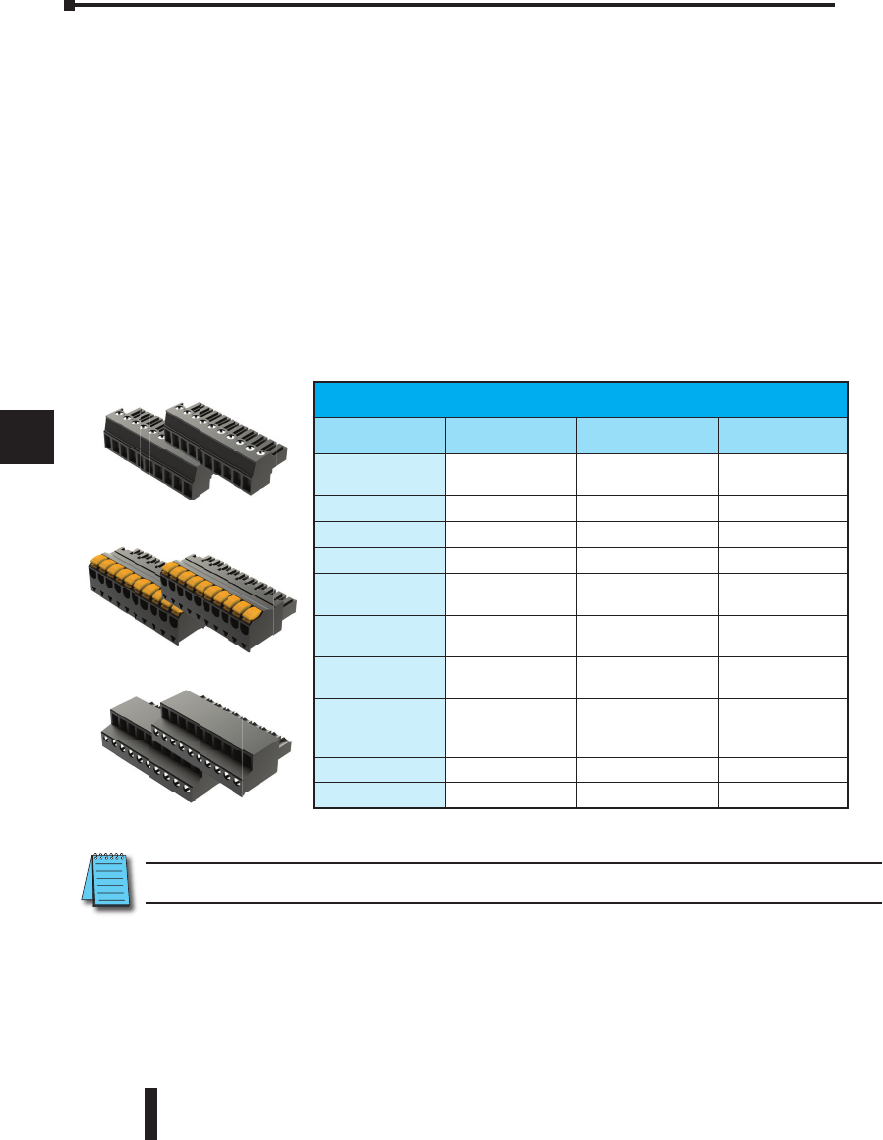
Terminal Block Connectors
The terminal block connectors are provided in kits of multiple connectors that are easily ordered
as a single part number. The kits for the 8-point modules and for the 4-point thermocouple
module include (2) 10-pin 3.81-mm connectors.
Terminal block kit part numbers and connector specifications are listed in the following table.
Terminal Block Specications
Part Number BX-RTB10 BX-RTB10-1 BX-RTB10-2
Connector Type
Screw Type
90 degree
Spring Clamp Type
180 degree
Screw Type
180 degree
Wire Exit
180 degree 180 degree 180 degree
Pitch
3.81 mm 3.81 mm 3.81 mm
Screw Size
M2 N/A M2
Screw Torque
Recommended
<1.77 lb·in
(0.2 N·m) N/A <1.77 lb·in
(0.2 N·m)
Screwdriver
Blade Width
2.5 mm 2.5 mm 2.5 mm
Wire Gauge
(Single Wire)
28–16 AWG 26–18 AWG 30–16 AWG
Wire Gauge
(Dual Wire)
28–18 AWG
30–20 AWG
(Dual Wire Ferrule
Required)
30–18 AWG
Wire Strip Length
0.24 in (6mm) 0.35 in (9mm) 0.26 in (6.5 mm)
Equiv. Dinkle P/N
EC381V-10P-BK ESC381V-10-BK EC381F-10P-BK
BX-RTB10 Kit
BX-RTB10-1 Kit
BX-RTB10-2 Kit
NOTE: BX-RTB10 terminal blocks are included with Temperature Input modules.
Chapter 8: BRX Analog I/O Expansion Modules
8-5
BRX User Manual, 2nd Edition
1
2
3
4
5
6
7
8
9
10
11
12
13
14
15
A
B
C
D
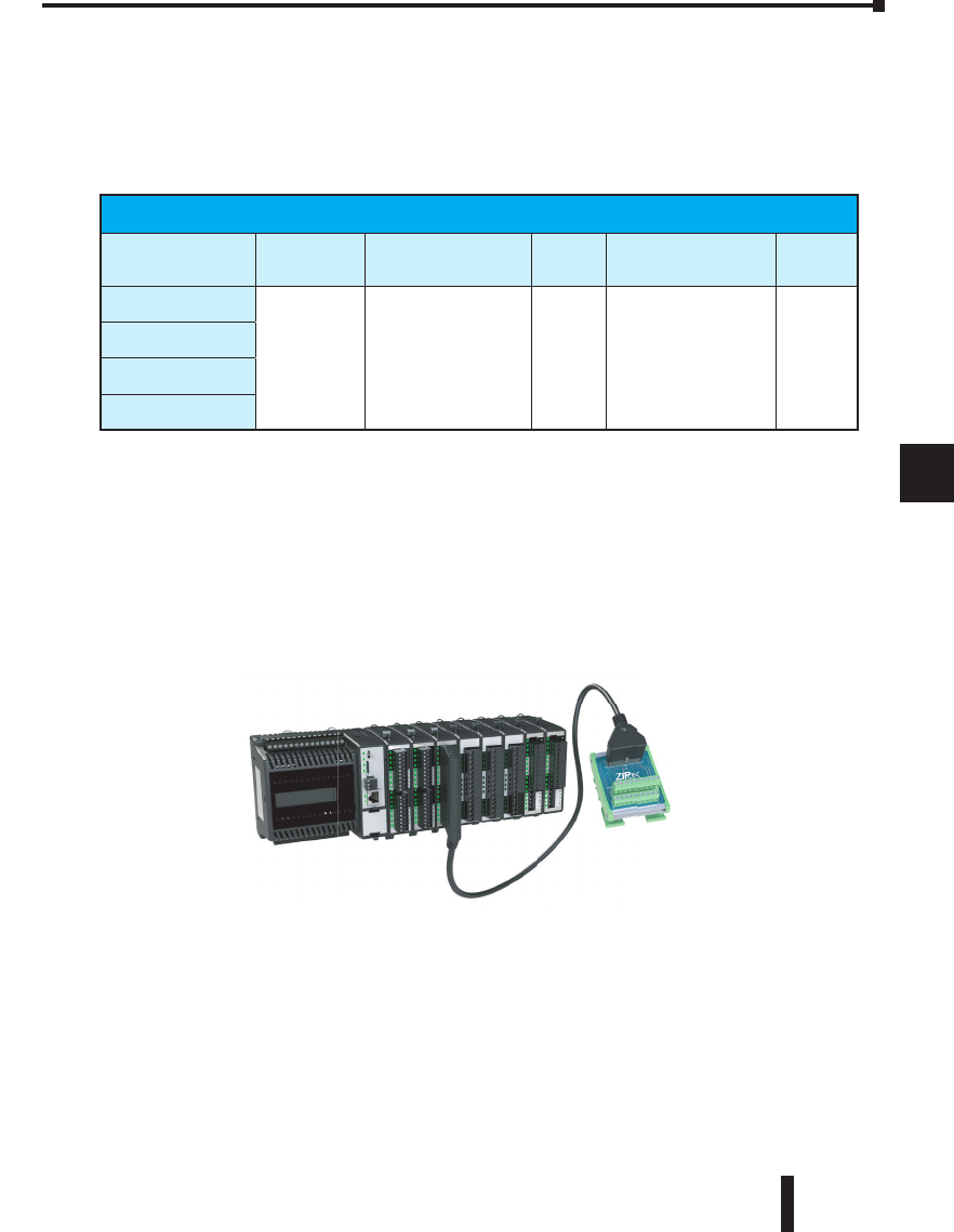
ZIPLink Wiring System
BRX analog expansion modules can be quickly connected to convenient ZIPLink remote
terminal blocks for ease of wiring remote I/O devices. The following table lists the connector
options. The ZIPLink wiring system is not available for use with the BRX Temperature Input
Module.
8-Point BRX Analog Expansion Module ZIPLink Selector
Expansion Module
Part No.
ZIPLink
Module
ZIPLink Module
Part No.
Qty
Needed
ZIPLink Cable
Part No.*
Qty
Needed
BX-08AD-1
Feedthrough
ZL-RTB20
(standard)
OR
ZL-RTB20-1
(compact)
1
ZL-BXEM-CBL20
ZL-BXEM-CBL20-1
ZL-BXEM-CBL20-2
1
BX-08AD-2B
BX-08DA-1
BX-08DA-2B
* Select the cable length: Blank = 0.5 m, -1 = 1.0 m, -2 = 2.0 m.
Available pigtail cables: ZL-BXEM-CBL20-1P = 1.0 m, ZL-BXEM-CBL20-2P = 2.0 m.
Chapter 8: BRX Analog I/O Expansion Modules
BRX User Manual, 2nd Edition
8-6
1
2
3
4
5
6
7
8
9
10
11
12
13
14
15
A
B
C
D
General Specifications
All BRX analog expansion modules and temperature input modules have the same general
specifications listed in the table below.
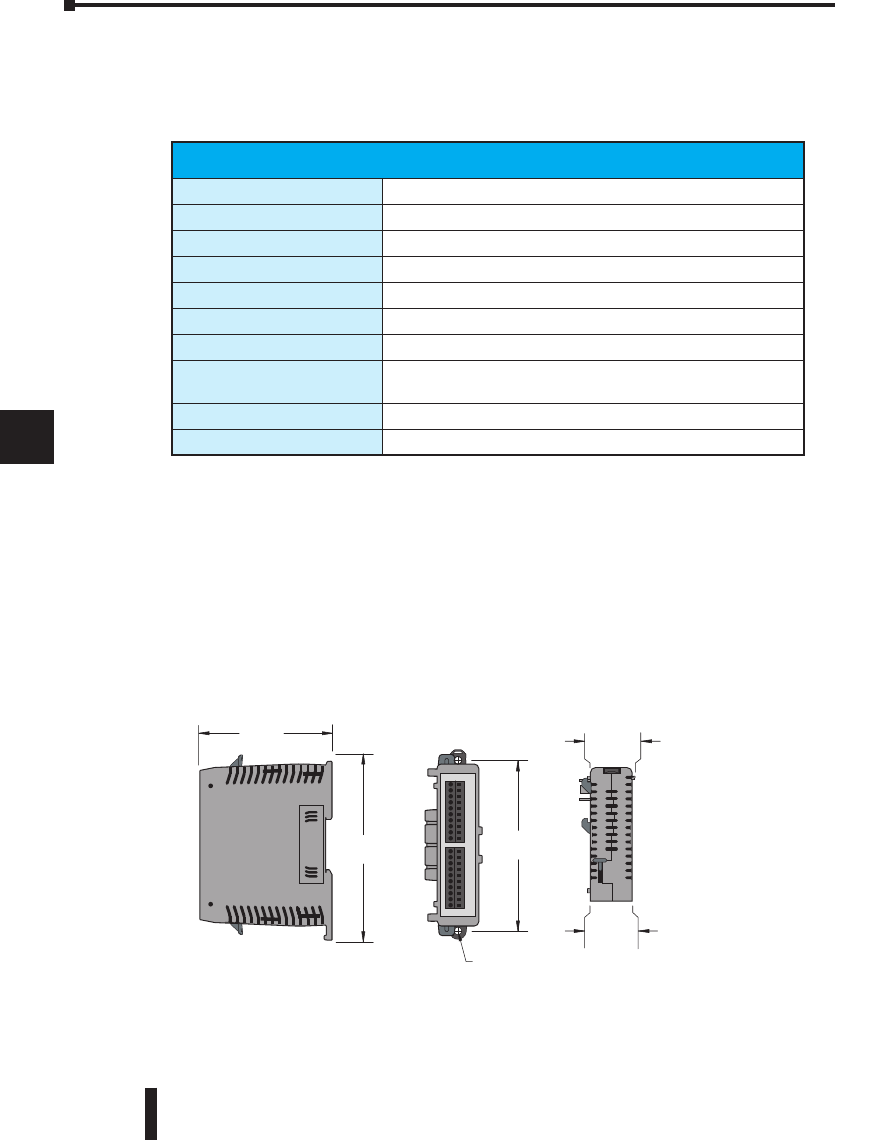
Dimensional Information
General Specications
Operating Temperature
0° to 45°C (32° to 113°F)
Storage Temperature
−20° to 70°C (−4° to 158°F)
Humidity
5 to 95% (non-condensing)
Environmental Air
No corrosive gases permitted
Vibration
IEC60068-2-6 (Test Fc)
Shock
IEC60068-2-27 (Test Ea)
Enclosure Type
Open Equipment
Agency Approvals
UL 61010-2-201 File # E139594 Canada and USA
CE (Safety: EN61010-2-201 and Immunity: EN61131-2: 2007)
Noise Immunity
NEMA ICS3-304
EU Directive
See the “EU Directive” topic in the BRX Help File.
2X Ø #8 Thru all
4.57
″
[116.2mm]
4.24
″
[107.8mm]
3.25
″
[82.6mm] 1.08
″
[27. 5mm]
1.00
″
[25.4mm]
Chapter 8: BRX Analog I/O Expansion Modules
8-7
BRX User Manual, 2nd Edition
1
2
3
4
5
6
7
8
9
10
11
12
13
14
15
A
B
C
D
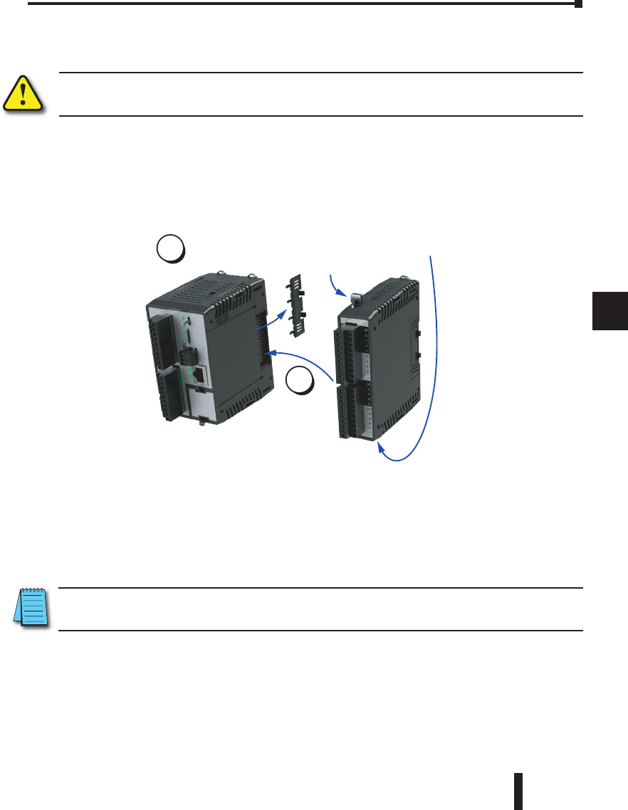
Module Installation
To install an expansion module, remove the connector cover on the right side of the MPU or
expansion module to which the new module is to be connected. Align the expansion connectors
and insert the module until you hear a “click”, indicating the module expansion connectors
have engaged.
To remove an expansion module locate the two disengagement plungers. One is located at the
top of the of the expansion module and a second one at the bottom of the expansion module.
Depressing both plungers at the same time will release the locking mechanism and disengage
the unit from the system.
WARNING: Do not apply field power until the following steps are completed. The BRX expansion
modules are NOT hot swappable.
RUN
TERM
STOP
PWR
RUN
ERR
TX
RX
LNK
ACT
1
2
To Install, remove
Connector Cover
To remove, depress
disengagement plungers
at top and bottom
of module
Align
expansion
connectors, insert,
and listen for “Click”
as the lock engages
NOTE: Allow a minimum of 45mm (1.75in) to the right of MPU chassis and any subsequent expansion
modules for mounting and dismounting of the modules.
Chapter 8: BRX Analog I/O Expansion Modules
BRX User Manual, 2nd Edition
8-8
1
2
3
4
5
6
7
8
9
10
11
12
13
14
15
A
B
C
D
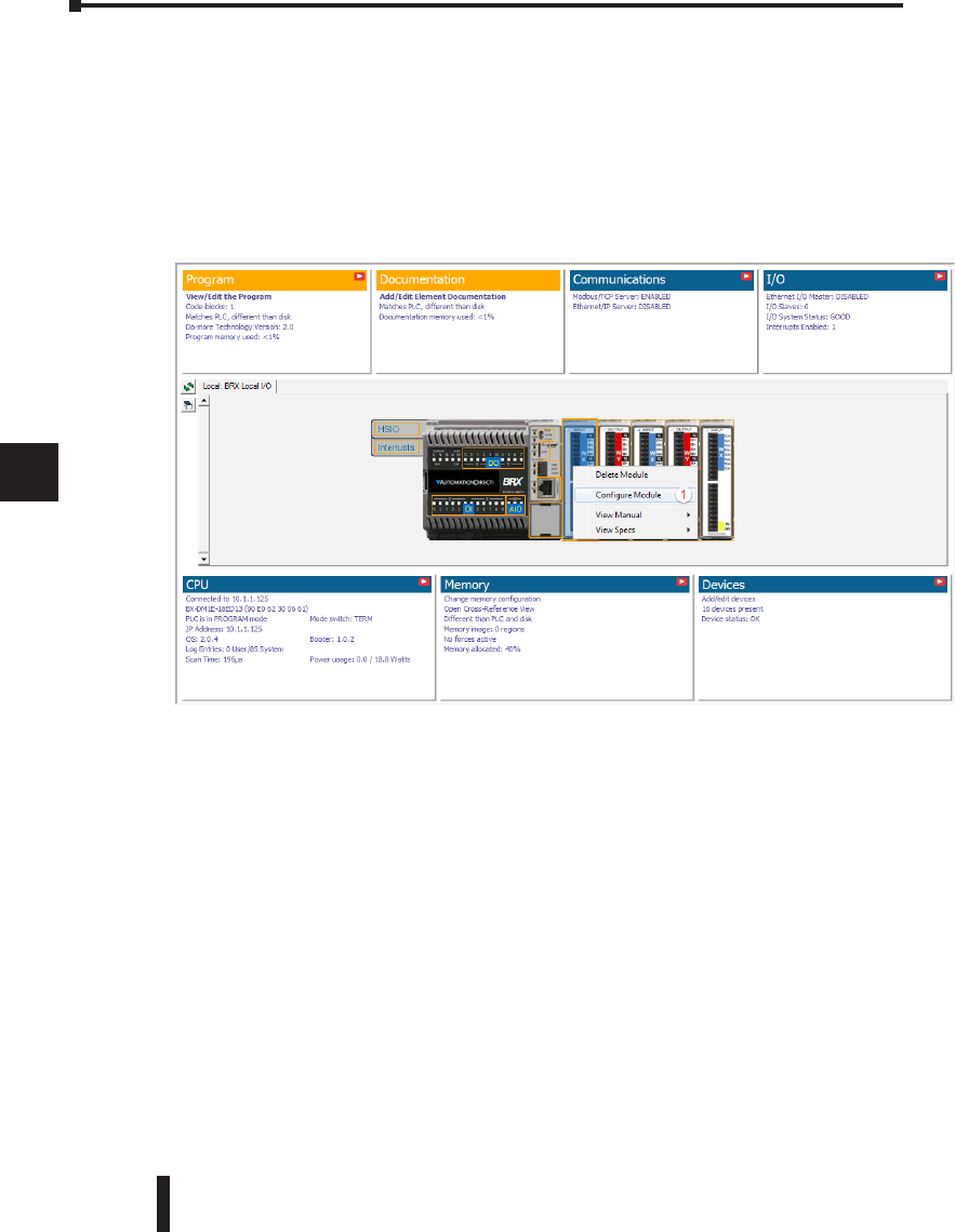
Module Configuration
Once the expansion module has snapped in place and is added to the project it instantly adds
additional I/O and features to the MPU with minimal additional setup required.
To configure a newly attached module, load the Do-more! Designer software and connect to
the BRX MPU, as discussed in Chapter 10. A graphical representation of the BRX unit with
its attached modules is displayed in the Dashboard of the software.
To access the module configuration dialogs, left-click or right-click on the module in the
Dashboard and select (1) Configure Module. The configuration dialogs for each module are
discussed in the corresponding section of this chapter.
Chapter 8: BRX Analog I/O Expansion Modules
8-9
BRX User Manual, 2nd Edition
1
2
3
4
5
6
7
8
9
10
11
12
13
14
15
A
B
C
D
Analog Tips and Troubleshooting
This subsection presents common tips on selection and installation of analog hardware, as well
as basic troubleshooting techniques, to maximize the performance of your analog input/output
circuits.
General Tips for Analog Circuits
When selecting and installing analog devices there are a few things to consider:
• Current devices are much more tolerant to noise than voltage devices.
• Current devices can handle much longer runs of wire without signal loss.
• Shielded twisted pair wire should always be used. Analog signals are typically low
power and the better your isolation the less noise you will have degrading the signal.
• If the analog signal is from a thermocouple, the appropriate thermocouple extension
wire and terminal blocks must be used if needed to extend wire lengths.
• Use the shortest wiring route whenever possible.
• Do not run analog signal wiring in the same conduit or wire way as AC wiring.
• Do not run analog signal wiring next to large
motors, high current switches, or transformers.
• Route the wiring through an approved cable
housing to minimize the risk of accidental damage.
• Shields should be connected only at one end, to
ground at the source device. Connecting both
ends of a shield will create a ground loop which
can increase the noise in a circuit.
• Bonding of the DC negative to ground should be
considered, with the exception of Class II power
supplies which should never be bonded to ground.
This can help with reducing noise induced into
analog circuits. Please note that consideration
should be given to all devices that will utilize
the power supply to insure that bonding of the
negative will not cause damage or interference.
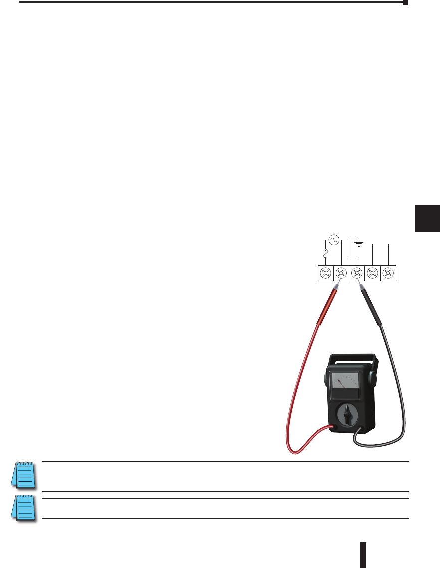
• AC power should be checked from neutral
to ground. This voltage should be less than
0.1 VAC.
L N G V+V-
AC
Power
Auxillary out
24VDC
300mA max.
AC Power In
120–240 VAC
-+
NOTE: Check local and national codes to choose the correct method for your application.
NOTE: Your company may have guidelines for wiring and cable installation. If so, you should check those
before you begin the installation.
Chapter 8: BRX Analog I/O Expansion Modules
BRX User Manual, 2nd Edition
8-10
1
2
3
4
5
6
7
8
9
10
11
12
13
14
15
A
B
C
D
Reducing Electrical Noise
Electrical noise is one of the most difficult problems to diagnose. It can enter the system from
a wide range of conducted or radiated sources.
Conducted noise is when the electrical interference is introduced into the system by way of
an attached wire, panel connection, etc. It may enter through an I/O point, a power supply
connection, the communication ground connection, or the chassis ground connection.
Radiated noise is when electrical interference is introduced into the system without a direct
electrical connection, such as via radio waves.
It may be difficult to determine how electrical noise is entering the system, but the corrective
actions for either type of noise problem are similar.
While electrical noise cannot be eliminated completely, it can be reduced to a level that will not
affect system function. Proper grounding of components and signal wiring along with proper
isolation of voltages can minimize noise in the system.
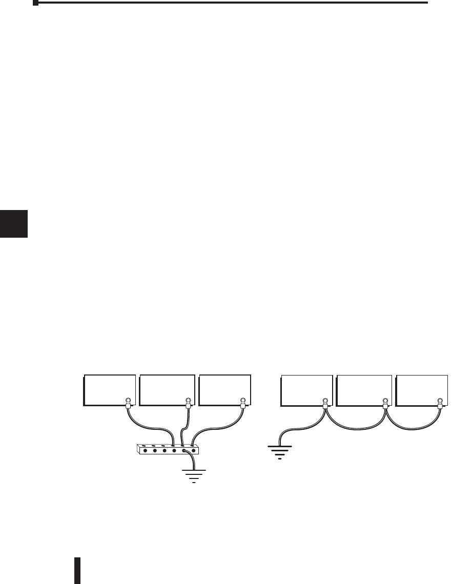
Grounding
Most noise problems result from improper grounding of the system. A good earth ground can
be the single most effective way to correct noise problems. If a ground is not available, install
a ground rod as close to the system as possible.
Ensure all ground wires are single point grounds and are not daisy chained from one device to
another. Ground metal enclosures around the system. Loose ground wires on your devices are
more susceptible to noise than the other wires in your system. A loose wire is no more than
a large antenna waiting to introduce noise into the system; therefore, you should tighten all
connections in your system. Review Chapter 1, “General Installation and Wiring Guidelines”,
if you have questions regarding how to ground your system.
PLC Other
Equipment
Power
Supply
GND GND GND
Proper Ground Connection
PLC Other
Equipment
Power
Supply
GND GND GND
Improper Ground Connection
Chapter 8: BRX Analog I/O Expansion Modules
8-11
BRX User Manual, 2nd Edition
1
2
3
4
5
6
7
8
9
10
11
12
13
14
15
A
B
C
D
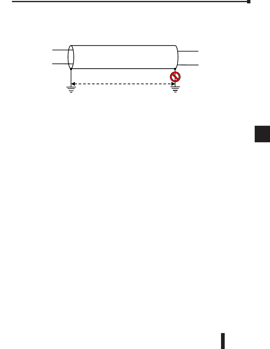
Cables with shields should be grounded on only one end of the shield. This prevents ground
loops and allows for any radiated noise collected by the shield to properly drain to a single
ground point.
Isolation
Electrical noise can enter the system through the power source for the MPU and I/O. Installing
an isolation transformer for all AC sources can correct this problem.
DC power sources should be properly grounded, except for Class II power supplies which
should never be bonded to ground. Switching DC power supplies commonly generate more
noise than linear supplies. Typically switching type supplies work well for analog circuits, but
for some circuits where noise can be a factor, linear type supplies may be needed.
Analog wiring should be placed in separate wire ways or wiring bundles. Keep AC and DC
wiring separated. Never run analog signal or communications wiring in parallel or in close
proximity to high voltage wiring.
Transformers, inductors, VFDs, DC drives, welders, static generators, ultrasonic devices, radio
transmitters, receivers, wiring and antennas, along with similar types of devices, generate large
amounts of RF interference. DC wiring, analog wiring and communications wiring should
be kept as far away from these sorts of devices and their associated input and output wiring as
possible.
Devices that generate noise such as those listed above, along with coil driven devices such as
relays, contactors, solenoids, etc., should be placed on a separate power supply from analog
circuits. If this is not possible, then great care should be taken to properly suppress the transient
voltage spikes from these devices turning on and off. See Chapter 1, “BRX General Installation
and Wiring Guidelines” for more information on this subject.
Shielded Twisted-pair cable
Poten�al
Difference
Chapter 8: BRX Analog I/O Expansion Modules
BRX User Manual, 2nd Edition
8-12
1
2
3
4
5
6
7
8
9
10
11
12
13
14
15
A
B
C
D
Current Module Tips and Troubleshooting
• Use shielded twisted pair wire. Suggested ADC cables are PLTC3-18-xS-xxxx or
PLTC3-18-xSS-xxxx
• Analog circuits follow Ohm’s Law. As such it is important to follow the specifications
for impedance in the circuit. If you allow the impedance values to go outside of the
specification, damage to the module will occur.
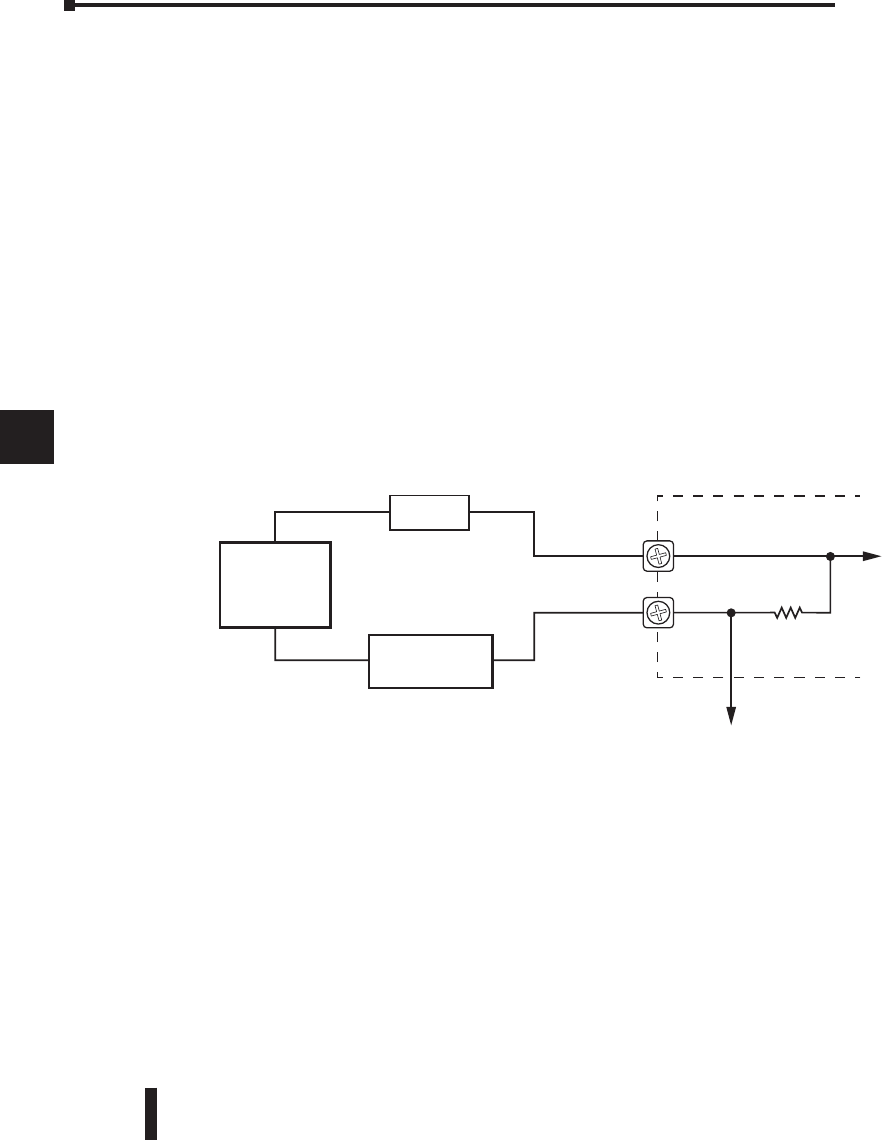
• If your transmitter requires a load resistance higher than 125Ω, you may need to add a
resistor in series with the module. Consider the following example for a transmitter
being operated from a 24VDC supply with a recommended load resistance of 750
ohms. Since the module has a 125-ohm resistance, you need to add an additional
resistor.
• If you suspect an I/O error, there are several things that could be causing the problem:
• A blown fuse.
• A loose terminal block.
• The 24VDC supply has failed or 24VDC has not been supplied to the I/O
common.
• The I/O point has failed.
• The DC power supply that powers the module should be checked for the negative side
to ground voltage being under 0.1 V for both AC and DC. If this voltage is floating,
it can cause errors and/or damage to the circuit.
CH1
COM
0V
125 ohms
+
Two-wire
Transmitter
-DC Supply
+24V 0V
R
Module Channel 1
R = Tr – Mr
R = 750 – 125
R ≥ 625
R = Resistor to add
Tr = Termination Requirement
Mr = Module resistance
(Internal 125 ohms)
Chapter 8: BRX Analog I/O Expansion Modules
8-13
BRX User Manual, 2nd Edition
1
2
3
4
5
6
7
8
9
10
11
12
13
14
15
A
B
C
D
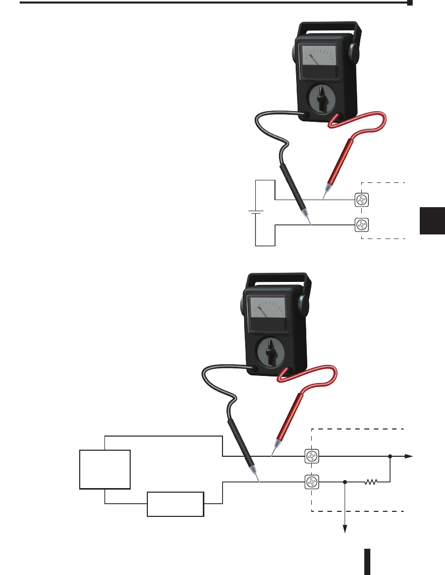
• To test a current input module, use a
1.5 V battery wired across the positive
and negative terminals of the channel to
check for current. When applied across
a current analog input point, a reading
of approximately 30% of the full scale
value should result.
0–20mA is 0–5VDC across the
input resistor
1.5V/5V=0.3
0.3*65535 = ~19660 counts or
0.3*32767=~9830 counts
• Most current input modules read
voltage across a shunt resistor. It may
be easier to test for proper current
by measuring the voltage across that
shunt resistor and applying Ohm’s Law
(Voltage/125Ω = Current).
CH1
COM
Module
+
-
1.5V
CH1
COM
0V
125 ohms
+
Two-wire
Transmitter
-DC Supply
+24V 0V
Module Channel 1
Chapter 8: BRX Analog I/O Expansion Modules
BRX User Manual, 2nd Edition
8-14
1
2
3
4
5
6
7
8
9
10
11
12
13
14
15
A
B
C
D
Voltage Module Tips and Troubleshooting
• Use shielded twisted pair wire. Suggested ADC cables are PLTC3-18-xS-xxxx or PLTC3-
18-xSS-xxxx.
• Jumper the positive and negative terminals together on unused voltage input channels.
• Analog circuits follow Ohm’s Law. As such it is important to follow the specifications
for impedance in the circuit. If you allow the impedance values to go outside of the
specification, damage to the module will occur.
• If you suspect an I/O error, there are several things that could be causing the problem:
• A blown fuse
• A loose terminal block
• The 24VDC supply has failed or 24VDC has not been supplied to the I/O common.
• The I/O point has failed.
• The DC power supply that powers the module should be checked for the negative side to
ground voltage being under 0.1 V for both AC and DC. If this voltage is floating, it can
cause errors and/or damage to the circuit.
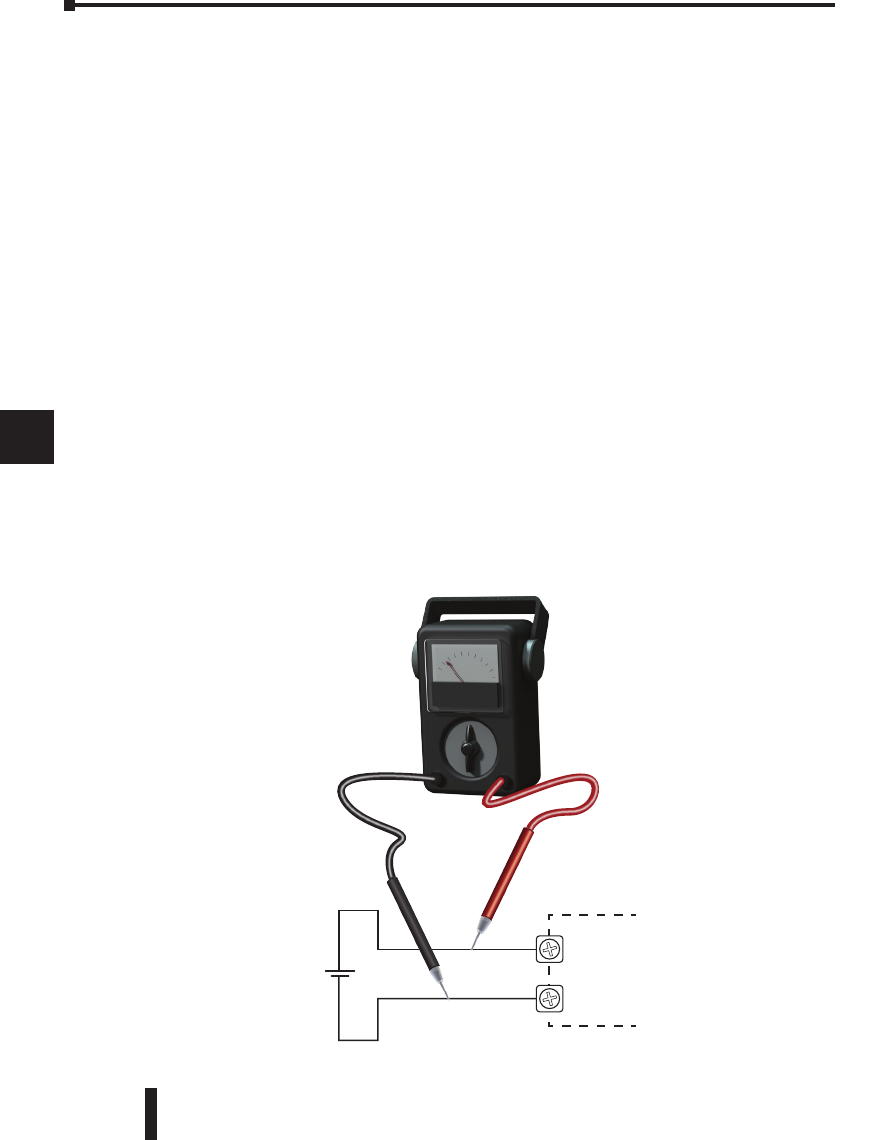
• To test the voltage input module, use a 1.5 V battery wired across the positive and negative
terminals of the input channel to check for voltage. When applied across a voltage analog
input point, a reading of approximately 1.5 V should result.
CH1
COM
Module
+
-
1.5V

Chapter 8: BRX Analog I/O Expansion Modules
8-15
BRX User Manual, 2nd Edition
1
2
3
4
5
6
7
8
9
10
11
12
13
14
15
A
B
C
D
Temperature (Thermocouple) Module Tips and Troubleshooting
• Use shielded thermocouple extension wire of the same type as the thermocouple.
• Do not use terminal blocks that are not designed for thermocouple extension wire.
• Thermocouple wires that have just been twisted to form a junction will inherently
be less accurate than factory made thermocouples. The use of twist junction
thermocouples is not recommended.
• Jumper each of the channel +/- connections together on the module with a short piece
of copper wire. This will cause the module to return the measured terminal block
temperature for that channel. Does it read the correct ambient temperature of the
thermocouple module? If so there probably isn’t anything wrong with the module.
This temperature will be several degrees higher than the ambient air temperature of
the enclosure.
• With a thermocouple simulator, you have to disable the burnout detection for the
module using the module setup in the Do-more! Designer software and download
the program to the PLC. This will disable the burnout circuitry, which will cause
incorrect readings if left enabled. Even then, it is likely that the module will not read
exactly what the simulator is putting out due to the wire differences and the terminal
block on the module causing some cold junction error.
• It is possible that the module may be damaged from exceeding the common mode
voltage spec which is 5 Volts. The voltage needs to be measured between each channel
on both plus and minus terminals of the module on both AC and DC scales and make
sure that it is under 5 Volts maximum. Preferably the voltage should be less than
0.1V.
• AC power should be checked from neutral to ground. This voltage should be less than
0.1 VAC.
• With grounded thermocouples, take precautions to prevent having a voltage potential
between thermocouple tips. A voltage of 1V or greater between tips will skew
measurements. For grounded thermocouples, the equipment and thermocouples must
be bonded with large-gauge braided wire to the same ground as the PLC.
• The DC power supply that powers the module should be checked for the negative side
to ground voltage being under 0.1V for both AC and DC. If this voltage is floating, it
can cause errors and/or damage to the circuit.
Chapter 8: BRX Analog I/O Expansion Modules
BRX User Manual, 2nd Edition
8-16
1
2
3
4
5
6
7
8
9
10
11
12
13
14
15
A
B
C
D
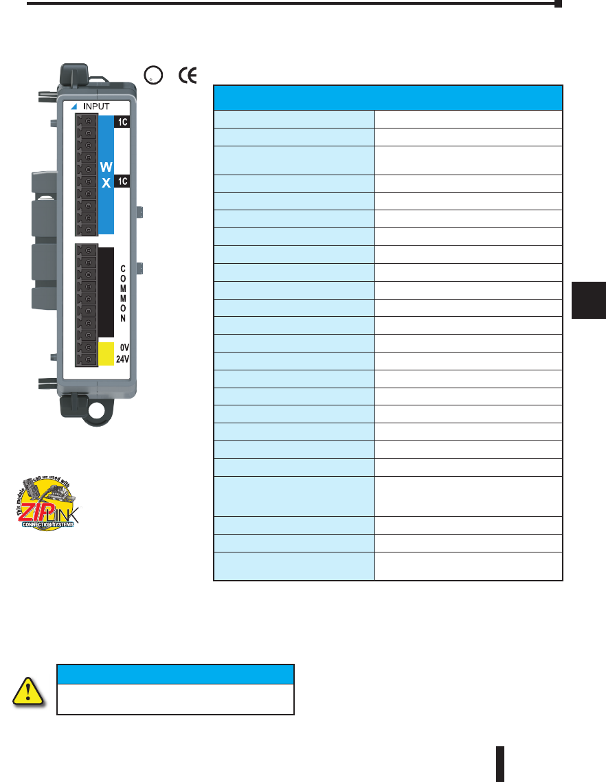
BX-08AD-1 Analog Current Sinking Input
I0+
I1+
I2+
I3+
I4+
I5+
I6+
I7+
BX-08AD-1
Analog Current Sinking Input Specications
Inputs per Module
8
Commons
1
Module Signal Input Range
0–20mA, 4–20mA (Default)
Signal Resolution
16-bit, 15-bit (Default)
Input Impedance
125Ω±0.1%, 1/10th watt
All Channel Update Rate
45ms (8 channels)
Over Current Circuit Detection Time
< 1second
Maximum Continuous Overload
(Voltage)
0.5 Watts (e.g. ±100V @ 5mA)
Sample Duration Time
5μs per channel
Hardware Filter Characteristics
Low Pass 1st order, −3dB @ 144Hz
Conversion Method
Successive approximation
Linearity Error (end to end)
±0.01% of range
Input Stability and Repeatability
±0.035% of range (after 10 min. warmup)
Full Scale Calibration Error
±0.02% of range
Offset Calibration Error
±0.02% of range
Accuracy vs. Temperature
±25PPM / ºC maximum
Maximum Inaccuracy
0.1% of range (incl. Temperature Drift)
Maximum Crosstalk
−96dB, 1 LSB
Channel to Backplane Isolation
1800VAC applied for one second
Channel to Channel Isolation
None
Loop Fusing (External)
Fast-acting 0.032A recommended
Backplane Power Consumption
0.1 W
External DC Power Required
Class 2 or LPS power supply
24VDC (±20%)
25mA
Heat Dissipation
2.5 W
Weight
100g (3.5 oz)
Software Version
Do-more! Designer Programming
Software version 2.1 or later
Terminal Blocks
Sold Separately
We recommend using prewired ZIPLink
cables and connection modules.
If you wish to hand-wire your module,
a removable terminal block is available.
See Wiring Termination Selection in this
chapter for all options.
IMPORTANT!
Hot-Swapping Information
NOTE: This device cannot be Hot Swapped.
U
L
CUS
R
Chapter 8: BRX Analog I/O Expansion Modules
8-17
BRX User Manual, 2nd Edition
1
2
3
4
5
6
7
8
9
10
11
12
13
14
15
A
B
C
D
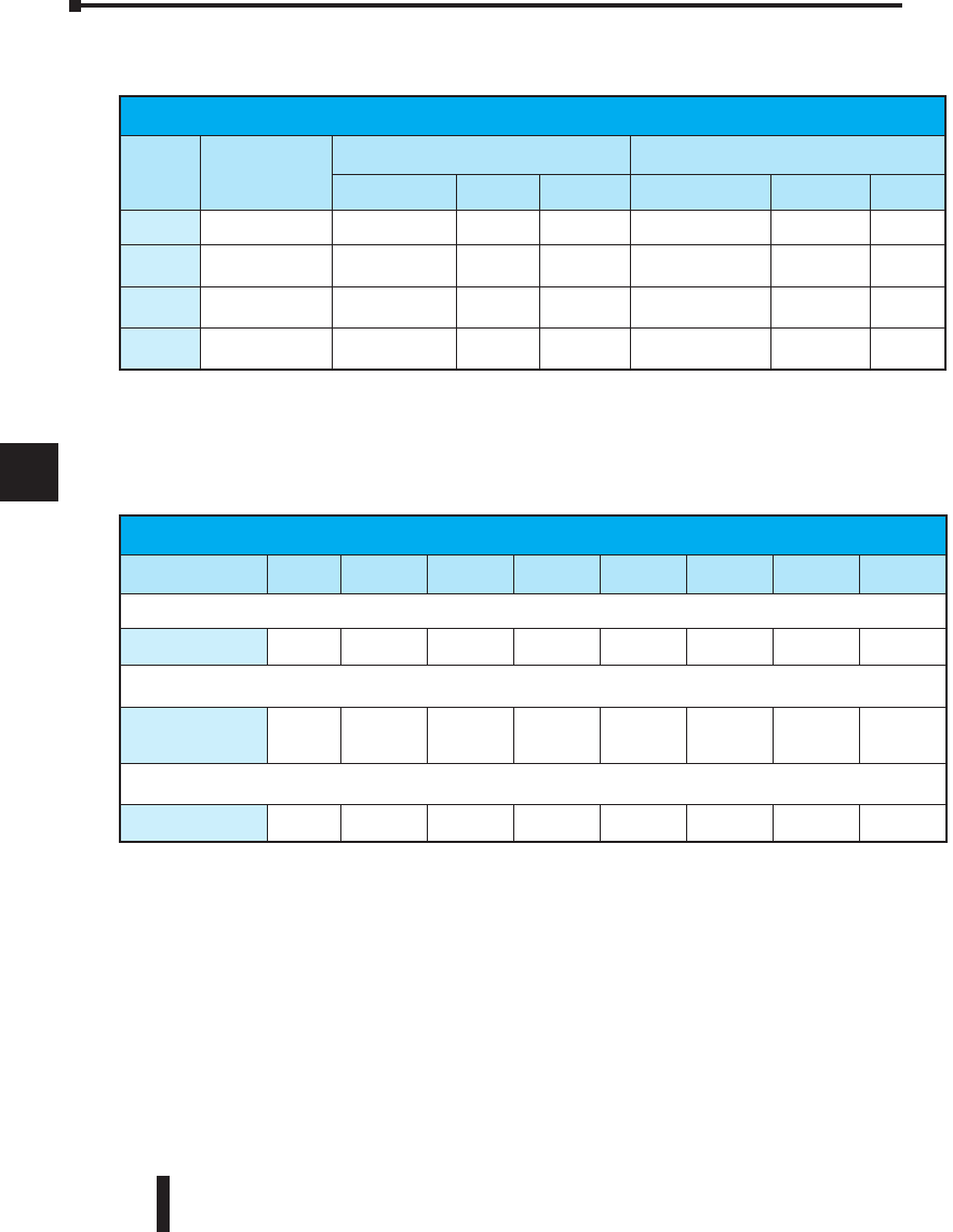
BX-08AD-1 Analog Current Sinking Input, continued
Data Range Specications
Selection Description
Enable 16 bit Unchecked
(15 bit Resolution, Default)
Enable 16 bit Checked
(16 bit Resolution)
Raw Counts Casting* µA Per
Count Raw Counts Casting* µA Per
Count
0–20mA unipolar 0–20mA
0–32767 – 0.61 0–65535 WXn:U 0.31
4–20mA unipolar 4–20mA
0–32767 – 0.49 0–65535 WXn:U 0.24
* For more information on Casting refer to Help topic DMD0309 in the Do-more! Designer Software.
The module reserves the first 24 bits of unused contiguous space in the X register, aligned to
an 8-bit word boundary, for status reporting. Error flags for this module are laid out within its
status register space as described in the following table.
Error Flag Specications
MSB LSB
1st Byte of unused X Registers
Module Status
-
----Data Not
Valid
Missing
24VDC
Self Test
Failed
2nd Byte of unused X Registers
Channel Open
(Broken Transmitter)*
Channel 8 Channel 7 Channel 6 Channel 5 Channel 4 Channel 3 Channel 2 Channel 1
3rd Byte of unused X Registers
Unused
--------
* Broken Transmitter bits will turn on below ~3.75 mA.
Chapter 8: BRX Analog I/O Expansion Modules
BRX User Manual, 2nd Edition
8-18
1
2
3
4
5
6
7
8
9
10
11
12
13
14
15
A
B
C
D
BX-08AD-1 Analog Current Sinking Input, continued
Analog Current Input Wiring
- +
24VDC
Class 2 or LP
S
User Supplied
Power
ISOLATED
ANALOG
CIRCUIT POWER
ISOLATED ANALOG
CIRCUIT COMMON
INTERNAL
MODULE CIRCUITRY
I0+
I1+
I2+
I3+
COM
0V
24V+
1C
COM
COM
1C
COM
COM
COM
COM
COM
CH0 ADC
CH1 ADC
CH2 ADC
CH3 ADC
125Ω
125Ω
125Ω
125Ω
I4+
I5+
I6+
I7+
CH4 ADC
CH5 ADC
CH6 ADC
CH7 ADC
125Ω
125Ω
125Ω
125Ω
Ix+
1C/COM
*Fuse
0.032 A
Ix+
1C/COM
*Fuse
0.032 A
+
Ix+
1C/COM
*Fuse
0.032 A
- +
- +
3-Wire Current
Transmitter
4-Wire 4-20 mA
Transmitter
2-Wire 4-20 mA
Transmitter
2-Wire Transmitter
3-Wire Transmitter
4-Wire Transmitter
Power
Supply
24VDC User
Supplied Power
+
–
+
–
+
+
–
–
User Supplied Transmitter Power
AC or DC
WX
WX
WX
*An Edison S500-32-R 0.032 A fast-acting fuse is recommended
for all analog voltage inputs, analog outputs, and current loops.
Analog Current Sinking Input Circuits
NOTE: Shield should be connected only at one end, to ground at the
source device.
Chapter 8: BRX Analog I/O Expansion Modules
8-19
BRX User Manual, 2nd Edition
1
2
3
4
5
6
7
8
9
10
11
12
13
14
15
A
B
C
D
BX-08AD-1 Analog Current Sinking Input, continued
Software Setup
After the module is installed, open the Do-more! Designer programming software version 2.1
or later, connect to the BRX MPU and open the Configure Module dialog as described at the
beginning of this chapter.
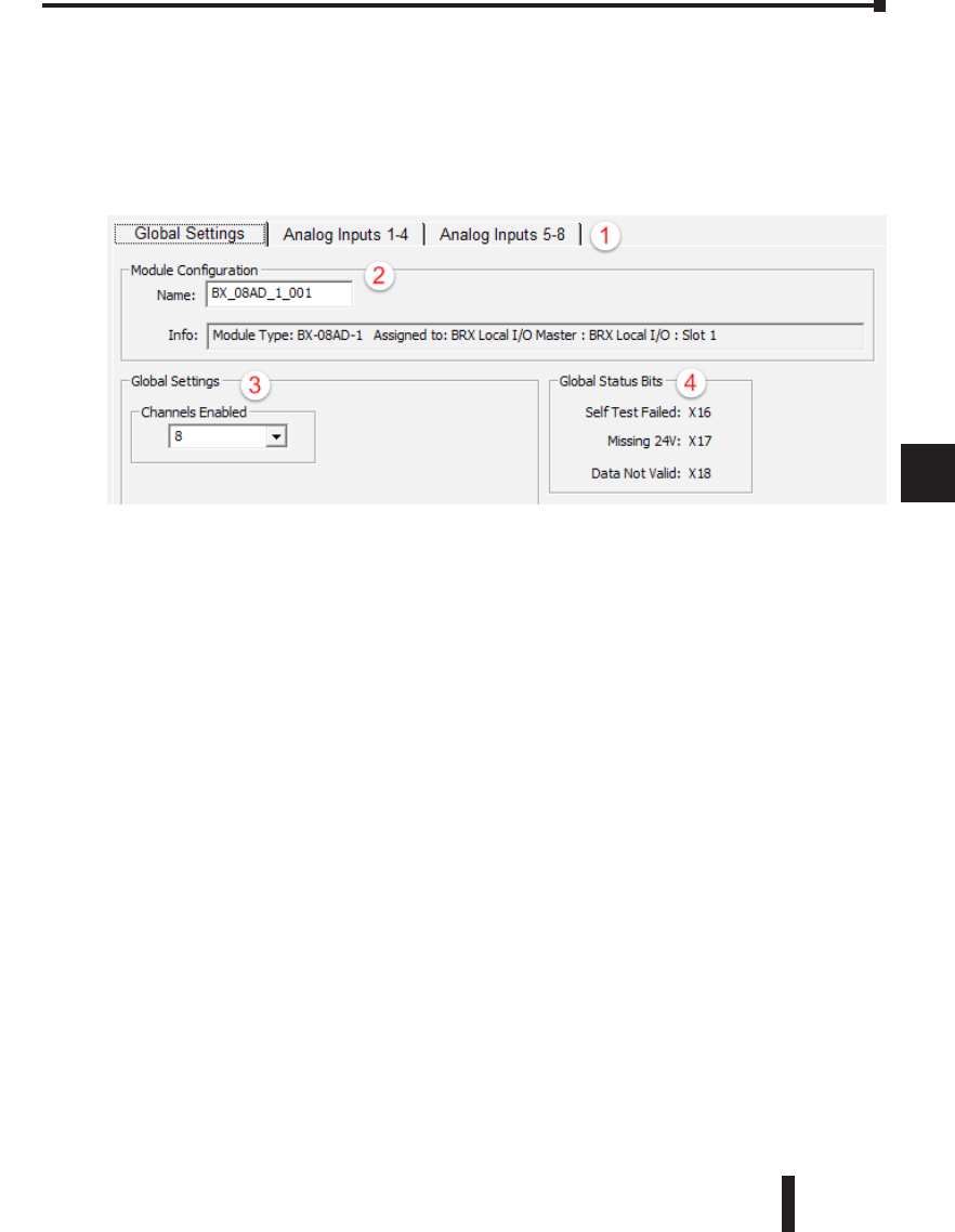
(1) The module options are divided into subsets across multiple tabs. Click the appropriate tab to
edit the configuration.
(2) Module Configuration
Name – Each module comes with a default name. This may be changed by the user to better
identify the module if desired.
Info – This is the system description of the module. It is static and may not be changed.
(3) Global Settings
Channels Enabled – Select how many channels will be used. The default is all channels.
Selecting fewer channels may increase the update frequency. See the module specifications for
details.
(4) Global Status Bits
Self Test Failed – This bit will be On if the module has failed its internal self-test. In this case
the module is likely bad and should be replaced.
Missing 24V – This bit will be On if the external 24VDC power is missing. Check the 24VDC
power connection on the module terminal block.
Data Not Valid – This bit will be On if the module does not have the latest configuration
parameters or the module has not been configured at all. Reload the program into the CPU
and power cycle.
Chapter 8: BRX Analog I/O Expansion Modules
BRX User Manual, 2nd Edition
8-20
1
2
3
4
5
6
7
8
9
10
11
12
13
14
15
A
B
C
D
BX-08AD-1 Analog Current Sinking Input, continued
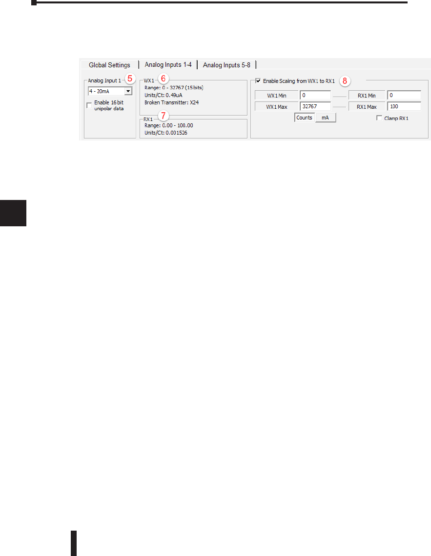
(5) Analog Input x
These settings are for each channel of the analog module.
Drop Down menu - Select the range of the analog input here.
Enable 16 bit unipolar data – Check this box to change the raw count range from a signed
decimal bipolar data format to an unsigned decimal data format. This may require that Casting
be used in the program in order to properly access the data. Refer to the chart of Data Range
Specifications earlier in this chapter to see if the registers must be accessed with Casting.
(6) WXx
Range – The number of Raw counts for the selected channel on the module
Units/Ct – The amount of current that will equal 1 raw count.
Broken Transmitter – The input register that when On will indicate that the loop is broken.
(7) RXx
Range – The engineering units to which the raw counts are scaled.
Units/Ct – The number of raw counts that will equal 1 scaled engineering unit.
(8) Enable Scaling from WXx to RXx
WXx Min – The minimum value of the raw counts to scale.
WXx Max – The maximum value of the raw counts to scale.
RXx Min – The minimum value of the engineering units for scaling.
RXx Max – The maximum value of the engineering units for scaling.
Counts/mA – Use these buttons to change the raw scaling to counts or milliamps.
Clamp RXx – If this box is checked, RXx will clamp at the minimum and maximum scaled
values.
Chapter 8: BRX Analog I/O Expansion Modules
8-21
BRX User Manual, 2nd Edition
1
2
3
4
5
6
7
8
9
10
11
12
13
14
15
A
B
C
D
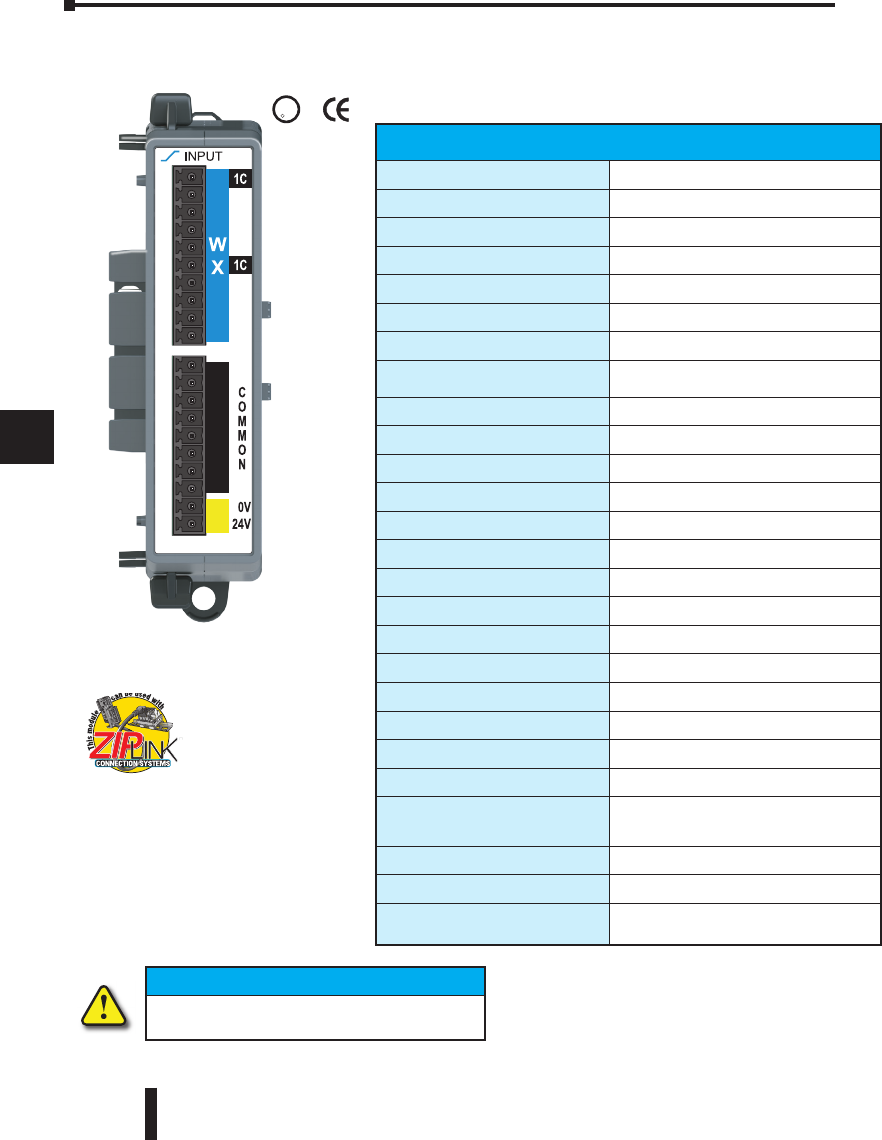
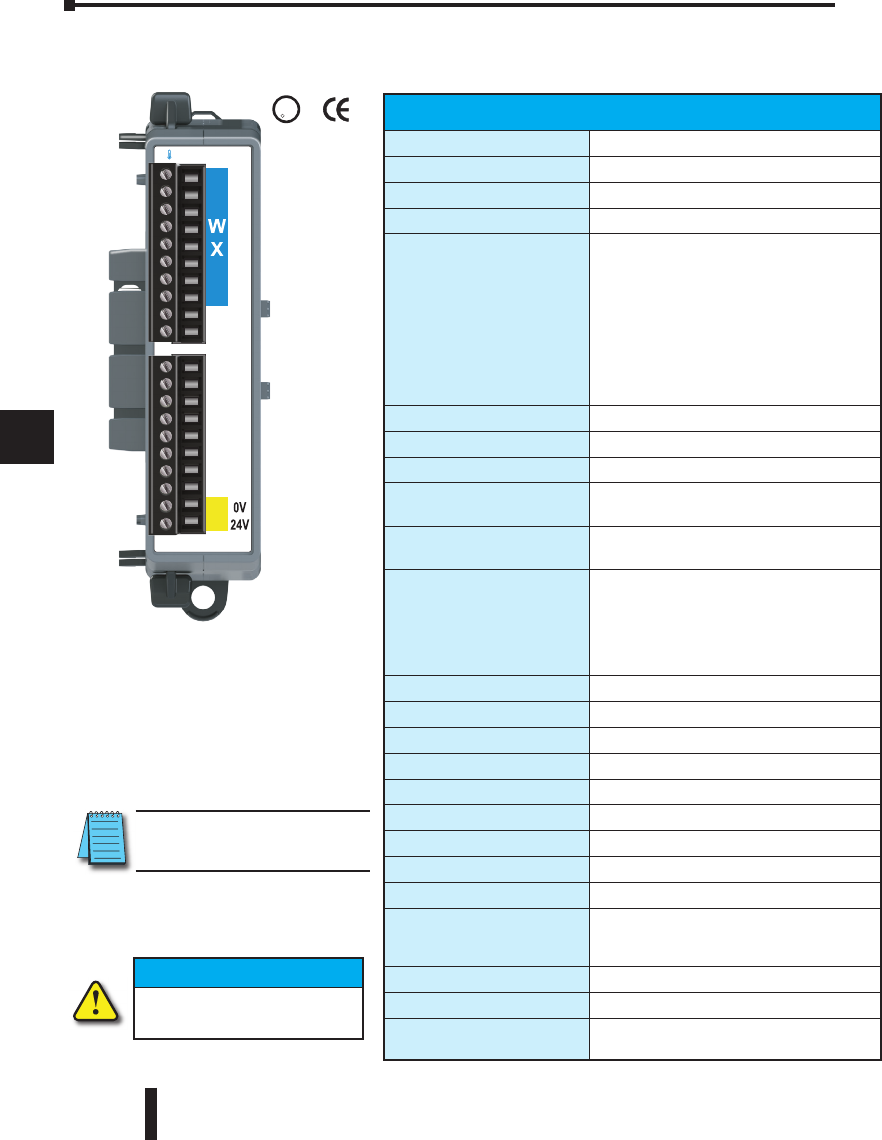
BX-08AD-2B Analog Voltage Input
V0+
V1+
V2+
V3+
V4+
V5+
V6+
V7+
BX-08AD-2B
Terminal Blocks
Sold Separately
We recommend using prewired ZIPLink
cables and connection modules.
If you wish to hand-wire your module,
a removable terminal block is available.
See Wiring Termination Selection in this
chapter for all options.
IMPORTANT!
Hot-Swapping Information
NOTE: This device cannot be Hot Swapped.
Analog Voltage Input Specications
Inputs per Module
8
Commons
1
Module Signal Input Range
±10 VDC, ±5 VDC,
0–5 VDC, 0–10 VDC (default)
Signal Resolution
16-bit, 15 bit (Default)
Input Impedance
>10MΩ
All Channel Update Rate
45ms (8 channels)
Sample Duration Time
5µs per channel
Hardware Filter Characteristics
Low Pass 2nd order, −3dB @ 15kHz
Conversion Method
Successive approximation
Accuracy vs. Temperature
±25PPM / °C maximum
Maximum Inaccuracy
0.15% of full range (over temp)
Linearity Error (end to end)
±0.03%
Input Stability and Repeatability
±0.06% of range (after 10 min. warmup)
Full Scale Calibration Error
±0.08% of range
Offset Calibration Error
±0.08% of range
Maximum Crosstalk
−96dB, 1 LSB
Channel to Backplane Isolation
1800VAC applied for one second
Channel to Channel Isolation
None
Loop Fusing (External)
Fast-acting 0.032A recommended
Backplane Power Consumption
0.1 W
External DC Power Required
Class 2 or LPS power supply
24VDC (±20%)
25mA
Heat Dissipation
2.5 W
Weight
100g (3.5 oz)
Software Version
Do-more! Designer Programming
Software version 2.1 or later
U
L
CUS
R
Chapter 8: BRX Analog I/O Expansion Modules
BRX User Manual, 2nd Edition
8-22
1
2
3
4
5
6
7
8
9
10
11
12
13
14
15
A
B
C
D
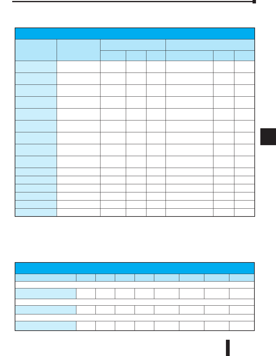
BX-08AD-2B Analog Voltage Input, continued
Data Range Specications
Selection Description
Enable 16 bit Unchecked
(15 bit Resolution, Default)1Enable 16 bit Checked
(16 bit Resolution)
Raw Counts Casting2µV Per
Count Raw Counts Casting2µV Per
Count
0–10V unipolar 10VDC
0–32767 - 305 0–65535 WXn:U 152
0–5V unipolar 5VDC
0–32767 - 152 0–65535 WXn:U 76
±
10V bipolar 10VDC
- - - −32768 to 32767 - 305
±5V bipolar 5VDC
- - - −32768 to 32767 - 152
1. Bipolar ranges default to 16-bit resolution.
2. For more information on Casting refer to Help topic DMD0309 in the Do-more! Designer Software.
The module reserves the first 24 bits of unused contiguous space in the X register, aligned to
an 8-bit word boundary, for status reporting. Error flags for this module are laid out within its
status register space as described in the following table.
Error Flag Specications
MSB LSB
1st Byte of unused X Registers
Module Status
-
----Data Not
Valid
Missing
24VDC
Self Test
Failed
2nd Byte of unused X Registers
Channel Out of
Range
Channel 8 Channel 7 Channel 6 Channel 5 Channel 4 Channel 3 Channel 2 Channel 1
3rd Byte of unused X Registers
Unused
--------
Chapter 8: BRX Analog I/O Expansion Modules
8-23
BRX User Manual, 2nd Edition
1
2
3
4
5
6
7
8
9
10
11
12
13
14
15
A
B
C
D
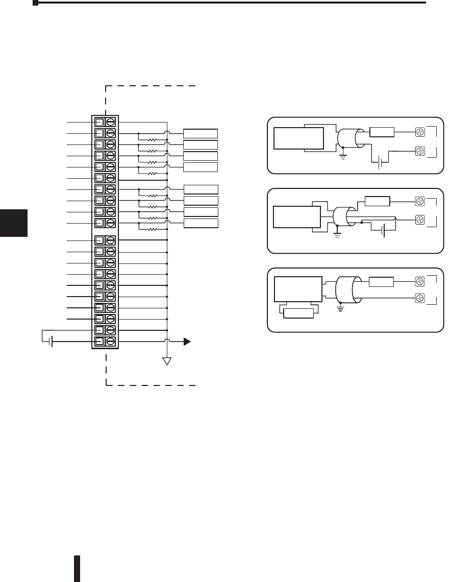
BX-08AD-2B Analog Voltage Input, continued
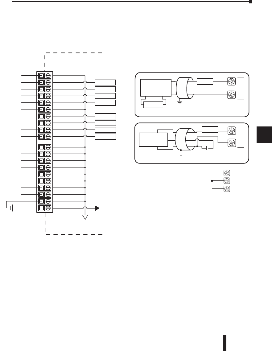
Analog Voltage Input Wiring
V0+
V1+
V2+
V3+
V4+
V5+
V6+
V7+
COM
COM
COM
COM
COM
COM
0V
24V+
- +
24VDC
Class 2 or LP
S
User Supplied
Power
ISOLATED
ANALOG
CIRCUIT POWER
ISOLATED ANALOG
CIRCUIT COMMON
INTERNAL
MODULE CIRCUITRY
COM
COM
1C
1C
CH0 ADC
CH1 ADC
CH2 ADC
CH3 ADC
CH4 ADC
CH5 ADC
CH6 ADC
CH7 ADC
1C/COM
1C/
COM
Vx+
4-Wire Voltage
Transmitter
4-Wire Transmitter
Optional Transmitter Power Supply
AC or DC
- +
24VDC User
Supplied Power
+
3-Wire Voltage
Transmitter
Vx+
3-Wire Transmitter
WX
WX
0.032 A
*Fuse
0.032 A
*Fuse
NOTE: Shield should be connected only at one end, to ground at the
source device.
V7+
V8+
COM
NOTE: For maximum accuracy: Jumper
unused inputs to common.
*An Edison S500-32-R 0.032 A fast-acting fuse is recommended
for all analog voltage inputs, analog outputs, and current loops.
+–
Analog Voltage Input Circuits
Chapter 8: BRX Analog I/O Expansion Modules
BRX User Manual, 2nd Edition
8-24
1
2
3
4
5
6
7
8
9
10
11
12
13
14
15
A
B
C
D
BX-08AD-2B Analog Voltage Input, continued
Software Setup
After the module is installed, open the Do-more! Designer programming software version 2.1
or later, connect to the BRX MPU and open the Configure Module dialog as described at the
beginning of this chapter..
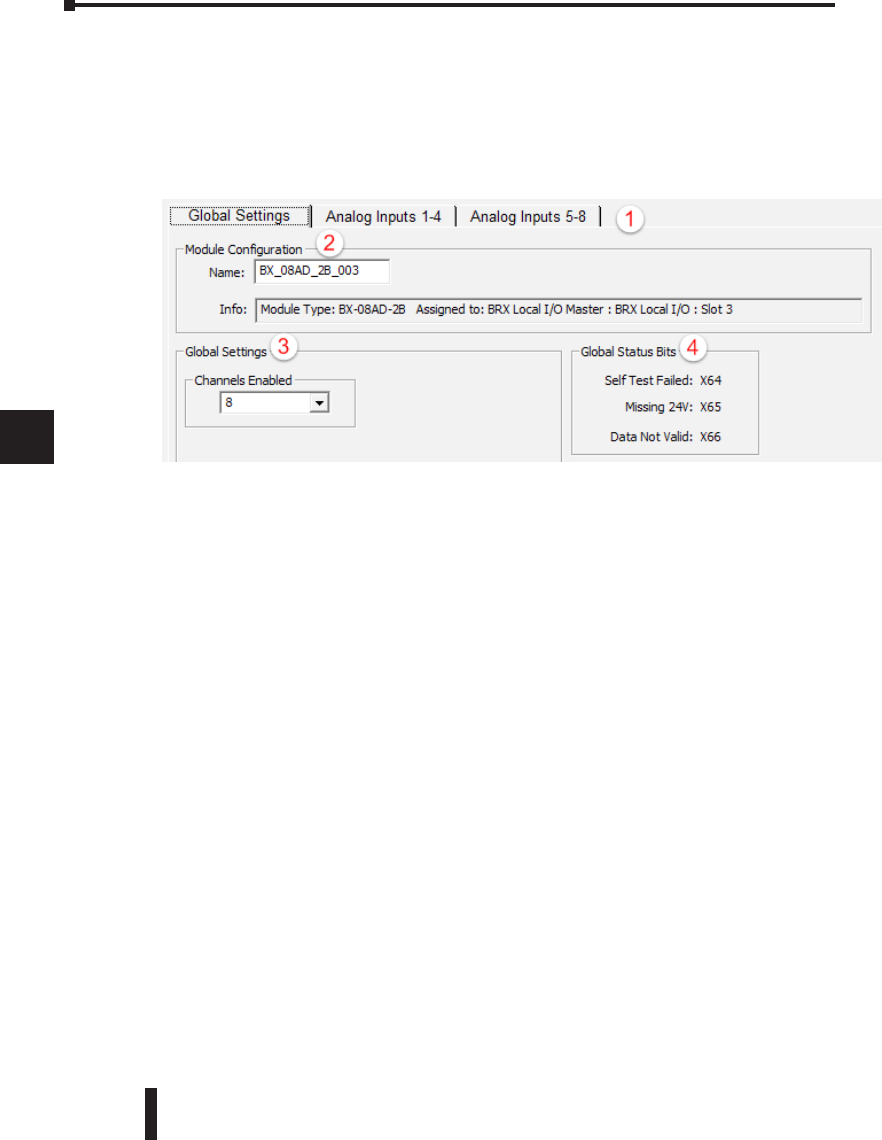
(1) The module options are divided into subsets across multiple tabs. Click the appropriate tab to
edit the configuration.
(2) Module Configuration
Name – Each module comes with a default name. This may be changed by the user to better
identify the module if desired.
Info – This is the system description of the module. This is static and may not be changed.
(3) Global Settings
Channels Enabled – Select how many channels will be used. The default is all channels.
Selecting fewer channels may increase the update frequency. See the module specifications for
details.
(4) Global Status Bits
Self Test Failed – This bit will be On if the module has failed its internal self-test. In this case
the module is likely bad and should be replaced.
Missing 24V – This bit will be On if the external 24VDC power is missing. Check the 24VDC
power connection on the module terminal block.
Data Not Valid – This bit will be On if the module does not have the latest configuration
parameters or the module has not been configured at all. Reload the program into the CPU
and power cycle.

Chapter 8: BRX Analog I/O Expansion Modules
8-25
BRX User Manual, 2nd Edition
1
2
3
4
5
6
7
8
9
10
11
12
13
14
15
A
B
C
D
BX-08AD-2B Analog Voltage Input, continued
(5) Analog Input x
These settings are for each channel of the analog module.
Drop Down menu - Select the range of the analog input here.
Enable 16 bit unipolar data – Check this box to change the raw count range from a signed
decimal bipolar data format to an unsigned decimal data format. This may require that Casting
be used in the program in order to properly access the data. Refer to the chart of Data Range
Specifications earlier in this chapter to see if the registers must be accessed with Casting.
(6) WXx
Range – The number of Raw counts for the selected channel on the module
Units/Ct – The amount of voltage that will equal 1 raw count.
Out of Range – The input register that when On will indicate that the voltage is outside of the
selected range.
(7) RXx
Range – The engineering units to which the raw counts are scaled.
Units/Ct – The number of raw counts that will equal 1 scaled engineering unit.
(8) Enable Scaling from WXx to RXx
WXx Min – The minimum value of the raw counts to scale.
WXx Max – The maximum value of the raw counts to scale.
RXx Min – The minimum value of the engineering units for scaling.
RXx Max – The maximum value of the engineering units for scaling.
Counts/VDC – Use these buttons to change the raw scaling to counts or volts.
Clamp RXx – If this box is checked, RXx will clamp at the minimum and maximum scaled
values.
Chapter 8: BRX Analog I/O Expansion Modules
BRX User Manual, 2nd Edition
8-26
1
2
3
4
5
6
7
8
9
10
11
12
13
14
15
A
B
C
D
BX-04THM Thermocouple Input
TC0+
TC3-
TC3+
TC2-
TC2+
TC1-
TC1+
TC0-
INPUT
BX-04THM
BX-RTB10 Terminal
Blocks Included
IMPORTANT!
Hot-Swapping Information
NOTE: This device cannot be
Hot Swapped.
Thermocouple Input Specications
Input Channels
4 Differential
Commons
0
Input Impedance
>5MΩ
Resolution
16-bit, 0.1°(C or F)
Thermocouple Input Ranges
Type J: −190° to 760°C (−310° to 1400°F)
(default)
Type E: −210° to 1000°C (−346° to 1832°F)
Type K: −150° to 1372°C (−238° to 2502°F)
Type R: 65° to 1768°C (149° to 3214°F)
Type S: 65° to 1768°C (149° to 3214°F)
Type T: −230° to 400°C (−382° to 752°F)
Type B: 529° to 1820°C (984° to 3308°F)
Type N: −70° to 1300°C (−94° to 2372°F)
Type C: 65° to 2320°C (149° to 4208°F)
Cold Junction Compensation
Automatic
Thermocouple Linearization
Automatic
Accuracy vs. Temperature
±50PPM per °C (maximum)
Linearity Error
±1°C maximum (±0.5°C typical)
Monotonic with no missing codes
Maximum Inaccuracy–
Temperature
±3°C maximum (excluding thermocouple
error) (including temperature drift)
Linear Voltage Input Ranges
0–39mV
±39mV
±78mV
0–156mV
±156mV
0–1.25 V
Maximum Inaccuracy–Voltage
0.06% @ 25°C, 0.10% @ 0–60°C
All Channel Update Rate
2.16 s
Sample Duration Time
270ms
Open Circuit Detection Time
Within 2s
Maximum Ratings
Fault protected inputs to ±50V
Common Mode Range
0.6 V (@ 16-bit Resolution)
Common Mode Rejection
100dB @ DC and 130dB @ 60Hz
Conversion Method
Sigma-Delta
Backplane Power Consumption
0.1 W
External DC Power Required
Class 2 or LPS power supply
24VDC (±20%)
25mA
Heat Dissipation
2.5 W
Weight
100g (3.5 oz)
Software Version
Do-more! Designer Programming Software
version 2.1 or later
U
L
CUS
R
NOTE: This device does not
support ZIPLink Wiring Systems
Chapter 8: BRX Analog I/O Expansion Modules
8-27
BRX User Manual, 2nd Edition
1
2
3
4
5
6
7
8
9
10
11
12
13
14
15
A
B
C
D
BX-04THM Thermocouple Input, continued
Data Range Specications
Selection Description
Enable 16 bit Unchecked
(15 bit Resolution, Default)1Enable 16 bit Checked
(16 bit Resolution)
Raw Counts Casting2µV Per
Count Raw Counts3Casting2µV Per
Count
Type J Type J
- - °C:
°F:
−1900 to 7600
−3100 to 14000 - -
Type K Type K
- - °C:
°F:
−2100 to 10000
−3460 to 18320 - -
Type E Type E
- - °C:
°F:
−1500 to 13720
−2380 to 25020 - -
Type R Type R
- - °C:
°F:
650 to 17680
1490 to 32140 - -
Type S Type S
- - °C:
°F:
650 to 17680
1490 to 32140 - -
Type T Type T
- - °C:
°F:
−2300 to 4000
−380 to 7520 - -
Type B Type B
- - °C:
°F:
5290 to 18200
9840 to 33080
-
WXn:U -
Type N Type N
- - °C:
°F:
−700 to 13000
−940 to 23720 - -
Type C Type C
- - °C:
°F:
650 to 23200
1490 to 42080
-
WXn:U -
0–39 mVDC Unipolar 39 mVDC
0–32767 - 1.2 0–65535 WXn:U 0.6
−
39–39 mVDC Bipolar 39 mVDC
- - −32768 to 32767 - 1.2
−
78–78 mVDC Bipolar 78 mVDC
- - −32768 to 32767 - 2.4
0–156 mVDC Unipolar 156 mVDC
0–32767 - 4.8 0–65535 WXn:U 2.4
−
156–156 mVDC Bipolar 156 mVDC
- - −32768 to 32767 - 4.8
0–1.25 VDC Unipolar 1.25 VDC
0–32767 - 38.1 0–65535 WXn:U 19.1
1. Thermocouple and bipolar ranges default to 16-bit resolution.
2. For more information on Casting refer to Help topic DMD0309 in the Do-more! Designer Software.
3. Temperatures have one implied decimal place (e.g., raw count of -1900 is -190.0°).
The module reserves the first 24 bits of unused contiguous space in the X register, aligned to
an 8-bit word boundary, for status reporting. Error flags for this module are laid out within its
status register space as described in the following table.
Error Flag Specications
MSB LSB
1st Byte of unused X Registers
Module Status
-
- - - - Data Not
Valid
Missing
24VDC
Self Test
Failed
2nd Byte of unused X Registers
Channel Out of Range
----Channel 4 Channel 3 Channel 2 Channel 1
3rd Byte of unused X Registers
Channel Open (Burn Out)
----Channel 4 Channel 3 Channel 2 Channel 1
Chapter 8: BRX Analog I/O Expansion Modules
BRX User Manual, 2nd Edition
8-28
1
2
3
4
5
6
7
8
9
10
11
12
13
14
15
A
B
C
D
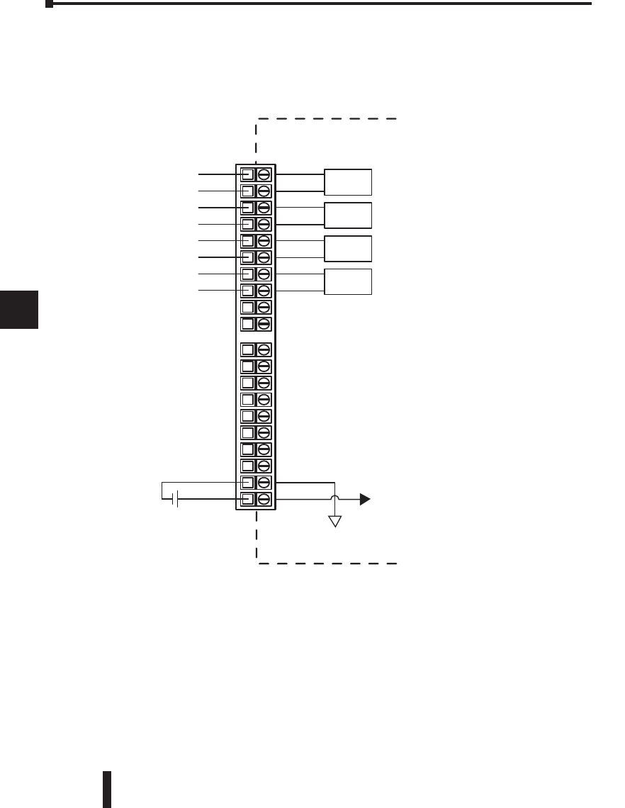
BX-04THM Thermocouple Input, continued
Analog Thermocouple/Voltage Input Wiring
CH0 T/C
INPUT
CH1 T/C
INPUT
CH2 T/C
INPUT
CH3 T/C
INPUT
0V
24V+
- +
24VDC
Class 2 or LPS
User Supplied
Power
ISOLATED ANALOG
CIRCUIT POWER
ISOLATED ANALOG
CIRCUIT COMMON
INTERNAL
MODULE CIRCUITRY
TC0+
TC0-
TC1+
TC1-
TC2+
TC2-
TC3+
TC3-
Chapter 8: BRX Analog I/O Expansion Modules
8-29
BRX User Manual, 2nd Edition
1
2
3
4
5
6
7
8
9
10
11
12
13
14
15
A
B
C
D
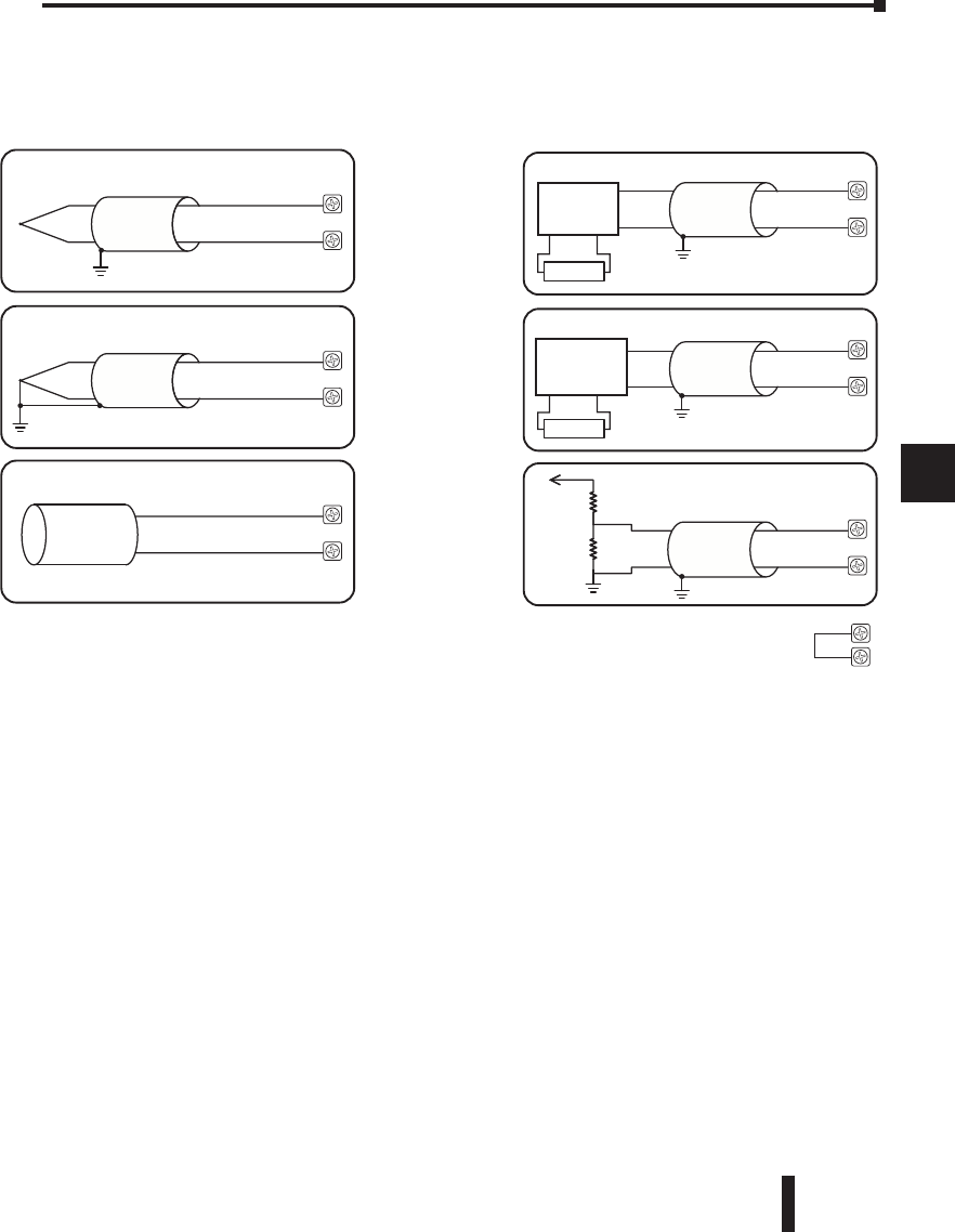
BX-04THM Thermocouple Input, continued
AC or DC
AC or DC
Thermocouple Input Circuits
Analog Voltage Input Circuits
Excitation Power Supply
Transmitter Power Supply
Ungrounded/Shielded
Thermocouple TC+
TC-
TC+
TC-
TC+
TC-
Grounded/Shielded
Thermocouple
Infrared
Thermocouple
4-wire
Voltage
Transmitter
Load Cell
or
Strain Gauge
Voltage Divider
TC+
TC-
TC+
TC-
TC+
TC-
TCx+
TCx-
For maximum accuracy:
Jumper unused inputs.
+–
+–
NOTE: Shield should be connected only at one end, to ground at the
source device.
NOTE: Thermocouple extension wire and proper thermocouple
terminal blocks must be used to extend thermocouples.
AutomationDirect thermocouple wire is recommended.
AC or DC
AC or DC
Thermocouple Input Circuits
Analog Voltage Input Circuits
Excitation Power Supply
Transmitter Power Supply
Ungrounded/Shielded
Thermocouple TC+
TC-
TC+
TC-
TC+
TC-
Grounded/Shielded
Thermocouple
Infrared
Thermocouple
4-wire
Voltage
Transmitter
Load Cell
or
Strain Gauge
Voltage Divider
TC+
TC-
TC+
TC-
TC+
TC-
TCx+
TCx-
For maximum accuracy:
Jumper unused inputs.
+–
+–
NOTE: Shield should be connected only at one end, to ground at the
source device.
NOTE: Thermocouple extension wire and proper thermocouple
terminal blocks must be used to extend thermocouples.
AutomationDirect thermocouple wire is recommended.
Chapter 8: BRX Analog I/O Expansion Modules
BRX User Manual, 2nd Edition
8-30
1
2
3
4
5
6
7
8
9
10
11
12
13
14
15
A
B
C
D
BX-04THM Thermocouple Input, continued
Software Setup
After the module is installed, open the Do-more! Designer programming software version 2.1
or later, connect to the BRX MPU and open the Configure Module dialog as described at the
beginning of this chapter..
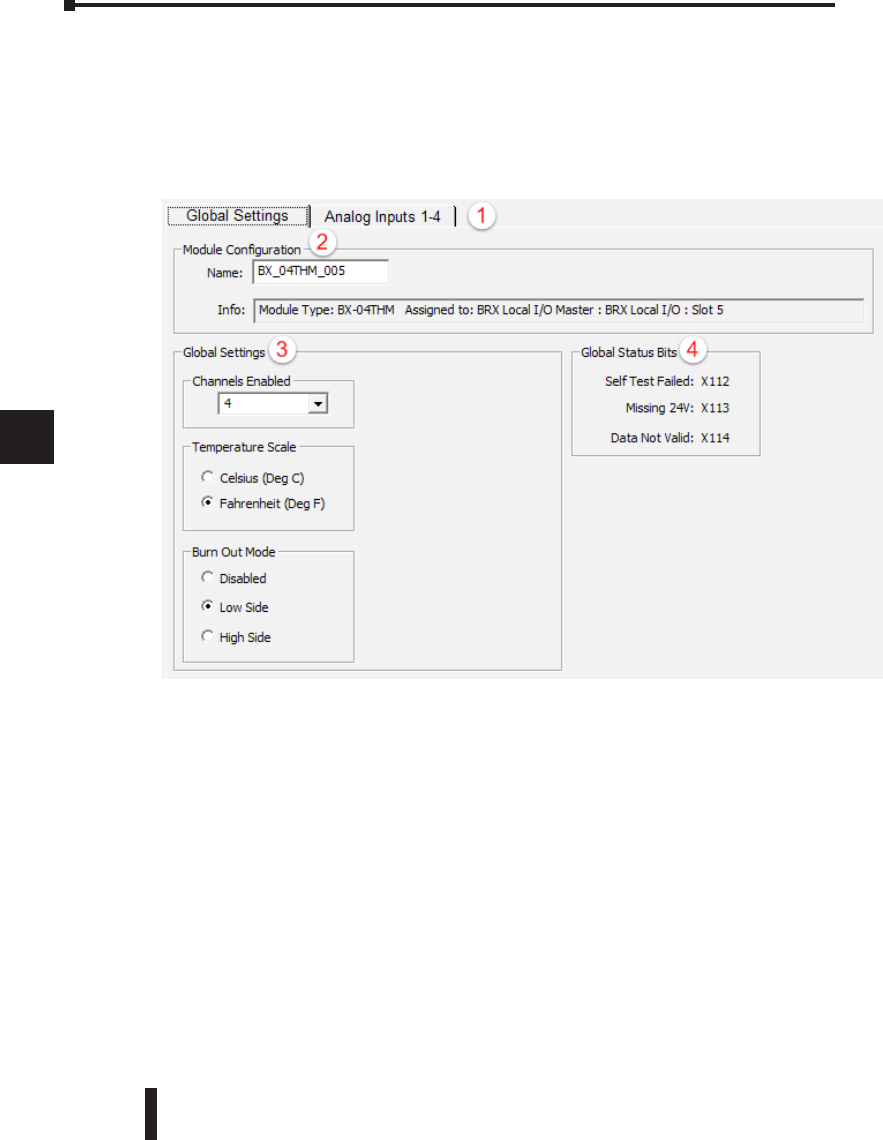
(1) The module options are divided into subsets across multiple tabs. Click the appropriate tab to
edit the configuration.
(2) Module Configuration
Name – Each module comes with a default name. This may be changed by the user to better
identify the module if desired.
Info – This is the system description of the module. This is static and may not be changed.
(3) Global Settings
Channels Enabled – Select how many channels will be used. The default is all channels.
Selecting fewer channels may increase the update frequency. See the module specifications for
details.
Temperature Scale – Select either Celcius or Fahrenheit.
Burn Out Mode – Select if the Input register should read Low or High on burn out or if burn
out detection should be disabled. Note: Burn Out Mode must be set to Disabled in order to
use a Thermocouple Calibrator.
Chapter 8: BRX Analog I/O Expansion Modules
8-31
BRX User Manual, 2nd Edition
1
2
3
4
5
6
7
8
9
10
11
12
13
14
15
A
B
C
D
BX-04THM Thermocouple Input, continued
(4) Global Status Bits
Self Test Failed – This bit will be On if the module has failed its internal self-test. In this case
the module is likely bad and should be replaced.
Missing 24V – This bit will be on if the external 24VDC power is missing. Check the 24VDC
power connection on the module terminal block.
Data Not Valid – This bit will be on if the module does not have the latest configuration
parameters or the module has not been configured at all. Reload the program into the CPU
and power cycle.
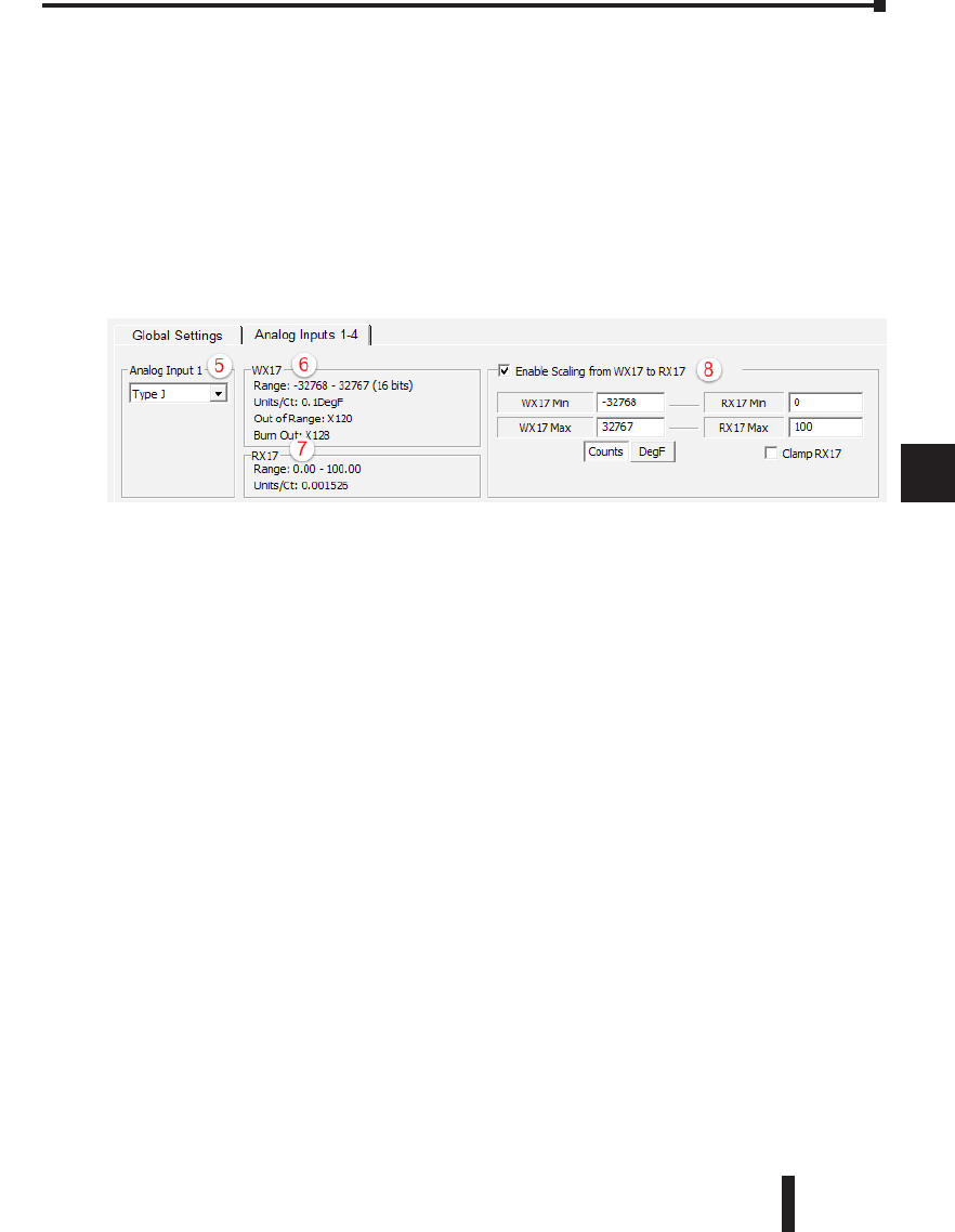
(5) Analog Input x
These settings are for each channel of the analog module.
Drop Down menu - Select the range of the analog input here.
(6) WXx
Range – The number of Raw counts for the selected channel on the module
Units/Ct – The amount of temperature or voltage that will equal 1 raw count.
Out of Range – The input register that when On will indicate that the input is outside of the
range selected.
Burn Out – If burn out is enabled, this register will be On when the loop is broken.
(7) RXx
Range – The engineering units to which the raw counts are scaled.
Units/Ct – The number of raw counts that will equal 1 scaled engineering unit.
(8) Enable Scaling from WXx to RXx
WXx Min – The minimum value of the raw counts to scale.
WXx Max – The maximum value of the raw counts to scale.
RXx Min – The minimum value of the engineering units for scaling.
RXx Max – The maximum value of the engineering units for scaling.
Counts/DegF – Use these buttons to change the raw scaling to counts or degrees (C or F).
Clamp RXx – If this box is checked, RXx will clamp at the minimum and maximum scaled
values.
Chapter 8: BRX Analog I/O Expansion Modules
BRX User Manual, 2nd Edition
8-32
1
2
3
4
5
6
7
8
9
10
11
12
13
14
15
A
B
C
D
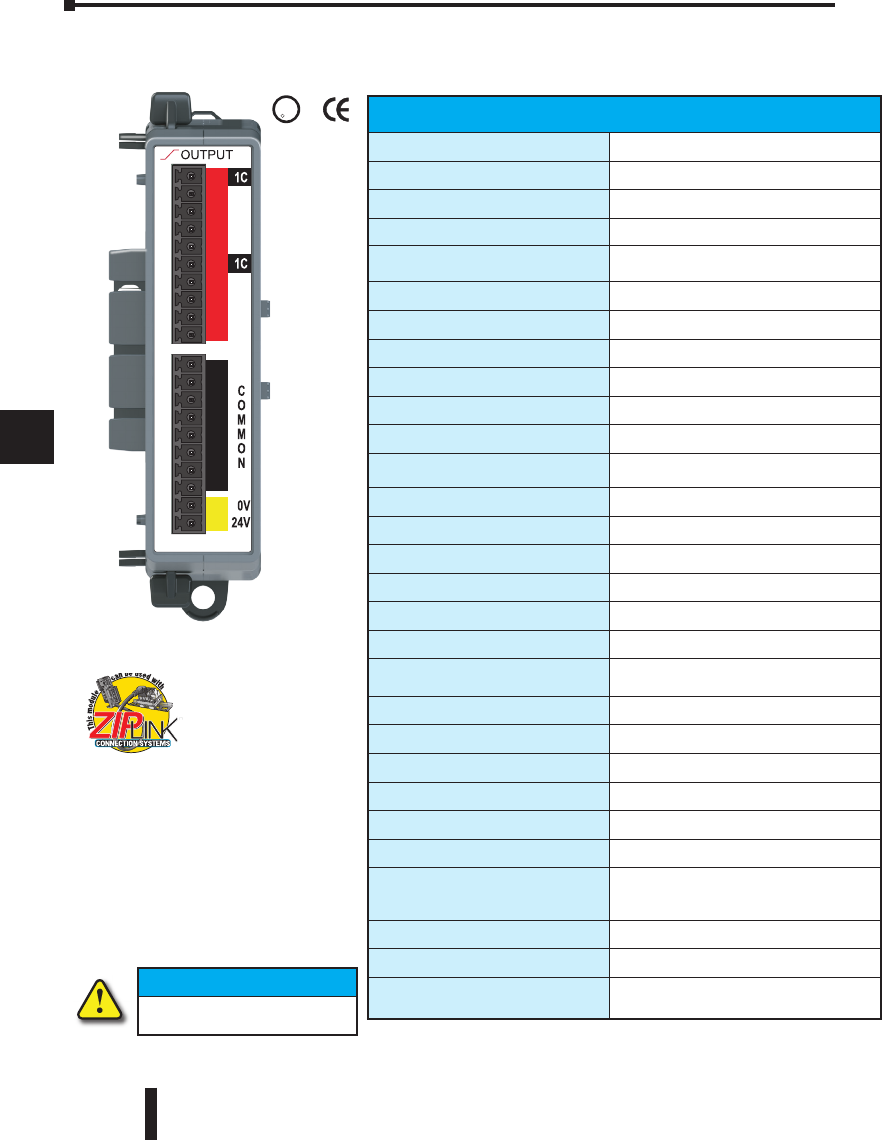
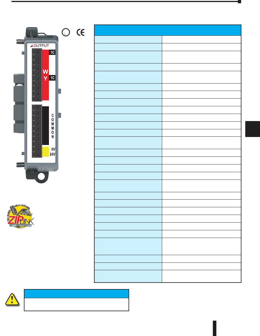
BX-08DA-1 Analog Current Source Output
W
Y
I0+
I1+
I2+
I3+
I4+
I5+
I6+
I7+
BX-08DA-1
Analog Current Source Ouput Specications
Outputs per Module
8
Commons
1
Module Signal Output Range
0–20mA, 4–20mA (Default)
Signal Resolution
16-bit, 15-bit (Default)
Output Type
Current Sourcing up to 22mA
Output Value in Fault Mode
~0mA
Maximum Load Impedance
700Ω
Maximum Capacitive Load
1000pF
Allowed Load Type
Grounded
Maximum Continuous Overload
30mA
All Channel Update Rate
1.5 ms per enabled channel
Maximum Inaccuracy
±0.15% of range
Maximum Full Scale Calibration Error
±0.08% of range
Maximum Offset Calibration Error
±0.06% of range
Conversion Method
Successive approximation
Accuracy vs. Temperature
±25PPM / ºC maximum
Maximum Crosstalk
+10μV
Linearity Error (end to end)
±0.06% of range
Output Stability and Repeatability
±0.02% of full range after 10 minute
warmup (typical)
Output Ripple
±0.01% of range/mA
Output Settling Time
200μs
Channel to Backplane Isolation
1800VAC applied for one second
Channel to Channel Isolation
None
Loop Fusing (
External
)
Fast-acting 0.032A recommended
Backplane Power Consumption
0.1 W
External DC Power Required
Class 2 or LPS power supply
24VDC (±20%)
250mA
Heat Dissipation
8.1 W
Weight
100g (3.5 oz)
Software Version
Do-more! Designer Programming
Software version 2.1 or later
Terminal Blocks
Sold Separately
We recommend using prewired ZIPLink
cables and connection modules.
If you wish to hand-wire your module,
a removable terminal block is available.
See Wiring Termination Selection in this
chapter for all options.
IMPORTANT!
Hot-Swapping Information
NOTE: This device cannot
be Hot Swapped.
U
L
CUS
R
Chapter 8: BRX Analog I/O Expansion Modules
8-33
BRX User Manual, 2nd Edition
1
2
3
4
5
6
7
8
9
10
11
12
13
14
15
A
B
C
D
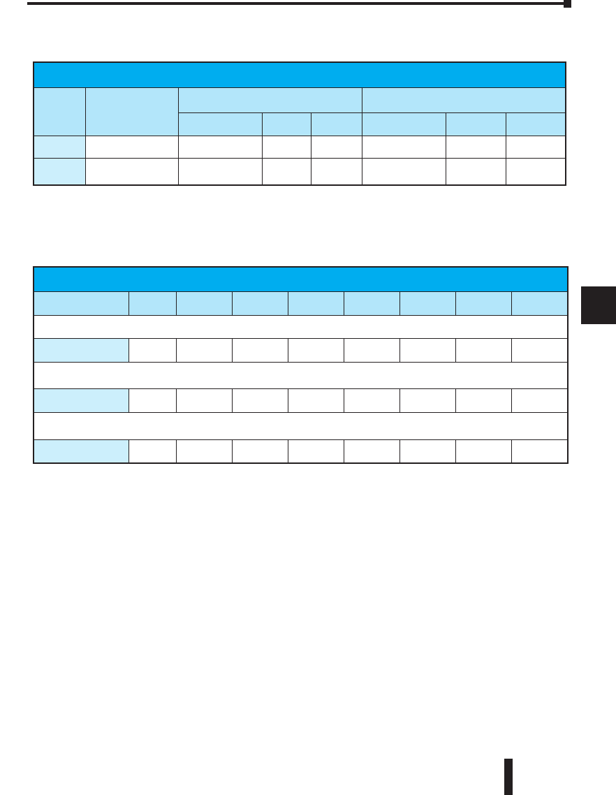
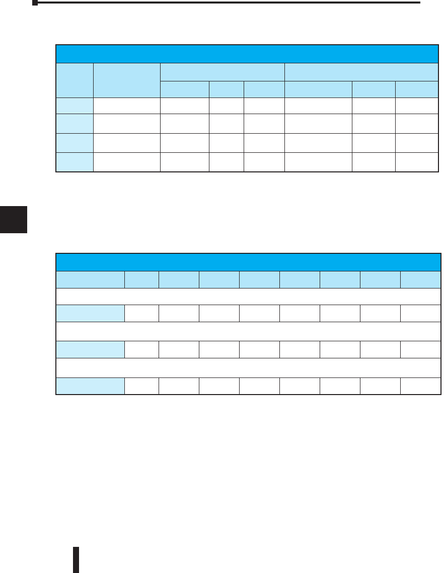
BX-08DA-1 Analog Current Source Output, continued
Data Range Specications
Selection Description
Enable 16 bit Unchecked
(15 bit Resolution, Default)
Enable 16 bit Checked
(16 bit Resolution)
Raw Counts Casting* µA Per
Count Raw Counts Casting* µA Per
Count
0–20mA unipolar 0–20mA
0–32767 - 0.61 0–65535 WYn:U 0.31
4–20mA unipolar 4–20mA
0–32767 - 0.49 0–65535 WYn:U 0.24
* For more information on Casting refer to Help topic DMD0309 in the Do-more! Designer Software.
The module reserves the first 24 bits of unused contiguous space in the X register, aligned to
an 8-bit word boundary, for status reporting. Error flags for this module are laid out within its
status register space as described in the following table.
Error Flag Specications
MSB LSB
1st Byte of unused X Registers
Module Status
-
----Data Not
Valid
Missing
24VDC
Self Test
Failed
2nd Byte of unused X Registers
Unused
--------
3rd Byte of unused X Registers
Unused
--------
Chapter 8: BRX Analog I/O Expansion Modules
BRX User Manual, 2nd Edition
8-34
1
2
3
4
5
6
7
8
9
10
11
12
13
14
15
A
B
C
D
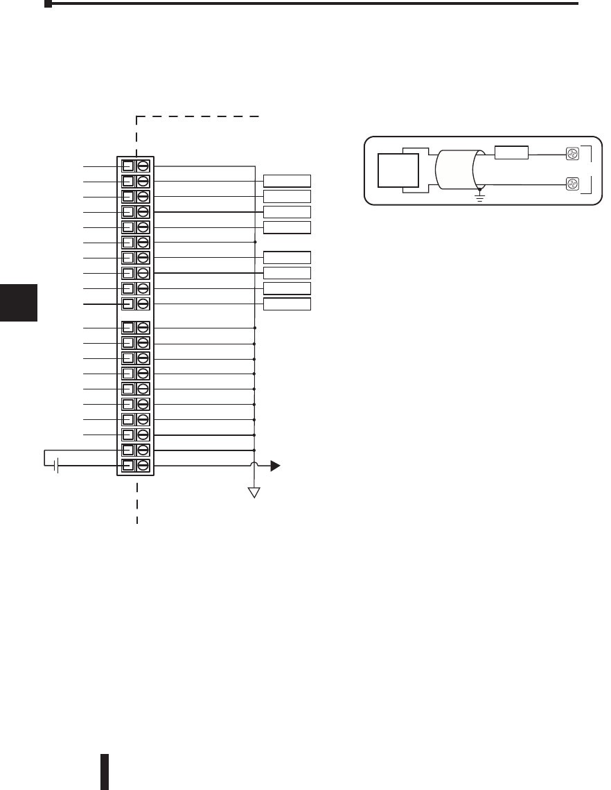
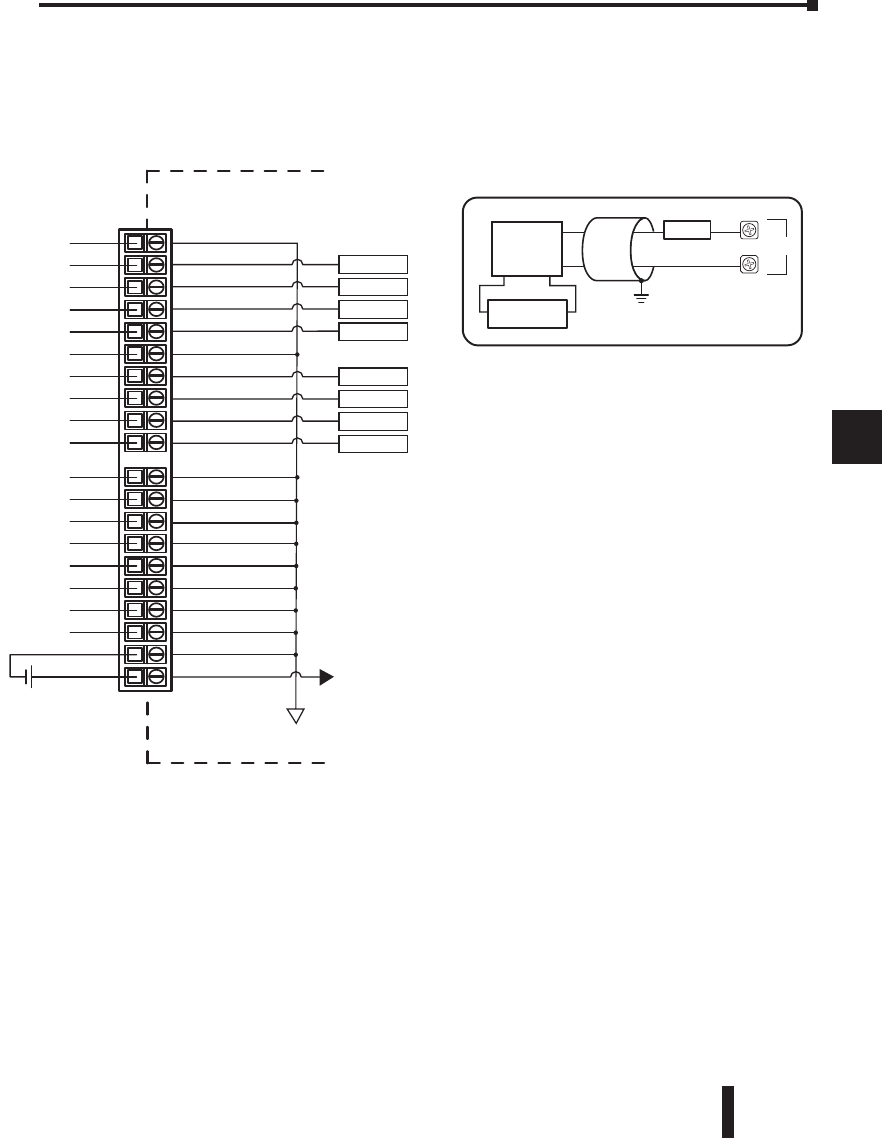
BX-08DA-1 Analog Current Source Output, continued
Analog Current Ouput Wiring
- +
24VDC
Class 2 or LP
S
User Supplied
Power
ISOLATED
ANALOG
CIRCUIT POWER
ISOLATED ANALOG
CIRCUIT COMMON
INTERNAL
MODULE CIRCUITRY
I0+
I1+
I2+
I3+
COM
0V
24V+
1C
COM
COM
1C
COM
COM
COM
COM
COM
CH0 DAC
CH1 DAC
CH2 DAC
CH3 DAC
4-20 mA current sourcing
4-20 mA current sourcing
4-20 mA current sourcing
4-20 mA current sourcing
I4+
I5+
I6+
I7+
CH4 DAC
CH5 DAC
CH6 DAC
CH7 DAC
4-20 mA current sourcing
4-20 mA current sourcing
4-20 mA current sourcing
4-20 mA current sourcing
*An Edison S500-32-R 0.032 A fast-acting fuse is recommended
for all analog voltage inputs, analog outputs, and current loops.
NOTE: Shield should be connected only at one end, to ground at the
source device.
Analog Current Source Output
mA Load
Ix+
1C/COM
WY
0.032 A
*Fuse
Chapter 8: BRX Analog I/O Expansion Modules
8-35
BRX User Manual, 2nd Edition
1
2
3
4
5
6
7
8
9
10
11
12
13
14
15
A
B
C
D
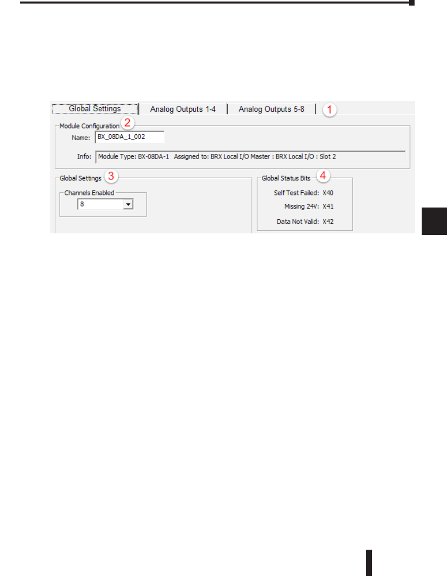
BX-08DA-1 Analog Current Source Output, continued
Software Setup
After the module is installed, open the Do-more! Designer programming software version 2.1
or later, connect to the BRX MPU and open the Configure Module dialog as described at the
beginning of this chapter..
(1) The module options are divided into subsets across multiple tabs. Click the appropriate tab to
edit the configuration.
(2) Module Configuration
Name – Each module comes with a default name. This may be changed by the user to better
identify the module if desired.
Info – This is the system description of the module. This is static and may not be changed.
(3) Global Settings
Channels Enabled – Select how many channels will be used. The default is all channels.
Selecting fewer channels may increase the update frequency. See the module specifications for
details.
(4) Global Status Bits
Self Test Failed – This bit will be On if the module has failed its internal self-test. In this case
the module is likely bad and should be replaced.
Missing 24V – This bit will be On if the external 24VDC power is missing. Check the 24VDC
power connection on the module terminal block.
Data Not Valid – This bit will be On if the module does not have the latest configuration
parameters or the module has not been configured at all. Reload the program into the CPU
and power cycle.
Chapter 8: BRX Analog I/O Expansion Modules
BRX User Manual, 2nd Edition
8-36
1
2
3
4
5
6
7
8
9
10
11
12
13
14
15
A
B
C
D
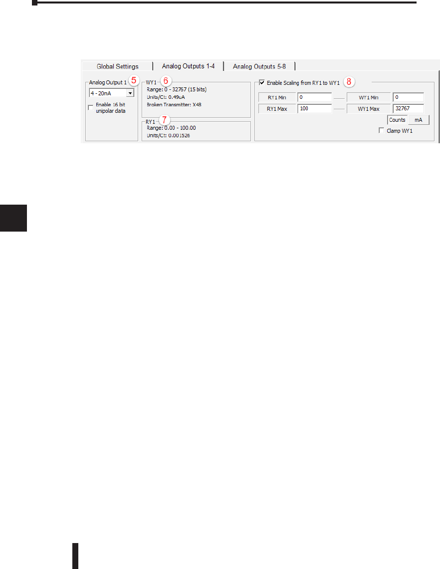
BX-08DA-1 Analog Current Source Output, continued
(5) Analog Output x
These settings are for each channel of the analog module.
Drop Down menu – Select the range of the analog output here.
Enable 16 bit unipolar data – Check this box to change the raw count range from a signed
decimal bipolar data format to an unsigned decimal data format. This may require that Casting
be used in the program in order to properly access the data. Refer to the chart of Data Range
Specifications earlier in this chapter to see if the registers must be accessed with Casting.
(6) WYx
Range – The number of Raw counts for the selected channel on the module
Units/Ct – The amount of current that will equal 1 raw count.
Broken Transmitter – The input register that when On will indicate that the loop is broken.
(7) RYx
Range – The engineering units to which the raw counts are scaled.
Units/Ct – The number of raw counts that will equal 1 scaled engineering unit.
(8) Enable Scaling from RYx to WYx
RYx Min – The minimum value of the engineering units for scaling.
RYx Max – The maximum value of the engineering units for scaling.
WYx Min – The minimum value of the raw counts to scale.
WYx Max – The maximum value of the raw counts to scale.
Counts/mA – Use these buttons to change the raw scaling to counts or milliamps.
Clamp WYx – If this box is checked, WYx will clamp at the minimum and maximum scaled
values.
Chapter 8: BRX Analog I/O Expansion Modules
8-37
BRX User Manual, 2nd Edition
1
2
3
4
5
6
7
8
9
10
11
12
13
14
15
A
B
C
D
BX-08DA-2B Analog Voltage Output
V0+
V1+
V2+
V3+
V4+
V5+
V6+
V7+
BX-08DA-2B
Terminal Blocks
Sold Separately
We recommend using prewired ZIPLink
cables and connection modules.
If you wish to hand-wire your module,
a removable terminal block is available.
See Wiring Termination Selection in this
chapter for all options.
IMPORTANT!
Hot-Swapping Information
NOTE: This device cannot be Hot Swapped.
Analog Voltage Output Specications
Outputs per Module
8
Commons
1
Module Signal Input Range
±10 VDC, ±5 VDC,
0–5 VDC, 0–10 VDC (Default)
Signal Resolution
16-bit, 15-bit (Default)
Output Type
Voltage outputs sourcing/sinking at
10mA (example 10V @ 1kΩ load).
Output Value in Fault Mode
Voltage outputs 0V (Unipolar or Bipolar)
Minimum Load Impedance
1kΩ
Maximum Capacitive Load
1000pF
Allowed Load Type
Grounded
Maximum Continuous Overload
15mA
All Channel Update Rate
3ms
Maximum Inaccuracy
0.2% of range
Maximum Full Scale Calibration
Error
±0.08% of range
Maximum Offset Calibration Error
±0.04% of range
Accuracy vs. Temperature
±25PPM / °C maximum
Maximum Crosstalk
+3µV
Linearity Error (end to end)
±0.01% of range
Output Stability and Repeatability
±0.02% of full range
after 10 min. warmup (typical)
Output Ripple
150 µV/mA
Output Settling Time
200µs
Channel to Backplane Isolation
1800VAC applied for one second
Channel to Channel Isolation
None
Loop Fusing (External)
Fast-acting 0.032A recommended
Backplane Power Consumption
0.1 W
External DC Power Required
Class 2 or LPS power supply
24VDC (±20%)
100mA
Heat Dissipation
3.1 W
Weight
100g (3.5 oz)
Software Version
Do-more! Designer Programming
Software version 2.1 or later
U
L
CUS
R
Do-more! Designer version 2.1 or higher required.
Chapter 8: BRX Analog I/O Expansion Modules
BRX User Manual, 2nd Edition
8-38
1
2
3
4
5
6
7
8
9
10
11
12
13
14
15
A
B
C
D
BX-08DA-2B Analog Voltage Output, continued
Data Range Specications
Selection Description
Enable 16 bit Unchecked
(15 bit Resolution, Default)1Enable 16 bit Checked
(16 bit Resolution)
Raw Counts Casting2µV Per
Count Raw Counts Casting2µV Per
Count
0–10V unipolar 10VDC
0–32767 - 305 0–65535 WYn:U 152
0–5V unipolar 5VDC
0–32767 - 152 0–65535 WYn:U 76
±10V bipolar 10VDC
- - −32768 to 32767 - 305
±5V bipolar 5VDC
- - −32768 to 32767 - 152
1. Bipolar ranges default to 16-bit resolution.
2. For more information on Casting refer to Help topic DMD0309 in the Do-more! Designer Software.
The module reserves the first 24 bits of unused contiguous space in the X register, aligned to
an 8-bit word boundary, for status reporting. Error flags for this module are laid out within its
status register space as described in the following table.
Error Flag Specications
MSB LSB
1st Byte of unused X Registers
Module Status
-
----Data Not
Valid
Missing
24VDC
Self Test
Failed
2nd Byte of unused X Registers
Unused
--------
3rd Byte of unused X Registers
Unused
--------
Chapter 8: BRX Analog I/O Expansion Modules
8-39
BRX User Manual, 2nd Edition
1
2
3
4
5
6
7
8
9
10
11
12
13
14
15
A
B
C
D
BX-08DA-2B Analog Voltage Output, continued
Analog Voltage Output Wiring
- +
24VDC
Class 2 or LP
S
User Supplied
Power
ISOLATED
ANALOG
CIRCUIT POWER
ISOLATED ANALOG
CIRCUIT COMMON
INTERNAL
MODULE CIRCUITRY
V0+
V1+
V2+
V3+
V4+
V5+
V6+
V7+
COM
0V
24V+
1C
COM
COM
1C
COM
COM
COM
COM
COM
CH0 DAC
CH1 DAC
CH2 DAC
CH3 DAC
voltage sink/source
voltage sink/source
voltage sink/source
voltage sink/source
CH4 DAC
CH5 DAC
CH6 DAC
CH7 DAC
voltage sink/source
voltage sink/source
voltage sink/source
voltage sink/source
*An Edison S500-32-R 0.032 A fast-acting fuse is recommended
for all analog voltage inputs, analog outputs, and current loops.
NOTE: Shield should be connected only at one end, to ground at the
source device.
Load
Power Supply
VDC
Load
Analog Voltage Output Circuit
Vx+
1C/COM
WY
0.032 A
*Fuse
Chapter 8: BRX Analog I/O Expansion Modules
BRX User Manual, 2nd Edition
8-40
1
2
3
4
5
6
7
8
9
10
11
12
13
14
15
A
B
C
D
BX-08DA-2B Analog Voltage Output, continued
Software Setup
After the module is installed, open the Do-more! Designer programming software version 2.1
or later, connect to the BRX MPU and open the Configure Module dialog as described at the
beginning of this chapter..
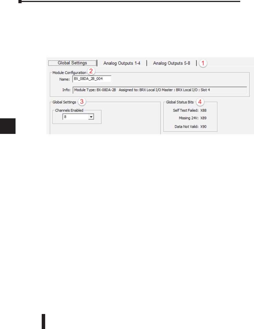
(1) The module options are divided into subsets across multiple tabs. Click the appropriate tab to
edit the configuration.
(2) Module Configuration
Name – Each module comes with a default name. This may be changed by the user to better
identify the module if desired.
Info – This is the system description of the module. This is static and may not be changed.
(3) Global Settings
Channels Enabled – Select how many channels will be used. The default is all channels.
Selecting fewer channels may increase the update frequency. See the module specifications for
details.
(4) Global Status Bits
Self Test Failed – This bit will be On if the module has failed its internal self-test. In this case
the module is likely bad and should be replaced.
Missing 24V – This bit will be On if the external 24VDC power is missing. Check the 24VDC
power connection on the module terminal block.
Data Not Valid – This bit will be On if the module does not have the latest configuration
parameters or the module has not been configured at all. Reload the program into the CPU
and power cycle.
Chapter 8: BRX Analog I/O Expansion Modules
8-41
BRX User Manual, 2nd Edition
1
2
3
4
5
6
7
8
9
10
11
12
13
14
15
A
B
C
D
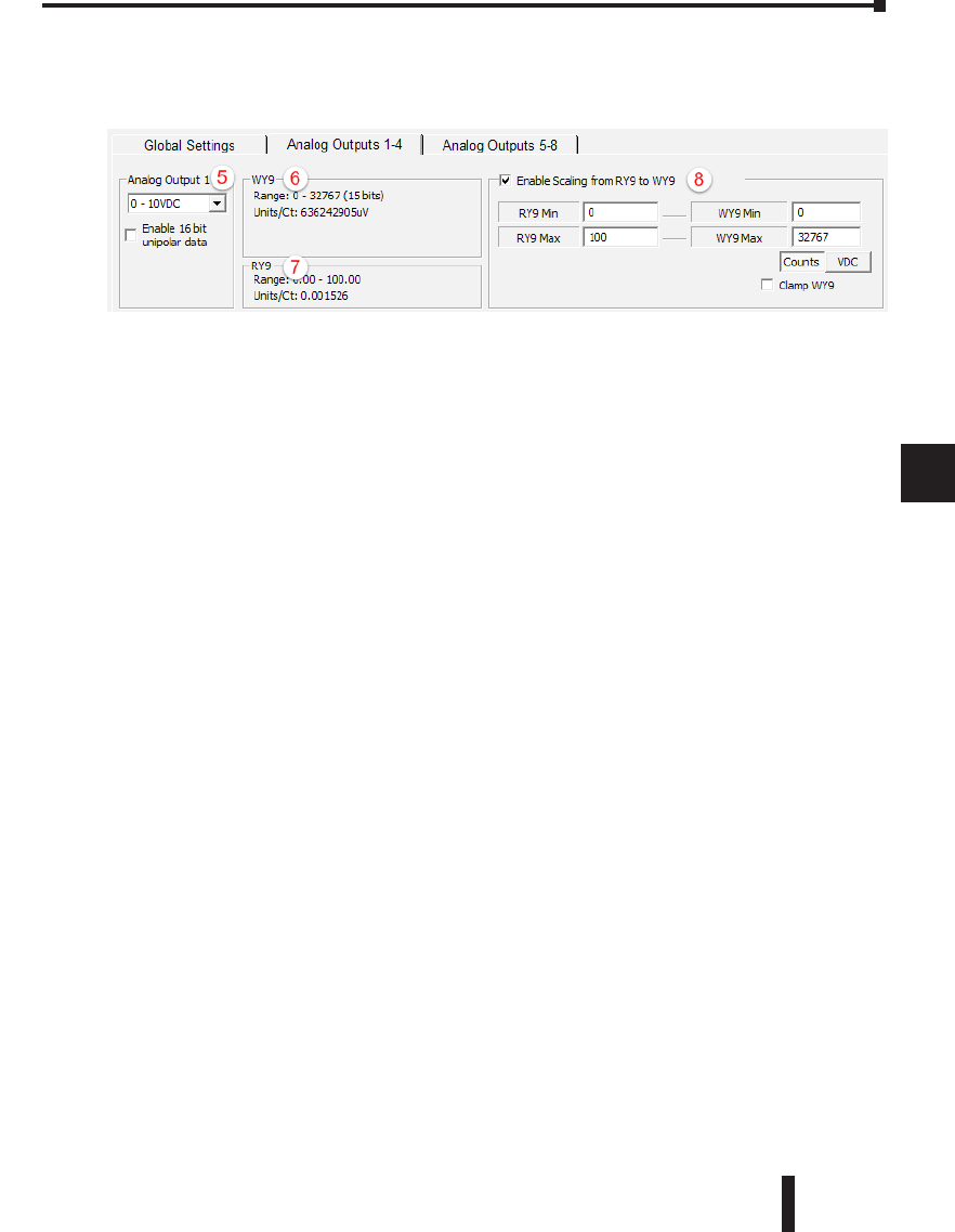
BX-08DA-2B Analog Voltage Output, continued
(5) Analog Output x
These settings are for each channel of the analog module.
Drop Down menu - Select the range of the analog output here.
Enable 16 bit unipolar data – Check this box to change the raw count range from a signed
decimal bipolar data format to an unsigned decimal data format. This may require that Casting
be used in the program in order to properly access the data. Refer to the chart of Data Range
Specifications earlier in this chapter to see if the registers must be accessed with Casting.
(6) WYx
Range – The number of Raw counts for the selected channel on the module
Units/Ct – The amount of voltage that will equal 1 raw count.
(7) RYx
Range – The engineering units to which the raw counts are scaled.
Units/Ct – The number of raw counts that will equal 1 scaled engineering unit.
(8) Enable Scaling from RYx to WYx
RYx Min – The minimum value of the engineering units for scaling.
RYx Max – The maximum value of the engineering units for scaling.
WYx Min – The minimum value of the raw counts to scale.
WYx Max – The maximum value of the raw counts to scale.
Counts/VDC – Use these buttons to change the raw scaling to counts or volts.
Clamp WYx – If this box is checked, WYx will clamp at the minimum and maximum scaled
values.

Chapter 8: BRX Analog I/O Expansion Modules
BRX User Manual, 2nd Edition
8-42
1
2
3
4
5
6
7
8
9
10
11
12
13
14
15
A
B
C
D
