CIDB 2.00.P65
User Manual: cidb
Open the PDF directly: View PDF ![]() .
.
Page Count: 2
ASUS CIDB User’s Guide 1
R
CIDB Chassis Sensor
E326
The optional ASUS CIDB is a module for providing audio alarm and logging when
there is an intrusion into the chassis of a computer system. The module detects a
chassis intrusion by either light striking its photo sensor or by contact when its switch
connectors are shorted by chassis-mounted momentary toggle switches. An intrusion
memory function allows detection by BIOS and LDCM v3.3 on the next bootup.
ACCESSORIES
Chassis Sensor
Using the ASUS CIDB
1. You must have an ASUS motherboard with a chassis connector. Motherboards
with intrusion components such as P2B-L(S), P2B-D(S), and P2B-D2 require
additional considerations (See reverse side.)
2. Connect the CIDB directly to the chassis connector or use the provided extension
cable and mount the CIDB to the chassis using a double-sided foam adhesive tape.
CAUTION! The CIDB component pins and metallic points must not come in
contact with another metallic surface or else shorting will occur!
3. Check the hardware settings:
• JP1 jumper should be enabled to use the photo sensor
• MS1 and MS2 connectors should be connected to momentary toggle switches
mounted on the chassis to use the contact method for triggering alarms.
• SW jumper should be enabled to allow the hardware monitoring compo-
nents to receive signals from the CIDB.
3. To stop the alarm from sounding, use the LDCM v3.3 software or place a jumper
on (or short manually) the CLR jumper momentarily.
4. If you have an updated BIOS with intrusion support. Booting the computer
after an intrusion will require a password which is configured through BIOS.
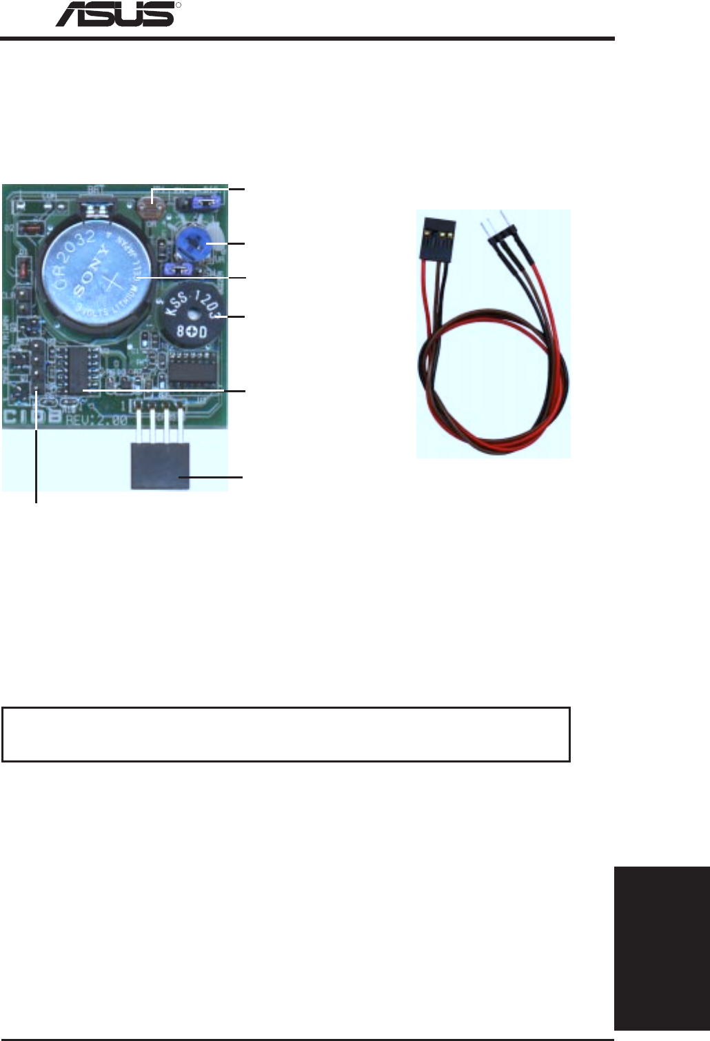
Battery for the memory
Buzzer to sound the alarm
Photo sensor to detect intrusion by light
Connector to dock with the motherboard’s chassis connector
Two switch connectors to detect intrusion by chassis
mounted micro switches
Intrusion memory
Photo sensor sensitivity adjustment
Chassis connector
extension cable
2ASUS CIDB User’s Guide
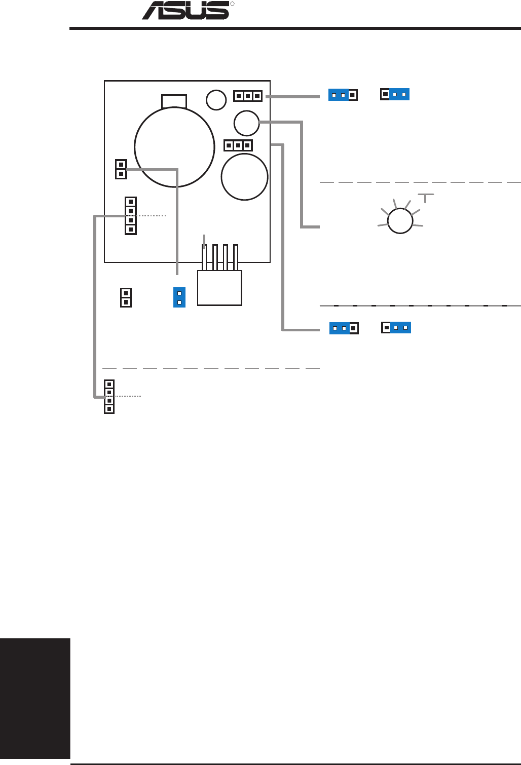
Normal Clear
Clear:
Stops the sounding alarm
CLR CLR
Enable Disable
JP1:
Enable/Disable
the Photo Sensor
JP1 JP1
11
MS1
MS2 MS1/MS2:
Micro Switch from the chassis
panel can be connected here
to trigger the chassis intrusion
alarm.
Enable Disable
SW:
Enable/Disable chassis intrusion
function in the motherboard
SW SW
11
ACCESSORIES
Chassis Sensor
R
CIDB Chassis Sensor
Setting up the ASUS CIDB
CON:
Sensitivity adjustment for the
photo sensor, (0) is least sensitive
and (5) is most sensitive
CON
1
2
3
4
50(not sensitive)
best range
(sensitive)
CR2032 3V
Lithium Cell
Buzzer
MS1
CLR
JP1
CON
OR
SW
MS2
+5 volt standy
from power supply
ASUS CIDB Additional Considerations
1. All motherboards with CIDB: If there is no power to the motheboard (i.e. re-
moving the power cord or turning the power supply’s switch off) the alarm will
not sound but the CIDB will still memorize an intrusion event which BIOS and
LDCM will detect on the next bootup.
2. Motherboard with chassis intrusion components: Photo sensor, switch, and
memory will not operate with power removed. Power is required to send a
signal to the motherboard’s intrusion memory and buzzer. When using the CIDB
on these motherboards, all the CIDB functions will be disabled, the
motherboard’s intrusion components must still be used. The CIDB can benefit
these motherboards by providing a chassis switch which will operate even when
the power is removed. Pins [2-3] of the SW jumper can be used for a momen-
tary toggle switch and the CIDB’s battery will be used to send an intrusion
signal to the motherboard’s intrusion memory.
3. The P2B-LS motherboard must use an external battery pack on the EXTBATT
connector or else neither the alarm or intrusion memory functions will work.
