Class Series Pgrman, 88 2316 01 RevC Class_series_programmers_manual_c Programmers Manual C
User Manual: class_series_programmers_manual_c datamax
Open the PDF directly: View PDF ![]() .
.
Page Count: 236 [warning: Documents this large are best viewed by clicking the View PDF Link!]
- Contents
- Overview
- Control Code Command Functions
- Immediate Command Functions
- System-Level Command Functions
- Extended System-Level Command Functions
- Label Formatting Command Functions
- Font Loading Command Functions
- Generating Label Formats
- Appendix A
- Appendix B
- Appendix C
- Appendix D
- Appendix E
- Appendix F
- Appendix G
- Appendix H
- Appendix I
- Appendix J
- Appendix K
- Appendix L
- Appendix M
- Appendix N
- Appendix O
- Appendix P
- Appendix Q
- Appendix R
- Appendix S
- Glossary

Class Series
Programmer’s Manual
Datamax International
Herbert House
12 Elizabeth Way, Pinnacles
Harlow, Essex CM19 5FE UK
Phone: +44 1279 772200
Fax: +44 1279 424448
Asia-Pacific
19 Loyang Way
#01-01 CILC Building
Singapore 508724
Phone: +65 542-2611
Fax: +65 542-3611
Corporate Headquarters
4501 Parkway Commerce Blvd.
Orlando, Fl 32808
Phone: 407-578-8007
Fax: 407-578-8377
CG Times (based upon Times New Roman), CG Triumvirate, MicroType, and TrueType are trademarks
of the AGFA Monotype Corporation.
PCL, Intellifont, and HP Laser JetII are trademarks of the Hewlett Packard Corporation.
Macintosh is a trademark of the Apple Corporation.
Windows is a trademark of the Microsoft Corporation.
All other brand and product names are trademarks, service marks, registered trademarks, or registered
service marks of their respective companies.
Information in this manual is subject to change without notice and does not represent a commitment on
the part of Datamax Corporation. No part of this manual may be reproduced or transmitted in any form or
by any means, for any purpose other than the purchaser’s personal use, without the expressed written
permission of Datamax Corporation.
© 2004 by Datamax Corporation
Part Number: 88-2316-01
Revision C

i
Contents
1 Overview
Who Should Use This Manual .......................................................................................1
Scope of this Manual.....................................................................................................1
General Conventions.....................................................................................................3
Computer Entry and Display Conventions.....................................................................3
Typical Data Flow Sequence.........................................................................................3
2 Control Code Command Functions
Introduction....................................................................................................................7
Attention-Getters ...........................................................................................................7
3 Immediate Command Functions
Introduction....................................................................................................................9
SOH # Reset ............................................................................................................9
SOH A Send ASCII Status String..............................................................................9
SOH B Toggle Pause..............................................................................................10
SOH C Stop/Cancel ................................................................................................11
SOH D SOH Shutdown ...........................................................................................11
SOH E Send Batch Quantity...................................................................................12
SOH F Send Status Byte........................................................................................12
SOH U Update System Database with Current Database ......................................12

ii
4 System Level Command Functions
Introduction..................................................................................................................13
STX A Set Time and Date......................................................................................13
STX a Enable Feedback Characters .....................................................................14
STX B Get Printer Time and Date Information .......................................................14
STX c Set Continuous Paper Length.....................................................................15
STX d Set Double Buffer Mode..............................................................................15
STX E Set Quantity For Stored Label ....................................................................16
STX e Select Edge Sensor....................................................................................16
STX F Form Feed ..................................................................................................16
STX f Set Form Stop Position (Backfeed Command) ...........................................17
STX G Print Last Label Format...............................................................................17
STX I Input Image Data ........................................................................................18
STX i Scalable Font Downloading ........................................................................19
STX J Set Pause for Each Label ...........................................................................19
STX K Extended-System Commands ....................................................................19
STX k Test RS-232 Port........................................................................................20
STX L Enter Label Formatting Command Mode....................................................20
STX M Set Maximum Label Length ........................................................................20
STX m Set Printer To Metric Mode.........................................................................20
STX n Set Printer to Imperial Mode .......................................................................21
STX O Set Start of Print (SOP) Position.................................................................21
STX o Cycle Cutter................................................................................................22

iii
STX P Set Printer to Character (HEX) Dump Mode...............................................22
STX p Controlled Pause ........................................................................................22
STX Q Clear All Modules........................................................................................22
STX q Clear Module ..............................................................................................23
STX R Ribbon Saver On/Off...................................................................................23
STX r Select Reflective Sensor.............................................................................24
STX S Set Feed Rate.............................................................................................24
STX s Set Single Buffer Mode...............................................................................24
STX T Print Dot Pattern Test Label........................................................................25
STX t Test DRAM Memory Module.......................................................................25
STX U Label Format String Replacement Field......................................................26
STX V Software Switch Settings ............................................................................27
STX v Request Firmware Version .........................................................................28
STX W Request Memory Module Information.........................................................29
STX w Test Flash Memory Module ........................................................................30
STX X Set Default Module .....................................................................................30
STX x Delete File from Module..............................................................................31
STX Y Output Sensor Values.................................................................................31
STX y Select Font Symbol Set ..............................................................................32
STX Z Print Configuration and Dot Pattern Labels.................................................32
STX z Pack Module...............................................................................................32
5 Extended System-Level Command Functions
Introduction..................................................................................................................33

iv
STX K Memory Configuration.................................................................................33
STX Kb Backfeed Time Delay..................................................................................34
STX KC Get Configuration........................................................................................35
STX Kc Configuration Set........................................................................................36
STX KD Database Configuration ..............................................................................59
STX Kd Set File as Factory Default..........................................................................60
STX KE Character Encoding ....................................................................................60
STX KF Select Factory Defaults...............................................................................61
STX Kf Set Present Distance..................................................................................62
STX Kp Module Protection.......................................................................................63
STX KQ Query Memory Configuration......................................................................64
STX Kq Query Memory Configuration......................................................................66
STX KR Reset Memory Configuration ......................................................................66
STX Kr Resettable Counter Reset...........................................................................67
STX KS Memory Configuration, Scalable Font Cache .............................................67
STX KV Verifier Enable/Disable ...............................................................................67
STX KW Memory Configuration, Printable Label Width.............................................67
STX Kx Delete Configuration File ............................................................................68
6 Label Formatting Command Functions
Introduction..................................................................................................................69
: Set Cut By Amount .....................................................................................69
A Set Format Attribute....................................................................................70
B Bar code Magnification ...............................................................................71

v
C Set Column Offset Amount .........................................................................71
c Set Cut By Amount .....................................................................................72
D Set Dot Size Width and Height ...................................................................72
E Terminate Label Formatting Mode and Print Label.....................................73
e Recall Printer Configuration........................................................................73
F Advanced Format Attributes .......................................................................73
f Set Present Speed......................................................................................74
G Place Data in Global Register.....................................................................74
H Enter Heat Setting ......................................................................................75
J Justification.................................................................................................75
M Select Mirror Mode......................................................................................76
m Set Metric Mode..........................................................................................76
n Set Inch (Imperial) Mode.............................................................................76
P Set Print Speed...........................................................................................77
p Set Backfeed Speed...................................................................................77
Q Set Quantity Of Labels To Print ..................................................................78
R Set Row Offset Amount ..............................................................................78
r Recall Stored Label Format ........................................................................79
S Set Slew Speed ..........................................................................................79
s Store Label Format In Module ....................................................................80
T Set Field Data Line Terminator...................................................................80
U Mark Previous Field as a String Replacement Field ...................................81
X Terminate Label Formatting Mode..............................................................81

vi
y Select Font Symbol Set ..............................................................................82
z Zero (Ø) Conversion to “0”..........................................................................82
+ (>) Make Last Field Entered Increment Numeric (Alphanumeric).....................83
- (<) Make Last Field Entered Decrement Numeric (Alphanumeric)...................84
^ Set Count by Amount..................................................................................85
Special Label Formatting Command Functions...........................................................85
STX S Recall Global Data And Place In Field...................................................86
STX T Print Time and Date...............................................................................86
7 Font Loading Command Functions
Introduction..................................................................................................................89
*c###D Assign Font ID Number...............................................................................89
)s###W Font Descriptor ...........................................................................................89
*c###E Character Code ..........................................................................................90
(s#W Character Download Data...........................................................................90
8 Generating Label Formats
Introduction..................................................................................................................91
Format Record Commands .........................................................................................91
Generating Records ....................................................................................................92
The Structure of a Record ...........................................................................................92
Record Structure Types...............................................................................................96
Internal Bit-Mapped Fonts.........................................................................................96
Smooth Font, Font Modules, and Downloaded Bit-Mapped Fonts............................96

vii
Scalable Fonts..........................................................................................................97
Bar Codes.................................................................................................................98
Images......................................................................................................................99
Graphics ...................................................................................................................99
Lines and Boxes....................................................................................................99
Polygons..............................................................................................................100
Circles .................................................................................................................101
Fill Patterns......................................................................................................101
Examples .........................................................................................................102
Advanced Format Attributes......................................................................................103
Appendix A
ASCII Control Chart...................................................................................................107
Appendix B
Sample Programs......................................................................................................109
VB Application to Send RAW Data via a Windows Printer Driver .............................114
Appendix C
Available Fonts – Sizes, References, and Samples ..................................................119
Appendix D
Reset Codes..............................................................................................................125
Appendix E
Single Byte Symbol Sets ...........................................................................................127

viii
Appendix F
Bar Code Summary Data ..........................................................................................137
Bar Code Default Widths and Heights.......................................................................139
Appendix G
Bar Code Details .......................................................................................................141
Appendix H
Font Mapping - Single and Double Byte Characters..................................................179
Appendix I
Symbol Sets and Character Maps.............................................................................181
Symbol Set Selection ................................................................................................181
Double-Byte Symbols, Chinese, Kanji and Korean....................................................183
Appendix J
The General Purpose Input Output (GPIO) Port........................................................185
GPIO Configuration (M-Class)...................................................................................185
GPIO-1 Configuration (I-Class, W-Class)..................................................................187
GPIO-2 Configuration (A-Class)................................................................................188
Appendix K
Resolutions, Module Identifiers, Maximum Field, Column & Character Values.........191
Appendix L
Speed Ranges...........................................................................................................193

ix
Appendix M
Commands by Function.............................................................................................195
Appendix N
Class Series DPL Constraint Cross-Reference .........................................................197
Appendix O
Image Loading...........................................................................................................203
Appendix P
UPC-A and EAN-13: Variable Price/Weight Bar Codes.............................................205
Appendix Q
International Language Print Capability Programming Examples..............................207
Appendix R
Plug and Play IDs......................................................................................................215
Appendix S
Bar Code Symbology Information Sources................................................................217
Glossary .....................................................................................................................219

x

Class Series Programmer’s Manual 1
Overview
Who Should Use This Manual
This manual is intended for programmers who wish to create their own label production software.
Operators without programming experience may prefer to use a label-creation software package. For
programming information on models not covered in this document, a copy may be downloaded from our
web site at http//www.datamaxcorp.com.
Scope of this Manual
This manual, arranged alphabetically by command, explains in detail Datamax Programming Language
(DPL) and its related uses in the writing, loading and storing of programs for the control and production
of label formats (designs) using the following Datamax printer models:
• A-Class
• E-Class (Non-Display)
• I-Class
• M-Class (Display-Equipped and Non-Display models)
• W-Class
Model distinctions, including specific printer configurations (i.e., Display-Equipped or Non-Display
Models) and / or equipment types (e.g., I-Class GPIO-1, graphics display, etc.), will be indicated in
this text to differentiate command compatibility. The appendices of this manual also contain details
that cannot be ignored. The use of any command will require checking for possible exclusionary
conditions.
þ Notes: (1) The commands in this manual apply to printer Application (firmware) Version 7.24 or greater (see
<STX>KC for more information).
(2) Programming information for the S-Class printer, as well as the Datamax legacy line of printers, can
be found in the DPL Programmer’s Manual (part number 88-2051-01). For backward compatibility
purposes, the Class Series of printers will ignore commands no longer processed; Appendix N lists these
commands.
(3) References to ‘menu settings’ refer either to the printer’s internal set-up menu, or to the printer’s
menu driven display system; please consult to the appropriate Operator’s Manual for details.

Overview
2 Class Series Programmer’s Manual
This manual contains the following chapters and appendices.
& OVERVIEW on page 1
Contents, organization, and conventions used in this manual; also includes a typical dataflow
sequence for the printer.
& CONTROL CODE COMMAND FUNCTIONS on page 7
Description of the attention-getter characters necessary for the printer to receive a command
sequence, and available alternate characters and line terminators.
& IMMEDIATE COMMAND FUNCTIONS on page 9
Description of the commands, listed alphabetically, that perform status queries and printer control
commands.
& SYSTEM-LEVEL COMMAND FUNCTIONS on page 13
Description of the commands, listed alphabetically, that control the printer and allow scalable font
and image downloads.
& EXTENDED SYSTEM-LEVEL COMMAND FUNCTIONS on page 33
Description of the commands, listed alphabetically, that control the printer.
& LABEL FORMATTING COMMAND FUNCTIONS on page 69
Description of commands, listed alphabetically, that control the position of text and images on the
media, print or store, and end the formatting process.
& FONT LOADING COMMAND FUNCTIONS on page 89
Description of commands, listed alphabetically, used when downloading font data in PCL-4
compatible bit-maps.
& GENERATING LABEL FORMATS on page 91
Description of the structure of records, the different types, and their use in generating label formats.
& APPENDICES A THROUGH S on pages 107 through 217
These contain details that cannot be ignored including various tables, programming examples,
printer default values, and bar code symbology details. See the Table of Contents for specific
content information.
& GLOSSARY on page 219
Definitions of words, abbreviations, and acronyms used in this manual.

Overview
Class Series Programmer’s Manual 3
General Conventions
These are some of the conventions followed in this manual:
• On the header of each page, the name of the chapter.
• On the footer of each page, the page number and the title of the manual.
• Names of other manuals referenced are in Italics.
• Notes are added to bring your attention to important considerations, tips or helpful suggestions.
• Boldface is also used to bring your attention to important information.
• This manual refers to IBM-PC based keyboard command characters for access to the ASCII character
set. Systems based on different formats (e.g., Apple’s Macintosh) should use the appropriate
keyboard command to access the desired ASCII character. See Appendix A for the ASCII character
set.
Computer Entry and Display Conventions
Command syntax and samples are formatted as follows:
• The Courier font in boldface indicates the DPL command syntax, and Italics are used to indicate the
command syntax parameters.
• Regular Courier font indicates sample commands, files and printer responses.
• Square brackets [ ] around something indicates that it is optional.
• <CR> is used to identify the line termination character. Other strings placed between < > in this
manual represent the character of the same ASCII name, and are single-byte hexadecimal values
(e.g., <STX>, <CR>, and <0x0D> equal 02, 0D, and 0D, respectively).
• Hexadecimal values are often displayed in ‘C’ programming language conventions (e.g., 0x02 = 02
hex, 0x41 = 41 hex, etc.)
Overview
4 Class Series Programmer’s Manual
Typical Dataflow Sequence
The typical dataflow sequence is summarized in the following bullets and detailed in the table below.
Printer Commands data is transmitted to the printer as shown in the table from left to right, top to bottom.
• Status commands
• Configuration commands
• Download commands
• Label format
• Status commands
• Label reprint commands
• Memory cleanup
Printer Commands Description Notes
<SOH>A
<STX>WG
“Status” commands: Get
Status, Request Memory
Module Storage
Information…
Optional, bidirectional
communication required
for these commands.
<STX>O220
<STX>n
<STX>V0
“Configuration”
commands, download
image…
See <STX>Kc to reduce
configuration commands
transferred
<SOH>D
<STX>
IApImagename<CR>image data...data
<CR>
“Download” commands,
image, fonts…
RAM (temporary) or
Flash (semi-permanent)
memory
<STX>L Begin label
D11 Label Header record
131100000500050Typical text field 01 Label Formatting Data
record –
Object type, orientation,
position, data
Q0001 Label Quantity
E Label Terminate record
Existing label formats
may be recalled. Label
header records are not
required
<SOH>A Status command Optional, bidirectional
communication required
for these commands.
<STX>U01new data for field 01
<STX>E0005
<STX>G
Reprint with New Data
Records Used for fast re-prints
<STX>xImagename<CR>
<STX>zA Memory cleanup Typically used for
temporary storage
Overview
Class Series Programmer’s Manual 5
Commands are available for retrieving stored label formats, updating data and adding new data. These
techniques are used for increasing throughput. See <STX>G, Label Recall Command ‘r’, and Label Save
Command ‘s’.
Typical commands used in the various stages shown above are listed in the tables that follow.
Configuration Commands
The following table lists some commands useful in controlling printer configuration. These
commands are generally effective only for the current power-up session; toggling power restores the
default configuration. See <STX>Kc for changes to the default power-up configuration. Changing the
default power-up configuration and saving objects in printer Flash memory can reduce the data
transmitted for each label and therefore improve throughput.
Configuration
Command
Name
Function
<STX>A Set Date and Time Set Date and Time
<STX>d Set Double Buffer Mode Force generation of multiple memory copies of label format;
usually not used
<STX>c Set Continuous Paper Length
Must be 0000 for gap media; not used for reflective media
<STX>e Set Edge Sensor Setup for gap or registration hole type stock
<STX>Kf Set Present Distance Determines label stop position, head relative. <STX>f edge
sensor relative equivalent command, older models
<STX>Kc Configuration Set Determines default power-up configuration
<STX>F Send Form Feed Sets the stop position of the printed label
<STX>M Set Maximum Label Length Length to search for next gap or reflective mark; not used
with continuous media
<STX>m Set to Metric Mode Subsequent measurements interpreted in metric, most units
mm/10. Label equivalent command can be used
<STX>n Set to Inch Mode Subsequent measurements interpreted in inches, most units
in/100, Label equivalent command can be used
<STX>O Set Start of Print Position Effect is not on label immediately following command since
media position is at Start of Print between labels; <STX>K
default position relative ± 64 in/100 maximum deviation
<STX>S Set Feed Rate Blank label movement speed
<STX>V Software Switch Enable optional hardware, cutter, present sensor
Overview
6 Class Series Programmer’s Manual
Download Commands
Download
Command
Name
Function
<STX>I Download Image Download Image to selected memory module
<STX>i Download Scalable Font Download Scalable Font to selected memory module
<ESC> Download Bitmapped Font Download Bitmapped Font to selected memory module
Label Header Commands
These commands determine how the label formatting occurs, effect print quality and quantity. They
are typically issued immediately following the <STX>L start of the label format. The Format
Attribute (A) and the Offset (C, R) commands can be changed at any point between format records to
achieve desired effects.
Label Header
Command
Name
A Set Format Attribute
C Column Offset
D Set Width and Dot Size
H Set Heat Setting
M Set Mirror Mode
P Set Print Speed
P Set Backup Speed
Q Set Quantity
R Set Row Offset
S Set Slew Speed
Class Series Programmer’s Manual 7
Control Code Command Functions
Introduction
The printer requires a special “attention-getter” character in order to receive a command sequence,
informing the printer that it is about to receive a command and the type of command it will be. Control
Commands, System-Level Commands, and Font Loading Commands have their own unique attention-
getter, followed by a command character that directs printer action.
Attention-Getters
The attention-getters (e.g., “SOH”) are standard ASCII control labels that represent a one character control
code (i.e., ^A or Ctrl A). Appendix A contains the entire ASCII Control Code Chart.
Attention-Getter For: ASCII Character Decimal Value HEX Value
Immediate Commands SOH 1 01
System-Level Commands
STX 2 02
Font Loading Commands
ESC 27 1B
Table 2-1: Control Code Listings
Alternate Control Code Modes
For systems unable to transmit certain control codes, Alternate Control Code Modes are available.
Configuring the printer to operate in an Alternate Control Code Mode (selected via the Setup Menu, the
<STX>Kc command or, where applicable, the <STX>KD command) requires the substitution of Standard
Control Characters with Alternate Control Characters in what otherwise is a normal data stream.
Control Character Standard Alternate Alternate 2
Custom Command Type
SOH 0x01 0x5E 0x5E User Defined Control
STX 0x02 0x7E 0x7E User Defined System
CR 0x0D 0x0D 0x7C User Defined Line Termination
ESC 0x1B 0x1B 0x1B User Defined Font Loading
“Count By” [1] 0x5E 0x40 0x40 User Defined Label Formatting
[1] See Label Formatting Commands, ^ set count by amount.
Table 2-2: Alternate Control Code Listings
þ Note: Throughout this manual <SOH>, <STX>, <CR>, <ESC>, and ^, will be used to indicate the control codes.
The actual values will depend on whether standard or alternate control codes are enabled for the
particular application.

Control Code Command Functions
8 Class Series Programmer’s Manual
Alternate Line Terminator Example
Alternate Control Codes provide for substitution of the line terminator, as well as the control characters
listed above. For example using Alternate 2, the line terminator <CR> (0x0D) is replaced by | (0x7C).
The following is a sample label format data stream for a printer configured for Alternate-2 Control Codes:
~L|1911A10001000101234560|X|~UT01ABCDE|~G|

Class Series Programmer’s Manual 9
Immediate Command Functions
Introduction
When the printer receives an Immediate Command, its current operation will be momentarily interrupted
to respond to the command. Immediate Commands may be issued before or after System-Level
commands; however, they may not be issued among Label Formatting Commands or during font or
image downloading. Immediate Commands consist of:
1. Attention-Getter, 0x01 or 0x5E, see Control Codes.
2. Command Character
SOH # Reset
This command resets the printer. Resetting the printer returns all settings to default and clears both
the communications and printing buffers. The command also clears DRAM memory.
Syntax: <SOH>#
Printer Response: The printer will reset.
<XON> T (The T may come before the <XON>)
SOH * Reset
(Display-Equipped Models only)
This command forces a soft reset of the microprocessor, which resets the printer. Resetting the printer
returns all settings to default and clears the communications and print buffers.
Syntax: <SOH>*
Printer Response: The printer will reset.
<XON> T (The T may come before the <XON>)
Immediate Command Functions
10 Class Series Programmer’s Manual
SOH A Send ASCII Status String
This command allows the host computer to check the current printer status. The printer returns a
string of eight characters, followed by a carriage return. Each character (see below) indicates an
associated condition, either true (Y) or false (N). Byte 1 is transmitted first. See <SOH>F.
Syntax: <SOH>A
Sample: <SOH>A
Printer Response: abcdefgh<CR>
Where:
Possible Values Interpretation Byte Transmit Sequence
a -
Y/N Y = Interpreter busy (Imaging) 1
b -
Y/N Y = Paper out or fault 2
c -
Y/N Y = Ribbon out or fault 3
d -
Y/N Y = Printing batch 4
e -
Y/N Y = Busy printing 5
f -
Y/N Y = Printer paused 6
g -
Y/N Y = Label presented 7
h -
N Always No 8
Table 3-1: ASCII Status Bytes
SOH B Toggle Pause
This command toggles the printer’s paused state between on and off. (This is the same function
achieved by pressing the PAUSE Key on the printer.)
Syntax: <SOH>B
Sample: <SOH>B
Printer Response: This command will illuminate the Paused/Stop Indicator and/or indicate
PAUSED on the LCD or graphics display panel, suspend printing, and wait
until one of the following occurs:
Ø The <SOH>B command is sent to the printer.
Ø The PAUSE Key is pressed.
Upon which the printer will turn the Paused/Stop Indicator ‘Off’ and/or
remove PAUSED from the LCD or graphics display panel, then resume
operation from the point of interruption. (If the Receive Buffer is not full,
an <XON> character will be transmitted from the printer.)

Immediate Command Functions
Class Series Programmer’s Manual 11
SOH C Stop/Cancel
This command performs the same function as pressing the STOP/CANCEL Key on the printer. This
function clears the current label format from the print buffer, pauses the printer, and illuminates the
Paused/Stop Indicator. (The pause condition is terminated as described under <SOH>B.)
Syntax: <SOH>C
Sample: <SOH>C
Printer Response: This command will clear the print buffer, pause the printer, illuminate the
Paused/Stop Indicator and/or indicate PAUSED on the LCD or graphics
display panel, suspend printing, and wait until one of the following occurs:
Ø The <SOH>B command is sent to the printer.
Ø The PAUSE Key is pressed.
Upon which the printer will turn the Paused/Stop Indicator ‘Off’ and/or
remove PAUSED from the LCD or graphics display panel. (If the Receive
Buffer is not full, an <XON> character will be transmitted from the printer.)
SOH D SOH Shutdown
(Non-Display Models only)
This commands the printer to ignore Immediate Commands (^A). The SOH shutdown command is
required before loading images or fonts because some may contain data sequences that could be
interpreted as Immediate Commands. After the SOH shutdown command is sent, Immediate
Commands can be turned back on by sending a valid SOH command three times, separated by a one
second delay between each command, or by manually resetting the printer. It is good practice to
check batch quantities (<SOH>E) to verify that the SOH commands are working.
Syntax: <SOH>D
Sample: <SOH>D
Printer Response: This printer will ignore Immediate Commands (^A) until a valid SOH
command is received three times, separated by a one second delay between
each command; or, until the printer is manually reset.
Immediate Command Functions
12 Class Series Programmer’s Manual
SOH E Send Batch Quantity
This command causes the printer to send back a four-digit number indicating the quantity of labels
that remain to be printed in the current batch, followed by a carriage return. Communications latency
may cause this value to be higher than actual on some printers.
Syntax: <SOH>E
Printer response: nnnn<CR>
Where: nnnn - Is four decimal digits, 0-9999.
SOH F Send Status Byte
This command instructs the printer to send a single status byte where each bit (1 or 0) represents one
of the printer’s status flags, followed by a carriage return (see below). If an option is unavailable for
the printer, the single bit will always be 0. See <SOH>A.
Syntax: <SOH>F
Printer response format: X<CR>
Where ‘X’ is 0 through 0xef with bits as indicated in the ‘Condition’ column below:
Bit[1] Value Condition
8 0 Always zero
7 1 or 0 Label presented
6 1 or 0 Printer paused
5 1 or 0 Busy printing
4 1 or 0 Printing batch
3 1 or 0 Ribbon out or Fault
2 1 or 0 Paper out or Fault
1 1 or 0 Command interpreter busy (Imaging)
[1] Bit one is the least significant bit.
SOH U Update System Database with Current Database
This command saves the current printer configuration to Flash memory. Only those parameters stored
in Flash memory are affected. These are all the parameters that can be modified via the Setup Menu.
The values of any <STX> System Commands issued prior to <SOH>U and affecting printer
configuration items will also be saved. See the <SOH># command, above, for details on what events
occur during a reset.
Syntax: <SOH>U
Printer response: The printer will reset.
<XON>T (The T may come before the <XON>).
Class Series Programmer’s Manual 13
System-Level Command Functions
Introduction
The most commonly used commands are the System-Level Commands. These are used to load and store
graphic information, in addition to printer control. System-Level Commands are used to override default
parameter values (fixed and selectable) and may be used before or after Immediate Commands but cannot
be issued among Label Formatting Commands. System-Level Commands consist of:
1. Attention-Getter, 0x02 or 0x7E, see Control Codes.
2. Command Character
3. Parameters (if any).
STX A Set Time and Date
This command sets the time and date. The initial setting of the date will be stored in the printer’s
internal inch counter. This date can be verified by printing a Configuration Label.
Syntax: <STX>AwmmddyyyyhhMMjjj
Where:
w 1 digit for day of week; 1 = Monday; 7 = Sunday
mm 2 digits for month
dd 2 digits for day
yyyy 4 digits for year
hh 2 digits for hour in 24 hour format
MM 2 digits for minutes
jjj 3 digits for Julian date (numerical day of the year) / constant; see notes below
Sample: <STX>A1020319960855034
Printed response: Mon. Feb 3, 1996, 8:55AM, 034
þ Notes: (1) When set to 000, the Julian date is automatically calculated; otherwise, the Julian date will print
as that entered number, without daily increments. If factory defaults are restored the actual Julian
date will also be restored.
(2) Printers without the Real Time Clock option lose the set time/date when power is removed.
(3) Response format is variable; see the Special Label Formatting Command <STX>T.
System-Level Command Functions
14 Class Series Programmer’s Manual
STX a Enable Feedback Characters
This command enables the feedback ASCII hex characters to be returned from the printer following
specific events after each completed batch of labels when using serial communications. The default
value is ‘Off’.
Syntax: <STX>a
Printer response: Event dependent. (Also, see Appendix D for error codes.)
Where:
Event Return Characters
Invalid character 0x07 ( BEL )
Label printed 0x1E ( RS )
End of batch 0x1F ( US )
STX B Get Printer Time and Date Information
This command instructs the printer to retrieve its internal time and date information.
Syntax: <STX>B
Sample: <STX>B
Printer response format: wmmddyyyyhhMMjjj<CR>
Where:
w 1 digit for day of week; 1 = Monday
mm 2 digits for month
dd 2 digits for day
yyyy 4 digits for year
hh 2 digits for hour in 24 hour format
MM 2 digits for minutes
jjj 3 digits for Julian date / constant*
* See <STX>A for details and restrictions.
Printer response sample:
1020319960855034<CR>
System-Level Command Functions
Class Series Programmer’s Manual 15
STX c Set Continuous Paper Length
This command sets the label size for applications using continuous media. It disables the top-of-form
function performed by the Media Sensor. The sensor, however, continues to monitor paper-out
conditions. See <STX>M.
Syntax: <STX>cnnnn
Where: nnnn
- Specifies the length of the media feed for each label format, in
inches/100 or millimeters/10 (see <STX>m).
Sample: <STX>c0100
This sample sets a label length of 100, which equals 1.00 inch (assuming Imperial Mode is selected).
þ Note: This command must be reset to zero for edge or reflective sensing operation.
STX d Set Double Buffer Mode
(Non-Display Models only)
This command, available for backward compatibility, enables double buffer mode. When printing
labels with incrementing, decrementing and replacement fields (see note below) the printer will only
erase and format those fields, leaving the rest of the label format untouched, and thus increasing
throughput. This command is only active if the labels being printed are less than half the maximum
size of the print buffer (see <STX>S).
Syntax: <STX>d
þ Note: This command is generally not used because fast formatting is the normal operating mode when the
number of variable print fields (Label Formatting commands +, -, <, >, u) is less than or equal to 1/3
of the total print field count. In this case the command will force fast formatting even when the
proportion of variable print fields is greater than 1/3 the total. The maximum label size is unaffected
by this command. The <STX>s command restores normal (fast) formatting.
System-Level Command Functions
16 Class Series Programmer’s Manual
STX E Set Quantity For Stored Label
This command sets a number of labels for printing using the format currently in the print buffer. (The
printer automatically stores the most recent format received in the buffer until the printer is reset or
power is removed.) When used in conjunction with the <STX>G command, this will print the labels.
Syntax: <STX>Ennnn
Where: nnnn
- A four-digit quantity, including leading zeros.
Sample: <STX>E0025
<STX>G
Printer response: 25 labels of the current format in memory will be printed.
þ Note: This command may be issued prior to a label format without a specified quantity, Qnnnnn. Also, if a
<CR> terminates the command, a five-digit quantity (nnnnn) can be entered.
STX e Select Edge Sensor
This command enables transmissive (see-through) sensing for top-of-form detection of die-cut, and
holed (or notched) media. This Media Sensor will detect a minimum gap of 0.1 inches (2.5 mm)
between labels (see the Operator’s Manual for media requirements). Use the <STX>O command to
adjust the print position. This is the printer default setting at power-up or reset.
Syntax: <STX>e
þ Note: This command is ignored when <STX>cnnnn is issued with a non-zero value for nnnn.
STX F Form Feed
This commands the printer to form feed to the next start of print.
Syntax: <STX>F
Printer response: The printer will form feed.
þ Note: Following a reset, if the length of the first label fed is less than the label offset value (defined by the
<STX>O command) the printer will advance past that label until a top-of-form is detected, or until the
offset is reached.

System-Level Command Functions
Class Series Programmer’s Manual 17
STX f Set Form Stop Position (Backfeed Command)
This sets the stop position of the printed label, allowing the label to stop at a point past the start-of-
print position. When the next label format is sent, the printer motor reverses direction to retract the
media to the start-of-print position. If quantities of more than one label are requested, the printer will
operate without backfeeding. A backfeed will then only occur when printing has stopped for a few
seconds.
Non-Display models: The printer must be set to ‘Host’ (via the menu) for this command to have
effect.
Display-equipped printers: SOP Emulation may be selected and enabled via the menu – if the SOP
Emulation is set to ‘Disabled’, this command is ignored.
Syntax: <STX>fnnn
Where: nnn - Is a three-digit distance from the Media Sensor, in inches/100 or
mm/10. This distance is independent of the start-of-print position
(<STX>O), yet it must be greater than the start-of-print position to
take effect.
Sample: <STX>f230
The sample sets a stop position distance of 230 (2.3 inches from the Media Sensor’s eye).
STX G Print Last Label Format
This command prints a previously formatted label and restarts a canceled batch job following the last
processed label. This is used when there is a label format in the buffer. The <STX>E command is
used to enter the quantity. (If the <STX>E command is not used only one label will print.)
Syntax: <STX>G

System-Level Command Functions
18 Class Series Programmer’s Manual
STX I Input Image Data
This command must precede image downloading from a host computer to the printer. The data that
immediately follows the command string will be image data. If any of the 8-bit input formats are to
be used, it is necessary to disable the Immediate Command interpreter by executing an <SOH>D
command before issuing the <STX>I command. See Appendix O for more information. To print an
image, see Generating Label Formats.
A-Class printers: A “ready mode” logo for the graphics display can input using this command. The
image must be stored on a Flash Module. The image name must be “LOGOLAB” in the following
DPL command. The available display area is 312 pixels wide by 94 pixels high. Images larger than
this specified width or height will be clipped on the right and/or bottom edges.
þ Note: The native format for storing downloaded PCX and BMP images is RLE-2. The result is a better
compression ratio and therefore the use of less module space for downloaded gray-scale images
and for images with very large areas of either black or white.
Syntax: <STX>Iabfnn…n<CR>data
Where: a - Memory Module Bank Select (see Appendix K).
b - Data Type (optional), A or omit.
b Value: Image Data Value Range:
A ASCII Characters 0-9, A-F, (7 bit)
omitted
00-FF, (8 bit)
f - Format Designator
f Designator:
Format Type:
F 7-bit Datamax image load file
B .BMP 8-bit format (image flipped), black and
white (B&W)
b .BMP 8-bit format (image as received), B&W
I .IMG 8-bit format (image flipped), B&W
i .IMG 8-bit format (image as received), B&W
P .PCX 8-bit format (image flipped), B&W
p .PCX 8-bit format (image as received), B&W
nn…n
- Up to 16 characters used as an image name.
<CR>
- 0x0d terminates the name.
data
- Image data
Sample: <SOH>D
<STX>IDpTest <CR>
data...data <CR>
The sample instructs the printer to (1) receive an 8-bit PCX image sent by the host in an 8-bit data
format, (2) name the image ‘Test’, and (3) store it in memory module D.

System-Level Command Functions
Class Series Programmer’s Manual 19
STX i Scalable Font Downloading
The command structure for downloading TrueType (.TTF) scalable fonts (font files may be single-
byte or double-byte character systems) is as follows:
Syntax: <STX>imtnnName<CR>xx…xdata…
Where: m - Memory Module Designator to save this font to; see Appendix K.
t - Type of scalable font being downloaded:
T = TrueType
nn - Two-digit font reference ID. Valid range is 50-99, 9A-9Z, 9a-9z,
(base 62 numbers).
Name
- The title, up to 16 characters, for this font.
<CR>
- 0x0d terminates the Name.
xx…x
- Eight-digit size of the font data, number of bytes, hexadecimal,
padded with leading zeros.
data
- The scalable font data.
Sample: <STX>iDT52Tree Frog<CR>000087C2data...
This sample downloads a TrueType font to module ‘D’ and assigns it the Font ID of 52 with the
name “Tree Frog”. The size of the font data is 0x87C2 bytes long.
STX J Set Pause for Each Label
This command causes the printer to pause after printing each label. It is intended for use with the peel
mechanism or tear bar when the Present Sensor option is not installed. After removing the printed
label, the PAUSE Key must be pushed in order to print the next label. (The printer must be reset to
clear the <STX>J command.)
Syntax: <STX>J
STX K Extended-System Commands
This expands the System-Level Commands. See the Extended-System Commands for more
information.

System-Level Command Functions
20 Class Series Programmer’s Manual
STX k Test RS-232 Port
This command instructs the printer to transmit the Y character from the printer’s RS-232 port.
(Failure to receive Y could indicate an interfacing problem.)
Syntax: <STX>k
Printer response: Y
STX L Enter Label Formatting Command Mode
This command switches the printer to the Label Formatting Command Mode. Once in this mode, the
printer expects to receive Record Structures and Label Formatting Commands. Immediate, System-
Level, and Font Loading commands will be ignored until the label formatting mode is terminated
with E, s, or X, (see Label Formatting Commands for additional information).
Syntax: <STX>L
STX M Set Maximum Label Length
This command instructs the printer move media this distance in search of the top-of-form (label edge,
notch, black mark, etc.) before declaring a paper fault. A paper fault condition can occur if this setting
is too close (within 0.1 inch [2.54 mm]) to the physical length of the label. Therefore, it is a good
practice to set this command to 2.5 to 3 times the actual label length used. The minimum value should
be at least 5” (127 mm).
Syntax: <STX>Mnnnn
Where: nnnn
- Is a four-digit length, 0000-9999, in/100 or mm/10. Maximum
setting is 9999 (99.99 inches or 2540 mm). The default setting is
16 inches/ 406.4 mm
Sample: <STX>M0500
The sample sets a maximum travel distance of 5 inches (unless the printer is in metric mode, see
<STX>m).
STX m Set Printer To Metric Mode
This command sets the printer to interpret measurements as metric values (e.g., <STX>c0100 will
equal 10.0 mm). The default is Imperial (see <STX>n).
Syntax: <STX>m

System-Level Command Functions
Class Series Programmer’s Manual 21
STX n Set Printer to Imperial Mode
This command sets the printer to interpret measurements as inch values (e.g., <STX>c0100 will
equal 1.00 inch). The printer defaults to this mode.
Syntax: <STX>n
STX O Set Start of Print (SOP) Position
This command sets the point to begin printing relative to the top-of-form (the label’s edge as detected
by the Media Sensor). The printer will feed from the top-of-form to the value specified in this
command to begin printing.
This value operates independently of the <STX>f command.
Non-Display models: The printer must be set to ‘Host’ (via the menu) for this command to have
effect.
Display-equipped models: If SOP Emulation is set to ‘Enabled’ (via the menu) – this command sets
the point where printing starts, emulating the selected legacy printer’s distance, as measured between
the media sensor and the printhead burn line. In addition, regardless of the SOP Emulation setting the
start of print position can be fine-tuned via the menu: Menu Mode / Print Control / Custom
Adjustments / Row Adjust.
Syntax: <STX>Onnnn
Where: nnnn
- Is a four-digit offset value in inches/100 or mm/10. The
“zero” setting is the default value, and settings below 50 are
adjusted back to the default value.
Non-display models: the default setting is 0220 in Imperial
Mode (0559 in Metric Mode).
Display-equipped models: the default setting is ‘Off’ and
the printer assumes the natural start of print position.
Sample (non-display
models):
<STX>O0300
The above sample sets a start of print position of 3.0 inches (unless in Metric Mode, see <STX>m).
Sample (display-
equipped models):
<STX>O0210
The above sample will begin printing 0.1 inch closer to the leading edge of the label if the 220
(Allegro) SOP Emulation was selected, or 1.0 inch farther away from the leading edge if 110
(ProdPlus) SOP Emulation was selected.

System-Level Command Functions
22 Class Series Programmer’s Manual
STX o Cycle Cutter
This command will cause the optional cutter mechanism to immediately perform a cut after all
previously received commands are executed. The cutter must be installed, enabled and the
interlock(s) closed for operation.
Syntax: <STX>o
STX P Set Printer to Character (HEX) Dump Mode
This command instructs the printer to assume Character Hex Dump Mode (also known as ASCII
dump or monitor mode). Data sent to the printer following this command will be printed in raw
ASCII format. To capture this data, labels must be at least four inches (102 mm) long and as wide as
the maximum print width. This command has the same effect as turning the printer ‘On’ while
pressing the FEED Key; however, no Configuration/Test Pattern label will be printed. To return to
normal operation the printer must be manually reset.
Syntax: <STX>P
STX p Controlled Pause
The controlled pause command will cause the printer to pause only after all previously received
commands are executed. This is often useful between label batches. (This command will not clear the
pause condition, see <SOH>B).
Syntax: <STX>p
STX Q Clear All Modules
This command instructs the printer to clear all of the Flash and DRAM modules (see the Operator’s
Manual of the corresponding printer for applicable module options). All stored data will be
destroyed.
Syntax: <STX>Q
System-Level Command Functions
Class Series Programmer’s Manual 23
STX q Clear Module
This command clears the selected Flash or DRAM module. If a module is corrupted during normal
operations (identifiable when the printer responds with a ‘No Modules Available’ message to a
<STX>W command), it must be cleared. All stored data will be destroyed.
Syntax: <STX>qa
Where:
a - Memory module designator, see Appendix K.
Sample: <STX>qA
The sample clears memory module A.
þ Notes: (1) If a module directory intermittently returns the message ‘No Modules Available’ or if data
continuously becomes corrupt with the write protect switch on, the module may be at the end of its
service. However, before concluding that a module is defective, cycle the printer’s power and test
the module.
(2) E-Class models: Some Flash Memory Expansion options must have Write Enable jumpers
installed to perform this command.
STX R Ribbon Saver On/Off
(Display-Equipped Models only)
This command enables the operation of the optional Ribbon Saver. It is the only command used to
control the Ribbon Saver. Its operation is continuous when enabled. The printer must be set to
thermal transfer (ribbon) printing mode then, during operation, the Ribbon Saver engages
automatically, lifting when the minimum amount of label white space is exceeded.
Syntax: <STX>Rx
Where:
x - Y - Enabled (Default = Menu selection.)
N - Disabled
Sample: <STX>RY
The sample will turn the ribbon saver on.
þ Note: This command is ignored on units not equipped with the ribbon saver option.

System-Level Command Functions
24 Class Series Programmer’s Manual
STX r Select Reflective Sensor
This command enables reflective (black mark) sensing for top-of-form detection of rolled butt-cut,
and fan-fold or tag stocks with reflective marks on the underside. This Media Sensor will detect a
minimum mark of 0.1 inches (2.54 mm) between labels (see the Operator’s Manual for media
requirements). The end of the black mark determines the top of form. Use the <STX>O command to
adjust the print position.
Syntax: <STX>r
Default setting: Edge sensing
STX S Set Feed Rate
This command controls the output rate of the media when the FEED Key is pressed.
Syntax: <STX>Sn
Where: n - Is a letter value (see Appendix L).
STX s Set Single Buffer Mode
(Non-Display Models only)
This command, available for backward compatibility, instructs the printer to use single buffer
operation. In single buffer mode, the printer will erase and format all fields. This, in turn, decreases
printer throughput when incremental, decremental, or replacement fields are used (see Label
Formatting Commands). See <STX>d.
Syntax: <STX>s
System-Level Command Functions
Class Series Programmer’s Manual 25
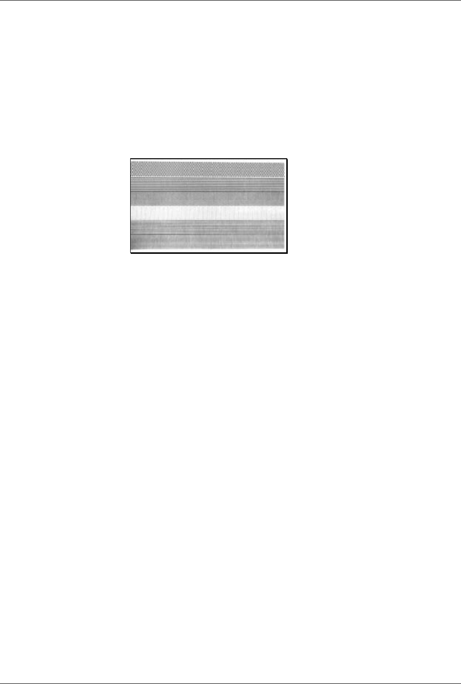
STX T Print Dot Pattern Test Label
This command instructs the printer to produce a Dot Pattern Label, a label comprised of different
patterns that exercise the printhead. This is the same test label printed when powering on the printer
while pressing the FEED Key, except that the printer will not produce a Configuration Label or enter
the Hex Dump Mode. (On display-equipped models, it can also be generated as a Quick Test Label.)
To view the full dot pattern use media at least 2 inches (51 mm) long and as wide as the maximum
print width.
Syntax: <STX>T
Printer response (dots
patterns may vary):
STX t Test DRAM Memory Module
This command tests the DRAM module. The printer returns a one-line message stating the module
condition (no message is returned if a module is unavailable).
Syntax: <STX>t
results -
Test results given as ‘Good’ or ‘Bad’.
Non-display models: The printer must be in Test Mode for the command to function. To enable the
Test Mode see the <STX>KD command.
Printer response format: axxxK results<CR>
Where: a -
2 = Slot B
xxx -
Module size in Kbytes
Display-equipped models: The printer must have Feedback Characters enabled for this command to
function. Feedback Characters can be enabled via the menu (see the Operator’s Manual for additional
information).
Printer response format: Module A: xxxxK DRAM Tested results<CR>
Module B: xxxxK DRAM Tested results<CR>
Module D: xxxxK DRAM Tested results<CR>
Where: xxxx -
Module size in Kbytes.

System-Level Command Functions
26 Class Series Programmer’s Manual
STX U Label Format String Replacement Field
This command places new label data into format fields to build a label. Two options are available:
Exact Length and Truncated Length.
To easily keep track of fields, place all of the fields to be updated with the command at the beginning
of the label format. A maximum of 99 format fields can be updated. Fields are numbered
consecutively 01 to 99 in the order received.
Exact Length Replacement Field Functions – The new data string must equal the original string
length and contain valid data. When the dynamic data is shorter than the length of the originally
defined data field, then field will be padded with blanks (or zero when the Format Record header
specifies a numeric bar code).
Syntax: <STX>Unnss…s<CR>
Where: nn - Is the format field number, 2 digits.
ss…s
- Is the new string data, followed by a <CR>
Exact Length Sample:
<STX>L
1A1100001000100DATA FIELD 1<CR>
161100001100110data field 2<CR>
161100001200120data field 3<CR>
Q0001
E
<STX>U01123<CR>
<STX>U02New data F2<CR>
<STX>E0002
<STX>G
The sample produces three labels. The first is formatted with the commands between <STX>L and E.
The next two labels print with the replacement data contained in the <STX>U commands (see
<STX>E and <STX>G). The barcode is the same length: 3 digits and nine spaces.
Truncated Length Replacement Field Functions – A variant of the <STX>U command includes the
truncate option ‘T’, where dynamic data shorter than the originally defined field length will not be
padded, and the original maximum field length is maintained for subsequent replacements.
Syntax: <STX>UTnnss…s<CR>
Where: nn - Is the format field number, 2 digits.
T - Truncate option
ss…s
- Is the new string data, followed by a <CR>
System-Level Command Functions
Class Series Programmer’s Manual 27
Truncated Sample: <STX>L
1A1100001000100data field 1<CR>
161100001100110data field 2<CR>
161100001200120data field 3<CR>
Q0001
E
<STX>UT01123<CR>
<STX>U02New data F2<CR>
<STX>E0002
<STX>G
The sample produces three labels. The first is formatted with the commands between <STX>L and E.
The next two labels print with the replacement data contained in the <STX>U commands (see
<STX>E and <STX>G). The barcode is shortened; it only has three digits (and no spaces).
STX V Software Switch Settings
This command controls the printer options, where the appropriate value allows the option(s) to be
‘On’ or ‘Off.’ Each option has a corresponding bit whose value is ‘1’ when enabled. The tables below
indicate the bit assignments and corresponding command value needed to enable the desired
option(s).
Display-equipped models: printer options are set by entering selections through the menu. The
software setting command allows two of these option settings to be modified without returning to the
menu.
Syntax: <STX>Vn
Where: n - Is a single digit ASCII numeric value from 0-F. The value of
n is used to override the power-up option settings. Reset or
power-up returns the printer to the original settings.
Sample: <STX>V5
The sample corresponds to setting Bits 0 and 2, creating a command value of 5. When applied, this
enables the Present Sensor and Cutter options.
Bit Assignment Printer Option
0 Cutter
1 N/A
2 Present Sensor
3 N/A
Table 4-1: Software Switch Bit Assignment
Use the bit assignment table above to determine the command value n in the binary table below (e.g.,
the command value 5 sets the bits 0 and 2 to ‘1’).
System-Level Command Functions
28 Class Series Programmer’s Manual
Command Values for Bits Assigned
Bit
n Value 3 2 1 0
0 0 0 0 0
1 0 0 0 1
4 0 1 0 0
5 0 1 0 1
Table 4-2: Software Switch Binary
STX v Request Firmware Version
This command causes the printer to send its version string (this data is the same as that printed on the
configuration label). The version may be different from printer to printer.
Syntax: <STX>v
Printer Response: VER: 4308 – 06.06 07/09/2001 <CR>
System-Level Command Functions
Class Series Programmer’s Manual 29
STX W Request Memory Module Information
This command requests a directory listing for memory module(s). Although a module can store font,
graphics and format data together, it can display only one type of information at a time. If the module
contains all three types of data, it will be necessary to check the directory three times, using each of
the control parameters, F, G, and L, to determine the contents. When no user accessible modules are
present, there is no printer response to <STX>WF, <STX>WG, or <STX>WL.
Syntax: <STX>Wa
Where: a - Data type:
F
G
L
f
=
=
=
=
Downloaded Font
Graphic (Image)
Label
All fonts (respective of the resident fonts available and any
fonts that have been downloaded).
Sample: <STX>Wf
Printer response (using
an E-Class printer):
Meaning:
MODULE: A<CR> Module ID ‘A’, fonts following reside in this module
103 CG Triumv <CR>
Downloaded font ID and name
MODULE: F<CR> Module ID ‘F’ (no user access), fonts following reside in this
module
000 <CR> Font internal ID 000, resident bitmapped font DPL ID 0
001 <CR> Font internal ID 001, resident bitmapped font DPL ID 1
002 <CR> Font internal ID 002, resident bitmapped font DPL ID 2
003 <CR> Font internal ID 003, resident bitmapped font DPL ID 3
004 <CR> Font internal ID 004, resident bitmapped font DPL ID 4
005 <CR> Font internal ID 005, resident bitmapped font DPL ID 5
006 <CR> Font internal ID 006, resident bitmapped font DPL ID 6
007 <CR> Font internal ID 007, resident bitmapped font DPL ID 7
008 <CR> Font internal ID 008, resident bitmapped font DPL ID 8
012 <CR> Font internal ID 012, resident bitmapped font DPL ID 9, A06
013 <CR> Font internal ID 013, resident bitmapped font DPL ID 9, A08
014 <CR> Font internal ID 014, resident bitmapped font DPL ID 9, A16
015 <CR> Font internal ID 015, resident bitmapped font DPL ID 9, A12
016 <CR> Font internal ID 016, resident bitmapped font DPL ID 9, A14
017 <CR> Font internal ID 017, resident bitmapped font DPL ID 9, A18
018 <CR> Font internal ID 018, resident bitmapped font DPL ID 9, A24
019 <CR> Font internal ID 019, resident bitmapped font DPL ID 9, A30
020 <CR> Font internal ID 020, resident bitmapped font DPL ID 9, A36
System-Level Command Functions
30 Class Series Programmer’s Manual
STX w Test Flash Memory Module
This command tests the Flash memory module. The time for each test will vary from 20 to 120
seconds, depending upon the size of the module. All stored data will be destroyed. If no module is
present, there will be no printer response.
Syntax: <STX>wa
Where: a - Module designator; see Appendix K.
Printer response format: Module A: xxxxK results
Where: A - Module tested.
xxxx
- Module size in kilobytes.
results
- Test results given as ‘Good’ or ‘Bad’.
þ Note: E-Class models: Some Flash Memory Expansion options must have Write Enable jumpers installed
to perform this command.
STX X Set Default Module
This command, typically used prior to the loading of PCL-4 bit-mapped fonts (see Font Loading
Commands), is designed to allow the user to select between modules when downloading information.
The default module is one of the following:
1. The first alpha designator of the existing modules if item 2 has not occurred.
2. The module selected by this command.
Syntax: <STX>Xa
Where: a - Module designator; See Appendix K.
Sample: <STX>XB
The sample sets ‘B’ as the default module.

System-Level Command Functions
Class Series Programmer’s Manual 31
STX x Delete File from Module
This command removes a specific file from the specified module. The file name is removed from the
module directory and thus the file cannot be accessed. The actual storage space occupied by the file is
not released. To reclaim deleted file storage space use <STX>z.
Syntax: <STX>xmtnn…n<CR>
Where: m - Module designator; see Appendix K.
t - The file type identification code:
G
L
F
S
=
=
=
=
Image file
Label format file
Bit-Mapped font file
Smooth scalable font file
nn…n
- The file name to delete, up to sixteen alphanumeric characters for
graphic or label format files, 3 for bit-mapped font files, and 2 for
smooth scalable font files.
STX Y Output Sensor Values
This command causes the printer to respond with the sensor value status. When <STX>Y is received,
the printer will respond with the digitally converted values of its internal analog sensors (see below).
To repeat the display of values, send the printer a ‘SPACE’ (20 hexadecimal). Send <ESC> to
terminate this function.
Non-display models: The printer must be in Test Mode for the command to function. To enable the
Test Mode see the <STX>KD command.
Display-equipped models: The printer must have Feedback Characters enabled for this command to
function. Feedback Characters can be enabled via the menu (see the Operator’s Manual for additional
information).
Syntax: <STX>Y
Printer response:
Thermistor ADC: 0048 Reflective ADC: 0000
Transmissive ADC: 0204 Paperout ADC: 0000 24 Volt ADC:
0217 Contrast ADC: 0093 TOF Adjust ADC: 0170 Ribbon
ADC: 0125 Battery Level: Good <CR>
Where: Paperout ADC: 0225 indicates paper is present;
0000 indicates paper is not present.
Battery level: Good indicates the battery has sufficient charge;
Low indicates the battery is insufficiently charged.
þ Notes: Equipped sensors vary with printer, model, and options. In addition, some readings require printer-
controlled paper movement to indicate a meaningful value.
System-Level Command Functions
32 Class Series Programmer’s Manual
STX y Select Font Symbol Set
This command selects the scalable font symbol set. The selected symbol set remains active until
another symbol set is selected. See the <STX>KS command and Appendices E, I, and H for more
information. Option dependant. Not all symbol sets can be used with all fonts.
Syntax: <STX>ySxx
Where: S - Byte-size designation; see Appendix H:
S = Single byte symbol sets.
U = Double byte symbol sets.
xx - Symbol set selection.
Sample: <STX>ySPM
The sample selects the PC-850 multilingual set.
STX Z Print Configuration and Dot Pattern Labels
This command prints Configuration and Dot Pattern Labels. The results are similar to performing the
power-up self-test, but the printer does not enter Hex Dump Mode. To capture all printed information,
use the labels as wide as the maximum print width and at least 4 inches (102 mm) long.
Syntax: <STX>Z
Printer response:
FRI SEPTEMBER 026, 1997 19:29 244
VER: E4304 - 04.06 08/24/01
BOOT 83-2329-04A
CODE 83-2325-04F
FONT 83-2337-01A
CPLD 59-2157-01C
SYSTEM RAM CHECKS____ GOOD
SYSTEM RAM SIZE___ 2016 KBYTES
SYSTEM RAM AVAIL__ 1264 KBYTES
REG POWER SUPPLY__ NO
INPUT VALUES
PAPER_____________ 255
DARKNESS__________ 131
TRAN______________ 255
REFL______________ 149
RIBM______________ 87
THR_______________ 48
24V_______________ 223
DIRECT THERMAL
COMMUNICATIONS NOT DETECTED
9600,8,N
EDGE
SOP ADJUST________ 128
PRESENT ADJUST____ 128
TOF LOW___________ 0
TOF DELTA_________ 10
TOF GAIN__________ 10
OOS MAXVOLT_______ 2
COUNTER INFORMATION
ABSOLUTE VALUES 9-18-1999
LENGTH____ 773 INCHES
TIME______ 20 HOURS
RESETTABLE VALUES 9-22-1999
LENGTH____ 576 INCHES
TIME______ 10 HOURS
MEMORY CONFIGURATION
INTERNAL MODULE______ 128
SCALABLE FONTS_______ 64
LABEL SIZE 0410:02218 IN
þ Notes: Printed information will vary according to printer, model, firmware version, and options.
STX z Pack Module
This command causes the printer to reclaim all storage space associated with all deleted files on the
specified module (see <STX>X and <STX>x).
Syntax: <STX>zm
Where: m - The module identification character, see Appendix K.

Class Series Programmer’s Manual 33
Extended System-Level Command Functions
Introduction
Extended System-Level Commands expand certain System-Level Commands, providing extra printer
control. Extended-System Commands are issued in the same context as System-Level Commands.
STX K Memory Configuration (Non-Display Models only)
This command configures the available DRAM (including any installed optional DRAM) as a method
for managing printer memory. Memory can be assigned to specific entities or functions in units of
4KB blocks. The allocation(s) set by this command, draw from the same memory pool, affecting
maximum print length and label throughput (see note below). The printer executes the memory
configuration specified by the command during the next idle period following its receipt, and is stored
in Flash memory then reinstated upon a power-up or reset. If the total requested memory allocation
exceeds the configurable memory available, contains no fields, or for configurations not specified, the
command will be rejected and the printer will assume its previous configuration. Any of the three
fields are optional, and are separated by the colon. Brackets indicate optional fields.
Syntax: <STX>Kix[:jy][:kz]<CR>
Sample: <STX>KM0020:S0015<CR>
In the sample, memory is allocated 20*4*1024 bytes for module space and 15*4*1024 bytes for the
scalable cache.
Where: i, j, k are M, S, or W; x, y, z are four-digit maximum numbers of 4K byte blocks or
inches/100 or (mm/10) as described below.
M Represents the start of a sequence (up to five characters) that assigns memory to the Internal
Module. If this field does not appear, then the Internal Module is not affected. If no Internal
Module exists, it will be created and formatted. Existing Internal Modules will be erased, re-
sized and formatted. The number that follows the M is a decimal number (up to four digits) that
specifies the size in 4KB blocks of memory to assign to the Internal Module. A value of “0000”
will delete the Internal Module (see Appendix J for additional information).
S Represents the start of a sequence (up to five characters) that assigns the amount of internal
memory allocated to the smooth scalable font processor. This field is optional; if it does not
appear, the current amount of memory assigned to the smooth scalable font processor will
remain unchanged. The allocation must be at least 15 (60KB) to print scalable fonts, and at least
30 for double-byte fonts. The number that follows the S is a decimal number (up to four digits)
that specifies the size in 4 KB blocks to assign to the smooth scalable font processor. Any value

Extended System-Level Command Functions
34 Class Series Programmer’s Manual
less than the minimum requirement results in the amount assigned to be zero (0), thereby
disabling the printing of smooth scalable fonts. The recommended value is 0025 (100KB).
W Represents the start of a sequence (up to five characters) that sets the printable label width.
Setting a width smaller than the natural (maximum) width of the printer effectively extends
printable label length. This field is optional; if it does not appear, the current printable label
width is left unchanged. The number that follows the W is a decimal number (up to four digits)
that specifies the printable label width in either 100ths of an inch or in millimeters, depending on
the current units setting of the printer (imperial or metric). If the value specified exceeds the
printable width of the printer, the printable label width is set to the maximum. If the value
specified is less than the minimum value allowed (200) then the printable label width is set to the
minimum allowed value.
þ Note: Label printing requirements may be computed as bytes (label print length * width allocation * printhead
resolution / 8). For maximum throughput, the memory allocated should allow for a minimum of three
times the computed requirement, or the available label length (as determined by <STX>KQ command)
should be three times the label print length.
STX Kb Backfeed Time Delay
(Non-Display Models only)
The backfeed time delay command controls the time a printed label is allowed to remain “presented”
before being retracted to the start of print position.
Syntax: <STX>Kbnnn<CR>
Where: nnn - Seconds/10

Extended System-Level Command Functions
Class Series Programmer’s Manual 35
STX KC Get Configuration
This command returns the configuration of the printer. The form of the returned data is similar to that
of a printed Configuration Label. This command should be parsed by KEYWORDS, not by
Character POSITIONS. Each line is terminated by a CR (0x0d) & LF (0x0a). Datamax will
make every effort to keep Keyword consistent.
Syntax: <STX>KC<CR>
Printer response:
CONFIGURATION
TUE 02:01PM
01AUG2001
PRINTER KEY:
4308-TB10-010327-
494
APPLICATION
VERSION:
83-2284-06E
06.06 07/09/2001
BOOT LOADER:
83-2269-03D 03.04
10/30/2000
SYSTEM INFORMATION
PRINT BUFFER SIZE:
280 in.
FLASH SIZE:
4 MB
RAM TEST:
PASS
OPTIONAL
LANGUAGES:
FRANCAIS
ITALIANO
DEUTSCH
ESPAÑOL
CONFIGURATION
FILE:
NONE
MEDIA SETTINGS
MEDIA TYPE
THERMAL TRANSFER
SENSOR TYPE
GAP
LABEL LENGTH
04.00 in.
MAXIMUM LABEL
LENGTH
•30.00 in.
PAPER OUT DISTANCE
00.25 in.
LABEL WIDTH
4.16 in.
SENSOR CALIBRATION
PAPER SENSOR LEVEL
144
GAP SENSOR LEVEL
30
EMPTY SENSOR LEVEL
0
SENSOR GAIN
10
PRINT CONTROL
HEAT
10
PRINT SPEED
6.0in/sec
FEED SPEED
6.0in/sec
REVERSE SPEED
4.0in/sec
ROW OFFSET
00.00 in.
COLUMN OFFSET
00.00 in.
PRESENT DISTANCE
0.00 in.
CUSTOM
ADJUSTMENTS:
DARKNESS
32
ROW ADJUST
64 DOTS
COLUMN ADJUST
0 DOTS
PRESENT ADJUST
64 DOTS
PRINTER OPTIONS
MODULES
A: NOT INSTALLED
B: NOT INSTALLED
D: FORMATTED
F: NOT INSTALLED
G: FORMATTED
X: FORMATTED
Y: 83-2296-01C
Z: NOT INSTALLED
PRESENT SENSOR
NOT INSTALLED
CUTTER
NOT INSTALLED
GPIO PORT:
NOT INSTALLED
SYSTEM SETTINGS
FACTORY SETTING
FILE
NONE
INTERNAL MODULE
1024 KB
DEFAULT MODULE
D
SCALEABLE FONT
CACHE
312 KB
SINGLE BYTE
SYMBOLS
PC-850
MULTILINGUAL
DOUBLE BYTE
SYMBOLS
UNICODE
ABSOLUTE COUNTER
3782 in.
27MAR2001
RESETTABLE COUNTER
205 in.
27MAR2001
FORMAT ATTRIBUTES
XOR
IMAGING MODE
MULTIPLE LABEL
PAUSE MODE
DISABLED
SELECT SECURITY
DISABLED
PEEL MODE
DISABLED
UNITS OF MEASURE
IMPERIAL
SOP EMULATION
DISABLED
BACK AFTER PRINT
DISABLED
MENU LANGUAGE
ENGLISH
COMMUNICATIONS
SERIAL PORT A:
BAUD RATE
9600 BPS
PROTOCOL
BOTH
PARITY
NONE
DATA BITS
8
STOP BITS
1
SERIAL PORT B:
NOT INSTALLED
PARALLEL PORT A:
PORT DIRECTION
UNI-DIRECTIONAL
PORT STATUS
DISABLED
PARALLEL PORT B:
PORT DIRECTION
BI-DIRECTIONAL
PORT STATUS
DISABLED
NIC ADAPTER:
DMXNET INACTIVE
HOST SETTINGS:
HOST TIMEOUT
10 SEC
CONTROL CODES
STANDARD CODES
FEEDBACK
CHARACTERS
DISABLED
ESC SEQUENCES
ENABLED
HEAT COMMAND
ENABLED
SPEED COMMANDS
ENABLED
DIAGNOSTICS
HEX DUMP MODE
DISABLED
PRINT TEST
RATE(min)
0
SENSOR READINGS
THR TRAN RIBM 24V
132 141 159 178
PS HD RANK
000 254 000
RIBBON SENSOR
LIMITS
RIBBON ADC LOW
105
RIBBON ADC HIGH
182
END OF LIST
þ Note: Displayed information and its formatted form will vary with printer, model, firmware version, and equipped
options.
Extended System-Level Command Functions
36 Class Series Programmer’s Manual
STX Kc Configuration Set
This command specifies the Power-up Configuration parameter values for the printer and is
equivalent to using other system commands followed by the <SOH>U. This command is intended
for easily configuring a custom setup, but NOT for dynamic configuration changes.
Configuration commands are examined for differences relative to the current configuration; the
command has no impact when there are no differences. Display-equipped printers will reset upon
completion of a command stream containing parameter value changes; non-display models perform
this reset only for certain functions, such as memory allocation. In any case, no commands should be
sent to the printer until this reset is complete. The following are highlights of this command:
• These parameter values are equivalent to changing the respective menu settings and do not affect
the factory default settings of the printer.
• If separated by a semi-colon (;), multiple parameter values may be sent in a single command
stream; see sample below.
• All values are stored in Flash memory and remain in effect until new values are received or until
factory defaults are restored.
• If system commands are sent that override the Power-up Configuration value(s), the Power-up
Configuration value(s) will be restored the next time the printer is powered ‘On’ or reset.
• These parameters are the same as those found in the Setup Menu (non-display models), or as
those found in the Menu System (display-equipped models). The respective functions are
documented in the appropriate Operator’s or Maintenance Manual. Not all commands are
effective on all Class printers.
þ Note: Illegal or out of range parameter values may have unpredictable results. In addition, Media
sensing scaling values, TOF Bias, etc. may not be effective on other printers of the same type
due to hardware tolerances.
Syntax: <STX>Kcaa1val1[;aaIvalI][;aanvaln]<CR>
Where: aa1, aaI, aan - Are two letter parameter names.
val1, valI, valn
- Are parameter values, with ranges appropriate for
the associated parameter.
Sample: <STX>KcPA120;CL600;STC<CR>
The sample sets the Present Adjust to 120 dots, the Continuous Label Length to 6 inches, and the
Sensor Type to Continuous.
The following table summarizes the different Set Configuration Command parameters. Descriptions
of these parameters can be found by referencing the Command Equivalent column of the table. Where
no equivalent is given, unique parameter descriptions follow the tables.
Extended System-Level Command Functions
Class Series Programmer’s Manual 37
Configuration Set Commands
<STX>Kc
Parameter Name Parameter
Pneumonic Value /
Range Units /
Interpretation Applicable
Printer Type Equivalent Menu Item
or Menu Item Number Command
Equivalent
Alignment Length
AL 0 – 999 1/100 in. Non-Display 19 N/A
Display-Equipped System Settings Single Byte Symbol Set AS 2 Byte alpha
character AA – ZZ, printer
resident symbol set Non-Display N/A
<STX>y, ySxx
Backup After Print
BA Y, N Enabled, Disabled Display-Equipped System Settings N/A
Backup Label BL 0, 3, 4 0 = Disabled, 3 = Active
Low, 4 = Active High I-Class GPIO-1
equipped printers Printer Options N/A
British Pound
BP Y, N Enabled, Disabled Display-Equipped N/A N/A
Backup (Reverse) Speed BS or bS alpha
character Model specific ranges;
see Appendix L. Display-Equipped Print Control pa
Buzzer Enable
BZ Y, N Enabled, Disabled Graphics Display-
Equipped System Settings N/A
Column Adjust
CA 0 – 128 Dots, model specific; see
Appendix K. Display-Equipped Print Control N/A
S, 1, 2
Standard, Alternate,
Alternate-2, Display-Equipped Communications N/A Control Codes CC
S, 1, 2
Standard, Alternate,
Alternate-2 Non-Display 9 <STX>KD
A/Y, E, N/D Display-Equipped Printer Options Cutter Equipped
CE
A, Y, N
Enabled, Disabled
Non-Display 4
<STX>V
Y, N Display-Equipped Communications Comm Heat Commands
CH
1, 0
Enabled, Disabled
Non-Display N/A
N/A
Display-Equipped Media Settings Continuous Label Length
CL 0 – 9999 1/100 in.
Non-Display 10
<STX>c
Column Offset
CO 0 – 9999 1/100 in. Display-Equipped Print Control Cnnnn
Y, N Display-Equipped Communications Comm Speed Commands
CS
1, 0
Enabled, Disabled
Non-Display N/A
N/A
Table 5-1: Configuration Set Commands
Extended System-Level Command Functions
38 Class Series Programmer’s Manual
Configuration Set Commands
<STX>Kc
Parameter Name Parameter
Pneumonic
Value /
Range Units /
Interpretation Applicable
Printer Type Equivalent Menu Item
or Menu Item Number Command
Equivalent
Comm TOF Commands
CT Y, N Enabled, Disabled Display-Equipped Communications N/A
DPI Emulation DE 200, 300,
400, 600 Dots per inch Display-Equipped System Settings N/A
Darkness
DK 1 – 64 N/A Display-Equipped Print Control N/A
Default Module
DM D, G Module Letter Display-Equipped System Settings <STX>X
Delay Rate (Quick Tests)
DR 0 – 120 Seconds Display-Equipped Diagnostics N/A
Double Byte Symbol Set DS 2 Byte alpha
character AA – ZZ, printer
resident symbol set Display-Equipped System Settings <STX>y, ySxx
0, 1 DPL, Line Display-Equipped System Settings Input Mode EM
0, 1, 2 DPL, Line, ESC/Pause Non-Display 21
N/A
End Character
EN D N/A Display-Equipped N/A N/A
End Of Print EP 1, 2, 3, 4 1=Low Pulse, 2=High
Pulse,
3=Active Low, 4=Active
High
Display-equipped Printer Options
(GPIO option) N/A
Start of Print
EQ 3, 4 3 = Active Low,
4 = Active High Display-Equipped Printer Options N/A
ESC Sequences
ES Y, N Enabled, Disabled Display-Equipped Communications N/A
Exact Time
ET Y, N Enabled, Disabled Non-Display 24 N/A
Empty Sensor Level
EV 0 – 255 N/A Display-Equipped Media Settings N/A
Format Attributes
FA X, O, T XOR, Opaque,
Transparent Display-Equipped System Settings An
Table 5-1: Configuration Set Commands (continued)
Extended System-Level Command Functions
Class Series Programmer’s Manual 39
Configuration Set Commands
<STX>Kc
Parameter Name Parameter
Pneumonic Value /
Range Units /
Interpretation Applicable
Printer Type Equivalent Menu Item
or Menu Item Number Command
Equivalent
Display Font Emulation
FE 0, 1, 2 0 = No Substitution
1 = Sub CG Times SA0
2 = Sub User S50 Non-Display
N/A N/A
Fault Handling
FH L, D, R See Table 5-2. Display-Equipped System Settings N/A
Feedback Mode
FM Y, N Enabled, Disabled Display-Equipped Communications <STX>a
Display-Equipped Printer Options GPIO Enable
GE A, V, N Applicator, Verifier,
Disabled Non-Display 25
N/A
Gap / Mark Value
GM 0 – 255 N/A Display-Equipped Media Settings N/A
Gain Reflective Value
GR 0 – 255 N/A Display-Equipped Media Settings N/A
Head Bias
HB L, R N/A A-Class only System Settings N/A
Head Cleaning
HC 0 – 9999 Inches (or centimeters)
multiplied by 1000 Display-Equipped Media Settings N/A
Heat
HE 0 – 30 N/A Display-Equipped Print Control Hnn
Host Timeout
HT 1 – 60 Seconds Display-Equipped Communications N/A
Y, N Display-Equipped Communications Ignore Control Codes IC
1, 0
Enabled, Disabled
Non-Display N/A
N/A
Ignore Distances
IE 1, 0 Enabled, Disabled Non-Display N/A N/A
Imaging Mode
IL M, S Multiple Label,
Single Label Display-Equipped System Settings N/A
100 – max
available, see
Appendix K
Kbytes Display-Equipped System Settings N/A Internal Module
IM
0 – 128 4 Kbytes (0 = disabled) Non-Display 17 <STX>KM
Label Alignment
LA Y, N, A Enabled, Disabled,
Automatic
See Table 5-3.
Non-Display 18 N/A
Table 5-1: Configuration Set Commands (continued)
Extended System-Level Command Functions
40 Class Series Programmer’s Manual
Configuration Set Commands
<STX>Kc
Parameter Name Parameter
Pneumonic
Value /
Range Units /
Interpretation Applicable
Printer Type Equivalent Menu Item
or Menu Item Number Command
Equivalent
N, A, P, L, M Display-Equipped System Settings N/A Legacy Emulation
LE
N, A, P, L
N=None, A=Allegro,
P=Prodigy,
L=Prodigy Plus,
M=Prodigy Max
Non-Display 22 N/A
Language Select
LS String Language Name Display-Equipped System Settings N/A
Display-Equipped Media Settings N/A Label Width
LW 75 – head
width, see
Appendix K
1/100 inch
Non-Display 15 <STX>KW
Module Commands
MC CZ 1-7 Flash Size / MB Display-Equipped N/A N/A
Maximum Label Length
ML 0 – 9999 1/100 inch Display-Equipped Media Settings <STX>M
Display-Equipped Media Settings N/A Media Type
MT D, T Direct, Thermal Transfer
Non-Display 1 <STX>KD
Mark Value
MV 0 – 255 N/A Display-Equipped Media Settings N/A
Disable Symbol Set
Selection
NS
Y, N
Enabled, Disabled
Non-Display N/A N/A
Display-Equipped Print Control Present Adjust
PA 0 – 128 Dots, model specific; see
Appendix K. Non-Display 6
N/A
Display-Equipped Print Control Print Contrast
PC 0 – 64 N/A
Non-Display N/A
N/A
Present Distance
PD 0 – 400 1/100 inch Display-Equipped Print Control <STX>Kf
Peel Mode
PE Y, N Enabled, Disabled Display-Equipped System Settings N/A
Printer Level
PL 000000 –
FFFFFF Hex Codes Display-Equipped System Settings N/A
Pause Mode
PM Y, N Enabled, Disabled Display-Equipped System Settings <STX>J
Paper Out Distance
PO 0 – 9999 1/100 inch Display-Equipped Media Settings N/A
Table 5-1: Configuration Set Commands (continued)
Extended System-Level Command Functions
Class Series Programmer’s Manual 41
Configuration Set Commands
<STX>Kc
Parameter Name Parameter
Pneumonic
Value /
Range Units /
Interpretation Applicable
Printer Type Equivalent Menu Item
or Menu Item Number Command
Equivalent
Parallel Direction
PP xDz See Table 5-4. Display-Equipped Communications N/A
A/Y, E, N/D Display-Equipped Printer Options <STX>V
Present Sensor Enable
PS
A, Y, N
Enabled, Disabled
Non-Display 3 <STX>V,
<STX>KD
Print Speed pS Alpha
character Model specific ranges;
see Appendix L. Display-Equipped Print Control P
Tear Position
PT Y, N Enabled, Disabled Non-Display 20 N/A
Paper Value
PV 0 – 255 N/A Display-Equipped Media Settings N/A
Password
PW A – Z, 0 – 9 Four characters.
If security is ‘On,’
8 characters
Display-Equipped System Settings N/A
Query Configuration
QQ Q N/A All Configuration Label N/A
Row Adjust RA 0 – 128 Dots, model specific; see
Appendix K. Display-Equipped Print Control N/A
Reflective TOF Bias
RB 0 – 50 .1 Volt DC Non-Display 14 N/A
Reflective TOF Delta
RD 0 – 50 .1 Volt DC Non-Display 13 N/A
Ribbon Saver Enable
RE A/Y, E, N/D Enabled, Disabled Display-Equipped Printer Options <STX>R
Row Adjust Finetune
RF + / – dots Resolution specific; see
Appendix K. Display-Equipped Printer Control N/A
Reflective TOF Gain
RG 0 – 15 .1 Volt DC Non-Display 12 N/A
Ribbon Low
RL 1.00 – 2.00 1/100 in. Display-Equipped Media Settings N/A
Table 5-1: Configuration Set Commands (continued)
Extended System-Level Command Functions
42 Class Series Programmer’s Manual
Configuration Set Commands
<STX>Kc
Parameter Name Parameter
Pneumonic Value /
Range Units /
Interpretation Applicable
Printer Type Equivalent Menu Item
or Menu Item Number Command
Equivalent
Reflective No Paper
Minimum (Out Of Stock)
RN 0 – 16 .1 Volt DC Non-Display 11 N/A
Row Offset
RO 0 – 9999 1/100 in. Display-Equipped Print Control Rnnnn
Ribbon Low Signal
RS 3, 4 3 = Active Low,
4 = Active High Display-Equipped Print Options N/A
Reflective Paper Value
RV 0 – 255 N/A Display-Equipped Media Settings N/A
SOP Adjust
SA 0 – 255 N/A Non-Display 5 <STX>O
100 – 8192 Kbytes Display-Equipped System Settings N/A Scalable Cache SC
0 – 128 4 Kbytes (0 = disabled) Non-Display 16
<STX>KS
SOP Emulation SE L, A, P, D L = Prodigy Plus,
A = Allegro,
P = Prodigy, D = Disable
Display-Equipped
System Settings N/A
Save As Filename
SF String Up to 16 characters Display-Equipped System Settings N/A
Sensor Gain Value
SG 0 – 32 N/A Display-Equipped Media Settings N/A
Scalable Heap
SH 0 – 9999 Kbytes Display-Equipped N/A N/A
Security Lock
Y, N Enabled, Disabled Display-Equipped System Settings N/A
Stop Location
SL
A, H Auto, Host Non-Display 20 N/A
Scanner Configuration
SN C, H, M, D,
B, V See Table 5-5. Display-Equipped Printer Options N/A
Display-Equipped Communications
N/A Serial Port
SP xyz See Table 5-6.
Non-Display 7 and 8 <STX>KD
Table 5-1: Configuration Set Commands (continued)
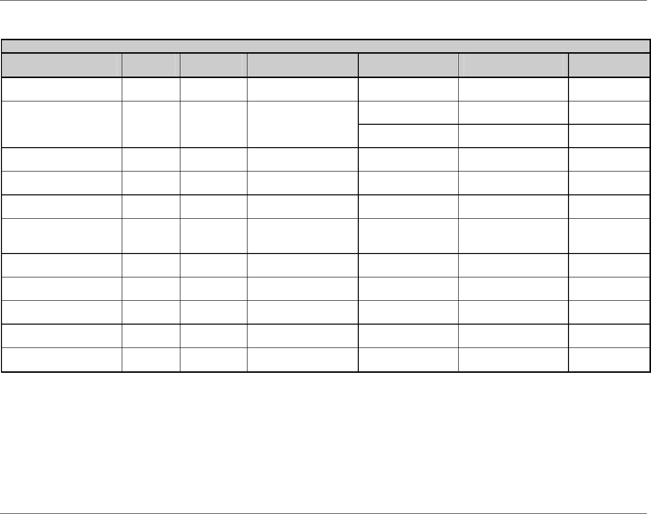
Extended System-Level Command Functions
Class Series Programmer’s Manual 43
Configuration Set Commands
<STX>Kc
Parameter Name Parameter
Pneumonic
Value /
Range Units /
Interpretation Applicable
Printer Type Equivalent Menu Item
or Menu Item Number Command
Equivalent
Slew Speed SS or sS alpha
character
Model specific ranges; see
Appendix L. Display-Equipped Print Control Sa
Display-Equipped Media Settings <STX>e,
<STX>r,
Sensor Type ST G, C, R Gap (edge),
Continuous,
Reflective Non-Display 2 <STX>KD
TOF Bias
TB 0 – 50 .1 Volt DC Non-Display 14 N/A
TOF Delta
TD 0 – 50 .1 Volt DC Non-Display 13 N/A
TOF Gain
TG 0 – 15 .1 Volt DC Non-Display 12 N/A
No Paper Min (Out Of
Stock)
TN 0 – 16 .1 Volt DC Non-Display 11 N/A
TOF Precedence
TP Y, N Enabled, Disabled Display-Equipped N/A N/A
Unit of Measure
UM M, I Metric, Imperial Display-Equipped System Settings <STX>m,
<STX>n
User Terminator
UT ON N/A Display-Equipped N/A N/A
Verifier Equip
VE A/Y, E, N/D Enabled, Disabled Display-Equipped Printer Options <STX>KV
Verifier Type
VT A, B, C, D Reserved for future use Display-Equipped Reserved for future use N/A
Table 5-1: Configuration Set Commands (concluded)

Extended System-Level Command Functions
44 Class Series Programmer’s Manual
<STX>Kc Parameter Overviews
(AL) Alignment Length – Critical for small labels when ‘Label Alignment’ is set to ‘Yes,’ this
command allows a length, measured from leading edge to leading edge of two successive labels
to be entered. The measured length must be provided to the nearest hundredth of an inch. For
very small labels, errors as small as 0.01” can result in noticeable print variations on the labels
between the media sensor and the printhead. The number of labels that can be fit between the
Media Sensor and the printhead will magnify any error in label alignment length. Errors are more
favorable on the low side than on the high side.
(AS) Single Byte Symbol Set – This command allows for a default single-byte symbol set. See
<STX>y or ySxx for command details.
(BA) Backup After Print – When the present distance is set with the GPIO enabled, this
command determines the timing of the label back up. When enabled, the printer immediately
backs up the label after the applicator-issued start of print signal is received, resulting in faster
throughput. If disabled, the printer will not initiate repositioning until the next label is ready to
print (may help prevent the curling of the label edge).
(BL) Backup Label – This command determines the timing of the label back up when the GPIO 1
option is installed and enabled. When enabled, the interface supports an input signal that allows
the printer to back up a label once it has been presented.
(BP) British Pound – This command, when enabled, will automatically switch from the Number
symbol (#) found at 0x23 (default PC-850 Multilingual Symbol Set) to the British Pound symbol
(£) at 0x9C.
(BS or bS) Backup Speed – This command controls the rate of label movement during backup
positioning for start of print, cutting or present distance; see Appendix C for available speed
ranges.
(BZ) Buzzer Enable – This command controls the audible signaling device that acknowledges
User Interface entries and, if enabled, sounds printer warning and fault conditions.
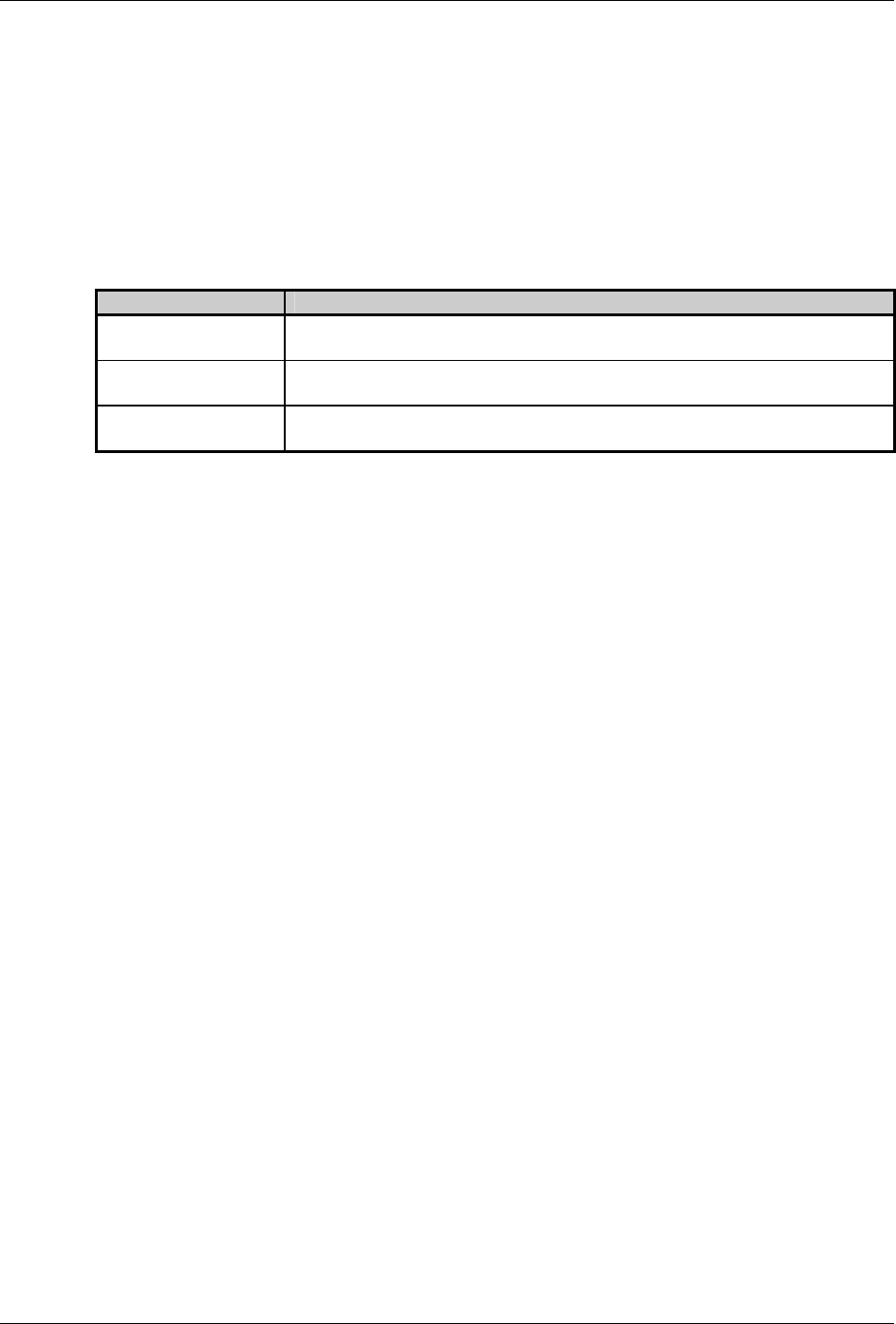
Extended System-Level Command Functions
Class Series Programmer’s Manual 45
(CA) Column Adjust – This command fine-tunes the Column Offset setting by shifting both the
horizontal start of print position and the Label Width termination point to the right in dots (see
Appendix K) to compensate for slight mechanical differences sometimes evident if multiple
printers share label formats.
(CC) Control Codes – This command, depending upon printer type, allows a change to the prefix
of the software commands interpreted by the printer:
Units / Interpretation Definition
Standard Codes Hex 01 = SOH command; Hex 02 = STX command; count-by = ^; Hex 1B =
ESC; Hex 0x0D = Carriage Return
Alternate Codes Hex 5E = SOH command; Hex 7E = STX command; count-by = @;
Hex 1B = ESC; Hex 0x0D = Carriage Return
Alternate Codes 2 Hex 5E = SOH command; Hex 7E = STX command; count-by = @;
Hex 1B = ESC; Hex 0x7C = Carriage Return
(CE) Cutter Equipped – A or Y - automatically senses device presence; if undetected, no error is
generated. E - enables the device, its presence must be detected; otherwise a fault is generated. N
or D - disables device detection. Note that the value range for non-display printers is Y, N only.
See <STX>V for command details.
(CH) Comm Heat Commands – This command causes the printer to disable the DPL Heat
command; instead, the Heat value is controlled via the menu setting.
(CL) Continuous Label Length – See <STX>c for command details.
(CO) Column Offset – See Cnnnn for command details.
(CS) Comm Speed Commands – This command causes the printer to disable the DPL speed
commands (Print, Feed, Slew, and Reverse); instead, the speed values are controlled via the menu
setting.
(CT) Comm TOF Commands – This command causes the printer to disable the DPL TOF (Gap,
Continuous, and Reflective) command; instead, the sensor type is controlled via the menu setting.

Extended System-Level Command Functions
46 Class Series Programmer’s Manual
(DE) DPI Emulation – This command allows printers with higher resolutions to emulate lower
print resolutions, as follows:
• 600 DPI can emulate 300 and 203 DPI resolutions
• 400 DPI can emulate a 203 DPI resolution
(DK) Darkness – This command controls the printhead strobe timing to fine-tune the HEAT
setting.
(DM) Default Module – See <STX>X for command details.
(DR) Delay Rate – This command sets the number of minutes to delay between multiple batch
printings of Quick Test Labels.
(DS) Double Byte Symbol Set – See <STX>y or ySxx for command details.
(EM) Input Mode – This command defines the type of printer language: Standard DPL
processing or Line Mode which exacts data terminated by a carriage return to be inserted in a
DPL template and printed.
(EN) End Character – This command terminates a <STX>Kc string.
(EP) End of Print – This command defines the programmable signal output that signifies the End
of Print (EOP) process:
Units / Interpretation Definition
Active Low Outputs a logic low (zero) following printing.
Active High Outputs a logic high (one) following printing.
Low Pulse Outputs a low pulse (approximately 30 milliseconds long) following printing.
High Pulse Outputs a high pulse (approximately 30 milliseconds long) following printing.
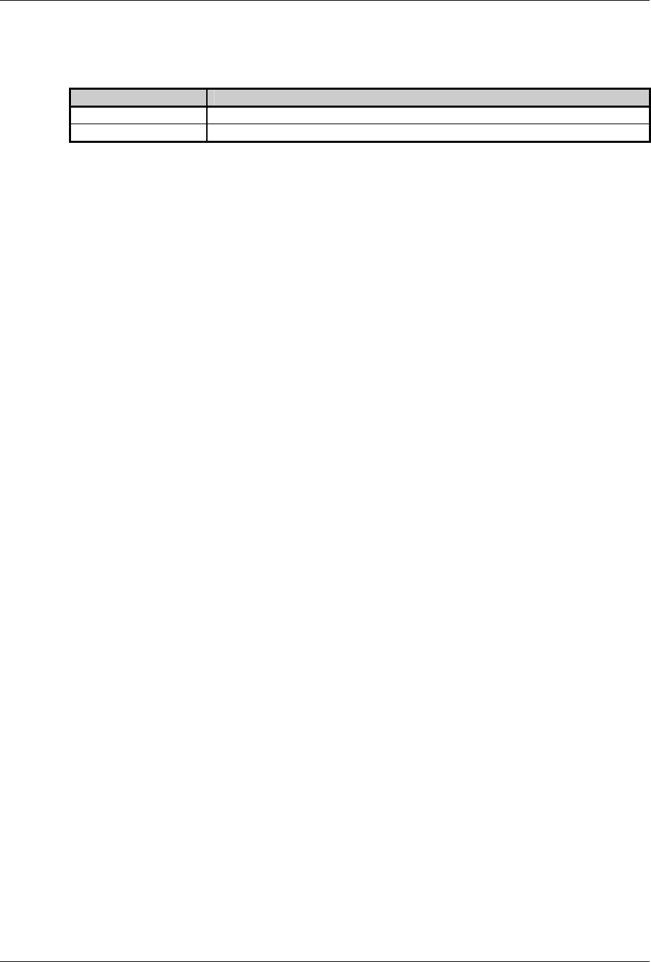
Extended System-Level Command Functions
Class Series Programmer’s Manual 47
(EQ) Start of Print – This command defines the programmable signal input that controls the Start
of Print (SOP) process:
Units / Interpretation Definition
Active Low SOP signal must go low for at least 50 milliseconds to initiate printing.
Active High SOP signal must go high for at least 50 milliseconds to initiate printing.
(ES) ESC Sequences – This command allows data containing invalid ESC control code
sequences to be processed (helpful because some systems send a “banner” to the printer). When
set to ‘Disabled,’ ESC sequences are ignored and the data is processed. Bitmapped font
downloads are disabled in this mode.
(ET) Exact Time – This command set the printer to wait until the system is idle before the next
label’s data and time fields are formatted to eliminate any discrepancy between the buffered and
printed times.
(EV) Empty Sensor Level – This command sets threshold value for the ‘Empty’ media sensor
parameter.
(FA) Format Attribute – See the An command for details.
(FE) Font Emulation –This command allows font substitution for all Datamax internal fonts,
allowing a new default font to be defined without changing the host DPL data streams. Selecting
a default font that supports a desired character set could match with third party software to print
native characters without modifying the PC drivers. In other words, match the PC font with the
Printer Font then no interpretation would be required by driver or printer. Depending on host
drivers, the user may have to disable Symbol Set commands and modify the Default Symbol set.
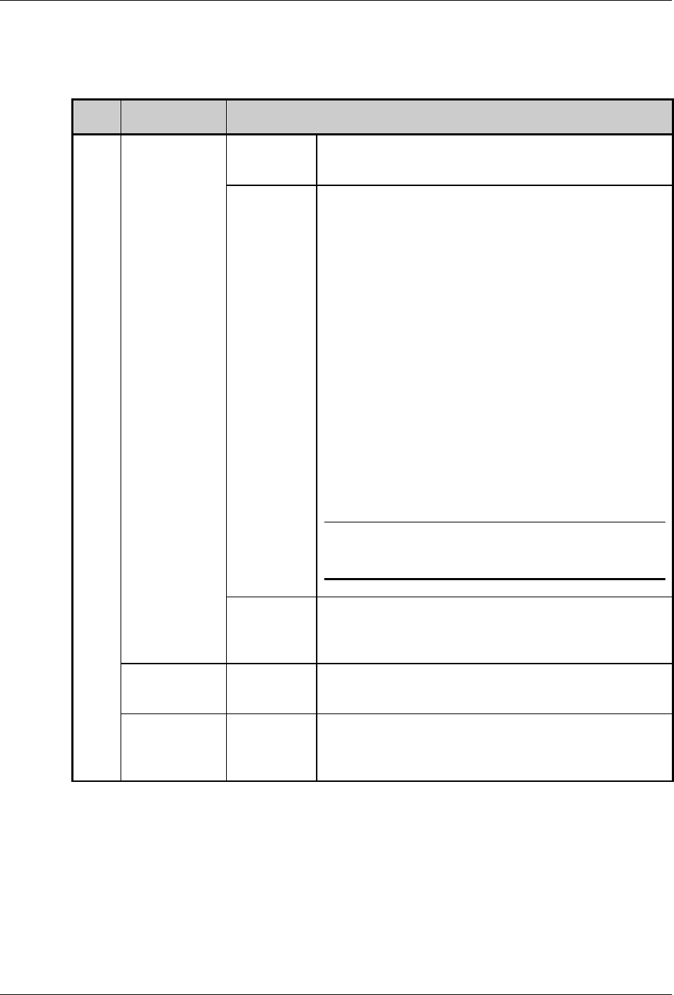
Extended System-Level Command Functions
48 Class Series Programmer’s Manual
(FH) Fault Handling – When a fault condition (ribbon out, media out, etc.) is detected, this
command determines the level of intervention and the disposition of the label being printed at the
time the fault occurred.
Value
Units /
Interpretation
Definition
0 = Standard
Printing stops and a fault message is displayed. After the
problem is corrected, the FEED Key must be pressed to
clear the fault. The label in process is reprinted.
1 = Void and
Retry Depending upon the RETRY COUNT, one of the
following actions when faulted:
• If the Retry Count setting has not been exceeded,
‘VOID’ is printed on the label in process and reprinting
occurs automatically;
• If the Retry Count has been exceeded, printing stops and
a fault message is displayed. After the problem is
corrected, the FEED Key must be pressed to clear the
fault. The label in process is reprinted; or,
• If the CANCEL Key is pressed the operator now has the
option of canceling the reprint:
To allow the reprint, press the ESCAPE Key or to cancel
the reprint, press the ENTER Key (the operator now has
the option of canceling the entire label batch by pressing
the ENTER Key again.)
þ Note: VOID will not be printed when insufficient space exists for
the height of the text (see VOID DISTANCE, below) or if the fault
occurred after the entire label was completed (i.e., when the label
reaches its Present Distance at or above the TOF).
x – Interaction
Level
2 = No
Reprint
Printing stops and a fault message is displayed. After the
problem is corrected, the FEED Key must be pressed to
clear the fault. The label in process is not reprinted.
y - Void
Distance .10 - 2.00 Sets the distance to backup the faulted label to print
‘VOID’ on its trailing edge, which also indirectly
establishes the font size of the void message.
x, y, z
z - Retry
Count 0 - 3 Establishes the number of times the printer will attempt to
reprint a label. If the last label printed in this count has
been voided, the printer will stop and display a fault
message.
Table 5-2: Configuration Set Commands for Fault Handling
Example: <STX>KcFH112<CR>
(The example configures the printer to back up and print a one-inch “VOID” message on a
label when a fault is detected; if two successive faults occur during the printing of that label
then the FEED Key must be pressed to clear the fault.)
Extended System-Level Command Functions
Class Series Programmer’s Manual 49
(FM) Feedback Mode – See <STX>a for command details.
(GE) GPIO Enable – This command is used to interface the printer to external controlling
devices (see Appendix J):
Units / Interpretation Definition
Applicator Enables the GPIO for a label applicator.
Verifier Enables the GPIO for a bar code verifier.
Disabled Disables the GPIO Port.
(GM) Gap / Mark Value – This command sets threshold value for the media sensor’s ‘gap /
mark’ parameter.
(GR) Gain Reflective Value – This command sets the sensitivity of the reflective media sensor.
(HB) Head Bias – This command instructs the printer to switch the dot zero position: as viewed
from the printer’s front panel (or label output side) – when dot zero occupies the left-most
location on the printhead then printing is left justified; when dot zero occupies the right-most
location, printing is right justified.
(HC) Head Cleaning – This command controls the printhead cleaning routine. The entered value
specifies the inch (or centimeter) count to reach before prompting a printhead cleaning. If the
number specified is exceeded three times, the printer will fault until cleaning is initiated.
þ Note: The number specified is multiplied by one thousand. Zero disables this function.
(HE) Heat – See Hnn for command details.
(HT) Host Timeout – This command controls the number of seconds a communications port must
be idle before the printer may process data from a different port. The value is also used to
“timeout” an image / label format download (i.e., if, at any time, data flow stops before a
complete label format is received, the data will be ignored).
(IC) Ignore Control Codes – This command allows the user to remove control codes (< 20 Hex)
in the data field. The selected line terminator is processed. When enabled, DPL Control Code
(SOH, STX, CR, ESC, and ^) characters are removed from the data string. (Note that some fonts
do have printable characters in this range and they will not be printed when enabled.)
Extended System-Level Command Functions
50 Class Series Programmer’s Manual
(IE) Ignore Distances – This command, when enabled, prevents <STX>O processing that will
change the start of print position.
(IL) Imaging Mode – This command instructs the printer whether to pre-image the label format:
Units / Interpretation Definition
Multiple Label The printer images multiple labels as memory permits, achieving the
fastest throughput; however, if time-stamping, the time will reflect the
moment the label is imaged rather than when actually printed.
Single Label The printer images the next label only after the previous label has been
successfully printed. Single processing provides time-stamps that are more
accurate, but it slows label throughput time.
þ Note: This selection can affect the accuracy of time-stamped labels and label throughput.
(IM) Internal Module – This command sets the number of 1K blocks (or 4K blocks for non-
display models, see the <STX>KM command) allocated for the internal RAM ‘D’ module.
(LA) Label Alignment – This command prevents labels with lengths that are less than the
distance between the printhead and the Media Sensor from being wasted at power-up. See the
appropriate Operator’s Manual for detailed information.
Media Type,
Operation Mode
Label
Alignment
Setting
Description
Continuous stock; 6.5” or greater
die-cut, notched and reflective
stocks; multiple form lengths
Disabled At power-up, printing will begin at the current label
position without any alignment (unless the RTC
option is installed).
Automatic Use for easy label length changes, and to
automatically set the maximum label length. Press
and hold the FEED Key four seconds and the printer
will automatically measure the label length. Once
loaded and aligned subsequent power-ups will result
in no wasted labels.
6.5” or less die-cut, notched and
reflective stocks
Enabled Use for constant label lengths. Specify the Label
Alignment Length using the <STX>KcAL command
or the Setup Menu. Press and hold the FEED Key
four seconds, or toggle printer power, and then the
printer will align with the specified length.
6.5” or less die-cut, notched and
reflective stocks with the Present
Sensor enabled
Automatic This mode of operation requires a Label Alignment
Length or that Label Alignment be set to AUTO. If
either of these conditions is not met, the printer will
not perform the alignment.
Table 5-3: Label Alignment Settings
þ Note: The Real Time Clock (RTC) option allows the position-state of the label to be stored, thus
eliminating the need for an alignment prior to the printing of the first label (assuming the
label position has not moved while power was off). If the label stock has been changed
then a Forced Alignment (press and hold the FEED Key 4 seconds) is recommended.

Extended System-Level Command Functions
Class Series Programmer’s Manual 51
(LE) Legacy Emulation – This command enables the <STX>O and <STX>f print positioning
commands to allow backward compatibility with label formats that were designed for the
Allegro® Prodigy®, and Prodigy Plus® (If the printer is display-equipped, also Prodigy Max®
emulation).
(LS) Language Select – This command selects the language in which the menu system messages
and configuration label are shown. Only languages that are resident will be available.
(LW) Label Width – This command sets the maximum limit for the printable width. Objects
extending beyond this limit will NOT print; see Appendix K. (For non-display models also see
the <STX>KW command.)
(MC) Module Commands – This command adjusts the size of Flash module ‘Z’ on the optional
Expansion Card (see Appendix K for module details).
(ML) Maximum Label Length – See <STX>M for command details.
(MT) Media Type – This command selects the printing method: Direct Thermal for use with heat
sensitive media or Thermal Transfer for use with media requiring a ribbon to create an image.
(For non-display models also see the <STX>KD command.)
(MV) Mark Value – This command sets threshold value for the reflective media sensor’s ‘mark’
parameter.
(NS) Disable Symbol Set Selection – This command prevents the <STX>y and y commands
from changing the default single-byte symbol set. When enabled, DPL Symbol Set commands are
ignored. (Note that when enabled the only way to change the current symbol set is to use the
<STX>KcAS command.)
(PA) Present Adjust – This command fine-tunes the Present Distance setting to compensate for
slight mechanical differences sometimes evident if multiple printers share label formats.
Extended System-Level Command Functions
52 Class Series Programmer’s Manual
(PC) Print Contrast – This command adjusts the relative print edge (gray) component of the print
quality, which allows fine-tuning for specific media/ribbon mix.
(PD) Present Distance – This command sets the label stop position past the start of print. When
the next label format is received, the printer will automatically backfeed to the start position. If
the present distance is set to zero, the printer will operate without reversing. (See Stop Location,
below).
(PE) Peel Mode – This command, when enabled, specifies that a Feed operation be prevented
when the label is presented and not removed, or if the printer is to wait for the GPIO start of print
signal.
(PL) Printer Level – This command is used to upgrade the software feature level of the printer.
(PM) Pause Mode – See <STX>J for command details.
(PO) Paper Out Distance – This command sets the length of travel before an out of stock
condition is declared.
(PP) Parallel Direction – This command controls the communications settings for the parallel
port(s):
Value Units / Interpretation
xDz x - A port ID
B port ID
z - U unidirectional (One-way printer communication)
B bidirectional (Enables IEEE 1284 back-channel operation)
Table 5-4: Parallel Communications Configuration Set Commands
(PS) Present Sensor Enable – A or Y - automatically senses device presence; if undetected, no
error is generated. E - enables the device, its presence must be detected; otherwise a fault is
generated. N or D - disables device detection. See <STX>V for command details. (Note that the
value range for non-display printers is Y, N only. Also see the <STX>KD command.)
(pS) Print Speed – See P for command details.

Extended System-Level Command Functions
Class Series Programmer’s Manual 53
(PT) Tear Position – This command sets the label stopping location at the tear plate on the
printer’s cover.
(PV) Paper Value – This command sets threshold value for the media sensor’s ‘paper’ parameter.
(PW) Password – This command modifies the numeric password required to access the menu
system when security is enabled. If security is enabled, enter the new password followed by the
old password (with no spaces) in this form: XXXXXXXX
(QQ) Configuration Query – This command causes the printer to respond with the current
configuration settings. The <STX>Kc response command stream format is sent to the host
computer via the serial port containing all parameters controlled by the <STX>Kc command, and
may be used for restoring the printer’s configuration or for configuring other printers.
(RA) Row Adjust – This command shifts the vertical start of print position in dots (see Appendix
K) to fine-tune the Row Offset setting to compensate for slight mechanical differences sometimes
evident if multiple printers share label formats.
(RB) Reflective TOF Bias – This command allows the manual entry for the control voltage level
to recognize a label “gap” or “mark.”
(RD) Reflective TOF Delta – This command allows the manual entry for the control of the low-
level voltage difference level to recognize a label “gap” or “mark.”
(RE) Ribbon Saver Enable – A or Y - automatically senses device presence; if undetected, no
error is generated. E - enables the device, its presence must be detected; otherwise a fault is
generated. N or D - disables device detection. See <STX>R for command details.
(RF) Row Adjust Finetune – This command shifts the vertical start of print position in dots (see
Appendix K) upward or downward to fine-tune the Row Offset setting to compensate for slight
mechanical differences sometimes evident if multiple printers share label formats.

Extended System-Level Command Functions
54 Class Series Programmer’s Manual
(RG) Reflective TOF Gain – This command allows the manual entry for the control of the
voltage to the LED emitter of the Media Sensor.
(RL) Ribbon Low – This command sets the threshold for a low ribbon indication.
(RN) Reflective No Paper Minimum – This command sets the media sensor’s reading for the Out
Of Stock (OOS) condition.
(RO) Row Offset – See Rnnnn for command details.
(RS) Ribbon Low Signal – This command sets the signal output that signifies the Ribbon Low
Diameter condition for the optional GPIO (see Appendix J).
(RV) Reflective Paper Value – This command sets the threshold value for the reflective media
sensor’s paper parameter.
(SA) SOP Adjust – This command sets the start of print (SOP) location, relative to the top of
form. See <STX>O for command details.
(SC) Scalable Cache – This command sets the number of 1K blocks allocated for the scaleable
font engine. Available memory dependent upon model; see Appendix K. (For non-display models
see the <STX>KS command.)
(SE) SOP Emulation – This command enables the <STX>O and <STX>f print positioning
commands to allow backward compatibility with label formats designed for other printers.
(SF) Save As Filename – This command saves the effective configuration of the printer to a file,
storing it in Flash memory.
Extended System-Level Command Functions
Class Series Programmer’s Manual 55
(SG) Sensor Gain Value – This command sets the control of the voltage to the LED emitter of
the Media Sensor.
(SH) Scalable Heap – This command sets a working “scratch pad space” in DRAM for scalable
font construction.
(SL) Security Lock – This command provides the ability to password protect all printer settings
made through the User Interface.
(SL) Stop Location – This command sets the label stopping (and in certain cases the starting)
location, as follows:
Setting Stop Location
Host Sets stop position according to options installed. If no options are installed the printer
sets stop location to the next label’s start of print. Host commands will override. The
stop location (present distance) may be controlled dynamically by the host using the
<STX>f or <STX>Kf commands. This selection has the same effect as <STX>KD
Ignore Host Distance bit value 0.
Auto Automatically sets the stop location. Installed options will be ‘auto-sensed’ and the
appropriate stop position will automatically be set. Host commands are ignored.
Extended System-Level Command Functions
56 Class Series Programmer’s Manual
(SN) Scanner Configuration – This command configures the optional linear scanner as follows:
Value Range / Interpretation
C, H, M, D,
B, V
C bar code count (number of codes to be read):
00 – 99 (00 = Auto [variable] mode)
þ Note: Do not use Auto Mode with bitmapped codes or codes with certain addendums;
see Appendix F.
H min readable height (sets the vertical distance of the code that must have identical reads):
1 - 1/16
2 - 2/16
3 - 3/16
4 - 1/4
5 - 1/2
0 - Disabled (defaults to Redundancy Level 2x)
þ Note: The selected distance should not exceed 50% of the measured bar code height
M mode (enables scanner detection by the printer):
A - auto (automatically senses presence); Y is also a valid enabler
E - enabled (presence must be detected or a fault is generated)
D - disabled (scanner disabled); N is also a valid disabler
D direct command
ab - reserved for future use
B bar codes (specifies the bar code, two digits) followed by ‘Y’ to enable or ‘N’ to disable the
code
01 - CODE 39
02 - IATA
03 - CODABAR
04 - INTERLEAVED 2 OF 5
05 - INDUSTRIAL 2 OF 5
06 - CODE 93
07 - CODE 128
08 - MSI/PLESSEY
09 - EAN(13/8)
10 - EAN(13/8)+2
11 - EAN(13/8)+5
12 - UPC(A/E)
13 - UPC(A/E)+2
14 - UPC(A/E)+5
þ Note: To maximize throughput and decoding integrity enable only those symbologies
that will be read.
V redundancy level (alternative method to ensure data integrity where the selected level sets a
number of consecutive, identical decodes required to pass the bar code; if a different value is
read then the count is restarted).
þ Note: Depending upon the print speed, higher levels may cause erroneous failures when
scanning multiple or small bar codes.
0 - Auto Mode
1 - read bar code 1X
2 - read bar code 2X
3 - read bar code 3X
4 - read bar code 4X
5 - read bar code 5X
6 - read bar code 6X
7 - read bar code 8X
8 - read bar code 10X
9 - read bar code 12X
A - read bar code 15X
B - read bar code 20X
C - read bar code 25X
D - read bar code 30X
E - read bar code 35X
F - read bar code 40X
G - read bar code 45X
Table 5-5: Scanner Configuration Set Commands
Example: <STX>KcSNC00H4MAB12YV0<CR>
Extended System-Level Command Functions
Class Series Programmer’s Manual 57
(The above sample sets the printer to sense the scanner automatically, to read a variable
number of UPC bar codes codes, and to pass only those codes where ¼ inch of the bar code has
identical reads.)
(SP) Serial Port – This command configures the serial communication port(s) as follows:
Value Range /
Interpretation
Example
xyz
xyzz
x - A port ID
B port ID
y - P protocol (handshaking)
z - type: B - both
S - software
H - hardware
N - none
y - p parity
z - type: N - none
O - odd
E - even
y - D data length
z - value: 8 - bits
7 - bits
y - S stop bits
z - value: 1 - bit
2 - bits
y - B baud rate
zz - value: 12 - 1200
24 - 2400
48 - 4800
96 - 9600
19 - 19200
28 - 28800
38 - 38400
Example:
<STX>KcSPAPB;SPApN;SPAD8;SPAS1;SPAB19<CR>
(The example configures Serial Port A to use hardware
and software handshaking, an eight-bit word, with no
parity and one stop bit at 19,200 bits per second.)
þ Notes:
E-Class and M-Class printer models – this command is
followed by the port ID, always ‘A’ (i.e., SPA).
A-Class printer models – this command is also used to
configure the GPIO Auxiliary port (ID always ‘B’).
Table 5-6: Serial Port Configuration Set Commands
Example: <STX>KcSPAD8<CR>
The above sample sets the serial port A to receive eight-bit words (the host computer
communications setup is expected to be the same).
(SS or sS) Slew Speed – This command controls the rate of label movement between printing
areas; see Appendix L.
(ST) Sensor Type – See <STX>e (edge) or <STX>r (reflective) for command details. (For non-
display models also see the <STX>KD command.)

Extended System-Level Command Functions
58 Class Series Programmer’s Manual
(TB) TOF Bias – This command controls the low-level voltage difference level to recognize a
label ‘gap’ or ‘mark’.
(TD) TOF Delta – This command controls the low-level voltage difference level to recognize a
label ‘gap’ or ‘mark’.
(TG) TOF Gain – This command controls the voltage to the LED emitter of the Media Sensor.
(TN) No Paper Min – This command sets the media sensor level for the Out Of Stock (OOS)
condition.
(TP) TOF Precedence – This command instructs the firmware to stop printing at the first top of
form mark it detects. The default, ‘No,’ prints all of the data then slows to the next TOF.
(UM) Units of Measure – See <STX>m (metric) or <STX>n (imperial) for command details.
(UT) User Terminator – This command allows word wrapping of long character strings of
commands to the next line in a file, for the purposes of readability only. In the <STX>Kc string,
the command UTON must fall somewhere before the first line terminator. The last command
needs to be END, followed by a line terminator (see the <STX>KcEN command for details).
(VE) Verifier Equip – A or Y - automatically senses device presence; if undetected, no error is
generated. E - enables the device, its presence must be detected; otherwise a fault is generated. N
or D - disables device detection. This command enables the GPIO for a bar code verifier (see
Appendix J).
(VT) Verifier Type – This command is reserved for future use.
Extended System-Level Command Functions
Class Series Programmer’s Manual 59
STX KD Database Configuration (Non-Display Models only)
This command, stored in Flash memory for future power-ups, controls the printer’s environment and
operates as a pseudo DIP switch. The <STX>Kc command is recommended for use over <STX>KD.
Syntax: <STX>KDwxyz<CR>
Where: w, x, y, and z are binary values with respective bit settings as defined in
the following table. (Bit 0 is least significant.)
Sample: <STX>KD@H@@<CR>
The sample configures the printer as follows:
@ Sets the communications to 9600 baud with an 8-bit word and no parity;
H Selects direct thermal printing, standard control characters, and enables the media cutter;
@ Selects gap sensing;
@ Is the default setting (items saved for future expansion).
þ Note: The Ignore Host Distance setting (see below) allows the printer to disregard <STX>O and <STX>f
commands; a feature provided for host system software that sends these commands with values
that may be inappropriate for the printer and result in incorrect start of print and present distances.
Use the <STX>KD command or the Setup Menu to enable this feature.
<STX>KD
Parameter Bit
Number Parameter
Function Parameter
Value(s)
0 – 2 BAUD Rate / Set Test Mode 0 = 9600, 1 = 600, 2 = 2400, 3 = 19200,
4 = 4800, 5 = 38400, 6 = 1200,
7 = 9600 Test Mode
3 Word Length and Parity 0 = 8 bits, no parity; 1 = 7 bits, even parity
4 & 5 Unused Set to 0
6 Always 1 Set to 1
w
7 Always 0 Set to 0
0 Print Method 0 = direct thermal, 1 = thermal transfer
1 Present Sensor 0 = not equipped, 1 = equipped
2 Control Character[1] 0 = standard, 1 = alternate characters
3 Cutter 0 = disabled, 1 = enabled
4 Ignore Host Distance 0 = disabled, 1 = enabled (See note above)
5 Alt-2 Control Codes[1] 0 = disabled, 1 = alternate-2 characters
6 Always 1 Set to 1
x
7 Always 0 Set to 0
0 & 1 Paper Type (Media Sensor) 0 = gap (edge), 1 = reflective, 2 = continuous
2 Linerless 0 = not equipped, 1 = equipped
3 – 5 Unused Set to 0
6 Always 1 Set to 1
y
7 Always 0 Set to 0
0 & 1 Reserved Set to 0
2 Reserved Set to 0
3 – 5 Unused Set to 0
6 Always 1 Set to 1
z
7 Always 0 Set to 0
[1] Selects the values of the control characters; see Control Codes.
Table 5-7: <STX>KD Configuration Commands

Extended System-Level Command Functions
60 Class Series Programmer’s Manual
STX Kd Set File as Factory Default
(Display-Equipped Models only)
This command selects the specified file name as the “factory default” for the printer’s configuration.
After execution, subsequent “Select Factory Default” commands will configure the printer to the
file’s configuration. Currently there are three ways to “Select Factory Defaults”: 1) by the <STX>KF
command; 2) power-up the printer while pressing the PAUSE and CANCEL Keys; or, 3) via the
printer’s menu system entry System Settings / Set Factory Defaults.
þ Note: Powering ‘On’ the printer while pressing the PAUSE, FEED and CANCEL Keys will reset the
configuration to the factory defaults.
Syntax: <STX>KdName<CR>
Where: Name -
The name, up to 16 characters, of the configuration file.
<CR> -
0x0d terminates the name.
Sample: <STX>KdPlant1
This command selects the configuration file “Plant1” as the default factory configuration.
STX KE Character Encoding
This command is provided primarily as a means for users of 7-bit communication and to embed
control characters and extended ASCII characters in their data streams. Any character in the DPL
datastream may be substituted with a delimited two-character ASCII hexadecimal numeric
equivalent. The command allows the delimiting character to be selected, and the encoding to be
enabled or disabled. When character encoding is enabled, the printer will decode any ASCII
hexadecimal numeric pairs following the delimiter as single-byte values. Character encoding is used
where control characters cannot be transmitted or where control characters within data may
prematurely terminate a label format record. Although the delimiter may be changed at any time
(except within a label format definition), there cannot be more than one defined delimiter, and
character encoding must be disabled with <STX>KEN prior to re-enabling, regardless of any change
in the delimiter.
Syntax: <STX>KEex<CR>
Where: e - Y – character encoding enabled
N – character encoding disabled
x - Delimiter: one ASCII character (Do not include when e = N)
Extended System-Level Command Functions
Class Series Programmer’s Manual 61
Sample: <STX>KEN
<STX>KEY\
<STX>L<CR>
1u0000001200120[)>\1E\01\1D\...\04\<CR>
E<CR>
The sample disables, and then enables character encoding with the backslash (\) as the delimiter. A
UPS MaxiCode will be formatted using a data string interpreted as: [)>RS01GS... EOT<CR>, then
formatting is terminated.
Character Encoding Syntax: This syntax requires at least two hexadecimal ASCII digits (0-9, A-F)
delimited by the character specified in the <STX>KE command. The number of hexadecimal digits
between the delimiter pair must be even; see notes below.
Syntax: xaa[bbcc…nn]x
Where: x - One byte delimiter, 0 to ff16, leading and trailing.
aa - 2 bytes, ASCII, hexadecimal encoded, range each character -
0-9, A-F
bb - 2 bytes, ASCII, hexadecimal encoded, range each character -
0-9, A-F (optional)
cc - 2 bytes, ASCII, hexadecimal encoded, range each character -
0-9, A-F (optional)
nn - 2 bytes, ASCII, hexadecimal encoded, range each byte - 0-9,
A-F (optional)
þ Notes: (1) A delimiter pair with no ASCII hexadecimal pairs between (e.g., \\) will be interpreted as one
byte whose value is that of the delimiting character, allowing the assigned delimiter to be
interpreted as itself rather than as the delimiter.
(2) A delimited string that contains either a non-valid hexadecimal character (e.g., FX) or an odd
number of bytes will be treated as an illegal string and, therefore, not correctly decoded.
Character Encoding Examples: In the following partial datastreams it is assumed that character
encoding is enabled and that the selected delimiter, a backslash (\), has been transmitted to the
printer (i.e., <STX>KEY\). In each example, the printer has not received an unpaired delimiter prior
the example.
Partial DPL
Sample Data Stream
Interpretation
AB\\CE 5 bytes AB\CE with values 4116, 4216, 5C16, 4316, 4416
\ABCDEF\ 3 bytes with values AB16, CD16, and EF16
1A\1A\1A 5 bytes 1A<SUB>1A with values 3116, 4116, 1A16, 3116, 4116.
<SUB> represents a single-byte ASCII control character with value 1A16
Alternate Control Codes with Alternate Line Terminator: Character Encoding can also be used
with the Alternate Control Character set. Alternate Control Characters are enabled, depending upon
the model, via a Setup Menu or the <STX>KD / <STX>Kc commands. See Control Codes.
STX KF Select Factory Defaults

Extended System-Level Command Functions
62 Class Series Programmer’s Manual
(Display-Equipped Models only)
This command restores the printer’s configuration to the “factory default” settings. These factory
default values may be either the Datamax default settings or the configuration file previously
specified in the <STX>Kd command.
Syntax: <STX>KF<CR>
STX Kf Set Present Distance
This command specifies an additional amount to advance the label after printing. This command has
the same effect as the <STX>f command, but specifies a distance to advance relative to the start of
print (<STX>O command) of the next label.
Syntax: <STX>Kfnnnn<CR>
Where: nnnn
- A four-digit present distance in inches/100 or mm/10.
Sample: <STX>Kf0100
The sample represents a one-inch label advance unless in metric mode (see <STX>m).

Extended System-Level Command Functions
Class Series Programmer’s Manual 63
STX Kp Module Protection
(Display-Equipped Models only)
This command controls memory module protection. When “protected”, a module will ignore format,
downloads and delete commands. This command can be useful to add data to Datamax reserved
modules, Z (ILPC) and Y (EFIGS). See Appendix K for a listing of the memory modules.
There are two types of modules: RAM (volatile) and Flash (non-volatile).
Ÿ RAM - When protected, if the power is cycled or if the printer is reset, the module state resets
back to unprotected.
Ÿ Flash - When protected, the module can be temporarily unprotected. However, if the power is
cycled or if the printer is reset, the module is initialized to ‘protected.’ To clear the protected state
forever, the module must be unprotected and then formatted.
Syntax: <STX>Kpmf
Where: m
-
Module ID – Range A to Z (See Appendix K).
Where: f
-
Flag specifying Enable or Disable protection.
0 – disable protection
1 – enable protection
Sample: <STX>KpY0
This example disables protection for memory module “Y”. Graphics may now be downloaded to
module “Y” and, on subsequent resets, these graphics will be protected.

Extended System-Level Command Functions
64 Class Series Programmer’s Manual
STX KQ Query Memory Configuration
This command causes the printer to transmit DRAM memory configuration to the host device
regarding the total amount installed, the amount available for configuration, and the amount currently
assigned to specific functions or entities. The printer’s response format is model dependent.
Syntax: <STX>KQ<CR>
Non-display model
response format:
INTERNAL MEMORY<CR>
VER: aa-cdd.ee mm/dd/yy<CR>
INSTALLED: iiii<CR>
AVAILABLE: vvvv<CR>
MODULE: X:xxxx<CR>
SCALABLE: ssss<CR>
LABEL MEM: LLLL<CR>
LABEL SIZE: wwww:gggg:oo<CR>
Where: <CR> -
ASCII Carriage Return (0x0D) record delimiter.
aa-
cdd.ee
mm/dd/yy
-
ASCII string sequence that represents the firmware version
number string.
iiii -
The number of 4KB blocks of DRAM memory.
vvvv -
The number of 4KB blocks of DRAM available for
configuration.
X: -
ASCII character identifying a DRAM module followed by an
ASCII colon (:). If no Internal Module is present, this field
and its associated legend will not appear.
xxxx -
The number of 4KB blocks of DRAM allocated as an
Internal Module.
ssss -
The number of 4KB blocks of DRAM assigned to the
smooth scalable font processor cache.
LLLL -
The number of 4KB blocks of DRAM assigned to label print
buffer.
wwww -
Current maximum printable label width (in 100ths of an inch
or millimeters).
gggg -
Current printable length (in 100ths of an inch or millimeters),
200 min. / 640 max.
oo -
Current label dimension unit’s designation: “IN” for inches
or “MM” for millimeters.

Extended System-Level Command Functions
Class Series Programmer’s Manual 65
Display-equipped
model response format:
Product: I4208 – 01.01 05/21/1999
Installed RAM: 8 MB
Label Width: 4.09 IN
Print Buffer Size: 272 IN
Allocation RAM: 6389 KB
Internal Files: 512 KB
Font Cache: 232 KB
Where: Product -
Printer model, type and firmware revision level.
Installed
RAM
-
Total amount of RAM.
Label Width -
Size in inches/millimeters of the printhead.
Print
Buffer Size
-
Tot
al number of inches/millimeters of Print Dot
Buffers available. (This is not the maximum size of
a label, which is limited to 99.99 inches.)
Allocation
RAM
-
Amount of RAM that can be configured for the
Internal Files, Font Cache and the remainder going
to the Print Buffer Size.
Internal
Files -
Size of the Internal Module used to store
downloaded fonts, graphics and label formats.
Font Cache -
Size of the Font Buffer used to temporarily store
characters. Increasing this buffer will increase
perfor
mance if labels have a large variety of font
sizes and characters.

Extended System-Level Command Functions
66 Class Series Programmer’s Manual
STX Kq Query Memory Configuration (new format)
(Display-Equipped Models only)
This command causes the printer to transmit its internal DRAM memory configuration to the host
device. The transmitted data provides information regarding the total amount of internal DRAM
installed, the amount available for configuration, and the amount currently assigned to specific
functions or entities.
Syntax: <STX>Kq<CR>
Printer response format:
Memory Configuration<CR>
Product: aaaacdd.ee mm/dd/yy<CR>
Installed RAM: iiiiMB<CR>
Label Width: vvvvoo<CR>
Print Buffer Size: :xxxxoo<CR>
Allocation RAM: ssssKB<CR>
Internal Files LLLLKB<CR>
Font Cache wwww:KB<CR>
Where: <CR> -
ASCII Carriage Return (0x0D) record delimiter.
aaaacdd.ee
mm/dd/yy -
ASCII string sequence that represents the firmware
version number string.
iiii -
The number of Megabytes of installed internal DRAM
memory.
vvvv -
The length of the Label Width.
xxxx -
The length of the Print Buffer.
ssss -
The number of Kilobytes of internal memory assigned to
the label Print Buffer
LLLL -
The number of Kilobytes assigned to the internal memory
module.
wwww -
The number of Kilobytes assigned to the Scalable Cache.
oo -
Current label dimension unit’s designation. “IN” for inches
and “MM” for millimeters.
STX KR Reset Memory Configuration
(Non-Display Models only)
This command resets the printer’s DRAM configuration to the default settings, see <STX>KM.
Syntax: <STX>KR<CR>

Extended System-Level Command Functions
Class Series Programmer’s Manual 67
STX Kr Resettable Counter Reset
This command resets the internal counters. Follow this command with an <SOH>U command to
retain the reset or the counters will revert to the previous values after cycling power.
Syntax: <STX>Kr<CR>
STX KS Memory Configuration, Scalable Font Cache
(Non-Display Models only)
See the <STX>K command.
STX KV Verifier Enable/Disable
(Display-Equipped Models only)
This command allows the verifier (option, if installed), to be enabled and disabled.
Syntax: <STX>KVa<CR>
Where: a - Y = verifier enable
N = verifier disable
STX KW Memory Configuration, Printable Label Width
(Non-Display Models only)
See the <STX>K command.

Extended System-Level Command Functions
68 Class Series Programmer’s Manual
STX Kx Delete Configuration File
(Display-Equipped Models only)
This command deletes the specified configuration file.
Syntax: <STX>KxmName<CR>
Where: m - Valid Module ID – Range A to Z.
Name
- The name, up to 16 characters, of the configuration file.
<CR>
- 0x0d terminates the name.
Sample: <STX>KxYPlant1
This command deletes the configuration file Plant1 located on Module Y. (Remember to prefix this
command with the Module (Un)Protect Command <STX>Kp).

Class Series Programmer’s Manual 69
Label Formatting Command Functions
Introduction
The <STX>L command switches the printer from the System-Level Processor to the Label Formatting
Processor. All commands following the <STX>L are interpreted as label formatting commands, and can be
used to override default parameter values. Selectable parameter value defaults may be also reassigned via
the Setup Menu, as defined in the corresponding Operator’s Manual. Label formats that contain no
commands overriding printer default values will assume those defaults.
: Set Cut By Amount
This command allows a predetermined number of labels to be printed before a cut is initiated. This
feature is useful when it is necessary to print an uncut strip of labels. Between 1 and 9999 labels may
be printed before a cut is made. The amount must be smaller than the quantity of labels printed.
Syntax: :nnnn
Where: nnnn
-
Is a four digit decimal number indicating the number of labels to
be printed before a cut is performed.
Sample: <STX>L<CR>
:0005<CR>
141100001000100SAMPLE LABEL<CR>
Q0021<CR>
E<CR>
The sample instructs the printer to make a cu
t after 5, 10, and 20 labels have been printed. Label 21
will be cut at the start of a subsequent label format (batch) unless a default (cut by amount) greater
than one has been entered.
þ Note: The cutter must be enabled and all mechanism interlocks closed for operation.
Label Formatting Command Functions
70 Class Series Programmer’s Manual
A Set Format Attribute
This command specifies the type of format operation and remains in effect until another format
command is specified or another label format has begun (<STX>L). Each label format defaults to
attribute 2 (Transparent Mode).
Syntax: An
Where: n - Is attribute mode 1, 2, 3, or 5; see table below.
The default is 1, (XOR Mode).
Sample: <STX>L
A3
141100001000100DATAMAX<CR>
141100001100110DATAMAX<CR>
E
The sample sets the printer to Opaque Mode and produces one label.
n Attribute Description Example
1 XOR
Mode In this mode, the region where text strings, images
or bar codes intersect will not be printed. (An odd
number of overlapping objects will print.)
2 Transparent
Mode This is the default mode; the intersecting regions of
text strings, images, and bar codes will print,
allowing the user to print fields on top of one
another.
3 Opaque
Mode Interacting text is obliterated by the text formatted
last. Each character cell is treated as opaque. This
mode is effective only in rotation 1. See Record
Structure Types.
5 Inverse
Mode This mode allows inverse (white on black) printing
(e.g., a proportionally sized border and background
are printed similar to photographic negative). If text
or image fields overlap in this mode, the effect will
be similar to the XOR mode.
Table 6-1: Format Attributes

Label Formatting Command Functions
Class Series Programmer’s Manual 71
B Bar Code Magnification
(Display-Equipped Models only)
This command provides a mechanism to specify bar codes greater than 36 dots (0-9,A-Z in the field
record). The value is reset to 1 at the start of every label and stays active for the entire label or set to a
new value.
Syntax: Bnn
Where: nn - Is a two digit decimal number indicating the magnification
value.
Sample: <STX>L<CR>
D11
B01
1a9305000100030ABCD<CR>
B03
1a3105000700030ABCD<CR>
Q0001
E
The sample instructs the printer to print two bar codes, each 9 dots by 3 dots.
C Set Column Offset Amount
This command allows horizontal adjustment of the point where printing begins. The printer is
instructed to print label formats nnnn units to the right of the position that the format specifies. This
feature is useful when a single format is to be printed on labels containing preprinted information.
þ Note: If using preprinted labels where the placement of the preprint data varies from label to label, the
printed information may overlap the preprinted data.
Syntax: Cnnnn
Where: nnnn
- Is a four-digit number for the column offset, inches/100 or
mm/10. The printer default is 0 for offset.
Sample: <STX>L
C0050
141100001000100DATAMAX<CR>
The sample shifts all format data 0.5 inches to the right, unless the printer is in metric mode, (see
Label Formatting Command ‘m’).

Label Formatting Command Functions
72 Class Series Programmer’s Manual
c Set Cut By Amount
This command is the same as the ‘:’ command except only a two-digit value can be entered. This
command allows a predetermined number of labels to be printed before a cut is made. 1 to 99 labels
may be printed before a cut is made.
Syntax: cnn
Where: nn - Is a two-digit number indicating the number of labels to be
printed before a cut is made. The printer default is one.
Sample <STX>L<CR>
c07<CR>
141100001000100SAMPLE LABEL<CR>
Q0021<CR>
E
The sample instructs the printer to make cuts after labels 7, 14, and 21 have been printed. See Label
Formatting Command ‘:’.
þ Note: The cutter must be enabled and all mechanism interlocks closed for the cut operation.
D Set Dot Size Width and Height
This command is used to change the size of a printed dot, hence the print resolution – dots per inch
(DPI) of the printhead. By changing the height of a dot, the maximum length of a label can be
increased or decreased. For the element sizes see Appendix K.
Syntax: Dwh
Where: w - Is Dot Width multiplier 1 or 2.
h - Is Dot Height multiplier 1, 2, or 3.
þ Note: D11 is the default value for 300, 400 and 600 DPI printer models, while D22 is the default value for
all 203 DPI printer models.

Label Formatting Command Functions
Class Series Programmer’s Manual 73
E Terminate Label Formatting Mode and Print Label
This command causes the printer, when the processing Label Formatting commands, to terminate the
Label Formatting Mode then generate, print, and feed a label. The label generated will be based on
whatever data has been received to that point, even if no printable data has been received. Other
termination commands are ‘X’ and ‘s’. Commands sent to the printer after the Terminate Label
command must be of the Immediate, System-Level, or Font Download type.
Syntax: E
Sample: <STX>L<CR>
121100000000000Testing<CR>
E<CR>
The sample will print one label.
e Recall Printer Configuration
(Display-Equipped Models only)
This command recalls a previously stored printer configuration. It is highly recommended that only
one Recall Printer Configuration command be used per label, and that it be used at the beginning of the
label; otherwise, unpredictable results will occur. (Printer configurations may be stored using the
Extended System Commands or the printer’s menu system.)
Syntax: eName<CR>
Where: Name - The name, up to 16 characters, of the configuration file.
<CR> - 0x0d terminates the name.
Sample: <STX>L<CR>
ePlant1<CR>
1A2210001000000Testing<CR>
E<CR>
The sample recalls the stored printer configuration, Plant1.
F Advanced Format Attributes
These commends extend the text presentation capabilities for Scalable Fonts. The format attribute
allows a set of label format records to select Bolding, Italicizing and Underlining. Additional
commands allow the specification of line rotation and font changes within a label field. Reference
Section 8.0, Generating Label Formats / Advanced Format Attributes for details.

Label Formatting Command Functions
74 Class Series Programmer’s Manual
f Set Present Speed
(Non-Display Models only)
This command controls the rate at which the present distance is positioned, allowing the media
movement to be slowed during ‘presentation’ (the distance traveled after printing is completed to the
label stop position). This command is used only within the context of a label format. The speed
assigned is retained until another label format is received or until power is removed; if a subsequent
format does not contain a present speed command then the present speed reverts to the slew speed.
Syntax: fa
Where: a - Is a single alpha character representing a speed, limited by the
slew speed range; see Appendix L. The default is the slew speed.
Sample: <STX>LD11H30PGSG
fA
191100200830165Fixed Data Field 1
E
<STX>L
191100200830165Fixed Data Field 1
E
The sample prints two labels; the first label has present speed of 1 inch per second, while the second
reverts to the slew speed of 4 inches per second.
G Place Data in Global Register
The ‘G’ command saves the print data of a print format record in a global register (temporary storage).
This data may be retrieved and copied to another record in the same label format using the special
Label Formatting Command, <STX>S. Global registers are named in the order received, beginning
with register A, ending at register P, and incrementing with each instance of the G command use.
Syntax: G
Sample: <STX>L<CR>
121100000000000Testing<CR>
G<CR>
1A2210001000000<STX>SA<CR>
E<CR>
The sample stores, retrieves and prints the data in global register A. One label is printed with
“Testing” in two locations.
Label Formatting Command Functions
Class Series Programmer’s Manual 75
H Enter Heat Setting
This command changes the “on time” of elements of the printhead. The default setting is 10 (except in
the case of printers with a menu, where the default setting can be changed through the keypad). An
increase or decrease in this value results in a change of heat applied by the printhead to the media,
lightening or darkening the print contrast accordingly. This is helpful when using different media
types, each requiring a different amount of heat to properly image the media. The host device can send
this command value to correct the heat setting per the application.
Syntax: Hnn
Where: nn - Is a two-digit heat value (00-30)
Sample: <STX>L<CR>
H15<CR>
141100001000100SAMPLE LABEL<CR>
E
The sample sets the printer for a heat value of 15 and prints one label.
þ Note: Non-Display Models – the “Darkness Potentiometer,” while providing subtle changes, is intended to
be used to match print contrast levels following printhead replacements.
J Justification
This command changes the printing justification.
þ Note: Display-Equipped Models – This command is only valid for use with scalable fonts.
Syntax: Ja
Where: a - Is a single-digit alpha character:
L = left justified (default)
R = right justified
C = center justified
Sample: <STX>L<CR>
1911A1801001000TEST1
JR
1911A1801000100TEST2
JC
1911A1802000200TEST3
E
The sample’s first text field “TEST1” will be printed at one inch up, one inch over going right. The
second text “TEST2” will be printed at one inch up one inch over, going left. (Note the characters
will not be reversed.) The third field “TEST3” will be centered on the point two inches up two inches
over.
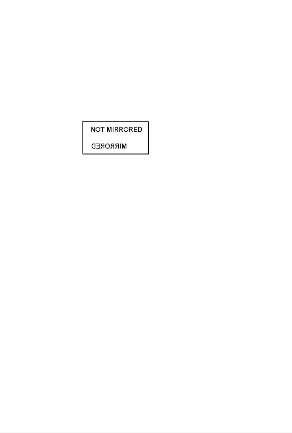
Label Formatting Command Functions
76 Class Series Programmer’s Manual
M Select Mirror Mode
This command instructs the printer to “mirror” all subsequent print field records. This command
toggles the mirroring mode. Mirrored fields are transposed visually, as if the object is viewed in a
mirror.
Syntax: M
Sample: <STX>L
161100003200010 NOT MIRRORED<CR>
M<CR>
161100003000400 MIRRORED<CR>
E
Printed Result:
m Set Metric Mode
This command sets the printer to measure in metric. When this command is sent, all measurements
will be interpreted as metric values, (e.g., a column offset of 0010 will be interpreted as 1.0 mm). All
printers default to Imperial (inch) mode.
Syntax: m
Sample: <STX>L<CR>
m
141100001000100SAMPLE LABEL<CR>
E
The sample prints the text (SAMPLE LABEL) starting at location coordinates 10.0 mm, 10.0 mm.
n Set Inch (Imperial) Mode
This command sets the printer to measure in inches. When this command is sent, all measurements
will change to inches. All printers default to Imperial units. Menu selectable.
Syntax: n
Sample: <STX>L<CR>
n
141100001000100SAMPLE LABEL<CR>
E
The sample prints the text (SAMPLE LABEL) starting at location coordinates 1.0 inch, 1.0 inch.

Label Formatting Command Functions
Class Series Programmer’s Manual 77
P Set Print Speed
This command sets a print speed for a label or batch of labels.
Syntax: Pa
Where: a - Is a single character representing a speed; see Appendix L for
valid ranges.
Sample: <STX>L
PC
141100001000100LABEL1<CR>
E
<STX>L
141100001000100LABEL2<CR>
E
The sample prints two labels, the first at a speed of 2 inches per second (51 mm per second) and the
second at the printer default.
p Set Backfeed Speed
This command, typically used in conjunction with the Cut or Peel and Present operations, controls the
rate at which the labels will reverse to align to the next start of print position. The setting remains in
effect until another backfeed speed command is received or until the printer is reset.
Syntax: pa
Where: a - Is a single alpha character representing a speed; see Appendix
L for valid ranges.
Sample: <STX>L
pF
The sample sets the printer to a backup speed of 3.5 IPS.
Label Formatting Command Functions
78 Class Series Programmer’s Manual
Q Set Quantity Of Labels To Print
This command sets the number of the label copies to be printed. A one to five digit value is allowed, if
the command is delimited by a carriage return <CR>. This permits host applications to generate label
quantity commands without the need to pad leading zeros. (A four-digit command value does not need
to be <CR> terminated.)
Syntax: Qnnnnn
Where: nnnnn
- Is a one to five-digit delimited value setting for the number of
labels to be printed. The default value is one.
Sample: <STX>L
121100000000000Testing<CR>
Q0020<CR>
E<CR>
The sample will print a batch of 20 identical labels.
R Set Row Offset Amount
This command allows vertical adjustment of the point where printing begins. The printer is instructed
to print label formats nnnn units above the position that the format specifies. This feature is useful
when a single format is to be printed on labels containing preprinted information.
þ Note: If using preprinted labels where the placement of the preprint data varies from label to label, the
printed information may overlap the preprinted data.
Syntax: Rnnnn
Where: nnnn
- Is a four-digit number (0000-
9999) for the row offset, in
inches/100 or millimeters/10. The printer default is 0.
Sample: <STX>L
R0037<CR>
141100001000100SAMPLE LABEL<CR>
E
The sample prints a label with a row offset amount of .37 inches, unless in metric mode.

Label Formatting Command Functions
Class Series Programmer’s Manual 79
r Recall Stored Label Format
This command is used to retrieve label formats stored on a memory module.
Syntax: rnn...n
Where: nn…n - Is a label name, up to 16 characters in length.
The samples below explain different ways to recall and print a label format. (To view a memory
module’s directory of label formats use the <STX>W command.)
String Sent: Printer Interpretation:
Sample 1: <STX>L<CR>
rTEST<CR>
Q0002<CR>
E<CR>
Begin label format
Retrieve format named TEST
Quantity requested = 2
Terminate formatting and print
Sample 2: <STX>L<CR>
rTEST<CR>
X<CR>
<STX>G<CR>
Begin label format
Retrieve format named test
Terminate formatting
Print
Sample 3: <STX>L<CR>
D11<CR>
PO<CR>
SO<CR>
rTEST<CR>
E<CR>
Begin label format
Dot size = 1x1
Print speed 0
Slew speed 0
Retrieve format named test
Terminate formatting and print
S Set Slew Speed
This command controls the rate at which the label is moved through non-printed areas. The setting
remains unchanged unless another slew speed command is received or until the printer is reset.
Syntax: Sa
Where: a -
Is a single alpha character representing a speed; see Appendix
L for valid ranges.
Sample: <STX>L
SE
141100001000100LABEL1<CR>
E
<STX>L
1411000010001000LABEL2<CR>
E
The sample sets the slew speed to 3 inches per second (76 mmps), and prints two labels. The slew
speed for the second label is the same as the first.

Label Formatting Command Functions
80 Class Series Programmer’s Manual
s Store Label Format In Module
This command stores a label format to a specified module. Supplying the module name will store the
label to that module; otherwise, using C will cause the label format to be stored in the selected default
module (see <STX>X). In addition, this command terminates the Label Formatting Command.
Syntax: sann…n
Where: a - Is the module designator representing a single character
module name; see Appendix K.
nn…n
- Represents the name of the label (maximum 16 characters).
Sample: <STX>L<CR>
D11<CR>
191100501000000123456789012<CR>
1911005020000001234567<CR>
191100500000000Sample<CR>
1X1100000000000B250250002002<CR>
Q0001<CR>
sATEST<CR>
The example stores a format in memory module A and names it ‘TEST’. (To recall a label format
from the module use the ‘r’ command.)
T Set Field Data Line Terminator
This command, intended for use with record types that accept binary data (e.g., PDF417), allows
special binary control codes (e.g., a carriage return) to be embedded in the printed data by setting an
alternate data line terminator. It remains valid only for the next format record, then the terminator
defaults back to the carriage return.
Syntax: Tnn
Where: nn - Is an ASCII two-character representation of a HEX code to be
used for the end of data terminator.
Sample: <STX>L<CR>
T00<CR>
191100200000000TEST<NULL>
141100001000100TERMIATOR<CR>
Q0001<CR>
E<CR>
The sample sets the printer to use a NULL terminator (ASCII NULL: HEX 00) for the data line
termination code. The terminator is immediately restored to a carriage return <CR>, as seen in the
format record containing the text ‘TERMINATOR’.

Label Formatting Command Functions
Class Series Programmer’s Manual 81
U Mark Previous Field as a String Replacement Field
This command controls the way replacement data is formatted. Specifying a field as a string
replacement for dynamic fields, and not for static fields, will optimize label throughput. See the
<STX>U command.
þ Note: The data string length of any replacement is set by the length of the original string; both must be
equal. The data being used when created must be valid for the font type being selected.
Syntax: U
Sample: <STX>L
D11
121100001000000123456789012<CR>
U<CR>
1211000020000001234567<CR>
U<CR>
161100000000000Sample<CR>
1X1100000000000B250250002002<CR>
Q0001
E
<STX>U01ABCDEFGHIJKL<CR>
<STX>U028901234<CR>
<STX>G
The sample sets up the label format for register loading and prints two labels. The first two of the four
format records have been designated as replacement fields. The second label is generated with
System-Level field-replacement commands and prints the last label.
X Terminate Label Formatting Mode
This command causes the printer, when in label formatting mode, to immediately switch to the system
command mode and generate a label format based on the data received at that point. However, unlike
the ‘E’ command, it will not print a label. (Other termination commands are the ‘E’ and ‘s’.)
Syntax: X
Sample: <STX>L<CR>
141100001000100SAMPLE<CR>
X<CR>
The sample will result in a label format, but no label will be printed.

Label Formatting Command Functions
82 Class Series Programmer’s Manual
y Select Font Symbol Set
This command, like the <STX>y, selects the scalable font symbol set. The selected symbol set
remains active until another symbol set is selected; see the <STX>y command for details.
Syntax: ySxx
Where: S - Byte-size designation; see Appendix H:
S = Single byte symbol sets.
U = Double byte symbol sets.
xx - Symbol set selection.
Sample: <STX>L
ySSW<CR>
The sample selects the Swedish symbol set for use in succeeding format records using scalable fonts.
z Zero (Ø) Conversion to “0”
This command removes the slash zero in fonts 0 to 8, and in the human readable field (if any) of the
bar codes A to Z. The command applies only to format records containing those fonts and bar codes,
and is effective only for the label format in which it appears.
þ Note: None of the smooth fonts (i.e., Font 9) use the slash zero. This command will have no effect on
scalable fonts.
Syntax: z
Sample: <STX>L
z
121100000000000Test0000<CR>
E

Label Formatting Command Functions
Class Series Programmer’s Manual 83
+ (>) Make Last Field Entered Increment Numeric (Alphanumeric)
This command, useful in printing sequenced labels, causes the printer to automatically increment a
field on the labels in a batch. The numeric data in the field will increment by the value assigned after
the plus sign (+) each time a label is produced (or the greater than character [>] can be substituted to
make the field increment alphabetically). This command is effective only on the label format record
that it follows, and is intended to be used with the Q, <STX>E, or <STX>G commands.
Syntax: *pii
Where: * - Is + for numeric increment, or > for alphanumeric
increment.
p - Is the fill character for the left-hand character of the field.
ii - Is the amount by which to increment the field.
Sample: <STX>L<CR>
13220000000000012345<CR>
+01<CR>
Q0003<CR>
E<CR>
The sample will generate a single field label format that prints the initial label with a value of 12345,
and then increments that number by one for the next two labels.
Embedding
Numeric strings for incrementing may also be embedded between alphabetic characters (e.g., when
systems require alphanumeric bar codes with alphabetic prefixes or suffixes).
Sample: <STX>L<CR>
161100000100010AB0001CD<CR>
+ 100<CR>
Q0003<CR>
E<CR>
The sample will print three labels, incrementing 0001 by 1 on each label with AB and CD remaining
untouched: AB0001CD, AB0002CD, AB0003CD. Note that the increment value has one leading
blank and two trailing zeros, while the blank is a pad character and the trailing zeroes are
placeholders that leave CD unchanged.

Label Formatting Command Functions
84 Class Series Programmer’s Manual
- (<) Make Last Field Entered Decrement Numeric (Alphanumeric)
This command, useful in printing sequenced labels, causes the printer to automatically decrement a
field on the labels in a batch. The numeric data in the field will decrement by the value assigned after
the minus (-) sign each time a label is produced (or the less than character [<] can be substituted to
make the field decrement alphabetically). This command is effective only on the label format record
that it follows, and is intended to be used with the Q, <STX>E or <STX>G commands.
Syntax: *pii
Where: * - Is - for numeric decrement, or < for alphanumeric decrement.
p - Is the fill character for the leftmost character of the field.
ii - Is the amount by which to decrement the field.
Sample: <STX>L<CR>
132200000000000123AB<CR>
<01<CR>
Q0003<CR>
E<CR>
The sample will generate a single field label format that prints the initial label with a value of 123AB,
and then decrements that number by one for the next two labels.
Embedding
Numeric strings for decrementing may also be embedded between alphabetic characters (e.g., when
systems require alphanumeric bar codes with alphabetic prefixes or suffixes).
Sample: <STX>L<CR>
1611000001000101000CD<CR>
- 100<CR>
Q0003<CR>
E<CR>
The sample will print three labels: 1000CD, 999CD, and 998CD. Note that the pad character is a
placeholder for digits removed from the left side in the subtraction process. When a fixed pitch font
(where all characters have the same width) is used, the justification of the rightmost character is
sustained regardless of the number of digits replaced by the pad character on the left side.
Label Formatting Command Functions
Class Series Programmer’s Manual 85
^ Set Count by Amount
This command allows applications using the increment / decrement field command to print more than
one label with the same field value before the field data is updated. All printers default to 1.
þ Note: This command can only be issued once per label format. In addition, when alternate Control Codes
are enabled, the ^ character must be replaced by the @ character (hexadecimal 0x40). See
Control Codes.
Syntax: ^nn
Where: ^ - May be 0x55 or 0x40, see Control Codes.
nn - Is a two-digit value that specifies the number of labels to be
generated before incrementing (or decrementing) the field value.
Sample: <STX>L<CR>
13220000000000012345<CR>
-01<CR>
^02<CR>
Q0006<CR>
E<CR>
The sample prints two labels containing the same field value before decrementing the field. Six labels
are printed.
Special Label Formatting Command Functions
Two Special Label Formatting Commands, the <STX>S and the <STX>T, are entered directly into the
data field of label format records. Do not confuse them with System-Level Commands because the same
control character is used. If alternate control codes are enabled the <STX> becomes ‘~’ (hexadecimal
0x7E); see Control Codes.
Label Formatting Character Command Description
<STX>S Recall global data and place in field
<STX>T Print time and date
Table 6-2: Special Label Formatting Commands
Label Formatting Command Functions
86 Class Series Programmer’s Manual
STX S Recall Global Data And Place In Field
This command, when in the format record data field, places data from a specified global register into
the data field. See the G command.
Syntax: <STX>Sn
Where: n - Specifies the global register (A − P) that contains the data to
place into the data field.
Sample: <STX>L<CR>
121100000000000DMX<CR>
G<CR>
1A2210001000000<STX>SA<CR>
E<CR>
The sample places the string “DMX” into the next available global register (A), and then line 4 is
effectively replaced by the data from global register A.
STX T Print Time and Date
This command, using string characters and markers, allows time and date data to be selected and
retrieved from the printer’s internal clock. In addition, the <STX>T may be preceded by data to be
printed/encoded, and/or the string may now be terminated by an <STX> command and then followed
by more data terminated by a <CR>. The string characters/markers are not printed; instead, the
printed label will show a corresponding print value.
þ Note: When using substitution you must ensure the converted string produces valid characters for the
selected bar code / font.
Syntax: <STX>Tstring<CR>
Where:
string
- Is any set of characters, A - Z and a – h. See the table below.
String
Characters
Print
Values String
Markers Print
Values
A Day of the week (Mon = 1, Sun = 7) VW Hour in 24 hour format
BCD Day of the week name XY Hour in 12 hour format
EF Month number Za Minutes
GH...O Month name gh Seconds
PQ Day bc AM or PM
RSTU Year def Julian date
Table 6-3: Time and Date String Characters
þ Note: The sample listings below assume a current printer date of December 21, 1998.

Label Formatting Command Functions
Class Series Programmer’s Manual 87
Sample 1: <STX>L<CR>
121100001000100<STX>TBCD GHI PQ, TU<CR>
E<CR>
Sample 1 will print SUN DEC 21, 98 on a label.
Sample 2: <STX>L<CR>
191100100100010<STX>TEF/PQ<CR>
E<CR>
Sample 2 will print 12/21 on a label.
Sample 3: <STX>L<CR>
191100100100010ABC <STX>TEF/PQ<STX> DEF<CR>
E<CR>
Sample 3 will print ABC 12/21 DEF on a label. (This illustrates a method of embedding the time
string. The string must be terminated by an <STX>.)

Label Formatting Command Functions
88 Class Series Programmer’s Manual
Class Series Programmer’s Manual 89
Font Loading Command Functions
Introduction
The commands used for font loading are usually generated by font creation software; however, the
assigned font ID number command must be sent to the printer before the font file. All Font Loading
Commands begin with <ESC> (ASCII control character 27 [decimal]).
The downloaded font will be stored in the default module (refer to the <STX>X command). The
commands in the table below are listed in their order of appearance, top to bottom, during font
downloading. The <SOH>D command must be sent prior to downloading a font.
Command Description
*c###D Assign Font ID Number
)s#Wnn...n Font Descriptor
*c#E Character Code
(s#W Character Download Data
Table 7-1: Font Loading Commands
*c###D Assign Font ID Number
This command is the first command required for downloading a font to either RAM or Flash Memory
modules. ESC represents the ASCII control character 27.
Syntax: <ESC>*c###D
Where: ### - Is the font ID numbers 100-999 (000 – 099 are reserved for
resident fonts).
)s###W Font Descriptor
This command (typically first data in a font file) contains all of the information about the font
contained in the file. Different font generation software will create different length header
information, but the initial 64 bytes will remain consistent with the PCL-4 (HP LaserJet II) format.
Syntax: <ESC>)s###Wddd...d
Where: ### -
Is the number of bytes of font descriptor data from 1 to 3
ASCII decimal digits.
dd...d
- Is the descriptor.

Font Loading Commands
90 Class Series Programmer’s Manual
*c###E Character Code
This code is the ASCII decimal value corresponding to the next downloaded character.
Syntax: <ESC>*c###E
Where: ### - Is the ASCII value of the character, three digits maximum, 0
to 999.
(s#W Character Download Data
This command contains all of the information for one downloaded character.
Syntax: <ESC>(s###Wnn…n
Where: ### -
Is the number of bytes of bit-mapped data, three digits
maximum, from 1 to 999.
nn...n
-
Is the bit-mapped data.
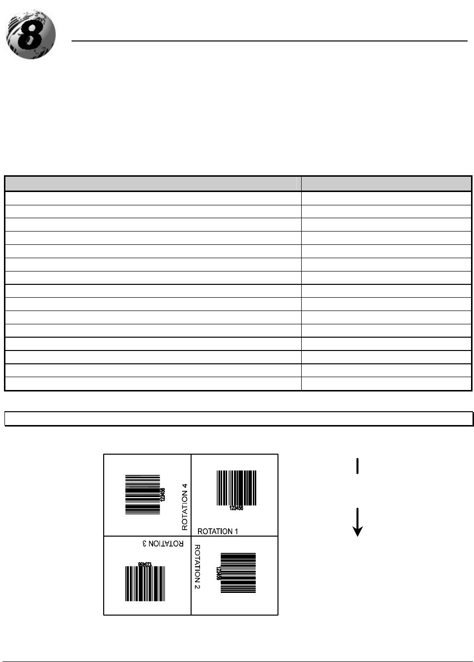
Class Series Programmer’s Manual 91
Generating Label Formats
Introduction
This section explains the use of the different fields in a print format record.
Format Record Commands
Table 8-1 is an example of a label format as seen by the printer, while Figure 8-1 is the label generated by
this format. The printer receives the data sequentially, left to right, top to bottom.
String Sent to Printer Printer Interpretation
<STX>L<CR> Begin label format
D11<CR> Set dot size
121100000050005Home Position<CR> Format text
191100602000200ROTATION 1<CR> Format text
291100602000200ROTATION 2<CR> Format text
391100602000200ROTATION 3<CR> Format text
491100602000200ROTATION 4<CR> Format text
1A3104003000260123456<CR> Format bar code with text
4a6210002500140123456<CR> Format bar code
1X1100000000000B400400003003<CR> Format box
1X1100002000000L400001<CR> Format line
1X1100000000200L001400<CR> Format line
121100004100010Printhead Location<CR> Format text
Q0001<CR> Number of labels
E<CR> End formatting, begin print
Table 8-1: Sample Label Format
þ Note: This example assumes that the printer is in ‘inch’ mode (<STX>n).
Printhead Location
Home Position
Media
Movement
Figure 8-1: Formatted Sample Label

Generating Label Formats
92 Class Series Programmer’s Manual
The first line in the sample format (Table 8-1) is the System-Level Command directing the printer to begin
label formatting. (Other System-Level Commands may precede the <STX>L for printer setup.) Lines 2, 14,
and 15 are Label Formatting Commands. Line 15 is the exit and print command. The remaining lines (3-
13) are print format records, explained in this chapter.
A record is a data string that contains the information to be printed on the label(s). Records are the building
blocks of label formats. Every record must end with a termination character (usually a carriage return,
<CR>). Omitting termination characters will result in the concatenation of records. Omitting the carriage
return that precedes the termination character E, which is necessary to complete the label formatting and
begin printing, will cause the printer to continue interpreting all subsequent data as label print format
records.
Generating Records
Every record is made of three parts: (1) a header that is 15 bytes in length, (2) the data to be printed,
and (3) a termination character (e.g., <CR>) marking the end of the field. The header is used to select
the appearance of the data when printed by choosing rotation, font type, size, and position options.
Every header contains similar information, but this information may be used in different ways by
different types of records. The six record types are:
1. Internal Bit-Mapped Font
2. Smooth Font (Simulated)
3. Scalable Font
4. Bar code
5. Images
6. Graphics
The Structure of a Record
The basic structure of the record is described below. For details regarding the various interpretations of
the six types see Record Structure Types.
The third line of the label format example in Table 8-1 consists of the following:
121100000050005HOME POSITION<CR>
This string comprises a complete record, shown below, divided into its three basic component parts.
Header Data String Termination Character
121100000050005 HOME POSITION <CR>
Table 8-2: Record Structure Components
The record conforms to the following fixed field format (spaces added for readability). Identifying
lower case letters have been placed below field values for reference in the following sections:
1
2
1
1
000
0005
0005
HOME POSITION <CR>
a
b
c
d
eee
ffff
gggg
[hhhh iiii] jj…j Termination character
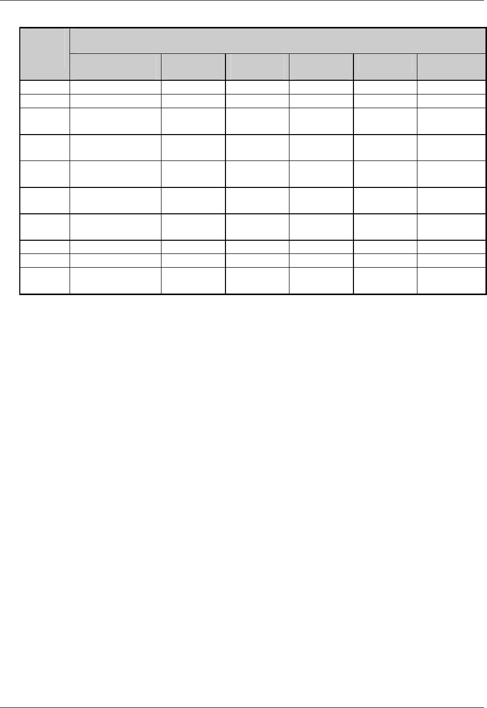
Generating Label Formats
Class Series Programmer’s Manual 93
Record Type
Location
Within
Record Internal Bit-
Mapped Font Smooth
Font Scalable
Font Bar
Code
Images
Graphics
a Rotation Rotation Rotation Rotation Rotation 1
b Font ID 9 9 Bar Code Y X
c Width
Multiplier Width
Multiplier Width
Multiplier Wide
Bar Width
Multiplier 1
d Height
Multiplier Height
Multiplier Height
Multiplier Narrow
Bar Height
Multiplier 1
eee 000 Font Size/
ID ID Bar Code
Height 000 000
ffff Row
Position Row
Position Row
Position Row
Position Row
Position Row Position
gggg Column
Position Column
Position Column
Position Column
Position Column
Position Column
Position
hhhh N/A N/A Font Height
N/A N/A N/A
iiii N/A N/A Font Width
N/A N/A N/A
jj...j
Data
String Data
String Data
String Data
String Image
Name Graphic
Specifiers
Table 8-3: Record Type Structure
In Table 8-3, the record structure is shown for each of the record types. The left-most column shows
the locations of all characters in the record, and corresponds to the example above the table. Each
record structure interprets the characters of the record in its own way, though some of the
interpretations of the characters are identical across all record types. For example, the characters ffff
are interpreted as Row Position in all record types. While c is a Width Multiplier for Internal Bit-
Mapped Font, Smooth Font, Scalable Font, and Image record types, it has other interpretations for Bar
Code and Graphics record types.
The Header Fields
Each of the fields in the record header is generally described below. Please reference the detailed
descriptions under Record Structure Types for variations. The field name titles of the following
paragraphs are preceded with a reference letter from Table 8-3. All characters sent to the printer within
the header fields are ASCII, alphanumeric.
a: Rotation
The first field of a header is a single ASCII character that selects the degree of rotation for the data
to be printed on a label. Valid rotation values are 1 (0º); 2 (90º); 3 (180º); and 4 (270º) clockwise.
Figure 8-1 shows the direction and amount of rotation clockwise, relative to the label feed
direction. The bottom left corner of the object is the pivot point.
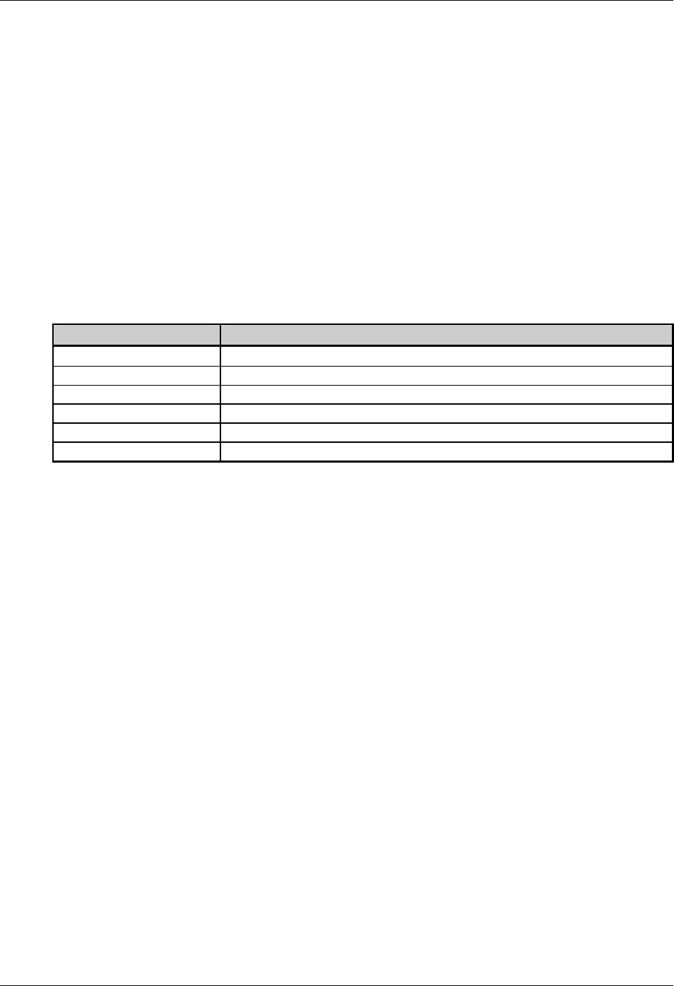
Generating Label Formats
94 Class Series Programmer’s Manual
b: Fonts, Bar Codes, Graphics and Images
The second field (b) determines how the rest of the fields are interpreted, as shown in the table
below. Values 0 through 9 select human-readable fonts. 0 through 8 will select standard Datamax
fonts; value 9 selects the CG Triumvirate smooth scalable font (internal) or scalable fonts. When 9
is used to select a scalable font, the font size (font I.D. number) is chosen by entering a value in the
height field eee.
Values A through z select bar codes. Values A through T (uppercase) will print bar codes with
human-readable interpretations. Values a through z (lowercase), will print bar codes only.
Value W requires two additional characters to specify the Bar Code/Font ID.
A font field value X selects a drawing object (line, box, circle or polygon), and field value Y is
used to print an image stored in a module.
Font Field Value (b) Interpretation
0-9 Font
A-T Bar code with human readable text.
a-z Bar code without human readable text.
Wxx Bar code/Font expansion
X Line, box, polygon, circle
Y Image
Table 8-4: Font Field Interpretations
c: Width Multiplier
Values 1-9 and A-O represent multiplication factors (base 25 numbers). For human-readable fonts,
the width multiplier represents the number of times the selected font dot tables are multiplied and
has no effect on the character height. For bar codes, this character specifies the wide bar width or
ratio. Values 1 through 9 and A through O will give a wide bar width of from 0.0033” (0.085 mm)
to 0.792” (2.011 mm) at a resolution dependent upon the printer model. See Appendix F for default
values.
d: Height Multiplier
The height multiplier has the same range and function as the width multiplier, but vertical. When
used in the context of bar codes, this field is the ratio denominator, or the small bar (module)
width. Values 1 through 9 and A through O will give a narrow bar width of one dot (dot size =
1/printhead resolution) to 24 dots. The narrow bar width resolution and range are dependent upon
the printhead resolution, see Appendix K. A “dot multiplier” command can also be used to change
the printed dot size (see Label Formatting Command ‘D’ and Appendix F).
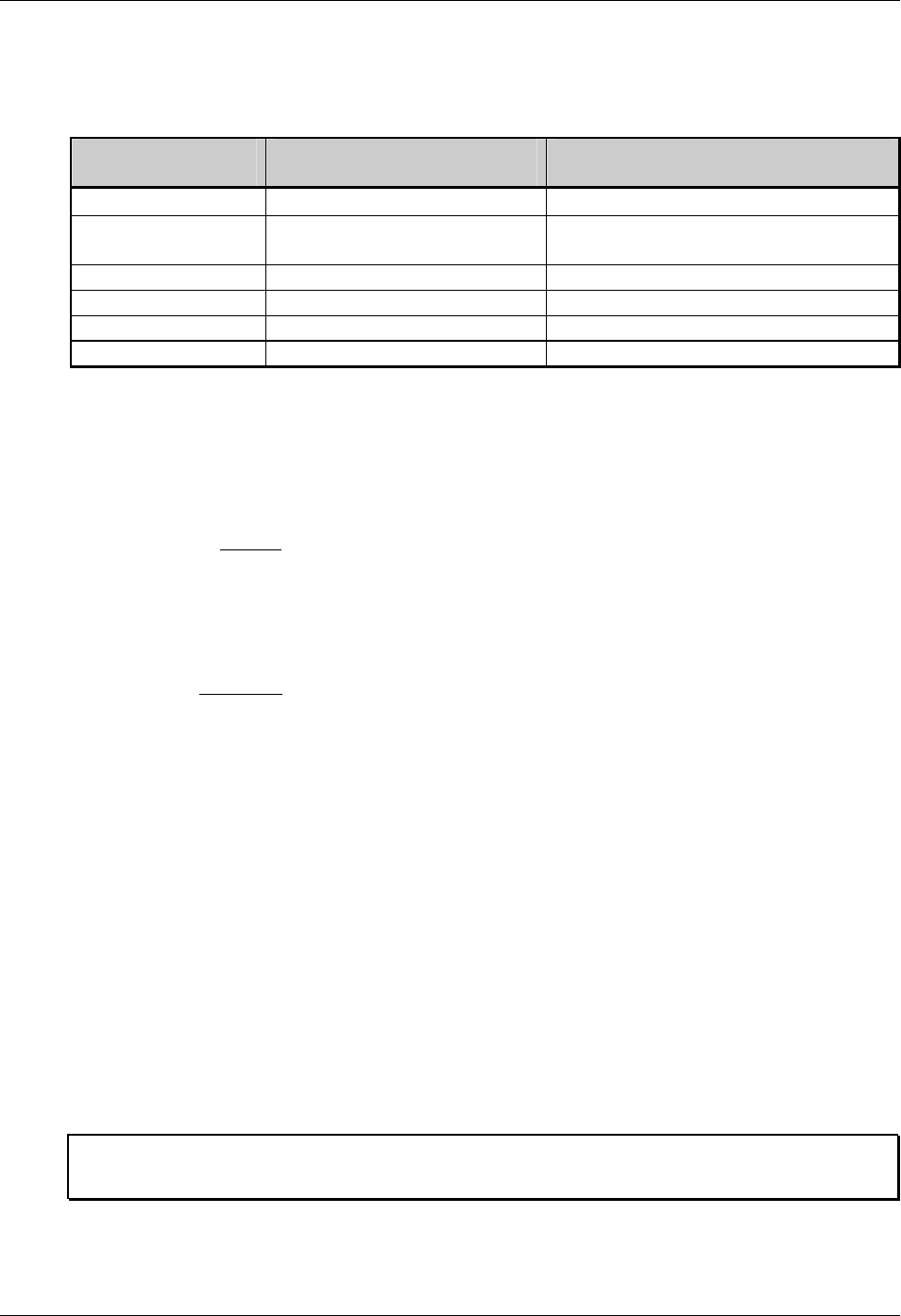
Generating Label Formats
Class Series Programmer’s Manual 95
eee: Bar Code Height (Font Size/Selection)
This field has interpretations dependent upon the value of the font b field, as shown below.
b
Font Field Value eee
Field Range eee
Field Interpretation
0-8 000 Not used –Internal bitmapped font
9 000-999, A04-A72, S00-S9z,
U00-U9z, u00-u9z Font height; Font selection
A-T 000-999 Bar code height (with human readable)
a-z 000-999 Bar code height
Wxx 000-999 Bar code height (with human readable)
X,Y 000 Not used
Table 8-5: Bar Code Height Field Interpretations
ffff: Row Position
The lower left corner of a label is considered the “home position” (see Figure 8-1). The row
position field is a vertical coordinate that determines how far above the home position the data is to
be printed. Field data is interpreted in hundredths of an inch or tenths of millimeters.
gggg: Column Position
This field is a horizontal coordinate that determines how far to the right of “home position” the
data will be printed. Appendix G lists the maximum values of the gggg field.
hhhh: Optional Scalable Font Height
The height of a scalable font can be specified in two ways: points or dots. To specify the height in
points the first character of the field is a ‘P’ followed by the number of points, 004 to 999. To
specify the size in dots, all four characters must be numeric. This field must be specified for
scalable fonts. (See note below Optional Scalable Font Width.)
iiii: Optional Scalable Font Width
The width of a scalable font can be specified in two ways, points or dots. To specify the width in
points, the first character of the field is a ‘P’ followed by the number of points, 004 to 999 points.
To specify the size in dots, all four characters must be numeric. This field must be specified for
scalable fonts. See note below.
þ Note: To ensure that the data stream is portable to different Datamax printers, specify the font size in
points. If the font is specified in dots, it will output differently on printers with different DPI/MMPI
resolutions. There are 72.307 points per 1 inch (2.847 mm).
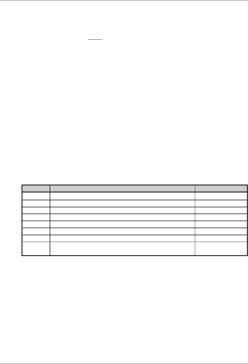
Generating Label Formats
96 Class Series Programmer’s Manual
jj…j: Data Field
The final field contains the data that will actually be printed on the label. A string of data can be up
to 255 characters in length, (except when using the PDF417 bar code, which may be up to 3000
characters long) ending with a carriage return. Characters placed in the data field will be printed as
long as they fall within the physical range of the printhead. Consult Appendix K for a listing by
printer.
Record Structure Types
Each of the six record types has its own field structure and is described in the following section. The
record types allow quick reference to the field types and their valid data inputs for the field. There are
similar, but unique, record structures for each: internal, bit-mapped fonts, internal smooth fonts,
downloaded bit-mapped fonts, scalable fonts, bar codes, images, and graphics. The field location
identifiers in the tables that follow are the same as those in Table 8-3.
1. Internal Bit-Mapped Fonts
This record type is used for internal bitmapped fonts (see Appendix C, Tables C-1 – C-5).
When a 0 through 8 is entered in field b, then the height field eee is not used. The bitmapped
fonts include 8 different fonts (see Appendix C). The character mapping for these fonts is shown
in Appendix A, or a subset thereof.
Field Valid Inputs Meaning
a 1, 2, 3 and 4 Rotation
b 0 to 8 (see Appendix C). Font
c 1 to 9 and A to O Width Multiplier
d 1 to 9 and A to O Height Multiplier
eee 000 N/A
ffff 0000 to 9999 Row
gggg 0000 to 9999 Dependent upon printer. See Appendix K. Column
jj…j Valid ASCII character string up to 255 characters, followed
by a termination character. Data
Table 8-6: Internal Bit-mapped Font Record Structure
2. Smooth Font, Font Modules, and Downloaded Bit-Mapped Fonts
This record type is used for internal smooth fonts (CG Triumvirate – see Table C-6) or a bit-
mapped font downloaded to a memory module (see Font Loading Commands).
When a 9 is entered in field b, then the height field eee determines the font. The internal smooth
font has up to 13 font sizes (see Appendix C). Values 100 through 999 select individual fonts
stored on DRAM, or Flash memory. These include downloaded bit-mapped fonts (see Table 8-5).
Use eee values of 096 – 099 for Kanji fonts, if equipped (see Appendix I). The character mapping
for these fonts is shown in Appendix A or a subset thereof.
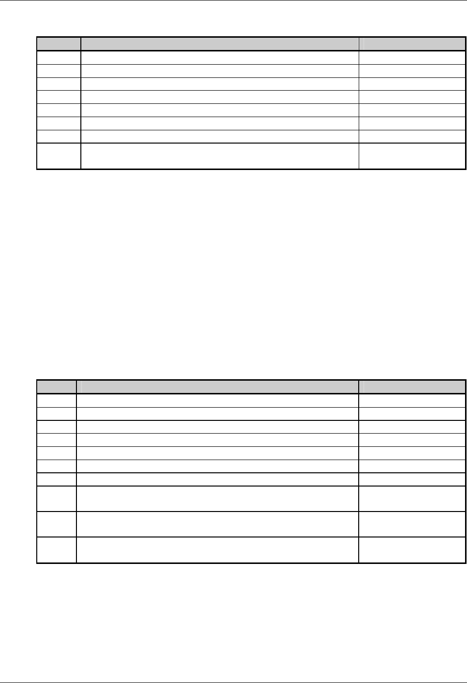
Generating Label Formats
Class Series Programmer’s Manual 97
Field Valid Inputs Meaning
a 1, 2, 3 and 4 Rotation
b 9 Fixed Value
c 1 to 9 and A to O Width Multiplier
d 1 to 9 and A to O Height Multiplier
eee 000 to 999 (000 to 099 Reserved), A04 to A72, x04 – x72* Font/size
ffff 0000 to 9999 Row
gggg 0000 to 9999 Dependent upon printer. See Appendix K. Column
jj…j Valid ASCII character string up to 255 characters followed
by a termination character. Data
* Where x is an upper case letter, see Appendix H.
Table 8-7: Smooth Font Record Structure
3. Scalable Fonts
The Smooth Scalable Font Technology has been licensed from AGFA. Both Intellifont (.CDI) and
TrueType (.TTF) Scalable Font file formats are supported. The eee field identifies the scalable
font, and data type – normal (binary) or Hex ASCII. Uppercase S or U – binary, lowercase u – Hex
ASCII. See Appendix H for additional information. Values S00 to S9z, and U00 to U9z (u00 to
u9z), select a scalable font, either internal or downloaded.
S00 and S01 are used for the standard internal (resident) fonts on display-equipped printers, while
S01 is used for the standard internal (resident) font on non-display models.
Field Valid Inputs Meaning
a 1, 2, 3 and 4 Rotation
b 9 Fixed Value
c 1 to 9 and A to O Width Multiplier
d 1 to 9 and A to O Height Multiplier
eee S00 to Szz, U00-Uzz, u00-uzz Font data type
ffff 0000 to 9999 Row
gggg Dependent upon printer. See Appendix K. Column
hhhh P004-P999, 0016-4163* Character height;
points, dots
iiii P004-P999, 0014-4163* Character width;
points, dots
jj…j Valid ASCII character string up to 255 characters followed by
a termination character. Data
* Character size specifications are printhead resolution dependent as indicated in the following table.
Table 8-8: Scalable Font Record Structure
Generating Label Formats
98 Class Series Programmer’s Manual
Character size (dots) Printhead
Resolution (DPI) Width Height
203 16-2817 16-2817
300 14-4163 16-4163
400 22-5550 22-5550
600 33-8325 33-8325
Table 8-9: Scalable Character Size Ranges
þ Note: A scalable font cache must be allocated to print. Minimum cache size is 15. The double byte
fonts require five units of additional cache.
4. Bar Codes
Valid inputs for the bar code field b are letters: uppercase letters will print a human-readable text
below the bar code; lowercase letters will only print the bar code. For example, entering a ‘p’ in the
b field selects the Postnet bar code. Because the Postnet font does not provide human-readable
data, the uppercase P is not valid. Other bar codes without a human-readable counterpart include u
(MaxiCode) and z (PDF417) – for additional model-specific restrictions see Appendix F.
For module-based bar codes, field d is the narrow bar width in dots (bar code module size). For
consistent results in all rotations for bar codes of this type, field d and field c must have the same
value. For ratio-based bar codes field c is the wide bar width in dots (the numerator); field d is the
narrow bar width in dots (the denominator). See Appendix G for specific bar code information and
variations in record format field usage.
The eee height field represents the bar code (symbol) height. The eee height field represents the
bar code height. The valid range (001 to 999) translates to bar heights ranging from .01 inch (.254
mm) to 9.99 inches (253.7 mm). For bar codes that require additional specified parameters, use the
jj…j data field as the location for these parameters. See the specific bar code for details in
Appendix G.
Field Valid Inputs Meaning
a 1, 2, 3 and 4 Rotation
b [bb]
A to Z and a to z (except P, u, v, z), or Wna where n is 1 to 9 and
a is A to S and a to s. No n is an implied 1.
Bar
Code
c 1 to 9 and A to O Wide Bar
d 1 to 9 and A to O Narrow Bar
eee 001 to 999 Symbol height
ffff 0000 to 9999 Row
gggg See Appendix K. Column
jj…j Valid ASCII character string up to 255 characters followed by a
termination character. Data
Table 8-10: Bar Code Record Structure
Placing a 0 (zero) in both c and d will cause the printer to use the default bar code ratio or module
size. Placing a 000 (zero) in the symbol height field causes the printer to use the default bar code
height.
Generating Label Formats
Class Series Programmer’s Manual 99
5. Images
An image record is used to print an image that is stored in a memory module. Images can be
printed only in Rotation 1 (see Input Image Data <STX>I).
Field Valid Inputs Meaning
a 1 Fixed Value
b Y Image
c 1 to 9 and A to O Width Multiplier
d 1 to 9 and A to O Height Multiplier
eee 000 Fixed Value
ffff 0000 to 9999 Row
gggg See Appendix K. Column
jj…j ASCII string, up to 16 characters followed by a termination
character. Image name
Table 8-11: Image Fields
6. Graphics
Using graphics, the printer can produce lines, boxes, polygons, and circles. This function is selected
by entering an X in field b. The values entered in the data field determine the sizes and shapes of
the objects to be drawn. Forms can be created using shaded boxes, complex logos, or even a simple
diagonal line without the need to download a graphics file to the printer. The following sub-
sections describe how to generate each kind of graphic.
Lines and Boxes
Lines and boxes are drawn by values that determine column and row starting position, length,
width, and wall thickness of the line or box (see Appendix K). Depending on the printer’s mode, all
measurements are interpreted as inches/100 or millimeters/10 (see <STX>m). The data field jj…j
is used to describe the line or box dimensions.
Segment Valid Inputs Meaning
a 1 Fixed value
b X Line / Box
c 1 Fixed Value
d 1 Fixed Value
eee 000 Fixed Value
ffff 0000 to 9999 Row
gggg 0000-9999, see Appendix K. Column
jj..j Lhhhvvv - Line Drawing
lhhhhvvvv - Line Drawing
Bhhhvvvbbbsss - Box Drawing
bhhhhvvvvbbbbssss - Box Drawing
*Line
**Line
***Box
****Box
Table 8-12: Line and Box Parameters
Generating Label Formats
100 Class Series Programmer’s Manual
*LINE: Lhhhvvv
Where: L = “L” and specifies line drawing,
hhh = horizontal width of line,
vvv = vertical height of line.
**LINE: lhhhhvvvv
Where: l = “l” and specifies line drawing,
hhhh = horizontal width of line,
vvvv = vertical height of line.
***BOX: Bhhhvvvbbbsss
Where: B = “B” and specifies box drawing,
hhh = horizontal width of box,
vvv = vertical height of box,
bbb = thickness of bottom and top,
sss = thickness of sides.
****BOX: bhhhhvvvvbbbbssss
Where: b = “b” specifies box drawing,
hhhh = horizontal width of box,
vvvv = vertical height of box,
bbbb = thickness of bottom and top box edges,
ssss = thickness of sides of box.
þ Note: Lines are sometimes better understood as filled-in boxes, while boxes are hollow.
Polygons
Polygons are created by defining the positions of the corners, specifying a number of data points
that represent the vertices of the object, which can range from a simple line (two points), or a
triangle (three points), to any free-form outline. Polygons may be filled with a variety of
different patterns. All row/column specifiers are interpreted as inches/100 or millimeters/10
depending on the printer mode, (see <STX>m).
Record structure for a polygon (spaces added for readability):
1 X 11 ppp rrrr cccc P ppp bbbb rrrr cccc rrrr cccc ... <CR>
Where:
1 Rotation (must be 1) 001 Fixed Value
X Graphic field ID 0001 Fixed Value
1 Multiplier (must be 1) rrrr Row of point 2
1 Multiplier (must be 1) cccc Column of point 2
ppp Fill pattern # rrrr Row of point 3
rrrr Row of point 1 cccc Column of point 3
cccc Column of point 1 ......
Additional points
P Polygon ID (Fixed Value) <CR> Termination character
Table 8-13: Polygon Record Structure
þ Note: The points must be specified in the order to be drawn; the last point specified is automatically
connected to the first point to close the polygon. If only two points are specified, a single line
will be drawn. See Label Formatting Command A.
Generating Label Formats
Class Series Programmer’s Manual 101
Circles
A circle is created by defining by its center point and radius. Circles can be filled with a variety of
different patterns. Row, column, and radius are interpreted as inches (100) or millimeters (10)
depending on printer mode.
Record structure for a circle (spaces have been added for readability):
1 X 11 fff rrrr cccc C ppp bbbb rrrr <CR>
Where:
1 Rotation (must be 1) cccc Column of the center point
X Graphic field C Circle ID (Fixed Value)
1 Multiplier (must be 1) 001 Fixed Value
1 Multiplier (must be 1) 0001 Fixed Value
fff Fill pattern # rrrr Radius of the circle
rrrr Row of the center point <CR> Termination character
Table 8-14: Circle Record Structure
Fill Patterns for Polygons and Circles:
0no pattern
1solid black
26% black
312% black
425% black
538% black
650% black
7little diamonds
8little circles
9right diagonal lines
10 left diagonal lines
11 small grid
Figure 8-2: Fill Patterns
Generating Label Formats
102 Class Series Programmer’s Manual
Examples (Spaces have been added for readability):
1. Triangle
The record:
1 X 11 000 0010 0010 P 001 0001 0040 0025 0010 0040<CR>
Produces a triangle with no fill pattern:
(row 0040, column 0025)
(row 0010, column 0010) (row 0010, column 0040)
2. Rectangle with Fill
The record:
1 X 11 004 0010 0010 P 001 0001 0050 0010 0050 0200 0010 0200<CR>
Produces a rectangle filled with pattern 4 (25% black):
(row 0010, column 0010) (row 0050, column 0200)
3. Circle
The record:
1 X 11 000 0100 0100 C 001 0001 0025<CR>
Produces a circle centered at row 0100, column 0100 with a radius of 0025 and no fill pattern:
4. Circle with Fill
The record:
1 X 11 009 0100 0100 C 001 0001 0025 <CR>
Produces a circle centered at row 0100, column 0100 with a radius of 0025 and filled with pattern
9 (right diagonal lines):
Generating Label Formats
Class Series Programmer’s Manual 103
Advanced Format Attributes
Two different advanced formatting attributes extend the text presentation capabilities. The first format
attribute allows a set of label format records to make a state change that modifies the font attributes of
any following DPL text records. The second format attribute provides a means of inserting text and
font formatting commands directly into the DPL data stream via a command delimiter structure. All
label formats begin by default with attributes disabled.
þ Note: These commands are only valid for “scalable” fonts, such as Internal Font 9, S00 and S01 or
downloaded TrueType scalable fonts. (Non-display models have limited standard font sets and
capabilities; see the notes below for applicability of commands and consult the appropriate operators
manual for available standard and optional font sets.)
The table below represents the current list of font attributes available to the user. Note that these
commands are delimited by the \<xxx> sequence (where xxx is from the list below).
Command
Units Purpose Notes
FB +/- Turns on or off emboldment of the font minus ‘-’ disable, plus ‘+’ enable
FI +/- Turns on or off italicize of the font minus ‘-’ disable, plus ‘+’ enable
FU +/- Turns on or off underlining of string. minus ‘-’ disable, plus ‘+’ enable
(display-equipped models only)
FPn Points Specify the vertical point size of the
following text relative to the base line. Display-equipped models only
FSn Points Specify the horizontal point size of the
following text relative to the base line. Display-equipped models only
FR[+/-]n
Degrees
Specify the rotation of the base line,
relative to the original print direction of
the record.
If a + or – precedes the numeric
value, then the direction is relative
to the current print direction.
Table 8-15: Advanced Format Attributes
For example, the first format attribute command can be illustrated as follows. The text below and the
resulting label (Figure 1) are examples of a current DPL format:
<STX>L
D11
1911S0102600040P018P018Old DPL World
1911S0102000040P018P018Old DPL World
1911S0101400040P018P018Old DPL World
1911S0100800040P018P018Old DPL World
1911S0100200040P018P018Old DPL World
E
Figure 1
Now, if the DPL format is modified as follows, the resulting label (Figure 2) is printed:
Generating Label Formats
104 Class Series Programmer’s Manual
<STX>L
D11
FA+
FB+
1911S0102600040P018P018New DPL World
FU+I+
1911S0102000040P018P018New DPL World
FI-U+B-
1911S0101400040P018P018New DPL World
FU-B+
1911S0100800040P018P018New DPL World
FB+I+U+
1911S0100200040P018P018New DPL World
FB-U-I-
E
Figure 2
Note that if all format commands after the first FB+ were deleted the entire label would have been
printed with bold scalable fonts. This is what is meant by a state change. Once invoked, that command
is in affect until turned off or the label format is terminated with the “E” “s” or the “X” command.
The second format attribute command is inserted into the text data stream and delimited by the angle
brackets “<>“ This structure takes the form of \<command>. An example of this command is as
follows:
<STX>L
D11
A2
FA+
1911S0105000020P018P018DPL allows \<FP36FS36>FONT\<FS10FP10> sizes
\<FS8FP12>in the string
1911S0103500100P018P018\<FR80>D\<FR-5>P\<FR-5>L\<FR-5> \<FR-5>l\<FR-
5>e\<FR->t\<FR-5>s\<FR-5> \<FR-5>y\<FR-5>o\<FR-5>u\<FR-5> \<FR-
5>w\<FR-5>r\<FR-5>i\<FR-5>t\<FR-5>e\<FR-5> \<FR-5>i\<FR-5>n\<FR-5>
\<FR-5>c\<FR-5>i\<FR-5>r\<FR-5>c\<FR-5>l\<FR-5>e\<FR-5>s\<FR-5> \<FR-
5>t\<FR-5>o\<FR-5>o\<FR-5>!
1911S0102400040P018P018\<FR+45>DPL allows \<FB+>Rotations\<FB-FR-90>
in the string
1911S0102000040P018P018DPL allows \<FB+>BOLD\<FB-> in the string
FU+
1911S0101400040P018P012DPL allows \<FI+>ITALICS\<FI-> in the string
FI+U-
1911S0101000040P018P012DPL allows \<FB+I+>COMBINATIONS\<FB-I-> in
the string
FB+I-
1911S0100600040P018P018DPL allows \<FB+>BOLD\<FB-> in the string
FU+I+
1911S0100200040P018P018DPL allows \<FB+>BOLD\<FB-> in the string
FB-U-I-
E
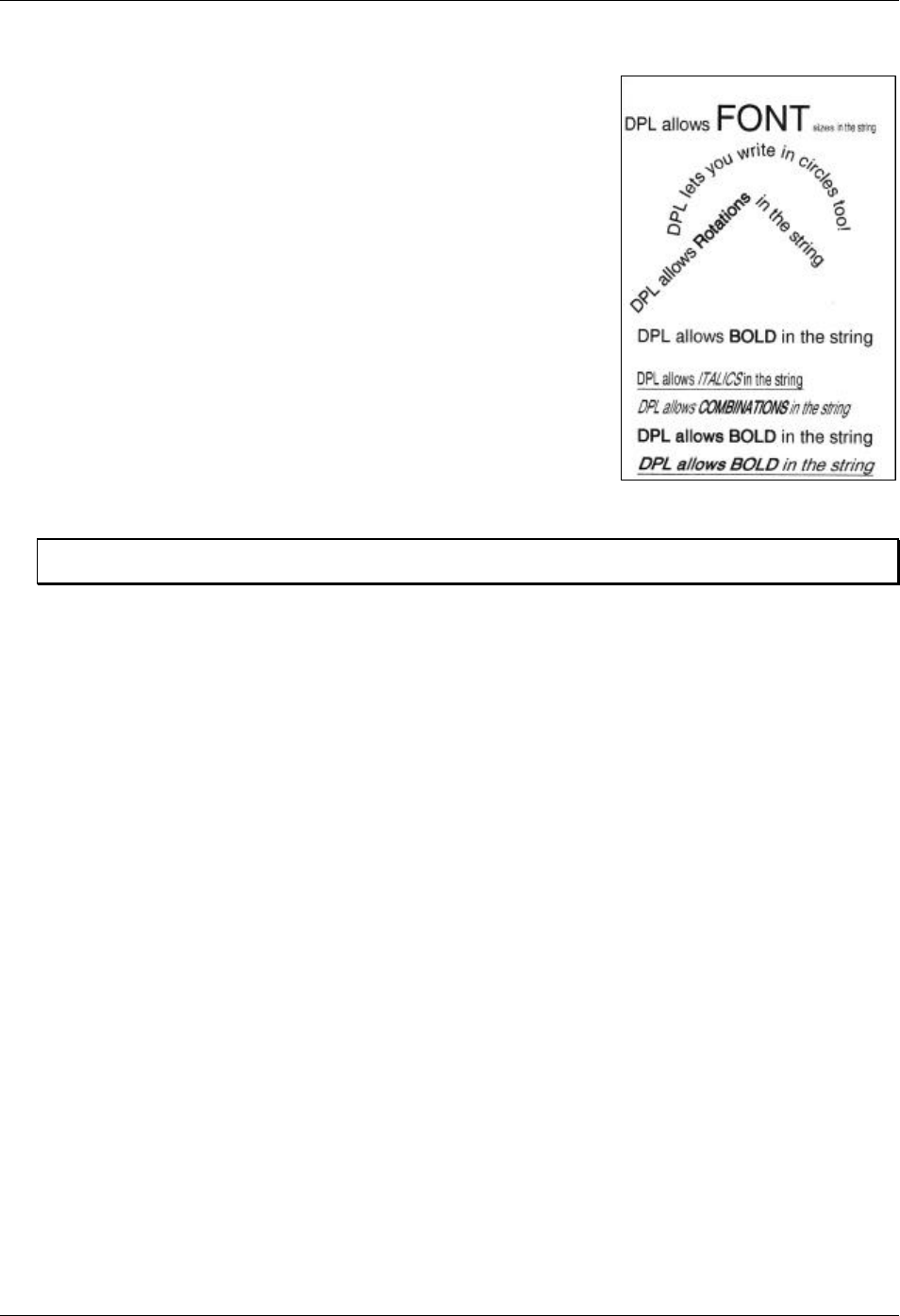
Generating Label Formats
Class Series Programmer’s Manual 105
Figure 3 is an example of the output from this DPL command
stream. The user has the ability to change the point and set size of
the font within the DPL command record. In addition, the angle of
the baseline may be specified relative to the current orientation of
the record. (For example, the command \<FR+45> will rotate the
baseline forty five degrees in the positive direction from the
default print direction.)
Figure 3
þ Note: Refer to back to Section 8 for more information regarding the DPL record format for a scalable font
text string.

Generating Label Formats
106 Class Series Programmer’s Manual
Class Series Programmer’s Manual 107
Appendix
ASCII Control Chart
Char Dec Hex Char Dec Hex Char Dec Hex Char Dec Hex
Ctrl @ NUL 0 00 32 20 @ 64 40 ` 96 60
Ctrl A SOH 1 01 ! 33 21 A 65 41 a 97 61
Ctrl B STX 2 02 “ 34 22 B 66 42 b 98 62
Ctrl C EXT 3 03 # 35 23 C 67 43 c 99 63
Ctrl D EOT 4 04 $ 36 24 D 68 44 d 100 64
Ctrl E ENQ 5 05 % 37 25 E 69 45 e 101 65
Ctrl F ACK 6 06 & 38 26 F 70 46 f 102 66
Ctrl G BEL 7 07 Ô 39 27 G 71 47 g 103 67
Ctrl H BS 8 08 ( 40 28 H 72 48 h 104 68
Ctrl I HT 9 09 ) 41 29 I 73 49 i 105 69
Ctrl J LF 10 0A * 42 2A J 74 4A j 106 6A
Ctrl K VT 11 0B + 43 2B K 75 4B k 107 6B
Ctrl L FF 12 0C , 44 2C L 76 4C l 108 6C
Ctrl M CR 13 0D - 45 2D M 77 4D m 109 6D
Ctrl N SO 14 0E . 46 2E N 78 4E n 110 6E
Ctrl O SI 15 0F / 47 2F O 79 4F o 111 6F
Ctrl P DLE 16 10 0 48 30 P 80 50 p 112 70
Ctrl Q DC1 17 11 1 49 31 Q 81 51 q 113 71
Ctrl R DC2 18 12 2 50 32 R 82 52 r 114 72
Ctrl S DC3 19 13 3 51 33 S 83 53 s 115 73
Ctrl T DC4 20 14 4 52 34 T 84 54 t 116 74
Ctrl U NAK 21 15 5 53 35 U 85 55 u 117 75
Ctrl V SYN 22 16 6 54 36 V 86 56 v 118 76
Ctrl W ETB 23 17 7 55 37 W 87 57 w 119 77
Ctrl X CAN 24 18 8 56 38 X 88 58 x 120 78
Ctrl Y EM 25 19 9 57 39 Y 89 59 y 121 79
Ctrl Z SUB 26 1A : 58 3A Z 90 5A z 122 7A
Ctrl [ ESC 27 1B ; 59 3B [ 91 5B { 123 7B
Ctrl \ FS 28 1C < 60 3C \ 92 5C | 124 7C
Ctrl ] GS 29 1D = 61 3D ] 93 5D } 125 7D
Ctrl ^ RS 30 1E > 62 3E ^ 94 5E ~ 126 7E
Ctrl _ US 31 1F ? 63 3F _ 95 5F 127 7F
Appendix A
108 Class Series Programmer’s Manual
ASCII Control Chart (continued)
Char Dec Hex Char Dec Hex Char Dec Hex Char Dec Hex
Ç 128 80 á 160 A0 192 C0 Ó 224 E0
ü 129 81 í 161 A1 193 C1 ß 225 E1
é 130 82 ó 162 A2 194 C2 Ô 226 E2
â 131 83 ú 163 A3 195 C3 Ò 227 E3
ä 132 84 ñ 164 A4 196 C4 õ 228 E4
à 133 85 Ñ 165 A5 197 C5 Õ 229 E5
å 134 86 ª 166 A6 ã 198 C6 µ 230 E6
ç 135 87 ° 167 A7 Ã 199 C7 þ 231 E7
ê 136 88 ¿ 168 A8 200 C8 Þ 232 E8
ë 137 89 ® 169 A9 201 C9 Ú 233 E9
è 138 8A 170 AA 202 CA Û 234 EA
ï 139 8B 1/2 171 AB 203 CB Ù 235 EB
î 140 8C 1/4 172 AC 204 CC ý 236 EC
ì 141 8D ¡ 173 AD 205 CD Ý 237 ED
Ä 142 8E 174 AE 206 CE 238 EE
Å 143 8F ¯ 175 AF 207 CF 239 EF
É 144 90 176 B0 ð 208 D0 240 F0
æ 145 91 177 B1 Ð 209 D1 ± 241 F1
Æ 146 92 ² 178 B2 Ê 210 D2 242 F2
ô 147 93 ³ 179 B3 Ë 211 D3 3/4 243 F3
ö 148 94 ´ 180 B4 È 212 D4 244 F4
ò 149 95 Á 181 B5 213 D5 245 F5
û 150 96 Â 182 B6 Í 214 D6 ÷ 246 F6
ù 151 97 À 183 B7 Î 215 D7 ¸ 247 F7
ÿ 152 98 © 184 B8 Ï 216 D8 º 248 F8
Ö 153 99 ¹ 185 B9 217 D9 ¨ 249 F9
Ü 154 9A 186 BA 218 DA · 250 FA
ø 155 9B » 187 BB 219 DB 251 FB
£ 156 9C 188 BC 220 DC 252 FC
Ø 157 9D ¢ 189 BD 221 DD 253 FD
x 158 9E ¥ 190 BE Ì 222 DE 254 FE
ƒ 159 9F 191 BF 223 DF 255 FF
þ Notes: (1) For hardware handshake XON/XOFF commands:
XON = Ctrl Q (DC1)
XOFF = Ctrl S (DC3)
(2) The Euro currency character ( ) has been added to the table above at 255 (FF) as a
Datamax standard for resident bit-mapped fonts 0,1,2,3,4,5,6, and 9 (CG Triumvirate).

Class Series Programmer’s Manual 109
Appendix
Sample Programs
‘C’ Language Program
The following sample ‘C’ program is included for reference. Figure B-1 shows the output generated
by this program.
/« DMX SERIES Sample C program «/
# include <stdio.h>
main ()
{
char «pcs = “590”;
char «desc = “10K OHM 1/4 WATT”;
fputs (“DMX Printer Test Program\n”, stdout);
fputs (“\x02L\n”, stdaux); /« STX L – Enter Label Formatting «/
fputs (“H07\n” stdaux); /« Enter Heat Setting of 7«/
fputs (“D11\n”, stdaux); /« Set Width and Height Dot Size «/
fprintf (stdaux, “191108010000025%s\n”,desc); /« Select smooth Font «/
fprintf (stdaux, “1a6210000000050%sPCS\n”, pcs); /« Select Bar code type ‘a’ «/
fputs (“E\n”, stdaux); /« End Label format mode and print«/
}
10K OHM 1/4 WATT
Figure B-1: Sample Label

Appendix B – Sample Programs
110 Class Series Programmer’s Manual
ASCII text file
The following ASCII text file will also generate the label shown in Figure B-1.
^BL
H07
D11
19110080100002510K OHM 1/4 WATT<CR>
1a6210000000050590PCS<CR>
E<CR>
VB Application Generating DPL
The following sample is a Visual Basic program that displays a database record on the screen. A user
can scroll through the records and then print a selected one. Five bar codes are printed along with data
fields and headings.
‘Printer DPL Controls
Dim CharSet As String ‘<STX> byte
Const StartLabel = “L”
Const EndLabel = “E”
Const PrintDensity = “D11”
‘Printer DPL Data to position dynamic information on label
Const OrderTxt = “191100704150010” ‘font 9, 24 pt
Const OrderBC = “1a6205004200120”
Const CustomerTxt = “191100603600010”
Const Item1NO = “191100403250010”
Const Item1BC = “1a6204002870010”
Const Item1Txt = “191100402690010”
Const Item1Qty = “191100603070260”
‘DPL Fixed Items on label
Const Itm1 = “191100303400010Item #”
Const Qty1 = “191100303400250Quantity”
Const Boxsize = “B065035002002”
Const BoxPos1 = “1X1100003050240”
Const Image1 = “1Y3300004750010SLANT1”
Dim Fixed As String
‘Item Variables
Dim Item1 As String
Dim PrintLabel As String
Dim OrderData As String
‘Print label by clicking print button with the mouse
Private Sub cmdPrint_Click()

Appendix B – Sample Programs
Class Series Programmer’s Manual 111
‘Concatenate all the dynamic data fields with the constant
header strings, terminated with <cr> Chr$(13)
OrderData = OrderTxt & txtOrderNo.Text & Chr$(13) &
OrderBC & txtOrderNo.Text & Chr$(13) & CustomerTxt &
txtCustomer.Text
Item1 = Item1NO & txtItem1.Text & Chr$(13) & Item1BC &
txtItem1.Text & Chr$(13) & Item1Txt & txtItem1Desc.Text &
Chr$(13) & Item1Qty & txtItem1Qty.Text
‘Concatinate entire label format and send out serial port
PrintLabel = CharSet & MaxLength & Chr$(13) & CharSet &
StartLabel & Chr$(13) & PrintDensity & Chr$(13) & Image1 &
Chr$(13) & OrderData & Chr$(13) & Item1 & Chr$(13) & Fixed &
Chr$(13) & EndLabel
Comm1.Output = PrintLabel End Sub
‘Display the record form on the screen
Private Sub Form_Load()
Fixed = Itm1 & Chr$(13) & Chr$(13) & Qty1 & Chr$(13) &
Chr$(13) & BoxPos1 & Boxsize & Chr$(13)
CharSet = Chr$(126) ‘Alternate <stx> character ~
MComm.PortOpen = 1 ‘Open the serial port
End Sub
‘Exit the program by clicking Exit button with the mouse
Private Sub cmdExit_Click()
Comm1.PortOpen = 0 ‘Close down the serial port
End
End Sub
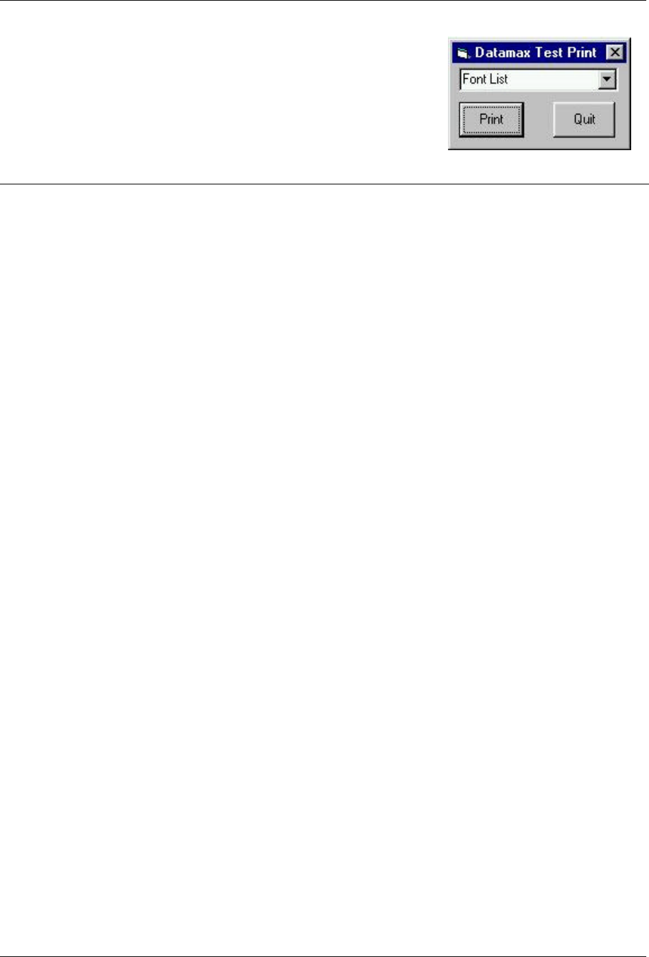
Appendix B – Sample Programs
112 Class Series Programmer’s Manual
VB Application interfacing via Windows Driver
Create a form similar to the one shown here.
VERSION 5.00
Begin VB.Form Form1
Caption = “Datamax Test Print”
ClientHeight = 1065
ClientLeft = 60
ClientTop = 345
ClientWidth = 2325
LinkTopic = “Form1”
MaxButton = 0 ‘False
MinButton = 0 ‘False
ScaleHeight = 1065
ScaleWidth = 2325
StartUpPosition = 3 ‘Windows Default
Begin VB.ComboBox cmboFonts
Height = 315
Left = 90
TabIndex = 2
Text = “Font List”
Top = 45
Width = 2130
End
Begin VB.CommandButton cmdExit
Caption = “Quit”
Height = 465
Left = 1350
TabIndex = 1
Top = 495
Width = 825
End
Begin VB.CommandButton cmdPrint
Caption = “Print”
Height = 465
Left = 90
TabIndex = 0
Top = 495
Width = 870
End
End
Attribute VB_Name = “Form1”
Attribute VB_GlobalNameSpace = False
Attribute VB_Creatable = False
Attribute VB_PredeclaredId = True
Attribute VB_Exposed = False
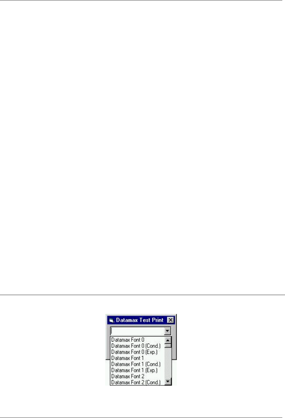
Appendix B – Sample Programs
Class Series Programmer’s Manual 113
‘Print label by clicking print button with the mouse
Private Sub cmdPrint_Click()
‘font name as seen in application font list box
‘if not found, driver will inform GDI to generate an
‘image that will be downloaded
Printer.FontName = cmboFonts.Text
‘1,440 twips equals one inch
Printer.Height = 6480 ‘4.5 inches in twips
Printer.Width = 5760 ‘4 inches in twips
Printer.CurrentX = 1440 ‘1 inch (column position)
Printer.CurrentY = 2160 ‘2 inches (row position)
Printer.Print “0123456789”
Printer.EndDoc
End Sub
Private Sub Form_Load()
Dim X As Printer
Dim I As Integer ‘Used for the font list
‘ search for printer queue name / driver name
For Each X In Printers
If X.DeviceName = “Datamax I-4206” Then ‘printer found
‘ Set printer as system default.
Set Printer = X
For I = 0 To Printer.FontCount - 1 ‘ Determine number of fonts.
cmboFonts.AddItem Printer.Fonts(I) ‘ Put each font into
list box.
Next I
Exit For
End If
Next
End Sub
‘Exit the program and shut down the serial port
‘by clicking Exit button with the mouse
Private Sub cmdExit_Click()
End
End Sub
When the program is run, the combo box should be populated with the available fonts as shown below.

Appendix B – Sample Programs
114 Class Series Programmer’s Manual
VB Application to Send RAW Data via a Windows Printer Driver
This is a sample Visual Basic program that checks for any printer driver attached to “LPT1”. If one is
installed then a DPL file can be printed via the print driver. **Note that this does not have to be a
Datamax DPL print driver. DPL is created by the application and sent to LPT1.
To begin, a global variable called SelPrinter must be defined as a string. Then use the following code
to create a .frm file.
VERSION 5.00
Object = “{F9043C88-F6F2-101A-A3C9-08002B2F49FB}#1.2#0”;
“comdlg32.ocx”
Begin VB.Form Form1
Caption = “Form1”
ClientHeight = 1290
ClientLeft = 165
ClientTop = 735
ClientWidth = 3750
LinkTopic = “Form1”
MaxButton = 0 ‘False
MinButton = 0 ‘False
ScaleHeight = 1290
ScaleWidth = 3750
StartUpPosition = 3 ‘Windows Default
Begin MSComDlg.CommonDialog CommonDialog1
Left = 1635
Top = 765
_ExtentX = 847
_ExtentY = 847
_Version = 393216
End
Begin VB.CommandButton cmdClose
Cancel = -1 ‘True
Caption = “Close”
Height = 372
Left = 2400
TabIndex = 3
Top = 735
Width = 972
End
Begin VB.CommandButton cmdStoreImage
Caption = “Print”
Default = -1 ‘True
Height = 372
Left = 240
TabIndex = 2
Top = 735
Width = 972
End
Begin VB.TextBox txtFile
Height = 288

Appendix B – Sample Programs
Class Series Programmer’s Manual 115
Left = 120
TabIndex = 1
Top = 360
Width = 3492
End
Begin VB.Label Label1
Caption = “File Name”
Height = 255
Left = 120
TabIndex = 0
Top = 135
Width = 1455
End
Begin VB.Menu File
Caption = “&File”
Begin VB.Menu open
Caption = “&Open”
End
Begin VB.Menu exit
Caption = “&Exit”
Shortcut = ^Q
End
End
End
Attribute VB_Name = “Form1”
Attribute VB_GlobalNameSpace = False
Attribute VB_Creatable = False
Attribute VB_PredeclaredId = True
Attribute VB_Exposed = False
Option Explicit
‘**********************************
#If Win32 Then
Private Type DOC_INFO_1
pDocName As String
pOutputFile As String
pDatatype As String
End Type
#End If ‘WIN32 Types
‘**********************************
‘** Function Declarations:
#If Win32 Then
Private Declare Function OpenPrinter& Lib “winspool.drv” Alias
“OpenPrinterA” (ByVal pPrinterName As String, phPrinter As Long, ByVal
pDefault As Long) ‘ Third param changed to long
Private Declare Function StartDocPrinter& Lib “winspool.drv” Alias
“StartDocPrinterA” (ByVal hPrinter As Long, ByVal Level As Long,
pDocInfo As DOC_INFO_1)

Appendix B – Sample Programs
116 Class Series Programmer’s Manual
Private Declare Function StartPagePrinter& Lib “winspool.drv” (ByVal
hPrinter As Long)
Private Declare Function WritePrinter& Lib “winspool.drv” (ByVal
hPrinter As Long, pBuf As Any, ByVal cdBuf As Long, pcWritten As Long)
Private Declare Function EndDocPrinter& Lib “winspool.drv” (ByVal
hPrinter As Long)
Private Declare Function EndPagePrinter& Lib “winspool.drv” (ByVal
hPrinter As Long)
Private Declare Function ClosePrinter& Lib “winspool.drv” (ByVal
hPrinter As Long)
#End If ‘WIN32
Dim ch As String * 1, f1 As Integer, loadfile As String
Private Sub cmdOpenFile_Click()
On Error GoTo ErrHandler
‘ Set Filters
CommonDialog1.Filter = “All Files (*.*)|*.*”
‘Specify Default Filter
CommonDialog1.FilterIndex = 1
‘Display Open dialog box
CommonDialog1.ShowOpen
loadfile = CommonDialog1.FileName
Label2.Caption = loadfile
Exit Sub
ErrHandler:
Exit Sub
End Sub
Private Sub cmdStoreImage_Click()
Dim hPrinter&
Dim jobid&
Dim res&
Dim written&
Dim printdata$
Dim docinfo As DOC_INFO_1
loadfile = Form1.txtFile.Text
If loadfile = ““ Then
MsgBox “You must Open a file to send”, vbExclamation
Exit Sub
End If
‘ Open file.
f1 = FreeFile
Open loadfile For Binary As f1
‘ Open printer for printing
res& = OpenPrinter(SelPrinter, hPrinter, 0)
If res = 0 Then
MsgBox “Unable to open the printer”
Exit Sub
End If

Appendix B – Sample Programs
Class Series Programmer’s Manual 117
docinfo.pDocName = “MyDoc”
docinfo.pOutputFile = vbNullString
docinfo.pDatatype = vbNullString
jobid = StartDocPrinter(hPrinter, 1, docinfo)
Call StartPagePrinter(hPrinter)
Call WritePrinter(hPrinter, ByVal printdata$, Len(printdata$),
written)
While Not EOF(1)
Get #f1, , ch
printdata$ = ch
Call WritePrinter(hPrinter, ByVal printdata$, Len(printdata$),
written)
Wend
Call EndPagePrinter(hPrinter)
Call EndDocPrinter(hPrinter)
Call ClosePrinter(hPrinter) ‘ Close when done
‘ Close file
Close #1
MsgBox “File sent to print spooler.”, vbExclamation
End Sub
Private Sub cmdClose_Click()
Unload Me
End Sub
Private Sub exit_Click()
End
End Sub
Private Sub Form_Load()
Dim X As Printer
‘ search for printer queue name / driver name
For Each X In Printers
If X.Port = “LPT1:” Then ‘printer found
‘ Set printer as system default.
SelPrinter = X.DeviceName
Exit For
End If
Next
End Sub
Private Sub lpt2_Click()
End Sub
Private Sub open_Click()
CommonDialog1.ShowOpen
loadfile = CommonDialog1.FileName
txtFile.Text = loadfile
End Sub
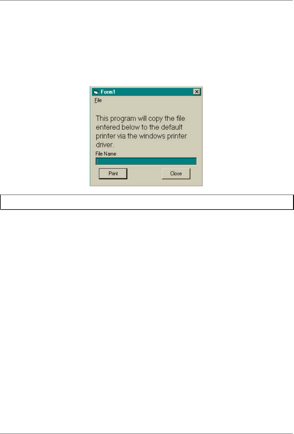
Appendix B – Sample Programs
118 Class Series Programmer’s Manual
Private Sub Printer_Click()
CommonDialog1.ShowPrinter
End Sub
This will create the form pictured below:
þ Note: It may be necessary to remove and reinsert the common dialog control due to Windows® registry
issues.
Class Series Programmer’s Manual 119
Appendix
Available Fonts – Sizes, References, and Samples
All character bit-mapped fonts available on the printers are described in this section. Each font has a name
(Font ID) associated with it for use in programming. Use the Font Number (in the left column of Table C-
1) in field b of the Format Record header to cause the printer to use the corresponding font.
Fonts 0 through 8 use the slash zero (Ø) conventions for distinguishing between the zero and the
alphabetic O. The slash can be removed with the label formatting command z. These fonts are non-
proportional (monospaced). Therefore, all of the characters take up the same amount of space when
printed. This is helpful when using variable data in a fixed area. The sizes of these fonts are shown on the
following pages.
The CG Triumvirate font number 9 is a proportional font. Each character will take up a different amount
of space when printed. For example, the letter W will be wider than the letter I.
Font
Number
Valid ASCII Characters (decimal) Use with Record
Structure Type
0 32-127, 255
1 32-168, 171, 172, 225, 255
2 32-168, 171, 172, 225, 255
3 32, 35-38, 40-58, 65-90, 128, 142-144, 146, 153, 154, 156, 157, 165,
168, 225, 255
4 32, 35-38, 40-58, 65-90, 128, 142-144, 146, 153, 154, 156, 157, 165,
168, 225, 255
5 32, 35-38, 40-58, 65-90, 128, 142-144, 146, 153, 154, 156, 157, 165,
168, 225, 255
6 32, 35-38, 40-58, 65-90, 128, 142-144, 146, 153, 154, 156, 157, 165,
168, 225, 255
7 32-126
8 32, 48-57, 60, 62, 67, 69, 78, 83, 84, 88, 90
Internal
Bit-Mapped
Fonts
9 32-126, 128-169, 171-173, 181-184, 189, 190, 198, 199, 208-216,
222, 224-237, 241, 243, 246-250, 255
Smooth Font*
9 Dependent upon selected symbol set, see Appendix H. Scalable Font
*E-Class and M-4206.
Table C-1: Valid Human-Readable Font (Internal) ASCII Characters
Appendix C – Available Fonts
120 Class Series Programmer’s Manual
Font sizes are dependent upon the printhead resolution of the printer used; Tables C-2 to C-5 contain a
listing of the font sizes by resolution with dimensions given in dots.
Font Height Width Spacing Point Size
Font 0 7 5 1 2.5
Font 1 13 7 2 4.6
Font 2 18 10 2 6.4
Font 3 27 14 2 9.6
Font 4 36 18 3 12.8
Font 5 52 18 3 18.4
Font 6 64 32 4 22.7
Font 7 32 15 5 11.3
Font 8 28 15 5 9.9
Table C-2: Font Sizes @ 203 DPI Resolution
Font Height Width Spacing Point Size
Font 0 10 7 1 2.4
Font 1 19 10 3 4.6
Font 2 27 15 3 6.5
Font 3 40 21 3 9.6
Font 4 53 27 4 12.7
Font 5 77 27 4 18.5
Font 6 95 47 6 22.8
Font 7 47 22 7 11.3
Font 8 41 22 7 9.8
Table C-3: Font Sizes @ 300 DPI Resolution
Font Height Width Spacing Point Size
Font 0 14 10 2 2.5
Font 1 26 14 4 4.6
Font 2 36 20 4 6.4
Font 3 54 28 4 9.6
Font 4 72 36 6 12.8
Font 5 104 36 6 18.4
Font 6 128 64 8 22.7
Font 7 64 30 10 11.3
Font 8 56 30 10 9.9
Table C-4: Font Sizes @ 406 DPI Resolution
Appendix C – Available Fonts
Class Series Programmer’s Manual 121
Font Height Width Spacing Point Size
Font 0 20 14 2 2.4
Font 1 38 20 6 4.6
Font 2 54 30 6 6.5
Font 3 80 42 6 9.6
Font 4 106 54 8 12.7
Font 5 154 54 8 18.5
Font 6 190 94 12 22.8
Font 7 94 44 14 11.3
Font 8 82 44 14 9.8
Table C-5: Font Sizes @ 600 DPI Resolution
Internal Smooth Font 9 (Smooth Font) Point Size Specifiers
Label format records with font code 9 (in Format Record header field b) can specify any of the font sizes
in the leftmost column of the table below. The corresponding specification in either column labeled Ann
or 0nn is used in the font size/selection (eee height) field to select the desired font size. Optional font
sets may contain subsets of those described here. For an optional font set that generates these fonts via
scalable font technology, the character mapping for this font is the selected scalable symbol set (see
Appendix E).
In the sample format below, a 300 DPI printer will use 4-point smooth font to produce a printed label
with the words “four point font”. Sample format:
<STX>L<CR>
1911A0400100010four point font<CR>
E<CR>
Smooth Font 9 Font Size Specification Syntax
Ann
Point
Size 203 DPI Print Resolution [1] 300, 400, & 600 DPI Print Resolutions [2]
0nn
4 - A04 -
5 - A05 000[3]
6 A06 A06 001
8 A08 A08 002
10 A10 A10 003
12 A12 A12 004
14 A14 A14 005
18 A18 A18 006
24 A24 A24 007
30 A30 A30 008
36 A36 A36 009
48 A48 A48 010
72 - A72 -
[1] All fonts greater than A36 are created from multiples of smaller fonts, 2x or 3x, as available.
[2]All fonts greater than A24 are created from multiples of smaller fonts, 2x or 3x, as available.
[3] Available at 300 DPI and greater print resolutions only.
Table C-6: Internal Bit-Mapped (Smooth Font) 9 Size Chart
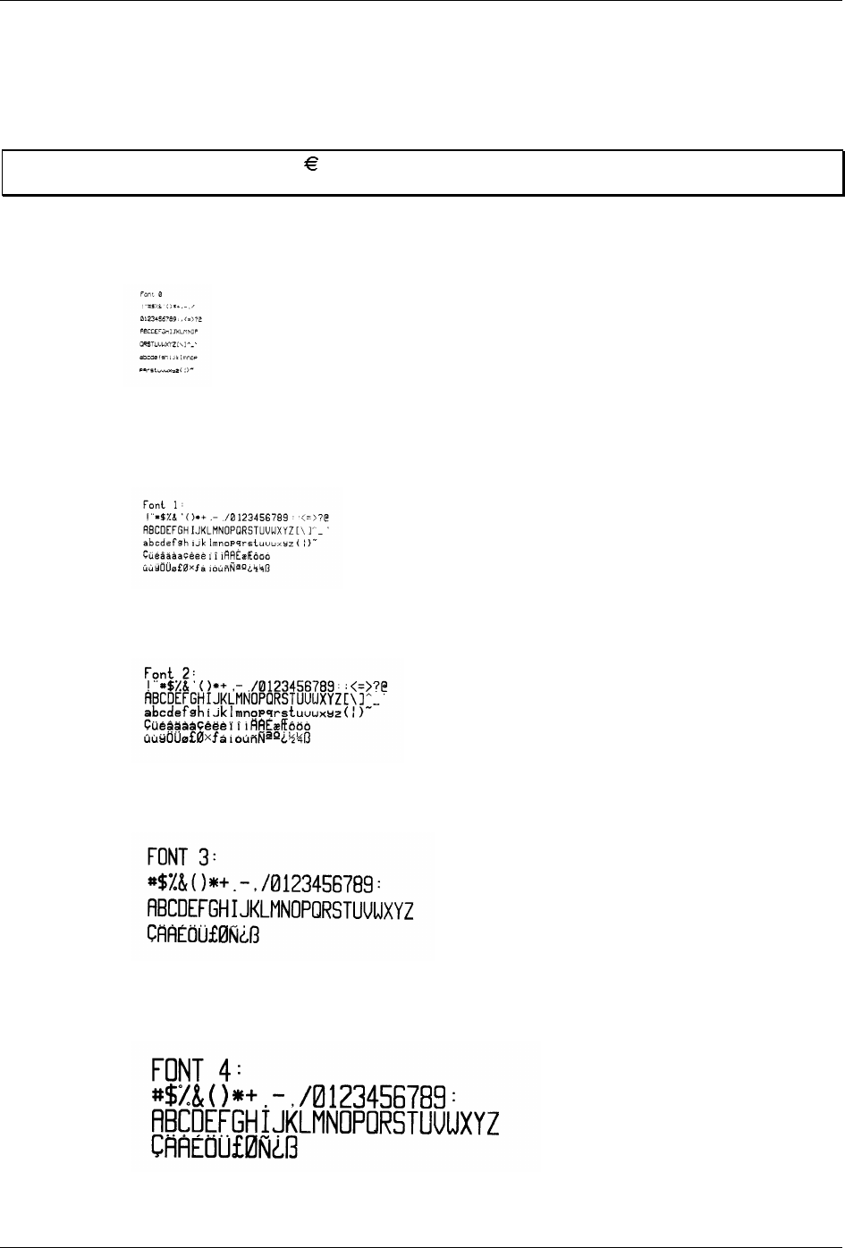
Appendix C – Available Fonts
122 Class Series Programmer’s Manual
Internal Bit-Mapped and Smooth Font Samples
The identifying number is used in the Format Record header field b to cause the printer to use the
corresponding font.
þ Note: The Euro currency character ( ) has been added to Fonts 0 – 6. For the E-Class and M-4206 only, the
character is also present in Font 9.
0: Identifies a 96-character alphanumeric font, uppercase and lowercase.
1: Identifies a 145-character uppercase and lowercase alphanumeric font that includes desenders and
ascenders.
2: Identifies a 138-character alphanumeric upper and lowercase font.
3: Identifies a 62-character alphanumeric uppercase font.
4: Identifies a 62-character alphanumeric uppercase font.
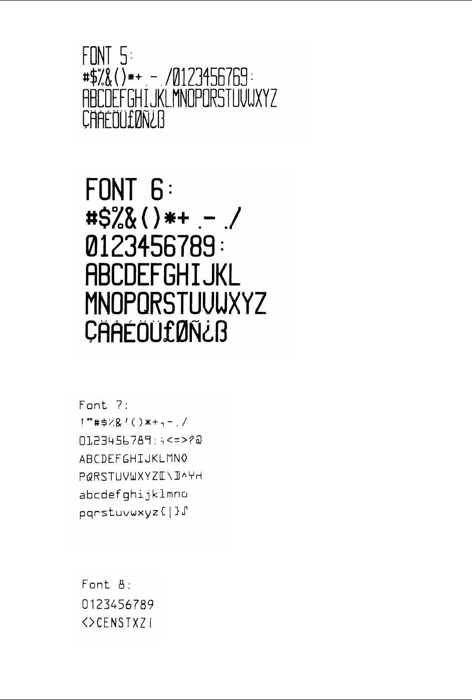
Appendix C – Available Fonts
Class Series Programmer’s Manual 123
5: Identifies a 62-character alphanumeric upper case font.
6: Identifies a 62-character alphanumeric uppercase font.
7: Identifies a font that prints OCR-A, size I.
8: Identifies a font that prints OCR-B, size III.
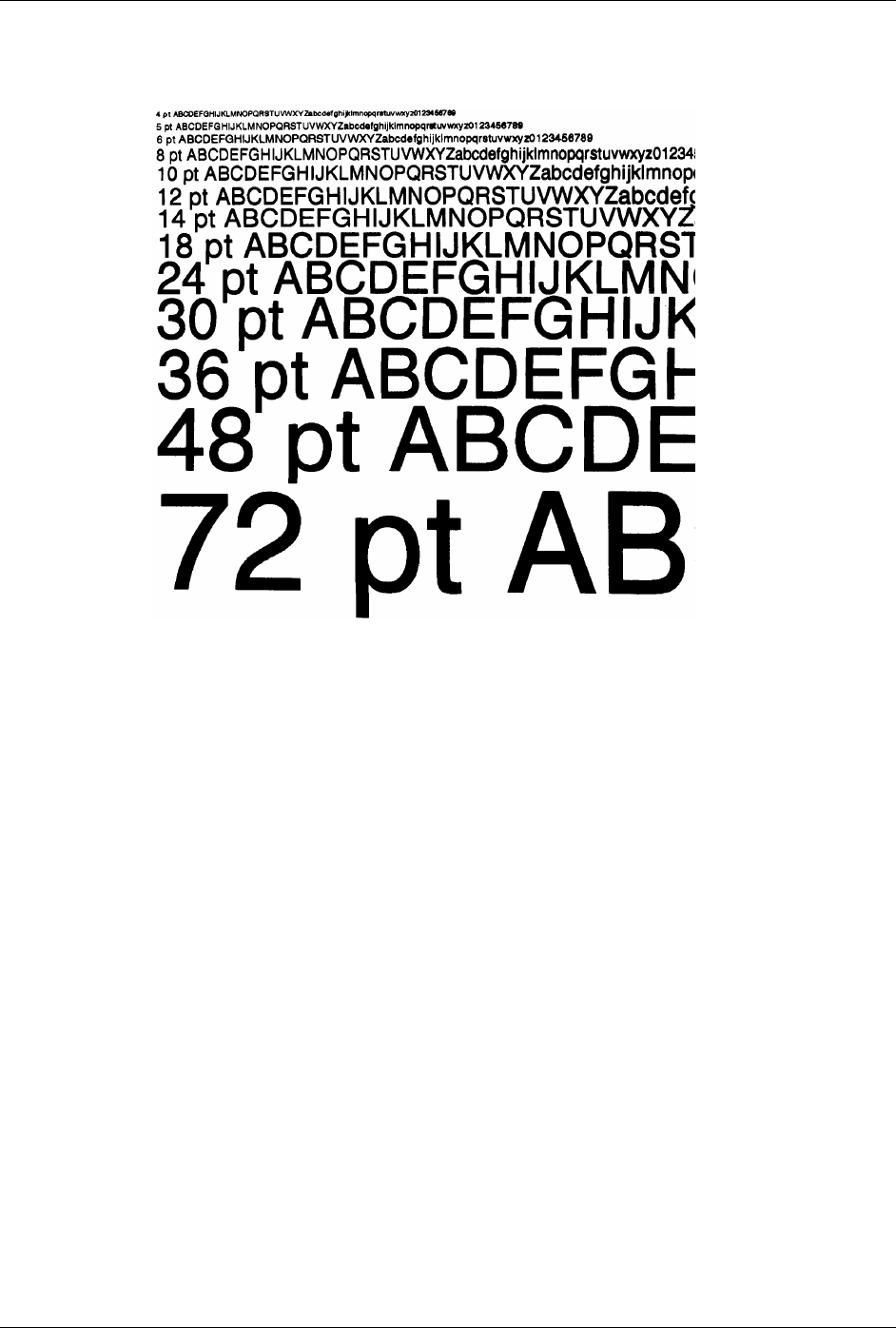
Appendix C – Available Fonts
124 Class Series Programmer’s Manual
9: Identifies the Internal CG Triumvirate font. Point sizes are selected by the number in the Format
Record header eee height field, see Table C-6.

Class Series Programmer’s Manual 125
Appendix
Reset Codes
The most common transmitted error codes are:
Uppercase “R”
This code is sent every time the printer is turned ‘On’, signaling a hardware reset.
Uppercase “T”
This code signals a software reset. A software reset is made by sending the command sequence to the
printer or by performing a reset using the front panel keys.
Lowercase “v”
There is an input buffer overflow situation, caused when an overflow of data is sent to the printer.

Appendix D – Reset Codes
126 Class Series Programmer’s Manual
Class Series Programmer’s Manual 127
Appendix
Single Byte Symbol Sets
The following tables include some of the sixty-six standard symbol sets. Not all of these symbol sets can
be used with every font. Symbol sets containing the Euro currency character are W1, WE, WG, WL, WT,
WR, and PM; see Appendix I, and the <STX>y command.
þ Note: The following sets were produced using a Windows-based PC-compatible with an English (United
States) keyboard properties layout. Results may vary if printing this document using a different input
locale.
(DN) ISO 60: Danish / Norwegian Symbol Set
0 1 2 3 4 5 6 7 8 9 A B C D E F
00
10
20 ! “ # $ % & ‘ ( ) * + , - . /
30 0 1 2 3 4 5 6 7 8 9 : ; < = > ?
40 @ A B C D E F G H I J K L M N O
50 P Q R S T U V W X Y Z Æ Ø Å ^ _
60 ‘ a b c d e f g h i j k l m n o
70 p q r s t u v w x y z æ ø å ¯ ¦
(DT) DeskTop Symbol Set
0 1 2 3 4 5 6 7 8 9 A B C D E F
00
10
20 ! “ # $ % & ‘ ( ) * + , - . /
30 0 1 2 3 4 5 6 7 8 9 : ; < = > ?
40 @ A B C D E F G H I J K L M N O
50 P Q R S T U V W X Y Z [ \ ] ^ -
60 ‘ a b c d e f g h i j k l m n o
70 p q r s t u v w x y z { | } ~ ¦
80
90
A0 ¶ § † ‡ © ® ¢ – — … fi fl
B0 “ “ µ ‰ • l o þ ✟ • ? ‘ ¬ ¦ =
C0 – ± × ÷ ° ′ ″ ¼ ½ ¾ ¹ ² ³ /
D0 ( ) « » ‚ „ ‘ ¡ ¿ Pt l £ ¥ ¤ ƒ ß
E0 ª º æ Æ ð Ð ij IJ t t œ Œ ø Ø þ Þ
F0 ‘ ‘ ˆ ¨ ˜ ? ? ” ° · ¯ , ? ' l
Appendix E – Single Byte Symbol Sets
128 Class Series Programmer’s Manual
(E1) ISO 8859/1 Latin 1 Symbol Set
0 1 2 3 4 5 6 7 8 9 A B C D E F
00
10
20 ! “ # $ % & ‘ ( ) * + , - . /
30 0 1 2 3 4 5 6 7 8 9 : ; < = > ?
40 @ A B C D E F G H I J K L M N O
50 P Q R S T U V W X Y Z [ \ ] ^ -
60 ‘ a b c d e f g h i j k l m n o
70 p q r s t u v w x y z { | } ~ ¦
80
90
A0 ¡ ¢ £ ¤ ¥ ¦ § ¨ © ª « ¬ - ® ¯
B0 ° ± ² ³ ´ µ ¶ · ¸ ¸ ¹ » ¼ ½ ¾ ¿
C0 À Á Â Ã Ä Å Æ Ç È É Ê Ë Ì Í Î Ï
D0 Ð Ñ Ò Ó Ô Õ Ö × Ø Ù Ú Û Ü Ý Þ ß
E0 à á â ã ä å æ ç è é ê ë ì í î ï
F0 ð ñ ò ó ô õ ö ÷ ø ù ú û ü ý þ ÿ
(E2) ISO 8859/2 Latin 2 Set
0 1 2 3 4 5 6 7 8 9 A B C D E F
00
10
20 ! “ # $ % & ‘ ( ) * + , - . /
30 0 1 2 3 4 5 6 7 8 9 : ; < = > ?
40 @ A B C D E F G H I J K L M N O
50 P Q R S T U V W X Y Z [ \ ] ^ -
60 ‘ a b c d e f g h i j k l m n o
70 p q r s t u v w x y z { | } ~ ¦
80
90
A0 ? L ¤ § ¨ ° Š · Z
B0 º l ´ · ¸ ¹ š “
z
C0 Á Â Ä Ç É Ë Í Î
D0 Ð Ó Ô Ö × Ø Ú Ü Ý ß
E0 á â ä ç é ë í î
F0 ó ô ö ÷ ú ü ý
(E5) ISO 8859/5 Latin 5 Set
0 1 2 3 4 5 6 7 8 9 A B C D E F
00
10
20 ! “ # $ % & ‘ ( ) * + , - . /
30 0 1 2 3 4 5 6 7 8 9 : ; < = > ?
40 @ A B C D E F G H I J K L M N O
50 P Q R S T U V W X Y Z [ \ ] ^ -
60 ‘ a b c d e f g h i j k l m n o
70 p q r s t u v w x y z { | } ~ ¦
80
90
A0 ¡ ¢ £ ¤ ¥ ¦ § ¨ ª « ¬ - ¯
B0 º ± ² ³ ´ µ ¶ · ¸ ¹ º » ¼ ½ ¾ ¿
C0 À Á Â Ã Ä Å Æ Ç È É Ê Ë Ì Í Î Ï
D0 Ñ Ò Ó Ô Õ Ö × Ø Ù Ú Û Ü ß
E0 à á â ã ä å æ ç è é ê ë ì í î ï
F0 ñ ò ó ô õ ö ÷ ø ù ú û ü I ÿ
Appendix E – Single Byte Symbol Sets
Class Series Programmer’s Manual 129
(FR) ISO 69: French Symbol Set
0 1 2 3 4 5 6 7 8 9 A B C D E F
00
10
20 ! “ £ $ % & ‘ ( ) * + , - . /
30 0 1 2 3 4 5 6 7 8 9 : ; < = > ?
40 à A B C D E F G H I J K L M N O
50 P Q R S T U V W X Y Z º ç § ^ _
60 µ a b c d e f g h i j k l m n o
70 p q r s t u v w x y z é ù è ¨ ¦
(GR) ISO 21: German Symbol Set
0 1 2 3 4 5 6 7 8 9 A B C D E F
00
10
20 ! “ # $ % & ? ( ) * + ? - . /
30 0 1 2 3 4 5 6 7 8 9 : ; < = > ?
40 § A B C D E F G H I J K L M N O
50 P Q R S T U V W X Y Z Ä Ö Ü ^ _
60 ‘ a b c d e f g h i j k l m n o
70 p q r s t u v w x y z ä ö ü ß ¦
(IT) ISO 15: Italian Symbol Set
0 1 2 3 4 5 6 7 8 9 A B C D E F
00
10
20 ! “ £ $ % & ‘ ( ) * + , - . /
30 0 1 2 3 4 5 6 7 8 9 : ; < = > ?
40 § A B C D E F G H I J K L M N O
50 P Q R S T U V W X Y Z º ç é ^ _
60 ù a b c d e f g h i j k l m n o
70 p q r s t u v w x y z à ò è ì ¦
(LG) Legal Symbol Set
0 1 2 3 4 5 6 7 8 9 A B C D E F
00
10
20 ! “ # $ % & ‘ ( ) * + , - . /
30 0 1 2 3 4 5 6 7 8 9 : ; = = ¢ ?
40 @ A B C D E F G H I J K L M N O
50 P Q R S T U V W X Y Z [ ] _
60 ° a b c d e f g h i j k l m n o
70 p q r s t u v w x y z § ¶ † ™ ¦
Appendix E – Single Byte Symbol Sets
130 Class Series Programmer’s Manual
(MC) Macintosh Symbol Set
0 1 2 3 4 5 6 7 8 9 A B C D E F
00
10
20 ! “ # $ % & ‘ ( ) * + , - . /
30 0 1 2 3 4 5 6 7 8 9 : ; < = > ?
40 @ A B C D E F G H I J K L M N O
50 P Q R S T U V W X Y Z [ \ ] ^ _
60 ` a b c d e f g h i j k l m n o
70 p q r s t u v w x y z { | } ~
80 Ä Å Ç É Ñ Ö Ü á à â ä ã å ç é è
90 ê ë í ì î ï ñ ó ò ô ö õ ú ù û ü
A0 † º ¢ £ § • ¶ ß ® © ™ ´ ¨ ≠ Æ Ø
B0 8 ± = = ¥ µ ∂ S ∏ p ∫ ª ° O æ
Ø
C0 ¿ ¡ ¬ v f ˜ ∆ « » … À Ã Õ Œ œ
D0 – — “ “ ‘ ‘ ÷ ◊ ÿ Ÿ / ¤ < > fi fl
E0 ‡ ` ‚ „ ‰ Â Ê Á Ë È Í Î Ï Ì Ó Ô
F0 Ò Ú Û Ù ˆ ˜ ¯ ? ? º ¸ ¨ ? ?
(PC) PC-8 Code Page 437 Symbol Set
0 1 2 3 4 5 6 7 8 9 A B C D E F
00 J ♥ ♦ ♣ ♠ l ? ? ? R
10 ✟ !! ¶ § - ? ↑ ↓ → ← ? ↔ ✟ ✟
20 ! “ # $ % & ‘ ( ) * + , - . /
30 0 1 2 3 4 5 6 7 8 9 : ; < = > ?
40 @ A B C D E F G H I J K L M N O
50 P Q R S T U V W X Y Z [ \ ] ^ _
60 ` a b c d e f g h i j k l m n o
70 p q r s t u v w x y z { | } ~ ¦
80 Ç ü é â ä à å ç ê ë è ï î ì Ä Å
90 É æ Æ ô ö ò û ù ÿ Ö Ü ¢ £ ¥ Pt ƒ
A0 á í ó ú ñ Ñ ª ° ¿ ¬ ¬ ½ ¼ ¡ « »
B0 ¦ ¦ ¦ ¦ ¦ ¦ ¦ + + ¦ ¦ + + + + +
C0 + - - + - + ¦ ¦ + + - - ¦ - + -
D0 - - - + + + + + + + + ¦ _ ¦ ¦ ¯
E0 a ß + p ? s µ ? ? T ? d 8 ? ? n
F0 = ± ≥ ≤ ( ) ÷ ˜ ? ? ? v n 2 ¦
(PD) PC-8 D/N, Code Page 437N Symbol Set
0 1 2 3 4 5 6 7 8 9 A B C D E F
00 J ♥ ♦ ♣ ♠ l ? ? ? R
10 ✟ !! ¶ § ? ? ↑ ↓ → ← ? ↔ ✟ ✟
20 ! “ # $ % & ‘ ( ) * + , - . /
30 0 1 2 3 4 5 6 7 8 9 : ; < = > ?
40 @ A B C D E F G H I J K L M N O
50 P Q R S T U V W X Y Z [ \ ] ^ _
60 ` a b c d e f g h i j k l m n o
70 p q r s t u v w x y z { | } ~ ¦
80 Ç ü é â ä à å ç ê ë è ï î ì Ä Å
90 É æ Æ ô ö ò û ù ÿ Ö Ü ø £ Ø ? ?
A0 á í ó ú ñ Ñ õ Õ ¿ ã Ã l ? ¡ ³ ¤
B0 ¦ ¦ ¦ ¦ ¦ ¦ ¦ + + ¦ ¦ + + + + +
C0 + - - + - + ¦ ¦ + + - - ¦ - + -
D0 - - - + + + + + + + + ¦ _ ¦ ¦ ¯
E0 a ß + p ? s µ ? ? T ? d 8 ? ? n
F0 = ± ≥ ≤ ( ) ÷ ˜ ? ? ? v n 2 ¦
Appendix E – Single Byte Symbol Sets
Class Series Programmer’s Manual 131
(PE) PC-852 Latin 2 Symbol Set
0 1 2 3 4 5 6 7 8 9 A B C D E F
00 J ♥ ♦ ♣ ♠ l ? ? ? R
10 ✟ !! ¶ § ? ? ↑ ↓ → ← ? ↔ ✟ ✟
20 ! “ # $ % & ‘ ( ) * + , - . /
30 0 1 2 3 4 5 6 7 8 9 : ; < = > ?
40 @ A B C D E F G H I J K L M N O
50 P Q R S T U V W X Y Z [ \ ] ^ _
60 ` a b c d e f g h i j k l m n o
70 p q r s t u v w x y z { | } ~ ¦
80 Ç ü é â ä ç l ë î Ä
90 É ô ö Ö Ü L ×
A0 á í ó ú Ž ž « »
B0 ¦ ¦ ¦ ¦ ¦ Á Â ¦ ¦ + + ?
C0 + - - + - + + + - - ¦ - + ¤
D0 ð Ð Ë Í Î + + ¦ _ ¯
E0 Ó ß Ô Š š Ú ý Ý ´
F0 ? “ ? ? ? § ÷ ¸ ° ¨ ´ n
(PI) PI Font Symbol Set
0 1 2 3 4 5 6 7 8 9 A B C D E F
00
10
20 „ ‚ “ “ ‘ ‘ 〈 〉 ™ ?
30 ¯ ? ? ? ä æ å ã ∆ > ∇ < « § » ¶
40 :: ∆ f h L l
50 P ℘ ∑ ? ‹ ›
60 + + ? ? + + - ?? U I +
+
? ?
70 + + ? ? - ¦ - ¦ ? ? +
+
¦ ✟ ¦
(PM) PC-850 Multilingual Symbol Set*
0 1 2 3 4 5 6 7 8 9 A B C D E F
00 J ✟ ✟ ✟ ✟ ✟ ? ? R
10 !! ¶ § ? é ê è ç ✟ ✟
20 ! “ # $ % & ‘ ( ) * + ‚ ¨ · /
30 0 1 2 3 4 5 6 7 8 9 : ; < = > ?
40 @ A B C D E F G H I J K L M N O
50 P Q R S T U V W X Y Z [ \ ] ^ _
60 ` a b c d e f g h i j k l m n o
70 p q r s t u v w x y z { | } ~ ¦
80 Ç ü é â ä à å ç ê ë è ï î ì Ä Å
90 É æ Æ ô ö ò û ù ÿ Ö Ü ø £ Ø × ƒ
A0 á í ó ú ñ Ñ ª ° ¿ ? ½ ¼ ¡ « »
B0 ¦ ¦ ¦ ¦ ¦ Á Â À © ¦ ¦ + + ¢ ¥ +
C0 + - - + - + ã Ã + + - - ¦ - + ¤
D0 ð Ð Ê Ë È i l ? Î + + ¦ _ ? Ì ¯
E0 Ó ß Ô Ò õ Õ µ þ Þ Ù Û Ú ý Ý ¯ ´
F0 - ± = ¾ ¶ § ÷ ¸ º “ . ¹ ³ ² ?
*Default Symbol Set
Appendix E – Single Byte Symbol Sets
132 Class Series Programmer’s Manual
(PT) PC-8 TK, Code Page 437T Symbol Set
0 1 2 3 4 5 6 7 8 9 A B C D E F
00 J ? ✟ ✟ ✟ ✟ ? R
10 !! ¶ § — é ê è ç ✟ ✟
20 ! ″ # $ % & ‘ ( ) * + ‚ - · /
30 0 1 2 3 4 5 6 7 8 9 : ; < = > ?
40 @ A B C D E F G H I J K L M N O
50 P Q R S T U V W X Y Z [ \ ] ^ _
60 ` a b c d e f g h i j k l m n o
70 p q r s t u v w x y z { | } ~ ¦
80 Ç ü é â ä à å ç ê ë è ï î ì Ä Å
90 É æ Æ ô ö ò û ù ÿ Ö Ü ¢ £ ¥ Pt ƒ
A0 á í ó ú ñ Ñ ª ° ¬ ¬ ½ ¼ ¡ ¡ « »
B0 ¦ ¦ ¦ ¦ ¦ ¦ ¦ + + ¦ ¦ + + + + +
C0 + - - + - + ¦ ¦ + + - - ¦ - + -
D0 - - - + + + + + + + + ¦ _ ¦ ¦ ¯
E0 a ß + p ? s µ ? ? T ? d 8 ? ? n
F0 = ± ≥ ≤ ( ) ÷ ˜ ? ? ? v n 2 ¦
(R8) Roman-8 Symbol Set
0 1 2 3 4 5 6 7 8 9 A B C D E F
00
10
20 ! “ # $ % & ‘ ( ) * + , - . /
30 0 1 2 3 4 5 6 7 8 9 : ; < = > ?
40 @ A B C D E F G H I J K L M N O
50 P Q R S T U V W X Y Z [ \ ] ^ -
60 ‘ a b c d e f g h i j k l m n o
70 p q r s t u v w x y z { | } ~ ¦
80
90
A0 À Â È Ê Ë Î Ï ? ` ˆ “ ˜ Ù Û £
B0 - Ý ý º Ç ç Ñ ñ ¡ ¿ ¤ £ ¥ § ƒ ¢
C0 â ê ô û á é ó ú à è ò ù ä ë ö ü
D0 Å î Ø Æ å Í ø æ Ä ì Ö Ü É Ï ß Ô
E0 Á Ã ã Ð ð Í Ì Ó Ò Õ õ Š š Ú Ÿ ÿ
F0 Þ þ · µ ¶ ¾ — ¼ ½ ª ° « ✟ » ±
(SP) ISO 17: Spanish Symbol Set
0 1 2 3 4 5 6 7 8 9 A B C D E F
00
10
20 ! “ £ $ % & ´ ( ) * + , - . /
30 0 1 2 3 4 5 6 7 8 9 : ; < = > ?
40 § A B C D E F G H I J K L M N O
50 P Q R S T U V W X Y Z ¡ Ñ ¿ ^ _
60 ` a b c d e f g h i j k l m n o
70 p q r s t u v w x y z º ñ ç ~ ¦
Appendix E – Single Byte Symbol Sets
Class Series Programmer’s Manual 133
(SW) ISO 11: Swedish Symbol Set
0 1 2 3 4 5 6 7 8 9 A B C D E F
00
10
20 ! “ # ¤ % & ‘ ( ) * + , - . /
30 0 1 2 3 4 5 6 7 8 9 : ; < = > ?
40 É A B C D E F G H I J K L M N O
50 P Q R S T U V W X Y Z Ä Ö Å Ü _
60 é a b c d e f g h i j k l m n o
70 p q r s t u v w x y z ä ö å ü ¦
(TS) PS Text Symbol Set
0 1 2 3 4 5 6 7 8 9 A B C D E F
00
10
20 ! “ # $ % & ‘ ( ) * + , - . /
30 0 1 2 3 4 5 6 7 8 9 : ; < = > ?
40 @ A B C D E F G H I J K L M N O
50 P Q R S T U V W X Y Z [ \ ] ^ _
60 ` a b c d e f g h i j k l m n o
70 p q r s t u v w x y z { | } ~
80
90
A0 ¡ ¢ £ / ¥ ƒ § ¤ ‘ “ « ‹ › ? ?
B0 - † ‡ · ¶ • , „ “ » … ‰ ¿
C0 ` ´ ˆ ˜ ¯ ? ? ¨ ° ¸ “ ? ?
D0 —
E0 Æ ª L Ø Œ º
F0 æ l ø œ ß
(UK) ISO 4: United Kingdom Symbol Set
0 1 2 3 4 5 6 7 8 9 A B C D E F
00
10
20 ! “ £ $ % & ‘ ( ) * + , - . /
30 0 1 2 3 4 5 6 7 8 9 : ; < = > ?
40 @ A B C D E F G H I J K L M N O
50 P Q R S T U V W X Y Z [ \ ] ^ _
60 ` a b c d e f g h i j k l m n o
70 p q r s t u v w x y z { | } ? ¦
(US) ISO 6: ASCII Symbol Set
0 1 2 3 4 5 6 7 8 9 A B C D E F
00
10
20 ! “ # $ % & ‘ ( ) * + , · . /
30 0 1 2 3 4 5 6 7 8 9 : ; < = > ?
40 @ A B C D E F G H I J K L M N O
50 P Q R S T U V W X Y Z [ \ ] ^ -
60 ‘ a b c d e f g h i j k l m n o
70 p q r s t u v w x y z { | } ~ ¦
Appendix E – Single Byte Symbol Sets
134 Class Series Programmer’s Manual
(VI) Ventura International Symbol Set
0 1 2 3 4 5 6 7 8 9 A B C D E F
00
10
20 ! “ # $ % & ‘ ( ) * + , - . /
30 0 1 2 3 4 5 6 7 8 9 : ; < = > ?
40 @ A B C D E F G H I J K L M N O
50 P Q R S T U V W X Y Z [ \ ] ^ _
60 ` a b c d e f g h i j k l m n o
70 p q r s t u v w x y z { | } ~
80
90 ↵ ✟ ?
¦ ?
A0 „ À Â È Ê Ë Î Ï ™ ‹ › Ú Û
B0 ‰ “ “ º Ç ç Ñ ñ ¡ ¿ ¤ £ ¥ § ƒ ¢
C0 â ê ô û á é ó ú à è ò ù ä ë ö ü
D0 Å î Ø Æ å í ø æ Ä ì Ö Ü É ï ß Ô
E0 Á Ã ã Í Ì Ó Ò Õ õ Š š Ú Ÿ ÿ
F0 Œ œ ¶ † ‡ — – ª º « • » …
(VU) Ventura US Symbol Set
0 1 2 3 4 5 6 7 8 9 A B C D E F
00
10
20 ! “ # $ % & ‘ ( ) * + , - . /
30 0 1 2 3 4 5 6 7 8 9 : ; < = > ?
40 @ A B C D E F G H I J K L M N O
50 P Q R S T U V W X Y Z [ \ ] ^ _
60 ‘ a b c d e f g h i j k l m n o
70 p q r s t u v w x y z { | } ~
80
90 ↵ ? ?
¦ ?
A0 „ ™
B0 ‰ “ “ º § ¢
C0
D0
E0
F0 ¶ † ‡ — – • …
(W1) Windows 3.1 Latin 1 Symbol Set
0 1 2 3 4 5 6 7 8 9 A B C D E F
00
10
20 ! “ # $ % & ‘ ( ) * + , - . /
30 0 1 2 3 4 5 6 7 8 9 : ; < = > ?
40 @ A B C D E F G H I J K L M N O
50 P Q R S T U V W X Y Z [ \ ] ^ _
60 ` a b c d e f g h i j k l m n o
70 p q r s t u v w x y z { | } ~ ¦
80 € ‚ ƒ „ … † ‡ ˆ ‰ Š ‹ Œ
90 ‘ ‘ “ “ • – — ˜ ™ š › œ Ÿ
A0 ¡ ¢ £ ¤ ¥ ¦ § ¨ © ª « ¬ - ® ¯
B0 ° ± ² ³ ´ µ ¶ · ¸ ¹ º » ¼ ½ ¾ ¿
C0 À Á Â Ã Ä Å Æ Ç È É Ê Ë Ì Í Î Ï
D0 Ð Ñ Ò Ó Ô Õ Ö × Ø Ù Ú Û Ü Ý Þ ß
E0 à á â ã ä å æ ç è é ê ë ì í î ï
F0 ð ñ ò ó ô õ ö ÷ ø ù ú û ü ý þ ÿ
Appendix E – Single Byte Symbol Sets
Class Series Programmer’s Manual 135
(WE) Windows 3.1 Latin 2 Symbol Set
0 1 2 3 4 5 6 7 8 9 A B C D E F
00
10
20 ! “ # $ % & ‘ ( ) * + , - . /
30 0 1 2 3 4 5 6 7 8 9 : ; < = > ?
40 @ A B C D E F G H I J K L M N O
50 P Q R S T U V W X Y Z [ \ ] ^ _
60 ` a b c d e f g h i j k l m n o
70 p q r s t u v w x y z { | } ~ ¦
80 € ‚ „ … † ‡ ‰ Š ‹ Ž
90 ‘ ‘ “ “ • – — ™ š › ž
A0 ? ? L ¤ ¦ § ¨ « ¬ -
B0 º ± ? l ´ µ ¶ · ¸ » “
C0 Á Â Ä Ç É Ë Í Î
D0 Ð Ó Ô Ö × Ú Ü Ý ß
E0 á â ä ç é ë í î
F0 ó ô ö ÷ ú ü ý
(WO) Windows 3.0 Latin 1 Symbol Set
0 1 2 3 4 5 6 7 8 9 A B C D E F
00
10
20 ! “ # $ % & ‘ ( ) * + , - . /
30 0 1 2 3 4 5 6 7 8 9 : ; < = > ?
40 @ A B C D E F G H I J K L M N O
50 P Q R S T U V W X Y Z [ \ ] ^ _
60 ` a b c d e f g h i j k l m n o
70 p q r s t u v w x y z { | } ˜ ¦
80
90 ` ’
A0 ¡ ¢ £ ¤ ¥ ¦ § ¨ ª « ¬ - ¯
B0 ° ± ² ³ ´ µ ¶ · ¸ ¹ º » ¼ ½ ¾ ¿
C0 À Á Â Ã Ä Å Æ Ç È É Ê Ë Ì Í Î Ï
D0 Ð Ñ Ò Ó Ô Õ Ö × Ø Ù Ú Û Ü Ý Þ ß
E0 à á â ã ä å æ ç è é ê ë ì í î ï
F0 ð ñ ò ó ô õ ö ÷ ø ù ú û ü ý þ ÿ
(WT) Windows 3.1 Latin 5 Symbol Set
0 1 2 3 4 5 6 7 8 9 A B C D E F
00
10
20 ! ˜ # $ % & ‘ ( ) * + ‚ - . /
30 0 1 2 3 4 5 6 7 8 9 : ; < = > ?
40 @ A B C D E F G H I J K L M N O
50 P Q R S T U V W X Y Z [ \ ] ^ _
60 ` a b c d e f g h i j k l m n o
70 p q r s t u v w x y z { | } ~ ¦
80 € , ƒ „ … † ‡ ˆ ‰ Š ‹ Œ
90 ‘ ‘ “ “ • – — ˜ ™ š › œ Ÿ
A0 ¡ ¢ £ ¤ ¥ ¦ § ¨ © ª « ¬ - ® ¯
B0 ° ± ² ³ ´ µ ¶ · ¸ ¹ º » ¼ ½ ¾ ¿
C0 À Á Â Ã Ä Å Æ Ç È É Ê Ë Ì Í Î Ï
D0 Ñ Ò Ó Ô Õ Ö × Ø Ù Ú Û Ü ß
E0 à á â ã ä å æ ç è é ê ë ì í î ï
F0 ñ ò ó ô õ ö ÷ ø ù ú û ü l ÿ

Appendix E – Single Byte Symbol Sets
136 Class Series Programmer’s Manual
Class Series Programmer’s Manual 137
Appendix
Bar Code Summary Data
Bar code fonts have alpha names (left column, below). Uppercase alpha names will print bar codes with human-readable interpretations, if
supported. Lowercase alpha names will print bar codes only. Place the ID in field b of the Format Record header to cause the printer to encode the
data field using the associated bar code symbology, see Appendix G for details. See Table F-2 for default values. The column labeled “Linear
Scanner Supported” provides an indication that printers equipped with a Linear Scanner are capable of recognizing the associated barcode
symbology.
Bar
Code
ID
Symbology
Length
Checksum
Valid ASCII Characters, decimal value representation Linear
Scanner
Supported
A / a Code 39 Varies No 32, 36, 37, 42, 43, 45-57, 65-90 ü
B / b UPC-A 11 Yes 48-57 Numeric only. Option V used in the 6th & 7th position ü
C / c UPC-E 6 Yes 48-57 Numeric only ü
D / d Interleaved 2 of 5 (I2 of 5) Varies No 48-57 Numeric only ü
E / e Code 128 Varies M-103 32-127 ü
F / f EAN-13 12 Yes 48-57 Numeric only. Option V used in 7th & 8th position ü
G / g EAN-8 7 Yes 48-57 Numeric only ü
H / h HBIC Varies M-43 32, 36-39, 42, 43, 45-57, 65-90 ü
I / i Codabar Varies No 36, 43, 45-58, 65-68 ü
J / j Interleaved 2 of 5 w/ a modulo 10 checksum Varies M-10 48-57 Numeric only ü
K / k Plessey Up to 14 M-10 48-57 Numeric only. Option + is last character for 2nd M-11 chksum
ü
L / l Interleaved 2 of 5 w/ modulo 10 checksum & bearer bars
13 M-10 48-57 Numeric only ü
M / m 2 digit UPC addendum 2 Yes 48-57 Numeric only [1]
N / n 5 digit UPC addendum 5 Yes 48-57 Numeric only [1]
O / o Code 93 Varies No 35-38, 42-58, 65-90, 97-122 ü
p Postnet Varies Yes 48-57 Numeric only
Q / q UCC/EAN 128 19 Yes 48-57 Numeric only ü
R / r UCC/EAN 128 K-Mart non-EDI 18 Yes 48-57 Numeric only ü
S / s UCC/EAN 128 Random Weight 34 + Yes 48-57 Numeric only ü
T / t Telepen Varies Yes Alphanumeric
U UPS MaxiCode 84 Yes Alphanumeric
Table F-1: Bar Code Characteristics
Appendix F – Barcode Summary Data
138 Class Series Programmer’s Manual
Bar
Code
ID
Symbology
Length
Checksum
Valid ASCII Characters, decimal value representation Linear
Scanner
Supported
u UPS MaxiCode w/ Byte Count Specified
Yes Alphanumeric
v FIM 1 No A, B, C, D
z PDF417 Varies Yes All
Z PDF417 w/ Byte Count Specified
Yes All
W1c DataMatrix Varies Yes All 8-bit values
W1C DataMatrix w/ Byte Count Specified
Yes All 8-bit values
W1d QR Code – Auto format Varies Yes Alphanumeric
W1D QR Code – Manual format Varies Yes Single-byte or Kanji double-byte
W1f Aztec Varies Yes All 8-bit values
W1F Aztec w/ Byte Count Specified
Yes All 8-bit values
W1G / g
USD-8 (Code 11) Varies Yes 45, 48-57
W1I EAN 128 w/auto subset switching [2] Varies Yes 32-127 ü
W1J Code 128 w/auto subset switching [2] Varies Yes 32-127 ü
W1k RSS (six types) [2] Varies Yes Numeric / Alphanumeric (type dependant)
W1R UCC/EAN Code 128 K-MART NON EDI 18 Yes 48-57 Numeric only
W1t TCIF Linked Bar Code 3 of 9 (TLC39) Varies Yes Alphanumeric
W1z MicroPDF417 Varies Yes All 8-bit values
W1Z MicroPDF417 w/ Byte Count Specified
Yes All 8-bit values
[1]Readable with the Linear Scanner Option only when using ‘Barcode Count’ (see the I-Class Operator’s Manual for details).
[2] Bar codes available only with display-equipped printer models.
Table F-1: Bar Code Characteristics (continued)
Appendix F – Barcode Summary Data
Class Series Programmer’s Manual 139
Bar Code Default Widths and Heights
203 DPI Resolutions 300 DPI Resolutions 400 DPI Resolutions 600 DPI Resolutions
Font Height
(inches) Ratio/
Module Size Height
(inches) Ratio/
Module Size Height
(inches) Ratio/
Module Size Height
(inches) Ratio/
Module Size
A .40 6:2 .40 9:4 .40 12:4 .40 18:6
B .80 3 .80 4 .80 6 .80 9
C .80 3 .80 4 .80 6 .80 9
D .40 5:2 .40 9:4 .40 10:4 .40 15:6
E .40 2 .40 4 .40 4 .40 6
F .80 3 .80 4 .80 6 .80 9
G .80 3 .80 4 .80 6 .80 9
H .40 6:2 .40 9:4 .40 12:4 .40 18:6
I .40 6:3 .40 9:4 .40 12:6 .40 18:6
J .40 5:2 .40 9:4 .40 10:4 .40 15:6
K .40 5:2 .40 9:4 .40 10:4 .40 15:6
L 1.30 5:2 1.30 9:4 1.30 10:4 1.30 15:6
M .90 3 .90 4 .90 6 .90 9
N .80 3 .80 4 .80 6 .80 9
O .40 6:3 .40 8:4 .40 12:6 .40 18:9
p .08 N/A .08 N/A .08 N/A .08 N/A
Q 1.40 2 1.40 4 1.40 4 1.40 6
R 1.40 2 1.40 4 1.40 4 1.40 6
S 1.40 2 1.40 3 1.40 4 1.40 6
T .80 1 .80 1 .80 2 .80 3
Table F-2: Bar Code Default Data
Appendix F – Barcode Summary Data
140 Class Series Programmer’s Manual
203 DPI Resolutions 300 DPI Resolutions 400 DPI Resolutions 600 DPI Resolutions
Font Height
(inches) Ratio/
Module Size Height
(inches) Ratio/
Module Size Height
(inches) Ratio/
Module Size Height
(inches) Ratio/
Module Size
U/u 1.00 N/A 1.00 N/A 1.00 N/A 1.00 N/A
v .5 1 .5 1 .5 2 .5 3
z N/A N/A N/A N/A N/A N/A N/A N/A
Z/z N/A N/A N/A N/A N/A N/A N/A N/A
W1C/W1c
N/A N/A N/A N/A N/A N/A N/A N/A
W1D/W1d
N/A N/A N/A N/A N/A N/A N/A N/A
W1F/W1f
N/A N/A N/A N/A N/A N/A N/A N/A
W1I .40 2 .40 4 .40 4 .40 6
W1J .40 2 .40 4 .40 4 .40 6
W1k N/A 2 N/A 3 N/A 4 N/A 6
W1G/W1g
.5 5:2 .5 7:3 .5 9:4 .5 14:6
W1R 1.40 2 1.40 4 1.40 4 1.40 6
W1T .40 6:2 .40 9:4 .40 12:4 .40 18:6
W1Z/W1z
N/A N/A N/A N/A N/A N/A N/A N/A
Table F-2: Bar Code Default Data (continued)
þ Note: Some bar codes will be sensitive to Label Command ‘D’ (set dot width and height size), see Label Formatting Commands for details.
Class Series Programmer’s Manual 141
Appendix
Bar Code Details
Unless noted, all bar codes shown here were produced using the ratio/module values of 00 and height
fields of 000 to cause the printer to produce symbols using default bar widths and height fields. See
Appendix F for the default values.
A: Code 3 of 9
Valid Characters: 0-9, A-Z, - . * $ / + % and the space character.
Variable Length.
Valid bar widths: The expected ratio of wide to narrow bars can range from 2:1 to 3:1.
The following example prints a code 3 of 9 bar code with a wide to narrow bar ratio of 3:1:
<STX>L
D11<CR>
1A00000001501000123456789<CR>
121100000000100Barcode A<CR>
E
B: UPC-A
Valid Characters: 0-9
Length: 12 digits. If the user provides 11 digits, the printer will compute the checksum. If the user
provides the checksum, the printer will check that it matches the expected checksum. If it does not
match, the printer will print out all zeros and the expected checksum. See Appendix P.
Valid bar widths: The fourth character of record is the width of the narrow bar in dots. All other bars
are a ratio of the narrow bar (2 times, 3 times, and 4 times the narrow bar width).
The following example prints a UPC-A bar code:
<STX>L
D11<CR>
1B000000015010001234567890<CR>
121100000000100Barcode B<CR>
E
Appendix G – Barcode Details
142 Class Series Programmer’s Manual
C: UPC-E
Valid Characters: 0-9
Length: Seven digits. If the user provides six digits, the printer will compute the checksum. If the user
provides the checksum, the printer will check that it matches the expected checksum. If it does not
match, the printer will print out all zeros and the expected checksum.
Valid bar widths: The fourth character of record is the width of the narrow bar in dots. All other bars
are a ratio of the narrow bar (2 times, 3 times, and 4 times the narrow bar width).
The following example prints a UPC-E bar code:
<STX>L
D11<CR>
1C0000000150100012345<CR>
121100000000100Barcode C<CR>
E
D: Interleaved 2 of 5 (I 2 of 5)
Valid Characters: 0-9
Variable Length.
Valid bar widths: The expected ratio of wide to narrow bars can range from 2:1 to 3:1.
The following example prints an Interleaved 2 of 5 bar code with a wide to narrow bar ratio of 3:1:
<STX>L
D11<CR>
1D000000015010001234567890<CR>
121100000000100Barcode D<CR>
E
E: Code 128
Valid Characters: The entire 128 ASCII character set.
Variable Length
Valid bar widths: The fourth character of record is the width of the narrow bar in dots. All other bars
are a ratio of the narrow bar (2 times the narrow bar width, 3 times the narrow bar width, and 4 times
the narrow bar width).
This printer supports the Code 128 subsets A, B, and C. The printer can be selected to start on any
code subset and switch to another within the data stream. The default code subset is B, otherwise the
first character (A, B, C) of the data field determines the subset. Subset switching is only performed in
response to code switch command. These commands are placed in the data to be encoded at
appropriate locations, see Table G-1.
Appendix G – Barcode Details
Class Series Programmer’s Manual 143
Subset A: Includes all of the standard uppercase alphanumeric keyboard characters plus the control
and special characters. To select Code 128 Subset A, place an ASCII A (DEC 65, HEX 41) before the
data to be encoded.
Subset B: Includes all of the standard uppercase alphanumeric keyboard characters plus the
lowercase alphabetic and special characters. To select Code 128 Subset B, place an ASCII B (DEC
66, HEX 42) before the data to be encoded. If no start character is sent for the Code 128 font, Code
128 Subset B will be selected by default.
Subset C: Includes the set of 100 digit pairs from 00 through 99 inclusive, as well as special
characters. Code 128 Subset C is used for double density encoding of numeric data. To select Code
128 Subset C, place an ASCII C (DEC 67, HEX 43) before the data to be encoded. Subset C can only
encode an even number of numeric characters. When the data to be encoded includes an odd number
of numeric characters, the last character causes the printer to automatically generate a ‘switch to
subset B’ and encode the last character appropriately in subset B.
þ Note: It is recommended to use a B as the first character to prevent an A or C from changing the subset.
Special Character Handling: Characters with an ASCII value greater than 95 are considered special
characters. To access these values, a two-character reference table is built into the printer, see table
below. As an example, to encode FNC2 into a Code 128 Subset A bar code, send the ASCII & (DEC
38, HEX 26) followed by an ASCII B (DEC 66, HEX 41). Code FNC2 will be encoded.
Example: ATEST&B123 Data Encoded: TEST<FNC2>123
ASCII 2 CHAR CODE A CODE B CODE C
96 &A FNC3 FNC3 -NA-
97 &B FNC2 FNC2 -NA-
98 &C SHIFT SHIFT -NA-
99 &D CODEC CODEC -NA-
100 &E CODEB FNC4 CODEB
101 &F FNC4 CODEA CODEA
102 &G FNC1 FNC1 FNC1
Table G-1: Special Character Handling
Control Codes: Control character encoding into Code 128 Subset A by sending these control codes:
` = NUL
a through z = 1 - 26
{ = ESC
| = FS
} = GS
~ = RS
ASCII 127 = US
The following example prints a Code 128 bar code:
<STX>L
D11<CR>
1E000000015010001234567890<CR>
121100000000100Barcode E<CR>
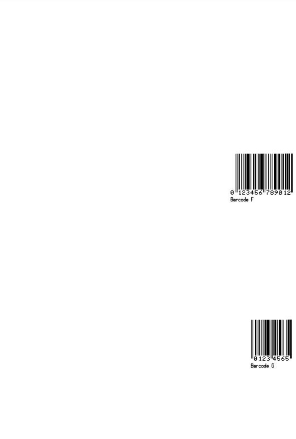
Appendix G – Barcode Details
144 Class Series Programmer’s Manual
E
F: EAN-13
Valid Characters: 0-9
Length: 13 digits. If the user provides 12 digits, the printer will compute the checksum. If the user
provides the checksum, the printer will check that it matches the expected checksum. If it does not
match, the printer will print all zeros and the expected checksum. See Appendix P.
Valid bar widths: The fourth character of record is the width of the narrow bar in dots. All other bars
are a ratio of the narrow bar (2 times, 3 times, and 4 times the narrow bar width).
The following example prints an EAN-13 bar code:
<STX>L
D11<CR>
1F0000000150100012345678901<CR>
121100000000100Barcode F<CR>
E
G: EAN-8
Valid Characters: 0-9
Length: 8 digits. If the user provides 7 digits, the printer will compute the checksum. If the user
provides the checksum, the printer will check that it matches the expected checksum. If it does not
match, the printer will print all zeros and the expected checksum.
Valid bar widths: The fourth character of record is the width of the narrow bar in dots. All other bars
are a ratio of the narrow bar (2 times, 3 times, and 4 times the narrow bar width).
The following example prints an EAN-8 bar code:
<STX>L
D11<CR>
1G00000001501000123456<CR>
121100000000100Barcode G<CR>
E
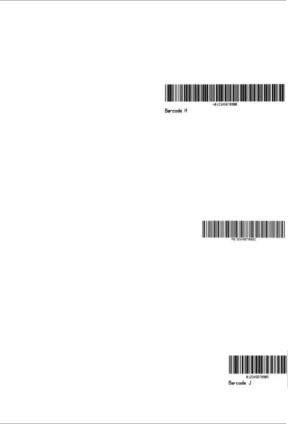
Appendix G – Barcode Details
Class Series Programmer’s Manual 145
H: Health Industry Bar Code (HBIC) (Code 39 bar code with a modulo 43 checksum)
Valid Characters: 0-9, A-Z, -$ /. %
Variable Length.
Valid bar widths: The expected ratio of wide to narrow bars can range from 2:1 to 3:1.
The host must supply leading “+”’s
The following example prints a HBIC bar code with a wide to narrow bar ratio of 3:1:
<STX>L
D11<CR>
1H0000000150050+0123456789<CR>
121100000000100Barcode H<CR>
E
I: Codabar
Valid Characters: 0-9, A-D, -, ., $, :, /, + (comma is not valid).
Variable Length but requires at least three characters.
Valid bar widths: The expected ratio of wide to narrow bars can range from 2:1 to 3:1.
Valid Codabar symbols require start and stop characters (A–D). These characters should be placed in
the data field along with other data to be included in the symbol.
The following example prints a Codabar bar code with a wide to narrow bar ratio of 3:1:
<STX>L
D11<CR>
1I63040001501000A1234567890D<CR>
121100000000100Barcode I<CR>
E
Barcode I
J: Interleaved 2 of 5 with a modulo 10 checksum.
Valid Characters: 0-9
Variable Length.
Valid bar widths: The expected ratio of wide to narrow bars can range from 2:1 to 3:1.
The following example prints an Interleaved 2 of 5 bar code with a modulo 10 checksum added and
with a wide to narrow bar ratio of 3:1:
<STX>L
D11<CR>
1J000000015010001234567890<CR>
121100000000100Barcode J<CR>
E
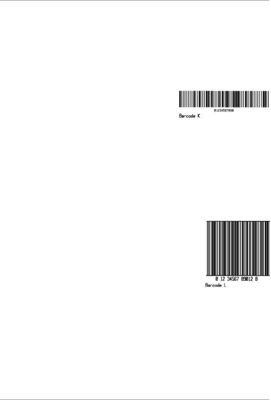
Appendix G – Barcode Details
146 Class Series Programmer’s Manual
K: Plessey
Valid Characters: 0-9
Length: 1 to 14 digits
Valid bar widths: The expected ratio of wide to narrow bars can range from 2:1 to 3:1.
If a + character is the last data character, an additional MSI checksum will be added to the bar code in
place of the + character.
The following example prints a Plessey bar code with a wide to narrow bar ratio of 3:1:
<STX>L
D11<CR>
1K000000015010001234567890<CR>
121100000000100Barcode K<CR>
E
L: Interleaved 2 of 5 with a modulo 10 checksum and shipping bearer bars.
Valid Characters: 0-9
Variable Length: For the bearer bars to be printed, 14 characters are required.
Valid bar widths: The expected ratio of wide to narrow bars can range from 2:1 to 3:1.
The following example prints an Interleaved 2 of 5 bar code with a modulo 10 checksum with a wide
to narrow bar ratio of 3:1 and bearer bars:
<STX>L
D11<CR>
1L00000001501000123456789012<CR>
121100000000100Barcode L<CR>
E
M: 2-digit UPC addendum
Valid Characters: 0-9
Length: 2 digits.
Valid bar widths: The fourth character of record is the width of the narrow bar in dots. All other bars
are a ratio of the narrow bar (2 times, 3 times, and 4 times the narrow bar width). Human readable
characters for this bar code symbology are printed above the symbol.
The following example prints a 2 digit UPC bar code addendum:
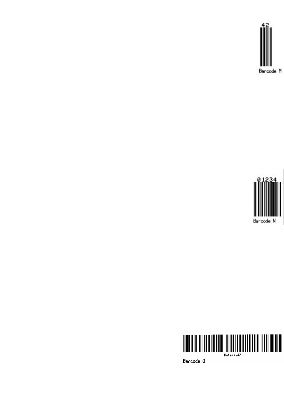
Appendix G – Barcode Details
Class Series Programmer’s Manual 147
<STX>L
D11<CR>
1M000000015010042<CR>
121100000000100Barcode M<CR>
E
N: 5-digit UPC addendum
Valid Characters: 0-9
Length: 5 digits.
Valid bar widths: The width multiplier is the width of the narrow bar in dots. All other bars are a ratio
of the narrow bar (2 times, 3 times, and 4 times the narrow bar width). Human readable characters for
this bar code symbology are printed above the symbol.
The following example prints a 5 digit UPC bar code addendum:
<STX>L
D11<CR>
1N000000015010001234<CR>
121100000000100Barcode N<CR>
E
O: Code 93
Valid Characters: 0-9, A-Z, -.$/+% and the space character.
Variable Length.
Valid bar widths: The width multiplier is the width of the narrow bar in dots. All other bars are a ratio
of the narrow bar (2 times, 3 times, and 4 times the narrow bar width).
The following example prints a Code 93 bar code:
<STX>L
D11<CR>
1O0000000150100Datamax42<CR>
121100000000100Barcode O<CR>
E
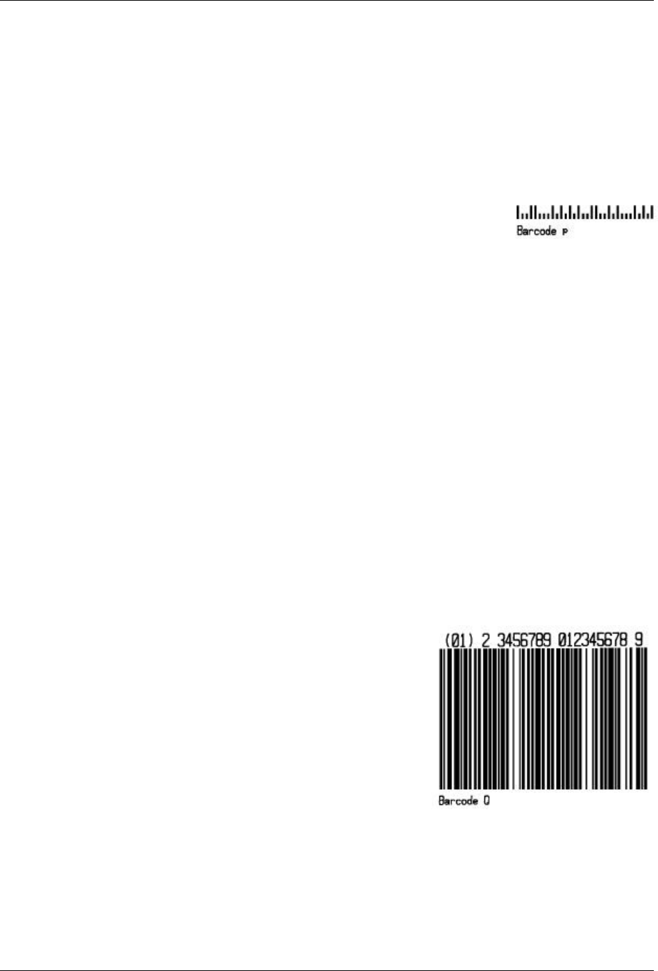
Appendix G – Barcode Details
148 Class Series Programmer’s Manual
p: Postnet
Valid Characters: 0-9
Length: 5, 9 or 11 digits
Valid bar widths: The width and height multiplier values of 00 will produce a valid Postnet symbol.
Usage: The bar code height field is ignored since the symbol height is United States Postal Service
specific. This bar code is to display the zip code on a letter or package for the US Postal Service.
The following example prints a Postnet bar code:
<STX>L
D11<CR>
1p000000015010032569<CR>
121100000000100Barcode p<CR>
E
Q: UCC/EAN Code 128
Valid Characters: 0-9
Length: 19 digits.
Valid bar widths: The fourth character of record is the width of the narrow bar in dots. All other bars
are a ratio of the narrow bar (2 times, 3 times, and 4 times the narrow bar width). Human readable
characters for this bar code symbology are printed above the symbol.
The printer spreads a weighted module 103 check sum.
The following example prints a UCC/EAN Code 128 bar code:
<STX>L
D11<CR>
1Q00000001501000123456789012345678<CR>
121100000000100Barcode Q<CR>
E
Appendix G – Barcode Details
Class Series Programmer’s Manual 149
R: UCC/EAN Code128 K-MART NON EDI
Valid Characters: 0-9
Length: 18 digits
Valid bar widths: The fourth character of record is the width of the narrow bar in dots. All other bars
are a ratio of the narrow bar (2 times, 3 times, and 4 times the narrow bar width). Human readable
characters for this bar code symbology are printed above the symbol. (See W1R for an alternate.)
This bar code is set up according to K-MART specifications.
The following example prints a KMART bar code.
<STX>L
D11<CR>
1R0000000150100012345678901234567<CR>
121100000000100Barcode R<CR>
E
S: UCC/EAN Code 128 Random Weight
Valid Characters: 0-9
Length: At least 34 digits.
Valid bar widths: The fourth character of record is the width of the narrow bar in dots. All other bars
are a ratio of the narrow bar (2 times, 3 times, and 4 times the narrow bar width).
This bar code is commonly used by the food and grocery industry.
The following example prints a UCC/EAN Code 128 Random Weight bar code:
<STX>L
D11<CR>
1S000000015005001100736750292601193042032020018002110123456<CR>
121100000000100Barcode S<CR>
E
Barcode S

Appendix G – Barcode Details
150 Class Series Programmer’s Manual
T: Telepen
Valid Characters: All 128 ASCII characters.
Variable Length
Valid bar widths: The fourth character of the record is the width of the narrow bar in dots. All other
bars are a ratio of the narrow bar (2 times, 3 times, and 4 times the narrow bar width).
The following example prints a Telepen bar code:
<STX>L
D11<CR>
1T0000000150100ABCDEF<CR>
121100000000100Barcode T<CR>
E Barcode T
u: UPS MaxiCode (Modes 2&3)
The printer supports MaxiCode as defined in the AIM Technical Specification. The following
examples illustrate various label format record message syntaxes for encoding data as MaxiCode. In
the following examples, special formatting is used to denote special ASCII characters as shown:
Symbol Hexadecimal Value
RS 1E
GS 1D
EOT 04 Printer message syntax allows for EOT to be substituted with
<CR> or the use of both EOT and <CR>.
UPS Modes 2 & 3 Explicit
The data stream can force Mode 2 or 3 encoding by placing #2 or #3, respectively, before the data,
as shown in the example below. If this is not specified, the printer chooses the best mode.
1u0000001200120#3[)>RS01GS96123456GS068GS001GS1Z12345675GSUPSNGS12345EGS0
89GSGS1/1GS10.1GSYGSGSGSUTRSEOT
This example will print encoding the MaxiCode symbol in Mode 3.
<STX>L
D11<CR>
1u0000001200120#3[)>RS01GS96123456GS068GS001GS1Z12345675GSUPSNGS12345EGS0
89GSGS1/1GS10.1GSYGSGSGSUTRSEOT
121100000000100Barcode u<CR>
E
Appendix G – Barcode Details
Class Series Programmer’s Manual 151
Where:
#3 Forces Mode 3 encoding
[)>RS01GS96
Message Header
123456 Maximum 9 alphanumeric ASCII, postal code
Primary Message
068 Country Code
001 Class
GS1Z1... Secondary Message
...TRSEOT
UPS 3.0 Examples
In the UPS 3.0 protocol examples that follow, Primary Message control characters GS will not be
encoded in the MaxiCode symbol. All characters, the Secondary Message, with the exception of the
leading GS, in are encoded.
An example of the UPS 3.0 zip + 4 with Message data format and message header:
1u0000001200120[)>RS01GS96841706672GS840GS001GS1Z12345675GSUPSNGS12345EGS0
89GSGS1/1GS10.1GSYGSGSGSUTRSEOT
Where:
[)>RS01GS96 Message Header
841706672 Maximum 9 alphanumeric ASCII, postal code Primary Message
840 Country Code
001 Class
GS1Z1... Secondary Message
...TRSEOT
An example of the UPS 3.0 international postal “V6C3E2” with Message data format and message
header:
1u0000001200120[)>RS01GS96V6C3E2GS068GS001GS1Z12345675GSUPSNGS12345EGS089G
SGS1/1GS10.1GSYGSGSGSUTRSEOT
Where:
[)>RS01GS96 Message Header
V6C3E2 Maximum 6 alphanumeric ASCII, international zip code Primary Message
068 Country Code
001 Class
GS1Z1... Secondary
Message
...TRSEOT
An example of the UPS 3.0 international zip “V6C3E2” without Message data format and message
header:
1u0000001200120V6C3E2GS068GS001GS1Z12345675GSUPSNGS12345EGS089GSGS1/1GS10.1
GSYGSGSGSUTRSEOT
Appendix G – Barcode Details
152 Class Series Programmer’s Manual
Where:
V6C3E2 Maximum 6 alphanumeric ASCII, international zip code Primary Message
068 Country Code
001 Class
GS1Z1... Secondary Message
...TRSEOT
An example of the UPS 3.0 zip + 4 “32707-3270” without Message data format and message header:
1u0000001200120327073270GS068GS001GS1Z12345675GSUPSNGS12345EGS089GSGS1/1GS1
0.1GSYGSGSGSUTRSEOT
Where:
32707 5 digit ASCII, Zip code Primary Message
3270 4 digit ASCII, +4 Zip code (not required)
068 Country Code
001 Class
GS1Z1... Secondary Message
...TRSEOT
U: UPS MaxiCode (Modes 2&3) with Byte Count Specifier
Specified Length – The upper case U identifies a UPS MaxiCode bar code with a 4-digit string length
specifier. This allows values 0x00 through 0xFF to be included within the data strings without
conflicting with the DPL format record terminators. The four-digit decimal data byte count
immediately follows the 4-digit column position field. This value includes all of the data following
the byte count field, but does not include itself.
<STX>L
D11<CR>
1U00000010001000051327895555840666this package<0x0D>is going to
Datamax<CR>
121100000000100Barcode U<CR>
E
From the example above, the bar code’s data stream,
1U00000010001000051327895555840666this
package<0x0D>is going to Datamax, now includes a Byte Count
Specifier (the portion in bold), where 0051 equals the four-
digit decimal data
byte count and includes all bytes that follow until the end of the bar code
data. Field termination is set by the byte count. <STX>, <CR>, and <0x0D>
all represent single byte values of hexadecimal 02, 0D, and 0D, respectively.
The UPS MaxiCode bar code produced encodes “327895555840666this
package<CR>is going to Datamax”, and prints a line of text: Barcode U.
Barcode U

Appendix G – Barcode Details
Class Series Programmer’s Manual 153
v: FIM
Valid Characters: A, B, C, or D
Length: 1 character
Valid bar widths: The width and height multiplier works the same as for fonts on this bar code.
This bar code is used to display the Facing Identification Mark (FIM) that is carried on certain types
of letter mail for the U S Postal Service:
FIM A: Courtesy reply mail with Postnet.
FIM B: Business reply, penalty or franked mail without Postnet.
FIM C: Business reply, penalty or franked mail with Postnet.
FIM D: OCR readable mail without Postnet (typically for envelopes with a courtesy reply window).
The following example prints an FIM A bar code:
<STX>L
D11<CR>
1v0000000150100A<CR>
121100000000100Barcode v<CR>
E
z : PDF-417
Valid Characters: All ASCII characters.
Variable Length – This two dimensional bar code holds large amounts of data in a small area, while
providing a high level of redundancy and error checking, if specified.
<STX>L
D11<CR>
1z0000000150100F1000000PDF417<CR>
121100000000100Barcode z<CR>
E
Barcode z
The example above prints a normal, security level one, PDF-417 bar code with a 1:2 aspect ratio and
best-fit rows and columns. The (bolded) bar code’s data stream
1z0000000150100F1000000PDF417<CR> decodes as follows:
Appendix G – Barcode Details
154 Class Series Programmer’s Manual
Example Data
Explanation
F 1-character specifying a normal or truncated bar code (T to truncate, F for normal).
1 1-digit security level ranging from 0 to 8.
00 2-digit aspect ratio specified as a fraction, with the first digit being the numerator
and the second digit the denominator. Use “00” for the default ratio of 1:2. Valid
range is from “00” to “99.”
00 2-digit number specifying the number of rows requested. Use “00” to let the printer
find the best fit. Valid range is from “03” to “90”. Row values less than 3 are set to
3, while row values greater than 90 are set to 90.
00 2-digit number specifying the number of columns requested. Use “00” to let the
printer find the best fit. Valid range is from “01” to “30”. Column values greater
than 30 are set to 30.
PDF417 The data stream to be encoded.
<CR> Terminates the data stream.
þ Note: Format Record header fields c and d should both be zero.
Z: PDF-417 with Byte Count Specifier
Specified Length – The upper case Z identifies a PDF-417 bar code with a string 4-digit length
specifier. This allows values 0x00 through 0xFF to be used within the data strings without conflicting
with the DPL format record terminators. The four-digit decimal data byte count immediately follows
the 4-digit column position field. This value includes all of the data following the byte count field, but
does not include itself.
<STX>L
D11<CR>
1Z00000001501000015F1000000pdf<0x0D>417<CR>
121100000000100Barcode Z<CR>
E Barcode Z
From the example above, the bar code’s data stream,
1Z00000001501000015F1000000pdf<CR>417, now includes a Byte Count Specifier (the
portion in bold), where 0015 equals the four-digit decimal data byte count and includes all bytes that
follow until the end of the bar code data. Field termination is set by the byte count. <STX>, <CR>,
and <0x0D> all represent single byte values of hexadecimal 02, 0D, and 0D, respectively. The PDF-
417 bar code produced encodes “pdf<CR>417”, and prints a line of text: Barcode Z.
Appendix G – Barcode Details
Class Series Programmer’s Manual 155
W1c: DataMatrix
Valid Characters: Any 8-bit byte data
Variable Length
DataMatrix is a two-dimensional matrix symbology, which is comprised of square modules arranged
within a perimeter finder pattern. There are two basic types: ECC 000-140 and ECC 200.
ECC 000 - 140 symbols:
These square symbols can be any odd sizes from 9x9 to 49x49, which may be specified in fields iii,
and jjj. If an ECC 000-140 symbol is specified with even numbers of rows or columns, the next
largest odd value will be used. Input values greater than 49 or less than 9 will cause the symbol to be
automatically sized for the input character stream. The record format is shown here, expanded with
spaces.
a W b[b] c d eee ffff gggg hhh i jjj kkk ll...l
Where:
Field Valid Inputs Meaning
a 1,2,3, and 4 Rotation
W W Fixed value, extended bar code set
b[b] c, 1c Selects DataMatrix the Bar code - the two differing values have no
other significance.
c 1 to 9 and A to O Module size horizontal multiplier
d 1 to 9 and A to O Module size vertical multiplier
eee 000 to 999 No Effect; Must be numeric
ffff 0000 to 9999 Label position, row
gggg 0000 to 9999 Label position, column
hhh
000, 050, 080, 100,
140 A 3-digit convolutional error correction level.
If any number other than one of these options is entered then the
nearest lesser value from the valid entries is used.
Example: Selecting an ECC value of 099 will cause the actual
ECC value of 080 to be used.
i 0 - 6 1 digit format identification:
0 - Automatically choose the encodation scheme based on the
characters to be encoded.
1 - Numeric data.
2 - Upper-case alphabetic.
3 - Upper-case alphanumeric and punctuation characters
(period, comma, hyphen, and slash).
4 - Upper-case alphanumeric.
5 - ASCII, the full 128 ASCII character set.
6 - Any 8-bit byte.
If a format identifier is selected which will not encode the input
character stream then the bar code symbol will not be printed.
It is recommended to use the auto-encodation format identification
since it will select the best possible encodation scheme for the
input stream.
Table G-2: DataMatrix ECC 000 – 140 Record Structure
Appendix G – Barcode Details
156 Class Series Programmer’s Manual
ECC 200 symbols:
There are 24 square symbol sizes available, with both row and column dimensions, which may be
specified in fields iii, and jjj, measured in modules as indicated in the following list - 10, 12, 14, 16,
18, 20, 22, 24, 26, 32, 36, 40, 44, 48, 52, 64, 72, 80, 88, 96, 104, 120, 132, and 144. If an ECC 200
symbol is specified with odd numbers of rows or columns, the next largest even value will be used.
Input values greater than 144 or less than 10 will cause the symbol to be automatically sized for the
input character stream. The record format is shown here, expanded with spaces.
a W b[b] c d eee ffff gggg hhh i jjj kkk ll...l
Where:
Field Valid Inputs Meaning
a 1,2,3, and 4 Rotation
W W Fixed value, extended bar code set
b[b] c, 1c Selects DataMatrix the Bar code - the two differing values have no
other significance.
c 1 to 9 and A to O module size horizontal multiplier
d 1 to 9 and A to O module size vertical multiplier
eee 000 to 999 No Effect; Must be numeric
ffff 0000 to 9999 label position, row
gggg 0000 to 9999 label position, column
hhh 200 ECC 200 uses Reed-Solomon error correction.
i 0 Fixed value, not used
jjj 10, 12, 14, 16, 18,
20, 22, 24, 26, 32,
36, 40, 44, 48, 52,
64, 72, 80, 88, 96,
104, 120, 132, 144
A 3 digit even number (or 000) of rows requested.
000 causes rows to be automatically determined. The symbol will
be sized to a square if the rows and columns do not match by
taking the larger of the two values.
kkk 10, 12, 14, 16, 18,
20, 22, 24, 26, 32,
36, 40, 44, 48, 52,
64, 72, 80, 88, 96,
104, 120, 132, 144
A 3 digit even number (or 000) of columns requested.
000 causes columns to be automatically determined. The symbol
will be sized to a square if the rows and columns do not match by
taking the larger of the two values.
ll...l
8-bit data Data to be encoded in the symbol
Table G-3: DataMatrix ECC 200 Record Structure
Example:
<STX>L
D11<CR>
1W1c44000010001002000000000DATAMAX<CR>
121100000000100Barcode W1c<CR>
E Barcode W1c
Appendix G – Barcode Details
Class Series Programmer’s Manual 157
W1C: DataMatrix with Byte Count Specifier
Specified Length – The upper case C identifies a DataMatrix bar code with a string 4-digit length
specifier. This allows values 0x00 through 0xFF to be included within the data strings without
conflicting with the DPL format record terminators. The four-digit decimal data byte count
immediately follows the four-digit column position field. This value includes all of the data following
the byte count field, but does not include itself.
<STX>L
D11<CR>
1W1C440000100010000292000000000Datamax<0x0D>prints best<CR>
121100000000100Barcode W1C<CR>
E
From the example above, the bar code’s data stream,
1W1C440000100010000292000000000
Datamax<0x0D>prints best, includes a Byte Count Specifier (the
portion in bold), where 0029 equals the four-digit decimal data byte count
and includes all bytes that follow until the end of the bar code data. Field
termination is set by the byte count. <STX>, <CR>, and <0x0D> all
represent single byte values of hexadecimal 02, 0D, and 0D, respectively.
The DataMatrix bar code produced encodes “Datamax<CR>prints best”,
and prints a line of text: Barcode W1C.
Barcode W1C
Appendix G – Barcode Details
158 Class Series Programmer’s Manual
W1d / W1D: QR Code
Valid Characters: Numeric Data, Alphanumeric Data, 8-bit byte data, and Kanji characters
Variable Length: The two-dimensional bar code (as documented in AIM, Version 7.0).
Syntax: a W1 b c d eee ffff gggg hh…h
Where:
Field Valid Inputs Meaning
a 1,2,3 and 4 Rotation
W1 W1 Fixed value, extended bar code set
b D and d Selects the QR bar code formatting mode, where:
D = Manual formatting. Allows the data string (hh…h)
to be entered with a comma (,) as a field separator;
fields are optional per QR Code specifications,
and the first field indicates Model 1 or Model 2
QR Code (Model 2 is the default).
d = Automatic formatting. Allows the data string
(hh…h) to be data only.
c 1 to 9 and A to O
Module size horizontal multiplier Each cell in the bar code is
square, therefore ‘c’ and ‘d’ must be equal. Depending on the
conversion mode (<STX>n or <STX>m), each unit in
dicates a
cell dimension of .01 inch or .1 mm.
d 1 to 9 and A to O Module size vertical multiplier. (See explanation for ‘c’, above.)
eee 000 to 999 No effect; must be numeric
ffff 0000 to 9999 Label position, row
gggg 0000 to 9999 Label position, column (see Appendix J)
hh…h Valid ASCII character
string, followed by (a)
termination
character(s).
QR Code data string (see Generation Structure, below).
Generation Structure
The data input structure (hh…h) is as follows:
Auto Format (W1d)
With bar code identifier ‘d’, the data begins after the last character of the column position field,
and does not include any command characters. The data string is terminated with a termination
character, usually a 0x0d hex that occurs twice in succession. The bar code symbol will have the
following characteristics:
1. Model 2
2. Error Correction Code Level = ‘M’ (Standard Reliability Level)
3. Mask Selection = Automatic
4. Data Input Mode = Automatic [1]
Example:
Appendix G – Barcode Details
Class Series Programmer’s Manual 159
<STX>L
D11<CR>
1W1d4400000100010This is the data portion<CR><CR> [3]
121100000000100Barcode W1D<CR>
E
(Two termination
characters
required.)
Manual Formatting (W1D)
With bar code identifier ‘D’, minor changes allow flexibility for data entry. (Spaces have been
added for readability.)
[q,] [e [m] i,] cdata cdata cdata…cdata term [2]
Where:
Field Valid Inputs Meaning
q 1, 2 QR Code Model number, optional. Model 2 is the default.
e H, Q, M, L Error Correction Level (Reed-Solomon) – Four levels
allowing recovery of the symbol codewords:
H = Ultra Reliability Level (30%)
Q = High Reliability Level (25%)
M = Standard Reliability Level (15%)
L = High Density Level (7%)
m 0 – 8, none Mask Number, optional:
None = Automatic Selection
0-7 = Mask 0 to Mask 7
8 = No Mask
I A, a, M, m Data Input Mode:
A = Automatic setting, ASCII [1]
a = Automatic, hex-ASCII [1]
M = Manual Setting, ASCII[2]
m = manual, hex-ASCII[2]
cdata N, A, B, K
immediately followed
by data
Character Mode:
N = Numeric, N data
A = Alphanumeric, A data
B = Binary , Bnnnn data (where nnnn = data byte-
count, 4 decimal digits; byte-count /2 for hex-
ASCII
K = Kanji, K data
term <CR>, <CR><CR> [3] The data string is terminated with a termination character,
generally a 0x0d hex, but can be changed by the operator. If
the Data Input Mode is Automatic, the data string is
terminated with two successive termination characters.
[1] When Data Input Mode = Automatic – Kanji data cannot be used; Manual data input is required.
[2] When using manual formatting commas are required between format fields and data types.
[3] <CR> represents the line termination character as defined by the current control code set or after use of
Txx, line field terminator label format command.
If HEX/ASCII mode is selected in manual Data Input Mode, only the data for Kanji or Binary
data types will be converted, therefore the other data types and all command characters must be
entered in ASCII format. If HEX/ASCII is selected in automatic Data Input Mode, all of the data
must be entered in HEX/ASCII format.
Appendix G – Barcode Details
160 Class Series Programmer’s Manual
Data Append Mode String Format, Manual Formatting – Bar Code W1D
D aa tt pp I
Where:
Field Valid Inputs Meaning
D D Data Append Mode String Format indicator
aa 00, 99 QR Code Number in Append Series, 2 decimal digits
tt Total number of QR Codes in series, 2 decimal digits
pp Value of Parity, 2 digits, 8 LSBs of data parity
e H, Q, M, L As above
m 0 – 8, none As above
i A, a, M, m As above
cdata N, A, B, K
immediately
followed by data
As above
term <CR>, <CR><CR> As above
Characteristics
Models:
Model 1 (original version), bar code versions 1 through 14
A. ECC Levels ‘H’, ‘M’, ‘Q’, and ‘L’
B. Mask Selection Automatic or 0 through 8
C. Data Input Modes Automatic and Manual
D. Data Append Mode
Model 2 (enhanced version), bar code versions 1 through 40
A. ECC Levels ‘H’, ‘M’, ‘Q’, and ‘L’
B. Mask Selection Automatic or 0 through 8
C. Data Input Modes Automatic and Manual
D. Data Append Mode
Representation of data:
Dark Cell = Binary 1
Light Cell = Binary 0
Symbol Size (not including quiet zone, 4 cells on each of the 4 sides):
Model 1: 21 X 21 cells to 73 X 73 cells (Versions 1 to 14, increase in steps of 4 cells per side)
Model 2: 21 X 21 cells to 177 X 177 cells (Versions 1 to 40, increase in steps of 4 cells per side)
Data Characters per symbol (maximum for symbol size):
Numeric Data
Model 1; Version 14; ECC = L: 1,167 characters
Model 2; Version 40; ECC = L: 7,089 characters
Appendix G – Barcode Details
Class Series Programmer’s Manual 161
Alphanumeric Data
Model 1; Version 14; ECC = L: 707 characters
Model 2; Version 40; ECC = L: 4,296 characters
Binary Data
Model 1; Version 14; ECC = L: 486 characters
Model 2; Version 40; ECC = L: 2,953 characters
Kanji Data
Model 1; Version 14; ECC = L: 299 characters
Model 2; Version 40; ECC = L: 1,817 characters
Code Type: Matrix
Orientation Independence: Yes
Example
<STX>L
D11<CR>
1W1D44000001000102HM,AThis is the data portion also
with binary,B0003<0xfe><0xca><0x83><0x0D>
121100000000100Barcode W1D<CR>
E
Barcode W1D
Where:
QR Code bar code, Cell Size = 0.1 inch square, positioned at X =. 1” and Y = .1”, ECC=H, Mask =
Automatic, Data Input Mode = Manual.
Other examples:
DPL field record, QR Code bar code, Cell Size = 0.04 inch square, positioned at X = .1” and Y =
.1”, ECC = H, Mask = 3, Data Input Mode = Manual:
1W1D4400000100010H3M,AThis is the data portion also with
binary,B0003<0xfe><0xca><0x83><0x0D>
DPL field record, QR Code bar code, Cell Size = 0.08 inch square, positioned at X = .1” and Y =
.1”, ECC = L, Mask = Automatic, Data Input Mode = Manual - Kanji:
1W1D88000001000102,LM,K<0x81><0x40><0x81><0x41><0x81><0x42><0x0
D>
DPL field record, QR Code bar code, Cell Size = 0.04 inch square, positioned at X = .1” and Y =
.1”, ECC = L, Mask = Automatic, Data Input Mode = Manual - Kanji (in Hex/ASCII format):
1W1D4400000100010L8m,K814081418142<0x0D>
DPL field record, QR Code bar code, Cell Size = 0.01 inch square, positioned at X = .1” and Y =
.1”, ECC = M, Mask = Automatic, Data Input Mode = Automatic:
1W1d1100000100010Pallet 35FGA, Box 55367, Datamax Corp,
Orlando, Florida 32707<0x0D><0x0D>
Appendix G – Barcode Details
162 Class Series Programmer’s Manual
W1f / W1F: Aztec
Valid Characters: All ASCII characters, depending upon the selected options.
Variable Length (W1f): This two dimensional bar code holds a large amount of data in a small area
and can provide a high level of error checking.
Specified Length (W1F): With a string four-digit length specifier, values 0x00 through 0xFF to be
included within the data strings without conflicting with the DPL format record terminators.
Syntax: a W1 b c d eee ffff gggg [hhhh] i jjj kk…k
Where:
Field Valid Inputs Meaning
a 1,2,3, and 4 Rotation
W1 W1 Fixed value, extended bar code set
b f and F Lowercase selects the Aztec bar code, variable length
Uppercase selects the Aztec bar code with a Byte Count Specifier
c 0 to 9 and A to O Module size horizontal multiplier, 0 = default size. The c/d module
size parameters should be equal to produce a square symbol. When the
label c
ommand (Dwh) is used to generate larger text, then c and d may
be used to compensate and ensure a square symbol.
d 0 to 9 and A to O Module size vertical multiplier, 0 = default size (See explanation for
‘c’, above.)
eee 000 No Effect
ffff 0000 to 9999 Label position, row
gggg 0000 to 9999 Label position, column
[hhhh]
0000 to 9999 Optional string length specifier. Field termination is set by this byte
count. This decimal value includes all of the data following this byte
count field, but does not include itself.
i 0, 1 Extended Channel Interpretation (ECI) mode; 0 = Disabled,
1 = Enabled
jjj 000 to 300 Error Correction (EC) / Amount (see table below), where:
000 – Default EC, approximately 23%
001 – 099 EC fixed value, expressed as a percent.
101 – 104 Compact core, 1 to 4 layers respectively.
201 – 232 Full size core, 1 to 32 layers respectively.
300 – Rune format, encodes three ASCII decimal digits 0-256;
scanner decode output is decimal number 0-256
kk…k 8-bit data,
followed by a
termination
character
Data to be encoded.
The error correction or size selection determines the symbol size and other characteristics of the
symbol, as shown in the following table. Attempting to encode more data that has been made
available will result in no symbol printed.
Appendix G – Barcode Details
Class Series Programmer’s Manual 163
Error Correction (EC) / Size Implications
jjj
Symbol
Size[1]
Symbol
Format
Maximum[2]
Binary Data
Bytes
Maximum[2]
Alphabetic
Characters
Maximum[2]
Numeric
Characters
000 variable data dependant 1914 3067 3832
001 to 099 variable data and EC
dependant 1914 3067 3832
101 15 compact 6 12 13
102 19 compact 19 33 40
102 19 compact 19 33 40
103 23 compact 33 57 70
104 27 compact 53 89 110
201 19 full size 8 15 18
202 23 full size 24 40 49
203 27 full size 40 68 84
204 31 full size 62 104 128
205 37 full size 87 144 178
206 41 full size 114 187 232
207 45 full size 145 236 294
208 49 full size 179 291 362
209 53 full size 214 348 433
210 57 full size 256 414 516
211 61 full size 298 482 601
212 67 full size 343 554 691
213 71 full size 394 636 793
214 75 full size 446 718 896
215 79 full size 502 808 1008
216 83 full size 559 900 1123
217 87 full size 621 998 1246
218 91 full size 687 1104 1378
219 95 full size 753 1210 1511
220 101 full size 824 1324 1653
221 105 full size 898 1442 1801
222 109 full size 976 1566 1956
223 113 full size 1056 1694 2116
224 117 full size 1138 1826 2281
225 121 full size 1224 1963 2452
226 125 full size 1314 2107 2632
227 131 full size 1407 2256 2818
228 135 full size 1501 2407 3007
229 139 full size 1600 2565 3205
230 143 full size 1702 2728 3409
231 147 full size 1806 2894 3616
232 151 full size 1914 3067 3832
300 11 Rune 1 1 1
[1] Measured in module size x, assuming default module size (cd=00).
[2] Maximum sizes are approximate and data dependant, and may be less than indicated.
Table G-4: Aztec Characteristics Index
Error Correction
Size 001 to 099: This value specifies the percent of symbol code words to be used for error
correction. Actual error correction word percentage will vary depending on data. The default value,
approximately 23%, is recommended. Any other value may be selected to meet the user’s needs.
Some minimum-security codeword may be generated depending on the data sent for encoding,

Appendix G – Barcode Details
164 Class Series Programmer’s Manual
particularly when the volume of that data is small. It the data capacity is exceeded no symbol is
printed.
Size 101 to 104: Values 101 through 104 result in 1 through 4 layers (two modules thick)
respectively, around the center finder pattern. Data volume constraints apply as indicated in the table
above. Symbols will be of the compact form. All available codeword will be used for error correction.
It the data capacity is exceeded no symbol is printed.
Size 201 to 232: Values 201 through 232 result in 1 through 32 layers (two modules thick)
respectively, around the center finder pattern. Data volume constraints apply as indicated in the table
above. Symbols will be of the full-size form. All available codewords will be used for error
correction. It the data capacity is exceeded no symbol is printed.
Size 300: Value 300 informs the printer that the data, which follows will be used to encode one
RUNE symbol. The data consists of one to three ASCII digits with value range of 0 to 256. The data
may include leading zeros. Data streams longer than three digits or data that includes non-numeric
characters may have unpredictable results.
Extended Channel Interpretation Mode: A value of 1 provides for extended channel codewords to
be inserted into the bar code symbol, using escape sequences in the datastream. This mode also
provides for effective Code 128 and UCC/EAN 128 emulations, when used in with appropriately
configured bar code readers. The valid values for escape sequences are of the form <ESC>n, where:
<ESC> – 1 byte with value 2710 = 1B16
n – 1 ASCII digit, range 0 through 6
These escape sequences are encoded as FLG(n) character pairs described in the International
Symbology Specification – Aztec Code, AIM, 1997-11-05, and the meanings of the values for n are
the same in both.
<ESC>0 – Is encoded as FLG(0), and interpreted as FNC1 or <GS> depending on its
location in the data stream. The printer does not validate <ESC>0 locations
in the data stream.
When <ESC>0 is the leading data in the stream, it is interpreted as a FNC1 as used in
the Code 128 symbology, and specifically for UCC/EAN 128 applications. For
appropriately configured scanners this will be interpreted/transmitted as a ]C1
symbology identifier preamble. The printer does not validate UCC/EAN 128 data
syntax.
When <ESC>0 follows a single alphabetic or two numeric characters respectively,
then it also interpreted as a FNC1. For appropriately configured scanners this would
be interpreted/transmitted as a ]C2 symbology identifier preamble, and the alpha or
numeric characters preceding the FNC1 are Application Indicators assigned by AIM
International. The printer does not check AI validity.
When <ESC>0 is anywhere else in the data stream, a <GS> replaces it in the bar code
symbol, as with UCC/EAN 128 field separators.
Appendix G – Barcode Details
Class Series Programmer’s Manual 165
<ESC>n – Is encoded as FLG(n), and is interpreted as signaling Extended Channel
Interpretation. When the value of n is from 1 to 6, it signals that the following n
digits comprise an extended channel identifier for use with ECI compliant bar code
scanners. An erroneous bar code symbol may result from failing to follow <ESC>n
with n digits. Any <ESC>0 following <ESC>n and not within the n digits will be
encoded as FLG(0). In the context of a FLG(n), any backslash ‘\’ (9210) will be
interpreted by the scanner as two backslashes ‘\\’.
Example 1: The variable length example encodes “AZTEC” with no ECI input, and 23% error
correction, and prints the bar code. A line of text is also printed.
<STX>L
D11<CR>
1W1f00000001501000000AZTEC<CR>
121100000000100Barcode W1f<CR>
E
Barcode W1f
Example 2: The specified length example includes a byte count field for all bytes that follow until the
end of the bar code data. The byte count is 17. The symbology encodes
“AZTEC<CR>barcode”, and prints the bar code. Notice that a <CR> does not terminate
the bar code format record. A line of text is also printed.
<STX>L
D11<CR>
1W1F000000015010000170000AZTEC<0x0D>barcode
121100000000100Barcode W1F<CR>
E
Barcode W1F
Functions Not Supported
• Structured Append
• Reader Initialization Symbol Generation
• Module shaving
Appendix G – Barcode Details
166 Class Series Programmer’s Manual
W1g / W1G: USD-8 (Code 11)
Valid Characters: 0-9,-
Bar Code Data String Length: Variable, typical max 41 characters
Non-Human Readable: W1g
Human Readable: W1G
USD-8 (Code 11) is a bar code which encodes the ten digits and the dash (-) character. An additional
character serves as the start and stop indicator. Each character has three bars and two spaces for a
total of five elements. Of these five elements, two are of medium width and three are narrow, except
for the “0”, “9”, and “-“ characters, which have only one wide element and four narrow elements.
The narrow bar size is specified in DPL by the narrow bar parameter, the medium is specified in DPL
by the wide bar parameter and the wide bar is fixed at 2 times the medium bar minus the narrow bar.
DPL calculates two checksum characters, C and K, and automatically places them prior to the stop
character. The following example prints a Code11 bar code:
<STX>L
D11
1W1G00000015001500123456789-<CR>
121100000000100Barcode W1G<CR>
E
Barcode W1G
W1I: EAN128 with Auto Subset Switching
Valid characters: The entire 128 ASCII character set.
Variable length, minimum 4 characters
Valid bar widths: The fourth character of record is the width of the narrow bar in dots. All other bars
are a ratio of the narrow bar (2 times the narrow bar width, 3 times the narrow bar width, and 4 times
the narrow bar width).
This printer supports the Code 128 subsets A, B, and C. If the data begins with at least four numeric
characters the default start code is subset C. If there is a non-numeric in the first four characters then
the default start code is subset B. The next character after start is always FNC1. Subset switching
between B and C is performed based on rules as below:
1. If in subset C and there are an odd number of numeric digits, subset B will be set prior to the last
digit.
2. If four or more numeric digits appear consecutively while in subset B, the character code C will be
set prior to the digits.
3. When in subset C and a non-numeric occurs subset B will be inserted prior to the character.
Note that there is no auto-switching from or to Subset A. Standard switches are still used (see table
below).
Appendix G – Barcode Details
Class Series Programmer’s Manual 167
Subset A: Includes all of the standard uppercase alphanumeric keyboard characters plus the control
and special characters.
Subset B: Includes all of the standard uppercase alphanumeric keyboard characters plus the
lowercase alphabetic and special characters.
Subset C: Includes the set of 100 digit pairs from 00 through 99 inclusive, as well as special
characters. EAN128 Subset C is used for double density encoding of numeric data.
Special Character Handling: Characters with an ASCII value greater than 95 are considered special
characters. To access these values, a two-character reference table is built into the printer, see table
below. As an example, to encode FNC2 into an EAN128 Subset A bar code, send the ASCII & (DEC
38, HEX 26) followed by an ASCII B (DEC 66, HEX 41). Code FNC2 will be encoded.
ASCII 2 CHAR CODE A CODE B CODE C
96 &A FNC3 FNC3 -NA-
97 &B FNC2 FNC2 -NA-
98 &C SHIFT SHIFT -NA-
99 &D CODEC -NA- -NA-
100 &E CODEB FNC4 -NA-
101 &F FNC4 CODEA CODEA
102 &G FNC1 FNC1 FNC1
Table G-8: Special Character Handling
Control Codes: Control character encoding into Code 128 Subset A by sending these control codes:
` = NUL
a through z = 1 - 26
{ = ESC
| = FS
} = GS
~ = RS
ASCII 127 = US
The following example prints an EAN128 bar code:
<STX>L
D11<CR>
1W1I000000025002512345&G10Z2133021AK<CR>
121100000000100Barcode W1I<CR>
E
Barcode W1I
When scanned this bar code will decode as:
[C][FNC1]1234[B]5[F1]10Z[C]213302[B]1AK(81)
Appendix G – Barcode Details
168 Class Series Programmer’s Manual
W1J: Code 128 with Auto Subset Switching
Valid characters: The entire 128 ASCII character set.
Variable length
Valid bar widths: The fourth character of record is the width of the narrow bar in dots. All other bars
are a ratio of the narrow bar (2 times the narrow bar width, 3 times the narrow bar width, and 4 times
the narrow bar width).
This printer supports the Code 128 subsets A, B, and C. If the data begins with at least four numeric
characters the default start code is subset C. If there is a non-numeric in the first four characters or
there are less than four then the default start code is subset B. Subset switching between B and C is
performed based on rules as below:
1. If in subset C and there are an odd number of numeric digits, subset B will be set prior to the last
digit.
2. If four or more numeric digits appear consecutively while in subset B, the character code C will
be set prior to the digits. If there is an odd number of numerics and already in B the first numeric
will be placed in B with the others in C.
3. When in subset C and a non-numeric occurs subset B will be inserted prior to the character.
Note there is no auto switching from or to subset A. Standard switches are still used. See table below.
Subset A: Includes all of the standard uppercase alphanumeric keyboard characters plus the control
and special characters.
Subset B: Includes all of the standard uppercase alphanumeric keyboard characters plus the
lowercase alphabetic and special characters.
Subset C: Includes the set of 100 digit pairs from 00 through 99 inclusive, as well as special
characters. Code128 Subset C is used for double density encoding of numeric data.
Special Character Handling: Characters with an ASCII value greater than 95 are considered special
characters. To access these values, a two-character reference table is built into the printer, see table
below. As an example, to encode FNC2 into a Code128 Subset A bar code, send the ASCII & (DEC
38, HEX 26) followed by an ASCII B (DEC 66, HEX 41). Code FNC2 will be encoded.
ASCII 2 CHAR CODE A CODE B CODE C
96 &A FNC3 FNC3 -NA-
97 &B FNC2 FNC2 -NA-
98 &C SHIFT SHIFT -NA-
99 &D CODEC -NA- -NA-
100 &E CODEB FNC4 -NA-
101 &F FNC4 CODEA CODEA
102 &G FNC1 FNC1 FNC1
Table G-9: Special Character Handling

Appendix G – Barcode Details
Class Series Programmer’s Manual 169
Control Codes: Control character encoding into Code 128 Subset A by sending these control codes:
` = NUL
a through z = 1 - 26
{ = ESC
| = FS
} = GS
~ = RS
ASCII 127 = US
The following example prints a Code128 Auto bar code:
<STX>L
D11<CR>
1W1J000000025002512345&G10Z2133021AK<CR>
121100000000100Barcode W1J<CR>
E
Barcode W1J
When scanned this bar code will decode as:
[C]1234[B]5[F1]10Z2 [C]133021[B]AK(95)
Appendix G – Barcode Details
170 Class Series Programmer’s Manual
W1k: Reduced Space Symbology (RSS)
Valid Characters: Type dependant
Bar Code Data String Length: Type dependant
RSS is a continuous, linear bar code symbology used for identification in EAN.UCC systems. There
are six different types:
RSS Type
Overview*
RSS-14
RSS-14 Truncated
RSS-14 Stacked
RSS-14 Stacked Omni-Directional
• Encodes a full 14-digit EAN.UCC item identification
within a linear symbol that can be scanned omni-
directionally.
• The encodable character set is 0 through 9.
• The maximum numeric data capacity is the application
identifier plus 14-digit numeric item identification.
• Error detection is mod 79 checksum.
RSS Limited
• Encodes a 14-digit EAN.UCC item identification with
indicator digits of zero or one within a linear symbol.
• The encodable character set is 0 through 9.
• The maximum numeric data capacity for is the application
identifier plus 14-digit numeric item identification.
• Data must begin with indicator 0 or 1. Any higher number
results in discarded data.
• Error detection is mod 89 checksum.
RSS Expanded
• Encodes EAN.UCC item identification plus
supplementary AI element strings.
• The encodable character is a subset of ISO 646, consisting
of upper and lower case letters, digits and 20 selected
punctuation characters, plus the special function character
FNC1, (#).
• The maximum numeric data capacity is 74 numeric or 41
alphanumeric.
• Error detection is mod 211 checksum.
* Additional data can be encoded in a two-dimensional composite as per specification. (See AIM Spec ITS/99-
001 “International Symbology Specification - Reduced Space Symbology” for more details.)
Syntax for RSS-14, RSS-14 Truncated, RSS-14 Stacked, RSS-14 Stacked Omni-Directional and RSS
Limited (spaces shown for readability):
a W1 k c d eee ffff gggg h i j m n…n | p…p
Where:
Appendix G – Barcode Details
Class Series Programmer’s Manual 171
Field Valid Inputs Meaning
a 1,2,3, and 4 Rotation
W1 W1 Fixed value, extended bar code set
k k Selects RSS bar code
c 0 to 9 and A to O Wide bar ratio, default = 2
d 0 to 9 and A to O Narrow bar ratio, default = 2
eee 000 No effect
ffff 0000 to 9999 Label position, row
gggg 0000 to 9999 Label position, column
h R, T, S, D, L RSS Type: R = RSS-14,
T = RSS Truncated,
S = RSS Stacked,
D = RSS Omni-Directional,
L = RSS Limited
i 1-9 Pixel Multiplier
j 0 to (i-1) X pixels to undercut
m 0 to (i-1) Y pixels to undercut
n…n 0 to 9 Numeric linear data, length 13 [1]
| | (optional) Vertical bar separates primary linear data and secondary
2-D data
p…p 2-D data (optional) Additional 2-D data [2]
[1] The application identifier is not encoded in the symbol nor is the last check digit; the user should enter in a
13-digit value. The decoding system will display the application identifier and calculate the check digit.
[2] The separator row height for two-dimensional composite is fixed at one times the pixel multiplier.
Table G-5: RSS-14, RSS-14 Truncated, RSS-14 Stacked, RSS-14 Stacked Omni-Directional and
RSS Limited Record Structures
Examples:
The following example prints an RSS-14 bar code.
<STX>L
D11
1W1k0000001500150R1002001234567890
121100000000100Barcode W1k<CR>
E
Barcode W1k
The following example prints an RSS-14 bar code with 2-D data.
<STX>L
D11
1W1k0000001500150R1002001234567890|123456-99/99/99
121100000000100Barcode W1k<CR>
E
Barcode W1k

Appendix G – Barcode Details
172 Class Series Programmer’s Manual
The following example prints an RSS-14 Truncated bar code.
<STX>L
D11
1W1k0000001500150T1002001234567890
121100000000100Barcode W1k<CR>
E
Barcode W1k
The following example prints an RSS-14 Stacked bar code.
<STX>L
D11
1W1k0000001500150S1002001234567890
121100000000100Barcode W1k<CR>
E
Barcode W1k
The following example prints an RSS-14 Stacked Omni-Directional bar
code.
<STX>L
D11
1W1k0000001500150D1002001234567890
121100000000100Barcode W1k<CR>
E
Barcode W1k
The following example prints an RSS-14 Limited bar code.
<STX>L
D11
1W1k0000001500150L1001501234567890
121100000000100Barcode W1k<CR>
E
Barcode W1k
Appendix G – Barcode Details
Class Series Programmer’s Manual 173
Syntax for the RSS Expanded bar code (spaces shown for readability):
a W1 k c d eee ffff gggg h i j m nn p…p | q…q
Where:
Field Valid Inputs Meaning
a 1,2,3, and 4 Rotation
W1 W1 Fixed value, extended bar code set
k k Selects RSS bar code
c 0 to 9 and A to O Wide bar ratio, default = 2
d 0 to 9 and A to O Narrow bar ratio, default = 2
eee 000 No effect
ffff 0000 to 9999 Label position, row
gggg 0000 to 9999 Label position, column
h E RSS Type: E= RSS Expanded
i 1-9 Pixel Multiplier
j 0 to (i-1) X pixels to undercut
m 0 to (i-1) Y pixels to undercut
nn 2-22, even only[2] Segments per row
p…p 0 to 9 Subset of ISO646, including alphanumerics
| | (optional) Vertical bar separates primary linear data and secondary 2-D data
q…q 2-D data (optional) Additional 2-D data [1]
[1] The separator row height for two-dimensional composite is fixed at one times the pixel multiplier.
[2] When using additional 2-D composite data, the sequence width must be at least 4.
Table G-6: RSS-14 Expanded Record Structure
Example:
The following example prints an RSS-14 Expanded bar code.
<STX>L
D11
1W1k0000001500150E100022001234567890
121100000000100Barcode W1k<CR>
E
Barcode W1k
W1R: UCC/EAN Code 128 K-MART NON EDI
Valid Characters: 0-9
Length: 18 digits
Valid bar widths: The fourth character of record is the width of the narrow bar in dots. All other bars
are a ratio of the narrow bar (2 times, 3 times, or 4 times the narrow bar width). Human readable
characters for this bar code symbology are printed above the symbol.
This bar code produces the same symbology as bar code ID “R”, except that the human readable field
has been modified to print on the bottom of the bar code (see below).
Appendix G – Barcode Details
174 Class Series Programmer’s Manual
The following example prints a KMART bar code:
<STX>L
D11<CR>
1W1R0000000150100012345678901234567<CR>
121100000000100Barcode W1R<CR>
E
34 567890 123 4567
Barcode W1R
W1t: TCIF Linked Bar Code 3 of 9 (TLC39)
Valid Characters: All ASCII characters.
Variable Length: Encodes a 25-character alphanumeric serial number in MicroPDF417 symbol.
Specified Length: Encodes a six-digit sequence in a standard 3 of 9 bar code (code 39) followed by a
link flag character in code 3 of 9.
Syntax: a W1 t c d eee ffff gggg hhhhhh ; ii…i
Where:
Field Valid Inputs Meaning
a 1,2,3, and 4 Rotation
W1 W1 Fixed value, extended bar code set
t t Selects TLC39 bar code
c 0 to 9 and A to O Wide bar of Code 39, ratio of wide to narrow must be between 2:1
and 3:1
d 0 to 9 and A to O Narrow bar of Code 39
eee 001 to 999 Height of Code 39
ffff 0000 to 9999 Label position, row
gggg 0000 to 9999 Label position, column
hhhhhh ECI Data Six digit ECI number
; Fixed Parses data. (If the seventh character is not a semi colon then only a
six-digit code 39 will print.)
Up to 25 alphanumeric serial number characters to be encoded in
the MicroPDF417 symbol. This symbol is fixed at four columns.
The number of rows is determined by the amount of data, as
follows:
Number of Alphanumeric Characters Number of Rows
1-14 4
15-22 6
i…i S/N Data
23-25 8
The link flag is the character “T” in code 39 without a start/stop indicator. The location of this flag is
based on the ECI code location, length and height. The location of the MicroPDF417 symbol is based
on the location of ECI bar code. The symbol’s module width and height are fixed at the default. The
following example prints a TLC39 bar code:
Appendix G – Barcode Details
Class Series Programmer’s Manual 175
<STX>L
D11
1Wt0000001500150123456;ABCD12345678901234
1911A0801300170A1B2C3DAAA
121100000000100Barcode W1t<CR>
E
Barcode W1t
W1z: MicroPDF417
Valid Characters: All ASCII characters, depending on the selected options.
Variable Length
Syntax: a W z c d eee ffff gggg h i j k 0 m…m
Where:
Field Valid Inputs Meaning
a 1,2,3, and 4 Rotation
W1 W1 Fixed value, extended bar code set
z z Selects the MicroPDF417 bar code
c 0 to 9 and A to O Module size horizontal multiplier, 0 – default size
d 0 to 9 and A to O Module size vertical multiplier, 0 – default size
eee 000 No Effect
ffff 0000 to 9999 Label position, row
gggg 0000 to 9999 Label position, column
h 1 to 4 Number columns
i 0 to 9 and A Row / Error Correction index
j 0, 1 Byte Compaction Mode (1), best compression for binary data
k 0, 1 Macro Character Substitution Disable (1)
0 0 Fixed ASCII digit 0.
Reserved for future use.
m…m 8-bit data Data to be encoded
This is a 2 dimensional bar code capable of holding large amounts of data in a small area. It provides
a high level of redundancy and error checking. Please reference the following specifications for
details: International Symbol Specification – MicroPDF417, AIM International Technical
Specification, version 1.0 1998-06-18; International Symbol Specification Code 128, AIM
International Technical Specification, version 1.0 1999-11-4; UCC/EAN-128 Application Identifier
Standard, Uniform Code Council, Inc, January 1993, revised July 1995; Application Standard for
Shipping Container Codes, Uniform Code Council, 1996. The following example prints a
MicroPDF417 bar code, default module size (cd = 00), with 1 column, 24 rows, error correction of
33%, no byte compaction, macro character substitution enabled.
<STX>L
D11<CR>
1W1z000000015010014000PDF417<CR>
121100000000100Barcode W1z<CR>
E
Barcode W1z
Appendix G – Barcode Details
176 Class Series Programmer’s Manual
The number of columns (h) and the row / error correction index (i) combine to form a
row/column/error correction selection index (hi) which determines other characteristics of the symbol
as shown in the following table.
Row/Column/Error Correction Selection Index (h, i) Implications
hi
Columns
Rows Maximum
Errors
Corrected[1]
Symbol
Width[2] Symbol
Height[3] Maximum
Binary Data
Bytes[4]
Maximum
Alphabetic
Characters[5]
Maximum
Numeric
Characters[5]
10 1 11 4 40 24 3 6 8
11 1 14 4 40 30 7 12 17
12 1 17 4 40 36 10 18 26
13 1 20 5 40 42 13 22 32
14 1 24 5 40 50 18 30 44
15 1 28 5 40 58 22 38 55
20 2 8 5 57 18 8 14 20
21 2 11 6 57 24 14 24 35
22 2 14 6 57 30 21 36 52
23 2 17 7 57 36 27 46 67
24 2 20 8 57 42 33 56 82
25 2 23 10 57 48 38 67 93
26 2 26 12 57 54 43 72 105
30 3 6 9 84 14 6 10 14
31 3 8 11 84 18 10 18 26
32 3 10 13 84 22 15 26 38
33 3 12 15 84 26 20 34 49
34 3 15 18 84 32 27 46 67
35 3 20 23 84 42 39 66 96
36 3 26 29 84 54 54 90 132
37 3 32 35 84 66 68 114 167
38 3 38 41 84 78 82 138 202
39 3 44 47 84 90 97 162 237
40 4 4 5 101 10 8 14 20
41 4 6 9 101 14 13 22 32
42 4 8 11 101 18 20 34 49
43 4 10 13 101 22 27 46 67
44 4 12 15 101 26 34 58 85
45 4 15 18 101 32 45 76 111
46 4 20 23 101 42 63 106 155
47 4 26 29 101 54 85 142 208
48 4 32 35 101 66 106 178 261
49 4 38 41 101 78 128 214 313
4A
4 44 47 101 90 150 250 366
[1] Can be any combination of 1∗erasures + 2∗substitutions (e.g. 13 maximum number of errors corrected might
include 7 erasures and 3 substitutions).
[2] Includes 1 module width of quiet zone on either side.
[3] Assumes the module height is 2∗module width, and includes one module width quiet zones on top and
bottom.
[4] Assumes Binary Compaction.
[5] Assumes Text Compaction.
Table G-7: MicroPDF417 Characteristics Index
þ Note: In the table above, row/column/error correction selection index (hi) values increasingly large do not
necessarily result in the ability to encode more data.

Appendix G – Barcode Details
Class Series Programmer’s Manual 177
Byte Compaction Mode (j = 1)
A value of 1 forces Byte Compaction. The compaction ratio is six 8-bit bytes of data compressed into
a 5-symbol codeword. See the table above for the maximum data allowed for any row/column/error
correction selection index (hi).
Macro Character Substitution Disable (k=1)
By default Macro Character Substitution is enabled (k=0). When enabled, Byte Compaction has
priority over Macro Character Substitution. When Macro Character Substitution is enabled, the data
stream header and trailer are compacted when they conform to the following forms:
[)>RS05GS data RS EoT
or
[)>RS06GS data RS EoT
where:
data may not contain adjacent bytes with values RS or GS
( RS = 3010 , 1E16 and GS = 2910 , 1D16 and EoT = 410 ,416)
Functions Not Supported
• General Purpose Extended Channel Interpretations, including Code-128 emulations
• Structured Append
• Reader Initialization Symbol Generation
• Module shaving
W1Z: Micro PDF417 with Byte Count Specifier
Specified Length – The upper case Z identifies a Micro PDF417 bar code with a 4-digit string length
specifier. This allows values 0x00 through 0xFF to be included within the data strings without
conflicting with the DPL format record terminators. The four-digit decimal data byte count
immediately follows the four-digit column position field. This value includes all of the data following
the byte count field, but does not include itself.
<STX>L
D11<CR>
1W1Z0000000150100001214000pdf<0x0D>417
121100000000100Barcode W1Z<CR>
E
Barcode W1Z
From the example, the bar code’s data stream,
1W1Z0000000150100001214000PDF<0x0D>417, includes a Byte Count Specifier (the
portion in bold), where 0012 equals the four-digit decimal data byte count and includes all bytes that
follow until the end of the bar code data. Field termination is set by the byte count. <STX>, <CR>,
and <0x0D> all represent single byte values of hexadecimal 02, 0D, and 0D, respectively. The Micro
PDF417 bar code produced encodes “pdf<CR>417”, and prints a line of text: Barcode W1Z.

Appendix G – Barcode Details
178 Class Series Programmer’s Manual
Class Series Programmer’s Manual 179
Appendix
Font Mapping - Single and Double Byte Characters
Label format records with font code 9 in the b field of the Format Record header can specify any of the
following bit-mapped or scalable fonts with the associated specification in the font size/selection (eee
height) field, as shown in the tables on the following pages.
Example: 1911u4000100010A0215134<CR>
The example above will produce a printed string consisting of the two Kanji characters referenced by the
two HEX ASCII pairs A0, 21, and 51, 34, on appropriately equipped printers.
Example: 1911U4001000100P012P012<0x38><0x77><0x00>
The above example will produce a printed string consisting of the one 12 point Kanji character referenced
by the byte pair with hex values 38 and 77 on appropriately equipped printers.
þ Note: Double byte hex representation character strings terminate with two null bytes and a <CR>, i.e., 0x 00
00 0D. The Hex-ASCII representation is terminated with <CR>.
The alphanumeric portion (nn) of the scalable font specifiers, Snn, Unn, unn, numbering system is a base
62 numbering system, 0, 1, 2…8, 9, A, B, C...X, Y, Z, a, b, c...x, y, z. For scalable fonts the S designation
signifies single byte characters and U designates double byte. The lower case U counterpart signifies that
print data in the label format record is in a hex-ASCII format. Fonts that have been downloaded with
designators of the form nn, where nn are alphanumeric, as seen in the font size specifier (eee height)
column below, may be referenced in label format records by their upper or lower case specifiers as
available. However, fonts created for double-byte access cannot be accessed using Snn as the font
designator, and vice versa, single-byte fonts cannot be accessed using Unn or unn.
þ Note: Downloading scalable fonts require specifying the font ID, a two character alphanumeric. The S, or U, u
used in referencing the font within label format records is not used in the download specification.
Attempting to utilize a scalable font with an inappropriate byte-size designation (e.g. S on double byte or
U, u on single byte) will have unpredictable results.
Appendix H – Font Mapping
180 Class Series Programmer’s Manual
Font 9, Font Specifications (eee Height) and Associated Characteristics
Font
Name Character
Mapping Font Size Specifier
(eee Height) Point
Size
Font 9 Bit-Mapped Resident Fonts (E-Class and M-4206, only)
CG Triumvirate[1] Single Byte 000 - 010 5, 6, 8, 10, 12, 14, 18, 24, 30,
36, 48, respectively
CG Triumvirate[1] Single Byte A04, A05, A06, A08, A10,
A12, A14, A18, A24, A30,
A36, A48, A72
4, 5, 6, 8, 10, 12, 14, 18, 24,
30, 36, 48, 72, respectively
Font 9 Bit-Mapped Downloaded Fonts
User downloaded
bit-mapped typeface Single Byte 100 - 999 user defined
Font 9 Scalable Resident Fonts Specifications (not available for E-Class and M-4206 )
CG Triumvirate
Bold Condensed
Scalable[1]
Single Byte S00 scalable
CG Triumvirate[1]
Scalable Single Byte S01 scalable
Font 9 Scalable Resident Fonts Specifications (optional)
CG Times
Scalable Single Byte SA0 scalable
CG Times Italic
Scalable Single Byte SA1 scalable
CG Times Bold
Scalable Single Byte SA2 scalable
CG Times Bold
Italic
Scalable
Single Byte SA3 scalable
Gothic B Kanji
Scalable Double Byte (Binary) U40 scalable
Gothic B Kanji
Scalable Double Byte (Hex ASCII) u40 scalable
GB Simplified
Chinese Scalable Double Byte (Binary) UC0 scalable
GB Simplified
Chinese Scalable Double Byte (Hex ASCII) uC0 scalable
Korean Hangul
Scalable Double Byte (Binary) UH0 scalable
Korean Hangul
Scalable Double Byte (Hex ASCII) uH0 scalable
Font 9 Scalable Downloaded Fonts
User downloaded
Scalable typeface Single Byte (Binary) S50 - S5z...
S90 - S9z scalable
User downloaded
Scalable typeface Double Byte (Binary) U50...,U5z...,...U90...,
U9z scalable
User downloaded
Scalable typeface Double Byte (Hex ASCII) u50...,u5z...,...u90...,
u9z scalable
[1] Standard internal fonts Table H-1: Font 9 Specifications
Class Series Programmer’s Manual 181
Appendix
Symbol Sets and Character Maps
Symbol Set Selection
Scalable fonts are mapped through a symbol set sometimes referred to as a ‘code page’. This mapping
allows the host application to select a variety of characters to match the application. For example in the
code page (CP), character code 0xE4 causes character Φ to be printed. In CP E7, the character code 0xE4
causes δ to be printed. Each of the CPs allows the host application to “emulate” a character set for their
application. Datamax printers that support scalable fonts contain either a standard or an enhanced group
of CPs as defined below. The CP (symbol set) is selected using a DPL Command, <STX>ySxx, where
xx is the two letter CP Identifier.
þ Note: Not all fonts have an entire compliment of character codes for a given code page (symbol set).
Single Byte Code Pages
Code Page Identifier Font Format
Datamax HP (PCL) Intellifont [1] MicroType [2] TrueType
Description
AR 8V √ √ √ [3] Arabic-8
CP 3R √ √ √ [3] PC Cyrillic
D1 11L √ ITC Zapf Dingbats/100
D2 12L √ ITC Zapf Dingbats/200
D3 13L √ ITC Zapf Dingbats/300
DN 0D √ √ √ ISO 60 Danish / Norwegian
DS 10L √ PS ITC Zapf Dingbats
DT 7J √ √ √ DeskTop
E1 0N √ √ √ ISO 8859/1 Latin 1
E2 2N √ √ √ ISO 8859/2 Latin 2
E5 5N √ √ √ ISO 8859/9 Latin 5
E6 6N √ √ √ ISO 8859/10 Latin 6
E7 12N √ √ ISO 8859/7 Latin/Greek
E9[3] 9N √ [4] √ [4] ISO 8859/15 Latin 9
EG 12N √ √ √ [3] ISO 8859/7 Latin/Greek
EH 7H √ √ √ [3] ISO 8859/8 Latin/Hebrew
ER 10N √ √ √ [3] ISO 8859/5 Latin/Cyrillic
FR 1F √ √ √ ISO 69: French
G8 8G √ √ √ [3] Greek-8
GK 12G √ √ √ [3] PC-8 Greek
GR 1G √ √ √ ISO 21: German
H0 0H √ √ √ [3] Hebrew-7
H8 8H √ √ √ [3] Hebrew-8
IT 0I √ √ √ ISO 15: Italian
LS[3] 14L √ √ √ HP4000 ITC Zapf Dingbats
LG 1U √ √ √ Legal
M8 8M √ √ √ Math-8
MC 12J √ √ [4] √ [4] Macintosh
Appendix I – Symbol Sets and Character Maps
182 Class Series Programmer’s Manual
Single Byte Code Pages
Code Page Identifier Font Format
Datamax HP (PCL) Intellifont [1] MicroType [2] TrueType
Description
MS 5M √ √ [4] √ [4] PS Math
P9[3] 13U √ [4] √ [4] PC-858 Multilingual
PB 6J √ √ √ Microsoft Publishing
PC 10U √ √ √ PC-8, Code Page 437
PD 11U √ √ √ PC-8 D/N, Code Page 437N
PE 17U √ √ √ PC-852 Latin 2
PG 10G √ √ √ [3] PC-851 Latin/Greek
PH 15H √ √ √ [3] PC-862 Latin/Hebrew
PI 15U √ √ √ Pi Font
PM 12U √ √ [4] √ [4] PC-850 Multilingual
PR 10V √ √ √ PC-864 Latin/Arabic
PT 9T √ √ √ PC-8 TK, Code Page 437T
PU 9J √ √ √ PC-1004
PV 26U √ √ √ PC-775 Baltic
PX 12U √ PTXT3000
PY 3Y √ [3] Non-UGL, Generic Pi Font
R8 8U √ √ √ Roman-8
R9[3] 4U √ [4] √ [4] Roman-9
SP 2S √ √ √ ISO 17: Spanish
SW 0S √ √ √ ISO 11: Swedish
SY 19M √ √ Symbol
TK 8T √ Turkish-8
TS 10J √ √ √ PS Text
UK 1E √ √ √ ISO 4: United Kingdom
US 0U √ √ √ ISO 6: ASCII
VI 13J √ √ √ Ventura International
VM 6M √ √ √ [3] Ventura Math
VU 14J √ √ √ Ventura US
W1[4] 19U √ √ √ Windows 3.1 Latin 1
WA 9V √ √ √ [3] Windows Latin/Arabic
WD 579L √ √ √ Wingdings
WE[4] 9E √ √ √ Windows 3.1 Latin 2
WG[4] 9G √ √ √ [3] Windows Latin/Greek
WL[4] 19L √ √ √ Windows 3.1 Baltic (Latv, Lith)
WN 9U √ Windows
WO 9U √ √ [4] √ [4] Windows 3.0 Latin 1
WR[4] 9R √ √ √ [3] Windows Latin/Cyrillic
WT[4] 5T √ √ √ Windows 3.1 Latin 5
[1] Supported in the E-Class and M-4206 models.
[2] Supported in the A-Class, I-Class, W-Class, M-4208 and M-4306 models.
[3] Not supported in the E-Class models.
[4] Contains the Euro currency symbol ( ).
Table I-1: Single Byte Code Pages
Appendix I – Symbol Sets and Character Maps
Class Series Programmer’s Manual 183
Double-Byte Symbols, Chinese, Kanji and Korean
Character Map Selection
Double byte scalable fonts are mapped through a ‘character map’. This mapping allows the host
application to select a variety of characters to match the application. Each of the code pages allows the
host application to emulate a character set for the application.
Double Byte Character Map
Character Map ID
TrueType Font
Description
B5 √ BIG 5 (Taiwan) Encoded
EU √ EUC (Extended UNIX Code)
GB √ Government Bureau Industry Standard; Chinese (PRC) ; default
JS √ JIS (Japanese Industry Standard); default
SJ √ Shift JIS
UC √ Unicode (including Korean)
Table I-2: Double Byte Character Map
The double-byte symbol set is selected using <STX>yUxx command. The single-byte symbol set is
selected using the same command, <STX>ySxx. Each affects an independent database selection and has
no impact on the other.

Appendix I – Symbol Sets and Character Maps
184 Class Series Programmer’s Manual
Class Series Programmer’s Manual 185
Appendix
The General Purpose Input Output (GPIO) Port
If GPIO equipped, printers can easily be programmed to interface with most applicator devices. There are
three different configurations of the GPIO Card. The GPIO functions are enabled and configured using
the menu system of the printer, or via <STX>Kc Commands. These parameters are stored in non-volatile
memory and saved for subsequent power-ups.
Printing with GPIO: When the GPIO is enabled, the printer will not print a label unless the Start of Print
signal is active. When a label is ready to print and the printer is waiting for the Start of Print signal the
printer will display “WAITING FOR SIGNAL”.
GPIO Configuration (M-Class)
The connection to the GPIO signals is accessed via the option port connector on the front of the printer or
the J6 connector on the Main PCB (51-2355-01). The printer requires firmware version 5.07 or greater.
The option port connector is an 8-pin Molex Microfit 3.0 P/N 44300-800. The J6 connector is an AMP
connector P/N 640456-8. Each of the GPIO pin functions is detailed below:
Options Port Connector Main PCB Connector J6
1 2 3 4
5 6 7 8
12345678
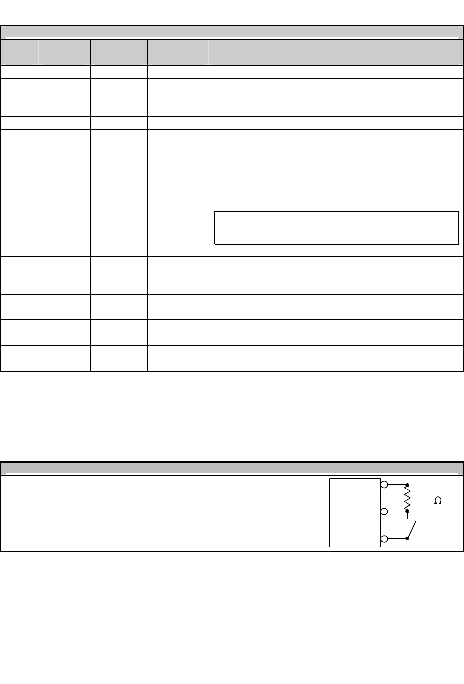
Appendix J – GPIO
186 Class Series Programmer’s Manual
M
-
Class GPIO Port Connections and Functions
Pin
# Signal
Name Signal
State Signal
Direction[1]
Signal
Description
1 Vcc +5 VDC Output Printer +5 VDC
2 Printer
Fault Low Output Goes low if the printer detects any fault. Applicable
only if cutter not equipped. To activate set the GPIO
Option to “YES” and Cutter Equipped to “NO” [2] .
3 Spare Reserved Input N/A
4 Start of
Print
(SOP)
Low
Level
Input For applicators, it is recommended to only set the SOP
signal to ACTIVE LOW. When ready to print a label,
the applicator should set this signal low for at least
50ms or until the EOP signal goes not active. (See
sample circuit next page.) To activate set the
PRESENT SENSOR Option to “YES” [2].
þ Note: If a label is ready to print, the printer will blink the
STOP LED, signifying “WAITING FOR SIGNAL,” until it
receives the applicator’s Start of Print signal.
5 End of
Print
(EOP)
Low
Level Output Goes low when printed label reaches the presented
position. Minimum signal time 20msecs. To activate
set GPIO Option to “YES” [2].
6 Signal
Ground Ground N/A N/A
7 +24V 1.6 Amp
(fused ) Input N/A
8 Signal
Ground Ground N/A N/A
[1] Signal direction given relative to the printer.
[2] Selection for this option can be set via the Printer Set Configuration Command <STX>Kc or the Printer Setup
Function. The Printer Set Configuration Parameter Mnemonics are “PS” for Present Sensor (N, Y, A [Auto]);
“CE” for Cutter Equipped (N, Y, A [Auto]) and “GE” for GPIO (N, Y or A [Applicator]). The Printer Setup
selections are as follows: Item #3, PRESENT SENSOR; Item #4, CUTTER EQUIPPED; and Item #25, GPIO.
M
-
Class Start of Print Control
Connections for an external Start of Print control can be made (1)
directly to Pin 4 using a TTL-level input or (2) with an interface
circuit similar to the one shown here (for additional interfacing data,
see the table above).
1
4
SOP
8
Gnd
1K
Vcc
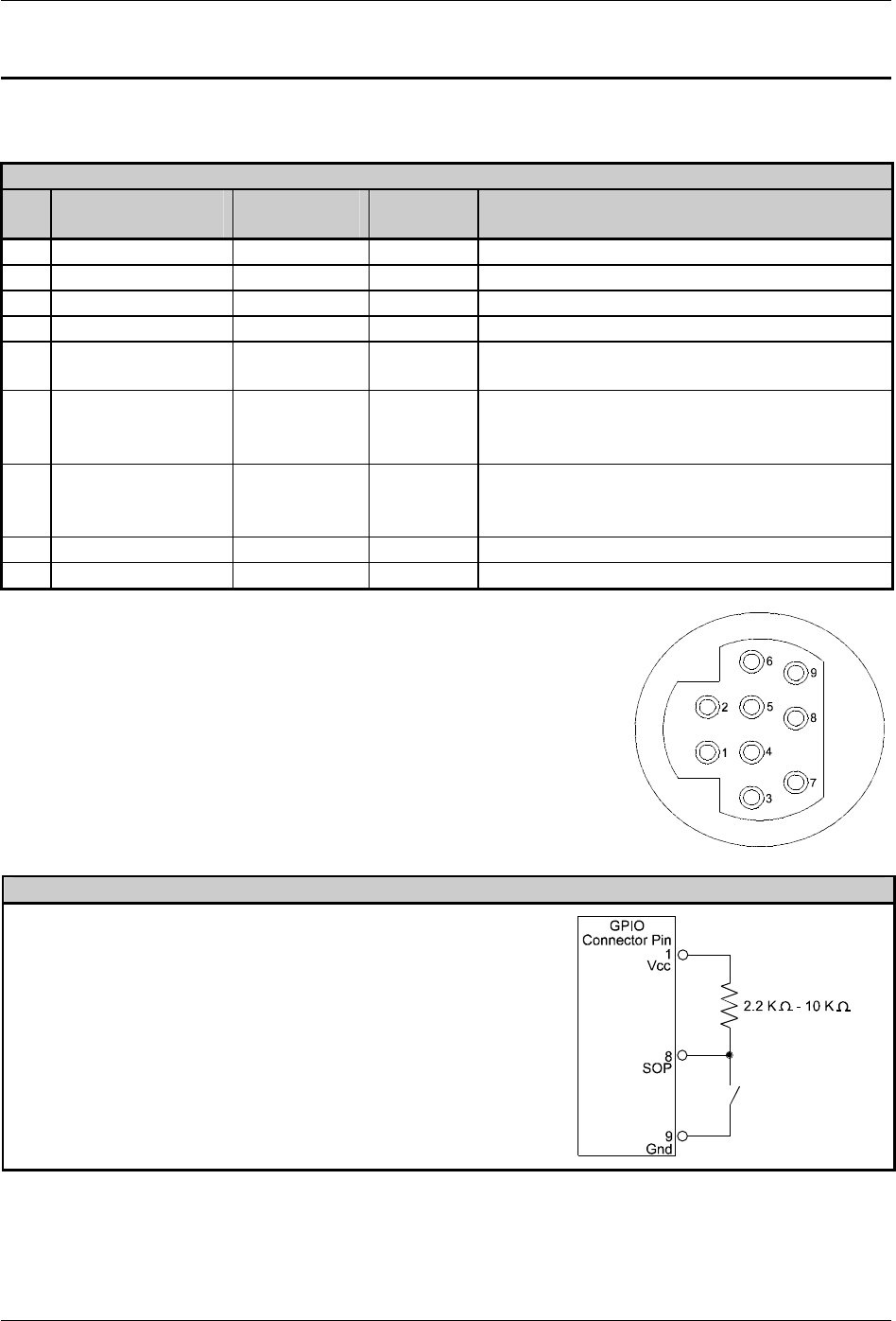
Appendix J – GPIO
Class Series Programmer’s Manual 187
GPIO-1 Configuration (I-Class & W-Class)
The GPIO-1 interface connector is a 9-pin Mini-DIN female type (e.g., Kycon KMDG-9S-BS) requiring a
9-pin Mini-DIN plug (e.g., Kycon KMDA-9P). Each GPIO-1 pin function is detailed in the table below:
I&W-Class GPIO-1 Pin Functions
Pin
# Signal
Name Signal
State Signal
Direction*
Signal
Description
1 Vcc +5 VDC Output Printer +5 VDC
2 Ribbon Fault Low Output Goes low when the printer detects ribbon out.
3 Paper Fault Low Output Goes low when the printer detects media out.
4 Printer Fault Low Output Goes low when any printer fault is detected.
5 Ribbon Low Programmable
Output Will signal Applicator when the ribbon supply
is low.
6 End of Print Programmable
Output Will signal Applicator when print is done. Can
be monitored to initiate next Start of Print
sequence.
7 Backup Label Programmable
Input When active, will back up the label once it has
been presented. (i.e., must have a present
distance greater than zero)
8 Start of Print Signal
Programmable
Input When active, will begin print.
9 Signal Ground Ground N/A N/A
*Signal direction is given relative to the printer.
GPIO-1 Pin Configuration (as viewed from the rear of the printer):
I&W-Class GPIO-1 Start of Print Control
Connections for an external Start of Print/Backup Label
control can be made (1) directly to Pin 8 / 7 using a TTL-level
input or (2) with an interface circuit similar to the one shown
right. For additional interfacing requirements, see the table
above.
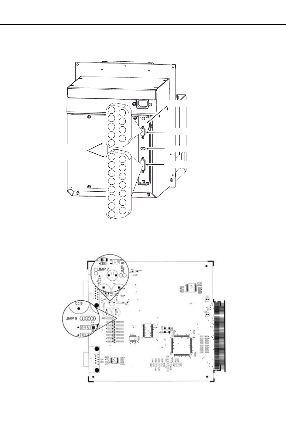
Appendix J – GPIO
188 Class Series Programmer’s Manual
GPIO-2 Configuration (A-Class)
The A-Class GPIO-2 (Applicator Interface Card) has two LEDs, an Auxiliary (Serial B) Port, and a GPIO
Port.
9
5
4
3
2
1
8
7
6
15
14
13
12
11
10
9
8
7
6
5
4
3
2
1
Auxiliary Port, J1
Green and Yellow LEDs
GPIO Port, J2
Applicator Interface Card
Connector
Pin-Outs
GPIO-2 Interface Card Location and Port Pin-outs
GPIO-2 Interface Card Jumper Locations
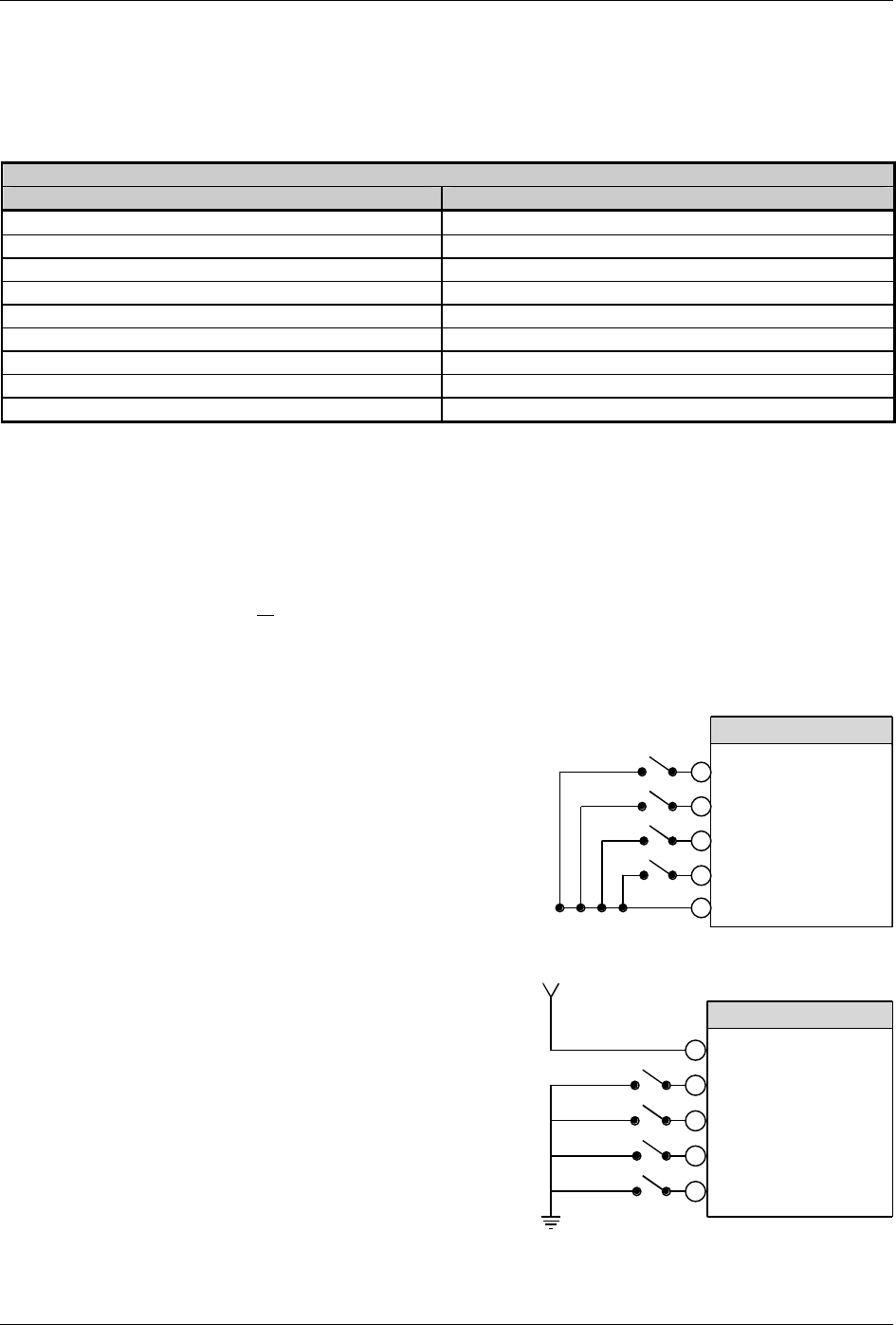
Appendix J – GPIO
Class Series Programmer’s Manual 189
The Auxiliary Port (J1) is an RS-232 interface. Serial data transfer settings, such as baud rate, word
length and parity, can be made using <STX>KcSP commands. These settings must match the device that
you are connecting. Jumpers JMP 1 – JMP 4 should be in installed.
GPIO-2 Auxiliary Data Port
Pin Number Signal
1 +5 VDC (0.5 Amp )
2 RX
3 TX
4 DTR
5 Ground
6 N/C
7 RTS
8 CTS
9 N/C
The GPIO Port allows convenient printer to applicator integration. Functions can be configured using the
menu system or via <STX>Kc commands. All configuration settings are saved in non-volatile memory.
Jumper settings are critical:
• Jumper settings allow the printer to power the applicator interface circuitry, or the applicator interface
circuitry can be powered externally.
• Jumper settings allow + 5 or +24 VDC output signal levels to be used.
The Applicator Start of Print Circuit will depend upon the applicator system’s requirements:
4 For applicator interface circuitry that
will use the printer’s +5 VDC, follow the
schematic shown right.
J2 - GPIO PORT
3
4
5
6
1
Start of Print
Feed Label
Pause Toggle
Reprint
Ground
4 For applicator interface circuitry that
will supply an external +5 VDC and
ground, follow the schematic shown
right.
For this configuration, JMP 7 and JMP 8
must be removed
3
4
5
6
2
Start of Print
Feed Label
Pause Toggle
Reprint
Vcc
Vcc = 5 VDC External Power Source
Ground
J2 -GPIO PORT
Appendix J – GPIO
190 Class Series Programmer’s Manual
The table below details the GPIO Port pin-outs, functions, and configurable settings:
WARNING
Failure to configure the GPIO Port’s jumpers for the device(s) you are connecting may
result in damage to the printer and/or the applicator.
GPIO Port (J2) Pin Functions and Associated Jumper Selections
Pin
# Signal
Name Signal
Direction Active
Setting Jumper
Placement Function /
Description
Ground Ground JMP 8 ‘On’ Printer chassis ground is used
1
Ground (Configurable)
Open Open JMP 8 ‘Off’ Ground return must be supplied
Output +5 VDC JMP 7 ‘On’ Printer +5 VDC is used
(.5 amp max.)
2
+5 VDC (Configurable)
Open Open JMP 7 ‘Off’ +5 VDC must be supplied
3 Start Of Print [5] Input Programmable [1]
4 Feed Label [4] Input Low
5 Pause Toggle Input Low
6 Reprint [3] Input Low
7 +24 VDC (1.0 amp max.) Output +24 VDC
8 Ground Ground Ground
N/A
N/A
9 Ribbon Low Output Programmable [1]
10 Service Required [2] Output Low
11 End Of Print Output Programmable [1]
12 Media Out Output Low
13 Ribbon Out Output Low
14 Data Ready (DRDY) Output Low
JMP 9:
Pins 1 & 2 =
+5 VDC
– OR –
Pins 2 & 3 =
+24 VDC
See WARNING message,
above.
When the output is inactive,
then all output pins will be
pulled up to the voltage
determined by this jumper
setting.
15 Spare Output N/A N/A N/A
[1] For details see Section 4.2.4 of the A-Class Operator’s Manual.
[2] Evoked by occurrences listed under ‘Fault Messages’ in Section 6.2 of the A-Class Operator’s Manual.
[3] Reprints the last label exactly, with no increment or time stamp changes; use it for error conditions. Always keeping this signal
LOW will result in non-stop printing.
[4] Advances media until the signal goes HIGH and, if not in continuous mode, the media will be positioned at the next available
media TOF.
[5] If active with no current print job, “WAITING FOR DATA” is displayed. Specifying a quantity of 9999 while always keeping
this signal ‘ON’ will cause non-stop label printing, except in single label mode (see Imaging Mode, Section 4.2.5 of the A-
Class Operator’s Manual), which will cause the printer to stop between labels.
The Green and Yellow Indicators offer a visual check of printer/applicator activity:
GPIO
-
2 Interface Indicators
• Yellow LED Flash at power-up and when the card’s outputs change state.
• Green LED Flash at power-up and when the card’s inputs change state.
Class Series Programmer’s Manual 191
Appendix
Print Resolutions, Module Identifiers, Maximum Field, Column, & Character Values
þ Note: Throughout the tables below, the following standards are used:
X = Supported Command
ND = Non-Display
Printer Model
Module ID
(Memory Bank)
Description A E I M (ND)
M W
A DRAM (512 KB - default size) X X
B Flash (256 KB available to user) [1] X[3]
X
C Default, as assigned by <STX>X X X X X X X
DRAM (512 KB - default size) configurable. X X
D
Internal DRAM (default 1MB) configurable. X X X X
G [2] 512 KB Flash Main PCB, configurable. X X X X
1.5 MB Flash, configurable.
H 5.5 MB Optional Expanded Flash Main Logic
Card, configurable.
X
64 KB Flash – Menu / EFIGS – protected X X X X
Y
128 KB Flash – 64 KB Menu / EFIGS
protected / 64 KB Flash, configurable. X
F 4 MB Flash – Option, configurable. X X
Z 4 MB Flash – Option ILPC – protected X X
[1] The availability/size of the Internal Flash Module is dependent upon the installed font option (expandable with the Flash
Memory Expansion Option) and available Flash memory; reference the Configuration Label, or following the <STX>KC
command the “INTERNAL FLASH MODULE PRESENT” message. The Flash memory has a limited number of writes
(approximately 100,000) and is intended for permanent (or semi-permanent) storage of downloaded images, fonts and label
formats.
[2] Not available for the I-4206 and I-4208.
[3] Not standard.
Table K-1: Printer Module Identifiers
Printer
(All models, or as noted) Maximum
Format Fields [3] Total Characters
for all Fields
A-Class 700 32768
E-Class 450 16,000
I-Class (I-4206 and I-4208) 500 32768
I-Class (I-4210, I-4212, I-4308, I-4406, and I-4604) 700 32768
M-Class (M-4206) 450 16,000
M-Class (M-4208 and M-4306) 700 32768
W-Class 700 32768
[3] When the product of the number of fields and characters in each field exceeds the available printer memory (the limiting
factor), portions of the label may not print.
Table K-2: Maximum Label Format Fields & Characters
Appendix K – Print Resolutions; Module Identifiers; Maximum Field, Column & Character Values
192 Class Series Programmer’s Manual
Print
Resolution Dot Dimensions
(Nominal) Maximum
Print Width Maximum
“gggg” Value
Printer
Model
DPI
DPMM
Inches
Millimeters
Dots
Millimeters
Inch
Metric
A-4212 203 8.0 .0043 x .0052 .11 x .13 832 104.1 0410 1041
A-4310 300 11.8 .0027 x .0043 .07 x .11 1248 105.7 0416 1057
E-4203 203 8.0 .0043 x .0052 .11 x .13 832 104.1 0410 1041
E-4204 203 8.0 .0043 x .0052 .11 x .13 832 104.1 0410 1041
E-4304 300 11.8 .0028 x .0056 .07 x .14 1248 105.7 0416 1057
I-4206 203 8.0 .0043 x .0052 .11 x .13 832 104.1 0410 1041
I-4208 203 8.0 .0043 x .0052 .11 x .13 832 104.1 0410 1041
I-4210 203 8.0 .0043 x .0052 .11 x .13 832 104.1 0410 1041
I-4212 203 8.0 .0043 x .0052 .11 x .13 832 104.1 0410 1041
I-4308 300 11.8 .0027 x .0043 .07 x .11 1248 105.7 0416 1046
I-4406 406 16.0 .0013 x .0018 .05 x .07 1664 104.1 0410 1041
I-4604 600 23.6 0008 x .0015 .03 x .06 2496 105.7 0416 1057
M-4206 203 8.0 .0043 x .0052 .11 x .13 864 108.0 0425 1080
M-4208 203 8.0 .0043 x .0052 .11 x .13 864 108.0 0425 1080
M-4306 300 11.8 .0027 x .0043 .07 x .11 1248 105.7 0416 1057
W-6208 203 8.0 0043 x .0052 .109 x .132 1344 168.1 0662 1681
W-6308 300 11.8 .00027 x .0043 .069 x .108 1920 162.6 0640 1626
W-8306 300 11.8 .00027 x .0043 .069 x .108 2560 216.7 0853 2167
Table K-3: Print Widths, Resolutions, and Record Column Field Values
Printer Resolution (DPI) Row Adjust Finetune <STX>KcRF Parameter Range (+/– dots)
203 -100 – 100 dots
300 -150 – 150 dots
400 -200 – 200 dots
600 -300 – 300 dots
Table K-4: Row Adjust Range per Print Resolution
Class Series Programmer’s Manual 193
Appendix
Speed Ranges
Speed Value:
Printer Speed Command* Inches per Second Millimeters per Second
A 1.0 25
B 1.5 38
C 2.0 51
D 2.5 63
E 3.0 76
F 3.5 89
G 4.0 102
H 4.5 114
I 5.0 127
J 5.5 140
K 6.0 152
L 6.5 165
M 7.0 178
N 7.5 191
O 8.0 203
P 8.5 216
Q 9.0 227
R 9.5 241
S 10.0 254
T 10.5 267
U 11.0 279
V 11.5 292
W 12.0 305
X 13.0 330
Y 14.0 356
Z 15.0 381
a 16.0 406
b 17.0 432
c 18.0 457
d 19.0 483
e 20.0 508
*Applicable speed values are printer dependent. See Table L-2, below.
Table L-1: Speed Command Values
Appendix L – Speed Ranges
194 Class Series Programmer’s Manual
Print Slew Backup
Printer Range Default Range Default Range Default
A-4212 C – W O C – f O C – G G
A-4310 C – S K C – d K C – G G
E-4203[1] A – G G A – G G A – E C
E-4204 A – G G A – G G A – E C
E-4304 A – G G A – G G A – E C
I-4206 C – K K C – K K C – G G
I-4208 C – O O C – O O C – G G
I-4308 C – O K C – O K C – G G
I-4210 C – S K C – S K C – G G
I-4212 C – W O C – W O C – G G
I-4406 C – K I C – K K C – G G
I-4604 C – G E C – G G C – G G
M-4206 C – K G C – K G C – G C
M-4208 C – O O C – O O C – G G
M-4306 C – K G C – K G C – G C
W-6208 C – O K C – S K C – G G
W-6308 C – O K C – S K C – G G
W-8306 C – K K C – O K C – G G
[1] Maximum speed is limited to ‘E’ unless the optional regulated power supply is attached.
Table L-2: Speed Ranges and Defaults by Model
Class Series Programmer’s Manual 195
Appendix
Commands by Function
Commands by Function
Function Command
Backup speed pa
Batch quantity request <SOH>E
Cancel <SOH>C
Character bit-mapped data <ESC>(snnnWdata
Character code <ESC>*cnnnE
Character dump mode <STX>P
Column offset amount Cnnnn
Configuration label and dot pattern print <STX>Z
Configuration Set (See Table 5-1 for listing) <STX>Kc
Continuous paper length <STX>cnnnn
Count by ^nn
Cut <STX>o
Cut by :nnnn
Cut by cnn
Decrement alphanumerically <fii
Decrement numerically - fii
DIP switch, host controlled settings <STX>Vn
Dot size height and width Dwh
Edge sensor enable <STX>e
Feed rate <STX>Sa
Feedback characters enable <STX>a
Field data line terminator Tnn
File delete from module <STX>xmfname
Firmware version request <STX>v
Font descriptor <ESC>)snnnW
Font ID number <ESC>*cnnnD
Form feed <STX>F
Set Present Distance <STX>Kfnnnn
Format attribute An
Graphics image download <STX>Iabfnamecr
Heat setting Hnn
Inches <STX>n
Increment alphanumerically >fii
Increment numerically +fii
Label format field replacement <STX>Unnstring
Label formatting start <STX>L
Label length maximum <STX>Mnnnn
Table M-1: Commands (A-L)
Appendix M – Commands By Function
196 Class Series Programmer’s Manual
Commands by Function
Function Command
Memory query <STX>KQ
Memory query (new format) <STX>Kq
Metric <STX>m
Metric m
Mirror M
Module clear <STX>qm
Module, compress <STX>zm
Module, directory request <STX>Wa
Module, set default <STX>Xm
Module, FLASH memory Test <STX>w
Module, RAM memory Test <STX>t
Modules, clear all <STX>Q
Pause for each label <STX>J
Pause toggle <SOH>B
Pause, controlled <STX>p
Place data in global register G
Print last label format <STX>G
Print speed Pa
Print time and date <STX>Tstring
Printhead dot pattern test label <STX>T
Quantity labels printed <STX>Ennnn
Quantity of labels Qnnnn
Recall global data and place in field <STX>Sa
Recall stored label rname
Reflective sensor select <STX>r
Replacement field tag U
Reset <SOH>#
Resettable counters reset <STX>Kr
Ribbon saver <STX>Rx
Row offset amount Rnnnn
RS-232 port test <STX>k
Scalable font download <STX>imtaabbb...bcrxxxxxxxxfff...f
Sensor values request <STX>Y
Slew rate Sa
Status ASCII string request <SOH>A
Status byte request <SOH>F
Store label in module & terminate formatting smname
Symbol set select <STX>ySaa
Symbol set select ySaa
Terminate formatting - print label format E
Terminate label formatting, do not print label X
Time and date request <STX>B
Time and date set <STX>AwMMddyearhhmmjjj
Update system database with current database <SOH>U
Zero (Ø) conversion to “0” z
Table M-1: Commands (M-Z)
Class Series Programmer’s Manual 197
Appendix
Class Series DPL Constraint Cross-Reference
þ Note: Throughout the tables below, the following standards are used:
X = Supported Command
ND = Non-Display
Class Printer Model
Immediate
Command
Description A E I M – ND
M W
# Reset X X X X X X
* Reset X X X X
A Send ASCII Status String X X X X X X
B Toggle Pause X X X X X X
C Stop/Cancel X X X X X X
D SOH Shutdown X X
E Send Batch Quantity X X X X X X
F Send Status Byte X X X X X X
U Update System Database with
Current Database X X X X X X
Table N-1: Immediate Command <SOH> Constraints
Class Printer Model
System Level
Command
Description A E I M – ND
M W
A Set Time and Date X X X X X X
a Enable Feedback Characters X X X X X X
B Get Printer Time and Date Info X X X X X X
b Set Cutter signal time
C Copy Module
c Set Continuous Paper Length X X X X X X
D Memory Dump
d Set Printer to Double Buffer Mode X X
E Set Quantity for Stored Label X X X X X X
e Select Edge Sensor X X X X X X
F Form Feed X X X X X X
f Set Form Stop Position X X X X X X
G Print Last Label Format X X X X X X
g Internal Batch Software Mode
H Set Cutter Signal Time
I Input Graphics Data X X X X X X
i Download Scalable Font X X X X X X
J Set Pause X X X X X X
k Test RS-232 Port X X X X X X
L Enter Label Formatting Mode X X X X X X
Table N-2: System Level Command <STX> Constraints
Appendix N – DPL Consraint Cross Reference
198 Class Series Programmer’s Manual
Class Printer Model
System Level
Command
Description A E I M – ND
M W
M Set Maximum Label Length X X X X X X
m Set Printer to Metric X X X X X X
N Enter Internal Batch
n Set Printer to Inches X X X X X X
O Set Start of Print Position X X X X X X
o Cycle Cutter X X X X X X
P Enter Character Dump Mode X X X X X X
p Controlled Pause X X X X X X
Q Clear All Modules X X X X X X
q Clear Module X X X X X X
R Ribbon Saver X X
r Select Reflective Sensor X X X X X X
S Set Feed Rate X X X X X X
s Set Printer to Single Buffer Mode X X
T Printhead Dot Pattern Test Label X X X X X X
t Test DRAM Memory Module X X X X X X
U Label Format Field Replacement X X X X X X
V Software Switch Settings X X X X X X
v Firmware Version Information X X X X X X
W Request Module Information X X X X X X
w Test FLASH Memory Module X X X X X X
X Set Default Module X X X X X X
x Delete Module File X X X X X X
Y Output Sensor Values X X X X X X
y Select Font Symbol Set X X X X X X
Z Print Configuration and Dot Pattern
X X X X X X
z Pack Module X X X X X X
Table N-2: System Level Command <STX> Constraints (continued)

Appendix N – DPL Consraint Cross Reference
Class Series Programmer’s Manual 199
Class Printer Model
Extended-
System
Command
Description A E I M – ND M W
Kb Backfeed Time Delay X X
KC Get Configuration X X X X X X
Kc Set Configuration X X X X X X
KD Database Configuration X X
Kd Set File as Factory Defaults X X X X
KE Character Encoding X X X X X X
KF Select Factory Defaults X X X X X X
Kf Set Present Distance X X X X X X
KI GPIO Input
KM Memory Configuration, Internal
Module X X
KO GPIO Output
KQ Query Memory Configuration X X X X X X
Kq Query Memory Configuration
(new format) X X X X X X
KP Module Protection X X X X
KR Reset Memory Configuration X X
Kr Reset Internal Counters X X X X X X
KS Memory Configuration, Scalable
Font Cache X X
KV Verifier Enable/Disable X X X X
KW Memory Configuration, Printable
Label Width X X
Kx Delete Configuration File X X X X
Table N-3: Extended-System Command Constraints
Appendix N – DPL Consraint Cross Reference
200 Class Series Programmer’s Manual
Class Printer Model
Label
Formatting
Command
Description A E I M – ND M W
: Set Cut by Amount X X X X X X
+ (>) Make Last Field Entered Increment
Numeric (Alphanumeric) X X X X X X
- (<)
Make Last Field Entered Decrement
Numeric (Alphanumeric) X X X X X X
^ Set Cut by Amount X X X X X X
A Set Format Attribute X X X X X X
B Bar Code Magnification X X X X
C Set Column Offset Amount X X X X X X
c Set Cut by Amount X X X X X X
D Set Dot Size Width and Height X X X X X X
E Terminate Label Formatting Mode
and Print Label X X X X X X
e Recall Printer Configuration X X X X
F Advanced Font Attributes X X X X X X
f Set Present Speed X X
G Place Data in Global Register X X X X X X
H Enter Heat Setting X X X X X X
J Justification X X X X X X
M Select Mirror Mode X X X X X X
m Set Metric Mode X X X X X X
n Set Inch Mode X X X X X X
P Set Print Speed X X X X X X
p Set Backfeed Speed X X X X X X
Q Set Quantity of Labels to Print X X X X X X
R Set Row Offset Amount X X X X X X
r Recall Stored Label Format X X X X X X
S Set Slew Speed X X X X X X
s Store Label Format in Module X X X X X X
T Set Field Data Line Terminator X X X X X X
U Mark Previous Field as a String
Replacement Field X X X X X X
W Wait Mode
X Terminate Label Formatting Mode X X X X X X
y Select Font Symbol Set X X X X X X
Z Zip Mode
z Zero (Ø) Conversion to “O” X X X X X X
<STX>S Recall Global Data X X X X X X
<STX>T Print Time and Date X X X X X X
Table N-4: Label Command Constraints
Appendix N – DPL Consraint Cross Reference
Class Series Programmer’s Manual 201
Class Printer Model
Internal
Font
Description A E I M – ND M W
9 (Ann) Smooth Internal CG
Triumvirate Bitmap Font:
Referencing the Font 9 to Smooth
CG Triumvirate Fonts are
automatically converted to the CG
Triumvirate Scalable Font, when
installed. The printed scalable font
is slightly smaller than previous
printers, measuring less than 1/16
inch over three inches of print.
X [2] X [1]
X [2] X [1]
X [2] X [2]
9 (S00) CG Triumvirate Bold
Condensed Scalable Font.
(Standard)
X
X
X X
9 (S01) CG Triumvirate Scalable
Font. (Standard)
X
X
X X
[1] Bitmapped Fonts may or may not be used depending on installed fonts.
[2] Scaleable Fonts are always used. Table N-5: Internal Font Constraints

Appendix N – DPL Consraint Cross Reference
202 Class Series Programmer’s Manual

Class Series Programmer’s Manual 203
Appendix
Image Loading
The printer will accept four types of image files: .BMP, .IMG, .PCX and a special Datamax 7-bit ASCII
file (as defined in this section). Using the Datamax 7-bit ASCII format will require at least twice as much
data transmission time as the other formats, (see <STX>I). The Datamax ASCII image file format is
made up of a set of records with identical formats, each representing a dot row of the image; a terminator
follows the last of these records.
Dot-row record
•
•
•
•
Dot-row record
Terminator
Each dot-row record has the following format:
Syntax: 80nndd...d<CR>
Where: nn - Is the number of character pairs in dd...d, represented in ASCII hex.
dd...d - Is dot data, character pairs, ASCII hex, 00-FF.
Duplicate records may be encoded using a repeat data record, following the data record that needs
duplicating. The repeat data record format is:
Syntax: 0000FFnn<CR>
Where: nn - Is the number of duplicates, ASCII hex, 00-FF.
The terminator, last record, at the image download is: FFFF<CR>

Appendix O – Image Loading
204 Class Series Programmer’s Manual
^BqA(CR)
^BIAAFLOGO(CR)
8030FFFFFFFFFFFFFFFFFFFFFFFFFFFFFFFFFFFFFFFFFFFFFFFFFFFFFFFFFFFFFFFFFFFFFFFFFFFFFFFFFFFFFFFFFFFF0000(CR)
8030FFFFFFFFFFFFFFFFFFFFFFFFFFFFFFFFFFFFFFFFFFFFFFFFFFFFFFFFFFFFFFFFFFFFFFFFFFFFFFFFFFFFFFFFFFFF0000(CR)
8030FFFFFFFFFFFFFFFFFFFFFFFFFFFFFFFFFFFFFFFFFFFFFFFFFFFFFFFFFFFFFFFFFFFFFFFFFFFFFFFFFFFFFFFFFFFF0000(CR)
8030FFFFFFFFFFFFFFFFFFFFFFFFFFFFFFFFFFFFFFFFFFFFFFFFFFFFFFFFFFFFFFFFFFFFFFFFFFFFFFFFFFFFFFFFFFFF0000(CR)
8030FFFFFFFFFFFFFFFFFFFFFFFFFFFFFFFFFFFFFFFFFFFFFFFFFFFFFFFFFFFFFFFFFFFFFFFFFFFFFFFFFFFFFFFFFFFF0000(CR)
8030FFFFFFFFFFFFFFFFFFFFFFFFFFFFFFFFFFFFFFFFFFFFFFFFFFFFFFFFFFFFFFFFFFFFFFFFFFFFFFFFFFFFFFFFFFFF0000(CR)
8030FFFFFFFFFFFFFFFFFFFFFFFFFFFFFFFFFFFFFFFFFFFFFFFFFFFFFFFFFFFFFFFFFFFFFFFFFFFFFFFFFFFFFFFFFFFF0000(CR)
8030FFC00000007FFC0003FFFFC001FC0001FC0003FFFFC0018000FFC001FF8000C0003FFFFE000000FFFFE0001FFFFF0000(CR)
8030FFC00000000FFC0003FFFFC001FC0001FC0003FFFFC0018000FFC001FF800040001FFFFE0000007FFFC0001FFFFF0000(CR)
8030FFC000000003FC0001FFFFC001FC0001FC0001FFFFC0018000FFC001FF800040001FFFFE0000003FFFC0001FFFFF0000(CR)
8030FFC000000000FC0001FFFFC001FE0001FE0001FFFFC00180007FC000FF800060001FFFFE0000003FFFC0003FFFFF0000(CR)
8030FFE0000000007E0001FFFFC001FE0001FE0001FFFFC00180007FC000FFC00060000FFFFE0000001FFFC0003FFFFF0000(CR)
8030FFE0000000003E0000FFFFC001FE0000FE0000FFFFC00180007FC0007FC00020000FFFFE0000001FFF80003FFFFF0000(CR)
8030FFE0000000001E0000FFFFC001FE0000FF0000FFFFC001C0007FC0007FC00030000FFFFE0010000FFF80003FFFFF0000(CR)
8030FFE0000000000F0000FFFFC001FE0000FF0000FFFFC001C0007FC0007FC00030000FFFFE00180007FF80007FFFFF0000(CR)
8030FFE0000000000700007FFFC001FF0000FF80007FFFC001C0007FC0003FC000380007FFFE00180007FF80007FFFFF0000(CR)
8030FFF0000000000380007FFFC001FF0000FF80007FFFC001C0003FC0003FE000380007FFFE001C0003FF80007FFFFF0000(CR)
8030FFF0000000000380007FFFC001FF0000FF80007FFFC001C0003FC0003FE000380007FFFE001E0003FF80007FFFFF0000(CR)
8030FFF0000000000180003FFFC001FF00007FC0003FFFC001C0003FC0001FE0001C0003FFFE001E0001FF0000FFFFFF0000(CR)
8030FFF00000000001C0003FFFC001FF00007FC0003FFFC001E0003FC0001FE0001C0003FFFE001F0000FF0000FFFFFF0000(CR)
8030FFF00007C00000C0003FFFC001FF00007FE0003FFFC001E0003FC0000FF0001E0003FFFE001F0000FF0000FFFFFF0000(CR)
8030FFF80007F80000E0001FFFC001FF80007FE0001FFFC001E0003FC0000FF0001E0001FFFE001F80007F0000FFFFFF0000(CR)
8030FFF80007FC0000E00000000001FF80007FE00000000001E0001FC0000FF0001E00000000001FC0007F0000FFFFFF0000(CR)
8030FFF80007FE0000600000000001FF80003FF00000000001E0001FC00007F0000F00000000001FC0003F0001FFFFFF0000(CR)
8030FFF80003FF0000700000000001FF80003FF00000000001F0001FC00007F0000F00000000001FE0001E0001FFFFFF0000(CR)
8030FFF80003FF0000700000000001FF80003FF00000000001F0001FC00007F8000F00000000001FE0001E0001FFFFFF0000(CR)
8030FFFC0001FFC0003C0000000001FFE0001FFE0000000001F8000FC00000FC0007E0000000001FFE00000003FFFFFF0000(CR)
8030FFFE0001FFC0001E0000000001FFE0001FFE0000000001F8000FC00000FC0007E0000000001FFF00000003FFFFFF0000(CR)
8030FFFE0001FFC0001E0000000001FFE0001FFE0000000001F8000FC00000FC0007F0000000001FFF00000007FFFFFF0000(CR)
8030FFFE0000FFC0001F0000000001FFE0000FFF0000000001F8000FC000007C0003F0000000001FFF80000007FFFFFF0000(CR)
8030FFFE0000FFC0001F0000000001FFE0000FFF0000000001FC0007C000007E0003F0000000001FFF80000007FFFFFF0000(CR)
8030FFFE0000FFE0001F0001FFC001FFE0000FFF8001FFC001FC0007C000003E0003F8000FFE001FFFC0000007FFFFFF0000(CR)
8030FFFE0000FFE0000F8001FFC001FFF0000FFF8000FFC001FC0007C000003E0003F8000FFE001FFFE000000FFFFFFF0000(CR)
8030FFFF0000FFE0000F8000FFC001FFF0000FFF8000FFC001FC0007C000003E0003F8000FFE001FFFE000000FFFFFFF0000(CR)
8030FFFF0000FFE0000F8000FFC001FFF00007FFC000FFC001FC0007C000001F0001FC000FFE001FFFF000000FFFFFFF0000(CR)
8030FFFF00007FE0000FC000FFC001FFF00007FFC0007FC001FE0007C002001F0001FC0007FE001FFFF000000FFFFFFF0000(CR)
8030FFFF00007FF0000FC0007FC001FFF00007FFE0007FC001FE0003C002001F0001FE0007FE001FFFF800000FFFFFFF0000(CR)
8030FFFF00007FF0000FE0007FC001FFF80007FFE0007FC001FE0003C003000F0001FE0007FE001FFFFC00001FFFFFFF0000(CR)
8030FFFF80007FF00007E0007FC001FFF80007FFE0003FC001FE0003C003000F0001FE0003FE001FFFFC00001FFFFFFF0000(CR)
8030FFFF80007FF00007E0003FC001FFF80003FFF0003FC001FE0003C00300078001FF0003FE001FFFFE00001FFFFFFF0000(CR)
8030FFFF80003FF00007F0003FC001FFF80003FFF0003FC001FE0003C00380078000FF0003FE001FFFFE00001FFFFFFF0000(CR)
8030FFFF80003FF80007F0003FC001FFF80003FFF0001FC001FF0003C00380078000FF8001FE001FFFFE00001FFFFFFF0000(CR)
8030FFFF80003FF80007F0001FC001FFF80003FFF8001FC001FF0001C003C0038000FF8001FE001FFFFE00001FFFFFFF0000(CR)
8030FFFFFFC0000000007FFC000001F80000000000FC000001FFF0000003FFE0000007FFC000001FFFC0003F80007FFF0000(CR)
8030FFFFFFE000000000FFFC000001F80000000000FE000001FFF8000003FFE0000007FFE000001FFFC0003FC0003FFF0000(CR)
8030FFFFFFF000000000FFFE000001F80000000000FE000001FFF8000003FFF0000007FFE000001FFFC0003FC0003FFF0000(CR)
8030FFFFFFFC00000000FFFE000001FC0000000000FE000001FFF8000003FFF0000007FFE000001FFFC0003FE0001FFF0000(CR)
8030FFFFFFFE00000000FFFE000001FC00000000007F000001FFF8000003FFF0000007FFF000001FFFC0003FE0001FFF0000(CR)
8030FFFFFFFF00000001FFFF000001FC00000000007F000001FFF8000003FFF8000007FFF000001FFF80003FF0000FFF0000(CR)
8030FFFFFFFFC0000001FFFF000001FC00000000007F000001FFF8000003FFF8000003FFF800001FFF80007FF0000FFF0000(CR)
8030FFFFFFFFE0000003FFFF800001FC00000000007F800001FFFC000003FFF8000003FFF800001FFF80007FF80007FF0000(CR)
8030FFFFFFFFF0000007FFFF800001FC00000000007F800001FFFC000003FFFC000003FFF800001FFF80007FF80007FF0000(CR)
8030FFFFFFFFF800000FFFFF800001FE00000000003FC00001FFFC000003FFFC000003FFFC00001FFF00007FFC0003FF0000(CR)
8030FFFFFFFFFE00001FFFFFC00001FE00000000003FC00001FFFC000003FFFE000003FFFC00001FFF00007FFC0003FF0000(CR)
8030FFFFFFFFFF00007FFFFFC00001FE00000000003FC00001FFFC000003FFFE000003FFFE00001FFF00007FFE0001FF0000(CR)
8030FFFFFFFFFF8003FFFFFFC00001FE00000000003FE00001FFFC000003FFFF000003FFFE00001FFF00007FFE0001FF0000(CR)
8030FFFFFFFFFFFFFFFFFFFFFFFFFFFFFFFFFFFFFFFFFFFFFFFFFFFFFFFFFFFFFFFFFFFFFFFFFFFFFFFFFFFFFFFFFFFF0000(CR)
8030FFFFFFFFFFFFFFFFFFFFFFFFFFFFFFFFFFFFFFFFFFFFFFFFFFFFFFFFFFFFFFFFFFFFFFFFFFFFFFFFFFFFFFFFFFFF0000(CR)
8030FFFFFFFFFFFFFFFFFFFFFFFFFFFFFFFFFFFFFFFFFFFFFFFFFFFFFFFFFFFFFFFFFFFFFFFFFFFFFFFFFFFFFFFFFFFF0000(CR)
8030FFFFFFFFFFFFFFFFFFFFFFFFFFFFFFFFFFFFFFFFFFFFFFFFFFFFFFFFFFFFFFFFFFFFFFFFFFFFFFFFFFFFFFFFFFFF0000(CR)
8030FFFFFFFFFFFFFFFFFFFFFFFFFFFFFFFFFFFFFFFFFFFFFFFFFFFFFFFFFFFFFFFFFFFFFFFFFFFFFFFFFFFFFFFFFFFF0000(CR)
8030FFFFFFFFFFFFFFFFFFFFFFFFFFFFFFFFFFFFFFFFFFFFFFFFFFFFFFFFFFFFFFFFFFFFFFFFFFFFFFFFFFFFFFFFFFFF0000(CR)
8030FFFFFFFFFFFFFFFFFFFFFFFFFFFFFFFFFFFFFFFFFFFFFFFFFFFFFFFFFFFFFFFFFFFFFFFFFFFFFFFFFFFFFFFFFFFF0000(CR)
FFFF(CR)
^BL(CR)
1Y1100000000000LOGO(CR)
E(CR) Figure O-1: Sample Datamax 7-bit ASCII File Image
Figure O-2: Sample Label

Class Series Programmer’s Manual 205
Appendix
UPC-A and EAN-13: Variable Price/Weight Bar Codes
The EAN/UPC standard allows for an additional checksum to be generated in the middle of the bar code
based on the data. This is used when the price or weight of an item is embedded into the bar code data
(commonly used in the food industry).
For the printer to generate this checksum, a ‘V’ must be placed in the data stream in the position the
checksum is requested. If the ‘V’ is placed in the 6th position for UPC-A or the 7th position for EAN-13,
a checksum will be generated using the next five digits in the data stream. If the ‘V’ is placed in the 7th
position for UPC-A or the 8th position for EAN-13, a checksum will be generated using the next four
digits in the data stream. The checksum is generated per the EAN/UPC bar code standard.
Examples:
1B110000200020012345V01199
Prints the UPC-A bar code with the variable price checksum in the sixth position.
1B1100002000200123456V0150
Prints the UPC-A bar code with the variable price checksum in the seventh position.
1F1100002000200123456V01199
Prints the EAN-13 bar code with the variable price checksum in the seventh position.
1F11000020002001234567V0150
Prints the EAN-13 bar code with the variable price checksum in the eighth position.

Appendix P – UPC-A and EAN-13
206 Class Series Programmer’s Manual

Class Series Programmer’s Manual 207
Appendix
International Language Print Capability (ILPC) Programming Examples
ILPC, offered as a field upgrade or a factory installable option, allows the printing of non-English
character sets, available with European language support (CG TIMES), KANJI language support
(GOTHIC B and GOTHIC E [available on the E-Class and non-display M-Class printer models]), Chinese
language support (SIMPLIFIED GB) and Korean Hangul. All of the features are embedded in the printer
resident firmware and accessible through DPL thus eliminating excessive download time of bitmapped
characters. Using scalable technology licensed from AGFA, this firmware allows users to print smooth
characters in sizes from 4pt (1.4 mm) to 999pt (350 mm) in over 40 languages. Consult Appendix I for
code page selections. Specific details regarding which characters are supported in each option can be
obtained through Datamax Technical Support.
ILPC - CG TIMES Option
The CG Times Option is a single-byte scalable font consisting of four typefaces in 38 Western European
languages. This option contains over 900 unique characters in each of the four typefaces from the CG
Times typeface family, Normal, Italic, Bold, and Bold Italic. Single-byte scalable fonts are selected using
a print format record (see Generating Label Formats and Appendix H for details).
Scalable CG TIMES Font Code (‘eee’ field):
SA0 - CG TIMES
SA1 - CG TIMES ITALIC
SA2 - CG TIMES BOLD
SA3 - CG TIMES BOLD ITALIC
Sample Greek DPL file and resulting label:
<02>L<CR>
D11<CR>
ySWG<CR>
1911SA003600020P020P020(WG) Greek Characters from<CR>
1911SA003000085P020P020the internal Symbol Set,<CR>
1911SA002400085P020P020font code SA0<CR>
1911SA001500050P020P020<ca><e1><eb><f9><f3><ef><f1><df><f3><e1><f4><e5><20><d3><f5><ed>
<dd><e4><f1><e9><ef><20><CR>
1911SA001100100P020P020<f4><f9><e3><20><c5><f4><e1><df><f1><f9><e3><20><f4><e7><f2><CR>
1911SA000700140P020P020Datamax<CR>
1X1100000100020B365190005005<CR>
Q0002<CR>
E<CR>
þ Note: The notation “<xx>” in this DPL file should be interpreted by the reader as representing the hexadecimal
value of the character sent to the printer.
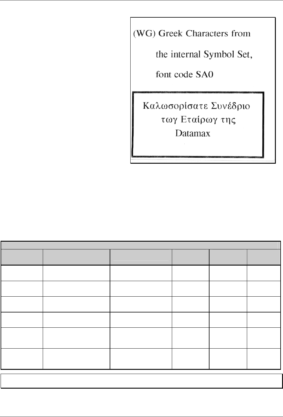
Appendix Q – ILPC Programming Examples
208 Class Series Programmer’s Manual
Sample label created using the preceding
data:
ILPC-KANJI Option
The Kanji Option is a double byte scalable font supporting Kanji Gothic B (or Gothic E on E-Class and
non-display M-Class printers). In the double byte format, the printer recalls one character printed from
every two 8-bit bytes sent from the host. Double byte scalable fonts are selected using a print format
record (see Generating Label Formats and Appendix H for details).
Scalable Double-Byte Font Map - KANJI
eee
(Font Code) Scalable
Font Type
Font Name Binary
Addressing
Hex ASCII
Addressing
Code
Pages
U40 Scalable Resident HG-Gothic-B Kanji
Scalable √ EUC, JIS,
SJIS, UC
u40 Scalable Resident HG-Gothic-B Kanji
Scalable √ EUC, JIS,
SJIS, UC
UK1 Scalable Resident HG-Gothic-E Kanji
Scalable √ EUC, JIS,
SJIS
uK1 Scalable Resident HG-Gothic-E Kanji
Scalable √ EUC, JIS,
SJIS
u50 -
u5z…
u90 - u9z
Scalable Non-Resident
(download)
User defined √
U50 -
U5z...
U90 - U9z
Scalable Non-Resident
(download) User defined √
þ Note: Not all fonts contain an entire compliment of character codes for a given character map. Gothic E is
available only on E-Class and non-display M-Class printers.
Sample Kanji Gothic B DPL file (binary addressing) and the resulting label:
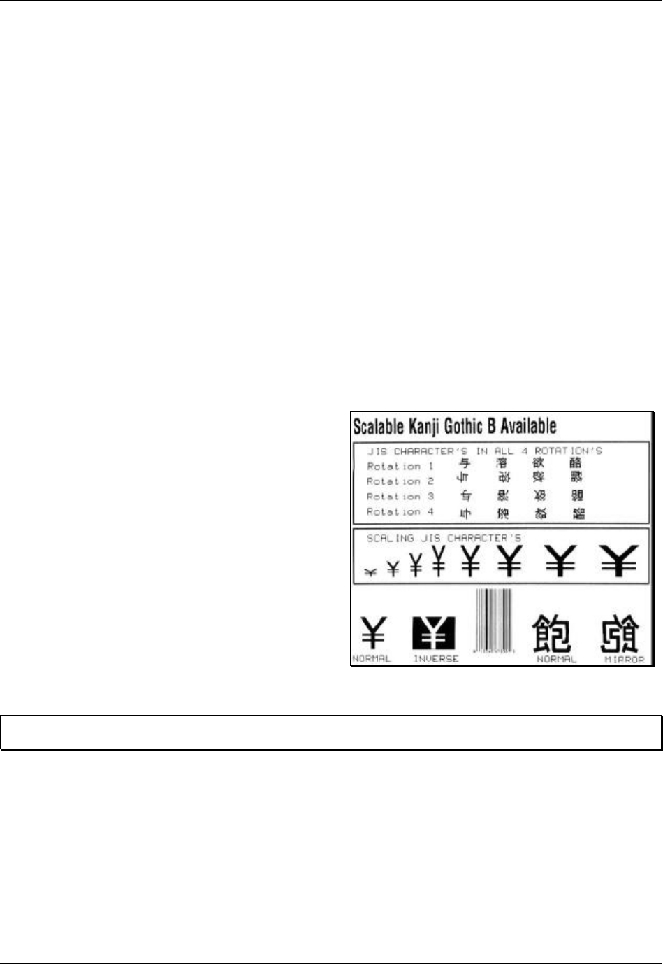
Appendix Q – ILPC Programming Examples
Class Series Programmer’s Manual 209
<02>L<CR>
D11<CR>
ySPM<CR>
1911S0003100010P020P015Scalable Kanji Gothic B Available<CR>
1B110000020017001234567890<CR>
yUJS<CR>
1X1100001900010b0392011000020002<CR>
112200002800030JIS CHARACTER’S IN ALL 4 ROTATION’S<CR>
112200002600030Rotation 1<CR>
1911U4002650150P012P012<4D><3F><21><21><21><21><4D><4F><21><21><21><21><4D><5F><21><21>
<21><21><4D><6F><00><00><CR>
112200002400030Rotation 2<CR>
2911U4002600150P012P012<4D><3F><00><00><CR>
2911U4002600205P012P012<4D><4F><00><00><CR>
2911U4002600250P012P012<4D><5F><00><00><CR>
2911U4002600300P012P012<4D><6F><00><00><CR>
112200002200030Rotation 3<CR>
3911U4002330315P012P012<4D><6F><21><21><21><21><4D><5F><21><21><21><21><4D><4F><21><21>
<21><21><4D><3F><00><00><CR>
112200002000030Rotation 4<CR>
4911U4001950165P012P012<4D><3F><00><00><CR>
4911U4001950215P012P012<4D><4F><00><00><CR>
4911U4001950265P012P012<4D><5F><00><00><CR>
4911U4001950315P012P012<4D><6F><00><00><CR>
1X1100001100010b0392007500020002<CR>
112200001650030SCALING JIS CHARACTER’S<CR>
1911U4001200020P010P020<21><6F><00><00><CR>
1911U4001200050P020P020<21><6F><00><00><CR>
1911U4001200080P030P020<21><6F><00><00><CR>
1911U4001200110P040P020<21><6F><00><00><CR>
1911U4001200145P040P030<21><6F><00><00><CR>
1911U4001200190P040P040<21><6F><00><00><CR>
1911U4001200250P040P050<21><6F><00><00><CR>
1911U4001200320P040P060<21><6F><00><00><CR>
112200000050010NORMAL INVERSE<CR>
112200000050245 NORMAL MIRROR<CR>
1911U4000250010P040P040<21><6F><00><00><CR>
1911U4000250245P040P040<4B><30><00><00><CR>
A5<CR>
1911U4000250090P040P040<21><6F><00><00><CR>
A1<CR>
M<CR>
1911U4000250390P040P040<4B><30><00><00><CR>
M<CR>
E<CR>
þ Note: The notation “<xx>” in this DPL file should be interpreted by the reader as representing the hexadecimal
value of the byte sent to the printer.
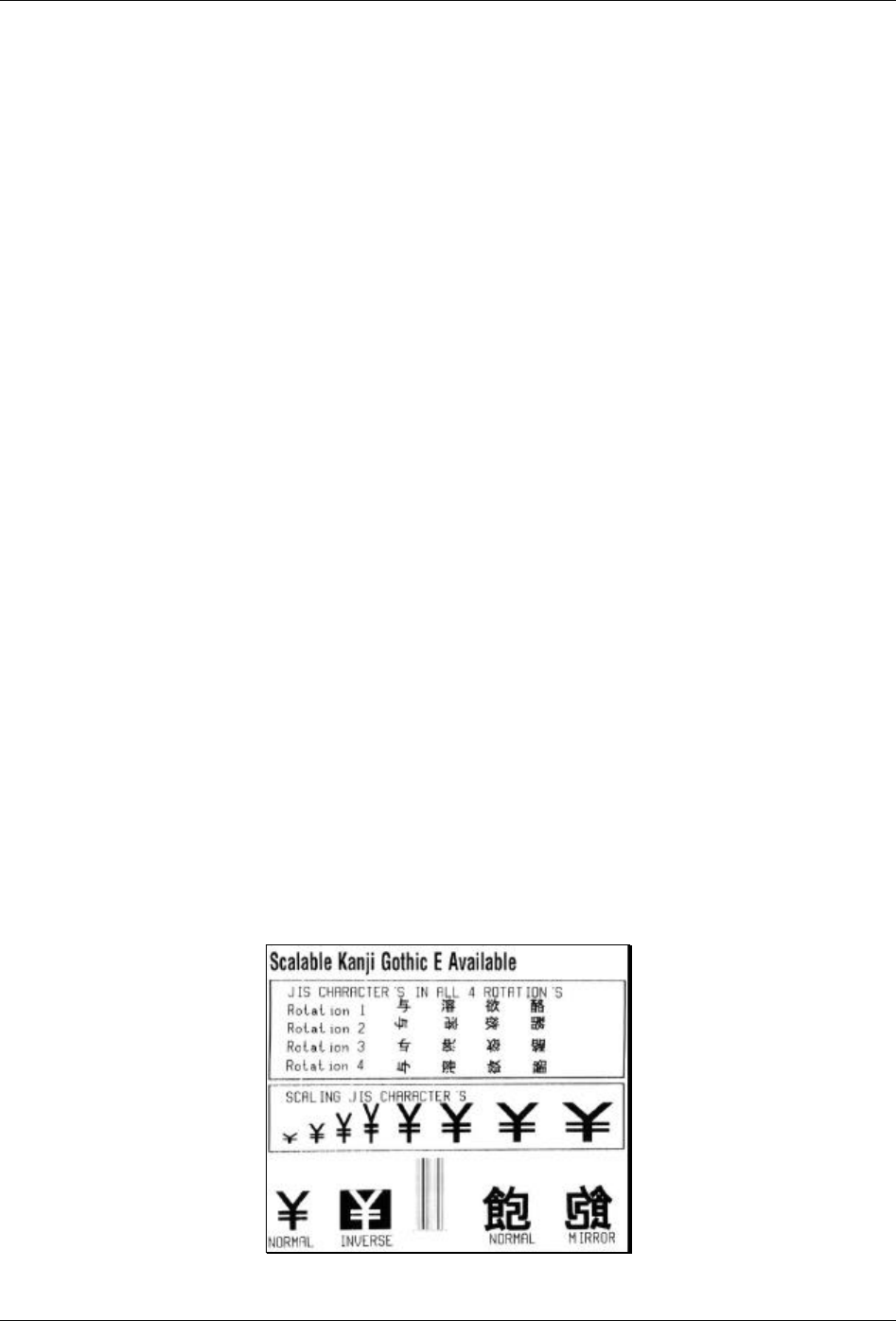
Appendix Q – ILPC Programming Examples
210 Class Series Programmer’s Manual
Sample Kanji Gothic E DPL file (Hex-ASCII addressing) and resulting label:
<02>L<CR>
D11<CR>
ySPM<CR>
1911S0003100010P020P015Scalable Kanji Gothic E Available<CR>
1B110000020017001234567890<CR>
yUJS<CR>
1X1100001900010b0392011000020002<CR>
112200002800030JIS CHARACTER’S IN ALL 4 ROTATION’S<CR>
112200002600030Rotation 1<CR>
1911uK102650150P012P0124D3F212121214D4F212121214D5F212121214D6F<CR>
112200002400030Rotation 2<CR>
2911uK102600150P012P0124D3F<CR>
2911uK102600205P012P0124D4F<CR>
2911uK102600250P012P0124D5F<CR>
2911uK102600300P012P0124D6F<CR>
112200002200030Rotation 3<CR>
3911uK102330315P012P0124D6F212121214D5F212121214D4F212121214D3F<CR>
112200002000030Rotation 4<CR>
4911uK101950165P012P0124D3F<CR>
4911uK101950215P012P0124D4F<CR>
4911uK101950265P012P0124D5F<CR>
4911uK101950315P012P0124D6F<CR>
1X1100001100010b0392007500020002<CR>
112200001650030SCALING JIS CHARACTER’S<CR>
1911uK101200020P010P020216F<CR>
1911uK101200050P020P020216F<CR>
1911uK101200080P030P020216F<CR>
1911uK101200110P040P020216F<CR>
1911uK101200145P040P030216F<CR>
1911uK101200190P040P040216F<CR>
1911uK101200250P040P050216F<CR>
1911uK101200320P040P060216F<CR>
112200000050010NORMAL INVERSE<CR>
112200000050245 NORMAL MIRROR<CR>
1911uK100250010P040P040216F<CR>
1911uK100250245P040P0404B30<CR>
A5<CR>
1911uK100250090P040P040216F<CR>
A1<CR>
M<CR>
1911uK100250390P040P0404B30<CR>
M<CR>
E<CR>
Appendix Q – ILPC Programming Examples
Class Series Programmer’s Manual 211
ILPC-CHINESE Option
The Chinese Option is a double byte scalable font supporting Simplified GB Chinese. In the double byte
format the printer recalls one character printed from every two 8-bit bytes sent from the host. Double byte
scalable fonts are selected using a print format record (see Generating Label Formats and Appendix H for
details).
DPL Big 5 Encoding Support: With the ILPC Chinese option, the printer firmware supports font files
that are encoded for the GB Character Map and the Big 5 Character Map. The resident Asian font in the
printer is encoded in the GB Character Map. To utilize the Big 5 Character Map, the user must download
a font file that is Big 5 encoded. The font file downloaded must be of a size compatible with the internal
module size available or of a size compatible with an external (plug in) module where applicable. Printing
characters from the Big 5 encoded font file is accomplished by:
1. Setting the character mapping with a System Command or Label Format Command (<STX>yUB5 or
yUB5, respectively).
2. Setting the ‘b’ field = ‘9’ and ‘eee’ field = ‘Unn’, where ‘nn’ is equal to the Font ID number selected
for the Big 5 encoded font file downloaded.
3. Selecting string data corresponding to the Big 5 Character Map.
Scalable Double-Byte Font Map - CHINESE
eee
(Font Code) Scalable
Font Type Font
Name Binary
Addressing
Hex ASCII
Addressing
Code
Pages
UC0
Scalable Resident Simplified
GB Chinese √ GB
uc0
Scalable Resident Simplified
GB Chinese √ GB
U50 -
U5z...
U90 - U9z
Scalable Non-Resident (download) Big 5 √ B5
u50 - u5z…
u90 - u9z Scalable Non-Resident (download) Big 5 √ B5
U50 -
U5z...
U90 - U9z
Scalable Non-Resident (download) User defined √
–
u50 - u5z…
u90 - u9z Scalable Non-Resident (download) User defined √
–
Sample Simplified GB Chinese DPL file (binary addressing) and resulting label:
<02>L<CR>
D11<CR>
ySPM<CR>
1911S0003100010P020P015Scalable Chinese Available in GB Character Set<CR>
1B110000020017001234567890<CR>
yUGB<CR>
1X1100001900010b0392011000020002<CR>
112200002800030GB CHARACTER’S IN ALL 4 ROTATION’S<CR>
112200002600030Rotation 1<CR>
1911UC002650150P012P012<BD><D0>A1><A1><A1><A1><BD><D1><A1><A1><A1><A1><BD><D2><A1><A1>
<A1><A1><BD><D3><00><00><CR>
112200002400030Rotation 2<CR>
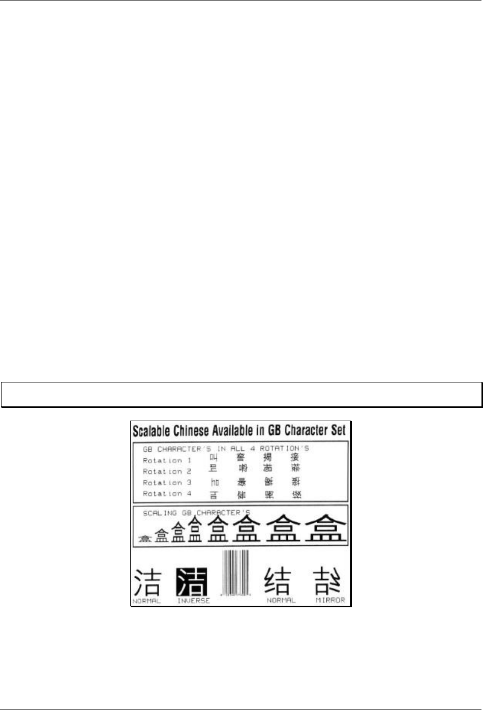
Appendix Q – ILPC Programming Examples
212 Class Series Programmer’s Manual
2911UC002600150P012P012<BD><D0><00><00><CR>
2911UC002600205P012P012<BD><D1><00><00><CR>
2911UC002600250P012P012<BD><D2><00><00><CR>
2911UC002600300P012P012<BD><D3><00><00><CR>
112200002200030Rotation 3<CR>
3911UC002330315P012P012<BD><D3><A1><A1><A1><A1><BD><D2><A1><A1><A1><A1><BD><D1><A1><A1>
<A1><A1><BD><D0><00><00><CR>
112200002000030Rotation 4<CR>
4911UC001950165P012P012<BD><D0><00><00><CR>
4911UC001950215P012P012<BD><D1><00><00><CR>
4911UC001950265P012P012<BD><D2><00><00><CR>
4911UC001950315P012P012<BD><D3><00><00><CR>
1X1100001100010b0392007500020002<CR>
112200001650030SCALING GB CHARACTER’S<CR>
1911UC001200020P010P020<BA><D0><00><00><CR>
1911UC001200050P020P020<BA><D0><00><00><CR>
1911UC001200080P030P020<BA><D0><00><00><CR>
1911UC001200110P040P020<BA><D0><00><00><CR>
1911UC001200145P040P030<BA><D0><00><00><CR>
1911UC001200190P040P040<BA><D0><00><00><CR>
1911UC001200250P040P050<BA><D0><00><00><CR>
1911UC001200320P040P060<BA><D0><00><00><CR>
112200000050010NORMAL INVERSE<CR>
112200000050245 NORMAL MIRROR<CR>
1911UC000250010P040P040<BD><E0><00><00><CR>
1911UC000250245P040P040<BD><E1><00><00><CR>
A5<CR>
1911UC000250090P040P040<BD><E0><00><00><CR>
A1<CR>
M<CR>
1911UC000250390P040P040<BD><E1><00><00><CR>
M<CR>
E<CR>
þ Note: The notation “<xx>” in this DPL file should be interpreted by the reader as representing the hexadecimal
value of the byte sent to the printer.
Appendix Q – ILPC Programming Examples
Class Series Programmer’s Manual 213
ILPC-KOREAN Option
The Korean Option is a double-byte scalable font supporting Korean Hangul. In the double-byte format,
the printer recalls one character printed from every two 8-bit bytes sent from the host. Double-byte
scalable fonts are selected using a print format record (see Generating Label Formats and Appendix H for
details).
Scalable Double-Byte Font Map - KOREAN
eee
(Font Code)
Scalable
Font Type
Font Name Binary
Addressing Hex ASCII
Addressing Code
Pages
UH0 Scalable Resident Korean Hangul √ UC
uh0 Scalable Resident Korean Hangul √ UC
u50 -
u5z…
u90 - u9z
Scalable Non-Resident
(download)
User defined √
U50 -
U5z...
U90 - U9z
Scalable Non-Resident
(download) User defined √
þ Note: Not all fonts contain an entire compliment of character codes for a given character map.
Sample Korean Hangul DPL file (binary addressing) and the resulting label:
<02>L<CR>
D11<CR>
ySPM<CR>
1911S0003100010P020P015Scalable Korean Available in UC Character Set<CR>
yUUC<CR>
1B110000020017001234567890<CR>
1X1100001900010b0392011000020002<CR>
112200002800030HANGUL CHARACTER’S IN ALL 4 ROTATIONS<CR>
112200002600030Rotation 1<CR>
1911UH002620150P012P012<AC><00><00><00><CR>
1911UH002620205P012P012<AC><65><00><00><CR>
1911UH002620250P012P012<AC><69><00><00><CR>
1911UH002620300P012P012<AC><DF><00><00><CR>
112200002400030Rotation 2<CR>
2911UH002550150P012P012<AC><00><00><00><CR>
2911UH002550205P012P012<AC><65><00><00><CR>
2911UH002550250P012P012<AC><69><00><00><CR>
2911UH002550300P012P012<AC><DF><00><00><CR>
112200002200030Rotation 3<CR>
3911UH002330165P012P012<AC><00><00><00><CR>
3911UH002330220P012P012<AC><65><00><00><CR>
3911UH002330265P012P012<AC><69><00><00><CR>
3911UH002330315P012P012<AC><DF><00><00><CR>
112200002000030Rotation 4<CR>
4911UH001950165P012P012<AC><00><00><00><CR>
4911UH001950215P012P012<AC><65><00><00><CR>
4911UH001950265P012P012<AC><69><00><00><CR>
4911UH001950315P012P012<AC><DF><00><00><CR>
1X1100001100010b0392007500020002<CR>
112200001650030SCALING HANGUL CHARACTERS<CR>
1911UH001200020P010P020<AC><AC><00><00><CR>
1911UH001200050P020P020<AC><AC><00><00><CR>
1911UH001200080P030P020<AC><AC><00><00><CR>
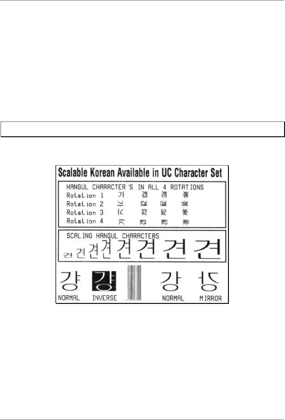
Appendix Q – ILPC Programming Examples
214 Class Series Programmer’s Manual
1911UH001200110P040P020<AC><AC><00><00><CR>
1911UH001200145P040P030<AC><AC><00><00><CR>
1911UH001200190P040P040<AC><AC><00><00><CR>
1911UH001200250P040P050<AC><AC><00><00><CR>
1911UH001200320P040P060<AC><AC><00><00><CR>
112200000200010NORMAL INVERSE<CR>
112200000200245 NORMAL MIRROR<CR>
1911UH000450010P040P040<AC><4D><00><00><CR>
1911UH000450245P040P040<AC><15><00><00><CR>
A5<CR>
1911UH000450090P040P040<AC><4D><00><00><CR>
A1<CR>
M<CR>
1911UH000450390P040P040<AC><15><00><00><CR>
M<CR>
E<CR>
þ Note: The notation “<xx>” in this DPL file should be interpreted by the reader as representing the hexadecimal
value of the byte sent to the printer.

Class Series Programmer’s Manual 215
Appendix
Plug and Play IDs
MFG:Datamax;
CMD:DPL;
MDL:I4208;
CLS:PRINTER;
DES:Datamax 4208 Label Printer Version 06.06 07/09/2001
Where:
CMD =
Fixed string “DPL”
MDL =
Model (valid MDLs are A4212, A4310, A4408, A4606, A6212, A6310, E4203, E4204, E4304,
M4206, M4208, M4306, I4206, I4208, I4308, I4210, I4212, I4406, I4604, W6308, W6208 &
W8306)
CLS =
Fixed string “PRINTER”
DES =
Description (subject to change with the application [firmware] revision and printer model)

Appendix R – Plug and Play IDs
216 Class Series Programmer’s Manual

Class Series Programmer’s Manual 217
Appendix
Bar Code Symbology Information Sources
AIM International, Inc.
11860 Sunrise Valley Drive, Suite 101
Reston, VA 22091 USA
Tel: 703-391-7621 Fax: 703-391-7624
Automotive Industry Action Group
26200 Lahser Road
Suite 200
Southfield, MI 48034 USA
Tel: 313-358-3570 Fax: 313-358-3253
AIM JAPAN
Aios Gotanda Bldg. 6F
1-10-7 Higashigotanda
Shinagawa-ku Tokyo 141 Japan
Tel: 03-3440-9085 Fax: 03-3440-9086
Computing Technology Industry Association
450 E. 22 Street Suite 230
Lombard, IL 60148-6158 USA
Tel: 630 268-1818 Fax: 630 278-1384
AIM EUROPE
The Old Vicarage
Haley Hill, Halifax HX3 6DR
West Yorkshire, England
Tel: 44-1422-359161 Fax: 44-1422-3556904
Health Industry Business Communications Council
PO Box 53528
Phoenix, AZ 85018 USA
Tel 602-318-1091
AIM UK
The Old Vicarage
Haley Hill, Halifax HX3 6DR
United Kingdom
Tel: 44-1422-359161 Fax: 44-1422-355604
International Article Numbering Association
(EAN)
Rue Royal 29
B-1000 Bruxelles
Belgium
Tel: 32-22-187674 Fax: 32-22-187585
AIM USA
634 Alpha Drive
Pittsburgh, PA 15238-2802 USA
Tel: 412-963-8588 Fax: 412-963-8753
Uniform Code Council, Inc. (UCC)
8163 Old Yankee Rd. Suite J
Dayton, OH 45458 USA
Tel: 513-435-3870 Fax: 513-435-4749
American National Standards Institute (ANSI)
11 West 42nd Street
New York, New York 10036 USA
Tel: 212-642-4900 Fax: 212-398-0023
U.S. Government Printing Office
732 North Capitol Street NW
Washington, DC 20401 USA
Tel: 202-512-1991 Fax: 202-512-1293

Appendix S – Barcode Symbology Information Sources
218 Class Series Programmer’s Manual

Class Series Programmer’s Manual 219
Glossary
alphanumeric Consisting of alphabetic, numeric, punctuation and other symbols.
backing material The silicon-coated paper carrier material to which labels with adhesive backing are
affixed. Also referred to as “liner”.
bar code A representation of alphanumeric information in a pattern of machine-readable marks. The
basic categories are divided into one-dimensional (UPC, Code 39, Postnet, etc.) and two-
dimensional bar codes (Data Matrix, MaxiCode, PDF417, etc.).
boot loader The resident program that loads the application from Flash memory, decompresses it into
the DRAM, and starts operations.
burn line The row of thermal elements in the printhead that create the images on the media.
calibration The process through which Media Sensor readings are entered into the printer for correct
sensor function (for example, detection of a given media type) and top of form positioning.
character set The entire complement of alphanumeric symbols contained in a given font.
checksum An alphanumeric error detection method used in many bar code symbologies for
informational security.
continuous media An uninterrupted roll or box of label or tag stock media that contains no gap, slit,
notch, or black mark to separate individual labels or tags.
cutter A mechanical device with a rotary or guillotine type blade used to cut labels or tags following
printing.
defaults The functional setting values returned following a factory reset of the printer.
diagnostics Programs used to locate and diagnose hardware problems.
die-cut media Media that has been cut into a pattern using a press, where the excess paper is removed
leaving individual labels, with gaps between them, attached to a backing material.
direct thermal The printing method that uses a heat sensitive media and only the heat of the thermal
printhead to create an image on the label.
direct thermal media Media coated with special chemicals that react and darken with the application of
heat.
DPI (dots per inch) A measurement of print resolution, rated in the number of thermal elements
contained in one inch of the printhead. Also referred to as “resolution.”

Glossary
220 Class Series Programmer’s Manual
DPL (Datamax Programming Language) programming commands used specifically for control of
and label production in Datamax printers.
fan-fold Media that is folded and stacked.
feed speed The rate at which the media moves under the printhead in non-printed areas and between
labels.
Flash memory Non-volatile memory (does not require printer power to maintain data) that can be
erased and reprogrammed, used to hold the printer’s operating program.
font A set of alphanumeric characters that share a particular typeface.
gap A space between die-cut or notched labels used to sense the top-of-form.
IPS (inches per second) Imperial measurement of printer speeds.
label A paper or synthetic printing material, typically with a pressure sensitive adhesive backing.
label length The distance from the top of the label to the bottom of the label as it exits the printer.
label repeat The distance from the top of one label to the top of the next label.
label tracking Excessive lateral (side to side) movement of the media as it travels under the printhead.
label width The left to right measurement of the label as it exits the printer.
media Generalized term for all types of printing stocks, including: roll fed, continuous, butt-cut, die-cut,
reflective, and fanfold.
media hub Device in the printer used to support roll media.
media sensor An electronic device equipped with photosensors to detect media and the top-of-form on
die-cut, notched or reflective media.
MMPS (millimeters per second) Metric measurement of printer speeds.
notched stock Media, typically tag stock, with holes or notches in the material that is used to signal the
top-of-form. The printer must be set to ‘gap’ to use this media type.
perforation Small cuts extending through the backing and/or label material to facilitate their separation.
Also referred to as “perf”.
preprinted media Label stock that contains borders, text, or graphics, floodcoating, etc.
present sensor An electronic sensor that provides a signal to the printer firmware that a label is present,
typically located beyond the printhead, where the labels exits the printer.
print speed The rate at which the media moves under the printhead during the printing process.

Glossary
Class Series Programmer’s Manual 221
reflective media Media imprinted with carbon-based black marks on the underside of the material,
which is used to signal the top-of-form when the ‘reflective’ Media Sensor is enabled.
registration Repeatable top to bottom alignment of printed labels.
reverse speed The backward rate of media motion into the printer during tear-off, peel and present and
cutting operations for positioning the label at the start of print position.
ribbon An extruded polyester tape with several layers of material, one of which is ink-like, used to
produce an image on the label. Also referred to as “foil”.
roll media A form of media that is wound upon a cardboard core.
start of print The position on the label where the printing actually begins.
tag stock A heavy paper or synthetic printing material, typically featuring a notch or black mark for top
of form and no adhesive backing.
thermal transfer The printing method that creates an image by transferring ink from a ribbon onto the
media using the heat from the thermal printhead.
TOF (top-of-form) The start of a new label as indicated by a label gap, notch, mark or programming.

Glossary
222 Class Series Programmer’s Manual
