CONTROLLER EDITOR Manual English Native Instruments Version 1.8 (English)
Native Instruments Controller Editor Version 1.8 Manual (English) controller_editor_1.8_manual_english Native Instruments - Controller Editor Version 1.8 - Manual (English)
User Manual: Native Instruments Controller Editor Version 1.8 Manual (English) Native Instruments - Controller Editor Version 1.8 - Manual (English)
Open the PDF directly: View PDF ![]() .
.
Page Count: 294 [warning: Documents this large are best viewed by clicking the View PDF Link!]
- Title Page
- Disclaimer
- Contact
- Table of Contents
- Welcome to the Controller Editor!
- Installation
- Quick Start
- Basic Concepts
- Using Your MASCHINE Controller
- Using Your MASCHINE MK2 Controller
- Using Your MASCHINE MIKRO Controller
- Using Your MASCHINE MIKRO MK2 Controller
- Using Your MASCHINE STUDIO Controller
- Using Your TRAKTOR KONTROL X1
- Using Your TRAKTOR KONTROL X1 MK2
- Using Your TRAKTOR KONTROL F1
- Using Your TRAKTOR KONTROL Z1
- Using Your TRAKTOR KONTROL Z2
- Using Your TRAKTOR KONTROL D2
- Using Your TRAKTOR KONTROL S8
- Using Your TRAKTOR KONTROL S4
- Using Your TRAKTOR KONTROL S4 MK2
- Using Your TRAKTOR KONTROL S2
- Using Your TRAKTOR KONTROL S2 MK2
- Using Your KOMPLETE KONTROL S-SERIES Keyboard
- Using Two or More Units of the Same Type
- Reference
- The Application Menu Bar
- The Preferences Window
- The Application Control Bar
- The Hardware Area
- The Inspector
- MIDI Message Parameters
- MIDI Message Types – Type Menu
- Assignments for Buttons
- Assignments for Key Zones
- Assignments for the Pads – Hit Action
- Assignments for Knobs and the Like
- Assignments for the Pads – Press Action
- Assignments for Digital Encoders
- Assignments for Analog Encoders
- Assignments for Touch Strips – Position Action (TRAKTOR KONTROL Devices)
- Assignments for Touch Strips (KOMPLETE KONTROL S-SERIES)
- Assignments for LED Chains and 7-segment Displays
Manual

The information in this document is subject to change without notice and does not represent a
commitment on the part of Native Instruments GmbH. The software described by this docu-
ment is subject to a License Agreement and may not be copied to other media. No part of this
publication may be copied, reproduced or otherwise transmitted or recorded, for any purpose,
without prior written permission by Native Instruments GmbH, hereinafter referred to as Native
Instruments.
“Native Instruments”, “NI” and associated logos are (registered) trademarks of Native Instru-
ments GmbH.
Mac, Mac OS, GarageBand, Logic, iTunes and iPod are registered trademarks of Apple Inc.,
registered in the U.S. and other countries.
Windows, Windows Vista and DirectSound are registered trademarks of Microsoft Corporation
in the United States and/or other countries.
All other trade marks are the property of their respective owners and use of them does not im-
ply any affiliation with or endorsement by them.
Document authored by: Native Instruments GmbH
Software version: 1.8.0 (04/2015)
Special thanks to the Beta Test Team, who were invaluable not just in tracking down bugs, but
in making this a better product.
Disclaimer

NATIVE INSTRUMENTS GmbH
Schlesische Str. 29-30
D-10997 Berlin
Germany
www.native-instruments.de
NATIVE INSTRUMENTS North America, Inc.
6725 Sunset Boulevard
5th Floor
Los Angeles, CA 90028
USA
www.native-instruments.com
NATIVE INSTRUMENTS K.K.
YO Building 3F
Jingumae 6-7-15, Shibuya-ku,
Tokyo 150-0001
Japan
www.native-instruments.co.jp
NATIVE INSTRUMENTS UK Limited
18 Phipp Street
London EC2A 4NU
UK
www.native-instruments.com
© NATIVE INSTRUMENTS GmbH, 2015. All rights reserved.
Contact

Table of Contents
1 Welcome to the Controller Editor! ...............................................................................13
1.1 About This Manual ...................................................................................................................... 13
1.2 Document Conventions ............................................................................................................... 14
2 Installation ...............................................................................................................16
2.1 Controller Editor as Part of an NI Product Installation ................................................................ 16
2.2 Downloading the Controller Editor from the Native Instruments Website .................................... 16
3 Quick Start ................................................................................................................18
3.1 Switching your NI Controller to MIDI Mode .................................................................................. 19
3.2 Loading MIDI Assignments ......................................................................................................... 21
3.2.1 Select the NI Controller .............................................................................................. 21
3.2.2 Select a Template ...................................................................................................... 23
3.2.3 Select a Page ............................................................................................................. 24
3.2.4 Select a Pad Page (MASCHINE Controller Family Only) .............................................. 27
3.2.5 Ready to Go? .............................................................................................................. 29
3.3 Modifying an Assignment ........................................................................................................... 29
3.4 Organizing Your Assignments ..................................................................................................... 31
3.4.1 Displaying the Lists of Templates and Pages ............................................................ 31
3.4.2 Renaming Templates and Pages ............................................................................... 32
3.4.3 Re-ordering Templates and Pages ............................................................................. 33
3.5 Saving and Loading Templates .................................................................................................. 33
4 Basic Concepts ......................................................................................................... 36
4.1 How the Controller Editor Works .................................................................................................. 36
4.2 Overview of the User Interface .................................................................................................... 36
4.2.1 Application Menu Bar ................................................................................................ 38
4.2.2 Application Control Bar ............................................................................................. 38
4.2.3 Hardware Area ........................................................................................................... 38
Table of Contents
CONTROLLER EDITOR - Manual - 4

4.2.4 Inspector ................................................................................................................... 40
4.3 The Mapping System .................................................................................................................. 47
4.3.1 Assignments .............................................................................................................. 47
4.3.2 Pages (or Knob Pages) ............................................................................................... 47
4.3.3 Pad Pages (MASCHINE Controller Family Only) .......................................................... 48
4.3.4 I/O and Level Pages (MASCHINE STUDIO Only) ........................................................... 48
4.3.5 Jog Wheel Pages (MASCHINE STUDIO Only) ................................................................ 49
4.3.6 Templates .................................................................................................................. 49
4.3.7 Configuration ............................................................................................................ 51
4.4 To Sum Up… .............................................................................................................................. 51
5 Using Your MASCHINE Controller ............................................................................... 52
5.1 Basic Controls ............................................................................................................................ 52
5.2 Assignable Control Elements ...................................................................................................... 54
5.3 Visual Feedback on Your Controller ............................................................................................ 57
5.3.1 Buttons ...................................................................................................................... 57
5.3.2 Pads .......................................................................................................................... 58
5.3.3 Knobs ........................................................................................................................ 59
5.4 The Displays ............................................................................................................................... 59
5.4.1 Switching Between Display Modes ............................................................................. 59
5.4.2 Knobs Display Mode ................................................................................................... 60
5.4.3 Pad Pages Display Mode ............................................................................................ 61
5.4.4 Knob Pages Display Mode .......................................................................................... 62
5.4.5 Template Display Mode .............................................................................................. 63
5.4.6 Monitor Display Mode ................................................................................................ 63
5.4.7 Settings Display Mode ............................................................................................... 64
6 Using Your MASCHINE MK2 Controller .......................................................................66
6.1 Basic Controls ............................................................................................................................ 66
6.2 Assignable Control Elements ...................................................................................................... 68
Table of Contents
CONTROLLER EDITOR - Manual - 5

6.3 Visual Feedback on Your Controller ............................................................................................ 71
6.3.1 Buttons ...................................................................................................................... 72
6.3.2 Multicolor Pads .......................................................................................................... 73
6.3.3 Knobs ........................................................................................................................ 74
6.3.4 Control Encoder ......................................................................................................... 74
6.4 The Displays ............................................................................................................................... 74
6.4.1 Switching Between Display Modes ............................................................................. 74
6.4.2 Knobs Display Mode ................................................................................................... 75
6.4.3 Pad Pages Display Mode ............................................................................................ 76
6.4.4 Template Display Mode .............................................................................................. 77
6.4.5 Monitor Display Mode ................................................................................................ 78
6.4.6 Settings Display Mode ............................................................................................... 78
7 Using Your MASCHINE MIKRO Controller ....................................................................80
7.1 Basic Controls ............................................................................................................................ 80
7.2 Assignable Control Elements ...................................................................................................... 82
7.3 Visual Feedback on Your Controller ............................................................................................ 84
7.3.1 Buttons ...................................................................................................................... 85
7.3.2 Pads .......................................................................................................................... 85
7.3.3 Control Encoder ......................................................................................................... 86
7.4 The Display ................................................................................................................................. 86
7.4.1 Switching Between Display Modes ............................................................................. 86
7.4.2 Control Display Mode ................................................................................................. 87
7.4.3 Template Display Mode .............................................................................................. 88
7.4.4 Setup Display Mode ................................................................................................... 89
8 Using Your MASCHINE MIKRO MK2 Controller .............................................................90
8.1 Basic Controls ............................................................................................................................ 90
8.2 Assignable Control Elements ...................................................................................................... 92
8.3 Visual Feedback on Your Controller ............................................................................................ 94
Table of Contents
CONTROLLER EDITOR - Manual - 6

8.3.1 Buttons ...................................................................................................................... 94
8.3.2 Multicolor Pads .......................................................................................................... 96
8.3.3 Control Encoder ......................................................................................................... 97
8.4 The Display ................................................................................................................................. 97
8.4.1 Switching Between Display Modes ............................................................................. 97
8.4.2 Control Display Mode ................................................................................................. 98
8.4.3 Template Display Mode .............................................................................................. 98
8.4.4 Setup Display Mode ................................................................................................... 99
9 Using Your MASCHINE STUDIO Controller ................................................................... 101
9.1 Basic Controls ............................................................................................................................ 101
9.2 Assignable Control Elements ...................................................................................................... 103
9.3 Visual Feedback on Your Controller ............................................................................................ 108
9.3.1 Buttons ...................................................................................................................... 109
9.3.2 Multicolor Pads .......................................................................................................... 110
9.3.3 Knobs ........................................................................................................................ 111
9.3.4 Control Encoder ......................................................................................................... 111
9.4 The Displays ............................................................................................................................... 111
9.4.1 Switching Between Display Modes ............................................................................. 112
9.4.2 Settings Display Mode ............................................................................................... 112
9.4.3 Calibration Display Mode ........................................................................................... 114
9.4.4 Knobs Display Mode ................................................................................................... 115
9.4.5 Pages Display Mode ................................................................................................... 117
9.4.6 Templates Display Mode ............................................................................................ 118
9.4.7 Monitor Display Mode ................................................................................................ 119
10 Using Your TRAKTOR KONTROL X1 ..............................................................................120
10.1 Basic Controls ............................................................................................................................ 120
10.2 Assignable Control Elements ...................................................................................................... 121
10.3 Visual Feedback on Your Controller ............................................................................................ 123
Table of Contents
CONTROLLER EDITOR - Manual - 7

10.4 Using Two or More TRAKTOR KONTROL X1 Units ......................................................................... 124
11 Using Your TRAKTOR KONTROL X1 MK2 ...................................................................... 125
11.1 Basic Controls ............................................................................................................................ 125
11.2 Assignable Control Elements ...................................................................................................... 126
11.3 Visual Feedback on Your Controller ............................................................................................ 128
11.4 Using Two or More TRAKTOR KONTROL X1 MK2 Units .................................................................. 130
12 Using Your TRAKTOR KONTROL F1 .............................................................................. 131
12.1 Basic Controls ............................................................................................................................ 131
12.2 Assignable Control Elements ...................................................................................................... 132
12.3 Visual Feedback on Your Controller ............................................................................................ 134
12.3.1 Buttons and Pads ...................................................................................................... 135
12.3.2 7-segment Display .................................................................................................... 136
12.4 Using Two or More TRAKTOR KONTROL F1 Units .......................................................................... 137
13 Using Your TRAKTOR KONTROL Z1 .............................................................................. 138
13.1 Basic Controls ............................................................................................................................ 138
13.2 Assignable Control Elements ...................................................................................................... 139
13.3 Visual Feedback on Your Controller ............................................................................................ 140
14 Using Your TRAKTOR KONTROL Z2 .............................................................................. 143
14.1 Basic Controls ............................................................................................................................ 143
14.2 Assignable Control Elements ...................................................................................................... 144
14.3 Visual Feedback on Your Controller ............................................................................................ 146
15 Using Your TRAKTOR KONTROL D2 ..............................................................................149
15.1 Basic Controls ............................................................................................................................ 149
15.2 Assignable Control Elements ...................................................................................................... 151
15.3 Visual Feedback on Your Controller ............................................................................................ 154
15.3.1 Buttons and Pads ...................................................................................................... 154
15.3.2 Performance Knobs, Slot Volume Faders, and Loop Encoder ...................................... 156
15.4 The Display ................................................................................................................................. 156
Table of Contents
CONTROLLER EDITOR - Manual - 8

15.4.1 Control Display Mode ................................................................................................. 157
15.4.2 Adjust Color And Brightness ...................................................................................... 158
16 Using Your TRAKTOR KONTROL S8 ..............................................................................161
16.1 Basic Controls ............................................................................................................................ 161
16.2 Assignable Control Elements ...................................................................................................... 163
16.2.1 Control Elements on the Deck Units ........................................................................... 164
16.2.2 Control Elements on the Mixer ................................................................................... 167
16.3 Visual Feedback on Your Controller ............................................................................................ 169
16.3.1 Buttons and Pads ...................................................................................................... 169
16.3.2 Performance Knobs, Slot Volume Faders, and Loop Encoder ...................................... 171
16.4 The Displays ............................................................................................................................... 172
16.4.1 Control Display Mode ................................................................................................. 172
16.4.2 Adjust Color And Brightness ...................................................................................... 174
17 Using Your TRAKTOR KONTROL S4 ..............................................................................177
17.1 Basic Controls ............................................................................................................................ 177
17.2 Assignable Control Elements ...................................................................................................... 179
17.2.1 Control Elements on the Left Deck ............................................................................. 180
17.2.2 Control Elements on the Right Deck .......................................................................... 181
17.2.3 Control Elements on the Mixer ................................................................................... 181
17.2.4 Assignment Parameters ............................................................................................ 183
17.3 Visual Feedback on Your Controller ............................................................................................ 183
17.3.1 Buttons ...................................................................................................................... 184
17.3.2 LED Chains ................................................................................................................ 185
18 Using Your TRAKTOR KONTROL S4 MK2 ...................................................................... 186
18.1 Basic Controls ............................................................................................................................ 186
18.2 Assignable Control Elements ...................................................................................................... 188
18.2.1 Control Elements on the Left Deck ............................................................................. 189
18.2.2 Control Elements on the Right Deck .......................................................................... 190
Table of Contents
CONTROLLER EDITOR - Manual - 9

18.2.3 Control Elements on the Mixer ................................................................................... 190
18.2.4 Assignment Parameters ............................................................................................ 192
18.3 Visual Feedback on Your Controller ............................................................................................ 192
18.3.1 Buttons ...................................................................................................................... 193
18.3.2 LED Chains ................................................................................................................ 194
19 Using Your TRAKTOR KONTROL S2 ..............................................................................195
19.1 Basic Controls ............................................................................................................................ 195
19.2 Assignable Control Elements ...................................................................................................... 196
19.3 Visual Feedback on Your Controller ............................................................................................ 197
19.3.1 Buttons ...................................................................................................................... 198
19.3.2 LED Chains ................................................................................................................ 199
20 Using Your TRAKTOR KONTROL S2 MK2 ...................................................................... 200
20.1 Basic Controls ............................................................................................................................ 200
20.2 Assignable Control Elements ...................................................................................................... 201
20.3 Visual Feedback on Your Controller ............................................................................................ 202
20.3.1 Buttons ...................................................................................................................... 203
20.3.2 LED Chains ................................................................................................................ 204
21 Using Your KOMPLETE KONTROL S-SERIES Keyboard ................................................... 205
21.1 Basic Controls ............................................................................................................................ 205
21.2 Assignable Control Elements ...................................................................................................... 207
21.3 Defining Key Zones ..................................................................................................................... 210
21.3.1 Overview of the Keybed Area ...................................................................................... 210
21.3.2 Editing Key Zones ...................................................................................................... 212
21.4 Visual Feedback on Your Keyboard ............................................................................................. 215
21.4.1 Visual Feedback on the Displays ............................................................................... 215
21.4.2 Visual Feedback on the Light Guide ........................................................................... 216
21.4.3 Visual Feedback on the Touch Strips ......................................................................... 216
21.4.4 Visual Feedback on the Buttons ................................................................................ 217
Table of Contents
CONTROLLER EDITOR - Manual - 10

21.5 Using Two or More KOMPLETE KONTROL S-SERIES Units ............................................................ 218
21.6 Stand-alone Operation ............................................................................................................... 218
22 Using Two or More Units of the Same Type ................................................................. 222
22.1 Renaming the Units .................................................................................................................... 222
22.2 Accessing Templates and Pages of a Particular Unit ................................................................. 224
22.3 Resolving Device Conflicts ......................................................................................................... 225
23 Reference .................................................................................................................227
23.1 The Application Menu Bar ........................................................................................................... 227
23.1.1 File Menu ................................................................................................................... 227
23.1.2 View Menu ................................................................................................................. 228
23.1.3 Help Menu ................................................................................................................. 228
23.2 The Preferences Window ............................................................................................................. 229
23.2.1 General Page ............................................................................................................. 230
23.2.2 Controller Page .......................................................................................................... 231
23.3 The Application Control Bar ........................................................................................................ 241
23.3.1 Device Menu .............................................................................................................. 242
23.3.2 Connect Button .......................................................................................................... 243
23.3.3 MIDI Activity Indicator ............................................................................................... 244
23.3.4 NI Logo ...................................................................................................................... 244
23.4 The Hardware Area ..................................................................................................................... 245
23.4.1 Label Fields ............................................................................................................... 245
23.4.2 Selection Frame ......................................................................................................... 247
23.4.3 Page Areas and Page Menus ..................................................................................... 247
23.5 The Inspector .............................................................................................................................. 249
23.5.1 Templates Pane ......................................................................................................... 250
23.5.2 Pages Pane ................................................................................................................ 256
23.5.3 Assign Pane ............................................................................................................... 266
23.6 MIDI Message Parameters .......................................................................................................... 270
Table of Contents
CONTROLLER EDITOR - Manual - 11

23.6.1 MIDI Message Types – Type Menu .............................................................................. 270
23.6.2 Assignments for Buttons ........................................................................................... 274
23.6.3 Assignments for Key Zones ........................................................................................ 280
23.6.4 Assignments for the Pads – Hit Action ...................................................................... 281
23.6.5 Assignments for Knobs and the Like .......................................................................... 282
23.6.6 Assignments for the Pads – Press Action .................................................................. 283
23.6.7 Assignments for Digital Encoders .............................................................................. 284
23.6.8 Assignments for Analog Encoders ............................................................................. 286
23.6.9 Assignments for Touch Strips – Position Action (TRAKTOR KONTROL Devices) .......... 289
23.6.10 Assignments for Touch Strips (KOMPLETE KONTROL S-SERIES) ................................. 290
23.6.11 Assignments for LED Chains and 7-segment Displays .............................................. 293
Table of Contents
CONTROLLER EDITOR - Manual - 12

1 Welcome to the Controller Editor!
This powerful tool turns your Native Instruments hardware controller into a versatile and effi-
cient MIDI remote control for your studio and live setup.
With the Controller Editor, you can precisely define which MIDI message to send when using
your NI controller. This way, you can put your whole music setup right at your fingertips and
remotely control MIDI-capable software or hardware from your NI controller. After you have
prepared your MIDI assignments with the Controller Editor, you can focus on what it’s all
about: making music!
1.1 About This Manual
This manual is divided into four parts:
• The first part introduces you to the Controller Editor: after a short description of the in-
stallation procedure (chapter ↑2, Installation), we will start with a brief tutorial (chapter
↑3, Quick Start).
• The second part illustrates the user interface of the Controller Editor, mapping scheme
and the various ways to interact with the software (chapter ↑4, Basic Concepts). This will
familiarize you with Controller Editor’s workflow.
• The third part shows you how to use your particular NI controller(s):
◦chapter ↑5, Using Your MASCHINE Controller,
◦chapter ↑6, Using Your MASCHINE MK2 Controller,
◦chapter ↑7, Using Your MASCHINE MIKRO Controller,
◦chapter ↑8, Using Your MASCHINE MIKRO MK2 Controller,
◦chapter ↑9, Using Your MASCHINE STUDIO Controller,
◦chapter ↑10, Using Your TRAKTOR KONTROL X1,
◦chapter ↑11, Using Your TRAKTOR KONTROL X1 MK2,
◦chapter ↑12, Using Your TRAKTOR KONTROL F1,
Welcome to the Controller Editor!
About This Manual
CONTROLLER EDITOR - Manual - 13
◦chapter ↑13, Using Your TRAKTOR KONTROL Z1,
◦chapter ↑14, Using Your TRAKTOR KONTROL Z2,
◦chapter ↑15, Using Your TRAKTOR KONTROL D2,
◦chapter ↑16, Using Your TRAKTOR KONTROL S8,
◦chapter ↑17, Using Your TRAKTOR KONTROL S4,
◦chapter ↑18, Using Your TRAKTOR KONTROL S4 MK2,
◦chapter ↑19, Using Your TRAKTOR KONTROL S2,
◦chapter ↑20, Using Your TRAKTOR KONTROL S2 MK2,
◦chapter ↑21, Using Your KOMPLETE KONTROL S-SERIES Keyboard,
◦and chapter ↑22, Using Two or More Units of the Same Type.
• Finally, the fourth part (chapter ↑23, Reference) is a detailed reference describing the
software interface and its operation. Read for information on every knob, button or field
present in the Controller Editor’s interface. You will also find here a complete list of avail-
able MIDI message types and parameters.
This manual generally refers to all Native Instruments hardware controller devices simply as
“NI controller.” If any information applies to a specific device only, e.g. the MASCHINE
controller, this will be mentioned explicitly.
1.2 Document Conventions
This document uses particular formatting to point out special facts and to warn you of poten-
tial issues. The icons introducing the following notes let you see what kind of information can
be expected:
Whenever this exclamation mark icon appears, you should read the corresponding note
carefully and follow the instructions and hints given there if applicable.
This light bulb icon indicates that a note contains useful extra information. This informa-
tion may often help you to solve a task more efficiently, but does not necessarily apply to
the setup or operating system you are using; however, it’s always worth a look.
Welcome to the Controller Editor!
Document Conventions
CONTROLLER EDITOR - Manual - 14

Furthermore, the following formatting is used:
• Text appearing in (drop-down) menus (such as Open…, Save as… etc.) and paths to loca-
tions on your hard drive or other storage devices is printed in italics.
• Text appearing elsewhere on the screen (labels of buttons, controls, text next to check
boxes etc.) is printed in light blue. Whenever you see this formatting applied, you will find
the same text appearing on the screen.
• Text appearing on the display(s) of your hardware controller is printed in grey. Whenever
you see this formatting applied, you will find the same text appearing on the display(s) of
your controller.
• Important names and concepts are printed in bold.
• References to keys on your computer’s keyboard you’ll find put in square brackets (e.g.,
“Press [Shift] + [Return]”).
1. Sequences of ordered instructions are introduced by numbers.
►Single instructions are introduced by this play button type arrow.
→Results of actions are introduced by this smaller arrow.
Welcome to the Controller Editor!
Document Conventions
CONTROLLER EDITOR - Manual - 15
2 Installation
This chapter describes how to install the Controller Editor in various situations.
2.1 Controller Editor as Part of an NI Product Installation
The Controller Editor is included in the product software package of NI hardware controllers
and was automatically installed during the installation procedure for your NI product.
We assume here that your NI product is already installed on your computer. For a detailed
description of this installation procedure, please refer to the Setup Guide provided with
your NI product.
You should find the Controller Editor at the following locations:
• Mac OS X: Applications/Native Instruments/Controller Editor
• Windows: Program Files\Native Instruments\Controller Editor
If for any reason the Controller Editor is not installed on your computer, please check that your
NI product is up to date. You can do this easily via the Service Center or via the Native Instru-
ments website. If updates are available for your product, download and install them.
You can also download a stand-alone installer for the Controller Editor from the Native Instru-
ments website — see next section for more information.
2.2 Downloading the Controller Editor from the Native Instruments
Website
Apart from being included in the software package of supported NI products, the Controller
Editor is also available for download from the Native Instruments website. If your NI controller
is already installed on your computer, use the Service Center to download the last driver up-
dates.
If your NI controller is not installed on your computer yet, you can manually download the
hardware drivers for your NI controller along with the Controller Editor. To do this:
Installation
Controller Editor as Part of an NI Product Installation
CONTROLLER EDITOR - Manual - 16

1. Open your favorite internet browser and go to the following URL:
http://www.native-instruments.com/updates
2. On this page, follow the link to the unprotected updates, drivers and the Service Center.
3. In the list of available downloads, follow the link to your specific NI controller.
4. Download the installer file for your operating system (Windows or Mac OS X) and save it to
your hard disk.
5. Navigate to the directory where you saved the installer file and double-click it.
This launches the installer.
6. The installation process is straightforward: follow the instructions on the screen and
you’re done.
Installation
Downloading the Controller Editor from the Native Instruments Website
CONTROLLER EDITOR - Manual - 17
3 Quick Start
This chapter provides a hands-on introduction to the Controller Editor.
It is assumed herein that the Controller Editor is installed on your computer. See chapter
↑2, Installation for more information.
The use of the Controller Editor is straightforward. Most actions can be done either from your
NI controller or via the Controller Editor interface, and this in various ways — you can choose
the one that best fits your needs.
In this chapter, we will successively show you how to:
1. Switch your NI controller to MIDI mode.
2. Load MIDI assignments for a specific task: Select a whole set of assignments (known as a
Template) for your controller; Select a particular subset of assignments (known as a Page)
for specific control elements on your controller; MASCHINE controller family only: Select
an additional subset of assignments (known as a Pad Page) for the pads.
3. Modify assignments to make them perfectly fit your own needs.
4. Organize your customized assignments.
5. Save and recall the whole set of assignments as a Template.
In this chapter, we will often focus on the Controller Editor interface. But the instructions
provided here can also be applied to most NI controllers — and for a few of them, even in
various ways. Notably, this is very handy in live situations. For each task, we provide a
small summary table with the corresponding shortcuts on each NI controllers. For more in-
formation on using your controller, please refer to the respective controller-specific chap-
ters, later in this manual.
For details on each and every element in the Controller Editor user interface, please refer to
chapter ↑23, Reference.
For details on each and every element in the Controller Editor user interface, please refer to
chapter ↑23, Reference.
Preparations
At this point, we assume that:
Quick Start
CONTROLLER EDITOR - Manual - 18
• Your computer is up and running.
• You have already installed your NI controller and the Controller Editor (see chapter ↑2, In-
stallation).
• Your NI controller is physically connected to your computer via the USB 2.0 cable.
3.1 Switching your NI Controller to MIDI Mode
First of all, let’s switch your NI controller to MIDI mode.
Indeed, your NI controller can run in two different and mutually exclusive modes:
• In Application mode, it controls its dedicated software (e.g. MASCHINE software) via the
Native Instruments’ ultra fast high-resolution proprietary NHL protocol. Depending on the
respective software, this mode will be called MASCHINE mode, TRAKTOR mode, etc.
• In MIDI mode, it can control any MIDI target(s) available (software or hardware) via the
MIDI protocol.
Switch to MIDI Mode Directly from your NI Controller
It is not necessary to start the Controller Editor software in order to switch your NI controller to
MIDI mode: you can do it directly from your controller.
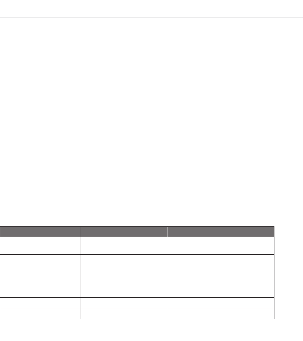
For each NI controller, the following table shows you how to switch to/from MIDI mode and
how to quickly see whether your controller currently is in MIDI mode or not:
NI Controller Switching to/from MIDI mode Checking that MIDI mode is on
KOMPLETE KONTROL S-SER-
IES
SHIFT + INSTANCE Both PRESET buttons lit
MASCHINE SHIFT + CONTROL SHIFT button dimly lit
MASCHINE MK2 SHIFT + CONTROL SHIFT button dimly lit
MASCHINE MIKRO SHIFT + F1 SHIFT button dimly lit
MASCHINE MIKRO MK2 SHIFT + F1 SHIFT button dimly lit
MASCHINE STUDIO SHIFT + CHANNEL SHIFT button dimly lit
TRAKTOR KONTROL S2 SHIFT + SHIFT (on both Decks) Both SHIFT buttons dimly lit
Quick Start
Switching your NI Controller to MIDI Mode
CONTROLLER EDITOR - Manual - 19
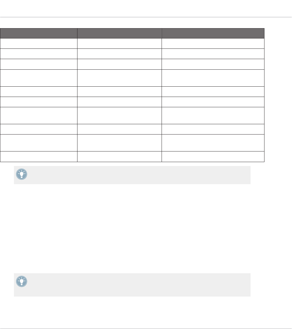
NI Controller Switching to/from MIDI mode Checking that MIDI mode is on
TRAKTOR KONTROL S2 MK2 SHIFT + SHIFT (on both Decks) Both SHIFT buttons dimly lit
TRAKTOR KONTROL S4 SHIFT + BROWSE button Loop Size Displays reading “ON”
TRAKTOR KONTROL S4 MK2 SHIFT + PREVIEW button Loop Size Displays reading “ON”
TRAKTOR KONTROL S8 SHIFT (any Deck) + BACK (right
Deck)
Both SHIFT buttons dimly or fully lit
TRAKTOR KONTROL D2 SHIFT (any Deck) + BACK SHIFT button dimly or fully lit
TRAKTOR KONTROL X1 SHIFT + HOTCUE HOTCUE button lit in green
TRAKTOR KONTROL X1 MK2 SHIFT + Load (both left and right
buttons)
SHIFT button lit
TRAKTOR KONTROL F1 SHIFT + BROWSE SHIFT button lit
TRAKTOR KONTROL Z1 MODE + CUES (ensure both A &
B headphone cues are pressed)
MODE button lit
TRAKTOR KONTROL Z2 SHIFT + Settings Settings button lit
Please find more information on this in the respective controller-specific chapters, later in
this manual.
Switch to MIDI Mode by Starting the Controller Editor
You can also switch all your connected NI controllers to MIDI mode by starting the Controller
Editor:
►Start the Controller Editor by selecting Start > All Programs > Native Instruments > Con-
troller Editor > Controller Editor (Windows) or Applications > Native Instruments > Con-
troller Editor (Mac OS X).
→This not only opens the Controller Editor, but also automatically switches any connected
controller(s) to MIDI mode.
If the Controller Editor is already open, you can check at any time whether your NI control-
ler is in MIDI mode or not, and if not, switch it back to MIDI mode via the Device menu
and the Connect button nearby — see ↑3.2.1, Select the NI Controller below.
Quick Start
Switching your NI Controller to MIDI Mode
CONTROLLER EDITOR - Manual - 20
Whichever method you have used, when switching your controller(s) to MIDI mode, the MIDI
assignments last used are automatically loaded along with their last state of use. If you are
starting the Controller Editor for the first time, the default MIDI assignments for your control-
ler(s) are loaded instead.
You can start right away using your NI controller as a MIDI remote control!
3.2 Loading MIDI Assignments
In order to load other MIDI assignments for your NI controller, we will use the Controller Edi-
tor.
As already mentioned, this can also be done from most NI controllers — see the controller-
specific chapters, later in this manual.
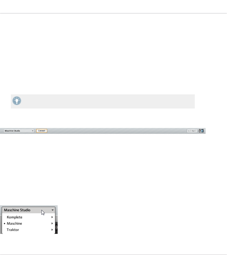
At the top of the Controller Editor window, you see a horizontal bar with a series of controls
ending in the NI logo at the far right. We call this bar the Application Control Bar:
The Application Control Bar, at the top of the Controller Editor window.
We will use the Application Control Bar to start loading new MIDI assignments.
3.2.1 Select the NI Controller
We first have to select the NI controller for which we want to load the MIDI assignments.
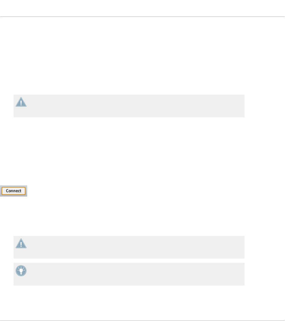
To select a controller:
►Click the Device menu (the first control from the left in the Application Control Bar), and
select the desired controller in the menu.
Choose your NI controller in the Device menu.
Quick Start
Loading MIDI Assignments
CONTROLLER EDITOR - Manual - 21
Here a few points of interest about the Device menu and the controller selection:
• In the menu both the folder containing the controller connected to your computer and the
name of the controller itself are indicated by a leading dot (•) in front of their name.
• Upon your selection, the menu closes and displays the name of the controller that you
just selected.
• The large controller picture below the menu is updated accordingly. This area is called
Hardware area — we will get back to it later.
The selection made in this Device menu does not affect in any way whether your NI con-
trollers are in MIDI mode or not. Its sole purpose is to select a controller for loading,
changing, and managing its MIDI assignments.
Optional: Check that the Selected Controller Is in MIDI Mode
Besides looking at your NI controller to see if it’s in MIDI mode (see ↑3.1, Switching your NI
Controller to MIDI Mode), you can also check the Controller Editor interface:
►Next to the Device menu in the Application Control Bar, you can check that the Connect
button is lit, indicating that the selected NI controller is in MIDI mode (and thus is con-
nected to the Controller Editor).
The Connect button lights up when your NI controller is in MIDI mode.
If the Connect button is unlit for any reason (for example, if you have started the MASCHINE
or TRAKTOR software after the Controller Editor), you can click it at any time to re-connect the
selected controller with the Controller Editor and switch it back to MIDI mode.
If the Connect button is grayed out and inactive, your NI controller might be disconnected
from your computer. Check the USB connection — if your controller is connected, ensure
that its drivers are properly installed (for more information, see chapter ↑2, Installation).
Your NI controller does not necessarily have to be in MIDI mode or even connected to your
computer in order to work on its MIDI assignments. This notably allows you to work on the
MIDI assignments even if your controller is not to hand at the moment.
Quick Start
Loading MIDI Assignments
CONTROLLER EDITOR - Manual - 22
3.2.2 Select a Template
We will now select a Template — a full set of assignments for all assignable control elements
on your NI controller.
For more information on the Templates, see ↑4.3, The Mapping System.
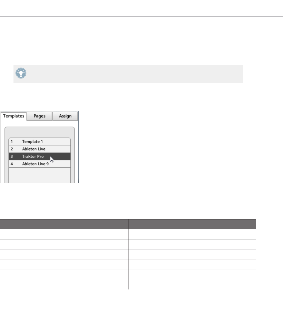
►On the right of the application, click the Templates tab and choose a Template in the list
that appears underneath.
The Template list allows you to load the desired Template.
From the Hardware
Some NI controllers also allow you to select Templates via following shortcuts:
NI Controller Template Selection
KOMPLETE KONTROL S-SERIES PRESET buttons
MASCHINE STUDIO SHIFT + Page buttons
MASCHINE MK2 SHIFT + Page buttons
MASCHINE SHIFT + Page buttons
MASCHINE MIKRO MK2 SHIFT + Left/Right Arrow buttons
MASCHINE MIKRO SHIFT + Left/Right Arrow buttons
Quick Start
Loading MIDI Assignments
CONTROLLER EDITOR - Manual - 23
NI Controller Template Selection
TRAKTOR KONTROL D2 Performance Mode buttons (left/right arrows on either
side of the displays)
TRAKTOR KONTROL S8 Performance Mode buttons (left/right arrows on either
side of the displays)
TRAKTOR KONTROL S4 n/a
TRAKTOR KONTROL S4 MK2 n/a
TRAKTOR KONTROL S2 n/a
TRAKTOR KONTROL S2 MK2 n/a
TRAKTOR KONTROL X1 n/a
TRAKTOR KONTROL X1 MK2 n/a
TRAKTOR KONTROL F1 n/a
TRAKTOR KONTROL Z1 n/a
TRAKTOR KONTROL Z2 n/a
More information on this in the respective controller-specific chapters, later in this manual.
Either way, the Template will automatically be loaded upon selection and its assignments will
be displayed. You can now control the new target from your NI controller.
Each assignment is recalled at the last state of use: the software automatically saves the last
value for each of the control elements assigned in this Template. When you load a Template
for the first time all assignments are at their default value.
TRAKTOR KONTROL S2: You can skip the following sections and directly go to ↑3.2.5,
Ready to Go?.
3.2.3 Select a Page
TRAKTOR KONTROL S2: There are no Pages available for this controller. Hence, you can
skip this section.
Quick Start
Loading MIDI Assignments
CONTROLLER EDITOR - Manual - 24
KOMPLETE KONTROL S-SERIES: Only one Page is available and it is always selected.
Hence, you can skip this section. Multiple Pages will be available in a future KOM-
PLETE KONTROL update.
Within each Template, some (or all) of the control elements of your NI controller can have mul-
tiple assignments, organized into Pages. In the Hardware area, these control elements are indi-
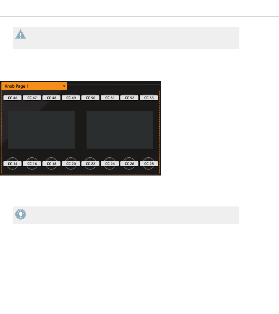
cated by a frame surrounding them.
The orange frame representing the Knob Page in the Hardware area for the MASCHINE STUDIO controller (detail).
At any time there is one active Page, i.e. one active subset of assignments for these specific
control elements.
For more information on the Pages, see ↑4.3, The Mapping System.
Thus, let’s select a particular Page of assignments for loading:
►To select a Page, click the Page menu (the orange menu above the orange frame in the
picture above) and select the desired Page in the list.
Quick Start
Loading MIDI Assignments
CONTROLLER EDITOR - Manual - 25

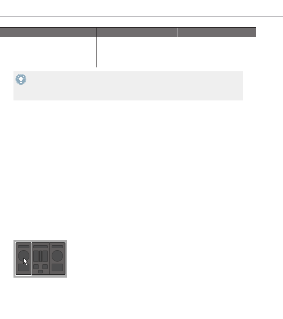
TRAKTOR KONTROL S2 MK2, S4 (MK2), and S8: the Overview Panel
Due to their great size and number of control elements, the TRAKTOR KONTROL S2 MK2, S4
(MK2) and TRAKTOR KONTROL S8 are divided into three parts in the Controller Editor: left
Deck, Mixer, and right Deck. Thus, before selecting any Page on these controllers, you first
have to choose a specific part for displaying. This is done via the Overview, at the top left cor-
ner of the Hardware area:
Use the Overview to select the desired Deck (S4 depicted).
You have two Pages at your disposal for each Deck. To select a specific Page:
1. Click the left or right Deck in the Overview.
2. Click the Page menu (the orange menu above the orange frame) and select the desired
Page in the list.
From the Hardware
You can also select Pages from your NI controller:
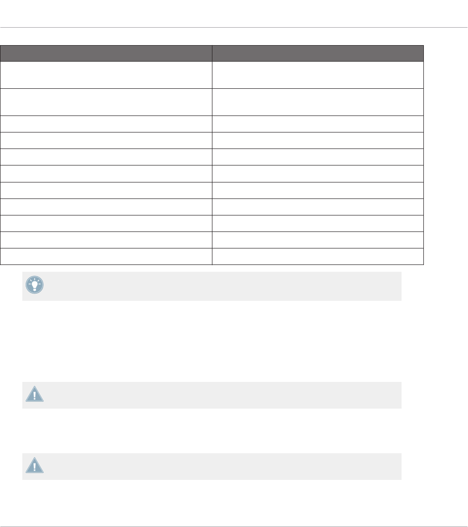
NI Controller # of Available Pages Page Switch/Selection
KOMPLETE KONTROL S-SERIES 1 n/a
MASCHINE (MK2) Unlimited Page buttons
MASCHINE MIKRO (MK2) Unlimited Left/Right Arrow buttons
MASCHINE STUDIO Unlimited Left/Right Arrow buttons
TRAKTOR KONTROL D2 2 for each Deck A–D DECK and/or SHIFT
TRAKTOR KONTROL S8 2 for each Deck A–D DECK and/or SHIFT
TRAKTOR KONTROL S4 2 for each Deck A–D DECK C/D then SHIFT
TRAKTOR KONTROL S4 MK2 2 for each Deck A–D DECK C/D then SHIFT
TRAKTOR KONTROL S2 n/a
Quick Start
Loading MIDI Assignments
CONTROLLER EDITOR - Manual - 26

NI Controller # of Available Pages Page Switch/Selection
TRAKTOR KONTROL S2 MK2 2 for each Deck A–B SHIFT
TRAKTOR KONTROL X1 2 SHIFT
TRAKTOR KONTROL X1 MK2 2 SHIFT
TRAKTOR KONTROL F1 2 SHIFT
TRAKTOR KONTROL Z1 Unlimited n/a
TRAKTOR KONTROL Z2 2 SHIFT
More information on this in the controller-specific chapters, later in this manual.
3.2.4 Select a Pad Page (MASCHINE Controller Family Only)
The sixteen pads of your MASCHINE STUDIO, MASCHINE (MK2) or MASCHINE MIKRO
(MK2) controller can optionally have multiple assignments, too. These are also organized into
pages: the Pad Pages. The Pad Page feature can be activated at the Template level: you can
have some Templates without Pad Pages (i.e. with one assignment each pad) and some other
with Pad Pages (i.e. with several assignments for each pad).
In the Hardware area, provided that the Pad Page feature is activated in the current Template,
the Pad Page is indicated by a blue frame around the pads:
Quick Start
Loading MIDI Assignments
CONTROLLER EDITOR - Manual - 27

The blue frame representing the Pad Page in the Hardware area for the MASCHINE controller family (detail).
At any time there is one active Pad Page, i.e. one subset of assignments for the pads.
For more information on the Pad Pages, see ↑4.3, The Mapping System.
Thus, let’s select a particular Pad Page of assignments for loading:
►To select a Pad Page, click the Pad Page menu (the blue menu above the blue frame) and
select the desired Pad Page in the list.
MASCHINE STUDIO: Your MASCHINE STUDIO controller offers another two optional pag-
ing systems: the I/O and Level Pages can store multiple assignments for the Level knob in
the Master section, and the Jog Wheel Pages can store multiple assignments for the jog
wheel and its LED ring. For more details, see section ↑4.3.4, I/O and Level Pages (MA-
SCHINE STUDIO Only) and ↑4.3.5, Jog Wheel Pages (MASCHINE STUDIO Only), respec-
tively.
From the Hardware
You can also select Pad Pages from your controller:
Quick Start
Loading MIDI Assignments
CONTROLLER EDITOR - Manual - 28
NI Controller # of Available Pad Pages Pad Page Selection
MASCHINE STUDIO 8 (if feature activated) Group buttons A–H
MASCHINE (MK2) 8 (if feature activated) Group buttons A–H
MASCHINE MIKRO (MK2) 8 (if feature activated) GROUP + pads 9–16
Fore more information on the available commands on your controller, see chapter ↑5, Using
Your MASCHINE Controller, ↑6, Using Your MASCHINE MK2 Controller, ↑7, Using Your
MASCHINE MIKRO Controller, ↑8, Using Your MASCHINE MIKRO MK2 Controller, or ↑9,
Using Your MASCHINE STUDIO Controller.
3.2.5 Ready to Go?
If you only plan to use a Template as it is, i.e. without modifying any of its MIDI assignments,
you’re done! As you may have noticed, you can do all this from within your MASCHINE Control-
ler, TRAKTOR KONTROL S8 or KOMPLETE KONTROL S-SERIES — this of course being the
preferred way for any live situation. If you used the Controller Editor, you can close the appli-
cation now: the corresponding NI background service will take care of everything and you can
start using your NI controller as a MIDI remote control right away!
3.3 Modifying an Assignment
Now, if you want to modify some of the assignments stored in the selected Template (and pos-
sibly one of its Pages), continue with these few more steps:
1. TRAKTOR KONTROL S2 (MK2) / S4 (MK2) / S8 only: In the Overview at the top left,
click the part of the controller (left Deck, Mixer, or right Deck) containing the control ele-
ment whose assignment you want to edit.
Quick Start
Loading MIDI Assignments
CONTROLLER EDITOR - Manual - 29

2. Select the desired control element. You can do this in two ways: In the Controller Editor,
click the control element within the hardware representation (a double-click on the con-
trol element directly brings the Inspector’s Assign pane to the front for faster editing, see
next step). You can also [Shift]-click several control elements of the same type (or click
and drag a rectangle) to select them. Or, on your NI controller (except KOMPLETE KON-
TROL S-SERIES), touch the control element (for this, the Touch Select option must be
enabled in File > Preferences > General — this is the case by default).
Either way, the control elements selected for editing get surrounded by the red Selection
Frame in the Controller Editor window:
3. In the Inspector (the right part of the Controller Editor interface), click the Assign tab:
The Assign pane opens up and displays all assignments’ properties for the selected con-
trol element(s).
4. Modify the assignment’s properties according to your needs: at the top, you can edit the
name of the assignment, and below, all MIDI properties like the type of MIDI message to
be sent, the MIDI channel to use, and so on. The assignment’s details will differ depend-
ing on the type of MIDI message you choose.
Quick Start
Modifying an Assignment
CONTROLLER EDITOR - Manual - 30

→That’s it! Now the corresponding control element on your NI controller triggers the MIDI
message that you just defined.
3.4 Organizing Your Assignments
Thanks to its powerful mapping system, the Controller Editor lets you organize your assign-
ments as you like. You can define Templates and Pages to address various situations: For ex-
ample, you could define different Pages to control different instruments in your setup. Further-
more, you could prepare different Templates for different songs in your live performance, with
all necessary Pages inside.
3.4.1 Displaying the Lists of Templates and Pages
To manage (create, delete, duplicate, etc.) your Templates and Pages, use the first two tabs of
the Inspector, namely Templates and Pages.
Quick Start
Organizing Your Assignments
CONTROLLER EDITOR - Manual - 31
The Templates tab and Pages tab allow you to organize your assignments.
• On the Templates pane, you find a list of all available Templates (both factory and user-
defined), along with an Edit menu holding all managing commands (e.g. New, Duplicate,
Delete, etc.). Below, you can see a few additional settings for the selected Template —
these settings vary with each NI controller.
• On the Pages pane, an equivalent list is available for the (Knob) Pages and, only for the
MASCHINE controllers, for the Pad Pages (and other Page types on the MASCHINE STU-
DIO), along with their corresponding Edit menus.
The Page functionality is not available on the TRAKTOR KONTROL S2.
For the TRAKTOR KONTROL X1 (MK2), F1, S2 MK2, S4 (MK2), S8 and for Z2, there is no
Edit menu available under the Pages list — instead, there is a Shift Mode menu available.
For more information on this, see the controller-specific chapters, later in this manual.
KOMPLETE KONTROL S-SERIES: Only one Page is available and it is always selected.
Multiple Pages will be available in a future KOMPLETE KONTROL update.
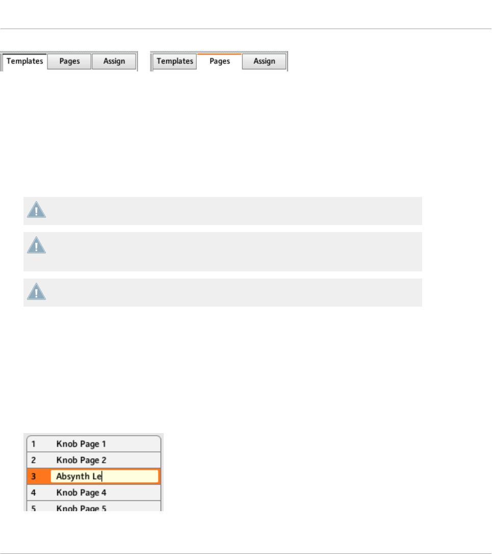
3.4.2 Renaming Templates and Pages
Let’s say you have just defined a Knob Page that controls one of your software synthesizers.
You might want to rename it so that you easily remember its purpose:
1. In the Knob Pages list, double-click the Page that you just defined (let’s say Knob Page
3). Its name gets highlighted.
2. Type a new name for this Page (for example, “Absynth Lead”) and press [Enter] on your
computer keyboard to confirm the change:
Quick Start
Organizing Your Assignments
CONTROLLER EDITOR - Manual - 32

3.4.3 Re-ordering Templates and Pages
You may want to put this Page at the top of the list, e.g. if you plan to use this synthesizer at
first in your song and want to have direct access to its parameters from your Controller:
1. Click the Page Absynth Lead in the list, hold the mouse button depressed and drag your
mouse toward the top of the list. An insertion line appears to show you the position where
the Page is going to be moved to.
2. When the insertion line reaches the top of the list (or the desired insertion position, wher-
ever it is), release the mouse button. The Page “Absynth Lead” takes its new position in
the list.
The Pages for the TRAKTOR KONTROL X1 (MK2), F1, S2 MK2, S4 (MK2), S8, and the Z2
cannot be reordered.
This process can also be applied to the other Pages as well as to the Templates (on the Tem-
plates pane). The Edit menus offer more managing features — you will find all details later in
this manual (mainly sections ↑23.5.1, Templates Pane and ↑23.5.2, Pages Pane). For a de-
tailed description of the mapping system, please refer to section ↑4.3, The Mapping System.
3.5 Saving and Loading Templates
Once you have defined a set of assignments that suits your needs, you have the possibility to
save it.
Actually, you don’t necessarily need to save it, since the Controller Editor automatically saves
the changes made to the Template you are working on (and its included Pages and single as-
signments). So if you only plan to use this Template later on the same computer, you can quit
the Controller Editor, the Template will be recalled with all modifications next time you switch
your NI controller to MIDI mode and select this Template.
You may want to use a modified or a newly created Template on another computer or you may
want to share your Template with other users. In that case, you can export a Template as a
Template file:
Quick Start
Organizing Your Assignments
CONTROLLER EDITOR - Manual - 33
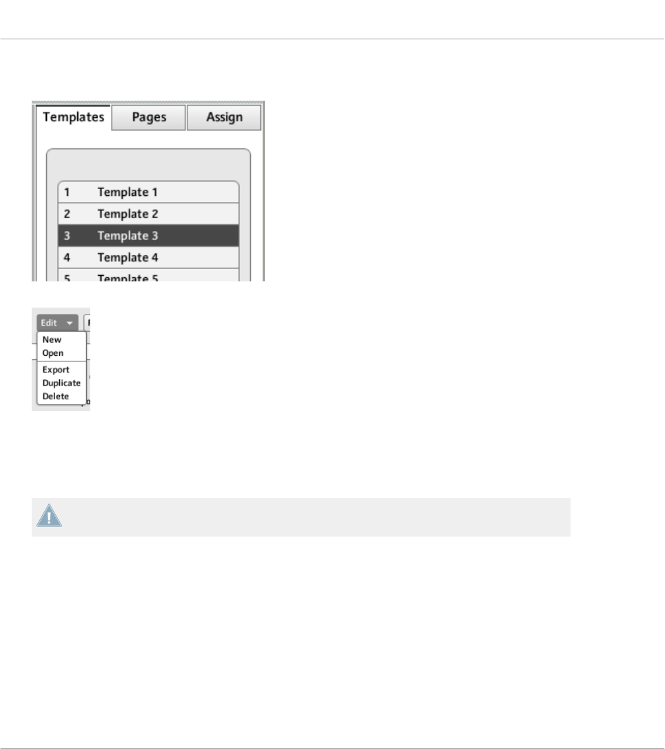
1. Go to the Templates pane of the Inspector and select the desired Template by clicking its
entry in the Template list. The selected Template is highlighted:
2. Below the list, click the Edit menu and select Export:
3. In the Save template dialog that opens, choose the destination and type the name of the
Template file to be exported. Please note that the filename that you choose can be differ-
ent from the Template’s name inside the Controller Editor. Once this is done, click Save
to export the file and you’re done.
Template filenames have various extensions depending on the affected NI controller.
Please see ↑4.3.6, Templates for a list of filename extensions.
You can now transfer this Template file to another computer, share it with a friend, etc.
On the other hand, as you would expect, the Controller Editor also allows you to load a Tem-
plate file. To do this:
1. In the Templates pane of the Inspector, click the Edit menu and select Open. An Open
template dialog appears that lets you navigate through your file system on your computer
and choose a Template file to import.
2. Select the desired Template file and click Open. The Template is loaded and appended to
your Template list.
Quick Start
Saving and Loading Templates
CONTROLLER EDITOR - Manual - 34

The Controller Editor provides many factory Templates for use with various MIDI targets.
Please refer to the Controller Editor Template Documentation to know how to use them!
Quick Start
Saving and Loading Templates
CONTROLLER EDITOR - Manual - 35

4 Basic Concepts
In this chapter we will introduce you to the basics of the Controller Editor. You might have al-
ready checked the previous chapter, which gives you a first idea of how to use the Controller
Editor. Here, we will approach the system in a more general way.
4.1 How the Controller Editor Works
The Controller Editor allows you to define the links between your NI controller and the audio
applications running on your computer or your external MIDI devices. It lets you decide how
your actions on the NI controller will be interpreted. For this purpose, the Controller Editor im-
plements a powerful mapping system allowing you to define as many MIDI assignments as you
want for each control element (knob, button, etc.) available on your NI controller.
The Controller Editor works in conjunction with a small background service installed on your
computer during the Controller Editor installation procedure. This background service takes
care of all communication matters between your NI controller and your MIDI-capable targets,
both on the software side and on the hardware side. It stays active even if you close the Con-
troller Editor application, which means you don’t need the Controller Editor open on your com-
puter to use your NI controller as a MIDI remote control! You can select and/or tweak your as-
signments in the Controller Editor and then quit the application — the assignments (and Tem-
plates / Pages, see below) stay active thanks to this small background service. Thus, the Con-
troller Editor can be seen as an assignment editor: use it to check or edit your assignments.
4.2 Overview of the User Interface
Now let’s look closely at the Controller Editor user interface. When you start the Controller Edi-
tor, you will see the application containing a Template, something like this:
Basic Concepts
How the Controller Editor Works
CONTROLLER EDITOR - Manual - 36
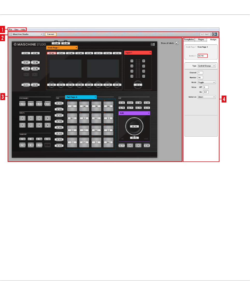
The Controller Editor user interface: the big view (Windows version pictured, with the MASCHINE STUDIO controller in the
Hardware area)
The user interface is divided into four main areas, namely:
(1) Application Menu Bar
(2) Application Control Bar
(3) Hardware area
(4) Inspector
In the following sections you will find a brief introduction to all areas of the software and their
corresponding control elements. For a detailed description of each of these elements, please
refer to chapter ↑23, Reference.
Basic Concepts
Overview of the User Interface
CONTROLLER EDITOR - Manual - 37
4.2.1 Application Menu Bar
At the top of the Controller Editor window (or at the top of your computer screen on Mac OS X),
the Application Menu Bar is similar to the one found with most applications on your operating
system. Here it consists of three menus (File, View, and Help) controlling the general functions
of the software:
The Application Menu Bar (Windows version pictured)
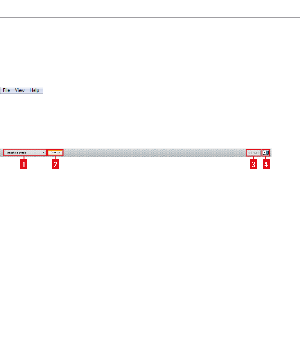
4.2.2 Application Control Bar
Right under the Application Menu Bar, the Application Control Bar holds menus and buttons
controlling the overall mapping system:
The Application Control Bar
From left to right, we have the following controls:
(1) Device menu: Allows you to select the controller of which you want to edit the MIDI assign-
ments.
(2) Connect button: Allows you to “call” your hardware — in other words, to switch it to MIDI
mode and connect it to the Controller Editor, in case it is currently connected to its dedicated
software.
(3) MIDI Activity indicator (except for KOMPLETE KONTROL S-SERIES keyboards): Shows any
incoming/outgoing MIDI data for the controller selected in the Device menu (1).
(4) NI Logo: Opens the About screen.
4.2.3 Hardware Area
Below the Application Control Bar is the Hardware area. The Hardware area is the largest part
of the user interface and basically represents your NI controller and all its control elements —
most of them are freely assignable to MIDI messages.
Basic Concepts
Overview of the User Interface
CONTROLLER EDITOR - Manual - 38
The Controller depicted in the Hardware area corresponds to the device selected in the Device
menu located in the Application Control Bar (see above).
►Click an assignable control element in the Hardware area to edit its assignment.
Compared to your real NI controller, the Hardware area holds a few additional graphical ele-
ments:
• Every control element that can be assigned to a MIDI message comes with a Label Field
which displays a name (describing by default its current assignment).
Pairs of mini buttons in the Hardware area: If mini buttons are not selected when you click
them, click their Label Field instead!
• A red Selection Frame highlights the selected control element(s).
• An orange Page (or Knob Page) menu allows you to select a particular Page (or Knob
Page) of assignments. The Page (or Knob Page) area, denoted by an orange frame, holds
the control elements affected by the Page (or Knob Page) selection in the menu. Please
refer to section ↑4.3.2, Pages (or Knob Pages) for more information on this.
The Page feature is not available on the TRAKTOR KONTROL S2.
• MASCHINE controllers only: If the Pad Page feature is activated, an additional blue Pad
Page menu allows you to select a particular page of assignments for the pads. The blue
frame highlights the Pad Page area, which holds the control elements included in the Pad
Pages — namely the pads. Please refer to section ↑4.3.3, Pad Pages (MASCHINE Con-
troller Family Only) for more information on this.
• MASCHINE STUDIO only: If the I/O and Level Page feature is activated, an additional red
I/O and Level Page menu allows you to select a particular assignment for the Level knob
(in the Master section of your controller). The red frame surrounds the control elements
involved in the I/O and Level Pages. Please refer to section ↑4.3.4, I/O and Level Pages
(MASCHINE STUDIO Only) for more information on this.
• MASCHINE STUDIO only: If the Jog Wheel Page feature is activated, an additional violet
Jog Wheel Page menu allows you to select a particular assignment for the jog wheel and
its LED ring. The violet frame highlights the jog wheel. Please refer to section ↑4.3.5, Jog
Wheel Pages (MASCHINE STUDIO Only) for more information on this.
Basic Concepts
Overview of the User Interface
CONTROLLER EDITOR - Manual - 39
• TRAKTOR KONTROL S2 (MK2) / S4 (MK2) / S8 only: At the upper left corner, the little
Overview allows you to select a specific part of your controller for displaying and editing
(left Deck, Mixer, or right Deck). The Hardware area displays the part of the S2/S4/S8
that you selected here.
You will find a detailed description of each Hardware area / NI controller and its assignable
control elements in the respective controller-specific chapters, later in this manual.
4.2.4 Inspector
At the right of the Hardware area, the Inspector is the control tower of your mapping system.
There, you can precisely define what has to be done on your target when you press, turn, or
move anything on your NI controller. Moreover, you can organize all your assignments into Pa-
ges and Templates. Section ↑23.5, The Inspector will give you a detailed description of all
what you can do with the Inspector.
The Inspector is divided into three panes, each of them controlling a specific part of the map-
ping scheme: the Templates pane, the Pages pane, and the Assign pane.
The Templates Pane
The Templates pane allows you to manage your Templates. It shows a list of available Tem-
plates along with a few editing functions.
A Template holds a whole mapping configuration for all control elements of your NI control-
ler. For more information, see ↑4.3.6, Templates below.
Basic Concepts
Overview of the User Interface
CONTROLLER EDITOR - Manual - 40
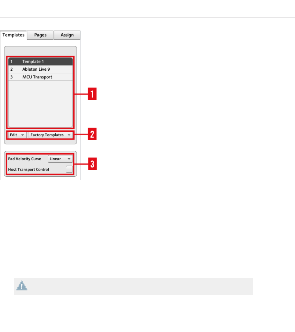
The Templates pane in the Inspector (here for the MASCHINE controller)
The Templates pane holds the following elements, from top to bottom:
(1) Template list: Shows all available Templates with, for each Template, an index number (not
editable) and a name (editable). There, you can select a Template for editing by clicking its
name, and modify its name by double-clicking it.
(2) Template Edit menu and Factory Templates menu: The Edit menu provides you with editing
functions like New, Save As, etc. The Factory Templates menu allows you to load factory Tem-
plates.
(3) Template Properties area: Gives you access to the properties of the Template that is current-
ly selected in the upper Template list.
The Template Properties area is available only for certain NI controllers.
Basic Concepts
Overview of the User Interface
CONTROLLER EDITOR - Manual - 41

The Pages Pane
The Pages pane allows you to manage your Pages. Pages are sets of assignments focused on
certain areas of your NI controller. Therefore, each NI controller will have different sets of Pa-
ges.
This feature is not available on TRAKTOR KONTROL S2 — if you are currently working on
a Template for this controller, you cannot activate the Pages pane (the tab is grayed out).
Pages are sets of assignments for specific control elements. For more info, see ↑4.3.2, Pa-
ges (or Knob Pages), ↑4.3.3, Pad Pages (MASCHINE Controller Family Only), ↑4.3.4, I/O
and Level Pages (MASCHINE STUDIO Only), and ↑4.3.5, Jog Wheel Pages (MA-
SCHINE STUDIO Only).
Basic Concepts
Overview of the User Interface
CONTROLLER EDITOR - Manual - 42
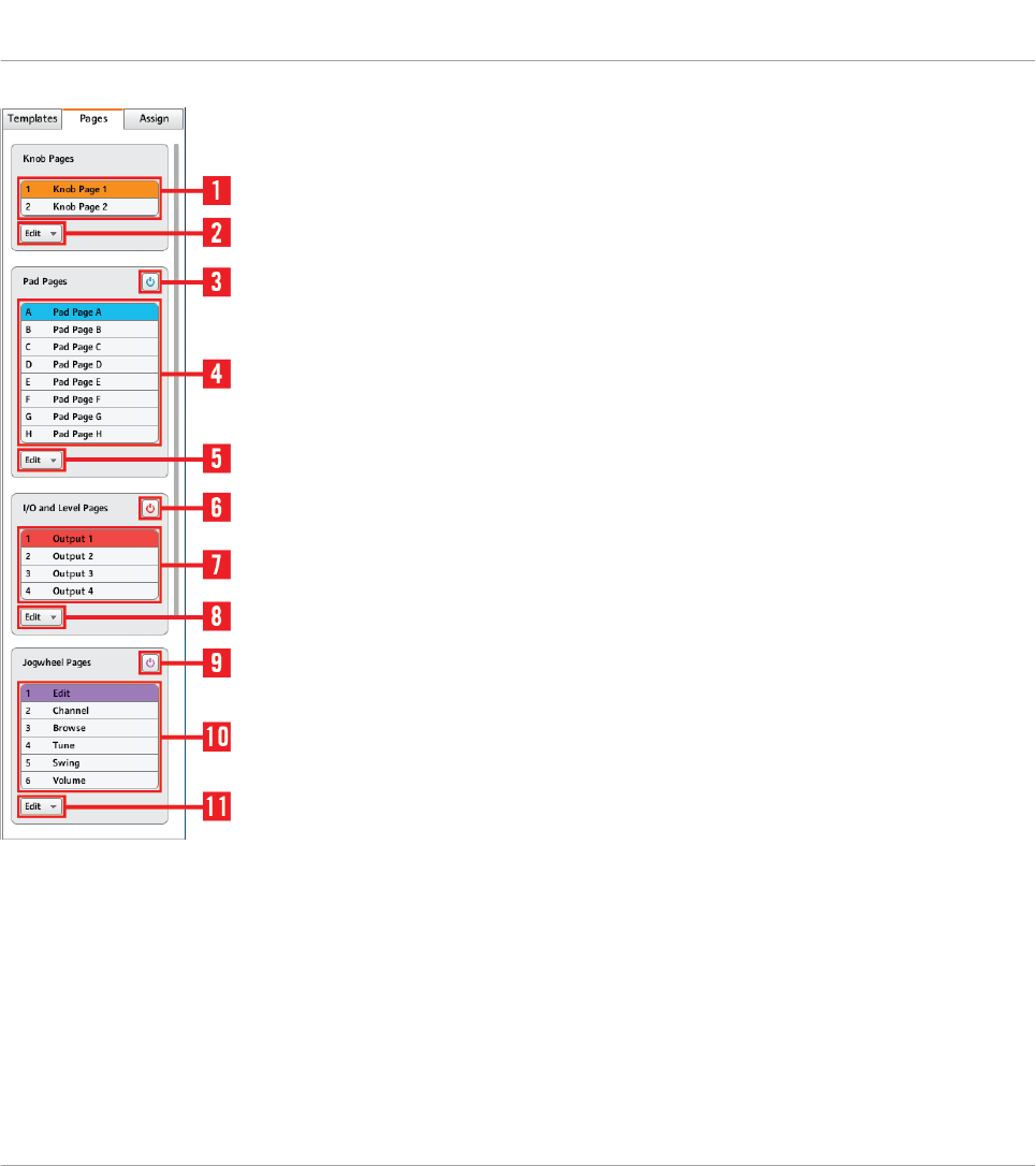
The Pages pane in the Inspector for the MASCHINE STUDIO controller.
The Pages pane holds the following elements:
(1) Knob Pages list or Pages list: Shows a list with all available (Knob) Pages with, for each of
them, an index number (uneditable) and a name (editable). There, you can select a Page for
editing by clicking its name, and modify its name by double-clicking it. On the MASCHINE
controllers, you can rearrange the page order via drag and drop. You can also select a Page via
the orange (Knob) Page menu in the Hardware area, or possibly from your NI controller.
Basic Concepts
Overview of the User Interface
CONTROLLER EDITOR - Manual - 43

(2) Knob Page Edit menu or Page Edit menu: Provides you with editing functions for the (Knob)
Pages like New, Duplicate, etc.
For some NI controllers, this Edit menu is replaced with a Shift Mode menu with the two
options Gate and Toggle allowing you to choose the behavior of the SHIFT button when
switching between Pages from your controller. For more information on this, see the con-
troller-specific chapters, later in this manual.
The following elements are available only if you are working on the assignments for either of
the MASCHINE controllers:
(3) Enable Pad Pages button: Activates/deactivates the Pad Page feature. If the Pad Page fea-
ture is deactivated, the rest of the area is minimized and grayed out. It will not be possible to
interact with the Pad Pages when they are deactivated.
(4) Pad Page list: Shows a list with all available Pad Pages with, for each of them, an index
number (uneditable) and a name (editable). There, you can select a Pad Page for editing by
clicking its name, and modify its name by double-clicking it. You can rearrange the page order
via drag and drop. You can also select a Pad Page via the Pad Page menu above the pads in
the Hardware area, or from your controller: On the MASCHINE (MK2) and MASCHINE STUDIO
controllers, use the Group buttons labeled A to H; on the MASCHINE MIKRO (MK2) controller,
hold the GROUP button and use pad 9–16.
(5) Pad Page Edit menu: Provides you with editing functions like New, Duplicate, etc.
The following elements are available only if you are working on the assignments for the MA-
SCHINE STUDIO:
(6) Enable I/O and Level Pages button: Activates/deactivates the I/O and Level Page feature. If
the I/O and Level Page feature is deactivated, the rest of the area is minimized and grayed out.
It will not be possible to interact with the I/O and Level Pages when they are deactivated. On
the other hand, this will make the eight Input/Output buttons available for MIDI assignments.
(7) I/O and Level Pages list: Shows a list with all available I/O and Level Pages. Each page will
have an index number (uneditable) and a name (editable). You can select a I/O and Level Page
for editing by clicking its name, and modify its name by double-clicking it. You can rearrange
the page order via drag and drop. You can also select a I/O and Level Page via the I/O and Lev-
el Pages menu above the Level knob in the Hardware area, or on your MASCHINE STUDIO
controller when in MIDI mode.
Basic Concepts
Overview of the User Interface
CONTROLLER EDITOR - Manual - 44

(8) I/O and Level Page Edit menu: Provides you with editing functions for the I/O and Level Pages
like New, Duplicate, etc.
(9) Jog Wheel Pages button: Activates/deactivates the Jog Wheel Page feature. If the Jog Wheel
Page feature is deactivated, the rest of the area is minimized and grayed out. It will not be
possible to interact with the Jog Wheel Pages when they are deactivated. On the other hand,
this will make the FUNCTION buttons available for MIDI assignments.
(10) Jog Wheel Page list: Shows a list with all available Jog Wheel Pages. Each page will have
an index number (uneditable) and a name (editable). You can select a Jog Wheel Page for edit-
ing by clicking its name, and modify its name by double-clicking it. You can rearrange the
page order via drag and drop. You can also select a Jog Wheel Page via the Jog Wheel Page
menu above the jog wheel in the Hardware area, or using the FUNCTION buttons on your MA-
SCHINE STUDIO controller when in MIDI mode.
(11) Jog Wheel Page Edit menu: Provides you with editing functions for the Jog Wheel Pages like
New, Duplicate, etc.
The Assign Pane
The last pane in the Inspector is the Assign pane. This is where you specify all details of the
assignment for a particular control element. This pane shows the properties of the currently se-
lected control element:
Basic Concepts
Overview of the User Interface
CONTROLLER EDITOR - Manual - 45

The Assign pane in the Inspector.
The Assign pane shows different properties depending on the type of element currently select-
ed.
(1) Description area: This area is similar for all control elements. It shows the following informa-
tion about the currently selected control element:
• The index number and the name of the Page of the selected control element (this is emp-
ty for elements not included in a Page).
• The element description (not editable) and its name (editable).
MASCHINE controller family: Depending on the controller and the selected control ele-
ment, an additional setting can be available in the Description area. See section ↑23.5.3,
Assign Pane for more details.
(2) Definition area: Defines the MIDI assignment properties for the current control element.
Please refer to section ↑23.5.3, Assign Pane in the reference chapter for more information.
Basic Concepts
Overview of the User Interface
CONTROLLER EDITOR - Manual - 46

4.3 The Mapping System
Whatever you do on your NI controller, the Controller Editor translates it into a MIDI message
that is then sent to the desired MIDI port — this is what the Controller Editor is all about:
mapping human actions to MIDI events.
The Controller Editor’s mapping system is structured in a way that allows you to efficiently or-
ganize your assignments. This makes the whole mapping process a lot easier and informs you
about what will happen whenever you actuate a control element on your NI controller. The next
paragraphs will introduce you to some basic concepts.
4.3.1 Assignments
An assignment defines which MIDI event is triggered by a particular control element. Available
MIDI event types are “MIDI Note,” “MIDI CC,” etc. Every action on a control element is trans-
lated into one MIDI event, the corresponding assignment defines the rules of that translation.
Depending on the type of control element (button, knob, pad, fader, encoder, pedal input,
footswitch…), the available assignments differ. For more details about all available assign-
ments for each type of control, please refer to section ↑23.6, MIDI Message Parameters.
4.3.2 Pages (or Knob Pages)
Pages are not available on TRAKTOR KONTROL S2.
For some of the control elements, you can have multiple assignments, organized in Pages (also
called Knob Pages on specific NI controllers). Those particular control elements are located in
the (Knob) Page area — indicated by the orange frame in the Hardware area, see section
↑4.2.3, Hardware Area above. A (Knob) Page is a set of assignments for all control elements in
this (Knob) Page area. One (Knob) Page can be selected (and loaded) at a time.
You can switch the available (Knob) Pages — either built-in or user-defined — via the Page
menu (or Knob Page menu) in the Hardware area or via the Page list (or Knob Page list) in the
Inspector. You can do it as well from your NI controller — more on this in the respective chap-
ters describing the use of each NI controller.
Basic Concepts
The Mapping System
CONTROLLER EDITOR - Manual - 47

When you select another (Knob) Page, all assignments for the control elements in the (Knob)
Page area are updated accordingly. All (Knob) Pages are stored as an editable list on the Pages
pane of the Inspector (for detailed information about the Inspector, see ↑23.5, The Inspector).
4.3.3 Pad Pages (MASCHINE Controller Family Only)
On the MASCHINE STUDIO, MASCHINE (MK2), and MASCHINE MIKRO (MK2) controllers,
you also have access to optional pages of assignments dedicated to the pads: the Pad Pages.
The Pad Pages work like the Pages and Knob Pages explained above, but they affect the six-
teen pads instead of the control elements in the (Knob) Page area.
The number of Pad Pages is limited to eight. One Pad Page can be selected at a time. When
you select another Pad Page, all assignments for the sixteen pads are updated accordingly. The
eight available Pad Pages are stored as an editable list on the Pages pane in the Inspector (you
will find all details about the Inspector in section ↑23.5, The Inspector).
The Pad Pages can be activated or deactivated, depending on your needs, via the Enable Pad
Pages button in the Inspector’s Pages pane:
• If activated, you can switch the available Pad Pages via the Pad Page menu (in the Hard-
ware area) or via the Pad Page list (in the Inspector). Again, you can do it as well from
your NI controller, via the Group buttons (labeled from A to H) or, for MIKRO controllers,
via the GROUP button and pads 9–16)..
• If deactivated, only one assignment can be set for each pad. The Group buttons A–H (or
the GROUP button on MIKRO controllers) can then be also assigned to MIDI commands.
4.3.4 I/O and Level Pages (MASCHINE STUDIO Only)
On the MASCHINE STUDIO controller, you also have access to optional pages of assignments
dedicated to the I/O and Level section: the I/O and Level Pages. The eight available I/O and
Level Pages allow you to store eight different assignments for the Level knob. Only one I/O and
Level Page can be selected at a time.
The I/O and Level Pages can be activated or deactivated via the Enable I/O and Level Pages
button in the Inspector’s Pages pane (you will find all details about the Inspector in section
↑23.5, The Inspector):
Basic Concepts
The Mapping System
CONTROLLER EDITOR - Manual - 48

• If activated, you can switch the available I/O and Level Pages by pressing the Input but-
tons (IN1, IN2, IN3, IN4) and Level meter buttons (MST, GRP, SND, CUE) on your con-
troller. The lit button indicates which I/O and Level page is currently active. You can also
do this in the Controller Editor via the I/O and Level Page menu (in the Hardware area) or
the I/O and Level Page list (in the Inspector).
• If deactivated, only one assignment can be set for the Level knob. The Input and Level
meter buttons can then be also assigned to MIDI commands.
4.3.5 Jog Wheel Pages (MASCHINE STUDIO Only)
On the MASCHINE STUDIO controller, you also have access to optional pages of assignments
dedicated to the jog wheel and its LED ring: the Jog Wheel Pages. The six available Jog Wheel
Pages allow you to store six different assignments for the jog wheel and its LED ring. Only one
Jog Wheel Page can be selected at a time.
The Jog Wheel Pages can be activated or deactivated via the Enable Jog Wheel Pages button in
the Inspector’s Pages pane (you will find all details about the Inspector in section ↑23.5, The
Inspector):
• If activated, you can switch the available Jog Wheel Pages by pressing the FUNCTION
buttons (under the jog wheel) on your controller. The lit LED near the jog wheel (EDIT,
CHANNEL, BROWSE, TUNE, SWING or VOLUME) indicates which Jog Wheel Page is cur-
rently active. You can also do this in the Controller Editor via the Jog Wheel Pages menu
(in the Hardware area) or the Jog Wheel Page list (in the Inspector).
• If deactivated, only one assignment can be set for the jog wheel and its LED ring. The
FUNCTION buttons can then be also assigned to MIDI commands.
4.3.6 Templates
A Template holds a mapping configuration for all control elements on your NI controller, in-
cluding the (Knob) Pages, Pad Pages, I/O and Level Pages and Jog Wheel Pages that might
exist. One Template can be selected at a time. The Template also determines if the generated
MIDI events have to be sent to the internal MIDI port (to access an application listening to
MIDI on your computer) or to the external MIDI port (to access an external MIDI-capable de-
vice) — only for controllers that are equipped with MIDI ports of course. Switching between
different Templates can be used, for example, to address different applications on your com-
puter or different hardware instruments.
Basic Concepts
The Mapping System
CONTROLLER EDITOR - Manual - 49
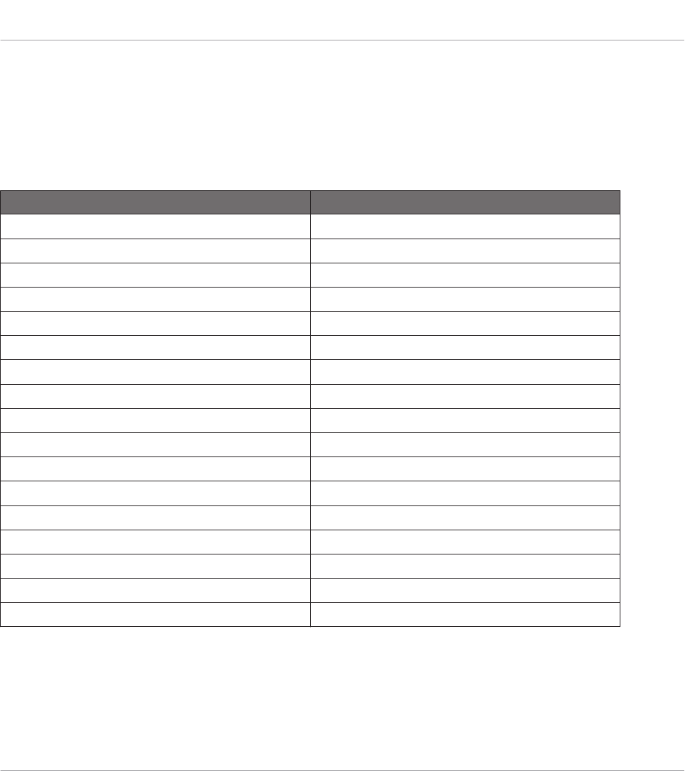
The Template contains all Knob Page/Pad Page/I/O and Level Page/Jog Wheel Page data, the
list of Knob Pages/Pad Pages/I/O and Level Pages/Jog Wheel Pages and the index of the last
selected Knob Page/Pad Page/I/O and Level Page/Jog Wheel Page. The Template also stores
the last state of each control element.
Templates can be stored as distinct files on your computer. These files have the following ex-
tensions:
NI Controller Template file extension
KOMPLETE KONTROL S-SERIES .nckk
MASCHINE .ncm
MASCHINE MK2 .ncm2
MASCHINE MIKRO .ncmm
MASCHINE MIKRO MK2 .ncmm2
MASCHINE STUDIO .ncmst
TRAKTOR KONTROL X1 .nckx1
TRAKTOR KONTROL X1 MK2 .nckx1m2
TRAKTOR KONTROL F1 .nckf1
TRAKTOR KONTROL Z1 .nckz1
TRAKTOR KONTROL Z2 .nckz2
TRAKTOR KONTROL D2 .nckd2
TRAKTOR KONTROL S8 .ncks8
TRAKTOR KONTROL S4 .ncks4
TRAKTOR KONTROL S4 MK2 .ncks4m2
TRAKTOR KONTROL S2 .ncks2
TRAKTOR KONTROL S2 MK2 .ncks2m2
You can switch among the available Templates (either built-in or user-defined) via the Tem-
plate list in the Templates pane of the Inspector. This can also be done from some NI control-
lers — more on this in the respective chapters describing the use of each NI controller.
When you select another Template, all assignments for all control elements of the controller
are updated accordingly, including the Pages, if any.
Basic Concepts
The Mapping System
CONTROLLER EDITOR - Manual - 50
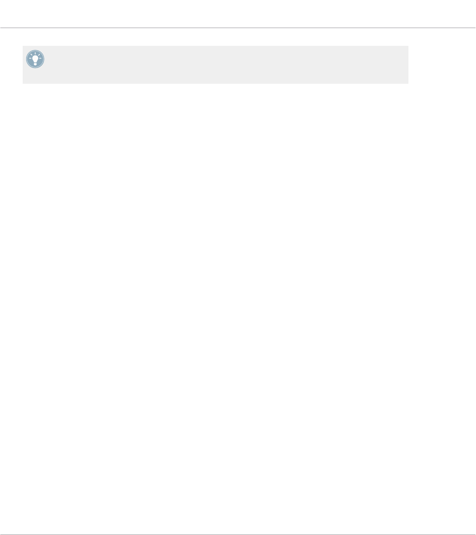
The Controller Editor provides many factory Templates for use with various MIDI targets.
Please refer to the Controller Editor Template Documentation for more information about
using them.
4.3.7 Configuration
For each NI controller, a working set of data contains all listed Templates, with all included
pages and assignments, and the index of the currently selected Template.
The working data sets for all controllers can be stored as a single Configuration file on your
computer. This type of file has the extension “.ncc.”
4.4 To Sum Up…
By utilizing your NI controller and the Hardware Service (the Controller Editor and the NI back-
ground service) you can remotely control any MIDI target. The Hardware Service was designed
in a way that allows you to forget its presence in a live situation: After having configured your
assignments, you can rely on your NI controller to allow you to control everything you need dur-
ing your performance. Triggering MIDI hardware devices and applications in various ways,
switching in real time to other sets of assignments (or groups thereof), all this can be done di-
rectly from your NI controller.
In fact, the only thing that you can not do from the Controller is modify your assignments… For
that, you will need to use the Controller Editor! But thanks to the powerful mapping scheme
using Templates and Pages, which is partly mirrored on your NI controller, you can prepare as
many assignments as you want and recall them instantly during your live performance.
In the next chapters, we will show you how to use your NI controller(s) with the assignments
defined within the Controller Editor.
Basic Concepts
The Mapping System
CONTROLLER EDITOR - Manual - 51

5 Using Your MASCHINE Controller
In this chapter, we will focus on what’s happening on your MASCHINE controller. By reading
this, you will learn:
• How to use the basic controls on your controller for navigating through the MIDI mapping
system.
• The list of all assignable control elements on your controller.
• How the various luminous elements give you some important information about their
state.
• How to use the powerful displays of your MASCHINE controller in MIDI mode.
To enjoy full functionality of your NI controller as a MIDI remote control, especially con-
cerning some control elements’ state and LED behavior, you need to tell your NI controller
what is the current state of the parameter in the MIDI target. You can do this by setting up
MIDI feedback channels coming from your MIDI target back to your NI controller. This way,
your controller will always stay up-to-date with the current parameter values in your target
software/hardware. For more information on how to configure these MIDI feedback chan-
nels, please refer to your target software/hardware’s documentation.
5.1 Basic Controls
This section shows you the commands available on your MASCHINE controller for basic tasks:
switching between MIDI mode and MASCHINE mode, and selecting sets (Templates) and sub-
sets (Knob Pages, Pad Pages) of MIDI assignments.
All these actions can of course be done via the Controller Editor user interface — see chap-
ter ↑3, Quick Start for example. Nevertheless, using your NI controller instead can be very
handy in a live situation!
Using Your MASCHINE Controller
Basic Controls
CONTROLLER EDITOR - Manual - 52
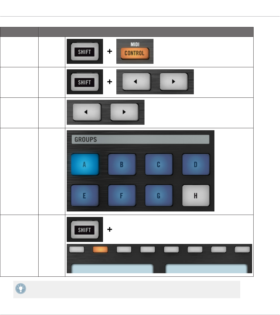
Selection Command
MIDI/MA-
SCHINE mode
SHIFT +
CON-
TROL
Templates SHIFT +
Page but-
tons
Knob Pages Page but-
tons
Pad Pages
(if activated)
Group
buttons
Display mode SHIFT +
Buttons
1–8
For more information on Templates, Knob Pages, and Pad Pages, see ↑4.3, The Mapping
System.
Using Your MASCHINE Controller
Basic Controls
CONTROLLER EDITOR - Manual - 53

For more information on the display modes, see ↑5.4, The Displays. There you will also
learn another way to select and load Templates and Knob Pages from your controller.
When your MASCHINE controller is in MIDI mode, its SHIFT button is dimly lit.
Adjusting Settings for your Controller
You can adjust various settings for your MASCHINE controller by entering its Settings display
mode or by going to File > Preferences > Controller. See ↑5.4.7, Settings Display Mode for
more information.
5.2 Assignable Control Elements
If you selected the MASCHINE controller in the Device menu of the Application Control Bar,
this is what the Hardware area looks like:
Using Your MASCHINE Controller
Assignable Control Elements
CONTROLLER EDITOR - Manual - 54
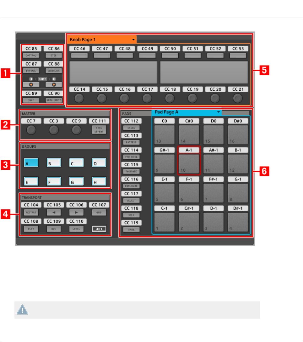
The Hardware area representing the MASCHINE controller.
In this Hardware area, you will notice the Knob Page menu and its associated Knob Page area
(orange frame), the Pad Page menu and its associated Pad Page area (blue frame), and the red
Selection Frame on the currently selected control element (pad 10 in the picture above).
The MASCHINE controller holds the following areas:
The names that you see on the device only refer to their original function in the MASCHINE
software. We use these names here only to describe the interface!
Using Your MASCHINE Controller
Assignable Control Elements
CONTROLLER EDITOR - Manual - 55

(1) Page buttons and buttons around: In the top left part, you find a set of eight buttons arranged
into four rows of two buttons. From these eight buttons, six are freely assignable (CONTROL
and STEP, BROWSE and SAMPLING, SNAP (F1), and AUTO WRITE (F2)) and two have spe-
cial functions: the left and right Page buttons (see previous section).
(2) MASTER area: The MASTER area holds four freely assignable control elements (three knobs
and one button).
(3) GROUPS area: The GROUPS area contains eight buttons labeled from A to H: the Group but-
tons. If you activated the Enable Pad Pages button in the Pages pane of the Inspector, these
buttons allow you to select the desired page of assignments for the pads (see ↑4.3.3, Pad Pa-
ges (MASCHINE Controller Family Only)). If you didn’t activate the Pad Pages, these eight but-
tons are freely assignable to MIDI events.
(4) TRANSPORT area: The TRANSPORT area contains eight buttons. Seven of them are freely
assignable: RESTART (LOOP), Previous, Next, GRID, PLAY, REC, and ERASE. The last one,
SHIFT, is a special button (see previous section). Therefore, this button cannot be assigned in
the Controller Editor.
(5) Knob Page area: The Knob Page area holds a set of eight buttons and eight knobs, with the
buttons being placed above and the knobs below the two displays, respectively. These sixteen
control elements are freely assignable. The Knob Page area is indicated by an orange frame
and headed by the Knob Page menu.
The buttons and knobs in the Knob Page area can also have other functions according to
the display mode that is currently active. See ↑5.4, The Displays for more on this.
(6) PADS area: The PADS area shows a column of eight freely assignable buttons (namely
SCENE, PATTERN, PAD MODE (KEYBOARD), NAVIGATE, DUPLICATE, SELECT, SOLO, and
MUTE) as well as a square of sixteen freely assignable pads. If you activated the Enable Pad
Pages button in the Pages pane of the Inspector, a Pad Page area (indicated by the blue
frame) groups the pads together and is headed by the Pad Page menu.
To Sum Up…
All control elements on your MASCHINE controller are freely assignable to MIDI events (with
the limitations due to the type of control element), with the following exceptions:
• The Page buttons and the SHIFT button have a predefined function (see previous sec-
tion).
Using Your MASCHINE Controller
Assignable Control Elements
CONTROLLER EDITOR - Manual - 56
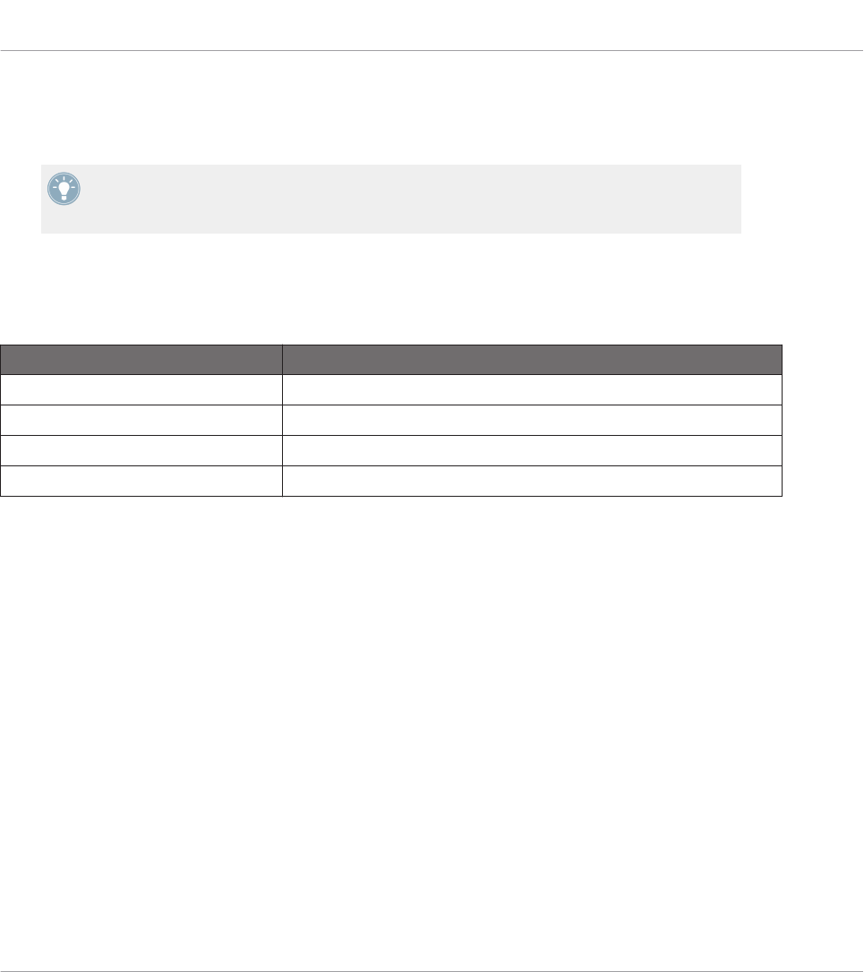
• The Group buttons, labeled A to H, are not assignable if you use the Pad Page feature —
they’re used for selecting Pad Pages, see previous section. If you deactivate the Pad Pa-
ges, the Group buttons are freely assignable like any other.
You can also split the controls of your controller between MIDI mode and MASCHINE mode
in order to control a MASCHINE plug-in instance while sending MIDI messages to the host
with the transport controls! See ↑23.5.1, Templates Pane for more information.
Assignment Parameters
The following table summarizes where to find all assignment details for each type of control
element on your controller:
Type of Control Element Assignment Parameters
Buttons ↑23.6.2, Assignments for Buttons
Pads – Hit action ↑23.6.4, Assignments for the Pads – Hit Action
Pads – Press action ↑23.6.6, Assignments for the Pads – Press Action
Knobs ↑23.6.8, Assignments for Analog Encoders
5.3 Visual Feedback on Your Controller
The fast bidirectional communication between your MASCHINE controller and the Hardware
Service on the software side allows status indications on your controller to be made in real
time.
Your MASCHINE controller provides you visual feedback in various ways:
• All buttons and pads are equipped with LEDs that inform you about the assignment state
of the control element at any time.
• The displays show you additional information about the assignments.
5.3.1 Buttons
The LEDs below each button can have three states: off, dimmed and bright. Their lighting be-
havior depends on the type and state of the control element.
The following table indicates you the possible states for the LEDs:
Using Your MASCHINE Controller
Visual Feedback on Your Controller
CONTROLLER EDITOR - Manual - 57

Button State LED State
Not assigned Off
Assigned – Off state Dimmed
Assigned – On state Bright
For buttons in Increment mode, the Off state corresponds to the zero value, while the On
state corresponds to a value greater than zero. See section ↑23.6.2, Assignments for But-
tons for more information on the various button modes.
Controlling the Button State
The On/Off state of each button can be controlled in two ways — internally via your actions on
the button, or remotely via MIDI feedback:
• In Toggle mode, both controls are enabled: both your actions on the button and the possi-
bly incoming MIDI messages are taken into account to update the button and LED state.
• In Trigger, Gate, and Increment mode, you can choose which control mode (internal or re-
mote via MIDI) you want to use. This is done via the LED On menu in the Assign pane of
the Inspector.
For more information on the button modes, LED On menu, and MIDI feedback mode, see
↑23.6.2, Assignments for Buttons.
Moreover, for the Buttons 1–8 above the displays, the particular assignment is shown within
the displays in Knobs display mode (see section ↑5.4.2, Knobs Display Mode).
5.3.2 Pads
Here are the rules for the pads. Since the pads have two functions (they are pressure-sensi-
tive), the states are indicated as follows:
• If the pad is not assigned, it is off.
• If there is an assignment for the Hit action, the pad’s LED behaves like that of a button
(see previous section).
Using Your MASCHINE Controller
Visual Feedback on Your Controller
CONTROLLER EDITOR - Manual - 58
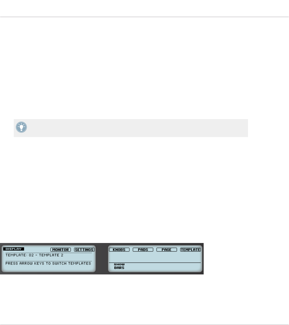
• If the Hit action is not assigned but the Press action is assigned to the Note message
type, the LED has a low brightness to show the Off state and a high brightness to show
the On state. For all other message types, the LED stays at low brightness.
5.3.3 Knobs
The assignments for the eight Knobs under the displays are indicated within the displays in
Knobs display mode. If a Knob is not assigned, the display reads “OFF.”
The VOLUME, TEMPO and SWING knobs in the MASTER area have no display, but, like for all
other controls, their value is shown in the displays in the Event line of the Monitor display
mode.
For more information on the various display modes on your MASCHINE controller, see next
section.
5.4 The Displays
The displays on your MASCHINE controller can show different parts of your mapping configu-
ration, depending on the display mode that is activated. Each display mode modifies the behav-
ior of Buttons 1–8 above the displays and Knobs 1–8 below them. Learn more about the differ-
ent display modes available for the MASCHINE controller in the following sections.
5.4.1 Switching Between Display Modes
First of all, to switch between display modes, press the SHIFT button on your MASCHINE con-
troller and hold it. On the displays, you see something like this:
The displays on your MASCHINE controller in MIDI mode, when the SHIFT button is depressed.
Using Your MASCHINE Controller
Visual Feedback on Your Controller
CONTROLLER EDITOR - Manual - 59

This screen allows you to select the desired display mode. On the top, you find six fields repre-
senting the six display modes, from left to right: MONITOR, SETTINGS, KNOBS, PADS, PAGE, and TEM-
PLATE.
►To switch to any of the display modes, hold the SHIFT button and press the correspond-
ing Button 3–8 above the displays.
At any time, you can press the SHIFT button again and switch to another display mode.
In the middle part of the left display, you see the name of the current Template. This is com-
mon to all display modes (except the Settings display mode), so that you can always be sure
about which Template is currently selected.
Below, a message reminds you that you can switch to another Template simply by pressing the
Page buttons, since you are already holding SHIFT (see ↑5.1, Basic Controls).
5.4.2 Knobs Display Mode
The Knobs display mode is probably the one you will use the most. In this mode, the displays
show the currently loaded Knob Page, with its eight button assignments on the top row and its
eight knob assignments on the bottom row:
The Knobs display mode mirrors the currently loaded Knob Page.
This display mode allows you to see which MIDI message is currently assigned to each control
element in the loaded Knob Page. In this mode, the 16 control elements around the displays
(Buttons 1–8 above and Knobs 1–8 below) trigger the MIDI messages assigned to them.
Each field mirrors the Label Field as defined in the Inspector’s Assign pane for the correspond-
ing control element: the name you defined there appears here — if you haven’t defined any
name for that control element yet, its label is simply its assigned MIDI message.
In the lower row, the displays additionally show the current value for each Knob. These values
can be displayed in two views: either via numerical values (like in the picture above), or via
small bars:
Using Your MASCHINE Controller
The Displays
CONTROLLER EDITOR - Manual - 60

The Knobs display mode with bars instead of numerical values.
You can switch between the two views by holding the SHIFT button and turning Knob 5:
1. Hold SHIFT (thus getting to the switching screen explained ↑5.4.1, Switching Between
Display Modes).
You can see the option “SHOW BARS” or “SHOW VALUES” above Knob 5 (depending on which
view is currently selected).
2. Turn Knob 5 to select the desired view.
3. Release SHIFT.
→The new view is displayed.
Note that depending on the assignment properties for each of the Knobs, its displayed value
(or bar) can either be going from 0 to 127 or from -63 to 64 (bipolar) — this second setting
can be useful for some types of controls (e.g. a stereo balance). This only affects the value/bar
shown on the displays — the real MIDI value will go from 0 to 127 anyway. Please refer to
section ↑23.6.8, Assignments for Analog Encoders for more information on this.
5.4.3 Pad Pages Display Mode
The Pad Pages display mode (labeled “PADS” on the displays) allows you to check the current
assignations for the pads of your MASCHINE controller, by mirroring the current Pad Page:
The Pad Pages display mode mirrors the Pad Page currently loaded.
On the left display, you find some general information about the loaded Template, Knob Page
and Pad Page. The right display summarizes the pads’ assignments stored in the active Pad
Page.
Using Your MASCHINE Controller
The Displays
CONTROLLER EDITOR - Manual - 61

5.4.4 Knob Pages Display Mode
The Knob Pages display mode allows you to switch between Knob Pages:
The Knob Pages display mode allows you to switch between Knob Pages.
On the left display, you find the usual general information about the currently loaded Tem-
plate, Knob Page and Pad Page.
On the right display, you see the list of your Knob Pages, as defined in the Knob Pages list of
the Inspector’s Pages pane.
1. Use Buttons 5 and 6 above the up and down arrows to scroll through the list and find the
Knob Page you wish to load next. You can also turn Knob 5.
2. When you have it, press Button 8 (“LOAD”) to load the selected Knob Page.
Actually, this functionality is already available in many ways: in the Controller Editor, you can
use the Knob Page menu (in the Hardware area) or the Knob Pages list (in the Inspector’s
Pages pane), and on the MASCHINE controller you have the Page buttons at your disposal. But
the Knob Pages display mode allows you a greater control over the Knob Page selection from
the MASCHINE controller:
• Unlike the Knob Page menu and Knob Pages list, you don’t have to open the Controller
Editor to switch to another Knob Page.
• Unlike the Page buttons on your controller, you can quietly choose the next Knob Page to
be loaded, even if it’s not the one right after/before the Knob Page currently loaded. You
can check its name to remember its assignments, and you can scroll the entire list to find
the page you want.
When you reach the end of a list while scrolling, you can choose whether the selection has
to jump at the other end of the list or stay on this last item. This can be set in Preferences
> General > Wrap Template and Page Lists.
Using Your MASCHINE Controller
The Displays
CONTROLLER EDITOR - Manual - 62

5.4.5 Template Display Mode
The Template display mode allows you to switch between Templates.
The Template display mode allows you to switch between Templates.
On the left display, you find the same general information about the Template, Knob Page and
Pad Page currently loaded.
On the right display, you see the list of your Templates, as defined in the Inspector’s Tem-
plates pane.
1. Use Button 5 and 6 above the up and down arrows to scroll through the list and find the
Template you wish to load next. You can also turn Knob 5.
2. When you have it, press Button 8 (“LOAD”) to load the selected Template.
Like for the Knob Pages, this functionality is already available in many ways: in the Controller
Editor you can use the Template list (in the Inspector’s Templates pane), and on the MA-
SCHINE controller you can press SHIFT + Page buttons. The Template display mode allows
you a greater control over the Template selection from your controller though, for the reasons
explained as those explained in the previous section for the Knob Pages.
5.4.6 Monitor Display Mode
The Monitor display mode provides you with useful information about the MIDI data sent by
your MASCHINE controller.
The Monitor display mode provides information about the MIDI data sent by your MASCHINE controller.
Using Your MASCHINE Controller
The Displays
CONTROLLER EDITOR - Manual - 63
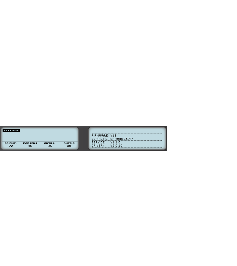
The left display shows the usual information about the current Template, Knob Page and Pad
Page.
The right display shows two lines:
• The Control line indicates the control element that you are currently actuating.
• The Event line shows the details of the MIDI event being currently sent by this control el-
ement.
This display mode is very useful to monitor what’s going out of your controller, for example for
debugging purpose: if something goes wrong somewhere in your MIDI chain, you can check
here what is actually sent by your MASCHINE controller.
5.4.7 Settings Display Mode
The Settings display mode allows you to adjust relevant parameters and provides information
about your MASCHINE controller.
The Settings display mode provides access to parameters for your MASCHINE controller.
The settings are grouped in the left display. They are the same as in File > Preferences > Con-
troller (when the MASCHINE controller is selected in the Controller menu at the top, of
course). The settings are:
•Brightness: Changes the backlight of the displays.
•Pad Sensitivity: Changes the sensitivity of the pads.
•Contrast L: Sets the contrast for the left display.
•Contrast R: Sets the contrast for the right display.
The right display provides you with some important information about your MASCHINE control-
ler and the Hardware Service:
• In the upper part, you find the firmware version of your MASCHINE controller along with
its serial number.
Using Your MASCHINE Controller
The Displays
CONTROLLER EDITOR - Manual - 64

• In the bottom part of the display, you see the version numbers of the NI Hardware Service
and hardware drivers.
Using Your MASCHINE Controller
The Displays
CONTROLLER EDITOR - Manual - 65

6 Using Your MASCHINE MK2 Controller
In this chapter, we will focus on what’s happening on your MASCHINE MK2 controller. By
reading this, you will learn:
• How to use the basic controls on your controller for navigating through the MIDI mapping
system.
• The list of all assignable control elements on your controller.
• How the various luminous elements give you some important information about their
state.
• How to use the powerful displays of your MASCHINE MK2 controller in MIDI mode.
To enjoy full functionality of your NI controller as a MIDI remote control, especially con-
cerning some control elements’ state and LED behavior, you need to tell your NI controller
what is the current state of the parameter in the MIDI target. You can do this by setting up
MIDI feedback channels coming from your MIDI target back to your NI controller. This way,
your controller will always stay up-to-date with the current parameter values in your target
software/hardware. For more information on how to configure these MIDI feedback chan-
nels, please refer to your target software/hardware’s documentation.
6.1 Basic Controls
This section shows you the commands available on your MASCHINE MK2 controller for basic
tasks: switching between MIDI mode and MASCHINE mode, and selecting sets (Templates)
and subsets (Knob Pages, Pad Pages) of MIDI assignments.
All these actions can of course be done via the Controller Editor user interface — see chap-
ter ↑3, Quick Start for example. Nevertheless, using your NI controller instead can be very
handy in a live situation!
Using Your MASCHINE MK2 Controller
Basic Controls
CONTROLLER EDITOR - Manual - 66
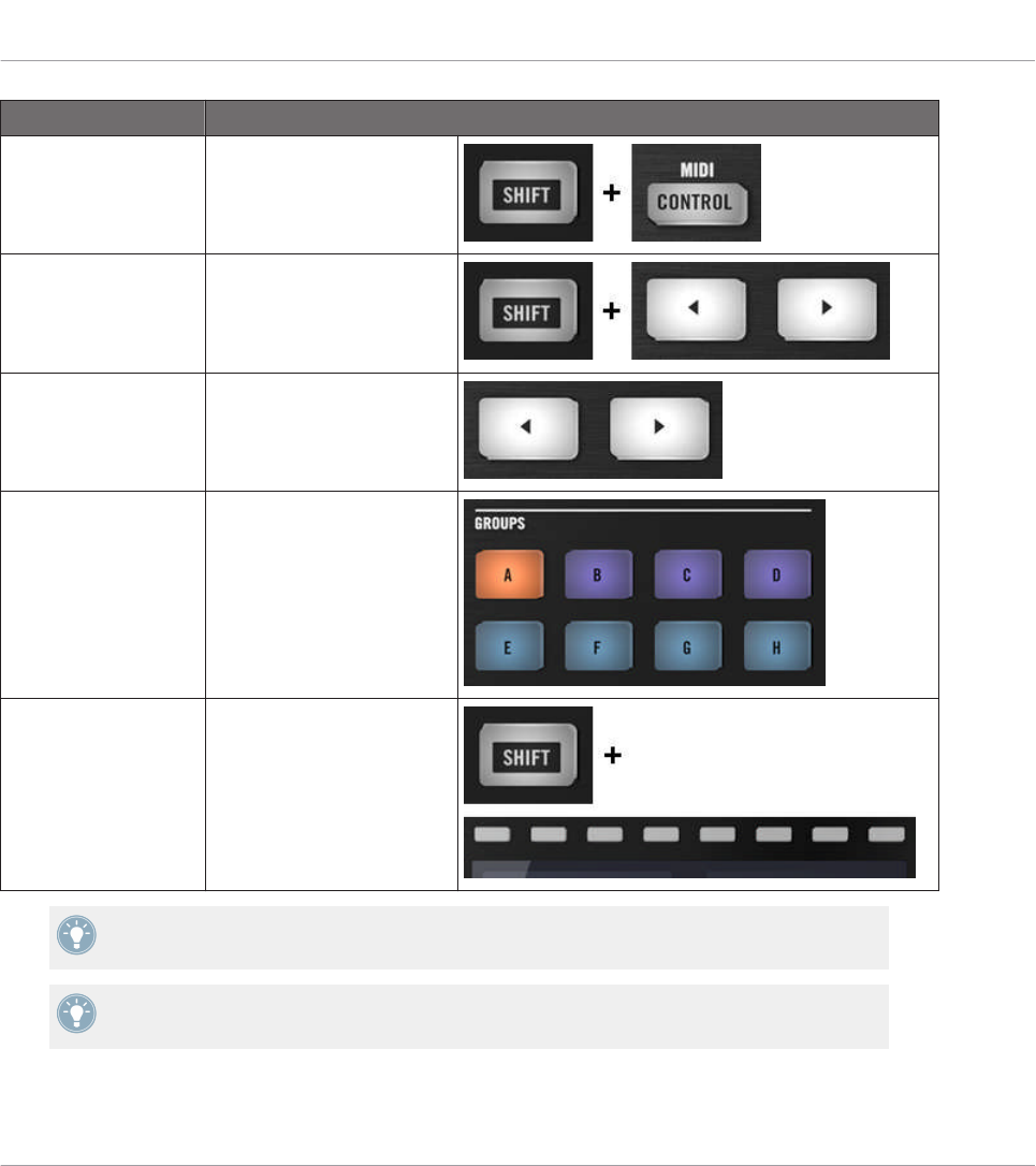
Selection Command
MIDI/MASCHINE
mode
SHIFT + CONTROL
Templates SHIFT + Page buttons
Knob Pages Page buttons
Pad Pages
(if activated)
Group buttons
Display mode SHIFT + Buttons 3–8
For more information on Templates, Knob Pages, and Pad Pages, see ↑4.3, The Mapping
System.
For more information on the display modes, see ↑6.4, The Displays. There you will also
learn another way to select and load Templates and Knob Pages from your controller.
When your MASCHINE MK2 controller is in MIDI mode, its SHIFT button is dimly lit.
Using Your MASCHINE MK2 Controller
Basic Controls
CONTROLLER EDITOR - Manual - 67

Adjusting Settings for your Controller
You can adjust various settings for your MASCHINE MK2 controller by entering its Settings
display mode or by going to File > Preferences > Controller. See ↑6.4.6, Settings Display Mode
for more information.
6.2 Assignable Control Elements
If you selected the MASCHINE MK2 controller in the Device menu of the Application Control
Bar, this is what the Hardware area looks like:
Using Your MASCHINE MK2 Controller
Assignable Control Elements
CONTROLLER EDITOR - Manual - 68
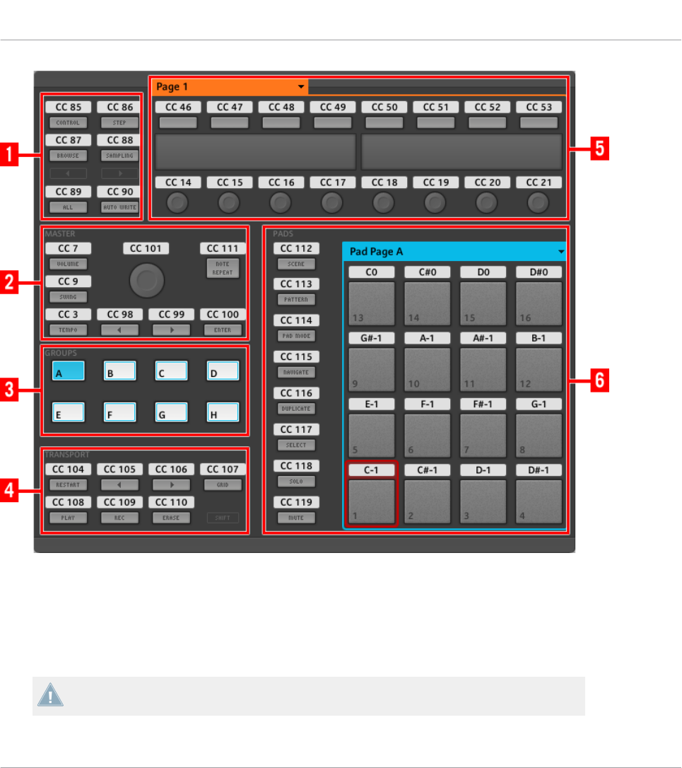
The Hardware area representing the MASCHINE MK2 controller.
In this Hardware area, you will notice the Knob Page menu and its associated Knob Page area
(orange frame), the Pad Page menu and its associated Pad Page area (blue frame), and the red
Selection Frame on the currently selected control element (pad 1 in the picture above).
The MASCHINE MK2 controller holds the following areas:
The names that you see on the device only refer to their original function in the MASCHINE
software. We use these names here only to describe the interface!
Using Your MASCHINE MK2 Controller
Assignable Control Elements
CONTROLLER EDITOR - Manual - 69
(1) Page buttons and buttons around: In the top left part, you find a set of eight buttons arranged
into four rows of two buttons. From these eight buttons, six are freely assignable (CONTROL
and STEP, BROWSE and SAMPLING, ALL, and AUTO WR.) and two have special functions:
the left and right Page buttons (see previous section).
(2) MASTER area: The MASTER area holds eight freely assignable control elements (seven but-
tons and the Control encoder).
(3) GROUPS area: The GROUPS area contains eight buttons labeled from A to H: the Group but-
tons. If you activated the Pad Pages button in the Pages pane of the Inspector, these buttons
allow you to select the desired page of assignments for the pads (see ↑4.3.3, Pad Pages (MA-
SCHINE Controller Family Only)). If you didn’t activate the Pad Pages, these eight buttons are
freely assignable to MIDI events.
(4) TRANSPORT area: The TRANSPORT area contains eight buttons. Seven of them are freely
assignable: RESTART, Previous, Next, GRID, PLAY, REC, and ERASE. The last one, SHIFT, is
a special button (see previous section). Therefore, this button cannot be assigned in the Con-
troller Editor.
(5) Knob Page area: The Knob Page area holds a set of eight buttons and eight knobs, with the
buttons being placed above and the knobs below the two displays, respectively. These sixteen
control elements are freely assignable. The Knob Page area is indicated by an orange frame
and headed by the Knob Page menu.
The buttons and knobs in the Knob Page area can also have other functions according to
the display mode that is currently active. See ↑6.4, The Displays for more on this.
(6) PADS area: The PADS area shows a column of eight freely assignable buttons (namely
SCENE, PATTERN, PAD MODE, NAVIGATE, DUPLICATE, SELECT, SOLO, and MUTE) as well
as a square of sixteen freely assignable pads. If you activated the Enable Pad Pages button in
the Pages pane of the Inspector, a Pad Page area (indicated by the blue frame) groups the
pads together and is headed by the Pad Page menu.
To Sum Up…
All control elements on your MASCHINE MK2 controller are freely assignable to MIDI events
(with the limitations due to the type of control element), with the following exceptions:
• The Page buttons and the SHIFT button have a predefined function (see previous sec-
tion).
Using Your MASCHINE MK2 Controller
Assignable Control Elements
CONTROLLER EDITOR - Manual - 70

• The Group buttons, labeled A to H, are not assignable if you use the Pad Page feature —
they’re used for selecting Pad Pages, see previous section. If you deactivate the Pad Pa-
ges, the Group buttons are freely assignable like any other.
You can also split the controls of your controller between MIDI mode and MASCHINE mode
in order to control a MASCHINE plug-in instance while sending MIDI messages to the host
with the transport controls! See ↑23.5.1, Templates Pane for more information.
Assignment Parameters
The following table summarizes where to find all assignment details for each type of control
element on your controller:
Type of Control Element Assignment Parameters
Buttons ↑23.6.2, Assignments for Buttons
Pads – Hit action ↑23.6.4, Assignments for the Pads – Hit Action
Pads – Press action ↑23.6.6, Assignments for the Pads – Press Action
Knobs 1–8 ↑23.6.8, Assignments for Analog Encoders
Control encoder – Push action ↑23.6.2, Assignments for Buttons
Control encoder – Turn action ↑23.6.7, Assignments for Digital Encoders
6.3 Visual Feedback on Your Controller
The fast bidirectional communication between your MASCHINE MK2 controller and the Hard-
ware Service on the software side allows status indications on your controller to be made in
real time.
Your MASCHINE MK2 controller provides you visual feedback in various ways:
• All buttons and pads are equipped with LEDs that inform you about their assignment
state at any time. Furthermore, the 16 pads and 8 Group buttons provide RGB LEDs.
• The displays show you additional information about the assignments.
Using Your MASCHINE MK2 Controller
Visual Feedback on Your Controller
CONTROLLER EDITOR - Manual - 71
6.3.1 Buttons
Basically, each button on your controller can have three states:
• Not assigned.
• Assigned, in Off state.
• Assigned, in On state.
The following paragraphs describe how the LED under each button keeps you informed on the
button states.
Single-Color Buttons
For all buttons except the Group buttons, the LEDs can have three states: off, dimmed and
bright. All are white except for the PLAY button (green) and the REC button (red). The LED
states directly indicate the button states:
Button State LED State
Not assigned Off
Assigned – Off state Dimmed
Assigned – On state Bright
For buttons in Increment mode, the Off state corresponds to the zero value, while the On
state corresponds to a value greater than zero. See section ↑23.6.2, Assignments for But-
tons for more information on the various button modes.
Multicolor Buttons
The eight Group buttons of your controller are equipped with RGB LEDs. This by far extends
the monitoring possibilities of these control elements. Their lighting behavior directly depends
on whether the Pad Pages are enabled or not.
• Pad Pages enabled: Each Group button mirrors the color defined for its Pad Page (the
Color setting for Pad Pages is described in ↑23.5.3, Assign Pane). All Group buttons are
dimmed except the button corresponding to the selected Pad Page.
• Pad Pages disabled: The Group buttons can be freely assigned. For each of them, you can
choose which from the 16 available colors should be used for the On and Off states.
Using Your MASCHINE MK2 Controller
Visual Feedback on Your Controller
CONTROLLER EDITOR - Manual - 72

With Pad Pages disabled, the Group buttons offer you three Color modes:
• Single mode: You can choose a color that will be used bright and dimmed for the On and
Off states, respectively. In this mode, the button’s lighting behaves like that of single-col-
or buttons (see table above).
• Dual mode: You can choose a color for the On state and another color for the Off state.
Both colors will be used at full brightness.
• HSB mode: This mode is only available when the button’s state is controlled via MIDI
feedback (see below). In HSB mode, you can precisely define from within your MIDI tar-
get which color the button will use.
Controlling the Button State
The On/Off state of each single-color or multicolor button can be controlled in two ways — in-
ternally via your actions on the button, or remotely via MIDI feedback:
• In Toggle mode, both controls are enabled: both your actions on the button and the possi-
bly incoming MIDI messages are taken into account to update the button and LED state.
• In Trigger, Gate, and Increment mode, you can choose which control mode (internal or re-
mote via MIDI) you want to use. This is done via the LED On menu in the Assign pane of
the Inspector.
For more information on the button modes, LED On menu, and MIDI feedback mode, see
↑23.6.2, Assignments for Buttons.
Moreover, for the Buttons 1–8 above the displays, the particular assignment is shown within
the displays in Knobs display mode (see section ↑6.4.2, Knobs Display Mode).
6.3.2 Multicolor Pads
The sixteen pads of your controller are equipped with RGB LEDs. Their lighting behavior is
close to that of multicolor buttons — but since the pads have two functions (Hit and Press),
their states are indicated as follows:
• If the pad is not assigned, it is off.
• If there is an assignment for the Hit action, the pad’s LED behaves like that of a multicol-
or Group button (see previous section).
Using Your MASCHINE MK2 Controller
Visual Feedback on Your Controller
CONTROLLER EDITOR - Manual - 73
• If the Hit action is not assigned but the Press action is assigned to the Note message
type, the LED has a low brightness to show the Off state and a high brightness to show
the On state. For all other message types, the LED stays at low brightness.
6.3.3 Knobs
The assignments for the eight Knobs under the displays are indicated within the displays in
Knobs display mode. If a Knob is not assigned, the display reads “OFF.”
For more information on the various display modes on your MASCHINE MK2 controller, see
section ↑6.4, The Displays.
6.3.4 Control Encoder
The Control encoder has no direct visual feedback, but like all other controls its assignment
and value are indicated on the right display when the displays are in Monitor display mode. If
the Control encoder is not assigned, the display reads “NONE.”
For more information on the various display modes on your MASCHINE MK2 controller, see
next section.
6.4 The Displays
The displays on your MASCHINE MK2 controller can show different parts of your mapping con-
figuration, depending on the display mode that is activated. Each display mode modifies the
behavior of Buttons 1–8 above the displays and Knobs 1–8 below them. Learn more about the
different display modes available on the MASCHINE MK2 controller in the following sections.
6.4.1 Switching Between Display Modes
First of all, to switch between display modes, press the SHIFT button on your MASCHINE MK2
controller and hold it. On the displays, you see something like this:
Using Your MASCHINE MK2 Controller
Visual Feedback on Your Controller
CONTROLLER EDITOR - Manual - 74
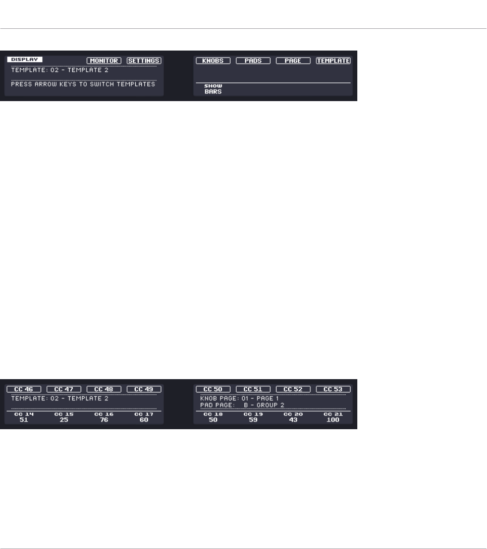
The displays on your MASCHINE MK2 controller in MIDI mode, when the SHIFT button is depressed.
This screen allows you to select the desired display mode. On the top, you find six fields repre-
senting the six display modes, from left to right: MONITOR, SETTINGS, KNOBS, PADS, PAGE, and TEM-
PLATE.
►To switch to any of the display modes, hold the SHIFT button and press the correspond-
ing Button 3–8 above the displays.
At any time, you can press the SHIFT button again and switch to another display mode.
In the middle part of the left display, you see the name of the current Template. This is com-
mon to all display modes (except the Settings display mode), so that you can always be sure
about which Template is currently selected.
Below, a message reminds you that you can switch to another Template simply by pressing the
Page buttons, since you are already holding SHIFT (see ↑6.1, Basic Controls).
6.4.2 Knobs Display Mode
The Knobs display mode is probably the one you will use the most. In this mode, the displays
show the currently loaded Knob Page, with its eight button assignments on the top row and its
eight knob assignments on the bottom row:
The Knobs display mode mirrors the currently loaded Knob Page.
This display mode allows you to see which MIDI message is currently assigned to each control
element in the loaded Knob Page. In this mode, the 16 control elements around the displays
(Buttons 1–8 above and Knobs 1–8 below) trigger the MIDI messages assigned to them.
Using Your MASCHINE MK2 Controller
The Displays
CONTROLLER EDITOR - Manual - 75

Each field mirrors the Label Field as defined in the Inspector’s Assign pane for the correspond-
ing control element: the name you defined there appears here — if you haven’t defined any
name for that control element yet, its label is simply its assigned MIDI message.
In the lower row, the displays additionally show the current value for each Knob. These values
can be displayed in two views: either via numerical values (like in the picture above), or via
small bars:
The Knobs display mode with bars instead of numerical values.
You can switch between the two views by holding the SHIFT button and turning Knob 5:
1. Hold SHIFT (thus getting to the switching screen explained in ↑6.4.1, Switching Between
Display Modes).
You can see the option “SHOW BARS” or “SHOW VALUES” above Knob 5 (depending on which
view is currently selected).
2. Turn Knob 5 to select the desired view.
3. Release SHIFT.
→The new view is displayed.
Note that depending on the assignment properties for each of the Knobs, its displayed value
(or bar) can either be going from 0 to 127 or from -63 to 64 (bipolar) — this second setting
can be useful for some types of controls (e.g. a stereo balance). This only affects the value/bar
shown on the displays — the real MIDI value will go from 0 to 127 anyway. Please refer to
section ↑23.6.8, Assignments for Analog Encoders for more information on this.
6.4.3 Pad Pages Display Mode
The Pad Pages display mode (labeled “PADS” on the displays) allows you to check the current
assignations for the pads of your MASCHINE MK2 controller, by mirroring the current Pad
Page:
Using Your MASCHINE MK2 Controller
The Displays
CONTROLLER EDITOR - Manual - 76
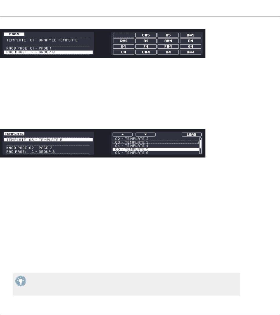
The Pad Pages display mode mirrors the Pad Page currently loaded.
On the left display, you find some general information about the loaded Template, Knob Page
and Pad Page. The right display summarizes the pads’ assignments stored in the active Pad
Page.
6.4.4 Template Display Mode
The Template display mode allows you to switch between Templates.
The Template display mode allows you to switch between Templates.
On the left display, you find the same general information about the Template, Knob Page and
Pad Page currently loaded.
On the right display, you see the list of your Templates, as defined in the Inspector’s Tem-
plates pane.
1. Use Button 5 and 6 above the up and down arrows to scroll through the list and find the
Template you wish to load next. You can also turn Knob 5 or the Control encoder.
2. When you have it, press Button 8 (“LOAD”) to load the selected Template.
Like for the Knob Pages, this functionality is already available in many ways: in the Controller
Editor you can use the Template list (in the Inspector’s Templates pane), and on the MA-
SCHINE MK2 controller you can press SHIFT + Page buttons. The Template display mode al-
lows you a greater control over the Template selection from your controller though, for the rea-
sons already explained in the previous section for the Knob Pages.
When you reach the end of the list, you can choose whether the selection has to jump to
the other list end or stay on this last item. This can be set in Preferences > General > Wrap
Template and Page Lists.
Using Your MASCHINE MK2 Controller
The Displays
CONTROLLER EDITOR - Manual - 77
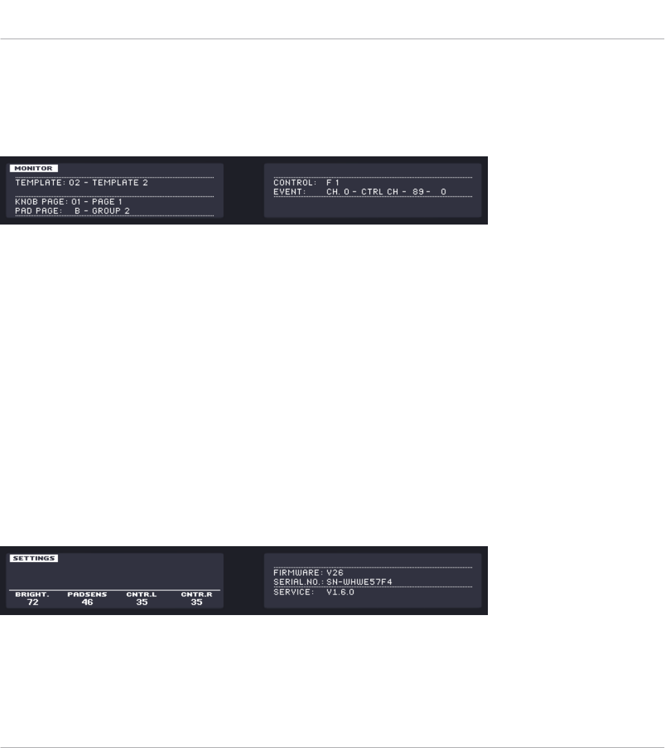
6.4.5 Monitor Display Mode
The Monitor display mode provides you with useful information about the MIDI data sent by
your MASCHINE MK2 controller.
The Monitor display mode provides information about the MIDI data sent by your MASCHINE MK2 controller.
The left display shows the usual information about the current Template, Knob Page and Pad
Page.
The right display shows two lines:
• The Control line indicates the control element that you are currently actuating.
• The Event line shows the details of the MIDI event being currently sent by this control el-
ement.
This display mode is very useful to monitor what’s going out of your controller, for example for
debugging purpose: if something goes wrong somewhere in your MIDI chain, you can check
here what is actually sent by your MASCHINE MK2 controller.
6.4.6 Settings Display Mode
The Settings display mode allows you to adjust relevant parameters and provides information
about your MASCHINE MK2 controller.
The Settings display mode provides access to parameters for your MASCHINE MK2 controller.
The settings are grouped in the left display. They are the same as in File > Preferences > Con-
troller (when the MASCHINE MK2 controller is selected in the Controller menu at the top, of
course). The settings are:
Using Your MASCHINE MK2 Controller
The Displays
CONTROLLER EDITOR - Manual - 78

•Brightness: Changes the backlight of the displays.
•Pad Sensitivity: Changes the sensitivity of the pads.
•Contrast L: Sets the contrast for the left display.
•Contrast R: Sets the contrast for the right display.
The right display provides you with some important information about your MASCHINE MK2
controller and the Hardware Service:
• In the upper part, you find the firmware version of your MASCHINE MK2 controller along
with its serial number.
• Below, you see the version numbers of the NI Hardware Service and hardware drivers.
Using Your MASCHINE MK2 Controller
The Displays
CONTROLLER EDITOR - Manual - 79
7 Using Your MASCHINE MIKRO Controller
In this chapter, we will focus on what’s happening on your MASCHINE MIKRO controller. By
reading this, you will learn:
• How to use the basic controls on your controller for navigating through the MIDI mapping
system.
• The list of all assignable control elements on your controller.
• How the various luminous elements give you some important information about their
state.
• How to use the powerful display of your MASCHINE MIKRO controller in MIDI mode.
To enjoy full functionality of your NI controller as a MIDI remote control, especially con-
cerning some control elements’ state and LED behavior, you need to tell your NI controller
what is the current state of the parameter in the MIDI target. You can do this by setting up
MIDI feedback channels coming from your MIDI target back to your NI controller. This way,
your controller will always stay up-to-date with the current parameter values in your target
software/hardware. For more information on how to configure these MIDI feedback chan-
nels, please refer to your target software/hardware’s documentation.
7.1 Basic Controls
This section shows you the commands available on your MASCHINE MIKRO controller for ba-
sic tasks: switching between MIDI mode and MASCHINE mode, and selecting sets (Templates)
and subsets (Knob Pages, Pad Pages) of MIDI assignments.
All these actions can of course be done via the Controller Editor user interface — see chap-
ter ↑3, Quick Start for example. Nevertheless, using your NI controller instead can be very
handy in a live situation!
Using Your MASCHINE MIKRO Controller
Basic Controls
CONTROLLER EDITOR - Manual - 80
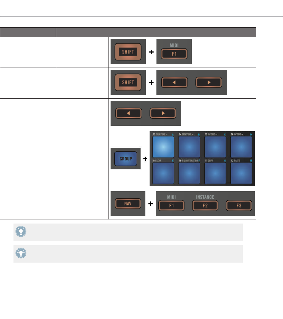
Selection Command
MIDI/MASCHINE
mode
SHIFT + F1
Templates SHIFT + Left/Right
Arrow buttons
Knob Pages Left/Right Arrow but-
tons
Pad Pages
(if activated)
GROUP + pads 9–16
Display mode NAV + F1–F3
For more information on Templates, Knob Pages, and Pad Pages, see ↑4.3, The Mapping
System.
For more information on the display modes, see ↑7.4, The Display.
When your MASCHINE MIKRO controller is in MIDI mode, its SHIFT button is dimly lit.
Using Your MASCHINE MIKRO Controller
Basic Controls
CONTROLLER EDITOR - Manual - 81
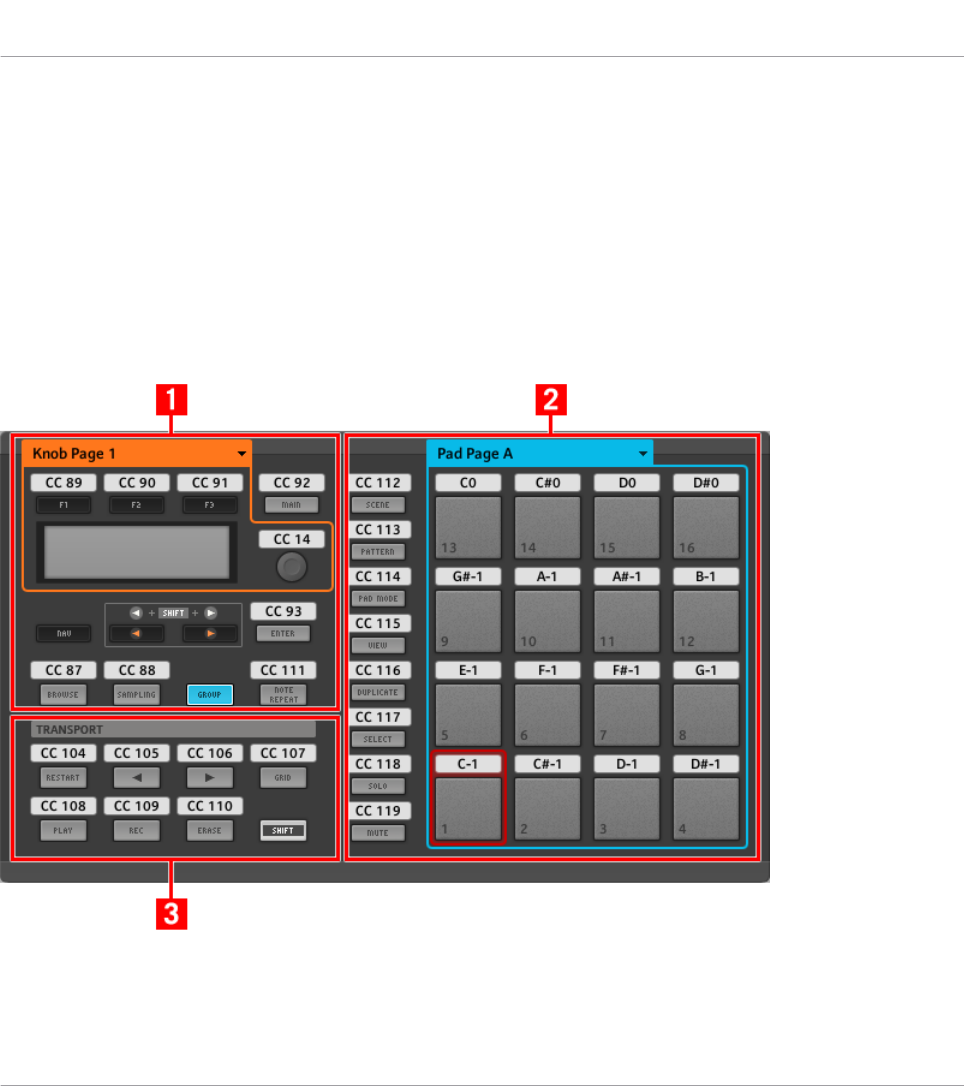
Adjusting Settings for your Controller
You can adjust various settings for your MASCHINE MIKRO controller by entering its Setup
display mode or by going to File > Preferences > Controller. See ↑7.4.4, Setup Display Mode
for more information.
7.2 Assignable Control Elements
If you selected the MASCHINE MIKRO controller in the Device menu of the Application Con-
trol Bar, this is what the Hardware area looks like:
The Hardware area representing the MASCHINE MIKRO controller.
Using Your MASCHINE MIKRO Controller
Assignable Control Elements
CONTROLLER EDITOR - Manual - 82
In this Hardware area, you will notice the Knob Page menu and its associated Knob Page area
(orange frame), the Pad Page menu and its associated Pad Page area (blue frame), and the red
Selection Frame on the currently selected control element (pad 1 in the picture above).
The MASCHINE MIKRO controller holds the following areas:
The names that you see on the device only refer to their original function in the MASCHINE
software. We use these names here only to describe the interface!
(1) CONTROL area: In the top left part, twelve buttons and the Control encoder are arranged
around the display. From these control elements, eight buttons are freely assignable (F1, F2,
F3, MAIN, ENTER, BROWSE, SAMPLING, and NOTE REPEAT) as well as the Control encoder.
The remaining four buttons (NAV, Left/Right Arrow, and GROUP) have special functions (see
previous section).
The CONTROL area also holds the Knob Page area, indicated by an orange frame and headed
by the Knob Page menu. The Knob Page area includes the F1, F2, and F3 buttons along with
the Control encoder.
The control elements in the Knob Page area can also have other functions according to the
display mode that is currently active. This is also the case for the ENTER button. See ↑7.4,
The Display for more on this.
If the Pad Page feature is deactivated, the GROUP button becomes freely assignable as
well.
(2) PADS area: The PADS area shows a column of eight freely assignable buttons (namely
SCENE, PATTERN, PAD MODE, VIEW, DUPLICATE, SELECT, SOLO, and MUTE) as well as a
square of sixteen freely assignable pads. If you activated the Enable Pad Pages button in the
Pages pane of the Inspector, a Pad Page area (indicated by the blue frame) groups the pads
together and is headed by the Pad Page menu.
(3) TRANSPORT area: The TRANSPORT area contains eight buttons. All of them are freely as-
signable except the last one, SHIFT, which has a special function (see previous section).
To Sum Up…
All control elements on your MASCHINE MIKRO controller are freely assignable to MIDI events
(with the limitations due to the type of control element), with the following exceptions:
Using Your MASCHINE MIKRO Controller
Assignable Control Elements
CONTROLLER EDITOR - Manual - 83
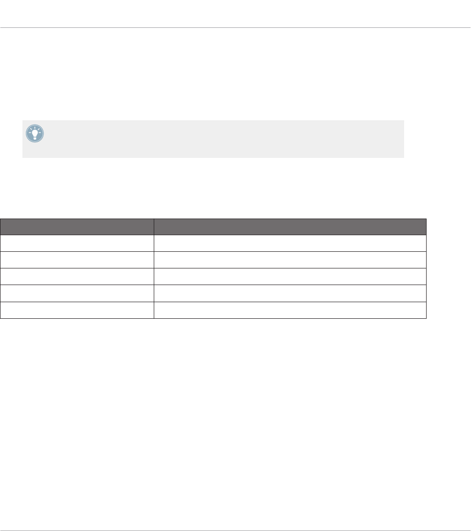
• The NAV, Left/Right Arrow and SHIFT buttons have a predefined function (see ↑7.1, Ba-
sic Controls).
• The GROUP button is not assignable if you use the Pad Page feature — it is used for se-
lecting Pad Pages (see ↑7.1, Basic Controls). If you deactivate the Pad Pages, the GROUP
button is freely assignable like any other button.
You can also split the controls of your controller between MIDI mode and MASCHINE mode
in order to control a MASCHINE plug-in instance while sending MIDI messages to the host
with the transport controls! See ↑23.5.1, Templates Pane for more information.
Assignment Parameters
The following table summarizes where to find all assignment details for each type of control
element on your controller:
Type of Control Element Assignment Parameters
Buttons ↑23.6.2, Assignments for Buttons
Pads – Hit action ↑23.6.4, Assignments for the Pads – Hit Action
Pads – Press action ↑23.6.6, Assignments for the Pads – Press Action
Control encoder – Push action ↑23.6.2, Assignments for Buttons
Control encoder – Turn action ↑23.6.7, Assignments for Digital Encoders
7.3 Visual Feedback on Your Controller
The fast bidirectional communication between your MASCHINE MIKRO controller and the
Hardware Service on the software side allows status indications on your controller to be made
in real time.
Your MASCHINE MIKRO controller provides you visual feedback in various ways:
• All buttons and pads are equipped with LEDs that inform you about the assignment state
of the control element at any time.
• The display shows you additional information about the assignments.
Using Your MASCHINE MIKRO Controller
Visual Feedback on Your Controller
CONTROLLER EDITOR - Manual - 84
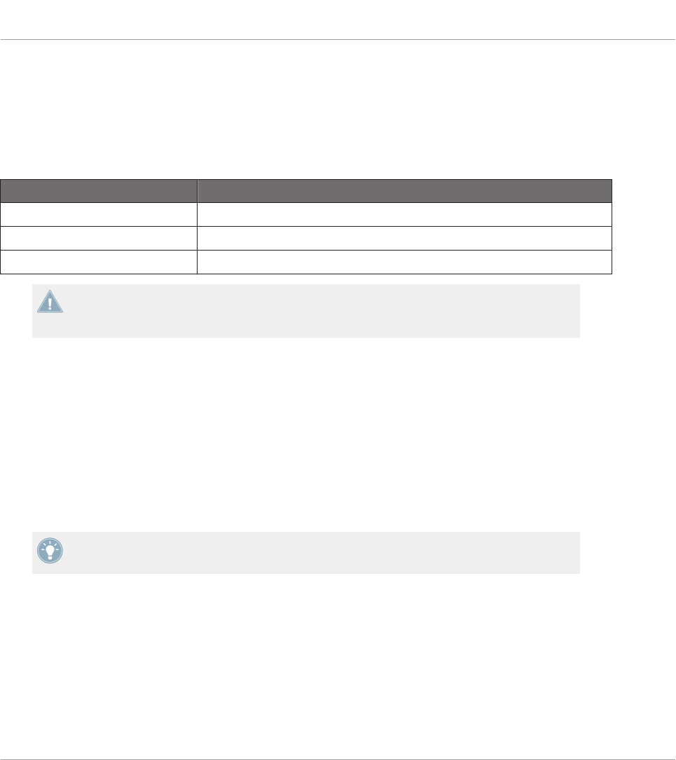
7.3.1 Buttons
The LEDs below each button can have three states: off, dimmed and bright. Their lighting be-
havior depends on the type and state of the control element.
The LED states directly indicate the button states:
Button State LED State
Not assigned Off
Assigned – Off state Dimmed
Assigned – On state Bright
For buttons in Increment mode, the Off state corresponds to the zero value, while the On
state corresponds to a value greater than zero. See section ↑23.6.2, Assignments for But-
tons for more information on the various button modes.
Controlling the Button State
The On/Off state of each button can be controlled in two ways — internally via your actions on
the button, or remotely via MIDI feedback:
• In Toggle mode, both controls are enabled: both your actions on the button and the possi-
bly incoming MIDI messages are taken into account to update the button and LED state.
• In Trigger, Gate, and Increment mode, you can choose which control mode (internal or re-
mote via MIDI) you want to use. This is done via the LED On menu in the Assign pane of
the Inspector.
For more information on the button modes, LED On menu, and MIDI feedback mode, see
↑23.6.2, Assignments for Buttons.
Moreover, for the F1–F3 buttons and for the Control encoder, the particular assignment is
shown within the display in Control display mode (see section ↑7.4.2, Control Display Mode).
7.3.2 Pads
Here are the rules for the pads. Since the pads have two functions (they are pressure-sensi-
tive), the states are indicated as follows:
Using Your MASCHINE MIKRO Controller
Visual Feedback on Your Controller
CONTROLLER EDITOR - Manual - 85
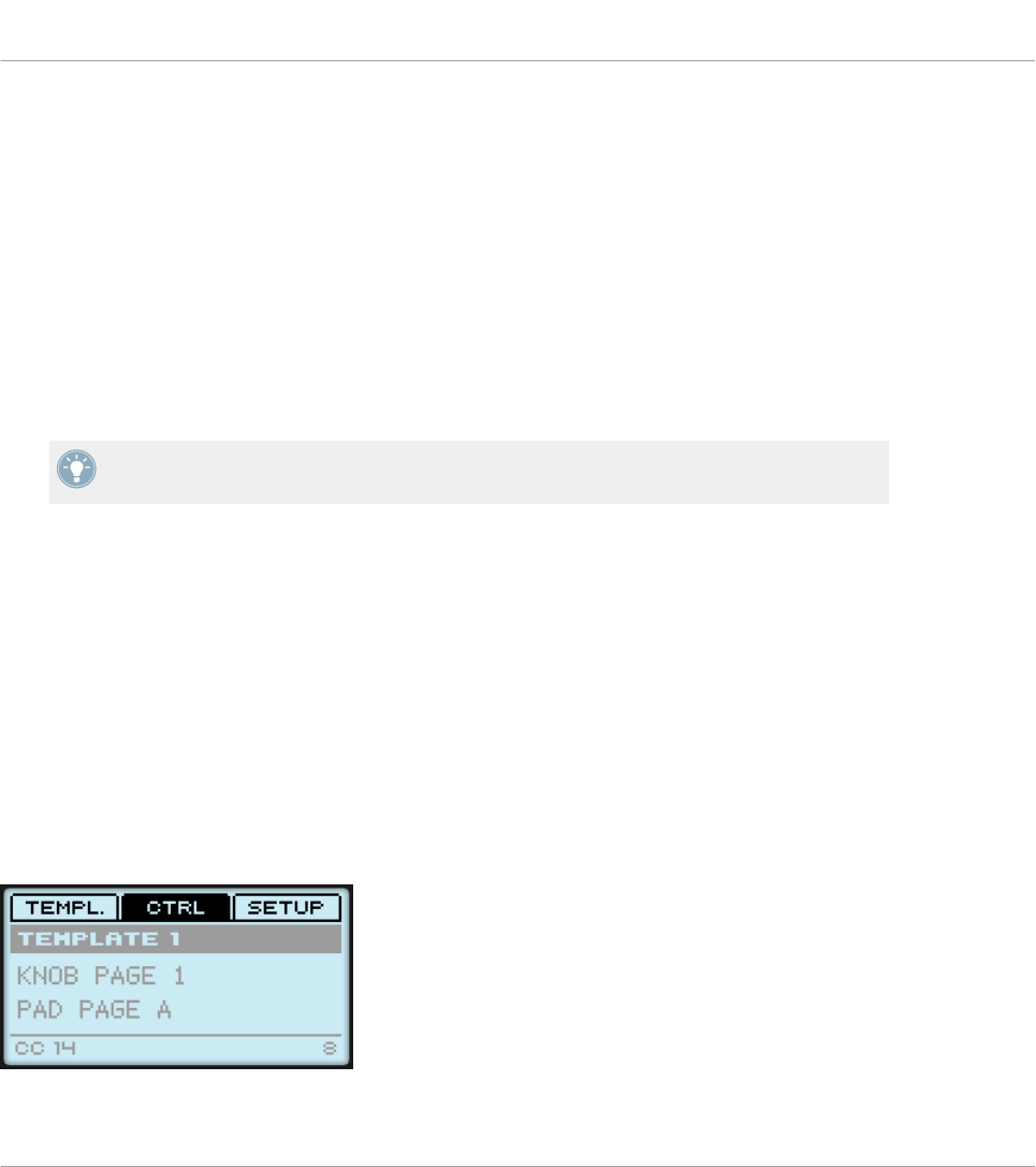
• If the pad is not assigned, it is off.
• If there is an assignment for the Hit action, the pad’s LED behaves like that of a button
(see previous section).
• If the Hit action is not assigned but the Press action is assigned to the Note message
type, the LED has a low brightness to show the Off state and a high brightness to show
the On state. For all other message types, the LED stays at low brightness.
7.3.3 Control Encoder
The assignment for the Control encoder is indicated within the display in Control display mode.
If the knob is not assigned and you didn’t change its default label, the display reads “OFF.”
For more information on the various display modes on your MASCHINE MIKRO controller,
see next section.
7.4 The Display
The display on your MASCHINE MIKRO controller can show different parts of your mapping
configuration, depending on the display mode that is activated. Learn more about the different
display modes available for the MASCHINE MIKRO controller’s display in the following sec-
tions.
7.4.1 Switching Between Display Modes
First of all, to switch between display modes, press the NAV button on your MASCHINE MIK-
RO controller and hold it. At the top of the display, you see three tabs:
The three tabs at the top of the display on your MASCHINE MIKRO controller when NAV is hold depressed.
Using Your MASCHINE MIKRO Controller
Visual Feedback on Your Controller
CONTROLLER EDITOR - Manual - 86
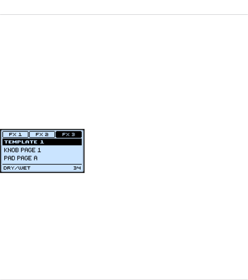
These tabs allow you to select the desired display mode from the three modes available: Tem-
plate, Control, and Setup:
►To switch to any of the display modes, hold the NAV button and press the desired F1–F3
button above the display.
At any time, you can press the NAV button again and switch to another display mode.
7.4.2 Control Display Mode
The Control display mode is probably the one you will use the most.
►To switch to the Control display mode, press NAV + F2.
In this mode, the display shows the assignments for the currently loaded Knob Page, with its
three button assignments on the top row for the F1–F3 buttons, and its Control encoder as-
signment on the bottom row:
The Control display mode mirrors the loaded Knob Page.
In this mode, the F1–F3 buttons and the Control encoder trigger their assigned MIDI messag-
es.
Each field mirrors the Label Field as defined in the Inspector’s Assign pane for the correspond-
ing control element: the name you defined there appears here — if you haven’t defined any
name yet for that control element, its label is simply its assigned MIDI message.
In the middle of the display, you can see the Template, Knob Page and (possibly) Pad Page
that are currently active. You can switch these at any time using the usual shortcuts (see ↑7.1,
Basic Controls).
Using Your MASCHINE MIKRO Controller
The Display
CONTROLLER EDITOR - Manual - 87
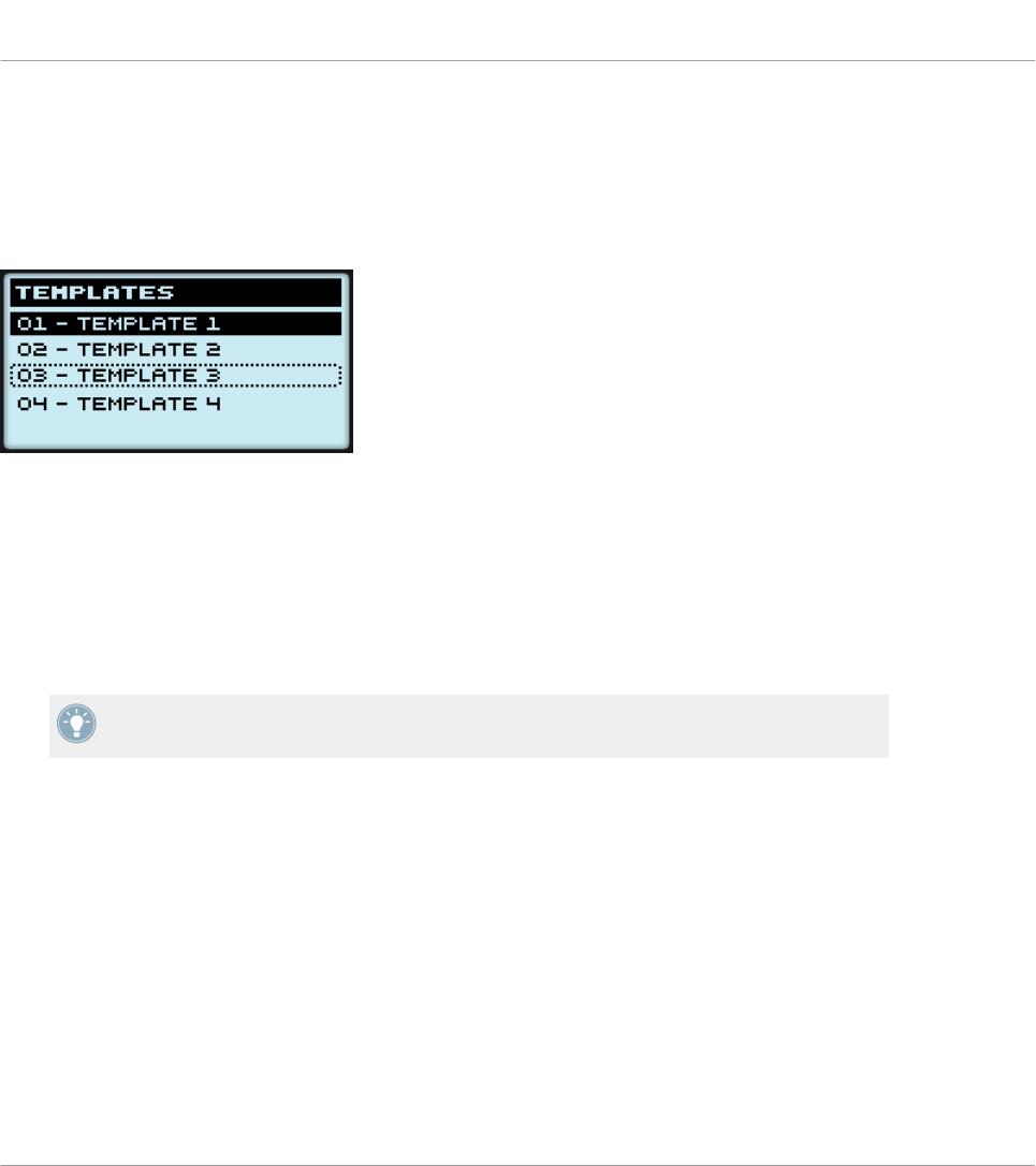
7.4.3 Template Display Mode
The Template display mode allows you to switch between Templates.
►To switch to the Template display mode, press NAV + F1.
The Template display mode gives you a greater control over Template switching.
In this mode, you see the list of your Templates as defined in the Inspector’s Templates pane.
The active Template is highlighted.
1. Turn the Control encoder to scroll through the list and find the Template you wish to load
next.
The selected Template is indicated by a dotted frame.
2. When you have it, press the Control encoder to load the selected Template.
Instead of the Control encoder, you can also use the Left/Right Arrow buttons to select an-
other Template, then the ENTER button to load it.
This functionality is already available in many ways: in the Controller Editor you can use the
Template list (in the Inspector’s Templates pane), and on the MASCHINE MIKRO controller
you have the shortcut SHIFT + Left/Right Arrow at your disposal. The Template display mode,
though, allows you a greater control over the Template selection from your controller:
• Unlike the Template list in the Controller Editor interface, you don’t have to open the
Controller Editor to switch to another Template.
• Unlike using the shortcut SHIFT + Left/Right Arrow on your controller, you can quietly
choose the next Template to be loaded, even if it’s not the one right after/before the Tem-
plate currently loaded. You can check its name to remember its assignments, and you can
scroll the entire list to find the Template you want.
Using Your MASCHINE MIKRO Controller
The Display
CONTROLLER EDITOR - Manual - 88
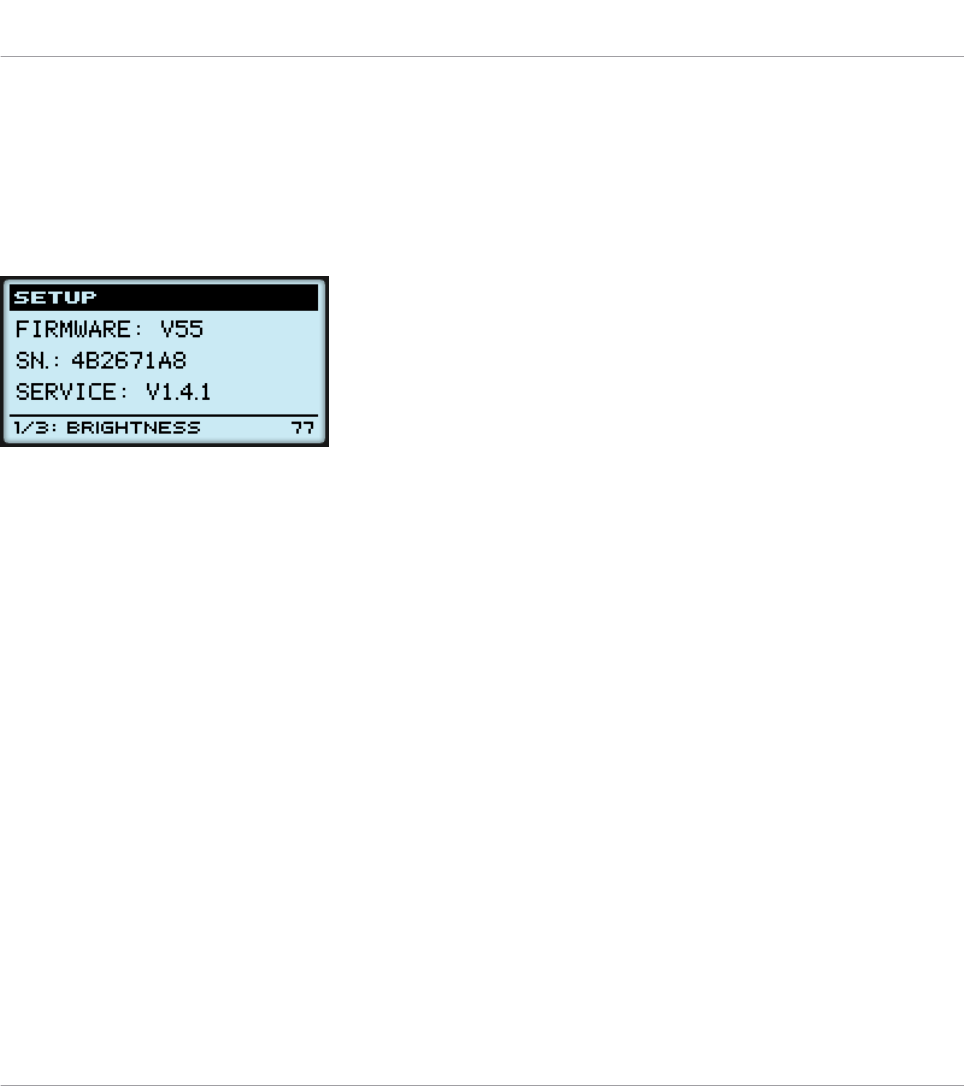
7.4.4 Setup Display Mode
The Setup display mode allows you to adjust relevant parameters and provides information
about your MASCHINE MIKRO controller.
►To switch to the Setup display mode, press NAV + F3.
The Setup display mode provides access to parameters for your MASCHINE MIKRO controller.
The settings appear on the bottom row of the display:
1. Press the Left/Right Arrow buttons repeatedly to scroll through the available settings.
2. Turn the Control encoder to change the value for a particular setting.
The settings are the same as in File > Preferences > Controller (when the MASCHINE MIKRO
controller is selected in the Controller menu at the top, of course). These are:
•Brightness: Adjusts the brightness of the display.
•Contrast: Adjusts the contrast of the display.
•Pad Sensitivity: Changes the sensitivity of the pads.
The middle part of the display provides you with some important information about your MA-
SCHINE MIKRO controller and the Hardware Service:
• In the upper part, you find the firmware version of your MASCHINE MIKRO controller
along with its serial number.
• Below, you see the version number of the NI Hardware Service.
Using Your MASCHINE MIKRO Controller
The Display
CONTROLLER EDITOR - Manual - 89
8 Using Your MASCHINE MIKRO MK2 Controller
In this chapter, we will focus on what’s happening on your MASCHINE MIKRO MK2 controller.
By reading this, you will learn:
• How to use the basic controls on your controller for navigating through the MIDI mapping
system.
• The list of all assignable control elements on your controller.
• How the various luminous elements give you some important information about their
state.
• How to use the powerful display of your MASCHINE MIKRO MK2 controller in MIDI
mode.
To enjoy full functionality of your NI controller as a MIDI remote control, especially con-
cerning some control elements’ state and LED behavior, you need to tell your NI controller
what is the current state of the parameter in the MIDI target. You can do this by setting up
MIDI feedback channels coming from your MIDI target back to your NI controller. This way,
your controller will always stay up-to-date with the current parameter values in your target
software/hardware. For more information on how to configure these MIDI feedback chan-
nels, please refer to your target software/hardware’s documentation.
8.1 Basic Controls
This section shows you the commands available on your MASCHINE MIKRO MK2 controller for
basic tasks: switching between MIDI mode and MASCHINE mode, and selecting sets (Tem-
plates) and subsets (Knob Pages, Pad Pages) of MIDI assignments.
All these actions can of course be done via the Controller Editor user interface — see chap-
ter ↑3, Quick Start for example. Nevertheless, using your NI controller instead can be very
handy in a live situation!
Using Your MASCHINE MIKRO MK2 Controller
Basic Controls
CONTROLLER EDITOR - Manual - 90
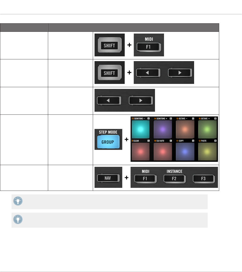
Selection Command
MIDI/MASCHINE
mode
SHIFT + F1
Templates SHIFT + Left/Right
Arrow buttons
Knob Pages Left/Right Arrow but-
tons
Pad Pages
(if activated)
GROUP + pads 9–16
Display mode NAV + F1–F3
For more information on Templates, Knob Pages, and Pad Pages, see ↑4.3, The Mapping
System.
For more information on the display modes, see ↑8.4, The Display.
When your MASCHINE MIKRO MK2 controller is in MIDI mode, its SHIFT button is dimly lit.
Using Your MASCHINE MIKRO MK2 Controller
Basic Controls
CONTROLLER EDITOR - Manual - 91

Adjusting Settings for your Controller
You can adjust various settings for your MASCHINE MIKRO MK2 controller by entering its Set-
up display mode or by going to File > Preferences > Controller. See ↑8.4.4, Setup Display
Mode for more information.
8.2 Assignable Control Elements
If you selected the MASCHINE MIKRO MK2 controller in the Device menu of the Application
Control Bar, this is what the Hardware area looks like:
The Hardware area representing the MASCHINE MIKRO MK2 controller.
Using Your MASCHINE MIKRO MK2 Controller
Assignable Control Elements
CONTROLLER EDITOR - Manual - 92
In this Hardware area, you will notice the Knob Page menu and its associated Knob Page area
(orange frame), the Pad Page menu and its associated Pad Page area (blue frame), and the red
Selection Frame on the currently selected control element (pad 11 in the picture above).
The MASCHINE MIKRO MK2 controller holds the following areas:
The names that you see on the device only refer to their original function in the MASCHINE
software. We use these names here only to describe the interface!
(1) CONTROL area: In the top left part, twelve buttons and the Control encoder are arranged
around the display. From these control elements, eight buttons are freely assignable (F1, F2,
F3, CONTROL, MAIN, BROWSE, SAMPLING, and NOTE REPEAT) as well as the Control en-
coder. The remaining four buttons (NAV, Left/Right Arrow, and GROUP) have special functions
(see previous section).
The CONTROL area also holds the Knob Page area, indicated by an orange frame and headed
by the Knob Page menu. The Knob Page area includes the F1, F2, and F3 buttons along with
the Control encoder.
The control elements in the Knob Page area can also have other functions according to the
display mode that is currently active. See ↑8.4, The Display for more on this.
If the Pad Page feature is deactivated, the GROUP button becomes freely assignable as
well.
(2) PADS area: The PADS area shows a column of eight freely assignable buttons (namely
SCENE, PATTERN, PAD MODE, VIEW, DUPLICATE, SELECT, SOLO, and MUTE) as well as a
square of sixteen freely assignable pads. If you activated the Enable Pad Pages button in the
Pages pane of the Inspector, a Pad Page area (indicated by the blue frame) groups the pads
together and is headed by the Pad Page menu.
(3) TRANSPORT area: The TRANSPORT area contains eight buttons. All of them are freely as-
signable except the last one, SHIFT, which has a special function (see previous section).
To Sum Up…
All control elements on your MASCHINE MIKRO MK2 controller are freely assignable to MIDI
events (with the limitations due to the type of control element), with the following exceptions:
• The NAV, Left/Right Arrow and SHIFT buttons have a predefined function (see ↑7.1, Ba-
sic Controls).
Using Your MASCHINE MIKRO MK2 Controller
Assignable Control Elements
CONTROLLER EDITOR - Manual - 93

• The GROUP button is not assignable if you use the Pad Page feature — it is used for se-
lecting Pad Pages (see ↑8.1, Basic Controls). If you deactivate the Pad Pages, the GROUP
button is freely assignable like any other button.
You can also split the controls of your controller between MIDI mode and MASCHINE mode
in order to control a MASCHINE plug-in instance while sending MIDI messages to the host
with the transport controls! See ↑23.5.1, Templates Pane for more information.
Assignment Parameters
The following table summarizes where to find all assignment details for each type of control
element on your controller:
Type of Control Element Assignment Parameters
Buttons ↑23.6.2, Assignments for Buttons
Pads – Hit action ↑23.6.4, Assignments for the Pads – Hit Action
Pads – Press action ↑23.6.6, Assignments for the Pads – Press Action
Control encoder – Push action ↑23.6.2, Assignments for Buttons
Control encoder – Turn action ↑23.6.7, Assignments for Digital Encoders
8.3 Visual Feedback on Your Controller
The fast bidirectional communication between your MASCHINE MIKRO MK2 controller and
the Hardware Service on the software side allows status indications on your controller to be
made in real time.
Your MASCHINE MIKRO MK2 controller provides you visual feedback in various ways:
• All buttons and pads are equipped with LEDs that inform you about their assignment at
any time. Furthermore, the 16 pads and the GROUP button provide RGB LEDs.
• The display shows you additional information about the assignments.
8.3.1 Buttons
Basically, each button on your controller can have three states:
Using Your MASCHINE MIKRO MK2 Controller
Visual Feedback on Your Controller
CONTROLLER EDITOR - Manual - 94
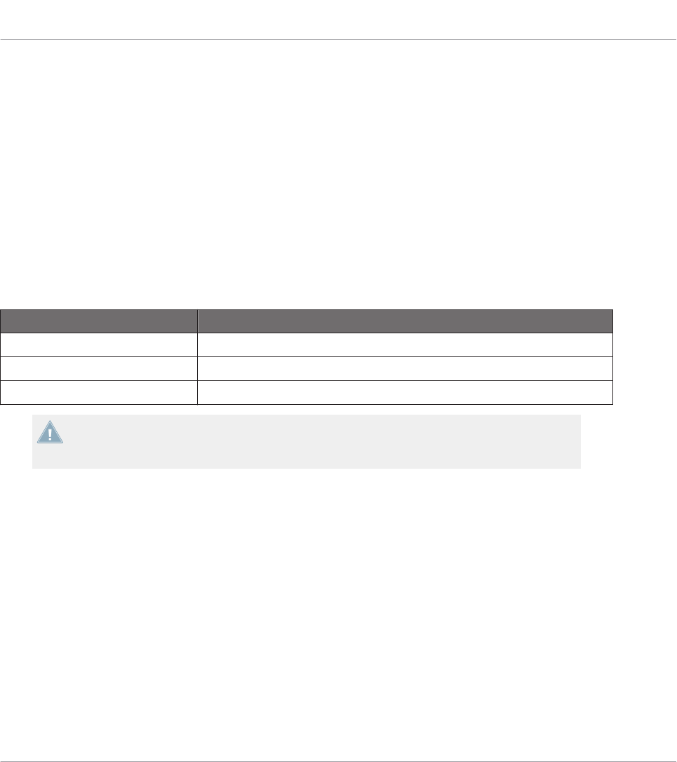
• Not assigned.
• Assigned, in Off state.
• Assigned, in On state.
The following paragraphs describe how the LED under each button keeps you informed on the
button states.
Single-Color Buttons
For all buttons except the GROUP button, the LEDs below each button can have three states:
off, dimmed and bright. All are white except for the PLAY button (green) and the REC button
(red).
The LED states directly indicate the button states:
Button State LED State
Not assigned Off
Assigned – Off state Dimmed
Assigned – On state Bright
For buttons in Increment mode, the Off state corresponds to the zero value, while the On
state corresponds to a value greater than zero. See section ↑23.6.2, Assignments for But-
tons for more information on the various button modes.
GROUP Button
The GROUP button of your controller is equipped with a RGB LED. This by far extends the
monitoring possibilities of this button. Its lighting behavior directly depends on whether the
Pad Pages are enabled or not.
• Pad Pages enabled: The GROUP button mirrors the color defined for its Pad Page (the
Color setting for Pad Pages is described in ↑23.5.3, Assign Pane).
• Pad Pages disabled: The GROUP button can be freely assigned, and you can choose
which from the 16 available colors should be used for its On and Off states.
With Pad Pages disabled, the GROUP button offer you three Color modes:
Using Your MASCHINE MIKRO MK2 Controller
Visual Feedback on Your Controller
CONTROLLER EDITOR - Manual - 95
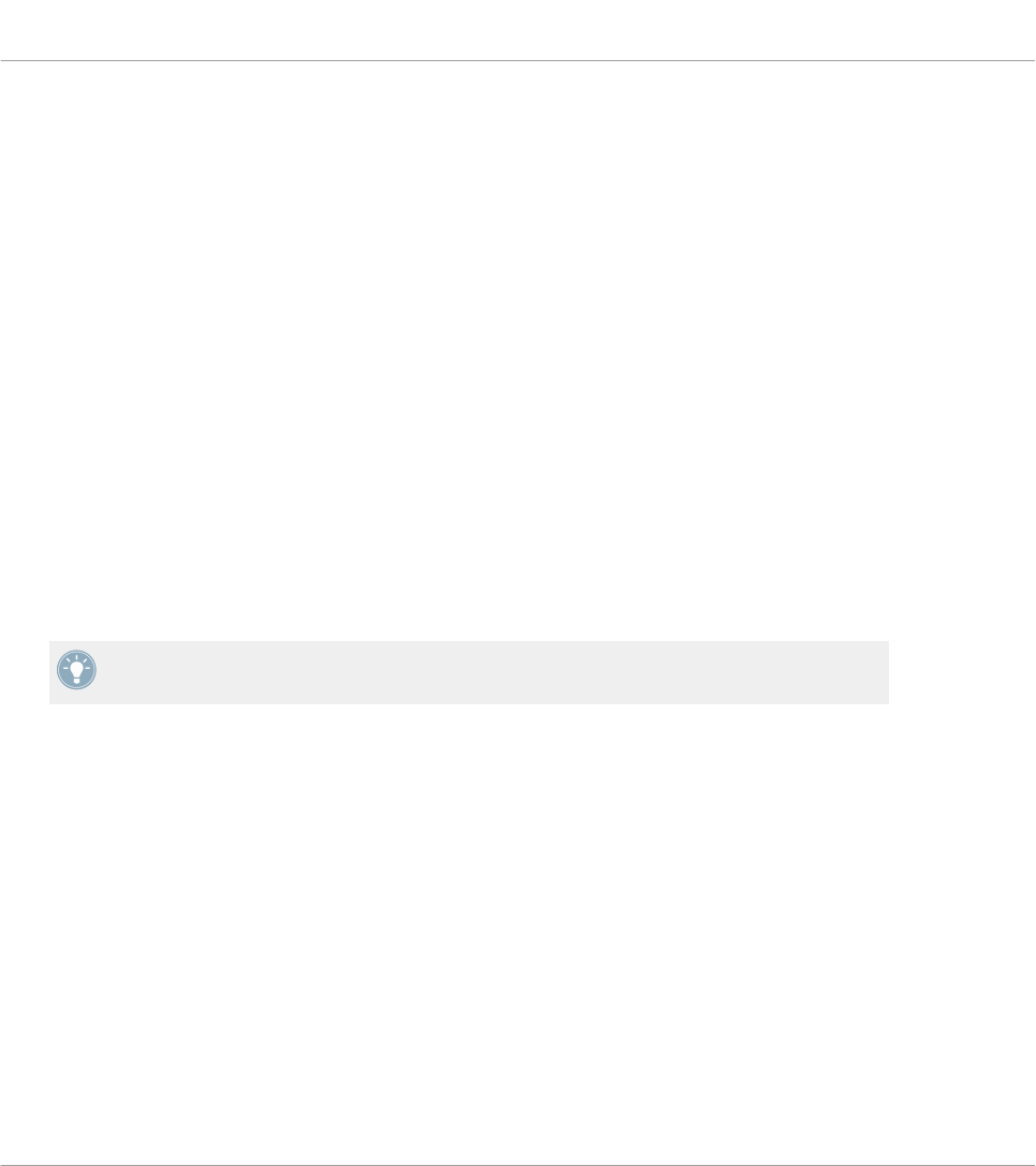
• Single mode: You can choose a color that will be used bright and dimmed for the On and
Off states, respectively. In this mode, the button’s lighting behaves like the single-color
buttons described above.
• Dual mode: You can choose a color for the On state and another color for the Off state.
Both colors will be used at full brightness.
• HSB mode: This mode is only available when the button’s state is controlled via MIDI
feedback (see below). In HSB mode, you can precisely define from within your MIDI tar-
get which color the button will use.
Controlling the Button State
The On/Off state of each button can be controlled in two ways — internally via your actions on
the button, or remotely via MIDI feedback:
• In Toggle mode, both controls are enabled: both your actions on the button and the possi-
bly incoming MIDI messages are taken into account to update the button and LED state.
• In Trigger, Gate, and Increment mode, you can choose which control mode (internal or re-
mote via MIDI) you want to use. This is done via the LED On menu in the Assign pane of
the Inspector.
For more information on the button modes, LED On menu, and MIDI feedback mode, see
↑23.6.2, Assignments for Buttons.
Moreover, for the F1–F3 buttons, the particular assignment is shown within the display in Con-
trol display mode (see section ↑8.4.2, Control Display Mode).
8.3.2 Multicolor Pads
The sixteen pads of your controller are equipped with RGB LEDs. Their lighting behavior is
close to that of the GROUP button — but since the pads have two functions (Hit and Press),
their states are indicated as follows:
• If the pad is not assigned, it is off.
• If there is an assignment for the Hit action, the pad’s LED behaves like that of a multicol-
or Group button (see previous section).
Using Your MASCHINE MIKRO MK2 Controller
Visual Feedback on Your Controller
CONTROLLER EDITOR - Manual - 96
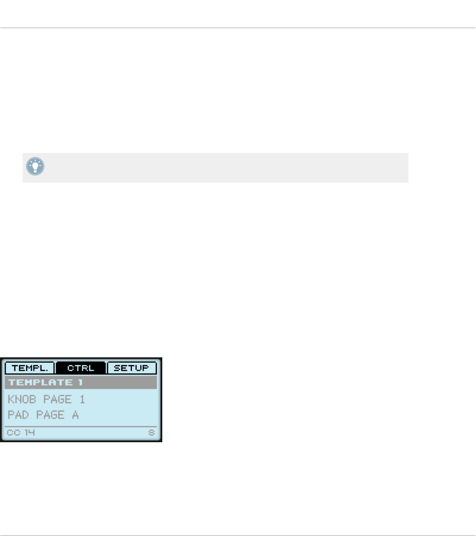
• If the Hit action is not assigned but the Press action is assigned to the Note message
type, the LED has a low brightness to show the Off state and a high brightness to show
the On state. For all other message types, the LED stays at low brightness.
8.3.3 Control Encoder
The assignment for the Control encoder is indicated within the display in Control display mode.
If the knob is not assigned and you didn’t change its default label, the display reads “OFF.”
For more information on the various display modes on your MASCHINE MIKRO MK2 con-
troller, see next section.
8.4 The Display
The display on your MASCHINE MIKRO MK2 controller can show different parts of your map-
ping configuration, depending on the display mode that is activated. Learn more about the dif-
ferent display modes available for the MASCHINE MIKRO MK2 controller’s display in the fol-
lowing sections.
8.4.1 Switching Between Display Modes
First of all, to switch between display modes, press the NAV button on your MASCHINE MIK-
RO MK2 controller and hold it. At the top of the display, you see three tabs:
The three tabs at the top of the display on your MASCHINE MIKRO MK2 controller when NAV is hold depressed.
These tabs allow you to select the desired display mode from the three modes available: Tem-
plate, Control, and Setup:
Using Your MASCHINE MIKRO MK2 Controller
Visual Feedback on Your Controller
CONTROLLER EDITOR - Manual - 97
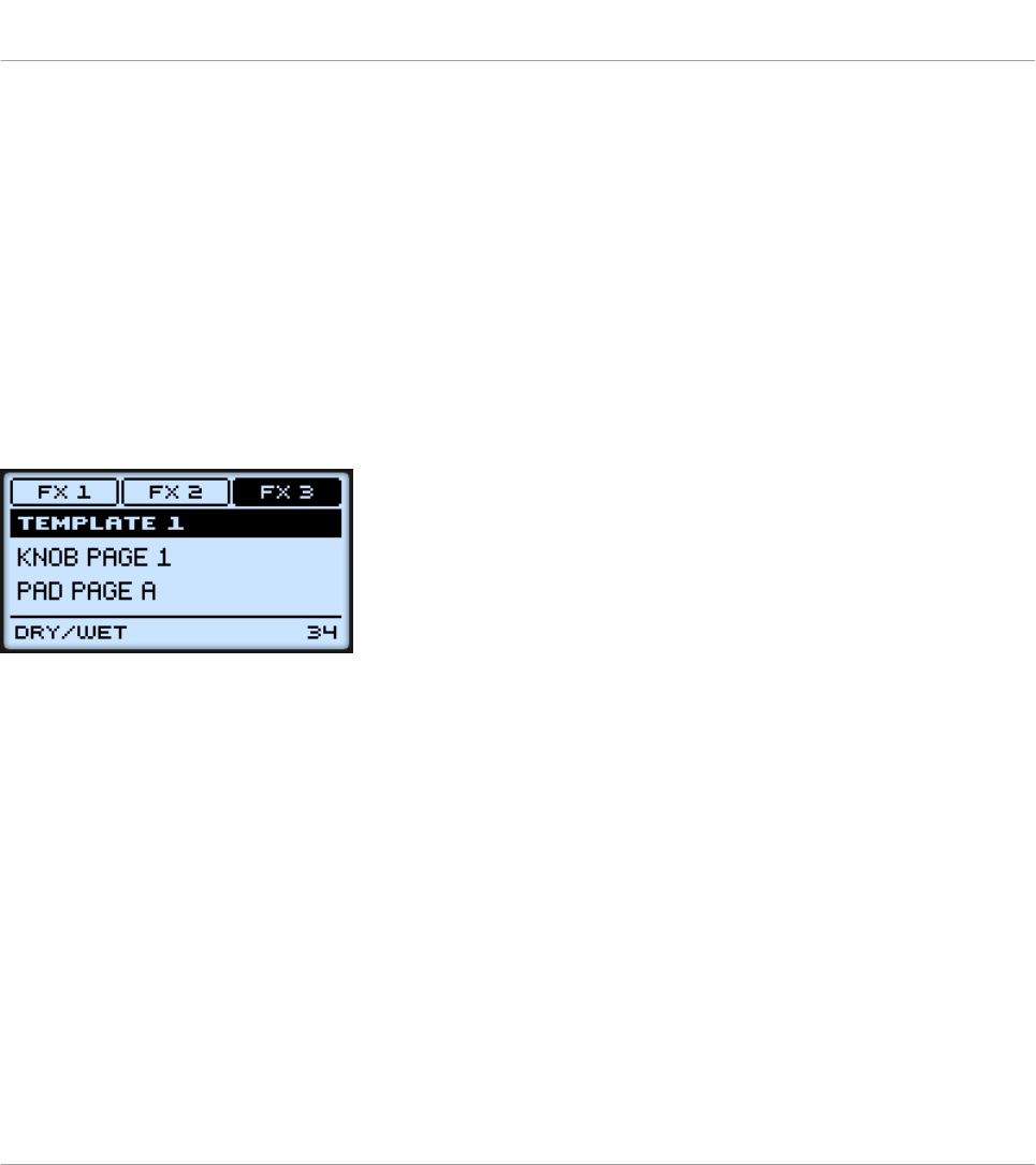
►To switch to any of the display modes, hold the NAV button and press the desired F1–F3
button above the display.
At any time, you can press the NAV button again and switch to another display mode.
8.4.2 Control Display Mode
The Control display mode is probably the one you will use the most.
►To switch to the Control display mode, press NAV + F2.
In this mode, the display shows the assignments for the currently loaded Knob Page, with its
three button assignments on the top row for the F1–F3 buttons, and its Control encoder as-
signment on the bottom row:
The Control display mode mirrors the loaded Knob Page.
In this mode, the F1–F3 buttons and the Control encoder trigger their assigned MIDI messag-
es.
Each field mirrors the Label Field as defined in the Inspector’s Assign pane for the correspond-
ing control element: the name you defined there appears here — if you haven’t defined any
name yet for that control element, its label is simply its assigned MIDI message.
In the middle of the display, you can see the Template, Knob Page and (possibly) Pad Page
that are currently active. You can switch these at any time using the usual shortcuts (see ↑7.1,
Basic Controls).
8.4.3 Template Display Mode
The Template display mode allows you to switch between Templates.
►To switch to the Template display mode, press NAV + F1.
Using Your MASCHINE MIKRO MK2 Controller
The Display
CONTROLLER EDITOR - Manual - 98
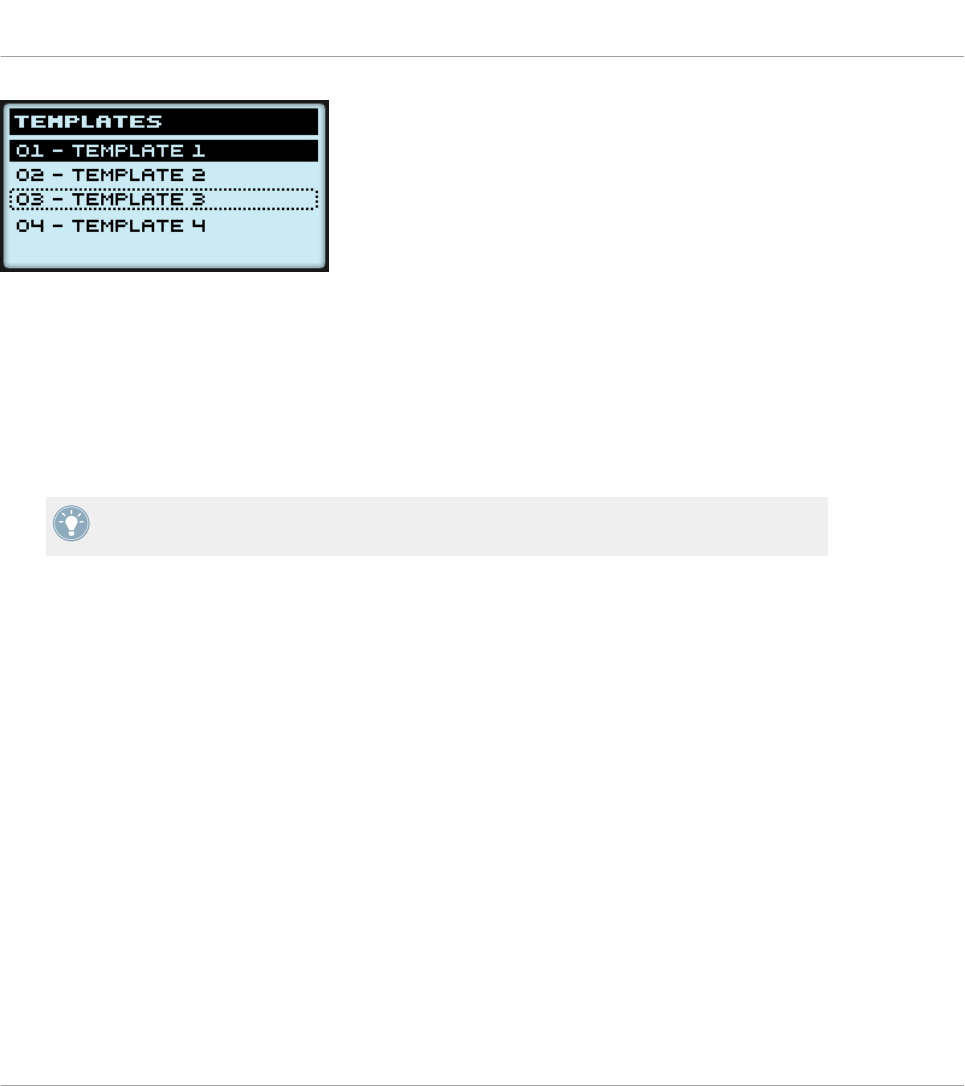
The Template display mode gives you a greater control over Template switching.
In this mode, you see the list of your Templates as defined in the Inspector’s Templates pane.
The active Template is highlighted.
1. Turn the Control encoder to scroll through the list and find the Template you wish to load
next.
The selected Template is indicated by a dotted frame.
2. When you have it, press the Control encoder to load the selected Template.
Instead of turning the Control encoder, you can also use the Left/Right Arrow buttons to se-
lect another Template, then press the Control encoder to load it.
This functionality is already available in many ways: in the Controller Editor you can use the
Template list (in the Inspector’s Templates pane), and on the MASCHINE MIKRO MK2 con-
troller you have the shortcut SHIFT + Left/Right Arrow at your disposal. The Template display
mode, though, allows you a greater control over the Template selection from your controller:
• Unlike the Template list in the Controller Editor interface, you don’t have to open the
Controller Editor to switch to another Template.
• Unlike using the shortcut SHIFT + Left/Right Arrow buttons on your controller, you can
quietly choose the next Template to be loaded, even if it’s not the one right after/before
the Template currently loaded. You can check its name to remember its assignments, and
you can scroll the entire list to find the Template you want.
8.4.4 Setup Display Mode
The Setup display mode allows you to adjust relevant parameters and provides information
about your MASCHINE MIKRO MK2 controller.
►To switch to the Setup display mode, press NAV + F3.
Using Your MASCHINE MIKRO MK2 Controller
The Display
CONTROLLER EDITOR - Manual - 99
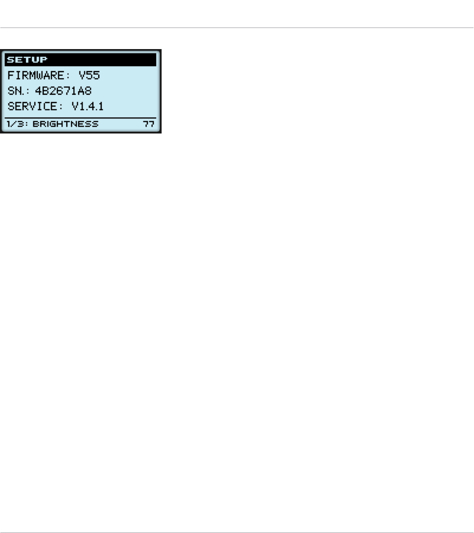
The Setup display mode provides access to parameters for your MASCHINE MIKRO MK2 controller.
The settings appear on the bottom row of the display:
1. Press the Left/Right Arrow buttons repeatedly to scroll through the available settings.
2. Turn the Control encoder to change the value for a particular setting.
The settings are the same as in File > Preferences > Controller (when the MASCHINE MIKRO
MK2 controller is selected in the Controller menu at the top, of course). These are:
•Brightness: Adjusts the brightness of the display.
•Contrast: Adjusts the contrast of the display.
•Pad Sensitivity: Changes the sensitivity of the pads.
The middle part of the display provides you with some important information about your MA-
SCHINE MIKRO MK2 controller and the Hardware Service:
• In the upper part, you find the firmware version of your MASCHINE MIKRO MK2 control-
ler along with its serial number.
• Below, you see the version number of the NI Hardware Service.
Using Your MASCHINE MIKRO MK2 Controller
The Display
CONTROLLER EDITOR - Manual - 100
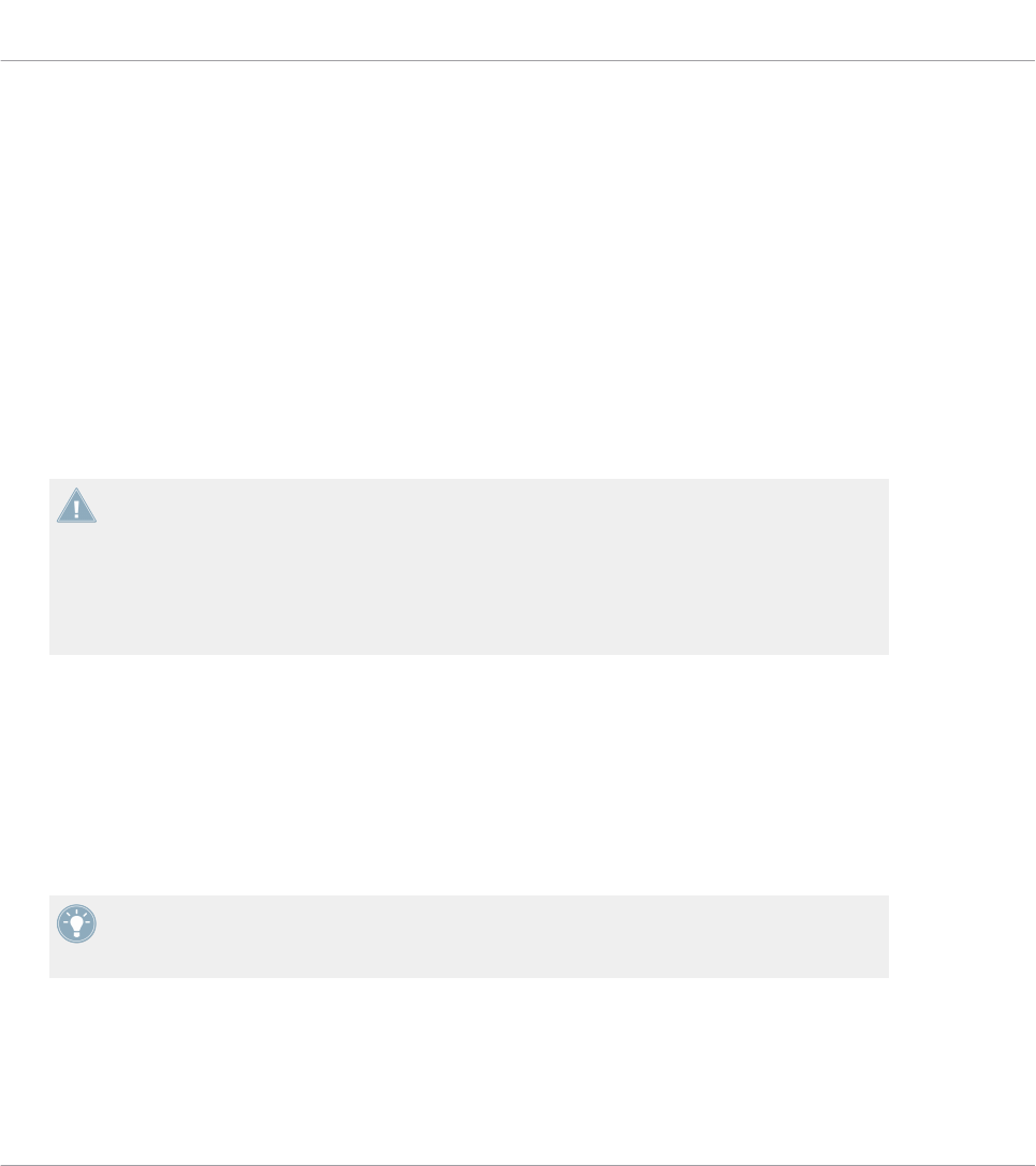
9 Using Your MASCHINE STUDIO Controller
In this chapter, we will focus on what’s happening on your MASCHINE STUDIO controller. By
reading this, you will learn:
• How to use the basic controls on your controller for navigating through the MIDI mapping
system.
• The list of all assignable control elements on your controller.
• How the various luminous elements give you some important information about their
state.
• How to use the powerful displays of your MASCHINE STUDIO controller in MIDI mode.
To enjoy full functionality of your NI controller as a MIDI remote control, especially con-
cerning some control elements’ state and LED behavior, you need to tell your NI controller
what is the current state of the parameter in the MIDI target. You can do this by setting up
MIDI feedback channels coming from your MIDI target back to your NI controller. This way,
your controller will always stay up-to-date with the current parameter values in your target
software/hardware. For more information on how to configure these MIDI feedback chan-
nels, please refer to your target software/hardware’s documentation.
9.1 Basic Controls
This section shows you the commands available on your MASCHINE STUDIO controller for ba-
sic tasks: switching between MIDI mode and MASCHINE mode, and selecting sets (Templates)
and subsets (Knob Pages, Pad Pages, I/O and Level Pages, and Jog Wheel Pages) of MIDI as-
signments.
All these actions can of course be done via the Controller Editor user interface — see chap-
ter ↑3, Quick Start for example. Nevertheless, using your NI controller instead can be very
handy in a live situation!
Using Your MASCHINE STUDIO Controller
Basic Controls
CONTROLLER EDITOR - Manual - 101
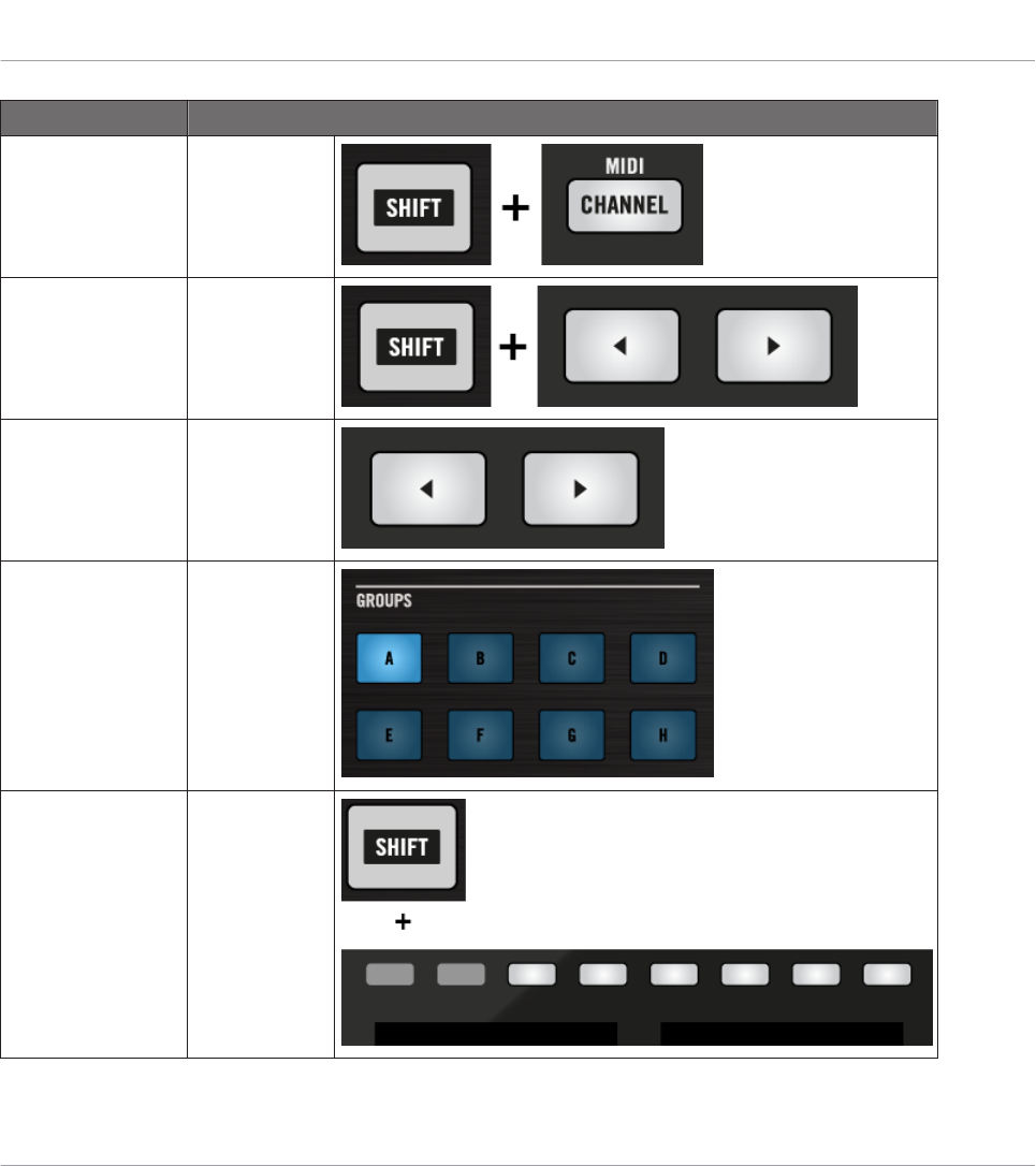
Selection Command
MIDI/MASCHINE
mode
SHIFT +
CHANNEL
Templates SHIFT + Page
buttons
Knob Pages Page buttons
Pad Pages
(if activated)
Group buttons
Display mode SHIFT + But-
tons 3–8
Using Your MASCHINE STUDIO Controller
Basic Controls
CONTROLLER EDITOR - Manual - 102
For more information on Templates, Knob Pages, Pad Pages, I/O and Level Pages, and Jog
Wheel Pages, see ↑4.3, The Mapping System.
For more information on the display modes, see ↑9.4, The Displays. There you will also
learn another way to select and load Templates and Knob Pages from your controller.
When your MASCHINE STUDIO controller is in MIDI mode, its SHIFT button is dimly lit.
Adjusting Settings for your Controller
You can adjust various settings for your MASCHINE STUDIO controller by entering its Settings
display mode or by going to File > Preferences > Controller. See ↑9.4.2, Settings Display Mode
for more information.
9.2 Assignable Control Elements
If you selected the MASCHINE STUDIO controller in the Device menu of the Application Con-
trol Bar, this is what the Hardware area looks like:
Using Your MASCHINE STUDIO Controller
Assignable Control Elements
CONTROLLER EDITOR - Manual - 103
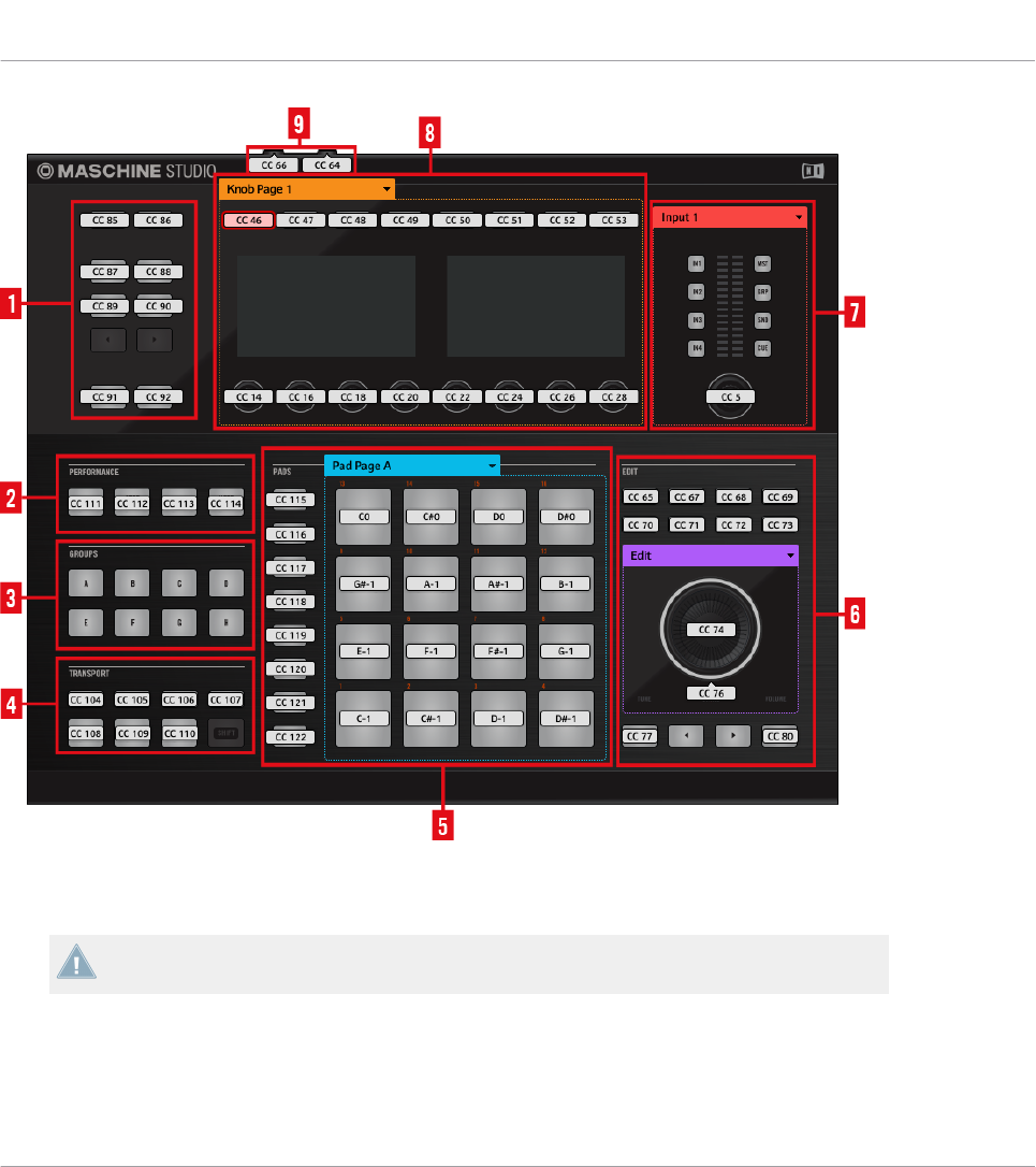
The Hardware area representing the MASCHINE STUDIO controller.
The MASCHINE STUDIO controller holds the following areas:
The names that you see on the device only refer to their original function in the MASCHINE
software. We use these names here only to describe the interface!
Using Your MASCHINE STUDIO Controller
Assignable Control Elements
CONTROLLER EDITOR - Manual - 104

(1) Control Buttons: In the top left part, you find a set of ten buttons arranged into five rows of
two buttons. From these ten buttons, eight are freely assignable (CHANNEL and PLUG-IN, AR-
RANGE and MIX, BROWSE and SAMPLING, ALL, and AUTO) and two have special functions:
the left and right Page buttons (see ↑9.1, Basic Controls).
(2) PERFORMANCE area: The PERFORMANCE area holds four freely assignable buttons.
(3) GROUPS area: The GROUPS area contains eight buttons labeled from A to H: the Group but-
tons. If you activated the Pad Pages button in the Pages pane of the Inspector, these buttons
allow you to select the desired page of assignments for the pads (see ↑4.3.3, Pad Pages (MA-
SCHINE Controller Family Only)). If you didn’t activate the Pad Pages, these eight buttons are
freely assignable to MIDI events.
(4) TRANSPORT area: The TRANSPORT area contains eight buttons. Seven of them are freely
assignable: RESTART, METRO, EVENTS, GRID, PLAY, REC, and ERASE. The last one, SHIFT,
is a special button (see previous section). Therefore, this button cannot be assigned in the
Controller Editor.
(5) PADS area: The PADS area shows a column of eight freely assignable buttons (namely
SCENE, PATTERN, PAD MODE, NAVIGATE, DUPLICATE, SELECT, SOLO, and MUTE) as well
as a square of sixteen freely assignable pads. If you activated the Enable Pad Pages button in
the Pages pane of the Inspector, a Pad Page area (indicated by the blue frame) groups the
pads together and is headed by the Pad Page menu.
(6) EDIT area: The EDIT area displays eight freely assignable buttons above the jog wheel
namely COPY, PASTE, NOTE, NUDGE, UNDO, REDO, QUANTIZE, and CLEAR. In addition,
the jog wheel itself and its outer ring can also be freely assigned. There is also a row of four
buttons below the jog wheel, two of these are also freely assignable (BACK and ENTER) the
other two buttons (left and right FUNCTION) allow you to select the desired page of assign-
ments for the jog wheel (EDIT, CHANNEL, BROWSE, TUNE, SWING, and VOLUME). If you ac-
tivated the Enable Jog Wheel Pages button in the Pages pane of the Inspector, a Jog Wheel
Page area (indicated by the violet frame) groups the Jog Wheel Pages together and is headed
by the Jog Wheel Page menu. If you deactivate the Jog Wheel Pages, the two FUNCTION but-
tons are freely assignable to MIDI events.
(7) I/O and Level area: The I/O and Level area shows two columns of four buttons which allow
you to select the desired Pages (namely IN1, IN2, IN3, IN4, and MST, GRP, SND, CUE) as
well as a freely assignable Level knob. If you activated the Enable I/O and Level Pages button
in the Pages pane of the Inspector, an I/O and Level Page area (indicated by the red frame)
Using Your MASCHINE STUDIO Controller
Assignable Control Elements
CONTROLLER EDITOR - Manual - 105
including the eight buttons and knob will be visible. This section is headed by the I/O and Lev-
el Pages menu. If you deactivate the I/O Level Pages, the eight buttons become freely assigna-
ble to MIDI events.
(8) Knob Page area: The Knob Page area holds a set of eight buttons and eight knobs, with the
buttons being placed above and the knobs below the two displays, respectively. These sixteen
control elements are freely assignable. Furthermore, the eight Knobs 1–8 can be both turned
and touched, leading to two different assignments for each Knob. The Knob Page area is indi-
cated by an orange frame and headed by the Knob Page menu.
The buttons and knobs in the Knob Page area can also have other functions according to
the display mode that is currently active. See ↑9.4, The Displays for more on this.
(9) Footswitch area: The footswitch area contains two freely assignable inputs which can be
controlled using a footswitch. Furthermore, both are stereo inputs: For each of them you can
assign messages to the tip and ring inputs independently.
To Sum Up…
All control elements on your MASCHINE STUDIO controller are freely assignable to MIDI
events (with the limitations due to the type of control element), with the following exceptions:
• The Page buttons, FUNCTION buttons and the SHIFT button have a predefined function
(see previous section).
• The Group buttons, labeled A to H, are not assignable if you use the Pad Page feature —
they’re used for selecting Pad Pages, see previous section. If you deactivate the Pad Pa-
ges, the Group buttons are freely assignable like any other.
You can also split the controls of your controller between MIDI mode and MASCHINE mode
in order to control a MASCHINE plug-in instance while sending MIDI messages to the host
with the transport controls! See ↑23.5.1, Templates Pane for more information.
Assignment Parameters
The following table summarizes where to find all assignment details for each type of control
element on your controller:
Using Your MASCHINE STUDIO Controller
Assignable Control Elements
CONTROLLER EDITOR - Manual - 106
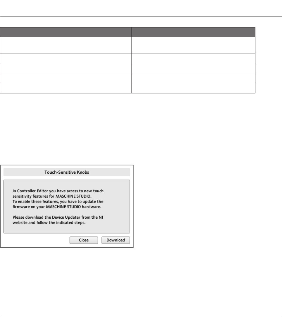
Type of Control Element Assignment Parameters
Buttons, Knobs 1–8 (Touch action), jog wheel (Push
action), footswitch inputs (both Tip and Ring actions)
↑23.6.2, Assignments for Buttons
Pads (Hit action) ↑23.6.4, Assignments for the Pads – Hit Action
Pads (Press action) ↑23.6.6, Assignments for the Pads – Press Action
Control encoder, jog wheel (Turn action) ↑23.6.7, Assignments for Digital Encoders
Knobs 1–8 (Turn action), Level knob ↑23.6.8, Assignments for Analog Encoders
Important: Update the Controller Firmware to the Latest Version!
Touch sensitivity features have been introduced in Controller Editor 1.7.1 for Knobs 1–8 (e.g.,
the new Touch action). These features will work on your MASCHINE STUDIO controller only if
its firmware is in version 22 or greater.
If Controller Editor is running and you connect a MASCHINE STUDIO controller that has a
firmware version lower than 22, a warning message pops up indicating how to update the firm-
ware of your controller:
The warning message helps you update your controller’s firmware.
If this message appears when you connect your MASCHINE STUDIO controller, do the follow-
ing to update its firmware:
Using Your MASCHINE STUDIO Controller
Assignable Control Elements
CONTROLLER EDITOR - Manual - 107

1. Click the Download button at the bottom of the message.
This will automatically start your favourite internet browser and open a page of the Native
Instruments website providing a link to the Device Updater.
2. Click the link to download the Device Updater to your computer.
3. Once the archive has been downloaded, extract it to the desired folder.
4. In the Explorer (Windows) or Finder (Mac OS X), navigate to the extracted folder and open
it.
5. Within that folder, double-click the “DeviceUpdater.exe” file (Windows) or the “DeviceUp-
dater” file (Mac OS X).
The Device Updater starts up.
6. Follow the instructions of the Device Updater to complete the firmware update.
In the rest of the manual, we assume that the firmware of your MASCHINE STUDIO controller
is in version 22 or greater.
If your computer is not currently connected to internet, click the Close button in the warn-
ing message: You will be able to use Controller Editor but the touch sensitivity features of
your MASCHINE STUDIO controller won’t be available. You can download the Device Up-
dater at a later point by opening the page at http://www.native-instruments.com/en/support/
downloads/ in your internet browser, clicking the Drivers and other files link, scrolling to
the Maschine Controller section and choosing the Device Updater for your operating sys-
tem.
9.3 Visual Feedback on Your Controller
The fast bidirectional communication between your MASCHINE STUDIO controller and the
Hardware Service on the software side allows status indications on your controller to be made
in real time.
Your MASCHINE STUDIO controller provides you visual feedback in various ways:
• All buttons and pads are equipped with LEDs that inform you about their assignment
state at any time. Furthermore, the 16 pads and 8 Group buttons provide RGB LEDs.
• The displays show you additional information about the assignments.
Using Your MASCHINE STUDIO Controller
Visual Feedback on Your Controller
CONTROLLER EDITOR - Manual - 108

9.3.1 Buttons
Basically, each button on your controller can have three states:
• Not assigned.
• Assigned, in Off state.
• Assigned, in On state.
The following paragraphs describe how the LED under each button keeps you informed on the
button states.
Single-Color Buttons
For all buttons except the Group buttons, the LEDs can have three states: off, dimmed and
bright. All are white except for the PLAY button (green) the REC button (red) and the IN (1-4)
buttons (blue). The LED states directly indicate the button states:
Button State LED State
Not assigned Off
Assigned – Off state Dimmed
Assigned – On state Bright
For buttons in Increment mode, the Off state corresponds to the zero value, while the On
state corresponds to a value greater than zero. See section ↑23.6.2, Assignments for But-
tons for more information on the various button modes.
Multicolor Buttons
The eight Group buttons of your controller are equipped with RGB LEDs. This by far extends
the monitoring possibilities of these control elements. Their lighting behavior directly depends
on whether the Pad Pages are enabled or not.
• Pad Pages enabled: Each Group button mirrors the color defined for its Pad Page (the
Color setting for Pad Pages is described in ↑23.5.3, Assign Pane). All Group buttons are
dimmed except the button corresponding to the selected Pad Page.
• Pad Pages disabled: The Group buttons can be freely assigned. For each of them, you can
choose which from the 16 available colors should be used for the On and Off states.
Using Your MASCHINE STUDIO Controller
Visual Feedback on Your Controller
CONTROLLER EDITOR - Manual - 109

With Pad Pages disabled, the Group buttons offer you three Color modes:
• Single mode: You can choose a color that will be used bright and dimmed for the On and
Off states, respectively. In this mode, the button’s lighting behaves like that of single-col-
or buttons (see table above).
• Dual mode: You can choose a color for the On state and another color for the Off state.
Both colors will be used at full brightness.
• HSB mode: This mode is only available when the button’s state is controlled via MIDI
feedback (see below). In HSB mode, you can precisely define from within your MIDI tar-
get which color the button will use.
Controlling the Button State
The On/Off state of each single-color or multicolor button can be controlled in two ways — in-
ternally via your actions on the button, or remotely via MIDI feedback:
• In Toggle mode, both controls are enabled: both your actions on the button and the possi-
bly incoming MIDI messages are taken into account to update the button and LED state.
• In Trigger, Gate, and Increment mode, you can choose which control mode (internal or re-
mote via MIDI) you want to use. This is done via the LED On menu in the Assign pane of
the Inspector.
For more information on the button modes, LED On menu, and MIDI feedback mode, see
↑23.6.2, Assignments for Buttons.
Moreover, for the Buttons 1–8 above the displays, the particular assignment is shown within
the displays in Knobs display mode (see section ↑9.4.4, Knobs Display Mode).
9.3.2 Multicolor Pads
The sixteen pads of your controller are equipped with RGB LEDs. Their lighting behavior is
close to that of multicolor buttons — but since the pads have two functions (Hit and Press),
their states are indicated as follows:
• If the pad is not assigned, it is off.
• If there is an assignment for the Hit action, the pad’s LED behaves like that of a multicol-
or Group button (see previous section).
Using Your MASCHINE STUDIO Controller
Visual Feedback on Your Controller
CONTROLLER EDITOR - Manual - 110
• If the Hit action is not assigned but the Press action is assigned to the Note message
type, the LED has a low brightness to show the Off state and a high brightness to show
the On state. For all other message types, the LED stays at low brightness.
9.3.3 Knobs
The assignments for the eight Knobs under the displays are indicated within the displays in
Knobs display mode. If a Knob is not assigned, the display reads “OFF.”
The MCU Mode check box allows you to set your MASCHINE STUDIO controller displays to
MCU mode in order to receive Mackie Control feedback from your DAW while keeping the
original assignment of the Buttons and Knobs in the Knob Page area. The MCU Mode set-
ting applies Page-wide.
For more information on the various display modes on your MASCHINE STUDIO controller,
see section ↑9.4, The Displays.
9.3.4 Control Encoder
The Control encoder has no direct visual feedback, but like all other controls its assignment
and value are indicated on the right display when the displays are in Monitor display mode. If
the Control encoder is not assigned, the display reads “NONE.”
For more information on the various display modes on your MASCHINE STUDIO controller,
see next section.
9.4 The Displays
The displays on your MASCHINE STUDIO controller can show different parts of your mapping
configuration, depending on the display mode that is activated. Each display mode modifies the
behavior of Buttons 1–8 above the displays and Knobs 1–8 below them. Learn more about the
different display modes available on the MASCHINE STUDIO controller in the following sec-
tions.
Using Your MASCHINE STUDIO Controller
Visual Feedback on Your Controller
CONTROLLER EDITOR - Manual - 111
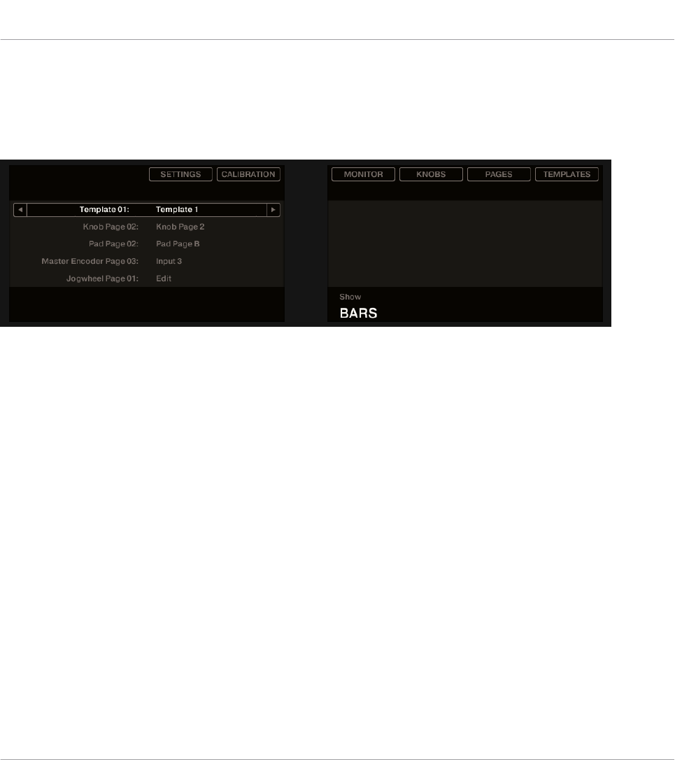
9.4.1 Switching Between Display Modes
First of all, to switch between display modes, press the SHIFT button on your MASCHINE STU-
DIO controller and hold it. On the displays, you see something like this:
The displays on your MASCHINE STUDIO controller in MIDI mode, when the SHIFT button is depressed.
This screen allows you to select the desired display mode. On the top, you find six fields repre-
senting the six display modes, from left to right: SETTINGS, CALIBRATION, MONITOR, KNOBS, PAGES,
and TEMPLATES.
►To switch to any of the display modes, hold the SHIFT button and press the correspond-
ing Button 2–8 above the displays.
At any time, you can press the SHIFT button again and switch to another display mode.
In the middle part of the left display, you see the name of the current Template. This is com-
mon to all display modes (except the Settings and Calibration display mode), so that you can
always be sure about which Template is currently selected.
Below, a message reminds you that you can switch to another Template simply by pressing the
Page buttons, since you are already holding SHIFT (see ↑9.1, Basic Controls).
9.4.2 Settings Display Mode
The Settings display mode allows you to adjust a few hardware settings and provides informa-
tion about your MASCHINE STUDIO controller.
Using Your MASCHINE STUDIO Controller
The Displays
CONTROLLER EDITOR - Manual - 112
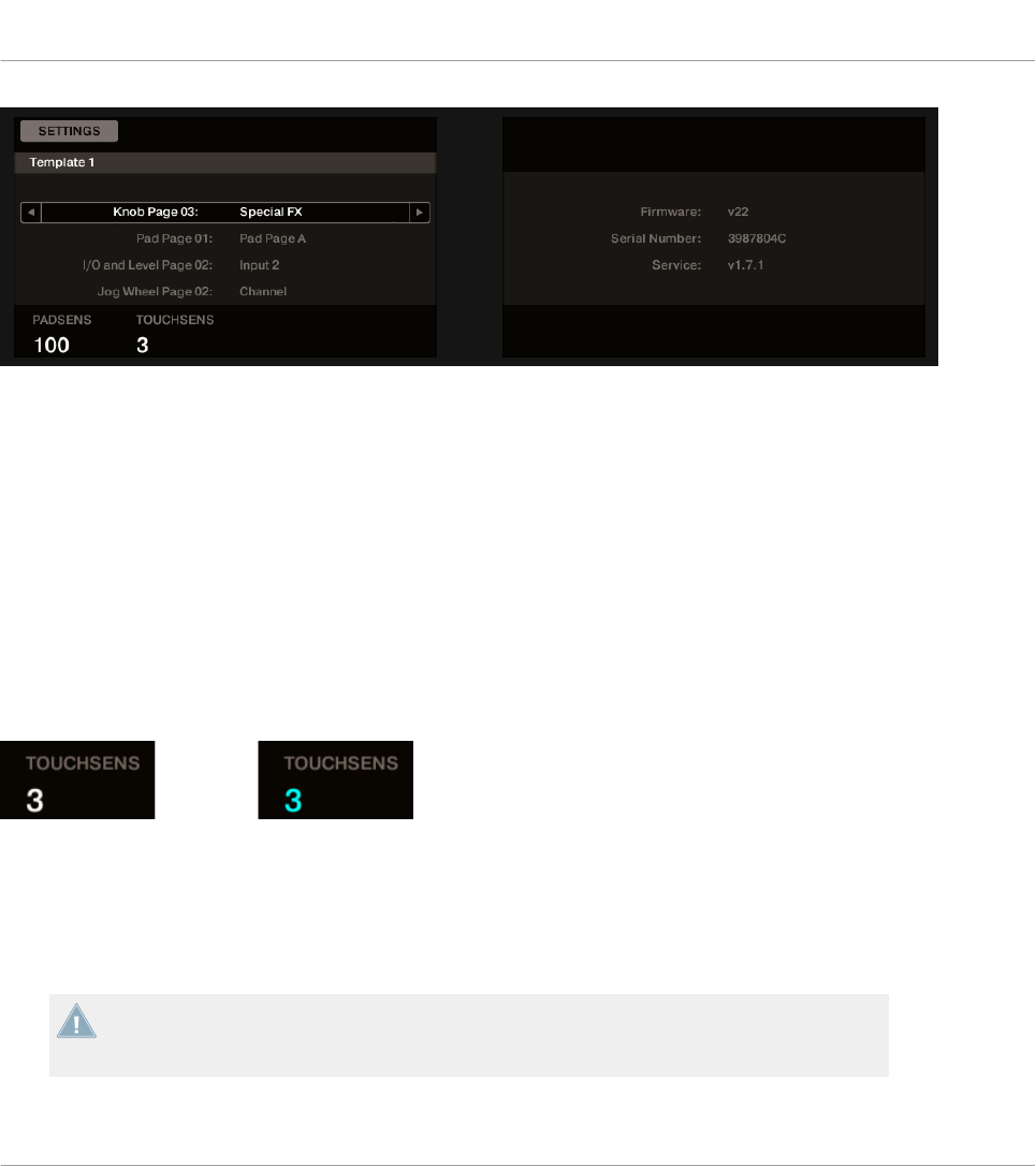
The Settings display mode provides access to parameters for your MASCHINE STUDIO controller.
Left Display
The settings are grouped in the left display. This screen gives also an overview of the selected
Pages. The available parameters are set out as follows:
• Knob 1 controls the pad sensitivity.
• Knob 2 controls the touch sensitivity of Knobs 1–8. At low sensitivity values, you will need
to apply a stronger pressure on Knobs 1–8 to send the MIDI message. At high sensitivity
values, a softer pressure on the knobs will already send the MIDI message.
For the touch sensitivity of Knobs 1–8, the value display above Knob 2 provides an additional
visual feedback that helps you quickly find the sensitivity that best fits your needs:
On the left, your touch is not detected; on the right, it is detected!
1. While looking at this sensitivity value, touch any Knob 1–8 under the controller displays.
As soon as your pressure on the Knob is detected, the number is highlighted.
2. Apply various pressures on the Knob and readjust the slider accordingly until you are sat-
isfied with the sensitivity.
These setting are also available in the Controller Editor software in File > Preferences >
Controller (when the MASCHINE STUDIO controller is selected in the Controller menu at
the top, of course). For more details, see section ↑23.2.2, Controller Page.
Using Your MASCHINE STUDIO Controller
The Displays
CONTROLLER EDITOR - Manual - 113
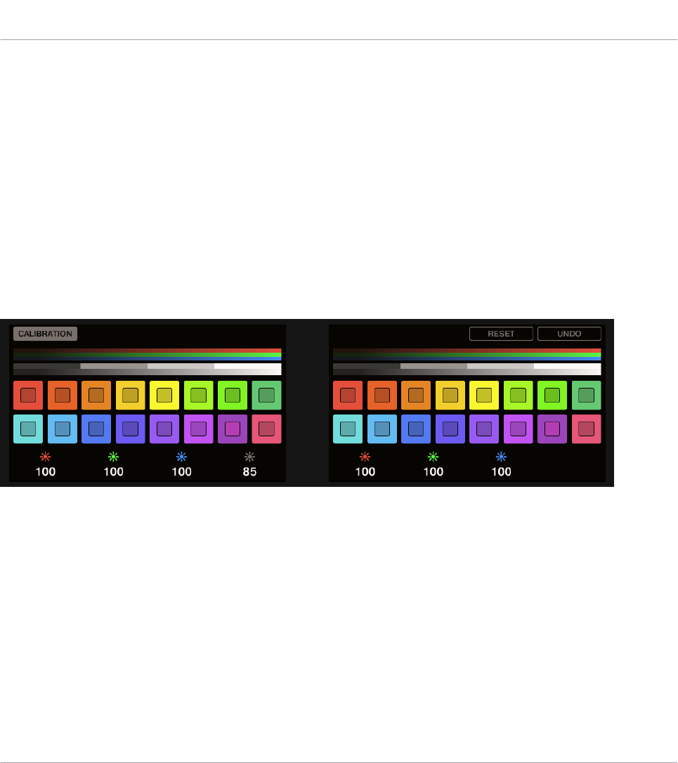
Right Display
The right display provides you with some important information about your MASCHINE STU-
DIO controller and the Hardware Service:
• In the upper part, you find the firmware version of your MASCHINE STUDIO controller
along with its serial number.
• Below, you see the version number of the NI Hardware Service.
9.4.3 Calibration Display Mode
The Calibration display mode allows you to adjust the color balance and brightness of the dis-
plays, but also to counter any visible color differences between the two displays on your MA-
SCHINE STUDIO controller.
The Calibration display mode provides access to the color and brightness settings for your MASCHINE STUDIO controller.
The RGB (Red, Green, Blue) parameters are grouped across each display with the brightness
parameter in the left display. The Calibration parameters are set out as follows:
• Knob 1 controls the red value for the left screen.
• Knob 2 controls the green value for the left screen.
• Knob 3 controls the blue value for the left screen.
• Knob 4 controls the brightness for both screens.
• Knob 5 controls the red value for the right screen.
• Knob 6 controls the green value for the right screen.
Using Your MASCHINE STUDIO Controller
The Displays
CONTROLLER EDITOR - Manual - 114
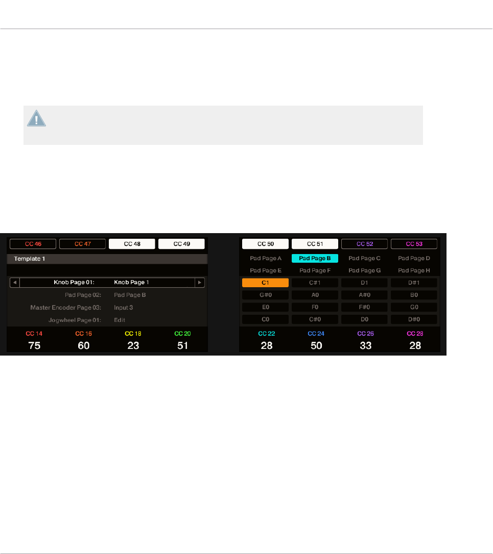
• Knob 7 controls the blue value for the right screen.
• Button 7 will reset the calibration parameters to the default setting.
• Button 8 will undo all changes to the calibration parameters.
The brightness setting (Knob 4) is also available in the Controller Editor software in File >
Preferences > Controller (when the MASCHINE STUDIO controller is selected in the Con-
troller menu at the top, of course). For more details, see section ↑23.2.2, Controller Page.
9.4.4 Knobs Display Mode
The Knobs display mode is probably the one you will use the most. In this mode, the displays
show the currently loaded Knob Page, with its eight button assignments on the top row and its
eight knob assignments on the bottom row:
The Knobs display mode mirrors the currently loaded Knob Page.
This display mode allows you to see which MIDI message is currently assigned to each control
element in the loaded Knob Page. In this mode, the 16 control elements around the displays
(Buttons 1–8 above and Knobs 1–8 below) trigger the MIDI messages assigned to them.
Each field mirrors the Label Field as defined in the Inspector’s Assign pane for the correspond-
ing control element: the name you defined in the Controller Editor will appear here on your
MASCHINE STUDIO — if you haven’t defined a name for a control element, it will simply dis-
play the assigned MIDI message.
In the lower row, the displays additionally show the current value for each Knob. These values
can be displayed in two views: either via numerical values (like in the picture above), or via
small bars:
Using Your MASCHINE STUDIO Controller
The Displays
CONTROLLER EDITOR - Manual - 115

The Knobs display mode with bars instead of numerical values.
You can switch between the two views by holding the SHIFT button and turning Knob 5:
1. Hold SHIFT (thus getting to the switching screen explained in ↑9.4.1, Switching Between
Display Modes).
You can see the option “SHOW BARS” or “SHOW VALUES” above Knob 5 (depending on which
view is currently selected).
2. Turn Knob 5 to select the desired view.
3. Release SHIFT.
→The new view is displayed.
Note that depending on the assignment properties for each of the Knobs, its displayed value
(or bar) can either be going from 0 to 127 or from -63 to 64 (bipolar) — this second setting
can be useful for some types of controls (e.g. a stereo balance). This only affects the value/bar
shown on the displays — the real MIDI value will go from 0 to 127 anyway. Please refer to
section ↑23.6.8, Assignments for Analog Encoders for more information on this.
The MCU Mode check box allows you to set your MASCHINE STUDIO controller displays to
MCU mode in order to receive Mackie Control feedback from your DAW while keeping the
original assignment of the Buttons and Knobs in the Knob Page area. The MCU Mode set-
ting applies Page-wide.
Using Your MASCHINE STUDIO Controller
The Displays
CONTROLLER EDITOR - Manual - 116
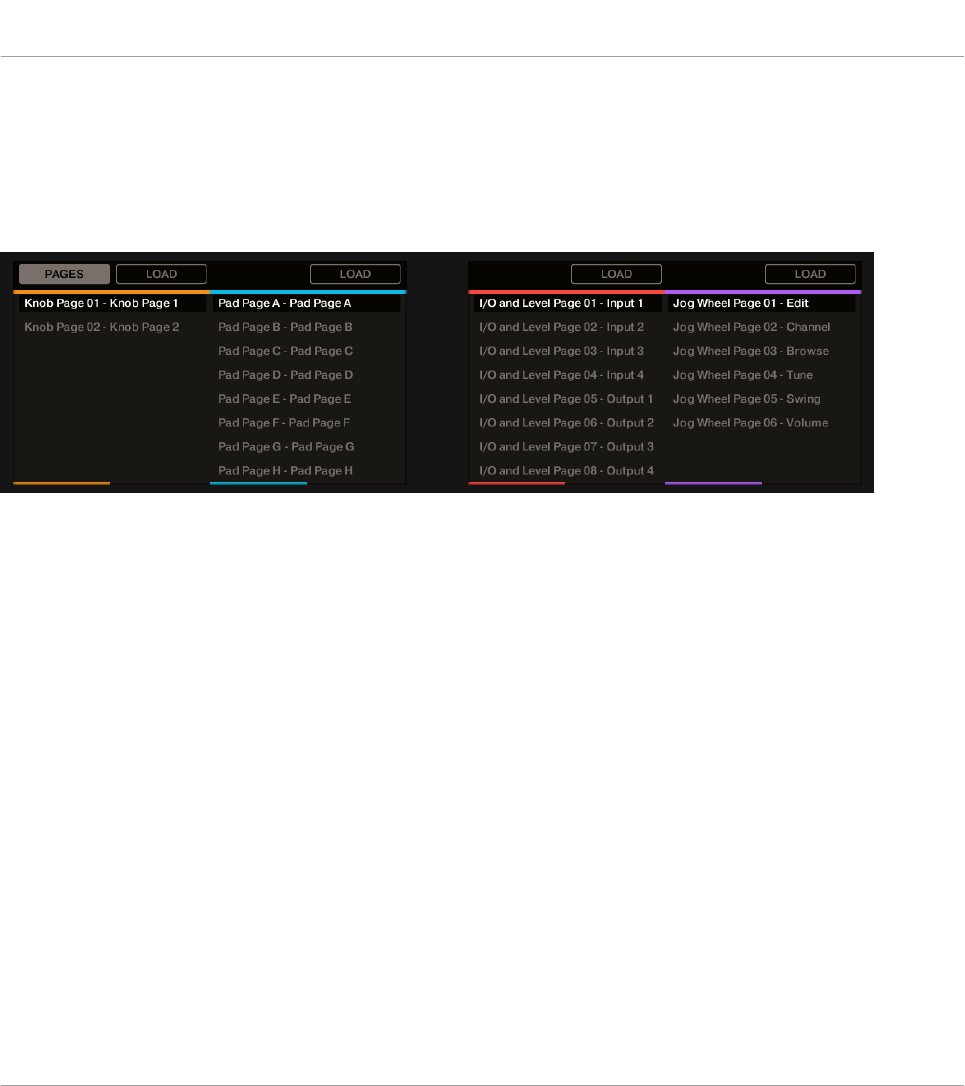
9.4.5 Pages Display Mode
The Pages display mode allows you to check the current assignations for the Knobs, Pads, I/O
and Level Knob and the Jog Wheel of your MASCHINE STUDIO controller, by mirroring the
current Pages:
The Pages display mode mirrors the Pages currently loaded.
Across the two displays you will find four columns, each representing a list of Pages (Knobs,
Pads, I/O and Level and the Jog Wheel). Use Knobs 1–8 to select a different page and press
the button (LOAD) directly above the column to load the selected page for example, to load a
new Knob Page:
1. Use Knob 1 to scroll through the list and find the Knob Page you wish to load.
2. When you have made your selection, press the Button 2 (LOAD) to load the selected Knob
Page.
Actually, this functionality is already available in many ways: in the Controller Editor, you can
use the Knob Page menu (in the Hardware area) or the Knob Pages list (in the Inspector’s
Pages pane), and on the MASCHINE STUDIO controller you have the Page buttons at your dis-
posal. But the Pages display mode allows you a greater control over Page selection from the
MASCHINE STUDIO controller:
• Unlike using the Knob Pages list, you don’t have to open the Controller Editor to switch to
another Page.
Using Your MASCHINE STUDIO Controller
The Displays
CONTROLLER EDITOR - Manual - 117
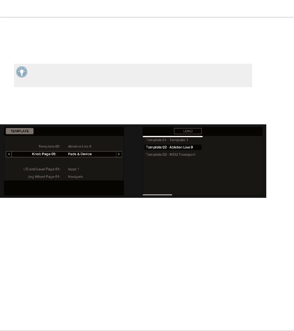
• When using the Pages display mode, you can choose the next page to be loaded, even if
it’s not the one right after/before the one currently loaded. You can check its name to re-
member its assignments, and you can scroll the lists of all Pages to find the page you
want.
When you reach the end of the list, you can choose whether the selection has to jump to
the other list end or stay on this last item. This can be set in Preferences > General > Wrap
Template and Page Lists.
9.4.6 Templates Display Mode
The Templates display mode allows you to switch between Templates.
The Templates display mode allows you to switch between Templates.
On the left display, you find the same general information about the Template currently load-
ed.
On the right display, you see the list of your Templates, as defined in the Inspector’s Tem-
plates pane.
1. Use Knob 5 to scroll through the list and find the Template you wish to load.
2. When you have made your selection, press Button 6 (LOAD) to load the selected Template.
As with the Pages display mode, this functionality is already available in other ways: in the
Controller Editor, you can use the Template list (in the Inspector’s Templates pane), and on
the MASCHINE STUDIO controller you have the Page buttons at your disposal. The Templates
display mode allows you a greater control over the Template selection from your controller for
the reasons already explained in the previous section for the Pages display mode.
Using Your MASCHINE STUDIO Controller
The Displays
CONTROLLER EDITOR - Manual - 118
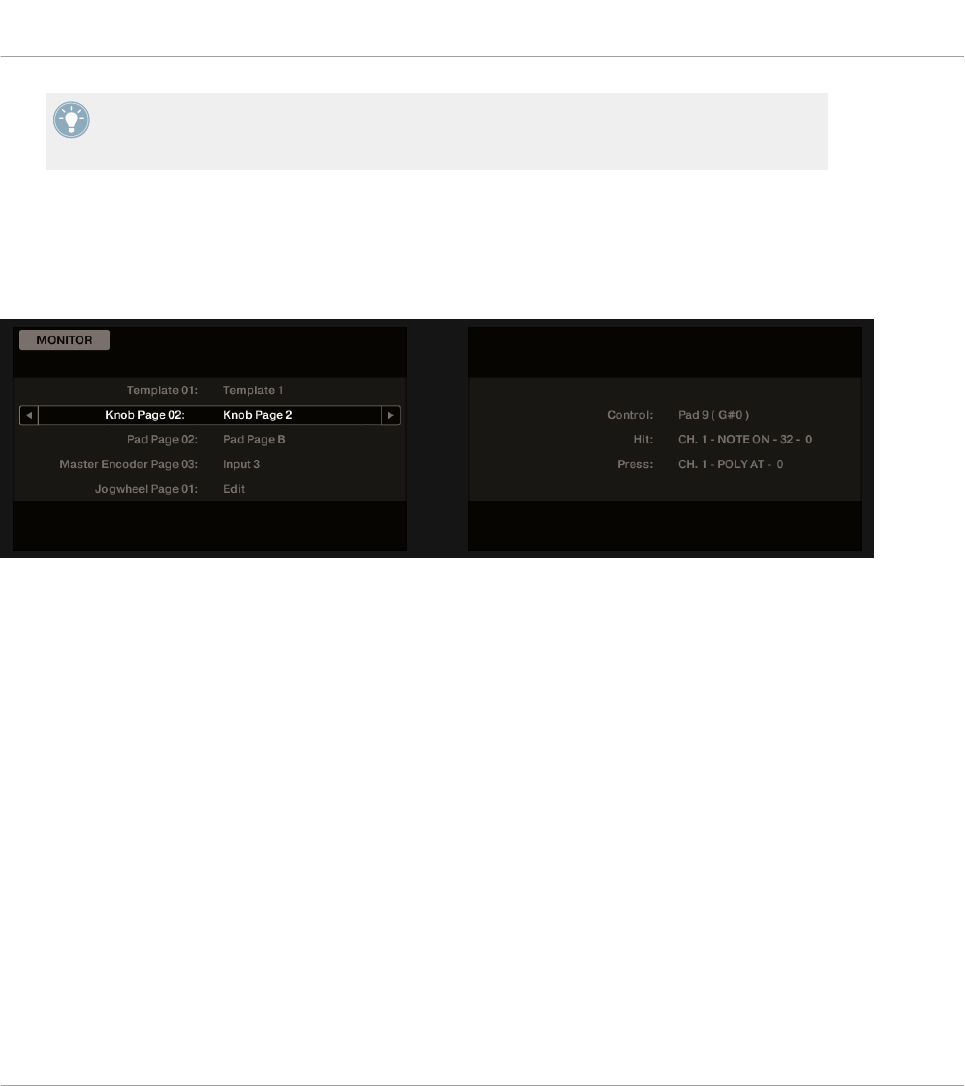
When you reach the end of the list, you can choose whether the selection has to jump to
the other list end or stay on this last item. This can be set in Preferences > General > Wrap
Template and Page Lists.
9.4.7 Monitor Display Mode
The Monitor display mode provides you with useful information about the MIDI data sent by
your MASCHINE STUDIO controller.
The Monitor display mode provides information about the MIDI data sent by your MASCHINE STUDIO controller.
The left display shows the usual information about the current Template and Pages.
The right display shows more information on the last MIDI message sent:
• The first row (Control) indicates the last control element that you actuated.
• If the last actuated element is not a pad, the second row (Event) shows the details of the
corresponding MIDI message that was sent.
• If the last actuated element is a pad, the second row (Hit) and third row (Press) show the
details of the MIDI messages corresponding to the Hit and Press actions on that pad, re-
spectively.
This display mode is very useful to monitor what’s going out of your controller, for example for
debugging purpose: if something goes wrong somewhere in your MIDI chain, you can check
here what is actually sent by your MASCHINE STUDIO controller.
Using Your MASCHINE STUDIO Controller
The Displays
CONTROLLER EDITOR - Manual - 119
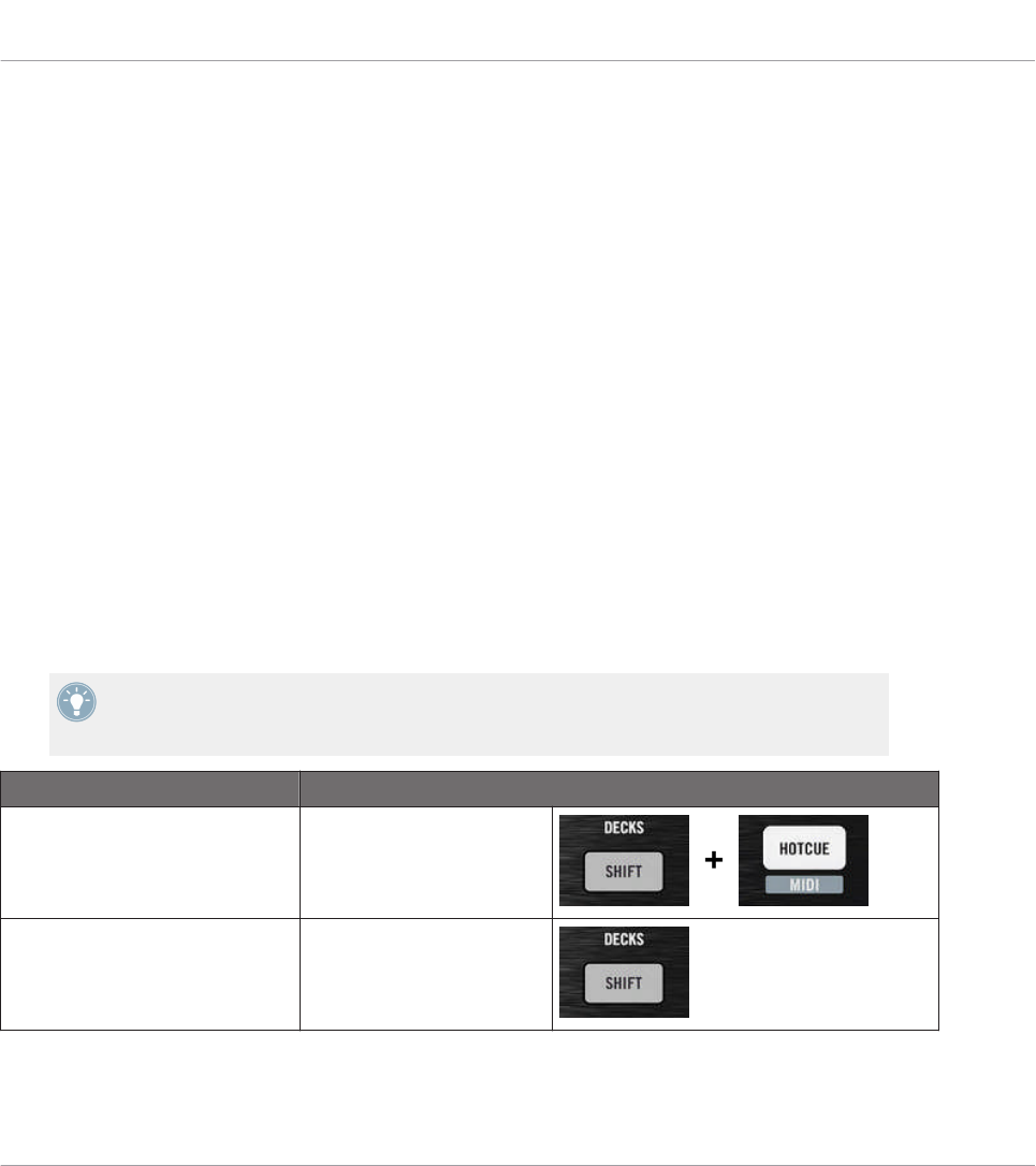
10 Using Your TRAKTOR KONTROL X1
In this chapter, we will focus on what’s happening on your TRAKTOR KONTROL X1. By read-
ing this, you will learn:
• How to use the basic controls on your controller for navigating through the MIDI mapping
system.
• The list of all assignable control elements on your controller.
• How the various luminous elements give you some important information about their
state.
• How to configure more than one X1 unit for use as MIDI remote controls.
10.1 Basic Controls
This section shows you the commands available on your TRAKTOR KONTROL X1 for basic
tasks: switching between MIDI mode and TRAKTOR mode, and selecting subsets (Pages) of
MIDI assignments.
All these actions can of course be done via the Controller Editor user interface — see chap-
ter ↑3, Quick Start for example. Nevertheless, using your NI controller instead can be very
handy in a live situation!
Selection Command
MIDI/TRAKTOR mode SHIFT + HOTCUE
Pages SHIFT
Using Your TRAKTOR KONTROL X1
Basic Controls
CONTROLLER EDITOR - Manual - 120
For more information on the Pages, see ↑4.3, The Mapping System.
You cannot switch between Templates from the TRAKTOR KONTROL X1. To do this, you
have to use the Controller Editor interface (see ↑3.2, Loading MIDI Assignments).
When your X1 is in MIDI mode, the HOTCUE button is lit in green.
Switching Between Pages: Gate vs. Toggle
The SHIFT button can have two operating modes:
• Gate mode: The Page is activated for the time the button is hold depressed.
• Toggle mode: The Page is activated until the next time you press the button again.
You can choose the desired mode for the SHIFT button in the Controller Editor. To do this:
1. Check that the TRAKTOR KONTROL X1 is selected in the Device menu.
2. On the Pages pane of the Inspector, click the Shift Mode menu and select the desired
mode Gate or Toggle.
Adjusting Settings for your Controller
You can adjust various settings for your TRAKTOR KONTROL X1 in File > Preferences > Con-
troller. See ↑23.2.2, Controller Page for more information.
10.2 Assignable Control Elements
If you selected the TRAKTOR KONTROL X1 in the Device menu of the Application Control Bar,
this is what the Hardware area looks like:
Using Your TRAKTOR KONTROL X1
Assignable Control Elements
CONTROLLER EDITOR - Manual - 121
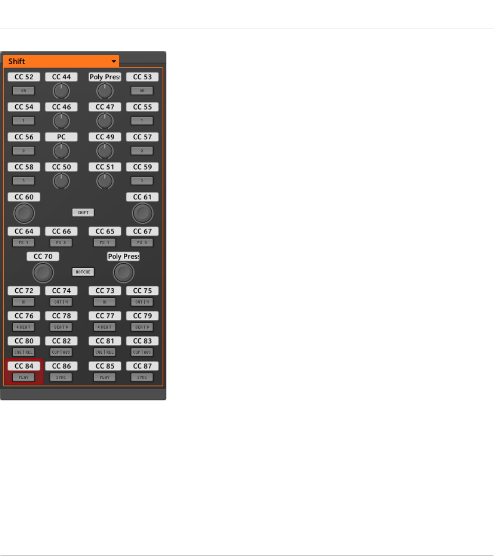
The Hardware area representing the TRAKTOR KONTROL X1.
In this Hardware area, you will notice the Page menu and its associated Page area (orange
frame), and the red Selection Frame on the currently selected control element (left Play button
in the picture above).
All control elements of the TRAKTOR KONTROL X1 are freely assignable to any MIDI event
(with the limitations due to the type of control element), with the exception of the SHIFT and
HOTCUE buttons. These buttons have specific functions explained in the previous section.
Using Your TRAKTOR KONTROL X1
Assignable Control Elements
CONTROLLER EDITOR - Manual - 122
The names that you see on the device only refer to their original function in the TRAKTOR
software.
The TRAKTOR KONTROL X1 holds the following assignable control elements:
• 24 freely assignable buttons.
• 8 freely assignable knobs.
• 4 freely assignable Push Encoders.
Assignment Parameters
The following table summarizes where to find all assignment details for each type of control
element on your controller:
Type of Control Element Assignment Parameters
Buttons ↑23.6.2, Assignments for Buttons
Knobs ↑23.6.5, Assignments for Knobs and the Like
Push Encoders – Push action ↑23.6.2, Assignments for Buttons
Push Encoders – Turn action ↑23.6.7, Assignments for Digital Encoders
10.3 Visual Feedback on Your Controller
The fast bidirectional communication between your TRAKTOR KONTROL X1 and the Hardware
Service on the software side allows status indications on your controller to be made in real
time.
On your TRAKTOR KONTROL X1, all buttons are equipped with LEDs that informs you about
the assignment state of the button at any time. The LEDs below each control element can have
three states: off, dimmed and bright. Their lighting behavior depends on the state of the con-
trol element.
The following table indicates you the possible states for the LEDs:
Using Your TRAKTOR KONTROL X1
Visual Feedback on Your Controller
CONTROLLER EDITOR - Manual - 123

Button State LED State
Not assigned Off
Assigned – Off state Dimmed
Assigned – On state Bright
For buttons in Increment mode, the Off state corresponds to the zero value, while the On
state corresponds to a value greater than zero.
Controlling the Button State
The state of each button can be controlled in two ways — internally via your actions on the
button, or remotely via MIDI feedback:
• In Toggle mode, both controls are enabled: both your actions on the button and the possi-
bly incoming MIDI messages are taken into account to update the button state.
• In Trigger, Gate, and Increment mode, you can choose which control mode you want to
use via the LED On menu located in the Assign pane of the Inspector.
For more information on the button modes, LED On menu, and MIDI feedback mode, see
↑23.6.2, Assignments for Buttons.
Adjusting the LED Brightness
You can adjust the LED brightness for both On and Off button states in File > Preferences >
Controller > Traktor Kontrol X1 - x > LEDs (see ↑23.2, The Preferences Window for more infor-
mation on the Preferences window).
10.4 Using Two or More TRAKTOR KONTROL X1 Units
You can use up to four TRAKTOR KONTROL X1 units simultaneously. This allows you to fur-
ther extend the number of parameters you can control in your target(s). For more information
on how to set up more than one TRAKTOR KONTROL X1 for use with the same computer,
please refer to chapter ↑22, Using Two or More Units of the Same Type.
Using Your TRAKTOR KONTROL X1
Using Two or More TRAKTOR KONTROL X1 Units
CONTROLLER EDITOR - Manual - 124

11 Using Your TRAKTOR KONTROL X1 MK2
In this chapter, we will focus on what’s happening on your TRAKTOR KONTROL X1 MK2. By
reading this, you will learn:
• How to use the basic controls on your controller for navigating through the MIDI mapping
system.
• The list of all assignable control elements on your controller.
• How the various luminous elements give you some important information about their
state.
• How to configure more than one X1 unit for use as MIDI remote controls.
11.1 Basic Controls
This section shows you the commands available on your TRAKTOR KONTROL X1 MK2 for ba-
sic tasks: switching between MIDI mode and TRAKTOR mode, and selecting subsets (Pages) of
MIDI assignments.
All these actions can of course be done via the Controller Editor user interface — see chap-
ter ↑3, Quick Start for example. Nevertheless, using your NI controller instead can be very
handy in a live situation!
Selection Command
MIDI/TRAKTOR mode SHIFT + both Load Left and
Load Right buttons
Pages SHIFT
Using Your TRAKTOR KONTROL X1 MK2
Basic Controls
CONTROLLER EDITOR - Manual - 125

For more information on the Pages, see ↑4.3, The Mapping System.
You cannot switch between Templates from the TRAKTOR KONTROL X1 MK2. To do this,
you have to use the Controller Editor interface (see ↑3.2, Loading MIDI Assignments).
When your TRAKTOR KONTROL X1 MK2 is in MIDI mode, the SHIFT button is lit at full
brightness.
Switching Between Pages: Gate vs. Toggle
The SHIFT button can have two operating modes:
• Gate mode: The Page is activated for the time the button is hold depressed.
• Toggle mode: The Page is activated until the next time you press the button again.
You can choose the desired mode for the SHIFT button in the Controller Editor. To do this:
1. Check that the TRAKTOR KONTROL X1 MK2 is selected in the Device menu.
2. On the Pages pane of the Inspector, click the Shift Mode menu and select the desired
mode Gate or Toggle.
Adjusting Settings for your Controller
You can adjust various settings for your TRAKTOR KONTROL X1 MK2 in File > Preferences >
Controller. See ↑23.2.2, Controller Page for more information.
11.2 Assignable Control Elements
If you selected the TRAKTOR KONTROL X1 MK2 in the Device menu of the Application Con-
trol Bar, this is what the Hardware area looks like:
Using Your TRAKTOR KONTROL X1 MK2
Assignable Control Elements
CONTROLLER EDITOR - Manual - 126
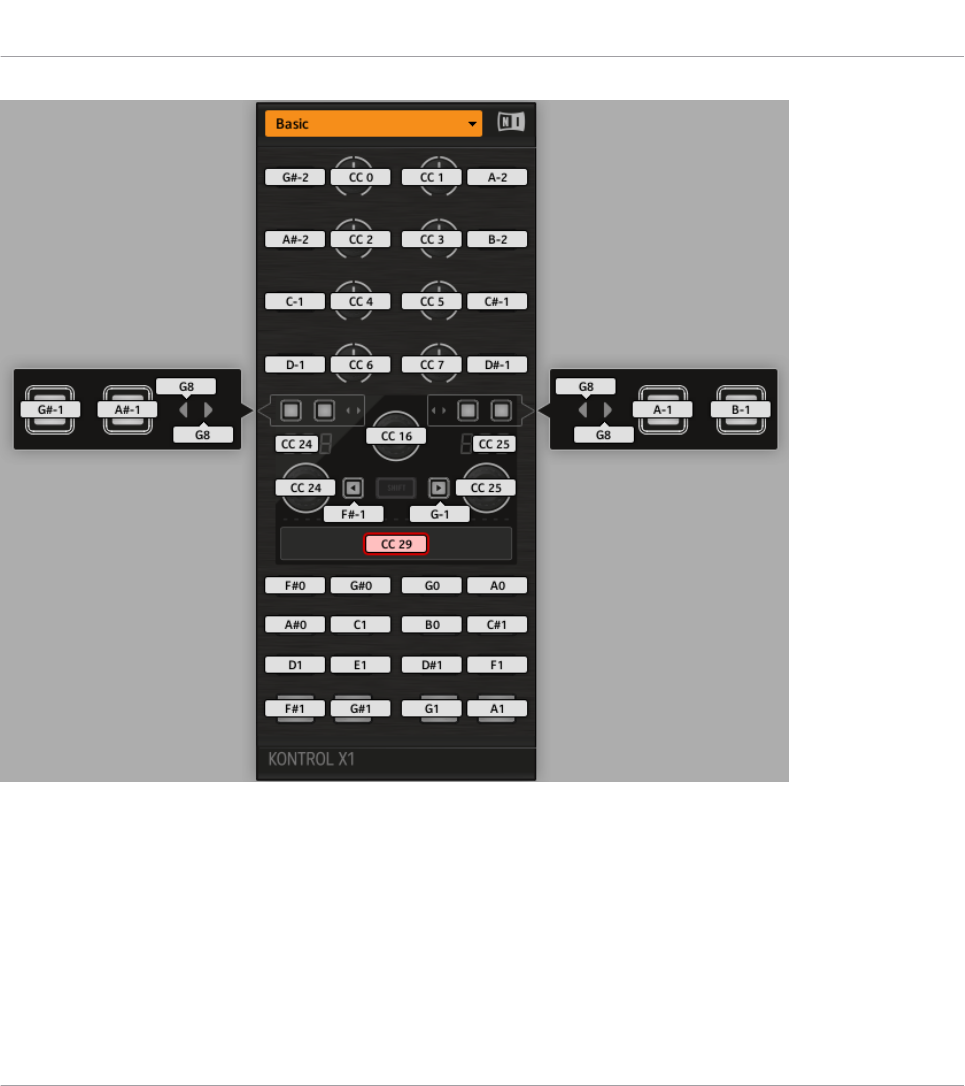
The Hardware area representing the TRAKTOR KONTROL X1 MK2.
In this Hardware area, you will notice the Page menu including its associated Page area, and
the red Selection Frame on the currently selected control element (the Touch Strip in the pic-
ture above).
All control elements of the TRAKTOR KONTROL X1 MK2 are freely assignable to any MIDI
event (with the limitations due to the type of control element), with the exception of the SHIFT
button. This button has a specific function explained in the previous section.
Using Your TRAKTOR KONTROL X1 MK2
Assignable Control Elements
CONTROLLER EDITOR - Manual - 127
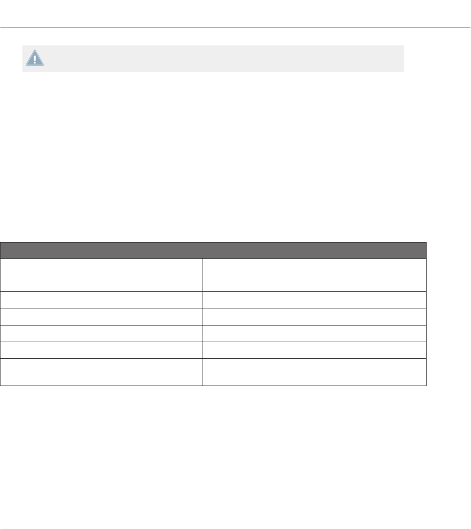
The names that you see on the device only refer to their original function in the TRAKTOR
software.
The TRAKTOR KONTROL X1 MK2 holds the following assignable control elements:
• 32 freely assignable buttons.
• 8 freely assignable knobs.
• 3 freely assignable capacitive encoders.
• 1 seven segment display.
• 1 freely assignable touch strip.
Assignment Parameters
The following table summarizes where to find all assignment details for each type of control
element on your controller:
Type of Control Element Assignment Parameters
Buttons ↑23.6.2, Assignments for Buttons
Knobs ↑23.6.5, Assignments for Knobs and the Like
Capacitive Encoders – Touch action ↑23.6.2, Assignments for Buttons
Capacitive Encoders – Push action ↑23.6.2, Assignments for Buttons
Capacitive Encoders – Turn action ↑23.6.7, Assignments for Digital Encoders
Touch Strip – Touch action ↑23.6.2, Assignments for Buttons
Touch Strip – Position ↑23.6.9, Assignments for Touch Strips – Position Action
(TRAKTOR KONTROL Devices)
11.3 Visual Feedback on Your Controller
The fast bidirectional communication between your TRAKTOR KONTROL X1 MK2 and the
Hardware Service on the software side allows status indications on your controller to be made
in real time.
Using Your TRAKTOR KONTROL X1 MK2
Visual Feedback on Your Controller
CONTROLLER EDITOR - Manual - 128
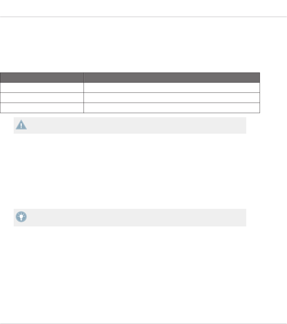
On your TRAKTOR KONTROL X1 MK2, all buttons are equipped with LEDs that informs you
about the assignment state of the button at any time. The LEDs below each control element
can have three states: off, dimmed and bright. Their lighting behavior depends on the state of
the control element.
The following table indicates you the possible states for the LEDs:
Button State LED State
Not assigned Off
Assigned – Off state Dimmed
Assigned – On state Bright
For buttons in Increment mode, the Off state corresponds to the zero value, while the On
state corresponds to a value greater than zero.
Controlling the Button State
The state of each button can be controlled in two ways — internally via your actions on the
button, or remotely via MIDI feedback:
• In Toggle mode, both controls are enabled: both your actions on the button and the possi-
bly incoming MIDI messages are taken into account to update the button state.
• In Trigger, Gate, and Increment mode, you can choose which control mode you want to
use via the LED On menu located in the Assign pane of the Inspector.
For more information on the button modes, LED On menu, and MIDI feedback mode, see
↑23.6.2, Assignments for Buttons.
Adjusting the LED Brightness
You can adjust the LED brightness for both On and Off button states in File > Preferences >
Controller > Traktor Kontrol X1 MK2 - x > LEDs (see ↑23.2, The Preferences Window for more
information on the Preferences window).
Using Your TRAKTOR KONTROL X1 MK2
Visual Feedback on Your Controller
CONTROLLER EDITOR - Manual - 129

Controlling the LED Chain State of the Touch Strip
The state of the LED chain can be controlled in two ways — internally via your actions on the
touch strip, or remotely via MIDI feedback. For more details, please refer to section ↑23.6.9,
Assignments for Touch Strips – Position Action (TRAKTOR KONTROL Devices).
11.4 Using Two or More TRAKTOR KONTROL X1 MK2 Units
You can use up to four TRAKTOR KONTROL X1 MK2 units simultaneously. This allows you to
further extend the number of parameters you can control in your target(s). For more informa-
tion on how to set up more than one TRAKTOR KONTROL X1 MK2 for use with the same com-
puter, please refer to chapter ↑22, Using Two or More Units of the Same Type.
Using Your TRAKTOR KONTROL X1 MK2
Using Two or More TRAKTOR KONTROL X1 MK2 Units
CONTROLLER EDITOR - Manual - 130
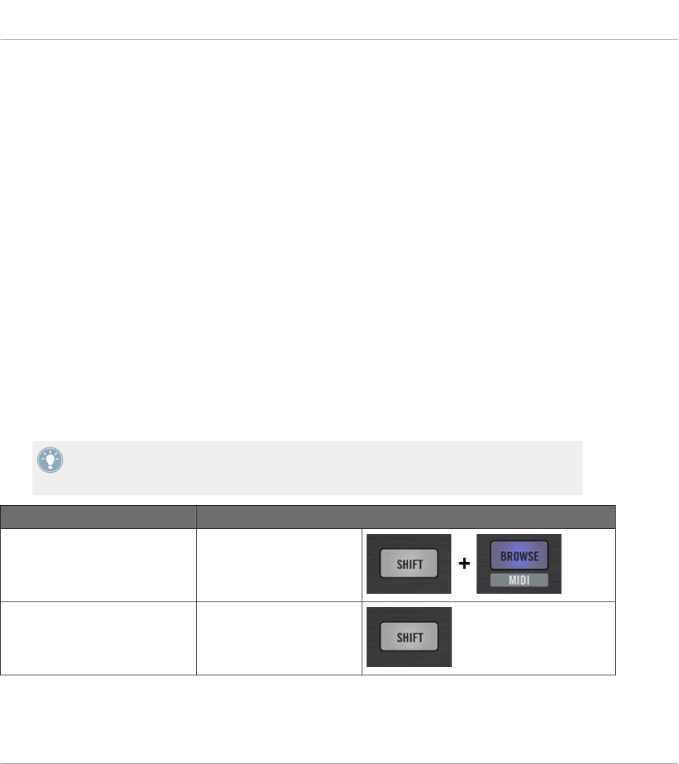
12 Using Your TRAKTOR KONTROL F1
In this chapter, we will focus on what’s happening on your TRAKTOR KONTROL F1. By read-
ing this, you will learn:
• How to use the basic controls on your controller for navigating through the MIDI mapping
system.
• The list of all assignable control elements on your controller.
• How the various luminous elements give you some important information about their
state.
• How to configure more than one F1 unit for use as MIDI remote controls.
12.1 Basic Controls
This section shows you the commands available on your TRAKTOR KONTROL F1 for basic
tasks: switching between MIDI mode and TRAKTOR mode, and selecting subsets (Pages) of
MIDI assignments.
All these actions can of course be done via the Controller Editor user interface — see chap-
ter ↑3, Quick Start for example. Nevertheless, using your NI controller instead can be very
handy in a live situation!
Selection Command
MIDI/TRAKTOR mode SHIFT + BROWSE
Pages SHIFT
Using Your TRAKTOR KONTROL F1
Basic Controls
CONTROLLER EDITOR - Manual - 131

For more information on the Pages, see ↑4.3, The Mapping System.
You cannot switch between Templates from the TRAKTOR KONTROL F1. To do this, you
have to use the Controller Editor interface (see ↑3.2, Loading MIDI Assignments).
When your F1 is in MIDI mode, the SHIFT button is lit.
Switching Between Pages: Gate vs. Toggle
The SHIFT button can have two operating modes:
• Gate mode: The Page is activated for the time the button is hold depressed.
• Toggle mode: The Page is activated until the next time you press the button again.
You can choose the desired mode for the SHIFT button in the Controller Editor. To do this:
1. Check that the TRAKTOR KONTROL F1 is selected in the Device menu.
2. On the Pages pane of the Inspector, click the Shift Mode menu and select the desired
mode Gate or Toggle.
Adjusting Settings for your Controller
You can adjust various settings for your TRAKTOR KONTROL F1 in File > Preferences > Con-
troller. See ↑23.2.2, Controller Page for more information.
12.2 Assignable Control Elements
If you selected the TRAKTOR KONTROL F1 in the Device menu of the Application Control Bar,
this is what the Hardware area looks like:
Using Your TRAKTOR KONTROL F1
Assignable Control Elements
CONTROLLER EDITOR - Manual - 132
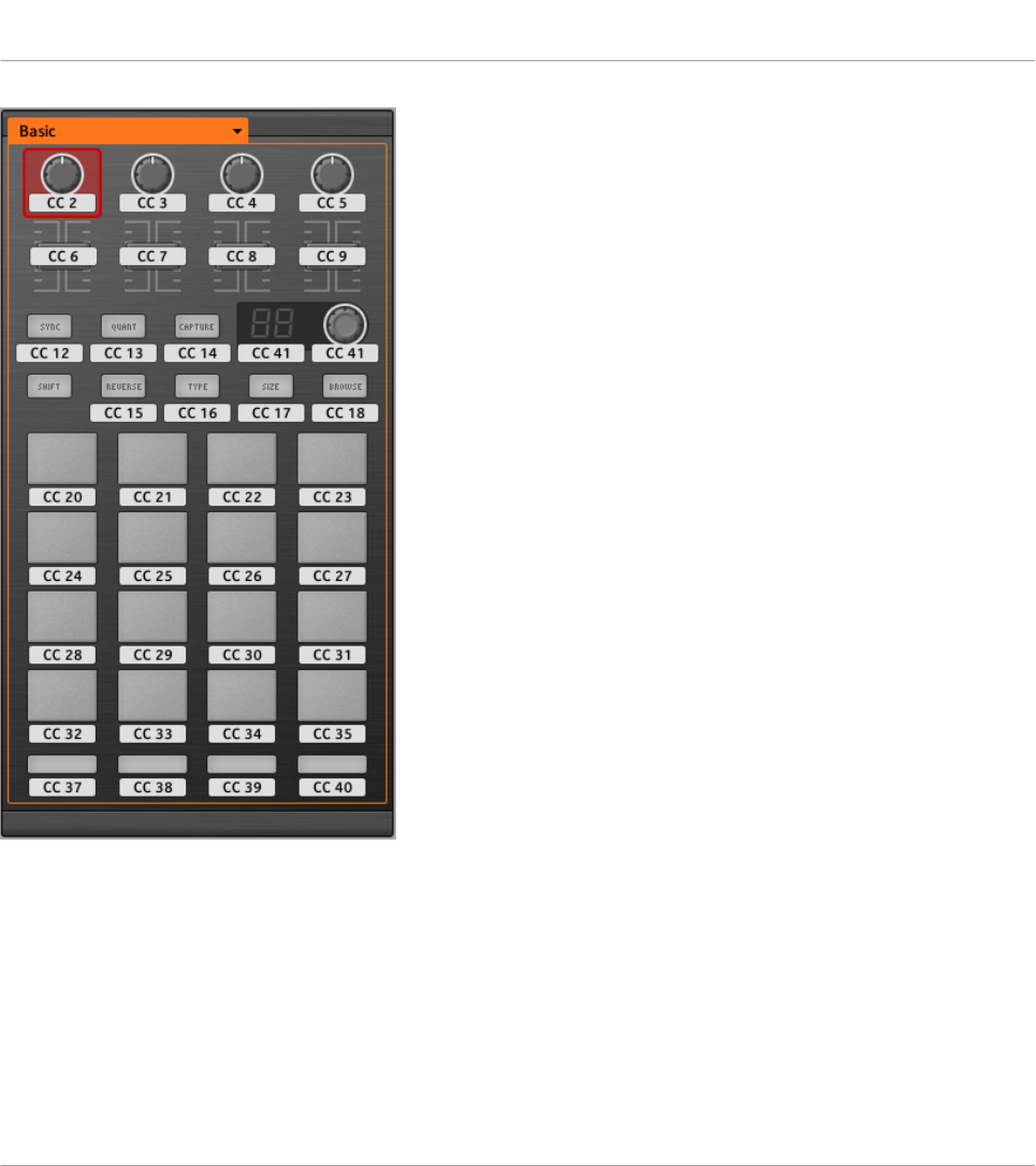
The Hardware area representing the TRAKTOR KONTROL F1.
In this Hardware area, you will notice the Page menu and its associated Page area (orange
frame), and the red Selection Frame on the currently selected control element (first FILTER
knob in the picture above).
All control elements of the TRAKTOR KONTROL F1 are freely assignable to any MIDI event
(with the limitations due to the type of control element), with the exception of the SHIFT but-
ton. This button has a specific function explained in the previous section.
Using Your TRAKTOR KONTROL F1
Assignable Control Elements
CONTROLLER EDITOR - Manual - 133
The names that you see on the device only refer to their original function in the TRAKTOR
software.
The TRAKTOR KONTROL F1 holds the following assignable control elements:
• 11 freely assignable buttons.
• 4 freely assignable knobs.
• 4 freely assignable faders.
• 1 freely assignable encoder knob.
• 1 freely assignable 7-segment display.
• 16 freely assignable pads.
Assignment Parameters
The following table summarizes where to find all assignment details for each type of control
element on your controller:
Type of Control Element Assignment Parameters
Buttons ↑23.6.2, Assignments for Buttons
Pads ↑23.6.2, Assignments for Buttons
Knobs ↑23.6.5, Assignments for Knobs and the Like
Faders ↑23.6.5, Assignments for Knobs and the Like
Encoder knob – Push action ↑23.6.2, Assignments for Buttons
Encoder knob – Turn action ↑23.6.7, Assignments for Digital Encoders
7-segment display ↑23.6.11, Assignments for LED Chains and 7-segment Displays
12.3 Visual Feedback on Your Controller
The fast bidirectional communication between your TRAKTOR KONTROL F1 and the Hardware
Service on the software side allows status indications on your controller to be made in real
time.
Your TRAKTOR KONTROL F1 provides you visual feedback in various ways:
Using Your TRAKTOR KONTROL F1
Visual Feedback on Your Controller
CONTROLLER EDITOR - Manual - 134
• All buttons and pads are equipped with LEDs that inform you about the assignment state
of the control element at any time.
• The 7-segment display shows you additional information about the assignment of your
choice.
12.3.1 Buttons and Pads
The LEDs below each button can have three states: off, dimmed and bright. Their lighting be-
havior depends on the state of the control element.
The following table indicates you the possible states for the LEDs:
Button State LED State
Not assigned Off
Assigned – Off state Dimmed
Assigned – On state Bright
For buttons in Increment mode, the Off state corresponds to the zero value, while the On
state corresponds to a value greater than zero.
Multicolor Pads
As for the pads, they are equipped with RGB LEDs. This by far extends the monitoring possibil-
ities of these control elements. Indeed, you can choose which from the 16 available colors you
want to use for the On and Off states — and this, for each pad individually!
The pads offer you three Color modes:
• Single mode: You can choose a color that will be used bright and dimmed for the On and
Off states, respectively. In this mode, the pad’s lighting behaves like the buttons (see ta-
ble above).
• Dual mode: You can choose a color for the On state and another color for the Off state.
Both colors will be used at full brightness.
• HSB mode: This mode is only available when the pad’s state is controlled via MIDI feed-
back (see below). In HSB mode, you can precisely define from within your MIDI target
which color the pad will use.
Using Your TRAKTOR KONTROL F1
Visual Feedback on Your Controller
CONTROLLER EDITOR - Manual - 135
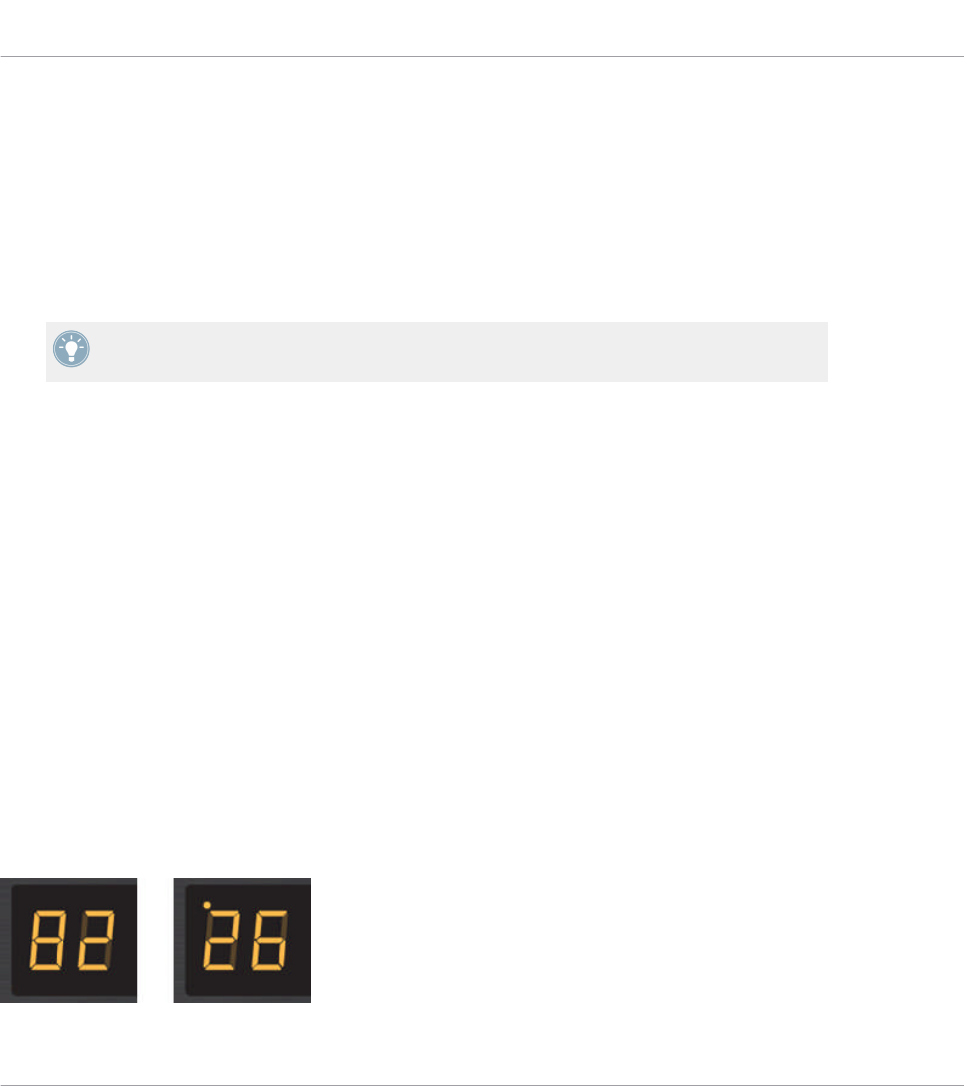
Controlling the State of the Control Elements
The state of each button/pad can be controlled in two ways — internally via your actions on it,
or remotely via MIDI feedback:
• In Toggle mode, both controls are enabled: both your actions on the control element and
the possibly incoming MIDI messages are taken into account to update the button state.
• In Trigger, Gate, and Increment mode, you can choose which control mode you want to
use via the LED On menu located in the Assign pane of the Inspector.
For more information on the modes, LED On menu, and MIDI feedback mode, see ↑23.6.2,
Assignments for Buttons.
Adjusting the LED Brightness
You can adjust the LED brightness for both On and Off states in File > Preferences > Controller
> Traktor Kontrol F1 - x > LEDs (see ↑23.2, The Preferences Window for more information on
the Preferences window).
12.3.2 7-segment Display
The 7-segment display next to the encoder knob can display any MIDI Note’ velocity or any
MIDI CC value. The displayed value depends on the display’s assignment settings as defined in
the Assign pane of the Inspector. See ↑23.6.11, Assignments for LED Chains and 7-segment
Displays for more information on the possible assignments.
Since the 7-segment display holds two digits and possible values range from 0 to 127, values
are displayed as follows:
• Values within 0–99 are displayed as 0–99.
• Values within 100–127 are displayed as 0–27 with an additional dot (•) at the top left cor-
ner of the display (meaning “+100”).
The 7-segment display reading 82 (left) and 126 (right).
Using Your TRAKTOR KONTROL F1
Visual Feedback on Your Controller
CONTROLLER EDITOR - Manual - 136

12.4 Using Two or More TRAKTOR KONTROL F1 Units
You can use up to four TRAKTOR KONTROL F1 units simultaneously. This allows you to fur-
ther extend the number of parameters you can control in your target(s). For more information
on how to set up more than one TRAKTOR KONTROL F1 for use with the same computer,
please refer to chapter ↑22, Using Two or More Units of the Same Type.
Using Your TRAKTOR KONTROL F1
Using Two or More TRAKTOR KONTROL F1 Units
CONTROLLER EDITOR - Manual - 137
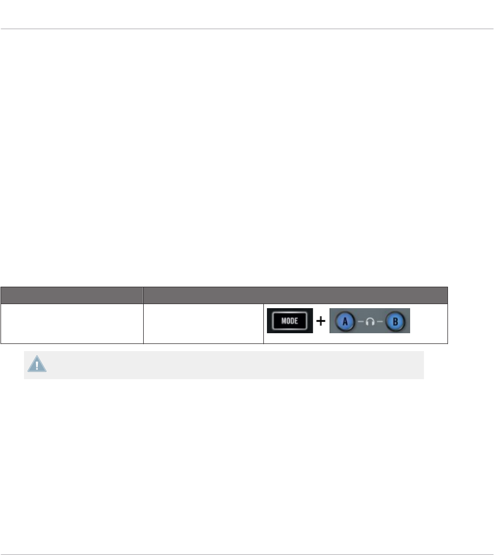
13 Using Your TRAKTOR KONTROL Z1
In this chapter, we will focus on what’s happening on your TRAKTOR KONTROL Z1. By read-
ing this, you will learn:
• How to use the basic controls on your controller for navigating through the MIDI mapping
system.
• The list of all assignable control elements on your controller.
• How the various luminous elements give you some important information about their
state.
13.1 Basic Controls
This section shows you the command available on your TRAKTOR KONTROL Z1 for switching
between MIDI mode and TRAKTOR mode.
Selection Command
MIDI/TRAKTOR mode MODE + Cues (ensure both
A & B headphone cues are
pressed)
You cannot switch between Templates from the TRAKTOR KONTROL Z1. To do this, you
have to use the Controller Editor interface (see ↑3.2, Loading MIDI Assignments).
When your Z1 is in MIDI mode, the MODE button is lit.
Adjusting Settings for your Controller
You can adjust various settings for your TRAKTOR KONTROL Z1 in File > Preferences > Con-
troller. See ↑23.2.2, Controller Page for more information.
Using Your TRAKTOR KONTROL Z1
Basic Controls
CONTROLLER EDITOR - Manual - 138
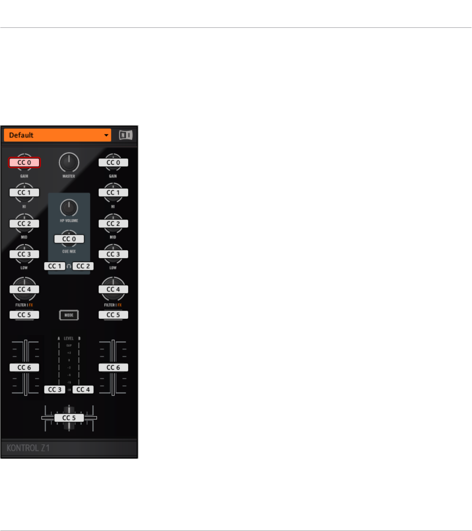
13.2 Assignable Control Elements
If you selected the TRAKTOR KONTROL Z1 in the Device menu of the Application Control Bar,
this is what the Hardware area looks like:
The Hardware area representing the TRAKTOR KONTROL Z1.
Using Your TRAKTOR KONTROL Z1
Assignable Control Elements
CONTROLLER EDITOR - Manual - 139

In this Hardware area, you will notice the Page menu and its associated Page area, and the red
Selection Frame on the currently selected control element (Deck Focus button B in the picture
above).
All control elements marked with a white Label Field in the Hardware area are freely assigna-
ble to any MIDI event (with the limitations due to the type of control element).
The names that you see on the device only refer to their original function in the TRAKTOR
software.
The TRAKTOR KONTROL Z1 holds the following assignable control elements:
• 4 freely assignable buttons.
• 11 freely assignable knobs.
• 3 freely assignable faders (2 channel faders and 1 crossfader).
• 2 assignable LED Meters.
Assignment Parameters
The following table summarizes where to find all assignment details for each type of control
element on your controller:
Type of Control Element Assignment Parameters
Buttons ↑23.6.2, Assignments for Buttons
Knobs ↑23.6.5, Assignments for Knobs and the Like
Faders ↑23.6.5, Assignments for Knobs and the Like
13.3 Visual Feedback on Your Controller
The fast bidirectional communication between your TRAKTOR KONTROL Z1 and the Hardware
Service on the software side allows status indications on your controller to be made in real
time. All buttons are equipped with LEDs that inform you about their assignment state at any
time.
Basically, each button on your controller can have three states:
• Not assigned.
Using Your TRAKTOR KONTROL Z1
Visual Feedback on Your Controller
CONTROLLER EDITOR - Manual - 140
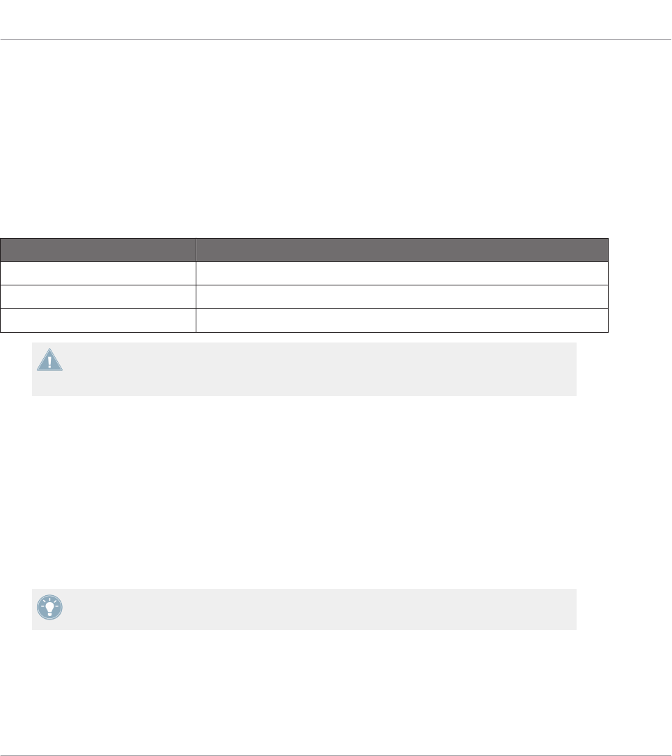
• Assigned, in Off state.
• Assigned, in On state.
The following paragraphs describe how the LED under each button keeps you informed on the
button states.
Single-Color Buttons
For all buttons the LEDs can have three states: off, dimmed and bright. The LED states direct-
ly indicate the button states:
Button State LED State
Not assigned Off
Assigned – Off state Dimmed
Assigned – On state Bright
For buttons in Increment mode, the Off state corresponds to the zero value, while the On
state corresponds to a value greater than zero. See section ↑23.6.2, Assignments for But-
tons for more information on the various button modes.
Controlling the Button State
The On/Off state of each single-color or multicolor button can be controlled in two ways — in-
ternally via your actions on the button, or remotely via MIDI feedback:
• In Toggle mode, both controls are enabled: both your actions on the button and the possi-
bly incoming MIDI messages are taken into account to update the button and LED state.
• In Trigger, Gate, and Increment mode, you can choose which control mode (internal or re-
mote via MIDI) you want to use. This is done via the LED On menu in the Assign pane of
the Inspector.
For more information on the button modes, LED On menu, and MIDI feedback mode, see
↑23.6.2, Assignments for Buttons.
Using Your TRAKTOR KONTROL Z1
Visual Feedback on Your Controller
CONTROLLER EDITOR - Manual - 141

Adjusting the LED Brightness
You can adjust the LED brightness for both On and Off states in File > Preferences > Controller
> Traktor Kontrol Z1 > LEDs (see ↑23.2, The Preferences Window for more information on the
Preferences window).
Using Your TRAKTOR KONTROL Z1
Visual Feedback on Your Controller
CONTROLLER EDITOR - Manual - 142
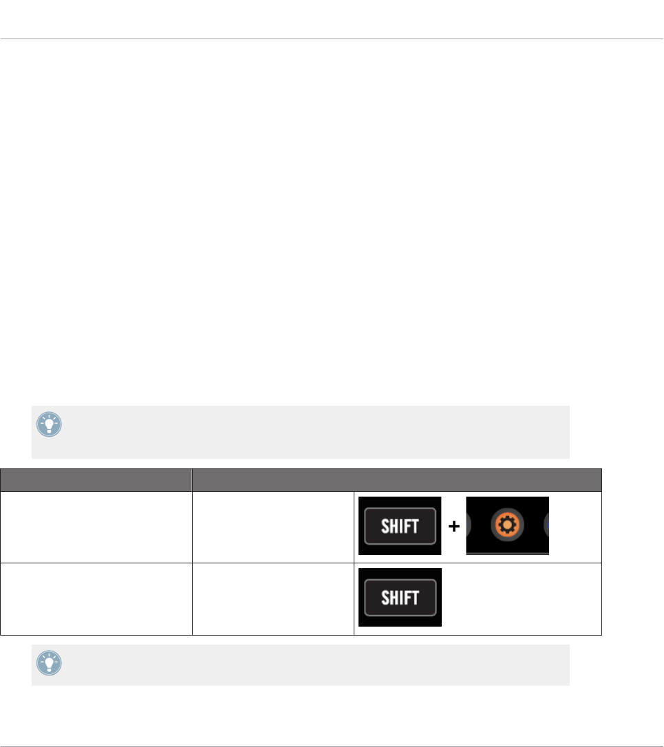
14 Using Your TRAKTOR KONTROL Z2
In this chapter, we will focus on what’s happening on your TRAKTOR KONTROL Z2. By read-
ing this, you will learn:
• How to use the basic controls on your controller for navigating through the MIDI mapping
system.
• The list of all assignable control elements on your controller.
• How the various luminous elements give you some important information about their
state.
14.1 Basic Controls
This section shows you the commands available on your TRAKTOR KONTROL Z2 for basic
tasks: switching between MIDI mode and TRAKTOR mode, and selecting subsets (Pages) of
MIDI assignments.
All these actions can of course be done via the Controller Editor user interface — see chap-
ter ↑3, Quick Start for example. Nevertheless, using your NI controller instead can be very
handy in a live situation!
Selection Command
MIDI/TRAKTOR mode SHIFT + Settings
Pages SHIFT
For more information on the Pages, see ↑4.3, The Mapping System.
Using Your TRAKTOR KONTROL Z2
Basic Controls
CONTROLLER EDITOR - Manual - 143
You cannot switch between Templates from the TRAKTOR KONTROL Z2. To do this, you
have to use the Controller Editor interface (see ↑3.2, Loading MIDI Assignments).
When your Z2 is in MIDI mode, the Settings button is lit.
Switching Between Pages: Gate vs. Toggle
The SHIFT button can have two operating modes:
• Gate mode: The Page is activated for the time the button is hold depressed.
• Toggle mode: The Page is activated until the next time you press the button again.
You can choose the desired mode for the SHIFT button in the Controller Editor. To do this:
1. Check that the TRAKTOR KONTROL Z2 is selected in the Device menu.
2. On the Pages pane of the Inspector, click the Shift Mode menu and select the desired
mode Gate or Toggle.
Adjusting Settings for your Controller
You can adjust various settings for your TRAKTOR KONTROL Z2 in File > Preferences > Con-
troller. See ↑23.2.2, Controller Page for more information.
14.2 Assignable Control Elements
If you selected the TRAKTOR KONTROL Z2 in the Device menu of the Application Control Bar,
this is what the Hardware area looks like:
Using Your TRAKTOR KONTROL Z2
Assignable Control Elements
CONTROLLER EDITOR - Manual - 144
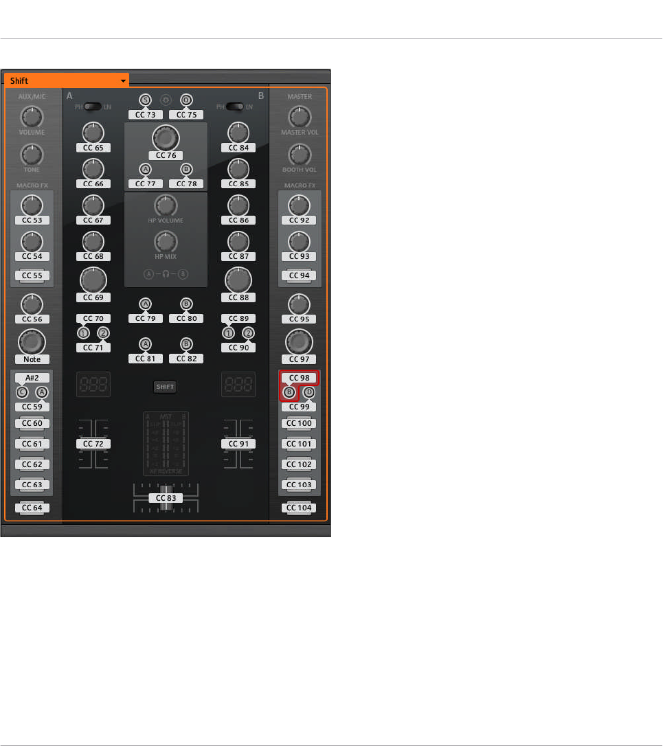
The Hardware area representing the TRAKTOR KONTROL Z2.
In this Hardware area, you will notice the Page menu and its associated Page area (orange
frame), and the red Selection Frame on the currently selected control element (Deck Focus
button B in the picture above).
All control elements marked with a white Label Field in the Hardware area are freely assigna-
ble to any MIDI event (with the limitations due to the type of control element).
Using Your TRAKTOR KONTROL Z2
Assignable Control Elements
CONTROLLER EDITOR - Manual - 145
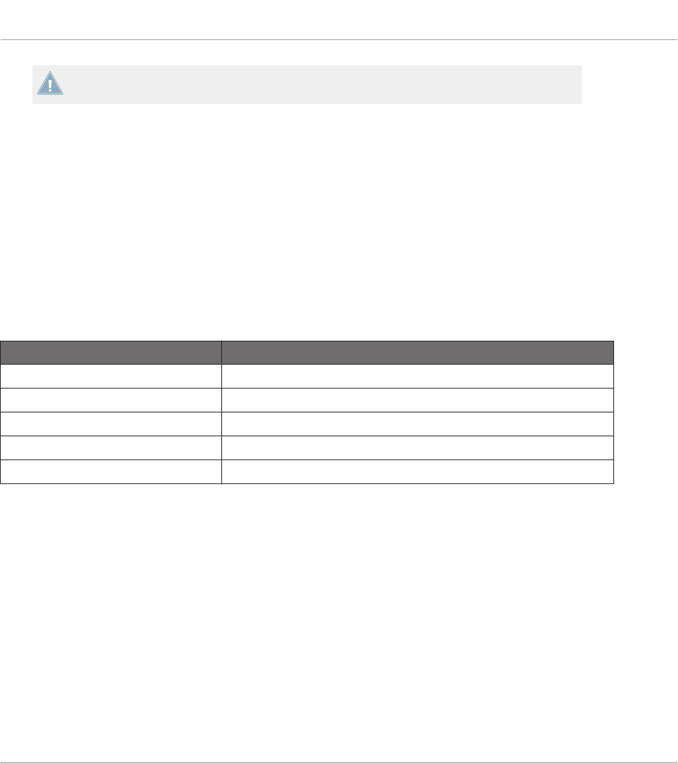
The names that you see on the device only refer to their original function in the TRAKTOR
software.
The TRAKTOR KONTROL Z2 holds the following assignable control elements:
• 28 freely assignable buttons including 8 multicolor buttons.
• 3 freely assignable encoders with Turn and Push action (2 Auto-loop encoders and the
BROWSE encoder).
• 16 freely assignable knobs.
• 3 freely assignable faders (2 channel faders and 1 crossfader).
Assignment Parameters
The following table summarizes where to find all assignment details for each type of control
element on your controller:
Type of Control Element Assignment Parameters
Buttons ↑23.6.2, Assignments for Buttons
Knobs ↑23.6.5, Assignments for Knobs and the Like
Faders ↑23.6.5, Assignments for Knobs and the Like
Encoders – Push action ↑23.6.2, Assignments for Buttons
Encoders – Turn action ↑23.6.7, Assignments for Digital Encoders
14.3 Visual Feedback on Your Controller
The fast bidirectional communication between your TRAKTOR KONTROL Z2 and the Hardware
Service on the software side allows status indications on your controller to be made in real
time. All buttons are equipped with LEDs that inform you about their assignment state at any
time.
Basically, each button on your controller can have three states:
• Not assigned.
• Assigned, in Off state.
Using Your TRAKTOR KONTROL Z2
Visual Feedback on Your Controller
CONTROLLER EDITOR - Manual - 146
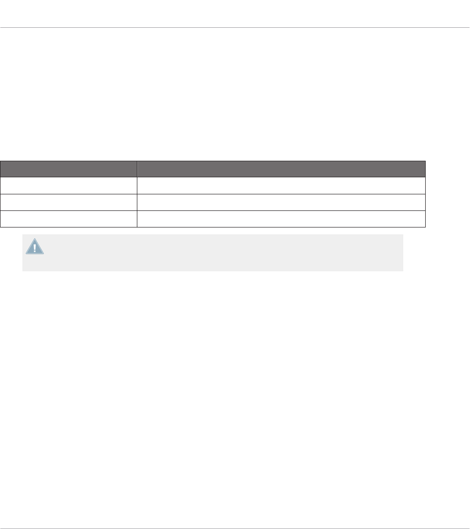
• Assigned, in On state.
The following paragraphs describe how the LED under each button keeps you informed on the
button states.
Single-Color Buttons
For all buttons except the Cue/Sample Trigger buttons 1–4 (on either side of your controller),
the LEDs can have three states: off, dimmed and bright. The LED states directly indicate the
button states:
Button State LED State
Not assigned Off
Assigned – Off state Dimmed
Assigned – On state Bright
For buttons in Increment mode, the Off state corresponds to the zero value, while the On
state corresponds to a value greater than zero. See section ↑23.6.2, Assignments for But-
tons for more information on the various button modes.
Multicolor Buttons
The eight Cue/Sample Trigger buttons (four on either side of your controller) are equipped with
RGB LEDs. This by far extends the monitoring possibilities of these control elements. Indeed,
you can choose which from the 16 available colors you want to use for the On and Off states —
and this, for each button individually!
The Cue/Sample Trigger buttons offer you three Color modes:
• Single mode: You can choose a color that will be used bright and dimmed for the On and
Off states, respectively. In this mode, the button’s lighting behaves like that of single-col-
or buttons (see table above).
• Dual mode: You can choose a color for the On state and another color for the Off state.
Both colors will be used at full brightness.
• HSB mode: This mode is only available when the button’s state is controlled via MIDI
feedback (see below). In HSB mode, you can precisely define from within your MIDI tar-
get which color the button will use.
Using Your TRAKTOR KONTROL Z2
Visual Feedback on Your Controller
CONTROLLER EDITOR - Manual - 147
Controlling the Button State
The On/Off state of each single-color or multicolor button can be controlled in two ways — in-
ternally via your actions on the button, or remotely via MIDI feedback:
• In Toggle mode, both controls are enabled: both your actions on the button and the possi-
bly incoming MIDI messages are taken into account to update the button and LED state.
• In Trigger, Gate, and Increment mode, you can choose which control mode (internal or re-
mote via MIDI) you want to use. This is done via the LED On menu in the Assign pane of
the Inspector.
For more information on the button modes, LED On menu, and MIDI feedback mode, see
↑23.6.2, Assignments for Buttons.
Adjusting the LED Brightness
You can adjust the LED brightness for both On and Off states in File > Preferences > Controller
> Traktor Kontrol Z2 > LEDs (see ↑23.2, The Preferences Window for more information on the
Preferences window).
Using Your TRAKTOR KONTROL Z2
Visual Feedback on Your Controller
CONTROLLER EDITOR - Manual - 148

15 Using Your TRAKTOR KONTROL D2
In this chapter, we will focus on what’s happening on your TRAKTOR KONTROL D2. By read-
ing this, you will learn:
• How to use the basic controls on your controller for navigating through the MIDI mapping
system.
• The list of all assignable control elements on your controller.
• How the various luminous elements give you some important information about their
state.
• How to use the powerful display of your TRAKTOR KONTROL D2 in MIDI mode.
To enjoy full functionality of your NI controller as a MIDI remote control, especially con-
cerning some control elements’ state and LED behavior, you need to tell your NI controller
what is the current state of the parameter in the MIDI target. You can do this by setting up
MIDI feedback channels coming from your MIDI target back to your NI controller. This way,
your controller will always stay up-to-date with the current parameter values in your target
software/hardware. For more information on how to configure these MIDI feedback chan-
nels, please refer to your target software/hardware’s documentation.
15.1 Basic Controls
This section shows you the commands available on your TRAKTOR KONTROL D2 for basic
tasks: switching between MIDI mode and TRAKTOR mode, selecting a Template, selecting
subsets (Pages) of MIDI assignments, and switching between display modes.
All these actions can of course be done via the Controller Editor user interface — see chap-
ter ↑3, Quick Start for example. Nevertheless, using your NI controller instead can be very
handy in a live situation!
Using Your TRAKTOR KONTROL D2
Basic Controls
CONTROLLER EDITOR - Manual - 149
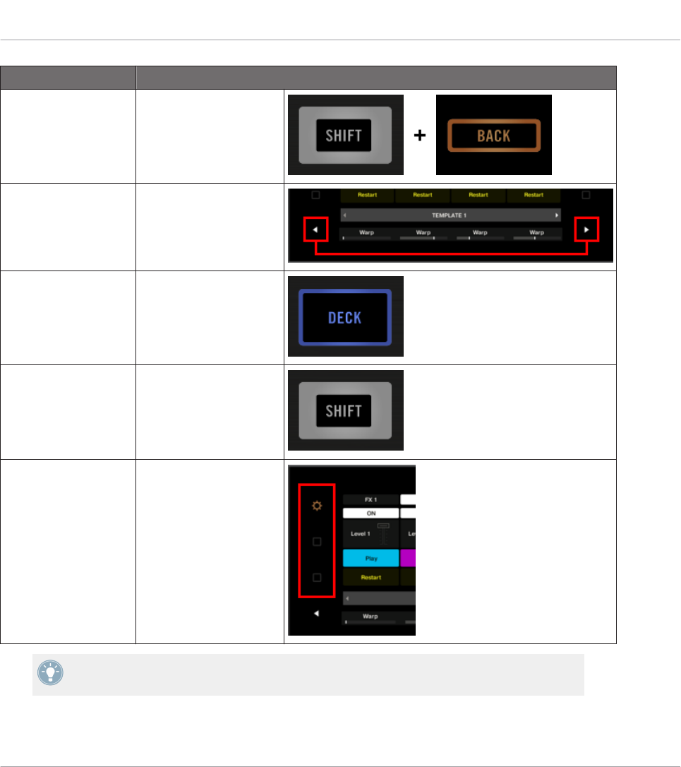
Selection Command
MIDI/TRAKTOR mode SHIFT + BACK
Templates Performance Mode but-
tons (left/right arrows)
Deck DECK button
Page SHIFT
Display mode Settings button and Dis-
play button 1–2
For more information on Templates and Pages, see ↑4.3, The Mapping System.
When your D2 is in MIDI mode, the SHIFT button is lit.
Using Your TRAKTOR KONTROL D2
Basic Controls
CONTROLLER EDITOR - Manual - 150

Switching Between Pages
In MIDI mode, D2 allows you to access four different Pages, organized as Deck A and C, each
with “Basic” and “Shift” variations. To load any of these Pages, do the following:
1. Switch to the desired Deck using the DECK buttons.
When the upper Deck A is selected, the DECK button and the control elements above it
are blue. When you switch to the lower Deck C, the DECK button and the control ele-
ments turn white.
2. Switch to the desired variation of the Deck using the SHIFT button.
Switching Between Decks and Pages: Gate vs. Toggle
The DECK and SHIFT buttons can have two operating modes:
• Gate mode: The Deck/Page is activated for the time the button is hold depressed.
• Toggle mode: The Deck/Page is activated until the next time you press the button again.
You can choose the desired mode in the Controller Editor. To do this:
1. Check that the TRAKTOR KONTROL D2 is selected in the Device menu.
2. On the Pages pane of the Inspector, click the Shift Mode menu and select the desired
mode Gate or Toggle.
Adjusting Settings for your Controller
You can adjust various settings for your TRAKTOR KONTROL D2 by going to File > Preferences
> Controller (see section ↑23.2.2, Controller Page). You can also adjust settings directly from
your controller by switching its display to Settings display mode (see section ↑15.4.2, Adjust
Color And Brightness).
15.2 Assignable Control Elements
Here is an overview of all assignable control elements in D2's Deck Unit.
Using Your TRAKTOR KONTROL D2
Assignable Control Elements
CONTROLLER EDITOR - Manual - 151
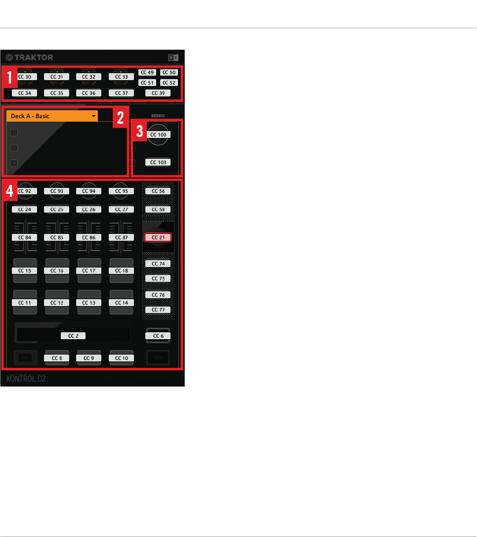
Controls on D2
D2 can be divided into the following areas:
(1) FX area: This area holds four FX buttons and four FX knobs, plus the Deck Selector buttons
A-D and the SELECT button. The buttons offer a button press assignment, while the four FX
knobs react to both turning and touching, allowing for two different assignments for each knob.
(2) Display area: This area doesn’t hold any MIDI-assignable elements. The display and the lit-
tle buttons around provide you feedback on your assignments and allow you to adjust a few
settings for your controller. See section 16.4 for more information.
Using Your TRAKTOR KONTROL D2
Assignable Control Elements
CONTROLLER EDITOR - Manual - 152
(3) BROWSE encoder and BACK button: These two control elements are freely assignable. The
BACK button offers a button press assignment, while the BROWSE encoder reacts to turning,
pushing, and touching, allowing for three different assignments for this encoder.
(4) Page area: The Page area holds all Deck controls. Apart from the DECK and SHIFT buttons,
all these control elements are freely assignable. The Page area is headed by the Page menu.
Furthermore, many control elements have multiple functions:
• The Loop encoder can be turned, pushed, and touched, allowing for three different as-
signments for this encoder.
• The Performance knobs 1–4 (beneath the display) react to turning and touching, which
can be assigned separately.
• The Slot Volume faders 1–4 are sensitive to sliding and touching, which can be assigned
separately.
• The Touch Strip detects both the touch and the position of your finger, leading to two dif-
ferent assignments.
Assignment Parameters for Control Elements on the Deck Unit
The following table summarizes where to find all assignment details for each type of control
element on the Deck Unit:
Type of Control Element Assignment Parameters
Buttons 25.6.2
Pads 25.6.2
FX knobs – Turn action 25.6.5
FX knobs – Touch action 25.6.2
Performance knobs – Turn action 25.6.8
Performance knobs – Touch action 25.6.2
Slot Volume faders – Slide action 25.6.5
Slot Volume faders – Touch action 25.6.2
BROWSE and Loop encoders – Turn action 25.6.7
BROWSE and Loop encoders – Push action 25.6.2
Using Your TRAKTOR KONTROL D2
Assignable Control Elements
CONTROLLER EDITOR - Manual - 153

Type of Control Element Assignment Parameters
BROWSE and Loop encoders – Touch action 25.6.2
Touch Strip – Touch action 25.6.2
Touch Strip – Position 25.6.9
15.3 Visual Feedback on Your Controller
The fast bidirectional communication between your TRAKTOR KONTROL D2 and the Hardware
Service on the software side allows status indications on your controller to be made in real
time.
Your TRAKTOR KONTROL D2 provides you visual feedback in various ways:
• All buttons and pads are equipped with LEDs that inform you about their assignment
state at any time. Furthermore, the eight pads provide RGB LEDs.
• The displays show you additional information about the assignments. This will be descri-
bed in section ↑15.4, The Display.
15.3.1 Buttons and Pads
All buttons and pads are equipped with single-color or multicolor LEDs. Basically, each button
or pad on your controller can have three states:
• Not assigned.
• Assigned, in Off state.
• Assigned, in On state.
Single-Color Buttons
For all buttons, the LEDs can have three states: off, dimmed and bright. The LED states direct-
ly indicate the button states:
Using Your TRAKTOR KONTROL D2
Visual Feedback on Your Controller
CONTROLLER EDITOR - Manual - 154
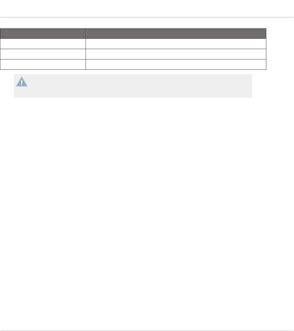
Button State LED State
Not assigned Off
Assigned – Off state Dimmed
Assigned – On state Bright
For buttons in Increment mode, the Off state corresponds to the zero value, while the On
state corresponds to a value greater than zero. See section ↑23.6.2, Assignments for But-
tons for more information on the various button modes.
Multicolor Pads
The eight pads of your controller are equipped with RGB LEDs. This by far extends the moni-
toring possibilities of these control elements. The pads offer you three Color modes:
• Single mode: You can choose a color that will be used bright and dimmed for the On and
Off states, respectively. In this mode, the pad’s lighting behaves like that of single-color
buttons (see above) except that you can choose the color.
• Dual mode: You can choose a color for the On state and another color for the Off state.
Both colors will be used at full brightness.
• HSB mode: This mode is only available when the pad’s state is controlled via MIDI feed-
back (see below). In HSB mode, you can precisely define from within your MIDI target
which color the pad will use.
Controlling the Button/Pad State
The On/Off state of each button or pad can be controlled in two ways — internally via your ac-
tions on the button/pad, or remotely via MIDI feedback:
• In Toggle mode, both controls are enabled: both your actions on the button/pad and the
possibly incoming MIDI messages are taken into account to update the button/pad and
LED state.
• In Trigger, Gate, and Increment mode, you can choose which control mode (internal or re-
mote via MIDI) you want to use. This is done via the LED On menu in the Assign pane of
the Inspector.
Using Your TRAKTOR KONTROL D2
Visual Feedback on Your Controller
CONTROLLER EDITOR - Manual - 155

For more information on the button modes, LED On menu, and MIDI feedback mode, see
↑23.6.2, Assignments for Buttons.
Buttons and Pads on the Display
In addition to the LED indications, the assignments for the FX buttons, Performance buttons,
and pads are shown within the display in Control display mode.
For more information on the display of your TRAKTOR KONTROL D2, see section ↑15.4,
The Display.
15.3.2 Performance Knobs, Slot Volume Faders, and Loop Encoder
Your TRAKTOR KONTROL D2 also gives feedback on additional control elements:
• Assignments for the Turn action of the four Performance knobs (under the display) and for
the Slide action of the four Slot Volume faders are indicated in the display in Control dis-
play mode.
For more information on the display of your TRAKTOR KONTROL D2, see section ↑15.4,
The Display.
• The Loop encoder (the push encoder next to the Slot Volume faders) is equipped with a
LED ring that indicates you the state of the encoder’s Push action. The LED ring’s behav-
ior is the same as that of buttons (see section ↑15.3.1, Buttons and Pads above), except
that there is no LED On menu in Trigger, Gate, and Increment mode: The LED ring always
reacts to incoming MIDI feedback signals (for more info on the button modes and the LED
On menu, see section ↑23.6.2, Assignments for Buttons).
15.4 The Display
The display on D2 can show various elements of your MIDI mapping configuration or give you
access to settings for your controller, depending on the display mode that is activated.
• In the default Control display mode, the display shows the assignments for particular con-
trol elements.
• In Settings display mode, you can adjust the color calibration of the display.
Using Your TRAKTOR KONTROL D2
Visual Feedback on Your Controller
CONTROLLER EDITOR - Manual - 156

Both display modes are described in the following sections.
15.4.1 Control Display Mode
By default, the display of your D2 is in Control display mode. In this mode it informs you about
both the assignments and the states of many control elements:
The display in Control display mode.
For each control element, the display indicates the element’s name as defined in its Label
Field.
By default the name defined in the Label Field is the MIDI message that will be sent by
this control element, but you can customize it to your liking, as in the picture above — for
more information, see section ↑23.4.1, Label Fields and ↑23.5.3, Assign Pane.
From top to bottom, each display shows the assignment and the state of the following control
elements:
• 1st row: FX buttons 1–4 above the display. Buttons in Off state are indicated by a dark
background, while buttons in On state are highlighted.
• 2nd row: Performance buttons 1–4 under the display. Buttons in Off state are indicated by
a dark background, while buttons in On state are highlighted.
• 3rd row: Slot Volume faders 1–4 (Slide action). A little fader picture indicates the current
value for the Slide action of each fader.
• 4th and 5th rows: Pads 1–8. The pad state is indicated in various ways depending on the
entry selected in the Color Mode menu in the Assign pane of the Inspector:
Using Your TRAKTOR KONTROL D2
The Display
CONTROLLER EDITOR - Manual - 157
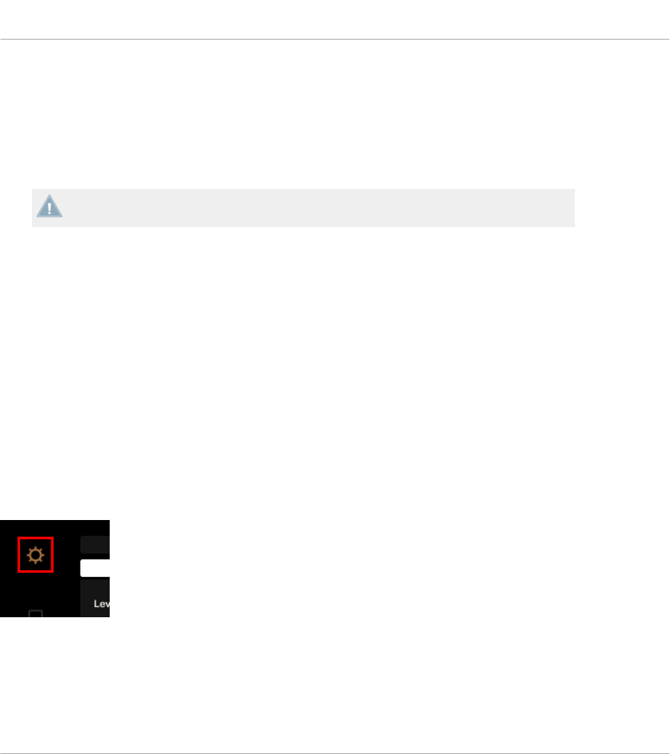
◦In Single or Dual color mode, the pad’s On state uses the color set in the Color Value
parameter (Single mode) or Color On parameter (Dual mode), while the pad’s Off state
uses the same color in a darkened version.
◦In HSB color mode (only available if the LED On menu is set to For MIDI Out), the
pad’s states use white instead and is indicated as for buttons (Off state with a dark
background, On state highlighted).
For more info on the modes available in the Color Mode menu, see section ↑15.3.1, But-
tons and Pads above.
• 6th row: This row shows you the current Template. You can switch to the previous/next
Template by pressing the lit Performance Mode buttons (showing left and right arrows) on
either side of the display, as described in section ↑15.1, Basic Controls.
• 7th row: Performance knobs 1–4 (Turn action) right under the display. A little bar indicates
the current value of the Turn action of each knob. Note that the bar can have its zero at
the left or in the middle, depending on the entry selected in the Display menu in the As-
sign pane of the Inspector — see section ↑23.6.8, Assignments for Analog Encoders.
15.4.2 Adjust Color And Brightness
The Settings display mode allows you to adjust a few hardware settings directly from your D2
device.
►To enter or exit Settings display mode, press the Settings button (showing a cog wheel) in
the top left of the display.
The Settings button.
The RGB settings let you adjust the color levels, as well as brightness. The various settings and
their current values are shown at the bottom of the display:
Using Your TRAKTOR KONTROL D2
The Display
CONTROLLER EDITOR - Manual - 158

The RGB settings.
►To adjust the red, green or blue level, turn the Performance knob 1 (RED), 2 (GREEN) or 3
(BLUE) beneath the display.
→The color levels are adjusted accordingly.
►To adjust the brightness, turn the Performance knob 4 beneath the display.
→The BRIGHTNESS value above Performance knob 4 is applied to the display.
You can also adjust brightness in the Controller Editor by going to File > Preferences >
Controller. See section ↑23.2.2, Controller Page for more information.
You can cancel your adjustments at any time by doing the following:
Using Your TRAKTOR KONTROL D2
The Display
CONTROLLER EDITOR - Manual - 159

►Turn the BROWSE encoder next to the display to select Reset or Undo, and press the en-
coder to confirm.
• The Reset option will reset all the settings to their default values.
• The Undo option will put the settings back to their previous values.
When you have made the desired color and/or brightness adjustments, press the Settings but-
ton again to exit Settings display mode.
Using Your TRAKTOR KONTROL D2
The Display
CONTROLLER EDITOR - Manual - 160

16 Using Your TRAKTOR KONTROL S8
In this chapter, we will focus on what’s happening on your TRAKTOR KONTROL S8. By read-
ing this, you will learn:
• How to use the basic controls on your controller for navigating through the MIDI mapping
system.
• The list of all assignable control elements on your controller.
• How the various luminous elements give you some important information about their
state.
• How to use the powerful displays of your TRAKTOR KONTROL S8 in MIDI mode.
To enjoy full functionality of your NI controller as a MIDI remote control, especially con-
cerning some control elements’ state and LED behavior, you need to tell your NI controller
what is the current state of the parameter in the MIDI target. You can do this by setting up
MIDI feedback channels coming from your MIDI target back to your NI controller. This way,
your controller will always stay up-to-date with the current parameter values in your target
software/hardware. For more information on how to configure these MIDI feedback chan-
nels, please refer to your target software/hardware’s documentation.
16.1 Basic Controls
This section shows you the commands available on your TRAKTOR KONTROL S8 for basic
tasks: switching between MIDI mode and TRAKTOR mode, selecting a Template, selecting the
desired Deck on each side, selecting subsets (Pages) of MIDI assignments, and switching be-
tween display modes.
All these actions can of course be done via the Controller Editor user interface — see chap-
ter ↑3, Quick Start for example. Nevertheless, using your NI controller instead can be very
handy in a live situation!
Using Your TRAKTOR KONTROL S8
Basic Controls
CONTROLLER EDITOR - Manual - 161

Selection Command
MIDI/TRAKTOR mode SHIFT (any Deck) +
BACK (right Deck)
Templates Performance Mode but-
tons (left/right arrows)
Decks DECK buttons
Pages (per Deck) SHIFT
Display mode Settings button and Dis-
play buttons 1–2
For more information on Templates and Pages, see ↑4.3, The Mapping System.
When your S8 is in MIDI mode, both SHIFT buttons are lit (dimly or fully).
Using Your TRAKTOR KONTROL S8
Basic Controls
CONTROLLER EDITOR - Manual - 162

Switching Between Decks and Pages
In MIDI mode, the S8 takes up TRAKTOR’s 4-Deck scheme. In other terms, the available Pa-
ges are organized per Deck, Decks A to D providing two Pages each (whose default names are
“Basic” and “Shift”). Thus, to load any of these Pages, do the following:
1. Switch to the desired Deck using the DECK buttons.
When the upper Deck (Deck A or B) is selected, the DECK button and the few control ele-
ments above it are blue. When you switch to the lower Deck (Deck C or D), the DECK but-
ton and these control elements turn white — this to remind you which Deck is currently
active on the left and right Deck Units of your controller.
2. Switch to the desired Page for that Deck using the SHIFT button of that Deck Unit.
Switching Between Decks and Pages: Gate vs. Toggle
The DECK and SHIFT buttons can have two operating modes:
• Gate mode: The Deck/Page is activated for the time the button is hold depressed.
• Toggle mode: The Deck/Page is activated until the next time you press the button again.
You can choose the desired mode in the Controller Editor. To do this:
1. Check that the TRAKTOR KONTROL S8 is selected in the Device menu.
2. On the Pages pane of the Inspector, click the Shift Mode menu and select the desired
mode Gate or Toggle.
Adjusting Settings for your Controller
You can adjust various settings for your TRAKTOR KONTROL S8 by going to File > Preferences
> Controller (see section ↑23.2.2, Controller Page). You can also adjust settings directly from
your controller by switching its displays to Settings display mode (see section ↑16.4.2, Adjust
Color And Brightness).
16.2 Assignable Control Elements
If you selected the TRAKTOR KONTROL S8 in the Device menu of the Application Control Bar,
you can choose which part of your controller you want to display in the Hardware area by click-
ing its miniature version in the Overview (in the top left corner):
Using Your TRAKTOR KONTROL S8
Assignable Control Elements
CONTROLLER EDITOR - Manual - 163

Click the desired part of your controller in the Overview to display its details in the Hardware
area.
In this Hardware area, you will notice the Page menu and its associated Page area (orange
frame) when the left or right Deck Unit is displayed, and the red Selection Frame on the cur-
rently selected control element.
The names that you see on the device only refer to their original function in the TRAKTOR
software.
16.2.1 Control Elements on the Deck Units
The left ands right Deck Units of your TRAKTOR KONTROL S8 hold the same control ele-
ments. Here is the list of all assignable control elements on either left Deck Unit of your S8.
Using Your TRAKTOR KONTROL S8
Assignable Control Elements
CONTROLLER EDITOR - Manual - 164

The left Deck Unit on the TRAKTOR KONTROL S8.
The Deck Units of the TRAKTOR KONTROL S8 hold the following areas:
(1) FX area: This area holds five buttons and four knobs, all of them freely assignable. Further-
more, the four FX knobs can be both turned and touched, leading to two different assignments
for each knob.
Using Your TRAKTOR KONTROL S8
Assignable Control Elements
CONTROLLER EDITOR - Manual - 165

(2) BROWSE encoder and BACK button: These two control elements are freely assignable. Fur-
thermore, the BROWSE encoder can be turned, pushed, and touched, leading to three differ-
ent assignments for this encoder.
(3) Display area: This area doesn’t hold any MIDI-assignable elements. The display and the lit-
tle buttons around provide you feedback on your assignments and allow you to adjust a few
settings for your controller. See section ↑16.4, The Displays for more information.
(4) Page area: The Page area holds all Deck controls. Apart from the DECK and SHIFT buttons,
all these control elements are freely assignable. The Page area is headed by the Page menu.
Furthermore, many control elements have multiple functions:
• The Loop encoder can be turned, pushed, and touched, leading to three different assign-
ments for this encoder.
• The Performance knobs 1–4 (under the displays) can be turned and touched, leading to
two different assignments.
• The Slot Volume faders 1–4 can be slid and touched, leading to two different assign-
ments.
• The Touch Strip detects both the touch and the position of your finger, leading to two dif-
ferent assignments.
Assignment Parameters for Control Elements on the Deck Units
The following table summarizes where to find all assignment details for each type of control
element on either Deck Unit:
Type of Control Element Assignment Parameters
Buttons ↑23.6.2, Assignments for Buttons
Pads ↑23.6.2, Assignments for Buttons
FX knobs – Turn action ↑23.6.5, Assignments for Knobs and the Like
FX knobs – Touch action ↑23.6.2, Assignments for Buttons
Performance knobs – Turn action ↑23.6.8, Assignments for Analog Encoders
Performance knobs – Touch action ↑23.6.2, Assignments for Buttons
Slot Volume faders – Slide action ↑23.6.5, Assignments for Knobs and the Like
Slot Volume faders – Touch action ↑23.6.2, Assignments for Buttons
Using Your TRAKTOR KONTROL S8
Assignable Control Elements
CONTROLLER EDITOR - Manual - 166

Type of Control Element Assignment Parameters
BROWSE and Loop encoders – Turn action ↑23.6.7, Assignments for Digital Encoders
BROWSE and Loop encoders – Push action ↑23.6.2, Assignments for Buttons
BROWSE and Loop encoders – Touch action ↑23.6.2, Assignments for Buttons
Touch Strip – Touch action ↑23.6.2, Assignments for Buttons
Touch Strip – Position ↑23.6.9, Assignments for Touch Strips – Position Ac-
tion (TRAKTOR KONTROL Devices)
16.2.2 Control Elements on the Mixer
Here is the list of all assignable control elements on the Mixer of your S8.
Using Your TRAKTOR KONTROL S8
Assignable Control Elements
CONTROLLER EDITOR - Manual - 167

The Mixer on the TRAKTOR KONTROL S8.
The Mixer of the TRAKTOR KONTROL S8 holds the following areas:
(1) Channel areas: In each of the four channel strips, all control elements are freely assignable
except the TRAKTOR button (at the top) and the FILTER and CUE buttons (at the bottom).
(2) Main area: In this area only the S (Snap) and Q (Quantize) buttons as well as the TEMPO
encoder are freely assignable. Furthermore, the TEMPO encoder can be both turned and push-
ed, leading to two different assignments.
Using Your TRAKTOR KONTROL S8
Assignable Control Elements
CONTROLLER EDITOR - Manual - 168

Most of the control elements in this area are audio controls related to the audio interface of
the S8. This is why they are not part of the MIDI mapping system.
(3) Crossfader: The crossfader is freely assignable as well.
Assignment Parameters for Control Elements on the Mixer
The following table summarizes where to find all assignment details for each type of control
element on the Mixer:
Type of Control Element Assignment Parameters
Buttons ↑23.6.2, Assignments for Buttons
Knobs ↑23.6.5, Assignments for Knobs and the Like
TEMPO encoder – Turn action ↑23.6.7, Assignments for Digital Encoders
TEMPO encoder – Push action ↑23.6.2, Assignments for Buttons
Channel faders and crossfader ↑23.6.5, Assignments for Knobs and the Like
16.3 Visual Feedback on Your Controller
The fast bidirectional communication between your TRAKTOR KONTROL S8 and the Hardware
Service on the software side allows status indications on your controller to be made in real
time.
Your TRAKTOR KONTROL S8 provides you visual feedback in various ways:
• All buttons and pads are equipped with LEDs that inform you about their assignment
state at any time. Furthermore, the 16 pads provide RGB LEDs.
• The displays show you additional information about the assignments. This will be descri-
bed in section ↑16.4, The Displays.
16.3.1 Buttons and Pads
All buttons and pads are equipped with single-color or multicolor LEDs. Basically, each button
or pad on your controller can have three states:
• Not assigned.
Using Your TRAKTOR KONTROL S8
Visual Feedback on Your Controller
CONTROLLER EDITOR - Manual - 169
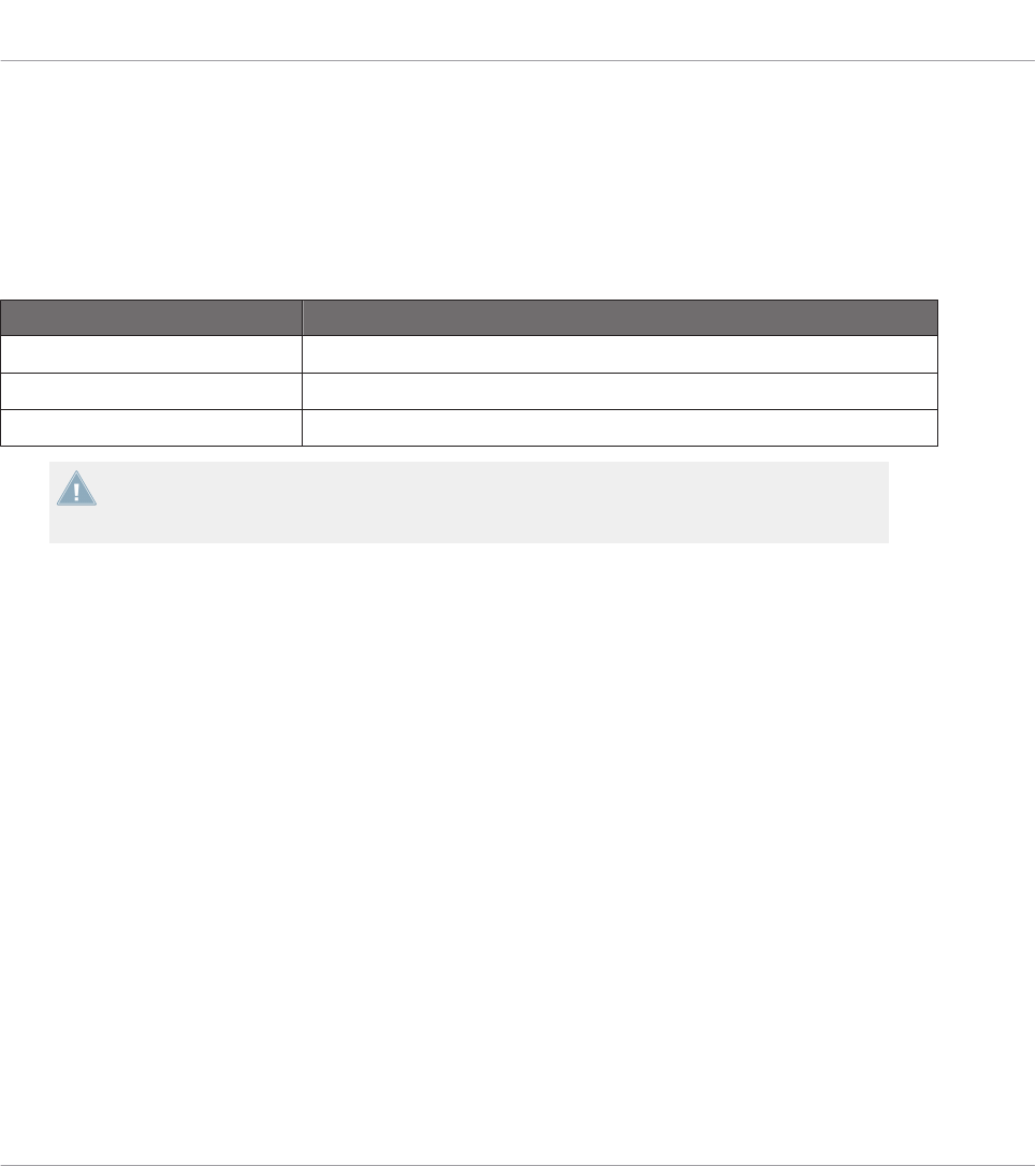
• Assigned, in Off state.
• Assigned, in On state.
Single-Color Buttons
For all buttons, the LEDs can have three states: off, dimmed and bright. The LED states direct-
ly indicate the button states:
Button State LED State
Not assigned Off
Assigned – Off state Dimmed
Assigned – On state Bright
For buttons in Increment mode, the Off state corresponds to the zero value, while the On
state corresponds to a value greater than zero. See section ↑23.6.2, Assignments for But-
tons for more information on the various button modes.
Multicolor Pads
The sixteen pads of your controller are equipped with RGB LEDs. This by far extends the moni-
toring possibilities of these control elements. The pads offer you three Color modes:
• Single mode: You can choose a color that will be used bright and dimmed for the On and
Off states, respectively. In this mode, the pad’s lighting behaves like that of single-color
buttons (see above) except that you can choose the color.
• Dual mode: You can choose a color for the On state and another color for the Off state.
Both colors will be used at full brightness.
• HSB mode: This mode is only available when the pad’s state is controlled via MIDI feed-
back (see below). In HSB mode, you can precisely define from within your MIDI target
which color the pad will use.
Controlling the Button/Pad State
The On/Off state of each button or pad can be controlled in two ways — internally via your ac-
tions on the button/pad, or remotely via MIDI feedback:
Using Your TRAKTOR KONTROL S8
Visual Feedback on Your Controller
CONTROLLER EDITOR - Manual - 170

• In Toggle mode, both controls are enabled: both your actions on the button/pad and the
possibly incoming MIDI messages are taken into account to update the button/pad and
LED state.
• In Trigger, Gate, and Increment mode, you can choose which control mode (internal or re-
mote via MIDI) you want to use. This is done via the LED On menu in the Assign pane of
the Inspector.
For more information on the button modes, LED On menu, and MIDI feedback mode, see
↑23.6.2, Assignments for Buttons.
Buttons and Pads in the Displays
In addition to the LED indications, on each Deck Unit the assignments for the FX buttons, Per-
formance buttons, and pads are shown within the displays in Control display mode.
For more information on the displays of your TRAKTOR KONTROL S8, see section ↑16.4,
The Displays.
16.3.2 Performance Knobs, Slot Volume Faders, and Loop Encoder
Your TRAKTOR KONTROL S8 also gives feedback on additional control elements:
• On each Deck Unit of your TRAKTOR KONTROL S8, assignments for the Turn action of
the four Performance knobs (under the display) and for the Slide action of the four Slot
Volume faders are indicated in the display in Control display mode.
For more information on the displays of your TRAKTOR KONTROL S8, see section ↑16.4,
The Displays.
• On each Deck Unit, the Loop encoder (the push encoder next to the Slot Volume faders)
is equipped with a LED ring that indicates you the state of the encoder’s Push action. The
LED ring’s behavior is the same as that of buttons (see section ↑16.3.1, Buttons and
Pads above).
See also
2Assignments for Buttons [➙ 274]
Using Your TRAKTOR KONTROL S8
Visual Feedback on Your Controller
CONTROLLER EDITOR - Manual - 171
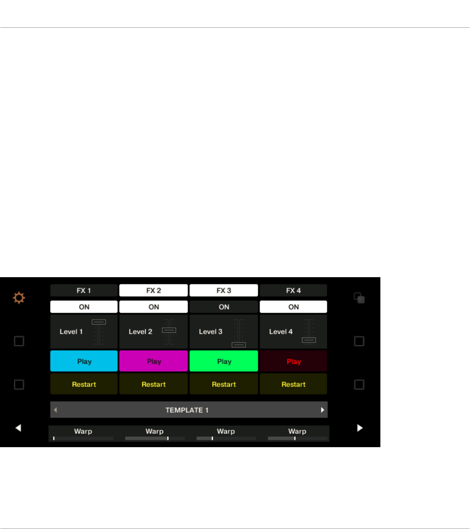
16.4 The Displays
The displays on your TRAKTOR KONTROL S8 can show various elements of your MIDI map-
ping configuration or give you access to settings for your controller, depending on the display
mode that is activated.
• In the default Control display mode, each display shows the assignments for particular con-
trol elements of the corresponding Deck Unit.
• In Settings display mode, you can adjust the color calibration of the displays.
Both display modes are described in the following sections.
16.4.1 Control Display Mode
By default, the displays of your S8 are in Control display mode. In this mode each display in-
forms you about both the assignments and the states of many control elements on that particu-
lar Deck Unit:
The display of a Deck Unit in Control display mode.
For each control element, the display indicates the element’s name as defined in its Label
Field.
Using Your TRAKTOR KONTROL S8
The Displays
CONTROLLER EDITOR - Manual - 172

By default the name defined in the Label Field is the MIDI message that will be sent by
this control element, but you can customize it to your liking, as in the picture above — for
more information, see section ↑23.4.1, Label Fields and ↑23.5.3, Assign Pane.
From top to bottom, each display shows the assignment and the state of the following control
elements:
• 1st row: FX buttons 1–4 above the display. Buttons in Off state are indicated by a dark
background, while buttons in On state are highlighted.
• 2nd row: Performance buttons 1–4 under the display. Buttons in Off state are indicated by
a dark background, while buttons in On state are highlighted.
• 3rd row: Slot Volume faders 1–4 (Slide action). A little fader picture indicates the current
value for the Slide action of each fader.
• 4th and 5th rows: Pads 1–8. The pad state is indicated in various ways depending on the
entry selected in the Color Mode menu in the Assign pane of the Inspector:
◦In Single or Dual color mode, the pad’s On state uses the color set in the Color Value
parameter (Single mode) or Color On parameter (Dual mode), while the pad’s Off state
uses the same color in a darkened version.
◦In HSB color mode (only available if the LED On menu is set to For MIDI Out), the
pad’s states use white instead and is indicated as for buttons (Off state with a dark
background, On state highlighted).
For more info on the modes available in the Color Mode menu, see section ↑16.3.1, But-
tons and Pads above.
• 6th row: This row shows you the current Template. You can switch to the previous/next
Template by pressing the lit Performance Mode buttons (showing left and right arrows) on
either side of the display, as described in section ↑16.1, Basic Controls.
• 7th row: Performance knobs 1–4 (Turn action) right under the display. A little bar indicates
the current value of the Turn action of each knob. Note that the bar can have its zero at
the left or in the middle, depending on the entry selected in the Display menu in the As-
sign pane of the Inspector — see section ↑23.6.8, Assignments for Analog Encoders.
Using Your TRAKTOR KONTROL S8
The Displays
CONTROLLER EDITOR - Manual - 173
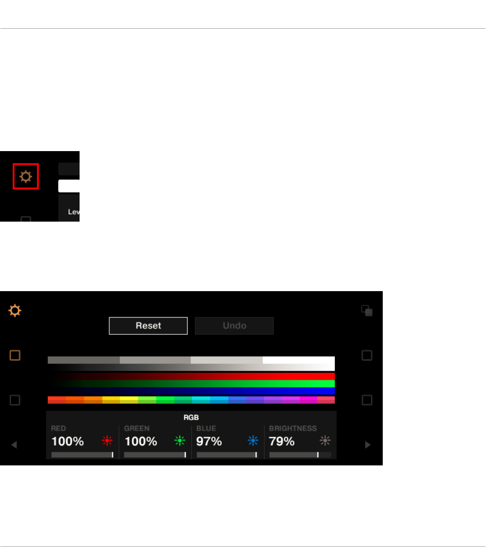
16.4.2 Adjust Color And Brightness
The Settings display mode allows you to adjust the displays' color rendition and brightness di-
rectly from your S8 device.
►To enter or exit Settings display mode, press the Settings button (showing a cog wheel) in
the top left of either display.
The Settings button.
The RGB settings let you adjust the color levels independently for each display as well as the
brightness for both displays. The various settings and their current values are shown at the bot-
tom of the displays:
The RGB settings (here on the right Deck Unit).
Using Your TRAKTOR KONTROL S8
The Displays
CONTROLLER EDITOR - Manual - 174
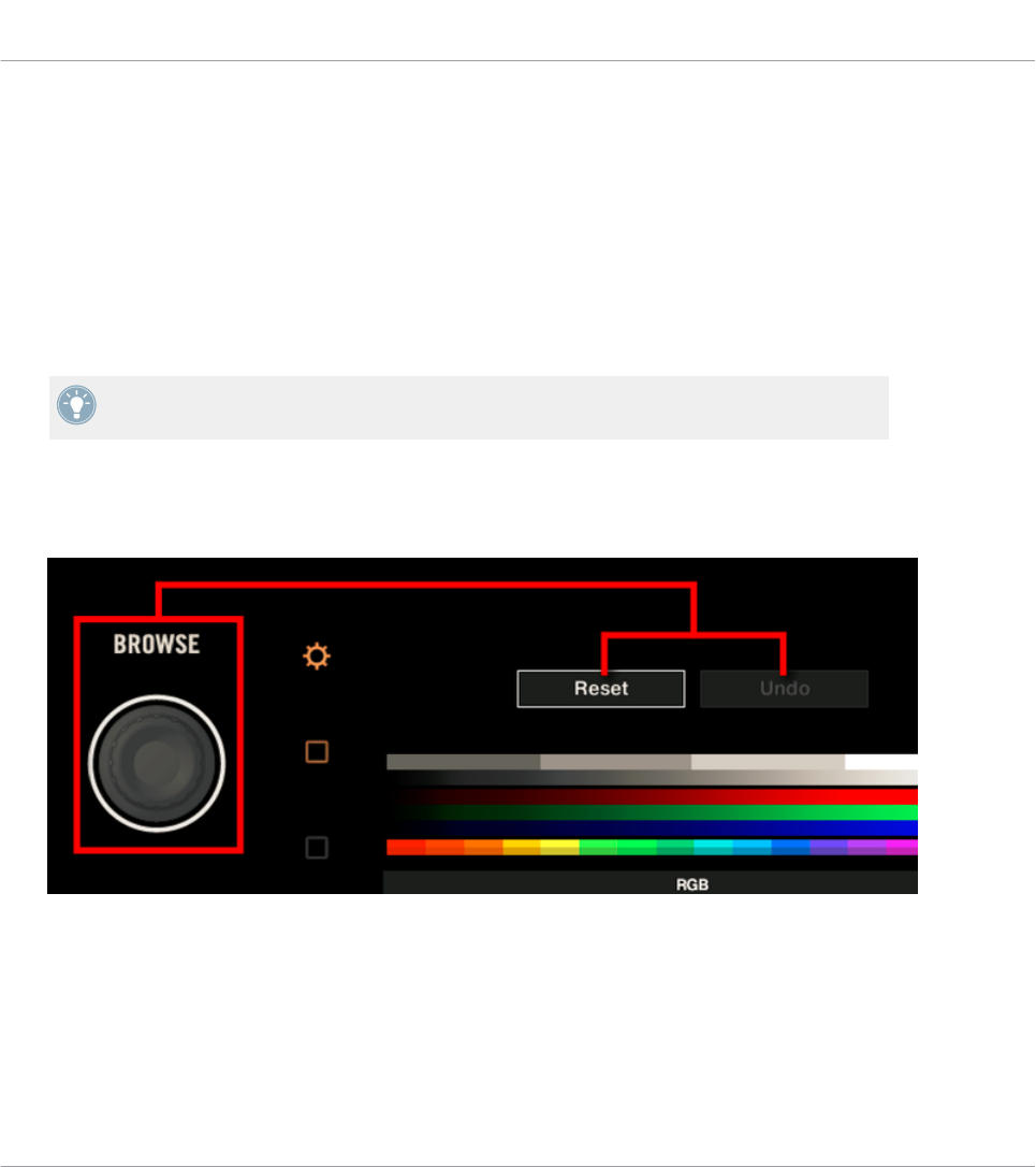
►To adjust the red, blue or green level of a particular display, turn the Performance knob 1
(RED), 2 (GREEN) or 3 (BLUE) beneath that display.
→The color levels of that display are adjusted accordingly.
►To adjust the brightness of both displays, turn the Performance knob 4 beneath any dis-
play.
→The brightness applies to both displays simultaneously. The BRIGHTNESS value above Per-
formance knob 4 is updated in both displays accordingly.
You can also adjust the brightness of the displays in the Controller Editor by going to File >
Preferences > Controller. See section ↑23.2.2, Controller Page for more information.
You can cancel your adjustments at any time by doing the following:
►Turn the BROWSE encoder next to the left display to select Reset or Undo, and press the
encoder to confirm.
• The Reset option will reset all the settings to their default values.
• The Undo option will put the settings back to their previous values.
When you have made the desired color and/or brightness adjustments, press the Settings but-
ton again to exit Settings display mode.
Using Your TRAKTOR KONTROL S8
The Displays
CONTROLLER EDITOR - Manual - 175

►
• The Reset option will reset all the settings to their default values.
• The Undo option will put the settings back to their previous values.
When you have made the desired adjustments to the various touch sensitivities, press the Set-
tings button again to exit Settings display mode.
Using Your TRAKTOR KONTROL S8
The Displays
CONTROLLER EDITOR - Manual - 176

17 Using Your TRAKTOR KONTROL S4
In this chapter, we will focus on what’s happening on your TRAKTOR KONTROL S4. By read-
ing this, you will learn:
• How to use the basic controls on your controller for navigating through the MIDI mapping
system.
• The list of all assignable control elements on your controller.
• How the various luminous elements give you some important information about their
state.
To enjoy full functionality of your NI controller as a MIDI remote control, especially con-
cerning some control elements’ state and LED behavior, you need to tell your NI controller
what is the current state of the parameter in the MIDI target. You can do this by setting up
MIDI feedback channels coming from your MIDI target back to your NI controller. This way,
your controller will always stay up-to-date with the current parameter values in your target
software/hardware. For more information on how to configure these MIDI feedback chan-
nels, please refer to your target software/hardware’s documentation.
17.1 Basic Controls
This section shows you the commands available on your TRAKTOR KONTROL S4 for basic
tasks: switching between MIDI mode and TRAKTOR mode, selecting the desired Deck on each
side, and selecting subsets (Pages) of MIDI assignments.
All these actions can of course be done via the Controller Editor user interface — see chap-
ter ↑3, Quick Start for example. Nevertheless, using your NI controller instead can be very
handy in a live situation!
Using Your TRAKTOR KONTROL S4
Basic Controls
CONTROLLER EDITOR - Manual - 177
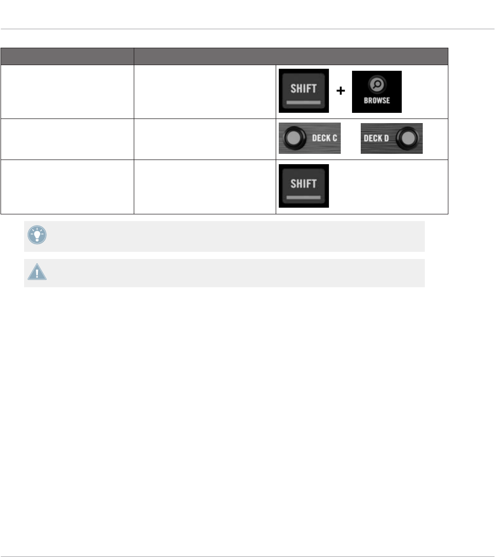
Selection Command
MIDI/TRAKTOR mode SHIFT + BROWSE button
Decks Deck Assign buttons
(DECK C / DECK D) and
Pages (per Deck) SHIFT
For more information on Pages, see ↑4.3, The Mapping System.
You cannot switch between Templates from the TRAKTOR KONTROL S4. To do this, you
have to use the Controller Editor interface (see ↑3.2, Loading MIDI Assignments).
When your S4 is in MIDI mode, both Loop Size Displays on your S4 read “ON” (meaning that
MIDI mode is on).
Switching Between Decks and Pages
In MIDI mode, the S4 takes up TRAKTOR’s 4-Deck scheme. In other terms, the available Pa-
ges are organized per Deck, Decks A to D providing two Pages each (whose default names are
“Basic” and “Shift”). Thus, to load any of these Pages, do the following:
1. Switch to the desired Deck using the Deck Assign buttons (DECK C on the left Deck,
DECK D on the right Deck).
When you switch to the lower Deck (C on the left, D on the right), the DECK C (or DECK
D) indicator lights up in the Deck Display while the DECK A (or DECK B) indicator turns
off — this to remind you which Deck is currently active.
2. Switch to the desired Page for that Deck using the SHIFT button of that Deck.
Please keep in mind that the DECK C and DECK D buttons are always in Toggle mode: When
you press one of them, the Deck controls switch to the alternate Deck until you press the but-
ton again.
Using Your TRAKTOR KONTROL S4
Basic Controls
CONTROLLER EDITOR - Manual - 178
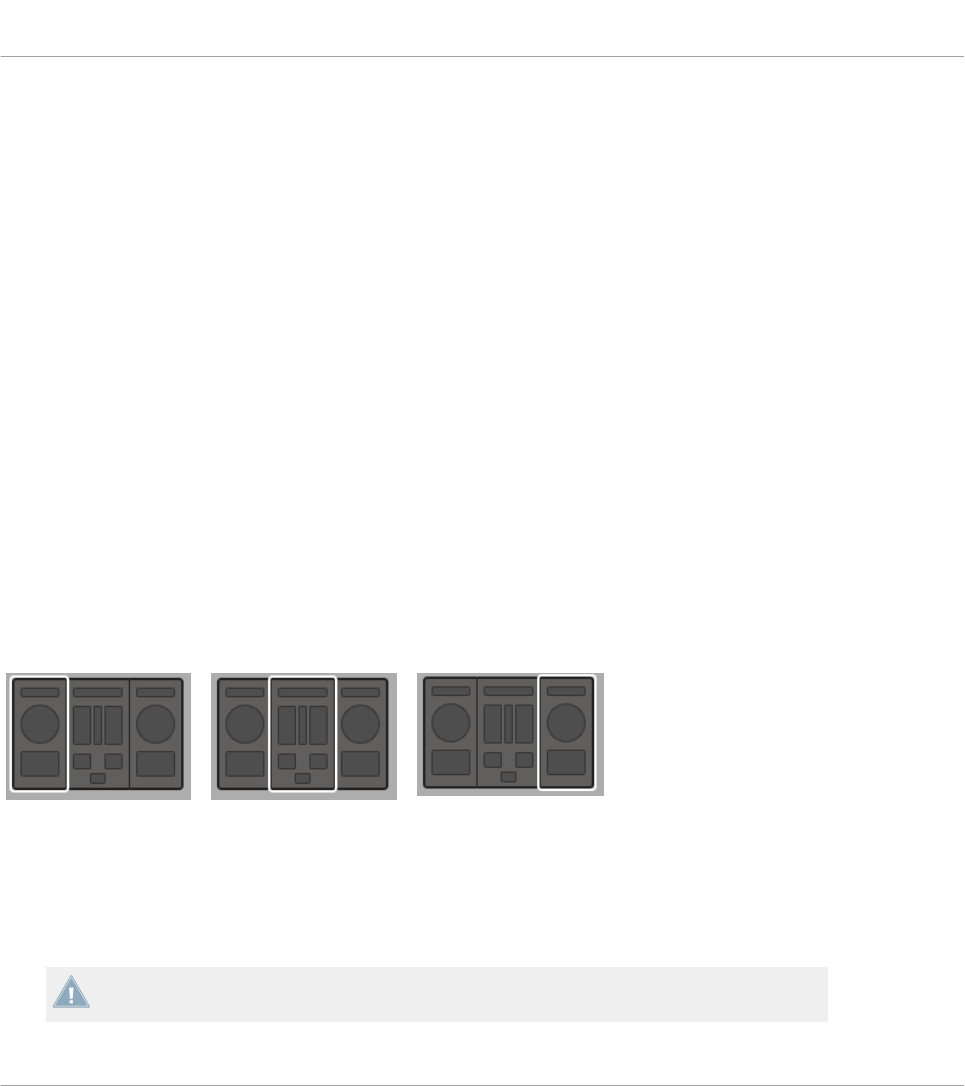
Switching Between Pages: Gate vs. Toggle
The SHIFT buttons can have two operating modes:
• Gate mode: The Page is activated for the time the button is hold depressed.
• Toggle mode: The Page is activated until the next time you press the button again.
You can choose the desired mode for the SHIFT button in the Controller Editor. To do this:
1. Check that the TRAKTOR KONTROL S4 is selected in the Device menu.
2. On the Pages pane of the Inspector, click the Shift Mode menu and select the desired
mode Gate or Toggle.
Adjusting Settings for your Controller
You can adjust various settings for your TRAKTOR KONTROL S4 in File > Preferences > Con-
troller. See ↑23.2.2, Controller Page for more information.
17.2 Assignable Control Elements
If you selected the TRAKTOR KONTROL S4 in the Device menu of the Application Control Bar,
you can choose which part of your controller you want to display in the Hardware area by click-
ing its miniature version in the Overview (in the top left corner):
Click the desired part of your controller in the Overview to display its details in the Hardware
area.
In this Hardware area, you will notice the Page menu and its associated Page area (orange
frame) when the left or right Deck is displayed, and the red Selection Frame on the currently
selected control element.
The names that you see on the device only refer to their original function in the TRAKTOR
software.
Using Your TRAKTOR KONTROL S4
Assignable Control Elements
CONTROLLER EDITOR - Manual - 179

17.2.1 Control Elements on the Left Deck
Here is the list of all assignable control elements on the Left Deck of your S4.
The Left Deck on the TRAKTOR KONTROL S4.
The Left Deck of the TRAKTOR KONTROL S4 holds the following areas:
Using Your TRAKTOR KONTROL S4
Assignable Control Elements
CONTROLLER EDITOR - Manual - 180

(1) Page area: The Page area holds all Deck controls. Apart from the Deck Assign (DECK C) and
SHIFT buttons, all these control elements are freely assignable: 17 buttons, 2 encoders, 1 fad-
er, and 1 jog wheel. The Page area is headed by the Page menu.
(2) FX area: This area holds 5 buttons and 4 knobs, all of them freely assignable.
(3) Footswitch input: The footswitch input of your S4 can also be freely assigned to any MIDI
event.
You will find all details concerning the assignment parameters for the control elements in
↑23.6, MIDI Message Parameters.
17.2.2 Control Elements on the Right Deck
The Right Deck of the TRAKTOR KONTROL S4 is very similar to the Left Deck described
above. It holds the same control elements, with the following exceptions:
• There is no footswitch input.
• There are two additional knobs (CUE MIX and MIC VOL) located on the front panel of your
S4. These knobs are freely assignable.
17.2.3 Control Elements on the Mixer
Here is the list of all assignable control elements on the Mixer of your S4.
Using Your TRAKTOR KONTROL S4
Assignable Control Elements
CONTROLLER EDITOR - Manual - 181
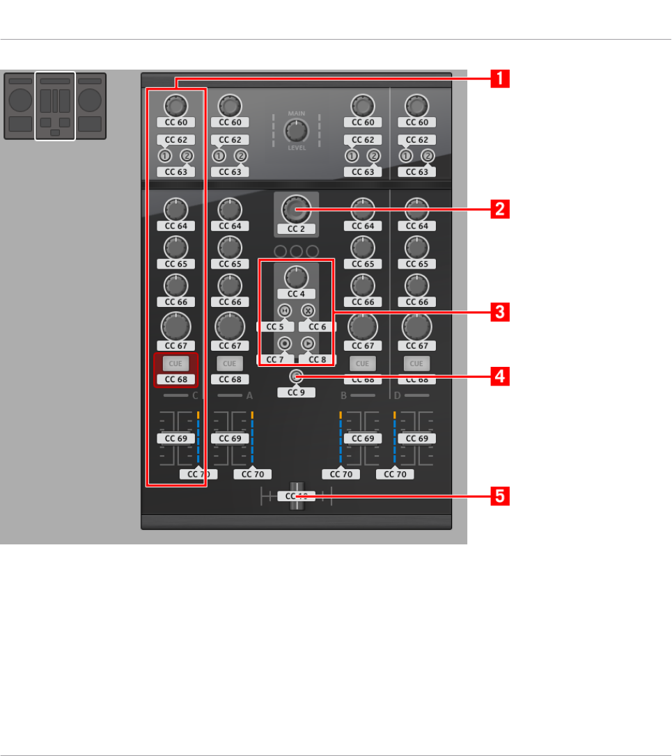
The Mixer on the TRAKTOR KONTROL S4.
The Mixer of the TRAKTOR KONTROL S4 holds the following areas:
(1) Channel areas: Each of the four channel strips holds 4 knobs, 3 buttons, 1 encoder, 1 fad-
er, and 1 LED chain. All of them are freely assignable.
(2) BROWSE encoder: The BROWSE encoder is freely assignable.
(3) Loop Recorder area: The Loop Recorder area holds 4 buttons and 1 knob. All of them are
freely assignable.
Using Your TRAKTOR KONTROL S4
Assignable Control Elements
CONTROLLER EDITOR - Manual - 182
(4) BROWSE button: The BROWSE button is freely assignable.
(5) Crossfader: The crossfader is freely assignable as well.
On the Mixer, the Main section (with the MAIN LEVEL knob and MAIN LEVEL meters), the
Master Display (with the Alert, USB, and Preview Play indicators along with the SNAP,
MASTER, and QUANT buttons), and the Deck Assignment indicators are excluded from the
MIDI mapping scheme. In other terms, you cannot assign MIDI events to any of these con-
trol elements.
17.2.4 Assignment Parameters
The following table summarizes where to find all assignment details for each type of control
element on your controller:
Type of Control Element Assignment Parameters
Buttons ↑23.6.2, Assignments for Buttons
Footswitch input ↑23.6.2, Assignments for Buttons
Knobs ↑23.6.5, Assignments for Knobs and the Like
Faders and crossfader ↑23.6.5, Assignments for Knobs and the Like
Encoders – Push action ↑23.6.2, Assignments for Buttons
Encoders – Turn action ↑23.6.7, Assignments for Digital Encoders
LED chains ↑23.6.11, Assignments for LED Chains and 7-segment Displays
17.3 Visual Feedback on Your Controller
The fast bidirectional communication between your TRAKTOR KONTROL S4 and the Hardware
Service on the software side allows status indications on your controller to be made in real
time.
Using Your TRAKTOR KONTROL S4
Assignable Control Elements
CONTROLLER EDITOR - Manual - 183
17.3.1 Buttons
On your TRAKTOR KONTROL S4, all buttons are equipped with LEDs that inform you about
the assignment state of the button at any time. The LEDs below each control element can have
three states: off, dimmed and bright. Their lighting behavior depends on the state of the con-
trol element.
The following table indicates you the possible states for the LEDs:
Button State LED State
Not assigned Off
Assigned – Off state Dimmed
Assigned – On state Bright
For buttons in Increment mode, the Off state corresponds to the zero value, while the On
state corresponds to a value greater than zero.
Controlling the Button State
The state of each button can be controlled in two ways — internally via your actions on the
button, or remotely via MIDI feedback:
• In Toggle mode, both controls are enabled: both your actions on the button and the possi-
bly incoming MIDI messages are taken into account to update the button state.
• In Trigger, Gate, and Increment mode, you can choose which control mode you want to
use via the LED On menu located in the Assign pane of the Inspector.
For more information on the button modes, LED On menu, and MIDI feedback mode, see
↑23.6.2, Assignments for Buttons.
Adjusting the LED Brightness
You can adjust the LED brightness for both On and Off button states in File > Preferences >
Controller > Traktor Kontrol S4 > LEDs (see ↑23.2, The Preferences Window for more informa-
tion on the Preferences window).
Using Your TRAKTOR KONTROL S4
Visual Feedback on Your Controller
CONTROLLER EDITOR - Manual - 184

17.3.2 LED Chains
The Mixer of the S4 provides four assignable LED chains that give you additional visual feed-
back on your target’s parameters. The feedback provided by each LED chain depends on its
assignment settings as defined in the Assign pane of the Inspector. See ↑23.6.11, Assign-
ments for LED Chains and 7-segment Displays for more information on the possible assign-
ments.
Using Your TRAKTOR KONTROL S4
Visual Feedback on Your Controller
CONTROLLER EDITOR - Manual - 185
18 Using Your TRAKTOR KONTROL S4 MK2
In this chapter, we will focus on what’s happening on your TRAKTOR KONTROL S4 MK2. By
reading this, you will learn:
• How to use the basic controls on your controller for navigating through the MIDI mapping
system.
• The list of all assignable control elements on your controller.
• How the various luminous elements give you some important information about their
state.
To enjoy full functionality of your NI controller as a MIDI remote control, especially con-
cerning some control elements’ state and LED behavior, you need to tell your NI controller
what is the current state of the parameter in the MIDI target. You can do this by setting up
MIDI feedback channels coming from your MIDI target back to your NI controller. This way,
your controller will always stay up-to-date with the current parameter values in your target
software/hardware. For more information on how to configure these MIDI feedback chan-
nels, please refer to your target software/hardware’s documentation.
18.1 Basic Controls
This section shows you the commands available on your TRAKTOR KONTROL S4 MK2 for ba-
sic tasks: switching between MIDI mode and TRAKTOR mode, selecting the desired Deck on
each side, and selecting subsets (Pages) of MIDI assignments.
All these actions can of course be done via the Controller Editor user interface — see chap-
ter ↑3, Quick Start for example. Nevertheless, using your NI controller instead can be very
handy in a live situation!
Using Your TRAKTOR KONTROL S4 MK2
Basic Controls
CONTROLLER EDITOR - Manual - 186
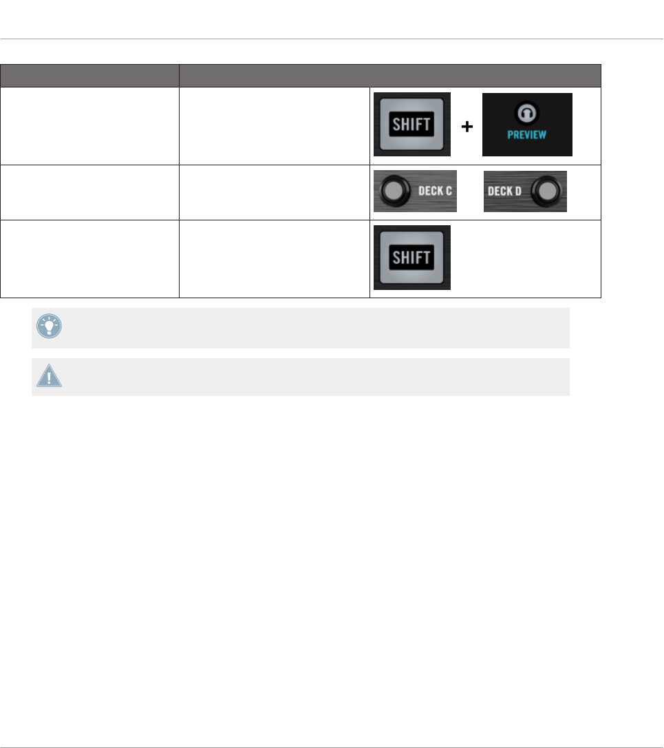
Selection Command
MIDI/TRAKTOR mode SHIFT + BROWSE button
Decks Deck Assign buttons
(DECK C / DECK D) and
Pages (per Deck) SHIFT
For more information on Pages, see ↑4.3, The Mapping System.
You cannot switch between Templates from the TRAKTOR KONTROL S4 MK2. To do this,
you have to use the Controller Editor interface (see ↑3.2, Loading MIDI Assignments).
When your S4 is in MIDI mode, both Loop Size Displays on your S4 read “ON” (meaning that
MIDI mode is on).
Switching Between Decks and Pages
In MIDI mode, the S4 takes up TRAKTOR’s 4-Deck scheme. In other terms, the available Pa-
ges are organized per Deck, Decks A to D providing two Pages each (whose default names are
“Basic” and “Shift”). Thus, to load any of these Pages, do the following:
1. Switch to the desired Deck using the Deck Assign buttons (DECK C on the left Deck,
DECK D on the right Deck).
When you switch to the lower Deck (C on the left, D on the right), the DECK C (or DECK
D) indicator lights up in the Deck Display while the DECK A (or DECK B) indicator turns
off — this to remind you which Deck is currently active.
2. Switch to the desired Page for that Deck using the SHIFT button of that Deck.
Please keep in mind that the DECK C and DECK D buttons are always in Toggle mode: When
you press one of them, the Deck controls switch to the alternate Deck until you press the but-
ton again.
Using Your TRAKTOR KONTROL S4 MK2
Basic Controls
CONTROLLER EDITOR - Manual - 187

Switching Between Pages: Gate vs. Toggle
The SHIFT buttons can have two operating modes:
• Gate mode: The Page is activated for the time the button is hold depressed.
• Toggle mode: The Page is activated until the next time you press the button again.
You can choose the desired mode for the SHIFT button in the Controller Editor. To do this:
1. Check that the TRAKTOR KONTROL S4 MK2 is selected in the Device menu.
2. On the Pages pane of the Inspector, click the Shift Mode menu and select the desired
mode Gate or Toggle.
Adjusting Settings for your Controller
You can adjust various settings for your TRAKTOR KONTROL S4 MK2 in File > Preferences >
Controller. See ↑23.2.2, Controller Page for more information.
18.2 Assignable Control Elements
If you selected the TRAKTOR KONTROL S4 MK2 in the Device menu of the Application Con-
trol Bar, you can choose which part of your controller you want to display in the Hardware area
by clicking its miniature version in the Overview (in the top left corner):
Click the desired part of your controller in the Overview to display its details in the Hardware
area.
In this Hardware area, you will notice the Page menu and its associated Page area (orange
frame) when the left or right Deck is displayed, and the red Selection Frame on the currently
selected control element.
The names that you see on the device only refer to their original function in the TRAKTOR
software.
Using Your TRAKTOR KONTROL S4 MK2
Assignable Control Elements
CONTROLLER EDITOR - Manual - 188
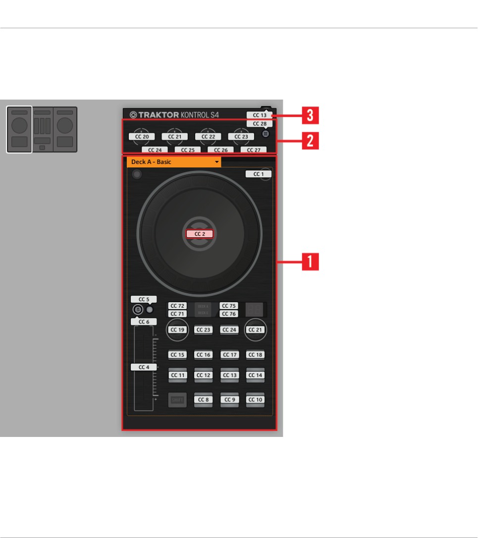
18.2.1 Control Elements on the Left Deck
Here is the list of all assignable control elements on the Left Deck of your S4.
The Left Deck on the TRAKTOR KONTROL S4 MK2.
The Left Deck of the TRAKTOR KONTROL S4 MK2 holds the following areas:
Using Your TRAKTOR KONTROL S4 MK2
Assignable Control Elements
CONTROLLER EDITOR - Manual - 189
(1) Page area: The Page area holds all Deck controls. Apart from the Deck Assign (DECK C) and
SHIFT buttons, all these control elements are freely assignable: 17 buttons, 2 encoders, 1 fad-
er, and 1 jog wheel. The Page area is headed by the Page menu.
(2) FX area: This area holds 5 buttons and 4 knobs, all of them freely assignable.
(3) Footswitch input: The footswitch input of your S4 can also be freely assigned to any MIDI
event.
You will find all details concerning the assignment parameters for the control elements in
↑23.6, MIDI Message Parameters.
18.2.2 Control Elements on the Right Deck
The Right Deck of the TRAKTOR KONTROL S4 MK2 is very similar to the Left Deck described
above. It holds the same control elements, with the following exceptions:
• There is no footswitch input.
• There are two additional knobs (CUE MIX and MIC VOL) located on the front panel of your
S4. These knobs are freely assignable.
18.2.3 Control Elements on the Mixer
Here is the list of all assignable control elements on the Mixer of your S4.
Using Your TRAKTOR KONTROL S4 MK2
Assignable Control Elements
CONTROLLER EDITOR - Manual - 190

The Mixer on the TRAKTOR KONTROL S4 MK2.
The Mixer of the TRAKTOR KONTROL S4 MK2 holds the following areas:
(1) Channel areas: Each of the four channel strips holds 4 knobs, 3 buttons, 1 encoder, 1 fad-
er, and 1 LED chain. All of them are freely assignable.
(2) BROWSE encoder: The BROWSE encoder is freely assignable.
(3) SNAP and QUANT buttons: The SNAP and QUANT buttons are freely assignable.
Using Your TRAKTOR KONTROL S4 MK2
Assignable Control Elements
CONTROLLER EDITOR - Manual - 191

(4) Loop Recorder area: The Loop Recorder area holds 4 buttons and 1 knob. All of them are
freely assignable.
(5) Preview button: The P button is freely assignable.
(6) Crossfader: The crossfader is freely assignable as well.
On the Mixer, the Main section (with the MAIN LEVEL knob and MAIN LEVEL meters), the
Master Display (with the Alert, USB, and Preview Play indicators along with the SNAP,
MASTER, and QUANT buttons), and the Deck Assignment indicators are excluded from the
MIDI mapping scheme. In other terms, you cannot assign MIDI events to any of these con-
trol elements.
18.2.4 Assignment Parameters
The following table summarizes where to find all assignment details for each type of control
element on your controller:
Type of Control Element Assignment Parameters
Buttons ↑23.6.2, Assignments for Buttons
Footswitch input ↑23.6.2, Assignments for Buttons
Knobs ↑23.6.5, Assignments for Knobs and the Like
Faders and crossfader ↑23.6.5, Assignments for Knobs and the Like
Encoders – Push action ↑23.6.2, Assignments for Buttons
Encoders – Turn action ↑23.6.7, Assignments for Digital Encoders
LED chains ↑23.6.11, Assignments for LED Chains and 7-segment Displays
18.3 Visual Feedback on Your Controller
The fast bidirectional communication between your TRAKTOR KONTROL S4 MK2 and the
Hardware Service on the software side allows status indications on your controller to be made
in real time.
Using Your TRAKTOR KONTROL S4 MK2
Assignable Control Elements
CONTROLLER EDITOR - Manual - 192

18.3.1 Buttons
On your TRAKTOR KONTROL S4 MK2, all buttons are equipped with LEDs that inform you
about the assignment state of the button at any time. The LEDs below each control element
can have three states: off, dimmed and bright. Their lighting behavior depends on the state of
the control element.
The following table indicates you the possible states for the LEDs:
Button State LED State
Not assigned Off
Assigned – Off state Dimmed
Assigned – On state Bright
For buttons in Increment mode, the Off state corresponds to the zero value, while the On
state corresponds to a value greater than zero.
Controlling the Button State
The state of each button can be controlled in two ways — internally via your actions on the
button, or remotely via MIDI feedback:
• In Toggle mode, both controls are enabled: both your actions on the button and the possi-
bly incoming MIDI messages are taken into account to update the button state.
• In Trigger, Gate, and Increment mode, you can choose which control mode you want to
use via the LED On menu located in the Assign pane of the Inspector.
For more information on the button modes, LED On menu, and MIDI feedback mode, see
↑23.6.2, Assignments for Buttons.
Adjusting the LED Brightness
You can adjust the LED brightness for both On and Off button states in File > Preferences >
Controller > Traktor Kontrol S4 MK2 > LEDs (see ↑23.2, The Preferences Window for more in-
formation on the Preferences window).
Using Your TRAKTOR KONTROL S4 MK2
Visual Feedback on Your Controller
CONTROLLER EDITOR - Manual - 193

18.3.2 LED Chains
The Mixer of the S4 provides four assignable LED chains that give you additional visual feed-
back on your target’s parameters. The feedback provided by each LED chain depends on its
assignment settings as defined in the Assign pane of the Inspector. See ↑23.6.11, Assign-
ments for LED Chains and 7-segment Displays for more information on the possible assign-
ments.
Using Your TRAKTOR KONTROL S4 MK2
Visual Feedback on Your Controller
CONTROLLER EDITOR - Manual - 194
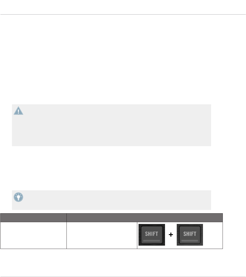
19 Using Your TRAKTOR KONTROL S2
In this chapter, we will focus on what’s happening on your TRAKTOR KONTROL S2. By read-
ing this, you will learn:
• How to use the basic controls on your controller for switching your controller to/from MIDI
mode.
• The list of all assignable control elements on your controller.
• How the various luminous elements give you some important information about their
state.
To enjoy full functionality of your NI controller as a MIDI remote control, especially con-
cerning some control elements’ state and LED behavior, you need to tell your NI controller
what is the current state of the parameter in the MIDI target. You can do this by setting up
MIDI feedback channels coming from your MIDI target back to your NI controller. This way,
your controller will always stay up-to-date with the current parameter values in your target
software/hardware. For more information on how to configure these MIDI feedback chan-
nels, please refer to your target software/hardware’s documentation.
19.1 Basic Controls
Here is how to switch between MIDI mode and TRAKTOR mode from your TRAKTOR KON-
TROL S2.
This can of course be done via the Controller Editor user interface — see chapter ↑3, Quick
Start for example. Nevertheless, using your NI controller instead can be very handy in a live
situation!
Selection Command
MIDI/TRAKTOR mode SHIFT + SHIFT (on both Decks)
Using Your TRAKTOR KONTROL S2
Basic Controls
CONTROLLER EDITOR - Manual - 195

When your S2 is in MIDI mode, both SHIFT buttons are dimly lit (meaning that MIDI mode is
on).
You cannot switch between Templates from the TRAKTOR KONTROL S2. To do this, you
have to use the Controller Editor interface (see ↑3.2, Loading MIDI Assignments).
Adjusting Settings for your Controller
You can adjust various settings for your TRAKTOR KONTROL S2 in File > Preferences > Con-
troller. See ↑23.2.2, Controller Page for more information.
19.2 Assignable Control Elements
If you selected the TRAKTOR KONTROL S2 in the Device menu of the Application Control Bar,
depending on the part of the S2 that you selected in the S2 Overview (in the top left corner),
this is what the Hardware area looks like:
The Hardware area representing the S2’s left Deck, Mixer, and right Deck, respectively.
In this Hardware area, you will notice the red Selection Frame on the currently selected control
element.
The names that you see on the device only refer to their original function in the TRAKTOR
software.
Using Your TRAKTOR KONTROL S2
Assignable Control Elements
CONTROLLER EDITOR - Manual - 196

On your TRAKTOR KONTROL S2, almost every control element is freely assignable to a MIDI
event. The few exceptions are the following:
• The SHIFT buttons on the left and right Decks have a special function (switching between
MIDI and TRAKTOR modes, see above).
• On the Mixer, the MAIN LEVEL knob, along with the Alert, USB, and Microphone indica-
tors are excluded from the MIDI mapping scheme. This is also the case for the CUE VOL
knob and the MIC ENGAGE button on the front panel. In other terms, you cannot assign
MIDI events to any of these control elements.
Assignment Parameters
The following table summarizes where to find all assignment details for each type of control
element on your controller:
Type of Control Element Assignment Parameters
Buttons ↑23.6.2, Assignments for Buttons
Knobs ↑23.6.5, Assignments for Knobs and the Like
Faders and crossfader ↑23.6.5, Assignments for Knobs and the Like
Encoders – Push action ↑23.6.2, Assignments for Buttons
Encoders – Turn action ↑23.6.7, Assignments for Digital Encoders
LED chains ↑23.6.11, Assignments for LED Chains and 7-segment Displays
19.3 Visual Feedback on Your Controller
The fast bidirectional communication between your TRAKTOR KONTROL S2 and the Hardware
Service on the software side allows status indications on your controller to be made in real
time.
Using Your TRAKTOR KONTROL S2
Visual Feedback on Your Controller
CONTROLLER EDITOR - Manual - 197

19.3.1 Buttons
On your TRAKTOR KONTROL S2, all buttons are equipped with LEDs that inform you about
the assignment state of the button at any time. The LEDs below each control element can have
three states: off, dimmed and bright. Their lighting behavior depends on the state of the con-
trol element.
The following table indicates you the possible states for the LEDs:
Button State LED State
Not assigned Off
Assigned – Off state Dimmed
Assigned – On state Bright
For buttons in Increment mode, the Off state corresponds to the zero value, while the On
state corresponds to a value greater than zero.
Controlling the Button State
The state of each button can be controlled in two ways — internally via your actions on the
button, or remotely via MIDI feedback:
• In Toggle mode, both controls are enabled: both your actions on the button and the possi-
bly incoming MIDI messages are taken into account to update the button state.
• In Trigger, Gate, and Increment mode, you can choose which control mode you want to
use via the LED On menu located in the Assign pane of the Inspector.
For more information on the button modes, LED On menu, and MIDI feedback mode, see
↑23.6.2, Assignments for Buttons.
Adjusting the LED Brightness
You can adjust the LED brightness for both On and Off button states in File > Preferences >
Controller > Traktor Kontrol S2 > LEDs (see ↑23.2, The Preferences Window for more informa-
tion on the Preferences window).
Using Your TRAKTOR KONTROL S2
Visual Feedback on Your Controller
CONTROLLER EDITOR - Manual - 198

19.3.2 LED Chains
The Mixer of the S2 provides two assignable LED chains that give you additional visual feed-
back on your target’s parameters. The feedback provided by each LED chain depends on its
assignment settings as defined in the Assign pane of the Inspector. See ↑23.6.11, Assign-
ments for LED Chains and 7-segment Displays for more information on the possible assign-
ments.
Using Your TRAKTOR KONTROL S2
Visual Feedback on Your Controller
CONTROLLER EDITOR - Manual - 199
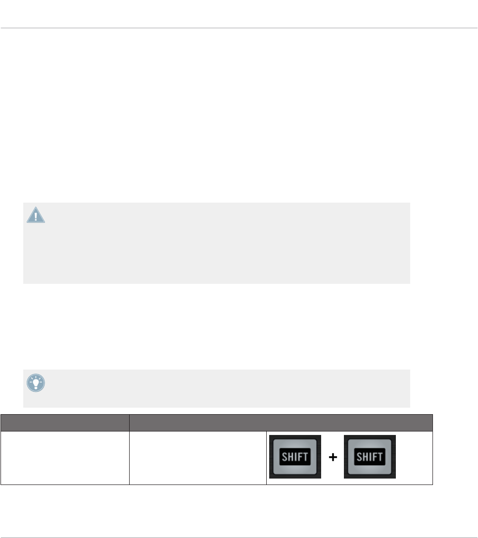
20 Using Your TRAKTOR KONTROL S2 MK2
In this chapter, we will focus on what’s happening on your TRAKTOR KONTROL S2 MK2. By
reading this, you will learn:
• How to use the basic controls on your controller for switching your controller to/from MIDI
mode.
• The list of all assignable control elements on your controller.
• How the various luminous elements give you some important information about their
state.
To enjoy full functionality of your NI controller as a MIDI remote control, especially con-
cerning some control elements’ state and LED behavior, you need to tell your NI controller
what is the current state of the parameter in the MIDI target. You can do this by setting up
MIDI feedback channels coming from your MIDI target back to your NI controller. This way,
your controller will always stay up-to-date with the current parameter values in your target
software/hardware. For more information on how to configure these MIDI feedback chan-
nels, please refer to your target software/hardware’s documentation.
20.1 Basic Controls
Here is how to switch between MIDI mode and TRAKTOR mode from your TRAKTOR KON-
TROL S2 MK2.
This can of course be done via the Controller Editor user interface — see chapter ↑3, Quick
Start for example. Nevertheless, using your NI controller instead can be very handy in a live
situation!
Selection Command
MIDI/TRAKTOR mode SHIFT + SHIFT (on both Decks)
Using Your TRAKTOR KONTROL S2 MK2
Basic Controls
CONTROLLER EDITOR - Manual - 200
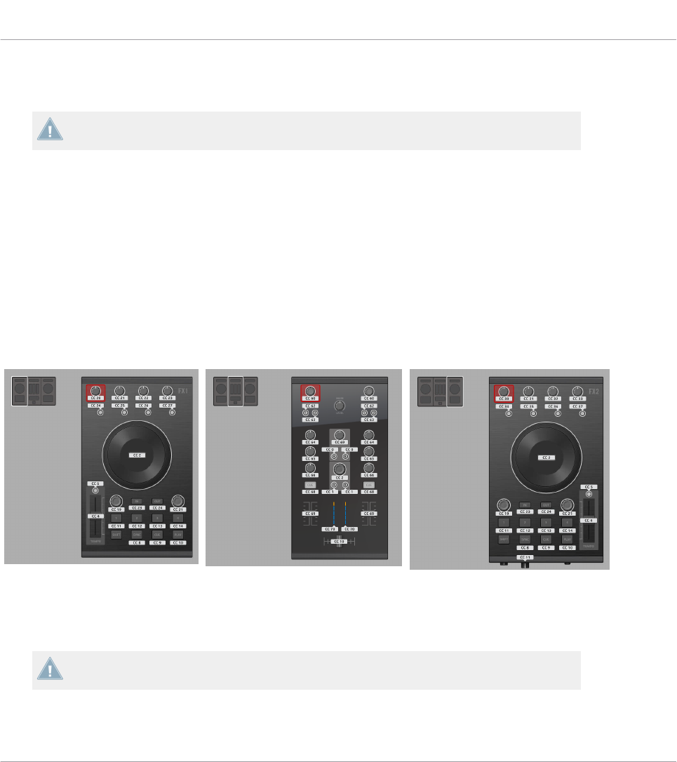
When your S2 is in MIDI mode, both SHIFT buttons are dimly lit (meaning that MIDI mode is
on).
You cannot switch between Templates from the TRAKTOR KONTROL S2 MK2. To do this,
you have to use the Controller Editor interface (see ↑3.2, Loading MIDI Assignments).
Adjusting Settings for your Controller
You can adjust various settings for your TRAKTOR KONTROL S2 MK2 in File > Preferences >
Controller. See ↑23.2.2, Controller Page for more information.
20.2 Assignable Control Elements
If you selected the TRAKTOR KONTROL S2 MK2 in the Device menu from the Application
Control Bar, depending on the part of the S2 MK2 that you selected in the S2 MK2 Overview
(in the top left corner), this is what the Hardware area looks like:
The Hardware area representing the S2 MK2’s left Deck, Mixer, and right Deck, respectively.
In this Hardware area, you will notice the red Selection Frame on the currently selected control
element.
The names that you see on the device only refer to their original function in the TRAKTOR
software.
Using Your TRAKTOR KONTROL S2 MK2
Assignable Control Elements
CONTROLLER EDITOR - Manual - 201

On your TRAKTOR KONTROL S2 MK2, almost every control element is freely assignable to a
MIDI event. The few exceptions are the following:
• The SHIFT buttons on the left and right Decks have a special function (switching between
MIDI and TRAKTOR modes, see above).
• On the Mixer, the MAIN LEVEL knob, along with the Alert, USB, and Microphone indica-
tors are excluded from the MIDI mapping scheme. This is also the case for the CUE VOL
knob and the MIC ENGAGE button on the front panel. In other terms, you cannot assign
MIDI events to any of these control elements.
Assignment Parameters
The following table summarizes where to find all assignment details for each type of control
element on your controller:
Type of Control Element Assignment Parameters
Buttons ↑23.6.2, Assignments for Buttons
Knobs ↑23.6.5, Assignments for Knobs and the Like
Faders and crossfader ↑23.6.5, Assignments for Knobs and the Like
Encoders – Push action ↑23.6.2, Assignments for Buttons
Encoders – Turn action ↑23.6.7, Assignments for Digital Encoders
LED chains ↑23.6.11, Assignments for LED Chains and 7-segment Displays
20.3 Visual Feedback on Your Controller
The fast bidirectional communication between your TRAKTOR KONTROL S2 MK2 and the
Hardware Service on the software side allows status indications on your controller to be made
in real time.
Using Your TRAKTOR KONTROL S2 MK2
Visual Feedback on Your Controller
CONTROLLER EDITOR - Manual - 202

20.3.1 Buttons
On your TRAKTOR KONTROL S2 MK2, all buttons are equipped with LEDs that inform you
about the assignment state of the button at any time. The LEDs below each control element
can have three states: off, dimmed and bright. Their lighting behavior depends on the state of
the control element.
The following table indicates you the possible states for the LEDs:
Button State LED State
Not assigned Off
Assigned – Off state Dimmed
Assigned – On state Bright
For buttons in Increment mode, the Off state corresponds to the zero value, while the On
state corresponds to a value greater than zero.
Controlling the Button State
The state of each button can be controlled in two ways — internally via your actions on the
button, or remotely via MIDI feedback:
• In Toggle mode, both controls are enabled: both your actions on the button and the possi-
bly incoming MIDI messages are taken into account to update the button state.
• In Trigger, Gate, and Increment mode, you can choose which control mode you want to
use via the LED On menu located in the Assign pane of the Inspector.
For more information on the button modes, LED On menu, and MIDI feedback mode, see
↑23.6.2, Assignments for Buttons.
Adjusting the LED Brightness
You can adjust the LED brightness for both On and Off button states in File > Preferences >
Controller > Traktor Kontrol S2 MK2 > LEDs (see ↑23.2, The Preferences Window for more in-
formation on the Preferences window).
Using Your TRAKTOR KONTROL S2 MK2
Visual Feedback on Your Controller
CONTROLLER EDITOR - Manual - 203

20.3.2 LED Chains
The Mixer of the S2 provides two assignable LED chains that give you additional visual feed-
back on your target’s parameters. The feedback provided by each LED chain depends on its
assignment settings as defined in the Assign pane of the Inspector. See ↑23.6.11, Assign-
ments for LED Chains and 7-segment Displays for more information on the possible assign-
ments.
Using Your TRAKTOR KONTROL S2 MK2
Visual Feedback on Your Controller
CONTROLLER EDITOR - Manual - 204
21 Using Your KOMPLETE KONTROL S-SERIES Keyboard
In this chapter, we will focus on what’s happening on your KOMPLETE KONTROL S-SERIES
keyboard. By reading this, you will learn:
• How to use the basic controls on your keyboard for navigating through the MIDI mapping
system.
• The list of all assignable control elements on your controller.
• How the various luminous elements and displays give you some important information
about the assignments’ state.
This chapter describes the MIDI assignments for the KOMPLETE KONTROL S25, S49, and
S61 all together — the only difference between them being the number of keys available.
To enjoy full functionality of your NI controller as a MIDI remote control, especially con-
cerning some control elements’ state and LED behavior, you need to tell your NI controller
what is the current state of the parameter in the MIDI target. You can do this by setting up
MIDI feedback channels coming from your MIDI target back to your NI controller. This way,
your controller will always stay up-to-date with the current parameter values in your target
software/hardware. For more information on how to configure these MIDI feedback chan-
nels, please refer to your target software/hardware’s documentation.
21.1 Basic Controls
This section shows you the commands available on your KOMPLETE KONTROL S-SERIES key-
board for basic tasks like switching between MIDI mode and KOMPLETE KONTROL mode or
selecting sets (Templates) of MIDI assignments.
Using Your KOMPLETE KONTROL S-SERIES Keyboard
Basic Controls
CONTROLLER EDITOR - Manual - 205
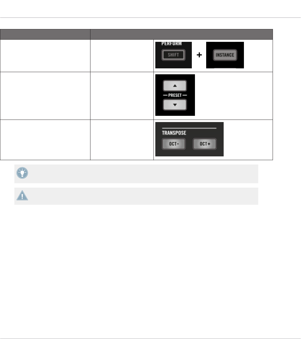
Selection Command
MIDI / KOMPLETE KONTROL
mode
SHIFT + INSTANCE
Templates PRESET buttons
Keybed range OCT-/OCT+ buttons
The name of the current Template is shown in the leftmost display. See section ↑21.4.1,
Visual Feedback on the Displays for more info.
For more information on Templates, see ↑4.3, The Mapping System.
When your KOMPLETE KONTROL S-SERIES keyboard is in MIDI mode, its PRESET buttons
are both fully lit.
TRANSPORT Section: Controlling Your DAW
Whether your KOMPLETE KONTROL S-SERIES keyboard is in MIDI mode or KOMPLETE KON-
TROL mode, the buttons in the TRANSPORT section send MCU messages, allowing you to re-
motely control the transport functions of your favorite DAW.
Using Your KOMPLETE KONTROL S-SERIES Keyboard
Basic Controls
CONTROLLER EDITOR - Manual - 206
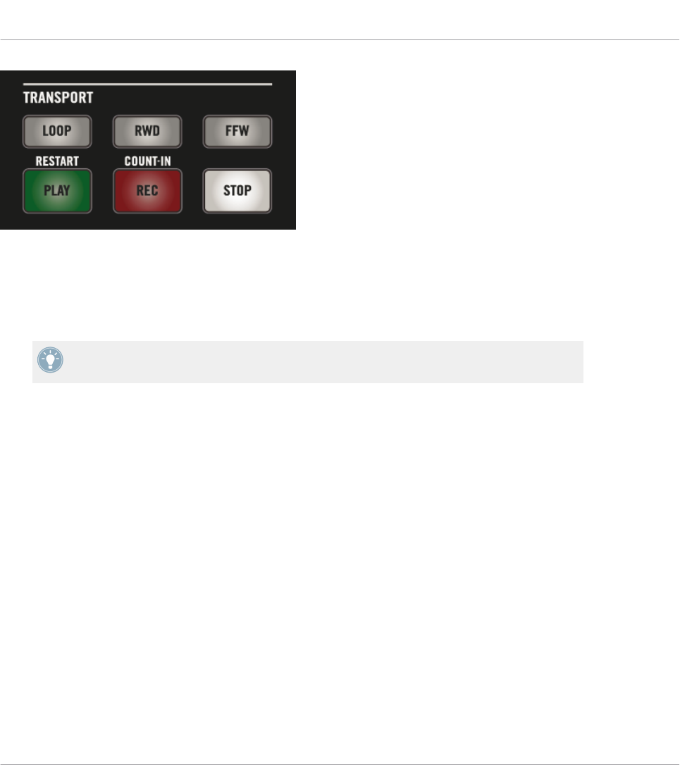
The buttons in the TRANSPORT section on your keyboard.
These MCU messages are sent on a virtual port of your keyboard labeled “Komplete Kontrol
DAW.” For this to work, you have to configure your DAW so that it listens to control surface
messages on this virtual port. To know how to do this, please refer to the documentation of
your DAW.
The LEDs of these buttons are controlled by your DAW using the same MCU messages on
the feedback channel — see section ↑21.4.4, Visual Feedback on the Buttons.
21.2 Assignable Control Elements
If you selected the KOMPLETE KONTROL S-SERIES keyboard in the Device menu of the Ap-
plication Control Bar, this is what the Hardware area looks like:
Using Your KOMPLETE KONTROL S-SERIES Keyboard
Assignable Control Elements
CONTROLLER EDITOR - Manual - 207

The Hardware area representing the KOMPLETE KONTROL S-SERIES keyboard.
In this Hardware area, you will notice the red Selection Frame on the currently selected control
element (Knob 4 in the picture above).
The names that you see on the device only refer to their original function.
On the KOMPLETE KONTROL S-SERIES keyboard, the following control elements can be as-
signed to MIDI commands:
(1) Touch strips: Both touch strips can be assigned to MIDI messages.
Using Your KOMPLETE KONTROL S-SERIES Keyboard
Assignable Control Elements
CONTROLLER EDITOR - Manual - 208

(2) Pedal and footswitch inputs: Both the pedal (EXPRESSION) and stereo footswitch (SUS-
TAIN) inputs (on the rear panel of your keyboard) can be assigned to MIDI messages. Further-
more, the SUSTAIN input is a stereo input: You can assign messages to the tip and ring inputs
independently.
(3) Knobs 1–8: The rotate action on the touch-sensitive Knobs 1–8 can be assigned to MIDI
messages. Furthermore, the displays underneath show you the names and current values of the
knobs’ assignments — for more details, see section ↑21.4.1, Visual Feedback on the Displays.
(4) Keybed area: The keys of your keyboard are of course assignable as well. The Keybed area
allows you to define various Key Zones with distinct MIDI assignments — this is described in
detail in section ↑21.3, Defining Key Zones. Furthermore, your keys send MIDI Aftertouch da-
ta, as described below.
Assignment Parameters
The following table summarizes where to find all assignment details for each type of control
element on your controller:
Type of Control Element Assignment Parameters
Touch strips ↑23.6.10, Assignments for Touch Strips (KOMPLETE KONTROL S-
SERIES)
EXPRESSION pedal input ↑23.6.5, Assignments for Knobs and the Like
SUSTAIN footswitch input (both Tip
and Ring actions)
↑23.6.2, Assignments for Buttons
Knobs 1–8 ↑23.6.8, Assignments for Analog Encoders
Keybed area The keys of the keybed are organized into one or more Key Zones.
See section ↑21.3, Defining Key Zones.
MIDI Aftertouch
In addition to being assignable to MIDI messages, the keys on your keyboard systematically
send MIDI Aftertouch messages:
• Aftertouch messages are always sent, even if your keys are not assigned (Key Zone disa-
bled, see section ↑21.3.2, Editing Key Zones).
• Keys send monophonic Aftertouch, i.e. Channel Pressure messages. In other words, the
Aftertouch value is applied to the whole keybed.
Using Your KOMPLETE KONTROL S-SERIES Keyboard
Assignable Control Elements
CONTROLLER EDITOR - Manual - 209

• If you have defined more than one Key Zone, the Aftertouch value will be sent on the
MIDI channel specified for the first (i.e. leftmost) Key Zone.
21.3 Defining Key Zones
Obviously, the keys of your KOMPLETE KONTROL S-SERIES keyboard can be assigned to
MIDI Note messages. The Controller Editor lets you manage the key assignments by using Key
Zones. A Key Zone is a group of contiguous keys to which you can assign a particular range of
MIDI notes. Key Zones are a flexible and handy tool that allows you to quickly set up advanced
key mappings:
• You don’t have to assign each key individually. Instead, assigning a key range to the Key
Zone will automatically set the correct assignments to all included keys.
• Each Key Zone can have its own MIDI channel, transposition, velocity curve, and color
setting. These will be applied to all included keys. You can also select multiple Key Zones
and set common values to the desired parameter(s) for all selected Key Zones at once.
• Key Zones span the entire range of MIDI notes. You can have between 1 and 16 Key
Zones. Key Zones cannot overlap (i.e. each key can only belong to one single Key Zone),
and they cannot have gaps between them (i.e. each key must belong to a Key Zone). You
can disable particular Key Zones: In this case their keys won’t send any MIDI Note mes-
sage (dead keys).
The following sections describe these features more in detail.
21.3.1 Overview of the Keybed Area
At the bottom of the Hardware area, the Keybed area allows you to define and manage your Key
Zones over the full range of notes:
The Keybed area lets you easily create and modify your Key Zones.
Using Your KOMPLETE KONTROL S-SERIES Keyboard
Defining Key Zones
CONTROLLER EDITOR - Manual - 210

The Keybed area shows a 128-key keybed along with a few additional elements:
• Each existing Key Zone is shown with its color and borders on the keybed:
• The scale under the keybed indicates the beginning of each octave:
• The gray frame above the keybed indicates the current range of your KOMPLETE KON-
TROL S-SERIES keyboard:
This frame depends on the model of the KOMPLETE KONTROL S-SERIES keyboard cur-
rently connected. If no keyboard is connected, the gray frame is not visible.
To reach any key from your KOMPLETE KONTROL S-SERIES keyboard, use the OCT- and
OCT+ buttons: These shift by one octave (down or up) the key range that you can play from
your keyboard.
• The thick red segment at the bottom of the keybed indicates the Key Zone(s) currently se-
lected.
This red segment is called the Selection Frame.
• Under the keybed, the Key Zone field displays the name of the selected Key Zone:
By default, the Key Zone’s label indicates the first and last key of the Zone (see picture
above), but you can modify it to your liking by clicking the field, typing a new name and
pressing [Enter] on your computer keyboard. The Key Zone field reads “…” if multiple
Zones are selected.
Using Your KOMPLETE KONTROL S-SERIES Keyboard
Defining Key Zones
CONTROLLER EDITOR - Manual - 211

• Disabled Key Zones (i.e. Key Zones not assigned to any MIDI message) are grayed out:
21.3.2 Editing Key Zones
To edit Key Zones, the Keybed area provides you with following tools.
Selecting Key Zones
As you hover the mouse over the keybed, the Key Zone under the mouse cursor is slightly high-
lighted to indicate that it will be selected as soon as you click.
►Click in the desired Key Zone on the keybed to select it.
You can also select multiple Key Zones to edit them at once. To do this, use the usual shortcut
of your operating system:
• To select multiple, non-contiguous Key Zones, hold [Ctrl] on your computer keyboard
([Cmd] on Mac OS X) and click the desired Key Zones.
• To select multiple, contiguous Key Zones, hold [Shift] on your computer keyboard and
click the first and the last Key Zones to be included. All Key Zones inbetween are includ-
ed in your selection.
The selected Key Zone(s) are indicated by the red Selection Frame underneath. You can then
adjust the assignment parameters for all selected Key Zones at once.
The assignment parameters for the selected Key Zone(s) are available in the Assign pane of
the Inspector. These parameters are described in detail in section ↑23.6.3, Assignments
for Key Zones.
Resizing Key Zones
►To resize a Key Zone, click its lower or upper border and drag your mouse horizontally.
When resizing Key Zones, please note the following:
Using Your KOMPLETE KONTROL S-SERIES Keyboard
Defining Key Zones
CONTROLLER EDITOR - Manual - 212

• Clicking a border of a Key Zone cancels any previous selection.
• The lower border of the leftmost Key Zone as well as the upper border of the rightmost
Key Zone are fixed and cannot be dragged.
• Since Key Zones cannot overlap, dragging the border of a Key Zone simultaneously resizes
the neighboring Key Zone accordingly so that both Key Zones stay “in contact.”
• You cannot resize a Key Zone to less than one key — this is also true for the neighboring
Key Zone that is simultaneously resized.
Adding or Deleting Key Zones
You can add a new Key Zone at the right end of the keybed:
►To add a new Key Zone at the right of the existing Key Zones, click the Add button at the
bottom of the Keybed area:
→The rightmost Key Zone is shrunk to half of its size and the remaining keys are included
into a new Key Zone.
If the rightmost Key Zone is only one key wide, it is moved one key to the left and a new one-
key-wide Key Zone is created at its right.
If you already have 16 Key Zones, the Add button is grayed out and disabled.
Alternatively you can split any existing Key Zone into two distinct Key Zones at the desired key:
►To split an existing Key Zone, hover your mouse within the Key Zone over the key at
which you want to split it, right-click ([Ctrl]-click on Mac OS X) and select Split key zone
in the context menu.
→The existing Key Zone is shrunk to the left of the key, and a new Key Zone is created
starting from that key up to the next Key Zone.
If the Key Zone you clicked in is only one key wide, or if you already have 16 Key Zones,
the Split key zone entry is not available in the context menu.
The other way around, you can delete single or multiple Key Zones as follows:
Using Your KOMPLETE KONTROL S-SERIES Keyboard
Defining Key Zones
CONTROLLER EDITOR - Manual - 213
►To delete a Key Zone, left-click to select and then right-click ([Ctrl]-click on Mac OS X)
and select Delete key zone in the context menu.
→The selected Key Zones are deleted and their keys are incorporated into the next Key
Zone to the left.
If you delete the leftmost Key Zone, its keys are incorporated into the next Key Zone to its
right.
If you only have one Key Zone set up, the Delete key zone entry is not available in the con-
text menu.
Enabling/Disabling a Key Zone
Disabling a Key Zone removes the assignments for all included keys: These keys won’t trigger
any MIDI message anymore. For example, this can be useful to avoid triggering unwanted MIDI
messages by mistake as you play keys in the neighboring Key Zones — or simply to have a
clean, better organized keybed.
►To disable a single or multiple Key Zones, left-click to select and then right-click ([Ctrl]-
click it on Mac OS X) and select Disable key zone in the context menu.
→The disabled Key Zones are grayed out in the Keybed area and their assignments are re-
moved: In the Assign pane of the Inspector, Type is set to Off. If the Key Zones had the
default label, they are renamed to Off.
On the Light Guide of your KOMPLETE KONTROL S-SERIES keyboard, a disabled Key
Zone will be indicated by unlit LEDs for the corresponding keys. For more info on the
Light Guide behavior in MIDI mode, see section ↑21.4.2, Visual Feedback on the
Light Guide.
You can re-enable a Key Zone at any time:
►To enable a Key Zone, right-click it ([Ctrl]-click it on Mac OS X) and select Enable key
zone in the context menu.
→The Key Zone is re-enabled. Its previous assignment settings and label are recalled.
Using Your KOMPLETE KONTROL S-SERIES Keyboard
Defining Key Zones
CONTROLLER EDITOR - Manual - 214

Adjusting the MIDI Assignments for the Selected Key Zone(s)
The assignment parameters for the selected Key Zone(s) are available in the Assign pane of the
Inspector. For a detailed description of these parameters, please refer to section ↑23.6.3, As-
signments for Key Zones.
21.4 Visual Feedback on Your Keyboard
The fast bidirectional communication between your KOMPLETE KONTROL S-SERIES keyboard
and the Hardware Service on the software side allows status indications on your keyboard to be
made in real time.
Your KOMPLETE KONTROL S-SERIES keyboard provides you visual feedback in various ways:
• The displays show you the name of the current Template along with the assignment
names and values for Knobs 1–8 above them.
• The Light Guide (above the keys) mirrors for each key the color of the Key Zone it belongs
to and indicates which keys are played.
• The touch strips include LED chains that inform you about their assignment value.
• The buttons in the TRANSPORT section, although not assignable to any MIDI message,
keep you informed about their state in the target DAW.
Each of these is described more in detail in the following sections.
21.4.1 Visual Feedback on the Displays
The nine displays on your keyboard provide following information:
•Display 1 (leftmost display) shows the name of the loaded Template.
•Display 2–9 (below Knobs 1–8) show the name (label) of the assignment for the Knob
above. When you touch a Knob, its associated display shows the current value of that as-
signment for a few moments, before turning back to the assignment name. Additionally, a
little bar at the top of each display provides an overview of the current value for each
Knob. If a Knob is not assigned, the display underneath is off.
Using Your KOMPLETE KONTROL S-SERIES Keyboard
Visual Feedback on Your Keyboard
CONTROLLER EDITOR - Manual - 215

Depending on the assignment properties for each of the Knobs, the bar at the top of each dis-
play can either fill from left to right (unipolar) or from the middle position (bipolar) — this sec-
ond setting can be useful for some types of controls (e.g. a stereo balance). This only affects
the value/bar shown on the displays—the real MIDI values will be in the range defined in the
Inspector’s Assign pane anyway. Please refer to section ↑23.6.8, Assignments for Analog En-
coders for more information on this.
21.4.2 Visual Feedback on the Light Guide
Right above the keys of your KOMPLETE KONTROL S-SERIES keyboard, the LEDs of the
Light Guide provide a useful and intuitive feedback on the current assignments for your keys.
Each LED describes the current state of the key below:
• If the key is disabled (i.e. controlling a key of a disabled Key Zone), its LED is off.
• If the key is enabled (i.e. controlling a key of an enabled Key Zone), its LED takes the
color of the Key Zone:
◦When the key is unpressed its LED is dim lit.
◦When the key is pressed its LED is fully lit.
Note that the assignments for your keys change as you shift your keyboard up or down along
the entire keybed via the OCT-/OCT+ buttons—the Light Guide instantly follows these changes
and keeps you informed on the new MIDI notes triggered by your keys.
21.4.3 Visual Feedback on the Touch Strips
Each touch strip is equipped with a two-colored (blue and white) LED chain that shows the po-
sition of the current value on the scale at any time (this position can also change over time,
i.e. it shows a movement). The lighting behavior of these LEDs will define how the MIDI as-
signment is displayed on the touch strip. It varies with the mode selected for the touch strip in
the Mode menu of the Inspector’s Assign pane, as described below.
Standard, Spring, and Ball Mode
In these modes a LED Mode menu at the bottom of the Assign pane allows you to select be-
tween two ways of displaying the value:
•Dot: The blue LED indicates the current value. White LEDs are disabled.
Using Your KOMPLETE KONTROL S-SERIES Keyboard
Visual Feedback on Your Keyboard
CONTROLLER EDITOR - Manual - 216
•Bar: The blue LED indicates the current value. Additionally, white LEDs fill the distance
between the current value (in blue) and the zero.
The position of the zero itself varies with the selected mode:
• In Spring mode, the zero is in the middle of the range.
• In Ball mode, the zero is at the bottom of the range.
• In Standard mode, you can choose the position of the zero via the Display menu: By se-
lecting Unipolar you place the zero at the bottom of the range; by selecting Bipolar you
place it in the middle of the range.
The position of the zero only affects the way the MIDI value is displayed—it doesn’t change
the actual range of the MIDI value. For the Modulation/CC1 touch strip, range is defined by
the Range From and Range To parameters in the Assign pane of the Inspector.
Stepped Mode
In Stepped mode the range of values is split into equally-sized sections. On your touch strip,
white LEDs indicate the borders of the sections, while blue LEDs fill the section containing the
current value.
The various modes of the touch strip not only affect the LED behavior but also the MIDI values
actually sent. You will find all details on this in section ↑23.6.10, Assignments for Touch
Strips (KOMPLETE KONTROL S-SERIES).
21.4.4 Visual Feedback on the Buttons
The LEDs below each button used in MIDI mode can have two states: dimmed and bright, indi-
cating the Off and On state of the button, respectively.
LED State Button State
Dimmed Off
Bright On
On your KOMPLETE KONTROL S-SERIES keyboard, the following buttons are affected:
•TRANSPOSE buttons (OCT- and OCT+): By default your keyboard controls the octaves locat-
ed in the middle of the entire keybed, and the OCT- and OCT+ buttons are in Off state
(dimmed). If the range currently controlled by your keyboard is above the default (middle)
Using Your KOMPLETE KONTROL S-SERIES Keyboard
Visual Feedback on Your Keyboard
CONTROLLER EDITOR - Manual - 217
key range, the OCT+ button turns on (fully lit); if it is below the default (middle) key
range, the OCT- button turns on (fully lit). This way, the OCT- and OCT+ buttons provide a
rough indication of the range currently controlled by your keys.
•PRESET buttons: In MIDI mode the PRESET buttons (which allow you to switch to the pre-
vious/next Template) are always on, that is, fully lit.
•TRANSPORT section: The LED states of the buttons in the TRANSPORT section are set by
MCU messages received by your keyboard on the “Komplete Kontrol DAW” virtual port—
the same port used by your keyboard to send the transport commands to your DAW (see
section ↑21.1, Basic Controls). These feedback messages must be sent by your DAW in
order to update the LED states on your keyboard. To know how to configure your DAW so
that it sends these MCU messages back to your keyboard, please refer to the documenta-
tion of your DAW.
You can adjust the brightness of the buttons’ On and Off states in the Controller page of
the Preferences window. For more information, see section ↑23.2.2, Controller Page.
21.5 Using Two or More KOMPLETE KONTROL S-SERIES Units
You can use up to four KOMPLETE KONTROL S-SERIES units simultaneously. This allows you
to further extend the number of parameters you can control in your target(s). For more informa-
tion on how to set up more than one KOMPLETE KONTROL S-SERIES for use with the same
computer, please refer to chapter ↑22, Using Two or More Units of the Same Type.
21.6 Stand-alone Operation
In addition to working in a computer-based music production environment, your KOMPLETE
KONTROL S-SERIES keyboard can also be used as a regular MIDI keyboard and controller
without a computer attached.
Important: Update the Controller Firmware to the Latest Version!
Stand-alone functionality was introduced in Controller Editor 1.8.0, and requires your KOM-
PLETE KONTROL S-SERIES keyboard's firmware to be version 52 or greater.
Using Your KOMPLETE KONTROL S-SERIES Keyboard
Using Two or More KOMPLETE KONTROL S-SERIES Units
CONTROLLER EDITOR - Manual - 218

If Controller Editor is running, and you connect a KOMPLETE KONTROL S-SERIES keyboard
that has a firmware version lower than 52, a warning message pops up indicating how to up-
date the firmware of your keyboard:
The warning message helps you update your controller’s firmware.
If this message appears when you connect your KOMPLETE KONTROL S-SERIES keyboard, do
the following to update the keyboard firmware:
1. Click the Download button at the bottom of the message.
This will automatically start your favorite internet browser and open a page of the Native
Instruments website providing a link to the Device Updater application.
2. Click the link to download the archive containing the Device Updater application to your
computer.
3. Once the archive has been downloaded, extract it to the desired folder.
4. In the Explorer (Windows) or Finder (OS X), navigate to the extracted folder and open it.
5. Within that folder, double-click the “DeviceUpdater.exe” file (Windows) or the “DeviceUp-
dater” file (OS X).
The Device Updater starts up.
6. Follow the on-screen instructions to complete the firmware update.
In this manual we assume that the firmware of your KOMPLETE KONTROL S-SERIES key-
board is version 52 or greater.
Using Your KOMPLETE KONTROL S-SERIES Keyboard
Stand-alone Operation
CONTROLLER EDITOR - Manual - 219
If your computer is not currently connected to the internet, click the Close button in the
warning message: You will be able to use Controller Editor but the stand-alone feature of
your KOMPLETE KONTROL S-SERIES keyboard won’t be available. You can download the
Device Updater at a later point by opening the page at http://www.native-instruments.com/
en/support/downloads/ in your internet browser, clicking the Drivers and other files link,
scrolling to the KOMPLETE KONTROL section and choosing the Device Updater for your
operating system.
Activating Stand-alone Operation
In order to use your KOMPLETE KONTROL S-SERIES keyboard in stand-alone mode, discon-
nect the USB cable from the device. After a brief moment, the default Template is loaded, and
stand-alone mode is active.
• By default, KOMPLETE KONTROL S-SERIES keyboards send notes to the 5-pin MIDI
OUT port on MIDI channel 1.
• MIDI data can be received via the MIDI IN port.
• Templates cannot be switched.
Changing MIDI Channel and Controller Numbers
When switching to stand-alone operation, the KOMPLETE KONTROL S-SERIES keyboard loads
the assignments made in the Default Template set up in Controller Editor.
You can change any assignments in the default 'Template 1' in the Templates pane of the In-
spector. Then, while the KOMPLETE KONTROL S-SERIES keyboard is connected:
►Right-click the Template 1 entry (Ctrl-click on Mac OS X).
►In the context menu which opens, select Set as Standalone Default.
Using Your KOMPLETE KONTROL S-SERIES Keyboard
Stand-alone Operation
CONTROLLER EDITOR - Manual - 220
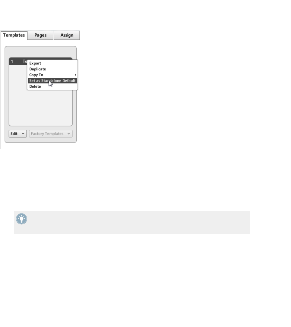
Setting a new Standalone Default Template.
►In the dialog window that opens, confirm that you want to overwrite the current Stand-
alone Default Template.
►Disconnect the KOMPLETE KONTROL S-SERIES keyboard from your computer.
→Your updated Standalone Default Template is loaded.
By creating additional Templates, you can switch between different stand-alone configura-
tions. KOMPLETE KONTROL S-SERIES keyboards can only load one stand-alone Template
at a time, though.
Using Your KOMPLETE KONTROL S-SERIES Keyboard
Stand-alone Operation
CONTROLLER EDITOR - Manual - 221
22 Using Two or More Units of the Same Type
For some NI controllers, the Controller Editor allows you to connect more than one device to
the same computer and use them simultaneously for controlling various MIDI targets. This can
be useful if you wish to control virtual decks of a DJ software or any other application requiring
an instant access to many parameters.
The affected NI controllers are listed in the following table:
NI Controller Maximum Number of Devices Used Simultaneously
TRAKTOR KONTROL X1 4
TRAKTOR KONTROL X1 MK2 4
TRAKTOR KONTROL F1 4
KOMPLETE KONTROL S-SERIES 4
Using the Controller Editor, you can create and manage individual Templates, Pages and as-
signments for each unit. For better distinction of multiple devices, it is necessary to assign a
specific name to each device by choosing from a list of four predefined names (e.g., Traktor
Kontrol X1 - 1 .. Traktor Kontrol X1 - 4).
By default, all devices have the same name. Therefore you will need to change the names of all
devices except one as soon as you want to use two or more devices simultaneously.
In the following sections, we will use the TRAKTOR KONTROL X1 as example. All instruc-
tions also apply to the other controllers in the table above.
22.1 Renaming the Units
We assume here that only one TRAKTOR KONTROL X1 unit is currently connected to your
computer. We will rename this unit before connecting an additional one. To rename the con-
nected unit, proceed as follows:
1. If the Controller Editor is not currently open, start it.
2. In the File menu, select Preferences….
This opens the Preferences window.
Using Two or More Units of the Same Type
Renaming the Units
CONTROLLER EDITOR - Manual - 222

3. Click the Controller tab on the left to open the Controller page.
4. In this page, check that the Controller menu at the very top reads Traktor Kontrol X1 - 1.
If not, click this menu and select Traktor Kontrol X1 - 1 in the list. The Controller page
now displays the settings for the connected TRAKTOR KONTROL X1:
The Controller page of the Preferences window showing the settings for the connected TRAKTOR KONTROL X1.
At the bottom of the page, the Device Name menu reads the current name assigned to your
TRAKTOR KONTROL X1. By default, you see the name Traktor Kontrol X1 - 1.
Using Two or More Units of the Same Type
Renaming the Units
CONTROLLER EDITOR - Manual - 223
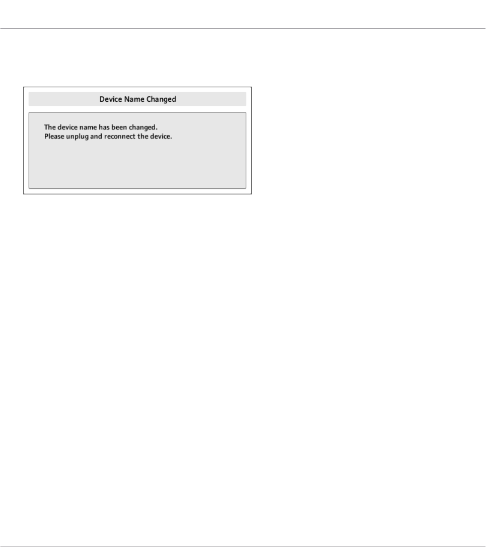
1. Click the Device Name menu and select another name from the available entries (for ex-
ample Traktor Kontrol X1 - 2). Upon your selection, a dialog warns you that you changed
the device name:
2. Follow the instructions in the warning dialog: unplug the unit, then reconnect it. The
warning dialog disappears.
3. Click OK at the bottom right corner of the Preferences window to close it.
4. Connect the second TRAKTOR KONTROL X1 to your computer.
→You now have your two TRAKTOR KONTROL X1 devices connected to your computer. You
can switch both to MIDI mode and use them simultaneously as MIDI remote controls.
As you can see, the second TRAKTOR KONTROL X1 still has its factory name. We only
changed the name of the first TRAKTOR KONTROL X1.
To connect further X1 devices to your computer, please repeat the steps described above (you
can use up to four X1 devices simultaneously).
22.2 Accessing Templates and Pages of a Particular Unit
To see or edit the Templates, Pages and assignments of any TRAKTOR KONTROL X1 device,
select its name in the Device menu of the Application Control Bar:
Using Two or More Units of the Same Type
Accessing Templates and Pages of a Particular Unit
CONTROLLER EDITOR - Manual - 224
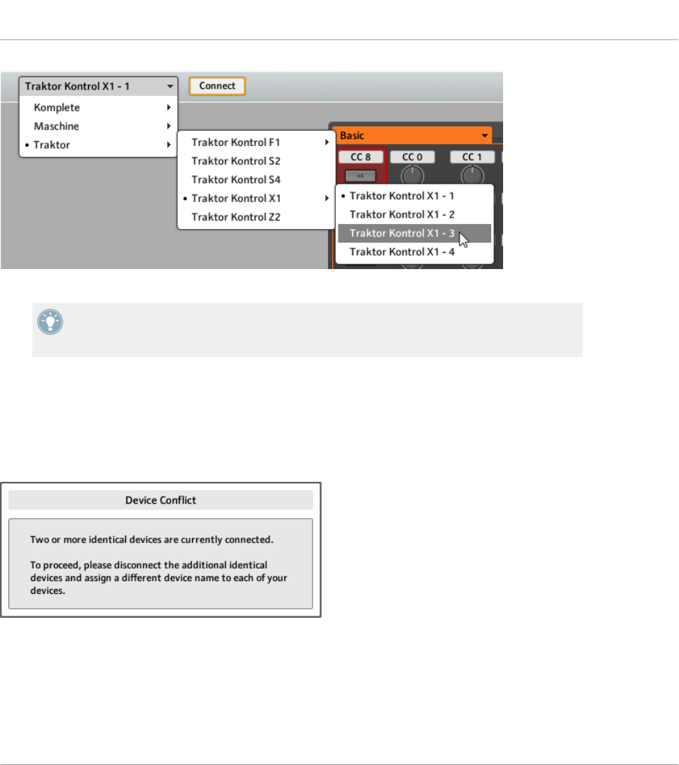
The Device menu.
You can change the name of your Controllers in the Controller Editor, provided that the rel-
evant units are connected. If a unit is not connected to your computer, the settings in the
Controller page of the Preferences window for that unit are grayed out and inactive.
22.3 Resolving Device Conflicts
If you connect an additional TRAKTOR KONTROL X1 with the same name as one of the al-
ready connected unit(s), a warning dialog will inform you about the device (name) conflict:
This message will appear if you connect at least two TRAKTOR KONTROL X1 without having renamed your devices before-
hand.
Please follow the instructions in the dialog: unplug the additional device, rename the original
devices as described above and then connect the new unit again.
Using Two or More Units of the Same Type
Resolving Device Conflicts
CONTROLLER EDITOR - Manual - 225

When selecting a name that is already occupied by another TRAKTOR KONTROL X1 unit, Con-
troller Editor asks to swap the device name between the device you want to rename and the
one that is currently assigned to the selected name. Should the selected name be used by a
device that is currently not connected or the name is not used by another device at all, the
chosen name is assigned to the selected controller. If a device name is currently in use, i.e.
the device is connected, this is reflected by a leading dot (•) in front of the device name for
visual distinction. To rename a controller, repeat the actions described above.
Using Two or More Units of the Same Type
Resolving Device Conflicts
CONTROLLER EDITOR - Manual - 226
23 Reference
This chapter systematically describes all the user interface elements of the Controller Editor.
The Controller Editor is the “control tower” of your NI controller’s remote control system. It
stores the links between hardware actions (what you do on your NI controller) and MIDI events
(what you want to achieve within a specific piece of MIDI-capable software or hardware).
23.1 The Application Menu Bar
The Controller Editor menu bar contains three menus: the File menu, the View menu and the
Help menu.
The Application Menu Bar, with its three menus (Windows depicted).
23.1.1 File Menu
The File menu allows you to manage the Configuration files, to tweak the overall behavior of
the application, and to quit the Controller Editor. The menu contains the following entries:
•Open Configuration: Opens a dialog allowing you to select the Configuration file you want to
load. The Configuration file contains all data sets used by the Controller Editor. For one
NI controller, the data set contains the list of all Templates, all data in the Templates in
the list, and the index of the currently selected Template — to sum up, the Configuration
file contains everything you can store for use with the Controller Editor. To load a Configu-
ration file, select Open Configuration from the File menu, navigate to the desired Configu-
ration file in the dialog that appears, and double-click it (or click it, then click Open). It
will replace the current configuration.
•Save Configuration…: Opens a dialog allowing you to save the current Configuration file
under another name. In the dialog, type the desired name for the new Configuration file,
then click Save.
Reference
The Application Menu Bar
CONTROLLER EDITOR - Manual - 227

You can also use the Save Configuration… command as a backup function: Save your Con-
figuration file somewhere else (hard drive, USB key…), and you will be able to load it
again.
There is no Save entry in the File menu. The Controller Editor will remember the current
configuration the next time you open the software. Be aware that loading another Configu-
ration file will overwrite the current configuration!
•Open Template…: Opens a dialog allowing you to select a Template file for loading for the
currently selected NI controller. The Template will be appended to the Template list in
the Inspector. See ↑23.5.1, Templates Pane for more information on the Template list
and the Template Edit menu.
•Preferences…: Opens the Preferences window. This window allows you to tune some glob-
al parameters of the Controller Editor. See ↑23.2, The Preferences Window for a descrip-
tion of the available parameters.
•Exit: Quits the Controller Editor application. Note that all assignments stay active thanks
to the NI Hardware Service running in background.
23.1.2 View Menu
The View menu controls the layout of the Controller Editor interface. This menu contains two
entries:
•Toggle Labels: Hides/shows the assignment labels in the Hardware area. This command is
equivalent to the Show all labels check box in the top right of the Hardware area.
•Select Device: This submenu lists all NI controllers currently activated as MIDI remote
controls. By selecting an entry in this submenu, you choose the NI controller from which
you want to see/modify the MIDI assignments. The Hardware area along with all Tem-
plates / Pages / assignments are updated accordingly. You can also select an NI controller
via the Device menu located on the left in the Application Control Bar (see section
↑23.3.1, Device Menu).
23.1.3 Help Menu
The Help menu gives you access to information that might help you in the use of the Controller
Editor. The menu contains five entries:
Reference
The Application Menu Bar
CONTROLLER EDITOR - Manual - 228

•Open Manual…: Opens the PDF version of this manual, located in the Controller Editor in-
stallation folder.
•Open Template Documentation…: Opens the PDF documentation which explains you how to
use predefined factory Templates for use with specific Native Instruments and Third Party
products.
•Launch Service Center…: Launches the NI Service Center. The NI Service Center helps you
to activate your Native Instruments product (if activation is required) and afterwards lets
you access product updates. Find more information about the NI Service Center in the
separate Quick Start Guide, located in the Service Center installation folder.
•Visit the Knowledge Base…: Opens the Knowledge Base on the Native Instruments website
in your web browser. This web page provides you with useful information about NI prod-
ucts, among them the Controller Editor.
•Visit Native Instruments on the web…: Opens the Native Instruments home page in your
web browser.
•About…: Opens the About screen (like clicking the Native Instruments logo). This dialog
contains valuable information about the software such as its version number.
23.2 The Preferences Window
The Preferences window holds parameters for the Controller Editor and for the various NI con-
trollers.
►To open the Preferences window, click the File menu in the Application Menu Bar and
select Preferences….
The Preferences window contains two pages, the General page and the Controller page, dis-
played by clicking the corresponding tabs:
Reference
The Preferences Window
CONTROLLER EDITOR - Manual - 229
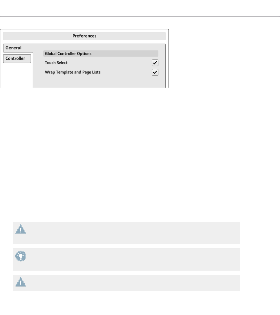
The Preferences window and its General and Controller tabs on the left (General page displayed).
23.2.1 General Page
The General page offers two options:
•Touch Select: If this option is activated, you can select the desired control element direct-
ly from your NI controller, the selection of any control element becoming more intuitive.
This can be useful to quickly assign the control elements: you don’t need to move your
mouse back and forth repeatedly between the Hardware area (where you select control el-
ements) and the Inspector’s Assign pane (where you can see or modify the corresponding
assignments) — instead, as soon as you actuate the desired control element on your NI
controller, it is automatically selected in the Controller Editor (the red Selection Frame fo-
cuses on it) and its assignment is automatically shown in the Assign pane of the Inspec-
tor. You can now focus on this Assign pane on your computer screen, making all selec-
tions from your hardware. This can be for example a very efficient way to work on large
series of assignments. Moreover, this ensures you that you’re really dealing with the con-
trol element you plan to use for that particular task.
For devices split into different sections in the Hardware area (and providing an Overview to
select a particular section for displaying), the Touch Select option only works in the section
currently displayed in the Hardware area.
For control elements allowing multiple actions (e.g., Push and Turn), the Touch Select op-
tion even allows to select the tab in the Assign pane corresponding to the particular action
(e.g., turning) you apply to the control element.
KOMPLETE KONTROL S-SERIES: The Touch Select option has no effect on the KOM-
PLETE KONTROL S-SERIES devices.
Reference
The Preferences Window
CONTROLLER EDITOR - Manual - 230

•Wrap Template and Page Lists: If activated, the selection jumps to the other end of the
Template or Page list whenever you press the Up (or Down) arrow key on your computer
keyboard or the corresponding shortcuts on your controller while the first (or last) entry is
selected in the list — in other terms, you “loop” the lists by joining both ends.
MASCHINE controller families: This is also true when using your controller’s shortcuts for
selecting Templates and (Knob) Pages. Note however that the Wrap Template and Page
Lists option does not affect the lists appearing in the corresponding display modes of your
controller.
23.2.2 Controller Page
The Controller page of the Preferences window allows you to adjust the settings for your various
NI controllers:
The Controller page of the Preferences window, here showing the settings for the MASCHINE MK2 controller.
1. Click the Controller menu at the top. This menu lists all NI controllers installed on your
computer.
2. In the drop-down list, select the NI controller whose parameters you want to adjust.
→Upon your selection, the rest of the Controller page displays the available settings for that
particular NI controller.
Reference
The Preferences Window
CONTROLLER EDITOR - Manual - 231
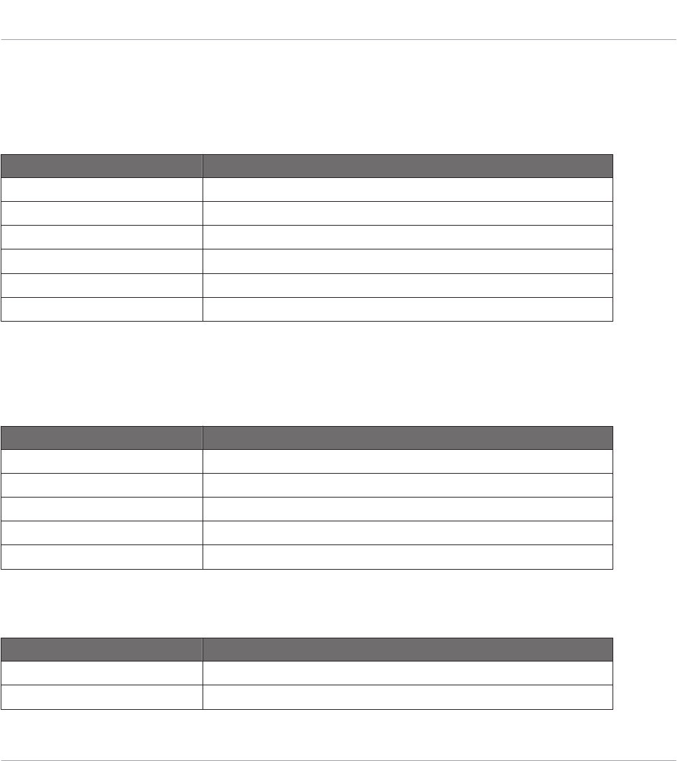
Settings for the MASCHINE and MASCHINE MK2 Controllers
For the MASCHINE and MASCHINE MK2 controllers, the settings are exactly the same as
those available on the displays of your controller in Settings display mode. As a reminder,
these settings are the following:
Section/control Description
Pads Section
Sensitivity slider Changes the sensitivity of the pads.
Display Section
Brightness slider Changes the backlight of the displays.
Contrast left slider Sets the contrast for the left display.
Contrast right slider Sets the contrast for the right display.
Settings for the MASCHINE MIKRO and MASCHINE MIKRO MK2 Controllers
For the MASCHINE MIKRO and MASCHINE MIKRO MK2 controllers, the settings are exactly
the same as those available on the display of your controller in Setup display mode. As a re-
minder, these settings are the following:
Section/control Description
Pads Section
Sensitivity slider Changes the sensitivity of the pads.
Display Section
Brightness slider Adjusts the brightness of the display.
Contrast slider Adjusts the contrast of the display.
Settings for the MASCHINE STUDIO Controller
For the MASCHINE STUDIO controller, the Controller page offers following settings:
Section/control Description
Pads Section
Sensitivity slider Changes the sensitivity of the pads.
Reference
The Preferences Window
CONTROLLER EDITOR - Manual - 232
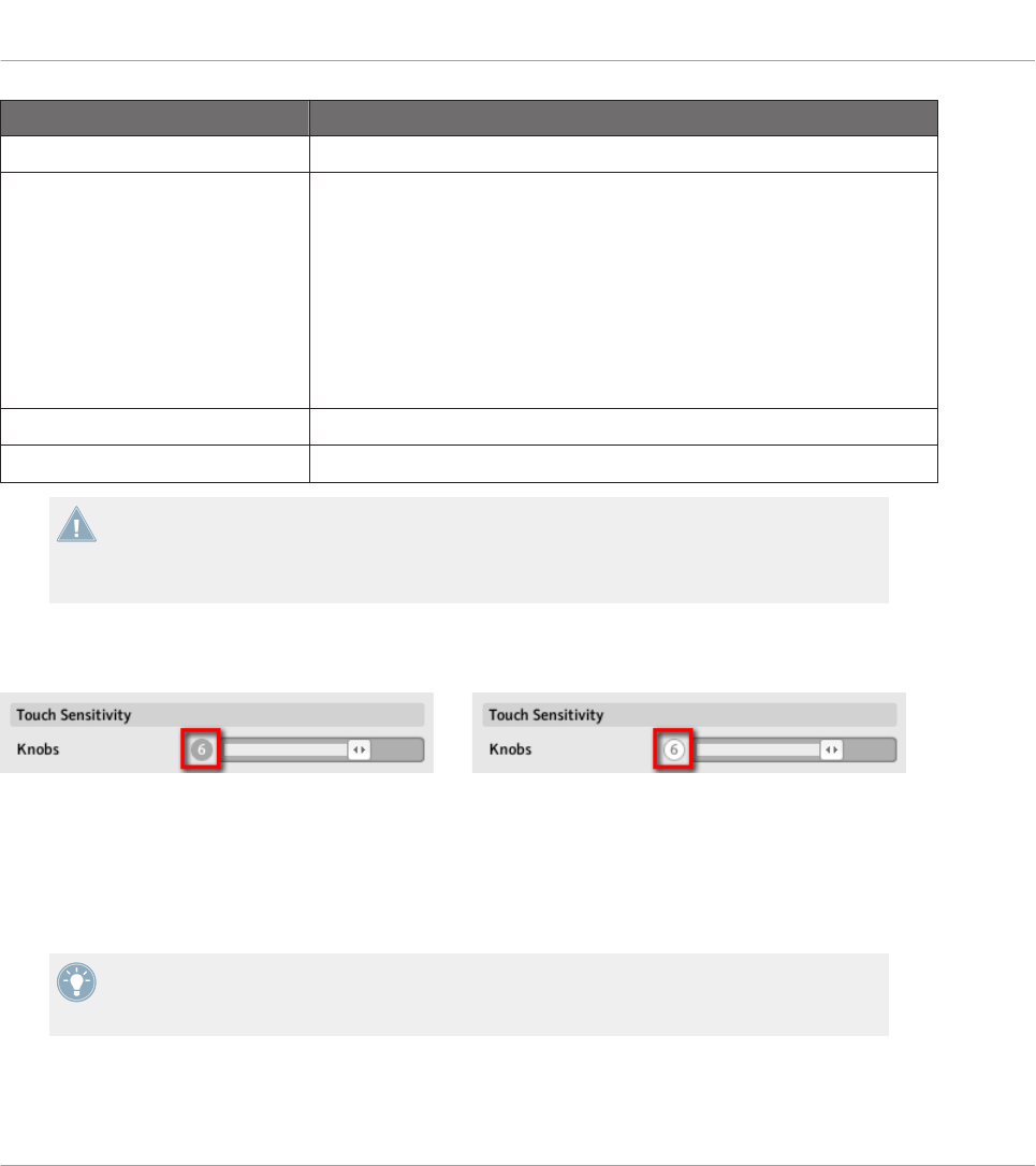
Section/control Description
Touch Sensitivity Section
Knobs slider Adjusts the touch sensitivity of Knobs 1–8. The values range from 1 to
8. At low sensitivity values (slider to the left), you will need to apply a
stronger pressure on Knobs 1–8 to send the MIDI message. At high sen-
sitivity values (slider to the right), a softer pressure on the knobs will al-
ready send the MIDI message.
The current sensitivity value is indicated by the number left of the slid-
er. Additionally, this number provides a visual feedback that helps you
quickly find the sensitivity that best fits your needs — see below for
more info.
Display Section
Brightness slider Changes the backlight of the displays.
All these settings can also be adjusted on your MASCHINE STUDIO controller: the pad sen-
sitivity and the knobs’ touch sensitivity are found in the Settings display mode and the
brightness setting is found in the Calibration display mode (see sections ↑9.4.2, Settings
Display Mode and ↑9.4.3, Calibration Display Mode, respectively).
To adjust the touch sensitivity of Knobs 1–8, use the sensitivity value displayed left of the slid-
er as follows:
On the left, your touch is not detected; on the right, it is detected!
1. While looking at this sensitivity value, touch any Knob 1–8 under the controller displays.
As soon as your pressure on the Knob is detected, the number turns red.
2. Apply various pressures on the Knob and readjust the slider accordingly until you are sat-
isfied with the sensitivity.
For example, you could set the sensitivity high enough to avoid that slight, unwanted
touches on the Knobs disturb your workflow, but still low enough to give the touch features
a “natural” feel — the best setting will depend on your fingers and needs!
Reference
The Preferences Window
CONTROLLER EDITOR - Manual - 233
Settings for the TRAKTOR KONTROL X1 and X1 MK2 (1–4)
For the TRAKTOR KONTROL X1, the Controller page offers following settings:
Effect Knobs Section Description
Recalibrate button Allows you to recalibrate the eight Effect Knobs (the Knobs arranged on
two columns at the top of your TRAKTOR KONTROL X1), in order to cor-
rect potential inaccuracies of both center position and range of the
Knobs. To start the calibration process, click Recalibrate. The process
consists of three steps, which ask you to turn the Knobs fully to the left,
fully to the right and to the center position.
The device is pre-calibrated in the factory. Executing the calibration procedure is only nec-
essary if you notice that some controls do not read the correct values.
LEDs Section Description
On-State Brightness slider Sets the brightness for the On state of the buttons on your Controller.
Off-State Brightness slider Sets the brightness for the Off state of the buttons on your Controller.
Status Section Description
Device Name menu Allows to select a different name for the connected TRAKTOR KON-
TROL X1 Controllers. This is useful when using more than one X1 unit
simultaneously. See chapter ↑21, Using Your KOMPLETE KONTROL S-
SERIES Keyboard for more information.
Start in MIDI-Mode check box If this check box is activated, your controller switches to MIDI mode as
soon as you start your computer, so you don’t have to switch it manually.
Settings for the TRAKTOR KONTROL F1 (1–4)
For the TRAKTOR KONTROL F1, the Controller page offers following settings:
Knobs Section Description
Recalibrate button Allows you to recalibrate the four FILTER knobs at the top of the F1. To
start the calibration process, click Recalibrate. The process consists of
three steps, which ask you to turn the knobs fully to the left, fully to the
right and to the center position.
Reference
The Preferences Window
CONTROLLER EDITOR - Manual - 234

The device is pre-calibrated in the factory. Executing the calibration procedure is only nec-
essary if you notice that some controls do not read the correct values.
Faders Section Description
Recalibrate button Allows you to recalibrate the vertical faders. Click Recalibrate to start
the calibration process, then follow the on-screen instructions.
LEDs Section Description
On-State Brightness slider Sets the brightness for the On state of the buttons on your Controller.
Off-State Brightness slider Sets the brightness for the Off state of the buttons on your Controller.
Status Section Description
Device Name menu Allows to select a different name for the connected TRAKTOR KON-
TROL F1 Controllers. This is useful when using more than one F1 unit
simultaneously. See chapter ↑21, Using Your KOMPLETE KONTROL S-
SERIES Keyboard for more information.
Start in MIDI-Mode check box If this check box is activated, your controller switches to MIDI mode as
soon as you start your computer, so you don’t have to switch it manually.
Settings for the TRAKTOR KONTROL S2, S2 MK2, S4, S4 MK2
For the TRAKTOR KONTROL S2/S4, the Controller page offers following settings:
Knobs Section Description
FX Recalibrate button Allows you to recalibrate the FX knobs. Click Recalibrate to start the cal-
ibration process, then follow the on-screen instructions.
EQs & Filters Recalibrate button Allows you to recalibrate the EQ and FILTER knobs. Click Recalibrate to
start the calibration process, then follow the on-screen instructions.
Reference
The Preferences Window
CONTROLLER EDITOR - Manual - 235
Faders Section Description
Vertical Faders Recalibrate button Allows you to recalibrate the vertical faders. Click Recalibrate to start
the calibration process, then follow the on-screen instructions.
Crossfader Recalibrate button Allows you to recalibrate the crossfader. Click Recalibrate to start the
calibration process, then follow the on-screen instructions.
LEDs Section Description
On-State Brightness slider Sets the brightness for the On state of the buttons on your Controller.
Off-State Brightness slider Sets the brightness for the Off state of the buttons on your Controller.
Footswitch Section (S4/S4 MK2
only)
Description
Active menu Select here the type of wiring used by the footswitch currently connect-
ed to the FOOTSWITCH socket. You can choose between active ring
(Ring) and active tip (Tip) wiring.
Status Section Description
Start in MIDI-Mode check box If this check box is activated, your controller switches to MIDI mode as
soon as you start your computer, so you don’t have to switch it manually.
Settings for the TRAKTOR KONTROL S8
For the TRAKTOR KONTROL S8, the Controller page offers following settings:
Knobs Section Description
FX Recalibrate button Allows you to recalibrate the FX knobs. Click Recalibrate to start the cali-
bration process, then follow the on-screen instructions.
EQs & Filters Recalibrate button Allows you to recalibrate the EQ and FILTER knobs. Click Recalibrate to
start the calibration process, then follow the on-screen instructions.
Reference
The Preferences Window
CONTROLLER EDITOR - Manual - 236
Faders Section Description
Short Faders Recalibrate button Allows you to recalibrate the Slot Volume faders. Click Recalibrate to start
the calibration process, then follow the on-screen instructions.
Channel Faders Recalibrate but-
ton
Allows you to recalibrate the channel faders. Click Recalibrate to start the
calibration process, then follow the on-screen instructions.
Crossfader Recalibrate button Allows you to recalibrate the crossfader. Click Recalibrate to start the cali-
bration process, then follow the on-screen instructions.
The device is pre-calibrated in the factory. Executing the calibration procedure is only nec-
essary if you notice that some controls do not read the correct values.
Display Section Description
Brightness slider Adjusts the brightness of the displays.
You can also adjust the brightness of the displays directly from your S8 by entering Set-
tings display mode. For more details, see section ↑16.4.2, Adjust Color And Brightness.
LEDs Section Description
On-State Brightness slider Sets the brightness for the On state of the buttons on your Controller.
Off-State Brightness slider Sets the brightness for the Off state of the buttons on your Controller.
Status Section Description
Start in MIDI-Mode check box If this check box is activated, your controller switches to MIDI mode as
soon as you start your computer, so you don’t have to switch it manually.
Settings for the TRAKTOR KONTROL D2
For the TRAKTOR KONTROL D2, the Controller page offers following settings:
Reference
The Preferences Window
CONTROLLER EDITOR - Manual - 237

Knobs Section Description
Recalibrate button Allows you to recalibrate the four knobs of the D2. To start the calibra-
tion process, click Recalibrate. The process consists of three steps,
which ask you to turn the knobs fully to the left, fully to the right and to
the center position.
Faders Section Description
Recalibrate button Allows you to recalibrate the four faders of the D2. To start the calibration
process, click Recalibrate. The process consists of three steps, which ask
you to turn the knobs fully to the left, fully to the right and to the center
position.
The device is pre-calibrated in the factory. Executing the calibration procedure is only nec-
essary if you notice that some controls do not read the correct values.
Display Section Description
Brightness slider Adjusts the brightness of the displays.
You can also adjust the brightness of the display directly from your D2 by entering Settings
display mode. For more details, see section ↑15.4.2, Adjust Color And Brightness.
LEDs Section Description
On-State Brightness slider Sets the brightness for the On state of the buttons on your Controller.
Off-State Brightness slider Sets the brightness for the Off state of the buttons on your Controller.
Status Section Description
Start in MIDI-Mode check box If this check box is activated, your controller switches to MIDI mode as
soon as you start your computer, so you don’t have to switch it manually.
Settings for the TRAKTOR KONTROL Z1
For the TRAKTOR KONTROL Z1, the Controller page offers following settings:
Reference
The Preferences Window
CONTROLLER EDITOR - Manual - 238
Knobs Section Description
Recalibrate button Allows you to recalibrate all knobs. Click Recalibrate to start the calibra-
tion process, then follow the on-screen instructions.
Faders Section Description
Vertical Faders Recalibrate button Allows you to recalibrate the vertical faders. Click Recalibrate to start
the calibration process, then follow the on-screen instructions.
Crossfader Recalibrate button Allows you to recalibrate the crossfader. Click Recalibrate to start the
calibration process, then follow the on-screen instructions.
The device is pre-calibrated in the factory. Executing the calibration procedure is only nec-
essary if you notice that some controls do not read the correct values.
LEDs Section Description
On-State Brightness slider Sets the brightness for the On state of the buttons on your Controller.
Off-State Brightness slider Sets the brightness for the Off state of the buttons on your Controller.
Status Section Description
Start in MIDI-Mode check box If this check box is activated, your controller switches to MIDI mode as
soon as you start your computer, so you don’t have to switch it manually.
Settings for the TRAKTOR KONTROL Z2
For the TRAKTOR KONTROL Z2, the Controller page offers following settings:
Knobs Section Description
Recalibrate button Allows you to recalibrate all knobs. Click Recalibrate to start the calibra-
tion process, then follow the on-screen instructions.
Reference
The Preferences Window
CONTROLLER EDITOR - Manual - 239

Faders Section Description
Vertical Faders Recalibrate button Allows you to recalibrate the vertical faders. Click Recalibrate to start
the calibration process, then follow the on-screen instructions.
Crossfader Recalibrate button Allows you to recalibrate the crossfader. Click Recalibrate to start the
calibration process, then follow the on-screen instructions.
The device is pre-calibrated in the factory. Executing the calibration procedure is only nec-
essary if you notice that some controls do not read the correct values.
LEDs Section Description
On-State Brightness slider Sets the brightness for the On state of the buttons on your Controller.
Off-State Brightness slider Sets the brightness for the Off state of the buttons on your Controller.
Status Section Description
Start in MIDI-Mode check box If this check box is activated, your controller switches to MIDI mode as
soon as you start your computer, so you don’t have to switch it manually.
Settings for the KOMPLETE KONTROL S-SERIES Keyboards (1–4)
For the KOMPLETE KONTROL S-SERIES keyboards, the Controller page offers following set-
tings:
LEDs Section Description
On-State Brightness slider Sets the brightness for the On state of the TRANSPOSE (OCT- and OCT
+), TRANSPORT, and PRESET buttons on your keyboard.
Off-State Brightness slider Sets the brightness for the Off state of the TRANSPOSE (OCT- and OCT
+) and TRANSPORT buttons on your keyboard. (The PRESET buttons are
not affected since they are always on.)
For more info on the lighting behavior of these buttons, please refer to section ↑21.4.4,
Visual Feedback on the Buttons.
Reference
The Preferences Window
CONTROLLER EDITOR - Manual - 240
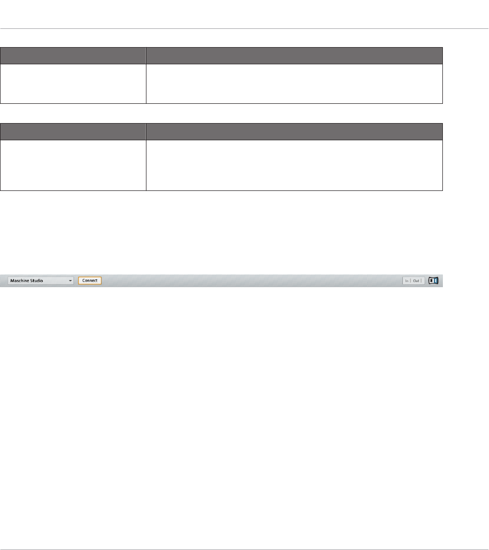
Expression Pedal Section Description
Recalibrate button Allows you to recalibrate the EXPRESSION pedal input. Click Recali-
brate to start the calibration process, then follow the on-screen instruc-
tions.
Status Section Description
Device Name menu Allows to select a different name for the connected KOMPLETE KON-
TROL S-SERIES keyboards. This is useful when using more than one
keyboard simultaneously. See chapter ↑21, Using Your KOM-
PLETE KONTROL S-SERIES Keyboard for more information.
23.3 The Application Control Bar
The Application Control Bar provides you with some global features controlling the behavior of
the Controller Editor.
The Application Control Bar contains some important features of the Controller Editor.
The next sections describe each of its elements in detail.
Reference
The Application Control Bar
CONTROLLER EDITOR - Manual - 241
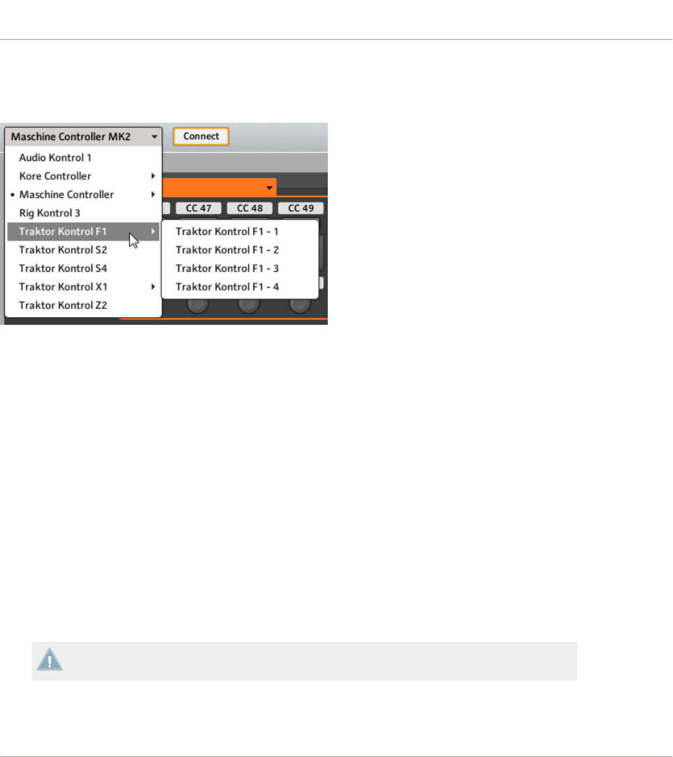
23.3.1 Device Menu
The Device menu.
The Device menu informs you which NI controller’s assignments you are working on. Further-
more, it allows you to switch to another NI controller in order to display and edit its assign-
ments. It is an alternative to the Select Device submenu located in the View menu of the Ap-
plication Menu Bar. Moreover, all connected NI controllers are marked with a leading dot (•)
for visual distinction.
To switch to another NI controller, do the following:
1. Click the Device menu to open a drop-down list containing all MIDI-capable NI control-
lers.
2. In the list, select the desired NI controller.
The Hardware area is updated accordingly and all Templates, Pages, and assignments are re-
called for the newly selected NI controller.
All parameters and settings displayed in the Controller Editor’s interface refer to the NI con-
troller currently selected in this Device menu, with the exception of the MIDI Activity indicator
and the NI Logo, at the far right of the Application Control Bar.
Worth to note is that all NI controllers currently in MIDI mode are still active, no matter
which controller is displayed in the Controller Editor.
Reference
The Application Control Bar
CONTROLLER EDITOR - Manual - 242

23.3.2 Connect Button
The Connect button.
The Connect button allows you to “call” your NI controller, in case it is currently controlling its
dedicated software (i.e. TRAKTOR or MASCHINE). This is the software equivalent to the re-
spective hardware shortcuts used to switch to MIDI mode.
Indeed, your NI controller can only connect to one application at a time:
• The NI controller can either be connected to its corresponding software, e.g. MASCHINE
(or one of its various plug-in instances currently running on your computer),
or
• It can connect to the Hardware Service, which is the gate to remote controlling all MIDI
targets from your NI controller — and whose assignments are defined via the Controller
Editor.
When you start the Controller Editor, it automatically connects to your NI controller(s) — the
rule is: the last application started takes control over your NI controller.
If the Connect button is off (the button is not lit), your NI controller is connected to an in-
stance of its dedicated software (e.g. the MASCHINE software for the MASCHINE controller).
►To switch to MIDI mode and connect your NI controller to the Controller Editor, click the
Connect button.
→The Connect button turns on.
You don’t need to have the Controller Editor open to switch your controller to MIDI. You
can do this via a shortcut on your controller. See ↑3.1, Switching your NI Controller to
MIDI Mode for more information.
Here are the possible states for the Connect button:
Reference
The Application Control Bar
CONTROLLER EDITOR - Manual - 243

NI Controller Connect Button
MIDI mode active Lit
MIDI mode inactive Off (click it to switch your controller to MIDI mode)
Not connected / not installed Grayed out (inactive)
To sum up, the Connect button always shows you the state of your NI controller.
23.3.3 MIDI Activity Indicator
The MIDI Activity indicator.
The MIDI Activity indicator displays incoming (In) and/or outgoing (Out) MIDI data for the con-
troller currently selected in the Device menu (see section ↑23.3.1, Device Menu). This can be
useful to check if everything is fine between the Controller Editor and its hardware and soft-
ware environment in your setup, and more generally, for any MIDI debugging purpose.
On the MASCHINE, MASCHINE MK2, and MASCHINE STUDIO controllers, you can use
the Monitor display mode to see the detailed MIDI message being sent. See ↑5.4.6, Moni-
tor Display Mode (MASCHINE), ↑6.4.5, Monitor Display Mode (MASCHINE MK2) or
↑9.4.7, Monitor Display Mode (MASCHINE STUDIO) for more information.
The MIDI Activity indicator is not available if a KOMPLETE KONTROL S-SERIES device is
selected.
23.3.4 NI Logo
The NI Logo.
When you click the NI Logo, located on the far right of the Application Control Bar, the About
screen opens.
Reference
The Application Control Bar
CONTROLLER EDITOR - Manual - 244

This About screen provides you with some interesting information about your Controller Editor
installation, including the version number and the credits.
The About screen can also be opened by selecting the About… entry in the Help menu of
the Application Menu Bar.
23.4 The Hardware Area
When shown the Hardware area represents the NI controller that you have selected in the De-
vice menu. The Hardware area has two main purposes:
• It provides you with a graphical representation of your NI controller, for ease of use.
• It allows you to select a Page to load (if relevant) and the control element(s) that you wish
to edit. For example, this can be particularly useful if your NI controller is not currently
connected to your computer. That way, you can prepare your assignments even if the
hardware is not currently there.
Pairs of mini buttons in the Hardware area: If mini buttons are not selected when you click
them, click their Label Field instead!
In addition to the exact representation of your NI controller, the Hardware area holds a few ex-
tra graphical elements that extend its usability: the Label Fields, the Selection Frame, and the
Page areas / Page menus (except for the TRAKTOR KONTROL S2 and KOMPLETE KON-
TROL S-SERIES). Let’s describe each of these.
23.4.1 Label Fields
Some Label Fields next to control elements in the Hardware area.
Reference
The Hardware Area
CONTROLLER EDITOR - Manual - 245
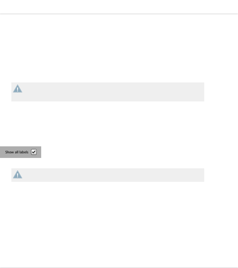
For every control element of the Hardware area that can be assigned to some MIDI message,
you find a Label Field above or below it. This field mirrors the Label Field located in the upper
part of the Assign pane in the Inspector, so that you can see all control elements along with
their names.
If no name has been defined yet for a control element, its Label Field displays by default the
MIDI message assigned to that control element.
Like all other assignments properties, these names are of course saved within the Pages and
Templates.
Many of the control elements already have a name on them in the Hardware area: this
name only refers to their original function in their dedicated software (MASCHINE and
TRAKTOR.)
Showing/Hiding All Labels
For the MASCHINE STUDIO, TRAKTOR KONTROL X1 MK2, S2 MK2, S4 MK2, S8, and Z1, a
Show all labels check box in the top right corner of the Hardware area allows you to show/hide
the labels of all control elements that are not selected. Hiding labels of the other control ele-
ments can help you focus on the assignments you are currently working on.
The Show all labels check box.
Labels for the selected control elements are always shown.
The Show all labels check box is equivalent to the Toggle Labels entry in the Application Menu
Bar’s View menu (see section ↑23.1.2, View Menu). To enable/disable it, you can also press
[Ctrl] + [L] on your computer keyboard ([Cmd] + [L] on Mac OS X).
Reference
The Hardware Area
CONTROLLER EDITOR - Manual - 246

23.4.2 Selection Frame
The Selection Frame highlights the control element that is currently focused.
The Selection Frame is a red frame highlighting the currently selected control element. When-
ever you select another control element in the Hardware area (or, with the Touch Select option
activated in the Preferences, on your NI controller), the Selection Frame highlights this control
element. At the same time, the Assign pane in the Inspector shows the assignment properties
for that element.
You can select two or more control elements of the same type in the Hardware area for
batch editing: Simply hold [Shift] on your computer keyboard and click the desired control
elements! You can also click and drag your mouse to draw a selection rectangle around sev-
eral control elements (only control elements of the same type will be included in the selec-
tion).
23.4.3 Page Areas and Page Menus
There is no Page area nor Page menu available for the TRAKTOR KONTROL S2 and KOM-
PLETE KONTROL S-SERIES.
Reference
The Hardware Area
CONTROLLER EDITOR - Manual - 247
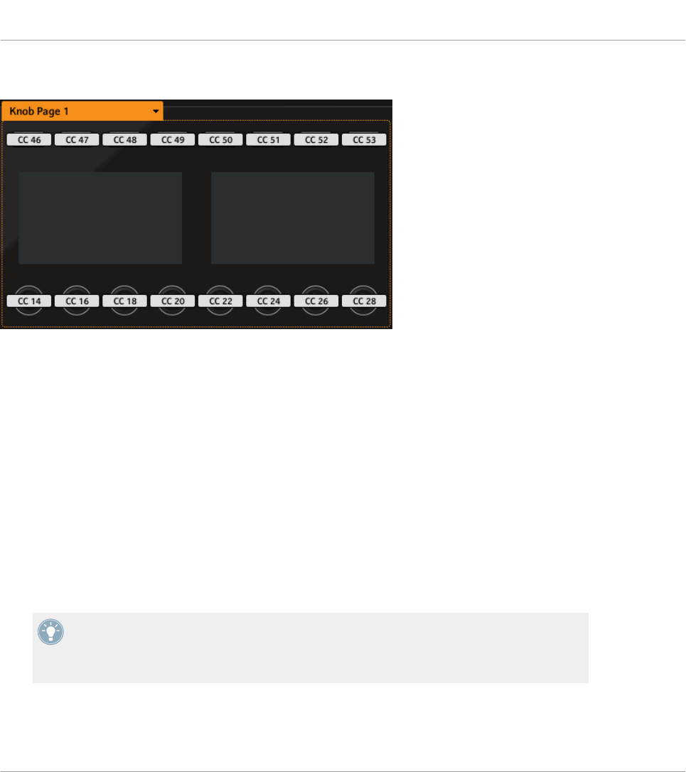
Page Areas
The Page area holds all control elements included in a Page (here the Knob Page area on the MASCHINE STUDIO control-
ler).
Inside the Hardware area, one or more colored frames highlight some of the control elements.
These frames define the various page areas, which hold all control elements included in the
corresponding paging system:
• TRAKTOR controller family, KOMPLETE KONTROL S-SERIES: The unique orange frame
indicates the area of the Pages.
• MASCHINE controller family: Additional frames are visible (if enabled):
◦Orange frame: Knob Pages.
◦Blue frame: Pad Pages.
◦Red frame (MASCHINE STUDIO only): I/O and Level Pages.
◦Violet frame (MASCHINE STUDIO only): Jog Wheel Pages.
As a short reminder: The control elements located in a Page area can have multiple assign-
ments, which are grouped on so-called Pages — with, on each Page, one assignment for
one control element (for a general explanation of the Controller Editor’s mapping system,
see section ↑4.3, The Mapping System).
Reference
The Hardware Area
CONTROLLER EDITOR - Manual - 248
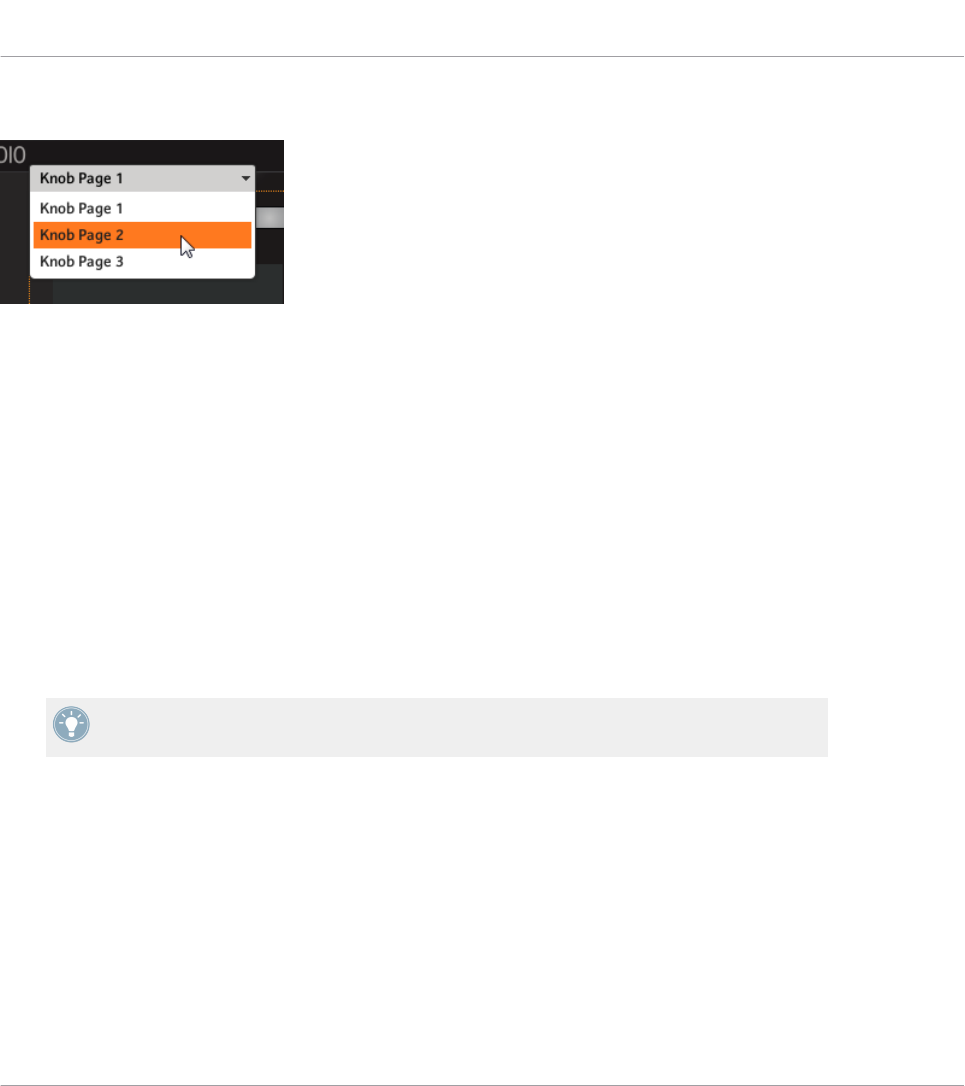
Page Menus
The Page menu allows you to select another Page (here the Knob Page menu on the MASCHINE STUDIO controller).
At the Page area’s upper left corner, the Page menu shows you the name of the Page currently
selected. Moreover, it allows you to select another set of assignments:
►To select a particular Page, click the Page menu and choose the desired entry from the
list — this list mirrors the corresponding Page list in the Inspector’s Pages pane.
The selected Page loads automatically, replacing the Page currently loaded.
23.5 The Inspector
Located on the right of the Controller Editor’s window, the Inspector is THE definitive place to
edit and organize your Templates, and its possible Pages, and all your control assignments. For
that reason, the Inspector is always visible.
If you are not sure about the terms “Template,” “Page,” etc., read section ↑4.3, The Map-
ping System again, where these basic concepts are explained.
As we already mentioned, the basic mapping workflow practically dives into the assignment hi-
erarchy. Let’s quickly look at it again, focusing on the Controller Editor window:
1. From the Application Control Bar’s Device menu, select the NI controller which you want
to work with. If you have only one Controller installed, it is automatically selected.
2. Choose a Template. This can be done for example via the Templates pane of the Inspector
(see below). As the Template loads, all its included Pages and assignments are loaded.
Reference
The Inspector
CONTROLLER EDITOR - Manual - 249

3. If the control element that you want to edit is located within a Page area, you also have to
select the desired Page. This can be done either via the corresponding Page menu or via
the Pages pane of the Inspector (see below). If the control element is somewhere else on
the NI controller, skip this step.
If you only want to use the assignments as they are, that’s all. But if you want to check the
assignments or modify them, you then follow the next steps:
1. Put the focus on the control element that you want to edit. This can be done either in the
Hardware area or directly on your controller (if the Touch Select option is activated in the
General page of the Preferences window) by clicking/touching the desired control ele-
ment.
2. Go to the Assign pane of the Inspector (see below) and tweak the assignment properties
for this control element.
Panes in the Inspector
The Inspector is divided into three panes, each of them taking care of a specific level in the
Controller Editor’s mapping system:
• The Templates pane allows you to manage your Templates.
• The Pages pane allows you to organize your Pages. This pane is not available for the
TRAKTOR KONTROL S2. When working with the MASCHINE controllers, this Pages pane
also allows you to activate and organize the Pad Pages.
• Last but not least, the Assign pane allows you to edit very precisely the MIDI assignment
for the control element currently selected in the Hardware area.
Let’s describe each of these three panes thoroughly. We will start with the Templates, then
look at the Pages, and finally describe all details of the assignments.
23.5.1 Templates Pane
The Templates pane allows you to select and manage your Templates. The Templates can be
used to store a whole set of assignments and Pages, for example for a specific use: a particular
hardware instrument, a particular software configuration for a live set, a particular song of your
set, etc.
►To show the Templates pane, click the Templates tab at the top of the Inspector.
Reference
The Inspector
CONTROLLER EDITOR - Manual - 250
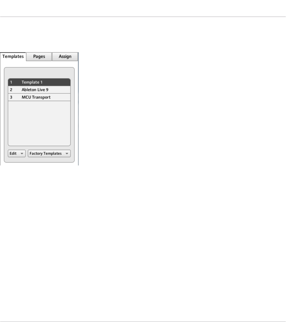
Template List
The Template list displays all available Templates:
The Template list, at the top of the Templates pane.
In this list, each entry represents a Template. The currently selected Template is highlighted in
the list.
►To select another Template, simply click its entry.
→The selected Template is automatically loaded, with all its Pages and control assign-
ments.
Each entry in the Template list has two elements: the Template number and the Template
name. The Template number is not editable — it defines the order of appearance of the Tem-
plate in the list. The Template name is editable:
►To rename the Template, double-click its name (it is then highlighted), type a new name,
and press [Enter] on your computer keyboard.
For your convenience, you can reorder the Templates in the list by drag and drop. Reordering
your Templates can be useful if you plan to use several Templates for a live performance and
you need to have them available in a specific order.
Reference
The Inspector
CONTROLLER EDITOR - Manual - 251
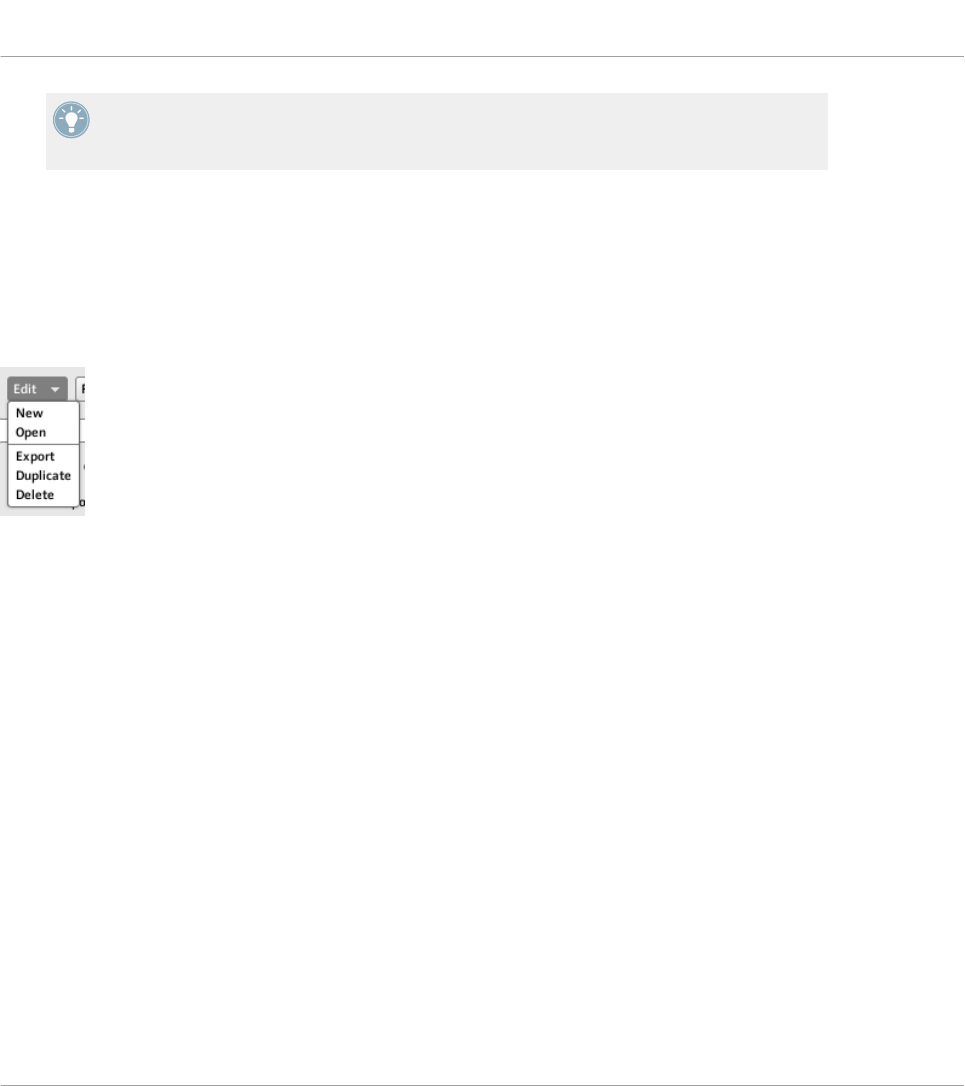
MASCHINE controller family and KOMPLETE KONTROL S-SERIES: You can also select di-
rectly Templates from your controller. For more details, please refer to the chapter describ-
ing your controller in this manual.
If the number of Templates is too big to fit in the displayed Template list, a scrollbar appears
on the right to navigate through the list.
Edit Menu
Located below the Template list, the Edit menu gives you access to important management
functions. To access any of these functions, click the menu and select the desired entry:
The Edit menu below the Template list.
The following commands are available:
•New: Creates a new default Template. This new Template is appended at the end of the
list. You can have as many Templates as you want in your list.
•Open: Opens a dialog allowing you to navigate to the desired Template file on your hard
drive to load it. Select the Template file and click OK (or double-click the Template file):
the Template will be appended at the end of the list and will automatically be loaded as
current Template.
•Export: Opens a dialog allowing you to export the selected Template as a file on your hard
drive. Select the destination and type the name of the Template file to be exported.
Please note that the filename that you choose can be different from the Template’s name
inside the Controller Editor. Once this is done, click Save to export the file.
•Duplicate: Duplicates the selected Template and insert it into the list at the position be-
low.
•Delete: Removes the selected Template. The entries below are moved up to fill the gap.
Reference
The Inspector
CONTROLLER EDITOR - Manual - 252
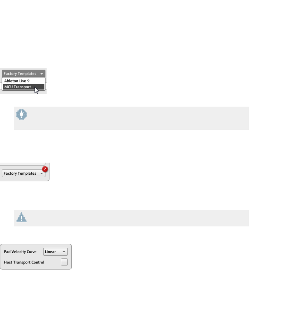
Factory Templates Menu
Next to the Edit menu, the Factory Templates menu allows you to load factory Templates pro-
vided with the Controller Editor. To load a Template, click the menu and select the desired en-
try:
The Factory Templates menu below the Template list.
The Templates selected in the Factory Templates menu are loaded into your Template list
above. If you modify or delete the Template once it is loaded in the Template list, the fac-
tory Template will stay untouched, ready to be loaded again later!
Furthermore, if new factory Templates are available since the last use of the Controller Editor,
a little bubble will appear at the upper right corner of the menu indicating the number of new
Templates:
The menu contains two new factory Templates.
Template Properties
There is no Template Properties area for the TRAKTOR KONTROL X1/X1 MK2/F1/S2/
S2 MK2/S8/Z1/Z2,and KOMPLETE KONTROL S-SERIES.
The Template Properties area contains settings for the Template selected in the Template list:
The Template Properties on the Templates pane (here for the MASCHINE controller).
Depending on the selected controller, you will find in the Template Properties up to three ele-
ments: the Pad Velocity Curve menu, the MIDI Port menu and the Host Transport Control
check box. These elements are described in the following paragraphs.
Reference
The Inspector
CONTROLLER EDITOR - Manual - 253
Pad Velocity Curve menu (MASCHINE Controller Family Only)
The Pad Velocity Curve menu allows you to choose from a list of seven velocity curves that af-
fect the behavior of the pads on your controller. A velocity curve defines how the pressure on
the pads will be translated into velocity values. In the Pad Velocity Curve menu, you can
choose between three soft, three hard and one linear curve. The soft curves are boosting lower
pressure values and damping higher pressure values (logarithmic response), the hard curves
are damping lower pressure values and boosting higher pressure values (exponential response).
The linear curve will translate pressure values into velocity values proportionally.
MIDI Port menu
For the NI controllers equipped with a MIDI output socket, the MIDI Port menu allows you to
specify whether you want to send the MIDI messages to the internal (virtual) MIDI port or to
the external (physical) MIDI port of your NI controller. When you click this menu, you see two
options:
•Internal: The MIDI messages are routed through the internal MIDI port. This way, they can
target other MIDI-capable applications running on your computer (provided that these ap-
plications are listening to this MIDI port — this has to be set in the target application’s
preferences).
•External: The MIDI messages are routed through the MIDI output socket of your NI con-
troller. That way, your Template can target other MIDI-capable hardware devices connect-
ed to the MIDI output socket of your controller.
There is no MIDI Port menu for the MASCHINE controller family nor for the KOM-
PLETE KONTROL S-SERIES keyboards. For these controllers, all MIDI messages are routed
through the internal MIDI port.
Host Transport Control (MASCHINE Controller Family Only)
Host Transport Control is a special feature to be used when the MASCHINE software is running
as plug-in in a host environment. It allows you to split the controls on MASCHINE (all control-
lers) so that some controls have the regular MASCHINE functions, while others control your
host. The controls are split as follows:
• On one hand, the PLAY, RESTART, Step Backwards, Step Forwards, and ERASE buttons
in the TRANSPORT section of your controller will send MIDI messages as defined in the
Template.
Reference
The Inspector
CONTROLLER EDITOR - Manual - 254
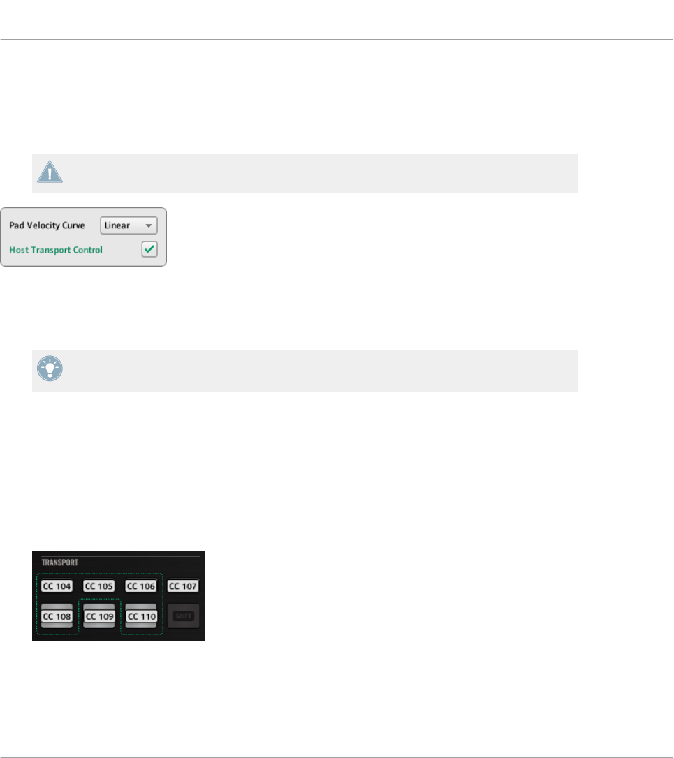
• On the other hand, all other control elements will control the MASCHINE plug-in loaded
in your host.
This notably allows you to control the transport functions of your sequencer via MIDI while you
control the MASCHINE plug-in with the rest of your controller!
The Host Transport Control feature works only if MASCHINE is running as a plug-in in a
host environment.
The Host Transport Control check box.
►Click the Host Transport Control check box to enable/disable the Host Transport Control
feature for the selected Template.
Keep in mind that the Host Transport Control option belongs to the Template Properties,
thus you can enable/disable it for each Template individually.
When Host Transport Control is active and your controller is focused on a MASCHINE plug-in
instance in your host environment, the following happens:
• On your controller, the PLAY, RESTART, Step Backwards, Step Forwards, and ERASE but-
tons are dimmed to indicate that they are in MIDI mode.
• All other control elements on your controller have their usual MASCHINE behavior, includ-
ing the display(s).
• In the Controller Editor, the affected buttons are highlighted in the Hardware area:
Reference
The Inspector
CONTROLLER EDITOR - Manual - 255
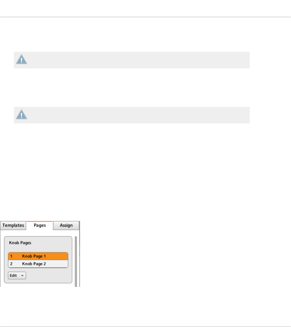
23.5.2 Pages Pane
The Pages pane is not available for the TRAKTOR KONTROL S2.
The Pages pane allows you to select and manage your Knob Pages, Pad Pages, I/O and Level Pa-
ges, and Jog Wheel Pages where relevant.
►To show the Pages pane, click the Pages tab at the top of the Inspector.
Remember that, according to the Controller Editor’s mapping system, all operations made
in the Pages pane affect the Pages located in the Template that is currently loaded!
The Pages are sets of assignments for the control elements located in the Page area of the
Hardware area. For example, Pages can be used to store the assignments for particular patches
of your target instrument, or for specific sections (filter section, effect section, etc.) of your in-
strument, or for different instruments in your setup. See section ↑4.3, The Mapping System for
more information.
Pages List
The Pages pane has some similarities with the Templates pane explained above. Similarly to
the Templates pane, the upper part of the Pages pane holds a Pages list (labeled Knob Pages
list for controllers of the MASCHINE family). This list displays all (Knob) Pages available in the
current Template:
The Knob Pages list, at the top of the Pages pane.
In this list, each entry represents a Page. The Page currently loaded is highlighted.
Reference
The Inspector
CONTROLLER EDITOR - Manual - 256

►To select another Page, simply click its entry.
→The selected Page is automatically loaded, with all its control assignments.
You can also select another Page via the Page menu on the top of the Page area in the
Hardware area (see section ↑23.4.3, Page Areas and Page Menus), or possibly from your NI
controller (see the relevant controller-specific chapter).
KOMPLETE KONTROL S-SERIES: The Pages list only contains one entry and it is always
selected. Multiple Pages will be available in a future KOMPLETE KONTROL update.
Each entry in the Pages list (or Knob Pages list) consists of a number and a name. The Page’s
number is not editable — it defines the order of appearance of the Page in the list. The Page’s
name is editable:
►To rename the Page, double-click its name (it is then highlighted), type a new name, and
press [Enter] on your computer keyboard.
Like in the Template list, you can reorder the Pages in the list by drag and drop:
►To move a Page in the list, click its entry, move your mouse vertically while holding the
mouse button depressed, and release the mouse button at the desired location.
→The Page takes its new place in the list.
This can be useful in a live situation, for example if you plan to use several Pages for different
parts of a song, and you need to have them in a specific order: When they are well ordered, you
can easily switch to the previous/next one by using the Page buttons on your NI controller (if
available).
You can reorder Pages only for controllers providing an unlimited number of pages (MA-
SCHINE controller family and TRAKTOR KONTROL Z1).
Edit Menu (MASCHINE Controller Family Only)
Right under the Pages list (or Knob Pages list), the Edit menu grants access to management
functions.
►To access any of these functions, click the Edit menu and select the desired entry.
Reference
The Inspector
CONTROLLER EDITOR - Manual - 257
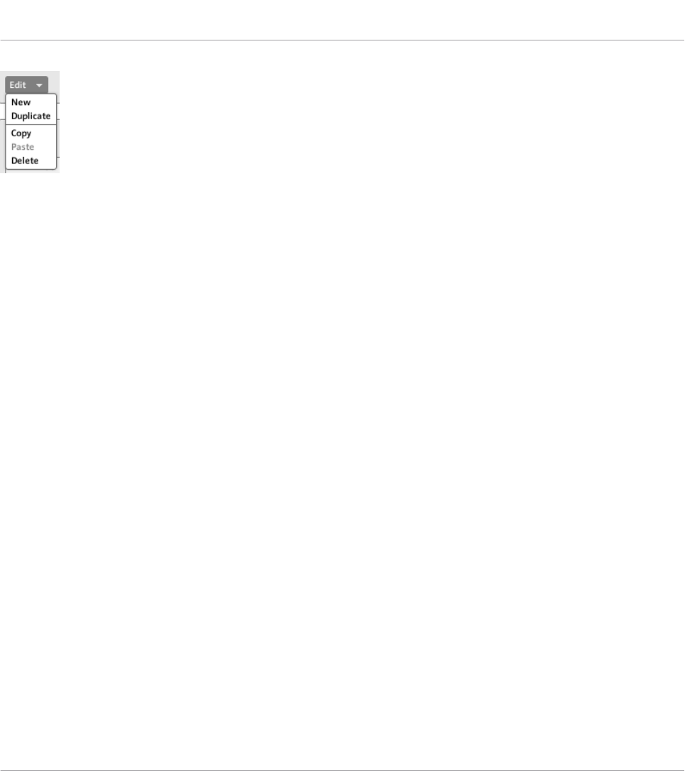
The Edit menu, below the Pages list (or Knob Pages list).
The following commands are available:
•New: Creates a new default Page. This new Page is appended at the end of the list. You
can have as many Pages as you want in your Template.
•Duplicate: Duplicates the selected Page and insert it at the next lower position in the list.
This can be useful to generate several Pages with only a few differences, without having
to start from scratch each time.
•Copy: Stores the selected Page into your operating system’s clipboard. This is very useful
to move or copy a particular Page to another Template: after having selected the desired
Page, choose this Copy command, then switch to another Template (using one of the
methods described in this manual), go back to the Inspector’s Pages pane, in the Pages
list select the entry below which you want to insert the copied Page, and use the Paste
command (see below).
•Paste: Inserts the Page stored in the clipboard below the Page currently selected in the
list. The inserted Page is then automatically loaded. You can use this command in con-
junction with the Copy command described above to transfer Pages between Templates.
•Delete: Removes the selected Page. The lower entries will move up and fill the gap.
Shift Mode Menu (TRAKTOR KONTROL X1, X1 MK2, F1, Z1, Z2, S2 MK2, S4, S4 MK2, S8)
Right under the Pages list, the Shift Mode menu allows you to adapt the behavior of the SHIFT
button used to switch between both Pages available on your controller. Two settings are availa-
ble:
•Gate: The Page is activated for the time the button is hold depressed.
•Toggle: The Page is activated until the next time you press the button again.
Reference
The Inspector
CONTROLLER EDITOR - Manual - 258
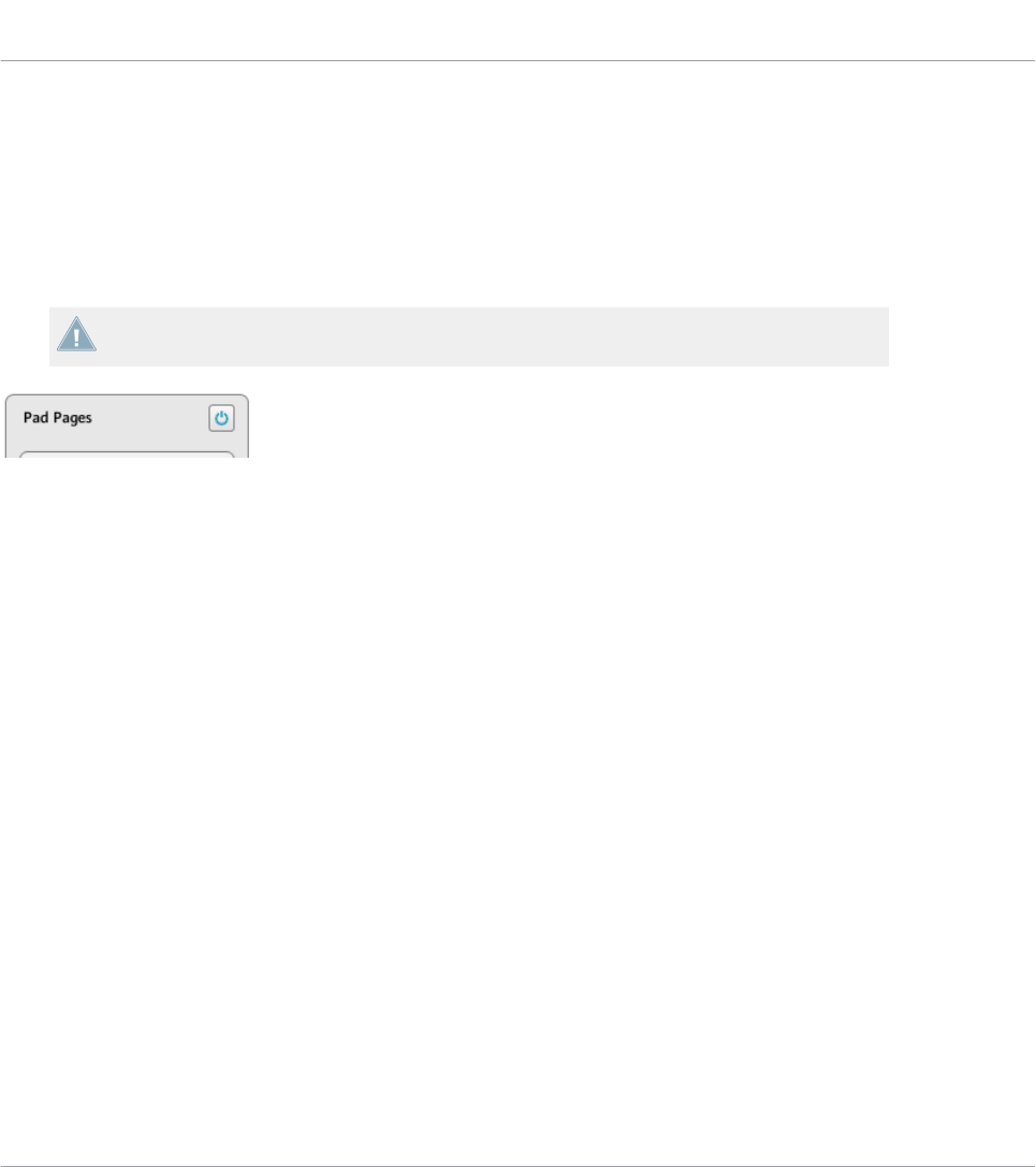
The Pad Pages Functionality (MASCHINE Controller Family Only)
For the MASCHINE controllers, the Pages pane offers an additional area that allows you to
manage the optional Pad Pages.
The Pad Pages are sets of assignments for the sixteen pads of your controller. For example, the
Pad Pages can be used to store the assignments for various patches of your target instrument,
or for different instruments in your setup.
Please refer to section ↑4.3.3, Pad Pages (MASCHINE Controller Family Only) for more in-
formation on the Pad Pages.
The Enable Pad Pages button on the right allows you to activate/deactivate the Pad Pages functionality.
At the top right of this area, you first see the Enable Pad Pages button. This button allows you to
activate/deactivate the Pad Page feature for your controller.
►To activate the Pad Pages, click the Enable Pad Pages button to enable it.
→The button switches on (blue) and the rest of the area is activated.
►To deactivate the Pad Pages, click the Enable Pad Pages button again.
→The button switches off and the rest of the area becomes minimized and grayed out.
While describing the rest of this area we assume that this Enable Pad Pages button is activat-
ed…
Below the Enable Pad Pages button, you see the Pad Pages list. This list shows all Pad Pages
available in the current Template:
Reference
The Inspector
CONTROLLER EDITOR - Manual - 259
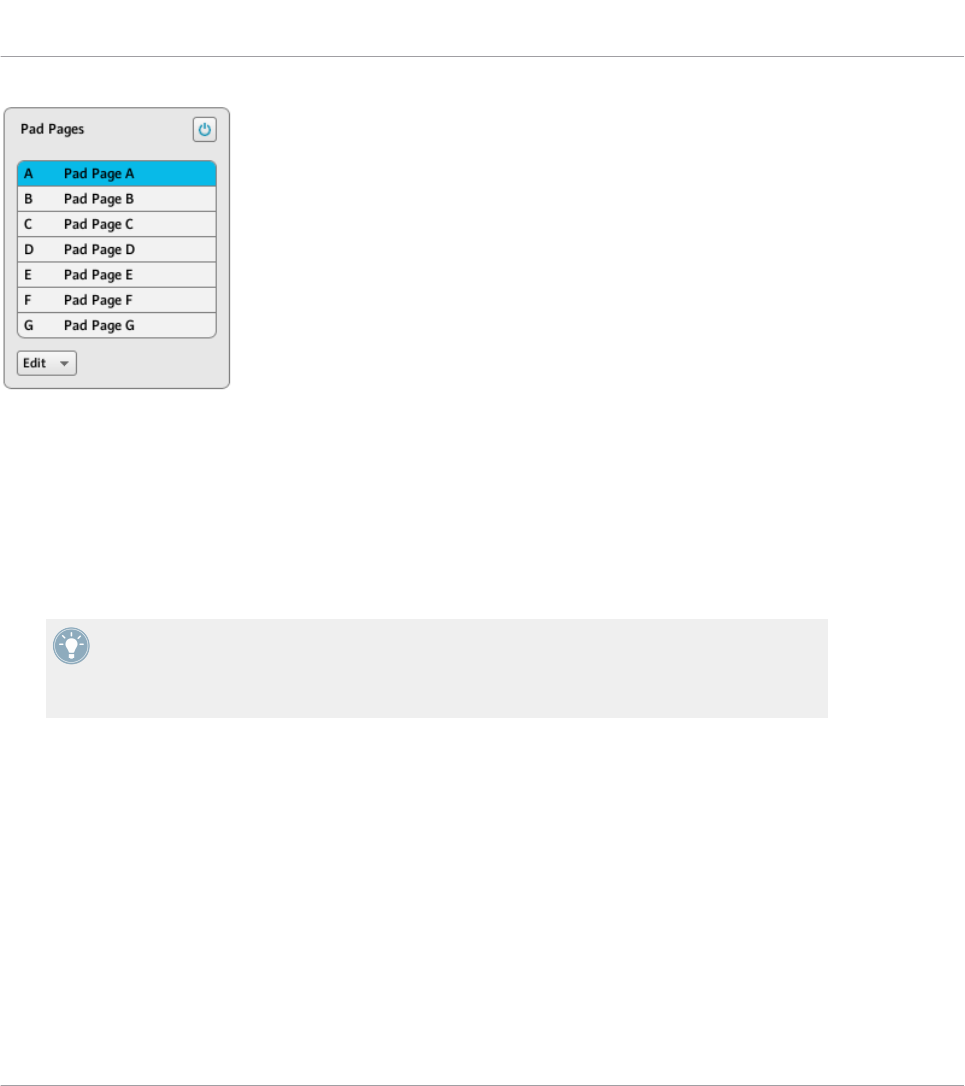
The Pad Pages list in the Pages pane.
In this list, each entry represents a Pad Page. The Pad Page currently loaded is highlighted in
the list.
►To select another Pad Page, simply click its entry.
→The selected Pad Page is automatically loaded, along with its control assignments for the
sixteen pads.
You can also select another Pad Page via the Pad Page menu on the top of the Pad Page
area, as well as via the Group buttons labeled A to H, in the Hardware area or on your MA-
SCHINE (MK2) controller. On the MASCHINE MIKRO (MK2) controller, you can hold the
GROUP button and press one of the pads 9–16.
Each entry in the Pad Pages list has two elements: the Pad Page letter and the Pad Page
name. The Pad Page letter is not editable — it defines the order of appearance of the Pad
Page in the list. Moreover, it links the Pad Page to the corresponding button on your controller:
• The corresponding Group button in the Hardware area and on your MASCHINE STUDIO,
MASCHINE MK2 or MASCHINE controller.
• The corresponding pad 9–16 in the Hardware area and on your MASCHINE MIKRO MK2
and MASCHINE MIKRO controller (used together with the GROUP button).
The Pad Page name is editable:
Reference
The Inspector
CONTROLLER EDITOR - Manual - 260
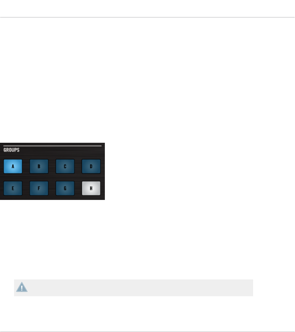
►To rename the Pad Page, double-click its name (it is then highlighted), type a new name,
and press [Enter] on your computer keyboard.
Like in the other lists, you can reorder the Pad Pages in the list via drag and drop:
►Click the desired Pad Page in the list, move your mouse vertically while holding the
mouse button depressed, and release the mouse button at the desired location.
→The Pad Page takes its new place in the list.
This can be useful in a live situation, for example if you plan to use several Pad Pages for ad-
dressing different parts of a song or sequence, and you need to have them in a specific order.
The number of Pad Pages is limited to eight. You’ll notice that your controller mirrors the num-
ber of existing Pad Pages: if some slots in the list are empty, the corresponding Group buttons
(or pads) are off:
Pad Pages A–G are assigned, Pad Page A is loaded, and there is no Pad Page H (here on the MASCHINE STUDIO control-
ler).
The I/O and Level Pages Functionality (MASCHINE STUDIO Only)
For the MASCHINE STUDIO controller, the Pages pane offers an additional area that allows
you to manage the optional I/O and Level pages.
The I/O and Level pages contain different assignments for the Level knob of your controller.
For example, I/O and Level pages can be used to control the level of various channels via the
Level knob.
Please refer to section ↑4.3.4, I/O and Level Pages (MASCHINE STUDIO Only) for more in-
formation on the I/O and Level Pages.
Reference
The Inspector
CONTROLLER EDITOR - Manual - 261
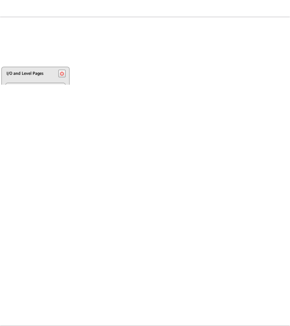
When the I/O and Level pages are activated the Input buttons (IN1, IN2, IN3, IN4), and Level
meter buttons (MST, GRP, SND, CUE) act as page selectors for assignments made on the Lev-
el knob. Assignments can only be made for these Input buttons and Level meter buttons when
the I/O and Level Pages are deactivated.
The Enable I/O and Level Pages button on the right allows you to activate/deactivate the I/O and Level Pages functionality.
At the top right of this area, you first see the Enable I/O and Level Pages button. This button al-
lows you to activate/deactivate the I/O and Level Pages feature for your controller.
►To activate the I/O and Level Pages, click the Enable I/O and Level Pages button to ena-
ble it.
→The button switches on (red) and the I/O and Level Pages are activated.
►To deactivate the I/O and Level Pages, click the I/O and Level Pages button again.
→The button switches off and the I/O and Level Pages become minimized and grayed out.
While describing the rest of this area we assume the I/O and Level Pages are activated…
Below the Enable I/O and Level Pages button, you see the and the I/O and Level Pages list. This
list shows all the I/O and Level Pages available in the current Template:
Reference
The Inspector
CONTROLLER EDITOR - Manual - 262
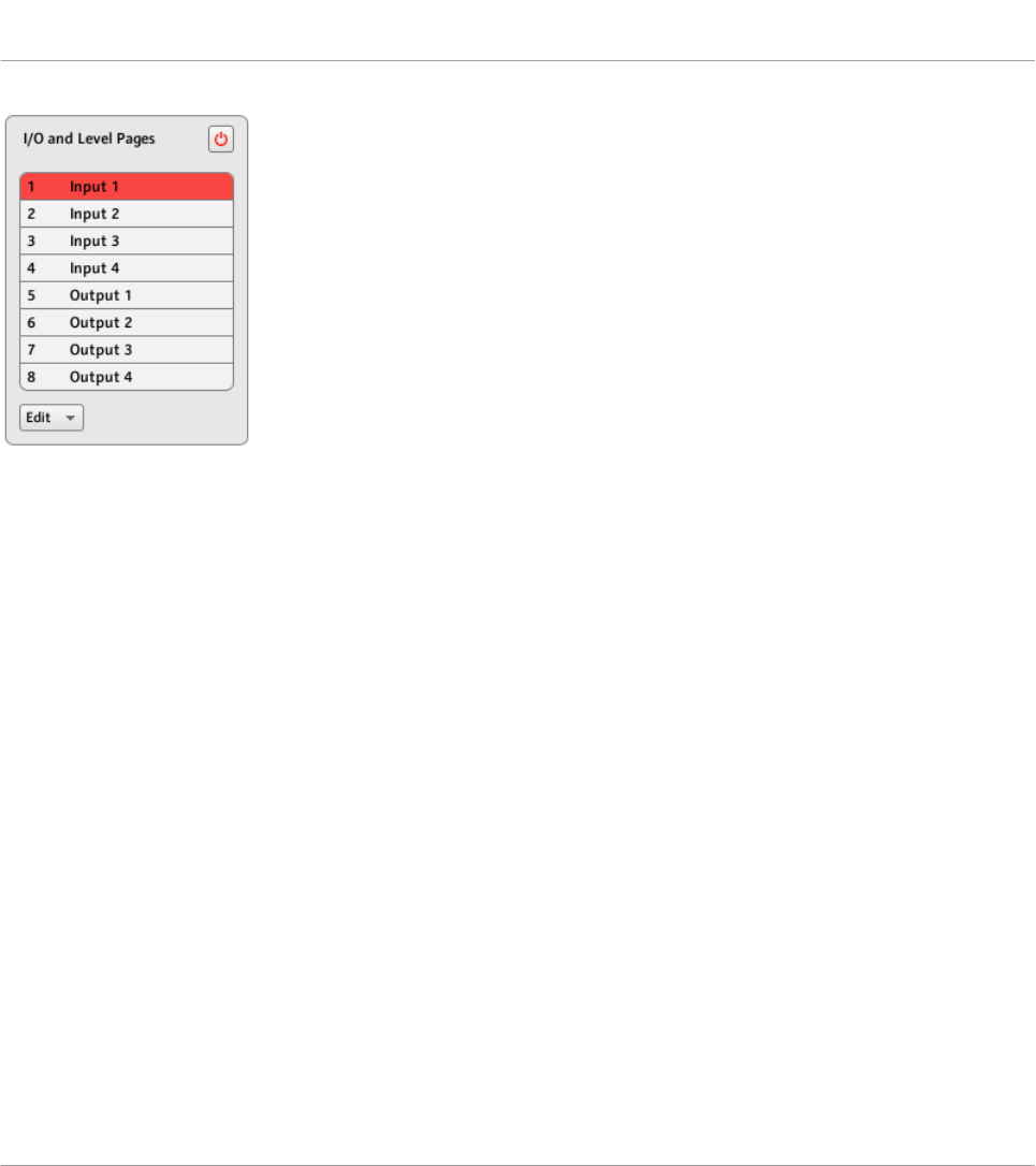
The I/O and Level Pages list in the Pages pane.
In this list, each entry represents an I/O and Level Page. The I/O and Level Page currently load-
ed is highlighted in the list.
►To select another I/O and Level Page, simply click its entry.
→The selected I/O and Level Page is automatically loaded, along with its assignment for
the Level knob.
Each entry in the I/O and Level Pages list has two elements: the page’s number and name. The
I/O and Level number is not editable — it defines the order of appearance of the I/O and Level
Page in the list. Moreover, it links the I/O and Level Pages to the corresponding button on your
controller:
• Input buttons (IN1, IN2, IN3, IN4).
• Level meter buttons (MST, GRP, SND, CUE).
The I/O and Level Page names are editable:
►To rename the I/O and Level Page, double-click its name (it is then highlighted), type a
new name, and press [Enter] on your computer keyboard.
Like in the other lists, you can reorder the I/O and Level Pages in the list via drag and drop:
►Click the desired I/O and Level Page in the list, move your mouse vertically while holding
the mouse button depressed, and release the mouse button at the desired location.
Reference
The Inspector
CONTROLLER EDITOR - Manual - 263
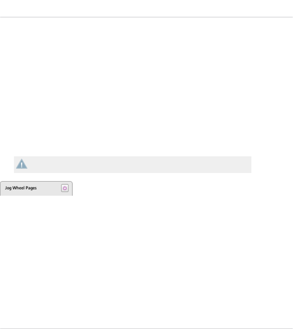
→The I/O and Level Page takes its new place in the list.
This can be useful in a live situation, for example if you plan to use several I/O and Level Pa-
ges for addressing different parts of a song or sequence, and you need to have them in a spe-
cific order.
The number of I/O and Level Pages is limited to eight. You’ll notice that your controller mirrors
the number of existing I/O and Level Pages: if some slots in the list are empty, the correspond-
ing Input buttons (IN1, IN2, IN3, IN4) or Level meter buttons (MST, GRP, SND, CUE) are off:
The Jog Wheel Pages Functionality (MASCHINE STUDIO Only)
For the MASCHINE STUDIO controller, the Pages pane offers an additional area that allows
you to manage your optional Jog Wheel Pages.
The Jog Wheel Pages are sets of assignments for the jog wheel and its LED ring. For example,
the Jog Wheel Pages can be used to store the assignments for various patches of your target
instrument, or for different instruments in your setup.
Please refer to section ↑4.3.5, Jog Wheel Pages (MASCHINE STUDIO Only) for more infor-
mation on the Jog Wheel Pages.
The Enable Jog Wheel Pages button on the right allows you to activate/deactivate the Jog Wheel Pages functionality.
At the top right of this area, you first see the Enable Jog Wheel Pages button. This button allows
you to activate/deactivate the Jog Wheel Pages feature for your controller.
►To activate the Jog Wheel Pages, click the Enable Jog Wheel Pages button to enable it.
→The button switches on (violet) and the lower part of the Pages pane is activated.
►To deactivate the Jog Wheel Pages, click the Enable Jog Wheel Pages button again.
→The button switches off and the lower part of the Pages pane becomes minimized and
grayed out.
While describing the rest of this area we assume that this Enable Jog Wheel Pages button is
activated…
Reference
The Inspector
CONTROLLER EDITOR - Manual - 264
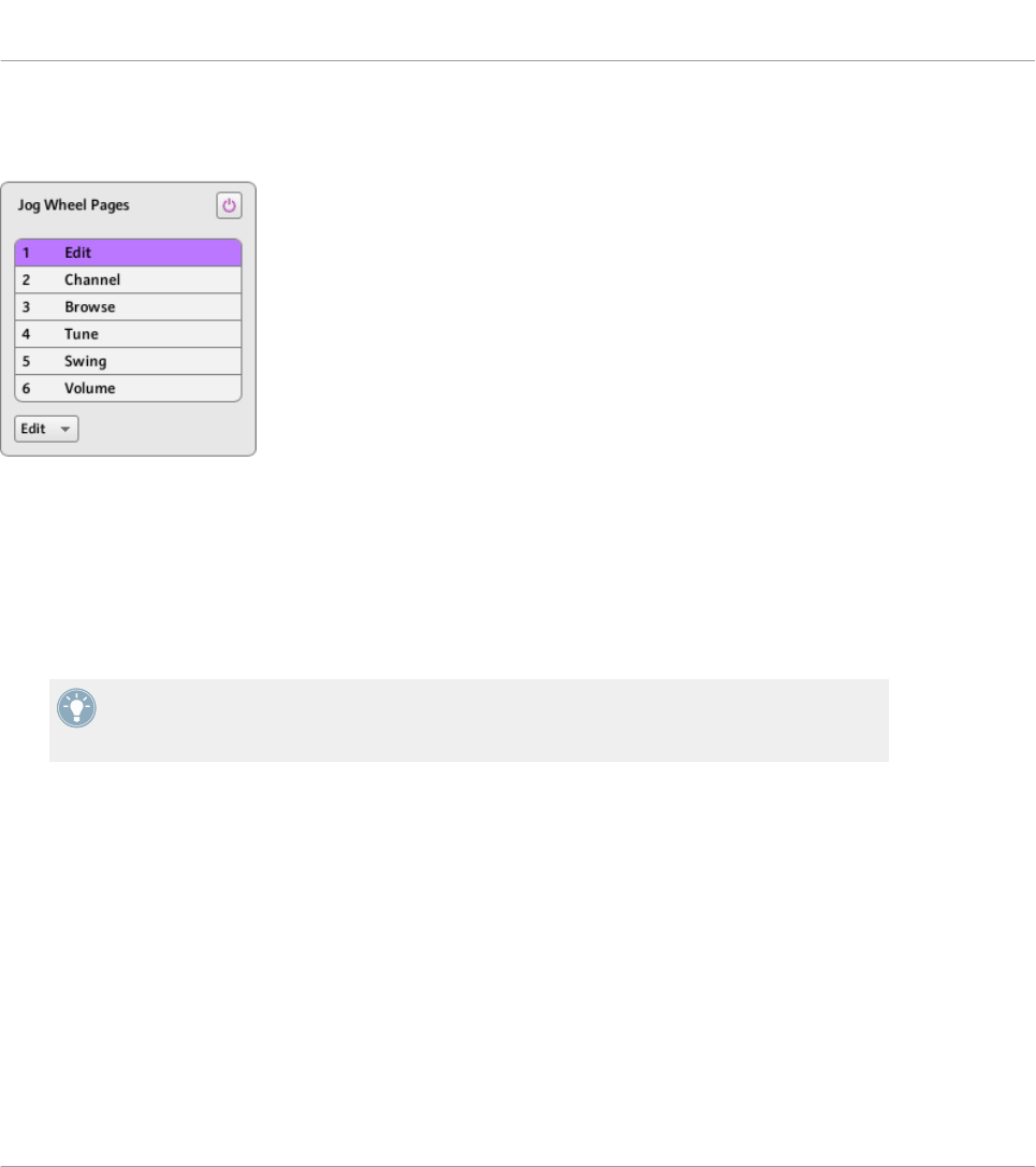
Below the Enable Jog Wheel Pages button, you see the Jog Wheel Pages list. This list shows all
Jog Wheel Pages available in the current Template:
The Jog Wheel Pages list, at the bottom of the Pages pane.
In this list, each entry represents a Jog Wheel Page. The Jog Wheel Page currently loaded is
highlighted in the list.
►To select another Jog Wheel Page, simply click its entry.
→The selected Jog Wheel Page is automatically loaded, along with its control assignments.
You can also select another Jog Wheel Page via the Jog Wheel Page menu on the top of the
Jog Wheel Page area, as well as via the FUNCTION buttons on your MASCHINE STUDIO
controller.
• Each entry in the Jog Wheel Pages list has a name.
The Jog Wheel Page name is editable:
►To rename a Jog Wheel Page, double-click its name (it is then highlighted), type a new
name, and press [Enter] on your computer keyboard.
Like in the other lists, you can reorder the Jog Wheel Pages in the list via drag and drop:
►Click the desired Jog Wheel Page in the list, move your mouse vertically while holding the
mouse button depressed, and release the mouse button at the desired location.
→The Jog Wheel Page takes its new place in the list.
Reference
The Inspector
CONTROLLER EDITOR - Manual - 265

This can be useful in a live situation, for example if you plan to use several Jog Wheel Pages
for addressing different parts of a song or sequence, and you need to have them in a specific
order.
The number of Jog Wheel Pages is limited to six.
23.5.3 Assign Pane
The Assign pane allows you to define all necessary MIDI assignment attributes for a particular
control element.
►To show the Assign pane, click the Assign tab at the top of the Inspector.
Indeed, it displays and allows to modify the assignment attributes for the control element that
is currently selected in the Hardware area — the one on which the red Selection Frame focus-
es.
As a reminder, to select a particular control element for editing, do the following:
1. Select a Template.
2. Select a Page if the desired element is located in a Page.
3. Click the control element in the Hardware area or touch it on your NI controller — provid-
ed that the Touch Select option is activated.
→The Assign pane then displays the assignment properties for that control element.
The Description Area
At the top of the Assign pane, the Description area displays some descriptive attributes for the
selected control element. The content of this section depends on the controller and the loca-
tion of the control element on the controller:
• If the selected control element belongs to a Page, the first line contains the number/letter
of the page followed by its name (as defined in the corresponding Page list of the Pages
pane, see ↑23.5.2, Pages Pane).
Reference
The Inspector
CONTROLLER EDITOR - Manual - 266
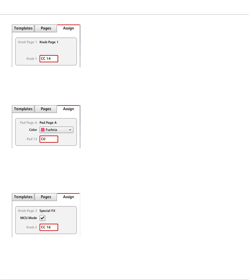
This is useful to quickly see which Page the assignment you are editing is belonging to.
This line is empty for control elements which are not included in any Page area. This is
not editable.
• MASCHINE STUDIO, MASCHINE MK2, and MASCHINE MIKRO MK2 controllers only: If
a pad is selected, the second line allows you to choose a color for the whole Pad Page.
Click the Color menu and select a color from the palette. On your controller, the selected
color will be mirrored by the corresponding Group button (MASCHINE STUDIO and MA-
SCHINE MK2) or by the GROUP button when that Pad Page is selected (MASCHINE MIK-
RO MK2).
• MASCHINE STUDIO only: If any of Knob 1–8 or Button 1–8 (below or above the displays)
is selected, the second line allows you to enable/disable the MCU Mode check box.
The MCU Mode check box allows you to set your MASCHINE STUDIO controller displays
Reference
The Inspector
CONTROLLER EDITOR - Manual - 267

to MCU mode in order to receive Mackie Control feedback from your DAW while keeping
the original assignment of the Buttons and Knobs in the Knob Page area. The MCU Mode
setting applies Page-wide.
• The last (or only) line displays on the left the element description, its “name” referring to
its original function in its dedicated software, which is for information only. On the right,
it displays the Label Field, which holds its user-definable name.
►To modify the name in the Label Field, click it, type a new name and press [Enter] on
your computer keyboard.
→Both Label Fields (in the Assign pane and in the Hardware area) are updated accordingly.
For particular control elements of some NI controllers, the name will also appear in the
controller’s hardware display(s).
KOMPLETE KONTROL S-SERIES: Modifying the name in the Label Field automatically re-
sets the assignment to its default value.
If no name has been defined yet for a control element, its Label Field displays by default the
MIDI message assigned to this control element.
To reset a Label Field to its default name, clear the field, then press the [Enter] key on
your computer keyboard.
The Definition Area
Below the Description area, the assignment properties explicitly define what has to be sent
when you actuate the control element on your NI controller: this is called the Definition area.
The properties in the Definition area differ according to the type of control element currently
selected: since a button, a knob, and a pad don’t have the same physical properties and be-
havior, they won’t be able to trigger the same types of MIDI events.
Furthermore, some control elements on certain NI controller can respond to different actions:
Reference
The Inspector
CONTROLLER EDITOR - Manual - 268

• MASCHINE Controller Family: The pads can be hit, but they can also be pressed. Further-
more:
◦On the MASCHINE MIKRO, MASCHINE MK2, MASCHINE MIKRO MK2, and MA-
SCHINE STUDIO controllers, the Control encoder can be both turned and pushed.
◦On the MASCHINE STUDIO controller, the jog wheel can be both turned and pushed,
and Knobs 1–8 under the displays can be both turned and touched.
• TRAKTOR KONTROL X1: The Push Encoders can be both turned and pushed.
• TRAKTOR KONTROL X1 MK2: The Push Encoders can be turned, pushed and touched.
Additionally, the Touch Strip has a position action, too.
• TRAKTOR KONTROL F1: The encoder knob can be both turned and pushed.
• TRAKTOR KONTROL S2/S4: The encoders (LOOP MOVE and LOOP SIZE on the Decks,
BROWSE on the Mixer) and the jog wheels can be both turned and pushed.
• TRAKTOR KONTROL S2 MK2/S4 MK2: The encoders (LOOP MOVE and LOOP SIZE on
the Decks, BROWSE on the Mixer) and the jog wheels can be both turned and pushed.
• TRAKTOR KONTROL S8: The BROWSE and Loop encoders can be turned, pushed and
touched. The TEMPO encoder can be turned and pushed. The FX knobs and the Perform-
ance knobs can be turned and touched. The Slot Volume faders can be slid and touched.
The touch strips detect both the touch and the position of your finger.
• TRAKTOR KONTROL D2: The BROWSE and Loop encoder can be turned, pushed and
touched. The TEMPO encoder can be turned and pushed. The FX knobs and the Perform-
ance knobs can be turned and touched. The Slot Volume faders can be slid and touched.
The touch strip detects both the touch and the position of your finger.
• TRAKTOR KONTROL Z1: The Push Encoders can be both turned and pushed.
• TRAKTOR KONTROL Z2: The Push Encoders (Auto-loop and BROWSE) can be both
turned and pushed.
• KOMPLETE KONTROL S-SERIES: The SUSTAIN footswitch input is stereo, i.e. it can re-
ceive signals both on the tip and on the ring.
For these multifunctional elements, the possible actions lead to two or more MIDI messages.
Hence, the Definition area displays corresponding Action tabs, each of them allowing to define
the MIDI event for one specific action.
Reference
The Inspector
CONTROLLER EDITOR - Manual - 269
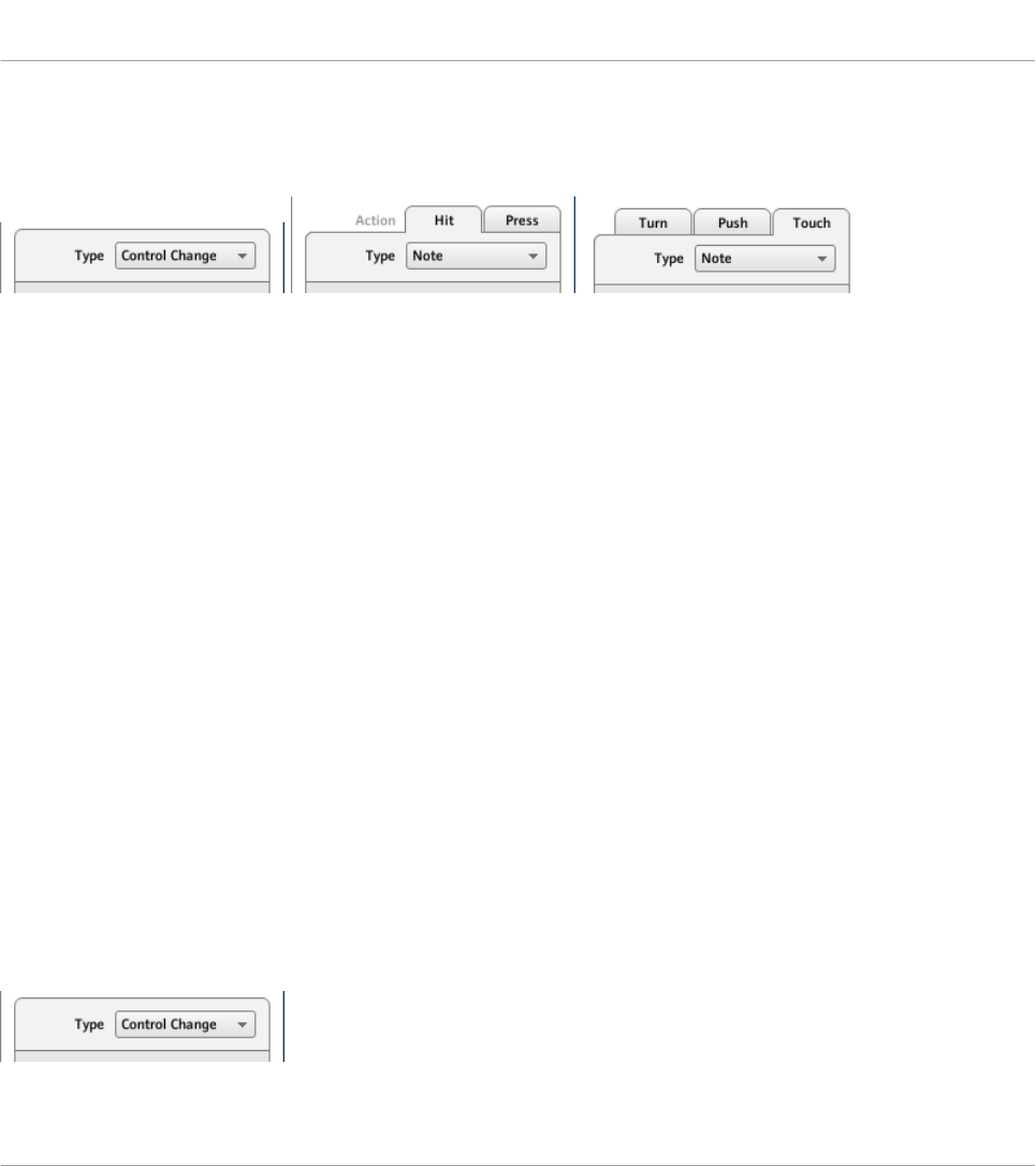
For control elements with only one function, the Definition area does not display any tabs, but
directly displays the assignment properties for the unique MIDI assignment of this control ele-
ment.
The top of the Definition area differs if the control element has one or more functions.
In the picture above, on the left you see the assignment for a button: in the middle you see the
two tabs (labeled Hit and Press) for a pad on the MASCHINE controller; on the right you see
the three tabs (labeled Turn, Push, and Touch) for the Capacitive Encoders on the TRAKTOR
KONTROL X1 MK2.
The label on each tab indicates the particular hardware action that will trigger the MIDI mes-
sage specified in that page.
The next section will describe each and every settings available for the assignments of MIDI
messages.
23.6 MIDI Message Parameters
You will find here the description of all possible parameters to be found within the Definition
area of the Inspector’s Assign pane, for all kinds of control elements and all NI controllers.
We will first give a few general rules valid for various sorts of control elements.
We will then detail the MIDI messages settings for each sort of control elements.
23.6.1 MIDI Message Types – Type Menu
For all control elements, the assignment definition starts with the same menu: the Type menu,
at the very top of the Definition area.
Reference
MIDI Message Parameters
CONTROLLER EDITOR - Manual - 270

The Type menu specifies the type of MIDI message that has to be sent upon action on this
control element. Depending on the type of hardware control element, the entries in this menu
will differ (for example, sending a “play” command from a knob wouldn’t make much sense).
The Type menu allows you to choose from various MIDI message types.
►To select a MIDI message type, click the Type menu and select the desired entry from
the list.
All other parameters displayed in the Assign pane’s Definition area depend both on the type of
control element that you are working on, and on the MIDI message type selected in this Type
menu.
Below is a list of all possible MIDI message types to be found in the Type menu.
Keep in mind that depending on the selected device and the particular control element,
some of them are not available in its Type menu. In the next sections, we will explain the
particularities for each control element available on your NI controller.
•Note: Sends a MIDI Note On/Off message. This message is sent over a specific MIDI chan-
nel set by the Channel parameter (range from 1 to 16, 1 by default). It tells your target to
play or stop the MIDI Note specified via the Note parameter (range from C-2 to G8). The
message also defines the velocity at which the note is played. This velocity is specified in
various ways, depending on the type of the selected control element (see next sections).
•Note (Relative): Sends a MIDI Note On message. This message type is actually made for
specific situations where some function in the target software must be triggered by an in-
coming Note On event. This can be the case, for example, for scrolling through lists,
where the target software only offers a trigger control for selecting the “next” or the “pre-
Reference
MIDI Message Parameters
CONTROLLER EDITOR - Manual - 271

vious” item in the list. With this Note (Relative) message type, you can use for example a
jog wheel on your TRAKTOR KONTROL S4 MK2 or a Push Encoder on your TRAKTOR
KONTROL X1 to scroll through the list in the target software. The message is sent over a
specific MIDI channel set by the Channel parameter (range from 1 to 16, 1 by default).
Two additional Note parameters define the MIDI note numbers triggered when turning the
control counter-clockwise and clockwise, respectively (both ranges from 0 to 127, that is
from MIDI Note C-1 to G9).
•Control Change: Sends a MIDI Control Change message. This message is sent over a spe-
cific MIDI channel set by the Channel parameter (range from 1 to 16, 1 by default). This
message tells your target to change the value of a specific continuous controller — con-
trolling for example some effect’s depth in your music application. The continuous con-
troller (CC) number is specified via the Number parameter (range from 0 to 127). The val-
ues to be sent for that controller are specified in various ways, depending on the type of
the selected control element (see next sections).
•Poly Pressure: Sends a MIDI Poly Pressure message (also called Polyphonic Aftertouch).
This message is sent over a specific MIDI channel set by the Channel parameter (range
from 1 to 16, 1 by default). It specifies the pressure at which a particular MIDI note is
held down. The MIDI note is specified via the Note parameter. The pressure values to be
sent are specified in various ways, depending on the type of the selected control element
(see next sections).
•Channel Pressure: Sends a MIDI Channel Pressure message (also called Channel After-
touch). This message is sent over a specific MIDI channel set by the Channel parameter
(range from 1 to 16, 1 by default). It specifies a common pressure at which all notes of
the MIDI channel are held down. The pressure values to be sent are specified in various
ways, depending on the type of the selected control element (see next sections).
•Program Change: Sends a MIDI Program Change message. This message is sent over a
specific MIDI channel set by the Channel parameter (range from 1 to 16, 1 by default). It
tells the target to switch to another program (or patch, preset…). The program number to
be sent can be specified in various ways, depending on the type of the selected control
element (see next sections).
•Pitchbend: Sends a MIDI Pitchbend message. This message is sent over a specific MIDI
channel set by the Channel parameter (range from 1 to 16, 1 by default). It is used to
control the Pitchbend Wheel (and anything that would respond to the MIDI Pitchbend
message in your target). This is quite similar to a Control Change message, but for histori-
Reference
MIDI Message Parameters
CONTROLLER EDITOR - Manual - 272

cal and practical reasons (on most hardware controllers/keyboards, the Pitchbend wheel is
a very specific control element), the Pitchbend is a distinct message in the MIDI specifi-
cations.
•Start: Sends a MIDI Start Song message. As its name implies, this message should be un-
derstood by your sequencer as a Start command. This message tells your sequencer to
start playback of the song/sequence from the beginning. There is no parameter needed for
this message.
•Stop: Sends a MIDI Stop Song message. This should be understood by your sequencer as
a Stop command. This message tells your sequencer to pause the playback of the song/
sequence at its current position. There is no parameter needed for this message.
•Continue: Sends a MIDI Continue Song message. As its name implies, this message
should be understood by your sequencer as a Continue command. This message tells your
target to start playback of the song/sequence from the current position. There is no pa-
rameter needed for this message.
•Song Position: Sends a MIDI Song Position message. This message tells your target to cue
the playback to a specific position in the song/sequence. Note that it does not start the
playback itself. The message is implemented in a specific way that allows you to switch
between two positions in the song or sequence. The position(s) in the song or sequence
can be specified in various ways, depending on the type of control element (see below).
The position in the song is counted in MIDI beats.
•MCU V-Pot: Emulates one of the Mackie Control’s 8 V-Pots.
•MCU Channel: Emulates one of the Mackie Control’s 8 channel faders.
•MCU Master: Emulates the master fader of the Mackie Control.
•MCU Wheel: Emulates the Wheel of the Mackie Control.
•MCU Button: Emulates the buttons of the Mackie Control.
•Off: Deactivates MIDI for the control element. Select this entry to disable that control ele-
ment or action. The control element / action won’t send any MIDI message, hence no pa-
rameter is displayed.
See also
2Assignments for Key Zones [➙ 280]
Reference
MIDI Message Parameters
CONTROLLER EDITOR - Manual - 273
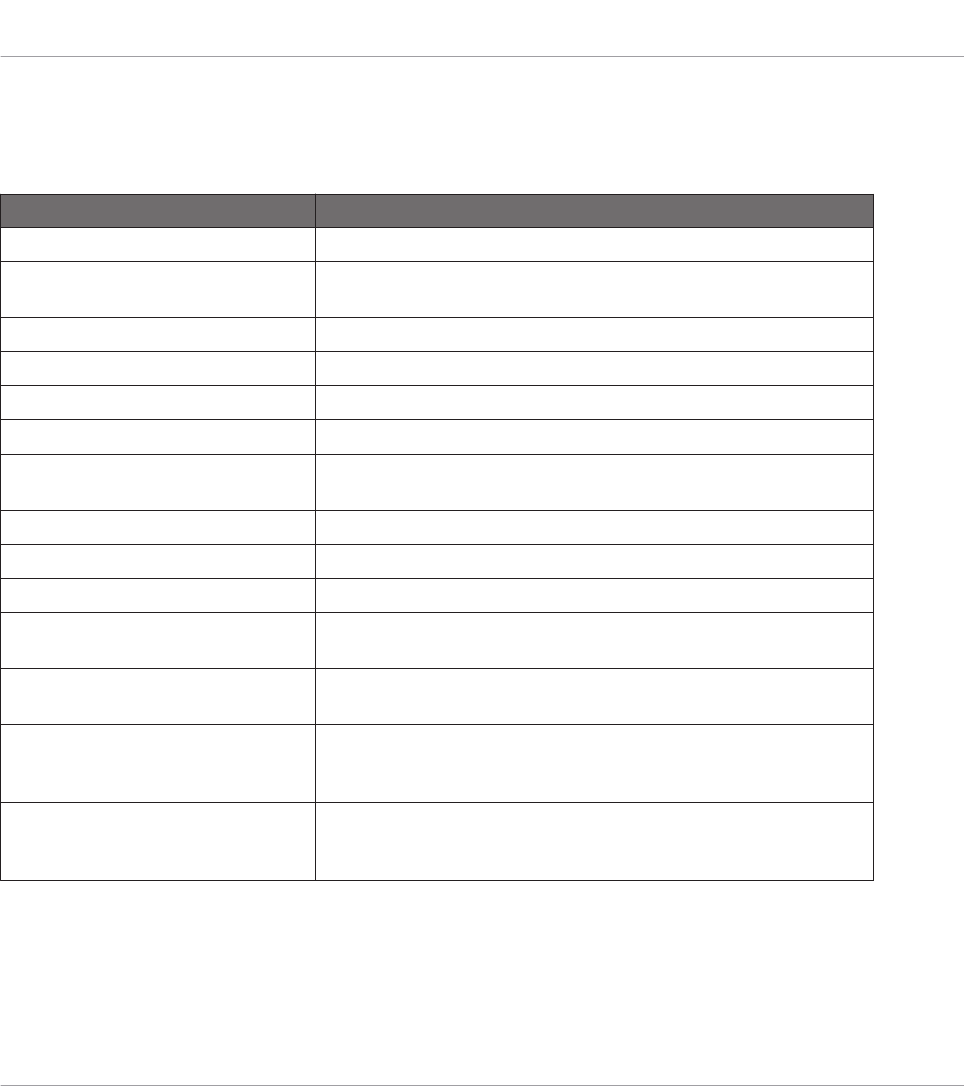
23.6.2 Assignments for Buttons
The assignments described here are valid for following control elements:
NI Controller Control elements
KOMPLETE KONTROL S-SERIES SUSTAIN footswitch input (both Tip and Ring actions)
MASCHINE STUDIO Buttons, jog wheel (Push action), Knobs 1–8 (Touch action), foot-
switch inputs (both Tip and Ring actions)
MASCHINE MK2 Buttons, Control encoder (Push action)
MASCHINE MIKRO (MK2) Buttons, Control encoder (Push action)
MASCHINE Buttons
TRAKTOR KONTROL X1 Buttons, Push Encoders (Push action)
TRAKTOR KONTROL X1 MK2 Buttons, Push Encoders (Touch and Push action), Touch Strip
(Touch action)
TRAKTOR KONTROL F1 Buttons, pads, encoder knob (Push action)
TRAKTOR KONTROL Z1 Buttons, encoder knob (Push action)
TRAKTOR KONTROL Z2 Buttons, encoders (Push action)
TRAKTOR KONTROL S2/S4 Buttons, encoders (Push action), jog wheels (Push action), footswitch
input (S4 only)
TRAKTOR KONTROL S2 MK2/
S4 MK2
Buttons, encoders (Push action), jog wheels (Push action), footswitch
input (S4 MK2 only)
TRAKTOR KONTROL S8 Buttons, Pads, encoders (Push action and Touch action, if any), as
well as the Touch action on the FX knobs, Performance knobs, Slot
Volume faders, and Touch Strips
TRAKTOR KONTROL D2 Buttons, Pads, encoder (Push action and Touch action, if any), as
well as the Touch action on the FX knobs, Performance knobs, Slot
Volume faders, and Touch Strip
For these control elements, the Type menu offers the following entries: Note, Control Change
(default setting), Poly Pressure, Channel Pressure, Program Change, Pitchbend, Start, Stop,
Continue, Song Position, MCU Button, and Off.
Reference
MIDI Message Parameters
CONTROLLER EDITOR - Manual - 274
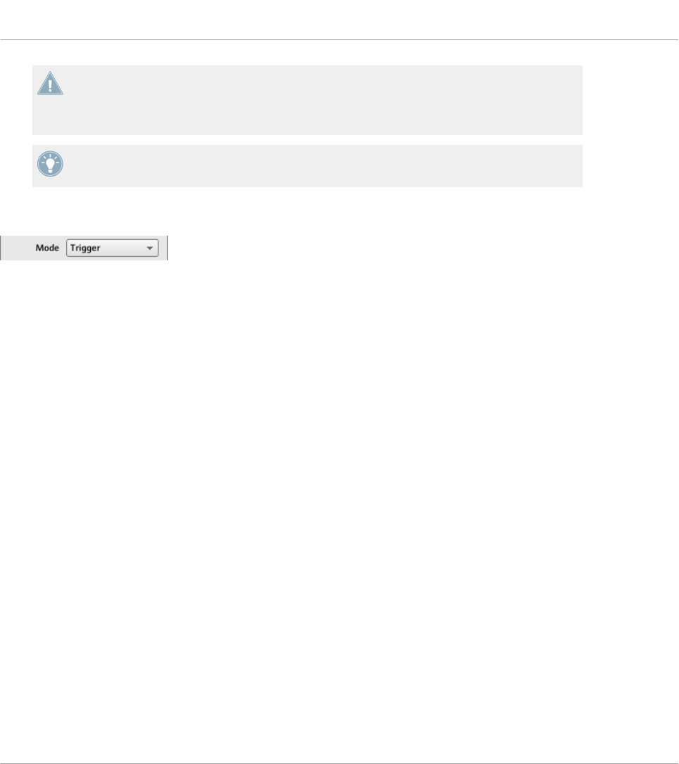
KOMPLETE KONTROL S-SERIES: For the SUSTAIN footswitch input, the Pitchbend, Start,
Stop, Continue, Song Position, and MCU Button entries are not available in the Type menu.
Indeed, these commands are already available via the dedicated TRANSPORT section or
via the touch strips on your keyboard.
For a general description of these MIDI message types, see ↑23.6.1, MIDI Message Types –
Type Menu.
Mode Menu
The Mode menu for buttons.
For the button-like control elements listed in the above table, and only for some of the MIDI
message types available for these control elements, you can choose from different behaviors
for the way the data is sent. This is controlled by the Mode menu. This menu can have up to
four entries, depending on the message type that you have selected in the Type menu. Here is
the list of all possible entries:
•Toggle: In this mode, the control element has two states, On and Off. If you press once, it
switches to the On state — if you press again, it switches to the Off state. This can be
useful for example for activating some effect, then deactivating it later. This is usually the
default mode. In this mode, you find two numeric fields: Off Value defines the value for
the Off state (from 0 to 127, 0 by default), and On Value defines the value for the On
state (0 to 127, 127 by default). For the Note message type, since the Off state is prede-
fined (it’s the MIDI Note Off message), you find instead a single Value parameter defining
the velocity of the MIDI Note On message.
•Gate: In this mode, the element switches to the On state for the time it is held depressed.
As soon as you release it, it switches back to the Off state. It is similar to the behavior of
a key on a keyboard: the note is played when you hold the key depressed, and the note is
switched off when you release the key. Like in Toggle mode, you find two numeric fields:
Value Off defines the value for the Off state (from 0 to 127, 0 by default), and Value On
defines the value for the On state (0 to 127, 127 by default). For the Note message type,
since the Off state is predefined (it’s the MIDI Note Off message), you find instead a sin-
gle Value parameter defining the velocity of the MIDI Note On message.
Reference
MIDI Message Parameters
CONTROLLER EDITOR - Manual - 275
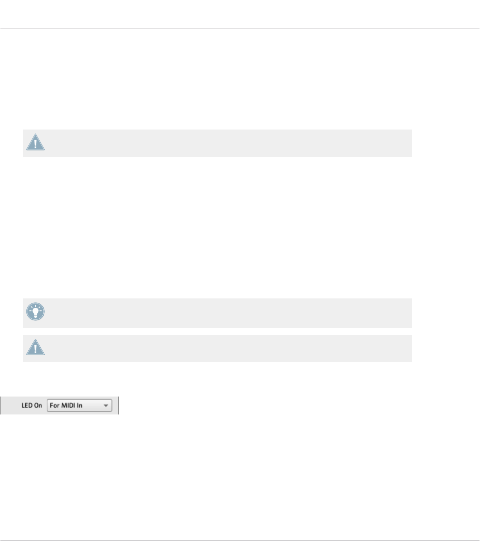
•Trigger: In this mode, only one message is sent when you hit the control element. There
are no On or Off states. For example, this can be useful for switching to another program
(preset, patch…) or for triggering one-shot samples (e.g. drum sounds or any other enve-
lope-controlled sounds). In this mode, you thus find only one numeric field called Value,
defining the value to be sent when you hit the control element. It goes from 0 to 127
(127 by default).
TRAKTOR KONTROL X1 MK2 and S8: The Trigger mode is not available for the Touch ac-
tion of the touch strip(s).
•Inc (Increment): In Increment mode, each action on the control element increases/de-
creases the parameter value. Two numeric fields Range From and To define the min and
max values of the interval, respectively, each of them going from 0 to 127 (by default, 0
for the min and 127 for the max). Below, another numeric field called Step defines the
increment to add (or to subtract if negative) each time that you press the button (it goes
from -127 to 127, with 1 as default value). Finally, the Wrap button allows you to “cycle”
the interval: If this button is activated, once the parameter reaches one of its limits, it
jumps to the other one upon the next time you hit the control element. If the Wrap button
is deactivated, the message sent upon the next hit keeps the maximal (or minimal) value
for the parameter.
If the values set in the Range From and Range To fields are equal, they turn red to indicate
a possible mistake when entering the values!
TRAKTOR KONTROL X1 MK2 and S8: The Increment mode is not available for the Touch
action of the touch strip(s).
LED On Menu
The LED On menu.
For all control elements with LEDs and in Trigger, Gate, or Increment mode, a LED On menu
allows you to choose from two LED lighting behaviors:
•For MIDI In (default): Selects the MIDI feedback mode. In this mode, the LED behavior is
controlled by the MIDI target via a MIDI feedback channel. The MIDI target sends a MIDI
message back to the controller to define the LED’s state. This control mode notably allows
Reference
MIDI Message Parameters
CONTROLLER EDITOR - Manual - 276
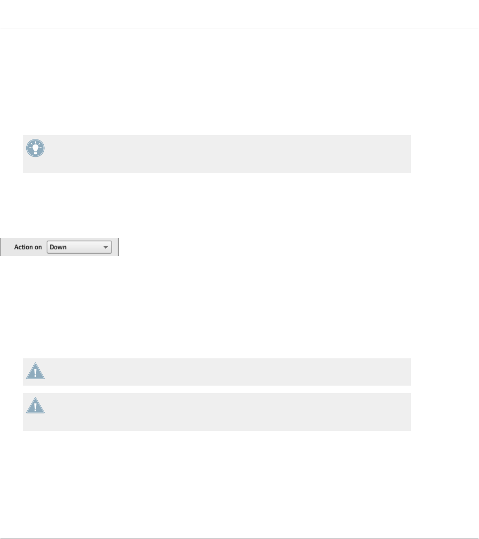
the button LED to be always reflecting the current state of the target’s parameter, even if
you changed this parameter via another way (e.g. with your mouse or via a keyboard short-
cut in the target software). For this to work, you have to define in your target the MIDI
message to be sent accordingly.
•For MIDI Out: Selects the internal control mode. In this mode, the LED behavior solely de-
pends on your actions on the button.
When the control element is set to Toggle mode, the LED On menu is not available because
both behaviors are used — the LED reacts both to your actions and to the (possibly) incom-
ing MIDI feedback messages.
Action On Menu
For the Toggle, Trigger, and Increment modes, an Action on menu at the bottom of the Defini-
tion area allows you to choose when the message has to be sent.
The Action on menu.
The two options proposed by the Action on menu are:
•Down (default setting): The message is sent when the button is switched to the Down
state (i.e. when you hit the button)
•Up: The message is sent when the button is switched to the Up state (i.e. when you re-
lease the button).
For Touch actions on all controllers, the Down and Up entries are called instead Touch and
Release, respectively.
When the control element is set to Gate mode, this menu is not available — it wouldn’t
make sense, since both Down and Up state already define the Values On and Off to be
sent.
Color Control
The parameters described here are valid for following control elements only:
Reference
MIDI Message Parameters
CONTROLLER EDITOR - Manual - 277
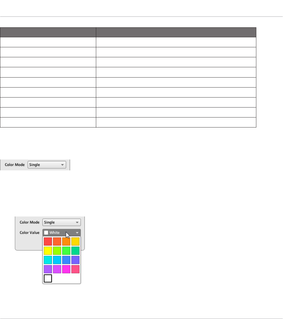
NI Controller Control elements
TRAKTOR KONTROL S2 MK2 Cue/Sample Trigger buttons (1–4) on either side
TRAKTOR KONTROL S4 MK2 Cue/Sample Trigger buttons (1–4) on either side
TRAKTOR KONTROL S8 Pads
TRAKTOR KONTROL X1 MK2 Cue/Sample Trigger buttons (1–4) on either side
TRAKTOR KONTROL F1 Pads
TRAKTOR KONTROL Z2 Cue/Sample Trigger buttons (1–4) on either side
MASCHINE STUDIO Pads, GROUP buttons
MASCHINE MK2 Pads, Group buttons (A–H)
MASCHINE MIKRO MK2 Pads, GROUP buttons
For these control elements, you can define which color(s) should be used for the On and Off
states. This is done via the menus located at the bottom of the Definition area.
The Color Mode menu allows you to choose from three coloring modes:
The Color Mode menu.
These modes are available:
•Single: You can choose a color that will be used bright and dimmed for the On and Off
states, respectively. The Color Value menu below allows you to choose this color from the
seventeen colors available in the picker.
Reference
MIDI Message Parameters
CONTROLLER EDITOR - Manual - 278
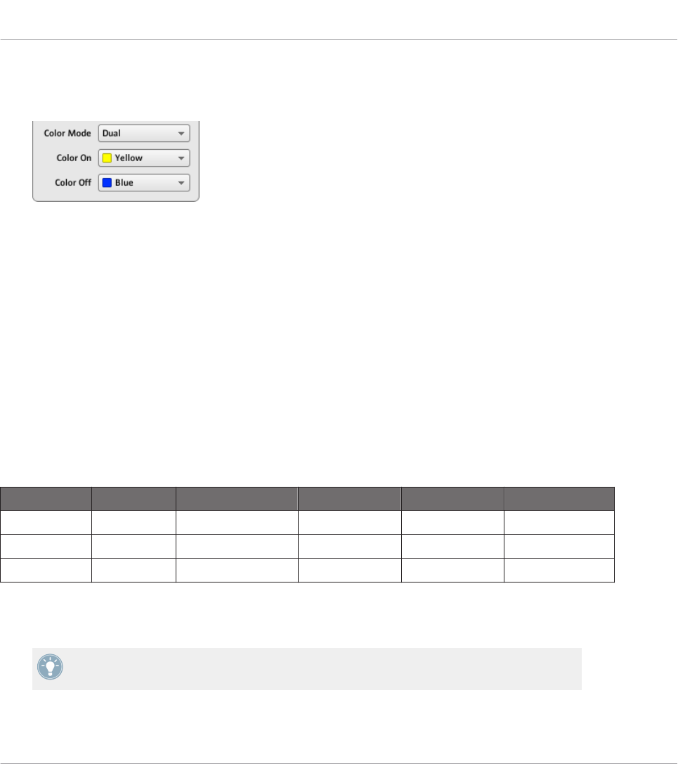
•Dual: You can choose a color for the On state and another color for the Off state. Both
colors will be used at full brightness. The Color On and Color Off menus allow you to
choose both colors from color pickers.
•HSB (Hue, Brightness, Saturation): This mode is only available when the pad’s state is
controlled via MIDI feedback — in other terms, when the pad is in Toggle mode or when
For MIDI In is selected in the LED On menu (see above). In HSB mode, you can precisely
define from within your MIDI target which color the pad will use. Hence, in this mode
there is no color picker available in the Assign tab.
When the pad is in HSB mode, the Hue, Brightness, and Saturation levels are sent via MIDI to
the controller using the pad’s assigned CC or Note. The MIDI channel used to transmit those
messages will determine its intent. For example, for a pad assigned to MIDI CC 9, you could:
• Send the CC 9 value 127 on channel 3 to set the pad to full brightness.
• Send the CC 9 value 16 on channel 1 to set the pad’s color to yellow.
For the TRAKTOR KONTROL F1 and TRAKTOR KONTROL X1 MK2, the following table lists
the MIDI channels used to define the pads’ colors on the four simultaneously available F1 or
X1 MK2 devices:
Parameter MIDI Values Device 1 (default) Device 2 * Device 3 * Device 4 *
Hue 0–127 Channel 1 Channel 4 Channel 7 Channel 10
Saturation 0–127 Channel 2 Channel 5 Channel 8 Channel 11
Brightness 0–127 Channel 3 Channel 6 Channel 9 Channel 12
* These channels will be used when two or more units of the same type are connected to your
computer. For example, if two TRAKTOR KONTROL F1 units are connected, the unit named
“Traktor Kontrol F1 - 2” will receive HSB parameters on channels 4–6.
For more information on using two or more units of the same type simultaneously, please
refer to chapter ↑22, Using Two or More Units of the Same Type.
Reference
MIDI Message Parameters
CONTROLLER EDITOR - Manual - 279
For the TRAKTOR KONTROL Z2, S2 MK2, S4 MK2, S8, MASCHINE MK2, MASCHINE MIK-
RO MK2, and MASCHINE STUDIO controllers, only channels 1–3 are used in the table above.
Please note that updating the control elements’ colors via HSB mode at a very high rate
can lead to MIDI bus overload, making your controller temporarily unresponsive! This is a
limitation of the MIDI protocol architecture. If this happens, decrease the amount of HSB
messages sent to your controller.
23.6.3 Assignments for Key Zones
The assignments described here are valid for the Key Zones defined for the KOMPLETE KON-
TROL S-SERIES keyboards. For more info on defining Key Zones for your keyboard, please re-
fer to section ↑21.3, Defining Key Zones.
For Key Zones, the Type menu offers the following entries: Note Range and Off.
•Note Range: Sends MIDI Note On/Off messages. These messages are sent over a specific
MIDI channel set by the Channel parameter (range from 1 to 16, 1 by default). It tells
your target to play/stop the note corresponding to the key you press/release on your key-
board, shifted by the Transpose value. The velocity at which the note is played depends
on how hard you hit the key and the velocity curve selected in the Velocity menu. The
Velocity menu provides following curves:
◦Soft 3, Soft 2, Soft 1: Velocities you play on the keyboard will be amplified. Soft 3 is
the most extreme setting: The softest hit on the key will be already audible.
◦Linear (default): Velocities you play on your keyboard will be transmitted “as is” to the
target.
◦Hard 1, Hard 2, Hard 3: Velocities you play on the keyboard will be attenuated.
Hard 3 is the most extreme setting: You will have to hit your keys with (quite a lot of)
force to hear the corresponding notes.
◦Fixed to Max: Whichever strength you use to hit the keys, the resulting notes will have
the maximum velocity (127).
•Off: As for any other control element, this simply removes the MIDI assignments. Note
that this is equivalent to disabling the Key Zone via the context menu in the Keybed area
— for more information, see section ↑21.3.2, Editing Key Zones.
Reference
MIDI Message Parameters
CONTROLLER EDITOR - Manual - 280
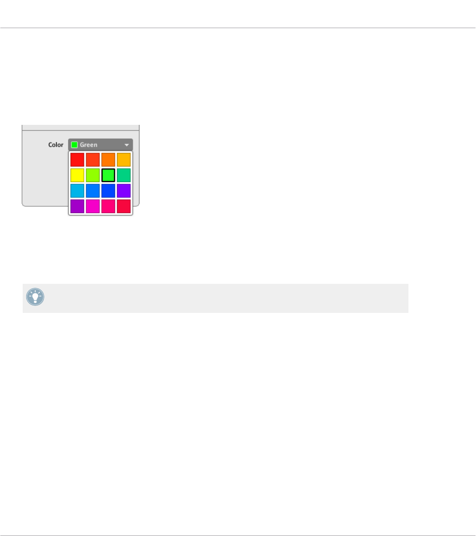
Color Control
For the Note message type, in addition to the parameters described in section ↑23.6.1, MIDI
Message Types – Type Menu, the Color setting allows you to define which color should be used
in the Light Guide (the LEDs above the keys on your keyboard) for the selected Key Zone:
►Click the Color menu and select the desired color from the color picker that opens:
→The selected color is applied to the Key Zone, as shown at the bottom of the Hardware
area. On your keyboard, the Light Guide mirrors this color above the keys in that Key
Zone.
To actually see the selected color in the Light Guide on your keyboard, you might need to
shift the keybed to keys within that Key Zone by pressing the OCT-/OCT+ buttons.
For more information on Key Zones, please refer to section ↑21.3, Defining Key Zones.
23.6.4 Assignments for the Pads – Hit Action
The assignments described here are valid for the pads of the whole MASCHINE controller fami-
ly (MASCHINE, MASCHINE MK2, MASCHINE MIKRO, MASCHINE MIKRO MK2, MA-
SCHINE STUDIO). The Hit action on a pad is very similar to actuating a button (see ↑23.6.2,
Assignments for Buttons above).
The only differences between hitting a pad and pressing a button are the following:
• The Pitchbend entry is not available in the Type menu.
Reference
MIDI Message Parameters
CONTROLLER EDITOR - Manual - 281

However, you can control the Pitchbend via the Press action of the same pad. This allows
you to create a very intuitive tuning control: With the Hit action of the pad triggering a
MIDI Note, you can then detune this note by varying the pressure that you’re applying to
the pad!
• There is no Action on menu.
Additionally, the pads of the MASCHINE MK2 and MASCHINE MIKRO MK2 controllers are
equipped with multicolor LEDs. You can define which color will be used for each pad state.
Please refer to section ↑23.6.2, Assignments for Buttons above for more information on this.
23.6.5 Assignments for Knobs and the Like
These virtually continuous control elements are characterized by a physically limited range.
The assignments described here are valid for following control elements:
NI Controller Control elements
KOMPLETE KONTROL S-SERIES EXPRESSION pedal input
TRAKTOR KONTROL X1 FX Knobs
TRAKTOR KONTROL X1 MK2 FX Knobs
TRAKTOR KONTROL F1 FILTER knobs, vertical faders
TRAKTOR KONTROL Z1 Knobs (Macro FX, Deck C/D Volume, Mixer), vertical faders
(channels), crossfader
TRAKTOR KONTROL Z2 Knobs (Macro FX, Deck C/D Volume, Mixer), vertical faders
(channels), crossfader
TRAKTOR KONTROL S2/S4 Knobs (FX, Mixer), vertical faders (TEMPO, channels), cross-
fader
TRAKTOR KONTROL S2 MK2/S4 MK2 Knobs (FX, Mixer), vertical faders (TEMPO, channels), cross-
fader
TRAKTOR KONTROL S8 Deck Units: FX and Performance knobs (Turn action), Slot
Volume faders (Slide action)
Mixer: channel knobs, channel faders, and crossfader
TRAKTOR KONTROL D2 Deck Unit: FX and Performance knobs (Turn action), Slot
Volume faders (Slide action)
Reference
MIDI Message Parameters
CONTROLLER EDITOR - Manual - 282

For these control elements, the Type menu offers the following entries: Control Change (default
setting), Poly Pressure, Channel Pressure, Program Change, Pitchbend, MCU Channel, MCU
Master, and Off.
KOMPLETE KONTROL S-SERIES keyboards: The MCU Channel and MCU Master entries
are not available for the EXPRESSION pedal input.
For a general description of these MIDI message types, see ↑23.6.1, MIDI Message Types –
Type Menu.
For Control Change, Poly Pressure, Channel Pressure, Program Change, and Pitchbend, two
numeric fields labeled Range From and To define the min and max values of the interval, re-
spectively. Both numeric fields go from 0 to 127 (by default, 0 for the min and 127 for the
max), except for the type Pitchbend, for which they go from -1.00 to 1.00.
If the values set in the Range From and Range To fields are equal, they turn red to indicate
a possible mistake when entering the values!
23.6.6 Assignments for the Pads – Press Action
The assignments described here are valid for the pads of the whole MASCHINE controller fami-
ly (MASCHINE, MASCHINE MK2, MASCHINE MIKRO, MASCHINE MIKRO MK2). The Press
action on a pad (i.e. maintaining a continuous pressure on the pad) is quite similar to actuat-
ing a knob (see ↑23.6.5, Assignments for Knobs and the Like above).
The Type menu offers the following entries: Note, Control Change, Poly Pressure (default set-
ting), Channel Pressure, Pitchbend (very useful for bending the tuning of sounds by pressure!),
and Off.
For a general description of these MIDI message types, see ↑23.6.1, MIDI Message Types –
Type Menu.
The types Control Change, Poly Pressure, Channel Pressure, and Pitchbend provide the same
parameters as with knobs: two numeric fields labeled Range From and To define the min and
max values of the interval, respectively. Both numeric fields go from 0 to 127 (by default, 0
for the min and 127 for the max), except for the type Pitchbend, for which they go from -1.00
to 1.00.
Reference
MIDI Message Parameters
CONTROLLER EDITOR - Manual - 283

If the values set in the Range From and Range To fields are equal, they turn red to indicate
a possible mistake when entering the values!
For the type Note, you have instead following parameters:
•Value: Sets the velocity of the note to be played.
•Threshold Off and On: Define the pressure threshold above (below) which the Note On (Off)
message is sent. The Threshold Off value should always be smaller than the Threshold On
value (have you ever considered stopping a note before playing it?). Both parameters
range from 0 % to 100 % (as a ratio with the maximum pressure).
As you can see, the settings for the Press action on a pad are quite similar to those of the usu-
al knobs. Here is a list of the differences:
• The Note type is added — and, for that, the on and off thresholds are needed.
• Program Change is not available because it would not be controllable.
23.6.7 Assignments for Digital Encoders
With “encoder” we mean a rotary, virtually continuous control element characterized by an
endless range.
The assignments described here are valid for following control elements:
NI Controller Control elements
MASCHINE STUDIO Jog wheel
MASCHINE MK2 Control encoder
MASCHINE MIKRO (MK2) Control encoder
TRAKTOR KONTROL X1 Push Encoders (Turn action)
TRAKTOR KONTROL X1 MK2 Push Encoders (Turn action)
TRAKTOR KONTROL F1 Encoder knob (Turn action)
TRAKTOR KONTROL Z1 Encoders (Turn action)
TRAKTOR KONTROL Z2 Encoders (Turn action)
TRAKTOR KONTROL S2/S4 Encoders (Turn action), jog wheels (Turn action)
TRAKTOR KONTROL S2 MK2/S4 MK2 Encoders (Turn action), jog wheels (Turn action)
Reference
MIDI Message Parameters
CONTROLLER EDITOR - Manual - 284

NI Controller Control elements
TRAKTOR KONTROL S8 Encoders (Turn action)
TRAKTOR KONTROL D2 Encoders (Turn action)
For these control elements, the Type menu offers the following entries: Note (Relative), Control
Change (default setting), Poly Pressure, Channel Pressure, Program Change, Song Position,
MCU Wheel, and Off.
For a general description of these MIDI message types, see ↑23.6.1, MIDI Message Types –
Type Menu.
For all types except Note (Relative), Control Change and MCU Wheel, you find following pa-
rameters:
• Two numeric fields labeled Range From and To define the min and max values of the in-
terval, respectively. Both numeric fields go from 0 to 127 (by default, 0 for the min and
127 for the max).
If the values set in the Range From and Range To fields are equal, they turn red to indicate
a possible mistake when entering the values!
• A numeric field Step defines the increment to add (or to subtract if negative) for each
step of control element (it goes from -128 to 127, with 1 as default value).
• The Wrap button allows you to “cycle” the interval: If this button is activated, once the
parameter reaches one of its limits, it jumps to the other one upon the next movement of
the encoder. If the Wrap button is deactivated, the message sent upon the next movement
keeps the maximal (or minimal) value for the parameter.
• S2/S4 jog wheels only: A Tick numeric field allows you to reduce the transmission sensi-
tivity in order to counterbalance the high number of counts per revolution, which is spe-
cific to this control element. This parameter goes from 20 to 1000.
For the S2/S4 jog wheels, the Step parameter ranges from -32 to 31 only.
Control Change
For the type Control Change, a Mode menu allows you to select between three operating
modes:
Reference
MIDI Message Parameters
CONTROLLER EDITOR - Manual - 285
•Absolute: In this mode the control element sends absolute values. Its parameters are the
same as those described above: two numeric fields Range From and To, a numeric field
Step and a Wrap button (see above).
•Relative: In this mode, the sent message is in a +1/-1 fashion — actually 1/127, which is
then understood by the target software as +1/-1 in that case. This allows the control ele-
ment to set the new Control Change value relatively to its current value. There is only one
parameter called Step which defines the increment to use. Increase the Step value to trig-
ger greater jumps in the target parameter value. If you choose a negative value for Step,
the control will be inverted.
•Relative (Offset): This mode is similar to the Relative mode explained above, with the dif-
ference that here the values sent for the “+1” and “-1” messages are 65 and 63, respec-
tively — in other terms, they are centered around 64 instead of 0. This is well suited for
some particular software implementations. As in Relative mode, a Step parameter defines
the increment to use.
The appropriate mode mostly depends on the requirements of your target! Please refer to
your target’s documentation to know which mode is best suited.
Note (Relative)
For the type Note (Relative), two Note parameters define the MIDI note numbers triggered
when turning the control counter-clockwise and clockwise, respectively (both ranges from MIDI
Note C-2 to G8). See section ↑23.6.1, MIDI Message Types – Type Menu for more information
on this message type.
23.6.8 Assignments for Analog Encoders
In contrast to the digital encoders described above, analog encoders output analog values. The
available MIDI message types are slightly different.
The assignments described here are valid for following control elements:
NI Controller Control elements
KOMPLETE KONTROL S-SER-
IES
Knobs 1–8 above the displays
TRAKTOR KONTROL S8 Performance knobs (Turn action) under the displays
Reference
MIDI Message Parameters
CONTROLLER EDITOR - Manual - 286
NI Controller Control elements
TRAKTOR KONTROL D2 Performance knobs (Turn action) under the displays
MASCHINE STUDIO Knobs 1–8 (Turn action) under the displays, Level knob
MASCHINE (MK2) Knobs 1–8 under the displays
For these control elements, the Type menu offers the following entries: Control Change (default
setting), Poly Pressure, Channel Pressure, Program Change, Pitchbend, MCU V-Pot, MCU
Channel, MCU Master, and Off.
KOMPLETE KONTROL S-SERIES: The Pitchbend, MCU V-Pot, MCU Channel, and MCU
Master entries are not available for Knobs 1–8.
For a general description of these MIDI message types, see ↑23.6.1, MIDI Message Types –
Type Menu.
For all types except Control Change and the MCU types, you find following parameters:
• Two numeric fields labeled Range From and To define the min and max values of the in-
terval, respectively. Both numeric fields go from 0 to 127 (by default, 0 for the min and
127 for the max), except for the type Pitchbend, for which they go from -1.00 to 1.00.
If the values set in the Range From and Range To fields are equal, they turn red to indicate
a possible mistake when entering the values!
• A numeric field labeled Resolution defines the physical angle on your encoder that is
needed to reach both limits of the interval (as defined by the Range From and To values).
Its values go from 30 to 3600 degrees (360 by default, i.e. one full revolution). For exam-
ple, if you choose 3600 (degrees), you will need to turn your knob ten times in order to go
from the minimum value to the maximum value defined by Range.
KOMPLETE KONTROL S-SERIES: The Resolution parameter is not available for Knobs 1–
8.
Control Change
For the type Control Change, a Mode menu allows you to select between three operating
modes:
Reference
MIDI Message Parameters
CONTROLLER EDITOR - Manual - 287
•Absolute: In this mode the control element sends absolute values. The Range From, To,
and Resolution parameters are the same as for the other message types (see above).
•Relative: In this mode the sent message is in a +1/-1 fashion — actually 1/127, which is
then understood by the target software as +1/-1 in that case. This allows the control ele-
ment to set the new Control Change value relatively to its current value. Two parameters
are available:
◦Step: Defines the increment to use. Increase the Step value to trigger greater jumps in
the target parameter value. If you choose a negative value for Step, the control will be
inverted.
◦Resolution: Adjusts the sensitivity of the control element to your actions. At high Res-
olution values, a little movement of the control element will be enough to trigger the
message. At lower Resolution values, you will have to move it more frankly to trigger
the message.
•Relative (Offset): This mode is similar to the Relative mode explained above, with the dif-
ference that here the values sent for the “+1” and “-1” messages are 65 and 63, respec-
tively — in other terms, they are centered around 64 instead of 0. This is well suited for
some particular software implementations. As in Relative mode, a Step parameter defines
the increment to use, and a Resolution parameter adjusts the sensitivity of the control el-
ement to your actions.
KOMPLETE KONTROL S-SERIES: The Resolution parameter is not available for Knobs 1–
8.
The appropriate mode mostly depends on your target’s requirements! Please refer to the
documentation of your target to know which mode is best suited.
Display Menu (MASCHINE Controllers and KOMPLETE KONTROL S-SERIES Only)
For the types Control Change (Absolute mode only), Poly Pressure, Channel Pressure, and
Pitchbend, the knobs show a Display menu that lets you decide how the parameter should ap-
pear on the display(s) of your controller: with the zero in the middle (Bipolar) or at the begin-
ning (Unipolar, by default) of the interval. This is up to you, since it depends on what you plan
to control with this assignment.
The Program Change type does not offer this parameter, since it is always unipolar.
Reference
MIDI Message Parameters
CONTROLLER EDITOR - Manual - 288
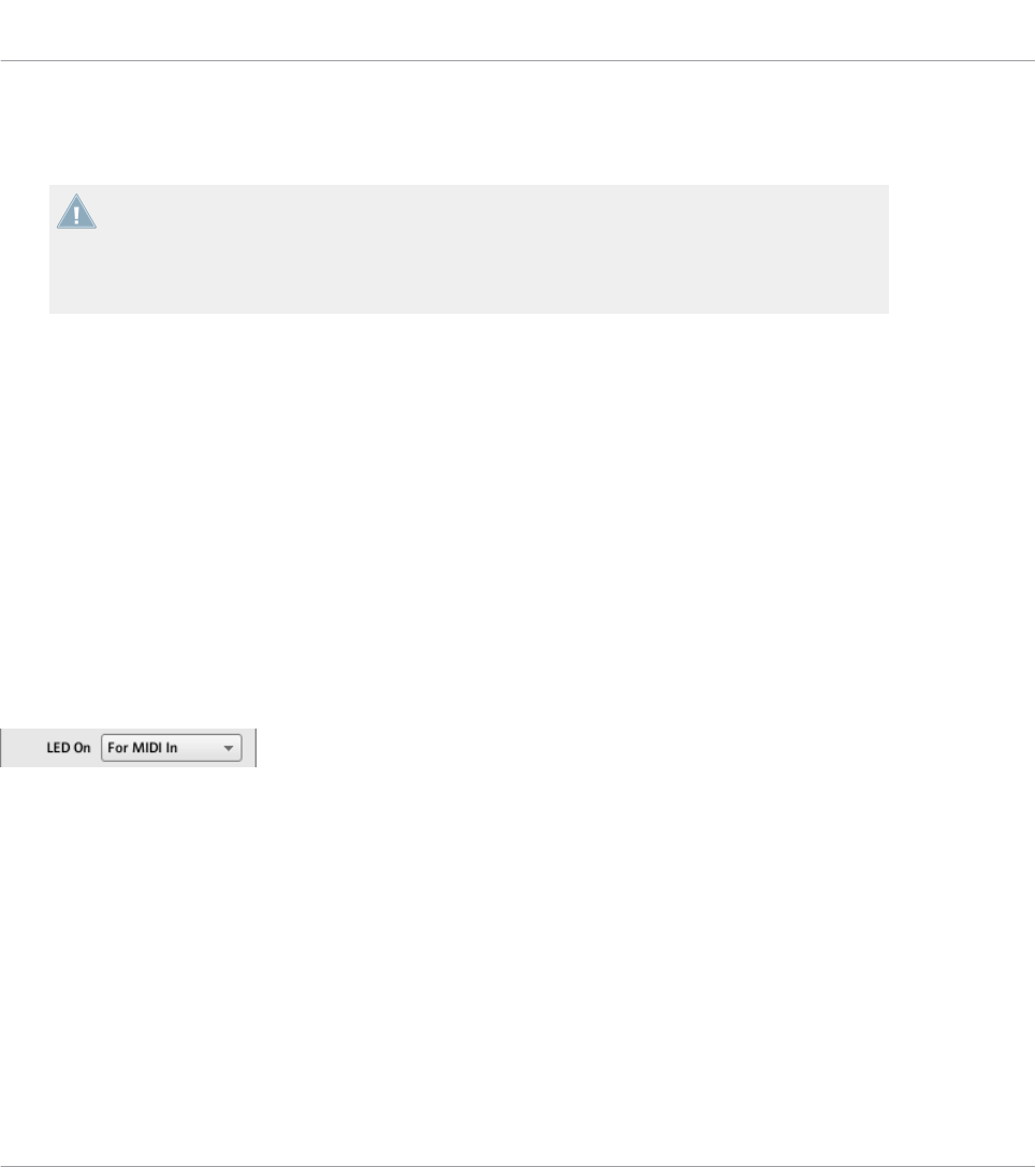
23.6.9 Assignments for Touch Strips – Position Action (TRAKTOR KONTROL Devices)
The assignments described in this section are valid for the Position action of the touch
strip on the TRAKTOR KONTROL X1 MK2, TRAKTOR KONTROL S8 and TRAKTOR KON-
TROL D2. The touch strips available on the KOMPLETE KONTROL S-SERIES have differ-
ent assignment parameters which are described in section ↑23.6.10, Assignments for
Touch Strips (KOMPLETE KONTROL S-SERIES).
The touch strip (Position action) on the TRAKTOR KONTROL X1 MK2, S8 and D2 is very simi-
lar to the analog encoders described in section ↑23.6.8, Assignments for Analog Encoders. The
only differences are the following:
• The Type menu offers an additional Note (Relative) message type: For this type, two Note
parameters define the MIDI note numbers triggered when dragging your finger to the left
or to the right on the touch strip, respectively (both ranges from MIDI Note C-2 to G8).
See section ↑23.6.1, MIDI Message Types – Type Menu for more information on this mes-
sage type.
• For all message types except the MCU types, you can define the behavior of the touch
strip’s LED chain via the LED On and LED Mode menus, as described in the following
paragraphs.
LED On Menu
The LED On menu.
The LED On menu allows you to choose from two LED chain lighting behaviors:
•For MIDI In (default): Selects the MIDI feedback mode. In this mode, the LED chain be-
havior is controlled by the MIDI target via a MIDI feedback channel. The MIDI target
sends a MIDI message back to the controller to define the LEDs’ state. This control mode
notably allows the LED chain to be always reflecting the current value of the target’s pa-
rameter, even if you changed this parameter via another way (e.g. with your mouse or via a
keyboard shortcut in the target software). For this to work, you have to define in your tar-
get the MIDI message to be sent accordingly.
Reference
MIDI Message Parameters
CONTROLLER EDITOR - Manual - 289

•For MIDI Out: Selects the internal control mode. In this mode, the LED chain behavior
solely depends on your actions on the touch strip.
LED Mode Menu
The LED Mode menu allows you to adjust how the LEDs react to the incoming MIDI message,
independently of its origin (this is set by the LED On menu described above). Following LED
modes are available:
•Orange Dot: In this mode the current value is represented by a single orange LED. Receiv-
ing a MIDI value of 0 will result in the leftmost LED being illuminated, whereas a MIDI
value of 127 would result in the rightmost LED being illuminated. A MIDI value of 64
would result in the center LED being illuminated. The other LEDs would have their values
assigned over this range accordingly.
•Blue Dot: Same as the Orange Dot mode above, except that a blue LED is used instead of
orange.
•Orange Bar: In this mode the current value is represented by a series of orange LEDs
which fill in starting from the leftmost LED up to the current value. For example, with a
MIDI value of 127, all LEDs would be on. With a MIDI value of 64, the first 11 LEDs
would be on (starting from the left) thus creating a bar which is half full. A MIDI value of
1 would result in only the left LED being on, while a MIDI value of 0 would result in all
LEDs being off.
•Blue Bar: Same as the Orange Bar mode above, but using blue LEDs instead of orange.
•Orange Pan: This mode is similar to the Bar modes described above, except that the bar
fills from the middle of the LED chain out to the specified value. For example, with a
MIDI value of 64, only the center LED on the chain would be lit in orange. With a MIDI
value of 0, the left 11 LEDs would be lit (starting from the center LED and extending left
to the MIDI value). Similarly, a MIDI value of 127 would result in the right 11 LEDs being
on (starting from the center and extending to the right).
•Blue Pan: Same as above, but using blue LEDs instead of orange.
23.6.10 Assignments for Touch Strips (KOMPLETE KONTROL S-SERIES)
The assignments described here are valid for the touch strips of the KOMPLETE KONTROL S-
SERIES keyboards.
Reference
MIDI Message Parameters
CONTROLLER EDITOR - Manual - 290
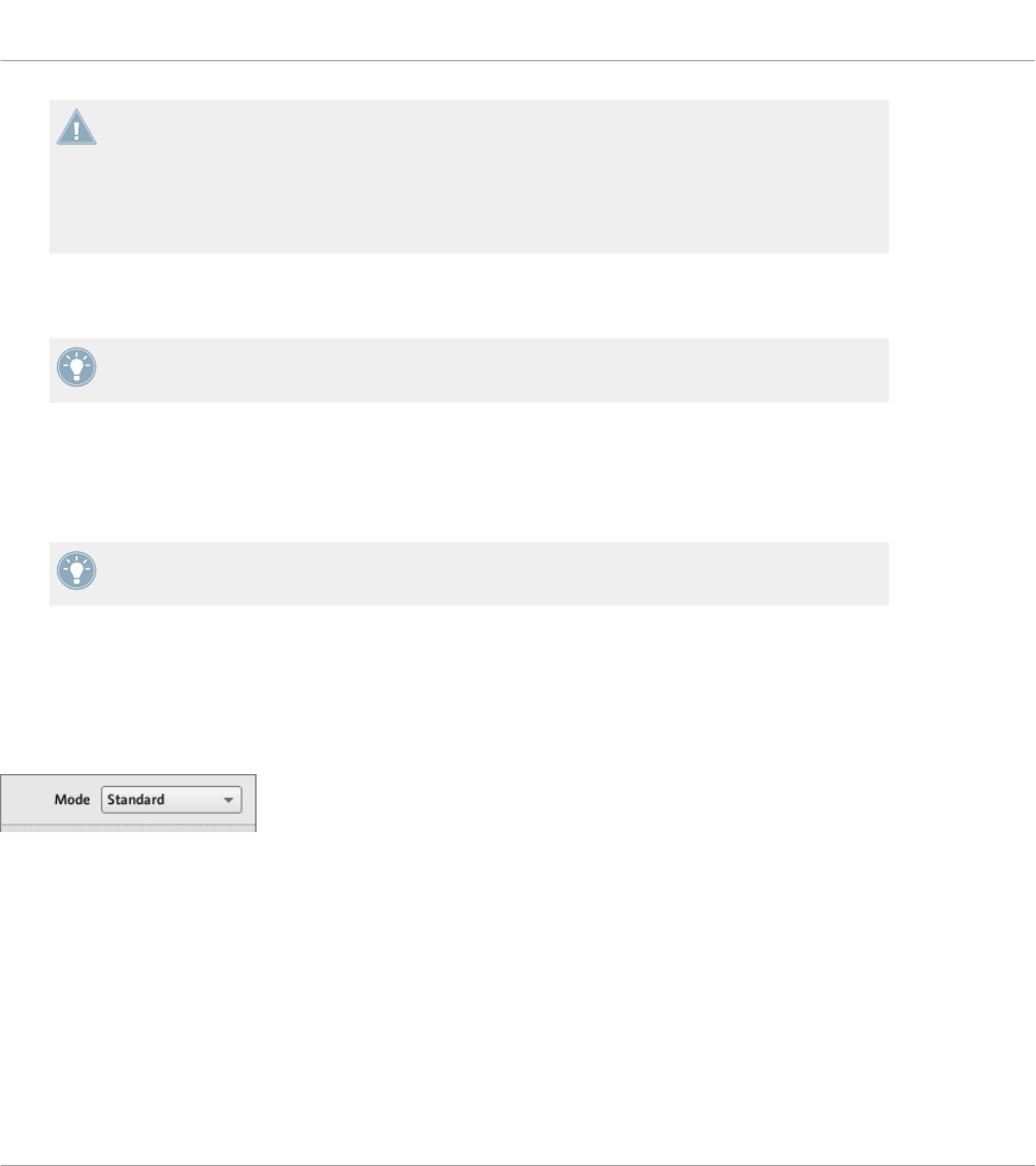
The assignments described here are valid for the touch strips of the KOMPLETE KON-
TROL S-SERIES keyboards. The touch strip available on the TRAKTOR KONTROL X1 MK2,
TRAKTOR KONTROL S8 and TRAKTOR KONTROL D2 has different assignment parameters
which are described in section ↑23.6.2, Assignments for Buttons (Touch action) and
↑23.6.9, Assignments for Touch Strips – Position Action (TRAKTOR KONTROL Devices)
(Position action).
For these control elements, the Type menu offers the following entries: Control Change, Pitch-
bend, and Off.
For a general description of these MIDI message types, see ↑23.6.1, MIDI Message Types –
Type Menu.
For both Control Change and Pitchbend types, two numeric fields labeled Range From and To
define the min and max values of the interval, respectively. For Control Change, both numeric
fields go from 0 to 127 (by default, 0 for the min and 127 for the max). For Pitchbend, both
numeric fields go from -1.00 to 1.00 instead.
If the values set in the Range From and Range To fields are equal, they turn red to indicate
a possible mistake when entering the values!
Mode Menu
You can choose from different behaviors affecting how the touch strip reacts to your actions
and generates the MIDI data to be sent. This is controlled by the Mode menu of the Assign
pane.
The Mode menu for touch strips.
The Mode menu has four entries, corresponding to four different behaviors:
•Standard: This is the default mode for the right touch strip on your KOMPLETE KON-
TROL S-SERIES keyboard and corresponds to the usual behavior for a modulation control.
In this mode the touch strip directly translates the position of your finger onto the range
specified by the Range From and To parameters above. When you put your finger some-
where on the strip, the value instantly jumps to the corresponding position and stays
Reference
MIDI Message Parameters
CONTROLLER EDITOR - Manual - 291

there. The Display and LED Mode menus allow you to define how the value should be in-
dicated on the strip’s LED chain — see section ↑21.4.3, Visual Feedback on the Touch
Strips for more details.
•Spring: This is the default mode for the left touch strip on your KOMPLETE KONTROL S-
SERIES keyboard and corresponds to the usual behavior for a pitchbend control. This
mode simulates a simple spring holding back the current MIDI value when it moves away
from its default position, which is in the middle of the strip. When you put your finger
somewhere on the strip, the value instantly jumps to the corresponding position and stays
there as long as you keep your finger on the strip. When you remove your finger, the value
moves back to the default position. The speed of this return trip can be adjusted via the
Strength slider: Using the analogy of the spring holding back the MIDI value, the higher
the Strength setting, the quicker the MIDI value will return to its default position.
•Ball: This mode simulates a ball (the current MIDI value) that would be attracted by the
gravity of your finger. If you put your finger at a particular location on the strip, the ball
will move from its current position towards your finger. If you keep your finger in place
until the ball reaches it, the ball stops there. If you remove your finger before, the ball
sustains its momentum and continues on its way beyond your finger. Note that the longer
you keep your finger on the strip, the faster the ball will get.
Alternatively, you can “throw” the ball by putting your finger on the ball’s current position
(blue LED), dragging it in any direction, and removing your finger. The faster you drag
your finger, the faster the ball will get.
The movement of the ball is also affected by following parameters:
◦Friction slider: Adjusts the air friction that slows down the ball once you have removed
your finger. The higher the Friction value, the quicker the ball will decelerate and
stop. When fully left, the ball never stops. When fully right, the ball stops instantly.
◦Gravity slider: Adjusts the attraction of your finger on the ball: The higher the Gravity
value, the faster the ball will move. This parameter doesn’t affect the ball movement if
you throw the ball with your finger (see above).
◦Walls menu: Adjusts the behavior of the ball when it reaches the range limits. If Walls
is set to On, the ball bounces off the range limit and continues its trip in the opposite
direction. If Walls is set to Off, the ball jumps to the opposite range limit and contin-
ues from there in the same direction.
Reference
MIDI Message Parameters
CONTROLLER EDITOR - Manual - 292
•Stepped: In Stepped mode, the touch strip is split into a certain amount of equally-sized
segments. Each segment is assigned to a unique MIDI value: When you touch that seg-
ment, its associated MIDI value is sent. The number of segments is defined via the Steps
numeric field. You can split the touch strip into 2, 3, 4, or 5 steps. The lower segment
will always output the lowest MIDI value, and the upper segment the highest value, as de-
fined by the Range From and Range To parameters. The other segments (if any) will out-
put MIDI values equally spread inbetween.
For example, if Range From and Range To are set to 0 and 127 (respectively) and Steps
is set to 4, the possible MIDI values will be 0, 42, 84, and 127.
LED Controls and Visual Feedback
The LED chain next to the touch strip provides an intuitive visual feedback for each of the be-
haviors described above. Depending on the mode selected for the touch strip, its LED chain
can be further adjusted via the Display and LED Mode menus. These menus, along with the
various behaviors of the LED chain, are described in section ↑21.4.3, Visual Feedback on the
Touch Strips.
23.6.11 Assignments for LED Chains and 7-segment Displays
The assignments described here are valid for following control elements:
NI Controller Control elements
TRAKTOR KONTROL S2/S4/S2 MK2/
S4 MK2
LED chains
TRAKTOR KONTROL Z1 7-segment display
TRAKTOR KONTROL F1 7-segment display
The LED chains and 7-segment displays are a bit particular. They actually don’t send any MIDI
message, but are used for MIDI feedback instead: the Assign pane allows you to define the
MIDI message they should react to.
For these control elements, the Type menu offers the following entries: Note, Control Change,
and Off.
• For the Note type, use the Note numeric field to select the desired MIDI Note. The control
element will then display the velocity at which this MIDI Note is played.
Reference
MIDI Message Parameters
CONTROLLER EDITOR - Manual - 293

• For the Control Change type, use the Number numeric field to select the desired Control
Change. The control element will then display the value of that Control Change.
Reference
MIDI Message Parameters
CONTROLLER EDITOR - Manual - 294
