C PDF Corbin Ltfb 4 H
LTFB-4-H Die Set LTFB-4-H Die Set
User Manual: PDF T E X T F I L E S
Open the PDF directly: View PDF ![]() .
.
Page Count: 2
How to Swage Bullets Using The
LTFB-4-H Die Set
1
2
3
4
6
5
7
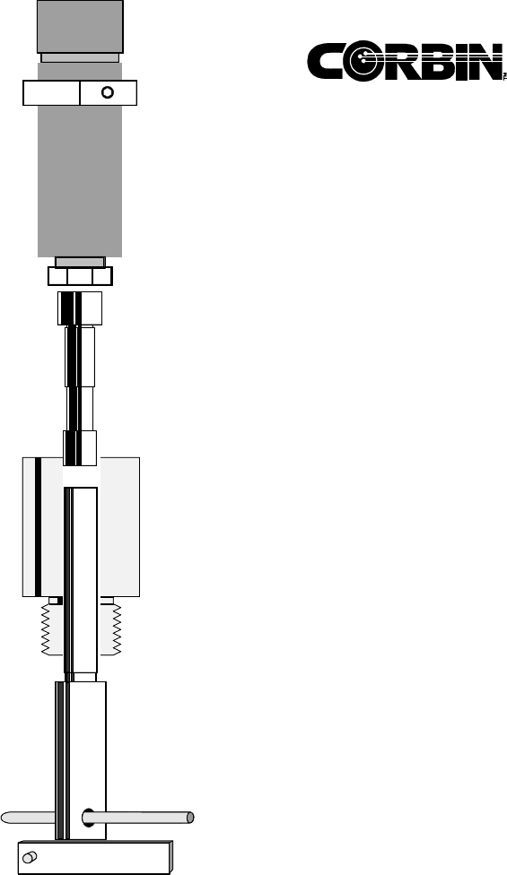
Type -H dies fit into the ram of the Corbin Mega-Mite manual (CSP-2), the Hydro, Jr. (CSP-2H) press,
and the Corbin Hydro-Press (CHP-1). The 4-die set consists of a CORE SWAGE (CSW--1-H), a CORE
SEAT(CS-1-H), a POINT FORM (PF-1-H) die, and a LEAD TIP (LT-1-H) die, each with one internal and
one external punch.
The external punch (1) is held in the floating punch holder (2), which comes with the press. A threaded
bushing (3) is removed from the bottom of the punch holder, placed over the external punch, and then
screwed back into the bottom of the punch holder to secure the punch. The punch holder screws into
the press head, so the punch faces the ram. (Large diameter punches, such as 600 Nitro, have their own
captive threaded bushing: do not remove this from the punch.)
The die (4) screws into the press ram, with its internal punch inside the ram. Some internal punches
require the use of spring powered retraction: they have a quarter inch diameter hole through the head
portion, through which a 1/4-inch diameter retraction pin (7) fits. The pin goes below the large spring
around the press ram, and pushes down on the pin, which then pushes the punch down when the ram
is raised, making it easier to insert material into the die.
A knock-out or ejection bar (5) goes through a slot in the press ram, below the spring and also below
the retraction pin (if one is required—not all punches have a hole through the head). The knock-out bar
contacts the head of the internal punch (6) on the down stroke, and comes to rest on the press mount-
ing plate. This stops the movement of the bar while the ram continues down, making the punch stop
and ejecting the component.
Once you have the punch holder adjusted to push the bullet just far enough to form a nice tip on the
bullet, and to allow proper ejection each time, go ahead and process all the bullets. The adjustment
and checking only has to be done on the first bullet. The open end of the jacket faces UP when you seat
the core, and it faces DOWN when you form the ogive. In every step, you want a small amount of
Corbin Swage Lube on the surface of the bullet or jacket, but not on the inside of the jacket.
If you use Corbin Core Bond, the core is swaged first, then put into the jacket by hand, and THEN
the core bond is put into the jacket (one or two drops, which should run down between jacket and
core). The core is melted quickly in the jacket, and the jacket is allowed to cool. Then, the jacket
must be boiled in hot water to which some baking soda has been added (a table spoon per quart
is sufficient). This neutralizes any remaining core bonding acid, which will destroy the surface
of the dies.
Spread the cleaned, bonded jackets out on a dry towel and let them dry from their own heat, then seat their cores using the
CS-1-H die, and form the ogive in the PF-1-H die as usual. Do not fail to clean the bonded cores in hot water and baking
soda, or you may destroy the point forming die from residual core bond, which attacks the die surfaces. (Core Bonding is an
option for jacketed bullets, not a requirement: it prevents the core and jacket from separating on impact and forces the
jacket to expand evenly with the core).
If you wish to make lead bullets, without a jacket, you can swage the core and put it directly into the point forming die.
However, if you do form it to almost finished diameter in the core seater, you will usually produce a slightly better bullet. To
do this requires a punch that seals the die bore, not the external punch which fits into a jacket. In some cases the external
point forming punch will fit. Try it by hand before inserting it with the force of the press, just in case it is too large to slip in
easily. Never insert any punch under force that will not slip in by hand!
Never try to swage a component that will not go into the die by hand. The swaging operation depends on each component
being slightly smaller than the die bore, and increases the bullet diameter a little with every step. The core seating die and
point forming die are matched to each other for a given jacket and core material to within 0.0005 to .0008 inches with the
core seater being smaller.
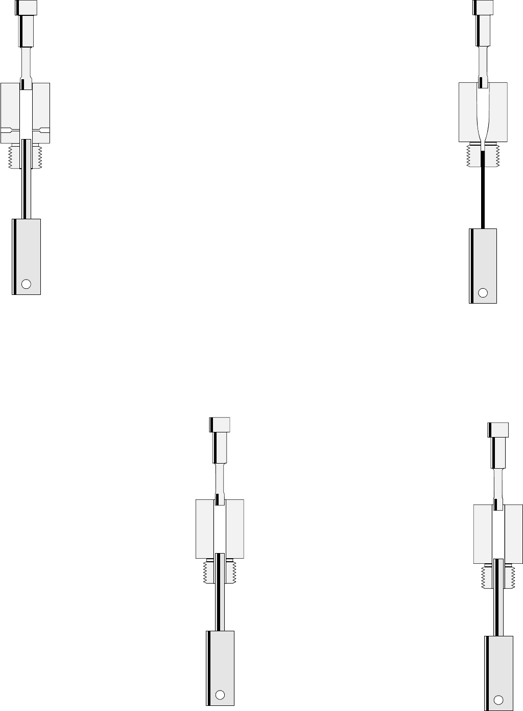
The first die is the CORE SWAGE (CSW-1-H).
It is used to form a piece of lead to precise di-
ameter, length and weight. You can use cut lead
wire, or a cast lead core. Apply a small amount
of Corbin Swage Lube to the cores as you handle
them.
There are three bleed holes through the
sides of the die, and its punches are very
close fits to the die bore. They are the small-
est punches in the set and only fit this die
properly.
For power presses, set the bottom sensor
so the pressure stops (red LED on the sen-
sor goes on) just as the swaged core is ejected
(internal punch even with the top of the die).
Use a knock-out bar that allows the punch to
come just to the die face, if you have more
than one height of bar with your press (hand
presses use three different heights of bars for
various punch and die lengths).
Set the floating punch holder so the desired
amount of lead is left in the die when the press
stops moving up (position of the top sensor controls top of
stroke on hydraulic presses, physical end of ram travel is fixed
on hand press).
After making the desired number of cores, clean them in hot
water to remove the swage lube, then let them dry and insert
them into bullet jackets (if jackets are used). Select a diam-
eter of external punch that fits the jacket ID at the point where
you want the core to be after seating. Thicker jackets, and
lighter cores in tapered jackets, both require a
larger diameter external punch than thinner jack-
ets or heavier bullets with a tapered commercial
jacket. (See Corbin Handbook for discussion of
proper core/jacket/punch fitting).
The core seating die (CS-1-H) is the second
die in a flat base die set. It is NOT used when
making rebated boattail bullets: instead, a pair
of RBT dies is used in sequence to seat the
core. The external punch can also be full di-
ameter for the die in order to make large lead
tip bullets, or have a projecting cone on the
end to make hollow points. The internal punch
can be flat, domed or have a conical projection
to form the mirror image of that shape in the
bullet base.
The correct core seating pressure is normally in
the 300 to 500 PSI range. This can vary with the
particular caliber, jacket thickness, and other fea-
tures of the bullet, so follow any written instruc-
tions provided with the die regarding the sug-
gested pressure. Always start with the pressure
in a low setting (300 to 500 psi) and increase is
slowly until the jacket expands to just under
the diameter you get with a swaged pure lead
slug in the die. Any greater pressure than this
will only stress the die and could bend punches
or break dies, and serves no useful purpose.
Apply a small amount of swaging lube to the
outside of each jacket as you pick it up to
insert in the die; the amount that you get by
rolling a drop between finger and thumb is
sufficient in most cases. Lubricant should not
be allowed inside the jacket: that is why the
cores were washed clean before insertion
into the jackets.
The final die for an open tip bullet is the POINT
FORMER (PF-1-H). It shapes the ogive curve
on the bullet and gives the bullet its final diam-
eter. The diameter of the point form die itself
is usually NOT the same as the bullet, and is
designed to match the core seater, the jacket
material and thickness, and the lead hardness.
The point form die is slightly different from
the others in that the internal punch must
push the bullet out by its nose, and consists
of a spring steel pin mounted in the punch head. This pin
must be retracted from the main cavity of the die during swag-
ing, or the tip of the bullet would form around it and prevent
ejection. When installing the internal punch, make absolutely
sure that the retraction pin goes through the punch head so
the retraction pin projects equally on both sides of the ram,
and that the die is, in fact, screwed down with the end of the
spring wire punch inside the die hole.
Shape the bullet by slowly lowering the external
punch and pushing the open end first into the die.
Eject, examine, and re-swage until the tip is closed
to about the size of the ejection pin diameter. For
lead tip bullets, leave the tip open and extrude suf-
ficient lead from the end of the bullet so that there
is enough lead to fill the cavity in the punch of
the lead tip forming die.
The final die for a lead tip bullet is the LT-1
LEAD TIP FORMER. It looks like the core
seater, but has a diameter slightly larger than
the final bullet, and the internal punch has a
cavity in the tip that is matched to the point form-
ing die shape. Gently push the lead tip bullet from
the point forming die into the LT die, to reshape
the tip. Adjust the external punch insertion so that
the bullet tip is just formed. Any further insertion
will tend to press the edge of the internal punch
against the jacket and create a ring or step in the
ogive. Lead tip bullets require a larger tip open-
ing, in the core seating operation, than open tip
bullets, in order to assure that the lead tip is con-
nected to the core securely.
