Efficient Design Of Adaptive Complex Narrowband IIR Filters COZ 1 Cr1485
User Manual: COZ-1
Open the PDF directly: View PDF ![]() .
.
Page Count: 4
- Index
- EUSIPCO 2004 Home Page
- Conference Info
- Sessions
- Tuesday 7.9.2004
- TueAmPS1-Coding and Signal Processing for Multiple-Ante ...
- TueAmSS1-Applications of Acoustic Echo Control
- TueAmOR1-Blind Equalization
- TueAmOR2-Image Pyramids and Wavelets
- TueAmOR3-Nonlinear Signals and Systems
- TueAmOR4-Signal Reconstruction
- TueAmPO1-Filter Design
- TueAmPO2-Multiuser and CDMA Communications
- TuePmSS1-Large Random Matrices in Digital Communication ...
- TuePmSS2-Algebraic Methods for Blind Signal Separation ...
- TuePmOR1-Detection
- TuePmOR2-Image Processing and Transmission
- TuePmOR3-Motion Estimation and Object Tracking
- TuePmPO1-Signal Processing Techniques
- TuePmPO2-Speech, Speaker, and Emotion Recognition
- TuePmSS3-Statistical Shape Analysis and Modelling
- TuePmOR4-Source Separation
- TuePmOR5-Adaptive Algorithms for Echo Compensation
- TuePmOR6-Multidimensional Systems and Signal Processing
- TuePmPO3-Channel Estimation, Equalization, and Modellin ...
- TuePmPO4-Image Restoration, Noise Removal, and Deblur
- Wednesday 8.9.2004
- WedAmPS1-Brain-Computer Interface - State of the Art an ...
- WedAmSS1-Performance Limits and Signal Design for MIMO ...
- WedAmOR1-Signal Processing Implementations and Applicat ...
- WedAmOR2-Continuous Speech Recognition
- WedAmOR3-Image Filtering and Enhancement
- WedAmOR4-Machine Learning for Signal Processing
- WedAmPO1-Parameter Estimation: Methods and Applications
- WedAmPO2-Video Coding and Multimedia Communications
- WedAmSS2-Prototyping for MIMO Systems
- WedAmOR5-Adaptive Filters I
- WedAmOR6-Speech Analysis
- WedAmOR7-Pattern Recognition, Classification, and Featu ...
- WedAmOR8-Signal Processing Applications in Geophysics a ...
- WedAmPO3-Statistical Signal and Array Processing
- WedAmPO4-Signal Processing Algorithms for Communication ...
- WedPmSS1-Monte Carlo Methods for Signal Processing
- WedPmSS2-Robust Transmission of Multimedia Content
- WedPmOR1-Carrier and Phase Recovery
- WedPmOR2-Active Noise Control
- WedPmOR3-Image Segmentation
- WedPmPO1-Design, Implementation, and Applications of Di ...
- WedPmPO2-Speech Analysis and Synthesis
- WedPmSS3-Content Understanding and Knowledge Modelling ...
- WedPmSS4-Poissonian Models for Signal and Image Process ...
- WedPmOR4-Performance of Communication Systems
- WedPmOR5-Signal Processing Applications
- WedPmOR6-Source Localization and Tracking
- WedPmPO3-Image Analysis
- WedPmPO4-Wavelet and Time-Frequency Signal Processing
- Thursday 9.9.2004
- ThuAmSS1-Maximum Usage of the Twisted Pair Copper Plant
- ThuAmSS2-Biometric Fusion
- ThuAmOR1-Filter Bank Design
- ThuAmOR2-Parameter, Spectrum, and Mode Estimation
- ThuAmOR3-Music Recognition
- ThuAmPO1-Image Coding and Visual Quality
- ThuAmPO2-Implementation Aspects in Signal Processing
- ThuAmSS3-Audio Signal Processing and Virtual Acoustics
- ThuAmSS4-Advances in Biometric Authentication and Recog ...
- ThuAmOR4-Decimation and Interpolation
- ThuAmOR5-Statistical Signal Modelling
- ThuAmOR6-Speech Enhancement and Restoration I
- ThuAmPO3-Image and Video Watermarking
- ThuAmPO4-FFT and DCT Realization
- ThuPmSS1-Information Transfer in Receivers for Concaten ...
- ThuPmSS2-New Directions in Time-Frequency Signal Proces ...
- ThuPmOR1-Adaptive Filters II
- ThuPmOR2-Pattern Recognition
- ThuPmOR3-Rapid Prototyping
- ThuPmPO1-Speech/Audio Coding and Watermarking
- ThuPmPO2-Independent Component Analysis, Blind Source S ...
- ThuPmSS3-Affine Covariant Regions for Object Recognitio ...
- ThuPmOR4-Source Coding and Data Compression
- ThuPmOR5-Augmented and Virtual 3D Audio
- ThuPmOR6-Instantaneous Frequency and Nonstationary Spec ...
- ThuPmPO3-Adaptive Filters III
- ThuPmPO4-MIMO and Space-Time Communications
- Friday 10.9.2004
- FriAmPS1-Getting to Grips with 3D Modelling
- FriAmSS1-Nonlinear Signal and Image Processing
- FriAmOR1-System Identification
- FriAmOR2-xDSL and DMT Systems
- FriAmOR3-Speech Enhancement and Restoration II
- FriAmOR4-Video Coding
- FriAmPO1-Loudspeaker and Microphone Array Signal Proces ...
- FriAmPO2-FPGA and SoC Realizations
- FriAmSS2-Nonlinear Speech Processing
- FriAmOR5-OFDM and MC-CDMA Systems
- FriAmOR6-Generic Audio Recognition
- FriAmOR7-Image Representation and Modelling
- FriAmOR8-Radar and Sonar
- FriAmPO3-Spectrum, Frequency, and DOA Estimation
- FriAmPO4-Biomedical Signal Processing
- FriPmSS1-DSP Applications in Advanced Radio Communicati ...
- FriPmOR1-Array Processing
- FriPmOR2-Sinusoidal Models for Music and Speech
- FriPmOR3-Recognizing Faces
- FriPmOR4-Video Indexing and Content Access
- Tuesday 7.9.2004
- Authors
- Papers
- Topics
- 1. DIGITAL SIGNAL PROCESSING
- 1.1 Filter design and structures
- 1.2 Fast algorithms
- 1.3 Multirate filtering and filter banks
- 1.4 Signal reconstruction
- 1.5 Adaptive filters
- 1.6 Sampling, Interpolation, and Extrapolation
- 1.7 Other
- 2. STATISTICAL SIGNAL AND ARRAY PROCESSING
- 2.1 Spectral estimation
- 2.2 Higher order statistics
- 2.3 Array signal processing
- 2.4 Statistical signal analysis
- 2.5 Parameter estimation
- 2.6 Detection
- 2.7 Signal and system modeling
- 2.8 System identification
- 2.9 Cyclostationary signal analysis
- 2.10 Source localization and separation
- 2.11 Bayesian methods
- 2.12 Beamforming, DOA estimation, and space-time adapti ...
- 2.13 Multichannel signal processing
- 2.14 Other
- 3. SIGNAL PROCESSING FOR COMMUNICATIONS
- 3.1 Signal coding, compression, and quantization
- 3.2 Modulation, encoding, and multiplexing
- 3.3 Channel modeling, estimation, and equalization
- 3.4 Joint source - channel coding
- 3.5 Multiuser communications
- 3.6 Multicarrier systems
- 3.7 Spread-spectrum systems and interference suppressio ...
- 3.8 Performance analysis, optimization, and limits
- 3.9 Broadband networks and subscriber loops
- 3.10 Application-specific systems and implementations
- 3.11 MIMO and Space-Time Processing
- 3.12 Synchronization
- 3.13 Cross-Layer Design
- 3.14 Ultrawideband
- 3.15 Other
- 4. SPEECH PROCESSING
- 4.1 Speech production and perception
- 4.2 Speech analysis
- 4.3 Speech synthesis
- 4.4 Speech coding
- 4.5 Speech enhancement and noise reduction
- 4.6 Isolated word recognition and word spotting
- 4.7 Continuous speech recognition
- 4.8 Spoken language systems and dialog
- 4.9 Speaker recognition and language identification
- 4.10 Other
- 5. AUDIO AND ELECTROACOUSTICS
- 5.1 Active noise control and reduction
- 5.2 Echo cancellation
- 5.3 Psychoacoustics
- 5.5 Audio coding
- 5.6 Signal processing for music
- 5.7 Binaural systems
- 5.8 Augmented and virtual 3D audio
- 5.9 Loudspeaker and Microphone Array Signal Processing
- 5.10 Other
- 6. IMAGE AND MULTIDIMENSIONAL SIGNAL PROCESSING
- 6.1 Image coding
- 6.2 Computed imaging (SAR, CAT, MRI, ultrasound)
- 6.3 Geophysical and seismic processing
- 6.4 Image analysis and segmentation
- 6.5 Image filtering, restoration and enhancement
- 6.6 Image representation and modeling
- 6.7 Digital transforms
- 6.9 Multidimensional systems and signal processing
- 6.10 Machine vision
- 6.11 Pattern Recognition
- 6.12 Digital Watermarking
- 6.13 Image formation and computed imaging
- 6.14 Image scanning, display and printing
- 6.15 Other
- 7. DSP IMPLEMENTATIONS, RAPID PROTOTYPING, AND TOOLS FO ...
- 7.1 Architectures and VLSI hardware
- 7.2 Programmable signal processors
- 7.3 Algorithms and applications mappings
- 7.4 Design methodology and rapid prototyping
- 7.6 Fast algorithms
- 7.7 Other
- 8. SIGNAL PROCESSING APPLICATIONS
- 8.1 Radar
- 8.2 Sonar
- 8.3 Biomedical processing
- 8.4 Geophysical signal processing
- 8.5 Underwater signal processing
- 8.6 Sensing
- 8.7 Robotics
- 8.8 Astronomy
- 8.9 Other
- 9. VIDEO AND MULTIMEDIA SIGNAL PROCESSING
- 9.1 Signal processing for media integration
- 9.2 Components and technologies for multimedia systems
- 9.4 Multimedia databases and file systems
- 9.5 Multimedia communication and networking
- 9.7 Applications
- 9.8 Standards and related issues
- 9.9 Video coding and transmission
- 9.10 Video analysis and filtering
- 9.11 Image and video indexing and retrieval
- 10. NONLINEAR SIGNAL PROCESSING AND COMPUTATIONAL INTEL ...
- 10.1 Nonlinear signals and systems
- 10.2 Higher-order statistics and Volterra systems
- 10.3 Information theory and chaos theory for signal pro ...
- 10.4 Neural networks, models, and systems
- 10.5 Pattern recognition
- 10.6 Machine learning
- 10.9 Independent component analysis and source separati ...
- 10.10 Multisensor data fusion
- 10.11 Other
- 11. WAVELET AND TIME-FREQUENCY SIGNAL PROCESSING
- 11.1 Wavelet Theory
- 11.2 Gabor Theory
- 11.3 Harmonic Analysis
- 11.4 Nonstationary Statistical Signal Processing
- 11.5 Time-Varying Filters
- 11.6 Instantaneous Frequency Estimation
- 11.7 Other
- 12. SIGNAL PROCESSING EDUCATION AND TRAINING
- 13. EMERGING TECHNOLOGIES
- Search
- Help
- About
- Current paper
EFFICIENT DESIGN OF ADAPTIVE COMPLEX NARROWBAND IIR FILTERS
Georgi Iliev1, Zlatka Nikolova2, Georgi Stoyanov2, Karen Egiazarian1
1 Institute of Signal Processing, Tampere University of Technology
P.O. Box 527, 33101 Tampere, Finland
phone: +358 3 3115 4329, fax: +358 3 3115 3817, email: iliev@cs.tut.fi
2 Department of Telecommunications, Technical University of Sofia
8 Kliment Ohridski St, 1000 Sofia, Bulgaria
phone: +359 2 965 3255, fax: +359 2 68 60 89, email: zvv@tu-sofia.bg
ABSTRACT
In this paper a new adaptive complex digital filter structure
is proposed. First, a very low sensitivity second-order com-
plex bandpass (BP) filter section with independent tuning of
the central frequency and the bandwidth (BW) is developed
(the low sensitivity of the narrow-band realization is ensur-
ing a higher BW-tuning accuracy or better precision in a
severe coefficient quantization). Then, a BP/Bandstop (BS)
adaptive filter structure is formed around this section, using
LMS algorithm to adapt the central frequency. The devel-
oped filter circuit is providing a low computational com-
plexity and a very fast convergence, and is convenient for
cancellation/enhancement of complex sinusoids or narrow-
band signals. All theoretical results in the work are verified
experimentally.
1.INTRODUCTION
The area of narrowband signal elimination/enhancement has
been widely investigated during the last years. A great num-
ber of realizations for real narrowband filters has been pro-
posed [1] – [4]. At the same time only a few complex coun-
terparts have been developed and completely studied [5],
[6]. In this work a new digital adaptive complex narrowband
filter is proposed and investigated.
First, very low magnitude sensitivity narrowband first-
order lowpass (LP) filter section is selected. Then, using a
general rotation transformation, second-order complex coef-
ficient bandpass (BP) section is obtained and its central fre-
quency is made variable without limitations by tuning the
transformation factor θ. The bandwidth (BW) of the section
is made tunable by using the spectral LP to LP transforma-
tion followed by truncated Taylor series expansion. The new
complex filter conducts well in finite wordlength environ-
ment and demonstrates very-low coefficient sensitivity.
Having in mind above-mentioned good characteristics of
this particular type of complex filter, we use it for the design
of an adaptive complex narrowband filter. The behaviour of
the filter has been tested with different values of the main
filter parameters, namely, step of adaptation and filter band-
width.
2.COMPLEX DIGITAL FILTER CIRCUIT
In [7], a new method of designing complex coefficient BP
and BS filters with independently tunable center frequency
and bandwidth is proposed. This method ensures wider
range of tuning of the bandwidth, lower stopband sensitivity,
reduced complexity and higher freedom of tuning compared
to the other well-known methods. We apply this method to
obtain a new complex digital adaptive narrow-band second
order filter section.
It is well known that if the variable z in a given real digi-
tal N-order transfer function H(z) is substituted by
]H] θ−
= or 11 )sincos( −− θ+θ= ]M] , (1)
the new complex coefficient transfer function H(e–jθ) will be
a 2N-order BP/BS filter. The complex circuit realizations
always have two inputs and two outputs (both real and
imaginary), i.e. it is described by 4 transfer functions:
+(]) = +(]) and +(]) = –+(]). (2)
If the starting function H(z) is LP, then all transfer func-
tions (2) are of BP type. If the initial function H(z) is of HP-
type, then some of transfer functions (2) are of BS type. The
new complex filter may have its central frequency every-
where on the frequency axis (0-π) tuned by changing of θ.
The filter’s bandwidth will be tuned in some limits using the
LP to LP spectral transformations of Constantinides
)(
11
1
1]7
]
]
]=
χ−
χ−
→−
−
−, (3)
followed by truncated Taylor series expansion in order to
avoid delay-free loops. But we can avoid the usage of trun-
cated Taylor series if we can tune directly the BW of the ini-
tial LP/HP filter by trimming a single multiplier coefficient.
When transformation (1) is applied, it was shown in [8]
that all the properties (including sensitivity) of the prototype
LP/HP structures will be inherited by the new complex
BP/BS filter. Therefore we shall try first to develop or select
a very low-sensitivity prototype for a given pole-disposition
1597
and then to apply transformation (1) in order to obtain a
complex BP section with high accuracy of tuning of the BW.
It is well known that mainly narrow-band BP/BS filters
are of practical importance. Such filters are obtained starting
from very narrow-band LP and wide-band HP prototypes.
As we need a narrow-band BP complex structure, a nar-
row-band (having poles near z = +1) LP structure with very
low-sensitivity has to be develop or found.
After sensitivities investigation of the most often used
first-order sections, it was found that one of the best appli-
cant for LP prototype circuit appeared to be our section LS1
(Fig.1a), proposed in [8]. It has a canonical number of multi-
pliers and delay elements and a unity DC gain. The transfer
function of this section is:
1
1
)21(1
)1(
)( −
−
β−−
+
β= ]
]
]+ (4)
Applying the circuit transformation proposed by Wata-
nabe and Nishihara [9] on this LS1 section, a BP second-
order complex realization is obtained (Fig.1b). This trans-
formation guarantees also a canonical number of elements
for the complex structure.
z
-
1
In
β
Out
(a)
β
In Re
z
-
1
Out Re In Im
z
-
1
Out Im
cos
θ
sin
θ
sin
θ
cos
θ
β
(b)
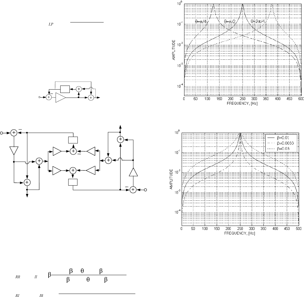
Figure 1: (a) Low-sensitivity first order LP section LS1; (b)
Second-order low-sensitivity complex BP structure realiza-
tion.
The transfer functions of the low-sensitivity prototype-
based complex section (Fig. 1b) are:
.
)12(cos)12(21
sin)1(2
)()(
;
)1
2(cos)12(21
)1
2(cos21
)()(
221
1
221
21
−−
−
−−
−−
−β+θ−β+
θβ−
β=−=
−+−+
−++
==
]]
]
]+]+
]]
]]
]+]+
(5)
All these transfer functions are of BP type.
In Fig.2a it is shown how the central frequency of the
magnitude response of HRR(z) (5) of the narrow-band second-
order sections of Fig. 1b is tuned by trimming of θ (for fixed
β). The results for the bandwidth tuning by changing β (for
fixed θ) are shown in Fig. 2b. It is seen that the bandwidth is
tuned without problem over a wide frequency range and the
shape of the magnitude is almost not varying in the tuning
process.
The behavior of the filter in a limited word-length envi-
ronment also was investigated. Due to the very low coeffi-
cient sensitivity of the initial section, our filter is behaving
very well even when the coefficients are severely quantized.
(a)
(b)
Figure 2: Magnitude responses of variable BP complex sec-
ond-order filter (a) for different values of θ; (b) for different
values of β.
3.ADAPTIVE COMPLEX NARROWBAND
FILTERING
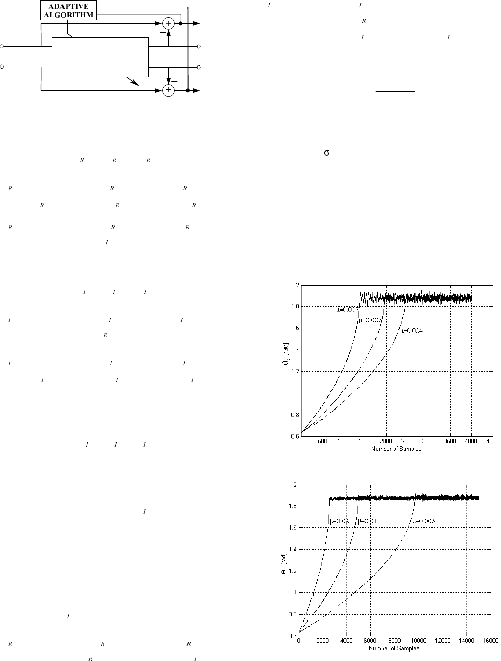
In Fig. 3 the block-diagram of our narrowband filter section
is shown. In the following we consider the input/output rela-
tions for corresponding BP/BS filters (Eq.(6)-(13)).
1598
SECOND-ORDER
COMPLEX
FILTER
x
R
(n)
x
I
(n)
e
R
(n)
y
I
(n)
y
R
(n)
e
I
(n)
Figure 3: Block-diagram of a BP/BS adaptive complex filter
section.
For the BP filter we have the following real output:
)()()( 21 Q\Q\Q\
+
=
, (6)
where
)2()12(2)1()(cos4)(2
)2()12()1()(cos)12(2)(
2
1
2
11
−−ββ+−θβ+β+
+−−β−−θ−β−=
Q[Q[QQ[
Q\Q\QQ\ (7)
).1()(sin)1(4
)2()12()1()(cos)12(2)( 2
2
22
−θβ−β−
−−−β−−θ−β−=
Q[Q
Q\Q\QQ\ (8)
The imaginary output is given by the following equa-
tion:
)()()( 21 Q\Q\Q\
+
=
, (9)
where
)1()(sin)1(4
)2()12()1()(cos)12(2)( 1
2
11
−θβ−β+
+−−β−−θ−β−=
Q[Q
Q\Q\QQ\ (10)
and
).2()12(2)1()(cos4)(2
)2()12()1()(cos)12(2)(
2
2
2
22
−−ββ+−θβ+β+
+−−β−−θ−β−=
Q[Q[QQ[
Q\Q\QQ\ (11)
For the bandstop filter we have the real output
)()()( Q\Q[QH
−
=
, (12)
and the imaginary output
)()()( Q\Q[QH
−
=
. (13)
The cost-function is the power of bandstop filter output
signal:
)]()([ QHQH ∗, (14)
where
)()()( QMHQHQH
+
=
. (15)
We apply a Least Mean Squares (LMS) algorithm to up-
date the filter coefficient responsible for the central fre-
quency as follows:
)]()(Re[)()1( ’Q\QHQQ ∗
µ+θ=+θ . (16)
Where µ is the step size controlling the speed of conver-
gence, (*) denotes complex-conjugate, y
′
(n) is a derivative of
)()()( QM\Q\Q\
+
=
with respect to the coefficient - subject
of adaptation,
)1()(cos)1(4)1()(sin)12(2
)1()(sin4)1()(sin)12(2)(
2
2
1
’
−θβ−β−−θ−β+
+−θβ−−θ−β=
Q[QQ\Q
Q[QQ\QQ\ (17)
and
).1()(sin4)1()(sin)12(2
)1()(cos)1(4
)1()(sin)12(2)(
2
2
1
’
−θβ−−θ−β+
+−θβ−β+
+−θ−β=
Q[QQ\Q
Q[Q
Q\QQ\
(18)
In order to ensure the stability of the adaptive algorithm
we should set the range of the step size µ. We use the results
reported in [10]:
)R(Trace
K
0<µ< , (19)
or in a more convenient form:
σ
<µ< 2
L
K
0. (20)
,QRXUFDVH 2 is the power of the signal y
′
(n), L is the fil-
ter order and K is a constant depending on the statistical
characteristics of the input signal. In most of the practical
situations K is approximately equal to 0.1.
4.SIMULATION RESULTS
We test our filter for elimination/enhancement of narrow-
band complex signals. Input signal is a mixture of white
noise and complex (analytic) sinusoidal signal.
(a)
(b)
1599
(c)
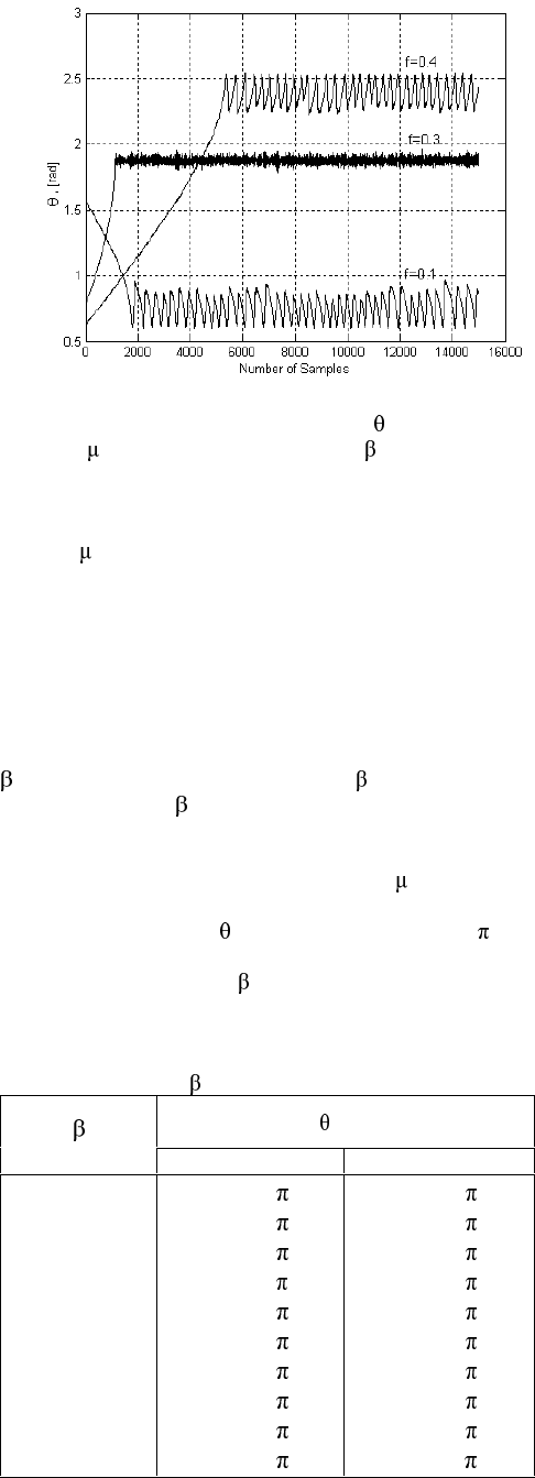
Figure 4: Trajectories of filter coefficient DIRUGLIIHUHQW
VWHS VL]H EIRU GLIIHUHQW EDQGZLGWK F IRU GLIIHUHQW
frequency f.
In Figure 4a the learning curves for different values of
VWHSVL]H DUHVKRZQ,WFDQEHREVHUYHGWKDWWKHODUJHUis the
step size the higher speed of adaptation could be achieved. In
Figure 4b the results for different filter bandwidth are pre-
sented. It is obvious that by narrowing the filter bandwidth
we make the process of convergence slower. Finally, in Fig-
ure 4c we show the behaviour of our filter for a wide range of
sinusoidal frequencies. In all the cases our filter converges to
the proper frequency value.
In the next experiment we investigate the dependence on
DQG LWV GHELDVLQJ effect. Parameter GHILQHV WKH ILOWHU
EDQGZLGWK DQG IRU § WKH UHVXOWLQJ ILOWHU LV D JRRG
approximation of an ideal notch filter. For the purpose of this
study, the input signal consists of a complex sinusoid at a
frequency of 0DQGZKLWHQRLVH6WHSVL]H LVVHWWR
We have conducted 30 independent trials with a data-length
of 7KH UHVXOWV IRU ZKLFK WUXH YDOXH LV DUH
summarized in Table 1. It can be seen that the estimates
improve continuRXVO\ZLWK Dpproaching 0.004.
Table 1: Simulation results for one complex sinusoid in white
QRLVHDVDIXQFWLRQRI DQGIRUDGDWDOHQJWKRI.
[rad]
mean standard deviation
0.050
0.045
0.040
0.035
0.030
0.025
0.020
0.015
0.010
0.005
0.5603
0.5533
0.5471
0.5411
0.5351
0.5278
0.5207
0.5139
0.5074
0.5004
0.0086
0.0075
0.0065
0.0057
0.0051
0.0042
0.0031
0.0026
0.0018
0.0011
5.CONCLUSIONS
A very low sensitivity real LP filter section was transformed
in this work to a complex BP section permitting a very pre-
cise tuning of the BW in much wider frequency range com-
pared to other known sections (based on truncated Taylor
series). The transformation factor θ is used to tune (also
adaptively, by applying an LMS algorithm) the central fre-
quency of the complex BP filter so obtained. The conver-
gence of the algorithm for the developed adaptive complex
filter circuit is investigated experimentally and the efficiency
of the adaptation is clearly demonstrated.
The main advantages of the proposed adaptive structure
are in its low computational complexity, fast convergence
(less than 100 iterations) and the convenience for implemen-
tation with CORDIC processors. The very low sensitivity of
the initial LP section ensures a high tuning accuracy even
with severely quantized multiplier coefficients.
REFERENCES
[1] G. Stoyanov and M. Kawamata, “Variable digital filters,”
Journal of Signal Processing, vol. 1, No 4, pp. 275–290,
July 1997.
[2] J. Chicharo and T. Ng, “Gradient-based adaptive IIR
notch filtering for frequency estimation”, IEEE Trans. on
ASSP, pp. 769 – 777, May 1990.
[3] R. Kumar and R. Pal, “A gradient algorithm for center-
frequency adaptive recursive bandpass filters”, Proc.
IEEE, pp. 371 – 372, Feb. 1985.
[4] A. Nehorai, “A minimal parameter adaptive notch filter
with constrained poles and zeros,” IEEE Trans. on ASSP,
pp. 983–996, Aug. 1985.
[5] S. Nishimura and Hai-Yun Jiang, “Gradient-based com-
plex adaptive IIR notch filters for frequency estimation”,
in Proc. of IEEE Asia Pacific Conference on Circuits and
Systems ’96, Seul, Korea, Nov. 1996, pp. 235–238.
[6] S. Nishimura and Hai-Yun Jiang, “Convergence analysis
of complex adaptive IIR notch filters”, in Proc. of ISCAS
’97, Hong Kong, June. 1997, pp. 2325 –2328.
[7] G. Stoyanov and Zl. Nikolova, “Improved method of de-
sign of complex coefficients variable IIR digital filters”,
in Proc. TELECOM’99, Varna, Bulgaria, vol. 2, Oct.
1999, pp.40–46.
[8] G. Stoyanov, M. Kawamata, Zl. Valkova, “New first and
second-order very low-sensitivity bandpass/ bandstop
complex digital filter sections. ” in Proc. IEEE 1997 Re-
gion 10th Annual Conf. "TENCON’97", Brisbane, Austra-
lia, vol. 1, Dec. 1997, pp. 61–64.
[9] E. Watanabe and A. Nishihara, “A Synthesis of a class of
complex digital filters based on circuitry transforma-
tions”, IEICE Trans., vol. E-74, No.11, pp. 3622 – 3624,
1991.
[10] S. Douglas, “Adaptive filtering,” in Digital Signal Proc-
essing Handbook. D. Williams and V. Madisetti, Eds.
Boca Raton: CRC Press LLC, 1999, pp. 451–619.
1600
