Cryotel Gt Manual Version 6
CryoTel-GT-manual-version-6-(2012)
CryoTel-GT-manual-version-6-(2012%2B)
CryoTel-GT-manual-version-6
User Manual:
Open the PDF directly: View PDF ![]() .
.
Page Count: 26

CryoTel® Family
Free-Piston Stirling Cryocoolers
OPERATING INSTRUCTIONS
Model: CryoTel® GT
Controller: Gen II v1.0.0
Manual Version: 6
Effective: May, 2012
®

CryoTel® GT User’s Manual Version 6 P a g e | 2
Manufactured by Sunpower, Inc., under the following patents: U.S. Pats 4,583,364; 4,602,174; 4,623,808; 4,649,283; 4,805,408;
4,864,232; 4,866,378; 4,912,409; 4,926,123; 5,003,777; 5,148,066; 5,342,176; 5,385,021; 5,450,521; 5,457,956; 5,461,859;
5,496,153; 5,502,968; 5,525,845; 5,537,820; 5,592,073; 5,642,088; 5,642,622; 5,715,693; 5,749,226; 5,775,273; 5,873,246;
5,941,079; 6,035,637; 6,038,874; 6,170,442; 6,199,381; 6,293,184; 6,446,336 B1; 6,536,326; 6,684,637; RE 38,337; 6,782,700;
U.S. patents pending. Also: Australia Patents 676,805; 677,518; 680,770; 685,997; 701,785; 709,315; 753,580;754032. Brazil PI
950368-5; PI 960 8885-0; PI 9710742-5; PI 9713840-1; PI 9713840-1. Canada patent 2,184,473. EPO 0655120 1B issued in
France, Italy, UK, Netherlands, Sweden and Germany (as DE 69329862.6-08). EPO 0693160 issued in Italy, UK, Netherlands
France, Germany (as DE 69403468 T2); EPO 0754364 1B issued in France, Italy, UK, Netherlands and Germany (as DE
69526217.3-08). EPO 0783618 1B issued in France, Italy, UK, Netherlands and Germany (as DE 69518926.3-08). EPO 0878014
1B issued in France, Italy, UK, Netherlands and Germany (as DE 69611387.2-08). EPO 0885413 1B issued in France, Italy, UK,
Netherlands and Germany (as DE 69627894.4-08). Italy 1297082. UK Patent No. 0,218,682; UK 2,334,307; UK 2,330,651. DBP
No. 0,218,682 (Germany).
India Patents 177477, 178274, 185034; 185035. Republic of Korea patents 0202290; 0292453; 0301548; 0309486; 0320093.
Mexico patents 184451; 194065; 197407; 201368. New Zealand Patents No. 263331; 282959; 319499; 302849; 517329.
Singapore Patent P-No. 48360; 51842; 87422; 87423; 87424. Taiwan patent NI-77875.
Japan Patents
Patents pending in United Kingdom, Germany, Italy, France, Netherlands, Sweden, Brazil, Japan, Republic of Korea, India,
China, Singapore.
Intellectual Property Declaration
Sunpower, the Sunpower graphic identifier, and CryoTel® are trademarks of Sunpower,
Inc. and are registered in the U.S. and other countries. Other products, logos, and
Company

CryoTel® GT User’s Manual Version 6 P a g e | 3
Contents
I. CryoTel® GT Operating Instructions ..................................................................................................4
II. Precautions (Dos and Don’ts) .........................................................................................................5
III. Unpacking .....................................................................................................................................6
IV. Mechanical Mounting ...................................................................................................................7
V. Attachment of Heat Load to Cold Finger ........................................................................................7
VI. Cold End Vacuum ..........................................................................................................................8
VII. Feedthroughs ...............................................................................................................................9
VIII. Temperature Sensor.................................................................................................................. 10
IX. Heat Rejection ............................................................................................................................ 12
X. CryoTel Operation ....................................................................................................................... 14
XI. LED and Digital Output 4 ............................................................................................................. 15
XII. Error Summary ........................................................................................................................... 16
XIII. CryoTel Serial Communications Command Reference ................................................................ 18
FIGURES
Figure 1: CryoTel® GT and Controller…….……………………………………………4
Figure 2: CryoTel® GT Cryocooler..……………………………………………………..6
Figure 3: Pressure Vessel Mounting Holes………………………………….………7
Figure 4: Weld Flange Holes ……………………………………………………….……..7
Figure 5: Cold Tip ¼”-20 Threaded Hole ..…………………………………….…….8
Figure 6: Power Cable………………………………………...................................9
Figure 7: Rear Pressure Vessel End Plate…………………………………….…….10
Figure 8: Temperature Sensor and Cable……………………………………….….10
Figure 9: Test Cap Assembly…………………………………………………………......11
Figure 10: Controller Temperature Sensor Connector……………….…………12
Figure 11: Water Jacket Heat Rejection…………………………………………….…13
Figure 12: Cooling Fin Heat Rejection……………………………………………….….13
Figure 13: CryoTel® Controller ……………….…………………………………….……..15
Figure 14: Controller LED’s …………………………………………………………………16
Figure 15: Error Codes…………………………………………………………………………16
Figure 15: I/O connector …………...……………………………………………….………18
CryoTel® GT User’s Manual Version 6 P a g e | 4
Introduction
Sunpower, Inc. is pleased to present this manual with your newly-purchased CryoTel® model cryocooler.
As the world leader in free-piston Stirling cryocooling, Sunpower fully supports its products and is
pleased to hear of any comments or concerns from new or existing clients.
I. CryoTel® GT Operating Instructions
The Sunpower cryocooler is a precision instrument; robust in many ways but fragile in others. This
operating manual provides standard-use instructions and precautions. Please post where technicians
will be working with the unit. Please do not assume that if a warning or instruction is not included here,
a particular test or application of this unit is acceptable. It may not be. If you have any questions about
this unit, or about any tests or applications you intend to perform, please contact Sunpower support
service at phone (740)-594-2221 or email info@sunpower.com
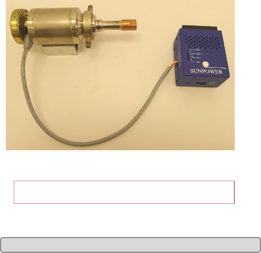
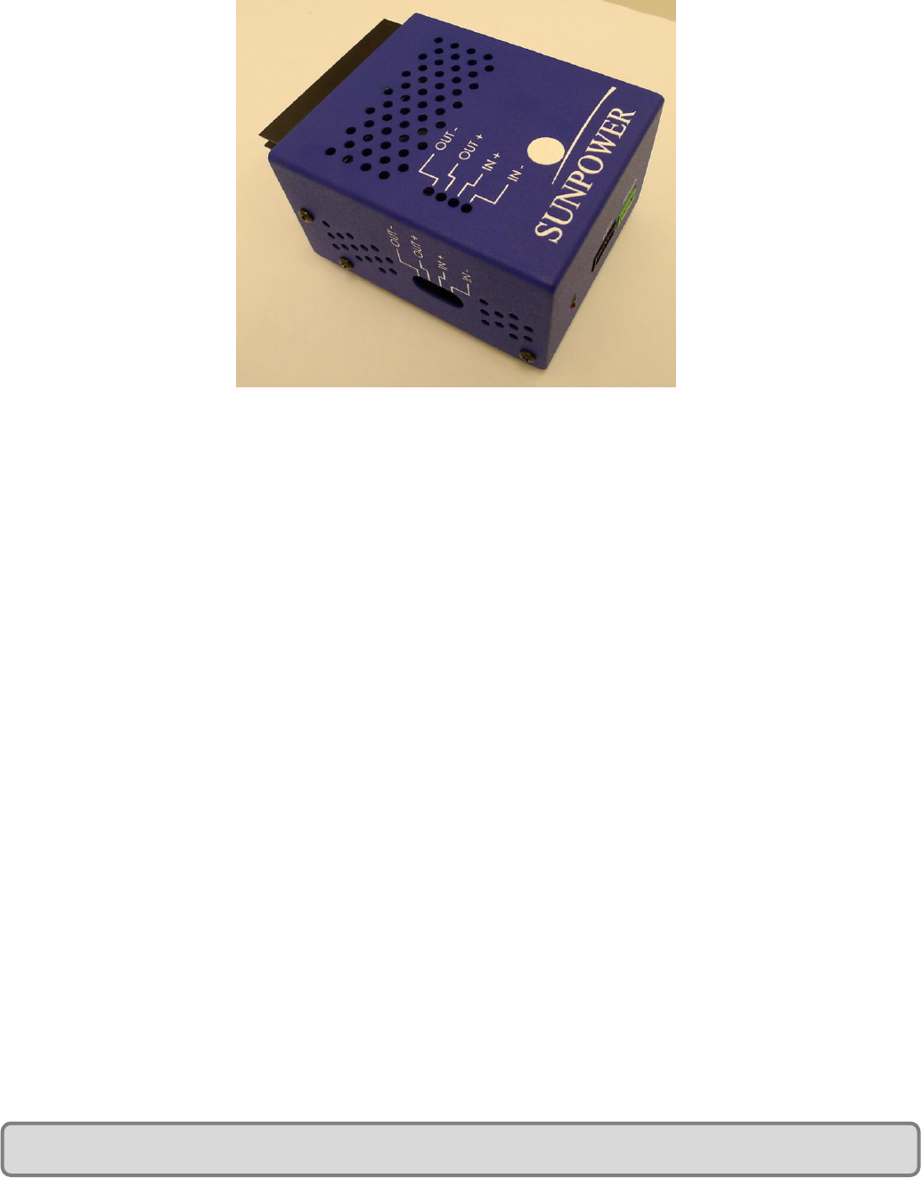
Figure 1: CryoTel® GT and Controller
CryoTel® GT dimensions: length with balancer: 260 mm (10.2 in); length without balancer: 217 mm (8.5 in); diameter:
83 mm (3.3 in);
mass: 3.1 kg

CryoTel® GT User’s Manual Version 6 P a g e | 5
II. Precautions (Dos and Don’ts)
Although the CryoTel® GT is mechanically robust, it can be damaged if not handled properly when in
operation or when removing from the packaging. The handling and operational Dos and Don’ts are
listed below. Refer to the diagram of the CryoTel® GT in Figure 2.
CRITICAL! – Do not operate the cryocooler without adequate cooling at the heat rejection site.
Overheating the cryocooler will cause permanent damage.
DON’T
Pick up the cryocooler by the cold finger
Set the cryocooler on the cold tip.
Allow the cold finger to be dented. The slightest dent will render the unit inoperable.
Drill holes, or in any other way puncture, or attempt to modify, the pressure vessel.
Operate the unit without proper cooling. Heat must be removed from the copper heat rejection
area of the cryocooler. If the cooler is provided with external cooling fins, air must be forced
over the fins and the flow path should not be obstructed.
Puncture or otherwise damage the copper service tube.
Subject the electrical feedthroughs to mechanical stress; i.e. axial or radial movements, axial
loads, blows, or the like.
Mount the cooler by suspending it from the balance absorber mounting bolt.
Apply clamping pressure to the pressure vessel.
Rigidly attach the absorber stud to “ground.” Instead, let the cooler “float” via a rubber bushing
or other means of articulation.
Remove the protective cover on the cold weld on the end of the copper service tube. Do not
subject the cover to blows.
Control power to the cryocooler by making or breaking the power leads between the controller
and the cryocooler.
Use an external, automatic, closed loop control system which attempts to control the cryocooler
operation by varying the set point settings in the cryocooler controller.
DO
Check with Sunpower before making any modifications to the cryocooler
Note that if the controller is installed in an enclosure, cooling must be provided.
If the cooler is operating in a laboratory test mode with heaters providing the thermal load to
the cold tip, interlocks should be provided so that the heater cannot operate unless the
cryocooler is running. This will prevent accidental overheating of the cold tip.
CryoTel® GT User’s Manual Version 6 P a g e | 6
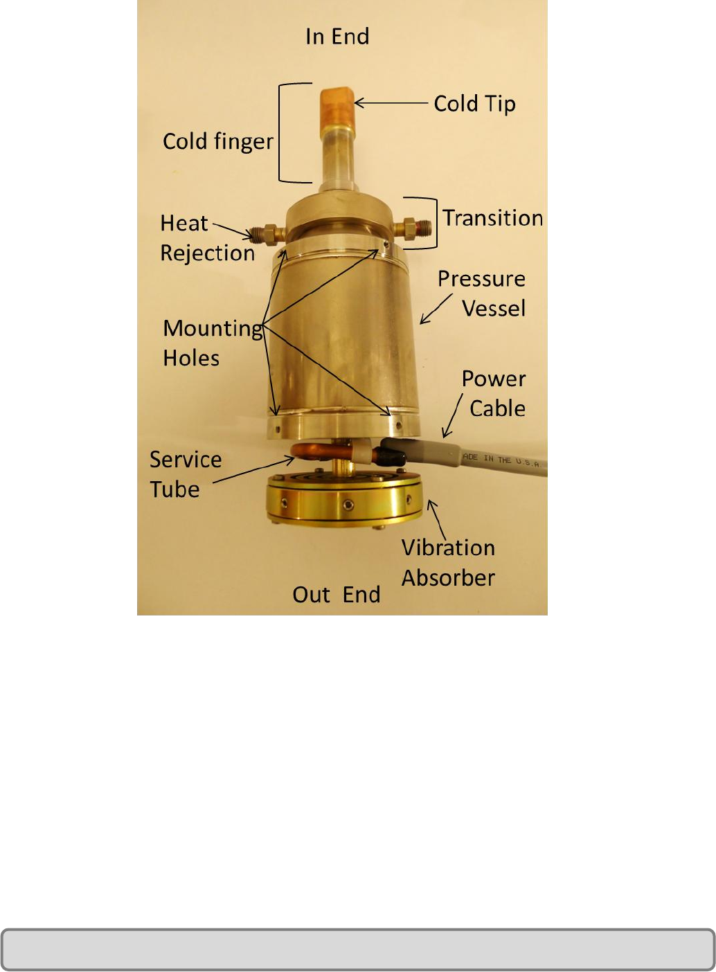
Figure 2: CryoTel® GT Cryocooler
III. Unpacking
When unpacking or handling, only hold the cryocooler by the pressure vessel or the transition (see
Figure 2). The CryoTel® GT may sit horizontally on a level bench top or table, but the cooler must be
supported to prohibit rolling. The cold finger must be protected from any contact as well.
CryoTel® GT User’s Manual Version 6 P a g e | 7
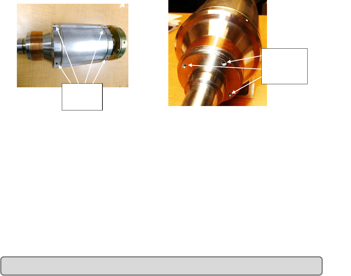
IV. Mechanical Mounting
The CryoTel® GT has a thick metal end plate on the “out” end of the pressure vessel nearest the passive
vibration absorber. M4 threaded holes on the outer diameter of the transition and end plate are
designed for attachment of the cooler to an external mechanical structure for testing or integration into
the application. These can be seen in Figure 3.
On the face of the external copper ring that rejects heat from the cooler is a stainless steel plate. The
plate has four M3 threaded holes that can be used for attaching a removable NW50 or customer
specified vacuum flange (see Figure 4). A vacuum flange can also be welded to this plate, but must be
done with a low energy weld such as plasma or micro TIG. It is recommended that, if needed, the
customer allow Sunpower to perform the welding operation. The mechanical structure including the
cryostat attachment plate, heat rejection copper, and transition have been designed to allow mounting
the entire assembly by the cryostat and cantilevering the cooler and vibration absorber from the
cryostat in a given application.
V. Attachment of Heat Load to Cold Finger
The copper cold tip at the end of the GT cold finger has a ¼”-20 threaded hole that can be used for
mounting equipment to the cold tip for applications or tests (see Figure 5). The application of force to
the cold tip must be handled with care and in accordance with these not-to-exceed limits:
Cantilevered force, cooler not in operation: do not exceed a cantilevered force on the
cold finger (static or shock) > 100 N (10.20kg).
Cantilevered force, cooler in operation: do not permit the heat load apparatus to deliver
force to the cold finger (static or shock) > 30 N (3.05 kg)
Vertical loading: do not exceed a pure tension or compression load > 300 N (30.50 kg)
Torque, cold finger: do not exceed a load >16 N*m (142 in*lbs)
Torque-copper cold tip ¼-20 Thread: do not exceed a load of 10 N*m (88 in*lbs)
Threaded
Mounting
Holes
3 of 4 M3
Threaded
holes
Figure 3: Pressure Vessel Mounting Holes
Figure 4: Weld Flange Holes
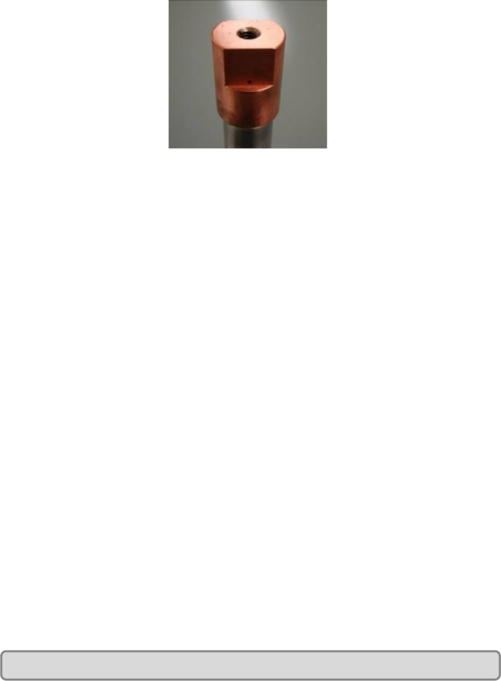
CryoTel® GT User’s Manual Version 6 P a g e | 8
Figure 5: Cold Tip ¼”-20 Threaded Hole
VI. Cold End Vacuum
The cold finger of the CryoTel® GT operates best in an insulated vacuum. The vacuum eliminates possible
loading of the cold finger from convection or condensation of elements in the atmosphere such as water
vapor and nitrogen. The vacuum is created by a customer provided vacuum Dewar or cryostat. As
previously noted a flange can connect the cryostat and the stainless steel vacuum flange with an O-ring
seal or welded attachment (Fig 4).
When using a mechanical vacuum pump it is appropriate to seal the flange with an O-ring and clamp.
The vacuum pump will remove any residual gasses released by the O-ring and continue to maintain a
vacuum inside the cryostat. However, an O-ring may corrode and become brittle over an extended
period of time.
For customer applications requiring long-term vacuum without using a vacuum pump, it is
recommended that the cryostat be welded to the CryoTel® vacuum interface.
CryoTel® GT User’s Manual Version 6 P a g e | 9
VII. Feedthroughs
The electrical pins on the metal plate at the end of the pressure vessel near the balance absorber are
surrounded by glass, which acts as an insulator and prevents helium from leaking out of the pressure
vessel. This arrangement is called a feedthrough. Because of the glass insulator, the feedthroughs should
be handled cautiously. They are a permanent feature of the pressure vessel back end plate and should
not be modified in any way.
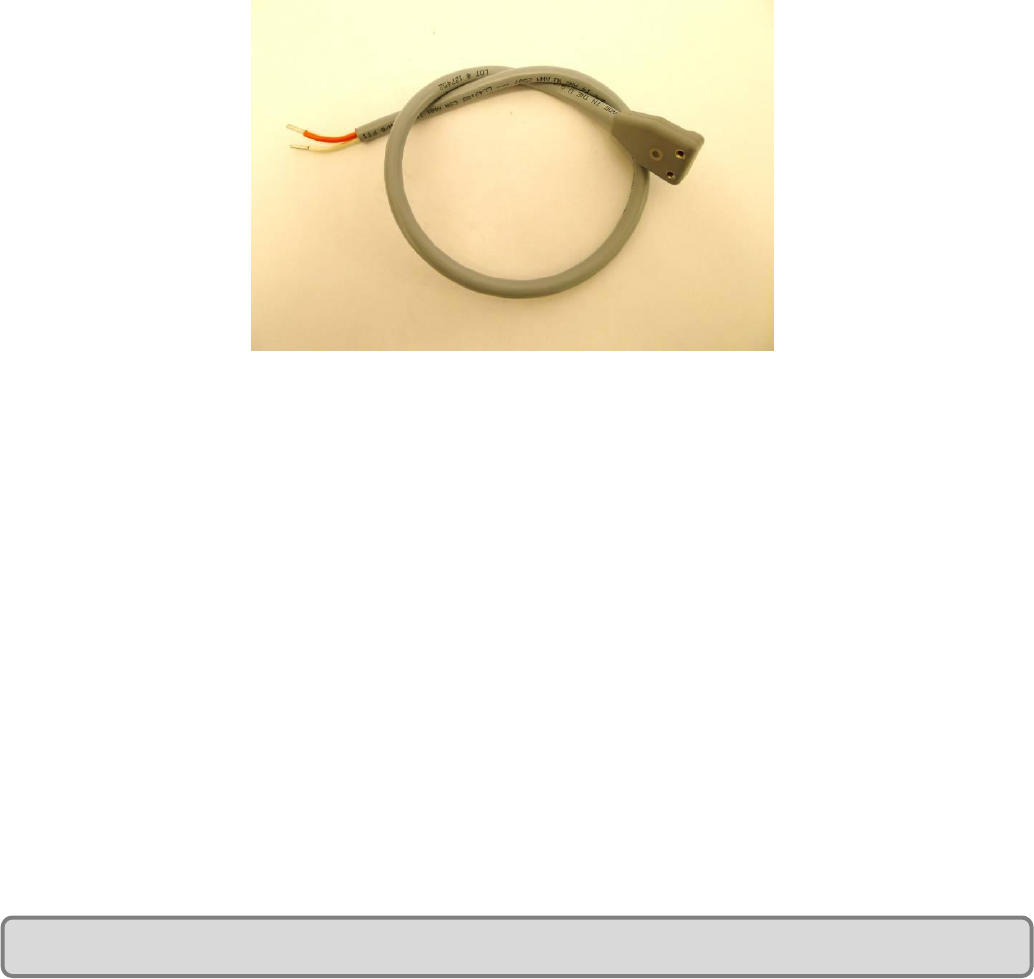
The CryoTel® GT is shipped with a power cable that attaches to the feedthroughs and the controller. This
cable consists of orange and white 16 gauge wires with a molded plastic connector for the feedthroughs
at one end and crimp sleeves to attach to the proper terminal block on the controller at the other end.
This harness is shown in Figure 6.
Figure 6: Power Cable
It is necessary to remove the balance absorber in order to install the power cable. The balance absorber
is attached with the center M5 screw. Remove this screw and the balance absorber will be free from
the cryocooler.
Install the power cable by aligning the cryocooler feedthrough pins with the holes in the cable connector
and pressing down. Insert the retaining screw into the connector and tighten.
Install the balance absorber by re-installing the M5 screw.
Important assembly notes:
The screw heads of the four balance absorber assembly screws need to be positioned so that none of
them are directly over either the power cord connector or the service tube elbow. This is to ensure that
the screw head does not impact either of these features during large amplitude displacements of the
balance absorber. See Figure 7 for details.
CryoTel® GT User’s Manual Version 6 P a g e | 10
Figure 7: Rear Pressure Vessel End Plate and Power Cable Wire Harness
VIII. Temperature Sensor
For proper operation of the CryoTel® controller it is necessary to mount a temperature sensor to the
object being cooled. The sensor allows the controller to measure and control the cooled object’s
temperature. The sensor feedback also controls the cooler’s power ramp-up. If the sensor is not
installed properly, the cooling capacity of the cryocooler will be severely limited and temperature
control will not function.
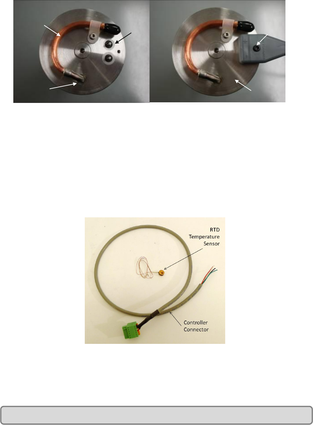
The controller is designed to us a Lakeshore PT-111 platinum RTD or equivalent. Sunpower packages the
PT-111 in a copper disk so that the sensors are identical in size, shape and wiring. Figure 8 shows the
sensor and the connector to the controller.
Figure 8: Temperature Sensor and cable
The temperature sensor is encased in a small copper slug. Use an M3 screw in the 3mm drilled hole to
attach the sensor to object being cooled. Use a thin layer of Indium, Apiezon grease, or similar thermal
grease between the sensor and the object to ensure proper thermal conduction.
Service
Tube
Pressure
Vessel
- Feedthrough
+ Feedthrough
Service Tube Elbow
Power
Cable
CryoTel® GT User’s Manual Version 6 P a g e | 11
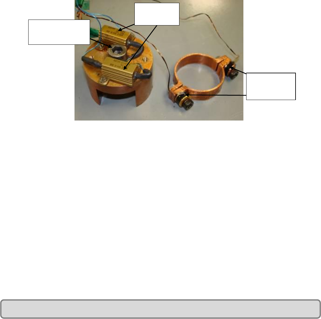
Laboratory testing can be accomplished with a test cap arrangement similar to the one shown in Fig 9.
The test cap is used to supply a specified heat load to the cold tip. The test cap consists of a copper cap
with two resistors, a through hole with ¼”-20 clearance for connection to the copper tip, and a copper
clamp ring with M3 clearance holes to clamp temperature sensors around the circumference of the cold
tip. Calculate the heat load (power in Watts = current x voltage) by providing a known voltage and
current across the resistors on the test cap. Mount the temperature sensor using one of the M3
mounting holes on the clamp ring. If using a second sensor, mount it to the clamp ring for independent
temperature measurement. If not, simply clamp the other half of the ring snuggly with an M3 screw.
Apply appropriate thermal grease to the bottom faces of the test cap and inside surface of the clamp
ring in order to maximize conduction between them and the cold tip. Mount the test cap to the cold tip
using the ¼”-20 threaded hole on the cold tip being sure not to apply more than 10 N*m of torque.
Figure 9: Test Cap Assembly
When the cold tip is contained in a vacuum vessel, use feedthroughs to connect the sensor wires to the
temperature sensor connector. Use at least four conductors connecting the feed through to the control
temperature sensor. Use additional feedthroughs if employing a test cap or other sensors inside the
cryostat. All wires inside the cryostat should be as small as possible in order to minimize parasitic
loading on the cooler. The wires of the temperature sensor are color coded to help insure proper
connection. Figure 10 describes proper connections of the temperature sensor to the CryoTel®
Controller.
Resistors
(heat load)
Temperature
sensors
¼”-20
Mounting screw
Copper Cap
Clamp Ring

CryoTel® GT User’s Manual Version 6 P a g e | 12
Mating connector for temperature interface is Digikey part number 277-1434-ND.
There is not a dedicated pin on the controller for connecting the shield of shielded temperature sensor
wiring. If noise becomes an issue, grounding the shield to the controller may help. The shield can be
connected to the I- wire at the controller and connected to Pin 4.
IX. Heat Rejection
Proper heat rejection is crucial to the operation of a cryocooler. Some CryoTel® heat rejection options
are a water jacket, copper fins, or a conducting solid.
CRITICAL! – Do not operate the cryocooler without adequate cooling at the heat rejection
site. Overheating the cryocooler will cause permanent damage.
A. Water Jacket
Sunpower can provide a permanent or removable water cooling jacket with the CryoTel® GT (Fig. 11 –
both are identical in appearance). Use a suitable thermal grease to maximize conduction between the
heat rejecter and the water jacket if using a removable unit (the permanent unit is installed at the
factory and does not require thermal grease). The thermal grease should be refreshed periodically as it
will dry out over time. After connecting the water supply to the water jacket for heat rejection, ensure
that air is removed from the water jacket. This can be done by flowing water through the cooling system
for several minutes prior to the run. If it appears that air is still trapped in the water jacket, try carefully
tilting the cooler in the direction away from the cooler discharge tube. This will raise the level of the
discharge tube and allow any trapped air to escape. Trapped air will decrease heat rejection and cooler
performance. Water should be flowing through the jacket at approximately 15mL per second (0.24
gallons per minute).
Temperature sensor connector
PIN Function Wire Color
1V+ Black
2 V- Green
3I+ Clear
4 I- / shield Red
Figure 10: Controller Temperature Sensor Connector
CryoTel® GT User’s Manual Version 6 P a g e | 13
Figure 11: Water Jacket Heat Rejection
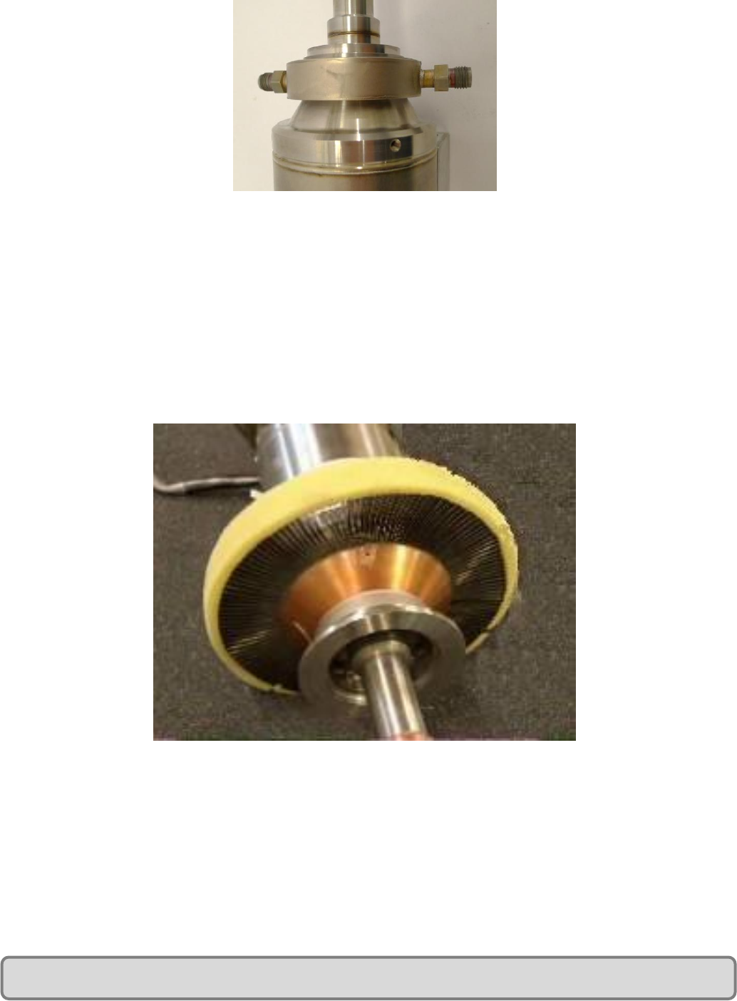
B. Copper Fins
Copper fins are also available in a permanent or removable form. If copper fins are used for heat
rejection (Fig. 12-permanent fins are pictured), use a fan with a rating of 100 cubic feet per minute (1.6e-
3 m3/min) for air through-flow. Sunpower recommends mounting the fan to a cylindrical shroud that can
be placed around the fins in order to direct the air through the fins. Note that some heat rejection also
occurs from the walls of the pressure vessel. Therefore avoid permitting any containment structure for
the cryocooler to hinder the heat rejection from any part of the cooler. It is also recommended to
electrically interlock the cooling fan and the controller in order to ensure that the cooler cannot operate
without also turning on the fan.
Figure 12: Cooling Fin Heat Rejection
C. Conducting Solid
Use of any other means of heat rejection necessitates ensuring that the proper amount of heat is being
transferred away from the rejecter and that the reject temperature is suitable. It is recommended to
involve Sunpower with the design of a conduction heat exchanger.

CryoTel® GT User’s Manual Version 6 P a g e | 14
X. CryoTel® Operation
CRITICAL! – Do not operate the cryocooler without adequate cooling at the heat rejection
site. Overheating the cryocooler will cause permanent damage.
A. Preparation
1. Attach application apparatus or test cap assembly to cold tip of cold finger.
a. Apply a thin layer of Apiezon thermal grease or Indium to the copper tip of the cold finger in
order to maximize conductivity.
2. Attach the customer-provided cryostat by appropriate means if a vacuum is required for the
application.
3. If using a vacuum, make wire connections from temperature sensor and any other measuring
devices inside the cryostat through Dewar feedthroughs.
a. For maximum performance, wires should not touch the walls of the Dewar. Contact with
walls will increase the heat loading (conduction) during use and will yield lower available
cooling power.
4. Seal the cryostat vacuum except for the connection to the vacuum pump (if using vacuum).
5. Mechanically attach the cryocooler assembly to the customer provided mounting device.
6. Connect the wiring from the cryostat feedthroughs to the appropriate test and measurement
devices.
a. The cold tip temperature sensor must be connected to the controller’s mating connector as
described previously using the provided connector (See Figure 10 for controller
connections).
7. Attach the vacuum pump to cryostat, start the vacuum and allow it to reach a vacuum of 10-4Torr or
better.
B. Beginning Operation
1. Prepare the CryoTel® GT for testing as described above.
2. Connect the cryocooler power cables for the CryoTel® GT to the controller’s power terminal block.
The orange wire should be connected to pin 2 (OUT +). The white wire should be connected to pin 1
(OUT -). (Controller connections shown in Fig. 13).
a. IMPORTANT! Verify the correct polarity is observed with respect to the CryoTel® GT –
orange power cable wires are positive, white wires are negative. Inversed polarity could
result in damage to the Cryocooler.
3. Connect the controller to a 48VDC power outlet. Connect +48V to the power terminal block pin3
(IN+). Connect the power return (ground) to pin 4 (IN-).
a. IMPORTANT! Verify the correct polarity is observed. Inversed polarity will result in
damage to the controller.
b. Note: Crimp ferrules should be used on wire ends connecting to the terminal block. The 14
Gauge ferrules are available at Digikey PN 288-1101-ND. The proper tool for crimping the
ferrules is Digikey PN 288-1163-ND.
c. The controller has a startup sequence that positions the piston in the axial center. This
sequence takes approximately 7-10 seconds once the controller is turned on.
d. The controller then applies a 60 Hz AC voltage to the motor, creating the oscillating motion
of the piston that begins the cooling process.
e. The controller increases the power to the cryocooler based on cold end temperature. The
maximum draw by the controller is approximately 300 WE.
4. Allow cold tip temperature to stabilize at desired cold end temperature.
CryoTel® GT User’s Manual Version 6 P a g e | 15
a. Proper operation of the CryoTel ®GT requires a minimum loading of 6 Watts. If minimum
load requirements are not met, the stabilized temperature will be below 77 K.
Figure 13: CryoTel® GT Controller
C. Operation Shutdown
1. Turn off the controller.
a. The quick rattle heard when power is cut off from the CryoTel ®is due to the stored energy
in the vibration absorber being dissipated.
b. In rare cases where the operating temperature was below 60 K, it has been observed that
the cooler can energize itself during shutdown and become an engine. To prevent this, allow
the cold tip to reach a temperature above 60 K before shutting down.
2. Allow the cold tip and the rest of the cryocooler temperature to rise to room temperature before
opening the vacuum in order to prevent the vapor outside the cryostat from condensing and
freezing on the cold tip.
a. Applying a heat load to the cold tip during the warming process reduces the time needed to
reach room temperature.
b. Sunpower recommends using a relay in conjunction with the temperature sensor to ensure
that the power supply to the heat load shuts off when the cold tip temperature reaches 300
K.
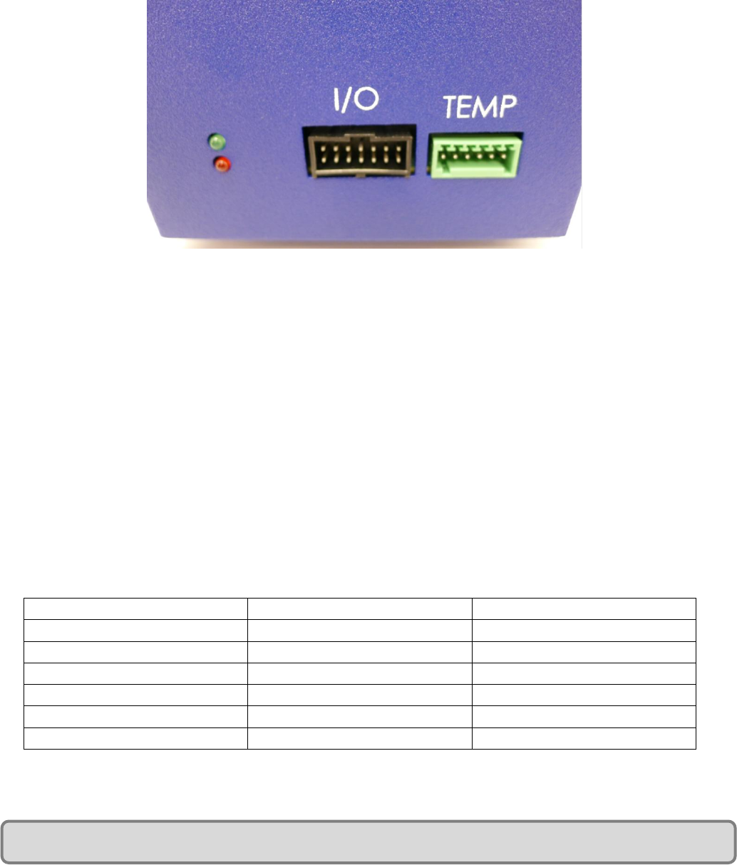
XI. LED and Digital Output 4
The two LEDs, shown in figure 14, indicate whether the cooler has reached its set point temperature or
if the cooler is still in cool down mode. The red LED will be on as long as the cooler is not at the
temperature setpoint. When the cooler reaches its set point temperature within the desired
temperature band the green LED will turn on. The default temperature band is 0.5K. See Section XIII,
page 27 for details on changing the temperature band.
CryoTel® GT User’s Manual Version 6 P a g e | 16
Digital Output 4 (I/O Connector pin 4) will go high (5V) when the cooler is at the set point temperature.
When the cooler is not at the temperature set point Digital Output 4 will be low (0V). See Figure 15 for
I/O connector pin out.
If both LEDs are flashing together repetitively, the controller is reporting an error. See Section XII for
details.
Figure 14: Controller LEDs
XII. Error Summary
If both LEDs are flashing together repetitively, the controller is reporting an error. There are two ways
to check the error codes. The ERROR<CR> command can be issued, or the number of LED flashes can be
counted.
When the ERROR<CR> command is issued, any errors that are present are indicated with a “1”. See
figure 15 for the error codes. Multiple error codes can be displayed simultaneously. For example a
return of “100001” would indicate an over current and temperature sensor error. See section XIII for
the serial communications reference.
To check and error code using the LEDs, count the number of flashes. Both the red and green LED will
flash simultaneously. There will be a series of short flashes followed by one long flash. The long flash
indicates the end of the sequence. The flash count includes both the short flashes and the long flash. If
there are multiple errors only one of them will be displayed by the LEDs, but after the long flash the red
and green LEDs will flash back-to back very rapidly.
Number of LED flashes
ERROR<CR> return value
Description
1
000001
Over Current
2
000010
Jumper Error
3
000100
Serial Error
4
001000
Non-volatile Memory Error
5
010000
Watchdog Error
6
100000
Temperature Sensor Error
Figure 15: Error Codes

CryoTel® GT User’s Manual Version 6 P a g e | 17
Error Details:
1. Over Current
a. If the controller detects an overcurrent it will immediately shut off the output to the
cryocooler.
b. Check the wiring between the controller and the cryocooler for any problems. If this does
not resolve the error contact Sunpower.
2. Jumper Error
a. Power cycle the controller. If this does not resolve the error contact Sunpower.
3. Serial Error
a. Communication with the controller may not be possible after a serial error.
b. Power cycle the controller. If this does not resolve the error contact Sunpower.
4. Non-volatile Memory Error
a. Power cycle the controller. If this does not resolve the error contact Sunpower.
5. Watchdog Error
a. Power cycle the controller. If the error occurs again contact Sunpower.
6. Temperature Sensor Error
a. Check the wiring between the controller and the temperature sensor including the fine wire
attached to the temperature sensor itself. Check if the controller is reporting an
appropriate temperature. If this does not resolve the error contact Sunpower.
b. If the temperate sensor wiring has intermittent problems, the error code will remain in the
controller even if the wiring starts functioning properly again. The controller must be power
cycled to clear the error code.
CryoTel® GT User’s Manual Version 6 P a g e | 18
XIII. CryoTel® Serial Communications Command Reference
Control the CryoTel® GT with any terminal emulator program. A common choice is Hyperterminal, as it
is included with Windows, (Windows 7 users may need to download Hyperterminal). The connecting
cable for basic functionality is included.
Caution: Use of an external program, such as LabVIEW™, to establish closed loop control of the
cryocooler via serial communication, may cause controller malfunction. Manual set point adjustments
may be made as required without problem.
A. Serial Interface Specifications
RS-232
Baud Rate: 4800
Flow control: none
Data bits: 8
Stop bits: 1
B. Controller Connector Wiring Information
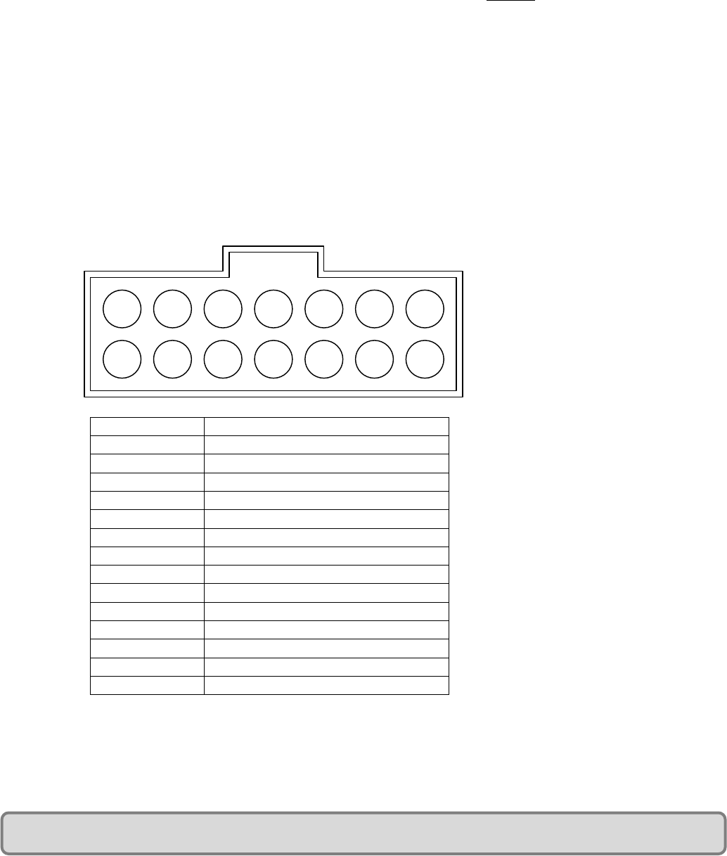
Pin Numbering for I/O connector and RS-232 connections on CryoTel® Controller
2
1
4
3
6
5
8
7
10
9
12
11
14
13
Pin Number
Function
1
Digital Out 1
2
Digital Out 2
3
Digital Out 3
4
Digital Out 4 (AT Temperature)
5
Digital Input 1 (Soft Stop)
6
Digital Input 2
7
Digital Input 3 (Thermostat)
8
Digital Input 4
9
Isolated I/O GND
10
Onboard Isolated 5V
11
Isolated I/O GND
12
Onboard Isolated 5V
13
RS-232 RX (Input)
14
RS-232 TX (Output)
Figure 16: I/O connector

CryoTel® GT User’s Manual Version 6 P a g e | 19
Some advanced function requires adding wires to the basic cable or creating a new cable. Part numbers
for the required additional parts are located below:
I/O connector Crimp Terminals
Manufacturer: Molex
Manufacturer PN: 90119-2109
Digi-key PN: WM2558-ND
Note: The above terminal is for 22-24AWG and is tin/lead over nickel. Different terminals are
available from the manufacturer.
I/O connector housing
Manufacturer: Molex
Manufacturer PN: 90142-0014
Digi-key PN: WM8039-ND
I/O terminal Crimper Tool for 22-28AWG
Manufacturer: Molex
Manufacturer PN: 63819-0200
Digi-key PN: WM9028-ND
CryoTel® GT User’s Manual Version 6 P a g e | 20
Basic Communication Functionality
CryoTel GT Terminal Emulator Commands
The following pages show an explanation of each of the terminal emulator commands and display examples.
All of the parameters set will be retained in memory when the controller is power cycled unless otherwise
noted.
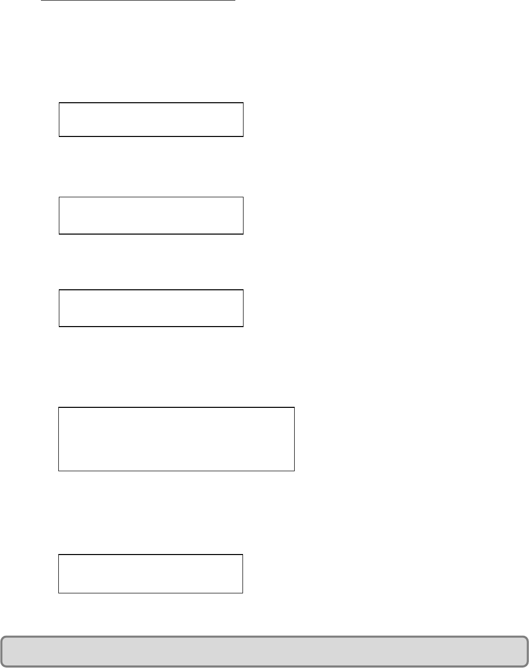
1) Display temperature sensor value in Kelvin
a) Command: TC<CR> (<CR> means “press Enter key”)
b) Returns the current temperature of the RTD in Kelvin.
2) Display target temperature in Kelvin
a) Command: SET TTARGET<CR>
b) Returns the target temperature of the controller in Kelvin when in temperature control mode (Default
mode).
3) Set target temperature when in temperature control mode.
(a) Command: SET TTARGET=<VAL><CR>
(b) Set the temperature the cryocooler will try to attain when in temperature control mode.
(c) VAL corresponds to the target temperature in Kelvin.
4) Display current command power and power limits
a) Command: E<CR>
b) The top value is the maximum allowable power for the current temperature. The middle value is the
minimum allowable power. The bottom is the current command power. All values displayed with this
command are in watts.
Advanced Communication Functionality
5) Show current control mode
a) Command: SET PID<CR>
b) This command will return the current control mode
TC
330.00
SET TTARGET
077.00
SET TTARGET=86.00
086.00
E
230.00
070.00
170.00
SET PID
002.00
CryoTel® GT User’s Manual Version 6 P a g e | 21
6) Set control Mode
a) Command: SET PID=<VAL><CR>
b) VAL may be a 2 or a 0. If it is 0, the controller will maintain a constant power as commanded by SET
PWOUT. If it is 2, the controller will try to maintain a constant temperature as commanded by SET
TTARGET.
c) The PID mode will be reset to the default value on a power cycle. The default value can be changed using
the SAVE PID command.
7) Change default control mode
a) Command: SAVE PID <CR>
b) Saves the current SET PID value as the default value. The saved value will be restored after a power cycle.
c) The value returned is the PID value that was saved.
8) Display user commanded power
a) Command: SET PWOUT<CR>
b) Display commanded power when in power control mode as set by SET PID.
9) Set user commanded power
a) Command: SET PWOUT=<VAL><CR>
b) Set command power when in power control mode as set by SET PID.
c) VAL corresponds to the target power in watts. While any number from 0.0 to 999.99 can be input, the
controller will only command a power that will not damage the cryocooler.
d) The minimum power is 70W @ 77 K.
e) The maximum power is a function of cold head temperature and increases as the cold temperature
decreases.
10) Display Soft Stop mode
a) Command: SET SSTOPM<CR>
b) Returns the current Soft Stop mode of the controller.
11) Set Soft Stop mode
a) Command: SET SSTOPM =<VAL><CR>
b) Sets the current Soft Stop mode of the controller. This command sets if Digital Input 1 or the SET SSTOP
command control the Soft Stop functionality used to shut down the cryocooler.
c) VAL corresponds to the Soft Stop mode of the controller. A 0 allows the SET SSTOP command to control
the Soft Stop functionality; a 1 allows Digital Input 1 (I/O connector pin 5) to control the Soft Stop
functionality.
SET PID=2
002.00
SET PWOUT
170.00
SET PWOUT=160
160.00
SAVE PID
002.00
SET SSTOPM
001.00
CryoTel® GT User’s Manual Version 6 P a g e | 22
d) When in Soft Stop Mode 1, setting Digital Input 1 high will shut down the cryocooler. Setting it low or
leaving it disconnected will allow the cryocooler to run. The Onboard Isolated 5V (I/O connector pin 10 or
pin 12) can be used to set Digital Input 1 high.
e) The soft stop function will slowly ramp down the cooler before shut down to minimize shutdown vibration.
12) Display soft stop status
a) Command: SET SSTOP<CR>
b) Returns the current soft stop status of the controller as set in Soft Stop mode 0 or 1.
13) Set soft stop status
a) Command: SET SSTOP=<VAL><CR>
b) Sets the current soft stop status of the controller when in Soft Stop Mode 0
c) VAL corresponds to the soft stop status. To initiate a soft stop enter 1, this will shut down the cooler but
allow the controller to remain on. Entering a 0 will restart the cooler from its stopped state.
d) If in Soft Stop Mode 1, this command will not control the Soft Stop functionality.
e) The soft stop function will slowly ramp down the cooler before shut down to minimize vibration.
14) Display user defined maximum power
a) Command: SET MAX<CR>
b) Returns the maximum power as set by the user.
15) Set user defined maximum power
a) Command: SET MAX=<VAL><CR>
b) Sets the user defined maximum power.
c) VAL corresponds to user defined maximum power output in Watts. Entering a value that exceeds the safe
operating power of the cooler will not result in damage to the cooler.
d) The maximum safe power is a function of cold head temperature and increases as the cold temperature
decreases. The maximum cooler power will be the lowest of the safe operating power or the SET MAX
value.
16) Display user defined minimum power
a) Command: SET MIN<CR>
b) Returns the minimum power as set by the user.
SET SSTOP
001.00
SET SSTOP=1
001.00
SET MAX
190.00
SET MAX=210
210.00
SET MIN
100.00
SET SSTOPM =1
001.00
CryoTel® GT User’s Manual Version 6 P a g e | 23
17) Set user defined minimum power
a) Command: SET MIN=<VAL><CR>
b) Sets the user defined minimum power.
c) VAL corresponds to user defined minimum power output in Watts. Entering a value that is below the safe
operating power of the cooler will not result in damage to the cooler.
18) Display user defined minimum and maximum powers
a) Command: SHOW MX<CR>
b) Returns the minimum and maximum powers respectively as set by the user.
19) Display cooler power as measured by the controller.
a) Command: P<CR>
b) Returns the cooler power in Watts as measured by the controller.
20) Display thermostat mode
a) Command: SET TSTATM<CR>
b) Returns the current thermostat mode of the controller.
21) Set thermostat mode
a) Command: SET TSTATM =<VAL><CR>
b) Sets the current thermostat mode of the controller. This functionality enables a user to add a thermostat to
the system which can be used to shut down the cryocooler.
c) VAL corresponds to the thermostat mode of the cryocooler. A 0 disables the thermostat functionality, a 1
enables this functionality.
d) When utilizing this functionality, opening the thermostat circuit will shut down the cooler. One side of the
thermostat should be attached to Digital Input 3 (I/O connector pin 7). The other side of the thermostat
should be attached to the Onboard Isolated 5V (I/O connector pin 10 or pin 12). Setting Digital Input 3
high will allow the cooler to run when in thermostat mode 1. If the Onboard Isolated 5V is not connected
to Digital Input 3 (the thermostat opens), the cooler will be shut down.
22) Display thermostat status
a) Command: TSTAT<CR>
b) Returns the current thermostat status of the controller.
SET MIN=120
120.00
SHOW MX
080.00
200.00
P
170.13
SET TSTATM
001.00
SET TSTATM =1
001.00
CryoTel® GT User’s Manual Version 6 P a g e | 24
c) If in thermostat mode 1, a return of 1 indicates the thermostat is closed and is allowing the Cryocooler to
run. A return of 0 indicates the thermostat is open and the Cryocooler is shut or is shutting down.
23) Display proportional constant of the temperature control loop.
a) Command: SET KP<CR>
b) Returns the proportional constant of the temperature control loop.
24) Set proportional constant of the temperature control loop.
a) Command: SET KP=<VAL><CR>
b) Sets the proportional constant of the temperature control loop.
c) VAL corresponds to the user defined proportional constant of the temperature control loop.
d) There may be some applications where the user may want to modify the PI constants to tune the
temperature control loop based on their individual system. This would require experience in tuning PID
control loops.
e) The default proportional constant for the GT is 050.00000. KP and KI will be reset to their defaults if the
RESET command is used.
25) Display integral constant of the temperature control loop.
a) Command: SET KI<CR>
b) Returns the integral constant of the temperature control loop.
26) Set integral constant of the temperature control loop.
a) Command: SET KI=<VAL><CR>
b) Sets the integral constant of the temperature control loop.
c) VAL corresponds to the user defined integral constant of the temperature control loop.
d) There may be some applications where the user may want to modify the PI constants to tune the
temperature control loop based on their individual system. This would require experience in tuning PID
control loops.
e) The default integral constant for the GT is 001.00000. KP and KI will be reset to their defaults if the
RESET command is used.
27) Display temperature band .
a) Command: SET TBAND<CR>
b) Returns the temperature band that the LEDS and the “At Temperature” pin on the I/O connector will
function per section XI.
TSTAT
001.00
SET KI
001.00000
SET KI=1
001.00000
SET KP
050.00000
SET KP=1
050.00000
SET TBAND
000.50

CryoTel® GT User’s Manual Version 6 P a g e | 25
28) Set temperature band..
a) Command: SET TBAND=<VAL><CR>
b) Sets the temperature band that the LEDS and the “At Temperature” pin on the I/O connector (Digital Out 4,
I/O connector pin 4) will function per section XI.
c) VAL corresponds to the user defined temperature band. The default band is 0.5K.
29) Set user password.
a) Command: SET PASS=<VAL><CR>
b) Sets the user defined password to unlock the controller parameters.
c) VAL corresponds to the user defined password. The default password is STIRLING. The password must
be between 1 and 10 characters in length. This command will return a 1 if the password was successfully
changed.
d) The controller must be unlocked to change the password. If the controller is locked and the password has
been misplaced, it must be sent back to Sunpower to be unlocked.
30) Display lock state
a) Command: LOCK<CR>
b) Returns the Lock state of the Cryocooler. A 0 indicates that controller parameters can be changed. A 1
indicates that all controller parameters are locked.
31) Set lock state
a) Command: LOCK=<Password><CR>
b) Locks all of the controller parameters from being changed. A return of 1 confirms that all controller
parameters are locked.
c) <Password> refers to the current user defined password. The Default password is STIRLING.
32) Set lock state
a) Command: UNLOCK=<Password><CR>
b) Unlocks the controller parameters. A return of 0 confirms that controller parameters can be changed.
c) <Password> refers to the current user defined password. The Default password is STIRLING.
SET TBAND=1.5
001.50
SET PASS=ABC123
001.00
LOCK
000.00
LOCK=STIRLING
001.00
UNLOCK=STIRLING
000.00
CryoTel® GT User’s Manual Version 6 P a g e | 26
33) Display list of most controller parameters.
a) Command: STATE<CR>
b) Returns a list of most of the controller parameters and what they are set to.
34) Display controller serial number
a) Command: SERIAL<CR>
b) Returns the controller serial number.
35) Display any error codes that are present.
a) Command: ERROR<CR>
b) Returns error codes if there are any present. See Section XII more information.
36) Reset controller parameters to the factory defaults.
a) Command: RESET=F<CR>
b) Resets the controller parameters to the factory defaults.
End of CryoTel® GT Operating Instructions Version 6
STATE
MODE = 002.00
TSTATM = 000.00
TSTAT = 000.00
SSTOPM = 000.00
SSTOP = 000.00
PID = 002.00
LOCK = 000.00
MAX = 300.00
MIN = 000.00
PWOUT = 000.00
TTARGET = 077.00
TBAND = 000.50
TEMP KP = 050.00000
TEMP KI = 001.00000
SERIAL
REV4.1 V1.0.0-123456789
ERROR
100000
RESET=F
RESETTING TO FACTORY DEFUALT…
FACTORY RESET COMPLETE!
