Installation And Upgrade Guide For Cisco Secure Access Control System 5.5 1121 CSACS1121UPK9 Csacs Book
User Manual: Cisco 1121 Secure Access Control System CSACS1121UPK9
Open the PDF directly: View PDF ![]() .
.
Page Count: 202 [warning: Documents this large are best viewed by clicking the View PDF Link!]
- Installation and Upgrade Guide for Cisco Secure Access Control System 5.5
- Part 1
- ACS Server Deployment
- Part 2
- ACS 5.5 on Cisco 1121 Secure Access Control System
- Introducing the Cisco 1121 Secure Access Control System Hardware
- Preparing to Install the Cisco 1121 Secure Access Control System Hardware
- Installing the Cisco 1121 Secure Access Control System Hardware
- Installing and Configuring the Cisco Secure Access Control System with CSACS-1121
- Part 3
- ACS 5.5 on Cisco SNS 3400 Servers
- Introducing the Cisco SNS-3415 and Cisco SNS-3495 Hardware Appliances
- Preparing to Install the Cisco SNS 3415 and Cisco SNS 3495 Hardware Appliances
- Installing the Cisco SNS 3415 and Cisco SNS 3495 Hardware Appliances
- Installing and Configuring the Secure Access Control System with the Cisco SNS-3415 and Cisco SNS-3495
- Part 4
- ACS 5.5 on VMware Virtual Machines
- Part 5
- Upgrading ACS to Release 5.5
- Upgrading the Cisco Secure Access Control System
- Upgrade Paths
- Upgrading an ACS Deployment from 5.4 to 5.5
- Upgrading the ACS Monitoring and Report Viewer
- Upgrading an ACS Deployment from 5.3 to 5.5
- Upgrading an ACS Server from 5.4 to 5.5
- Upgrading an ACS Server from 5.3 to 5.5
- Applying an ACS Patch
- Upgrading ACS 5.3 or 5.4 on the CSACS-1120 or CSACS-1121 to the Cisco SNS-3415 or Cisco SNS-3495
- Upgrading the Cisco Secure Access Control System
- Part 6
- Post-Installation Tasks
- Part 7
- Reference
- Troubleshooting
- Site Log
- Maintaining the CSACS-1121, Cisco SNS-3415, and Cisco SNS-3495 Appliances
- Index


THE SPECIFICATIONS AND INFORMATION REGARDING THE PRODUCTS IN THIS MANUAL ARE SUBJECT TO CHANGE WITHOUT NOTICE. ALL
STATEMENTS, INFORMATION, AND RECOMMENDATIONS IN THIS MANUAL ARE BELIEVED TO BE ACCURATE BUT ARE PRESENTED WITHOUT
WARRANTY OF ANY KIND, EXPRESS OR IMPLIED. USERS MUST TAKE FULL RESPONSIBILITY FOR THEIR APPLICATION OF ANY PRODUCTS.
THE SOFTWARE LICENSE AND LIMITED WARRANTY FOR THE ACCOMPANYING PRODUCT ARE SET FORTH IN THE INFORMATION PACKET THAT
SHIPPED WITH THE PRODUCT AND ARE INCORPORATED HEREIN BY THIS REFERENCE. IF YOU ARE UNABLE TO LOCATE THE SOFTWARE LICENSE
OR LIMITED WARRANTY, CONTACT YOUR CISCO REPRESENTATIVE FOR A COPY.
The following information is for FCC compliance of Class A devices: This equipment has been tested and found to comply with the limits for a Class A digital device, pursuant
to part 15 of the FCC rules. These limits are designed to provide reasonable protection against harmful interference when the equipment is operated in a commercial
environment. This equipment generates, uses, and can radiate radio-frequency energy and, if not installed and used in accordance with the instruction manual, may cause
harmful interference to radio communications. Operation of this equipment in a residential area is likely to cause harmful interference, in which case users will be required
to correct the interference at their own expense.
The following information is for FCC compliance of Class B devices: The equipment described in this manual generates and may radiate radio-frequency energy. If it is not
installed in accordance with Cisco’s installation instructions, it may cause interference with radio and television reception. This equipment has been tested and found to
comply with the limits for a Class B digital device in accordance with the specifications in part 15 of the FCC rules. These specifications are designed to provide reasonable
protection against such interference in a residential installation. However, there is no guarantee that interference will not occur in a particular installation.
Modifying the equipment without Cisco’s written authorization may result in the equipment no longer complying with FCC requirements for Class A or Class B digital
devices. In that event, your right to use the equipment may be limited by FCC regulations, and you may be required to correct any interference to radio or television
communications at your own expense.
You can determine whether your equipment is causing interference by turning it off. If the interference stops, it was probably caused by the Cisco equipment or one of its
peripheral devices. If the equipment causes interference to radio or television reception, try to correct the interference by using one or more of the following measures:
• Turn the television or radio antenna until the interference stops.
• Move the equipment to one side or the other of the television or radio.
• Move the equipment farther away from the television or radio.
• Plug the equipment into an outlet that is on a different circuit from the television or radio. (That is, make certain the equipment and the television or radio are on circuits
controlled by different circuit breakers or fuses.)
Modifications to this product not authorized by Cisco Systems, Inc. could void the FCC approval and negate your authority to operate the product.
The Cisco implementation of TCP header compression is an adaptation of a program developed by the University of California, Berkeley (UCB) as part of UCB’s public
domain version of the UNIX operating system. All rights reserved. Copyright © 1981, Regents of the University of California.
NOTWITHSTANDING ANY OTHER WARRANTY HEREIN, ALL DOCUMENT FILES AND SOFTWARE OF THESE SUPPLIERS ARE PROVIDED “AS IS” WITH
ALL FAULTS. CISCO AND THE ABOVE-NAMED SUPPLIERS DISCLAIM ALL WARRANTIES, EXPRESSED OR IMPLIED, INCLUDING, WITHOUT
LIMITATION, THOSE OF MERCHANTABILITY, FITNESS FOR A PARTICULAR PURPOSE AND NONINFRINGEMENT OR ARISING FROM A COURSE OF
DEALING, USAGE, OR TRADE PRACTICE.
IN NO EVENT SHALL CISCO OR ITS SUPPLIERS BE LIABLE FOR ANY INDIRECT, SPECIAL, CONSEQUENTIAL, OR INCIDENTAL DAMAGES, INCLUDING,
WITHOUT LIMITATION, LOST PROFITS OR LOSS OR DAMAGE TO DATA ARISING OUT OF THE USE OR INABILITY TO USE THIS MANUAL, EVEN IF CISCO
OR ITS SUPPLIERS HAVE BEEN ADVISED OF THE POSSIBILITY OF SUCH DAMAGES.
Cisco and the Cisco logo are trademarks or registered trademarks of Cisco and/or its affiliates in the U.S. and other countries. To view a list of Cisco trademarks, go to this
URL: www.cisco.com/go/trademarks. Third-party trademarks mentioned are the property of their respective owners. The use of the word partner does not imply a partnership
relationship between Cisco and any other company. (1110R)
Installation and Upgrade Guide for Cisco Secure Access Control System 5.5
Copyright ©2005-2013 Cisco Systems, Inc. All rights reserved.

iii
Installation and Upgrade Guide for Cisco Secure Access Control System 5.5
OL-28603-01
CONTENTS
Preface xi
Audience xi
Document Organization xii
Installation, Upgrade, and Migration Scenarios xiv
Document Conventions xvi
Safety Warnings xvi
Product Documentation xxii
Documentation Updates xxiii
Obtaining Documentation and Submitting a Service Request xxiii
xxiii
PART
1ACS Server Deployment
CHAPTER
1Understanding the ACS Server Deployment 1-1
Deployment Scenarios 1-1
Small ACS Deployment 1-1
Split ACS Deployment 1-2
Medium ACS Deployment 1-3
Large ACS Deployment 1-3
Dispersed ACS Deployment 1-4
Understanding the ACS Server Setup 1-5
Primary Server 1-5
Secondary Server 1-6
Logging Server 1-6
PART
2ACS 5.5 on Cisco 1121 Secure Access Control System
CHAPTER
2Introducing the Cisco 1121 Secure Access Control System Hardware 2-1
Product Overview 2-1
CSACS-1121 Series Appliance Overview 2-1
Product Serial Number Location 2-3
Cisco Product Identification Tool 2-3
Hardware Features 2-4

Contents
iv
Installation and Upgrade Guide for Cisco Secure Access Control System 5.5
OL-28603-01
CSACS-1121 Appliance Front-Panel View 2-4
LEDs on the CSACS-1121 Front Panel 2-5
CSACS-1121 Appliance Back-Panel View 2-5
LEDs on the CSACS-1121 Rear Panel 2-6
Input/Output Ports and Connectors 2-6
Regulatory Compliance 2-7
CHAPTER
3Preparing to Install the Cisco 1121 Secure Access Control System Hardware 3-1
Safety Guidelines 3-1
General Precautions 3-2
Safety with Equipment 3-3
Safety with Electricity 3-3
Preventing Electrostatic Discharge Damage 3-5
Lifting Guidelines 3-5
Preparing Your Site for Installation 3-6
Site Planning 3-6
Rack Installation Safety Guidelines 3-7
Site Environment 3-8
Airflow Guidelines 3-8
Temperature and Humidity Guidelines 3-9
Power Considerations 3-9
Method of Procedure 3-10
Unpacking and Checking the Contents of Your Shipment 3-11
Cisco Information Packet and Warranty 3-11
Required Tools and Equipment 3-13
Installation Checklist 3-13
Creating a Site Log 3-14
Ethernet and Console Port Considerations 3-15
CHAPTER
4Installing the Cisco 1121 Secure Access Control System Hardware 4-1
Rack-Mounting Configuration Guidelines 4-1
Mounting the CSACS-1121 Series Appliance in a 4-Post Rack 4-2
4-Post Rack-Mount Hardware Kit 4-3
Installing the Slide Rails in a Rack 4-3
Installing the Appliance into the Slide Rails 4-6
Connecting Cables 4-7
Connecting the Network Interface 4-8
Multiple Network Interface Connectors 4-10
Configuring Multiple Network Interfaces 4-10

Contents
v
Installation and Upgrade Guide for Cisco Secure Access Control System 5.5
OL-28603-01
Bonding Ethernet Interfaces 4-11
Configuring Interface Bonding 4-12
Removing NIC Bond 4-13
Connecting the Console 4-15
Connecting the Keyboard and Video Monitor 4-16
Cable Management 4-17
Powering Up the CSACS-1121 Series Appliance 4-17
Checklist for Power Up 4-18
Power-Up Procedure 4-18
Checking the LEDs 4-19
Preparing to Transport the Rack Cabinet 4-19
Removing or Replacing the CSACS-1121 Series Appliance 4-20
Removing a CSACS-1121 Series Appliance 4-21
Replacing a CSACS-1121 Series Appliance 4-21
CHAPTER
5Installing and Configuring the Cisco Secure Access Control System with CSACS-1121 5-1
Installation Using the CSACS-1121 Series Appliance 5-1
Downloading the Cisco Secure ACS 5.5 ISO Image 5-2
Installing the ACS Server 5-2
Running the Setup Program 5-2
Verifying the Installation Process 5-5
Resetting the Administrator Password 5-6
Reimaging the ACS Server 5-7
Regulatory Compliance 5-8
PART
3ACS 5.5 on Cisco SNS 3400 Servers
CHAPTER
6Introducing the Cisco SNS-3415 and Cisco SNS-3495 Hardware Appliances 6-1
Product Overview 6-1
Cisco SNS-3415 and Cisco SNS-3495 Appliances Overview 6-1
Cisco SNS-3415 and Cisco SNS-3495 Appliances Hardware Specifications 6-2
Chasis Front View 6-3
Chasis Rear View 6-3
Product Serial Number Location 6-5
Cisco Product Identification Tool 6-5
LED Indicators on Cisco SNS 3415 and 3495 Appliances 6-5
Cisco SNS-3415/3495 Appliance Front-Panel View 6-6
Cisco SNS-3415/3495 Appliance Back-Panel View 6-7

Contents
vi
Installation and Upgrade Guide for Cisco Secure Access Control System 5.5
OL-28603-01
Internal Diagnostic LEDs 6-8
Regulatory Compliance 6-9
CHAPTER
7Preparing to Install the Cisco SNS 3415 and Cisco SNS 3495 Hardware Appliances 7-1
Safety Guidelines 7-1
Unpacking and Inspecting the Server 7-2
Preparing for Server Installation 7-3
Installation Guidelines 7-4
Rack Requirements 7-4
Equipment Requirements 7-5
Slide Rail Adjustment Range 7-5
Server Specifications 7-5
Physical Specifications 7-5
Environmental Specifications 7-6
Power Specifications 7-6
450-W Power Supply 7-6
650-W Power Supply 7-7
CHAPTER
8Installing the Cisco SNS 3415 and Cisco SNS 3495 Hardware Appliances 8-1
Installing the Cisco SNS-3415/3495 Appliance Rack 8-1
Cisco Integrated Management Controller (CIMC) 8-5
Configuring CIMC 8-5
Connecting Cables 8-8
Connecting the Network Interface 8-8
Connecting the Console 8-9
Connecting the Keyboard and Video Monitor 8-10
Cable Management 8-10
Connecting and Powering On the Cisco SNS-3415/3495 Appliance 8-11
Connecting and Powering On the Server (Standalone Mode) 8-11
System BIOS and CIMC Firmware 8-13
Updating the BIOS and CIMC Firmware 8-13
Accessing the System BIOS 8-13
Service Headers and Jumpers 8-14
Header Locations on the Motherboard 8-14
Using the BIOS Recovery Header J41 8-15
Using the Clear CMOS Header J37 8-17

Contents
vii
Installation and Upgrade Guide for Cisco Secure Access Control System 5.5
OL-28603-01
CHAPTER
9Installing and Configuring the Secure Access Control System with the Cisco SNS-3415 and
Cisco SNS-3495 9-1
Installing ACS on the Cisco SNS-3415/3495 Appliance 9-1
Downloading the Cisco Secure ACS 5.5 ISO Image 9-2
Installing the ACS Server 9-2
Installing ACS 5.5 on the Cisco SNS-3415/3495 Appliance Remotely Using CIMC 9-2
Installing ACS 5.5 on the Cisco SNS-3415/3495 Appliance Using the USB Drive 9-4
Creating a Bootable USB Drive 9-5
Running the Setup Program 9-6
Verifying the Installation Process 9-8
Resetting the Administrator Password 9-9
Reimaging the Cisco SNS-3415/3495 Appliance 9-10
Regulatory Compliance 9-11
PART
4ACS 5.5 on VMware Virtual Machines
CHAPTER
10 Installing ACS in a VMware Virtual Machine 10-1
Virtual Machine Requirements 10-2
Install VMware Server 10-3
Install VMware vSphere Client 10-3
Configuring the VM for ESXi 5.0 and ESXi 5.1 10-5
Preparing the VM for ACS Server Installation 10-9
Configuring the VM Using the DVD Drive 10-10
Installing the ACS Server on ESXi 5.0 and 5.1 10-11
VMware Hardening Requirements 10-13
VMware Tools Support 10-13
PART
5Upgrading ACS to Release 5.5
CHAPTER
11 Upgrading the Cisco Secure Access Control System 11-1
Upgrade Paths 11-2
Upgrading an ACS Deployment from 5.4 to 5.5 11-3
Upgrading the Log Collector Server 11-3
Upgrading the Secondary Servers 11-6
Upgrading the Primary Server 11-8
Upgrading the PKI Data and Certificates 11-9
Promoting a Secondary Server to Primary 11-10
Upgrading the ACS Monitoring and Report Viewer 11-11

Contents
viii
Installation and Upgrade Guide for Cisco Secure Access Control System 5.5
OL-28603-01
Restoring the Monitoring and Report Viewer Data After Upgrade 11-11
Upgrading the Database 11-11
Upgrading the Reports 11-11
Upgrading an ACS Deployment from 5.3 to 5.5 11-12
Upgrading an ACS Server from 5.4 to 5.5 11-12
Upgrading an ACS Server Using the Application Upgrade Bundle 11-12
Reimaging and Upgrading an ACS Server 11-14
Upgrading an ACS Server from 5.3 to 5.5 11-15
Applying an ACS Patch 11-16
Upgrading ACS 5.3 or 5.4 on the CSACS-1120 or CSACS-1121 to the Cisco SNS-3415 or
Cisco SNS-3495 11-17
PART
6Post-Installation Tasks
CHAPTER
12 Post-Installation Tasks 12-1
Licenses 12-1
Types of Licenses 12-2
Accessing the Web Interface 12-2
Logging In 12-2
Logging Out 12-4
Configuring ACS 12-4
PART
7Reference
APPENDIX
ATroubleshooting A-1
Troubleshooting Overview A-1
Problem Solving A-2
Troubleshooting the Power and Cooling Systems in the CSACS-1121 Series
Appliance A-3
Environmental Reporting Features A-3
Troubleshooting Adapter Cards, Cables, and Connections in the CSACS-1121 Series
Appliance A-4
Maintaining the Cisco SNS-3415/3495 Appliance A-5
Reading the LEDs A-5
LEDs of CSACS-1121 Series Appliance A-5
Front-Panel LEDs A-5
Back-Panel LEDs A-6
LEDs of the Cisco SNS-3415/3495 Appliance A-7

Contents
ix
Installation and Upgrade Guide for Cisco Secure Access Control System 5.5
OL-28603-01
Product Serial Number Location A-7
Cisco Product Identification Tool A-8
APPENDIX
BSite Log B-1
APPENDIX
CMaintaining the CSACS-1121, Cisco SNS-3415, and Cisco SNS-3495 Appliances C-1
Maintaining the CSACS-1121 Series Appliance C-1
Maintaining Your Site Environment C-1
General Exterior Cleaning and Inspection C-2
Appliance C-2
Cables and Connectors C-2
Adapter Cards C-2
Cooling C-3
Temperature C-3
Humidity C-4
Altitude C-4
Electrostatic Discharge C-4
Electromagnetic and Radio Frequency Interference C-4
Magnetism C-5
Power Source Interruptions C-5
Maintaining Cisco the SNS-3415/3495 Appliance C-5
I
NDEX

Contents
x
Installation and Upgrade Guide for Cisco Secure Access Control System 5.5
OL-28603-01

1
Installation and Upgrade Guide for Cisco Secure Access Control System 5.5
OL-28603-01
Preface
Revised: December 2, 2016, OL-28603-01
This guide describes the system requirements, installation, upgrade, configuration, troubleshooting, and
maintenance process for Cisco Secure Access Control System Release 5.5 (ACS 5.5).
ACS 5.5 consists of an ACS 5.5 server, the Cisco Application Deployment Engine operating system
2.1.1.126 (ADE-OS), and ACS 5.5 software.
The ADE-OS and ACS 5.5 software run on a dedicated Cisco 3415/3495 Secure Access Control System
Series appliance (Cisco SNS-3415 or Cisco SNS-3495), on a dedicated Cisco 1121 Secure Access
Control System Series appliance (CSACS-1121), or on a VMware server. However, ACS 5.5 continues
to support CSACS-1121 appliances that you have used for ACS 5.3, and you can upgrade to ACS 5.5.
For virtual machine (VM)-based installations, you need to configure the VM environment to meet
minimal system requirements, as well as install the ACS 5.5 software. The supported VMware versions
are ESXi 5.0 and ESXi 5.1.
ACS 5.5 is compatible with ADE-OS 2.x. If you are using ACS 5.1, you must upgrade to this ADE-OS
version as part of the ACS 5.5 upgrade.
Warranty, service, and support information is located in the Cisco Information Packet that shipped with
your appliance.
Audience
This guide is designed for administrators who install and configure the SNS-3415, SNS-3496, Cisco
ACS 1121 appliances and VMware servers or for administrators who upgrade their ACS deployment to
Release 5.5.
To use this hardware publication, you should be familiar with networking equipment and cabling and
should have a basic knowledge of electronic circuitry and wiring practices.
Warning
Only trained and qualified personnel should be allowed to install, replace, or service this
equipment.
Statement 1030

2
Installation and Upgrade Guide for Cisco Secure Access Control System 5.5
OL-28603-01
Document Organization
The topics in this guide are grouped into introduction, installation procedures, upgrade, post-installation
tasks, and reference categories, and are organized in the following way:
Table 1 Document Organization
Part Chapter
Part 1: ACS Server Deployment Chapter 1, “Understanding the ACS Server
Deployment”—Provides an overview of ACS
server deployments and their components. Read
this chapter for planning a new ACS deployment.
Part 2: ACS 5.5 on Cisco 1121 Secure Access
Control System
Chapter 2, “Introducing the Cisco 1121 Secure
Access Control System Hardware”—Provides an
overview of CSACS-1121 hardware.
Chapter 3, “Preparing to Install the Cisco 1121
Secure Access Control System
Hardware”—Describes the safety instructions,
site requirements, and tasks to perform before
installing the CSACS-1121.
Chapter 4, “Installing the Cisco 1121 Secure
Access Control System Hardware”—Provides
instructions on rack-mounting configuration,
mounting the CSACS-1121, connecting cables,
powering up the appliance, and removing and
replacing the appliance.
Chapter 5, “Installing and Configuring the Cisco
Secure Access Control System with
CSACS-1121”—Describes how to install ACS for
the first time with CSACS-1121.
Part 3: ACS 5.5 on Cisco SNS 3400 Servers Chapter 6, “Introducing the Cisco SNS-3415 and
Cisco SNS-3495 Hardware
Appliances”—Provides an overview of the Cisco
SNS-3415 and Cisco SNS-3495 hardware.
Chapter 7, “Preparing to Install the Cisco SNS
3415 and Cisco SNS 3495 Hardware
Appliances”—Describes the safety instructions,
site requirements, and tasks to perform before
installing the Cisco SNS-3415 and Cisco
SNS-3495.
Chapter 8, “Installing the Cisco SNS 3415 and
Cisco SNS 3495 Hardware
Appliances”—Provides instructions on
rack-mounting configuration, mounting the Cisco
SNS-3415 and Cisco SNS-3495, connecting
cables, powering up the appliance, and removing
and replacing the appliance.

3
Installation and Upgrade Guide for Cisco Secure Access Control System 5.5
OL-28603-01
Chapter 9, “Installing and Configuring the Secure
Access Control System with the Cisco SNS-3415
and Cisco SNS-3495”—Describes how to install
ACS for the first time with the Cisco SNS-3415
and Cisco SNS-3495.
Part 4: ACS 5.5 on VMware Virtual Machines Chapter 10, “Installing ACS in a VMware Virtual
Machine”—Describes how to install ACS using
VMware ESX.
Part 5: Upgrading ACS to Release 5.5 Chapter 11, “Upgrading the Cisco Secure Access
Control System”—Describes how to upgrade an
ACS server from 5.4 to 5.5 and how to upgrade an
ACS 5.4 deployment to 5.5.
Part 6: Post-Installation Tasks Chapter 12, “Post-Installation Tasks”—Provides
information on installing an ACS license and a list
of configuration tasks to perform after
installation.
Part 7: Reference Appendix A, “Troubleshooting”—Provides some
techniques for troubleshooting the initial
CSACS-1121 startup.
Appendix B, “Site Log”—Provides
recommendations for maintaining a site log to
record all actions related to installing and
maintaining the CSACS-1121, Cisco SNS-3415,
or Cisco SNS-3495.
Appendix C, “Maintaining the CSACS-1121,
Cisco SNS-3415, and Cisco SNS-3495
Appliances”—Provides recommendations on
maintaining the CSACS-1121, Cisco SNS-3415,
and Cisco SNS-3495 Series appliance after
installation.
Table 1 Document Organization (continued)
Part Chapter

4
Installation and Upgrade Guide for Cisco Secure Access Control System 5.5
OL-28603-01
Installation, Upgrade, and Migration Scenarios
Table 1 lists some common scenarios that you might come across while installing, upgrading, or
migrating to ACS 5.5. For each of the scenarios, references to the respective chapters or guides are
provided in the order that you must follow.
Table 2 Installation, Upgrade, and Migration Scenarios
Scenario Reference
Installing ACS for the first time using the CSACS-1121
appliance
1. Chapter 2, “Introducing the Cisco 1121 Secure Access Control
System Hardware”
2. Chapter 3, “Preparing to Install the Cisco 1121 Secure Access
Control System Hardware”
3. Chapter 4, “Installing the Cisco 1121 Secure Access Control
System Hardware”
4. Chapter 5, “Installing and Configuring the Cisco Secure Access
Control System with CSACS-1121”
5. Chapter 12, “Post-Installation Tasks”
Installing ACS for the first time using the Cisco
SNS-3415 or Cisco SNS-3495 appliances
1. Chapter 6, “Introducing the Cisco SNS-3415 and Cisco
SNS-3495 Hardware Appliances”
2. Chapter 7, “Preparing to Install the Cisco SNS 3415 and Cisco
SNS 3495 Hardware Appliances”
3. Chapter 8, “Installing the Cisco SNS 3415 and Cisco SNS 3495
Hardware Appliances”
4. Chapter 9, “Installing and Configuring the Secure Access
Control System with the Cisco SNS-3415 and Cisco
SNS-3495”
5. Chapter 12, “Post-Installation Tasks”
Installing ACS for the first time with a VMware server 1. Chapter 10, “Installing ACS in a VMware Virtual Machine”
2. Chapter 12, “Post-Installation Tasks”
Upgrading from ACS 5.2/5.3 to 5.5 1. Chapter 11, “Upgrading the Cisco Secure Access Control
System”

5
Installation and Upgrade Guide for Cisco Secure Access Control System 5.5
OL-28603-01
Migrating from ACS 4.2 on the same hardware platform
(CSACS-1120 Series appliance)
1. Back up the ACS 4.2 data from the CSACS-1120 Series
appliance and restore the data on an intermediate migration
machine.
This intermediate migration machine must be a Windows
server. See the ACS 5.5 Migration Guide at:
http://www.cisco.com/en/US/docs/net_mgmt/
cisco_secure_access_control_system/5.5/migration/guide/
migration_guide.html
2. Perform a clean installation of ACS 5.5 on the CSACS-1120
appliance. See Chapter 5, “Reimaging the ACS Server.”
3. Perform migration of data from ACS 4.2 to ACS 5.5 according
to the instructions that are provided in the ACS 5.5 Migration
Guide. See:
http://www.cisco.com/en/US/docs/net_mgmt/
cisco_secure_access_control_system/5.5/
migration/guide/migration_guide.html.
Migrating from ACS 4.2 on a different hardware
platform
1. Perform initial installation of ACS 5.5 on a CSACS-1121 Series
appliance or Cisco SNS-3415 Series appliance or VMware
server.
–
To install ACS 5.5 on a CSACS-1121 appliance, see
Chapter 5, “Installation Using the CSACS-1121 Series
Appliance.”
–
To install ACS 5.5 on a Cisco SNS-3415 appliance, see
Chapter 9, “Installing ACS on the Cisco SNS-3415/3495
Appliance.”
–
To install ACS 5.5 on a VMware server, see Chapter 10,
“Installing ACS in a VMware Virtual Machine.”
2. Perform migration of data from ACS 4.2 to ACS 5.5 according
to the instructions that are provided in the ACS 5.5 Migration
Guide. See:
http://www.cisco.com/en/US/docs/net_mgmt/
cisco_secure_access_control_system/5.5/migration/
guide/migration_guide.html.
Table 2 Installation, Upgrade, and Migration Scenarios (continued)
Scenario Reference

6
Installation and Upgrade Guide for Cisco Secure Access Control System 5.5
OL-28603-01
Document Conventions
This guide uses the following conventions to convey instructions and information.
Note Means reader take note. Notes contain helpful suggestions or references to material not covered in
the manual.
Caution Means reader be careful. In this situation, you might do something that could result in equipment
damage or loss of data.
Safety Warnings
Safety warnings appear throughout this publication in procedures that, if performed incorrectly, might
harm you. A warning symbol precedes each warning statement. The safety warnings provide safety
guidelines that you should follow when working with any equipment that connects to electrical power
or telephone wiring. Included in the warnings are translations in several languages.
For detailed information about compliance guidelines and translated safety warnings, see Regulatory
Compliance and Safety Information for Cisco Secure Access Control System.
Item Convention
Commands, keywords, special terminology, and
options that should be selected during procedures
boldface font
Variables for which you supply values and new or
important terminology
italic font
Displayed session and system information, paths
and file names
screen font
Information you enter boldface screen font
Variables you enter italic screen font
Menu items and button names boldface font
Indicates menu items to select, in the order you
select them.
Option > Network Preferences

7
Installation and Upgrade Guide for Cisco Secure Access Control System 5.5
OL-28603-01
Warning
IMPORTANT SAFETY INSTRUCTIONS
This warning symbol means danger. You are in a situation that could cause bodily injury. Before
you work on any equipment, be aware of the hazards involved with electrical circuitry and be
familiar with standard practices for preventing accidents. Use the statement number provided
at the end of each warning to locate its translation in the translated safety warnings that
accompanied this device.
Statement 1071
SAVE THESE INSTRUCTIONS
Waarschuwing
BELANGRIJKE VEILIGHEIDSINSTRUCTIES
Dit waarschuwingssymbool betekent gevaar. U verkeert in een situatie die lichamelijk letsel kan
veroorzaken. Voordat u aan enige apparatuur gaat werken, dient u zich bewust te zijn van de
bij elektrische schakelingen betrokken risico's en dient u op de hoogte te zijn van de standaard
praktijken om ongelukken te voorkomen. Gebruik het nummer van de verklaring onderaan de
waarschuwing als u een vertaling van de waarschuwing die bij het apparaat wordt geleverd,
wilt raadplegen.
BEWAAR DEZE INSTRUCTIES
Varoitus
TÄRKEITÄ TURVALLISUUSOHJEITA
Tämä varoitusmerkki merkitsee vaaraa. Tilanne voi aiheuttaa ruumiillisia vammoja. Ennen
kuin käsittelet laitteistoa, huomioi sähköpiirien käsittelemiseen liittyvät riskit ja tutustu
onnettomuuksien yleisiin ehkäisytapoihin. Turvallisuusvaroitusten käännökset löytyvät
laitteen mukana toimitettujen käännettyjen turvallisuusvaroitusten joukosta varoitusten
lopussa näkyvien lausuntonumeroiden avulla.
SÄILYTÄ NÄMÄ OHJEET
Attention
IMPORTANTES INFORMATIONS DE SÉCURITÉ
Ce symbole d'avertissement indique un danger. Vous vous trouvez dans une situation pouvant
entraîner des blessures ou des dommages corporels. Avant de travailler sur un équipement,
soyez conscient des dangers liés aux circuits électriques et familiarisez-vous avec les procédures
couramment utilisées pour éviter les accidents. Pour prendre connaissance des traductions des
avertissements figurant dans les consignes de sécurité traduites qui accompagnent cet appareil,
référez-vous au numéro de l'instruction situé à la fin de chaque avertissement.
CONSERVEZ CES INFORMATIONS
Warnung
WICHTIGE SICHERHEITSHINWEISE
Dieses Warnsymbol bedeutet Gefahr. Sie befinden sich in einer Situation, die zu Verletzungen
führen kann. Machen Sie sich vor der Arbeit mit Geräten mit den Gefahren elektrischer
Schaltungen und den üblichen Verfahren zur Vorbeugung vor Unfällen vertraut. Suchen Sie mit
der am Ende jeder Warnung angegebenen Anweisungsnummer nach der jeweiligen
Übersetzung in den übersetzten Sicherheitshinweisen, die zusammen mit diesem Gerät
ausgeliefert wurden.
BEWAHREN SIE DIESE HINWEISE GUT AUF.

8
Installation and Upgrade Guide for Cisco Secure Access Control System 5.5
OL-28603-01
Avvertenza
IMPORTANTI ISTRUZIONI SULLA SICUREZZA
Questo simbolo di avvertenza indica un pericolo. La situazione potrebbe causare infortuni alle
persone. Prima di intervenire su qualsiasi apparecchiatura, occorre essere al corrente dei
pericoli relativi ai circuiti elettrici e conoscere le procedure standard per la prevenzione di
incidenti. Utilizzare il numero di istruzione presente alla fine di ciascuna avvertenza per
individuare le traduzioni delle avvertenze riportate in questo documento.
CONSERVARE QUESTE ISTRUZIONI
Advarsel
VIKTIGE SIKKERHETSINSTRUKSJONER
Dette advarselssymbolet betyr fare. Du er i en situasjon som kan føre til skade på person. Før
du begynner å arbeide med noe av utstyret, må du være oppmerksom på farene forbundet med
elektriske kretser, og kjenne til standardprosedyrer for å forhindre ulykker. Bruk nummeret i
slutten av hver advarsel for å finne oversettelsen i de oversatte sikkerhetsadvarslene som fulgte
med denne enheten.
TA VARE PÅ DISSE INSTRUKSJONENE
Aviso
INSTRUÇÕES IMPORTANTES DE SEGURANÇA
Este símbolo de aviso significa perigo. Você está em uma situação que poderá ser causadora de
lesões corporais. Antes de iniciar a utilização de qualquer equipamento, tenha conhecimento
dos perigos envolvidos no manuseio de circuitos elétricos e familiarize-se com as práticas
habituais de prevenção de acidentes. Utilize o número da instrução fornecido ao final de cada
aviso para localizar sua tradução nos avisos de segurança traduzidos que acompanham este
dispositivo.
GUARDE ESTAS INSTRUÇÕES
¡Advertencia!
INSTRUCCIONES IMPORTANTES DE SEGURIDAD
Este símbolo de aviso indica peligro. Existe riesgo para su integridad física. Antes de manipular
cualquier equipo, considere los riesgos de la corriente eléctrica y familiarícese con los
procedimientos estándar de prevención de accidentes. Al final de cada advertencia encontrará
el número que le ayudará a encontrar el texto traducido en el apartado de traducciones que
acompaña a este dispositivo.
GUARDE ESTAS INSTRUCCIONES
Varning!
VIKTIGA SÄKERHETSANVISNINGAR
Denna varningssignal signalerar fara. Du befinner dig i en situation som kan leda till
personskada. Innan du utför arbete på någon utrustning måste du vara medveten om farorna
med elkretsar och känna till vanliga förfaranden för att förebygga olyckor. Använd det nummer
som finns i slutet av varje varning för att hitta dess översättning i de översatta
säkerhetsvarningar som medföljer denna anordning.
SPARA DESSA ANVISNINGAR
9
Installation and Upgrade Guide for Cisco Secure Access Control System 5.5
OL-28603-01
10
Installation and Upgrade Guide for Cisco Secure Access Control System 5.5
OL-28603-01
Aviso
INSTRUÇÕES IMPORTANTES DE SEGURANÇA
Este símbolo de aviso significa perigo. Você se encontra em uma situação em que há risco de
lesões corporais. Antes de trabalhar com qualquer equipamento, esteja ciente dos riscos que
envolvem os circuitos elétricos e familiarize-se com as práticas padrão de prevenção de
acidentes. Use o número da declaração fornecido ao final de cada aviso para localizar sua
tradução nos avisos de segurança traduzidos que acompanham o dispositivo.
GUARDE ESTAS INSTRUÇÕES
Advarsel
VIGTIGE SIKKERHEDSANVISNINGER
Dette advarselssymbol betyder fare. Du befinder dig i en situation med risiko for
legemesbeskadigelse. Før du begynder arbejde på udstyr, skal du være opmærksom på de
involverede risici, der er ved elektriske kredsløb, og du skal sætte dig ind i standardprocedurer
til undgåelse af ulykker. Brug erklæringsnummeret efter hver advarsel for at finde
oversættelsen i de oversatte advarsler, der fulgte med denne enhed.
GEM DISSE ANVISNINGER
11
Installation and Upgrade Guide for Cisco Secure Access Control System 5.5
OL-28603-01

12
Installation and Upgrade Guide for Cisco Secure Access Control System 5.5
OL-28603-01
Product Documentation
Note The printed and electronic documentation is sometimes updated after original publication. Therefore,
you should also review the documentation on http://www.cisco.com for any updates.
Table 3 lists the product documentation that is available for ACS 5.5 on Cisco.com. To find end-user
documentation for all products on Cisco.com, go to: http://www.cisco.com/go/techdocs
Select Products > Security > Access Control and Policy > Policy and Access Management > Cisco
Secure Access Control System.
Table 3 Product Documentation
Document Title Available Formats
Cisco Secure Access Control System In-Box
Documentation and China RoHS Pointer Card
http://www.cisco.com/en/US/products/ps9911/
products_documentation_roadmaps_list.html
Migration Guide for Cisco Secure Access
Control System 5.5
http://www.cisco.com/en/US/products/ps9911/
prod_installation_guides_list.html
User Guide for Cisco Secure Access Control
System 5.5
http://www.cisco.com/en/US/products/ps9911/
products_user_guide_list.html
CLI Reference Guide for Cisco Secure Access
Control System 5.5
http://www.cisco.com/en/US/products/ps9911/
prod_command_reference_list.html
Supported and Interoperable Devices and
Software for Cisco Secure Access Control
System 5.5
http://www.cisco.com/en/US/products/ps9911/
products_device_support_tables_list.html
Release Notes for Cisco Secure Access Control
System 5.5
http://www.cisco.com/en/US/products/ps9911/
prod_release_notes_list.html
Software Developer’s Guide for Cisco Secure
Access Control System 5.5
http://www.cisco.com/en/US/products/ps9911/
products_programming_reference_guides_list.html
Regulatory Compliance and Safety Information
for Cisco Secure Access Control System
http://www.cisco.com/en/US/docs/net_mgmt/
cisco_secure_access_control_system/5.4/
regulatory/compliance/csacsrcsi.html

13
Installation and Upgrade Guide for Cisco Secure Access Control System 5.5
OL-28603-01
Obtaining Documentation and Submitting a Service Request
Documentation Updates
Table 3 lists the updates to the Installation and Upgrade Guide for Cisco Secure Access Control System
5.5.
Obtaining Documentation and Submitting a Service Request
For information on obtaining documentation, using the Cisco Bug Search Tool (BST), submitting a
service request, and gathering additional information, see What’s New in Cisco Product Documentation.
To receive new and revised Cisco technical content directly to your desktop, you can subscribe to
the What’s New in Cisco Product Documentation RSS feed. The RSS feeds are a free service.
Table 4 Updates to the Installation and Upgrade Guide for Cisco Secure ACS 5.5
Date Description
11/25/2013 Cisco Secure Access Control System, Release 5.5

14
Installation and Upgrade Guide for Cisco Secure Access Control System 5.5
OL-28603-01

P
ART
1
ACS Server Deployment

CHAPTER
1-1
Installation and Upgrade Guide for Cisco Secure Access Control System 5.5
OL-28603-01
1
Understanding the ACS Server Deployment
This chapter provides an overview of possible ACS server deployments and their components.
This chapter contains:
•Deployment Scenarios, page 1-1
•Understanding the ACS Server Setup, page 1-5
Deployment Scenarios
This section describes three deployment scenarios in which ACS might be used:
•Small ACS Deployment, page 1-1
•Medium ACS Deployment, page 1-3
•Large ACS Deployment, page 1-3
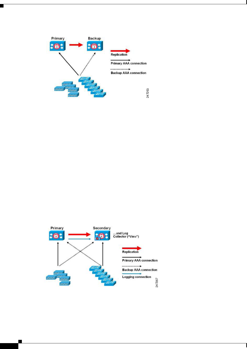
Small ACS Deployment
The most basic ACS deployment consists of two servers; see Figure 1-1. One is the primary server that
provides all of the configuration, authentication, and policy requirements for the network.
The second server is used as a backup server if the connectivity is lost between the AAA clients and the
primary server. You use replication from the primary ACS server to the secondary server to keep the
secondary server in synchronization with the primary server.
In a small network, this configuration allows you to configure the primary and secondary RADIUS or
TACACS servers on all AAA clients in the same way.
1-2
Installation and Upgrade Guide for Cisco Secure Access Control System 5.5
OL-28603-01
Chapter 1 Understanding the ACS Server Deployment
Deployment Scenarios
Figure 1-1 Small ACS Deployment
As the number of users and AAA clients increases in an organization, Cisco recommends changing the
deployment ACS from the basic design and using split ACS deployment design; see Figure 1-2.
Split ACS Deployment
In split ACS deployment, you use primary and secondary servers as in a small ACS deployment, but the
AAA load is split between the two servers to optimize AAA flow. Each server handles the full workload
of both servers if there is a AAA connectivity problem, but during normal operations, neither server
carries the full load of authentication requests.
This property of the servers allows for less stress on each ACS system, provides better loading, and
makes you aware of the functional status of the secondary server through normal operations.
Another advantage of this arrangement is that each server can be used for specific operations, such as
device administration and network admission, but can still be used to perform all the AAA functions in
the event of a failure.
With two ACS systems now processing authentication requests and collecting accounting data from
AAA clients, Cisco recommends using one of the systems as a log collector. Figure 1-2 shows the
secondary ACS server as the log collector.
Figure 1-2 Split ACS Deployment
Another advantage of this design is that it also allows for growth as shown in Figure 1-3.
1-3
Installation and Upgrade Guide for Cisco Secure Access Control System 5.5
OL-28603-01
Chapter 1 Understanding the ACS Server Deployment
Deployment Scenarios
Medium ACS Deployment
As the local network grows, you need to add more ACS servers to the system. In this scenario, you should
consider promoting the primary server to perform configuration services and using the secondary servers
for AAA functions. When the amount of log traffic increases, you should use one of the secondary
servers as a centralized dedicated log collector server. ACS 5.5 supports one additional ACS instance in
a deployment. The ACS 5.5 medium deployment supports 14 ACS instances. You can designate this
additional ACS instance as a dedicated instance that can be promoted to a primary instance when the
actual primary instance goes down.
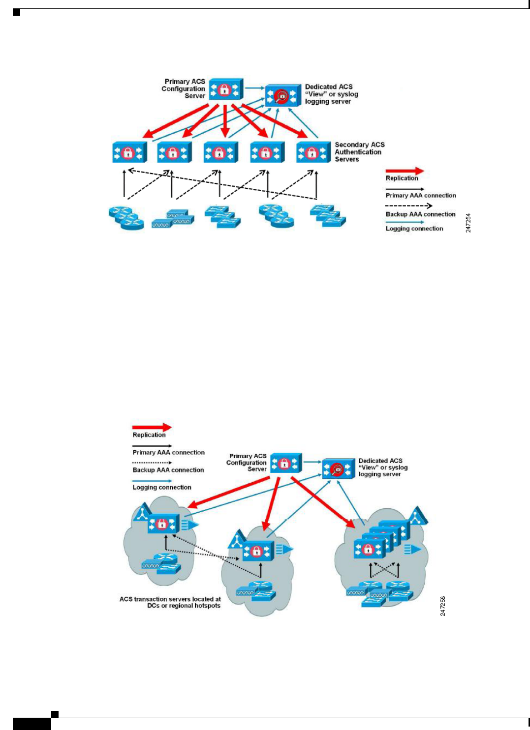
Figure 1-3 Medium ACS Deployment
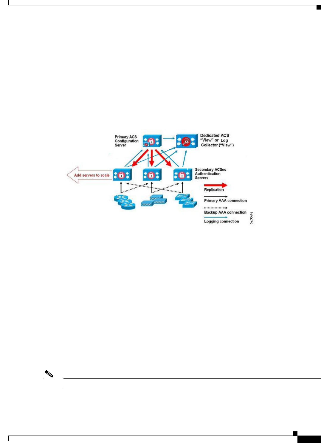
Large ACS Deployment
In a large ACS deployment, as shown in Figure 1-4, centralized logging is highly recommended. ACS
5.5 supports one additional ACS instance in a deployment. The ACS 5.5 large deployment supports 22
ACS instances. You can designate this additional ACS instance as a dedicated instance that can be
promoted to a primary instance when the actual primary instance goes down. Cisco recommends a
dedicated logging server (Monitoring and Report server) because of the potentially high syslog traffic
that a busy network can generate. Because ACS generates syslog messages for outbound log traffic, any
RFC-3164-compliant syslog server will work to collect outbound logging traffic.
This type of server enables you to use the reports and alerts features that are available in ACS for all
ACS servers. This requires special licensing, which is discussed in the User Guide for Cisco Secure
Access Control System 5.5. See Installing the ACS Server, page 5-2, for more information on installing
the ACS server.
You should also consider having the servers send logs to both a Monitoring and Report server and a
generic syslog server. The addition of the generic syslog server provides a backup if the Monitoring and
Report server goes down.
Note ACS 5.5 does not support large deployments with more than 22 ACS instances.
1-4
Installation and Upgrade Guide for Cisco Secure Access Control System 5.5
OL-28603-01
Chapter 1 Understanding the ACS Server Deployment
Deployment Scenarios
Figure 1-4 Large ACS Deployment
Dispersed ACS Deployment
A dispersed ACS deployment is useful for organizations that have campuses located throughout the
world. There may be a home campus where the primary network resides, but there may be additional
LANs, sized from small to large, in campuses in different regions.
To optimize AAA performance, each of these remote campuses should have its own AAA infrastructure.
See Figure 1-5. The centralized management model should still be used to maintain a consistent,
synchronized AAA policy.
A centralized-configuration, primary ACS server and a separate Monitoring and Report server should
still be used. However, each of the remote campuses will have unique requirements.
Figure 1-5 Dispersed ACS Deployment
Some of the factors to consider when planning a network with remote sites are:
•Check whether there is a central or external database (Microsoft Active Directory [AD] or
Lightweight Directory Access Protocol [LDAP]) in use. For the purposes of optimization, each
remote site should have a synchronized instance of the external database available for ACS to access.

1-5
Installation and Upgrade Guide for Cisco Secure Access Control System 5.5
OL-28603-01
Chapter 1 Understanding the ACS Server Deployment
Understanding the ACS Server Setup
•The location of the AAA clients is also a major consideration. You should place your ACS servers
as close as possible to the AAA clients to reduce the effects of network latency and the possibility
of loss of access caused by WAN failure.
•ACS has console access for some functions, such as backup. Consider using a terminal at each site.
This allows for secure console access outside of network access to each server.
•If small, remote sites are in close proximity and have reliable WAN connectivity to other sites, you
may consider using an ACS server in a nearby site as a backup server for the local site for redundant
configuration.
•DNS should be properly configured on all ACS nodes to ensure access to the external databases.
Understanding the ACS Server Setup
This section briefly describes the roles of various ACS servers and how to configure them. For more
information on assigning a role to a server and configuring it, see the User Guide for Cisco Secure Access
Control System 5.5.
This section contains:
•Primary Server, page 1-5
•Secondary Server, page 1-6
•Logging Server, page 1-6
The installation procedure is similar for any ACS server.
See Chapter 5, “Installing and Configuring the Cisco Secure Access Control System with
CSACS-1121.” for installing ACS with the CSACS-1121 appliance, Chapter 9, “Installing and
Configuring the Secure Access Control System with the Cisco SNS-3415 and Cisco SNS-3495.” for
installing ACS with the Cisco SNS-3415 appliance, or Chapter 10, “Installing ACS in a VMware Virtual
Machine” for installing ACS with VMware ESX. In an ACS deployment, ensure that you first install a
primary server.
Primary Server
In an ACS deployment, only one instance serves as an ACS primary, which provides the configuration
capabilities and serves as the source for replication.
On an ACS primary server, you can set up all the system configurations that are required for an ACS
deployment. However you must configure licenses and local certificates individually for each ACS
secondary server.

1-6
Installation and Upgrade Guide for Cisco Secure Access Control System 5.5
OL-28603-01
Chapter 1 Understanding the ACS Server Deployment
Understanding the ACS Server Setup
Secondary Server
Except the primary server, all the other instances function as a secondary server.
A secondary ACS server receives all the system configurations from the primary server, except that you
need to configure the following on each secondary server:
•License—Install a unique base license for each of the ACS secondary servers in the deployment.
•New local certificates—You can either configure the local certificates on the secondary servers or
import the local certificates from the primary server.
•Logging server—You can configure either the primary server or the secondary server to be the
logging server for ACS. Cisco recommends that you configure a secondary ACS server as the
logging server.
Note You cannot translate a network address between the primary and secondary servers when selecting the
installation location for the secondary server.
The secondary server must be activated to join the ACS environment. The administrator can either
activate a secondary server or set up automatic activation. By default, the activation is set to Automatic.
After the secondary server is activated, it is synchronized with the configuration and replication updates
from the primary server.
Logging Server
Either a primary server or one of the secondary servers can function as a logging server.
The logging server receives the logs from the primary server and all the ACS secondary servers in the
deployment. Cisco recommends that you allocate one of the ACS secondary servers as the Monitoring
and Report server and exclude this particular secondary server from the AAA activities.
The three main logging categories are Audit, Accounting, and Diagnostics.
For more details on logging categories and configuration, see the User Guide for Cisco Secure Access
Control System 5.5.

P
ART
2
ACS 5.5 on Cisco 1121 Secure Access Control System
CHAPTER
2-1
Installation and Upgrade Guide for Cisco Secure Access Control System 5.5
OL-28603-01
2
Introducing the Cisco 1121 Secure Access
Control System Hardware
This chapter gives an overview of the Cisco Secure Access Control System (CSACS-1121) hardware. It
covers the appliance hardware, major components, controls, connectors, and front- and rear-panel LED
indicators.
This chapter contains:
•Product Overview, page 2-1
•Hardware Features, page 2-4
•Regulatory Compliance, page 2-7
Product Overview
This section describes the power requirements, rack-mount hardware kit, and features of the
CSACS-1121 Series appliance.
This section contains:
•CSACS-1121 Series Appliance Overview, page 2-1
•Product Serial Number Location, page 2-3
•Cisco Product Identification Tool, page 2-3
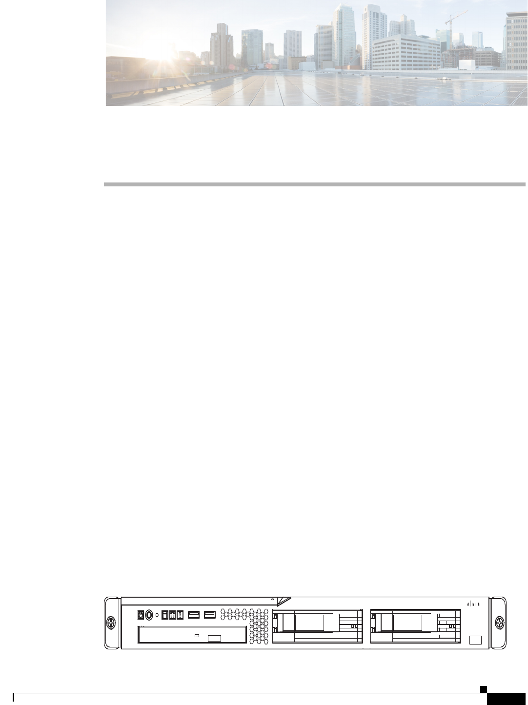
CSACS-1121 Series Appliance Overview
The CSACS-1121 Series appliance (see Figure 2-1) is contained in a standard shelf-rack enclosure. The
appliance weighs from 24.25 lb (11.0 kg) to 28.0 lb (12.7 kg). It measures 1.75 inches high x 17.3 inches
wide x 22.0 inches deep (44.5 mm x 440.0 mm x 559.0 mm). These dimensions do not include the rack
handles.
Figure 2-1 Cisco 1121 Secure Access Control System Front View
195212
Cisco 1121 Secure
Accrss Control System
CISCO

2-2
Installation and Upgrade Guide for Cisco Secure Access Control System 5.5
OL-28603-01
Chapter 2 Introducing the Cisco 1121 Secure Access Control System Hardware
Product Overview
The CSACS-1121 Series appliance is configured for AC-input power and has a single auto-ranging
AC-input power supply, mounted in a standard 19-inch (48.3 cm), 4-post equipment rack (using the
rack-mount brackets provided). The CSACS-1121 features include:
•Microprocessor—Intel Core 2 Duo 2.4-GHz processor with an 800-MHz front side bus (FSB) and
2 MB of Layer 2 cache.
•Four synchronous dynamic RAM (SDRAM) slots that are installed with 4 GB.
•Two 250-GB SATA hard drives installed.
•A fixed RJ-45 10BASE-T/100BASE-TX/1000BASE-T network interface connector (located on the
rear panel).
•One slimline DVD-ROM drive (located on the front panel).
•One DB-9 serial (console) port (located on the rear panel).
•Front-to-rear airflow blowers using two 40-mm exhaust fans and ducting for the CPU and memory,
two 40-mm exhaust fans built into the power supply, and one PCI exhaust fan.
•Expansion slot support—One PCI-X (located on the rear panel).
•Four USB 2.0 ports (two located on the rear panel, two on the front panel).
•One PS/2 keyboard port (located on the rear panel).
•One PS/2 mouse port (located on the rear panel).
•One PS/2 video monitor port (located on the rear panel).
•One DB-15 serial (video) port (located on the rear panel).
•Four Gigabit Ethernet interfaces.
•Rear-access cabling.
•Front-panel appliance LEDs:
–
Appliance power
–
Hard disk drive activity
–
Locator
–
System error
–
CD drive activity
For a description of the LEDs, see CSACS-1121 Appliance Front-Panel View, page 2-4.
•Back-panel appliance LEDs:
–
Ethernet activity
–
Ethernet link
For a description of the LEDs, see CSACS-1121 Appliance Back-Panel View, page 2-5
•The CSACS-1121 appliance is normally shipped with a rack-mount hardware kit which includes
either brackets or rails that allow the CSACS-1121 to be positioned in a 4-post equipment rack. For
more information, see Chapter 4, “Installing the Cisco 1121 Secure Access Control System
Hardware.”
Note The rack-mount hardware kit does not include a 2-post equipment rack.
2-3
Installation and Upgrade Guide for Cisco Secure Access Control System 5.5
OL-28603-01
Chapter 2 Introducing the Cisco 1121 Secure Access Control System Hardware
Product Overview
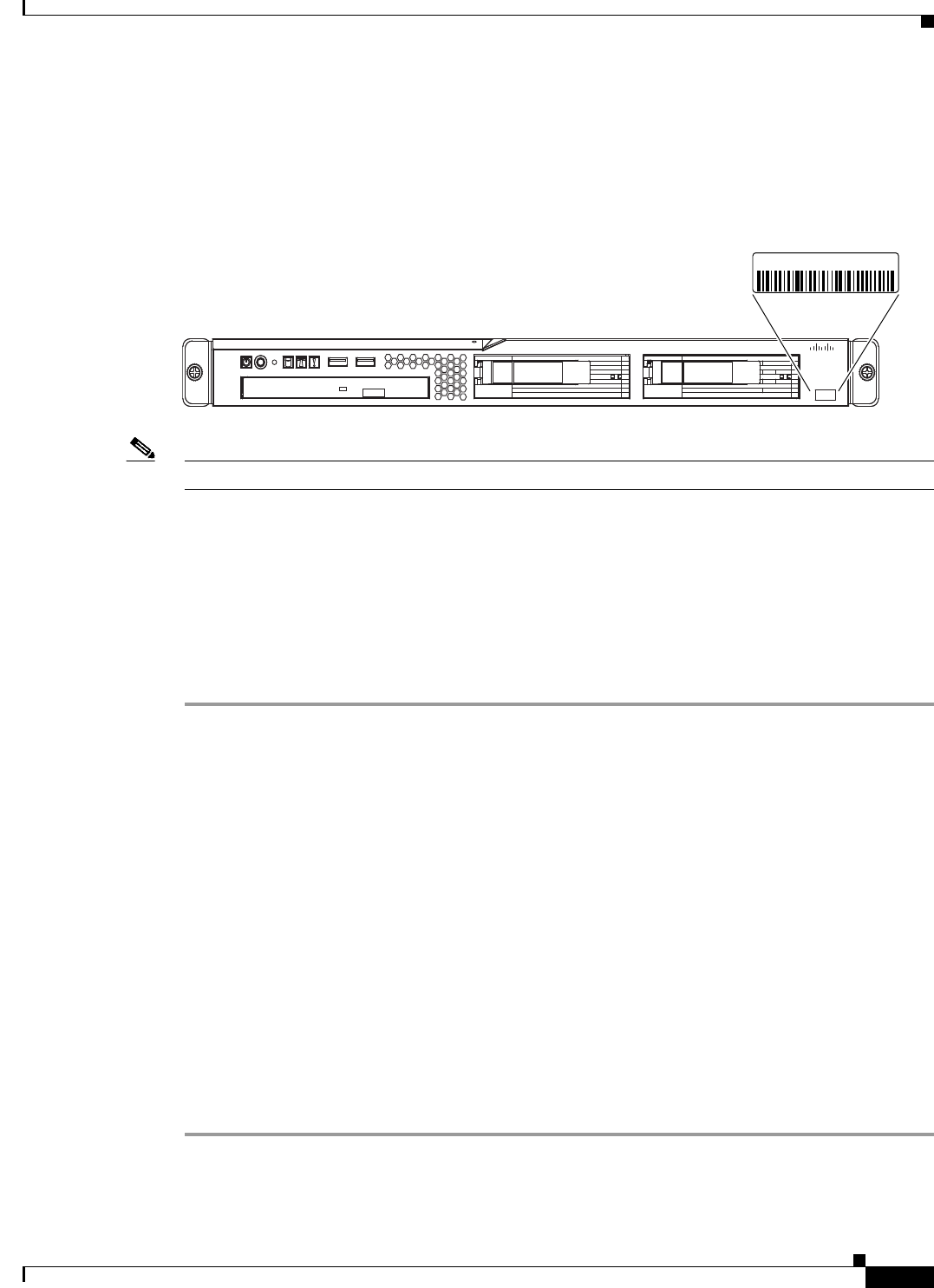
Product Serial Number Location
The serial number label is located on the front panel of the CSACS-1121 Series appliance, at the lower
Left. Figure 2-2 shows the location of this label.
Figure 2-2 CSACS-1121 Appliance Serial Number Location
Note The serial number for the CSACS-1121 Series appliance is 11 characters long.
Cisco Product Identification Tool
The Cisco Product Identification (CPI) tool helps you retrieve the serial number of your Cisco products.
Before you submit a request for service online or by phone, use the CPI tool to locate your product serial
number. You can access this tool from the Cisco Support website.
To access this tool:
Step 1 Click the Get Tools & Resources link.
Step 2 Click the All Tools (A-Z) tab.
Step 3 Select Cisco Product Identification Tool from the alphabetical drop-down list.
This tool offers three search options:
•Search by product ID or model name.
•Browse for Cisco model.
•Copy and paste the output of the show command to identify the product.
Search results show an illustration of your product with the serial number label location highlighted.
Locate the serial number label on your product and record the information before you place a
service call.
You can access the CPI tool at:
http://tools.cisco.com/Support/CPI/index.do
To access the CPI tool, you require a Cisco.com user ID and password. If you have a valid service
contract but do not have a user ID or password, you can register at:
http://tools.cisco.com/RPF/register/register.do
195213
Cisco 1121 Secure
Accrss Control System
CISCO
XXXXNNNNNNN
2-4
Installation and Upgrade Guide for Cisco Secure Access Control System 5.5
OL-28603-01
Chapter 2 Introducing the Cisco 1121 Secure Access Control System Hardware
Hardware Features
Hardware Features
This section describes the front- and rear-panel controls, ports, and LED indicators on the CSACS-1121
Series appliance.
This section contains:
•CSACS-1121 Appliance Front-Panel View, page 2-4
•CSACS-1121 Appliance Back-Panel View, page 2-5
•Input/Output Ports and Connectors, page 2-6
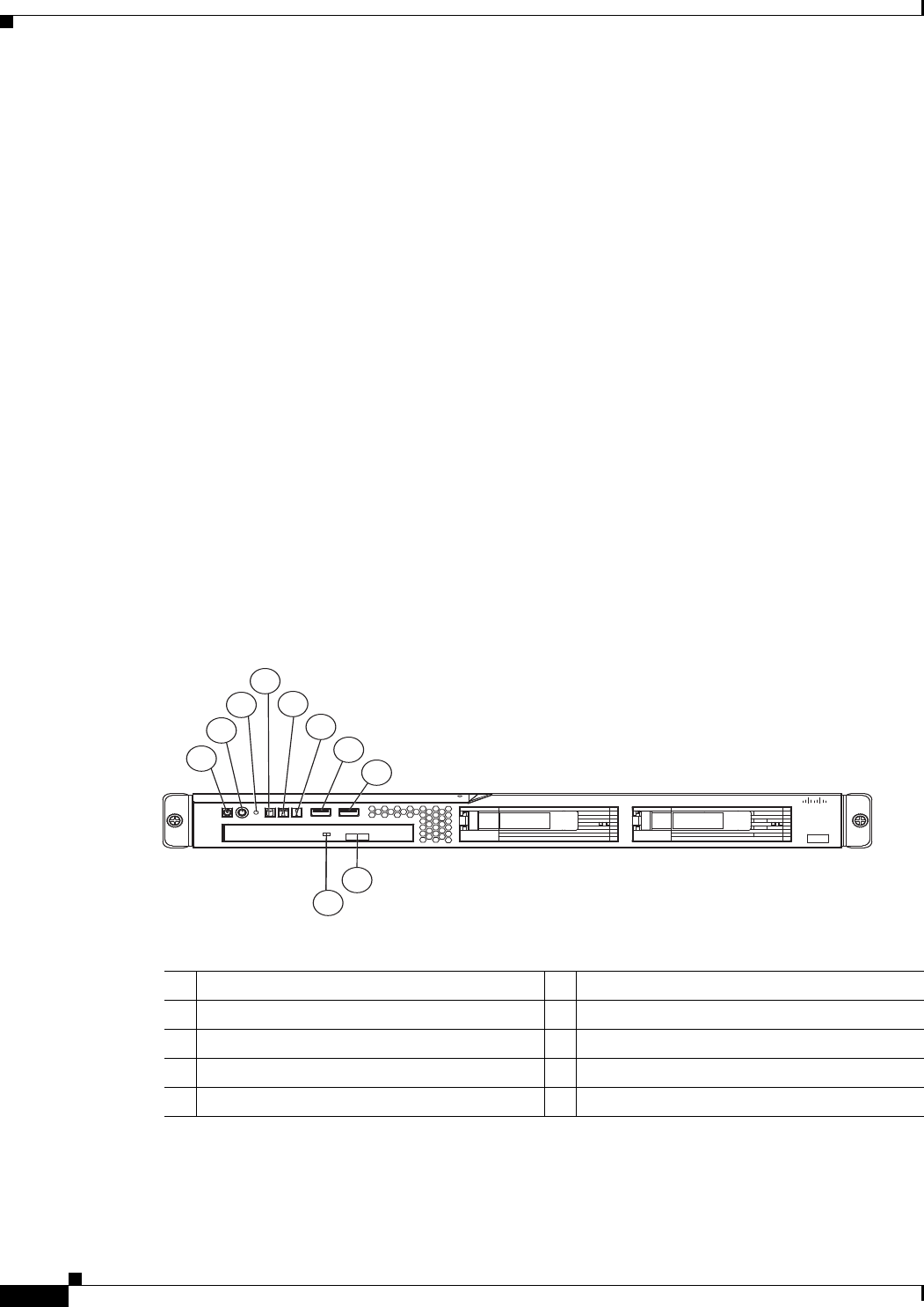
CSACS-1121 Appliance Front-Panel View
The front panel of the CSACS-1121 Series appliance contains:
•Power-control button
•Reset button
•Two USB 2.0 ports
•CD-eject button
•Various LEDs (appliance and CD drive)
Figure 2-3 shows the components of the front panel.
Figure 2-3 CSACS-1121 Series Appliance Front View
The following table describes the callouts in Figure 2-3.
1
2
4
5
6
7
8
9
10
3
195214
Cisco 1121 Secure
Accrss Control System
CISCO
1Appliance power LED 6System-error LED
2Power-control button 7USB 1 connector
3Reset button 8USB 2 connector
4Hard disk drive activity LED 9CD-eject button
5Locator LED 10 CD drive activity LED
2-5
Installation and Upgrade Guide for Cisco Secure Access Control System 5.5
OL-28603-01
Chapter 2 Introducing the Cisco 1121 Secure Access Control System Hardware
Hardware Features
LEDs on the CSACS-1121 Front Panel
Table 2-1 describes the LEDs located on the front panel of the CSACS-1121 Series appliance.
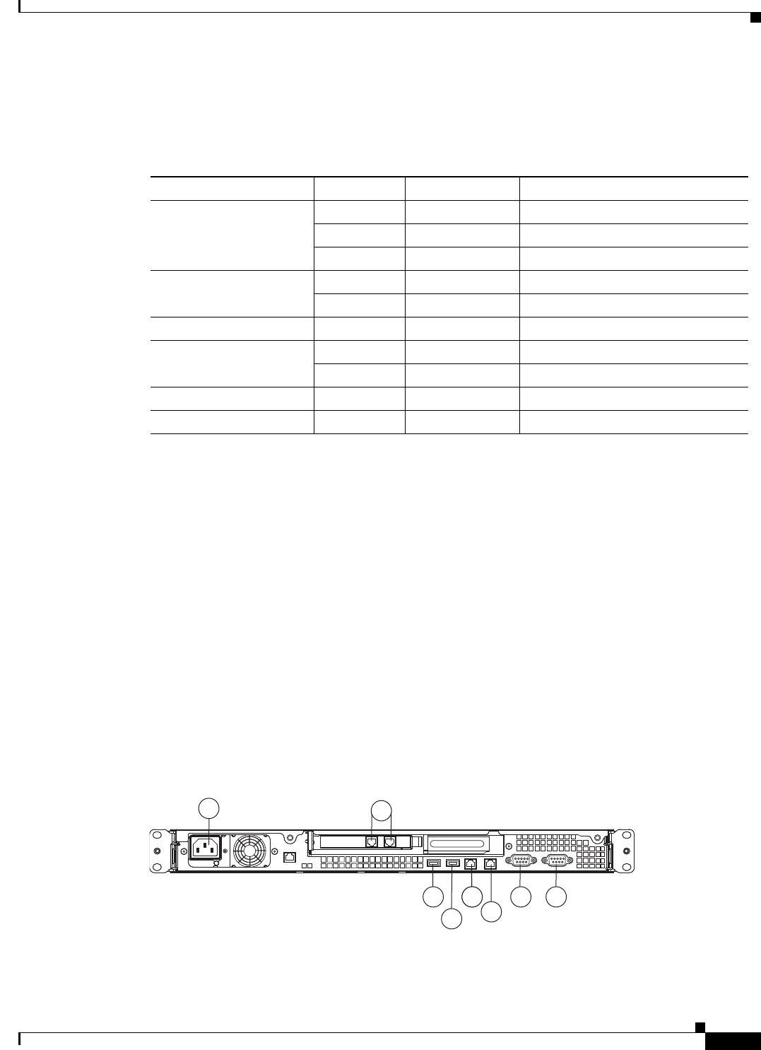
CSACS-1121 Appliance Back-Panel View
The back panel of the CSACS-1121 Series appliance contains:
•AC power connector
•Serial connector
•One Video connector
•Four Ethernet (RJ-45) connectors
•Two USB 2.0 ports
•Ethernet LEDs
Figure 2-4 shows the components of the back panel.
The locations of the rack-mounting brackets are also shown on the left and right sides of the appliance.
(See Rack-Mounting Configuration Guidelines, page 4-1 for instructions on how to install the
mounting brackets.)
Figure 2-4 CSACS-1121 Series Appliance Rear View
Table 2-1 Front-Panel LEDs
LED Color State Description
Appliance power Green On Power on
Green Blinking Sleep (standby)
Off Off Power off
Hard disk drive Green Random blinking Hard disk drive activity
Off Off No hard disk drive activity
Reset Button — — Press the button to do a soft reset
Locator LED Blue Blinking System is booting up
Off Off System bootup is completed
System error Amber On A system error has occurred
CD drive activity Green On The CD drive is in use
197065
1
8 4 4 3
7
2
65
2-6
Installation and Upgrade Guide for Cisco Secure Access Control System 5.5
OL-28603-01
Chapter 2 Introducing the Cisco 1121 Secure Access Control System Hardware
Hardware Features
The following table describes the callouts in Figure 2-4.
.
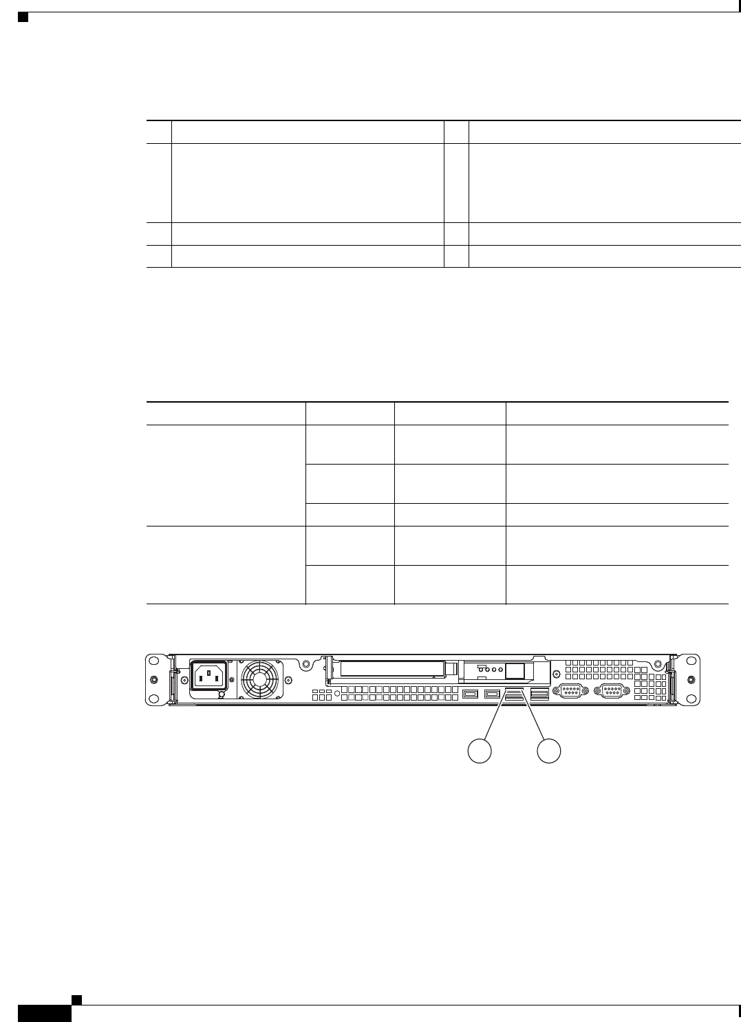
LEDs on the CSACS-1121 Rear Panel
Table 2-2 describes the LEDs located on the rear panel of the CSACS-1121 Series appliance. Figure 2-5
shows these LEDs.
Figure 2-5 CSACS-1121 Rear Panel LEDs
Input/Output Ports and Connectors
The CSACS-1121 Series appliance supports the following types of Input/Output connectors:
•Two Gigabit Ethernet ports (on the rear panel)
•One serial port (on the rear panel)
•One parallel port (on the rear panel)
•USB 2.0 ports (2 on the front panel, 2 on the rear panel)
1 AC power receptacle 5 Gigabit Ethernet 1
2 Gigabit Ethernet 6 (In use) Gigabit Ethernet 0
Note This NIC must be used for network
installation and for the management
interface.
3 Serial connector 7 USB 3 connector
4 Video connector 8 USB 4 connector
Table 2-2 Rear-Panel LEDs
LED Color State Description
Ethernet activity LED Green On Activity exists between the server
and the network
Green Blinking Activity exists between the server
and the network
Off Off No activity exists
Ethernet link LED Green Random blinking Ethernet controller is connected to
the network
Off Off Ethernet controller is not connected
to the network
276861
12

2-7
Installation and Upgrade Guide for Cisco Secure Access Control System 5.5
OL-28603-01
Chapter 2 Introducing the Cisco 1121 Secure Access Control System Hardware
Regulatory Compliance
Warning
To avoid electric shock, do not connect safety extra-low voltage (SELV) circuits to
telephone-network voltage (TNV) circuits. LAN ports contain SELV circuits, and WAN ports
contain TNV circuits. Some LAN and WAN ports both use RJ-45 connectors. Use caution when
connecting cables.
Statement 1021
Regulatory Compliance
For regulatory compliance and safety information, see Regulatory Compliance and Safety Information
for Cisco Secure Access Control System. This document is available online at Cisco.com:
http://www.cisco.com/en/US/docs/net_mgmt/cisco_secure_access_control_system/5.4/regulatory/
compliance/csacsrcsi.html
For more information, see Obtaining Documentation and Submitting a Service Request, page -13.

2-8
Installation and Upgrade Guide for Cisco Secure Access Control System 5.5
OL-28603-01
Chapter 2 Introducing the Cisco 1121 Secure Access Control System Hardware
Regulatory Compliance

CHAPTER
3-1
Installation and Upgrade Guide for Cisco Secure Access Control System 5.5
OL-28603-01
3
Preparing to Install the Cisco 1121 Secure
Access Control System Hardware
This chapter describes the safety instructions, site requirements, and tasks you must perform before
installing the CSACS-1121 Series appliance.
This chapter contains:
•Safety Guidelines, page 3-1
•Preparing Your Site for Installation, page 3-6
•Ethernet and Console Port Considerations, page 3-15
Note Read the Regulatory Compliance and Safety Information for the Cisco 1121 Secure Access Control
System before you begin the installation.
Safety Guidelines
Before you begin installing the CSACS-1121 Series appliance, review the safety guidelines in this
chapter and Rack-Mounting Configuration Guidelines, page 4-1 to avoid injuring yourself or damaging
the equipment.
In addition, before replacing, configuring, or maintaining the appliance, review the safety warnings
listed in Safety Warnings, page 6 and in the Cisco Regulatory Compliance and Safety Information for
the Cisco 1121 Secure Access Control System document.
This section contains:
•General Precautions, page 3-2
•Safety with Equipment, page 3-3
•Safety with Electricity, page 3-3
•Preventing Electrostatic Discharge Damage, page 3-5
•Lifting Guidelines, page 3-5

3-2
Installation and Upgrade Guide for Cisco Secure Access Control System 5.5
OL-28603-01
Chapter 3 Preparing to Install the Cisco 1121 Secure Access Control System Hardware
Safety Guidelines
General Precautions
Observe the following general precautions for using and working with your appliance:
•Observe and follow service markings. Do not service any Cisco product except as explained in your
appliance documentation. Opening or removing covers that are marked with the triangular symbol
with a lightning bolt may expose you to electrical shock. Components inside these compartments
should be serviced only by an authorized service technician.
•If any of the following conditions occur, unplug the product from the electrical outlet and replace
the part, or contact your authorized service provider:
–
The power cable, extension cord, or plug is damaged.
–
An object has fallen into the product.
–
The product has been exposed to water.
–
The product has been dropped or damaged.
–
The product does not operate correctly when you follow the operating instructions.
•Keep your appliance away from radiators and heat sources. Also, do not block cooling vents.
•Do not spill food or liquids on your appliance, and never operate the product in a wet environment.
•Do not push any objects into the openings of your appliance. Doing so can cause fire or electric
shock by shorting out interior components.
•Use the product only with other equipment approved by Cisco.
•Allow the product to cool before removing covers or touching internal components.
•Use the correct external power source. Operate the product only from the type of power source
indicated on the electrical ratings label. If you are not sure of the type of power source required,
consult your service representative or local power company.
•Use only approved power cables. If you have not been provided with a power cable for your
appliance or for any AC-powered option intended for your appliance, purchase a power cable that is
approved for use in your country.
The power cable must be rated for the product and for the voltage and current marked on the
product’s electrical ratings label. The voltage and current rating of the cable should be greater than
the ratings marked on the product.
•To help prevent electric shock, plug the appliance and power cables into properly grounded
electrical outlets. These cables are equipped with three-prong plugs to help ensure proper
grounding. Do not use adapter plugs or remove the grounding prong from a cable. If you must use
an extension cord, use a three-wire cord with properly grounded plugs.
•Observe extension cord and power strip ratings. Make sure that the total ampere rating of all
products plugged into the extension cord or power strip does not exceed 80 percent of the extension
cord or power strip ampere ratings limit.
•Do not use appliance, or voltage converters, or kits sold for appliances with your product.
•To help protect your appliance from sudden, transient increases and decreases in electrical power,
use a surge suppressor, line conditioner, or uninterruptible power supply (UPS).
•Position cables and power cords carefully; route cables and the power cord and plug so that they
cannot be stepped on or tripped over. Be sure that nothing rests on your appliance cables or
power cord.
•Do not modify power cables or plugs. Consult a licensed electrician or your power company for site
modifications. Always follow your local or national wiring rules.

3-3
Installation and Upgrade Guide for Cisco Secure Access Control System 5.5
OL-28603-01
Chapter 3 Preparing to Install the Cisco 1121 Secure Access Control System Hardware
Safety Guidelines
Safety with Equipment
The following guidelines will help ensure your safety and protect the equipment. However, this list does
not include all potentially hazardous situations, so be alert.
Warning
Read the installation instructions before connecting the system to the power source.
Statement 1004
•Always disconnect all power cords and interface cables before moving the appliance.
•Never assume that power is disconnected from a circuit; always check.
•Keep the appliance chassis area clear and dust-free before and after installation.
•Keep tools and assembly components away from walk areas where you or others could trip
over them.
•Do not work alone if potentially hazardous conditions exist.
•Do not perform any action that creates a potential hazard to people or makes the equipment unsafe.
•Do not wear loose clothing that may get caught in the appliance chassis.
•Wear safety glasses when working under conditions that may be hazardous to your eyes.
Safety with Electricity
Warning
This unit is intended for installation in restricted access areas. A restricted access area can be
accessed only through the use of a special tool, lock and key, or other means of security.
Statement 1017
Warning
To avoid electric shock, do not connect safety extra-low voltage (SELV) circuits to
telephone-network voltage (TNV) circuits. LAN ports contain SELV circuits, and WAN ports
contain TNV circuits. Some LAN and WAN ports both use RJ-45 connectors.
Statement 1021
Warning
Do not touch the power supply when the power cord is connected. For systems with a power
switch, line voltages are present within the power supply even when the power switch is off and
the power cord is connected. For systems without a power switch, line voltages are present within
the power supply when the power cord is connected.
Statement 4
Warning
Before working on equipment that is connected to power lines, remove jewelry (including rings,
necklaces, and watches). Metal objects will heat up when connected to power and ground and can
cause serious burns or weld the metal object to the terminals.
Statement 43
Warning
Before working on a chassis or working near power supplies, unplug the power cord on AC units;
disconnect the power at the circuit breaker on DC units.
Statement 12

3-4
Installation and Upgrade Guide for Cisco Secure Access Control System 5.5
OL-28603-01
Chapter 3 Preparing to Install the Cisco 1121 Secure Access Control System Hardware
Safety Guidelines
Warning
Do not work on the system or connect or disconnect cables during periods of lightning activity.
Statement 1001
Warning
This equipment is intended to be grounded. Ensure that the host is connected to earth ground
during normal use.
Statement 39
Warning
When installing or replacing the unit, the ground connection must always be made first and
disconnected last.
Statement 1046
Follow these guidelines when working on equipment powered by electricity:
•Locate the room’s emergency power-off switch. Then, if an electrical accident occurs, you can
quickly turn off the power.
•Disconnect all power before doing the following:
–
Working on or near power supplies.
–
Installing or removing an appliance.
–
Performing most hardware upgrades.
•Never install equipment that appears damaged.
•Carefully examine your work area for possible hazards, such as moist floors, ungrounded power
extension cables, and missing safety grounds.
•Never assume that power is disconnected from a circuit; always check.
•Never perform any action that creates a potential hazard to people or makes the equipment unsafe.
•Never work alone when potentially hazardous conditions exist.
•If an electrical accident occurs, proceed as follows:
–
Use caution, and do not become a victim yourself.
–
Turn off power to the appliance.
–
If possible, send another person to get medical aid. Otherwise, determine the condition of the
victim, and then call for help.
–
Determine whether the person needs rescue breathing, external cardiac compressions, or other
medical attention; then take appropriate action.
In addition, use the following guidelines when working with any equipment that is disconnected from a
power source but still connected to telephone wiring or network cabling:
•Never install telephone wiring during a lightning storm.
•Never install telephone jacks in wet locations unless the jack is specifically designed for it.
•Never touch uninsulated telephone wires or terminals unless the telephone line is disconnected at
the network interface.
•Use caution when installing or modifying telephone lines.

3-5
Installation and Upgrade Guide for Cisco Secure Access Control System 5.5
OL-28603-01
Chapter 3 Preparing to Install the Cisco 1121 Secure Access Control System Hardware
Safety Guidelines
Preventing Electrostatic Discharge Damage
Electrostatic discharge (ESD) can damage equipment and impair electrical circuitry. ESD can occur
when electronic printed circuit cards are improperly handled and can cause complete or intermittent
failures. Always follow ESD-prevention procedures when removing and replacing modules:
•When unpacking a static-sensitive component from its shipping carton, do not remove the
component from the antistatic packing material until you are ready to install the component in your
appliance. Just before unwrapping the antistatic packaging, be sure to discharge static electricity
from your body.
•When transporting a sensitive component, first place it in an antistatic container or packaging.
•Handle all sensitive components in a static-safe area. If possible, use antistatic floor pads and
workbench pads.
•Ensure that the CSACS-1121 Series appliance is electrically connected to earth ground.
•Wear an ESD-preventive wrist strap, ensuring that it makes good skin contact. Connect the clip to
an unpainted surface of the appliance to channel unwanted ESD voltages safely to ground. To guard
against ESD damage and shocks, the wrist strap and cord must operate effectively.
•If no wrist strap is available, ground yourself by touching a metal part of the appliance.
Caution For the safety of your equipment, periodically check the resistance value of the antistatic wrist strap. It
should be between 1 and 10 Mohm.
Lifting Guidelines
The CSACS-1121 Series appliance weighs between 15 lb (9.071 kg) and 33 lb (14.96 kg) depending on
what hardware options are installed in the appliance. The appliance is not intended to be moved
frequently. Before you install the appliance, ensure that your site is properly prepared so you can avoid
having to move the appliance later to accommodate power sources and network connections.
Whenever you lift the appliance or any heavy object, follow these guidelines:
•Always disconnect all external cables before lifting or moving the appliance.
•Ensure that your footing is solid, and balance the weight of the object between your feet.
•Lift the appliance slowly; never move suddenly or twist your body as you lift.
•Keep your back straight and lift with your legs, not your back. If you must bend down to lift the
appliance, bend at the knees, not at the waist, to reduce the strain on your lower back muscles.
•Lift the appliance from the bottom; grasp the underside of the appliance exterior with both hands.

3-6
Installation and Upgrade Guide for Cisco Secure Access Control System 5.5
OL-28603-01
Chapter 3 Preparing to Install the Cisco 1121 Secure Access Control System Hardware
Preparing Your Site for Installation
Preparing Your Site for Installation
Before installing the CSACS-1121 Series appliance, it is important to prepare the following:
Step 1 Prepare the site (see Site Planning, page 3-6) and review the installation plans or method of
procedures (MOPs).
Step 2 Unpack and inspect the appliance.
Step 3 Gather the tools and test equipment required to properly install the appliance.
This section contains:
•Site Planning, page 3-6
•Unpacking and Checking the Contents of Your Shipment, page 3-11
•Required Tools and Equipment, page 3-13
•Installation Checklist, page 3-13
•Creating a Site Log, page 3-14
Site Planning
Warning
This unit is intended for installation in restricted access areas. A restricted access area can be
accessed only through the use of a special tool, lock and key, or other means of security.
Statement 1017
Typically, you should have prepared the installation site beforehand. As part of your preparation, obtain
a floor plan of the site and the equipment rack where the CSACS-1121 Series appliance will be housed.
Determine the location of any existing appliances and their interconnections, including communications
and power. Following the airflow guidelines (see Airflow Guidelines, page 3-8) to ensure that adequate
cooling air is provided to the appliance.
All personnel involved in the installation of the appliance, including installers, engineers, and
supervisors, should participate in the preparation of a MOP for approval by the customer. For more
information, see Method of Procedure, page 3-10.
The following sections provide the site requirement guidelines that you must consider before installing
the appliance:
•Rack Installation Safety Guidelines, page 3-7
•Site Environment, page 3-8
•Airflow Guidelines, page 3-8
•Temperature and Humidity Guidelines, page 3-9
•Power Considerations, page 3-9
•Method of Procedure, page 3-10
3-7
Installation and Upgrade Guide for Cisco Secure Access Control System 5.5
OL-28603-01
Chapter 3 Preparing to Install the Cisco 1121 Secure Access Control System Hardware
Preparing Your Site for Installation
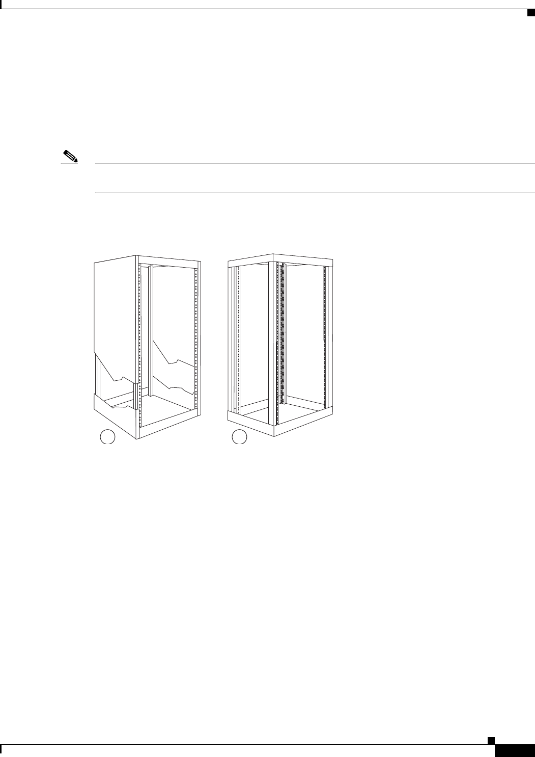
Rack Installation Safety Guidelines
The CSACS-1121 Series appliance can be mounted in most four-post telephone company (telco-type),
19-inch equipment racks that comply with the EIA standard for equipment racks (EIA-310-D). The
distance between the center lines of the mounting holes on the two mounting posts must be 18.31 inches
+/- 0.06 inch (46.50 cm +/- 0.15 cm). The rack-mounting hardware that is included with the appliance
is suitable for most 19-inch equipment racks or telco-type frames.
Note Cisco strongly recommends using four-post racks whenever possible, but your rack must have at least
two posts that provide mounting flanges for mounting an appliance.
Figure 3-1 shows a couple of common examples of four-post equipment racks.
Figure 3-1 Four-Post Equipment Rack Types
Four-Post (Partially-Enclosed) Rack
Image “1” in Figure 3-1 shows a freestanding, partially-enclosed rack with two mounting posts in the
front and two more at the rear. The CSACS-1121 Series appliance may be installed in this type of
enclosed rack, because the appliance only requires an unobstructed flow of cooling air into the front of
the chassis and pushed out of the rear to maintain acceptable operating temperatures for its internal
components.
Four-Post (Open) Rack
Image “2” Figure 3-1 shows a freestanding, four-post open rack with two mounting posts in front and
two mounting posts at the back. The mounting posts in this type of rack are often adjustable so that you
can position the rack-mounted unit within the depth of the rack rather than flush-mount it with the front
of the rack.
Before installing your CSACS-1121 Series appliance in a rack, review the following guidelines:
•Two or more people are required to install the appliance in a rack.
•Ensure that the room air temperature is below 95°F (35°C).
•Do not block any air vents; usually, 6 inches (15 cm) of space provides proper airflow.
310199
1 2

3-8
Installation and Upgrade Guide for Cisco Secure Access Control System 5.5
OL-28603-01
Chapter 3 Preparing to Install the Cisco 1121 Secure Access Control System Hardware
Preparing Your Site for Installation
•Plan the appliance installation starting from the bottom of the rack.
•Do not extend more than one appliance out of the rack at the same time.
•Connect the appliance to a properly grounded outlet.
•Do not overload the power outlet when installing multiple devices in the rack.
•Do not place any object weighing more than 110 lb (50 kg) on top of rack-mounted devices.
Site Environment
The location of your appliance and the layout of your equipment rack or wiring room are extremely
important considerations for proper operation. Equipment placed too close together, inadequate
ventilation, and inaccessible panels can cause malfunctions and shutdowns, and can make maintenance
difficult. Plan for access to front and rear panels of the appliance.
The following precautions will help you plan an acceptable operating environment for your appliance
and will help you avoid environmentally caused equipment failures:
•Ensure that the room where your appliance operates has adequate circulation. Electrical equipment
generates heat. Without adequate circulation, ambient air temperature may not cool equipment to
acceptable operating temperatures. For more information, see Airflow Guidelines, page 3-8.
•Ensure that the site of the rack includes provisions for source AC power, grounding, and
network cables.
•Allow sufficient space to work around the rack during the installation. You need:
–
At least 3 feet (9.14 m) adjacent to the rack to move, align, and insert the appliance.
–
At least 24 inches (61 cm) of clearance in front of and behind the appliance for maintenance
after installation.
•To mount the appliance between two posts or rails, the usable aperture (the width between the inner
edges of the two mounting flanges) must be at least 17.7 inches (45.0 cm).
Note The rack-mount kit does not include a 2-post equipment rack.
•Use appropriate strain-relief methods to protect cables and equipment connections.
•To avoid noise interference in network interface cables, do not route them directly across or along
power cables.
•Always follow ESD-prevention procedures as described in Preventing Electrostatic Discharge
Damage, page 3-5 to avoid damage to equipment. Damage from static discharge can cause
immediate or intermittent equipment failure.
Airflow Guidelines
To ensure adequate airflow through the equipment rack, it is recommended that you maintain a clearance
of at least 6 inches (15.24 cm) at the front and the rear of the rack. If airflow through the equipment rack
and the appliances that occupy it, is blocked or restricted, or if the ambient air being drawn into the rack
is too warm, an overtemperature condition within the rack and the appliances that occupy it can occur.
The site should also be as dust-free as possible. Dust tends to clog the appliance fans, reducing the flow
of cooling air through the equipment rack and the appliances that occupy it. This reduction increases the
risk of an overtemperature condition.

3-9
Installation and Upgrade Guide for Cisco Secure Access Control System 5.5
OL-28603-01
Chapter 3 Preparing to Install the Cisco 1121 Secure Access Control System Hardware
Preparing Your Site for Installation
Additionally, the following guidelines will help you plan your equipment rack configuration:
•Besides airflow, you must allow clearance around the rack for maintenance.
•When mounting an appliance in an open rack, ensure that the rack frame does not block the front
intakes or the rear exhausts.
Temperature and Humidity Guidelines
Table 3-1 lists the operating and non-operating environmental site requirements for the CSACS-1121
Series appliance. The appliance normally operates within the ranges listed; however, a temperature
measurement approaching a minimum or maximum parameter indicates a potential problem.
Maintain normal operation by anticipating and correcting environmental anomalies before they approach
critical values by properly planning and preparing your site before you install the appliance.
Power Considerations
You configure the CSACS-1121 Series appliance with AC-input power only. Ensure that all power
connections conform to the rules and regulations in the National Electrical Codes (NECs), as well as
local codes. While planning power connections to your appliance, the following precautions and
recommendations must be followed:
•Check the power at your site before installation and periodically after installation to ensure that you
are receiving clean power (free of spikes and noise). Install a power conditioner if necessary.
•The AC power supply includes the following features:
–
Autoselect feature for 110-V or 220-V operation.
–
An electrical cord for all appliances. (A label near the power cord indicates the correct voltage,
frequency, current draw, and power dissipation for the appliance.)
Warning
This product relies on the building’s installation for short-circuit (overcurrent) protection.
Ensure that a fuse or circuit breaker no larger than 120 VAC, 15A U.S. (240 VAC, 10A
international) is used on the phase conductors (all current-carrying conductors).
Statement 13
•Install proper grounding to your host equipment rack to avoid damage from lightning and
power surges.
Table 3-1 Operating and Nonoperating Environmental Specifications
Specification Minimum Maximum
Temperature, ambient operating 50°F (10°C) 95°F (35°C)
Temperature, ambient nonoperating and storage -40°F (°C) 158°F (70°C)
Humidity, ambient (noncondensing) operating 10% 90%
Humidity, ambient (noncondensing)
nonoperating and storage
5% 95%
Vibration, operating 5–500 Hz, 2.20 g RMS random —

3-10
Installation and Upgrade Guide for Cisco Secure Access Control System 5.5
OL-28603-01
Chapter 3 Preparing to Install the Cisco 1121 Secure Access Control System Hardware
Preparing Your Site for Installation
Warning
This equipment must be grounded. Never defeat the ground conductor or operate the equipment
in the absence of a suitably installed ground conductor. Contact the appropriate electrical
inspection authority or an electrician if you are uncertain that suitable grounding is available.
Statement 1024
•The AC-input power supply that operates on input voltage and frequency within the ranges of 100
to 240 VRMS and 50/60 Hz without the need for operator adjustments. Table 3-2 provides
additional information on electrical inputs.
Method of Procedure
As described previously, part of your preparation includes reviewing installation plans or MOPs. An
example of a MOP (a preinstallation checklist of tasks and considerations that need to be addressed and
agreed upon before proceeding with the installation) is as follows:
Step 1 Assign personnel.
Step 2 Determine protection requirements for personnel, equipment, and tools.
Step 3 Evaluate potential hazards that may affect service.
Step 4 Schedule time for installation.
Step 5 Determine any space requirements.
Step 6 Determine any power requirements.
Step 7 Identify any required procedures or tests.
Step 8 On an equipment plan, make a preliminary decision that locates each CSACS-1121 Series appliance that
you plan to install.
Step 9 Read this hardware installation guide.
Step 10 Verify the list of replaceable parts for installation (screws, bolts, washers, and so on) so that the parts are
identified.
Step 11 Check the required tools list to make sure the necessary tools and test equipment are available. For more
information, see Required Tools and Equipment, page 3-13.
Step 12 Perform the installation.
Table 3-2 Electrical Input Specifications
Specifications Minimum Maximum
Sine-wave input 50 Hz 60 Hz
Input voltage low range 100 V ac 127 V ac
Input voltage high range 200 V ac 240 V ac
Approximate input kilovolt-amperes (kVA) 0.102 kVA 0.55 kVA
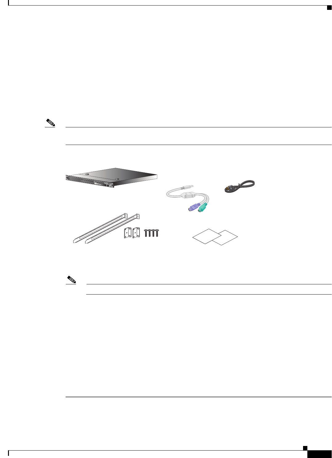
3-11
Installation and Upgrade Guide for Cisco Secure Access Control System 5.5
OL-28603-01
Chapter 3 Preparing to Install the Cisco 1121 Secure Access Control System Hardware
Preparing Your Site for Installation
Unpacking and Checking the Contents of Your Shipment
The shipping package for the CSACS-1121 Series appliance is designed to reduce the possibility of
product damage associated with routine material handling experienced during shipment. To reduce the
potential for damage to the product, transport the appliance in its original Cisco packaging. Failure to
do so may result in damage to the appliance. Also, do not remove the appliance from its shipping
container until you are ready to install it.
The appliance, cables, and any optional equipment you ordered may be shipped in more than one
container. A Notes section has been provided to record damaged or missing items. Figure 3-2 displays
the shipment items with the CSACS-1121 series appliance.
Note Do not discard the packaging materials used in shipping your CSACS-1121 Series appliance. You will
need the packaging materials in the future if you move or ship your appliance.
Figure 3-2 Items Shipped with the CSACS-1121 Series Appliance
Inspect all items for shipping damage. If anything appears to be damaged, or if you encounter problems
installing or configuring your appliance, contact your customer service representative.
Note The rack-mount kit does not include a 2-post equipment rack.
Cisco Information Packet and Warranty
The Cisco Information Packet provides warranty, service, and support information.
To access and download the Cisco Information Packet and your warranty and license agreements from
Cisco.com:
Launch your Internet browser and go to:
http://www.cisco.com/en/US/products/prod_warranties_listing.html
The Warranties and License Agreements page appears.
To read the Cisco Information Packet:
Step 1 Click the Information Packet Number field, and ensure that the part number 78-5235-03D0
is highlighted.
Step 2 Select the language in which you would like to read the document.
276972
Cisco ACS Appliance
AC Power Cord
Documentation
Rack Mounting Kit
USB to PS2
Dongle Cable

3-12
Installation and Upgrade Guide for Cisco Secure Access Control System 5.5
OL-28603-01
Chapter 3 Preparing to Install the Cisco 1121 Secure Access Control System Hardware
Preparing Your Site for Installation
Step 3 Click Go.
The Cisco Limited Warranty and Software License page from the Information Packet appears.
Step 4 Read the document online, or click the PDF icon to download and print the document.
You must have Adobe Acrobat Reader to view and print PDF files. You can download the reader from
the Adobe website.
To read translated and localized warranty information about your product:
Step 1 Enter this part number in the Warranty Document Number field:
78-5236-01C0
Step 2 Select the language in which you would like to read the document.
Step 3 Click Go.
The Cisco warranty page appears.
Step 4 Review the document online, or click the PDF icon to download and print the document in PDF.
You can also contact the Cisco Service and Support website for assistance at:
http://www.cisco.com/en/US/support/
Duration of Hardware Warranty
Ninety (90) days.
Replacement, Repair, or Refund Policy for Hardware
Cisco or its service center will use commercially reasonable efforts to ship a replacement part within ten
(10) working days after receipt of the Return Materials Authorization (RMA) request. Actual delivery
times can vary depending on the customer location.
Cisco reserves the right to refund the purchase price as its exclusive warranty remedy.
To Receive a Return Materials Authorization (RMA) Number
Contact the company from which you purchased the product. If you purchased the product directly from
Cisco, contact your Cisco Sales and Service Representative.
Complete the information below, and keep it for reference:
Company product purchased from —
Company telephone number and
website location
—
Product model number —
Product serial number1
1. See the “Product Serial Number Location” section on page 2-3 and the “Product Serial Number Location” section on page A-7
for more information.
—
Maintenance contact number —

3-13
Installation and Upgrade Guide for Cisco Secure Access Control System 5.5
OL-28603-01
Chapter 3 Preparing to Install the Cisco 1121 Secure Access Control System Hardware
Preparing Your Site for Installation
Required Tools and Equipment
Caution The fastener pack in the rack-mount kit, contains eight rack screws. You must check these screws to
ensure that they are the appropriate size for the holes in your rack. Using the wrong-sized screws for
your threaded rack holes can damage the rack.
You need the following tools and equipment to install the CSACS-1121 Series appliance in a 4-post rack:
Warning
Only trained and qualified personnel should be allowed to install, replace, or service this
equipment.
Statement 1030
•ESD-preventive cord and wrist strap.
•Number 2 Phillips screwdriver.
•Flat-blade screwdrivers (small, 3/16-inch (0.476 cm) and medium, 1/4-inch [0.625 cm]) to remove
the cover if you are upgrading memory or other components.
•Rack-mount Kit. For more information on kit contents, see 4-Post Rack-Mount Hardware Kit,
page 4-3.
•Cables for connection to the LAN ports (depending on the configuration).
•Ethernet switch for connection to the Ethernet (LAN) port or ports.
You need to have either of the following for the initial configuration of the CSACS-1121
Series appliance:
•USB keyboard and Video Graphics Array (VGA) monitor.
or
•Console terminal (an ASCII terminal or a PC running terminal-emulation software) that is
configured for 9600 baud, 8 data bits, no parity, 1 stop bit, and no hardware flow control.
•Console cable for connection to the serial (console) port. A null-modem cable is recommended.
Installation Checklist
To assist you with your installation and to provide a historical record of what was done, and by whom,
use the following installation checklist. Make a copy of this checklist and mark the entries as you
complete each task.
After the checklist is completed, include a copy of it for each CSACS-1121 Series appliance in your site
log (see Creating a Site Log, page 3-14 for information about creating a site log) along with other records
for your new appliance.

3-14
Installation and Upgrade Guide for Cisco Secure Access Control System 5.5
OL-28603-01
Chapter 3 Preparing to Install the Cisco 1121 Secure Access Control System Hardware
Preparing Your Site for Installation
Creating a Site Log
The site log (see Appendix B, “Site Log,” for a sample site log) provides a record of all actions related
to installing and maintaining the CSACS-1121 Series appliance. Keep the log in an accessible place near
the appliance so that anyone who performs tasks has access to it.
Use the installation checklist (see Installation Checklist, page 3-13) to verify the steps in the installation
and maintenance of your appliance. Site Log entries might include the following:
•Installation progress—Make a copy of the appliance installation checklist, and insert it into the site
log. Make entries as you complete each task.
•Upgrade, removal, and maintenance procedures—Use the site log as a record of ongoing appliance
maintenance and expansion history. Each time a task is performed on the appliance, update the site
log to reflect the following information:
–
Installation of new adapter cards.
–
Removal or replacement of adapter cards and other upgrades.
–
Configuration changes.
–
Maintenance schedules and requirements.
–
Maintenance procedures performed.
–
Intermittent problems.
–
Comments and notes.
Installation Checklist for Site:
CSACS-1121:
Task Verified by Date
Installation checklist copied — —
Background information placed in site log — —
Site power voltages verified — —
Installation site power check completed — —
Required tools availability verified — —
Additional equipment availability verified — —
CSACS-1121 Series appliance received — —
Cisco Information Packet publication received — —
Appliance components verified — —
Initial electrical connections established — —
ASCII terminal (for local configuration) verified — —
Signal distance limits verified — —
Startup sequence steps completed — —
Initial operation verified — —

3-15
Installation and Upgrade Guide for Cisco Secure Access Control System 5.5
OL-28603-01
Chapter 3 Preparing to Install the Cisco 1121 Secure Access Control System Hardware
Ethernet and Console Port Considerations
Ethernet and Console Port Considerations
ACS 5.5 supports multiple network interface connectors. There are four Ethernet connectors on the rear
panel of the CSACS-1121 Series appliance. See Multiple Network Interface Connectors, page 4-10 for
more information on multiple network interface connectors. The Gigabit Ethernet ports use UTP cables.
Cisco recommends Category 5 UTP cable. The maximum segment distance is 328 feet (100 meters). The
UTP cables look like the cables used for ordinary telephones. However, UTP cables meet certain
electrical standards that telephone cables do not. Cables are not included.
The appliance includes an asynchronous serial console port, which enables you to access the appliance
locally (using a console terminal). This section describes important cabling information that must be
considered before connecting a console terminal—either an ASCII terminal or a PC running
terminal-emulation software—to the console port.
Note The console cable is not included with the CSACS-1121 Series appliance.

3-16
Installation and Upgrade Guide for Cisco Secure Access Control System 5.5
OL-28603-01
Chapter 3 Preparing to Install the Cisco 1121 Secure Access Control System Hardware
Ethernet and Console Port Considerations

CHAPTER
4-1
Installation and Upgrade Guide for Cisco Secure Access Control System 5.5
OL-28603-01
4
Installing the Cisco 1121 Secure Access
Control System Hardware
This chapter describes how to install your CSACS-1121 Series appliance and connect it to the network.
It contains:
•Rack-Mounting Configuration Guidelines, page 4-1
•Mounting the CSACS-1121 Series Appliance in a 4-Post Rack, page 4-2
•Connecting Cables, page 4-7
•Powering Up the CSACS-1121 Series Appliance, page 4-17
•Preparing to Transport the Rack Cabinet, page 4-19
•Removing or Replacing the CSACS-1121 Series Appliance, page 4-20
Before you begin the installation, read the Regulatory Compliance and Safety Information for the Cisco
1121 Secure Access Control System available on http://www.cisco.com at the following location:
http://www.cisco.com/en/US/docs/net_mgmt/cisco_secure_access_control_system/5.4/regulatory/
compliance/csacsrcsi.html.
Warning
Only trained and qualified personnel should be allowed to install, replace, or service
this equipment.
Statement 1030
Warning
This unit is intended for installation in restricted access areas. A restricted access area can be
accessed only through the use of a special tool, lock and key, or other means of security.
Statement 1017
Rack-Mounting Configuration Guidelines
Each CSACS-1121 Series appliance has a set of rack handles (installed at the factory). You will use these
handles later when you install the appliance in a 4-post rack. You can front (flush) mount or mid-mount
the appliance in a 19-inch (48.3-cm) equipment rack that conforms to the 4-post rack specification (the
inside width of the rack should be 17.5 inches [44.45 cm]).
Mount the appliance in the brackets. When the appliance is installed in the rack, it requires one EIA
1.75-inch (4.4-cm) vertical mounting space or 1 rack unit (RU) for mounting.

4-2
Installation and Upgrade Guide for Cisco Secure Access Control System 5.5
OL-28603-01
Chapter 4 Installing the Cisco 1121 Secure Access Control System Hardware
Mounting the CSACS-1121 Series Appliance in a 4-Post Rack
Caution You must leave clearance in the front and rear of the CSACS-1121 Series appliance, to allow cooling air
to be drawn in through the front and circulated through the appliance and out the rear of the appliance.
The Rack Installation Safety Guidelines, page 3-7 and the following information will help you plan the
equipment rack configuration:
•When mounting an appliance in an equipment rack, ensure that the rack is bolted to the floor.
•Because you may install more than one appliance in the rack, ensure that the weight of all the
appliances installed does not make the rack unstable.
Caution Some equipment racks are also secured to ceiling brackets due to the weight of the equipment in the rack.
If you use this type of installation, ensure that the rack you are using to install the appliances is secured
to the building structure.
•As mentioned in Airflow Guidelines, page 3-8, maintain a 6-inch (15.2-cm) clearance at the front
and rear of the appliance to ensure adequate air intake and exhaust.
•Avoid installing appliances in an overly congested rack. Air flowing to or from other appliances in
the rack might interfere with the normal flow of cooling air through the appliances, increasing the
potential for overtemperature conditions within the appliances.
•Allow at least 24 inches (61 cm) of clearance at the front and rear of the rack for
appliance maintenance.
Caution To prevent appliance overheating, never install an appliance in an enclosed rack or a room that is not
properly ventilated or air conditioned.
•Follow your local practices for cable management. Ensure that cables to and from appliances do not
impede access for performing equipment maintenance or upgrades.
Note The rack-mount hardware kit does not include a 2-post equipment rack.
Mounting the CSACS-1121 Series Appliance in a 4-Post
Rack
Warning
When the appliance is installed in a rack and is fully extended on its slide rail, it is possible for
the rack to become unstable and tip over, which could cause serious injury. To eliminate the risk
of rack instability from extending the rail or in the event of an earthquake, you should affix the
rack to the floor.
This section contains:
•4-Post Rack-Mount Hardware Kit, page 4-3
•Installing the Slide Rails in a Rack, page 4-3
•Installing the Appliance into the Slide Rails, page 4-6
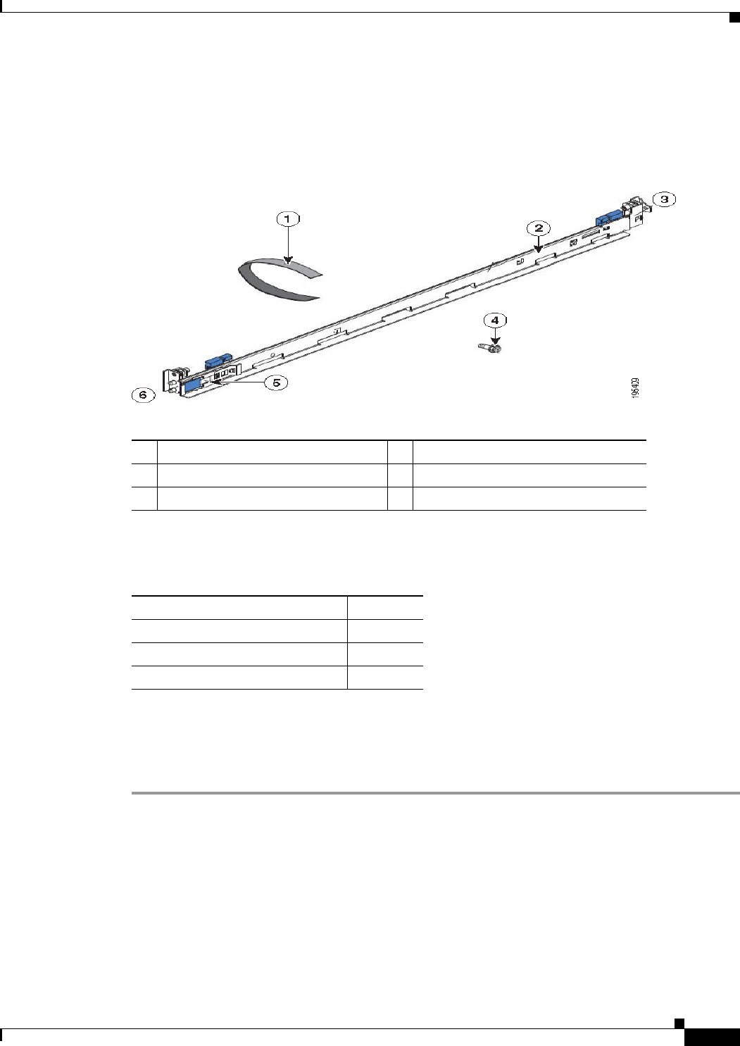
4-3
Installation and Upgrade Guide for Cisco Secure Access Control System 5.5
OL-28603-01
Chapter 4 Installing the Cisco 1121 Secure Access Control System Hardware
Mounting the CSACS-1121 Series Appliance in a 4-Post Rack
4-Post Rack-Mount Hardware Kit
Figure 4-1 shows the items that you need to install the CSACS-1121 Series appliance in a 4-post rack.
Figure 4-1 Release Levers on the Slide Rail Hardware
The following table describes the callouts in Figure 4-1.
Table 4-1 lists the contents of the rack-mount hardware kit (Cisco part number CSACS-1U-RAILS).
Installing the Slide Rails in a Rack
To install the CSACS-1121 Series appliance in a rack:
Step 1 Press on the rail-adjustment bracket on the rear of the slide rail (see Figure 4-2) to prevent the bracket
from moving.
Step 2 Press the adjustment tabs 1 and 2 (see Figure 4-2) and slide the rail-locking carrier toward the front of
the slide rail until it snaps into place.
Step 3 Press the adjustment Tabs 1 and 2 and slide the rail-locking carrier toward the rear of the slide until it
snaps into place.
1Cable straps 4M6 screws
2Slide rail 5Shipping bracket
3Front of rail 6Rear of rail
Table 4-1 Rack-Mount Hardware Kit
Item Quantity
Slide rails 2
Cable straps 6
M6 screws 6
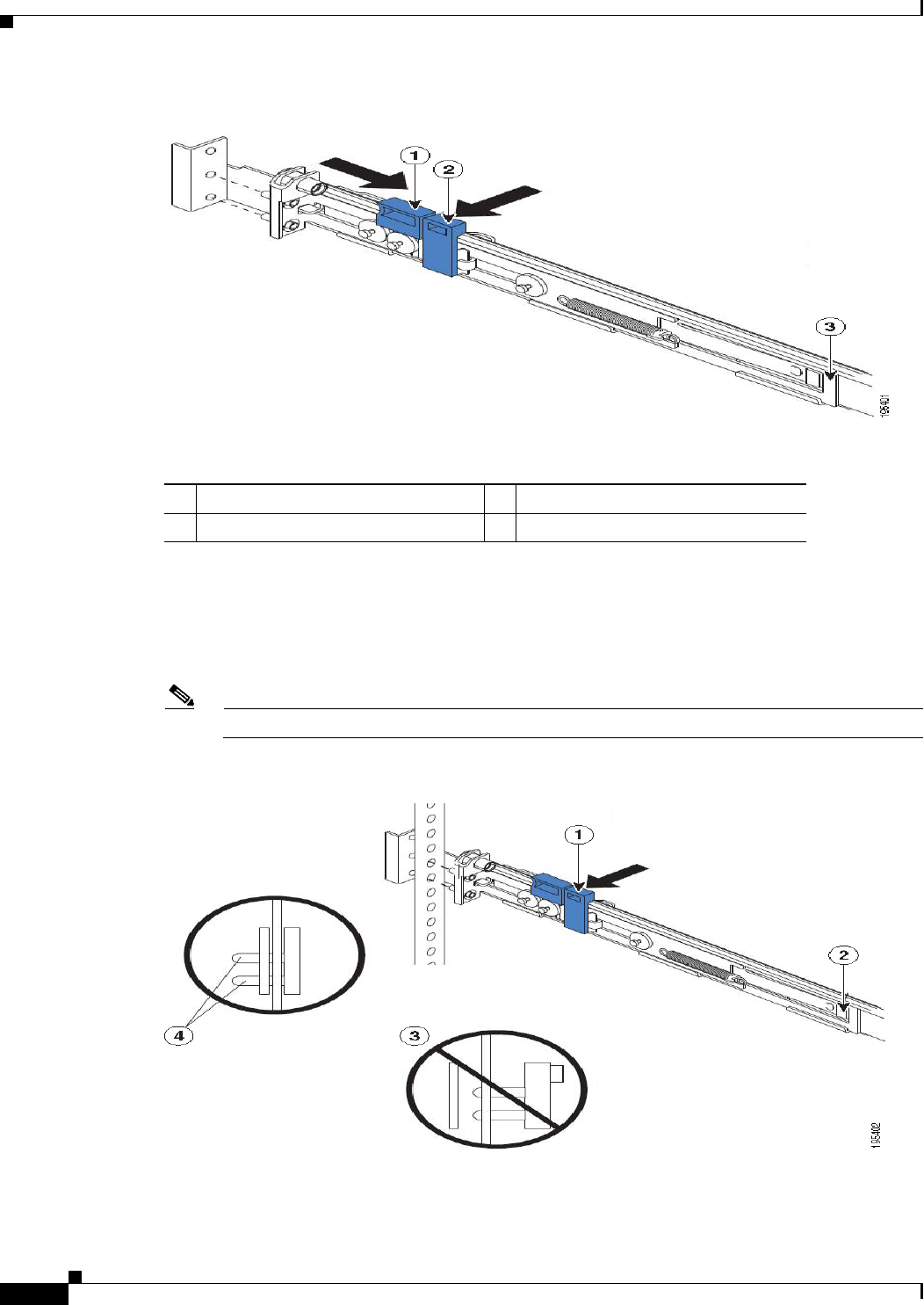
4-4
Installation and Upgrade Guide for Cisco Secure Access Control System 5.5
OL-28603-01
Chapter 4 Installing the Cisco 1121 Secure Access Control System Hardware
Mounting the CSACS-1121 Series Appliance in a 4-Post Rack
Figure 4-2 Installing the Slide Rail into the Rack
The following table describes the callouts in Figure 4-2.
If you need to adjust the slide-rail length, lift the release tab (see Figure 4-3) and fully extend the
rail-adjustment bracket from the rear of the slide rail until it snaps into place.
Step 4 Align the pins on the rear rail-locking carrier with the holes on the rear mounting flange.
Step 5 Press the adjustment tab (see Figure 4-3) to secure the rear of the slide rail to the rear mounting flange.
Note Ensure that the pins are fully extended through the mounting flange and slide rail.
Figure 4-3 Adjusting the Slide-rail Length
1Adjustment tab 1 3Rail-adjustment bracket
2Adjustment tab 2
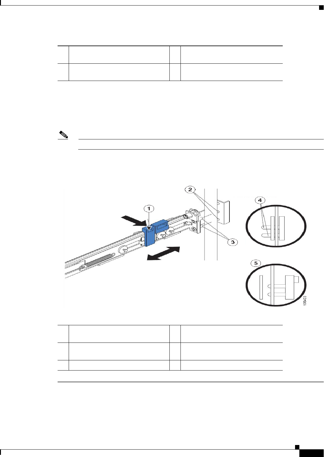
4-5
Installation and Upgrade Guide for Cisco Secure Access Control System 5.5
OL-28603-01
Chapter 4 Installing the Cisco 1121 Secure Access Control System Hardware
Mounting the CSACS-1121 Series Appliance in a 4-Post Rack
The following table describes the callouts in Figure 4-3.
Step 6 Align the pins (see Figure 4-4) on the front rail-locking carrier to the front mounting flange.
If you have adjusted the rail length, push the rail-locking carrier back toward the rear of the slide rail to
align the slide rail with the mounting flange.
Step 7 Press the adjustment tab to secure the front of the slide rail to the front mounting flange.
Note Ensure that the pins are fully extended through the mounting flange and the slide rail.
Step 8 Repeat these steps for the other slide rail.
Figure 4-4 Aligning the Slide Rail with the Mounting Flange
The following table describes the callouts in Figure 4-4.
1Adjustment tab 3Pins not extended through the
mounting flange and slide rail
2Release tab 4Pins extended through the mounting
flange and slide rail
1Adjustment tab 4Pins extended through the mounting
flange and slide rail
2Mounting flange 5Pins not extended through the
mounting flange and slide rail
3Pins
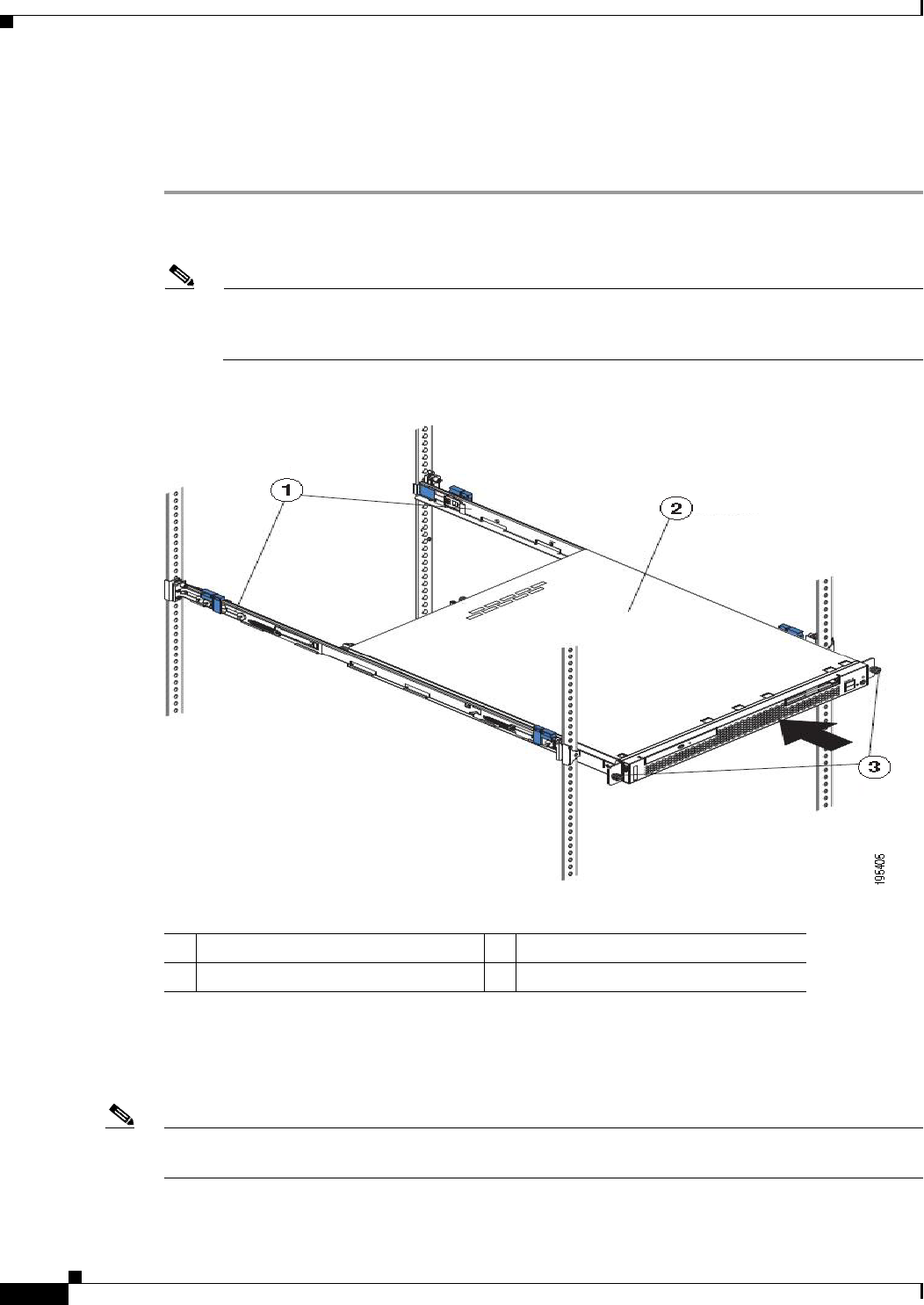
4-6
Installation and Upgrade Guide for Cisco Secure Access Control System 5.5
OL-28603-01
Chapter 4 Installing the Cisco 1121 Secure Access Control System Hardware
Mounting the CSACS-1121 Series Appliance in a 4-Post Rack
Installing the Appliance into the Slide Rails
To install the CSACS-1121 Series appliance into the slide rails:
Step 1 Align the server on the slide rails and push it fully into the rack cabinet.
Step 2 Secure the server to the front mounting flanges with the captive thumbscrews (see Figure 4-5).
Note You must leave the shipping brackets attached to the slide rails unless the shipping brackets
impede the server from sliding fully into the rack cabinet. If you need to remove the shipping
brackets, see Step 3.
Figure 4-5 Aligning the Server on the Slide Rails
The following table describes the callouts in Figure 4-5.
Step 3 Press the release tab (see Figure 4-6) as indicated on the shipping bracket, and remove the shipping
bracket from the slide rail.
Step 4 Repeat step 3 for the other shipping bracket. Store the shipping brackets for future use.
Note You must reinstall the shipping brackets on the slide rails before you transport the rack cabinet with the
server installed. To reinstall the shipping brackets, reverse the steps.
1Shipping brackets 3Thumbscrews
2ACS server
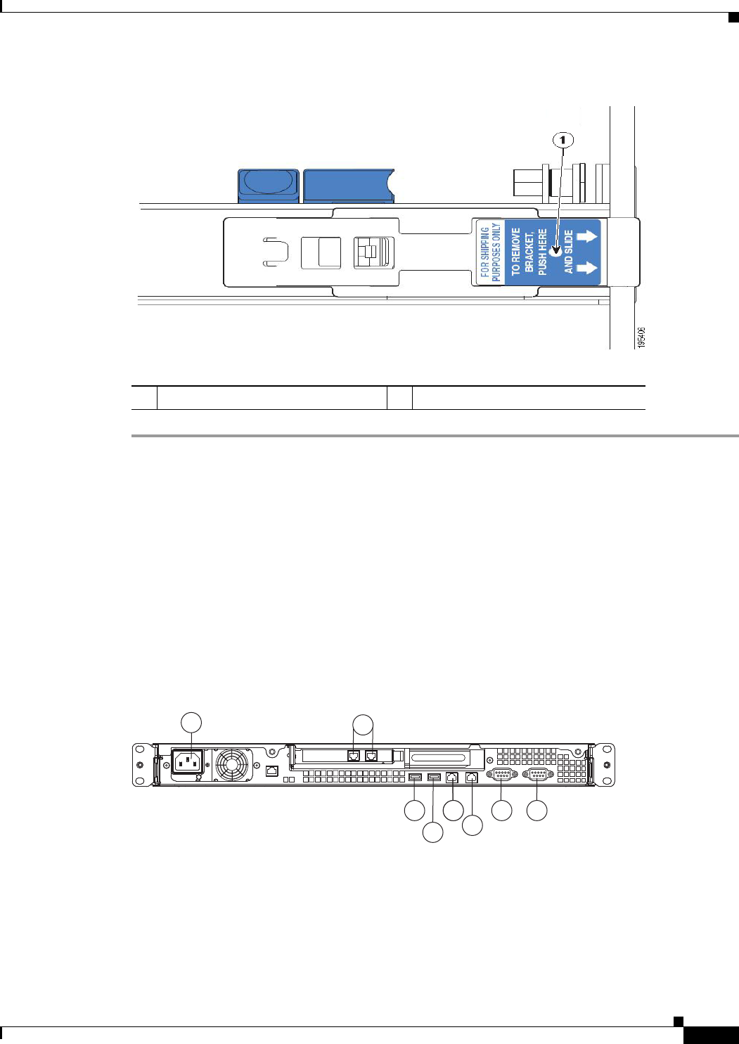
4-7
Installation and Upgrade Guide for Cisco Secure Access Control System 5.5
OL-28603-01
Chapter 4 Installing the Cisco 1121 Secure Access Control System Hardware
Connecting Cables
Figure 4-6 Removing the Shipping Brackets
The following table describes the callout in Figure 4-6.
Connecting Cables
This section describes how to connect your CSACS-1121 Series appliance to the network and the
appliance console. This section includes:
•Connecting the Network Interface, page 4-8
•Connecting the Console, page 4-15
•Connecting the Keyboard and Video Monitor, page 4-16
•Cable Management, page 4-17
Figure 4-7 CSACS-1121 Series Appliance Rear View
1Release tab
197065
1
8 4 4 3
7
2
65
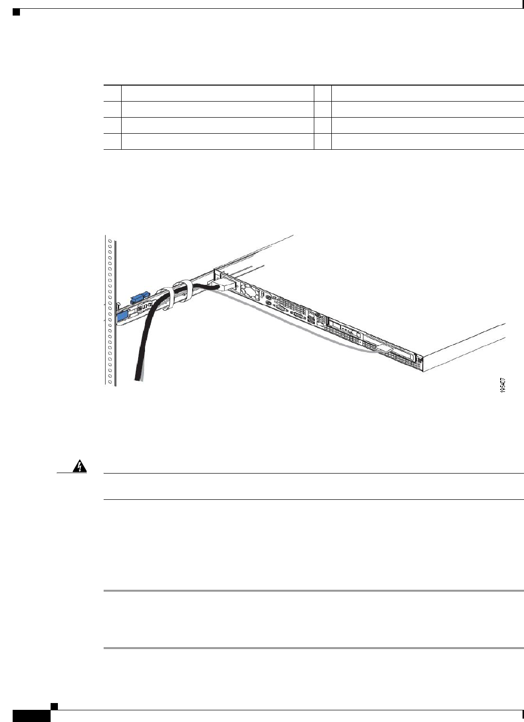
4-8
Installation and Upgrade Guide for Cisco Secure Access Control System 5.5
OL-28603-01
Chapter 4 Installing the Cisco 1121 Secure Access Control System Hardware
Connecting Cables
The following table describes the callouts in Figure 4-7.
.
Attach cables (such as keyboard, monitor cables, if required) to the rear of the server. Route the cables
to the left corner of the server (as viewed from the rear in Figure 4-8) and use the cable straps to secure
the cables to the slide rails.
Figure 4-8 Connecting the Cables
Connecting the Network Interface
Warning
Do not work on the system or connect or disconnect cables during periods of lightning activity.
Statement 1001
This section describes how to connect the CSACS-1121 Series appliance Ethernet port.
The Ethernet connector supports Serial over LAN (SOL) cables. The RJ-45 port supports standard
straight-through and crossover Category 5 unshielded twisted-pair (UTP) cables. Cisco does not supply
Category 5 UTP cables; these cables are available commercially.
To connect the cable to the appliance Ethernet port:
Step 1 Verify that the appliance is turned off.
Step 2 Connect one end of the cable to the Gigabit Ethernet 0 port on the appliance.
Step 3 Connect the other end to a switch in your network.
1 AC power receptacle 5 (Blocked) Gigabit Ethernet 1
2 (Blocked) Gigabit Ethernet 6 (In Use) Gigabit Ethernet 0
3 Serial connector 7 USB 3 connector
4 Video connector 8 USB 4 connector
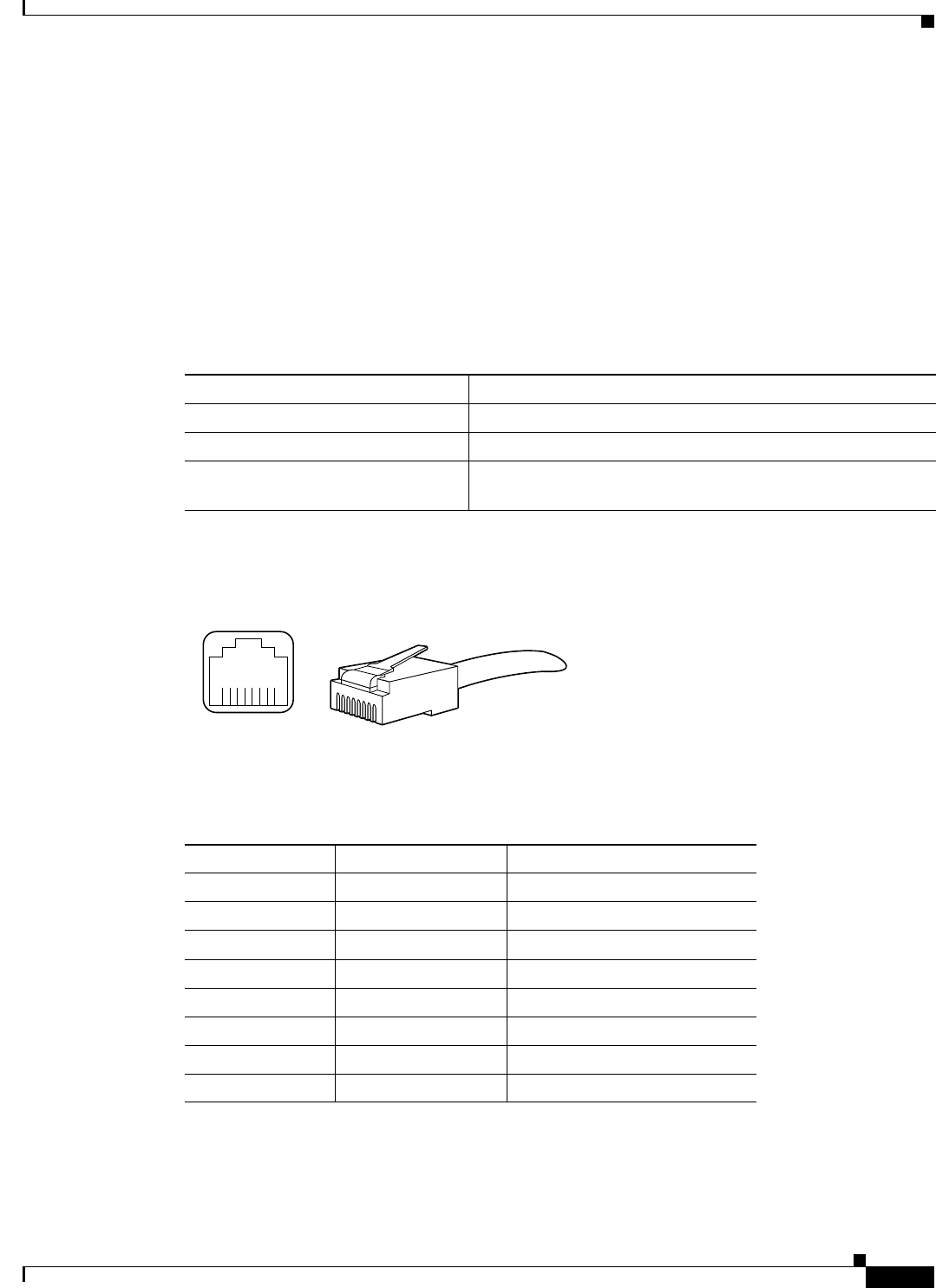
4-9
Installation and Upgrade Guide for Cisco Secure Access Control System 5.5
OL-28603-01
Chapter 4 Installing the Cisco 1121 Secure Access Control System Hardware
Connecting Cables
Ethernet Port Connector
The CSACS 1121 Series appliance comes with two integrated dual-port Ethernet controllers. ACS 5.5
supports multiple NICs. See Multiple Network Interface Connectors, page 4-10 for more information.
These controllers provide an interface for connecting to 10-Mb/s, 100-Mb/s, or 1000-Mb/s networks and
provide full-duplex (FDX) capability, which enables simultaneous transmission and reception of data on
the Ethernet LAN.
To access the Ethernet port, connect a Category 3, 4, 5, 5E, or 6 unshielded twisted-pair (UTP) cable to
the RJ-45 connector on the back of the appliance.
Table 4-2 describes the UTP cable Categories.
Figure 4-9 shows the Ethernet RJ-45 port and plug.
Figure 4-9 RJ-45 Port and Plug
Table 4-3 lists and describes the RJ-45 pin signals used on the connector.
Tabl e 4-2 Eth ernet Cabling Guidelines
Type Description
10BASE-T EIA Categories 3, 4, or 5 UTP (2 or 4 pair) up to 328 ft (100 m)
100BASE-TX EIA Category 5 UTP (2 pair) up to 328 ft (100 m)
1000BASE-T EIA Category 6 UTP (recommended), Category 5E UTP or
5 UTP (2 pair) up to 328 ft (100 m)
210222
8 7 6 5 4 3 2 1
RJ-45 connector
Table 4-3 Ethernet Port Pinout
Ethernet Port Pin Signal Description
1 TxD+ Transmit data +
2 TxD– Transmit data –
3 RxD+ Receive data +
4 Termination network No connection
5 Termination network No connection
6 RxD– Receive data –
7 Termination network No connection
8 Termination network No connection

4-10
Installation and Upgrade Guide for Cisco Secure Access Control System 5.5
OL-28603-01
Chapter 4 Installing the Cisco 1121 Secure Access Control System Hardware
Connecting Cables
Multiple Network Interface Connectors
ACS 5.5 with the Cisco SNS-3415, Cisco SNS-3495, virtual machine, or CSACS-1121 platform allows
you to use up to four network interfaces: Ethernet 0, Ethernet 1, Ethernet 2, and Ethernet 3.
Note To avoid system failures, you must ensure that Ethernet interface 0 is up and running successfully.
Table 4-4 lists the ACS 5.5 services that are distributed among the network interfaces.
Note Management service is supported only on Ethernet 0 network interface.
ACS management functions use only Ethernet interface 0, whereas authentication, authorization, and
accounting (AAA) protocols use all of the configured network interfaces. You must connect the ACS
nodes in the distributed deployment only to Ethernet 0. The syslog messages are sent and received at the
log collector’s Ethernet 0 interface. Data forwarding from one interface to another interface is prohibited
to prevent potential security issues. The external identity stores are supported only on Ethernet
interface 0. In ACS 5.5, multiple network interface connectors are also supported for the RADIUS and
TACACS+ proxy functionalities.
Cisco recommends you to use IP address from different subnets for different interfaces in ACS. If you
use IP address from same subnet for different interfaces in ACS, it results in ACS to send ARP replies
with same MAC address for the IP addresses from the same subnet. This recommendation is not
applicable for NIC bonding feature. The CLI and ACS management interfaces are accessible from both
Ethernet 0 and Ethernet 1 interfaces if you configure both the Ethernet 0 and Ethernet 1 interfaces with
IP addresses from the same subnet. Therefore, the IP addresses for the Ethernet 0 and Ethernet 1
interfaces should be from different subnets to restrict accessing ACS (CLI and ACS Web interface) only
using Ethernet interface 0.
Configuring Multiple Network Interfaces
By default, Ethernet interface 0 takes the IP address that is assigned for ACS. However, for the other
Ethernet ports, you must configure the IP address manually.
Table 4-4 ACS 5.5 Functional Interface Distribution Among Network Interfaces
Functional Interface Network Interface
Customer Logging Ethernet 0
Device Administration (TACACS+) All
Distributed Management Ethernet 0
External ID Stores (AD, LDAP, and RSA) Ethernet 0
Management GUI (HTTP) Ethernet 0
Management CLI (Secure Shell [SSH]) Ethernet 0
Monitoring and Troubleshooting/ACS View Syslog All
Network Access (RADIUS) All
RADIUS Proxy All
TACACS+ P roxy Al l

4-11
Installation and Upgrade Guide for Cisco Secure Access Control System 5.5
OL-28603-01
Chapter 4 Installing the Cisco 1121 Secure Access Control System Hardware
Connecting Cables
To configure the IP address for Ethernet ports, complete the following steps:
Step 1 Log in to the ACS CLI using the CLI username and password.
Step 2 Enter config t to enter configuration mode of the ACS CLI.
Step 3 Enter the interface GigabitEthernet number command.
Step 4 Enter the no shutdown command to bring up the interface.
Step 5 Enter the ip address ip address subnet mask command.
The console displays the following message:
Changing the IP may result in undesired side effects on any installed application(s).
Are you sure you want to proceed? Y/N [N]:
Step 6 Enter Y.
The specified interface is configured with the given IP address.
ACS restarts automatically. Wait for some time to ensure that all the processes are up and running
successfully.
In an IPv6-enabled network, the Ethernet interface 0 can work as a dual-stack interface, but configuring
an IPv4 address is mandatory. The Ethernet interfaces other than Ethernet 0 use an IPv6 address or an
IPv4 address or both of them. If you want to use an IPv4 address for the other Ethernet ports, you must
configure IPv4 addresses using the ip address Ipv4 address ip-mask command as described above.
Note ACS 5.5 supports IPv4 and IPv6 dual-stack networking but does not support pure IPv6 network.
Bonding Ethernet Interfaces
ACS supports bonding of two physical interfaces into a single virtual interface. This feature is called
Network Interface Card (NIC) Bonding. This bonding of two physical interfaces into one virtual
interface helps ACS process access requests when one of the two interfaces go down. When one physical
interface in the bond goes down, the other physical interface in the same bond works as a backup for the
other one and processes all the requests that come to this bonding. The NIC Bonding feature in ACS
provides only a backup of one physical interface when the other interface is down. The other general
features of NIC bonding, such as load balancing, are not supported. In ACS 5.5, with four Ethernet
interfaces being available, you can create two bonds.
Guidelines for creating NIC bonding in ACS:
•Bond 0—You can combine Ethernet interface 0 and Ethernet interface 1 to make bond 0. Ethernet
interfaces 0 and 1 act as slaves of bond 0. For bond 0, Ethernet interface 0 is the primary slave, and
Ethernet interface 1 is the secondary slave. Therefore, when Ethernet interface 0 goes down,
Ethernet interface 1 acts as a backup for Ethernet interface 0 and processes all requests. Ethernet
interface 1 cannot be the primary slave in bond 0. Bond 0 takes the IP address of Ethernet interface
0 and removes the IP address of Ethernet interface 1. Bond 0 takes the MAC address of Ethernet
interface 0 and assigns the same to Ethernet interface 1.
•Bond 1—You can combine Ethernet interface 2 and Ethernet interface 3 to make bond 1. Ethernet
interfaces 2and 3 act as slaves of bond 1. For bond 1, Ethernet interface 2 is the primary slave, and
Ethernet interface 3 is the secondary slave. Therefore, when Ethernet interface 2 goes down,
Ethernet interface 3 acts as a backup for Ethernet interface 2 and processes all requests. Ethernet

4-12
Installation and Upgrade Guide for Cisco Secure Access Control System 5.5
OL-28603-01
Chapter 4 Installing the Cisco 1121 Secure Access Control System Hardware
Connecting Cables
interface 3 cannot be the primary slave in bond 1. Bond 1 takes the IP address of Ethernet interface
2 and removes the IP address of Ethernet interface 3. Bond 1 takes the MAC address of Ethernet
interface 2 and assigns the same to Ethernet interface 3.
•ACS can have only two bonds, bond 0 and bond 1, as stated above. You cannot bond interfaces 1
and 2 together. It is not possible to make the Ethernet 2 or Ethernet 3 interfaces a backup interface
for Ethernet 0.
•Within a single bond, the two physical Ethernet interfaces that are involved should be from the same
subnet. You cannot create interface bonding with Ethernet interfaces from different subnets.
Ethernet interface 0 should be assigned an IPv4 address before creating bond 0. Similarly, you
cannot create bond 1 without an IPv4 or IPv6 address assigned to Ethernet 2 interface.
•Ethernet interface 0 acts as both the management interface and the runtime interface, whereas the
other three interfaces act as runtime interfaces. In ACS, you can create bond 0 and leave the Ethernet
interfaces 2 and 3 as is. In this case, bond 0 acts as a manangement and runtime interface, and
Ethernet interfaces 2 and 3 act as runtime interfaces. If you create two bonds, bond 0 and bond 1,
bond 0 acts as a management and runtime interface, and bond 1 acts as a runtime interface.
•You can change the IP address of the primary slave interface in a bonding. The new IP address is
assigned to the bonding interface because bonding takes the IP address of the primary slave.
•When you break the interface bonding, the IP address assigned to the bonding interface is assigned
back to the primary slave interface. The secondary slave will be down without any IP address. You
must manually configure an IP address for the secondary slave.
•If you want to configure interface bonding to an ACS instance in a distributed deployment,
deregister the ACS instance from the deployment, configure interface bonding, and then register the
ACS instance back to the deployment.
•Use the show running-config and show interface commands to see the bonding interface
information.
Configuring Interface Bonding
To create bond 0, complete the following steps:
Step 1 Log in to the ACS CLI using the CLI username and password.
Step 2 Enter config t to enter configuration mode.
Step 3 Enter the interface GigabitEthernet 0 command.
Step 4 Enter the no shutdown command to bring up the interface up.
Step 5 Enter the backup interface GibabitEthernet 1 command.
The console displays the following message:
WARN: IP address of interface eth1 will be removed once NIC bonding is enabled.
Configuring backup interface may result in undesired side effects on any installed
application(s).
Are you sure you want to proceed? Y/N [N]:
Step 6 Enter Y.
The console displays the following message:
Shutting down ntpd: [ OK ]
ntpd: Synchronizing with time server: [ OK ]
Starting ntpd: [ OK ]

4-13
Installation and Upgrade Guide for Cisco Secure Access Control System 5.5
OL-28603-01
Chapter 4 Installing the Cisco 1121 Secure Access Control System Hardware
Connecting Cables
Bonding Interface was modified.
ACS is restarting and a new HTTP certificate will be generated.
Stopping ACS.
Stopping Management and View........
Bond 0 is now configured.
ACS restarts automatically. Wait for some time to ensure that all processes are up and running
successfully.
To create bond 1, complete the following steps:
Step 1 Log in to the ACS CLI using the CLI username and password.
Step 2 Enter config t to enter configuration mode.
Step 3 Enter the interface GigabitEthernet 2 command.
Step 4 Enter the no shutdown command to bring up the interface.
Step 5 Enter the backup interface GigabitEthernet 3 command.
The console displays the following message:
WARN: IP address of interface eth3 will be removed once NIC bonding is enabled.
Configuring backup interface may result in undesired side effects on any installed
application(s).
Are you sure you want to proceed? Y/N [N]:
Step 6 Enter Y.
The console displays the following message:
Shutting down ntpd: [ OK ]
ntpd: Synchronizing with time server: [ OK ]
Starting ntpd: [ OK ]
Bonding Interface was modified.
ACS is restarting and a new HTTP certificate will be generated.
Stopping ACS.
Stopping Management and View........
Bond 1 is now configured.
ACS restarts automatically. Wait for some time to ensure that all processes are up and running
successfully.
Removing NIC Bond
Use the no form of the backup interface command to remove NIC bonding from ACS.
To remove bond 0, complete the following steps:
Step 1 Log in to ACS CLI using the CLI username and password.
Step 2 Enter config t to enter configuration mode.
Step 3 Enter the interface GigabitEthernet 0 command.

4-14
Installation and Upgrade Guide for Cisco Secure Access Control System 5.5
OL-28603-01
Chapter 4 Installing the Cisco 1121 Secure Access Control System Hardware
Connecting Cables
Step 4 Enter the no backup interface GigabitEthernet 1 command.
The console displays the following message:
Removing backup interface configuration may result in undesired side effects on any
installed application(s).
Are you sure you want to proceed? Y/N [N]:
Step 5 Enter Y.
The console displays the following message:
Shutting down ntpd: [ OK ]
ntpd: Synchronizing with time server: [ OK ]
Starting ntpd: [ OK ]
Bonding Interface was modified.
ACS is restarting and a new HTTP certificate will be generated.
ACS is not running.
To start ACS type 'application start acs'.
Starting ACS ..........
To verify that ACS processes are running, use the
'show application status acs' command.
Bond 0 is now removed.
ACS restarts automatically. Wait for some time to ensure that all processes are up and running
successfully.
To remove bond 1, complete the following steps:
Step 1 Log in to ACS CLI using the CLI username and password.
Step 2 Enter config t to enter configuration mode.
Step 3 Enter the interface GigabitEthernet 2 command.
Step 4 Enter the no backup interface GigabitEthernet 3 command.
The console displays the following message:
Removing backup interface configuration may result in undesired side effects on any
installed application(s).
Are you sure you want to proceed? Y/N [N]:
Step 5 Enter Y.
The console displays the following message:
Shutting down ntpd: [ OK ]
ntpd: Synchronizing with time server: [ OK ]
Starting ntpd: [ OK ]
Bonding Interface was modified.
ACS is restarting and a new HTTP certificate will be generated.
ACS is not running.
To start ACS type 'application start acs'.
Starting ACS ..........
To verify that ACS processes are running, use the
'show application status acs' command.

4-15
Installation and Upgrade Guide for Cisco Secure Access Control System 5.5
OL-28603-01
Chapter 4 Installing the Cisco 1121 Secure Access Control System Hardware
Connecting Cables
Bond 1 is now removed.
ACS restarts automatically. Wait for some time to ensure that all processes are up and running
successfully.
Connecting the Console
Warning
Do not work on the system or connect or disconnect cables during periods of lightning activity.
Statement 1001
Your CSACS-1121 Series appliance has a DCE-mode console port for connecting a console terminal to
your appliance. The appliance uses a DB-9 serial connector for the console port.
The console port on the CSACS-1121 Series appliance includes an EIA/TIA-232 asynchronous serial
(DB-9) connector. This serial console connector (port) allows you to access the appliance locally by
connecting a terminal—either a PC running terminal-emulation software or an ASCII terminal—to the
console port.
To connect a PC running terminal-emulation software to the console port, use a DB-9 female to DB-9
female straight-through cable.
To connect an ASCII terminal to the console port, use a DB-9 female to DB-25 male straight-through
cable with a DB-25 female to DB-25 female gender changer.
To connect a terminal or a PC running terminal-emulation software to the console port on the
CSACS-1121 Series appliance:
Step 1 Connect the terminal using a straight-through cable to the console port.
Step 2 Configure your terminal or terminal-emulation software for 9600 baud, 8 data bits, no parity, 1 stop bit,
and no hardware flow control.
Serial (Console) Port Connector
The CSACS 1121 Series appliance has one serial port connector located on the back panel of
the appliance.
Figure 4-10 shows the pin number assignments for the 9-pin, male D-shell serial port connector located
on the back panel of the appliance. These pin number assignments are those defined for RS-232-C and
conform to industry standards.
Figure 4-10 Serial Port Connector
Table 4-5 lists and describes the serial (console) port pinout.
15
69
83193

4-16
Installation and Upgrade Guide for Cisco Secure Access Control System 5.5
OL-28603-01
Chapter 4 Installing the Cisco 1121 Secure Access Control System Hardware
Connecting Cables
Connecting the Keyboard and Video Monitor
Warning
Do not work on the system or connect or disconnect cables during periods of lightning activity.
Statement 1001
This section describes how to connect a keyboard and video monitor to the CSACS-1121
Series appliance.
As an alternative to the keyboard and video monitor, you can use a serial console to connect to the
CSACS-1121 appliance.
The CSACS-1121 appliance does not provide support for a mouse.
The CSACS-1121 provides USB ports on the front and rear of the appliance that can be used to connect
a keyboard and video monitor.
To connect a keyboard and video monitor to the appliance:
Step 1 Verify that the appliance is turned off.
Step 2 Connect the end of the keyboard cable to the PS/2 (keyboard) port which is located on the back panel of
the appliance.
Table 4-5 DB-9 Serial (Console) Port Pinout
Serial Port Pin Signal Description
1 DCD Data Carrier Detect
2 RXD Receive Data
3 TXD Transmit Data
4 DTR Data Terminal Ready
5 GND Signal Ground
6 DSR Data Set Ready
7 RTS Request To Send
8CTSClear To Send
9 RI Ring Indicator

4-17
Installation and Upgrade Guide for Cisco Secure Access Control System 5.5
OL-28603-01
Chapter 4 Installing the Cisco 1121 Secure Access Control System Hardware
Powering Up the CSACS-1121 Series Appliance
Step 3 Connect the end of the video monitor cable to the PS/2 (video monitor) port which is located on the back
panel of the appliance.
Step 4 Power on the appliance.
Cable Management
Cable management is the most visual aspect of your appliance setup. However, cable management is
often overlooked because it can be time consuming.
Equipment racks and enclosures house more equipment today than ever before. This growth has
increased the need for organized cable management both inside and outside the rack. Poor cable
management not only leads to damaged cables or increased time for adding or changing cables, but also
blocks critical airflow or access. These problems can lead to inefficiencies in the performance of your
equipment or even downtime.
There are many solutions to address cable management. They can range from simple cable management
rings, to vertical or horizontal organizers, to troughs and ladders.
All CSACS-1121 Series appliance cables should be properly dressed so as not to interfere with each
other or other pieces of equipment. Use local practices to ensure that the cables attached to your
appliance are properly dressed.
Proceed to the next section, Powering Up the CSACS-1121 Series Appliance, page 4-17, to continue the
installation process.
Powering Up the CSACS-1121 Series Appliance
Warning
Do not touch the power supply when the power cord is connected. For systems with a power
switch, line voltages are present within the power supply even when the power switch is off and
the power cord is connected. For systems without a power switch, line voltages are present within
the power supply when the power cord is connected.
Statement 4
Warning
This equipment is intended to be grounded. Ensure that the host is connected to earth ground
during normal use.
Statement 39
This section contains:
•Checklist for Power Up, page 4-18
•Power-Up Procedure, page 4-18
•Checking the LEDs, page 4-19
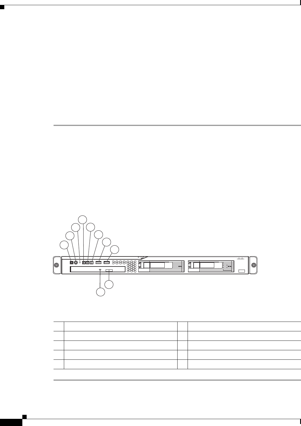
4-18
Installation and Upgrade Guide for Cisco Secure Access Control System 5.5
OL-28603-01
Chapter 4 Installing the Cisco 1121 Secure Access Control System Hardware
Powering Up the CSACS-1121 Series Appliance
Checklist for Power Up
You are ready to power up the CSACS-1121 Series appliance if:
•The appliance is securely mounted.
•Power, network, and interface cables are properly connected.
Power-Up Procedure
To power up the CSACS-1121 Series appliance and verify its initialization and self-test, follow this
procedure. When the procedure is completed, the appliance is ready to be configured.
Step 1 Review the information in Safety Guidelines, page 3-1.
Step 2 Plug the AC power cord into the power cord receptacle at the rear of the appliance. (See location 1 in
Figure 4-7.)
Step 3 Connect the other end of the power cord to a power source at your installation site.
Step 4 Press the power button on the front of the appliance. (See location 2 in Figure 4-11.)
The appliance should begin booting. After the operating system boots, you are ready to initialize the
basic software configuration. For configuration procedures, see the software installation guide or user
guide.
Figure 4-11 CSACS-1121 Series Appliance Front View
The following table describes the callouts in Figure 4-11.
1
2
4
5
6
7
8
9
10
3
195214
Cisco 1121 Secure
Accrss Control System
CISCO
1Appliance power LED 6System-error LED
2Power-control button 7USB 1 connector
3Reset button 8USB 2 connector
4Hard disk drive activity LED 9CD-eject button
5Locator LED 10 CD drive activity LED
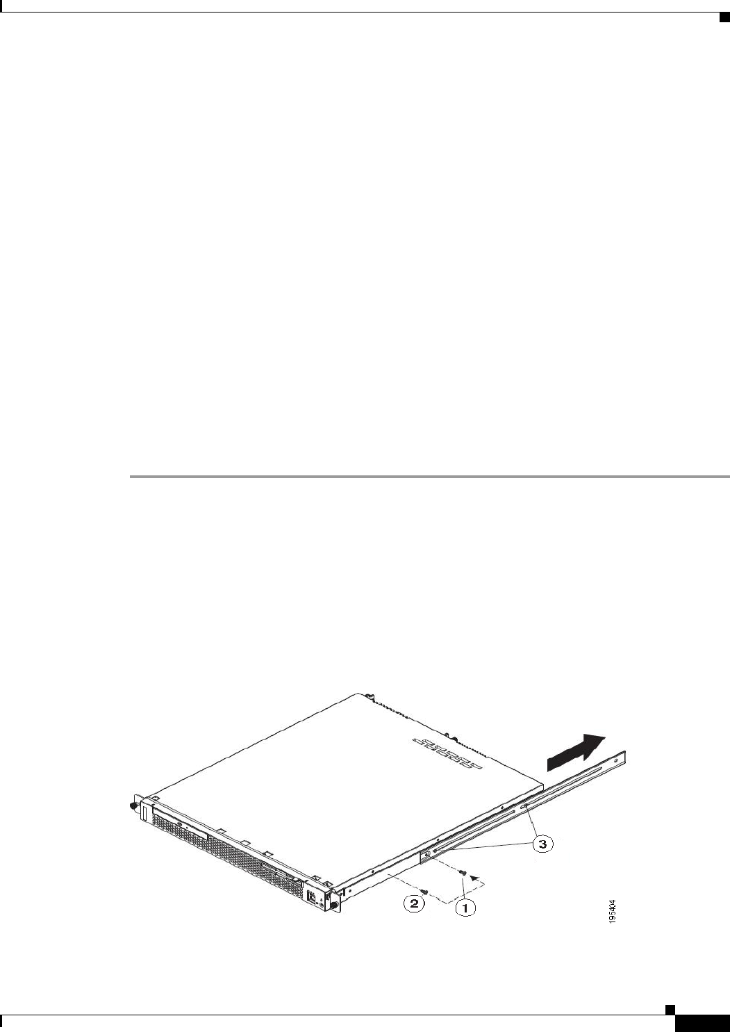
4-19
Installation and Upgrade Guide for Cisco Secure Access Control System 5.5
OL-28603-01
Chapter 4 Installing the Cisco 1121 Secure Access Control System Hardware
Preparing to Transport the Rack Cabinet
Checking the LEDs
When the CSACS-1121 Series appliance is up and running, observe the front-panel LEDs. The following
LEDs provide power, activity, and status information:
CSACS-1121 Appliance Front-Panel LEDs
•Appliance power, green:
–
On when power is on.
–
Off when power is off or an error condition has been detected in the operating voltages.
•Hard disk activity, green:
–
On when appliance software has booted up and the appliance is operational.
–
Off when appliance has not yet booted or an error condition has been detected in the
boot process.
For more detailed information about the LEDs, see Troubleshooting, page A-1.
Preparing to Transport the Rack Cabinet
To transport the CSACS-1121 Series appliance to another location with the server installed:
Step 1 Remove the large screw (see Figure 4-12) and discard it.
Step 2 Remove and save the front screw.
Step 3 Loosen the other two rear screws.
Step 4 Fully extend the rail and insert the screw you saved into the position where the large screw had been
located.
Step 5 Tighten all screws to secure the rail.
Step 6 Repeat the steps from 1 to 5 for the other rail.
Figure 4-12 Preparing to Transport the Rack Cabinet
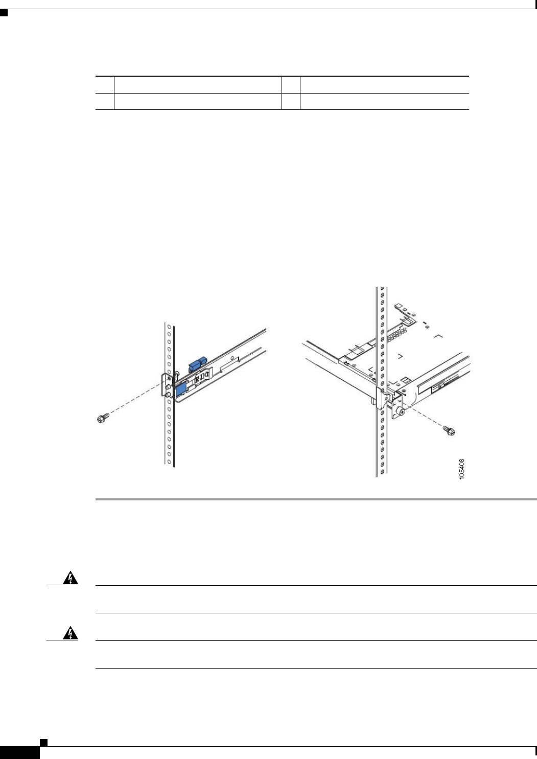
4-20
Installation and Upgrade Guide for Cisco Secure Access Control System 5.5
OL-28603-01
Chapter 4 Installing the Cisco 1121 Secure Access Control System Hardware
Removing or Replacing the CSACS-1121 Series Appliance
The following table describes the callouts in Figure 4-12.
Step 7 You must secure the server to the rack, by doing the following:
a. If necessary, disconnect the cables from the rear of the server.
b. Slide the server out of the rack 150 mm (6 inches) and insert the M6 screws in each slide rail.
c. Secure the server to the rack cabinet with the M6 screws. See Figure 4-13.
Step 8 Ensure that the rails are fully extended to the rear of the rack cabinet.
If you have removed the shipping brackets on the slide rails, you must reinstall them before you transport
the rack cabinet with the server installed. Reverse the instructions on the shipping bracket to reinstall it,
as shown in Figure 4-6.
Figure 4-13 Preparing to Move the Rack Cabinet to Another Location
Removing or Replacing the CSACS-1121 Series Appliance
Warning
Before working on a system that has an On/Off switch, turn OFF the power and unplug the power
cord.
Statement 1
Warning
Ultimate disposal of this product should be handled according to all national laws and
regulations.
Statement 1040
1Large screw 3Two rear screws
2Front screw

4-21
Installation and Upgrade Guide for Cisco Secure Access Control System 5.5
OL-28603-01
Chapter 4 Installing the Cisco 1121 Secure Access Control System Hardware
Removing or Replacing the CSACS-1121 Series Appliance
This section contains:
•Removing a CSACS-1121 Series Appliance, page 4-21
•Replacing a CSACS-1121 Series Appliance, page 4-21
Removing a CSACS-1121 Series Appliance
To remove a CSACS-1121 Series appliance from your network:
Step 1 Power down the appliance.
Step 2 Disconnect the power cords and network cables.
Step 3 Physically remove the appliance from the rack.
The appliance is in constant communication on your network; thus, when the network notices that the
appliance is no longer responding to it, the network stops sending requests to the appliance. This change
is visible to users.
Note If other appliances are attached to the network, the network continues sending requests to the
other appliances.
Replacing a CSACS-1121 Series Appliance
To replace an appliance:
Step 1 Remove the appliance from the network.
Step 2 Install a new appliance using the same installation procedures that you used for the previous appliance.
Step 3 Configure the new appliance using the same configuration parameters that you used for the
removed appliance.

4-22
Installation and Upgrade Guide for Cisco Secure Access Control System 5.5
OL-28603-01
Chapter 4 Installing the Cisco 1121 Secure Access Control System Hardware
Removing or Replacing the CSACS-1121 Series Appliance

CHAPTER
5-1
Installation and Upgrade Guide for Cisco Secure Access Control System 5.5
OL-28603-01
5
Installing and Configuring the Cisco Secure
Access Control System with CSACS-1121
This chapter describes how to install and initially configure CSACS-1121 and the ACS 5.5 server.
•Installation Using the CSACS-1121 Series Appliance, page 5-1
•Downloading the Cisco Secure ACS 5.5 ISO Image, page 9-2
•Installing the ACS Server, page 5-2
•Resetting the Administrator Password, page 5-6
•Reimaging the ACS Server, page 5-7
Installation Using the CSACS-1121 Series Appliance
The CSACS-1121 appliance is preinstalled with the ACS 5.5 software. This section gives you an
overview of the installation process and the tasks that you must perform before installing ACS.
Before you begin installing ACS 5.5, you must:
1. Open the box and check the contents. See Chapter 3, “Unpacking and Checking the Contents of Your
Shipment.”
2. Read Chapter 2, “Introducing the Cisco 1121 Secure Access Control System Hardware.”
3. Read the general precautions and safety warnings in Chapter 3, “Preparing to Install the Cisco 1121
Secure Access Control System Hardware.”
4. Install the appliance in the rack. See Chapter 4, “Installing the Cisco 1121 Secure Access Control
System Hardware.”
5. Connect the CSACS-1121 to the network and appliance console. See Chapter 4, “Connecting
Cables.”
6. Power up the CSACS-1121 appliance. See Chapter 4, “Powering Up the CSACS-1121 Series
Appliance.”
7. Run the setup command at the CLI prompt to configure the initial settings for the ACS server. See
Running the Setup Program, page 5-2.

5-2
Installation and Upgrade Guide for Cisco Secure Access Control System 5.5
OL-28603-01
Chapter 5 Installing and Configuring the Cisco Secure Access Control System with CSACS-1121
Downloading the Cisco Secure ACS 5.5 ISO Image
Downloading the Cisco Secure ACS 5.5 ISO Image
You can download the Cisco Secure ACS 5.5 ISO image from Cisco.com
Step 1 Go to http://www.cisco.com/go/acs. You must already have a valid Cisco.com login credentials to access
this link.
Step 2 Click Download Software.
The Cisco Secure ACS Release 5.5 software image appears on the Cisco.com page. You can test all the
Cisco ACS services once your installation and initial configuration are complete.
Note You can download the ACS 5.x software images from Cisco.com only when you have a valid Software
Application Support (SAS) contract for a previous version of ACS 5.x software. If you do not have a
valid SAS contract for a previous version, you must contact your Sales Engineer (SE), Accounts
Manager (AM), or Cisco partners to publish the software image on Cisco.com to the specific customers
account.
Installing the ACS Server
This section describes how to install ACS on the CSACS-1121 Series appliance.
This section contains:
•Running the Setup Program, page 5-2
•Verifying the Installation Process, page 5-5
Running the Setup Program
This section describes the setup process to install the ACS server.
The setup program launches an interactive command-line interface (CLI) that prompts you for the
required parameters.
An administrator can use the console or a dumb terminal to configure the initial network settings and
provide the initial administrator credentials for the ACS 5.5 server using the setup program. The setup
process is a one-time configuration task.
To install the ACS server:
Step 1 Power on the appliance.
The setup prompt appears:
Please type ‘setup’ to configure the appliance
localhost login:
Step 2 At the login prompt, enter setup and press Enter.
The console displays a set of parameters. You must enter the parameters as described in Table 5-1.

5-3
Installation and Upgrade Guide for Cisco Secure Access Control System 5.5
OL-28603-01
Chapter 5 Installing and Configuring the Cisco Secure Access Control System with CSACS-1121
Installing the ACS Server
Note You can interrupt the setup process at any time by typing Ctrl-C before the last setup value is entered.
Table 5-1 Network Configuration Parameters
Prompt Default Conditions Description
Host Name localhost First letter must be an ASCII character.
Length must be from 3 to 15 characters.
Valid characters are alphanumeric (A-Z,
a-z, 0-9), hyphen (-), and the first
character must be a letter.
Note When you intend to use AD ID
store and set up multiple ACS
instances with same name prefix,
use maximum of 15 characters as
the host name so that it does not
affect the AD functionality.
Enter the hostname.
IPV4 IP Address None, network specific Must be a valid IPv4 address between
0.0.0.0 and 255.255.255.255.
Enter the IP address.
IPv4 Netmask None, network specific Must be a valid IPv4 address between
0.0.0.0 and 255.255.255.255.
Enter a valid netmask.
IPv4 Gateway None, network specific Must be a valid IPv4 address between
0.0.0.0 and 255.255.255.255.
Enter a valid default gateway.
Domain Name None, network specific Cannot be an IP address.
Valid characters are ASCII characters, any
numbers, hyphen (-), and period (.).
Enter the domain name.
IPv4 Primary Name
Server Address
None, network specific Must be a valid IPv4 address between
0.0.0.0 and 255.255.255.255.
Enter a valid name
server address.
Add another
nameserver
None, network specific Must be a valid IPv4 address between
0.0.0.0 and 255.255.255.255.
Note You can configure a maximum of
three name servers from ACS CLI.
To configure multiple name
servers, enter Y.
NTP Server time.nist.gov Must be a valid IPv4 address between
0.0.0.0 and 255.255.255.255 or a domain
name server.
Note You can configure a maximum of
three NTP servers from ACS CLI.
Enter a valid domain name
server or an IPv4 address.
Timezone UTC Must be a valid local time zone. Enter a valid timezone.
SSH Service None, network specific None To enable SSH service,
enter Y.

5-4
Installation and Upgrade Guide for Cisco Secure Access Control System 5.5
OL-28603-01
Chapter 5 Installing and Configuring the Cisco Secure Access Control System with CSACS-1121
Installing the ACS Server
The console requests for the parameters as shown below:
localhost login: setup
Enter hostname[]: acs-server-1
Enter IP address[]: a.b.c.d
Enter IP default netmask[]: 255.255.255.255
Enter IP default gateway[]: a.b.c.d
Enter default DNS domain[]: mycompany.com
Enter primary nameserver[]: a.b.c.d
Add secondary nameserver? Y/N : n
Add primary NTP server [time.nist.gov]: a.b.c.d
Add secondary NTP server? Y/N : n
Enter system timezone[UTC]:
Enable SSH service? Y/N [N] : y
Enter username [admin]: admin
Enter password:
Enter password again:
Pinging the gateway...
Pinging the primary nameserver...
Username admin The name of the first administrative user.
You can accept the default or enter a new
username.
Must be from 3 to 8 characters, and must
be alphanumeric (A-Z, a-z, 0-9).
Enter the username.
Admin Password None No default password. Enter your
password.
The password must be at least six
characters in length, have at least one
lowercase letter, one uppercase letter, and
one number.
In addition:
•Save the user and password
information for the account that you
set up for initial configuration.
•Remember and protect these
credentials because they allow
complete administrative control of the
ACS hardware, the CLI, and the
application.
•If you lose your administrative
credentials, you can reset your
password by using the ACS 5.5
Installation and Recovery DVD.
Enter the password.
Table 5-1 Network Configuration Parameters (continued)
Prompt Default Conditions Description

5-5
Installation and Upgrade Guide for Cisco Secure Access Control System 5.5
OL-28603-01
Chapter 5 Installing and Configuring the Cisco Secure Access Control System with CSACS-1121
Installing the ACS Server
Do not use `Ctrl-C' from this point on...
Appliance is configured
Installing applications...
Installing acs...
Generating configuration...
Rebooting...
After the ACS server is installed, the system reboots automatically.
Now, you can log into ACS using the CLI username and password that was configured during the
setup process.
Note You can use this username and password to log into ACS only via the CLI.
Note The initial setup of the ACS 5.5 server should be configured with an IPv4 address. You can configure
the IPv6 IP address for your server only after the initial setup is completed.
Note ACS 5.5 supports IPv4 and IPv6 dual stack networking and does not support pure IPv6 network.
Verifying the Installation Process
To verify that you have correctly completed the installation process:
Step 1 When the system reboots, at the login prompt enter the username you configured during setup, and
press Enter.
Step 2 At password prompt, enter the password you configured during setup, and press Enter.
Step 3 Verify that the application has been installed properly by entering show application, and press Enter.
The console displays:
<name> <Description>
acs Cisco Secure Access Control System 5.5
Step 4 At the system prompt, check the release and ACS version that are installed, at the system prompt by
entering show application version acs and pressing Enter.
The console displays:
Cisco ACS VERSION INFORMATION
-----------------------------
Version : 5.5.0.46
Internal Build ID : B.221
Note The Version and Internal Build ID may change for different versions of this release.

5-6
Installation and Upgrade Guide for Cisco Secure Access Control System 5.5
OL-28603-01
Chapter 5 Installing and Configuring the Cisco Secure Access Control System with CSACS-1121
Resetting the Administrator Password
Step 5 Check the status of ACS processes, at the system prompt by entering show application status acs,
and press Enter.
The console displays:
ACS role: PRIMARY
Process 'database' running
Process 'management' running
Process 'runtime' running
Process 'ntpd' running
Process 'view-database' running
Process 'view-jobmanager' running
Process 'view-alertmanager' running
Process 'view-collector' running
Process 'view-logprocessor' running
Note To get the latest ACS patches and to keep your ACS up-to-date, visit
http://software.cisco.com/download/navigator.html?i=rt
Resetting the Administrator Password
If you are not able to log in to the system due to the loss of the administrator password, you can use the
ACS 5.5 recovery DVD to reset the administrator password.
To reset the administrator password:
Step 1 Power up the appliance.
Step 2 Insert the ACS 5.5 recovery DVD.
The console displays:
Welcome to Cisco Secure ACS 5.5 Recovery
To boot from hard disk press <Enter>
Available boot options:
[1] Cisco Secure ACS 5.5 Installation (Keyboard/Monitor)
[2] Cisco Secure ACS 5.5 Installation (Serial Console)
[3] Reset Administrator Password (Keyboard/Monitor)
[4] Reset Administrator Password (Serial Console)
<Enter> Boot from hard disk
Please enter boot option and press <Enter>.
boot:
To reset the administrator password, at the system prompt, enter 3 if you are using a keyboard and video
monitor, or enter 4 if you are using a serial console port.
The console displays a set of parameters.
Step 3 Enter the parameters as described in Table 5-2.

5-7
Installation and Upgrade Guide for Cisco Secure Access Control System 5.5
OL-28603-01
Chapter 5 Installing and Configuring the Cisco Secure Access Control System with CSACS-1121
Reimaging the ACS Server
The console displays:
Admin username:
[1]:admin
[2]:admin2
[3]:admin3
Enter number of admin for password recovery:1
Password:
Verify password:
Save change&reeboot? [Y/N]:
Reimaging the ACS Server
To reimage the ACS server:
Step 1 Power up the appliance.
Step 2 Insert the ACS Recovery DVD.
The console displays:
Welcome to Cisco Secure ACS 5.5 Recovery
To boot from hard disk press <Enter>
Available boot options:
[1] Cisco Secure ACS 5.5 Installation (Keyboard/Monitor)
[2] Cisco Secure ACS 5.5 Installation (Serial Console)
[3] Reset Administrator Password (Keyboard/Monitor)
[4] Reset Administrator Password (Serial Console)
<Enter> Boot from hard disk
Please enter boot option and press <Enter>.
boot:
Step 3 At the console prompt, enter 1 if you are using a keyboard and video monitor, or enter 2 if you are using
a serial console port, and press Enter.
The reimage process uninstalls the existing ADE-OS and ACS versions, and installs the latest versions.
For the installation process, see the section Running the Setup Program, page 5-2.
Table 5-2 Password Reset Parameters
Parameter Description
Admin username Enter the number of the administrator whose password you want to reset.
Password Enter the new password for the administrator.
Verify password Enter the password again.
Save change & Reboot Enter Y to save.

5-8
Installation and Upgrade Guide for Cisco Secure Access Control System 5.5
OL-28603-01
Chapter 5 Installing and Configuring the Cisco Secure Access Control System with CSACS-1121
Regulatory Compliance
Regulatory Compliance
For regulatory compliance and safety information, see Regulatory Compliance and Safety Information
for Cisco Secure Access Control System. This document is available online at Cisco.com:
http://www.cisco.com/en/US/docs/net_mgmt/cisco_secure_access_control_system/5.4/regulatory/
compliance/csacsrcsi.html

P
ART
3
ACS 5.5 on Cisco SNS 3400 Servers

CHAPTER
6-1
Installation and Upgrade Guide for Cisco Secure Access Control System 5.5
OL-28603-01
6
Introducing the Cisco SNS-3415 and Cisco
SNS-3495 Hardware Appliances
This chapter gives an overview of the Cisco Secure Access Control System (Cisco SNS-3415 and Cisco
SNS-3495) hardware. It covers the appliance hardware, major components, controls, connectors, and
front- and rear-panel LED indicators.
•Product Overview, page 6-1
•LED Indicators on Cisco SNS 3415 and 3495 Appliances, page 6-5
•Regulatory Compliance, page 6-8
Product Overview
This section describes the power requirements, rack-mount hardware kit, and features of the Cisco
SNS-3415 and Cisco SNS-3495 appliances.
This section contains:
•Cisco SNS-3415 and Cisco SNS-3495 Appliances Overview, page 6-1
•Cisco SNS-3415 and Cisco SNS-3495 Appliances Hardware Specifications, page 6-2
•Product Serial Number Location, page 6-4
•Cisco Product Identification Tool, page 6-4
Cisco SNS-3415 and Cisco SNS-3495 Appliances Overview
The Cisco SNS-3415/3495 server is designed for performance and density over a wide range of business
workloads, from web serving to distributed databases.
Building on the success of the Cisco SNS-3415/3495 server, the enterprise-class Cisco SNS-3415/3495
server further extends the capabilities of the Cisco Unified Computing System portfolio in a 1U form
factor. The Cisco SNS-3415 server does this with the addition of the Intel Xeon processor E5-2600
product family, which delivers significant performance and efficiency gains. In addition, the Cisco
SNS-3415/3495 server offers up to 256 GB of RAM, 8 drives, and 2 x 1 GbE lights-out management
(LOM) ports that deliver outstanding levels of density and performance in a compact package.

6-2
Installation and Upgrade Guide for Cisco Secure Access Control System 5.5
OL-28603-01
Chapter 6 Introducing the Cisco SNS-3415 and Cisco SNS-3495 Hardware Appliances
Product Overview
Cisco SNS-3415 and Cisco SNS-3495 Appliances Hardware Specifications
Table 6-1describes the hardware specifications of Cisco SNS-3415 and Cisco SNS-3495 appliances.
Table 6-1 Cisco SNS 3415 and Cisco SNS 3495 Hardware Summary
Note ACS 5.5 supports an optional redundant power supply unit for Cisco SNS-3415-K9.
Cisco Secure ACS
Appliance Hardware Specifications Diagrams
Cisco SNS-3415-K9 •Cisco UCS C220 M3
•Single socket Intel E5-2609
2.4Ghz CPU 4 total cores, 4 total
threads
•16 GB RAM
•1 x 600-GB disk
•Embedded Software RAID 0
•4 GE network interfaces
•For physical, environmental, and
power specifications, see Server
Specifications, page 7-5.
•Cisco SNS-3415/3495 Appliance
Front View
•Cisco SNS-3415/3495 Appliance
Rear View
Cisco SNS-3495-K9 •Cisco UCS C220 M3
•Dual socket Intel E5-2609
2.4Ghz CPU 8 total cores, 8 total
threads
•32 GB RAM
•2 x 600-GB disks
•RAID 0+1
•4 GE network interfaces
•For physical, environmental, and
power specifications, see Server
Specifications, page 7-5.
•Cisco SNS-3415/3495 Appliance
Front View
•Cisco SNS-3415/3495 Appliance
Rear View
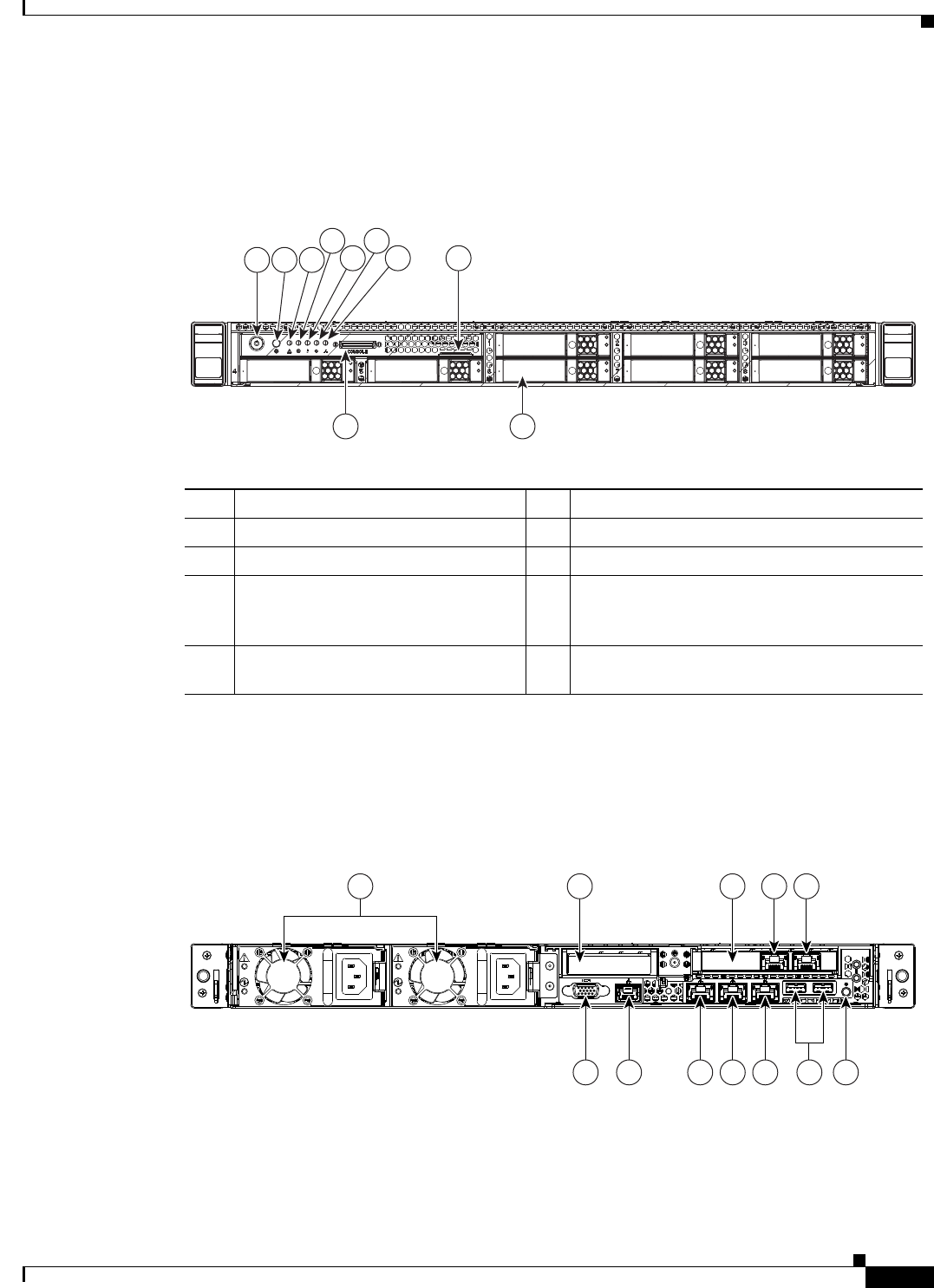
6-3
Installation and Upgrade Guide for Cisco Secure Access Control System 5.5
OL-28603-01
Chapter 6 Introducing the Cisco SNS-3415 and Cisco SNS-3495 Hardware Appliances
Product Overview
Chasis Front View
Figure 6-1 shows the Cisco SNS-3415/3495 Server.
Figure 6-1 Cisco SNS-3415/3495 Appliance Front View
Chasis Rear View
Figure 6-2 shows the external features of the Cisco SNS-3415 and Cisco SNS-3495 appliances rear
panel.
Figure 6-2 Cisco SNS-3415/3495 Appliance Rear View
HDD4 HDD5
HDD1
HDD6
HDD2
HDD7
HDD3
HDD8
8
9 10
1 3
4
5 7
6
2
331682
1 Power button/Power status LED 6 Power supply status LED
2 Identification button/LED 7 Network link activity LED
3 System status LED 8 Asset tag (serial number)
4 Fan status LED 9 KVM connector (used with KVM cable that
provides two USB, one VGA, and one serial
connector)
5 Temperature status LED 10 Drives (up to eight hot-swappable 2-5-inch
drives)
PSU1
PSU1
PSU2
PSU2
PSU1 PSU2
PCIe2
6 7 8 9 10 1211
2 3 4 51
360856

6-4
Installation and Upgrade Guide for Cisco Secure Access Control System 5.5
OL-28603-01
Chapter 6 Introducing the Cisco SNS-3415 and Cisco SNS-3495 Hardware Appliances
Product Overview
Product Serial Number Location
The serial number label is located on the front panel of the Cisco SNS-3415 or Cisco SNS-3495
appliance, at the top of the server. Figure 6-1 shows the location of this label.
Cisco Product Identification Tool
The Cisco Product Identification (CPI) tool helps you retrieve the serial number of your Cisco products.
Before you submit a request for service online or by phone, use the CPI tool to locate your product serial
number. You can access this tool from the Cisco Support website.
To access this tool:
Step 1 Click the Get Tools & Resources link.
Step 2 Click the All Tools (A-Z) tab.
Step 3 Select Cisco Product Identification Tool from the alphabetical drop-down list.
This tool offers three search options:
•Search by product ID or model name.
•Browse for Cisco model.
•Copy and paste the output of the show command to identify the product.
Search results show an illustration of your product with the serial number label location highlighted.
Locate the serial number label on your product and record the information before you place a
service call.
You can access the CPI tool at:
http://tools.cisco.com/Support/CPI/index.do
To access the CPI tool, you require a Cisco.com user ID and password. If you have a valid service
contract but do not have a user ID or password, you can register at:
http://tools.cisco.com/RPF/register/register.do
1 Power supplies (up to two) 7 Serial port (RJ-45 connector)
2 Slot 2: Low-profile Peripheral Component
Interconnect Express (PCIe) slot on riser
(half-height, half-length, x16 connector, x16
lane width)
8 1-GB Ethernet dedicated management port
used to access CIMC (labeled M)
3 Slot 1: PCIe1 card containing 1-GB Ethernet
ports (GigE2 and GigE3)
9 1-GB Ethernet port 1 (GigE0) for Cisco
Secure ACS management communication
4 1-GB Ethernet port 3 (GigE2) 10 1-GB Ethernet port 2 (GigE1)
5 1-GB Ethernet port 4 (GigE3) 11 USB Ports
6 VGA video connector 12 Rear identification button

6-5
Installation and Upgrade Guide for Cisco Secure Access Control System 5.5
OL-28603-01
Chapter 6 Introducing the Cisco SNS-3415 and Cisco SNS-3495 Hardware Appliances
LED Indicators on Cisco SNS 3415 and 3495 Appliances
LED Indicators on Cisco SNS 3415 and 3495 Appliances
This section describes the front- and rear-panel controls, ports, and LED indicators on the Cisco
SNS-3415 or Cisco SNS-3495 appliances.
This section contains:
•Cisco SNS-3415/3495 Appliance Front-Panel View, page 6-5
•Cisco SNS-3415/3495 Appliance Back-Panel View, page 6-6
•Internal Diagnostic LEDs, page 6-7
Cisco SNS-3415/3495 Appliance Front-Panel View
Figure 6-1 shows the components of the Cisco SNS-3415 or Cisco SNS-3495 appliance front-panel
view.
Table 6-2 describes the LEDs located on the front panel of the Cisco SNS-3415 or Cisco SNS-3495
appliance
Table 6-2 Front-Panel LEDs
LED Name State
Power button/Power
status LED
•Off—There is no AC power to the server.
•Amber—The server is in standby power mode. Power is supplied only
to the CIMC and some motherboard functions.
•Green—The server is in main power mode. Power is supplied to all
server components.
Identification •Off—The Identification LED is not in use.
•Blue—The Identification LED is activated.
System status •Green—The server is running in normal operating condition.
•Green, blinking—The server is performing system initialization and
memory check.
•Amber, steady—The server is in a degraded operational state. For
example:
–
Power supply redundancy is lost.
–
CPUs are mismatched.
–
At least one CPU is faulty.
–
At least one DIMM is faulty.
–
At least one drive in a RAID configuration failed.
•Amber, blinking—The server is in a critical fault state. For example:
–
Boot failed.
–
Fatal CPU and/or bus error is detected.
–
Server is in over-temperature condition.

6-6
Installation and Upgrade Guide for Cisco Secure Access Control System 5.5
OL-28603-01
Chapter 6 Introducing the Cisco SNS-3415 and Cisco SNS-3495 Hardware Appliances
LED Indicators on Cisco SNS 3415 and 3495 Appliances
Cisco SNS-3415/3495 Appliance Back-Panel View
Figure 6-2 shows the components of the Cisco SNS-3415 and Cisco 3495 appliance back-panel view.
Table 6-3 describes the LEDs located on the front panel of the Cisco SNS-3415 or Cisco SNS-3495
appliance.
Fan status •Green—All fan modules are operating properly.
•Amber, steady—One fan module has failed.
•Amber, blinking—Critical fault, two or more fan modules have
failed.
Temperature status •Green—The server is operating at normal temperature.
•Amber, steady—One or more temperature sensors have exceeded a
warning threshold.
•Amber, blinking—One or more temperature sensors have exceeded a
critical threshold.
Power supply status •Green—All power supplies are operating normally.
•Amber, steady—One or more power supplies are in a degraded
operational state.
•Amber, blinking—One or more power supplies are in a critical fault
state.
Network link activity •Off—The Ethernet link is idle.
•Green—One or more Ethernet LOM ports are link-active, but there is
no activity.
•Green, blinking—One or more Ethernet LOM ports are link-active,
with activity.
Hard drive fault •Off—The hard drive is operating properly.
•Amber—This hard drive has failed.
•Amber, blinking—The device is rebuilding.
Hard drive activity •Off—There is no hard drive in the hard drive sled (no access, no
fault).
•Green—The hard drive is ready.
•Green, blinking—The hard drive is reading or writing data.
Table 6-2 Front-Panel LEDs (continued)
LED Name State

6-7
Installation and Upgrade Guide for Cisco Secure Access Control System 5.5
OL-28603-01
Chapter 6 Introducing the Cisco SNS-3415 and Cisco SNS-3495 Hardware Appliances
LED Indicators on Cisco SNS 3415 and 3495 Appliances
Internal Diagnostic LEDs
The server has internal fault LEDs for fan modules and DIMMs. The LED lights amber to indicate a
failed component.
Note Power must be connected to the server for these LEDs to be operate.
Figure 6-3 shows the locations of these internal LEDs in Cisco SNS-3415 or Cisco SNS-3495 appliance.
Table 6-3 Back-Panel LEDs
LED Name State
Power supply fault •Off—The power supply is operating normally.
•Amber, blinking—An event warning threshold has been reached, but
the power supply continues to operate.
•Amber, solid—A critical fault threshold has been reached, causing the
power supply to shut down (for example, a fan failure or an
over-temperature condition).
Power supply AC OK •Off—There is no AC power to the power supply.
•Green, blinking—AC power OK, DC output not enabled.
•Green, solid—AC power OK, DC outputs OK.
1-Gb Ethernet dedicated
management link speed
•Off—link speed is 10 Mbps.
•Amber—link speed is 100 Mbps.
•Green—link speed is 1 Gbps.
1-Gb Ethernet dedicated
management link status
•Off—No link is present.
•Green—Link is active.
•Green, blinking—Traffic is present on the active link.
1-Gb Ethernet link speed •Off—link speed is 10 Mbps.
•Amber—link speed is 100 Mbps.
•Green—link speed is 1 Gbps.
1-Gb Ethernet link status •Off—No link is present.
•Green—Link is active.
•Green, blinking—Traffic is present on the active link.
Identification •Off—The Identification LED is not in use.
•Blue—The Identification LED is activated.
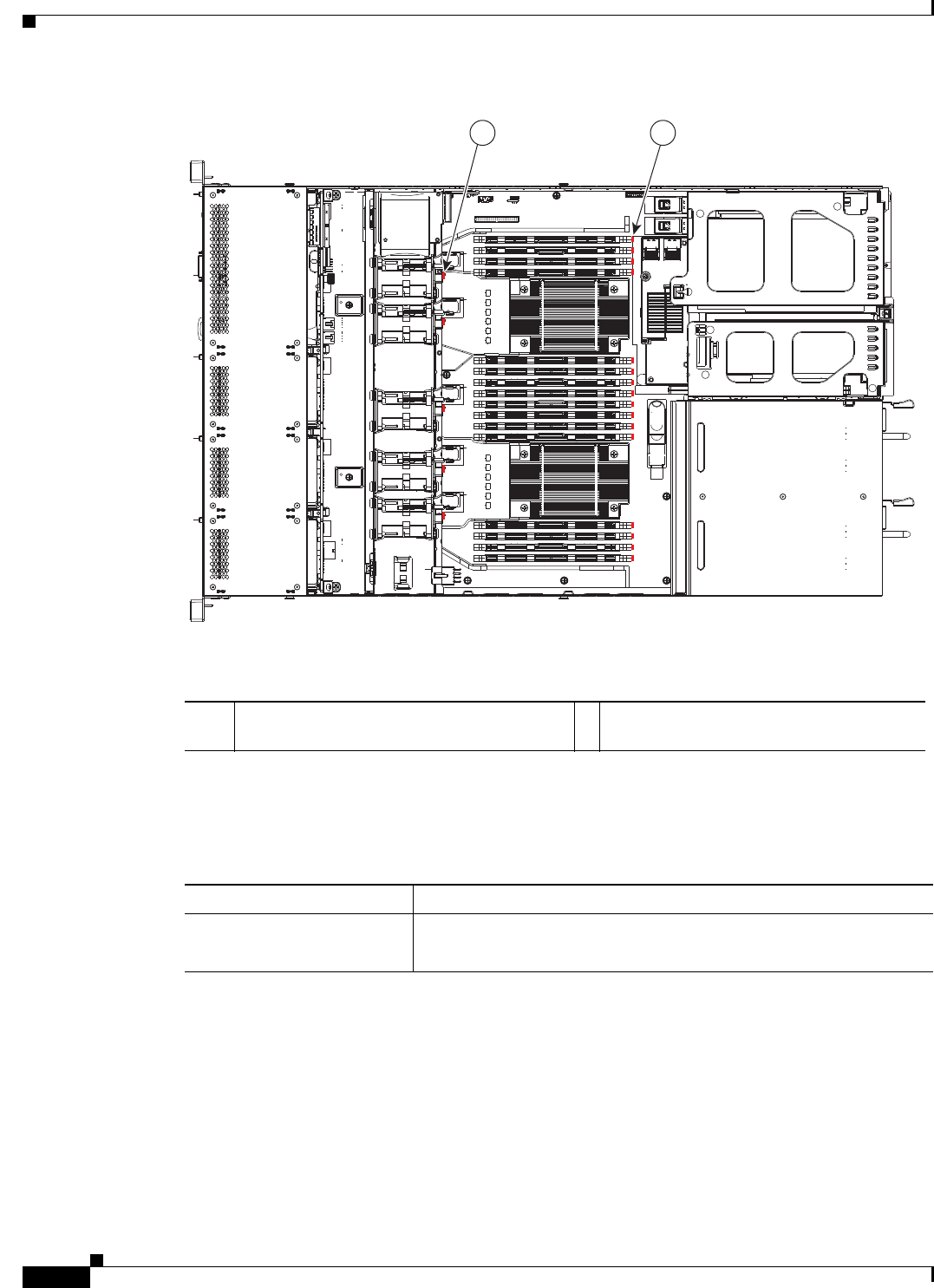
6-8
Installation and Upgrade Guide for Cisco Secure Access Control System 5.5
OL-28603-01
Chapter 6 Introducing the Cisco SNS-3415 and Cisco SNS-3495 Hardware Appliances
Regulatory Compliance
Figure 6-3 Cisco SNS-3415 Internal Diagnostic LED Locations
The following table describes the callouts in Figure 6-3
Table 6-4 describes the internal diagnostic LEDs located inside the Cisco SNS-3415 or Cisco SNS-3495
appliance.
Regulatory Compliance
For regulatory compliance and safety information, see Regulatory Compliance and Safety Information
for Cisco Secure Access Control System. This document is available online at Cisco.com:
http://www.cisco.com/en/US/docs/net_mgmt/cisco_secure_access_control_system/5.4/regulatory/com
pliance/csacsrcsi.html
For more information, see Obtaining Documentation and Submitting a Service Request, page -13.
FAN4
1 2
331693
1 Fan module fault LEDs (one next to each fan
connector on the motherboard)
2 DIMM fault LEDs (one next to each DIMM
socket on the motherboard)
Table 6-4 Internal Diagnostic LEDs
LED Name State
Internal diagnostic LEDs (all) •Off—Component is functioning normally.
•Amber—Component has failed.

CHAPTER
7-1
Installation and Upgrade Guide for Cisco Secure Access Control System 5.5
OL-28603-01
7
Preparing to Install the Cisco SNS 3415 and
Cisco SNS 3495 Hardware Appliances
This section provides information on how you can prepare your site for safely installing the Cisco
SNS-3415 or Cisco SNS-3495 appliance.
This section contains the following topics:
•Safety Guidelines, page 7-1
•Unpacking and Inspecting the Server, page 7-2
•Preparing for Server Installation, page 7-3
•Server Specifications, page 7-5
Safety Guidelines
Note Before you install, operate, or service a Cisco SNS-3415 or Cisco SNS-3495 appliance, review the
Regulatory Compliance and Safety Information for Cisco Secure Access Control System for important
safety information.
Warning
IMPORTANT SAFETY INSTRUCTIONS
This warning symbol means danger. You are in a situation that could cause bodily injury. Before
you work on any equipment, be aware of the hazards involved with electrical circuitry and be
familiar with standard practices for preventing accidents. Use the statement number provided at
the end of each warning to locate its translation in the translated safety warnings that
accompanied this device.
Statement 1071
Warning
To prevent the system from overheating, do not operate it in an area that exceeds the maximum
recommended ambient temperature of: 40° C (104° F).
Statement 1047

7-2
Installation and Upgrade Guide for Cisco Secure Access Control System 5.5
OL-28603-01
Chapter 7 Preparing to Install the Cisco SNS 3415 and Cisco SNS 3495 Hardware Appliances
Unpacking and Inspecting the Server
Warning
The plug-socket combination must be accessible at all times, because it serves as the main
disconnecting device.
Statement 1019
Warning
This product relies on the building’s installation for short-circuit (overcurrent) protection.
Ensure that the protective device is rated not greater than: 250 V, 15 A.
Statement 1005
Warning
Installation of the equipment must comply with local and national electrical codes.
Statement 1074
When you are installing a server, use the following guidelines:
•Plan your site configuration and prepare the site before installing the server. See the Cisco UCS Site
Preparation Guide for the recommended site planning tasks.
•Ensure that there is adequate space around the server to allow for servicing the server and for
adequate airflow. The airflow in this server is from front to back.
•Ensure that the air-conditioning meets the thermal requirements listed in the Server Specifications,
page 7-5.
•Ensure that the cabinet or rack meets the requirements listed in the “Rack Requirements” section on
page 7-4.
•Ensure that the site power meets the power requirements listed in the Server Specifications,
page 7-5. If available, you can use an uninterruptible power supply (UPS) to protect against power
failures.
Caution Avoid UPS types that use ferroresonant technology. These UPS types can become unstable with systems
such as the Cisco UCS, which can have substantial current draw fluctuations from fluctuating data traffic
patterns.
Unpacking and Inspecting the Server
Caution When handling internal server components, wear an ESD strap and handle modules by the carrier edges
only.
Tip Keep the shipping container in case the server requires shipping in the future.
Note The chassis is thoroughly inspected before shipment. If any damage occurred during transportation or
any items are missing, contact your customer service representative immediately.
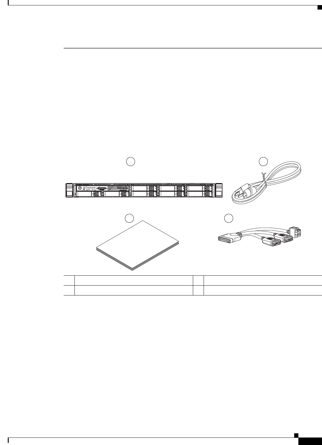
7-3
Installation and Upgrade Guide for Cisco Secure Access Control System 5.5
OL-28603-01
Chapter 7 Preparing to Install the Cisco SNS 3415 and Cisco SNS 3495 Hardware Appliances
Preparing for Server Installation
To inspect the shipment, follow these steps:
Step 1 Remove the server from its cardboard container and save all packaging material.
Step 2 Compare the shipment to the equipment list provided by your customer service representative and
Figure 7-1. Verify that you have all items.
Step 3 Check for damage and report any discrepancies or damage to your customer service representative. Have
the following information ready:
•Invoice number of shipper (see the packing slip)
•Model and serial number of the damaged unit
•Description of damage
•Effect of damage on the installation
Figure 7-1 Shipping Box Contents
Preparing for Server Installation
This section provides information about preparing for server installation, and it includes the following
topic
•Installation Guidelines, page 7-4
•Rack Requirements, page 7-4
•Equipment Requirements, page 7-5
•Slide Rail Adjustment Range, page 7-5
1Server 3Documentation
2Power cord (optional, up to two) 4KVM cable
Cisco
UCS C-Series
1 2
3 4
331685

7-4
Installation and Upgrade Guide for Cisco Secure Access Control System 5.5
OL-28603-01
Chapter 7 Preparing to Install the Cisco SNS 3415 and Cisco SNS 3495 Hardware Appliances
Preparing for Server Installation
Installation Guidelines
Warning
To prevent the system from overheating, do not operate it in an area that exceeds the maximum
recommended ambient temperature of: 40° C (104° F).
Statement 1047
Warning
The plug-socket combination must be accessible at all times, because it serves as the main
disconnecting device.
Statement 1019
Warning
This product relies on the building's installation for short-circuit (overcurrent) protection.
Ensure that the protective device is rated not greater than: 250 V, 15 A.
Statement 1005
Warning
Installation of the equipment must comply with local and national electrical codes.
Statement 1074
When you are installing a server, use the following guidelines:
•Plan your site configuration and prepare the site before installing the server. See the Cisco UCS Site
Preparation Guide for the recommended site planning tasks.
•Ensure that there is adequate space around the server to allow for servicing the server and for
adequate airflow. The airflow in this server is from front to back.
•Ensure that the air-conditioning meets the thermal requirements listed in the Server Specifications,
page 7-5.
•Ensure that the cabinet or rack meets the requirements listed in the Rack Requirements, page 7-4
section.
•Ensure that the site power meets the power requirements listed in the Server Specifications,
page 7-5. If available, you can use an uninterruptible power supply (UPS) to protect against power
failures.
Caution Avoid UPS types that use ferroresonant technology. These UPS types can become unstable with systems
such as the Cisco SNS-3415 or Cisco SNS-3495 appliance, which can have substantial current draw
fluctuations from fluctuating data traffic patterns.
Rack Requirements
This section provides the requirements for the standard open racks.
The rack must be of the following type:
•A standard 19-in. (48.3-cm) wide, four-post EIA rack, with mounting posts that conform to English
universal hole spacing, per section 1 of ANSI/EIA-310-D-1992.

7-5
Installation and Upgrade Guide for Cisco Secure Access Control System 5.5
OL-28603-01
Chapter 7 Preparing to Install the Cisco SNS 3415 and Cisco SNS 3495 Hardware Appliances
Server Specifications
•The rack post holes can be square .38-inch (9.6 mm), round .28-inch (7.1 mm), #12-24 UNC, or
#10-32 UNC when you use the supplied slide rails.
•The minimum vertical rack space per server must be one RU, equal to 1.75 in. (44.45 mm).
Equipment Requirements
The slide rails supplied by Cisco Systems for this server do not require tools for installation. The inner
rails (mounting brackets) are pre-attached to the sides of the server.
Slide Rail Adjustment Range
The slide rails for this server have an adjustment range of 24 to 36 inches (610 to 914 mm).
Server Specifications
This section lists the technical specifications for the server and includes the following sections:
•Physical Specifications, page 7-5
•Environmental Specifications, page 7-6
•Power Specifications, page 7-6
Physical Specifications
Table 7-1 lists the physical specifications of the server.
Table 7-1 Physical Specifications
Description Specification
Height 1.7 in. (4.3 cm)
Width 16.9 in. (42.9 cm)
Depth 28.5 in. (72.4 cm)
Weight (fully loaded chasis) 35.6 lb. (16.1 Kg)

7-6
Installation and Upgrade Guide for Cisco Secure Access Control System 5.5
OL-28603-01
Chapter 7 Preparing to Install the Cisco SNS 3415 and Cisco SNS 3495 Hardware Appliances
Server Specifications
Environmental Specifications
Table 7-2 lists the environmental specifications of the server.
Power Specifications
The power specifications for the two power supply options are listed in the following sections:
•450-W Power Supply, page 7-6
•650-W Power Supply, page 7-7
You can get more specific power information for your exact server configuration by using the Cisco UCS
Power Calculator:
http://www.cisco.com/assets/cdc_content_elements/flash/dataCenter/cisco_ucs_power_calculator/
Note Do not mix power supply types in the server. Both power supplies must be either 450W or 650W.
Note ACS 5.5 supports an optional redundant power supply unit for Cisco SNS-3415-K9.
450-W Power Supply
Table 7-3 lists the environmental specifications of the server.
Table 7-2 Environmental Specifications
Description Specification
Temperature, operating: 41 to 104°F (5 to 40°C)
Derate the maximum temperature by 1°C per every 305 meters of
altitude above sea level.
Temperature, non-operating -40 to 149°F (-40 to 65°C)
Humidity (RH), noncondensing 10 to 90%
Altitude, operating 0 to 10,000 feet
Altitude, non-operating 0 to 40,000 feet
Sound power level
Measure A-weighted per
ISO7779 LwAd (Bels)
Operation at 73°F (23°C)
5.4
Sound pressure level
Measure A-weighted per
ISO7779 LpAm (dBA)
Operation at 73°F (23°C)
37

7-7
Installation and Upgrade Guide for Cisco Secure Access Control System 5.5
OL-28603-01
Chapter 7 Preparing to Install the Cisco SNS 3415 and Cisco SNS 3495 Hardware Appliances
Server Specifications
650-W Power Supply
Table 7-4 lists the environmental specifications of the server.
Table 7-3 Power Supply Specifications
Description Specification
AC input voltage range Low range: 100 to 120 VAC
High range: 200 to 240 VAC
AC input frequency Range: 47 to 63 Hz (single phase, 50 to 60Hz nominal)
AC line input current (steady
state)
6.0 A peak at 100 VAC
3.0 A peak at 208 VAC
Maximum output power for each
power supply
450 W
Power supply output voltage Main power: 12 VDC
Standby power: 12 VDC
Table 7-4 Power Supply Specifications
Description Specification
AC input voltage range 90 to 264 VAC (self-ranging, 180 to 264 VAC nominal)
AC input frequency Range: 47 to 63 Hz (single phase, 50 to 60Hz nominal)
AC line input current (steady
state)
7.6 A peak at 100 VAC
3.65 A peak at 208 VAC
Maximum output power for each
power supply
650 W
Power supply output voltage Main power: 12 VDC
Standby power: 12 VDC

7-8
Installation and Upgrade Guide for Cisco Secure Access Control System 5.5
OL-28603-01
Chapter 7 Preparing to Install the Cisco SNS 3415 and Cisco SNS 3495 Hardware Appliances
Server Specifications

CHAPTER
8-1
Installation and Upgrade Guide for Cisco Secure Access Control System 5.5
OL-28603-01
8
Installing the Cisco SNS 3415 and Cisco SNS
3495 Hardware Appliances
This chapter describes how to install your Cisco SNS-3415 or Cisco SNS-3495 appliance and connect it
to the network.
It contains:
•Installing the Cisco SNS-3415/3495 Appliance Rack, page 8-1
•Cisco Integrated Management Controller (CIMC), page 8-5
•Configuring CIMC, page 8-5
•Connecting Cables, page 8-8
•Connecting and Powering On the Cisco SNS-3415/3495 Appliance, page 8-11
Before you begin the installation, read the Regulatory Compliance and Safety Information for the Cisco
3415 or 3495 Secure Access Control System available on http://www.cisco.com at the following
location:
http://www.cisco.com/en/US/docs/net_mgmt/cisco_secure_access_control_system/5.4/regulatory/
compliance/csacsrcsi.html.
Warning
Only trained and qualified personnel should be allowed to install, replace, or service
this equipment.
Statement 1030
Warning
This unit is intended for installation in restricted access areas. A restricted access area can be
accessed only through the use of a special tool, lock and key, or other means of security.
Statement 1017
Installing the Cisco SNS-3415/3495 Appliance Rack
This section describes how to install the Cisco SNS-3415 or Cisco SNS-3495 appliance in a rack.
Warning
To prevent bodily injury when mounting or servicing this unit in a rack, you must take special
precautions to ensure that the system remains stable. The following guidelines are provided to
ensure your safety:
This unit should be mounted at the bottom of the rack if it is the only unit in the rack.
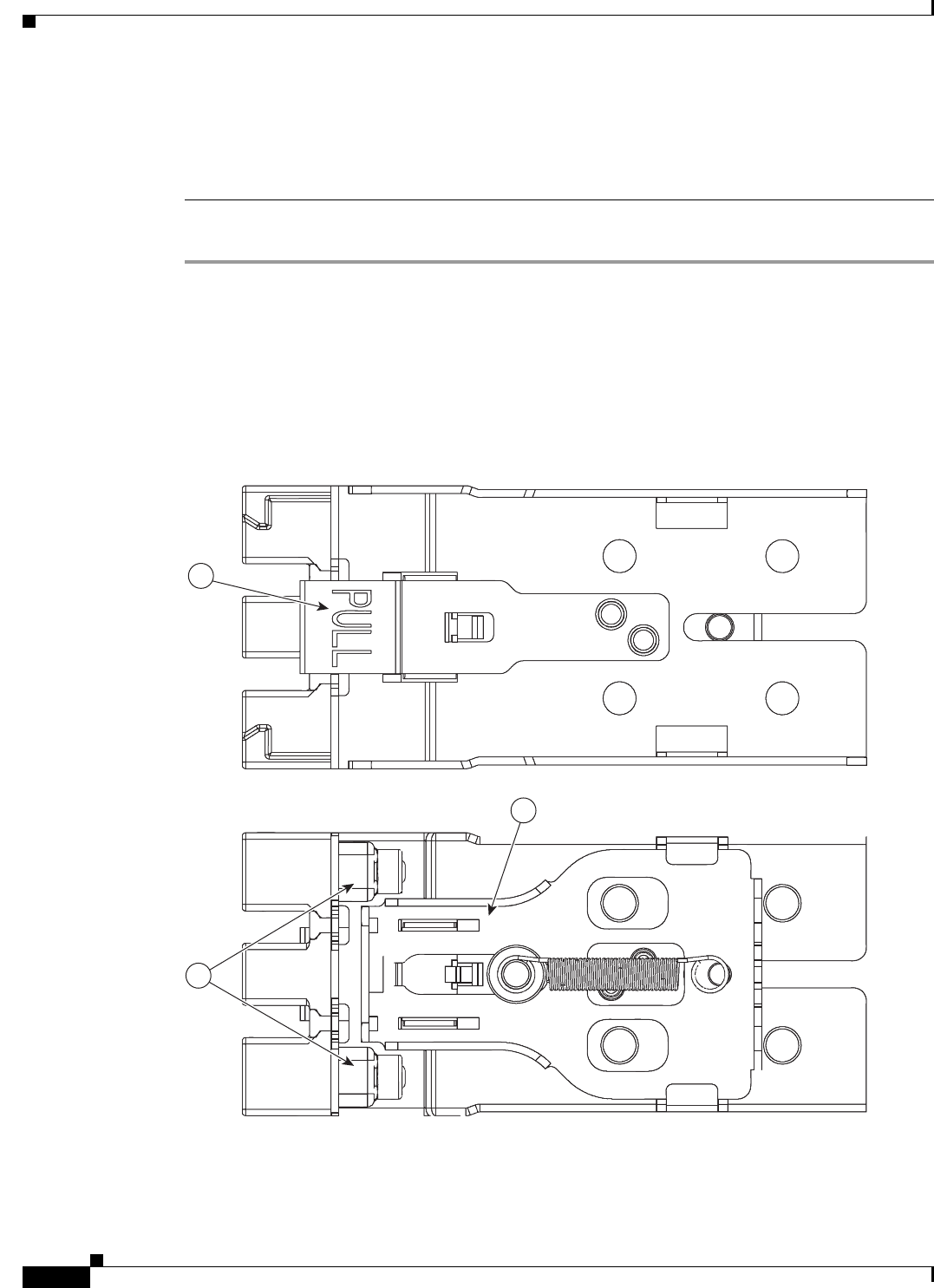
8-2
Installation and Upgrade Guide for Cisco Secure Access Control System 5.5
OL-28603-01
Chapter 8 Installing the Cisco SNS 3415 and Cisco SNS 3495 Hardware Appliances
Installing the Cisco SNS-3415/3495 Appliance Rack
When mounting this unit in a partially filled rack, load the rack from the bottom to the top with
the heaviest component at the bottom of the rack.
If the rack is provided with stabilizing devices, install the stabilizers before mounting or
servicing the unit in the rack.
Statement 1006
To install the slide rails and the server into a rack, follow these steps:
Step 1 Open the front securing latch (see Figure 8-1). The end of the slide-rail assembly marked “FRONT” has
a spring-loaded securing latch that must be open before you can insert the mounting pegs into the
rack-post holes.
a. On the rear side of the securing-latch assembly, hold open the clip marked “PULL.”
b. Slide the spring-loaded securing latch away from the mounting pegs.
c. Release the clip marked “PULL” to lock the securing latch in the open position.
Figure 8-1 Front Securing Latch
3
1
2
332061
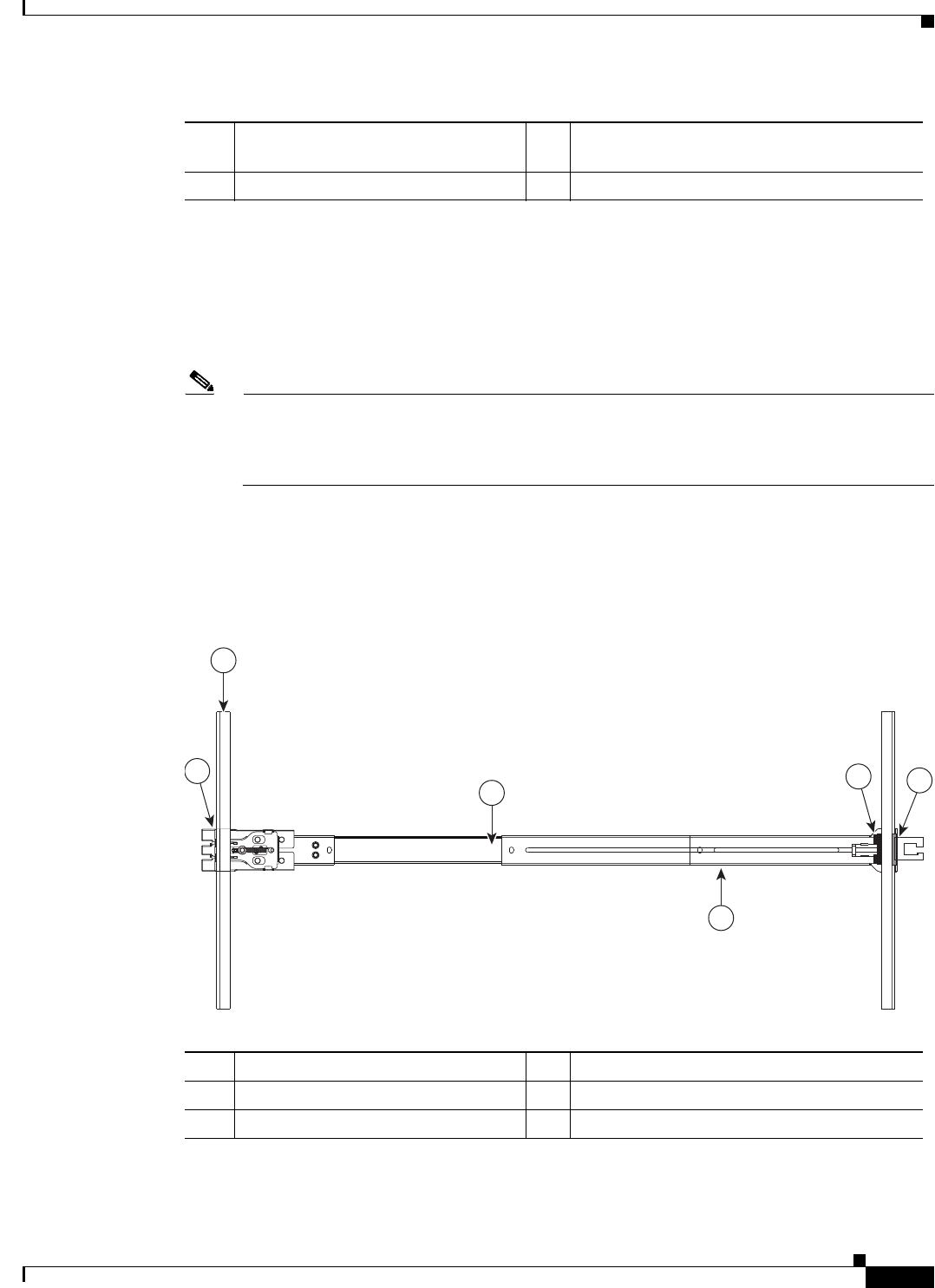
8-3
Installation and Upgrade Guide for Cisco Secure Access Control System 5.5
OL-28603-01
Chapter 8 Installing the Cisco SNS 3415 and Cisco SNS 3495 Hardware Appliances
Installing the Cisco SNS-3415/3495 Appliance Rack
Step 2 Install the slide rails onto the rack:
a. Position a slide-rail assembly inside the two left-side rack posts (see Figure 8-2).
Use the “FRONT” and “REAR” markings on the slide-rail assembly to orient the assembly correctly
with the front and rear rack posts.
b. Position the front mounting pegs so that they enter the desired front rack-post holes from the front.
Note The mounting pegs that protrude through the rack-post holes are designed to fit round or square
holes, or smaller #10-32 round holes when the mounting peg is compressed. If your rack has
#10-32 rack-post holes, align the mounting pegs with the holes and then compress the
spring-loaded pegs to expose the #10-32 inner peg.
c. Expand the length-adjustment bracket until the rear mounting pegs protrude through the desired
holes in the rear rack post.
Use your finger to hold the rear securing latch open when you insert the rear mounting pegs to their
holes. When you release the latch, it wraps around the rack post and secures the slide-rail assembly.
Figure 8-2 Attaching a Slide Rail Assembly
d. Attach the second slide-rail assembly to the opposite side of the rack. Ensure that the two slide-rail
assemblies are level and at the same height with each other.
1 Clip marked “PULL” on rear of
assembly
3 Spring-loaded securing latch on front of
assembly
2 Front mounting pegs
331689
1
3
256
4
1 Front-left rack post 4 Length-adjustment bracket
2 Front mounting pegs 5 Rear mounting pegs
3 Slide-rail assembly 6 Rear securing latch

8-4
Installation and Upgrade Guide for Cisco Secure Access Control System 5.5
OL-28603-01
Chapter 8 Installing the Cisco SNS 3415 and Cisco SNS 3495 Hardware Appliances
Installing the Cisco SNS-3415/3495 Appliance Rack
e. Pull the inner slide rails on each assembly out toward the rack front until they hit the internal stops
and lock in place.
Step 3 Insert the server into the slide rails:
Note The inner rails are pre-attached to the sides of the server at the factory. You can order
replacement inner rails if these are damaged or lost (Cisco PID UCSC-RAIL1-I).
a. Align the inner rails that are pre-attached to the server sides with the front ends of the empty slide
rails.
b. Push the server into the slide rails until it stops at the internal stops.
c. Push in the plastic release clip on each inner rail (labelled PUSH), and then continue pushing the
server into the rack until its front latches engage the rack posts.
Step 4 Attach the (optional) cable management arm (CMA) to the rear of the slide rails:
Note The CMA is designed for mounting on either the right or left slide rails. These instructions
describe an installation to the rear of the right slide rails, as viewed from the rear of server.
a. Slide the plastic clip on the inner CMA arm over the flange on the mounting bracket that attached
to the side of the server. See Figure 8-3.
Note Whether you are mounting the CMA to the left or right slide rails, be sure to orient the engraved
marking, “UP” so that it is always on the upper side of the CMA. See Figure 8-3.
b. Slide the plastic clip on the outer CMA arm over the flange on the slide rail. See Figure 8-3.
c. Attach the CMA retaining bracket to the left slide rail. Slide the plastic clip on the bracket over the
flange on the end of the left slide
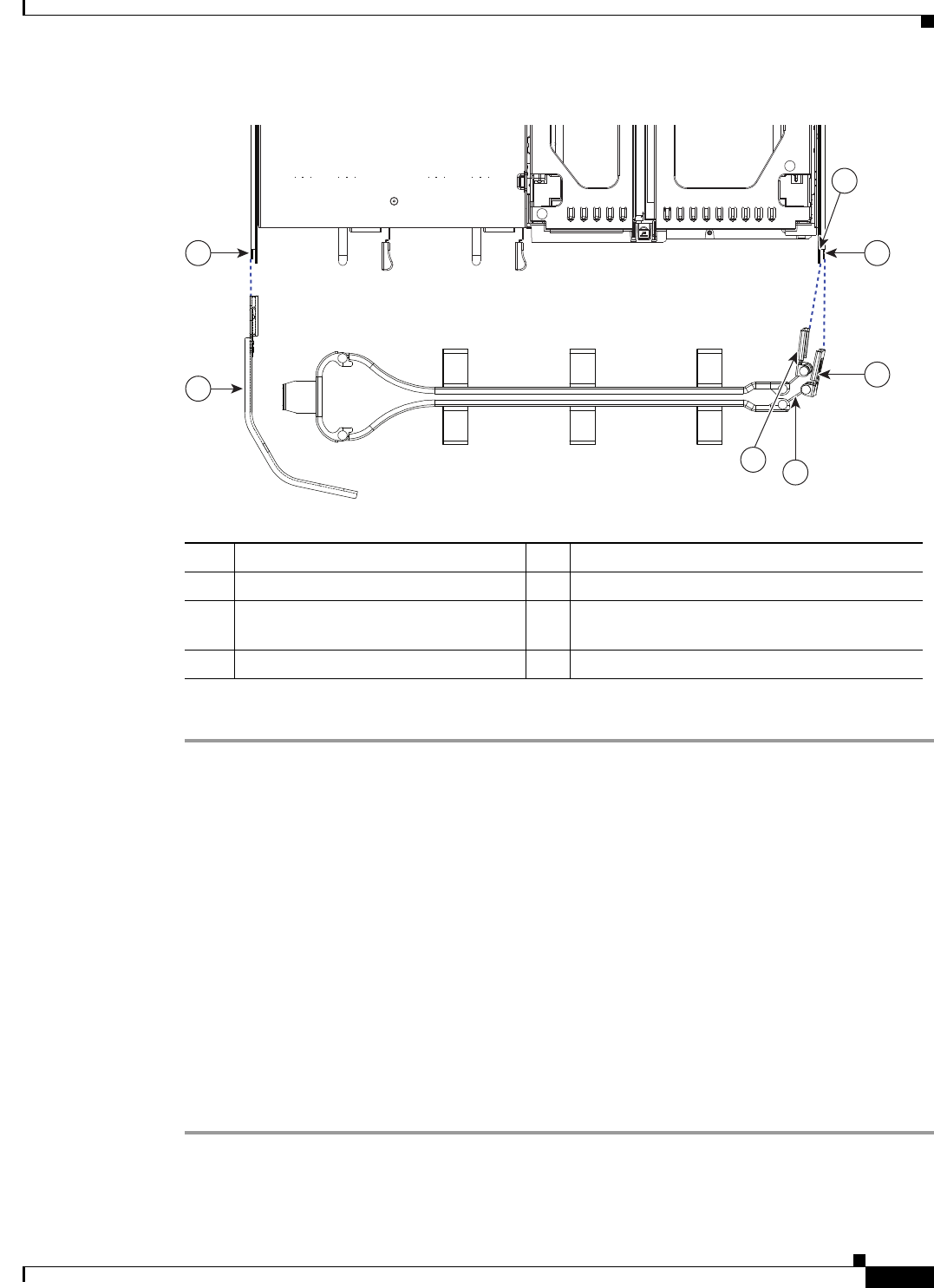
8-5
Installation and Upgrade Guide for Cisco Secure Access Control System 5.5
OL-28603-01
Chapter 8 Installing the Cisco SNS 3415 and Cisco SNS 3495 Hardware Appliances
Cisco Integrated Management Controller (CIMC)
Figure 8-3 Attaching the Cable Management Arm (Rear of Server Shown)
Step 5 Continue with the “Connecting and Powering on Cisco SNS-3415/3495 Appliance”.
Cisco Integrated Management Controller (CIMC)
You can monitor the server inventory, health, and system event logs by using the built-in Cisco Integrated
Management Controller 1.4.7a (CIMC) GUI or CLI interfaces. See the user documentation for your
firmware release at the following URL:
http://www.cisco.com/en/US/products/ps10739/products_installation_and_configuration_guides_list.html
Configuring CIMC
You can perform all operations on the Cisco SNS-3415 or Cisco SNS-3495 appliance through the CIMC.
To do this, you must first configure an IP address and IP gateway to access the CIMC from a web-based
browser.
Step 1 Plug in the power cord.
Step 2 Press the Power button to boot the server.
7
331690
6
5
4
3
1
2
1 Flange on rear of outer left slide rail 5 Inner CMA arm attachment clip
2 CMA retaining bracket 6 “UP” orientation marking
3 Flange on rear of right mounting
bracket
7 Outer CMA arm attachment clip
4 Flange on rear of outer right slide rail
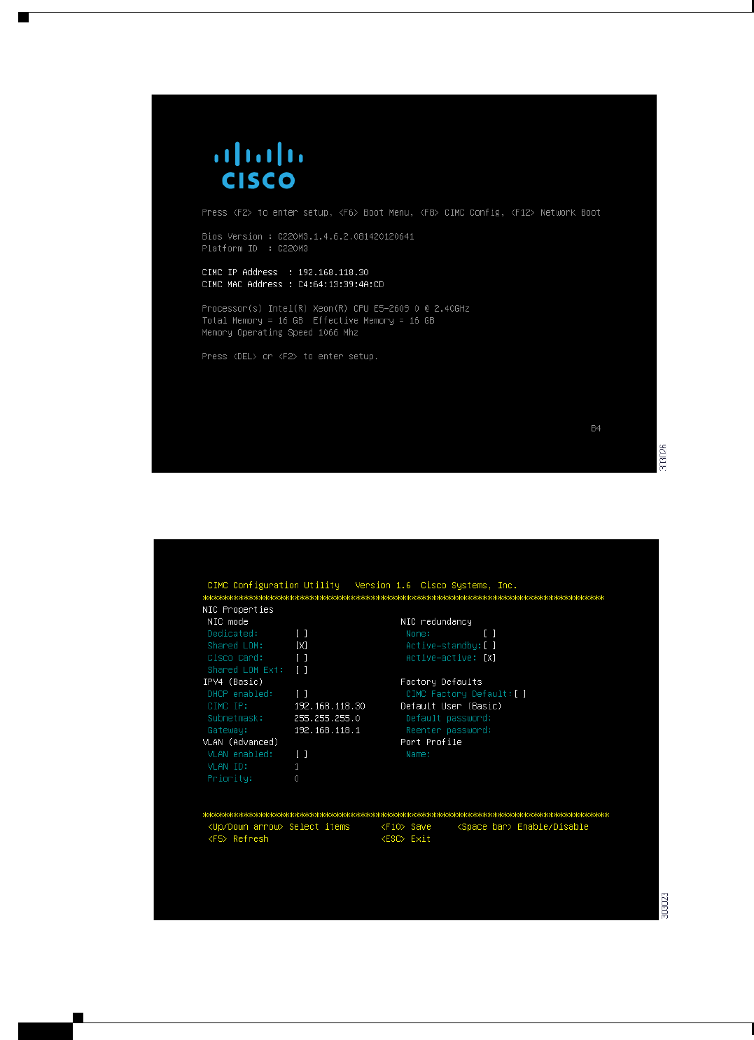
8-6
Installation and Upgrade Guide for Cisco Secure Access Control System 5.5
OL-28603-01
Chapter 8 Installing the Cisco SNS 3415 and Cisco SNS 3495 Hardware Appliances
Configuring CIMC
Step 3 During bootup, press F8 when prompted to open the BIOS CIMC Configuration Utility. The following
screen appears.

8-7
Installation and Upgrade Guide for Cisco Secure Access Control System 5.5
OL-28603-01
Chapter 8 Installing the Cisco SNS 3415 and Cisco SNS 3495 Hardware Appliances
Configuring CIMC
Step 4 Set the NIC mode to your choice for which ports to use to access the CIMC for server management (see
Figure 6-1 for identification of the ports):
–
Dedicated—The 1-Gb Ethernet management port is used to access the CIMC. You must select
NIC redundancy None and select IP settings.
–
Shared LOM (default)—The two 1-Gb Ethernet ports are used to access the CIMC. This is the
factory default setting, along with Active-active NIC redundancy and DHCP enabled.
–
Cisco Card—The ports on an installed Cisco UCS P81E VIC are used to access the CIMC. You
must select a NIC redundancy and IP setting.
Note The Cisco Card NIC mode is currently supported only with a Cisco UCS P81E VIC
(N2XX-ACPCI01) that is installed in PCIe slot 1.
Step 5 Use this utility to change the NIC redundancy to your preference. This server has three possible NIC
redundancy settings:
–
None—The Ethernet ports operate independently and do not fail over if there is a problem.
–
Active-standby—If an active Ethernet port fails, traffic fails over to a standby port.
–
Active-active—All Ethernet ports are utilized simultaneously.
Step 6 Choose whether to enable DHCP for dynamic network settings, or to enter static network settings.
Note Before you enable DHCP, your DHCP server must be preconfigured with the range of MAC
addresses for this server. The MAC address is printed on a label on the rear of the server. This
server has a range of six MAC addresses assigned to the CIMC. The MAC address printed on
the label is the beginning of the range of six contiguous MAC addresses.
Step 7 Optional: Use this utility to make VLAN settings.
Step 8 Use this utility to set a default CIMC user password.
Note Changes to the settings take effect after approximately 45 seconds. Refresh with F5 and wait
until the new settings appear before you reboot the server in the next step.
Step 9 Press F10 to save your settings and reboot the server.
Note If you chose to enable DHCP, the dynamically assigned IP and MAC addresses are displayed on
the console screen during bootup.
Note By default, the baud rate of the serial port is set to 115200. After you configure CIMC, log in to the
CIMC user interface and change the serial port buad rate to 9600.

8-8
Installation and Upgrade Guide for Cisco Secure Access Control System 5.5
OL-28603-01
Chapter 8 Installing the Cisco SNS 3415 and Cisco SNS 3495 Hardware Appliances
Connecting Cables
Connecting Cables
This section describes how to connect your Cisco SNS-3415 or Cisco SNS-3495 appliance to the
network and the appliance console. This section includes:
•Connecting the Network Interface, page 8-8
•Connecting the Console, page 8-9
•Connecting the Keyboard and Video Monitor, page 8-10
•Cable Management, page 8-10
Attach cables (such as keyboard, monitor cables, if required) to the rear of the server. Route the cables
properly and use the cable straps to secure the cables to the slide rails. See Figure 6-2 “Cisco
SNS-3415/3495 Appliance Rear View” for reference on the rear view of the appliance.
Connecting the Network Interface
Warning
Do not work on the system or connect or disconnect cables during periods of lightning activity.
Statement 1001
This section describes how to connect the Cisco SNS-3415 or Cisco SNS-3495 appliance Ethernet port.
The Ethernet connector supports Serial over LAN (SOL) cables. The RJ-45 port supports standard
straight-through and crossover Category 5 unshielded twisted-pair (UTP) cables. Cisco does not supply
Category 5 UTP cables; these cables are available commercially.
To connect the cable to the appliance Ethernet port:
Step 1 Verify that the appliance is turned off.
Step 2 Connect one end of the cable to the Gigabit Ethernet 0 port on the appliance.
Step 3 Connect the other end to a switch in your network.
Ethernet Port Connector
The Cisco SNS 3415 or Cisco SNS-3495 appliance comes with two integrated dual-port Ethernet
controllers. ACS 5.5 supports multiple NICs. See Multiple Network Interface Connectors, page 4-10 for
more information. These controllers provide an interface for connecting to 10-Mb/s, 100-Mb/s, or
1000-Mb/s networks and provide full-duplex (FDX) capability, which enables simultaneous
transmission and reception of data on the Ethernet LAN.
To access the Ethernet port, connect a Category 3, 4, 5, 5E, or 6 unshielded twisted-pair (UTP) cable to
the RJ-45 connector on the back of the appliance.
Table 8-1 describes the UTP cable Categories.
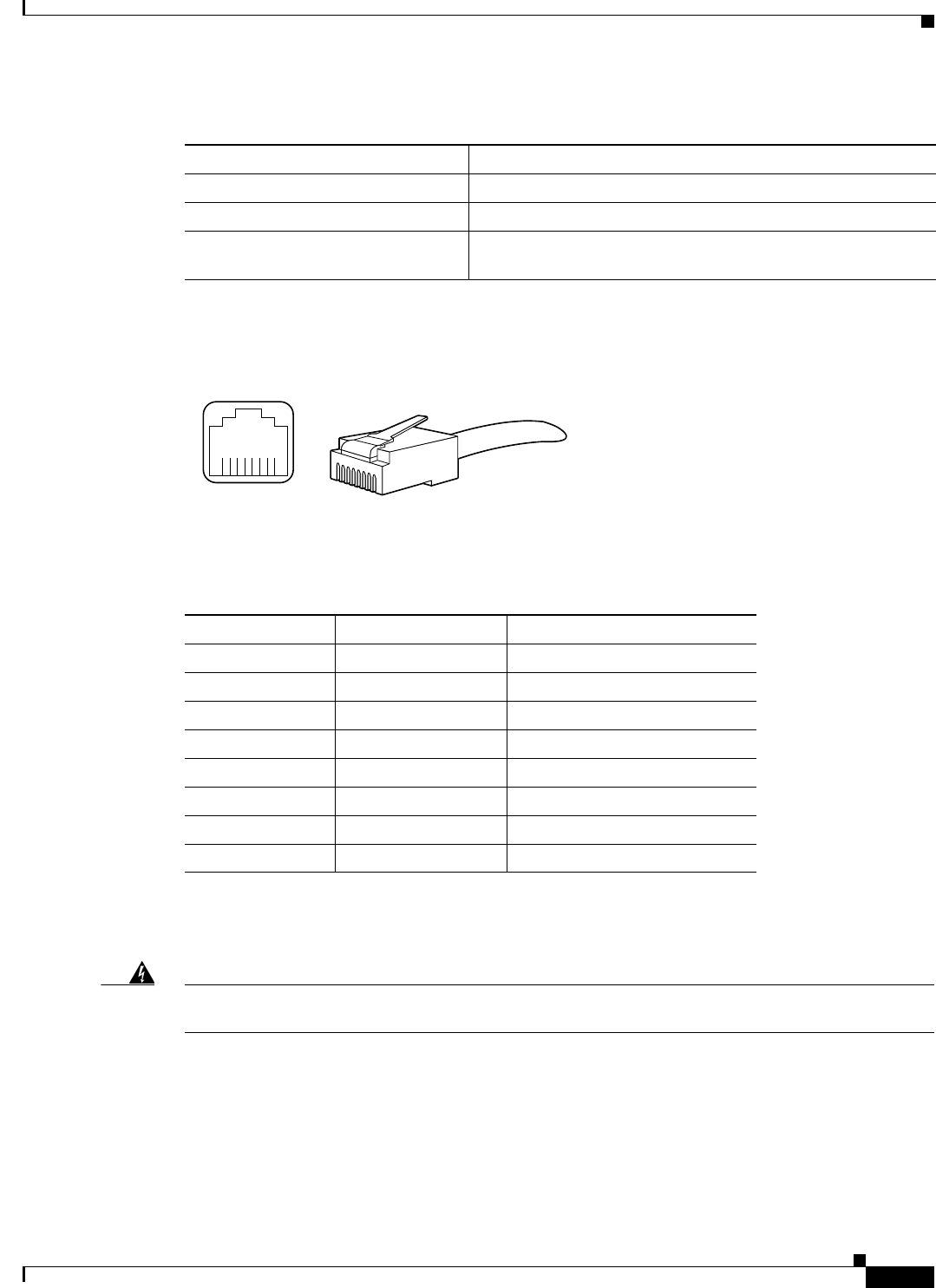
8-9
Installation and Upgrade Guide for Cisco Secure Access Control System 5.5
OL-28603-01
Chapter 8 Installing the Cisco SNS 3415 and Cisco SNS 3495 Hardware Appliances
Connecting Cables
Figure 8-4 shows the Ethernet RJ-45 port and plug.
Figure 8-4 RJ-45 Port and Plug
Table 8-2 lists and describes the RJ-45 pin signals used on the connector.
Connecting the Console
Warning
Do not work on the system or connect or disconnect cables during periods of lightning activity.
Statement 1001
Your Cisco SNS-3415 or Cisco SNS-3495 appliance has a DCE-mode console port for connecting a
console terminal to your appliance. The appliance uses a DB-9 serial connector for the console port.
The console port on the Cisco SNS-3415 or Cisco SNS-3495 appliance includes an EIA/TIA-232
asynchronous serial (DB-9) connector. This serial console connector (port) allows you to access the
appliance locally by connecting a terminal—either a PC running terminal-emulation software or an
ASCII terminal—to the console port.
Tabl e 8-1 Eth ernet Cabling Guidelines
Type Description
10BASE-T EIA Categories 3, 4, or 5 UTP (2 or 4 pair) up to 328 ft (100 m)
100BASE-TX EIA Category 5 UTP (2 pair) up to 328 ft (100 m)
1000BASE-T EIA Category 6 UTP (recommended), Category 5E UTP or
5 UTP (2 pair) up to 328 ft (100 m)
210222
8 7 6 5 4 3 2 1
RJ-45 connector
Table 8-2 Ethernet Port Pinout
Ethernet Port Pin Signal Description
1 TxD+ Transmit data +
2 TxD– Transmit data –
3 RxD+ Receive data +
4 Termination network No connection
5 Termination network No connection
6 RxD– Receive data –
7 Termination network No connection
8 Termination network No connection

8-10
Installation and Upgrade Guide for Cisco Secure Access Control System 5.5
OL-28603-01
Chapter 8 Installing the Cisco SNS 3415 and Cisco SNS 3495 Hardware Appliances
Connecting Cables
To connect a PC running terminal-emulation software to the console port, use a DB-9 female to DB-9
female straight-through cable.
To connect an ASCII terminal to the console port, use a DB-9 female to DB-25 male straight-through
cable with a DB-25 female to DB-25 female gender changer.
To connect a terminal or a PC running terminal-emulation software to the console port on the Cisco
SNS-3415 or Cisco SNS-3495 appliance:
Step 1 Connect the terminal using a straight-through cable to the console port.
Step 2 Configure your terminal or terminal-emulation software for 9600 baud, 8 data bits, no parity, 1 stop bit,
and no hardware flow control.
Connecting the Keyboard and Video Monitor
Warning
Do not work on the system or connect or disconnect cables during periods of lightning activity.
Statement 1001
This section describes how to connect a keyboard and video monitor to the Cisco SNS-3415 or Cisco
SNS-3495 appliance.
You can connect the keyboard and video monitor to the Cisco SNS-3415 or Cisco SNS-3495 appliance
using the KVM connector available in the front panel of the Cisco SNS-3415 or Cisco SNS-3495
appliance. A KVM cable is shipped along with the appliance that provides two USB, one VGA, and one
serial connector.
The Cisco SNS-3415 or Cisco SNS-3495 appliance does not provide support for a mouse.
The Cisco SNS-3415 or Cisco SNS-3495 provides USB ports on the rear of the appliance that can be
used to connect a keyboard and video monitor.
To connect a keyboard and video monitor to the appliance:
Step 1 Verify that the appliance is turned off.
Step 2 Connect the end of the keyboard cable to the PS/2 (keyboard) port which is located on the back panel of
the appliance.
Step 3 Connect the end of the video monitor cable to the PS/2 (video monitor) port which is located on the back
panel of the appliance.
Step 4 Power on the appliance.
Cable Management
Cable management is the most visual aspect of your appliance setup. However, cable management is
often overlooked because it can be time consuming.

8-11
Installation and Upgrade Guide for Cisco Secure Access Control System 5.5
OL-28603-01
Chapter 8 Installing the Cisco SNS 3415 and Cisco SNS 3495 Hardware Appliances
Connecting and Powering On the Cisco SNS-3415/3495 Appliance
Equipment racks and enclosures house more equipment today than ever before. This growth has
increased the need for organized cable management both inside and outside the rack. Poor cable
management not only leads to damaged cables or increased time for adding or changing cables, but also
blocks critical airflow or access. These problems can lead to inefficiencies in the performance of your
equipment or even downtime.
There are many solutions to address cable management. They can range from simple cable management
rings, to vertical or horizontal organizers, to troughs and ladders.
All Cisco SNS-3415 or Cisco SNS-3495 appliance cables should be properly dressed so as not to
interfere with each other or other pieces of equipment. Use local practices to ensure that the cables
attached to your appliance are properly dressed.
Proceed to the next section, Connecting and Powering On the Cisco SNS-3415/3495 Appliance,
page 8-11, to continue the installation process.
Connecting and Powering On the Cisco SNS-3415/3495
Appliance
•Connecting and Powering On the Server (Standalone Mode), page 8-11
•System BIOS and CIMC Firmware, page 8-13
•Service Headers and Jumpers, page 8-14
Connecting and Powering On the Server (Standalone Mode)
Note This section describes how to power on the server, assign an IP address, and connect to server
management when using the server in standalone mode. To use the server in UCS integration, specific
cabling and settings are required. See Installation for Cisco UCS Integration.
Note The server is shipped with a default NIC mode called Shared LOM, default NIC redundancy is
active-active, and DHCP is enabled. Shared LOM mode enables the two 1-Gb Ethernet ports to access
the Cisco Integrated Management Interface (CIMC). If you want to use the 1-Gb Ethernet dedicated
management port, or a port on a Cisco UCS P81E Virtual Interface Card (VIC) to access the CIMC, you
must first connect to the server and change the NIC mode as described in Step 3 of the following
procedure. In that step, you can also change the NIC redundancy and set static IP settings.
Use the following procedure to perform initial setup of the server:
Step 1 Attach a supplied power cord to each power supply in your server, and then attach the power cord to a
grounded AC power outlet. See the Power Specifications for power specifications. Wait for
approximately two minutes to let the server boot in standby power during the first bootup.
You can verify power status by looking at the Power Status LED (see ):
•Off—There is no AC power present in the server.

8-12
Installation and Upgrade Guide for Cisco Secure Access Control System 5.5
OL-28603-01
Chapter 8 Installing the Cisco SNS 3415 and Cisco SNS 3495 Hardware Appliances
Connecting and Powering On the Cisco SNS-3415/3495 Appliance
•Amber—The server is in standby power mode. Power is supplied only to the CIMC and some
motherboard functions.
•Green—The server is in main power mode. Power is supplied to all server components.
Note During bootup, the server beeps once for each USB device that is attached to the server. Even if there
are no external USB devices attached, there is a short beep for each virtual USB device such as a virtual
floppy drive, CD/DVD drive, keyboard, or mouse. A beep is also emitted if a USB device is hot-plugged
or hot-unplugged during BIOS power-on self test (POST), or while you are accessing the BIOS Setup
utility or the EFI shell.
Step 2 Connect a USB keyboard and VGA monitor by using the supplied KVM cable connected to the KVM
connector on the front panel (see Figure 6-1).
Note Alternatively, you can use the VGA and USB ports on the rear panel. However, you cannot use the front
panel VGA and the rear panel VGA at the same time. If you are connected to one VGA connector and
you then connect a video device to the other connector, the first VGA connector is disabled.
Step 3 See the “Configuring CIMC” section on page 8-5 to enter in to the BIOS CIMC Configuration Utility.
Use this utility to set NIC mode, NIC redundancy, and choose whether to enable DHCP or set static
network settings.
Step 4 Connect to the CIMC for server management. Connect Ethernet cables from your LAN to the server,
using the ports that you selected in Step 3. The Active-active and Active-passive NIC redundancy
settings require you to connect to two ports.
Step 5 Enter the IP address of the CIMC in your browser to connect to the CIMC Setup Utility. The CIMC IP
address is configured in Step 3 (either a static address or the address assigned by your DHCP server).
To manage the server, see the Cisco UCS C-Series Rack-Mount Server Configuration Guide or the Cisco
UCS C-Series Rack-Mount Server CLI Configuration Guide for instructions on using those interfaces.
The links to these documents are in the C-Series documentation roadmap:
http://www.cisco.com/go/unifiedcomputing/c-series-doc

8-13
Installation and Upgrade Guide for Cisco Secure Access Control System 5.5
OL-28603-01
Chapter 8 Installing the Cisco SNS 3415 and Cisco SNS 3495 Hardware Appliances
Connecting and Powering On the Cisco SNS-3415/3495 Appliance
System BIOS and CIMC Firmware
This section includes information about the system BIOS 1.4.7b.0, and it includes the following sections:
•Updating the BIOS and CIMC Firmware, page 8-13
•Accessing the System BIOS, page 8-13
Updating the BIOS and CIMC Firmware
Caution When you upgrade the BIOS firmware, you must also upgrade the CIMC firmware to the same version
or the server will not boot. Do not power off the server until the BIOS and CIMC firmware are matching
or the server will not boot.
Cisco provides the Cisco Host Upgrade Utility to assist with simultaneously upgrading the BIOS, CIMC,
and other firmware to compatible levels.
The server uses firmware obtained from and certified by Cisco. Cisco provides release notes with each
firmware image. There are several methods for updating the firmware:
•Recommended method for systems running firmware level 1.2 or later: Use the Cisco Host
Upgrade Utility to simultaneously upgrade the CIMC is 1.4.7a, BIOS 1.4.7b.0, LOM, LSI storage
controller, and Cisco UCS P81E VIC firmware to compatible levels.
See the Cisco Host Upgrade Utility Quick Reference Guide for your firmware level at the documentation
roadmap link below.
Note Your system firmware must be at minimum level 1.2 to use the Cisco Host Upgrade Utility. If
your firmware is prior to level 1.2, you must use the methods below to update the BIOS and
CIMC firmware individually.
•You can upgrade the BIOS using the EFI interface, or upgrade from a Windows or Linux platform.
See the Cisco UCS C-Series Rack-Mount Server BIOS Upgrade Guide.
•You can upgrade the CIMC and BIOS firmware by using the CIMC GUI interface. See the Cisco
UCS C-Series Rack-Mount Server Configuration Guide.
•You can upgrade the CIMC and BIOS firmware by using the CIMC CLI interface. See the Cisco
UCS C-Series Rack-Mount Server CLI Configuration Guide.
For links to the documents listed above, see the documentation roadmap at the following URL:
http://www.cisco.com/go/unifiedcomputing/c-series-doc
Accessing the System BIOS
To change the BIOS settings for your server, follow these steps. Detailed instructions are also printed on
the BIOS screens.
Step 1 Enter the BIOS setup utility by pressing the F2 key when prompted during bootup.
Note The version and build of the current BIOS are displayed on the Main page of the utility.

8-14
Installation and Upgrade Guide for Cisco Secure Access Control System 5.5
OL-28603-01
Chapter 8 Installing the Cisco SNS 3415 and Cisco SNS 3495 Hardware Appliances
Connecting and Powering On the Cisco SNS-3415/3495 Appliance
Step 2 Use the arrow keys to select the BIOS menu page.
Step 3 Highlight the field to be modified by using the arrow keys.
Step 4 Press Enter to select the field that you want to change, and then modify the value in the field.
Step 5 Press the right arrow key until the Exit menu screen is displayed.
Step 6 Follow the instructions on the Exit menu screen to save your changes and exit the setup utility (or Press
F10). You can exit without saving changes by pressing Esc.
Service Headers and Jumpers
This section includes the following topics:
•Header Locations on the Motherboard, page 8-14
•Using the BIOS Recovery Header J41, page 8-15
•Using the Clear CMOS Header J37, page 8-17
Header Locations on the Motherboard
See Figure 8-5. The block of headers is shown in red. The individual headers are shown in the magnified
view. The pin numbering is the same for all headers in the block.

8-15
Installation and Upgrade Guide for Cisco Secure Access Control System 5.5
OL-28603-01
Chapter 8 Installing the Cisco SNS 3415 and Cisco SNS 3495 Hardware Appliances
Connecting and Powering On the Cisco SNS-3415/3495 Appliance
Figure 8-5 Service Header Locations
Using the BIOS Recovery Header J41
Depending on which stage the BIOS becomes corrupted, you might see different behavior.
•If the BIOS BootBlock is corrupted, you might see the system get stuck on the following message:
Initializing and configuring memory/hardware
•If it is a non-BootBlock corruption, the following message is displayed:
****BIOS FLASH IMAGE CORRUPTED****
Flash a valid BIOS capsule file using CIMC WebGUI or CLI interface.
IF CIMC INTERFACE IS NOT AVAILABLE, FOLLOW THE STEPS MENTIONED BELOW.
1. Connect the USB stick with recovery.cap file in root folder.
2. Reset the host.
IF THESE STEPS DO NOT RECOVER THE BIOS
1. Power off the system.
2. Mount recovery jumper.
3. Connect the USB stick with recovery.cap file in root folder.
4. Power on the system.
Wait for a few seconds if already plugged in the USB stick.
REFER TO SYSTEM MANUAL FOR ANY ISSUES.
FAN1
FAN2
FAN3
FAN4
FAN4
FAN5
PSU2
PCIe1
PCIe2
PSU1
CPU1
CPU2
333940
123
13 2
1 J41 BIOS RCVR BOOT 2 J37 Clear CMOS

8-16
Installation and Upgrade Guide for Cisco Secure Access Control System 5.5
OL-28603-01
Chapter 8 Installing the Cisco SNS 3415 and Cisco SNS 3495 Hardware Appliances
Connecting and Powering On the Cisco SNS-3415/3495 Appliance
Note As indicated by the message shown above, there are two procedures for recovering the BIOS. Try
procedure 1 first, then if that does not recover the BIOS, use procedure 2.
Note The server must have CIMC version 1.4(6) or later to use these procedures.
Procedure 1: Reboot With recovery.cap File
Step 1 Download the BIOS update package and extract it to a temporary location.
Step 2 Copy the contents of the extracted Initializing and configuring memory/hardware folder to the root
directory a USB thumb drive. The recovery folder contains the recovery file that is required in this
procedure.
Note The recovery.cap file must be in the root directory of the USB thumb drive. Do not rename this
file. The USB thumb drive must be formatted with either FAT16 or FAT32 file systems.
Step 3 Insert the USB thumb drive into a USB port on the server.
Step 4 Reboot the server.
Step 5 Return the server to main power mode by pressing the Power button on the front panel.
The server boots with the updated BIOS boot block. When the BIOS detects a valid recovery.cap file on
the USB thumb drive, it displays this message:
recovery.cap
Step 6 Wait for server to complete the BIOS update, then remove the USB thumb drive from the server.
Note During the BIOS update, the CIMC will shut down the server and the screen will be blank for
about 10 minutes. Do not unplug the power cords during this update. The CIMC will power on
the server after the update is complete.
Procedure 2: Use Recovery Jumper and recovery.cap File
See Figure 8-5 for the location of the J41 header.
Step 1 Download the BIOS update package and extract it to a temporary location.
Step 2 Copy the contents of the extracted Found a valid recovery file...Transferring to CIMC
System would flash the BIOS image now...
System would restart with recovered image after a few seconds... folder to the root directory a USB
thumb drive. The recovery folder contains the recovery file that is required in this procedure.
Note The recovery.cap file must be in the root directory of the USB thumb drive. Do not rename this
file. The USB thumb drive must be formatted with either FAT16 or FAT32 file systems.
Step 3 Power off the server as described in Shutting Down and Powering Off the Server.

8-17
Installation and Upgrade Guide for Cisco Secure Access Control System 5.5
OL-28603-01
Chapter 8 Installing the Cisco SNS 3415 and Cisco SNS 3495 Hardware Appliances
Connecting and Powering On the Cisco SNS-3415/3495 Appliance
Step 4 Disconnect all power cords from the power supplies.
Step 5 Slide the server out the front of the rack far enough so that you can remove the top cover. You might have
to detach cables from the rear panel to provide clearance.
Caution Caution If you cannot safely view and access the component, remove the server from the rack.
Step 6 Remove the top cover as described in Removing and Replacing the Server Top Cover.
Step 7 Move the shorting jumper to pins 2 and 3 of the J41 header (see Figure 2-5).
Step 8 Reconnect AC power cords to the server. The server powers up to standby power mode.
Step 9 Insert the USB thumb drive that you prepared in Step 2 into a USB port on the server.
Step 10 Return the server to main power mode by pressing the Power button on the front panel.
The server boots with the updated BIOS boot block. When the BIOS detects a valid recovery.cap file on
the USB thumb drive, it displays this message:
recovery.cap
Step 11 Wait for server to complete the BIOS update, then remove the USB thumb drive from the server.
Note During the BIOS update, the CIMC will shut down the server and the screen will be blank for
about 10 minutes. Do not unplug the power cords during this update. The CIMC will power on
the server after the update is complete.
Step 12 After the server has fully booted, power off the server again and disconnect all power cords.
Step 13 Move the jumper back to the default pins 1 and 2 of the J41 header.
Note If you do not move the jumper, after recovery completion you see the prompt, Found a valid
recovery file...Transferring to CIMC
System would flash the BIOS image now...
System would restart with recovered image after a few seconds....
Step 14 Replace the top cover, replace the server in the rack, replace power cords and any other cables, then
power on the server by pressing the Power button.
Using the Clear CMOS Header J37
See Figure 8-5 for the location of this header. You can jumper this header to clear the server's CMOS
settings in the case of a system hang. For example, if the server hangs because of incorrect settings and
does not boot, use this jumper to invalidate the settings and reboot with defaults.
Caution Clearing the CMOS removes any customized settings and might result in data loss. Make a note of any
necessary customized settings in the BIOS before you use this clear CMOS procedure.
Step 1 Power off the server as described in Shutting Down and Powering Off the Server.
Step 2 Disconnect all power cords from the power supplies.

8-18
Installation and Upgrade Guide for Cisco Secure Access Control System 5.5
OL-28603-01
Chapter 8 Installing the Cisco SNS 3415 and Cisco SNS 3495 Hardware Appliances
Connecting and Powering On the Cisco SNS-3415/3495 Appliance
Step 3 Slide the server out the front of the rack far enough so that you can remove the top cover. You might have
to detach cables from the rear panel to provide clearance.
Caution If you cannot safely view and access the component, remove the server from the rack.
Step 4 Remove the top cover as described in Removing and Replacing the Server Top Cover.
Step 5 Move the shorting jumper to pins 2 and 3 of the J37 header (see Figure 2-5).
Step 6 Reinstall the top cover and reconnect AC power cords to the server. The server powers up to standby
power mode, indicated when the Power LED on the front panel is amber.
Step 7 Return the server to main power mode by pressing the Power button on the front panel. The server is in
main power mode when the Power LED is green.
Note You must allow the entire server, not just the service processor, to reboot to main power mode
to complete the reset. This is because the state of the jumper cannot be determined without the
host CPU running.
Step 8 Press the Power button to shut down the server to standby power mode, and then remove AC power cords
from the server to remove all power.
Step 9 Remove the top cover from the server.
Step 10 Move the shorting jumper from header pins 2 and 3, back to its default position on pins 1 and 2.
Note If you do not move the jumper, the CMOS settings are reset to the default every time that you
power-cycle the server.
Step 11 Replace the top cover, replace the server in the rack, replace power cords and any other cables, then
power on the server by pressing the Power button.

CHAPTER
9-1
Installation and Upgrade Guide for Cisco Secure Access Control System 5.5
OL-28603-01
9
Installing and Configuring the Secure Access
Control System with the Cisco SNS-3415 and
Cisco SNS-3495
This chapter describes how to install and initially configure the Cisco SNS-3415 or Cisco SNS-3495 and
the ACS 5.5 server.
This chapter contains:
•Installing ACS on the Cisco SNS-3415/3495 Appliance, page 9-1
•Downloading the Cisco Secure ACS 5.5 ISO Image, page 9-2
•Installing the ACS Server, page 9-2
•Resetting the Administrator Password, page 9-10
•Reimaging the Cisco SNS-3415/3495 Appliance, page 9-11
Installing ACS on the Cisco SNS-3415/3495 Appliance
The Cisco SNS-3415 or Cisco SNS-3495 appliance is preinstalled with the ACS 5.5 software. This
section gives you an overview of the installation process and the tasks that you must perform before
installing ACS.
Before you begin installing ACS 5.5, you must:
1. Open the box and check the contents. See Chapter 7, “Unpacking and Inspecting the Server.”
2. Read Chapter 6, “Introducing the Cisco SNS-3415 and Cisco SNS-3495 Hardware Appliances.”.
3. Read the general precautions and safety warnings in Chapter 7, “Preparing to Install the Cisco SNS
3415 and Cisco SNS 3495 Hardware Appliances.”
4. Install the appliance in the rack. See Chapter 7, “Preparing for Server Installation.”
5. Connect the Cisco SNS-3415 or Cisco SNS-3495 to the network and appliance console. See
Chapter 8, “Connecting Cables.”
6. Power up the Cisco SNS-3415 or Cisco SNS-3495 appliance. See Chapter 8, “Connecting and
Powering On the Cisco SNS-3415/3495 Appliance.”
7. Power up the Cisco SNS-3415 or Cisco SNS-3495 appliance to the network and appliance console.
See Chapter 8, “Connecting Cables.”

9-2
Installation and Upgrade Guide for Cisco Secure Access Control System 5.5
OL-28603-01
Chapter 9 Installing and Configuring the Secure Access Control System with the Cisco SNS-3415 and Cisco
Downloading the Cisco Secure ACS 5.5 ISO Image
8. Run the setup command at the CLI prompt to configure the initial settings for the ACS server. See
Running the Setup Program, page 9-6. The setup can be done by using the appliance console or
CIMC.
You can use the Cisco UCS Server Configuration Utility, Release 3.0 User Guide to configure the
Cisco SNS-3415 or Cisco SNS-3495 appliance. You can also see the Cisco UCS C-Series Rack Server
guides for more information on Cisco SNS-3415 or Cisco SNS-3495 appliance.
Downloading the Cisco Secure ACS 5.5 ISO Image
You can download the Cisco Secure ACS 5.5 ISO image from Cisco.com
Step 1 Go to http://www.cisco.com/go/acs. You must already have a valid Cisco.com login credentials to access
this link.
Step 2 Click Download Software.
The Cisco Secure ACS Release 5.5 software image appears on the Cisco.com page. You can test all the
Cisco ACS services once your installation and initial configuration are complete.
Note You can download the ACS 5.x software images from Cisco.com only when you have a valid Software
Application Support (SAS) contract for a previous version of ACS 5.x software. If you do not have a
valid SAS contract for a previous version, you must contact your Sales Engineer (SE), Accounts
Manager (AM), or Cisco partners to publish the software image on Cisco.com to the specific customers
account.
Installing the ACS Server
After you download the Cisco Secure ACS 5.5 ISO image, you can use any of the following options to
install and set up the Cisco Secure ACS 5.5 software on your appliance:
•Configure the Cisco Integrated Management Interface (CIMC) and use it to install Cisco Secure
ACS 5.5 remotely via the network. See Configuring CIMC, page 8-5, Installing ACS 5.5 on the
Cisco SNS-3415/3495 Appliance Remotely Using CIMC, page 9-2 and Running the Setup Program,
page 9-6.
•Create a bootable USB Drive and use it to install Cisco Secure ACS 5.5. See Creating a Bootable
USB Drive, page 9-5, Installing ACS 5.5 on the Cisco SNS-3415/3495 Appliance Using the USB
Drive, page 9-4, and Running the Setup Program, page 9-6.
Installing ACS 5.5 on the Cisco SNS-3415/3495 Appliance Remotely Using
CIMC
After you have configured the CIMC for your appliance, you can use it to manage your Cisco SNS-3415
or Cisco SNS-3495 appliance. You can perform all operations including BIOS configuration on your
Cisco SNS-3415 or Cisco SNS-3495 appliance through the CIMC.
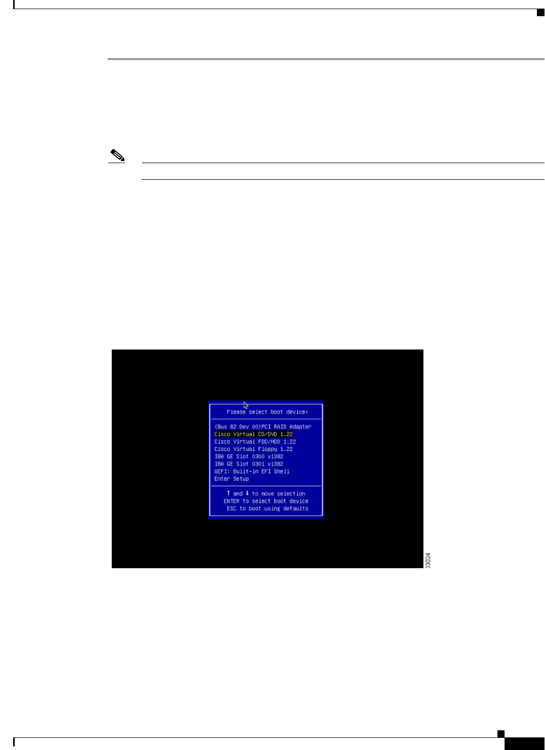
9-3
Installation and Upgrade Guide for Cisco Secure Access Control System 5.5
OL-28603-01
Chapter 9 Installing and Configuring the Secure Access Control System with the Cisco SNS-3415 and Cisco
Installing the ACS Server
Step 1 Connect to the CIMC for server management. Connect Ethernet cables from your LAN to the server,
using the ports that you selected in NIC Mode setting. The Active-active and Active-passive NIC
redundancy settings require you to connect to two ports.
Step 2 Use a browser and the IP address of the CIMC to log in to the CIMC Setup Utility. The IP address is
based upon your CIMC config settings that you made (either a static address or the address assigned by
your DHCP server).
Note The default user name for the server is admin. The default password is password.
Step 3 Use your CIMC credentials to log in.
Step 4 Click Launch KVM Console.
Step 5 Click the Virtual Media tab.
Step 6 Click Add Image to select the ACS 5.5 ISO from the system running your client browser.
Step 7 Check the Mapped check box against the virtual CD/DVD drive that you have created.
Step 8 Click the KVM tab.
Step 9 Choose Macros > Ctrl-Alt-Del to boot the Cisco SNS-3415 or Cisco SNS-3495 appliance using the ISO
image.
Step 10 Enter F6 to bring up the boot menu. A screen similar to the following one appears.
Step 11 Select the CD/DVD that you mapped and press Enter. The following message is displayed.
Welcome to the Cisco Secure ACS 5.5 Recovery
To boot from hard disk press <Enter>
Available boot options:
[1] Cisco Secure ACS Installation (Keyboard/Monitor)
[2] Cisco Secure ACS Installation (Serial Console)
[3] Recover administrator password (Keyboard/Monitor
[4] Recover administrator password (Serial Console)
<Enter> Boot existing OS from hard disk.

9-4
Installation and Upgrade Guide for Cisco Secure Access Control System 5.5
OL-28603-01
Chapter 9 Installing and Configuring the Secure Access Control System with the Cisco SNS-3415 and Cisco
Installing the ACS Server
Enter boot option and press <Enter>
boot:
Step 12 At the boot prompt, enter 1 and press Enter.
Step 13 After you enter the network configuration parameters in the Setup mode, the appliance automatically
reboots, and returns to the shell prompt mode.
Step 14 Exit from the shell prompt mode. The appliance comes up.
Step 15 Continue with Verifying the Installation Process, page 5-5.
Installing ACS 5.5 on the Cisco SNS-3415/3495 Appliance Using the USB
Drive
To install ACS 5.5 on the Cisco SNS-3415 or Cisco SNS-3495 appliance using the USB drive, complete
the following steps:
Before You Begin
You need to create a bootable USB drive. See Creating a Bootable USB Drive, page 9-5.
Step 1 Power on the Cisco SNS-3415 or Cisco SNS-3495 appliance.
Step 2 Plug in your bootable USB drive that has the Cisco Secure ACS ISO image into the USB port.
Step 3 Restart ACS and go to the BIOS mode.
Step 4 In the BIOS mode, choose boot from USB.
Step 5 Exit from the BIOS mode and click Save.
Step 6 Again, restart ACS and boot from USB.
Step 7 Now, continue reimaging the Cisco SNS-3415 or Cisco SNS-3495 using the USB drive.
The following message is displayed.
Welcome to the Cisco Secure ACS 5.5 Recovery
To boot from hard disk press <Enter>
Available boot options:
[1] Cisco Secure ACS Installation (Keyboard/Monitor)
[2] Cisco Secure ACS Installation (Serial Console)
[3] Reset administrator password (Keyboard/Monitor
[4] Reset administrator password (Serial Console)
<Remove USB key and reboot to boot existing Hard Disk>
Please enter boot option and press <Enter>
boot:
Step 8 At the boot prompt, enter 1 and press Enter.
Step 9 After you enter the network configuration parameters in Setup mode, the appliance automatically
reboots and returns to the shell prompt mode.
Step 10 Exit from the shell prompt mode. The appliance comes up.

9-5
Installation and Upgrade Guide for Cisco Secure Access Control System 5.5
OL-28603-01
Chapter 9 Installing and Configuring the Secure Access Control System with the Cisco SNS-3415 and Cisco
Installing the ACS Server
Step 11 Continue with Verifying the Installation Process, page 5-5.
Creating a Bootable USB Drive
The Cisco Secure ACS 5.5 ISO image contains a “Documentation\USB-Bootable-Scripts” directory that
has a Readme file and a script to create a bootable USB to install Cisco Secure Access Control System
5.5.
Before You Begin
•You should have read the Readme in the “Documentation\USB-Bootable-Scripts” directory.
•You need the following:
–
Linux machine with RHEL-5 or RHEL-6, CentOS 5.x or CentOS 6.x. If you are going to use
your PC or MAC, ensure that you have installed a Linux VM on it.
–
A 4-GB USB drive
–
The iso-to-usb.sh script
•You should have access permissions to the drives in the local Linux machine.
Step 1 Plug in your USB drive into the USB port.
Step 2 Copy the iso-to-usb.sh script and the Cisco Secure ACS 5.5 ISO image to a directory on your linux
machine.
Step 3 Enter the following command:
iso-to-usb.sh source_iso usb_device
For example, # ./iso-to-usb.sh ACS_v5.5.0.46.0a.iso/dev/sdc where iso-to-usb.sh is the name of the
script, ACS_v5.5.0.46.0a.iso is the name of the ISO image, and /dev/sdc is your USB device.
The following success message is displayed.
*** W A R N I N G ***
THIS SCRIPT WILL DELETE ALL EXISTING CONTENT ON YOUR USB DRIVE: /dev/sdb/
ARE YOU SURE YOU WANT TO CONTINUE? [Y/N]: y
Deleting partition table on USB drive: /dev/sdb ...
Creating new partition table on USB drive: /dev/sdb ...
Formatting BOOT partition: /dev/sdb1 as VFAT ...
Formatting DATA partition: /dev/sdb2 as EXT2 ...
Copying syslinux files to USB partition: /dev/sdb1 ...
Copying ISO file to USB partition: /dev/sdb2 ...
DONE!
Step 4 Unplug your USB drive.

9-6
Installation and Upgrade Guide for Cisco Secure Access Control System 5.5
OL-28603-01
Chapter 9 Installing and Configuring the Secure Access Control System with the Cisco SNS-3415 and Cisco
Installing the ACS Server
Note After you execute the command iso-to-usb.sh, your USB drive will be partitioned in a format where
non-Linux operating systems will not recognize all of the spaces available in it. To repartition your USB
drive for general purpose use with Windows or MAC operating system, you need to run the command
repurpose-usb.sh utility in this directory. This utility will repartition and reformat your USB key for
general use.
Running the Setup Program
This section describes the setup process to install the ACS server.
The setup program launches an interactive command-line interface (CLI) that prompts you for the
required parameters.
An administrator can use the console or a dumb terminal to configure the initial network settings and
provide the initial administrator credentials for the ACS 5.5 server using the setup program. The setup
process is a one-time configuration task.
To install the ACS server:
Step 1 Power on the appliance.
The setup prompt appears:
Please type ‘setup’ to configure the appliance
localhost login:
Step 2 At the login prompt, enter setup and press Enter.
The console displays a set of parameters. You must enter the parameters as described in Table 9-1.
Note You can interrupt the setup process at any time by typing Ctrl-C before the last setup value is entered.
Table 9-1 Network Configuration Parameters
Prompt Default Conditions Description
Host Name localhost First letter must be an ASCII character.
Length must be from 3 to 15 characters.
Valid characters are alphanumeric (A-Z,
a-z, 0-9), hyphen (-), and the first
character must be a letter.
Note When you intend to use AD ID
store and set up multiple ACS
instances with same name prefix,
use maximum of 15 characters as
the host name so that it does not
affect the AD functionality.
Enter the hostname.
IPV4 IP Address None, network specific Must be a valid IPv4 address between
0.0.0.0 and 255.255.255.255.
Enter the IP address.

9-7
Installation and Upgrade Guide for Cisco Secure Access Control System 5.5
OL-28603-01
Chapter 9 Installing and Configuring the Secure Access Control System with the Cisco SNS-3415 and Cisco
Installing the ACS Server
IPv4 Netmask None, network specific Must be a valid IPv4 address between
0.0.0.0 and 255.255.255.255.
Enter a valid netmask.
IPv4 Gateway None, network specific Must be a valid IPv4 address between
0.0.0.0 and 255.255.255.255.
Enter a valid default gateway.
Domain Name None, network specific Cannot be an IP address.
Valid characters are ASCII characters, any
numbers, hyphen (-), and period (.).
Enter the domain name.
IPv4 Primary Name
Server Address
None, network specific Must be a valid IPv4 address between
0.0.0.0 and 255.255.255.255.
Enter a valid name
server address.
Add/ another
nameserver
None, network specific Must be a valid IPv4 address between
0.0.0.0 and 255.255.255.255.
Note You can configure a maximum of
three name servers from ACS CLI.
To configure multiple name
servers, enter Y.
NTP Server time.nist.gov Must be a valid IPv4 address between
0.0.0.0 and 255.255.255.255 or a domain
name server.
Note You can configure a maximum of
three NTP servers from ACS CLI.
Enter a valid domain name
server or an IPv4 address.
Timezone UTC Must be a valid local time zone. Enter a valid timezone.
SSH Service None, network specific None To enable SSH services,
enter Y.
Table 9-1 Network Configuration Parameters (continued)
Prompt Default Conditions Description

9-8
Installation and Upgrade Guide for Cisco Secure Access Control System 5.5
OL-28603-01
Chapter 9 Installing and Configuring the Secure Access Control System with the Cisco SNS-3415 and Cisco
Installing the ACS Server
The console requests for the parameters as shown below:
localhost login: setup
Enter hostname[]: acs-server-1
Enter IP address[]: a.b.c.d
Enter IP default netmask[]: 255.255.255.255
Enter IP default gateway[]: a.b.c.d
Enter default DNS domain[]: mycompany.com
Enter primary nameserver[]: a.b.c.d
Add secondary nameserver? Y/N : n
Add primary NTP server [time.nist.gov]: a.b.c.d
Add secondary NTP server? Y/N : n
Enter system timezone[UTC]:
Enable SSH service Y/N [N] : y
Enter username [admin]: admin
Enter password:
Enter password again:
Pinging the gateway...
Pinging the primary nameserver...
Username admin The name of the first administrative user.
You can accept the default or enter a new
username.
Must be from 3 to 8 characters, and must
be alphanumeric (A-Z, a-z, 0-9).
Enter the username.
Admin Password None No default password. Enter your
password.
The password must be at least six
characters in length, have at least one
lowercase letter, one uppercase letter, and
one number.
In addition:
•Save the user and password
information for the account that you
set up for initial configuration.
•Remember and protect these
credentials because they allow
complete administrative control of the
ACS hardware, the CLI, and the
application.
•If you lose your administrative
credentials, you can reset your
password by using the ACS 5.5
installation CD.
Enter the password.
Table 9-1 Network Configuration Parameters (continued)
Prompt Default Conditions Description

9-9
Installation and Upgrade Guide for Cisco Secure Access Control System 5.5
OL-28603-01
Chapter 9 Installing and Configuring the Secure Access Control System with the Cisco SNS-3415 and Cisco
Installing the ACS Server
Do not use `Ctrl-C' from this point on...
Appliance is configured
Installing applications...
Installing acs...
Generating configuration...
Rebooting...
After the ACS server is installed, the system reboots automatically.
Now, you can log into ACS using the CLI username and password that was configured during the
setup process.
Note You can use this username and password to log in to ACS only via the CLI.
Note The initial setup of the ACS 5.5 server should be configured with an IPv4 IP address. You can configure
the IPv6 IP address for your server only after the initial setup is completed.
Note ACS 5.5 supports IPv4 and IPv6 dual stack networking and does not support pure IPv6 network.
Verifying the Installation Process
To verify that you have correctly completed the installation process:
Step 1 When the system reboots, at the login prompt enter the username you configured during setup, and
press Enter.
Step 2 At password prompt, enter the password you configured during setup, and press Enter.
Step 3 Verify that the application has been installed properly by entering the show application command, and
press Enter.
The console displays:
<name> <Description>
acs Cisco Secure Access Control System 5.5
Step 4 At the system prompt, check the release and ACS version that are installed, by entering the show
application version acs command and pressing Enter.
The console displays:
Cisco ACS VERSION INFORMATION
-----------------------------
Version : 5.5.0.46
Internal Build ID : B.221
Note The Version and Internal Build ID may change for different versions of this release.

9-10
Installation and Upgrade Guide for Cisco Secure Access Control System 5.5
OL-28603-01
Chapter 9 Installing and Configuring the Secure Access Control System with the Cisco SNS-3415 and Cisco
Resetting the Administrator Password
Step 5 Check the status of ACS processes, at the system prompt by entering show application status acs,
and press Enter.
The console displays:
ACS role: PRIMARY
Process 'database' running
Process 'management' running
Process 'runtime' running
Process 'ntpd' running
Process 'view-database' running
Process 'view-jobmanager' running
Process 'view-alertmanager' running
Process 'view-collector' running
Process 'view-logprocessor' running
Note To get the latest ACS patches and to keep your ACS up-to-date, visit
http://software.cisco.com/download/navigator.html?i=rt
Resetting the Administrator Password
If you are not able to log in to the system due to the loss of the administrator password, you can use the
ACS 5.5 recovery DVD to reset the administrator password.
Note You can also use the bootable USB drive and CIMC to reset the administrator password.
To reset the administrator password:
Step 1 Power up the appliance.
Step 2 Insert the ACS 5.5 recovery DVD.
The console displays:
Welcome to Cisco Secure ACS 5.5 Recovery
To boot from hard disk press <Enter>
Available boot options:
[1] Cisco Secure ACS 5.5 Installation (Keyboard/Monitor)
[2] Cisco Secure ACS 5.5 Installation (Serial Console)
[3] Reset Administrator Password (Keyboard/Monitor)
[4] Reset Administrator Password (Serial Console)
<Enter> Boot from hard disk
Please enter boot option and press <Enter>.
boot:
To reset the administrator password, at the system prompt, enter 3 if you are using a keyboard and video
monitor, or enter 4 if you are using a serial console port.

9-11
Installation and Upgrade Guide for Cisco Secure Access Control System 5.5
OL-28603-01
Chapter 9 Installing and Configuring the Secure Access Control System with the Cisco SNS-3415 and Cisco
Reimaging the Cisco SNS-3415/3495 Appliance
The console displays a set of parameters.
Step 3 Enter the parameters as described in Table 9-2.
The console displays:
Admin username:
[1]:admin
[2]:admin2
[3]:admin3
Enter number of admin for password recovery:1
Password:
Verify password:
Save change&reeboot? [Y/N]:
Reimaging the Cisco SNS-3415/3495 Appliance
You can either use CIMC or the bootable USB drive to reimage the Cisco SNS-3415 or Cisco SNS-3495
appliance with ACS 5.5.
To reimage the Cisco SNS-3415 or Cisco SNS-3495 appliance:
•Reimage using CIMC. See Installing ACS 5.5 on the Cisco SNS-3415/3495 Appliance Remotely
Using CIMC, page 9-2
•Reimage using bootable USB drive. See Installing ACS 5.5 on the Cisco SNS-3415/3495 Appliance
Using the USB Drive, page 9-4
Regulatory Compliance
For regulatory compliance and safety information, see Regulatory Compliance and Safety Information
for Cisco Secure Access Control System. This document is available online at Cisco.com:
http://www.cisco.com/en/US/docs/net_mgmt/cisco_secure_access_control_system/5.4/regulatory/
compliance/csacsrcsi.html
Table 9-2 Password Reset Parameters
Parameter Description
Admin username Enter the number of the administrator whose password you want to reset.
Password Enter the new password for the administrator.
Verify password Enter the password again.
Save change & Reboot Enter Y to save.

9-12
Installation and Upgrade Guide for Cisco Secure Access Control System 5.5
OL-28603-01
Chapter 9 Installing and Configuring the Secure Access Control System with the Cisco SNS-3415 and Cisco
Regulatory Compliance

P
ART
4
ACS 5.5 on VMware Virtual Machines

CHAPTER
10-1
Installation and Upgrade Guide for Cisco Secure Access Control System 5.5
OL-28603-01
10
Installing ACS in a VMware Virtual Machine
This chapter describes the system requirements and installation of ACS 5.5 in a VMware virtual
machine.
This section contains:
•Virtual Machine Requirements, page 10-2
•Configuring the VM for ESXi 5.0, ESXi 5.1, and ESXi 5.5, page 10-5
•Preparing the VM for ACS Server Installation, page 10-10
•Installing the ACS Server on ESXi 5.0, ESXi 5.1, and ESXi 5.5, page 10-11
•VMware Hardening Requirements, page 10-13
•VMware Tools Support, page 10-14

10-2
Installation and Upgrade Guide for Cisco Secure Access Control System 5.5
OL-28603-01
Chapter 10 Installing ACS in a VMware Virtual Machine
Virtual Machine Requirements
Virtual Machine Requirements
The minimum system requirements for the VMware virtual machine (VM) must be similar to the
CSACS-1121 appliance hardware configuration.
Table 10-1 lists the minimum system requirements to install ACS 5.5 on a VMware virtual machine.
Note If you want to upgrade the ACS installed on virtual machine to ACS 5.5, the virtual machine disk size
should be greater than or equal to 500 GB.
The disk space management mechanism in ACS 5.5 manages the system automatically and configures
the available file volumes on the file system per file type, such as local store, logs, configuration, cache,
and so on. The actual file size limits are calculated at the time of installation, based on the hard coded
relative disk quota configuration (percent based), using the disk size as an input. However, ACS database
logs have a fixed size. ACS 5.5 gets installed with a variable hard disk size between 60 GB and 750 GB,
based on the disk size that was chosen while creating the VMware instance. If you want to change the
size of the ACS disk after the installation, complete the following procedure:
•Back up your data.
•Reimage the ACS application or install a fresh application.
•Restore the backed up data.
While restoring the backed up data, a warning message is displayed when the backup size or ACS view
database size exceeds the corresponding disk quota. However, the restore operation will not be
interrupted. The restore operation fails only when the hard limit of /opt partition size is reached.
Table 10-1 Minimum System Requirements
Requirement Type Minimum Requirements
CPU 2 CPUs (dual CPU, Xeon, Core2 Duo or 2 single CPUs)
Memory 4 GB RAM
Hard Disk A minimum of 60 GB is required.
Maximum storage is up to 750 GB.
Note ACS partitions the available disk space automatically
during the installation process.
Note It is recommended that you allocate the hard disk size to be
greater than 500 GB for the secondary instance, which acts
as a log collector.
NIC (Network Interface Card) 1 Gb dedicated NIC interface
Hypervisor •VMware ESXi 5.0
•VMware ESXi 5.0 Update 2
•VMware ESXi 5.1
•VMware ESXi 5.1 Update 2
•VMware ESXi 5.5 Update 1 after you install patch 3 or a
subsequent patch.

10-3
Installation and Upgrade Guide for Cisco Secure Access Control System 5.5
OL-28603-01
Chapter 10 Installing ACS in a VMware Virtual Machine
Virtual Machine Requirements
In ACS 5.5, the log collector server can be installed on a 60 GB disk space. An ACS view log collector
node usually requires more space to maintain a database of logs and reports. Therefore, the
recommended disk size for the secondary instance, which acts as a log collector server, is 500 GB.
When you allocate 60 GB for the log collector server, the view database gets only 5.6 GB as total disk
space. As a result of this, some of the functionalities may not work properly. The functionalities that may
be affected are backup, full backup, incremental backup, logging recovery, purge, database compress
operation, and so on.
Note It is recommended to maintain incremental or full backup of size less than 20 GB on a 32-bit system
running on Cisco SNS-3415 and Cisco SNS-3495 appliances.
While creating the VMware instances, ensure that the resources allocated for VMware instances with
respect to CPU cores, RAM, and disk, are not more than the actual physical resources of the VMware
host server. For example, if the VMware host server has a total of 10 CPU cores, then the sum of the
allocated CPU cores for all the VMware instances that are created on that server should not exceed 10.
Note In large ACS distributed deployment environments that are hosted on the VM, it is recommended that
all VM hosting servers have CPUs from the same vendor.
Note It is recommended that if hyperthreading is enabled on any one of the VMware hosts, it should be
enabled on all the VMware hosts that host the ACS VM as part of the same deployment.
Note ACS 5.5 does not get installed over multiple disks (by defining one Logical volume Manager [LVM]
disk).
Install VMware Server
Install the VMware server with the default options and proper IP address.
Install VMware vSphere Client
The VMware vSphere client is used to access the VMware server from a remote location.
To install the VMware vSphere Client:
Step 1 Go to the following link.
http://IP address of VMware server
You should have valid Cisco.com login credentials to access this link.
Step 2 Click Download to download the VMware vSphere client software.
Step 3 Run the installer.
Step 4 Log into the VMware server.
Figure 10-1 displays the login window of the VMware server.
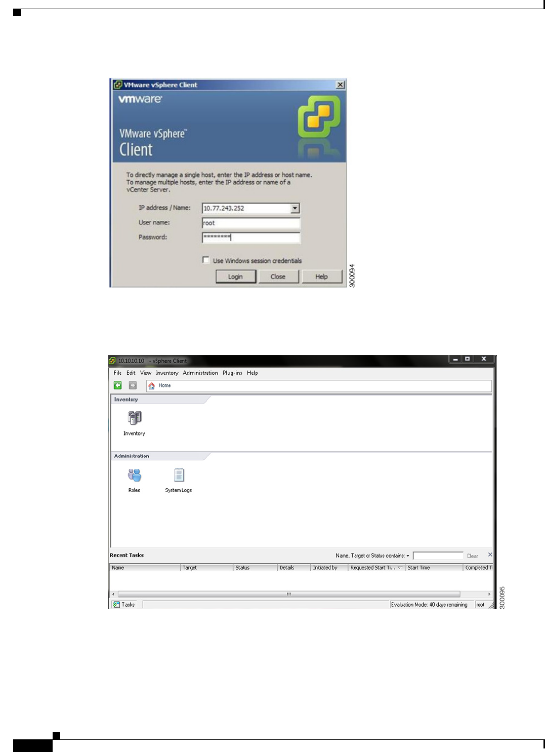
10-4
Installation and Upgrade Guide for Cisco Secure Access Control System 5.5
OL-28603-01
Chapter 10 Installing ACS in a VMware Virtual Machine
Virtual Machine Requirements
Figure 10-1 Login Window
The vSphere client window is displayed. (Figure 10-2)
Figure 10-2 vSphere Client Window
Step 5 Choose Help > About VMware vSphere to verify the VMware ESX and vSphere client versions.
Figure 10-3 displays the VMware vSphere versions.
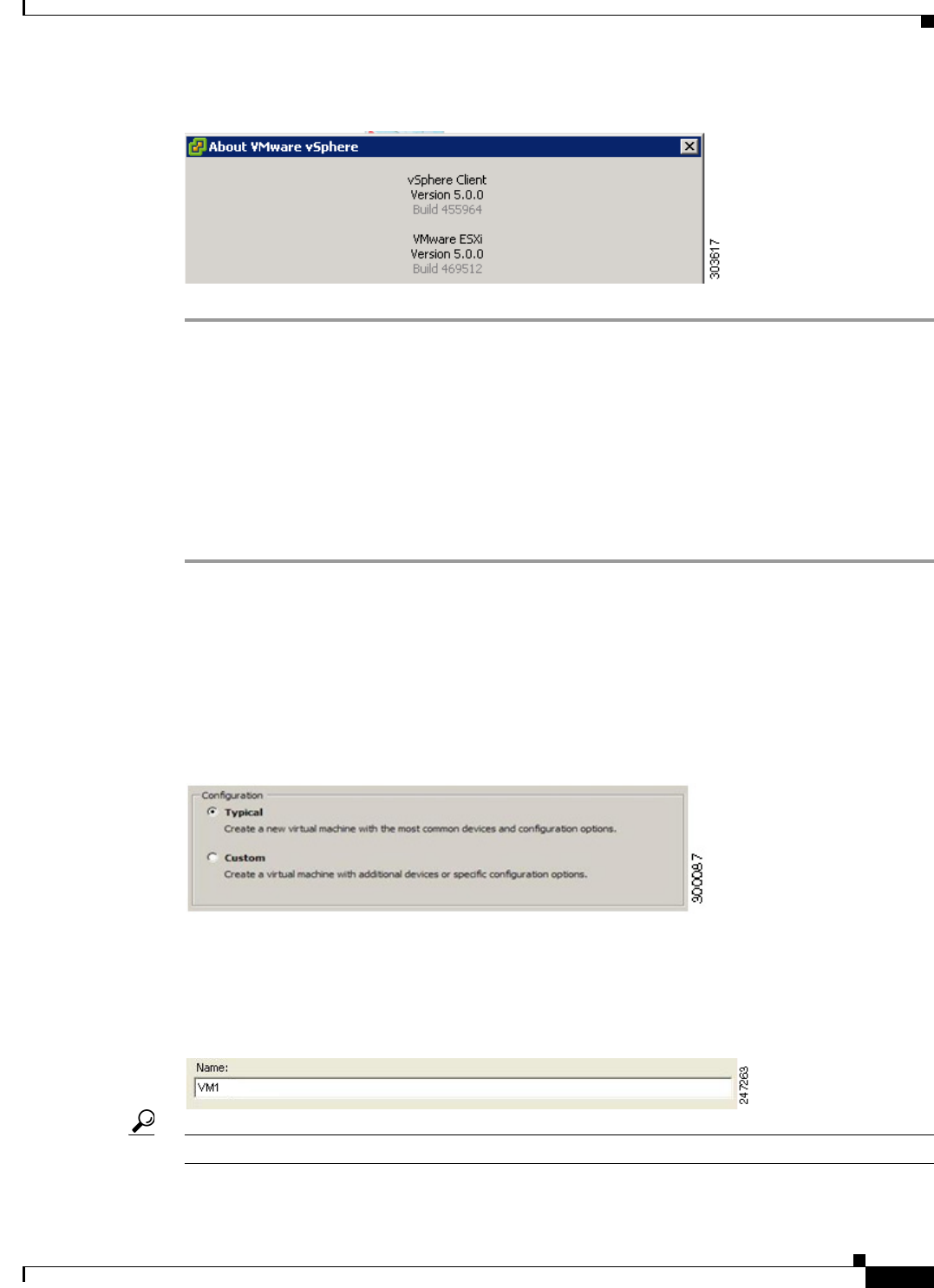
10-5
Installation and Upgrade Guide for Cisco Secure Access Control System 5.5
OL-28603-01
Chapter 10 Installing ACS in a VMware Virtual Machine
Configuring the VM for ESXi 5.0, ESXi 5.1, and ESXi 5.5
Figure 10-3 About VMware vSphere
Configuring the VM for ESXi 5.0, ESXi 5.1, and ESXi 5.5
The host uses virtualization software such as ESX server to run the virtual machine. The host provides
the CPU and memory resources to the virtual machine to access storage and to connect to the network.
This section describes the VM configuration process using the VMware vSphere Client.
To configure the VM for ESXi 5.0, ESXi 5.1, and ESXi 5.5, complete the following steps:
Step 1 Log in to the ESX server.
Step 2 In the VMware vSphere Client, in the left pane, right-click your host container and choose New Virtual
Machine.
The New Virtual Machine Wizard appears.
Step 3 In the Configuration Type dialog box, choose Typical as the VM configuration, as shown in Figure 10-4,
and click Next.
Figure 10-4 Virtual Machine Configuration Dialog Box
The Name and Location dialog box appears. (Figure 10-5)
Step 4 Enter the name you will use to reference the VM, and click Next.
Figure 10-5 Name and Location Dialog Box
Tip Use the hostname that you will use for your VM host.
The Data Storage dialog box appears. (Figure 10-6)
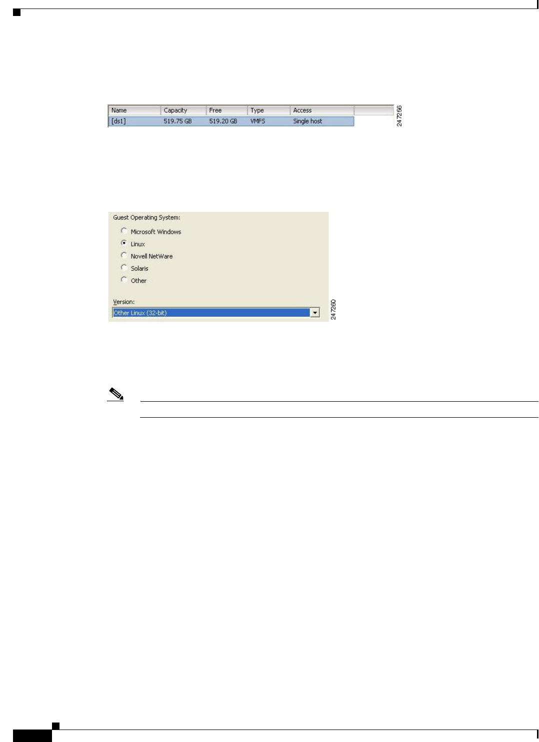
10-6
Installation and Upgrade Guide for Cisco Secure Access Control System 5.5
OL-28603-01
Chapter 10 Installing ACS in a VMware Virtual Machine
Configuring the VM for ESXi 5.0, ESXi 5.1, and ESXi 5.5
Step 5 Choose a data store that has a minimum of 500 GB free space available, and click Next.
Figure 10-6 Data Storage Dialog Box
The Guest Operating System dialog box appears. (Figure 10-7)
Step 6 Click the Linux radio button, and from the Version drop-down list, choose Other Linux (32-bit).
Figure 10-7 Guest Operating System Dialog Box
The Network dialog box appears. (Figure 10-8)
Step 7 Select the number of NICs that you want to use in the network window, and click Next. You can use up
to four NICs.
Note ACS does not support VMXNET2 (Enhanced) and VMXNET3 adapters.
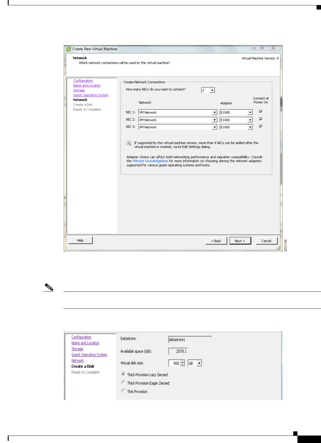
10-7
Installation and Upgrade Guide for Cisco Secure Access Control System 5.5
OL-28603-01
Chapter 10 Installing ACS in a VMware Virtual Machine
Configuring the VM for ESXi 5.0, ESXi 5.1, and ESXi 5.5
Figure 10-8 Network Dialog Box
The Create a Disk dialog box appears. (Figure 10-9)
Step 8 Select the disk size as 500 GB in the virtual disk capacity window, and click Next.
Note You can configure the minimum virtual disk space requirement to be 60 GB. There may be a critical issue
if you use 60 GB as virtual disk space. You can view the workaround in the troubleshooting section.
Figure 10-9 Create a Disk Dialog Box
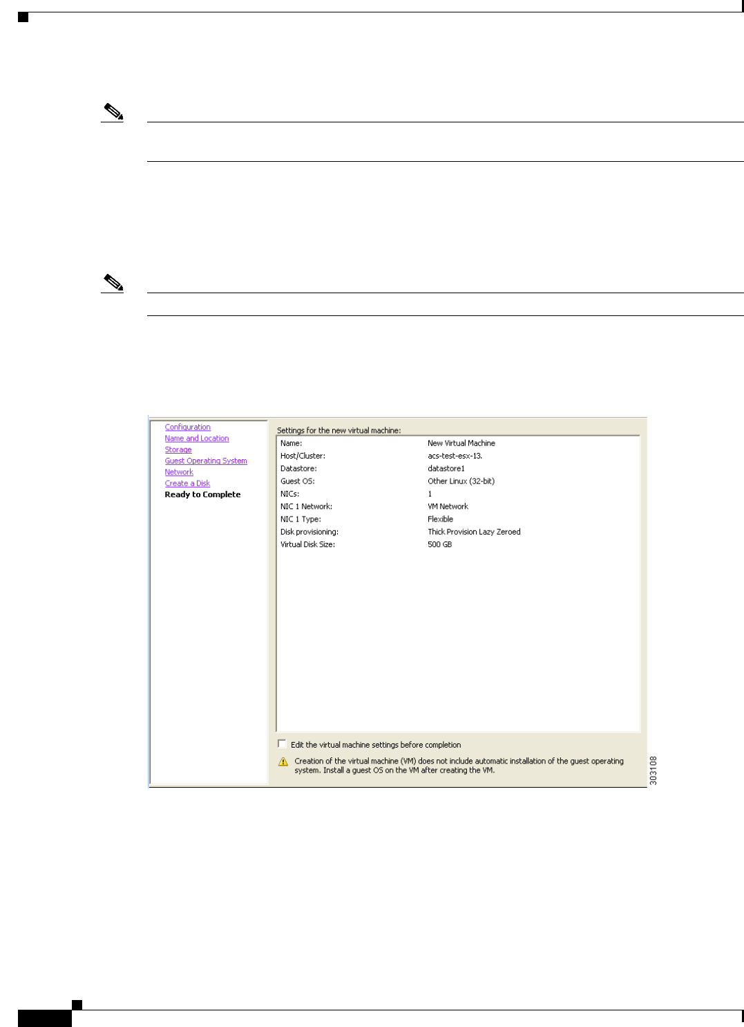
10-8
Installation and Upgrade Guide for Cisco Secure Access Control System 5.5
OL-28603-01
Chapter 10 Installing ACS in a VMware Virtual Machine
Configuring the VM for ESXi 5.0, ESXi 5.1, and ESXi 5.5
The Ready to Complete dialog box appears. Figure 10-10.
Note Do not choose VMware thin provisioning as a storage type because ACS supports only thick
provisioning on all supported VMware servers.
If ACS is installed in a VMware with thin provisioning storage type, you are recommended to:
1. Take a backup of the ACS configuration.
2. Reimage the VMware with the thick provisioning storage type.
3. Restore the backup in the newly converted thick provisioned storage VMware.
Note Do not over-provision hardware resources such as RAM, CPU, and disks for your virtual machines.
Step 9 Verify the configuration details—such as Name, Guest OS, Virtual CPU, Memory, and Virtual Disk
Size—of the newly created VM.
Figure 10-10 Ready to Complete Dialog Box
Step 10 Check the Edit the virtual machine settings before completion check box, and click Next.
The Memory Configuration dialog box appears. (Figure 10-11)
Step 11 Enter 4096 MB, and click Next.
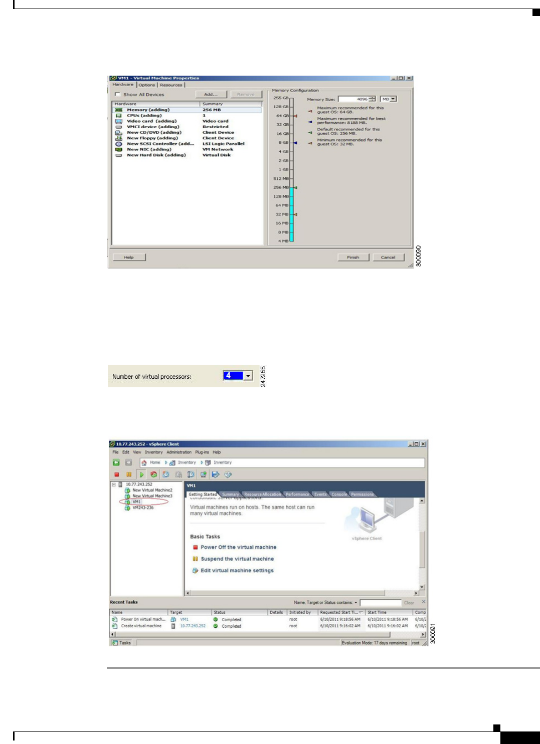
10-9
Installation and Upgrade Guide for Cisco Secure Access Control System 5.5
OL-28603-01
Chapter 10 Installing ACS in a VMware Virtual Machine
Configuring the VM for ESXi 5.0, ESXi 5.1, and ESXi 5.5
Figure 10-11 Memory Configuration Dialog Box
The Number of Virtual Processors dialog box appears. (Figure 10-12)
Step 12 From the Number of virtual processors drop-down list, choose 2 (if 2 is available), or you can choose
any number and click Finish.
Figure 10-12 Number of Virtual Processors Dialog Box
Step 13 The virtual machine is installed and will be listed in the VMware drawer, as follows.
Figure 10-13 vSphere Client
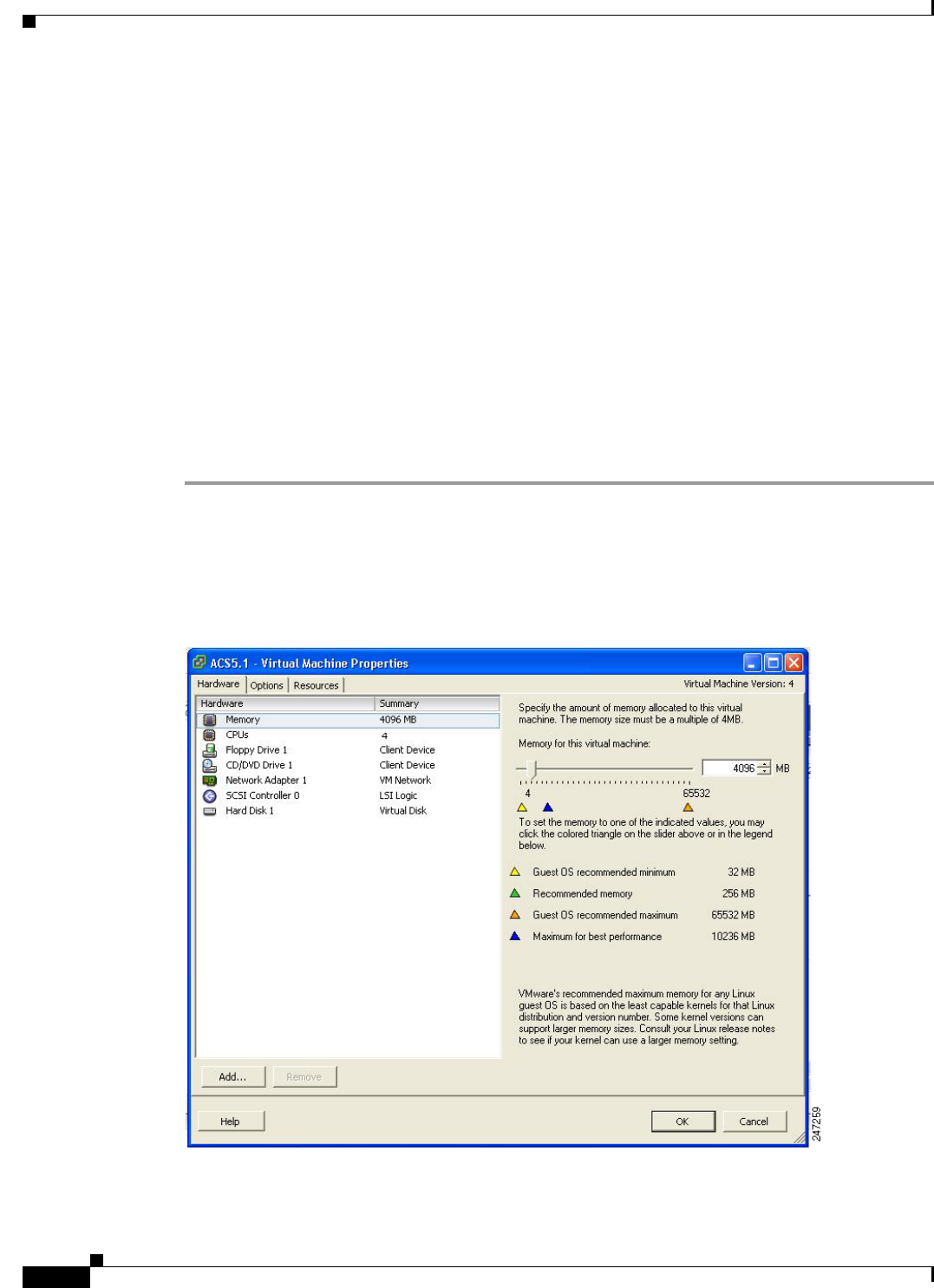
10-10
Installation and Upgrade Guide for Cisco Secure Access Control System 5.5
OL-28603-01
Chapter 10 Installing ACS in a VMware Virtual Machine
Preparing the VM for ACS Server Installation
Preparing the VM for ACS Server Installation
After configuring the VM, you are ready to install ACS, Release 5.5. To install the ACS server from your
ACS Install Disk, you need to configure the VM to boot from the ACS Install Disk.
The VM must be configured with a virtual DVD drive, in order to boot from the ACS 5.5 DVD.
This can be performed using different methods, depending on your environment.
See Configuring the VM Using the DVD Drive, page 10-10 to configure the VM using the DVD drive
of your VMware ESX server host.
Configuring the VM Using the DVD Drive
This section describes how to configure the VM to boot from the ACS Install Disk using the DVD drive
of the VMware ESX server host.
To configure the VM using the DVD drive:
Step 1 In the VMware vSphere Client, highlight the newly created VM, and choose Edit Virtual
Machine Settings.
The Virtual Machine Properties window appears. Figure 10-14 displays the properties of a VM that was
created with the name ACS 5.5.
Figure 10-14 Virtual Machine Properties Dialog Box
Step 2 In the Virtual Machine Properties dialog box, choose CD/DVD Drive 1.
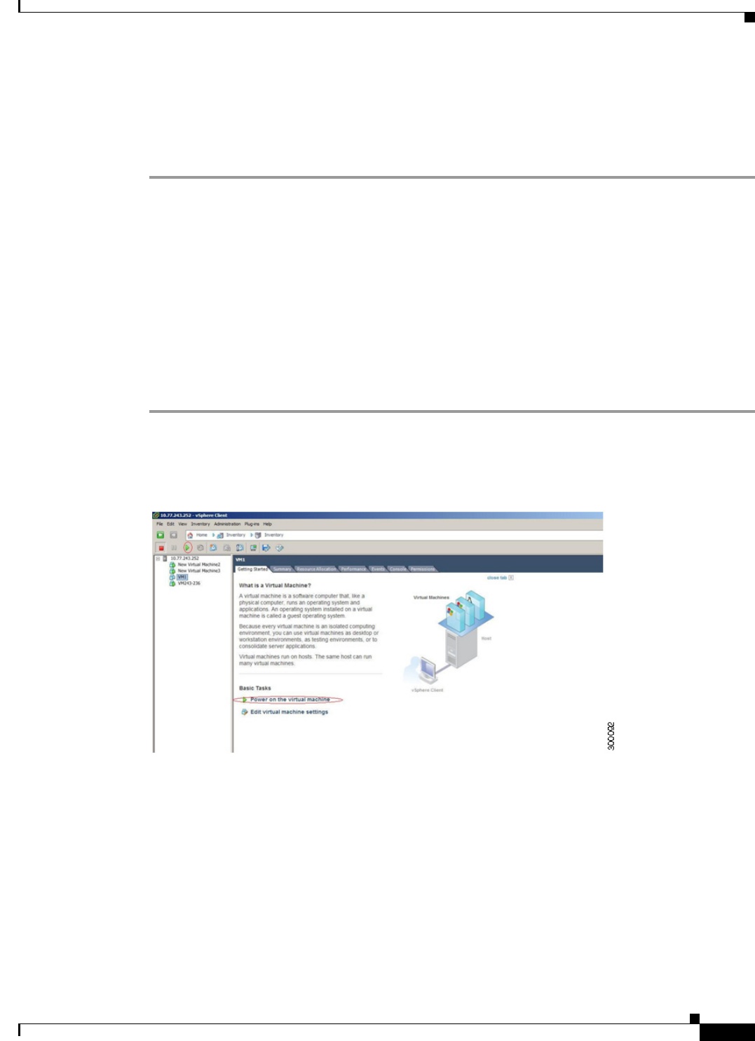
10-11
Installation and Upgrade Guide for Cisco Secure Access Control System 5.5
OL-28603-01
Chapter 10 Installing ACS in a VMware Virtual Machine
Installing the ACS Server on ESXi 5.0, ESXi 5.1, and ESXi 5.5
The CD/DVD Drive 1 properties dialog box appears.
Step 3 Choose the Host Device option, and from the drop-down list, choose your DVD host device.
Step 4 Choose the Connect at Power On option, and click OK to save your settings.
You can now use the DVD drive of the VMware ESX server to install the ACS server.
When you complete the configuration, click the Console tab, right-click the VM from the left pane, and
choose GUEST > Send Ctrl+Alt+Del to restart the VM.
Installing the ACS Server on ESXi 5.0, ESXi 5.1, and ESXi
5.5
This section describes how to install ACS 5.5 on VMware ESXi 5.0, ESXi 5.1, and ESXi 5.5.
To install the ACS 5.5 server, complete the following steps:
Step 1 Log in to the VMware vSphere Client.
Step 2 Insert the ACS 5.5 Install Disk in to the VMware ESX host CD/DVD drive, and power on the VM.
Figure 10-15 Power on the Virtual Machine
Step 3 Store the ACS 5.5 recovery ISO image in the VMware vSphere client, to access the VMware Server.
Step 4 Click the CD icon on the tool bar and choose Connect CD/DVD 1 > Connect to ISO image on local
disk.
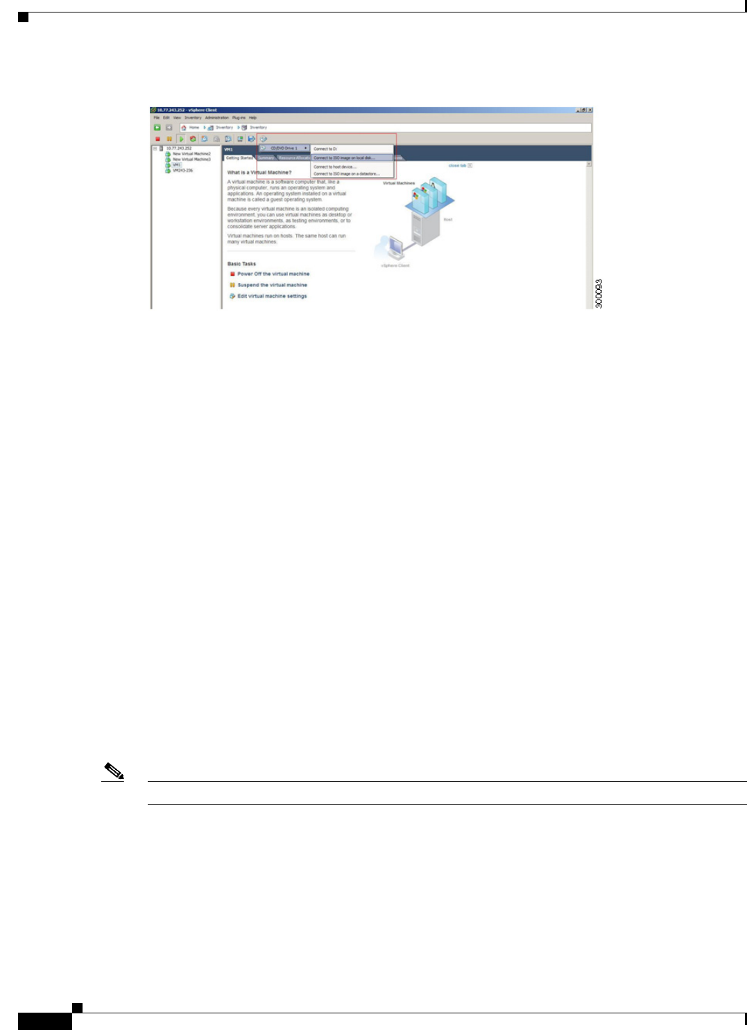
10-12
Installation and Upgrade Guide for Cisco Secure Access Control System 5.5
OL-28603-01
Chapter 10 Installing ACS in a VMware Virtual Machine
Installing the ACS Server on ESXi 5.0, ESXi 5.1, and ESXi 5.5
Figure 10-16 Connecting to ISO image on Local Disk
Step 5 Browse and locate the ACS 5.5 ISO image.
Move to the console tab. You will lose your cursor control as soon as you enter the console tab.
Step 6 Press Ctrl + Alt to get cursor control.
Step 7 Press Enter.
The machine restarts with the ACS 5.5 recovery ISO image loaded. Now, the user is prompted with the
install option for ACS 5.5.
When the ACS 5.5 Install Disk boots, the console displays:
Welcome to Cisco Secure ACS 5.5 Recovery
To boot from the hard disk press <Enter>
Available boot options:
[1] Cisco Secure ACS 5.5 Installation (Monitor/Keyboard)
[2] Cisco Secure ACS 5.5 Installation (Serial Console)
[3] Reset Administrator Password (Keyboard/Monitor)
[4] Reset Administrator Password (Serial Console)
<Enter> Boot from hard disk
Please enter boot option and press <Enter>.
boot: 1
You can select either the monitor and keyboard port, or the console port to perform the initial setup.
Step 8 At the system prompt, type 1 to select a monitor and keyboard port, or type 2 to select a console port,
and press Enter.
ACS installation begins on the VM.
Note Allow 20 minutes for the installation process to complete.
When the installation process finishes, the VM reboots automatically.
When the VM reboots, the console displays:
Type 'setup' to configure your appliance
localhost:
Step 9 At the system prompt, type setup, and press Enter.
The Setup Wizard appears and guides you through the initial configuration.

10-13
Installation and Upgrade Guide for Cisco Secure Access Control System 5.5
OL-28603-01
Chapter 10 Installing ACS in a VMware Virtual Machine
VMware Hardening Requirements
The console requests for the parameters, as shown below.
localhost login: setup
Enter hostname[]: acs54-server-1
Enter IP address[]: a.b.c.d
Enter IP default netmask[]: 255.255.255.255
Enter IP default gateway[]: a.b.c.d
Enter default DNS domain[]: mycompany.com
Enter primary nameserver[]: a.b.c.d
Add secondary nameserver? Y/N : n
Add primary NTP server [time.nist.gov]: a.b.c.d
Add secondary NTP server? Y/N : n
Enter system timezone[UTC]:
Enable SSH service? Y/N [N[ : y
Enter username [admin]: admin
Enter password:
Enter password again:
Bringing up network interface...
Pinging the gateway...
Pinging the primary nameserver...
Virtual machine detected, configuring VMware tools...
File descriptor 4 (/opt/system/etc/debugd-fifo) leaked on lvm.static invocation
Parent PID 3036: /bin/bash
Do not use `Ctrl-C' from this point on...
debugd[2455]: [2809]: config:network: main.c[252] [setup]: Setup is complete.
Installing applications...
Installing acs...
Generating configuration...
Rebooting...
For more information on the setup process, see Running the Setup Program, page 5-2.
VMware Hardening Requirements
Both the VMware server and the operating system on which the VMware virtual machine is running must
be hardened according to the guidelines that are specified by the VMware and operating system vendors.
See the VMware support website for more details. Some helpful links are:
•http://www.vmware.com/support/
•http://kb.vmware.com/selfservice/microsites/search.do?language=en_US&cmd=displayKC&external
Id=1017910
•http://communities.vmware.com/community/vmtn

10-14
Installation and Upgrade Guide for Cisco Secure Access Control System 5.5
OL-28603-01
Chapter 10 Installing ACS in a VMware Virtual Machine
VMware Tools Support
VMware Tools Support
ACS 5.5 supports VMware Tools 9.0.0. The benefits of using VMware Tools in ACS 5.5 are:
•Improved NIC performance
•Improved Small Computer System Interface (SCSI) I/O performance
•Synchronization of guest operating system time with the host time
A new line of text appears, which says Virtual machine detected, configuring VMware Tools when
you run the initial Setup Wizard. You can also do the following to check if the VMware Tools are
installed:
Click the Summary tab of the virtual machine in the vSphere client. You can see that the text
“Running” appears against VMware Tools. This confirms that the VMware Tools are installed and
running.
You can use the CLI command show inventory. When you run this CLI, a list appears that shows the
NIC driver information. If the VMware Tools are installed, then the driver information is listed as VMware
Virtual Ethernet Driver.

P
ART
5
Upgrading ACS to Release 5.5

CHAPTER
11-1
Installation and Upgrade Guide for Cisco Secure Access Control System 5.5
OL-28603-01
11
Upgrading the Cisco Secure Access Control
System
This chapter explains how to upgrade an ACS deployment or a standalone ACS server from 5.3/5.4 or
from the latest available patch to 5.5.
Note When you upgrade from ACS 5.4 to ACS 5.5 using the “Upgrading an ACS server using the
ApplicationUpgrade Bundle” method, it is mandatory to install the “Pointed-PreUpgrade-
CSCum04132-5.4.0.46.0a” patch before you start upgrading from ACS 5.4 version. You can install this
patch directly on any cumulative patch version.
Note When you upgrade from ACS 5.3 to 5.5 using the “Upgrading an ACS server using the
ApplicationUpgrade Bundle” method, it is mandatory to install the following patches one by one in the
order specified:
1 Install ACS 5.3 patch 8 (ACS 5.3.0.40.8) or a subsequent patch. You need to install patch 8 or a
subsequent patch prior to the upgrade or the upgrade may fail.
2 Install the “Pointed-PreUpgrade-CSCum04132-5.3.0.40” patch over patch 8 or a subsequent patch
before you start upgrading from ACS 5.3 version.
Note If you are using ACS 5.0/5.1/5.2, you must first upgrade to ACS 5.3/5.4 before upgrading to ACS 5.5.
For information on upgrading from ACS 5.x to ACS 5.3, see the Installation and Upgrade Guide for
Cisco Secure Access Control System 5.3.
Note The versions prior to ACS 5.5 does not have any security policy configuration in CLI. When you upgrade
from ACS 5.3 or 5.4 to ACS 5.5, the password-policy is configured by default for CLI Admin.
Note Upgrading to ACS 5.5 may fail if any LDAP identity store is configured without groups or attributes and
an AD identity store is not configured. To avoid this issue, before upgrading to ACS 5.5, either add
groups or attributes to the LDAP identity store or configure an AD identity store.
This chapter describes the following scenarios:

11-2
Installation and Upgrade Guide for Cisco Secure Access Control System 5.5
OL-28603-01
Chapter 11 Upgrading the Cisco Secure Access Control System
•Upgrading an ACS Deployment from 5.4 to 5.5, page 11-3
•Upgrading an ACS Deployment from 5.3 to 5.5, page 11-12
•Upgrading an ACS Server from 5.4 to 5.5, page 11-12
You can use any one of the following procedures:
–
Upgrading an ACS Server Using the Application Upgrade Bundle, page 11-12—For an
incremental upgrade of an ACS server from 5.4 to 5.5.
–
Reimaging and Upgrading an ACS Server, page 11-14—To back up ACS 5.4 application data
and restore it on ACS 5.5.
•Upgrading an ACS Server from 5.3 to 5.5, page 11-15
•Applying an ACS Patch, page 11-16
•Upgrading ACS 5.3 or 5.4 on the CSACS-1120 or CSACS-1121 to the Cisco SNS-3415 or Cisco
SNS-3495, page 11-17
The upgrade process involves upgrading an ACS server, which includes the Monitoring and Report
Viewer and the configuration information in the database.
Note ACS 5.5 upgrades ADE-OS 1.x to the 2.x version as a part of the application upgrade process.
During the upgrade process, ACS upgrades the ACS server to 5.5 and restores the data to the ACS 5.5
server. As part of the restore operation, ACS converts the configuration data to a 5.5-compatible format.
ACS stores the data upgrade information in the acsupgrade.log file. To view the content of this log file,
download the support bundle.
For information on downloading the support bundle, see the CLI Reference Guide for Cisco Secure
Access Control System 5.5. Also, see ADE.log, which logs the details of all operations that are performed
in the ACS CLI. If you are migrating ACS from 4.x to 5.5, follow the migration procedure as described
in the Migration Guide for Cisco Secure Access Control System 5.5.
You must have a repository that is configured with an FTP, Network File System (NFS), or Secure FTP
(SFTP) network server (but not a TFTP repository) to perform the ACS upgrade.
To create a repository, use the repository command. For more details about the commands that are used
in this chapter, see the CLI Reference Guide for Cisco Secure Access Control System 5.5.
Upgrade Paths
You can use the following upgrade paths to upgrade the ACS server from 5.x versions to ACS 5.5:
•Path 1: ACS 5.4 to ACS 5.5. To upgrade from ACS 5.4 to 5.5, see Upgrading an ACS Server from
5.4 to 5.5, page 11-12.
•Path 2: ACS 5.3 to ACS 5.5. To upgrade from ACS 5.3 to 5.5, see Upgrading an ACS Server from
5.3 to 5.5, page 11-15.
•Path 3: ACS 5.0/5.1/5.2 to ACS 5.3/5.4 to ACS 5.5. To upgrade from 5.0/5.1/5.2 to ACS 5.3, see
the Installation and Upgrade Guide for Cisco Secure Access Control System 5.3. To upgrade from
5.0/5.1/5.2 to ACS 5.4, see the Installation and Upgrade Guide for Cisco Secure Access Control
System 5.3.

11-3
Installation and Upgrade Guide for Cisco Secure Access Control System 5.5
OL-28603-01
Chapter 11 Upgrading the Cisco Secure Access Control System
Upgrading an ACS Deployment from 5.4 to 5.5
Note When you upgrade from ACS 5.3 to ACS 5.5, you must install patch 8 or a subsequent patch before you
start upgrading to ACS 5.5.
Note If you want to upgrade the ACS installed on a virtual machine to ACS 5.5, the virtual machine disk size
should be greater than or equal to 500 GB.
Upgrading an ACS Deployment from 5.4 to 5.5
Note When you upgrade from ACS 5.4 to ACS 5.5, it is mandatory to install the pointed patch before you start
upgrading from ACS 5.4 version. The name of the patch file is
Pointed-PreUpgrade-CSCum04132-5-4-0-46-0a.tar.gpg. You can install this pointed patch directly on
FCS candidate build or on top of any cumulative patch version.
Follow the procedure that is described in this section to upgrade an ACS 5.4 deployment to ACS 5.5.
The deployment upgrade process consists of the following phases:
•Upgrading the Log Collector Server, page 11-3
•Upgrading the Secondary Servers, page 11-6
•Upgrading the Primary Server, page 11-8
Note ACS does not support interoperability between ACS 5.4 and ACS 5.5 deployments.
Usually, in a deployment scenario where multiple ACS instances are involved, the primary ACS instance
functions as a master database for the configuration data, and one of the secondary ACS instances stores
the Monitoring and Report data. You can also use the primary instance to store the Monitoring and
Report data.
Initially, you need to upgrade the log collector server to ACS 5.5 and use this server as a common log
collector between the ACS 5.4 and 5.5 deployments, until the 5.5 upgrade for all servers is complete.
There are some exceptions to this usual setup, which you can handle as described below:
If the ACS 5.4 primary server also functions as a log collector in your 5.4 deployment, you should
promote any one of the secondary servers as the primary server in the deployment before upgrading the
existing primary server. See Promoting a Secondary Server to Primary, page 11-10.
Note Before upgrading any secondary server, must deregister it from the primary server.
Upgrading the Log Collector Server
To upgrade a log collector server to ACS 5.5, complete the following steps:

11-4
Installation and Upgrade Guide for Cisco Secure Access Control System 5.5
OL-28603-01
Chapter 11 Upgrading the Cisco Secure Access Control System
Upgrading an ACS Deployment from 5.4 to 5.5
Step 1 Choose any secondary server to become a log collector:
a. From the primary ACS server, choose System Administration > Configuration > Log
Configuration > Log Collector.
The Log Collector page is displayed.
b. From the Select Log Collector Server drop-down list, choose the new secondary instance to be the
log collector, and click Set Log Collector.
The ACS services of the new secondary log collector are restarted.
Step 2 Enter the show application status acs command in EXEC mode to check whether all process are up and
running successfully, and press Enter.
The console displays:
Process 'database' running
Process 'management' running
Process 'runtime' running
Process 'ntpd' running
Process 'adclient' running
Process 'view-database' running
Process 'view-jobmanager' running
Process 'view-alertmanager' running
Process 'view-collector' running
Process 'view-logprocessor' running
You can now see that all processes are up and running.
Step 3 Deregister the old log collector server from the deployment, and delete it from the ACS 5.4 primary
server so that it is now a standalone server:
a. From the web interface of the ACS 5.4 primary server, choose System Administration >
Operations > Distributed System Management.
The Distributed System Management page appears.
b. From the Secondary Instances table, check the check box next to the secondary instance that you
want to deregister.
c. Click Deregister.
The system displays the following message:
This operation will deregister the selected ACS Instance from the Primary Instance.
Do you wish to continue?
d. Click OK.
The secondary instance (old log collector) services are restarted.
e. Log in to the ACS 5.4 primary server.
f. Choose System Administration > Operations > Distributed System Management.
g. From the Secondary Instances table, check the check box next to the deregistered secondary instance
that you want to delete.
h. Click Delete.
The following message appears:
Are you sure you want to delete the selected item/items?

11-5
Installation and Upgrade Guide for Cisco Secure Access Control System 5.5
OL-28603-01
Chapter 11 Upgrading the Cisco Secure Access Control System
Upgrading an ACS Deployment from 5.4 to 5.5
i. Click OK.
The Secondary Instances table on the Distributed System Management page appears without the
deleted secondary instance.
Step 4 Back up the log collector data:
From the ACS CLI, enter the following backup command in EXEC mode to perform a backup and place
the backup in a remote repository:
backup backup-file-name repository repository-name
Note When you back up your data, if the data size exceeds the allowed disk quota of ACS, a warning
message is displayed in the CLI, and an alarm is triggered in ACS Monitoring and Reports.
Step 5 Upgrade the old ACS log collector:
Perform the procedure in Upgrading an ACS Server from 5.4 to 5.5, page 11-12.
When all the process are up and running on the log collector server, you need to view the Monitoring
and Report Viewer; choose Monitoring Configuration > System Operations > Data Upgrade Status
to confirm if the upgrade is successful. The Data Upgrade Status page appears with the status of the
Monitoring and Report Viewer data upgrade.
When the database upgrade completes, ACS displays the following message:
Upgrade completed successfully.
Now the old log collector is upgraded to 5.5 and functions as the ACS 5.5 standalone primary server, as
well as a log collector. For more information, see Upgrading the ACS Monitoring and Report Viewer,
page 11-11.
Step 6 Define the 5.5 log collector as a remote log target for the 5.4 deployment.
a. Choose System Administration > Configuration > Log Configuration > Remote Log Targets.
The Remote Log Targets page appears.
b. Click Create.
The Create page appears.
c. Enter the values for the following fields:
–
Name—The name of the remote log target. Maximum length is 32 characters.
–
Description—(Optional) A description of the remote log target. Maximum description length is
1024 characters.
–
Type—The type of remote log target. Syslog is the only option.
–
IP Address—IP address of the remote log target, in the format x.x.x.x. Specify the IP address of
the 5.5 log collector server.
–
Use Advanced Syslog Options—Click to enable advanced syslog options, which include port
number, facility code, and maximum length.
–
Port—The port number of the remote log target that is used as the communication channel
between the ACS and the remote log target (default is 514). Enter 20514 for the port number.
–
Facility Code—(Optional) Choose an option from the Facility Code drop-down list.
–
Maximum Length—The maximum length of the remote log target messages. Valid options are
from 200 to 1024.

11-6
Installation and Upgrade Guide for Cisco Secure Access Control System 5.5
OL-28603-01
Chapter 11 Upgrading the Cisco Secure Access Control System
Upgrading an ACS Deployment from 5.4 to 5.5
d. Click Submit.
The remote log target configuration is saved. The Remote Log Targets page appears with the new remote
log target configuration.
Now, the authentication details from the 5.4 deployment are logged in both the 5.4 and 5.5 log collector
servers.
Step 7 On the 5.4 primary server, configure the appropriate logging categories for the remote log target:
a. Choose System Administration > Configuration > Log Configuration > Logging Categories >
Global.
The Logging Categories page appears; from here, you can view the logging categories.
b. Click the name of the logging category that you want to configure, or click the radio button next to
the name of the logging category that you want to configure, and click Edit.
c. In the General tab, complete the following fields:
–
Log Severity—Use the drop-down list to choose the severity level. Valid options are FATAL,
ERROR, WARN, INFO, and DEBUG.
–
Log to Local Target—Check to enable logging to the local target.
–
Local Target is Critical—Check the check box to make this local target the critical target.
Usable for accounting and for AAA audit (passed authentication) logging category types only.
d. Click the Remote Syslog Target tab and choose Remote Targets to view the logs.
e. Click Submit.
The Logging Categories page appears, with your configured logging category. Proceed with
Upgrading the Secondary Servers, page 11-6.
Upgrading the Secondary Servers
Use this procedure to upgrade each ACS 5.4 secondary server in your deployment to ACS 5.5:
Tip To ensure that you preserve the local certificates of the secondary server, you should promote each
secondary server to the primary role and then perform the ACS 5.5 upgrade. See Upgrading the PKI Data
and Certificates, page 11-9.
Before upgrading a secondary ACS server, ensure that the server is active and that it is not in local mode.
To verify the status from the web interface of the secondary server, choose System Administration >
Operations > Local Operations.
Step 1 Verify if the secondary server is a log collector. If so, change the log collector server to any other
secondary server; otherwise, proceed to Step 2.
a. From the ACS 5.4 primary server, System Administration > Configuration > Log Configuration
> Log Collector.
ACS displays the current log collector server.
b. From the Select Log Collector drop-down list, choose a different server to configure as a log
collector.

11-7
Installation and Upgrade Guide for Cisco Secure Access Control System 5.5
OL-28603-01
Chapter 11 Upgrading the Cisco Secure Access Control System
Upgrading an ACS Deployment from 5.4 to 5.5
c. Click Set Log Collector.
Step 2 Deregister the secondary server from the 5.4 deployment and delete it from the ACS 5.4 primary server,
so that it now becomes a standalone server:
a. Choose System Administration > Operations > Distributed System Management.
The Distributed System Management page appears.
b. From the Secondary Instances table, check the check box next to the secondary instance that you
want to deregister.
c. Click Deregister.
The system displays the following message:
This operation will deregister the selected ACS Instance from the Primary Instance.
Do you wish to continue?
d. Click OK.
The ACS machine restarts.
e. Log in to the ACS 5.4 primary server.
f. Choose System Administration > Operations > Distributed System Management.
g. From the Secondary Instances table, check the check box next to the secondary instance that you
want to delete.
h. Click Delete.
The following message appears:
Are you sure you want to delete the selected item/items?
i. Click OK.
The Secondary Instances table on the Distributed System Management page appears without the
deleted secondary instance.
Step 3 Back up the secondary server data.
From the ACS CLI, issue the following backup command in EXEC mode to perform a backup and place
the backup in a repository:
backup backup-name repository repository-name
Note When you back up your data, if the data size exceeds the allowed disk quota of ACS, a warning
message is displayed in the CLI, and an alarm is triggered in ACS Monitoring and Reports.
Step 4 Upgrade the ACS server to 5.5. See Upgrading an ACS Server from 5.4 to 5.5, page 11-12.
Step 5 Register the secondary server to the ACS 5.5 primary server.
a. Choose System Administration > Operations > Local Operations > Deployment Operations.
The Deployment Operations page appears.
b. Complete the following mandatory fields under the Registration dialog box:
–
Primary Instance—The hostname of the 5.5 primary server with which you wish to register the
secondary instance.
–
Admin Username—Username of an administrator account.

11-8
Installation and Upgrade Guide for Cisco Secure Access Control System 5.5
OL-28603-01
Chapter 11 Upgrading the Cisco Secure Access Control System
Upgrading an ACS Deployment from 5.4 to 5.5
–
Admin Password—The password for the administrator account.
–
Hardware Replacement—Check to enable the existing ACS instance to re-register with the
primary instance and get a copy of the configuration that is already present in the primary
instance.
–
Recovery Keyword—Specify the same hostname that was used in the 5.4 deployment to ensure
that you associate this secondary server with the Monitoring and Report data that was collected
earlier.
After you submit this information, this instance connects to the primary instance. The primary
instance finds the associated ACS instance records based on the keyword and marks each record
as registered.
c. Click Register to Primary.
The system displays the following message:
This operation will register this ACS Instance as a secondary to the specified Primary
Instance. ACS will be restarted. You will be required to login again. Do you wish to
continue?
d. Click OK.
ACS restarts automatically. Wait for some time to ensure that all processes are up and running
successfully.
Note When you register a secondary instance to a primary instance, you can use any account that is
created on the primary instance. The credentials that you create on the primary instance are
replicated to the secondary instance.
After the registration is complete, ACS performs a full synchronization and sends the ACS 5.5
configuration data to the 5.5 secondary server.
Step 6 Import local and outstanding Certificate Signing Requests (CSRs).
See the Importing Server Certificates and Associating Certificates to Protocols section and the
Generating Self-Signed Certificates section of the User Guide for Cisco Secure Access Control System
5.5.
Proceed with Upgrading the Primary Server, page 11-8.
Upgrade the ACS 5.4 primary server to ACS 5.5 once all the secondary servers are upgraded to ACS 5.5.
When there is no secondary server that is registered with the primary server, the primary server itself
acts as a log collector.
Upgrading the Primary Server
To upgrade the primary server from a 5.4 to 5.5 deployment:
Step 1 Ensure that the primary server is a standalone server:
a. Select System Administration > Operations > Distributed System Management.
The Distributed System Management page appears.

11-9
Installation and Upgrade Guide for Cisco Secure Access Control System 5.5
OL-28603-01
Chapter 11 Upgrading the Cisco Secure Access Control System
Upgrading an ACS Deployment from 5.4 to 5.5
b. Check if there are secondary servers listed in the Secondary Instances table. If there are any
secondary servers, upgrade those servers before upgrading the 5.4 primary server. See Upgrading
the Secondary Servers, page 11-6.
Step 2 Upgrade the ACS server to 5.5. See Upgrading an ACS Server from 5.4 to 5.5, page 11-12.
Step 3 Register the newly upgraded 5.5 server with the existing primary ACS 5.5 server:
a. Choose System Administration > Operations > Local Operations > Deployment Operations.
The Deployment Operations page appears.
b. Complete the following mandatory fields under the Registration dialog box:
–
Primary Instance—The hostname of the primary server with which you wish to register the
secondary instance.
–
Admin Username—Username of an administrator account.
–
Admin Password—The password for the administrator account.
–
Hardware Replacement—Check to enable the existing ACS instance to re-register with the
primary instance and get a copy of the configuration that is already present in the primary
instance.
–
Recovery Keyword—Specify the same hostname that was used in the 5.4 deployment to ensure
that you associate this server with the Monitoring and Report data that was collected earlier.
After you submit this information, this instance connects to the primary instance. The primary
instance finds the associated ACS instance records based on the keyword and marks each record
as registered.
c. Click Register to Primary.
The system displays the following message:
This operation will register this ACS Instance as a secondary to the specified Primary
Instance. ACS will be restarted. You will be required to login again. Do you wish to
continue?
d. Click OK.
ACS will restart automatically. Wait for some time to ensure that all processes are up and running
successfully.
Note When you register a secondary to a primary instance, you can use any account that is created on
the primary instance. The credentials that you create on the primary instance are replicated to
the secondary instance.
Promote this instance as the ACS 5.5 primary server again. See Promoting a Secondary Server to
Primary, page 11-10.
Now the ACS 5.4 deployment is completely upgraded to ACS 5.5.
Upgrading the PKI Data and Certificates
When you upgrade from ACS 5.4 to ACS 5.5 using application upgrade method, ACS restores the Public
Key Infrastructure (PKI), the local certificates, and outstanding CSRs.

11-10
Installation and Upgrade Guide for Cisco Secure Access Control System 5.5
OL-28603-01
Chapter 11 Upgrading the Cisco Secure Access Control System
Upgrading an ACS Deployment from 5.4 to 5.5
Reimaging and upgrade method allows you to back up ACS 5.4 instance data and retrieve it in ACS 5.5.
If you use reimaging and upgrade method, the PKI, local certificates, and outstanding CSRs in ACS 5.5
instance are erased and the data that is retrieved from ACS 5.4 instance will be stored in ACS 5.5
instance.
Promoting a Secondary Server to Primary
Step 1 From the web interface of the primary server, choose System Administration > Operations >
Distributed System Management.
The Distributed System Management page appears.
Step 2 In the Secondary Instances table, check the check box next to the secondary server that you want to
promote to primary.
Step 3 Click Promote.
The system displays the following message:
This operation will promote the selected ACS Instance to become the new Primary Instance.
As a consequence, the current Primary Instance will be demoted to a Secondary.
Do you wish to continue?
Step 4 Click OK.
The system promotes the choosen secondary server to primary and moves it to the Primary Instances
table. The existing primary server is automatically moved to the Secondary Instances table.
When the registration completes, ACS performs a full synchronization and sends the ACS 5.5
configuration data to the newly promoted primary server.

11-11
Installation and Upgrade Guide for Cisco Secure Access Control System 5.5
OL-28603-01
Chapter 11 Upgrading the Cisco Secure Access Control System
Upgrading the ACS Monitoring and Report Viewer
Upgrading the ACS Monitoring and Report Viewer
ACS invokes the upgrade of the Monitoring and Report Viewer as a subtask during upgrade.
The maximum disk space that is available for the ACS Monitoring and Report Viewer is 150 GB.
This section contains:
•Restoring the Monitoring and Report Viewer Data After Upgrade, page 11-111
•Upgrading the Database, page 11-11
•Upgrading the Reports, page 11-11
To check the status of the database upgrade, in the Monitoring and Report Viewer, choose Monitoring
Configuration > System Operations > Data Upgrade Status.
The Data Upgrade Status page appears, indicating the status of the Monitoring and Report Viewer data
upgrade.
When the database upgrade completes, ACS displays the following message:
Upgrade completed successfully.
Restoring the Monitoring and Report Viewer Data After Upgrade
When you restore the backup data after upgrading to 5.5, ACS automatically synchronizes the changes
with the database and reports, if any changes are found.
The report data is available only for the period during which you create a backup and not for the period
when you restore the data. For example, if you back up the data in June and restore it in August, the
report data that is available is the data for June and not for August. To get the latest report data, you need
to run the reports again.
Upgrading the Database
After the 5.5 upgrade, if you restore a backup that was made prior to the upgrade, ACS displays the
database version as AVPair:DBVersion=5.5 and maintains the schema version as 5.5 in the
av_system_settings table. When the database process restarts, ACS checks the ACS version and the
database version if they are out-of-date and performs a schema and data upgrade.
Upgrading the Reports
After you upgrade to 5.5, if you restore a backup that was made before the upgrade, ACS checks whether
the reports tag displays “View 5.5.” Then, when the web process starts, ACS performs the necessary
updates.
Note When you click Switch Database, the logs that are generated after performing Step 7 (upgrading the
database schema to version 5.2) of the log collector server upgrade are lost. ACS retains only the logs
that are generated before you perform Step 7.

11-12
Installation and Upgrade Guide for Cisco Secure Access Control System 5.5
OL-28603-01
Chapter 11 Upgrading the Cisco Secure Access Control System
Upgrading an ACS Deployment from 5.3 to 5.5
Upgrading an ACS Deployment from 5.3 to 5.5
Note When you upgrade from ACS 5.3 to ACS 5.5 using the “Reimaging and Upgrading an ACS Server
method, you must install patch 8 or a subsequent patch before you start upgrading to ACS 5.5.
Note When you upgrade from ACS 5.3 to 5.5 using the "Upgrading an ACS server using the
ApplicationUpgrade Bundle" method, it is mandatory to install the following patches one by one in the
order specified:
1 Install ACS 5.3 patch 8 (ACS 5.3.0.40.8) or a subsequent patch. You need to install patch 8 or a
subsequent patch prior to the upgrade or the upgrade may fail.
2 Install the "Pointed-PreUpgrade-CSCum04132-5.3.0.40" patch over patch 8 or a subsequent patch
before you start upgrading from ACS 5.3 version.
After installing the specified patch, follow the same procedure that was described in Upgrading an ACS
Deployment from 5.4 to 5.5, page 11-3.
Upgrading an ACS Server from 5.4 to 5.5
The following are the two ways in which you can upgrade an ACS server from 5.4 to 5.5. You can use
either one of these upgrade methods:
•Upgrading an ACS Server Using the Application Upgrade Bundle, page 11-12
•Reimaging and Upgrading an ACS Server, page 11-14
Note When you upgrade from ACS 5.4 to ACS 5.5 using the "Upgrading an ACS server using the
ApplicationUpgrade Bundle" method, it is mandatory to install the "Pointed-PreUpgrade-
CSCum04132-5.4.0.46.0a" patch before you start upgrading from ACS 5.4 version. You can install this
patch directly on any cumulative patch version.
Upgrading an ACS Server Using the Application Upgrade Bundle
To upgrade an ACS server from 5.4 to 5.5:
Step 1 Place the ACS 5.5 application upgrade bundle (ACS_5.5.tar.gz) in a remote repository.
To configure the repository, follow the procedure that is given in the CLI Reference Guide for Cisco
Access Control System 5.5.
Step 2 Enter the following application upgrade command in EXEC mode.
application upgrade ACS_5.5.tar.gz repository-name
ACS displays the following confirmation message:
Save the current ADE-OS running configuration? (yes/no) [yes] ?

11-13
Installation and Upgrade Guide for Cisco Secure Access Control System 5.5
OL-28603-01
Chapter 11 Upgrading the Cisco Secure Access Control System
Upgrading an ACS Server from 5.4 to 5.5
It is strongly recommended to take full backup before upgrade. Do you want to take a
backup now ? (yes/no) [yes] ?
Note The backup file created at this stage is saved in the same remote repository that you would have
created to store the application upgrade bundle.
Note When you upgrade ACS from an older version to version 5.5, if the upgrade bundle size exceeds
the allowed disk quota, a warning message is displayed in the CLI, and an alarm is triggered in
ACS Monitoring and Reports.
Step 3 Enter yes.
When the ACS upgrade is complete, the following message appears:
% CARS Install application required post install reboot...
The system is going down for reboot NOW!
Application upgrade successful
While ACS upgrades the ACS 5.4 configuration data, it also converts the ACS 5.4 Monitoring and Report
Viewer data to the 5.5 format.
Step 4 To monitor the status of the data upgrade, from the Monitoring and Report Viewer, choose Monitoring
Configuration > System Operations > Data Upgrade Status.
The Data Upgrade Status page appears, indicating the status of the Monitoring and Report Viewer data
upgrade.
When the database upgrade completes, ACS displays the following message:
Upgrade completed successfully.
Step 5 Click OK.
Step 6 Enter the show application version acs command to check whether the ACS version was upgraded
successfully.
The following message is displayed:
Cisco ACS VERSION INFORMATION
-----------------------------
Version : 5.5.0.46.0a
Internal Build ID : B.221
Step 7 Enter the show application status acs command in EXEC mode to check whether all processes are up
and running successfully, and press Enter.
The console displays:
ACS role: PRIMARY
Process 'database' running
Process 'management' running
Process 'runtime' running
Process 'ntpd' running
Process 'adclient' running
Process 'view-database' running
Process 'view-jobmanager' running

11-14
Installation and Upgrade Guide for Cisco Secure Access Control System 5.5
OL-28603-01
Chapter 11 Upgrading the Cisco Secure Access Control System
Upgrading an ACS Server from 5.4 to 5.5
Process 'view-alertmanager' running
Process 'view-collector' running
Process 'view-logprocessor' running
Now you can see that all processes are up and running and that ACS is successfully upgraded to version
5.5.
Reimaging and Upgrading an ACS Server
This section explains how to upgrade ACS 5.4 to 5.5 by backing up the ACS 5.4 data and restoring it on
a reimaged ACS 5.5 server. You must have physical access to the ACS appliance to perform this upgrade
procedure.
To perform a reimage and upgrade to ACS 5.5:
Step 1 Back up the ACS data from the ACS 5.4 server.
Step 2 Enter the following backup command in EXEC mode to perform a backup and place the backup in a
repository.
backup backup-name repository repository-name
Note When you back up your data, if the data size exceeds the allowed disk quota, a warning message
is displayed in the CLI, and an alarm is triggered in ACS Monitoring and Reports.
Note Ensure that you use a remote repository for the ACS 5.4 data backup. Otherwise, you might lose
the backed-up data after you install 5.5.
Step 3 Use the ACS 5.5 recovery DVD to install ACS 5.5. See Reimaging the ACS Server, page 5-7.
This reimages the ACS server to a fresh ACS 5.5 server that does not have any configuration data.
Step 4 Configure a repository in the fresh ACS 5.5 server to restore the backed-up data.
Step 5 Restore the data that was previously backed up in Step 2 to the ACS 5.5 server.
Enter the restore command in EXEC mode to restore the backup:
restore filename repository repository-name
Note When you restore the backed-up data, if the data size exceeds the allowed disk quota, a warning
message is displayed in the CLI, and an alarm is triggered in ACS Monitoring and Reports.
Note If you restore the ADE-OS backup in a different hardware, you must change the IP address of
the ACS machine to bring it to the running state.
While restoring the data, using the 5.4 backup file, this command restores the ACS 5.4 configuration
data. It also converts and upgrades the ACS 5.4 Monitoring and Report Viewer data to the 5.5 format.

11-15
Installation and Upgrade Guide for Cisco Secure Access Control System 5.5
OL-28603-01
Chapter 11 Upgrading the Cisco Secure Access Control System
Upgrading an ACS Server from 5.3 to 5.5
If the backed-up data size exceeds the allowed disk quota of ACS, a warning message is displayed in the
CLI, and an alarm is displayed in ACS Monitoring and Reports.
Step 6 To monitor the status of the data upgrade, from the Monitoring and Report Viewer, choose Monitoring
Configuration > System Operations > Data Upgrade Status.
The Data Upgrade Status page appears, indicating the upgrade status of the Monitoring and Report
Viewer data.
When the database upgrade completes, the following message is displayed.
Upgrade completed successfully.
Step 7 Click OK.
Note If the scheduled backup is already configured in ACS 5.4 or previous releases, you must enter the
Encryption Password in the Backup ACS Configuration Data page after successful upgrade to ACS 5.5.
Warning
The ACS restore does not update PKI on EAP or management interface. HTTPS uses a
self-signed certificate, even if the database has a CA signed certificate only.
The work-around for this is:
1. Create a temporary self-signed certificate and assign EAP or management interface to it.
2. Re-assign EAP or management interface to the CA signed certificate.
3. Delete the self-signed certificate.
Note If the backup data is huge in size, the extraction process might take a minimum of 1 hour to many hours
to complete.
Note Restore the backup file in the same ACS server, to avoid IP conflict issues.
Upgrading an ACS Server from 5.3 to 5.5
To upgrade your ACS 5.3 server to ACS 5.5, follow the same procedure that was described in Upgrading
an ACS Server from 5.4 to 5.5, page 11-12.
Note When you upgrade from ACS 5.3 to 5.5 using the “Upgrading an ACS server using the
ApplicationUpgrade Bundle” method, it is mandatory to install the following patches one by one in the
order specified:
1 Install ACS 5.3 patch 8 (ACS 5.3.0.40.8) or a subsequent patch. You need to install patch 8 or a
subsequent patch prior to the upgrade or the upgrade may fail.
2 Install the “Pointed-PreUpgrade-CSCum04132-5.3.0.40” patch over patch 8 or a subsequent patch
before you start upgrading from ACS 5.3 version.

11-16
Installation and Upgrade Guide for Cisco Secure Access Control System 5.5
OL-28603-01
Chapter 11 Upgrading the Cisco Secure Access Control System
Applying an ACS Patch
Applying an ACS Patch
You can download the ACS 5.5 cumulative patches from the following location:
http://www.cisco.com/cisco/software/navigator.html?a=a&i=rpm
To download and apply the patches:
Step 1 Log in to Cisco.com and navigate to Security > Access Control and Policy > Policy and Access
Management > Cisco Secure Access Control System > Cisco Secure Access Control System 5.5.
Step 2 Download the patch.
Step 3 Install the ACS 5.5 cumulative patch by running the following acs patch command in EXEC mode. To
install the ACS patch:
acs patch install patch-name repository repository-name
ACS displays the following confirmation message:
Save the Current ADE-OS running configuration? (yes/no) [yes] ? yes
Note When you upgrade ACS from an older version to version 5.5, if the upgrade bundle size exceeds
the allowed disk quota, a warning message is displayed in the CLI, and an alarm is triggered in
ACS Monitoring and Reports.
Step 4 Enter yes.
ACS displays the following message:
Generating configuration...
Saved the ADE-OS running configuration to startup successfully
Getting bundle to local machine...
md5: aa45b77465147028301622e4c590cb84
sha256: 3b7f30d572433c2ad0c4733a1d1fb55cceb62dc1419b03b1b7ca354feb8bbcfa
% Please confirm above crypto hash with what is posted on download site.
% Continue? Y/N [Y]?
Step 5 The ACS 5.5 patch install displays the md5 and sha256 checksum. Compare it with the value displayed
on Cisco.com at the download site. Do one of the following:
•Enter Y if the crypto hashes match. If you enter Y, ACS proceeds with the installation steps.
% Installing an ACS patch requires a restart of ACS services.
Would you like to continue? yes/no
•Enter N if the crypto hashes do not match. If you enter N, ACS stops the installation process.
Step 6 Enter yes.
The ACS version is upgraded to the applied patch. Check whether all services are running properly using
the show application status acs command in ACS CLI EXEC mode.
Step 7 Enter the show application version acs command in EXEC mode to check if the patch is installed
properly. ACS displays the following message:
acs/admin# show application version acs

11-17
Installation and Upgrade Guide for Cisco Secure Access Control System 5.5
OL-28603-01
Chapter 11 Upgrading the Cisco Secure Access Control System
Upgrading ACS 5.3 or 5.4 on the CSACS-1120 or CSACS-1121 to the Cisco SNS-3415 or Cisco SNS-3495
CISCO ACS VERSION INFORMATION
------------------------------
Version: 5.5.0.46.1
Internal Build ID: B.225
Patches:
5-5-0-46-1
acs/admin #
Note During patch installation, if the patch size exceeds the allowed disk quota, a warning message is
displayed in the ACS CLI, and an alarm is displayed in the ACS Monitoring and Reports page.
Upgrading ACS 5.3 or 5.4 on the CSACS-1120 or
CSACS-1121 to the Cisco SNS-3415 or Cisco SNS-3495
If you have ACS 5.3 or 5.4 installed on the CSACS-1120 or CSACS-1121 appliance and would like to
upgrade to the Cisco SNS-3415 or Cisco SNS-3495, perform the following steps:
Step 1 Back up your existing ACS 5.3 or 5.4 setup.
Step 2 Install ACS in a Cisco SNS-3415 or Cisco SNS-3495 appliance with ACS 5.5 installed on it.
Step 3 Restore the ACS 5.3 or 5.4 backup taken in Step 1.
Note The application upgrade command is not applicable if you want to move to ACS 5.5 on a
Cisco SNS-3415 or Cisco SNS-3495 appliance. You must install ACS 5.5 on the Cisco SNS-3415 or
Cisco SNS-3495 appliance and restore the backup obtained from your CSACS-1120 or CSACS-1121
appliance.

11-18
Installation and Upgrade Guide for Cisco Secure Access Control System 5.5
OL-28603-01
Chapter 11 Upgrading the Cisco Secure Access Control System
Upgrading ACS 5.3 or 5.4 on the CSACS-1120 or CSACS-1121 to the Cisco SNS-3415 or Cisco SNS-3495

P
ART
6
Post-Installation Tasks

CHAPTER
12-1
Installation and Upgrade Guide for Cisco Secure Access Control System 5.5
OL-28603-01
12
Post-Installation Tasks
This chapter describes the tasks that you must perform after completing the ACS installation
successfully.
This chapter contains:
•Licenses, page 12-1
•Accessing the Web Interface, page 12-2
•Configuring ACS, page 12-4
Licenses
To operate ACS, you must install a valid license. ACS prompts you to install a valid base license when
you first access the web interface.
Note Each server requires a unique base license in a distributed deployment.
This section contains:
•Types of Licenses, page 12-2

12-2
Installation and Upgrade Guide for Cisco Secure Access Control System 5.5
OL-28603-01
Chapter 12 Post-Installation Tasks
Accessing the Web Interface
Types of Licenses
Table 12-1 shows ACS 5.5 license support:
.
Accessing the Web Interface
The ACS web interface is supported on HTTPS-enabled Microsoft Internet Explorer versions 10.x and
11.x and Firefox version 24.1.1 ESR, 25.x, and 26.x.
This section contains:
•Logging In, page 12-2
•Logging Out, page 12-4
Logging In
When you log into the ACS web interface for the first time, you are prompted to install the license file.
To log into the ACS web interface:
Step 1 Enter the ACS URL in your browser.
For example, https://acs_host/acsadmin, https://[IPv6 address]/acsadmin, or https://ipv4
address/acsadmin, where /acs_host is the IP address or Domain Name System (DNS) hostname. The
DNS hostname works for IPv6 when the given IP address is resolvable to both IPv4 and IPv6 formats.
The login page appears.
Table 12-1 ACS License Support
License Description
Base License The base license is required for all software instances deployed, as well as for all appliances. The
base license enables you to use all the ACS functionality except license controlled features, and
it enables standard centralized reporting features.
•Required for each ACS instance, primary and secondary.
•Required for all appliances.
•Supports deployments with up to 500 network devices (AAA Clients).
The following are the types of base license:
•Permanent—This license does not have an expiration date. Supports deployments with up to
500 network devices (AAA Clients).
•Evaluation—Expires 90 days from the time the license is issued. Supports deployments with
up to 50 managed devices.
The number of devices is determined by the number of unique IP addresses that you configure.
This includes the subnet masks that you configure. For example, a subnet mask of 255.255.255.0
implies 256 unique IP addresses and hence the number of devices is 256.
Add-On Licenses Add-on licenses can only be installed on an ACS server with permanent base license. A large
deployment needs permanent base license to be installed.
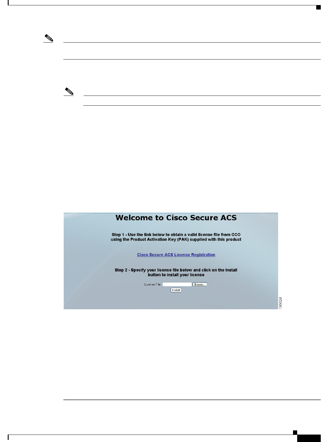
12-3
Installation and Upgrade Guide for Cisco Secure Access Control System 5.5
OL-28603-01
Chapter 12 Post-Installation Tasks
Accessing the Web Interface
Note Launching the ACS web interface using IPv6 addresses is not supported in Mozilla Firefox version 4.x
or later.
Step 2 In the Username field, enter ACSAdmin, which is the default username. The value is not case-sensitive.
Step 3 In the Password field, enter default, which is the default password. The value is case-sensitive.
Note Click Reset to clear the Username and Password fields and start over, if needed.
Step 4 Click Login or press Enter.
The login page reappears, prompting you to change your password.
Step 5 Enter default in the Old Password field, then enter a new password in the New Password and Confirm
Password fields.
If you forget your password, use the acs reset-password <username> command to reset your password
to its default setting. You are prompted to change your password after a reset. See CLI Reference Guide
for Cisco Secure Access Control System 5.5 for more information.
Step 6 Click Login or press Enter.
You are prompted to install a valid license, as shown in Figure 12-1.
Figure 12-1 ACS 5.5 License Screen
The license page appears only the first time that you log into ACS.
Step 7 Click Browse and choose a valid, unique base license for the ACS server.
For more information on installing a valid license, see the User Guide for Cisco Secure Access Control
System 5.5.
•If your login is successful, the main page of the ACS web interface appears.
•If your login is unsuccessful, the following error message appears:
Access Denied. Please contact your System Administrator for assistance.
The Username and Password fields are cleared.
Step 8 Re-enter the valid username and password, and click Login.

12-4
Installation and Upgrade Guide for Cisco Secure Access Control System 5.5
OL-28603-01
Chapter 12 Post-Installation Tasks
Configuring ACS
Note When you use Internet Explorer to view the ACS web interface, if the Enhanced Security Configuration
(ESC) is enabled, you would observe issues in displaying pages and pop-ups of the ACS web interface.
To overcome this issue, you must disable the ESC from the Internet Explorer settings.
Logging Out
To log out of the ACS web interface:
Step 1 Click Logout in the ACS web interface header to end your administrative session.
A dialog box appears, prompting you to confirm whether you want to log out of ACS.
Step 2 Click OK.
You are logged out.
Caution For security reasons, Cisco recommends that you log out of the ACS when you complete your
administrative session. If you do not log out, the ACS web interface logs you out after 30 minutes of
inactivity, and does not save any unsubmitted configuration data.
For more information on using the Web Interface, see the User Guide for Cisco Secure Access Control
System 5.5.
Configuring ACS
Use the ACS web interface for initial configuration setup. The ACS web interface allows you to access
pages, perform configuration tasks, and view interface configuration errors.
When you finish installing the license file, perform the following ACS configuration setup:
•Configuring system administrators and accounts
•Configuring ACS in a distributed deployment
•Managing system administration configurations:
–
Configuring global system options
–
Configuring dictionaries
–
Configuring local server certificates
–
Configuring logs
•Configuring data backup
•Configuring collection filters
•Managing ACS logging
•Specifying e-mail settings
•Specifying session settings
•Specifying system alarm settings

12-5
Installation and Upgrade Guide for Cisco Secure Access Control System 5.5
OL-28603-01
Chapter 12 Post-Installation Tasks
Configuring ACS
•Configuring data purging
•Configuring password policies
For details on each operation and other administrative functions, such as ACS Monitoring and Reports,
see the User Guide for Cisco Secure Access Control System 5.5.
For details on migration and problems with migration, see the Migration Guide for Cisco Secure Access
Control System 5.5.
For up-to-date information on Cisco.com, see the Release Notes for Cisco Secure Access Control System
5.5.

12-6
Installation and Upgrade Guide for Cisco Secure Access Control System 5.5
OL-28603-01
Chapter 12 Post-Installation Tasks
Configuring ACS

P
ART
7
Reference

A-1
Installation and Upgrade Guide for Cisco Secure Access Control System 5.5
OL-28603-01
APPENDIX
A
Troubleshooting
The CSACS-1121, Cisco SNS-3415, and Cisco SNS-3495 series appliances undergoes extensive testing
before it leaves the factory. If you encounter problems, use the information in this appendix to help
isolate problems or to eliminate the appliance as the source of the problem.
Although an overtemperature or overvoltage condition is unlikely at initial startup, a discussion of
environmental temperature and voltage monitoring functions is provided in Regulatory Compliance,
page 2-7 section.
Note The procedures in this chapter assume that you are troubleshooting the initial CSACS-1121 series, Cisco
SNS-3415, or Cisco SNS-3495 series appliances startup, and that the appliance is in the original factory
configuration. If you have removed or replaced components, or changed any default settings, the
recommendations in this chapter might not apply.
This appendix does not cover every possible issue that might occur on an appliance but instead focuses
on those events that are frequently seen by the customer.
This appendix contains:
•Troubleshooting Overview, page A-1
•Problem Solving, page A-2
•Reading the LEDs, page A-5
•Product Serial Number Location, page A-7
Troubleshooting Overview
At the initial system boot, you should verify the following:
•The external power cable is connected, and the proper power source is being applied. For more
information, see Power Considerations, page 3-9, Power Specifications, page 7-6, Powering Up the
CSACS-1121 Series Appliance, page 4-17, Connecting and Powering On the Cisco SNS-3415/3495
Appliance, page 8-11, and Troubleshooting the Power and Cooling Systems in the CSACS-1121
Series Appliance, page A-3.
•The appliance fan and blower are operating. See Airflow Guidelines, page 3-8, Environmental
Specifications, page 7-6, and Troubleshooting the Power and Cooling Systems in the CSACS-1121
Series Appliance, page A-3.
•The appliance software boots successfully.

A-2
Installation and Upgrade Guide for Cisco Secure Access Control System 5.5
OL-28603-01
Appendix A Troubleshooting
Problem Solving
•The adapter cards (if installed) are properly installed in their slots, and each initializes (is enabled
by the appliance software) without problems.
When each of these conditions is met, the hardware installation is complete, and you should proceed to
perform a basic configuration. For proper configuration features, see Chapter 5, “Installing and
Configuring the Cisco Secure Access Control System with CSACS-1121,” or Chapter 9, “Installing and
Configuring the Secure Access Control System with the Cisco SNS-3415 and Cisco SNS-3495,” or the
User Guide for Cisco Secure Access Control System 5.5.
If you cannot locate the source of the problem, contact a customer service representative for information
on how to proceed. For technical support information, see the Cisco Information Packet publication that
is shipped with your appliance. Before you call, ensure that you have the following information ready:
•Appliance chassis type and serial number. For more information, see Cisco Product Identification
Tool, page 2-3.
•Maintenance agreement or warranty information (see the Cisco Information Packet).
•Type of software and version number (if applicable).
•Date you received the new appliance.
•Brief description of the problem you are facing and the steps you have taken to isolate and resolve
the problem.
Note Be sure to provide the customer service representative with any upgrade or maintenance information that
was performed on the CSACS-1121, Cisco SNS-3415, and Cisco SNS-3495 series appliances after your
initial installation. For site log information, see Creating a Site Log, page 3-14 and Site Log, page B-1
Problem Solving
The key to problem solving is to isolate the problem to a specific location by comparing what the
CSACS-1121, Cisco SNS-3415, or Cisco SNS-3495 series appliance is doing with what it should be
doing.
In other words, when troubleshooting, define the specific symptoms, identify all potential problems that
could be causing the symptoms, and then systematically eliminate each potential problem (from most
likely to least likely) until the symptoms disappear.
The following steps provide guidelines you can use during the troubleshooting process.
Step 1 Analyze the problem and create a clear problem statement. Define symptoms and potential causes.
Step 2 Gather the facts that you need to help isolate possible causes.
Step 3 Consider possible causes based on the facts that you gathered.
Step 4 Create an action plan based on those causes. Begin with the most likely problem and devise a plan in
which you manipulate only one variable.
Step 5 Implement the action plan. Perform each step carefully while testing to see whether the
symptom disappears.
Step 6 Analyze the results to determine whether the problem has been resolved. If the problem is resolved,
consider the process complete.
If the problem has not been resolved, create an action plan based on the next most probable cause on
your list. Return to Step 4 and repeat the process until the problem is solved.

A-3
Installation and Upgrade Guide for Cisco Secure Access Control System 5.5
OL-28603-01
Appendix A Troubleshooting
Problem Solving
Be sure to undo anything that you changed while implementing your action plan. Remember to change
only one variable at a time.
Note The LEDs on the front and back panel of the appliance enable you to determine the performance and
operation of the appliance. For a description of these LEDs, see Reading the LEDs, page A-5.
When troubleshooting, check the following appliance subsystems first:
•Power and cooling systems (external power source, power cable, and appliance fans). Also, check
for inadequate ventilation, air circulation, or environmental conditions.
•Adapter card—Checking the LEDs on the adapter card can help you to identify a failure.
•Cables—Verify that the external cables connecting the appliance to the network are all secure.
Troubleshooting the Power and Cooling Systems in the CSACS-1121 Series
Appliance
Both the power LED and the fans can help you troubleshoot a power problem. Check the following items
to help isolate the problem:
•When the CSACS-1121 Series appliance is connected to the power source, is the appliance power
LED on the front panel on? If not, check the AC power cord connection; if the power LED is still
off, the problem might be due to a power supply failure.
•Does the appliance shut down after being on for only a short time?
–
Check for an environmentally induced shutdown. For more information, see Environmental
Reporting Features, page A-3 section.
–
Check the fans. If the fans are not working, the appliance will overheat and shut itself down.
If the fans are not working, you might need to check the power supply connection to the fans.
Checking this connection will require you to shut down the appliance, remove any external
cables, and open up the appliance.
–
Ensure that the appliance intake and exhaust vents are clear.
–
Check the environmental site requirements in Temperature and Humidity Guidelines, page 3-9.
•Does the appliance partially boot, but the LEDs do not light? Check for a power supply failure by
inspecting the power LED on the front panel of the appliance:
–
If the LED is on, the power supply is functional.
–
If the LED is off, see the Cisco Information Packet for warranty information, or contact your
customer service representative.
Environmental Reporting Features
The CSACS-1121 Series appliance has protection circuits that monitor and detect overcurrent,
overvoltage, and overtemperature conditions inside the appliance.
If the power supply shuts down or latches off, an AC cycle switches off for 15 seconds and switches on
for 1 second to reset the power supply. For more information, see Regulatory Compliance, page 2-7.

A-4
Installation and Upgrade Guide for Cisco Secure Access Control System 5.5
OL-28603-01
Appendix A Troubleshooting
Problem Solving
The following conditions can cause an abnormally high appliance temperature:
•Fan failure
•Air conditioner failure in the room
•Airflow blocked to cooling vents
Take steps to correct the problem. For information about environmental operating conditions, see
Temperature and Humidity Guidelines, page 3-9.
Troubleshooting Adapter Cards, Cables, and Connections in the
CSACS-1121 Series Appliance
Network problems can be caused by an adapter card, cables or cable connections, or external devices
such as a hub, wall jack, WAN interface, or terminal. Check for the following symptoms to help isolate
a problem:
•Adapter card is not recognized by the CSACS-1121 Series appliance:
–
Ensure that the adapter card is firmly seated in its slot.
–
Check the LEDs on the adapter card. Each adapter card has its own set of LEDs.
–
Verify that your software release supports the adapter card. See the documentation that was
included with your adapter card.
•Adapter card is recognized, but interface ports do not initialize:
–
Ensure that the adapter card is firmly seated in its slot.
–
Check external cable connections.
–
Verify that your software release supports the adapter card. See the documentation that was
included with your adapter card.
•The CSACS-1121 Series appliance does not boot properly, or it constantly or intermittently reboots:
–
Ensure that the adapter card is firmly seated in its slot.
–
Check the appliance chassis or the application software. For warranty information, see the Cisco
Information Packet publication that is shipped with your appliance or contact your customer
service representative.
•If you are using the console port with a terminal, and the CSACS-1121 Series appliance boots but
the console screen is frozen:
–
Check the external console connection.
–
Verify that the parameters for your terminal are set as follows:
(a) The terminal should have the same data rate that the appliance has (9600 bps is the default).
(b) 8 data bits.
(c) No parity generated or checked.
(d) 1 stop bit.
•The CSACS-1121 Series appliance powers on and boots only when an adapter card is removed.
Check the adapter card. For warranty information, see the Cisco Information Packet publication that
is shipped with your appliance or contact your customer service representative.
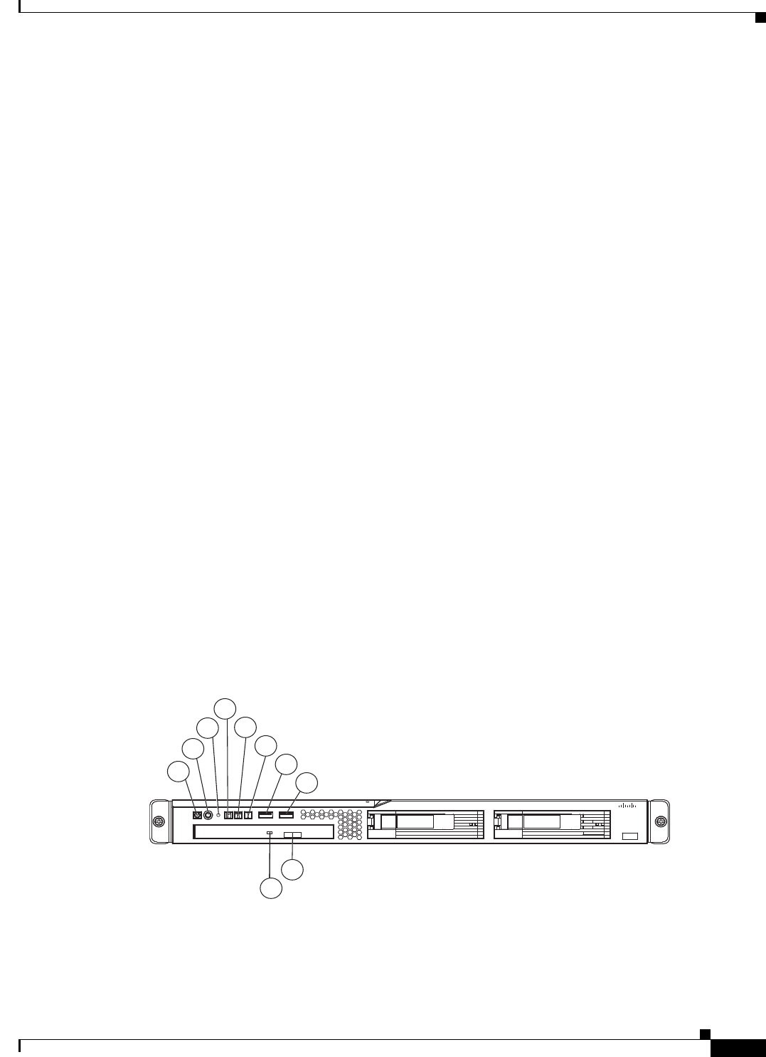
A-5
Installation and Upgrade Guide for Cisco Secure Access Control System 5.5
OL-28603-01
Appendix A Troubleshooting
Maintaining the Cisco SNS-3415/3495 Appliance
•The CSACS-1121 Series appliance powers on and boots only when a particular cable is
disconnected. There might be a problem with the cable. For warranty information, see the Cisco
Information Packet publication that is shipped with your appliance or contact your customer
service representative.
Maintaining the Cisco SNS-3415/3495 Appliance
The Cisco SNS-3415 or Cisco SNS-3495 appliance is based on the Cisco UCS C220 Server. Please refer
to the Cisco UCS C220 Server Installation and Service Guide for information on how to maintain your
Cisco SNS-3415 or Cisco SNS-3495 appliance, and to install and replace the server components, if
necessary.
Reading the LEDs
There are several LEDs on the CSACS-1121, Cisco SNS-3415, and Cisco SNS-3495 appliances. LEDs
serve the following purposes:
•Indicate that basic power is available to the appliance.
•Indicate the hard disk, CD drive, and network activity statuses.
This section contains:
•LEDs of CSACS-1121 Series Appliance, page A-5
•LEDs of the Cisco SNS-3415/3495 Appliance, page A-7
LEDs of CSACS-1121 Series Appliance
Front-Panel LEDs
Figure A-1 Front-Panel LEDs
1
2
4
5
6
7
8
9
10
3
195214
Cisco 1121 Secure
Accrss Control System
CISCO
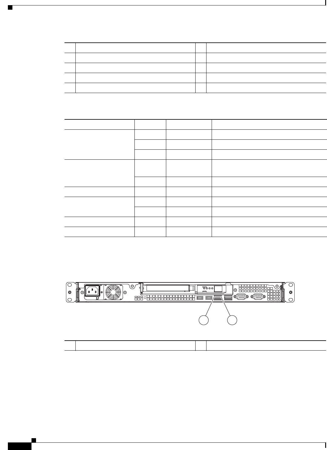
A-6
Installation and Upgrade Guide for Cisco Secure Access Control System 5.5
OL-28603-01
Appendix A Troubleshooting
Reading the LEDs
Back-Panel LEDs
Figure A-2 CSACS-1121 Back-Panel LEDs
1Appliance power LED 6System-error LED
2Power-control button 7USB 1 connector
3Reset button 8USB 2 connector
4Hard disk drive activity LED 9CD-eject button
5Locator LED 10 CD drive activity LED
Table A-1 Front-Panel LED Descriptions
LED Color State Description
Appliance power Green On Power on.
Green Blinking Sleep (standby).
Off Off Power off.
Hard disk drive activity Green Random
blinking
Hard disk drive activity.
Off Off No hard disk drive activity.
Reset button — — Press the button to do a soft reset.
Locator LED Blue Blinking System is booting up.
Off Off System bootup is completed.
System-error Amber On A system error has occurred.
CD drive activity Green On The CD drive is in use.
1Ethernet activity LED 2Ethernet link LED
276861
12
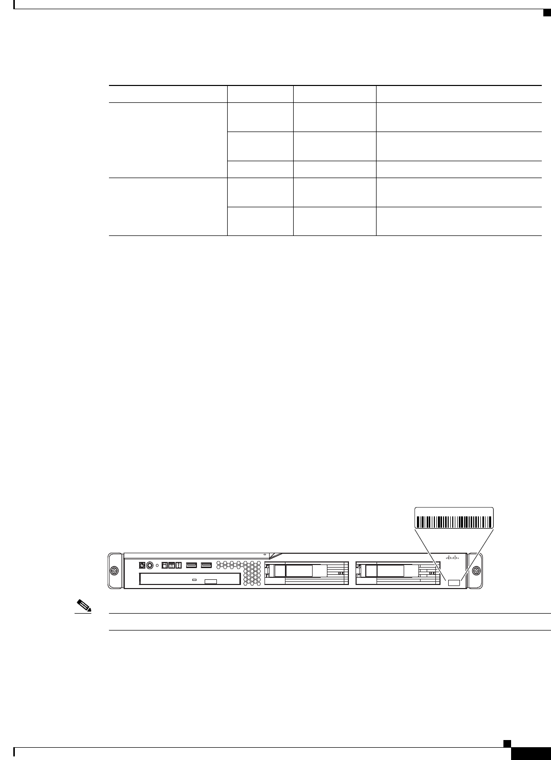
A-7
Installation and Upgrade Guide for Cisco Secure Access Control System 5.5
OL-28603-01
Appendix A Troubleshooting
Product Serial Number Location
LEDs of the Cisco SNS-3415/3495 Appliance
See Cisco SNS-3415/3495 Appliance Front-Panel View, page 6-5, to view the available front-panel
LEDs in the Cisco SNS-3415 or Cisco SNS-3495 appliance.
See Cisco SNS-3415/3495 Appliance Back-Panel View, page 6-6, to view the available back-panel LEDs
in the Cisco SNS-3415 or Cisco SNS-3495 appliance.
See Internal Diagnostic LEDs, page 6-7, to view the available internal diagnostic LEDs in the Cisco
SNS-3415 or Cisco SNS-3495 appliance.
Product Serial Number Location
On the CSACS-1121 Series appliance, the serial number label is located on the front panel of the
appliance, at the lower-left. Figure A-3 shows the location of the serial number label.
This section contains details on Cisco Product Identification Tool, page A-8.
Figure A-3 Serial Number Location for the CSACS-1121 Series Appliance
Note The serial number for the CSACS-1121 Series appliance is 11 characters long.
On the SNS-3415 or SNS-3495 appliance, the serial number for the server is printed on a label on the
top of the server, near the front.
Table A-2 Rear-Panel LEDs
LED Color State Description
Ethernet activity LED Green On Activity exists between the server
and the network.
Green Blinking Activity exists between the server
and the network.
Off Off No activity exists.
Ethernet link LED Green Random blinking Ethernet controller is connected to
the network.
Off Off Ethernet controller is not connected
to the network.
195213
Cisco 1121 Secure
Accrss Control System
CISCO
XXXXNNNNNNN

A-8
Installation and Upgrade Guide for Cisco Secure Access Control System 5.5
OL-28603-01
Appendix A Troubleshooting
Product Serial Number Location
Cisco Product Identification Tool
The Cisco Product Identification (CPI) tool helps you retrieve the serial number of your Cisco products.
Before you submit a request for service online or by phone, use the CPI tool to locate your product serial
number. You can access this tool from the Cisco Support website.
To access the CPI tool:
Step 1 Click the Tools & Resources link.
Step 2 Click the Show All Tools tab.
Step 3 Choose Cisco Product Identification Tool from the alphabetical list.
This tool offers three search options:
•Search by product ID or model name.
•Browse for Cisco model.
•Copy and paste the output of the show command to identify the product.
Search results show an illustration of your product with the location of the serial number label
highlighted. Locate the serial number label on your product and record the information before you place
a service call.
You can access the CPI tool from Cisco.com at:
http://tools.cisco.com/Support/CPI/index.do
Access to the CPI tool on the Cisco Support website requires a Cisco.com user ID and password. If you
have a valid service contract but do not have a user ID or password, you can register at:
http://tools.cisco.com/RPF/register/register.do

B-1
Installation and Upgrade Guide for Cisco Secure Access Control System 5.5
OL-28603-01
APPENDIX
B
Site Log
The site log provides a record of all actions related to installing and maintaining the CSACS-1121 Series
appliance. Keep the log in an accessible place near the appliance chassis so that anyone who performs
tasks has access to it. Use the installation checklist (see the Installation Checklist, page 3-13) to verify
the steps for the installation and maintenance process of your appliance.
Site Log entries might include the following:
•Installation progress—Make a copy of the appliance installation checklist, and insert it into the site
log. Make entries as you complete each task.
•Upgrade, removal, and maintenance procedures—Use the site log as a record of ongoing appliance
maintenance and expansion history. Each time a task is performed on the appliance, update the site
log to reflect the following information:
–
Configuration changes
–
Maintenance schedules and requirements
–
Maintenance procedures performed
–
Intermittent problems
–
Comments and notes
Table B-1 shows a sample site log. Make copies of the sample, or design your own site log to meet the
needs of your site and equipment.
Table B-1 Site Log
Date Description of Action Performed or Symptom Observed Initials
Date Description
Date Description
Date Description

B-2
Installation and Upgrade Guide for Cisco Secure Access Control System 5.5
OL-28603-01
Appendix B Site Log
C-1
Installation and Upgrade Guide for Cisco Secure Access Control System 5.5
OL-28603-01
APPENDIX
C
Maintaining the CSACS-1121, Cisco
SNS-3415, and Cisco SNS-3495 Appliances
The CSACS-1121, Cisco SNS-3415, and Cisco SNS-3495 Series appliances are configured to order and
is ready for installation when it leaves the factory. After you install and configure your appliance, you
may have to perform specific maintenance procedures and operations to ensure that the appliance is
operating properly.
These preventive procedures will maintain your appliance in good operating condition and minimize the
need for costly, time-consuming service procedures.
Caution To help prevent problems, before performing any procedures in this chapter, review Safety Warnings,
page -6 and the Safety Guidelines, page 3-1 sections.
The following sections discuss various environmental factors that can adversely affect appliance
performance and longevity. This section includes:
•Maintaining the CSACS-1121 Series Appliance, page C-1
•Maintaining Cisco the SNS-3415/3495 Appliance, page C-5
Maintaining the CSACS-1121 Series Appliance
Maintaining Your Site Environment
Good preventive maintenance includes regular visual inspections of the appliance, including exterior
cleaning and inspection.
This chapter contains:
•General Exterior Cleaning and Inspection, page C-2
•Cooling, page C-3
•Temperature, page C-3
•Humidity, page C-4
•Altitude, page C-4
•Electrostatic Discharge

C-2
Installation and Upgrade Guide for Cisco Secure Access Control System 5.5
OL-28603-01
Appendix C Maintaining the CSACS-1121, Cisco SNS-3415, and Cisco SNS-3495 Appliances
Maintaining the CSACS-1121 Series Appliance
•Electromagnetic and Radio Frequency Interference, page C-4
•Magnetism, page C-5
•Power Source Interruptions, page C-5
General Exterior Cleaning and Inspection
This section details the cleaning requirements for exterior surfaces of the appliance. It also provides
information on inspecting cables and adapter cards.
Caution Never spray cleaning solution on the surfaces of the appliance. Over spray can penetrate into the
appliance and cause electrical problems and corrosion.
Appliance
Use a lint-free, nonabrasive cloth to perform cleaning. Do not use a solvent, abrasive cleaning agents, or
tissue paper. If the appliance is dirty (for example, with thick dust), use a soft damp cloth and gently
wipe the surface of the appliance.
Immediately wipe any water or liquid off from the appliance.
Dust and Particles
A clean operating environment can greatly reduce the negative effects of dust and other particles, which
act as insulators and interfere with the operation of an appliance’s mechanical components. In addition
to regular cleaning, you should follow these guidelines to deter contamination of the appliance:
•Do not permit smoking anywhere near the appliance.
•Do not permit food or drink near the appliance.
Cables and Connectors
Periodically inspect cables and connectors to and from your appliance periodically to see if they are worn
out or loose.
Adapter Cards
Check the connections on the adapter cards. Ensure that they are secured to the appliance and have not
been jarred loose or mechanically damaged.
Corrosion
The oil from a person’s fingers, or prolonged exposure to high temperature or humidity, can corrode the
gold-plated edge connectors and pin connectors on adapter cards in the appliance. This corrosion on
adapter card connectors is a gradual process that can eventually lead to intermittent failure of
electrical circuits.
To prevent corrosion, you should avoid touching contacts on adapter cards. Protecting the appliance from
corrosive elements is especially important in moist and salty environments, which tend to promote
corrosion. Also, as a further deterrent to corrosion, the appliance should not be used in extreme
temperatures, as explained in the Temperature, page C-3 section.

C-3
Installation and Upgrade Guide for Cisco Secure Access Control System 5.5
OL-28603-01
Appendix C Maintaining the CSACS-1121, Cisco SNS-3415, and Cisco SNS-3495 Appliances
Maintaining the CSACS-1121 Series Appliance
Cooling
Exhaust fans in the power supply and in the appliance cool the power supply and the appliance by
drawing air in through various openings in the front of the appliance and blowing it out the back.
However, the fans also draw dust and other particles into the appliance, causing contaminant buildup,
which results in an increase in the appliance’s internal temperature and interferes with the operation of
various appliance components.
To avoid these conditions, we recommend keeping your work environment clean to reduce the amount
of dust and dirt around the appliance, thereby reducing the amount of contaminants drawn into the
appliance by the fans.
Temperature
Temperature extremes can cause a variety of problems, including premature aging and failure of
integrated circuits (ICs) or mechanical failure of devices. Extreme temperature fluctuations can cause
ICs to become loose in their sockets, causing expansion and contraction of disk drive platters, resulting
in read or write data errors.
The heat emission of an ACS appliance would be in the range of 341 to 1024 BTUs (100 to 300 W).
To minimize the negative effects of temperature on appliance performance, follow these guidelines:
•Table C-1 lists the air temperature that you must maintain according to the altitude where your ACS
server is placed.
Tabl e C- 1 Air Temperature Maintenance
.
•Ensure that the appliance has adequate ventilation. Do not place it within a closed-in wall unit or on
top of cloth, which can act as insulation. Do not place it where it will receive direct sunlight,
particularly in the afternoon. Do not place it next to a heat source of any kind, including heating
vents during winter.
Adequate ventilation is particularly important at high altitudes. Appliance performance may not be
optimum when the appliance is operating at high temperatures as well as high altitudes. Do
the following:
•Ensure that all slots and openings on the appliance remain unobstructed, especially the fan vents on
the back of the appliance.
•Clean the appliance at regular intervals to avoid any buildup of dust and debris, which can cause the
appliance to overheat.
Server State Altitude Air Temperature
On 3000 ft (0 to 914.4 m) 50.0° to 95.0°F (10° to 35°C)
On 3000 ft (914.4 m) to 7000 ft
(2133.6 m)
50.0° to 89.6°F (10° to 32°C)
Off Maximum altitude: 7000 ft
(2133.6 m)
50.0° to 109.4°F (10° to 43°C)
Shipping Maximum altitude: 7000 ft
(2133.6 m)
-40° to 140°F (40° to 60°C)

C-4
Installation and Upgrade Guide for Cisco Secure Access Control System 5.5
OL-28603-01
Appendix C Maintaining the CSACS-1121, Cisco SNS-3415, and Cisco SNS-3495 Appliances
Maintaining the CSACS-1121 Series Appliance
•If the appliance has been exposed to abnormally cold temperatures, allow a 2-hour warm-up period
to bring it up to normal operating temperature before turning it on. Failure to do so may cause
damage to internal components, particularly the hard disk drive.
Humidity
High-humidity conditions can cause moisture migration and penetration into the appliance. This
moisture can cause corrosion of internal components and degradation of properties such as electrical
resistance, thermal conductivity, physical strength, and size. Extreme moisture buildup inside the
appliance can result in electrical shorts, which can cause serious damage to the appliance.
Each appliance is rated to operate at 8 to 80 percent relative humidity, with a humidity gradation of
10 percent per hour. Buildings in which climate is controlled by air conditioning in the warmer months
and by heat during the colder months usually maintain an acceptable level of humidity for appliances.
However, if an appliance is located in an unusually humid location, a dehumidifier can be used to
maintain the humidity within an acceptable range.
Altitude
Operating an appliance at high altitudes (low atmospheric pressure) reduces the efficiency of forced and
convection cooling which can result in electrical problems related to arcing and corona effects. This
condition can also cause sealed components with internal pressure, such as electrolytic capacitors, to fail
or perform at reduced efficiency.
Electrostatic Discharge
Electrostatic discharge (ESD) results from the buildup of static electricity on the human body and certain
other objects. This static electricity is often produced by simple movements, such as walking across a
carpet.
ESD is a discharge of a static electrical charge that occurs when a person whose body contains such a
charge touches a component in the appliance. This static discharge can cause components, especially
ICs, to fail. ESD is a problem particularly in dry environments where the relative humidity is below
50 percent.
To reduce the effects of ESD, you should observe the following guidelines:
•Wear a grounding wrist strap. If a grounding wrist strap is unavailable, touch an unpainted metal
surface on the appliance chassis periodically to neutralize any static charge.
•Keep components in their antistatic packaging until they are installed.
•Avoid wearing clothing made of wool or synthetic materials.
Electromagnetic and Radio Frequency Interference
Electromagnetic interference (EMI) and radio frequency interference (RFI) from an appliance can
adversely affect devices such as radio and television receivers operating near the appliance. Radio
frequencies emanating from an appliance can also interfere with cordless and low-power telephones.
RFI is defined as any EMI with a frequency above 10 kHz. This type of interference can travel from the
appliance to other devices through the power cable and power source, or through the air, like transmitted
radio waves. The Federal Communications Commission (FCC) publishes specific regulations to limit the
amount of EMI and RFI emitted by computing equipment. Each appliance meets these FCC regulations.

C-5
Installation and Upgrade Guide for Cisco Secure Access Control System 5.5
OL-28603-01
Appendix C Maintaining the CSACS-1121, Cisco SNS-3415, and Cisco SNS-3495 Appliances
Maintaining Cisco the SNS-3415/3495 Appliance
To reduce the possibility of EMI and RFI, follow these guidelines:
•Operate the appliance only with the appliance cover installed.
•Ensure that the screws on all peripheral cable connectors are securely fastened to their
corresponding connectors on the back of the appliance.
•Always use shielded cables with metal connector shells for attaching peripherals to the appliance.
Magnetism
Hard disk drives are susceptible to the effects of magnetism as they store data magnetically. Hard disk
drives should never be stored near magnetic sources such as:
•Monitors
•Printers
•Telephones with real bells
•Fluorescent lights
Power Source Interruptions
Appliances are especially sensitive to variations in voltage supplied by the AC power source.
Overvoltage, undervoltage, and transients (or spikes) can erase data from the memory or even cause
components to fail. To protect against these types of problems, power cables should always be properly
grounded and one, or both, of the following methods should be used:
•Place the appliance on a dedicated power circuit (rather than sharing a circuit with other electrical
equipment). In general, do not allow the appliance to share a circuit with any of the following:
–
Copier machines
–
Teletype machines
–
Laser printers
–
Fax machines
–
Any other motorized equipment
Besides the above equipment, the greatest threats to an appliance’s power supply are surges or blackouts
caused by electrical storms.
If a blackout occurs—even a temporary one—while the appliance is turned on, turn off the appliance
immediately and disconnect it from the electrical outlet. Leaving the appliance on may cause problems
when the power is restored.
Maintaining Cisco the SNS-3415/3495 Appliance
Caution To help prevent problems, before performing any procedures in this chapter, review Safety Warnings,
page -6 and the Safety Guidelines, page 3-1 sections.
To maintain the Cisco SNS-3415 or Cisco SNS-3495 appliance, see Maintaining the Server Chapter in
the Cisco UCS C220 Server Installation and Service Guide.

C-6
Installation and Upgrade Guide for Cisco Secure Access Control System 5.5
OL-28603-01
Appendix C Maintaining the CSACS-1121, Cisco SNS-3415, and Cisco SNS-3495 Appliances
Maintaining Cisco the SNS-3415/3495 Appliance

IN-1
Installation and Upgrade Guide for Cisco Secure Access Control System 5.5
OL-28603-01
INDEX
Numerics
4-post hardware kit
rack-mount 4-3
4-post rack, mounting appliance on 4-2
A
ACS deployment 1-1
adapter cards
troubleshooting A-4
airflow
guidelines 3-8
altitude
guidelines C-4
B
back panel 2-5, 4-7
LEDs 2-6
C
cable
connecting 4-7, 8-8, 8-11
management 4-17, 8-10
troubleshooting A-4
checking
LEDs 4-19
checklist, installation 3-14
checklist, power up 4-18
configuration
site 3-8
connecting
cables 4-7, 8-8, 8-11
network interface 4-8, 8-8
connections
troubleshooting A-4
considerations
power 3-9
console port, pinouts
serial 4-16
cooling system
troubleshooting A-3
corrosion
preventing damage C-2
CPI tool
identification 2-3, 6-5, A-8
CSACS 1121 Series appliance
front view 2-4
D
DHCP, enabling 8-7
dust
preventing damage C-4
E
electricity
safety with 3-3
electromagnetic interference
See EMI
electrostatic discharge 3-5
See ESD
EMI

Index
IN-2
Installation and Upgrade Guide for Cisco Secure Access Control System 5.5
OL-28603-01
preventing effects of C-4
environment
maintaining C-1
site 3-8
environmental
features A-3
specifications (table) 3-9
equipment
racks
rack-mounting 3-9
safety with 3-3
ESD
preventing damage C-4
preventing effects of 3-5, C-4
F
features
environmental reporting A-3
front panel
LEDs 2-5
troubleshooting A-5
front view
Cisco SNS 3415 appliance 6-3
CSACS 1121 Series appliance 2-4
G
grounding (warning) 4-17
guidelines
airflow 3-8
lifting 3-5
rack installation 3-7
rack-mounting configuration 4-1, 8-1
safety 3-1
temperature maintenance C-3
H
hardware
troubleshooting procedures A-1
humidity
maintenance guidelines C-4
I
identification
CPI 2-3, 6-5, A-8
information packet and warranty 3-11
installation
checklist 3-14
IP settings 8-7
NIC modes 8-7
NIC redundancy 8-7
unpacking and inspection 7-3
verification 5-5, 9-8
installing ACS server
setup program 5-2, 9-6
post-installation tasks 12-1
IP settings, DHCP or static 8-7
K
kit
mounting 4-2
rack-mount hardware (table) 4-3
L
LEDs
back panel 2-6
checking 4-19
front panel 2-5
lifting guidelines 3-5
location

Index
IN-3
Installation and Upgrade Guide for Cisco Secure Access Control System 5.5
OL-28603-01
serial number 2-3, A-7
log, site 3-14, B-1
M
magnetism
preventing effects of C-5
maintenance C-1
temperature C-3
management
cable 4-17, 8-10
method of procedures
See MOP
MOP 3-6, 3-10
N
network interface
connecting 4-8, 8-8
multi NIC 4-10
NIC bonding 4-11
NIC
LEDs
troubleshooting A-6
NIC 1 and NIC 2
RJ-45 pinout 4-9, 8-9
NIC modes, setting 8-7
NIC redundancy 8-7
O
overview
product 2-1
P
packing list 7-3
planning
site 3-6
post-installation tasks 12-1
power
considerations 3-9
power lines (warning) 3-3
power source interruptions
preventing damage from C-5
power supplies (warning) 3-3
power supply (warning) 3-3, 4-17
power system
troubleshooting A-3
power up
procedure 4-18
precautions
general precautions 3-2
problem solving
See troubleshooting
procedure
method of 3-10
power up 4-18
product
overview 2-1
R
rack
enclosed (do not use) 3-7
four-post (open) 3-7
rack, mounting on 4-post 4-2
rack installation
guidelines 3-7
rack-mount
4-post hardware kit 4-3
rack-mounting configuration
guidelines 4-1, 8-1
radio frequency interference. See RFI
regulatory compliance 2-7, 5-8, 6-9, 9-11
removing
CSACS 1121 Series appliance 4-20

Index
IN-4
Installation and Upgrade Guide for Cisco Secure Access Control System 5.5
OL-28603-01
restricted access (warning) 3-3, 3-6, 4-1, 8-1
RFI
preventing effects of C-4
RJ-45 pinout
NIC 1 and NIC 2 4-9, 8-9
S
safety
guidelines 3-1
SELV circuits (warning) 3-3
serial
console port, pinouts 4-16
serial number
location 2-3, A-7
setting NIC modes 8-7
setting NIC redundancy 8-7
site
configuration 3-8
environment 3-8
maintenance factors C-1
log 3-14, B-1
planning 3-6
requirement, MOPs 3-10
site log B-1
static IP, setting 8-7
T
temperature
maintenance guidelines C-3
temperature and humidity guidelines 3-9
tools and equipment
required 3-13
trained and qualified (warning) 4-1, 8-1
troubleshooting
adapter cards A-4
cables A-4
connections A-4
cooling system A-3
Ethernet LEDs A-6
front panel LEDs A-5
power system A-3
U
ucs
installing ACS in UCS 9-1
ucs overview 6-1
unpacking
checking shipment 3-11
unpacking the server 7-3
upgrading
ACS deployment 11-3, 11-12
ACS Monitoring and Report Viewer 11-11
ACS server 11-12
post-installation tasks 12-1
V
VMWare
configuring 10-5
hardware requirements 10-2
installing 10-1
installing ACS server 10-11
W
warranty 3-11
