Cubase SX/SL – VST Plug Ins From Previous Versions Steinberger Legacy Plugins Effects VSTi Cubasevst
Steinberger Legacy Plugins Cubase VST Effects VSTi CubaseVST_Effects_VSTi Steinberger - Legacy Plugins - Cubase VST Effects VSTi
Steinberger Legacy Plugins Cubase VST Effects VSTi cubasevst_effects_vsti Steinberger - Legacy Plugins - Cubase VST Effects VSTi
User Manual: Steinberger Legacy Plugins Cubase VST Effects VSTi Steinberger - Legacy Plugins - Cubase VST Effects VSTi
Open the PDF directly: View PDF ![]() .
.
Page Count: 46
VST plug-ins from previous
Cubase VST versions

Manual by Anders Nordmark
Quality Control: C. Bachmann, H. Bischoff, S. Pfeifer, C. Schomburg
The information in this document is subject to change without notice and does not rep-
resent a commitment on the part of Steinberg Media Technologies GmbH. The software
described by this document is subject to a License Agreement and may not be copied
to other media except as specifically allowed in the License Agreement. No part of this
publication may be copied, reproduced or otherwise transmitted or recorded, for any
purpose, without prior written permission by Steinberg Media Technologies GmbH.
All product and company names are ™ or ® trademarks of their respective owners.
Windows XP is a trademark of Microsoft Corporation. The Mac logo is a trademark
used under license. Macintosh and Power Macintosh are registered trademarks.
© Steinberg Media Technologies GmbH, 2004.
All rights reserved.

VST plug-ins from previous Cubase versions CUBASE SX/SL
3
Introduction
This document describes the VST effects from old versions of Cubase
VST (Cubase VST 5 and earlier), included for reasons of compatibility.
CUBASE SX/SL VST plug-ins from previous Cubase versions
4
Cubase 5 audio effect plug-ins
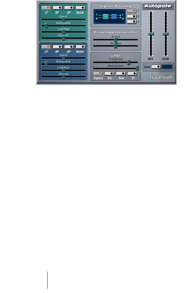
Autopole
The Autopole is a filter effect containing two separate filters capable of
operating in four different modes, an Envelope Generator and an LFO
with four different waveforms. It also lets you choose between three dif-
ferent Signal Routing modes to control how an incoming signal should
be sent through the filters.
The Autopole should be used as an insert effect. If you want to apply
it on several channels at once, you can use it as an insert effect on a
group channel and route the desired channels to the group channel.

VST plug-ins from previous Cubase versions CUBASE SX/SL
5
The parameters for the different “sections” of the Autopole are the fol-
lowing:
The Filters
Parameter Description
Filter Mode buttons
(LP, BP, HP, Notch)
These buttons let you decide in which mode the Filter should op-
erate:
LP: This is a Low-Pass Filter that “filters out” the high frequency
content of the incoming signal, according to a certain set thresh-
old level. Only signals below the threshold will pass through.
BP: This is a Band-Pass filter that only lets signals around the set
frequency through, filtering out all other content.
HP: This is a High-Pass Filter that “filters out” the low frequency
content of the incoming signal, according to a certain set thresh-
old level. Only signals above the threshold will pass through.
Notch: This is a filter that cuts off the signals around the set fre-
quency, leaving all other content unaffected.
Cutoff This is used for setting the Cutoff frequency, i.e. the threshold at
which the filter should “kick in”. The farther to the right you drag
the sliders, the higher the frequency.
Resonance This affects the resonance of the filter. Increasing the resonance
gives a more pronounced, lively filter sound. Be wary of extremely
high levels of resonance since they might induce unpleasant dis-
tortion.
LFO Mod These sliders govern how the filter cut-off frequencies are af-
fected by the LFO (see below). The sliders are “zero-centered”,
meaning that in the middle position (zero) no LFO modulation will
be applied. By dragging the sliders to the left or right, you cause
an increasing amount of modulation to the cut-off frequency. The
difference is that if you drag the sliders to the left, the waveform
of the LFO is inverted, creating a different effect.
EG Mod These sliders work in conjunction with the Envelope Generator
settings (see below). They control to which extent the cut-off fre-
quencies of the filters should be affected by the Envelope Gener-
ator. Drag the sliders to the right if you want to raise the cut-off
frequencies and if you want to lower the frequencies, drag the
sliders to the left. Leave the sliders in the middle position if you
don’t want Envelope data to affect the cut-off frequencies.

CUBASE SX/SL VST plug-ins from previous Cubase versions
6
Signal Routing
By clicking one of the three buttons, you choose how an input stereo
signal will pass though the filters. The signal flow chart to the left of
the buttons indicates the path:
•
Option # 1 will have the signal from each channel pass through both
of the filters in series (one after the other).
•
With option # 2, the signal from each channel will pass through both
of the filters in parallel, and then be mixed at the output.
•
Finally, option # 3 causes the signals from both channels to each
pass through a separate filter. I.e. the left signal only passes through
Filter A, and the right signal only passes through Filter B.
When using the Autopole with mono material, options 1 and 2 are the
best choices (sending the signal through the filters in series or in paral-
lel, respectively).
Envelope Generator
This section controls how the input signal is converted into Envelope
data. This, in its turn, affects the EG Mod sliders in the Filter sections
and the Modulation slider in the LFO section:
Parameter Description
Attack This regulates how fast the Envelope Generator will respond to an input
signal as it rises in sound level. The farther to the left you drag the slider,
the faster the response will be.
Release This governs how fast the Envelope Generator will respond to an input
signal as it drops in sound level. The farther to the left you drag the slider,
the faster the response will be.

VST plug-ins from previous Cubase versions CUBASE SX/SL
7
LFO
These are the controls for the Low Frequency Oscillator, used for
adding continuous filter movement, wah-wah effects, etc:
Output Controls
Chopper2
Chopper2 is an earlier version of the Chopper plug-in, included for
reasons of compatibility. It has the same parameters as Chopper with
the addition of independent input and output level settings.
Parameter Description
Frequency This slider controls the speed of the LFO. The farther to the right you
drag the slider, the faster the oscillation will be.
Modulation Use this slider to control how the speed of the LFO should be modu-
lated by the Envelope Generator (and thus by the level of the input sig-
nal). If you drag the slider to the left, a loud input signal will cause the
LFO to slow down and if you drag to the right, the LFO will speed up.
In the middle position, the speed of the LFO is unaffected.
Waveform
Buttons
These buttons are used for choosing a waveform for the LFO. You can
choose between Square, Sine, Saw and Triangle.
Parameter Description
Mix This controls the balance between the output from the Autopole and the in-
put signal. In the middle position, both signals are equally mixed. The higher
you drag the slider, the more dominant the effect will be. Conversely, with
lower settings the unaffected original signal will be more pronounced.
Gain This slider regulates the output level from the Autopole. The higher you
drag the slider, the higher the level.
Sync When this is activated, the LFO will restart in intervals according to the
current Song tempo, which is useful for tempo sync and special effects.
Click the button to activate sync, and then click in the small display to the
right to select at which note values the LFO should be restarted:
1/1, 1/2, 1/4, 1/8 or 1/16.
For example, setting this to 1/4 will make the LFO restart on each beat
(quarter note) according to the current tempo.
CUBASE SX/SL VST plug-ins from previous Cubase versions
8
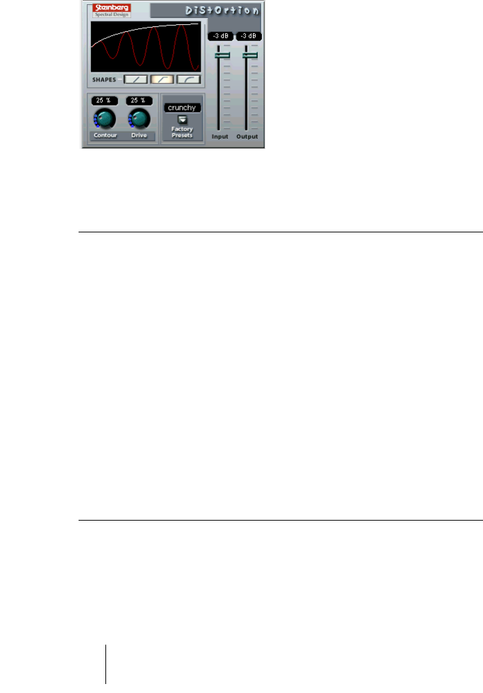
Distortion
The Distortion effect plug-in is capable of producing anything from a
soft “crunch” to all-out distortion.
The parameters are as follows:
Parameter Values Description
Input -24dB to 0dB Sets the Input level.
Output -24dB to 0dB Sets the Output level. As distortion generates
harmonics, it increases the level of the processed
signal. You can use the Output fader to compen-
sate for the level increase.
Shapes Linear,
Non-linear 1,
Non-linear 2
Determines how much the input signal is affected
by the distortion effect.
Non-linear 2 will produce
the strongest distortion.
Contour 0-100% This is a selective low pass filter, altering the
tonal quality of the distortion.
Drive 0-100% Governs the amount of distortion.
Factory Presets Soft, Crunchy, Dirty,
Wracky, Evil
Select one of five presets, which can be used as
they are, or as a basis for further “tweaking”. Note
that these presets are not stored parameter set-
tings, but different basic distortion algorithms.
VST plug-ins from previous Cubase versions CUBASE SX/SL
9
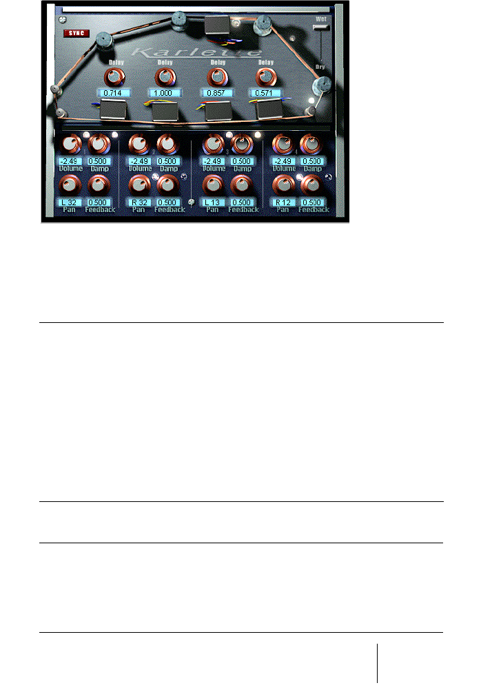
Karlette
The Karlette is a four-channel delay that emulates a “tape-loop” echo.
The four “tape-heads” can be set to a certain note value or a certain
time, depending on whether Tempo Sync is activated or not.
For the four “tape-heads”, you can set the following parameters:
In addition, the following global parameters are available:
Parameter Description
Delay With the sync button activated, the delay can be set to a note value
synchronized to the Cubase SX/SL tempo. If the sync button is
deactivated, the delay can be freely set to a time value.
Volume The amplitude of the delay. With the knob turned all the way to the left,
the delay is muted.
Damp The higher the value, the more the delay is dampened (the high fre-
quencies are attenuated) to produce a more subtle effect.
Pan Sets the stereo position for the delay.
Feedback Sets the number of delay repeats.
Parameter Description
Dry/Wet Sets the level balance between the dry signal and the effect. If Kar-
lette is used as a send effect, this should be set to maximum as you
can instead control the dry/effect balance with the send.
Sync Turns Tempo Sync on or off.
CUBASE SX/SL VST plug-ins from previous Cubase versions
10
Metalizer2
The Metalizer2 is an older version of the Metalizer plug-in, included for
reasons of compatibility.
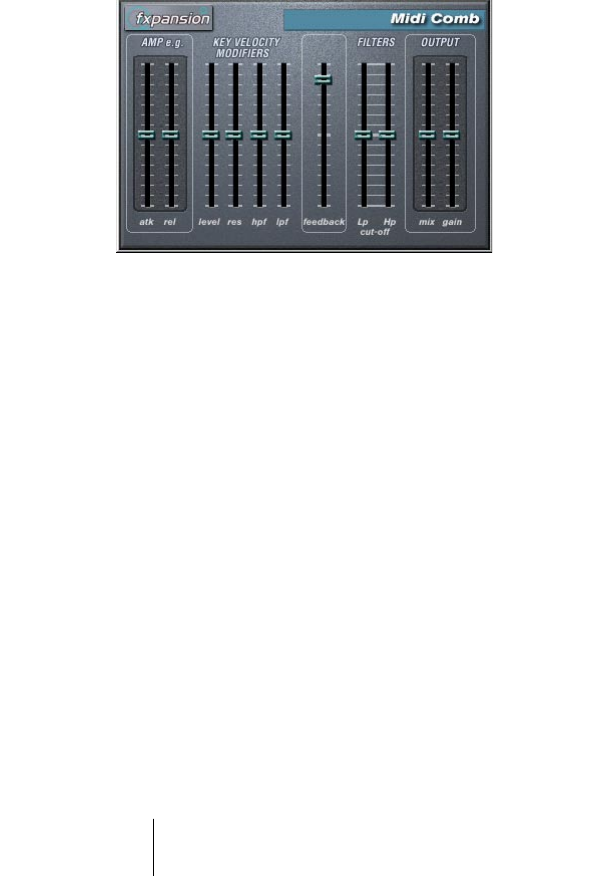
MIDIComb
This is a comb filter, which can be described as one or several very
short delays with high feedback, causing resonating peaks at certain
frequencies. To operate, the MIDI Comb needs both audio and MIDI
input. While the MIDI Comb is used as an insert effect on an audio
channel, the signals that actually trigger it are the ones sent from a
MIDI track.
Setting Up
The MIDI Comb requires both an audio signal and a MIDI input to
function.
To set it up, proceed as follows:
1.
Select the audio to be affected by the MIDI Comb.
This can be audio material from any Audio Track, or even a live audio input routed to a
Audio Track (provided you have a low latency audio card). If a live audio input is used,
monitoring must be set to input (the “In” buttons in the Inspector must be lit).
2.
Select the MIDI Comb as an Insert effect for the Audio channel.
Click the Edit button to open the MIDI Comb panel.

VST plug-ins from previous Cubase versions CUBASE SX/SL
11
3.
Select a MIDI Track.
This can be an empty MIDI Track, or a MIDI Track containing data, it doesn’t matter.
However, if you wish to play the MIDI Comb in real-time - as opposed to having a re-
corded Part playing it - the Track has to be selected for the effect to receive the MIDI
output.
4.
Open the Output column for the MIDI Track pop-up menu and select
MIDI Comb.
The MIDI Output from the Track is now routed to the MIDI Comb.
What to do next depends on whether you are using live or recorded
audio and whether you are using real-time or recorded MIDI. We will
assume for the purposes of this manual that you are using recorded
audio, and play the MIDI in real-time.
Make sure the MIDI Track is selected and start playback.
5.
Now play a few notes on your MIDI keyboard.
As you can hear, the audio track material is affected by what you play on your MIDI key-
board.
The MIDI Comb is polyphonic with up to 8 voices, i.e. you can play up to
8 MIDI notes at once and each tone will produce a separate resonating
tone.
You can now make settings for the MIDI Comb using the following pa-
rameters:
Amp e.g.
Parameter Description
Atk Use this slider to set the attack time of the resonant tones cre-
ated by the comb filter - i.e how soon they will start to resonate
after being triggered by MIDI notes. The farther down you drag
the slider, the slower the attack.
Rel This controls the release time of the resonant tones created by
the comb filter - i.e. how soon the sound will be cut off. The far-
ther up you drag the slider, the longer the sound will resonate.

CUBASE SX/SL VST plug-ins from previous Cubase versions
12
Key Velocity Modifiers
Feedback
Parameter Description
Level This determines how the filter responds to MIDI notes with differ-
ent velocity values. At the middle setting, all tones produced by
the filter will sound at an equal level regardless of the velocity val-
ues of the MIDI notes that trigger them. If you move the slider up-
wards, MIDI notes with higher velocity values will produce louder
comb filter tones. Conversely, moving the slider downwards
causes the level of the filter tones to increase with lower MIDI
note velocities.
Res This affects the resonance (feedback) of the produced tones de-
pending on the velocity value of the MIDI notes that trigger them.
In the middle position, the resonance is unaffected regardless of
velocity. By dragging the slider upwards, tones triggered by MIDI
notes with a high velocity value will get increased resonance. By
dragging the slider downwards, tones triggered by MIDI notes
with a low velocity value will become more resonant.
HPF & LPF The MIDI Comb features both a High-Pass filter and a Low-Pass
filter (see “Filters” below) that can be used for “filtering out” cer-
tain frequencies of the resonating tones according to a certain
set filter cutoff frequency. These two sliders determine how much
the High-Pass and Low-Pass filters should be affected by the
MIDI note velocity values. Positive values cause higher velocities
to increase the effect of the filters, negative values cause higher
velocities to decrease the effect.
Parameter Description
Feedback This slider governs the amount of effect output from the MIDI
Comb that is fed back in again. The more effect feedback, the
more complex the sound. Drag the slider upwards to increase
feedback.

VST plug-ins from previous Cubase versions CUBASE SX/SL
13
Filters
Output
Parameter Description
LP Cut-off Use this to set the frequency threshold of the Low-Pass Filter.
This filter cuts off all of the high frequencies relative to the set
threshold. The farther up you drag the slider, the more of the high
frequencies will be allowed to pass through.
HP Cut-off Use this to set the frequency threshold of the High-Pass Filter.
This filter cuts off all of the low frequencies relative to the set
threshold. The farther down you drag the slider, the more of the
low frequencies will be allowed to pass through.
Parameter Description
Mix Use this to set the balance between the original, unprocessed
signal and the signal affected by the MIDI Comb. In the middle
position, they are equally mixed. Drag the slider upwards for a
more dominant effect sound and vice versa.
Gain This controls the output level from the MIDI Comb. Drag the
slider upwards to increase the level.
CUBASE SX/SL VST plug-ins from previous Cubase versions
14
Mysterizer
The Mysterizer is a multi-effect plug-in with a unique hands-on user
interface. It can be used as an insert effect or a send effect, and al-
lows you to choose between eight different effects. For each effect,
you can control two parameters by clicking and dragging in the dis-
play, allowing for continuous real-time effect manipulation, subtle
sweeping changes or weird, wild mutations.
Here’s how to use the Mysterizer:
1.
Play back some audio and route the audio channel through the Mys-
terizer (either as an insert or a send effect).
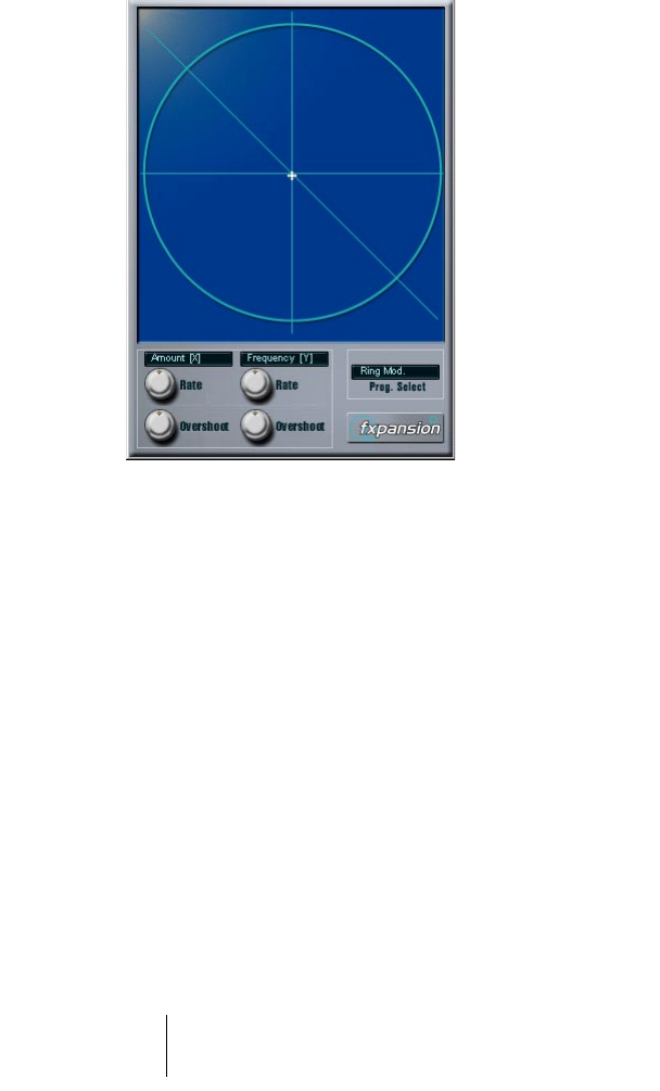
2.
Open the Mysterizer effect control panel and click the Prog Select
field to the right to select the desired effect.
Each time you click, the next effect is selected. For a list of the effects, see below.
3.
When you have selected an effect you want to use, the two text fields
to the left show you which parameters are controlled on the X-axis
and Y-axis respectively.
In the figure above, the Ring Mod effect is selected, with Amount controlled on the X-axis
and Frequency on the Y-axis.

VST plug-ins from previous Cubase versions CUBASE SX/SL
15
4.
Click in the display and drag the hair cursor to change the parameter
settings.
The X-axis goes from left to right and the Y-axis goes from top to bottom, which means
that the “zero setting” for both axes is in the upper left corner of the display.
5.
Experiment!
The Rate and Overshoot knobs
When you move the hair cursor, you will see how the small white dot
moves to follow your adjustments. This represents the actual parame-
ter settings. The Rate and Overshoot controls at the bottom of the
window control how quickly and accurately the white dot follows your
movements - in other words how your mouse movements are “inter-
preted” by the effect.
•
The Rate knobs determine how fast the Mysterizer will respond when
you move the hair cursor to a new position.
You can make independent settings for the X- and Y-axis.
•
The Overshoot knobs determine how far from “the target position” the
white dot will be allowed to stray along the corresponding axis when
moving the hair cursor.
Moderate settings can give a more natural feel when a parameter is changed. Maxi-
mum Overshoot settings (turning the knob all the way to the right) will cause constant
movement back and forth along the corresponding axis relative to the target position,
because the white dot will never “reach the target” and come to rest. This can create
an undulating, LFO-like special effect, the speed and range of which can be controlled
with the corresponding Rate knob.

CUBASE SX/SL VST plug-ins from previous Cubase versions
16
The Effects
The following effects are available:
• Ring Modulator
An effect with which the incoming audio
is ring modulated by an internal, vari-
able frequency oscillator, thereby producing new harmonics.
X-axis governs the amount of effect, Y-axis the frequency of the built-in oscillator.
• Comb Delay
A delay with high feedback, causing
resonating peaks at certain frequencies.
X-axis governs the f
eedback amount, Y-axis the manual delay time (pitch).
• Mono Delay
A monaural delay. X-axis controls the delay feedback, Y-axis the delay time.
• Stereo Delay
A stereo delay with which the repeats are heard in both the left and right channels.
X-axis controls the delay feedback, Y-axis the delay time.
• Low-Pass Filter (LP)
A filter that cuts off high frequencies
according to a set frequency threshold.
Only
signals below the cut-off frequency will be heard.
X-axis governs the
filter resonance, Y-axis the cutoff frequency.
• High-Pass Filter (HP)
A filter that cuts off low frequencies
according to a set frequency threshold.
Only
signals above the cut-off frequency will be heard.
X-axis governs the
filter resonance, Y-axis the cutoff frequency.
• Band-Pass Filter (BP)
A filter that cuts off all frequencies except those around the set cut-off frequency.
X-axis governs the
filter resonance, Y-axis the cutoff frequency.
• Distortion
A standard distortion effect.
X-axis controls the drive (distortion) amount, Y-axis serves as a tone control.
VST plug-ins from previous Cubase versions CUBASE SX/SL
17
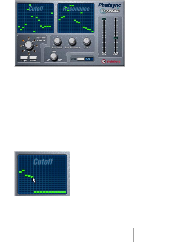
PhatSync
PhatSync is a pattern-controlled multimode filter that can create
rhythmic, pulsating filter effects.
General Operation
PhatSync can produce two simultaneous 16-step patterns for the fil-
ter cutoff and resonance parameters, synced to the sequencer tempo.
Setting Step Values
•
Setting step values is done by clicking in the pattern grid windows.
Individual step entries can be freely dragged up or down the vertical axis, or directly set
by clicking in an empty grid box. By click-dragging left or right consecutive step entries
will be set to the pointer position.
Setting filter cutoff values in the grid window.
CUBASE SX/SL VST plug-ins from previous Cubase versions
18
•
The horizontal axis show the pattern steps 1-16 from left to right, and
the vertical axis determines the (relative) filter cutoff frequency and
resonance setting.
The higher up on the vertical axis a step value is entered, the higher the relative filter
cutoff frequency or filter resonance setting.
•
By starting playback and editing the patterns for the cutoff and reso-
nance parameters, you can hear how your filter patterns affects the
sound source connected to PhatSync directly.
Selecting New Patterns
•
Created patterns are saved with the song, and up to 8 different Cutoff
and Resonance patterns can be saved internally.
Both the Cutoff and Resonance patterns are saved together in the 8 Pattern memories.
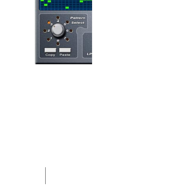
•
To select new patterns you use the Pattern Selector.
New patterns are all set to the same step value by default.
Pattern Selector.
Using Pattern Copy and Paste to create variations
You can use the Copy and Paste buttons below the Pattern selector
to copy a pattern to another Pattern memory location, which is useful
for creating variations on a pattern.
•
Click the Copy button with the pattern you wish to copy selected,
then select another Pattern memory location, and click Paste.
The pattern is copied to the new location, and can now be edited to create variations
using the original pattern as a starting point.

VST plug-ins from previous Cubase versions CUBASE SX/SL
19
PhatSync Parameters
Reverb (PC only)
This is an earlier version of the Reverb B plug-in, included for reasons
of compatibility.
Reverb 32 (PC only)
This is an earlier version of the Reverb A plug-in.
Parameter/Value Description
Base Cutoff This sets the base filter cutoff frequency. Cutoff values
set in the Cutoff Grid windows are values relative to the
Base Cutoff value.
Base Resonance This sets the base filter resonance. Resonance values set
in the Resonance Grid windows are values relative to the
Base Resonance value. Note that very high Base Reso-
nance settings can produce loud ringing effects at certain
frequencies.
Glide This will apply glide between the pattern step values,
causing values to change more smoothly.
Filter Mode (LP, BP, HP) This selects between lowpass (LP), bandpass (BP) or
highpass (HP) filter modes.
Sync (1/32, 1/16, 1/8, 1/4) This sets the pattern beat resolution, i.e. what note values
the pattern will play in relation to the tempo.
Mix Adjusts the mix between dry and processed signal.
Gain Sets the overall volume.
CUBASE SX/SL VST plug-ins from previous Cubase versions
20
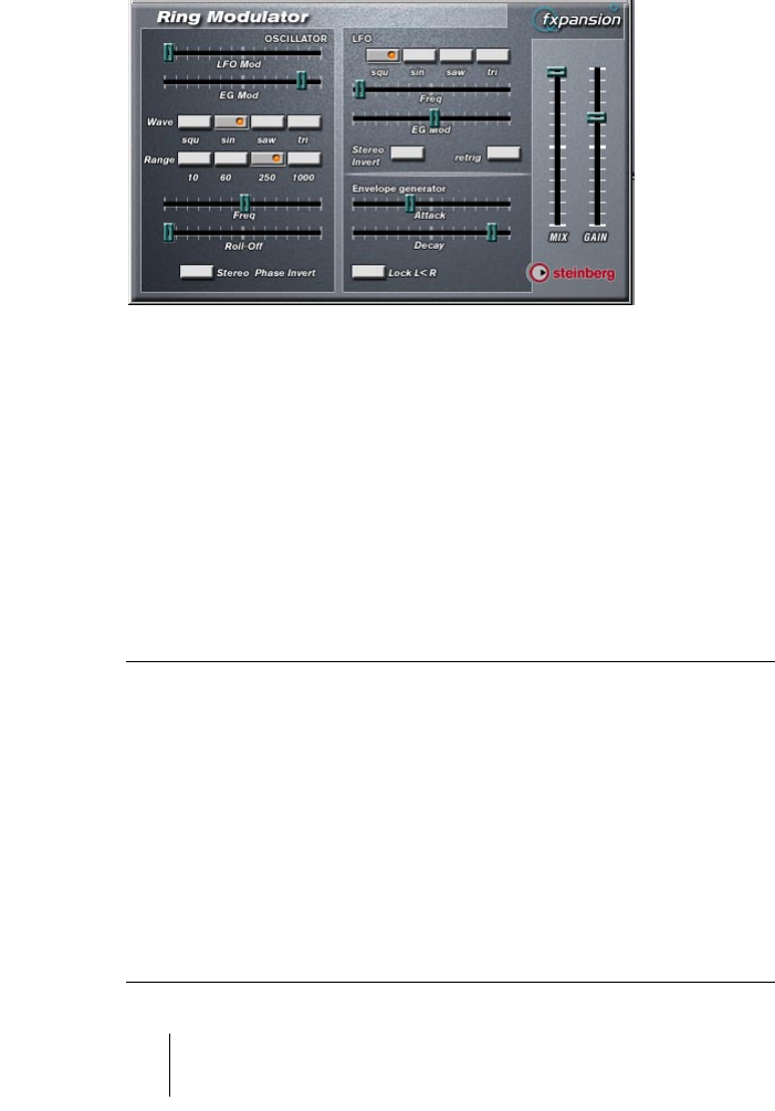
Ring Modulator
This is an earlier version of the Ringmodulator plug-in, with slightly dif-
ferent panel layout and parameters.
The Ring Modulator can produce complex, bell-like enharmonic
sounds. Ring Modulators work by multiplying two audio signals to-
gether. The ring modulated output contains added frequencies gener-
ated by the sum of, and the difference between, the frequencies of the
two signals.
The Ring Modulator has a built-in oscillator that is multiplied with the
input signal to produce the effect.
Parameters
Parameter Description
Oscillator LFO Mod LFO Mod controls how much the oscillator frequency is affected
by the LFO.
Oscillator EG Mod EG Mod controls how much the oscillator frequency is affected
by the Envelope (which is triggered by the input signal). Positive
and negative values can be set, with center position represent-
ing no modulation. Left of center, a loud input signal will de-
crease the oscillator pitch, whereas right of center the oscillator
pitch will increase when fed a loud input.
Oscillator Wave Selects the oscillator waveform; square, sine, saw or triangle.
Oscillator Range Determines the frequency range of the oscillator in Hz.

VST plug-ins from previous Cubase versions CUBASE SX/SL
21
Freq Sets the oscillator frequency +/- 2 octaves within the selected
range.
Roll Off Cuts high frequencies in the oscillator waveform, to soften the
overall sound. This is best used when harmonically rich wave-
forms are selected (e.g. square or saw).
Stereo Phase Invert Flips the phase of the oscillator waveform on the right channel.
LFO Waveform Selects the LFO waveform; square, sine, saw or triangle.
LFO Freq Sets the LFO Speed.
EG Mod Controls how much the input signal level - via the Envelope
Generator - affects the LFO Speed. Positive and negative values
can be set, with center position representing no modulation. Left
of center, a loud input signal will slow down the LFO, whereas
right of center a loud input signal will speed it up.
Stereo Invert This inverts the LFO waveform for the right channel of the oscil-
lator, which produces a wider stereo perspective for the modula-
tion.
Retrig Causes the LFO cycle to reset itself at the start of each bar dur-
ing playback, which can be used for certain LFO effects synced
to the tempo.
Envelope Generator The Envelope Generator section controls how the input signal is
converted to envelope data, which can then be used to control
oscillator pitch and LFO speed. It has two main controls:
Attack sets how fast the EG output level rises in response to a
rising input signal.
Decay controls how fast the EG output level falls in response to
a falling input signal.
Lock L<R When this switch is enabled, the L and R input signals are
merged, and produce the same EG output level for both oscilla-
tor channels. When disabled, each channel has its own EG,
which affect the two channels of the oscillator independently.
Mix Adjusts the mix between dry and processed signal.
Gain Sets the overall volume.
Parameter Description
CUBASE SX/SL VST plug-ins from previous Cubase versions
22
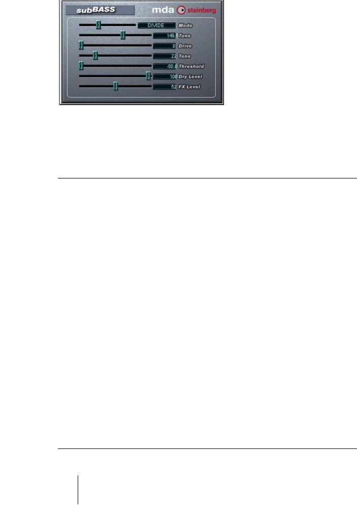
subBASS
The subBASS is a bass synthesizer that can generate low frequency
content and track the pitch from the audio material for deep, sub-sonic
bass effects.
The parameters are as follows:
Parameter Description
Mode There are three modes of operation: Boost produces a warm bass boost
to the signal. Divide generates a pitch tracking signal an octave below
the input signal. Trigger adds a decaying “boom” produced by an oscilla-
tor, typically triggered by a kick drum.
Tune This sets the maximum frequency to be affected (20-500Hz). Set as low
as possible to avoid unwanted distortion. In “Trigger” mode this sets the
oscillator frequency.
Drive In Boost mode, raising the Drive parameter adds “crunch” to the effect. In
Divide mode, increasing Drive to 50% overdrives the sub-octave signal
producing a square wave, and increasing Drive to 100% produces a
square wave one octave above (i.e. at the original input frequency). In
Trigger mode this changes the tone of the oscillator, with higher settings
producing a thinner sound.
Tone This is a lowpass filter that can be used to change the brightness of the
signal. In “Trigger” mode this sets the decay time of the generated oscil-
lator boom.
Threshold This sets the threshold for the effect. Increase to “gate” the effect and to
cut out unwanted background rumble.
Dry Level Sets the level of the original, unprocessed signal.
FX Level Sets the level of the processed signal.

VST plug-ins from previous Cubase versions CUBASE SX/SL
23
Tranceformer2
Tranceformer2 is a previous version of the Tranceformer plug-in. The
parameters are the same with the addition of an input level control.

CUBASE SX/SL VST plug-ins from previous Cubase versions
24
Earlier audio effect plug-ins
Autopan
This makes the sound move automatically between the left and right
channel.
The parameters are as follows:
Parameter Explanation
LFO Freq This sets the speed of the panning effect.
Width This sets the depth of the effect, that is, how far out to the left/right
speaker the sound should move.
Waveform This sets the shape of the LFO producing the effect. Sine and Tri-
angle both produce a smooth sweep, but with different character-
istics. Sawtooth creates a ramp (sweep from one speaker to the
other and then a quick jump back). Pulse makes the signal jump
back and forth between the speakers.
Output Level The stereo output level of the effect.

VST plug-ins from previous Cubase versions CUBASE SX/SL
25
Choirus and Choirus 2
For some computer configurations, the original Choirus effect gave rise
to clicks and distorted sound. The Choirus2 effect solves this problem. It
is identical to the “Choirus Classic” featurewise, but draws slightly more
computer power.
Choirus is a chorus and flanger effect which adds “depth” and “ani-
mation” to a sound. It basically works as follows: The original signal is
delayed and the amount of delay is continuously varied by an “LFO”.
This delayed signal is then added back in with the original.
• The Choirus plug-ins are mono in-stereo out effects.
When using them as insert effects for stereo channels, only the left or right channel will
be processed (depending on the routing settings you make for the insert slot).
Parameter Explanation
Time This is the basic amount of delay applied to the signal. The larger
the value, the richer the sound (up to a certain extent). For flanger
types of effects, use the lower range of values.
Width Sets the amount of variation in the delay of the signal. The larger the
value, the more drastic the effect. This value should be balanced
with the Time setting for optimal results.
LFO Freq This is the speed of the LFO “sweep”. The larger the value, the
faster sweep.
Feedback and
Feed Bal
These control the amount of output signal re-routed back to the in-
put of the effect. For soft and wide chorus effects, keep these val-
ues low. For flanger sounds and special fx, raise these values.
Glimmer and
Glimmer 2
Progressively add more “voices” making the chorus richer and more
animated. The Glimmer parameter also adjusts the stereo spread.
Out Levl The stereo output level of the effect.

CUBASE SX/SL VST plug-ins from previous Cubase versions
26
Espacial
This is a basic reverb effect with dedicated control over early reflec-
tions. As there is no Mix control, you should use this as a send effect
(an insert on an FX Channel track). Please note though that the Espa-
cial is a mono in-stereo out effect - when used on a stereo channel,
only the left or right channel will be processed (depending on the
routing settings you make for the insert slot).
The parameters are:
Parameter Explanation
Size Affects the apparent size of the simulated room.
Width This parameter also affects the impression of the size and shape of
the simulated room. It also affects the “density” and clearness of
the reverb.
Time The decay time of the reverberation.
ER Start The start time of the Early Reflections - the first “echo” from the
walls in a simulated room.
ER Width Early Reflection “density” and clearness.
ER Gain The balance between Early Reflections/direct sound in the input to
the actual reverb. When this parameter is fully raised, no Early Re-
flections will be heard at all.
ER Decay Determines the gradual attenuation of Early Reflections.
ER Outp The level of Early Reflections in the Effect Output.
Output Level The stereo output level of the effect.
VST plug-ins from previous Cubase versions CUBASE SX/SL
27
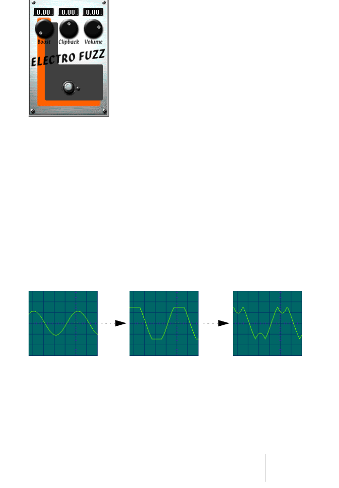
Electro Fuzz
This is a simulation of the good old transistor distortion stomp box. It
accepts a mono input and is used as an Insert or Send Effect.
The Electro Fuzz has the following parameters:
•Boost
This governs the amount of distortion. If you want to increase the distortion without
raising the signal level, you may have to adjust the Volume knob as well.
•Clipback
Raising this parameter will “invert” the part of the signal that is above the clipping level,
instead of employing hard clipping. The result is that more 2nd order harmonics are
added, changing the character of the distortion.
•Volume
This is a volume control for the output signal from the Electro Fuzz.
Increasing the Clipback value... ...will invert the clipped signal peaks, adding harmon-
If you distort a sine wave, by raising
the Boost parameter... ...it will be clipped like this.
CUBASE SX/SL VST plug-ins from previous Cubase versions
28
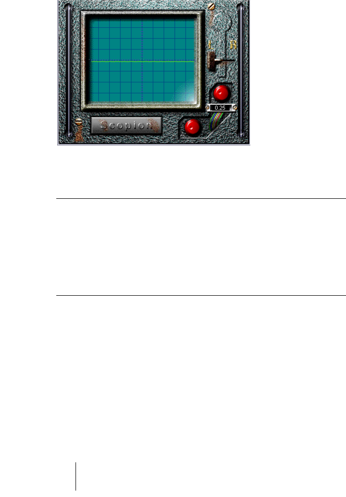
Scopion
The Scopion is an basic on-board oscilloscope that analyzes the left
or right side of a stereo input signal and displays the waveform con-
tents in real time. There are three parameters:
•If you click the Scopion label plate below the display, a help screen will
be shown, explaining the functionality of the parameters in the window.
Parameter Description
L/R Switch Clicking this switch allows you to choose between displaying the
left and right side of the stereo input signal.
Frequency This knob (directly below the L/R switch) allows you to scale the
waveform horizontally.
Amplitude This knob (at the bottom of the Scopion window) allows you to
scale the waveform vertically.

VST plug-ins from previous Cubase versions CUBASE SX/SL
29
Stereo Echo
The Stereo Echo is a delay with separate settings for the left and right
channel. It can also be used as a single mono delay, in which case the
maximum delay time will be doubled.
The Stereo Echo accepts a mono input only. It is normally used as a
Send Effect.
The Stereo Echo has the following parameters:
Parameter Explanation
Delay1 The delay time for the left channel. The maximum delay time depends on
the sample rate setting. If you link both channels for mono operation (see
below), the maximum delay time will double.
Feedbck1 The delay feedback for the left channel. Higher values result in a higher
number of echo repeats.
Link 1-2 Activating this switch turns the effect into a mono delay. When Link is on,
only the left channel parameters will be available (Delay1, Feedback1, etc).
Delay 2 The delay time for the right channel.
Feedbck2 The delay feedback for the right channel.
Del2 Bal This parameter determines how much of the left channel output is sent to
the right channel input. When set to 0.0 (fully left), then none of the left
channel output is added to the right channel input; when it is set to 1.0 (
fully right), the right input receives both its normal source and the com-
plete output of the left channel.
Volume L The output level of the left channel delay.
Volume R The output level of the right channel delay.

CUBASE SX/SL VST plug-ins from previous Cubase versions
30
Stereo Wizard
The Stereo Wizard is a stereo width enhancer that takes a stereo input
signal and makes it sound “wider”. StereoWizard will give best result if
you use “real” stereo material (as opposed to mono channels panned
to different positions in the stereo image), but you could also apply ste-
reo ambience or reverb to a mono signal, and then use Stereo Wizard
to enhance the stereo width of the reverb.
The Stereo Wizard has the following parameters:
Parameter Explanation
Amount Higher values result in a greater stereo width. Normally, you should
set this to values between 0.00 - 0.20; higher values can be used
for special effects.
Reverse Reverses the left and right channel.
VST plug-ins from previous Cubase versions CUBASE SX/SL
31
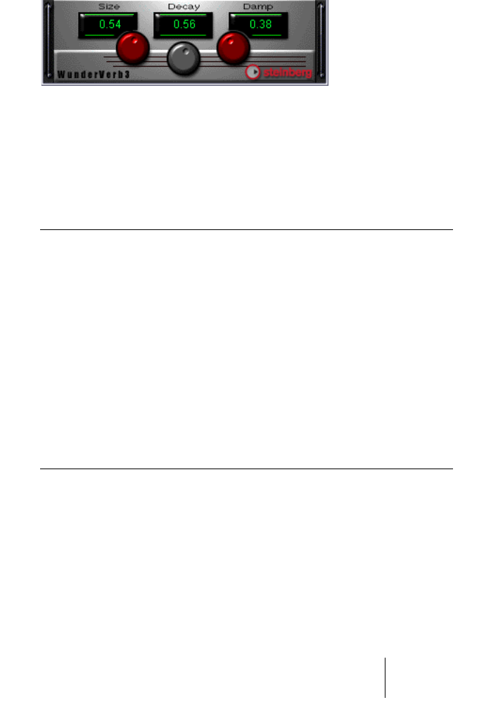
WunderVerb 3
WunderbVerb 3 is a reverb plug-in which provides natural sounding
reverb effects, and still uses very little processor power.
• The WunderVerb 3 plug-in is a mono in-stereo out effect.
When using it as an insert effect for a stereo channel, only the left or right channel will
be processed (depending on the routing settings you make for the insert slot).
Use the Program pop-up to select one of ten Reverb Types:
Hall The reverberation of a medium-sized hall.
Large Hall The reverberation of a larger hall.
Large Room The reverberation of a large room.
Medium Room The reverberation of a medium-sized room.
Small Room The reverberation of a very small room.
Plate The slightly metallic effect of a plate reverb.
Gated A special effect, where the reverb is abruptly cut off.
Effect 1 A special “bouncing” effect.
Echoes An echo (delay) effect.
Effect 2 A special, resonant effect, suitable for “ringing” metal sounds.

CUBASE SX/SL VST plug-ins from previous Cubase versions
32
You can adjust the following three parameters:
Size
This is the size of the simulated room. Changing this will affect the
density and character of the reverb. If you have selected a Reverb
Type where you can hear the individual “bounces” (Effect 1, Echoes,
etc), raising the Size will increase the time between each “bounce”,
like the time control on a delay effect.
Decay
This is the decay time for the reverb. The higher the value, the longer
the reverb.
Damp
Raising this value will cause the high frequency contents of the reverb
sound to die out quicker. This results in a softer, darker reverb.
VST plug-ins from previous Cubase versions CUBASE SX/SL
33
Cubase 5 VST Instruments
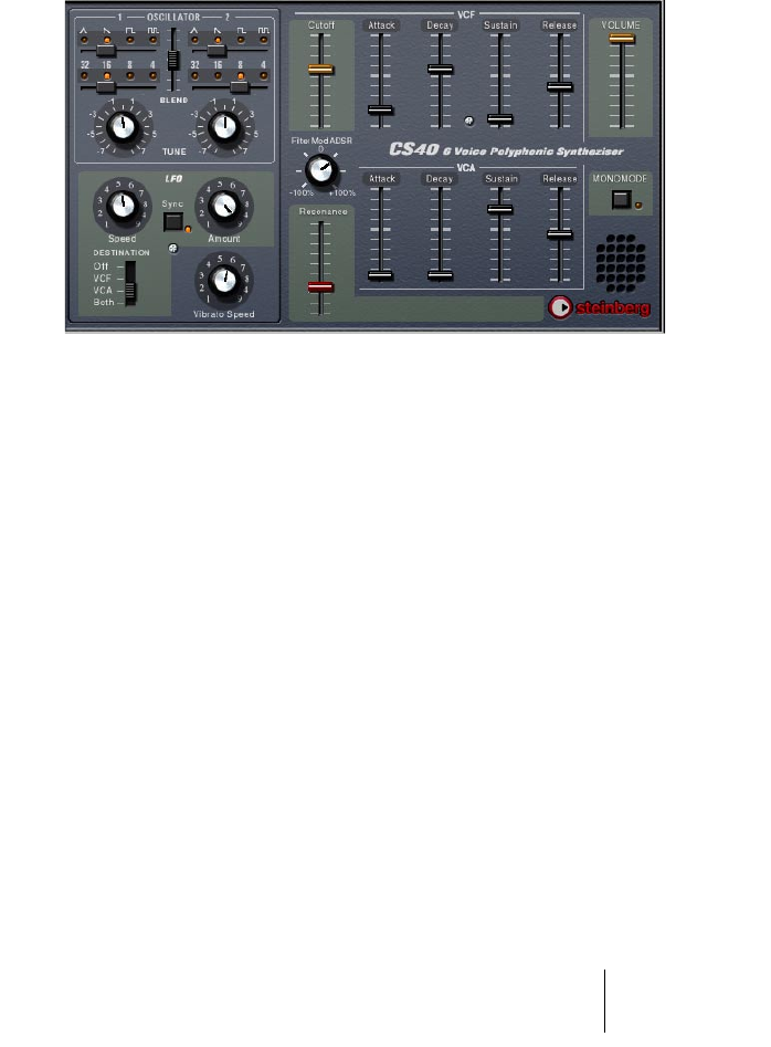
CS40
The CS40 is a straightforward software synthesizer with the following
main features:
•The CS40 is polyphonic with up to 6 voices.
•The CS40 receives MIDI in Omni mode (on all MIDI channels).
You don’t need to select a MIDI channel to direct MIDI to the CS40.
•The CS40 responds to the following MIDI messages:
MIDI Note On/Off (velocity governs volume).
Volume.
Pan.
Pitch Bend (± 2 semitones).
Modulation (vibrato).

CUBASE SX/SL VST plug-ins from previous Cubase versions
34
CS40 Parameters
Parameter Description
Oscillator 1 Range Selects an octave range for oscillator 1; 32, 16, 8 or 4 feet.
Oscillator 1 Waveform The basic waveform for oscillator 1; Triangle, Sawtooth,
Square or Pulse.
Oscillator 1 Tune Detunes Oscillator 1 ± 7 semitones.
Oscillator 2 parameters Same as Oscillator 1.
Oscillator Blend Adjusts the relative volume mix between oscillator 1 and 2.
LFO Speed Governs the speed of the LFO. If LFO Sync is activated, this
parameter sets the LFO speed in various beat increments to
the sequencer tempo.
LFO Sync Syncs the LFO speed to the set sequencer tempo.
LFO Amount This governs the amount of LFO modulation applied to the
destination parameters.
LFO Destination This sets the destination parameter(s) for the LFO. You can
apply modulation to the VCF cutoff frequency, the VCA am-
plitude, or both.
Vibrato Speed Governs the speed of the Vibrato LFO. The Vibrato amount
is controlled by the Mod Wheel.
VCF Cutoff The Cutoff Frequency for the filter, governing the amount of
high frequencies in the sound.
VCF Resonance The Resonance control for the filter. Raise this for a more
hollow, pronounced filter effect.
Filter Mod ADSR This controls how much the VCF cutoff is affected by the
VCF Envelope. Negative values invert the Envelope settings.
VCF Attack, Decay,
Sustain, Release
The Filter Envelope. Use these parameters to determine how
the filter should open and close with time, when a note is
played.
VCA Attack, Decay,
Sustain, Release
The Amplitude Envelope. Use these parameters to determine
how the volume should open and close with time, when a
note is played.
MonoMode When activated the CS40 will be monophonic.
Volume Governs the overall volume.
VST plug-ins from previous Cubase versions CUBASE SX/SL
35
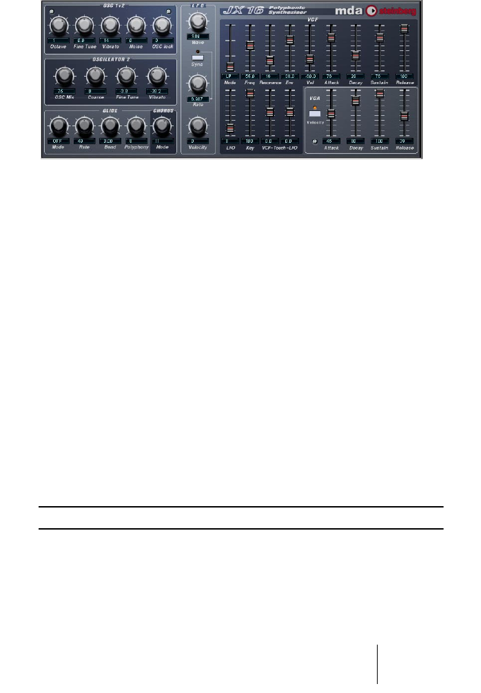
JX16 Synthesizer
The JX16 is a dual oscillator software synthesizer with the following
main features:
•The JX16 is polyphonic with up to 16 voices.
The polyphony setting for each patch is user programmable.
•Low CPU load and high quality sound (low aliasing distortion).
•Multimode Filter.
Lowpass, Bandpass and Hipass filter modes are available.
•Oscillator Lock function enables the creation of pulse and square
waveforms with classic PWM (Pulse Width Modulation).
See page 36.
•Built-in stereo chorus effect.
•The JX16 receives MIDI in Omni mode (on all MIDI channels).
You don’t need to select a MIDI channel to direct MIDI to the JX16.
•The JX16 responds to MIDI Controller messages.
See page 40.
All parameters can be automated as described in the Operation Manual.

CUBASE SX/SL VST plug-ins from previous Cubase versions
36
Osc 1+2 Section
This section contains parameters affecting both oscillators.
The Oscillator 2 Section
This section contains parameters that affect oscillator 2 only.
About the “Oscillator Lock” parameter
JX16 features two oscillators per voice, with fixed sawtooth wave-
forms. You can, however, generate square waves and PWM (pulse
width modulation) with the JX16, by combining the two oscillators us-
ing the “OSC lock” and Oscillator 2 “Vibrato” parameters. The follow-
ing applies:
•“OSC lock” allows the phase of Oscillator 2 to be fixed relative to
OSC 1, producing pulse waves when Oscillator 2 has the same pitch
and level as OSC 1.
Parameter Description
Octave Tunes the oscillators in octave steps.
Fine Tune Tunes the oscillators in cent (100th of a semitone) steps.
Vibrato Governs how much the LFO should modulate the pitch of the oscilla-
tors (vibrato). The Vibrato parameter is also controllable via MIDI by us-
ing the Mod Wheel.
Noise This parameter produces white noise mixed with the oscillators. By us-
ing the “OSC lock” parameter you can “cancel out” the oscillators and
use pure noise as the sound source. This is described below.
OSC lock See below.
Parameter Description
OSC Mix Controls the level of oscillator 2. 100 produces equal level to oscilla-
tor 1, which has a fixed output level.
Coarse Tuning of Oscillator 2, in semitone steps.
Fine Tune Fine tuning of Oscillator 2, in cent (=100th of a semitone) steps.
Vibrato This lets you apply vibrato on the second oscillator only. This can be
useful for creating PWM effects - see page 36 for a further descrip-
tion. Both positive and negative values can be set.

VST plug-ins from previous Cubase versions CUBASE SX/SL
37
•If the oscillators are tuned to the same pitch and level, an “OSC lock”
setting of 50% produces a square wave with higher and lower set-
tings producing progressively narrower pulse waveforms.
With an “OSC lock” setting of 0% the two oscillators cancel out completely, which is
useful if you only want to use the noise generator as a sound source.
•By applying the Oscillator 2 “Vibrato” parameter when OSC lock is
set to around 50%, classic PWM is produced.
You can also detune Oscillator 2 for even richer modulation effects.
•In “Free” mode the oscillator phase is allowed to drift, producing a
random timbre change.
By experimenting with these parameters, many different timbres and
modulation effects can be produced.
The Glide/Chorus Section
This section contains Glide parameters, and also the Polyphony and
Chorus parameters.
Parameter Description
Mode If set to “On”, the pitch will glide up or down between notes played. If
set to “Held”, Glide will only be applied when you press a key while an-
other key is held.
Rate Controls the time it takes for the pitch to glide from one note to the next
when using Glide. If Bend (see below) is used, this parameter controls
the time it takes for the pitch bend to “land” at the correct pitch.
Bend Applies an initial pitch bend to the notes played. Negative values causes
the pitch to slide up to the pitch of the note played, and vice versa.
Polyphony This sets the polyphony, i.e. the number of voices a patch can use.
Chorus This adds a stereo chorus effect. The values set different modulation
rates and depths for the effect.

CUBASE SX/SL VST plug-ins from previous Cubase versions
38
The LFO Section
This is where you set up the LFO (Low Frequency Oscillator). LFOs
are used to modulate parameters like pitch (vibrato) or the filter cutoff.
The VCF Section
This section contains the filter parameters:
Parameter Description
LFO Wave This sets the LFO waveform for modulating parameters: Sine pro-
duces smooth modulation suitable for vibrato, Square produces
stepped modulation between two alternating values, Saw+/- pro-
duces ramp up/down values respectively, and Random will produce
random stepped modulation.
LFO Sync If this is activated, the LFO rate will be synced to the sequencer
tempo in various beat divisions that can be set with the LFO Rate
parameter.
LFO Rate Governs the modulation rate of the LFO.
LFO Rate
(tempo sync on)
If the “LFO Sync” parameter is activated, the LFO rate will be synced
to the sequencer tempo, according to the different beat divisions that
can be specified here.
LFO Velocity This allows you to control the LFO Rate parameter with velocity, i.e.
by how hard or soft you strike a note on the keyboard. The harder you
play the faster the LFO rate.
Parameter Description
VCF Mode Sets the filter mode to either lowpass (LP), highpass (HP), bandpass
(BP) or off. The filter modes are described below this table.
VCF Freq
(Cutoff)
Controls the filter frequency or “cutoff”. If a lowpass filter is used, it
could be said to control the opening and closing of the filter, produc-
ing the classic “sweeping” synthesizer sound. How this parameter
operates is governed by the filter mode (see page 39).
Resonance The Resonance control for the filter. Raise this for a more pronounced
filter sweep effect. If set to 100, the filter will self-oscillate and pro-
duce a pitch. See the “VCF Key” parameter below for a description of
how this can be used.
VCF Env Controls how much the filter cutoff should be affected by the VCF
Envelope parameters. Negative values will invert the filter envelope
settings.

VST plug-ins from previous Cubase versions CUBASE SX/SL
39
About the filter modes
The JX16 features a multimode filter. The various filter modes are
selected with the VCF Mode parameter, and are as follows:
• Lowpass (LP)
Lowpass filters lets low frequencies pass and cuts out the high frequencies. This is the
most commonly used filter type in analog synthesizers.
• Bandpass (BP)
A bandpass filter cuts frequencies above and below the cutoff frequency, allowing a
specific range of frequencies to pass while attenuating all others.
• Highpass (HP)
A highpass filter is the opposite of a lowpass filter, cutting out the lower frequencies
and letting the high frequencies pass.
VCF Vel Determines how the filter cutoff will be affected by velocity, i.e. how
hard or soft you strike a key. Positive values will increase the cutoff
frequency the harder you strike a key. Negative values will invert this
relationship.
VCF Att/Dec/
Sus/Rel
The Filter Envelope Attack, Decay, Sustain and Release parameters.
Use these parameters to determine how the filter cutoff should open
and close with time, when a note is played.
VCF LFO This controls how much the filter cutoff is modulated by the LFO (low
frequency oscillator).
VCF Key If this parameter is set to values over 0, the filter cutoff frequency will
increase the further up on the keyboard you play. If set to 100, it will
track the notes on the keyboard, enabling you to “play” the filter as an
extra sound source, as the filter self-oscillates and produces a pitch
when the resonance is set to 100.
VCF Touch This sets the amount the VCF cutoff parameter should be affected by
Aftertouch. If positive values are set, the filter cutoff is raised the
harder you press. Negative values invert this relationship.
LFO Touch This sets the amount the VCF LFO parameter should be affected by
Aftertouch. If positive values are set, the modulation increases the
harder you press. Negative values invert this relationship.
Parameter Description

CUBASE SX/SL VST plug-ins from previous Cubase versions
40
The VCA Section
This section contains the VCA Envelope parameters, governing the
amplitude (volume) of the sound:
MIDI Controller Messages
The JX16 responds to the following MIDI Controller Messages:
Parameter Description
VCA Att/Dec/Sus/Rel The VCA Attack, Decay, Sustain and Release parameters.
Use these parameters to determine how the volume should
change with time, when a note is played.
VCA Velocity This determines whether the VCA Envelope should be af-
fected by velocity, i.e. by how hard or soft you strike a note on
the keyboard.
Controller Parameter/Value
Pitch Bend +/- 2 Semitones
CC1 (Mod Wheel) Vibrato
Aftertouch Can control filter cutoff and filter cutoff modulation (by the LFO).
CC2 / CC3 Increases and decreases filter frequency, respectively.
CC7 Volume
CC16 Increase filter resonance
Program Change # 1-64
VST plug-ins from previous Cubase versions CUBASE SX/SL
41
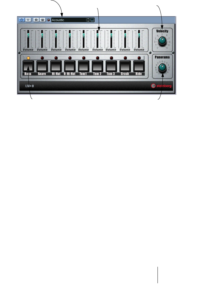
LM-9
The LM-9 is a basic drum machine. It has the following properties:
•LM-9 is polyphonic with up to 9 voices.
•LM-9 receives MIDI in Omni mode (on all MIDI channels).
You don’t need to select a MIDI channel to direct MIDI to LM-9.
•LM-9 responds to the following MIDI messages:
MIDI Note On/Off (velocity governs volume).
Furthermore, all parameters can be automated as described in the
Operation Manual chapter “VST Instruments”.
Volume fader (one for
each drum sound).
This adjusts the Pan (the position in
the stereo image) for the individual
drums. The setting is applied to the
currently selected drum , indicated by
a lit yellow LED over the Pad button.
This sets the global velocity
sensitivity for LM-9.
Pad (one for each drum sound).
Press to audition the drum sound
assigned to the Pad, or to select
a sound for adjusting pan.
Program switch

CUBASE SX/SL VST plug-ins from previous Cubase versions
42
LM-9 Parameters
Drum sounds
LM-9 comes with two sets of drum sounds; “Acoustic” and “Beat
Box”. Acoustic features samples of an acoustic drum kit and Beat Box
features classic analog drum machine sounds. The table below shows
how the drum sounds are assigned to note values on your MIDI key-
board. The mapping is GM compatible:
Parameter Description
Velocity This sets the global velocity sensitivity for LM-9. The higher the
value, the more sensitive LM-9 will be to incoming velocity data. If
set to “0”, the sounds will play back with a fixed velocity value.
Volume sliders The volume sliders are used to adjust the volume for each individual
drum sound.
Pad The Pads are used for two things: To audition the individual drum
sounds, and to select a sound for adjusting pan.
Panorama This is used to position an individual sound in the stereo image. The
setting applies to the currently selected sound, indicated by a lit yel-
low LED over the Pad button.
Drum sound Note value
Bass C1
Snare D1
Hi-Hat F#1
O-Hi-Hat A#1
Tom 1 D2
Tom 2 B1
Tom 3 A1
Crash C#2
Ride D#2
VST plug-ins from previous Cubase versions CUBASE SX/SL
43
Switching the sets
Use the Program menu to switch between the two supplied drum
sets, just like you switch between effect programs.
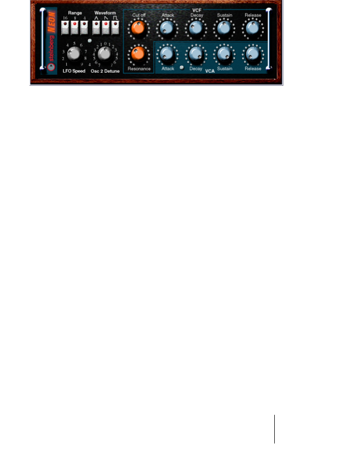
The Neon
The Neon is a simple software synthesizer. It has the following proper-
ties:
•The Neon is polyphonic with up to 16 voices.
However, since each added voice consumes CPU power, the maximum polyphony
may be limited by the speed of your computer.
•The Neon receives MIDI in Omni mode (on all MIDI channels).
You don’t need to select a MIDI channel to direct MIDI to the Neon.
•The Neon responds to the following MIDI messages:
MIDI Note On/Off (velocity governs volume).
Volume.
Pan (remember to pan the two Instrument channels hard Left/Right if you want to use
MIDI Pan messages).
Pitch Bend (± 2 semitones).
Modulation (vibrato).
Furthermore, all parameters can be automated as described in the
Operation Manual chapter “VST Instruments”.

CUBASE SX/SL VST plug-ins from previous Cubase versions
44
Neon Parameters
Parameter Description
Range Selects an octave range for the oscillators, 16, 8 or 4 feet.
Waveform The basic waveform for the oscillators, Triangle, Sawtooth or
Square.
LFO Speed Governs the speed of the vibrato. The vibrato depth is con-
trolled via MIDI Modulation messages (for example, using the
Mod Wheel on your MIDI controller).
Osc 2 Detune Allows you to detune the “second oscillator” ± 7 semitones. By
setting this to a value close to “twelve o’clock”, you will get fine
detuning, for a warmer, fatter sound.
VCF Cutoff The Cutoff Frequency for the filter, governing the amount of
high frequencies in the sound. On the Neon, the Cutoff control
also serves as a Depth control for the Filter Envelope (VCF
Att
ack, Decay, Sustain, Release), so that the lower the setting
of the Cutoff parameter, the more will the filter be affected by
the Filter Envelope.
VCF Resonance
The Resonance control for the filter. Raise this for a more hollow
,
pronounced filter effect.
VCF Attack, Decay,
Sustain, Release
The Filter Envelope. Use these parameters to determine how the
filter should open and close with time, when a note is played.
VCA Attack, Decay,
Sustain, Release
The Amplitude Envelope. Use these parameters to determine
how the amplitude (volume) should change with time, when a
note is played.
Index

CUBASE SX/SL
46 Index
A
Autopan 24
Autopole 4
C
Choirus/Choirus 2 25
Chopper2 7
CS40 33
D
Distortion 8
E
Electro Fuzz 27
Espacial 26
J
JX16 35
K
Karlette 9
L
LM-9 41
M
Metalizer2 10
MIDIComb 10
Mysterizer 14
N
Neon 43
P
PhatSync 17
R
Reverb 19
Reverb32 19
Ring Modulator
(Cubase 5 plug-in) 20
S
Scopion 28
Stereo Echo 29
Stereo Wizard 30
subBASS 22
T
Tranceformer2 23
W
Wunderverb 3 31
