Cisco Unified Communications Manager Configuration Guide For The TelePresence System 3200 Cucm Cts Admin
User Manual: 3200
Open the PDF directly: View PDF ![]() .
.
Page Count: 170 [warning: Documents this large are best viewed by clicking the View PDF Link!]
- Cisco Unified Communications Manager Configuration Guide for the Cisco TelePresence System
- Contents
- What’s in This Guide
- Contents
- How to Use This Guide
- Before You Begin
- Additional System Information
- Document Organization
- Related Documentation
- Obtaining Documentation and Submitting a Service Request
- Contents
- Adding a Cisco TelePresence Image to the Cisco Unified Communications Manager Server
- Downloading the Cisco TelePresence Software
- Step 1 Navigate to www.cisco.com.
- Step 2 Click on the Log In button, then enter your username and password.
- Step 3 Click Support.
- Step 4 Enter the following search term into the text box:
- Step 5 Click the Cisco TelePresence Administration Software hyperlink that displays.
- Step 6 Click the Download Software hyperlink.
- Step 7 Navigate to your product using the navigation tool that displays.
- Step 8 Select the software that you require for your installation.
- Step 9 Choose the latest release and click either Add to Cart or Download.
- Step 10 Click Download and then Accept License Agreement, and follow the prompts to download the file.
- Step 11 Copy these files to a Secure File Transfer Protocol (SFTP) server that is accessible by Unified CM.
- Step 12 Load the system image onto the Unified CM server by completing the following steps:
- Installing the Cisco TelePresence COP File to the Unified CM Server
- Step 13 Log in to the Unified CM administrative GUI.
- Step 14 From the Navigation drop-down list, on the top right of the GUI, select Cisco Unified OS Administration. Click Go to go to the Cisco Unified CM Administration home page.
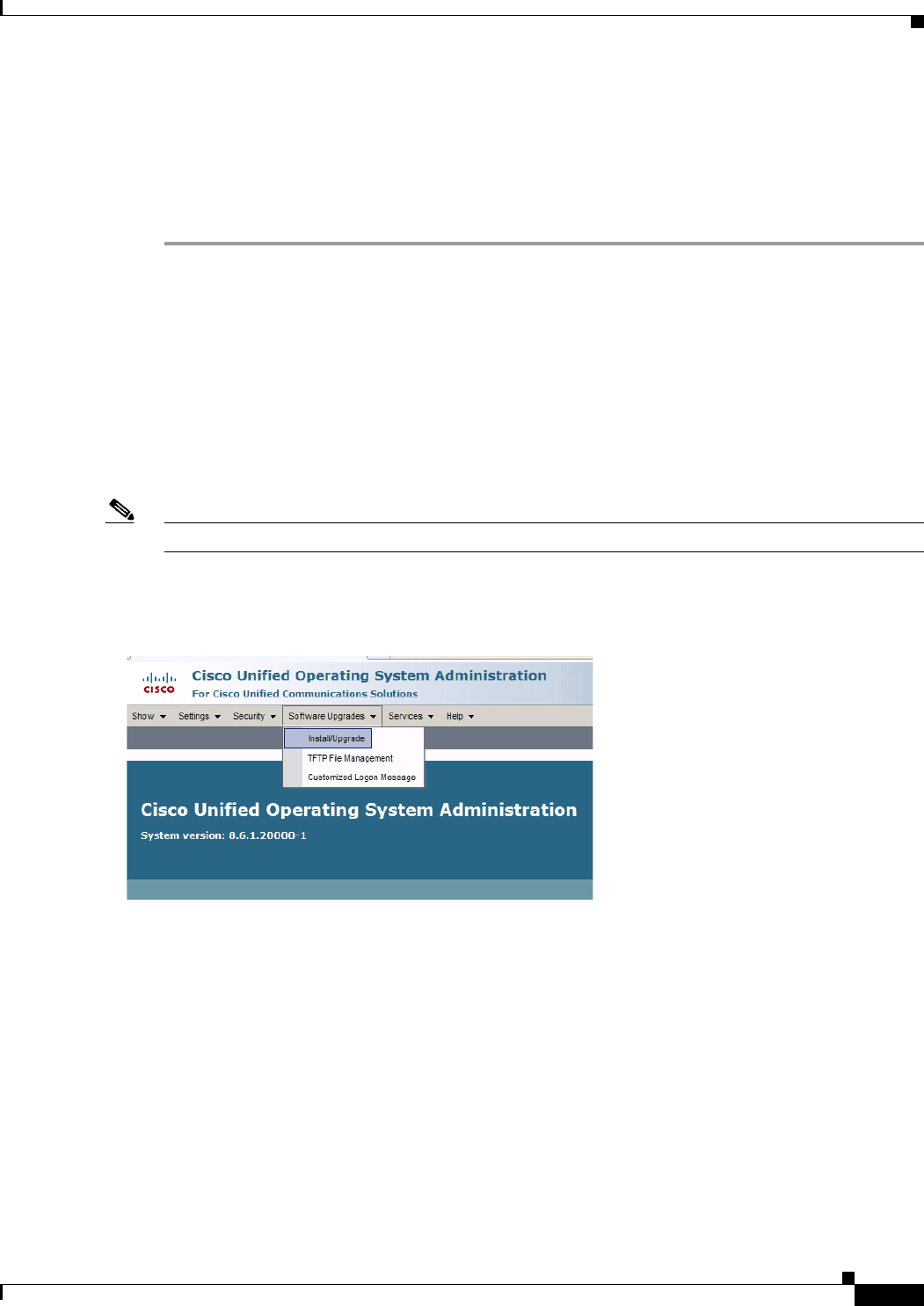
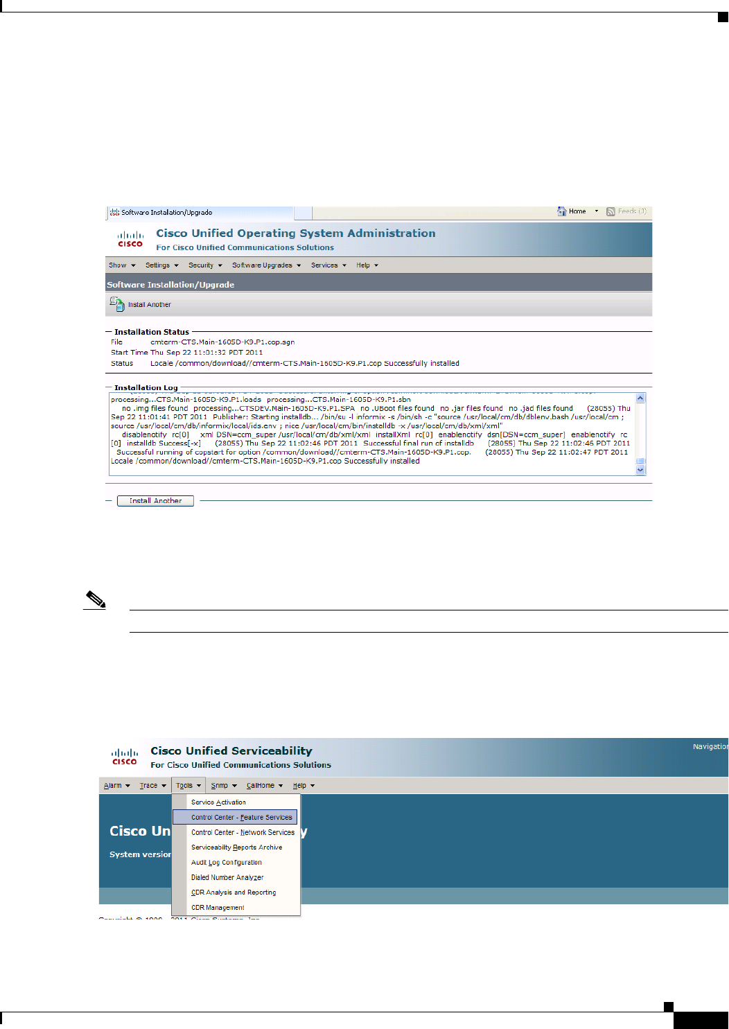
- Step 15 Navigate to Software Upgrades > Install/Upgrade.
- Figure 1-1 Cisco Unified Operating System Administration Screen
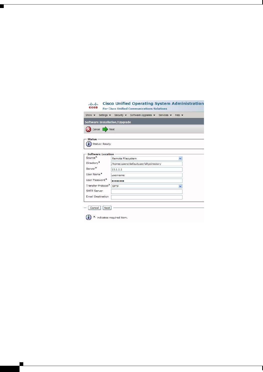
- Step 16 In the Software Location area, specify the following information in the fields:
- Step 17 Click Next.
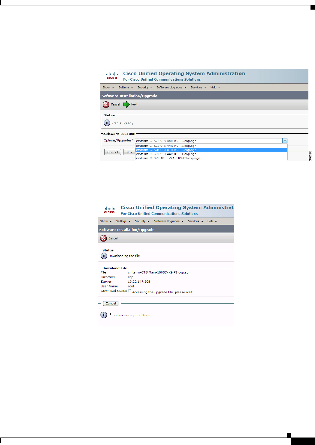
- Step 18 Choose the COP file that you want to install from the available file names in the Options/Upgrades drop-down list.
- Step 19 Click Next.
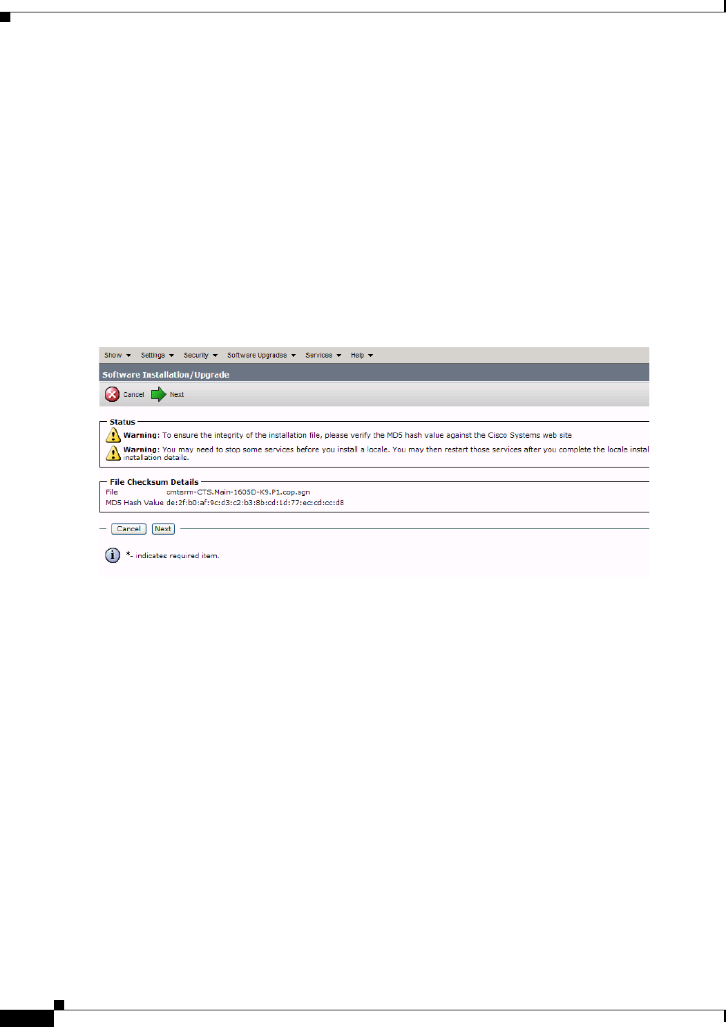
- Step 20 After installation completes, verify the file validity by completing the following steps:
- Figure 1-5 File Checksum Details Area
- Figure 1-6 Installation Status Area
- Figure 1-7 Cisco Unified Serviceability Window
- Downloading the Cisco TelePresence Software
- Configuring Phone Security Profile Information
- Adding a New Phone Security Profile for CTS
- Step 1 Log in to the Cisco Unified CM Administration interface.
- Step 2 Choose System > Security Profile and click Phone Security Profile.
- Step 3 Click the Add New button at the bottom of the window. The Phone Security Profile Configuration window appears.
- Step 4 From the Phone Security Profile Type drop-down menu, choose the phone type.
- Step 5 Click Next.
- Step 6 From the Select the phone security profile protocol drop-down menu, choose SIP.
- Step 7 Click Next. The Phone Security Profile Configuration window appears containing your Product Type and Device Protocol selections.
- Step 8 Proceed to Configuring the Phone Security Profile to complete the remaining tasks on the Phone Security Profile Configuration page.
- Configuring the Phone Security Profile
- Before You Begin
- Procedure
- SIP Phone Security Profile Information
- Step 1 From the Cisco Unified CM Administration interface, Choose System > Security Profile and click Phone Security Profile.
- Step 2 Search for a Phone Security Profile using the search features or follow the steps in Adding a New Phone Security Profile for CTS.
- Step 3 Enter configuration information on the Phone Security Profile Information page using the information in Table 1-1 as a guide.
- Step 4 Click the Save button to save your settings.
- Phone Security Profile CAPF Information
- Parameters Used in Phone Field
- Adding a New Phone Security Profile for CTS
- Adding a Cisco TelePresence Device to the Unified CM Server
- Using the Unified CM GUI to Add a Cisco TelePresence Device
- Step 1 Log in to the Cisco Unified CM Administration interface.
- Step 2 If required, choose the Cisco Unified CM Administration drop-down choice and click Go.
- Step 3 From the Device drop-down menu, choose Phone. The Find and List Phones Page appears.
- Step 4 Click the Add New button at the bottom of the window. The Add a New Phone window appears.
- Step 5 In the Add a New Phone window, click the Phone Type drop-down list and choose Cisco TelePresence system that corresponds with your device.
- Step 6 Click Next to display the Phone Configuration window.
- Step 7 Fill out the fields in the Phone Configuration window. Refer to Table 1-4 through Table 1-14 for a description of these fields.
- Step 8 When you have finished making your changes, click Save to save your settings.
- Device Information Area
- Protocol-Specific Information Area
- Certification Authority Proxy Function (CAPF) Information Area
- MLPP Information Area
- Product Specific Configuration Layout Area
- User Preferences Area
- Dial Plan Area
- Directory Number Area
- Global Location Area
- SSH Information Area
- External CTS Log Destination Area
- SNMP Configuration Parameters Area
- SNMP Trap Receiver Parameters Area
- Saving Your Settings
- Using the Unified CM GUI to Add a Cisco TelePresence Device
- Configuring the Directory Number for the Cisco TelePresence Device
- Directory Number Information
- Step 1 If you have not already done so, click Add a new DN in the Association Information box to open the Directory Number Configuration window.
- Step 2 Enter the directory information using the information in Table 1-16 as a guide.
- Step 3 Make sure that the check box at the bottom of the Directory Number Information section is marked as indicated: Active: Checked
- Step 4 Click Save to save your settings.
- Directory Number Settings
- AAR Settings
- Call Forward and Call Pickup Settings
- MLPP Alternate Party Settings
- Line Settings for All Devices
- Line X on Device X
- Multiple Call/Call Waiting Settings on Device SEPXXXXXXXXXXXX
- Forwarded Call Information Display on Device SEPXXXXXXXXXXXX
- Directory Number Information
- Where to Go Next
- Contents
- Managing the Speed-Dial Directory (Favorites)
- Adding Speed-Dial Numbers (Favorites) from the Unified CM Administration Page
- Step 1 Log in to the Cisco Unified Communications Manager Administration interface.
- Step 2 From the Device drop-down menu, choose Phone. The Find and List Phones Page appears.
- Step 3 Enter your search criteria in the fields provided and click Find.
- Step 4 Click on the phone that you want to configure with speed-dial buttons. The Phone Configuration window for that phone appears.
- Step 5 Click the Related Links drop-down list box at the top right side of the window.
- Step 6 Choose Add/Update Speed Dials and click Go. The Speed Dial Configuration window for this phone appears with the following configurable fields:
- Step 7 Create your favorites list in these Speed Dial (Button) Settings field using the information in Table 2-1 as a guide.
- Step 8 Click Save to apply your changes, then click Close to close the window.
- Step 9 Click Save and then Apply Config. The phone will reboot for the changes to take effect. This will take a few minutes.
- Step 10 View your Favorites by tapping Directory and then Favorites on your Touch 12 device.
- Adding Speed-Dial Numbers (Favorites) from the User Options Page
- Step 1 Log in to the Cisco Unified CM User Options page, as shown in Figure 2-1.
- Step 2 Click User Options and select Device, as shown in Figure 2-2. The Device Configuration page appears, as shown in Figure 2-3.
- Step 3 In the Device box, click the Name drop down menu and select the phone for which you would like to create, modify, or delete speed dials, as shown in Figure 2-3. The model name will appear in the Description field, as shown in Figure 2-4.
- Step 4 Click Save.
- Step 5 Click Speed Dials. The Speed Dial and Abbreviated Dial Configuration page appears, as shown in Figure 2-5.
- Step 6 In the Speed Dial Settings Number field, enter the Cisco TelePresence telephone numbers (for example, 84243737). See Figure 2-5.
- Step 7 In the Speed Dial Settings Label and ASCII Label fields, enter a name or friendly name. These can be a combination of letters or numbers. Hyphens and spaces are ok, but do not use any special characters (for example, % @ ! $). See Figure 2-5.
- Step 8 Click Save and Apply Config when you are done. Once you save, the phone will reboot for the changes to take effect. This will take a few minutes.
- Step 9 View your Favorites by tapping Directory and then Favorites on your Touch 12 device.
- Adding Speed-Dial Numbers (Favorites) from the Unified CM Administration Page
- Enabling the Directory Feature
- Step 1 Log in to the Cisco Unified Communications Manager Administration interface.
- Step 2 Go to System > Enterprise Parameters.
- Step 3 Scroll to CCMUser Parameters.
- Step 4 Locate Show Directory from the list and choose True from the drop-down menu.
- Step 5 Click Save to save your settings. The change will take effect on next login to Cisco Unified Communications Manager User Options window. Default is True.
- Configuring a Corporate Directory
- Configuring the BFCP over UDP Collaboration Feature
- BFCP Backward Compatibility
- Configuring the VCS Zone
- Configuring BFCP For Your Cisco TelePresence Device
- Adding a New BFCP Profile
- Step 1 Go to Device > Device Settings > SIP Profile.
- Step 2 Click Add New. The SIP Profile Configuration window appears.
- Step 3 Create a name for the BFCP profile. For example, “Standard BFCP SIP Profile.”
- Step 4 Click to select the Allow Presentation Sharing using BFCP check box, as shown in Figure 2-6.
- Step 5 Leave the remaining field defaults and click Apply Config and then Save.
- Step 6 Configure the BFCP trunk by performing the tasks in the “Configuring the Unified CM Trunk” section on page 2-11.
- Configuring the Unified CM Trunk
- Step 1 Go to Device > Trunk.
- Step 2 Select the trunk for the Cisco VCS and set it to use the new BFCP profile.
- Step 3 (Optional) Configure security between the Unified CM and Cisco VCS for Cisco TelePresence EX and Cisco TelePresence C Series endpoints by choosing vcs interop in the Normalization Script window (Unified CM 8.6(2a)SU2 and later releases), as sh...
- Step 4 Click Save to save your settings.
- Adding a New BFCP Profile
- T1 Support Extended Reach
- Quality Per Display - 720p (Lite)
- Self View Control
- Conference Control Protocol (CCP) VPN Security Solution
- Single Microphone Mute
- Watermark Removal
- Step 1 Request a Broadcast license from your Cisco account representative.
- Step 2 Rename the license .txt file to SEPxxxxxxxxxxxx.lic (where xxx is the MAC address in all caps).
- Step 3 Upload your newly named file to the Unified CM TFTP directory and restart the TFTP.
- Step 4 Restart you TelePresence system by logging in to the TelePresence system and entering the utils system restart command at the admin prompt.
- Step 5 Once your broadcast license is loaded, log in as admin to check your license status using command-line interface (CLI).
- Step 6 At the admin prompt enter show license status. The license status shows that it is disabled. For example:
- Step 7 At the admin prompt enter set license broadcast enable.
- Step 8 Reboot the system by entering the utils system restart command at the admin prompt.
- Screen Dimming
- Installing Language Versions
- Table 2-4 Languages Available for Cisco TelePresence Systems
- Understanding Locale Pack File Types and Naming Conventions
- Installing Locale Installers for the Unified CM Server
- Step 1 Log in to cisco.com.
- Step 2 Navigate to Support > All Downloads.
- Step 3 Navigate to Products > Voice and Unified Communications > IP Telephony > Unified Communications Platform > Cisco Unified Communications Manager (CallManager) > Cisco Unified Communications Manager Version {your version number}.
- Step 4 Click the link that says Unified Communications Manager/CallManager Locale Installer.
- Step 5 Download the locale installer (*.cop.sgn file) for the Combined Network.
- Step 6 Download the locale installer (*.cop.sgn file) for your language and country of choice. See Table 2-4 for a list of the Unified CM locale codes that correspond with each language and country.
- Step 7 Copy the files to a TFTP server that is accessible by Unified CM.
- Step 8 Log in to Unified CM and upload the locale installers to the Unified CM Server. See “Installing the Cisco TelePresence COP File to the Unified CM Server” section on page 1-3 (Step 13 through Step 23) for instructions.
- Installing Locale Packs for the CTS or TX System and Touch 12 Device
- Step 1 Log in to cisco.com.
- Step 2 Navigate to Support > All Downloads > Products > TelePresence > TelePresence Endpoints - Immersive > your TelePresence series > your TelePresence system.
- Step 3 Download the locale pack file bundle: Cisco TelePresence Language Pack for CTS500-32, CTS1300-47, TX1310-65, TX9000, TX9200 (*.cop.sgn file).
- Step 4 Copy the file bundle to a TFTP server that is accessible by Unified CM.
- Step 5 Log in to Unified CM and upload the file bundle to the Unified CM server. See “Installing the Cisco TelePresence COP File to the Unified CM Server” section on page 1-3 (Step 13 through Step 23) for instructions.
- Step 6 Restart the TFTP server to activate the newly-installed locale packs.
- Step 7 Continue to the “Configuring User Interface Language, Ringtones and Date and Time” section on page 2-20.
- Configuring User Interface Language, Ringtones and Date and Time
- Step 1 Log in to Cisco Unified CM Administration.
- Step 2 Navigate to System > Device Pool (to change device dates and time settings).
- Step 3 Navigate to Device > Phone.
- Step 4 Search for your device and click on the hyperlink under Device Name to select it.
- Step 5 Navigate to Device Information to change the device language and ringtones.
- Step 6 Click Save, then click OK when prompted.
- Step 7 Click Apply Config, then click OK when prompted.
- Related Information
- Contents
- Understanding COP Files
- Distinguishing Between the Cisco TelePresence Touch 12 and the Cisco Unified IP Phone in Unified CM
- Understanding COP File Naming Convention
- Understanding Contents of the COP File
- Using COP Files to Upgrade From the IP Phone to a Cisco TelePresence Touch 12
- Determining the Type of Codec Used by Your System
- Kit and Parts List
- Upgrading From Cisco TelePresence Software Releases 1.7.4 and Above
- Step 1 Copy the COP file to a Secure File Transfer Protocol (SFTP) server that is accessible by Unified CM.
- Step 2 Log in to the Unified CM administration interface (GUI).
- Step 3 From the Navigation drop-down menu, on the top right of the GUI, select Cisco Unified OS Administration.
- Step 4 Enter your user ID and password if prompted to do so.
- Step 5 Navigate to Software Upgrades > Install/Upgrade, as shown in Figure 3-3.
- Step 6 In the Software Location area, specify the following information in the fields, as shown in Figure 3-4.:
- Step 7 Click Next. Unified CM accesses the SFTP server. The Software Location area lists the COP files that Unified CM finds in the directory that you specified.
- Step 8 In the Options/Upgrades drop-down menu, choose the COP file that you want to install from the available file names, as shown in Figure 3-5.
- Step 9 Click Next.
- Step 10 After installation completes, verify the file validity by completing the following steps:
- Step 11 Click Next to begin installation.
- Step 12 From the Navigation drop-down menu on the top right of the GUI, select Cisco Unified Serviceability and click Go.
- Step 13 Enter your user ID and password if prompted to do so.
- Step 14 Restart the TFTP server by completing the following steps:
- Step 15 From the Navigation drop-down menu on the top right of the GUI, select Cisco Unified CM Administration and click Go.
- Step 16 To apply the software to all devices of a specified type, complete the following steps:
- Step 17 To load the software for a specific device, complete the following steps:
- Step 18 Apply the codec file image to your system by completing the following steps:
- Step 19 Connect the Touch 12 to the system as described in the “Connecting the Cisco TelePresence Touch 12 to the System” section on page 1-20.
- Upgrading From Cisco TelePresence Software Releases Prior to CTS 1.7.4
- Step 1 Copy the COP file to a Secure File Transfer Protocol (SFTP) server that is accessible by Unified CM.
- Step 2 Log in to the Unified CM Administration interface.
- Step 3 From the Navigation drop-down menu, on the top right of the GUI, select Cisco Unified OS Administration. The Cisco Unified Operation System Administration screen appears.
- Step 4 Enter your user ID and password if prompted to do so.
- Step 5 Navigate to Software Upgrades > Install/Upgrade.
- Step 6 In the Software Location window, specify the following information in the fields, as shown in Figure 3-15:
- Step 7 Click Next.
- Step 8 Choose the COP file that you want to install from the available file names in the Options/Upgrades drop-down menu, as shown in Figure 3-16.
- Step 9 Click Next.
- Step 10 After installation completes, verify the file validity by completing the following steps:
- Step 11 Click Next to begin installation.
- Step 12 From the Navigation drop-down menu on the top right of the GUI, select Cisco Unified Serviceability and click Go.
- Step 13 Enter your user ID and password if prompted to do so.
- Step 14 Restart the TFTP server by completing the following steps:
- Step 15 From the Navigation drop-down menu on the top right of the GUI, select Cisco Unified CM Administration and click Go.
- Step 16 To apply the software to all devices of a specified type, complete the following steps:
- Step 17 To load the software for a specific device, complete the following steps:
- Step 18 Apply the codec file image to your system by completing the following steps:
- Step 19 Apply the COP (Loads) file to the codec, which in turn allows the Touch 12 file to be installed by the Touch 12, by completing the following steps:
- Step 20 Connect the Touch 12 to the system as described in the “Connecting the Cisco TelePresence Touch 12 to the System” section on page 1-20.
- Connecting the Cisco TelePresence Touch 12 to the System
- Step 1 Connect one Ethernet cable between the “Network Uplink Input RJ-45” port on the rear of the Touch 12 and the connection labeled “To AP” on the PoE unit.
- Step 2 Connect one Ethernet cable between the “To Phone” connection on the codec and the connection labeled “To Switch” on the PoE unit, as shown in Figure 3-27.
- Step 3 Connect one end of the power cord to the PoE unit and plug the other end into a wall outlet.
- Step 1 Connect the other side of the Ethernet cable to the “To Phone” connection on the system codec.
- Step 2 Connect one side of the Ethernet cable that is supplied with the Touch 12 to the “Network Uplink Input RJ-45” port on the rear of the device, as shown in Figure 3-28.
- Configuring the Directory on the Cisco TelePresence Touch 12
- Enabling User Data Services
- Step 1 Log in to the Cisco Unified CM Administration interface.
- Step 2 From the Navigation drop-down menu on the top right of the Unified CM Administration interface, select Cisco Unified Serviceability and click Go.
- Step 3 Enter your user ID and password if prompted to do so.
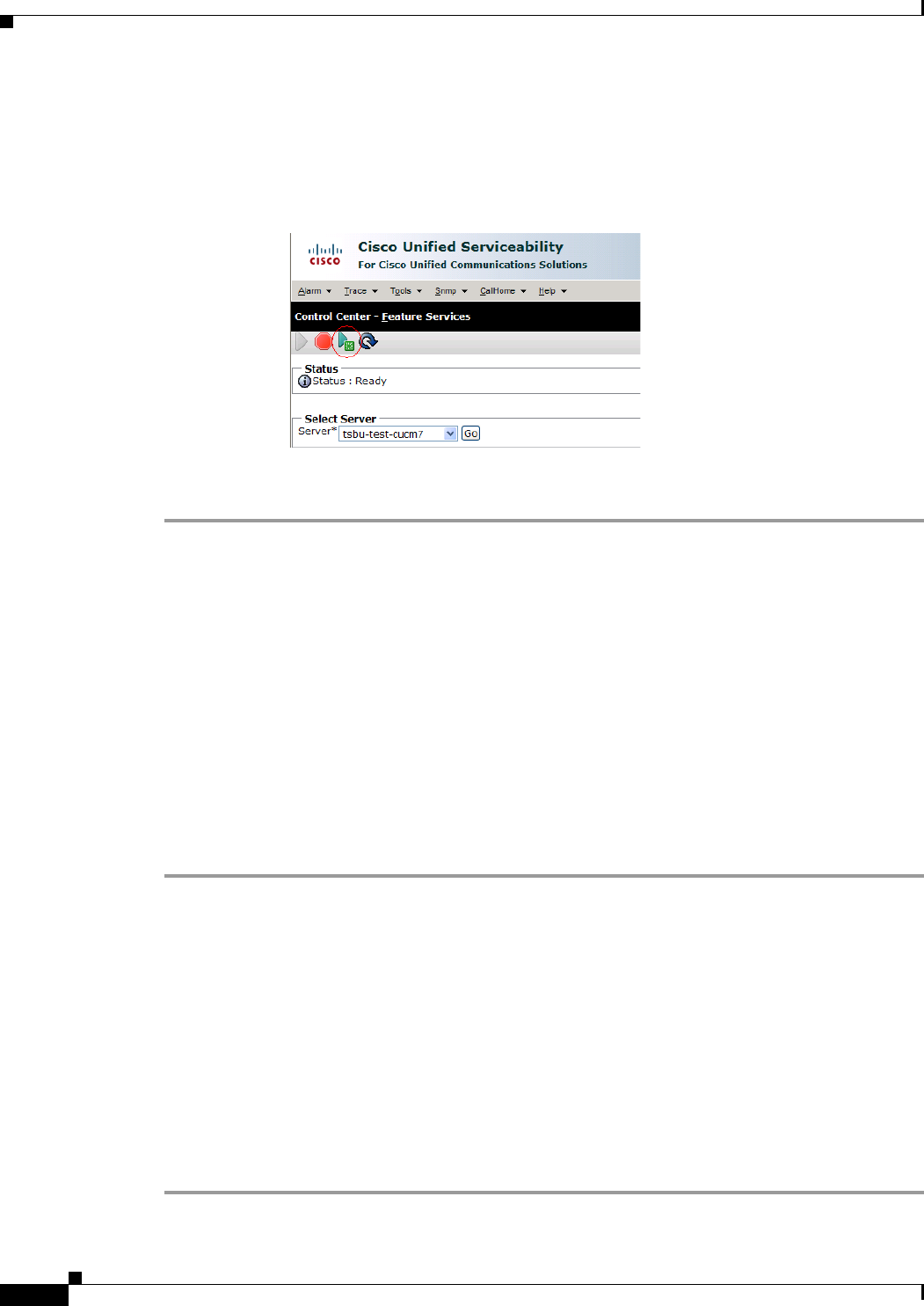
- Step 4 Navigate to Tools > Control Center—Feature Services.
- Step 5 Select the Unified CM server from the drop-down menu and click Go.
- Step 6 Scroll to the CM Services window and click the Cisco User Data Services radio button, as shown in Figure 3-30.
- Step 7 Click Restart to save your changes and start the service.
- Step 8 Proceed to Configuring the Search User Limit.
- Configuring the Search User Limit
- Step 1 From the Navigation drop-down menu on the top right of the Unified CM Administration interface, select Cisco Unified CM Administration and click Go.
- Step 2 The Cisco Unified CM Administration window appears, as shown in Figure 3-31.
- Step 3 Navigate to System > Enterprise Parameters.
- Step 4 Scroll to the User Search Parameters window.
- Step 5 Enter 500 in the User Search Limit field, as shown in Figure 3-32.
- Step 6 Click Save to save your changes.
- Step 7 Click Apply Config to apply your changes.
- Enabling User Data Services
- Setting the Idle Display Default (“Home”) Screen
- Step 1 Navigate to the user device by going to Device > Phone.
- Step 2 Scroll to the User Preferences window.
- Step 3 In the Idle Display field, choose one of the following options from the drop-down menu:
- Step 4 Optional. Check the box at the top of the User Preferences window to allow the user to change preferences, as shown in Figure 3-33.
- Step 5 Click Apply Config then click Save.
- Related Information
- Contents
- Troubleshooting Your Configuration
- Before You Begin
- Testing Your Unified CM Server
- Step 1 Log in to the Admin CLI with Secure Shell (SSH).
- Step 2 Enter the command utils network ping {X}, where X is the IP address or DNS name of the Unified CM server. If the command results in a 0% packet loss, the network is functioning properly. If there is any packet loss, check your network for errors.
- Managing Passwords
- Resetting Your Unified CM Secure Shell Password
- Step 1 Log into the Cisco Unified CM Administration interface.
- Step 2 Navigate to Device > Phone. The Find and List Phones window appears.
- Step 3 To locate a specific phone, enter search criteria and click Find.
- Step 4 Click on the hyperlink under Device Name, and scroll down to the Product Specific Configuration Layout Area.
- Step 5 Scroll down to the SSH Information Area.
- Step 6 Change your password using the following guidelines:
- Step 7 Under SSH admin Life, enter a number between 0 and 365. This will dictate the time parameter of your password:
- Step 8 Save your changes by clicking Restart. This enables the updated configuration to be read and applied to the system; and then Calling Service is restarted. Alternately you can click Reset, which causes the system to reboot. On startup, the syst...
- Resetting Your CTS Codec Password
- Resetting Your Unified CM Secure Shell Password
- Managing Phone Reset and Codec Connectivity
- Resetting a Cisco TelePresence System
- Synchronizing a Cisco TelePresence System
- Procedure
- Step 1 Choose Device > Phone. The Find and List Phones window appears.
- Step 2 Choose the search criteria to use and Click Find. The window displays a list of phones that match the search criteria.
- Step 3 Check the check boxes next to the phones that you want to synchronize. To choose all phones in the window, check the check box in the matching records title bar.
- Step 4 Click Apply Config to Selected. The Apply Configuration Information dialog displays.
- Step 5 Click OK.
- Restoring Connectivity to the Codec
- Related Information
- Contents
- Important Notes
- Configuring the Cisco Unified IP Phone
- Adding a New Phone
- Step 1 Log in to the Cisco Unified CM Administration interface.
- Step 2 From the Device drop-down menu, choose Phone. The Find and List Phones Page appears.
- Step 3 Choose the type of Cisco Unified IP Phone you have (Cisco 7970, Cisco 7971, or Cisco 7975) from the Phone Type drop-down menu.
- Step 4 Click Next. The Phone Configuration window appears.
- Step 5 Choose SIP from the Select the Device Protocol drop-down menu.
- Step 6 Click Next. The Phone Configuration window is updated with the following configuration fields:
- Step 7 Proceed to “Managing Cisco Unified IP Phones” section on page 5-3 to configure the fields found in the Phone Configuration window.
- Managing Cisco Unified IP Phones
- Before You Begin
- Step 1 Log in to the Cisco Unified CM Administration interface.
- Step 2 From the Device drop-down menu, choose Phone. The Find and List Phones Page appears.
- Step 3 Search for a phone using the fields provided or choose a phone from the drop-down menu.
- Step 4 Click Find. A list of devices appears.
- Step 5 Click on a device in the Device Name (Line) column. The Phone Configuration page for that device appears.
- Step 6 In the Phone Type box, verify the following requirements:
- Step 7 Enter information in the following sections found on the Phone Configuration page to configure the Cisco IP Phone 7970 Series:
- Device Information
- Protocol Specific Information
- Certification Authority Proxy Function (CAPF) Information
- Expansion Module Information
- External Data Locations Information
- Extension Information
- MLPP Information
- Do Not Disturb
- Secure Shell Information
- Product Specific Configuration Layout
- Adding a New Phone
- Configuring MIDlets
- Before You Begin
- Procedure
- Creating MIDlets IP Phone Service in Unified CM
- Step 1 Log in to the Cisco Unified CM Administration interface.
- Step 2 From the Navigation drop-down menu in the upper right corner, choose Cisco Unified CM Administration and click Go.
- Step 3 From the Device drop-down menu, go to Device Settings and click on Phone Services. The Find and List IP Phone Services window appears.
- Step 4 Click the Add New button. The IP Phone Services Configuration screen appears.
- Step 5 Fill in the following fields:
- Step 6 Click the Enable check box.
- Step 7 Click Save to save your changes.
- Configuring the MIDlets IP Phone Interface
- Step 1 Log in to the Cisco Unified CM Administration interface.
- Step 2 From the Navigation drop-down menu in the upper right corner, choose Cisco Unified CM Administration and click Go.
- Step 3 From the Device drop-down menu, choose Phone. The Find and List Phones Page appears.
- Step 4 Search for a phone using the fields provided or choose a phone from the drop-down menu and click Find. A list of devices appears.
- Step 5 Click on a device in the Device Name (Line) column. The Phone Configuration page for that device appears.
- Step 6 From the Related Links drop-down menu in the upper right corner, choose Subscribe/Unsubscribe Services and then click Go. The Subscribed Cisco IP Phone Services window for that device appears.
- Step 7 In the Service Information box, choose MIDlet IP phone service from the Select a Service drop-down list and click Next. The Subscribed Cisco IP Phone Services window is updated with configurable Service Name and ASCII Service Name fields.
- Step 8 Click Subscribe to save your settings or Back to return to the original Subscribed Cisco IP Phone Services window.
- Step 9 Click Save to save your settings.
- Setting Phone URL Parameters for MIDlets
- MIDlets Troubleshooting Tips
- Assigning a Directory Number for the Shared-Line Cisco Unified IP Phone
- Adding a New Directory Number
- Step 1 Log in to the Cisco Unified CM Administration interface.
- Step 2 From the Device drop-down menu, choose Phone. The Find and List Phones Page appears.
- Step 3 Locate and click the highlighted Cisco Unified IP phone device that you created in the “Adding a Cisco TelePresence Image to the Cisco Unified Communications Manager Server” section on page 1-1. The Association Information window appears.
- Step 4 In the Association Information window, click Line [1] - Add a new DN. The Directory Number Configuration window appears.
- Step 5 Proceed to the “Configuring the Directory Number for a Shared Line” section on page 5-22 to configure the directory number for a shared line in the Directory Number Configuration window.
- Configuring the Directory Number for a Shared Line
- Configuring Directory Number Information
- Enabling Auto Answer Option
- Call Forward and Call Pickup Settings
- MLPP Information
- Line X on Device X
- Multiple Call/Call Waiting Settings on Device X
- Forwarded Call Information Display on Device X
- Adding a New Directory Number
- Verifying and Troubleshooting IP Phone Configuration
- Verifying Your Configuration
- Step 1 Log in to the Cisco Unified CM Administration interface.
- Step 2 From the Device drop-down menu, choose Phone. The Find and List Phones Page appears.
- Step 3 Search for a phone using the fields provided or choose a phone from the drop-down menu.
- Step 4 Click Find. A list of devices appears.
- Step 5 Click on a device in the Device Name (Line) column. The Phone Configuration page for that device appears.
- Step 6 Verify that the following devices are registered:
- Troubleshooting Your IP Phone Configuration
- Managing Phone Reset and Codec Connectivity
- Information About Phone Reset
- Resetting the Cisco Unified IP Phone 7970 Series
- Step 1 Choose Device > Phone. The Find and List Phones window appears.
- Step 2 To locate a specific phone, enter search criteria and click Find. A list of phones that match the search criteria displays.
- Step 3 Click the check boxes next to the phones that you want to reset. To choose all the phones in the window, click Select All.
- Step 4 Click Reset Selected. The Device Reset window appears.
- Step 5 Choose Reset from the listed options in the Device Reset window.
- Synchronizing a Phone
- Procedure
- Step 1 Choose Device > Phone. The Find and List Phones window appears.
- Step 2 Choose the search criteria to use and Click Find. The window displays a list of phones that match the search criteria.
- Step 3 Check the check boxes next to the phones that you want to synchronize. To choose all phones in the window, check the check box in the matching records title bar.
- Step 4 Click Apply Config to Selected. The Apply Configuration Information dialog displays.
- Step 5 Click OK.
- Resetting the Cisco Unified IP Phone 7970 Series Factory Image
- Step 1 Disconnect the power from the phone.
- Step 2 While holding down the “#” key, reconnect the power.
- Step 3 As soon as you see the line button lights to the right side of the display cycling yellow, release the “#” key.
- Step 4 Press the following buttons in sequence: 3, 4, 9, 1, 6, 7, 2, 8, 5, 0, *, #.
- Verifying Your Configuration
- Contents
- Cisco TelePresence over Satellite Networks
- Ordering a Satellite License
- Loading a Satellite License on Unified CM
- Identifying the CTS Satellite Endpoints
- Step 1 Log in to the Cisco Unified CM Administration interface.
- Step 2 From the Device drop-down menu, choose Phone.
- Step 3 Using the Find search fields, locate the CTS that will be used as a satellite endpoint.
- Step 4 Click Reset to bring up a new dialog box, and then click Restart.
- Step 5 Repeat Step 2 through Step 4 for each CTS satellite endpoint.
- Enabling the Satellite Feature
- Additional Licensing Information
- Index

Cisco Systems, Inc.
www.cisco.com
Cisco has more than 200 offices worldwide.
Addresses, phone numbers, and fax numbers
are listed on the Cisco website at
www.cisco.com/go/offices.
Cisco Unified Communications Manager
Configuration Guide for the
Cisco TelePresence System
February 2013
Text Part Number: OL-21851-01
THE SPECIFICATIONS AND INFORMATION REGARDING THE PRODUCTS IN THIS MANUAL ARE SUBJECT TO CHANGE WITHOUT NOTICE. ALL
STATEMENTS, INFORMATION, AND RECOMMENDATIONS IN THIS MANUAL ARE BELIEVED TO BE ACCURATE BUT ARE PRESENTED WITHOUT
WARRANTY OF ANY KIND, EXPRESS OR IMPLIED. USERS MUST TAKE FULL RESPONSIBILITY FOR THEIR APPLICATION OF ANY PRODUCTS.
THE SOFTWARE LICENSE AND LIMITED WARRANTY FOR THE ACCOMPANYING PRODUCT ARE SET FORTH IN THE INFORMATION PACKET THAT
SHIPPED WITH THE PRODUCT AND ARE INCORPORATED HEREIN BY THIS REFERENCE. IF YOU ARE UNABLE TO LOCATE THE SOFTWARE LICENSE
OR LIMITED WARRANTY, CONTACT YOUR CISCO REPRESENTATIVE FOR A COPY.
The Cisco implementation of TCP header compression is an adaptation of a program developed by the University of California, Berkeley (UCB) as part of UCB’s public
domain version of the UNIX operating system. All rights reserved. Copyright © 1981, Regents of the University of California.
NOTWITHSTANDING ANY OTHER WARRANTY HEREIN, ALL DOCUMENT FILES AND SOFTWARE OF THESE SUPPLIERS ARE PROVIDED “AS IS” WITH
ALL FAULTS. CISCO AND THE ABOVE-NAMED SUPPLIERS DISCLAIM ALL WARRANTIES, EXPRESSED OR IMPLIED, INCLUDING, WITHOUT
LIMITATION, THOSE OF MERCHANTABILITY, FITNESS FOR A PARTICULAR PURPOSE AND NONINFRINGEMENT OR ARISING FROM A COURSE OF
DEALING, USAGE, OR TRADE PRACTICE.
IN NO EVENT SHALL CISCO OR ITS SUPPLIERS BE LIABLE FOR ANY INDIRECT, SPECIAL, CONSEQUENTIAL, OR INCIDENTAL DAMAGES, INCLUDING,
WITHOUT LIMITATION, LOST PROFITS OR LOSS OR DAMAGE TO DATA ARISING OUT OF THE USE OR INABILITY TO USE THIS MANUAL, EVEN IF CISCO
OR ITS SUPPLIERS HAVE BEEN ADVISED OF THE POSSIBILITY OF SUCH DAMAGES.
Cisco and the Cisco logo are trademarks or registered trademarks of Cisco and/or its affiliates in the U.S. and other countries. To view a list of Cisco trademarks, go to this
URL: www.cisco.com/go/trademarks. Third-party trademarks mentioned are the property of their respective owners. The use of the word partner does not imply a partnership
relationship between Cisco and any other company. (1110R)
Any Internet Protocol (IP) addresses and phone numbers used in this document are not intended to be actual addresses and phone numbers. Any examples, command display
output, network topology diagrams, and other figures included in the document are shown for illustrative purposes only. Any use of actual IP addresses or phone numbers in
illustrative content is unintentional and coincidental.
Cisco Unified Communications Manager Configuration Guide for the Cisco TelePresence System
© 2014 Cisco Systems, Inc. All rights reserved.

iii
Cisco Unified Communications Manager Configuration Guide for the Cisco TelePresence System
OL-21851-01
CONTENTS
What’s in This Guide ix
Contents i-ix
How to Use This Guide ix
Before You Begin x
Web Browser Support x
CTS Software Download x
DHCP Connectivity xi
COP (Loads) File Download xi
Call Control Device Requirements xi
MAC Address xii
Unified Communications Manager and MIDlets Download xii
Additional System Information xiii
Adding or Removing a Presentation Codec xiii
Call Control Device Features for Cisco TelePresence xiii
Software Compatibility xiii
Cisco TelePresence Bandwidth Requirements xiii
Device and Cluster Security Modes xiv
Supported Unified CM Characters and Digits for the CTS Device Page xiv
Document Organization xiv
Related Documentation xv
Obtaining Documentation and Submitting a Service Request xvii
CHAPTER
1Configuring Cisco Unified Communications Manager for the Cisco TelePresence System 1-1
Contents 1-1
Adding a Cisco TelePresence Image to the Cisco Unified Communications Manager Server 1-1
Downloading the Cisco TelePresence Software 1-1
Installing the Cisco TelePresence COP File to the Unified CM Server 1-3
Configuring Phone Security Profile Information 1-8
Adding a New Phone Security Profile for CTS 1-8
Configuring the Phone Security Profile 1-9
SIP Phone Security Profile Information 1-9
Phone Security Profile CAPF Information 1-11
Parameters Used in Phone Field 1-11

Contents
iv
Cisco Unified Communications Manager Configuration Guide for the Cisco TelePresence System
OL-21851-01
Adding a Cisco TelePresence Device to the Unified CM Server 1-12
Using the Unified CM GUI to Add a Cisco TelePresence Device 1-12
Device Information Area 1-13
Protocol-Specific Information Area 1-15
Certification Authority Proxy Function (CAPF) Information Area 1-16
MLPP Information Area 1-17
Product Specific Configuration Layout Area 1-17
User Preferences Area 1-20
Optional Hardware 1-22
Auxiliary Control Unit 1-22
Dial Plan Area 1-23
Directory Number Area 1-23
Global Location Area 1-24
SSH Information Area 1-25
External CTS Log Destination Area 1-28
SNMP Configuration Parameters Area 1-30
SNMP Trap Receiver Parameters Area 1-31
Managing SNMP MIBs and SNMP Traps 1-33
Saving Your Settings 1-33
Configuring the Directory Number for the Cisco TelePresence Device 1-33
Directory Number Information 1-33
Directory Number Settings 1-34
AAR Settings 1-35
Call Forward and Call Pickup Settings 1-36
MLPP Alternate Party Settings 1-37
Line Settings for All Devices 1-37
Line X on Device X 1-37
Multiple Call/Call Waiting Settings on Device SEPXXXXXXXXXXXX 1-38
Forwarded Call Information Display on Device SEPXXXXXXXXXXXX 1-39
Where to Go Next 1-39
CHAPTER
2Configuring Cisco TelePresence Features 2-1
Contents 2-1
Managing the Speed-Dial Directory (Favorites) 2-1
Adding Speed-Dial Numbers (Favorites) from the Unified CM Administration Page 2-1
Adding Speed-Dial Numbers (Favorites) from the User Options Page 2-3
Enabling the Directory Feature 2-6
Configuring a Corporate Directory 2-6
Configuring the BFCP over UDP Collaboration Feature 2-9

Contents
v
Cisco Unified Communications Manager Configuration Guide for the Cisco TelePresence System
OL-21851-01
Configuring the VCS Zone 2-9
Configuring BFCP For Your Cisco TelePresence Device 2-11
Adding a New BFCP Profile 2-11
Configuring the Unified CM Trunk 2-11
T1 Support Extended Reach 2-12
Quality Per Display - 720p (Lite) 2-13
Self View Control 2-13
Self View Control Feature Behavior 2-14
Shroud Lights 2-14
Answering Calls 2-14
Dismissing Calls 2-14
Related Self View Feature Information 2-14
Conference Control Protocol (CCP) VPN Security Solution 2-14
Related CCP VPN Feature Information 2-15
Single Microphone Mute 2-15
Watermark Removal 2-16
Screen Dimming 2-16
Installing Language Versions 2-17
Understanding Locale Pack File Types and Naming Conventions 2-18
Installing Locale Installers for the Unified CM Server 2-19
Installing Locale Packs for the CTS or TX System and Touch 12 Device 2-19
Configuring User Interface Language, Ringtones and Date and Time 2-20
Related Information 2-21
CHAPTER
3Loading Cisco Options Package (COP) Files on the Cisco TelePresence System 3-1
Contents 3-1
Understanding COP Files 3-1
Distinguishing Between the Cisco TelePresence Touch 12 and the Cisco Unified IP Phone in
Unified CM 3-2
Understanding COP File Naming Convention 3-2
Understanding Contents of the COP File 3-3
Using COP Files to Upgrade From the IP Phone to a Cisco TelePresence Touch 12 3-3
Determining the Type of Codec Used by Your System 3-3
Kit and Parts List 3-5
Upgrading From Cisco TelePresence Software Releases 1.7.4 and Above 3-5
Upgrading From Cisco TelePresence Software Releases Prior to CTS 1.7.4 3-12
Connecting the Cisco TelePresence Touch 12 to the System 3-20
Configuring the Directory on the Cisco TelePresence Touch 12 3-22

Contents
vi
Cisco Unified Communications Manager Configuration Guide for the Cisco TelePresence System
OL-21851-01
Enabling User Data Services 3-23
Configuring the Search User Limit 3-23
Setting the Idle Display Default (“Home”) Screen 3-24
Related Information 3-25
CHAPTER
4Verifying and Troubleshooting the Cisco TelePresence System Configuration 4-1
Contents 4-1
Troubleshooting Your Configuration 4-1
Managing Passwords 4-4
Resetting Your Unified CM Secure Shell Password 4-5
Resetting Your CTS Codec Password 4-5
Managing Phone Reset and Codec Connectivity 4-7
Resetting a Cisco TelePresence System 4-7
Synchronizing a Cisco TelePresence System 4-7
Restoring Connectivity to the Codec 4-8
Related Information 4-8
CHAPTER
5Configuring and Managing the Cisco Unified IP Phone 5-1
Contents 5-1
Important Notes 5-1
Configuring the Cisco Unified IP Phone 5-2
Adding a New Phone 5-2
Managing Cisco Unified IP Phones 5-3
Device Information 5-3
Protocol Specific Information 5-7
Certification Authority Proxy Function (CAPF) Information 5-7
Expansion Module Information 5-8
External Data Locations Information 5-8
Extension Information 5-9
MLPP Information 5-10
Do Not Disturb 5-10
Secure Shell Information 5-10
Product Specific Configuration Layout 5-10
Configuring MIDlets 5-18
Creating MIDlets IP Phone Service in Unified CM 5-19
Configuring the MIDlets IP Phone Interface 5-20
Setting Phone URL Parameters for MIDlets 5-20
MIDlets Troubleshooting Tips 5-21

Contents
vii
Cisco Unified Communications Manager Configuration Guide for the Cisco TelePresence System
OL-21851-01
Assigning a Directory Number for the Shared-Line Cisco Unified IP Phone 5-22
Adding a New Directory Number 5-22
Configuring the Directory Number for a Shared Line 5-22
Configuring Directory Number Information 5-23
Enabling Auto Answer Option 5-23
Call Forward and Call Pickup Settings 5-23
MLPP Information 5-24
Line X on Device X5-24
Multiple Call/Call Waiting Settings on Device X5-24
Forwarded Call Information Display on Device X5-24
Verifying and Troubleshooting IP Phone Configuration 5-24
Verifying Your Configuration 5-24
Troubleshooting Your IP Phone Configuration 5-25
Managing Phone Reset and Codec Connectivity 5-27
Information About Phone Reset 5-28
Resetting the Cisco Unified IP Phone 7970 Series 5-28
Synchronizing a Phone 5-28
Resetting the Cisco Unified IP Phone 7970 Series Factory Image 5-29
CHAPTER
ASatellite Licenses for the Cisco TelePresence System A-1
Contents A-1
Cisco TelePresence over Satellite Networks A-1
Supported CTS Devices A-2
Supported CTS Software A-2
Supported Satellite Bandwidth A-2
Satellite Security A-2
Ordering a Satellite License A-3
Loading a Satellite License on Unified CM A-3
Identifying the CTS Satellite Endpoints A-4
Enabling the Satellite Feature A-4
Additional Licensing Information A-4
G
LOSSARY
I
NDEX

Contents
viii
Cisco Unified Communications Manager Configuration Guide for the Cisco TelePresence System
OL-21851-01

ix
Cisco Unified Communications Manager Configuration Guide for the Cisco TelePresence System
OL-21851-01
What’s in This Guide
Revised: June 9, 2015, OL-21851-01
Contents
This preface contains the following sections:
•How to Use This Guide, page ix
•Before You Begin, page x
•Additional System Information, page xiii
•Document Organization, page xiv
•Related Documentation, page xv
•Obtaining Documentation and Submitting a Service Request, page xvii
How to Use This Guide
The Cisco Unified Communications Manager Configuration Guide for the Cisco TelePresence System
provides information to help you use the Cisco Unified Communications Manager (Unified CM)
Administration interface to configure the following Cisco TelePresence System (CTS) products:
•TelePresence Immersive Endpoints
–
Cisco TelePresence System TX9200 Series
–
Cisco TelePresence System TX9000 Series
–
Cisco TelePresence System 3200 Series
–
Cisco TelePresence System 3000 Series
–
Cisco TelePresence System TX1300 Series
–
Cisco TelePresence System 1300 Series
•TelePresence Personal Endpoints > TelePresence Office
–
Cisco TelePresence System 1100
–
Cisco TelePresence System 1000
–
Cisco TelePresence System 500 Series

x
Cisco Unified Communications Manager Configuration Guide for the Cisco TelePresence System
OL-21851-01
Contents
Note The entries that are recommended or required in the configuration fields in this guide are for configuring
the Unified CM for Cisco TelePresence specifically. While some configuration fields in the
administration interface offer a variety of choices, Cisco recommends that you follow the guidelines
presented in this document to set up your Cisco TelePresence configuration successfully.
Before You Begin
Before beginning the tasks in this guide, verify the following:
•Web Browser Support, page x
•CTS Software Download, page x
•DHCP Connectivity, page xi
•COP (Loads) File Download, page xi
•Call Control Device Requirements, page xi
•MAC Address, page xii
•Unified Communications Manager and MIDlets Download, page xii
Web Browser Support
Cisco administration interfaces are supported on Internet Explorer (IE) versions 6, 7, 8 and 9 and Firefox
version 3.6, 5 and 9.
CTS Software Download
Make sure you have downloaded supported CTS software. Navigate to your CTS device on Cisco.com.
1. Navigate to your device:
•Product Support > TelePresence > TelePresence Immersive Endpoints
–
Cisco TelePresence System TX9200 Series
–
Cisco TelePresence System TX9000 Series
–
Cisco TelePresence System 3200 Series
–
Cisco TelePresence System 3000 Series
–
Cisco TelePresence System TX1300 Series
–
Cisco TelePresence System 1300 Series
•Products > TelePresence > TelePresence Personal Endpoints > TelePresence Office
–
Cisco TelePresence System 1100
–
Cisco TelePresence System 1000
–
Cisco TelePresence System 500 Series
For example:

xi
Cisco Unified Communications Manager Configuration Guide for the Cisco TelePresence System
OL-21851-01
Contents
Products > TelePresence > TelePresence Endpoints - Immersive > Cisco TelePresence TX9200
Series > Cisco TelePresence TX9200 > TelePresence Software-1.9.3(44)
2. Select software and choose whether to download now or add it to your cart.
DHCP Connectivity
Provide a Dynamic Host Configuration Protocol (DHCP) server to achieve connectivity. CTS uses
DHCP by default. If no DHCP server is available, refer to your system assembly guide’s First Time Setup
chapter, in the section that instructs how to use a static IP network address.
•For CTS 500-32, 1300-47, 1310-65, and TX9x00 systems: Refer to your system assembly guide’s
First Time Setup chapter.
•For CTS 500-37, 1x00, 1300-65, 30x0, and 32x0 systems: Refer to Configuring a Static IP Address
for Networks That Do Not Use DHCP.
COP (Loads) File Download
The Cisco Options Package (COP) file is a mechanism for installing files on a Unified CM in a secure
manner. See Chapter 3, “Loading Cisco Options Package (COP) Files on the Cisco TelePresence
System” for complete information.
Call Control Device Requirements
All new Cisco TelePresence Systems which use the Cisco TelePresence Touch 12 for call control take 6
units of the Unified CM unit license:
•0 units for the Cisco TelePresence Touch device
•6 units for the Cisco TelePresence unit
All existing Cisco TelePresence Systems which use the IP Phone for call control take 11 units of the
Unified CM unit license:
•5 units for the Cisco Unified IP Phone 7970/7975
•6 units for the Cisco TelePresence unit
You can configure the system and the Cisco Unified IP Phone as a shared line in Cisco Unified CM.
Note When using the IP Phone, please note the following:
For all SCCP and SIP firmware upgrades from firmware release versions earlier than 8.3(3) to version
8.5(3) or a later release, you must first upgrade your firmware to version 8.5(2). Once you have upgraded
to version 8.5(2), you can upgrade your Cisco Unified IP Phone to version 8.5(3) or a later release.
See the Installation Notes section of the Cisco Unified IP Phone Release Notes for Firmware Release
8.5(3) (SCCP and SIP) for download instructions.

xii
Cisco Unified Communications Manager Configuration Guide for the Cisco TelePresence System
OL-21851-01
Contents
MAC Address
Make sure the MAC address of the device you are installing is known or available:
•The MAC address comprises a unique 12-character hexadecimal number that identifies a
Cisco Unified IP phone or other hardware device.
•Locate the MAC address number on a label on the back of the Cisco TelePresence system primary
codec (for example, 000B6A409C405). Unified CM makes the MAC address a required field for
Cisco Unified IP phone device configuration.
The MAC address is also displayed on the CTS main display screen during boot-up.
Note When entering the MAC address in Unified CM fields, do not use spaces or dashes, and do not
include any other characters that may precede the MAC address on the label.
Unified Communications Manager and MIDlets Download
Note This section pertains only to systems that uses a Cisco Unified IP phone for call control. If your system
uses a Cisco Touch device for call control, skip this section.
Make sure that Unified CM is running and is using supported software for your release. For complete
Cisco TelePresence software compatibility information, see the software support matrix on the
Cisco TelePresence Administration Software page at the following URL:
http://www.cisco.com/en/US/products/ps8332/products_device_support_tables_list.html
You must download and configure MIDlets to enable all available features on your CTS Cisco Unified
IP phone. The supported MIDlet version is embedded in the software files that are available when you
click Download Software on the Cisco Unified Communications Manager Support page at the following
URL:
http://www.cisco.com/en/US/products/sw/voicesw/ps556/tsd_products_support_series_home.html
Or navigate to Products > Voice and Unified Communications > IP Telephony > Call Control >
Cisco Unified Communications Manager (CallManager) > Cisco Unified Communications
Manager Version x.x > Unified Communications Manager/CallManager Device Packages.
Check the following:
•The Cisco TelePresence device name in Unified CM follows the following format: The characters
“SEP” followed by the device MAC address. Assign the hostname so that it is resolvable by
Domain Name System (DNS), for example:”
MAC address: “ 000DD12345A1 ”
Cisco TelePresence Host Name: “ SEP000DD12345A1 ”
Note DNS (domain) is optional.

xiii
Cisco Unified Communications Manager Configuration Guide for the Cisco TelePresence System
OL-21851-01
Contents
Additional System Information
For more information, see the following sections:
•Adding or Removing a Presentation Codec, page xiii
•Call Control Device Features for Cisco TelePresence, page xiii
•Software Compatibility, page xiii
•Cisco TelePresence Bandwidth Requirements, page xiii
•Device and Cluster Security Modes, page xiv
•Supported Unified CM Characters and Digits for the CTS Device Page, page xiv
•Document Organization, page xiv
Adding or Removing a Presentation Codec
When you add or remove a CTS presentation codec in the system configuration, you must also do so
from the Unified CM administration interface. After the configuration change is complete, click Reset
to sync this configuration change with the CTS codec.
Call Control Device Features for Cisco TelePresence
There are additional features that can be configured on standard Cisco TelePresence call control devices.
The settings described in this document are provided specifically to configure a Touch 12 as a
Cisco TelePresence device.
For complete Cisco TelePresence user options on the Touch 12, refer to the Cisco TelePresence System
User Guide on cisco.com that corresponds with your system’s software release.
Many of the settings also apply to the Cisco Unified IP Phone call control device. See Chapter 5,
“Configuring and Managing the Cisco Unified IP Phone” for specifics.
Note Features that are not mentioned in this or other guides are assumed to be un-supported at this time.
Software Compatibility
For complete information about software and firmware compatibility for the CTS, see the
Cisco TelePresence Administration Software Compatibility Matrix on Cisco.com.
Cisco TelePresence Bandwidth Requirements
For information about Cisco TelePresence service level requirements including bandwidth, latency
(delay), jitter (variations in delay), and packet loss, see the “Understanding How Endpoints Determine
fps and Video Quality” section of the Administration Guide for Cisco TelePresence TX Software Release
6.0 on Cisco.com.

xiv
Cisco Unified Communications Manager Configuration Guide for the Cisco TelePresence System
OL-21851-01
Contents
Device and Cluster Security Modes
During a call, the Media is Encrypted icon (closed lock) is displayed on the screen only when the Device
Security mode is set to encrypted and cluster security mode is set to 1 (mixed mode). While configuring
your system, check the following settings:
•Device Security Mode should be set to Encrypted in the SIP Phone Security Profile Information
field. See the “SIP Phone Security Profile Information” section on page 9 for configuration
information.
•Cluster Security Mode field is set to 1 (mixed mode) in the Configuration Settings for CTL Client
in Cisco Unified CM Administration > System > Enterprise Parameters. To configure and verify
cluster security mode, see the Verifying the Cisco Unified Communications Manager Security Mode
section of the Cisco TelePresence Security Solutions Guide.
Supported Unified CM Characters and Digits for the CTS Device Page
Use the information in Table 1 as a guide for supported Unified CM characters and digits that are used
to configure and maintain the Cisco TelePresence system. For general Unified CM support
documentation, see the Unified CM documentation roadmaps for your release on Cisco.com:
http://www.cisco.com/en/US/products/sw/voicesw/ps556/products_documentation_roadmaps_list.html
Note Unified CM no longer the ‘$’ (currency symbol) in system passwords.
Document Organization
Information for using the Unified CM with the Cisco TelePresence System application are provided in
the following chapters:
•Chapter 1, “Configuring Cisco Unified Communications Manager for the Cisco TelePresence
System”
•Chapter 2, “Configuring Cisco TelePresence Features”
•Chapter 3, “Loading Cisco Options Package (COP) Files on the Cisco TelePresence System”
•Chapter 4, “Verifying and Troubleshooting the Cisco TelePresence System Configuration”
Table 1 Supported Unified CM Characters and Digits for Cisco TelePresence Device Configurations
Character or Digit Description Where Used
•Digits 0 through 9
•* (Asterisk)
•# (Number sign or hash)
•+ (Plus sign, escape
symbol)
The number that you want the system to dial
when the user presses the speed-dial button.
Note The speed-dial function does not
allow you to configure pauses or
waits.
•Speed Dial and Abbreviated Dial
Configuration window, Number field.
•Multilevel precedence and preemption
MLPP Alternate Party Settings, Target
(Destination) field.
See Chapter 1, “Configuring Cisco Unified
Communications Manager for the
Cisco TelePresence System.”

xv
Cisco Unified Communications Manager Configuration Guide for the Cisco TelePresence System
OL-21851-01
Contents
•Chapter 5, “Configuring and Managing the Cisco Unified IP Phone”
•Appendix A, “Satellite Licenses for the Cisco TelePresence System”
•“Glossary”
•“Index”
Related Documentation
Related Topic Document Title
Cisco command-line interface (CLI) information
for configuring the Cisco TelePresence System.
•Cisco TelePresence System Command-Line Interface Reference
Guide.
Cisco Jabber Video for TelePresence (previously
called Movi) home page.
•Cisco Jabber Video for TelePresence
Cisco Multipoint Control Unit (MCU) 4500 Series
home page.
•Cisco TelePresence MCU 4500 Series
Cisco switch support information. •Product Support > Switches
Cisco TelePresence support information. •Product Support > TelePresence (Video Conferencing)
Cisco TelePresence administration software
download page.
•Download Software Select a Product page on Cisco.com:
http://www.cisco.com/cisco/software/navigator.html
Cisco TelePresence Manager documentation
home page.
•Cisco TelePresence Manager home page on Cisco.com
Cisco TelePresence Recording Server
information.
•Cisco TelePresence Recording Server home page on Cisco.com
Cisco TelePresence System Codec home page. •Cisco Telepresence System Integrator C Series
Cisco TelePresence System compatibility
information.
•Software Compatibility Information for the Cisco TelePresence
System
Cisco TelePresence System EX Series home page. •Cisco TelePresence System EX Series
Cisco TelePresence System MXP Series home
page.
•Cisco TelePresence System MXP Series
Cisco TelePresence Video Communication Server
(VCS) home page.
•Cisco TelePresence Video Communication Server (VCS)
Cisco TelePresence Video Communication Server
(VCS) support documentation
•Cisco Unified Communications Manager with Cisco VCS
Cisco TelePresence Deployment Guide
•Cisco TelePresence Video Communication Server (VCS)
Cisco Unified Communications Manager Support
page.
•Cisco Unified Communications Manager Support
Cisco Unified IP Phone 8900 Series home page. •Cisco Unified IP Phone 8900 Series
Cisco Unified IP Phone 9900 Series home page. •Cisco Unified IP Phones 9900 Series
Cisco Unified IP Phone firmware download
instructions in the Installation Notes section.
• Cisco Unified IP Phone Release Notes for Firmware Release 8.5(3)
(SCCP and SIP)

xvi
Cisco Unified Communications Manager Configuration Guide for the Cisco TelePresence System
OL-21851-01
Contents
Cisco Unified IP Phones 7900 Series
documentation.
•Cisco Unified IP Phones 7900 Series Maintain and Operate Guides
Cisco Unified Mobility documentation. •Cisco Unified Mobility
Cisco Validated Design Program. Systems and
solutions designed, tested, and documented to
facilitate faster, more reliable, and more
predictable customer deployments.
•Cisco TelePresence Network Systems 2.0 Design Guide
Complete software and firmware compatibility. • Cisco TelePresence Administration Software Compatibility Matrix
Configuring CTS administration software
features.
•Cisco TelePresence System Administration Guide
CTS Administration and User Guides:
Configuration, maintenance, and monitoring tasks
using Cisco TelePresence administration
software.
•Products > TelePresence > TelePresence Immersive Endpoints >
TelePresence System > Cisco TelePresence Administration
Software
http://www.cisco.com/en/US/products/ps8332/tsd_products_
support_series_home.html
Documentation resources for administering the
Cisco Unified Communications Manager system.
•Cisco Unified Communications Manager Documentation Guide for
Release 8.0(1)
Features supported on the Touch 12 device. •Cisco TelePresence System User Guide
How to configure and manage security on the
Cisco TelePresence System.
•Cisco TelePresence Security Solutions Configuration Guide
How to configure Cisco WebEx OneTouch for
Cisco TelePresence.
• Cisco WebEx OneTouch for Cisco TelePresence Configuration
Guide
How to navigate to Cisco TelePresence System
(CTS) hardware and software documentation,
including information about CTS devices.
•Cisco.com
Products > TelePresence
Information about the Cisco TelePresence
Multipoint Switch (CTMS).
•Cisco TelePresence Multipoint Switch home page on Cisco.com
Install and use the Cisco TelePresence Touch 12. •Installing and Configuring the Cisco TelePresence Touch 12
•Cisco TelePresence Touch 12 User Guide
•Cisco TelePresence Touch 12 Meeting Quick Reference
Overview of the features available on your
Cisco IP Phone 7970 Series.
•Cisco Unified IP Phone 7970 Series Phone Guide for Cisco Unified
Communications Manager 7.0 (SCCP and SIP)
Reference and procedural guide for system and
phone administrators who plan to configure call
security features for Cisco Unified
Communications Manager.
•Cisco Unified Communications Manager Security Guide, Release
7.1(2)
Session Initiation Protocol (SIP) page. •Session Initiation Protocol (SIP)
Troubleshooting the CTS and Cisco Unified CM
Administration interfaces and related hardware
components.
• Cisco TelePresence System Troubleshooting Guide
Unified CM documentation types and locations. •Cisco Unified Communications Manager (CallManager)
Documentation Roadmaps
Unified CM install and upgrade guides. •Cisco Unified Communications Manager (CallManager) Install and
Upgrade Guides

xvii
Cisco Unified Communications Manager Configuration Guide for the Cisco TelePresence System
OL-21851-01
Contents
Obtaining Documentation and Submitting a Service Request
For information on obtaining documentation, submitting a service request, and gathering additional
information, see the monthly What’s New in Cisco Product Documentation, which also lists all new and
revised Cisco technical documentation, at the following URL:
http://www.cisco.com/en/US/docs/general/whatsnew/whatsnew.html
Subscribe to the What’s New in Cisco Product Documentation as a Really Simple Syndication (RSS) feed
and set content to be delivered directly to your desktop using a reader application. The RSS feeds are a free
service and Cisco currently RSS version 2.0.

xviii
Cisco Unified Communications Manager Configuration Guide for the Cisco TelePresence System
OL-21851-01
Contents

CHAPTER
1-1
Cisco Unified Communications Manager Configuration Guide for the Cisco TelePresence System
OL-21851-01
1
Configuring Cisco Unified Communications
Manager for the Cisco TelePresence System
Revised: June 9, 2015, OL-21851-01
Contents
This chapter explains how to download the Cisco TelePresence Administration Software from the
cisco.com web site and configure a new device using the Cisco Unified Communications Manager web
interface, and includes the following sections:
•Adding a Cisco TelePresence Image to the Cisco Unified Communications Manager Server,
page 1-1
•Configuring Phone Security Profile Information, page 1-8
•Adding a Cisco TelePresence Device to the Unified CM Server, page 1-12
•Configuring the Directory Number for the Cisco TelePresence Device, page 1-33
•Where to Go Next, page 1-39
Adding a Cisco TelePresence Image to the Cisco Unified
Communications Manager Server
This section describes the steps you take to add a new Cisco TelePresence Device to Cisco Unified
Communications Manager (Unified CM) and includes the following topics:
•Downloading the Cisco TelePresence Software, page 1-1
•Installing the Cisco TelePresence COP File to the Unified CM Server, page 1-3
Downloading the Cisco TelePresence Software
Note Complete these steps prior to using your Cisco TelePresence Touch 12 device.

1-2
Cisco Unified Communications Manager Configuration Guide for the Cisco TelePresence System
OL-21851-01
Chapter 1 Configuring Cisco Unified Communications Manager for the Cisco TelePresence System
Adding a Cisco TelePresence Image to the Cisco Unified Communications Manager Server
If you have not yet installed the Cisco TelePresence software onto the Unified CM server, complete the
following steps to add it:
Note If you already downloaded the software and added it to the Unified CM server, skip this section and
continue to the “Adding a Cisco TelePresence Device to the Unified CM Server” section on page 1-12
to add a new device to Unified CM.
Step 1 Navigate to www.cisco.com.
Step 2 Click on the Log In button, then enter your username and password.
Step 3 Click Support.
Step 4 Enter the following search term into the text box:
cisco telepresence administration software
Step 5 Click the Cisco TelePresence Administration Software hyperlink that displays.
Alternatively, you can click the Downloads tab and enter the name of your system into the text box.
Step 6 Click the Download Software hyperlink.
Step 7 Navigate to your product using the navigation tool that displays.
Step 8 Select the software that you require for your installation.
Systems that use a Cisco TelePresence Touch device for call control only require the Cisco TelePresence
System and Cisco TelePresence Touch file. Systems that use a Cisco Unified IP phone for call control
require the Cisco TelePresence System and the Cisco TelePresence Midlet Phone Application .jad and
.jar files.
Step 9 Choose the latest release and click either Add to Cart or Download.
a. If you choose Add to Cart, click on Download Cart.
b. If you choose Download, click Accept License Agreement.
Step 10 Click Download and then Accept License Agreement, and follow the prompts to download the file.
Note For systems that use a Cisco TelePresence Touch device, the software to run the Touch device is included
with the COP file. For systems that use a Cisco Unified IP phone for call control, the latest MIDlets
software version is included with the Unified CM device pack. For more information about the files for
systems that use a Cisco TelePresence Touch device, see the “Understanding COP Files” section on
page 1-1.
Step 11 Copy these files to a Secure File Transfer Protocol (SFTP) server that is accessible by Unified CM.
Step 12 Load the system image onto the Unified CM server by completing the following steps:
a. Open a supported web browser.
Note The Cisco Unified CM Administration program requires Internet Explorer version 6, 7, 8 or 9 or
Firefox version 3.6, 5 or 9.
b. In the address bar of the web browser, enter the following URL:
https://UCM-server-name
1-3
Cisco Unified Communications Manager Configuration Guide for the Cisco TelePresence System
OL-21851-01
Chapter 1 Configuring Cisco Unified Communications Manager for the Cisco TelePresence System
Adding a Cisco TelePresence Image to the Cisco Unified Communications Manager Server
Where
UCM-server-name
is the IP address or DNS name of the Cisco Unified Communications Manager server.
c. Upload the Cisco TelePresence system image to the Unified CM server by completing the steps in
theInstalling the Cisco TelePresence COP File to the Unified CM Server section that follows.
Installing the Cisco TelePresence COP File to the Unified CM Server
To install the Cisco TelePresence system files to the Unified CM server, complete the following steps.
Step 13 Log in to the Unified CM administrative GUI.
Step 14 From the Navigation drop-down list, on the top right of the GUI, select Cisco Unified OS
Administration. Click Go to go to the Cisco Unified CM Administration home page.
The Cisco Unified Operation System Administration screen displays.
Note Log in with your username and password if prompted to do so.
Step 15 Navigate to Software Upgrades > Install/Upgrade.
Figure 1-1 Cisco Unified Operating System Administration Screen
1-4
Cisco Unified Communications Manager Configuration Guide for the Cisco TelePresence System
OL-21851-01
Chapter 1 Configuring Cisco Unified Communications Manager for the Cisco TelePresence System
Adding a Cisco TelePresence Image to the Cisco Unified Communications Manager Server
Step 16 In the Software Location area, specify the following information in the fields:
•In the Source drop-down list, select Remote Filesystem.
•In the Directory field, enter the location of the file on the SFTP server.
•In the Server field, enter the server name or IP address.
•In the User Name and User Password fields, enter the user name and password used to access the
SFTP server.
•In the Transfer Protocol drop-down list, select SFTP.
Figure 1-2 Specifying SFTP Server and File Location
Step 17 Click Next.
Unified CM accesses the SFTP server. The Software Location area lists the COP files that Unified CM
finds in the directory that you specified.
1-5
Cisco Unified Communications Manager Configuration Guide for the Cisco TelePresence System
OL-21851-01
Chapter 1 Configuring Cisco Unified Communications Manager for the Cisco TelePresence System
Adding a Cisco TelePresence Image to the Cisco Unified Communications Manager Server
Step 18 Choose the COP file that you want to install from the available file names in the Options/Upgrades
drop-down list.
Figure 1-3 Specifying the COP File
Step 19 Click Next.
The Unified CM GUI shows the COP file being installed.
Figure 1-4 COP File Installation
1-6
Cisco Unified Communications Manager Configuration Guide for the Cisco TelePresence System
OL-21851-01
Chapter 1 Configuring Cisco Unified Communications Manager for the Cisco TelePresence System
Adding a Cisco TelePresence Image to the Cisco Unified Communications Manager Server
Step 20 After installation completes, verify the file validity by completing the following steps:
a. Make a note of the information in the File Checksum Details area. This value is shown in Figure 1-5.
b. Log in to the SFTP server and enter the following command:
c. md5sum filename.cop.sgn
where:
filename is the file name of the COP file on the SFTP server.
d. Make a note of the checksum value that displays as a result of the md5sum command.
e. Compare the MD5 Hash Value that displays in this area to the MD5 checksum value that you find
in the COP file on the server and make sure that they match to ensure that the file is not corrupted.
f. If the values match, continue to the next step; if the values do not match, retry the file installation.
Figure 1-5 File Checksum Details Area
1-7
Cisco Unified Communications Manager Configuration Guide for the Cisco TelePresence System
OL-21851-01
Chapter 1 Configuring Cisco Unified Communications Manager for the Cisco TelePresence System
Adding a Cisco TelePresence Image to the Cisco Unified Communications Manager Server
Step 21 Click Next to begin installation.
The installation log displays the installation progress.
After the .loads, codec and Touch 12 files are extracted, the interface displays a status of Complete in
the Installation Status area.
Figure 1-6 Installation Status Area
Step 22 From the Navigation drop-down list on the top right of the GUI, select Cisco Unified Serviceability and
click Go.
The Cisco Unified Serviceability window displays.
Note Enter your user ID and password if prompted to do so.
Step 23 Restart the TFTP server by completing the following steps:
a. Navigate to Tools > Control Center - Feature Services.
Figure 1-7 Cisco Unified Serviceability Window
b. Choose the correct TFTP server from the drop-down list that displays and click Go.
1-8
Cisco Unified Communications Manager Configuration Guide for the Cisco TelePresence System
OL-21851-01
Chapter 1 Configuring Cisco Unified Communications Manager for the Cisco TelePresence System
Configuring Phone Security Profile Information
c. In the CM Services area click the Cisco Tftp radio button.
d. Click the Restart button (either the Restart button on the bottom of the page or the button circled in
red in Figure 1-8).
Figure 1-8 Restart Button in Features Services Page
Step 24 Add the Cisco TelePresence device to the Unified CM server by completing the steps in the “Adding a
Cisco TelePresence Device to the Unified CM Server” section on page 1-12
Configuring Phone Security Profile Information
This section describes how to create and configure a phone security profile for a Cisco TelePresence
device using Unified CM. This section contains the following tasks:
•Adding a New Phone Security Profile for CTS, page 1-8
•Configuring the Phone Security Profile, page 1-9
Adding a New Phone Security Profile for CTS
To add a new phone security profile for CTS:
Step 1 Log in to the Cisco Unified CM Administration interface.
Step 2 Choose System > Security Profile and click Phone Security Profile.
Step 3 Click the Add New button at the bottom of the window. The Phone Security Profile Configuration
window appears.
Step 4 From the Phone Security Profile Type drop-down menu, choose the phone type.
Step 5 Click Next.
Step 6 From the Select the phone security profile protocol drop-down menu, choose SIP.
Step 7 Click Next. The Phone Security Profile Configuration window appears containing your Product Type
and Device Protocol selections.
Step 8 Proceed to Configuring the Phone Security Profile to complete the remaining tasks on the Phone Security
Profile Configuration page.

1-9
Cisco Unified Communications Manager Configuration Guide for the Cisco TelePresence System
OL-21851-01
Chapter 1 Configuring Cisco Unified Communications Manager for the Cisco TelePresence System
Configuring Phone Security Profile Information
Configuring the Phone Security Profile
Before You Begin
In the Phone Security Profile Configuration window, verify your Product Type and Device Protocol
settings:
•Phone Type—select your Cisco TelePresence system in the drop-down list
•Device Protocol—SIP
Procedure
Proceed to the following configuration tasks:
•SIP Phone Security Profile Information, page 1-9
•Phone Security Profile CAPF Information, page 1-11
•Parameters Used in Phone Field, page 1-11
SIP Phone Security Profile Information
If you chose SIP as the device protocol:
Step 1 From the Cisco Unified CM Administration interface, Choose System > Security Profile and click
Phone Security Profile.
Step 2 Search for a Phone Security Profile using the search features or follow the steps in Adding a New Phone
Security Profile for CTS.
Step 3 Enter configuration information on the Phone Security Profile Information page using the information
in Table 1-1 as a guide.
Step 4 Click the Save button to save your settings.
Table 1-1 SIP Phone Security Profile Information Fields
Field Required Setting
Name Yes Enter a name for the security profile.
When you save the new profile, the name displays in the Device
Security Profile drop-down list box in the Phone Configuration
window for the phone type and protocol.
Tip Include the device model and protocol in the security profile
name to help you find the correct profile when you are
searching for or updating a profile.
Description — Enter a description for the security profile.
Nonce Validity Time Yes Enter the number of minutes (in seconds) that the nonce value is valid.
The default value equals 600 (10 minutes). When the time expires,
Cisco Unified CM generates a new value.

1-10
Cisco Unified Communications Manager Configuration Guide for the Cisco TelePresence System
OL-21851-01
Chapter 1 Configuring Cisco Unified Communications Manager for the Cisco TelePresence System
Configuring Phone Security Profile Information
Device Security Mode Yes Choose Encrypted from the drop-down menu (recommended).
Encrypted mode allows Cisco Unified CM to provide integrity,
authentication, and encryption for the phone. A TLS connection that
uses AES128/SHA opens for signaling, and SRTP carries the media for
all phone calls on all SRTP-capable SIP hops.
Note The Media is Encrypted icon (closed lock) is displayed on the
screen only when the Device Security mode is set to encrypted
and cluster security mode is set to 1 (mixed mode).
To configure and verify cluster security mode, see the
Veri f y ing t h e Cisco Unified Communications Manager
Security Mode section of the Cisco TelePresence Security
Solutions Guide.
Additional Device Security Mode field choices:
•Non Secure—No security features except image authentication
exist for the phone. A TCP connection opens to Cisco Unified CM.
•Authenticated—Cisco Unified CM provides integrity and
authentication for the phone. A TLS connection that uses
NULL/SHA opens.
Transport Type Yes When Device Security Mode is Non Secure, choose one of the
following options from the drop-down list box (not all options may
display):
•TCP—Choose the Transmission Control Protocol to ensure that
packets get received in the same order they are sent. This protocol
ensures that no packets get dropped, but the protocol does not
provide any security.
•UDP—Choose the User Datagram Protocol to ensure that packets
are received quickly. This protocol, which can drop packets, does
not ensure that packets are received in the order that they are sent.
This protocol does not provide any security.
•TCP + UDP—Choose this option if you want to use a combination
of TCP and UDP. This option does not provide any security.
When Device Security Mode is Authenticated or Encrypted, TLS
specifies the Transport Type. TLS provides signaling integrity, device
authentication, and signaling encryption (encrypted mode only) for
SIP phones.
Note If Device Security Mode cannot be configured in the profile,
the transport type specifies UDP.
Enable Digest Authentication — Not supported on CTS devices. Leave this box unchecked.
Table 1-1 SIP Phone Security Profile Information Fields (continued)
Field Required Setting

1-11
Cisco Unified Communications Manager Configuration Guide for the Cisco TelePresence System
OL-21851-01
Chapter 1 Configuring Cisco Unified Communications Manager for the Cisco TelePresence System
Configuring Phone Security Profile Information
Phone Security Profile CAPF Information
To configure the Phone Security Profile CAPF Information fields:
Step 1 Enter Phone Security Profile CAPF Information using the information in Table 1-2 as a guide.
Step 2 Click the Save button to save your settings.
Parameters Used in Phone Field
To configure the Parameters Used in Phone Field:
Step 1 Enter the SIP Phone Port information using the information in Table 1-3 as a guide.
Step 2 Click the Save button to save your settings.
TFTP Encrypted Config — When this box is checked, Cisco Unified CM encrypts phone
downloads from the TFTP server. This option exists for Cisco phones
only.
Tip Cisco recommends that you enable this option and configure a
symmetric key to secure digest credentials and administrative
passwords.
Exclude Digest Credentials in
Configuration File
— When this box is checked, Cisco Unified CM omits digest credentials
in phone downloads from the TFTP server. This option exists for
Cisco Unified IP SIP Phone models 7905, 7912, 7940, and 7960 only.
Table 1-1 SIP Phone Security Profile Information Fields (continued)
Field Required Setting
Table 1-2 Phone Security Profile CAPF Information
Field Required Setting
Authentication Mode Yes Choices are:
•By Null String
•By Existing Certificate (precedence to LSC)
•By Existing Certificate (precedence to MIC)
Key Size (Bits) Yes Choices are:
•512
•1024
•2048
Note These fields are related to the CAPF Information settings on the Phone Configuration page.

1-12
Cisco Unified Communications Manager Configuration Guide for the Cisco TelePresence System
OL-21851-01
Chapter 1 Configuring Cisco Unified Communications Manager for the Cisco TelePresence System
Adding a Cisco TelePresence Device to the Unified CM Server
Adding a Cisco TelePresence Device to the Unified CM Server
Note Before you begin this procedure, note the MAC address of the Cisco TelePresence device. See the
“Before You Begin” section on page -x for information about determining the MAC address.
This section includes the steps you take to add a new Cisco TelePresence device to the Unified CM server
and includes the following steps:
•Using the Unified CM GUI to Add a Cisco TelePresence Device, page 1-12
•Device Information Area, page 1-13
•Protocol-Specific Information Area, page 1-15
•Certification Authority Proxy Function (CAPF) Information Area, page 1-16
•MLPP Information Area, page 1-17
•Product Specific Configuration Layout Area, page 1-17
•User Preferences Area, page 1-20
•Dial Plan Area, page 1-23
•Global Location Area, page 1-24
•SSH Information Area, page 1-25
•External CTS Log Destination Area, page 1-28
•SNMP Configuration Parameters Area, page 1-30
•SNMP Trap Receiver Parameters Area, page 1-31
•Saving Your Settings, page 1-33
Using the Unified CM GUI to Add a Cisco TelePresence Device
To add a new Cisco TelePresence device to the Unified CM server, complete the following steps.
Step 1 Log in to the Cisco Unified CM Administration interface.
Step 2 If required, choose the Cisco Unified CM Administration drop-down choice and click Go.
Step 3 From the Device drop-down menu, choose Phone. The Find and List Phones Page appears.
Step 4 Click the Add New button at the bottom of the window. The Add a New Phone window appears.
Table 1-3 Parameters Used in Phone Field
Field Required Setting
SIP Phone Port Yes This setting applies to SIP phones that are using UDP transport.
Enter the port number for Cisco Unified SIP IP Phones that are using UDP
to listen for SIP messages from Cisco Unified CM. The default setting
equals 5060.
Phones that are using TCP or TLS ignore this setting.

1-13
Cisco Unified Communications Manager Configuration Guide for the Cisco TelePresence System
OL-21851-01
Chapter 1 Configuring Cisco Unified Communications Manager for the Cisco TelePresence System
Adding a Cisco TelePresence Device to the Unified CM Server
Step 5 In the Add a New Phone window, click the Phone Type drop-down list and choose Cisco TelePresence
system that corresponds with your device.
You added this phone type when you downloaded and applied the Cisco TelePresence file in the
“Installing the Cisco TelePresence COP File to the Unified CM Server” section on page 1-3,
Step 6 Click Next to display the Phone Configuration window.
Step 7 Fill out the fields in the Phone Configuration window. Refer to Table 1-4 through Table 1-14 for a
description of these fields.
Step 8 When you have finished making your changes, click Save to save your settings.
Device Information Area
Table 1-4 provides you with a description of the fields in the Device Information Area.
Note Fields marked with an asterisk ( * ) in the administration interface are required entries.
Table 1-4 Fields in the Device Information Area
Field Setting
Registration Read-only. Indicates whether the system is Registered with Cisco Unified Communications
Manager and lists the registered Unified CM address.
IP Address IP address for the Cisco TelePresence System.
After you add the device, you can click on the address to see information for that phone in a new
window.
Active Load ID View-only field showing the status of the active load.
Device is Active check box View only field.
Device is Trusted check
box
View only field.
MAC Address* MAC address for the Cisco TelePresence primary codec. For example, 000DD12345A1.
Description Short, free-format description of the device.
Device Pool* Your device pools. Choose a device pool from the drop-down menu.
Click View Details to open the Device Details window, which includes the following system
setting information:
•Device Pool Settings
•Roaming Sensitive Settings
•Device Mobility Related Information
•Geolocation Configuration
•Incoming Calling Party Settings
•Incoming Called Party Settings

1-14
Cisco Unified Communications Manager Configuration Guide for the Cisco TelePresence System
OL-21851-01
Chapter 1 Configuring Cisco Unified Communications Manager for the Cisco TelePresence System
Adding a Cisco TelePresence Device to the Unified CM Server
Common Device
Configuration
Your configured devices. Leave field as < None>.
Click View Details to open the Common Device Configuration Detail window, which includes
the following system setting information:
•Common Device Configuration Information
•Multilevel Precedence and Preemption Information
Phone Button Template* Standard_Cisco_TelePresence.
Note Unless you have created extra button templates, you will see the default button template
for your device.
Softkey Template (systems
that use a Cisco Unified IP
Phone for call control only)
<None>
Note This field is only for systems that use a Cisco Unified IP Phone for call control.
Common Phone Profile* Standard Common Phone Profile.
Calling Search Space <None>
Note Information in this field reflects Calling Search Spaces that have been created on this
Unified CM.
Media Resource Group List <None>
Location* Hub_None.
Additional choice is Phantom.
User Locale <None>
Note This field supports user locales listed in Table 2-4.
Network Locale <None>
Note This field supports network locales listed in Table 2-4.
Device Mobility Mode* Default.
Click View Current Device Mobility Settings to open the Device Mobility Details window,
which shows the current device mobility settings.
Owner User ID Saved User IDs. Leave field as <None>.
Phone Load Name Specify required version of Cisco TelePresence System if no device default is set.
Use Trusted Relay Point* Default.
Always Use Prime Line* Default.
Always Use Prime Line for
Voice Message*
Default.
Calling Party
Transformation CSS
<None>
Geolocation <None>
Check-Boxes in the Device Information Area
Use Device Pool Calling
Party Transformation CSS
Box is checked.
Retry Video Call as Audio Box is checked.
Table 1-4 Fields in the Device Information Area (continued)
Field Setting

1-15
Cisco Unified Communications Manager Configuration Guide for the Cisco TelePresence System
OL-21851-01
Chapter 1 Configuring Cisco Unified Communications Manager for the Cisco TelePresence System
Adding a Cisco TelePresence Device to the Unified CM Server
Protocol-Specific Information Area
Table 1-5 provides you with a description of the fields in the Protocol-Specific Information area.
Note Fields marked with an asterisk ( * ) in the administration interface are required entries for basic
configuration.
Ignore Presentation
Indicators
Box is un-checked.
Allow Control of Device
from CTI
Box is checked.
Logged Into Hunt Group Box is checked.
Remote Device Box is un-checked.
Note When you are finished making changes, click Save to save your settings.
Table 1-4 Fields in the Device Information Area (continued)
Field Setting
Table 1-5 Fields in the Protocol-Specific Information Area
Field Setting
Packet Capture Mode* <None>
Packet Capture Duration 0
Presence Group* Standard Presence Group
SIP Dial Rules <None>
MTP Preferred Originating
Codec*
711ulaw (default).
Device Security Profile* Cisco TelePresence name of system - Standard SIP Non-Secure Profile (default)
Note For more information about configuring Cisco Unified CM security features, refer
to the Cisco Unified Communications Manager Security Guide, Release 7.1(2).
Rerouting Calling Search Space <None>
Note Information in this field reflects Calling Search Spaces that have been created on
this Unified CM.
SUBSCRIBE Calling Search
Space*
<None>
Note Information in this field reflects Calling Search Spaces that have been created on
this Unified CM.
SIP Profile* Choose Standard SIP Profile.
Information in this field reflects SIP profiles that have been created on this Unified CM.
Digest User <None>
Check-Boxes
Media Termination point
Required
Box is un-checked.

1-16
Cisco Unified Communications Manager Configuration Guide for the Cisco TelePresence System
OL-21851-01
Chapter 1 Configuring Cisco Unified Communications Manager for the Cisco TelePresence System
Adding a Cisco TelePresence Device to the Unified CM Server
Certification Authority Proxy Function (CAPF) Information Area
Table 1-6 describes the fields in the Certification Authority Proxy Function (CAPF) Information area.
Note This option will not be visible unless you have enabled CAPF on the Cisco Unified Communications
Manager service parameter.
The Security Profile contains additional CAPF settings.
For more information about CAPF, refer to the Securing Cisco TelePresence Products document for your
software release, available at the following URL:
http://www.cisco.com/en/US/partner/products/ps8332/
products_installation_and_configuration_guides_list.html
Note Fields marked with an asterisk ( * ) in the administration interface are required entries for basic
configuration.
Unattended Port Box is un-checked.
Allow Presentation Sharing
using BFCP
Box is checked.
Note When you are finished making changes, click Save to save your settings.
Table 1-5 Fields in the Protocol-Specific Information Area (continued)
Field Setting
Table 1-6 Fields in the Certification Authority Proxy Function (CAPF) Information Area
Field Required? Setting
Certificate Operation* Yes No Pending Operation. Most configuration fields in the CAPF Information
window cannot be modified.
Note The drop-down menu allows you to Install/Upgrade, Delete, or
Troubleshoot. If you choose one of these options, the remaining fields
in the CAPF Information window can be modified.
Authentication Mode* Yes If No Pending Operation is chosen in the Certificate Operation field, this field
is view only by default.
Authentication String — Leave this field unchanged.
Key Size (Bits)* Yes If No Pending Operation is chosen in the Certificate Operation field, this field
is view only by default.
Operation Completes By — If No Pending Operation is chosen in the Certificate Operation field, this field
is view only by default.
Certificate Operation Status — <None>
Note When you are finished making changes, click Save to save your settings.

1-17
Cisco Unified Communications Manager Configuration Guide for the Cisco TelePresence System
OL-21851-01
Chapter 1 Configuring Cisco Unified Communications Manager for the Cisco TelePresence System
Adding a Cisco TelePresence Device to the Unified CM Server
MLPP Information Area
In the MLPP Information area, leave the MLPP Domain field at the default of <None>.
Product Specific Configuration Layout Area
Table 1-7 contains descriptions of the Product Specific Configuration Layout information fields.
Note Fields marked with an asterisk ( * ) in the administration interface are required entries for basic
configuration.
Note Not all choices are available for all devices; some choices are product-specific.
For more information about these fields, see the “Product Specific Configuration Layout” section on
page 5-10.
Table 1-7 Fields in the Product Specific Configuration Layout Area
Field Description
Cisco TelePresence
Type*
Indicates the type of Cisco TelePresence system you have installed.
Admin. Web Access* When enabled, allows access to the Cisco TelePresence Web Administration interface.
Default is Enabled
Room Name Conference room name as described in Microsoft Exchange or Domino. Used to schedule
conference calls. This field accepts a text string with a maximum of 64 characters.
Note If you have the Cisco TelePresence Manager application, the name of the conference room
is required. The name must exactly match the resource mailbox (including domain name) as
it is entered in the Microsoft Exchange or Domino database. It will be used to schedule
conference calls.
Maximum Call
Duration (in minutes)
Maximum duration (in minutes) allowed for a Cisco TelePresence conference call.
•Minimum is 0
•Maximum is 10080 (7 days).
•Default is 0 (no call duration set). The default setting disables this feature.
Note This feature is coordinated with the Maximum Call Duration Timer in the Cisco Unified
Communications Manager service parameters. If values other than 0 are entered for either
of these fields, the smaller value takes precedence.

1-18
Cisco Unified Communications Manager Configuration Guide for the Cisco TelePresence System
OL-21851-01
Chapter 1 Configuring Cisco Unified Communications Manager for the Cisco TelePresence System
Adding a Cisco TelePresence Device to the Unified CM Server
Quality (per Display)* Bandwidth used by the system. Higher bandwidth increases video quality, but may also cause
packets to be dropped and video to be interrupted.
Choices are:
•Highest Detail, Best Motion: 1080p (default)
•Highest Detail, Better Motion: 1080p
•Highest Detail, Good Motion: 1080p
•High Detail, Best Motion: 720p
•High Detail, Better Motion: 720p
•High Detail, Good Motion: 720p
•High Detail, Limited Motion: 720p (Lite)
If your system uses a Cisco Unified IP Phone for call control, note the following caveats for the
720p (Lite) choice:
–
The audio addin conf softkey is not available.
–
You must have MIDlets installed on the Unified CM.
•Network friendly for personal systems: 480p
For more information about 720p (Lite), see Quality Per Display - 720p (Lite).
Note Limited bandwidth mode: 360p may be listed as an option in this field but is not yet
available; it is supported in a future release.
Bandwidth Allocation
Weights*
Sets the bandwidth allocation ratio between conference video and presentation video. Default value
of this parameter is a weight of 8 for main video and a weight of 2 for presentation video for a total
weight of 10.
Choices are:
•9 Main / 1 Presentation
•8 Main / 2 Presentation (default)
•6 Main / 4 Presentation
•4 Main / 6 Presentation
•3 Main / 7 Presentation
See also the TX Software Features chapter of the Administration Guide for Cisco TelePresence TX
Software Release 6.0.
Main Display Frames
Per Second* (TX13x0
and TX9x00 systems
only)*
Selects the frame rate, or frames per second (fps), on the main display screen. Choice are:
•30 fps main
•60 fps main
Presentation Input
Device*
Indicates whether you have a presentation input device. Choices are:
•None (default)
•Document Camera
Note This parameter must correctly reflect how your system is configured. Any discrepancy will
cause CTS to function improperly.
Table 1-7 Fields in the Product Specific Configuration Layout Area (continued)
Field Description

1-19
Cisco Unified Communications Manager Configuration Guide for the Cisco TelePresence System
OL-21851-01
Chapter 1 Configuring Cisco Unified Communications Manager for the Cisco TelePresence System
Adding a Cisco TelePresence Device to the Unified CM Server
Presentation Output
Device*
Indicates if you have a presentation output device. Choices are:
•None (default)
•Projector/Display
Note This parameter must correctly reflect how your system is configured. Any discrepancy will
cause CTS to function improperly.
Lights* Defines how the lights operate in a CTS conference room. Choices are:
•On with calls only (default)
•On with display settings
•On all the time
Note On the CTS 500, the lights are powered by the display. When the display turns off according
to the display settings in Unified CM, the lights also turn off. However, if you have chosen
the “On all the time” setting for the lights, the setting is not honored during power
saving/non-business hours (when display settings are not active). To bypass power
saving/non-business hours defaults, extend the business hours to all the time in the Display
On Duration field.
See also Notes About Auxiliary Control.
Advertise G.722
Codec*
Wideband Codec. Indicates whether Cisco Telepresence endpoints will advertise the G.722 audio
codec to Unified CM. When enabled, preference is given to this audio codec.
Choices are:
•Use System Default (default)—This CTS will defer to the setting specified in the enterprise
parameter, Advertise G.722 Codec
•Disabled—This CTS will not advertise G.722 to Unified CM
•Enabled—This CTS will advertise G.722 to Unified CM
See the Configuring Wideband Codec section of the Cisco Unified IP Phone 7931G Administration
Guide for Cisco Unified Communications Manager 6.1(3) (SCCP) for more information about the
G.722 codec.
External SYSLOG
Address
Configures the external syslog address. Allowed values: Syslog address format can be either:
•host
or
•host:port
Host is either a hostname or IP address (up to 60 characters long). Port is a number between 0 and
65535. Default is 514.
Alternate CUCM for
Directory Lookup
Configures the alternate Cisco Unified CM IP address that the CTS should query in the directory.
This field can be either an IP address, domain name, or URL. Maximum length: 64.
TelePresence
Recording Server
Address
Configures the address (IP address or DNS name) of the Cisco TelePresence Recording Server
(CTRS). Maximum length: 64.
Table 1-7 Fields in the Product Specific Configuration Layout Area (continued)
Field Description

1-20
Cisco Unified Communications Manager Configuration Guide for the Cisco TelePresence System
OL-21851-01
Chapter 1 Configuring Cisco Unified Communications Manager for the Cisco TelePresence System
Adding a Cisco TelePresence Device to the Unified CM Server
User Preferences Area
Table 1-8 shows the fields in the User Preferences area.
Note Fields marked with an asterisk ( * ) in the administration interface are required entries for basic
configuration.
Presentation Frames
Per Second*
Selects the frames per second (fps) for the external presentation.
Live Desk Number Specifies the number that the system dials when the user presses the Live Desk button or softkey.
For more information, refer to the Live Desk in Cisco Unified CM section of the Release Notes for
Cisco TelePresence System Software Release 1.9.
Table 1-7 Fields in the Product Specific Configuration Layout Area (continued)
Field Description
Table 1-8 Fields in the User Preferences Area
Field Description
Days Display Not
Active
Specifies the days of the week that the Cisco TelePresence system display remains off by default.
Choices are Monday through Sunday. Default is Saturday
To select multiple days, hold down the Control key.
Display On Time Specifies the time of day that the Cisco TelePresence system display(s) will remain on after being
turned on. Enter a value using a 24-hour format where 00:00 indicates 12:00 midnight and 23:59
indicates 11:59 pm.
Default is 07:30.
Note If you clear the default value so that the field is blank, the display(s) turn off after the
completion of each call.
Display On Duration Specifies the length of time the Cisco TelePresence system display(s) will remain on if a “Display
On Time” value is defined. Enter a value using a 24-hour format, where 1:30 indicates one hour and
thirty minutes. The maximum value is 24:00 (24 hours).
Default is 10:30.
Note If you clear the default value so that the field is blank, then the display turns off at 11:59 pm.
The time set in this field affects how the lights operate on the CTS 500. See the “Lights
(CTS 500 only)” field description later in this table.
Idle Display* Selects the idle screen (“home screen”) on the phone interface when CTS is idle. Choices are:
•Default Detailed (default)
•Manual
•Calendar
•Directory
•Favorites
•Default Simple

1-21
Cisco Unified Communications Manager Configuration Guide for the Cisco TelePresence System
OL-21851-01
Chapter 1 Configuring Cisco Unified Communications Manager for the Cisco TelePresence System
Adding a Cisco TelePresence Device to the Unified CM Server
CTS Auto Answer* Allows the CTS endpoint to override the Unified CM DN settings on a shared line.
Choices are:
•Follow CUCM DN Settings (default)—
–
Internal calls are set to Auto Answer or No Auto Answer
–
External calls are set to No Auto Answer
Note If your system uses a Cisco Unified IP phone for call control, you must configure the phone
in Unified CM so that CTS Auto Answer is turned off. Otherwise, the phone might answer
the call instead of the CTS system.
•CTS Override - Auto Answer All—Sets Auto Answer on for both internal and external calls
regardless of the DN configuration.
•CTS Override - Auto Answer Internal Only—Sets Auto Answer on for internal calls regardless
of the DN configuration.
•CTS Override - Auto Answer External Only—Sets Auto Answer on for external calls regardless
of the DN configuration.
Note Auto Answer is set to No by default on the CTS 500 32.”
Second Row Capacity
(CTS 32x0 systems
only)*
Number of second-row conference room seats supported in a CTS 3210 or TX9200 meeting room.
Default is 12 seats.
Table Microphone
Count (CTS 1100,
CTS 1300 and
TX1310 systems
only)*
Number of microphones that are available. Choose a number from the drop-down menu.
Note See the “Setting Up the Microphones” section of the Cisco TelePresence System 1300
Assembly, First-Time Setup, and Field-Replaceable Unit Guide for more information.
Maximum Self View
Time (in seconds)*
Leave the default setting.
Note Camera loopback is always in self view or flipped mode.
See the “Self View Control” section on page 2-13 for information about using the Self View feature.
Check Boxes
Enable Audio Echo
Cancellation (AEC)
Check this box to enable audio echo cancellation in the CTS. Default is True.
Note This box is not available for CTS 500-32 and CTS 500-37 systems running Unified CM
version 8.5 and higher (but is still available on all other CTS devices). To enable or disable
AEC on the CTS 500-32 and CTS 500-37, use the set audio aec disable and set audio aec
enable command-line interface (CLI) commands.
Enable Call
Termination Ring
Check this box to enable the a ring tone at the termination of a call. Default is True.
Enable Single
Microphone Mute
Check this box to enable the single microphone mute feature. Default is disabled.
Note For multiple microphone systems only.
See Single Microphone Mute.
Table 1-8 Fields in the User Preferences Area (continued)
Field Description

1-22
Cisco Unified Communications Manager Configuration Guide for the Cisco TelePresence System
OL-21851-01
Chapter 1 Configuring Cisco Unified Communications Manager for the Cisco TelePresence System
Adding a Cisco TelePresence Device to the Unified CM Server
Optional Hardware
Click the appropriate check boxes in the Optional Hardware area if the following optional hardware
devices are installed:
•presentation codec: a CTS 500-37, CTS 1100 Series, CTS 1300-65, or CTS 3000 Series endpoint.
•A/V Expansion Box (audio/video extension unit)
•Auxiliary Control Unit
Note This parameter must correctly reflect how your system is configured. Any discrepancy will cause the
CTS to function improperly. See the “Product Specific Configuration Layout Area” section on page 1-17
to find the default values for your system.
Some check boxes will not appear for some device types. The CTS 1100 and the CTS 1300 use the
Auxiliary Control Unit by default, for example, so these boxes are automatically checked.
See the Cisco TelePresence Hardware Options and Upgrade Guide for more information about installing
and maintaining optional hardware.
Figure 1-9 and Figure 1-13 show additional features that you can manage from the Product Specific
Configuration Layout window:
Auxiliary Control Unit
Required if installed. Only the following systems use the Auxiliary Control Unit: Cisco TelePresence
Systems 1000, 1100, 1300-65, 3000, 3010, 3200
Choose the appropriate option from the drop-down list for Auxiliary Control Unit Power Control:
•On with calls only, as shown in Figure 1-9. See Notes About Auxiliary Control.
•On with display settings
•On all the time
Figure 1-9 Auxiliary Control Unit Settings
See the “Product Specific Configuration Layout Area” section on page 1-17 to find the default values
for your system. See also the Cisco TelePresence Hardware Options and Upgrade Guide for more
information about hardware options.
Note The CTS 1100 and the CTS 1300-65 use the Auxiliary Control Unit by default.
Notes About Auxiliary Control
•Auxiliary Video Input—On some systems, auxiliary video input may be displayed on the primary
65-inch main screen even when the auxiliary presentation display is powered off or is disconnected
from the presentation codec.
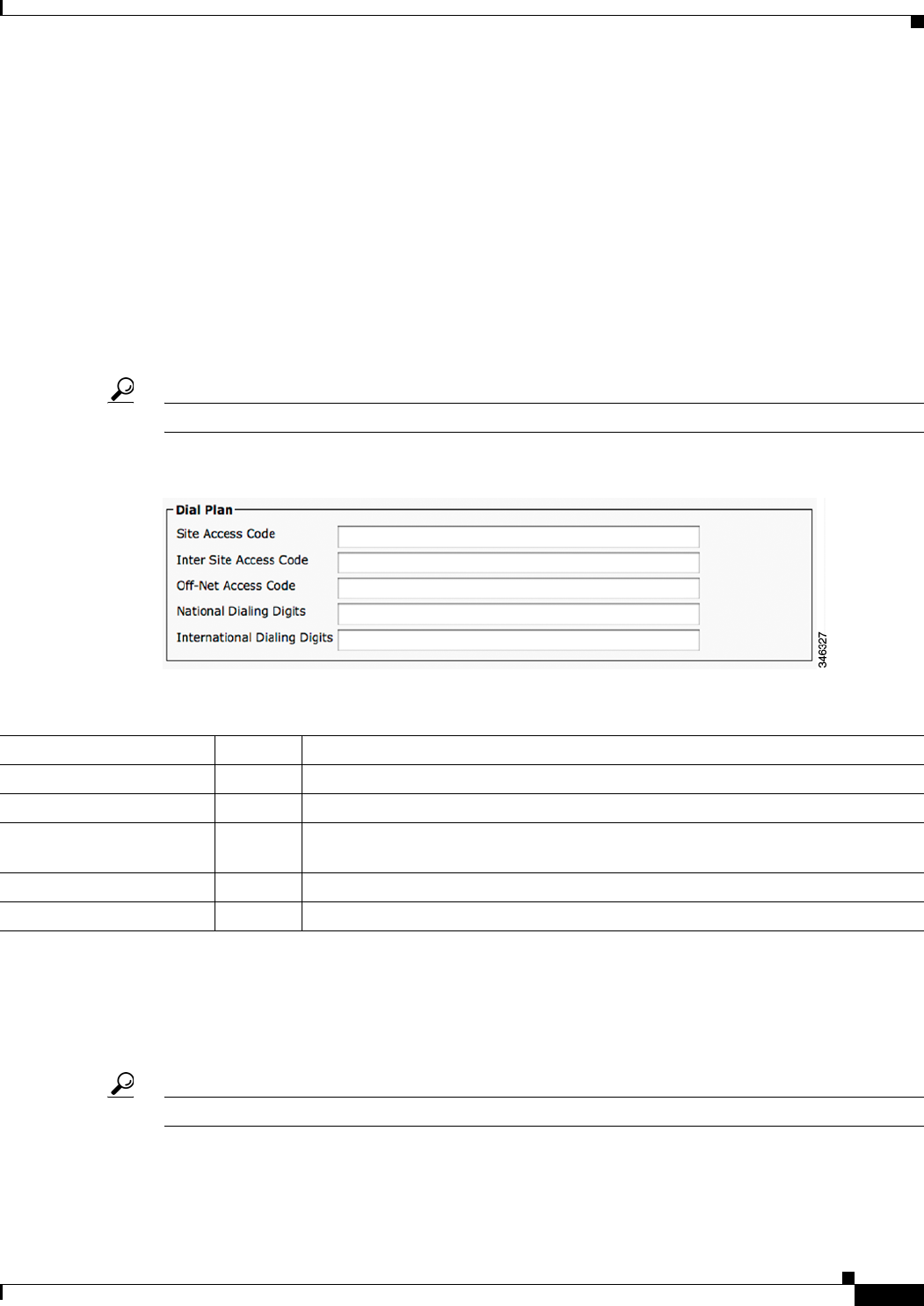
1-23
Cisco Unified Communications Manager Configuration Guide for the Cisco TelePresence System
OL-21851-01
Chapter 1 Configuring Cisco Unified Communications Manager for the Cisco TelePresence System
Adding a Cisco TelePresence Device to the Unified CM Server
Ensure that the Auxiliary presentation display is powered on and connected at all times. Consult the
manual for your display to make any configuration changes.
•Auxiliary Power Control: On With Calls Only—On some systems when Power Control is
configured for “On with calls only” and there is an Auxiliary HDMI port connected (Active Display
or Projector), the lights will remain on for 5 minutes after the call has been terminated. If no
Auxiliary HDMI port is in use, the lights will go off immediately.
Dial Plan Area
Provide dial plan information for the Cisco TelePresence device using the descriptions in Table 1-9.
Click Save to save your settings.
Tip Only numeric values are allowed.
Figure 1-10 Dial Plan Settings
Directory Number Area
Provide directory number information for the Cisco TelePresence device using the descriptions in
Table 1-10. Click Save to save your settings.
Tip Only numeric values are accepted.
Table 1-9 Cisco TelePresence Dial Plan Information
Field Required? Description
Site Access Code — Specifies the access code of this site (cluster). Maximum field length is 6.
Inter Site Access Code — Specifies the access code to dial another site (cluster). Maximum field length is 6.
Off-Net Access Code — Specifies the access code to dial outside of the network (PSTN). Maximum field
length is 3.
National Dialing Digits — Specifies the digits dialed to place a national call. Maximum field length is 6.
International Dialing Digits — Specifies the digits dialed to place an international call. Maximum field length is 6.
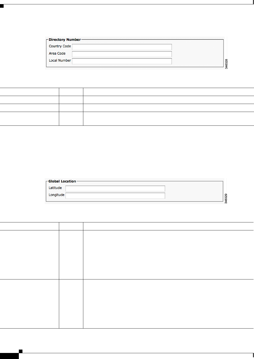
1-24
Cisco Unified Communications Manager Configuration Guide for the Cisco TelePresence System
OL-21851-01
Chapter 1 Configuring Cisco Unified Communications Manager for the Cisco TelePresence System
Adding a Cisco TelePresence Device to the Unified CM Server
Figure 1-11 Directory Number Settings
Global Location Area
Provide global location information for the Cisco TelePresence device using the descriptions in
Table 1-11 as a guide. Click Save to save your settings.
Figure 1-12 Global Location Settings
Table 1-10 Cisco TelePresence Directory Number
Field Required? Description
Country Code — Specifies the country code for this site. Maximum field length is 4.
Area Code — Specifies the area code for this site. Maximum field length is 6.
Local Number — Specifies the subscriber number of this Cisco TelePresence endpoint. Maximum
field length is 15.
Table 1-11 Cisco TelePresence Global Location
Field Required? Description
Latitude — Indicates the site’s latitude. The format for this field is as follows: dd mm ss P
•dd—Degrees. Values are 0 to 89.
•mm—Minutes. Values are 0 to 59.
•ss—Seconds (optional). Values are 0 to 59.
•P—Direction. Values are N (north) or S (south).
Maximum field length is 15 characters.
Longitude — Indicates the site’s longitude. The format for this field is as follows: ddd mm ss P
•ddd—Degrees. Values are 0 to 179.
•mm—Minutes. Values are 0 to 59.
•ss—Seconds (optional). Values are 0 to 59.
•P—Direction. Values are E (east) or W (west).
Maximum field length is 15 characters.
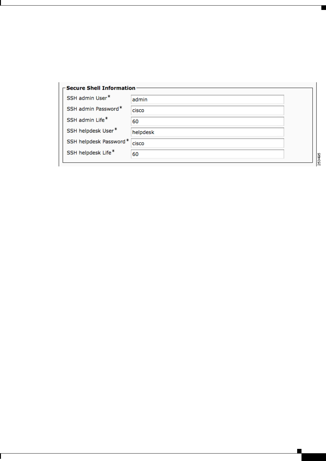
1-25
Cisco Unified Communications Manager Configuration Guide for the Cisco TelePresence System
OL-21851-01
Chapter 1 Configuring Cisco Unified Communications Manager for the Cisco TelePresence System
Adding a Cisco TelePresence Device to the Unified CM Server
SSH Information Area
Figure 1-13 shows the Secure Shell (SSH) Information window.
Figure 1-13 SSH Information Window
Using the information in Table 1-12 as a guide, provide a username and password for the SSH account
that will be used to access the command line interface (CLI) and the Cisco TelePresence Web
Administration interface.
Changing the SSH username and password also changes the username and password for the
Cisco TelePresence administration interface.
Click Save to save your settings.

1-26
Cisco Unified Communications Manager Configuration Guide for the Cisco TelePresence System
OL-21851-01
Chapter 1 Configuring Cisco Unified Communications Manager for the Cisco TelePresence System
Adding a Cisco TelePresence Device to the Unified CM Server
Table 1-12 Cisco TelePresence Secure Shell Settings
Field Required? Setting
SSH Admin User Yes Username for the Secure Shell account. Used for SSH access and to access
the Cisco TelePresence administration interface. Cisco Technical Assistance
Center (TAC) uses secure shell for troubleshooting and debugging. Contact
TAC for further assistance. Default user name is admin. The length of this
username can be between 6 and 64 characters. This username supports CLI
multi-level access (MLA).
Do not use any of the following user names: apache, daemon, help,
helpdesk, nobody, operator, or shutdown.
Usernames and passwords can contain upper and lower case alphanumeric
characters and the underscore and dash characters. User names cannot start
with a - (dash) or _ (underscore).
Note for SSH admin and SSH helpdesk user names: You cannot swap the
SSH admin user name and the SSH Helpdesk user name without performing
an interim user name change. For example, given an admin user name of
minad and a helpdesk name of deskhelp, perform the following steps to
change the admin name to deskhelp and the helpdesk name to minad:
1. Change the admin user name to a temporary password (for example,
admintemp) and change the helpdesk name to minad.
2. Click Save, then click Apply Config.
3. Wait until the “Calls Not Possible” pop-up screen disappears from the
Touch Device.
4. Change the admin user name to deskhelp.
SSH Admin Password Yes Password for the SSH account to be used for SSH access and to access the
Cisco TelePresence Web Administration interface. Default password is cisco.
•Maximum field length is 64 characters.
•Minimum field length is 6 characters.

1-27
Cisco Unified Communications Manager Configuration Guide for the Cisco TelePresence System
OL-21851-01
Chapter 1 Configuring Cisco Unified Communications Manager for the Cisco TelePresence System
Adding a Cisco TelePresence Device to the Unified CM Server
SSH Admin Life Yes Sets the password expiration duration to ensure that the system is protected
when using Cisco TelePresence Command Line Interface (CLI). You must
periodically update this password. See Figure 1-13 to see updated SSH fields
that are used to update your password.
Password expiration can be set to have a value between 0 and 365. A setting
of 0 disables password aging. Default is 60 days. Unless the configured life
has been disabled (by being set to 0), password age is set to have 2 days
remaining in the following situations:
•New installations and factory resets.
•Software upgrades (if the password age is less than the configured age).
•Password recovery (using the pwrecovery command).
An on-screen warning message is sent to the CLI user when 14 days remain
on the current password, and so on until the password expires. If the password
is allowed to expire, the system ignores the CLI login attempt and the user
cannot access the system unless a new password is created by entering
information in the SSH Information Area window.
Save your changes by clicking Restart. This enables the updated
configuration to be read, applied to the CTS, and then Calling Service is
restarted. Alternately you can click Reset, which causes the CTS to reboot.
On startup, the CTS reads the Unified CM configuration and applies any
changes.
See the Cisco TelePresence System Command-Line Interface Reference
Guide for more information.
Table 1-12 Cisco TelePresence Secure Shell Settings (continued)
Field Required? Setting

1-28
Cisco Unified Communications Manager Configuration Guide for the Cisco TelePresence System
OL-21851-01
Chapter 1 Configuring Cisco Unified Communications Manager for the Cisco TelePresence System
Adding a Cisco TelePresence Device to the Unified CM Server
External CTS Log Destination Area
This subsection comprises six fields. The first four configure the CTS to “push” the captured log file to
a remote server:
•External CTS Log Address
•Protocol
•External CTS Log User Name
•External CTS Log User Password
The second two fields configure the CTS to automatically capture logs on a periodic basis:
•Log Period
SSH Helpdesk User Yes Username for the Helpdesk user secure shell account. Used for SSH access
and to access the Cisco TelePresence administration interface.
Cisco Technical Assistance Center (TAC) uses secure shell for
troubleshooting and debugging. Contact TAC for further assistance. Default
user name is helpdesk. The length of this username can be between 6 and 64
characters.
The helpdesk user has limited access to the CLI and no set commands are
allowed.
Do not use any of the following user names: admin, apache, daemon,
nobody, operator, or shutdown.
User names and passwords can contain upper and lower case alphanumeric
characters and the underscore and dash characters. User names cannot start
with a - (dash) or _ (underscore).
Note for SSH admin and SSH helpdesk user names: You cannot swap the
SSH admin user name and the SSH Helpdesk user name without performing
an interim user name change. For example, given an admin user name of
minad and a helpdesk name of deskhelp, perform the following steps to
change the admin name to deskhelp and the helpdesk name to minad:
1. Change the admin user name to a temporary password (for example,
admintemp) and change the helpdesk name to minad.
2. Click Save, then click Apply Config.
3. Wait until the “Calls Not Possible” pop-up screen disappears from the
Touch Device.
4. Change the admin user name to deskhelp.
5. Click Save, then click Apply Config.
SSH Helpdesk Password Yes Password for the SSH account to be used for SSH access and to access the
Cisco TelePresence Web Administration interface. Default password is cisco.
•Maximum field length is 64 characters.
•Minimum field length is 6 characters.
SSH Helpdesk Life Yes
Table 1-12 Cisco TelePresence Secure Shell Settings (continued)
Field Required? Setting

1-29
Cisco Unified Communications Manager Configuration Guide for the Cisco TelePresence System
OL-21851-01
Chapter 1 Configuring Cisco Unified Communications Manager for the Cisco TelePresence System
Adding a Cisco TelePresence Device to the Unified CM Server
•Log Start Time
Note These two sets of fields can be configured independently of each other.
Enter external CTS log address information into the fields using the information in Table 1-12 as a guide.
Click Save to save your settings.
Table 1-13 Cisco TelePresence External CTS Log Destination Settings
Field Required? Setting
External CTS Log Address — Configures the external CTS logging address. If populated, when CTS logs
are generated, a copy of the logs will be sent to this address using the chosen
protocol. You may append a destination path to the address of the remote
machine.
Address format can be either:
•host
or
•host:port
Host is either a hostname or IP address (up to 60 characters long). Port is a
number between 0 and 65535. Default is 514.
Protocol — Selects the protocol to be used to transfer the CTS logs to the Logging
Destination. Choose from the following:
•SCP (default)
•SFTP
•FTP
External CTS Log User Name — Configures the external CTS logging user name.
Maximum length: 64
External CTS Log User
Password
— Configures the external CTS logging user password. Password is write only.
Maximum length: 64
Log Period — The frequency with which the system will automatically generate external
CTS log information. Choose from the following:
•Never (default)
•Once per Day
•Once per 3 Days
•Once per Week
Log Start Time — Indicates the time of day CTS will generate logs. The value should be in a 24
hour format. Where 00:00 is the beginning of the day and 23:59 is the end of
the day. Leaving this field blank will turn off the automatic logging function.
Maximum length: 5
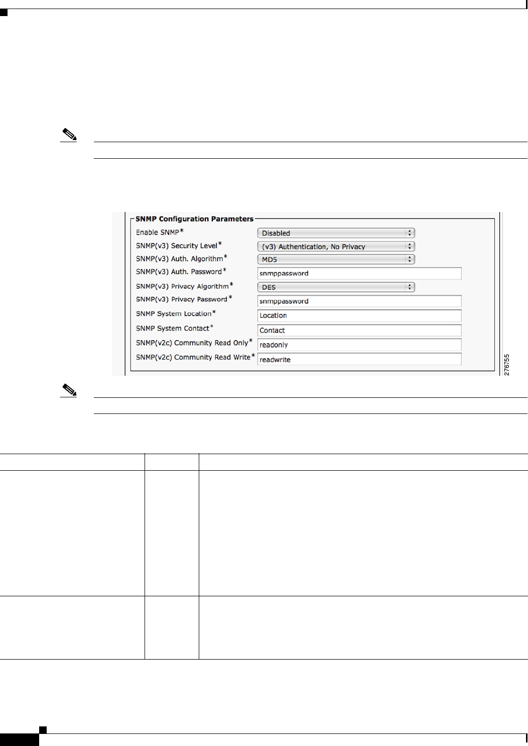
1-30
Cisco Unified Communications Manager Configuration Guide for the Cisco TelePresence System
OL-21851-01
Chapter 1 Configuring Cisco Unified Communications Manager for the Cisco TelePresence System
Adding a Cisco TelePresence Device to the Unified CM Server
SNMP Configuration Parameters Area
Using the information in Table 1-14 as a guide, provide the required Simple Network Management
Protocol (SNMP) configuration parameters for accessing the SNMP server that is associated with the
Cisco TelePresence device. Figure 1-14 shows the SNMP Configuration Parameters screen.
Note Passwords in SNMP parameter fields can only be 32 characters in length.
Figure 1-14 SNMP Configuration Parameters
Note All SNMP fields are marked to reflect the applicable SNMP version.
Table 1-14 Cisco TelePresence SNMP Configuration Parameters
Field Required? Setting
Enable SNMP Yes Enables or disables SNMP on the CTS. SNMP must be enabled for the
Cisco TelePresence system to support SNMP. Options include the following:
•Disabled (default)
•Enabled (v3)
•Enabled (v3/v2)
•Enabled (v2c)
Note SNMP username is automatically configured by the system as
“admin”.
SNMP (v3) Security Level Yes Level of security supported by the SNMP user. This field is only used for
SNMP v3. Choose from the following security levels:
•(v3) Authentication, No Privacy
•(v3) Authentication, Privacy

1-31
Cisco Unified Communications Manager Configuration Guide for the Cisco TelePresence System
OL-21851-01
Chapter 1 Configuring Cisco Unified Communications Manager for the Cisco TelePresence System
Adding a Cisco TelePresence Device to the Unified CM Server
SNMP Trap Receiver Parameters Area
Table 1-15 lists the preset SNMP trap receiver parameters that are associated with the
Cisco TelePresence device.
SNMP (v3) Auth. Algorithm Yes Authentication algorithm supported by the SNMP user. This field is only used
for SNMP v3. Choose from the following algorithms:
•MD5—Message-Digest algorithm 5
•SHA—Secure Hash Algorithm
SNMP (v3) Auth. Password Yes SNMP administration user authentication password used to gain access to the
SNMP v3 server associated with the Cisco TelePresence system. Default
password is snmppassword.
•Maximum field length is 32 characters.
•Minimum field length is 8 characters.
SNMP (v3) Privacy Algorithm Yes Privacy algorithm supported by the SNMP user. This field is only used for
SNMP v3. Choose from the following privacy algorithms:
•DES—Data Encryption Standard
•AES—Advanced Encryption Standard
SNMP (v3) Privacy Password Yes SNMP administration privacy password used to gain access via SNMP v3 on
the Cisco TelePresence system. Default password is snmppassword.
•Maximum field length is 32 characters.
•Minimum field length is 8 characters.
SNMP System Location Yes SNMP System Location associated with this Cisco TelePresence system.
Maximum field length is 64 characters.
Default is Location.
SNMP System Contact Yes Name of the SNMP system contact associated with this Cisco TelePresence
system. Maximum field length is 64 characters.
Default is Contact.
SNMP (v2c) Community Read
Only
Yes SNMP community strings authenticate access to MIB objects and function as
embedded passwords. Read-only gives read access to authorized management
stations to all objects in the MIB except the community strings, but does not
allow write access. This field is only used for SNMP v2c.
Default is readonly.
SNMP (v2c) Community Read
Write
Yes SNMP community strings authenticate access to MIB objects and function as
embedded passwords. Read-write gives read and write access to authorized
management stations to all objects in the MIB, but does not allow access to
the community strings. This field is only used for SNMP v2c.
Default is readwrite.
Table 1-14 Cisco TelePresence SNMP Configuration Parameters (continued)
Field Required? Setting

1-32
Cisco Unified Communications Manager Configuration Guide for the Cisco TelePresence System
OL-21851-01
Chapter 1 Configuring Cisco Unified Communications Manager for the Cisco TelePresence System
Adding a Cisco TelePresence Device to the Unified CM Server
Note Using the information in Table 1-15 as a guide, you can set up to five trap destinations.
Table 1-15 Cisco TelePresence SNMP Trap Receiver Parameters
Field Required? Setting
SNMP Trap Receiver 1
SNMP (v3) Trap Receiver
Address
— IPV4 IP address or hostname of the SNMP trap receiver (the remote SNMP
system) where SNMP traps will be sent. Maximum field length is 64
characters.
SNMP (v3) Trap Username — SNMP v3 only. Username used to access the system where SNMP traps are
received. Maximum field length is 32 characters. Username must begin with
a letter.
Note: Do not use a username of admin in this field.
SNMP Security Level Yes SNMP v3 only. Level of security supported by the SNMP Trap Receiver.
Possible field values are:
•(v3) No Authentication, No Privacy (default)
•(v3) Authentication, No Privacy
•(v3) Authentication, Privacy
•(v2c) Notification
SNMP (v3) Auth. Algorithm Yes SNMP v3 only. Choose from the following authenticated algorithms:
•MD5—Message-Digest algorithm 5
•SHA—Secure Hash Algorithm
SNMP (v3) Auth. Password Yes SNMP v3 only. Password used to gain access to the SNMP server associated
with the Cisco TelePresence system. Default password is snmppassword.
•Maximum field length is 32 characters.
•Minimum field length is 8 characters.
Note Each algorithm requires different privacy and authentication
passwords.
SNMP (v3) Privacy Algorithm Yes SNMP v3 only. Choose from the following privacy algorithms:
•AES—Advanced Encryption Standard
•DES—Data Encryption Standard
SNMP (v3) Privacy Password Yes SNMP v3 only. Default password is snmppassword1.
•Maximum field length is 32 characters.
•Minimum field length is 8 characters.
Note Each algorithm requires different privacy and authentication
passwords.
SNMP(v2c) Community String Yes Community string supported by the Trap Receiver. This field is only used for
SNMP v2c.
Default is communityString. Maximum length: 64

1-33
Cisco Unified Communications Manager Configuration Guide for the Cisco TelePresence System
OL-21851-01
Chapter 1 Configuring Cisco Unified Communications Manager for the Cisco TelePresence System
Configuring the Directory Number for the Cisco TelePresence Device
Managing SNMP MIBs and SNMP Traps
See the Cisco TelePresence System Message Guide for information about managing SNMP MIBs and
Traps.
Saving Your Settings
When you have finished making changes to the parameters in the Phone Configuration window, click
Save then Apply Config. The Apply Configuration Information window appears showing the chosen
device name.
Note You must save the configuration before continuing. When you click Apply Config, the device might go
through a restart. When restart is initiated, connected calls will be preserved but calls in progress may
be dropped.
Configuring the Directory Number for the Cisco TelePresence
Device
Note You must restart your system after you have completed the configuration tasks in this section.
Use the information in the following sections to configure the directory number in the Directory Number
Configuration window. When you have finished entering configuration information, click Save and
follow the prompts to restart the system.
•Directory Number Information, page 1-33
•Directory Number Settings, page 1-34
•AAR Settings, page 1-35
•Call Forward and Call Pickup Settings, page 1-36
•MLPP Alternate Party Settings, page 1-37
•Line Settings for All Devices, page 1-37
•Line X on Device X, page 1-37
•Multiple Call/Call Waiting Settings on Device SEPXXXXXXXXXXXX, page 1-38
•Forwarded Call Information Display on Device SEPXXXXXXXXXXXX, page 1-39
Directory Number Information
To configure settings in the Directory Number Information box, complete the following steps:
Step 1 If you have not already done so, click Add a new DN in the Association Information box to open the
Directory Number Configuration window.

1-34
Cisco Unified Communications Manager Configuration Guide for the Cisco TelePresence System
OL-21851-01
Chapter 1 Configuring Cisco Unified Communications Manager for the Cisco TelePresence System
Configuring the Directory Number for the Cisco TelePresence Device
Step 2 Enter the directory information using the information in Table 1-16 as a guide.
Step 3 Make sure that the check box at the bottom of the Directory Number Information section is marked as
indicated:
Active: Checked
Step 4 Click Save to save your settings.
Directory Number Settings
The fields described in Table 1-17 are left unchanged in the Directory Number Settings box:
Table 1-16 Cisco TelePresence Device Directory Number Information
Field Required? Setting
Directory Number Yes Phone number for the Cisco TelePresence device.
Note To use Cisco WebEx features, the phone number
that is entered in Cisco Unified CM administration
must be configured in full, including the country
code, and must exactly match the phone number that
is entered in the CTMS administration Dial In
Number field.
Route Partition — Choose from the drop-down menu or leave the default,
<None>.
Description — Optional. Enter a device description.
Alerting Name Yes Enter the CTS endpoint name.
ASCII Alerting Name — Optional. Enter the ASCII alerting name.
Table 1-17 Cisco TelePresence Device Directory Number Settings
Field Required? Setting
Voice Mail Profile — Set to “NoVoiceMail” if you do not have voicemail
capability.
Calling Search Space — <None>
Presence Group Yes Leave the default setting.
User Hold MOH Audio
Source
—<None>

1-35
Cisco Unified Communications Manager Configuration Guide for the Cisco TelePresence System
OL-21851-01
Chapter 1 Configuring Cisco Unified Communications Manager for the Cisco TelePresence System
Configuring the Directory Number for the Cisco TelePresence Device
AAR Settings
The fields described in Table 1-18 are left unchanged in the AAR Settings box:
Network Hold MOH Audio
Source
—<None>
Auto Answer Yes Leave the default setting.
Additional drop-down menu choices:
•Auto Answer Off
Note Optionally, you can set Auto Answer Off and
instead configure the Product Specific
Configuration Layout Area “CTS Auto Answer”
setting to have the CTS pick up the call.
•Auto Answer with Headset
•Auto Answer with Speakerphone
Note To assign a directory number for the shared-line
Cisco Unified IP Phone, choose Auto Answer with
Speakerphone. See the “Assigning a Directory
Number for the Shared-Line Cisco Unified IP
Phone” section on page 5-22.
Note If you are using the IP Phone and the call is
connected as audio only, verify that the following
check-boxes are checked:
—Disable Speakerphone
—Disable Speakerphone and Headset
Table 1-17 Cisco TelePresence Device Directory Number Settings
Field Required? Setting
Ta b l e 1- 1 8 C i s c o Te l e P r e s e n ce Device AAR Settings
Field Required? Setting
AAR — Voice Mail
Check the box to select.
AAR Destination Mask
AAR Destination Mask details.
AAR Group
Leave the default setting in the drop-down menu.
Note Check the box to retain the current destination information in the call forwarding history.

1-36
Cisco Unified Communications Manager Configuration Guide for the Cisco TelePresence System
OL-21851-01
Chapter 1 Configuring Cisco Unified Communications Manager for the Cisco TelePresence System
Configuring the Directory Number for the Cisco TelePresence Device
Call Forward and Call Pickup Settings
The fields described in Table 1-19 are left unchanged in the Call Forward and Call Pickup Settings box:
Table 1-19 Cisco TelePresence Device Call Forward and Call Pickup Settings
Field Required? Setting
Calling Search Space Activation Policy
—Calling Search Space
Use System Default.
Additional drop-down menu choices:
•With Configured CSS
•With Activating Device/Line CSS
Forward All — Voice Mail
Check the box to select.
Destination
Destination details.
Calling Search Space
Leave field as <None>.
Secondary Calling Search Space for Fall Forward
Forward Busy Internal — Voice Mail
Check the box to select.
Destination
Destination details.
Calling Search Space
Leave field as <None>.
Forward Busy External —
Forward No Answer
Internal
Yes (if no
voicemail
capability)
Forward No Answer
External
Yes (if no
voicemail
capability)
Forward No Coverage
Internal
—Voice Mail
Check the box to select.
Destination
Destination details.
Calling Search Space
Leave field as <None>.
Forward No Coverage
External
—
Forward on CTI Failure —
Forward Unregistered
Internal
—
Forward Unregistered
External
—
Forward Unregistered
External
—
Call Pickup Group —
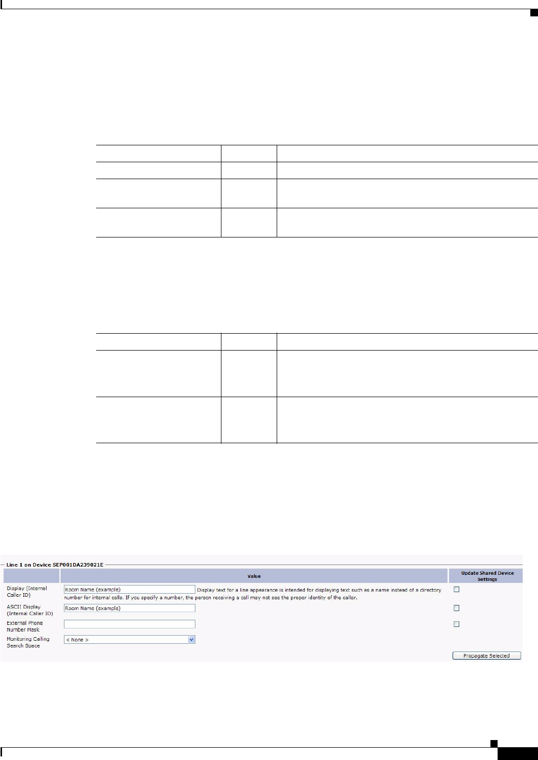
1-37
Cisco Unified Communications Manager Configuration Guide for the Cisco TelePresence System
OL-21851-01
Chapter 1 Configuring Cisco Unified Communications Manager for the Cisco TelePresence System
Configuring the Directory Number for the Cisco TelePresence Device
MLPP Alternate Party Settings
The fields described in Table 1-20 are left unchanged in the multilevel precedence and preemption
(MLPP) Alternate Party Settings box:
Line Settings for All Devices
The fields described in Table 1-21 are left unchanged in the Line Settings for All Devices Settings box:
Line X on Device X
Manage the TFTP profile for the Cisco TelePresence endpoint by configuring the meeting room name
so that the room name appears on the Cisco WebEx Participant List, as shown in Figure 1-15.
Figure 1-15 Display (Internal Caller ID) Fields
Line X on Device X Fields are described in Table 1-22.
Table 1-20 Cisco TelePresence Device MLPP Alternate Party Settings
Field Required? Setting
Target (Destination) — Leave the default setting. Supported characters: 0-9, +, *, #.
MLPP Calling Search
Space
—<None>
AARMLPP No Answer
Ring Duration (seconds)
— Leave the default setting.
Table 1-21 Cisco TelePresence Device Line Settings for All Devices Settings
Field Required? Setting
Hold Reversion Ring
Duration (seconds)
— Leave the default setting.
Note Setting the Hold Reversion Ring Duration to zero
will disable the feature.
Hold Reversion
Notification Interval
(seconds)
— Leave the default setting.
Note Setting the Hold Reversion Notification Interval to
zero will disable the feature.

1-38
Cisco Unified Communications Manager Configuration Guide for the Cisco TelePresence System
OL-21851-01
Chapter 1 Configuring Cisco Unified Communications Manager for the Cisco TelePresence System
Configuring the Directory Number for the Cisco TelePresence Device
Multiple Call/Call Waiting Settings on Device SEPXXXXXXXXXXXX
The Multiple Call/Call Waiting settings make it possible to place a meeting on hold, dial a phone
number, and have up to four active calls on one device. This feature is useful for adding phone calls to
a Cisco TelePresence meeting.
The default setting for the maximum number of additional phone calls allowed on the CTS
Cisco Unified IP phone is 4.
Note Valid range for Maximum Number of calls is 1-46.
To configure multiple call waiting settings on a specific device:
Step 1 Enter configuration settings in the fields provided using the information in Table 1-23 as a guide.
Table 1-22 Cisco TelePresence Device Line X on Device X Settings
Field Required? Setting
Display (Internal Caller ID) — Leave the default setting. For Cisco WebEx, enter your
room name so that the room name appears on the
Cisco WebEx Participant List.
Note Display text for a line appearance is intended for
displaying text such as a name instead of a directory
number for internal calls. If you specify a number,
the person receiving a call may not see the proper
identity of the caller.
ASCII Display (Internal
Caller ID)
— Leave the default setting. For Cisco WebEx, enter your
room name so that the room name appears on the
Cisco WebEx Participant List.
External Phone Number
Mask
— Leave the default setting.
Visual Message Waiting
Indicator Policy
Yes Leave the default setting.
Audible Message Waiting
Indicator Policy
Yes Leave the default setting.
Ring Setting (Phone Idle) Yes Leave the default setting.
Ring Setting (Phone
Active)
— Leave the default setting. Applies to this line when any line
on the phone has a call in progress.
Call Pickup Group Audio
Alert Setting (Phone Idle)
— Leave the default setting.
Recording Option Yes Leave the default setting.
Recording Profile — <None>
Monitoring Calling Search
Space
—<None>

1-39
Cisco Unified Communications Manager Configuration Guide for the Cisco TelePresence System
OL-21851-01
Chapter 1 Configuring Cisco Unified Communications Manager for the Cisco TelePresence System
Where to Go Next
Step 2 Click Save to save your settings.
Forwarded Call Information Display on Device SEPXXXXXXXXXXXX
Leave the following information unchanged in the Forwarded Call Information Display on Device X
Settings box:
•Caller Name
•Caller Number
•Redirected Number
•Dialed Number
Where to Go Next
If you have an IP Phone, proceed to Chapter 5, “Configuring and Managing the Cisco Unified IP Phone.”
Table 1-23 Cisco TelePresence Device Multiple Call/Call Waiting Settings
Field Required? Setting
Maximum Number of Calls Yes Up to 4.
Busy Trigger Yes 2 (Recommended)
Note Less than or equal to the maximum number of
calls. By default, after two calls are started, a
third attempt at connecting to the IP phone
results in a busy signal.

1-40
Cisco Unified Communications Manager Configuration Guide for the Cisco TelePresence System
OL-21851-01
Chapter 1 Configuring Cisco Unified Communications Manager for the Cisco TelePresence System
Where to Go Next

CHAPTER
2-1
Cisco Unified Communications Manager Configuration Guide for the Cisco TelePresence System
OL-21851-01
2
Configuring Cisco TelePresence Features
Revised: June 9, 2015, OL-21851-01
Contents
•Managing the Speed-Dial Directory (Favorites), page 2-1
•Enabling the Directory Feature, page 2-6
•Configuring the BFCP over UDP Collaboration Feature, page 2-9
•T1 Support Extended Reach, page 2-12
•Quality Per Display - 720p (Lite), page 2-13
•Self View Control, page 2-13
•Conference Control Protocol (CCP) VPN Security Solution, page 2-15
•Single Microphone Mute, page 2-15
•Watermark Removal, page 2-16
•Screen Dimming, page 2-16
•Installing Language Versions, page 2-17
•Related Information, page 2-21
Managing the Speed-Dial Directory (Favorites)
This section contains the following information:
•Adding Speed-Dial Numbers (Favorites) from the Unified CM Administration Page, page 2-1
•Adding Speed-Dial Numbers (Favorites) from the User Options Page, page 2-3
Adding Speed-Dial Numbers (Favorites) from the Unified CM Administration
Page
To add speed-dial numbers to your Cisco TelePresence System:

2-2
Cisco Unified Communications Manager Configuration Guide for the Cisco TelePresence System
OL-21851-01
Chapter 2 Configuring Cisco TelePresence Features
Managing the Speed-Dial Directory (Favorites)
Step 1 Log in to the Cisco Unified Communications Manager Administration interface.
Step 2 From the Device drop-down menu, choose Phone. The Find and List Phones Page appears.
Step 3 Enter your search criteria in the fields provided and click Find.
Step 4 Click on the phone that you want to configure with speed-dial buttons. The Phone Configuration window
for that phone appears.
Step 5 Click the Related Links drop-down list box at the top right side of the window.
Step 6 Choose Add/Update Speed Dials and click Go. The Speed Dial Configuration window for this phone
appears with the following configurable fields:
•Speed Dial (Button) Settings—numbers 1 through 40.
•Speed Dial (Abbreviated Dial) Settings—numbers 41 through 199. CTS does not support
abbreviated dialing, so you do not need to use this field.
Step 7 Create your favorites list in these Speed Dial (Button) Settings field using the information in Table 2-1
as a guide.
Step 8 Click Save to apply your changes, then click Close to close the window.
Step 9 Click Save and then Apply Config. The phone will reboot for the changes to take effect. This will take
a few minutes.
Note Do not click Reset. Doing so will cause the phone to reset and the phone could take 10 to 30 minutes to
come back up.
Table 2-1 Speed Dial Configuration Window
Number Field Description
Number from 1
to 40.
— Indicates the order of your contacts in your
Favorites list.
Number Enter the number that you want the system to dial
when the user calls the contact from the Favorites
list. The following digits and characters are
allowed:
•Digits 0 through 9
•* (Asterisk)
•# (Number sign or hash)
•+ (Plus sign, escape symbol)
Note The speed-dial (favorites) function does not
allow pauses or waits.
Label Enter the text that you want to display to identify
your contact.
ASCII Label This field provides the same information as the
Label field, but you must limit input to ASCII
characters. Devices that do not support unicode
(internationalized) characters display the content of
the ASCII Label field.
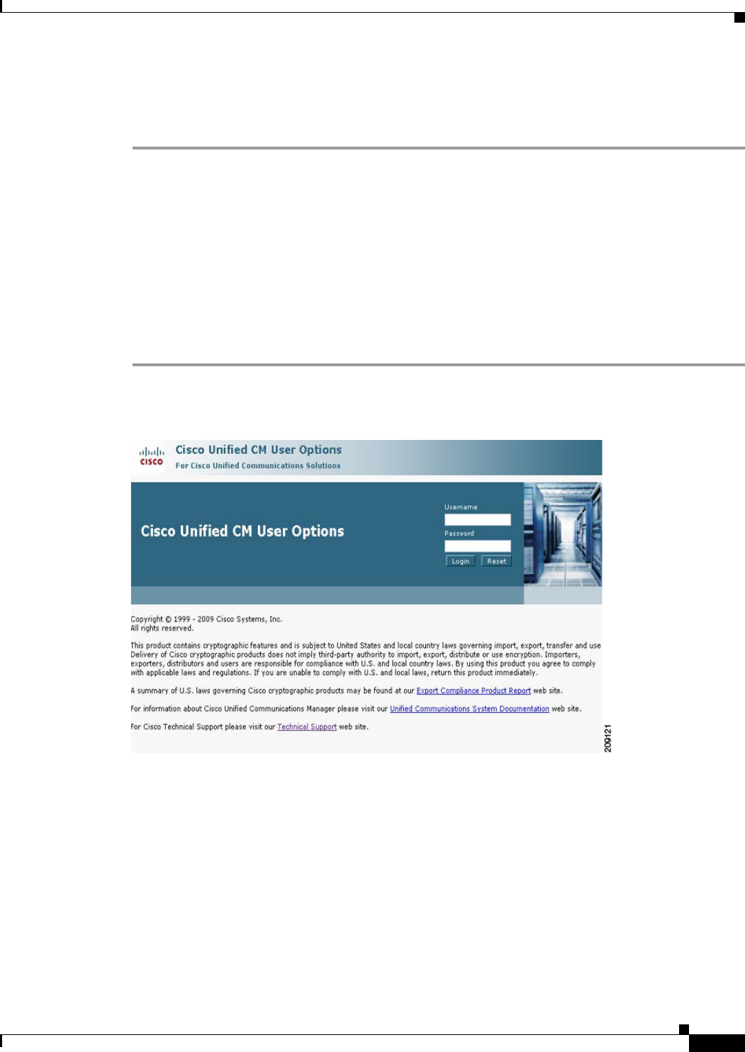
2-3
Cisco Unified Communications Manager Configuration Guide for the Cisco TelePresence System
OL-21851-01
Chapter 2 Configuring Cisco TelePresence Features
Managing the Speed-Dial Directory (Favorites)
Step 10 View your Favorites by tapping Directory and then Favorites on your Touch 12 device.
For more information about making a call using favorites, refer to the Placing and Receiving Calls
chapter in the Cisco TelePresence System User Guide.
Adding Speed-Dial Numbers (Favorites) from the User Options Page
End-users can easily log in to the Cisco Personal Communications Assistant (if installed) and then
choose User Options from the menu bar to navigate to User Options. When logged in and viewing User
Options, you can access a User Guide, change the locale for the windows, and access additional
configuration options from the Related Links drop-down list, including speed dials, phone services, and
line-specific options (call forwarding, message-waiting indicators, and ring patterns).
To manage your Speed-Dials (Favorites) from User Options:
Step 1 Log in to the Cisco Unified CM User Options page, as shown in Figure 2-1.
Figure 2-1 Cisco Unified CM User Options Log In
Step 2 Click User Options and select Device, as shown in Figure 2-2. The Device Configuration page appears,
as shown in Figure 2-3.

2-4
Cisco Unified Communications Manager Configuration Guide for the Cisco TelePresence System
OL-21851-01
Chapter 2 Configuring Cisco TelePresence Features
Managing the Speed-Dial Directory (Favorites)
Figure 2-2 User Options > Device
Step 3 In the Device box, click the Name drop down menu and select the phone for which you would like to
create, modify, or delete speed dials, as shown in Figure 2-3. The model name will appear in the
Description field, as shown in Figure 2-4.
Figure 2-3 Device Configuration
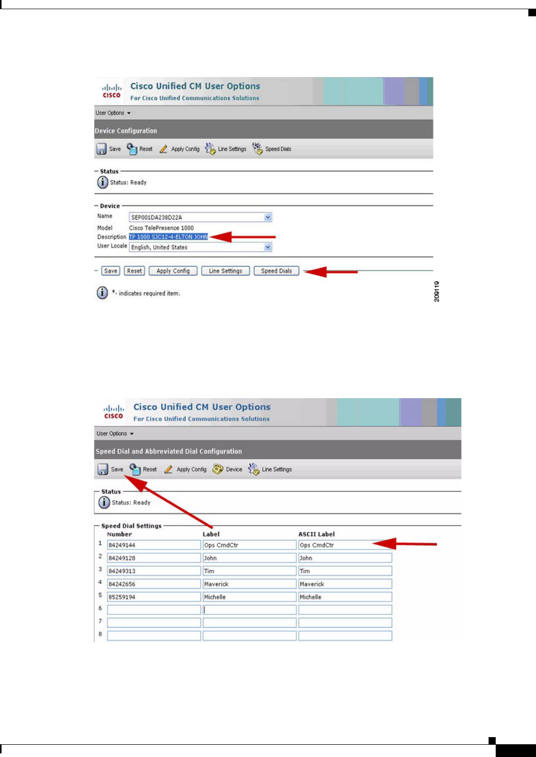
2-5
Cisco Unified Communications Manager Configuration Guide for the Cisco TelePresence System
OL-21851-01
Chapter 2 Configuring Cisco TelePresence Features
Managing the Speed-Dial Directory (Favorites)
Figure 2-4 Device Description
Step 4 Click Save.
Step 5 Click Speed Dials. The Speed Dial and Abbreviated Dial Configuration page appears, as shown in
Figure 2-5.
Figure 2-5 Speed Dial and Abbreviated Dial Configuration
Step 6 In the Speed Dial Settings Number field, enter the Cisco TelePresence telephone numbers (for example,
84243737). See Figure 2-5.

2-6
Cisco Unified Communications Manager Configuration Guide for the Cisco TelePresence System
OL-21851-01
Chapter 2 Configuring Cisco TelePresence Features
Enabling the Directory Feature
Step 7 In the Speed Dial Settings Label and ASCII Label fields, enter a name or friendly name. These can be
a combination of letters or numbers. Hyphens and spaces are ok, but do not use any special characters
(for example, % @ ! $). See Figure 2-5.
Step 8 Click Save and Apply Config when you are done. Once you save, the phone will reboot for the changes
to take effect. This will take a few minutes.
Note Do not click Reset. Doing so will cause the phone to reset and the phone could take 10 to 30 minutes to
come back up.
Step 9 View your Favorites by tapping Directory and then Favorites on your Touch 12 device.
For more information about making a call using favorites, refer to the Placing and Receiving Calls
chapter in the Cisco TelePresence System User Guide.
Enabling the Directory Feature
The Directory button on the Cisco TelePresence Touch 12 allows a user to look up TelePresence phone
numbers for co-workers. To support this feature, you must configure corporate directories. See
Configuring a Corporate Directory for more information.
To set up Directory for the user from the Cisco Unified Communications Manager Administration
interface:
Step 1 Log in to the Cisco Unified Communications Manager Administration interface.
Step 2 Go to System > Enterprise Parameters.
Step 3 Scroll to CCMUser Parameters.
Step 4 Locate Show Directory from the list and choose True from the drop-down menu.
This parameter determines whether or not the option Directory appears on your call control device
Options web (CCMUser). If this option is enabled, the user can search directory.
Step 5 Click Save to save your settings. The change will take effect on next login to Cisco Unified
Communications Manager User Options window. Default is True.
Configuring a Corporate Directory
Cisco Unified Communications Manager uses a Lightweight Directory Access Protocol (LDAP)
directory to store authentication and authorization information about users of Cisco Unified
Communications Manager applications that interface with Cisco Unified Communications Manager.
Authentication establishes the users' rights to access the system. Authorization identifies the telephony
resources that a user is permitted to use, such as a specific telephone extension.
To install and set up these features, refer to the following chapters in the Cisco Unified Communications
Manager Administration Guide:
•LDAP System Configuration
•LDAP Directory Configuration

2-7
Cisco Unified Communications Manager Configuration Guide for the Cisco TelePresence System
OL-21851-01
Chapter 2 Configuring Cisco TelePresence Features
Enabling the Directory Feature
•LDAP Authentication Configuration
In Cisco Unified Communications Manager Administration, use the User Management > End User
menu path to configure end users.
The End User Configuration window in Cisco Unified Communications Manager Administration allows
the administrator to add, search, display, and maintain information about Cisco Unified
Communications Manager end users. End users can control phones after you associate a phone in the
End User Configuration window.
Tips About Configuring End Users
Consult the following information before you begin to configure end users:
•To verify whether the Enable Synchronizing from LDAP Server check box is checked, choose
System > LDAP > LDAP System. If the check box is checked, LDAP synchronization is enabled;
if not, LDAP synchronization is disabled.
•If you enable LDAP synchronization in Cisco Unified Communications Manager Administration,
you thereby configure your system to use the LDAP corporate directory as the end user directory for
Cisco Unified Communications Manager. In this scenario, you cannot add or delete users in
Cisco Unified Communications Manager Administration. You add and remove end users in the
corporate LDAP directory.
•If you enable LDAP synchronization in Cisco Unified Communications Manager Administration,
you cannot change some existing user information, including user IDs, in the End User
Configuration windows. Instead, you must use the corporate LDAP directory to update some user
information.
•If you configure your system to authenticate users against the LDAP directory, you cannot configure
or change end user passwords in Cisco Unified Communications Manager Administration. You
configure and change end user passwords in the corporate LDAP directory.
After the LDAP directory configuration completes, users can use the Corporate Directory service on
your Cisco Unified IP Phone 7970 Series to look up users in the corporate directory.
Cisco-Provided Default IP Phone Services
Table 2-2 displays the Cisco-provided default IP phone services that display if you specify the search
parameter, IP Phone Service, and then click Find. Cisco Unified Communications Manager
automatically provisions these Cisco-provided default services. To update these services, click the link
in the Find and List IP Phone Service window. You can change the name of the service, where the default
service displays on the phone, and the service URL. If you change the service URL for the default
services, choose Both from the Service Provisioning drop-down list box, which displays in the Phone
Configuration window, the Enterprise Parameter Configuration window, and the Common Phone Profile
Configuration window.

2-8
Cisco Unified Communications Manager Configuration Guide for the Cisco TelePresence System
OL-21851-01
Chapter 2 Configuring Cisco TelePresence Features
Enabling the Directory Feature
Tip Some Cisco Unified IP Phone models do not support IP phone services. To determine the support for
your phone model, see the Cisco Unified IP Phone Administration Guide and the Cisco Unified
Communications Manager Software Compatibility Matrix on Cisco.com.
Table 2-2 Cisco-provided Default Services
Default Services Description
Corporate Directory This XML service allows the phone to display the corporate directory on the
phone. By default, for phones with a Directory button/option, the corporate
directory option displays when a user presses the Directory button/option on the
phone. By default, the service URL is Application:Cisco/CorporateDirectory.
By default, the corporate directory automatically displays on all phones that
support services in the cluster, and you (or the end user) cannot subscribe to the
service.
If you update the corporate directory option because you want to configure this
option to support a custom directory, for example, you update the Service URL
to point to your custom directory, make sure that Both is chosen from the
Service Provisioning drop-down list box, which displays in the Phone
Configuration window, Enterprise Parameter Configuration window, or the
Common Phone Profile Configuration window.
Intercom Calls This XML service allows the phone to display the history records for intercom
calls. By default, for phones with a Directory button/option, the intercom history
option displays when a user presses the Directory button/option on the phone.
By default, the service URL is Application: Cisco/IntercomCalls. This service
does not automatically display on all phones that support services in the cluster;
therefore, you must manually subscribe to the service; for example, you can
subscribe to the service in the Cisco Unified CM User Options.
Missed Calls This XML service allows the phone to display missed calls on the phone. By
default, for phones with a Directory button/option, the missed calls option
displays when a user presses the Directory button/option on the phone. By
default, the service URL is Application:Cisco/MissedCalls. By default, the
Missed Calls option automatically displays on all phones that support services
in the cluster, and you (or the end user) cannot subscribe to the service.
Placed Calls This XML service allows the phone to display calls that the user has placed on
the phone. By default, for phones with a Directory button/option, the placed
calls option displays when a user presses the Directory button/option on the
phone. By default, the service URL is Application:Cisco/PlacedCalls. By
default, the Placed Calls option automatically displays on all phones that
support services in the cluster, and you (or the end user) cannot subscribe to the
service.
Received Calls This XML service allows the phone to display received calls on the phone. By
default, for phones with a Directory button/option, the received calls option
displays when a user presses the Directory button/option on the phone. By
default, the service URL is Application:Cisco/ReceivedCalls. By default, the
Received Calls option automatically displays on all phones that support services
in the cluster, and you (or the end user) cannot subscribe to the service.

2-9
Cisco Unified Communications Manager Configuration Guide for the Cisco TelePresence System
OL-21851-01
Chapter 2 Configuring Cisco TelePresence Features
Configuring the BFCP over UDP Collaboration Feature
Configuring the BFCP over UDP Collaboration Feature
Binary Floor Control Protocol (BFCP) is used for controlling access to the media resources in a meeting.
BFCP allows the CTS and the remote endpoint to view presentation and main display video
simultaneously with improved presentation resolution for all third-party telepresence endpoints.
The CTS offers three media lines: one for audio, one for the main video, and the other for presentation
or content using the session description protocol (SDP). Additionally, an application line is sent in the
SDP for the BFCP control channel. The bandwidth of the presentation media line matches the capability
of the CTS. For example, if the CTS is capable of 30 frames per second (fps), the presentation media
line bandwidth will be 4Mbps.
The CTS uses BFCP over user datagram protocol (UDP) in both secure and non-secure BFCP modes.
BFCP requires a minimum CTS Release of 1.8 and a minimum Unified CM release of 8.6(2a)SU2.
BFCP Backward Compatibility
BFCP is enabled by default on all CTS endpoints beginning with CTS Release 1.8. Endpoints using CTS
software prior to CTS Release 1.8 must either disable BFCP on all new SIP profiles in the Unified CM
Administration interface, or upgrade all CTS endpoints to CTS Release 1.8.
Configure your system in the following order:
1. Configuring the VCS Zone, page 2-9
2. Adding a New BFCP Profile, page 2-11
3. Configuring the Unified CM Trunk, page 2-11
Configuring the VCS Zone
Note The Cisco VCS and Unified CM must be operational before you begin.
To enable BFCP with Cisco VCS, the trunk from the Cisco VCS to Unified CM must have a custom
BFCP profile configured in the Cisco Unified Communications Manager Administration interface and
you must change the VCS Zone in the Cisco VCS administration interface.
For complete Cisco VCS configuration support, see the Cisco Unified Communications Manager with
Cisco VCS Cisco TelePresence Deployment Guide.
To change the Zone configuration in Cisco VCS:
Step 1 Navigate to the CUCM neighbor zone VCS Configuration > Zones.
Voicemail This XML service allows users to retrieve voice messages on the phone. By
default, for phones with a Messages button/option, the voice mail option
displays when a user presses the Messages button/option on the phone. By
default, the service URL is Application:Cisco/Voicemail. By default, the
Voicemail option automatically displays on all phones that support services in
the cluster, and you (or the end user) cannot subscribe to the service.
Table 2-2 Cisco-provided Default Services (continued)
Default Services Description

2-10
Cisco Unified Communications Manager Configuration Guide for the Cisco TelePresence System
OL-21851-01
Chapter 2 Configuring Cisco TelePresence Features
Configuring the BFCP over UDP Collaboration Feature
Step 2 Change the Advanced Zone profile from Cisco Unified Communications Manager to Custom.
Step 3 Set the parameters listed in Table 2-3.
Note To use BFCP with endpoints registered to CUCM 8.6(2a)SU2 or later, select Custom for the Advanced
Zone profile, configure the entries as above, then change SIP UDP/BFCP filter mode to Off.
If your system uses TLS connectivity from the Cisco VCS to Unified CM, and Cisco VCS is configured
with optimal routing, either Unified CM has to trust the certificates for each Cisco VCS in the network,
or you must select Custom for the Advanced Zone profile, configure the entries as above, then change
Call signaling routed mode to Always. This ensures that the VCS neighbored to Unified CM will remain
in the call signaling path for calls to and from Unified CM, so that Unified CM only has to trust this VCS
cluster’s certificates.
Step 4 Ensure that SIP UDP/BFCP filter mode is set to Off.
For more information about the VCS, go to the Cisco TelePresence Video Communication Server (VCS)
home page on Cisco.com.
Table 2-3 Zone Parameters
Parameter Value
Monitor peer status Yes
Call signaling routed mode Auto
Automatically respond to H.323
searches
Off
Automatically respond to SIP
searches
Off
Empty INVITE allowed On
SIP poison mode Off
SIP encryption mode Auto
SIP SDP attribute line limit mode Off
SIP SDP attribute line limit length 130
SIP multipart MIME strip mode Off
SIP UPDATE strip mode On
Interworking SIP Search Strategy Options
SIP UDP/BFCP filter mode On
SIP Duo Video filter mode Off
SIP record route address type IP
SIP Proxy-Require header strip list <Blank>
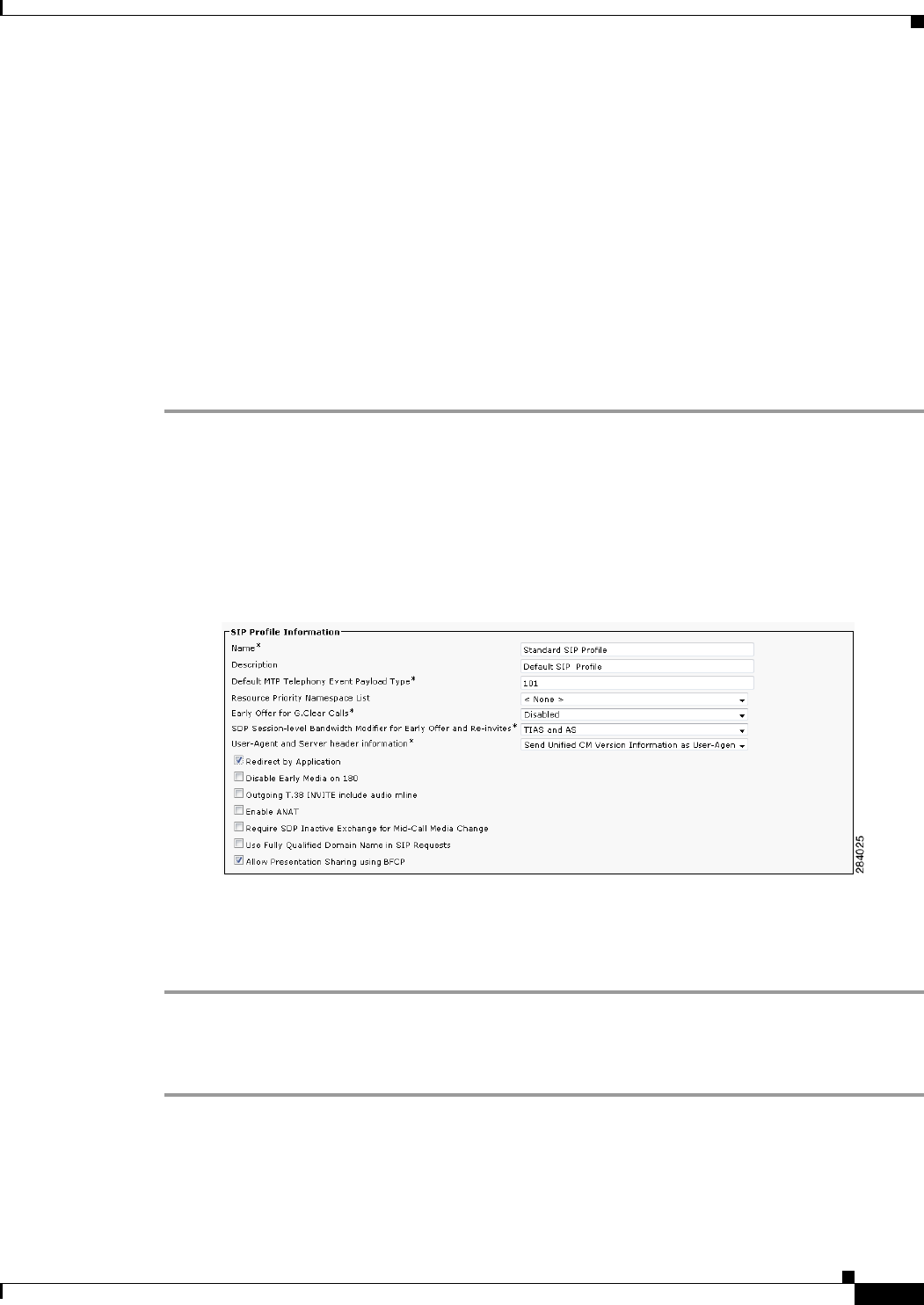
2-11
Cisco Unified Communications Manager Configuration Guide for the Cisco TelePresence System
OL-21851-01
Chapter 2 Configuring Cisco TelePresence Features
Configuring the BFCP over UDP Collaboration Feature
Configuring BFCP For Your Cisco TelePresence Device
This section includes the steps you perform to configure BFCP and apply it to your Cisco TelePresence
system and includes the following topics:
•Adding a New BFCP Profile, page 2-11
•Configuring the Unified CM Trunk, page 2-11
Adding a New BFCP Profile
To add a new profile for BFCP and to associate the BFCP profile to the trunk configuration on Unified
CM for the trunk between VCS and CUCM, follow the steps in this section. This profile needs to be
associated with every trunk and device that will use BFCP for presentation.
Step 1 Go to Device > Device Settings > SIP Profile.
Step 2 Click Add New. The SIP Profile Configuration window appears.
Step 3 Create a name for the BFCP profile. For example, “Standard BFCP SIP Profile.”
Step 4 Click to select the Allow Presentation Sharing using BFCP check box, as shown in Figure 2-6.
Figure 2-6 SIP Profile Information - Allow Presentation Sharing Using BFCP
Step 5 Leave the remaining field defaults and click Apply Config and then Save.
Step 6 Configure the BFCP trunk by performing the tasks in the “Configuring the Unified CM Trunk” section
on page 2-11.
Configuring the Unified CM Trunk
Step 1 Go to Device > Trunk.
Step 2 Select the trunk for the Cisco VCS and set it to use the new BFCP profile.
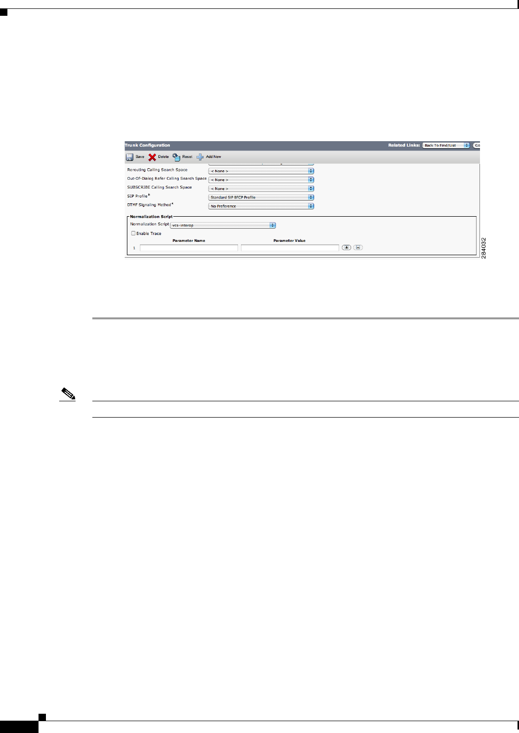
2-12
Cisco Unified Communications Manager Configuration Guide for the Cisco TelePresence System
OL-21851-01
Chapter 2 Configuring Cisco TelePresence Features
T1 Support Extended Reach
Step 3 (Optional) Configure security between the Unified CM and Cisco VCS for Cisco TelePresence EX and
Cisco TelePresence C Series endpoints by choosing vcs interop in the Normalization Script window
(Unified CM 8.6(2a)SU2 and later releases), as shown in Figure 2-7.
Figure 2-7 Normalization Script Window - VCS Interop Security
Step 4 Click Save to save your settings.
See the Cisco Unified Communications Manager with Cisco VCS Cisco TelePresence Deployment Guide
for complete VCS security support information.
T1 Support Extended Reach
Note The following information applies only to single-screen systems.
The Quality per Display field in the Product Specific Configuration Layout Area window has a new
setting: “High Detail, Limited Motion: 720p (Lite)” as part of the Extended Reach feature. Extended
Reach users in locations where bandwidth is costly or unreliable. Because internet bandwidth is not
dedicated, there may be experience issues or even call drops at certain times of the day due to a decrease
in available bandwidth. Extended Reach is directly related to the quality of the call.
This feature enables the following:
•T1/E1 with QoS: 720p (Lite) and 720p (Good). See Quality Per Display - 720p (Lite). Any endpoint
configured “High Detail, Limited Motion: 720p (Lite)” is in T1 mode and advertises bandwidth as
appropriate.
•“Best Effort” premium broadband (Fiber-Optic Broadband Internet (FIOS), Cable).
•Sends and receives audio and video from legacy T1/E1 endpoints.
•Video output: 936Kbps.
•Presentation output: 100Kbps using 1 frame per second (FPS).
•Four jitter buffer sizes: 85ms, 125ms, 165ms, and 245ms.
•Progressive iFrames.
•Multi-point Long Term Reference Picture (LTRP) repair mechanism in H.264 codecs.
•High definition (HD) inter-operability with third-party endpoints.

2-13
Cisco Unified Communications Manager Configuration Guide for the Cisco TelePresence System
OL-21851-01
Chapter 2 Configuring Cisco TelePresence Features
Quality Per Display - 720p (Lite)
•Media eXperience Engine (MXE) compatibility.
This feature disables the following:
•Audio add-in (conference) is disabled for a T1 endpoint—Only one audio or audio-video call can
be made at a time.
•Backward compatibility prior to CTS Release 1.5 is not available—The endpoint displays the
following message “Remote site not compatible – Contact Help Desk.”
•Standard definition (SD) interop endpoints will not see the T1 endpoint when that endpoint is
detected to be the loudest endpoint speaking during a call.
Quality Per Display - 720p (Lite)
The Quality Per Display field is where you can set the bandwidth that will be used by the system. Higher
bandwidth increases video quality, but may also cause packets to be dropped and video to be interrupted.
The following describes expected behavior and feature limitations of the High Detail, Limited Motion:
720p (Lite) bandwidth option:
1. CTS Release 1.5.3 endpoints are not supported on an HD interop bridge; calls are dropped.
2. CTS Release 1.6.x endpoints running 720p (Lite) are supported on an HD interop bridge. All other
CTS endpoints are then downgraded to 720p (Lite).
3. If a CTS Release 1.6.x endpoint running 720p (Lite) calls into a non-HD common intermediate
format (CIF) interop bridge, video from legacy video endpoints will be seen on the 720p (Lite) CTS.
However, video from the 720p (Lite) CTS will not be seen on the legacy endpoint. Video from other
CTS endpoints in the call will be seen on both legacy and 720p (Lite) endpoints.
For configuration information, see Product Specific Configuration Layout Area.
Self View Control
The Self View feature allows you to view how you will be seen by others in a Cisco TelePresence
meeting before the meeting begins. By touching the Self View softkey on your CTS Cisco Unified IP
phone while the CTS is idle (not in a call), you can see a mirror image of you and your room for a
specified amount of time (5 to 180 seconds), as configured in the Maximum Self View Time (in seconds)
field in the Product Specific Configuration Layout Area fields for your system.
While in Self View mode, any active presentation is visible in the Presentation-in-Picture (PiP) or on the
LCD display. On multi-screen systems (CTS 3000 Series and TX9000 Series), the Self View mirror
image appears on all screens. On the CTS 1300, which has three cameras and a single display, the self
view image is displayed from the center camera. Once you are in Self View mode, you can use the CTS
Cisco Unified IP phone to select between Left, Center, and Right camera views.
Note You cannot use the Self View feature while in an active call.
See the “Product Specific Configuration Layout Area” section on page 1-17 for information about
setting the Self View time in the Maximum Self View Time (in seconds) field.
See the following sections for more information:
•Self View Control Feature Behavior, page 2-14

2-14
Cisco Unified Communications Manager Configuration Guide for the Cisco TelePresence System
OL-21851-01
Chapter 2 Configuring Cisco TelePresence Features
Self View Control
•Related Self View Feature Information, page 2-14
Self View Control Feature Behavior
The following sections describe Self View features and behavior:
•Shroud Lights, page 2-14
•Answering Calls, page 2-14
•Dismissing Calls, page 2-14
Shroud Lights
The lights that surround the main display screen are activated when accessing the Self View feature.
When answering an incoming call in Self View mode, the lights remain on throughout the call. When
you exit Self View mode, the lights remain on for a short period of time, similar to the system’s behavior
at the end of a normal Cisco TelePresence call.
Answering Calls
If the CTS system is configured for Auto Answer and is in Self View mode when it receives an incoming
call, the standard incoming call alert is heard and you can answer the call manually.
When a call is received while you are in Self View mode, you can exit the feature to accept the incoming
video. If there is an active presentation on-screen when the call comes through, options on the CTS
Cisco Unified IP phone allow you to share or hide the presentation.
Dismissing Calls
You can dismiss calls while in Self View mode without disrupting the Self View video and active
presentation. Press Ignore to dismiss the call and return to the Self View page.
Pressing Ignore while in Self View mode does not divert the call. The incoming call continues to ring
inaudibly until the remote end disconnects from the call. You can choose to answer the incoming call by
pressing Answer, or wait until the call times out.
Note If you have voicemail configured in Unified CM, the incoming call alert is not issued because the call
goes directly to voicemail.
Related Self View Feature Information
For more information about the Self View feature, refer to the Cisco TelePresence System User Guide
that corresponds with your system’s software release.

2-15
Cisco Unified Communications Manager Configuration Guide for the Cisco TelePresence System
OL-21851-01
Chapter 2 Configuring Cisco TelePresence Features
Conference Control Protocol (CCP) VPN Security Solution
Conference Control Protocol (CCP) VPN Security Solution
This feature allows an administrative domain that is hosting a Business-to-Business (B2B) conference
to configure its Cisco TelePresence Multipoint Switch (CTMS) using a specific URL structure. This
URL structure allows the CCP HTTP traffic of participating CTS endpoints to be routed hop by hop
across one or more service provider (SP) HTTP proxies to reach the correct CTMS.
In the CCP VPN model (fixed path) solution, the Administrator configures the enterprise by adding a
static (fixed path) configuration file to the Cisco Unified Communications Manager (Unified CM).
When the CTS joins a CTMS meeting, it attempts to route CCP traffic based on this configuration file.
All CCP HTTP traffic then attempts to go to the local CTMS. If no local CTMS matches, packet traffic
is routed to the HTTP proxy.
You can verify configuration status by checking the system status messages for your system and by
checking the configuration using command-line interface (CLI) commands. When configuration is
complete, the Meeting Control button is active on the CTS Cisco Unified IP phone.
Note This feature is only active if the enterprise configuration file on the Cisco Unified Communications
Manager TFTP server is configured. If there is no TFTP configuration file present on the system,
conference control uses the Internet model (free path).
This feature cannot be configured while in an active Cisco TelePresence call.
Related CCP VPN Feature Information
For more information, see the following documentation on Cisco.com:
•Cisco TelePresence Multipoint Switch
•Cisco TelePresence System Command-Line Interface Reference Guide
•Cisco TelePresence System Messages Guide
•Cisco TelePresence System User Guide
Single Microphone Mute
On systems with multiple microphones, you can mute individual microphones by pressing and holding
the Mute button for three seconds until the green LED light turns off. That microphone is now muted
(no muted Microphone icon displays on the main screen). To unmute the locally muted microphone,
press the Mute button once. The green LED light turns on and the microphone is active again (or muted
if the room is already muted).
Note Global room muting is still available by pressing the Mute button once on any table microphone.
This feature is supported on Gen 2 and all TX series devices. To check if you are running a Gen 2 device,
enter the following command:
admin: show hardware audio
Audio DSP Build ID : 01.07.0003
Audio Base Board ID : 0xAB (? Gen 2)

2-16
Cisco Unified Communications Manager Configuration Guide for the Cisco TelePresence System
OL-21851-01
Chapter 2 Configuring Cisco TelePresence Features
Watermark Removal
Once you have verified that you are running a Gen 2 device, go to the Cisco Unified Communications
Manager Administration interface and check the Enable Single Microphone Mute box at the bottom of
the device Product Specific Configuration Layout window. This feature is disabled by default.
Single microphone mute is supported in Unified CM firmware release 8.5.1 and later releases.
Watermark Removal
Broadcast customers who want to remove the Cisco logo from their video presentations when it
interferes with on-screen elements can do so in the Unified CM Administration interface by
downloading a Broadcast license.
Step 1 Request a Broadcast license from your Cisco account representative.
Your license arrives in separate emails.
Step 2 Rename the license .txt file to SEPxxxxxxxxxxxx.lic (where xxx is the MAC address in all caps).
Note Be sure to keep the .lic extension in lower case.
Step 3 Upload your newly named file to the Unified CM TFTP directory and restart the TFTP.
Step 4 Restart you TelePresence system by logging in to the TelePresence system and entering the utils system
restart command at the admin prompt.
Step 5 Once your broadcast license is loaded, log in as admin to check your license status using command-line
interface (CLI).
Step 6 At the admin prompt enter show license status. The license status shows that it is disabled. For example:
admin:show license status
License feature status
satellite:
No feature license found
broadcast:
Valid license found
License feature is disabled ?
Feature is currently not running
admin:
Step 7 At the admin prompt enter set license broadcast enable.
Step 8 Reboot the system by entering the utils system restart command at the admin prompt.
Your Broadcast license is now installed and enabled.
Screen Dimming
To save power and extend the lifespan of the Cisco TelePresence Touch 12 device, the Touch 12 will dim
between the hours specified in the User Preferences Area in Unified CM. For more information, see the
“User Preferences Area” section on page 1-20.

2-17
Cisco Unified Communications Manager Configuration Guide for the Cisco TelePresence System
OL-21851-01
Chapter 2 Configuring Cisco TelePresence Features
Installing Language Versions
When dimming is active, the screen is dimmed and the home button is glowing. If the Touch 12 or one
of its hard buttons is touched, the device will turn back on. The device will stay on until the system has
been idle for one hour. At that time, the screen will dim again.
The screen will not dim during the specified hours when the system is in a call, recording or
troubleshooting. The screen will automatically wake up when an incoming call or pop-up notification
appears, or when an upgrade begins.
Installing Language Versions
Note This feature is only supported on systems that use the Touch 12 device for call control, and that use
software release 1.10.0 or 6.0.0 or later.
Unified CM enables you to configure devices for a specific locale, language and country. This
configuration alters the text and date/time formats of the user interface (UI), as well as tones.
In order to change the UI language and tones, you must install the appropriate locale packs. These packs
allow you to view and receive the chosen translated text or ringtones on your Touch 12 device.
Cisco provides a locale pack file bundle on cisco.com that 14 languages other than English. Table 2-4
contains a list of these available languages.
Table 2-4 Languages Available for Cisco TelePresence Systems
Language CTS/TX Locale Code Unified CM Locale Code Unified CM User Locale Value
Arabic ar_DEF ar_EG
English en_DEF — English, United States or <None>
Chinese (Simplified) -
China
zh_DEF zh_CN or zh_HK
Chinese (Traditional)
- Taiwan
zh_TW zh_TW
Dutch nl_DEF nl_NL Nederlands, Koninkrijk der Nederlanden
French fr_DEF fr_FR Français, République française
French - Canada fr_CA fr_CA
Note The Unified CM locale
installer for this language
is not available on
cisco.com for Unified CM
releases prior to 9.1. To
order this locale installer
for earlier releases, contact
your Systems Engineer.
Français canadien, Canada
German de_DEF de_DE Deutsch, Deutschland
Italian it_DEF it_IT Italiano, Repubblica Italiana
䬨ỻᷕ㔯, 㘖忂宅, 䬨ỻ
⫿, ᷕ⋶Ṣ㮹ℙ⚥
䷩橼ᷕ㔯, 婆妨, 㬋橼⫿,
⚳婆, 冢䀋

2-18
Cisco Unified Communications Manager Configuration Guide for the Cisco TelePresence System
OL-21851-01
Chapter 2 Configuring Cisco TelePresence Features
Installing Language Versions
Understanding Locale Pack File Types and Naming Conventions
There are two types of locale files: locale installers for Unified CM and locale packs for CTS and TX
systems.
Locale Installers
Locale installer files are installed to Unified CM. They must be installed before the locale packs are
installed. The locale installer files on Unified CM enable the CTS or TX system and the Touch 12 device
to install and use the locale packs properly.
Note Cisco highly recommends that you install both the Combined Network locale installer and the locale
installer for your preferred language and country. The Combined Network locale installer contains
country-specific files for various network items, including ringtones, annunciators and gateway tones.
Locale installer files use the following naming conventions:
cm-locale-UnifiedCMLocaleCode-M.m.a.p-b.cop.sgn
where:
UnifiedCMLocaleCode = the five-character locale identifier expressed as ll_RR or
combined_network
–
ll = the language, such as es (Spanish) or zh (Chinese).
–
RR = the specific region to which the language is targeted, such as ES (Spanish - Spain) or TW
(Chinese - Taiwan).
M = Major release number
m = Minor release number
a = Maintenance release number
p = Patch number
Japanese ja_DEF ja_JP
Korean ko_DEF ko_KR
Portuguese - Brazil pt_BR pt_BR
Note pt_PT is not supported.
Português Brasileiro, República
Federativa do Brasil
Russian ru_DEF ru_RU
Spanish - USA and
Latin America
es_DEF es_CO or es_MX Español, República de Colombia
Spanish - Spain es_ES es_ES Español, Reino de España
Turkish tr_DEF tr_TR Tûrkçe, Türkiye
Table 2-4 Languages Available for Cisco TelePresence Systems (continued)
Language CTS/TX Locale Code Unified CM Locale Code Unified CM User Locale Value
㖍㛔婆, Nihongo,
Japanese, 㖍㛔⚥
䞲ῃ㠊, ╖䞲⹒ῃ
Pyccĸий, Российская
Федерация

2-19
Cisco Unified Communications Manager Configuration Guide for the Cisco TelePresence System
OL-21851-01
Chapter 2 Configuring Cisco TelePresence Features
Installing Language Versions
b = Build number
Locale Packs
Each locale pack contains language information for a specific language and country. When installed to
the CTS or TX system, the locale pack changes the language of the Touch 12 device.
The locale pack file bundle for CTS uses the following naming conventions:
po-locale-ctsmain_combo-M.m.a.p-b.cop.sgn
where:
M = Major release number
m = Minor release number
a = Maintenance release number
p = Patch number
b = Build number
Installing Locale Installers for the Unified CM Server
Prior to installing the locale files to your system, you must download the locale installer for both the
Combined Network and your country of preference. To install your locale installer, complete the
following steps:
Step 1 Log in to cisco.com.
Step 2 Navigate to Support > All Downloads.
Step 3 Navigate to Products > Voice and Unified Communications > IP Telephony > Unified
Communications Platform > Cisco Unified Communications Manager (CallManager) > Cisco
Unified Communications Manager Version {your version number}.
Step 4 Click the link that says Unified Communications Manager/CallManager Locale Installer.
Step 5 Download the locale installer (*.cop.sgn file) for the Combined Network.
Step 6 Download the locale installer (*.cop.sgn file) for your language and country of choice. See Table 2-4 for
a list of the Unified CM locale codes that correspond with each language and country.
Step 7 Copy the files to a TFTP server that is accessible by Unified CM.
Step 8 Log in to Unified CM and upload the locale installers to the Unified CM Server. See “Installing the
Cisco TelePresence COP File to the Unified CM Server” section on page 1-3 (Step 13 through Step 23)
for instructions.
Note If the upgrade file is located on a Linux or Unix server, you must enter a forward slash at the beginning
of the directory path. For example, if the upgrade file is in the "patches" directory, you must enter
"/patches". If the upgrade file is located on a Windows server, check with your system administrator for
the correct directory path.

2-20
Cisco Unified Communications Manager Configuration Guide for the Cisco TelePresence System
OL-21851-01
Chapter 2 Configuring Cisco TelePresence Features
Installing Language Versions
Installing Locale Packs for the CTS or TX System and Touch 12 Device
Note The process to install the COP files used for locale packs on to Unified CM for Cisco TelePresence
Systems is the same process as that used to install COP files for Cisco Unified IP Phones. For more
information about COP files, refer to Chapter 3, “Loading Cisco Options Package (COP) Files on the
Cisco TelePresence System”.
To install your locale pack, complete the following steps:
Step 1 Log in to cisco.com.
Step 2 Navigate to Support > All Downloads > Products > TelePresence > TelePresence Endpoints -
Immersive > your TelePresence series > your TelePresence system.
Step 3 Download the locale pack file bundle: Cisco TelePresence Language Pack for CTS500-32,
CTS1300-47, TX1310-65, TX9000, TX9200 (*.cop.sgn file).
Step 4 Copy the file bundle to a TFTP server that is accessible by Unified CM.
Step 5 Log in to Unified CM and upload the file bundle to the Unified CM server. See “Installing the
Cisco TelePresence COP File to the Unified CM Server” section on page 1-3 (Step 13 through Step 23)
for instructions.
Step 6 Restart the TFTP server to activate the newly-installed locale packs.
Note Do not restart the TFTP server until you have installed the locale packs on all servers in the cluster.
Step 7 Continue to the “Configuring User Interface Language, Ringtones and Date and Time” section on
page 2-20.
Configuring User Interface Language, Ringtones and Date and Time
After you upload the file to Unified CM and restart the TFTP server, complete the following steps to
apply your preferred language settings:
Step 1 Log in to Cisco Unified CM Administration.
Step 2 Navigate to System > Device Pool (to change device dates and time settings).
•Enter search criteria for your device pool and click Find.
•Click the hyperlink under Date/Time Group that corresponds with your device pool.
•Change the Separator, Date Format and Time Format fields to your preferred settings.
•Click Save.
Note For more information on how to set up a device pool, or how to set up your date and time format, refer
to the Device Pool Setup and Date and Time Group Setup chapters of the Cisco Unified Communications
Manager Administration Guide.

2-21
Cisco Unified Communications Manager Configuration Guide for the Cisco TelePresence System
OL-21851-01
Chapter 2 Configuring Cisco TelePresence Features
Related Information
Step 3 Navigate to Device > Phone.
Step 4 Search for your device and click on the hyperlink under Device Name to select it.
Step 5 Navigate to Device Information to change the device language and ringtones.
•Change the User Locale field to your language and country of preference. To find the Unified CM
User Locale Value that corresponds with your language, see Table 2-4. Changing this field changes
the language on the Touch 12 device. Onscreen messages also change on the following systems: CTS
500-32, CTS 1300-47, TX 1310-65, and TX 9x00 series.
Note The User Locale value that you select must correspond with the locale pack you installed. See
Table 2-4 for the CTS locale codes. If you select <None>, the Touch 12 language will default to
English, United States.
•Change the Network Locale field to the country name of the locale installer you installed. This
action changes the Touch 12 device ringtone sound and cadence. If you select <None>, your CTS
tones will default to United States English.
Step 6 Click Save, then click OK when prompted.
Step 7 Click Apply Config, then click OK when prompted.
Note If you upgrade your system to the newest software release, you must download and install the locale
packs whose numbering matches your new software. For example, if you upgraded from TX 6.0.0 to
6.0.1, you would need to download both the 6.0.1 TX files and the locale pack file bundle for 6.0.1.
Related Information
For more information about Cisco TelePresence features that you configure in Unified CM, refer to the
Cisco TelePresence System User Guide on cisco.com that corresponds with your system’s software
release.

2-22
Cisco Unified Communications Manager Configuration Guide for the Cisco TelePresence System
OL-21851-01
Chapter 2 Configuring Cisco TelePresence Features
Related Information

CHAPTER
1-1
Cisco Unified Communications Manager Configuration Guide for the Cisco TelePresence System
OL-21851-01
1
Loading Cisco Options Package (COP) Files on
the Cisco TelePresence System
Revised: June 9, 2015, OL-21851-01
Contents
This chapter contains the following sections:
•Understanding COP Files, page 1-1
•Distinguishing Between the Cisco TelePresence Touch 12 and the Cisco Unified IP Phone in
Unified CM, page 1-2
•Understanding COP File Naming Convention, page 1-2
•Understanding Contents of the COP File, page 1-3
•Using COP Files to Upgrade From the IP Phone to a Cisco TelePresence Touch 12, page 1-3
•Configuring the Directory on the Cisco TelePresence Touch 12, page 1-22
•Setting the Idle Display Default (“Home”) Screen, page 1-24
•Related Information, page 1-25
Understanding COP Files
Before you can use the Cisco TelePresence Touch 12, you must install a Cisco Options Package (COP)
file to Cisco Unified Communications Manager (Unified CM). The COP file is a zipped file that contains
the codec and control device (for example, Cisco TelePresence Touch 12 or Cisco Unified IP Phone)
image files, and a loads file that lists the contents of the COP file. For more information, see the
“Understanding Contents of the COP File” section on page 1-3.
The COP file is the default method of file distribution for all releases 1.8.0 and beyond, whether your
system uses either a Cisco TelePresence Touch 12 or a Cisco Unified IP Phone for call control.
Systems that are running Cisco TelePresence System software release 1.7.4 or 1.7.5 can use a COP file
to upgrade and install software, even though the Cisco TelePresence Touch 12 is not supported on any
releases prior to 1.8.0. Systems that are running Cisco TelePresence System software releases 1.8.0 and
above must use a COP file to upgrade and install their software.

1-2
Cisco Unified Communications Manager Configuration Guide for the Cisco TelePresence System
OL-21851-01
Chapter 1 Loading Cisco Options Package (COP) Files on the Cisco TelePresence System
Distinguishing Between the Cisco TelePresence Touch 12 and the Cisco Unified IP Phone in Unified CM
After you use a COP file to upgrade your system, carry out all subsequent upgrades by using the COP
file. Perform the upgrade by specifying the file name in Unified CM and omitting all file extensions.
Note Specifying a codec image file with a specific file extension, or specifying a file that is not included in a
COP file, might result in the system reporting a version mismatch.
Find the COP file in the “Download” section of the Cisco support site for your product, located at the
following URL:
http://www.cisco.com/cisco/web/support/index.html
Distinguishing Between the Cisco TelePresence Touch 12 and
the Cisco Unified IP Phone in Unified CM
You do not register the Cisco TelePresence Touch 12 in Unified CM. This configuration method differs
from the configuration for a Cisco TelePresence system that uses a Cisco Unified IP Phone for call
control, where you register both the codec and Cisco Unified IP Phone in Unified CM. With a system
that uses a Cisco TelePresence Touch 12 device, you only register the codec in Unified CM.
To upgrade your system, specify the name of the COP file, with no file types or extensions, in the
Unified CM Administration interface. You can specify the name in either of the following fields:
•Unified CM Device Defaults Load Information field—Specifies this file for all devices of the same
type
•Device Phone Load Name field—Specifies this file for a single device.
Note If your system is running a CTS version earlier than 1.7.4, you first specify the file name with an .sbn
or .SPA extension, then you specify the file name with no extension. For detailed steps, see the
“Upgrading From Cisco TelePresence Software Releases Prior to CTS 1.7.4” section on page 1-12.
Unified CM automatically extracts the codec and Cisco TelePresence Touch 12 files from the COP file
and applies them to your Cisco TelePresence system.
For more information, see the “Upgrading From Cisco TelePresence Software Releases 1.7.4 and
Above” section on page 1-5 and “Upgrading From Cisco TelePresence Software Releases Prior to
CTS 1.7.4” section on page 1-12.
Understanding COP File Naming Convention
The COP file uses the following naming convention:
CTS.r-r-r-bbbR-K9.Pv.cop.sgn
where:
•r-r-r is the Cisco TelePresence System (CTS) software release
•bbb is the build name
•v specifies the hardware version

1-3
Cisco Unified Communications Manager Configuration Guide for the Cisco TelePresence System
OL-21851-01
Chapter 1 Loading Cisco Options Package (COP) Files on the Cisco TelePresence System
Understanding Contents of the COP File
The Pv variable differs depending on the contents of the COP file and the codec that is used by the
system.
Understanding Contents of the COP File
The COP file can contain multiple files, including any of the following types of files:
•Codec image files
•Cisco TelePresence Touch 12 image files
•MIDlet files
For the purpose of understanding how COP files are used with the Cisco TelePresence Touch 12, assume
that the COP file contains three files: a loads file, a codec image file, and a Cisco TelePresence Touch 12
image file.
The loads file lists the file names of the specific codec and Cisco TelePresence Touch 12 image files. It
contains the following entries:
•<copname>: The COP file name.
•<ctsmainImage>: The codec image file name.
•<ctsdevImage>: The Cisco TelePresence Touch 12 image file name.
Using COP Files to Upgrade From the IP Phone to a
Cisco TelePresence Touch 12
Note Do not physically connect the Touch 12 to the system until you complete the software upgrade
procedure. The Touch 12 requires software version 1.8 or higher.
The following sections describe how to upgrade your system from a Cisco Unified IP Phone to a
Cisco TelePresence Touch 12:
•Determining the Type of Codec Used by Your System, page 1-3
•Kit and Parts List, page 1-5
•Upgrading From Cisco TelePresence Software Releases 1.7.4 and Above, page 1-5
•Upgrading From Cisco TelePresence Software Releases Prior to CTS 1.7.4, page 1-12
•Connecting the Cisco TelePresence Touch 12 to the System, page 1-20
Caution The display used in this product contains mercury. Dispose of according to local, state, and federal laws.
Determining the Type of Codec Used by Your System
Note See the “Understanding COP Files” section on page 1-1 before working with COP files.
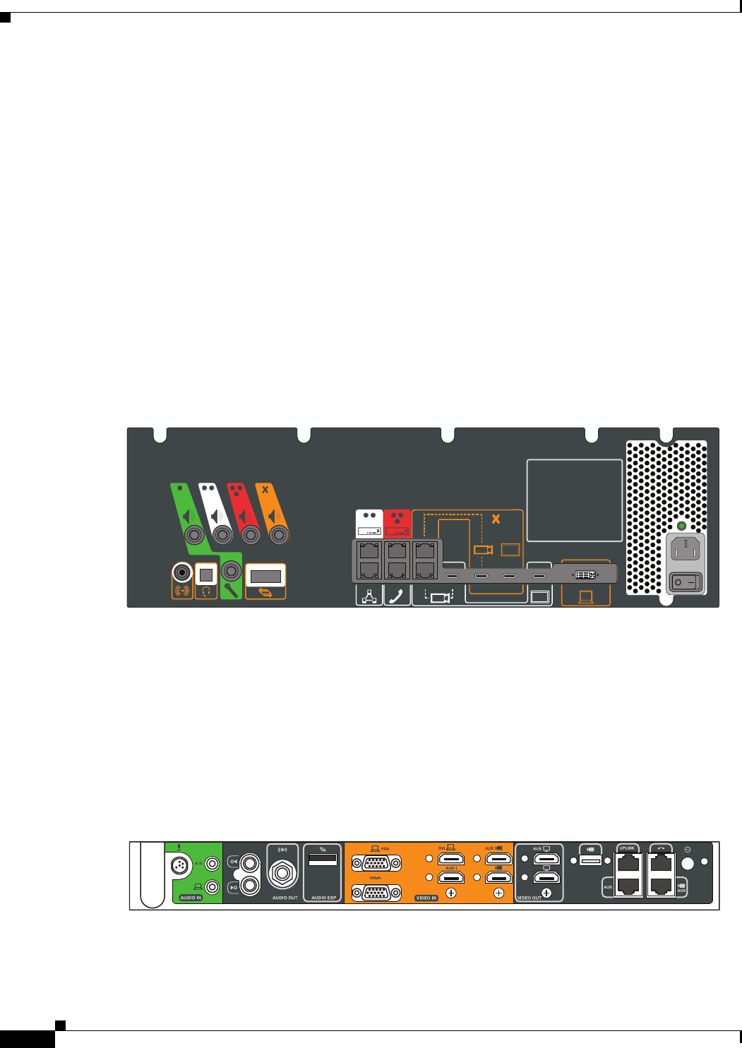
1-4
Cisco Unified Communications Manager Configuration Guide for the Cisco TelePresence System
OL-21851-01
Chapter 1 Loading Cisco Options Package (COP) Files on the Cisco TelePresence System
Using COP Files to Upgrade From the IP Phone to a Cisco TelePresence Touch 12
The following installation instructions specify loading an .sbn or .SPA file in Unified CM before you
specify the COP file name with no extensions. The file extension depends on the type of codec you use
in your system. To determine the type of file you specify, use the following guide:
Codec Example 1
If your codec looks like the one in Figure 3-1, use the .sbn file. The following systems use this codec:
•Cisco TelePresence System 500-37 (PID: CTS-500-37)
•Cisco TelePresence System 1000 (PID: CTS-1000)
•Cisco TelePresence System 1100 (PID: CTS-1100)
•Cisco TelePresence System 1300-65 (PID: CTS-1300)
•Cisco TelePresence System 3000 (PID: CTS-3000)
•Cisco TelePresence System 3010 (PID: CTS-3010)
•Cisco TelePresence System 3200 (PID: CTS-3200)
•Cisco TelePresence System 3210 (PID: CTS-3210)
Figure 3-1 Codec CTS-CODEC-PRI-G2 or CTS-CODEC-PRIM
Codec Example 2
If your codec looks like the one in Figure 3-2, use the .SPA file. The following systems use this codec:
•Cisco TelePresence System 500-32 (PID: CTS-500-32)
•Cisco TelePresence System TX1300 47 (PID: CTS-1300-47)
•Cisco TelePresence System TX1310-65 (PID: CTS-TX1310-65)
•Cisco TelePresence System TX9000 (PID: CTS-TX9000)
•Cisco TelePresence System TX9200 (PID: CTS-TX9200)
Figure 3-2 Codec CTS-CODEC-SING-G1 or CTS-CODEC-PRI-G2R
343024
343023

1-5
Cisco Unified Communications Manager Configuration Guide for the Cisco TelePresence System
OL-21851-01
Chapter 1 Loading Cisco Options Package (COP) Files on the Cisco TelePresence System
Using COP Files to Upgrade From the IP Phone to a Cisco TelePresence Touch 12
Kit and Parts List
Table 3-1 lists kits to order to upgrade your system from a Cisco Unified IP Phone to a
Cisco TelePresence Touch 12 (Touch 12).
Upgrading From Cisco TelePresence Software Releases 1.7.4 and Above
To load the COP files to Unified CM and upgrade your codec and Touch 12 software for systems that are
running CTS software version 1.7.4 and above, complete the following steps.
Step 1 Copy the COP file to a Secure File Transfer Protocol (SFTP) server that is accessible by Unified CM.
Step 2 Log in to the Unified CM administration interface (GUI).
Step 3 From the Navigation drop-down menu, on the top right of the GUI, select Cisco Unified OS
Administration.
Table 3-1 Cisco TelePresence Touch 12 Upgrade Kit and Parts List
Kit Number CTS
CTS-CTRL-DV12-A •Cisco TelePresence System 500-32 (PID: CTS-500-32)
•Cisco TelePresence System TX1300 47 (PID: CTS-1300-47)
•Cisco TelePresence System TX1310 65 (PID: CTS-TX1310-65)
•Cisco TelePresence System TX9000 (PID: CTS-TX9000)
•Cisco TelePresence System TX9200 (PID: CTS-TX9200)
Includes the Touch 12 device, part number CTS-CTRL-DV12.
CTS-CTRL-DV12-B •Cisco TelePresence System 1000 (PID: CTS-1000)
•Cisco TelePresence System 1100 (PID: CTS-1100)
•Cisco TelePresence System 1300-65 (PID: CTS-1300)
•Cisco TelePresence System 3000 (PID: CTS-3000)
•Cisco TelePresence System 3010 (PID: CTS-3010)
•Cisco TelePresence System 3200 (PID: CTS-3200)
•Cisco TelePresence System 3210 (PID: CTS-3210)
Includes:
•CTS-CTRL-DV12—Touch 12 device
•AIR-PWRINJ4—The Power injector for the Touch 12
•CTS-JUMPER-CORD—This cord connects the power injector to the power distribution unit
(PDU) for your system. The PDU end of the cord uses a IEC 60320 C19 connector to connect
to the PDU.
CTS-CTRL-DV12-C Cisco TelePresence System 500-37 (PID: CTS-500-37)
CTS-CTRL-DV12-C contains the same parts as the CTS-CTRL-DV12-B; however the
CTS-JUMPER-CORD is removed and replaced with a country-specific power cord. This change is
required because a Cisco TelePresence System 500-37 does not ship with a PDU.
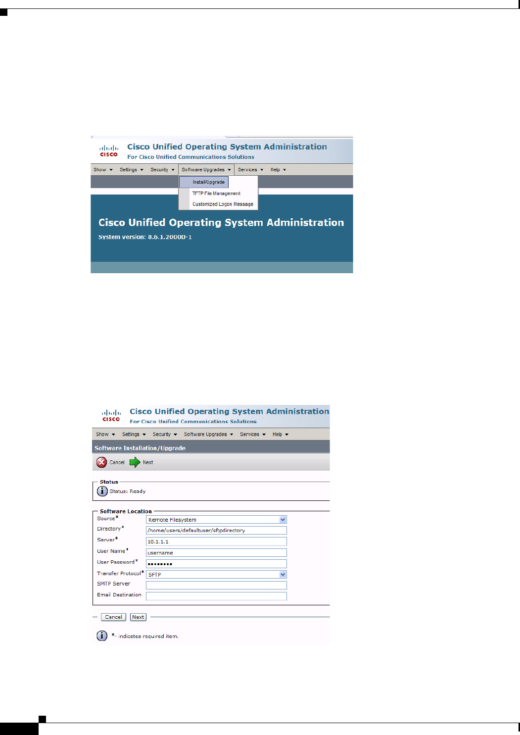
1-6
Cisco Unified Communications Manager Configuration Guide for the Cisco TelePresence System
OL-21851-01
Chapter 1 Loading Cisco Options Package (COP) Files on the Cisco TelePresence System
Using COP Files to Upgrade From the IP Phone to a Cisco TelePresence Touch 12
The Cisco Unified Operation System Administration screen appears.
Step 4 Enter your user ID and password if prompted to do so.
Step 5 Navigate to Software Upgrades > Install/Upgrade, as shown in Figure 3-3.
Figure 3-3 Cisco Unified Operating System Administration Screen
Step 6 In the Software Location area, specify the following information in the fields, as shown in Figure 3-4.:
•In the Source drop-down menu, select Remote Filesystem.
•In the Directory and Server fields, enter the location of the COP file on the SFTP server.
•In the User Name and User Password fields, enter the user name and password used to access the
SFTP server.
•In the Transfer Protocol drop-down menu, select SFTP.
Figure 3-4 Specifying SFTP Server and File Location
Step 7 Click Next. Unified CM accesses the SFTP server. The Software Location area lists the COP files that
Unified CM finds in the directory that you specified.
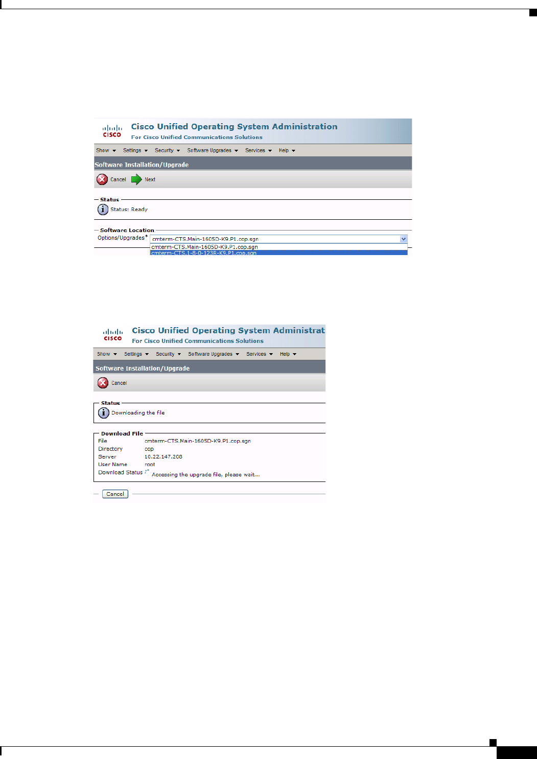
1-7
Cisco Unified Communications Manager Configuration Guide for the Cisco TelePresence System
OL-21851-01
Chapter 1 Loading Cisco Options Package (COP) Files on the Cisco TelePresence System
Using COP Files to Upgrade From the IP Phone to a Cisco TelePresence Touch 12
Step 8 In the Options/Upgrades drop-down menu, choose the COP file that you want to install from the
available file names, as shown in Figure 3-5.
Figure 3-5 Specifying the File To Be Used After Installing the COP File
Step 9 Click Next.
The Unified CM GUI shows the COP file being installed, as shown in Figure 3-6.
Figure 3-6 COP File Installation
Step 10 After installation completes, verify the file validity by completing the following steps:
a. Make a note of the information in the File Checksum Details area. This value is circled in Figure 3-7.
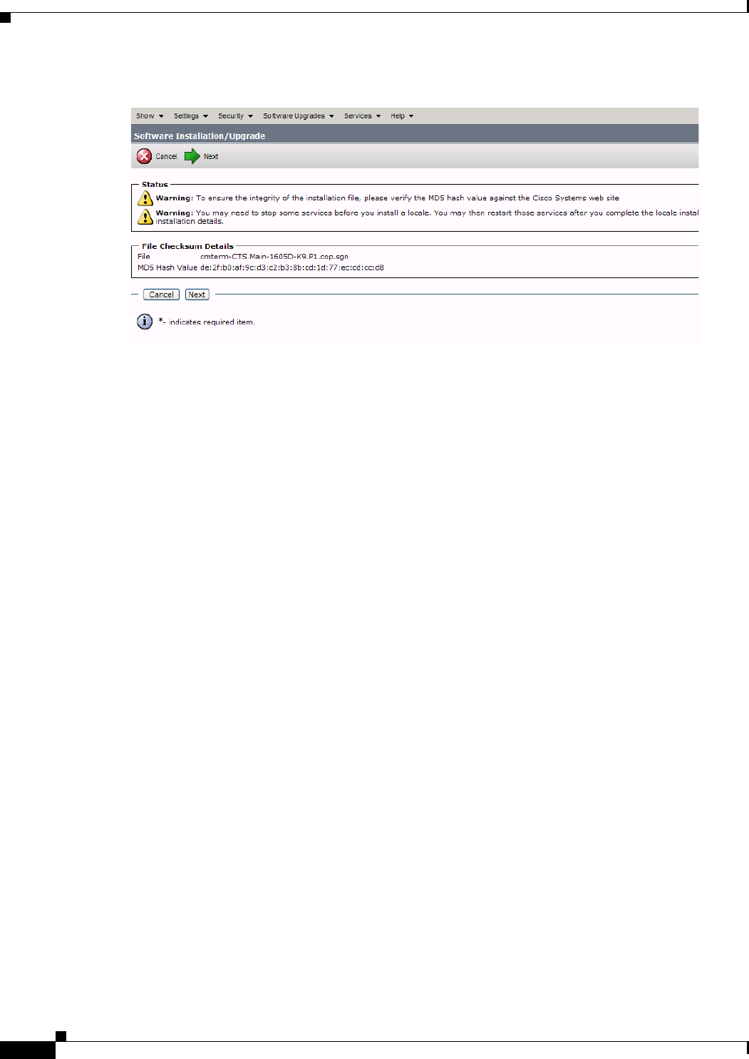
1-8
Cisco Unified Communications Manager Configuration Guide for the Cisco TelePresence System
OL-21851-01
Chapter 1 Loading Cisco Options Package (COP) Files on the Cisco TelePresence System
Using COP Files to Upgrade From the IP Phone to a Cisco TelePresence Touch 12
Figure 3-7 File Checksum Details Area
b. Log in to the SFTP server and enter the following command:
c. md5sum filename.cop.sgn
where:
filename is the file name of the COP file on the SFTP server.
d. Make a note of the checksum value that displays as a result of the md5sum command.
e. Compare the MD5 Hash Value that displays in this area to the MD5 checksum value that you find
in the COP file on the server and make sure that they match to ensure that the file is not corrupted.
f. If the values match, continue to the next step; if the values do not match, retry the file installation.
Step 11 Click Next to begin installation.
The installation log shows the installation progress.
After the .loads, codec and Touch 12 files are extracted, the interface shows Complete in the Installation
Status window, as shown in Figure 3-7.
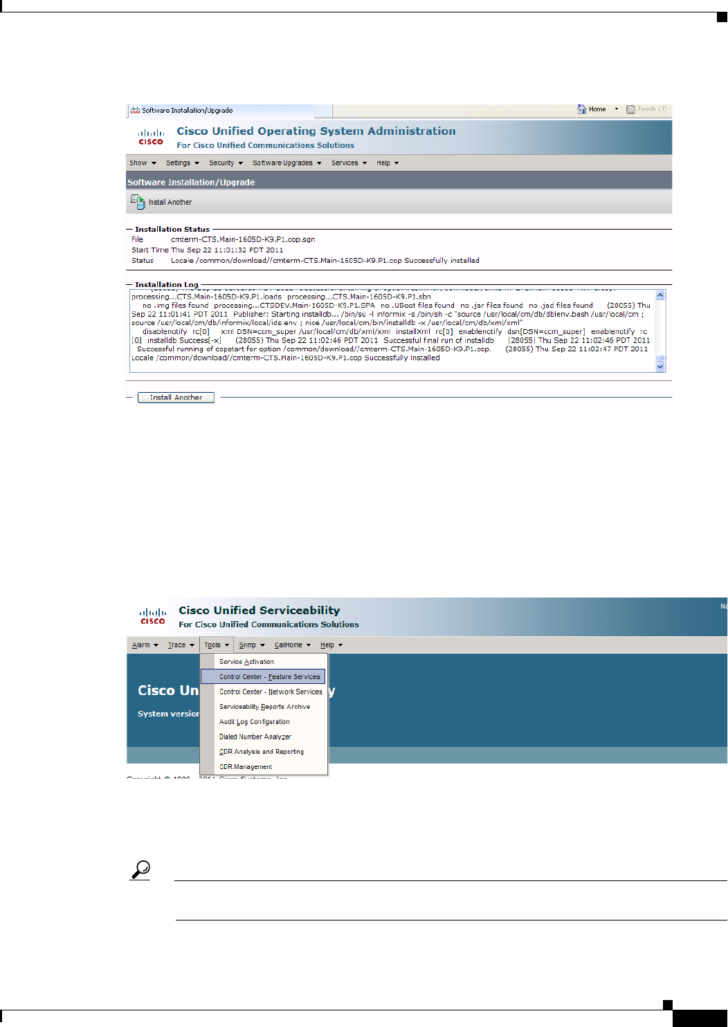
1-9
Cisco Unified Communications Manager Configuration Guide for the Cisco TelePresence System
OL-21851-01
Chapter 1 Loading Cisco Options Package (COP) Files on the Cisco TelePresence System
Using COP Files to Upgrade From the IP Phone to a Cisco TelePresence Touch 12
Figure 3-8 Installation Status Window
Step 12 From the Navigation drop-down menu on the top right of the GUI, select Cisco Unified Serviceability
and click Go.
The Cisco Unified Serviceability window appears.
Step 13 Enter your user ID and password if prompted to do so.
Step 14 Restart the TFTP server by completing the following steps:
a. Navigate to Tools > Control Center - Feature Services, as shown in Figure 3-9.
Figure 3-9 Cisco Unified Serviceability Window
b. Choose the correct TFTP server from the drop-down menu and click Go.
c. In the CM Services area, click the Cisco Tftp radio button.
d. Click the Restart button
Tip You can use either the Restart button on the bottom of the page, or the button circled in red in
Figure 3-10.
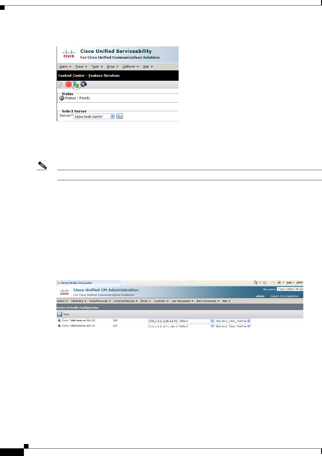
1-10
Cisco Unified Communications Manager Configuration Guide for the Cisco TelePresence System
OL-21851-01
Chapter 1 Loading Cisco Options Package (COP) Files on the Cisco TelePresence System
Using COP Files to Upgrade From the IP Phone to a Cisco TelePresence Touch 12
Figure 3-10 Restart Button in Features Services Page
Step 15 From the Navigation drop-down menu on the top right of the GUI, select Cisco Unified CM
Administration and click Go.
The Cisco Unified CM Administration window appears.
Step 16 To apply the software to all devices of a specified type, complete the following steps:
Note To load the software per device, rather than apply it as a default, continue to Step 17.
a. Navigate to Device > Device Settings > Device Defaults.
b. Locate the system to which you want to apply a default codec image.
c. Apply the 1.8.0 codec image file as the default image file for all systems of a specified type by
completing the following steps:
1. In the Load Information field, enter the name of the COP file, removing the cmterm- in front of
the file name.
In the example in Figure 3-11, the administrator specified a default codec file image of
CTS.1-8-0-123R-K9.P2 for all Cisco TelePresence 500-32 systems.
Figure 3-11 Specifying the Default Codec File Image for All Systems of a Specified Type
2. Click Save to save your changes.
d. Navigate to Device > Phone.
e. Search and access the device type for which you want to apply the new codec image file by
completing the following steps:
1. In the Find Phone Where area, choose the Device Type and begins with drop-down choices.
2. Enter the device type for the endpoint; for example, Cisco TelePresence 500-32.
3. Click Find. An example results screen is shown in Figure 3-12.
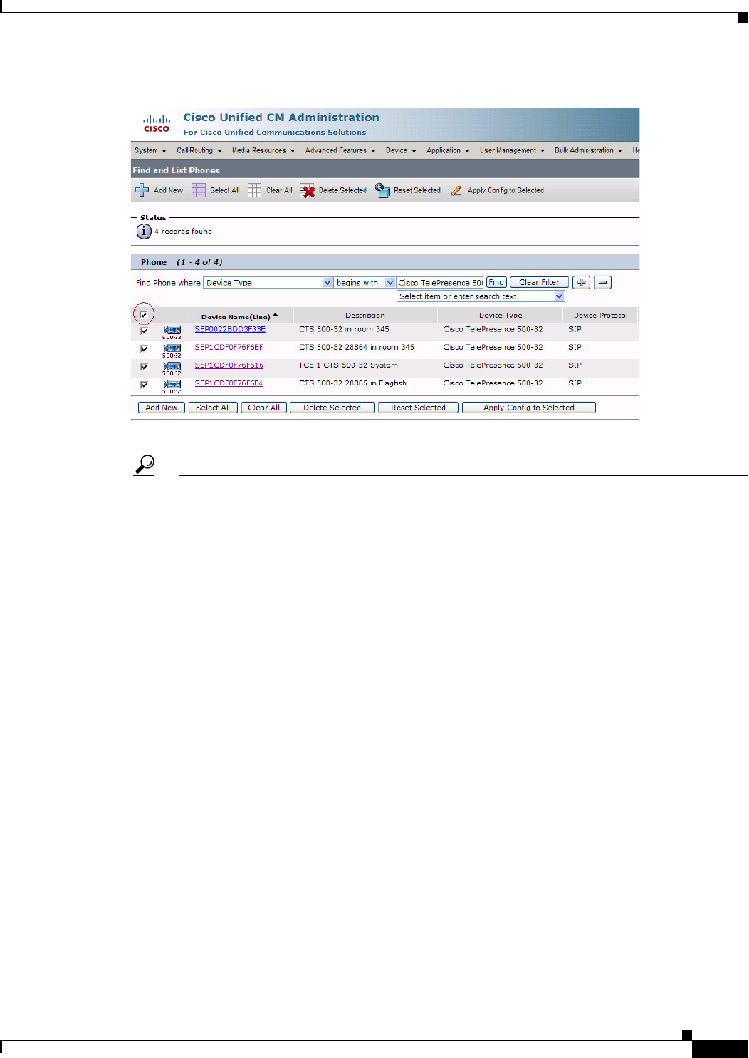
1-11
Cisco Unified Communications Manager Configuration Guide for the Cisco TelePresence System
OL-21851-01
Chapter 1 Loading Cisco Options Package (COP) Files on the Cisco TelePresence System
Using COP Files to Upgrade From the IP Phone to a Cisco TelePresence Touch 12
Figure 3-12 Results Screen After Device Type Search
4. Select the check box on the left side of the page to select all devices.
Tip This check box is circled in red in Figure 3-12.
5. Click Apply Config to Selected to apply the configuration to all selected devices.
f. Continue to Step 18.
Step 17 To load the software for a specific device, complete the following steps:
a. Navigate to Device > Phone.
b. Search and access your device by completing the following steps:
1. Use the drop-down choices to specify a valid search term, or leave the fields blank to find all
devices.
2. Click Find.
3. Click the hypertext link in the Device Name (Line) row that corresponds to your device.
Step 18 Apply the codec file image to your system by completing the following steps:
a. In the Phone Load Name field, enter the name of the COP file, removing the cmterm-in front of the
file name.
In the example in Figure 3-13, the administrator specified a file name of CTS.1-8-0-123R-K9.P2.

1-12
Cisco Unified Communications Manager Configuration Guide for the Cisco TelePresence System
OL-21851-01
Chapter 1 Loading Cisco Options Package (COP) Files on the Cisco TelePresence System
Using COP Files to Upgrade From the IP Phone to a Cisco TelePresence Touch 12
Figure 3-13 Phone Load Name Field
b. Click Save.
c. Click Apply Config.
Step 19 Connect the Touch 12 to the system as described in the “Connecting the Cisco TelePresence Touch 12
to the System” section on page 1-20.
Upgrading From Cisco TelePresence Software Releases Prior to CTS 1.7.4
To load the .sbn or .SPA and COP files to Unified CM and upgrade your codec and Touch 12 software
in systems that are running CTS software versions that are lower than 1.7.4, complete the following
steps.
Step 1 Copy the COP file to a Secure File Transfer Protocol (SFTP) server that is accessible by Unified CM.
Step 2 Log in to the Unified CM Administration interface.
Step 3 From the Navigation drop-down menu, on the top right of the GUI, select Cisco Unified OS
Administration. The Cisco Unified Operation System Administration screen appears.
Step 4 Enter your user ID and password if prompted to do so.
Step 5 Navigate to Software Upgrades > Install/Upgrade.
Figure 3-14 Cisco Unified Operating System Administration Screen
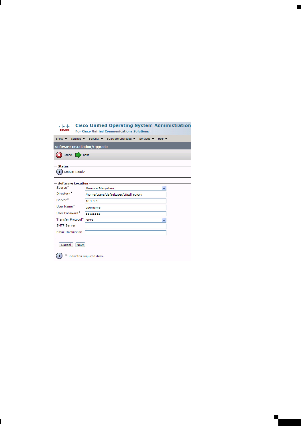
1-13
Cisco Unified Communications Manager Configuration Guide for the Cisco TelePresence System
OL-21851-01
Chapter 1 Loading Cisco Options Package (COP) Files on the Cisco TelePresence System
Using COP Files to Upgrade From the IP Phone to a Cisco TelePresence Touch 12
Step 6 In the Software Location window, specify the following information in the fields, as shown in
Figure 3-15:
•In the Source drop-down menu, select Remote Filesystem.
•In the Directory and Server fields, enter the location of the COP file on the SFTP server.
•In the User Name and User Password fields, enter the user name and password used to access the
SFTP server.
•In the Transfer Protocol drop-down menu, select SFTP.
•
Figure 3-15 Specifying SFTP Server and File Location
Step 7 Click Next.
Unified CM accesses the SFTP server. The Software Location area lists the COP files that Unified CM
finds in the directory that you specified.
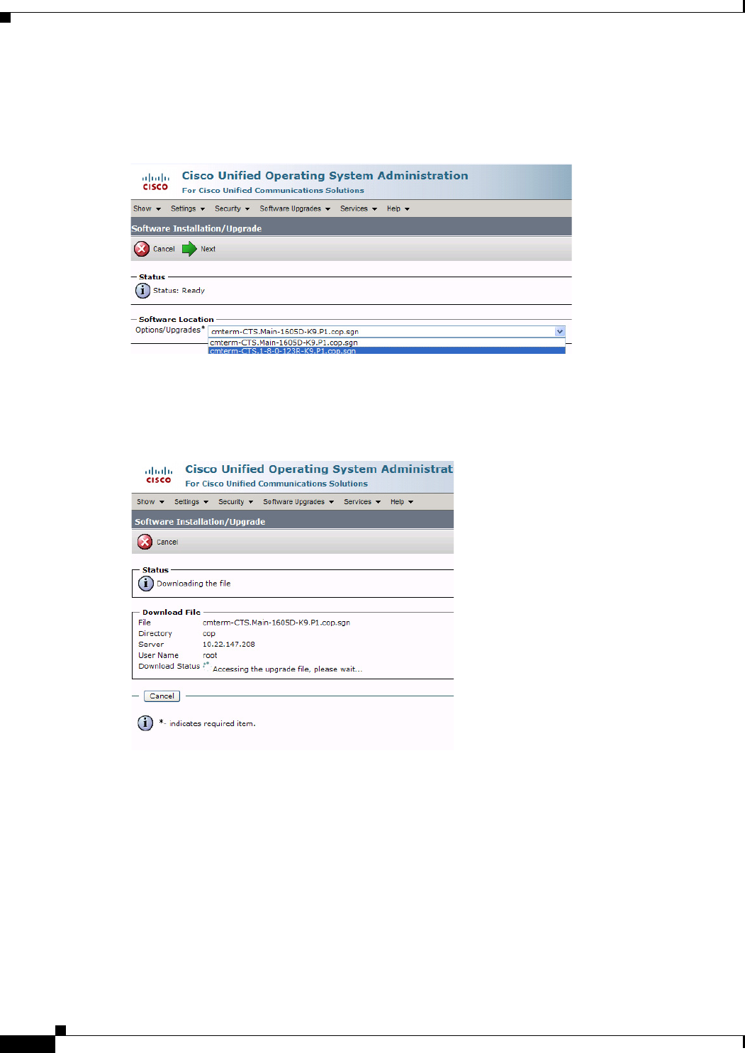
1-14
Cisco Unified Communications Manager Configuration Guide for the Cisco TelePresence System
OL-21851-01
Chapter 1 Loading Cisco Options Package (COP) Files on the Cisco TelePresence System
Using COP Files to Upgrade From the IP Phone to a Cisco TelePresence Touch 12
Step 8 Choose the COP file that you want to install from the available file names in the Options/Upgrades
drop-down menu, as shown in Figure 3-16.
Figure 3-16 Specifying the COP File
Step 9 Click Next.
The Unified CM GUI shows the COP file being installed, as shown in Figure 3-17.
Figure 3-17 COP File Installation
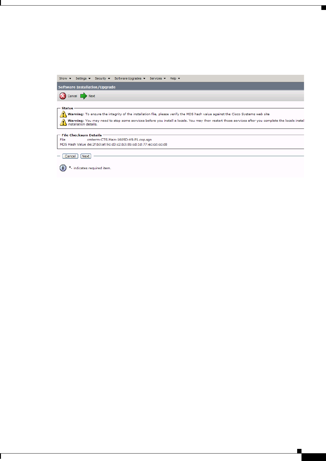
1-15
Cisco Unified Communications Manager Configuration Guide for the Cisco TelePresence System
OL-21851-01
Chapter 1 Loading Cisco Options Package (COP) Files on the Cisco TelePresence System
Using COP Files to Upgrade From the IP Phone to a Cisco TelePresence Touch 12
Step 10 After installation completes, verify the file validity by completing the following steps:
a. Make a note of the information in the File Checksum Details window, as shown in Figure 3-18.
Figure 3-18 File Checksum Details Window
b. Log in to the SFTP server and enter the following command:
c. md5sum filename.cop.sgn
where filename is the file name of the COP file on the SFTP server.
d. Make a note of the checksum value that displays as a result of the md5sum command.
e. Compare the MD5 Hash Value that displays in this area to the MD5 checksum value that you find
in the COP file on the server and make sure that they match to ensure that the file is not corrupted.
f. If the values match, continue to the next step; if the values do not match, retry the file installation.
Step 11 Click Next to begin installation.
The installation log shows the installation progress.
After the .loads, codec and Touch 12 files are extracted, the interface shows Complete in the Installation
Status window, as shown in Figure 3-19.
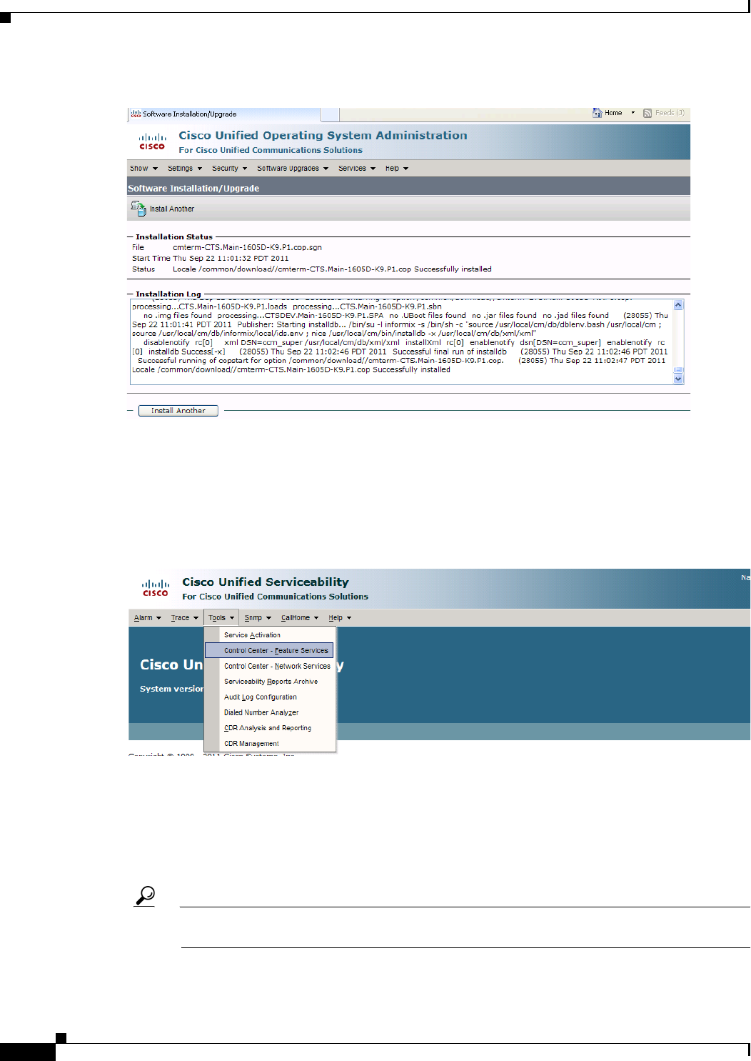
1-16
Cisco Unified Communications Manager Configuration Guide for the Cisco TelePresence System
OL-21851-01
Chapter 1 Loading Cisco Options Package (COP) Files on the Cisco TelePresence System
Using COP Files to Upgrade From the IP Phone to a Cisco TelePresence Touch 12
Figure 3-19 Installation Status Window
Step 12 From the Navigation drop-down menu on the top right of the GUI, select Cisco Unified Serviceability
and click Go.
The Cisco Unified Serviceability window appears, as shown in Figure 3-20.
Step 13 Enter your user ID and password if prompted to do so.
Figure 3-20 Cisco Unified Serviceability Window
Step 14 Restart the TFTP server by completing the following steps:
a. Navigate to Tools > Control Center - Feature Services.
b. Choose the correct TFTP server from the drop-down menu and click Go.
c. In the CM Services window click the Cisco TFTP radio button.
d. Click the Restart button.
Tip You can use either the Restart button on the bottom of the page or the button circled in red in
Figure 3-21.
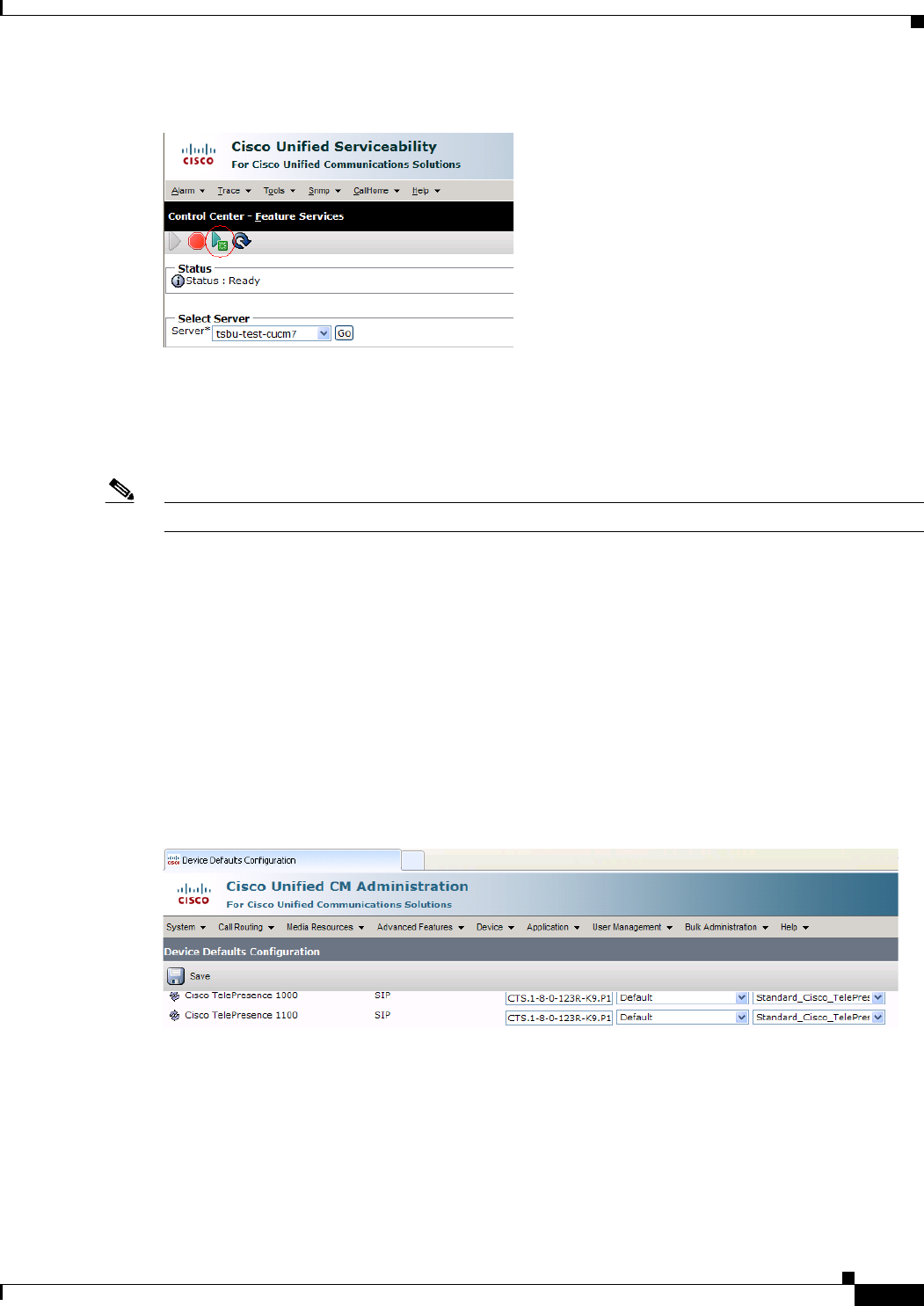
1-17
Cisco Unified Communications Manager Configuration Guide for the Cisco TelePresence System
OL-21851-01
Chapter 1 Loading Cisco Options Package (COP) Files on the Cisco TelePresence System
Using COP Files to Upgrade From the IP Phone to a Cisco TelePresence Touch 12
Figure 3-21 Restart Button in Features Services Page
Step 15 From the Navigation drop-down menu on the top right of the GUI, select Cisco Unified CM
Administration and click Go.
The Cisco Unified CM Administration window appears.
Step 16 To apply the software to all devices of a specified type, complete the following steps:
Note To load the software per device, rather than apply it as a default, continue to Step 17.
a. Navigate to Device > Device Settings > Device Defaults.
b. Locate the system to which you want to apply a default codec image.
c. Apply the 1.8.0 codec image file as the default image file for all systems of a specified type by
completing the following steps:
1. In the Load Information field, enter the name of the COP file, making the following changes:
•If your system uses the codec shown in Figure 3-1, append a file type of .sbn.
In the example in Figure 3-22, the administrator specified a default codec file image of
CTS.1-8-0-123R-K9.P1.sbn for all CTS 1100 systems. The original COP file name was
cmterm-CTS.1-8-0-123R-K9.P1.
Figure 3-22 Specifying the Default .sbn File Image for All Systems of a Specified Type
•If your system uses the codec shown in Figure 3-2, append a file type of .SPA.
In the example in Figure 3-23, the administrator specified device a default codec file image of
CTS.1-8-0-123R-K9.P2.SPA for all CTS 500-32 systems. The original COP file name was
cmterm-CTS.1-8-0-123R-K9.P2.

1-18
Cisco Unified Communications Manager Configuration Guide for the Cisco TelePresence System
OL-21851-01
Chapter 1 Loading Cisco Options Package (COP) Files on the Cisco TelePresence System
Using COP Files to Upgrade From the IP Phone to a Cisco TelePresence Touch 12
Figure 3-23 Specifying the Default .SPA File Image for All Systems of a Specified Type
2. Click Save to save your changes.
d. Navigate to Device > Phone.
e. Search and access the device type for which you want to apply the new codec image file by
completing the following steps:
1. In the Find Phone Where area, choose the Device Type and begins with drop-down choices.
2. Enter the device type for the endpoint; for example, Cisco TelePresence 500-32.
3. Click Find. An example results screen is shown in Figure 3-24.
Figure 3-24 Results Screen After Device Type Search
4. Select the check box on the left side of the page to select all devices.
Tip This check box is circled in red in Figure 3-24.
5. Click Apply Config to Selected to apply the configuration to all selected devices.
f. Continue to Step 18.
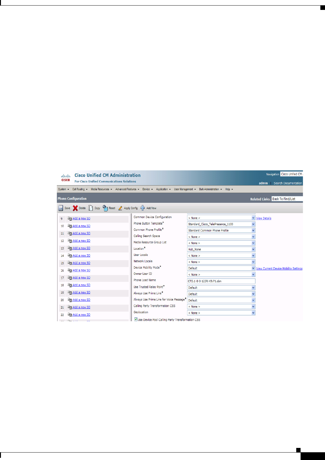
1-19
Cisco Unified Communications Manager Configuration Guide for the Cisco TelePresence System
OL-21851-01
Chapter 1 Loading Cisco Options Package (COP) Files on the Cisco TelePresence System
Using COP Files to Upgrade From the IP Phone to a Cisco TelePresence Touch 12
Step 17 To load the software for a specific device, complete the following steps:
a. Navigate to Device > Phone.
b. Search and access your device by completing the following steps:
1. Use the drop-down choices to specify a valid search term, or leave the fields blank to find all
devices.
2. Click Find.
3. Click the hypertext link in the Device Name (Line) row that corresponds to your device.
Step 18 Apply the codec file image to your system by completing the following steps:
a. If your system uses the codec shown in Figure 3-1, append a file type of .sbn.
In the example in Figure 3-25, the administrator specified a default codec file image of
CTS.1-8-0-123R-K9.P1.sbn for all the specified system. The original COP file name was
cmterm-CTS.1-8-0-123R-K9.P1.
Figure 3-25 Specifying an .sbn File Image for a Specific System
b. If your system uses the codec shown in Figure 3-2, append a file type of .SPA.
In the example in Figure 3-26, the administrator specified a codec file image of
CTS.1-8-0-123R-K9.P2.SPA. The original COP file name was cmterm-CTS.1-8-0-123R-K9.P2.
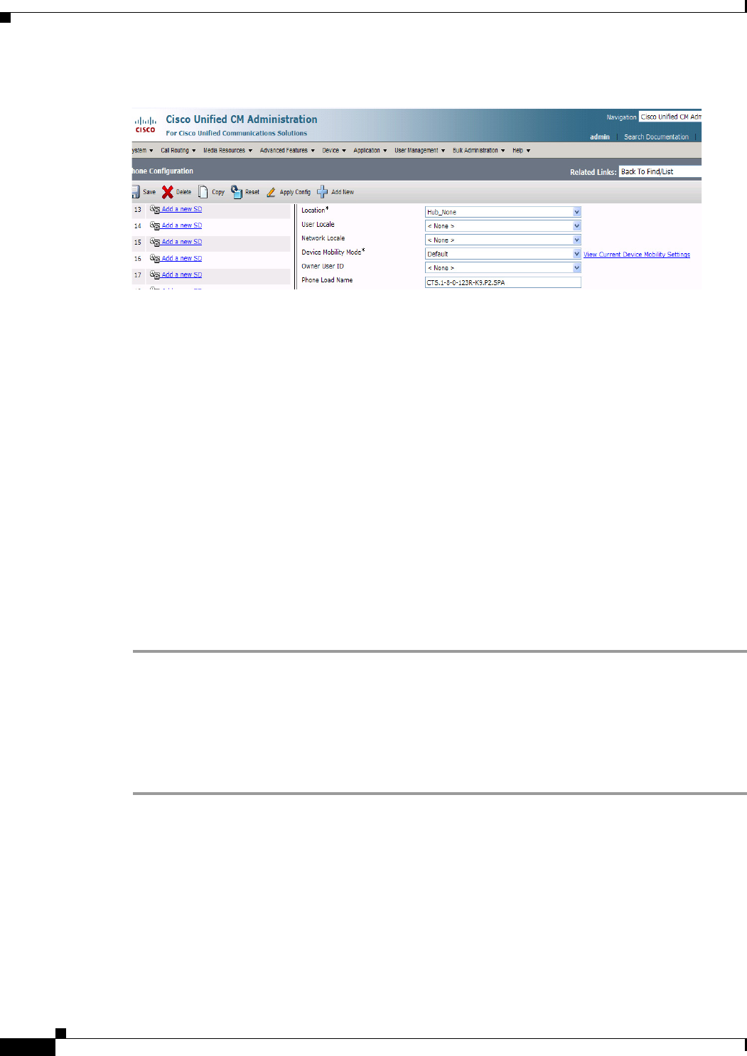
1-20
Cisco Unified Communications Manager Configuration Guide for the Cisco TelePresence System
OL-21851-01
Chapter 1 Loading Cisco Options Package (COP) Files on the Cisco TelePresence System
Using COP Files to Upgrade From the IP Phone to a Cisco TelePresence Touch 12
Figure 3-26 Specifying an .SPA File Image for a Specific System
c. Click Save.
d. Click Apply Config to apply the configuration to this device.
The codec shuts down, applies the .SPA codec file as its boot file, and reboots.
Step 19 Apply the COP (Loads) file to the codec, which in turn allows the Touch 12 file to be installed by the
Touch 12, by completing the following steps:
a. Redo Step 15 through Step 17 in this section, making the following changes:
b. In the Load Information field (for all devices of a specified type) or the Phone Load Name field (for
a single device), enter the name of the COP file, omitting all file types.
In the examples in Figure 3-23 and Figure 3-26, you would change the file name from
CTS.1-8-0-123R-K9.P2.SPA to CTS.1-8-0-123R-K9.P2. In the examples in Figure 3-22 and
Figure 3-25, you would change the file name from CTS.1-8-0-123R-K9.P1.sbn to
CTS.1-8-0-123R-K9.P1.
c. Click Save.
d. Click Apply Config.
Step 20 Connect the Touch 12 to the system as described in the “Connecting the Cisco TelePresence Touch 12
to the System” section on page 1-20.
Connecting the Cisco TelePresence Touch 12 to the System
For systems that use the codec shown in Figure 3-1, connect the Touch 12 device, by completing the
following tasks:
Step 1 Connect one Ethernet cable between the “Network Uplink Input RJ-45” port on the rear of the Touch 12
and the connection labeled “To AP” on the PoE unit.
Step 2 Connect one Ethernet cable between the “To Phone” connection on the codec and the connection labeled
“To Switch” on the PoE unit, as shown in Figure 3-27.
Step 3 Connect one end of the power cord to the PoE unit and plug the other end into a wall outlet.
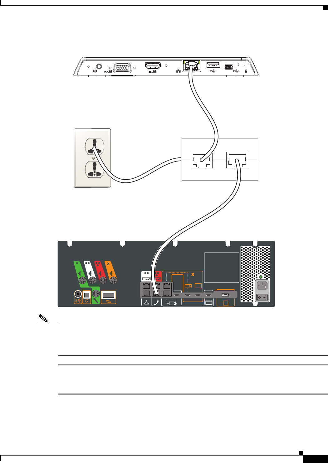
1-21
Cisco Unified Communications Manager Configuration Guide for the Cisco TelePresence System
OL-21851-01
Chapter 1 Loading Cisco Options Package (COP) Files on the Cisco TelePresence System
Using COP Files to Upgrade From the IP Phone to a Cisco TelePresence Touch 12
Figure 3-27 Cisco TelePresence Touch Connections with Power over Ethernet Unit
Note After you connect the Touch device, you should see a series of circled numbers on the lower left side of
the Touch display. The numbers change to check marks as the device is starting. If the circled numbers
do not change to check marks or you receive a message on the Touch device that it could not register to
the codec, disconnect the Touch device, wait 5 minutes, then reconnect it.
For systems that use the codec shown in Figure 3-2, connect the Touch 12 by doing the following:
Step 1 Connect the other side of the Ethernet cable to the “To Phone” connection on the system codec.
Step 2 Connect one side of the Ethernet cable that is supplied with the Touch 12 to the “Network Uplink Input
RJ-45” port on the rear of the device, as shown in Figure 3-28.
Wall Outlet
To AP To Switch
PoE Unit
Codec
Cisco Touch
209824
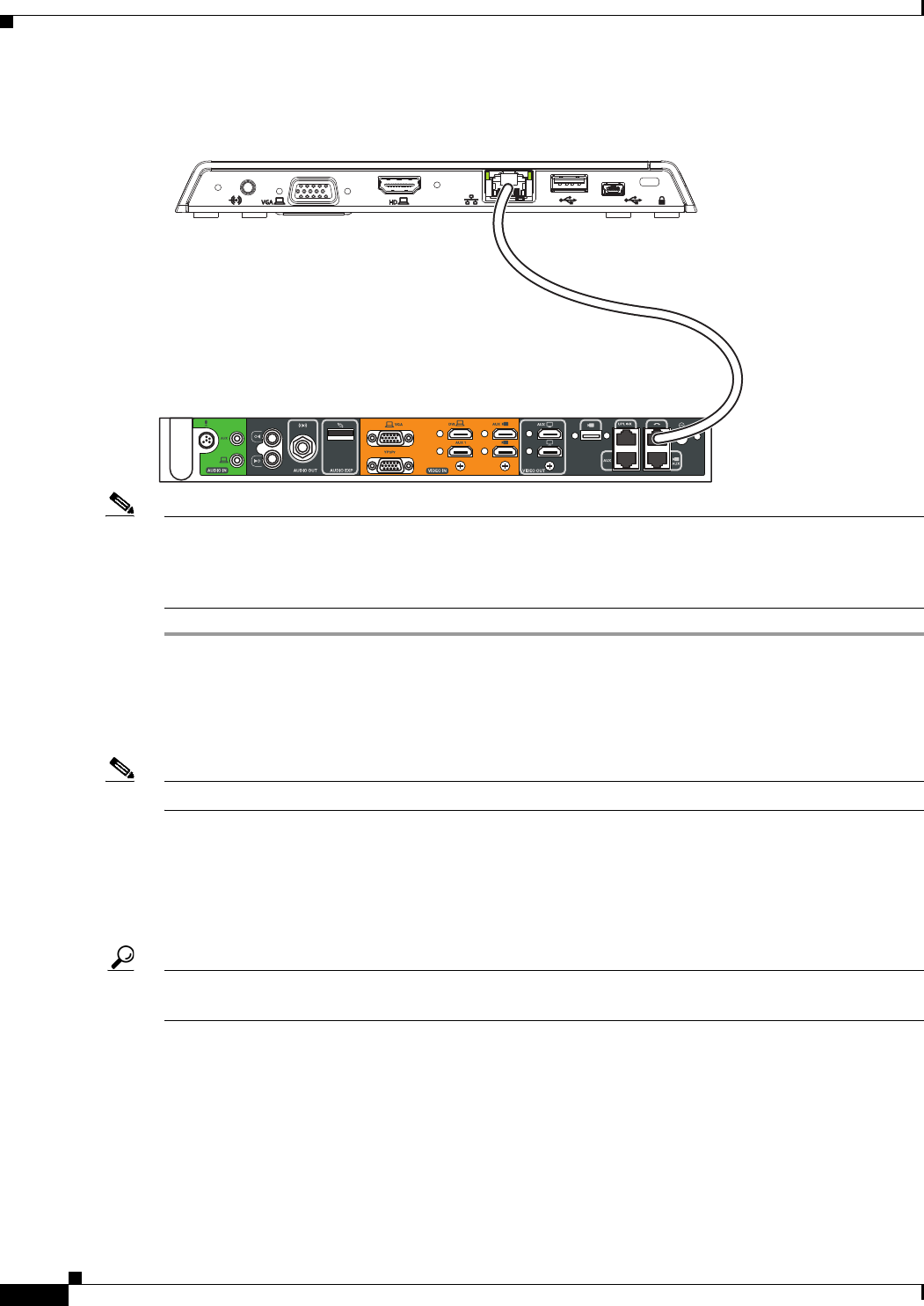
1-22
Cisco Unified Communications Manager Configuration Guide for the Cisco TelePresence System
OL-21851-01
Chapter 1 Loading Cisco Options Package (COP) Files on the Cisco TelePresence System
Configuring the Directory on the Cisco TelePresence Touch 12
Figure 3-28 Cisco TelePresence Touch Connection
Note After you connect the Touch device, you should see a series of circled numbers on the lower left side of
the Touch display. The numbers change to check marks as the device is starting. If the circled numbers
do not change to check marks or you receive a message on the Touch device that it could not register to
the codec, disconnect the Touch device, wait 5 minutes, then reconnect it.
Configuring the Directory on the Cisco TelePresence Touch 12
Note The Cisco TelePresence Touch 12 requires Unified CM 8.5.1 or higher.
To use the directory service for the Cisco TelePresence Touch 12, you must make the following changes
in Cisco Unified Communications Manager (Unified CM):
1. Enable Cisco User Data Services (UDS) on systems running a minimum of Unified CM 8.6(2).
2. Configure the User Search Limit to 500.
Tip The Cisco TelePresence Touch 12 still functions if you do not enable User Data Services in Unified CM
8.6(1) or higher, but you cannot access the directory.
Go to the following sections to configure the directory:
•Enabling User Data Services, page 1-23
•Configuring the Search User Limit, page 1-23
209825
Cisco Touch
Codec
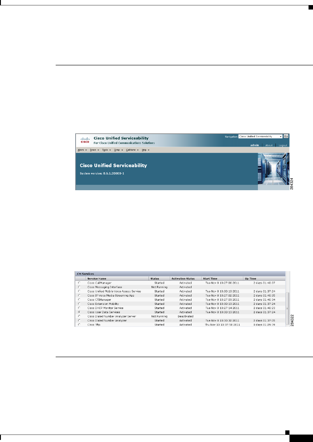
1-23
Cisco Unified Communications Manager Configuration Guide for the Cisco TelePresence System
OL-21851-01
Chapter 1 Loading Cisco Options Package (COP) Files on the Cisco TelePresence System
Configuring the Directory on the Cisco TelePresence Touch 12
Enabling User Data Services
To enable Cisco User Data Services:
Step 1 Log in to the Cisco Unified CM Administration interface.
Step 2 From the Navigation drop-down menu on the top right of the Unified CM Administration interface,
select Cisco Unified Serviceability and click Go.
The Cisco Unified Serviceability window appears, as shown in Figure 3-29.
Figure 3-29 Cisco Unified Serviceability Window
Step 3 Enter your user ID and password if prompted to do so.
Step 4 Navigate to Tools > Control Center—Feature Services.
Step 5 Select the Unified CM server from the drop-down menu and click Go.
Step 6 Scroll to the CM Services window and click the Cisco User Data Services radio button, as shown in
Figure 3-30.
Figure 3-30 Cisco User Data Services
Step 7 Click Restart to save your changes and start the service.
Step 8 Proceed to Configuring the Search User Limit.
Configuring the Search User Limit
To configure the Search User Limit to 500:
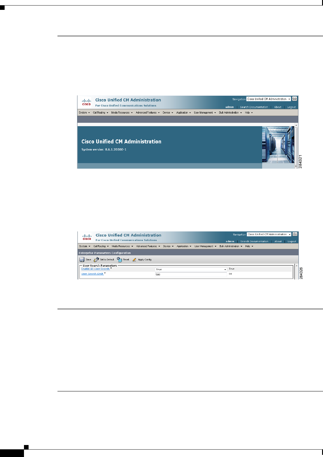
1-24
Cisco Unified Communications Manager Configuration Guide for the Cisco TelePresence System
OL-21851-01
Chapter 1 Loading Cisco Options Package (COP) Files on the Cisco TelePresence System
Setting the Idle Display Default (“Home”) Screen
Step 1 From the Navigation drop-down menu on the top right of the Unified CM Administration interface,
select Cisco Unified CM Administration and click Go.
Step 2 The Cisco Unified CM Administration window appears, as shown in Figure 3-31.
Figure 3-31 Cisco Unified CM Administration Window
Step 3 Navigate to System > Enterprise Parameters.
Step 4 Scroll to the User Search Parameters window.
Step 5 Enter 500 in the User Search Limit field, as shown in Figure 3-32.
Figure 3-32 User Search Parameters Window
Step 6 Click Save to save your changes.
Step 7 Click Apply Config to apply your changes.
Setting the Idle Display Default (“Home”) Screen
The steps to set the idle display default screen on the Cisco TelePresence Touch 12 are the same in the
Cisco Unified Communications Manager Administration interface as those for the Cisco Unified IP
phone.
To choose the default (“home”) screen:
Step 1 Navigate to the user device by going to Device > Phone.
Step 2 Scroll to the User Preferences window.
Step 3 In the Idle Display field, choose one of the following options from the drop-down menu:
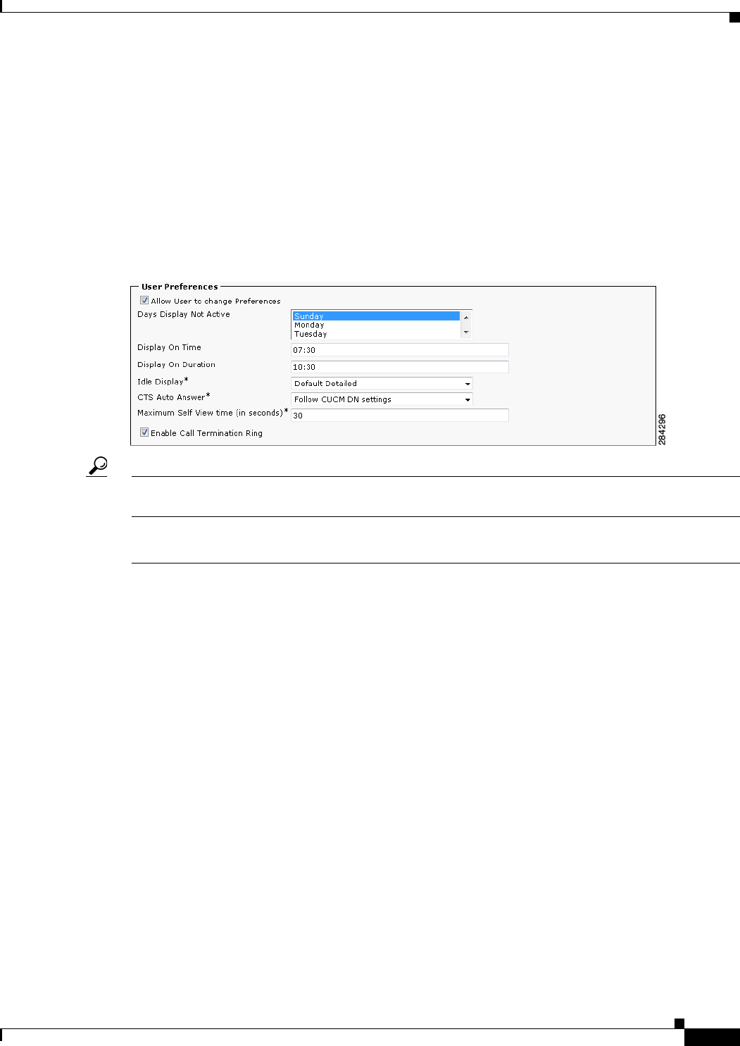
1-25
Cisco Unified Communications Manager Configuration Guide for the Cisco TelePresence System
OL-21851-01
Chapter 1 Loading Cisco Options Package (COP) Files on the Cisco TelePresence System
Related Information
•Default Detailed
•Manual
•Directory
•Favorites
•Default Simple
Step 4 Optional. Check the box at the top of the User Preferences window to allow the user to change
preferences, as shown in Figure 3-33.
Figure 3-33 Set User Preferences - Idle Display “Home” Screen
Tip Only two preferences are allowed to be changed by the user on the Cisco TelePresence Touch 12 when
you check the “Allow User to change Preferences” box: Auto Answer (on or off) and Ringtone.
Step 5 Click Apply Config then click Save.
Related Information
See the following documentation for more information:
•Cisco TelePresence Command-Line Interface Reference Guide
•Cisco Unified Serviceability Administration Guide
•Disaster Recovery System Administration Guide
•Installing and Configuring the Cisco TelePresence Touch 12
•Cisco TelePresence Touch

1-26
Cisco Unified Communications Manager Configuration Guide for the Cisco TelePresence System
OL-21851-01
Chapter 1 Loading Cisco Options Package (COP) Files on the Cisco TelePresence System
Related Information

CHAPTER
4-1
Cisco Unified Communications Manager Configuration Guide for the Cisco TelePresence System
OL-21851-01
4
Verifying and Troubleshooting the
Cisco TelePresence System Configuration
Revised: June 9, 2015, OL-21851-01
Contents
The following sections describe how to verify your Cisco TelePresence System with Cisco Unified
Communications Manager (Unified CM) configuration:
•Troubleshooting Your Configuration, page 4-1
•Managing Passwords, page 4-4
•Managing Phone Reset and Codec Connectivity, page 4-7
Troubleshooting Your Configuration
Use the information in Table 4-1 to help you troubleshoot your configuration.
Before You Begin
First check that the following conditions have been met:
•Power has been applied.
•The Cisco TelePresence System has been installed and configured according to the instructions in
Cisco TelePresence System Assembly Guides.
•Unified CM has been configured to support the Cisco TelePresence System as described in this
guide.
•The endpoint can be accessed with an IP address through the Web UI.

4-2
Cisco Unified Communications Manager Configuration Guide for the Cisco TelePresence System
OL-21851-01
Chapter 4 Verifying and Troubleshooting the Cisco TelePresence System Configuration
Troubleshooting Your Configuration
Testing Your Unified CM Server
You also can test for proper communication between your Unified CM server by completing the
following steps:
Step 1 Log in to the Admin CLI with Secure Shell (SSH).
Step 2 Enter the command utils network ping {X}, where X is the IP address or DNS name of the Unified CM
server. If the command results in a 0% packet loss, the network is functioning properly. If there is any
packet loss, check your network for errors.
Table 4-1 Troubleshooting the Cisco TelePresence Configuration
Problem Possible Cause Possible Solutions
The system does not upgrade. •The system cannot find or download the
upgrade file from the Cisco Unified CM
TFTP server.
•AutoUpgrade is set to false.
1. Check that the correct upgrade file name is
configured on the TX system Device page
in Cisco Unified CM.
2. Check whether the upgrade file is
uploaded to the TFTP server.
3. Check whether TFTP service has been
restarted after the upgrade file is uploaded.
4. Check whether the TX system is pointed to
correct the TFTP server where the upgrade
file is located.
5. Set AutoUpgrade to True. Determine your
settings by entering the following CLI
command:
show upgrade det
If AutoUpgrade is set to False, re-set it to
True. Contact TAC for assistance.
See also the Cisco TelePresence
Administration Software Command
References home page on Cisco.com for
information about CLI commands
The system was moved to a
different Unified CM and the
registration is rejected.
CTL File Issues
The system was associated with a different
secure Unified CM at one time and the
system preserved the previous Certificate
Trust List (CTL) file.
Delete the CTL file through the administration
interface in the Cisco Unified CM
Administration interface.

4-3
Cisco Unified Communications Manager Configuration Guide for the Cisco TelePresence System
OL-21851-01
Chapter 4 Verifying and Troubleshooting the Cisco TelePresence System Configuration
Troubleshooting Your Configuration
The Cisco TelePresence unit
does not register with
Unified CM:
•From the Unified CM
device page, the system
status shows
unregistered or
unknown.
•From the codec Web user
interface (UI), system
status shows unknown or
inaccessible for Unified
CM.
CTS Unknown Issues
Cisco TelePresence System could be
unknown:
•MAC address is entered incorrectly.
•Cisco Unified CM does not know about
the system.
•System is not registered because it is
unplugged.
Profile or Provisioning Issues
•System profile is not provisioned
properly in Cisco Unified CM.
Directory Number Issues
•Directory Number (DN) is not
configured.
•Verify the phone registration by doing the
following:
–
Log in to the Cisco Unified CM
Administration interface.
–
Click on the IP address and verify the
phone registration.
•Log in to Unified CM and make sure that
the system profile and the directory
number (DN) are created and configured
properly.
•Make sure the system MAC address is
entered correctly in Unified CM.
•Delete the CTL file through the
administration interface.
•Completely delete the system from
Unified CM, including its associated DN,
then add it back to Unified CM.
Tip Even if you make minor changes on the
Unified CM Device page (such as in
the Description field), remember to
click Save and restart the system.
TFTP Issues
•Unified CM or TFTP service issue.
•TFTP port 6970 is blocked so that the
CTS cannot download the “device config
xml” file from Unified CM TFTP server.
XML Issues
•XML configuration file is suspected to
be corrupted on the Unified CM
database.
•Make sure Unified CM and TFTP service
is running. Restart services if necessary.
•Make sure there is no firewall or device
between the system and Cisco Unified CM
that blocks the 6970 port.
Hostname Issues
•Cannot resolve hostname of Unified CM.
If you are using the Unified CM hostname as
the TFTP server on the system, make sure that
the hostname can be resolved by the domain
name system (DNS).
System un-registers from
time to time.
SIP Issues
•The system experiences a SIP
registration timeout.
Network Issues
•Intermittent network issues could cause
packets to be dropped.
1. Confirm that Unified CM is receiving SIP
messages and whether the system is
responding.
2. Collect a packet capture if necessary to
submit to Cisco technical response for
further review.
Table 4-1 Troubleshooting the Cisco TelePresence Configuration (continued)
Problem Possible Cause Possible Solutions

4-4
Cisco Unified Communications Manager Configuration Guide for the Cisco TelePresence System
OL-21851-01
Chapter 4 Verifying and Troubleshooting the Cisco TelePresence System Configuration
Managing Passwords
Managing Passwords
The following sections contain information to help you manage your passwords:
•Resetting Your Unified CM Secure Shell Password, page 4-5
•Resetting Your CTS Codec Password, page 4-5
•Related Information, page 4-8
Orange question mark
appears in the
Administration interface
Troubleshooting >
Microphones page for the
two outside microphones of
the second row table
(CTS 32x0 and TX9200
only).
The second row was configured for a
“reduced configuration” second row that
seats eight people rather than 12. The two
outside microphones are not recognized by
the system.
Change the Second Row Capacity setting from
8 to 12. See Product Specific Configuration
Layout Area to update your Second Row
Capacity settings.
The Touch 12 device is not
recognized or not available.
COP File Issues
•The image COP file was not installed or
not correctly installed.
Device Information Issues
•The Phone Load Name is not correct in
Unified CM.
Device Pack Issues
•The Device Pack was not installed or not
correctly installed.
•The system software upgraded, but a
new Device Pack was not installed.
•Re-install the COP file. Refer to the
“Upgrading From Cisco TelePresence
Software Releases 1.7.4 and Above”
section on page 1-5 for instructions.
•Enter the correct Phone Load Name in
Unified CM:
–
Log in to Unified CM and navigate to
Device > Phone.
–
Enter search criteria for your device,
and click on the hyperlink under
Device Name to view the Device
Information page.
–
Enter the correct Phone Load Name.
•Re-install the Device Pack.
Time does not show correctly
on the system or Touch 12.
Network Time Protocol (NTP) is not
configured properly or the codec does not
sync up with NTP.
1. If NTP is not configured, access
Cisco Unified CM date/time group,
configure NTP properly and assign to a
system device pool.
2. Make sure that the system can ping NTP,
and there is no firewall blocking the 123
NTP port.
See also the Cisco TelePresence System
Administration Guide.
Table 4-1 Troubleshooting the Cisco TelePresence Configuration (continued)
Problem Possible Cause Possible Solutions

4-5
Cisco Unified Communications Manager Configuration Guide for the Cisco TelePresence System
OL-21851-01
Chapter 4 Verifying and Troubleshooting the Cisco TelePresence System Configuration
Managing Passwords
Resetting Your Unified CM Secure Shell Password
To reset your secure shell password:
Step 1 Log into the Cisco Unified CM Administration interface.
Step 2 Navigate to Device > Phone. The Find and List Phones window appears.
Step 3 To locate a specific phone, enter search criteria and click Find.
Step 4 Click on the hyperlink under Device Name, and scroll down to the Product Specific Configuration
Layout Area.
Step 5 Scroll down to the SSH Information Area.
Step 6 Change your password using the following guidelines:
•Maximum field length—64 characters
•Minimum field length—6 characters
Step 7 Under SSH admin Life, enter a number between 0 and 365. This will dictate the time parameter of your
password:
•If 0, the password will never expire.
•If 365, the password will expire in 365 days.
Step 8 Save your changes by clicking Restart. This enables the updated configuration to be read and applied
to the system; and then Calling Service is restarted. Alternately you can click Reset, which causes the
system to reboot. On startup, the system reads the Unified CM configuration and applies any changes.
See the “SSH Information Area” section on page 1-25 for more information about password aging.
Resetting Your CTS Codec Password
Note You must be in the Cisco TelePresence room to read the newly requested pass code that shows on the
main display.
At each point where the pwrecovery account requires input, the program will wait up to 60 seconds. If
nothing is entered, the Cisco TelePresence System will inform you that the entry took too long and will
exit.
If you encounter any difficulty, open a case with Technical Assistance Center (TAC) via the Internet at
http://tools.cisco.com/ServiceRequestTool/create/, or contact your Cisco technical support
representative and provide the representative with the information you have gathered about the problem.
Before You Begin
Make sure that the system is not in a call, and that there is only one instance of someone trying to reset
the password, otherwise the session will abort.
Procedure
To reset your system codec password:

4-6
Cisco Unified Communications Manager Configuration Guide for the Cisco TelePresence System
OL-21851-01
Chapter 4 Verifying and Troubleshooting the Cisco TelePresence System Configuration
Managing Passwords
Step 1 SSH into the codec from your laptop.
Step 2 Login with the following:
•Username: pwrecovery
•Password: pwreset
The following message appears in the SSH client window:
Example 4-1 Welcome to Password Reset
dhcp-249:~ $ ssh pwrecovery@10.00.00.100
pwrecovery@10.00.00.100's password:
***********************************************
***********************************************
** **
** Welcome to password reset **
** **
***********************************************
***********************************************
Do you want to continue ? (y/n):y
Preparing the system...
Please enter the passcode:
Step 3 The system will ask whether you want to continue. Type Y then return to continue
Note If desired, type any other key then return to exit.
This system will now prepare for password reset and prompt you for a passcode. The new passcode is
displayed on the system main display, as shown in the following example:
Password reset is now being run
Passcode: 919175
Note The passcode is a randomly generated number and will be different for each login attempt. If you enter
the wrong passcode, the system will inform you that the passcode was incorrect and will exit, as shown
in the following example. If this happens, repeat Step 1 and Step 2.
Example 4-2 Invalid Password Reset Request
Do you want to continue ? (y/n):y
Preparing the system...
Please enter the passcode:12345
Sorry that was an invalid passcode...
Logging off
Connection to 10.00.00.100 closed.
dhcp-249:~ $
When you enter the correct passcode, the system will then reset the administration account name and
password to the system defaults. The following example shows successful password reset information:

4-7
Cisco Unified Communications Manager Configuration Guide for the Cisco TelePresence System
OL-21851-01
Chapter 4 Verifying and Troubleshooting the Cisco TelePresence System Configuration
Managing Phone Reset and Codec Connectivity
Example 4-3 Successful Password Reset Request
Please enter the passcode:507530
resetting admin name and password
stopping any existing admin session
admin account and password reset to default
success in applying security rules
Logging off
Connection to 10.00.00.100 closed.
dhcp-249:~ $
Note If you are using the system with a Cisco Unified Communications Manager, the next time you perform
a “Refresh” or “Reset” from the Unified CM, the administration account name and password will be
reconfigured to the values specified in the Unified CM device page.
Managing Phone Reset and Codec Connectivity
The following sections contain information about managing the following system components:
•Resetting a Cisco TelePresence System, page 4-7
•Synchronizing a Cisco TelePresence System, page 4-7
•Restoring Connectivity to the Codec, page 4-8
Resetting a Cisco TelePresence System
If a device is not registered with Cisco Unified Communications Manager, you cannot reset or restart it.
If a device is registered, to restart a device without shutting it down, click the Restart button. To shut
down a device and bring it back up, click the Reset button. To return to the previous window without
resetting or restarting the device, click Close.
Synchronizing a Cisco TelePresence System
To synchronize a phone with the most recent configuration changes, perform the following procedure,
which applies any outstanding configuration settings in the least-intrusive manner possible. (For
example, a reset/restart may not be required on some affected devices.)
Procedure
Step 1 Choose Device > Phone. The Find and List Phones window appears.
Step 2 Choose the search criteria to use and Click Find. The window displays a list of phones that match the
search criteria.
Step 3 Check the check boxes next to the phones that you want to synchronize. To choose all phones in the
window, check the check box in the matching records title bar.
Step 4 Click Apply Config to Selected. The Apply Configuration Information dialog displays.

4-8
Cisco Unified Communications Manager Configuration Guide for the Cisco TelePresence System
OL-21851-01
Chapter 4 Verifying and Troubleshooting the Cisco TelePresence System Configuration
Managing Phone Reset and Codec Connectivity
Step 5 Click OK.
Restoring Connectivity to the Codec
If you lose connectivity to the CTS codec(s), power off the system by turning the following power
switches to the Off position: the two left PDUs, single right PDU, and the PDU or auxiliary control unit
behind the center display assembly (if present). Then power on the system by turning each switch to the
On position. Connectivity should automatically be restored.
For more information about the system codec, refer to the Cisco TelePresence System Assembly, Use &
Care, and Field-Replaceable Unit Guide for your system on Cisco.com:
Support > Products > TelePresence > Cisco TelePresence System
Related Information
See the Cisco TelePresence System Troubleshooting Guide for information about system passwords and
troubleshooting the Cisco TelePresence System and Cisco Unified CM Administration interfaces and
related hardware components.

CHAPTER
5-1
Cisco Unified Communications Manager Configuration Guide for the Cisco TelePresence System
OL-21851-01
5
Configuring and Managing the Cisco Unified IP
Phone
Revised: June 9, 2015, OL-21851-01
Note This chapter does not apply to systems that use a Touch 12 device for call control or that use software
release 6.0.0 or later. Midlets are only used for systems that use a Cisco Unified IP Phone for call control.
Contents
This chapter describes how to configure and manage the Cisco Unified IP Phone and the Enhanced
Phone User Interface that uses Java MIDlets on the Cisco Unified IP phone.
This chapter contains the following information:
•Important Notes, page 5-1
•Configuring the Cisco Unified IP Phone, page 5-2
•Creating MIDlets IP Phone Service in Unified CM, page 5-19
•Configuring MIDlets, page 5-18
•MIDlets Troubleshooting Tips, page 5-21
•Assigning a Directory Number for the Shared-Line Cisco Unified IP Phone, page 5-22
•Verifying and Troubleshooting IP Phone Configuration, page 5-24
Important Notes
See the following advisories and important notes that may affect system behavior:
•MIDlets Software Releases, page 5-1
•Adding a New Phone with MIDlets Capability, page 5-2
MIDlets Software Releases
The supported MIDlets version is embedded in the software files that are available on the Cisco Unified
Communications Manager Support page at the following URL:
http://www.cisco.com/en/US/products/sw/voicesw/ps556/tsd_products_support_series_home.html

5-2
Cisco Unified Communications Manager Configuration Guide for the Cisco TelePresence System
OL-21851-01
Chapter 5 Configuring and Managing the Cisco Unified IP Phone
Configuring the Cisco Unified IP Phone
Adding a New Phone with MIDlets Capability
If you are using Unified CM release 8.0 and wish to enable MIDlets features on new phone installations,
you must first enable Web Access. Web Access is not enabled by default; it must be enabled manually
in the Web Access field of the Product Specific Configuration Layout window.
Configuring the Cisco Unified IP Phone
Use the information in this section to perform the following tasks:
•Adding a New Phone, page 5-2
•Managing Cisco Unified IP Phones, page 5-3
Note The Cisco Unified IP Phone is connected to the Cisco TelePresence device with an Ethernet cable. See
the cabling chapters in the Cisco TelePresence Assembly guides for more detailed cabling instructions.
Go to the Cisco Support Pages to find installation documentation for your Cisco TelePresence System:
Support > Cisco TelePresence > Cisco TelePresence System
Adding a New Phone
To add a new phone:
Step 1 Log in to the Cisco Unified CM Administration interface.
Step 2 From the Device drop-down menu, choose Phone. The Find and List Phones Page appears.
Step 3 Choose the type of Cisco Unified IP Phone you have (Cisco 7970, Cisco 7971, or Cisco 7975) from the
Phone Type drop-down menu.
Step 4 Click Next. The Phone Configuration window appears.
Step 5 Choose SIP from the Select the Device Protocol drop-down menu.
Step 6 Click Next. The Phone Configuration window is updated with the following configuration fields:
•Device Information
•Protocol Specific Information
•Certification Authority Proxy Function (CAPF) Information
•Expansion Module Information
•External Data Locations Information
•Extension Information
•MLPP Information
•Do Not Disturb
•Secure Shell Information
•Product Specific Configuration Layout
Step 7 Proceed to “Managing Cisco Unified IP Phones” section on page 5-3 to configure the fields found in the
Phone Configuration window.

5-3
Cisco Unified Communications Manager Configuration Guide for the Cisco TelePresence System
OL-21851-01
Chapter 5 Configuring and Managing the Cisco Unified IP Phone
Configuring the Cisco Unified IP Phone
Managing Cisco Unified IP Phones
Before You Begin
Before starting the following procedure, note the MAC address of the Cisco TelePresence phone device.
See the Before You Begin section for information about determining the MAC address.
Note You must restart your system after you have completed the configuration tasks in this section.
Use the tasks in this section to configure the Cisco Unified IP Phone for MIDlets. When you are finished
configuring your settings, click Save and follow the prompts to restart the system.
To configure the Cisco Unified IP phone:
Step 1 Log in to the Cisco Unified CM Administration interface.
Step 2 From the Device drop-down menu, choose Phone. The Find and List Phones Page appears.
Step 3 Search for a phone using the fields provided or choose a phone from the drop-down menu.
Tip Search for a device type that contains “7970” or “7975.”
Step 4 Click Find. A list of devices appears.
Step 5 Click on a device in the Device Name (Line) column. The Phone Configuration page for that device
appears.
Step 6 In the Phone Type box, verify the following requirements:
•Phone Type—Cisco 7970, Cisco 7971, or Cisco 7975
•Device Protocol—SIP
Step 7 Enter information in the following sections found on the Phone Configuration page to configure the
Cisco IP Phone 7970 Series:
•Device Information, page 5-3
•Protocol Specific Information, page 5-7
•Certification Authority Proxy Function (CAPF) Information, page 5-7
•Expansion Module Information, page 5-8
•External Data Locations Information, page 5-8
•Extension Information, page 5-9
•MLPP Information, page 5-10
•Do Not Disturb, page 5-10
•Secure Shell Information, page 5-10
•Product Specific Configuration Layout, page 5-10
Device Information
Enter the settings to configure the Cisco Unified IP Phone 7970 Series using the information in
Table 5-1 as a guide.

5-4
Cisco Unified Communications Manager Configuration Guide for the Cisco TelePresence System
OL-21851-01
Chapter 5 Configuring and Managing the Cisco Unified IP Phone
Configuring the Cisco Unified IP Phone
Note Assign the same directory number that is assigned to the Cisco TelePresence device to the
Cisco Unified IP Phone 7970 Series.
Note The “Required” column in the table reflects fields marked with an asterisk ( * ) in the administration
interface, which are required entries for basic configuration.
Table 5-1 Cisco Unified IP Phone 7970 Series Device Information
Field Required? Setting
Registration — Read-only. Indicates whether the system is
Registered with Cisco Unified Communications
Manager and lists the registered Unified CM
address.
IP Address — Cisco Unified IP Phone IP address. Click on the IP
address to log into the phone in a new Device
Information window.
Active Load ID — View-only field showing the status of the active
load.
Note Available on the Cisco Unified IP Phone but
not available on the CTS.
Device is active — A green check mark indicates that the device is
active.
Device is trusted — A green check mark indicates that the device is
trusted.
MAC Address Yes MAC address for the Cisco Unified IP Phone 7975.
Description — Short description of the device.
Device Pool Yes Your device pools. Leave field as Default.
Click View Details to open the Device Details
window, which includes the following system
setting information:
•Device Pool Settings
•Roaming Sensitive Settings
•Device Mobility Related Information
•Incoming Calling Party Settings
Common Device Configuration — Your configured devices. Leave field as <None>.
Click Details or View to see the following
information in a new window:
•Common Device Configuration Information
•Multilevel Precedence and Preemption
Information

5-5
Cisco Unified Communications Manager Configuration Guide for the Cisco TelePresence System
OL-21851-01
Chapter 5 Configuring and Managing the Cisco Unified IP Phone
Configuring the Cisco Unified IP Phone
Phone Button Template Yes Standard_7975 SIP.
Note Unless you have created extra button
templates, you will see the default button
template for your device.
Softkey Template — <None>
Common Phone Profile Yes Standard Common Phone Profile.
Calling Search Space — <None>
AAR Calling Search Space — <None>
Media Resource Group List — <None>
User Hold MOH Audio Source — <None>
Network Hold MOH Audio Source — <None>
Location Yes Hub_None.
AAR Group — <None>
User Locale — <None>
Note This field user locales in the United States.
Network Locale — <None>
Note This field user locales in the United States.
Built In Bridge Yes Default.
Privacy Yes Default.
Device Mobility Mode Yes Default.
Note Click Current Device Mobility Settings or
View to see Device Mobility Details for the
current device in a new window:
Owner User ID — Saved User IDs. Leave field as <None>.
Phone Personalization Yes Default.
Services Provisioning Yes Default.
Phone Load Name — Leave default setting.
Single Button Barge — Default.
Join Across Lines — Default.
Use Trusted Relay Point Yes Default.
BLF Audible Alert Setting (Phone
Idle)
Yes Default.
BLF Audible Alert Setting (Phone
Busy)
Yes Default.
Always Use Prime Line Yes Default.
Always Use Prime Line for Voice
Message
Yes Default.
Calling Party Transformation CSS — <None>
Table 5-1 Cisco Unified IP Phone 7970 Series Device Information (continued)
Field Required? Setting

5-6
Cisco Unified Communications Manager Configuration Guide for the Cisco TelePresence System
OL-21851-01
Chapter 5 Configuring and Managing the Cisco Unified IP Phone
Configuring the Cisco Unified IP Phone
Geolocation — <None>
Check-Boxes
Use Device Pool Calling Party
Transformation CSS
— Box is checked.
Ignore Presentation Indicators Box is unchecked.
Retry Video Call as Audio Box is checked.
Allow Control of Device from CTI Box is checked.
Logged Into Hunt Group Box is checked.
Remote Device Box is unchecked
Protected Device — A new Softkey template without supplementary
service Softkeys must be used for a protected
phone.
Hot Line Device — A custom Softkey template without supplementary
service Softkeys must be used for a Hot line Device.
Note When you are finished making changes, click Save to save your settings.
Table 5-1 Cisco Unified IP Phone 7970 Series Device Information (continued)
Field Required? Setting

5-7
Cisco Unified Communications Manager Configuration Guide for the Cisco TelePresence System
OL-21851-01
Chapter 5 Configuring and Managing the Cisco Unified IP Phone
Configuring the Cisco Unified IP Phone
Protocol Specific Information
Link the Cisco TelePresence device to Cisco Unified Communications Manager phone profiles for the
presence group and security-related SIP phone settings using the information in Table 5-2 as a guide.
Note The “Required” column in the table reflects fields marked with an asterisk ( * ) in the administration
interface, which are required entries for basic configuration.
Certification Authority Proxy Function (CAPF) Information
Table 5-3 describes fields found in the Certification Authority Proxy Function (CAPF) Information
section on the Phone Configuration page. Leave all fields unchanged.
Table 5-2 Cisco Unified IP Phone 7970 Series Protocol-Specific Information
Field Required? Setting
Packet Capture Mode Yes <None>
Packet Capture Duration — 0
Presence Group Yes Standard Presence group.
SIP Dial Rules — <None>
MTP Preferred Originating Codec Yes 711ulaw
Device Security Profile Yes Use the default setting.
Note For more information about configuring
Cisco Unified CM security features, refer
to the Cisco Unified Communications
Manager Security Guide, Release 7.1(2).
Rerouting Calling Search Space — <None>
SUBSCRIBE Calling Search Space — <None>
SIP Profile Yes Choose from the following:
•Standard SIP Profile
•Standard BFCP SIP Profile
Information in this field reflects SIP profiles that
have been created on this Unified CM.
See “Configuring the BFCP over UDP
Collaboration Feature” in Chapter 2, “Configuring
Cisco TelePresence Features.”
Digest User — <None>
Check-Boxes
Media Termination point Required — Box is un-checked.
Unattended Port
Require DTMF Reception
Note When you are finished making changes, click Save to save your settings.

5-8
Cisco Unified Communications Manager Configuration Guide for the Cisco TelePresence System
OL-21851-01
Chapter 5 Configuring and Managing the Cisco Unified IP Phone
Configuring the Cisco Unified IP Phone
Expansion Module Information
Table 5-4 describes fields found in the Expansion Module Information section on the Phone
Configuration page. Leave all fields unchanged.
External Data Locations Information
Define the server locations for external data using the information in the following sections as a guide:
•External Data Location Settings for CTS Release 1.7 and Later—Table 5-5
Note Observe the Following—The server designation can be either the IP address or the hostname of the
Cisco TelePresence device that is associated with this phone.
If a server hostname is used, it must be resolvable by the Cisco Unified IP Phone 7970 Series DNS.
•The format for each required field is http://server hostname: or IP address: Followed by the 8080
port address, then a slash and one of the following, depending on the field:
–
services.html
–
getservicesmenu.jsp
–
authenticate.html - For CTS release 1.6 systems with MIDlets and earlier (only allowable
option)
–
idle.html
•Leave fields in the External Data Locations Information table blank to use the default settings.
Table 5-3 CAPF Settings
Field Required? Setting
Certificate Operation Yes No Pending Operation.
Authentication Mode Yes Leave this field unchanged.
Authentication String —
Key Size (Bits) Yes
Operation Completes By Optional
Certificate Operation Status — <None>
Note Security Profile Contains Additional CAPF Settings. See the “Phone Security Profile CAPF
Information” section on page 1-11.
Table 5-4 Expansion Module Information
Field Required? Setting
Module 1 — <None>
Module 1 Load Name — Leave blank.
Module 2 — <None>
Module 2 Load Name — Leave blank.

5-9
Cisco Unified Communications Manager Configuration Guide for the Cisco TelePresence System
OL-21851-01
Chapter 5 Configuring and Managing the Cisco Unified IP Phone
Configuring the Cisco Unified IP Phone
Tip Be careful when typing URLs to avoid typos.
External Data Location Settings for CTS Release 1.7 and Later
Note CTS Release 1.7 and later releases require that your system be running MIDlets.
Extension Information
Table 5-6 describes fields found in the Extension Information section on the Phone Configuration page.
Table 5-5 External Data Location Settings for CTS Release 1.7 and Later
Field Setting
Information Leave all fields blank to use the default.
Note Default settings that were configured in the Enterprise Parameters
Configuration.
Directory
Messages
Services
Authentication
Server
Proxy Server
Idle
Idle Timer
(seconds)
Set to 0 to use the default.
Secure
Authentication
URL
Leave all fields blank to use the default.
Secure Directory
URL
Enter the secure URL for the server from which the phone obtains directory
information. This parameter specifies the URL that secured Cisco Unified IP
Phones use when you press the Directory button.
Note If you do not provide a Secure Directory URL, the device uses the
nonsecure URL. If you provide both a secure URL and a nonsecure URL,
the device chooses the appropriate URL, based on its capabilities.
Leave this field blank to accept the default setting.
Maximum length: 255
Secure Idle URL —
Secure
Information URL
—
Secure Message
URL
—
Secure Services
URL
—

5-10
Cisco Unified Communications Manager Configuration Guide for the Cisco TelePresence System
OL-21851-01
Chapter 5 Configuring and Managing the Cisco Unified IP Phone
Configuring the Cisco Unified IP Phone
Note Leave all fields unchanged.
MLPP Information
Leave the multilevel precedence and preemption information (MLPP) Domain field as <None>.
Do Not Disturb
Table 5-7 describes fields found in the Do Not Disturb (DND) section on the Phone Configuration page.
Secure Shell Information
Table 5-8 describes fields found in the Secure Shell Information section on the Phone Configuration
page. Leave all fields unchanged.
Product Specific Configuration Layout
Table 5-9 describes fields found in the Product Specific Configuration Layout section on the Phone
Configuration page. Leave all fields unchanged. To access this information from the administration
interface, click the question mark icon (online help) located at the top of the Product Specific
Configuration Layout Area box.
Table 5-6 Cisco Unified IP Phone 7970 Series Extension Information
Field Required? Setting
Check-Box
Enable Extension Mobility
— Leave box unchecked.
Log Out Profile — Current Device Settings.
Log in Time — <None>
Log Out Time
Table 5-7 Cisco Unified IP Phone 7970 Series Do Not Disturb Fields
Field Required? Setting
Check-Box
Do Not Disturb
— Leave box unchecked.
DND Option Yes Common Phone Profile Setting.
DND Incoming Call Alert — <None>
Table 5-8 Cisco Unified IP Phone 7970 Series Secure Shell Information Fields
Field Required? Setting
Secure Shell Admin User — Leave field blank.
Secure Shell Admin Password

5-11
Cisco Unified Communications Manager Configuration Guide for the Cisco TelePresence System
OL-21851-01
Chapter 5 Configuring and Managing the Cisco Unified IP Phone
Configuring the Cisco Unified IP Phone
Table 5-9 Product Specific Configuration Layout Fields
Field Required? Setting Description
Check-Box
Disable Speakerphone
Yes Leave the box checked
(speakerphone disabled).
Disable only the speakerphone functionality.
Disabling speakerphone functionality will not affect
the headset. You can use lines and speed dials with
headset/handset.
Check-Box
Disable Speakerphone and
Headset
Yes Leave the box checked
(speakerphone and headset
disabled).
Note The Auto Answer
feature does not
work if the Disable
Speakerphone and
Headset box is
unchecked.
Disable all speakerphone functions and headset
microphone.
Forwarding Delay Yes Disabled. Indicates whether the internal switch begins
forwarding packets between the PC port and
switched port on your phone when your phone
becomes active. When forwarding delay is set to
disabled, the internal switch begins forwarding
packets immediately. When forwarding delay is set
to enabled, the internal switch waits 8 seconds
before forwarding packets between the PC port and
the SW port. You should set Forwarding Delay to
enabled when you connect both ports to switches for
redundant uplinks or when you daisy chain phones
together.
PC Port Yes Disabled. Indicates whether the PC port on the phone is
enabled or disabled. The port labeled “10/100 PC”
on the back of the phone connects a PC or
workstation to the phone so they can share a single
network connection.
Settings Access Yes Enabled. Indicates whether the Settings button on the phone is
functional. When Settings Access is enabled, you
can change the phone network configuration, ring
type, and volume on the phone. When Settings
Access is disabled, the Settings button is completely
disabled; no options appear when you press the
button. Also, you cannot adjust the ringer volume or
save any volume settings. When Settings Access is
restricted, you can only access User Preferences and
volume settings.

5-12
Cisco Unified Communications Manager Configuration Guide for the Cisco TelePresence System
OL-21851-01
Chapter 5 Configuring and Managing the Cisco Unified IP Phone
Configuring the Cisco Unified IP Phone
Gratuitous ARP Yes Disabled. Indicates whether the phone will learn MAC
addresses from Gratuitous ARP responses.
Disabling the phones ability to accept Gratuitous
ARP will prevent applications which use this
mechanism for monitoring and recording of voice
streams from working. If monitoring capability is
not desired, change this setting to Disabled.
PC Voice VLAN Access Yes Enabled. Indicates whether the phone will allow a device
attached to the PC port to access the Voice VLAN.
Disabling Voice VLAN Access will prevent the
attached PC from sending and receiving data on the
Voice VLAN. It will also prevent the PC from
receiving data sent and received by the phone. Set
this setting to Enabled if an application is being run
on the PC that requires monitoring of the phones
traffic. These could include monitoring and
recording applications and use of network
monitoring software for analysis purposes.
Video Capabilities Yes Disabled. —
Auto Line Select Yes Disabled. When enabled, indicates that the phone will shift the
call focus to incoming calls on all lines. When
disabled, the phone will only shift the focus to
incoming calls on the currently used line.
Web Access Yes Choose Enabled.
Note If you are using
Cisco Unified CM
firmware release 8.0
and wish to enable
MIDlets features on
new phone
installations, you
must first enable this
field.
Indicates whether the phone will accept connections
from a web browser or other HTTP client. Disabling
the web server functionality of the phone will block
access to the phones internal web pages. These pages
provide statistics and configuration information.
Features, such as QRT (Quality Report Tool), will
not function properly without access to the phones
web pages. This setting will also affect any
serviceability application such as CiscoWorks 2000
that relies on web access.
Days Display Not Active — Choose a day of the week. Allows the user to specify the days that the backlight
is to remain off by default. Typically this would be
Saturday and Sunday for US corporate customers.
Saturday and Sunday should be the default. The list
contains all of the days of the week. To turn off
backlight on Saturday and Sunday the User would
hold down Control and select Saturday and Sunday.
Table 5-9 Product Specific Configuration Layout Fields (continued)
Field Required? Setting Description

5-13
Cisco Unified Communications Manager Configuration Guide for the Cisco TelePresence System
OL-21851-01
Chapter 5 Configuring and Managing the Cisco Unified IP Phone
Configuring the Cisco Unified IP Phone
Display On Time — Leave the default setting. Indicates the time of day the display is to
automatically turn itself on for days listed in the off
schedule. The value should be in a 24 hour format.
Where 0:00 is the beginning of the day and 23:59 is
the end of the day. Leaving this field blank will
activate the display at the beginning of the day (e.g.
- “0:00”). To set the display to turn on at 7:00AM the
user would enter “07:00” without the quotes. If you
wanted the display to turn on at 2:00PM you would
enter “14:00” without the quotes. Maximum length:
5.
Display On Duration — Leave the default setting. Indicates the amount of time the display is to be
active for when it is turned on by the programmed
schedule. No value indicates the end of the day.
Maximum value is 24 hours. This value is in free
form hours and minutes. “1:30” would activate the
display for one hour and 30 minutes. Maximum
length: 5.
Display Idle Timeout — Leave the default setting. Indicates how long to wait before the display is
turned off when it was turned on by user activity.
This inactivity timer will continually reset itself
during user activity. Leaving this field blank will
make the phone use a pre-determined default value
of one hour. Maximum value is 24 hours. This value
can be in free form hours and minutes. “1:30” would
turn off the display after one hour and 30 minutes of
inactivity. Maximum length: 5.
Span to PC Port Yes Disabled. Indicates whether the phone will forward packets
transmitted and received on the Phone Port to the PC
Port. Select Enabled if an application is being run on
the PC Port that requires monitoring of the IP
Phone's traffic such as monitoring and recording
applications (common in call center environments)
or network packet capture tools used for diagnostic
purposes. To use this feature PC Voice VLAN access
must be enabled.
Logging Display Yes PC Controlled. Selects what type of console logging is allowed. This
option does not control the generation of logs - just
whether the logs display. Disabled indicates that
logging does not display to the console, nor to the
connected downstream port. PC Controlled indicates
that the workstation attached to the PC port will
control whether logging is enabled. Enabled
indicates that logs are always sent both to the
console and to downstream port. Use Enabled to
force logs on so they can be captured with a packet
sniffer.
Table 5-9 Product Specific Configuration Layout Fields (continued)
Field Required? Setting Description

5-14
Cisco Unified Communications Manager Configuration Guide for the Cisco TelePresence System
OL-21851-01
Chapter 5 Configuring and Managing the Cisco Unified IP Phone
Configuring the Cisco Unified IP Phone
Load Server — Leave field blank. Indicates that the phone will use an alternative server
to obtain firmware loads and upgrades, rather than
the defined TFTP server. This option enables you to
indicate a local server to be used for firmware
upgrades, which can assist in reducing install times,
particularly for upgrades over a WAN.
Enter the hostname or the IP address (using standard
IP addressing format) of the server. The indicated
server must be running TFTP services and have the
load file in the TFTP path. If the load file is not
found, the load will not install. The phone will not be
redirected to the TFTP server. If this field is left
blank, the phone will use the designated TFTP server
to obtain its load files and upgrades. Maximum
length: 256.
Recording Tone Yes Disabled. Configures the recording tone to enabled or disabled
on the phone. If enabled, the phone mixes the
recording tone into both directions for every call.
Recording Tone Local
Vo l u m e
Yes Leave default setting. Configures the loudness setting of the recording tone
that the local party hears. This loudness setting
applies regardless of the actual device used for
hearing (handset, speakerphone, headset). The
loudness setting should be in the range of 0% to
100%, with 0% being no tone and 100% being at the
same level as the current volume setting. Minimum:
0, Maximum: 100.
Recording Tone Remote
Vo l u m e
Yes Leave default setting. Configures the loudness setting of the recording tone
that the remote party hears. The loudness setting
should be in the range of 0% to 100%, with 0% being
less than -66dBM and 100% being -4dBM.
Minimum: 0, Maximum: 100.
Recording Tone Duration — Leave field blank. Indicates the length of time in milliseconds for
which the recording tone is inserted in the audio
stream. The default for this parameter is set to the
value in the Network Locale file for this field. The
valid range for this parameter is a value between 1
and 3000 milliseconds. Minimum: 1, Maximum:
3000.
Display On When Incoming
Call
Yes Disabled. When the phone is in Screen Save mode this will
turn the display on when a call is ringing.
RTCP Yes Disabled. Maintains statistics for audio.
Table 5-9 Product Specific Configuration Layout Fields (continued)
Field Required? Setting Description

5-15
Cisco Unified Communications Manager Configuration Guide for the Cisco TelePresence System
OL-21851-01
Chapter 5 Configuring and Managing the Cisco Unified IP Phone
Configuring the Cisco Unified IP Phone
“More” Softkey Timer — Leave default setting. Revert the soft keys displayed to the initial set after
you touch the more soft key. The valid range of
values for this timer are 5 to 30 -- indicating the
number of seconds before the softkey set reverts. A
value of 0 may also be entered to disable the timer.
Maximum length: 2.
Auto Call Select Yes Enabled. Enables or disables the automatic call focus
switching feature. When “Enabled,” the phone UI
will automatically switch focus to certain calls on
the same line if no user interaction has occurred for
10 seconds. If “Disabled”, the phone UI will not
automatically switch call focus. Disabling the Auto
Call Select feature automatically disables the Auto
Line Select feature.
Log Server — Leave field blank. Specifies an IP address and port of a remote system
where log messages are sent. Maximum length: 32.
Advertise G.722 Codec Yes Use System Default. Indicates whether Cisco Unified IP Phones will
advertise the G.722 codec to Cisco Unified
Communications Manager. Codec negotiation
involves two steps:
1. The phone must advertise the supported
codec(s) to Cisco Unified Communications
Manager (not all endpoints support the same set
of codecs).
2. When Cisco Unified Communications Manager
gets the list of supported codecs from all phones
involved in the call attempt, it chooses a
commonly-supported codec based on various
factors, including the region pair setting.
Valid values specify Use System Default (this phone
will defer to the setting specified in the enterprise
parameter, Advertise G.722 Codec), Disabled (this
phone will not advertise G.722 to Cisco Unified
Communications Manager) or Enabled (this phone
will advertise G.722 to Cisco Unified
Communications Manager).
Wideband Headset UI
Control
Yes Enabled. Users can enable or disable Wideband Headset
option on phone user interface (UI).
Wideband Headset Yes Enabled. Enables or disables the use of a Wideband Headset
on the phone. Used in conjunction with User Control
Wideband Headset.
Table 5-9 Product Specific Configuration Layout Fields (continued)
Field Required? Setting Description

5-16
Cisco Unified Communications Manager Configuration Guide for the Cisco TelePresence System
OL-21851-01
Chapter 5 Configuring and Managing the Cisco Unified IP Phone
Configuring the Cisco Unified IP Phone
Peer Firmware Sharing Yes Disabled. PPID. Enables or disables Pee- to-Peer image
distribution in order to allow a single phone in a
subnet to retrieve an image firmware file then
distribute it to its peers - thus reducing TFTP
bandwidth and providing for a faster firmware
upgrade time.
Cisco Discovery Protocol
(CDP): Switch Port
Yes Enabled. Administrators can enable or disable Cisco
Discovery Protocol (CDP) on the switch port.
Warning
CDP should only be disabled on the
Network port if this phone is connected
to a non-Cisco switch.
Cisco Discovery Protocol
(CDP): PC Port
Yes Enabled. Administrators can enable or disable Cisco
Discovery Protocol (CDP) on the PC port.
Warning
Disabling CDP on the PC port will
prevent Cisco VT Advantage/Unified
Video Advantage from working properly
on this phone.
Link Layer Discovery
Protocol - Media Endpoint
Discover (LLDP-MED):
Switch Port
Yes Enabled. Administrators can enable or disable Link Layer
Discovery Protocol (LLDP-MED) on the switch
port.
Link Layer Discovery
Protocol (LLDP): PC Port
Yes Enabled. Administrators can enable or disable Link Layer
Discovery Protocol (LLDP) on the PC port.
LLDP Asset ID — Leave field blank. Administrators can set Asset ID for Link Layer
Discovery Protocol. Maximum length: 32.
LLDP Power Priority Yes Leave the default setting. Administrators can set Power Priority for Link Layer
Discovery Protocol.
Wireless Headset
Hookswitch Control
Yes Disabled. Administrators can enable or disable Wireless
Headset Hookswitch Control.
Table 5-9 Product Specific Configuration Layout Fields (continued)
Field Required? Setting Description

5-17
Cisco Unified Communications Manager Configuration Guide for the Cisco TelePresence System
OL-21851-01
Chapter 5 Configuring and Managing the Cisco Unified IP Phone
Configuring the Cisco Unified IP Phone
IPv6 Load Server — Leave blank. Indicates that the phone will use an alternative IPv6
server to obtain firmware loads and upgrades, rather
than the defined TFTP server. This option enables
you to indicate a local IPv6 server to be used for
firmware upgrades, which can assist in reducing
install times, particularly for upgrades over a WAN.
Enter the hostname or the IPv6 address (using
standard IPv6 addressing format) of the server. The
indicated server must be running TFTP services and
have the load file in the TFTP path. If the load file is
not found, the load will not install. The phone will
not be redirected to the TFTP server. If this field is
left blank, the phone will use the designated TFTP
server to obtain its load files and upgrades.
Maximum length: 256.
IPv6 Log Server — Leave blank. Specifies an IPv6 address and port of a remote
system where log messages are sent. The phone
sends the log data to the IPv6 server specified in this
field. However, as of Unified CM release 7.1(2), the
log viewer application cannot receive log data that
gets sent to an IPv6 address. You can view the log
data by using a network packet sniffer. Maximum
length: 256.
802.1x Authentication — User Controlled. Specifies the 802.1x authentication feature status.
Detect Unified CM
Connection Failure
Yes Leave the default setting
(Normal).
Determines the sensitivity that the phone has for
detecting a connection failure to Cisco Unified
Communications Manager (Unified CM), which is
the first step before device failover to a backup
Unified CM/SRST occurs.
Valid values specify Normal (detection of a Unified
CM connection failure occurs at the standard system
rate) or Delayed (detection of a Unified CM
connection failover occurs approximately four times
slower than Normal).
For faster recognition of a Unified CM connection
failure, choose Normal. If you prefer failover to be
delayed slightly to give the connection the
opportunity to reestablish, choose Delayed. Note
that the precise time difference between Normal and
Delayed connection failure detection depends on
many variables that are constantly changing.
Table 5-9 Product Specific Configuration Layout Fields (continued)
Field Required? Setting Description

5-18
Cisco Unified Communications Manager Configuration Guide for the Cisco TelePresence System
OL-21851-01
Chapter 5 Configuring and Managing the Cisco Unified IP Phone
Configuring MIDlets
Configuring MIDlets
To use the Enhanced Phone User Interface (MIDlets), your Cisco Unified IP Phone 7970 Series must be
configured to run a new application service. This section explains how to implement the MIDlets
interface, which is available in Cisco TelePresence System (CTS) Release 1.5 and later releases.
The Cisco Unified IP Phone auto-configures the IP address of the CTS. The CTS obtains the phone IP
address using CDP data and CTS sends the command to the Cisco Unified IP Phone to start the MIDlet.
The launch command specifies the IP address of the CTS.
Before You Begin
If you are upgrading from an older XML specification identifier (XSI) user interface to MIDlets, you
must reset the phone and reset the CTS to allow the Java MIDlets application to work with the
Cisco Unified IP Phone. See the “Managing Phone Reset and Codec Connectivity” section on page 4-7
for reset information.
Minimum Ring Volume Yes 0-Silent.
Additional drop-down menu
choices:
•2 through 15.
Controls the minimum ring volume on an IP phone.
This value is set by the administrator, and can not be
changed by an end user. The end user can increase
the ring volume, but may not decrease the ring
volume below the level defined. The minimum ring
volume range is from 0 to 15, with 0 (silent) being
the default value.
HTTPS Server Yes HTTP and HTTPS Enabled. Allows the administrator to permit HTTP and
HTTPS or HTTPS-only connections if Web Access
is enabled.
Handset/Headset Monitor — Disabled. When handset/headset monitoring is enabled, a
supervisor can pick up the inactive handset/headset
and hear the call in progress. For example, if an
agent is on a call on the headset, a supervisor can
hear the other party on the handset. Only the
microphone on the active handset/headset is in use.
For example, if an agent is active on the headset,
then the headset microphone is active and the
handset microphone is disabled.
Enbloc Dialing — Enabled. —
Switch Port Remote
Configuration
Yes D isabled. —
PC Port Remote
Configuration
Yes D isabled. —
Automatic Port
Synchronization
Yes D isabled. —
SSH Access Yes Disabled. —
80-bit SRTCP Yes Disabled. —
Table 5-9 Product Specific Configuration Layout Fields (continued)
Field Required? Setting Description

5-19
Cisco Unified Communications Manager Configuration Guide for the Cisco TelePresence System
OL-21851-01
Chapter 5 Configuring and Managing the Cisco Unified IP Phone
Configuring MIDlets
Procedure
This section contains the following configuration tasks:
•Creating MIDlets IP Phone Service in Unified CM, page 5-19
•Configuring the MIDlets IP Phone Interface, page 5-20
•Setting Phone URL Parameters for MIDlets, page 5-20
Creating MIDlets IP Phone Service in Unified CM
To create IP Phone Service in Unified CM:
Step 1 Log in to the Cisco Unified CM Administration interface.
Step 2 From the Navigation drop-down menu in the upper right corner, choose Cisco Unified CM
Administration and click Go.
Step 3 From the Device drop-down menu, go to Device Settings and click on Phone Services. The Find and
List IP Phone Services window appears.
Step 4 Click the Add New button. The IP Phone Services Configuration screen appears.
Step 5 Fill in the following fields:
a. Service Name—Required. The Service Name must match the filename of the .jad file.
Note Your filename must not contain the .jad extension. The .jad extension is appended automatically when
you name the file.
b. ASCII Service Name—Required. The ASCII service name must match the configured service
name.
c. Service Description—MIDlet UI.
d. Service URL—Required. IP address of the Service URL must be that of the Unified CM and in the
following format:
http://xx.xx.xx.xx:6970/TSPM-y-y-y-YY.jad
The following describes the necessary Service URL content:
–
xx.xx.xx.xx is the IP address of the Unified CM server.
–
y-y-y- is the version of the MIDlet application being added to Unified CM.
–
YY is the build version of the MIDlet application being added to Unified CM.
e. Service Category—Required. Choose Java MIDlet from the drop-down menu.
f. Service Type—Required. Choose Standard IP Phone Service.
g. Service Vendor Name—Must be exactly “Cisco” (case-sensitive).
h. Service Version—Leave blank.
Step 6 Click the Enable check box.
Step 7 Click Save to save your changes.

5-20
Cisco Unified Communications Manager Configuration Guide for the Cisco TelePresence System
OL-21851-01
Chapter 5 Configuring and Managing the Cisco Unified IP Phone
Configuring MIDlets
Configuring the MIDlets IP Phone Interface
The Cisco Unified IP Phone auto-configures the IP address of the CTS; the CTS obtains the phone IP
address using CDP data and the CTS sends the command to the Cisco Unified IP Phone to start the
MIDlet. The system launch command specifies the IP address of the CTS.
To configure each Cisco Unified IP Phone 7970 Series to run the MIDlet IP phone interface:
Step 1 Log in to the Cisco Unified CM Administration interface.
Step 2 From the Navigation drop-down menu in the upper right corner, choose Cisco Unified CM
Administration and click Go.
Step 3 From the Device drop-down menu, choose Phone. The Find and List Phones Page appears.
Step 4 Search for a phone using the fields provided or choose a phone from the drop-down menu and click Find.
A list of devices appears.
Step 5 Click on a device in the Device Name (Line) column. The Phone Configuration page for that device
appears.
Step 6 From the Related Links drop-down menu in the upper right corner, choose Subscribe/Unsubscribe
Services and then click Go. The Subscribed Cisco IP Phone Services window for that device appears.
Step 7 In the Service Information box, choose MIDlet IP phone service from the Select a Service drop-down
list and click Next. The Subscribed Cisco IP Phone Services window is updated with configurable
Service Name and ASCII Service Name fields.
Step 8 Click Subscribe to save your settings or Back to return to the original Subscribed Cisco IP Phone
Services window.
If the phone is already subscribed to an older MIDlet version:
a. Unsubscribe the phone from the older service.
b. Subscribe the phone to the new IP phone service that you created in the “Creating MIDlets IP Phone
Service in Unified CM” section on page 5-19.
Step 9 Click Save to save your settings.
Note If you are upgrading from an older XML specification identifier (XSI) user interface to MIDlets, you
must reset the phone and reset the CTS to allow the Java MIDlets application to work with the
Cisco Unified IP Phone. See the “Managing Phone Reset and Codec Connectivity” section on page 4-7
for reset information.
Setting Phone URL Parameters for MIDlets
Make sure the default services URL is set for MIDlets. To override default settings:
Step 1 Log in to the Cisco Unified CM Administration interface.
Step 2 Choose System > Enterprise Parameters Configuration.
Step 3 In the Phone URL Parameters box, set the URL Services in the following format:
http://xx.xx.xx.xx:8080/ccmcip/getservicesmenu.jsp

5-21
Cisco Unified Communications Manager Configuration Guide for the Cisco TelePresence System
OL-21851-01
Chapter 5 Configuring and Managing the Cisco Unified IP Phone
MIDlets Troubleshooting Tips
Where xx.xx.xx.xx is the IP address of the Unified CM server.
Note You may use a hostname providing the CTS and the phone is provisioned with a DNS name server.
Step 4 Click Save to save your settings.
MIDlets Troubleshooting Tips
•If the MIDlet does not come up at all, verify that the Unified CM is subscribed. Reset the phone.
•Verify that the phone has the correct firmware for that MIDlet.
•Verify that the CTS has the correct image for that MIDlet.
•If the MIDlet comes up with a blank white screen, verify that the Service URL for the phone is blank.
•If the phone fails to register, verify that phone type is set correctly. For example, Cisco Unified IP
Phone 7970 should not be set as 7975.
•If the phone is stuck in the initializing phase, restart TSPS on the CTS. If after the restart the phone
shows “phoneui=xsi,” reboot the CTS.
•Check the Service URL. If it ends with “services.html,” make it blank and apply changes. Reboot
the CTS.
•If no services appear on the phone, even though subscribed to a valid service, check the “Services
Provisioning” field to make sure it is set to Default.
•If the MIDlet fails to start, make sure that the Enable box checked.
•Make sure the service that you are using to subscribe your phone is pointing to the correct JAD file.

5-22
Cisco Unified Communications Manager Configuration Guide for the Cisco TelePresence System
OL-21851-01
Chapter 5 Configuring and Managing the Cisco Unified IP Phone
Assigning a Directory Number for the Shared-Line Cisco Unified IP Phone
Assigning a Directory Number for the Shared-Line Cisco Unified
IP Phone
To assign a directory number to a shared-line Cisco Unified IP phone, perform the following tasks using
the Cisco Unified Communications Manager Administration interface.
•Adding a New Directory Number, page 5-22
•Configuring the Directory Number for a Shared Line, page 5-22
Adding a New Directory Number
To add a new directory number:
Step 1 Log in to the Cisco Unified CM Administration interface.
Step 2 From the Device drop-down menu, choose Phone. The Find and List Phones Page appears.
Step 3 Locate and click the highlighted Cisco Unified IP phone device that you created in the “Adding a
Cisco TelePresence Image to the Cisco Unified Communications Manager Server” section on page 1-1.
The Association Information window appears.
Step 4 In the Association Information window, click Line [1] - Add a new DN. The Directory Number
Configuration window appears.
Note Use the device MAC address to help you determine which line to select. The MAC address is also used
as a device number (represented by X in this document) for the settings in the Directory Number
Configuration window.
Step 5 Proceed to the “Configuring the Directory Number for a Shared Line” section on page 5-22 to configure
the directory number for a shared line in the Directory Number Configuration window.
Configuring the Directory Number for a Shared Line
Note You must restart your system after you have completed the configuration tasks in this section.
To configure the directory number for a shared line, perform the tasks in the following sections. When
you are finished configuring your settings, click Save and follow the prompts to restart the system.
•Configuring Directory Number Information, page 5-23
•Enabling Auto Answer Option, page 5-23
•Call Forward and Call Pickup Settings, page 5-23
•MLPP Information, page 5-24
•Line X on Device X, page 5-24
•Multiple Call/Call Waiting Settings on Device X, page 5-24

5-23
Cisco Unified Communications Manager Configuration Guide for the Cisco TelePresence System
OL-21851-01
Chapter 5 Configuring and Managing the Cisco Unified IP Phone
Assigning a Directory Number for the Shared-Line Cisco Unified IP Phone
•Forwarded Call Information Display on Device X, page 5-24
Configuring Directory Number Information
To configure directory number information:
Step 1 Enter the directory number settings for the shared Cisco Unified IP Phone line using the information in
Table 5-10 as a guide.
Step 2 Make sure that the following check box at the bottom of the Directory Number Information window
is marked as indicated:
•Active: Checked
Step 3 Click Save to save your settings.
Enabling Auto Answer Option
To enable the Auto Answer option:
Step 1 Choose Auto Answer with Speakerphone in the Auto Answer drop-down menu. Use default settings
for all other selections. See the “Directory Number Settings” section on page 1-34.
Step 2 Click Save to save your settings.
Call Forward and Call Pickup Settings
Leave all fields unchanged. See the “Call Forward and Call Pickup Settings” section on page 1-36.
Table 5-10 Shared-Line Directory Number Information
Field Required? Setting
Directory Number Yes Directory number for the Cisco Unified IP Phone
7970 Series.
Route Partition — <Any>
Description
Alerting Name
ASCII Alerting Name

5-24
Cisco Unified Communications Manager Configuration Guide for the Cisco TelePresence System
OL-21851-01
Chapter 5 Configuring and Managing the Cisco Unified IP Phone
Verifying and Troubleshooting IP Phone Configuration
MLPP Information
Leave the following fields unchanged:
•Multilevel precedence
•Preemption information
Line X on Device X
Leave all fields unchanged. See the “Line X on Device X” section on page 1-37.
Multiple Call/Call Waiting Settings on Device X
See the “Multiple Call/Call Waiting Settings on Device SEPXXXXXXXXXXXX” procedure on
page 1-38.
Forwarded Call Information Display on Device X
Leave the following information unchanged in the Forwarded Call Information Display on Device X
Settings box:
•Caller Name
•Caller Number
•Redirected Number
•Dialed Number
Verifying and Troubleshooting IP Phone Configuration
The following sections describe how to verify your Cisco TelePresence System (CTS) with
Cisco Unified Communications Manager (Unified CM) configuration:
•Verifying Your Configuration, page 5-24
•Troubleshooting Your IP Phone Configuration, page 5-25
•Managing Phone Reset and Codec Connectivity, page 5-27
Verifying Your Configuration
To verify that your Cisco TelePresence System is configured successfully:
Step 1 Log in to the Cisco Unified CM Administration interface.
Step 2 From the Device drop-down menu, choose Phone. The Find and List Phones Page appears.
Step 3 Search for a phone using the fields provided or choose a phone from the drop-down menu.
Tip Search for a device type that contains “7970” or “7975.”

5-25
Cisco Unified Communications Manager Configuration Guide for the Cisco TelePresence System
OL-21851-01
Chapter 5 Configuring and Managing the Cisco Unified IP Phone
Verifying and Troubleshooting IP Phone Configuration
Step 4 Click Find. A list of devices appears.
Step 5 Click on a device in the Device Name (Line) column. The Phone Configuration page for that device
appears.
Step 6 Verify that the following devices are registered:
•The Cisco TelePresence device
•The Cisco Unified IP Phone 7970 Series
Troubleshooting Your IP Phone Configuration
Use the information in Table 5-11 to help you troubleshoot your configuration.
Table 5-11 Troubleshooting the Cisco TelePresence Configuration
Problem Possible Cause Possible Solutions
The Cisco Unified IP Phone
7970 Series does not register.
Phone could be unknown:
•Unified CM does not know about it.
•CTS is not registered because it is
unplugged.
•CTS MAC address is entered incorrectly.
Verify Phone Registration—Log in to the
Cisco Unified CM Administration interface.
Click on the IP address and verify phone
registration.
The phone does not display
the Cisco TelePresence idle
screen.
•Phone could be unknown:
–
Unified CM does not know about it.
–
CTS is not registered because it is
unplugged.
–
The phone did not receive an IP
address.
•There could be errors in the
Cisco Unified Communications
Manager Phone Configuration window:
–
Incorrect IP address
–
Typos in the external location URLs
1. Verify Phone Registration—Log in to the
Cisco Unified CM Administration
interface. Click on the IP address and
verify phone registration.
2. Verify Phone in the System—Log in to
the Cisco TelePresence System
Administration interface to verify that the
system can detect the phone.
3. Correct Typos in URL—See Managing
Cisco Unified IP Phones for information
about configuring external URLs.

5-26
Cisco Unified Communications Manager Configuration Guide for the Cisco TelePresence System
OL-21851-01
Chapter 5 Configuring and Managing the Cisco Unified IP Phone
Verifying and Troubleshooting IP Phone Configuration
CTS does not auto answer
when the feature is enabled
•An incoming conference call is ringing
and the CTS does not auto answer
immediately.
•The call is connected but there is no
video.
The CTS rings and auto-answers a call based
on how these features were configured in
Unified CM.
If the call is connected as audio only, check
your IP phone configuration and make sure the
“Disable Speaker/Headset” box is checked.
To disable the IP phone speaker/headset:
1. Log on to the Cisco Unified CM
Administration interface.
2. Search for your directory number (DN).
Two devices are displayed: CTS and IP
Phone
3. Click on the IP_Phone device.
4. Scroll down to the Product Specific
Configuration Layout Area window.
5. Verify that the following check-boxes are
checked in the Product Specific
Configuration Layout window:
–
Disable Speakerphone
–
Disable Speakerphone and Headset
6. Apply and Save the configuration.
7. Reset the device. See the “Managing
Phone Reset and Codec Connectivity”
section on page 5-27 for reset information.
MIDlet fails to start up
properly, shows the
following message:
“setting up network
connections”
TCP Issues
MIDlet cannot establish TCP connections
with the CTS.
CTS IP Address Issues
Possible incorrect CTS IP address is assigned
to the phone profile authentication server
URL.
1. Ensure that the correct CTS IP address is
in the Authentication Server URL for the
phone device in Unified CM.
2. Click Save.
3. Reset the phone.
See Managing Cisco Unified IP Phones
for information about configuring external
URLs.
See also the “Managing Phone Reset and
Codec Connectivity” section on page 5-27
for reset information.
MIDlet upgrade hangs,
shows the following
message:
“Error contact
administrator”
MIDlet Upgrade Issues
The phone firmware is unable to uninstall the
older version cleanly to make way for the
new version. The issue happens during
upgrade of the MIDlet if the phone is not
reset after the upgrade.
Reset the phone after upgrade.
See the “Managing Phone Reset and Codec
Connectivity” section on page 5-27 for reset
information.
See also Managing Cisco Unified IP Phones
for information about configuring external
URLs.
Table 5-11 Troubleshooting the Cisco TelePresence Configuration (continued)
Problem Possible Cause Possible Solutions

5-27
Cisco Unified Communications Manager Configuration Guide for the Cisco TelePresence System
OL-21851-01
Chapter 5 Configuring and Managing the Cisco Unified IP Phone
Verifying and Troubleshooting IP Phone Configuration
Managing Phone Reset and Codec Connectivity
The following sections contain information about managing the following system components:
•Information About Phone Reset, page 5-28
•Resetting the Cisco Unified IP Phone 7970 Series, page 5-28
•Synchronizing a Phone, page 5-28
•Resetting the Cisco Unified IP Phone 7970 Series Factory Image, page 5-29
MIDlet fails to initialize
properly, showing the
following message:
“Configuration error.”
Authentication Issues
The MIDlet does not find Authentication
Server URL or it does not recognize its
format.
Supported Character Issues
Non-English characters are used on phone
device profile.
1. Properly configure the Authentication
Server URL for the phone
2. Click Save.
3. Reset the phone.
Tip Use only English characters.
See Managing Cisco Unified IP Phones for
information about configuring external URLs.
See also the “Managing Phone Reset and
Codec Connectivity” section on page 5-27 for
reset information.
Cisco Unified IP Phone 7970
Series goes dead during
CTS endpoint or MIDlet
upgrade.
Phone Firmware Issues
Occasionally, an unexpected phone power
cycle can occur during a CTS endpoint or
MIDlet version upgrade. During
CTS endpoint upgrades, the CTS briefly
powers off the phone then brings it back up
when upgrade is complete. But if the phone
power cycle is occurring at the same time, the
phone's firmware image can be damaged and
the phone will not power back on.
To avoid this problem, unplug the phone before
upgrading the CTS endpoint. When upgrade is
complete, plug the phone back in and upgrade
the MIDlet.
If you encounter a phone that will not power
back on after a CTS endpoint or MIDlet
upgrade, perform a phone factory reset to
restore the firmware image. See Resetting the
Cisco Unified IP Phone 7970 Series Factory
Image.
On some CTS 500
installations, the
Cisco Unified IP Phone
rejects a direct firmware
upgrade.
During installation, Cisco Unified
Communications Manager will
automatically upgrade the firmware on
Cisco Unified IP Phone 7970 Series to the
minimum version required. But if the
firmware on the IP phone is outdated, the
phone may reject the direct firmware
upgrade.
Upgrade the IP Phone 7970 Series to an
intermediate unsigned firmware version before
upgrading to the final firmware required by the
endpoint. See Adding a Cisco TelePresence
Image to the Cisco Unified Communications
Manager Server for download instructions. See
also the Cisco Unified Communications
Operating System Administration Guide for
complete software upgrade instructions.
Table 5-11 Troubleshooting the Cisco TelePresence Configuration (continued)
Problem Possible Cause Possible Solutions

5-28
Cisco Unified Communications Manager Configuration Guide for the Cisco TelePresence System
OL-21851-01
Chapter 5 Configuring and Managing the Cisco Unified IP Phone
Verifying and Troubleshooting IP Phone Configuration
Information About Phone Reset
If a device is not registered with Cisco Unified Communications Manager, you cannot reset or restart it.
If a device is registered, to restart a device without shutting it down, click the Restart button. To shut
down a device and bring it back up, click the Reset button. To return to the previous window without
resetting or restarting the device, click Close.
Note Resetting a gateway/trunk/media devices drops any calls in progress that are using that
gateway/trunk/media devices. Restarting a gateway/media devices tries to preserve the calls in progress
that are using that gateway/media devices, if possible. Other devices wait until calls are complete before
restarting or resetting. Resetting/restarting a H323 device does not physically reset/restart the hardware;
it only reinitializes the configuration loaded by Cisco Unified Communications Manager.
Resetting the Cisco Unified IP Phone 7970 Series
Reset a Cisco Unified IP Phone at any time by following these steps:
Note If a call is in progress, the phone does not reset until the call completes.
Step 1 Choose Device > Phone. The Find and List Phones window appears.
Step 2 To locate a specific phone, enter search criteria and click Find. A list of phones that match the search
criteria displays.
Step 3 Click the check boxes next to the phones that you want to reset. To choose all the phones in the window,
click Select All.
Step 4 Click Reset Selected. The Device Reset window appears.
Step 5 Choose Reset from the listed options in the Device Reset window.
This shuts down the chosen devices and brings them back up (performs a complete shutdown and
reinitialization of the phones).
Note See the “Synchronizing a Phone” section on page 5-28 for instructions on updating the phone with the
latest configuration changes by using the least-intrusive method.
Synchronizing a Phone
To synchronize a phone with the most recent configuration changes, perform the following procedure,
which applies any outstanding configuration settings in the least-intrusive manner possible. (For
example, a reset/restart may not be required on some affected devices.).
Procedure
Step 1 Choose Device > Phone. The Find and List Phones window appears.
Step 2 Choose the search criteria to use and Click Find. The window displays a list of phones that match the
search criteria.

5-29
Cisco Unified Communications Manager Configuration Guide for the Cisco TelePresence System
OL-21851-01
Chapter 5 Configuring and Managing the Cisco Unified IP Phone
Verifying and Troubleshooting IP Phone Configuration
Step 3 Check the check boxes next to the phones that you want to synchronize. To choose all phones in the
window, check the check box in the matching records title bar.
Step 4 Click Apply Config to Selected. The Apply Configuration Information dialog displays.
Step 5 Click OK.
Resetting the Cisco Unified IP Phone 7970 Series Factory Image
To reset the phone to the factory image:
Step 1 Disconnect the power from the phone.
Step 2 While holding down the “#” key, reconnect the power.
Step 3 As soon as you see the line button lights to the right side of the display cycling yellow, release the “#”
key.
Step 4 Press the following buttons in sequence: 3, 4, 9, 1, 6, 7, 2, 8, 5, 0, *, #.
The cycling line button lights then change from yellow to red. Within a few minutes the phone will begin
booting.

5-30
Cisco Unified Communications Manager Configuration Guide for the Cisco TelePresence System
OL-21851-01
Chapter 5 Configuring and Managing the Cisco Unified IP Phone
Verifying and Troubleshooting IP Phone Configuration

A-1
Cisco Unified Communications Manager Configuration Guide for the Cisco TelePresence System
OL-21851-01
APPENDIX
A
Satellite Licenses for the Cisco TelePresence
System
Revised: June 9, 2015, OL-21851-01
Contents
The information in this appendix explains how to order and enable satellite licenses. This appendix
contains the following sections:
•Cisco TelePresence over Satellite Networks, page A-1
•Ordering a Satellite License, page A-3
•Loading a Satellite License on Unified CM, page A-3
•Identifying the CTS Satellite Endpoints, page A-4
•Enabling the Satellite Feature, page A-4
•Additional Licensing Information, page A-4
Cisco TelePresence over Satellite Networks
The Cisco TelePresence over Satellite Networks solution extends the reach of Cisco TelePresence to
remote, tactical locations where terrestrial bandwidth is not available. This solution incorporates
existing Cisco TelePresence endpoint and infrastructure products with new software releases designed
to function more effectively on poor, high-delay networks.
The following features and benefits are supported:
•Relaxed latency, jitter, and packet-loss thresholds allow the Cisco TelePresence meeting application
to function effectively over poor, high-delay, real-world satellite networks.
•Qualification and testing of Type 1 encryption devices with the Cisco TelePresence application
enable military-grade security for Cisco TelePresence calls.
•New network and environment recommendations provide guidance for remote, tactical, and even
mobile deployments of the Cisco TelePresence System (CTS).
This section contains the following information:
•Supported CTS Devices, page A-2
•Supported CTS Software, page A-2

A-2
Cisco Unified Communications Manager Configuration Guide for the Cisco TelePresence System
OL-21851-01
Appendix A Satellite Licenses for the Cisco TelePresence System
Cisco TelePresence over Satellite Networks
•Supported Satellite Bandwidth, page A-2
•Satellite Security, page A-2
Supported CTS Devices
The CTS 500, CTS 1000, CTS 1100, and CTS 1300 endpoint models are supported as the remote
endpoint on the far end of a satellite link.
Other endpoint models (CTS 3000 Series and CTS 3200 Series) have not been qualified to work on the
remote side of a satellite link because the bandwidth needed for these three-screen systems quickly
becomes cost-prohibitive to run over satellite networks. Any Cisco TelePresence endpoint or mix of
endpoints (for a multipoint call) can be used on the terrestrial side of the satellite link.
Supported CTS Software
You must be running CTS software version 1.5 or a later release on all Cisco TelePresence endpoints,
Cisco TelePresence Multipoint Switches, and Cisco TelePresence Managers within your network to
participate in a satellite call.
Note CTS Release Software is backward compatible up to two prior releases.
Supported Satellite Bandwidth
You will need a minimum of 3-MB bandwidth (at 720p, good motion handling) in a
single-channel-per-carrier (SCPC) configuration over a single-hop satellite link.
Note Because the Cisco TelePresence video and audio are traveling up to the satellite and back down to an
earth station, significant (500 ms or more) latency is introduced into the signal. The result is noticeable
delay in the conversation. In addition, atmospheric conditions or other interference may impact
satellite-link performance and introduce jitter or packet loss into the call. The result may be noticeable
degradation of the video quality.
CTS software release 1.5 and later releases support satellite deployment configurations that significantly
raise the thresholds for network warning messages and call termination. When a satellite endpoint joins
a call (point-to-point or multipoint), all other endpoints in the call negotiate the new threshold setting,
so no one in the call gets warning messages or gets dropped just because a satellite-based endpoint joins
the call.
For information about Cisco TelePresence service level requirements including bandwidth, latency
(delay), jitter (variations in delay), and packet loss, see the Cisco TelePresence Network Systems 2.0
Design Guide on Cisco.com.
Satellite Security
The Cisco TelePresence application Transport Layer Security (TLS) and Secure Real-Time Transport
Protocol (SRTP) encryption for signaling and media paths.

A-3
Cisco Unified Communications Manager Configuration Guide for the Cisco TelePresence System
OL-21851-01
Appendix A Satellite Licenses for the Cisco TelePresence System
Ordering a Satellite License
Ordering a Satellite License
You can order satellite licenses when you initially order your CTS, or you can purchase separate satellite
licenses to upgrade an existing CTS. Note the following details when you order a satellite license:
•The product authorization key (PAK) will either be physically delivered to your location or
electronically delivered via E-mail.
•Product Number:
–
Physical: CTS-SATELLITE=
–
Electronic: L-CTS-SATELLITE=
Loading a Satellite License on Unified CM
After you have received the satellite license, load it on Unified CM by following these steps:
Caution Do not edit or change the contents of the license or it will become invalid.
Step 1 Load the license file into the Unified CM TFTP directory.
Step 2 After making sure that the license is available on your computer, log in to the Unified CM
Administration interface and follow these steps:
a. From the Navigation drop-down menu in the upper right corner, choose Cisco Unified OS
Administration and click Go.
b. Log in to Cisco Unified OS Administration interface.
c. From the Software Upgrades drop-down menu, choose TFTP File Management and click the
Upload File button. A dialog box appears.
d. Browse to find the appropriate license and upload the license. Leave the Directory field blank.
Step 3 Restart the Unified CM TFTP server and complete these steps:
a. From the Navigation drop-down menu, choose Cisco Unified Serviceability and click Go.
b. Log into Cisco Unified Serviceability.
c. From the Tools drop-down menu, choose Control Center - Feature Services.
d. In the Select Server box, choose the TFTP server from the drop-down menu and click Go.
e. In the CM Services box, click the Cisco TFTP radio button.
f. Click Restart.
g. Repeat Step c through Step e for all TFTP servers.

A-4
Cisco Unified Communications Manager Configuration Guide for the Cisco TelePresence System
OL-21851-01
Appendix A Satellite Licenses for the Cisco TelePresence System
Identifying the CTS Satellite Endpoints
Identifying the CTS Satellite Endpoints
After you have loaded the satellite license on Unified CM, identify the CTS satellite endpoints so that
they can retrieve the satellite licenses.
To identify the CTS satellite endpoints using the Cisco Unified CM Administration interface:
Step 1 Log in to the Cisco Unified CM Administration interface.
Step 2 From the Device drop-down menu, choose Phone.
Step 3 Using the Find search fields, locate the CTS that will be used as a satellite endpoint.
Step 4 Click Reset to bring up a new dialog box, and then click Restart.
Step 5 Repeat Step 2 through Step 4 for each CTS satellite endpoint.
Enabling the Satellite Feature
After the satellite license has been loaded on Unified CM, and the CTS satellite endpoints have been
identified, you are ready to enable the satellite feature using CTS command-line interface (CLI)
commands. For information about using CTS CLI commands, see the Cisco TelePresence System
Command-Line Interface Reference Guide.
To enable the satellite feature:
Step 1 Check to see that the satellite license is available. From the CTS CLI admin command prompt, enter the
following command:
admin:show license status
License feature status
satellite:
Valid license found
License feature is disabled
Feature is currently not running
Step 2 Enable the satellite feature using the following command:
admin:set license satellite enable
License for satellite feature changed to enabled
Step 3 Restart the calling services using the following command:
admin:utils service restart Calling
Calling_Services Restarting...done
Additional Licensing Information
See the Cisco TelePresence Administration Software Licensing Information page on Cisco.com.

GL-1
Cisco Unified Communications Manager Configuration Guide for the Cisco TelePresence System
OL-21851-01
GLOSSARY
OL-21851-01
A
ACU Auxiliary Control Unit. Provides the ability to conserve energy by powering the lights, projector, and
optional peripherals for Cisco TelePresence systems on and off. The ACU is controlled by the CTS
Administrator.
ad hoc meeting Non-scheduled, administrator-initiated, dial-out meeting. A meeting scheduler or administrator
initiates the meeting through the Cisco TelePresence Multipoint Switch (CTMS) administration
interface by listing the telephone number of the rooms which will participate in the multipoint meeting.
See static meeting.
AES Advanced Encryption Standard. An encryption standard comprising three block ciphers, AES-128,
AES-192, and AES-256, adopted from a larger collection originally published as Rijndael. Each AES
cipher has a 128-bit block size, with key sizes of 128, 192 and 256 bits, respectively.
Auto Answer A phone set to automatically answer an inbound call. Use the Auto Answer feature in Cisco Unified
Communications Manager. Activating this option or button causes the speaker phone to go off hook
automatically when an incoming call is received.
Auto Collaborate Cisco TelePresence simple information sharing using a powerful “Auto Collaborate” feature that
allows any object, document, or PC application to be displayed in a plug-and-play fashion.
Auto Collaborate enables you to share images instantly in multiple locations by plugging in a laptop
computer or high-definition ceiling document camera. The Cisco TelePresence 3000 Series built-in
projector automatically displays images from the most recently activated device.
Ceiling cameras are perfect for capturing images of objects that are too valuable to ship, or cannot
easily be copied or sent electronically. Cisco recommends and document cameras made by WolfVision,
specifically the WolfVision Visualizer. This is a special live-camera system designed for picking up any
object on a working surface with perfect illumination and depth of focus. All types of objects (e.g.,
photos, books, brochures, transparencies, slides, or three-dimensional objects) can be picked up
quickly and easily, and meeting participants can use a wireless remote to control light, zoom, or focus.
Cisco TelePresence 3000 and 1000 systems support the Auto Collaborate capability, and meeting
organizers can project content in multiple locations, including above or below displays, or on the side
of a room.
A/V Expansion Box Audio/video extension unit. Required if your system uses an Auxiliary Control Unit (ACU).
AXL Administrative XML. SOAP-based protocol that enables remote provisioning of Unified CM.
Cisco AXL Web Service allows Unified CM to be updated from Architecture for Voice, Video and
Integrated Data (AVVID) client-based applications that use AXL.

Glossary
GL-2
Cisco Unified Communications Manager Configuration Guide for the Cisco TelePresence System
OL-21851-01
B
bit rate Speed at which bits are transmitted, usually expressed in bits per second.
black screen codes System status information messages that appear on the main display screen before your meeting starts
and while the screen is still black. For example, “Please wait, you are the first meeting participant.”
For more information, see the Cisco TelePresence System User Guide.
BPDU Bridge Protocol Data Units. Data frames that exchange information about bridge IDs and root path
costs. A bridge sends a BPDU frame using the unique MAC address of the port as a source address, and
a destination address of the Spanning Tree Protocol (STP) multicast address 01:80:C2:00:00:00.
C
CCP The Conference Control Protocol (CCP) is an interface between the CTS and the CTMS that controls
the following elements of a Cisco TelePresence conference:
•Locks a meeting.
•Sets the switching policy.
•Sends end meeting notifications.
•Obtains the roster list.
•Requests to meeting to be extended.
•Sends black screen messages. See black screen codes.
•Allows you to specify default outbound http proxy route.
CIF Common Intermediate Format. A video standard that provides 352x288 pixels, or picture elements, of
video resolution.
Cisco CTI Manager CTI Manager is required in a cluster for applications that use TAPI or JTAPI Computer Telephony
Integration (CTI). The CTI Manager acts as a broker between the CTI application and the Cisco Unified
Communications Manager Service. It provides authentication of the application and enables control or
monitoring of authorized devices. The CTI application communicates with a primary CTI Manager and,
in the event of a failure, will switch to a backup CTI Manager. The CTI Manager should be enabled
only on call processing subscribers, thus allowing for a maximum of eight CTI Managers in a cluster.
Cisco recommends that you load-balance CTI applications across the various CTI Managers in the
cluster to provide maximum resilience, performance, and redundancy.
Cisco TelePresence
TX Series
The Cisco TelePresence TX Series high-definition presentation capabilities and simple controls on a
touch display help make your meeting as immersive and natural as possible. See Immersive
Telepresence Endpoints.
Cisco Unified
Communications
Manager
Unified CM. Application that extends enterprise telephony features and capabilities to packet
telephony network devices such as IP phones and multimedia applications. Open telephony application
interfaces make possible services such as multimedia conferencing and interactive multimedia response
systems.

Glossary
GL-3
Cisco Unified Communications Manager Configuration Guide for the Cisco TelePresence System
OL-21851-01
codec The “brain” of the CTS. The primary codec connects with the network and Cisco Unified
Communications Manager (Cisco Unified CM) to perform call management functions for the system.
The secondary codec performs processing for the system elements that are attached to them. The
optional presentation codec the document camera (if present), auxiliary displays, and works with an
auxiliary control unit and audio extension unit for additional audio/video applications. The number and
type of codecs your system uses depends on which CTS device you are using.
See presentation codec, primary codec, secondary codec.
CTMS Cisco TelePresence Multipoint Switch. Support for voice-activated switching in up to 48 locations in a
single meeting across many endpoints.
CTRS Cisco TelePresence Recording Server. Providing HD studio recording capabilities in existing
Cisco TelePresence rooms. Recordings can be archived automatically on a schedule or transferred to a
digital content management system. The CTRS can deliver Cisco TelePresence recordings to any
video-enabled device including PCs, smartphones, and digital signs. CTRS runs on the same reliable
Media Convergence Server platform as Cisco TelePresence Multipoint Switch and Cisco TelePresence
Manager.
CTS device Cisco TelePresence System (CTS) device: CTS 500, CTS 1000, CTS 1100, CTS 1300, CTS 3000
series, CTS 3200 series.
CTS-Manager Cisco TelePresence Manager. Software application that schedules and manages Cisco TelePresence
calls using common enterprise groupware such as Microsoft Exchange and Lotus Notes.
CTS Manager
PreQualification
Assistant
The CTS-Man PreQualification Assistant ensures that your pre-configuration set-up is performed
correctly. The data that is entered into the Tool Test Configuration forms that are used to verify
connections to the servers and to get data from them to be used to configure CTS-Man.
CUCM Cisco Unified Communications Manager (Unified CM).
D
default gateway A router on a computer network that serves as an access point to another network.
DES Data Encryption Standard. A block cipher (a form of shared secret encryption) that was selected by the
National Bureau of Standards as an official Federal Information Processing Standard (FIPS) for the
United States in 1976 and which has subsequently enjoyed widespread use internationally. It is based
on a symmetric-key algorithm that uses a 56-bit key.
DHCP Dynamic Host Configuration Protocol. Provides a mechanism for allocating IP addresses dynamically
so that addresses can be reused when hosts no longer need them.
Directory Button or Softkey on the Cisco Unified IP Phone that is configured from the Administration and User
interfaces. Gives users access to several directories including the Corporate Directory and the Personal
Directory.
display screen
animation
System information icons that may be displayed on the Cisco TelePresence System (CTS) main display
screen. System information includes call connection status alerts, meeting alerts, and maintenance
alerts. These alerts fade from one state to another to show the status of the system.

Glossary
GL-4
Cisco Unified Communications Manager Configuration Guide for the Cisco TelePresence System
OL-21851-01
display screen icon System information icons that may be displayed on the Cisco TelePresence System (CTS) display
screen. System information includes call connection status alerts, meeting alerts, and maintenance
alerts.
DMP Digital Media Player. Cisco Digital Media Players are highly-reliable, IP-based endpoints that can play
high-definition live and on-demand video, motion graphics, web pages, and dynamic content on digital
displays, usually an LCD Professional Series display or any other directly attached television screen,
monitor, or projector (analog or digital, standard-definition or high-definition) that shows media to an
audience. There is an extra input connector for the Digital Media Player (DMP) on your
Cisco TelePresence device. See the Cisco Digital Media Players home page on Cisco.com.
See also LCD.
DN Directory number.
DNS Domain Name System. Domain in which the phone resides. Primary Domain Name System (DNS)
server (DNS Server 1) and optional backup DNS servers (DNS Server 2-5) used by the phone.
Redundant DNS servers that point to the Cisco Unified CM are configured and listed on the in-room
phone by navigating to Settings > Network Configuration > IPv4 Configuration.
DSCP Differentiated Services Code Point. A field in the header of IP packets for packet classification
purposes. DSCP for TelePresence Calls field description: This parameter specifies the DSCP value for
Cisco TelePresence calls. This parameter is set to the default value unless a Cisco support engineer
instructs otherwise. This is a required field, if present on your system. Default: CS4(precedence 4)
DSCP (100000) and is selectable per device.
DVI DVI cables are used for direct digital connections between source video (namely, video cards) and LCD
monitors. Plugs into desktop, PC, or laptop docking station. See also VGA.
E
enbloc dialing Allows you to compose and edit the number to dial on your phone's display before it is sent to the phone
system to be dialed.
endpoint Cisco TelePresence System (CTS) endpoint. The combination of hardware and software that comprise
a Cisco TelePresence System. The hardware for an endpoint includes a Cisco Unified IP Phone
7900 Series, one or more large-screen meeting displays, plus presentation devices, cameras,
microphones, speakers, and in some models, lighting systems.

Glossary
GL-5
Cisco Unified Communications Manager Configuration Guide for the Cisco TelePresence System
OL-21851-01
EWS Exchange Web Services. Managed API that provides an intuitive interface for developing client
applications that use Exchange Web Services. The EWS Managed API provides unified access to
Microsoft Exchange Server resources, while using Microsoft Office Outlook–compatible business
logic. The EWS Managed API communicates with the Exchange Client Access server by means of
EWS SOAP messages.
extranet An extranet is a private network that uses Internet protocols and network connectivity. An extranet can
be viewed as part of a company's intranet that is extended to users outside the company, usually via the
Internet. It has also been described as a “state of mind” in which the Internet is perceived as a way to
do business with a selected set of other companies (business-to-business, B2B), in isolation from all
other Internet users. In contrast, business-to-consumer (B2C) models involve known servers of one or
more companies, communicating with previously unknown consumer users.
An extranet can be understood as an intranet mapped onto the public Internet or some other
transmission system not accessible to the general public, but managed by more than one company's
administrator(s). For example, military networks of different security levels may map onto a common
military radio transmission system that never connects to the Internet. Any private network mapped
onto a public one is a virtual private network (VPN), often using special security protocols.
F
Favorites The Favorites softkey and screen on the CTS Cisco Unified IP Phone.
fluorescent lamp A lamp that uses electricity to excite mercury vapor in a gas that results in an energy that produces
short-wave ultraviolet light. This light then causes a phosphor to fluoresce, producing visible light.
Sources of light in most rooms are either incandescent light bulbs that use tungsten filaments or
fluorescent lights. Each of these light sources, and the amount of light in terms of lumens or watts,
produces a different color temperature. This color temperature is sometimes expressed using terms such
cool, warm, or daylight, but can be expressed more precisely in kelvins (K) as a numeric value. When
adjusting the images on the display screens for the Cisco TelePresence system, you must take the color
temperature of the ambient light in the room into consideration.
full duplex mode Transmission of data in two directions simultaneously.
G
guest operating
system
An operating system that is installed and run in a virtual machine. In the Cisco TelePresence
environment, the CTS Manager, CTMS, and CTRS are guest operating systems. Before you can install
the guest operating system, you must obtain the installation media for the operating system and
configure the virtual machine to use the CD/DVD drive to access the installation media. See VMware.
gzip GNU zip. Software application used for file compression.
H
half duplex mode Transmission of data in one direction at a time.

Glossary
GL-6
Cisco Unified Communications Manager Configuration Guide for the Cisco TelePresence System
OL-21851-01
HD High definition display. High-definition video or HD video refers to any video system of higher
resolution than standard-definition (SD) video, and most commonly involves display resolutions of
1280×720 pixels (720p) or 1920×1080 pixels (1080i/1080p).
HDMI Document camera input and cable.
I
IDR An IDR frame is a special kind of I frame used in MPEG-4 AVC encoding. IDR frames can be used to
create Advanced Video Coding (AVC) streams, which can be easily edited.
Immersive
Telepresence
Endpoints
CTS 3210, CTS 1300, Cisco TelePresence T3. Provides an immersive, interactive in-person
experience. See also personal system.
incandescent lamp A lamp that allows an electric current to pass through a thin filament, heating it and causing it to emit
light. Sources of light in most rooms are either incandescent light bulbs that use tungsten filaments or
fluorescent lights. Each of these light sources, and the amount of light in terms of lumens or watts,
produces a different color temperature. This color temperature is sometimes expressed using terms such
cool, warm, or daylight, but can be expressed more precisely in kelvins (K) as a numeric value. When
adjusting the images on the display screens for the Cisco TelePresence system, you must take the color
temperature of the ambient light in the room into consideration.
Internet model (free
path)
The Internet model is an unsecured “free path” model of packet delivery: Packets are delivered in any
way possible and each uncontrolled router on the way to the destination handles how to deliver the
packet to the next stop. See VPN model (fixed path).
IP address A device identifier on a TCP/IP network.
J
jitter
jitter call
jitter period
Variation in packet transit delay caused by queuing, contention, and serialization effects on the path
through the network. In general, higher levels of jitter are more likely to occur on either slow or heavily
congested links.
Jitter call is the average jitter measurement per call. Shown in the Jitter/Call output field as part of Per
Call Jitter and Packet Loss Reporting.
Jitter period is the interval between two times of maximum effect (or minimum effect) of a signal
characteristic that varies regularly with time. Jitter frequency, the more commonly quoted figure, is its
inverse.
The CTS measures jitter every 10 seconds. The Jitter/Period field reports the jitter measurement for the
last 10-second period.
The CTS calculates jitter as the sum of the maximum deviation (both late and early) from the expected
arrival time as given by the frame period. CMA computes frame jitter based on the arrival time of the
last packet of a frame.

Glossary
GL-7
Cisco Unified Communications Manager Configuration Guide for the Cisco TelePresence System
OL-21851-01
L
LCD Liquid crystal display. The LCD display is an accessory for the Cisco Digital Media Player (DMP) for
use in your digital signage network or your enterprise TV network. It is used for displaying video,
images, or computer data during a Cisco TelePresence meeting. See the Cisco LCD Professional Series
Displays home page on Cisco.com for more information.
See also DMP.
LED Light-emitting diode. Indicators on the CTS that determine whether the user is sitting within camera
range.
light temperature A theoretical means of describing visible light that is determined by comparing its hue with a heated
black-body radiator. The lamp’s color temperature is the temperature in kelvins at which the heated
black-body radiator matches the hue of the lamp.
Live Desk The Live Desk is a person who has been assigned to a Cisco TelePresence endpoint to assist you with
problems that may occur during a meeting. To connect to Live Desk, touch the Live Desk softkey. If a
Live Desk has not been assigned to your Cisco TelePresence endpoint, the following message is
displayed on your phone screen: “There is no Live Desk number configured”
If your system is running CTS software release 1.9.1 or later, you can configure Live Desk using the
Live Desk field in Unified CM. For more information, refer to the Live Desk in Cisco Unified CM
section of the Release Notes for Cisco TelePresence System Software Release 1.9.
If your system is running CTS software release prior to 1.9.1, you can configure Live Desk in the
Configure > Live Desks Window of the CTS-Manager Administration interface. Refer to the
Cisco TelePresence Manager Installation and Configuration Guide on Cisco.com.
LTRP Long Term Reference Picture.
M
MAC address Media Access Control address. A hardware address that uniquely identifies each node of a network.
MD5 Message-Digest algorithm 5. Widely used cryptographic hash function with a 128-bit hash value. As
an Internet standard (RFC 1321), MD5 has been employed in a wide variety of security applications,
and is also commonly used to check the integrity of files. MD5 is not suitable for applications like SSL
certificates or digital signatures that rely on this property. An MD5 hash is typically expressed as a 32
digit hexadecimal number.
Meeting Extension Meeting Extension feature that can be used from the CTS Cisco Unified IP phone when MIDlets are
configured. This feature provides an option on the CTS Cisco Unified IP phone to extend
Cisco TelePresence meetings past their scheduled end time. Meeting participants may request to extend
the scheduled meeting using the phone softkey options. CTS Manager Administrators can configure
Meeting Extension settings using the Meeting Options tab on the CTS Manager System
Configuration > Application Settings page.

Glossary
GL-8
Cisco Unified Communications Manager Configuration Guide for the Cisco TelePresence System
OL-21851-01
MIDlets Mobile Information Device Profile (MIDP). A Java application designed to run on resource-constrained
devices such as phones, PDAs, intelligent appliances, and the like. A MIDlet (in J2ME) is similar to a
Java Applet (in J2SE), but more specialized, efficient, and optimized for limited devices. MIDlets
graphics and animation, multimedia, touchscreen, networking, persistent data storage, and provides
excellent Look And Feel (LAF) integration with the host platform.
The Cisco Unified IP Phone uses MIDlets as part of the Cisco TelePresence System Enhanced Phone
User Interface: MIDlets support CTS Cisco Unified IP phone features. Configure MIDlets in the
Cisco Unified CM Administration interface for Cisco TelePresence.
See Configuring and Managing the Cisco Unified IP Phone for more information.
mixed mode Cluster Security Mode field is set to 1 in the Configuration Settings for CTL Client in Cisco Unified
CM Administration > System > Enterprise Parameters. To configure and verify cluster security
mode, see the Verifying the Cisco Unified Communications Manager Security Mode section of the
Cisco TelePresence Security Solutions Guide.
multipoint meeting Multipoint is where you are able to connect more than two sites in one video conference. This normally
requires a bridge, although some video conference units are also able to connect multiple sites.
MXE Media eXperience Engine. The Cisco Media Experience Engine is a modular media processing system
that provides interoperability between Cisco TelePresence and video conferencing devices, extending
the reach of collaboration and communication within organizations. MXE provides 720p
interoperability with video conferencing.
Configure MXE in CTS-Manager. See also Cisco TelePresence Firewall and Access List
Considerations for support information for Cisco TelePresence.
N
nonce A nonce value (a random number that digest authentication) is used to calculate the MD5 hash of the
digest authentication password.
Non-permitted User Cisco WebEx user role configured in the CTS Manager Administration interface. These users are not
permitted to request Cisco WebEx; no Cisco WebEx meeting options are available to these users. See
Permitted User.
O
One-Button-to-Push Launches a call with Cisco TelePresence Manager. Cisco TelePresence Manager works with enterprise
groupware software such as Microsoft Exchange and Lotus Notes to allow you to schedule
Cisco TelePresence meetings just as you would a regular meeting. Enterprise groupware sends
Cisco TelePresence Manager the meeting schedule, and the software pushes that information to the
in-room phone for call launch. The “One-Button-to-Push” feature allows you to simply touch the
meeting that is listed on the in-room IP phone to start a Cisco TelePresence meeting.

Glossary
GL-9
Cisco Unified Communications Manager Configuration Guide for the Cisco TelePresence System
OL-21851-01
P
Participant List A list of Cisco WebEx meeting participants displayed on the phone that are visible when you touch the
Participant List softkey or the phone screen touch button on the fully configured CTS Cisco Unified
Phone. This list is configured in Cisco Unified CM Display (Internal Caller ID) fields.
P-frame An easily compressible video frame type. A video frame is compressed using different algorithms that
allow varied amounts of data compression. These different algorithms for video frames are called
picture types or frame types. The three major picture types used in the different video algorithms are I,
P, and B .
Permitted User Cisco WebEx user role configured in the CTS Manager Administration interface. These users are
permitted to request Cisco WebEx for specific meetings using CTS Manager. See Non-permitted User.
personal system Personal Cisco TelePresence System. The virtual, in-person experience of Cisco TelePresence directly
into the private office. The CTS 500 and CTS 1000 are considered to be personal systems. See also
Immersive Telepresence Endpoints.
PiP Presentation-in-Picture. Data or graphics content sharing through an external monitor known as
presentation-in-picture (PiP) format for space-constrained offices. Using the PiPCtrl softkey and
options in the PiP control screen on your CTS Cisco Unified IP phone, you can toggle the position of
the PiP between center, left, or right locations on the screen or change its size in relation to the meeting
participant video input during a meeting.
PoE Power over Ethernet.
point-to-point
meeting
The direct connection of two sites in a video conference. This only works if both sites use the same
type of connection (either IP or ISDN).
Premium User Cisco WebEx user role configured in the CTS Manager Administration interface: Cisco WebEx is
always on. Controlled on the CTS Manager LDAP configuration page.
presentation codec The presentation codec provides 30 frames per second to support full-motion video presentations
between Cisco TelePresence endpoints.
Presenter Cisco WebEx user role configured in the CTS Manager Administration interface: A Presenter shares
presentations, specific applications, or the entire desktop. The Presenter controls the annotation tools
and can grant and revoke remote control over the shared applications and desktop to individual
Attendees.
primary codec The primary codec is the primary unit; it communicates with secondary units, sends and receives
packets on the uplink network. It contains an onboard Gigabit Ethernet switch. For example, in a
CTS 3000 or CTS 3200 system, the primary codec controls two secondary codecs as well as many
system components and the graphical user interfaces (GUI). In a Cisco TelePresence 1000, it controls
all system functions.
PCB Printed circuit board.

Glossary
GL-10
Cisco Unified Communications Manager Configuration Guide for the Cisco TelePresence System
OL-21851-01
R
RFC Request for Comments. Document series used as the primary means for communicating information
about the Internet. Some RFCs are designated by the IAB as Internet standards.
S
scheduled meeting Multipoint TelePresence meetings are scheduled by end users using Microsoft Exchange or IBM
Domino clients in the same manner that a point-to-point meeting is scheduled. Scheduled meetings
require no CTMS administrator interaction. CTS Manager is a required component for scheduled
meetings. It provides the interface between Microsoft Exchange or Lotus Domino and the CTMS,
allowing the appropriate resources on the CTMS to be reserved for the multipoint meeting.
Scheduling API Cisco TelePresence Scheduling API provides programmatic access to your organization's
CTS-Manager using a simple, powerful, and secure application-programming interface for customers
who are not using Microsoft Exchange or IBM Domino Notes. For developers this API allows
groupware applications to utilize Cisco TelePresence Manager for scheduling Cisco TelePresence calls
with resource reservations and One-Button-to-Push.
screen resolution The fineness of detail that can be presented in the image on the CTS main display screen.
Recommended screen resolution for Cisco TelePresence is 1024 x 768.
SD Standard definition display. See HD.
secondary codec Codecs that assist the primary codec in the large Cisco TelePresence 3000/3200 systems. Secondary
codecs process audio and video signals and send them to the primary codec, which multiplexes the
signals into separate, single RTP streams.
Show and Share If your Cisco TelePresence network administrator has configured Cisco Show and Share as your
enterprise video portal, you can immediately publish your recording or save a draft to
Cisco Show and Share from the Cisco TelePresence Touch 12 or Cisco Unified IP phone. For more
information on creating and viewing recordings, see the Cisco TelePresence System User Guide on
Cisco.com that corresponds with your system’s software release.
single system A Cisco TelePresence System featuring a single main display screen.
SHA Secure Hash Algorithm. A set of cryptographic hash functions designed by the National Security
Agency (NSA) and published by the NIST as a U.S. Federal Information Processing Standard. The
three SHA algorithms are structured differently and are distinguished as SHA-0, SHA-1, and SHA-2.
SIP Session Initiation Protocol. Protocol designed to signal the setup of voice and multimedia calls over IP
networks.
SNMP Simple Network Management Protocol. Network management protocol used almost exclusively in
TCP/IP networks as a means to monitor and control network devices, and to manage configurations,
statistics collection, performance, and security. See the Cisco TelePresence System Message Guide.
SOAP Simple Object Access Protocol. XML-based protocol to let applications exchange information over
HTTP.

Glossary
GL-11
Cisco Unified Communications Manager Configuration Guide for the Cisco TelePresence System
OL-21851-01
SSCD System Status Collection Daemon. The daemon gathers statistics about the system it is running on and
stores this information. Those statistics can then be used to find current performance bottlenecks
(performance analysis, for example) and predict future system load (capacity planning, for example).
static meeting Non-scheduled meetings configured on the Cisco TelePresence Multipoint Switch (CTMS) through the
administration interface. A meeting scheduler or administrator, who sets up the static meeting,
manually assigns a meeting access number that is used to access the meeting. See ad hoc meeting.
switching mode CTS Manager configuration. CTS 3000 and CTS 3200 endpoints only.
Auto-Assign—Switching mode is determined by the default CTMS policy, which is configured in
System Configuration > Policy Management page of your CTMS setup.
Room—All the participant displays of the endpoint are switched each time the meeting participant who
is speaking changes to a meeting participant at a different endpoint.
Speaker—Only the corresponding participant display (left, center, or right) is switched; the remaining
participant displays are not switched. Using the speaker switching mode provides the ability to view up
to three different remote endpoints at the same time.
Sysop System Operation (sysop) Logs. Sysop messages describe system activity. Some messages can help you
identify and resolve system operation problems. These messages are available to the user from the CTS
Administration interface. See the Cisco TelePresence System Administration Guide on Cisco.com.
Syslog System Logs (syslog). Debugging logs that are collected from your system and used by Cisco technical
response to diagnose and resolve issues. These messages are not ordinarily seen by the user.
T
.tar
untar
tar (derived from tape archive) is both file format (in the form of a type of archive bitstream) and the
name of the program used to handle such files. Used to collate collections of files into one larger file,
for distribution or archiving, while preserving file system information such as user and group
permissions, dates, and directory structures. Downloadable Linux or Unix files found on the internet
are compressed using a tar or tar.gz compression format.
Open a tar file, or “untar” it.
trap An SNMP trap is a message which is initiated by a network element and sent to the network
management system. See the Cisco TelePresence System Message Guide.
triple system A Cisco TelePresence System featuring three main screen display screens.

Glossary
GL-12
Cisco Unified Communications Manager Configuration Guide for the Cisco TelePresence System
OL-21851-01
TFTP Trivial File Transfer Protocol. Simplified version of FTP that allows files to be transferred from one
computer to another over a network, usually without the use of client authentication (for example,
username and password).
TIP Telepresence Interoperability Protocol. The TIP Specification provides a protocol for interoperability
between videoconferencing products, including streaming of audio, video, and data to and from
videoconferencing products.
This feature adds TIP 7 support to the CTS and CTMS 1.7 release. The main purpose of the feature is
for CTS and CTMS to operate in a strict TIP V7 mode when communicating with devices advertising
TIP V7 support. This feature adds the ability to differentiate between MUX and TIP modes of operation
to help with the strict adherence to the TIP V7 specifications as well as improving debugging and other
operational processes. This feature adds the ability for the CTS to be configured for operation in a
TIP-only mode and configured with a set of media features typically not used in Cisco-only
deployments. This helps the CTS and CTMS inter-operate with third-party TIP devices.
TIP allows only endpoints with Restricted media settings to join Cisco TelePresence meetings. TIP
endpoints are expected to be able to send restricted media and to drop endpoints that can only transmit
un-restricted media. See the Telepresence Interoperability Protocol for Developers home page on
Cisco.com.
U
UDI Unique device identification.
V
VGA Video Graphics Array port and cable for Cisco TelePresence. A CTS endpoint initiates a presentation
at any point by plugging the VGA Auxiliary cable into the CTS endpoint presenter's laptop, which
automatically shares from the presenter’s laptop. The last participant in the meeting to plug in their
laptop with the VGA cable shares their presentation using PiP. See the Cisco TelePresence System User
Guide for more information about sharing presentations.
virtual machine A virtual machine (VM) is a software implementation of a machine (a computer, for example) that
executes programs like a physical machine does. A system virtual machine provides a complete system
platform which the execution of a complete operating system (OS). See the Cisco TelePresence System
Commercial Express Installation Guide on Cisco.com for more information.
VLAN ID The identification of the virtual LAN, which is used by the standard IEEE 802.1Q. Being on 12 bits, it
allows the identification of 4096 VLANs.

Glossary
GL-13
Cisco Unified Communications Manager Configuration Guide for the Cisco TelePresence System
OL-21851-01
VMware VMware software provides a completely virtualized set of hardware to the guest operating system.
VMware software virtualizes the hardware for a video adapter, a network adapter, and hard disk
adapters. The host provides pass-through drivers for guest USB, serial, and parallel devices. In this way,
VMware virtual machines become highly portable between computers, because every host looks nearly
identical to the guest. In practice, a system administrator can pause operations on a virtual machine
guest, move or copy that guest to another physical computer, and there resume execution exactly at the
point of suspension. Alternately, for enterprise servers, a feature called VMotion allows the migration
of operational guest virtual machines between similar but separate hardware hosts sharing the same
storage. Each of these transitions is completely transparent to any users on the virtual machine at the
time it is being migrated. See the Cisco TelePresence System Commercial Express Installation Guide
on Cisco.com for more information.
VPN model (fixed
path)
The VPN model uses a fixed, more secure path for packet delivery. VPNs only allow authorized
personnel to gain access to their network.
W
WebDAV Web-based Distributed Authoring and Versioning (WebDAV) is a set of methods based on the Hypertext
Transfer Protocol (HTTP) that facilitates collaboration between users in editing and managing
documents and files stored on World Wide Web servers. WebDAV was defined in RFC 4918 by a
working group of the Internet Engineering Task Force (IETF).
WebEx Cisco WebEx collaboration tools combine real-time desktop sharing with phone conferencing. See the
Cisco TelePresence WebEx OneTouch Configuration Guide for the Cisco TelePresence System for
first-time setup information. See also the Cisco TelePresence System User Guide that corresponds with
your system.

Glossary
GL-14
Cisco Unified Communications Manager Configuration Guide for the Cisco TelePresence System
OL-21851-01

IN-1
Cisco Unified Communications Manager Configuration Guide for the Cisco TelePresence System
OL-21851-01
INDEX
A
adding a device 1-1
audio echo cancellation
CTS 500-32, 1-21
B
BFCP 2-9
BFCP profile 2-9
VCS Zone settings 2-9
BFCP SIP Profile 5-7
C
CAPF Information window
configuration fields
Authentication Mode 1-16
Authentication String 1-16
Certificate Operation 1-16
Certificate Operation Status 1-16
Key Size (Bits) 1-16
Operation Completes By 1-16
Cisco Unified IP Phones
synchronizing configuration 4-7, 5-28
Cisco WebEx Participant List
Display (Internal Caller ID) fields 1-37
codec
restoring connectivity 4-8
configure the Search User Limit 3-23
configuring the directory
directory service 3-22
CTS 3x00 configuration
second-row conference room seats 1-21
CTS 500 - Product Specific Configuration Layout fields
Quality (per Display) 1-18
D
Device Information window
configuration fields
Active Load ID 1-13
Allow Control of Device from CTI 1-15
Always Use Prime Line 1-14
Always Use Prime Line for Voice Message 1-14
Calling Party Transformation CSS 1-14
Calling Search Space 1-14
Common Device Configuration 1-14
Common Phone Profile 1-14
Description 1-13
Device Mobility Mode 1-14
Device Pool 1-13
Ignore Presentation Indicators 1-15
IP Address 1-13
Locale 1-14
Location 1-14
Logged Into Hunt Group 1-15
MAC Address 1-13
Media Resource Group List 1-14
Network Locale 1-14
Owner User ID 1-14
Phone Button Template 1-14
Phone Load Name 1-14
Registration 1-13
Remote Device 1-15
Retry Video Call as Audio 1-14

Index
IN-2
Cisco Unified Communications Manager Configuration Guide for the Cisco TelePresence System
OL-21851-01
Softkey Template 1-14
Use Device Pool Calling Party Transformation
CSS 1-14
Use Trusted Relay Point 1-14
Directory Numbers
AAR Settings fields
AAR 1-34
Assigning Shared Lines
adding new directory number 5-22
call forward and pickup settings 5-23
configuring 5-22
directory number information 5-23
directory number information fields
Alerting Name 5-23
ASCII Alerting Name 5-23
Description 5-23
Directory Number 5-23
Route Partition 5-23
MLPP information 5-24
Call/Call Waiting Settings fields
Busy Trigger 1-38
Maximum Number of Calls 1-38
Call Forward and Pickup Settings fields
Calling Search Space Activation Policy 1-35
Secondary Calling Search Space for Fall
Forward 1-35
Call Information Display 1-38
Directory Number Configuration window
directory number information 1-32
Directory Number Configuration window fields
Alerting Name 1-33
ASCII Alerting Name 1-33
Description 1-33
Directory Number 1-33
Route Partition 1-33
Directory Number Settings fields
Auto Answer 1-34
Calling Search Space 1-33
Network Hold MOH Audio Source 1-34
Presence Group 1-33
User Hold MOH Audio Source 1-33
Voice Mail Profile 1-33
Line and Devices Settings fields
ASCII Display (Internal Caller ID) 1-37
Audible Message Waiting Indicator Policy 1-37
Call Pickup Group Audio Alert Setting (Phone
Idle) 1-37
Display (Internal Caller ID) 1-37
External Phone Number Mask 1-37
Monitoring Calling Search Space 1-37
Recording Option 1-37
Recording Profile 1-37
Ring Setting (Phone Active) 1-37
Ring Setting (Phone Idle) 1-37
Visual Message Waiting Indicator Policy 1-37
Line Settings for All Devices fields
Hold Reversion Notification Interval
(seconds) 1-36
Hold Reversion Ring Duration (seconds) 1-36
MLPP Alternate Party Settings fields
AARMLPP No Answer Ring Duration
(seconds) 1-36
MLPP Calling Search Space 1-36
Target (Destination) 1-36
E
enable Cisco User Data Services 3-23
I
idle display default screen 3-24
L
Locale Installers 2-19
Locale Packs 2-19

Index
IN-3
Cisco Unified Communications Manager Configuration Guide for the Cisco TelePresence System
OL-21851-01
M
MIDlets
adding a new phone 5-2
configuring
CAPF Information window fields
Authentication Mode 5-8
Authentication String 5-8
Certificate Operation 5-8
Certificate Operation Status 5-8
Key Size (Bits) 5-8
Operation Completes By 5-8
Device Information window fields
AAR Calling Search Space 5-5
AAR Group 5-5
Active Load ID 5-4
Allow Control of Device from CTI 5-6
Always Use Prime Line 5-5
Always Use Prime Line for Voice
Message 5-6
BLF Audible Alert Setting (Phone Busy) 5-5
BLF Audible Alert Setting (Phone Idle) 5-5
Built In Bridge 5-5
Calling Party Transformation CSS 5-6
Calling Search Space 5-5
Common Device Configuration 5-4
Common Phone Profile 5-5
Description 5-4
Device Mobility Mode 5-5
Device Pool 5-4
Geolocation 5-6
Hot Line Device 5-6
Ignore Presentation Indicators 5-6
IP Address 5-4
Join Across Lines 5-5
Location 5-5
Logged Into Hunt Group 5-6
MAC Address 5-4
Media Resource Group List 5-5
Network Hold MOH Audio Source 5-5
Network Locale 5-5
Owner User ID 5-5
Phone Button Template 5-5
Phone Load Name 5-5
Phone Personalization 5-5
Privacy 5-5
Protected Device 5-6
Registration 5-4
Remote Device 5-6
Retry Video Call as Audio 5-6
Services Provisioning 5-5
Single Button Barge 5-5
Softkey Template 5-5
Use Device Pool Calling Party Transformation
CSS 5-6
User Hold MOH Audio Source 5-5
User Locale 5-5
Use Trusted Relay Point 5-5
Device is active 5-4
Device is trusted 5-4
Do Not Disturb settings
DND Incoming Call Alert 5-10
DND Option 5-10
Do Not Disturb 5-10
Expansion Module Information window 5-8
Extension Information window 5-9
External Data Locations Information window
fields
Authentication Server 5-9
Directory 5-9
Idle 5-9
Idle Timer (seconds) 5-9
Information 5-9
Messages 5-9
Proxy Server 5-9
Secure Authentication URL 5-9
Secure Directory URL 5-9
Secure Idle URL 5-9
Secure Information URL 5-9
Secure Message URL 5-9
Secure Services URL 5-9
Services 5-9
Product Specific Configuration Layout settings
802.1x Authentication 5-17

Index
IN-4
Cisco Unified Communications Manager Configuration Guide for the Cisco TelePresence System
OL-21851-01
Advertise G.722 Codec 5-15
Auto Call Select 5-15
Auto Line Select 5-12
Cisco Discovery Protocol (CDP)
PC Port 5-16
Switch Port 5-16
Days Display Not Active 5-12
Detect Unified CM Connection Failure 5-17
Disable Speakerphone 5-11
Disable Speakerphone and Headset 5-11
Display Idle Timeout 5-13
Display On Duration 5-13
Display On Time 5-13
Display On When Incoming Call 5-14
Enbloc Dialing 5-18
Forwarding Delay 5-11
Gratuitous ARP 5-12
Handset/Headset Monitor 5-18
HTTPS Server 5-18
IPv6 Load Server 5-17
IPv6 Log Server 5-17
Link Layer Discovery Protocol (LLDP)
PC Port 5-16
Link Layer Discovery Protocol - Media End-
point Discover (LLDP-MED)
Switch Port 5-16
LLDP Asset ID 5-16
LLDP Power Priority 5-16
Load Server 5-14
Logging Display 5-13
Log Server 5-15
Minimum Ring Volume 5-18
More Softkey Timer 5-15
PC Port 5-11
PC Voice VLAN Access 5-12
Peer Firmware Sharing 5-16
Recording Tone 5-14
Recording Tone Duration 5-14
Recording Tone Local Volume 5-14
Recording Tone Remote Volume 5-14
RTCP 5-14
Settings Access 5-11
Span to PC Port 5-13
Video Capabilities 5-12
Web Access 5-12
Wideband Headset 5-15
Wideband Headset UI Control 5-15
Wireless Headset Hookswitch Control 5-16
Protocol Specific Information window fields
Device Security Profile 5-7
Digest User 5-7
Media Termination point Required 5-7
MTP Preferred Originating Codec 5-7
Packet Capture Duration 5-7
Packet Capture Mode 5-7
Presence Group 5-7
Require DTMF Reception 5-7
Rerouting Calling Search Space 5-7
SIP Dial Rules 5-7
SIP Profile 5-7
SUBSCRIBE Calling Search Space 5-7
Unattended Port 5-7
Secure Shell Information settings
Secure Shell Password 5-10
Secure Shell User 5-10
managing the phone 5-3
software download 5-1
MIDlets, configuring
MLPP Information window 5-10
MIDlets features
configuring 2-1
CCP VPN Security 2-14
Self View 2-13
Self View, behavior 2-14
MLPP Domain field 1-17
P
Passwords
Characters and digits
MLPP Alternate Party Settings i-vi
Speed Dial and Abbreviated Dial
Configuration i-vi
Characters and digits, supported i-vi

Index
IN-5
Cisco Unified Communications Manager Configuration Guide for the Cisco TelePresence System
OL-21851-01
resetting in CTS 4-5
Unified CM secure shell 4-5
Phone
configuring MIDlets 5-18
configuring phone interface 5-20
creating phone service 5-19
setting phone parameters 5-20
Phone reset
If you lose connectivity 4-8
Information about 4-7, 5-28
phone firmware
reset the phone to the factory image 5-29
Resetting a Cisco Unified IP Phone 5-28
Synchronizing a phone 4-7, 5-28
phones
synchronizing configuration 4-7, 5-28
Phone Security Profile
adding a new profile 1-8
CAPF information 1-11
CAPF information fields
Authentication Mode 1-11
Key Size (Bits) 1-11
configuring 1-8
parameters used in phone field 1-11
SIP Phone Port 1-12
SIP phone security 1-9
SIP phone security fields
Description 1-9
Device Security Mode 1-10
Enable Digest Authentication 1-10
Exclude Digest Credentials in Configuration
File 1-11
Name 1-9
Nonce Validity Time 1-9
TFTP Encrypted Config 1-11
Transport Type 1-10
phone services
Cisco-provided default services 2-7
Product Specific Configuration Layout
auxiliary control unit 1-22
dial plan information 1-23
International Dialing Digits 1-23
Inter Site Access Code 1-23
National Dialing Digits 1-23
Off-Net Access Code 1-23
Site Access Code 1-23
directory number 1-23
Area Code 1-24
Country Code 1-24
Local Number 1-24
external CTS log destination 1-26
External CTS Log Address 1-28
External CTS Log User Name 1-28
External CTS Log User Password 1-28
Log Period 1-28
Log Start Time 1-28
external CTS log destination, Protocol 1-28
global location 1-24
Latitude 1-24
Longitude 1-24
secure shell information 1-25
Secure Shell Password 1-25
Secure Shell User 1-25
SSH Admin Life 1-26
SSH Helpdesk Life 1-26
SSH Helpdesk Password 1-26
SSH Helpdesk User 1-26
SNMP configuration parameters 1-28
Enable SNMP 1-29
SNMP (v2c) Community Read Only 1-30
SNMP (v2c) Community Read Write 1-30
SNMP (v3) Auth. Algorithm 1-29
SNMP (v3) Auth. Password 1-30
SNMP (v3) Privacy Algorithm 1-30
SNMP (v3) Privacy Password 1-30
SNMP (v3) Security Level 1-29
SNMP System Contact 1-30
SNMP System Location 1-30

Index
IN-6
Cisco Unified Communications Manager Configuration Guide for the Cisco TelePresence System
OL-21851-01
SNMP trap receive parameter
SNMP (v3) Trap Username 1-31
SNMP trap receive parameters 1-30
SNMP(v2c) Community String 1-31
SNMP (v3) Auth. Algorithm 1-31
SNMP (v3) Auth. Password 1-31
SNMP (v3) Privacy Algorithm 1-31
SNMP (v3) Privacy Password 1-31
SNMP (v3) Trap Receiver Address 1-31
SNMP Security Level 1-31
Product Specific Configuration Layout check boxes
Enable Audio Echo Cancellation (AEC) 1-21
Enable Call Termination Ring 1-21
Enable Single Microphone Mute 1-21
Product Specific Configuration Layout fields
Admin. Web Access 1-17
Advertise G.722 Codec 1-19
Alternate Unified CM for Directory Lookup 1-19
Auto Answer off 1-21
Cisco TelePresence Recording Server Address 1-19
Cisco TelePresence Type 1-17
CTS Auto Answer 1-21
Days Display Not Active 1-20
Display On Duration 1-20
Display On Time 1-20
External SYSLOG Address 1-19
Idle Display 1-20
Lights 1-19
Live Desk Number 1-20
Maximum Call Duration (in minutes) 1-17
Presentation Frames Per Second 1-20
Presentation Input Device 1-18
Presentation Output Device 1-19
Room Name (from Exchange(R)) 1-17
Second Row Capacity 1-21
Table Microphone Count 1-21
Protocol Specific Information window
configuration fields
Allow Presentation Sharing using BFCP 1-16
Device Security Profile 1-15
Digest User 1-15
Media Termination point Required 1-15
MTP Preferred Originating Codec 1-15
Packet Capture Duration 1-15
Packet Capture Mode 1-15
Presence Group 1-15
Rerouting Calling Search Space 1-15
SIP Dial Rules 1-15
SIP Profile 1-15
SUBSCRIBE Calling Search Space 1-15
Unattended Port 1-16
S
Screen 2-16
Security
Cluster Security Mode i-vi, 1-8
Device Security Mode i-vi
Media is Encrypted icon (closed lock) i-vi
Setting up Directory
Show Directory 2-6
Speed dial
adding numbers, administration 2-1
adding numbers, end user 2-3
T
Troubleshooting
Authentication Issues 5-27
correct typos in URL 5-25
CTL File Issues 4-2
CTS 32x0
Second Row Capacity setting 4-4
CTS 32x0 microphones
Orange question mark error 4-4
CTS does not auto answer 5-26
CTS IP Address Issues 5-26

Index
IN-7
Cisco Unified Communications Manager Configuration Guide for the Cisco TelePresence System
OL-21851-01
disable Speaker/Headset 5-26
Firmware
Cisco Unified IP Phone goes dead 5-27
Cisco Unified IP Phone rejects a direct firmware
upgrade 5-27
MIDlet Issues
Cannot establish TCP connections with the
CTS 5-26
MIDlet does not find Authentication Server
URL 5-27
MIDlets fails to initialize 5-27
MIDlets fails to start up properly 5-26
MIDlet upgrade hangs 5-26
MIDlet Upgrade Issues 5-26
phon does not register 5-25
phone does not display Cisco TelePresence idle
screen 5-25
Phone Firmware Issues 5-27
Registration
CTS does not register with Unified CM 4-3
CTS status shows unregistered or unknown 4-3
CTS Unknown Issues
CTS MAC address is entered incorrectly 4-3
CTS unregisters from time to time 4-3
CTS was moved to a different Unified CM 4-2
Directory Number Issues 4-3
Hostname Issues 4-3
Network Issues 4-3
Profile or Provisioning Issues 4-3
SIP Issues 4-3
TFTP Issues 4-3
XML Issues 4-3
Supported Characters Issues 5-27
TCP Issues 5-26
verify phone in the system 5-25
verify phone registration 5-25
U
Unified CM Administration
NTP settings 4-4
time does not show correctly on the CTS or phone 4-4
upgrading
codec type 3-3
connecting a Touch device 3-20
from a phone to the Touch device 3-3
software CTS 1.7.4 and above 3-5
software prior to CTS 1.7.4 3-12
Touch device kits 3-5
V
Verifying
registered devices 5-24
W
watermark removal
broadcast license 2-16
WebEx
Adding a New Phone with MIDlets Capability 5-2

Index
IN-8
Cisco Unified Communications Manager Configuration Guide for the Cisco TelePresence System
OL-21851-01
