CVGFSVX001 EN Centrifugal Water Chillers CVGF Svn02b E4
User Manual: Centrifugal Water Chillers CVGF
Open the PDF directly: View PDF ![]() .
.
Page Count: 68
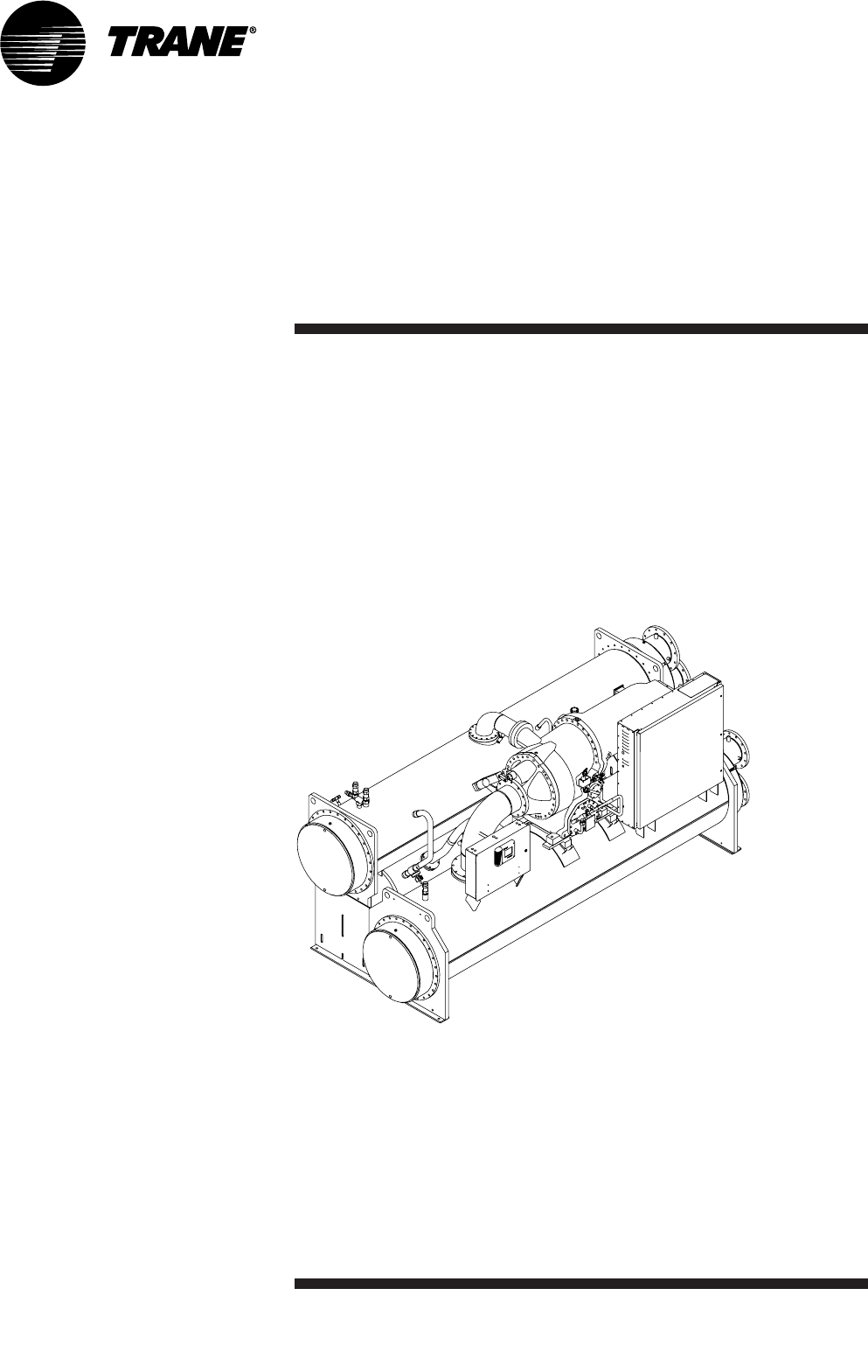
Installation
Manual
Gear-Driven
Centrifugal Water-
Cooled Liquid Chillers
CVGF-SVN02B-E4
X39640686020
Unit Model
CVGF 400-1000 Ton Units
(50 and 60 Hz)
CVGF-SVN02B-E4
© 2004 American Standard Inc. All rights reserved.
Warnings and
Cautions
NOTICE: Warnings and Cautions appear at appropriate sections throughout this manual.
Read these carefully.
WARNING - Indicates a potentially hazardous situation which, if not avoided, could result in
death or serious injury.
CAUTION - Indicates a potentially hazardous situation which, if not avoided, may result in
minor or moderate injury. It may also be used to alert against unsafe practices.
CAUTION - Indicates a situation that may result in equipment or property-damage-only
accidents.
CVGF-SVN02B-E4 3
Contents
Warnings and Cautions
General Information
Installation: Mechanical
Installation: Electrical
2
4
32
56
CVGF-SVN02B-E4
4
General
Information
Conversion Chart
SI Multiply by METRIC
psi 6.89 kPa
psi .069 Bar
psi .070 kg/cm²
degrees °F (F-32)×5/9 Degrees C
pound-ft 1.36 Nm
pound-ft 0.138 kg-m
pound-ft 0.0014 kN-m
gpm (US) 0.063 L/s
gpm (US) 6.309 m³/sec
gpm (US) 63.09 cm³/sec
in-H²O 0.249 kPa
in-H²O 0.0361 psi
in-H²O 0.0736 in-Hg
inches 25.4 mm
inches 2.54 cm
feet 0.305 meters
feet² 0.093 meters²
Microns 0.001 mm Hg
Safety Control Settings Chart
Control Settings I-P Settings SI
Oil pressure control Cut-in 12 psi, Cut-in 151 kPa,
Cut-out 9 psi Cut-out 124 kPa
High pressure control Cut-out 195 psi Cut-out 1344 kPa
High oil temperature Cut-out 165°F Cut-out 74°C
Low oil temperature Cut-out 5°F below set point Cut-out 2.8°C below set point
High motor temperature Cut-out 265°F ± 15°F Cut-out 130°C ± 8°C
Oil Chart
USA Europe
Oil 0037 Oil 021E
Oil 0049 Oil 0020E
MODEL: CVGF500
MODEL NO:
CVGF0500RA0U33809405C1B5C1C23A1A201E3AA0
SERIAL NO: S.O. NO:
ELECTRICAL CHARACTERISTICS:
RATED VOLTAGE: 380 VOLTS 50HZ 3PH
NAMEPLATE NMKW: 338 kW
VOLTAGE UTILIZATION RANGE: 345- 422 VAC
MINIMUM CIRCUIT AMPACITY: 726 AMPS
MAXIMUM FUSE: 1200 AMPS
MAXIMUM CIRCUIT BREAKER 1200 AMPS
MAXIMUM OVERLOAD TRIP: 617 AMPS
MAX MAX
VOLTS-AC HZ PH RLA LRAY
LRAD
COMPRESSOR MOTOR 380 50 3 577 1048 3286
OIL PUMP MOTOR 380 50 31.43 FLA
OIL TANK HEATER 115 50 1000 WATTS TOTAL
CONTROL CIRCUIT 115 50 1500 VA MAX
WHEN MOTOR CONTROLLER PROVIDED BY OTHERS
TRANE ENGINEERING SPEC. S6516-0360 APPLIES
GENERAL CHARACTERISTICS:
REFRIGERANT SYSTEM
TO BE FIELD CHARGED ACTUALLY CHARGED
WITH 340 KG OF R-134A WITH KG OF R-134A
MAXIMUM REFRIGERANT WORKING PRESSURE
HI SIDE 15.2 BAR LOW SIDE 15.2 BAR
FACTORY TEST PRESSURE
HI SIDE 16.7 BAR LOW SIDE 16.7 BAR
FIELD LEAK TEST PRESSURE 82.50 BAR MAX.
TESTED AT BAR
LEAK TEST AND CHARGING SPECIFICATION ARE SUPPLIED
IN CONTROL PANEL (SERVICE LITERATURE MANUAL)
MANUFACTURED UNDER ONE OR MORE OF THE FOLLOWING
U.S. PATENTS: 4686834 4689967 4715190 5056032
5058031 5434738 5563489 5836382
SERVICE LITERATURE
INSTALLATION, OPERATION AND MAINTENANCE MANUAL:
CVGF-SVN02A-EN AND CVGF-SVU02A-EN
“FOR INSTALLATION REQUIREMENTS, USE ELECTRICAL
CHARACTERISTICS NOT PRODUCT DESCRIPTION”
PRODUCT DESCRIPTION:
MODL CVGF DSEQ A0 NTON 500 VOLT 380
HRTZ 50 CPKW 338 CPIM 940 EVSZ 500
EVBS C EVTB TE25 EFLD WATE EVWB NM15
EVWP 2 EVCO FLGE EVWA RERE CDSZ 500
CDBS C CDTB TE28 CFLD WATE CDWB NM15
CDCO FLGE CDWA RERE ORSZ 23 AGLT UL
SPKGEXPS INSL YES OPTM YES WVUO YES
TRMM TRMS LCLD CLDC LANG ENGL SRTY USTR
SRRL 952 PNCO DISC TEST PTR3
Figure 1. Typical unit nameplate
CVGF-SVN02B-E4
Literature Change History
CVGF-SVX001-E4 (July 2000)
This manual describes the
installation, operation, and
maintenance of CVGF units.
CVGF-SVN02A-E4 (2002)
Replaces CVGF-SVX001-E4.
About this Manual
This manual describes proper
installation of Model CVGF, 50 Hz
and 60 Hz chillers with the Tracer
CH530 Controls platform. See
Figures 2 and 3 for an illustration
of a CVGF Centrifugal Chiller
with the Tracer CH530 Unit
Control Panel.
These chillers are equipped with
microcomputer-based control
systems. A careful review of this
information along with the
submittal package provided for
the unit will assure that the
chiller is correctly installed.
Unit Identification -
Nameplates
When the unit arrives, compare
all nameplate data with order,
submittal and shipping
information. A typical unit
nameplate is shown in Figure 1.
5
General
Information

CVGF-SVN02B-E4
Unit Nameplates
The CVGF unit nameplate
(Figure 2 shows the nameplate
location) is applied to the
exterior surface of the control
panel. The starter nameplate is
located inside the starter panel.
The unit nameplate provides the
following information:
• Unit model
• Unit serial number
• Unit device number - identifies
unit electrical requirements
- Lists correct operating
charges of HFC-134a and
lubrication oil
- Lists unit test pressures and
maximum working pressures
The starter nameplate provides
the following information:
• Panel model number
• Rated load amps
• Voltage
• Electrical characteristics -
starter type, wiring
• Options included
Unit Inspection
When the unit is delivered, verify
that it is the correct unit and that
it is properly equipped.
Inspect all exterior components
for visible damage. Report any
apparent damage or material
shortage to the carrier and make
a “unit damage” notation on the
carrier’s delivery receipt. Specify
the extent and type of damage
found and notify the appropriate
Trane Sales Office.
Do not proceed with installation
of a damaged unit without sales
office approval.
Inspection Checklist
To protect against loss due to
damage incurred in transit,
complete the pre-commissioning
checklist, which can be obtained
from your Trane representative.
• Inspect the individual pieces of
the shipment before accepting
the unit. Check for obvious
damage to the unit or packing
material.
• Inspect the unit for concealed
damage as soon as possible
after delivery and before it is
stored. Concealed damage
must be reported within 10
days after receipt.
• If concealed damage is
discovered, stop unpacking the
shipment. Do not remove
damaged material from the
receiving location. Take photos
of the damage, if possible. The
owner must provide reasonable
evidence that the damage did
not occur after delivery.
• Notify the Trane sales
representative and arrange for
repair. Do not repair the unit,
however, until damage is
inspected by the transportation
representative.
6
General
Information

Loose Parts Inventory
The loose parts items ship in the
motor junction box for units
without a unit-mounted starter,
or in the starter panel for units
equipped with a unit-mounted
starter. This includes the
isolation pads, extra oil filter,
and any optional factory-shipped
items.
Unit Description
The CVGF units are single-
compressor, gear-type, water-
cooled liquid chillers designed
for installation indoors. Each unit
is a completely assembled,
hermetic package that is factory-
piped, wired, leak-tested,
dehydrated, oil-charged, and
tested for proper control
operation before shipment.
Note: high-voltage starters are
not unit-mounted before
shipment.
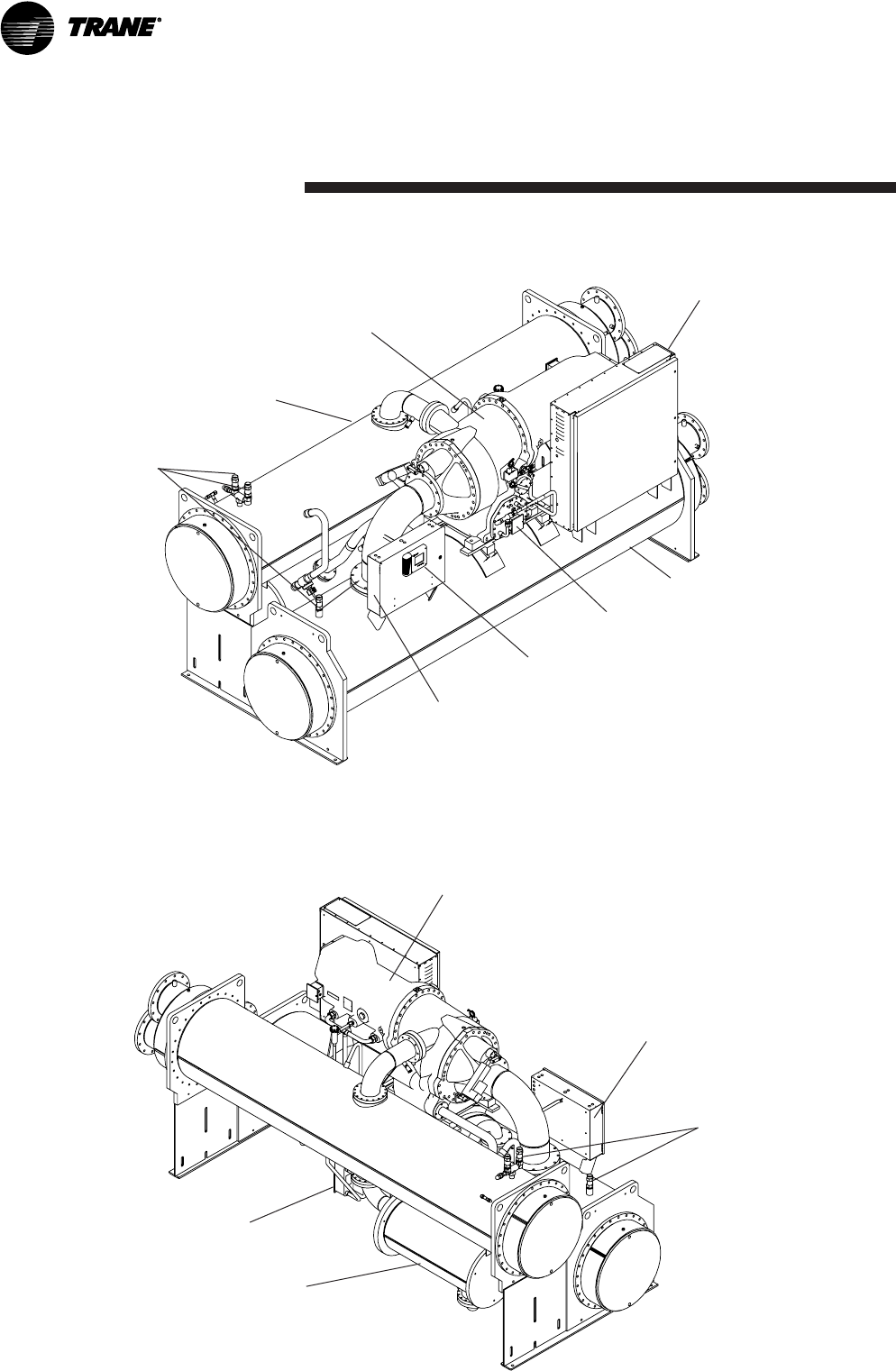
Figure 2 and Figure 3 show a
typical CVGF unit and its
components. Water inlet and
outlet openings are covered
before shipment. The oil tank is
factory-charged with 15 gallons
(56.8L) of Trane Oil 37 and a
holding charge of 5 psig (34 kPa)
of dry nitrogen at 70°F (21°C).
(See the Operation Maintenance
Manual for equivalent oil
specification.)
CVGF-SVN02B-E4 7
General
Information
CVGF-SVN02B-E4
8
General
Information
Figure 2. Component location for typical CVGF unit
Relief valves
Unit nameplate
Control Panel CH530
Evaporator
Oil Pump
Two-stage compressor
Unit-mounted starter (optional)
Condenser
Motor
Unit nameplate
Relief valves
Oil cooler
Economizer
Figure 3. Component location for typical CVGF unit (back view)

H = (9th digit) Unit Voltage
D = 380V-60 Hz
F = 460V-60 Hz
H = 575V-60 Hz
N = 4160V-60 Hz
P = 3300V-60 Hz
R = 380V-50 Hz
T = 400V-50 Hz
U = 415V-50 Hz
V = 3300V-50 Hz
X = 6600V-60 Hz
Z = 6600V-50 Hz
S = Special
A0 = (10th and 11th digit) Design
Sequence
C = (12th digit) Control Enclosure
C = Standard Control Enclosure
S = Special
316 = (13th, 14th, and 15th digit)
Compressor Motor Power (kw)
221 = 221 CPKW
254 = 254 CPKW
285 = 285 CPKW
316 = 316 CPKW
357 = 357 CPKW
401 = 401 CPKW
240 = 240 CPKW
266 = 266 CPKW
301 = 301 CPKW
338 = 338 CPKW
374 = 374 CPKW
430 = 430 CPKW
444 = 444 CPKW
484 = 484 CPKW
511 = 511 CPKW
532 = 532 CPKW
574 = 574 CPKW
594 = 594 CPKW
641 = 641 CPKW
674 = 674 CPKW
719 = 719 CPKW
751 = 751 CPKW
808 = 808 CPKW
SSS = Special
0900 = (16th, 17th, 18th, and 19th
digit) Compressor Impeller Cutback
0880 CPIM
0890 CPIM
0900 CPIM
0910 CPIM
0920 CPIM
0930 CPIM
0940 CPIM
0950 CPIM
0960 CPIM
0970 CPIM
0980 CPIM
0990 CPIM
1000 through 1510 = Cutback is the
same as the FCOD for impeller
cutback
SSSS = Special
5 = (20th digit) Evaporator Shell Size
1 = 1000 ton evaporator
5 = 500 ton evaporator
7 = 700 ton evaporator
S = Special
B = (21st digit) Evaporator Tube
Bundle
A = Small bundle
B = Medium bundle
C = Large bundle
D = Extra large bundle
S = Special
1 = (22nd digit) Evaporator Tubes
1 = .75 diameter .025 wall internally
enhanced cu tube
2 = 1.00 diameter .025 wall internally
enhanced cu tube
S = Special
CVGF-SVN02B-E4 9
General
Information
Model number digits are selected
and assigned in accordance with the
following definitions using the
typical model number example
shown below:
CVGF0500HA0C31609005B1B5B1
C2306G4A1E2CC0A0CL
C = (1st digit)
V = (2nd digit) Hermetic Centrifugal
Compressor
G = (3rd digit) Gear Drive
F = (4th digit) Development
sequence
0500 = (5th, 6th, 7th, and 8th digit)
Nominal compressor tonnage
0400 = 400 tons
0500 = 500 tons
0650 = 650 tons
0800 = 800 tons
1000 = 1000 tons
SSSS = Special

CVGF-SVN02B-E4
0 = (30th digit) Factory Installed
Insulation
0 = None
A = Factory installed insulation
1 = (31st digit) Control: Operating
Status
0 = None
1 = Operating Status
G = (32nd digit) Control: Generic
BAS
0 = None
G = Generic BAS
4 = (33rd digit) Tracer
Communication Interface
0 = None
4 = COMM 4
5 = COMM 5
A = (34th digit) Chilled Water Reset -
Outdoor Air Temperature Sensor
0 = None
A = Chilled Water Reset – With
Outdoor Air Temp Sensor
1 = (35th digit) Control: Extended
Operation
0 = None
1 = Extended Operation
E = (36th digit) Language
E = English
F = French
G = German
T = Italian
P = Spanish
S = Special
10
General
Information
B = (23rd digit) Evaporator
Waterbox
B = 150 PSI Non-Marine - 2 pass
C = 150 PSI Non-Marine - 3 pass
D = 150 PSI Marine - 2 pass
E = 150 PSI Marine - 3 pass
H = 300 PSI Marine - 2 pass
J = 300 PSI Marine - 3 pass
L = 300 PSI Non-Marine - 2 pass
M = 300 PSI Non-Marine - 3 pass
S = Special
5 = (24th digit) Condenser Shell Size
1 = 1000 ton condenser
5 = 500 ton condenser
7 = 700 ton condenser
S = Special
B = (25th digit) Condenser Tube
Bundle
A = Small bundle
B = Medium bundle
C = Large bundle
D = Extra large bundle
S = Special
1 = (26th digit) Condenser Tubes
1 = .75 diameter .028 wall internally
enhanced cu tube
2 = 1.00 diameter .028 wall internally
enhanced cu tube
3 = .75 diameter .035 wall 90/10 cu/ni
tube
4 = .75 diameter .028 wall titanium
tube
S = Special
C = (27th digit) Condenser Waterbox
A = 150 PSI Marine - 2 pass
C = 150 PSI Non-Marine - 2 pass
E = 300 PSI Marine - 2 pass
G = 300 PSI Non-Marine - 2 pass
S = Special
23 = (28th and 29th digit) Orifice
Series
13 Orifice series
14 Orifice series
15 Orifice series
16 Orifice series
17 Orifice series
18 Orifice series
19 Orifice series
20 Orifice series
22 Orifice series
23 Orifice series
25 Orifice series
27 Orifice series
28 Orifice series
30 Orifice series
31 Orifice series
33 Orifice series
35 Orifice series
38 Orifice series
40 Orifice series
42 Orifice series
44 Orifice series
47 Orifice series
49 Orifice series
51 Orifice series
56 Orifice series
SS = Special

A = (41st digit) Starter Type
A = Star-Delta - unit mounted
B = Solid State - unit mounted
C = Star-Delta - remote mounted
E = X-line full volt - remote mounted
F = Autotransformer - remote
mounted
G = Primary reactor - remote
mounted
M= Solid State Floor Mounted
N= Solid State Wall Mounted
R = Customer supplied
0 = (42nd digit) Additional Pressure
Vessel Compliance
0 = None
N = Non-destructive Examination for
China
K = KHK Japanese pressure vessel
code
C = (43rd digit) Control: Condenser
Refrigerant Pressure
0 = None
C = Condenser Refrigerant Pressure
L = (44th digit) Manufacturing
Location
L = La Crosse, Wisconsin
T = Tai Cang, China
C = (39th digit) Impeller Rim
Diameter 2nd Stage
A = 9.5 Rim diameter
B = 10.0 Rim diameter
C = 10.6 Rim diameter
D = 11.1 Rim diameter
E = 11.6 Rim diameter
F = 9.8 Rim diameter
G = 10.4 Rim diameter
H = 11.0 Rim diameter
J = 11.7 Rim diameter
K = 12.7 Rim diameter
L = 13.5 Rim diameter
M = 14.3 Rim diameter
N = 15.1 Rim diameter
S = Special
0 = (40th digit) Special Options
0 = None
S = Special option
CVGF-SVN02B-E4 11
General
Information
2 = (37th digit) Motor Frame Size
2 = 400 Frame
3 = 440E Frame
4 = 5000 Frame
S = Special
C = (38th digit) Impeller Rim
Diameter 1st Stage
A = 9.5 Rim diameter
B = 10.0 Rim diameter
C = 10.6 Rim diameter
D = 11.1 Rim diameter
E = 11.6 Rim diameter
F = 9.8 Rim diameter
G = 10.4 Rim diameter
H = 11.0 Rim diameter
J = 11.7 Rim diameter
K = 12.7 Rim diameter
L = 13.5 Rim diameter
M = 14.3 Rim diameter
N = 15.1 Rim diameter
S = Special

CVGF-SVN02B-E4
12
General
Information
Service Model Numbers –
Solid State Motor Starter
An example of a typical Solid State
“IT” starter model number is:
CVSR0035FAA01EA0E1
Model Number Digit Identification -
Model number digits are selected
and assigned in accordance with the
following definitions using the
model number example shown
above.
C = (1st digit)
V = 2nd digit)
S = (3rd digit)
R = (4th digit) Development
Sequence
R = Cutler Hammer Solid State “IT”
starter for gear drive centrifugal
chillers with CH530 controls
0035 = (5th, 6th, 7th, and 8th digit)
Starter Size
Use Rated Load Amps (RLA) value
F = (9th digit) Unit Voltage
D = 380V-60Hz-3Ph
F = 460V-60Hz-3Ph
H = 575V-60Hz-3Ph
R = 380V-50Hz-3Ph
T = 400V-50Hz-3Ph
U = 415V-50Hz-3Ph
S = Special
A = (10th digit) Design Sequence
A = Original Design
A = (11th digit) Starter Type
B = Unit Mounted
M = Remote Floor Mounted
N = Remote Wall Mounted
S = Special
0 = (12th digit) Connection Type
0 = Terminal Block
1 = Disconnect Switch - Non-Fused
2 = Circuit Breaker
3 = Circuit Breaker Current Limiting
4 = Circuit Breaker High Interrupt
Cap
5 = Circuit Breaker Higher Interrupt
Cap
S = Special
1 = (13th digit) Agency Listing
1 = UL & cUL Listed (Standard on all
units)
2 = CE
E = (14th Digit) Power Factor
Correction Capacitor
0 = None
D = 25 KVAR
E = 30 KVAR
F = 35 KVAR
G = 40 KVAR
H = 45 KVAR
J = 50 KVAR
K = 60 KVAR
L = 70 KVAR
M = 75 KVAR
N = 80 KVAR
P = 90 KVAR
R = 100 KVAR
T = 120 KVAR
U = 125 KVAR
V = 150 KVAR
S = Special
A = (15th Digit) Ground Fault
Protection
0 = None
A = Ground Fault Protection
S = Special
0 = (16th digit) Special Options
0 = None
S = Special Options ( See Sales
Order)
E = (17th digit) Literature Language
E = English
F = French
G = German
P = Spanish
T = Italian
S = Special
1 = (18th digit) Oil Pump Starter
Circuit
1 = 1 HP Oil Pump Motor
2 = 1.5 HP Oil Pump

CVGF-SVN02B-E4 13
General
Information
Service Model Numbers -
Wye-delta Motor Starter
An example of a typical chiller
starter model number is:
CVSN0035FAA01EA0E1
Model Number Digit Identification -
Model number digits are selected
and assigned in accordance with the
following definitions using the
model number example shown
above.
C = (1st digit)
V = 2nd digit)
S = (3rd digit)
N = (4th digit) Development
Sequence
N = Cutler-Hammer electrical-
mechanical starter for gear drive
centrifugal chillers with CH530
controls
0035 = (5th, 6th, 7th, and 8th digit)
Starter Size
F = (9th digit) Unit Voltage
D = 380V-60Hz-3Ph
F = 460V-60Hz-3Ph
H = 575V-60Hz-3Ph
R = 380V-50Hz-3Ph
T = 400V-50Hz-3Ph
U = 415V-50Hz-3Ph
S = Special
A = (10th digit) Design Sequence
A = Original Design
A = (11th digit) Starter Type
A = Star-Delta - Unit Mounted
C = Star-Delta - Remote Mounted
S = Special
0 = (12th digit) Connection Type
0 = Terminal Block
1 = Disconnect Switch - Non-Fused
2 = Circuit Breaker
3 = Circuit Breaker Current Limiting
4 = Circuit Breaker High Interrupt
Cap
5 = Circuit Breaker Higher Interrupt
Cap
S = Special
1 = (13th digit) Agency Listing
1 = UL & cUL Listed (Standard on all
units)
2 = CE.
E = (14th Digit) Power Factor
Correction Capacitor
0 = None
D = 25 KVAR
E = 30 KVAR
F = 35 KVAR
G = 40 KVAR
H = 45 KVAR
J = 50 KVAR
K = 60 KVAR
L = 70 KVAR
M = 75 KVAR
N = 80 KVAR
P = 90 KVAR
R = 100 KVAR
T = 120 KVAR
U = 125 KVAR
V = 150 KVAR
S = Special
A = (15th Digit) Ground Fault
Protection
0 = None
A = Ground Fault Protection
S = Special
0 = (16th digit) Special Options
0 = None
S = Special Options (See Sales
Order)
E = (17th digit) Literature Language
E = English
F = French
G = German
P = Spanish
T = Italian
S = Special
1 = (18th digit) Oil Pump Starter
Circuit
1 = 1 HP Oil Pump Motor
2 = 1.5 HP Oil Pump Motor

CVGF-SVN02B-E4
14
General
Information
Installation Overview
For convenience, Table 1 summarizes responsibilities that are typically associated with the CVGF chiller
installation process.
Table 1. Installation responsibility chart for CVGF units
Requirement Trane-supplied, Trane-supplied, Field-supplied,
Trane-installed Field-installed Field-installed
Rigging Safety chains
Clevis connectors
Isolation Isolation pads Spring isolators
Spring isolators
Electrical
Terminal lugs
Ground connection(s)
Jumper bars
BAS wiring (optional)
IPC wiring
Control voltage wiring
Optional relays and wiring
Water piping Thermometers
Pressure Relief Relief valves
Insulation Insulation (optional) Insulation
Lifting beam equipment, skates,
rollers, and other lifting
operations
Circuit breakers or non-fused
disconnects (optional)
Circuit breakers or fusible
disconnects (optional)
Temperature sensor
(optional outdoor air)
Remote-mounted starter
(optional)
Chilled-water-pump contactor and
wiring
Condenser-water-pump contactor
and wiring
Flow switches (may be
field-supplied) Water flow pressure gauges
Isolation and balancing valves
water piping
Pressure relief valves (for water
boxes as
required)
Vent line and flexible connector
Unit-mounted starter
(optional)
Vent and drain valves

CVGF-SVN02B-E4 15
Refer to the Mechanical and
Electrical sections of this manual
for detailed instructions.
• Locate and maintain the loose
parts such as, isolators, bulb
wells, temperature sensors,
flow sensors or other factory-
ordered field-installed options,
as required. Loose parts are
located in the starter panel if
equipped with a unit-mounted
starter. If not equipped with a
unit-mounted starter, loose
parts are shipped in the motor
junction box.
• Install the unit on a foundation
with flat support surfaces, level
within 1/4" (6 mm) and of
sufficient strength and mass to
support the chiller operating
weight. Place the manufacturer-
supplied isolation-pad
assemblies under the unit.
• Install the unit per the
instructions outlined in the
Mechanical Installation section.
• Complete all water piping and
electrical connections.
Note: Field piping must be
arranged and supported to
avoid stress on the equipment.
It is strongly recommended
that the piping contractor
provide at least 3 feet (914 mm)
of clearance between the pre-
installation piping and the
planned location of the unit.
This will allow for the proper fit
upon arrival of the unit at the
installation site. All necessary
piping adjustments can be
made at that time.
• Where specified, supply and
install valves in the water
piping, upstream and
downstream of the evaporator
and condenser water boxes, in
order to isolate the shells for
maintenance and to balance
and trim the system.
• Supply and install flow
switches or equivalent devices
in both the chilled-water piping
and the condenser-water
piping. Interlock each switch
with the proper pump starter, to
ensure that the unit can only
operate when water flow is
established.
Note: reference graphs 1-16 in
the Installation Mechanical
section for proper water flow.
• Supply and install taps for
thermometers and a pressure
gauge manifold in the water
piping, adjacent to the inlet and
outlet connections of both the
evaporator and the condenser.
• Supply and install drain valves
on each water box.
• Supply and install vent cocks
on each water box.
• Where specified, supply and
install strainers ahead of all
pumps and automatic
modulating valves.
• Supply and install refrigerant
pressure-relief piping from the
pressure-relief valve to the
atmosphere.
• If necessary, supply enough
HFC-134a refrigerant (1 pound
= .45 kg) and dry nitrogen (75
psig = 517 kPa maximum) for
leak testing.
• Evacuate the unit to less than
500 microns (0.5 mm Hg) or
according to local code.
• Charge with refrigerant 134a.
• Go over the pre-commissioning
check sheet and ensure that all
items have been completed.
• Start the unit under the
supervision of a qualified
service technician.
General
Information

Table 2. General data: 400 and 500 ton units
Nominal Tonnage 400 400 400 400 500 500 500 500
1.0 1.0 0.75 0.75 1.0 1.0 0.75 0.75
Two Three Two Three Two Three Two Three
Refrigerant Type R134a R134a R134a R134a R134a R134a R134a R134a
Refrigerant Charge - 650 650 650 650 750 750 750 750
pounds (kg) (295) (295) (295) (295) (295) (295) (295) (295)
Oil Charge 15 15 15 15 15 15 15 15
(gallon (l)) (56.8) (56.8) (56.8) (56.8) (56.8) (56.8) (56.8) (56.8)
Overall Dimensions - Feet-Inch (mm)
Length 15'- 10 13/16" 15'- 10 13/16" 15'- 10 13/16" 15'- 10 13/16" 15'- 10 13/16" 15'- 10 13/16" 15'- 10 13/16" 15'- 10 13/16"
(4800) (4800) (4800) (4800) (4800) (4800) (4800) (4800)
Width 6' - 6 19/64" 6' - 6 19/64" 6' - 6 19/64" 6' - 6 19/64" 6' - 6 19/64" 6' - 6 19/64" 6' - 6 19/64" 6' - 6 19/64"
(1989) (1989) (1989) (1989) (1989) (1989) (1989) (1989)
Height 6' - 10 1/2" 6' - 10 1/2" 6' - 10 1/2" 6' - 10 1/2" 6' - 10 1/2" 6' - 10 1/2" 6' - 10 1/2" 6' - 10 1/2"
(2096) (2096) (2096) (2096) (2096) (2096) (2096) (2096)
2' - 7 1/8" 2' - 7 1/8" 2' - 7 1/8" 2' - 7 1/8" 2' - 7 1/8" 2' - 7 1/8" 2' - 7 1/8" 2' - 7 1/8"
(791) (791) (791) (791) (791) (791) (791) (791)
8" 8" 8" 8" 8" 8" 8" 8"
(203) (203) (203) (203) (203) (203) (203) (203)
2' - 1 1/2" 2' - 1 1/2" 2' - 1 1/2" 2' - 1 1/2" 2' - 1 1/2" 2' - 1 1/2" 2' - 1 1/2" 2' - 1 1/2"
(3060) (3060) (3060) (3060) (3060) (3060) (3060) (3060)
10" 10" 10" 10" 10" 10" 10" 10"
(254) (254) (254) (254) (254) (254) (254) (254)
Weight - pounds (kg)) except Waterboxes
Compressor/Motor 6220 6220 6220 6220 6220 6220 6220 6220
(2821) (2821) (2821) (2821) (2821) (2821) (2821) (2821)
Evaporator 3948 3948 4228 4228 4193 4193 4568 4568
(1791) (1791) (1918) (1918) (1902) (1902) (2072) (2072)
Condenser 2857 2857 3472 3472 3152 3152 3877 3877
(1296) (1296) (1575) (1575) (1430) (1430) (1759) (1759)
Economizer 535 535 535 535 535 535 535 535
(243) (243) (243) (243) (243) (243) (243) (243)
Starter Panel 500 500 500 500 500 500 500 500
(227) (227) (227) (227) (227) (227) (227) (227)
Control Panel 70 70 70 70 70 70 70 70
(318) (318) (318) (318) (318) (318) (318) (318)
2127 2127 2127 2127 2127 2127 2127 2127
(965) (965) (965) (965) (965) (965) (965) (965)
17867 17867 17867 17867 17867 17867 17867 17867
(8104) (8104) (8104) (8104) (8104) (8104) (8104) (8104)
21460 21460 21460 21460 22564 22564 22564 22564
(9734) (9734) (9734) (9734) (10235) (10235) (10235) (10235)
Operational Data
447 298 407 271 550 367 511 340
(28) (20) (25.6) (17) (34) (23) (32) (21)
1638 1092 1493 995 2018 1346 1873 124895
(103) (69) (94) (63) (127) (85) (118) (79)
499 499 487 487 606 606 586 586
(31) (31) (31) (31) (38) (38) (37) (37)
1831 1831 1786 1786 2221 2221 2148 2148
(115) (115) (113) (113) (140) (140) (135) (135)
CVGF-SVN02B-E4
16
General
Information
Evaporator Water Pass
Evaporator Water
Connection (NPS)
Condenser Nominal
Connector Size (NPS)
Miscellaneous Item
Minimum Evaporator
Flow in gpm (l/sec)
Maximum Evaporator
Flow in gpm (l/sec)
Minimum Condenser
Flow in gpm (l/sec)
Maximum Condenser
Flow in gpm (l/sec)
Tube Outside Diameter
(inch)
Evaporator Inside
Diameter
Condenser Inside
Diameter
Shipping Weight
Operating Weight

CVGF-SVN02B-E4 17
General
Information
T
able 2. General data: 400 and 500 ton units (continued)
Nominal Tonnage 400 400 400 400 500 500 500 500
1.0 1.0 0.75 0.75 1.0 1.0 0.75 0.75
Two Three Two Three Two Three Two Three
Water Volume - 150 pound Waterboxes
101.7 101.49 95.7 95.4 117.2 116.9 111.2 110.9
(385) (384) (361) (361) (444) (443) (421) (420)
112 112 110.4 110.4 127.8 127.8 125.0 125.0
(424) (424) (418) (418) (484) (484) (473) (473)
Evaporator 2-pass Weight
Supply - pound 304 304 304 304 304 304 304 304
(kg) (138) (138) (138) (138) (138) (138) (138) (138)
Return - pound 337 337 337 337 337 337 337 337
(kg) (153) (153) (153) (153) (153) (153) (153) (153)
Evaporator 3-pass Weight
Supply - pound 314 314 314 314 314 314 314 314
(kg) (142) (142) (142) (142) (142) (142) (142) (142)
Return - pound 332 332 332 332 332 332 332 332
(kg) (151) (151) (151) (151) (151) (151) (151) (151)
Condenser 2-pass Weight
Supply - pound 304 304 304 304 304 304 304 304
(kg) (138) (138) (138) (138) (138) (138) (138) (138)
Return - pound 341 341 341 341 341 341 341 341
(kg) (155) (155) (155) (155) (155) (155) (155) (155)
300 pound Waterboxes
101.9 101.6 95.9 95.6 117.4 117.0 111.4 111.1
(386) (385) (363) (362) (444) (443) (422) (421)
112.3 112.3 110.6 110.6 128.0 128.0 125.3 125.3
(425) (425) (419) (419) (485) (485) (474) (474)
Evaporator 2-pass Weight
Supply - pound 427 427 427 427 427 427 427 427
(kg) (194) (194) (194) (194) (194) (194) (194) (194)
Return - pound 446 446 446 446 446 446 446 446
(kg) (202) (202) (202) (202) (202) (202) (202) (202)
Evaporator 3-pass Weight
Supply - pound 448 448 448 448 448 448 448 448
(kg) (203) (203) (203) (203) (203) (203) (203) (203)
Return - pound 448 448 448 448 448 448 448 448
(kg) (203) (203) (203) (203) (203) (203) (203) (203)
Condenser 2-pass Weight
Supply - pound 421 421 421 421 421 421 421 421
(kg) (191) (191) (191) (191) (191) (191) (191) (191)
Return - pound 436 436 436 436 436 436 436 436
(kg) (198) (198) (198) (198) (198) (198) (198) (198)
Evaporator Water
Storage gallon (l)
Condenser Water
Storage gallon (l)
Evaporator Water
Storage gallon (l)
Condenser Water
Storage gallon (l)
Evaporator Water Pass
Tube Outside Diameter
(inch)
CVGF-SVN02B-E4
18
General
Information
Table 3. General data: 650 ton units
Nominal Tonnage 650
1.0 0.75
Two Three Two Three
Refrigerant Type R134a R134a R134a R134a
Refrigerant Charge - 975 975 975 975
pounds (kg) (442.3) (442.3) (442.3) (442.3)
Oil Charge 15 15 15 15
gallon (l) (56.8) (56.8) (56.8) (56.8)
Overall Dimensions - Feet-Inch (mm)
Length 16' 16' 16' 16'
4877 4877 4877 4877
Width 6' - 9 3/4 6' - 9 3/4 6' - 9 3/4 6' - 9 3/4
(2076) (2076) (2076) (2076)
Height 7' - 5 11/32" 7' - 5 11/32" 7' - 5 11/32" 7' - 5 11/32"
(2270) (2270) (2270) (2270)
3' - 1/4" 3' - 1/4" 3' - 1/4" 3' - 1/4"
(921) (921) (921) (921)
10" 8" 10" 8"
(254) (203) (254) (203)
2' - 1 1/2" 2' - 1 1/2" 2' - 1 1/2" 2' - 1 1/2"
(648) (648) (648) (648)
12" 12" 12" 12"
(300) (300) (300) (300)
Weight - pounds (kg)) except Waterboxes
Compressor/Motor 6800 6800 6800 6800
(3084) (3084) (3084) (3084)
Evaporator 5461 5834 5461 5834
(2477) (2643) (2477) (2643)
Condenser 3937 4763 3937 4763
(1786) (2161) (1786) (2161)
Economizer 799 799 799 799
(362) (362) (362) (362)
Starter Panel 542 542 542 542
(246) (246) (246) (246)
Control Panel 70 70 70 70
(318) (318) (318) (318)
2745 2745 2745 2745
(1245) (1245) (1245) (1245)
24140 24140 24140 24140
(10950) (10950) (10950) (10950)
28344 28344 28344 28344
(12857) (12857) (12857) (12857)
Operational Data
625 417 566 378
(39) (26) (36) (24)
2501 1529 1493 995
(158) (97) (94) (63)
682 682 668 668
(43) (43) (42) (42)
2501 2501 2450 2450
(158) (258) (155) (155)
Evaporator Water
Pass
Evaporator Water
Connection (NPS)
Condenser Nominal
Connector Size (NPS)
Miscellaneous Item
Minimum
Evaporator Flow in
gpm (l/sec)
Maximum
Evaporator Flow in
gpm (l/sec)
Minimum
Condenser Flow in
gpm (l/sec)
Maximum
Condenser Flow in
gpm (l/sec)
Tube Outside
Diameter (inch)
Evaporator Inside
Diameter
Condenser
Inside Diameter
Shipping Weight
Operating Weight

CVGF-SVN02B-E4 19
General
Information
Table 3. General data: 650 ton units (continued)
Nominal Tonnage 650
1.0 0.75
Two Three Two Three
Water Volume - 150 pound Waterboxes
163.2 158.2 154.1 149.1
(618) (599) (583) (564)
185.1 185.1 188.5 188.5
(701) (701) (714) (714)
Evaporator 2-pass Weight
Supply - pound 304 304 304 304
(kg) (138) (138) (138) (138)
Return - pound 337 337 337 337
(kg) (153) (153) (153) (153)
Evaporator 3-pass Weight
Supply - pound 314 314 314 314
(kg) (142) (142) (142) (142)
Return - pound 332 332 332 332
(kg) (151) (151) (151) (151)
Condenser 2-pass Weight
Supply - pound 304 304 304 304
(kg) (138) (138) (138) (138)
Return - pound 341 341 341 341
(kg) (155) (155) (155) (155)
300 pound Waterboxes
163.2 158.2 154.1 149.1
(618) (599) (583) (564)
185.1 185.1 189.4 189.4
(701) (701) (717) (717)
Evaporator 2-pass Weight
Supply - pound 427 427 427 427
(kg) (194) (194) (194) (194)
Return - pound 446 446 446 446
(kg) (202) (202) (202) (202)
Evaporator 3-pass Weight
Supply - pound 448 448 448 448
(kg) (203) (203) (203) (203)
Return - pound 448 448 448 448
(kg) (203) (203) (203) (203)
Condenser 2-pass Weight
Supply - pound 421 421 421 421
(kg) (191) (191) (191) (191)
Return - pound 436 436 436 436
(kg) (198) (198) (198) (198)
Evaporator Water
Storage gallon (l)
Condenser Water
Storage gallon (l)
Evaporator Water
Storage (gallon (l))
Condenser Water
Storage gallon (l)
Evaporator Water Pass
Tube Outside
Diameter (inch)

CVGF-SVN02B-E4
20
General
Information
Table 4. General data: 700 ton family
Nominal Tonnage 560 560 560 560 630 630 630 630
1.0 1.0 0.75 0.75 1.0 1.0 0.75 0.75
Two Three Two Three Two Three Two Three
875 875 875 875 925 925 925 925
(397) (397) (397) (397) 420) (420) (420) (420)
15 15 15 15 15 15 15 15
(56.8) (56.8) (56.8) (56.8) (56.8) (56.8) (56.8) (56.8)
Overall Dimensions - Feet-Inch (mm)
Length 16'11" 16'11" 16'11" 16'11" 16'11" 16'11" 16'11" 16'11"
(5153) (5153) (5153) (5153) (5153) (5153) (5153) (5153)
Width 6'10" 6'10" 6'10" 6'10" 6'10" 6'10" 6'10" 6'10"
(2075) (2075) (2075) (2075) (2075) (2075) (2075) (2075)
Height 7'5" 7'5" 7'5" 7'5" 7'5" 7'5" 7'5" 7'5"
(2269) (2269) (2269) (2269) (2269) (2269) (2269) (2269)
36-1/4" 36-1/4" 36-1/4" 36-1/4" 36-1/4" 36-1/4" 36-1/4" 36-1/4"
(921) (921) (921) (921) (921) (921) (921) (921)
10" 8" 10" 8" 10" 8" 10" 8"
(254) (203) (254) (203) (254) (203) (254) (203)
29-1/2" 29-1/2" 29-1/2" 29-1/2" 29-1/2" 29-1/2" 29-1/2" 29-1/2"
(749) (749) (749) (749) (749) (749) (749) (749)
12" 12" 12" 12" 12" 12" 12" 12"
(304) (304) (304) (304) (304) (304) (304) (304)
Weight- pound (kg) 150 Lb. Waterboxes
6440 6440 6440 6440 6440 6440 6440 6440
(2921) (2921) (2921) (2921) (2921) (2921) (2921) (2921)
5949 5949 6283 6283 5940 5940 6480 6480
(2698) (2698) (2850) (2850) (2694) (2694) (2939) (2939)
4651 4651 5515 5515 4875 4875 5824 5824
(2110) (2110) (2502) (2502) (2211) (2211) (2642) (2642)
904 904 904 904 904 904 904 904
(410) (410) (410) (410) (410) (410) (410) (410)
542 542 542 542 542 542 542 542
(246) (246) (246) (246) (246) (246) (246) (246)
70 70 70 70 70 70 70 70
(318) (318) (318) (318) (318) (318)) (318) (318)
1216 1216 1216 1216 1216 1216 1216 1216
(552) (552) (552) (552) (552) (552) (552) (552)
1867 1891 1867 1891 1867 1891 1867 1891
(847) (858) (847) (858) (847) (858) (847) (858)
298 298 298 298 298 298 298 298
(135) (135) (135) (135) (135) (135) (135) (135)
22,024 22,048 23,222 23,246 22,239 22,263 23,728 23,750
(9990) (10001) (10553) (10544) (10541) (10552) (10763) (10773)
2608 2575 2519 2486 2809 2776 2689 2656
(1183) (1168) (1143) (1128) (1274) (1259) (1220) (1205)
997 997 997 997 1047 1047 1047 1047
(452) (452) (452) (452) (475) (475) (475) (475)
25,629 25,620 26,738 26,729 26,095 26,086 27,464 27,453
(11625) (11621) (12128) (12124) (11836) (11832) (12457) (12452)
Evaporator Water
Connection size
(NPS)
Condenser Nominal
Connector size
(NPS)
Economizer weight
Starter panel
weight
Control panel
weight
I/C Piping and
Supports
Waterboxes
Miscellaneous Item
Total Shipping
Weight
Total Water
Volume
Refrigerant and Oil
Total Weight
Evaporator Water
Pass
Evaporator Inside
Diameter
Condenser Inside
Diameter
Compressor
weight
Evaporator weight
Condenser weight
Tube Outside
Diameter (inch)
Refrigerant Charge
- pounds (kg)
Oil charge -
gallons (l)
CVGF-SVN02B-E4 21
General
Information
Table 4. General data: 700 ton family (continued)
Nominal Tonnage 560 560 560 560 630 630 630 630
1.0 1.0 0.75 0.75 1.0 1.0 0.75 0.75
Two Three Two Three Two Three Two Three
Operational Data
625 417 566 378 706 471 628 419
(39.4) (26.3) (35.7) (23.8) (44.5) (29.7) (39.6) (26.4)
2293 1529 2077 1385 2581 1726 2304 1536
(144.6) (96.4) (131) (87.4) (162.8) (108.9) (145.3) (96.9)
682 682 668 668 764 764 744 744
(43) (43) (42.1) (42.1) (48.2) (48.2) (47) (47)
2501 2501 2450 2450 2801 2801 2727 2727
(157.7) (157.7) (154.5) (154.5) (176.7) (176.7) (172) (172)
150 pound waterboxes
150.7 146.4 141.8 137.5 162.7 158.4 151 146.7
(570.4) (554.2) (537) (520.5) (616) (600) (572) (555.3)
162.8 162.8 161 161 174.9 174.9 172.2 172.2
(616.3) (616.3) (609.5) (609.5) (662.1) (662.1) (652) (652)
Evaporator 2-pass Weight
Supply - pound 492.7 492.7 492.7 492.7 492.7 492.7 492.7 492.7
(kg) (223.5) (223.5) (223.5) (223.5) (223.5) (223.5) (223.5) (223.5)
Return - pound 435.2 435.2 435.2 435.2 435.2 435.2 435.2 435.2
(kg) (197.4) (197.4) (197.4) (197.4) (197.4) (197.4) (197.4) (197.4)
Evaporator 3-pass Weight
Supply - pound 476.6 476.6 476.6 476.6 476.6 476.6 476.6 476.6
(kg) (216.2) (216.2) (216.2) (216.2) (216.2) (216.2) (216.2) (216.2)
Return - pound 478.9 478.9 478.9 478.9 478.9 478.9 478.9 478.9
(kg) (217.2) (217.2) (217.2) (217.2) (217.2) (217.2) (217.2) (217.2)
Condenser 2-pass Weight
Supply - pound 500.2 500.2 500.2 500.2 500.2 500.2 500.2 500.2
(kg) (226.9) (226.9) (226.9) (226.9) (226.9) (226.9) (226.9) (226.9)
Return - pound 437.6 437.6 437.6 437.6 437.6 437.6 437.6 437.6
(kg) (198.5) (198.5) (198.5) (198.5) (198.5) (198.5) (198.5) (198.5)
300 pound Waterboxes
151 146.6 142.1 137.7 163 158.6 151.3 146.9
(571.6) (554.9) (537.9) (521.3) (617) (600.4) (572.7) (556.1)
163.4 163.4 161.6 161.6 175.5 175.5 172.8 172.8
(618.5) (618.5) (611.7) (611.7) (664.3) (664.3) (654.1) (654.1)
Evaporator 2-pass Weight
Supply - pound 625.9 625.9 625.9 625.9 625.9 625.9 625.9 625.9
(kg) (283.9) (283.9) (283.9) (283.9) (283.9) (283.9) (283.9) (283.9)
Return - pound 590.5 590.5 590.5 590.5 590.5 590.5 590.5 590.5
(kg) (267.8) (267.8) (267.8) (267.8) (267.8) (267.8) (267.8) (267.8)
Evaporator 3-pass Weight
Supply - pound 624.9 624.9 624.9 624.9 624.9 624.9 624.9 624.9
(kg) (283.4) (283.4) (283.4) (283.4) (283.4) (283.4) (283.4) (283.4)
Return - pound 627.2 627.2 627.2 627.2 627.2 627.2 627.2 627.2
(kg) (284.5) (284.5) (284.5) (284.5) (284.5) (284.5) (284.5) (284.5)
Condenser 2-pass Weight
Supply - pound 625.1 625.1 625.1 625.1 625.1 625.1 625.1 625.1
(kg) (283.5) (283.5) (283.5) (283.5) (283.5) (283.5) (283.5) (283.5)
Return - pound 594.4 594.4 594.4 594.4 594.4 594.4 594.4 594.4
(kg) (269.6) (269.6) (269.6) (269.6) (269.6) (269.6) (269.6) (269.6)
Minimum Evaporator
Flow GPM (l/s)
Maximum Evaporator
Flow GPM (l/s)
Minimum Condenser
Flow GPM (l/s)
Maximum Condenser
Flow GPM (l/s)
Evaporator Water
Storage gallons (l)
Condenser Water
Storage gallons (l)
Evaporator Water
Storagegallons (l)
Condenser Water
Storage gallons (l)
Evaporator Water
Pass
Tube Outside Diameter
(inch)
CVGF-SVN02B-E4
22
General
Information
Table 4. General data: 700 ton family (continued)
Nominal Tonnage 700
1.0 0.75
Two Three Two Three
975 975 975 975
(442) (442) (442) (442)
15 15 15 15
(56.8) (56.8) (56.8) (56.8)
Overall Dimensions - Feet-Inch (mm)
Length 16'11" 16'11" 16'11" 16'11"
(5153) (5153) (5153) (5153)
Width 6'10" 6'10" 6'10" 6'10"
(2075) (2075) (2075) (2075)
Height 7'5" 7'5" 7'5" 7'5"
(2269) (2269) (2269) (2269)
36-1/4" 36-1/4" 36-1/4" 36-1/4"
(921) (921) (921) (921)
10" 8" 10" 8"
(254) (203) (254) (203)
29-1/2" 29-1/2" 29-1/2" 29-1/2"
(749) (749) (749) (749)
12" 12" 12" 12"
(304) (304) (304) (304)
Weight- pound (kg) 150 Lb. Waterboxes
6440 6440 6440 6440
(2921) (2921) (2921) (2921)
6320 6320 6701 6701
(2867) (2867) (3040) (3040)
5077 5077 6122 6122
(2303) (2303) (2777) (2777)
904 904 904 904
(410) (410) (410) (410)
542 542 542 542
(246) (246) (246) (246)
70 70 70 70
(318) (318) (318) (318)
1216 1216 1216 1216
(552) (552) (552) (552)
1867 1891 1867 1891
(847) (858) (847) (858)
298 298 298 298
(135) (135) (135) (135)
22,821 22,845 24,247 24,271
(10351) (10362) (10998) (11009)
2999 2966 2866 2833
(1360) (1345) (1300) (1285)
1097 1097 1097 1097
(498) (498) (498) (498)
26,917 26,908 28,210 28,201
(12209) (12205) (12796) (12792)
Evaporator Water
Connection size
(NPS)
Condenser Nominal
Connector size
(NPS)
Economizer weight
Starter panel
weight
Control panel
weight
I/C Piping and
Supports
Waterboxes
Miscellaneous Item
Total Shipping
Weight
Total Water Volume
Refrigerant and Oil
Total Weight
Evaporator Water
Pass
Evaporator Inside
Diameter
Condenser Inside
Diameter
Compressor weight
Evaporator weight
Condenser weight
Tube Outside Diameter
(inch)
Refrigerant Charge
- pounds (kg)
Oil charge - gallons (l)
CVGF-SVN02B-E4 23
General
Information
Table 4. General data: 700 ton family (continued)
Nominal Tonnage 700
1.0 0.75
Two Three Two Three
Operational Data
784 523 698 465
(49.5) (33) (44) (29.3)
2874 1916 2559 1706
(181.3) (120.9) (161.4) (107.6)
838 838 816 816
(52.9) (52.9) (51.5) (51.5)
3071 3071 2993 2993
(193.7) (193.7) (188.8) (188.8)
150 pound waterboxes
174.4 170.1 161.5 157.2
(660.2) (644) (611.3) (595.1)
185.8 185.8 183 183
(703.3) (703.3) (693) (693)
Evaporator 2-pass Weight
Supply - pound 492.7 492.7 492.7 492.7
(kg) (223.5) (223.5) (223.5) (223.5)
Return - pound 435.2 435.2 435.2 435.2
(kg) (197.4) (197.4) (197.4) (197.4)
Evaporator 3-pass Weight
Supply - pound 476.6 476.6 476.6 476.6
(kg) (216.2) (216.2) (216.2) (216.2)
Return - pound 478.9 478.9 478.9 478.9
(kg) (217.2) (217.2) (217.2) (217.2)
Condenser 2-pass Weight
Supply - pound 500.2 500.2 500.2 500.2
(kg) (226.9) (226.9) (226.9) (226.9)
Return - pound 437.6 437.6 437.6 437.6
(kg) (198.5) (198.5) (198.5) (198.5)
300 pound Waterboxes
174.7 170.3 161.8 157.4
(661.3) (644.7) (612.5) (595.8)
186.4 186.4 183.6 183.6
(705.6) (705.6) (695) (695)
Evaporator 2-pass Weight
Supply - pound 625.9 625.9 625.9 625.9
(kg) (283.9) (283.9) (283.9) (283.9)
Return - pound 590.5 590.5 590.5 590.5
(kg) (267.8) (267.8) (267.8) (267.8)
Evaporator 3-pass Weight
Supply - pound 624.9 624.9 624.9 624.9
(kg) (283.4) (283.4) (283.4) (283.4)
Return - pound 627.2 627.2 627.2 627.2
(kg) (284.5) (284.5) (284.5) (284.5)
Condenser 2-pass Weight
Supply - pound 625.1 625.1 625.1 625.1
(kg) (283.5) (283.5) (283.5) (283.5)
Return - pound 594.4 594.4 594.4 594.4
(kg) (269.6) (269.6) (269.6) (269.6)
Minimum Evaporator
Flow GPM (l/s)
Maximum Evaporator
Flow GPM (l/s)
Minimum Condenser
Flow GPM (l/s)
Maximum Condenser
Flow GPM (l/s)
Evaporator Water
Storage gallons (l)
Condenser Water
Storage gallons (l)
Evaporator Water
Storagegallons (l)
Condenser Water
Storage gallons (l)
Evaporator Water
Pass
Tube Outside
Diameter (inch)

CVGF-SVN02B-E4
24
Table 5. General data: 800 ton units
Nominal Tonnage 800
1.0 0.75
Two Three Two Three
Refrigerant Type R134a R134a R134a R134a
Refrigerant Charge- 975 975 975 975
pounds (kg) (442.3) (442.3) (442.3) (442.3)
Oil Charge 15 15 15 15
gallon (l) (56.8) (56.8) (56.8) (56.8)
Overall Dimensions - Feet-Inch (mm)
Length 16' 16' 16' 16'
4877 4877 4877 4877
Width 6' - 9 3/4" 6' - 9 3/4" 6' - 9 3/4" 6' - 9 3/4"
(2076) (2076) (2076) (2076)
Height 7' - 5 11/32" 7' - 5 11/32" 7' - 5 11/32" 7' - 5 11/32"
(2270) (2270) (2270) (2270)
3' - 1/4" 3' - 1/4" 3' - 1/4" 3' - 1/4"
(9208) (9208) (9208) (9208)
10" 8" 10" 8"
(250) (203) (250) (203)
2' - 5 1/2" 2' - 5 1/2" 2' - 5 1/2" 2' - 5 1/2"
(749) (749) (749) (749)
12" 12" 12" 12"
(305) (305) (305) (305)
Weight - pounds (kg) except Waterboxes
Compressor/Motor 6800 6800 6800 6800
(3084) (3084) (3084) (3084)
Evaporator 5835 6275 5835 6275
(2647) (2846) (2647) (2846)
Condenser 4375 5400 4375 5400
(1985) (2449) (1985) (2449)
Economizer 799 799 799 799
(362) (362) (362) (362)
Starter Panel 542 542 542 542
(246) (246) (246) (246)
Control Panel 70 70 70 70
(318) (318) (318) (318)
Miscellaneous Item 2745 2745 2745 2745
(1245) (1245) (1245) (1245)
Shipping Weight 25218 25218 25218 25218
(11439) (11439) (11439) (11439)
Operating Weight 29924 29924 29924 29924
(13573) (13573) (13573) (13573)
Operational Data
784 523 698 465
(50) (33) (44) (29)
3071 1916 1873 1248
(194) (121) (118) (79)
838 838 816 816
(53) (53) (52) 52)
3071 3071 2993 2993
(194) (194) (189) (189)
General
Information
Tube Outside Diameter
(Inch)
Evaporator Water Pass
Evaporator Inside
Diameter
Evaporator Water
Connection (NPS)
Condenser Inside
Diameter
Condenser Nominal
Connector Size (NPS)
Minimum Evaporator
Flow in gpm (l/sec)
Maximum Evaporator
Flow in gpm (l/sec)
Minimum Condenser
Flow in gpm (l/sec)
Maximum Condenser
Flow in gpm (l/sec)
CVGF-SVN02B-E4 25
General
Information
Table 5. General data: 800 ton units (continued)
Nominal Tonnage 800
1.0 0.75
Two Three Two Three
Water Volume - 150 pound Waterboxes
190.4 185.4 177.4 172.4
(721) (702) (672) (653)
213.5 213.5 218.0 218.0
(808) (808) (828) (828)
Evaporator 2-pass Weight
Supply - pound 303.57 303.57 303.57 303.57
(kg) (137.7) (137.7) (137.7) (137.7)
Return - pound 337.16 337.16 337.16 337.16
(kg) (152.9) (152.9) (152.9) (152.9)
Evaporator 3-pass Weight
Supply - pound 313.56 313.56 313.56 313.56
(kg) (142.2) (142.2) (142.2) (142.2)
Return - pound 331.72 331.72 331.72 331.72
(kg) (150.5) (150.5) (150.5) (150.5)
Condenser 2-pass Weight
Supply - pound 303.69 303.69 303.69 303.69
(kg) (137.8) (137.8) (137.8) (137.8)
Return - pound 340.67 340.67 340.67 340.67
(kg) (154.5) (154.5) (154.5) (154.5)
300 pound Waterboxes
190.4 185.4 177.4 172.4
(721) (702) (672) (653)
214.5 214.5 219.0 219.0
(812) (812) (829) (829)
Evaporator 2-pass Weight
Supply - pound 426.69 426.69 426.69 426.69
(kg) (193.5) (193.5) (193.5) (193.5)
Return - pound 446.20 446.20 446.20 446.20
(kg) (202.4) (202.4) (202.4) (202.4)
Evaporator 3-pass Weight
Supply - pound 447.81 447.81 447.81 447.81
(kg) (203.1) (203.1) (203.1) (203.1)
Return - pound 447.98 447.98 447.98 447.98
(kg) (203.2) (203.2) (203.2) (203.2)
Condenser 2-pass Weight
Supply - pound 421.43 421.43 421.43 421.43
(kg) (191.2) (191.2) (191.2) (191.2)
Return - pound 436.11 436.11 436.11 436.11
(kg) (197.8) (197.8) (197.8) (197.8)
Evaporator Water Pass
Evaporator Water Storage
gallon (l)
Condenser Water Storage
gallon (l)
Evaporator Water Storage
gallon (l)
Condenser Water Storage
gallon (l)
Tube Outside Diameter
(inch)
CVGF-SVN02B-E4
26
General
Information
Table 6. General data: 1000 ton family
Bundle A A A A B B B B
1.0 1.0 0.75 0.75 1.0 1.0 0.75 0.75
Two Three Two Three Two Three Two Three
Overall Dimensions - Feet-Inch (mm)
Length 17' - 5 13/32" 17' - 5 13/32" 17' - 5 13/32"17' - 5 13/32" 17' - 5 13/32" 17' - 5 13/32" 17' - 5 13/32" 17' - 5 13/32"
(5320) (5320) (5320) (5320) (5320) (5320) (5320) (5320)
Width 7' - 6 39/64" 7' - 6 39/64" 7' - 6 39/64" 7' - 6 39/64" 7' - 6 39/64" 7' - 6 39/64" 7' - 6 39/64" 7' - 6 39/64"
(2301) (2301) (2301) (2301) (2301) (2301) (2301) (2301)
Height 8' - 4" 8' - 4" 8' - 4" 8' - 4" 8' - 4" 8' - 4" 8' - 4" 8' - 4"
(2540) (2540) (2540) (2540) (2540) (2540) (2540) (2540)
3' 7 3/4" 3' 7 3/4" 3' 7 3/4" 3' 7 3/4" 3' 7 3/4" 3' 7 3/4" 3' 7 3/4" 3' 7 3/4"
(1111) (1111) (1111) (1111) (1111) (1111) (1111) (1111)
12" 10" 12" 10" 12" 10" 12" 10"
(305) (250) (305) (250) (305) (250) (305) (250)
2' - 11 1/4" 2' - 11 1/4" 2' - 11 1/4" 2' - 11 1/4" 2' - 11 1/4" 2' - 11 1/4" 2' - 11 1/4" 2' - 11 1/4"
(895) (895) (895) (895) (895) (895) (895) (895)
14" 14" 14" 14" 14" 14" 14" 14"
(356) (356) (356) (356) (356) (356) (356) (356)
Weight - pounds (kg) 150 pound Waterboxes
9493 9493 9493 9493 9493 9493 9493 9493
(4306) (4306) (4306) (4306) (4306) (4306) (4306) (4306)
7537 7537 8190 8190 7787 7787 8474 8474
(3419) (3419) (3715) (3715) (3532) (3532) (3844) (3844)
6571 6571 7707 7707 6816 6816 8148 8148
(2981) (2981) (3496) (3496) (3092) (3092) (3696) (3696)
1461 1461 1461 1461 1461 1461 1461 1461
(663) (663) (663) (663) (663) (663) (663) (663)
Evaporator Water pass
Evaporator Water
Connection size (NPS)
Condenser Nominal
Connector size (NPS)
Compressor
weight
Evaporator weight
Condenser weight
Economizer weight
Condenser Inside
Diameter
Tube Outside
Diameter (inch)
Evaporator Inside
Diameter
CVGF-SVN02B-E4 27
General
Information
Table 6. General data: 1000 ton family (continued)
Bundle C C C C D D D D
1.0 1.0 0.75 0.75 1.0 1.0 0.75 0.75
Two Three Two Three Two Three Two Three
Overall Dimensions - Feet-Inch (mm)
Length 17' - 5 13/32" 17' - 5 13/32" 17' - 5 13/32" 17' - 5 13/32" 17' - 5 13/32" 17' - 5 13/32" 17' - 5 13/32" 17' - 5 13/32"
(5320) (5320) (5320) (5320) (5320) (5320) (5320) (5320)
Width 7' - 6 39/64" 7' - 6 39/64" 7' - 6 39/64" 7' - 6 39/64" 7' - 6 39/64" 7' - 6 39/64" 7' - 6 39/64" 7' - 6 39/64"
(2301) (2301) (2301) (2301) (2301) (2301) (2301) (2301)
Height 8' - 4" 8' - 4" 8' - 4" 8' - 4" 8' - 4" 8' - 4" 8' - 4" 8' - 4"
(2540) (2540) (2540) (2540) (2540) (2540) (2540) (2540)
3' 7 3/4" 3' 7 3/4" 3' 7 3/4" 3' 7 3/4" 3' 7 3/4" 3' 7 3/4" 3' 7 3/4" 3' 7 3/4"
(1111) (1111) (1111) (1111) (1111) (1111) (1111) (1111)
12" 10" 12" 10" 12" 10" 12" 10"
(305) (250) (305) (250) (305) (250) (305) (250)
2' - 11 1/4" 2' - 11 1/4" 2' - 11 1/4" 2' - 11 1/4" 2' - 11 1/4" 2' - 11 1/4" 2' - 11 1/4" 2' - 11 1/4"
(895) (895) (895) (895) (895) (895) (895) (895)
14" 14" 14" 14" 14" 14" 14" 14"
(356) (356) (356) (356) (356) (356) (356) (356)
Weight - pounds (kg) 150 pound Waterboxes
9493 9493 9493 9493 9493 9493 9493 9493
(4306) (4306) (4306) (4306) (4306) (4306) (4306) (4306)
7537 7537 8190 8190 7787 7787 8474 8474
(3419) (3419) (3715) (3715) (3532) (3532) (3844) (3844)
6571 6571 7707 7707 6816 6816 8148 8148
(2981) (2981) (3496) (3496) (3092) (3092) (3696) (3696)
1461 1461 1461 1461 1461 1461 1461 1461
(663) (663) (663) (663) (663) (663) (663) (663)
Evaporator Water pass
Evaporator Water
Connection size (NPS)
Condenser Nominal
Connector size (NPS)
Compressor
weight
Evaporator weight
Condenser weight
Economizer weight
Condenser Inside
Diameter
Tube Outside
Diameter (inch)
Evaporator Inside
Diameter
CVGF-SVN02B-E4
28
General
Information
Table 6. General data: 1000 ton family (continued)
Bundle AAA ABB BB
1.0 1.0 0.75 0.75 1.0 1.0 0.75 0.75
Two Three Two Three Two Three Two Three
542 542 542 542 542 542 542 542
(246) (246) (246) (246) (246) (246) (246) (246)
70 70 70 70 70 70 70 70
(318) (318) (318) (318) (318) (318) (318) (318)
1430 1430 1439 1439 1430 1430 1439 1439
(649) (649) (653) (653) (649) (649) (653) (653)
Waterboxes 3222 3274 3222 3274 3222 3274 3222 3274
pound (kg) (1461) (1485) (1461) (1485) (1461) (1485) (1461 (1485)
520 520 520 520 520 520 520 520
(236) (236) (236) (236) (236) (236) (236) (236)
30933 30985 32731 32783 31428 31480 33456 33508
(14031) (14055) (14846) (14870) (14256) (14279) (15175) (15199)
3797 3745 3867 3816 4059 4008 4136 4085
(1722) (1699) (1754) (1731) (1841) (1818) (1876) (1853)
1347 1347 1347 1347 1397 1397 1397 1397
(611) (611) (611) (611) (634) (634) (634) (634)
36077 36077 37945 37946 36884 36885 38989 38990
(16364) (16364) (17212) (17212) (16730) (16731) (17685) (17686)
Starter panel -
pound (kg)
Evaporator Water
pass
Control panel -
pound (kg)
I/C Piping and
Supports - pound
(kg)
Miscellaneous
Item - pound (kg)
Total Water
Volume - pound
(kg)
Refrigerant and
Oil - pound (kg)
Total Shipping -
pound (kg)
Tube Outside
Diameter (inch)
Total Weight -
pound (kg)
CVGF-SVN02B-E4 29
General
Information
Table 6. General data: 1000 ton family (continued)
Bundle C C C C D D D D
1.0 1.0 0.75 0.75 1.0 1.0 0.75 0.75
Two Three Two Three Two Three Two Three
542 542 542 542 542 542 542 542
(246) (246) (246) (246) (246) (246) (246) (246)
70 70 70 70 70 70 70 70
(318) (318) (318) (318) (318) (318) (318) (318)
1430 1430 1439 1439 1430 1430 1439 1439
(649) (649) (653) (653) (649) (649) (653) (653)
3222 3274 3222 3274 3222 3274 3222 3274
(1461) (1485) (1461) (1485) (1461) (1485) (1461) (1485)
520 520 520 520 520 520 520 520
(236) (236) (236) (236) (236) (236) (236) (236)
32101 32153 34189 34241 32639 32691 34656 34708
(14561) (14584) (15508) (15531) (14805) (14828) (15720) (15743)
4405 4353 4411 4359 4686 4635 4599 4547
(1998) (1974) (2001) (1977) (2126) (2102) (2086) (2062)
1447 1447 1447 1447 1497 1497 1497 1497
(656) (656) (656) (656) (679) (679) (679) (679)
37953 37953 40047 40047 38822 38823 40752 40752
(17215) (17215) (18165) (18165) (17609) (17610) (18484) (18485)
Starter panel
weight - pound
(kg)
Evaporator
Water pass
Control panel
weight - pound
(kg)
I/C Piping and
Supports - pound
(kg)
Miscellaneous
Item - pound (kg)
Total Water
Volume - pound
(kg)
Refrigerant and
Oil - pound (kg)
Total Shipping -
pound (kg)
Tube Outside
Diameter (inch)
Waterboxes -
pound (kg)
Total Weight -
pound (kg)

CVGF-SVN02B-E4
30
General
Information
Table 6. General data: 1000 ton family (continued)
Bundle A A A A B B B B
1.0 1.0 0.75 0.75 1.0 1.0 0.75 0.75
Two Three Two Three Two Three Two Three
1225 1225 1225 1225 1275 1275 1275 1275
(556) (556) (556) (556) (578) (578) (578) (578)
15 15 15 15 15 15 15 15
(56.8) (56.8) (56.8) (56.8) (56.8) (56.8) (56.8) (56.8)
781 521 822 548 896 598 921 614
(2956) (1972) (3112) (2074) (3392) (2264) (3486) (2324)
2864 1909 3013 2009 3287 2191 3377 2251
(10841) (7226) (11405) (7605) (12443) (8294) (12783) (8521)
925 925 938 938 1020 1020 1056 1056
(3502) (3502) (3551) (3551) (3861) (3861) (3997) (3997)
3391 3391 3441 3441 3741 3741 3874 3874
(12836) (12836) (13026) (13026) (14161) (14161) (14665) (14665)
150 pound waterboxes
216.5 210.3 222.5 216.4 233.7 227.6 237.3 231.2
(819.5) (796.1) (842.3) (819.2) (884.7) (861.6) (898.3) (875.2)
238.6 238.6 241 241 252.8 252.8 258.5 258.5
(903.2) (903.2) (912.3) (912.3) (957.0) (957.0) (978.5) (978.5)
Evaporator 2-pass Weight
Supply - pound 849.3 849.3 849.3 849.3 849.3 849.3 849.3 849.3
(kg) (385.2) (385.2) (385.2) (385.2) (385.2) (385.2) (385.2) (385.2)
Return - pound 758.2 758.2 758.2 758.2 758.2 758.2 758.2 758.2
(kg) (343.9) (343.9) (343.9) (343.9) (343.9) (343.9) (343.9) (343.9)
Evaporator 3-pass Weight
Supply - pound 827.1 827.1 827.1 827.1 827.1 827.1 827.1 827.1
(kg) (375.2) (375.2) (375.2) (375.2) (375.2) (375.2) (375.2) (375.2)
Return - pound 831.8 831.8 831.8 831.8 831.8 831.8 831.8 831.8
(kg) (377.3) (377.3) (377.3) (377.3) (377.3) (377.3) (377.3) (377.3)
Condenser 2-pass Weight
Supply - pound 854.2 854.2 854.2 854.2 854.2 854.2 854.2 854.2
(kg) (387.5) (387.5) (387.5) (387.5) (387.5) (387.5) (387.5) (387.5)
Return - pound 760.8 760.8 760.8 760.8 760.8 760.8 760.8 760.8
(kg) (345.1) (345.1) (345.1) (345.1) (345.1) (345.1) (345.1) (345.1)
300 pound Waterboxes
217 210.7 223.1 216.7 234.3 228 237.9 231.6
(821.4) (797.6) (844.5) (820.3) (886.9) (863.1) (900.5) (876.7)
239.3 239.3 241.6 241.6 253.4 253.4 259.2 259.2
(905.8) (905.8) (914.6) (914.6) (959.2) (959.2) (981.2) (981.2)
Evaporator 2-pass Weight
Supply - pound 1041.7 1041.7 1041.7 1041.7 1041.7 1041.7 1041.7 1041.7
(kg) (472.5) (472.5) (472.5) (472.5) (472.5) (472.5) (472.5) (472.5)
Return - pound 983.5 983.5 983.5 983.5 983.5 983.5 983.5 983.5
(kg) (446.1) (446.1) (446.1) (446.1) (446.1) (446.1) (446.1) (446.1)
Evaporator 3-pass Weight
Supply - pound 1041.7 1041.7 1041.7 1041.7 1041.7 1041.7 1041.7 1041.7
(kg) (472.5) (472.5) (472.5) (472.5) (472.5) (472.5) (472.5) (472.5)
Return - pound 1045.7 1045.7 1045.7 1045.7 1045.7 1045.7 1045.7 1045.7
(kg) (474.3) (474.3) (474.3) (474.3) (474.3) (474.3) (474.3) (474.3)
Condenser 2-pass Weight
Supply - pound 1004.8 1004.8 1004.8 1004.8 1004.8 1004.8 1004.8 1004.8
(kg) (455.8) (455.8) (455.8) (455.8) (455.8) (455.8) (455.8) (455.8)
Return - pound 986.1 986.1 986.1 986.1 986.1 986.1 986.1 760.8
(kg) (447.3) (447.3) (447.3) (447.3) (447.3) (447.3) (447.3) (447.3))
Note: Immediately report any unit damage incurred during handling or installation at the job site to Trane sales office.
Refrigerant Oil charge -
pound (kg)
Evaporator Water
pass
Oil charge -
gallons (l)
Mininum Evaporator
Flow - GPM (l/s)
Maximum Evaporator
Flow - GPM (l/s)
Minimum Condenser
flow - GPM (l/s)
Maximum Condenser
flow - GPM (l/s)
Evaporator Water
Storage - gallons (l)
Condenser Water
Storage - gallons (l)
Evaporator Water
Storage - gallons (l)
Condenser Water
Storage - gallons (l)
Tube Outside Diameter
(inch)

CVGF-SVN02B-E4 31
General
Information
Table 6. General data: 1000 ton family (continued)
Bundle C C C C D D D D
1.0 1.0 0.75 0.75 1.0 1.0 0.75 0.75
Two Three Two Three Two Three Two Three
1325 1325 1325 1325 1375 1375 1375 1375
(601) (601) (601) (601) (624) (624) (624) (624)
15 15 15 15 15 15 15 15
(56.8) (56.8) (56.8) (56.8) (56.8) (56.8) (56.8) (56.8)
1003 669 1021 681 1115 744 1136 757
(3797) (2532) (3865) (2578) (4221) (2816) (4300) (2866)
3678 2452 3745 2497 4090 2726 4165 2777
(13923) (9282) (14176) (9452) (15482) (10319) (15766) (10512))
1192 1192 1176 1176 1307 1307 1213 1213
(4512) (4512) (4452) (4452) (4948) (4948) (4592) (4592)
4372 4372 4311 4311 4792 4792 4447 4447
(16550) (16550) (16319) (16319) (18140) (18140) (16834) (16834)
150 pound waterboxes
249.7 243.5 252.4 246.2 266.5 260.4 269.5 263.3
(945.2) (921.7) (955.4) (932.0) (1009) (985.7) (1020) (996.7)
278.3 278.3 276.3 276.3 295.2 295.2 281.8 281.8
(1054) (1054) (1046) (1046) (1118) (1118) (1067) (1067)
Evaporator 2-pass Weight
Supply - pound 849.3 849.3 849.3 849.3 849.3 849.3 849.3 849.3
(kg) (385.2) (385.2) (385.2) (385.2) (385.2) (385.2) (385.2) (385.2)
Return - pound 758.2 758.2 758.2 758.2 758.2 758.2 758.2 758.2
(kg) (343.9) (343.9) (343.9) (343.9) (343.9) (343.9) (343.9) (343.9)
Evaporator 3-pass Weight
Supply - pound 827.1 827.1 827.1 827.1 827.1 827.1 827.1 827.1
(kg) (375.2) (375.2) (375.2) (375.2) (375.2) (375.2) (375.2) (375.2)
Return - pound 831.8 831.8 831.8 831.8 831.8 831.8 831.8 831.8
(kg) (377.3) (377.3) (377.3) (377.3) (377.3) (377.3) (377.3) (377.3)
Condenser 2-pass Weight
Supply - pound 854.2 854.2 854.2 854.2 854.2 854.2 854.2 854.2
(kg) (387.5) (387.5) (387.5) (387.5) (387.5) (387.5) (387.5) (387.5)
Return - pound 760.8 760.8 760.8 760.8 760.8 760.8 760.8 760.8
(kg) (345.1) (345.1) (345.1) (345.1) (345.1) (345.1) (345.1) (345.1)
300 pound Waterboxes
250.2 243.9 252.9 246.6 267 260.7 270 263.7
(947.1) (923.3) (957.3) (933.5) (1011) (986.9) (1022) (998.2)
278.9 278.9 276.9 276.9 295.9 295.9 282.4 282.4
(1056) (1056) (1048) (1048) (1120) (1120) (1069) (1069
Evaporator 2-pass Weight
Supply - pound 1041.7 1041.7 1041.7 1041.7 1041.7 1041.7 1041.7 1041.7
(kg) (472.5) (472.5) (472.5) (472.5) (472.5) (472.5) (472.5) (472.5)
Return - pound 983.5 983.5 983.5 983.5 983.5 983.5 983.5 983.5
(kg) (446.1) (446.1) (446.1) (446.1) (446.1) (446.1) (446.1) (446.1)
Evaporator 3-pass Weight
Supply - pound 1041.7 1041.7 1041.7 1041.7 1041.7 1041.7 1041.7 1041.7
(kg) (472.5) (472.5) (472.5) (472.5) (472.5) (472.5) (472.5) (472.5)
Return - pound 1045.7 1045.7 1045.7 1045.7 1045.7 1045.7 1045.7 1045.7
(kg) (474.3) (474.3) (474.3) (474.3) (474.3) (474.3) (474.3) (474.3)
Condenser 2-pass Weight
Supply - pound 1004.8 1004.8 1004.8 1004.8 1004.8 1004.8 1004.8 1004.8
(kg) (455.8) (455.8) (455.8) (455.8) (455.8) (455.8) (455.8) (455.8)
Return - pound 986.1 986.1 986.1 986.1 986.1 986.1 986.1 760.8
(kg) (447.3) (447.3) (447.3) (447.3) (447.3) (447.3) (447.3) (447.3)
Note: Immediately report any unit damage incurred during handling or installation at the job site to Trane sales office.
Refrigerant Oil charge -
pound (kg)
Evaporator Water
pass
Oil charge -
gallons (l)
Mininum Evaporator
Flow - GPM (l/s)
Maximum Evaporator
Flow - GPM (l/s)
Minimum Condenser
flow - GPM (l/s)
Maximum Condenser
flow - GPM (l/s)
Evaporator Water
Storage - gallons (l)
Condenser Water
Storage - gallons (l)
Evaporator Water
Storage - gallons (l)
Condenser Water
Storage - gallons (l)
Tube Outside Diameter
(inch)

Location Requirements
Noise Considerations
• Locate the unit away from
sound-sensitive areas.
• Install the isolation pads or
isolation springs under the
unit.
• Use rubber boot-type isolators
for all water piping at the unit.
• Use flexible electrical conduit
for final connection to the UPC.
Note: Consult an acoustical
engineer for critical applications.
Foundation
Provide rigid, non-warping
mounting pads or a concrete
foundation of sufficient strength
and mass to support the chiller
operating weight (including
completed piping and full
operating charges of refrigerant,
oil and water).
Storage
If the chiller is to be stored for at
least one month prior to
installation, observe the
following precautions:
• Do not remove the protective
coverings from the electrical
panel.
• Store the chiller in a dry,
vibration-free, secure area.
• At least every three months,
attach a gauge to the service
valve and manually check the
pressure of dry nitrogen in the
refrigerant circuit. If the
pressure is below 5 psig (34
kPa) at 70°F (20°C), call a
qualified service organization
and the appropriate Trane sales
office.
After the chiller is in place, level
the chiller within 1/4" (6 mm)
over its length and width.
Trane is not responsible for
equipment problems resulting
from an improperly designed or
constructed foundation.
Vibration Eliminators
• Use rubber boot-type isolators
for all water piping at the unit.
• Use flexible electrical conduit
for final connection to the UPC.
• Isolate all pipe hangers and be
sure they are not supported by
main structural beams that
could introduce vibration into
occupied spaces.
• Make sure that the piping does
not put additional stress on the
unit.
Note: Do not use metal braided-
type eliminators on the water
piping. Metal braided
eliminators are not effective at
the frequencies at which the unit
will operate.
CVGF-SVN02B-E4
32
Installation:
Mechanical

Installation:
Mechanical
CVGF-SVN02B-E4 33
Clearances
Provide enough space around
the unit to allow the installation
and maintenance personnel
unrestricted access to all service
points. Refer to submittal
drawings for the unit
dimensions.
Allow adequate clearance for
condenser and compressor
servicing. A minimum of 36"
(914 mm) is recommended for
compressor service and to
provide sufficient clearance for
the opening of control panel
doors. Refer to Figures 4 and 5,
Tables 7 and 8 for minimum
clearances required for
condenser tube service. In all
cases, local codes will take
precedence over these
recommendations.
Notes: Required vertical
clearance above the unit is 36"
(914 mm). There should be no
piping or conduit located over
the compressor motor.
If the room configuration
requires a variance to the
clearance dimensions, contact
your Trane sales office
representative.
CVGF-SVN02B-E4
34
Installation:
Mechanical
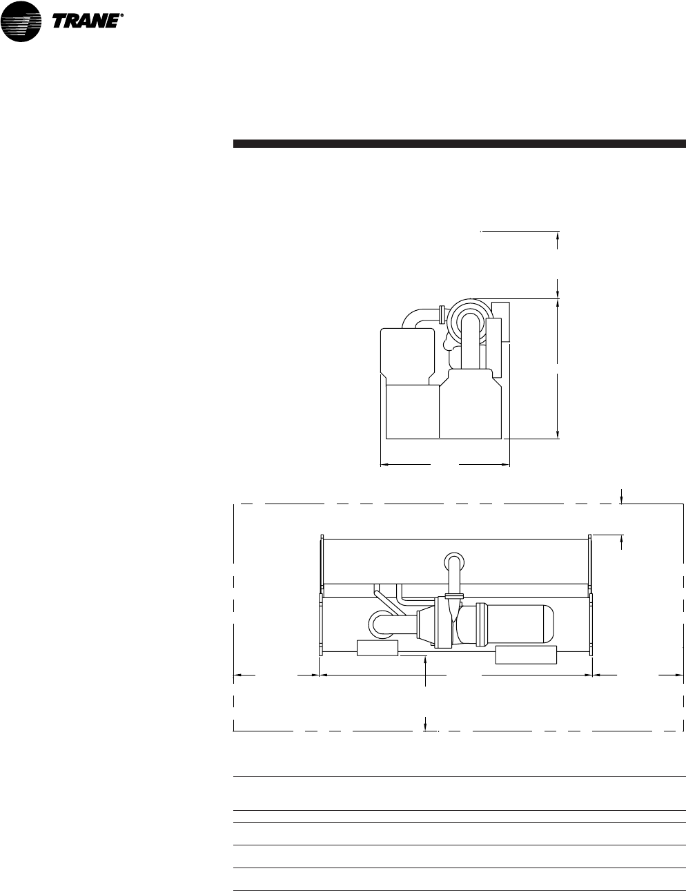
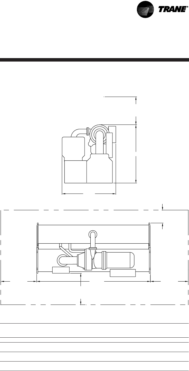
36" (914 mm)
Recommended
clearance
Height
Width
18" (457 mm)
Recommended
clearance
CL1/CL2 Length CL1/CL2
48" (1219 mm)
Recommended
clearance
Table 7. Dimensions for figure 4
Clearance Tube Pull
Feet-Inch (mm)
Compressor Shell Size CL1 CL2 Length Height Width
400-500 500 13' 11" 3' 7" 13' 5" 6' 11" 6' 6"
(4.235) (1.092) (4.083) (1.790) (1.984)
560-700 700 13' 11" 3' 7" 13' 5" 6' 11" 6' 10"
(4.235) (1.092) (4.083) (1.790) (2.083)
740-1000 1000 13' 11" 3' 7" 13' 5" 8' 4" 7' 6-3/4"
(4.235) (1.092) (4.083) (2.540) (2.305)
Notes:
CL1 at either end of the machine and is required for tube pull clearance.
CL2 is always at the opposite end of the machine from CL1 and is required for service clearance.
Add 14-5/8" (37.1 cm) on each end for the water box.
Unit Dimensions With Unit
Mounted Starters
Figure 4. Recommended operating and service clearances –
Model CVGF with unit-mounted starters
Dimensions Feet-Inch (m-meters)
CVGF-SVN02B-E4 35
Installation:
Mechanical
Figure 5. Recommended operating and service clearances –
Model CVGF without unit-mounted starters
36" (914 mm)
Recommended
clearance
Height
Width
18" (457 mm)
Recommended
clearance
CL1/CL2 Length CL1/CL2
36" (914 mm)
Recommended
clearance
Table 8. Dimensions for figure 5
Clearance Tube Pull
Feet-Inch (mm)
Compressor Shell Size CL1 CL2 Length Height Width
400-500 500 13' 11" 3' 7" 13' 5" 6' 11" 6' 3"
(4.235) (1.092) (4.083) (1.790) (1.913)
560-700 700 13' 11" 3' 7" 13' 5" 6' 11" 6' 7"
(4.235) (1.092) (4.083) (1.790) (2.028)
740-1000 1000 13' 11" 3' 7" 13' 5" 8' 4" 7' 5"
(4.235) (1.092) (4.083) (2.540) (2.261)
Notes:
CL1 at either end of the machine and is required for tube pull clearance.
CL2 is always at the opposite end of the machine from CL1 and is required for service clearance.
Add 14-5/8" (37.1 cm) on each end for the water box.
Unit Dimensions Without Unit
Mounted Starters
Dimensions Feet-Inch (m-meters)
CVGF-SVN02B-E4
36
Installation:
Mechanical
Water Pipe Connections
Table 9 applies to all CVGF
chiller tonnage sizes 500, 700
and 1000.
Refer to Table 9 for water pipe
connection sizing information
and evaporator and condenser
water pass information. All
measurement are in either US
or metric equivalents.
Ventilation
The unit produces heat even
though the compressor is
cooled by the refrigerant. Make
provisions to remove heat
generated by unit operation
from the equipment room.
Ventilation must be adequate to
maintain an ambient
temperature lower than 122°F
(50°C).
Vent the unit pressure relief
valves in accordance with all
local and national codes.
Make provisions in the
equipment room to keep the
chiller from being exposed to
freezing temperatures of 32°F
(0°C).
Water Drainage
Locate the unit near a large-
capacity drain for water vessel
drain-down during shutdown or
repair. Condensers and
evaporators are provided with
drain connections. All local and
national codes apply.
Moving and Rigging
The Model CVGF chiller should
be moved by lifting at
designated lift points only. Refer
to the rigging diagram that ships
with each unit for specific per
unit weight data.
Table 9. Model CVGF water connection pipe size (mm)
Shell Size
500 700 1000
Water Passes
Nominal Pipe Size (inches) NPS
Evaporator
2-pass 8" 10" 12"
(DN200) (DN250) (DN300)
3-pass 8" 8" 10"
(DN200) (DN200) (DN250)
Condenser
2-pass 10" 12" 14"
(DN250) (DN300) (DN350)
WARNING
Heavy Objects!
Do not use cables (chains or
slings) except as shown. Each of
the cables (chains or slings)
used to lift the unit must be
capable of supporting the entire
weight of the unit. Lifting cables
(chains or slings) may not be of
the same length. Adjust as
necessary for even unit lift.
Other lifting arrangements may
cause equipment or property-
only damage. Failure to properly
lift unit may result in death or
serious injury. See details
below:
• Follow the procedures and
diagrams in this manual and in
the submittal.
• Always use lifting equipment
with a capacity exceeding the
unit lifting weight by an
adequate safety factor. (+10%).
CVGF-SVN02B-E4 37
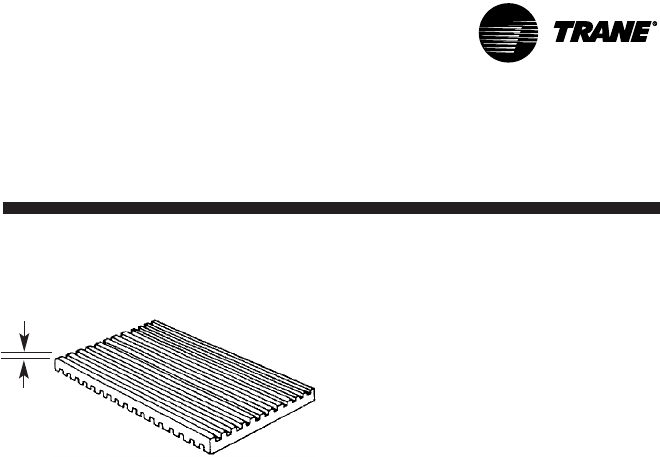
5/16-3/8"
(8-10 mm)
Installation:
Mechanical
Chiller Isolation
To minimize sound and vibration
transmission through the
building structure, and to assure
proper weight distribution over
the mounting surface, install
isolation pads or spring isolators
under the chiller feet.
Note: Isolation pads are
provided with each chiller unless
spring isolators are specified on
the sales order.
Specific isolator loading data is
provided in the until submittal
package. Also refer to Table 10. If
necessary, contact your local
Trane sales office for further
information.
Isolation Pads
When the unit is ready for final
placement, position isolation
pads end-to-end under the full
length of the chiller leg. The
pads measure 6" x 18" (152 x 457
mm). See Figure 6. No gaps
should be present between
pads.
Remember that the chiller must
be level within 1/4" (6 mm) over
its length and width after it is
lowered onto the isolation pads.
In addition, all piping connected
to the chiller must be properly
isolated and supported so that it
does not place any stress on the
unit.
Spring Isolators
Spring isolators should be
considered whenever chiller
installation is planned for an
upper-story location. Spring
isolator selection and placement
information is presented in
Figure 7 and Figure 8.
Note: Three types of spring
isolators, shown in Tables 11-13
are used. Each type has its own
maximum loading
characteristics.
Spring isolators are typically
shipped assembled and ready
for installation. To install and
adjust the isolators properly,
follow the instructions given.
Note: Do not adjust the isolators
until the chiller is piped and
charged with refrigerant and
water.
1. Position the spring isolators
under the chiller as shown in
Figure 7 and Figure 9. Make
sure that each isolator is
centered in relation to the
tube sheet.
2. Set isolators on the sub-base;
shim or grout them as
necessary to provide a flat,
level surface as the same
elevation for all mountings. Be
sure to support the full
underside of the isolator base
plate; no not straddle gaps or
small shims.
3. If required, bolt the isolators
to the floor through the slots
provided, or cement the pads.
Note: fastening the isolators
to the floor is not necessary
unless specified.
4. If the chiller must be fastened
to the isolators, insert cap
screws through the chiller
base and into the holes
tapped in the upper housing
of each isolator. Do not allow
the screws to protrude below
the underside of the isolator
upper housing. An alternative
method of fastening the chiller
to the isolators is to cement
the neoprene pads.
5. Set the chiller on the isolators;
refer to the "Rigging" section
for lifting instructions.
The weight of the chiller will
force the upper housing of
each isolator down, perhaps
causing it to rest on the
isolator's lower housing.
Figure 9 illustrates spring
isolator construction.
Figure 6. Isolation pad
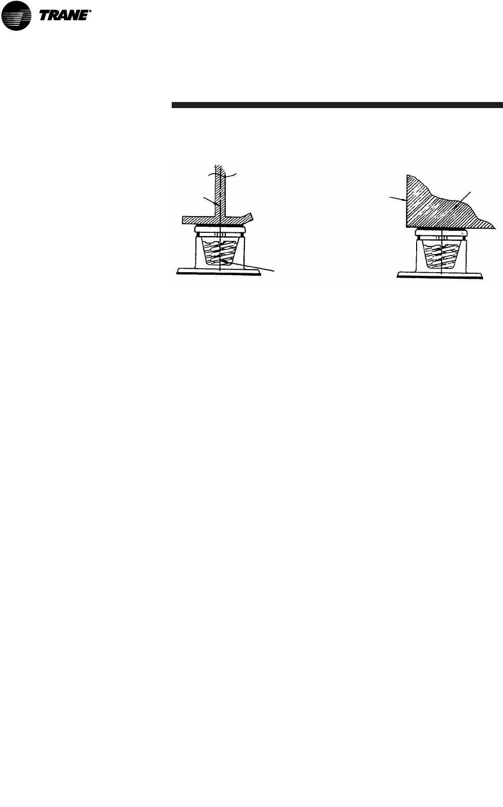
CVGF-SVN02B-E4
38
6. Check the clearance on each
isolator. If this dimension is
less than 1/4" (6 mm) on any
isolator, use a wrench to turn
the adjusting bolt one
complete revolution upward.
Repeat this operation until a
1/4" (6 mm) clearance is
obtained at all isolators.
7. After the minimum required
clearance is obtained on each
of the isolators, level the
chiller by turning the adjusting
bolt on each of the isolators
on the low side of the unit. Be
sure to work from one isolator
to the next.
Remember that the chiller
must be level to within 1/4" (6
mm) over its length and width
and that clearance of each
isolator must be 1/4" (6 mm).
Figure 7. Chiller foot or isolator orientation
Side View of Unit End View of Unit
Center
tube
sheet
support
leg
End of
tube sheet
Outside edge
of tube sheet
Center of Isolator
Spring
Note: The spring isolator must be
centered in relation to the tube sheet. Do
not align the isolator with the flat part of
the chiller foot, because the tube sheet is
often off-center.
Note: Place isolator near outside edge of
tube sheet as shown.
Installation:
Mechanical
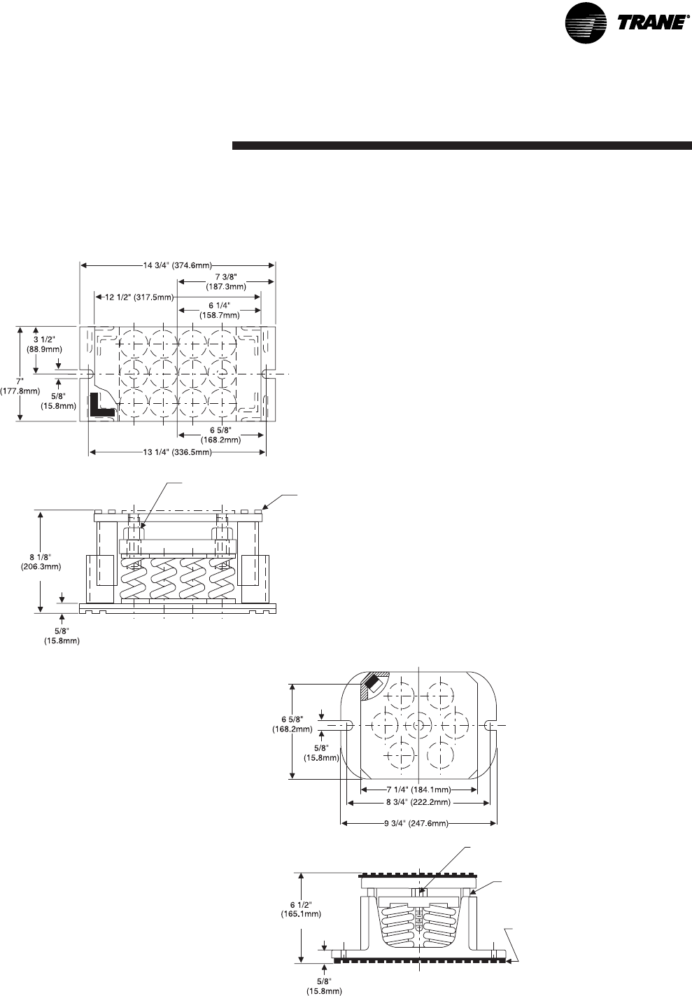
CVGF-SVN02B-E4 39
Installation:
Mechanical
CT-12 Spring Isolators
Free Height
1/4"
(6.3mm)
Acoustical
nonskid
neoprene
pad (top
and
bottom)
(2) 1-B UNC Adjusting
and Leveling Bolts
Figure 8. Typical spring isolator construction
CT-7 Spring Isolators
C-C Foundation Bolts
Free Height
Adjust isolator so that the upper
housing clears the lower housing by at
least 1/4
" (6.3mm) and not more than 1/2"
(12.7mm)
1/4" (6.3mm) Acoustical nonskid
neoprene pad (top and bottom)
3/4" (19.0mm)
10 UNC Adjusting and leveling bolt
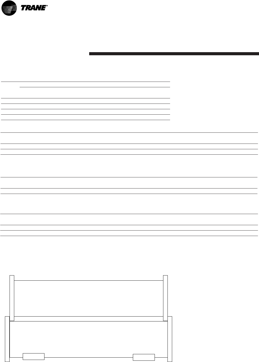
CVGF-SVN02B-E4
40
Installation:
Mechanical
Table 11. Selected spring isolators – CVGF 500
Deflection
inches (mm)
CT-12-27 X10350665-030 9000 (4082) 1.06 (27) Orange A & C
CT-12-28 X10350665-040 10800 (4898.8) 1.02 (26) Green B & D
Note: Each type CT-12 spring isolator has 12 springs.
Isolator type
and size
Trane Part
#
Maximum Load
lbm (kg)
Spring Color
Coding
Location
Used
Table 12. Selected spring isolators – CVGF 700
Deflection
inches (mm)
CT-7-31 X10350664-050 7700 (3492.7) 0.83 (21) Gray A, B, C, D
Note: Each type CT-7 spring isolator has 7 springs.
Isolator type
and size
Trane Part
#
Maximum Load
lbm (kg)
Spring Color
Coding
Location
Used
Table 13. Selected spring isolators – CVGF 1000
Deflection
inches (mm)
CT-12-28 X10350665-040 10000 (4535.9) 1.02 (26) Green A
CT-12-31 X10350665-050 13200 (5987.4) 0.83 (21) Gray B, C, D
Note: Each type CT-12 spring isolator has 12 springs.
Isolator type
and size
Trane Part
#
Maximum Load
lbm (kg)
Spring Color
Coding
Location
Used
Figure 9. Load points - 500, 700 and 1000 ton families (reference table 10)
Condenser
Evaporator
Top View
A
B
C
D
Table 10. Isolation loads - 500, 700 and 1000 ton families
(reference figure 9)
500 Ton Family 700 Ton Family 1000 Ton Family
Maximum Load - Maximum Load - Maximum Load -
pound (kg) pound (kg) pound (kg)
A 5905 (2679) 8388 (3805) 10750 (4846)
B 7005 (3177) 9431 (4278) 12665 (5745)
C 6090 (2762) 8991 (4078) 11500 (5216)
D 7225 (3277) 10340 (4690) 13545 (6144)
Location
Point
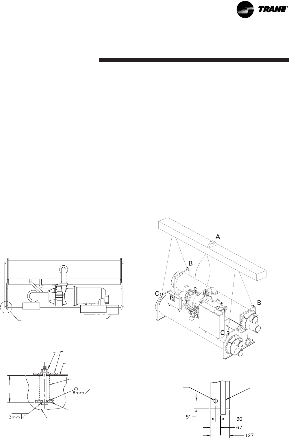
CVGF-SVN02B-E4 41
Installation:
Mechanical
CVGF Rigging
1. Dimensions are in millimeters
(mm). Figure 10.
WARNING
Heavy Objects!
Do not use cables (chains or
slings) except as shown. Each of
the cables (chains or slings)
used to lift the unit must be
capable of supporting the entire
weight of the unit. Lifting cables
(chains or slings) may not be of
the same length. Adjust as
necessary for even unit lift.
Other lifting arrangements may
cause equipment or property-
only damage. Failure to properly
lift unit may result in death or
serious injury. See details below.
1. Use a 3600 mm lifting beam
and adjust the chains (cables)
for an even, level lift.
2. 900 mm recommended
clearance above highest point of
compressor.
3. Attach safety chains or cables
as shown, and without tension.
The safety chain is not used for
lifting, but is there to prevent
the unit from rolling.
4. More details weight
information is available on
request.
2. Each chain or cable used to lift
the unit must be capable of
supporting the entire weight
of the chiller.
3. Use a 3600 mm lifting beam
and adjust the chains or
cables for an even, level lift.
4. 900 mm recommended
clearance above highest point
of compressor.
5. Attach safety chains or cables
as shown in Figure 11, and
without tension. The safety
chain is not used for lifting,
but is there to prevent the unit
from rolling.
6. More detailed weight
information is available upon
request.
Figure 10. Rigging diagram with anchor hole
and bolt detail
See anchor hole
detail
Motor
Terminal Box
Control
Panel
Optional unit-
mounted
starter
Figure 11. Rigging diagram with safety chain placement
Anchor Bolt Detail
Nuts should not be tight.
Leave 2 to 3 mm gap.
Unit mounting pad 13 mm
thick (by Trane)
Vibration isolator (by Trane)
75 mm steel pipe
152 × 152 × 19 mm
steel plate
Concrete
To meet
local codes
Recommended procedure to allow for
thermal expansion. (Unless otherwise
specified, parts are furnished by the
customer.)
Anchor Hole Detail
4 × 22 mm
diameter holes for
anchoring the unit
Evaporator
tubesheet
Dimensions are typical for each corner

CVGF-SVN02B-E4
42
Installation:
Mechanical
Water Pressure Drop Data
Pressure drop for CVGF 500 Condensers with 0.75 inch OD
tubes and 2 pass waterboxes
Pressure Drop (in feet of water)
Flow (in GPM)
Pressure drop for CVGF 500 Evaporators with 0.75 inch OD
tubes and 2 pass waterboxes
Pressure drop (in feet of water)
Bundle C
Flow (in GPM)
Graph 1.
Graph 2.
Bundle A Bundle B
Bundle C
Bundle A Bundle B
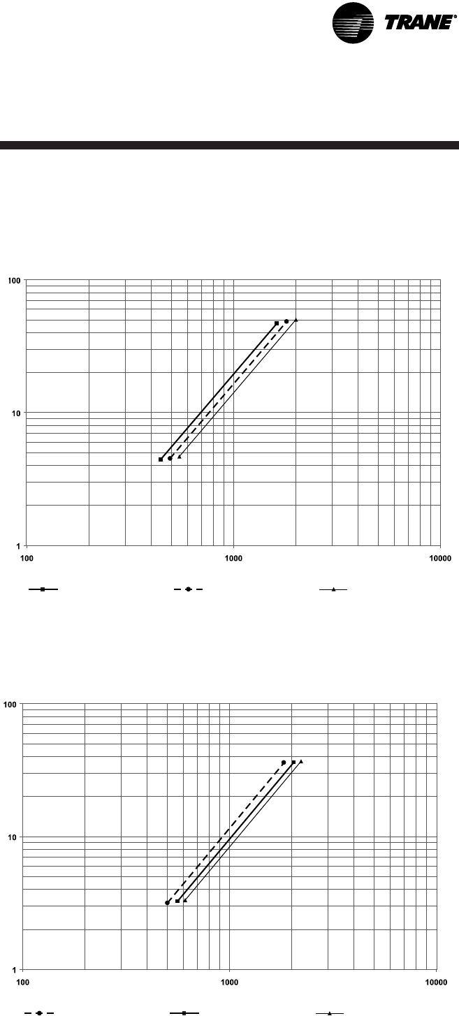
CVGF-SVN02B-E4 43
Installation:
Mechanical
Water Pressure Drop Data
Pressure drop for CVGF 500 Evaporators with 1.0 inch OD
tubes and 2 pass waterboxes
Flow (in GPM)
Pressure drop for CVGF 500 Condensers with 1.0 inch OD
tubes and 2 pass waterboxes
Pressure drop (in feet of water)
Flow (in GPM)
Pressure drop (in feet of water)
Graph 3.
Graph 4.
Bundle C
Bundle A Bundle B
Bundle C
Bundle A Bundle B
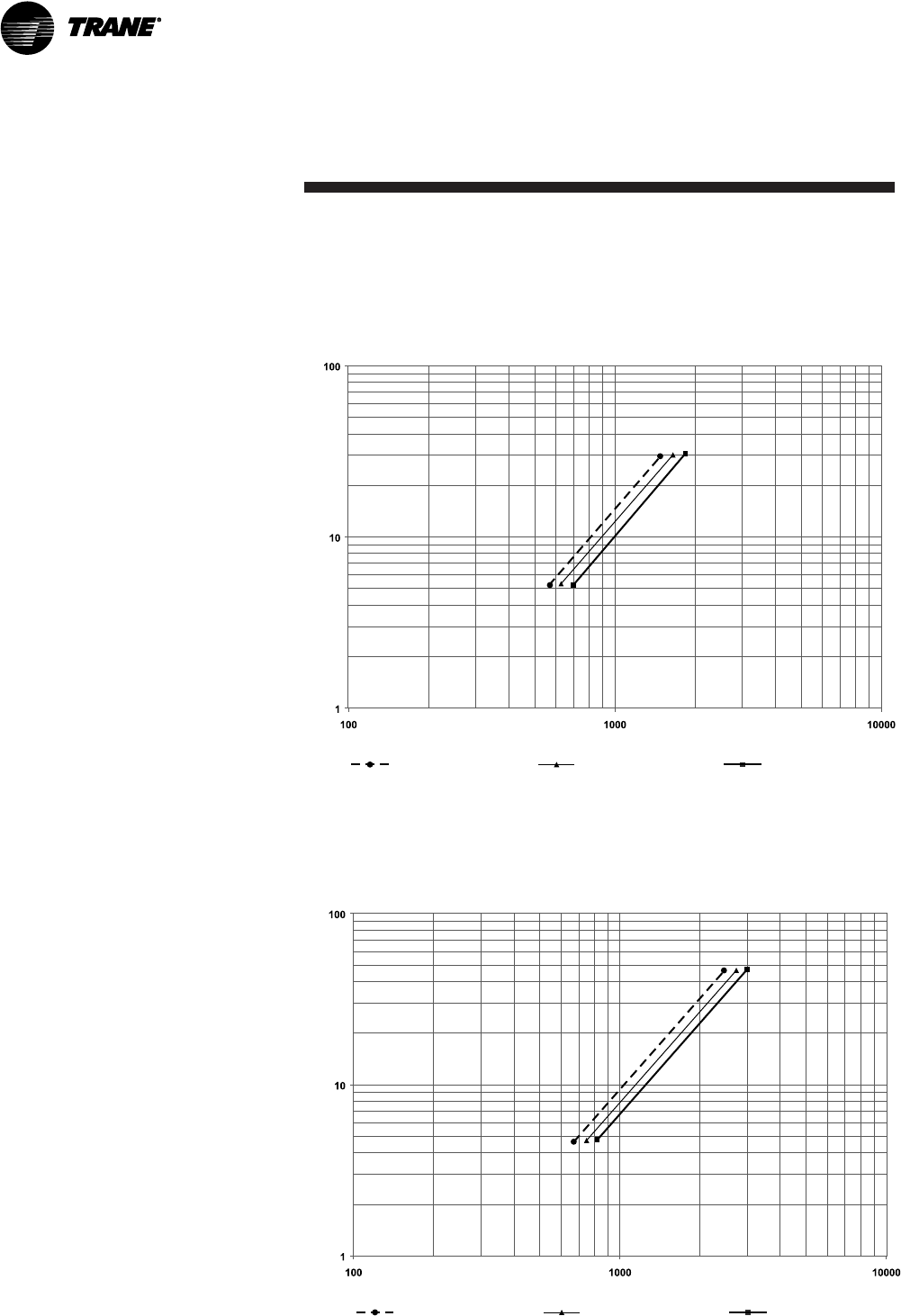
CVGF-SVN02B-E4
44
Installation:
Mechanical
Water Pressure Drop Data
Pressure drop for CVGF 700 Evaporators with 3/4 inch OD
tubes and 2 pass waterboxes
Pressure drop (in feet of water)
Flow (in GPM)
Pressure drop for CVGF 700 Condensers with 3/4 inch OD tubes
and 2 pass waterboxes
Pressure drop (in feet of water)
Flow (in GPM)
Graph 5.
Graph 6.
Bundle C
Bundle A Bundle B
Bundle C
Bundle A Bundle B
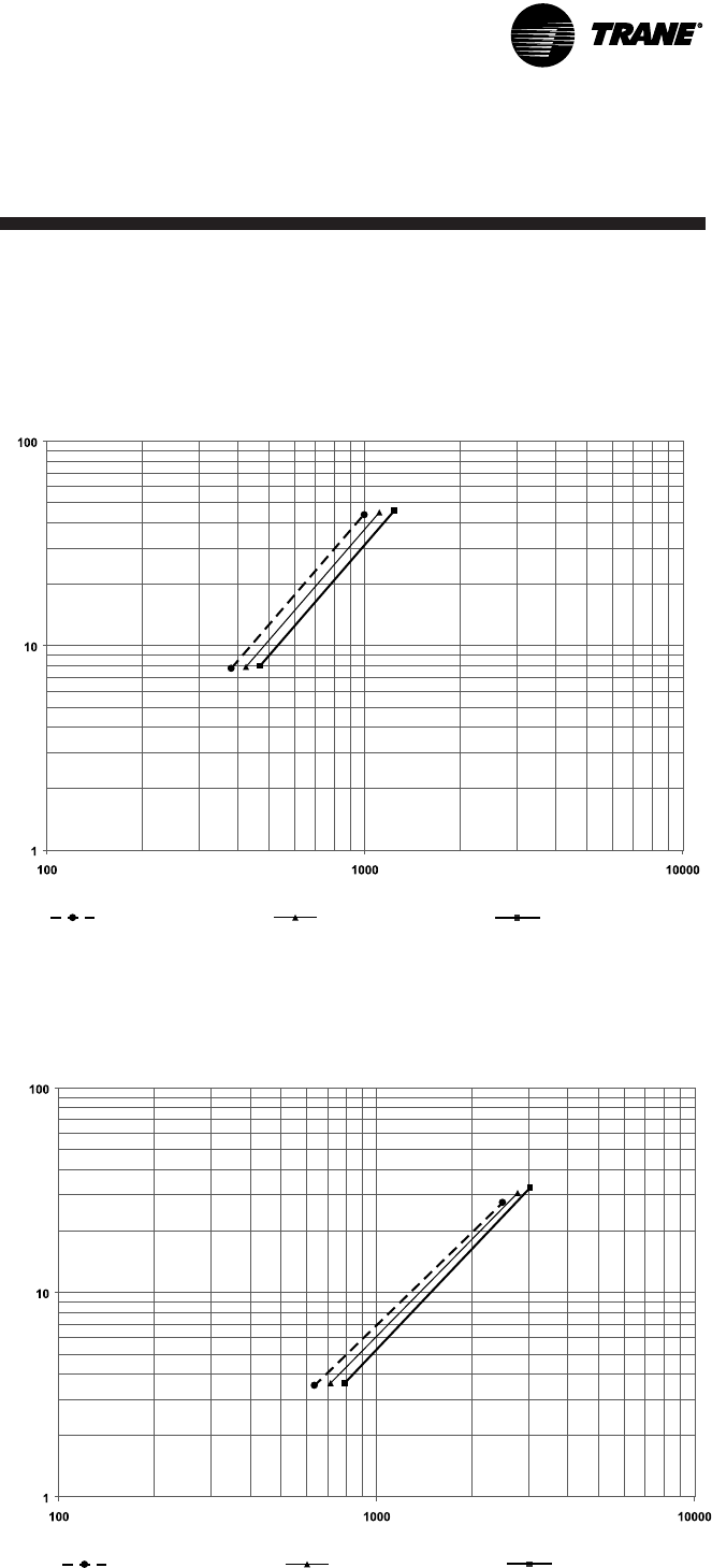
CVGF-SVN02B-E4 45
Installation:
Mechanical
Water Pressure Drop Data
Pressure drop for CVGF 700 Evaporators with 3/4 inch OD
tubes and 3 pass waterboxes
Pressure drop (in feet of water)
Flow (in GPM)
Pressure drop for CVGF 700 Evaporators with 1.0 inch OD
tubes and 2 pass waterboxes
Pressure drop (in feet of water)
Flow (in GPM)
Graph 7.
Graph 8.
Bundle C
Bundle A Bundle B
Bundle C
Bundle A Bundle B
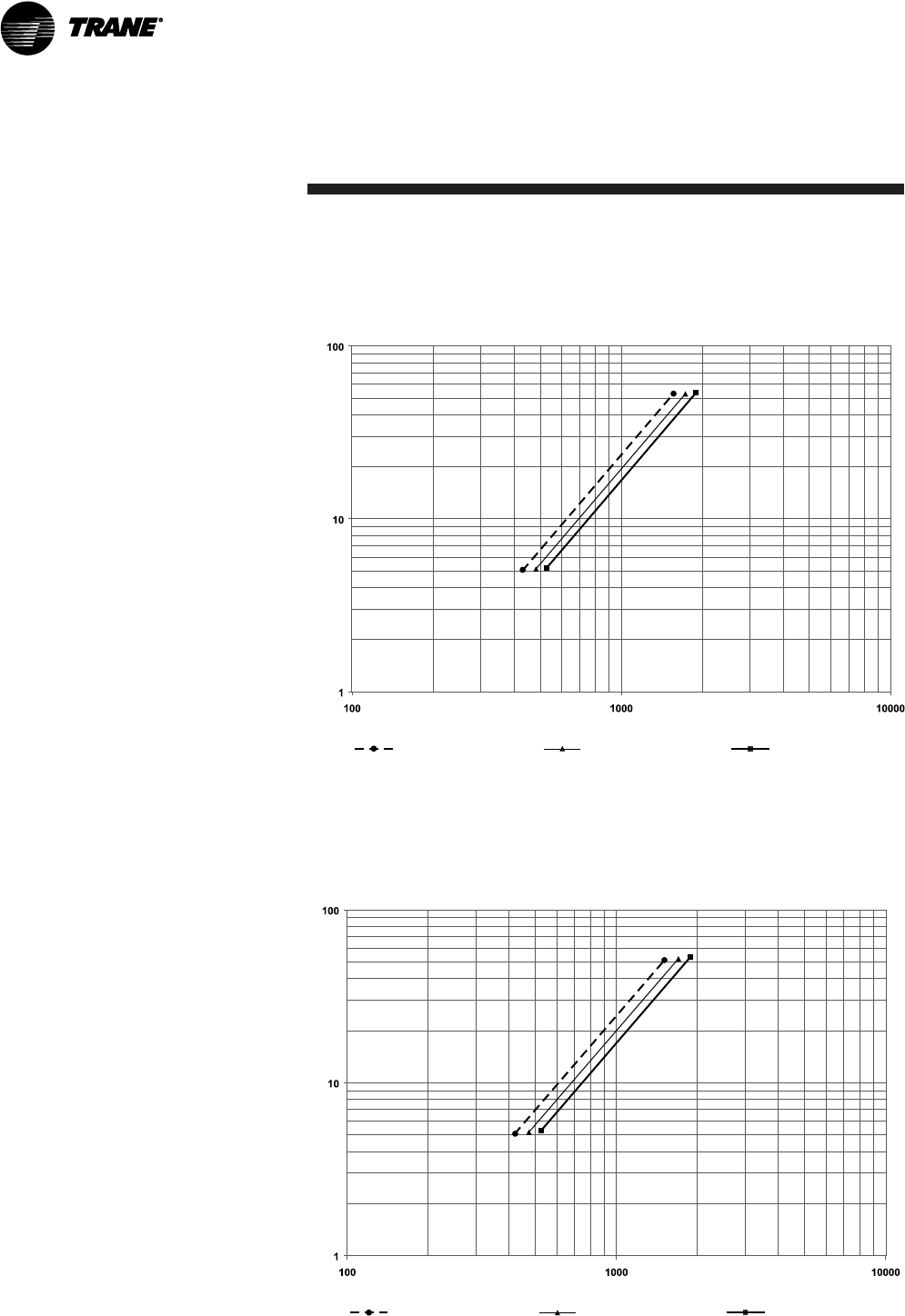
CVGF-SVN02B-E4
46
Installation:
Mechanical
Water Pressure Drop Data
Pressure drop for CVGF 700 Condensers with 1.0 inch OD tubes
and 2 pass waterboxes
Pressure drop (in feet of water)
Flow (in GPM)
Pressure drop for CVGF 700 Evaporators with 1.0 inch OD
tubes and 3 pass waterboxes
Pressure drop (in feet of water)
Flow (in GPM)
Graph 9.
Graph 10.
Bundle C
Bundle A Bundle B
Bundle C
Bundle A Bundle B
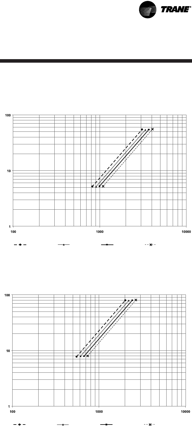
CVGF-SVN02B-E4 47
Installation:
Mechanical
Water Pressure Drop Data
Pressure drop for CVGF 1000 Evaporators with 3/4 inch OD
tubes and 2 pass waterboxes
Pressure drop (in feet of water)
Flow (in GPM)
Pressure drop for CVGF 1000 Evaporators with 3/4 inch OD
tubes and 3 pass waterboxes
Pressure drop (in feet of water)
Flow (in GPM)
Graph 11.
Graph 12.
Bundle C
Bundle A Bundle B Bundle D
Bundle C
Bundle A Bundle B Bundle D
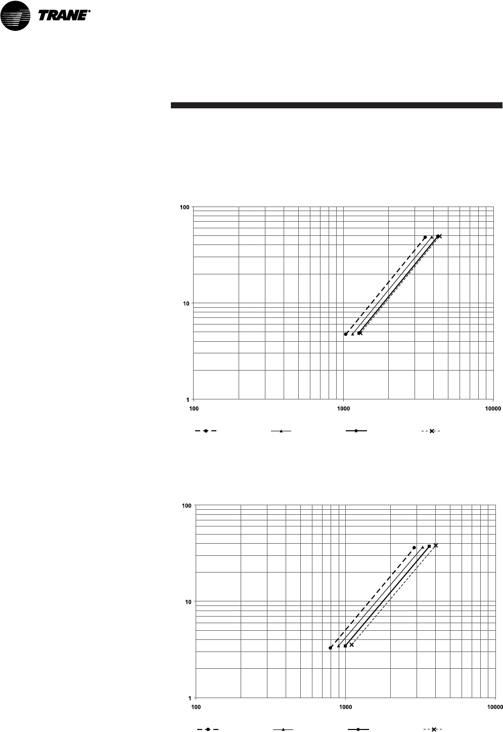
Pressure drop for CVGF 1000 Condensers with 3/4 inch OD
tubes and 2 pass waterboxes
CVGF-SVN02B-E4
48
Installation:
Mechanical
Water Pressure Drop Data
Pressure drop (in feet of water)
Flow (in GPM)
Pressure drop for CVGF 1000 Evaporators with 1.0 inch OD
tubes and 2 pass waterboxes
Pressure drop (in feet of water)
Flow (in GPM)
Graph 13.
Graph 14.
Bundle C
Bundle A Bundle B Bundle D
Bundle C
Bundle A Bundle B Bundle D

CVGF-SVN02B-E4 49
Installation:
Mechanical
Pressure drop for CVGF 1000 Condensers with 1.0 inch OD
tubes and 2 pass waterboxes
Water Pressure Drop Data
Pressure drop (in feet of water)
Flow (in GPM)
Pressure drop for CVGF 1000 Evaporators with 1.0 inch OD
tubes and 3 pass waterboxes
Pressure drop (in feet of water)
Flow (in GPM)
Graph 15.
Graph 16.
Bundle C
Bundle A Bundle B Bundle D
Bundle C
Bundle A Bundle B Bundle D

CVGF-SVN02B-E4
50
Installation:
Mechanical
Evaporator Piping
Components
Note: Ensure that all piping
components are between the
shutoff valves, so that both the
condenser and the evaporator
can be isolated.
Piping components include all
devices and controls used to
provide proper water-system
operation and unit operating
safety. These components and
their general locations are
described below.
Entering Chilled-Water Piping
• Air vents (to bleed air from
system)
• Water pressure gauges
manifolded with shutoff valves
• Pipe unions
• Vibration eliminators (rubber
boots)
• Shutoff (isolation) valves
• Thermometers
• Cleanout tees
• Pipe strainer
Leaving Chilled-Water Piping
• Air vents (to bleed air from
system)
• Water pressure gauges
manifolded with shutoff valves
• Pipe unions
• Vibration eliminators (rubber
boots)
• Shutoff (isolation) valves
• Thermometers
• Cleanout tees
• Balancing valve
• Pressure relief valve
• Flow switch
CAUTION
Equipment damage!
To prevent evaporator damage,
do not exceed 150 psig (1035
kPa) evaporator water pressure
for standard water boxes. The
maximum pressure for high-
pressure water boxes is 300 psig
(2100 kPa). To prevent tube
damage by erosion, install a
strainer in the evaporator water
inlet piping.
Connecting Groove Pipes
CAUTION
Piping damage!
To prevent damage to water
piping, do not overtighten the
connections.
Note: Make sure that all piping is
flushed and cleaned prior to
starting the unit.
CAUTION
Equipment damage!
To prevent equipment damage,
bypass the unit if using an acidic
flushing agent.
Vents and Drains
Install pipe plugs or ball valves,
with National Pipe Thread (NPT)
to water hose thread
connections, in evaporator and
condenser water box drain and
vent connections before filling
the water systems.
To drain water, remove the vent
and drain plugs or open the ball
valves. Install an NPT connectors
in the drain connection, and
connect a hose to it.

CVGF-SVN02B-E4 51
Installation:
Mechanical
Condenser Piping
Components
Piping components include all
devices and controls used to
provide proper water-system
operation and unit operating
safety. These components and
their general locations are given
below.
Entering condenser-water piping
• Air vents (to bleed air from
system)
• Water pressure gauges
manifolded with shutoff valves
• Pipe unions
• Vibration eliminators (rubber
boots)
• Shutoff (isolation) valves, one
per pass
• Thermometers
• Cleanout tees
• Pipe strainer
Leaving condenser-water piping
• Air vents (to bleed air from
system)
• Water pressure gauges with
manifolded shutoff valves
• Pipe unions
• Vibration eliminators (rubber
boots)
• Shutoff (isolation) valves, one
per pass
• Thermometers
• Cleanout tees
• Balancing valve
• Pressure relief valve
• Flow switch
CAUTION
Condenser damage!
To prevent condenser damage,
do not exceed 150 psig (1035
kPa) water pressure for
standard water boxes. The
maximum pressure for high-
pressure water boxes is 300 psig
(2100 kPa).
To prevent tube damage, install
a strainer in the condenser
water inlet piping.
To prevent tube corrosion,
ensure that the initial water fill
has a balanced pH.
Water Treatment
CAUTION
Water Treatment!
Do not use untreated or
improperly treated water. Use of
untreated or improperly treated
water may result in equipment
damage.
Using untreated or improperly
treated water in these units may
result in inefficient operation
and possible tube damage.
Consult a qualified water-
treatment specialist to
determine whether treatment is
needed. The following
disclamatory label is provided
on each CVGF unit:
The use of improperly treated or
untreated water in this
equipment may result in scaling,
erosion, corrosion, algae, or
slime. The services of a qualified
water-treatment specialist
should be engaged to determine
what treatment, if any, is
advisable. The Trane Company
warranty specifically excludes
liability for corrosion, erosion, or
deterioration of Trane
equipment. Trane assumes no
responsibility for the results of
the use of untreated, improperly
treated, saline, or brackish
water.
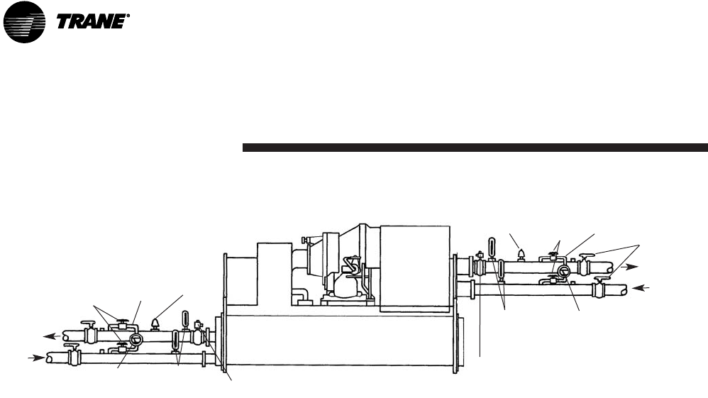
CVGF-SVN02B-E4
52
Installation:
Mechanical
Figure 12. Typical thermometer, valving, and manifold pressure gauge set-up
Evaporator
waterflow
Pressure
differential
gauge
Thermometers Relief
valve
Shutoff
valves
Manifold
Flow
switch
Relief
valve
Condenser
water flow
Pressure
differential
gauge
Thermometers
Shutoff
valves Manifold
Flow switch Isolation
valves
Water Pressure Gauges
and Thermometers
Install field-supplied
thermometers and pressure
gauges (with manifolds
whenever practical) as shown in
Figure 12. Locate pressure
gauges or taps in a straight run
of pipe; avoid placement near
elbows, and so forth. Be sure to
install the gauges at the same
elevation on each shell if the
shells have opposite-end water
connections.
To read manifolded water
pressure gauges, open one valve
and close the other (depending
upon the reading desired). This
eliminates errors resulting from
differently calibrated gauges
installed at unmatched
elevations.
Water Pressure-Relief
Valves
CAUTION
Shell Damage!
Install a pressure-relief valve in
both the evaporator and
condenser water systems.
Failure to do so could result in
shell damage.
Install a water pressure-relief
valve in one of the condenser,
and one of the evaporator, water
box drain connections, or on the
shell side of any shutoff valve.
Water vessels with close-
coupled shutoff valves have a
high potential for hydrostatic
pressure buildup during a water
temperature increase. Refer to
applicable codes for pressure-
relief valve installation
guidelines.
Flow-Sensing Devices
Use field provided flow switches
or differential pressure switches
with pump interlocks to sense
system water flow. Flow switch
locations are schematically
shown in Figure 12.
To provide chiller protection,
install and wire flow switches in
series with the water pump
interlocks, for both chilled-water
and condenser-water circuits
(refer to the Installation Electrical
section). Specific connections
and schematic wiring diagrams
are shipped with the unit.

CVGF-SVN02B-E4 53
Installation:
Mechanical
Flow switches must stop or
prevent compressor operation if
either system water flow drops
below the required minimum
that is shown on the pressure
drop curves. Follow the
manufacturer’s
recommendations for selection
and installation procedures.
General guidelines for flow
switch installation are outlined
below.
• Mount the switch upright, with
a minimum of 5 pipe diameters
of straight, horizontal run on
each side.
• Do not install close to elbows,
orifices, or valves.
Note: The arrow on the switch
must point in the direction of the
water flow.
• To prevent switch fluttering,
remove all air from the water
system
Note: The CH530 provides a six-
second time delay on the flow
switch input before shutting
down the unit on a loss-of-flow
diagnostic. If machine
shutdowns persist, contact your
local Trane representative.
• Adjust the switch to open when
water flow falls below nominal.
Refer to the General Data
tables for minimum flow
recommendations for specific
water-pass arrangements. Flow
switch contacts are closed
when there is proof of water
flow.

CVGF-SVN02B-E4
54
Installation:
Mechanical
Refrigerant Pressure-Relief
Valve Venting
WARNING
Possible refrigerant
asphyxiation!
Relief valve venting must be
vented outdoors. Refrigerant is
heavier than air and will
displace available oxygen to
breathe, causing asphyxiation or
other health risks. Each chiller
or Multiple chillers must have
their own separate relief valves
and vent piping. Consult local
regulations for any special relief-
line requirements. Failure to
vent relief valves outdoors could
result in death and serious
injury.
Note: Vent pipe size must
conform to the ANSI/ASHRAE
Standard 15 for vent pipe sizing.
All country, federal, state, and
local codes take precedence over
any suggestions stated in this
manual.
All relief valve venting is the
responsibility of the installing
contractor.
All CVGF units use evaporator
and condenser pressure-relief
valves that must be vented to
the outside of the building.
Relief valve connection sizes and
locations are shown in the unit
submittals. Refer to local codes
for relief valve vent line sizing
information.
CAUTION
Do not exceed vent piping code
specifications. Failure to heed
specifications could result in
capacity reduction, unit damage,
and relief valve damage.
After the relief valve has opened,
it will reclose when pressure is
reduced to a safe level.
Note: Relief valves tend to leak if
they have opened and must be
replaced.
Thermal Insulation
All CVGF units are available with
optional factory installed
thermal insulation. If the unit is
not factory insulated, install
insulation over the areas with
designated dotted lines in Figure
13. Refer to Table 14 for types
and quantities of insulation
required. All CVGF units come
from the factory with oil sump
insulation.
Notes: Refrigerant charging
valves, water temperature
sensors, and drain and vent
connections, when insulated,
must remain accessible for
service.
Use only water-base latex paint
on factory applied insulation.
Failure to do so may result in
insulation shrinkage.
Note: Units in environments
with higher humidity may
require additional insulation.
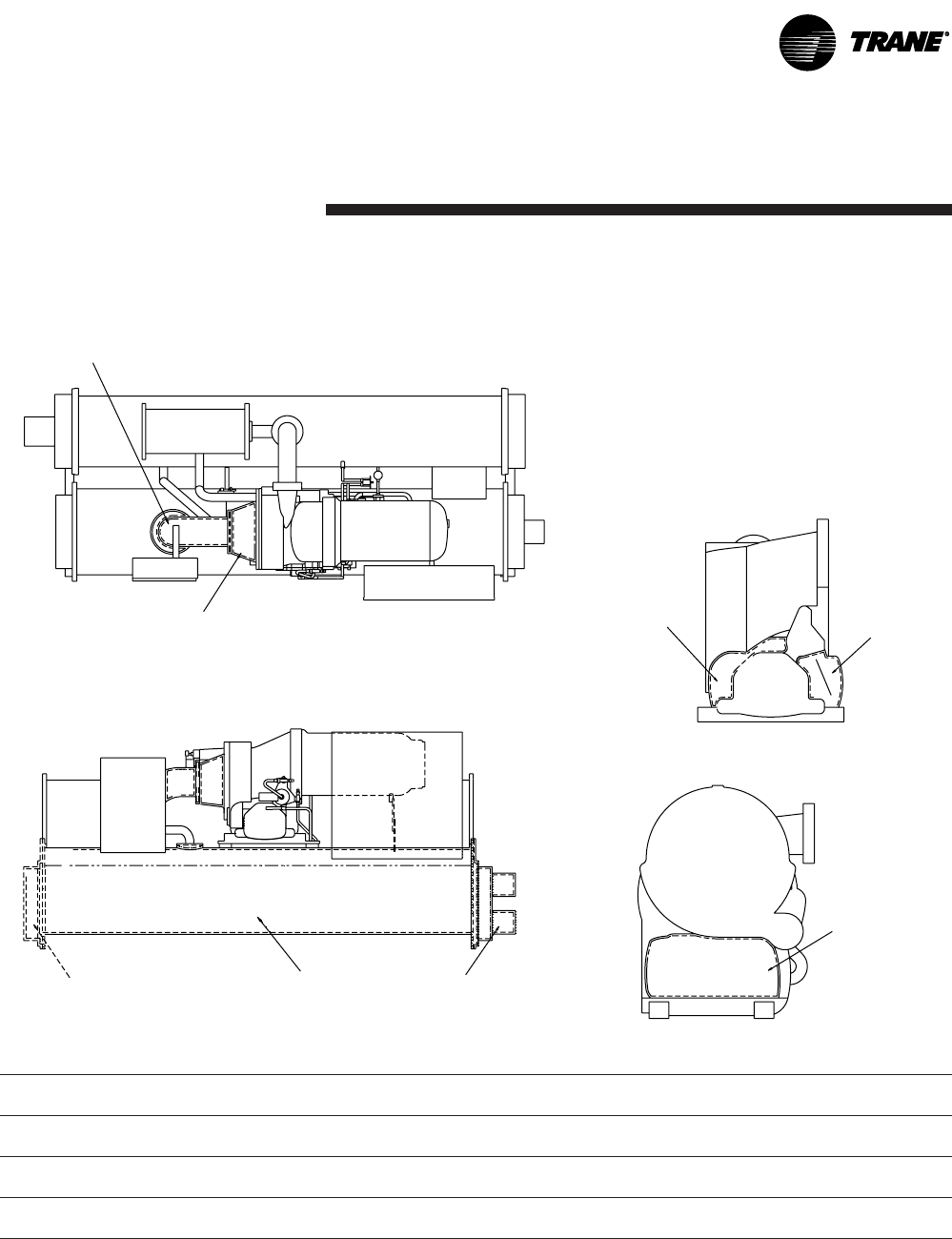
CVGF-SVN02B-E4 55
Table 14. Recommended insulation types
Square Feet
Location Type (Square m)
3/4" wall (19 mm) 160 (15)
3/4" wall (19 mm) 20 (2)
3/4" wall (19 mm) 10 (1)
Installation:
Mechanical
Figure 13. Typical CVGF insulation requirements
Suction line pipe
Suction cover
Evaporator water box Evaporator Evaporator water box
Oil sump casing Oil sump
casing
Oil sump casing
Gear Housing – Front View
Gear Housing – Side View
Insulate where dotted lines are indicated.
Evaporator, waterboxes and tube sheets
Compressor suction elbow and suction cover
All components and piping on low side of system

CVGF-SVN02B-E4
56
Installation:
Electrical
All field-installed wiring must
conform to National Electric
Code (NEC) guidelines, as well
as to any applicable state and
local codes. Be sure to satisfy
proper equipment grounding
requirements per NEC.
All field-installed wiring must be
checked for proper terminations,
and for possible shorts or
grounds.
Do not modify or cut enclosure
to provide electrical access.
Removable panels have been
provided for this purpose.
Modify these panels only; away
from enclosure. Refer to
installation information shipped
with the starter or submittal
drawings.
CAUTION
TO AVOID DAMAGE TO
STARTER COMPONENTS,
remove debris inside the starter
panel. Failure to do so may
cause an electrical short that
seriously damages the starter
components.
WARNING!
Rotating Components!
During installation, testing,
servicing and troubleshooting of
this product it may be necessary
to measure the speed of
rotating components. Have a
qualified or licensed service
individual who has been
properly trained in handling
exposed rotating components,
perform these tasks. Failure to
follow all safety precautions
when exposed to rotating
components could result in
death or serious injury.
As you review this manual,
along with the wiring
instructions presented in this
section, keep in mind that:
General Requirements
WARNING!
Live Electrical
Components!
During installation, testing,
servicing and troubleshooting of
this product, it may be
necessary to work with live
electrical components. Have a
qualified licensed electrician or
other individual who has been
properly trained in handling live
electrical components perform
these tasks. Failure to follow all
electrical safety precautions
when exposed to live electrical
components could result in
death or serious injury.
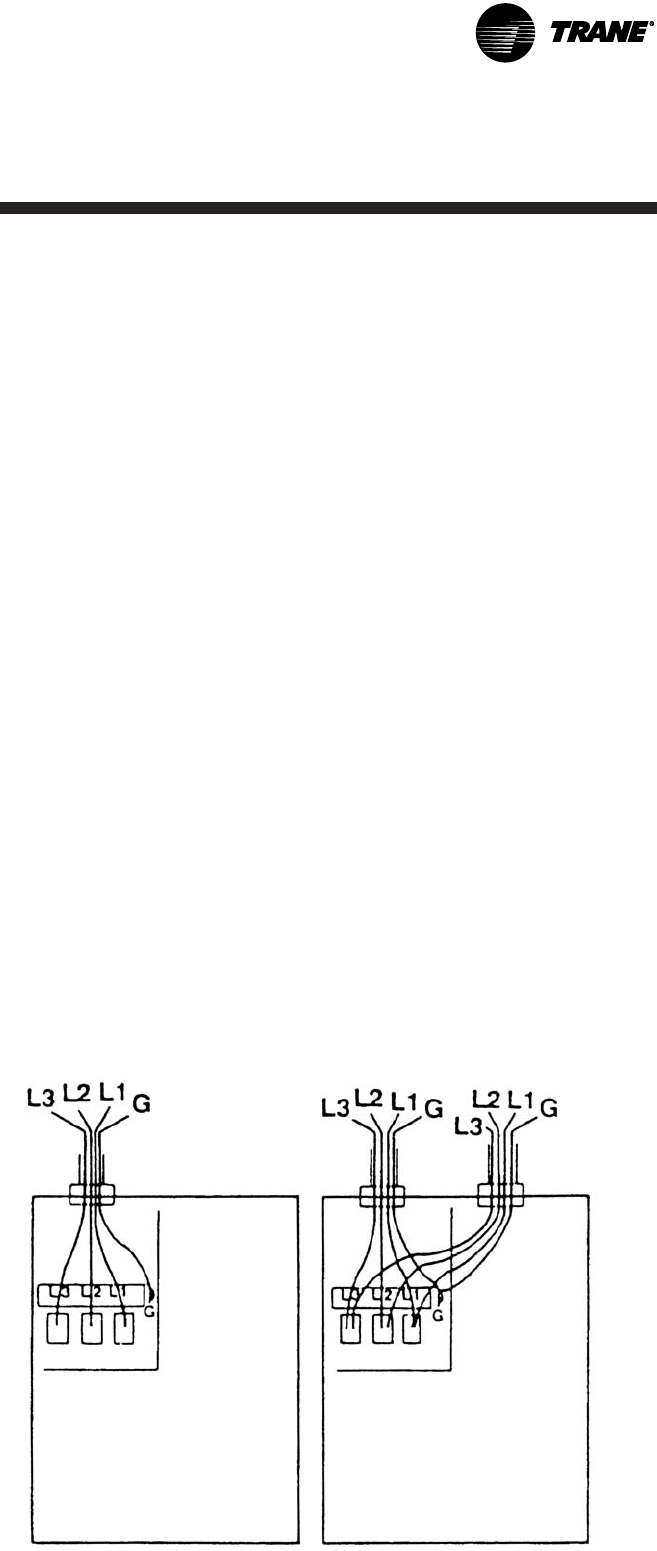
CVGF-SVN02B-E4 57
Installation:
Electrical
Power Supply Wiring
To assure that power supply
wiring to the starter panel is
properly installed and
connected, review and follow the
guidelines outlined below.
3-Phase Power Source
1. Verify that the starter
nameplate ratings are
compatible with the power
supply characteristics and with
the electrical data on the unit
nameplate.
2. If the starter enclosure must
be cut to provide electrical
access, exercise care to
prevent debris from falling
inside the enclosure. If the
starter cabinet has a
removable panel, be sure to
remove the panel from the
unit before drilling holes.
CAUTION
Damage to Starter
components!
To avoid damage remove debris
inside the starter panel. Failure
to do so may cause an electrical
short that seriously damages the
starter components.
3. Use copper conductors to
connect the 3-phase power
supply to the remote or unit-
mounted starter panel.
CAUTION
Use Copper Conductors
Only!
Unit terminals are not designed
to accept other types of
conductors. Failure to use
copper conductors may result in
equipment damage.
4. Size the power supply wiring
in accordance with the
Minimum Circuit Ampacity
(MCA) shown on the unit
nameplate.
(MCA = (RLA x 1.25) + Control
Power Load)
5. Make sure that the incoming
power wiring is properly
phased; each power supply
conduit run to the starter must
carry the correct number of
conductors to ensure equal
phase representation. See
Figure 14.
6. As you install the power
supply conduit, make sure
that this position does not
interfere with the
serviceability of any of the
unit components, nor with
structural members and
equipment.
Also, assure that the conduit is
long enough to simplify any
servicing that may be necessary
in the future (for example,
starter removal).
Note: Use flexible conduit to
enhance serviceability and
minimize vibration transmission.
Circuit Breakers and
Fusible Disconnects
Size the circuit breaker or fuse
disconnect in compliance with
NEC or local guidelines.
Figure 14. Proper phasing for starter power supply wiring and
conduit loading
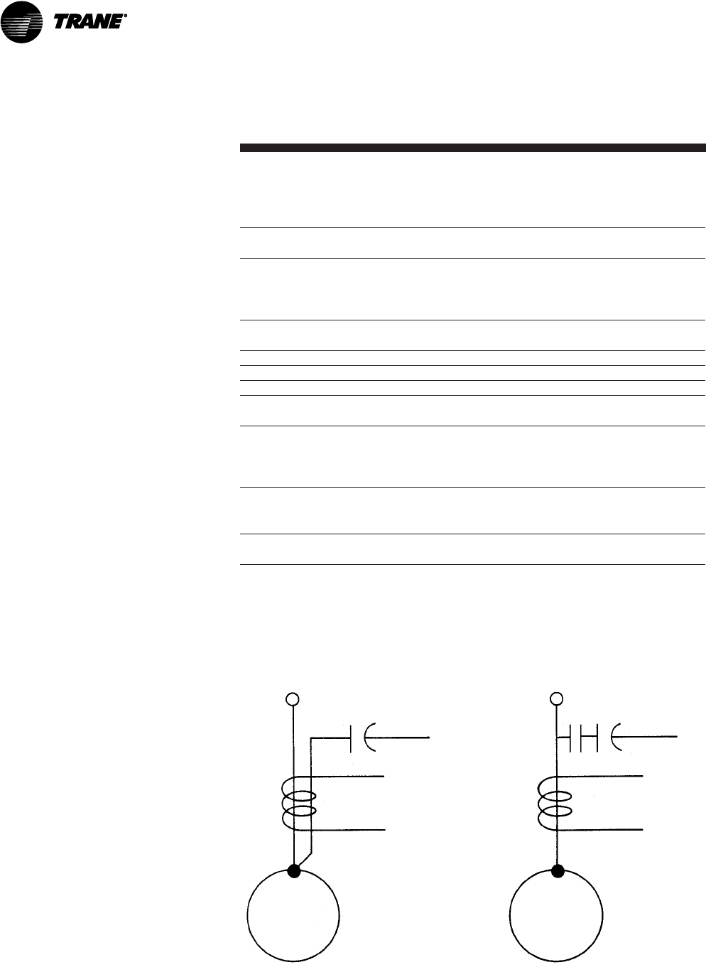
CVGF-SVN02B-E4
58
Installation:
Electrical
Optional PFCCs
Power factor correction
capacitors (PFCCs) are designed
to provide power factor
correction for the compressor
motor. They are available as an
option.
Note: Remember that the PFCC
nameplate voltage rating must
be greater than or equal to the
compressor voltage rating
stamped on the unit nameplate.
See Table 15 to determine what
PFCC is appropriate for each
compressor voltage application.
CAUTION
Motor of safety overload
damage!
PFCC must be wired into the
starter correctly. Failure to do so
may cause misapplication of
these capacitors and result in a
loss of motor overload
protection and subsequently
cause motor damage.
Table 15. PFCC design voltage sizing per compressor voltage
application
PFCC Design Voltage Compressor Motor Rating
(See Unit Nameplate)
480V/60 Hz 380V/60 Hz
440V/60 Hz
460V/60 Hz
480V/60 Hz
600V/60 Hz 575V/60 Hz
600V/60 Hz
2400V/60 Hz 2300V/60 Hz
2400V/60 Hz
PFCC Rating Compressor Motor Rating
(See Unit Nameplate)
480V/50 Hz 346V/50 HZ
380V/50 HZ
400V/50 Hz
415V/50 Hz
4160V/60 Hz 3300V/60 Hz
4160V/60 Hz
6600V/60 Hz
4160V/50 Hz 3300V/50 Hz
6600V/50 Hz
Figure 15. PFCC leads routed through overload current transformer
Line
PFCC
Overload
Current
Transformer
Motor
Load
- OR -
Line
PFCC
Overload
Current
Transformer
Motor Load
Note: See the attached wiring diagram for more detail.
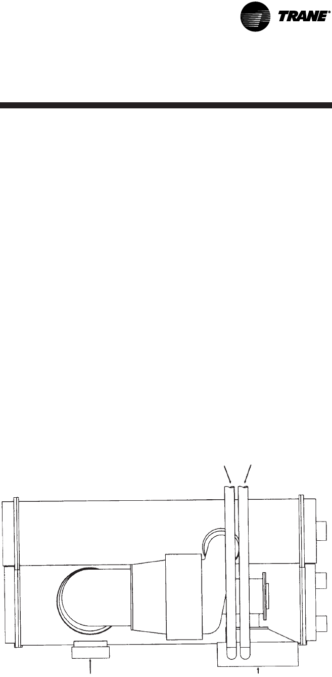
CVGF-SVN02B-E4 59
Installation:
Electrical
Interconnecting Wiring
Typical equipment room conduit
layouts with and without unit-
mounted starters are shown in
Figures 15 and 16, respectively.
IMPORTANT
Keep in mind that the
interconnecting wiring between
the starter panel, compressor
and UCP control panel is factory-
installed with unit-mounted
starters but must be field-
installed when a remote-
mounted starter is used.
Figure 16. Typical equipment room layout with unit-mounted, Wye-
Delta
Line Side Power
Conduits
Unit Control
Panel
Unit Mounted
Starter
Note: See Starter submittal drawing for location of incoming wiring to the starter.
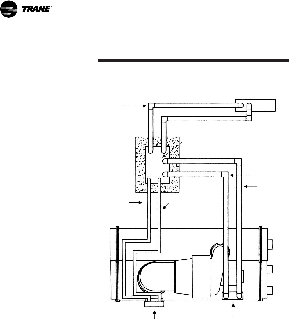
CVGF-SVN02B-E4
60
Installation:
Electrical
Figure 17. Typical equipment room layout with remote-mounted
Wye-Delta starter
Line side
power
wiring
Remote-mounted starter
Load power
wiring
115 Volt control
conduit
See Note 2
IPC circuit
conduit <30V
See Note 3
Motor terminal box
Notes:
1. Refer to the unit field connection diagram for approximate UCP
knockout locations.
2. 115-volt conduit must enter the higher than 30 Vdc Class I portion
of the unit control panel.
3. IPC circuit conduit must enter the Low Voltage Class II portion of
the UCP.
4. See starter submittal drawing for location of incoming wiring to
the starter.

CVGF-SVN02B-E4 61
Installation:
Electrical
Starter to Motor (Remote-
Mounted Starters Only)
Ground Wire Terminal Lugs
Ground wire lugs are provided in
the motor terminal box and in
the starter panel.
Terminal Clamps
Terminal clamps are supplied
with the motor terminals to
accommodate either bus bars or
standard motor terminal wire
lugs. Terminal clamps provide
additional surface area to
minimize the possibility of
improper electrical connections.
Wire Terminal Lugs
Wire terminal lugs must be field-
supplied.
1. Use field-provided crimp-type
wire terminal lugs properly
sized for the application.
Note: Wire size ranges for the
starter line and load-side lugs
are listed on the starter
submittal drawings supplied
by the starter manufacturer or
Trane. Carefully review the
submitted wire lug sizes for
compatibility with the
conductor sizes specified by
the electrical engineer or
contractor.
2. A terminal clamp with a 3/8"
bolt is provided on each
motor terminal stud; use the
factor-supplied Belleville
washers on the wire lug
connections.
Figure 18 illustrates the
juncture between a motor
terminal stud and terminal
clamp.
3. Tighten each bolt to 24 foot-
pounds.
4. Install but do not connect the
power leads between the
starter and compressor motor.
(These connections will be
completed under supervision
of a qualified Trane service
engineer after the prestart
inspection).
CAUTION
Correct motor wire
terminations!
Ensure the power supply wiring
and output motor wiring are
connected to the proper
terminals. Failure to do so will
cause catastrophic failure of the
starter and, or the motor.
Bus Bars
Install bus bars between the
motor terminals when a low-
voltage “across-the-line,”
“primary reactor/resistor,” “auto
transformer,” customer-supplied
solid-state starter, or customer-
supplied AFD are field applied.
Be sure to bus motor terminal T1
to T6, T2 to T4, and T3 to T5.
Note: Bus bars are not needed in
high-voltage applications since
only 3 terminals are used in the
motor and starter.
Starter to UCP (Remote-
Mounted Starters Only)
Electrical connections required
between the remote-mounted
starter and the unit control panel
are shown in an example of a
point-to-point starter-to-UCP
connection diagram as shown at
the end of the manual.
Note: Install control voltage
conduit into control voltage
section of chiller control panel
and starter panel. Do not route
with low voltage (30 volts)
conduit wires.
When sizing and installing the
electrical conductors for these
circuits, follow the guidelines
listed.
Unless otherwise specified use
14 ga. wire for 120 V control
circuits.

CVGF-SVN02B-E4
62
Installation:
Electrical
CAUTION
Damage to Starter
components!
To avoid damage remove debris
inside the starter panel. Failure
to do so may cause an electrical
short that seriously damages
the starter components.
1. If the starter enclosure must
be cut to provide electrical
access, exercise care to
prevent debris from falling
inside the enclosure.
2. Use only shielded twisted pair
for the interprocessor
communication (IPC) circuit
between the starter and the
UCP on remote mounted
starters. Recommended wire
is Beldon Type 8760, 18 AWG
for runs up to 1000 feet.
Note: The polarity of the IPC
wire pair is critical for proper
operation.
3. Separate low-voltage (less
than 30V) wiring from the
115V wiring by running each
in its own conduit.
4. As you route the IPC circuit
out of the starter enclosure,
make sure that it is at least 6"
from all wires carrying a
higher voltage.
5. For UCP IPC shielded twisted
pair wiring, the shield should
be grounded on one end only
at UCP at 1X1-G. The other
end should be unterminated
and taped back on the cable
sheath to prevent any contact
between shield and ground.
6. Oil Pump Interlock - All
starters must provide an
interlock (N.O.) contact with
the chiller oil pump connected
to the UCP at Terminals 1A-J2-
7 and 1A9-J2-9.
The purpose of this interlock is
to power the oil pump on the
chiller in the event that a starter
failure, such as welded contacts,
keeps the chiller motor running
after the controller interrupts the
run signal.
CAUTION
Electrical Noise!
Maintain at least 6 inches
between low-voltage (<30V) and
high voltage circuits. Failure to
do so could result in electrical
noise that may distort the
signals carried by the low-
voltage wiring, including the
IPC.
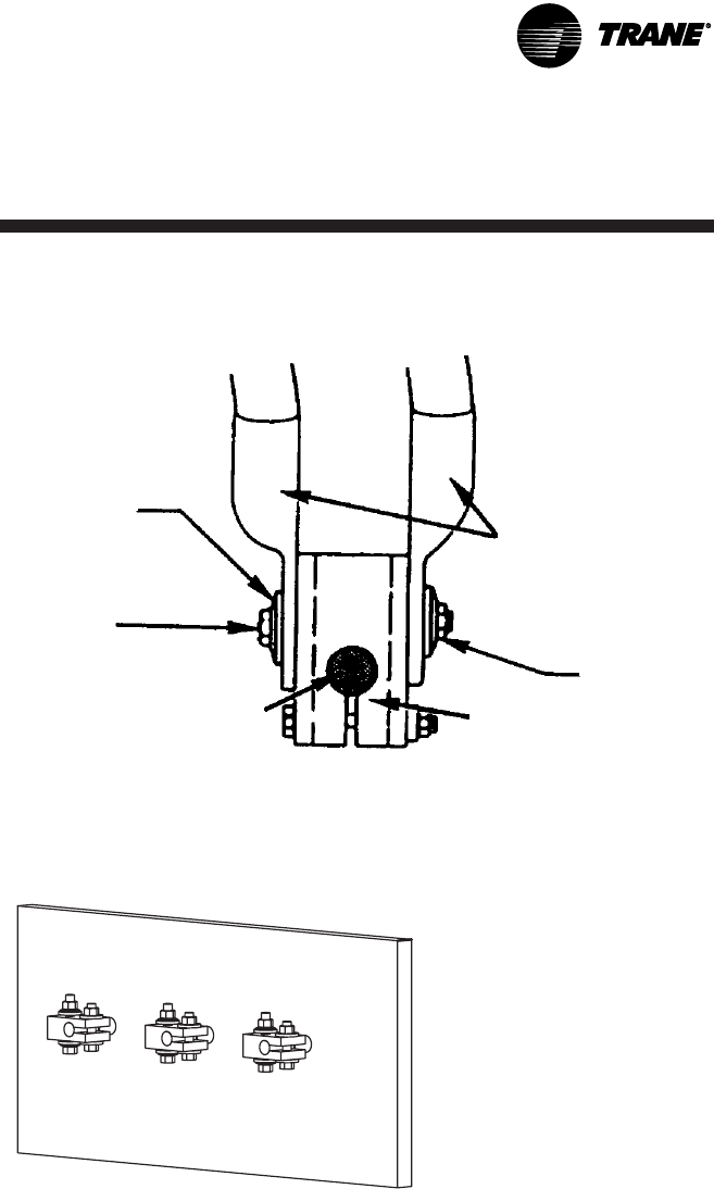
CVGF-SVN02B-E4 63
Installation:
Electrical
Figure 18. Terminal stud, clamp and lug assembly
Belleville
washer
3/8"* Bolt
Terminal
lugs
Belleville
washer
Motor
terminal
stud
Terminal
clamp
Front View
Mid Voltage
RXL RATR RPIR CXL CATR CPIR

CVGF-SVN02B-E4
64
Installation:
Electrical
Optional Relay Circuits
Optional Control and Output
Circuits
Install various optional wiring as
required by the owner’s
specifications.
Optional Tracer
Communication Interface
This control options allows the
unit control panel to exchange
information such as chiller
status and operating set points
with a Tracer system.
Figure 19 illustrates how such a
communication control network
might appear.
Note: The circuit must be run in
separate conduit to prevent
electrical noise interference.
Additional information about the
Tracer Communication options
is published in the installation
manual and operator’s guide
that ships with the Tracer.
Unit Start-Up
All phases of initial unit start-up
must be conducted under the
supervision of a qualified local
service engineer. This includes
pressure testing, evacuation,
electrical checks, refrigerant
charging, actual start-up and
operator instruction.
Advance notification is required
to assure that initial start-up is
scheduled as close to the
requested date as possible.
Starter Module
Configuration
The starter LLID configuration
settings will be checked (and
configured for Remote Starters)
during start-up commissioning.
To configurate starter module,
and perform other starter
checks, it is recommended that
the line voltage three phase
power be turned off and secured
(locked out), and then a separate
source control power (115 Vac)
be utilized to power up the
control circuit. To do this,
remove control coil circuit fuse,
typically 2F4, and then connect
separate source power cord to
starter terminal block 2X1-1 (H),
2X1-2 (N), and Ground. Use the
as-built starter schematic to
assure correct fuse and
terminals. Verify correct fuse is
removed, control circuit
connections are correct, then
apply the 115 Vac separate
source power to service the
controls.
Forms Information
Samples of start-up and
operating forms along with
other helpful forms are found in
the Operation Maintenance
manual which can be obtained
from the nearest Trane office.
It is recommended that the
serviceman contact the local
Trane office to obtain the most
recent printing date of the form.
The forms in the operation and
maintenance manual are only
current at the time of printing of
the manual.
After obtaining the most recent
form, complete all the
information and forward it to
your local Trane office.
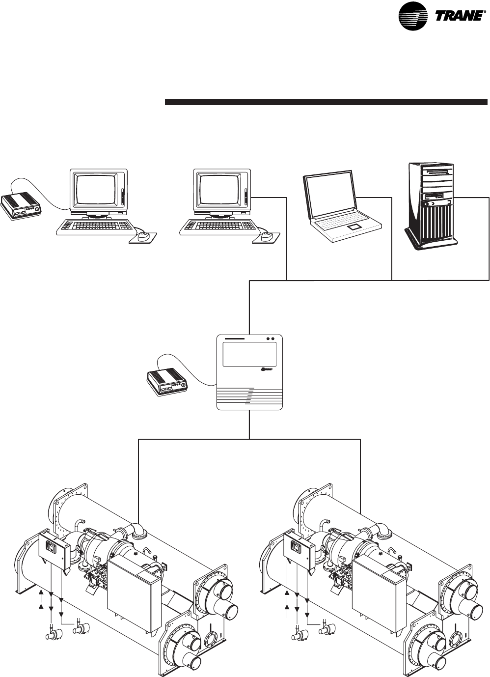
CVGF-SVN02B-E4 65
Installation:
Electrical
Figure 19 – Illustrates communication control network to chiller units with CH530
R
Modem
Remote PC
Workstation
PC Workstation
Notebook PC
Workstation Database Server for
Multiple Sites
BCU
Modem
Building
Control Unit
Chilled Water
Supply (CHW)
and Return
Water
Temperature
Sensors Chiller 1 Chiller 2
LAN
AI
BO
BO
Chilled
Water
Pump
Condenser
Water Pump
Chilled Water
Supply (CHW)
and Return
Water
Temperature
Sensors
AI
BO
BO
Chilled
Water
Pump
Condenser
Water
Pump
Literature Order Number
File Number
Supersedes
Stocking Location
Trane has a policy of continuous product and product data improvement and reserves the right to
change design and specifications without notice. Only qualified technicians should perform the
installation and servicing of equipment referred to in this publication.
Société Trane – Société Anonyme au capital de 41500 000 F – Siege Social: 1 rue des Amériques –
88190 Golbey – France – Siret 306 050 188-00011 – RSC Epinal B 306 050 188
Numéro d’identification taxe intracommunanutaire: FR 83 3060501888
Trane
A business of American Standard Companies
www.trane.com
For more information contact your local Trane office
or e-mail us at comfort@trane.com
Literature Order Number
File Number
Supersedes
Stocking Location
CVGF-SVN02B-E4
SL-RF-CTV-CVGF-SVN02B-E4-604
CVGF-SVN02A-E4
La Crosse
