Cisco Unified Customer Voice Portal (CVP) 8.x Solution Reference Network Design (SRND) CVP 8 Cvp8xsrnd
User Manual: CVP-8
Open the PDF directly: View PDF ![]() .
.
Page Count: 223 [warning: Documents this large are best viewed by clicking the View PDF Link!]
- Cisco Unified Customer Voice Portal (CVP) Solution Reference Network Design (SRND)
- Contents
- Preface
- Unified CVP Architecture Overview
- What's New in This Chapter
- What is VoiceXML?
- What is the Cisco Unified Customer Voice Portal?
- Unified CVP Product and Solution Components
- Unified CVP Product Components
- Additional Unified CVP Solution-Related Components
- Cisco Ingress Voice Gateway
- Cisco VoiceXML Gateway
- Cisco Egress Gateway
- Video Endpoints
- Cisco Unified Communications Manager
- Cisco Unified Contact Center
- Cisco Gatekeeper
- SIP Proxy Server
- DNS Server
- Cisco Security Agent
- Content Services Switch
- Application Content Engine (ACE)
- Third-Party Media Server
- Third-Party Automatic Speech Recognition (ASR) and Text-to-Speech (TTS) Servers
- Network Monitor
- Call Flows
- Design Process
- Quality of Service (QoS)
- Licensing Information
- Functional Deployment Models
- Distributed Deployments
- What's New in This Chapter
- Distributed Gateways
- Call Survivability in Distributed Deployments
- Call Admission Control Considerations
- Designing Unified CVP for High Availability
- What's New in This Chapter
- Overview
- Layer 2 Switch
- Originating Gateway
- SIP Proxy
- Unified CVP SIP Service
- Server Groups
- Gatekeeper
- Unified CVP H.323 Service
- Unified CVP IVR Service
- VoiceXML Gateway
- Content Services Switch (CSS)
- Media Server
- Unified CVP VXML Server
- Automatic Speech Recognition (ASR) and Text-to-Speech (TTS) Server
- Cisco Unified Communications Manager
- Intelligent Contact Management (ICM)
- Interactions with Cisco Unified ICM
- What's New in This Chapter
- Network VRU Types
- Network VRU Types and Unified CVP Deployment Models
- Hosted Implementations
- Deployment Models and Sizing Implications for Calls Originated by Cisco Unified Communications Manager and ACDs
- Using Third-Party VRUs
- DS0 Trunk Information
- Trunk Utilization Routing and Reporting
- Enhanced User-to-User Information
- Custom SIP Headers
- Courtesy Callback
- Post Call Survey
- Calls Originated by Cisco Unified Communications Manager
- Gateway Options
- Design Implications for Unified CVP VXML Server
- Network Infrastructure Considerations
- Call Transfer Options
- Using the GKTMP NIC
- Media File Options
- Managing, Monitoring, and Reporting
- Sizing
- Licensing
- Index
- 8.0_SRND.pdf

Americas Headquarters
Cisco Systems, Inc.
170 West Tasman Drive
San Jose, CA 95134-1706
USA
http://www.cisco.com
Tel: 408 526-4000
800 553-NETS (6387)
Fax: 408 527-0883
Cisco Unified Customer Voice Portal (CVP) Solution
Reference Network Design (SRND)
Cisco Unified Customer Voice Portal (CVP) Release 8.0(1)
October 1, 2012
Last Revised: January 21, 2013
Text Part Number: OL-15989-06

iii
Cisco Unified Customer Voice Portal (CVP) 8.x Solution Reference Network Design (SRND)
OL-15989-06
CONTENTS
Preface xiii
Audience xiii
New or Changed Information for This Release xiii
Revision History xiv
Obtaining Documentation, Obtaining Support, and Security Guidelines xiv
CHAPTER
1Unified CVP Architecture Overview 1-1
What's New in This Chapter 1-1
What is VoiceXML? 1-2
What is the Cisco Unified Customer Voice Portal? 1-3
Unified CVP Product and Solution Components 1-4
Unified CVP Product Components 1-5
Unified CVP Call Server (Call Server) 1-5
Unified CVP VXML Server (VXML Server) 1-6
Cisco Unified Call Studio (Call Studio) 1-7
Unified CVP Reporting Server (Reporting Server) 1-7
Unified CVP Operations Console Server (Operations Console) 1-7
Additional Unified CVP Solution-Related Components 1-8
Cisco Ingress Voice Gateway 1-8
Cisco VoiceXML Gateway 1-9
Cisco Egress Gateway 1-9
Video Endpoints 1-9
Cisco Unified Communications Manager 1-10
Cisco Unified Contact Center 1-10
Cisco Gatekeeper 1-11
SIP Proxy Server 1-11
DNS Server 1-13
Cisco Security Agent 1-13
Content Services Switch 1-14
Application Content Engine (ACE) 1-15
Third-Party Media Server 1-15
Third-Party Automatic Speech Recognition (ASR) and Text-to-Speech (TTS) Servers 1-16
Network Monitor 1-17
Call Flows 1-17

Contents
iv
Cisco Unified Customer Voice Portal (CVP) 8.x Solution Reference Network Design (SRND)
OL-15989-06
Typical SIP Unified CVP Call Flow 1-17
Typical H.323 Unified CVP Call Flow 1-18
Design Process 1-19
H.323 and Unified CVP 1-20
Call Flow Models 1-20
How Unified CVP Routes Outbound Calls (Unified CVP Algorithm for Routing) 1-21
Distributed Network Options 1-22
Cube Deployment with SIP Trunks 1-22
Design Considerations 1-23
High Availability Options 1-23
Scalability Options 1-24
Virtualization 1-24
Quality of Service (QoS) 1-24
Licensing Information 1-24
CHAPTER
2Functional Deployment Models 2-1
What's New in This Chapter 2-1
Unified CVP VXML Server (Standalone) 2-2
Protocol-Level Call Flow 2-2
Transfers and Subsequent Call Control 2-3
Call Director 2-4
SIP Protocol-Level Call Flow 2-4
H.323 Protocol-Level Call Flow 2-5
Transfers and Subsequent Call Control 2-6
Comprehensive 2-6
SIP Protocol-Level Call Flow 2-8
H.323 Protocol-Level Call Flow 2-9
Transfers and Subsequent Call Control 2-10
VRU Only 2-11
Protocol-Level Call Flow 2-12
Basic Video Service 2-13
2-14
CHAPTER
3Distributed Deployments 3-1
What's New in This Chapter 3-1
Distributed Gateways 3-1
Ingress and/or Egress Gateway at the Branch 3-1
Ingress or VoiceXML Gateway at Branch 3-2

Contents
v
Cisco Unified Customer Voice Portal (CVP) 8.x Solution Reference Network Design (SRND)
OL-15989-06
Co-Located Unified CVP VXML Servers and Gateways 3-3
Gateways at the Branch, with Centralized Unified CVP VXML Servers 3-3
Cisco Unified Communications Manager 3-3
Unified CM as an Egress Gateway 3-3
Unified CM as an Ingress Gateway 3-4
Multicast Music-on-Hold (MOH) 3-4
Design Considerations 3-4
Call Survivability in Distributed Deployments 3-5
Call Admission Control Considerations 3-6
Gatekeeper Call Admission Control 3-6
Unified CM Call Admission Control 3-7
H.323 Call Flows 3-7
Multiple Cisco Unified CM Clusters 3-9
SIP Call Flows 3-10
RSVP 3-10
H.323 Gatekeeper Call Routing 3-10
CHAPTER
4Designing Unified CVP for High Availability 4-1
What's New in This Chapter 4-2
Overview 4-2
Layer 2 Switch 4-3
Originating Gateway 4-4
Configuration 4-4
Call Disposition 4-5
SIP Proxy 4-5
Cisco Unified SIP Proxy (CUSP) Support 4-7
CUSP Deployment Methods 4-7
Performance Matrix for CUSP Deployment 4-8
CUSP Design Considerations 4-9
Configuration 4-9
SIP Proxy Server Configuration 4-9
Cisco IOS Gateway Configuration 4-10
Call Disposition 4-11
Unified CVP SIP Service 4-11
Configuration 4-12
Configuring High Availability for Calls in Progress 4-12
Call Disposition 4-13
Server Groups 4-14
Server Group Heartbeat Settings 4-15

Contents
vi
Cisco Unified Customer Voice Portal (CVP) 8.x Solution Reference Network Design (SRND)
OL-15989-06
Static Routes Validation 4-15
Design Considerations 4-16
Diagnostics 4-16
Gatekeeper 4-16
Gatekeeper Redundancy Using HSRP 4-16
Gatekeeper Redundancy Using Alternate Gatekeeper 4-17
Configuration 4-18
HSRP Configuration 4-18
Alternate Gatekeeper 4-18
Call Disposition 4-19
Unified CVP H.323 Service 4-19
Configuration 4-20
Configuring High Availability for New Calls 4-20
Configuring High Availability for Calls in Progress 4-20
Additional Cisco IOS Gateway Configuration 4-21
Call Disposition 4-21
Unified CVP IVR Service 4-21
Configuration 4-22
Call Disposition 4-22
VoiceXML Gateway 4-23
Configuration 4-23
Centralized VoiceXML Gateways 4-24
Distributed VoiceXML Gateways (Co-Resident Ingress Gateway and VoiceXML) 4-24
Distributed VoiceXML Gateways (Separate Ingress Gateway and VoiceXML) 4-25
H.323 Alternate Endpoints 4-27
Call Disposition 4-28
Hardware Configuration for High Availability on the Voice Gateways 4-28
Content Services Switch (CSS) 4-28
Configuration 4-29
Call Disposition 4-29
Media Server 4-30
Configuration When Using Unified CVP Microapplications 4-30
Call Disposition When Using Unified CVP Microapplications 4-31
Configuration When Using Cisco Unified Call Studio Scripting 4-31
Unified CVP VXML Server 4-31
Configuration 4-31
Standalone Self-Service Deployments 4-31
Deployments Using ICM 4-32
Call Disposition 4-32

Contents
vii
Cisco Unified Customer Voice Portal (CVP) 8.x Solution Reference Network Design (SRND)
OL-15989-06
Automatic Speech Recognition (ASR) and Text-to-Speech (TTS) Server 4-32
Configuration 4-32
Standalone Self-Service Deployments 4-32
Deployments Using ICM 4-33
Call Disposition 4-33
Cisco Unified Communications Manager 4-33
Configuration 4-34
Call Disposition 4-34
Intelligent Contact Management (ICM) 4-34
Configuration 4-34
Call Disposition 4-35
CHAPTER
5Interactions with Cisco Unified ICM 5-1
What's New in This Chapter 5-2
Network VRU Types 5-2
Overview of Unified ICM Network VRUs 5-3
Unified CVP as a Type 10 VRU 5-3
Unified CVP as Type 5 VRU 5-4
Unified CVP as Type 3 or 7 VRU (Correlation ID Mechanism) 5-5
Unified CVP as Type 8 or 2 VRU (Translation Route ID Mechanism) 5-6
Network VRU Types and Unified CVP Deployment Models 5-6
Model #1: Standalone Self-Service 5-7
Model #2: Call Director 5-8
Model #3a: Comprehensive Using ICM Micro-Apps 5-8
Model #3b: Comprehensive Using Unified CVP VXML Server 5-8
Model #4: VRU Only 5-8
Model #4a: VRU Only with NIC Controlled Routing 5-8
Model #4b: VRU Only with NIC Controlled Pre-Routing 5-9
Hosted Implementations 5-10
Overview of Hosted Implementations 5-10
Using Unified CVP in Hosted Environments 5-11
Unified CVP Placement and Call Routing in a Hosted Environment 5-11
Network VRU Type in a Hosted Environment 5-13
Deployment Models and Sizing Implications for Calls Originated by Cisco Unified Communications
Manager and ACDs 5-13
Using Third-Party VRUs 5-15
DS0 Trunk Information 5-15
Trunk Utilization Routing and Reporting 5-16
Combining Gateway Trunk Utilization with Server Group Pinging 5-16

Contents
viii
Cisco Unified Customer Voice Portal (CVP) 8.x Solution Reference Network Design (SRND)
OL-15989-06
Deployment Considerations 5-16
Enhanced User-to-User Information 5-17
Manipulating the UUS Field 5-18
Using UUI 5-18
REFER and 302 Redirects and UUI 5-19
Design Considerations 5-19
Custom SIP Headers 5-19
Passing Information in SIP Headers to Unified ICM 5-19
String Format and Parsing 5-20
Passing of Headers from the ICM Script 5-20
Examples of Unified ICM Scripting for Custom SIP Headers 5-21
Courtesy Callback 5-21
Example Scripts and Audio Files 5-22
Callback Criteria 5-23
Typical Use Scenario 5-23
Courtesy Callback Prerequisites and Design Considerations 5-24
Post Call Survey 5-25
Post Call Survey Typical Uses 5-25
Post Call Survey Design Considerations 5-25
CHAPTER
6Calls Originated by Cisco Unified Communications Manager 6-1
What's New in This Chapter 6-1
Differences in Calls Originated by Cisco Unified Communications Manager 6-1
Customer Call Flows 6-2
Unified ICM Outbound Calls with Transfer to IVR 6-2
Internal Help Desk Calls 6-2
Warm Consultative Transfers and Conferences 6-3
Protocol Call Flows 6-3
Model #1: Standalone Self-Service 6-3
Model #2: Call Director 6-4
Model #3a: Comprehensive Using ICM Micro-Apps 6-5
Model #3b: Comprehensive Using Unified CVP VXML Server 6-6
Deployment Implications 6-6
Unified ICM Configuration 6-6
Hosted Implementations 6-7
Cisco Unified Communications Manager Configuration 6-7
Gatekeeper or SIP Proxy Dial-Plan Configuration 6-7
Sizing 6-8
Gateways 6-8

Contents
ix
Cisco Unified Customer Voice Portal (CVP) 8.x Solution Reference Network Design (SRND)
OL-15989-06
KPML Support 6-8
MTP Usage on UCM Trunk 6-8
Design Considerations 6-9
CHAPTER
7Gateway Options 7-1
What's New in This Chapter 7-1
PSTN Gateway 7-2
VoiceXML Gateway with DTMF or ASR/TTS 7-2
VoiceXML and PSTN Gateway with DTMF or ASR/TTS 7-3
Cisco Integrated 3G-H324M Gateway 7-3
Gateway Topology and Call Flow 7-3
CVP Configuration 7-4
TDM Interfaces 7-4
Cisco Unified Border Element 7-5
Mixed G.729 and G.711 Codec Support 7-6
Gateway Choices 7-6
Gateway Sizing 7-7
Using MGCP Gateways 7-11
CHAPTER
8Design Implications for Unified CVP VXML Server 8-1
What is VoiceXML over HTTP? 8-1
Multi-Language Support 8-2
Differences in the Supported Web Application Servers 8-2
Where to Install Cisco Unified Call Studio 8-3
CHAPTER
9Network Infrastructure Considerations 9-1
What's New in This Chapter 9-1
Bandwidth Provisioning and QoS Considerations 9-2
Unified CVP Network Architecture Overview 9-2
Voice Traffic 9-2
Call Control Traffic 9-3
Data Traffic 9-5
Bandwidth Sizing 9-5
VoiceXML Documents 9-5
Media File Retrieval 9-6
H.323 Signaling 9-7
SIP Signaling 9-7

Contents
x
Cisco Unified Customer Voice Portal (CVP) 8.x Solution Reference Network Design (SRND)
OL-15989-06
ASR and TTS 9-7
Voice Traffic (G.711 and G.729) 9-9
Call Admission Control 9-9
Local Branch Call Admission Control (LBCAC/Queue-at-the-Edge) 9-9
Queue-at-the-Edge Branch Office Deployment Model 9-10
LBCAC Concept Definitions 9-11
Importance and Comparison of LBCAC Feature 9-11
Design Considerations 9-11
High Availability and Failover 9-12
Additional Important Information for LBCAC 9-12
QoS Marking 9-13
Network Latency 9-13
Blocking Initial G.711 Media Burst 9-15
Network Security Using Firewalls 9-16
CHAPTER
10 Call Transfer Options 10-1
What's New in This Chapter 10-1
Release Trunk Transfers 10-2
Takeback-and-Transfer (TNT) 10-2
Hookflash and Wink 10-3
SIP Hookflash Support 10-4
Design Considerations 10-4
Two B Channel Transfer (TBCT) 10-4
ICM Managed Transfers 10-5
Network Transfer 10-6
SIP Refer Transfer 10-7
H.323 Refer Transfer 10-7
Intelligent Network (IN) Release Trunk Transfers 10-7
VoiceXML Transfers 10-8
CHAPTER
11 Using the GKTMP NIC 11-1
The Cisco Gatekeeper External Interface 11-1
The Unified ICM GKTMP NIC 11-1
Typical Applications of GKTMP with Unified CVP 11-2
Protocol-Level Call Flow 11-3
Deployment Implications 11-5

Contents
xi
Cisco Unified Customer Voice Portal (CVP) 8.x Solution Reference Network Design (SRND)
OL-15989-06
CHAPTER
12 Media File Options 12-1
Deployment and Ongoing Management 12-1
Co-Resident Unified CVP Call Server, Media Server, and Unified CVP VXML Server 12-2
Bandwidth Calculation for Prompt Retrieval 12-3
Configuring Caching and Streaming in Cisco IOS 12-3
Streaming and Non-Streaming 12-3
Caching 12-4
Caching Query URLs 12-4
TCP Socket Persistence 12-4
Cache Aging 12-5
Branch Office Implications 12-6
CHAPTER
13 Managing, Monitoring, and Reporting 13-1
What's New in This Chapter 13-1
Unified CVP Operations Console Server: Managing and Monitoring 13-1
DS0 Trunk Information for Reporting 13-2
End-to-End Tracking of Individual Calls: Log Files 13-3
Formal Reporting 13-3
New Reporting Features 13-4
Cisco Unified IC Templates 13-5
Backup and Restore 13-6
More Information 13-6
Unified System CLI and Web Services Manager (WSM) 13-7
Analysis Manager versus the Unified System CLI 13-7
The Analysis Manager 13-8
Unified System CLI Overview 13-8
Unified System CLI Modes of Operation 13-9
Unified System CLI Questions and Answers 13-10
CHAPTER
14 Sizing 14-1
What's New in This Chapter 14-1
Sizing Overview 14-2
Unified CVP Call Server 14-3
Call Server Log Directory Size Estimate 14-3
Unified CVP VXML Server (VXML Server) 14-4
Unified CVP Co-Residency 14-5
Unified Presence Server 14-7

Contents
xii
Cisco Unified Customer Voice Portal (CVP) 8.x Solution Reference Network Design (SRND)
OL-15989-06
Unified CVP Video Service 14-8
Sizing Unified CVP Basic Video Service 14-8
Unified CVP Reporting Server 14-8
How to Use Multiple Unified CVP Reporting Servers 14-9
Reporting Message Details 14-10
Example Applications 14-11
CHAPTER
15 Licensing 15-1
I
NDEX

xiii
Cisco Unified Customer Voice Portal (CVP) 8.x Solution Reference Network Design (SRND)
OL-15989-06
Preface
Last revised on: May 2, 2010
This document provides design considerations and guidelines for deploying enterprise network solutions
that include the Cisco Unified Customer Voice Portal (CVP).
This document builds upon ideas and concepts presented in the latest version of the Cisco Unified
Contact Center Enterprise (Unified CCE) Solution Reference Network Design (SRND), which is
available online at
http://www.cisco.com/en/US/products/sw/custcosw/ps1844/products_implementation_design_gui
des_list.html
Note Unless stated otherwise, the information in this document applies to Cisco Unified Customer Voice
Portal (CVP) 8.x (8.0 and all subsequent 8.x releases). Any differences between the various releases of
Cisco Unified CVP are specifically noted in the text.
Audience
This design guide is intended for the system architects, designers, engineers, and Cisco channel partners
who want to apply best design practices for the Cisco Unified Customer Voice Portal (CVP).
This document assumes that you are already familiar with basic contact center terms and concepts and
with the information presented in the Cisco Unified CCE SRND. To review those terms and concepts,
refer to the documentation at the preceding URL.
New or Changed Information for This Release
Within each chapter, new and revised information is listed in a section titled What’s New in This Chapter.

xiv
Cisco Unified Customer Voice Portal (CVP) 8.x Solution Reference Network Design (SRND)
OL-15989-06
Preface
Revision History
This document may be updated at any time without notice. You can obtain the latest version of this
document online at
http://www.cisco.com/en/US/products/sw/custcosw/ps1006/products_implementation_design_gui
des_list.html
Visit this Cisco.com website periodically and check for documentation updates by comparing the
revision date (on the front title page) of your copy with the revision date of the online document.
The following table lists the revision history for this document.
Obtaining Documentation, Obtaining Support, and Security
Guidelines
For information on obtaining documentation, obtaining support, providing documentation feedback,
security guidelines, and also recommended aliases and general Cisco documents, see the monthly
What’s New in Cisco Product Documentation, which also lists all new and revised Cisco technical
documentation, at:
http://www.cisco.com/en/US/docs/general/whatsnew/whatsnew.html
Revision Date Comments
August 8, 2008 Updates were added for licensing and several other topics.
February 27, 2008 Initial release of this document for Cisco Unified CVP 7.0.
November 30, 2009 Corrected some minor errors.
August 18, 2009 Content was updated as indicated in New or Changed Information for This
Release, page xiii.
April 22, 2009 Content was updated for Cisco Unified Communications System
Release 7.1.
January 28, 2009 The name “VoiceXML server” was changed to “Unified CVP
VXML Server” throughout this document.
The name “VoiceXML Studio” was changed to “Cisco Unified Call Studio”
throughout this document.
Some content was updated in the chapters on Gateway Options, page 7-1,
and Call Transfer Options, page 10-1.
April 20, 2010 Initial release of this document for Cisco Unified CVP 8.0.

CHAPTER
1-1
Cisco Unified Customer Voice Portal (CVP) 8.x Solution Reference Network Design (SRND)
OL-15989-06
1
Unified CVP Architecture Overview
Last revised on: May 2, 2010
Over the past two decades, many customers have invested in TDM-based interactive voice response
(IVR) applications to automate simple customer transactions such as checking account or 401K account
inquires. In addition, many TDM-based IVR platforms were based on proprietary development
environments and hardware platforms, which typically meant restricting the customer's integration
options with automatic speech recognition (ASR) and text-to-speech (TTS) solutions. Over the past few
years there has been a dramatic shift to using VoiceXML (VXML) standards-based technology to
support the next generation of IVR applications.
Because the implementation of Unified CVP is based on VXML, the discussion of Unified CVP begins
with the following overview of VXML as it relates to Unified CVP.
The chapter covers the following major topics:
• What is VoiceXML?, page 1-2
• What is the Cisco Unified Customer Voice Portal?, page 1-3
• Unified CVP Product and Solution Components, page 1-4
• Call Flows, page 1-17
• Design Process, page 1-19
• Quality of Service (QoS), page 1-24
• Licensing Information, page 1-24
What's New in This Chapter
Table 1-1 lists the topics that are new in this chapter or that have changed significantly from previous
releases of this document.
Table 1-1 New or Changed Information Since the Previous Release of This Document
New or Revised Topic Description
Cisco Security Agent, page 1-13 There is a new version of CSA especially for Unified
CVP
Application Content Engine (ACE), page 1-15 An alternative to CSS for load balancing and
failover.

1-2
Cisco Unified Customer Voice Portal (CVP) 8.x Solution Reference Network Design (SRND)
OL-15989-06
Chapter 1 Unified CVP Architecture Overview
What is VoiceXML?
What is VoiceXML?
Voice eXtensible Markup Language, or VoiceXML VXML, is a markup language similar to HTML, that
is used for developing IVR services and leverages the power of web development and content delivery.
VoiceXML was designed for creating audio dialogs that feature synthesized speech, digitized audio,
recognition of speech or dual-tone multifrequency (DTMF) key input, and recording of spoken input. It
is a common language for content providers, tool providers, and platform providers, and it promotes
service portability across implementation platforms.
VoiceXML separates service logic from user interaction and presentation logic in VoiceXML voice web
pages. It also shields application authors from low-level, platform-specific IVR and call control details.
VoiceXML is easy to use for simple interactions, yet it provides language features to support complex
IVR dialogs.
VoiceXML programs are rendered (or executed) by a VoiceXML browser, much like an HTML program
is rendered via an internet browser (such as Internet Explorer). A Cisco Voice Gateway (or router) can
provide the VoiceXML browser function. For small deployments, the Ingress Voice Gateway and
VoiceXML Gateway are typically deployed in the same router. The Cisco IOS VoiceXML Gateway
provides both gateway and VoiceXML browser functions.
In the most simple call processing scenario, a new call arrives and the voice gateway dial peer matches
the call to an available VoiceXML gateway port. The VoiceXML gateway port represents a Voice over
IP (VoIP) endpoint and can be logically thought of as a voice response unit (VRU) port. Upon arrival of
the new call, the VoiceXML gateway (that is, the VRU) sends an HTTP request to a Cisco Unified CVP
VXML Server for instruction. The URL contained in the HTTP request correlates to a specific
VoiceXML doc.
In response to the HTTP request, the Unified CVP VXML Server sends the requested, dynamically
generated VoiceXML doc to the VoiceXML gateway (that is, the voice browser) to be rendered. A typical
VoiceXML doc is short and prompt the caller for some input, then includes the results in a new HTTP
request that redirects the caller to another URL and VoiceXML doc. Because a typical call requires
numerous prompts and caller inputs, there are numerous VoiceXML documents that need to be rendered
and a large number of possible paths through these VoiceXML documents.
To logically link the many different VoiceXML documents that may need to be rendered and to greatly
simplify the task of creating VoiceXML documents, a graphical scripting tool is often used to allow the
IVR service developer to easily develop complete IVR services with conditional logic and customer
relationship management (CRM) database integration. Cisco Unified Call Studio is one such scripting
tool. The Cisco Unified CVP VXML Server is capable of executing scripts developed with Cisco Unified
Call Studio, and both were designed to work with Cisco Unified CVP Server, Cisco Voice Gateways,
Cisco VoiceXML Gateways, Cisco Unified Communications Manager, Cisco Unified Contact Center,
and Cisco's VoIP-enabled LAN/WAN.
How Unified CVP Routes Outbound Calls
(Unified CVP Algorithm for Routing),
page 1-21
Steps through the process of outbound call routing.
Cube Deployment with SIP Trunks, page 1-22 Introduces support for the Cisco Unified Border
Element product.
Virtualization, page 1-24 Unified CVP may be installed and run on Virtual
Machines (VMs).
Table 1-1 New or Changed Information Since the Previous Release of This Document
New or Revised Topic Description

1-3
Cisco Unified Customer Voice Portal (CVP) 8.x Solution Reference Network Design (SRND)
OL-15989-06
Chapter 1 Unified CVP Architecture Overview
What is the Cisco Unified Customer Voice Portal?
What is the Cisco Unified Customer Voice Portal?
Unified CVP is both a product and a solution. As a product, its media kit includes specific software
items, as listed in the first part of Unified CVP Product and Solution Components, page 1-4. As a
solution, Unified CVP relies on additional Unified CVP components. The additional components are
described in Additional Unified CVP Solution-Related Components, page 1-8. The resulting solution
provides carrier-class IVR and IP switching services on Voice over IP (VoIP) networks.
Unified CVP includes the following features:
• Carrier-class Performance
Create your solution using a reliable, redundant, and scalable platform, which enables works with
service providers and large enterprise networks.
• Call Switching and Routing Support
Route and transfer calls between voice gateways and IP endpoints. Voice gateways provide natural
integration of TDM ACDs and PBXs with the PSTN.
After completing the routing or transfer of a call, Unified CVP maintains H.323 or SIP call control
to provide switching services similar to takeback-and-transfer (TNT) between IP endpoints via the
Unified ICM Enterprise (ICME) interface. Integration with Cisco Unified Presence Server and a
gatekeeper helps provide easily managed dial plans.
Supports call routing services for both SIP (RFC 3261) and H.323 protocols. Existing customers can
continue to use H.323 call services. Or, they can migrate to SIP over time. The Unified CVP solution
can run as a hybrid, directing both SIP and H.323 calls until all call flows are switched over to SIP.
• IP-based IVR services
–
IVR Services. In addition to switching and transfer, Unified CVP provides classic
prompt-and-collect functions, such as Press 1 for Sales.
–
Voice Enabled IVR Services. Provides sophisticated audio and video self-service applications
with CRM database integration as well as ASR and TTS integrated via Media Resource Control
Protocol (MRCP). Examples include banking and brokerage account handling, and airline
reservations.
–
Queuing. Park calls for personalized prompts or hold music while waiting for a call center agent
to become available. Calls can be prioritized based on their CRM profiles.
–
Take Back. Take back a transferred call for further IVR treatment or transfer.
• VoiceXML Services
Provides a platform for developing powerful, speech-driven interactive applications accessible from
any phone. The VoiceXML platform includes:
–
The Cisco Unified CVP VXML Server, a J2EE- and J2SE-compliant application server that
dynamically drives the caller experience.
–
The Cisco Unified Call Studio, a drag-and-drop graphical user interface (GUI) for the rapid
creation of advanced voice applications.
• Unified CVP Operations Console Server (Operations Console)
Centrally operate, administer, maintain, and provision the components in the Unified CVP solution
from its web-based Operations Console. Integrate with Cisco Contact Center Support Tools. (Refer
to Unified CVP Operations Console Server (Operations Console), page 1-7 for hosting
information.)

1-4
Cisco Unified Customer Voice Portal (CVP) 8.x Solution Reference Network Design (SRND)
OL-15989-06
Chapter 1 Unified CVP Architecture Overview
Unified CVP Product and Solution Components
• VRU reporting
Access historical data using its included centralized reporting database. Design and run custom
reports using its well-documented schema.
• Compatibility and Integration
–
Use with other Cisco Call Routing and VoIP Products, including, Cisco Unified Intelligent
Contact Management Hosted or Cisco Unified Intelligent Contact Management Enterprise,
Cisco Gatekeepers, Cisco Gateways, and Unified Contact Center Enterprise (UCCE).
–
Use with Cisco Unified Communications Manager (Unified CM). Unified CM manages and
switches VoIP calls among IP phones. When combined with Unified ICME, Unified CM
becomes the UCCE product.
–
Use with the Public Switch Telephone Network (PSTN). Calls can be moved onto an IP-based
network for Unified CVP treatment and then moved back out to a PSTN for further call routing
to a call center.
–
Integration with Cisco Unified Contact Center (details)
Unified CVP integrates with Cisco Unified Contact Center via a VRU Peripheral Gateway (PG).
This integration enables Cisco Unified Contact Center Enterprise (Unified CCE) to control
Unified CVP VoIP switching and IVR services. It also enables Unified CCE to control the agent
selection application and to initiate the Real-Time Transport Protocol (RTP) stream transfer
from the VoiceXML gateway to the selected agent. Unified CVP integration with Unified CCE
requires that the traditional Cisco Unified Communications Manager PG be used for Unified
CCE integration with Cisco Unified Communications Manager.
Unified CCE can be integrated with Unified CVP via the Cisco Unified Intelligent Contact
Manager (ICM) System PG and the parent-child deployment model. This integration method
provides callers with some simple up-front menus and prompts by the parent Unified ICM and
Unified CVP, and it intelligently routes the calls via skill groups to the best Cisco Unified
Contact Center Express or Enterprise child. Queuing control and agent selection are handled by
the child contact center solution. In this model, it is also easy for a TDM automatic call
distributor (ACD) to play the role of a child. All call transfers between Unified CVP and
children will retain call data, and the ICM will provide enterprise-wide browser-based
consolidated reporting.
Unified CVP integration is not directly supported with the Unified CCE System PG (which is
also used by System Unified CCE). The Unified CCE System PG supports only the Cisco
Unified IP IVR. Unified CVP works only with System PG children via the parent-child
deployment model. Unified CVP can also provide IVR services for Unified CCE outbound IVR
campaigns and post-call customer surveys.
Unified CVP Product and Solution Components
As mentioned previously, Unified CVP is both a product and a solution. The following topics describe
both the components that make up the Unified CVP product, and the additional components that make
up the Unified CVP solution.
The Cisco Unified Customer Voice Portal (CVP) product consists of the following components:
• Unified CVP Call Server (Call Server), page 1-5
• Unified CVP VXML Server (VXML Server), page 1-6
• Cisco Unified Call Studio (Call Studio), page 1-7

1-5
Cisco Unified Customer Voice Portal (CVP) 8.x Solution Reference Network Design (SRND)
OL-15989-06
Chapter 1 Unified CVP Architecture Overview
Unified CVP Product and Solution Components
• Unified CVP Reporting Server (Reporting Server), page 1-7
• Unified CVP Operations Console Server (Operations Console), page 1-7
• Additional Unified CVP Solution-Related Components, page 1-8
The following components of the Unified CVP solution are not part of the Unified CVP product but are
still required for a complete solution:
• Cisco Ingress Voice Gateway, page 1-8
• Cisco VoiceXML Gateway, page 1-9
• Cisco Egress Gateway, page 1-9
• Video Endpoints, page 1-9
• Cisco Unified Communications Manager, page 1-10
• Cisco Unified Contact Center, page 1-10
• Cisco Gatekeeper, page 1-11
• SIP Proxy Server, page 1-11
• DNS Server, page 1-13
• Cisco Security Agent, page 1-13
• Content Services Switch, page 1-14
• Third-Party Media Server, page 1-15
• Application Content Engine (ACE), page 1-15
• Third-Party Automatic Speech Recognition (ASR) and Text-to-Speech (TTS) Servers, page 1-16
• Network Monitor, page 1-17
The following sections discuss each of these components in more detail. Depending on the particular
deployment model you choose, some of the above components might not be required.
Unified CVP Product Components
The following topics describe the Cisco Unified Customer Voice Portal (CVP) product components.
Note A Unified CVP server can, optionally, be part of the enterprise domain.
Unified CVP Call Server (Call Server)
The Unified CVP Call Server (Call Server) component provides the following independent services,
which all run on the same Windows 2003 server:
• SIP Service
This service communicates with the Unified CVP solution components such as the SIP Proxy
Server, Ingress Gateway, Unified CM SIP trunks, and SIP phones.
The SIP service implements a Back-to-Back User Agent (B2BUA). This B2BUA accepts SIP invites
from ingress voice gateways and typically directs those new calls to an available VoiceXML gateway
port. After completing call setup, the Unified CVP B2BUA acts as an active intermediary for any
subsequent call control. While the Unified CVP SIP signaling is hairpinned through this service, this
service does not touch the RTP traffic.

1-6
Cisco Unified Customer Voice Portal (CVP) 8.x Solution Reference Network Design (SRND)
OL-15989-06
Chapter 1 Unified CVP Architecture Overview
Unified CVP Product and Solution Components
Integrated into this B2BUA is the ability to interact with the Cisco Unified ICM via the ICM Service.
This integration provides the ability for the SIP Service to query the Unified ICM for routing
instruction and service control. This integration also allows Unified ICM to initiate subsequent call
control to do things such as requesting that a caller be transferred from queue to an agent or
transferred from one agent to another agent.
• ICM Service
This service is responsible for all communication between Unified CVP components and Unified
ICM. It sends and receives messages on behalf of the SIP Service, the IVR Service, and the H.323
Service.
• IVR Service
This service creates the VoiceXML pages that implement the Unified CVP Microapplications based
on Run VRU Script instructions received from Unified ICM. The IVR Service functions as the VRU
leg (in Unified ICM Enterprise parlance), and calls must be transferred to it from the SIP Service in
order to execute microapplications. The VoiceXML pages created by this module are sent to the
VoiceXML gateway to be executed.
• H.323 Service (Formerly known as the Unified CVP Voice Browser)
This service interacts with the IVR Service to relay call arrival, release, and transfer call control
between it and the other H.323 components. This service is needed only for deployments using
H.323.
A Unified CVP Call Server can be deployed co-resident with the Unified CVP VXML Server or a media
server. Optionally, a Unified CVP Call Server can be deployed as part of the Enterprise Windows
Domain.
For hardware details, refer to the latest version of the Hardware and System Software Specification for
Cisco Unified CVP (formerly called the Bill of Materials), available at:
http://www.cisco.com/en/US/products/sw/custcosw/ps1006/prod_technical_reference_list.html
Unified CVP VXML Server (VXML Server)
The Unified CVP VXML Server executes advanced IVR applications by exchanging VoiceXML pages
with the VoiceXML gateway's built-in voice browser. Like almost all other Unified CVP product
components, it runs within a Java 2 Enterprise Edition (J2EE) application server environment such as
Tomcat or WebSphere, and many customers add their own custom-built or off-the-shelf J2EE
components to interact with back-end hosts and services. Unified CVP VXML Server applications are
written using Cisco Unified Call Studio and are deployed to the VXML Server for execution. The
applications are invoked on an as-needed basis by a special microapplication which must be executed
from within the Unified ICME routing script.
The VXML Server can also be deployed in a standalone configuration that does not include any Unified
ICME components. In this configuration model, applications are invoked as a direct result of calls
arriving in the VoiceXML gateway, and a single post-application transfer is allowed.
The VXML Server can be installed co-resident with a Unified CVP Call Server or the media server.
The VXML Server can execute on Windows 2003 servers. For hardware requirements and details, refer
to the latest version of the Hardware and System Software Specification for Cisco Unified CVP (formerly
called the Bill of Materials), available at:
http://www.cisco.com/en/US/products/sw/custcosw/ps1006/prod_technical_reference_list.html
For a further discussion of the VXML Server, and its latest added features, refer to the User Guide for
Cisco Unified CVP VXML Server and Cisco Unified Call Studio, Release 8.0(1).

1-7
Cisco Unified Customer Voice Portal (CVP) 8.x Solution Reference Network Design (SRND)
OL-15989-06
Chapter 1 Unified CVP Architecture Overview
Unified CVP Product and Solution Components
Cisco Unified Call Studio (Call Studio)
The Cisco Unified Call Studio (Call Studio) is the service creation environment (script editor) for
Unified CVP VXML Server applications. It is based on the open source Eclipse framework, and it
provides advanced drag-and-drop graphical editing as well as the ability to insert vendor-supplied and
custom-developed plug-ins that enable applications to interact with other services in the network. The
Call Studio is essentially an offline tool whose only interaction with the Unified CVP VXML Server is
to deliver compiled applications and plugged-in components for execution.
The Call Studio executes on Windows XP or Windows Vista workstations or servers. Because the license
is associated with the MAC address of the machine on which it is running, customers typically designate
one or more data center servers for that purpose. Cisco Unified Call Studio cannot run on machines also
running a headless version of the Cisco Security Agent.
For additional hardware details, refer to the latest version of the Hardware and System Software
Specification for Cisco Unified CVP (formerly called the Bill of Materials), available at:
http://www.cisco.com/en/US/products/sw/custcosw/ps1006/prod_technical_reference_list.html
Note Cisco Security Agent is not supported on Unified Call Studio.
Unified CVP Reporting Server (Reporting Server)
The Unified CVP Reporting Server is a Windows 2003 server that hosts an IBM Informix Dynamic
Server (IDS) database management system. The Reporting Server provides consolidated historical
reporting for a distributed self-service deployment. The database schema is prescribed by the Unified
CVP product, but the schema is fully published so that customers can develop custom reports based on
it. The Reporting Server receives reporting data from the IVR Service, the SIP Service (if used), and the
Unified CVP VXML Server (VXML Server). The Reporting Server depends on the Unified CVP Call
Server (Call Server) to receive call records.
For Standalone Unified CVP VXML Server deployments, one Call Server is needed per Reporting
Server. The Reporting Server must be local to the Call Server(s) and VXML Server(s) that it is servicing.
Deploying the Reporting Server at a remote location across the WAN is not supported. Multiple
Reporting Servers should be used and placed at each site when Call Server(s) and VXML Server(s) exist
at multiple locations.
The Reporting Server does not itself perform database administrative and maintenance activities such as
backups or purging. However, Unified CVP provides access to such maintenance tasks through the
Unified CVP Operations Console Server.
Unified CVP Operations Console Server (Operations Console)
The Unified CVP Operations Console Server is a Windows 2003 server that provides an Operations
Console for the browser-based administration and configuration for all Unified CVP product
components, and it offers shortcuts into the administration and configuration interfaces of other Unified
CVP solution components. The Operations Console is a required component in all Unified CVP
deployments.
The Operations Console must be run on a separate physical machine from other Unified CVP devices.
However, beginning with Unified CVP 8.0(1), it can be located on the same server with Support Tools
2.4.

1-8
Cisco Unified Customer Voice Portal (CVP) 8.x Solution Reference Network Design (SRND)
OL-15989-06
Chapter 1 Unified CVP Architecture Overview
Unified CVP Product and Solution Components
The Operations Console also offers a direct link to Support Tools, which can collect trace logs and
perform other diagnostic and instrumentation functions on many solution components. The Operations
Console is, in effect, the dashboard from which an entire Unified CVP deployment can be managed.
The Operations Console must itself be configured with a map of the deployed solution network. It can
then collect and maintain configuration information from each deployed component. Both the network
map and the configuration information are stored locally on the server, where it can be backed up by
off-the-shelf backup tools. A web browser-based user interface, the Operations Console, provides the
ability to both display and modify the network map and the stored configuration data and to distribute
such modifications to the affected solution components.
The Operations Console can display two views of configuration parameters for managed components.
The runtime view shows the status of all configuration parameters as those components are currently
using them. The configured or offline view shows the status of all configuration parameters that are
stored in the Operations Server database and will be deployed to the device the next time a Save and
Deploy option is executed.
The Operations Console allows configuration parameters to be updated or preconfigured even when the
target component is not online or running. If the target server (without its services) comes online, the
user can apply the configured settings to that server. These settings will become active when that server's
services also come online. Only then will they be reflected in the runtime view.
The Operations Console Server is not a redundant component. As such, the Operations Console Server
cannot be duplicated within a deployment. Backups of the configuration database should be take
regularly or whenever changes are made.
Additional Unified CVP Solution-Related Components
The following additional components are used in the various call flow models (solutions) described in
Call Flows, page 1-17.
Cisco Ingress Voice Gateway
The Cisco Ingress Voice Gateway is the point at which an incoming call enters the Unified CVP system.
It terminates TDM calls on one side and implements VoIP on the other side. It serves as a pivot point for
extension of calls from the TDM environment to VoIP endpoints. Therefore, WAN bandwidth is
conserved because no hairpinning of the media stream occurs. It also provides for sophisticated call
switching capabilities at the command of other Unified CVP solution components.
Unified CVP Ingress Voice Gateways support both SIP and H.323. Media Gateway Control Protocol
(MGCP) voice gateways are supported if they are registered with Cisco Unified Communications
Manager.
For the most current list of supported gateways, refer to Gateway Choices, page 7-6. For approved
gateway/software combinations refer to the latest version of the Hardware and System Software
Specification for Cisco Unified CVP (formerly called the Bill of Materials), available at:
http://www.cisco.com/en/US/products/sw/custcosw/ps1006/prod_technical_reference_list.html

1-9
Cisco Unified Customer Voice Portal (CVP) 8.x Solution Reference Network Design (SRND)
OL-15989-06
Chapter 1 Unified CVP Architecture Overview
Unified CVP Product and Solution Components
The Ingress Gateway can be deployed separately from the VoiceXML Gateway, but in most
implementations they are one and the same: one gateway performs both functions. Gateways are often
deployed in farms, for Centralized deployment models. In Branch deployment models, one combined
gateway is usually located at each branch office.
Cisco VoiceXML Gateway
The VoiceXML Gateway hosts the Cisco IOS Voice Browser. This component interprets VoiceXML
pages from either the Unified CVP Server IVR Service or the Unified CVP VXML Server. The
VoiceXML Gateway encodes .wav files and accepts DTMF input. It then returns the results to the
controlling application and waits for further instructions.
The Cisco VoiceXML Gateway can be deployed on the same router as the Unified CVP Ingress Voice
Gateway. This model is typically desirable in deployments with small branch offices. But the VoiceXML
Gateway can also run on a separate router platform, and this model is typically desirable in deployments
with large or multiple voice gateways, where only a small percentage of the traffic is for Unified CVP.
This model enables an organization to share PSTN trunks between normal office users and contact center
agents and to route calls based upon the dialed number.
The Cisco VoiceXML Gateway can encode .wav files stored in flash memory or on a third-party media
server. Prompts retrieved from a third-party media server can be cached in the router to reduce WAN
bandwidth and prevent poor voice quality. The VoiceXML doc will provide a pointer to the location of
the .wav file to be played or it will provide the address of a TTS server to generate a .wav file. The
VoiceXML Gateway interacts with ASR and TTS servers via MRCP.
Supported VoiceXML Gateways include the Cisco 2800 Series, 3800 Series, 5350XM, and 5400 XM.
For the most current list of supported VoiceXML Gateways, refer to the latest version of the Hardware
and System Software Specification for Cisco Unified CVP (formerly called the Bill of Materials),
available at:
http://www.cisco.com/en/US/products/sw/custcosw/ps1006/prod_technical_reference_list.html
Unless it is combined with the Ingress Gateway (described in the previous topic), the VoiceXML
Gateway does not require any TDM hardware. All its interfaces are VoIP on one side and HTTP (carrying
VXML or .wav files) and MRCP (carrying ASR and TTS traffic) on the other side. As with Ingress
Gateways, VoiceXML Gateways are often deployed in farms for Centralized deployment models, or one
per office in Branch deployments.
Cisco Egress Gateway
The Egress Voice Gateway is used only when calls need to be extended to TDM networks or equipment
such as the PSTN or a TDM ACD. While the RTP stream goes between the ingress and egress voice
gateway ports, the signaling stream logically goes through the Unified CVP Server and ICM in order to
allow subsequent call control (such as transfers).
Video Endpoints
When using the Unified CVP Basic Video Service, the following video endpoints are supported:
• Cisco Unified IP Phone 7985G
• Cisco Unified Video Advantage
• Cisco TelePresence

1-10
Cisco Unified Customer Voice Portal (CVP) 8.x Solution Reference Network Design (SRND)
OL-15989-06
Chapter 1 Unified CVP Architecture Overview
Unified CVP Product and Solution Components
Cisco Unified Communications Manager
Cisco Unified Communications Manager (Unified CM) is the main call processing component of a Cisco
Unified Communications system. It manages and switches VoIP calls among IP phones. Unified CM
combines with Cisco Unified Intelligent Contact Manager Enterprise (Unified ICME) to form Cisco
Unified Contact Center Enterprise (Unified CCE). Unified CVP interacts with Unified CM primarily as
a means for sending PSTN-originated calls to Unified CCE agents. SIP gateway calls are routed to an
available Unified CM SIP trunk, and H.323 gateway calls are routed to an available Unified CM H.323
trunk.
The following common scenarios require calls to Unified CVP to originate from Unified CM endpoints:
• A typical office worker (not an agent) on an IP phone dials an internal help desk number.
• An agent initiates a consultative transfer that gets routed to a Unified CVP queue point.
• A Cisco Unified Outbound Dialer port transfers a live call to a Unified CVP port for an IVR
campaign.
A single Unified CM can originate and receive calls from both SIP and H.323 devices. PSTN calls that
arrived on MGCP voice gateways registered with Unified CM can also be routed or transferred to
Unified CVP via either SIP or H.323, depending upon the deployment model chosen.
Unified CM is an optional component in the Unified CVP solution. Its use in the solution depends on the
type of call center being deployed. Pure TDM-based call centers using ACDs, for example, typically do
not use Unified CM (except when migrating to Cisco Unified CCE), nor do strictly self-service
applications using the Unified CVP Standalone Self-Service deployment model. Unified CM generally
is used as part of the Cisco Unified CCE solution, in which call center agents are part of an IP solution
using Cisco IP Phones, or when migrating from TDM ACDs.
Only specific versions of Unified CM are compatible with Unified CVP solutions. Unified CVP is
supported with SIP only if Cisco Unified CM 5.0 or later release is used. Unified CVP is supported with
H.323 for Cisco Unified CM 4.x or later releases. For full details on version compatibility, consult the
latest version of the Hardware and System Software Specification for Cisco Unified CVP (formerly
called the Bill of Materials), available at:
http://www.cisco.com/en/US/products/sw/custcosw/ps1006/prod_technical_reference_list.html
Cisco Unified Contact Center
Either Cisco Unified CCE or Cisco Unified Intelligent Contact Management (ICM) is a required
component when advanced call control (IP switching, transfers to agents, and so forth) is required in
Unified CVP. The Hosted versions of these products might also be used for this purpose. Unified ICM
provides call-center agent management capabilities and call scripting capabilities. Variable storage
capability and database access through the Unified CCE or Unified ICM application gateways are also
powerful tools. A Unified CVP application can take advantage of these capabilities because Unified CVP
applications can be called from within a Unified CCE or Unified ICM script in a non-standalone Unified
CVP deployment model.
The Unified CVP Call Server (Call Server) maintains a GED-125 Service Control Interface connection
to Unified CCE or Unified ICM. GED-125 is a third-party-control protocol in which a single socket
connection is used to control many telephone calls. From the point of view of Unified CCE or Unified
ICM, the Call Server is a voice response unit (VRU) connected to Unified CCE or Unified ICM, just as
all other GED-125 VRUs are connected. Unified CVP is simply a VRU peripheral to Unified CCE or
Unified ICM.

1-11
Cisco Unified Customer Voice Portal (CVP) 8.x Solution Reference Network Design (SRND)
OL-15989-06
Chapter 1 Unified CVP Architecture Overview
Unified CVP Product and Solution Components
Cisco Gatekeeper
The gatekeeper is a network element used by H.323 gateways for call routing. The gatekeeper is required
for all H.323 installations for dial plan configuration and bandwidth management.
Scenarios for gatekeeper usage include:
• To map specific dialed numbers to specific Unified CVP Servers or VoiceXML gateways.
• To load-balance new calls to a set of Unified CVP Servers or VoiceXML gateways.
• To route the transfer of callers from a VoiceXML gateway port to a Cisco IP Phone.
• To provide failover capabilities for H.323 endpoints.
The Gatekeeper is the focus for high availability design in the H.323 protocol arena, and it is only used
in Unified CVP implementations that use H.323 for call control. Like the SIP Proxy Server, it mixes
directory lookup services with load balancing and failover capabilities, producing fault tolerance among
H.323 endpoints. Unlike the SIP Proxy Server, control messages do not pass through it to target
endpoints; instead, it uses a request/response server paradigm.
Two gatekeeper failover mechanisms are supported:
• HSRP. For redundancy, Gatekeepers can be deployed in pairs using the HSRP (Hot Standby Routing
Protocol), one redundant pair per site.
• Alternate Gatekeepers. The VBAdmin SetGatekeeper command allows multiple IP addresses to be
configured. The H.323 Service keeps track of a currently active Gatekeeper from that IP list. It
begins by sending all requests to the first gatekeeper on the list.
If the currently active Gatekeeper fails, it moves to the next one in the list, and that one becomes the
current gatekeeper. The H.323 Service continues to use that gatekeeper until it too fails, at which
time it begins using the subsequent Gatekeeper in the list. When the list is exhausted, the next
failover is back to the top of the list.
For sizing purposes, each Gatekeeper should be sized to handle the entire load.
For more information on H.323 gatekeepers, refer to the Overview of the Cisco IOS Gatekeeper available
online at: http://www.cisco.com/en/US/docs/ios/12_2/gktmp/gktmpv4_2/iosgk.html.
Also consult the Cisco Gatekeeper External Interface Reference, available at
http://www.cisco.com/en/US/docs/ios/12_3/gktmpv4_3/guide/gktmp4_3.html
SIP Proxy Server
The SIP Proxy Server is the component that routes individual SIP messages among SIP endpoints. It
plays a key role in Unified CVP high-availability architecture for call switching. It is designed to support
multiple SIP endpoints of various types and to implement load balancing and failover among these
endpoints. Deployment of a SIP Proxy in the solution enables a more centralized configuration of the
dial plan routing configuration.
The Cisco Unified Presence Server (CUP Server), which has a built-in SIP Proxy function, and the Cisco
Unified SIP Proxy Server (CUSP Server), which runs on an ISR gateway, are tested and supported with
Unified CVP.
The SIP Proxy can be configured with multiple static routes (also called server group elements on the
CUSP Server) in order to do load balancing and failover with outbound calls. The static routes can point
to an IP address or a regular DNS A host record.
DNS SRV is also supported, but is not qualified for use on the CUSP Server. It is qualified for the devices
that need to reach the CUSP Server, such as Unified CVP, the Ingress Gateway, and Unified CM.

1-12
Cisco Unified Customer Voice Portal (CVP) 8.x Solution Reference Network Design (SRND)
OL-15989-06
Chapter 1 Unified CVP Architecture Overview
Unified CVP Product and Solution Components
Unified CVP can also be deployed without a SIP Proxy Server depending on the design and complexity
of the solution. In such cases, some of the same functions can be provided by the Unified CVP Server
SIP Service. If a SIP Proxy Server is not used, then Ingress Gateways and Unified CMs must point
directly to Unified CVP. In such a deployment, load balancing is done via DNS SRV lookups from the
gateway to the DNS Server. Load balancing of calls outbound from Unified CVP (outbound call leg) can
be done in a similar fashion.
The benefits of using a SIP Proxy Server include:
• Priority and weight routing can be used with the routes for load balancing and failover.
• If a SIP Proxy Server is already used in your SIP network, Unified CVP can be an additional SIP
endpoint—it fits incrementally into the existing SIP network.
• If the Cisco Unified Presence Server is being used as the SIP Proxy Server, dial plan management
is available in the web administration of the static routes.
• If the Cisco Unified Presence Server is being used as the SIP Proxy Server, you are better positioned
to also take advantage of Presence and Cisco Unified Client, as a compliment to Unified CVP.
If a SIP Proxy Server is not used, then Ingress Gateways and Unified CMs need to point directly to
Unified CVP. In such a deployment:
• Load balancing is done via DNS SRV lookups from Gateway to DNS Server—SIP calls can be
balanced using this mechanism.
• Load balancing of calls outbound from Unified CVP (outbound call leg) can be done in similar
fashion.
• Failover of SIP rejections (code 503 only) can also be performed if SRV records are configured with
ordered priorities.
The following guidelines apply to the use of a Cisco Unified Presence server as a SIP Proxy:
• A Unified CM publisher is required in order to install Cisco Unified Presence. Therefore, you need
at least one Unified CM publisher if you plan on using the Cisco Unified Presence server as a SIP
Proxy (even for a TDM-only deployment with no Unified CM or Unified CCE agents). Unified CM
does not need any Device License Units to perform this function.
• A Cisco Unified CM 7.x publisher can support six Cisco Unified Presence nodes per cluster,
contained in three dual-node sub-clusters.
• The Cisco Unified Presence servers can be clustered over the WAN, provided the required
conditions are met. Refer to Cisco Unified Presence Server documentation for clustering over WAN
conditions. Document is available at:
http://www.cisco.com/en/US/products/ps6837/tsd_products_support_series_home.html
In situations where redundancy across two or more sites is required but clustering over the WAN
with Cisco Unified Presence servers is not needed or cannot be supported, you will need at least one
Unified CM publisher and one Cisco Unified Presence server at each site. Cisco Unified Presence
configuration data is not shared between clusters, so you must configure each Cisco Unified
Presence server with dial plan information.
• If you have multiple Cisco Unified Presence servers, in order for them to provide redundancy to
Unified CVP, you must configure a DNS SRV record that provides load balancing and/or failover
pointing at both servers. You then configure Unified CVP to use this single DNS SRV record as the
SIP Proxy Server.

1-13
Cisco Unified Customer Voice Portal (CVP) 8.x Solution Reference Network Design (SRND)
OL-15989-06
Chapter 1 Unified CVP Architecture Overview
Unified CVP Product and Solution Components
• If you have multiple Cisco Unified Communications Manager clusters, you do not need a Cisco
Unified Presence server attached to each cluster for SIP Proxy functionality. It is possible for a
single Cisco Unified Presence server to provide SIP Proxy services for multiple clusters. However,
depending on where the clusters are located, you might want to have multiple Cisco Unified
Presence servers for redundancy (such as with clustering over the WAN).
DNS Server
This optional component may be installed anywhere in the network. Its purpose in general is to resolve
hostnames to IP addresses. Unified CVP, can make both Type A record lookups and SRV Type record
lookups. If the DNS server is slow to respond, is unavailable, is across the WAN, or so forth, this will
affect performance.
The DNS Server comes into play during SIP interactions in the following situations:
• When a call arrives at an Ingress Gateway, the dial peer can use DNS to alternate calls between the
two SIP Proxy Servers. The SIP Proxy Servers can also use DNS to distribute incoming calls among
multiple SIP Services. If SIP Proxy Servers are not being used, then the Ingress Gateway can use
DNS directly to distribute inbound calls among multiple SIP Services.
• When the SIP Service is instructed by Unified CCE to transfer the call to the VRU leg, it can use
DNS to alternate such requests between two SIP Proxy Servers. If SIP Proxy Servers are not being
used, the SIP Service can use DNS directly to distribute VRU legs among multiple VoiceXML
Gateways.
• When transferring a call to an agent using a SIP Proxy Server, the Cisco Unified Presence Server
SIP Proxy cannot use DNS SRV for outbound calls; it must be configured with multiple static routes
in order to do load balancing and failover. (The Cisco Unified Presence Server supports DNS SRV,
but it has not been tested in Unified CVP deployments.) The static routes can point to an IP address
or a regular DNS A host record. If SIP Proxy Servers are not being used, then the SIP Service can
use DNS to locate the target agent's IP address.
The use of the DNS Server for SIP routing is entirely optional in Unified CVP. It is not required to have
a dedicated DNS Server, but the existing DNS server needs to handle the additional load of Unified CVP.
For every call destined for Unified CVP that comes into the network, there will be approximately 3 to 4
DNS lookups. You can determine the number of DNS queries per second by determining the number of
calls per second for the solution, and multiplying that number by 4.
DNS lookups are needed for DNS SRV queries, not necessarily for A record queries, which could also
be configured locally in the system "etc host" file. Unified CVP Server Groups can alternately be used
to avoid DNS SRV lookups.
Cisco Security Agent
The Cisco Security Agent (CSA) software is an optional, but highly recommended, component of
Unified CVP which enhances the security of the Unified CVP servers. By monitoring the behavior of
applications running on a Unified CVP server, monitoring the network traffic, and so forth, CSA
effectively prevents malicious software from disrupting the services provided by the server.
The Cisco Security Agent is not an anti-virus tool. Rather, it provides behavior-based protection and is
intended to be used in combination with one of the supported third-party anti-virus products. The list of
supported anti-virus products is provided in the Unified CVP Bill of Materials (BOM).
The Cisco Security Agent provided for Unified CVP has been specially configured to allow the Unified
CVP software, and all the supported third party products, to perform their functions. Other versions of
CSA are not configured for Unified CVP and cannot be installed on a Unified CVP server.

1-14
Cisco Unified Customer Voice Portal (CVP) 8.x Solution Reference Network Design (SRND)
OL-15989-06
Chapter 1 Unified CVP Architecture Overview
Unified CVP Product and Solution Components
There are two ways to use the CSA feature of Unified CVP:
• If you want the protection of CSA but do not intend to customize its protection policies, install the
unmanaged Cisco Security Agent provided by Cisco.
• If you want to modify the behavior of CSA, buy and install the Cisco Security Agent Management
Console for CSA and import and modify the policies supplied with the unmanaged agent.
The Cisco Security Agent is not automatically installed by the Unified CVP installer. After installing
Unified CVP, do one of the following:
• Obtain the unmanaged version of CSA for Unified CVP and install it on the server. The unmanaged
version will include the supplied Cisco security policies which cannot be modified.
• Or, obtain the Cisco Security Management Console and install it. Then obtain the .export file that
contains the Cisco security policy, modify the policy as desired, and deploy CSA using your
modified policy.
For detailed information about Cisco Security Agent, its unmanaged and managed versions, and about
obtaining and installing the software, refer to Cisco Security Agent Installation/Deployment Guide for
Cisco Unified Customer Voice Portal, Release 8.0(1). The document is available under Install and
Upgrade Guides at
http://www.cisco.com/en/US/products/sw/custcosw/ps1006/prod_installation_guides_list.html
You can also download the software from the Cisco website, refer to:
http://tools.cisco.com/support/downloads/pub/Redirect.x?mdfid=270563413
Note Cisco does not support a user-modified version of the CSA security policy. Also, note that CSA for
Unified CVP is not supported on the device running Unified CVP Call Studio, nor on any non-CVP
devices. There are specific versions of CSA for other Cisco devices
Content Services Switch
The Content Services Switch (CSS) is a load-balancing device designed to provide robust, highly
available and scalable network services for data centers. The CSS can be logically placed between one
or more VoiceXML Gateways and one or more Unified CVP VXML Servers, Media Servers, and
ASR/TTS Servers. Various mechanisms allow the CSS to implement transparent load balancing and
failover across these servers. One of these mechanism is the stateful redundancy mechanism, which is
called Adaptive Session Redundancy in CSS terms. Adaptive Session Redundancy (ASR) provides
session-level redundancy for applications where active flows (including TCP and UDP) must continue
without interruption, even if the master CSS fails-over to the backup CSS.
CSS is an optional device, but it is highly recommended. Without it, the IVR Service implements a poor
man's failover mechanism, but it is not load-balanced and various retries and delays are part of the
algorithm, all of which can be avoided if CSS is used.
The CSS is normally deployed as a Virtual Router Redundancy Protocol (VRRP) pair. VRRP provides
box-to-box redundancy for CSS pairs. For session-level redundancy (stateful failover), CSS pairs could
use the Adaptive Session Redundancy option to minimize VXML Server license port usage during a CSS
failover. VRRP is useful in all deployment models except for Call Director call flows, which do not
require use of Unified CVP VXML Servers, Media Servers, or ASR/TTS servers. If SSL is used in the
solution, you will need an SSL module for the CSS 11503 or 11506 chassis.

1-15
Cisco Unified Customer Voice Portal (CVP) 8.x Solution Reference Network Design (SRND)
OL-15989-06
Chapter 1 Unified CVP Architecture Overview
Unified CVP Product and Solution Components
Application Content Engine (ACE)
You may use the Application Content Engine (ACE) as an alternative to the Content Services Switch
(CSS) for server load balancing and failover. As a load-balancing device, ACE determines which server
in a set of load-balanced servers, should receive the client request for service. Load balancing helps
fulfill the client request in the shortest amount of time without overloading either the server or the server
farm as a whole.
Refer to the Cisco ACE 4700 Series Appliance Server Load-Balancing Configuration Guide to learn
more about load-balancing with ACE.
To migrate from CSS to ACE, use the ACE2CSS Converter tool. Refer to:
http://www.cisco.com/en/US/docs/interfaces_modules/services_modules/ace/v3.00_A2/configuration/
css_to_ace/user/guide/cssaceug.html
To configure Unified CVP for ACE. refer to the Configuration and Administration Guide for Cisco
Unified Customer Voice Portal available at:
http://www.cisco.com/en/US/products/sw/custcosw/ps1006/tsd_products_support_series_home.html
You must have an ACE license to use ACE under load conditions. The minimum licensing requirements
for ACE are:
• 1-Gbps throughput license (ACE-AP-01-LIC)
• A non-default SSL feature license, if you intend to use ACE for SSL
• Application Acceleration License (ACE-AP-OPT-LIC-K9) which allows more than 50 concurrent
connections on ACE
Refer to the your ACE product documentation and ACE release notes for more licensing information.
Note There are two features for the VXML Server that assist with load balancing:
• Limiting Load Balancer Involvement
• Enhanced HTTP Probes for Load Balancers
Refer to the configuration options ip_redirect and license_depletion_probe_error in the User Guide for
Unified CVP VXML Server and Cisco Unified Call Studio, available at:
http://www.cisco.com/en/US/products/sw/custcosw/ps1006/products_user_guide_list.html
Third-Party Media Server
The media server component is a simple web server, such as Microsoft IIS or Apache, and is an optional
component that can provide prerecorded audio files, external VoiceXML documents, or external ASR
grammars to the gateway. Because some of these files can be stored in local flash memory on the
gateways, the media server can be an optional component. However, in practice, most installations use
a centralized media server to simplify distribution of prerecorded customer prompt updates. Media
server functionality can also include a caching engine. The gateways themselves, however, can also do
prompt caching when configured for caching. Typical media servers used are Microsoft IIS and Apache,
both of which are HTTP-based.
As with ASR/TTS Servers, Media Servers may be deployed simplex, as a redundant pair, or with CSS
in a farm. Note that the VoiceXML Gateway caches .wav files it retrieves from the Media Server. In most
deployments, the Media Server encounters extremely low traffic from Unified CVP.

1-16
Cisco Unified Customer Voice Portal (CVP) 8.x Solution Reference Network Design (SRND)
OL-15989-06
Chapter 1 Unified CVP Architecture Overview
Unified CVP Product and Solution Components
The Media Server can be installed co-resident with the Unified CVP Call Server or Unified CVP
VXML Server.
For the most current information on media servers, refer to the latest version of the Hardware and System
Software Specification for Cisco Unified CVP (formerly called the Bill of Materials), available at:
http://www.cisco.com/en/US/products/sw/custcosw/ps1006/prod_technical_reference_list.html
Third-Party Automatic Speech Recognition (ASR) and Text-to-Speech (TTS) Servers
This component provides speech recognition services and text-to-speech services for the VoiceXML
Gateway. Communication between the ASR/TTS server(s) and the VoiceXML Gateway uses Media
Resource Control Protocol (MRCP). MRCP v1 can be used on the VoiceXML Gateway when the
application is based on either Micro-Apps or the Unified CVP VXML Server (VXML Server). MRCP v2
can be used on the VoiceXML Gateway only with applications that are based on the VXML Server.
For capacity and redundancy reasons, a Content Services Switch (CSS) is usually used to mediate
between a VoiceXML Gateway and a farm of ASR/TTS servers. If CSS is not used, then a VoiceXML
Gateway can support a maximum of two ASR/TTS Servers.
Cisco does not sell, OEM, or support any ASR/TTS software or servers. Cisco does, however, test
Unified CVP with ScanSoft, Nuance, and IBM offerings. A certification process is currently being
developed to allow additional vendors to qualify their products against Unified CVP VoiceXML, and the
World Wide Web Consortium (W3C) provides a rich feature set to support the ASR grammars. The
simplest to implement and support is inline grammars, by which the set of acceptable customer responses
is passed to the gateway. Another form is external grammars, by which Unified ICM passes a pointer to
an external grammar source. The VXML Server adds this pointer to the VoiceXML document that it
sends to the VoiceXML Gateway, which then loads the grammar and uses it to check ASR input from the
caller. In this case, the customer is responsible for creating the grammar file. A third type of grammar is
the built-in grammar. For a complete explanation of grammar formats, consult the W3C website at:
http://www.w3.org/TR/speech-grammar/
The text for TTS is passed directly from the Unified CVP VXML Server to the gateway. This action is
referred to as inline TTS in this document.
The actual speech recognition and speech synthesis are performed by a separate server that interfaces
directly to the VoiceXML gateway via Media Resource Control Protocol (MRCP). Currently, ScanSoft,
Nuance, and IBM are the supported ASR/TTS engines. These ASR/TTS engines also support (with
limitations) voice recognition and synthesis for multiple languages.
For the latest information on supported languages and limitations of these ASR/TTS engines, refer to
the following websites:
• Nuance and ScanSoft
http://www.nuance.com
• IBM
http://www-306.ibm.com/software/voice/
These are third-party products, which the customer or partner must purchase directly from the vendor.
The customer also receives technical support directly from the vendor. That does not, however, mean that
the vendor's latest software version can be used. Unified CVP is carefully tested with specific versions
of each vendor's product, and Cisco Technical Assistance Center (TAC) will not support Unified CVP
customers who use different ASR/TTS versions than those which have been tested with Cisco Unified

1-17
Cisco Unified Customer Voice Portal (CVP) 8.x Solution Reference Network Design (SRND)
OL-15989-06
Chapter 1 Unified CVP Architecture Overview
Call Flows
CVP. For additional details on supported ASR and TTS products, consult the latest version of the
Hardware and System Software Specification for Cisco Unified CVP (formerly called the Bill of
Materials), available at:
http://www.cisco.com/en/US/products/sw/custcosw/ps1006/prod_technical_reference_list.html
Network Monitor
An SNMP management station can be used to monitor the solution deployment's health.
Call Flows
This section describes the Unified CVP call flows for both SIP and H.323 calls.
Typical SIP Unified CVP Call Flow
Unified CVP provides the ability to switch calls using Session Initiation Protocol (SIP) rather than, or
in addition to, H.323. SIP is the preferred protocol for Unified CVP. The H.323 protocol support is
available primarily to provide backward compatibility for users of previous versions of Unified CVP.
These are referred to as legacy deployments.
The remainder of this topic presents a typical call flow scenario using SIP. The description roughly
follows the Comprehensive call flow model. However, it is not presented as an actual solution, only as
an introduction to the overall flow of information in a Unified CVP solution.
The call flow consists of an incoming call requiring initial self-service, followed by queue treatment,
and finally delivery to a Unified ICME agent. The following diagram presents a general SIP-based
solution. A detailed description of the call flow follows the diagram.
Typical SIP Unified CVP call flow:
1. The call arrives at an Ingress Voice Gateway and sends an invite message to the SIP Proxy Server
which forwards the message to the SIP Service.
2. The Proxy Server determines the IP address of the Unified CVP Server for the dialed number and
then forwards the invite to the selected Unified CVP Server SIP Service.

1-18
Cisco Unified Customer Voice Portal (CVP) 8.x Solution Reference Network Design (SRND)
OL-15989-06
Chapter 1 Unified CVP Architecture Overview
Call Flows
3. The SIP Service consults Unified ICME via the Unified CVP Server ICM Service, which causes
Unified ICME to run a routing script.
4. The routing script typically initiates a transfer of the call to a VoiceXML Gateway port via the SIP
service.
5. The VoiceXML Gateway sends a message to the IVR service, which requests scripted instructions
from Unified ICME.
6. Unified ICME exchanges VRU instructions with the VoiceXML gateway via the IVR service. The
instructions can include requests to invoke more sophisticated applications on the Unified CVP
VXML server. Such requests result in multiple exchanges between the Unified CVP VXML Server
and the VoiceXML Gateway to provide self-service.
7. If the customer wants to transfer to a live agent, the Unified ICME routing script queues the caller
for an available agent. While waiting for an available agent, Unified ICME provides additional
instructions to the VoiceXML Gateway to provide queueing treatment to the caller.
8. When an agent becomes available, Unified ICME sends a message to the Unified CVP Server SIP
Service, which forwards a message via the SIP Proxy Server to the Ingress Gateway and to
Unified CM to transfer the call away from the VoiceXML Gateway port and deliver it to the
Unified CM agent IP phone.
During the VRU exchanges, the VoiceXML Gateway interacts with an ASR/TTS Server to play text as
speech or recognize speech as data. It also interacts and with a Media Server (not shown in the diagram,
but connected to the VoiceXML Gateway) to fetch audio files and prompts. These two devices, as well
as the Unified CVP VXML Server, can be located behind a Content Services Switch (CSS), which offers
sophisticated failover and redundancy capability. (CSSs are optional, though recommended, and are not
displayed in the diagram.)
During this entire process, the SIP Service, the IVR Service, and the VXML Server send a stream of
reporting events to the Reporting Server (also not shown in the diagram, but connected to the Unified
CVP Call Server), which processes and stores the information in a database for later reporting. All these
devices use SNMP (Simple Network Management Protocol) to support a monitoring console. Cisco
Unified Operations Manager can also be configured to process and forward SNMP events to higher-level
monitoring stations such as HP OpenView.
All components in the solution can be managed by the Unified CVP Operations Console Server
(Operations Console). The Operations Console is not shown in the diagram, but is connected to all the
components that it manages. The Operations Console uses a variety of means to pull together the
configuration, management, and monitoring of the entire solution into a single station, which can be
accessed via a standard web browser.
VXML Server applications are designed and built using Call Studio (essentially an offline tool and not
shown in the diagram).
Typical H.323 Unified CVP Call Flow
This topic, and the following diagram, present a typical call flow scenario using H.323. Like the previous
SIP description, it follows the Comprehensive call flow model, but is only intended as an introduction,
not as a suggested implementation.

1-19
Cisco Unified Customer Voice Portal (CVP) 8.x Solution Reference Network Design (SRND)
OL-15989-06
Chapter 1 Unified CVP Architecture Overview
Design Process
H.323 Call Flow:
1. A typical H.323 Unified CVP call arrives at an ingress voice gateway and sends a route request to
the H.323 Gatekeeper to determine which Unified CVP Server should receive this new call.
2. The ingress gateway interacts with the Unified CVP Server H.323 Service, which consults Unified
ICME via the Unified CVP Server IVR Service and Unified CVP Server ICM Service. This
consultation causes Unified ICME to run a routing script.
3. The routing script typically initiates a transfer of the call to a VoiceXML Gateway port via the ICM,
IVR, and H.323 Services.
4. The VoiceXML Gateway sends a message to the H.323 Service, which requests scripted instructions
from Unified ICME via the IVR and ICM Services.
5. Unified ICME exchanges VRU instructions with the VoiceXML Gateway via the ICM, IVR, and
H.323 IVR Services. Among these VRU instructions can be requests to invoke more sophisticated
applications on the Unified CVP VXML Server. Such requests will result in multiple exchanges
between the Unified CVP VXML Server and the VoiceXML Gateway in order to provide
self-service.
6. If the customer wants to transfer to a live agent, the Unified ICME routing script queues for an
available agent. While waiting for an available agent, the Unified ICME provides additional
instruction to the VoiceXML Gateway to provide queueing treatment to the caller.
7. When an agent becomes available, Unified ICME sends a message to the Unified CVP Server H.323
Service, which queries the H.323 gatekeeper for routing instructions to the appropriate Unified CM
H.323 trunk.
8. The H.323 Service signals to the Ingress Gateway and Unified CM to transfer the call away from
the VoiceXML Gateway port and deliver it to the Unified CM agent IP phone.
Refer to Typical SIP Unified CVP Call Flow, page 1-17 for more information.
Design Process
When designing a Unified CVP deployment consider the following high-level steps:
1. It is critical to first choose a call flow model for your functional deployment.
2. After choosing a call flow model, Unified CVP solution designers must determine where the Unified
CVP components are going to be deployed (in the data center or at a branch).

1-20
Cisco Unified Customer Voice Portal (CVP) 8.x Solution Reference Network Design (SRND)
OL-15989-06
Chapter 1 Unified CVP Architecture Overview
Design Process
3. Then Unified CVP solution designers much choose the amount of availability and resiliency that is
justifiable or required.
4. Finally, Unified CVP solution designers must size the deployment to provide the justifiable or
required grade of service for the initial deployment and near-term growth.
Note SIP Protocol Best Choice for Unified CVP Deployments
SIP provides improved scalability, performance, and interoperability. It is the preferred protocol to use
for call control.
H.323 and Unified CVP
For users of previous versions of Unified CVP, where SIP was not an alternative, upgrading while
keeping call flows unchanged (at least initially) is a useful option. Indeed, a Unified CVP solution is
capable of running as a hybrid, that is, some call flows using H.323 and some using SIP. The software
must all be upgraded first; then flows must be cut over in groups, perhaps by DNIS or by application (see
the discussion in Installation and Upgrade Guide for Cisco Unified Customer Voice Portal). A single
call can be controlled by either SIP or H.323, but not both. Different call legs on the same overall call
should also be consistent regarding protocol, either SIP or H323. For example, if the TDM call is SIP,
then the consult from the UCM into CVP by the agent should also use SIP. However, a single Unified
CVP component can carry some calls in each category.
Most customers who are staying with H.323 are advised to move to the Comprehensive Call Flow Model,
if they currently use Queue and Transfer.
SIP implementation is not equivalent to H.323. SIP does not support GKTMP. If this feature is required,
you must remain with H.323 protocol.
Note For information on converting from H.323 to SIP, refer to the Configuration and Administration Guide
for Cisco Unified Customer Voice Portal.
Call Flow Models
As mentioned previously, the first step in the design process is to determine what functionality you need.
Unified CVP offers a number of call flow models to support differing needs. The deployment model you
choose depends on the call flow preferences, geographic distribution requirements, and hardware
configurations that best satisfy your company's needs.
• Unified CVP VXML Server (standalone) — Provides a standalone VRU with no integration to
Unified ICM for queuing control or subsequent call control. Used to deploy self-service VXML
applications.
• Call Director — Provides IP switching services only.
This model is useful if you want to:
–
Only use Unified CVP to provide Unified ICME with VoIP call switching.
–
Want to prompt/collect using third-party VRUs and ACDs.
–
Do not want to use a Unified CVP VXML Server.
• Comprehensive — Provides IVR services, queue treatment, and IP switching services. The
previously described typical call flows use this functional deployment model.

1-21
Cisco Unified Customer Voice Portal (CVP) 8.x Solution Reference Network Design (SRND)
OL-15989-06
Chapter 1 Unified CVP Architecture Overview
Design Process
This model is useful if you want to:
–
Want to use Unified CVP to provide Unified ICME with VoIP call switching capabilities.
–
Want to use Unified CVP to provide Unified ICME with VRU services—including integrated
self-service applications, queuing, and/or initial prompt and collect.
–
Want to use video IVR, video queuing, and video agent capabilities.
–
Might want to use an optional Unified CVP VXML Server.
–
Might want to prompt or collect using optional ASR/TTS services.
• VRU Only — Provides IVR services, queuing treatment, and switching for SS7/IN PSTN endpoints.
This model relies upon the PSTN to transfer calls between call termination endpoints.
This model is useful if you:
–
Want to use Unified CVP to provide Unified ICME with VRU services—including integrated
self-service applications and/or initial prompt and collect.
–
Do not want to use Unified CVP for switching calls.
–
Might want to use an optional Unified CVP VXML Server.
–
Might want to prompt or collect using optional ASR/TTS services
For more details and design considerations for each of these functional deployment models, see the
chapter on Functional Deployment Models, page 2-1.
How Unified CVP Routes Outbound Calls (Unified CVP Algorithm for Routing)
When you are configuring a dial plan and call routing, you can combine Unified CVP features (such as
Location Based CAC, SigDigits, SendToOriginator, LocalSRV, and Use Outbound Proxy) to achieve
your desired effect.
The following priority and conditionals are used to formulate the destination SIP URI for the outbound
calls made by Unified CVP. This description covers CONNECT messages which include labels from the
ICM (VXML GW, CUCM, etc), as well as calls to the ringtone service, recording servers, and error
message playback service.
Note The following algorithm only covers calls using the SIP subsystem, which includes audio only and basic
video SIP calls.
The algorithm for creating the destination SIP URI host portion for outbound calls, given the ICM label
is as follows.
1. At the start of the algorithm, the ICM label is provided. It may already have the Location siteID
inserted by the ICM subsystem, or SigDigits may be prepended if used. For network VRU labels,
the ICM subsystem passes in the entire prefix + correlation ID as the label.
2. If Send to Originator is matched for the Unified CCE label, the IP or hostname of the caller (ingress
gateway) is used by the Unified CVP algorithm, which returns the SIP URI.
The setting for SendtoOriginator only applies to callers who are on IOS gateways (the SIP
UserAgent header is checked), because non-IOS gateways do not have the CVP "bootstrap" service
used by the Cisco VXML gateway.
3. If use outbound proxy is set, then use the host of the proxy - return SIP URI.
4. If local static route is found for the label - return the SIP URI.

1-22
Cisco Unified Customer Voice Portal (CVP) 8.x Solution Reference Network Design (SRND)
OL-15989-06
Chapter 1 Unified CVP Architecture Overview
Design Process
5. Else throw RouteNotFoundException WARNING trace in the logs.
Note • To avoid complex Dialed Number strings, do not use the Sigdigits feature if Locations CAC siteIDs
are used.
• An Outbound Proxy FQDN can be specified as a Server Group FQDN (local SRV FQDN). A local
static route destination can also be configured as a Server Group FQDN.
• Ringtone DN (91919191), Recording Server (93939393), and Error message services (92929292)
follow the same algorithm outlined above.
• SendToOriginator can work in conjunction with a REFER label.
• A REFER label can work with the SigDigits setting.
Distributed Network Options
After choosing a functional deployment model, Unified CVP solution designers must determine where
the Unified CVP components will be deployed. Unified CVP deployment can use one of the following
primary distributed network options:
• Combined Branch Gateways — Enables call treatment at the edge and integration of locally dialed
numbers into the enterprise virtual contact center. This option can be either a combined Ingress and
VoiceXML gateway, or separate gateways, but typically the gateways are combined when deployed
in a branch.
• Branch Ingress Gateways with Centralized VoiceXML Gateways — Enables integration of locally
dialed numbers and resource grouping of VoiceXML gateways. This option might be desirable for
organizations with many medium to large branches, but with few contact center calls in those
branches. However, VRU announcements would have to traverse the WAN from the VoiceXML
Gateway to the Ingress Gateway.
• Branch Egress Gateways — Enables calls to be transferred across the WAN to remote TDM
terminations.
• Branch Agents — Enables a virtual contact center where agents can be located anywhere on the IP
network.
It is also possible to use a combination of these distributed options. For more details and design
considerations for each of these distributed network options, see the chapter on Distributed
Deployments, page 3-1.
Cube Deployment with SIP Trunks
The use of third party SIP trunks with Unified CVP is supported by using the Cisco Unified Border
Element (CUBE) product. CUBE performs the role of session border controller (SBC), for SIP
normalization and interoperability.
Note ASR100X platform is not supported for CUBE with CVP Solution.
CUBE on ISR gateways is supported. Also, survivability service is supported on the CUBE gateway.

1-23
Cisco Unified Customer Voice Portal (CVP) 8.x Solution Reference Network Design (SRND)
OL-15989-06
Chapter 1 Unified CVP Architecture Overview
Design Process
Design Considerations
Please observe the following restrictions when deploying CUBE with SIP Trunks:
• Specifically with REFER call flows initiated with Unified CVP Call Server, CUBE does not
currently support passing the Refer-To header URI destination as-is from CVP. It rewrites the
destination address based on the dial peer configuration. The impact of this issue is that dial plan
needs to be duplicated on CVP and CUBE. The following note is further explanation.
Note IOS voice architecture and call routing is based on the assumption that dial-peer match is
required for all outbound calls. All voice components (SIP, H.323, Application) in IOS presume
that there is a matched dial-peer for an outgoing call and tries to get the call properties from that
dial-peer.
Routing a Unified CVP-initiated REFER transparently through CUBE, without a dial peer
configuration, is not supported.
• CUBE must be configured in media pass through mode in the Unified CVP deployment. Media flow
around mode cannot be used because it is not supported or validated. Only media pass through
mode, the default mode on the dial peer, is supported for CUBE.
• CUBE does not currently support a Unified CVP generated REFER message with GTD or NSS
mime body pass through. It will send the REFER, but will drop the mime body portion.
• If you plan to use the Alternate Destination Routing (ADR) feature of the service provider, do not
use Unified CVP survivability.
High Availability Options
After choosing a functional deployment model and distributed deployment options, Unified CVP
solution designers must choose the amount of availability required. Unified CVP solution designers can
increase solution availability in the following areas:
• Multiple gateways, Unified CVP Servers, Unified CVP VXML Servers, VRU PGs, Cisco Unified
Presence Servers, and gatekeepers — Enables inbound and outbound call processing and IVR
services to continue upon component failure.
• Multiple call processing locations — Enables call processing to continue in the event of a loss of
another call processing location.
• Redundant WAN links — Enables Unified CVP call processing to occur upon failure of individual
WAN links.
• Content Services Switches — Provides an efficient means to remove failed Unified CVP Servers,
Unified CVP VXML Servers, and Media Servers from the load-balancing algorithms being used for
those components.
• Application Content Engine (ACE) — Provides an alternative to the Content Services Switch (CSS)
for server load balancing and failover.
It is also possible to use a combination of these high availability options to be utilized. For more details
and design considerations for each of these high-availability network options, see the chapter on
Designing Unified CVP for High Availability, page 4-1.

1-24
Cisco Unified Customer Voice Portal (CVP) 8.x Solution Reference Network Design (SRND)
OL-15989-06
Chapter 1 Unified CVP Architecture Overview
Quality of Service (QoS)
Scalability Options
After choosing the functional model and the distributed and high-availability deployment options,
Unified CVP solution designers must then size their solution and select appropriate hardware. To make
Unified CVP deployments larger, Unified CVP supports multiple gateways, Unified CVP Servers, and
Unified CVP VXML Servers.
To load-balance HTTP requests efficiently to multiple Unified CVP Servers, Unified CVP
VXML Servers, and media stores, you can use the Content Services Switch (CSS) or the Application
Content Engine (ACE) Refer to Content Services Switch, page 1-14 and Application Content Engine
(ACE), page 1-15.
For more details on choosing appropriate hardware for your deployment, see the chapter on Sizing,
page 14-1.
Virtualization
Unified CVP may be installed and run on Virtual Machines (VMs) provided by VMware software.
Running in a virtual environment has the potential for reducing the number of hardware boxes needed
to run a Unified CVP deployment, to facilitate the deployment's administration, and to leverage your
ESX (tm) infrastructure.
The following Unified CVP deployments are supported using VMware VMs:
• All SIP call flows, deployments, and features that could be installed on a physical server
• Mixed environments of physical and virtual servers
Note Deployments assume that you do not oversubscribe or overcommit the CPU and memory resources
beyond what is available physically on the host.
For specific information about virtualization with Unified CVP, refer to:
http://www.cisco.com/go/uc-virtualized.
Quality of Service (QoS)
Quality of Service is the measure of transmission quality and service availability of a network. Unified
CVP implements Layer 3 QoS defaults on all relevant network paths, and provides a management
interface via the Unified CVP Operations Console Server to modify QoS settings at each end of
specifically designated data paths.
Note For instructions on configuring QoS for Unified CVP, refer to the Operations Console online help.
For QoS design information, refer to the Enterprise QoS solution Reference Network Design Guide.
Licensing Information
For Unified CVP licensing information refer to the Cisco Customer Contact Solutions Ordering Guide.
This guide is a frequently updated source for all Unified CVP licensing information.

1-25
Cisco Unified Customer Voice Portal (CVP) 8.x Solution Reference Network Design (SRND)
OL-15989-06
Chapter 1 Unified CVP Architecture Overview
Licensing Information
Cisco employees and partners with a valid login account can access the ordering guide at:
http://www.cisco.com/web/partners/downloads/partner/WWChannels/technology/ipc/downloads/C
CBU_ordering_guide.pdf
If you need licensing information for Unified CVP but you cannot access the Ordering Guide, contact
your local Cisco Systems Engineer (SE) or Partner.

1-26
Cisco Unified Customer Voice Portal (CVP) 8.x Solution Reference Network Design (SRND)
OL-15989-06
Chapter 1 Unified CVP Architecture Overview
Licensing Information

CHAPTER
2-1
Cisco Unified Customer Voice Portal (CVP) 8.x Solution Reference Network Design (SRND)
OL-15989-06
2
Functional Deployment Models
Last revised on: October 13, 2010
This chapter covers the following functional deployment models for Unified CVP:
• Unified CVP VXML Server (Standalone), page 2-2
• Call Director, page 2-4
• Comprehensive, page 2-6
• VRU Only, page 2-11
For each model, this chapter provides a short discussion of the typical customer requirements for that
deployment model, a list of the required and optional components, and a step-by-step call flow.
The functional deployment models presented in this chapter assume all components are located in a
single site, and no discussion of failover is covered. Distributed deployment scenarios where
components are separated across a WAN link are discussed in the chapter on Distributed Deployments,
page 3-1. High-availability deployment options are covered in the chapter on Designing Unified CVP
for High Availability, page 4-1.
What's New in This Chapter
Table 2-1 lists the topics that are new in this chapter or that have changed significantly from previous
releases of this document.
Table 2-1 New or Changed Information Since the Previous Release of This Document
New or Revised Topic Described in:
There are no new topics for the April 12, 2010 version of
the SRND.

2-2
Cisco Unified Customer Voice Portal (CVP) 8.x Solution Reference Network Design (SRND)
OL-15989-06
Chapter 2 Functional Deployment Models
Unified CVP VXML Server (Standalone)
Unified CVP VXML Server (Standalone)
This deployment model is the simplest of the Unified CVP functional deployment models. It provides
organizations with a standalone IVR solution for automated self-service. Callers can access Unified CVP
via either local, long distance, or toll-free numbers terminating at Unified CVP Ingress voice gateways.
Callers can also access Unified CVP from VoIP endpoints. Figure 2-1 illustrates this model.
Figure 2-1 Functional Deployment Model for a Unified CVP VXML Server (Standalone)
This model requires the following components:
• Ingress voice gateway(s)
• VoiceXML gateway(s) (Can be co-resident with the ingress gateway)
• Unified CVP VXML Server(s)
• Cisco Unified Call Studio
• Unified CVP Operations Console Server
Optional components for this model include:
• ASR/TTS server(s)
• Third-party media server(s)
• Content Services Switch(es)
• Application Content Engine (ACE)
• Egress voice gateway(s)
• Unified CVP Reporting Server
Protocol-Level Call Flow
1. A call arrives at the ingress gateway via TDM, SIP, or H.323. The gateway performs normal inbound
POTS or VoIP dial-peer matching.
2. The selected VoiceXML gateway port invokes the Unified CVP self-service TCL script.
3. The TCL script invokes the Unified CVP standalone bootstrap VoiceXML Document, which
performs an HTTP request to the configured IP address of the Unified CVP VXML Server.
270619
Customer Data
servers
PSTN VXML
MRCP/RTSP
IOS
Gateway
ASR/TTS
V
Unified CVP
VXML server
(standalone)
Backend
Interface

2-3
Cisco Unified Customer Voice Portal (CVP) 8.x Solution Reference Network Design (SRND)
OL-15989-06
Chapter 2 Functional Deployment Models
Unified CVP VXML Server (Standalone)
4. The Unified CVP VXML Server runs the application specified in the HTTP URL and returns a
dynamically generated VoiceXML document to the VoiceXML gateway. The Unified CVP
VXML Server application may access back-end systems to incorporate personalized data into the
VoiceXML document that is sent to the VoiceXML gateway.
5. The VoiceXML gateway parses and renders the VoiceXML document. For spoken output, the
VoiceXML gateway either retrieves and plays back prerecorded audio files referenced in the
VoiceXML document, or it streams media from a text-to-speech (TTS) server. Caller input can be
captured either by DTMF detection on the Ingress Gateway or via DTMF/speech recognition on an
ASR server.
6. As defined in the VoiceXML document, the VoiceXML gateway submits an HTTP request
containing the results of the caller input to the Unified CVP VXML Server. The Unified CVP
VXML Server again runs the application specified in the HTTP URL and returns a dynamically
generated VoiceXML document to the VoiceXML gateway. The dialog continues by repeating steps
5 and 6.
7. The IVR dialogue ends when either the caller hangs up, the application releases, or the application
initiates a transfer.
Transfers and Subsequent Call Control
In addition to providing self-service, the Standalone VoiceXML deployment model can transfer callers
to another endpoint – either VoIP (for example, Cisco Unified Communications Manager) or TDM (for
example, egress voice gateway to PSTN or TDM ACD). However, no IVR application data can be passed
to the new endpoint with this deployment model, therefore there will be no agent screen pop if the
endpoint is a TDM ACD.
This model supports the following types of transfers:
• VoiceXML Bridged Transfer
• VoiceXML Blind Transfer
• Release Trunk Transfer (TNT, hookflash, TBCT, and SIP Refer)
The VoiceXML transfers are invoked using Cisco Unified Call Studio's transfer element. Release Trunk
Transfers are invoked by providing specially formatted return values in Cisco Unified Call Studio's
subdialog_return element.
Agent transfers from agent phones are not supported in standalone deployments. Agent transfers from
an agent's IP phone must be controlled by a Unified CCE supported with Unified CVP comprehensive
deployments.
In the case of a VoiceXML Bridged Transfer, the outcome of the transferred call leg (transfer failed,
transfer call leg released, and so forth) is submitted back to the Unified CVP VXML Server. The
VoiceXML session is then resumed, and further iterations of IVR call treatment and transfers can be
performed. During the period of time that the call is transferred, a Unified CVP VXML Server port
license is utilized with a bridged transfer.
In the case of a VoiceXML 2.0 Blind Transfer, the call remains connected through the ingress voice
gateway, but Unified CVP does not have any method to provide any subsequent call control.
In the case of a Release Trunk Transfer, the ingress voice gateway port is released and no subsequent
call control is possible.
For more details on transfers, see to the chapter on Call Transfer Options, page 10-1.

2-4
Cisco Unified Customer Voice Portal (CVP) 8.x Solution Reference Network Design (SRND)
OL-15989-06
Chapter 2 Functional Deployment Models
Call Director
Call Director
This functional deployment model provides organizations with a mechanism to route and transfer calls
across a VoIP network. The most common usage scenario for this model is for organizations with
multiple TDM ACD and TDM IVR locations that are integrated with Unified ICM via an ACD or IVR
PG, and they wish to use Unified ICM to route and transfer calls intelligently across these locations
without having to utilize PSTN pre-routing or release trunk transfer services. In this functional
deployment model, Unified CVP and Unified ICM can also pass call data between these ACD and IVR
locations. In this deployment model, Unified ICM can also provide cradle-to-grave reporting for all
calls. Although customers can have a Unified CVP Reporting Server in this deployment model, it is
optional because there is very little call information stored in the Unified CVP reporting database.
This functional deployment model is often the initial step in the migration from a TDM-based contact
center to a VoIP-based contact center. When the organization is ready to implement CVP-based IVR
services and Cisco Unified Contact Center Enterprise, the organization can migrate their Unified CVP
deployment to the comprehensive functional deployment model.
Callers can access Unified CVP via either local, long distance, or toll-free numbers terminating at
Unified CVP ingress voice gateways. Callers can also access Unified CVP from VoIP endpoints.
Call Director deployments can utilize either H.323, SIP, or a combination.
This model requires the following components:
• Ingress voice gateway(s)
• Egress voice gateway(s)
• Unified CVP Server
• Unified CVP Operations Console Server
• Cisco Unified ICM Enterprise
• H.323 gatekeeper (H.323 deployments)
• SIP Proxy Server (for SIP deployments)
Optional components for this model include:
• Unified CVP Reporting Server
SIP Protocol-Level Call Flow
VoIP-based Pre-Routing
1. A call arrives at the ingress gateway and sends a SIP INVITE message to the SIP Proxy Server,
which forwards the request to the Unified CVP Server SIP Service.
2. The SIP Service sends a route request to Unified ICM via the Unified CVP Server ICM Service and
the VRU PG. This route request causes Cisco Unified ICM to run a routing script based upon the
dialed number and other criteria.
3. The Unified ICM routing script selects a target and returns a translation route label to the Unified
CVP Server SIP Service, which then signals via the SIP Proxy Server to the egress voice gateway
(which connects to the TDM termination) and the ingress voice gateway to enable the call to be set
up between the ingress and egress voice gateways. While the RTP stream flows directly between the
ingress and egress voice gateways, call control signaling flows through Unified CVP in order to
allow subsequent call control.

2-5
Cisco Unified Customer Voice Portal (CVP) 8.x Solution Reference Network Design (SRND)
OL-15989-06
Chapter 2 Functional Deployment Models
Call Director
4. When the call arrives at the selected termination, the termination equipment sends a request to its
PG for routing instructions. This step resolves the translation route and allows any call data from the
previously run Unified ICM script to be passed to the selected termination. If the selected
termination is a TDM IVR platform, then self-service will be provided and the caller can either
release or request to be transferred to a live agent. If the selected termination is a TDM ACD
platform, then the caller will be queued until an available agent is selected by the TDM ACD. Call
data can then be popped onto the agent screen. After receiving live assistance, the caller can either
release or request to be transferred to another agent.
VoIP-based Transfer
1. Regardless of whether the call was initially routed to a TDM IVR or ACD location, the caller can
request to be transferred to another location. When this occurs, the TDM IVR or ACD sends a
post-route request with call data (via its PG) to Cisco Unified ICM.
2. When Unified ICM receives this post-route request, it runs a routing script based upon the transfer
dialed number and other criteria. The Unified ICM routing script selects a new target for the call and
then signals to the Unified CVP Server SIP Service to release the call leg to the originally selected
termination and to extend the call to a new termination.
3. When the call arrives at the new termination, the termination equipment sends a request to its PG
for routing instructions. This step resolves a translation route that was allocated for this call to this
new termination location, and it allows any call data from the previous location (IVR port or agent)
to be passed to the new termination. Calls can continue to be transferred between locations using
this same VoIP-based transfer call flow.
H.323 Protocol-Level Call Flow
VoIP-based Pre-Routing
1. A call arrives at the ingress gateway and sends a RAS request to the H.323 gatekeeper to find the IP
address of an appropriate Unified CVP Server for that dialed number.
2. The ingress voice gateway then sends an H.225 call setup message to the Unified CVP Server H.323
Service. For a brief instance, a G.711 voice stream exists between the ingress voice gateway and the
Unified CVP Server H.323 Service.
3. The Unified CVP Server H.323 Service sends a route request to Cisco Unified ICM via the Unified
CVP Server IVR Service, Unified CVP ICM Service, and VRU PG. This request causes Unified
ICM to run a routing script based upon the dialed number and other criteria.
4. The Unified ICM routing script selects a target and returns a translation route label (dialed number)
to the Unified CVP Server H.323 Service, which then sends a RAS request to the H.323 gatekeeper
to find the IP address of the selected termination (an egress voice gateway to the PSTN or
front-ending a TDM peripheral).
5. The Unified CVP Server H.323 Service then sends an H.225 call setup message to the egress voice
gateway and makes an Empty Capability Set (ECS) request to the ingress voice gateway to redirect
the call. While the RTP stream flows directly between the ingress and egress voice gateways, call
control signaling flows through Unified CVP in order to allow subsequent call control.
6. When the call arrives at the selected termination, the termination equipment sends a request to its
PG for routing instructions. This step resolves the translation route and allows any call data from the
previously run Unified ICM script to be passed to the selected termination. If the selected
termination is a TDM IVR platform, then self-service will be provided and the caller can either
release or request to be transferred to a live agent. If the selected termination is a TDM ACD

2-6
Cisco Unified Customer Voice Portal (CVP) 8.x Solution Reference Network Design (SRND)
OL-15989-06
Chapter 2 Functional Deployment Models
Comprehensive
platform, then the caller will be queued until an available agent is selected by the TDM ACD. Call
data can then be popped onto the agent screen. After receiving live assistance, the caller can either
release or request to be transferred to another agent.
VoIP-based Transfer
1. Regardless of whether the call was initially routed to a TDM IVR or ACD location, the caller can
request to be transferred to another location. When this occurs, the TDM IVR or ACD will send a
post-route request with call data (via its PG) to Cisco Unified ICM.
2. When Unified ICM receives this post-route request, it runs a routing script based upon the transfer
dialed number and other criteria. The Unified ICM routing script selects a new target for the call and
then signals to the Unified CVP Server H.323 Service to release the call leg to the originally selected
termination and to extend the call to a new termination. The H.323 Service queries the H.323
gatekeeper in order to get an IP address for the new termination.
3. When the call arrives at the new termination, the termination equipment sends a request to its PG
for routing instructions. This step resolves a translation route that was allocated for this call to this
new termination location, and it allows any call data from the previous location (IVR port or agent)
to be passed to the new termination. Calls can continue to be transferred between locations using
this same VoIP-based transfer call flow.
Transfers and Subsequent Call Control
In addition to the transfers managed by Unified ICM (as described above), the Call Director deployment
model can transfer calls to non-ICM terminations or invoke a Release Trunk Transfer in the PSTN. If a
call is transferred to a non-ICM termination, then no call data can be passed to the termination, no further
call control is possible for that call, and the cradle-to-grave call reporting that Unified ICM captures is
completed. In the case of a Release Trunk Transfer, the ingress voice gateway port is released, no call
data can be passed to the termination, and no further call control is possible for that call. If the Release
Trunk Transfer was translation-routed to another ICM peripheral, call data and cradle-to-grave reporting
can be maintained. For more details on transfers, see the chapter on Call Transfer Options, page 10-1.
If a selected termination (for either a new or transferred call) returns a connection failure or busy status,
or if the target rings for a period of time that exceeds the Unified CVP Call Server's ring-no-answer
(RNA) timeout setting, the Unified CVP Call Server cancels the transfer request and sends a transfer
failure indication to Unified ICM. This scenario causes a Router Requery operation. The Unified ICM
routing script then recovers control and has the opportunity to select a different target or take other
remedial action.
Comprehensive
This functional deployment model provides organizations with a mechanism to route and transfer calls
across a VoIP network, to offer IVR services, and to queue calls before being routed to a selected agent.
The most common usage scenario for this functional deployment model is for organizations wanting a
pure IP-based contact center. Callers are provided IVR services initially and then, upon request, are
provided queue treatment and are transferred to a selected Unified CCE agent. Upon request, callers can
also be transferred between Unified CCE agents. In this functional deployment model, Unified CVP and
Unified ICM can also pass call data between these endpoints and provide cradle-to-grave reporting for
all calls. Figure 2-2 illustrates this model.
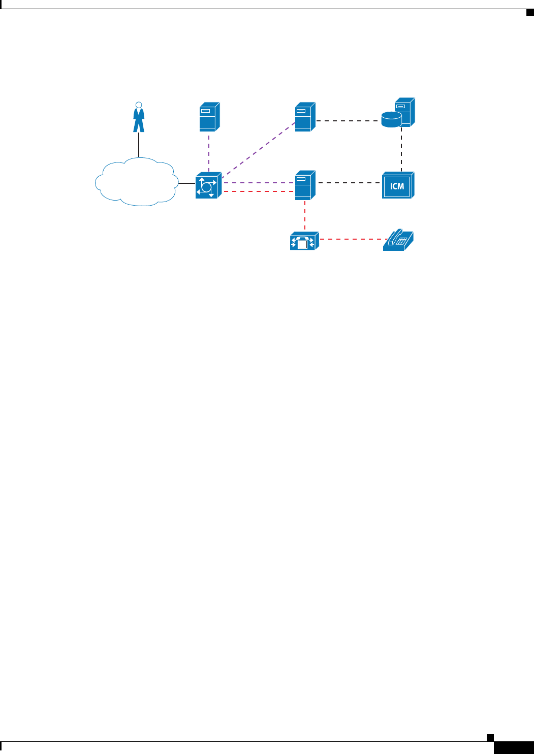
2-7
Cisco Unified Customer Voice Portal (CVP) 8.x Solution Reference Network Design (SRND)
OL-15989-06
Chapter 2 Functional Deployment Models
Comprehensive
Figure 2-2 Comprehensive Functional Deployment Model
This functional deployment model provides all the capabilities of the Standalone Unified CVP
VXML Server and Call Director functional deployment models, plus the ability to route and queue calls
to Unified CCE agents.
Callers can access Unified CVP via either local, long distance, or toll-free numbers terminating at the
Unified CVP ingress voice gateways. Callers can also access Unified CVP from VoIP endpoints.
Comprehensive deployments can utilize either H.323, SIP, or a combination.
This model requires the following components:
• Ingress voice gateway(s)
• VoiceXML gateway(s) (Can be co-resident with the ingress gateway)
• Unified CVP Server
• Unified CVP Operations Console Server
• Cisco Unified ICM Enterprise
• H.323 gatekeeper (for H.323 deployments)
• SIP Proxy Server (for SIP deployments)
Optional components for this model include:
• Unified CVP VXML Server
• Egress voice gateway(s)
• ASR / TTS server(s)
• Third-party media server(s)
• Content Services Switch(es)
• Application Content Engine (ACE)
• Unified CVP Reporting Server
270617
Unified CVP
VXML server
Customer Data
servers
PSTN VXML GED-125
Backend
Interface
SIP or H.323
SIP or H.323
MRCP/RTSP
IOS
Gateway
ASR/TTS
CVP
Call server
Agent
Endpoint
V
Cisco Unified
Communications
Manager
M

2-8
Cisco Unified Customer Voice Portal (CVP) 8.x Solution Reference Network Design (SRND)
OL-15989-06
Chapter 2 Functional Deployment Models
Comprehensive
SIP Protocol-Level Call Flow
Initial Call Treatment and Self-Service
1. A call arrives at the ingress gateway and sends a SIP invite message to the SIP Proxy Server, which
forwards the request to the Unified CVP Server SIP Service.
2. The SIP Service sends a route request to Unified ICM via the Unified CVP Server ICM Service and
the VRU PG. This route request causes Cisco Unified ICM to run a routing script based upon the
dialed number and other criteria.
3. The Unified ICM routing script utilizes a Send to VRU node to return a label to the SIP Service to
have the call sent to a VoiceXML gateway. The Unified CVP Server SIP Service sends an invite
message to the VoiceXML gateway via the SIP Proxy Server, which translates the label DN to the
IP address of the VoiceXML gateway.
4. The Voice XML gateway sends an HTTP new-call message to the Unified CVP Server IVR Service
with the label DN provided by Unified ICM. The IVR Service then sends a route request message
to Unified ICM (via the Unified ICM Service), which then allows Unified ICM to re-enter the
previously started routing script. The routing script is re-entered at the successful exit path of the
Send to VRU node. The Unified ICM routing script then uses Run Script nodes to instruct the IVR
service about the desired call treatment. If call treatment requires complex IVR self-services, service
control can be redirected to a Unified CVP VXML Server application. Upon completion of the
Unified CVP VXML Server application or a request by the caller to transfer to a live agent, service
control is returned to the Unified CVP Server IVR Service. If the initial call treatment is simple with
just a few prompts, then the IVR Service can utilize Unified CVP microapplications to generate
VoiceXML documents for the VoiceXML gateway, and a Unified CVP VXML Server is not
required.
Caller Requests to Transfer to Live Agent
1. When the caller requests to transfer to a live agent, the Unified ICM routing script queues the caller
for an appropriate skill group and sends Run VRU Script messages to the IVR Service to have queue
treatment provided (assuming no agent is available).
2. When a Unified CCE agent becomes available, Unified ICM requests the Unified CVP Server IVR
Service to transfer the call the selected agent.
3. The IVR Service then requests the SIP Service to transfer the caller to the dialed number of the
selected agent. The SIP Service then sends a SIP invite message to the SIP Proxy Server, which finds
the Cisco Unified Communications Manager SIP Trunk IP address associated with this agent DN,
and then forwards the SIP Invite message to Cisco Unified Communications Manager (Unified CM).
4. Unified CM accepts the incoming SIP Trunk call and routes it to the selected agent.
Caller Requests to be Transferred to a Second Skill Group
1. If the caller requests to be transferred to a second agent, then the first agent will initiate a transfer
from their Unified CCE agent desktop application. This action generates a route request from the
agent PG to the Unified ICM central controller. Unified ICM then executes a routing script that
queues the call to another skill group. Assuming no agent is available, the Unified ICM script will
use the Send to VRU node, which will signal to the SIP Service to release the call leg to the
Unified CM SIP Trunk and connect the call back to a VoiceXML gateway.
2. The VoiceXML gateway sends an HTTP new-call request to the IVR Service, which forwards that
request to Unified ICM in order to allow the routing script to be re-entered at the exit of the Send to
VRU node. Unified ICM then sends Run VRU Script messages to the IVR Service to allow queue
treatment to be provided to the caller while waiting for a second agent.

2-9
Cisco Unified Customer Voice Portal (CVP) 8.x Solution Reference Network Design (SRND)
OL-15989-06
Chapter 2 Functional Deployment Models
Comprehensive
3. When a second Unified CCE agent becomes available, Unified ICM requests the Unified CVP
Server IVR Service to transfer the call the selected agent.
4. The IVR Service then requests the SIP Service to transfer the caller to the dialed number of the
selected agent. The SIP Service then sends a SIP invite message to the SIP Proxy Server, which finds
the Unified CM SIP Trunk IP address associated with the second agent DN, and then forwards the
SIP Invite message to Unified CM.
5. Unified CM accepts the incoming SIP trunk call and routes it to the second agent.
Note Due to a limitation in earlier versions of Cisco IOS, Cisco recommended configuring an MTP because
it was required for call flows in which the first agent consulted and was queued and then completed the
transfer before connecting to a second agent. This limitation no longer applies, and MTP configuration
is not required on SIP trunks if you are running the latest versions of Cisco IOS. Consult the Cisco
Unified CVP 7.0(2) Release Notes for details about this limitation. Also note that there are certain
situations where MTP usage can still be allocated dynamically (for example, when there is a SIP DTMF
capability mismatch).
H.323 Protocol-Level Call Flow
Initial Call Treatment and Self-Service
1. A call arrives at the ingress gateway and sends a RAS request to the H.323 gatekeeper to find the IP
address of the Unified CVP Server for that dialed number.
2. The ingress voice gateway then sends an H.225 call setup message to the Unified CVP Server H.323
Service. For a brief instance, a G.711 voice stream exists between the ingress voice gateway and the
Unified CVP Server H.323 Service.
3. The Unified CVP Server H.323 Service sends a route request to Cisco Unified ICM via the Unified
CVP Server IVR Service, Unified CVP ICM Service, and VRU PG. This request causes Unified
ICM to run a routing script based upon the dialed number and other criteria.
4. The Unified ICM routing script utilizes a Send to VRU node to return a label to the H.323 Service
to have the call sent to a VoiceXML gateway. The H.323 Service sends a RAS request to the H.323
gatekeeper to find the IP Address of the VoiceXML gateway associated with the label returned by
Unified ICM. The Unified CVP H.323 Service sends an H.225 setup message to the VXML
Gateway.
5. The Voice XML gateway sends an HTTP new-call message to the Unified CVP Server IVR Service,
with the label DN provided by Unified ICM. The IVR Service then sends a route request message
to Unified ICM (via the IVR Service, ICM Service, and VRU PG), which then allows Unified ICM
to re-enter the previously started routing script. The routing script is re-entered at the successful exit
path of the Send to VRU node. The Unified ICM routing script then uses Run Script nodes to instruct
the IVR service about the desired call treatment. If call treatment requires complex IVR
self-services, service control can be redirected to a Unified CVP VXML Server application. Upon
completion of the Unified CVP VXML Server application or a request by the caller to transfer to a
live agent, service control is returned to the Unified CVP Server IVR Service. If the initial call
treatment is simple with just a few prompts, then the IVR Service can utilize Unified CVP
microapplications to generate VoiceXML documents for the VoiceXML gateway, and a
Unified CVP VXML Server is not required.

2-10
Cisco Unified Customer Voice Portal (CVP) 8.x Solution Reference Network Design (SRND)
OL-15989-06
Chapter 2 Functional Deployment Models
Comprehensive
Caller Requests to Transfer to Live Agent
1. When the caller requests to transfer to a live agent, the Unified ICM routing script queues the caller
for an appropriate skill group and sends Run VRU Script messages to the IVR Service to have queue
treatment provided (assuming no agent is available).
2. When a Unified CCE agent becomes available, Unified ICM requests the Unified CVP Server IVR
Service to transfer the call the selected agent.
3. The IVR Service then requests the H.323 Service to transfer the caller to the dialed number of the
selected agent. The H.323 Service then sends a RAS message to the H.323 gatekeeper to find the
Unified CM H.323 Trunk IP address associated with this agent DN, and then sends an H.225 call
setup message to Unified CM.
4. Unified CM accepts the incoming H.323 trunk call and routes it to the selected agent.
Caller Requests to be Transferred to a Second Skill Group
1. If the caller requests to be transferred to a second agent, then the first agent will initiate a transfer
from their Unified CCE agent desktop application. This action generates a route request from the
agent PG to the Unified ICM central controller. Unified ICM then executes a routing script that
queues the call to another skill group. Assuming no agent is available, the Unified ICM script will
use the Send to VRU node, which signals to the H.323 Service to release the call leg to the
Unified CM H.323 Trunk and to connect the call back to a VoiceXML gateway. A RAS request to
the H.323 gatekeeper is to find the IP address of the VoiceXML gateway.
2. The VoiceXML gateway sends an HTTP new-call request to the IVR Service, which forwards that
request to Unified ICM in order to allow the routing script to be re-entered at the exit of the Send to
VRU node. Unified ICM then sends Run VRU Script messages to the IVR Service to allow queue
treatment to be provided to the caller while waiting for a second agent.
3. When a second Unified CCE agent becomes available, Unified ICM requests the Unified CVP
Server IVR Service to transfer the call the selected agent.
4. The IVR Service then requests the H.323 Service to transfer the caller to the dialed number of the
selected agent. The H.323 Service sends a RAS request to the H.323 gatekeeper to get the IP address
of the Unified CM H.323 trunk associated with the second agent DN. The H.323 Service then sends
an H.225 setup message to Unified CM.
5. Unified CM accepts the incoming H.323 trunk call and routes it to the second agent.
Transfers and Subsequent Call Control
In addition to transfers manager by Unified ICM (as described above), the Comprehensive deployment
model can transfer calls to non-ICM terminations or it can invoke a Release Trunk Transfer in the PSTN.
If a call is transferred to a non-ICM termination, then no call data can be passed to the termination, no
further call control is possible for that call, and the cradle-to-grave call reporting that Unified ICM
captures is completed. In the case of a Release Trunk Transfer, the ingress voice gateway port is released,
no call data can be passed to the termination, and no further call control is possible for that call. If the
Release Trunk Transfer was translation-routed to another ICM peripheral, call data and cradle-to-grave
reporting can be maintained. For more details on transfers, see the chapter on Call Transfer Options,
page 10-1.
If a selected termination (for either a new or transferred call) returns a connection failure or busy status,
or if the target rings for a period of time that exceeds the Unified CVP Call Server's ring-no-answer
(RNA) timeout setting, the Unified CVP Call Server cancels the transfer request and sends a transfer

2-11
Cisco Unified Customer Voice Portal (CVP) 8.x Solution Reference Network Design (SRND)
OL-15989-06
Chapter 2 Functional Deployment Models
VRU Only
failure indication to Unified ICM. This scenario causes a Router Requery operation. The Unified ICM
routing script then recovers control and has the opportunity to select a different target or take other
remedial action.
VRU Only
This functional deployment model provides self-service applications and queueing treatment for
organizations that are utilizing advanced PSTN switching services that are controlled via a Cisco Unified
ICM PSTN Network Interface Controller (NIC). Two Unified ICM PSTN NICs are available that allow
subsequent call control of calls in the PSTN. They are the SS7 NIC and the Carrier Routing Service
Protocol (CRSP) NIC. These NICs go beyond allowing Unified ICM to pre-route calls intelligently to
Unified ICM peripherals (such as ACDs and IVRs); they also allow Unified ICM to invoke mid-call
transfers in the PSTN. Figure 2-3 illustrates this model.
Figure 2-3 Functional Deployment Model for VRU Only
A typical call in this model would be pre-routed by Unified ICM to a Unified CVP Ingress Voice
Gateway for call treatment and queueing. When an agent becomes available, Unified ICM instructs the
PSTN to transfer the call to that agent. The agents can be Cisco Unified Contact Center Enterprise
agents, Cisco Unified Contact Center Express agents, or traditional ACD agents. If necessary, Unified
ICM can request the PSTN (via the NIC) to transfer the call again and again, just as Unified ICM can
request Unified CVP to transfer the call again and again. In this functional deployment model, the
Unified CVP Ingress Voice Gateway is just a Unified ICM-managed PSTN termination point that is
capable of providing VRU services via a VoiceXML gateway, the Unified CVP Server IVR Service, the
Unified CVP Server ICM Service, and Unified ICM. In this functional deployment model, neither the
Unified CVP Server H.323 Service nor the Unified CVP Server SIP Service is used for call control. All
call control and switching is controlled by Unified ICM and the PSTN. In this functional deployment
model, Unified ICM can pass call data between these termination points (for a screen pop or other
intelligent treatment) and provide cradle-to-grave reporting for all calls.
270618
Customer Data
servers
PSTN VXML GED-125
MRCP/RTSP
IOS
Gateway
PSTN Switch
or PGW
ASR/TTS
CVP
Call server
ICM
PSTN NIC
V
Unified CVP
VXML server
Backend
Interface

2-12
Cisco Unified Customer Voice Portal (CVP) 8.x Solution Reference Network Design (SRND)
OL-15989-06
Chapter 2 Functional Deployment Models
VRU Only
This model requires the following components:
• Ingress voice gateway(s)
• VoiceXML gateway(s) (Can be co-resident with the ingress gateway)
• Unified CVP Server running IVR Service and ICM Service
• Unified CVP Operations Console Server
• Cisco Unified ICM Enterprise and NIC (SS7 or CRSP)
Optional components for this model include:
• Unified CVP VXML Server
• ASR / TTS server(s)
• Third-party media server(s)
• Content Services Switch(es)
• Application Content Engine (ACE)
• Unified CVP Reporting Server
• H.323 gatekeeper (for H.323 deployments)
• SIP Proxy Server (for SIP deployments)
Protocol-Level Call Flow
Initial Call Treatment and Self-Service
1. A call arrives at the PSTN, and the PSTN sends a new-call message to Unified ICM via either a
CRSP NIC or SS7 NIC. Unified ICM invokes a routing script based upon the dialed number, and the
routing script uses either a Send to VRU node or a Translation Route to VRU node to send a result
to the PSTN to have the call routed to the Unified CVP ingress voice gateway. Depending upon the
PSTN capability and Unified ICM VRU type for the Unified CVP deployment, the response returned
to the PSTN is either a translation route label (dialed number) or a dialed number plus correlation
ID.
2. The PSTN routes the call to an available ingress voice gateway port. The ingress voice gateway
performs normal inbound POTS dial-peer matching to deliver the call to an available VoiceXML
gateway port. An H.323 RAS request to an H.323 gatekeeper or a SIP Invite message to a SIP Proxy
server could be used to aid in the routing of the call to an available VoiceXML gateway port, if
desired.
3. The Voice XML gateway sends an HTTP new-call message to the Unified CVP Server IVR Service
with the dialed number delivered from the PSTN. This dialed number represents either a translation
route label or a correlation ID. Either way, the Unified ICM VRU PG will recognize this call and
send a request instruction message to the in-progress Unified ICM routing script. The next routing
script node is typically a Run VRU Script node to instruct the VRU which microapplication is to be
executed.
4. The Unified CVP Server IVR Service sends a dynamically generated VoiceXML document to the
VoiceXML gateway for rendering.
5. The VoiceXML gateway parses and renders the VoiceXML document. If call treatment requires
complex IVR self-services, service control can be redirected to a Unified CVP VXML Server
application. Upon completion of the Unified CVP VXML Server application or a request by the
caller to transfer to a live agent, service control is returned to Unified CVP Server IVR Service. If
the initial call treatment is simple with just a few prompts, then the IVR Service can utilize Unified

2-13
Cisco Unified Customer Voice Portal (CVP) 8.x Solution Reference Network Design (SRND)
OL-15989-06
Chapter 2 Functional Deployment Models
Basic Video Service
CVP microapplications to generate VoiceXML documents for the VoiceXML gateway, and a
Unified CVP VXML Server is not required. If desired, the Unified ICM routing script can terminate
the call, and a disconnect message will be sent by the Unified ICM to the PSTN via the PSTN NIC.
Caller Requests to Transfer to Live Agent
6. When the caller requests to transfer to a live agent, the Unified ICM routing script queues the caller
for an appropriate skill group and sends Run VRU Script messages to the IVR Service to have queue
treatment provided (assuming no agent is available).
7. When a Unified CCE agent or a TDM ACD agent becomes available, Unified ICM immediately
sends a connect message to the PSTN via the PSTN NIC. The connect message will contain either
a translation route label or a dialed number plus correlation ID (depending upon the PSTN
capabilities). Upon receipt of the connect request, the PSTN releases the call leg to the Unified CVP
ingress voice gateway and connects the call to the new termination. If the new termination is a TDM
ACD, the previous queueing treatment could be skipped and the TDM ACD could provide the queue
treatment. Any call data associated with this call will be passed to the Unified ICM Peripheral
Gateway (PG) for the selected peripheral.
Caller Requests to be Transferred to a Second Skill Group
8. If the caller requests to be transferred to a second agent, then the first agent will initiate a transfer
from their agent desktop application (Unified CCE or TDM). This action generates a route request
from the PG to the Unified ICM central controller.
9. Unified ICM executes a routing script. If the caller needs to be placed back into queue on Unified
CVP or to another ACD location (TDM or IP), then Unified ICM sends a connect message to the
PSTN via the PSTN NIC to have the call transferred. If the caller needs to be transferred to an agent
on the same Unified CM peripheral, then Unified ICM instructs Unified CM (via the Unified CM
PG) to transfer the call.
Basic Video Service
The Basic Video Service is simply an extension of the existing Comprehensive deployment model, but
it allows for a video caller to interact with a video agent. IVR and queuing are audio-only.
The following video endpoints are supported when using the Unified CVP Basic Video Service:
• Cisco Unified IP Phone 7985G
• Cisco Unified Video Advantage
• Cisco TelePresence
The Basic Video Service supports the following call flows with Cisco TelePresence:
• A TelePresence caller dials into Unified CVP, receives audio-only IVR and/or queuing treatment,
and then is transferred to an Agent on a second TelePresence unit.
• A TelePresence caller dials into Unified CVP, receives audio-only IVR and/or queuing treatment,
and then is transferred to an Agent on a second TelePresence unit. The TelePresence Agent can
conference in a second Agent on an audio-only IP phone by dialing a direct extension from their
TelePresence phone.
• A TelePresence caller dials into Unified CVP, receives audio-only IVR and/or queuing treatment,
and then is transferred to an Agent on a second TelePresence unit. The TelePresence Agent can
conference in a Unified CVP dialed number that results in audio queuing, followed by connection
to a second Agent on an audio-only IP phone.

2-14
Cisco Unified Customer Voice Portal (CVP) 8.x Solution Reference Network Design (SRND)
OL-15989-06
Chapter 2 Functional Deployment Models
Basic Video Service
• A TelePresence caller dials into Unified CVP, receives audio-only IVR and/or queuing treatment,
and then is transferred to an Agent on an audio-only IP Phone. MTP must be enabled on the SIP
trunk or else one-way audio is encountered.
Because the Basic Video Service is simply an extension of the SIP-based Comprehensive deployment
model, the required components and SIP protocol-level call flow details are identical.

CHAPTER
3-1
Cisco Unified Customer Voice Portal (CVP) 8.x Solution Reference Network Design (SRND)
OL-15989-06
3
Distributed Deployments
Last revised on: May 2, 2010
In a distributed deployment, the ingress gateways are geographically separated from the Unified CVP
Call Server. This chapter discusses how these types of deployments should be designed as well as how
to handle call survivability and call admission control.
The chapter covers the following major topics:
• Distributed Gateways, page 3-1
• Call Survivability in Distributed Deployments, page 3-5
• Call Admission Control Considerations, page 3-6
What's New in This Chapter
Table 3-1 lists the topics that are new in this chapter or that have changed significantly from previous
releases of this document.
Distributed Gateways
Unified CVP can use several different types of gateways depending on the deployment model. This
section discusses each type of gateway and how a distributed deployment can affect them.
Ingress and/or Egress Gateway at the Branch
In this deployment model, ingress gateways located at a branch office are typically used to provide
callers with access using local phone numbers rather than centralized or non-geographic numbers. This
capability is especially important in international deployments spanning multiple countries. Egress
Table 3-1 New or Changed Information Since the Previous Release of This Document
New or Revised Topic Description
Multicast Music-on-Hold (MOH), page 3-4 Describes two methods for using Multicast
Music-on-Hold.
RSVP, page 3-10 RSVP available for SIP trunks.

3-2
Cisco Unified Customer Voice Portal (CVP) 8.x Solution Reference Network Design (SRND)
OL-15989-06
Chapter 3 Distributed Deployments
Distributed Gateways
gateways are located at branches either for localized PSTN breakout or for integration of decentralized
TDM platforms into the Unified CVP switching solution. Apart from the gateways, all other Unified
CVP components are centrally located, and WAN links provide data connectivity from each branch
location to the central data center.
Ingress or VoiceXML Gateway at Branch
Consideration needs to be given to other voice services that are being run at the branch. For example,
the branch is typically a remote Cisco Unified Communications Manager (Unified CM) site supporting
both ACD agent and non-agent phones. This model also implies that the PSTN gateway is used not only
for ingress of Unified CVP calls but also for ingress/egress of normal user calls for that site. In
circumstances where the VoiceXML and voice gateway functions reside at the same branch location but
on separate devices, special attention has to be paid to the dial plan to ensure that the VRU leg is sent to
the local VoiceXML resource because the Unified CVP Call Server settransferlabel mechanism applies
only to co-resident VoiceXML and voice gateway configurations.
When the ingress gateway and VoiceXML gateway at a branch do not reside on the same gateway, there
are two ways to ensure that the calls are handled within the branch and not sent across the WAN to a
different VoiceXML gateway:
• Configure Unified ICM with multiple Customers, one per location.
This option relies on the Unified ICM configuration to differentiate between calls based on the
Dialed Number. The Dialed Number is associated with a Customer representing the branch site.
When a NetworkVRU is needed, the NetworkVRU associated with the Customer in Unified ICM is
selected and the caller is sent to that NetworkVRU. This allows you to have multiple NetworkVRUs,
each with a unique label. The downside of this method is that each NetworkVRU requires its own
VRU scripts in Unified ICM. The Unified ICM configuration overhead of making a change to each
NetworkVRU script quickly becomes overwhelming when a large number of remote sites are
required.
• Configure Unified CVP using the SigDigits feature.
The SigDigits feature in Unified CVP allows you to use the dial plan on the SIP Proxy or gatekeeper
to route calls to the correct site. When the call arrives at an ingress gateway, the gateway will
prepend digits before sending the call to Unified CVP. Those prepended digits are unique to that site
from a dial-plan perspective.
When the call arrives at Unified CVP, Unified CVP will strip the prepended digits and store them in
memory, resulting in the original DID on which the call arrived. Unified CVP then notifies Unified
ICM of the call arrival using the original DID, which matches a Dialed Number in Unified ICM.
When Unified ICM returns a label to Unified CVP in order to transfer the call to a VoiceXML
gateway for IVR treatment or to transfer the call to an agent phone, Unified CVP will prepend the
digits that it stored in memory before initiating the transfer. The dial plan in the SIP Proxy or
gatekeeper must be configured with the prepended digits in such a way to ensure that calls with a
certain prepended digit string are sent to specific VoiceXML gateways or egress gateways. The
prepended digits are prepended as a tech-prefix when using H.323.
It is important to remember that when the VXML gateway receives the call, the CVP bootstrap
service will be configured to strip the digits again, so that when the IVR leg of the call is set up, the
original DN is used on the incoming VXML request. Note that digits could be prepended to
translation route DNs as well, and that the egress or receiving component (such as Cisco Unified
CM) may need to strip digits to see the original DN.

3-3
Cisco Unified Customer Voice Portal (CVP) 8.x Solution Reference Network Design (SRND)
OL-15989-06
Chapter 3 Distributed Deployments
Distributed Gateways
The term SigDigits is used to describe this feature because the command in Unified CVP to turn on
the feature and specify how many significant digits should be stripped is setsigdigits X for H.323,
and for SIP it is called Prepend Digits in the Operations Console.
This method is preferred because it involves the least amount of Unified ICM configuration
overhead; a single NetworkVRU and single set of VRU scripts and Unified ICM routing scripts is
all that is needed. This allows all of the Unified CVP servers and VoiceXML gateways to function
as a single network-wide virtual IVR from the perspective of Unified ICM.
The SigDigits feature can also be used to solve multi-cluster call admission control problems. (See
Call Admission Control Considerations, page 3-6, for more information.)
Co-Located Unified CVP VXML Servers and Gateways
Either all gateways and servers are centralized or each site has its own set of co-located Unified CVP
VXML Servers and gateways.
Advantages of co-location:
• A WAN outage does not impact self-service applications.
• No WAN bandwidth is required.
Disadvantages of co-location:
• Extra Unified CVP VXML Servers are required when using replicated branch offices.
• There is additional overhead when deploying applications to multiple Unified CVP VXML Servers.
Gateways at the Branch, with Centralized Unified CVP VXML Servers
Advantages of centralized VoiceXML:
• Administration and reporting are centralized.
• Unified CVP VXML Server capacity can be shared among branch offices.
Disadvantages of centralized VoiceXML:
• Branch survivability is limited.
• WAN bandwidth must be sized for additional VoiceXML over HTTP traffic.
Cisco Unified Communications Manager
In a Unified CVP environment, Cisco Unified Communications Manager (Unified CM) can be an ingress
or egress gateway. It is more common for Unified CM to be an egress gateway because typically callers
are calling from the PSTN, being queued by Unified CVP, and then being switched to Unified CM for
handling by an agent. If the caller is not calling from the PSTN but from an IP phone instead, then
Unified CM is an ingress gateway from the perspective of Unified CVP.
Unified CM as an Egress Gateway
Unified CVP normally depends on the gatekeeper for dial-plan resolution and call admission control. To
deploy Unified CM alongside Unified CVP, you must use Unified CM call admission control for calls
between the ingress Unified CVP gateway and the agent IP phone. The ability for Unified CM to identify

3-4
Cisco Unified Customer Voice Portal (CVP) 8.x Solution Reference Network Design (SRND)
OL-15989-06
Chapter 3 Distributed Deployments
Distributed Gateways
the ingress Unified CVP gateway correctly is complicated because the Unified CVP Call Server is the
component that is actually making the H.323 call to Unified CM. Therefore, Unified CM sees the call as
coming from the centralized Unified CVP Call Server rather than from the remote ingress gateway.
The Unified CVP Call Server is able to solve this problem by setting the sourcesignaladdress field
inside the H.323 setup to the IP address of the ingress gateway. Upon receiving the setup from Unified
CVP, Unified CM sees the source signaling address and knows that the address is the one that should be
used when determining from which location the call is coming. Because Unified CM has this ingress
gateway IP configured, Unified CM will use its Locations call admission control configuration to deduct
the bandwidth between the ingress gateway and the destination IP phone locations. The Unified CVP
Call Server should not be configured as a gateway in Unified CM; instead, the Unified CVP Call Server
should send calls to Unified CM via a gatekeeper-controlled H.323 trunk. (See Call Admission Control
Considerations, page 3-6, for more information on call admission control mechanisms.)
Unified CM as an Ingress Gateway
When an IP phone initiates a call to Unified CVP, Unified CM acts as the ingress gateway to Unified
CVP. An H.323 or SIP trunk is used to send calls to Unified CVP. For more information on these types
of call flows, see the chapter on Calls Originated by Cisco Unified Communications Manager, page 6-1.
Multicast Music-on-Hold (MOH)
Multicasting may be used for Music-on-Hold with supplementary services on Unified CM as an
alternative to the unicast MOH. There are two ways to deploy using this feature:
• With Unified CM multicasting the packets on the local LAN
• With the branch gateway(s) multicasting on their local LAN(s)
Use the latter method when SRST (survivable remote site telephony) is configured on the gateway. This
method enables the deployment to use MOH locally and avoid MOH streaming over the WAN link.
Note References for Using Multicast MOH
Refer to the following for configuring MOH on the Call Manager Enterprise (CME):
http://www.cisco.com/en/US/docs/voice_ip_comm/cucme/admin/configuration/guide/cmemoh.html#w
pmkr1022205
Design Considerations
The following considerations apply when using Multicast MOH:
• Do not set modem passthrough nse codec g711ulaw globally, or on a dial peer on the ingress/egress
gateway. This setting may cause Unified CM to stop the MOH after a timeout period of 10-12
seconds.
• Do not set media inactivity on the ingress gateway, because multicast MOH does not send RTP or
RTCP, so the call may get disconnected due to media inactivity configuration. The setting
media-inactivity-criteria all doesn't support multicast traffic.
• SIP-based Multicast MOH is not supported on the 5400 platform since ccm-manager-based MOH
subsystems are not supported on 5400 platform. This limitation also includes the ability of a TDM
caller to hear multicast packets broadcasted from the Unified CM MOH server.

3-5
Cisco Unified Customer Voice Portal (CVP) 8.x Solution Reference Network Design (SRND)
OL-15989-06
Chapter 3 Distributed Deployments
Call Survivability in Distributed Deployments
Call Survivability in Distributed Deployments
Distributed deployments require design considerations for other voice services that are being run at the
branch. For example, the branch is typically a remote Unified CM site supporting both ACD agent and
non-agent phones. This deployment also implies that the PSTN gateway is used not only for ingress of
Unified CVP calls but also for ingress/egress of the regular non-ACD phone calls.
Branch reliability becomes somewhat more of an issue than it is in a centralized Unified CVP model
because WANs are typically less reliable than LAN links. Therefore, you must provide mechanisms that
are local to the branch to gracefully handle calls that are impacted by loss of a WAN link to the central
site.
Call survivability must be considered for both the Unified CVP and non-CVP calls. For the Unified CM
endpoint phones, survivability is accomplished via a Cisco IOS feature known as Survivable Remote
Site Telephony (SRST). For further details on SRST, refer to the latest version of the Cisco Unified
Communications SRND Based on Cisco Unified Communications Manager, available at
http://www.cisco.com/en/US/products/sw/voicesw/ps556/products_implementation_design_guides
_list.html
For Unified CVP calls, survivability is handled by a combination of services from a TCL script
(survivability.tcl) and SRST functions. The survivability TCL script is used to monitor the H.225 or SIP
connection for all calls that ingress through the remote gateway. If a signaling failure occurs, the TCL
script takes control of the call and redirects it to a configurable destination. The destination choices for
the TCL script are configured as parameters in the Cisco IOS Gateway configuration.
Alternative destinations for this transfer could be another IP destination (including the SRST call agent
at the remote site), *8 TNT, or hookflash. With transfers to the SRST call agent at the remote site, the
most common target is an SRST alias or a Basic ACD hunt group. For further information about these
SRST functions, refer to the Cisco Unified Communications SRND Based on Cisco Unified
Communications Manager.
Voice Mail and Recording Servers do not send Real-Time Control Protocol (RTCP) packets in reverse
direction toward the caller (TDM Voice Gateway), and this could falsely trigger the media-inactivity
timer of the survivability script. So it is important to apply the survivability.tcl script carefully to the
dial-peers because a call might drop if it goes to the voice mail or to a recording element. One method
is to use a separate dial-peer for voice mail or recording calls, and do not associate the Unified CVP
survivability script for those dial-peers. Another method is to disable the media-inactivity on the
survivability script associated with the voice mail or recording dial-peers.
For further information on configuration and application of these transfer methods, refer to the latest
version of Configuration and Administration Guide for Cisco Unified Customer Voice Portal, available
at
http://www.cisco.com/en/US/products/sw/custcosw/ps1006/products_installation_and_configuration_g
uides_list.html.
Also refer to Cube Deployment with SIP Trunks, page 1-22.
Note To take advantage of alternate routing upon signaling failures, you must use the survivability service on
all gateways pointing to Unified CVP. Always use this service, unless you have a specific
implementation that prevents using it.

3-6
Cisco Unified Customer Voice Portal (CVP) 8.x Solution Reference Network Design (SRND)
OL-15989-06
Chapter 3 Distributed Deployments
Call Admission Control Considerations
Note Router requery is not supported when using SIP Refer with Unified CVP Comprehensive Call Flow, and
the survivability service is handling the REFER message from Unified CVP. Router requery with Refer
can be supported in other call flows when IOS is handling the REFER without the survivability service,
or else Unified CM is handling the REFER. For third party SIP trunks, the support of router requery with
REFER is dependent on their implementation and support for SIP REFER itself.
Call Admission Control Considerations
Call admission control must also be considered from a solution perspective, not just a Unified CVP
perspective. These considerations are most evident in the distributed branch office model where there
are other voice services, such as Cisco Unified CM, sharing the same gateways with Unified CVP and
the amount of bandwidth between the sites is limited. The most important item to consider in this case
is which call admission control mechanisms are in place on the network so that a consistent call
admission control mechanism can be used to account for all the calls traversing the WAN from that site.
If two call admission control mechanisms can admit four calls each and the WAN link is able to handle
only four calls, then it is possible for both call admission control entities to admit four calls onto the
WAN simultaneously and thereby impair the voice quality. If a single call admission mechanism cannot
be implemented, then each call admission control mechanism must have bandwidth allocated to it. This
situation is not desirable because it leads to inefficient bandwidth over-provisioning.
There are three call admission control mechanisms that can be used in a Unified CVP environment:
gatekeeper call admission control, Unified CM Locations, and Unified CM RSVP Agent. In a single-site
deployment, call admission control is not necessary.
Unified CM performs call admission by assigning devices to certain locations and keeping track of how
many calls are active between these locations. Because Unified CM knows how many calls are active
and what codec is in use for each call, it is able to calculate how much bandwidth is in use and to limit
the number of calls allowed.
A thorough conceptual understanding of call admission control mechanisms is important. These
mechanisms are explained in the Cisco Unified Communications SRND Based on Cisco Unified
Communications Manager, available at
http://www.cisco.com/en/US/products/sw/voicesw/ps556/products_implementation_design_guides
_list.html
Gatekeeper Call Admission Control
In a pure TDM environment where Unified CVP is switching calls from an ingress gateway to an egress
gateway attached to a TDM ACD/IVR, the gatekeeper can handle the call admission control
functionality.
If Unified CM is the egress gateway, gatekeeper call admission control can be used only if the ingress
Unified CVP gateways and the IP phones are at different sites. Note that gatekeeper dial-plan resolution
is still in use.
Because Unified CM locations-based call admission control is used between the remote sites of a cluster,
a gatekeeper typically is used for dial-plan resolution only. Understanding the routing of calls in the dial
plan and the gatekeeper resolution is important because call routing situations might occur in which it is
necessary to use more than one set of gatekeepers in the implementation. This is particularly common

3-7
Cisco Unified Customer Voice Portal (CVP) 8.x Solution Reference Network Design (SRND)
OL-15989-06
Chapter 3 Distributed Deployments
Call Admission Control Considerations
when using this model in a situation where more than one Unified CM cluster are being used to control
the remote sites. For further discussion and information on this topic, see H.323 Gatekeeper Call
Routing, page 3-10.
Unified CM Call Admission Control
If Unified CM is sending or receiving calls from Unified CVP and there are Unified CVP gateways and
IP phone agents co-located at remote sites, it is important to understand the call flows in order to design
and configure call admission control correctly.
H.323 Call Flows
The gatekeeper and Unified CM do not share bandwidth usage information. Networks shared by both the
gatekeeper and IP phones will have two separate call admission control mechanisms determining if there
is enough bandwidth to place a call. Instead of using the gatekeeper for call admission control, it is
possible to use Unified CM Locations as the call admission control mechanism for Unified CVP calls.
How Unified CM determines an endpoint’s location is key to designing call admission control properly.
Consider the basic call flow of a Unified CVP call versus a non-CVP call. When a user picks up an IP
phone and makes a call from the remote site to the central site, Unified CM considers the location
definitions of the endpoints and the codec requirements defined in the Unified CM Region
configurations and decides whether or not to allow the call. Note that the call admission control and the
codec requirements are controlled between these endpoints by Unified CM as the controlling call agent.
By default, Unified CM looks at the source IP address of an incoming H.323 call to determine which
H.323 device is originating the call. Unified CM then uses the configuration of this device to determine
its location and to perform call admission control for the call. When Unified CVP is delivering calls from
a remote branch gateway to a Unified CM IP Phone, Unified CVP is in the middle of the H.323 signaling,
so the source IP address from Unified CM's perspective is the Unified CVP Server. Because the Unified
CVP Server is centralized along with Unified CM, it is not possible to perform call admission control
based on the Unified CVP Server's IP address. Unified CM must be aware that calls arriving from
Unified CVP are actually coming from a gateway at a specific branch so that it can calculate call
admission control correctly. In order to solve this problem, Unified CVP must be configured to insert
information in the payload of the H.323 SETUP message that identifies the IP address of the originating
gateway, and Unified CM must be configured to look at this information when determining on which
gateway an H.323 call is arriving.
This requires enabling one Unified CM service parameter and ensuring that another parameter is set to
its default value:
• Change the cluster-wide service parameter Accept unknown TCP connection to True. (The default
is False.)
• Ensure that the service parameter Device Name of gatekeeper trunk that will use port 1720
remains at its default setting of blank.
When set to True, the service parameter Accept Unknown TCP Connection changes the behavior for
inbound H.323 calls. Unified CM accepts an unknown H.225 TCP connection and waits for the H.323
SETUP message. Unified CM then extracts the User-to-User Information Element (UUIE) and examines
the sourceCallSignalAddress field, which contains the IP address of the originating gateway.
Unified CM compares this address against its configured gateways. If a match is found, the call is treated
as if it originated from the voice gateway and not the Unified CVP Server. The Unified CVP Server IP
address must not be configured as an H.323 gateway, otherwise Unified CM will match first on the
source IP address and will not look at the information in the sourceCallSignalAddress field. In order to

3-8
Cisco Unified Customer Voice Portal (CVP) 8.x Solution Reference Network Design (SRND)
OL-15989-06
Chapter 3 Distributed Deployments
Call Admission Control Considerations
deliver calls to Unified CM from Unified CVP without specifying Unified CVP as an H.323 gateway,
you must configure an H.323 Gatekeeper Trunk in Unified CM so that Unified CVP will sends calls to
Unified CM via the gatekeeper over the trunk.
The Unified CM service parameter Device Name of gatekeeper trunk that will use port 1720 is used
to force a gatekeeper-controlled trunk to register to a gatekeeper on port 1720. This feature causes any
inbound H323 call that is signaling on port 1720 to be treated immediately as a gatekeeper-controlled
trunk call. The H.225 signaling address is not examined in this case.
This behavior is not how Unified CM traditionally treats a gatekeeper-controlled H.323 call. Typically,
all gatekeeper-controlled calls come from the hub location (location None or Hub_None). These changes
ensure that the call is not treated as a gatekeeper-controlled call and that locations-based call admission
control is applied. Note that, in this model, if Unified CM does not match the gateway signaling address
in its list of configured gateways, it rejects the call. Figure 3-1 illustrates the decision tree for H.323 call
processing.
Figure 3-1 Cisco Unified CM H.323 Signaling Flow Topology
To configure Unified CVP to work correctly with Unified CM call admission control, use VBAdmin to
set the Unified CVP Server parameter setlocationsbasedcac on. This setting tells Unified CVP to
populate the sourceCallSignalAddress field and to use TCP port 1720 when sending calls to Unified CM.
191324
Match
Match
No Match
Equals
Port 1720
No
Not equal to
Port 1720
No
Match
Match
Inbound H.323 call
to Cisco Unified
CallManager
Check
H.225 TCP connection
peer IP address
against configured
H.323 gateways.
Process call,
sourcing it as if from
configured gateway.
Ye s
No Match
Examine
signaling
port number.
Is it configured as
a gatekeeper
controlled trunk?
Does the port number
match a dynamic port used
for a configured
gatekeeper controlled trunk?
Process call as an
incoming gatekeeper
controlled trunk call.
Send ARQ to gatekeeper,
and process call using
the IP peer address.
Wait for H.225
Setup Message,
then extract source
signaling address.
Check
H.225 signaling
addressagainst
configured H.323
gateways
H225ReleaseComplete
with cause IE - Call
Rejected. User hears
re-order tone.
Process call,
sourcing it as if from
configured gateway.
Accept inbound
H.225 TCP
connection.

3-9
Cisco Unified Customer Voice Portal (CVP) 8.x Solution Reference Network Design (SRND)
OL-15989-06
Chapter 3 Distributed Deployments
Call Admission Control Considerations
When using this feature in conjunction with calls originated by Unified CM, the
sourceCallSignalAddress populated by Unified CVP will be the IP address of Unified CM. If the call is
transferred back to Unified CM, it will inspect this field and try to find a configured gateway with that
IP address, but the call will fail because normally Unified CM will never be configured as a gateway. As
a workaround to this problem, configure each Unified CM in the cluster as an H.323 gateway, but be sure
to never configure the Unified CM dial plan to send calls using those gateways.
Multiple Cisco Unified CM Clusters
When more than one centralized Unified CM cluster are used for the remote sites, additional
consideration must be given to routing calls based on agent selection. In a multi-cluster environment,
each cluster manages a group of remote sites and tracks the voice calls to those sites within the
locations-based call admission control mechanism. Using the changes discussed above, Unified CM
considers H.323 calls within its locations-based call admission control mechanism. Because H.323 is a
peer-to-peer protocol, an H.323 gateway can signal a call to any other call agent that will accept it.
Considering the locations-based call admission control mechanism described above, it is necessary for
the remote gateway to be told to signal a call to the Unified CM cluster that owns the location of that
remote gateway. However, in a Unified CCE environment, Unified ICM tracks the availability of agents
without considering on which cluster they are located. This ability provides great scalability for
Unified CCE but must be accounted for in this type of implementation.
If a call coming in through a Unified CVP ingress gateway is destined for an IP Phone at a different site
registered to a different cluster, the call must first be routed through the cluster that is handling call
admission control for the ingress gateway, and then routed to the destination cluster. If the call is routed
directly from the ingress gateway to the destination cluster, the cluster that is handling call admission
control for the ingress gateway is not aware of the call traversing the WAN and does not deduct
bandwidth appropriately.
This call routing can be handled by using the SigDigits feature in Unified CVP and its associated
dial-plan configuration. The SigDigits feature in Unified CVP allows you to use the dial plan on the SIP
Proxy or gatekeeper to route calls to a specific Unified CM cluster. When the call arrives at an ingress
gateway, the gateway will prepend digits before sending the call to Unified CVP. Those prepended digits
are unique to that site from a dial-plan perspective. When the call arrives at Unified CVP, Unified CVP
will strip the prepended digits and store them in memory, resulting in the original DID on which the call
arrived. When Unified ICM returns a label to Unified CVP in order to transfer the call to an agent phone,
Unified CVP will prepend the digits that it stored in memory before initiating the transfer. The dial-plan
configuration in the SIP Proxy or gatekeeper is configured with the prepended digits so that calls with a
certain prepended digit string are sent to a specific Unified CM cluster. The digits are prepended as a
tech-prefix when using H.323.
For more information on how the SigDigits feature works, see Distributed VoiceXML Gateways
(Separate Ingress Gateway and VoiceXML), page 4-25.

3-10
Cisco Unified Customer Voice Portal (CVP) 8.x Solution Reference Network Design (SRND)
OL-15989-06
Chapter 3 Distributed Deployments
Call Admission Control Considerations
SIP Call Flows
With SIP-based call flows, Cisco Unified CM 6.0 (and prior releases) is able to look at only the source
IP address of the incoming SIP INVITE from Unified CVP. This limitation causes a problem with call
admission control because Unified CM is not able to identify which gateway behind Unified CVP
originated the call.
Cisco Unified CM 6.1 has enhanced the SIP Trunk to look beyond the source IP address and to inspect
information contained in the SIP header when determining which device originated a call. This
enhancement allows the SIP trunk to be dynamically selected by the original source IP address rather
than the remote port on Unified CVP, and therefore different SIP profiles and settings can be used on the
source trunks that are different from the Unified CVP trunk.
More specifically, the Call-Info header in the SIP INVITE will specify the originating device in the
following format:
<sip: IPAddress:port>;purpose=x-c isco-origIP
Where IPAddress:port indicates the originating device and its SIP signaling port.
This source IP SIP trunk selection feature does not impact the bandwidth monitoring for call admission
control. In Unified CM release 8.0, bandwidth monitoring is performed with SIP using locations
configuration on Unified CVP and Unified CM. The following header is used by the location server in
Unified CM to manipulate bandwidth information for call admission control.
Call-Info: [urn:x-cisco-remotecc:callinfo];x-cisco-loc-id="PKID";x-cisco-loc-name="Loc-NAME"
RSVP
Cisco Unified CM 5.0 introduced support for Resource Reservation Protocol (RSVP) between endpoints
within a cluster, and 8.0 UCM introduces RSVP over the SIP Trunk. RSVP is a protocol used for call
admission control, and it is used by the routers in the network to reserve bandwidth for calls. RSVP is
not qualified for call control signaling via the Unified CVP Call Server in SIP or H323 in the 8.0 release.
The recommended solution for CAC is to employ Locations configuration on Unified CVP and in
Unified CM.
For more information on RSVP, refer to the latest version of the Cisco Unified Communications SRND
Based on Cisco Unified Communications Manager, available at
http://www.cisco.com/en/US/products/sw/voicesw/ps556/products_implementation_design_guides
_list.html
H.323 Gatekeeper Call Routing
For proper configuration of remote H.323 gateways with a Unified CM cluster, first consider the H.225
implications of this configuration without the use of gatekeeper.
When configuring dial-peer destinations for the Cisco IOS Gateways, you must configure a dial peer
pointing to the IP addresses of the Unified CM servers that are processing calls for that gateway. These
server IP addresses must be the same servers that are in the redundancy group of the device pool
definition for that gateway in the Unified CM configuration. (See Figure 3-2.) If the remote H.323
gateway sends a call to a Unified CM server that is not in the redundancy group for that gateway, the call
is rejected. For example, if the Madison gateway in Figure 3-2 sends a call to the.3 server, the call is
rejected.
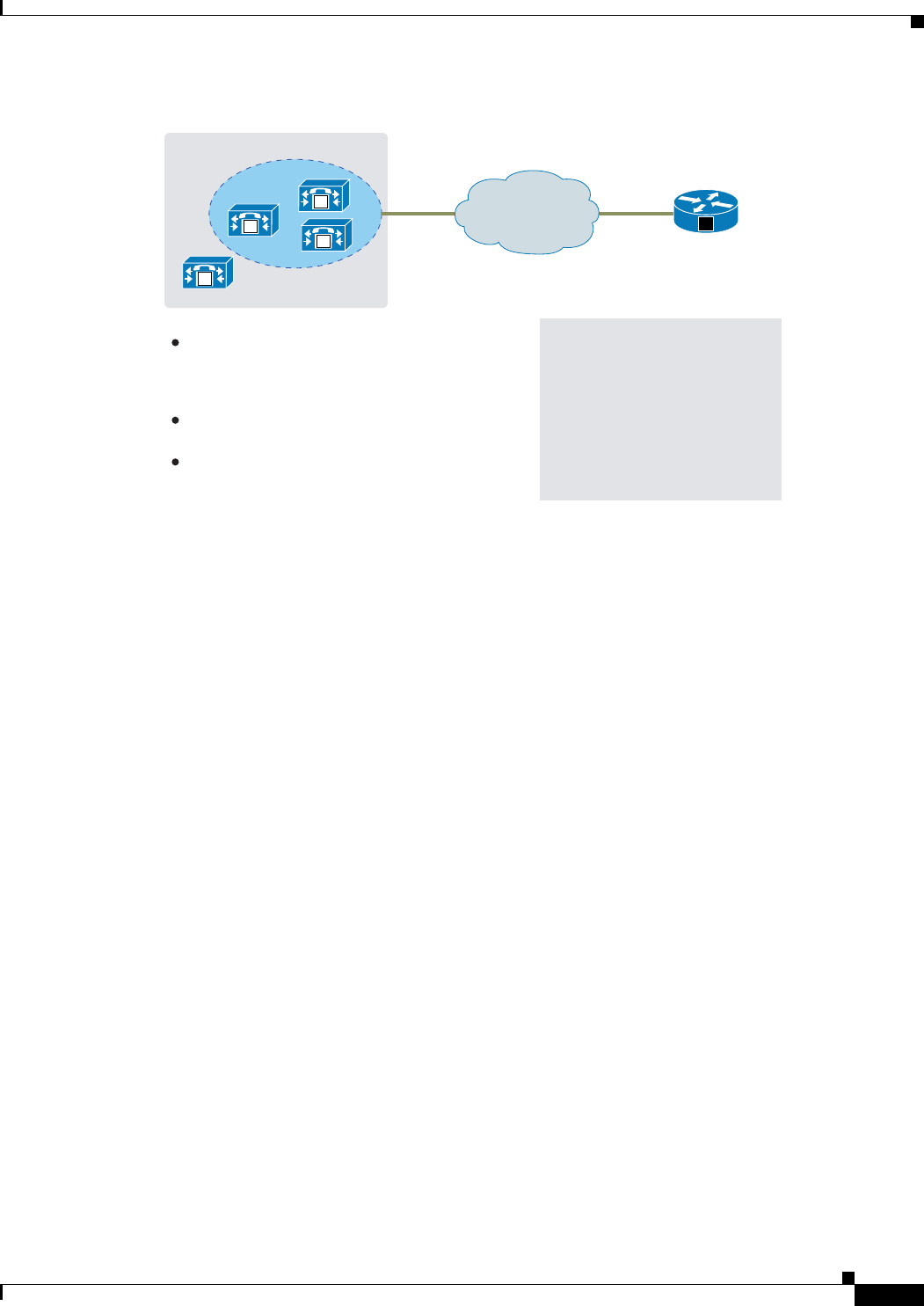
3-11
Cisco Unified Customer Voice Portal (CVP) 8.x Solution Reference Network Design (SRND)
OL-15989-06
Chapter 3 Distributed Deployments
Call Admission Control Considerations
Figure 3-2 Dial Peer Configuration
While the example in Figure 3-2 is simple to understand, the configuration can become challenging to
maintain for several hundred remote sites over an extended period of time. If the Cisco Unified CM
gatekeeper redundancy group is changed, all the remote H.323 gateway dial-peer targets must be
changed to match the new IP address of the server added to the redundancy group. A gatekeeper can help
reduce this challenge.
When using the gatekeeper for configuration, the H.323 gateway makes a Registration Admission Status
(RAS) request to the gatekeeper for an IP address to which to send the call. The gatekeeper automatically
responds with one of the Unified CM server addresses defined in the redundancy group for the
gatekeeper trunk. If the redundancy group is changed, Unified CM must re-register to the gatekeeper.
However, no further configuration is necessary on the remote gateway.
191325
San Jose Headquarters
.1
.3
.2
WAN V
M
M
M
M
Publisher
Madison
Dial Peer Configuration
dial-peer voice 1 voip
destination-pattern 1...
preference 1
session target ipv4:10.10.10.1
dial-peer voice 2 voip
destination-pattern 1...
preference 2
session target ipv4:10.10.10.2
Be sure to configure a dial peer for each
Cisco Unified CallManager server in the
redundancy group and device pool assigned
to the gateway in Cisco Unified CallManager.
Ensure that the IP addresses in the configurations
match on both sides of the link.
The Cisco Unified CallManager redundancy
group for the Madison gateway contains the
.1 and .2 servers.

3-12
Cisco Unified Customer Voice Portal (CVP) 8.x Solution Reference Network Design (SRND)
OL-15989-06
Chapter 3 Distributed Deployments
Call Admission Control Considerations

CHAPTER
4-1
Cisco Unified Customer Voice Portal (CVP) 8.x Solution Reference Network Design (SRND)
OL-15989-06
4
Designing Unified CVP for High Availability
Last revised on: April 4, 2011
This chapter describes guidelines and best practices for designing a high-availability Unified CVP
system.
This chapter covers the following topics:
• Overview, page 4-2
• Layer 2 Switch, page 4-3
• Originating Gateway, page 4-4
• SIP Proxy, page 4-5
• Unified CVP SIP Service, page 4-11
• Server Groups, page 4-14
• Gatekeeper, page 4-16
• Unified CVP H.323 Service, page 4-19
• Unified CVP IVR Service, page 4-21
• VoiceXML Gateway, page 4-23
• Content Services Switch (CSS), page 4-28
• Media Server, page 4-30
• Unified CVP VXML Server, page 4-31
• Automatic Speech Recognition (ASR) and Text-to-Speech (TTS) Server, page 4-32
• Cisco Unified Communications Manager, page 4-33
• Intelligent Contact Management (ICM), page 4-34

4-2
Cisco Unified Customer Voice Portal (CVP) 8.x Solution Reference Network Design (SRND)
OL-15989-06
Chapter 4 Designing Unified CVP for High Availability
What's New in This Chapter
What's New in This Chapter
Table 4-1 lists the topics that are new in this chapter or that have changed significantly from previous
releases of this document.
Overview
A high-availability design provides the highest level of failure protection. Your solution may vary
depending upon business needs such as:
• Tolerance for call failure
• Budget
• Topological considerations
Unified CVP can be deployed in many configurations that use numerous hardware and software
components. Each solution must be designed in such a way that a failure impacts the fewest resources
in the call center. The type and number of resources impacted depends on how stringent the business
requirements are and which design characteristics you choose for the various Unified CVP components,
including the network infrastructure. A good Unified CVP design is tolerant of most failures (defined
later in this chapter), but sometimes not all failures can be made transparent to the caller.
Unified CVP is a sophisticated solution designed for mission-critical call centers. The success of any
Unified CVP deployment requires a team with experience in data and voice internet working, system
administration, and Unified CVP application configuration.
Before implementing Unified CVP, use careful preparation and design planning to avoid costly upgrades
or maintenance later in the deployment cycle. Always design for the worst possible failure scenario, with
future scalability in mind for all Unified CVP sites.
In summary, plan ahead and follow all the design guidelines and recommendations presented in this
guide and in the latest version of the Cisco Unified Communications Solution Reference Network Design
(SRND) Based on Cisco Unified Communications Manager, available at:
http://www.cisco.com/en/US/products/sw/voicesw/ps556/products_implementation_design_guides
_list.html
For assistance in planning and designing your Unified CVP solution, consult your Cisco or certified
Partner Systems Engineer (SE).
Table 4-1 New or Changed Information Since the Previous Release of This Document
New or Revised Topic Description
Cisco Unified SIP Proxy (CUSP) Support,
page 4-7
Two deployment methods for the CUSP proxy
server
Server Groups, page 4-14 Dynamic routing feature that enables the
originating endpoint to have knowledge of the
status of the destination address before attempting
to send the SIP INVITE
VoiceXML Gateway, page 4-23 Support for mixed G.729 and G.711 codecs on
different legs of the same call, and new load
balancing assistance features

4-3
Cisco Unified Customer Voice Portal (CVP) 8.x Solution Reference Network Design (SRND)
OL-15989-06
Chapter 4 Designing Unified CVP for High Availability
Layer 2 Switch
A Note About the Unified CVP Call Server Component
The other chapters of this document treat the Unified CVP Call Server as a single component because
those chapters have no need to examine it in any more depth than that. When discussing Unified CVP
high availability however, it is important to understand that there are actually several parts to this
component:
• H.323 Service — Responsible for H.323 processing of incoming and outgoing calls as well as
registering with the gatekeeper. The H.323 Service was known as the Unified CVP Voice Browser
in previous versions of Unified CVP.
• SIP Service — Responsible for processing incoming and outgoing calls via SIP.
• ICM Service — Responsible for the interface to ICM. The ICM Service communicates with the
VRU PG using GED-125 to provide ICM with IVR control. The ICM Service was part of the
Application Server in previous releases of Unified CVP, but now it is a separate component.
• IVR Service — Responsible for the conversion of Unified CVP Microapplications to VoiceXML
pages, and vice versa. The IVR Service was known as the Application Server in previous Unified
CVP versions.
Layer 2 Switch
Figure 4-1 shows a high-level layout for a fault-tolerant Unified CVP system. Each component in the
Unified CVP site is duplicated for redundancy. The quantity of each of these components varies based
on the expected busy hour call attempts (BHCA) for a particular deployment. The following sections
describe the failover strategy for each of these components.
Figure 4-1 Redundant Unified CVP System
191323
SIP Proxy /
Gatekeeper
SIP Proxy /
Gatekeeper
VRU PG
VXML
server
Call
server
CSS /
ACE
V
PSTN
VRU PG
VXML
server
Call
server
CSS /
ACE
V

4-4
Cisco Unified Customer Voice Portal (CVP) 8.x Solution Reference Network Design (SRND)
OL-15989-06
Chapter 4 Designing Unified CVP for High Availability
Originating Gateway
In Figure 4-1, two switches provide the first level of network redundancy for the Unified CVP Servers:
• If one switch fails, only a subset of the components becomes inaccessible. The components
connected to the remaining switch can still be accessed for call processing.
• If a Content Services Switch (CSS) is used, its redundant partner must reside on the same VLAN in
order to send keep-alive messages to each other via Virtual Router Redundancy Protocol (VRRP), a
protocol similar to Hot Standby Router Protocol (HSRP). If one of the switches fails, the other CSS
is still functional.
• Although Figure 4-1 shows a CSS being used for redundancy, you may also use the Application
Content Engine (ACE). Refer to Application Content Engine (ACE), page 1-15.
For more information on data center network design, refer to the Data Center documentation available at
http://www.cisco.com/go/designzone
Note NIC teaming is not currently supported in the Unified CVP solution.
Note Cisco recommends that the NIC card and ethernet switch be set to 100 MB full duplex for 10/100 links,
or set to auto-negotiate for gigabit links.
Originating Gateway
The function of the originating gateway in a Unified CVP solution is to accept calls from the PSTN and
direct them to Unified CVP for call routing and IVR treatment.
This section covers the following topics:
• Configuration, page 4-4
• Call Disposition, page 4-19
Configuration
For the most current information on how to provide redundancy and reliability for originating gateways
and T1/E1 lines, refer to the latest version of the Cisco Unified Contact Center Enterprise Solution
Reference Network Design (SRND), available at
http://www.cisco.com/en/US/products/sw/custcosw/ps1844/products_implementation_design_gui
des_list.html
In addition, consider the following issues when designing gateways for high availability in a Unified
CVP solution:
• When used in ICM-integrated models, the originating gateway communicates with Unified CVP
using H.323 or SIP. Unlike MGCP, SIP and H.323 do not have redundancy features built into the
protocol. Instead, SIP and H.323 rely on the gateways and call processing components for
redundancy.
• When configuring the gateway, it is best to bind the H.323 or SIP signaling to the virtual loopback
interface, as illustrated in the following configuration examples:
H.323:

4-5
Cisco Unified Customer Voice Portal (CVP) 8.x Solution Reference Network Design (SRND)
OL-15989-06
Chapter 4 Designing Unified CVP for High Availability
SIP Proxy
interface Loopback0
ip address 10.0.0.10 255.255.255.255
h323-gateway voip interface
h323-gateway voip id sj-gk ipaddr 10.0.1.100 1719 <<- GK IP
h323-gateway voip h323-id sj-gw1
h323-gateway voip bind srcaddr 10.0.0.10
SIP:
voice service voip
sip
bind control source-interface Loopback0
bind media source-interface Loopback0
This configuration allows call signaling to operate independent of the physical interfaces. In this
way, if one interface fails, the other interface can handle the traffic. Each gateway interface should
be connected to a different physical switch to provide redundancy in the event that one switch or
interface fails. Each interface on the gateway is configured with an IP address on a different subnet.
The IP Router(s) for the network is then configured with redundant routes to the Loopback address
through the use of static routes or a routing protocol. If a routing protocol is used, pay careful
attention to the number of routes being exchanged with the gateway, and consider using filters to
limit the routing updates so that the gateway is only advertising the loopback address and not
receiving routes.
Call Disposition
If the originating gateway fails, the following conditions apply to call disposition:
• Calls in progress are dropped. There is nothing that can be done to preserve these calls because the
PSTN switch has lost the D-channel to all T1/E1 trunks on this gateway.
• New calls are directed by the PSTN carrier to a T1/E1 at an alternate gateway, provided the PSTN
switch has its trunks and dial plan configured to do so.
SIP Proxy
A SIP Proxy server plays a similar role to the gatekeeper in a Unified CVP solution. The SIP Proxy
server provides dial plan resolution on behalf of SIP endpoints, allowing dial plan information to be
configured in a central place instead of statically on each SIP device. A SIP Proxy server is not required
in a Unified CVP solution, but it is used in most solutions because of the benefits of centralized
configuration and maintenance. Multiple SIP Proxy servers can be deployed in the network to provide
load balancing, redundancy, and regional SIP call routing services. In a Unified CVP solution, the
choices for SIP call routing are:
• SIP Proxy Server
–
Advantages:
Weighted load balancing and redundancy.
Centralized dial-plan configuration.
SIP Proxy may already exist or be used for other applications for dial-plan resolution or
intercluster call routing.
–
Disadvantages:
Additional server and/or hardware required for SIP Proxy if not already deployed.

4-6
Cisco Unified Customer Voice Portal (CVP) 8.x Solution Reference Network Design (SRND)
OL-15989-06
Chapter 4 Designing Unified CVP for High Availability
SIP Proxy
• Static routes using Server Groups (DNS SRV records) on a DNS Server
–
Advantages:
Weighted load balancing and redundancy.
–
Disadvantages:
Might not be able to use an existing DNS server, depending on the location of the DNS server.
The ability to share or delegate DNS server administration rights might not be possible in some
organizations.
Dial-plan configuration needs to be configured on each device individually (Cisco Unified
Communications Manager, Unified CVP, and gateways).
DNS SRV lookup is performed for each and every call by Unified CVP. If the DNS server is
slow to respond, is unavailable, is across the WAN, or so forth, this will affect performance.
• Static routes using local DNS SRV records
–
Advantages:
Weighted load balancing and redundancy.
Does not depend on an external DNS Server, thus eliminating a point of failure, latency, and
DNS Server performance concerns.
–
Disadvantages:
Dial plan must be configured on each device individually (Cisco Unified Communications
Manager, Unified CVP, and gateways).
Note The options for static routes using SRV with a DNS Server, or using Server Groups, can introduce some
unexpected, long delays during failover and load balancing with UDP transport on the Unified CVP Call
Server when the primary destination is shut down or is off the network. With UDP, the per-hop delay is
3.5 seconds (if retry count is 2) or 7.5 seconds (if retry count is 3). This delay is on every call or every
other call (on average) during failure, depending on load balancing, and is accordance with section
17.1.1.1 of RFC 3261 regrading the T1 timer.
• Static routes using IP addresses
–
Advantages:
Does not depend on any other device (DNS or Proxy) to deliver calls to the destination.
–
Disadvantages:
No redundancy possible for SIP calls from Unified CVP.
Dial plan must be configured on each device individually.
This option makes sense only for environments that do not have redundancy (single server) or for
lab deployments.
Each device in the Unified CVP solution can use the above methods for determining where to send a call.
The Unified CVP Call Server interface to the SIP network is through the Unified CVP SIP Service,
which is discussed in the section on Unified CVP SIP Service, page 4-11.
Note Due to long delays when DNS is used with the Cisco Unified Presence proxy server, Cisco recommends
that you disable the DNS server on the Cisco Unified Presence server (CUP Server). Refer to CUP Server
release notes for more information.

4-7
Cisco Unified Customer Voice Portal (CVP) 8.x Solution Reference Network Design (SRND)
OL-15989-06
Chapter 4 Designing Unified CVP for High Availability
SIP Proxy
Cisco Unified SIP Proxy (CUSP) Support
The 8.0(1) release of Unified CVP has been validated with Cisco Unified SIP Proxy Server (CUSP
Server) version 1.1.4. This means that Unified CVP now supports both the CUP and CUSP proxy servers.
The following bullets show the differences between the two implementations:
• CUSP is a dedicated SIP proxy server, whereas the CUP proxy is a presence server with a proxy
engine.
• There is a difference in the hardware they run on: the CUSP server runs on the gateway, and the CUP
server runs in the MCS machine.
• CUP also has different default settings. For example, Record Route is on by default on the CUP
proxy, since it is needed for MS OCS federation. Record route is off by default on the CUSP proxy.
• For additional information, refer to the Solution sizing tool:
http://tools.cisco.com/cucst/faces/login.jsp
CUSP Deployment Methods
There are 2 deployment options supported with CUSP proxy in the CVP solution. These methods are
presented in the next two topics.
Deployment Option A - Redundant Sip Proxy Servers
This method:
• Consists of 2 gateways for redundancy, geographically separated, 1 proxy module each, using SRV
priority for redundancy of proxies, no HSRP.
• The ISR is dedicated to the proxy blade function and is not co-located as a VXML gateway, or as a
TDM gateway, due to platform validation restrictions on CUSP.
• TDM gateways are configured with SRV or with Dial Peer Preferences to use the primary and
secondary CUSP proxies.
• CUSP is set with Server Groups to find primary and back up Unified CVP, Unified CM and VXML
gateways.
• Unified CVP is set up with Server Group to use the primary and secondary CUSP proxies.
• Cisco Unified CM is set up with a Route Group with multiple SIP Trunks, to use the primary and
secondary CUSP proxies.
Example of Option A
In this example, ISR1 is on the east coast and ISR2 is on the west coast. The TDM gateways will use the
closest ISR, and only cross the WAN when needing to failover to the secondary priority blades.
The SRV records look like this:
east-coast.proxy.atmycompany.com
blade 10.10.10.10 priority 1 weight 10 (this blade is in ISR1 on east coast)
blade 10.10.10.20 priority 2 weight 10 (this blade is in ISR2 on west coast)
west-coast.proxy.atmycompany.com
blade 10.10.10.20 priority 1 weight 10 (this blade is in ISR2 on west coast)
blade 10.10.10.10 priority 2 weight 10 (this blade is in ISR1 on east coast)

4-8
Cisco Unified Customer Voice Portal (CVP) 8.x Solution Reference Network Design (SRND)
OL-15989-06
Chapter 4 Designing Unified CVP for High Availability
SIP Proxy
Deployment Option B - Redundant SIP Proxy Servers (Double Capacity)
This method:
• Consists of 2 gateways for redundancy, 2 proxy modules in each chassis. All 4 proxy servers are in
active mode with calls being balanced between them.
• Uses SRV to load balance across proxies with priority.
• The ISR is dedicated to the proxy blade function and is not co-located as a VXML gateway, nor as
a TDM gateway, due to platform validation restrictions on CUSP.
• TDM gateways are set with SRV or with Dial Peer Preferences to use the primary and secondary
CUSP proxies.
• CUSP is set with Server Groups to find primary and back up Unified CVP, Unified CM and VXML
gateways.
• Unified CVP is set up with Server Group to use the primary and secondary CUSP proxies.
• Cisco Unified CM is set up with Route Group with multiple SIP Trunks, to use the primary and
secondary CUSP proxies.
Example of Option B
With this example ISR1 is on the east coast and ISR2 is on the west coast. The TDM gateways will use
the closest ISR, and only cross the WAN when needing to failover to the secondary priority blades. The
SRV records look like this:
east-coast.proxy.atmycompany.com
blade 10.10.10.10 priority 1 weight 10 (this blade is in ISR1 on east coast)
blade 10.10.10.20 priority 1 weight 10 (this blade is in ISR1 on east coast)
blade 10.10.10.30 priority 2 weight 10 (this blade is in ISR2 on west coast)
blade 10.10.10.40 priority 2 weight 10 (this blade is in ISR2 on west coast)
west-coast.proxy.atmycompany.com
blade 10.10.10.30 priority 1 weight 10 (this blade is in ISR2 on west coast)
blade 10.10.10.40 priority 1 weight 10 (this blade is in ISR2 on west coast)
blade 10.10.10.10 priority 2 weight 10 (this blade is in ISR1 on east coast)
blade 10.10.10.20 priority 2 weight 10 (this blade is in ISR1 on east coast)
Performance Matrix for CUSP Deployment
Table #2 in the CUSP public data sheet “Performance Measured in the Number of New Call Attempts
per Second" shows performance data for the CUSP server.
CUSP baseline tests were done in isolation on the proxy, and capacity numbers (450 TCP, 500 UDP
transactions per second) should be used as the highest benchmark, and most stressed condition
allowable.
A CVP call, from the proxy server perspective, entails on average, 4 separate SIP calls:
• Caller inbound leg
• VXML outbound leg
• Ringtone outbound leg
• Agent outbound leg
When a consult with CVP queuing occurs, an additional 4 SIP transactions will be incurred for the
session, effectively doubling the number of calls.

4-9
Cisco Unified Customer Voice Portal (CVP) 8.x Solution Reference Network Design (SRND)
OL-15989-06
Chapter 4 Designing Unified CVP for High Availability
SIP Proxy
CUSP Design Considerations
Always turn the Record Route setting off on the proxy server to avoid a single point of failure and allow
fault tolerance routing, as well as increase the performance of the Proxy server. Using record route
setting on the proxy server doubles the impact to performance, as shown in the CUSP baseline matrix,
and also breaks the high availability model since the proxy becomes a single point of failure for the call,
if the proxy were to go down.
Record Route is turned off by default on CUSP.
Note Upstream Element Routing with SIP Heartbeats
With CUSP proxy, any response to a INVITE or OPTIONS is a good response, so CUSP will not mark
an element down when it receives a response. If the response is configured in the failover response code
list for the server group, then CUSP will failover to the next element in the group; otherwise, it will send
the response downstream as the final response.
The CUP proxy version 7.0(5) supports upstream route destination status using OPTIONS ping and
INVITE requests, but with a variation on how it was implemented in CUSP. CUP will only start pinging
a route only after it has failed a call attempt or a OPTIONS ping with any 5XX response. It will mark
the destination as out-of-service with any 5XX response to an INVITE or an OPTIONS message.
Configuration
The following sections discuss configuration of the SIP Proxy Server and Cisco IOS Gateways using SIP.
It is not meant to be an exhaustive list of configuration options but only highlights certain configuration
concepts.
SIP Proxy Server Configuration
The SIP Proxy Server should be configured with static routes that point at the appropriate devices
(Unified CVP Call Servers, VoiceXML gateways, Cisco Unified Communications Manager cluster, and
so forth). The SIP Proxy Server configuration allows you to specify the priority of the routes. In the case
where there are multiple routes to the same destination, you can configure the SIP Proxy to load-balance
across the destinations with equal priority or to send the calls in a prioritized manner using different
priorities.
The Cisco Unified Presence Server SIP Proxy cannot use DNS SRV for outbound calls; it must be
configured with multiple static routes in order to do load balancing and failover. (The Cisco Unified
Presence Server does support the DNS SRV feature, but it has not been tested in Unified CVP
deployments.) The static routes can point to an IP address or a regular DNS A host record.
To reduce the impact of a Proxy Server failure, Cisco recommends that you disable the RecordRoute
header from being populated by the SIP Proxy Server. (It is on by default on a Cisco Unified Presence
Server proxy.) In this way, the inbound calls route through a SIP Proxy; but once they reach the Unified
CVP Call Server (Call Server), the signaling is exchanged directly between the originating device and
the Call Server, and a SIP Proxy failure will not affect the calls in progress.

4-10
Cisco Unified Customer Voice Portal (CVP) 8.x Solution Reference Network Design (SRND)
OL-15989-06
Chapter 4 Designing Unified CVP for High Availability
SIP Proxy
Cisco IOS Gateway Configuration
With Cisco IOS gateways, dial-peers are used to match phone numbers, and the destination can be a SIP
Proxy Server, DNS SRV, or IP address. The following example shows a Cisco IOS gateway configuration
to send calls to a SIP Proxy Server using the SIP Proxy's IP address.
sip-ua
sip-server ipv4:10.4.1.100:5060
dial-peer voice 1000 voip
session target sip-server
...
The sip-server command on the dial-peer tells the Cisco IOS gateway to use the globally defined
sip-server that is configured under the sip-ua settings. In order to configure multiple SIP Proxies for
redundancy, you can change the IP address to a DNS SRV record, as shown in the following example.
The DNS SRV record allows a single DNS name to be mapped to multiple servers.
sip-ua
sip-server dns:cvp.cisco.com
dial-peer voice 1000 voip
session target sip-server
...
Alternatively, you can configure multiple dial-peers to point directly at multiple SIP Proxy servers, as
shown in the following example. This configuration allows you to specify IP addresses instead of relying
on DNS.
dial-peer voice 1000 voip
session target ipv4:10.4.1.100
preference 1
...
dial-peer voice 1000 voip
session target ipv4:10.4.1.101
preference 1
...
In the preceding examples, the calls are sent to the SIP Proxy server for dial plan resolution and call
routing. If there are multiple Unified CVP Call Servers, the SIP Proxy server would be configured with
multiple routes for load balancing and redundancy. It is possible for Cisco IOS gateways to provide load
balancing and redundancy without a SIP Proxy Server. The following example shows a Cisco IOS
gateway configuration with multiple dial-peers so that the calls are load-balanced across three Unified
CVP Call Servers.
dial-peer voice 1001 voip
session target ipv4:10.4.33.131
preference 1
...
dial-peer voice 1002 voip
session target ipv4:10.4.33.132
preference 1
...
dial-peer voice 1003 voip
session target ipv4:10.4.33.133
preference 1
...
DNS SRV records allow an administrator to configure redundancy and load balancing with finer
granularity than with DNS round-robin redundancy and load balancing. A DNS SRV record allows you
to define which hosts should be used for a particular service (the service in this case is SIP), and it allows

4-11
Cisco Unified Customer Voice Portal (CVP) 8.x Solution Reference Network Design (SRND)
OL-15989-06
Chapter 4 Designing Unified CVP for High Availability
Unified CVP SIP Service
you to define the load-balancing characteristics among those hosts. In the following example, the
redundancy provided by the three dial-peers configured above is replaced with a single dial-peer using
a DNS SRV record. Note that a DNS server is required in order to do the DNS lookups.
ip name-server 10.4.33.200
dial-peer voice 1000 voip
session target dns:cvp.cisco.com
With Cisco IOS gateways, it is possible to define DNS SRV records statically, similar to static host
records. This capability allows you to simplify dial-peer configuration while also providing DNS SRV
load balancing and redundancy. The downside of this method is that, if the SRV record needs to be
changed, it must be changed on each gateway instead of on a centralized DNS server. The following
example shows the configuration of static SRV records for SIP services handled by cvp.cisco.com, and
the SIP SRV records for cvp.cisco.com are configured to load-balance across three servers.
ip host cvp4cc2.cisco.com 10.4.33.132
ip host cvp4cc3.cisco.com 10.4.33.133
ip host cvp4cc1.cisco.com 10.4.33.131
(SRV records for SIP/TCP)
ip host _sip._tcp.cvp.cisco.com srv 1 50 5060 cvp4cc3.cisco.com
ip host _sip._tcp.cvp.cisco.com srv 1 50 5060 cvp4cc2.cisco.com
ip host _sip._tcp.cvp.cisco.com srv 1 50 5060 cvp4cc1.cisco.com
(SRV records for SIP/UDP)
ip host _sip._udp.cvp.cisco.com srv 1 50 5060 cvp4cc3.cisco.com
ip host _sip._udp.cvp.cisco.com srv 1 50 5060 cvp4cc2.cisco.com
ip host _sip._udp.cvp.cisco.com srv 1 50 5060 cvp4cc1.cisco.com
Call Disposition
Calls are handled as indicated for the following failure scenarios:
• Primary SIP Proxy Server fails
Active calls are preserved. Subsequent transfers of calls are successful, provided the backup SIP
Proxy is available and the RecordRoute header is not being populated by the SIP Proxy. If the
RecordRoute header is populated, signaling to the gateway will not be possible and subsequent
transfer attempts will fail.
• All SIP Proxy Servers fail or are unreachable
New calls arriving at the gateway are default-routed if survivability is configured on the gateway.
Unified CVP SIP Service
The Unified CVP SIP Service is the service on the Unified CVP Call Server (Call Server) that handles
all incoming and outgoing SIP messaging and SIP routing. The Call Server can be configured to use a
SIP Proxy server for outbound dial plan resolution, or it can be configured to use static routes based on
IP address or DNS SRV. Call Servers do not share configuration information about static routes;
therefore, if a change needs to be made to a static route, then the change must be made on each Call
Server's SIP Service. Cisco recommends that you use a SIP Proxy Server to minimize configuration
overhead.

4-12
Cisco Unified Customer Voice Portal (CVP) 8.x Solution Reference Network Design (SRND)
OL-15989-06
Chapter 4 Designing Unified CVP for High Availability
Unified CVP SIP Service
Configuration
If only a single SIP Proxy server is needed for outbound call routing from the Call Server, choose the
SIP Proxy configuration when configuring the SIP Service. In the Unified CVP Operations Console
Server (Operations Console), configure the following:
• Add a SIP Proxy Server and specify the IP address of the server.
Under the Call Server SIP Service settings, configure the following:
• Enable Outbound Proxy = True
• Use DNS SRV type query = False
• Outbound Proxy Host = SIP Proxy Server configured above
When using multiple SIP Proxy servers for outbound redundancy from the Call Server, configure the SIP
Proxy with a DNS name and configure DNS SRV records in order to reach the SIP Proxy Servers. The
DNS SRV records can exist on an external DNS Server, or they can be configured in a local DNS SRV
record on each CVP server. In the OAMP Console, configure the following:
• Add a SIP Proxy Server and specify DNS name of the server.
Under the SIP Service configuration, configure the following:
• Enable Outbound Proxy = True
• Use DNS SRV type query = True
• The DNS SRV record should then be configured with the list of SIP Proxy Servers.
To configure the Local DNS SRV record on each server, under the SIP Service configuration, check
Resolve SRV records locally.
To use a Server Group for redundant proxy servers:
1. Select resolve SRV records locally and type in the name of the server group for the outbound proxy
domain name.
2. Under System > Server Groups, create a new server group with two proxy servers that have priority
1 and 2.
3. Deploy the server group configuration to the Call Server.
Configuring High Availability for Calls in Progress
In the event that a Call Server fails with calls in progress, it is possible to salvage all calls if certain
gateway configuration steps have been taken. A Call Server can fail in one of several ways:
• The server can crash.
• The process can crash.
• The process can hang.
• There can be a network outage.

4-13
Cisco Unified Customer Voice Portal (CVP) 8.x Solution Reference Network Design (SRND)
OL-15989-06
Chapter 4 Designing Unified CVP for High Availability
Unified CVP SIP Service
The configuration discussed in this section protects against all of these situations. However, the
following two situations cannot be protected against:
• Someone stops the process with calls in progress. This situation occurs when a system administrator
forgets to put the Call Server out-of-service first to allow calls in progress to finish before stopping
the process.
• The Call Server exceeds the recommended call rate. Although there is a throttle for the absolute
number of calls allowed in the Call Server, there is no throttle for call rate. In general, exceeding the
recommended calls per second (cps) for an extended period of time can cause erratic and
unpredictable call behavior on certain components of the CVP solution if one of the components is
not sized correctly or if the call load is not balanced according to the weight and sizing of each call
processing component. (Refer to Chapter 14, “Sizing” for call server call rate details.)
For call survivability, configure the originating gateways as described in the latest version of the
Configuration and Administration Guide for Cisco Unified Customer Voice Portal (CVP), available at
http://www.cisco.com/en/US/products/sw/custcosw/ps1006/products_installation_and_configurati
on_guides_list.html
The survivability.tcl script itself also contains some directions and useful information.
In the event of most downstream failures (including a Call Server failure), the call is default-routed by
the originating gateway. Note that survivability is not applicable in the Unified CVP Standalone and
NIC-routing models because there is no Unified CVP H.323 or SIP Service involved anywhere in those
models.
There is also a mechanism for detection of calls that have been cleared without Unified CVP’s
knowledge:
• Unified CVP checks every 2 minutes for inbound calls that have a duration older than a configured
time (the default is 120 minutes).
• For those calls, Unified CVP sends an UPDATE message. If the message receives a rejection or is
undeliverable, then the call is cleared and the license released.
The CVP SIP Service can also add the Session Expires header on calls so that endpoints such as the
originating gateway may perform session refreshing on their own. RFC 4028 (Session Timers in the
Session Initiation Protocol) has more details on the usage of Session Expires with SIP calls.
Call Disposition
Calls are handled as indicated for the following scenarios:
• Calls in progress
If the Unified CVP SIP Service fails after the caller has been transferred (transfers include transfer
to an IP phone, VoiceXML gateway, or other egress gateway), then the call continues normally until
a subsequent transfer activity (if applicable) is required from the Unified CVP SIP Service. If the
caller has not hung up and is awaiting further activity, there is a period of 9 to 18 seconds of silence
before the caller is default-routed by survivability to an alternate location.
If the call has not yet been transferred, the caller hears 9 to 18 seconds of silence before being
default-routed by survivability to an alternate location. (Survivability does not apply in NIC-routing
models.)

4-14
Cisco Unified Customer Voice Portal (CVP) 8.x Solution Reference Network Design (SRND)
OL-15989-06
Chapter 4 Designing Unified CVP for High Availability
Server Groups
• New calls
New calls are directed by the SIP Proxy to an alternate Unified CVP Call Server. If no Call Servers
are available, the call is default-routed to an alternate location by survivability. (Survivability does
not apply in NIC-routing models.)
Server Groups
A Server Group is a dynamic routing feature that enables the originating endpoint to have knowledge of
the status of the destination address before attempting to send the SIP INVITE. Whether the destination
is unreachable over the network, or is out of service at the application layer, the originating SIP user
agent can have fore-knowledge of the status through a heartbeat mechanism.
Although, there was already an H.323 endpoint registration mechanism, the Server Groups features adds
a heartbeat mechanism with endpoints for SIP.
This feature allows faster failover on call control by eliminating delays due to failed endpoints.
Note • Server Groups are not automatically created. Server Groups are not created by the upgrade to
8.0(1). You must explicitly configure Server Groups for their deployment, and turn the feature on
after upgrading, in order to take advantage of the feature.
• Upgrade for customers who already use Local SRV. Release 7.0(2) customers who already have
an srv.xml file configured with local SRV must run the import command mentioned below in order
to put their configuration into the Unified CVP Operations Console Server database. Do this before
saving and deploying any new server groups to avoid overwriting your previous configuration.
The Unified CVP SIP Subsystem builds on the local SRV configuration XML available with Release
7.0(1).
A Server Group consists of one or more destination addresses (endpoints), and is identified by a Server
Group domain name. This domain name is also known as the SRV cluster domain name, or FQDN. The
SRV mechanism is used, but the DNS server resolution of the record is not performed. Server Groups
remains the same as the Release 7.0(1) local SRV implementation (srv.xml), but the Server Groups
feature adds the extra heartbeat mechanism on top of it, as an option.
Note • Server Groups in Unified CVP and Server Groups in CUSP proxy servers work the same way.
• Only endpoints defined in a Server Group may have heartbeats sent to them.
The srv.xml configuration file was used in the 7.0(1) release to configure SRV records locally, to avoid
the overhead of DNS SRV querying. However, the method of configuration was manual, and could not
be pushed from the Unified CVP Operations Console Server (Operations Console). Also, there was no
validation on the min and max values for fields.
Release 8.0(1) adds this configuration into the Operations Console SIP subsystem using the Server
Groups concept. The Server Group term just refers to the local SRV configuration. When you turn on
Server Groups with Heartbeating, you get the dynamic routing capability for Unified CVP to
preemptively monitor the status of endpoints. This feature only covers outbound calls from Unified CVP.
To cover the inbound calls to Unified CVP, the CUSP proxy server can send similar heartbeats to Unified
CVP, which can respond with status responses.

4-15
Cisco Unified Customer Voice Portal (CVP) 8.x Solution Reference Network Design (SRND)
OL-15989-06
Chapter 4 Designing Unified CVP for High Availability
Server Groups
Server Group Heartbeat Settings
The Server Group heartbeat default setting sets the ping up/down interval between any two pings; it is
not the setting between pings to the same endpoint. The Server Group does not wake up at a specific
interval and ping all elements because this approach would introduce a seesaw effect on CPU usage.
Also, it takes more resources when the system has to ping many end points. For example, for 3 total
elements across all groups, to proactively ping each element at 30 second intervals, you have to set the
ping interval at 10 seconds.
It is less deterministic for reactive mode since elements that are currently down can fluctuate so the ping
interval fluctuates with it.
Note • Heartbeat Behavior Settings for Server Groups. To turn off pinging when the element is up, set
Up Endpoint Heartbeat Interval to zero (reactive pinging). To turn off pinging when the element is
down, set the Down Endpoint Heartbeat Interval to zero (proactive pinging). To ping when the
element is either up or down, set the heartbeat intervals to greater than zero (adaptive pinging).
• Heartbeat Response Handling. Any endpoint that CVP may route calls to should respond to
OPTIONS with some response, either a 200 OK or some other response. Any response to a heartbeat
will indicate the other side is alive and reachable. A 200 OK is usually returned, but proxy servers
like the Cisco Unified Presence Server (CUP Server) or Cisco Unified SIP Proxy Server (CUSP
Server) may return a 483 Too Many Hops response, since the max-forwards header is set to zero in
an OPTIONS message. Sometimes the endpoints may not allow OPTIONS or PING, and may return
405 Method Not Allowed, which is fine as well.
By default, Server Group heartbeats are performed using a UDP socket connection. The transport type
can be changed to TCP from the Operations Console Server Groups window.
Whenever an element has an unreachable or overloaded status, that element is marked as being down
completely, that is for both UDP and TCP transports. When the element is up again, it is allowed to be
routable for both UDP and TCP.
Note TLS transport is not supported.
Duplicate Server Group Elements are excluded for heartbeating since the heartbeating is already
established for that element.
Note Refer to the Configuration and Administration Guide for Cisco Unified Customer Voice Portal for
typical configurations for the Server Groups feature. Document available at:
http://www.cisco.com/en/US/products/sw/custcosw/ps1006/products_installation_and_configuration_g
uides_list.html.
Static Routes Validation
The hostname or IP address of a static route is validated at startup and configuration deployment time
with a DNS lookup resolution. If the hostname does not resolve to an A record or an SRV record, then
the route is disabled and a notice is printed in the Unified CVP error log. The calls will not be routable
to this route in this state. If the host is in the local SRV Server Groups configuration as an SRV name,
then the host will not undergo this check, because it resolves to a local SRV name. IP addresses always
pass this validation.

4-16
Cisco Unified Customer Voice Portal (CVP) 8.x Solution Reference Network Design (SRND)
OL-15989-06
Chapter 4 Designing Unified CVP for High Availability
Gatekeeper
Design Considerations
Observe the following design considerations when implementing Server Groups:
• When you are using the Local SRV configuration, that configuration does not work with the DNS
SRV configuration. However, elements may be declared as A record hostnames instead of IP
addresses, and resolved through a DNS server lookup or in the OS etc host file.
• If you are using the CUP proxy, typically the SRV cluster name (such as proxy-servers.cisco.com)
will need to be defined in the service parameters section of the proxy configuration. Otherwise a 404
not found rejection may result. The CUSP proxy has a similar configuration in the CLI.
Diagnostics
The CVP log file has traces which show endpoint status events. Refer to the Unified CVP System CLI
instructions in the Configuration and Administration Guide for Cisco Unified Customer Voice Portal,
available at:
http://www.cisco.com/en/US/products/sw/custcosw/ps1006/products_installation_and_configuration_g
uides_list.html
Gatekeeper
An H.323 gatekeeper is used when using H.323 in any of the ICM-integrated deployment models except
Model #4 (VRU Only with NIC Controlled Routing), which does not use Unified CVP for call control
at all. Additionally, if SIP is used as the call control protocol, the gatekeeper is not required. An
originating gateway can perform all of its H.323 call routing by using VoIP dial-peers that contain static
IP addresses, whereas the Unified CVP H.323 Service must always perform a gatekeeper Remote Access
Service (RAS) lookup to route calls.
Note In one particular situation, when using the VBAdmin SetTransferLabel option, the H.323 Service
ignores the IP address returned from the gatekeeper and instead routes the IVR call leg back to the
originating gateway from which the call arrived. This feature ensures that no WAN bandwidth is used
during IVR treatment or queuing. A gatekeeper is still required in this situation because the H.323
Service has to perform the gatekeeper lookup function to obtain possible alternate endpoints in the event
that the attempt to transfer the call to the originating gateway fails.
Unified CVP can use one of the following types of gatekeeper high-availability mechanisms:
• Gatekeeper Redundancy Using HSRP, page 4-16
• Gatekeeper Redundancy Using Alternate Gatekeeper, page 4-17
Only HSRP and alternate gatekeeper are supported by Unified CVP. Alternate gatekeeper support was
introduced in Unified CVP 3.1 SR1.
Gatekeeper Redundancy Using HSRP
HSRP is a Cisco proprietary router redundancy protocol that allows two or more gatekeepers to share
the same IP address in an active/standby fashion. Using HSRP, two gatekeepers work together to present
the appearance of a single virtual IP address on the LAN.

4-17
Cisco Unified Customer Voice Portal (CVP) 8.x Solution Reference Network Design (SRND)
OL-15989-06
Chapter 4 Designing Unified CVP for High Availability
Gatekeeper
The gatekeepers share the same IP and MAC addresses. Therefore, if one of the gatekeepers fails, the
hosts on the LAN are able to continue forwarding packets to a consistent IP and MAC address. The
process of transferring the routing responsibilities from one device to another is transparent to the user.
The H.323 endpoints (such as the Unified CVP H.323 Service, Cisco Unified Communications Manager,
and gateways) register to a virtual IP address that represents the HSRP gatekeeper pair.
If one gatekeeper fails, its partner assumes primary control. The major disadvantage of HSRP is that both
gatekeepers in the HSRP failover pair must reside on the same IP subnet or VLAN, therefore they
generally cannot be separated geographically. Gatekeepers using HSRP for redundancy also do not share
any state information. Therefore, when a failover occurs, all of the devices must re-register with the
gatekeeper from scratch.
As of Unified CVP 3.1 SR1, HSRP is no longer recommended. Instead gatekeeper clustering and
alternate gatekeeper configuration on Unified CVP is the preferred method of gatekeeper redundancy.
Gatekeeper Redundancy Using Alternate Gatekeeper
The Unified CVP H.323 Service can be configured with a list of alternate gatekeepers (as many as
needed; there is no limit). When the H.323 Service starts, it attempts to register to the first gatekeeper in
the list. If the registration is not successful, it tries the remaining gatekeepers sequentially in the list until
a successful registration occurs.
The H.323 Service stays registered to that gatekeeper until either of the following events occurs:
• That gatekeeper has some type of failure. The H.323 Service recognizes a gatekeeper failure in the
following ways:
–
The periodic RAS Registration Request (RRQ) to the gatekeeper times out or is rejected.
–
An Admission Request (ARQ) on a transfer times out.
–
The gatekeeper pro-actively tells the H.323 Service to unregister, such as when the
administrator does a shutdown on the gatekeeper configuration.
• The user does another setGK from VBAdmin. This causes the H.323 Service to register with the first
gatekeeper in the list, if that gatekeeper is available; otherwise, it once again does a sequential
attempt.
Gatekeeper clustering is not required in order to use Unified CVP alternate gatekeeper. It is possible to
have two gatekeepers identically configured and also configure Unified CVP with alternate gatekeepers
to provide redundancy.
The Unified CVP H.323 Service does not support gatekeeper clustering messages, but there is no reason
that the gatekeepers cannot be part of a GUP cluster. In this way, other H.323 endpoints that natively
support clustering (such as Cisco Unified Communications Manager and Cisco IOS gateways) can take
advantage of the benefits of gatekeeper clustering. Unified CVP simply ignores clustering messages,
such as when one of the gatekeepers in the cluster becomes overloaded or when Unified CVP registers
with the gatekeeper.
Because Unified CVP does not automatically learn the other members of the gatekeeper cluster when it
registers to the gatekeeper, it is necessary to define the gatekeeper cluster members statically in Unified
CVP. Unified CVP uses one or more of the gatekeepers in the cluster as the alternate gatekeepers in its
list and detects failure according to the rules mentioned earlier in this section.

4-18
Cisco Unified Customer Voice Portal (CVP) 8.x Solution Reference Network Design (SRND)
OL-15989-06
Chapter 4 Designing Unified CVP for High Availability
Gatekeeper
Configuration
This section covers the following topics:
• HSRP Configuration, page 4-18
• Alternate Gatekeeper, page 4-18
HSRP Configuration
On the primary gatekeeper, enter these commands:
interface ethernet 0
ip address 10.0.1.98 255.255.255.0
! Unique IP address for this GK
standby 1 ip 10.0.1.100
! Member of standby group 1, sharing virtual address 10.0.1.100
standby 1 preempt
! Claim active role when it has higher priority.
standby 1 priority 110
! Priority is 110.
On the backup gatekeeper, enter these commands:
interface ethernet 0
ip address 10.0.1.99 255.255.255.0
standby 1 ip 10.0.1.100
standby 1 preempt
standby 1 priority 100
On both gatekeepers, enter identical gatekeeper configurations. For example:
gatekeeper
! Enter gatekeeper configuration mode.
zone local gk-sj cisco.com 10.0.1.100
! Define local zone using HSRP virtual address as gatekeeper RAS address.
For more information, refer to the latest version of the Configuration and Administration Guide for
Cisco Unified Customer Voice Portal (CVP), available at
http://www.cisco.com/en/US/products/sw/custcosw/ps1006/products_installation_and_configurati
on_guides_list.html
Alternate Gatekeeper
Configure alternate gatekeepers using Unified CVP VBAdmin, as shown in the following examples:
set GK "10.0.1.100, 10.0.2.100, 10.0.3.100"
This example sets up three gatekeepers to which the H.323 Service could possible register. In
each case, the H.323 Service registers to the first local zone that is configured in that gatekeeper.
It also uses the default RAS port 1719.
setGK "10.0.1.100:zone1:1718, 10.0.2.100"
This example causes the H.323 Service to attempt to register first to gatekeeper 10.0.1.100 on
port 1718 with local zone zone1. If that gatekeeper fails, the H.323 Service subsequently
attempts to register to 10.0.2.100 on port 1719, with the first local zone defined on that
gatekeeper.

4-19
Cisco Unified Customer Voice Portal (CVP) 8.x Solution Reference Network Design (SRND)
OL-15989-06
Chapter 4 Designing Unified CVP for High Availability
Unified CVP H.323 Service
Call Disposition
The call dispositions presented in this section apply to both HSRP and alternate gatekeeper.
A gatekeeper can fail in any of the following ways:
• The primary gatekeeper fails
–
Some calls in progress may not be transferred during the period that the endpoints are
re-registering to the backup gatekeeper. After the failed transfer, an error is returned to the ICM.
If the ICM script is coded to return an error (an END node does this) and survivability is
configured on the gateway, the call is default-routed.
–
New calls arriving at the incoming gateway and Unified CVP are serviced correctly, although it
is possible that some of the calls might invoke survivability during the period that the endpoints
are re-registering to the backup gatekeeper.
• All gatekeepers fail
–
The Unified CVP H.323 Service goes out of service.
–
Calls in progress are not transferred. After the failed transfer, an error is returned to the ICM.
If the ICM script is coded to return an error (an END node does this) and survivability is
configured on the gateway, the call is default-routed.
–
New calls arriving at the gateway are default-routed if survivability is configured on the
gateway.
• The primary gatekeeper degrades but does not fail
–
There are two conditions that usually cause this behavior: low memory due to memory leaks or
excessive debug levels causing CPU overload.
–
In this situation, call processing behavior is unpredictable due to the fact that there might be no
clean failover to the backup gatekeeper. If survivability is configured on the gateway, calls are
default-routed.
Unified CVP H.323 Service
When multiple Unified CVP Call Servers (Call Servers) are used for redundancy and scalability
purposes in Unified CVP, Cisco recommends using a gatekeeper for load balancing and failover services.
The H.323 Service is the component of the Call Server that processes H.323 messages and registers with
the gatekeeper.
While it is possible for the ingress PSTN gateways to send H.323 calls to the H.323 Service using
dial-peers with the specific IP address of the Call Server, doing so results in delays to callers during a
failure scenario. In this scenario, a dial-peer is statically configured on the ingress gateways to
load-balance across Unified CVP servers, or in a prioritized fashion so that the primary server is always
used under normal conditions. When the H.323 Service is no longer reachable for whatever reason, the
dial-peer will attempt to send the call to the failed server and wait for a timeout to occur before
proceeding to the next dial-peer configured, and this process occurs for each new call.
When a gatekeeper is used instead, the gateway dial-peer simply points to the gatekeeper, and the
gatekeeper is responsible for determining which Call Servers are active and it load balances across them.
The gatekeeper's registration process enables it to know which servers are available and does not suffer
from the same time-outs as dial-peers. Therefore, Cisco recommends using a gatekeeper instead of static
Cisco IOS dial-peers for redundancy and load balancing.

4-20
Cisco Unified Customer Voice Portal (CVP) 8.x Solution Reference Network Design (SRND)
OL-15989-06
Chapter 4 Designing Unified CVP for High Availability
Unified CVP H.323 Service
Configuration
Unified CVP H.323 configuration for high availability is performed primarily on the ingress gateways,
but it is also necessary to configure the H.323 Service to register to the gatekeeper.
Configuring High Availability for New Calls
The gatekeeper knows which Call Servers are in service or out of service. It is therefore important to let
a gatekeeper route incoming calls to a Call Server. By default, Unified CVP H.323 Services register to
the gatekeeper with a technology prefix (tech-prefix) of 2#. The Unified CVP H.323 Service must
register with a tech-prefix, and it is not possible to configure the H.323 Service without a tech-prefix.
A technology prefix is a way for the gatekeeper to categorize registering endpoints by functionality. In
general, no additional configuration is needed on the gatekeeper for incoming calls. The H.323 Service
registers to the gatekeeper with 2#, and the originating gateway prepends a 2# to the incoming Dialed
Number Identification Service (DNIS) digits. The gatekeeper automatically knows how to match the
gateway request to an available Call Server. On the gatekeeper, the command show gatekeeper
gw-type-prefix displays the route plan that the gatekeeper uses to route calls.
On the originating gateways, define the dial-peer for the Call Servers as follows:
dial-peer voice 11111 voip
session target ras
tech-prefix 2#
The command session target ras instructs the gateway to send the call to its gatekeeper. The command
tech-prefix 2# instructs the gateway to prepend 2# to the DNIS number when sending the call to the
gatekeeper.
Configuring High Availability for Calls in Progress
In the event that a Call Server fails with calls in progress, it is possible to salvage all calls if certain
gateway configuration steps have been taken. A Call Server can fail in one of the following ways:
• The server can crash.
• The process can crash.
• The process can hang.
• There can be a network outage.
The configuration discussed in this section protects against all of these situations. However, the
following two situations cannot be protected against:
• Someone stops the process with calls in progress. This situation occurs when a system administrator
forgets to put the Call Server out-of-service first to allow calls in progress to finish before stopping
the process.
• The Call Server exceeds the recommended call rate. Although there is a throttle for the absolute
number of calls allowed in the Call Server, there is no throttle for call rate. In general, exceeding
5 calls per second (cps) for an extended period of time causes the Call Server to have erratic and
unpredictable behavior. This situation can be prevented by proper sizing of the Unified CVP system.
For call survivability, configure the originating gateways as described in the latest version of the
Configuration and Administration Guide for Cisco Unified Customer Voice Portal (CVP), available at
http://www.cisco.com/en/US/products/sw/custcosw/ps1006/products_installation_and_configurati
on_guides_list.html

4-21
Cisco Unified Customer Voice Portal (CVP) 8.x Solution Reference Network Design (SRND)
OL-15989-06
Chapter 4 Designing Unified CVP for High Availability
Unified CVP IVR Service
The survivability.tcl script itself also contains some directions and useful information.
In the event of most downstream failures (including a Call Server failure), the call is default-routed by
the originating gateway. Note that survivability is not applicable in the Unified CVP Standalone and
NIC-routing models because there is no Unified CVP Call Server involved anywhere in those models.
Additional Cisco IOS Gateway Configuration
The command in the following example disables the TCP timeout for H.225 signaling on the gateway:
voice service voip
h323
no h225 timeout keepalive
This action allows the gateway to lose connectivity with the Call Server or Cisco Unified
Communications Manager but still retain active calls. If you do no t use this command, calls that are still
active that are otherwise unaffected by the failure (that is, the RTP stream is still streaming between the
endpoints) will be disconnected when the TCP session times out.
The following commands specify the RTP media timeout:
ip rtcp report interval 2000
gateway
timer receive-rtcp 4
When the gateway detects that RTCP messages have not been received in the specified interval, the call
is disconnected.
Call Disposition
If the Unified CVP H.323 Service fails, the following conditions apply:
• Calls in progress
If the Unified CVP H.323 Service fails after the caller has been transferred (transfers include
transfer to an IP phone, VoiceXML gateway, or other egress gateway), then the call continues
normally until a subsequent transfer activity (if applicable) is required from the Unified CVP H.323
Service. If the caller has not hung up and is awaiting further activity, there is a period of 9 to
18 seconds of silence before the caller is default-routed by survivability to an alternate location.
If the call has not yet been transferred, the caller hears 9 to 18 seconds of silence before being
default-routed by survivability to an alternate location. (Survivability does not apply in NIC-routing
models.)
• New calls
New calls are directed by the gatekeeper to an alternate Unified CVP Call Server. If no Call Servers
are available, the call is default-routed to an alternate location by survivability. (Survivability does
not apply in Unified CVP Standalone and NIC-routing models.)
Unified CVP IVR Service
With Unified CVP 3.1 and earlier, the IVR Service (previously called the Application Server) was
treated independently of the H.323 Service (previously called the Voice Browser) and VoiceXML
gateways. High availability was achieved by configuring the Unified CVP Voice Browser and VoiceXML

4-22
Cisco Unified Customer Voice Portal (CVP) 8.x Solution Reference Network Design (SRND)
OL-15989-06
Chapter 4 Designing Unified CVP for High Availability
Unified CVP IVR Service
gateways with a list of application server IP addresses and/or using the Content Services Switch (CSS).
With Unified CVP 4.0 and later releases, the IVR Service is tightly coupled with the SIP Service or
H.323 Service. If the IVR Service goes out of service, the H.323 or SIP Service will be taken out of
service as well so that no further calls are accepted by the Unified CVP Call Server.
Configuration
No additional configuration is needed in order to tell the H.323 or SIP Service which IVR Service to use.
By default, the H.323 and SIP Service use the IVR Service that resides on the same server. It is also no
longer necessary to configure the VoiceXML gateway with the IP address of the Call Server’s IVR
Service. When SIP is used, the SIP Service inserts the URL of the Call Server's IVR Service into a header
in the SIP INVITE message when the call is sent to the VoiceXML gateway. The VoiceXML gateway
extracts this information from the SIP INVITE and uses it when determining which Call Server to use.
When H.323 is used, the VoiceXML gateway examines the source IP address of the incoming call from
the Call Server. This IP address is then used as the address for the Call Server’s IVR Service.
The following example illustrates the VoiceXML bootstrap service that is invoked when a call is
received:
service bootstrap flash:bootstrap.tcl
paramspace english index 0
paramspace english language en
paramspace english location flash
paramspace english prefix en
Unlike Unified CVP 3.1 and earlier releases, with Unified CVP 4.0 and later releases you do not have to
configure the IP address of the Call Server. The bootstrap.tcl learns the IP address of the source Call
Server and uses it as its call server. There is no need for a CSS or backup Call Server configuration
because receiving a call from the Call Server means that the server is up and operational.
The following files in flash memory on the gateway are also involved with high availability: handoff.tcl,
survivability.tcl, recovery.vxml, and several .wav files. Use Trivial File Transfer Protocol (TFTP) to load
the proper files into flash. Configuration information for each file can be found within the file itself. For
more information, refer to the latest version of the Configuration and Administration Guide for Cisco
Unified Customer Voice Portal (CVP), available at
http://www.cisco.com/en/US/products/sw/custcosw/ps1006/products_installation_and_configurati
on_guides_list.html
Call Disposition
If the Unified CVP IVR Service fails, the following conditions apply to the call disposition:
• Calls in progress are default-routed to an alternate location by survivability on the originating
gateway. (Survivability does not apply in NIC-routing models.)
• New calls are directed to an in-service Unified CVP IVR Service.

4-23
Cisco Unified Customer Voice Portal (CVP) 8.x Solution Reference Network Design (SRND)
OL-15989-06
Chapter 4 Designing Unified CVP for High Availability
VoiceXML Gateway
VoiceXML Gateway
The VoiceXML gateway parses and renders VoiceXML documents obtained from one or several sources:
the Unified CVP Call Server (from its IVR Service), the Unified CVP VXML Servers, or some other
external VoiceXML source. Rendering a VoiceXML document consists of retrieving and playing
prerecorded audio files, collecting and processing user input, and/or connecting to an ASR/TTS server
for voice recognition and dynamic text-to-speech conversion.
For a discussion of using mixed codecs in CVP deployments, see Mixed G.729 and G.711 Codec
Support, page 7-6. For a discussion of the benefits and drawbacks of each codec, refer to Voice Traffic,
page 9-2.
Note VXML GW must not have load balanced path, as this route on VXML GW will cause a call HTTP Client
Error. If the VXML GW has load balancing route to CVP Call Server, it may use a different source
address to send HTTP message to CVP Call Server, which would cause CVP to return a 500 Server Error
message. In VXML GW, it is not possible to bind any specific interface for the HTTP Client side. So, if
VXML GW sends NEW_CALL using one interface and CALL_RESULT using another interface, CVP
will return a 500 Server Error.
Configuration
High availability configuration for VoiceXML gateways is controlled by the gatekeeper for H.323, the
SIP proxy for SIP, and/or the Unified CVP Call Server (Call Server). Whether the VoiceXML gateways
are distributed or centralized also influences how high availability is achieved.
In the event that a Call Server is unable to connect to a VoiceXML gateway, an error is returned to the
ICM script. In the ICM script, separate the Send to VRU node from the first Run External script node in
order to catch the VoiceXML gateway connection error. If an END script node is used off the X-path of
the Send to VRU node, the call is default-routed by survivability on the originating gateway.
(Survivability does not apply in VRU-only models.) A Queue to Skill group node could also be used, but
that method is effective only if there is an agent available. Otherwise, ICM tries to queue the caller, and
that attempt fails because the Call Server is once again unable to connect to a VoiceXML gateway. An
END node could then also be used off the X-path of the Queue to Skill Group node to default-route the
call.
Note There are two features for the VXML Server that assist with load balancing:
• Limiting Load Balancer Involvement
• Enhanced HTTP Probes for Load Balancers
Refer to the configuration options ip_redirect and license_depletion_probe_error in the User Guide for
Unified CVP VXML Server and Cisco Unified Call Studio, available at:
http://www.cisco.com/en/US/products/sw/custcosw/ps1006/products_user_guide_list.html

4-24
Cisco Unified Customer Voice Portal (CVP) 8.x Solution Reference Network Design (SRND)
OL-15989-06
Chapter 4 Designing Unified CVP for High Availability
VoiceXML Gateway
Centralized VoiceXML Gateways
In this configuration, the VoiceXML gateways reside in the same data center as the Unified CVP Call
Server.
H.323 VoiceXML Gateways
On the gatekeeper, configure a zone prefix list that contains the H.323 IDs of all VoiceXML gateways at
the data center. For example, assume that there are three VoiceXML gateways in the data center with
H.323 IDs of VoiceXMLgw1, VoiceXMLgw2, and VoiceXMLgw3, and that the ICM label for the
Network VRU is 5551000. In this example, the gatekeeper distributes calls in essentially a round-robin
scheme among all three VoiceXML gateways, provided they are all in service:
zone prefix gkzone-name 5551000* gw-priority 10 VoiceXMLgw1 VoiceXMLgw2 VoiceXMLgw3
SIP VoiceXML Gateways
If you are using Cisco Unified Presence Server: On the SIP proxy server, configure a static route for the
Network VRU label for each gateway. If the VRU label is 5551000, the static route pattern would be
5551000* in order to allow for the correlation-id to be appended and routed to the VoiceXML gateway.
If you are using SIP static routes on the Unified CVP Call Server: Under the SIP Service configuration
for the Call Server, configure a static route for each Network VRU label and gateway. If the VRU label
is 5551000, the static route pattern would be 5551000>. The > is a wildcard representing one or more
digits, and it is needed so that the correlation-id appended to the DNIS number can be passed to the
VoiceXML gateway correctly.
Note Other wildcard characters can be used. Refer to the topic Valid Formats for Dialed Numbers in the
Operations Console online help for complete wildcard format and precedence information.
In the case of both SIP proxy or Unified CVP static routes, the next-hop address of the route can be either
the IP address of the gateway or a DNS SRV record. If you are using an IP address, you must create
multiple static routes, one for each VoiceXML gateway. In the case of DNS SRV, only one route per
Network VRU label is needed, and the SRV record will provide for load-balancing and redundancy.
Distributed VoiceXML Gateways (Co-Resident Ingress Gateway and VoiceXML)
In this configuration, the gateway that processes the incoming call from the PSTN is separated from the
Unified CVP servers by a low-bandwidth connection such as a WAN, and the VoiceXML gateway that
is used is the same as the ingress gateway. The purpose of this configuration is to keep the media stream
at the edge to avoid consuming bandwidth on the WAN.
H.323 VoiceXML Gateways
Use the SetTransferLabel in VBAdmin (not gatekeeper zone prefixes) to control the selection of the
VoiceXML gateway. The SetTransferLabel command is specified per Network VRU label. When the
Unified CVP Call Server receives a label from ICM that matches what is configured in the
SetTransferLabel, the Call Server performs a gatekeeper lookup but ignores the destination gateway
returned by the gatekeeper and sends the call back to the gateway that originated the call. The H.323
Service determines the originating gateway by looking at the source IP address of the H.323 signaling.

4-25
Cisco Unified Customer Voice Portal (CVP) 8.x Solution Reference Network Design (SRND)
OL-15989-06
Chapter 4 Designing Unified CVP for High Availability
VoiceXML Gateway
SIP VoiceXML Gateways
With SIP, the equivalent of the SetTransferLabel command is the Send to Originator configuration under
the SIP Service. If the Network VRU label is 5551000, the Send to Originator pattern would be
5551000>. The > is a wildcard pattern representing one or more digits. The SIP Service determines the
originating gateway by looking at the Remote-Party-ID header in the SIP INVITE message.
Note Other wildcard characters can be used. Refer to the topic Valid Formats for Dialed Numbers in the
Operations Console online help for complete wildcard format and precedence information.
Distributed VoiceXML Gateways (Separate Ingress Gateway and VoiceXML)
In this configuration, the gateway that processes the incoming call from the PSTN is separated from the
Unified CVP servers by a low-bandwidth connection such as a WAN, and the VoiceXML gateway that
is used is different than the ingress gateway but located at the same site as the ingress gateway. The
purpose of this configuration is to keep the media stream at the same site and not consume bandwidth
on the WAN and to optimize VoiceXML gateway sizing when it is appropriate to separate ingress and
VoiceXML gateways. In this case, setTransferLabel and Send to Originator cannot be used because you
would not want the IVR leg of the call to go back to the ingress gateway. Additionally, it is also
impractical to use a gatekeeper or SIP Proxy to control the call routing because you would have to
configure separate Network VRUs, Network VRU labels, and customers in ICM for each remote site.
Instead, use SetSigDigits functionality.
With this method, the Call Server strips the leading significant digit(s) from the incoming DNIS number.
The value that is stripped is saved and prepended when subsequent transfers for the call occur.
H.323 VoiceXML Gateways
When H.323 is used, the significant digit is prepended with a # sign so that the gatekeeper treats it as a
technology prefix. The VoiceXML gateway at the remote site should register to the gatekeeper with the
same technology prefix as the leading significant digit(s) that were stripped from the DNIS number. The
gatekeeper then routes the IVR leg of the call to the correct VoiceXML gateway. If you are using Cisco
Unified Communications Manager (Unified CM), remember that Unified CVP indiscriminately
prepends the sigdigits value to all transfers, including those to Unified CM. Therefore, when using
Unified CM in this scenario, it is necessary to define a gatekeeper-controlled trunk for each of the
VoiceXML gateway tech-prefixes and to add zone prefix configuration to the gatekeeper for the
Unified CM agents, as illustrated in the following example.
Configuration of ingress gateway:
dial-peer voice 1000 voip
tech-prefix 2# (gets the call to CVP)
translate-outgoing called 99
Apply a translation-rule to the incoming DNIS number to prepend the value 3:
translation-rule 99
Rule 1 8002324444 38002324444
Assuming the DNIS number is 8002324444, the final DNIS string routed to Unified CVP is
2#38002324444.
Configuration in VB Admin:
setTechPrefix 2#

4-26
Cisco Unified Customer Voice Portal (CVP) 8.x Solution Reference Network Design (SRND)
OL-15989-06
Chapter 4 Designing Unified CVP for High Availability
VoiceXML Gateway
setSigDigits 1
Strip one digit from the DNIS number after stripping the 2# technology prefix.
Configuration of VoiceXML gateway:
Register to the gatekeeper with tech-prefix 3#:
h323-gateway voip tech-prefix 3#
Cisco Unified CM configuration (if used):
Create a separate gatekeeper-controlled trunk corresponding to each of the tech-prefixes used by the
VXML gateways.
Gatekeeper configuration:
Define zone prefixes to route calls appropriately to Unified CM agents (only if using Cisco Unified CM).
Summary of call routing:
1. A call arrives at Unified CVP with a DNIS string of 2#38002324444.
2. Unified CVP first strips the tech-prefix (2#), leaving 38002324444.
3. Unified CVP then strips one digit (3) from the beginning of the DNIS string, leaving 8002324444.
4. 8002324444 is passed to ICM for call routing.
5. When it is time to transfer, assume ICM returns the label 5551000102. Unified CVP prepends 3#,
giving 3#5551000102. This value is then passed to the gatekeeper for address resolution.
6. The gatekeeper resolves this label to the VoiceXML gateway that registered with tech-prefix 3#.
7. The VoiceXML gateway strips the 3#, leaving 5551000102 for the destination address.
SIP VoiceXML Gateways
When SIP is used, the significant digits are prepended to the DNIS number, and a SIP Proxy can be
configured to route based on those prepended digits. The static routes in the SIP Proxy for the VoiceXML
gateway should have the digits prepended. Because these prepended digits were originally populated by
the ingress gateway, the SIP Proxy can use them to determine which VoiceXML gateway to use based
on the incoming gateway. In this way, calls arriving at a particular site can always be sent back to that
site for VoiceXML treatment, with the result that no WAN bandwidth is used to carry the voice RTP
stream. Keep in mind that Unified CVP indiscriminately prepends the sigdigits value to all transfers,
including those to Unified CM. Therefore, when using Unified CM in this scenario, it is necessary to
strip the prepended digits when the call arrives so that the real DNIS number of the phone can be used
by Unified CM to route the call, as illustrated in the following example.
Configuration of ingress gateway:
Apply a translation-rule to the incoming DNIS to prepend the value 3333:
translation-rule 99
rule 1 8002324444 33338002324444
dial-peer voice 1000 voip
translate-outgoing called 99
Assuming the DNIS number is 8002324444, the final DNIS string routed to Unified CVP is
33338002324444.

4-27
Cisco Unified Customer Voice Portal (CVP) 8.x Solution Reference Network Design (SRND)
OL-15989-06
Chapter 4 Designing Unified CVP for High Availability
VoiceXML Gateway
Configuration of Unified CVP SIP Service:
To configure the SIP service, in the Operations Console, select the Call Server > SIP tab. Many of the
settings are on the Advanced Configuration window.
Configuration of VoiceXML gateway:
Configure the VXML gateway to match the DNIS string, including the prepended digits:
dial-peer voice 3000 voip
incoming-called number 33335551000T
service bootstrap
...
Configure the Unified CVP bootstrap.tcl application with the sigdigits parameter, telling it how many
digits to strip off of the incoming DNIS string:
application
service bootstrap flash:bootstrap.tcl
param sigdigits 4
...
Cisco Unified CM configuration (if used):
Configure Unified CM to strip the prepended digits, either by using the Significant Digits configuration
on the SIP Trunk configuration page or by using translation patterns.
SIP Proxy configuration:
Define static routes on the SIP Proxy, with the prepended digit present, to be sent to the appropriate
VoiceXML gateway. Because transfers to agents on a Unified CM cluster will also have the digits
prepended, the static routes for agent phones must also contain the prepended digits.
Summary of call routing:
1. A call arrives at Unified CVP with a DNIS number of 33338002324444.
2. Unified CVP then strips four digits (3333) from the beginning of the DNIS string, leaving
8002324444.
3. 8002324444 is passed to ICM for call routing.
4. When it is time to transfer, assume ICM returns the label 5551000102. Unified CVP prepends 3333,
giving 33335551000102.
5. The SIP Service then resolves the address using the SIP Proxy or local static routes, and it sends the
call to the VoiceXML gateway.
6. The VoiceXML gateway bootstrap.tcl will strip the 3333, leaving 5551000102 for the destination
address.
H.323 Alternate Endpoints
In all cases for either centralized or distributed deployments, configure alternate endpoints for each of
the VoiceXML gateways in case the VoiceXML gateway rejects the incoming request (perhaps due to
error or overload):
endpoint alt-ep h323id VoiceXMLgw1 ip-address-VoiceXMLgw2
endpoint alt-ep h323id VoiceXMLgw2 ip-address-VoiceXMLgw3
endpoint alt-ep h323id VoiceXMLgw3 ip-address-VoiceXMLgw1

4-28
Cisco Unified Customer Voice Portal (CVP) 8.x Solution Reference Network Design (SRND)
OL-15989-06
Chapter 4 Designing Unified CVP for High Availability
Content Services Switch (CSS)
Call Disposition
If the VoiceXML gateway fails, the following conditions apply to the call disposition:
• Calls in progress are default-routed to an alternate location by survivability on the ingress gateway.
(Survivability does not apply in NIC-routing models.)
• New calls find an alternate VoiceXML gateway.
Hardware Configuration for High Availability on the Voice Gateways
The individual hardware components have the following high-availability options:
• Redundant power supplies and on-hand spares
• Separate components for higher availability
• Dedicated components, which have fewer interaction issues
Example 1: Separate PSTN Gateway and VoiceXML Gateway
A PSTN gateway and a separate VoiceXML gateway provide greater availability than a combine PSTN
and VoiceXML gateway.
Example2: Duplicate Components for Higher Availability
• Two 8-T1 PSTN gateways provide greater availability than one 16-T1 PSTN gateway.
• Two 96-port Unified CVP VXML Servers provide greater availability than one 192-port
Unified CVP VXML Server.
• Larger designs can use N+1 spares for higher availability.
Example3: Geographic Redundancy for Higher Availability
Geographical redundancy and high availability can be achieved by purchasing duplicate hardware for
Side A and Side B.
Content Services Switch (CSS)
The VoiceXML gateway is the only box in the Unified CVP system that makes requests to the CSS.
When the VoiceXML gateway needs to make a request for media, ASR/TTS, or VoiceXML, it looks in
its configuration to determine to where it should make the request. When a CSS is used, the IP address
that is configured on the VoiceXML gateway is a virtual IP address that points to a service configured
on the CSS. There are three types of services that the VoiceXML gateway client can request from the
CSS:
• Media Server
• ASR/TTS
• Unified CVP VXML Server
If the primary CSS that is servicing these requests should fail, the client VoiceXML gateway must still
be able to obtain media and VoiceXML from the servers.
Note Cisco recommends using the CSS to find an available VXML Server via heartbeat and to perform load
balancing. Subsequent requests and responses between the VoiceXML gateway and the VXML Server
should bypass the CSS.

4-29
Cisco Unified Customer Voice Portal (CVP) 8.x Solution Reference Network Design (SRND)
OL-15989-06
Chapter 4 Designing Unified CVP for High Availability
Content Services Switch (CSS)
Note There are two features for the VXML Server that assist with load balancing:
• Limiting Load Balancer Involvement
• Enhanced HTTP Probes for Load Balancers
Refer to the configuration options ip_redirect and license_depletion_probe_error in the User Guide for
Unified CVP VXML Server and Cisco Unified Call Studio, available at:
http://www.cisco.com/en/US/products/sw/custcosw/ps1006/products_user_guide_list.html
Configuration
You can configure high availability for the CSS by using the Virtual IP (VIP) Redundancy method, as
described in the latest version of the Configuration and Administration Guide for Cisco Unified
Customer Voice Portal (CVP), available at
http://www.cisco.com/en/US/products/sw/custcosw/ps1006/products_installation_and_configurati
on_guides_list.html
Also refer to the latest version of the CSS Redundancy Configuration Guide, available at
http://www.cisco.com/en/US/products/hw/contnetw/ps792/products_installation_and_configuratio
n_guides_list.html
Essentially, a master/backup pair of CSSs functions very much like an HSRP gatekeeper pair. They must
reside on the same VLAN and exchange heartbeats using Virtual Router Redundancy Protocol (VRRP),
a protocol very similar to HSRP. If the primary CSS fails, the backup CSS recognizes the failure within
three seconds and begins processing client requests to its configured virtual IP addresses. The
configuration of the master and backup CSSs must always be kept in synchronization.
Call Disposition
If the master CSS fails, then the following conditions apply to the call disposition:
• Calls in progress encounter various behaviors, depending on the type of service the VoiceXML
gateway client requested:
–
Media server requests are unaffected.
The VoiceXML gateway has a very short-lived interaction with the CSS for audio files. Upon
receiving a media server request from the gateway, the CSS simply provides an HTTP redirect
IP address for the VoiceXML gateway. At that point, the gateway fetches the audio file directly
from the media server, bypassing any further interaction with the CSS. Additionally, media file
requests to the CSS are very infrequent because the VoiceXML gateway caches previously
retrieved media files.
–
Unified CVP IVR Service requests are unaffected.
Only the initial VoiceXML document request to a Unified CVP IVR Service uses the CSS. The
CSS first picks a Unified CVP IVR Service to service the request. The first document passes
through the CSS on its return to the VoiceXML gateway. However, subsequent VoiceXML
requests are made directly from the VoiceXML gateway client to the Unified CVP IVR Service.
If the CSS fails during the very brief period that the first VoiceXML document is being returned,
the VoiceXML gateway simply retries the request. If the backup (now primary) CSS selects the
same Unified CVP IVR Service as the previous one, there is an error due to a duplicate call
instance. In that case, the caller is default-routed by survivability on the originating gateway.

4-30
Cisco Unified Customer Voice Portal (CVP) 8.x Solution Reference Network Design (SRND)
OL-15989-06
Chapter 4 Designing Unified CVP for High Availability
Media Server
–
ASR/TTS requests typically fail but might be recoverable.
When the VoiceXML gateway first makes an ASR/TTS request to the CSS, a TCP connection
is opened from the VoiceXML gateway to the Media Resource Control Protocol (MRCP) server.
That TCP connection goes through the CSS and persists until the caller disconnects or is
transferred to an agent. If the primary CSS fails, that TCP connection is terminated. The
VoiceXML gateway returns an error code, which you could write a script to work around. The
worst-case scenario is that the caller is default-routed to an alternate location by survivability
on the originating gateway.
–
Unified CVP VXML Server requests may fail.
The VoiceXML gateway is "sticky" to a particular Unified CVP VXML Server for the duration
of the VoiceXML session. It uses CSS cookies to provide that stickiness.
Configuring Adaptive Session Redundancy (ASR) on CSS peers in an active-backup VIP
redundancy and virtual interface redundancy environment will provide a stateful failover of
most existing calls. ASR ensures that, if the master CSS fails, the backup CSS has the necessary
flow-state information to continue most active calls without interruption when the backup CSS
assumes mastership.
For the few cases where the existing call cannot continue, the VoiceXML gateway returns an
error code, which you could write a script to work around. The worst-case scenario is that the
caller is default-routed to an alternate location by survivability on the originating gateway.
The Adaptive Session Redundancy (ASR) feature of CSS ensures that port licenses are not
temporarily and needlessly unavailable on the VXML Server. The VXML Server is stateful, and
the ASR feature minimizes VXML Server license port usage during a CSS failover.
New calls are directed transparently to the VIPs on the backup CSS,and service is unaffected.
Media Server
Audio files can be stored locally in flash memory on the VoiceXML gateway or on an HTTP/TFTP file
server. By definition, audio files stored locally are highly available. However, HTTP/TFTP file servers
provide the advantage of centralized administration of audio files.
Configuration When Using Unified CVP Microapplications
The VoiceXML gateway sends HTTP requests to an HTTP media server to obtain audio files. It uses the
following VoiceXML gateway configuration parameters to locate a server when not using a CSS:
ip host mediaserver <ip-address-of-primary-media-server>
ip host mediaserver-backup <ip-address-of-secondary-media-server>
The backup server is invoked only if the primary server is not accessible, and this is not a load-balancing
mechanism. Each new call attempts to connect to the primary server. If failover occurs, the backup server
is used for the duration of the call; the next new call will attempt to connect to the primary server.
Note that mediaserver is not a fixed name, and it needs to match whatever name was assigned to the
media_server ECC variable in the ICM script.
The VoiceXML gateway also uses the following VoiceXML gateway configuration parameters to locate
a server when using a CSS:
ip host mediaserver <ip-address-of-CSS-VIP-for-media-server>
ip host mediaserver-backup <ip-address-of-CSS-VIP-for-media-server>

4-31
Cisco Unified Customer Voice Portal (CVP) 8.x Solution Reference Network Design (SRND)
OL-15989-06
Chapter 4 Designing Unified CVP for High Availability
Unified CVP VXML Server
Because the CSS almost always locates a media server on the first request, a backup server is rarely
invoked. However, it is helpful to configure the backup server when using a CSS for deployments where
there are multiple data centers with a CSS in each.
Call Disposition When Using Unified CVP Microapplications
If the media server fails, the following conditions apply to the call disposition:
• Calls in progress should recover automatically. The high-availability configuration techniques
described above should make the failure transparent to the caller. If the media request does fail, use
scripting techniques to work around the error (for example, retry the request, transfer to an agent or
label, or use TTS).
• New calls are directed transparently to the backup media server, and service is not affected.
• If the media server is located across the WAN from the VoiceXML gateway and the WAN connection
fails, the gateway continues to use prompts from gateway cache until the requested prompt becomes
stale, at which time the gateway attempts to re-fetch the media and the call fails if survivability is
not enabled. If survivability is enabled, the call are default-routed.
Configuration When Using Cisco Unified Call Studio Scripting
When scripting in Cisco Unified Call Studio, unlike with ICM scripting, there is no concept of “-backup”
for media files. The best the script writer can do is to point Properties->AudioSettings->Default Audio
Path URI in the application to a single media server or the CSS VIP address for a farm of media servers.
Unified CVP VXML Server
The VoiceXML gateway makes HTTP requests to the Unified CVP VXML Server to obtain VoiceXML
documents.
Configuration
The Unified CVP VXML Server high-availability configuration and behavior differ between Standalone
deployments and deployments that are integrated with ICM, as described in the following sections.
Standalone Self-Service Deployments
For instructions on configuring primary and backup Unified CVP VXML Servers, see the latest version
of the Cisco Unified CVP Configuration and Administration Guide, available at
http://www.cisco.com/en/US/products/sw/custcosw/ps1006/products_installation_and_configuration_g
uides_list.html.
Specifically, it is the CVPPrimaryVXMLServer and CVPBackupVXMLServer gateway parameters that
control the high availability characteristics of the Unified CVP VXML Server. If Unified CVP
VXML Server load balancing and more robust failover capabilities are desired, a CSS or ACE device

4-32
Cisco Unified Customer Voice Portal (CVP) 8.x Solution Reference Network Design (SRND)
OL-15989-06
Chapter 4 Designing Unified CVP for High Availability
Automatic Speech Recognition (ASR) and Text-to-Speech (TTS) Server
may be used. (For configuration details, see the latest version of the Cisco Unified CVP Configuration
and Administration Guide.) Load balancing can also be achieved without a CSS or ACE device by
varying the primary and backup Unified CVP VXML Server configurations across multiple gateways.
Deployments Using ICM
When a Unified CVP VXML Server is used in conjunction with ICM, the ICM script will pass a URL
to the VoiceXML gateway in order to invoke the VoiceXML applications. You can configure the ICM
script to first attempt to connect to Unified CVP VXML Server A, and if the application fails out the
X-path of the Unified CVP VXML Server ICM script node, Unified CVP VXML Server B should be
tried. The IP address in the URL can also represent Unified CVP VXML Server VIPs on the CSS.
Call Disposition
If the Unified CVP VXML Server fails, the following conditions apply to the call disposition:
• Calls in progress in a Standalone deployment are disconnected. Calls in progress in an
ICM-integrated deployment can be recovered using scripting techniques to work around the error as
shown in the script above (for example, retry the request, transfer to an agent or label, or force an
error with an END script node to invoke survivability on the originating gateway).
• New calls are directed transparently to an alternate Unified CVP VXML Server.
Note Without a CSS or ACE device, callers might experience a delay at the beginning of the call and
have to wait for the system to timeout while trying to connect to the primary Unified CVP
VXML Server.
Automatic Speech Recognition (ASR) and Text-to-Speech (TTS)
Server
The VoiceXML gateway sends MRCP requests to the ASR/TTS servers in order to perform voice
recognition and text-to-speech instructions that are defined in a VoiceXML document.
Configuration
The ASR/TTS high-availability configuration and behavior differ between Standalone and
ICM-integrated deployments, as described in the following sections.
Standalone Self-Service Deployments
A CSS or ACE device is required in Standalone deployments to provide failover capabilities for
ASR/TTS. For instructions on configuring the CSS or ACE device for ASR/TTS and on configuring the
ASR/TTS Server in a Standalone deployment, see the latest version of the Configuration and
Administration Guide for Cisco Unified Customer Voice Portal (CVP), available at:
http://www.cisco.com/en/US/products/sw/custcosw/ps1006/products_installation_and_configurati
on_guides_list.html

4-33
Cisco Unified Customer Voice Portal (CVP) 8.x Solution Reference Network Design (SRND)
OL-15989-06
Chapter 4 Designing Unified CVP for High Availability
Cisco Unified Communications Manager
Deployments Using ICM
The VoiceXML gateway uses gateway configuration parameters to locate an ASR/TTS server both when
using a CSS or ACE device and when not using a one. Note that the backup server is invoked only if the
primary server is not accessible and if this is not a load-balancing mechanism. Each new call attempts
to connect to the primary server. If failover occurs, the backup server is used for the duration of the call;
the next new call will attempt to connect to the primary server.
The hostnames (such as asr-en-us) are fixed and cannot be modified. The only portion that may be
modified is the locale. In the following example, there is a set of primary and backup English ASR/TTS
servers and a set of Spanish servers. Configure the CSS, if used, according to the instructions in the latest
version of the Configuration and Administration Guide for Cisco Unified Customer Voice Portal (CVP),
available at
http://www.cisco.com/en/US/products/sw/custcosw/ps1006/products_installation_and_configurati
on_guides_list.html
When a CSS is used, the IP addresses mentioned the following example would be the virtual IP address
for the ASR/TTS service on the CSS.
ip host asr-en-us <ip-address-of-primary-English-ASR-server>
ip host asr-en-us-backup <ip-address-of-secondary-English-ASR-server>
ip host tts-en-us <ip-address-of-primary-English-TTS-server>
ip host tts-en-us-backup <ip-address-of-secondary-English-TTS-server>
ip host asr-es-es <ip-address-of-primary-Spanish-ASR-server>
ip host asr-es-es-backup <ip-address-of-secondary-Spanish-ASR-server>
ip host tts-es-es <ip-address-of-primary-Spanish-TTS-server>
ip host tts-es-es-backup <ip-address-of-secondary-Spanish-TTS-server>
For a discussion of using mixed codecs in CVP deployments, see Mixed G.729 and G.711 Codec
Support, page 7-6. For a discussion of the benefits and drawbacks of each codec, refer to Voice Traffic,
page 9-2.
Note The ASR speech license is not released until the caller is transferred to the agent.
Call Disposition
If the ASR/TTS MRCP server fails, the following conditions apply to the call disposition:
• Calls in progress in Standalone deployments are disconnected. Calls in progress in ICM-integrated
deployments can be recovered using scripting techniques to work around the error (for example,
retry the request, transfer to an agent or label, switch to prerecorded prompts and DTMF-only input
for the remainder of the call, or label or force an error with an END script node to invoke
survivability on the originating gateway).
• New calls in Standalone or ICM-integrated deployments are directed transparently to an alternate
ASR/TTS server if a CSS is being used. New calls in ICM-integrated deployments are directed
transparently to an alternate ASR/TTS server if "-backup" gateway hostnames have been used.
Cisco Unified Communications Manager
Unified CVP transfers callers to Cisco Unified Contact Center Enterprise (Unified CCE) agent phones
or desktops using H.323 or SIP. The Unified CVP Call Server (Call Server) receives an agent label from
the ICM and routes the call using a gatekeeper or SIP proxy. The call is then sent to the appropriate Cisco

4-34
Cisco Unified Customer Voice Portal (CVP) 8.x Solution Reference Network Design (SRND)
OL-15989-06
Chapter 4 Designing Unified CVP for High Availability
Intelligent Contact Management (ICM)
Unified Communications Manager (Unified CM) in the cluster, which connects the caller to the agent.
The Call Server proxies the call signaling, so it remains in the call signaling path after the transfer is
completed. However, the RTP stream flows directly from the originating gateway to the phone. This fact
becomes very significant in discussions of high availability.
Unified CVP version 8.0(1) also supports the Analysis Manager. Refer to The Analysis Manager,
page 13-8.
Configuration
For the most current information on providing Unified CM for high availability, refer to the latest version
of the Cisco Unified Contact Center Enterprise Solution Reference Network Design (SRND) available
at:
http://www.cisco.com/en/US/products/sw/custcosw/ps1844/products_implementation_design_guides_li
st.html.
Call Disposition
If the Unified CM process fails on the server that is either hosting the call or hosting the phone, the
following conditions apply to the call disposition:
• Calls in progress are preserved. Skinny Client Control Protocol (SCCP) phones have the ability to
preserve calls even when they detect the loss of their Unified CM. The caller-and-agent conversation
continues until either the caller or agent goes on-hook. The Unified CVP Call Server recognizes that
Unified CM has failed, assumes the call should be preserved, and maintains the signaling channel
to the originating gateway. In this way, the originating gateway has no knowledge that Unified CM
has failed. Note that additional activities in the call (such as hold, transfer, or conference) are not
possible. Once the parties go on-hook, the phone then re-homes to another Unified CM server. When
the agent goes on-hook, Real-Time Control Protocol (RTCP) packets cease transmitting to the
originating gateway, which causes the gateway to disconnect the caller 9 to 18 seconds after the
agent goes on-hook. If survivability has been configured on the gateway and the caller is waiting for
some additional activity (the agent might think the caller is being blind-transferred to another
destination), the caller is default-routed to an alternate location.
• New calls are directed to an alternate Unified CM server in the cluster.
Intelligent Contact Management (ICM)
Cisco Intelligent Contact Management (ICM) software provides enterprise-wide distribution of
multichannel contacts (inbound/outbound telephone calls, Web collaboration requests, email messages,
and chat requests) across geographically separated contact centers. ICM software is an open
standards-based solution whose capabilities include routing, queuing, monitoring, and fault tolerance.
Configuration
For the most current information on configuring ICM for high availability, refer to the latest version of
the Cisco Unified Contact Center Enterprise Solution Reference Network Design (SRND), available at
http://www.cisco.com/en/US/products/sw/custcosw/ps1844/products_implementation_design_gui
des_list.html

4-35
Cisco Unified Customer Voice Portal (CVP) 8.x Solution Reference Network Design (SRND)
OL-15989-06
Chapter 4 Designing Unified CVP for High Availability
Intelligent Contact Management (ICM)
Call Disposition
There are many components in Cisco ICM, and call disposition varies depending on the component that
fails. Although there are a few exceptions, the following conditions apply to the call disposition:
• If the Voice Response Unit (VRU) Peripheral Gateway (PG) or any component on the VRU PG fails,
calls in progress are default-routed by survivability on the originating gateway.
• If the Logger fails, calls in progress are unaffected.
• If the primary router fails, calls in progress are unaffected. If both the Side A and Side B routers fail,
calls in progress are default-routed by survivability on the originating gateway.
• New calls are directed to the backup ICM component.

4-36
Cisco Unified Customer Voice Portal (CVP) 8.x Solution Reference Network Design (SRND)
OL-15989-06
Chapter 4 Designing Unified CVP for High Availability
Intelligent Contact Management (ICM)

CHAPTER
5-1
Cisco Unified Customer Voice Portal (CVP) 8.x Solution Reference Network Design (SRND)
OL-15989-06
5
Interactions with Cisco Unified ICM
Last revised on: July 13, 2011
This chapter discusses Cisco Unified Intelligent Contact Management (ICM) from the perspective of its
relationship with Unified CVP. In some cases, the choice of deployment model has implications for
Unified ICM; and in other cases, certain choices about the Unified ICM configuration carry implications
for the Unified CVP deployment.
This chapter covers the following major topics:
• Network VRU Types, page 5-2
• Network VRU Types and Unified CVP Deployment Models, page 5-6
• Hosted Implementations, page 5-10
• Deployment Models and Sizing Implications for Calls Originated by Cisco Unified
Communications Manager and ACDs, page 5-13
• Using Third-Party VRUs, page 5-15
• DS0 Trunk Information, page 5-15
• Trunk Utilization Routing and Reporting, page 5-16
• Enhanced User-to-User Information, page 5-17
• Custom SIP Headers, page 5-19
• Courtesy Callback, page 5-21
• Post Call Survey, page 5-25

5-2
Cisco Unified Customer Voice Portal (CVP) 8.x Solution Reference Network Design (SRND)
OL-15989-06
Chapter 5 Interactions with Cisco Unified ICM
What's New in This Chapter
What's New in This Chapter
Table 5-1 lists the topics that are new in this chapter or that have changed significantly from previous
releases of this document.
Note The Generic PG is a consolidated PG that requires both separate peripherals for Unified CM and the
VRU. It is best not to use the Generic PG for Unified CVP. Use the VRU PG instead.
Network VRU Types
This section first discusses Network VRU types for Unified ICM in general, then it discusses them as
they relate to Unified CVP deployments in particular.
This section covers the following topics:
• Overview of Unified ICM Network VRUs, page 5-3
• Unified CVP as a Type 10 VRU, page 5-3
• Unified CVP as Type 5 VRU, page 5-4
• Unified CVP as Type 3 or 7 VRU (Correlation ID Mechanism), page 5-5
• Unified CVP as Type 8 or 2 VRU (Translation Route ID Mechanism), page 5-6
In this document, the terms voice response unit (VRU) and interactive voice response (IVR) are used
interchangeably.
Table 5-1 New or Changed Information Since the Previous Release of This Document
New or Revised Topic Description
DS0 Trunk Information, page 5-15 Pass the PSTN gateway trunk and DS0
information to Unified ICM from the arriving SIP
call.
Trunk Utilization Routing and Reporting,
page 5-16
Push the status of memory, DS0, DSP and the CPU
to Unified CVP, for routing, reporting and
scripting.
Enhanced User-to-User Information, page 5-17 Using UUI to pass information.
Custom SIP Headers, page 5-19 Pass selected SIP header information to and from
Unified ICM for modification within ICM scripts.
Courtesy Callback, page 5-21 Offer callers, who meet your criteria, the option to
be called back by the system instead of waiting on
the phone for an agent.
Post Call Survey, page 5-25 Configure a call flow so that after the agent hangs
up, the caller is transferred to a DNIS that prompts
the caller with a post call survey.

5-3
Cisco Unified Customer Voice Portal (CVP) 8.x Solution Reference Network Design (SRND)
OL-15989-06
Chapter 5 Interactions with Cisco Unified ICM
Network VRU Types
Overview of Unified ICM Network VRUs
This section describes the types of Unified ICM VRUs used for Unified CVP applications. Unified ICM
perceives calls that need IVR treatment as having two portions: the Switch leg and the VRU leg. The
Switch is the entity that first receives the call from the network or caller. The VRU is the entity that plays
audio and preforms prompt-and-collect functions. Unified CVP can participate in the Switch role or the
VRU role, or both, from the perspective of Unified ICM. In a network deployment, multiple Unified CVP
devices can also be deployed to provide the Switch and VRU portions independently.
The call delivery to VRU can be based on either a Correlation ID or a translation route mechanism,
depending on the network capability to pass the call reference identification to the VRU. Call reference
identification is needed because Unified ICM has to correlate the two legs of the same call in order to
provide instructions for completing the call. In the Unified ICM application, the VRU has to supply this
call reference ID to Unified ICM when the VRU asks for instructions on how to process the incoming
call that it receives from the switch. This mechanism enables Unified ICM to retrieve the appropriate
call context for this same call, which at this stage is to proceed to the IVR portion of the call. These two
correlation mechanisms operate as follows:
• Correlation ID
This mechanism is used if the network can pass the call reference ID to the VRU, which is usually
the case when the VRU is located in the network with the switch and the call signaling can carry this
information (for example, the Correlation ID information is appended to the dialed digits when
Unified ICM is used). This mechanism usually applies to calls being transferred within the VoIP
network.
• Translation Route ID
This mechanism is used when the VRU is reachable across the PSTN (for example, the VRU is at
the customer premise) and the network cannot carry the call reference ID information in delivering
the call to the VRU. A temporary directory number (known as a translation route label) has to be
configured in Unified ICM to reach the VRU, and the network routes the call normally to the VRU
as with other directory number routing in the PSTN. When the VRU asks for instructions from
Unified ICM, the VRU supplies this label (which could be a subset of the received digits) and
Unified ICM can correlate the two portions of the same call. Normally the PSTN carrier will
provision a set of translation route labels to be used for this purpose.
Note The deployed VRU can be located in the network (Network VRU) or at the customer premises. In the
latter scenario, a Network Applications Manager (NAM) would be deployed in the network and a
Customer ICM (CICM) would be deployed at the customer premises. The corresponding Correlation ID
or Translation Route ID should be used accordingly, as described earlier, depending on the location of
the VRU.
Unified CVP as a Type 10 VRU
Type 10 was designed to simplify the configuration requirements in Unified CVP Comprehensive Model
deployments. The Type 10 VRU is the preferred VRU Type for all new installations, but it requires Cisco
Unified ICM 7.1 or later releases. Unified ICM 7.0 deployments should use the VRU types outlined in
subsequent sections of this chapter. Prior to Unified ICM 7.5(3), the Type 10 VRU did not support ICM
Customers, which is a Unified ICM feature that allows you to have multiple Network VRUs and is
typically used in Hosted deployments. Deployments that need to use ICM Customers can use the other
VRU types outlined below, or they can use Unified ICM 7.5(3) or later releases. Although

5-4
Cisco Unified Customer Voice Portal (CVP) 8.x Solution Reference Network Design (SRND)
OL-15989-06
Chapter 5 Interactions with Cisco Unified ICM
Network VRU Types
ICM Customers are now supported, one cannot initiate a two-step transfer from the Unified CVP VRU
switch leg to a completely separate Unified CVP (for example, a two-steps CVP-to-CVP transfer using
SendToVRU). A translation route would have to be used in order for such a two-step transfers to work.
Type 10 Network VRU has the following behavior:
• There is a Handoff of routing client responsibilities to the Unified CVP switch leg.
• There is an automatic transfer to the Unified CVP VRU leg, resulting in a second transfer in the case
of calls originated by the VRU, ACD, or Cisco Unified Communications Manager (Unified CM).
• For calls originated by Unified CM, the Correlation ID transfer mechanism is used. The Correlation
ID is automatically added to the end of the transfer label defined in the Type 10 Network VRU
configuration.
• The final transfer to the Unified CVP VRU leg is similar to a Type 7 transfer, in that a RELEASE
message is sent to the VRU prior to any transfer.
In Unified CVP implementations without the ICM Customers feature (that is, in Unified CVP
implementations with a single Network VRU), a single Type 10 Network VRU should be defined, and
all Unified ICM VRU scripts should be associated with it. It requires one label for the Unified CVP
Switch leg routing client, which will transfer the call to the Unified CVP VRU leg. If calls will be
transferred to Unified CVP from Unified CM, it also needs another label for the Unified CM routing
client, and this label should be different from the label used for the CVP Routing Client. This label will
transfer the call to the Unified CVP Switch leg. The Unified ICM Router will send this label to
Unified CM with a Correlation ID concatenated to it. Unified CM must be configured to handle these
arbitrary extra digits.
The Unified CVP Switch leg peripheral should be configured to point to the same Type 10 Network
VRU. Also, all incoming dialed numbers for calls that are to be transferred to Unified CVP should be
associated with a Customer Instance that points to the same Type 10 Network VRU.
For calls that originate at a Call Routing Interface VRU or at a TDM ACD, a TranslationRouteToVRU
node should be used to transfer the call to Unified CVP’s Switch leg peripheral. For all other calls, use
either a SendToVRU node, a node that contains automatic SendToVRU behavior (such as the queuing
nodes), or a RunExternalScript.
Unified CVP as Type 5 VRU
Note Cisco Unified ICM 7.1 introduces the Type10 Network VRU. This VRU must be used for all new
implementations of Unified CVP using Unified ICM 7.1 or greater. The Type5 VRU must be used for
existing customer deployments that have upgraded or for deployments that are not running Unified ICM
7.1 or later.
Type 5 and Type 6 are similar in the sense that the VRU entity functions both as a switch (call control)
and as the VRU (IVR). However, they differ on how to connect to the VRU.
In Type 6, the Switch and the VRU are the same device, therefore the call is already at the VRU. No
Connect and Request Instructions message sequence is needed from the point of view of Unified ICM.
On the other hand, in Type 5, the Switch and the VRU are different devices even though they are in the
same service node from the viewpoint of Unified ICM (that is, they both interact with Unified ICM
through the same PG interface). Therefore, Unified ICM uses a Connect and Request Instructions
sequence to complete the IVR call.

5-5
Cisco Unified Customer Voice Portal (CVP) 8.x Solution Reference Network Design (SRND)
OL-15989-06
Chapter 5 Interactions with Cisco Unified ICM
Network VRU Types
Note In a Unified CVP application, there are two legs of the call as perceived by Unified ICM: the Switch leg
and the VRU leg. In the case where Unified CVP acts as the service node application (that is, when
Unified CVP receives the call from the network directly and not via pre-routing), Unified CVP will
appear to Unified ICM as Type 5 because the call control (Unified CVP) and the VRU device are
different. Hence, Unified CVP must be configured as VRU Type 5 in the Unified ICM and NAM
configuration for the Switch leg. The VRU leg requires a different setup, depending on the deployment
model (for example, the VRU leg could be Type 7 in the Comprehensive Unified ICM enterprise
deployment model). For examples of configuring Unified CVP as Type 5, refer to the latest version of
the Configuration and Administration Guide for Cisco Unified Customer Voice Portal (CVP), available
at
http://www.cisco.com/en/US/products/sw/custcosw/ps1006/products_installation_and_configuration_g
uides_list.html.
Neither Correlation ID nor Translation Route ID is needed when Unified CVP acts as a Type 5 VRU to
Unified ICM and the NAM. However, a dummy label is sometimes required.
Unified CVP as Type 3 or 7 VRU (Correlation ID Mechanism)
Note Cisco Unified ICM 7.1 introduces the Type10 Network VRU. This VRU must used for all new
implementations of Unified CVP using Unified ICM 7.1 or greater, except as VRU Only (Model #4a,
described below). The Type 3 or 7 VRU must be used for existing customer deployments that have
upgraded or for deployments that are not running Unified ICM 7.1 or later.
When the VRU functions as an IVR with the Correlation ID mechanism, Unified ICM uses Type 3 and
Type 7 to designate sub-behaviors of the VRU via the PG in the Correlation ID scheme. Both Type 3 and
Type 7 VRUs can be reached via the Correlation ID mechanism, and a PG is needed to control the VRU.
However, the difference between these two types is in how they release the VRU leg and how they
connect the call to the final destination.
In Type 3, the switch that delivers the call to the VRU can take the call from the VRU and connect it to
a destination (or agent).
In Type 7, the switch cannot take the call away from the VRU. When the IVR treatment is complete,
Unified ICM must disconnect or release the VRU leg before the final connect message can be sent to the
Switch leg to instruct the switch to connect the call to the destination.
When used as an Intelligent Peripheral IVR, Unified CVP can function with either Type 3 or 7, but it is
somewhat more efficient under Type 7 because it gets a positive indication from Unified ICM when its
VRU leg is no longer needed (as opposed to waiting for the VoiceXML gateway to inform it that the call
has been pulled away).
As stated previously, there are two legs of the call: the Switch leg and the VRU leg. Different Unified
CVP hardware can be used for each leg, but from the perspective of Unified ICM functionality, there will
be a Unified CVP via PG acting as VRU Type 5 (that is, a service node) along with potentially a different
Unified CVP via another PG acting as VRU Type 7 to complete the IVR application (self service,
queuing, and so forth).

5-6
Cisco Unified Customer Voice Portal (CVP) 8.x Solution Reference Network Design (SRND)
OL-15989-06
Chapter 5 Interactions with Cisco Unified ICM
Network VRU Types and Unified CVP Deployment Models
For configuration examples of the Unified CVP application with VRU Type 3 or Type 7, refer to the
latest version of the Configuration and Administration Guide for Cisco Unified Customer Voice Portal
(CVP), available at
http://www.cisco.com/en/US/products/sw/custcosw/ps1006/products_installation_and_configurati
on_guides_list.html
Unified CVP as Type 8 or 2 VRU (Translation Route ID Mechanism)
Note Cisco Unified ICM 7.1 introduces the Type10 Network VRU. This VRU must be used for all new
implementations of Unified CVP using Unified ICM 7.1 or greater, except as VRU Only (Model #4a,
described below). The Type 8 or 2 VRU must be used for existing customer deployments that have
upgraded or for deployments that are not running Unified ICM 7.1 or later.
When the VRU functions as an IVR with the Translation Route ID mechanism, Unified ICM uses Type 8
or Type 2 to designate sub-behaviors of the VRU via the PG in the translation route scheme. Both Type 2
and Type 8 VRUs can be reached via the Translation Route mechanism, and PG is needed to control the
VRU. However, they differ in how they connect the call to the final destination.
In Type 8, the switch that delivers the call to the VRU can take the call from the VRU and connect it to
a destination/agent.
Type 2 is used when the switch does not have the ability to take the call away from the VRU to deliver
it to an agent. In that case, when the IVR treatment is complete, Unified ICM sends the final connect
message to the VRU (rather than to the original switch) to connect the call to the destination. The VRU
effectively assumes control of the switching responsibilities when it receives the call. This process is
known as a handoff.
Similarly to the Correlation ID case, there are two legs of the call: the Switch leg and the VRU leg.
Unified CVP can be used for either the Switch leg or the VRU leg. For example, when a Network
Interface Controller (NIC), NAM, or CICM is involved, Unified CVP should be configured as Type 2 or
Type 8 in the VRU leg.
For configuration examples of the Unified CVP application with VRU Type 8 or Type 2, refer to the
latest version of the Configuration and Administration Guide for Cisco Unified Customer Voice Portal
(CVP), available at
http://www.cisco.com/en/US/products/sw/custcosw/ps1006/products_installation_and_configurati
on_guides_list.html
Network VRU Types and Unified CVP Deployment Models
This section describes how Network VRU types relate to the Unified CVP deployment models described
the chapter on Functional Deployment Models, page 2-1. This section covers the following topics:
• Model #1: Standalone Self-Service, page 5-7
• Model #2: Call Director, page 5-8
• Model #3a: Comprehensive Using ICM Micro-Apps, page 5-8
• Model #3b: Comprehensive Using Unified CVP VXML Server, page 5-8

5-7
Cisco Unified Customer Voice Portal (CVP) 8.x Solution Reference Network Design (SRND)
OL-15989-06
Chapter 5 Interactions with Cisco Unified ICM
Network VRU Types and Unified CVP Deployment Models
• Model #4: VRU Only, page 5-8
–
Model #4a: VRU Only with NIC Controlled Routing, page 5-8
–
Model #4b: VRU Only with NIC Controlled Pre-Routing, page 5-9
In Unified ICM, a Network VRU is a configuration database entity. It is accessed using the Network
VRU Explorer. A Network VRU entry contains the following pieces of information:
• Type — A number from 2 to 10, which corresponds to one of the types described previously.
• Labels — A list of labels that Unified ICM can use to transfer a call to the particular Network VRU
being configured. These labels are relevant only for Network VRUs of Type 3, 7, or 10 (that is, those
VRU types that use the Correlation ID mechanism to transfer calls), and they are required but never
used in the case of Type 5. Each label consists of two parts:
–
A digit string, which becomes a DNIS that can be understood by the gatekeeper (when H.323 is
used), by a SIP Proxy Server or a static route table (when SIP is used), or by gateway dial peers.
–
A routing client, or switch leg peripheral. In other words, each peripheral device that can act as
a Switch leg must have its own label, even though the digit strings will likely be the same in all
cases.
Network VRU configuration entries themselves have no value until they are associated with active calls.
There are three places in Unified ICM where this association is made:
• Under the Advanced tab for a given peripheral in the PG Explorer tool
• In the Customer Instance configuration in the Unified ICM Instance Explorer tool
• In every VRU Script configuration in the VRU Script List tool
Depending on the protocol-level call flow, Unified ICM Enterprise looks at either the peripheral or the
Customer Instance to determine how to transfer a call to a VRU. Generally speaking, Unified ICM
Enterprise examines the Network VRU that is associated with the Switch leg peripheral when the call
first arrives on a Switch leg, and the Network VRU that is associated with the VRU leg peripheral when
the call is being transferred to the VRU using the Translation Route mechanism. It examines the Network
VRU that is associated with the Customer Instance when the call is being transferred to the VRU using
the Correlation ID mechanism.
Unified ICM Enterprise also examines the Network VRU that is associated with the VRU Script every
time it encounters a RunExternalScript node in its routing script. If Unified ICM does not believe the
call is currently connected to the designated Network VRU, it will not execute the VRU Script.
Unified ICM Enterprise Release 7.1 introduced Network VRU Type 10, which simplifies the
configuration of Network VRUs for Unified CVP. For most call flow models, a single Type 10 Network
VRU can take the place of the Type 2, 3, 7, or 8 Network VRUs that were associated with the Customer
Instance and/or the switch and VRU leg peripherals. The only major call flow model that still requires
Type 7 or 8 is VRU Only (Model #4a, described below).
Note that the previously recommended VRU types still work as before, even in Unified ICM
Enterprise 7.1. New installations should use Type 10 if possible, and existing installations may
optionally switch to Type 10.
Model #1: Standalone Self-Service
The Standalone Self-Service model typically does not interface with Unified ICM VRU scripts, so a
Network VRU setting is not relevant. The Standalone Self-Service model with Unified ICM Label
Lookup does not use the VRU scripts in Unified ICM; it simply issues a Route Request to the VRU PG
Routing Client, therefore a Network VRU is not needed.

5-8
Cisco Unified Customer Voice Portal (CVP) 8.x Solution Reference Network Design (SRND)
OL-15989-06
Chapter 5 Interactions with Cisco Unified ICM
Network VRU Types and Unified CVP Deployment Models
Model #2: Call Director
In this model, Unified ICM (and therefore Unified CVP) is responsible for call switching only. It does
not provide queuing or self-service, so there is no VRU leg. Therefore, a Network VRU setting is not
required in this case.
Model #3a: Comprehensive Using ICM Micro-Apps
In this model, Unified CVP devices act as both the Switch and the VRU leg, but the call does need to be
transferred from the Switch leg to the VRU leg before any call treatment (playing .wav files or accepting
user input) can take place. Associate all Unified CVP peripherals with a Type 10 Network VRU in this
case.
Note Type10 is available only in Unified ICM 7.1 and later, and new implementations must use this
configuration. For Unified ICM 7.0, a Type 2 Network VRU must be used in this case.
Associate all incoming dialed numbers with a Customer Instance that is associated with a Type 10
Network VRU. All the VRU Scripts that will be executed by this call must be associated with the same
Type 10 Network VRU. Although it is not always necessary, the best practice is for the Unified ICM
routing script to execute a SendToVRU node prior to the first RunExternalScript node.
Note Type10 is available only in Unified ICM 7.1 and later, and new implementations must use this
configuration. For Unified ICM 7.0, a Type 7 must be used in this case.
Model #3b: Comprehensive Using Unified CVP VXML Server
From the perspective of call routing and the Network VRU, this model is identical to Model #3a,
described above.
Model #4: VRU Only
In this model, the call first arrives at Unified ICM through an ICM-NIC interface, not through Unified
CVP. At least initially, Unified CVP is not responsible for the Switch leg; its only purpose is as a VRU.
However, depending on which kind of NIC is used, it might be required to take over the Switch leg once
it receives the call. This model actually has two submodels, which we are described separately in the
following sections.
Model #4a: VRU Only with NIC Controlled Routing
This submodel assumes a fully functional NIC that is capable of delivering the call temporarily to a
Network VRU (that is, to Unified CVP's VRU leg) and then retrieving the call and delivering it to an
agent when that agent is available. It further assumes that, if the agent is capable of requesting that the
call be re-transferred to another agent or back into queue or self-service, the NIC is capable of retrieving
the call from the agent and re-delivering it as requested.

5-9
Cisco Unified Customer Voice Portal (CVP) 8.x Solution Reference Network Design (SRND)
OL-15989-06
Chapter 5 Interactions with Cisco Unified ICM
Network VRU Types and Unified CVP Deployment Models
There are two variants of this submodel, depending on whether the Correlation ID or the Translation
Route mechanism is used to transfer calls to the VRU. Most NICs (actually, most PSTN networks) are
not capable of transferring a call to a particular destination directory number and carrying an arbitrary
Correlation ID along with it, which the destination device can pass back to Unified ICM in order to make
the Correlation ID transfer mechanism function properly. For most NICs, therefore, the Translation
Route mechanism must be used.
There are a few exceptions to this rule, however, in which case the Correlation ID mechanism can be
used. The NICs that are capable of transmitting a Correlation ID include Call Routing Service Protocol
(CRSP), SS7 Intelligent Network (SS7IN), and Telecom Italia Mobile (TIM). However, because this
capability also depends on the PSTN devices that connect behind the NIC, check with your PSTN carrier
to determine whether the Correlation ID can be passed through to the destination.
If the NIC is capable of transmitting the Correlation ID, the incoming dialed numbers must all be
associated with a Customer Instance that is associated with a Type 7 Network VRU. The Type 7 Network
VRU must contain labels that are associated to the NIC routing client, and all the VRU Scripts must also
be associated with that same Type 7 Network VRU. The peripherals need not be associated with any
Network VRU. Although it is not always necessary, the best practice is for the Unified ICM routing script
to execute a SendToVRU node prior to the first RunExternalScript node.
If the NIC is not capable of transmitting a Correlation ID (the usual and safe case), then the incoming
dialed numbers must all be associated with a Customer Instance that is not associated with any Network
VRU. The Unified CVP peripherals must, however, be associated with a Network VRU of Type 8, and
all the VRU Scripts must also be associated with that same Type 8 Network VRU. In this case it is always
necessary to insert a TranslationRouteToVRU node in the routing script prior to the first
RunExternalScript node. If the call is going to the VRU leg because it is being queued, generally the
TranslationRouteToVRU node should appear after the Queue node. In that way, an unnecessary delivery
and removal from Unified CVP can be avoided when the requested agent is already available.
Model #4b: VRU Only with NIC Controlled Pre-Routing
This submodel assumes a less capable NIC that can deliver the call only once, whether to a VRU or to
an agent. Once the call is delivered, the NIC cannot be instructed to retrieve the call and re-deliver it
somewhere else. In these cases, Unified CVP can take control of the switching responsibilities for the
call. From the perspective of Unified ICM, this process is known as a handoff.
Calls that fit this particular submodel must use the Translation Route mechanism to transfer calls to the
VRU. There is no way to implement a handoff using the Correlation ID mechanism.
To implement this model with Unified ICM 7.1, the incoming dialed numbers must all be associated with
a Customer Instance that is associated with a Type 10 Network VRU. The VRU labels are associated with
the Unified CVP routing client, not the NIC. The Unified CVP peripherals and VRU Scripts must be
associated with the Type 10 Network VRU. In this case, it is always necessary to insert a
TranslationRouteToVRU node in the routing script, followed by a SendToVRU node, prior to the first
RunExternalScript node. If the call is going to the VRU leg because it is being queued, generally these
two nodes should appear after the Queue node. In that way, an unnecessary delivery and removal from
Unified CVP can be avoided if the requested agent is already available.
To implement this model with Unified ICM 7.0, the incoming dialed numbers must all be associated with
a Customer Instance that is associated with a Type 7 Network VRU. The VRU labels are associated with
the Unified CVP routing client, not the NIC. The Unified CVP peripherals must be associated with a
Network VRU of Type 2, but all the VRU Scripts must be associated with the Type 7 Network VRU. In
this case, it is always necessary to insert a TranslationRouteToVRU node in the routing script, followed
by a SendToVRU node, prior to the first RunExternalScript node. If the call is going to the VRU leg

5-10
Cisco Unified Customer Voice Portal (CVP) 8.x Solution Reference Network Design (SRND)
OL-15989-06
Chapter 5 Interactions with Cisco Unified ICM
Hosted Implementations
because it is being queued, generally these two nodes should appear after the Queue node. In that way,
an unnecessary delivery and removal from Unified CVP can be avoided if the requested agent is already
available.
Note Two different VRU transfer nodes are required. The first one transfers the call away from the NIC with
a handoff, and it establishes Unified CVP as a Switch leg device for this call. Physically the call is
delivered to an ingress gateway. The second transfer delivers the call to the VoiceXML gateway and
establishes Unified CVP as the call's VRU device as well.
Hosted Implementations
This section covers the following topics:
• Overview of Hosted Implementations, page 5-10
• Using Unified CVP in Hosted Environments, page 5-11
• Unified CVP Placement and Call Routing in a Hosted Environment, page 5-11
• Network VRU Type in a Hosted Environment, page 5-13
Overview of Hosted Implementations
Hosted implementations incorporate a two-level hierarchy of Unified ICM systems. The Network
Application Manager (NAM) sits at the top level, and one or more Customer ICMs (CICMs) sit below
it. Both the NAM and CICM are really complete ICMs in and of themselves, with a communication link
between them known as Intelligent Network Call Routing Protocol (INCRP). Each CICM acts in an
isolated fashion; it is not aware of the other CICMs, nor is it aware that the NAM is itself another ICM.
It has no connection to the other CICMs, but its connection to the NAM is through a NIC – specifically,
the INCRP NIC.
Traditionally, customers implement Hosted setups because they are service providers. They want to
provide ICM contact center services to multiple customers of their own. Each customer is hosted on its
own CICM, and the NAM is responsible for routing calls, which are delivered to the service provider, to
the appropriate customer's CICM. The individual customers run their own contact centers with their own
ACDs connected to PGs at their own premises. The PGs, in turn, are connected to their assigned CICMs
at the service provider. Thus, the service provider owns and hosts the NAM and all the CICMs, but all
the ACDs are owned and hosted by the individual customers. The PGs for those ACDs are owned by the
service provider but are located at the customer's premises, next to the ACDs. The service provider itself
does not necessarily operate any ACDs of its own, but it could; those PGs could be connected to a CICM
that is assigned to the service provider, or they could actually be connected to the NAM itself.
In terms of ICM scripting, all incoming calls initially invoke an appropriate NAM routing script that has
the primary responsibility of identifying the appropriate target customer. The script then delegates
control to a routing script that is running on that customer's CICM. The CICM-based routing script can
then select the appropriate ACD to which to deliver the call, and it can return the necessary translation
route label to the NAM. The NAM can then instruct its routing client to deliver the call to the designated
target ACD. If the CICM routing script determines that no ACD can currently take the call or that it
cannot yet identify which ACD should take the call, it can ask the NAM to place the call into queue at a
Service Control VRU. The CICM routing script can then issue Network VRU Script requests via the
NAM to that VRU until a routing decision is made.

5-11
Cisco Unified Customer Voice Portal (CVP) 8.x Solution Reference Network Design (SRND)
OL-15989-06
Chapter 5 Interactions with Cisco Unified ICM
Hosted Implementations
In practice, however, the NAM and CICM architecture is flexible enough to enable a number of other
possibilities. Many Hosted customers use this topology simply as a way to get more calls or more PGs
through their ICM setup. Others use CICMs, not for customer contact centers, but for outsourcers. In
such cases, the NAM handles perhaps the same number of calls as the CICM, and the CICM machines
themselves might be located quite far away from the NAM. Also, the NAM and CICM architecture was
designed at a time when all contact centers ran on TDM-based ACDs. The addition of VoIP routing and
ACDs based on Unified CM (that is, Unified CCE) with direct agent routing made matters considerably
more complicated.
Using Unified CVP in Hosted Environments
When Unified CVP is involved, it is usually used as a self-service and/or queuing platform connected to
the NAM and physically located within the service provider's data center. Thus, it enables the traditional
service provider not only to route calls to the appropriate customer-owned ACDs but also to retain
control of calls that are queued for those ACDs and to provide either basic prompt-and-collect capability
or full-featured self-service applications to its customers. The latter case typically incorporates
Unified CVP VXML Servers into the network. Depending on the customer's needs, the service provider
might host the Unified CVP VXML Servers or the customer might host them. Additionally, the service
provider might write and own the self-service application, or the customer might write and own them.
Allowing the customer to own or host the Unified CVP VXML Servers is a convenient solution when
the self-service application needs to reference back-end services. It allows the customer to keep control
of that interaction within its own enterprise network, while transmitting only VoiceXML over HTTP to
the service provider's VoiceXML gateway.
In many Hosted environments, particularly when the service provider is itself a PSTN carrier, all the
actual call routing occurs via an ICM NIC. In that sense, these deployments are very much like Model
#4b: VRU Only with NIC Controlled Pre-Routing, page 5-9. The same situation applies if a PGW is
being used to route calls using (typically) the ICM SS7 NIC. However, quite often the service provider
does not have a NIC interface at all, and all calls arrive via TDM interfaces such as T3 or E3. In those
cases, Unified CVP is used as the Switch leg as well as the VRU leg. This situation is similar to Model
#3a: Comprehensive Using ICM Micro-Apps, page 5-8, or Model #3b: Comprehensive Using
Unified CVP VXML Server, page 5-8.
Unified CVP Placement and Call Routing in a Hosted Environment
As described previously, if Unified CVP is used in its traditional way as a true Network VRU, it is
usually connected at the NAM. However, various requirements might cause Unified CVP to be placed at
the CICM level instead, or in addition. The following guidelines apply when considering where to place
Unified CVP components:
• If Unified CVP is placed at the NAM and Unified CVP handles both the Switch leg and the VRU
leg, use the Correlation ID transfer mechanism. The SendToVRU node may be executed by either
the NAM or the CICM routing script. (The RunExternalScript nodes should also be in the same
script that executed the SendToVRU.)
• If Unified CVP is placed at the NAM and a NIC handles the Switch leg while Unified CVP handles
the VRU leg, either the Correlation ID transfer mechanism or the Translation Route transfer
mechanism may be used, depending on the capabilities of the NIC. (See Model #4a: VRU Only with
NIC Controlled Routing, page 5-8.) In this case, the following guidelines also apply:
–
If Correlation ID transfers are used, then the SendToVRU node may be contained in either the
NAM or the CICM routing script. (The RunExternalScript nodes should also be in the same
script that executed the SendToVRU.)

5-12
Cisco Unified Customer Voice Portal (CVP) 8.x Solution Reference Network Design (SRND)
OL-15989-06
Chapter 5 Interactions with Cisco Unified ICM
Hosted Implementations
–
If Translation Route transfers are used, then the TranslationRouteToVRU node, together with
all RunExternalScript nodes, must be in the NAM routing script. The implication here is that
the call is queued (or treated with prompt-and-collect) before the particular CICM is selected.
This configuration does not make much sense for queuing, but it could be useful for service
providers who want to offer initial prompt-and-collect before delegating control to the CICM.
• If Unified CVP is placed at the CICM and a NIC handles the Switch leg while Unified CVP handles
the VRU leg, only the Translation Route transfer method can be used. The TranslationRouteToVRU
node, together with all RunExternalScript nodes, must be in the CICM routing script.
Adding calls initiated by Unified CM or an ACD brings additional constraints. Both of these devices are
considered ACDs from the ICM perspective, and they most likely are connected at the CICM level.
Assuming these are new calls (as opposed to continuations of existing calls), the route request will come
from the ACD and the resulting label will be returned to the ACD. Neither Unified CM nor any ACD is
capable of transmitting a Correlation ID upon transfer; only the Translation Route transfer method can
be used. This limitation further implies that the transfer destination (for example, Unified CVP) must
also be connected at the CICM level, not the NAM level.
If the calls are not new but continuations of existing calls, then they are attempts to transfer an existing
inbound caller from one agent to another agent. Customers might want these transfers to be either blind
network transfers (that is, the first agent drops off and the caller is delivered to a second agent or queued
for a second agent) or warm consultative transfers (that is, the caller goes on hold while the first agent
speaks to a second agent or waits in queue for a second agent and eventually hangs up, leaving the caller
talking to the second agent). The following guidelines apply to such transfers:
• Blind network transfers
Whether or not the original call was introduced to the NAM via a NIC or Unified CVP Switch leg,
the transfer label will be passed from the CICM to the NAM to the original Switch leg device. There
are two sub-cases of blind network transfers:
–
If the Switch leg device is Unified CVP or a NIC that can handle Correlation ID, the Correlation
ID transfer mechanism can be used. The SendToVRU node and all RunExternalScript nodes
must be incorporated in the CICM routing script. The Unified CVP VRU leg can be connected
to the NAM. This combination of blind transfer with Correlation ID transfer is ideal for Unified
CVP and should be employed if at all possible.
–
If the Switch leg device is a NIC that cannot handle Correlation ID, then the Translation Route
transfer method must be used, which further implies that the Unified CVP VRU leg device must
be connected to the CICM.
Note In this case, the customer might have to deploy additional dedicated Unified CVP Call
Servers at the CICM level because the NAM-level Unified CVP Call Servers cannot be
used.
• Warm consultative transfers
Unified CVP provides warm consultative transfers only in the case of Unified CCE agents
transferring calls to other Unified CCE agents, where Unified CVP owns the initial Switch leg for
the inbound call. For TDM agents, the ACD's own mechanisms are used and Unified CVP is not
involved. In the case where the incoming calls to Unified CCE agents arrive through a NIC, the
Unified ICM Network Consultative Transfer facility can be used, and it also would not involve
Unified CVP.

5-13
Cisco Unified Customer Voice Portal (CVP) 8.x Solution Reference Network Design (SRND)
OL-15989-06
Chapter 5 Interactions with Cisco Unified ICM
Deployment Models and Sizing Implications for Calls Originated by Cisco Unified Communications Manager and
In the one supported case where Unified CVP owns the initial Switch leg and the transfer is among
Unified CCE agents, the Translation Route transfer method must be used because Unified CM
cannot handle Correlation ID transfers. Again, this means that the Unified CVP VRU leg device
must be connected to the CICM.
Note In this case, the customer might have to deploy additional dedicated Unified CVP Call
Servers at the CICM level because the NAM-level Unified CVP Call Servers cannot be used.
Network VRU Type in a Hosted Environment
In Hosted environments, there are always two ICM systems to consider: the NAM and the CICM in
question. Network VRU Types are configured differently in the NAM than in the CICM.
The NAM, as described earlier, sees new calls arrive either from a NIC or from Unified CVP, and it is
aware of the Unified CVP VRU leg device. The NAM Network VRU Types must be configured exactly
as if it were an independent ICM operating with those devices. The fact that transfer labels sometimes
come from a CICM can be ignored for the purposes of configuring Network VRU Types.
The CICM, on the other hand, sees new calls arrive from a NIC – the Intelligent Network Call Routing
Protocol (INCRP) NIC, to be specific. All the dialed numbers that can arrive from the NAM must be
associated with a Customer Instance that is associated with a Type 7 Network VRU. Associate that
Network VRU with all VRU Scripts, and provide the same label as you need in the NAM Network VRU
definition, but with the INCRP NIC as its routing client. Other than that, no peripherals have Network
VRUs configured.
Deployment Models and Sizing Implications for Calls Originated
by Cisco Unified Communications Manager and ACDs
The information in this section applies to all ACDs as well as to all Cisco Unified Communications
Manager (Unified CM) integrations that use Unified CVP rather than Cisco IP IVR for queuing. As far
as Unified CVP is concerned, these devices share the following characteristics:
• They manage agents and can therefore be destinations for transfers.
• They can issue Route Requests and can therefore be Switch leg devices.
• Although they can be Switch leg devices, they cannot handle more than one transfer and they might
not be able to handle the Correlation ID.
A Unified CM or ACD user would typically issue a Route Request for one of the following reasons:
• To be connected to another agent in a particular skill group
• To reach a self-service application
• To blind-transfer a previously received call to one of the above entities
In addition, a Unified CM user in particular might issue a Route Request for one of the following
reasons:
• To deliver a successful outbound call from the Unified ICM Outbound dialer to a self-service
application based on Unified CVP
• To warm-transfer a call that the user had previously received to either a particular skill group or a
self-service application

5-14
Cisco Unified Customer Voice Portal (CVP) 8.x Solution Reference Network Design (SRND)
OL-15989-06
Chapter 5 Interactions with Cisco Unified ICM
Deployment Models and Sizing Implications for Calls Originated by Cisco Unified Communications Manager and ACDs
Each of the above calls invokes an Unified ICM routing script. The script might or might not search for
an available destination agent or service. If it finds an appropriate destination, it sends the corresponding
label either back to the ACD or, if blind-transferring an existing call, to the original caller's Switch leg
device. If it needs to queue the call or if the ultimate destination is intended to be a self-service
application rather than an agent or service, the script sends a VRU translation route label either back to
the ACD or, if blind-transferring an existing call, to the original caller's Switch leg device.
If the above sequence results in transferring the call to Unified CVP's VRU leg device, there is a second
transfer to deliver it to a VoiceXML gateway. To ensure that these events take place, the following
Unified ICM configuration elements are required:
• For new calls from the ACD or warm transfers of existing calls:
–
The Unified CVP peripheral must be configured to be associated with a Type 10 Network VRU
(Type 2 if Unified ICM 7.0 is used).
–
The dialed number that the ACD dialed must be associated with a Customer Instance that is
associated with a Type 10 Network VRU (Type 7 if Unified ICM 7.0 is used).
–
With Unified ICM 7.0, or with a Unified ICM 7.1 and an ACD that is not Unified CM, the
routing script that was invoked by the ACD dialed number must contain a
TranslationRouteToVRU node to get the call to Unified CVP's Switch leg, followed by a
SendToVRU node to get the call to the VoiceXML gateway and Unified CVP's VRU leg.
–
With Unified ICM 7.1 and Unified CM, the routing script that was invoked by Unified CM
should use a SendToVRU node to send the call to Unified CVP using the Correlation ID. The
Type10 VRU will perform an automatic second transfer to the VoiceXML gateway VRU leg.
–
All the VRU scripts that are executed by that routing script must be associated with the Type 10
Network VRU (Type 7 if Unified ICM 7.0 is used).
• For blind transfers of existing calls:
–
It does not matter to which Network VRU the Unified CVP peripheral is associated.
–
The dialed number that the ACD dialed must be associated with a Customer Instance that is
associated with a Type 10 Network VRU (Type 7 if Unified ICM 7.0 is used).
–
The routing script that was invoked by the ACD dialed number must contain a SendToVRU node
to get the call to the VoiceXML gateway and Unified CVP's VRU leg.
–
All the VRU scripts that are executed by that routing script must be associated with the Type 10
Network VRU (Type 7 if Unified ICM 7.0 is used).
When Unified ICM chooses an agent or ACD destination label for a call, it tries to find one that lists a
routing client that can accept that label. For calls originated by an ACD or Unified CM which are not
blind transfers of existing calls, the only possible routing client is the ACD or Unified CM. Once the call
has been transferred to Unified CVP, because of the handoff operation, the only possible routing client
is the Unified CVP Switch leg. But in the case of blind transfers of existing calls, two routing clients are
possible: (1) the Unified CVP Call Server switch leg that delivered the original call, or (2) the ACD or
Unified CM. For calls that originate through Unified CVP, you can prioritize Unified CVP labels above
ACD or Unified CM labels by checking the Network Transfer Preferred box in the Unified ICM Setup
screen for the Unified CVP peripheral.
When using Unified CVP to do network transfers, an agent blind-transfers the caller to a new destination
and the Network Transfer Preferred option is used. In this scenario, the agent should use the CTI Agent
Desktop (and not the phone itself) to invoke the transfers. In addition to the CTI Agent Desktop, the
Unified ICM Dialed Number Plan should be used. If configured with the same DN as the CTI Route
Point, the Unified ICM Dialed Number Plan causes Unified ICM to intercept the transfer and run the
Unified ICM routing script without sending the transfer commands to Unified CM through JTAPI. When

5-15
Cisco Unified Customer Voice Portal (CVP) 8.x Solution Reference Network Design (SRND)
OL-15989-06
Chapter 5 Interactions with Cisco Unified ICM
Using Third-Party VRUs
the Unified ICM script returns a label, that label will be returned to the Network routing client (Unified
CVP), and the caller is sent directly to the new destination. This configuration avoids a timing problem
that can occur if an agent uses Unified CM CTI Route Points to initiate a network transfer.
Using Third-Party VRUs
A third-party TDM VRU can be used in any of the following ways:
• As the initial routing client (using the GED-125 Call Routing Interface)
• As a traditional VRU (using the GED-125 Call Routing Interface)
• As a Service Control VRU (using the GED-125 Service Control Interface)
In the first and second cases, the VRU acts exactly like an ACD, as described in the section on
Deployment Models and Sizing Implications for Calls Originated by Cisco Unified Communications
Manager and ACDs, page 5-13. Like an ACD, the VRU can be a destination for calls that arrive from
another source. Calls can even be translation-routed to such devices in order to carry call context
information. (This operation is known as a traditional translation route, not a TranslationRouteToVRU.)
Also like an ACD, the VRU can issue its own Route Requests and invoke routing scripts to transfer the
call to subsequent destinations or even to Unified CVP for self-service operations. Such transfers almost
always use the Translation Route transfer mechanism.
In the third case, the VRU takes the place of either Unified CVP's Switch leg or Unified CVP's VRU leg,
or it can even take the place of Unified CVP entirely. Such deployments are beyond the scope of this
document.
DS0 Trunk Information
Release 8.0(1) of Unified CVP adds the capability of passing the PSTN gateway trunk and DS0
information to Unified ICM from the arriving SIP call.
PSTN gateway trunk and DS0 information received at ICM can be used for two purposes
• Reporting
• Routing in the Unified CCE Script Editor where TrunkGroupID and TrunkGroupChannelNum
information is available for routing decisions.
The following message is used in the logic examples that follow:
The PSTN trunk group data comes from the PSTN Gateway in the SIP INVITE message as given below:
Via: SIP/2.0/UDP 192.168.1.79:5060;x-route-tag="tgrp:2811-b-000";x-ds0num="ISDN 0/0/0:15
0/0/0:DS1 1:DS0";branch
Examples
The following logic is used in Unified CVP to parse and pass the PSTN trunk group info to Unified ICM:
• For TrunkGroupID, look for tgrp: in the x-route-tag field
If tgrp: found TrunkGroupID = <value after tgrp:> + <data between ISDN and :DS1 tags>
Using the above example: TrunkGroupID = 2811-b-000<space>0/0/0:15 0/0/0
else TrunkGroupID = <IP addr of originating device in Via header> + <data between ISDN and
:DS1 tags>
Using the above example: TrunkGroupID = 192.168.1.79<space>0/0/0:15 0/0/0

5-16
Cisco Unified Customer Voice Portal (CVP) 8.x Solution Reference Network Design (SRND)
OL-15989-06
Chapter 5 Interactions with Cisco Unified ICM
Trunk Utilization Routing and Reporting
• For TrunkGroupChannelNum, look for :DS0 in x-ds0num field
If found, TrunkGroupChannelNum = <value before the :DS0>
Using the above example: TrunkGroupChannelNum = 1
else, TrunkGroupChannelNum = <max int value> to indicate we didn't find the DS0 value
Using the above example: TrunkGroupChannelNum = Integer.MAX_VALUE (2^31 - 1)
Trunk Utilization Routing and Reporting
The Trunk Utilization feature enables the gateways to push the status of memory, DS0, DSP and the CPU
to Unified CVP, not only for real time routing, but also for Unified ICM reporting and scripting purposes,
as well as Unified CVP reporting.
Because this feature uses a push method to send resource data to Unified CVP, resources are monitored
more closely and failover can occur faster when a device goes down or is out of resources.
Some of the characteristics of this feature include:
• Each gateway can publish an SIP OPTIONS message with CPU, Memory, DS0 and DSP info to
Unified CVP every 3 minutes when operation conditions are normal on the gateway.
• The push interval is configurable via IOS CLI on the Gateway.
• If a high water mark level is reached, the gateway will send the SIP OPTIONS message immediately
with an Out-Of-Service = true indication and will not send another OPTIONS message until the low
water mark level is reached with an Out-Of-Service = false indication.
• Up to 5 Resource Availability Indication (RAI) targets can be configured on the gateway.
Trunk Utilization Routing could also be used to update trunk group status in the Unified CCE router.
Then a PSTN call (through the ICM script) can query the router with a pre-route from an SS7 NIC to see
the most available ingress gateway to use for the post route to Unified CVP.
Note DS0 is the data line that provides utilization information about the number of trunks free on a gateway.
Combining Gateway Trunk Utilization with Server Group Pinging
When combining the Server Group element polling feature with the IOS Gateway trunk utilization
feature, your solution will have faster failover for high availability call signaling. This combination is
recommended.
Deployment Considerations
Configuration and Deployment Considerations
• For Proxy Server Deployment with CUSP:
Configure TDM originating gateways for rai-targets to provide status in OPTIONS message to
primary and secondary Unified CVP Call Servers, for reporting purposes only. The data is only used
for reporting, not routing, so the data only needs to be sent to Call Servers that have reporting turned
on.
Configure primary and secondary CUSP proxy servers with Server Groups pinging to Unified CVP,
VXML gateways, and CUCM elements.

5-17
Cisco Unified Customer Voice Portal (CVP) 8.x Solution Reference Network Design (SRND)
OL-15989-06
Chapter 5 Interactions with Cisco Unified ICM
Enhanced User-to-User Information
Configure Unified CVP with Server Group pinging to both primary and secondary CUSP proxies
for outbound calls.
• For Non Proxy Deployment:
Configure TDM originating gateways for RAI-targets to provide status in OPTIONS message to
primary and secondary Call Servers. Unified CVP can handle the messages for both reporting and
routing purposes. If used for routing, then the gateway will have to be in a server group by itself on
Unified CVP.
Configure Unified CVP with Server Groups pinging to Unified CVP, VXML gateways and CUCM
elements for outbound calls.
Configure VXML gateways for rai-targets to provide status in the OPTIONS message to primary
and secondary Call Servers.
• Refer to IOS documentation for recommendations on the high and low watermark settings.
• Unified CVP Call Servers can be configured to send the same hostname in the contact header of
OPTIONS requests to the gateways. This enables a single rai target to be configured to all Call
Servers. This is important since the limit is only 5 targets. The parameter to set is called Options
Header Override.
Limitations:
• RAI not currently supported on Proxy Servers.
CUP and CUSP servers do not currently handle the RAI header of OPTIONS messages, so they will
not mark the status of elements with that information. If VXML gateways are down, Unified CVP
could still send the call via the proxy, because the proxy does not handle incoming RAI headers in
OPTIONS. It is possible to use a local static route scheme on Unified CVP to send all calls to the
proxy except the VXML gateways calls, in order to create a server group for VXML gateways and
take advantage of RAI updates for routing.
Enhanced User-to-User Information
UUI, is data provided via ISDN Supplementary Services as User-to-User services. The User-to-User
Information feature enables information transfer between calling and called ISDN numbers during call
setup and call disconnect with up to 128 octets of data for each message.
For calls involving Unified CVP transfers or disconnects, you can use the User-to-User Information
feature to pass ISDN data provided from the PSTN, in the GTD, to the Unified ICM router, and then
from Unified ICM to third-party ACDs.
The ingress/egress gateway can use application specific data in the UUI field for use in CTI applications
and for better third-party ACD integration.
For example, it is sometimes desirable to capture data from an external system (such as caller-entered
digits from a third-party IVR) and pass that data to Unified ICM on a new call.
Unified CVP can send UUI in hex encoded format on the outbound direction of Unified CVP, for
example to the agent or even to the IVR.
While UUI is ISDN data, Unified CVP and the gateways support tunneling the ISDN data in SIP
messages on the VoIP side. The data can be encapsulated in the content body of the SIP message in a
Generic Type Descriptor (GTD) content type.

5-18
Cisco Unified Customer Voice Portal (CVP) 8.x Solution Reference Network Design (SRND)
OL-15989-06
Chapter 5 Interactions with Cisco Unified ICM
Enhanced User-to-User Information
Whereas RTP media port and codec information is defined as a SDP body type, ISDN data is
encapsulated in a Generic Type Descriptor body type by the IOS gateways. When both RTP and ISDN
data are sent to Unified CVP via the TDM gateway, both body types are sent in a multipart/mixed mime
type, that includes both SDP and GTD parts.
The following configuration in the gateway is required to turn on the Enhanced UUI feature:
voice service voip
signaling forward unconditional
Manipulating the UUS Field
UUI can be set by ICM scripts and extracted by Unified CVP to be resent in SIP messages.
UUI processing scenarios:
• When GTD (generic type descriptor) data is present in the inbound call leg of the SIP INVITE
message in the mime body format for GTD, Unified CVP saves the GTD data as inbound GTD and
the UUI portion (if present) is passed to Unified ICM.
This GTD format is supported by the IOS gateways on outbound voip dial peers with SIP transport.
If Unified ICM modifies the data, it sends the modified UUI back to Unified CVP. Unified CVP
converts the UUI data it receives from Unified ICM into Hex and modifies the UUS (if it is present)
and overwrites the inbound GTD value. Only the UUS portion will be modified, using the format:
UUS,3,<converted Hex value of data from ICM>
The rest of the GTD parameter values are preserved, keeping the values as they arrived from the
caller GTD.
• When GTD is not present in the inbound call leg, Unified CVP prints an informational message on
the trace stating No GTD Body present in Caller Body and the call continues as a regular call.
Note The modified UUI from Unified ICM is passed using the user.microapp.uui ECC variable, or the
Call.UsertoUserInfo variable.
If both variables are used, Call.UsertoUserInfo takes precedence.
Modified GTD is set in the outbound INVITE mime body from CVP SIP B2BUA, which includes IP
originated callers as well as TDM callers. If a DTMF label for outpulse transfer is received on a
connected call, then the BYE will be sent with the GTD only if UUI is passed by Unified ICM. The BYE
is sent immediately after the SIP INFO with DTMF.
Using UUI
Extract the UUI in your Unified ICM Script by looking at the Call ECC variable user.microapp.uui and
the Call.UserToUserInfo variable, such as in the IF node. By using the SET node on either one of these
variables, the variable can be set on the outbound direction of the call.
Setting Call.UserToUserInfo takes precedence over using the ECC variable.
Note Unified CVP will not send a BYE message on the DTMF label if UUI is not received from Unified ICM.
If a BYE message is received, then the GTD from the received BYE is used to send it on the other leg.

5-19
Cisco Unified Customer Voice Portal (CVP) 8.x Solution Reference Network Design (SRND)
OL-15989-06
Chapter 5 Interactions with Cisco Unified ICM
Custom SIP Headers
The ingress gateway should be configured with signaling forward unconditional, as in the following
example, so that GTD with UUI/UUS can be forwarded on the VoIP side.
Example:
voice service voip
signaling forward unconditional
REFER and 302 Redirects and UUI
If UUI is set in the Unified CCE script, and a refer call flow is being used, then the UUI is placed in a
mime body and hex encoded according to a ATT IP Toll Free NSS format. This applies to 302 redirect
responses as well.
Example of NSS Mime Body format for UUI in REFER/302 messages
VER,1.00
PRN,t1113,*,att**,1993
FAC,
UUS,0,(hex encoded UUI string here)
Design Considerations
The UUI data transfer feature cannot be used with Hookflash or TBCT transfers.
Custom SIP Headers
The Custom SIP Header feature enables Unified CVP to pass selected SIP header information to and
from Unified ICM for modification within ICM scripts. This feature allows much greater flexibility in
providing SIP interoperability with 3rd party SIP trunks and gateways.
Passing Information in SIP Headers to Unified ICM
Unified CVP enables the passing of one or more SIP headers to Unified ICM for manipulation within
the ICM script. Unified CVP administrator can use the Unified CVP Operations Console Server user
interface (Operations Console) to select a specific header, or a header and specific parameters within that
header. These SIP headers can be passed to Unified ICM in the SIPHeader field of the New Call and
Request Instruction messages sent from the CVP ICM subsystem to Unified ICM.
To access the variable in the ICM script, access the Call.SIPHeader field. Setting this field will cause
Unified CVP to use that data in outbound SIP calls to IVR or Agents, or REFER or 302 redirect
messages.
The amount of space available to send header data to Unified ICM is limited and is truncated to 255
bytes. The SIP protocol RFC provides a mechanism to represent common header field names in an
abbreviated form. Hence, the compact header format as defined in RFC 3261 (and other RFCs for newly
defined headers) is used for the header titles before passing the header to Unified ICM.
Note Not all headers have a compact format. For example, P-Headers or private headers (for example
P-Asserted-Identity) may not have a compact form and hence the full header name shall be passed to
ICM.
Please refer to the table in the RFC3261 that defines the compact header abbreviations.

5-20
Cisco Unified Customer Voice Portal (CVP) 8.x Solution Reference Network Design (SRND)
OL-15989-06
Chapter 5 Interactions with Cisco Unified ICM
Custom SIP Headers
String Format and Parsing
The following example shows the formatting of a string sent to Unified ICM based on Operations
Console SIP configuration screen settings:
"User-to-User: 123456789"
"f:Name <sip:from@127.0.0.1:6666>;param1;param2|v:SIP/2.0/UDP viaHost"
The delimiter is the bar character.
The data may be parsed with string manipulation syntax in the script such as this example.
Caution No syntax checking.
There is no syntax checking while adding or modifying headers in the Operations Console. You must be
careful that the headers are in correct SIP syntax. The only characters not allowed in Operations Console
input are the semicolon and the comma, since these are used internally to store the configuration. Call
failures due to this feature could be expected, and are not defects, but a consequence of using the feature
improperly, as this is an "experts only" advanced feature. Typically, if there is a problem with the header
syntax, the CVP log will show that the INVITE could not be sent due to a SIP stack parsing exception,
and the call will be aborted. In other cases, if a mandatory SIP header is modified incorrectly, the call
itself may get sent to an unexpected destination or the receiver may not be able to handle the call if the
message is not conforming to RFC.
Passing of Headers from the ICM Script
The objective of this feature is to provide a scriptable option to modify SIP headers on the outgoing
Unified CVP transfer. You can specify SIP header values in outgoing SIP INVITES only. The specifying
can include the addition, modification, or removal of header values.
Note The SIP header modification feature is a powerful tool which can tweak SIP headers as needed. You
should exercise caution when applying SIP Profiles and ensure that the profile does not create interop
issues, rather than solving them. Unified CVP provides the flexibility to add/modify/remove outgoing
SIP header in the INVITE message only. This enables you to deploy Unified CVP in many scenarios to
facilitate inter-operability with third-party devices.
Outgoing SIP header feature do not allow you to remove or add Mandatory SIP headers. Only the modify
option is available for basic mandatory headers. These include SIP headers such as To, From, Via, CSeq,
Call-Id and Max-Forwards. There is no checking for the modifications in the ICM script editor, it is
actually enforced by the java SIP stack layer by throwing a DsSipParserException.
Typically, with Unified ICM, if the field is greater than 255 chars then it is truncated. In the SIP
subsystem, if there is a problem updating or adding a header with the string given from the Unified ICM
script, then you will either see an WARN type message in the Unified CVP log, if there is an
DsSipParserException, or else it will send the INVITE as - is with unexpected results on the receiver end.
This feature is applicable only for outgoing SIP INVITES (only the initial INVITE, not reinvites).
Changes to the INVITE are applied just before it is sent out. There is no restriction on the changes that
can be applied.
The header length (including header name) after modification should not exceed 255.

5-21
Cisco Unified Customer Voice Portal (CVP) 8.x Solution Reference Network Design (SRND)
OL-15989-06
Chapter 5 Interactions with Cisco Unified ICM
Courtesy Callback
Examples of Unified ICM Scripting for Custom SIP Headers
In the script editor, the Set node is used to set the call variable string for SIPHeaderInfo as in the
examples that follow.
In the Unified ICM script delimit the header, operation, and value with a tilde character, and use the bar
character to concatenate operations.
Scripting Examples for Outbound Header Manipulations
Troubleshooting information for CVP 8.0(1) can be found on the CVP 8.0 Doc-Wiki Troubleshooting
page: http://docwiki-dev.cisco.com/wiki/Troubleshooting_Tips_for_Unified_CVP_8.0%281%29
Courtesy Callback
Courtesy Callback reduces the time callers have to wait on hold or in a queue. The feature enables your
system to offer callers, who meet your criteria, the option to be called back by the system instead of
waiting on the phone for an agent. The caller who has been queued by Unified CVP can hang up and
subsequently be called back when an agent is close to becoming available (preemptive callback). This
feature is provided as a courtesy to the caller so that the caller does not have to wait on the phone for an
agent.
Preemptive callback does not change the time a customer must wait to be connected to an agent, but
rather enables the caller to hang up and not be required to remain in queue listening to music. Callers
who have remained in queue or have undergone the callback treatment will appear the same to agents
answering the call.
Example Notes
"Call-Info~add~<sip:x@y>;parm1=value1" Adds a Call-Info header with the proper
call info syntax as per RFC3261.
"Via~add~SIP/2.0/UDP viaHost Adds a Via header to the message.
"v~add~SIP/2.0/UDP
viaHost|f~mod~<sip:123@host>;parm1=value1"
Short Form notation, plus concatenated
operations. Adds a VIA header and
modifies the From header.
"Call-Info~add~parm1=value1 Incorrect:
This will fail due to incorrect syntax of
Call-Info header per RFC 3261. You will
see a WARN message in the CVP log.
This is enforced in the stack.
"From~add~<sip:x@y>;parm1=value1" From header add and modify will do the
same thing, since only one From header is
allowed in a message per RFC 3261. This
is enforced in the stack.
"Call-ID~add~12345@xyz" Same as From header, only one allowed.
"Call-ID~mod~12345@abc" Same as From header, only one allowed.
"User-To-User~mod~this is a
test|P-Localization-Info~mod~1234567890"
Can be used to concatenate operations in
one ICM variable Set Node.
"Call-ID~rem" Removes the first header called Call-Id in
the message.
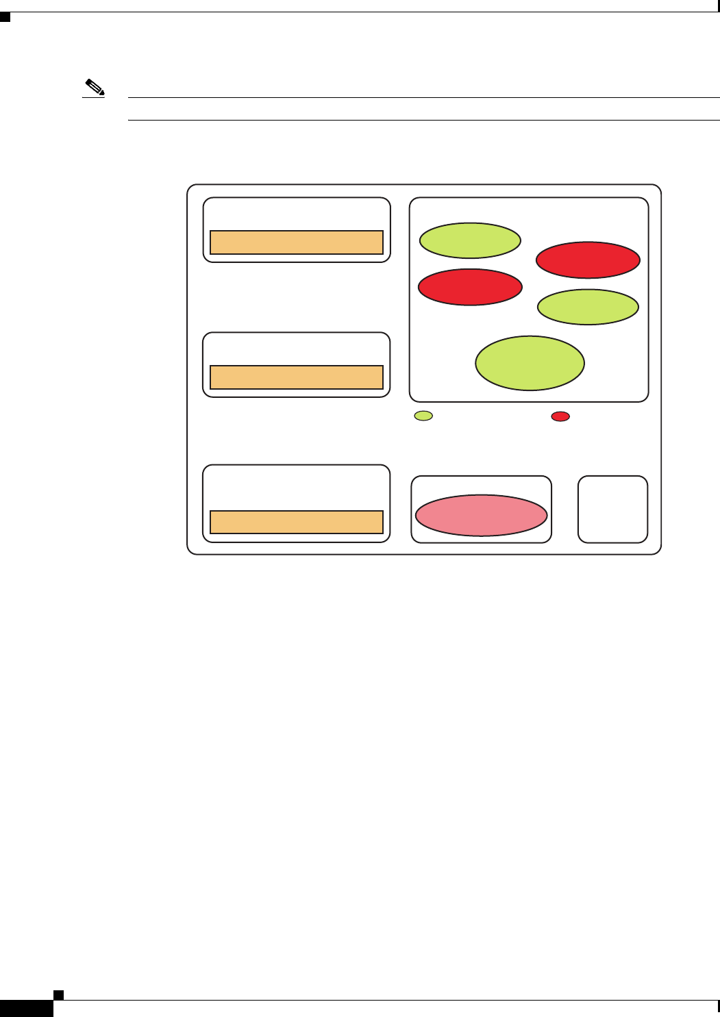
5-22
Cisco Unified Customer Voice Portal (CVP) 8.x Solution Reference Network Design (SRND)
OL-15989-06
Chapter 5 Interactions with Cisco Unified ICM
Courtesy Callback
Note Scheduling a callback to occur at a specified time is not part of this feature.
The following illustration shows the components needed for the Courtesy Callback feature.
Example Scripts and Audio Files
The courtesy callback features is implemented using Unified ICM scripts. Modifiable example scripts
are provided on the Unified CVP 8.0(1) install media in the \CVP\Downloads and Samples\ folder. These
scripts determine whether or not to offer the caller a callback, depending on the criteria previously
described. The files provided are:
• CourtesyCallback.ICMS, the ICM script
• CourtesyCallbackStudioScripts.zip, a collection of Call Studio scripts
Sample audio files that accompany the sample studio scripts are installed to the
<CVP_HOME>\OPSConsoleServer\CCBDownloads\CCBAudioFiles.zip and also as part of the Media
Files installation option.
• If CCBAudioFiles.zip is used, it's contents must be unzipped onto the your media server.
CCBAudioFiles.zip has Courtesy Callback specific application media files under en-us\app and
media files for Say It Smart under en-us\sys. If you already have media files for Say It Smart on your
media server, then only the media files under en-us\app are needed.
The sample scripts are set up to use the default location of "http://<server>:<port>/en-us/app". The
default location of the sample audio files must be changed in the sample scripts to accommodate your
needs (i.e. substitute the media server IP address and port in <server> and <port>).
The following example scripts are provided:
cvp_ccb_vxml.tcl
VXML Gateway
Realtime Callback Database
Unified CVP Reporting Server
survivability.tcl
Ingress/PreemptiveCallback
Gateway Unified ICM
Customization
of these
applications
is allowed
Customization
of these
applications
is not allowed
CourtesyCallback
Scr i p t
CallbackEntry
Queueing Apps
(BillingQueue)
CallbackWait
CallbackEngine
CallbackQueue
Unified CVP VXML Server
Operations
Consol e

5-23
Cisco Unified Customer Voice Portal (CVP) 8.x Solution Reference Network Design (SRND)
OL-15989-06
Chapter 5 Interactions with Cisco Unified ICM
Courtesy Callback
• BillingQueue
This script is responsible for playing queue music to callers that either choose to not have a callback
occur or must reenter the queue for a short period after receiving a callback.
You may customize this script to suit your business needs.
• CallbackEngine
This script keeps the VoIP leg of a callback alive between when a caller elects to have a callback and
when a caller receives the callback.
Do not customize this script.
• Callback Entry
This script handles the initial IVR when a caller enters the system and when the caller is provided
with the opportunity to receive a callback.
You may customize this script to suit your business needs.
• CallbackQueue
This script handles the keepalive mechanism of a call while a caller is in queue and listening to the
music played within the BillingQueue script.
Do not customize this script.
• CallbackWait
This script handles the IVR portion of a call when a customer is called back.
You may customize this script to suit your business needs.
Callback Criteria
Examples of callback criteria you can establish include:
• Number of minutes a customer is expected to be waiting in queue exceeds some maximum number
of minutes (based on your average call handling time per customer)
Note The included sample scripts use this method for determining callback eligibility.
• Assigned status of a customer (gold customers may be offered the opportunity to be called back
instead of remaining on the line)
• The service a customer has requested (sales calls, or system upgrades, etc. may be established as
callback criteria)
Typical Use Scenario
If the caller decides to be called back by the system, they leave their name and phone number. Their
request remains in the system and when the system determines that an agent will be available soon (or
is available), then the system places a callback to the caller. The caller answers the call and confirms that
they are the original caller, and the system connects the caller to the agent after a short wait.
A typical use of the Courtesy Callback feature follows this pattern:
1. The caller arrives at Unified CVP and the call is treated in the normal IVR environment.

5-24
Cisco Unified Customer Voice Portal (CVP) 8.x Solution Reference Network Design (SRND)
OL-15989-06
Chapter 5 Interactions with Cisco Unified ICM
Courtesy Callback
2. The Call Studio and Unified ICM Courtesy Callback scripts determine if the caller is eligible for a
callback based on the rules of your organization (such as in the prior list of conditions).
3. If a courtesy callback can be offered, the system tells the caller the approximate wait time and offers
to call the customer back when an agent is available.
4. If the caller chooses not to use the callback feature, queuing continues as normal.
Otherwise, the call continues as indicated in the remaining steps.
5. If the caller chooses to receive a callback, the system prompts the caller to record their name and to
key in their phone number.
6. The system writes a database record to log the callback information.
Note If the database is not accessible, then the caller is not offered a callback and they are placed in
queue.
7. The caller is disconnected from the TDM side of the call. However, the IP side of the call in Unified
CVP and Unified ICM is still active. This keeps the call in the same queue position. No queue music
is played, so VXML gateway resources used during this time are less than if the caller had actually
been in queue.
8. When an agent in the service/skill category the caller is waiting for is close to being available (as
determined by your callback scripts), then the system calls the person back. The recorded name is
announced when the callback is made to insure the correct person accepts the call.
9. The system asks the caller, through an IVR session, to confirm that they are the person who was
waiting for the call and that they are ready for the callback.
If the system cannot reach the callback number provided by the caller (for example, the line is busy,
RNA, network problems, etc.) or they do not confirm they are the caller, then the call is not sent to
an agent. In this way, the agent is always guaranteed that someone is there waiting when they take
the call. The system assumes that the caller is already on the line by the time the agent gets the call.
This is why this feature is called preemptive callback - the system assumes that the caller is already
on the line by the time the agent gets the call and that the caller has to wait minimal time in queue
before speaking to an agent.
10. The system presents the call context on the agent screen-pop, as normal.
In the event that the caller cannot be reached after a configurable max number and frequency of retries,
the callback is aborted and the database status is updated appropriately. You can run reports to determine
if any manual callbacks are necessary based on your business rules.
Additional Conceptional Information
The Configuration and Administration Guide for Cisco Unified Customer Voice Portal guide provides a
call flow description of the function of the scripts that provide the Courtesy Callback feature.
Courtesy Callback Prerequisites and Design Considerations
The following prerequisites and caveats apply to the Courtesy Callback feature:
• Calls that allow Callbacks must be queued using a Unified CVP VXML Server.
• The Unified CVP Reporting Server must be installed and licensed.
• The call flow for your deployment must use SIP. The H.323 protocol is not supported for Courtesy
Callback.

5-25
Cisco Unified Customer Voice Portal (CVP) 8.x Solution Reference Network Design (SRND)
OL-15989-06
Chapter 5 Interactions with Cisco Unified ICM
Post Call Survey
• The callback feature relies on the POTS survivability.tcl script running on the ingress gateway.
Therefore, only PSTN-originated calls are eligible for Courtesy Callback. IP-originated callers are
not offered the option of a callback.
• Answering machine detection is not available for this feature. During the callback, the best that can
be done is to prompt the caller with a brief IVR session and acknowledge with DTMF that they are
ready to take the call.
• Calls that are transferred to agents using DTMF *8, TBCT, or hookflash cannot use the Courtesy
Callback feature.
• Callbacks are a best-effort mechanism. After a limited number of attempts to reach a caller during
a callback, the callback is terminated and marked as failed.
• Customers must configure the allowed/blocked numbers that Callback is allowed to place calls to
through the Operations Management Console.
Post Call Survey
A post call survey is typically used by a contact center to determine whether a customer was satisfied
with their call center experience (did they find the answer they were looking for using the self service or
did they have a pleasant experience with the contact center agent, and so forth).
The Post Call Survey (PCS) feature enables you to configure a call flow so that after the agent hangs up,
the caller is transferred to a DNIS that prompts the caller with a post call survey.
There are two responses a caller can have to a post call survey request:
1. The caller is prompted during IVR treatment as to whether they would like to participate in a post
call survey. If they choose to do so, they are automatically transferred to the survey call after the
agent ends the conversation.
2. The caller is prompted to participate, but declines the post call survey. A Unified ICM script writer
can use an ECC variable to turn off the ability for Post Call Survey on a per-call basis. By setting
the ECC variable to 'n', the call will not be transferred to the PCS DNIS.
For reporting purposes, the post call survey call has the same Call-ID and call context as the original
inbound call.
Post Call Survey Typical Uses
The caller is typically asked whether they would like to participate in a survey during the call. In some
cases, the system configuration based on dialed number(s) determines if the post call survey gets invoked
at the end of conversation with agent(s). When the customer completes the conversation with an agent,
the customer is automatically redirected to a survey. The post call survey gets triggered by the hang-up
event from the last agent.
A customer can use the keypad on a touch tone phone and/or voice with ASR/TTS to respond to
questions asked during the survey. From the Unified CCE point of view, the post call survey call is just
like another regular call. During the post call survey, the call context information is retrieved from the
original customer call.
Post Call Survey Design Considerations
Please observe the following conditions when using the Post Call Survey feature:

5-26
Cisco Unified Customer Voice Portal (CVP) 8.x Solution Reference Network Design (SRND)
OL-15989-06
Chapter 5 Interactions with Cisco Unified ICM
Post Call Survey
• When the PCS is initiated, the call context of the customer call that was just transferred to the agent
is replicated into the call context of the Post Call Survey call for Unified CM reporting purposes.
Unfortunately, any call context entered by the agent after the call has transferred does not get
replicated into the PCS call context. So, the call context of the Post Call Survey call is limited to the
data available up to the point where the call is transferred to the Agent.
• REFER call flows are not supported with post call survey, because the survey call needs to be made
when the agent hangs up. With REFER, Unified CVP is removed from the call.

CHAPTER
6-1
Cisco Unified Customer Voice Portal (CVP) 8.x Solution Reference Network Design (SRND)
OL-15989-06
6
Calls Originated by Cisco Unified
Communications Manager
Last revised on: April 4, 2011
This chapter covers the following major topics:
• What's New in This Chapter, page 6-1
• Customer Call Flows, page 6-2
• Protocol Call Flows, page 6-3
• Deployment Implications, page 6-6
• KPML Support, page 6-8
What's New in This Chapter
Table 6-1 lists the topics that are new in this chapter or that have changed significantly from previous
releases of this document.
Differences in Calls Originated by Cisco Unified
Communications Manager
A call originated by Cisco Unified Communications Manager (Unified CM) first enters the Unified ICM
system when someone dials a Unified CM route point that is associated with the JTAPI interface into
Unified ICM. Such calls initiate a Unified ICM routing script that can be used to place the caller into
queue or into a self-service application, select an available agent, or invoke Application Gateway . A call
invoked through the JTAPI interface to Unified ICM is a typical post-route request; it provides a dialed
number, ANI, variables, and so forth, and returns a label. Unified CM then delivers the call to the
Table 6-1 New or Changed Information Since the Previous Release of This Document
New or Revised Topic Description
KPML Support, page 6-8 KPML is an out-of-band dtmf method that passes
key press information through SIP signaling instead
of through the RTP stream.

6-2
Cisco Unified Customer Voice Portal (CVP) 8.x Solution Reference Network Design (SRND)
OL-15989-06
Chapter 6 Calls Originated by Cisco Unified Communications Manager
Customer Call Flows
destination specified by the returned label. As with other ACD post-route requests, the exchange ends
there. Unified ICM has no ability to send a subsequent label to that Unified CM unless Unified CM
issues another post-route request.
This limitation is the first difference between calls originated by Unified CM and calls originated
through a Unified CVP ingress gateway. Unified CVP can continue to route and re-route the call as many
times as necessary. For this reason, when calls are originated from Unified CM, routing client
responsibilities should be handed off to Unified CVP as soon as possible.
The second difference has to do with how calls are transferred to a VRU. ACD routing clients such as
Unified CM may be transferred only by using a TranslationRouteToVRU label. When Unified CVP is
the routing client, it can handle Translation Route labels as well as the Correlation ID labels that are
generated by SendToVRU nodes.
Locations-based call admission control is not supported for IP originated calls, including calls where the
agent performs a warm transfer or conference
The next sections provide more details on these differences.
Customer Call Flows
The following types of calls are originated by Unified CM and must be treated differently than calls
originated by Unified CVP:
• Unified ICM Outbound Calls with Transfer to IVR, page 6-2
• Internal Help Desk Calls, page 6-2
• Warm Consultative Transfers and Conferences, page 6-3
Unified ICM Outbound Calls with Transfer to IVR
The Cisco Unified CCE Outbound Dialer introduces an outbound call by impersonating a Skinny Client
Control Protocol (SCCP) phone and asking Unified CM to place the outbound call. When it detects that
a person has answered, it transfers the call to a Unified CCE destination, taking itself out of the loop. If
the customer requirement is to provide a Unified CVP message or a self-service application to the called
party, then the call is transferred to Unified CVP using a Unified CM route point. This process fits the
definition of a call originated by Unified CM.
Internal Help Desk Calls
Enterprises that place IP phones on employees' desks often want to provide those employees with the
capability to call into a self-service application. An example might be an application that allows
employees to sign up for health benefits. Or the employee might be trying to reach an agent, such as the
IT help desk, and ends up waiting in queue. Both of these scenarios result in calls originating from
Unified CM to Unified CVP.
The internal caller could also dial into a self-service application hosted on a Unified CVP VXML Server
that is deployed using Model #1, Standalone Self-Service. No ICM is involved in this scenario, but it
still qualifies as a call originated by Unified CM.

6-3
Cisco Unified Customer Voice Portal (CVP) 8.x Solution Reference Network Design (SRND)
OL-15989-06
Chapter 6 Calls Originated by Cisco Unified Communications Manager
Protocol Call Flows
Warm Consultative Transfers and Conferences
In a typical contact center call flow, most companies want to provide their agents with the ability to
transfer callers to a second agent, who might or might not currently be available. There are two ways to
do this transfer: blind transfer or warm consultative transfer (or conference).
In a blind transfer, the first agent dials a number and hangs up; the caller then gets connected to the
second agent or placed into a queue if necessary. This type of transfer does not involve a call originated
by Unified CM, and it is called Network Transfer. Network Transfer is also discussed in the section on
ICM Managed Transfers, page 10-5.
In a warm transfer or conference, the agent dials a number and is connected to the second agent while
the caller is placed on hold. The two agents can talk, then they can conference in the caller, and the first
agent can then drop off. If the second agent is not available, it is the first agent (and not the caller) who
is placed into a queue. All of this processing can take place without involving Unified CVP, unless the
first agent needs to be queued. In that case, the first agent's call must be transferred to Unified CVP, thus
creating a call originated by Unified CM.
Protocol Call Flows
This section describes the protocol-level call flows for calls originated by Unified CM in each of the
following relevant deployment models:
• Model #1: Standalone Self-Service, page 6-3
• Model #2: Call Director, page 6-4
• Model #3a: Comprehensive Using ICM Micro-Apps, page 6-5
• Model #3b: Comprehensive Using Unified CVP VXML Server, page 6-6
Note Model #4, VRU Only with NIC Controlled Routing, is not discussed here because there is no NIC
involved with calls originated by Unified CM.
Model #1: Standalone Self-Service
Model #1 does not involve Unified ICM. It arises when a Unified CM user dials a directory number that
connects to a Unified CVP VoiceXML gateway and invokes a Unified CVP VXML Server application.
The VoiceXML gateway is configured in Unified CM as an H.323 gateway or SIP trunk. The call flow
for this model is as follows:
1. A caller dials a route pattern.
2. Unified CM directs the call to the VoiceXML gateway.
3. The VoiceXML gateway invokes a voice browser session based on the configured Unified CVP
self-service application.
4. The Unified CVP self-service application makes an HTTP request to the Unified CVP
VXML Server.
5. The Unified CVP VXML Server starts a self-service application.
6. The Unified CVP VXML Server and VoiceXML gateway exchange HTTP requests and VoiceXML
responses.

6-4
Cisco Unified Customer Voice Portal (CVP) 8.x Solution Reference Network Design (SRND)
OL-15989-06
Chapter 6 Calls Originated by Cisco Unified Communications Manager
Protocol Call Flows
7. The caller hangs up.
Note The script must not execute a Transfer node, unless it is to a TDM destination. Transfers to an IP
destination will result in an IP-to-IP call, which is supported, but requires that you add ip-ip-gw
commands (CUBE commands) to the gateway configuration for the transfer operation to another VoIP
destination to succeed.
Model #2: Call Director
Model #2 has no VRU leg; it is all switching. Therefore, calls originated by Unified CM will always be
delivered directly to their targets or else rejected. No queuing or self-service is involved.
This model assumes that the call is truly originating from Unified CM. This model excludes calls that
originally arrived through a Unified CVP ingress gateway and were transferred to Unified CM, and are
now being transferred again. Such situations are rare because Unified CM can usually handle those
transfers itself. There are exceptions, however, such as when the target is an ACD other than
Unified CM, but those situations are not covered here.
This model requires that the following items be configured:
• Unified CM route point that invokes a Unified ICM script
• Unified CVP configured as a Type 2 NetworkVRU
• VRU translation routes to Unified CVP
• Translation route Dialed Number Identification Service (DNIS) numbers configured in the Unified
CVP Call Server
• Unified CM configured with an H.323 trunk or SIP trunk
• Unified CM route patterns for Translation Route DNIS
The call flow for this model is as follows:
1. A caller dials a route point.
2. Unified ICM invokes a routing script.
3. The routing script encounters a TranslationRouteToVRU node to transfer the call to Unified CVP.
(Unified CVP is configured as a Type 2 NetworkVRU.)
4. Unified ICM returns the translation route label to Unified CM.
5. Unified CM consults the gatekeeper, DNS SRV, or SIP Proxy to locate the Unified CVP Call Server.
6. Unified CM connects the call to the Unified CVP Call Server.
7. Unified CM briefly establishes a G.711 media connection between the caller and the Unified CVP
H.323 Service (for H.323 only).
8. The routing script encounters a Select or Label node, and it selects a target label.
9. Unified ICM returns the target label to the Unified CVP Call Server (not to the device that issued
the route request).
10. The Unified CVP Call Server consults the gatekeeper, DNS SRV, or SIP Proxy to locate the
destination device.
11. The Unified CVP Call Server communicates via H.323 or SIP with the target device and instructs
Unified CM to establish a media stream to it.

6-5
Cisco Unified Customer Voice Portal (CVP) 8.x Solution Reference Network Design (SRND)
OL-15989-06
Chapter 6 Calls Originated by Cisco Unified Communications Manager
Protocol Call Flows
Now consider what happens if the target device issues another route request to Unified ICM. This part
of the call flow would not be possible without the initial TranslationRouteToVRU mentioned step 3.
12. Unified ICM invokes a new routing script.
13. The routing script encounters a Select or Label node, and it selects a target label.
14. Unified ICM returns the target label to the Unified CVP Call Server (not to the device that issued
the route request).
15. The Unified CVP Call Server consults the gatekeeper, DNS SRV, or SIP Proxy to locate the
destination device.
16. The Unified CVP Call Server communicates via H.323 or SIP with the target device and instructs
Unified CM to establish a media stream to the device.
Model #3a: Comprehensive Using ICM Micro-Apps
Model #3a involves both call switching and VRU activity. It differs from Model #2, therefore, in that
calls must be transferred to the Unified CVP VoiceXML gateway after they are transferred to the Unified
CVP Switch leg. Queuing is possible in this model, as is basic prompt-and-collect activity.
This model requires that the following items be configured:
• Unified CM CTI route point that invokes a Unified ICM script
• Unified CVP configured as a Type 10 NetworkVRU
• The CTI route point configured in Unified ICM as a DN with a Type 10 NetworkVRU
• The NetworkVRU must have labels for the Unified CVP Switch leg routing client
• The NetworkVRU labels must be configured in a gatekeeper or SIP Proxy to point to VoiceXML
gateways
• Unified CM configured with an H.323 trunk or SIP trunk
The call flow for this model is as follows:
1. A caller dials a route point.
2. Unified ICM invokes a routing script.
3. The routing script encounters a SendToVRU node to transfer the call to Unified CVP. (Unified CVP
is configured as a Type 10 NetworkVRU.)
4. Unified ICM returns the VRU label with Correlation ID to Unified CM.
5. Unified CM consults the gatekeeper, DNS SRV, or SIP Proxy to locate the Unified CVP Call Server.
6. The call is connected to the Unified CVP Call Server.
7. Unified CM briefly establishes a G.711 media connection between the caller and the Unified CVP
H.323 Service (for H.323 only).
8. Unified ICM sends a VRU transfer label with Correlation ID to the Unified CVP Call Server.
9. The Unified CVP Call Server consults the gatekeeper, DNS SRV, or SIP Proxy to locate the
Vo i c e X M L g a t ew a y.
10. The Unified CVP Call Server communicates via H.323 or SIP with the VoiceXML gateway and
instructs Unified CM to establish a media stream to it.
11. The routing script executes one or more Unified CVP Microapplications via RunExternalScript
nodes, plays media files, requests DTMF input, and so forth.

6-6
Cisco Unified Customer Voice Portal (CVP) 8.x Solution Reference Network Design (SRND)
OL-15989-06
Chapter 6 Calls Originated by Cisco Unified Communications Manager
Deployment Implications
12. While the Unified CVP Microapplications are in progress, a target agent becomes available to take
the call.
13. Unified ICM determines a label for the target agent.
14. Unified ICM returns the target label to the Unified CVP Call Server.
15. The Unified CVP Call Server consults the gatekeeper, DNS SRV, or SIP Proxy to locate the
destination device.
16. The Unified CVP Call Server communicates via H.323 or SIP with the target device and instructs
Unified CM to establish a media stream to it, removing the VoiceXML gateway's media stream.
If the target device later issues another route request to Unified ICM, the call flow is again exactly as
described above. The call must again be transferred with Correlation ID via SendToVRU to the Unified
CVP Call Server and VoiceXML gateway to create the VRU leg. Microapplications might be executed,
and eventually the new target label is delivered to the Unified CVP Switch leg, which transfers the call
to that target.
Model #3b: Comprehensive Using Unified CVP VXML Server
Model #3b does not differ significantly from Model #3a as far as call control and signaling are
concerned. The only difference is that the Unified CVP Microapplications executed in Model #3b might
include subdialog requests to the Unified CVP VXML Server as well. Of course, self-service
applications are not likely to be invoked during the period when the call is queued. Any agent selection
nodes or queue nodes in the Unified ICM routing script would therefore likely be postponed until after
the self-service application has completed and control has returned to the Unified ICM routing script.
Deployment Implications
This section presents guidelines for the following aspects of incorporating calls originated by
Unified CM into the deployment:
• Unified ICM Configuration, page 6-6
• Hosted Implementations, page 6-7
• Cisco Unified Communications Manager Configuration, page 6-7
• Sizing, page 6-8
Unified ICM Configuration
• With Cisco Unified ICM 7.0, if you want Unified CVP to be able to perform subsequent call control,
always translation-route the call to Unified CVP as a Type 2 NetworkVRU before delivering the call
to its next destination. This practice creates a hand-off, putting Unified CVP in charge of subsequent
transfers for the call because Unified CM is not able to receive any further labels.
• If you want to perform any queuing treatment, prompt and collect, or self-service applications,
always follow the above translation route with a SendToVRU node. SendToVRU can sometimes be
invoked implicitly by a Queue node or a RunExternalScript node, but you should not rely on that
method. Always include an actual SendToVRU node.

6-7
Cisco Unified Customer Voice Portal (CVP) 8.x Solution Reference Network Design (SRND)
OL-15989-06
Chapter 6 Calls Originated by Cisco Unified Communications Manager
Deployment Implications
• With Cisco Unified ICM 7.1, if you want Unified CVP to be able to perform subsequent call control,
a translation route is not necessary if you use a Type 10 NetworkVRU. The Type 10 VRU uses the
Correlation ID mechanism to perform a transfer from Unified CM to Unified CVP using a
SendToVRU node. When the SendToVRU node is used with a Type 10 VRU, an initial transfer to
Unified CVP hands off call control to Unified CVP, and then an automatic second transfer to the
VRU leg is performed to deliver the call to a VoiceXML gateway for IVR treatment.
Note This call flow and all others in this document assume Cisco Unified ICM 7.0(0) or later.
• For additional configuration requirements, see Protocol Call Flows, page 6-3.
Hosted Implementations
Translation routes sent by one ICM router must be received by a peripheral that is connected to the same
ICM router. Therefore, you can translation-route a call from a Unified CM at the CICM level into
Unified CVP only if Unified CVP is also located at the CICM level. In Hosted environments, this means
you must provision Unified CVP Call Servers (Call Servers) at the CICM level even if you already have
other Call Servers at the NAM level. VoiceXML gateways and gatekeepers can, of course, be shared.
For more details on this subject, see the chapter on Interactions with Cisco Unified ICM, page 5-1.
Cisco Unified Communications Manager Configuration
The following guidelines apply to Unified CM configuration:
• Configure a gatekeeper-controlled H.323 trunk or SIP trunk. With Unified CVP 4.1 and later
releases, an MTP is no longer required for H.323 trunks. Configure the gatekeeper to send calls to
Unified CM using this trunk.
• Configure the appropriate route patterns for the Translation Route DNIS or VRU Label with
Correlation ID appended. The Correlation ID method is used with a Type 10 VRU, and the route
pattern in Unified CM must be configured to allow the extra digits to be appended, such as adding
a ! to the end of the route pattern.
• When configuring agent labels, consider which device is the routing client. For cases where the label
will be returned directly to Unified CM, Unified CM must be the routing client. For cases where the
label will be sent to Unified CVP, the labels must be associated with each of the Unified CVP Switch
leg Call Servers.
Gatekeeper or SIP Proxy Dial-Plan Configuration
If you are using a gatekeeper or SIP Proxy, the VRU label associated with the Unified CM routing client
must be different than the VRU label associated with the Unified CVP routing clients. This is because
the VRU label for a call originated by Unified CM is intended to send the call to the Unified CVP Call
Server to hand off call control first, whereas the VRU label for a call where Unified CVP is already the
routing client is intended to be sent to the VXML gateway for treatment. Once the call has been sent to
Unified CVP to hand off call control, Unified CVP does a subsequent transfer to the VRU label
associated with the Unified CVP routing client and delivers the call to the VXML gateway for treatment.
The dial plan in your gatekeeper or SIP Proxy should be structured as follows:
[Unified CM routing client VRU label + correlation-id]: pointing to CVP server(s)

6-8
Cisco Unified Customer Voice Portal (CVP) 8.x Solution Reference Network Design (SRND)
OL-15989-06
Chapter 6 Calls Originated by Cisco Unified Communications Manager
KPML Support
[CVP routing client VRU label + correlation-id]: pointing to VXML gateway(s)
For discusions of the Cisco Gatekeeper and the Cisco SIP Proxy Server refer to Cisco Gatekeeper,
page 1-11 and SIP Proxy Server, page 1-11.
Sizing
Most customer implementations are not primarily designed for calls originated by Unified CM. The
main driver is usually incoming customer calls, although calls originated by Unified CM are frequently
a component, particularly in the case of warm transfers. Remember to consider those calls when sizing
equipment.
Gateways
Calls originated by Unified CM do not use ingress gateways at all. Calls are delivered directly from
Unified CM to the Unified CVP Call Server. They do, however, use VoiceXML gateways whenever a
VRU leg is in use. Therefore, for the purposes of sizing VoiceXML gateways, consider each Unified CM
call that is either in queue or conducting self-service activities.
KPML Support
KPML is an out-of-band dtmf method that passes key press information through SIP signaling instead
of through the RTP stream.
Typical Unified CVP Comprehensive call flows use the inband RFC2833 DTMF configuration on
endpoints. However, there are some endpoints that do not support inband RFC2833, such as the 7985
video phone, and CTI Ports used in UCCE Mobile Agent deployments.
For these endpoints, when the destination behind the SIP Trunk is set with RFC2833, Cisco Unified CM
allocates an MTP resource because the line side and the trunk side require a translation of the inband
packets to the out-of-band signaling messages for DTMF.
To avoid MTP allocation, the destination of the SIP Trunk needs to be configured using the SIP KPML
DTMF method (that is, the No Preference setting). Also, the VXML bootstrap dial peer requires SIP and
KPML settings.
The Unified CVP SIP subsystem can pass through Subscribe and Notify events related to KPML DTMF
digits (out-of-band DTMF).
MTP Usage on UCM Trunk
When using the UCM SIP Trunk with certain unique call flows, such as Unity Voice Mail or Mobile
Agent, there may be a requirement to use an MTP resource.
The requirement occurs when the negotiated media capabilities of the endpoints do not match, such as
with DTMF in-band versus out-of-band capability. In this case, the UCM may dynamically allocate an
MTP due to the DTMF media capabilities mismatch.
MTP may also be required when interoperating with third party devices.

6-9
Cisco Unified Customer Voice Portal (CVP) 8.x Solution Reference Network Design (SRND)
OL-15989-06
Chapter 6 Calls Originated by Cisco Unified Communications Manager
KPML Support
Design Considerations
The following limitations apply when using the KPLM feature:
1. If you have configured KPML for SIP on a dial-peer, you cannot use the same dial-peer for H.323.
Another bootstrap DP can be configured with the same pattern and a priority may be put on it to
handle the H.323 calls.
2. ASR/TTS is not supported with KPML.
The SIP Trunk should be configured for DTMF No Preference if KPML is set on the gateway. If the SIP
Trunk points to the Cisco Unified Presence Server (CUP Server) or Unified CVP directly, the DTMF
Preference should still be set to No Preference, because the Unified CVP B2BUA is in the middle of the
call, and the SDP attributes are passed through as though they came directly from the VXML gateway.

6-10
Cisco Unified Customer Voice Portal (CVP) 8.x Solution Reference Network Design (SRND)
OL-15989-06
Chapter 6 Calls Originated by Cisco Unified Communications Manager
KPML Support

CHAPTER
7-1
Cisco Unified Customer Voice Portal (CVP) 8.x Solution Reference Network Design (SRND)
OL-15989-06
7
Gateway Options
Last revised on: May 16, 2011
Cisco offers a large range of voice gateway models to cover a large range of requirements. Many, but not
all, of these gateways have been qualified for use with Unified CVP. For the list of currently supported
gateway models, always check the latest version of the Hardware and System Software Specification for
Cisco Unified CVP (formerly called the Bill of Materials), available at
http://www.cisco.com/en/US/products/sw/custcosw/ps1006/prod_technical_reference_list.html
Gateways are used in Unified CVP for conversion of TDM to IP and for executing VoiceXML
instructions. The following sections help you determine which gateways to incorporate into your design:
• PSTN Gateway, page 7-2
• VoiceXML Gateway with DTMF or ASR/TTS, page 7-2
• VoiceXML and PSTN Gateway with DTMF or ASR/TTS, page 7-3
• Cisco Integrated 3G-H324M Gateway, page 7-3
• TDM Interfaces, page 7-4
• Gateway Choices, page 7-6
• Gateway Sizing, page 7-7
• Using MGCP Gateways, page 7-11
What's New in This Chapter
Table 7-1 lists the topics that are new in this chapter or that have changed significantly from previous
releases of this document.
Table 7-1 New or Changed Information Since the Previous Release of This Document
New or Revised Topic Description
Cisco Integrated 3G-H324M Gateway, page 7-3 Cisco Integrated 3G-H324M Gatway
worflow and configuration guidelines.

7-2
Cisco Unified Customer Voice Portal (CVP) 8.x Solution Reference Network Design (SRND)
OL-15989-06
Chapter 7 Gateway Options
PSTN Gateway
PSTN Gateway
In this type of deployment, the voice gateway is used as the PSTN voice gateway. The voice gateway is
responsible for converting TDM speech to IP and for recognizing DTMF digits and converting them to
H.245 or RFC2833 events. Unified CVP does not currently support passing SIP-Notify or KPML DTMF
events.
In a centralized Unified CVP deployment, you can separate the VoiceXML functionality from the ingress
gateway to provide a separate PSTN ingress layer. The separate PSTN layer and VoiceXML farm enables
the deployment to support a large number of VoiceXML sessions and PSTN interfaces. For example, the
Cisco AS5400XM can accept a DS3 connection, providing support for up to 550 DS0s. However, a
gateway that is handling that many ingress calls cannot also support as many VoiceXML sessions. In
such cases, the VoiceXML sessions should be off-loaded to a separate farm of VoiceXML-only gateways.
Note Any TDM interface can be used as long as it is supported by the Cisco IOS gateway and by the Cisco IOS
version compatible with CVP.
VoiceXML Gateway with DTMF or ASR/TTS
A standalone VoiceXML gateway is a voice gateway with no PSTN interfaces or DSPs. The VoiceXML
gateway enables customers to interact with the Cisco IOS VoiceXML Browser via DTMF tones or
ASR/TTS. Because the gateway does not have PSTN interfaces, voice traffic is sent via Real-Time
Transport Protocol (RTP) to the gateway, and DTMF tones are sent via out-of-band H.245 or RFC2833
events.
A voice gateway deployment using VoiceXML with DTMF or ASR/TTS, but no PSTN, enables you to
increase the scale of the deployment and support hundreds of VoiceXML sessions per voice gateway.
In a centralized Unified CVP deployment, you could use a VoiceXML farm. For example, if you want to
support 300 to 10,000 or more VoiceXML sessions, possible voice gateways include the Cisco
AS5350XM gateway. The standalone AS5350XM can support many DTMF or ASR/TTS VoiceXML
sessions per voice gateway. In addition, Cisco recommends that you stack the AS5350XM gateways to
support large VoiceXML IVR farms. However, for better performance and higher capacity, and to avoid
the need for stacking, you can use the 3945 or 3945-E series gateways. Refer to Table 7-2.
In a distributed Unified CVP deployment, consider providing an extra layer of redundancy at the branch
office. You can deploy a separate PSTN gateway and a VoiceXML gateway to provide an extra layer of
redundancy. In addition, for a centralized Cisco Unified Communications Manager deployment, you
must provide support for Survivable Remote Site Telephony (SRST). The Cisco 2800 Series and
3800 Series and the newer 2900 Series and 3900 Series routers are the best choices for the voice gateway
because they support SRST.
Gateway Sizing, page 7-7 Considerations for sizing gateways for
use with Unified CVP
Mixed G.729 and G.711 Codec Support, page 7-6 Requirements for mixed codec
transcoding with and without CUBE and
Unified CVP.
Table 7-1 New or Changed Information Since the Previous Release of This Document
New or Revised Topic Description
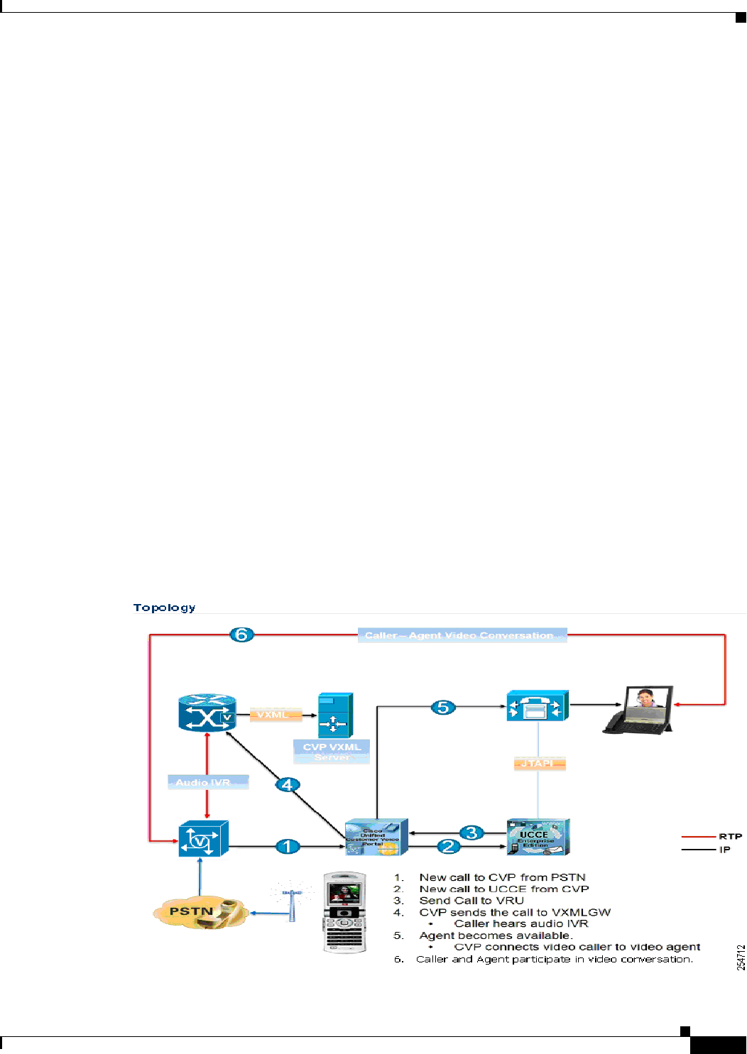
7-3
Cisco Unified Customer Voice Portal (CVP) 8.x Solution Reference Network Design (SRND)
OL-15989-06
Chapter 7 Gateway Options
VoiceXML and PSTN Gateway with DTMF or ASR/TTS
For a discussion of the upside and downside of each codec, refer to Voice Traffic, page 9-2.
VoiceXML and PSTN Gateway with DTMF or ASR/TTS
The most popular voice gateway is the combination VoiceXML and PSTN Interface Gateway. In
addition, for a centralized Cisco Unified Communications Manager deployment, you must provide
support for Survivable Remote Site Telephony (SRST). The Cisco 2800 Series and 3800 Series and the
newer 2900 Series and 3900 Series routers are the best choices for the voice gateway because they
support SRST.
Cisco Integrated 3G-H324M Gateway
The Cisco Integrated 3G-324M Gateway - or Video Gateway - allows multimedia communications
(H.324M) between 3G (third generation) mobile handsets and Cisco AS5xxx Universal Gateways. Refer
to the information on Cisco.com for more in-depth information about the Cisco Integrated 3G-324M
Gateway:
http://www.cisco.com/en/US/docs/video/milticomm/3g324m.html
Gateway Topology and Call Flow
The following figure displays the topology and call flow for the Cisco Integrated 3G-H324M
Gateway call flow model.
Figure 7-1 Cisco Integrated 3G-H324M Video Gateway Topology and Call Flow

7-4
Cisco Unified Customer Voice Portal (CVP) 8.x Solution Reference Network Design (SRND)
OL-15989-06
Chapter 7 Gateway Options
TDM Interfaces
The call flow shown in the previous figure is as follows:
1. A new call arrives from the PSTN network to Unified CVP.
2. The new call is sent from Unified CVP to Unified CCE.
3. Call is sent from Unified CCE to Unified CVP/VRU.
4. Unified CVP sends the call to the VXML Gateway.
The caller hears audio IVR.
5. The Agent becomes available.
Unified CVP connects the video caller to the video agent.
6. Caller-Agent video conversation begins.
CVP Configuration
For information on configuring Unified CVP for this feature, please refer to the Unified CVP
Configuration and Administration (CAG) Guide which you can locate from this link:
http://www.cisco.com/en/US/products/sw/custcosw/ps1006/products_installation_and_configuration_guide
s_list.html.
TDM Interfaces
The Cisco AS5400XM Universal Gateway offers unparalleled capacity in only two rack units (2 RUs)
and provides best-of-class voice, fax, and remote-access services. High density (up to 550 DS0s on one
Channelized T3 (CT3) of voice over IP (VoIP) and two CT3s of time-division multiplexing (TDM)
switching), low power consumption (as low as 2.4 A at 48 VDC per G.711 CT3), high-density packet
voice digital signal processor (DSP) modules, universal port DSPs, and session border control (SBC)
features make the Cisco AS5400XM Universal Gateway ideal for many network deployment
architectures, especially co-location environments and mega points of presence (POPs).
The Cisco AS5350XM Universal Gateway is the one-rack-unit (1 RU) gateway that supports 2-, 4-,8-,
or 16-port T1/12-port E1 configurations and provides universal port data, voice, and fax services on any
port at any time. The Cisco AS5350XM Universal Gateway offers high performance and high reliability
in a compact, modular design. This cost-effective platform is ideally suited for internet service providers
(ISPs) and enterprise companies that require innovative universal services.
The Cisco 2800 Series and 3800 Series and the newer 2900 Series and 3900 Series Routers support the
widest range of packet telephony-based voice interfaces and signaling protocols within the industry,
providing connectivity support for more than 90 percent of the world's private branch exchanges (PBXs)
and public switched telephone network (PSTN) connection points. Signaling support includes T1/E1
Primary Rate Interface (PRI), T1 channel associated signaling (CAS), E1-R2, T1/E1 QSIG Protocol, T1
Feature Group D (FGD), Basic Rate Interface (BRI), foreign exchange office (FXO), E&M, and foreign
exchange station (FXS). The Cisco 2800 Series and 3800 Series Routers can be configured to support
from two to 450 voice channels. The Cisco 2900 Series and 3900 Series Routers can be configured to
support from two to 900 voice channels.
For the most current information about the various digital (T1/E1) and analog interfaces supported by
the various voice gateways, refer to the latest product documentation available at the following sites:

7-5
Cisco Unified Customer Voice Portal (CVP) 8.x Solution Reference Network Design (SRND)
OL-15989-06
Chapter 7 Gateway Options
Cisco Unified Border Element
• Cisco 2800 Series
http://www.cisco.com/en/US/products/ps5854/tsd_products_support_series_home.html
• Cisco 3800 Series
http://www.cisco.com/en/US/products/ps5855/tsd_products_support_series_home.html
• Cisco AS5300
http://www.cisco.com/en/US/products/hw/univgate/ps501/tsd_products_support_series_home.html
• Cisco 2900 Series
http://www.cisco.com/en/US/products/ps10537/index.htm.
• Cisco 3900 Series
http://www.cisco.com/en/US/products/ps10536/index.htm
Cisco Unified Border Element
The Cisco Unified Border Element (formerly known as the Cisco Multiservice IP-to-IP Gateway) is a
session border controller (SBC) that provides connectivity between IP voice networks using H.323 or
SIP. Unified CVP supports Cisco Unified Border Element starting with Unified CVP 4.1. Cisco Unified
Border Element is supported in flow-through mode only, so that all calls are routed through the Cisco
Unified Border Element.
Note Unlike flow-through mode, with flow-around mode, customers lose the ability to do DTMF
interworking, transcoding, and other key functions such as tcl and media capabilities that flow-through
will otherwise allow.
A Unified Border Element is typically needed when replacing a TDM voice circuit with an IP voice
trunk, such as a SIP trunk, from a telephone company. The Cisco Unified Border Element serves as a
feature-rich demarcation point for connecting enterprises to service providers over IP voice trunks.
The Cisco Unified Border Element has been tested with, and can be used in, any of the following
scenarios:
• SIP-to-SIP connectivity between a third-party SIP device and Cisco Unified CVP
• SIP-to-SIP connectivity between Cisco Unified Communications Manager and Cisco Unified CVP
• Co-residency of the VoiceXML Gateway and the Cisco Unified Border Element for any of the above
scenarios
For CUBE session numbers, refer to:
http://www.cisco.com/en/US/prod/collateral/voicesw/ps6790/gatecont/ps5640/order_guide_c07_4
62222.html.
• Transcoding between G.711 and G.729
For more information about using the Cisco Unified Border Element with Unified CVP, including
topologies and configurations, refer to the document Cisco Unified Border Element for Contact Center
Solutions, available at
http://cisco.com/en/US/docs/voice_ip_comm/unified_communications/cubecc.html
Note Due to a limitation in Cisco IOS, the Cisco Unified Border Element does not support mid-call escalation
or de-escalation from audio to video, and vice versa.

7-6
Cisco Unified Customer Voice Portal (CVP) 8.x Solution Reference Network Design (SRND)
OL-15989-06
Chapter 7 Gateway Options
Mixed G.729 and G.711 Codec Support
Note Using a Cisco Unified Border Element between Cisco Unified Communications Manager (Unified CM)
and CVP is not supported.
Using a SIP Trunk Without a Cisco Unified Border Element
When connecting to a third-party SIP device, including a SIP PSTN service provider, if a Cisco Unified
Border Element is not placed between Unified CVP and the SIP device, the customer is responsible for
doing integration testing to ensure that both sides are compatible.
When connecting to a PSTN SIP Trunking service without a Cisco Unified Border Element, carefully
consider how the connection between the customer and service provider will be secured, and how NAT
and/or address hiding will be accomplished. Otherwise, it is possible for the service-provider network
to have full access to the customer network. The Cisco Unified Border Element addresses both of these
concerns, and it is the service-provider interconnect interface recommended by Cisco.
Mixed G.729 and G.711 Codec Support
CVP supports mixed G.711 and G.729 codecs in Standalone and Comprehensive SIP deployments with
Cisco Unified Border Element Enterprise Edition (CUBE) and Cisco Unified Communications Manager
(Unified CM). Calls that are ingressed through a SIP trunk from the carrier to a CUBE require IOS
15.1(2)T or later T for mixed codec support. You can use any combination of codecs on the legs of a call.
For example, a caller can place a call using the G.729 codec, hear an IVR prompt played using the G.711
codec, be transferred to the first Agent using the G.729 codec, and then transferred to the second agent
using the G.711 codec.
Unified CVP passes media information in SIP messages to Media Termination Points. Media Termination
Points extend supplementary services, such as call hold, call transfer, call park, and conferencing, that are
otherwise not available when a call is routed to an endpoint.When using mixed codecs with Unified CVP, you
must use a transcoder to translate the codec used on one call leg to the codec used on the next call leg. Unified
CVP does not include a transcoder. You must include either Unified CM, CUBE, or a DSP farm in a Unified
CVP deployment that uses mixed codecs.
Transcoding codecs requires IOS 15.1(2)T or later T release.
For information on the benefits of using the G.711 versus G.729 codec, see G.729 Versus G.711 Codec
Support, page 9-3.
Gateway Choices
Unified CVP uses gateways for two purposes: TDM ingress and VoiceXML rendering. Any Cisco
gateway that is supported by Unified CVP can usually be used for either purpose or both. However,
depending on your deployment model, you might need only one of the functions:
• Model #1: Standalone Self-Service
All calls use both ingress and VoiceXML.
• Model #2: Call Director
All calls use ingress only.
• Model #3a: Comprehensive Using Unified ICM Micro-Apps
All calls use ingress, and some calls use VoiceXML.

7-7
Cisco Unified Customer Voice Portal (CVP) 8.x Solution Reference Network Design (SRND)
OL-15989-06
Chapter 7 Gateway Options
Gateway Sizing
• Model #3b: Comprehensive Using Unified CVP VXML Server
All calls use ingress, and some calls use VoiceXML.
• Model #4: VRU Only with NIC Controlled Routing
All calls use both ingress and VoiceXML.
In cases where both ingress and VoiceXML are required, you can choose to run both functions on the
same gateways or you can choose to designate some gateways for ingress and others for VoiceXML. Use
the following guidelines to determine whether the functions should be combined or split:
• In classical branch office deployments, where the call needs to be queued at the branch where it
arrived, ingress and VoiceXML functions must always be combined.
• In cases where a large number of non-CVP PSTN connections will share the gateways, it is
recommended to dedicated Ingress for that purpose, and use separate VXML gateways.
• VoiceXML-only gateways are less costly because they do not require DSP farms or TDM cards. Use
a spreadsheet to determine which way you obtain the best price.
• With relatively low call volume, it is usually better to combine the functions for redundancy
purposes. Two combined gateways are better than one of each because the loss of one gateway still
allows calls to be processed, though at a lower capacity.
The next decision is whether to use Cisco Integrated Service Router (ISR) gateways (Cisco 2800, 3800
Series routers), ISR-G2 (2900, or 3900 Series routers), or the Cisco AS5x00 Series gateways. The
AS5x00 Series gateways should be used in sites that need to support Channelized T3 (CT3) interfaces.
ISR-G2 gateways should be used in sites that need to support T1/E1 interfaces.
For more information on the Cisco AS5x00 Series Gateways, refer to the technical specifications
available at
http://www.cisco.com/en/US/products/hw/iad/index.html
For more information on the Cisco Integrated Service Routers (ISRs), refer to the documentation
available at
http://www.cisco.com/en/US/products/hw/routers/index.html
Gateway Sizing
Individual Cisco gateways can handle various call capacities depending on whether they are doing
ingress only, VoiceXML only, or a combination of the two. Gateways doing VoiceXML activities also
have different call capacities depending on whether or not they are supporting ASR or TTS activities and
on the type of VoiceXML application being executed. For instance, an intensive JavaScript application
reduces call capacity. Gateways doing HTTPS experience lower call capacity as compared to HTTP.
In general, gateways performing ingress-only can be sized according to the number of TDM cables that
can be connected to them. For gateways that are combined or VoiceXML-only, it is important to ensure
that the overall CPU usage will be less than 75% on average. The numbers in Table 7-3 are based on
Unified CVP VoiceXML documents; other applications that generate more complex VoiceXML
documents will have a higher impact on performance. The following factors affect CPU usage:
• Calls per second (cps)
• Maximum concurrent calls
• Maximum concurrent VoiceXML sessions
Before sizing the voice gateways, use the UCCE Resource Calculator to determine the maximum number
of trunks (DS0s) and VoiceXML IVR ports needed to support the entire solution.

7-8
Cisco Unified Customer Voice Portal (CVP) 8.x Solution Reference Network Design (SRND)
OL-15989-06
Chapter 7 Gateway Options
Gateway Sizing
For almost all Unified CVP deployment models, sizing is based on the maximum number of concurrent
VoiceXML sessions and VoIP calls. The following tables list this information for different IOS release
versions as follows:
• Table 7-2 (IOS version 15.1.1T)
• Table 7-3, Table 7-4, and Table 7-5(IOS version 12.4.15 and greater, but not including 15.1.1.T)
Table 7-2 For Cisco IOS Release 15.1.1T and greater
Maximum Number of VoiceXML Sessions Supported by Cisco Voice Gateways
VXML Gateway CPU Capacity for IOS 15.1.1T or Later T
Platform VXML Only VXML + PSTN Memory
DTMF ASR DTMF ASR Recommended
1861 5 3 4 2 256 MB
2801 7 4 5 3 256 MB
2811 30 20 23 15 256 MB
2821 48 32 36 25 256 MB
2851 60 40 45 30 512 MB
3825 130 85 102 68 512 MB
3845 160 105 125 83 512 MB
5000XM 200 135 155 104 512 MB
2901 12 8 9 6 2 GB
2911 60 40 47 31 2 GB
2921 90 60 71 48 2 GB
2951 120 80 95 64 2 GB
3925 240 160 190 127 2 GB
3945 340 228 270 180 2 GB
3925E 700 470 570 375 2 GB
3945E 850 570 680 450 2 GB
Based on ISO 15.1.1T, G.711, basic calls, Ethernet egress, CPU NTE 75%
(5000XM 80%)
Table 7-3 For Cisco IOS Release 12.4.(15)T5 and greater, but prior to Release 15.0.1M or 15.1. 1T
Maximum Number of VoiceXML Sessions Supported by Cisco Voice Gateways
Cisco Voice
Gateway
Platform
Dedicated VoiceXML Gateway Voice Gateway and VoiceXML
Memory
Recommended
VoiceXML
and DTMF
VoiceXML and
ASR/TTS
VoiceXML
and DTMF
VoiceXML and
ASR/TTS
1861 5 4 4 2 256 MB
2801 7 6 6 4 256 MB
2811 30 24 25 20 256 MB
2821 45 36 36 30 256 MB
2851 60 56 56 48 512 MB

7-9
Cisco Unified Customer Voice Portal (CVP) 8.x Solution Reference Network Design (SRND)
OL-15989-06
Chapter 7 Gateway Options
Gateway Sizing
3825 180 140 210 130 512 MB
3845 200 155 230 145 512 MB
AS5350XM1240 192 240 160 512 MB (default)
AS5400XM1240 192 240 160 512 MB (default)
1. Not to exceed 80% of CPU utilization.
Table 7-4 For Cisco IOS Release 12.4.(15)T5 and greater, but prior to version 15.0.1M or 15.1. 1T
Maximum Number of VoiceXML Sessions Supported by Cisco Voice Gateways
Executing Intensive JavaScript Applications
Cisco Voice
Gateway
Platform
Dedicated VoiceXML Gateway Voice Gateway and VoiceXML
Memory
Recommended
VoiceXML
and DTMF
VoiceXML and
ASR/TTS
VoiceXML
and DTMF
VoiceXML and
ASR/TTS
1861 2 2 2 2 256 MB
2801 3 2 2 2 256 MB
2811 10 5 10 5 256 MB
2821 20 15 15 15 256 MB
2851 30 25 25 20 512 MB
3825 70 55 85 50 512 MB
3845 80 60 95 60 512 MB
AS5350XM1
1. Not to exceed 80% of CPU utilization.
105 85 110 70 512 MB (default)
AS5400XM1105 85 110 70 512 MB (default)
Table 7-5 For Cisco IOS Release 12.4.(15)T5 and greater, but prior to release 15.0.1M or 15.1. 1T
Maximum Number of VoiceXML Sessions Supported by Cisco Voice Gateways Using
HTTPS
Cisco Voice
Gateway
Platform
Dedicated VoiceXML Gateway Voice Gateway and VoiceXML
Memory
Recommended
VoiceXML
and DTMF
VoiceXML and
ASR/TTS
VoiceXML
and DTMF
VoiceXML and
ASR/TTS
1861 3 2 2 2 256 MB
2801 4 4 4 2 256 MB
2811 15 10 15 10 256 MB
2821 30 20 20 15 256 MB
2851 40 35 30 25 512 MB
Table 7-3 For Cisco IOS Release 12.4.(15)T5 and greater, but prior to Release 15.0.1M or 15.1. 1T
Maximum Number of VoiceXML Sessions Supported by Cisco Voice Gateways
Cisco Voice
Gateway
Platform
Dedicated VoiceXML Gateway Voice Gateway and VoiceXML
Memory
Recommended
VoiceXML
and DTMF
VoiceXML and
ASR/TTS
VoiceXML
and DTMF
VoiceXML and
ASR/TTS

7-10
Cisco Unified Customer Voice Portal (CVP) 8.x Solution Reference Network Design (SRND)
OL-15989-06
Chapter 7 Gateway Options
Gateway Sizing
Note The following note does not apply to Cisco IOS Release 15.0.1M and IOS 15.1.1T.
Performance numbers for the Cisco 3825 Series and 3845 Series Integrated Services Routers (ISRs) are
higher when the voice gateway and the VoiceXML gateway functions reside on the same router
(co-resident deployment). When the call is connected to the VoiceXML gateway from the ingress voice
gateway, the media flows directly between the two. In a co-resident deployment, the gateway does not
have to spend CPU cycles to packetize and de-packetize the RTP packets. Hence, by saving these CPU
cycles, the gateway can support increased VoiceXML sessions.
The numbers in Table 7-3, Table 7-4, and Table 7-5 assume the only activities running on the gateway
are VXML with basic routing and IP connectivity. If you intend to run additional applications such as
fax, security, normal business calls, and so forth, then the capacity numbers presented here should be
prorated accordingly. The numbers mentioned in the "Voice Gateway and VoiceXML" column mean that
the indicated number of VoiceXML sessions and voice calls can be supported simultaneous on the same
gateway. For example, in Table 7-3 the AS5350XM can terminate a maximum of 240 PSTN calls, and
those 240 PSTN calls could have 240 corresponding VoiceXML sessions at the same time.
The numbers represent performance with scripts generated by Unified CVP Studio running on the
Unified CVP VXML Server. Other VoiceXML applications might perform differently. These figures
apply if the CPU utilization does not exceed more than 75%, Voice Activity Detection (VAD) is turned
off, and your system is running VoiceXML v2.0 and MRCP v2 with Cisco IOS Release 12.4(15)T5. The
Cisco 1861 Integrated Services Router requires Cisco IOS 12.4(20)T1 as the minimum release.
Note These performance numbers are accurate when used with either the Cisco Call Server or Cisco
Unified CVP VXML Server. Performance can, and often does, vary with different applications.
Performance from external VoiceXML applications (such as Nuance OSDMs) might not be
representative of the performance when interoperating with non-Cisco applications. You must ensure
that the CPU usage is less than 75% on average and that adequate memory is available on Cisco gateways
at full load when running external VoiceXML applications. Users should contact the application provider
of the desired VoiceXML application for performance and availability information. Be aware that
external VoiceXML applications are not provided by Cisco, and Cisco makes no claims or warranties
regarding the performance, stability, or feature capabilities of the application when interoperating in a
Cisco environment.
3825 115 90 125 75 512 MB
3845 125 100 135 85 512 MB
AS5350XM1155 120 138 95 512 MB (default)
AS5400XM1155 120 138 95 512 MB (default)
1. Not to exceed 80% of CPU utilization.
Table 7-5 For Cisco IOS Release 12.4.(15)T5 and greater, but prior to release 15.0.1M or 15.1. 1T
Maximum Number of VoiceXML Sessions Supported by Cisco Voice Gateways Using
HTTPS (continued)
Cisco Voice
Gateway
Platform
Dedicated VoiceXML Gateway Voice Gateway and VoiceXML
Memory
Recommended
VoiceXML
and DTMF
VoiceXML and
ASR/TTS
VoiceXML
and DTMF
VoiceXML and
ASR/TTS

7-11
Cisco Unified Customer Voice Portal (CVP) 8.x Solution Reference Network Design (SRND)
OL-15989-06
Chapter 7 Gateway Options
Using MGCP Gateways
Note Cisco does not specifically test or qualify mixes of traffic because there are infinite combinations. All
numbers should be seen as guidelines only and will vary from one implementation to the next based on
configurations and traffic patterns. It is recommended that the systems be engineered for worst-case
traffic (all ASR) if it is not known or cannot be predicted what kinds of calls will be offered to the VXML
gateway.
Note If you run VoiceXML on one of the Cisco 1800, 2800, 3800 or 2900 and 3900 Series gateways, additional
licenses (FL-VXML-1 or FL-VXML-12) are required.
Also consult the following links to ensure that the concurrent call load and call arrival rates do not exceed
the listed capacities:
• Model Comparison:
http://www.cisco.com/en/US/products/ps10536/prod_series_comparison.html
• Gateway Sizing for Contact Center Traffic:
http://cisco.biz/en/US/docs/voice_ip_comm/cucm/srnd/8x/gateways.html#wp1043594
In addition to these capacities, also consider how much DRAM and flash memory to order. The capacity
that comes with the machine by default is usually sufficient for most purposes. However, if your
application requires large numbers of distinct .wav files (as with complex self-service applications) or
if your application has unusually large .wav files (as with extended voice messages or music files), you
might want to increase the amount of DRAM in order to accommodate more cache space. The .wav files
are recorded at 8 kbps. Additionally, if you plan to use the flash memory itself rather than a media server
to house media files, you might want to expand your flash memory order. The use of DRAM for prompt
caching is discussed in detail in the chapter on Media File Options, page 12-1.
Using MGCP Gateways
Cisco Unified CVP requires the deployment of H.323 or SIP gateways. However, customers might
require the use of MGCP 0.1 voice gateways with Cisco Unified Communications Manager deployments
for purposes of overlap sending, NSF, and Q.SIG support. The following design considerations apply to
deploying Cisco Unified CVP in this environment:
• Design and plan a phased migration of each MGCP voice gateway to SIP.
• Implement both MGCP 0.1 and SIP.
Because of the way MGCP works, a PSTN interface using MGCP can be used for MGCP only.
Therefore, if you want to use MGCP for regular Cisco Unified Communications Manager calls and
H.323 or SIP for Unified CVP calls, you will need two PSTN circuits.
• Deploy a second H.323 or SIP voice gateway at each Unified CVP location.
• Send calls through the Cisco Unified Communications Manager to Unified CVP.

7-12
Cisco Unified Customer Voice Portal (CVP) 8.x Solution Reference Network Design (SRND)
OL-15989-06
Chapter 7 Gateway Options
Using MGCP Gateways
When sending calls through Cisco Unified Communications Manager to Unified CVP, the following
guidelines apply:
• The Unified CVP survivability.tcl script cannot be used in this solution. If the remote site is
disconnected from the central site, the call will be dropped.
• There will be an additional hit on the performance of Cisco Unified Communications Manager. This
is because, in a "normal" Unified CVP deployment, Cisco Unified Communications Manager
resources are not used until the call is sent to the agent. In this model, Cisco Unified
Communications Manager resources are used for all calls to Unified CVP, even if they terminate in
self-service. This is in addition to the calls that are extended to agents. If all calls are eventually
extended to an agent, the performance impact on Cisco Unified Communications Manager is
approximately double that of a "normal" Unified CVP deployment. This factor alone typically limits
this scenario to small call centers only.
• In order to queue calls at the edge, you must use the sigdigits feature in Unified CVP to ensure that
the calls are queued at the appropriate site or VXML gateway. For more information on how the
sigdigits feature works, see the chapters on Distributed Deployments, page 3-1, and Designing
Unified CVP for High Availability, page 4-1.

CHAPTER
8-1
Cisco Unified Customer Voice Portal (CVP) 8.x Solution Reference Network Design (SRND)
OL-15989-06
8
Design Implications for Unified CVP
VXML Server
Last revised on: May 2, 2010
This chapter cover the following topics:
• What is VoiceXML over HTTP?, page 8-1
• Multi-Language Support, page 8-2
• Differences in the Supported Web Application Servers, page 8-2
• Where to Install Cisco Unified Call Studio, page 8-3
What is VoiceXML over HTTP?
Communication between the Cisco Unified CVP VXML Server and the Voice Browser is based on
request-response cycles using VXML over HTTP. VXML documents are linked together by using the
Uniform Resource Identifiers (URI), a standardized technology to reference resources within a network.
User input is carried out by web forms similar to HTML. Therefore, forms contain input fields that are
edited by the user and sent back to a server.
Resources for the Voice Browser are located on the Unified CVP VXML Server. These resources are
VXML files, digital audio, instructions for speech recognition (Grammars) and scripts. Every
Communication process between the VXML browser and Voice Application has to be initiated by the
VXML browser as a request to the Unified CVP VXML Server. For this purpose, VXML files contain
Grammars which specify expected words and phrases. A Link contains the URL that refers to the Voice
application. The browser connects to that URL as soon as it recovers a match between spoken input and
one of the Grammars.
When gauging Unified CVP VXML Server performance, consider the following key aspects:
• QoS and network bandwidth between the Web application server and the voice gateway
See Chapter 9, “Network Infrastructure Considerations”, for more details.
• Performance on the Unified CVP VXML Server
The Hardware and System Software Specification for Cisco Unified CVP (formerly called the Bill
of Materials), available at
http://www.cisco.com/en/US/products/sw/custcosw/ps1006/prod_technical_reference_list.html,
specifies the supported hardware for a Unified CVP VXML Server.

8-2
Cisco Unified Customer Voice Portal (CVP) 8.x Solution Reference Network Design (SRND)
OL-15989-06
Chapter 8 Design Implications for Unified CVP VXML Server
Multi-Language Support
• Use of prerecorded audio versus Text-to-Speech (TTS)
Voice user-interface applications tend to use prerecorded audio files wherever possible. Recorded
audio sounds much better than TTS. Prerecorded audio file quality must be designed so that it does
not impact download time and browser interpretation. Make recordings in 8-bit mu-law 8 kHz
format.
• Audio file caching
Make sure the voice gateway is set to cache audio content to prevent delays from having to download
files from the media source. For more details about prompt management on supported gateways, see
Configuring Caching and Streaming in Cisco IOS, page 12-3.
• Use of grammars
A voice application, like any user-centric application, is prone to certain problems that might be
discovered only through formal usability testing or observation of the application in use. Poor
speech recognition accuracy is one type of problem common to voice applications, and a problem
most often caused by poor grammar implementation. When users mispronounce words or say things
that the grammar designer does not expect, the recognizer cannot match their input against the
grammar. Poorly designed grammars containing many difficult-to-distinguish entries also results in
many mis-recognized inputs, leading to decreased performance on the Unified CVP VXML Server.
Grammar tuning is the process of improving recognition accuracy by modifying a grammar based
on an analysis of its performance.
Multi-Language Support
The Cisco IOS Voice Browser or the Media Resource Control Protocol (MRCP) specification does not
impose restrictions on support for multiple languages. However, there might be restrictions on the
automatic speech recognition (ASR) or TTS server. Check with your preferred ASR/TTS vendor about
their support for your languages before preparing a multilingual application.
You can dynamically change the ASR server value by using the command cisco property
com.cisco.asr-server in the VXML script. This property overrides any previous value set by the VXML
script.
Differences in the Supported Web Application Servers
From a very high-level perspective, IBM WebSphere Application Server
(http://www.ibm.com/websphere) is a complete J2EE application server environment complete with an
administration console and connection pooling. However, Tomcat (http://tomcat.apache.org/) is a simple
and basic environment with a Servlet Engine and a Java Server Pages engine only. The decision to use
Tomcat or WebSphere Application Server depends on your current enterprise infrastructure
requirements. In many cases, Tomcat is more than sufficient. But if you already have WebSphere
infrastructure and management capabilities or have a preference for WebSphere in general, you should
use it for Unified CVP.
Performance tests conducted on the web application server showed only slight variations in the processor
performance between the two Web Application Servers using metrics such as the following:
• Impact of call volume
• Impact of application size
• Impact of application complexity

8-3
Cisco Unified Customer Voice Portal (CVP) 8.x Solution Reference Network Design (SRND)
OL-15989-06
Chapter 8 Design Implications for Unified CVP VXML Server
Where to Install Cisco Unified Call Studio
Either a Tomcat or WebSphere Application server running Unified CVP VXML can support up to
1200 simultaneous calls per Cisco MCS-7845-I3-CCE2 server. For UCS performance numbers, refer to
the Cisco doc-wiki link:
http://docwiki.cisco.com/wiki/Virtualization_for_Unified_CVP
Where to Install Cisco Unified Call Studio
Cisco Unified Call Studio is an Integrated Development Environment (IDE). As in the case of any IDE,
the Unified Call Studio needs to be installed in a setup that is conducive for development, such as
workstations that are used for other software development or business analysis purposes. Because the
Unified Call Studio is Eclipse-based, many other development activities (such as writing Java programs
or building object models) can be migrated to this tool so that developers and analysts have one common
utility for most of their development needs.
Because the Unified Call Studio has not been tested with Microsoft Windows 2003, Cisco does not
recommended co-locating the Cisco Unified Call Studio with the Unified CVP VXML Server.

8-4
Cisco Unified Customer Voice Portal (CVP) 8.x Solution Reference Network Design (SRND)
OL-15989-06
Chapter 8 Design Implications for Unified CVP VXML Server
Where to Install Cisco Unified Call Studio

CHAPTER
9-1
Cisco Unified Customer Voice Portal (CVP) 8.x Solution Reference Network Design (SRND)
OL-15989-06
9
Network Infrastructure Considerations
Last revised on: October 18, 2010
This chapter presents deployment characteristics and provisioning requirements of the Unified CVP
network. Provisioning guidelines are presented for network traffic flows between remote components
over the WAN, including recommendations for applying proper Quality of Service (QoS) to WAN traffic
flows.
For the most current information on network considerations, refer to the sections on deployment models,
bandwidth, and QoS presented in the latest version of the Cisco Unified Contact Center Enterprise
Solution Reference Network Design (SRND), available at
http://www.cisco.com/en/US/products/sw/custcosw/ps1844/products_implementation_design_gui
des_list.html
This chapter covers the following topics:
• What's New in This Chapter, page 9-1
• Bandwidth Sizing, page 9-5
• Call Admission Control, page 9-9
• QoS Marking, page 9-13
• Network Latency, page 9-13
• Blocking Initial G.711 Media Burst, page 9-15
• Network Security Using Firewalls, page 9-16
What's New in This Chapter
Table 9-1 lists the topics that are new in this chapter or that have changed significantly from previous
releases of this document.
Table 9-1 New or Changed Information Since the Previous Release of This Document
New or Revised Topic Description
Voice Traffic, page 9-2 Benefits of G729 versus G711 codec

9-2
Cisco Unified Customer Voice Portal (CVP) 8.x Solution Reference Network Design (SRND)
OL-15989-06
Chapter 9 Network Infrastructure Considerations
Bandwidth Provisioning and QoS Considerations
Bandwidth Provisioning and QoS Considerations
In many Unified CVP deployments, all components are centralized; therefore, there is no WAN network
traffic to consider. In general, there are only two scenarios when WAN network structure must be
considered in a Unified CVP environment:
• In a distributed Unified CVP deployment, when the ingress gateways are separated from the Unified
CVP servers by a WAN.
• In Unified CVP deployments where the ingress gateway and the agent are separated over a WAN.
The agent can be a TDM ACD agent or a Unified CCE agent.
Unlike Unified ICM, Unified CVP has a very simple view of QoS:
• Unified CVP has no concept of a private WAN network structure. All WAN activity, when required,
is conducted on a converged WAN network structure.
• Unified CVP does not use separate IP addresses for high and low priority traffic.
• Unified CVP does mark the QoS DSCP of SIP packets. H.323 traffic must be marked by routers or
switches in the network using access control lists (ACLs).
Adequate bandwidth provisioning is an important component in the success of Unified CVP
deployments. Bandwidth guidelines and examples are provided in this chapter to help with provisioning
the required bandwidth.
Note RSVP. Cisco Unified CM 5.0 introduced support for Resource Reservation Protocol (RSVP) between
endpoints within a cluster, and 8.0 Unified CM introduces RSVP over the SIP Trunk. RSVP is a protocol
used for call admission control, and it is used by the routers in the network to reserve bandwidth for calls.
RSVP is not qualified for call control signaling via the Unified CVP Call Server in SIP or H.323 in the
8.0(1) release. The recommended solution for Call Admission Control is to employ Locations
configuration on CVP and in UCM. Refer to Local Branch Call Admission Control
(LBCAC/Queue-at-the-Edge), page 9-9.
Unified CVP Network Architecture Overview
In a Unified CVP environment, WAN and LAN traffic can be grouped into the following categories:
• Voice Traffic, page 9-2
• Call Control Traffic, page 9-3
• Data Traffic, page 9-5
Voice Traffic
Voice calls consist of Real-Time Transport Protocol (RTP) packets that contain actual voice samples.
RTP packets are transmitted in the following cases:
• Between the ingress PSTN gateway or originating IP phone and one of the following:
–
Another IP phone, such as an agent
The destination phone might or might not be co-located with the ingress gateway or calling IP
phone, and the connection can be over a WAN or LAN.
–
An egress gateway front-ending a TDM ACD (for legacy ACDs or IVRs)

9-3
Cisco Unified Customer Voice Portal (CVP) 8.x Solution Reference Network Design (SRND)
OL-15989-06
Chapter 9 Network Infrastructure Considerations
Bandwidth Provisioning and QoS Considerations
The egress gateway might or might not be co-located with the ingress gateway, and the
connection can be over a WAN or LAN.
–
A VoiceXML gateway performing prompt-and-collect treatment
The VoiceXML gateway will usually be the same gateway as the ingress gateway, but it can be
different. In either case, both the ingress and VoiceXML gateways are typically co-located
(located on the same LAN). The connection is typically over a LAN but can be over a WAN.
• Between the VoiceXML gateway and the ASR/TTS server. The RTP stream between the VoiceXML
gateway and ASR/TTS server must be G.711.
G.729 Versus G.711 Codec Support
CVP supports mixed G.711 and G.729 codecs in Standalone and Comprehensive SIP deployments with
Cisco Unified Border Element Enterprise Edition (CUBE) and Cisco Unified Communications Manager
(Unified CM). Calls that are ingressed through a SIP trunk from the carrier to a CUBE require IOS
15.1(2)T or later T for mixed codec support. You can use any combination of codecs on the legs of a call.
For more information on use of mixed codecs in a CVP deployment, see Mixed G.729 and G.711 Codec
Support, page 7-6.
Benefits and drawbacks for G.711 codec include:
• You do not have to convert prompts to G.729
• However, the solution requires significantly more bandwidth over the WAN link.
Benefits and drawbacks for G.729 codec include:
• No extra bandwidth is required.
• You must convert all prompts to G.729
• G.729 prompts have an inferior audio quality to G.711 prompts
• ASR/TTS cannot be used.
Call Control Traffic
There are several types of call control traffic in a Unified CVP solution. Call control functions include
those used to set up, maintain, tear down, or redirect calls.
H.323 or SIP
Unified CVP is currently certified with three types of VoIP endpoints: Cisco IOS voice gateways, Cisco
Unified Communications Manager (Unified CM), and the PGW in either Call Control mode or Signaling
mode. Call Control traffic flows between the following endpoints:
• Ingress gateway to/from Unified CVP Call Server
The ingress gateway can be a PGW, Unified CM, or a Cisco IOS gateway, or other SIP device in the
case of SIP. The connection can be over a WAN or LAN.
• Unified CVP Call Server to/from egress gateway
The egress gateway can be Unified CM or a Cisco IOS gateway. The egress gateway is either a
VoiceXML gateway used to provide prompt-and-collect treatment to the caller, or it is the target of
a transfer to an agent (Unified CCE or TDM) or a legacy TDM IVR. The connection can be over a
WAN or LAN.

9-4
Cisco Unified Customer Voice Portal (CVP) 8.x Solution Reference Network Design (SRND)
OL-15989-06
Chapter 9 Network Infrastructure Considerations
Bandwidth Provisioning and QoS Considerations
Note Currently approved deployment designs do not support SIP for interoperability between the
PGW and Unified CVP. If your design requires this functionality, contact the Cisco Assessment
to Quality (A2Q) team.
GED-125
The Unified CVP Call Server and the Unified ICM VRU PG communicate using the GED-125 protocol.
The GED-125 protocol includes:
• Messages that control the caller experience, such as notification when a call arrives
• Instructions to transfer or disconnect the caller
• Instructions that control the IVR treatment the caller experiences
The VRU PG normally connects to Unified CVP over a LAN connection. However, in deployments that
use clustering over the WAN, it is possible for Unified CVP to connect to the redundant VRU PG across
the WAN.
At this time, no tool exists that specifically addresses communications between the VRU PG and
Unified CVP. However, bandwidth consumed between the Unified ICM Central Controller and VRU PG
is very similar to the bandwidth consumed between the VRU PG and Unified CVP.
The VRU Peripheral Gateway to ICM Central Controller Bandwidth Calculator tool is available (with
proper login authentication) through the Cisco Steps to Success Portal at
http://tools.cisco.com/s2s/HomePage.do?method=browseHomePage
You can also access the Bandwidth Calculator directly (with proper login authentication) at
http://tools.cisco.com/s2slv2/ViewDocument?docName=EXT-AS-100901
If the VRU PGs are split across the WAN, the total bandwidth required would be double what the
calculator tool reports: once for Unified ICM Central Controller to VRU PG and once for VRU PG to
Unified CVP.
Media Resource Control Protocol (MRCP)
The VoiceXML gateway communicates with ASR/TTS servers using Media Resource Control Protocol
(MRCP) v1.0. This protocol currently works with Real-Time Streaming Protocol (RTSP) to help
establish control connections to ASR/TTS servers such as Nuance, Scansoft, and IBM WebSphere Voice
Server. The connection can be over the LAN or WAN.
ICM Central Controller to Unified CVP VRU PG
No tool exists that specifically addresses communications between the Unified ICM Central Controller
and the Unified CVP VRU PG. Testing has shown, however, that the tool for calculating bandwidth
needed between the Unified ICM Central Controller and the IP IVR PG also produces accurate
measurements for Unified CVP if you perform the following substitution in one field:
For the field labeled Average number of RUN VRU SCRIPT nodes, substitute the number of
Unified ICM script nodes that interact with Unified CVP. Nodes that can interact with Unified CVP
are Run External Script, Label, Divert Label, Queue to Skill Group, Queue to Agent, Agent, Release,
Send to VRU, and Translation Route to VRU.
This bandwidth calculator tool is available (with proper login authentication) at:
http://tools.cisco.com/s2slv2/ViewDocument?docName=EXT-AS-100901
The connection in this case can be over a WAN or LAN.

9-5
Cisco Unified Customer Voice Portal (CVP) 8.x Solution Reference Network Design (SRND)
OL-15989-06
Chapter 9 Network Infrastructure Considerations
Bandwidth Sizing
Data Traffic
Data traffic includes VoiceXML documents and prerecorded media files returned as a result of HTTP
requests executed by the VoiceXML gateway. Specifically:
• The VoiceXML gateway requests media files in an HTTP request to a media file server. The media
server response returns the media file in the body of the HTTP message. The VoiceXML gateway
then converts the media files to RTP packets and plays them to the caller. The connection in this case
can be over a WAN or LAN.
• The VoiceXML gateway requests VoiceXML documents from either the Unified CVP
VXML Server or the Unified CVP IVR Service. The connection in this case can be over a WAN or
LAN.
This chapter focuses primarily on the types of data flows and bandwidth used between a remote ingress
gateway and the components with which it interfaces:
• Unified CVP VXML Server
• Unified CVP Call Server IVR Service
• Unified CVP Call Server SIP or H.323 Service
• IP phones
• Media servers
• Egress gateways
• ASR or TTS servers
Guidelines and examples are presented to help estimate required bandwidth and, where applicable,
provision QoS for these network segments.
Bandwidth Sizing
As discussed above, most of the bandwidth requirements in a Unified CVP solution occur in a
Distributed Unified CVP topology, due primarily to the fact that the ingress and/or VoiceXML gateway
is separated from the servers that provide it with media files, VoiceXML documents, and call control
signaling. For purposes of the following discussion, assume all calls to a branch begin with one minute
of IVR treatment followed by a single transfer to an agent that also lasts one minute. Each branch has
20 agents, and each agent handles 30 calls per hour for a total of 600 calls per hour per branch. The call
average rate is therefore 0.166 calls per second (cps) per branch.
Note that even a slight change in these variables might have a large impact on sizing. It is important to
remember that .166 calls per second is an average for the entire hour. Typically, calls do not come in
uniformly across an entire hour, and there are usually peaks and valleys within the busy hour. Try to find
the busiest traffic period, and calculate the call arrival rate based on the worst-case scenario.
VoiceXML Documents
VoiceXML (VXML) documents are generated based on voice application scripts written using either
Unified ICM scripts or Cisco Unified Call Studio, or both. A VoiceXML document is generated for every
prompt that is played to the caller. The VoiceXML documents vary in size, depending on the type of
prompt being used; menu prompts with many selections are much larger than a simple prompt that
simply plays an announcement.

9-6
Cisco Unified Customer Voice Portal (CVP) 8.x Solution Reference Network Design (SRND)
OL-15989-06
Chapter 9 Network Infrastructure Considerations
Bandwidth Sizing
On average, a VoiceXML document between the Unified CVP Call Server or Unified CVP
VXML Server and the gateway is about 7 kilobytes. You can calculate the bandwidth used by
approximating the number of prompts that will be used per call, per minute. The calculation, for this
example, is as follows:
7,000 bytes ∗ 8 bits = 56,000 bits per prompt
(.166 call/second) * (56,000 bit/prompt) * (# of prompts / call) = bps per branch
However, if you are going to use a more complex application that uses many menu prompts (more than
the average estimated above) or if you want to calculate the bandwidth more exactly, you can use the
VoiceXML document sizes listed in Table 9-2 to calculate the amount of bandwidth needed. The
document sizes in Table 9-2 are measured from the Unified CVP VXML Server to the VXML Gateway.
Media File Retrieval
Media files (prompts) can be stored locally in flash memory on each router. This method eliminates
bandwidth considerations, but maintainability becomes an issue because a prompt that requires changes
must then be replaced on every router. If the prompts are instead stored on an HTTP media server (or an
HTTP cache engine), the gateway can locally cache voice prompts once it has initially retrieved the
prompts. If configured correctly, the HTTP media server can cache many, if not all, prompts, depending
on the number and size of the prompts. The refresh period for the prompts is defined on the HTTP media
server. Therefore, the bandwidth utilized would be limited to the initial load of the prompts at each
gateway, plus periodic updates after the expiration of the refresh interval.
Not caching prompts at the gateway causes significant Cisco IOS performance degradation (as much as
35% to 40%) in addition to the extra bandwidth usage. For the most current information on configuring
gateway prompt caching, refer to the latest version of the Configuration and Administration Guide for
Cisco Unified Customer Voice Portal (CVP), available at
http://www.cisco.com/en/US/products/sw/custcosw/ps1006/products_installation_and_configurati
on_guides_list.html
Assume that there is a total of 50 prompts, with an average size of 50 kB and a refresh interval of
15 minutes. The bandwidth usage would then be:
(50 prompts) ∗ (50,000 bytes/prompt) ∗ (8 bits/byte) = 20,000,000 bits
(20,000,000 bits) / (900 secs) = 22.2 average kbps per branch
Table 9-2 Approximate Size of VXML Document Types
VXML Document Type VXML Document Size (approximate)
Root document (one required at beginning of call) 19,000 bytes
Subdialog_start (at least one per call at beginning
of call)
700 bytes
Query gateway for Call-ID and GUID (one
required per call)
1,300 bytes
Menu (increases in size with number of menu
choices)
1,000 bytes + 2,000 bytes per menu choice
Play announcement (simple .wav file) 1,100 bytes
Cleanup (one required at end of call) 4,000 bytes

9-7
Cisco Unified Customer Voice Portal (CVP) 8.x Solution Reference Network Design (SRND)
OL-15989-06
Chapter 9 Network Infrastructure Considerations
Bandwidth Sizing
H.323 Signaling
Every call that is processed by the branch gateway requires 6000 bytes, plus 1000 bytes for each
transferred call to an agent, giving a total of 56,000 bits per call (7000 bytes ∗ 8 bits). Thus, the average
bandwidth required would be (0.166 ∗ 56 kbps) = 9.3 kbps for the WAN link to the remote branch.
SIP Signaling
SIP is a text-based protocol, therefore the packets used are larger than with H.323. The typical SIP call
flow uses about 17,000 bytes per call. Using the previous bandwidth formulas based on calls per second,
the average bandwidth usage would be:
(17,000 bytes/call) ∗ (8 bits/byte) = 136,000 bits per call
(0.166 calls/second) ∗ (136 kilobits/call) = 22.5 average kbps per branch
ASR and TTS
Centralized Automatic Speech Recognition (ASR) and Text-to-Speech (TTS) are now supported in
distributed Unified CVP deployments as of Unified CVP 4.0. In order to support this model, QoS must
be configured on the network and bandwidth must be reserved specifically for the ASR/TTS RTP and
MRCP traffic. ASR/TTS cannot use silence suppression and must use the G.711 codec, therefore
centralized ASR/TTS is bandwidth intensive. ASR/TTS RTP and MRCP traffic is not tagged with QoS
DSCP markings, therefore it is necessary to use access control lists (ACLs) to classify and re-mark the
traffic at the remote site and central site.
Note Cisco does not support ASR/TTS over the WAN.
Classifying RTP Media Traffic Between VoiceXML Gateways and ASR/TTS Servers
The RTP port range used by the VoiceXML gateway is the normal Cisco IOS RTP UDP port range of
16384 to 32767; however, the RTP UDP port range used by the ASR/TTS server can vary by OS and
ASR/TTS vendor. It is possible to construct an ACL to match the traffic from the ASR/TTS server based
on the VoiceXML gateway UDP port range; but if possible, Cisco recommends finding the ports used by
the ASR/TTS server as well. The RTP traffic should be marked with DSCP EF so that it is placed in the
priority queue with other voice traffic.
The QoS priority queue must also be configured to support the maximum number of ASR/TTS sessions
anticipated. If a call admission control mechanism such as Cisco Unified CM locations or Resource
Reservation Protocol (RSVP) is used, this extra priority queue bandwidth should not be included when
configuring the locations or RSVP bandwidth. For example, if you want to support two ASR/TTS G.711
sessions (80 kbps each) as well as four IP telephony phone calls using G.729 (24 kbps each), the priority
queue total bandwidth would be 256 kbps. The locations call admission control or RSVP bandwidth
should be limited to only the IP telephony bandwidth (96 kbps in this example). Configuring the
locations or RSVP bandwidth with 256 kbps would allow IP telephony calls to use all of the bandwidth
and conflict with the ASR/TTS sessions.

9-8
Cisco Unified Customer Voice Portal (CVP) 8.x Solution Reference Network Design (SRND)
OL-15989-06
Chapter 9 Network Infrastructure Considerations
Bandwidth Sizing
Classifying MRCP Traffic Between VoiceXML Gateways and ASR/TTS Servers
The MRCP traffic is much easier to classify. ASR/TTS servers listen on TCP 554 for MRCP requests,
therefore this port should be used in ACLs to classify the traffic. The bandwidth used by MRCP can vary
depending on how often the application uses the ASR/TTS resource. MRCP uses about 2000 bytes per
interaction. If there is an ASR/TTS interaction every 3 seconds per call, you can calculate the average
bandwidth as follows:
(2000 bytes/interaction) ∗ (20 interactions/minute) ∗ (8 bits/byte) = 320,000 bits per minute per call
(320,000 bits per minute) / (60 seconds/minute) = 5.3 average kbps per branch
If you configure a maximum of 6 ASR/TTS sessions at any given time, then (6 ∗ 5.3 kbps) = 32 average
kbps per branch.
Limiting the Maximum Number of ASR/TTS-Enabled Calls
It is possible to limit the number of calls enable for ASR/TTS so that, once the limit is reached, regular
DTMF prompt-and-collect can be used instead of rejecting the call altogether. In the following example,
assume 5559000 is the ASR/TTS DNIS and 5559001 is the DTMF DNIS. You can configure the ingress
gateway to do the ASR load limiting for you by changing the DNIS when you have exceeded maximum
connections allowed on the ASR/TTS VoIP dial peer.
voice translation-rule 3
rule 3 /5559000/ /5559001/
!
voice translation-profile change
translate called 3
!
!Primary dial-peer is ASR/TTS enabled DNIS in ICM script
dial-peer voice 9000 voip
max-conn 6
preference 1
destination-pattern 55590..
...
!
!As soon as 'max-conn' is exceeded, next preferred dial-peer will change the DNIS to a
DTMF prompt & collect ICM script
dial-peer voice 9001 voip
translation-profile outgoing change
preference 2
destination-pattern 55590..
...
!
Note 80 kbps is the rate for G.711 full-duplex with no VAD, including IP/RTP headers and no compression.
24 kbps is the rate for G.729 full-duplex with no VAD, including IP/RTP headers and no compression.
For more information on VoIP bandwidth usage, refer to the Voice Codec Bandwidth Calculator (login
authentication required), available at http://tools.cisco.com/Support/VBC/do/CodecCalc1.do.

9-9
Cisco Unified Customer Voice Portal (CVP) 8.x Solution Reference Network Design (SRND)
OL-15989-06
Chapter 9 Network Infrastructure Considerations
Call Admission Control
Voice Traffic (G.711 and G.729)
Unified CVP can support both G.711 and G.729. However, both call legs and all IVR on a given call
must use the same voice codec. If you are using ASR/TTS for speech recognition, then G.711 must be
used because ASR/TTS servers support only G.711. For the most current bandwidth information on
voice RTP streams, refer to the latest version of the Cisco Unified Communications SRND Based on
Cisco Unified Communications Manager, available at
http://www.cisco.com/en/US/products/sw/voicesw/ps556/products_implementation_design_guides
_list.html
Call Admission Control
Call admission control is the mechanism for determining if there is enough bandwidth available on the
network to carry an RTP stream. Unified CM can use its own locations mechanism or RSVP to track
bandwidth between the ingress gateway and destination IP phone locations.
For more information about call admission control, see the chapter on Distributed Deployments,
page 3-1.
Note RSVP. Cisco Unified CM 5.0 introduced support for Resource Reservation Protocol (RSVP) between
endpoints within a cluster and Unified CM Release 8.0 introduces RSVP over the SIP trunk. RSVP is a
protocol used for call admission control, and it is used by the routers in the network to reserve bandwidth
for calls. RSVP is not qualified for call control signaling via the Unified CVP Call Server in SIP or H.323
in the 8.0(1) release. The recommended solution for Call Admission Control is to employ Locations
configuration on Unified CVP and in Unified CM.
For more information on RSVP, refer to the latest version of the Cisco Unified Communications SRND
Based on Cisco Unified Communications Manager, available at
http://www.cisco.com/en/US/products/sw/voicesw/ps556/products_implementation_design_guides
_list.html
Local Branch Call Admission Control (LBCAC/Queue-at-the-Edge)
When you are using the Unified CVP Branch Office call flow model deployment you need to control the
number of calls that go over the WAN link to branch offices, based on the available bandwidth of the
WAN link. Decisions for admitting calls are based on the Call Admission Control (CAC) computations
which must be correct and representative of the bandwidth being used by an individual call. These
computations must work whether the calls are IP call between two phones within CCM, calls over
SIP/H.323 trunks, or calls originated from TDM-IP GW.
Additionally, for queue-at-the-edge functionality, the call originating from a specific branch office
should be deterministically routed to a local VXML Gateway based on priority. That is, always choose
a local branch agent if possible.
The following diagram illustrates a typical branch office deployment.
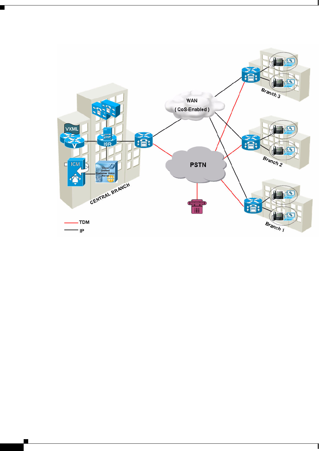
9-10
Cisco Unified Customer Voice Portal (CVP) 8.x Solution Reference Network Design (SRND)
OL-15989-06
Chapter 9 Network Infrastructure Considerations
Call Admission Control
Queue-at-the-Edge Branch Office Deployment Model
You can deploy Unified CVP in a centralized UCM branch office deployment to provide
queue-at-the-edge functionality. In this deployment model, branch-located ingress gateways are
typically used to allow callers access using local phone numbers rather than centralized or
non-geographic numbers. This consideration is especially important in international deployments
spanning multiple countries.
Egress gateways are located at branches either for localized PSTN breakout or for integration of
decentralized TDM platforms (ACDs) into the CVP switching solution. Apart from the gateways all
other CVP components are centrally located and WAN links provide data connectivity from each branch
location to the central data center. (Although the media server is centrally located, commonly used VRU
media is cached at the local branch.)
In the Unified CVP branch office deployment model using queue-at-the-edge, the only equipment at the
branch office is an ingress gateway (optionally acting as a VXML gateway as well), IP phones for
Unified CCE agents, IPT (user) phones, and agent desktops.
You can configure Unified CCE Skill Groups, dial plans and routing priorities so that callers who ingress
at one branch are connected by preference to agents who are located at the same branch. In these cases,
the RTP traffic flows directly from ingress gateway to IP phone, and does not need to traverse the WAN
(although signaling and data may traverse the WAN).

9-11
Cisco Unified Customer Voice Portal (CVP) 8.x Solution Reference Network Design (SRND)
OL-15989-06
Chapter 9 Network Infrastructure Considerations
Call Admission Control
The goal of this model is to first route the calls locally to an agent available in the branch office, if
possible, and keep the media streams local. If the local agent is not available, only the call gets routed
to the agent on another branch office over the WAN link; the originating call and the initial VRU
treatment are done locally.
Another advantage of this deployment configuration is that in the event of WAN link failure, the call can
still be routed locally using the CVP survivability application running on the pots dial-peer for TDM
originated calls.
LBCAC Concept Definitions
The following definitions are important to the LBCAC feature:
• Phantom Location. A default location with unlimited bandwidth used when calculating calls that
are hairpinned over an H.323 or SIP trunk or when the H.323 or SIP call is queued at the local
branch, to enable correct bandwidth calculations. The Phantom location should be assigned to the
gateway or trunk for CVP.
• siteID. The siteID is a string of numbers that is appended to the label from Unified ICM so that the
dial plan can be configured to route the call to a specific destination, such as the branch VXML
gateway or egress gateway, or UCM node. The siteID can be appended at the front of the label, at
the end, or not at all. This configuration is separate from the Unified CM location configuration, and
is specific to Unified CVP. The siteID is used to indicate the real location of the call and allow the
bandwidth to be deducted from the correct location. siteID is unique across multiple Unified CM
clusters. Multiple siteIDs can still route to the same branch office (if needed) by mapping the unique
siteIDs to same branch gateways in proxy/gatekeeper routes
Importance and Comparison of LBCAC Feature
The LBCAC Feature addresses two important issues with the prior CAC feature:
1. Bandwidth miscalculations in CAC with IP originated callers, as well as with any post transfers from
agents.
2. Inability to deterministically select a local VXML GW for VRU treatment at the branch office
during warm transfers from an agent due to no correlation between the two calls at consult.
Comparing LBCAC to the OrigIP Trunk feature on Unified CM:
• Before Unified CM implemented the phantom trunk and siteID feature for bandwidth calculation,
there was the existing feature used by Unified CVP that enabled the correct trunk to be selected
depending on the original IP of the caller. This feature enabled Unified CM to select to the correct
trunk for the TDM gateway, instead of only using the single Unified CVP trunk, and it only applies
to incoming calls on the trunk. With this feature, distinct SIP profiles and trunk settings could be
used for each branch gateway without being limited to the settings of the single Unified CVP trunk.
This feature has no impact on bandwidth calculations.
Router Requery with LBCAC
• When a call is rejected by the UCM due to not enough bandwidth, a SIP message 488 Not Acceptable
Here is returned to Unified CVP, where it will trigger a router requery over the GED-125 interface
to the VRU peripheral, and the UCCE Router may return another agent label if requery is configured
properly.
Design Considerations
The following considerations apply when using LBCAC:

9-12
Cisco Unified Customer Voice Portal (CVP) 8.x Solution Reference Network Design (SRND)
OL-15989-06
Chapter 9 Network Infrastructure Considerations
Call Admission Control
• A trunk configured with MTP required will not work with the LBCAC siteID feature. The reason is
when MTP is inserted, the media is terminated between the end point and MTP resource, not
between the two end points.
• If a MTP/Transcoder/TRP media resource is inserted by the UCM media layer, the incoming
location information is not used.
• If the inter cluster call is not hair-pin/loop back to the same cluster, the former behavior of Location
CAC logic will apply.
• Each site is uniquely identified by one siteID. Multiple gateways at the same site would need to align
to the same siteID, but if two clusters happen to use the same location name, then two siteIDs can
map to the same physical branch.
• A second Unified CM cluster may have the same location as the first cluster, but will still be required
to use a unique siteID on Unified CVP. You can define a route in the proxy server to send those
cluster calls to the common VXML gateway at the same location, but used by both the clusters.
• Each cluster would manage the bandwidth for devices in its cluster. If two clusters happen to use the
same physical location, then they would each separately manage the bandwidth for the phones that
they manage.
High Availability and Failover
The following considerations apply when using LBCAC:
• During the CAC failure, Unified CVP returns a failure code to Unified CCE that triggers router
requery.
• If a branch doesn't have a VXML Gateway, then it is recommended to use the VXML Gateway at
the Central data center.
Additional Important Information for LBCAC
The previous version of Unified CVP provided a method of configuring CAC. This method is superseded
by the LBCAC method presented here. Both configuration methods are provided in the Configuration
and Administration Guide for Cisco Unified Customer Voice Portal (CVP), available at:
http://www.cisco.com/en/US/products/sw/custcosw/ps1006/products_installation_and_configurati
on_guides_list.html

9-13
Cisco Unified Customer Voice Portal (CVP) 8.x Solution Reference Network Design (SRND)
OL-15989-06
Chapter 9 Network Infrastructure Considerations
QoS Marking
QoS Marking
The Unified CVP Call Server marks only the QoS DSCP for SIP messages. If QoS is needed for Unified
CVP H.323 signaling and data traffic across a WAN, configure network routers for QoS using the IP
address and ports to classify and mark the traffic as recommended in Table 9-3.
Neither the CVP-Data queue nor the Signaling queue is a priority queue as described in Cisco IOS router
terminology. The priority queue is used for voice or other real-time traffic, while call signaling and
Unified CVP traffic are reserved a certain amount of bandwidth based on the call volume.
Network Latency
Once proper application bandwidth and QOS policies are in place, another important consideration in a
distributed CVP deployment is that of network latency. With sufficient network bandwidth, the primary
contributor to latency is distance between the VXML gateway and the CallServer/VXML Server.In
distributed CVP deployments, it is important to minimize this latency and to also understand its effect
on solution performance.
The primary effect of network latency between CVP components is on the end user’s calling experience.
Call signaling latency, either SIP or H.323, between the CVP Call Servers and voice gateways will affect
the call setup time and may add a period of silence during this setup. This includes the initial call setup
and subsequent transfers and/or conferences that are part of the final call flow. VXML application
document download time is also significantly affected by network latency and will have a pronounced
effect on the ultimate caller experience.
Table 9-3 Recommended Port Usage and QoS Settings
Component Port Queue PHB DSCP
Maximum
Latency
(Round Trip)
Media Server TCP 80 CVP-Data AF111
1. The DSCP (or PHB) value for CVP-Data traffic is only a recommendation. You can choose the actual DSCP value used to mark the traffic according to
your preference.
1011 sec
Unified CVP Call Server, H.323 TCP 1720 Call Signaling CS3 24 200 ms
Unified CVP Call Server, SIP TCP or UDP 5060 Call Signaling CS3 24 200 ms
Unified CVP IVR Service TCP 8000 CVP-Data AF1111011 sec
Unified CVP VXML Server TCP 7000 CVP-Data AF1111011 sec
Ingress Gateway, H.323 TCP 1720 Call Signaling CS3 24 200 ms
Ingress Gateway, SIP TCP or UDP 5060 Call Signaling CS3 24 200 ms
VoiceXML Gateway, H.323 TCP 1720 Call Signaling CS3 24 200 ms
VoiceXML Gateway, SIP TCP or UDP 5060 Call Signaling CS3 24 200 ms
H.323 Gatekeeper UDP 1719 Call Signaling CS3 24 200 ms
SIP Proxy Server TCP or UDP 5060 Call Signaling CS3 24 200 ms
MRCP TCP 554 Call Signaling CS3 24 200 ms

9-14
Cisco Unified Customer Voice Portal (CVP) 8.x Solution Reference Network Design (SRND)
OL-15989-06
Chapter 9 Network Infrastructure Considerations
Network Latency
Some recommendations are defined below to help minimize the effect of geographic separation of
VXML gateway from CVP CallsServer/VXML Server. However, in some cases depending on the
business needs of the customer callflows, it may still be necessary to co-locate the
CallServer/VXMLServer with the remote VXML gateways.
The solution makes heavy use of the HTTP protocol to transfer Voice XML documents and other media
files that are ultimately played to the caller. For the best end user calling experience, this HTTP traffic
should be treated with a priority higher than that of normal HTTP traffic in an enterprise network. The
recommendation is to treat this HTTP traffic the same as CVP call signaling traffic if possible. Measures
that may be used to work around latency issues include moving the VXML Server to the same local area
as the VXML gateway, or using Cisco Wide Area Application Services (WAAS).
Otherwise, system configuration changes listed in the following bullets can help with WAN delays.
1. Provide audio to the caller during periods of silence
The following settings provide ringback and audio during times of dead air so that the caller does not
disconnect.
• On the survivability service, the setting for "wan-delay-ringback" can be set to 1 to add a
ringback tone during longer than normal call setup times with IVR.
• IVR subsystem settings for IVR.FetchAudioDelay and IVR.FetchAudioMinimum are added.
They are WAN Delay settings for when root doc fetch is delayed over the WAN link.
• Specify the value for IVR.FetchAudio as follows: fetchaudio="flash:holdmusic.wav". Leave the
default empty so that nothing will be played in a normal scenario.
Note • A default setting of 2 is needed to avoid a blip sound in a normal network scenario.
• Setting WAN Delay to zero will have the effect of immediately playing holdmusic.wav and then
playing it for a minimum of 5 seconds.
• ECC variables such as user.microapp.fetchdelay, user.microapp.fetchminimum and
user.microapp.fetchaudio may be used to override these values in between invocations of
getSpeechExternal microapps.
2. Disable Microsoft TCP Chimney settings
Disabling TCP offloading(Chimney) on CVP servers is to be done as per
http://www.cisco.com/en/US/ts/fn/632/fn63215.html.
Apply the following Microsoft patch on the CVP Server boxes: http://support.microsoft.com/kb/948496
Windows 2003 SP2 turns on the TCPChimney Stack by default, which helps off-load some of the TCP
traffic from the NIC to the CPU.
The procedure to disable TCP Offloading / Chimney issue is shown below. Steps 2 - 4 are described at
the WORKAROUND section of the above link.
• Apply the patch (listed at the RESOLUTION section of the above link; pick the right one)
• Disable offloading from the NIC properties window
• Verify the changes in the registry
3. Enable Path MTU Discovery on the VXML gateways
On the VXML gateways, add the following command: ip tcp path-mtu-discovery
Path MTU Discovery is a method for maximizing the use of available bandwidth in the network between
the endpoints of a TCP connection.

9-15
Cisco Unified Customer Voice Portal (CVP) 8.x Solution Reference Network Design (SRND)
OL-15989-06
Chapter 9 Network Infrastructure Considerations
Blocking Initial G.711 Media Burst
4. Minimize round trips between the VXML server and the ICM script
When control is passed from a running VXML server application back to the ICM script, a significant
WAN delay will be incurred.
Once a VXML Server application starts executing, the best practice is to minimize the number of trips
back to the ICM script. Each round trip between the VXML Server and the ICM script incurs delay due
to establishing two new TCP connections and HTTP retrieval of several VXML documents, including
the VXML server root document.
5. Decrease the size of the VMXL server root document.
On the VXML server, in your specific gateway adapter's plugin.xml file:
Change:
<setting name="vxml_error_handling">default</setting>
To:
<setting name="vxml_error_handling">minimal</setting>
As an example, the location of the plugin.xml file for the CISCO DTMF 1 GW adapter is:
Cisco\CVP\VXMLServer\gateways\cisco_dtmf_01\6.0.1\plugin.xml
Blocking Initial G.711 Media Burst
When a gateway first receives a call, the gateway signals the Unified CVP Call Server (Call Server) using
H.323 in order to hand off the call control responsibilities. To establish this initial call, a short media
stream is established between the gateway and the Call Server. The media stream is only in one direction,
from the gateway to the Call Server. Because this media stream is not accounted for by Unified CM’s
locations-based call admission control, Cisco recommends that the media stream be blocked from
traversing bandwidth-constrained links to avoid oversubscribing the priority queue. This precaution is
needed only for H.323 deployments; SIP deployments do not have this consideration.
The following IOS configuration will avoid the unnecessary connection attempts and avoid ICMP
destination unreachable responses on the network due to failure to establish an RTP connection with the
Voice Browser. The symptom that the customer is having will be a high CPU spike as shown in the "show
proc cpu" output, and the process called "IP Input" can get over 10% CPU utilization without this
workaround.
access-list 100 deny udp host 10.0.0.1 host 10.10.0.100 range 16384 65535
access-list 100 permit ip any any
interface serial0/0
ip access-group 100 out
In the preceding example, 10.0.0.1 is the voice gateway’s H.323-bound IP address and 10.10.0.100 is the
Call Server. If there are multiple Call Servers, add one ACL entry for each. The interface serial0/0 is the
WAN interface connecting to the central site that is hosting the Call Server.
Note The preceding workaround will also avoid sending ICMP “unreachable” messages that occur due to the
failure to establish the RTP connection.

9-16
Cisco Unified Customer Voice Portal (CVP) 8.x Solution Reference Network Design (SRND)
OL-15989-06
Chapter 9 Network Infrastructure Considerations
Network Security Using Firewalls
Network Security Using Firewalls
When configuring network security using firewalls or ACLs, refer to Table 9-4 for information about
TCP/UDP ports used by Unified CVP, voice gateways, VoiceXML gateways. For a complete listing of
ports used by Unified CVP, refer to the Unified CVP Port Utilization Guide.
Note Because the Unified CVP Operations Console Server uses dynamic ports for communication with other
components, it cannot be deployed outside of a firewall while the rest of the Unified CVP components
reside inside the firewall.
Table 9-4 TCP/UDP Ports Used by Unified CVP, Voice Gateways, and VoiceXML Gateways
Source and Destination Component Destination Port
Voice Gateway to Media Server TCP 80
Voice Gateway to Unified CVP Call Server H.225 TCP 1720
Voice Gateway to Unified CVP Call Server SIP TCP or UDP 5060
Voice Gateway to Unified CVP Call Server TCP 8000 (non-SSL); TCP 8443 (SSL)
Voice Gateway to Unified CVP VXML Server TCP 7000 (non-SSL); TCP 7443 (SSL)
Voice Gateway to MRCP Server TCP 554
Unified CVP Call Server to Egress Voice Gateway H.225 TCP 1720
Unified CVP Call Server to Egress Voice Gateway SIP TCP or UDP 5060
Unified CVP Call Server to VoiceXML Gateway H.225 TCP 1720
Unified CVP Call Server to VoiceXML Gateway SIP TCP or UDP 5060
Unified CVP Call Server to H.323 Gatekeeper UDP 1719
Unified CVP Call Server to SIP Proxy Server TCP or UDP 5060

CHAPTER
10-1
Cisco Unified Customer Voice Portal (CVP) 8.x Solution Reference Network Design (SRND)
OL-15989-06
10
Call Transfer Options
Last revised on: August 8, 2011
Designing for call transfers is one of the major steps required when designing a Unified CVP
deployment. There are numerous transfer options that can be used with Unified CVP. The goal of this
chapter is to explain each of the various options and to provide pros, cons, and considerations associated
with each.
This chapter covers the following topics:
• Release Trunk Transfers, page 10-2
• ICM Managed Transfers, page 10-5
• Network Transfer, page 10-6
• SIP Refer Transfer, page 10-7
• H.323 Refer Transfer, page 10-7
• Intelligent Network (IN) Release Trunk Transfers, page 10-7
• VoiceXML Transfers, page 10-8
What's New in This Chapter
Table 10-1 lists the topics that are new in this chapter or that have changed significantly from previous
releases of this document.
Table 10-1 New or Changed Information Since the Previous Release of This Document
New or Revised Topic Description
SIP Hookflash Support, page 10-4 SIP support for transfer using a hookflash signal.

10-2
Cisco Unified Customer Voice Portal (CVP) 8.x Solution Reference Network Design (SRND)
OL-15989-06
Chapter 10 Call Transfer Options
Release Trunk Transfers
Release Trunk Transfers
This section deals with the types of transfers that release the ingress trunk, thus removing the gateway
and Unified CVP from the call control loop. There is no tromboning in these cases. These transfers have
the following characteristics:
• Release Trunk Transfers can be invoked by the Unified CVP VXML Server (standalone model) or
via the Unified ICM.
• Unified ICM Network Transfer using Unified CVP as the routing client will not work because
Unified CVP can no longer control the call.
• These transfers are blind, meaning that if the transfer fails for any reason, Unified ICM does not
recover control of the call. Router Requery is not supported.
• From the standpoint of Unified ICM reporting, Release Trunk Transfers cause the switch leg to
terminate, resulting in a TCD record being written to the database for the call even though the caller
is still potentially talking to an agent. This behavior differs from other types of transfers in which
the TCD record does not get finalized until the caller actually hangs up.
• Because the ingress trunk is released, you do not have to size gateways to include calls that have
been transferred in this way. This behavior differs from other types of transfers in which gateway
resources continue to be occupied until the caller hangs up.
• Because Unified CVP is no longer monitoring the call, you do not have to size Unified CVP Call
Servers to include calls that have been transferred in this way. Additionally, Unified CVP Call
Director port licenses are not required.
There are three signaling mechanisms available to trigger a release trunk transfer:
• Takeback-and-Transfer (TNT), page 10-2
• Hookflash and Wink, page 10-3
• Two B Channel Transfer (TBCT), page 10-4
Takeback-and-Transfer (TNT)
TNT (also known as Transfer Connect) is a transfer mechanism offered by some U.S. PSTN service
providers (such as AT&T and Verizon). With this transfer method, inband DTMF tones are outpulsed to
the PSTN by Unified CVP. These inband tones act as a signaling mechanism to the PSTN to request a
transfer to be completed. A typical DTMF sequence is *8xxxx, where xxxx represents a new routing label
that the PSTN understands. Upon detection of a TNT DTMF sequence, the PSTN drops the call leg to
the ingress gateway port and then re-routes the caller to a new PSTN location (such as a TDM ACD
location).
This behavior might be necessary for a customer with existing ACD site(s) but no IVR, who wants to
use Unified CVP initially as just an IVR. Over time, the customer might want to transition agents from
the TDM ACD(s) to Cisco Unified CCE and use Unified CVP as an IVR, queueing point, and transfer
pivot point (thus eliminating the need for TNT services).
In Unified CVP deployments with the ICM, the DTMF routing label outpulsed could have been a Unified
ICM translation routing label to enable passing of call data to another Unified ICM peripheral (such as
a TDM ACD). In this scenario, Unified CVP views the call as completed, and Unified CVP call control
is ended. With TNT, if the transfer to the termination point fails, there is nothing Unified CVP can do to
re-route the call. While some TNT services do have the ability to re-route the call back to Unified CVP,
Unified CVP sees this call as a new call.

10-3
Cisco Unified Customer Voice Portal (CVP) 8.x Solution Reference Network Design (SRND)
OL-15989-06
Chapter 10 Call Transfer Options
Release Trunk Transfers
Hookflash and Wink
Hookflash and wink are signaling mechanisms typically associated with a TDM PBX or ACD.
Hookflash applies only to analog trunks and wink applies only to digital trunks (T1 or E1 channel), but
otherwise they are similar in function. Both hookflash and wink send an on-hook or off-hook signal to
the PBX or ACD, which responds with dial tone (or the PBX winks back on a digital trunk). This
signaling causes the voice gateway to send a string of routing digits to the PBX or ACD. Upon collection
of the routing digits, the PBX or ACD transfers the caller to the new termination, which could be an ACD
queue or service on that same PBX or ACD.
This behavior might be necessary for a customer with an existing ACD but no IVR, who wants to use
Unified CVP initially as an IVR logically installed on the line side of their existing PBX or ACD. Over
time, the customer might want to transition agents from the TDM ACD to Cisco Unified CCE and have
the voice gateways connected to the PSTN instead of the line side of the PBX or ACD. In Unified CVP
deployments with Unified ICM, the routing label could be a Unified ICM translation routing label. This
label enables passing of call data to the ACD service (and subsequently to the agent in a screen pop).
With hookflash and wink, if the transfer to the termination point fails, there is nothing Unified CVP can
do to re-route the call. While some PBX or ACD models do have the ability to re-route the call back to
Unified CVP, Unified CVP sees this call as a new call.
Hookflash transfer has been problematic in the past because the PBXs and the gateways have constrained
support for this feature. If at all possible, avoid using the PBX for Unified ICM switching, and terminate
all incoming calls on Unified CVP ingress gateways rather than on the PBX, thus allowing Unified CVP
to route calls to the PBX rather than the other way around.
However, if hookflash transfers are required, the following guidelines and notes apply:
• Cisco 1700 Series Gateways were not tested with hookflash transfers.
• Cisco 2800 and 3800 Series Gateways can support Analog FXO or Digital FXO (T1/CAS). This
function is considered line-side hookflash to the PBX, and it worked very well in tests with Avaya
Definity G3. (However, E&M is not supported at this time.) You can adjust the hookflash duration
with the command timing hookflash-out under the voice-port. This feature is useful if you have a
PBX that has a non-configurable hookflash duration, and it gives you the ability to adjust the
hookflash duration on the gateway side.
• Cisco 5x00 Series Gateways were tested with T1/CAS and the command e&m-fgb dtmf dnis. E&M
is considered "trunk-side hookflash" to the PBX, and not all switches support trunk-side hookflash
(the Avaya Definity G3 does not). Additionally, the hookflash duration on the Cisco 5x00 Series
Gateways is 200 ms, and you must configure the PBX for this same duration. This option varies with
switch type, and a proof-of-concept with the switch vendor is highly recommended.
• In Deployment Model #1, Standalone Self-Service, a TCL script is required to produce the
hookflash. A TCL script is provided with Unified CVP.
• For Digital FXO (T1 CAS) Trunks, Automatic Number Identification (ANI) is not available to the
call when it gets to Unified CVP. In some Unified CVP deployment models, the ICM might already
know the ANI if the call had been pre-routed there.
• For Digital FXO (T1 CAS) Trunks, Dialed Number Identification Service (DNIS) must be
configured on the gateway, based on the T1/E1 channel on which the call arrives. The PBX is
programmed to route certain DNIS calls over certain T1 trunks. Because the call arrives to the
gateway on that trunk, you can definitively configure its DNIS. The drawback to this approach is
that the gateway trunk allocation must be predetermined. You must know what percentage of calls
arrive to which DNISs so that the trunk groups on the gateway can be allocated accordingly.

10-4
Cisco Unified Customer Voice Portal (CVP) 8.x Solution Reference Network Design (SRND)
OL-15989-06
Chapter 10 Call Transfer Options
Release Trunk Transfers
An alternate method that can be used on some PBXs is a "converse on step," whereby DTMF tones
indicating DNIS and ANI are sent to the IVR. This method requires a single main Unified ICM
routing script to input DNIS digits using a Get Data (GD) Microapplication and to invoke the correct
sub-script based on the collected DNIS digits. This method requires close coordination between
Cisco, the PBX vendor, and the customer, and it has not yet been tested.
• For FGB E&M Trunks in Cisco 5x100 series Gateways, ANI and DNIS can be sent by using “*” as
the delimiter. For example: *ANI*DNIS*. For Configuration details, please refer to ANI/DNIS
Delimiter for CAS Calls on CT1, available online at:
http://www.cisco.com/en/US/customer/docs/ios/12_1t/12_1t1/feature/guide/anidnis.html
SIP Hookflash Support
Hookflash is a signalling mechanism that is typically associated with a TDM PBX or ACD. The endpoint
sends an on-hook or off-hook signal to the PBX or ACD, which responds with a dial tone. This signaling
causes the voice gateway to send a string of routing digits to the PBX or ACD. Upon collection of the
routing digits, the PBX or ACD transfers the caller to the new termination, which could be an ACD queue
or service on that same PBX or ACD.
The SIP Hookflash feature permits Unified CVP to transfer SIP calls using a hook flash followed by the
DTMF destination. This feature enables deployments in which a PBX front-ends the Unified CVP
ingress gateway, and in which the PBX provides non-VoIP connectivity to agents.
In a typical use case, the caller calls into the system and is transferred to an agent who is associated with
a TDM ACD. Unified CCE returns the label for Unified CVP to perform a hookflash transfer to the
PSTN so that the caller can be routed to the correct agent. The label returned will have an HF pre-pended
to the hookflash routing digits. The caller is transferred to the agent and Unified CVP is no longer in
control of the call.
Design Considerations
The following limitations apply to using the SIP Hookflash feature:
• This feature is only supported on 2X and 3X gateways. It is not supported on 5X gateways (e.g.
5400XM).
• Hookflash only applies to TDM originated calls. Once hookflash is invoked by Unified CVP,
Unified CVP is no longer in control of the call.
Two B Channel Transfer (TBCT)
TBCT is an ISDN-based release trunk signaling mechanism that is offered by some PSTN service
providers. When a TBCT is invoked, the ingress gateway places the initial inbound call on hold briefly
while a second call leg (ISDN B Channel) is used to call the termination point. When the termination
point answers the call, the gateway sends ISDN signaling to the PSTN switch to request that the transfer
be completed and that the call be bridged through the PSTN switch and removed from the ingress
gateway. As with a TNT transfer, the termination point might be a TDM PBX or ACD connected to the
PSTN.

10-5
Cisco Unified Customer Voice Portal (CVP) 8.x Solution Reference Network Design (SRND)
OL-15989-06
Chapter 10 Call Transfer Options
ICM Managed Transfers
This behavior might be necessary for a customer with existing ACD site(s) but no IVR, who wants to
use Unified CVP initially as just an IVR. Over time, the customer might want to transition agents from
the TDM ACD(s) to Cisco Unified CCE and use Unified CVP as an IVR, queueing point, and transfer
pivot point (thus eliminating the need for TBCT services and using Unified CVP to perform reroute on
transfer failure).
ICM Managed Transfers
Most Unified CVP customers use Unified ICM Managed transfers. Unified CVP performs this function
most naturally, providing gateway-based switching for Unified ICM and Unified CCE installations.
In Unified CVP deployments with Unified ICM, Unified ICM provides all call control. VoiceXML call
control from the Unified CVP VXML Server is not supported when Unified ICM is deployed with
Unified CVP.
Unified ICM Managed transfers transfer the call to a new termination point, which can be any of the
following:
• A Cisco Unified Communications Manager phone
• An egress port on the same gateway as the ingress port
• A distant egress gateway that has a TDM connection to a TDM ACD or PBX (making use of toll
bypass features)
• A Unified CVP VoiceXML gateway for queuing or self-service activities
To terminate the call, the voice gateway selects an outgoing POTS or VoIP dial-peer based on the
destination specified by Unified ICM. When a Unified ICM VoIP transfer occurs, the ingress voice
gateway port is not released. If the termination point is an egress voice gateway, then a second voice
gateway port is utilized. Unified CVP continues to monitor the call, and Unified ICM also retains control
of the call and can instruct Unified CVP to transfer the call to a new destination.
This type of transfer is used when Unified CVP is used as a call treatment platform and queue point for
Unified CCE agents. Unified CVP could also be used to provide call treatment to front- end calls to TDM
ACD locations supported by Unified ICM. This type of transfer allows for calls to be transferred between
peripherals supported by Unified ICM, with full call context and without any tromboning of the voice
path.
Calls that are transferred in this way have the following characteristics:
• Unified ICM Network Transfer using Unified CVP as the routing client functions properly because
Unified CVP continues to control the call.
• These transfers are supervised, meaning that if the transfer fails for any reason, the Unified ICM
routing script does recover control via the Router Requery mechanism.
• From the standpoint of Unified ICM reporting, the switch leg does not terminate until the caller
actually hangs up. Thus, the TCD record that is written for the switch leg of the call encompasses
the entire life of the call, from initial ingress to hang-up.
• Because the ingress trunk is not released, you must size gateways to include calls that have been
transferred in this way.
• Because Unified CVP continues to monitor the call, you must size Unified CVP Call Servers to
include calls that have been transferred in this way. Additionally, Unified CVP Call Director port
licenses are required, except for calls that are connected to Cisco Unified Communications Manager
agents.

10-6
Cisco Unified Customer Voice Portal (CVP) 8.x Solution Reference Network Design (SRND)
OL-15989-06
Chapter 10 Call Transfer Options
Network Transfer
Network Transfer
Unified CVP provides the capability to transfer calls to another destination after they have been
answered by an agent. This capability are referred to as Network Transfer.
When a call is transferred from Unified CVP to an agent, and that agent wants to transfer the call to
another agent, the agent can make that transfer using either the agent IP phone or agent desktop.
Transfers from the IP phone are made using CTI route points that point to a Unified ICME script.
Transfers from the agent desktop are made using the Dialed Number Plan.
There are two flags in Unified ICME to control the Network Transfer:
• NetworkTransferEnabled — This is a flag in the Unified ICME script. If enabled, it instructs the
Unified ICM to save the information about the initial routing client (the routing client that sent the
NewCall route request).
• NetworkTransferPreferred — This flag is checked on the Unified CVP PG configuration. If it is
checked, then any route request from this routing client (where Unified ICME knows about the
initial routing client) will send the route response to the initial routing client instead of the routing
client that sent the route request.
The following recommendations apply when using Network Transfer:
• Network Transfer using the two flags listed above can be used to perform a blind transfer only from
agent 1 to agent 2 via Unified CVP. In this case, Unified CVP will get instruction from
Unified ICME to pull the call back from agent 1 and route it either to a VoiceXML gateway (for IVR
treatment) or to another destination (to agent 2, for example).
• Network Transfer cannot be used to perform a warm transfer or conference with Unified CVP
because the call leg to agent 1 must be active while agent 1 performs a consultation or conference.
Unified CVP cannot pull the call back from agent 1 during the warm transfer and/or conference.
If a caller would like to dial the same number regardless of a blind transfer, warm transfer, or conference,
then the following recommendations and best practices can be used:
• Do not enable the NetworkTransferEnable flag in the Unified ICME script.
• Any transfer or conference request from an agent must dial the CTI Route Point of the same
Unified CCE PG to preserve the call context during the transfer. Dialing the Route Pattern or CTI
Route Point of another PG will not preserve the call context.
• Always use SendToVru as the first node in the Unified ICME routing script.
• In H.323-based deployments, there are two timers in Cisco Unified Communications Manager that
must be set to a value greater than the Unified CVP RONA timer. These timers are used to handle
the situation of consultation completion while agent 2’s phone is ringing. The timers are:
–
Clusterwide Parameters (Service) ->Media Exchange Timer
–
Clusterwide Parameters (Service) ->Media Resource Allocation Timer
• In H.323-based deployments, if you are using Cisco Unified CM 6.1.3 or earlier release, then you
have to uncheck the flag "Wait for Far End H.245 Terminal Capability Set" on the Unified CM
trunks configured with the UCCE PG Routing client label.
• Extra ports will be used during the consultation, blind transfer, and/or conference. They are released
only when the originating consultation is terminated.

10-7
Cisco Unified Customer Voice Portal (CVP) 8.x Solution Reference Network Design (SRND)
OL-15989-06
Chapter 10 Call Transfer Options
SIP Refer Transfer
SIP Refer Transfer
In some scenarios, it is desirable for Unified CVP to transfer a call to a SIP destination and not have
Unified ICM and Unified CVP retain any ability for further call control. Unified CVP can perform a SIP
Refer transfer, which allows Unified CVP to remove itself from the call, thus freeing up licensed Unified
CVP ports. The Ingress Voice Gateway port remains in use until the caller or the terminating equipment
releases the call. SIP Refer transfers may be used in both Comprehensive and Call Director deployments.
A SIP Refer transfer can be invoked by either of the following methods:
• Unified ICM sends Unified CVP a routing label with a format of rfXXXX (For example, rf5551000).
• An application-controlled alternative is to set an ECC variable (user.sip.referertransfer) to the value
y in the Unified ICM script, and then send that variable to Unified CVP.
The SIP Refer transfer can be invoked after Unified CVP queue treatment has been provided to a caller.
SIP Refer transfers can be made to Cisco Unified Communications Manager or other SIP endpoints, such
as a SIP-enabled ACD.
Router requery on a failed REFER transfer is supported using SIP with the Unified CVP release 8.0(1),
but only on calls where the survivability service is not handling the REFER request.
H.323 Refer Transfer
Unified CVP 4.0(2) introduces a new transfer mechanism for H.323 calls that behaves in a similar
manner to SIP Refer. This feature allows Unified CVP to remove itself from the call, thus freeing up call
control ports. Using this feature, the call can be queued at the VoiceXML gateway and then sent to an
agent on Cisco Unified Communications Manager or other H.323 endpoints such as an ACD.
Unified CVP cannot execute further call control operations after this kind of transfer has been executed;
however, Unified CVP Survivability can still be used for failure recovery in this scenario. This feature
can be used in both Comprehensive and Call Director call flow models, and it is available only for
PSTN-originated calls via a Cisco IOS gateway running the Unified CVP Survivability service.
The H.323 Refer transfer can be invoked by either of the following methods:
• Unified ICM sends Unified CVP a routing label with a format of RF88#xxxx# (For example,
RF88#5551000#).
• An application-controlled alternative is to set an ECC variable (user.h323.rftransfer) to the value y
in the Unified ICM script, and then send that variable to Unified CVP. The CVP H.323 service will
modify the received label automatically to conform to the format given above.
The Unified CVP Survivability service should be enabled to execute the H323 Refer transfers by using
the following parameter:
param icm-rf 1
Intelligent Network (IN) Release Trunk Transfers
Customers using Deployment Model #4 (VRU Only with NIC Controlled Routing) rely on call switching
methods that do not involve Unified CVP. In these situations, all switching instructions are exchanged
directly between a Unified ICM Network Interface Controller (NIC) and the PSTN. Examples of such
NIC interfaces include Signaling System 7 (SS7) and Call Routing Service Protocol (CRSP). The SS7
NIC is also used as an interface into the PGW in deployments that involve that device. Thus, PGW
deployments perform this type of transfer.

10-8
Cisco Unified Customer Voice Portal (CVP) 8.x Solution Reference Network Design (SRND)
OL-15989-06
Chapter 10 Call Transfer Options
VoiceXML Transfers
VoiceXML Transfers
VoiceXML call control is supported only in standalone Unified CVP deployments (Deployment Model
#1) in which call control is provided by the Unified CVP VXML Server. Deployment Model #3b, which
also incorporates the Unified CVP VXML Server, does not support VoiceXML call control. In those and
all Unified ICM integrated deployments, Unified ICM must make all call control decisions.
The Unified CVP VXML Server can invoke three types of transfers: Release Trunk transfers, VoiceXML
blind transfers, and VoiceXML bridged transfers. Release Trunk transfers result in the incoming call
being released from the ingress voice gateway. VoiceXML blind transfers result in the call being bridged
to an egress voice gateway or a VoIP endpoint, but the Unified CVP VXML Server releases all
subsequent call control. VoiceXML bridged transfers result in the call being bridged to an egress voice
gateway or a VoIP endpoint, but the Unified CVP VXML Server retains call control so that it can return
a caller to an IVR application or transfer the caller to another termination point.
Release Trunk transfers from the Unified CVP VXML Server are invoked using the subdialog_return
element. The Unified CVP VXML Server can invoke a TNT transfer, TBCT transfer, and
HookFlash/Wink transfers as well as SIP Refer transfers. For TDM Release Trunk transfers (TNT, TBCT
and Hookflash/Wink), the VoiceXML gateway must be combined with the ingress gateway in order for
the Release Trunk transfer to work.
VoiceXML blind and bridged transfers are invoked using the Transfer element in Cisco Unified Call
Studio. VoiceXML Transfers will transfer the call to any dial-peer that is configured in the gateway.
VoiceXML Blind Transfers differ from VoiceXML Bridged Transfers in the following ways:
• VoiceXML blind transfers do not support call progress supervision, whereas Bridged transfers do.
This means that if a blind transfer fails, the Unified CVP VXML Server script does not recover
control and cannot attempt a different destination or take remedial action.
• VoiceXML blind transfers cause the Unified CVP VXML Server script to end. Always connect the
"done exit" branch from a Blind transfer node to a subdialog_return and a hang-up node.
Bridged transfers do not terminate the script. The Unified CVP VXML Server waits until either the
ingress or the destination call ends. The script ends only if the ingress call leg hangs up. If the destination
call leg hangs up first, the script recovers control and continues with additional self-service activity. Note
that the Unified CVP VXML Server port license remains in use for the duration of a bridged transfer,
even though the script is not actually performing any processing.

CHAPTER
11-1
Cisco Unified Customer Voice Portal (CVP) 8.x Solution Reference Network Design (SRND)
OL-15989-06
11
Using the GKTMP NIC
Last revised on: May 2, 2010
This chapter covers the following topics:
• The Cisco Gatekeeper External Interface, page 11-1
• The Unified ICM GKTMP NIC, page 11-1
• Typical Applications of GKTMP with Unified CVP, page 11-2
The Cisco Gatekeeper External Interface
The Cisco H.323 Gatekeeper provides an external interface that uses Gatekeeper Transaction Message
Protocol (GKTMP) to hand off the processing of Registration Admission Status (RAS) requests to
external applications. This feature allows organizations to supplement the on-board capabilities of the
gatekeeper and to provide support for externally managed dial plans and intelligent call routing in an
H.323 voice network.
GKTMP is based on RAS and provides a set of ASCII request and response messages that can be used
to exchange information between the Cisco IOS Gatekeeper and the external application over a TCP
connection.
For more information, consult the Cisco Gatekeeper External Interface Reference, available at
http://www.cisco.com/en/US/docs/ios/12_3/gktmpv4_3/guide/gktmp4_3.html
The Unified ICM GKTMP NIC
Using its GKTMP NIC, Unified ICM can function as a GKTMP server for the gatekeeper, processing
GKTMP request messages as route requests and running routing scripts in the normal way. The RAS
sourceInfo Alias and destinationInfo Alias are made available to the Unified ICM script as the Calling
Line ID and Dialed Number respectively, the latter typically being used for script selection by the
Unified ICM Router. The Unified ICM script might perform many different functions, including
database or back-end system access, and finally sends a label back to the NIC for return to the gatekeeper
and ultimately back to the requesting endpoint as the modified destinationInfo Alias. The Unified ICM
script can also modify the sourceInfo Alias. However, not all requesting endpoints use the translated
sourceInfo Alias that is returned; Cisco IOS gateways make use of it, whereas the Unified CVP Call
Server and Cisco Unified Communications Manager both ignore it.

11-2
Cisco Unified Customer Voice Portal (CVP) 8.x Solution Reference Network Design (SRND)
OL-15989-06
Chapter 11 Using the GKTMP NIC
Typical Applications of GKTMP with Unified CVP
To force the gatekeeper to reject the Admission Request (ARQ) and return an Admission Reject (ARJ)
to the requesting endpoint, the Unified ICM script can return a BUSY label, optionally with an additional
reason code (for example, DESTINATION_UNKNOWN).
For information on how to configure the GKTMP NIC, consult the ICM Setup and Installation Guide,
available at:
http://www.cisco.com/en/US/products/sw/custcosw/ps1001/tsd_products_support_series_home.ht
ml
Typical Applications of GKTMP with Unified CVP
The GKTMP NIC can be used with Unified CVP in both pre-routing and post-routing call scenarios. The
former is used to process the Admission Request from the ingress gateway before the call is routed to
the Unified CVP Call Server (Call Server) and answered, the latter for transfers being performed by the
Unified CVP Call Server.
• Intelligent rejection before the call is answered by Unified CVP
When the Call Server receives an H.225 SETUP message, it answers the call by returning a
CONNECT message immediately. Sometimes it is necessary to make a routing decision before
delivering the call to Unified CVP and before the call is answered. One example is the use of
look-ahead routing, in which the Unified ICM script determines the availability and reachability of
other Unified ICM peripherals that will be required for the overall call scenario once the call has
been delivered to Unified CVP. With the GKTMP NIC, it is possible to reject calls intelligently for
alternate routing via the TDM network rather than answering them and not having the resources to
handle them subsequently.
• Selection of Call Server based on H.323 call information
Occasionally the gatekeeper static configuration is not sufficient for selection of the most
appropriate Call Server to handle an incoming call. For example, the routing decision might need to
be based on the calling line ID or source signalling address.
• Manipulation of the calling line ID
Modification of the sourceInfo Alias is sometimes useful in order to overload the calling line ID with
additional information required by the destination endpoint, where translation routing is not
possible.
• Unified ICM-based dial plan
Unified ICM implements a centralized H.323 voice network dial plan, reducing the need for dial
plan configuration on individual gatekeepers. This approach is appropriate only if the dial plan is
large, complex, dynamic, and difficult to maintain across multiple gatekeepers.
• Time-of-day routing
This feature allows the gatekeeper routing to be supplemented with decisions based on date and
time, possibly to handle time-dependent resource availability.
• Back-end system and database queries
Unified ICM database lookup or application gateway capabilities data from external systems can be
incorporated into routing decisions.

11-3
Cisco Unified Customer Voice Portal (CVP) 8.x Solution Reference Network Design (SRND)
OL-15989-06
Chapter 11 Using the GKTMP NIC
Typical Applications of GKTMP with Unified CVP
• Filtering calls that might be sent immediately to an available destination and bypass Unified CVP
While this approach might be seen as a way to avoid using Call Server resources, it limits the
functionality available. For example, there can be no intelligent re-query for alternative destinations
on ring-no-answer, nor will this approach allow the call to be taken back to Unified CVP for
subsequent call treatment and transfers.
• Pre-routing with context passing to Unified CVP
This method is used if call context collected during the pre-routing phase of the call needs to be
passed to Unified CVP rather than simply performing a standalone routing request via the GKTMP
NIC. In this example, the Call Server must be configured as a Type 2 VRU so that the call can be
translation-routed to it and still perform a subsequent transfer.
Protocol-Level Call Flow
Fundamentally, GKTMP allows a Unified ICM routing script to provide additional external business
rules that are called by the gatekeeper to select an alternative destination label or target IP address for a
call, given a dialed number or label. However, the protocol-level call flow differs depending on the
purpose for which the GKTMP request is being used, as described in the following scenarios:
• Pre-routing of incoming calls, but call context passing is not required, page 11-3
In this mode of operation, calls arriving at an ingress gateway make a request to Unified ICM to
select either a particular Unified CVP Call Server target or a non-CVP target. When a Call Server is
selected, the call is delivered to Unified CVP as a completely new call, with no link to the Unified
ICM script involved in the GKTMP-based routing step.
• Pre-routing of incoming calls, and call context passing is required, page 11-4
In this scenario, calls that arrive at an ingress gateway make a request to Unified ICM via the
GKTMP NIC before being delivered to a particular Unified CVP Call Server target. Any information
obtained by this initial Unified ICM routing script is preserved and made available to the Unified
ICM script as processing resumes when the call is delivered to the Call Server.
• Routing of post-ICM calls, page 11-4
This is to modify the routing of calls that are being transferred to a destination label returned to
Unified CVP by an ICM routing script. No information obtained by the previous routing script is
available to the new script invoked by the GKTMP request, which functions in a purely standalone
manner.
Pre-routing of incoming calls, but call context passing is not required
1. A call arrives at the ingress gateway.
2. The ingress gateway requests the gatekeeper to identify a target Unified CVP Call Server (or other
IP destination).
3. The gatekeeper issues a GKTMP Request ARQ to Unified ICM via the GKTMP NIC.
4. Unified ICM starts a routing script based on dialed number, ANI, time of day, and so forth.
5. The Unified ICM routing script might return either a Response ARQ or a Response ACF to the
gatekeeper. In the former case, Unified ICM returns modified information in the response, and the
gatekeeper resumes ARQ processing to select the IP endpoint. This approach is adopted if Unified
ICM is returning a destination label only and not selecting the required destination IP endpoint
address(es) explicitly. In the latter case, Unified ICM completes the processing of the request,

11-4
Cisco Unified Customer Voice Portal (CVP) 8.x Solution Reference Network Design (SRND)
OL-15989-06
Chapter 11 Using the GKTMP NIC
Typical Applications of GKTMP with Unified CVP
returning modified information and the selected target IP endpoints. In this case the gatekeeper
regards the request as completed, does no further processing of the request, and returns the ACF to
the endpoint that issued the ARQ. The Unified ICM routing script ends at this point.
6. The gatekeeper returns the selected IP address to the ingress gateway.
7. If the target is not a Unified CVP device, the ingress gateway sets up a VoIP call to that target.
8. If the target is a Unified CVP Call Server, the ingress gateway sets up a new call to it.
9. The Unified CVP Call Server sends a New Call message to Unified ICM.
10. Unified ICM starts an independent routing script to handle the incoming call.
11. Normal call flow continues. Transfer to VRU leg, Transfer to agent, as well as subsequent blind
Network VRU Transfers to secondary agents or return-to-queue are fully supported.
Pre-routing of incoming calls, and call context passing is required
1. A call arrives at the ingress gateway.
2. The ingress gateway requests the gatekeeper to identify a target Unified CVP Call Server (or other
IP destination).
3. The gatekeeper issues a GKTMP Request ARQ to Unified ICM via the GKTMP NIC.
4. Unified ICM starts a routing script based on dialed number, ANI, time of day, and so forth.
5. The Unified ICM routing script executes a TranslationRouteToVRU to select a target Unified CVP
Call Server.
6. Unified ICM returns the selected translation route label (and optionally the destination endpoint IP
address) in the GKTMP Response ARQ or ACF via the GKTMP NIC.
7. The gatekeeper returns the selected IP address to the ingress gateway.
8. The ingress gateway sets up a new call to the selected Unified CVP Call Server.
9. The Unified CVP Call Server sends a RequestInstruction message to Unified ICM.
10. The Unified ICM routing script resumes after the TranslationRouteToVRU node.
11. Normal call flow continues. Transfer to VRU leg, Transfer to agent, as well as subsequent blind
Network VRU Transfers to secondary agents or return-to-queue are fully supported. (For limitations
in Unified ICM versions prior to 7.0(0), see Deployment Implications, page 11-5.)
Routing of post-ICM calls
1. Unified ICM selects a target agent or other destination label. The Unified ICM routing script ends
at this point.
2. Unified ICM returns the selected label to the Unified CVP Call Server.
3. The Unified CVP Call Server requests the gatekeeper for the endpoint IP address associated with
that label.
4. The gatekeeper issues a GKTMP Request ARQ to Unified ICM via the GKTMP NIC.
5. Unified ICM starts a completely independent routing script based on the selected label, ANI, time
of day, and so forth.
6. This new Unified ICM routing script selects an appropriate target for the call.
7. Unified ICM returns the selected label (and optionally the destination endpoint IP address) in the
GKTMP Response ARQ or ACF response via the GKTMP NIC. The Unified ICM routing script
ends at this point.
8. The gatekeeper returns the selected endpoint IP address to the Unified CVP Call Server.

11-5
Cisco Unified Customer Voice Portal (CVP) 8.x Solution Reference Network Design (SRND)
OL-15989-06
Chapter 11 Using the GKTMP NIC
Typical Applications of GKTMP with Unified CVP
9. The Unified CVP Call Server performs and Empty Capability Set transfer, communicating with the
ingress gateway and the transfer destination endpoint to establish a VoIP call between them.
Deployment Implications
GKTMP is a simple request/response protocol. From the perspective of Unified ICM, this means that the
GKTMP NIC cannot perform any call control other than returning a single label and/or endpoint IP
address. Third-party call control through the GKTMP NIC is not possible once that single destination
has been returned. However, it is possible when call control responsibilities are handed off to Unified
CVP. The following discussion covers these call control implications for each of the three types of call
flows described in the previous section:
• Pre-routing of incoming calls, but call context passing is not required, page 11-5
• Pre-routing of incoming calls, and call context passing is required, page 11-5
• Routing of post-ICM calls, page 11-5
• Other implications, page 11-6
Pre-routing of incoming calls, but call context passing is not required
Two ICM routing scripts are required for this option. The first script identifies the initial target for the
incoming call; the second script is the normal routing script for call handling at Unified CVP, which is
described elsewhere in this guide. The transfer from one script to the other is via a plain label; it is not
a translation route or a VRU leg transfer. The GKTMP-initiated script cannot perform any queuing or
other VRU activity; it can only modify the Admission Request content and optionally return an endpoint
IP address.
In the case where the pre-routing script returns a label that is associated with an endpoint other than a
Unified CVP Call Server, no further call control is possible unless the endpoint is an ACD or VRU with
its own post-routing interface into Unified ICM and its own ability to perform call control operations.
Pre-routing of incoming calls, and call context passing is required
With this option, the GKTMP-initiated and Unified CVP-initiated routing scripts are one and the same.
A TranslationRouteToVRU node must be used to move the call to a Type 2 Unified CVP NetworkVRU.
This node must precede any Queue node if the customer needs the ability to perform any subsequent
agent-to-agent transfers, even if an appropriate agent is already available. This action might seem like
an extraneous transfer, but it is necessary in order to force call control hand-off to Unified CVP.
Following the TranslationRouteToVRU and prior to execution of any RunExternalScript nodes, a second
VRU transfer is required using a SendToVRU node to establish the VRU call leg to the VoiceXML
gateway.
Routing of post-ICM calls
Two completely independent Unified ICM routing scripts are used in this scenario. The only connection
between the two is that the label returned by the first routing script becomes a Dialed Number that the
gatekeeper uses to invoke the second routing script. This transfer is not via a translation route or VRU
leg, and call context is not available to the second script, other than what is included in the gatekeeper
request itself.

11-6
Cisco Unified Customer Voice Portal (CVP) 8.x Solution Reference Network Design (SRND)
OL-15989-06
Chapter 11 Using the GKTMP NIC
Typical Applications of GKTMP with Unified CVP
Other implications
Note that inserting the GKTMP NIC into the call flow does result in additional route requests being
processed by the Unified ICM Router for each call processed in this way, and additional call detail
records are written by the Unified ICM Logger. Where possible, configure the GKTMP server triggers
on the gatekeeper so that only those calls specifically requiring the additional routing functionality
afforded by the GKTMP NIC generate a Request ARQ to Unified ICM.

CHAPTER
12-1
Cisco Unified Customer Voice Portal (CVP) 8.x Solution Reference Network Design (SRND)
OL-15989-06
12
Media File Options
Last revised on: May 2, 2010
This chapter covers the following topics:
• Deployment and Ongoing Management, page 12-1
• Co-Resident Unified CVP Call Server, Media Server, and Unified CVP VXML Server, page 12-2
• Bandwidth Calculation for Prompt Retrieval, page 12-3
• Configuring Caching and Streaming in Cisco IOS, page 12-3
• Configuring Caching and Streaming in Cisco IOS, page 12-3
• Branch Office Implications, page 12-6
Deployment and Ongoing Management
Voice prompts can be stored in the following locations:
• In flash memory on each local gateway
In this way, gateways do not have to retrieve .wav files for prompts, so WAN bandwidth is not
affected. However, if a prompt needs to change, you must change it on every gateway. Cisco
recommends that you store prompts in flash only for critical prompts such as error messages or other
messages that can be used when the WAN is down.
• On an HTTP media server
In this way, each local gateway (if properly configured) can cache many or all prompts, depending
on the number and size of the prompts (up to 100 MB of prompts). The best way to test whether your
media server is appropriately serving the media files is to use a regular web browser such as Internet
Explorer and specify the URL of a prompt on the media server, such as
http://10.4.33.130/en-us/sys/1.wav. Your web browser should be able to download and play the .wav
file without any authentication required.

12-2
Cisco Unified Customer Voice Portal (CVP) 8.x Solution Reference Network Design (SRND)
OL-15989-06
Chapter 12 Media File Options
Co-Resident Unified CVP Call Server, Media Server, and Unified CVP VXML Server
Co-Resident Unified CVP Call Server, Media Server, and
Unified CVP VXML Server
If your Unified CVP Call Server, Media Server, and Unified CVP VXML Server reside on the same
hardware server and you have multiple co-resident servers, Unified CVP will not automatically use the
same physical server for call control, VXML, and media file services. Just because the components are
co-resident, that does not force one component to use the other co-resident components, and it is just as
likely to use the components located on another server.
By default, the components are load-balanced across all of the physical servers and do not attempt to use
the same server for all of the services. Over the course of thousands of calls, all of the components on
all of the servers will be load-balanced and equally utilized, but for one particular call it is possible to
be using several different physical servers. Because of this, for one particular call you can be using
H.323/SIP call control on one server, VoiceXML on another server, and the media files on yet another
server.
You can simplify management and troubleshooting by configuring Unified CVP to use the same physical
server for all of these functions on a per-call basis. Of course, if there is only one server in the system,
then this is not a concern. The instructions below show you how to configure Unified CVP so that it does
use components on the same physical server instead of load-balancing and using a random server for
each component.
Perform the following steps to choose the co-resident Unified CVP VXML Server in the ICM Script
Editor:
1. When setting up the media_server ECC variable that specifies your Unified CVP VXML Server in
the ICM script, use the Formula Editor to set the media_server ECC variable to
concatenate("http://",Call.RoutingClient,":7000/CVP"), where Call.RoutingClient is the
built-in call variable that ICM sets automatically for you. The routing client name in ICM is not
necessarily the same as the Unified CVP Server's hostname (and usually is not the same).
2. You can then use the routing client name as a hostname in the VXML gateway. However, do not use
non-compliant characters such as an underscore as part of the hostname because the router cannot
translate the hostname to an IP address if it contains any non-complaint characters. Cisco also
recommends using the ip hostname strict command in the router to prevent the use of invalid
characters in the hostname. This will ensure that the hostname is acceptable to Unified CVP.
3. Configure the routing client hostname for every Unified CVP Server Routing Client.
Perform the following steps to choose the co-resident Media Server in Cisco Unified Call Studio:
1. In the ICM script, set one of the ToExtVXM L[ ] array variables with the call.routingclient data, such
as "ServerName=call.routingclient." This variable will be passed to the Unified CVP VXML Server,
and the variable will be stored in the session data with the variable name ServerName.
2. In Cisco Unified Call Studio, use a substitution to populate the Default Audio Path. Add the
Application_Modifier element found under the Context folder, and specify the Default Audio Path
under the Settings tab in the following format:
http://{Data.Session.ServerName}
If you are using Micro-Apps in conjunction with the Unified CVP VXML Server, you will have to pay
careful attention to the media_server ECC variable in the ICM script because the same variable is used
to specify both the Unified CVP VXML Server and the media server, but the contents of the variable
uses a different format depending on which server you want to specify. The media_server ECC variable

12-3
Cisco Unified Customer Voice Portal (CVP) 8.x Solution Reference Network Design (SRND)
OL-15989-06
Chapter 12 Media File Options
Bandwidth Calculation for Prompt Retrieval
should be used as indicated below whenever you want to use a Micro-App for prompting. If you
subsequently want to use the VXML Server, you will have to rewrite this variable by following the
instructions above.
1. When setting up the media_server ECC variable that specifies your Media server in the ICM script,
use the Formula Editor to set the media_server ECC variable to
concatenate("http://",Call.RoutingClient), where Call.RoutingClient is the built-in call variable
that ICM sets automatically for you. The routing client name in ICM is not necessarily the same as
the Unified CVP Server's hostname (and usually is not the same).
2. You can then use the name of the routing client as a hostname in the VXML gateway. However, do
not use non-compliant characters such as an underscore as part of the hostname because the router
cannot translate the hostname to an IP address if it contains any non-complaint characters. Cisco
also recommends using the ip hostname strict command in the router to prevent the use of invalid
characters in the hostname. This will ensure that the hostname is acceptable to Unified CVP.
3. Configure the routing client hostname for every Unified CVP Server Routing Client.
Bandwidth Calculation for Prompt Retrieval
When prompts are stored on an HTTP media server, the refresh period for the prompts is defined on that
server. The bandwidth consumed by prompts consists of the initial loading of the prompts at each
gateway and of the periodic updates at the expiration of the refresh interval.
As an example of determining the bandwidth consumed by prompts, assume that a deployment has
50 prompts with an average size of 50 kB (50,000 bytes) each. Also assume that the refresh period for
the prompts is defined as 15 minutes (900 seconds) on the HTTP media server. The WAN bandwidth
required for prompts in this deployment can be calculated as follows:
(50 prompts) ∗ (50,000 bytes/prompt) ∗ (8 bits/byte) = 20,000,000 bits
(20,000,000 bits) / (900 seconds) = 22.2 kbps per branch
Configuring Caching and Streaming in Cisco IOS
The Cisco IOS VoiceXML Browser uses an HTTP client, which is a part of Cisco IOS. The client fetches
VoiceXML documents, audio files, and other file resources. There are two key properties associated
with playing audio prompts: caching and streaming. These two properties are closely related to each
other, and they can affect system performance greatly when the router is under load.
Streaming and Non-Streaming
In non-streaming mode, the entire audio file must be downloaded from the HTTP server onto the router
before the Media Player can start playing the prompt. This implies delay for the caller. If the audio file
is relatively small, the caller should not notice any delay because downloading a small file should take
only a few milliseconds. The delay of loading larger files can be overcome by using either caching or
streaming mode.
In streaming mode, the Media Player "streams" the audio in "media chunks" from the HTTP server to
the caller. As soon as the first chunk is fetched from the server, the Media Player can start playing. The
advantage of streaming mode is that there is no noticeable delay to the caller, irrespective of the size of
the audio prompt. The disadvantage of streaming mode is that, because of all of the back-and-forth

12-4
Cisco Unified Customer Voice Portal (CVP) 8.x Solution Reference Network Design (SRND)
OL-15989-06
Chapter 12 Media File Options
Configuring Caching and Streaming in Cisco IOS
interactions from fetching the media file in chunks, it deteriorates performance. Additionally, the ability
to cache the files in memory reduces the advantage of streaming large files directly from the HTTP
server.
The recommendation for a Unified CVP VoiceXML gateway is to use non-streaming mode for the
prompts in combination with caching. The Cisco IOS command to configure non-streaming mode is:
ivr prompt streamed none
Caching
There are two types of cache involved in storing media files: the IVR Media Player cache and the HTTP
Client cache. The HTTP Client cache is used for storing files that are downloaded from the HTTP server.
In non-streaming mode, the entire media file is stored inside the HTTP Client cache. In streaming mode,
the first chunk of the media file is stored in the HTTP Client cache and in the IVR cache, and all
subsequent chunks of the file are saved in the IVR cache only.
Because of the above recommendation to use only non-streaming mode, the IVR prompt cache is never
used and the HTTP Client cache is the primary cache. The HTTP Client cache also has the advantage of
being able to store 100 MB of prompts, whereas the IVR cache is limited to 16 MB.
To configure the HTTP Client cache, use the following IOS commands:
http client cache memory file <1-10000>
Where <1-10000> is the file size in kilobytes. The default maximum file size is 50 kB, but the
recommended file size is 600 kB. Any file that is larger than the configured HTTP Client
memory file size will not be cached.
http client cache memory pool <0-100000>
Where <0-100000> is the total memory size available for all prompts, expressed in kilobytes.
A value of zero disables HTTP caching. The default memory pool size for the HTTP Client
cache is 10 Mb. The recommended memory pool size is the total size of all prompts stored on
the media server, up to 100 MB.
Caching Query URLs
A query is a URL that has a question mark (?) followed by one or more "name=value" attribute pairs in
it. The Unified CVP VXML Server uses query URLs heavily when generating the dynamic VoiceXML
pages that are rendered to the caller. Because each call is unique, data retrieved from a query URL is
both wasteful of cache memory and a possible security risk because the query URL can contain
information such as account numbers or PINs.
Query URL caching is disabled by default in Cisco IOS. To ensure that it is disabled, issue a show run
command in Cisco IOS and ensure that the following Cisco IOS command does not appear:
http client cache query
TCP Socket Persistence
The overhead for opening and closing the TCP socket connections can take a toll on the system
performance, especially when the applications issue many small requests one after another. To reduce
this socket connection overhead, the client can keep the socket open after a previous application request
is fulfilled, so that the next application can reuse the same connection. This is feasible as long as the two

12-5
Cisco Unified Customer Voice Portal (CVP) 8.x Solution Reference Network Design (SRND)
OL-15989-06
Chapter 12 Media File Options
Configuring Caching and Streaming in Cisco IOS
connections have the same host IP address and port number. This kind of connection is referred to as a
persistent connection. As the name implies, the connection can last over a long period of time without
being shut down.
To establish a persistent connection, both the client and the server must agree that the connection is going
to be a persistent one. To configure the Cisco IOS HTTP Client to request a persistent connection from
the server, configure the following command:
http client connection persistent
Cache Aging
The HTTP Client manages its cache by the "freshness" of each cached entry. Whether a cached entry is
fresh or stale depends on two numbers: Age and FreshTime. Age is the elapsed time since the file was
last downloaded from the server. FreshTime is the duration that the file is expected to stay fresh in the
HTTP Client cache since the file was last downloaded.
There are several variables that can affect the FreshTime of a file, such as HTTP message headers from
the server and the cache refresh value configured via the command line interface (CLI).
The FreshTime of a file is determined in the following sequence:
1. When a file is downloaded from the HTTP server, if one of the HTTP message headers contains the
following:
Cache-Control: max-age = <value in seconds>
Then the max-age is used as the FreshTime for this file.
2. If step 1 does not apply, but the following two headers are included in the HTTP message:
Expires: <expiration date time>
Date: <Current date time>
Then the difference (Expires – Date) is used as the FreshTime for this file.
3. The HTTP/1.1 spec, RFC 2616 (HyperText Transport Protocol), recommends that either one of the
HTTP message headers as described in step 1 or 2 above should be present. If the server fails to send
both 1 and 2 in its HTTP response, then take 10% of the difference between Date and Last-Modified
from the following message headers:
Last-Modified: <last-modified date time>
Date: <Current date time>
So the FreshTime for this file is calculated as:
FreshTime = 10% ∗ ((Date) – (Last-Modified))
4. The CLI allows the user to assign a FreshTime value to the files as a provisional value in case none
of the message headers in steps 1 to 3 are present:
http client cache refresh <1-864000>
The default refresh value is 86400 seconds (24 hours). The configured HTTP Client cache refresh
has no effect on files when any of the message headers in steps 1 to 3 are present. But if the resultant
FreshTime from the CLI command calculation turns out to be less than the system default (which is
86400 seconds), the FreshTime will be set to the default value (86400 seconds). This command is
also not retroactive. That is, the newly configured refresh value applies only to new incoming files,
and it has no effect on the entries already in the cache.

12-6
Cisco Unified Customer Voice Portal (CVP) 8.x Solution Reference Network Design (SRND)
OL-15989-06
Chapter 12 Media File Options
Branch Office Implications
Stale files are refreshed on an as-needed basis only. This means that a stale cached entry can stay in the
cache for a long time until it is removed to make room for either a fresh copy of the same file or another
file that needs its memory space in the cache.
A stale cached entry is removed on an as-needed basis when all of the following conditions are true:
• The cached entry becomes stale.
• Its refresh count is zero (0); that is, the cached entry is not being used.
• Its memory space is needed to make room for other entries.
When the Age exceeds the FreshTime and the file needs to be played, the HTTP Client will check with
the media server to determine whether or not the file has been updated. When the HTTP Client issues a
GET request to the server, it uses a conditional GET to minimize its impact on network traffic. The GET
request includes an If-Modified-Since in the headers sent to the server. With this header, the server will
either reply with a 304 response code (Not Modified) or return the entire file if the file was indeed
updated recently.
Note that this conditional GET applies only to non-streaming mode. Under streaming mode, the HTTP
Client always issues an unconditional GET; that is, no If-Modified-Since header is included in the GET
request, thus resulting in an unconditional reload for each GET in streaming mode.
You can reload individual files into cache by issuing the following command:
test http client get http://10.0.0.130/en-us/sys/1.wav reload
Branch Office Implications
In most cases, customers implementing Unified CVP in branch office deployments expect a small
footprint for hardware, and they will not have a local media server. Therefore, it is necessary to store
some critical prompts in flash, such as error messages or other messages that are played to the caller
when the WAN is down.
When recorded in G.711 mu-law format, typical prompts of average duration are about 10 to 15 kB in
size. When sizing gateways for such implementations, size the flash memory by factoring in the number
of prompts and their sizes, and also leave room for storing the Cisco IOS image.

CHAPTER
13-1
Cisco Unified Customer Voice Portal (CVP) 8.x Solution Reference Network Design (SRND)
OL-15989-06
13
Managing, Monitoring, and Reporting
Last revised on: July 18, 2011
This chapter discusses various types of managing, monitoring, and reporting functions that can be used
with Unified CVP. It covers the following areas:
• What's New in This Chapter, page 13-1
• End-to-End Tracking of Individual Calls: Log Files, page 13-3
• Formal Reporting, page 13-3
• Unified System CLI and Web Services Manager (WSM), page 13-7
What's New in This Chapter
Table 13-1 lists the topics that are new in this chapter or that have changed significantly from previous
releases of this document.
Unified CVP Operations Console Server: Managing and
Monitoring
The Unified CVP Operations Console Server has a web-based interface (the Operations Console) from
which you can configure the Unified CVP components in the Unified CVP solution. You can also
monitor all components in the Unified CVP solution.
Table 13-1 New or Changed Information Since the Previous Release of This Document
New or Revised Topic Description
DS0 Trunk Information for Reporting DS0 Trunk Information for Reporting, page 13-2
Formal Reporting, page 13-3 New reporting features.
Unified System CLI and Web Services Manager
(WSM), page 13-7
New CLI that enables an administrator to obtain
version, platform, license, log, trace, configuration,
session, debug, and other information from all
Unified Cisco solution products.

13-2
Cisco Unified Customer Voice Portal (CVP) 8.x Solution Reference Network Design (SRND)
OL-15989-06
Chapter 13 Managing, Monitoring, and Reporting
DS0 Trunk Information for Reporting
You can manage the following Unified CVP components directly from the Operations Console:
• Unified CVP Call Server
• Unified CVP VXML Server
• Unified CVP Reporting Server
The Operations Console provides web-based interfaces for mapping and summarizing the solution
network configuration, setting and displaying configuration information on a batch or per-node basis,
and storing local copies of these configurations. The Operations Console also provides the ability to
distribute Cisco Unified Call Studio applications to Unified CVP VXML Servers. Finally, the
Operations Console provides basic visual indications as to which managed components are functioning
properly and which are having problems.
The Operations Console provides access to the following operations:
• Troubleshooting
Use the Operations Console to access the Support Tools interface, which provides the ability to
retrieve and process trace logs from most components, plus the ability to set or reset trace levels on
these components.
• Health Monitoring
You can use any SNMP-standard monitoring tool to get a detailed visual and tabular representation
of the health of the solution network. All Unified CVP product components and most Unified CVP
solution components also issue SNMP traps and statistics that can be delivered to any standard
SNMP management station or monitoring tool.
• Statistical Monitoring
Unified CVP infrastructure statistics include real-time and interval data on the Java Virtual Machine
(JVM), threading, and licensing. You can access these statistics by selecting the Control Center from
the System menu and then selecting a device. SNMP statistics can also be used.
• Direct administration of individual Cisco IOS-based components
Administrators can select an individual gateway, gatekeeper, or Content Services Switch for direct
administration. Secure Shell (SSH) is used for the gateway and gatekeeper, while Telnet is used for
the Content Services Switch (CSS).
Note Internally, the Operations Console is occasionally referred to as the OAMP (Operate, Administer,
Maintain, Provision). The Operations Console manages individual components through the Unified CVP
Resource Manager, which is co-located with each managed Unified CVP component. The Resource
Manager is invisible to the end-user.
For more information on the Operations Console, see the Operations Console online help.
For information about the many new features for the Operations Console, refer to the new Operations
Console Guide for Cisco Unified Customer Voice Portal, available at:
http://www.cisco.com/en/US/products/sw/custcosw/ps1006/products_user_guide_list.html
DS0 Trunk Information for Reporting
Unified CVP release 8.0(1) adds the capability of passing the PSTN gateway trunk and DS0 information
on which the SIP call arrived to Unified ICM. This information can be used for routing and for reporting.

13-3
Cisco Unified Customer Voice Portal (CVP) 8.x Solution Reference Network Design (SRND)
OL-15989-06
Chapter 13 Managing, Monitoring, and Reporting
End-to-End Tracking of Individual Calls: Log Files
Refer to the topic DS0 Trunk Information, page 5-15 and the topic Trunk Utilization Routing and
Reporting, page 5-16.
End-to-End Tracking of Individual Calls: Log Files
When a call arrives at a Unified CVP ingress gateway, Cisco IOS assigns that call (regardless of whether
SIP or H.323 is being used) a 36-digit hexadecimal Global Unique Identifier (GUID) that uniquely
identifies the call. Unified CVP carries that GUID through all of the components that the call encounters,
as follows:
• Ingress gateway — shown in Cisco IOS log files
• VoiceXML gateway — shown in Cisco IOS log files
• Unified CVP components — shown in Unified CVP log files
• Unified Intelligent Contact Management Enterprise (ICME) — shown in the Extended Call Context
(ECC) variable user.media.id and stored with all Termination Call Detail (TCD) and Route Call
Detail (RCD) records
• Automatic speech recognition (ASR) and text-to-speech (TTS) servers — shown in logs as the
logging tag
• Cisco Unified Communications Manager (Unified CM) — appears in the detailed logs
Thus, with proper levels of logging enabled, a call can be traced through all of the above components.
The Unified CVP logs are located in $CVP_HOME\logs. All of the Unified CVP logs roll over at
12:00 AM every night, with the date as part of the filename. The format of the date is yyyy-mm-dd. All
of these logs will also roll over when they reach the predefined size limit of 100 MB and will have a
number as part of the filename extension. The number indicates which log it was for that day. When the
entire logs directory reaches a predefined size, old files are purged as necessary.
For more information on Unified CVP logging, see the Troubleshooting Guide for Cisco Unified
Customer Voice Portal, available at
http://cisco.com/en/US/products/sw/custcosw/ps1006/tsd_products_support_series_home.html
Note Although Unified CVP components do not themselves synchronize machine times, customers must
provide a cross-component time synchronization mechanism, such as NTP, in order to assure accurate
time stamps for logging and reporting.
Formal Reporting
The Unified CVP Reporting Server houses the Reporting Service and hosts an IBM Informix Dynamic
Server (IDS) database management system.
The Reporting Service provides historical reporting to a distributed self-service deployment in a call
center environment. The system is used to assist call center managers with call activity summary
information to manage daily operations. It can also provide operational analysis of various IVR
applications.
The Reporting Service receives reporting data from the IVR Service, the SIP Service (if used), and the
Unified CVP VXML Server. (To capture the data from the Unified CVP VXML Server in the
Unified CVP Reporting Server's database, the Unified CVP VXML Server should be added by using the

13-4
Cisco Unified Customer Voice Portal (CVP) 8.x Solution Reference Network Design (SRND)
OL-15989-06
Chapter 13 Managing, Monitoring, and Reporting
Formal Reporting
CVP VXML Server device in the Unified CVP Operations Console Server (Operations Console).
Selecting the VXML Server Standalone device option will not capture the Unified CVP Reporting
data.) As stated, the Reporting Service is deployed together with an Informix database management
system, and it transforms and writes this reporting data into that database. The database schema is
prescribed by the Unified CVP product, but the schema is fully published so that customers can develop
custom reports based on it.
The Reporting Service does not itself perform database administrative and maintenance activities such
as backups or purges. However, Unified CVP provides access to such maintenance tasks through the
Operations Console.
A single Reporting Server may be used in a deployment. If a single Reporting Server is used, it does not
necessary represent a single point of failure, because data safety and security are provided by the
database management system, and temporary outages are tolerated due to persistent buffering of
information on the source components.
If more than one Reporting Server is used, be aware of the following restrictions:
• Each Unified CVP Call Server can be associated with only one Unified CVP Reporting Server.
• Reports cannot span multiple Informix databases.
Note Although Unified CVP components do not themselves synchronize machine times, customers must
provide a cross-component time synchronization mechanism, such as NTP, in order to assure accurate
time stamps for logging and reporting.
New Reporting Features
Note For reporting requirements related to the Courtesy Callback feature, refer to Courtesy Callback,
page 5-21.
The following is the list of features introduced in Unified CVP Release 8.0(1) for the Unified CVP
Reporting server (Reporting Server).
1. The Reporting server enables you to integrate with Cisco Unified Intelligence Center (Unified IC),
enabling you to run user friendly custom reports in the Unified IC environment. Unified IC
templates are shipped with all Unified CVP installations. These templates provide examples to
report against Call, Application, Callback, and Trunk Grout Utilization structures.
2. The Reporting Server provides increased data retention times by increasing the database space
requirements
3. All database backup files are compressed and stored on the Reporting Server. The backup file is
called cvp_backup_data.gz and is stored on the %INFORMIXBACKUP% drive in a folder named
cvp_db_backup.
Size for Unified CVP Release 7.0(2) and Below
Size for Unified CVP Release 8.0(1) and
Above
2GB (lab testing environment only) 2GB (lab testing environment only-no change)
50 GB 100 GB
100 GB 200 GB

13-5
Cisco Unified Customer Voice Portal (CVP) 8.x Solution Reference Network Design (SRND)
OL-15989-06
Chapter 13 Managing, Monitoring, and Reporting
Formal Reporting
4. Using the new System CLI you can make the request to list log files on the Reporting Server (show
log). This request includes the Informix Database Server Engine logs. The show tech-support
command also includes these files.
5. Debug can now be turned on (or off) from within the System CLI with the debug level 3 (or 0)
command. When on, this command generates trace files for all administrative procedures, Purge,
Statistics and Aggregator. Care should be taken when turning this on because the trace files place an
elevated burden on the database.
6. Log data for administrative procedures are now written on a nightly basis to the
%CVP_HOME%\logs folder.
7. All StartDateTime, EndDateTime and EventDateTime values are stored as UTC in the various
Reporting Server tables.
8. The Reporting Server supports the Analysis Manager tool by allowing Analysis Manager to query
the Reporting Server as long as the user is authenticated. This user would typically be the
cvp_dbuser login.
9. Transfer Type data and Transfer Labels for SIP and H.323 call events are now stored in the call event
table.
10. There is a data aggregator, which aggregates Unified CVP data in fifteen minute increments. Cisco
Unified Intelligence Center templates are created to capture this information. Call data is
summarized at 15 minute, daily, and weekly intervals. Dominant Path information is summarized at
the same intervals. These summaries are stored in the call_15, call_daily, call_weekly,
applicationsummary_15, applicationsummary_daily, and applicationsummary_weekly tables. Call
data is summarized into the Call_* structure, while an aggregate of each element invoked by each
application is stored in the ApplicationSummary_* structures.
11. To perform a post installation or upgrade of the Reporting Server, you only need to run a single file
(%CVP_HOME%\bin\CVP_Database_Config.bat). Log in as Informix user and run this file. This
file is a replacement for the two files used in the past. (ReportingRunAsInformix.bat and
ReportingRunAsCVP_DbAdmin.bat). This script is run after an installation or an upgrade and is
designed to upgrade from CVP 4.x or CVP 7.x.
12. Summary purge results are now logged in the log table.
13. Three new scheduled tasks have been added or the Reporting Server scheduler.
–
CVPSummary, which builds summary tables
–
CVPCallArchive, which archives Callback data to maintain callback database performance.
–
CVPLogDump, which extracts the administrative logs on a nightly basis.
14. All metadata for administrative processes has been moved into a new Ciscoadmin database. This
removes the tables from normal view of reporting users.
Cisco Unified IC Templates
Cisco Unified Intelligence Center templates (CUIC Templates for Reporting Server) are used by
customers who want to generate user friendly reports on call data stored in the database.
Please refer to the following guides for more information about the packaged Unified CVP template and
for information on how to create additional templates:
• Reporting Guide for Cisco Unified Customer Voice Portal, available at:
http://www.cisco.com/en/US/products/sw/custcosw/ps1006/products_installation_and_configurati
on_guides_list

13-6
Cisco Unified Customer Voice Portal (CVP) 8.x Solution Reference Network Design (SRND)
OL-15989-06
Chapter 13 Managing, Monitoring, and Reporting
Formal Reporting
• Reporting Guide for Cisco Unified ICM Enterprise & Hosted available at:
http://www.cisco.com/en/US/products/sw/custcosw/ps4145/products_user_guide_list.html
Backup and Restore
Unified CVP utilizes RAID as protection against failure of a single drive in a mirrored pair. However,
RAID 10 will not protect against the loss of a site, loss of a machine, or a loss of both mirrored drives.
Unified CVP allows customers, by means of the Operations Console, to schedule daily database backups
or to run database backups on-demand. This capability enables the customer to restore the database
manually (if needed) to the last backup time, so that the worst-case scenario is losing about 24 hours
worth of data.
Database backups are written to the local database server. However, storing backups only on a local
machine does not protect the system against server failures or the loss of a site. Cisco recommends that
Unified CVP customers copy the backup files to a different machine, preferably at a different location.
Customers who choose to do this must assume all security and backup management responsibilities.
Backups are compressed and stored on disk. During a backup, the oldest of two backups is removed and
replaced with the most recent backup while a new backup is made. In the event of a hardware failure
during a backup which results in a bad backup image, the older backup image can be used to replace the
failed backup image. Retention of older backups is beyond the scope of the Unified CVP Reporting
Server and should be managed by the customer.
In Cisco Unified CVP, there is a supported script to perform a database restore.
There are two reasons why you would want to restore a backup image. The first would be in the event
that older data on a backup image needs to be recovered. The second reason would be the case of a
machine that has been rebuilt after a hardware failure, where you would want to recover as much data as
possible.
Note Although it is possible to restore a backup image from one reporting server to another, such a restoration
is not supported with the CVP restore process.
The restore process in CVP is as follows:
1. Stop the CallServer process (Reporting Server).
2. Execute the script:
%CVP_Home%\bin\cvprestore.bat
3. Restart the CallServer Process.
More Information
For more information on Unified CVP reporting, see the Reporting Guide for Cisco Unified Customer
Voice Portal, available at
www.cisco.com/en/US/products/sw/custcosw/ps1006/products_installation_and_configuration_gu
ides_list

13-7
Cisco Unified Customer Voice Portal (CVP) 8.x Solution Reference Network Design (SRND)
OL-15989-06
Chapter 13 Managing, Monitoring, and Reporting
Unified System CLI and Web Services Manager (WSM)
Unified System CLI and Web Services Manager (WSM)
For release 8.0(1), the Unified CVP infrastructure includes the Web Services Manager, a services layer
that supports a Diagnostic Portal API.
The following features are supported by the Unified CVP Infrastructure:
1. Diagnostic Portal API service support by the WebServices Manager.
2. Unified System Command Line Interface (Unified System CLI) - A client tool that supports the
diagnostic portal API and other APIs for collecting diagnostic data.
3. Licensing.
–
Common Licensing for all CVP components (VXMLServer, CallServer, Reporting Server, and
Call Studio all support FlexLM)
–
30 ports with 30 day expiration for CallServer and VXMLServer evaluation licenses
–
10,000 database writes for Reporting Server evaluation licenses
–
Licenses are only valid if the new license feature, CVP_SOFTWARE, is added. This new feature
will be used to ensure that customers have the right to run the current version of CVP
4. Serviceability Across Products.
–
Enhanced Log & Trace messages
The CVP WebService Manager (WSM) is a new component that is installed automatically on all Unified
CVP Servers, including Remote Operations Manager (ROM) only installations. WSM interacts with
various subsystems and infrastructure handlers, consolidates the response, and publishes an xml
response. WSM supports secure authentication and data encryption on each of the interfaces.
Analysis Manager versus the Unified System CLI
The Diagnostic Portal API is accessed by the Analysis Manager and the Unified System CLI. The
Analysis Manager and the Unified System CLI have similar set of features, but the following differences:
Analysis Manager
• The Analysis Manager is a GUI-based client that is part of the Unified CM Real Time Monitoring
Tool (RTMT). The Analysis Manager has a user friendly interface due to its GUI based design.
• The Analysis Manager is not bundled with CVP and is not installed by CVP installer.
Unified System CLI
• Unified System CLI is a command line based tool. The Unified System CLI is more flexible because
it can be used in a batch file to perform more complex tasks.
• The Unified System CLI is bundled with Unified CVP installer, and is also bundled with the Unified
CCE installer.
The following diagram shows how the two interfaces interact with the WSM to provide information
about Unified CVP components.
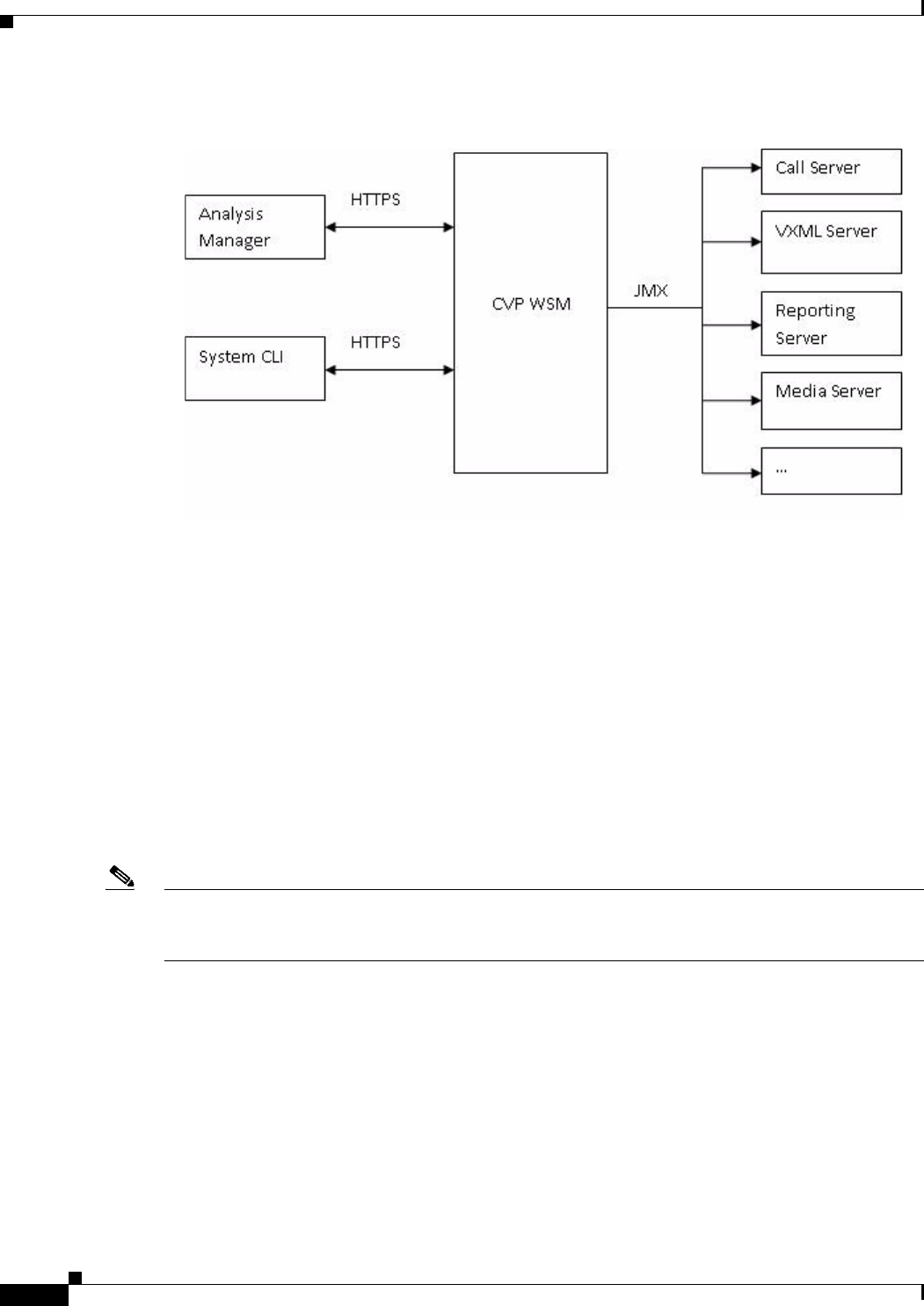
13-8
Cisco Unified Customer Voice Portal (CVP) 8.x Solution Reference Network Design (SRND)
OL-15989-06
Chapter 13 Managing, Monitoring, and Reporting
Unified System CLI and Web Services Manager (WSM)
Figure 13-1 Typical Use of the Web Services Layer
The Analysis Manager
The Web Service Manager supports all diagnostic (health and status) requests from the new Analysis
Manager. Analysis Manager provides end users a common interface for collecting health and status
information for all devices in its network topology. If Unified CVP is configured as a part of the solution,
you can leverage the WSM through the Analysis Manager to collect diagnostic details like server map,
version information, licenses, configuration, components, logs, traces, performance factors, platform
information for each CVP Device on a component and sub-component level. Users can set/reset debug
levels using the Analysis Manager on a component and sub-component level.
The Analysis Manager is part of UCM RTMT tool.
A new user with username wsmadmin is created during installation with the same password as the
Unified CVP Operations Console Server administrator user. Use wsmadmin to control access to the
diagnostic portal services.
Note For a discussion of the Analysis Manager, and a related discussion of the Analysis Call Path tool, refer
to: Cisco Unified Analysis Manager available at:
http://www.cisco.com/en/US/docs/voice_ip_comm/cucm/service/8_0_1/rtmt/ch1_overview.html
Unified System CLI Overview
When an issue arises in Unified CVP operation, you can use the System CLI tool to collect data to be
reviewed by Cisco engineers. For example, you can use the System CLI if you suspect a call is not
handled correctly. In this case you would use the show tech-support command to collect data and send
the data to Cisco support.
Important features of the Unified System CLI:
• It is automatically installed on all Unified CVP servers as part of the infrastructure; there is no
additional installation required on any Unified CVP server.

13-9
Cisco Unified Customer Voice Portal (CVP) 8.x Solution Reference Network Design (SRND)
OL-15989-06
Chapter 13 Managing, Monitoring, and Reporting
Unified System CLI and Web Services Manager (WSM)
• Every Unified CVP server is also aware of at least one seed device (the Unified CVP Operations
Console server). Your entire solution topology is automatically retrieved from the Operations
Console on any Unified CVP box by using System mode. There is no additional configuration
needed for System mode.
• The Unified System CLI uses a consistent command across multiple products and servers.
• The Unified System CLI can be executed as a Windows scheduled job.
The following diagram summaries the high-level commands for the Unified System CLI and shows the
devices and Unified Cisco products that it interacts with.
Unified System CLI Modes of Operation
The Unified System CLI can operate interactively in two modes:
• Local mode.
–
In the local mode, the Unified System CLI only interacts with a single device. For example, the
show version command shows only the version for a single device.
• System mode.

13-10
Cisco Unified Customer Voice Portal (CVP) 8.x Solution Reference Network Design (SRND)
OL-15989-06
Chapter 13 Managing, Monitoring, and Reporting
Unified System CLI and Web Services Manager (WSM)
–
In the System mode, the Unified System CLI automatically detects the Unified CVP Operations
Console (which acts as a seed device for the CLI) and then interacts with all of the devices in
the device list in the Operations Console to extract the solution topology automatically.
In this mode, the show version command shows the version information for all devices in the
device list.
–
All of the commands available in local mode for a single device are available in system mode.
–
The command syntax remains the same in system mode.
–
There are additional options to limit the system command option to certain device group, device
type, or list of servers.
In addition to the interactive user interface, the Unified System CLI can be used as a batch command.
This feature allows the System CLI to be used in scheduled jobs.
Unified System CLI Questions and Answers
Q1: Does Unified System CLI affect the performance of a the device(s) it queries?
A1: Unified System CLI runs at a low priority; it uses idle CPU time on the System. It should not affect
call processing even if executed on a system running under load.
The response time from the given CLI command will vary depending on the load of the system and the
server response time. The response time when there in no running load should be below 5 seconds for
each server for simple operations like show version, show license, show debug, and show perf. The
response time when there is no running load for show platform should be below 10 seconds for each
server.
However, the response time cannot be determined for commands such as show trace, show log, show
sessions, show all, and show tech-support. The response for these commands can vary depending on
the data being transferred by the server.
Q2: Can I redirect the output of a Unified System CLI command to a network drive?
A2: Yes. Just specify the path to the network drive.
Q3: Can I filter and include multiple components and devices?
A3: Yes. Use the component and subcomponent options to filter components and subcomponents and
use the server option to filter devices. You may use "|" symbol to select multiple components or
subcomponents or devices. For example:
admin:show debug subcomponent cvp:SIP|cvp:ICM|cvp:IVR
Component: CallServer, subcomponent: SIP
Trace level = 0
Description:
Application data:
Component: CallServer, subcomponent: ICM
Trace level = 0
Description:
Application data:
Component: CallServer, subcomponent: IVR

13-11
Cisco Unified Customer Voice Portal (CVP) 8.x Solution Reference Network Design (SRND)
OL-15989-06
Chapter 13 Managing, Monitoring, and Reporting
Unified System CLI and Web Services Manager (WSM)
Trace level = 0
Description:
Application data:
admin:
Q4: Can turning on "debug level 3" affect the performance on a production system?
A4: Yes. Therefore the debug level should be set to 0 for normal production environment. The definition
of debug levels are given below for reference:
level 1 --- Low performance impact
level 2 --- Medium performance impact
level 3 --- High performance impact
Q5: How do I set the debug level to its default?
A6: Set the debug level to 0.
Note For detailed information on using the Unified System CLI, refer to: Unified System CLI in:
Configuration and Administration Guide for Cisco Unified Customer Voice Portal, available at:
http://www.cisco.com/en/US/products/sw/custcosw/ps1006/products_installation_and_configuration_g
uides_list.html.

13-12
Cisco Unified Customer Voice Portal (CVP) 8.x Solution Reference Network Design (SRND)
OL-15989-06
Chapter 13 Managing, Monitoring, and Reporting
Unified System CLI and Web Services Manager (WSM)

CHAPTER
14-1
Cisco Unified Customer Voice Portal (CVP) 8.x Solution Reference Network Design (SRND)
OL-15989-06
14
Sizing
Last revised on: July 13, 2011
This chapter discusses how to determine how many physical machines to order and, in the case of
gateways and gatekeepers, what kind to order.
This chapter covers the following topics:
• Sizing Overview, page 14-2
• Unified CVP Call Server, page 14-3
• Unified CVP VXML Server (VXML Server), page 14-4
• Unified CVP Co-Residency, page 14-5
• Unified Presence Server, page 14-7
• Unified CVP Video Service, page 14-8
• Unified CVP Reporting Server, page 14-8
What's New in This Chapter
Table 14-1 lists the topics that are new in this chapter or that have changed significantly from previous
releases of this document.
Table 14-1 New or Changed Information Since the Previous Release of This Document
New or Revised Topic Described in:
Sizing co-resident deployments Unified CVP Co-Residency, page 14-5
Unified CVP VXML Server sizing Unified CVP VXML Server (VXML Server),
page 14-4
Call Servcer Log Directory Space Needed Call Server Log Directory Size Estimate,
page 14-3

14-2
Cisco Unified Customer Voice Portal (CVP) 8.x Solution Reference Network Design (SRND)
OL-15989-06
Chapter 14 Sizing
Sizing Overview
Sizing Overview
When sizing a contact center, first determine the worst-case contact center profile in terms of the number
of calls that are in each state. In other words, if you were to observe the contact center at its busiest
instant in the busiest hour, how many calls would you find are in each of the following states:
• Self-service — Calls that are executing applications using the Unified CVP VXML Server
• Queue and collect — Calls that are in queue for an agent or that are executing prompt-and-collect
type self-service applications
• Talking — Calls that are connected to agents or to third-party TDM VRU applications
In counting the number of calls that are in the talking state, count only calls that are using Unified CVP
or gateway resources. To determine whether a talking call is using resources, you must consider how the
call gets transferred to that VRU or agent. If the call was transferred via VoIP, it continues to use an
ingress gateway port and it continues to use a Unified CVP resource because Unified CVP continues to
monitor the call and provides the ability to retrieve it and re-deliver it at a later time. The same is true of
calls that are tromboned to a TDM target, using both an incoming and an outgoing TDM port on the same
gateway or on a different gateway (that is, toll bypass). Calls that are transferred to VRUs or agents in
this manner should be counted as talking calls.
However, if the call was transferred via *8 TNT, hookflash, Two B Channel Transfer (TBCT), or an ICM
NIC, neither the gateway nor Unified CVP play any role in the call. Both components have reclaimed
their resources, therefore such calls should not be counted as talking calls.
Finally, include in the overall call counts those calls that have been transferred back into Unified CVP
for queuing or self-service, via either blind or warm methods. For instance, if a warm transfer is used
and the agent is queued at Unified CVP during the post-route phase, the call would use two ports due to
two separate call control sessions at Unified CVP. Because these calls usually do not amount to more
than 5% or 10% of the overall call volume, it is easy to overlook them.
The definitions of these call states differ somewhat from the definitions used for port licensing purposes
(see Licensing, page 15-1). The use of automatic speech recognition (ASR) or text-to-speech (TTS) has
nothing to do with delineating which calls are in which state, whereas it does for licensing purposes.
Similarly, the call state determination has nothing to do with whether the agents are Unified CCE agents
or ACD agents, nor does it matter whether the customer intends to use Unified CVP's ability to retrieve
and re-deliver the call to another agent or back into self-service.
Note The solution must be sized for the number of ports in use for calls in a talking state to agents. Even
though licenses for those ports do not have to be purchased when using Unified CCE agents, TDM agents
do require a Call Director license.
In addition to the overall snapshot profile of calls in the contact center, you must also consider the busiest
period call arrival rate in terms of calls per second. You will need this information for the contact center
as a whole. Because it is hard to identify a true maximum arrival rate, you can use statistical means to
arrive at this number. Except in fairly small implementations, this is seldom the critical factor in
determining sizing.
With the above data, you can begin sizing each component in the network. This section next considers
the Unified CVP products: Unified CVP Call Server and Unified CVP VXML Server followed by the
Unified Presence Server and Unified CVP Reporting Server. This section deals entirely with the number
and type of physical components required to support the Unified CVP system, but it does not include
any discussion of redundancy. For an understanding of how to extend these numbers to support higher
reliability, see Designing Unified CVP for High Availability, page 4-1.

14-3
Cisco Unified Customer Voice Portal (CVP) 8.x Solution Reference Network Design (SRND)
OL-15989-06
Chapter 14 Sizing
Unified CVP Call Server
Unified CVP Call Server
Note The Unified CVP Call Server (Call Server) is not used in Model #1: Standalone Self-Service. This
section does not apply to such deployments.
Unified CVP Call Servers are sized according to the number of calls they can handle, in addition to their
maximum call arrival rate.
Note For UCS performance numbers, refer to the Cisco doc-wiki link:
http://docwiki.cisco.com/wiki/Virtualization_for_Unified_CVP
Note The following Example Call Server call rate calculations pertain to the MCS-7845-I3-CCE2 server.
Each Call Server can handle 1200 SIP calls or 500 H.323 calls. Each Call Server is further limited to a
sustained call arrival rate of 14 call per second (cps) for SIP and 7 cps for H.323. However, Model #4 is
exempt from this limitation because the Call Server in that model does not perform any H.323 or SIP
processing.
Specifically, the number of Call Servers required is the larger of:
((Self Service) + (Queue and Collect) + Talking) / 1200 [or 500 for H.323], rounded up
or
(Average call arrival rate) / 14, rounded up [7 for H.323; except in Model #4]
If you have a Call Server servicing both SIP and H.323 calls, you can size the server by prorating the
performance used for each call type. For example, if 60% of the calls will be H.323 and 40% SIP, the
maximum load in terms of active calls in this case will be:
60% ∗ (500 H.323 calls) + 40% ∗ (1200 SIP calls) = 780 active calls
In addition, calls delivered to the Cisco Unified Communications Manager cluster should be
load-balanced among the subscribers in the cluster and should not exceed 2 calls per second (cps) per
subscriber.
Call Server Log Directory Size Estimate
Use the following formula to calculate the estimated space per day (in Gigabytes) for the Call Server
Directory log file.
3.5 * R
Table 14-2 Call Server Call Rate by Server Model Number
Server Model MCS-7845-I3-CCE2
Maximum SIP Calls 1200
Maximum H.323 Calls 500
Sustained Calls per Second (SIP) 14
Sustained Calls per Second (H.323) 7

14-4
Cisco Unified Customer Voice Portal (CVP) 8.x Solution Reference Network Design (SRND)
OL-15989-06
Chapter 14 Sizing
Unified CVP VXML Server (VXML Server)
Where: R = number of calls per second
For proper serviceability, reserve enough space to retain from 5 to 7 days of log messages.
To set the log directory size, refer to the Operations Console, Infrastructure tab for Call Server set up.
Unified CVP VXML Server (VXML Server)
VXML Server call rate calculations are shown in the table and examples below.
Note The following VXML Server example call rate calculations pertain to the MCS-7845-I3-CCE2 server.
Unified CVP VXML Server sizing with HTTP is simple: one Unified CVP VXML Server can handle up
to 1200 calls. If you are using Unified CVP VXML Servers, you should size those machines according
to the following formula:
Calls / 1200, rounded up,
where Calls refers to the number of calls that are actually in Unified CVP VXML Server self-service
applications at that busy moment snapshot in time.
Note For UCS performance numbers, refer to the Cisco doc-wiki link:
http://docwiki.cisco.com/wiki/Virtualization_for_Unified_CVP
Unified CVP can also be configured to use HTTPS on the Unified VXML Server and on the Unified CVP
IVR Service. (IVR Service can generate very basic VoiceXML documents and is part of the
Unified CVP Call Server.) Due to the large processing overhead of HTTPS, the Tomcat application
server can achieve a maximum of only 100 simultaneous connections, depending on the configuration.
Table 14-4 provides simultaneous call information for HTTPS calls using various applications and call
flow models.
Table 14-3 VXML Server Call Rates by Server Model Number
Unified CVP VXML Server
Model:
MCS-7845-I3-CCE2
Maximum Simultaneous Calls 1200

14-5
Cisco Unified Customer Voice Portal (CVP) 8.x Solution Reference Network Design (SRND)
OL-15989-06
Chapter 14 Sizing
Unified CVP Co-Residency
Note For UCS performance numbers, refer to the Cisco doc-wiki link:
http://docwiki.cisco.com/wiki/Virtualization_for_Unified_CVP
In all of the above scenarios, the Reporting and Datafeed options were disabled. Also note that:
• Cisco IOS Release 12.4(15)T5 or later release is required on the gateway to support the HTTPS
option. (Mainline Cisco IOS currently is not supported.)
Cisco recommends the following configuration on the Cisco IOS VoiceXML Gateway with HTTPS
option. Not having this configuration setting can severely impact the performance and sizing of the
VXML gateway and the overall solution in general with HTTPS.
http client connection persistence
http client cache memory pool 15000
http client cache memory file 1000
Unified CVP Co-Residency
Note The following call rate calculations pertain to the MCS-7845-I3-CCE2 server.
The following components can be installed on the same physical server (co-resident):
• Unified CVP Call Server (Call Server)
• Unified CVP VXML Server (VXML Server)
• Media Server
A SIP-based co-resident server can handle 1200 SIP calls as well as 1200 VXML Server sessions
simultaneously, and it can handle a sustained call arrival rate of 14 calls per second.
Table 14-4 HTTPS Simultaneous Calls for Unified CVP Servers
Unified CVP Call Server Type, Application, and Call Flow
Model
Model:
MCS-7845-I3-CCE2
Unified CVP VXML Server
Max Simultaneous HTTPS Connections with
WebSphere (Standalone Call Flow Model)
250
Unified CVP VXML Server
Max Simultaneous HTTPS Connections with Tomcat
(Standalone Call Flow Model)
100
Unified CVP Call Server and VXML Server
Max Simultaneous HTTPS Connections with
WebSphere (Comprehensive Call Flow Model)
100
Unified CVP Call Server and VXML Server
Max Simultaneous HTTPS Connections with
Tomcat (Comprehensive Call Flow Model
100

14-6
Cisco Unified Customer Voice Portal (CVP) 8.x Solution Reference Network Design (SRND)
OL-15989-06
Chapter 14 Sizing
Unified CVP Co-Residency
Note This means you can run 1200 ports of Call Server doing SIP call control, and 1200 ports of VXML Server
on one server with a 1200 port license.
An H.323 co-resident server can handle 500 H.323 calls as well as 500 VXML Server sessions
simultaneously, and it can handle a sustained call arrival rate of 6 calls per second.
Note This means you can run 500 ports of Call Server doing H.323 call control, and 500 ports of VXML
Server on one server with a 500 port license.
The number of Unified CVP Call Servers required is the larger of:
((Self Service) + (Queue and Collect) + Talking) / 1200 [or 500 for H.323], rounded up,
or
(Average call arrival rate) / 14 [or 6 for H.323], rounded up, except in the VRU-only model
The co-resident media server can be used for up to 1200 calls [or 500 for H.323], assuming that prompt
caching is enabled in the VoiceXML gateways. If multiple co-resident servers are to be used, you must
load-balance across the co-resident media servers in order to spread the load of the calls across all of the
servers. To reduce the administrative overhead of managing content on multiple media servers, separate
dedicated media servers can be used.
This means you can run 1200 ports of the Call Server with SIP call control, and 1200 ports of the
VXML Server, all on one server with 1200 port licenses. An H.323 co-resident server can handle 500
H.323 calls as well as 500 VXML Server sessions simultaneously, and it can handle a sustained call
arrival rate of 6 calls per second. This means you can run 500 ports of the Call Server with H.323 call
control, and 500 ports of the VXML Server, all on one server with 500 licensed ports.
Example
For example, assume that your deployment must be sized for 1200 self-service ports, 500 queue and
collect ports, and 3700 simultaneous calls to agents.
Note In the above example definition, self-service means that a call requires SIP or H.323 call control and
runs an application on the VXML Server. Queue and collect means that a call requires SIP or H.323 call
control and runs an application using Microapps only on the Call Server.
The following example applies for VXML and HTTP sessions only. The same values apply to both
co-resident and distributed deployments of Call Servers and VXML Servers.
The number of servers required using SIP call control would be as follows:
((Self Service) + (Queue and Collect) + Talking) / 1200 [or 500 for H.323], rounded up
((1200) + (500) + 3700) / 1200 = 5 servers
If you use the Cisco Unified Border Element as a Session Border Controller (SBC) for flow-through calls
to handle VXML requirements, then you must use the sizing information presented above. The Cisco
Unified Border Element is limited to the maximum number of simultaneous VXML sessions or calls as
outlined above for the particular situation and hardware platform.
If you use the Cisco Unified Border Element as an SBC to handle flow-through calls only (no VXML),
then take Voice Activity Detection (VAD) into consideration and refer to the sizing information in the
Cisco Unified Border Element Ordering Guide, available at

14-7
Cisco Unified Customer Voice Portal (CVP) 8.x Solution Reference Network Design (SRND)
OL-15989-06
Chapter 14 Sizing
Unified Presence Server
http://www.cisco.com/en/US/prod/collateral/voicesw/ps6790/gatecont/ps5640/order_guide_c07_4
62222.html
Co-Resident Unified CVP Reporting Server and Unified CVP Call Server
The Unified CVP Reporting Server can also be co-resident with the Unified CVP Call Server, but only
for Standalone VoiceXML deployments. The Call Server is normally not needed in a Standalone
VoiceXML deployment; but if reporting is desired, a Call Server is required in order to send the reporting
data from the VXML Server to the Reporting Server. Thus, when the Reporting Server is co-resident
with a Call Server, the Call Server is not processing any SIP or H.323 calls but is simply relaying
reporting data from the VXML Server.
The co-resident Call Server does not have a significant impact on performance in this model, therefore
the sizing information in the section on the Unified CVP Reporting Server, page 14-8, does not change.
Note If CUBE is to be used as an SBC to handle flow-thru or flow-around calls only (no vxml), with VAD in
consideration, we can use the CUBE Ordering Guide for sizing.
If CUBE is to be used as an SBC for flow-thru or flow-around calls AND is to handle vxml requirements,
we must use the sizing information in the CVP SRND. CUBE will be limited to the maximum number
of simultaneous vxml sessions\calls as outlined there for the particular situation and hardware platform.
Unified Presence Server
The Cisco Unified Presence server is the SIP Proxy Server provided by Cisco for use with Unified CVP.
Table 14-5 outlines the performance of the various server types.
The sizing numbers in Table 14-5 assume a dedicated SIP Proxy. If you are using the same Cisco Unified
Presence server for presence services, you should adjust the numbers accordingly, based on the capacity
used. For instance, if the Cisco Unified Presence server supports 2500 presence users but you will
actually have only 1250 (50%), then that leaves approximately 50% of the SIP Proxy capacity.
The capacities in Table 14-5 are measured in calls per second (cps). However, one call coming in from
the PSTN is not equivalent to one call through Cisco Unified Presence. Multiple calls are actually
generated per inbound customer call for queuing, ringback, and subsequent agent transfers. A typical
incoming call will be transferred by Unified CVP four times, so the inbound PSTN call rate should be
multiplied by 4.
Table 14-5 Call Handling Capacities for Cisco Unified Presence Servers
Cisco Server Model Recording Function UDP TCP
MCS-7825 Record-Route On 200 cps 100 cps
Record-Route Off 300 cps 300 cps
MCS-7835 Record-Route On 200 cps 100 cps
Record-Route Off 300 cps 300 cps
MCS-7845 Record-Route On 600 cps 200 cps
Record-Route Off 1100 cps 500 cps

14-8
Cisco Unified Customer Voice Portal (CVP) 8.x Solution Reference Network Design (SRND)
OL-15989-06
Chapter 14 Sizing
Unified CVP Video Service
For example:
If Unified CVP receives 20 PSTN calls per second, Cisco Unified Presence will see about 80 calls
per second.
Table #2 in the CUSP public data sheet “Performance Measured in the Number of New Call Attempts
per Second" shows additional performance data for the CUSP server.
Unified CVP Video Service
Cisco Unified CVP release 7.0 introduced capabilities for video-capable agents of Cisco Unified
Contact Center Enterprise (Unified CCE).
The same Unified CVP Call Server can be used to service both video calls and traditional audio calls, as
long as the audio calls are handled using the Unified CVP comprehensive call flow. If any model other
than the comprehensive model is used for the audio calls, then separate Call Servers must be used for
the video and audio calls.
Sizing Unified CVP Basic Video Service
The Unified CVP Basic Video Service employs the Unified CVP Comprehensive call flow, and as such
it requires the Unified CVP Call Server, the Unified CVP VXML Server, and VXML Gateways. Sizing
of these components for the Basic Video Service is done in the same manner as for traditional audio
applications.
Cisco Unified Videoconferencing hardware, Radvision IVP, and Radvision iContact are not required for
the Basic Video Service.
Unified CVP Reporting Server
There are many variables to take into account when sizing the Unified CVP Reporting Server. Different
VoiceXML applications have different characteristics, and those characteristics play a large part in the
amount of reporting data generated. Some of these factors are:
• The types of elements used in the application
• The granularity of data required
• The call flow users take through the application
• The length of calls
• The number of calls
To size the Reporting Server, you must first estimate how much reporting data will be generated by your
VoiceXML application. The example applications and the tables in subsequent sections of this chapter
will help you to determine the number of reporting messages generated for your application.
Once you have determined the number of reporting messages generated by your application, complete
the following steps for each VoiceXML application:
1. Estimate the number of minutes customers will spend receiving VoiceXML call treatment by that
application.
2. Estimate the calls per second that the application will receive.
3. Estimate the number of reporting messages for your application.

14-9
Cisco Unified Customer Voice Portal (CVP) 8.x Solution Reference Network Design (SRND)
OL-15989-06
Chapter 14 Sizing
Unified CVP Reporting Server
Use the following equation to determine the number of reporting messages generated per second, per
call, for each VoiceXML application:
A# = %CPS ∗ CPS ∗ MSG / Min / 60
Where:
A# = the number of estimated reporting messages per second for an application. Complete one
calculation per application (A1, A2, …, An).
CPS = the number of calls per second.
%CPS = the percentage of calls that use this VoiceXML application.
MSG = the number of reporting messages this application generates. To determine the number
of reporting messages generated by your application, use the information provided in the
sections on Reporting Message Details, page 14-10, and Example Applications, page 14-11.
Min = Amount of time spent in the application (in minutes).
60 = the number of seconds in one minute.
Next, estimate the total number of reporting messages that your deployment will generate per second by
summing the values obtained from the previous calculation for each application:
A(total) = A1+ A2+…..+An
This is the total number of reporting messages generated per second by your VoiceXML applications.
The Cisco MCS-7845 Reporting Servers can handle 420 messages per second. If the total number of
reporting messages per second for your deployment is less than 420, you can use a single Reporting
Server. If it is greater, you need to use multiple Reporting Servers and partition the VoiceXML
applications to use specific Reporting Servers.
How to Use Multiple Unified CVP Reporting Servers
If the number of messages per second (as determined in steps 1 and 2 above) exceeds the Unified CVP
Reporting Server (Reporting Server) capacity, then the deployment must be partitioned vertically.
When vertically partitioning to load-balance reporting data, a Unified CVP system designer must
consider the following requirements that apply to deployments of multiple Reporting Servers:
• Each Unified CVP Call server and each Unified CVP VXML Server can be associated with only one
Unified CVP Reporting Server.
• Reports cannot span multiple Informix databases.
For more information on these requirements, refer to the Reporting Guide for Cisco Unified Customer
Voice Portal, available at
http://www.cisco.com/en/US/products/sw/custcosw/ps1006/products_installation_and_configurati
on_guides_list.html
When designing Unified CVP deployments with multiple Reporting Servers, observe the following
guidelines:
• Subdivide applications that generate more combined call processing and application messages than
are supported by one Reporting Server.
• VoiceXML can be filtered, and filtering out non-interesting data creates more usable data
repositories that support higher message volume.
• Configure the dial plan and/or other available means to direct the incoming calls to the appropriate
Call Server and VXML Server.

14-10
Cisco Unified Customer Voice Portal (CVP) 8.x Solution Reference Network Design (SRND)
OL-15989-06
Chapter 14 Sizing
Unified CVP Reporting Server
If you need to combine data from multiple databases, possible options may include:
• Exporting reporting data to Excel, comma separated values (CSV) files, or another format that
allows data to be combined out side of the database
• Exporting reporting data to CSV files and importing it into a customer-supplied database
• Extracting data to a customer-supplied data warehouse and running reports against that data
Reporting Message Details
Table 14-6 outlines the various elements or activities and the number of reporting messages generated
by each.
Table 14-6 Number of Reporting Messages per Element or Activity
Element or Activity Number of Reporting Messages (Unfiltered)
Start1
1. These elements are required in every application and cannot be filtered.
2
End12
Subdialog_start12
Subdialog_return12
Hotlink 2
HotEvent 2
Transfer w/o Audio 2
Currency w/o Audio 2
Flag 2
Action 2
Decision 2
Application Transfer 2
VXML Error 2
CallICMInfo (per call) 2
Session Variable (per change) 2
Custom Log (per item) 2
Play (Audio file or TTS) 2
Get Input (DTMF) 5
Get Input (ASR) 9
Form 10
Digit_with_confirm 20
Currency_with_confirm 20
ReqICMLabel 30

14-11
Cisco Unified Customer Voice Portal (CVP) 8.x Solution Reference Network Design (SRND)
OL-15989-06
Chapter 14 Sizing
Unified CVP Reporting Server
Example Applications
This section presents some examples of applications that can be used to estimate the number of reporting
messages that will be generated by your particular application.
Low Complexity
Total: 16 reporting messages per minute per call.
Medium Complexity DTMF Only
Total: 39 reporting messages per minute per call.
Element Type
Approximate Number of
Reporting Messages
Start 2
Subdialog_start 2
Play element 2
Play element 2
Play element 2
Play element 2
Subdialog_end 2
End 2
Element Type
Approximate Number of
Reporting Messages
Start 2
Subdialog_strart 2
Play element 2
Get input 5
Play element 2
Get input 5
Form 10
Input 5
Transfer with audio 2
Subdialog_end 2
End 2

14-12
Cisco Unified Customer Voice Portal (CVP) 8.x Solution Reference Network Design (SRND)
OL-15989-06
Chapter 14 Sizing
Unified CVP Reporting Server
Medium Complexity Using Automatic Speech Recognition (ASR)
Total: 51 reporting messages per minute per call.
High Complexity Using Automatic Speech Recognition (ASR)
Total: 107 reporting messages per minute per call.
Element Type
Approximate Number of
Reporting Messages
Start 2
Subdialog_strart 2
Play element 2
Get input 9
Play element 2
Get input 9
Form 10
Input 9
Transfer with audio 2
Subdialog_end 2
End 2
Element Type
Approximate Number of
Reporting Messages
Start 2
Subdialog_strart 2
Icmrequrestlabel 30
Form 10
ASR capture 9
Digit with confirm 20
Form 10
Digit with confirm 20
Subdialog_end 2
End 2

CHAPTER
15-1
Cisco Unified Customer Voice Portal (CVP) 8.x Solution Reference Network Design (SRND)
OL-15989-06
15
Licensing
Last revised on: May 2, 2010
The licensing information for Cisco Unified CVP has been consolidated and moved into the Cisco
Customer Contact Solutions Ordering Guide. The Ordering Guide provides a single, frequently updated
source for all the Unified CVP licensing information. Cisco employees and Partners with a valid login
account can access the Ordering Guide at:
http://www.cisco.com/web/partners/downloads/partner/WWChannels/technology/ipc/downloads/C
CBU_ordering_guide.pdf
If you need licensing information for Unified CVP but you cannot access the Ordering Guide, contact
your local Cisco Systems Engineer (SE) or Partner.

15-2
Cisco Unified Customer Voice Portal (CVP) 8.x Solution Reference Network Design (SRND)
OL-15989-06
Chapter 15 Licensing

IN-1
Cisco Unified Customer Voice Portal (CVP) 8.x Solution Reference Network Design (SRND)
OL-15989-06
INDEX
Symbols
? 12-4
*8 TNT 3-5, 10-2, 14-2
Numerics
3G-H324M Gateway
configuration 7-4
A
ACD 5-13
admission control for calls 3-6
aging cache 12-5
alternate
endpoints 4-27
gatekeeper 4-17, 4-18
Application Content Engine (ACE)
discussed 1-15
migrate from CSS to ACE 1-15
minimum license information 1-15
application examples 14-11
architecture 1-1
ASR 1-16, 4-32, 7-2, 7-3, 9-7
automatic call distributor (ACD) 5-13
Automatic Speech Recognition (ASR) 1-16, 4-32, 7-2, 7-3,
9-7
B
backup and restore 13-6
bandwidth
for retrieving prompts 12-3
provisioning 9-2, 9-5
Basic Video Service 2-13, 14-8
blind transfer 6-3
blocking media streams 9-15
border element 7-5
branch office
gateways 3-1
media server 12-6
C
cache aging 12-5
caching
prompts 12-3, 12-4
query URLs 12-4
call admission control 9-9
Call Director
call flow model described 1-20
deployment model 2-4, 5-8, 6-4
calls
admission control 3-6
control of 2-3, 2-6, 2-10
control traffic 9-3
disposition of 4-5, 4-11, 4-13, 4-19, 4-21, 4-22, 4-28, 4-29,
4-31, 4-32, 4-33, 4-34, 4-35
failures 4-19
flows 1-17, 2-2, 2-4, 2-5, 2-8, 2-9, 2-12, 3-7, 3-10, 6-2, 6-3, 11-3
help desk 6-2
initial treatment 2-8, 2-9, 2-12
in progress 4-12, 4-20
log files 13-3
maximum number 9-8

Index
IN-2
Cisco Unified Customer Voice Portal (CVP) 8.x Solution Reference Network Design (SRND)
OL-15989-06
originated by Cisco Unified CM 5-13, 6-1
outbound 6-2
post-ICM 11-4, 11-5
pre-routing 11-3, 11-4, 11-5
queue and collect 14-2
routing 3-10, 5-11
self-service 14-2
survivability 3-5
tracking 13-3
traffic 9-2
transfers 2-3, 2-5, 2-6, 2-8, 2-10, 2-13, 10-1
typical call flow described 1-17
Call Server 14-3
Call Studio 1-7, 4-31, 8-3
CCE 1-10
Central Controller 9-4
centralized
VoiceXML gateways 4-24
VXML Servers 3-3
Cisco integrated 3G-H324M
topology and call flow 7-3
Cisco IOS 4-10, 4-21, 12-3
Cisco Security Agent
for CVP, discussed 1-13
managed and unmanaged 1-14
managed and unmanaged versions 1-14
two ways to use with CVP 1-14
Cisco Unified Border Element 7-5
Cisco Unified Call Studio 1-7, 4-31, 8-3
Cisco Unified Presence 14-7
clusters 3-9
co-located VXML Servers and gateways 3-3
components of CVP 1-4
Comprehensive call flow model
described 1-20
Comprehensive deployment model
described 2-6
Using ICM Micro-Apps 5-8, 6-5
Using Unified CVP VXML Server 5-8, 6-6
configuration
3G-H324M gateway 7-4
configuration of
ASR 4-32
caching for prompts 12-3, 12-4
Cisco IOS 4-21
Cisco IOS gateway 4-10
Cisco Unified CM 4-34, 6-7
Content Services Switch (CSS) 4-29
dial plan 6-7
gatekeeper 4-18
H.323 4-20
HSRP 4-18
Intelligent Contact Management (ICM) 4-34
IVR service 4-22
media server 4-30
originating gateway 4-4
SIP Proxy Server 4-9, 4-12
streaming for prompts 12-3
TTS 4-32
Unified CVP VXML Server 4-31
Unified ICM 6-6
VoiceXML gateway 4-23, 4-25
consultative transfer 6-3
Content Services Switch (CSS) 1-14, 4-28
control traffic 9-3
co-resident
ingress gateway and VoiceXML 4-24
servers 14-5
Correlation ID 5-3, 5-5
CSS 1-14, 4-28
CVP
architecture 1-1
Call Server 14-3
Cisco Unified Call Studio 8-3
components 1-4
co-residency 14-5
described 1-3
GKTMP 11-2

Index
IN-3
Cisco Unified Customer Voice Portal (CVP) 8.x Solution Reference Network Design (SRND)
OL-15989-06
licensing 15-1
Operations Console 13-1
Server 1-5
sizing components 14-1
Video Service 14-8
D
data
reporting 13-1
traffic 9-5
deployment models
Call Director 2-4
Comprehensive models 2-6
distributed models 3-1
functional models 2-1
hosted implementations 5-10, 6-7
Model #1 - Standalone Self-Service 5-7, 6-3
Model #2 - Call Director 5-8, 6-4
Model #3a - Comprehensive Using ICM
Micro-Apps 5-8, 6-5
Model #3b - Comprehensive Using Unified CVP
VXML Server 5-8, 6-6
Model #4a - VRU Only with NIC Controlled
Routing 5-8
Model #4b - VRU Only with NIC Controlled
Pre-Routing 5-9
Model #4 - VRU Only 5-8
Network VRU types 5-6
standalone self-service 4-31, 4-32
types and their uses, summarized 1-20
Unified CVP VXML Server (Standalone) 2-2
VRU only 2-11
design process
overall steps 1-19
SIP protocol recommended 1-19
dial peers 3-10
dial plan 6-7
disposition of calls 4-5, 4-11, 4-13, 4-19, 4-21, 4-22, 4-28, 4-29,
4-31, 4-32, 4-33, 4-34, 4-35
distributed
deployments 3-1
gateways 3-1
network options 1-22
VoiceXML gateways 4-24, 4-25
DNS Server 1-13
domain, CVP part of 1-5
DTMF 7-2, 7-3
E
Egress Gateway 1-9
enterprise domain, CVP part of 1-5
example applications 14-11
F
firewalls 9-16
flow of calls 6-2, 6-3, 11-3
formal reporting 13-3
functional deployment models 1-20, 2-1
G
G.711 9-15
G.711 and G.729 support 9-9
gatekeeper
alternate 4-17, 4-18
call admission control 3-6
call routing 3-10
configuration 4-18, 6-7
described 1-11
H.323 3-10
high availability 4-16
HSRP 4-16, 4-18
redundancy 4-16
required for all H.323 installations 1-11
Gatekeeper Transaction Message Protocol
(GKTMP) 11-1

Index
IN-4
Cisco Unified Customer Voice Portal (CVP) 8.x Solution Reference Network Design (SRND)
OL-15989-06
gateways
at a branch office 3-1
centralized 4-24
Cisco integrated 3G-H324M 7-3
Cisco IOS 4-10, 4-21
co-located with VXML Servers 3-3
distributed 3-1, 4-24, 4-25
maximum VoiceXML sessions 7-8, 7-9
MGCP 7-11
originating calls 4-4
PSTN 7-2, 7-3
selecting appropriate ones 7-1, 7-6
sizing 6-8, 7-7
using Cisco Unified CM 3-3, 3-4
voice egress 1-9
voice ingress 1-8
VoiceXML 1-9, 3-2, 4-23, 7-2, 7-3
GED-125 9-4
GKTMP 11-1
H
H.323
call flow 2-5, 2-9, 3-7
call flow, typical, diagram and process 1-18
configuration 4-20
gatekeeper 3-10
Refer transfer 10-7
Service 4-19
signaling 9-7
hardware for high availability 4-28
health monitoring 13-2
help desk calls 6-2
high availability
deployment options 1-23
design considerations 4-1
Layer 2 switch 4-3
hookflash 3-5, 10-3, 14-2
hosted implementations 5-10, 6-7
HSRP
configuration 4-18
gatekeeper redundancy 4-16
HTTP 8-1
I
IBM Informix Dynamic Server (IDS) 13-3
ICM
call transfers 10-5
Central Controller 9-4
configuration 6-6
high availability 4-34
interactions with CVP 5-1
with AST/TTS 4-33
with Unified CVP VXML Server 4-32
IDS 13-3
IN 10-7
Informix Dynamic Server (IDS) 13-3
infrastructure of the network 9-1
Ingress Voice Gateway 1-8
initial call treatment 2-8, 2-9, 2-12
in-progress calls 4-12, 4-20
Intelligent Contact Management (ICM) 4-34, 5-1
Intelligent Network (IN) Release Trunk Transfers 10-7
IOS 4-10, 4-21, 12-3
IVR Service 4-21
L
Layer 2 switch 4-3
licensing 15-1
log files 13-3
M
managing the Unified CVP system 13-1
maximum

Index
IN-5
Cisco Unified Customer Voice Portal (CVP) 8.x Solution Reference Network Design (SRND)
OL-15989-06
number of calls 9-8
VoiceXML sessions 7-8, 7-9
media files 9-6, 12-1
Media Gateway Control Protocol (MGCP) 7-11
Media Resource Control Protocol (MRCP) 9-4
media server 1-15, 4-30
messages for reporting 14-10
MGCP 7-11, 9-4
microapplications 4-30
Model #1 - Standalone Self-Service 5-7, 6-3
Model #2 - Call Director 5-8, 6-4
Model #3a - Comprehensive Using ICM Micro-Apps 5-8,
6-5
Model #3b - Comprehensive Using Unified CVP VXML
Server 5-8, 6-6
Model #4a - VRU Only with NIC Controlled Routing 5-8
Model #4b - VRU Only with NIC Controlled
Pre-Routing 5-9
Model #4 - VRU Only 5-8
monitoring the Unified CVP system 13-1
MRCP 9-8
multi-language support 8-2
multiple reporting servers 14-9
N
network infrastructure 9-1
Network Interface Controller (NIC) 11-1
network security 9-16
Network VRU types 5-2, 5-6, 5-13
NIC 11-1
non-streaming prompts 12-3
O
OAMP 13-2
OAMP Resource Manager (ORM) 13-2
Operate, Administer, Maintain, Provision (OAMP) 13-2
Operations Console 13-1
Operations Console Server 1-7
originating gateway 4-4
ORM 13-2
outbound calls 6-2
P
peripheral gateway (PG) 9-4
PG 9-4
ports
usage 9-13, 9-16
post-ICM calls 11-4, 11-5
pre-routing 11-3, 11-4, 11-5
presence 14-7
Presence Server 1-11
prompts
bandwidth 12-3
caching 12-3, 12-4
non-streaming 12-3
streaming 12-3
protocol-level call flow 2-2, 2-12
provisioning bandwidth 9-2, 9-5
proxy server
server group elements 1-11
types supported 1-11
PSTN gateways 7-2, 7-3
Q
QoS 9-2, 9-13
Quality of Service (QoS) 9-2, 9-13
query URLs 12-4
queue-and-collect calls 14-2
R
RAID 13-6
RAS 11-1

Index
IN-6
Cisco Unified Customer Voice Portal (CVP) 8.x Solution Reference Network Design (SRND)
OL-15989-06
redundant
gatekeepers 4-16
Refer transfer 10-7
Registration Admission Status (RAS) 11-1
release trunk transfers 10-2
reporting
described 13-1
examples 14-11
messages 14-10
multiple servers 14-9
Server 1-7
servers 14-8
Resource Reservation Protocol (RSVP) 3-10
restoring data files 13-6
routing calls 5-11
RSVP 3-10
RTP 9-7
S
SBC 7-5
scalability options 1-24
scripting 4-31
security
on the network 9-16
security agent for CVP 1-13
self-service
calls 2-8, 2-9, 2-12, 14-2
deployment model 4-31, 4-32
separate ingress gateway and VoiceXML 4-25
server group elements, proxy server 1-11
servers
Cisco Unified Presence 14-7
co-resident 14-5
multiple 14-9
reporting 14-8
sizing 6-8
VoiceXML 8-1
session border controller (SBC) 7-5
SIP
call flow 1-17, 2-4, 2-8, 3-10
call transfers 10-7
dial plan 6-7
Proxy Server 1-11, 4-5, 4-12
signaling 9-7
SIP Service 4-11
SIP protocol
recommended for deployments 1-19
sizing
components 6-8, 14-1
scalability options 1-24
skill groups 2-8, 2-10, 2-13
Standalone Self-Service deployment model 4-31, 4-32, 5-7,
6-3
statistical monitoring 13-2
streaming of prompts 12-3
survivability of calls 3-5
T
Takeback-and-Transfer (TNT) 10-2
TBCT 10-4, 14-2
TCP socket persistence 12-4
TDM interface 7-3, 7-4
Telecom Italia Mobile (TIM) 5-8
Text-to-Speech (TTS) 1-16, 4-32, 7-2, 7-3, 9-7
third-party
media server 1-15
VRUs 5-15
TIM 5-8
TNT 10-2
traffic
marking 9-13
voice 9-2, 9-9
transfers
blind 6-3
call transfer options 10-1
consultative 6-3

Index
IN-7
Cisco Unified Customer Voice Portal (CVP) 8.x Solution Reference Network Design (SRND)
OL-15989-06
in Call Director deployments 2-6
in Comprehensive deployments 2-10
in standalone VoiceXML deployments 2-3
to live agent 2-8, 2-10, 2-13
VoIP-based 2-5, 2-6
warm 6-3
Translation Route ID 5-3, 5-6
troubleshooting 13-2
TTS 1-16, 4-32, 7-2, 7-3, 9-7
Two B Channel Transfer (TBCT) 10-4, 14-2
Type 10 VRU 5-3
Type 2 VRU 5-6
Type 3 VRU 5-5
Type 5 VRU 5-4
Type 7 VRU 5-5
Type 8 VRU 5-6
types of Network VRUs 5-2, 5-6, 5-13
U
Unified Call Studio 1-7, 4-31, 8-3
Unified CM
as egress gateway 3-3
as ingress gateway 3-4
call admission control 3-7
calls originated by 5-13, 6-1
configuration 6-7
described 1-10
high availability 4-33
multiple clusters 3-9
Unified Contact Center Enterprise (CCE) 1-10
Unified Presence 14-7
Unified Presence Server 1-11
V
video endpoints 1-9
Video Service 14-8
voice response unit (VRU) 5-15
voice traffic 9-2, 9-9
VoiceXML
alternate endpoints 4-27
call transfers 10-8
centralized servers 3-3
Cisco Unified Call Studio 1-7, 4-31
described 1-2
documents 9-5
Gateway 1-9
gateways 3-2, 4-23, 7-2, 7-3
maximum number of sessions 7-8, 7-9
over HTTP 8-1
Server 1-6, 8-1, 14-4
sizing 14-4
Unified CVP VXML Server 4-31
Unified CVP VXML Server (Standalone) 2-2
VoIP-based
pre-routing 2-4, 2-5
transfers 2-5, 2-6
VRU 5-15
VRU call flow model
described 1-21
VRU Only deployment model 2-11, 5-8
VRU Only with NIC Controlled Pre-Routing 5-9
VRU Only with NIC Controlled Routing 5-8
VRU PG 9-4
W
warm consultative transfer 6-3
Web application servers 8-2
wink 10-3

Index
IN-8
Cisco Unified Customer Voice Portal (CVP) 8.x Solution Reference Network Design (SRND)
OL-15989-06
