CVT
User Manual: cvt
Open the PDF directly: View PDF ![]() .
.
Page Count: 238 [warning: Documents this large are best viewed by clicking the View PDF Link!]
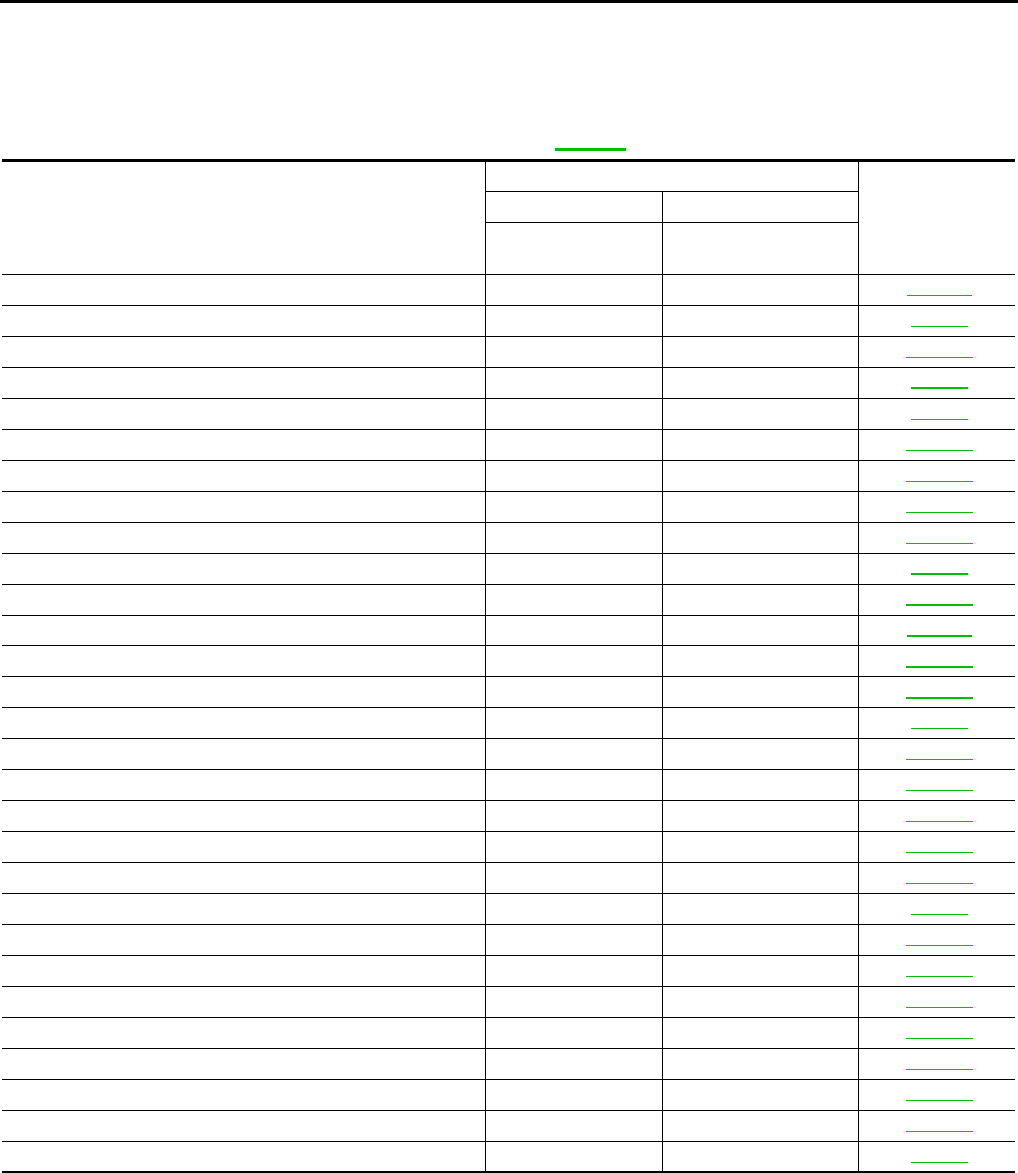
- QUICK REFERENCE INDEX
- Table of Contents
- INDEX FOR DTC
- PRECAUTIONS
- Precautions for Supplemental Restraint System (SRS) “AIR BAG” and “SEAT BELT PRE-TENSIONER”
- Precautions for Procedures without Cowl Top Cover
- Precautions Necessary for Steering Wheel Rotation After Battery Disconnect
- Precautions for On Board Diagnostic (OBD) System of CVT and Engine
- Precautions for TCM and CVT Assembly Replacement
- Removal and Installation Procedure for CVT Unit Connector
- Precautions
- Service Notice or Precautions
- PREPARATION
- CVT FLUID
- CVT SYSTEM
- ON BOARD DIAGNOSTIC (OBD) SYSTEM
- TROUBLE DIAGNOSIS
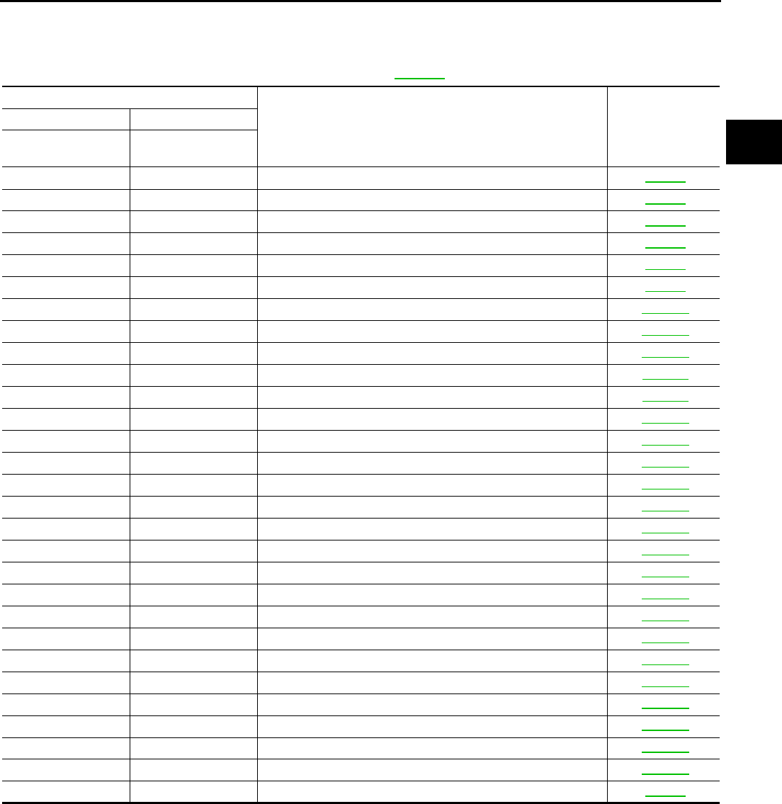
- DTC Inspection Priority Chart
- Fail-safe
- FAIL-SAFE FUNCTION
- Output Speed Sensor (Secondary Speed Sensor)
- Input Speed Sensor (Primary Speed Sensor)
- PNP Switch
- Manual Mode Switch
- CVT Fluid Temperature Sensor
- Transmission Fluid Pressure Sensor A (Secondary Pressure Sensor)
- Pressure Control Solenoid A (Line Pressure Solenoid)
- Pressure Control Solenoid B (Secondary Pressure Solenoid)
- Torque Converter Clutch Solenoid
- Step Motor
- CVT Lock-up Select Solenoid
- TCM Power Supply (Memory Back-up)
- FAIL-SAFE FUNCTION
- How to Perform Trouble Diagnosis for Quick and Accurate Repair
- CVT Electrical Parts Location (With Manual Mode)
- CVT Electrical Parts Location (Without Manual Mode)
- Circuit Diagram
- Inspections before Trouble Diagnosis
- Road Test
- Check before Engine Is Started
- Check at Idle
- Cruise Test
- Vehicle Speed When Shifting Gears
- TCM Input/Output Signal Reference Values
- CONSULT-II Function (TRANSMISSION)
- Diagnostic Procedure without CONSULT-II
- DTC U1000 CAN COMMUNICATION LINE
- DTC P0615 START SIGNAL CIRCUIT
- DTC P0703 STOP LAMP SWITCH CIRCUIT
- DTC P0705 PARK/NEUTRAL POSITION SWITCH
- DTC P0710 CVT FLUID TEMPERATURE SENSOR CIRCUIT
- DTC P0715 INPUT SPEED SENSOR CIRCUIT (PRI SPEED SENSOR)
- DTC P0720 VEHICLE SPEED SENSOR CVT (SECONDARY SPEED SENSOR)
- DTC P0725 ENGINE SPEED SIGNAL
- DTC P0730 BELT DAMAGE
- DTC P0740 TORQUE CONVERTER CLUTCH SOLENOID VALVE
- DTC P0744 A/T TCC S/V FUNCTION (LOCK-UP)
- DTC P0745 LINE PRESSURE SOLENOID VALVE
- DTC P0746 PRESSURE CONTROL SOLENOID A PERFORMANCE (LINE PRESSURE SOLENOID VALVE)
- DTC P0776 PRESSURE CONTROL SOLENOID B PERFORMANCE (SEC PRESSURE SOLENOID VALVE)
- DTC P0778 PRESSURE CONTROL SOLENOID B ELECTRICAL (SEC PRESSURE SOLENOID VALVE)
- DTC P0826 MANUAL MODE SWITCH CIRCUIT
- DTC P0840 TRANSMISSION FLUID PRESSURE SENSOR A CIRCUIT (SEC PRESSURE SENSOR)
- DTC P0841 PRESSURE SENSOR FUNCTION
- DTC P0845 TRANSMISSION FLUID PRESSURE SENSOR B CIRCUIT (PRI PRESSURE SENSOR)
- DTC P0868 SECONDARY PRESSURE DOWN
- DTC P1701 TRANSMISSION CONTROL MODULE (POWER SUPPLY)
- DTC P1705 THROTTLE POSITION SENSOR
- DTC P1722 ESTM VEHICLE SPEED SIGNAL
- DTC P1723 CVT SPEED SENSOR FUNCTION
- DTC P1726 ELECTRIC THROTTLE CONTROL SYSTEM
- DTC P1740 LOCK-UP SELECT SOLENOID VALVE CIRCUIT
- DTC P1745 LINE PRESSURE CONTROL
- DTC P1777 STEP MOTOR - CIRCUIT
- DTC P1778 STEP MOTOR - FUNCTION
- SECOND POSITION SWITCH
- CVT INDICATOR CIRCUIT
- TROUBLE DIAGNOSIS FOR SYMPTOMS
- Wiring Diagram — CVT — NONDTC
- CVT Indicator Lamp Does Not Come On
- Engine Cannot Be Started in “P” and “N” Position
- In “P” Position, Vehicle Moves Forward or Backward When Pushed
- In “N” Position, Vehicle Moves
- Large Shock “N” -> “R” Position
- Vehicle Does Not Creep Backward in “R” Position
- Vehicle Does Not Creep Forward in “D”, “S” or “L” Position
- CVT Does Not Shift
- Cannot Be Changed to Manual Mode
- CVT Does Not Shift in Manual Mode
- Cannot Be Changed to Second Position (WITHOUT MANUAL MODE)
- Cannot Be Changed to “L” Position (WITHOUT MANUAL MODE)
- Vehicle Does Not Decelerate by Engine Brake
- SHIFT CONTROL SYSTEM
- CVT SHIFT LOCK SYSTEM
- Description
- Shift Lock System Electrical Parts Location
- Wiring Diagram — CVT — SHIFT (With Intelligent Key)
- Wiring Diagram — CVT — SHIFT (Without Intelligent Key)
- Shift Lock Control Unit Reference Values
- Component Inspection
- AIR BREATHER HOSE
- DIFFERENTIAL SIDE OIL SEAL
- CVT FLUID COOLER VALVE
- TRANSAXLE ASSEMBLY
- SERVICE DATA AND SPECIFICATIONS (SDS)
- POWER SUPPLY ROUTING CIRCUIT
- ELECTRICAL UNITS
- SUPER MULTIPLE JUNCTION (SMJ)
- FUSE BLOCK - JUNCTION BOX (J/B)
- FUSE, FUSIBLE LINK AND RELAY BOX

CVT-1
CVT
C TRANSMISSION/TRANSAXLE
CONTENTS
D
E
F
G
H
I
J
K
L
M
SECTION
A
B
CVT
Revision: 2006 August 2006 Murano
CVT
INDEX FOR DTC ........................................................ 6
Alphabetical Index .................................................... 6
DTC No. Index ......................................................... 7
PRECAUTIONS .......................................................... 8
Precautions for Supplemental Restraint System
(SRS) “AIR BAG” and “SEAT BELT PRE-TEN-
SIONER” .................................................................. 8
Precautions for Procedures without Cowl Top Cover ..... 8
Precautions Necessary for Steering Wheel Rotation
After Battery Disconnect .......................................... 8
OPERATION PROCEDURE ................................. 8
Precautions for On Board Diagnostic (OBD) System
of CVT and Engine ................................................... 9
Precautions for TCM and CVT Assembly Replace-
ment ......................................................................... 9
EEPROM ERASING PATTERNS .......................... 9
METHOD FOR ERASING THE EEPROM IN THE
TCM ...................................................................... 9
METHOD FOR WRITING DATA FROM THE
ROM ASSEMBLY IN THE TRANSAXLE ............ 10
CHECK METHOD ............................................... 10
Removal and Installation Procedure for CVT Unit
Connector ............................................................... 10
REMOVAL ........................................................... 10
INSTALLATION ................................................... 10
Precautions .............................................................11
Service Notice or Precautions ................................ 12
CVT FLUID COOLER SERVICE ......................... 12
OBD-II SELF-DIAGNOSIS .................................. 12
PREPARATION ......................................................... 13
Special Service Tools ............................................. 13
Commercial Service Tools ...................................... 14
CVT FLUID ............................................................... 15
Checking CVT Fluid ............................................... 15
FLUID LEVEL CHECK ........................................ 15
Changing CVT Fluid ............................................... 16
CVT Fluid Cooler Cleaning .................................... 17
CVT FLUID COOLER CLEANING PROCEDURE
... 17
CVT FLUID COOLER DIAGNOSIS PROCE-
DURE .................................................................. 18
CVT FLUID COOLER INSPECTION PROCE-
DURE .................................................................. 19
CVT FLUID COOLER FINAL INSPECTION ........ 19
CVT SYSTEM ............................................................ 20
Cross-sectional View - RE0F09A ........................... 20
Control System ....................................................... 21
Hydraulic Control System ....................................... 22
TCM Function ......................................................... 23
CONTROL SYSTEM OUTLINE .......................... 23
CONTROL SYSTEM DIAGRAM ......................... 23
CAN Communication .............................................. 24
SYSTEM DESCRIPTION .................................... 24
Input/Output Signal of TCM .................................... 24
Line Pressure and Secondary Pressure Control .... 25
NORMAL CONTROL .......................................... 25
FEEDBACK CONTROL ...................................... 25
Shift Control ............................................................ 25
“D” POSITION ..................................................... 26
“S” POSITION (WITHOUT MANUAL MODE) ...... 26
“L” POSITION (WITHOUT MANUAL MODE) ...... 26
“M” POSITION ..................................................... 26
DOWNHILL ENGINE BRAKE CONTROL (AUTO
ENGINE BRAKE CONTROL) .............................. 26
ACCELERATION CONTROL .............................. 26
Lock-up and Select Control .................................... 27
TORQUE CONVERTER CLUTCH AND SELECT
CONTROL VALVE CONTROL ............................ 27
Control Valve .......................................................... 28
FUNCTION OF CONTROL VALVE ..................... 28
ON BOARD DIAGNOSTIC (OBD) SYSTEM ............ 29
Introduction ............................................................. 29
OBD-II Function for CVT System ........................... 29
One or Two Trip Detection Logic of OBD-II ............ 29
ONE TRIP DETECTION LOGIC ......................... 29
TWO TRIP DETECTION LOGIC ......................... 29
OBD-II Diagnostic Trouble Code (DTC) ................. 29
HOW TO READ DTC AND 1ST TRIP DTC ......... 29
HOW TO ERASE DTC ........................................ 30
HOW TO ERASE DTC (WITH CONSULT-II) ....... 31

CVT-2
Revision: 2006 August 2006 Murano
HOW TO ERASE DTC (WITH GST) ................... 31
Malfunction Indicator Lamp (MIL) ........................... 32
DESCRIPTION .................................................... 32
TROUBLE DIAGNOSIS ............................................ 33
DTC Inspection Priority Chart .................................33
Fail-safe .................................................................. 33
FAIL-SAFE FUNCTION ....................................... 33
How to Perform Trouble Diagnosis for Quick and
Accurate Repair ...................................................... 34
INTRODUCTION ................................................. 34
WORK FLOW ...................................................... 35
DIAGNOSTIC WORKSHEET .............................. 36
CVT Electrical Parts Location (With Manual Mode) ... 39
CVT Electrical Parts Location (Without Manual
Mode) ..................................................................... 40
Circuit Diagram ....................................................... 41
Inspections before Trouble Diagnosis .................... 42
CVT FLUID CHECK ............................................ 42
STALL TEST ........................................................ 42
LINE PRESSURE TEST ...................................... 44
Road Test ............................................................... 46
DESCRIPTION .................................................... 46
CONSULT-II SETTING PROCEDURE ................ 46
Check before Engine Is Started .............................. 48
Check at Idle ........................................................... 48
Cruise Test .............................................................. 52
Vehicle Speed When Shifting Gears ...................... 56
TCM Input/Output Signal Reference Values ........... 57
TCM TERMINAL CONNECTOR LAYOUT .......... 57
TCM INSPECTION TABLE .................................. 57
CONSULT-II Function (TRANSMISSION) .............. 60
FUNCTION .......................................................... 60
CONSULT-II REFERENCE VALUE ..................... 60
CONSULT-II SETTING PROCEDURE ................ 63
WORK SUPPORT MODE ................................... 63
SELF-DIAGNOSTIC RESULT MODE ................. 65
DATA MONITOR MODE ...................................... 68
CAN DIAGNOSTIC SUPPORT MONITOR
MODE .................................................................. 70
Diagnostic Procedure without CONSULT-II ............ 71
OBD-II SELF-DIAGNOSTIC PROCEDURE
(WITH GST) ......................................................... 71
DTC U1000 CAN COMMUNICATION LINE .............. 72
Description .............................................................. 72
On Board Diagnosis Logic ...................................... 72
Possible Cause ....................................................... 72
DTC Confirmation Procedure ................................. 72
WITH CONSULT-II .............................................. 72
WITH GST ........................................................... 72
Wiring Diagram — CVT — CAN ............................. 73
Diagnostic Procedure ............................................. 74
DTC P0615 START SIGNAL CIRCUIT ..................... 75
Description .............................................................. 75
CONSULT-II Reference Value ................................ 75
On Board Diagnosis Logic ...................................... 75
Possible Cause ....................................................... 75
DTC Confirmation Procedure ................................. 75
WITH CONSULT-II .............................................. 75
Wiring Diagram — CVT — STSIG ..........................76
Diagnostic Procedure ..............................................77
DTC P0703 STOP LAMP SWITCH CIRCUIT ............79
Description ..............................................................79
CONSULT-II Reference Value .................................79
On Board Diagnosis Logic ......................................79
Possible Cause .......................................................79
DTC Confirmation Procedure ..................................79
WITH CONSULT-II ...............................................79
Diagnostic Procedure ..............................................80
DTC P0705 PARK/NEUTRAL POSITION SWITCH ...81
Description ..............................................................81
CONSULT-II Reference Value .................................81
On Board Diagnosis Logic ......................................81
Possible Cause .......................................................81
DTC Confirmation Procedure ..................................81
WITH CONSULT-II ...............................................82
WITH GST ...........................................................82
Wiring Diagram — CVT — PNP/SW .......................83
Diagnostic Procedure ..............................................85
Component Inspection ............................................87
PNP SWITCH ......................................................87
DTC P0710 CVT FLUID TEMPERATURE SENSOR
CIRCUIT ....................................................................88
Description ..............................................................88
CONSULT-II Reference Value .................................88
On Board Diagnosis Logic ......................................88
Possible Cause .......................................................88
DTC Confirmation Procedure ..................................88
WITH CONSULT-II ...............................................88
WITH GST ...........................................................88
Wiring Diagram — CVT — FTS ..............................89
Diagnostic Procedure ..............................................90
Component Inspection ............................................92
CVT FLUID TEMPERATURE SENSOR ..............92
DTC P0715 INPUT SPEED SENSOR CIRCUIT (PRI
SPEED SENSOR) .....................................................93
Description ..............................................................93
CONSULT-II Reference Value .................................93
On Board Diagnosis Logic ......................................93
Possible Cause .......................................................93
DTC Confirmation Procedure ..................................93
WITH CONSULT-II ...............................................93
WITH GST ...........................................................93
Wiring Diagram — CVT — PRSCVT ......................94
Diagnostic Procedure ..............................................95
DTC P0720 VEHICLE SPEED SENSOR CVT (SEC-
ONDARY SPEED SENSOR) .....................................98
Description ..............................................................98
CONSULT-II Reference Value .................................98
On Board Diagnosis Logic ......................................98
Possible Cause .......................................................98
DTC Confirmation Procedure ..................................98
WITH CONSULT-II ...............................................98
WITH GST ...........................................................98
Wiring Diagram — CVT — SESCVT ......................99
Diagnostic Procedure ............................................100
DTC P0725 ENGINE SPEED SIGNAL ....................104
Description ............................................................104

CVT-3
D
E
F
G
H
I
J
K
L
M
A
B
CVT
Revision: 2006 August 2006 Murano
CONSULT-II Reference Value .............................. 104
On Board Diagnosis Logic ................................... 104
Possible Cause .................................................... 104
DTC Confirmation Procedure ............................... 104
WITH CONSULT-II ............................................ 104
Diagnostic Procedure ........................................... 104
DTC P0730 BELT DAMAGE .................................. 106
Description ........................................................... 106
CONSULT-II Reference Value .............................. 106
On Board Diagnosis Logic ................................... 106
Possible Cause .................................................... 106
DTC Confirmation Procedure ............................... 106
WITH CONSULT-II ............................................ 106
Diagnostic Procedure ........................................... 107
DTC P0740 TORQUE CONVERTER CLUTCH
SOLENOID VALVE ................................................. 108
Description ........................................................... 108
CONSULT-II Reference Value .............................. 108
On Board Diagnosis Logic ................................... 108
Possible Cause .................................................... 108
DTC Confirmation Procedure ............................... 108
WITH CONSULT-II ............................................ 108
WITH GST ......................................................... 108
Wiring Diagram — CVT — TCV ........................... 109
Diagnostic Procedure ............................................110
Component Inspection ..........................................112
TORQUE CONVERTER CLUTCH SOLENOID
VALVE ................................................................112
DTC P0744 A/T TCC S/V FUNCTION (LOCK-UP) ..113
Description ............................................................113
CONSULT-II Reference Value ...............................113
On Board Diagnosis Logic ....................................113
Possible Cause .....................................................113
DTC Confirmation Procedure ................................113
WITH CONSULT-II .............................................113
WITH GST ..........................................................113
Diagnostic Procedure ............................................114
DTC P0745 LINE PRESSURE SOLENOID VALVE ..116
Description ............................................................116
CONSULT-II Reference Value ...............................116
On Board Diagnosis Logic ....................................116
Possible Cause .....................................................116
DTC Confirmation Procedure ................................116
WITH CONSULT-II .............................................116
WITH GST ..........................................................116
Wiring Diagram — CVT — LPSV ..........................117
Diagnostic Procedure ............................................118
Component Inspection ......................................... 120
PRESSURE CONTROL SOLENOID VALVE A
(LINE PRESSURE SOLENOID VALVE) ........... 120
DTC P0746 PRESSURE CONTROL SOLENOID A
PERFORMANCE (LINE PRESSURE SOLENOID
VALVE) .................................................................... 121
Description ........................................................... 121
CONSULT-II Reference Value .............................. 121
On Board Diagnosis Logic ................................... 121
Possible Cause .................................................... 121
DTC Confirmation Procedure ............................... 121
WITH CONSULT-II ............................................ 121
WITH GST .........................................................121
Diagnostic Procedure ...........................................122
DTC P0776 PRESSURE CONTROL SOLENOID B
PERFORMANCE (SEC PRESSURE SOLENOID
VALVE) ....................................................................124
Description ............................................................124
CONSULT-II Reference Value ..............................124
On Board Diagnosis Logic ....................................124
Possible Cause .....................................................124
DTC Confirmation Procedure ...............................124
WITH CONSULT-II ............................................124
WITH GST .........................................................124
Diagnostic Procedure ...........................................125
DTC P0778 PRESSURE CONTROL SOLENOID B
ELECTRICAL (SEC PRESSURE SOLENOID
VALVE) ....................................................................127
Description ............................................................127
CONSULT-II Reference Value ..............................127
On Board Diagnosis Logic ....................................127
Possible Cause .....................................................127
DTC Confirmation Procedure ...............................127
WITH CONSULT-II ............................................127
WITH GST .........................................................127
Wiring Diagram — CVT — SECPSV ....................128
Diagnostic Procedure ...........................................129
Component Inspection ..........................................131
PRESSURE CONTROL SOLENOID VALVE B
(SECONDARY PRESSURE SOLENOID VALVE)
.131
DTC P0826 MANUAL MODE SWITCH CIRCUIT ...132
Description ............................................................132
CONSULT-II Reference Value ..............................132
On Board Diagnosis Logic ....................................132
Possible Cause .....................................................132
DTC Confirmation Procedure ...............................132
WITH CONSULT-II ............................................132
Wiring Diagram — CVT — MMSW .......................133
Diagnostic Procedure ...........................................134
Component Inspection ..........................................136
MANUAL MODE SWITCH ................................136
DTC P0840 TRANSMISSION FLUID PRESSURE
SENSOR A CIRCUIT (SEC PRESSURE SENSOR) .137
Description ............................................................137
CONSULT-II Reference Value ..............................137
On Board Diagnosis Logic ....................................137
Possible Cause .....................................................137
DTC Confirmation Procedure ...............................137
WITH CONSULT-II ............................................137
WITH GST .........................................................137
Wiring Diagram — CVT — SECPS ......................138
Diagnostic Procedure ...........................................139
DTC P0841 PRESSURE SENSOR FUNCTION .....142
Description ............................................................142
CONSULT-II Reference Value ..............................142
On Board Diagnosis Logic ....................................142
Possible Cause .....................................................142
DTC Confirmation Procedure ...............................142
WITH CONSULT-II ............................................142
Diagnostic Procedure ...........................................143

CVT-4
Revision: 2006 August 2006 Murano
DTC P0845 TRANSMISSION FLUID PRESSURE
SENSOR B CIRCUIT (PRI PRESSURE SENSOR) .145
Description ............................................................145
CONSULT-II Reference Value ..............................145
On Board Diagnosis Logic ....................................145
Possible Cause .....................................................145
DTC Confirmation Procedure ...............................145
WITH CONSULT-II ............................................145
WITH GST .........................................................145
Wiring Diagram — CVT — PRIPS ........................146
Diagnostic Procedure ...........................................147
DTC P0868 SECONDARY PRESSURE DOWN .....150
Description ............................................................150
CONSULT-II Reference Value ..............................150
On Board Diagnosis Logic ....................................150
Possible Cause .....................................................150
DTC Confirmation Procedure ...............................150
WITH CONSULT-II ............................................150
Diagnostic Procedure ...........................................151
DTC P1701 TRANSMISSION CONTROL MODULE
(POWER SUPPLY) ..................................................153
Description ............................................................153
On Board Diagnosis Logic ....................................153
Possible Cause .....................................................153
DTC Confirmation Procedure ...............................153
WITH CONSULT-II ............................................153
Wiring Diagram — CVT — POWER .....................154
Diagnostic Procedure ...........................................155
DTC P1705 THROTTLE POSITION SENSOR .......158
Description ............................................................158
CONSULT-II Reference Value ..............................158
On Board Diagnosis Logic ....................................158
Possible Cause .....................................................158
DTC Confirmation Procedure ...............................158
WITH CONSULT-II ............................................158
Diagnostic Procedure ...........................................159
DTC P1722 ESTM VEHICLE SPEED SIGNAL .......160
Description ............................................................160
CONSULT-II Reference Value ..............................160
On Board Diagnosis Logic ....................................160
Possible Cause .....................................................160
DTC Confirmation Procedure ...............................160
WITH CONSULT-II ............................................160
Diagnostic Procedure ...........................................161
DTC P1723 CVT SPEED SENSOR FUNCTION .....162
Description ............................................................162
On Board Diagnosis Logic ....................................162
Possible Cause .....................................................162
DTC Confirmation Procedure ...............................162
WITH CONSULT-II ............................................162
Diagnostic Procedure ...........................................163
DTC P1726 ELECTRIC THROTTLE CONTROL
SYSTEM ..................................................................164
Description ............................................................164
On Board Diagnosis Logic ....................................164
Possible Cause .....................................................164
DTC Confirmation Procedure ...............................164
WITH CONSULT-II ............................................164
Diagnostic Procedure ...........................................165
DTC P1740 LOCK-UP SELECT SOLENOID VALVE
CIRCUIT ..................................................................166
Description ............................................................166
CONSULT-II Reference Value ...............................166
On Board Diagnosis Logic ....................................166
Possible Cause .....................................................166
DTC Confirmation Procedure ................................166
WITH CONSULT-II .............................................166
WITH GST .........................................................166
Wiring Diagram — CVT — L/USSV ......................167
Diagnostic Procedure ............................................168
Component Inspection ..........................................170
LOCK-UP SELECT SOLENOID VALVE ............170
DTC P1745 LINE PRESSURE CONTROL .............171
Description ............................................................171
On Board Diagnosis Logic ....................................171
Possible Cause .....................................................171
DTC Confirmation Procedure ................................171
WITH CONSULT-II .............................................171
Diagnostic Procedure ............................................171
DTC P1777 STEP MOTOR - CIRCUIT ....................172
Description ............................................................172
CONSULT-II Reference Value ...............................172
On Board Diagnosis Logic ....................................172
Possible Cause .....................................................172
DTC Confirmation Procedure ................................172
WITH CONSULT-II .............................................172
WITH GST .........................................................172
Wiring Diagram — CVT — STM ...........................173
Diagnostic Procedure ............................................174
Component Inspection ..........................................175
STEP MOTOR ...................................................175
DTC P1778 STEP MOTOR - FUNCTION ................176
Description ............................................................176
CONSULT-II Reference Value ...............................176
On Board Diagnosis Logic ....................................176
Possible Cause .....................................................176
DTC Confirmation Procedure ................................176
WITH CONSULT-II .............................................176
WITH GST .........................................................177
Diagnostic Procedure ............................................177
SECOND POSITION SWITCH ................................178
Description ............................................................178
CONSULT-II Reference Value ...............................178
Wiring Diagram — CVT — SPSW ........................179
Diagnostic Procedure ............................................180
Component Inspection ..........................................181
SECOND POSITION SWITCH ..........................181
CVT INDICATOR CIRCUIT ......................................182
Description ............................................................182
CONSULT-II Reference Value ...............................182
Diagnostic Procedure ............................................182
CVT INDICATOR SYMPTOM CHART ...............182
TROUBLE DIAGNOSIS FOR SYMPTOMS ............183
Wiring Diagram — CVT — NONDTC ...................183
CVT Indicator Lamp Does Not Come On ..............187
SYMPTOM: ........................................................187
DIAGNOSTIC PROCEDURE .............................187
Engine Cannot Be Started in “P” and “N” Position .189

CVT-5
D
E
F
G
H
I
J
K
L
M
A
B
CVT
Revision: 2006 August 2006 Murano
SYMPTOM: ....................................................... 189
DIAGNOSTIC PROCEDURE ............................ 189
In “P” Position, Vehicle Moves Forward or Backward
When Pushed ....................................................... 190
SYMPTOM: ....................................................... 190
DIAGNOSTIC PROCEDURE ............................ 190
In “N” Position, Vehicle Moves ............................. 191
SYMPTOM: ....................................................... 191
DIAGNOSTIC PROCEDURE ............................ 191
Large Shock “N” → “R” Position ........................... 192
SYMPTOM: ....................................................... 192
DIAGNOSTIC PROCEDURE ............................ 192
Vehicle Does Not Creep Backward in “R” Position . 194
SYMPTOM: ....................................................... 194
DIAGNOSTIC PROCEDURE ............................ 194
Vehicle Does Not Creep Forward in “D”, “S” or “L”
Position ................................................................ 196
SYMPTOM: ....................................................... 196
DIAGNOSTIC PROCEDURE ............................ 196
CVT Does Not Shift .............................................. 198
SYMPTOM: ....................................................... 198
DIAGNOSTIC PROCEDURE ............................ 198
Cannot Be Changed to Manual Mode .................. 200
SYMPTOM: ....................................................... 200
DIAGNOSTIC PROCEDURE ............................ 200
CVT Does Not Shift in Manual Mode ................... 201
SYMPTOM: ....................................................... 201
DIAGNOSTIC PROCEDURE ............................ 201
Cannot Be Changed to Second Position (WITHOUT
MANUAL MODE) ................................................. 203
SYMPTOM: ....................................................... 203
DIAGNOSTIC PROCEDURE ............................ 203
Cannot Be Changed to “L” Position (WITHOUT
MANUAL MODE) ................................................. 204
SYMPTOM: ....................................................... 204
DIAGNOSTIC PROCEDURE ............................ 204
Vehicle Does Not Decelerate by Engine Brake .... 206
SYMPTOM: ....................................................... 206
DIAGNOSTIC PROCEDURE ............................ 206
SHIFT CONTROL SYSTEM ................................... 208
Removal and Installation ...................................... 208
CONTROL DEVICE COMPONENTS (WITH
MANUAL MODE) .............................................. 208
CONTROL DEVICE COMPONENTS (WITH-
OUT MANUAL MODE) ...................................... 209
CONTROL CABLE COMPONENTS ................. 210
REMOVAL ......................................................... 210
INSTALLATION ..................................................211
Adjustment of CVT Position ..................................211
Checking of CVT Position .................................... 212
CVT SHIFT LOCK SYSTEM ................................... 213
Description ........................................................... 213
Shift Lock System Electrical Parts Location ......... 213
Wiring Diagram — CVT — SHIFT (With Intelligent
Key) ......................................................................214
Wiring Diagram — CVT — SHIFT (Without Intelli-
gent Key) ..............................................................216
Shift Lock Control Unit Reference Values ............218
SHIFT LOCK HARNESS CONNECTOR TERMI-
NALS LAYOUT ..................................................218
SHIFT LOCK CONTROL UNIT INSPECTION
TABLE ...............................................................218
Component Inspection ..........................................219
SHIFT LOCK SOLENOID ..................................219
DETENTION SWITCH (FOR KEY) ...................219
DETENTION SWITCH (FOR SHIFT) ................219
KEY LOCK SOLENOID (WITH INTELLIGENT
KEY) ..................................................................219
KEY LOCK SOLENOID (WITHOUT INTELLI-
GENT KEY) .......................................................220
KEY SWITCH (WITH INTELLIGENT KEY) .......220
KEY SWITCH (WITHOUT INTELLIGENT KEY) .221
IGNITION KNOB SWITCH (WITH INTELLIGENT
KEY) ..................................................................221
STOP LAMP SWITCH .......................................221
AIR BREATHER HOSE ..........................................222
Removal and Installation ......................................222
DIFFERENTIAL SIDE OIL SEAL ............................223
Removal and Installation ......................................223
COMPONENTS .................................................223
REMOVAL .........................................................223
INSTALLATION .................................................224
CVT FLUID COOLER VALVE .................................225
Removal and Installation ......................................225
COMPONENTS .................................................225
REMOVAL .........................................................226
INSTALLATION .................................................228
Component Inspection ..........................................228
TRANSAXLE ASSEMBLY ......................................229
Removal and Installation ......................................229
COMPONENTS (2WD MODELS) .....................229
COMPONENTS (AWD MODELS) .....................230
REMOVAL .........................................................231
INSPECTION ....................................................233
INSTALLATION .................................................234
SERVICE DATA AND SPECIFICATIONS (SDS) ....236
General Specifications ..........................................236
Vehicle Speed When Shifting Gears ....................236
Stall Speed ...........................................................236
Line Pressure .......................................................236
Solenoid Valves ....................................................237
CVT Fluid Temperature Sensor ............................237
Primary Speed Sensor .........................................237
Secondary Speed Sensor .....................................237
Removal and Installation ......................................237
CVT-6
INDEX FOR DTC
Revision: 2006 August 2006 Murano
INDEX FOR DTC PFP:00024
Alphabetical Index NCS00122
NOTE:
If DTC “U1000 CAN COMM CIRCUIT” is displayed with other DTCs, first perform the trouble diagnosis
for “DTC U1000 CAN COMMUNICATION LINE”. Refer to CVT-72 .
*1: These numbers are prescribed by SAE J2012.
Items
(CONSULT-II screen terms)
DTC
Reference page
OBD-II Except OBD-II
CONSULT-II
GST*1
CONSULT-II only
“TRANSMISSION”
A/T TCC S/V FNCTN P0744 P0744 CVT-113
ATF TEMP SEN/CIRC P0710 P0710 CVT-88
BELT DAMG — P0730 CVT-106
BRAKE SW/CIRC — P0703 CVT-79
CAN COMM CIRCUIT U1000 U1000 CVT-72
CVT SPD SEN/FNCTN — P1723 CVT-162
ENGINE SPEED SIG — P0725 CVT-104
ELEC TH CONTROL — P1726 CVT-164
ESTM VEH SPD SIG — P1722 CVT-160
INPUT SPD SEN/CIRC P0715 P0715 CVT-93
L/PRESS CONTROL — P1745 CVT-171
L/PRESS SOL/CIRC P0745 P0745 CVT-116
LU-SLCT SOL/CIRC P1740 P1740 CVT-166
MANUAL MODE SWITCH — P0826 CVT-132
PNP SW/CIRC P0705 P0705 CVT-81
PRESS SEN/FNCTN — P0841 CVT-142
PRS CNT SOL/A FCTN P0746 P0746 CVT-121
PRS CNT SOL/B CIRC P0778 P0778 CVT-127
PRS CNT SOL/B FCTN P0776 P0776 CVT-124
SEC/PRESS DOWN — P0868 CVT-150
STARTER RELAY/CIRC — P0615 CVT-75
STEP MOTR CIRC P1777 P1777 CVT-172
STEP MOTR/FNC P1778 P1778 CVT-176
TCC SOLENOID/CIRC P0740 P0740 CVT-108
TCM-POWER SUPPLY — P1701 CVT-153
TP SEN/CIRC A/T — P1705 CVT-158
TR PRS SENS/A CIRC P0840 P0840 CVT-137
TR PRS SENS/B CIRC P0845 P0845 CVT-145
VEH SPD SEN/CIR AT P0720 P0720 CVT-98
INDEX FOR DTC
CVT-7
D
E
F
G
H
I
J
K
L
M
A
B
CVT
Revision: 2006 August 2006 Murano
DTC No. Index NCS00123
NOTE:
If DTC “U1000 CAN COMM CIRCUIT” is displayed with other DTCs, first perform the trouble diagnosis
for “DTC U1000 CAN COMMUNICATION LINE”. Refer to CVT-72 .
*1: These numbers are prescribed by SAE J2012.
DTC
Items
(CONSULT-II screen terms) Reference page
OBD-II Except OBD-II
CONSULT-II
GST*1
CONSULT-II only
“TRANSMISSION”
— P0615 STARTER RELAY/CIRC CVT-75
— P0703 BRAKE SW/CIRC CVT-79
P0705 P0705 PNP SW/CIRC CVT-81
P0710 P0710 ATF TEMP SEN/CIRC CVT-88
P0715 P0715 INPUT SPD SEN/CIRC CVT-93
P0720 P0720 VEH SPD SEN/CIR AT CVT-98
— P0725 ENGINE SPEED SIG CVT-104
— P0730 BELT DAMG CVT-106
P0740 P0740 TCC SOLENOID/CIRC CVT-108
P0744 P0744 A/T TCC S/V FNCTN CVT-113
P0745 P0745 L/PRESS SOL/CIRC CVT-116
P0746 P0746 PRS CNT SOL/A FCTN CVT-121
P0776 P0776 PRS CNT SOL/B FCTN CVT-124
P0778 P0778 PRS CNT SOL/B CIRC CVT-127
— P0826 MANUAL MODE SWITCH CVT-132
P0840 P0840 TR PRS SENS/A CIRC CVT-137
— P0841 PRESS SEN/FNCTN CVT-142
P0845 P0845 TR PRS SENS/B CIRC CVT-145
— P0868 SEC/PRESS DOWN CVT-150
— P1701 TCM-POWER SUPPLY CVT-153
— P1705 TP SEN/CIRC A/T CVT-158
— P1722 ESTM VEH SPD SIG CVT-160
— P1723 CVT SPD SEN/FNCTN CVT-162
— P1726 ELEC TH CONTROL CVT-164
P1740 P1740 LU-SLCT SOL/CIRC CVT-166
— P1745 L/PRESS CONTROL CVT-171
P1777 P1777 STEP MOTR CIRC CVT-172
P1778 P1778 STEP MOTR/FNC CVT-176
U1000 U1000 CAN COMM CIRCUIT CVT-72
CVT-8
PRECAUTIONS
Revision: 2006 August 2006 Murano
PRECAUTIONS PFP:00001
Precautions for Supplemental Restraint System (SRS) “AIR BAG” and “SEAT
BELT PRE-TENSIONER” NCS00124
The Supplemental Restraint System such as “AIR BAG” and “SEAT BELT PRE-TENSIONER”, used along
with a front seat belt, helps to reduce the risk or severity of injury to the driver and front passenger for certain
types of collision. This system includes seat belt switch inputs and dual stage front air bag modules. The SRS
system uses the seat belt switches to determine the front air bag deployment, and may only deploy one front
air bag, depending on the severity of a collision and whether the front occupants are belted or unbelted.
Information necessary to service the system safely is included in the SRS and SB section of this Service Man-
ual.
WARNING:
●To avoid rendering the SRS inoperative, which could increase the risk of personal injury or death
in the event of a collision which would result in air bag inflation, all maintenance must be per-
formed by an authorized NISSAN/INFINITI dealer.
●Improper maintenance, including incorrect removal and installation of the SRS, can lead to per-
sonal injury caused by unintentional activation of the system. For removal of Spiral Cable and Air
Bag Module, see the SRS section.
●Do not use electrical test equipment on any circuit related to the SRS unless instructed to in this
Service Manual. SRS wiring harnesses can be identified by yellow and/or orange harnesses or
harness connectors.
Precautions for Procedures without Cowl Top Cover NCS001AJ
When performing the procedure after removing cowl top cover, cover
the lower end of windshield with urethane, etc.
Precautions Necessary for Steering Wheel Rotation After Battery Disconnect
NCS00125
NOTE:
●This Procedure is applied only to models with Intelligent Key system and NVIS/IVIS (NISSAN/INFINITI
VEHICLE IMMOBILIZER SYSTEM - NATS).
●Remove and install all control units after disconnecting both battery cables with the ignition knob in the
″LOCK″ position.
●Always use CONSULT-II to perform self-diagnosis as a part of each function inspection after finishing
work. If DTC is detected, perform trouble diagnosis according to self-diagnostic results.
For models equipped with the Intelligent Key system and NVIS/IVIS, an electrically controlled steering lock
mechanism is adopted on the key cylinder.
For this reason, if the battery is disconnected or if the battery is discharged, the steering wheel will lock and
steering wheel rotation will become impossible.
If steering wheel rotation is required when battery power is interrupted, follow the procedure below before
starting the repair operation.
OPERATION PROCEDURE
1. Connect both battery cables.
NOTE:
Supply power using jumper cables if battery is discharged.
2. Use the Intelligent Key or mechanical key to turn the ignition switch to the ″ACC″ position. At this time, the
steering lock will be released.
PIIB3706J
PRECAUTIONS
CVT-9
D
E
F
G
H
I
J
K
L
M
A
B
CVT
Revision: 2006 August 2006 Murano
3. Disconnect both battery cables. The steering lock will remain released and the steering wheel can be
rotated.
4. Perform the necessary repair operation.
5. When the repair work is completed, return the ignition switch to the ″LOCK″ position before connecting
the battery cables. (At this time, the steering lock mechanism will engage.)
6. Perform a self-diagnosis check of all control units using CONSULT-II.
Precautions for On Board Diagnostic (OBD) System of CVT and Engine NCS001AK
The ECM has an on board diagnostic system. It will light up the malfunction indicator lamp (MIL) to warn the
driver of a malfunction causing emission deterioration.
CAUTION:
●Be sure to turn the ignition switch OFF and disconnect the battery cable from the negative termi-
nal before any repair or inspection work. The open/short circuit of related switches, sensors, sole-
noid valves, etc. will cause the MIL to light up.
●Be sure to connect and lock the connectors securely after work. A loose (unlocked) connector will
cause the MIL to light up due to an open circuit. (Be sure the connector is free from water, grease,
dirt, bent terminals, etc.)
●Be sure to route and secure the harnesses properly after work. Interference of the harness with a
bracket, etc. may cause the MIL to light up due to a short circuit.
●Be sure to connect rubber tubes properly after work. A misconnected or disconnected rubber tube
may cause the MIL to light up due to a malfunction of the EVAP system or fuel injection system,
etc.
●Be sure to erase the unnecessary malfunction information (repairs completed) from the TCM and
ECM before returning the vehicle to the customer.
Precautions for TCM and CVT Assembly Replacement NCS00126
CAUTION:
●Check if new data (Unit ID) are entered correctly after replacing CVT assembly and erasing data in
TCM. (Connect CONSULT-II, and then turn ignition switch OFF.)
●When replacing CVT assembly or TCM, refer to the pattern table below and erase the EEPROM in the
TCM if necessary.
EEPROM ERASING PATTERNS
METHOD FOR ERASING THE EEPROM IN THE TCM
1. Connect CONSULT-II to data link connector. Refer to CVT-63, "CONSULT-II SETTING PROCEDURE" .
2. Turn ignition switch ON. Confirm that CONSULT-II is turned ON.
3. Move selector lever to “R” position.
4. Touch “START (NISSAN BASED VHCL)” on CONSULT-II.
5. Select “SELF-DIAG RESULTS” mode for “TRANSMISSION” with CONSULT-II.
6. Press the brake pedal and turn the brake switch ON.
7. Press the accelerator pedal (0.5/8 - 4/8 throttle) not to exceed the half, and hold it in the half or less open
position. (This will set the closed throttle position signal to OFF and the wide open throttle position signal
to OFF.)
8. Touch “ERASE” on CONSULT-II, and then touch “YES”.
9. Wait 3 seconds and then release the accelerator pedal.
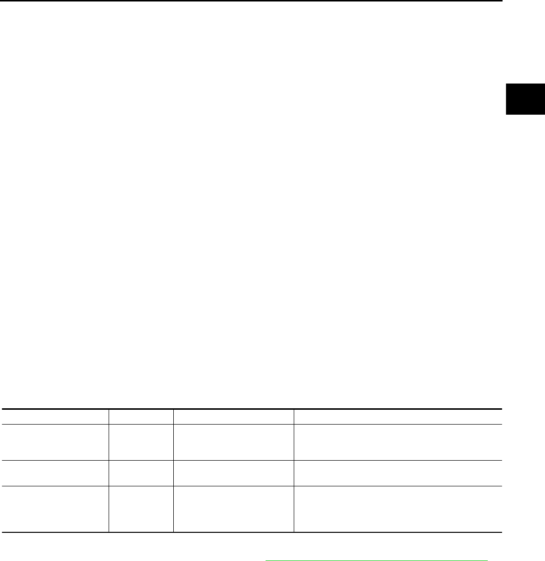
CVT assembly TCM Erasing EEPROM in TCM Remarks
Replaced Replaced Not required
Not required because the EEPROM in the TCM is in
the default state. (CVT assembly must be replaced
first.)
Not replaced Replaced Not required Not required because the EEPROM in the TCM is in
the default state.
Replaced Not replaced Required
Required because data has been written in the
EEPROM in the TCM and because the TCM cannot
write data from the ROM assembly in the transmis-
sion.
CVT-10
PRECAUTIONS
Revision: 2006 August 2006 Murano
10. Turn ignition switch OFF.
METHOD FOR WRITING DATA FROM THE ROM ASSEMBLY IN THE TRANSAXLE
In the following procedure, the TCM reads data from the ROM assembly and writes it to the EEPROM in the
TCM.
1. Erase the EEPROM in the TCM.
2. Move selector lever to “P” position.
3. Turn ignition switch ON.
CHECK METHOD
●Standard: About 2 seconds after the ignition switch ON, the CVT indicator lamp lights up for 2 seconds.
●Non-standard: Even after the ignition switch ON, the CVT indicator lamp does not light up after 2 seconds
or illuminates immediately.
CAUTION:
Perform in the “P” or “N” position.
Action for Non-standard
●Replace the CVT assembly.
●Replace the TCM.
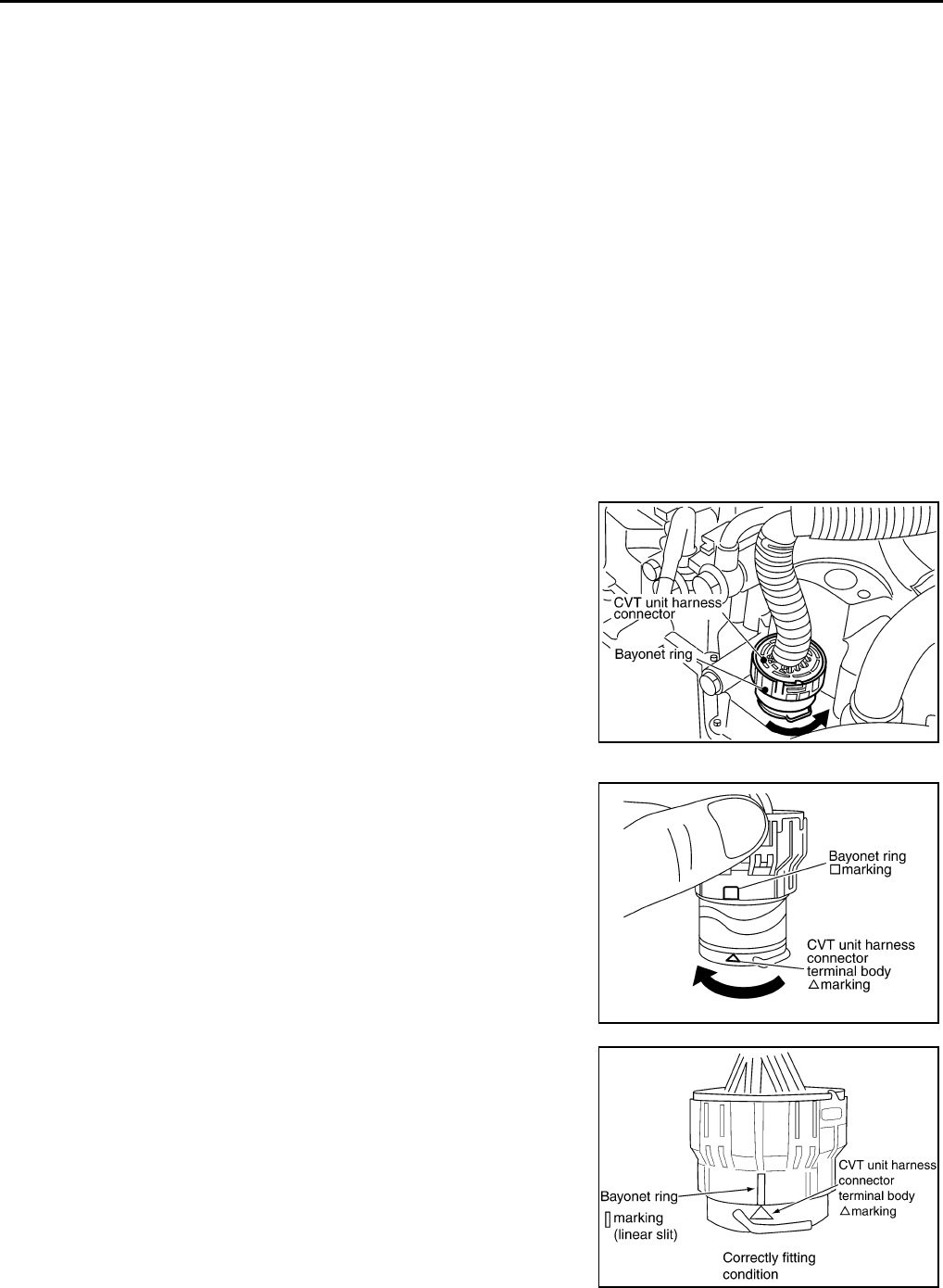
Removal and Installation Procedure for CVT Unit Connector NCS00127
REMOVAL
Rotate bayonet ring counterclockwise, pull out CVT unit harness
connector upward and remove it.
INSTALLATION
1. Align ∆ marking on CVT unit harness connector terminal body
with ❏ marking on bayonet ring, insert CVT unit harness con-
nector, and then rotate bayonet ring clockwise.
2. Rotate bayonet ring clockwise until ∆ marking on CVT unit har-
ness connector terminal body is aligned with the slit on bayonet
ring as shown in the figure (correctly fitting condition), install
CVT unit harness connector to CVT unit harness connector ter-
minal body.
SCIA2096E
SCIA2097E
SCIA2098E
PRECAUTIONS
CVT-11
D
E
F
G
H
I
J
K
L
M
A
B
CVT
Revision: 2006 August 2006 Murano
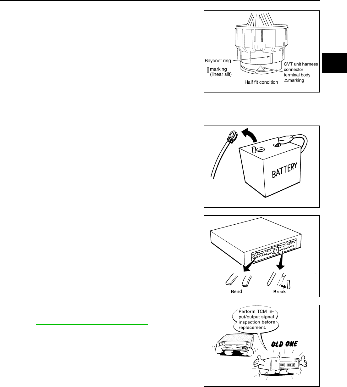
CAUTION:
●Securely align ∆ marking on CVT unit harness connector
terminal body with bayonet ring slit. Then, be careful not
to make a half fit condition as shown in the figure.
●Do not mistake the slit of bayonet ring for other dent por-
tion.
Precautions NCS00128
NOTE:
If any malfunction occurs in the RE0F09A model transaxle, replace the entire transaxle assembly.
●Before connecting or disconnecting the TCM harness con-
nector, turn ignition switch OFF and disconnect negative
battery cable. Because battery voltage is applied to TCM
even if ignition switch is turned OFF.
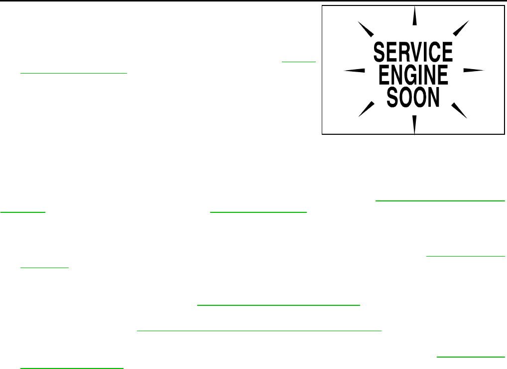
●When connecting or disconnecting pin connectors into or
from TCM, take care not to damage pin terminals (bend or
break).
When connecting pin connectors make sure that there are
not any bends or breaks on TCM pin terminal.
●Before replacing TCM, perform TCM input/output signal
inspection and make sure whether TCM functions properly
or not. CVT-57, "TCM INSPECTION TABLE".
SCIA2099E
SEF289H
SEF291H
MEF040DA
CVT-12
PRECAUTIONS
Revision: 2006 August 2006 Murano
●After performing each TROUBLE DIAGNOSIS, perform
“DTC Confirmation Procedure”.
If the repair is completed the DTC should not be displayed
in the “DTC Confirmation Procedure”.
●Always use the specified brand of CVT fluid. Refer to MA-10,
"Fluids and Lubricants" .
●Use lint-free paper, not cloth rags, during work.
●After replacing the CVT fluid, dispose of the waste oil using the
methods prescribed by law, ordinance, etc.
Service Notice or Precautions NCS00129
CVT FLUID COOLER SERVICE
If CVT fluid contains friction material (clutches, brakes, etc.), or if a CVT is replaced, inspect and clean the
CVT fluid cooler mounted in the radiator or replace the radiator. Flush cooler lines using cleaning solvent and
compressed air after repair. For CVT fluid cooler cleaning procedure, refer to CVT-17, "CVT Fluid Cooler
Cleaning" . For radiator replacement, refer to CO-13, "RADIATOR" .
OBD-II SELF-DIAGNOSIS
●CVT self-diagnosis is performed by the TCM in combination with the ECM. The results can be read
through the blinking pattern of the malfunction indicator lamp (MIL). Refer to the table on CVT-65, "Display
Items List" for the indicator used to display each self-diagnostic result.
●The self-diagnostic results indicated by the MIL are automatically stored in both the ECM and TCM mem-
ories.
Always perform the procedure on CVT-30, "HOW TO ERASE DTC" to complete the repair and
avoid unnecessary blinking of the MIL.
For details of OBD-II, refer to EC-45, "ON BOARD DIAGNOSTIC (OBD) SYSTEM" .
●Certain systems and components, especially those related to OBD, may use the new style slide-
locking type harness connector. For description and how to disconnect, refer to PG-62, "HAR-
NESS CONNECTOR" .
SEF217U
PREPARATION
CVT-13
D
E
F
G
H
I
J
K
L
M
A
B
CVT
Revision: 2006 August 2006 Murano
PREPARATION PFP:00002
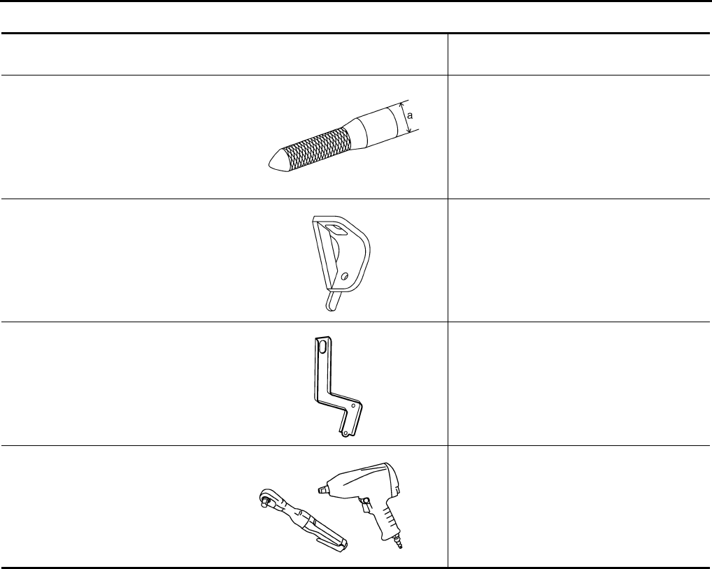
Special Service Tools NCS0012B
The actual shapes of Kent-Moore tools may differ from those of special service tools illustrated here.
Tool number
(Kent-Moore No.)
Tool name
Description
—
(OTC3492)
Oil pressure gauge set
Measuring line pressure
—
(J-34339-A)
Drift
a: 85.69 mm (3.37 in) dia.
b: 50.4 mm (1.98 in) dia.
Installing differential side oil seal
● With AWD models
● Converter housing side (right)
—
(J-47244)
Drift
a: 65.83 mm (2.59 in) dia.
b: 53.85 mm (2.12 in) dia.
Installing differential side oil seal
● Transaxle case side (left)
ST33400001
(J-47005)
Drift
a: 69.85 mm (2.75 in) dia.
b: 49.53 mm (1.95 in) dia.
Installing differential side oil seal
● With 2WD models
● Converter housing side (right)
SCIA7531E
NT084
SCIA5777E
SCIA5777E
CVT-14
PREPARATION
Revision: 2006 August 2006 Murano
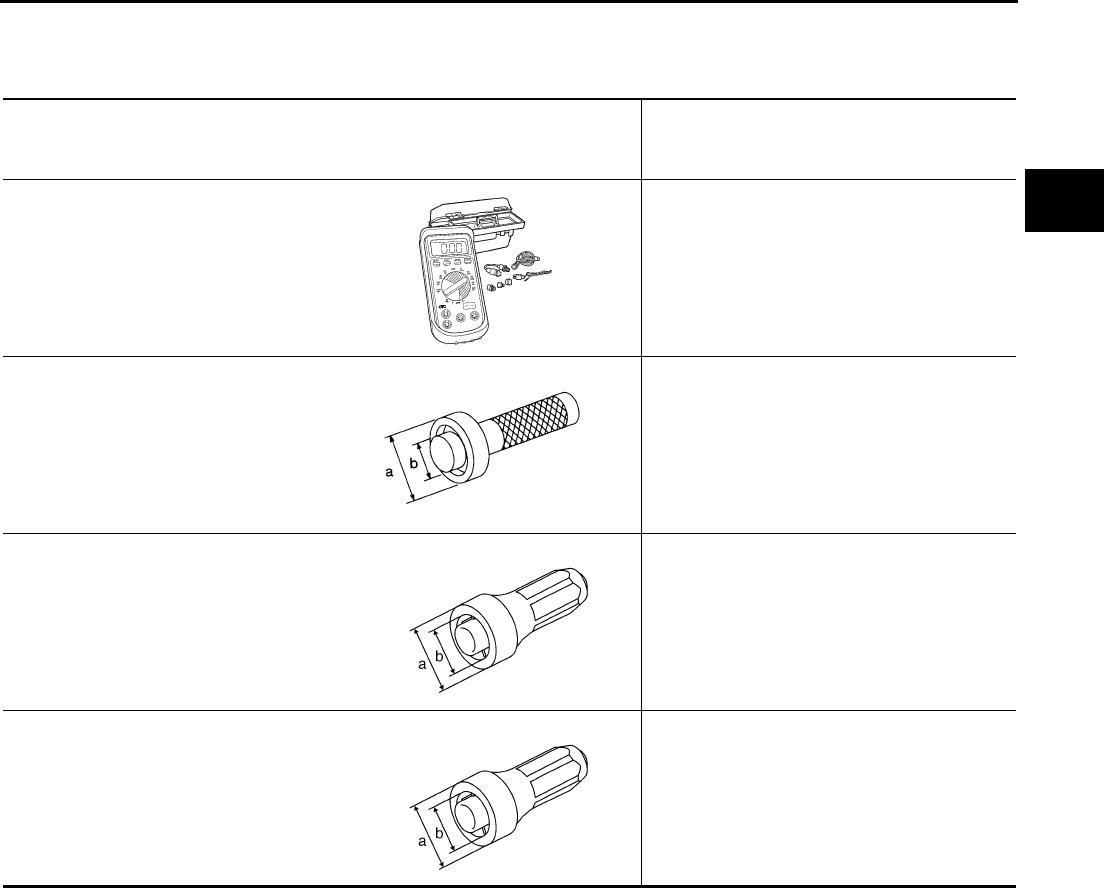
Commercial Service Tools NCS0012C
Tool number
Tool name Description
31197CA000
Drive plate location guide
a: 14 mm (0.55 in) dia.
Installing transaxle assembly
31093CA000
Slinger
Removing and installing transaxle assembly
31092CA000
Slinger
Removing and installing transaxle assembly
Power tool Loosening nuts and bolts
SCIA2013E
SCIA2014E
SCIA2015E
PBIC0190E
CVT FLUID
CVT-15
D
E
F
G
H
I
J
K
L
M
A
B
CVT
Revision: 2006 August 2006 Murano
CVT FLUID PFP:KLE50
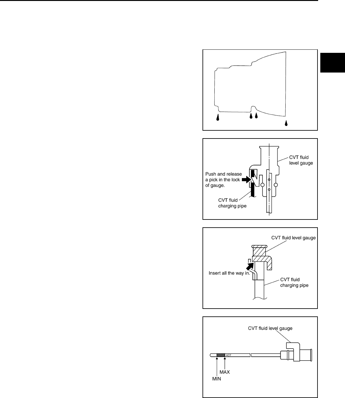
Checking CVT Fluid NCS0012D
FLUID LEVEL CHECK
Fluid level should be checked with the fluid warmed up to 50 to 80°C (122 to 176°F). The fluid level check pro-
cedure is as follows:
1. Check for fluid leakage.
2. With the engine warmed up, drive the vehicle in an urban area.
When ambient temperature is 20°C (68°F), it takes about 10
minutes for the CVT fluid to warm up to 50 to 80°C (122 to
176°F).
3. Park the vehicle on a level surface.
4. Apply parking brake firmly.
5. With engine at idle, while depressing brake pedal, move shift
selector throughout the entire shift range.
6. Pull out the CVT fluid level gauge from the CVT fluid charging
pipe after pressing the tab on the CVT fluid level gauge to
release the lock.
7. Wipe fluid off the CVT fluid level gauge. Insert the CVT fluid
level gauge rotating 180° from the originally installed position,
then securely push the CVT fluid level gauge until it meets the
top end of the CVT fluid charging pipe.
CAUTION:
When wiping away the CVT fluid level gauge, always use
lint-free paper, not a cloth rag.
8. Place the selector lever in “P” or “N” and make sure the fluid
level is within the specified range.
CAUTION:
When reinstalling CVT fluid level gauge, insert it into the
CVT fluid charging pipe and rotate it to the original installa-
tion position until it is securely locked.
SMA146B
SCIA1933E
SCIA1931E
SCIA1932E
CVT-16
CVT FLUID
Revision: 2006 August 2006 Murano
9. Check CVT fluid condition.
●If CVT fluid is very dark or smells burned, check operation of
CVT. Flush cooling system after repair of CVT.
●If CVT fluid contains frictional material (clutches, brakes, etc.),
replace radiator and flush cooler line using cleaning solvent
and compressed air after repair of CVT. Refer to CO-13,
"RADIATOR" and CVT-17, "CVT Fluid Cooler Cleaning" .
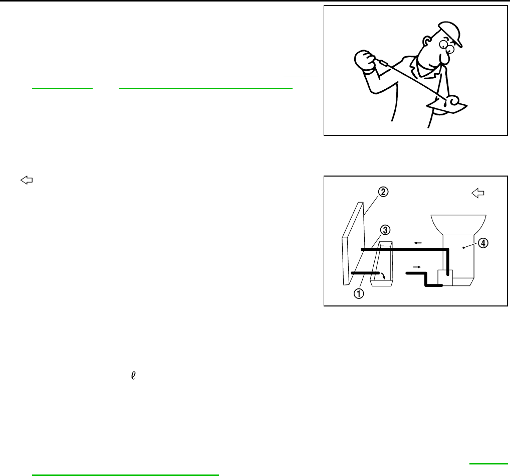
Changing CVT Fluid NCS0012E
1. Warm up CVT fluid by driving the vehicle for 10 minutes.
●: Vehicle front
●Radiator (2)
●CVT fluid cooler hose [inlet side (3)]
●Transaxle assembly (4)
2. Drain CVT fluid from CVT fluid cooler hose [outlet side (1)] and
refill with new CVT fluid at CVT fluid charging pipe with the
engine running at idle speed.
3. Refill until new CVT fluid comes out from CVT fluid cooler hose
[outlet side (1)].
About 30 to 50% extra fluid will be required for this procedure.
CAUTION:
●Use only Genuine NISSAN CVT Fluid NS-2. Do not mix with other fluid.
●Using CVT fluid other than Genuine NISSAN CVT Fluid NS-2 will deteriorate in driveability and
CVT durability, and may damage the CVT, which is not covered by the warranty.
●When filling CVT fluid, take care not to scatter heat generating parts such as exhaust.
●Delete CVT fluid deterioration date with CONSULT-II after changing CVT fluid. Refer to CVT-64,
"Check CVT Fluid Deterioration Date" .
4. Check fluid level and condition.
ATA0022D
CVT fluid:
Genuine NISSAN CVT Fluid NS-2
Fluid capacity:
Approx. 10.2 (10-6/8 US qt, 9 lmp qt)
SCIA6088E
CVT FLUID
CVT-17
D
E
F
G
H
I
J
K
L
M
A
B
CVT
Revision: 2006 August 2006 Murano
CVT Fluid Cooler Cleaning NCS0012F
Whenever an automatic transaxle is repaired, overhauled, or replaced, the CVT fluid cooler mounted in the
radiator must be inspected and cleaned.
Metal debris and friction material, if present, can be trapped or become deposit in the CVT fluid cooler. This
debris can contaminate the newly serviced CVT or, in severe cases, can block or restrict the flow of CVT fluid.
In either case, malfunction of the newly serviced CVT may occur.
Debris, if present, may deposit as CVT fluid enters the cooler inlet. It will be necessary to back flush the cooler
through the cooler outlet in order to flush out any built up debris.
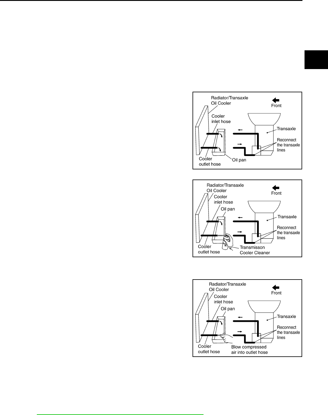
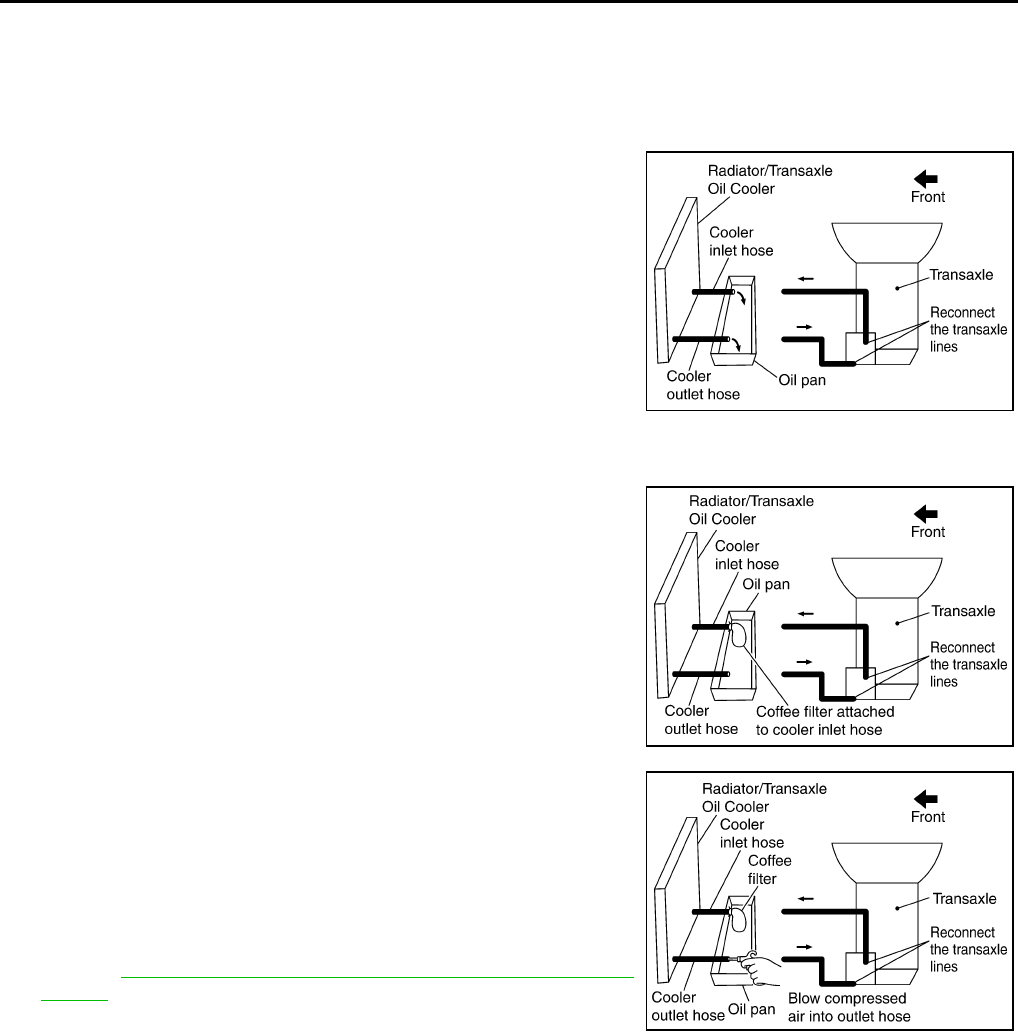
CVT FLUID COOLER CLEANING PROCEDURE
1. Position an oil pan under the transaxle's inlet and outlet cooler hoses.
2. Identify the inlet and outlet fluid cooler hoses.
3. Disconnect the fluid cooler inlet and outlet rubber hoses from the
steel cooler tubes or bypass valve.
NOTE:
Replace the cooler hoses if rubber material from the hose
remains on the tube fitting.
4. Allow any CVT fluid that remains in the cooler hoses to drain into
the oil pan.
5. Insert the extension adapter hose of a can of Transmission
Cooler Cleaner (Nissan P/N 999MP-AM006) into the cooler out-
let hose.
CAUTION:
●Wear safety glasses and rubber gloves when spraying
the Transmission Cooler Cleaner.
●Spray Transmission Cooler Cleaner only with adequate
ventilation.
●Avoid contact with eyes and skin.
●Do not breath vapors or spray mist.
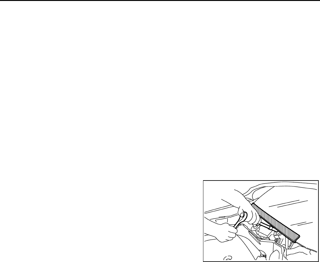
6. Hold the hose and can as high as possible and spray Transmis-
sion Cooler Cleaner in a continuous stream into the cooler outlet hose until CVT fluid flows out of the
cooler inlet hose for 5 seconds.
7. Insert the tip of an air gun into the end of the cooler outlet hose.
8. Wrap a shop rag around the air gun tip and of the cooler outlet
hose.
9. Blow compressed air regulated to 5 to 9 kg/cm2 (70 to 130 psi)
through the cooler outlet hose for 10 seconds to force out any
remaining CVT fluid.
10. Repeat steps 5 through 9 three additional times.
11. Position an oil pan under the banjo bolts that connect the CVT
fluid cooler steel lines to the transaxle.
12. Remove the banjo bolts.
13. Flush each steel line from the cooler side back toward the tran-
saxle by spraying Transmission Cooler Cleaner in a continuous stream for 5 seconds.
14. Blow compressed air regulated to 5 to 9 kg/cm2 (70 to 130 psi) through each steel line from the cooler
side back toward the transaxle for 10 seconds to force out any remaining CVT fluid.
15. Ensure all debris is removed from the steel cooler lines.
16. Ensure all debris is removed from the banjo bolts and fittings.
17. Perform CVT-18, "CVT FLUID COOLER DIAGNOSIS PROCEDURE" .
SCIA4421E
SCIA4422E
SCIA4423E
CVT-18
CVT FLUID
Revision: 2006 August 2006 Murano
CVT FLUID COOLER DIAGNOSIS PROCEDURE
NOTE:
Insufficient cleaning of the cooler inlet hose exterior may lead to inaccurate debris identification.
1. Position an oil pan under the transaxle's inlet and outlet cooler hoses.
2. Clean the exterior and tip of the cooler inlet hose.
3. Insert the extension adapter hose of a can of Transmission
Cooler Cleaner (Nissan P/N 999MP-AM006) into the cooler out-
let hose.
CAUTION:
●Wear safety glasses and rubber gloves when spraying
the Transmission Cooler Cleaner.
●Spray Transmission Cooler Cleaner only with adequate
ventilation.
●Avoid contact with eyes and skin.
●Do not breath vapors or spray mist.
4. Hold the hose and can as high as possible and spray Transmis-
sion Cooler Cleaner in a continuous stream into the cooler outlet hose until CVT fluid flows out of the
cooler inlet hose for 5 seconds.
5. Tie a common white, basket-type coffee filter to the end of the
cooler inlet hose.
6. Insert the tip of an air gun into the end of the cooler outlet hose.
7. Wrap a shop rag around the air gun tip and end of cooler outlet
hose.
8. Blow compressed air regulated to 5 to 9 kg/cm2 (70 to 130 psi)
through the cooler outlet hose to force any remaining CVT fluid
into the coffee filter.
9. Remove the coffee filter from the end of the cooler inlet hose.
10. Perform CVT-19, "CVT FLUID COOLER INSPECTION PROCE-
DURE" .
SCIA4421E
SCIA4424E
SCIA4425E
CVT FLUID
CVT-19
D
E
F
G
H
I
J
K
L
M
A
B
CVT
Revision: 2006 August 2006 Murano
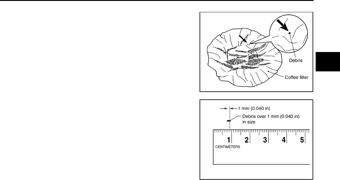
CVT FLUID COOLER INSPECTION PROCEDURE
1. Inspect the coffee filter for debris.
a. If small metal debris less than 1 mm (0.040 in) in size or metal
powder is found in the coffee filter, this is normal. If normal
debris is found, the CVT fluid cooler/radiator can be re-used and
the procedure is ended.
b. If one or more pieces of debris are found that are over 1 mm
(0.040 in) in size and/or peeled clutch facing material is found in
the coffee filter, the fluid cooler is not serviceable. The radiator/
fluid cooler must be replaced and the inspection procedure is
ended.
CVT FLUID COOLER FINAL INSPECTION
After performing all procedures, ensure that all remaining oil is cleaned from all components.
SCIA2967E
SCIA7031E
CVT-20
CVT SYSTEM
Revision: 2006 August 2006 Murano
CVT SYSTEM PFP:31036
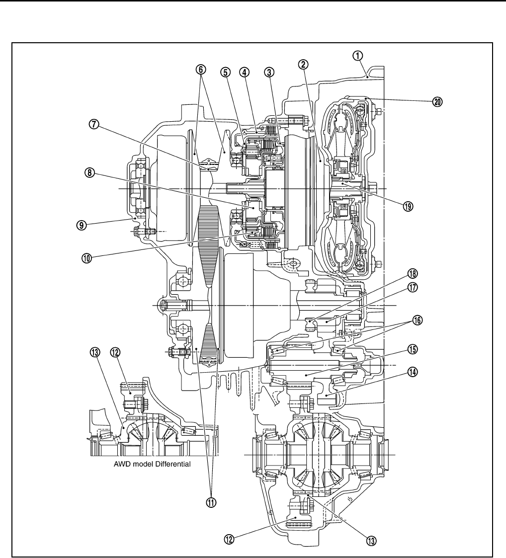
Cross-sectional View - RE0F09A NCS0012G
1. Converter housing 2. Oil pump 3. Forward clutch
4. Reverse brake 5. Planetary carrier 6. Primary pulley
7. Steel belt 8. Sun gear 9. Side cover
10. Internal gear 11. Secondary pulley 12. Final gear
13. Differential case 14. Idler gear 15. Reduction gear
16. Taper roller bearing 17. Output gear 18. Parking gear
19. Input shaft 20. Torque converter
SCIA4837E
CVT SYSTEM
CVT-21
D
E
F
G
H
I
J
K
L
M
A
B
CVT
Revision: 2006 August 2006 Murano
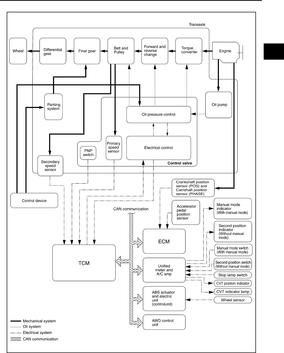
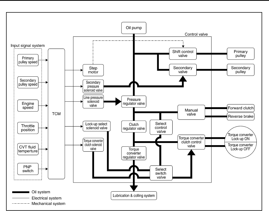
Control System NCS0012H
SCIA6883E
CVT-22
CVT SYSTEM
Revision: 2006 August 2006 Murano
Hydraulic Control System NCS0012I
SCIA1807E

CVT SYSTEM
CVT-23
D
E
F
G
H
I
J
K
L
M
A
B
CVT
Revision: 2006 August 2006 Murano
TCM Function NCS0012J
The function of the TCM is to:
●Receive input signals sent from various switches and sensors.
●Determine required line pressure, shifting point, and lock-up operation.
●Send required output signals to the step motor and the respective solenoids.
CONTROL SYSTEM OUTLINE
The CVT senses vehicle operating conditions through various sensors. It always controls the optimum shift
position and reduces shifting and lock-up shocks.
*: Without manual mode.
CONTROL SYSTEM DIAGRAM
SENSORS (or SIGNAL)
Þ
TCM
Þ
ACTUATORS
PNP switch
Accelerator pedal position signal
Closed throttle position signal
Engine speed signal
CVT fluid temperature sensor
Vehicle speed signal
Manual mode signal
Second position signal*
Stop lamp switch signal
Primary speed sensor
Secondary speed sensor
Primary pressure sensor
Secondary pressure sensor
Shift control
Line pressure control
Primary pressure control
Secondary pressure control
Lock-up control
Engine brake control
Vehicle speed control
Fail-safe control
Self-diagnosis
CONSULT-II communication line
Duet-EA control
CAN system
On board diagnosis
Step motor
Torque converter clutch solenoid
valve
Lock-up select solenoid valve
Line pressure solenoid valve
Secondary pressure solenoid
valve
Manual mode indicator
Second position indicator*
CVT position indicator
CVT indicator lamp
Starter relay
SCIA7495E
CVT-24
CVT SYSTEM
Revision: 2006 August 2006 Murano
CAN Communication NCS0012K
SYSTEM DESCRIPTION
CAN (Controller Area Network) is a serial communication line for real time application. It is an on-vehicle mul-
tiplex communication line with high data communication speed and excellent error detection ability. Many elec-
tronic control units are equipped onto a vehicle, and each control unit shares information and links with other
control units during operation (not independent). In CAN communication, control units are connected with 2
communication lines (CAN-H line, CAN-L line) allowing a high rate of information transmission with less wiring.
Each control unit transmits/receives data but selectively reads required data only. For details, refer to LAN-32,
"CAN Communication Unit" .
Input/Output Signal of TCM NCS0012L
*1: Input by CAN communications.
*2: If these input and output signals are different, the TCM triggers the fail-safe function.
*3: Without manual mode.
Control item
Fluid
pressure
control
Select con-
trol
Shift con-
trol
Lock-up
control
CAN com-
munication
control
Fail-safe
function
(*2)
Input
PNP switch X X X X X X
Accelerator pedal position signal (*1) XXXXXX
Closed throttle position signal(*1) XXXX
Engine speed signal(*1) XX XXX
CVT fluid temperature sensor X X X X X
Manual mode signal(*1) X XXXX
Second position signal(*1) (*3) XXX
Stop lamp switch signal(*1) XXXX
Primary speed sensor X X X X X
Secondary speed sensor X X X X X X
Primary pressure sensor X X
Secondary pressure sensor X X X
TCM power supply voltage signal X X X X X X
Out-
put
Step motor X X
TCC solenoid valve X X X
Lock-up select solenoid valve X X X
Line pressure solenoid valve X X X X
Secondary pressure solenoid valve X X X
CVT SYSTEM
CVT-25
D
E
F
G
H
I
J
K
L
M
A
B
CVT
Revision: 2006 August 2006 Murano
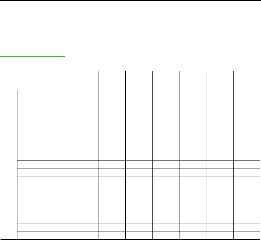
Line Pressure and Secondary Pressure Control NCS0012M
●When an input torque signal equivalent to the engine drive force is sent from the ECM to the TCM, the
TCM controls the line pressure solenoid valve and secondary pressure solenoid valve.
●This line pressure solenoid controls the pressure regulator valve as the signal pressure and adjusts the
pressure of the operating oil discharged from the oil pump to the line pressure most appropriate to the
driving state. Secondary pressure is controlled by decreasing line pressure.
NORMAL CONTROL
Optimize the line pressure and secondary pressure, depending on driving conditions, on the basis of the throt-
tle position, the engine speed, the primary pulley (input) revolution speed, the secondary pulley (output) revo-
lution speed, the brake signal, the PNP switch signal, the lock-up signal, the voltage, the target gear ratio, the
fluid temperature, and the fluid pressure.
FEEDBACK CONTROL
When controlling the normal fluid pressure or the selected fluid pressure, the secondary pressure can be set
more accurately by using the fluid pressure sensor to detect the secondary pressure and controlling the feed-
back.
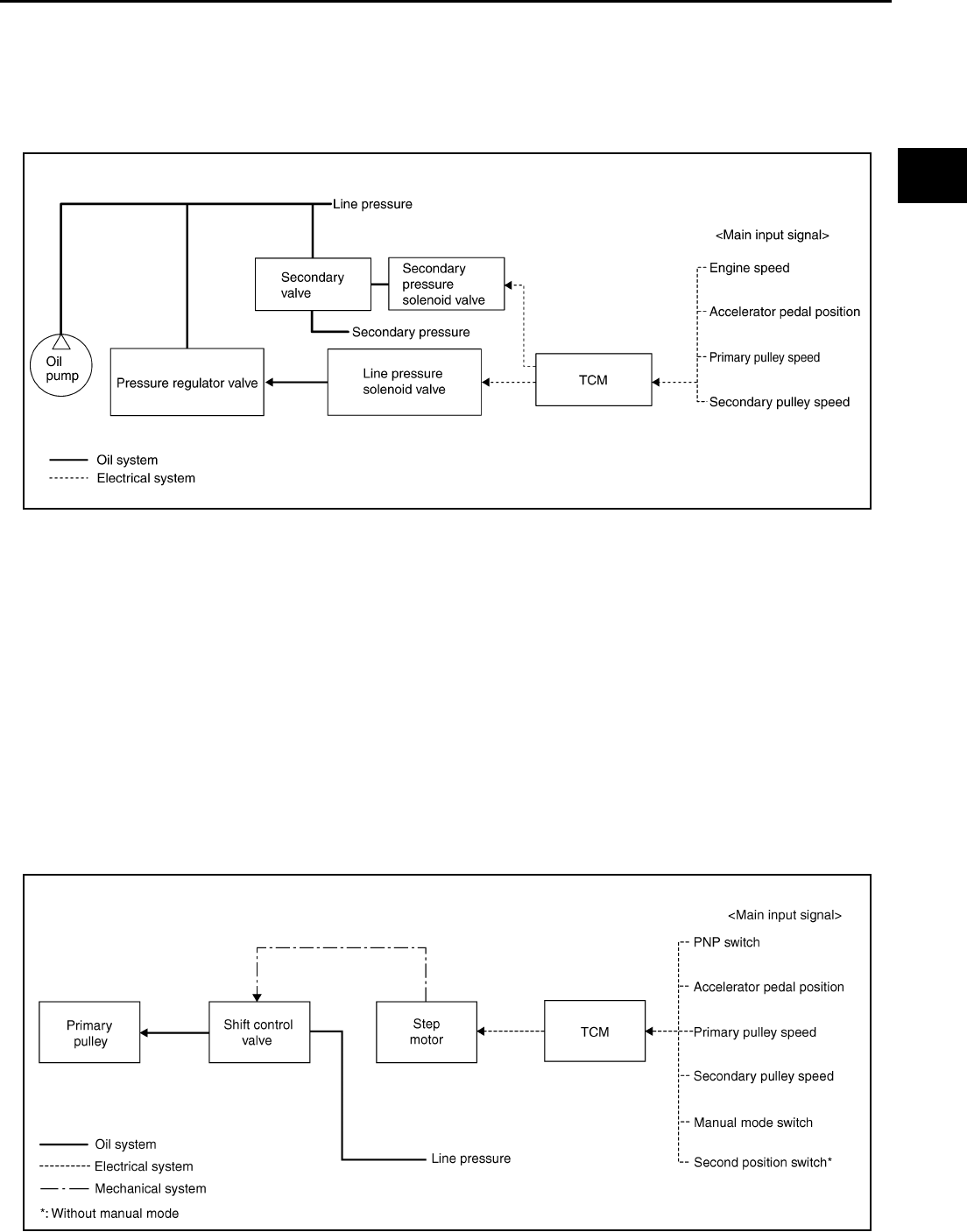
Shift Control NCS0012N
In order to select the gear ratio which can obtain the driving force in accordance with driver's intention and the
vehicle condition, TCM monitors the driving conditions, such as the vehicle speed and the throttle position and
selects the optimum gear ratio, and determines the gear change steps to the gear ratio. Then send the com-
mand to the step motor, and control the flow-in/flow-out of line pressure from the primary pulley to determine
the position of the moving-pulley and control the gear ratio.
SCIA1846E
SCIA8097E
CVT-26
CVT SYSTEM
Revision: 2006 August 2006 Murano
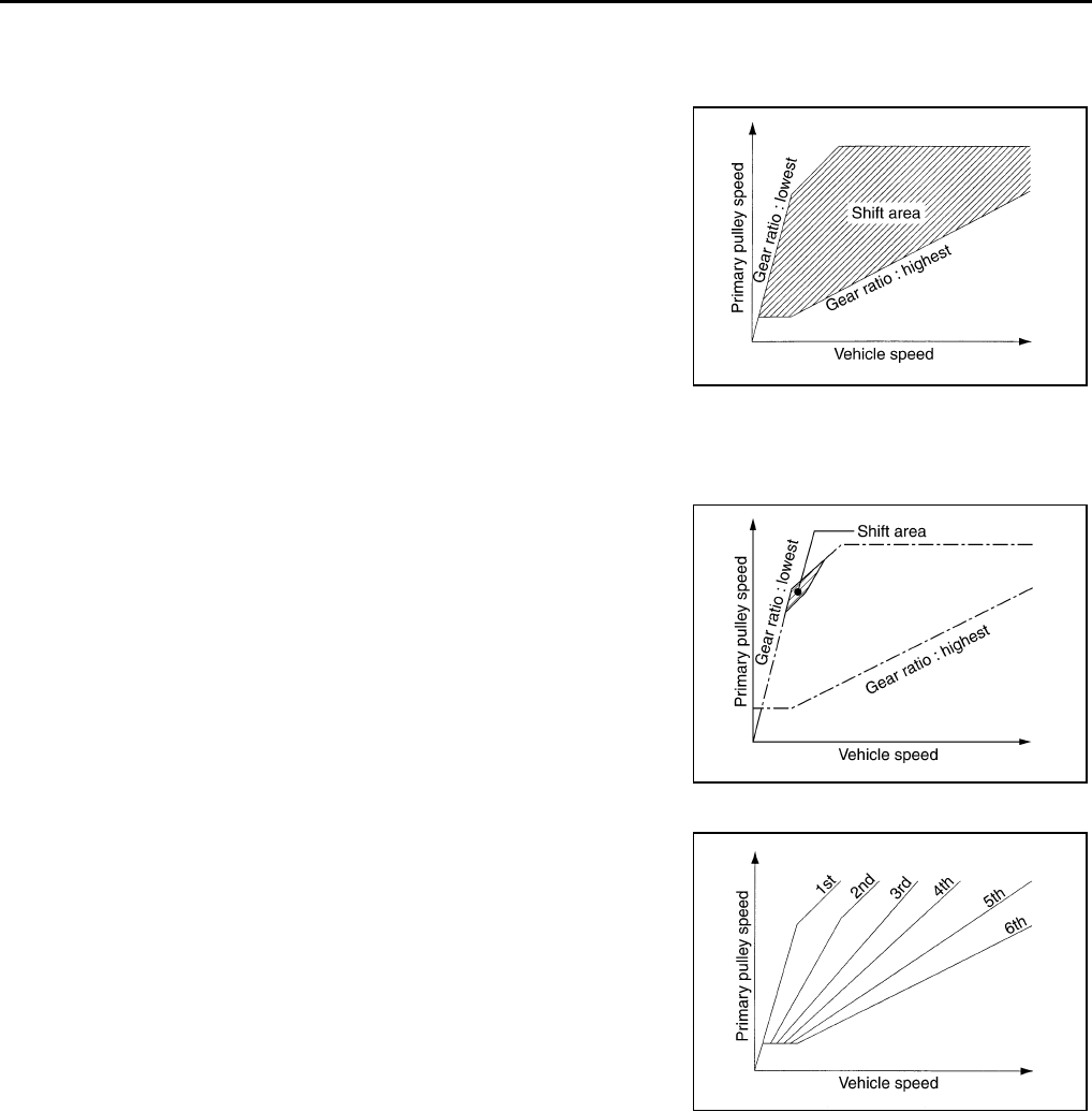
NOTE:
The gear ratio is set for every position separately.
“D” POSITION
Shifting over all the ranges of gear ratios from the lowest to the high-
est.
“S” POSITION (WITHOUT MANUAL MODE)
Use this position for the improved engine braking.
“L” POSITION (WITHOUT MANUAL MODE)
By limiting the gear range to the lowest position, the strong driving
force and the engine brake can be secured.
“M” POSITION
When the selector lever is put in the manual shift gate side, the fixed
changing gear line is set. By moving the selector lever to + side or -
side, the manual mode switch is changed over, and shift change like
M/T becomes possible following the changing gear set line step by
step.
DOWNHILL ENGINE BRAKE CONTROL (AUTO ENGINE BRAKE CONTROL)
When downhill is detected with the accelerator pedal released, the engine brake will be strengthened up by
downshifting so as not to accelerate the vehicle more than necessary.
ACCELERATION CONTROL
According to vehicle speed and a change of accelerator pedal angle, driver's request for acceleration and driv-
ing scene are judged. This function assists improvement in acceleration feeling by making the engine speed
proportionate to the vehicle speed. And a shift map which can gain a larger driving force is available for com-
patibility of mileage with driveability.
SCIA1953E
SCIA1955E
SCIA4582E
CVT SYSTEM
CVT-27
D
E
F
G
H
I
J
K
L
M
A
B
CVT
Revision: 2006 August 2006 Murano
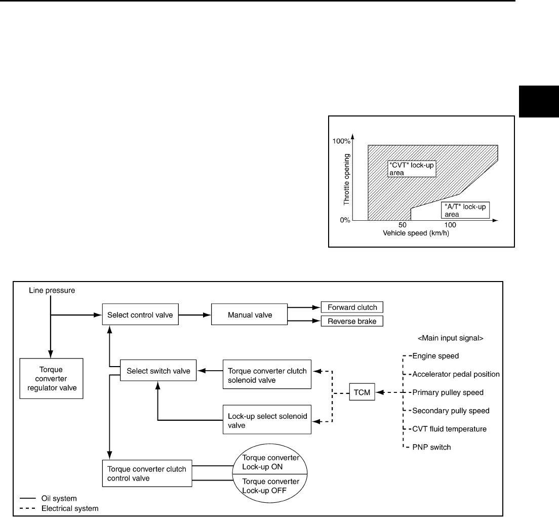
Lock-up and Select Control NCS0012O
●The torque converter clutch piston in the torque converter is engaged to eliminate torque converter slip to
increase power transmission efficiency.
●The torque converter clutch control valve operation is controlled by the torque converter clutch solenoid
valve, which is controlled by a signal from TCM. The torque converter clutch control valve engages or
releases the torque converter clutch piston.
●When shifting between “N” (“P”) ⇔ “D” (“R”), torque converter clutch solenoid controls engagement power
of forward clutch and reverse brake.
●The lock-up applied gear range was expanded by locking up the
torque converter at a lower vehicle speed than conventional
CVT models.
TORQUE CONVERTER CLUTCH AND SELECT CONTROL VALVE CONTROL
Lock-up and Select Control System Diagram
Lock-up Released
In the lock-up released state, the torque converter clutch control valve is set into the unlocked state by the
torque converter clutch solenoid and the lock-up apply pressure is drained.
In this way, the torque converter clutch piston is not coupled.
Lock-up Applied
In the lock-up applied state, the torque converter clutch control valve is set into the locked state by the torque
converter clutch solenoid and lock-up apply pressure is generated.
In this way, the torque converter clutch piston is pressed and coupled.
Select Control
When shifting between “N” (“P”)⇔“D” (“R”), optimize the operating pressure on the basis of the throttle posi-
tion, the engine speed, and the secondary pulley (output) revolution speed to lessen the shift shock.
SCIA1958E
SCIA2374E
CVT-28
CVT SYSTEM
Revision: 2006 August 2006 Murano
Control Valve NCS0012P
FUNCTION OF CONTROL VALVE
Name Function
Torque converter regulator valve Optimizes the supply pressure for the torque converter depending on driving conditions.
Pressure regulator valve Optimizes the discharge pressure from the oil pump depending on driving conditions.
TCC control valve ●Activates or deactivate the lock-up.
●Lock-up smoothly by opening lock-up operation excessively.
TCC solenoid valve Controls the TCC control valve or select control valve.
Shift control valve Controls flow-in/out of line pressure from the primary pulley depending on the stroke dif-
ference between the stepping motor and the primary pulley.
Secondary valve Controls the line pressure from the secondary pulley depending on operating condi-
tions.
Clutch regulator valve Adjusts the clutch operating pressure depending on operating conditions.
Secondary pressure solenoid valve Controls the secondary valve.
Line pressure solenoid valve Controls the line pressure control valve.
Step motor Controls the pulley ratio.
Manual valve Transmits the clutch operating pressure to each circuit in accordance with the selected
position.
Select control valve Engages forward clutch, reverse brake smoothly depending on select operation.
Select switch valve Switches torque converter clutch solenoid valve control pressure use to torque con-
verter clutch control valve or select control valve.
Lock-up select solenoid valve Controls the select switch valve.
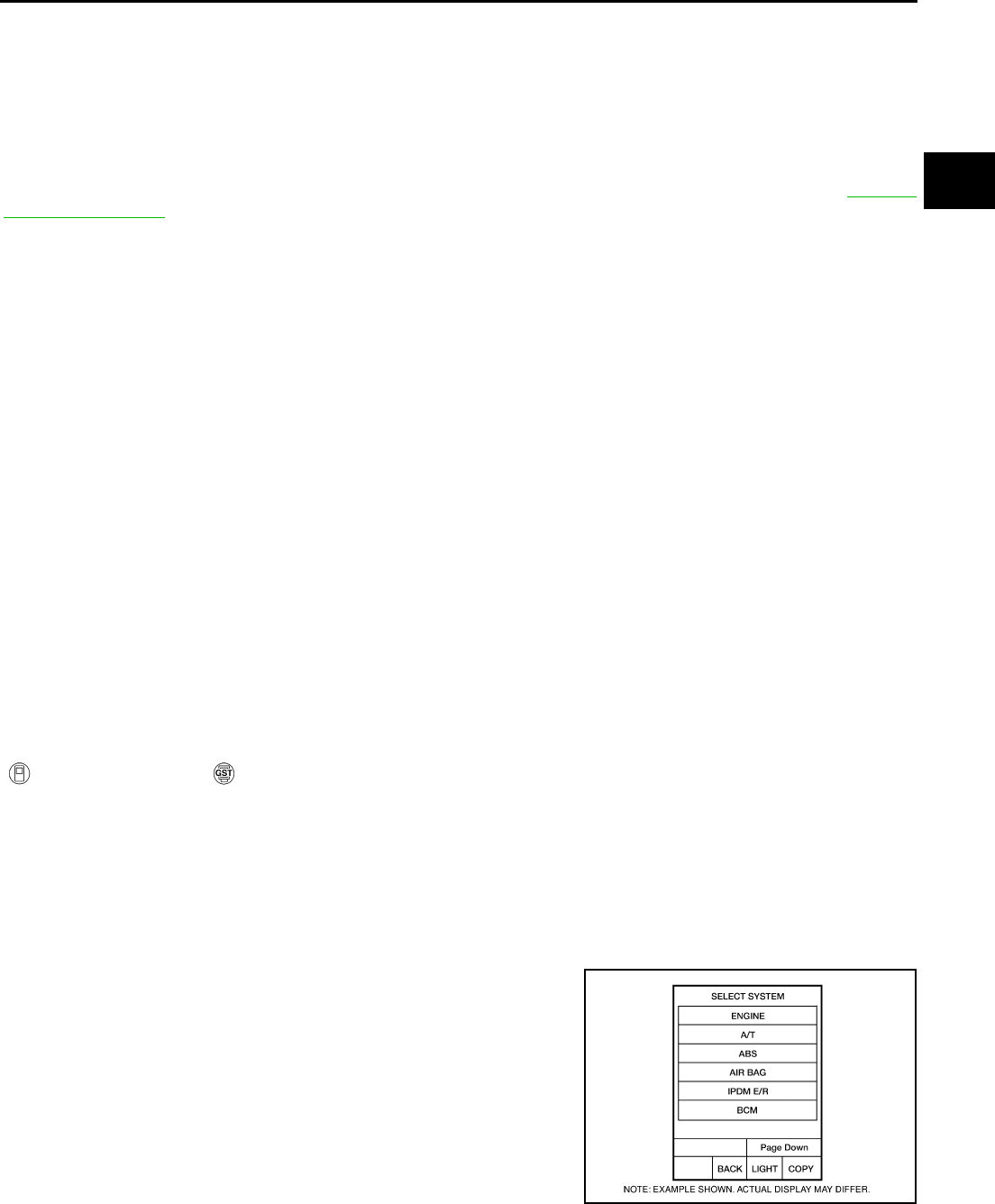
ON BOARD DIAGNOSTIC (OBD) SYSTEM
CVT-29
D
E
F
G
H
I
J
K
L
M
A
B
CVT
Revision: 2006 August 2006 Murano
ON BOARD DIAGNOSTIC (OBD) SYSTEM PFP:00028
Introduction NCS0012Q
The CVT system has two self-diagnostic systems.
The first is the emission-related on board diagnostic system (OBD-II) performed by the TCM in combination
with the ECM. The malfunction is indicated by the MIL (malfunction indicator lamp) and is stored as a DTC in
the ECM memory, and the TCM memory.
The second is the TCM original self-diagnosis performed by the TCM. The malfunction is stored in the TCM
memory. The detected items are overlapped with OBD-II self-diagnostic items. For detail, refer to CVT-65,
"Display Items List" .
OBD-II Function for CVT System NCS0012R
The ECM provides emission-related on board diagnostic (OBD-II) functions for the CVT system. One function
is to receive a signal from the TCM used with OBD-related parts of the CVT system. The signal is sent to the
ECM when a malfunction occurs in the corresponding OBD-related part. The other function is to indicate a
diagnostic result by means of the MIL (malfunction indicator lamp) on the instrument panel. Sensors, switches
and solenoid valves are used as sensing elements.
The MIL automatically illuminates in One or Two Trip Detection Logic when a malfunction is sensed in relation
to CVT system parts.
One or Two Trip Detection Logic of OBD-II NCS0012S
ONE TRIP DETECTION LOGIC
If a malfunction is sensed during the first test drive, the MIL will illuminate and the malfunction will be stored in
the ECM memory as a DTC. The TCM is not provided with such a memory function.
TWO TRIP DETECTION LOGIC
When a malfunction is sensed during the first test drive, it is stored in the ECM memory as a 1st trip DTC
(diagnostic trouble code) or 1st trip freeze frame data. At this point, the MIL will not illuminate. — 1st trip
If the same malfunction as that experienced during the first test drive is sensed during the second test drive,
the MIL will illuminate. — 2nd trip
The “trip” in the “One or Two Trip Detection Logic” means a driving mode in which self-diagnosis is performed
during vehicle operation.
OBD-II Diagnostic Trouble Code (DTC) NCS0012T
HOW TO READ DTC AND 1ST TRIP DTC
DTC and 1st trip DTC can be read by the following methods.
( with CONSULT-II or GST) CONSULT-II or GST (Generic Scan Tool) Examples: P0705, P0720 etc.
These DTC are prescribed by SAE J2012.
(CONSULT-II also displays the malfunctioning component or system.)
●1st trip DTC No. is the same as DTC No.
●Output of the diagnostic trouble code indicates that the indicated circuit has a malfunction. How-
ever, in case of the Mode II and GST, they do not indicate whether the malfunction is still occurring
or occurred in the past and returned to normal.
CONSULT-II can identify them as shown below, therefore, CONSULT-II (if available) is recom-
mended.
A sample of CONSULT-II display for DTC and 1st trip DTC is shown
on the next page. DTC or 1st trip DTC of a malfunction is displayed
in SELF-DIAGNOSTIC RESULTS mode for “ENGINE” with CON-
SULT-II. Time data indicates how many times the vehicle was driven
after the last detection of a DTC.
BCIA0030E
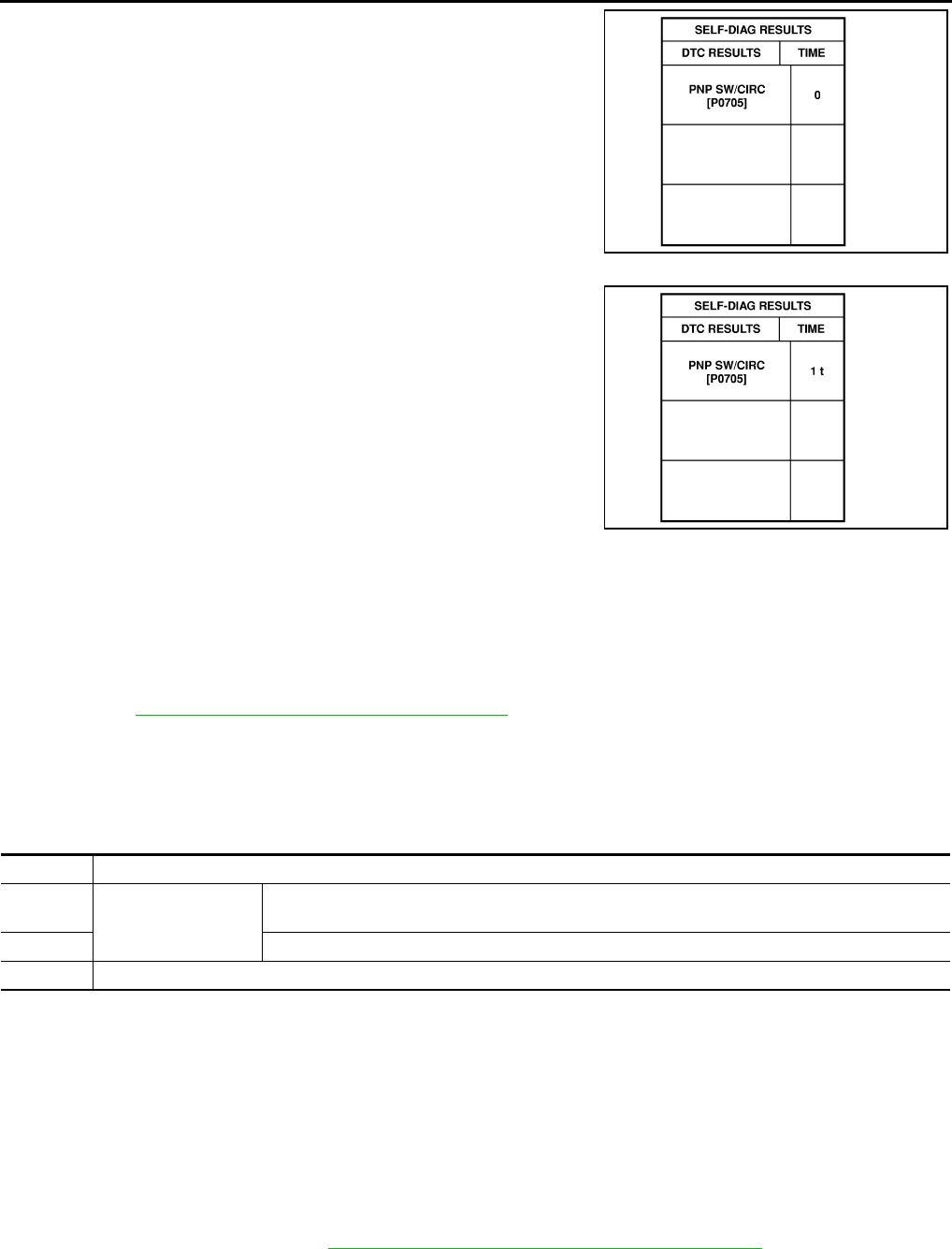
CVT-30
ON BOARD DIAGNOSTIC (OBD) SYSTEM
Revision: 2006 August 2006 Murano
If the DTC is being detected currently, the time data will be “0”.
If a 1st trip DTC is stored in the ECM, the time data will be “1t”.
Freeze Frame Data and 1st Trip Freeze Frame Data
The ECM has a memory function, which stores the driving condition such as fuel system status, calculated
load value, engine coolant temperature, short term fuel trim, long term fuel trim, engine speed and vehicle
speed at the moment the ECM detects a malfunction.
Data which are stored in the ECM memory, along with the 1st trip DTC, are called 1st trip freeze frame data,
and the data, stored together with the DTC data, are called freeze frame data and displayed on CONSULT-II
or GST. The 1st trip freeze frame data can only be displayed on the CONSULT-II screen, not on the GST. For
details, refer to EC-112, "CONSULT-II Function (ENGINE)" .
Only one set of freeze frame data (either 1st trip freeze frame data or freeze frame data) can be stored in the
ECM. 1st trip freeze frame data is stored in the ECM memory along with the 1st trip DTC. There is no priority
for 1st trip freeze frame data, and it is updated each time a different 1st trip DTC is detected. However, once
freeze frame data (2nd trip detection/MIL on) is stored in the ECM memory, 1st trip freeze frame data is no
longer stored. Remember, only one set of freeze frame data can be stored in the ECM. The ECM has the fol-
lowing priorities to update the data.
Both 1st trip freeze frame data and freeze frame data (along with the DTC) are cleared when the ECM mem-
ory is erased.
HOW TO ERASE DTC
The diagnostic trouble code can be erased by CONSULT-II, GST or ECM DIAGNOSTIC TEST MODE as
described following.
●If the battery cable is disconnected, the diagnostic trouble code will be lost within 24 hours.
●When you erase the DTC, using CONSULT-II or GST is easier and quicker than switching the mode
selector on the ECM.
The following emission-related diagnostic information is cleared from the ECM memory when erasing DTC
related to OBD-II. For details, refer to EC-46, "Emission-Related Diagnostic Information" .
●Diagnostic trouble codes (DTC)
●1st trip diagnostic trouble codes (1st trip DTC)
●Freeze frame data
SAT015K
SAT016K
Priority Items
1 Freeze frame data Misfire — DTC: P0300 - P0306
Fuel Injection System Function — DTC: P0171, P0172, P0174, P0175
2 Except the above items (Includes CVT related items)
3 1st trip freeze frame data
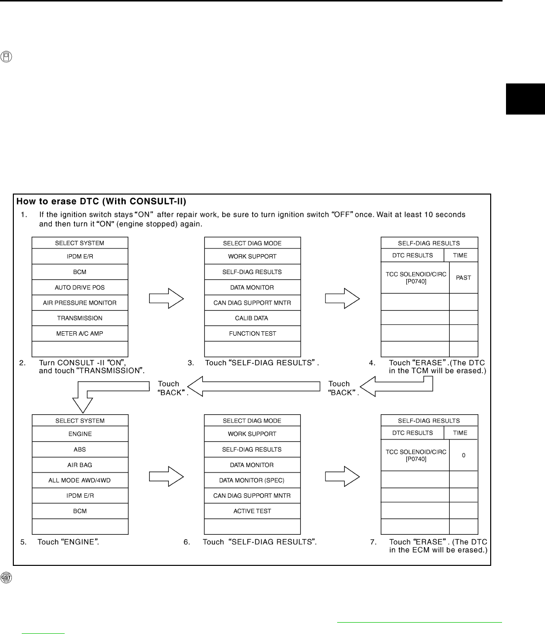
ON BOARD DIAGNOSTIC (OBD) SYSTEM
CVT-31
D
E
F
G
H
I
J
K
L
M
A
B
CVT
Revision: 2006 August 2006 Murano
●1st trip freeze frame data
●System readiness test (SRT) codes
●Test values
HOW TO ERASE DTC (WITH CONSULT-II)
●If a DTC is displayed for both ECM and TCM, it is necessary to be erased for both ECM and TCM.
1. If the ignition switch stays ON after repair work, be sure to turn ignition switch OFF once. Wait at least 10
seconds and then turn it ON (engine stopped) again.
2. Turn CONSULT-II ON and touch “TRANSMISSION”.
3. Touch “SELF-DIAG RESULTS”.
4. Touch “ERASE”. (The DTC in the TCM will be erased.) Then touch “BACK” twice.
5. Touch “ENGINE”.
6. Touch “SELF-DIAG RESULTS”.
7. Touch “ERASE”. (The DTC in the ECM will be erased.)
HOW TO ERASE DTC (WITH GST)
1. If the ignition switch stays ON after repair work, be sure to turn ignition switch OFF once. Wait at least 10
seconds and then turn it ON (engine stopped) again.
2. Select Mode 4 with GST (Generic Scan Tool). For details, refer to EC-124, "Generic Scan Tool (GST)
Function" .
SCIA7508E
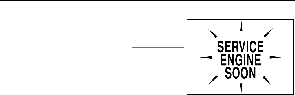
CVT-32
ON BOARD DIAGNOSTIC (OBD) SYSTEM
Revision: 2006 August 2006 Murano
Malfunction Indicator Lamp (MIL) NCS0012U
DESCRIPTION
The MIL is located on the instrument panel.
1. The MIL will light up when the ignition switch is turned ON with-
out the engine running. This is a bulb check.
●If the MIL does not light up, refer to DI-38, "WARNING
LAMPS" , or see EC-667, "MIL AND DATA LINK CONNEC-
TOR" .
2. When the engine is started, the MIL should go off.
If the MIL remains on, the on board diagnostic system has
detected an engine system malfunction.
SEF217U
TROUBLE DIAGNOSIS
CVT-33
D
E
F
G
H
I
J
K
L
M
A
B
CVT
Revision: 2006 August 2006 Murano
TROUBLE DIAGNOSIS PFP:00004
DTC Inspection Priority Chart NCS0012V
If some DTCs are displayed at the same time, perform inspections one by one based on the following priority
chart.
NOTE:
If DTC “U1000 CAN COMM CIRCUIT” is displayed with other DTCs, first perform the trouble diagnosis
for “DTC U1000 CAN COMMUNICATION LINE”. Refer to CVT-72 .
Fail-safe NCS0012W
The TCM has an electrical fail-safe mode. This mode makes it possible to operate even if there is an error in a
main electronic control input/output signal circuit.
FAIL-SAFE FUNCTION
If any malfunction occurs in a sensor or solenoid, this function controls the CVT to make driving possible.
Output Speed Sensor (Secondary Speed Sensor)
The shift pattern is changed in accordance with throttle position when an unexpected signal is sent from the
output speed sensor (secondary speed sensor) to the TCM. The manual mode position and second position is
inhibited, and the transaxle is put in “D”.
Input Speed Sensor (Primary Speed Sensor)
The shift pattern is changed in accordance with throttle position and secondary speed (vehicle speed) when
an unexpected signal is sent from the input speed sensor (primary speed sensor) to the TCM. The manual
mode position and second position is inhibited, and the transaxle is put in “D”.
PNP Switch
If an unexpected signal is sent from the PNP switch to the TCM, the transaxle is put in “D”.
Manual Mode Switch
If an unexpected signal is sent from the manual mode switch to the TCM, the transaxle is put in “D”.
CVT Fluid Temperature Sensor
If an unexpected signal is sent from the CVT fluid temperature sensor to the TCM, the gear ratio in use before
receiving the unexpected signal is maintained or the gear ratio is controlled to keep engine speed under 5000
rpm.
Transmission Fluid Pressure Sensor A (Secondary Pressure Sensor)
●If an unexpected signal is sent from the transmission fluid pressure sensor A (secondary pressure sensor)
to the TCM, the secondary pressure feedback control is stopped and the offset value obtained before the
non-standard condition occurs is used to control line pressure.
●If transmission fluid pressure sensor A (secondary pressure sensor) error signal is input to TCM, second-
ary pressure feedback control stops, but line pressure is controlled normally.
Pressure Control Solenoid A (Line Pressure Solenoid)
If an unexpected signal is sent from the solenoid to the TCM, the pressure control solenoid A (line pressure
solenoid) is turned OFF to achieve the maximum fluid pressure.
Pressure Control Solenoid B (Secondary Pressure Solenoid)
If an unexpected signal is sent from the solenoid to the TCM, the pressure control solenoid B (secondary pres-
sure solenoid) is turned OFF to achieve the maximum fluid pressure.
Torque Converter Clutch Solenoid
If an unexpected signal is sent from the solenoid to the TCM, the torque converter clutch solenoid is turned
OFF to cancel the lock-up.
Priority Detected items (DTC)
1 U1000 CAN communication line
2 Except above
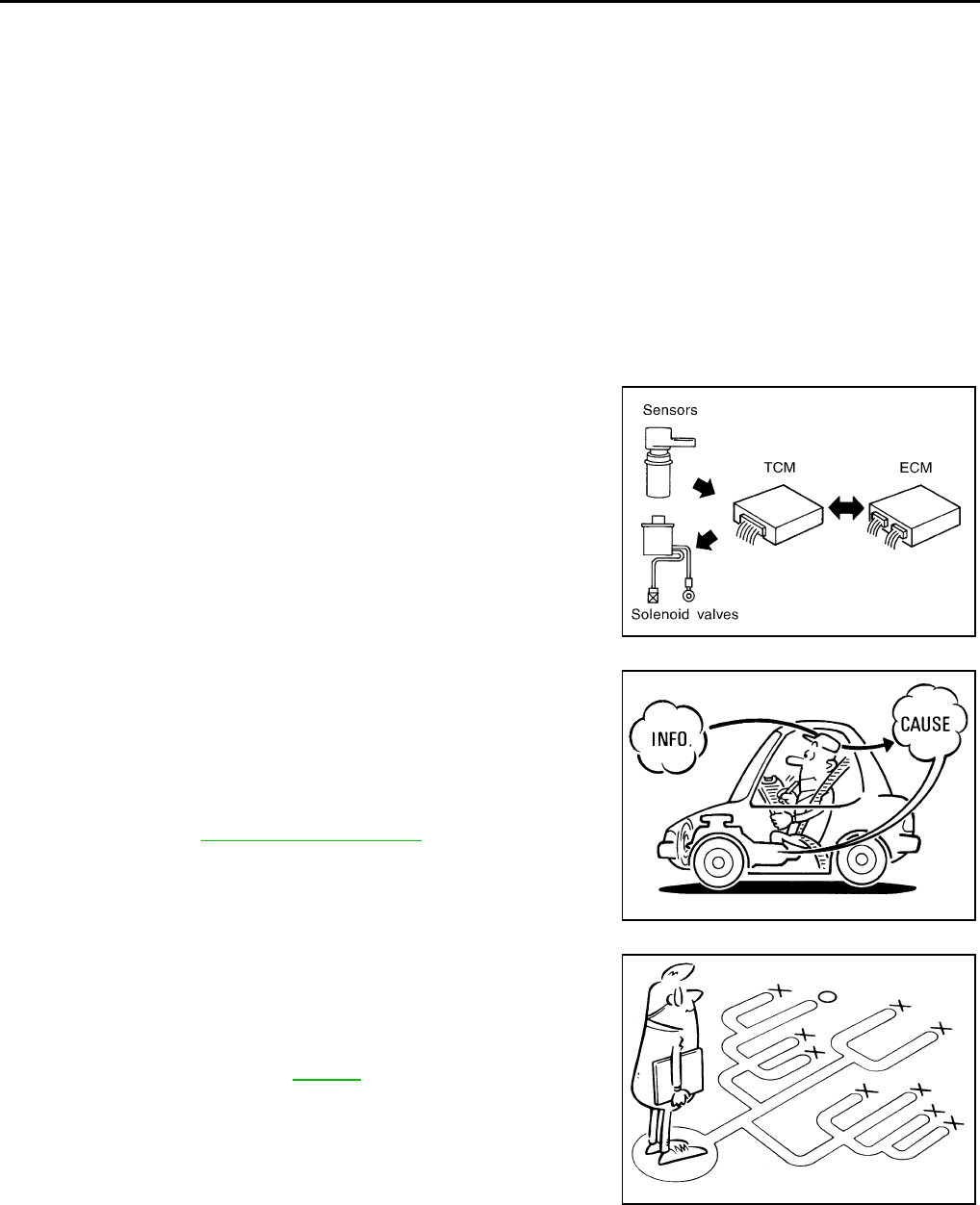
CVT-34
TROUBLE DIAGNOSIS
Revision: 2006 August 2006 Murano
Step Motor
If an unexpected signal is sent from the step motor to the TCM, the step motor coil phases “A” through “D” are
all turned OFF to hold the gear ratio used right before the non-standard condition occurred.
CVT Lock-up Select Solenoid
If an unexpected signal is sent from the solenoid to the TCM, the CVT lock-up select solenoid is turned OFF to
cancel the lock-up.
TCM Power Supply (Memory Back-up)
Transaxle assembly is protected by limiting the engine torque when the memory back-up power supply (for
controlling) from the battery is not supplied to TCM. Normal statues is restored when turning the ignition switch
OFF to ON after the normal power supply.
How to Perform Trouble Diagnosis for Quick and Accurate Repair NCS0012X
INTRODUCTION
The TCM receives a signal from the vehicle speed sensor, PNP switch and provides shift control or lock-up
control via CVT solenoid valves.
The TCM also communicates with the ECM by means of a signal
sent from sensing elements used with the OBD-related parts of the
CVT system for malfunction-diagnostic purposes. The TCM is capa-
ble of diagnosing malfunctioning parts while the ECM can store mal-
functions in its memory.
Input and output signals must always be correct and stable in the
operation of the CVT system. The CVT system must be in good
operating condition and be free of valve seizure, solenoid valve mal-
function, etc.
It is much more difficult to diagnose an error that occurs intermit-
tently rather than continuously. Most intermittent errors are caused
by poor electric connections or improper wiring. In this case, careful
checking of suspected circuits may help prevent the replacement of
good parts.
A visual check only may not find the cause of the errors. A road test
with CONSULT-II (or GST) or a circuit tester connected should be
performed. Follow the CVT-35, "WORK FLOW" .
Before undertaking actual checks, take a few minutes to talk with a
customer who approaches with a driveability complaint. The cus-
tomer can supply good information about such errors, especially
intermittent ones. Find out what symptoms are present and under
what conditions they occur. A “DIAGNOSTIC WORKSHEET” as
shown on the example (Refer to CVT-36 ) should be used.
Start your diagnosis by looking for “conventional” errors first. This will
help troubleshoot driveability errors on an electronically controlled
engine vehicle.
Also check related Service bulletins.
SAT631IB
SAT632I
SEF234G
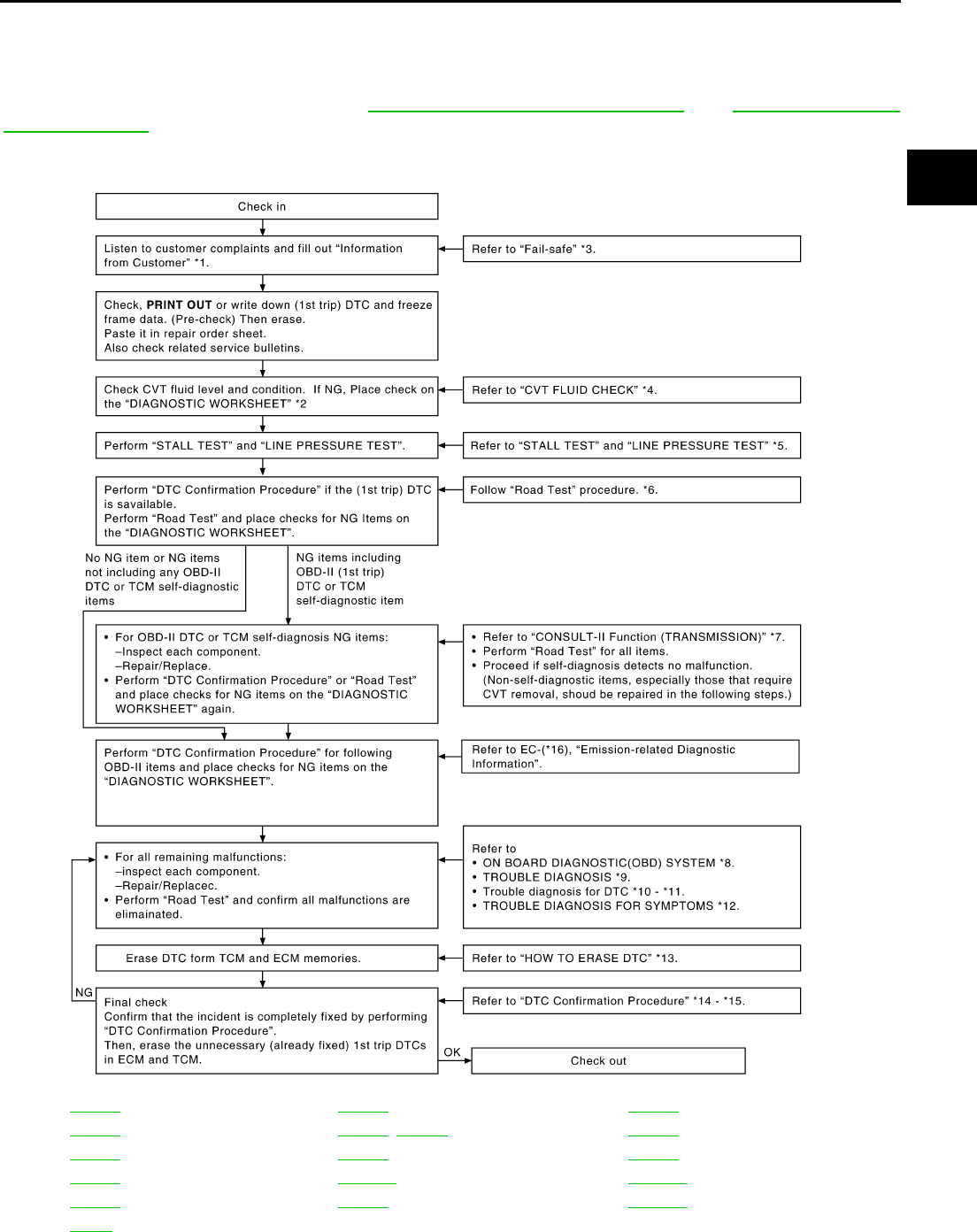
TROUBLE DIAGNOSIS
CVT-35
D
E
F
G
H
I
J
K
L
M
A
B
CVT
Revision: 2006 August 2006 Murano
WORK FLOW
A good understanding of the malfunction conditions can make troubleshooting faster and more accurate.
In general, each customer feels differently about a malfunction. It is important to fully understand the symp-
toms or conditions for a customer complaint.
Make good use of the two sheets provided, CVT-36, "Information From Customer" and CVT-36, "Diagnostic
Worksheet Chart" , to perform the best troubleshooting possible.
Work Flow Chart
*1. CVT-36 *2. CVT-36 *3. CVT-33
*4. CVT-42 *5. CVT-42, CVT-44 *6. CVT-46
*7. CVT-60 *8. CVT-29 *9. CVT-33
*10. CVT-72 *11. CVT-176 *12. CVT-183
*13. CVT-30 *14. CVT-72 *15. CVT-176
*16. EC-46
SCIA6877E
CVT-36
TROUBLE DIAGNOSIS
Revision: 2006 August 2006 Murano
DIAGNOSTIC WORKSHEET
Information From Customer
KEY POINTS
●WHAT..... Vehicle & CVT model
●WHEN..... Date, Frequencies
●WHERE..... Road conditions
●HOW..... Operating conditions, Symptoms
Diagnostic Worksheet Chart
Customer name MR/MS Model & Year VIN
Trans. Model Engine Mileage
malfunction Date Manuf. Date In Service Date
Frequency ❏ Continuous ❏ Intermittent ( times a day)
Symptoms ❏ Vehicle does not move. (❏ Any position ❏ Particular position)
❏ No shift
❏ Lock-up malfunction
❏ Shift shock or slip (❏ N → D ❏ N → R ❏ Lock-up ❏ Any drive position)
❏ Noise or vibration
❏ No pattern select
❏ Others
()
Malfunction indicator lamp (MIL) ❏ Continuously lit ❏ Not lit
1❏ Read the item on cautions concerning fail-safe and understand the customer's complaint. CVT-33
2
❏ CVT fluid inspection
CVT-42
❏ Leak (Repair leak location.)
❏ State
❏ Amount
3
❏ Stall test and line pressure test
CVT-42,
CVT-44
❏ Stall test
❏ Torque converter one-way clutch
❏ Reverse brake
❏ Forward clutch
❏ Steel belt
❏ Engine
❏ Line pressure low
❏ Primary pulley
❏ Secondary pulley
❏ Line pressure inspection - Suspected part:
TROUBLE DIAGNOSIS
CVT-37
D
E
F
G
H
I
J
K
L
M
A
B
CVT
Revision: 2006 August 2006 Murano
4
❏ Perform road test. CVT-46
4-1.
Check before engine is started CVT-48
❏ CVT-187, "CVT Indicator Lamp Does Not Come On"
❏ Perform self-diagnosis. Enter checks for detected items. CVT-65
❏ CVT-72, "DTC U1000 CAN COMMUNICATION LINE" .
❏ CVT-75, "DTC P0615 START SIGNAL CIRCUIT" .
❏ CVT-79, "DTC P0703 STOP LAMP SWITCH CIRCUIT" .
❏ CVT-81, "DTC P0705 PARK/NEUTRAL POSITION SWITCH" .
❏ CVT-88, "DTC P0710 CVT FLUID TEMPERATURE SENSOR CIRCUIT" .
❏ CVT-93, "DTC P0715 INPUT SPEED SENSOR CIRCUIT (PRI SPEED SENSOR)" .
❏ CVT-98, "DTC P0720 VEHICLE SPEED SENSOR CVT (SECONDARY SPEED
SENSOR)" .
❏ CVT-104, "DTC P0725 ENGINE SPEED SIGNAL" .
❏ CVT-106, "DTC P0730 BELT DAMAGE" .
❏ CVT-108, "DTC P0740 TORQUE CONVERTER CLUTCH SOLENOID VALVE" .
❏ CVT-113, "DTC P0744 A/T TCC S/V FUNCTION (LOCK-UP)" .
❏ CVT-116, "DTC P0745 LINE PRESSURE SOLENOID VALVE" .
❏ CVT-121, "DTC P0746 PRESSURE CONTROL SOLENOID A PERFORMANCE
(LINE PRESSURE SOLENOID VALVE)" .
❏ CVT-124, "DTC P0776 PRESSURE CONTROL SOLENOID B PERFORMANCE
(SEC PRESSURE SOLENOID VALVE)" .
❏ CVT-127, "DTC P0778 PRESSURE CONTROL SOLENOID B ELECTRICAL (SEC
PRESSURE SOLENOID VALVE)" .
❏ CVT-132, "DTC P0826 MANUAL MODE SWITCH CIRCUIT" .
❏ CVT-137, "DTC P0840 TRANSMISSION FLUID PRESSURE SENSOR A CIRCUIT
(SEC PRESSURE SENSOR)" .
❏ CVT-142, "DTC P0841 PRESSURE SENSOR FUNCTION" .
❏ CVT-145, "DTC P0845 TRANSMISSION FLUID PRESSURE SENSOR B CIRCUIT
(PRI PRESSURE SENSOR)" .
❏ CVT-150, "DTC P0868 SECONDARY PRESSURE DOWN" .
❏ CVT-153, "DTC P1701 TRANSMISSION CONTROL MODULE (POWER SUPPLY)"
.
❏ CVT-158, "DTC P1705 THROTTLE POSITION SENSOR" .
❏ CVT-160, "DTC P1722 ESTM VEHICLE SPEED SIGNAL" .
❏ CVT-162, "DTC P1723 CVT SPEED SENSOR FUNCTION" .
❏ CVT-164, "DTC P1726 ELECTRIC THROTTLE CONTROL SYSTEM" .
❏ CVT-166, "DTC P1740 LOCK-UP SELECT SOLENOID VALVE CIRCUIT" .
❏ CVT-172, "DTC P1777 STEP MOTOR - CIRCUIT" .
❏ CVT-176, "DTC P1778 STEP MOTOR - FUNCTION" .
4-2.
Check at idle CVT-48
❏ CVT-189, "Engine Cannot Be Started in “P” and “N” Position" .
❏ CVT-190, "In “P” Position, Vehicle Moves Forward or Backward When Pushed" .
❏ CVT-191, "In “N” Position, Vehicle Moves" .
❏ CVT-192, "Large Shock “N” → “R” Position" .
❏ CVT-194, "Vehicle Does Not Creep Backward in “R” Position" .
❏ CVT-196, "Vehicle Does Not Creep Forward in “D”, “S” or “L” Position" .
CVT-38
TROUBLE DIAGNOSIS
Revision: 2006 August 2006 Murano
44-3.
Cruise test CVT-52
❏ CVT-198, "CVT Does Not Shift" .
❏ CVT-200, "Cannot Be Changed to Manual Mode" .
❏ CVT-201, "CVT Does Not Shift in Manual Mode" .
❏ CVT-203, "Cannot Be Changed to Second Position (WITHOUT MANUAL MODE)" .
❏ CVT-204, "Cannot Be Changed to “L” Position (WITHOUT MANUAL MODE)" .
❏ CVT-206, "Vehicle Does Not Decelerate by Engine Brake" .
❏ perform self-diagnosis. Enter checks for detected items. CVT-65
❏ CVT-72, "DTC U1000 CAN COMMUNICATION LINE" .
❏ CVT-75, "DTC P0615 START SIGNAL CIRCUIT" .
❏ CVT-79, "DTC P0703 STOP LAMP SWITCH CIRCUIT" .
❏ CVT-81, "DTC P0705 PARK/NEUTRAL POSITION SWITCH" .
❏ CVT-88, "DTC P0710 CVT FLUID TEMPERATURE SENSOR CIRCUIT" .
❏ CVT-93, "DTC P0715 INPUT SPEED SENSOR CIRCUIT (PRI SPEED SENSOR)" .
❏ CVT-98, "DTC P0720 VEHICLE SPEED SENSOR CVT (SECONDARY SPEED
SENSOR)" .
❏ CVT-104, "DTC P0725 ENGINE SPEED SIGNAL" .
❏ CVT-106, "DTC P0730 BELT DAMAGE" .
❏ CVT-108, "DTC P0740 TORQUE CONVERTER CLUTCH SOLENOID VALVE" .
❏ CVT-113, "DTC P0744 A/T TCC S/V FUNCTION (LOCK-UP)" .
❏ CVT-116, "DTC P0745 LINE PRESSURE SOLENOID VALVE" .
❏ CVT-121, "DTC P0746 PRESSURE CONTROL SOLENOID A PERFORMANCE
(LINE PRESSURE SOLENOID VALVE)" .
❏ CVT-124, "DTC P0776 PRESSURE CONTROL SOLENOID B PERFORMANCE
(SEC PRESSURE SOLENOID VALVE)" .
❏ CVT-127, "DTC P0778 PRESSURE CONTROL SOLENOID B ELECTRICAL (SEC
PRESSURE SOLENOID VALVE)" .
❏ CVT-132, "DTC P0826 MANUAL MODE SWITCH CIRCUIT" .
❏ CVT-137, "DTC P0840 TRANSMISSION FLUID PRESSURE SENSOR A CIRCUIT
(SEC PRESSURE SENSOR)" .
❏ CVT-142, "DTC P0841 PRESSURE SENSOR FUNCTION" .
❏ CVT-145, "DTC P0845 TRANSMISSION FLUID PRESSURE SENSOR B CIRCUIT
(PRI PRESSURE SENSOR)" .
❏ CVT-150, "DTC P0868 SECONDARY PRESSURE DOWN" .
❏ CVT-153, "DTC P1701 TRANSMISSION CONTROL MODULE (POWER SUPPLY)"
.
❏ CVT-158, "DTC P1705 THROTTLE POSITION SENSOR" .
❏ CVT-160, "DTC P1722 ESTM VEHICLE SPEED SIGNAL" .
❏ CVT-162, "DTC P1723 CVT SPEED SENSOR FUNCTION" .
❏ CVT-164, "DTC P1726 ELECTRIC THROTTLE CONTROL SYSTEM" .
❏ CVT-166, "DTC P1740 LOCK-UP SELECT SOLENOID VALVE CIRCUIT" .
❏ CVT-172, "DTC P1777 STEP MOTOR - CIRCUIT" .
❏ CVT-176, "DTC P1778 STEP MOTOR - FUNCTION" .
5❏ Inspect each system for items found to be NG in the self-diagnosis and repair or replace the malfunctioning parts.
6❏ Perform all road tests and enter the checks again for the required items. CVT-46
7❏ For any remaining NG items, perform the “diagnosis procedure” and repair or replace the malfunctioning parts.
8❏ Erase the results of the self-diagnosis from the TCM. CVT-31,
CVT-31
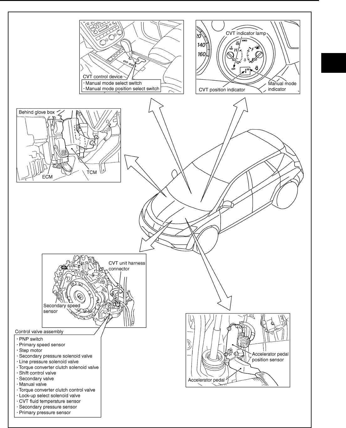
TROUBLE DIAGNOSIS
CVT-39
D
E
F
G
H
I
J
K
L
M
A
B
CVT
Revision: 2006 August 2006 Murano
CVT Electrical Parts Location (With Manual Mode) NCS0012Y
SCIA7491E
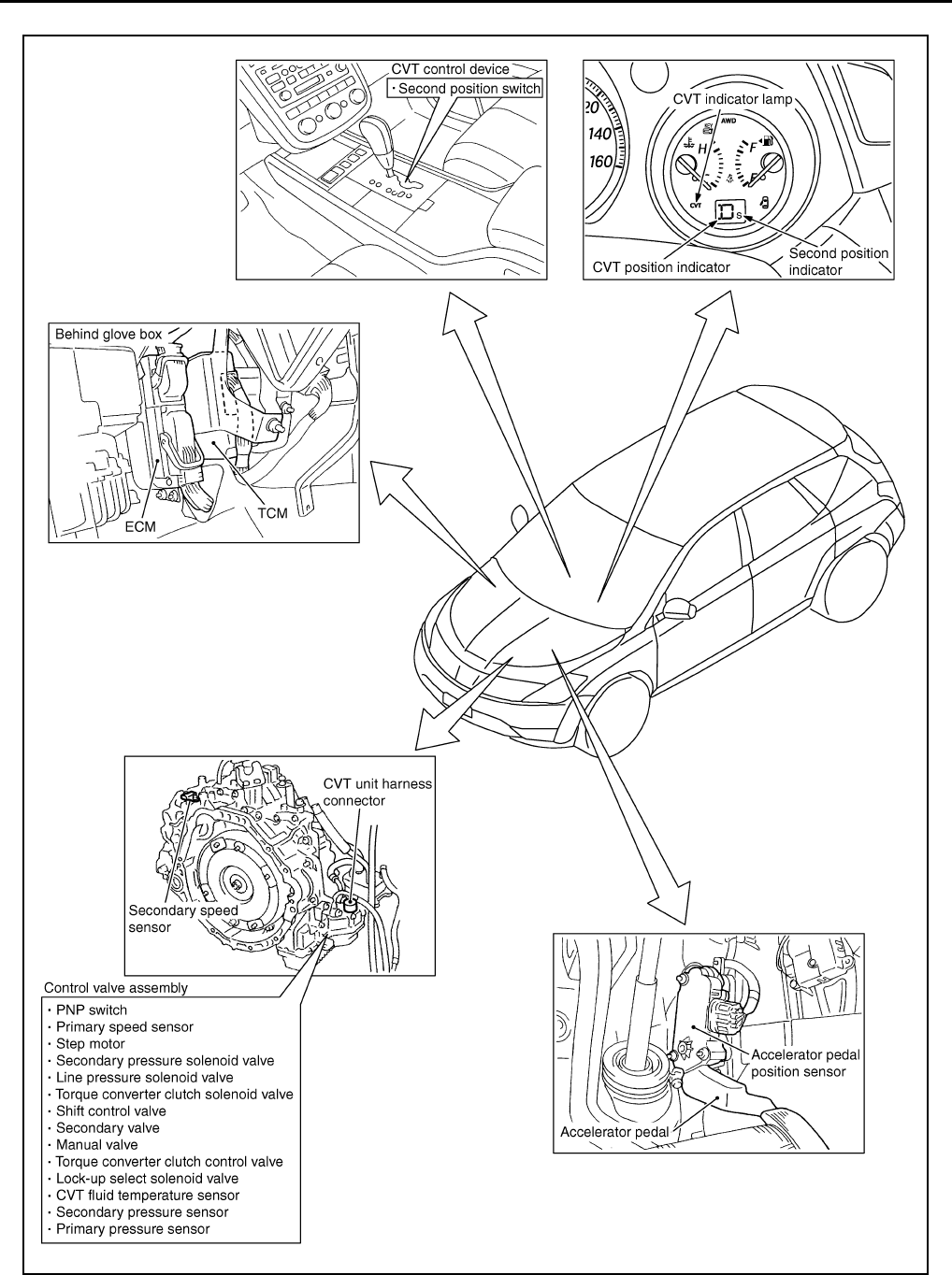
CVT-40
TROUBLE DIAGNOSIS
Revision: 2006 August 2006 Murano
CVT Electrical Parts Location (Without Manual Mode) NCS0012Z
SCIA7492E
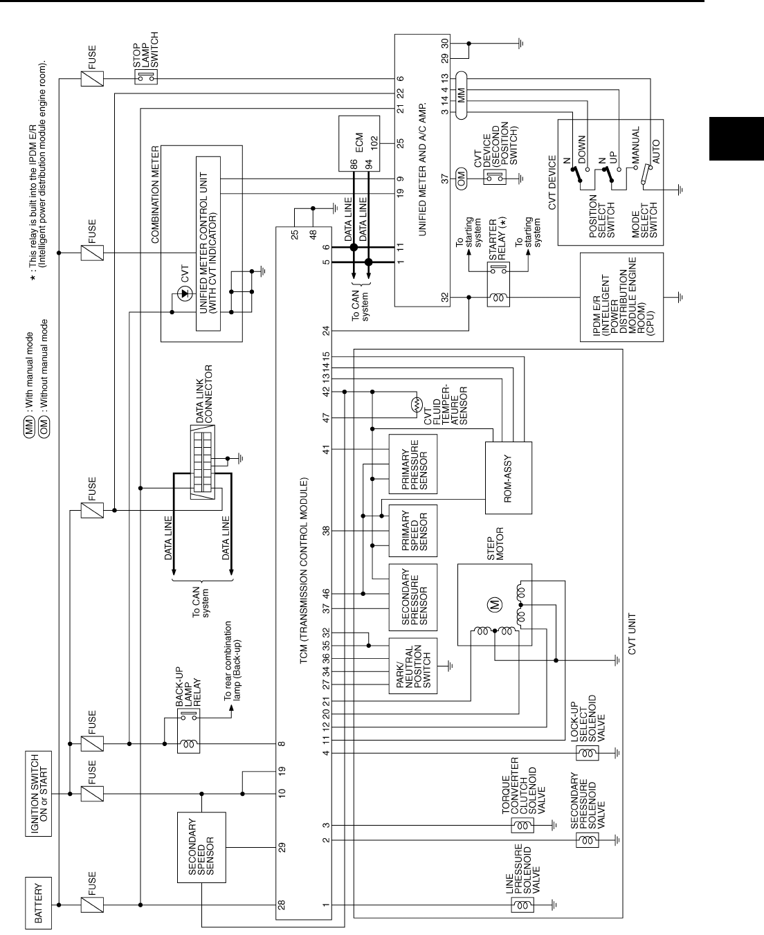
TROUBLE DIAGNOSIS
CVT-41
D
E
F
G
H
I
J
K
L
M
A
B
CVT
Revision: 2006 August 2006 Murano
Circuit Diagram NCS00130
TCWB0258E
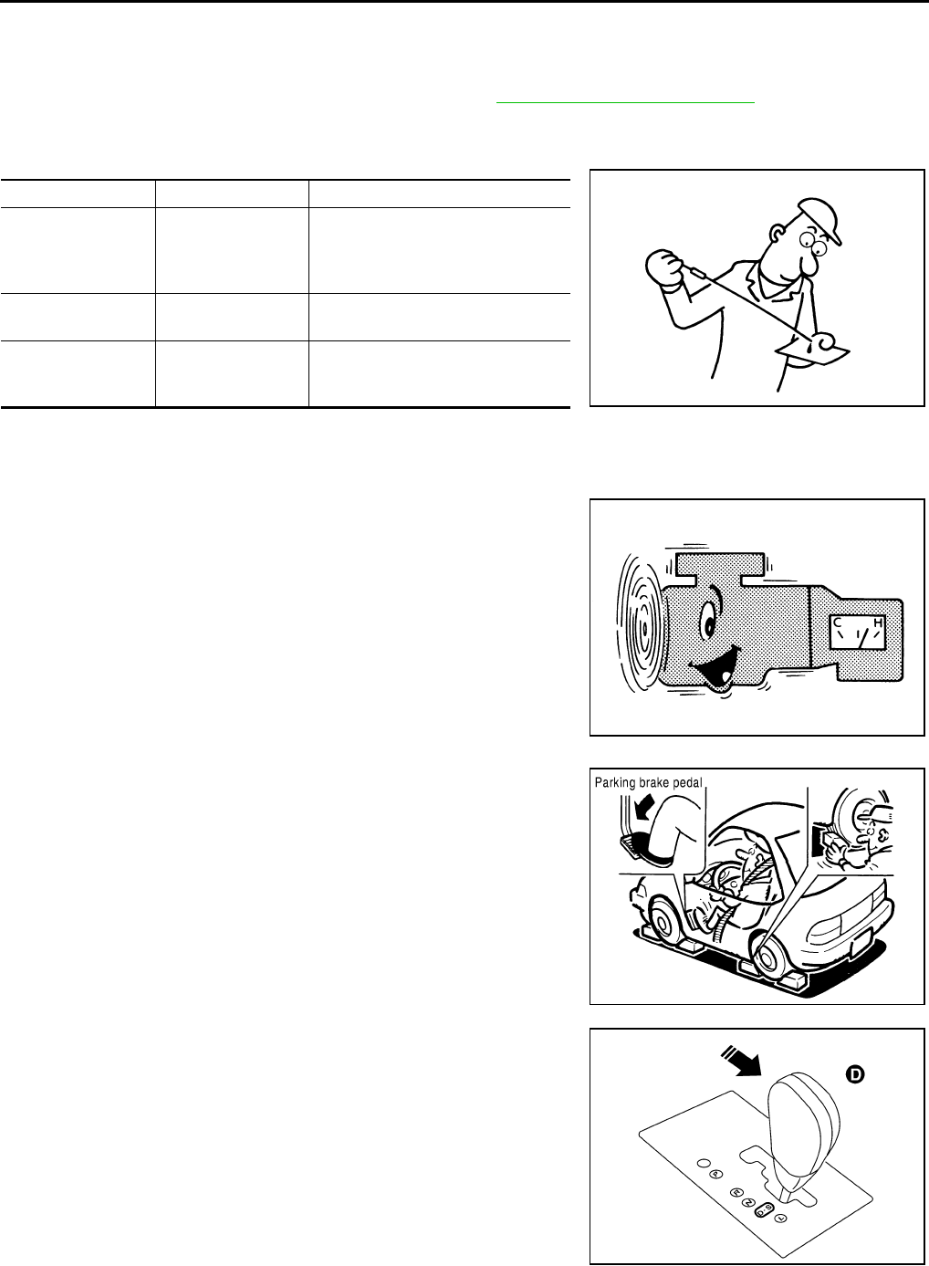
CVT-42
TROUBLE DIAGNOSIS
Revision: 2006 August 2006 Murano
Inspections before Trouble Diagnosis NCS00131
CVT FLUID CHECK
Fluid Leakage and Fluid Level Check
Inspect for fluid leakage and check the fluid level. Refer to CVT-15, "Checking CVT Fluid" .
Fluid Condition Check
Inspect the fluid condition.
STALL TEST
Stall Test Procedure
1. Inspect the amount of engine oil. Replenish the engine oil if necessary.
2. Drive for about 10 minutes to warm up the vehicle so that the
CVT fluid temperature is 50 to 80°C (122 to 176°F). Inspect the
amount of CVT fluid. Replenish if necessary.
3. Securely engage the parking brake so that the tires do not turn.
4. Install a tachometer where it can be seen by driver during test.
●It is good practice to mark the point of specified engine
rpm on indicator.
5. Start engine, apply foot brake, and place selector lever in “D”
position.
Fluid status Conceivable cause Required operation
Varnished (viscous
varnish state)
Clutch, brake
scorched
Replace the CVT fluid and check
the CVT main unit and the vehicle
for malfunctions (wire harnesses,
cooler pipes, etc.)
Milky white or
cloudy Water in the fluid Replace the CVT fluid and check for
places where water is getting in.
Large amount of
metal powder mixed
in
Unusual wear of
sliding parts within
CVT
Replace the CVT fluid and check for
improper operation of the CVT.
SAT638A
SAT647B
SCIA7463E
SCIA4285E
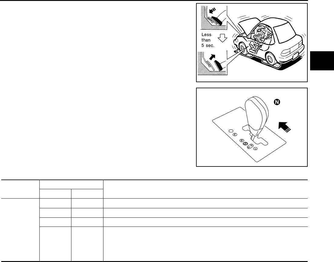
TROUBLE DIAGNOSIS
CVT-43
D
E
F
G
H
I
J
K
L
M
A
B
CVT
Revision: 2006 August 2006 Murano
6. While holding down the foot brake, gradually press down the
accelerator pedal.
7. Quickly read off the stall speed, and then quickly remove your
foot from the accelerator pedal.
CAUTION:
Do not hold down the accelerator pedal for more than 5 sec-
onds during this test.
8. Move the selector lever to the “N” position.
9. Cool down the CVT fluid.
CAUTION:
Run the engine at idle for at least 1 minute.
10. Repeat steps 6 through 9 with selector lever in “R” position.
Judgment Stall Test
O: Stall speed within standard value position.
H: Stall speed is higher than standard value.
L: Stall speed is lower than standard value.
Stall speed: 2,700 - 3,250 rpm
SAT514G
SCIA4286E
Selector lever position Expected problem location
“D” “R”
Stall rotation
HO
●Forward clutch
OH
●Reverse brake
LL
●Engine and torque converter one-way clutch
HH
●Line pressure low
●Primary pulley
●Secondary pulley
●Steel belt
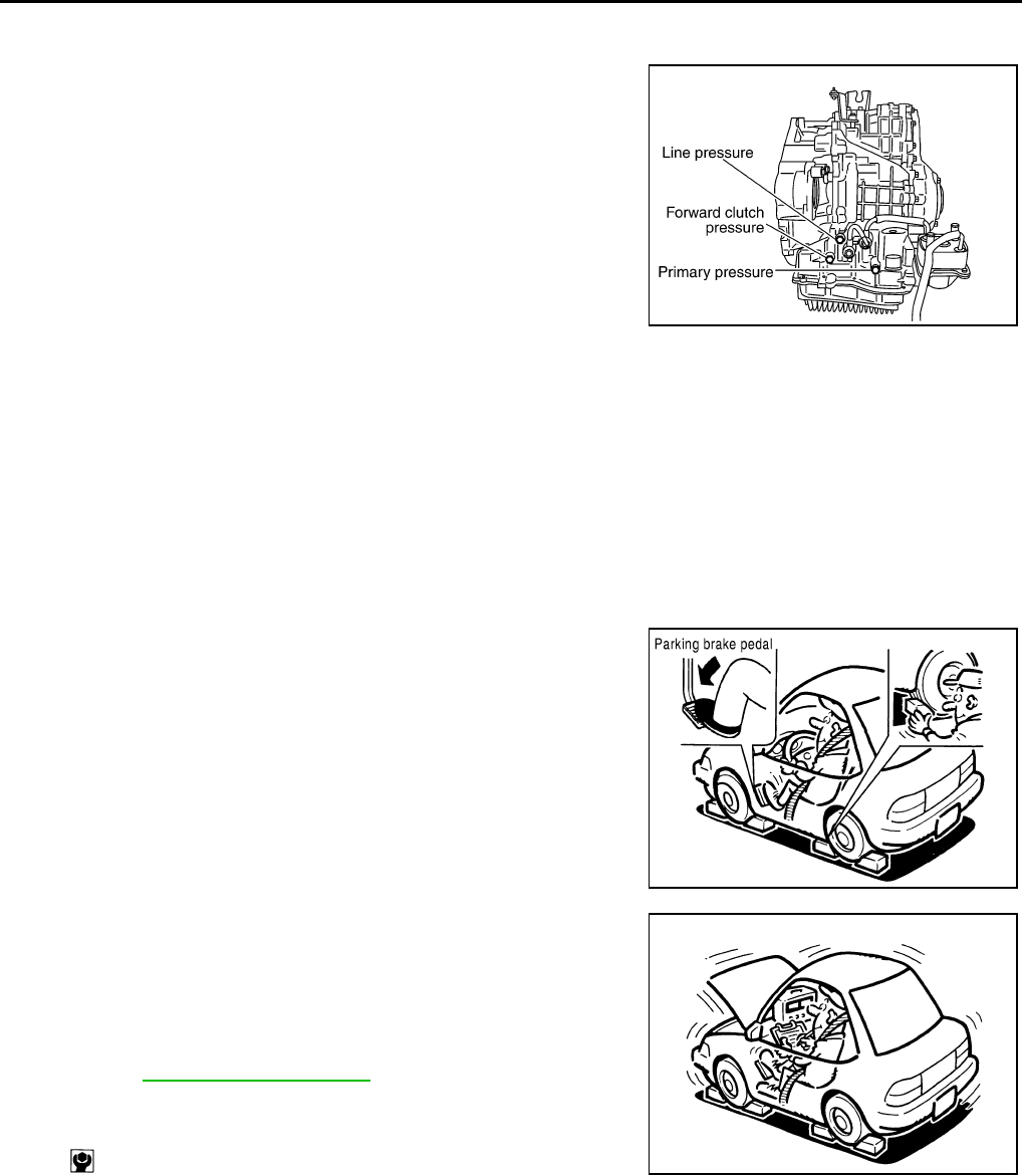
CVT-44
TROUBLE DIAGNOSIS
Revision: 2006 August 2006 Murano
LINE PRESSURE TEST
Line Pressure Test Port
Line Pressure Test Procedure
1. Inspect the amount of engine oil and replenish if necessary.
2. Drive the car for about 10 minutes to warm it up so that the CVT fluid reaches in the range of 50 to 80°C
(122 to 176°F), then inspect the amount of CVT fluid and replenish if necessary.
NOTE:
The CVT fluid temperature rises in the range of 50 - 80°C (122 - 176°F) during 10 minutes of driving.
3. After warming up CVT, remove the oil pressure detection plug and install the oil pressure gauge [special
service tool: - (OTC3492)].
CAUTION:
When using the oil pressure gauge, be sure to use the O-ring attached to the oil pressure detec-
tion plug.
4. Securely engage the parking brake so that the tires do not turn.
5. Start the engine, and then measure the line pressure at both idle
and the stall speed.
CAUTION:
●Keep the brake pedal pressed all the way down during
measurement.
●When measuring the line pressure at the stall speed,
refer to CVT-42, "STALL TEST" .
6. After the measurements are complete, install the oil pressure
detection plug and tighten to the specified torque below.
CAUTION:
●Do not reuse O-ring.
●Apply CVT fluid to O-ring.
SCIA1980E
SCIA7463E
: 7.5 N·m (0.77 kg-m, 66 in-lb) SAT493G
TROUBLE DIAGNOSIS
CVT-45
D
E
F
G
H
I
J
K
L
M
A
B
CVT
Revision: 2006 August 2006 Murano
Line Pressure
*1 : Without manual mode
*2 : Reference values
Judgment of Line Pressure Test
*1 : Without manual mode.
Engine speed Line pressure kPa (kg/cm2 , psi)
“R”, “D” and “L”*1 positions
At idle 750 (7.65, 108.8)
At stall 5,700 (58.14, 826.5)*2
Judgment Possible cause
Idle speed
Low for all positions
(“P”, “R”, “N”, “D”,
“L”*1 )
Possible causes include malfunctions in the pressure supply system and low oil pump output.
For example
●Oil pump wear
●Pressure regulator valve or plug sticking or spring fatigue
●Oil strainer Þ oil pump Þ pressure regulator valve passage oil leak
●Engine idle speed too low
Only low for a spe-
cific position
Possible causes include an oil pressure leak in a passage or device related to the position after
the pressure is distributed by the manual valve.
High
Possible causes include a sensor malfunction or malfunction in the line pressure adjustment func-
tion.
For example
●Accelerator pedal position signal malfunction
●CVT fluid temperature sensor malfunction
●Pressure control solenoid A (line pressure solenoid) malfunction (sticking in OFF state, filter
clog, cut line)
●Pressure regulator valve or plug sticking
Stall speed
Line pressure does
not rise higher than
the line pressure for
idle.
Possible causes include a sensor malfunction or malfunction in the pressure adjustment function.
For example
●Accelerator pedal position signal malfunction
●TCM malfunction
●Pressure control solenoid A (line pressure solenoid) malfunction (shorting, sticking in ON state)
●Pressure regulator valve or plug sticking
The pressure rises,
but does not enter
the standard posi-
tion.
Possible causes include malfunctions in the pressure supply system and malfunction in the pres-
sure adjustment function.
For example
●Accelerator pedal position signal malfunction
●Pressure control solenoid A (line pressure solenoid) malfunction (sticking, filter clog)
●Pressure regulator valve or plug sticking
Only low for a spe-
cific position
Possible causes include an oil pressure leak in a passage or device related to the position after
the pressure is distributed by the manual valve.

CVT-46
TROUBLE DIAGNOSIS
Revision: 2006 August 2006 Murano
Road Test NCS00132
DESCRIPTION
●The purpose of the test is to determine overall performance of
CVT and analyze causes of problems.
●The road test consists of the following three parts:
1. “Check Before Engine Is Started” CVT-48 .
2. “Check at Idle” CVT-48 .
3. “Cruise Test” CVT-52 .
●Before road test, familiarize yourself with all test procedures and
items to check.
●Perform tests on all items until specified symptom is found.
Troubleshoot items which check out No Good after road test.
CONSULT-II SETTING PROCEDURE
●Using CONSULT-II, perform a cruise test and record the result.
●Print the result and ensure that shifts and lock-ups take place as
per Shift Schedule.
1. Set CONSULT-II. Refer to GI-38, "CONSULT-II Start Procedure" .
2. Touch “DATA MONITOR” on “SELECT DIAG MODE” screen.
SAT786A
SAT496G
SAT601J
BCIA0031E
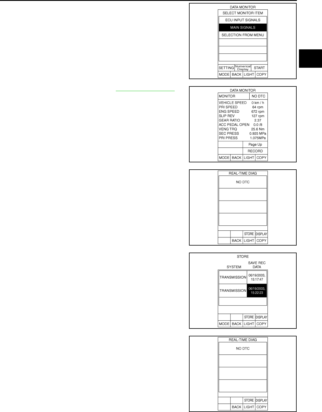
TROUBLE DIAGNOSIS
CVT-47
D
E
F
G
H
I
J
K
L
M
A
B
CVT
Revision: 2006 August 2006 Murano
3. Touch “MAIN SIGNALS” to set recording condition.
4. See “Numerical Display”, “Barchart Display” or “Line Graph Dis-
play”.
5. Touch “START”.
6. When performing cruise test. Refer to CVT-52, "Cruise Test" .
7. After finishing cruise test part, touch “RECORD”.
8. Touch “STORE”.
9. Touch “BACK”.
10. Touch “DISPLAY”.
SCIA5493E
SCIA4584E
SCIA4492E
SCIA4493E
SCIA4492E
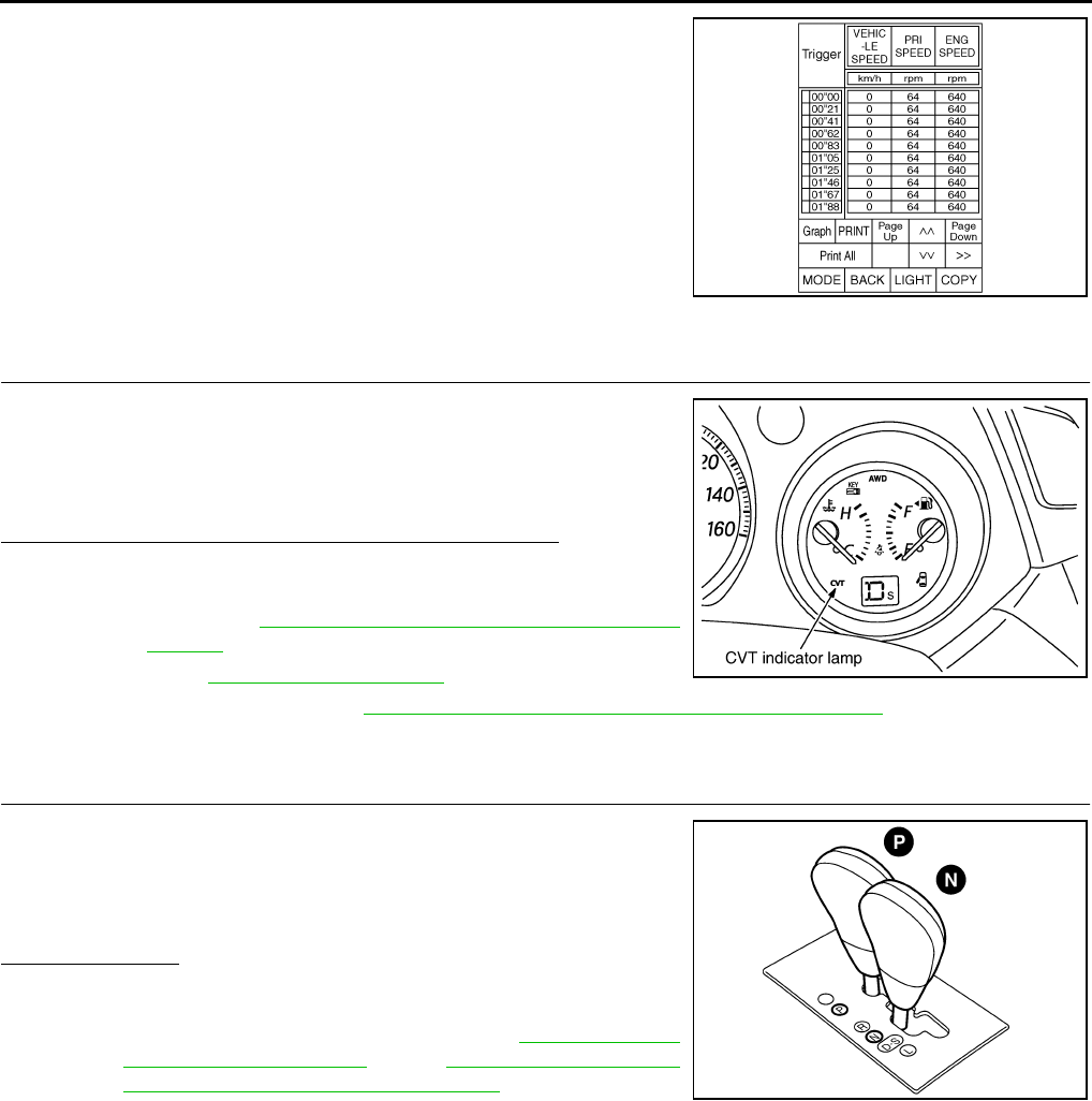
CVT-48
TROUBLE DIAGNOSIS
Revision: 2006 August 2006 Murano
11. Touch “PRINT”.
12. Check the monitor data printed out.
Check before Engine Is Started NCS00133
1. CHECK CVT INDICATOR LAMP
1. Park vehicle on flat surface.
2. Move selector lever to “P” position.
3. Turn ignition switch OFF. Wait at least 5 seconds.
4. Turn ignition switch ON. (Do not start engine.)
Does CVT indicator lamp come on for about 2 seconds?
YES >> 1. Turn ignition switch OFF.
2. Perform self-diagnosis and note NG items.
Refer to CVT-65, "SELF-DIAGNOSTIC RESULT
MODE" .
3. Go to CVT-48, "Check at Idle" .
NO >> Stop “Road Test”. Go to CVT-187, "CVT Indicator Lamp Does Not Come On" .
Check at Idle NCS00134
1. CHECK STARTING THE ENGINE
1. Park vehicle on flat surface.
2. Move selector lever to “P” or “N” position.
3. Turn ignition switch OFF.
4. Turn ignition switch to “START” position.
Is engine started?
YES >> GO TO 2.
NO >> Stop “Road Test”. Mark the box “Engine Cannot Be
Started In “P” and “N” position” on the CVT-36, "DIAG-
NOSTIC WORKSHEET" . Go to CVT-189, "Engine Can-
not Be Started in “P” and “N” Position" .
SCIA4494E
SCIA7497E
SCIA4361E
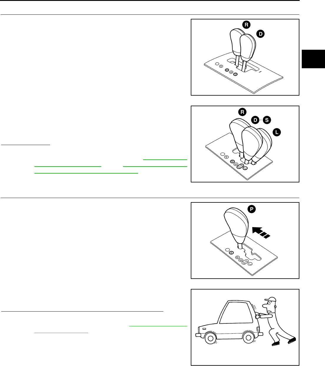
TROUBLE DIAGNOSIS
CVT-49
D
E
F
G
H
I
J
K
L
M
A
B
CVT
Revision: 2006 August 2006 Murano
2. CHECK STARTING THE ENGINE
With manual mode
1. Turn ignition switch ON.
2. Move selector lever to “D”, “M” or “R” position.
3. Turn ignition switch to “START” position.
Without manual mode
1. Turn ignition switch ON.
2. Move selector lever to “D”, “S”, “L” or “R” position.
3. Turn ignition switch to “START” position.
Is engine started?
YES >> Stop “Road Test”. Mark the box “Engine Cannot Be
Started In “P” and “N” position” on the CVT-36, "DIAG-
NOSTIC WORKSHEET" . Go to CVT-189, "Engine Can-
not Be Started in “P” and “N” Position" .
NO >> GO TO 3.
3. CHECK “P” POSITION FUNCTION
1. Move selector lever to “P” position.
2. Turn ignition switch OFF.
3. Release parking brake.
4. Push vehicle forward or backward.
5. Apply parking brake.
Does vehicle move when it is pushed forward or backward?
YES >> Mark the box “In “P” Position, Vehicle Moves Forward or
Backward When Pushed” on the CVT-36, "DIAGNOS-
TIC WORKSHEET" . Continue “Road Test”.
NO >> GO TO 4.
SCIA4585E
SCIA4362E
SCIA4363E
SAT796A
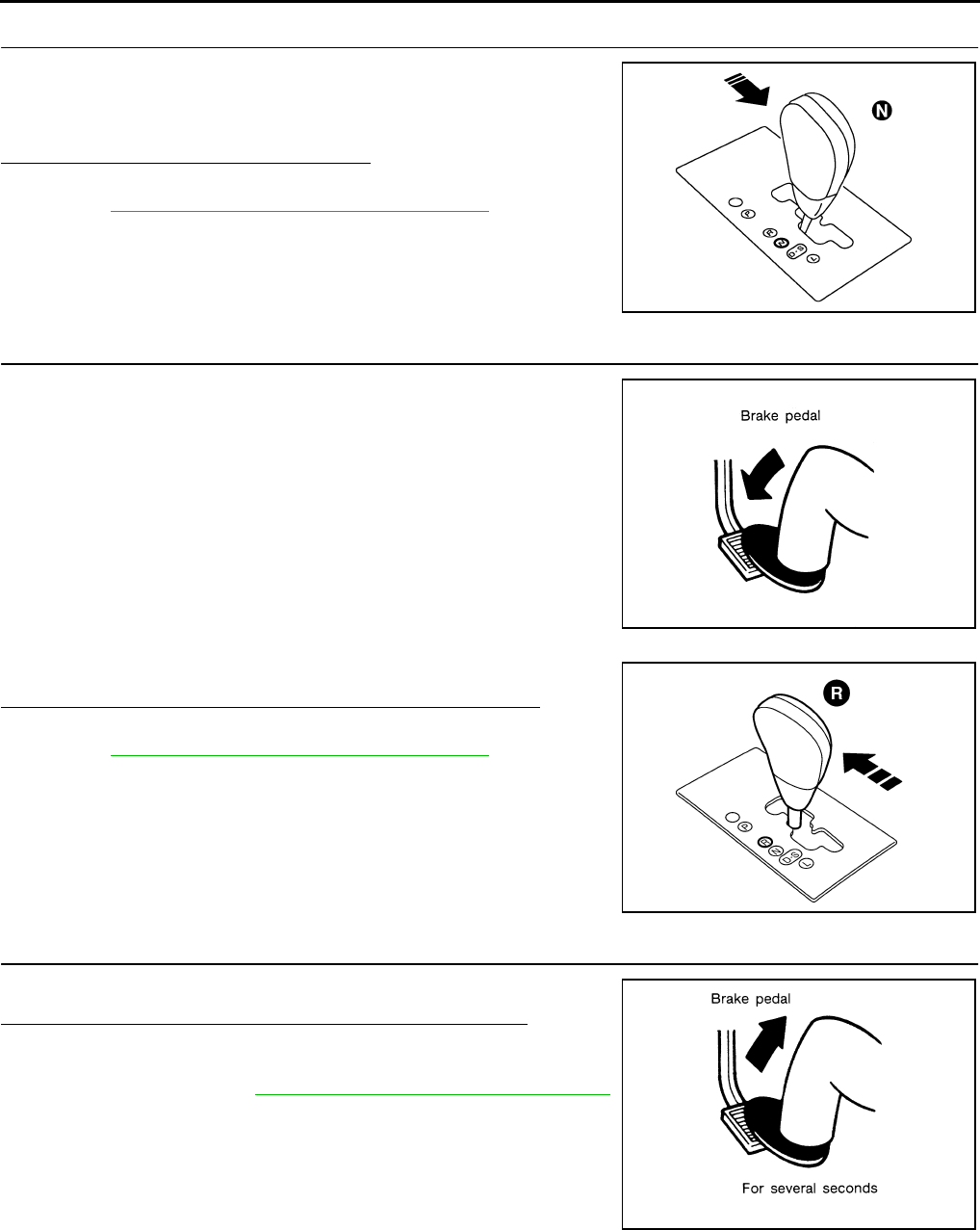
CVT-50
TROUBLE DIAGNOSIS
Revision: 2006 August 2006 Murano
4. CHECK “N” POSITION FUNCTION
1. Start engine.
2. Move selector lever to “N” position.
3. Release parking brake.
Does vehicle move forward or backward?
YES >> Mark the box “In “N” Position, Vehicle Moves” on the
CVT-36, "DIAGNOSTIC WORKSHEET" . Continue
“Road Test”.
NO >> GO TO 5.
5. CHECK SHIFT SHOCK
1. Apply foot brake.
2. Move selector lever to “R” position.
Is there large shock when changing from “N” to “R” position?
YES >> Mark the box “Large shock “N”→“R” Position” on the
CVT-36, "DIAGNOSTIC WORKSHEET" . Continue
“Road Test”.
NO >> GO TO 6.
6. CHECK “R” POSITION FUNCTION
Release foot brake for several seconds.
Does vehicle creep backward when foot brake is released?
YES >> GO TO 7.
NO >> Mark the box “Vehicle Does Not Creep Backward in “R”
Position” on the CVT-36, "DIAGNOSTIC WORKSHEET"
. Continue “Road Test”.
SCIA7507E
SAT797A
SCIA4364E
SAT799A
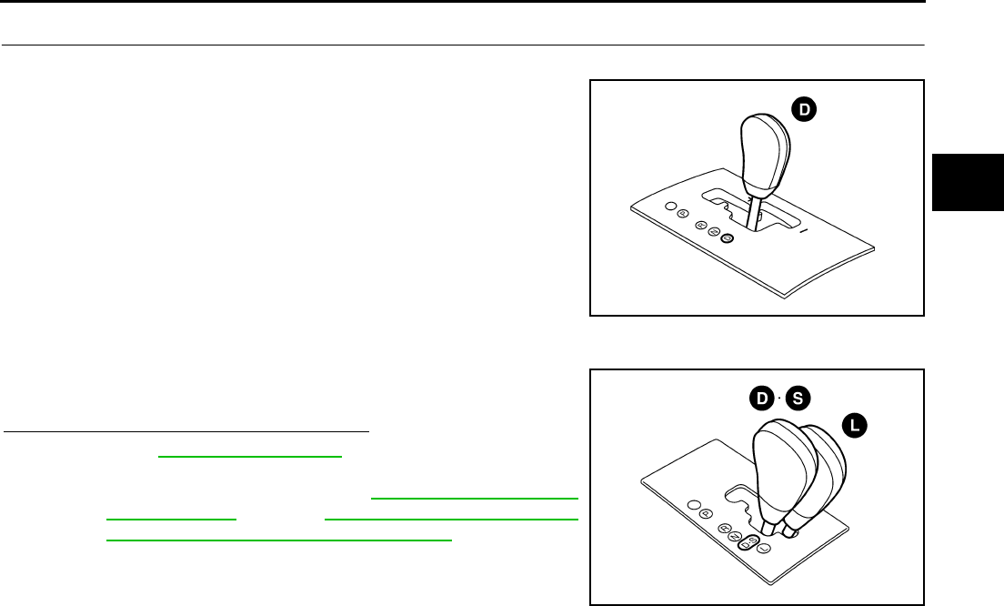
TROUBLE DIAGNOSIS
CVT-51
D
E
F
G
H
I
J
K
L
M
A
B
CVT
Revision: 2006 August 2006 Murano
7. CHECK “D”, “S”, “L” POSITION FUNCTION
With manual mode
Move selector lever to “D” position and check if vehicle creeps for-
ward.
Without manual mode
Move selector lever to “D”, “S” and “L” positions and check if vehicle
creeps forward.
Does vehicle creep forward in all positions?
YES >> Go to CVT-52, "Cruise Test" .
NO >> Mark the box “Vehicle Does Not Creep Forward in “D”,
“S” or “L” Position” on the CVT-36, "DIAGNOSTIC
WORKSHEET" . Go to CVT-196, "Vehicle Does Not
Creep Forward in “D”, “S” or “L” Position" .
SCIA4586E
SCIA4365E
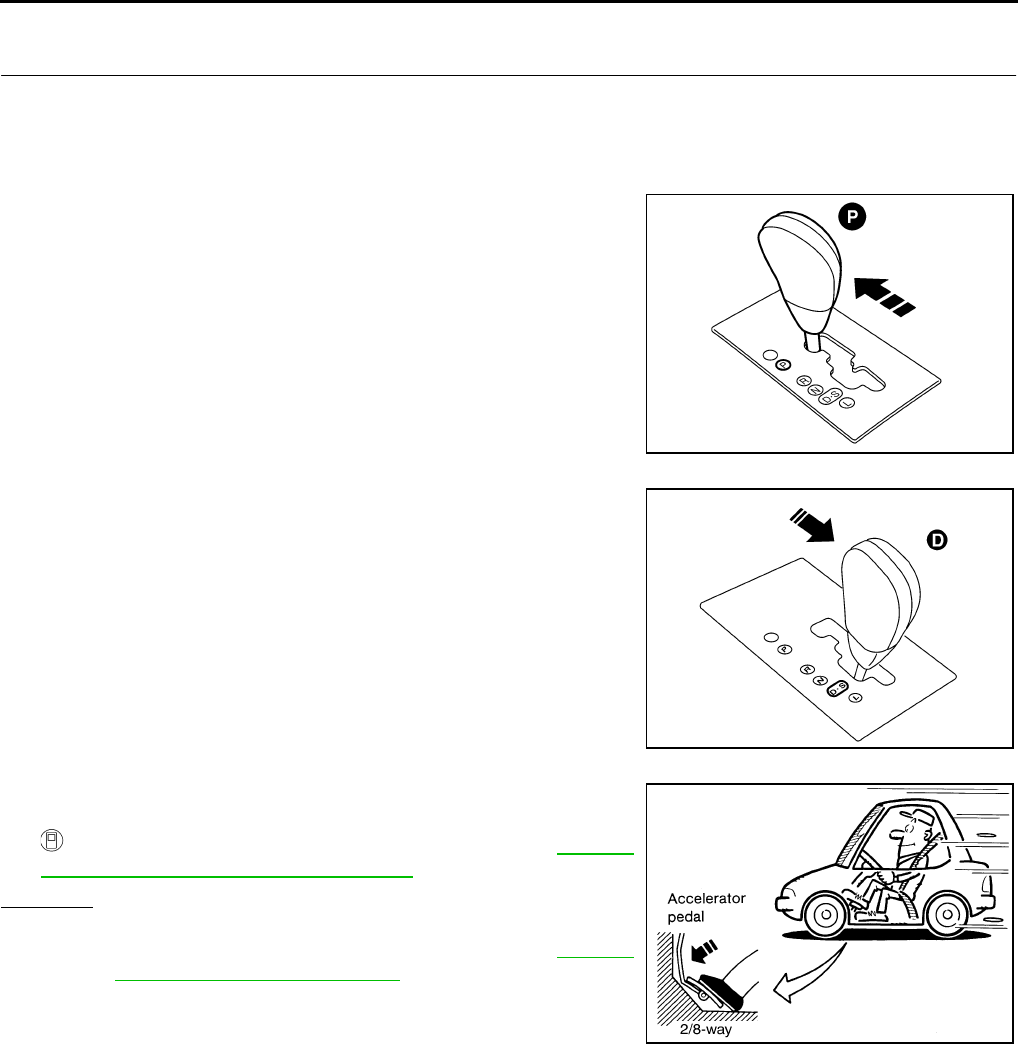
CVT-52
TROUBLE DIAGNOSIS
Revision: 2006 August 2006 Murano
Cruise Test NCS00135
1. CHECK VEHICLE SPEED WHEN SHIFTING GEARS — PART 1
1. Drive vehicle for approximately 10 minutes to warm engine oil and CVT fluid up to operating temperature.
2. Park vehicle on flat surface.
3. Move selector lever to “P” position.
4. Start engine.
5. Move selector lever to “D” position.
6. Accelerate vehicle to 2/8-way throttle depressing accelerator
pedal constantly.
Read vehicle speed and engine speed. Refer to CVT-56,
"Vehicle Speed When Shifting Gears" .
OK or NG
OK >> GO TO 2.
NG >> Mark the box of “CVT Does Not Shift” on the CVT-36,
"DIAGNOSTIC WORKSHEET" . Continue “Road Test”.
CVT fluid operating temperature: 50 - 80°C (122 - 176°F)
SCIA4363E
SCIA4285E
SCIA6644E
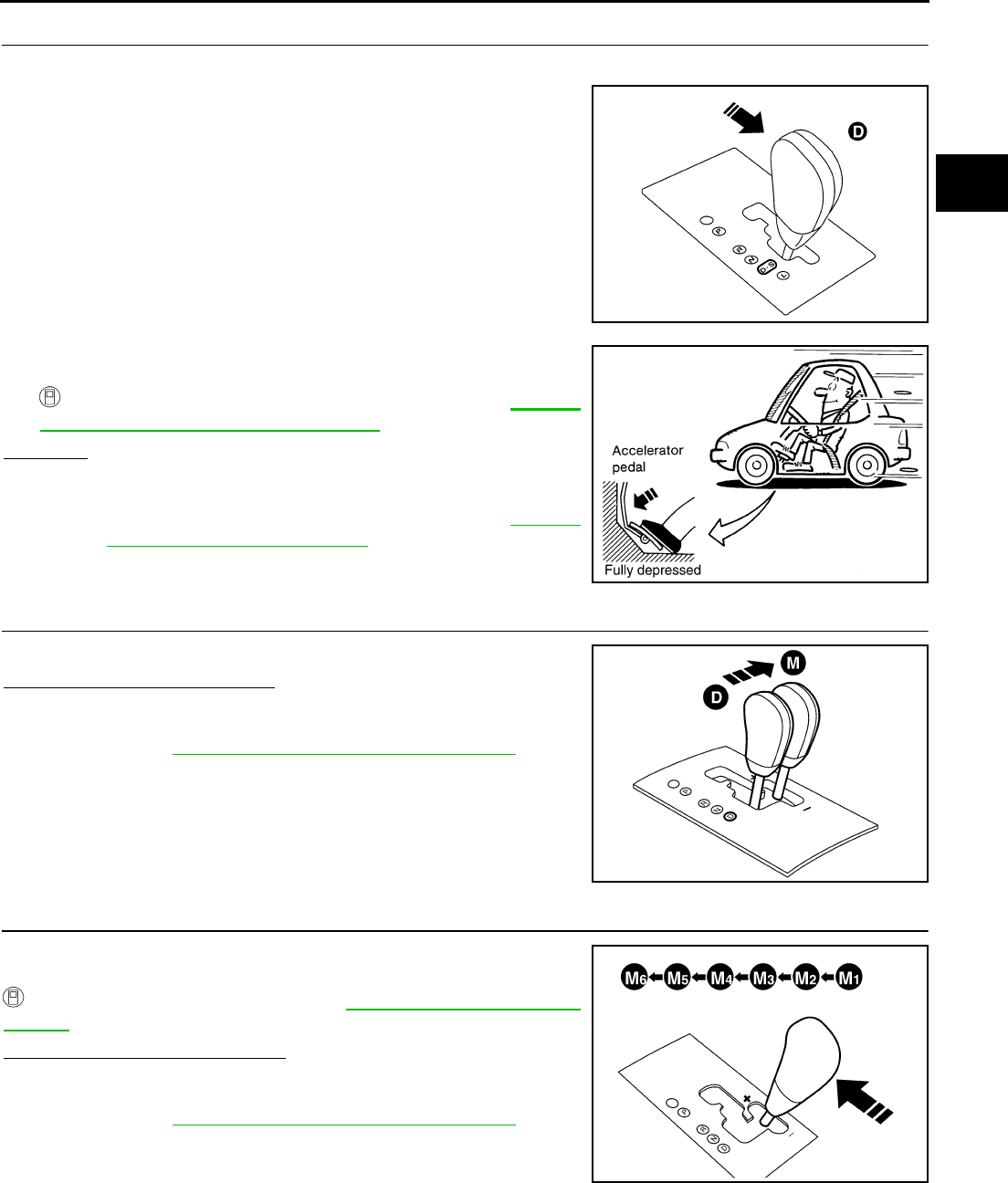
TROUBLE DIAGNOSIS
CVT-53
D
E
F
G
H
I
J
K
L
M
A
B
CVT
Revision: 2006 August 2006 Murano
2. CHECK VEHICLE SPEED WHEN SHIFTING GEARS — PART 2
1. Park vehicle on flat surface.
2. Move selector lever to “D” position.
3. Accelerate vehicle to full depression depressing accelerator
pedal constantly.
Read vehicle speed and engine speed. Refer to CVT-56,
"Vehicle Speed When Shifting Gears" .
OK or NG
OK >> GO TO 3.(With manual mode)
OK >> GO TO 7. (Without manual mode)
NG >> Mark the box of “CVT Does Not Shift” on the CVT-36,
"DIAGNOSTIC WORKSHEET" . Continue “Road Test”.
3. CHECK MANUAL MODE FUNCTION
Move to manual mode from “D” position.
Does it switch to manual mode?
YES >> GO TO 4.
NO >> Mark the box of “Cannot Be Changed to Manual Mode”
on the CVT-36, "DIAGNOSTIC WORKSHEET" . Con-
tinue “Road Test”.
4. CHECK SHIFT-UP FUNCTION
During manual mode driving, is upshift from M1 → M2 → M3 → M4
→ M5 → M6 performed?
Read the gear position. Refer to CVT-68, "DATA MONITOR
MODE" .
Is upshifting correctly performed?
YES >> GO TO 5.
NO >> Mark the box of “CVT Does Not Shift in Manual Mode”
on the CVT-36, "DIAGNOSTIC WORKSHEET" . Con-
tinue “Road Test”.
SCIA4285E
SCIA4366E
SCIA4587E
SCIA5954E
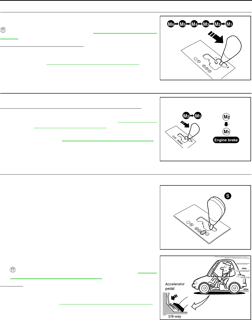
CVT-54
TROUBLE DIAGNOSIS
Revision: 2006 August 2006 Murano
5. CHECK SHIFT-DOWN FUNCTION
During manual mode driving, is downshift from M6 → M5 → M4 →
M3 → M2 → M1 performed?
Read the gear position. Refer to CVT-68, "DATA MONITOR
MODE" .
Is downshifting correctly performed?
YES >> GO TO 6.
NO >> Mark the box of “CVT Does Not Shift in Manual Mode”
on the CVT-36, "DIAGNOSTIC WORKSHEET" . Con-
tinue “Road Test”.
6. CHECK ENGINE BRAKE FUNCTION
Check engine brake.
Does engine braking effectively reduce speed in M1 position?
YES >> 1. Stop the vehicle.
2. Perform self-diagnosis. Refer to CVT-65, "SELF-
DIAGNOSTIC RESULT MODE" .
NO >> Mark the box of “Vehicle Does Not Decelerate by Engine
Brake” on the CVT-36, "DIAGNOSTIC WORKSHEET" .
then continue trouble diagnosis.
7. CHECK “S” POSITION FUNCTION — PART 1
1. Park vehicle on flat surface.
2. Move selector lever to “S” position.
3. Accelerate vehicle to 2/8-way throttle depressing accelerator
pedal constantly.
Read vehicle speed and engine speed. Refer to CVT-56,
"Vehicle Speed When Shifting Gears" .
OK or NG
OK >> GO TO 8.
NG >> Mark the box of “Cannot Be Changed to Second Posi-
tion” on the CVT-36, "DIAGNOSTIC WORKSHEET" .
Continue “Road Test”.
SCIA5955E
SCIA5956E
SCIA4367E
SCIA6644E
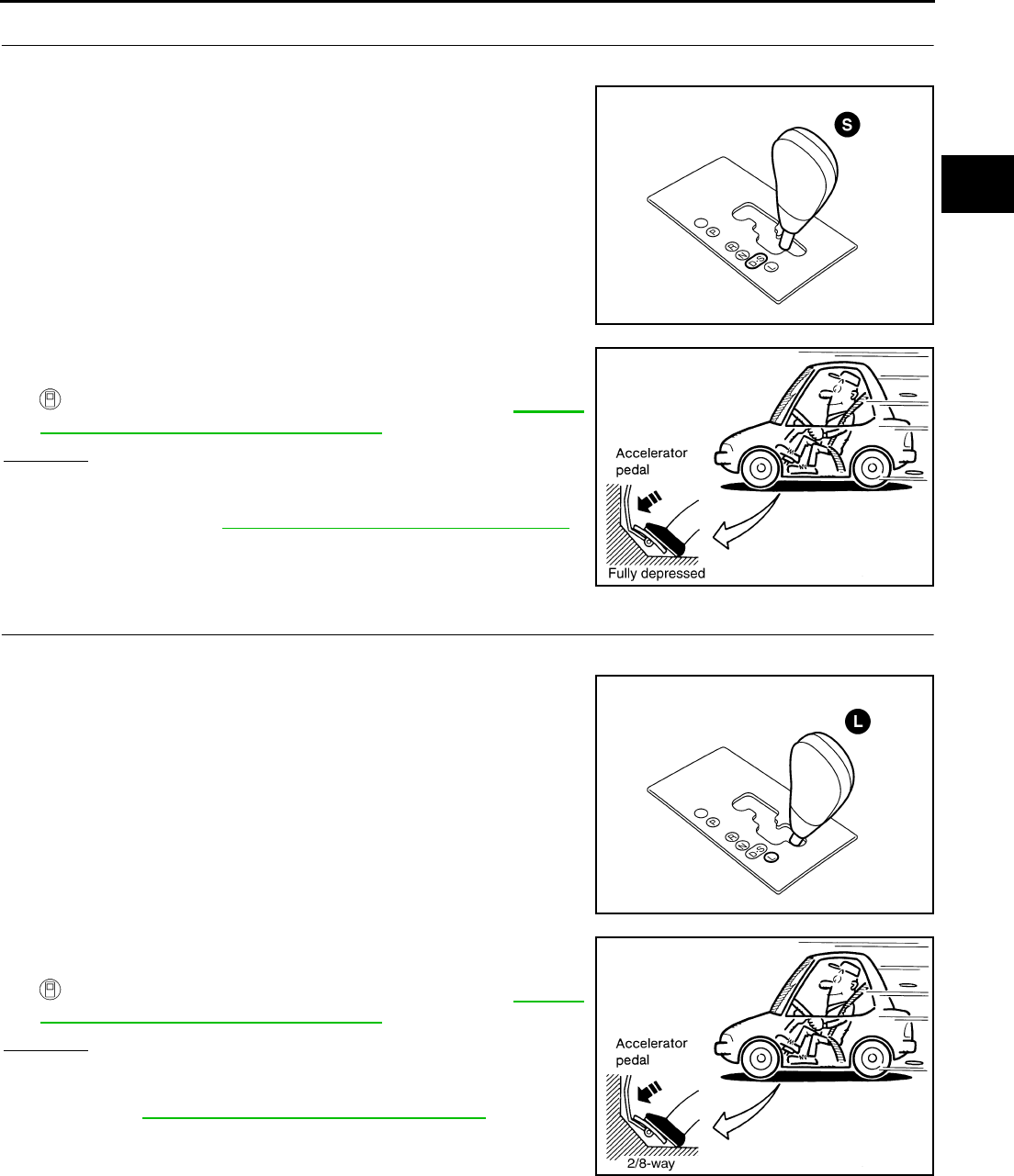
TROUBLE DIAGNOSIS
CVT-55
D
E
F
G
H
I
J
K
L
M
A
B
CVT
Revision: 2006 August 2006 Murano
8. CHECK “S” POSITION FUNCTION — PART 2
1. Park vehicle on flat surface.
2. Move selector lever to “S” position.
3. Accelerate vehicle to full depression depressing accelerator
pedal constantly.
Read vehicle speed and engine speed. Refer to CVT-56,
"Vehicle Speed When Shifting Gears" .
OK or NG
OK >> GO TO 9.
NG >> Mark the box of “Cannot Be Changed to Second Posi-
tion” on the CVT-36, "DIAGNOSTIC WORKSHEET" .
Continue “Road Test”.
9. CHECK “L” POSITION FUNCTION — PART 1
1. Park vehicle on flat surface.
2. Move selector lever to “L” position.
3. Accelerate vehicle to 2/8-way throttle depressing accelerator
pedal constantly.
Read vehicle speed and engine speed. Refer to CVT-56,
"Vehicle Speed When Shifting Gears" .
OK or NG
OK >> GO TO 10.
NG >> Mark the box of “Cannot Be Changed to “L” Position ” on
the CVT-36, "DIAGNOSTIC WORKSHEET" . Continue
“Road Test”.
SCIA4367E
SCIA4366E
SCIA4368E
SCIA6644E

CVT-56
TROUBLE DIAGNOSIS
Revision: 2006 August 2006 Murano
10. CHECK “L” POSITION FUNCTION — PART 2
1. Park vehicle on flat surface.
2. Move selector lever to “L” position.
3. Accelerate vehicle to full depression depressing accelerator
pedal constantly.
Read vehicle speed and engine speed. Refer to CVT-56,
"Vehicle Speed When Shifting Gears" .
OK or NG
OK >> GO TO 11.
NG >> Mark the box of “Cannot Be Changed to “L” Position ” on
the CVT-36, "DIAGNOSTIC WORKSHEET" . Continue
“Road Test”.
11. CHECK ENGINE BRAKE FUNCTION
Check engine brake.
Does engine braking effectively reduce speed in “L” position?
YES >> 1. Stop the vehicle.
2. Perform self-diagnosis. Refer to CVT-65, "SELF-
DIAGNOSTIC RESULT MODE" .
NO >> Mark the box of “Vehicle Does Not Decelerate by Engine
Brake” on the CVT-36, "DIAGNOSTIC WORKSHEET" .
then continue trouble diagnosis.
Vehicle Speed When Shifting Gears NCS00136
Numerical value data are reference values.
*: Without manual mode
CAUTION:
Lock-up clutch is engaged when vehicle speed is approximately 18 km/h (11 MPH) to 90 km/h (56 MPH).
SCIA4368E
SCIA4366E
SCIA6372E
Engine type Throttle position Shift pattern Engine speed (rpm)
At 40 km/h (25 MPH) At 60 km/h (37 MPH)
VQ35DE
8/8
“D” position
Second position*
“L” position*
2,800 - 4,300 3,900 - 5,300
2/8
“D” position 1,200 - 2,000 1,300 - 2,100
Second position* 2,200 - 3,000 2,800 - 3,600
“L” position* 2,800 - 3,600 3,800 - 4,600
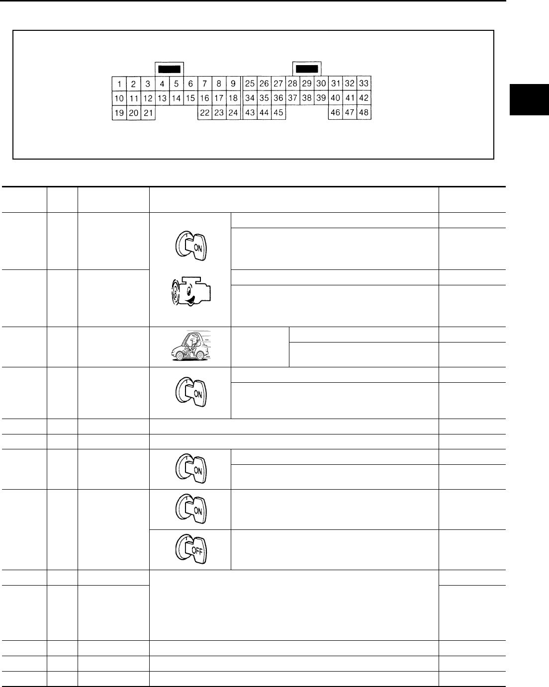
TROUBLE DIAGNOSIS
CVT-57
D
E
F
G
H
I
J
K
L
M
A
B
CVT
Revision: 2006 August 2006 Murano
TCM Input/Output Signal Reference Values NCS00137
TCM TERMINAL CONNECTOR LAYOUT
TCM INSPECTION TABLE
Data are reference values and are measured between each terminal and ground.
SCIA0495E
Terminal Wire
color Item Condition Data (Approx.)
1R/Y
Pressure con-
trol solenoid
valve A (Line
pressure sole-
noid valve) and
Release your foot from the accelerator pedal. 5.0 - 7.0 V
Press the accelerator pedal all the way down. 1.0 - 3.0 V
2W/B
Pressure con-
trol solenoid
valve B (Sec-
ondary pressure
solenoid valve)
Release your foot from the accelerator pedal. 5.0 - 7.0 V
Press the accelerator pedal all the way down. 3.0 - 4.0 V
3L/W
Torque con-
verter clutch
solenoid valve
When vehi-
cle cruises in
“D” position.
When CVT performs lock-up. 6.0 V
When CVT does not perform lock-up. 1.0 V
4L/Y
Lock-up select
solenoid valve
Selector lever in “P” and “N” positions Battery voltage
Wait at least for 5 seconds with the selector lever in
“R”, “D”, “S”* and “L”* positions
*: Without manual mode.
0 V
5 L CAN-H — —
6 Y CAN-L — —
8SB
Back-up lamp
relay
Selector lever in “R” position. 0 V
Selector lever in other positions. Battery voltage
10 Y/L Power supply
— Battery voltage
—0 V
11 G/R Step motor A Within 2 seconds after ignition switch ON, the time measurement by using
the pulse width measurement function (Hi level) of CONSULT-II.*1
CAUTION:
Connect the diagnosis data link cable to the vehicle diagnosis connec-
tor.
*1: A circuit tester cannot be used to test this item.
30.0 msec
12 O/B Step motor B 10.0 msec
13 G/W ROM assembly — —
14 L/R ROM assembly — —
15 BR/R ROM assembly — —
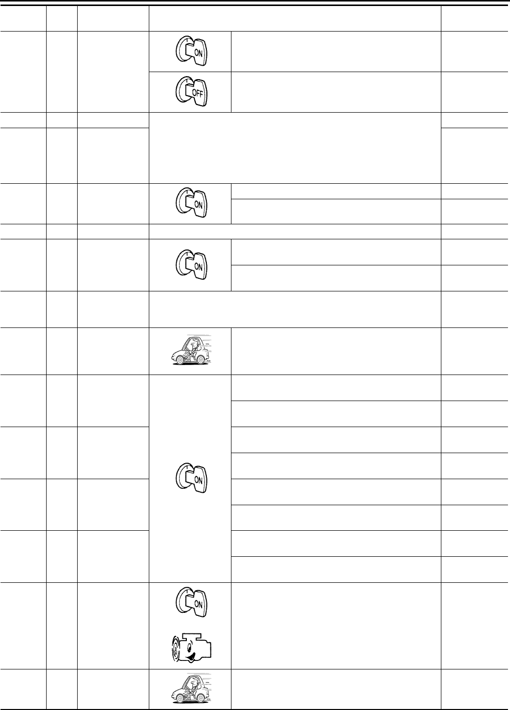
CVT-58
TROUBLE DIAGNOSIS
Revision: 2006 August 2006 Murano
19 Y/L Power supply
—Battery voltage
—0 V
20 R Step motor C Within 2 seconds after ignition switch ON, the time measurement by using
the pulse width measurement function (Hi level) of CONSULT-II.*1
CAUTION:
Connect the diagnosis data link cable to the vehicle diagnosis connec-
tor.
*1: A circuit tester cannot be used to test this item.
30.0 msec
21 R/G Step motor D 10.0 msec
24 G/O Starter relay
Selector lever in “N” and “P”positions. Battery voltage
Selector lever in other positions. 0 V
25 B Ground Always 0 V
27 BR/W PNP switch 1
Selector lever in “R”, “N”, “D” and “S”* positions.
*: Without manual mode. 0 V
Selector lever in “P” and “L”* positions.
*: Without manual mode. Battery voltage
28 Y/R
Power supply
(memory back-
up)
Always Battery voltage
29 G
Output speed
sensor (Second-
ary speed sen-
sor)
When driving [“D” position, 20 km/h (12 MPH)]. 300 Hz
32 GR PNP switch 3
(monitor)
Selector lever in “D”, “S”* and “L”* positions.
*: Without manual mode. 0 V
Selector lever in “P”, “R” and “N” positions. 8.0 V - Battery
voltage
34 P/B PNP switch 2
Selector lever in “N”, “D”, “S”* and “L”* positions.
*: Without manual mode. 0 V
Selector lever in “P” and “R” positions. 10.0 V - Battery
voltage
35 P/L PNP switch 3
Selector lever in “D”, “S”* and “L”* positions.
*: Without manual mode. 0 V
Selector lever in “P”, “R” and “N” positions. 8.0 V - Battery
voltage
36 G PNP switch 4
Selector lever in “R”, “D” and “S”* positions.
*: Without manual mode. 0 V
Selector lever in “P”, “N” and “L”* positions.
*: Without manual mode.
10.0 V - Battery
voltage
37 V/W
Transmission
fluid pressure
sensor A (Sec-
ondary pressure
sensor)
and “N” position idle 0.8 V
38 LG
Input speed sen-
sor (Primary
speed sensor)
When driving [“D” position, 20 km/h (12 MPH)]. 600 Hz
Terminal Wire
color Item Condition Data (Approx.)
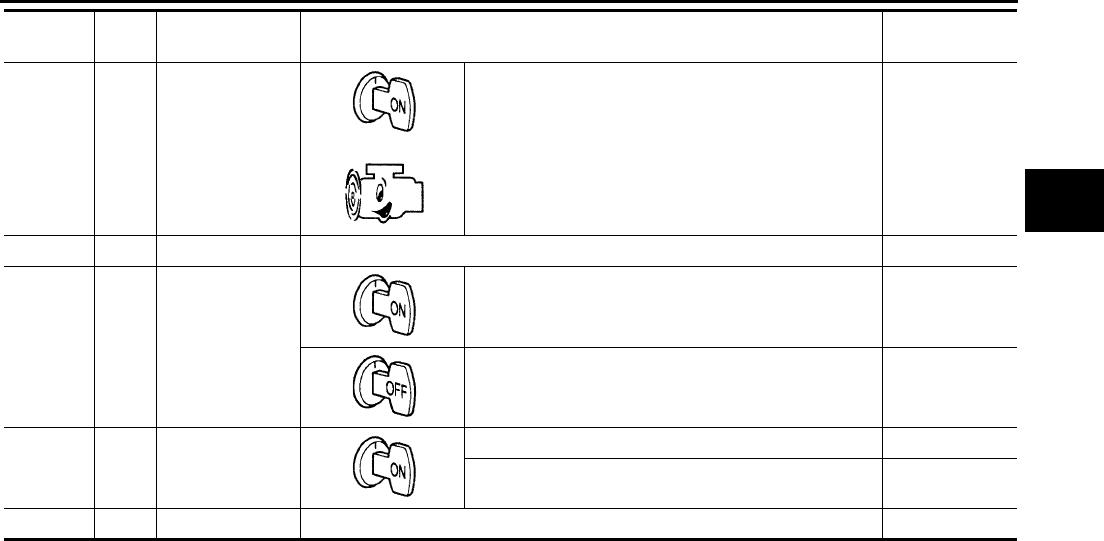
TROUBLE DIAGNOSIS
CVT-59
D
E
F
G
H
I
J
K
L
M
A
B
CVT
Revision: 2006 August 2006 Murano
41 V/O
Transmission
fluid pressure
sensor B (Pri-
mary pressure
sensor)
and “N” position idle 0.7 - 3.5 V
42 W/R Sensor ground Always 0 V
46 L/O Sensor power
— 4.5 - 5.5 V
— 0 V
47 V CVT fluid tem-
perature sensor
When CVT fluid temperature is 20°C (68°F) 2.0 V
When CVT fluid temperature is 80°C (176°F) 1.0 V
48 B Ground Always 0 V
Terminal Wire
color Item Condition Data (Approx.)

CVT-60
TROUBLE DIAGNOSIS
Revision: 2006 August 2006 Murano
CONSULT-II Function (TRANSMISSION) NCS00138
CONSULT-II can display each diagnostic item using the diagnostic test modes shown below.
FUNCTION
CONSULT-II REFERENCE VALUE
Diagnostic test mode Function Reference page
Work support This mode enables a technician to adjust some devices faster and more accurately by
following the indications on CONSULT-II. CVT-63
Self-diagnostic results Self-diagnostic results can be read and erased quickly. CVT-65
Data monitor Input/Output data in the TCM can be read. CVT-68
CAN diagnostic support
monitor The results of transmit/receive diagnosis of CAN communication can be read. CVT-70
CALIB data Characteristic information for TCM and CVT assembly can be read. Do not use, but
displayed. —
Function test Performed by CONSULT-II instead of a technician to determine whether each system
is “OK” or “NG”. —
ECU part number TCM part number can be read. —
Item name Condition Display value (Approx.)
VSP SENSOR During driving Approximately matches the speedometer
reading.
ESTM VSP SIG
PRI SPEED SEN During driving (lock-up ON) Approximately matches the engine speed.
ENG SPEED SIG Engine running Closely matches the tachometer reading.
SEC HYDR SEN “N” position idle 0.8 - 1.0 V
PRI HYDR SEN “N” position idle 0.7 - 3.5 V
ATF TEMP SEN When CVT fluid temperature is 20°C (68°F). 1.8 - 2.0 V
When CVT fluid temperature is 80°C (176°F). 0.6 - 1.0 V
VIGN SEN Ignition switch: ON Battery voltage
VEHICLE SPEED During driving Approximately matches the speedometer
reading.
PRI SPEED During driving (lock-up ON) Approximately matches the engine speed.
SEC SPEED During driving 45 X Approximately matches the speed-
ometer reading.
ENG SPEED Engine running Closely matches the tachometer reading.
GEAR RATIO During driving 2.37 - 0.43
ACC PEDAL OPEN Released accelerator pedal - Fully depressed
accelerator pedal 0.0/8 - 8.0/8
SEC PRESS “N” position idle 0.5 - 0.9 MPa
PRI PRESS “N” position idle 0.3 - 0.9 MPa
STM STEP During driving -20 step - 190 step
ISOLT1 Lock-up OFF 0.0 A
Lock-up ON 0.7 A
ISOLT2 Release your foot from the accelerator pedal. 0.8 A
Press the accelerator pedal all the way down. 0.0 A
ISOLT3 Secondary pressure low - Secondary pressure
high. 0.8 - 0.0 A
SOLMON1 Lock-up OFF 0.0 A
Lock-up ON 0.6 - 0.7 A
TROUBLE DIAGNOSIS
CVT-61
D
E
F
G
H
I
J
K
L
M
A
B
CVT
Revision: 2006 August 2006 Murano
SOLMON2 “N” position idle 0.8 A
When stalled 0.3 - 0.6 A
SOLMON3 “N” position idle 0.6 - 0.7 A
When stalled 0.4 - 0.6 A
INH SW3M
Selector lever in “D”, “S”* and “L”* positions
*: Without manual mode. ON
Selector lever in “P”, “R” and “N” positions OFF
INH SW4
Selector lever in “R”, “D” and “S”* positions
*: Without manual mode. ON
Selector lever in “P”, “N” and “L”* positions
*: Without manual mode. OFF
INH SW3
Selector lever in “D”, “S”* and “L”* positions
*: Without manual mode. ON
Selector lever in “P”, “R” and “N” positions OFF
INH SW2
Selector lever in “N”, “D”, “S”* and “L”* positions
*: Without manual mode. ON
Selector lever in “P” and “R” positions OFF
INH SW1
Selector lever in “R”, “N”, “D” and “S”* positions
*: Without manual mode. ON
Selector lever in “P” and “L”* positions
*: Without manual mode. OFF
BRAKE SW Depressed brake pedal ON
Released brake pedal OFF
FULL SW Fully depressed accelerator pedal ON
Released accelerator pedal OFF
IDLE SW Released accelerator pedal ON
Fully depressed accelerator pedal OFF
SPORT MODE SW
Selector lever in “S”* and “L”* positions
*: Without manual mode. ON
Selector lever in other positions OFF
DOWNLVR Selector lever: - side ON
Other than the above OFF
UPLVR Selector lever: + side ON
Other than the above OFF
NON MMODE Manual shift gate position (neutral, +side, -side) OFF
Other than the above ON
MMODE Manual shift gate position (neutral) ON
Other than the above OFF
INDDRNG Selector lever in “D” position ON
Selector lever in other positions OFF
INDLRNG
Selector lever in “L”* position
*: Without manual mode. ON
Selector lever in other positions OFF
INDNRNG Selector lever in “N” position ON
Selector lever in other positions OFF
INDRRNG Selector lever in “R” position ON
Selector lever in other positions OFF
Item name Condition Display value (Approx.)
CVT-62
TROUBLE DIAGNOSIS
Revision: 2006 August 2006 Murano
INDPRNG Selector lever in “P” position ON
Selector lever in other positions OFF
SMCOIL D
During driving Changes ON ⇔ OFF.
SMCOIL C
SMCOIL B
SMCOIL A
LUSEL SOL OUT
Selector lever in “P” and “N” positions ON
Wait at least for 5 seconds with the selector
lever in “R”, “D”, “S”* and “L”* positions
*: Without manual mode.
OFF
STRTR RLY OUT Selector lever in “P” and “N” positions ON
Selector lever in other positions OFF
STRTR RLY MON Selector lever in “P” and “N” positions ON
Selector lever in other positions OFF
VDC ON VDC operate ON
Other conditions OFF
TCS ON TCS operate ON
Other conditions OFF
ABS ON ABS operate ON
Other conditions OFF
RANGE
Selector lever in “N” or “P” position. N·P
Selector lever in “R” position. R
Selector lever in “D” position. D
Selector lever in “S”* position.
*: Without manual mode. S
Selector lever in “L”* position.
*: Without manual mode. L
M GEAR POS During driving 1, 2, 3, 4, 5, 6
Item name Condition Display value (Approx.)
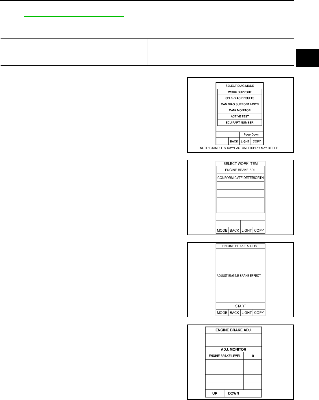
TROUBLE DIAGNOSIS
CVT-63
D
E
F
G
H
I
J
K
L
M
A
B
CVT
Revision: 2006 August 2006 Murano
CONSULT-II SETTING PROCEDURE
Refer to GI-38, "CONSULT-II Start Procedure" .
WORK SUPPORT MODE
Display Item List
Engine Brake Adjustment
1. Touch “WORK SUPPORT” on “SELECT DIAG MODE” screen.
2. Touch “ENGINE BRAKE ADJ”.
3. Touch “START”.
4. Set “ENGINE BRAKE LEVEL” by touching “UP” or “DOWN”.
5. Turn ignition switch OFF, wait at least 5 seconds and then turn
ignition switch ON.
6. Engine brake level set is completed.
Item name Description
ENGINE BRAKE ADJ. The engine brake level setting can be canceled.
CONFORM CVTF DETERIORTN The CVT fluid deterioration level can be checked.
BCIA0031E
SCIA4287E
SCIA4288E
“ENGINE BRAKE LEVEL”
0: Initial set value (Engine brake level control is
activated)
OFF: Engine brake level control is deactivated.
SAT934J
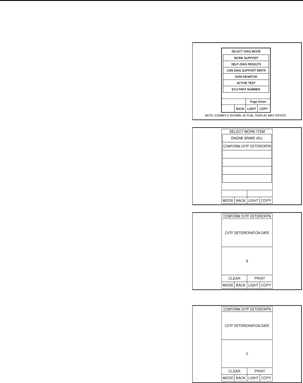
CVT-64
TROUBLE DIAGNOSIS
Revision: 2006 August 2006 Murano
CAUTION:
Mode of “+1” “0” “-1” “-2” “OFF” can be selected by pressing the “UP” “DOWN” on CONSULT-II
screen. However, do not select mode other than “0” and “OFF”. If the “+1” or “-1” or “-2” is
selected, that might cause the irregular driveability.
Check CVT Fluid Deterioration Date
1. Touch “WORK SUPPORT” on “SELECT DIAG MODE” screen.
2. Touch “CONFORM CVTF DETERIORTN”.
3. Check “CVTF DETERIORATION DATE”.
CAUTION:
Touch “CLEAR” after changing CVT fluid, and then erase
“CVTF DETERIORATION DATE”.
BCIA0031E
SCIA4287E
“CVTF DETERIORATION DATE”
More than 210000:
It is necessary to change CVT fluid.
Less than 210000:
It is not necessary to change CVT fluid.
SCIA4289E
SCIA4290E
TROUBLE DIAGNOSIS
CVT-65
D
E
F
G
H
I
J
K
L
M
A
B
CVT
Revision: 2006 August 2006 Murano
SELF-DIAGNOSTIC RESULT MODE
After performing self-diagnosis, place check marks for results on the CVT-36, "DIAGNOSTIC WORKSHEET" .
Reference pages are provided following the items.
Operation Procedure
1. Touch “SELF-DIAG RESULTS” on “SELECT DIAG MODE”
screen.
Display shows malfunction experienced since the last erasing
operation.
Display Items List X: Applicable —: Not applicable
BCIA0031E
Items (CONSULT-
II screen terms) Malfunction is detected when...
TCM self-
diagnosis OBD-II (DTC)
Reference
page
“TRANS-
MISSION”
with CON-
SULT-II
MIL *1,
“ENGINE” with
CONSULT-II or
GST
CAN COMM CIR-
CUIT
When TCM is not transmitting or receiving CAN communica-
tion signal for 2 seconds or more. U1000 U1000 CVT-72
STARTER RELAY/
CIRC
If this signal is ON other than in P or N position, this is
judged to be a malfunction.
(And if it is OFF in P or N position, this is judged to be a mal-
function too.)
P0615 — CVT-75
BRAKE SW/CIRC When the brake switch does not switch to ON or OFF P0703 — CVT-79
PNP SW/CIRC ●PNP switch 1-4 signals input with impossible pattern
●PNP switch 3 monitor terminal open or short circuit P0705 P0705 CVT-81
ATF TEMP SEN/
CIRC
During running, the CVT fluid temperature sensor signal volt-
age is excessively high or low P0710 P0710 CVT-88
INPUT SPD SEN/
CIRC
●Input speed sensor (primary speed sensor) signal is not
input due to an open circuit.
●An unexpected signal is input when vehicle is being
driven.
P0715 P0715 CVT-93
VEH SPD SEN/
CIR AT
●Signal from vehicle speed sensor CVT [Output speed sen-
sor (Secondary speed sensor)] not input due to open or
short circuit
●Unexpected signal input during running
P0720 P0720 CVT-98
ENGINE SPEED
SIG
TCM does not receive the CAN communication signal from
the ECM. P0725 — CVT-104
BELT DAMG Unexpected gear ratio detected P0730 — CVT-106
TCC SOLENOID/
CIRC
Normal voltage not applied to solenoid due to open or short
circuit P0740 P0740 CVT-108
A/T TCC S/V
FNCTN
●CVT cannot perform lock-up even if electrical circuit is
good.
●TCM detects as irregular by comparing difference value
with slip rotation.
P0744 P0744 CVT-113
L/PRESS SOL/
CIRC
●Normal voltage not applied to solenoid due to open or
short circuit
●TCM detects as irregular by comparing target value with
monitor value.
P0745 P0745 CVT-116
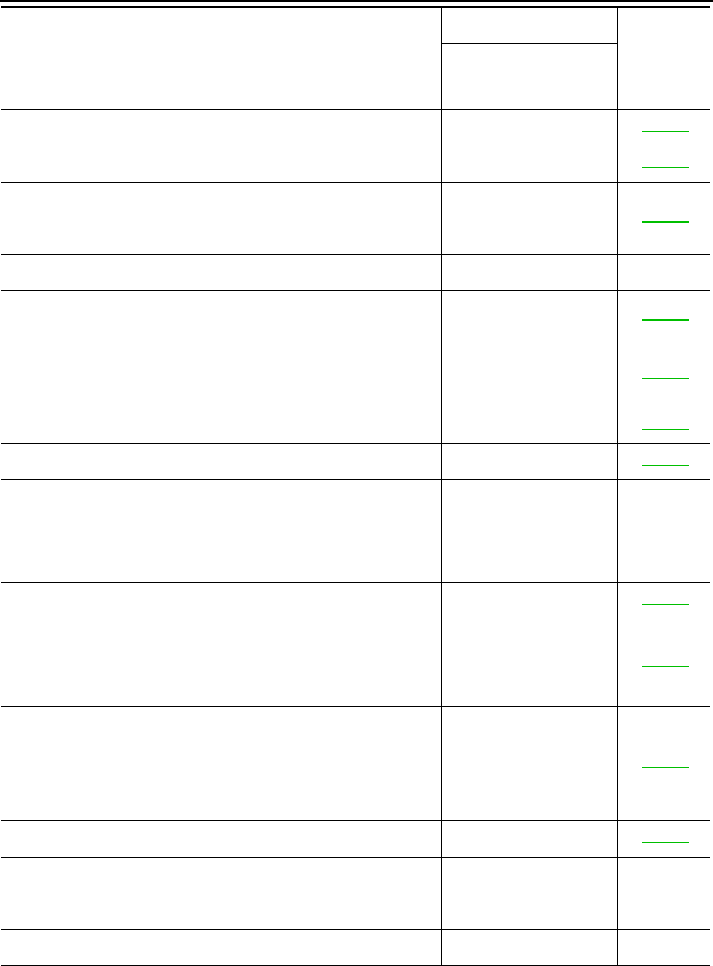
CVT-66
TROUBLE DIAGNOSIS
Revision: 2006 August 2006 Murano
PRS CNT SOL/A
FCTN
Unexpected gear ratio was detected in the LOW side due to
excessively low line pressure. P0746 P0746 CVT-121
PRS CNT SOL/B
FCTN
Secondary pressure is too high or too low compared with the
commanded value while driving. P0776 P0776 CVT-124
PRS CNT SOL/B
CIRC
●Normal voltage not applied to solenoid due to cut line,
short, or the like
●TCM detects as irregular by comparing target value with
monitor value.
P0778 P0778 CVT-127
MANUAL MODE
SWITCH
When an impossible pattern of switch signals is detected, a
malfunction is detected. P0826 — CVT-132
TR PRS SENS/A
CIRC
Signal voltage of the transmission fluid pressure sensor A
(secondary pressure sensor) is too high or too low while driv-
ing.
P0840 P0840 CVT-137
PRESS SEN/
FNCTN
Correlation between the values of the transmission fluid
pressure sensor A (secondary pressure sensor) and the
transmission fluid pressure sensor B (primary pressure sen-
sor) is out of specification.
P0841 — CVT-142
TR PRS SENS/B
CIRC
Signal voltage of the transmission fluid pressure sensor B
(primary pressure sensor) is too high or too low while driving. P0845 P0845 CVT-145
SEC/PRESS
DOWN
Secondary fluid pressure is too low compared with the com-
manded value while driving. P0868 — CVT-150
TCM-POWER
SUPPLY
●When the power supply to the TCM is cut OFF, for exam-
ple because the battery is removed, and the self-diagnosis
memory function stops
●This is not a malfunction message (Whenever shutting
OFF a power supply to the TCM, this message appears on
the screen.)
P1701 — CVT-153
TP SEN/CIRC A/T TCM does not receive the proper accelerator pedal position
signals (input by CAN communication) from ECM. P1705 — CVT-158
ESTM VEH SPD
SIG
●CAN communication with the ABS actuator and the elec-
tric unit (control unit) is malfunctioning.
●There is a great difference between the vehicle speed sig-
nal from the ABS actuator and the electric unit (control
unit), and the vehicle speed sensor signal.
P1722 — CVT-160
CVT SPD SEN/
FNCTN
A rotation sensor error is detected because the gear does
not change in accordance with the position of the stepping
motor.
CAUTION:
One of the “P0720 VEH SPD SEN/CIR AT”, the “P0715
INPUT SPD SEN/CIRC” or the “P0725 ENGINE SPEED
SIG“ is displayed with the DTC at the same time.
P1723 — CVT-162
ELEC TH CON-
TROL
The electronically controlled throttle for ECM is malfunction-
ing. P1726 — CVT-164
LU-SLCT SOL/
CIRC
●Normal voltage not applied to solenoid due to cut line,
short, or the like
●TCM detects as irregular by comparing target value with
monitor value.
P1740 P1740 CVT-166
L/PRESS CON-
TROL TCM detects the unexpected line pressure. P1745 — CVT-171
Items (CONSULT-
II screen terms) Malfunction is detected when...
TCM self-
diagnosis OBD-II (DTC)
Reference
page
“TRANS-
MISSION”
with CON-
SULT-II
MIL *1,
“ENGINE” with
CONSULT-II or
GST
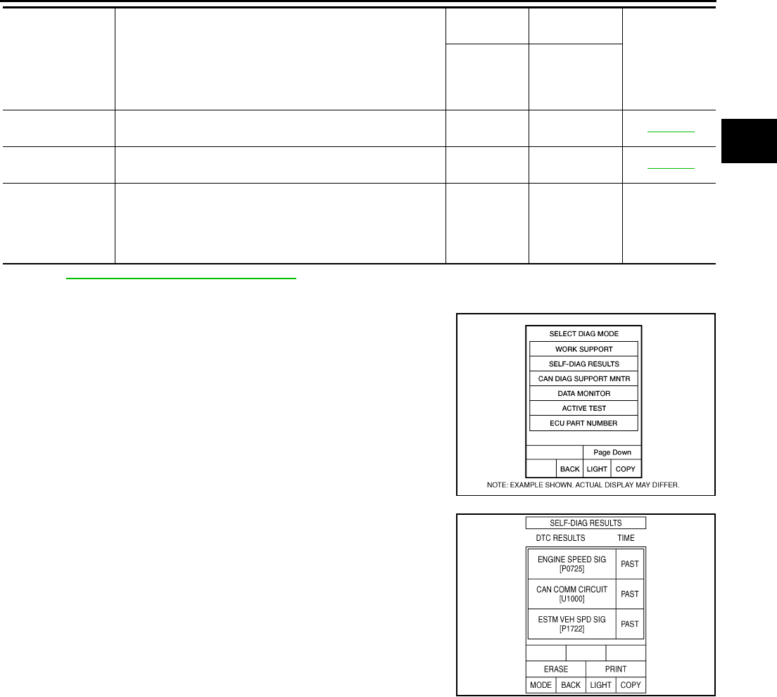
TROUBLE DIAGNOSIS
CVT-67
D
E
F
G
H
I
J
K
L
M
A
B
CVT
Revision: 2006 August 2006 Murano
*1: Refer to CVT-32, "Malfunction Indicator Lamp (MIL)" .
How to Erase Self-diagnostic Results
1. Touch “SELF-DIAG RESULTS” on“ SELECT DIAG MODE”
screen.
2. Touch “ERASE”. (The self-diagnostic results will be erased.)
STEP MOTR
CIRC
Each coil of the step motor is not energized properly due to
an open or a short. P1777 P1777 CVT-172
STEP MOTR/FNC There is a great difference between the number of steps for
the stepping motor and for the actual gear ratio. P1778 P1778 CVT-176
NO DTC IS
DETECTED: FUR-
THER TESTING
MAY BE
REQUIRED
No NG item has been detected. X X —
Items (CONSULT-
II screen terms) Malfunction is detected when...
TCM self-
diagnosis OBD-II (DTC)
Reference
page
“TRANS-
MISSION”
with CON-
SULT-II
MIL *1,
“ENGINE” with
CONSULT-II or
GST
BCIA0031E
SCIA4614E
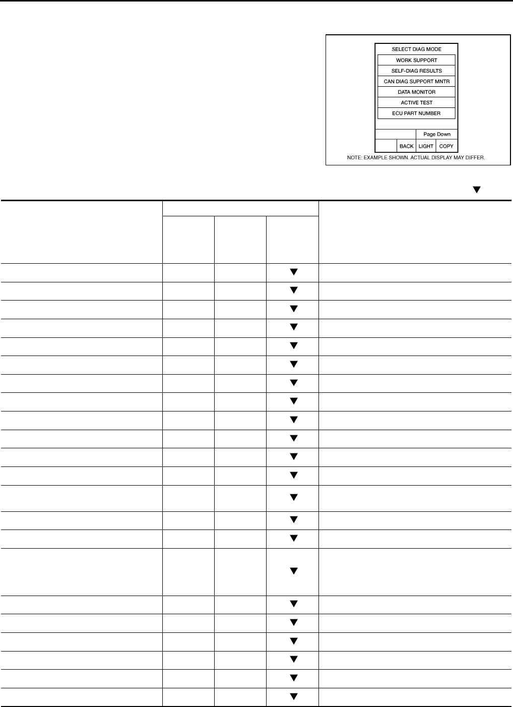
CVT-68
TROUBLE DIAGNOSIS
Revision: 2006 August 2006 Murano
DATA MONITOR MODE
Operation Procedure
1. Touch “DATA MONITOR” on “SELECT DIAG MODE” screen.
NOTE:
When malfunction is detected, CONSULT-II performs
“REAL-TIME DIAGNOSIS”. Also, any malfunction detected
while in this mode will be displayed at real time.
Display Items List
X: Standard, —: Not applicable, : Option
BCIA0031E
Monitored item (Unit)
Monitor item selection
Remarks
ECU
INPUT
SIGNALS
MAIN SIG-
NALS
SELEC-
TION
FROM
MENU
VSP SENSOR (km/h) X — Output speed sensor (secondary speed sensor).
ESTM VSP SIG (km/h) X —
PRI SPEED SEN (rpm) X —
ENG SPEED SIG (rpm) X —
SEC HYDR SEN (V) X —
PRI HYDR SEN (V) X —
ATF TEMP SEN (V) X — CVT fluid temperature sensor
VIGN SEN (V) X —
VEHICLE SPEED (km/h) — X Vehicle speed recognized by the TCM.
PRI SPEED (rpm) — X Primary pulley speed.
SEC SPEED (rpm) — — Secondary pulley speed.
ENG SPEED (rpm) — X
SLIP REV (rpm) — X Difference between engine speed and primary
pulley speed
GEAR RATIO — X
G SPEED (G) — —
ACC PEDAL OPEN (0.0/8) X X
Degree of opening for accelerator recognized by
the TCM
For fail-safe operation, the specific value used
for control is displayed.
TRQ RTO — —
SEC PRESS (MPa) — X
PRI PRESS (MPa) — X
ATF TEMP — X
DSR REV (rpm) — —
DGEAR RATIO — —
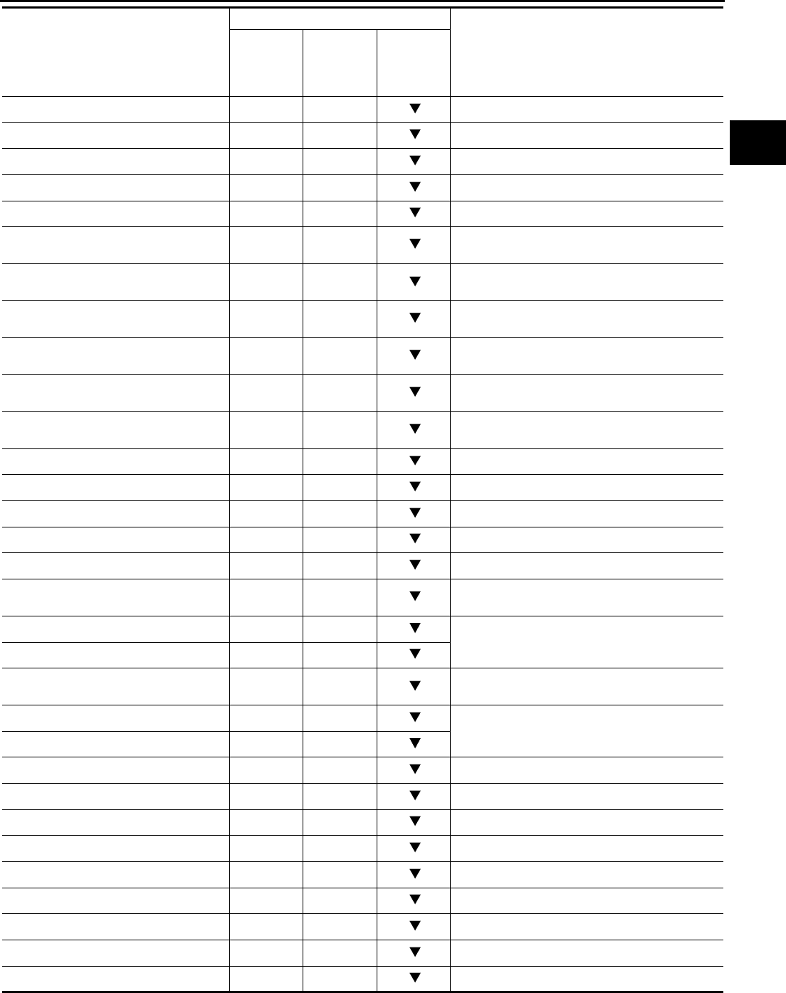
TROUBLE DIAGNOSIS
CVT-69
D
E
F
G
H
I
J
K
L
M
A
B
CVT
Revision: 2006 August 2006 Murano
DSTM STEP (step) — —
STM STEP (step) — X
LU PRS (MPa) — —
LINE PRS (MPa) — —
TGT SEC PRESS (MPa) — —
ISOLT1 (A) — X Torque converter clutch solenoid valve output
current
ISOLT2 (A) — X Pressure control solenoid valve A (line pressure
solenoid valve) output current
ISOLT3 (A) — X Pressure control solenoid valve B (secondary
pressure solenoid valve) output current
SOLMON1 (A) X X Torque converter clutch solenoid valve monitor
current
SOLMON2 (A) X X Pressure control solenoid valve A (line pressure
solenoid valve) monitor current
SOLMON3 (A) X X Pressure control solenoid valve B (secondary
pressure solenoid valve) monitor current
INH SW3M (ON/OFF) X — PNP switch 3 ON-OFF status monitor
INH SW4 (ON/OFF) X — PNP switch 4 ON-OFF status
INH SW3 (ON/OFF) X — PNP switch 3 ON-OFF status
INH SW2 (ON/OFF) X — PNP switch 2 ON-OFF status
INH SW1 (ON/OFF) X — PNP switch 1 ON-OFF status
BRAKE SW (ON/OFF) X X Stop lamp switch (Signal input with CAN commu-
nications)
FULL SW (ON/OFF) X X Signal input with CAN communications
IDLE SW (ON/OFF) X X
SPORT MODE SW (ON/OFF) X X Second position switch (Signal input with CAN
communications)
STRDWNSW (ON/OFF) X — Not mounted but displayed.
STRUPSW (ON/OFF) X —
DOWNLVR (ON/OFF) X —
UPLVR (ON/OFF) X —
NONMMODE (ON/OFF) X —
MMODE (ON/OFF) X —
INDLRNG (ON/OFF) — — “L” position indicator output *
INDDRNG (ON/OFF) — — “D” position indicator output
INDNRNG (ON/OFF) — — “N” position indicator output
INDRRNG (ON/OFF) — — “R” position indicator output
INDPRNG (ON/OFF) — — “P” position indicator output
Monitored item (Unit)
Monitor item selection
Remarks
ECU
INPUT
SIGNALS
MAIN SIG-
NALS
SELEC-
TION
FROM
MENU
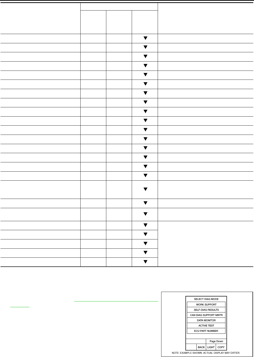
CVT-70
TROUBLE DIAGNOSIS
Revision: 2006 August 2006 Murano
*:Without manual mode.
CAN DIAGNOSTIC SUPPORT MONITOR MODE
Operation Procedure
1. Touch “CAN DAIG SUPPORT MNTR” on “SELECT DIAG
MODE” screen. Refer to LAN-17, "CAN Diagnostic Support
Monitor" .
CVT LAMP (ON/OFF) — —
SPORT MODE IND (ON/OFF) — —
MMODE IND (ON/OFF) — —
SMCOIL D (ON/OFF) — — Step motor coil “D” energizing status
SMCOIL C (ON/OFF) — — Step motor coil “C” energizing status
SMCOIL B (ON/OFF) — — Step motor coil “B” energizing status
SMCOIL A (ON/OFF) — — Step motor coil “A” energizing status
LUSEL SOL OUT (ON/OFF) — —
REV LAMP (ON/OFF) — X
STRTR RLY OUT (ON/OFF) — — Starter relay
LUSEL SOL MON (ON/OFF) — —
STRTR RLY MON (ON/OFF) — — Starter relay
VDC ON (ON/OFF) X —
TCS ON (ON/OFF) X —
ABS ON (ON/OFF) X —
ACC ON (ON/OFF) X — Not mounted but displayed.
RANGE — X
Indicates position is recognized by TCM. Indi-
cates a specific value required for control when
fail-safe function is activated.
M GEAR POS — X
Voltage (V) — — Displays the value measured by the voltage
probe.
Frequency (Hz) — —
The value measured by the pulse probe is dis-
played.
DUTY-HI (high) (%) — —
DUTY-LOW (low) (%) — —
PLS WIDTH-HI (ms) — —
PLS WIDTH-LOW (ms) — —
Monitored item (Unit)
Monitor item selection
Remarks
ECU
INPUT
SIGNALS
MAIN SIG-
NALS
SELEC-
TION
FROM
MENU
BCIA0031E

TROUBLE DIAGNOSIS
CVT-71
D
E
F
G
H
I
J
K
L
M
A
B
CVT
Revision: 2006 August 2006 Murano
Diagnostic Procedure without CONSULT-II NCS00139
OBD-II SELF-DIAGNOSTIC PROCEDURE (WITH GST)
Refer to EC-124, "Generic Scan Tool (GST) Function" .
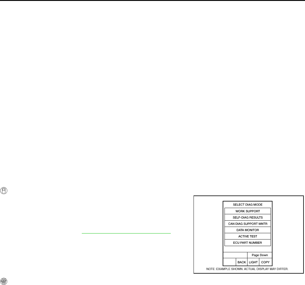
CVT-72
DTC U1000 CAN COMMUNICATION LINE
Revision: 2006 August 2006 Murano
DTC U1000 CAN COMMUNICATION LINE PFP:23710
Description NCS0013A
CAN (Controller Area Network) is a serial communication line for real time application. It is an on-vehicle mul-
tiplex communication line with high data communication speed and excellent malfunction detection ability.
Many electronic control units are equipped onto a vehicle, and each control unit shares information and links
with other control units during operation (not independent). In CAN communication, control units are con-
nected with 2 communication lines (CAN-H line, CAN-L line) allowing a high rate of information transmission
with less wiring. Each control unit transmits/receives data but selectively reads required data only.
On Board Diagnosis Logic NCS0013B
●This is an OBD-II self-diagnostic item.
●Diagnostic trouble code “U1000 CAN COMM CIRCUIT” with CONSULT-II is detected when TCM cannot
communicate to other control units.
Possible Cause NCS0013C
Harness or connectors
(CAN communication line is open or shorted.)
DTC Confirmation Procedure NCS0013D
NOTE:
If “DTC Confirmation Procedure” has been previously performed, always turn ignition switch OFF and
wait at least 10 seconds before performing the next test.
After the repair, touch “ERASE” on “SELF-DIAG RESULTS” and then perform the following procedure to con-
firm the malfunction is eliminated.
WITH CONSULT-II
1. Turn ignition switch ON. (Do not start engine.)
2. Select “DATA MONITOR” mode for “TRANSMISSION” with
CONSULT-II.
3. Start engine and wait for at least 6 seconds.
4. If DTC is detected, go to CVT-74, "Diagnostic Procedure" .
WITH GST
Follow the procedure “WITH CONSULT-II”.
BCIA0031E
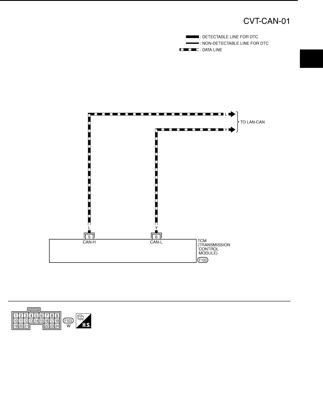
DTC U1000 CAN COMMUNICATION LINE
CVT-73
D
E
F
G
H
I
J
K
L
M
A
B
CVT
Revision: 2006 August 2006 Murano
Wiring Diagram — CVT — CAN NCS0013E
TCWA0147E
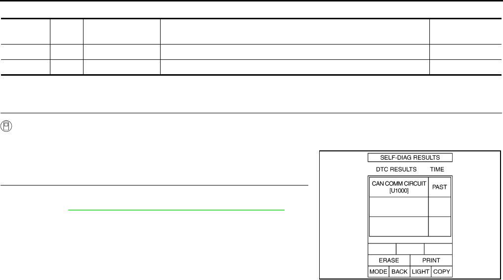
CVT-74
DTC U1000 CAN COMMUNICATION LINE
Revision: 2006 August 2006 Murano
TCM terminal data are reference values, measured between each terminal and ground.
Diagnostic Procedure NCS0013F
1. CHECK CAN COMMUNICATION CIRCUIT
With CONSULT-II
1. Turn ignition switch ON and start engine.
2. Select “SELF-DIAG RESULTS” mode for “TRANSMISSION”
with CONSULT-II.
Is any malfunction of the “U1000 CAN COMM CIRCUIT” indicated?
YES >> Print out CONSULT-II screen, go to LAN section. Refer
to LAN-3, "Precautions When Using CONSULT-II" .
NO >> INSPECTION END
Terminal Wire
color Item Condition Data (Approx.)
5 L CAN-H — —
6 Y CAN-L — —
SCIA5982E
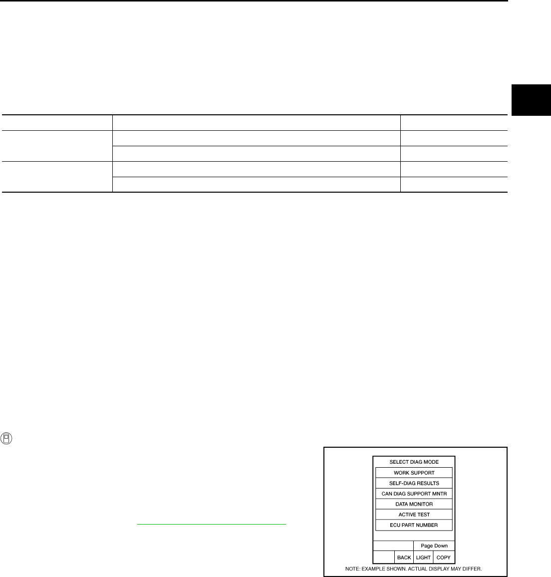
DTC P0615 START SIGNAL CIRCUIT
CVT-75
D
E
F
G
H
I
J
K
L
M
A
B
CVT
Revision: 2006 August 2006 Murano
DTC P0615 START SIGNAL CIRCUIT PFP:25230
Description NCS0013G
●TCM controls starter relay in IPDM E/R.
●TCM switches starter relay ON at “P” or “N” position and allows to crank engine.
●Then it prohibits cranking other than at “P” or “N” position.
CONSULT-II Reference Value NCS0013H
Remarks: Specification data are reference values.
On Board Diagnosis Logic NCS0013I
●This is not an OBD-II self-diagnostic item.
●Diagnostic trouble code “P0615 STARTER RELAY/CIRC” with CONSULT-II is detected when starter relay
switched ON other than at “P” or “N” position. (Or when switched OFF at “P” or “N” position).
Possible Cause NCS0013J
●Harness or connectors
(Starter relay and TCM circuit is open or shorted.)
●Starter relay
DTC Confirmation Procedure NCS0013K
CAUTION:
Always drive vehicle at a safe speed.
NOTE:
If “DTC Confirmation Procedure” has been previously performed, always turn ignition switch OFF and
wait at least 10 seconds before performing the next test.
After the repair, touch “ERASE” on “SELF-DIAG RESULTS” and then perform the following procedure to con-
firm the malfunction is eliminated.
WITH CONSULT-II
1. Turn ignition switch ON. (Do not start engine.)
2. Select “DATA MONITOR” mode for “TRANSMISSION” with
CONSULT-II.
3. Start engine.
4. Drive vehicle for at least 2 consecutive seconds.
5. If DTC is detected, go to CVT-77, "Diagnostic Procedure" .
Item name Condition Display value
STRTR RLY OUT Selector lever in “P” and “N” positions ON
Selector lever in other positions OFF
STRTR RLY MON Selector lever in “P” and “N” positions ON
Selector lever in other positions OFF
BCIA0031E
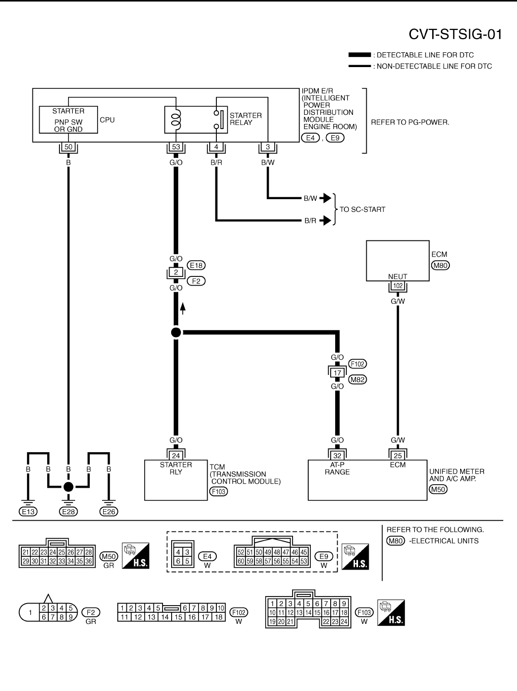
CVT-76
DTC P0615 START SIGNAL CIRCUIT
Revision: 2006 August 2006 Murano
Wiring Diagram — CVT — STSIG NCS0013L
TCWA0245E
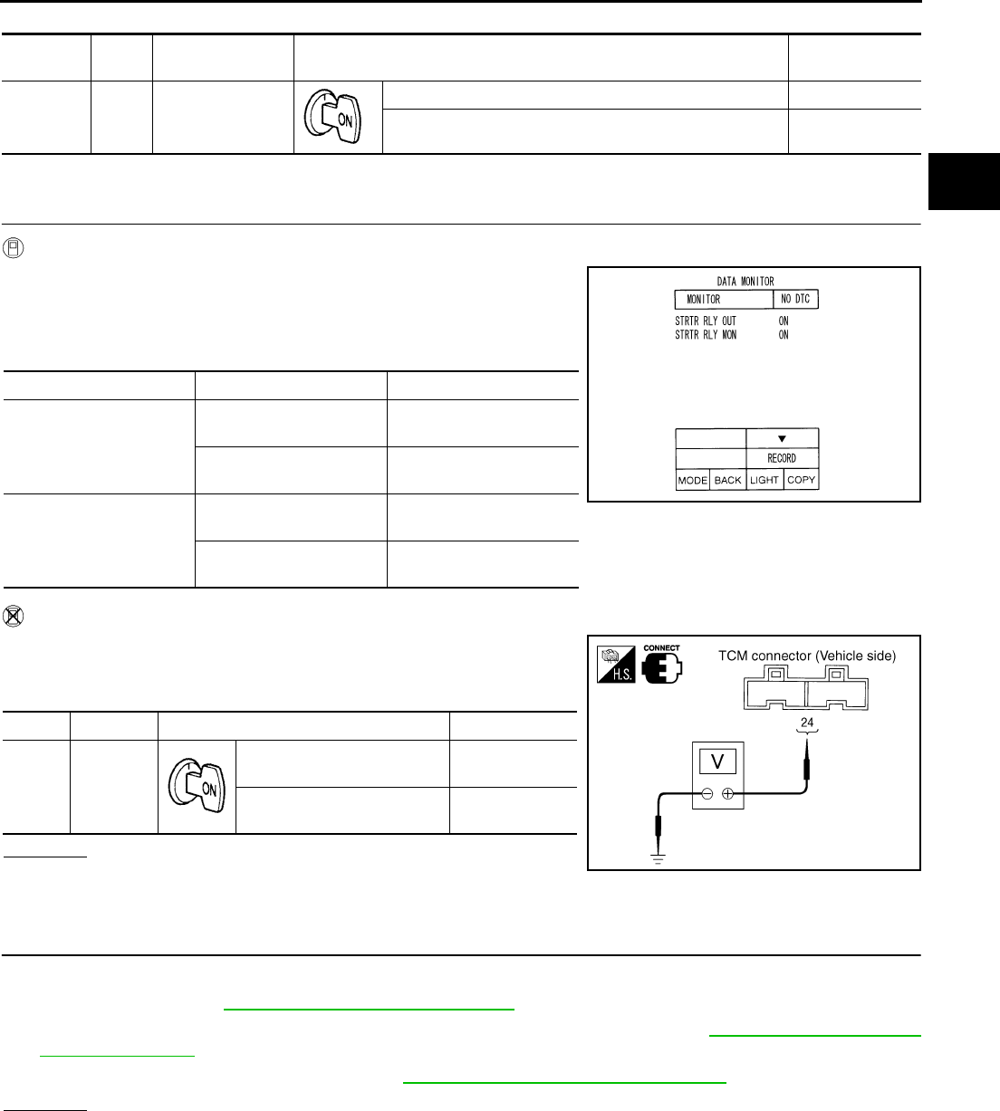
DTC P0615 START SIGNAL CIRCUIT
CVT-77
D
E
F
G
H
I
J
K
L
M
A
B
CVT
Revision: 2006 August 2006 Murano
TCM terminal data are reference values, measured between each terminal and ground.
Diagnostic Procedure NCS0013M
1. CHECK STARTER RELAY SIGNAL
With CONSULT-II
1. Turn ignition switch ON. (Do not start engine.)
2. Select “SELECTION FROM MENU” in “DATA MONITOR” mode
for “TRANSMISSION” with CONSULT-II and check monitor
“STRTR RLY OUT”, “STRTR RLY MON”(PNP relay) ON/OFF.
Without CONSULT-II
1. Turn ignition switch ON. (Do not start engine.)
2. Check voltage between the TCM connector terminal and
ground.
OK or NG
OK >> GO TO 3.
NG >> GO TO 2.
2. DETECT MALFUNCTIONING ITEM
Check the following:
●Starter relay. Refer to PG-67, "STANDARDIZED RELAY" .
●Open or short-circuit in the harness between TCM and the starter relay. Refer to CVT-76, "Wiring Diagram
— CVT — STSIG" .
●Ground circuit for the starter relay. Refer to SC-10, "Wiring Diagram — START —" .
OK or NG
OK >> GO TO 3.
NG >> Repair or replace damaged parts.
Terminal Wire
color Item Condition Data (Approx.)
24 G/O Starter relay
Selector lever in “N” and “P” positions Battery voltage
Selector lever in other positions 0 V
Item name Condition Display value
STRTR RLY OUT
Selector lever in “P” and
“N” positions ON
Selector lever in other
positions OFF
STRTR RLY MON
Selector lever in “P” and
“N” positions ON
Selector lever in other
positions OFF
Name Terminal Condition Data (Approx.)
Starter
relay
24 -
Ground
Selector lever in “N” and “P”
positions Battery voltage
Selector lever in other posi-
tions 0 V
SCIA2274E
SCIA2022E

CVT-78
DTC P0615 START SIGNAL CIRCUIT
Revision: 2006 August 2006 Murano
3. CHECK DTC
Perform “DTC Confirmation Procedure”. Refer to CVT-75, "DTC Confirmation Procedure" .
OK or NG
OK >> INSPECTION END
NG >> GO TO 4.
4. CHECK TCM
1. Check TCM input/output signals. Refer to CVT-57, "TCM Input/Output Signal Reference Values" .
2. If NG, re-check TCM pin terminals for damage or loose connection with harness connector.
OK or NG
OK >> INSPECTION END
NG >> Repair or replace damaged parts.
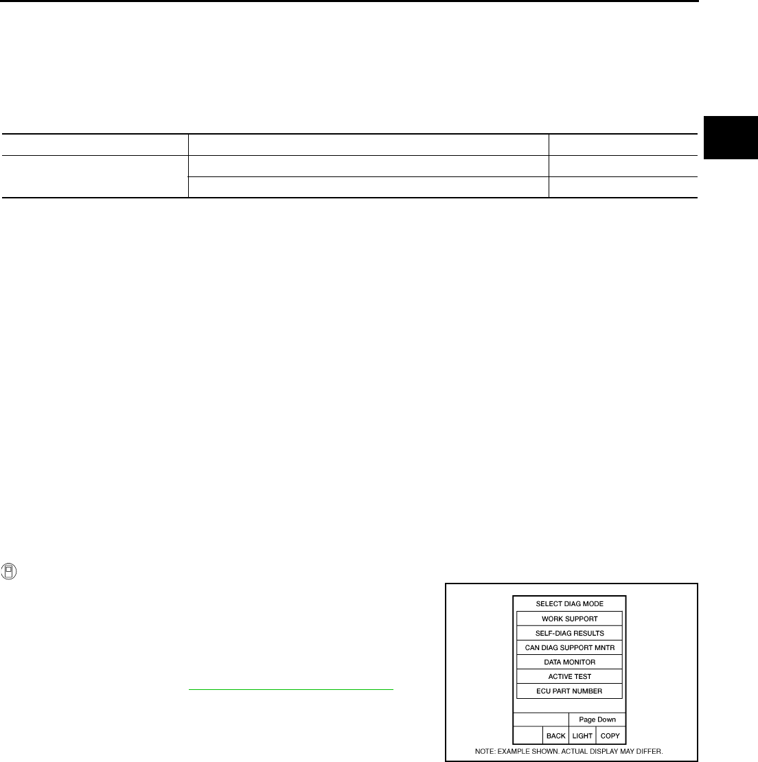
DTC P0703 STOP LAMP SWITCH CIRCUIT
CVT-79
D
E
F
G
H
I
J
K
L
M
A
B
CVT
Revision: 2006 August 2006 Murano
DTC P0703 STOP LAMP SWITCH CIRCUIT PFP:25320
Description NCS0013N
ON, OFF status of the stop lamp switch is sent via the CAN communication from the unified meter and A/C
amp to TCM using the signal.
CONSULT-II Reference Value NCS0013O
Remarks: Specification data are reference values.
On Board Diagnosis Logic NCS0013P
●This is not an OBD-II self-diagnostic item.
●Diagnostic trouble code “P0703 BRAKE SW/CIRC” with CONSULT-II is detected when the stop lamp
switch does not switch to ON and OFF.
–The stop lamp switch does not switch to ON, OFF.
Possible Cause NCS0013Q
●Harness or connectors
(Stop lamp switch, and unified meter and A/C amp circuit are open or shorted.)
(CAN communication line is open or shorted.)
●Stop lamp switch
DTC Confirmation Procedure NCS0013R
CAUTION:
Always drive vehicle at a safe speed.
NOTE:
If “DTC Confirmation Procedure” has been previously performed, always turn ignition switch OFF and
wait at least 10 seconds before performing the next test.
After the repair, touch “ERASE” on “SELF-DIAG RESULTS” and then perform the following procedure to con-
firm the malfunction is eliminated.
WITH CONSULT-II
1. Turn ignition switch ON. (Do not start engine.)
2. Select “DATA MONITOR” mode for “TRANSMISSION” with
CONSULT-II.
3. Start engine.
4. Start vehicle for at least 3 consecutive seconds.
5. If DTC is detected, go to CVT-80, "Diagnostic Procedure" .
Item name Condition Display value
BRAKE SW Depressed brake pedal ON
Released brake pedal OFF
BCIA0031E
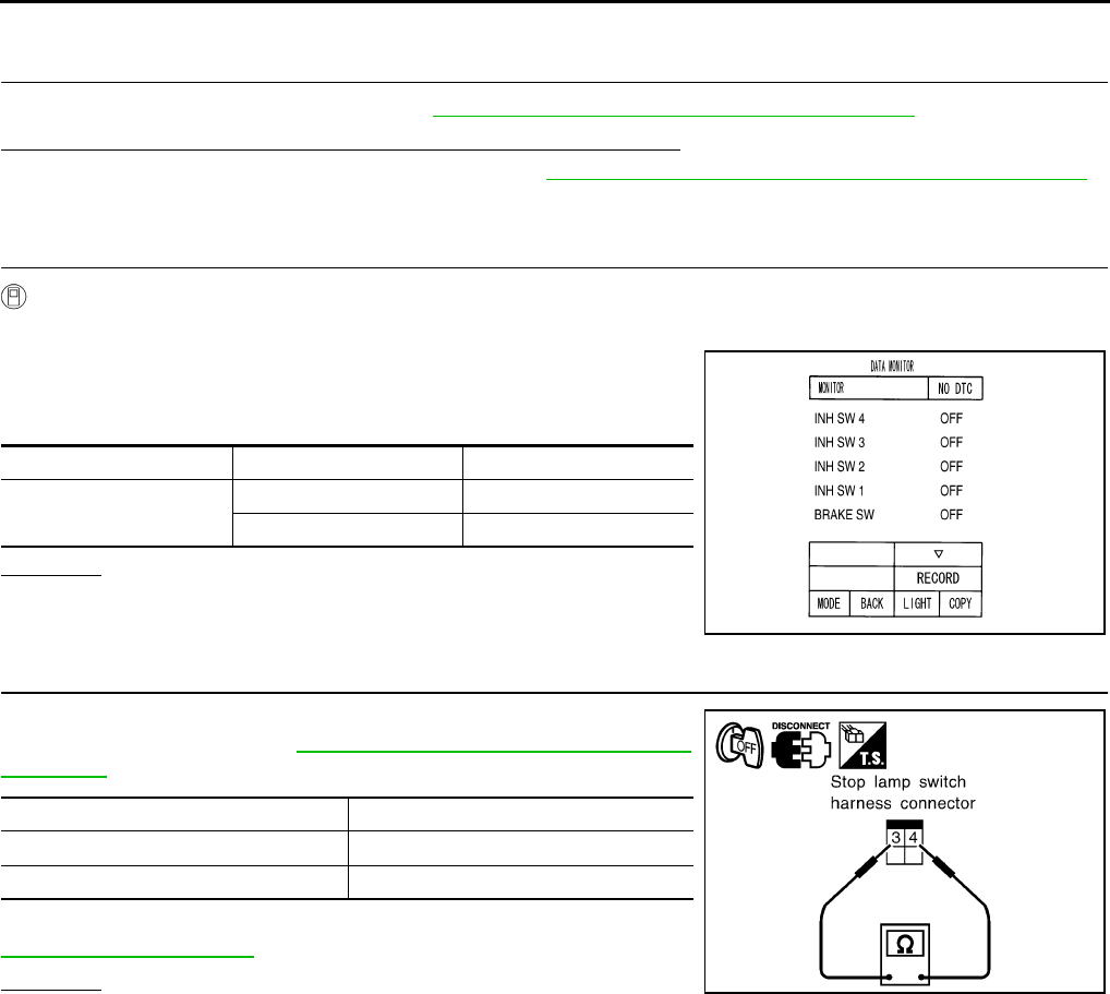
CVT-80
DTC P0703 STOP LAMP SWITCH CIRCUIT
Revision: 2006 August 2006 Murano
Diagnostic Procedure NCS0013S
1. CHECK CAN COMMUNICATION LINE
Perform the self-diagnosis check. Refer to CVT-65, "SELF-DIAGNOSTIC RESULT MODE" .
Is any malfunction of the “U1000 CAN COMM CIRCUIT” indicated?
YES >> Check CAN communication line. Refer to CVT-72, "DTC U1000 CAN COMMUNICATION LINE" .
NO >> GO TO 2.
2. CHECK STOP LAMP SWITCH CIRCUIT
With CONSULT-II
1. Turn ignition switch ON. (Do not start engine.)
2. Select “ECU INPUT SIGNALS” in “DATA MONITOR” mode for
“TRANSMISSION” with CONSULT-II.
3. Read out ON/OFF switching action of the “BRAKE SW”.
OK or NG
OK >> INSPECTION END
NG >> GO TO 3.
3. CHECK STOP LAMP SWITCH
Check continuity between stop lamp switch harness connector E116
terminals 3 and 4. Refer to CVT-183, "Wiring Diagram — CVT —
NONDTC" .
Check stop lamp switch after adjusting brake pedal — refer to
BR-6, "BRAKE PEDAL" .
OK or NG
OK >> Check the following. If NG, repair or replace damaged
parts.
●Harness for short or open between battery and stop lamp switch.
●Harness for short or open between stop lamp switch and unified meter and A/C amp.
NG >> Repair or replace the stop lamp switch.
Item name Condition Display value
BRAKE SW Depressed brake pedal ON
Released brake pedal OFF
SCIA2275E
Condition Continuity
When brake pedal is depressed Yes
When brake pedal is released No
SCIA2126E
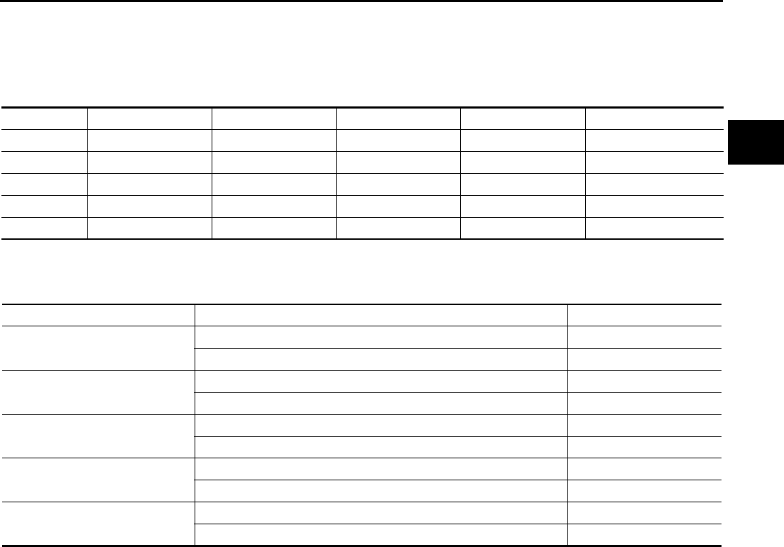
DTC P0705 PARK/NEUTRAL POSITION SWITCH
CVT-81
D
E
F
G
H
I
J
K
L
M
A
B
CVT
Revision: 2006 August 2006 Murano
DTC P0705 PARK/NEUTRAL POSITION SWITCH PFP:32006
Description NCS0013T
●The PNP switch includes 4 transmission position switches.
●TCM judges the selector lever position by the PNP switch signal.
*: Without manual mode
CONSULT-II Reference Value NCS0013U
Remarks: Specification data are reference values.
*: Without manual mode
On Board Diagnosis Logic NCS0013V
●This is an OBD-II self-diagnostic item.
●Diagnostic trouble code “P0705 PNP SW/CIRC” with CONSULT-II is detected under the following condi-
tions.
–When TCM does not receive the correct voltage signal from the PNP switches 1, 2, 3 and 4 based on the
gear position.
–When the signal from monitor terminal of PNP switch 3 is different from PNP switch 3.
Possible Cause NCS0013W
●Harness or connectors
(PNP switches 1, 2, 3, 4 and TCM circuit is open or shorted.)
●PNP switches 1, 2, 3, 4
●PNP switch 3 monitor terminal is open or shorted
DTC Confirmation Procedure NCS0013X
CAUTION:
Always drive vehicle at a safe speed.
NOTE:
If “DTC Confirmation Procedure” has been previously performed, always turn ignition switch OFF and
wait at least 10 seconds before performing the next test.
After the repair, touch “ERASE” on “SELF-DIAG RESULTS” and then perform the following procedure to con-
firm the malfunction is eliminated.
Shift position PNP switch 1 PNP switch 2 PNP switch 3 PNP switch 4 PNP switch 3 (monitor)
P OFF OFF OFF OFF OFF
R ON OFF OFF ON OFF
N ON ON OFF OFF OFF
D · S* ON ON ON ON ON
L* OFF ON ON OFF ON
Item name Condition Display value
INH SW3M Selector lever in “D”, “S”* and “L”* positions ON
Selector lever in “P”, “R” and “N” positions OFF
INH SW4 Selector lever in “R”, “D” and “S”* positions ON
Selector lever in “P”, “N” and “L”* positions OFF
INH SW3 Selector lever in “D”, “S”* and “L”* positions ON
Selector lever in “P”, “R” and “N” positions OFF
INH SW2 Selector lever in “N”, “D”, “S”* and “L”* positions ON
Selector lever in “P” and “R” positions OFF
INH SW1 Selector lever in “R”, “N”, “D” and “S”* positions ON
Selector lever in “P” and “L”* positions OFF
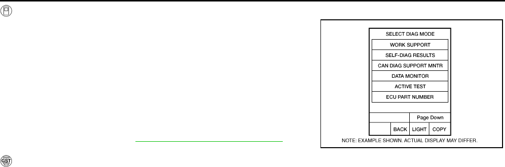
CVT-82
DTC P0705 PARK/NEUTRAL POSITION SWITCH
Revision: 2006 August 2006 Murano
WITH CONSULT-II
1. Turn ignition switch ON. (Do not start engine.)
2. Select “DATA MONITOR” mode for “TRANSMISSION” with
CONSULT-II.
3. Start engine.
4. Drive vehicle and maintain the following conditions for at least 2
consecutive seconds.
VEHICLE SPEED: More than 10 km/h (6 MPH)
ENG SPEED: More than 450 rpm
ACC PEDAL OPEN: More than 1.0/8
5. If DTC is detected, go to CVT-85, "Diagnostic Procedure" .
WITH GST
Follow the procedure “WITH CONSULT-II”.
BCIA0031E
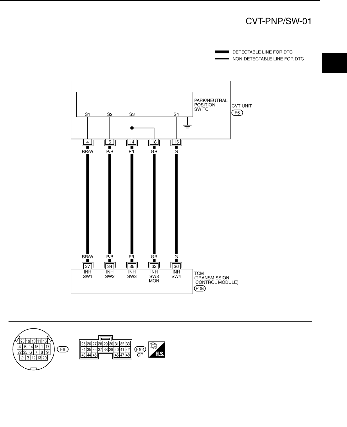
DTC P0705 PARK/NEUTRAL POSITION SWITCH
CVT-83
D
E
F
G
H
I
J
K
L
M
A
B
CVT
Revision: 2006 August 2006 Murano
Wiring Diagram — CVT — PNP/SW NCS0013Y
TCWA0246E
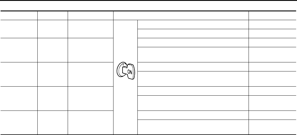
CVT-84
DTC P0705 PARK/NEUTRAL POSITION SWITCH
Revision: 2006 August 2006 Murano
TCM terminal data are reference values, measured between each terminal and ground.
*: Without manual mode
Terminal Wire color Item Condition Data (Approx.)
27 BR/W PNP switch 1 Selector lever in “R”, “N”, “D” and “S”* positions. 0 V
Selector lever in “P” and “L”* positions. Battery voltage
32 GR PNP switch 3
(monitor)
Selector lever in “D”, “S”* and “L”* positions. 0 V
Selector lever in “P”, “R” and “N” positions. 8.0 V - Battery volt-
age
34 P/B PNP switch 2
Selector lever in “N”, “D”, “S”* and “L”* positions. 0 V
Selector lever in “P” and “R” positions. 10.0 V - Battery
voltage
35 P/L PNP switch 3
Selector lever in “D”, “S”* and “L”* positions. 0 V
Selector lever in “P”, “R” and “N” positions. 8.0 V - Battery volt-
age
36 G PNP switch 4
Selector lever in “R”, “D” and “S”* positions. 0 V
Selector lever in “P”, “N” and “L”* positions. 10.0 V - Battery
voltage
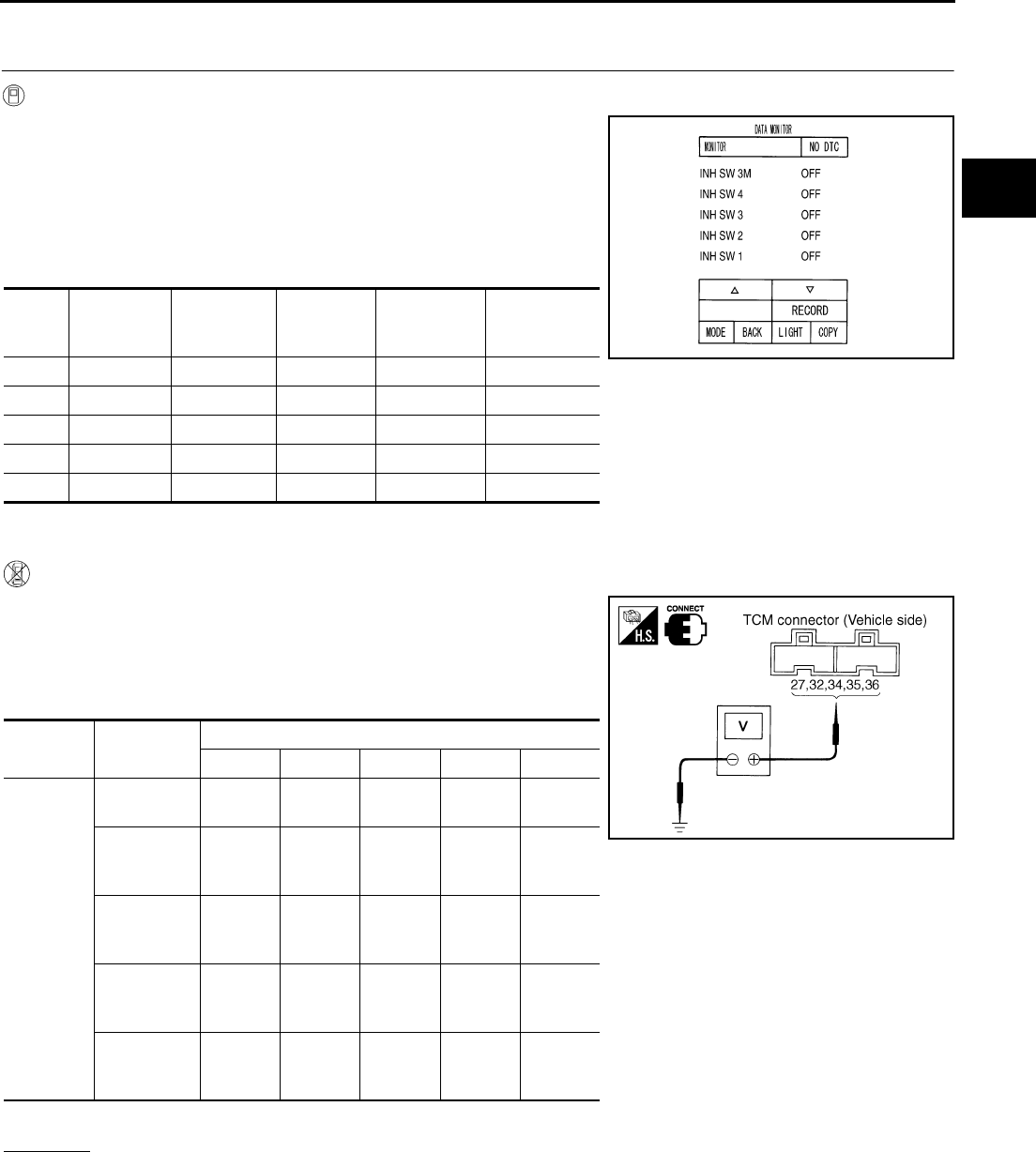
DTC P0705 PARK/NEUTRAL POSITION SWITCH
CVT-85
D
E
F
G
H
I
J
K
L
M
A
B
CVT
Revision: 2006 August 2006 Murano
Diagnostic Procedure NCS0013Z
1. CHECK PNP SW SIGNALS
With CONSULT-II
1. Turn ignition switch ON. (Do not start engine.)
2. Select “ECU INPUT SIGNALS” in “DATA MONITOR” mode for
“TRANSMISSION” with CONSULT-II.
3. Change selector lever to “P”, “R”, “N”, “D”, “S”* and “L”* posi-
tions to check the value of “INH SW1” “INH SW2” “INH SW3”
“INH SW4” and “INH SW3M”.
*: Without manual mode
*: Without manual mode
Without CONSULT-II
1. Turn ignition switch ON. (Do not start engine.)
2. Change selector lever to “P“, “R”, “N”, “D”, “S”* and “L”* posi-
tions to check voltage between the TCM connector terminals
and ground.
*: Without manual mode
*: Without manual mode
OK or NG
OK >> GO TO 5.
NG >> GO TO 2.
Shift
posi-
tion
“INH SW1” “INH SW2” “INH SW3” “INH SW4” “INH SW3M”
P OFF OFF OFF OFF OFF
R ON OFF OFF ON OFF
N ON ON OFF OFF OFF
D · S* ON ON ON ON ON
L* OFF ON ON OFF ON
SCIA2276E
Connector Terminal Shift position
PRND · S*L*
F104
27 – Ground Battery
voltage 0 V 0 V 0 V Battery
voltage
34 – Ground
10.0 V –
Battery
voltage
10.0 V –
Battery
voltage
0 V 0 V 0 V
35 – Ground
8.0 V –
Battery
voltage
8.0 V –
Battery
voltage
8.0 V –
Battery
voltage
0 V 0 V
36 – Ground
10.0 V –
Battery
voltage
0 V
10.0 V –
Battery
voltage
0 V
10.0 V –
Battery
voltage
32 – Ground
8.0 V –
Battery
voltage
8.0 V –
Battery
voltage
8.0 V –
Battery
voltage
0 V 0 V
SCIA2024E
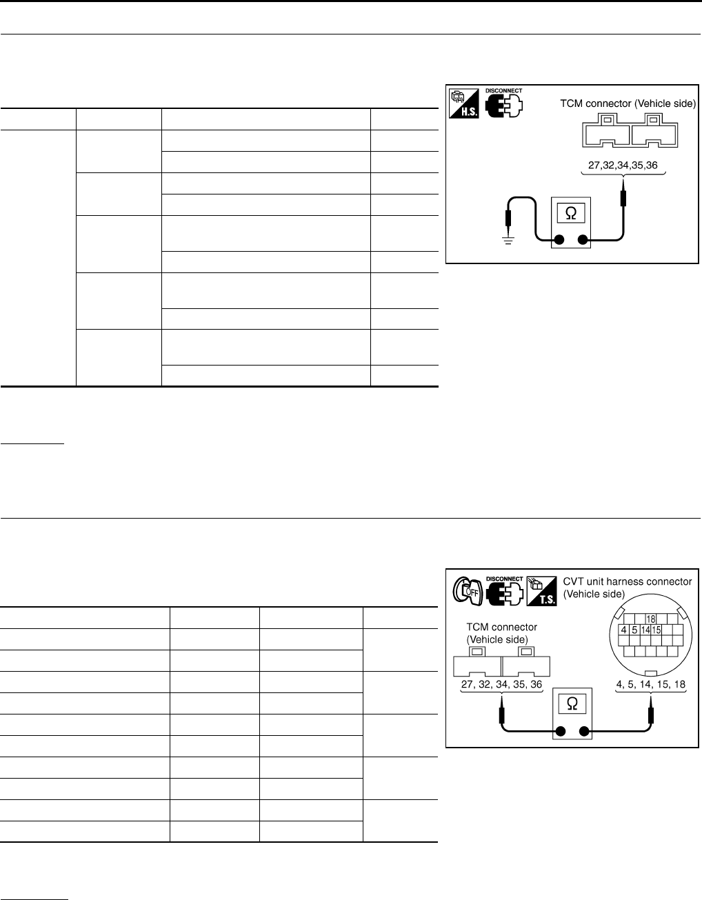
CVT-86
DTC P0705 PARK/NEUTRAL POSITION SWITCH
Revision: 2006 August 2006 Murano
2. CHECK PNP SWITCH CIRCUIT
1. Turn ignition switch OFF.
2. Disconnect TCM connector.
3. Check continuity between TCM connector terminals and ground.
*: Without manual mode
4. If OK, check harness for short-circuit to ground or power supply.
OK or NG
OK >> GO TO 5.
NG >> GO TO 3.
3. CHECK HARNESS BETWEEN TCM AND PNP SWITCH
1. Turn ignition switch OFF.
2. Disconnect TCM connector and CVT unit harness connector.
3. Check continuity between TCM connector terminals and CVT
unit harness connector terminals.
4. If OK, check harness for short to ground and short to power.
5. Reinstall any part removed.
OK or NG
OK >> GO TO 4.
NG >> Repair or replace damaged parts.
Connector Terminal Condition Continuity
F104
27 - Ground Select lever in “P” and “L”* positions No
Select lever in other positions Yes
34 - Ground Select lever in “P” and “R” positions No
Select lever in other positions Yes
35 - Ground
Select lever in “P”, “R” and “N” posi-
tions No
Select lever in other positions Yes
36 - Ground
Select lever in “P”, “N” and “L”* posi-
tions No
Select lever in other positions Yes
32 - Ground
Select lever in “P”, “R” and “N” posi-
tions No
Select lever in other positions Yes
SCIA5258E
Item Connector Terminal Continuity
TCM connector F104 27 Yes
CVT unit harness connector F6 4
TCM connector F104 34 Yes
CVT unit harness connector F6 5
TCM connector F104 35 Yes
CVT unit harness connector F6 14
TCM connector F104 32 Yes
CVT unit harness connector F6 18
TCM connector F104 36 Yes
CVT unit harness connector F6 15
SCIA3182E
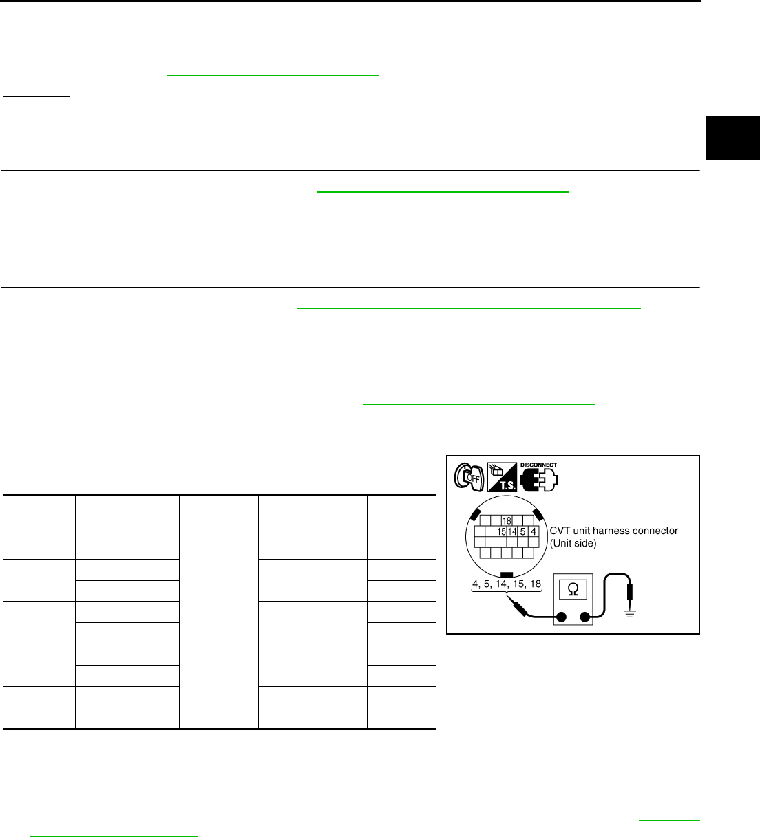
DTC P0705 PARK/NEUTRAL POSITION SWITCH
CVT-87
D
E
F
G
H
I
J
K
L
M
A
B
CVT
Revision: 2006 August 2006 Murano
4. DETECT MALFUNCTIONING ITEM
Check the following.
●PNP switch. Refer to CVT-87, "Component Inspection" .
OK or NG
OK >> GO TO 5.
NG >> Repair or replace damaged parts.
5. CHECK DTC
Perform “DTC Confirmation Procedure”. Refer to CVT-81, "DTC Confirmation Procedure" .
OK or NG
OK >> INSPECTION END
NG >> GO TO 6.
6. CHECK TCM
1. Check TCM input/output signals. Refer to CVT-57, "TCM Input/Output Signal Reference Values" .
2. If NG, re-check TCM pin terminals for damage or loose connection with harness connector.
OK or NG
OK >> INSPECTION END
NG >> 1. Repair or replace damaged parts.
2. Replace the transaxle assembly. Refer to CVT-229, "Removal and Installation" .
Component Inspection NCS00140
PNP SWITCH
1. Change selector lever to various positions to check the continu-
ity between terminals on the PNP switch and ground.
*: Without manual mode
2. If NG, check continuity with control cable disconnected. (Refer to step 1 above.)
3. If OK, with the control cable disconnected, adjust the control cable. Refer to CVT-211, "Adjustment of CVT
Position" .
4. If NG, even when the control cable is disconnected, replace the transaxle assembly. Refer to CVT-229,
"Removal and Installation" .
PNP SW Shift position Connector Terminal Continuity
SW 1 “R”, “N”, “D”, “S”*
F6
4 - Ground Yes
other positions No
SW 2 “N”, “D”, “S”*, “L”* 5 - Ground Yes
other positions No
SW 3 “D”, “S”*, “L”* 14 - Ground Yes
other positions No
SW 4 “R”, “D”, “S”* 15 - Ground Yes
other positions No
SW 3 Moni-
tor
“D”, “S”*, “L”* 18 - Ground Yes
other positions No
SCIA4678E
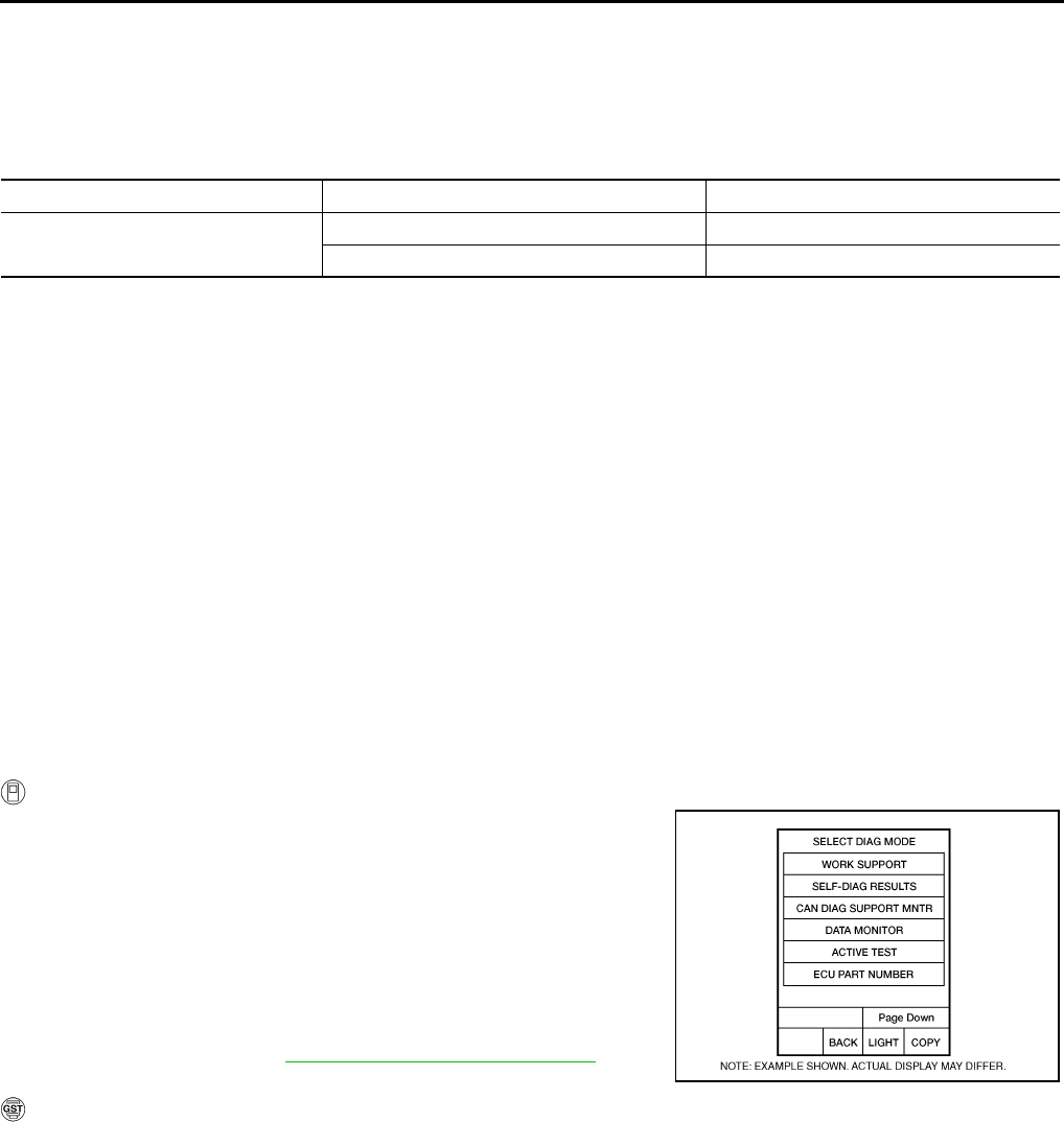
CVT-88
DTC P0710 CVT FLUID TEMPERATURE SENSOR CIRCUIT
Revision: 2006 August 2006 Murano
DTC P0710 CVT FLUID TEMPERATURE SENSOR CIRCUIT PFP:31020
Description NCS00141
The CVT fluid temperature sensor detects the CVT fluid temperature and sends a signal to the TCM.
CONSULT-II Reference Value NCS00142
Remarks: Specification data are reference values.
On Board Diagnosis Logic NCS00143
●This is an OBD-II self-diagnostic item.
●Diagnostic trouble code “P0710 ATF TEMP SEN/CIRC” with CONSULT-II is detected when TCM receives
an excessively low or high voltage from the sensor.
Possible Cause NCS00144
●Harness or connectors
(Sensor circuit is open or shorted.)
●CVT fluid temperature sensor
DTC Confirmation Procedure NCS00145
CAUTION:
Always drive vehicle at a safe speed.
NOTE:
If “DTC Confirmation Procedure” has been previously performed, always turn ignition switch OFF and
wait at least 10 seconds before performing the next test.
After the repair, touch “ERASE” on “SELF-DIAG RESULTS” and then perform the following procedure to con-
firm the malfunction is eliminated.
WITH CONSULT-II
1. Turn ignition switch ON. (Do not start engine.)
2. Select “DATA MONITOR” mode for “TRANSMISSION” with
CONSULT-II.
3. Start engine and maintain the following conditions for at least 10
minutes (Total).
VEHICLE SPEED: 10 km/h (6 MPH) or more
ENG SPEED: 450 rpm more than
ACC PEDAL OPEN: More than 1.0/8
RANGE: “D” position
4. If DTC is detected, go to CVT-90, "Diagnostic Procedure" .
WITH GST
Follow the procedure “WITH CONSULT-II”.
Item name Condition Display value (Approx.)
ATF TEMP SEN When CVT fluid temperature is 20°C (68°F). 1.8 - 2.0 V
When CVT fluid temperature is 80°C (176°F). 0.6 - 1.0 V
BCIA0031E
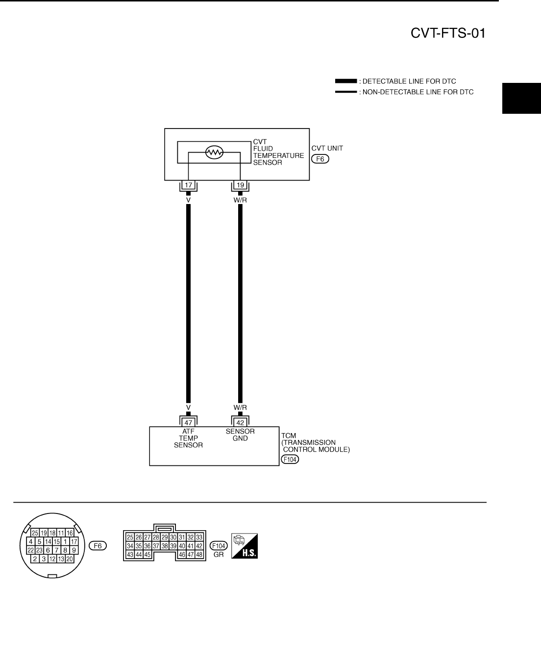
DTC P0710 CVT FLUID TEMPERATURE SENSOR CIRCUIT
CVT-89
D
E
F
G
H
I
J
K
L
M
A
B
CVT
Revision: 2006 August 2006 Murano
Wiring Diagram — CVT — FTS NCS00146
TCWA0247E
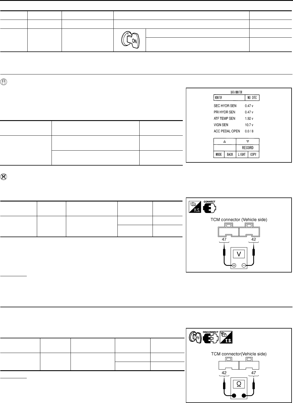
CVT-90
DTC P0710 CVT FLUID TEMPERATURE SENSOR CIRCUIT
Revision: 2006 August 2006 Murano
TCM terminal data are reference values, measured between each terminal and ground.
Diagnostic Procedure NCS00147
1. CHECK CVT FLUID TEMPERATURE SENSOR SIGNAL
With CONSULT-II
1. Start engine.
2. Select “ECU INPUT SIGNALS” in “DATA MONITOR” mode for
“TRANSMISSION” with CONSULT-II.
3. Read out the value of “ATF TEMP SEN”.
Without CONSULT-II
1. Start engine.
2. Check voltage between TCM connector terminals.
3. Turn ignition switch OFF.
4. Disconnect TCM connector.
5. Check if there is continuity between connector terminal and
ground.
OK or NG
OK >> GO TO 5.
NG >> GO TO 2.
2. CHECK CVT FLUID TEMPERATURE SENSOR CIRCUIT
1. Turn ignition switch OFF.
2. Disconnect the TCM connector.
3. Check resistance between TCM connector terminals.
OK or NG
OK >> GO TO 5.
NG >> GO TO 3.
Terminal Wire color Item Condition Data (Approx.)
42 W/R Sensor ground Always 0 V
47 V CVT fluid tempera-
ture sensor
When CVT fluid temperature is 20°C (68°F). 2.0 V
When CVT fluid temperature is 80°C (176°F). 1.0 V
Item name Condition Display value
(Approx.)
ATF TEMP SEN
When CVT fluid temperature is 20°C
(68°F). 1.8 - 2.0 V
When CVT fluid temperature is 80°C
(176°F). 0.6 - 1.0 V SCIA2277E
Name Connector Terminal Temperature
°C (°F)
Voltage
(Approx.)
CVT fluid tem-
perature sen-
sor
F104 47 - 42
20 (68) 2.0 V
80 (176) 1.0 V
SCIA2027E
Name Connector Terminal Temperature
°C (°F)
Resistance
(Approx.)
CVT fluid tem-
perature sensor F104 47 - 42 20 (68) 6.5 kΩ
80 (176) 0.9 kΩ
SCIA2510E
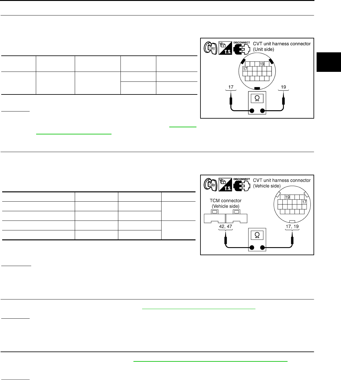
DTC P0710 CVT FLUID TEMPERATURE SENSOR CIRCUIT
CVT-91
D
E
F
G
H
I
J
K
L
M
A
B
CVT
Revision: 2006 August 2006 Murano
3. CHECK CVT FLUID TEMPERATURE SENSOR
1. Turn ignition switch OFF.
2. Disconnect CVT unit harness connector.
3. Check resistance between CVT unit harness connector termi-
nals.
4. Reinstall any part removed.
OK or NG
OK >> GO TO 4.
NG >> Replace the transaxle assembly. Refer to CVT-229,
"Removal and Installation" .
4. CHECK HARNESS BETWEEN TCM AND CVT FLUID TEMPERATURE SENSOR
1. Turn ignition switch OFF.
2. Disconnect the TCM connector and CVT unit harness connector.
3. Check continuity between TCM connector terminals and CVT
unit harness connector terminals.
4. If OK, check harness for short to ground and short to power.
5. Reinstall any part removed.
OK or NG
OK >> GO TO 5.
NG >> Repair or replace damaged parts.
5. CHECK DTC
Perform “DTC Confirmation Procedure”. Refer to CVT-88, "DTC Confirmation Procedure" .
OK or NG
OK >> INSPECTION END
NG >> GO TO 6.
6. CHECK TCM
1. Check TCM input/output signals. Refer to CVT-57, "TCM Input/Output Signal Reference Values" .
2. If NG, re-check TCM pin terminals for damage or loose connection with harness connector.
OK or NG
OK >> INSPECTION END
NG >> Repair or replace damaged parts.
Name Connector Terminal Tempera-
ture °C (°F)
Resistance
(Approx.)
CVT fluid
tempera-
ture sensor
F6 17 - 19
20 (68) 6.5 kΩ
80 (176) 0.9 kΩ
SCIA4679E
Item Connector Terminal Continuity
TCM connector F104 42 Yes
CVT unit harness connector F6 19
TCM connector F104 47 Yes
CVT unit harness connector F6 17
SCIA4680E
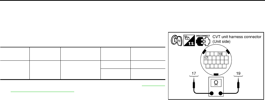
CVT-92
DTC P0710 CVT FLUID TEMPERATURE SENSOR CIRCUIT
Revision: 2006 August 2006 Murano
Component Inspection NCS00148
CVT FLUID TEMPERATURE SENSOR
1. Turn ignition switch OFF.
2. Disconnect CVT unit harness connector.
3. Check resistance between CVT unit harness connector termi-
nals.
4. If NG, replace the transaxle assembly. Refer to CVT-229,
"Removal and Installation" .
Name Connector Terminal Tempera-
ture °C (°F)
Resistance
(Approx.)
CVT fluid
tempera-
ture sensor
F6 17 - 19
20 (68) 6.5 kΩ
80 (176) 0.9 kΩ
SCIA4679E
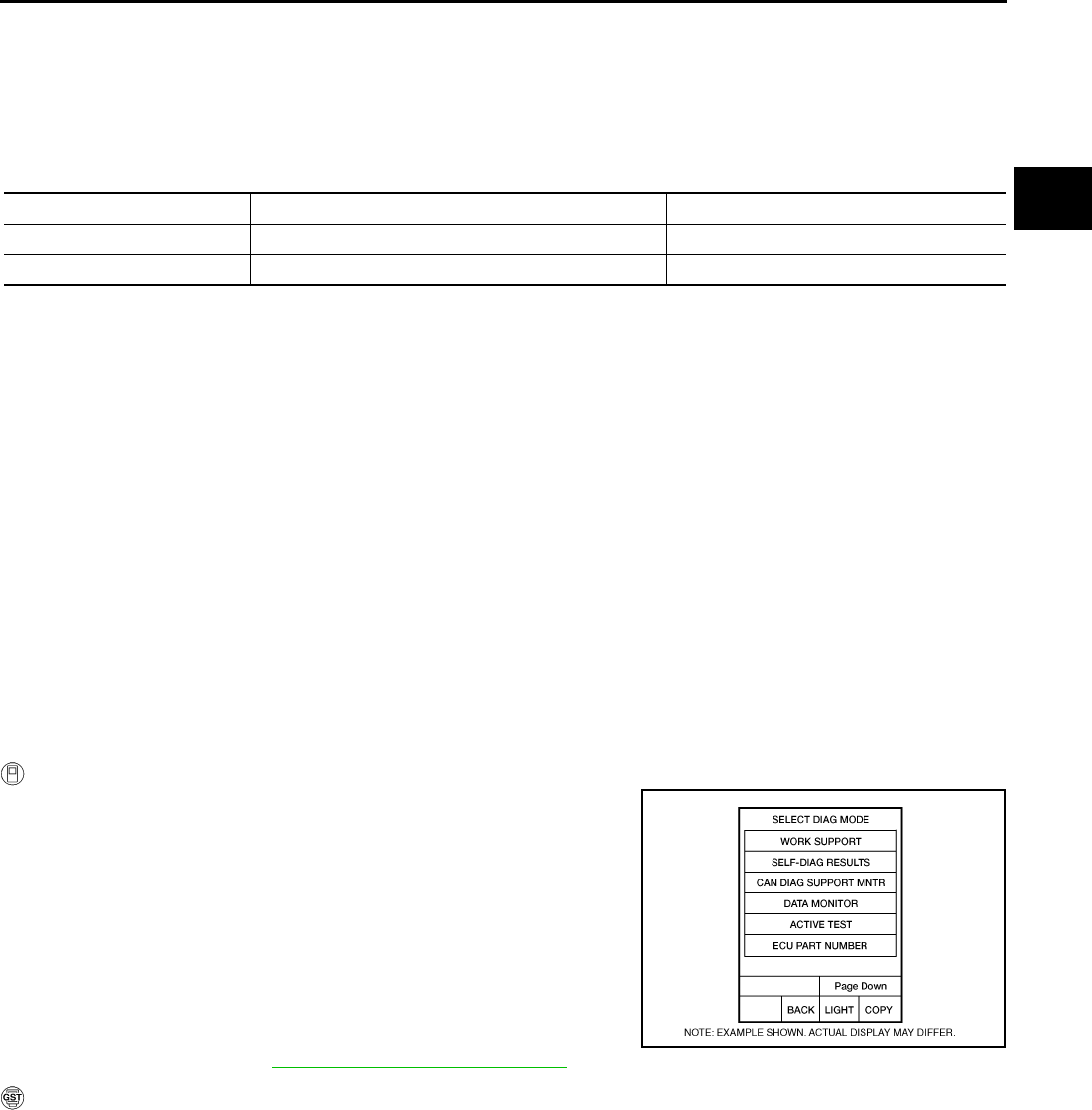
DTC P0715 INPUT SPEED SENSOR CIRCUIT (PRI SPEED SENSOR)
CVT-93
D
E
F
G
H
I
J
K
L
M
A
B
CVT
Revision: 2006 August 2006 Murano
DTC P0715 INPUT SPEED SENSOR CIRCUIT (PRI SPEED SENSOR) PFP:31935
Description NCS00149
The input speed sensor (primary speed sensor) detects the primary pulley revolution speed and sends a sig-
nal to the TCM.
CONSULT-II Reference Value NCS0014A
Remarks: Specification data are reference values.
On Board Diagnosis Logic NCS0014B
●This is an OBD-II self-diagnostic item.
●Diagnostic trouble code “P0715 INPUT SPD SEN/CIRC” with CONSULT-II is detected when TCM does
not receive the proper signal from the sensor.
Possible Cause NCS0014C
●Harness or connectors
(Sensor circuit is open or shorted.)
●Input speed sensor (Primary speed sensor)
DTC Confirmation Procedure NCS0014D
CAUTION:
Always drive vehicle at a safe speed.
NOTE:
If “DTC Confirmation Procedure” has been previously performed, always turn ignition switch OFF and
wait at least 10 seconds before performing the next test.
After the repair, touch “ERASE” on “SELF-DIAG RESULTS” and then perform the following procedure to con-
firm the malfunction is eliminated.
WITH CONSULT-II
1. Turn ignition switch ON and select “DATA MONITOR” mode for
“TRANSMISSION” with CONSULT-II.
2. Start engine and maintain the following conditions for at least 5
consecutive seconds.
VEHICLE SPEED: 10 km/h (6 MPH) or more
ACC PEDAL OPEN: More than 1.0/8
RANGE: “D” position
ENG SPEED: 450 rpm or more
Driving location: Driving the vehicle uphill (increased
engine load) will help maintain the driving conditions
required for this test.
3. If DTC is detected, go to CVT-95, "Diagnostic Procedure" .
WITH GST
Follow the procedure “WITH CONSULT-II”.
Item name Condition Display value
ENG SPEED SIG Engine running Closely matches the tachometer reading.
PRI SPEED SEN During driving (lock-up ON) Approximately matches the engine speed.
BCIA0031E

CVT-94
DTC P0715 INPUT SPEED SENSOR CIRCUIT (PRI SPEED SENSOR)
Revision: 2006 August 2006 Murano
Wiring Diagram — CVT — PRSCVT NCS0014E
TCWA0254E
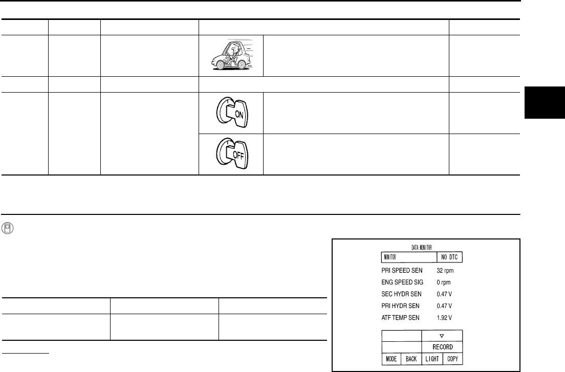
DTC P0715 INPUT SPEED SENSOR CIRCUIT (PRI SPEED SENSOR)
CVT-95
D
E
F
G
H
I
J
K
L
M
A
B
CVT
Revision: 2006 August 2006 Murano
TCM terminal data are reference values, measured between each terminal and ground.
Diagnostic Procedure NCS0014F
1. CHECK INPUT SIGNALS
With CONSULT-II
1. Start engine.
2. Select “ECU INPUT SIGNALS” in “DATA MONITOR” mode for
“TRANSMISSION” with CONSULT-II.
3. Start vehicle and read out the value of “PRI SPEED SEN”.
OK or NG
OK >> GO TO 6.
NG >> GO TO 2.
Terminal Wire color Item Condition Data (Approx.)
38 LG
Input speed sensor
(Primary speed sen-
sor)
When driving [“D” position, 20 km/h (12
MPH)]. 600 Hz
42 W/R Sensor ground Always 0 V
46 L/O Sensor power
— 4.5 - 5.5 V
— 0 V
Item name Condition Display value
PRI SPEED SEN During driving (lock-up
ON)
Approximately matches
the engine speed.
SCIA2278E
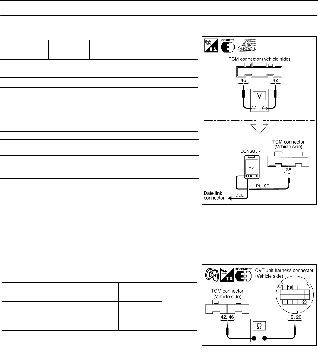
CVT-96
DTC P0715 INPUT SPEED SENSOR CIRCUIT (PRI SPEED SENSOR)
Revision: 2006 August 2006 Murano
2. CHECK INPUT SPEED SENSOR (PRIMARY SPEED SENSOR)
1. Start engine.
2. Check voltage between TCM connector terminals.
3. Check the pulse with CONSULT-II or oscilloscope, when vehicle
cruises.
OK or NG
OK >> GO TO 6.
NG - 1 >> Battery voltage is not supplied: GO TO 3.
NG - 2 >> Battery voltage is supplied, but there is a malfunction in
the frequency: GO TO 4.
3. CHECK HARNESS BETWEEN TCM AND CVT UNIT HARNESS CONNECTOR (SENSOR POWER
AND SENSOR GROUND)
1. Turn ignition switch OFF.
2. Disconnect TCM connector and CVT unit harness connector.
3. Check continuity between TCM connector terminals and CVT
unit harness connector terminals.
4. If OK, check harness for short to ground and short to power.
5. Reinstall any part removed.
OK or NG
OK >> GO TO 6.
NG >> Repair open circuit or short to ground or short to power in harness or connectors.
Item Connector Terminal Data (Approx.)
TCM connector F104 46 - 42 4.5 - 5.5 V
Name Condition
Input speed sensor
(Primary speed
sensor)
When running at 20 km/h (12 MPH) in “D” position with the
closed throttle position signal OFF, use the CONSULT-II
pulse frequency measuring function.
CAUTION:
Connect the data link connector to the vehicle-side diag-
nosis connector.
Item Connector Terminal Name Data
(Approx.)
TCM connector F104 38
Input speed sen-
sor (Primary
speed sensor)
600 Hz
SCIA1915E
Item Connector Terminal Continuity
TCM connector F104 42 Yes
CVT unit harness connector F6 19
TCM connector F104 46 Yes
CVT unit harness connector F6 20
SCIA4681E
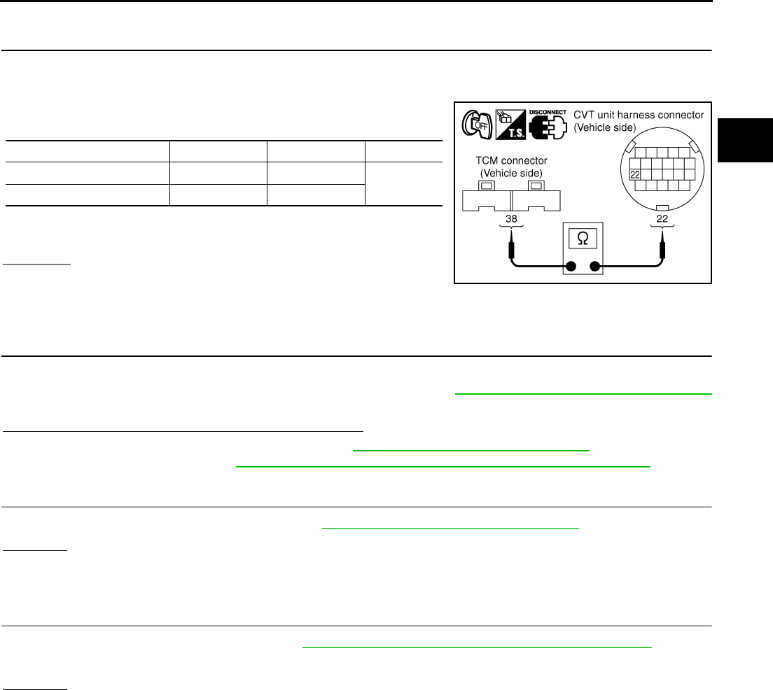
DTC P0715 INPUT SPEED SENSOR CIRCUIT (PRI SPEED SENSOR)
CVT-97
D
E
F
G
H
I
J
K
L
M
A
B
CVT
Revision: 2006 August 2006 Murano
4. CHECK HARNESS BETWEEN TCM AND CVT UNIT HARNESS CONNECTOR [INPUT SPEED SEN-
SOR (PRIMARY SPEED SENSOR)]
1. Turn ignition switch OFF.
2. Disconnect TCM connector and CVT unit harness connector.
3. Check continuity between TCM connector terminal and CVT unit
harness connector terminal.
4. If OK, check harness for short to ground and short to power.
5. Reinstall any part removed.
OK or NG
OK >> GO TO 5.
NG >> Repair open circuit or short to ground or short to power
in harness or connectors.
5. CHECK THE TCM SHORT
Replace same type TCM, perform self-diagnosis check. Erase self-diagnostic results and then drive the vehi-
cle [10 km/h (6 MPH) or more], perform self-diagnosis check. Refer to CVT-93, "DTC Confirmation Procedure"
.
Is the “P0715 INPUT SPD SEN/CIRC” detected again?
YES >> Replace the transaxle assembly. Refer to CVT-229, "Removal and Installation" .
NO >> Replace TCM. Refer to CVT-9, "Precautions for TCM and CVT Assembly Replacement" .
6. CHECK DTC
Perform “DTC Confirmation Procedure”. Refer to CVT-93, "DTC Confirmation Procedure" .
OK or NG
OK >> INSPECTION END
NG >> GO TO 7.
7. CHECK TCM
1. Check TCM input/output signals. Refer to CVT-57, "TCM Input/Output Signal Reference Values" .
2. If NG, re-check TCM pin terminals for damage or loose connection with harness connector.
OK or NG
OK >> INSPECTION END
NG >> Repair or replace damaged parts.
Item Connector Terminal Continuity
TCM connector F104 38 Yes
CVT unit harness connector F6 22
SCIA4682E
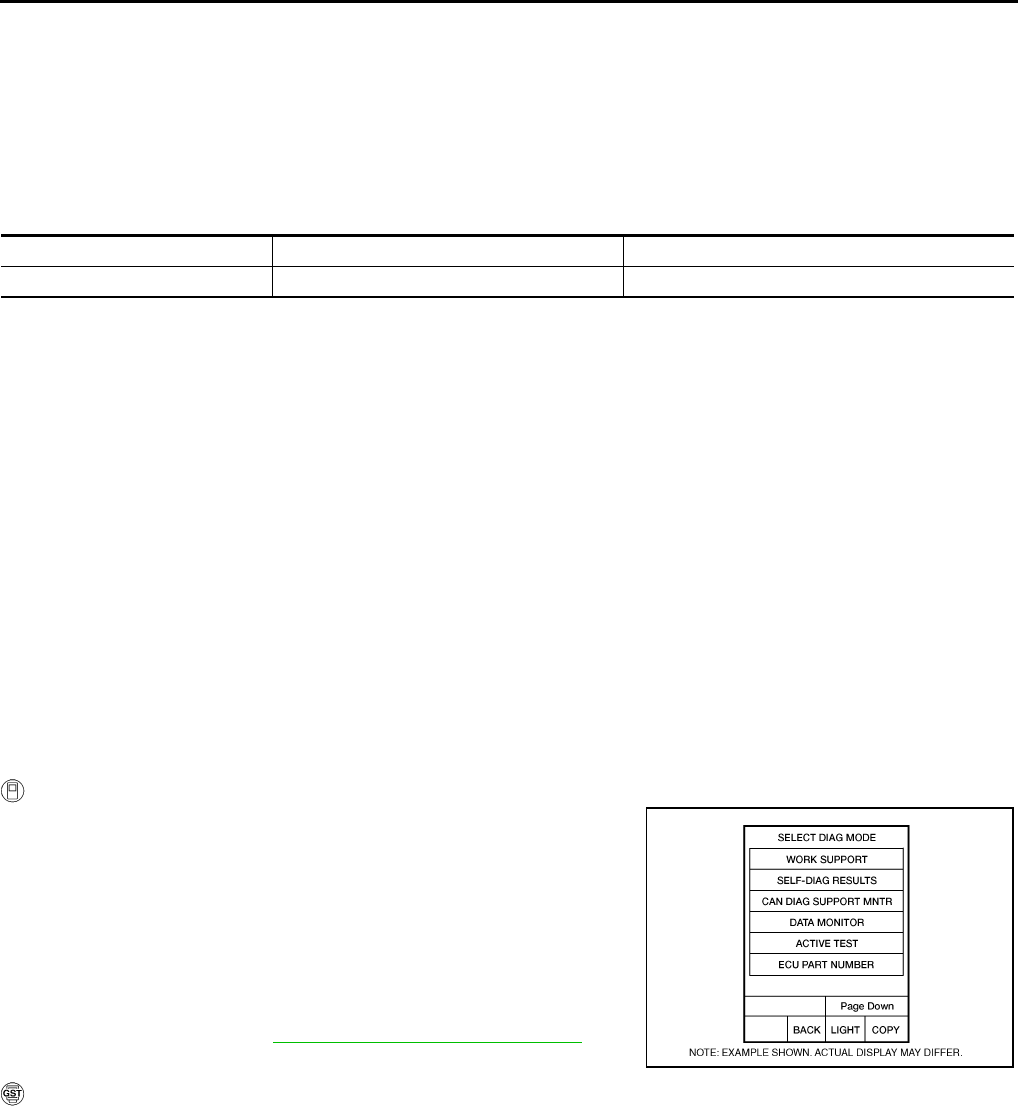
CVT-98
DTC P0720 VEHICLE SPEED SENSOR CVT (SECONDARY SPEED SENSOR)
Revision: 2006 August 2006 Murano
DTC P0720 VEHICLE SPEED SENSOR CVT (SECONDARY SPEED SENSOR)
PFP:31935
Description NCS0014G
The vehicle speed sensor CVT [output speed sensor (secondary speed sensor)] detects the revolution of the
CVT output shaft and emits a pulse signal. The pulse signal is sent to the TCM, which converts it into vehicle
speed.
CONSULT-II Reference Value NCS0014H
Remarks: Specification data are reference values.
On Board Diagnosis Logic NCS0014I
●This is an OBD-II self-diagnostic item.
●Diagnostic trouble code “P0720 VEH SPD SEN/CIR AT” with CONSULT-II is detected TCM does not
receive the proper signal from the sensor.
Possible Cause NCS0014J
●Harness or connectors
(Sensor circuit is open or shorted.)
●Output speed sensor (Secondary speed sensor)
DTC Confirmation Procedure NCS0014K
CAUTION:
Always drive vehicle at a safe speed.
NOTE:
If “DTC Confirmation Procedure” has been previously performed, always turn ignition switch OFF and
wait at least 10 seconds before performing the next test.
After the repair, touch “ERASE” on “SELF-DIAG RESULTS” and then perform the following procedure to con-
firm the malfunction is eliminated.
WITH CONSULT-II
1. Turn ignition switch ON and select “DATA MONITOR” mode for
“TRANSMISSION” with CONSULT-II.
2. Start engine and maintain the following conditions for at least 12
consecutive seconds.
ACC PEDAL OPEN: More than 1.0/8
RANGE: “D” position
Driving location: Driving the vehicle uphill (increased
engine load) will help maintain the driving conditions
required for this test.
3. If DTC is detected, go to CVT-100, "Diagnostic Procedure" .
WITH GST
Follow the procedure “WITH CONSULT-II”.
Item name Condition Display value
VSP SENSOR During driving Approximately matches the speedometer reading.
BCIA0031E
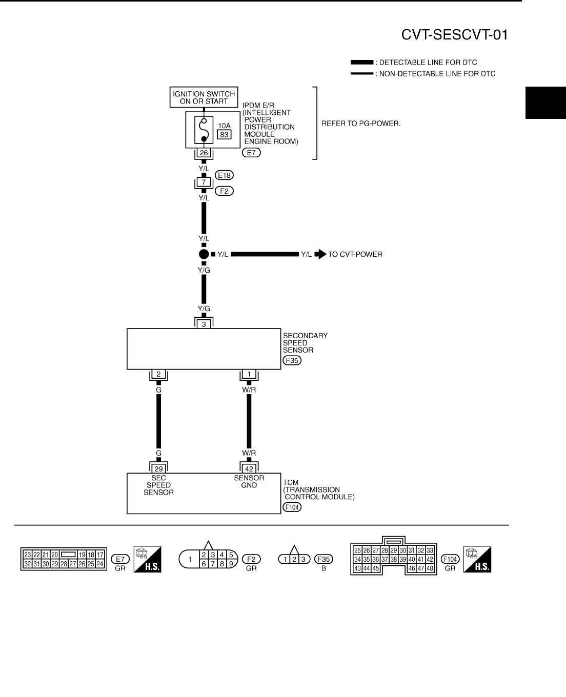
DTC P0720 VEHICLE SPEED SENSOR CVT (SECONDARY SPEED SENSOR)
CVT-99
D
E
F
G
H
I
J
K
L
M
A
B
CVT
Revision: 2006 August 2006 Murano
Wiring Diagram — CVT — SESCVT NCS0014L
TCWA0248E
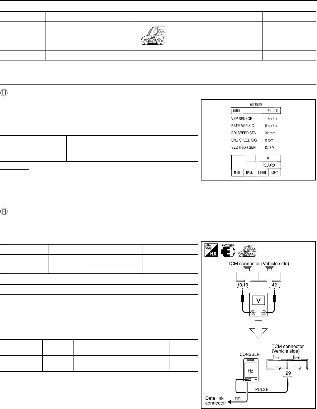
CVT-100
DTC P0720 VEHICLE SPEED SENSOR CVT (SECONDARY SPEED SENSOR)
Revision: 2006 August 2006 Murano
TCM terminal data are reference values, measured between each terminal and ground.
Diagnostic Procedure NCS0014M
1. CHECK INPUT SIGNAL
With CONSULT-II
1. Start engine.
2. Select “ECU INPUT SIGNALS” in “DATA MONITOR” mode for
“TRANSMISSION” with CONSULT-II.
3. Start vehicle and read out the value of “VSP SENSOR”.
OK or NG
OK >> GO TO 8.
NG >> GO TO 2.
2. CHECK SECONDARY SPEED SENSOR
With CONSULT-II
1. Start engine.
2. Check power supply to output speed sensor (secondary speed sensor) by voltage between TCM connec-
tor terminals 10, 19 and 42. Refer to CVT-41, "Circuit Diagram" .
3. If OK, check the pulse when vehicle cruises.
OK or NG
OK >> GO TO 8.
NG >> GO TO 3.
Terminal Wire color Item Condition Data (Approx.)
29 G
Output speed
sensor (Second-
ary speed sen-
sor)
When driving [“D” position, 20 km/h
(12 MPH)]. 300 Hz
42 W/R Sensor ground Always 0 V
Item name Condition Display value
VSP SENSOR During driving Approximately matches
the speedometer reading.
SCIA2279E
Item Connector Terminal Data (Approx.)
TCM connector F103, F104 10 - 42 Battery voltage
19 - 42
Name Condition
Output speed sen-
sor (Secondary
speed sensor)
When running at 20 km/h (12 MPH) in “D” position, use the
CONSULT-II pulse frequency measuring function.
CAUTION:
Connect the data link connector to the vehicle-side diag-
nosis connector.
Item Connector Terminal Name Data
(Approx.)
TCM connector F104 29 Output speed sensor
(Secondary speed sensor) 300 Hz
SCIA2344E
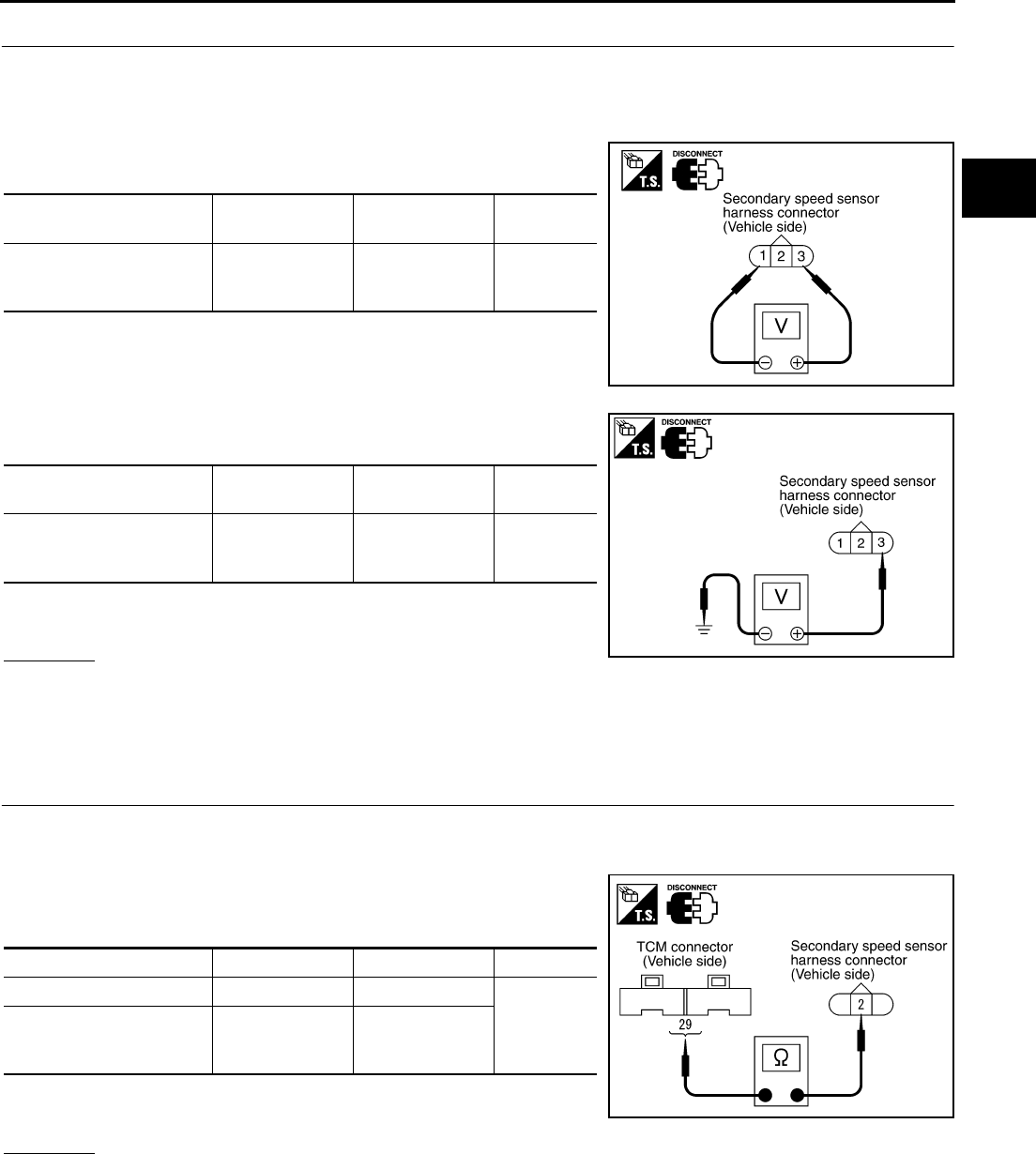
DTC P0720 VEHICLE SPEED SENSOR CVT (SECONDARY SPEED SENSOR)
CVT-101
D
E
F
G
H
I
J
K
L
M
A
B
CVT
Revision: 2006 August 2006 Murano
3. CHECK POWER AND SENSOR GROUND
1. Turn ignition switch OFF.
2. Disconnect the output speed sensor (secondary speed sensor) harness connector.
3. Turn ignition switch ON.
4. Check voltage between output speed sensor (secondary speed
sensor) harness connector terminals.
5. Check voltage between output speed sensor (secondary speed
sensor) harness connector terminal and ground.
6. If OK, check harness for short to ground and short to power.
7. Reinstall any part removed.
OK or NG
OK >> GO TO 4.
NG - 1 >> Battery voltage is not supplied between terminals 1 and 3, terminals 1 and ground.: GO TO 6.
NG - 2 >> Battery voltage is not supplied between terminals 1 and 3 only.: GO TO 7.
4. CHECK HARNESS BETWEEN TCM AND OUTPUT SPEED SENSOR (SECONDARY SPEED SEN-
SOR)
1. Turn ignition switch OFF.
2. Disconnect TCM connector and output speed sensor (secondary speed sensor) harness connector.
3. Check continuity between TCM connector terminal and output
speed sensor (secondary speed sensor) harness connector ter-
minal.
4. If OK, check harness for short to ground and short to power.
5. Reinstall any part removed.
OK or NG
OK >> GO TO 5.
NG >> Repair open circuit or short to ground or short to power in harness or connectors.
Item Connector Terminal Data
(Approx.)
Output speed sensor (Sec-
ondary speed sensor) har-
ness connector
F35 1 - 3 Battery volt-
age
SCIA2345E
Item Connector Terminal Data
(Approx.)
Output speed sensor (Sec-
ondary speed sensor) har-
ness connector
F35 3 - Ground Battery volt-
age
SCIA2346E
Item Connector Terminal Continuity
TCM connector F104 29
Yes
Output speed sensor (Sec-
ondary speed sensor) har-
ness connector
F35 2
SCIA1967E
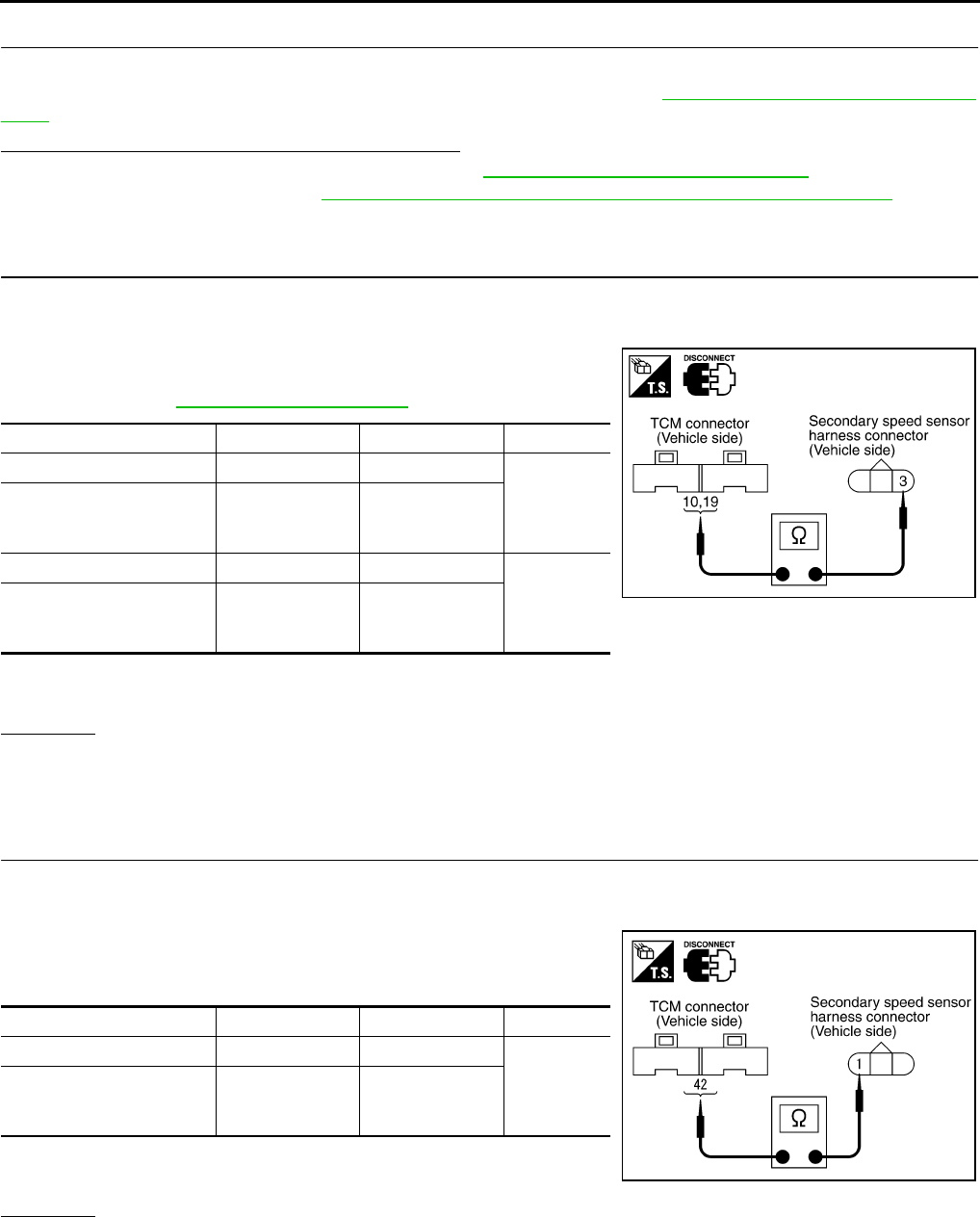
CVT-102
DTC P0720 VEHICLE SPEED SENSOR CVT (SECONDARY SPEED SENSOR)
Revision: 2006 August 2006 Murano
5. CHECK THE TCM SHORT
Replace same type TCM, perform self-diagnosis check. Erase self-diagnostic results and them drive the vehi-
cle [more than 40 km/h (25 MPH)], perform self-diagnosis check. Refer to CVT-98, "DTC Confirmation Proce-
dure" .
Is “P0720 VEH SPD SEN/CIR AT” detected again?
YES >> Replace the transaxle assembly. Refer to CVT-229, "Removal and Installation" .
NO >> Replace TCM. Refer to CVT-9, "Precautions for TCM and CVT Assembly Replacement" .
6. CHECK HARNESS BETWEEN TCM AND OUTPUT SPEED SENSOR (SECONDARY SPEED SEN-
SOR) (POWER)
1. Turn ignition switch OFF.
2. Disconnect TCM connector and output speed sensor (secondary speed sensor) harness connector.
3. Check continuity between TCM connector terminals and output
speed sensor (secondary speed sensor) harness connector ter-
minal. Refer to CVT-41, "Circuit Diagram" .
4. If OK, check harness for short to ground and short to power.
5. Reinstall any part removed.
OK or NG
OK >> 10 A fuse (No. 83, located in the IPDM E/R) or ignition switch are malfunctioning.
NG >> Repair open circuit or short to ground or short to power in harness or connectors.
7. CHECK HARNESS BETWEEN TCM AND OUTPUT SPEED SENSOR (SECONDARY SPEED SEN-
SOR) (SENSOR GROUND)
1. Turn ignition switch OFF.
2. Disconnect TCM connector and output speed sensor (secondary speed sensor) harness connector.
3. Check continuity between TCM connector terminal and output
speed sensor (secondary speed sensor) harness connector ter-
minal.
4. If OK, check harness for short to ground and short to power.
5. Reinstall any part removed.
OK or NG
OK >> GO TO 8.
NG >> Repair open circuit or short to ground or short to power in harness or connectors.
Item Connector Terminal Continuity
TCM connector F103 10
Yes
Output speed sensor (Sec-
ondary speed sensor) har-
ness connector
F35 3
TCM connector F103 19
Yes
Output speed sensor (Sec-
ondary speed sensor) har-
ness connector
F35 3
SCIA2369E
Item Connector Terminal Continuity
TCM connector F104 42
Yes
Output speed sensor (Sec-
ondary speed sensor) har-
ness connector
F35 1
SCIA2347E

DTC P0720 VEHICLE SPEED SENSOR CVT (SECONDARY SPEED SENSOR)
CVT-103
D
E
F
G
H
I
J
K
L
M
A
B
CVT
Revision: 2006 August 2006 Murano
8. CHECK DTC
Perform “DTC Confirmation Procedure”. Refer to CVT-98, "DTC Confirmation Procedure" .
OK or NG
OK >> INSPECTION END
NG >> GO TO 9.
9. CHECK TCM
1. Check TCM input/output signals. Refer to CVT-57, "TCM Input/Output Signal Reference Values" .
2. If NG, re-check TCM pin terminals for damage or loose connection with harness connector.
OK or NG
OK >> INSPECTION END
NG >> Repair or replace damaged parts.
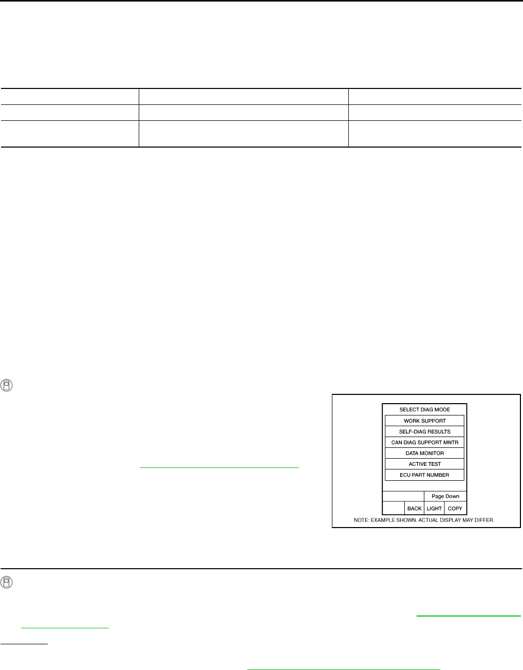
CVT-104
DTC P0725 ENGINE SPEED SIGNAL
Revision: 2006 August 2006 Murano
DTC P0725 ENGINE SPEED SIGNAL PFP:24825
Description NCS0014N
The engine speed signal is sent from the ECM to the TCM.
CONSULT-II Reference Value NCS0014O
Remarks: Specification data are reference values.
On Board Diagnosis Logic NCS0014P
●This is not an OBD-II self-diagnostic item.
●Diagnostic trouble code “P0725 ENGINE SPEED SIG” with CONSULT-II is detected when TCM does not
receive the engine speed signal (input by CAN communication) from ECM.
Possible Cause NCS0014Q
Harness or connectors
(The ECM to the TCM circuit is open or shorted.)
DTC Confirmation Procedure NCS0014R
CAUTION:
Always drive vehicle at a safe speed.
NOTE:
If “DTC Confirmation Procedure” has been previously performed, always turn ignition switch OFF and
wait at least 10 seconds before performing the next test.
After the repair, touch “ERASE” on “SELF-DIAG RESULTS” and then perform the following procedure to con-
firm the malfunction is eliminated.
WITH CONSULT-II
1. Turn ignition switch ON and select “DATA MONITOR” mode for
“TRANSMISSION” with CONSULT-II.
2. Start engine and maintain the following conditions for at least 10
consecutive seconds.
PRI SPEED SEN: More than 1000 rpm
3. If DTC is detected, go to CVT-104, "Diagnostic Procedure" .
Diagnostic Procedure NCS0014S
1. CHECK DTC WITH ECM
With CONSULT-II
1. Turn ignition switch ON. (Do not start engine.)
2. Select “SELF-DIAG RESULTS” mode for “ENGINE” with CONSULT-II. Refer to EC-115, "SELF-DIAG
RESULTS MODE" .
OK or NG
OK >> GO TO 2.
NG >> Check the DTC detected item. Refer to EC-115, "SELF-DIAG RESULTS MODE" .
Item name Condition Display value
ENG SPEED SIG Engine running Closely matches the tachometer reading.
ACC PEDAL OPEN Released accelerator pedal - Fully depressed accel-
erator pedal 0.0/8 - 8.0/8
BCIA0031E
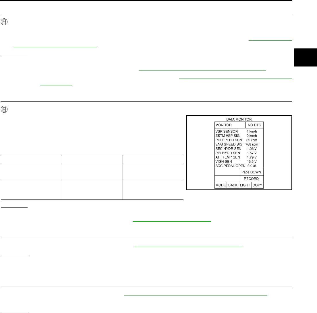
DTC P0725 ENGINE SPEED SIGNAL
CVT-105
D
E
F
G
H
I
J
K
L
M
A
B
CVT
Revision: 2006 August 2006 Murano
2. CHECK DTC WITH TCM
With CONSULT-II
1. Turn ignition switch ON. (Do not start engine.)
2. Select “SELF-DIAG RESULTS” mode for “TRANSMISSION” with CONSULT-II. Refer to CVT-65, "SELF-
DIAGNOSTIC RESULT MODE" .
OK or NG
OK >> GO TO 3.
NG >> Check the DTC detected item. Refer to CVT-65, "SELF-DIAGNOSTIC RESULT MODE" .
●If DTC of CAN communication line is detected, go to CVT-72, "DTC U1000 CAN COMMUNICA-
TION LINE" .
3. CHECK INPUT SIGNALS
With CONSULT-II
1. Start engine.
2. Select “ECU INPUT SIGNALS” in “DATA MONITOR” mode for
“TRANSMISSION” with CONSULT-II.
3. While monitoring “ENG SPEED SIG”, check for engine speed
change corresponding to “ACC PEDAL OPEN”.
OK or NG
OK >> GO TO 4.
NG >> Check ignition signal circuit. Refer to EC-640, "IGNITION SIGNAL" .
4. CHECK DTC
Perform “DTC Confirmation Procedure”. Refer to CVT-104, "DTC Confirmation Procedure" .
OK or NG
OK >> INSPECTION END
NG >> GO TO 5.
5. CHECK TCM
1. Check TCM input/output signals. Refer to CVT-57, "TCM Input/Output Signal Reference Values" .
2. If NG, re-check TCM pin terminals for damage or loose connection with harness connector.
OK or NG
OK >> INSPECTION END
NG >> Repair or replace damaged parts.
Item name Condition Display value
ENG SPEED SIG Engine running Closely matches the
tachometer reading.
ACC PEDAL OPEN
Released accelerator
pedal - Fully depressed
accelerator pedal
0.0/8 - 8.0/8 SCIA4504E
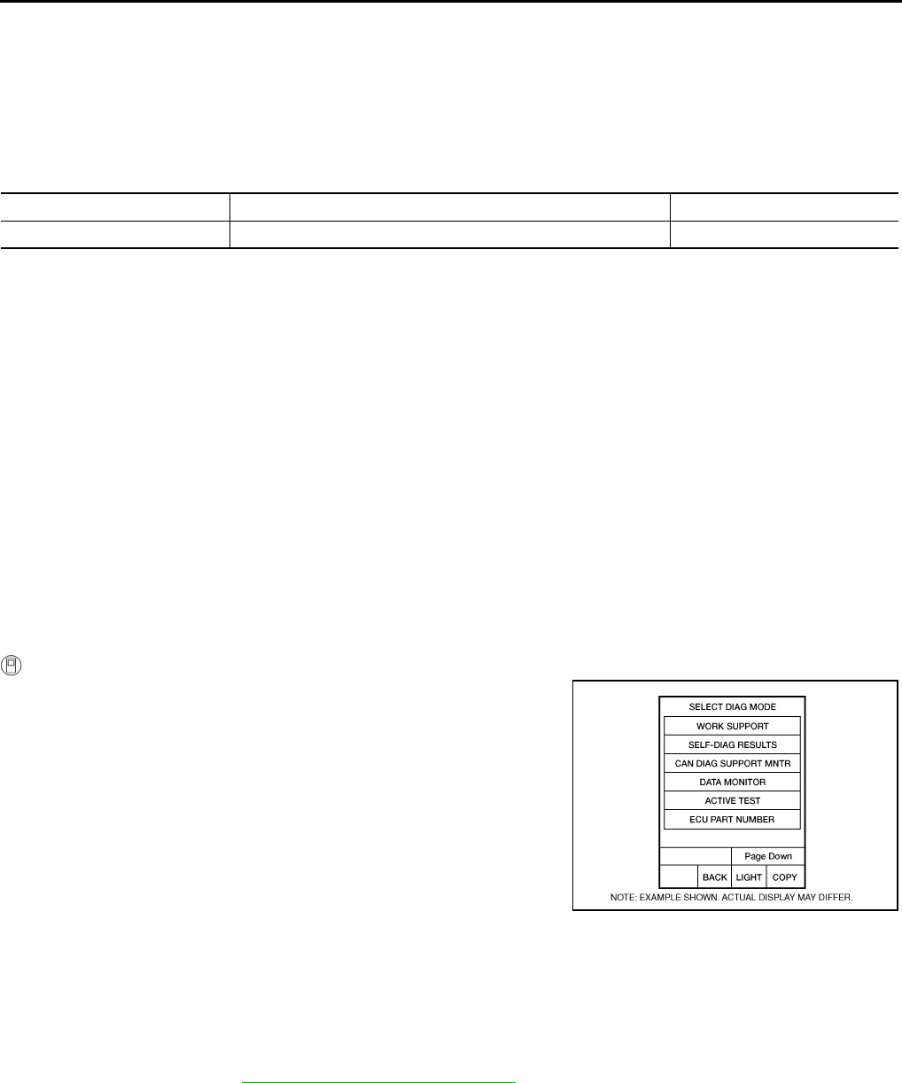
CVT-106
DTC P0730 BELT DAMAGE
Revision: 2006 August 2006 Murano
DTC P0730 BELT DAMAGE PFP:31935
Description NCS0014T
TCM selects the gear ratio using the engine load (throttle position), the primary pulley revolution speed, and
the secondary pulley revolution speed as input signal. Then it changes the operating pressure of the primary
pulley and the secondary pulley and changes the groove width of the pulley.
CONSULT-II Reference Value NCS0014U
Remarks: Specification data are reference values.
On Board Diagnosis Logic NCS0014V
●This is not an OBD-II self-diagnostic item.
●TCM calculates the actual gear ratio with input speed sensor (primary speed sensor) and output speed
sensor (secondary speed sensor).
●Diagnostic trouble code “P0730 BELT DAMG” with CONSULT-II is detected, when TCM receives an unex-
pected gear ratio signal.
Possible Cause NCS0014W
Transaxle assembly
DTC Confirmation Procedure NCS0014X
CAUTION:
Always drive vehicle at a safe speed.
NOTE:
If “DTC Confirmation Procedure” has been previously performed, always turn ignition switch OFF and
wait at least 10 seconds before performing the next test.
After the repair, perform the following procedure to confirm the malfunction is eliminated.
WITH CONSULT-II
1. Turn ignition switch ON and select “DATA MONITOR” mode for
“TRANSMISSION” with CONSULT-II.
2. Make sure that output voltage of CVT fluid temperature sensor
is within the range below.
ATF TEMP SEN: 1.0 - 2.0 V
If out of range, drive the vehicle to decrease the voltage
(warm up the fluid) or stop engine to increase the voltage
(cool down the fluid)
3. Select “DATA MONITOR” mode for “TRANSMISSION” with
CONSULT-II.
4. Start engine and maintain the following conditions for at least 30
consecutive seconds.
TEST START FROM 0 km/h (0 MPH)
CONSTANT ACCELERATION: Keep 30 sec or more
VEHICLE SPEED: 10 km/h (6 MPH) or more
ACC PEDAL OPEN: More than 1.0/8
RANGE: “D” position
ENG SPEED: 450 rpm or more
5. If DTC is detected, go to CVT-107, "Diagnostic Procedure" .
Item name Condition Display value (Approx.)
GEAR RATIO During driving 2.37 - 0.43
BCIA0031E

DTC P0730 BELT DAMAGE
CVT-107
D
E
F
G
H
I
J
K
L
M
A
B
CVT
Revision: 2006 August 2006 Murano
Diagnostic Procedure NCS0014Y
1. CHECK DTC
Perform “DTC Confirmation Procedure”. Refer to CVT-106, "DTC Confirmation Procedure" .
Are any DTC displayed?
YES - 1>> DTC except for “P0730 BELT DAMG” is displayed: Go to Check the DTC detected item. Refer to
CVT-65, "SELF-DIAGNOSTIC RESULT MODE" .
YES - 2>> DTC for “P0730 BELT DAMG” is displayed: Replace the transaxle assembly. Refer to CVT-229,
"Removal and Installation" .
NO >> INSPECTION END
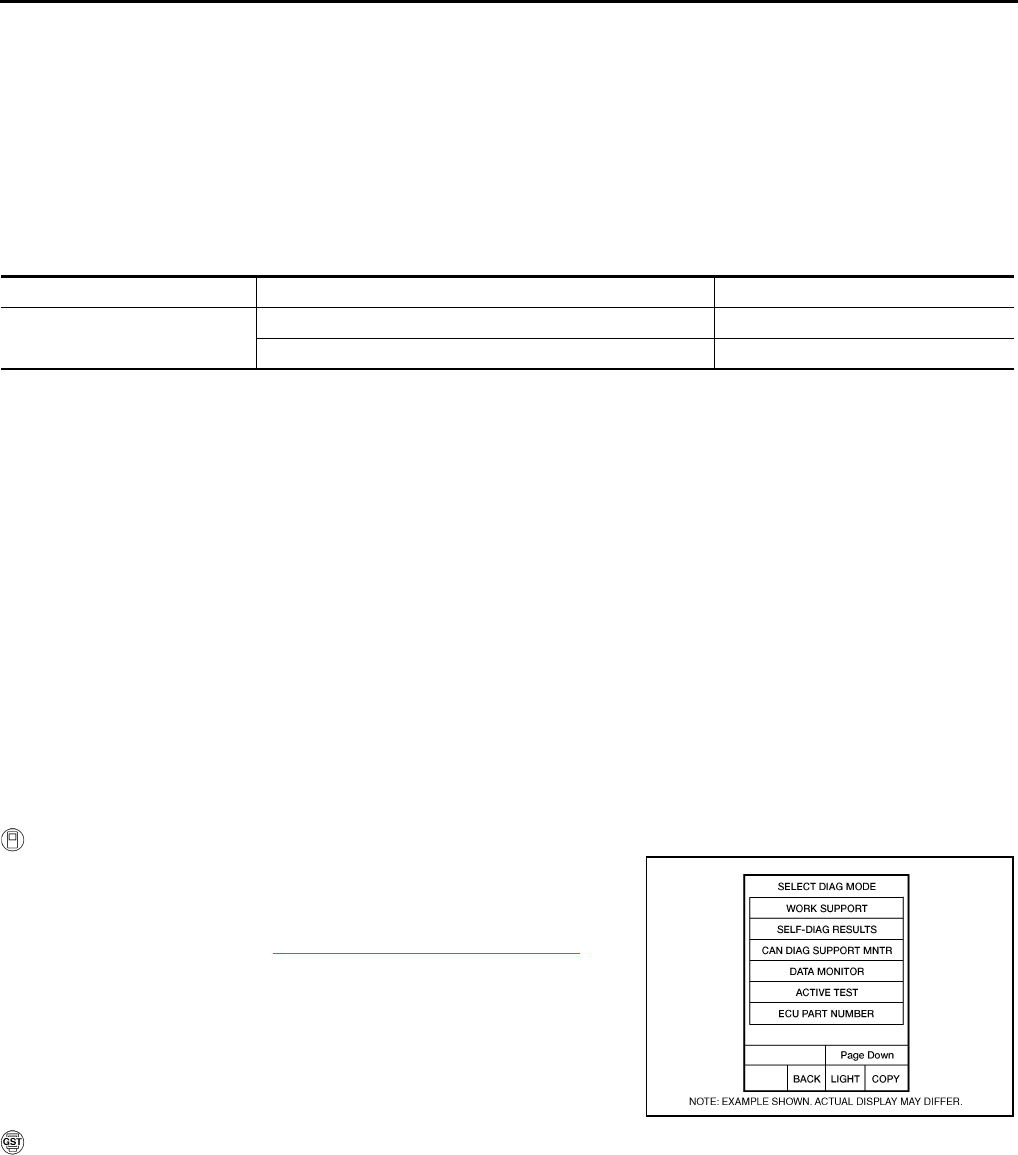
CVT-108
DTC P0740 TORQUE CONVERTER CLUTCH SOLENOID VALVE
Revision: 2006 August 2006 Murano
DTC P0740 TORQUE CONVERTER CLUTCH SOLENOID VALVE PFP:31940
Description NCS0014Z
●The torque converter clutch solenoid valve is activated by the TCM in response to signals sent from the
vehicle speed and accelerator pedal position sensors. Lock-up piston operation will then be controlled.
●Lock-up operation, however, is prohibited when CVT fluid temperature is too low.
●When the accelerator pedal is depressed (less than 2.0/8) in lock-up condition, the engine speed should
not change abruptly. If there is a big jump in engine speed, there is no lock-up.
CONSULT-II Reference Value NCS00150
Remarks: Specification data are reference values.
On Board Diagnosis Logic NCS00151
●This is an OBD-II self-diagnostic item.
●Diagnostic trouble code “P0740 TCC SOLENOID/CIRC” with CONSULT-II is detected under the following
conditions.
–TCM detects an improper voltage drop when it tries to operate the solenoid valve.
Possible Cause NCS00152
●Torque converter clutch solenoid valve
●Harness or connectors
(Solenoid circuit is open or shorted.)
DTC Confirmation Procedure NCS00153
NOTE:
If “DTC Confirmation Procedure” has been previously performed, always turn ignition switch OFF and
wait at least 10 seconds before performing the next test.
After the repair, touch “ERASE” on “SELF-DIAG RESULTS” and then perform the following procedure to con-
firm the malfunction is eliminated.
WITH CONSULT-II
1. Turn ignition switch ON. (Do not start engine.)
2. Select “DATA MONITOR” mode for “TRANSMISSION” with
CONSULT-II and wait at least 10 consecutive seconds.
3. If DTC is detected, go to CVT-110, "Diagnostic Procedure" .
WITH GST
Follow the procedure “WITH CONSULT-II”.
Item name Condition Display value (Approx.)
ISOLT1 Lock-up OFF 0.0 A
Lock-up ON 0.7 A
BCIA0031E
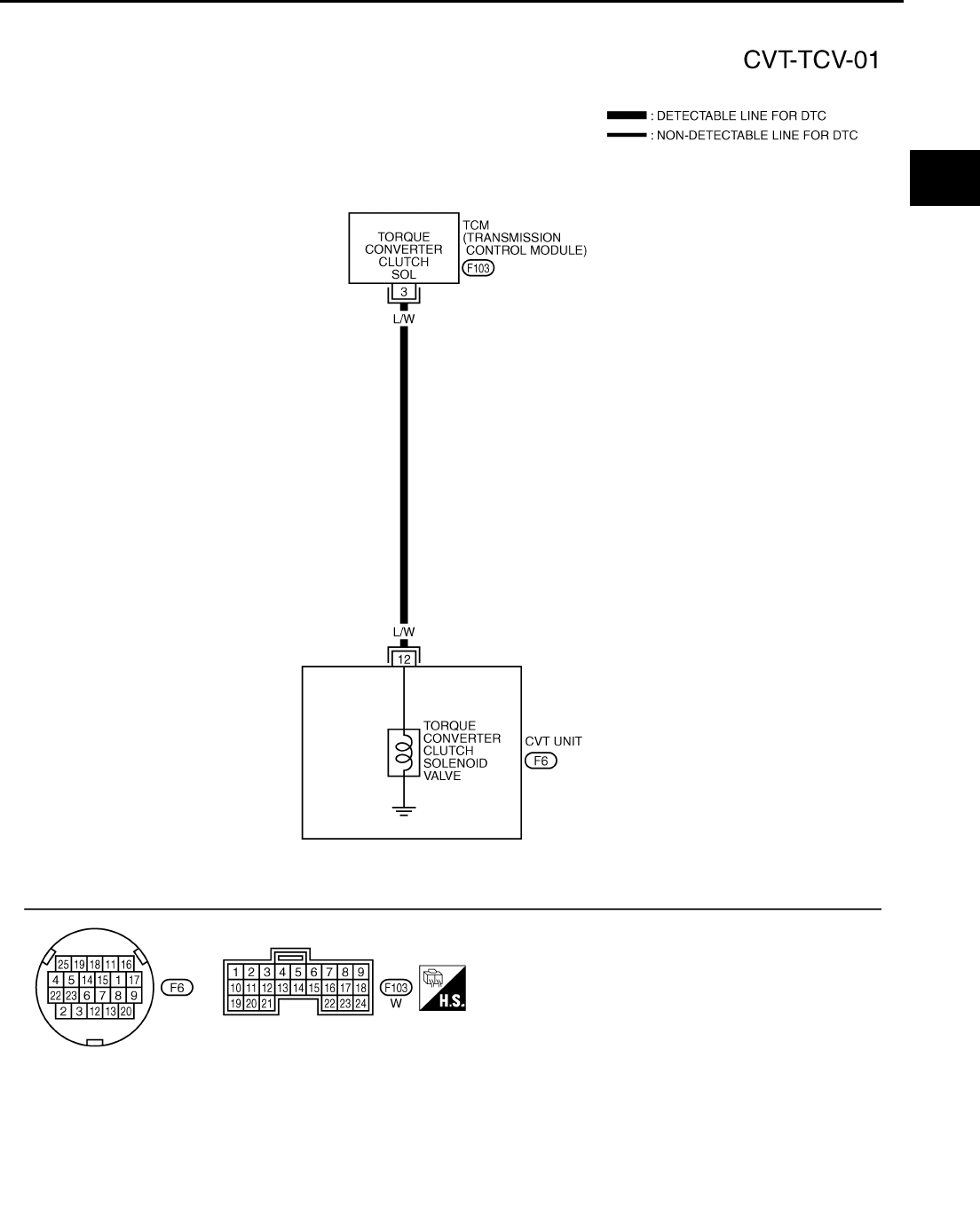
DTC P0740 TORQUE CONVERTER CLUTCH SOLENOID VALVE
CVT-109
D
E
F
G
H
I
J
K
L
M
A
B
CVT
Revision: 2006 August 2006 Murano
Wiring Diagram — CVT — TCV NCS00154
TCWA0251E
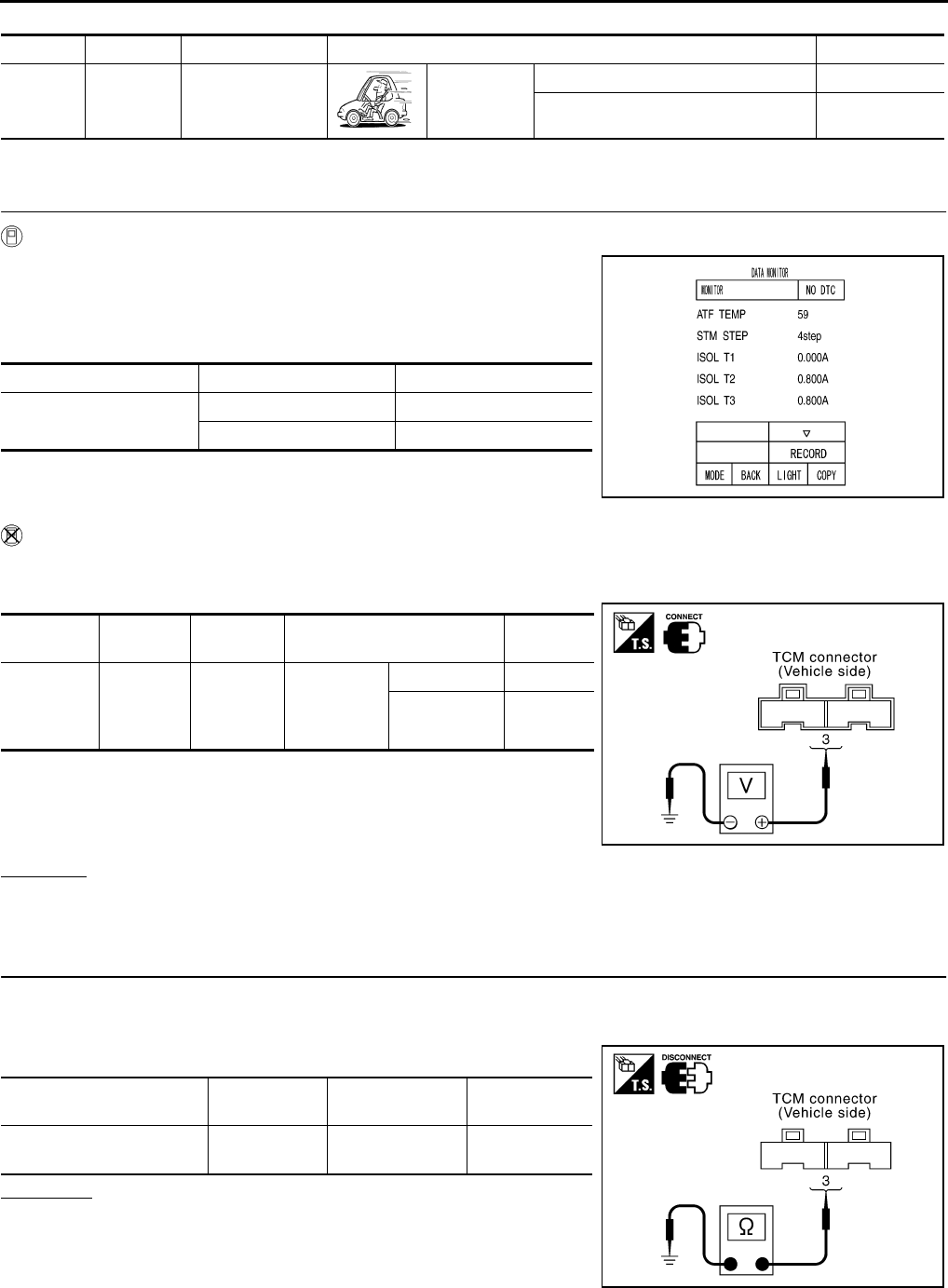
CVT-110
DTC P0740 TORQUE CONVERTER CLUTCH SOLENOID VALVE
Revision: 2006 August 2006 Murano
TCM terminal data are reference values, measured between each terminal and ground.
Diagnostic Procedure NCS00155
1. CHECK INPUT SIGNAL
With CONSULT-II
1. Start engine.
2. Select “MAIN SIGNALS” in “DATA MONITOR” mode for
“TRANSMISSION” with CONSULT-II.
3. Start vehicle and read out the value of “ISOLT1”.
Without CONSULT-II
1. Start engine.
2. Check voltage between TCM connector terminal and ground.
3. Turn ignition switch OFF.
4. Disconnect TCM connector.
5. Check if there is continuity between the connector terminal and
ground.
OK or NG
OK >> GO TO 5.
NG >> GO TO 2.
2. CHECK TORQUE CONVERTER CLUTCH SOLENOID VALVE CIRCUIT
1. Turn ignition switch OFF.
2. Disconnect TCM connector.
3. Check resistance between TCM connector terminal and ground.
OK or NG
OK >> GO TO 5.
NG >> GO TO 3.
Terminal Wire color Item Condition Data (Approx.)
3L/W
Torque converter
clutch solenoid
valve
When vehi-
cle cruises in
“D” position.
When CVT performs lock-up. 6.0 V
When CVT does not perform lock-up. 1.0 V
Item name Condition Display value (Approx.)
ISOLT1 Lock-up OFF 0.0 A
Lock-up ON 0.7 A
SCIA2349E
Name Connector Terminal Condition Voltage
(Approx.)
Torque
converter
clutch sole-
noid valve
F103 3 - Ground
When vehi-
cle cruises
in “D” posi-
tion
Lock-up ON 6.0 V
Lock-up OFF 1.0 V
SCIA1917E
Solenoid valve Connector Terminal Resistance
(Approx.)
Torque converter clutch
solenoid valve F103 3 - Ground 3.0 - 9.0 Ω
SCIA1970E
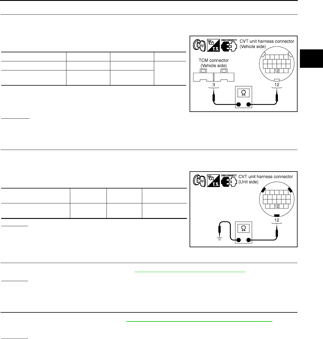
DTC P0740 TORQUE CONVERTER CLUTCH SOLENOID VALVE
CVT-111
D
E
F
G
H
I
J
K
L
M
A
B
CVT
Revision: 2006 August 2006 Murano
3. CHECK HARNESS BETWEEN TCM AND TORQUE CONVERTER CLUTCH SOLENOID VALVE
1. Turn ignition switch OFF.
2. Disconnect TCM connector and CVT unit harness connector.
3. Check continuity between TCM connector terminal and CVT unit
harness connector terminal.
4. If OK, check harness for short to ground and short to power.
5. If OK, check continuity between ground and CVT assembly.
6. Reinstall any part removed.
OK or NG
OK >> GO TO 4.
NG >> Repair or replace damaged parts.
4. CHECK VALVE RESISTANCE
1. Turn ignition switch OFF.
2. Disconnect CVT unit harness connector.
3. Check resistance between CVT unit harness connector terminal
and ground.
OK or NG
OK >> GO TO 5.
NG >> Repair or replace damaged parts.
5. CHECK DTC
Perform “DTC Confirmation Procedure”. Refer to CVT-108, "DTC Confirmation Procedure" .
OK or NG
OK >> INSPECTION END
NG >> GO TO 6.
6. CHECK TCM
1. Check TCM input/output signals. Refer to CVT-57, "TCM Input/Output Signal Reference Values" .
2. If NG, re-check TCM pin terminals for damage or loose connection with harness connector.
OK or NG
OK >> INSPECTION END
NG >> Repair or replace damaged parts.
Item Connector Terminal Continuity
TCM connector F103 3
Yes
CVT unit harness connec-
tor F6 12
SCIA4683E
Solenoid Valve Connector Terminal Resistance
(Approx.)
Torque converter clutch sole-
noid valve F6 12 - Ground 3.0 - 9.0 Ω
SCIA4684E
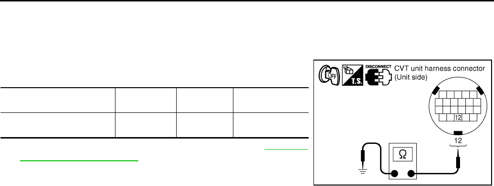
CVT-112
DTC P0740 TORQUE CONVERTER CLUTCH SOLENOID VALVE
Revision: 2006 August 2006 Murano
Component Inspection NCS00156
TORQUE CONVERTER CLUTCH SOLENOID VALVE
1. Turn ignition switch OFF.
2. Disconnect CVT unit harness connector.
3. Check resistance between CVT unit harness connector terminal
and ground.
4. If NG, replace the transaxle assembly. Refer to CVT-229,
"Removal and Installation" .
Solenoid Valve Connector Terminal Resistance
(Approx.)
Torque converter clutch sole-
noid valve F6 12 - Ground 3.0 - 9.0 Ω
SCIA4684E
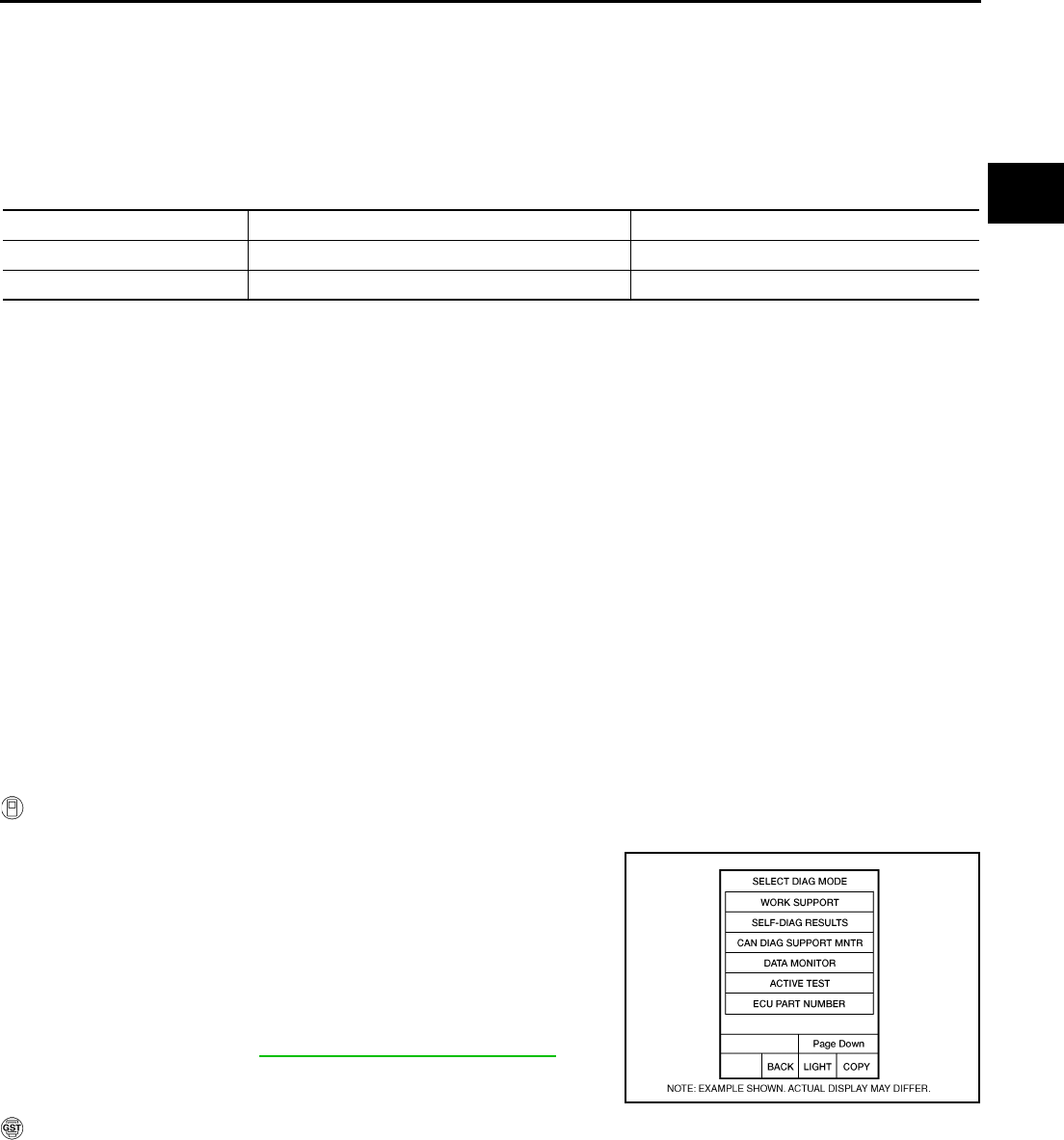
DTC P0744 A/T TCC S/V FUNCTION (LOCK-UP)
CVT-113
D
E
F
G
H
I
J
K
L
M
A
B
CVT
Revision: 2006 August 2006 Murano
DTC P0744 A/T TCC S/V FUNCTION (LOCK-UP) PFP:31940
Description NCS00157
This malfunction is detected when the torque converter clutch does not lock-up as instructed by the TCM. This
is not only caused by electrical malfunction (circuits open or shorted), but also by mechanical malfunction such
as control valve sticking, improper solenoid valve operation, etc.
CONSULT-II Reference Value NCS00158
Remarks: Specification data are reference values.
On Board Diagnosis Logic NCS00159
●This is an OBD-II self-diagnostic item.
●Diagnostic trouble code “P0744 A/T TCC S/V FNCTN” with CONSULT-II is detected under the following
conditions.
–When CVT cannot perform lock-up even if electrical circuit is good.
–When TCM compares difference value with slip revolution and detects an irregularity.
Possible Cause NCS0015A
●Torque converter clutch solenoid valve
●Hydraulic control circuit
DTC Confirmation Procedure NCS0015B
CAUTION:
Always drive vehicle at a safe speed.
NOTE:
If “DTC Confirmation Procedure” has been previously performed, always turn ignition switch OFF and
wait at least 10 seconds before performing the next test.
After the repair, touch “ERASE” on “SELF-DIAG RESULTS” and then perform the following procedure to con-
firm the malfunction is eliminated.
WITH CONSULT-II
1. Turn ignition switch ON. (Do not start engine.)
2. Select “DATA MONITOR” mode for “TRANSMISSION” with
CONSULT-II.
3. Start engine and maintain the following condition for at least 30
seconds.
ACC PEDAL OPEN: More than 1.0/8
RANGE: “D” position
[Vehicle speed: Constant speed of more than 40 km/h (25
MPH)]
4. If DTC is detected go to CVT-114, "Diagnostic Procedure" .
WITH GST
Follow the procedure “WITH CONSULT-II”.
Item name Condition Display value
ENG SPEED SIG Engine running Closely matches the tachometer reading.
PRI SPEED SEN During driving (lock-up ON) Approximately matches the engine speed.
BCIA0031E
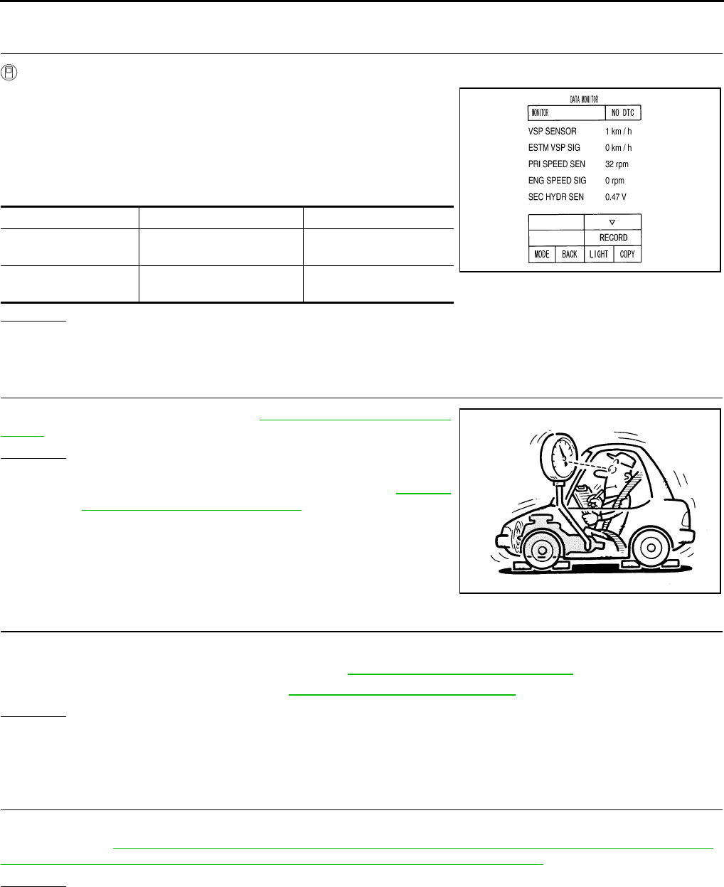
CVT-114
DTC P0744 A/T TCC S/V FUNCTION (LOCK-UP)
Revision: 2006 August 2006 Murano
Diagnostic Procedure NCS0015C
1. CHECK INPUT SIGNALS
With CONSULT-II
1. Start engine.
2. Select “ECU INPUT SIGNALS” in “DATA MONITOR” mode for
“TRANSMISSION” with CONSULT-II.
3. Start vehicle.
4. Check if there is a great difference between “ENG SPEED SIG”
and “PRI SPEED SEN”. (Lock-up ON.)
OK or NG
OK >> GO TO 5.
NG >> GO TO 2.
2. CHECK LINE PRESSURE
Perform line pressure test. Refer to CVT-44, "LINE PRESSURE
TEST" .
OK or NG
OK >> GO TO 3.
NG >> Repair or replace damaged parts. Refer to CVT-45,
"Judgment of Line Pressure Test" .
3. DETECT MALFUNCTIONING ITEM
Check the following:
●Torque converter clutch solenoid valve. Refer to CVT-112, "Component Inspection" .
●Lock-up select solenoid valve. Refer to CVT-170, "Component Inspection" .
OK or NG
OK >> GO TO 4.
NG >> Repair or replace damaged parts.
4. CHECK OUTPUT SPEED SENSOR (SECONDARY SPEED SENSOR) SYSTEM AND INPUT SPEED
SENSOR (PRIMARY SPEED SENSOR) SYSTEM
Check output speed sensor (secondary speed sensor) system and input speed sensor (primary speed sensor)
system. Refer to CVT-98, "DTC P0720 VEHICLE SPEED SENSOR CVT (SECONDARY SPEED SENSOR)" ,
CVT-93, "DTC P0715 INPUT SPEED SENSOR CIRCUIT (PRI SPEED SENSOR)" .
OK or NG
OK >> GO TO 5.
NG >> Repair or replace damaged parts.
Item name Condition Display value
ENG SPEED SIG Engine running Closely matches the
tachometer reading.
PRI SPEED SEN During driving (lock-up ON) Approximately matches
the engine speed.
SCIA2279E
SAT494G

DTC P0744 A/T TCC S/V FUNCTION (LOCK-UP)
CVT-115
D
E
F
G
H
I
J
K
L
M
A
B
CVT
Revision: 2006 August 2006 Murano
5. CHECK DTC
Perform “DTC Confirmation Procedure”. Refer to CVT-113, "DTC Confirmation Procedure" .
OK or NG
OK >> INSPECTION END
NG >> GO TO 6.
6. CHECK TCM
1. Check TCM input/output signals. Refer to CVT-57, "TCM Input/Output Signal Reference Values" .
2. If NG, re-check TCM pin terminals for damage or loose connection with harness connector.
OK or NG
OK >> INSPECTION END
NG >> 1. Repair or replace damaged parts.
2. Replace the transaxle assembly. Refer to CVT-229, "Removal and Installation" .
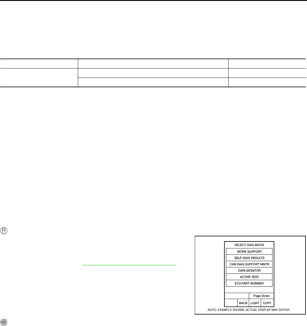
CVT-116
DTC P0745 LINE PRESSURE SOLENOID VALVE
Revision: 2006 August 2006 Murano
DTC P0745 LINE PRESSURE SOLENOID VALVE PFP:31940
Description NCS0015D
The pressure control solenoid valve A (line pressure solenoid valve) regulates the oil pump discharge pres-
sure to suit the driving condition in response to a signal sent from the TCM.
CONSULT-II Reference Value NCS0015E
Remarks: Specification data are reference values.
On Board Diagnosis Logic NCS0015F
●This is an OBD-II self-diagnostic item.
●Diagnostic trouble code “P0745 L/PRESS SOL/CIRC” with CONSULT-II is detected under the following
conditions.
–TCM detects an improper voltage drop when it tries to operate the solenoid valve.
–When TCM compares target value with monitor value and detects an irregularity.
Possible Cause NCS0015G
●Harness or connectors
(Solenoid circuit is open or shorted.)
●Pressure control solenoid valve A (Line pressure solenoid valve)
DTC Confirmation Procedure NCS0015H
NOTE:
If “DTC Confirmation Procedure” has been previously performed, always turn ignition switch OFF and
wait at least 10 seconds before performing the next test.
After the repair, perform the following procedure to confirm the malfunction is eliminated.
WITH CONSULT-II
1. Turn ignition switch ON and select “DATA MONITOR” mode for
“TRANSMISSION” with CONSULT-II.
2. Start engine and wait at least 5 seconds.
3. If DTC is detected, go to CVT-118, "Diagnostic Procedure" .
WITH GST
Follow the procedure “WITH CONSULT-II”.
Item name Condition Display value (Approx.)
ISOLT2 Release your foot from the accelerator pedal. 0.8 A
Press the accelerator pedal all the way down. 0.0 A
BCIA0031E

DTC P0745 LINE PRESSURE SOLENOID VALVE
CVT-117
D
E
F
G
H
I
J
K
L
M
A
B
CVT
Revision: 2006 August 2006 Murano
Wiring Diagram — CVT — LPSV NCS0015I
TCWA0249E
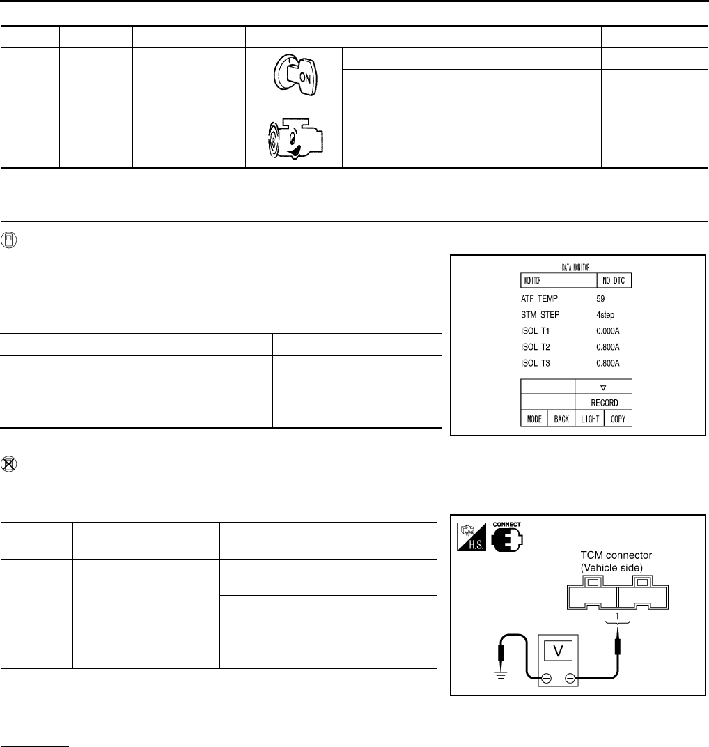
CVT-118
DTC P0745 LINE PRESSURE SOLENOID VALVE
Revision: 2006 August 2006 Murano
TCM terminal data are reference values, measured between each terminal and ground.
Diagnostic Procedure NCS0015J
1. CHECK INPUT SIGNAL
With CONSULT-II
1. Start engine.
2. Select “MAIN SIGNALS” in “DATA MONITOR” mode for
“TRANSMISSION” with CONSULT-II.
3. Read out the value of “ISOLT2”.
Without CONSULT-II
1. Start engine.
2. Check voltage between TCM connector terminal and ground.
3. Turn ignition switch OFF.
4. Disconnect TCM connector.
5. Check if there is continuity between connector terminal and ground.
OK or NG
OK >> GO TO 5.
NG >> GO TO 2.
Terminal Wire color Item Condition Data (Approx.)
1R/Y
Pressure control
solenoid valve A
(Line pressure
solenoid valve)
and
Release your foot from the accelerator pedal. 5.0 - 7.0 V
Press the accelerator pedal all the way down. 1.0 - 3.0 V
Item name Condition Display value (Approx.)
ISOLT2
Release your foot from
the accelerator pedal. 0.8 A
Press the accelerator
pedal all the way down. 0.0 A
SCIA2349E
Name Connector Terminal Condition Voltage
(Approx.)
Pressure
control
solenoid
valve A
(Line pres-
sure sole-
noid valve)
F103 1 - Ground
Release your foot from
the accelerator pedal. 5.0 - 7.0 V
Press the accelerator
pedal all the way down. 1.0 - 3.0 V
SCIA2348E
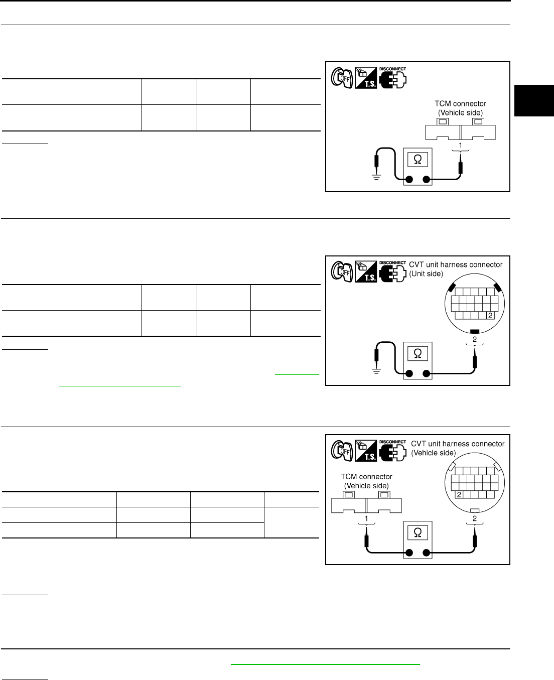
DTC P0745 LINE PRESSURE SOLENOID VALVE
CVT-119
D
E
F
G
H
I
J
K
L
M
A
B
CVT
Revision: 2006 August 2006 Murano
2. CHECK PRESSURE CONTROL SOLENOID VALVE A (LINE PRESSURE SOLENOID VALVE) CIRCUIT
1. Turn ignition switch OFF.
2. Disconnect TCM connector.
3. Check resistance between TCM connector terminal and ground.
OK or NG
OK >> GO TO 5.
NG >> GO TO 3.
3. CHECK VALVE RESISTANCE
1. Turn ignition switch OFF.
2. Disconnect CVT unit harness connector.
3. Check resistance between CVT unit harness connector terminal
and ground.
OK or NG
OK >> GO TO 4.
NG >> Replace the transaxle assembly. Refer to CVT-229,
"Removal and Installation" .
4. CHECK HARNESS BETWEEN TCM AND PRESSURE CONTROL SOLENOID VALVE A (LINE PRES-
SURE SOLENOID VALVE)
1. Turn ignition switch OFF.
2. Disconnect CVT unit harness connector and TCM connector.
3. Check continuity between TCM connector terminal and CVT unit
harness connector terminal.
4. If OK, check harness for short to ground and short to power.
5. If OK, check continuity between ground and CVT assembly.
6. Reinstall any part removed.
OK or NG
OK >> GO TO 5.
NG >> Repair open circuit or short to ground or short to power in harness or connectors.
5. CHECK DTC
Perform “DTC Confirmation Procedure”. Refer to CVT-116, "DTC Confirmation Procedure" .
OK or NG
OK >> INSPECTION END
NG >> GO TO 6.
Solenoid valve Connector Terminal Resistance
(Approx.)
Pressure control solenoid valve A
(Line pressure solenoid valve) F103 1 - Ground 3.0 - 9.0 Ω
SCIA4685E
Solenoid valve Connector Terminal Resistance
(Approx.)
Pressure control solenoid valve A
(Line pressure solenoid valve) F6 2 - Ground 3.0 - 9.0 Ω
SCIA4686E
Item Connector Terminal Continuity
TCM connector F103 1 Yes
CVT unit harness connector F6 2
SCIA4687E
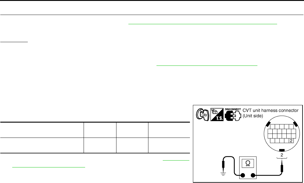
CVT-120
DTC P0745 LINE PRESSURE SOLENOID VALVE
Revision: 2006 August 2006 Murano
6. CHECK TCM
1. Check TCM input/output signals. Refer to CVT-57, "TCM Input/Output Signal Reference Values" .
2. If NG, re-check TCM pin terminals for damage or loose connection with harness connector.
OK or NG
OK >> INSPECTION END
NG >> 1. Repair or replace damaged parts.
2. Replace the transaxle assembly. Refer to CVT-229, "Removal and Installation" .
Component Inspection NCS0015K
PRESSURE CONTROL SOLENOID VALVE A (LINE PRESSURE SOLENOID VALVE)
1. Turn ignition switch OFF.
2. Disconnect CVT unit harness connector.
3. Check resistance between CVT unit harness connector terminal
and ground.
4. If NG, replace the transaxle assembly. Refer to CVT-229,
"Removal and Installation" .
Solenoid valve Connector Terminal Resistance
(Approx.)
Pressure control solenoid valve A
(Line pressure solenoid valve) F6 2 - Ground 3.0 - 9.0 Ω
SCIA4686E

DTC P0746 PRESSURE CONTROL SOLENOID A PERFORMANCE (LINE PRES-
SURE SOLENOID VALVE)
CVT-121
D
E
F
G
H
I
J
K
L
M
A
B
CVT
Revision: 2006 August 2006 Murano
DTC P0746 PRESSURE CONTROL SOLENOID A PERFORMANCE (LINE PRES-
SURE SOLENOID VALVE) PFP:31941
Description NCS0015L
The pressure control solenoid valve A (line pressure solenoid valve) regulates the oil pump discharge pres-
sure to suit the driving condition in response to a signal sent from the TCM.
CONSULT-II Reference Value NCS0015M
Remarks: Specification data are reference values.
On Board Diagnosis Logic NCS0015N
●This is an OBD-II self-diagnostic item.
●Diagnostic trouble code “P0746 PRS CNT SOL/A FCTN” with CONSULT-II is detected under the following
conditions.
–Unexpected gear ratio was detected in the LOW side due to excessively low line pressure.
Possible Cause NCS0015O
●Line pressure control system
●Output speed sensor (Secondary speed sensor)
●Input speed sensor (Primary speed sensor)
DTC Confirmation Procedure NCS0015P
CAUTION:
Always drive vehicle at a safe speed.
NOTE:
If “DTC Confirmation Procedure” has been previously performed, always turn ignition switch OFF and
wait at least 10 seconds before performing the next test.
After the repair, touch “ERASE” on “SELF-DIAG RESULTS” and then perform the following procedure to con-
firm the malfunction is eliminated.
WITH CONSULT-II
1. Turn ignition switch ON and select “DATA MONITOR” mode for
“TRANSMISSION” with CONSULT-II.
2. Start engine and maintain the following conditions for at least 10
consecutive seconds. Test start from 0 km/h (0 MPH).
ATF TEMP SEN: 1.0 - 2.0 V
ACC PEDAL OPEN: More than 1.0/8
RANGE: “D” position
VEHICLE SPEED: 10 km/h (6 MPH) More than
Driving location: Driving the vehicle uphill (increased
engine load) will help maintain the driving conditions
required for this test.
3. If DTC is detected, go to CVT-122, "Diagnostic Procedure" .
WITH GST
Follow the procedure “WITH CONSULT-II”.
Item name Condition Display value (Approx.)
PRI PRESS “N” position idle 0.3 - 0.9 MPa
BCIA0031E
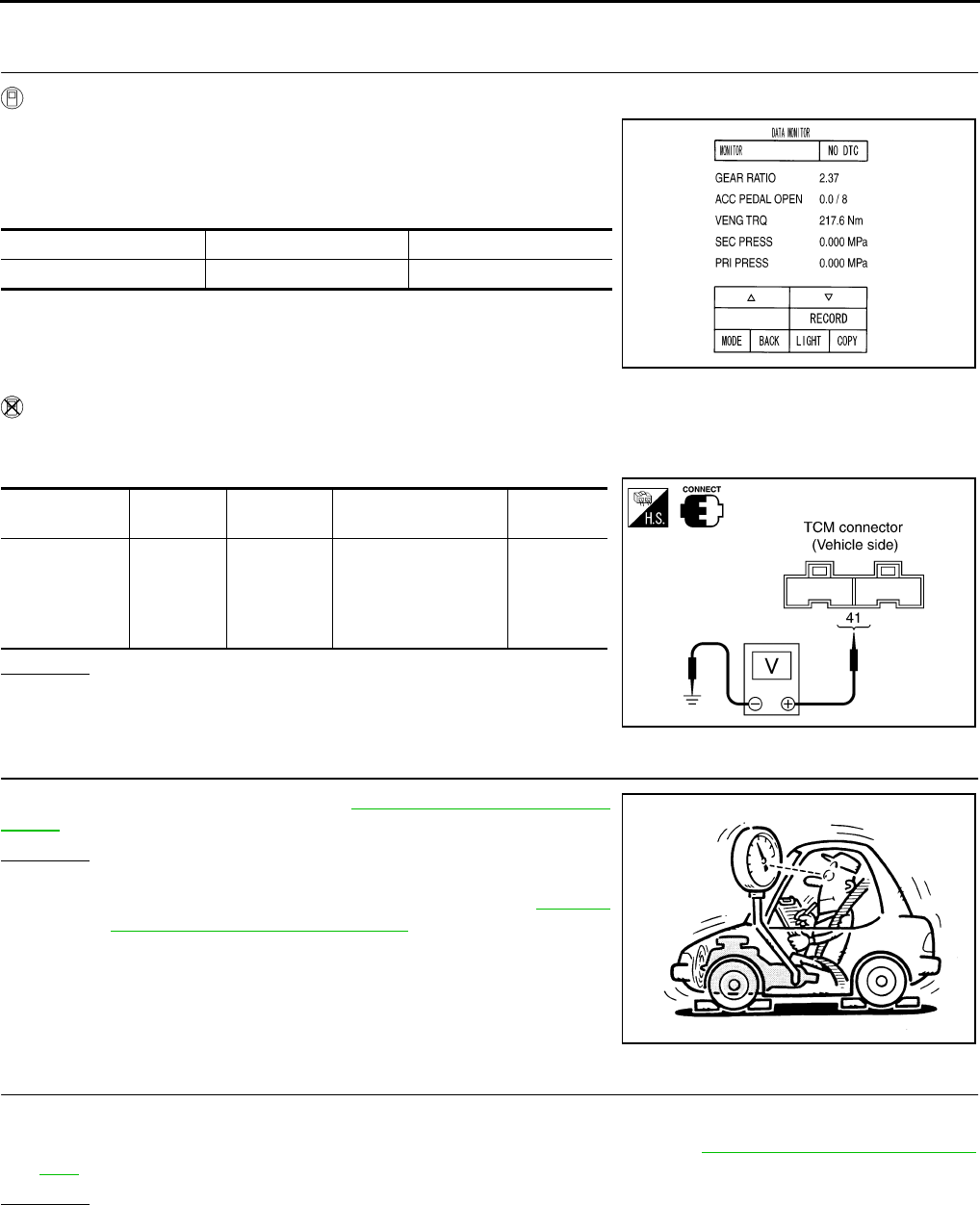
CVT-122
DTC P0746 PRESSURE CONTROL SOLENOID A PERFORMANCE (LINE PRES-
SURE SOLENOID VALVE)
Revision: 2006 August 2006 Murano
Diagnostic Procedure NCS0015Q
1. CHECK INPUT SIGNAL
With CONSULT-II
1. Start engine.
2. Select “MAIN SIGNALS” in “DATA MONITOR” mode for
“TRANSMISSION” with CONSULT-II.
3. Start vehicle and read out the value of “PRI PRESS”.
Without CONSULT-II
1. Start engine.
2. Check voltage between TCM connector terminal and ground.
OK or NG
OK >> GO TO 5.
NG >> GO TO 2.
2. CHECK LINE PRESSURE
Perform line pressure test. Refer to CVT-44, "LINE PRESSURE
TEST" .
OK or NG
OK >> GO TO 3.
NG >> Repair or replace damaged parts. Refer to CVT-45,
"Judgment of Line Pressure Test" .
3. DETECT MALFUNCTIONING ITEM
Check the following:
●Pressure control solenoid valve A (line pressure solenoid valve). Refer to CVT-120, "Component Inspec-
tion" .
OK or NG
OK >> GO TO 4.
NG >> Repair or replace damaged parts.
Item name Condition Display value (Approx.)
PRI PRESS “N” position idle 0.3 - 0.9 MPa
SCIA2366E
Name Connector Terminal Condition Voltage
(Approx.)
Transmission
fluid pressure
sensor B (Pri-
mary pressure
sensor)
F104 41 - Ground “N” position idle 0.7 - 3.5 V
SCIA1922E
SAT494G

DTC P0746 PRESSURE CONTROL SOLENOID A PERFORMANCE (LINE PRES-
SURE SOLENOID VALVE)
CVT-123
D
E
F
G
H
I
J
K
L
M
A
B
CVT
Revision: 2006 August 2006 Murano
4. CHECK OUTPUT SPEED SENSOR (SECONDARY SPEED SENSOR) SYSTEM AND INPUT SPEED
SENSOR (PRIMARY SPEED SENSOR) SYSTEM
Check output speed sensor (secondary speed sensor) system and input speed sensor (primary speed sensor)
system. Refer to CVT-98, "DTC P0720 VEHICLE SPEED SENSOR CVT (SECONDARY SPEED SENSOR)" ,
CVT-93, "DTC P0715 INPUT SPEED SENSOR CIRCUIT (PRI SPEED SENSOR)" .
OK or NG
OK >> GO TO 5.
NG >> Repair or replace damaged parts.
5. DETECT MALFUNCTIONING ITEM
Check the following:
●Power supply and ground circuit for TCM. Refer to CVT-154, "Wiring Diagram — CVT — POWER" .
●The TCM pin terminals for damage or loose connection with harness connector.
OK or NG
OK >> GO TO 6.
NG >> Repair or replace damaged parts.
6. CHECK DTC
Perform “DTC Confirmation Procedure”. Refer to CVT-121, "DTC Confirmation Procedure" .
OK or NG
OK >> INSPECTION END
NG >> Replace the transaxle assembly or TCM. Refer to CVT-229, "Removal and Installation" .
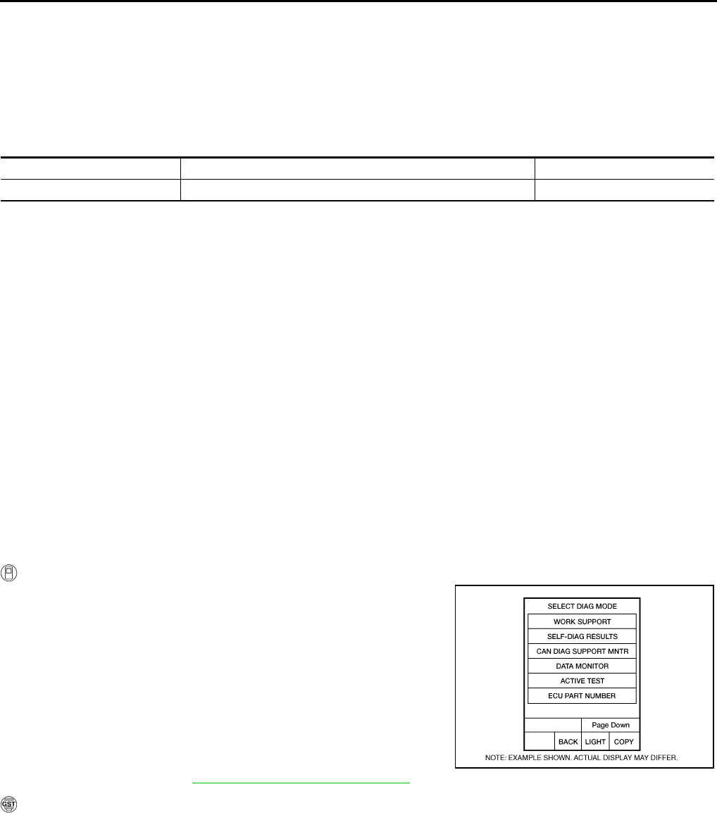
CVT-124
DTC P0776 PRESSURE CONTROL SOLENOID B PERFORMANCE (SEC PRES-
SURE SOLENOID VALVE)
Revision: 2006 August 2006 Murano
DTC P0776 PRESSURE CONTROL SOLENOID B PERFORMANCE (SEC PRES-
SURE SOLENOID VALVE) PFP:31941
Description NCS0015R
The pressure control solenoid valve B (secondary pressure solenoid valve) regulates the secondary pressure
to suit the driving condition in response to a signal sent from the TCM.
CONSULT-II Reference Value NCS0015S
Remarks: Specification data are reference values.
On Board Diagnosis Logic NCS0015T
●This is an OBD-II self-diagnostic item.
●Diagnostic trouble code “P0776 PRS CNT SOL/B FCTN” with CONSULT-II is detected when secondary
pressure is too high or too low compared with the commanded value while driving.
Possible Cause NCS0015U
●Harness or connectors
(Solenoid circuit is open or shorted.)
●Pressure control solenoid valve B (Secondary pressure solenoid valve system)
●Transmission fluid pressure sensor A (Secondary pressure sensor)
●Line pressure control system
DTC Confirmation Procedure NCS0015V
CAUTION:
Always drive vehicle at a safe speed.
NOTE:
If “DTC Confirmation Procedure” has been previously performed, always turn ignition switch OFF and
wait at least 10 seconds before performing the next test.
After the repair, perform the following procedure to confirm the malfunction is eliminated.
WITH CONSULT-II
1. Turn ignition switch ON and select “DATA MONITOR” mode for
“TRANSMISSION” with CONSULT-II.
2. Start engine and maintain the following conditions for at least 30
consecutive seconds.
ATF TEMP SEN: 1.0 - 2.0 V
ACC PEDAL OPEN: More than 1.0/8
RANGE: “D” position
VEHICLE SPEED: 10 km/h (6 MPH) More than
Driving location: Driving the vehicle uphill (increased
engine load) will help maintain the driving conditions
required for this test.
3. If DTC is detected, go to CVT-125, "Diagnostic Procedure" .
WITH GST
Follow the procedure “WITH CONSULT-II”.
Item name Condition Display value (Approx.)
SEC PRESS “N” position idle 0.5 - 0.9 MPa
BCIA0031E
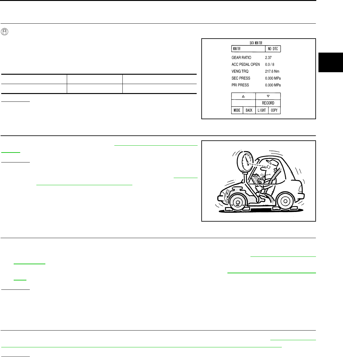
DTC P0776 PRESSURE CONTROL SOLENOID B PERFORMANCE (SEC PRES-
SURE SOLENOID VALVE)
CVT-125
D
E
F
G
H
I
J
K
L
M
A
B
CVT
Revision: 2006 August 2006 Murano
Diagnostic Procedure NCS0015W
1. CHECK INPUT SIGNAL
With CONSULT-II
1. Start engine.
2. Select “MAIN SIGNALS” in “DATA MONITOR” mode for
“TRANSMISSION” with CONSULT-II.
3. Start vehicle and read out the value of “SEC PRESS”.
OK or NG
OK >> GO TO 5.
NG >> GO TO 2.
2. CHECK LINE PRESSURE
Perform line pressure test. Refer to CVT-44, "LINE PRESSURE
TEST" .
OK or NG
OK >> GO TO 3.
NG >> Repair or replace damaged parts. Refer to CVT-45,
"Judgment of Line Pressure Test" .
3. DETECT MALFUNCTIONING ITEM
Check the following:
●Pressure control solenoid valve B (Secondary pressure solenoid valve). Refer to CVT-131, "Component
Inspection" .
●Pressure control solenoid valve A (Line pressure solenoid valve). Refer to CVT-120, "Component Inspec-
tion" .
OK or NG
OK >> GO TO 4.
NG >> Repair or replace damaged parts.
4. CHECK TRANSMISSION FLUID PRESSURE SENSOR A (SECONDARY PRESSURE SENSOR) SYS-
TEM
Check transmission fluid pressure sensor A (secondary pressure sensor) system. Refer to CVT-137, "DTC
P0840 TRANSMISSION FLUID PRESSURE SENSOR A CIRCUIT (SEC PRESSURE SENSOR)" .
OK or NG
OK >> GO TO 5.
NG >> Repair or replace damaged parts.
Item name Condition Display value (Approx.)
SEC PRESS “N” position idle 0.5 - 0.9 MPa
SCIA2366E
SAT494G

CVT-126
DTC P0776 PRESSURE CONTROL SOLENOID B PERFORMANCE (SEC PRES-
SURE SOLENOID VALVE)
Revision: 2006 August 2006 Murano
5. DETECT MALFUNCTIONING ITEM
Check the following:
●Power supply and ground circuit for TCM. Refer to CVT-154, "Wiring Diagram — CVT — POWER" .
●The TCM pin terminals for damage or loose connection with harness connector.
OK or NG
OK >> GO TO 6.
NG >> Repair or replace damaged parts.
6. CHECK DTC
Perform “DTC Confirmation Procedure”. Refer to CVT-124, "DTC Confirmation Procedure" .
OK or NG
OK >> INSPECTION END
NG >> Replace the transaxle assembly. Refer to CVT-229, "Removal and Installation" .
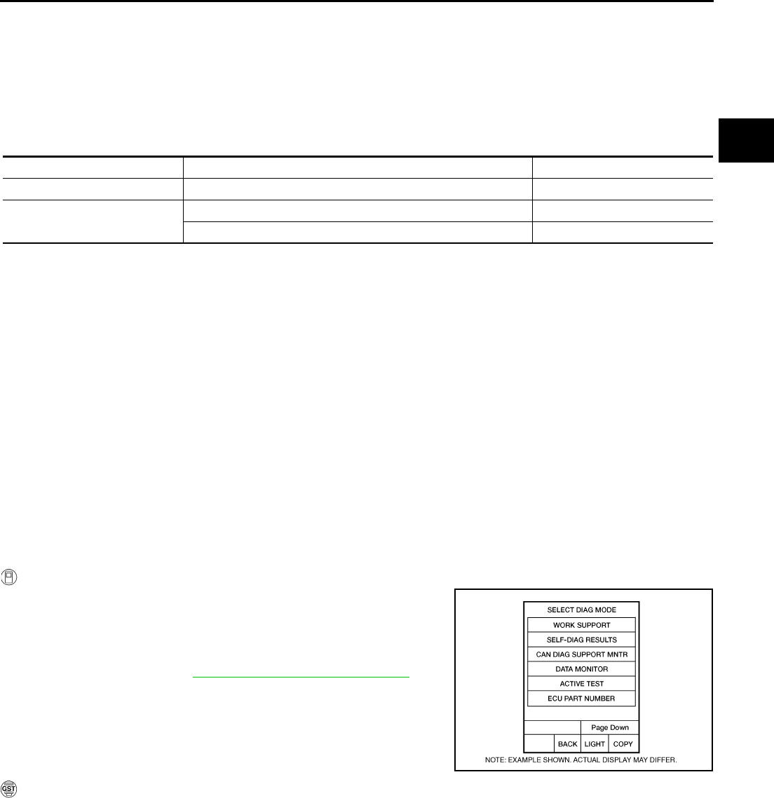
DTC P0778 PRESSURE CONTROL SOLENOID B ELECTRICAL (SEC PRES-
SURE SOLENOID VALVE)
CVT-127
D
E
F
G
H
I
J
K
L
M
A
B
CVT
Revision: 2006 August 2006 Murano
DTC P0778 PRESSURE CONTROL SOLENOID B ELECTRICAL (SEC PRESSURE
SOLENOID VALVE) PFP:31941
Description NCS0015X
The pressure control solenoid valve B (secondary pressure solenoid valve) regulates the oil pump discharge
pressure to suit the driving condition in response to a signal sent from the TCM.
CONSULT-II Reference Value NCS0015Y
Remarks: Specification data are reference values.
On Board Diagnosis Logic NCS0015Z
●This is an OBD-II self-diagnostic item.
●Diagnostic trouble code “P0778 PRS CNT SOL/B CIRC” with CONSULT-II is detected under the following
conditions.
–TCM detects an improper voltage drop when it tries to operate the solenoid valve.
–When TCM compares target value with monitor value and detects an irregularity.
Possible Cause NCS00160
●Harness or connectors
(Solenoid circuit is open or shorted.)
●Pressure control solenoid valve B (Secondary pressure solenoid valve)
DTC Confirmation Procedure NCS00161
NOTE:
If “DTC Confirmation Procedure” has been previously performed, always turn ignition switch OFF and
wait at least 10 seconds before performing the next test.
After the repair, perform the following procedure to confirm the malfunction is eliminated.
WITH CONSULT-II
1. Turn ignition switch ON.
2. Select “DATA MONITOR” mode for “TRANSMISSION” with
CONSULT-II.
3. Start engine and wait at least 5 seconds.
4. If DTC is detected, go to CVT-129, "Diagnostic Procedure" .
WITH GST
Follow the procedure “WITH CONSULT-II”.
Item name Condition Display value (Approx.)
ISOLT3 Secondary pressure low - Secondary pressure high 0.8 - 0.0 A
SOLMON3 “N” position idle 0.6 - 0.7 A
When stalled 0.4 - 0.6 A
BCIA0031E
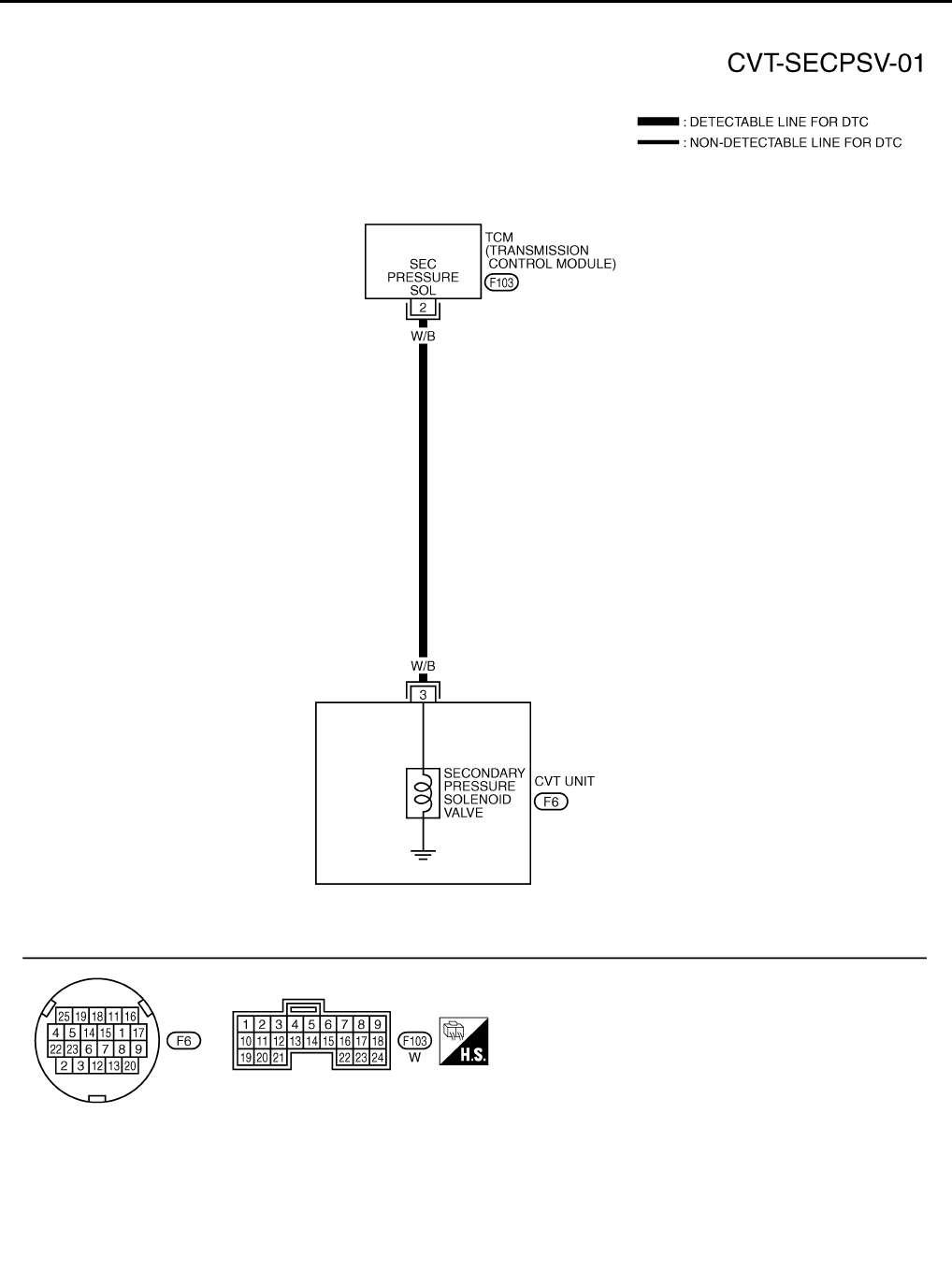
CVT-128
DTC P0778 PRESSURE CONTROL SOLENOID B ELECTRICAL (SEC PRES-
SURE SOLENOID VALVE)
Revision: 2006 August 2006 Murano
Wiring Diagram — CVT — SECPSV NCS00162
TCWA0250E
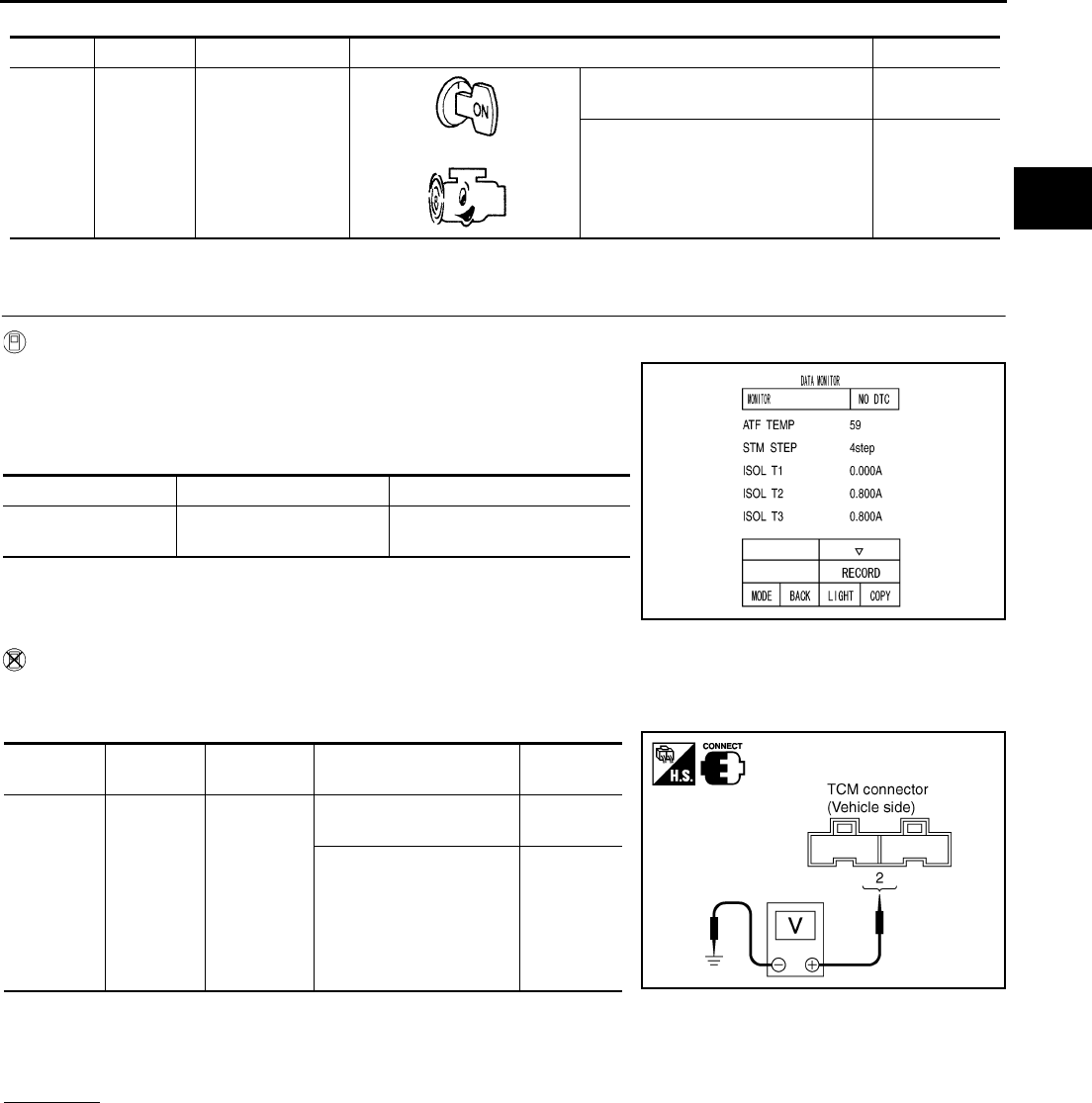
DTC P0778 PRESSURE CONTROL SOLENOID B ELECTRICAL (SEC PRES-
SURE SOLENOID VALVE)
CVT-129
D
E
F
G
H
I
J
K
L
M
A
B
CVT
Revision: 2006 August 2006 Murano
TCM terminal data are reference values, measured between each terminal and ground.
Diagnostic Procedure NCS00163
1. CHECK INPUT SIGNAL
With CONSULT-II
1. Start engine.
2. Select “MAIN SIGNALS” in “DATA MONITOR” mode for
“TRANSMISSION” with CONSULT-II.
3. Read out the value of “ISOLT3”.
Without CONSULT-II
1. Start engine.
2. Check voltage between TCM connector terminal and ground.
3. Turn ignition switch OFF.
4. Disconnect TCM connector.
5. Check if there is continuity between connector terminal and ground.
OK or NG
OK >> GO TO 5.
NG >> GO TO 2.
Terminal Wire color Item Condition Data (Approx.)
2W/B
Pressure control
solenoid valve B
(Secondary pres-
sure solenoid
valve)
and
Release your foot from the accelera-
tor pedal. 5.0 - 7.0 V
Press the accelerator pedal all the
way down. 3.0 - 4.0 V
Item name Condition Display value (Approx.)
ISOLT3 Secondary pressure low -
Secondary pressure high 0.8 - 0.0 A
SCIA2349E
Name Connector Terminal Condition Voltage
(Approx.)
Pressure
control
solenoid
valve B
(Second-
ary pres-
sure
solenoid
valve)
F103 2 - Ground
Release your foot from
the accelerator pedal. 5.0 - 7.0 V
Press the accelerator
pedal all the way down. 3.0 - 4.0 V
SCIA4506E

CVT-130
DTC P0778 PRESSURE CONTROL SOLENOID B ELECTRICAL (SEC PRES-
SURE SOLENOID VALVE)
Revision: 2006 August 2006 Murano
2. CHECK PRESSURE CONTROL SOLENOID VALVE B (SECONDARY PRESSURE SOLENOID VALVE)
CIRCUIT
1. Turn ignition switch OFF.
2. Disconnect TCM connector.
3. Check resistance between TCM connector terminal and ground.
OK or NG
OK >> GO TO 5.
NG >> GO TO 3.
3. CHECK VALVE RESISTANCE
1. Turn ignition switch OFF.
2. Disconnect CVT unit harness connector.
3. Check resistance between CVT unit harness connector terminal
and ground.
OK or NG
OK >> GO TO 4.
NG >> Repair or replace damaged parts.
4. CHECK HARNESS BETWEEN TCM AND PRESSURE CONTROL SOLENOID VALVE B (SECONDARY
PRESSURE SOLENOID VALVE)
1. Turn ignition switch OFF.
2. Disconnect TCM connector and CVT unit harness connector.
3. Check continuity between TCM connector terminal and CVT unit
harness connector terminal.
4. If OK, check harness for short to ground and short to power.
5. Reinstall any part removed.
OK or NG
OK >> GO TO 5.
NG >> Repair or replace damaged parts.
5. CHECK DTC
Perform “DTC Confirmation Procedure”. Refer to CVT-127, "DTC Confirmation Procedure" .
OK or NG
OK >> INSPECTION END
NG >> GO TO 6.
Solenoid valve Connector Terminal Resistance
(Approx.)
Pressure control solenoid
valve B (Secondary pres-
sure solenoid valve)
F103 2 - Ground 3.0 - 9.0 Ω
SCIA4507E
Solenoid valve Connector Terminal Resistance
(Approx.)
Pressure control solenoid
valve B (Secondary pres-
sure solenoid valve)
F6 3 - Ground 3.0 - 9.0 Ω
SCIA4688E
Item Connector Terminal Continuity
TCM connector F103 2
Yes
CVT unit harness connec-
tor F6 3
SCIA4689E
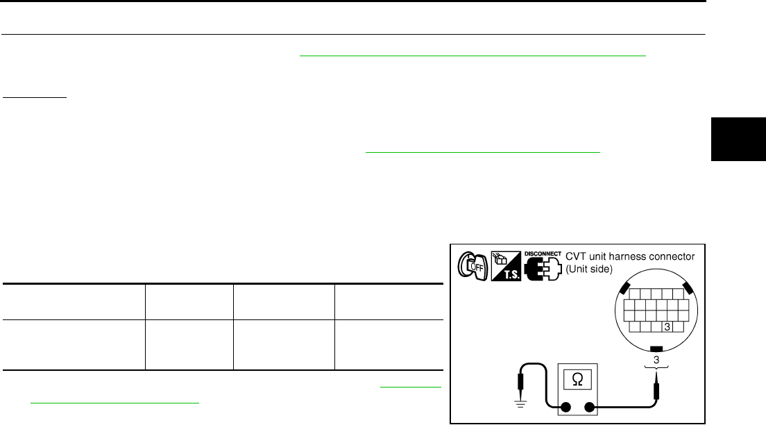
DTC P0778 PRESSURE CONTROL SOLENOID B ELECTRICAL (SEC PRES-
SURE SOLENOID VALVE)
CVT-131
D
E
F
G
H
I
J
K
L
M
A
B
CVT
Revision: 2006 August 2006 Murano
6. CHECK TCM
1. Check TCM input/output signals. Refer to CVT-57, "TCM Input/Output Signal Reference Values" .
2. If NG, re-check TCM pin terminals for damage or loose connection with harness connector.
OK or NG
OK >> INSPECTION END
NG >> 1. Repair or replace damaged parts.
2. Replace the transaxle assembly. Refer to CVT-229, "Removal and Installation" .
Component Inspection NCS00164
PRESSURE CONTROL SOLENOID VALVE B (SECONDARY PRESSURE SOLENOID VALVE)
1. Turn ignition switch OFF.
2. Disconnect CVT unit harness connector.
3. Check resistance between CVT unit harness connector terminal
and ground.
4. If NG, replace the transaxle assembly. Refer to CVT-229,
"Removal and Installation" .
Solenoid Valve Connector Terminal Resistance
(Approx.)
Pressure control sole-
noid valve B (Secondary
pressure solenoid valve)
F6 3 - Ground 3.0 - 9.0 Ω
SCIA4688E
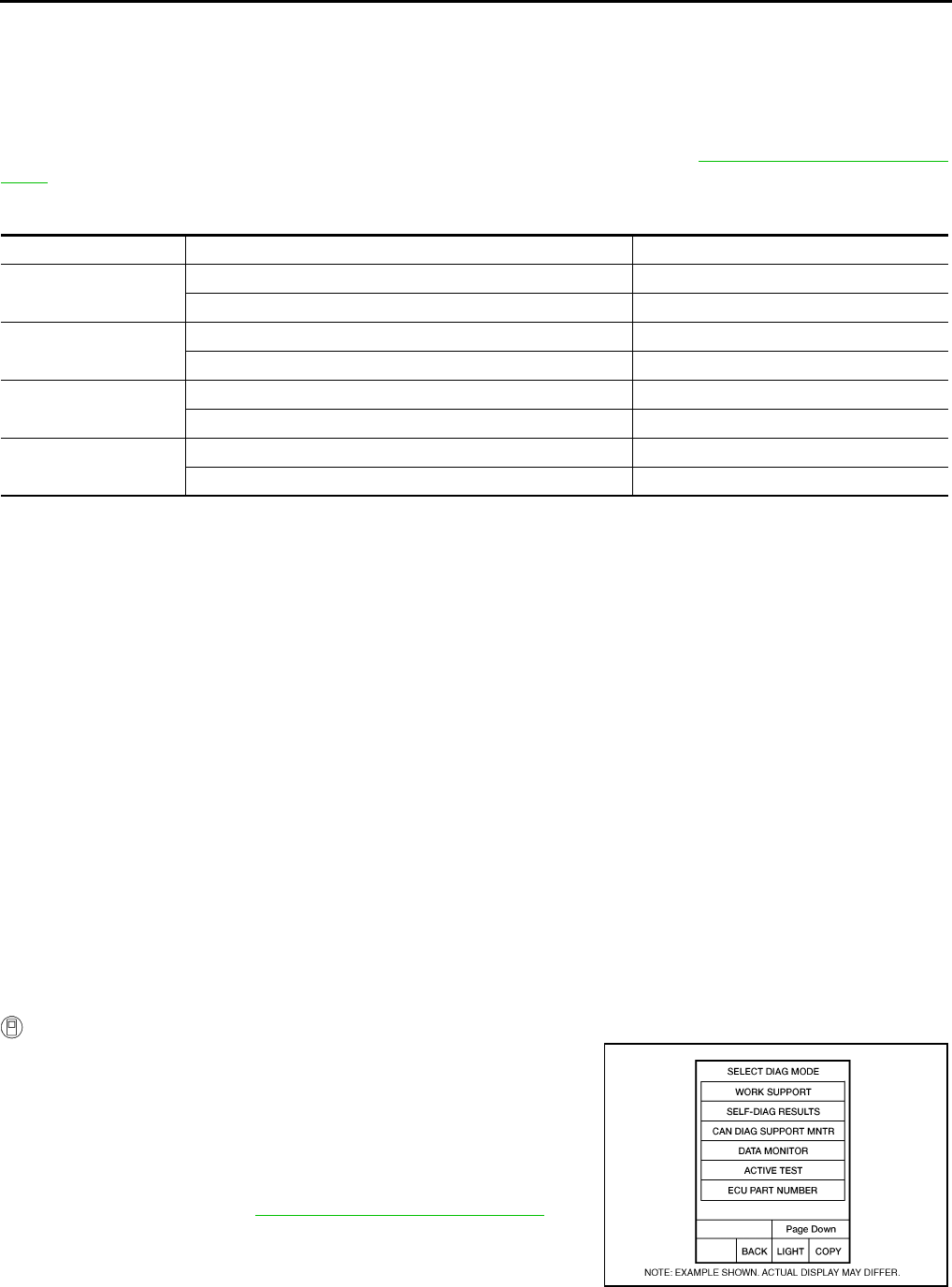
CVT-132
DTC P0826 MANUAL MODE SWITCH CIRCUIT
Revision: 2006 August 2006 Murano
DTC P0826 MANUAL MODE SWITCH CIRCUIT PFP:34901
Description NCS00165
Manual mode switch is installed in CVT control device. The manual mode switch sends shift up and shift down
switch signals to TCM.
TCM sends the switch signals to unified meter and A/C amp via CAN communication line. Then manual mode
switch position is indicated on the CVT position indicator. For inspection, refer to CVT-182, "Diagnostic Proce-
dure" .
CONSULT-II Reference Value NCS00166
On Board Diagnosis Logic NCS00167
●This is not an OBD-II self-diagnostic item.
●Diagnostic trouble code “P0826 MANUAL MODE SWITCH” with CONSULT-II is detected when TCM
monitors Manual mode, Non manual mode, Up or Down switch signal, and then detects irregular with
impossible input pattern for 1 second or more.
Possible Cause NCS00168
●Harness or connectors
(These switches circuit is open or shorted.)
(TCM, and unified meter and A/C amp circuit are open or shorted.)
(CAN communication line is open or shorted.)
●Manual mode select switch (Built into CVT control device)
●Manual mode position select switch (Built into CVT control device)
DTC Confirmation Procedure NCS00169
CAUTION:
Always drive vehicle at a safe speed.
NOTE:
If “DTC Confirmation Procedure” has been previously conducted, always turn ignition switch OFF and
wait at least 10 seconds before conducting the next test.
After the repair, perform the following procedure to confirm the malfunction is eliminated.
WITH CONSULT-II
1. Turn ignition switch ON. (Do not start engine.)
2. Select “DATA MONITOR” mode for “TRANSMISSION” with
CONSULT-II.
3. Start engine.
4. Move selector lever to “M” position.
5. Drive vehicle for at least 2 consecutive seconds.
6. If DTC is detected, go to CVT-134, "Diagnostic Procedure" .
Item name Condition Display value
MMODE Manual shift gate position (neutral) ON
Other than the above OFF
NON MMODE Manual shift gate position (neutral, +side, -side) OFF
Other than the above ON
UPLVR Selector lever: + side ON
Other than the above OFF
DOWNLVR Selector lever: - side ON
Other than the above OFF
BCIA0031E
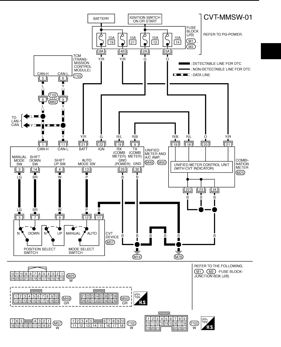
DTC P0826 MANUAL MODE SWITCH CIRCUIT
CVT-133
D
E
F
G
H
I
J
K
L
M
A
B
CVT
Revision: 2006 August 2006 Murano
Wiring Diagram — CVT — MMSW NCS0016A
TCWB0259E
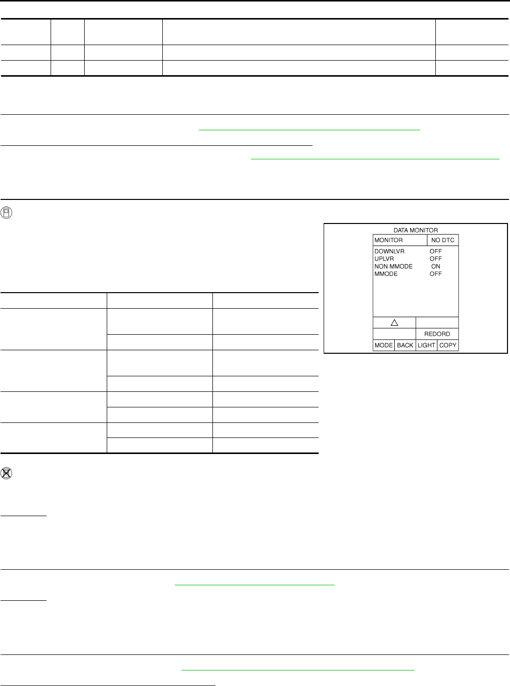
CVT-134
DTC P0826 MANUAL MODE SWITCH CIRCUIT
Revision: 2006 August 2006 Murano
TCM terminal data are reference values, measured between each terminal and ground.
Diagnostic Procedure NCS0016B
1. CHECK CAN COMMUNICATION LINE
Perform the self-diagnosis check. Refer to CVT-65, "SELF-DIAGNOSTIC RESULT MODE" .
Is any malfunction of the “U1000 CAN COMM CIRCUIT” indicated?
YES >> Check CAN communication line. Refer to CVT-72, "DTC U1000 CAN COMMUNICATION LINE" .
NO >> GO TO 2.
2. CHECK MANUAL MODE SWITCH SIGNALS
With CONSULT-II
1. Turn ignition switch ON. (Do not start engine.)
2. Select “ECU INPUT SIGNALS” in “DATA MONITOR” mode for
“TRANSMISSION” with CONSULT-II.
3. Read out ON/OFF switching action of the “MMODE”, “NON M-
MODE”, “UPLVR”, “DOWNLVR”.
Without CONSULT-II
Drive vehicle in the manual mode, and confirm that the actual gear position and the meter's indication of the
position mutually coincide when the selector lever is shifted to the “+ (up)” or “- (down)” side (1st ⇔ 6th gear).
OK or NG
OK >> GO TO 7.
NG >> GO TO 3.
3. CHECK MANUAL MODE SWITCH
Check manual mode switch. Refer to CVT-136, "Component Inspection" .
OK or NG
OK >> GO TO 4.
NG >> Repair or replace damaged parts.
4. CHECK SELF-DIAGNOSTIC RESULTS (UNIFIED METER AND A/C AMP)
Perform self-diagnosis check. Refer to DI-15, "CONSULT-II Function (METER A/C AMP)" .
Is any malfunction detected by self-diagnosis?
YES >> Check the malfunctioning system.
NO >> GO TO 5.
Terminal Wire
color Item Condition Data (Approx.)
5 L CAN-H — —
6 Y CAN- L — —
Item name Condition Display value
MMODE
Manual shift gate posi-
tion (neutral) ON
Other than the above OFF
NON MMODE
Manual shift gate posi-
tion (neutral, +side, -side) OFF
Other than the above ON
UPLVR Selector lever: + side ON
Other than the above OFF
DOWNLVR Selector lever: - side ON
Other than the above OFF
SCIA4588E
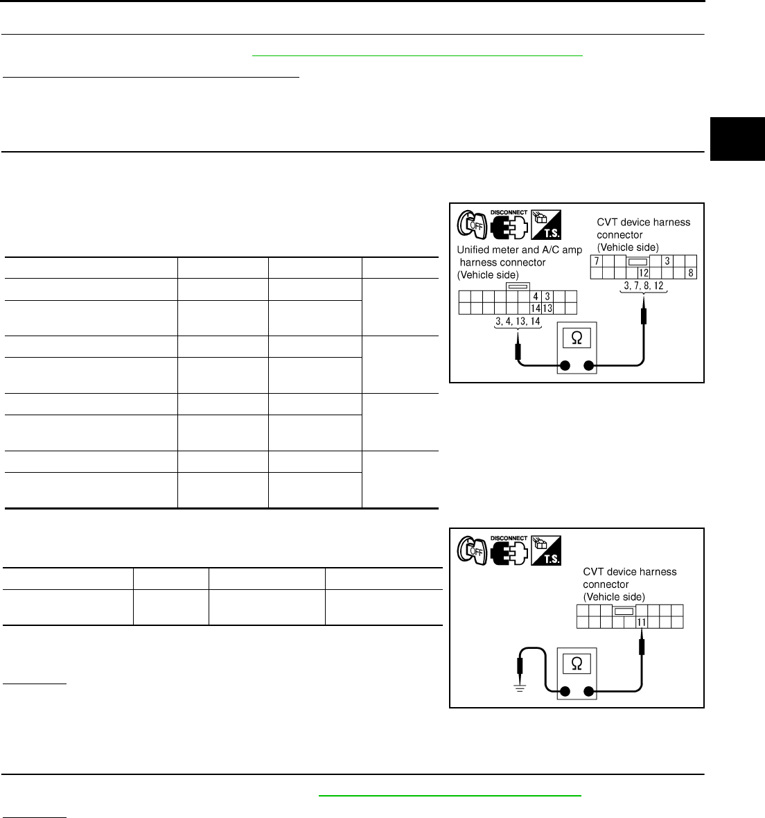
DTC P0826 MANUAL MODE SWITCH CIRCUIT
CVT-135
D
E
F
G
H
I
J
K
L
M
A
B
CVT
Revision: 2006 August 2006 Murano
5. CHECK SELF-DIAGNOSTIC RESULTS (COMBINATION METER)
Perform self-diagnosis check. Refer to DI-15, "Self-Diagnosis Mode of Combination Meter" .
Is any malfunction detected by self-diagnosis?
YES >> Check the malfunctioning system.
NO >> GO TO 6.
6. CHECK MANUAL MODE SWITCH CIRCUIT
1. Turn ignition switch OFF.
2. Disconnect CVT device connector and unified meter and A/C amp connector.
3. Check continuity between CVT device harness connector termi-
nals and unified meter and A/C amp harness connector termi-
nals.
4. Check continuity between CVT device harness connector termi-
nal and ground.
5. If OK, check harness for short to ground and short to power.
6. Reinstall any part removed.
OK or NG
OK >> GO TO 7.
NG >> Repair open circuit or short to ground or short to power
in harness or connectors.
7. CHECK DTC
Perform “DTC Confirmation Procedure”. Refer to CVT-132, "DTC Confirmation Procedure" .
OK or NG
OK >> INSPECTION END
NG >> GO TO 8.
Item Connector Terminal Continuity
CVT device harness connector M57 3
Yes
Unified meter and A/C amp
harness connector M49 3
CVT device harness connector M57 7
Yes
Unified meter and A/C amp
harness connector M49 14
CVT device harness connector M57 8
Yes
Unified meter and A/C amp
harness connector M49 4
CVT device harness connector M57 12
Yes
Unified meter and A/C amp
harness connector M49 13
SCIA4589E
Item Connector Terminal Continuity
CVT device harness
connector M57 11- Ground Yes
SCIA4590E
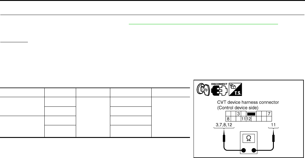
CVT-136
DTC P0826 MANUAL MODE SWITCH CIRCUIT
Revision: 2006 August 2006 Murano
8. CHECK TCM
1. Check TCM input/output signals. Refer to CVT-57, "TCM Input/Output Signal Reference Values" .
2. If NG, re-check TCM pin terminals for damage or loose connection with harness connector.
OK or NG
OK >> INSPECTION END
NG >> Repair or replace damaged parts.
Component Inspection NCS0016C
MANUAL MODE SWITCH
Check continuity between CVT device harness connector terminals.
Item Position Connector Terminal Continuity
Manual mode
select switch
Auto
M57
12 - 11
Yes
Manual 3 - 11
Manual mode
position select
switch
Up 8 - 11
Down 7 - 11
SCIA4591E
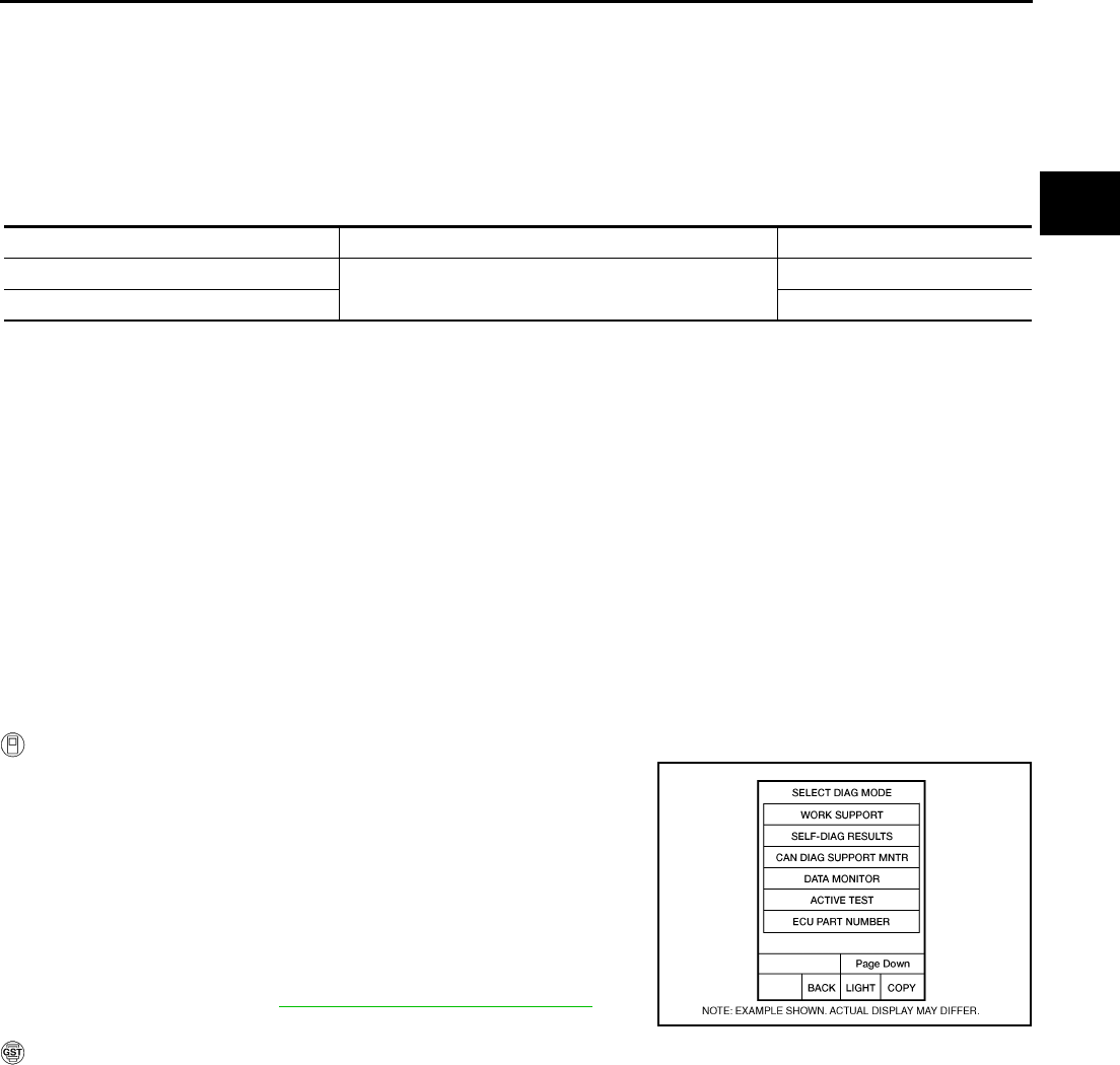
DTC P0840 TRANSMISSION FLUID PRESSURE SENSOR A CIRCUIT (SEC
PRESSURE SENSOR)
CVT-137
D
E
F
G
H
I
J
K
L
M
A
B
CVT
Revision: 2006 August 2006 Murano
DTC P0840 TRANSMISSION FLUID PRESSURE SENSOR A CIRCUIT (SEC
PRESSURE SENSOR) PFP:31936
Description NCS0016D
The transmission fluid pressure sensor A (secondary pressure sensor) detects secondary pressure of CVT
and sends TCM the signal.
CONSULT-II Reference Value NCS0016E
Remarks: Specification data are reference values.
On Board Diagnosis Logic NCS0016F
●This is an OBD-II self-diagnostic item.
●Diagnostic trouble code “P0840 TR PRS SENS/A CIRC” with CONSULT-II is detected when TCM detects
an improper voltage drop when it receives the sensor signal.
Possible Cause NCS0016G
●Transmission fluid pressure sensor A (Secondary pressure sensor)
●Harness or connectors
(Switch circuit is open or shorted.)
DTC Confirmation Procedure NCS0016H
NOTE:
If “DTC Confirmation Procedure” has been previously performed, always turn ignition switch OFF and
wait at least 10 seconds before performing the next test.
After the repair, perform the following procedure to confirm the malfunction is eliminated.
WITH CONSULT-II
1. Turn ignition switch ON and select “DATA MONITOR” mode for
“TRANSMISSION” with CONSULT-II.
2. Make sure that output voltage of line temperature sensor is
within the range below.
ATF TEMP SEN: 1.0 - 2.0 V
If out of range, drive the vehicle to decrease the voltage
(warm up the fluid) or stop engine to increase the voltage
(cool down the fluid)
3. Start engine and wait for at least 5 consecutive seconds.
4. If DTC is detected, go to CVT-139, "Diagnostic Procedure" .
WITH GST
Follow the procedure “WITH CONSULT-II”.
Item name Condition Display value (Approx.)
SEC HYDR SEN “N” position idle 0.8 - 1.0 V
SEC PRESS 0.5 - 0.9 MPa
BCIA0031E
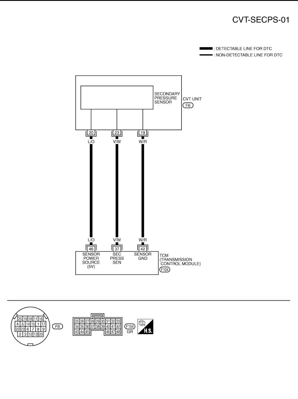
CVT-138
DTC P0840 TRANSMISSION FLUID PRESSURE SENSOR A CIRCUIT (SEC
PRESSURE SENSOR)
Revision: 2006 August 2006 Murano
Wiring Diagram — CVT — SECPS NCS0016I
TCWA0253E
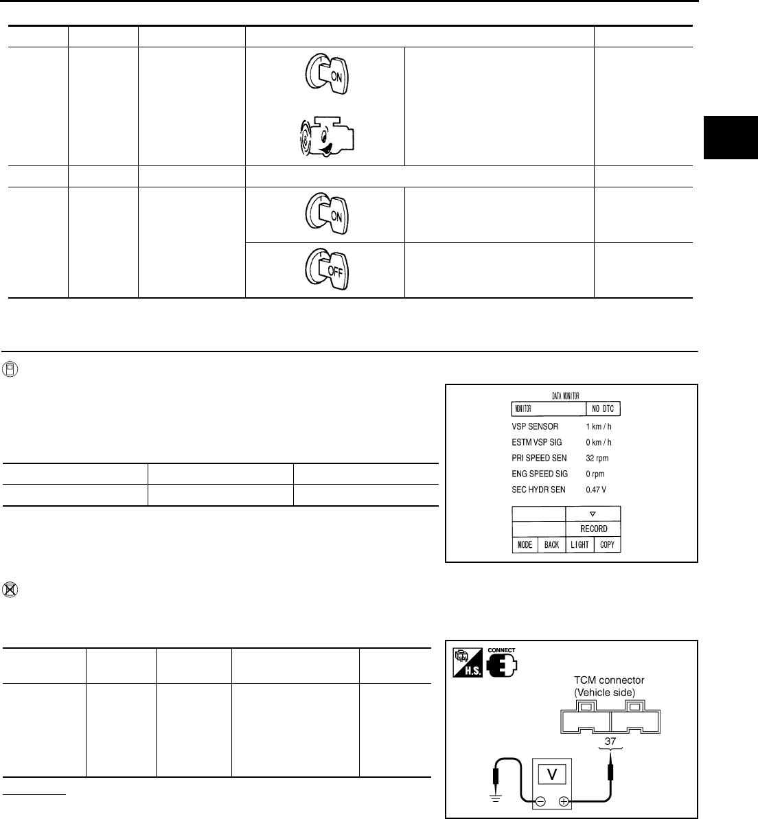
DTC P0840 TRANSMISSION FLUID PRESSURE SENSOR A CIRCUIT (SEC
PRESSURE SENSOR)
CVT-139
D
E
F
G
H
I
J
K
L
M
A
B
CVT
Revision: 2006 August 2006 Murano
TCM terminal data are reference values, measured between each terminal and ground.
Diagnostic Procedure NCS0016J
1. CHECK INPUT SIGNAL
With CONSULT-II
1. Start engine.
2. Select “ECU INPUT SIGNALS” in “DATA MONITOR” mode for
“TRANSMISSION” with CONSULT-II.
3. Start vehicle and read out the value of “SEC HYDR SEN”.
Without CONSULT-II
1. Start engine.
2. Check voltage between TCM connector terminal and ground.
OK or NG
OK >> GO TO 5.
NG >> GO TO 2.
Terminal Wire color Item Condition Data (Approx.)
37 V/W
Transmission fluid
pressure sensor A
(Secondary pres-
sure sensor)
and “N” position idle 0.8 V
42 W/R Sensor ground Always 0 V
46 L/O Sensor power
— 4.5 - 5.5 V
— 0 V
Item name Condition Display value (Approx.)
SEC HYDR SEN “N” position idle 0.8 - 1.0 V
SCIA2279E
Name Connector Terminal Condition Voltage
(Approx.)
Transmission
fluid pres-
sure sensor A
(Secondary
pressure sen-
sor)
F104 37 - Ground “N” position idle 0.8 V
SCIA4508E

CVT-140
DTC P0840 TRANSMISSION FLUID PRESSURE SENSOR A CIRCUIT (SEC
PRESSURE SENSOR)
Revision: 2006 August 2006 Murano
2. CHECK SENSOR POWER AND SENSOR GROUND
1. Turn ignition switch ON. (Do not start engine)
2. Check voltage between TCM connector terminals.
OK or NG
OK >> GO TO 4.
NG >> GO TO 3.
3. CHECK HARNESS BETWEEN TCM AND CVT UNIT HARNESS CONNECTOR (SENSOR POWER
AND SENSOR GROUND)
1. Turn ignition switch OFF.
2. Disconnect TCM connector and CVT unit harness connector.
3. Check continuity between TCM connector terminals and CVT
unit harness connector terminals.
4. If OK, check harness for short to ground and short to power.
5. Reinstall any part removed.
OK or NG
OK >> Replace TCM. Refer to CVT-9, "Precautions for TCM and CVT Assembly Replacement" .
NG >> Repair open circuit or short to ground or short to power in harness or connectors.
4. CHECK HARNESS BETWEEN TCM AND TRANSMISSION FLUID PRESSURE SENSOR A (SECOND-
ARY PRESSURE SENSOR)
1. Turn ignition switch OFF.
2. Disconnect TCM connector and CVT unit harness connector.
3. Check continuity between TCM connector terminal and CVT unit
harness connector terminal.
4. If OK, check harness for short to ground and short to power.
5. Reinstall any part removed.
OK or NG
OK >> GO TO 5.
NG >> Repair open circuit or short to ground or short to power
in harness or connectors.
Item Connector Terminal Data
(Approx.)
TCM connector F104 46 - 42 4.5 - 5.5 V
SCIA2367E
Item Connector Terminal Continuity
TCM connector F104 42 Yes
CVT unit harness connector F6 19
TCM connector F104 46 Yes
CVT unit harness connector F6 20
SCIA4681E
Item Connector Terminal Continuity
TCM connector F104 37 Yes
CVT unit harness connector F6 23
SCIA4690E

DTC P0840 TRANSMISSION FLUID PRESSURE SENSOR A CIRCUIT (SEC
PRESSURE SENSOR)
CVT-141
D
E
F
G
H
I
J
K
L
M
A
B
CVT
Revision: 2006 August 2006 Murano
5. CHECK DTC
Perform “DTC Confirmation Procedure”. Refer to CVT-137, "DTC Confirmation Procedure" .
OK or NG
OK >> INSPECTION END
NG >> GO TO 6.
6. CHECK TCM
1. Check TCM input/output signals. Refer to CVT-57, "TCM Input/Output Signal Reference Values" .
2. If NG, re-check TCM pin terminals for damage or loose connection with harness connector.
OK or NG
OK >> Replace the transaxle assembly. Refer to CVT-229, "Removal and Installation" .
NG >> Repair or replace damaged parts.
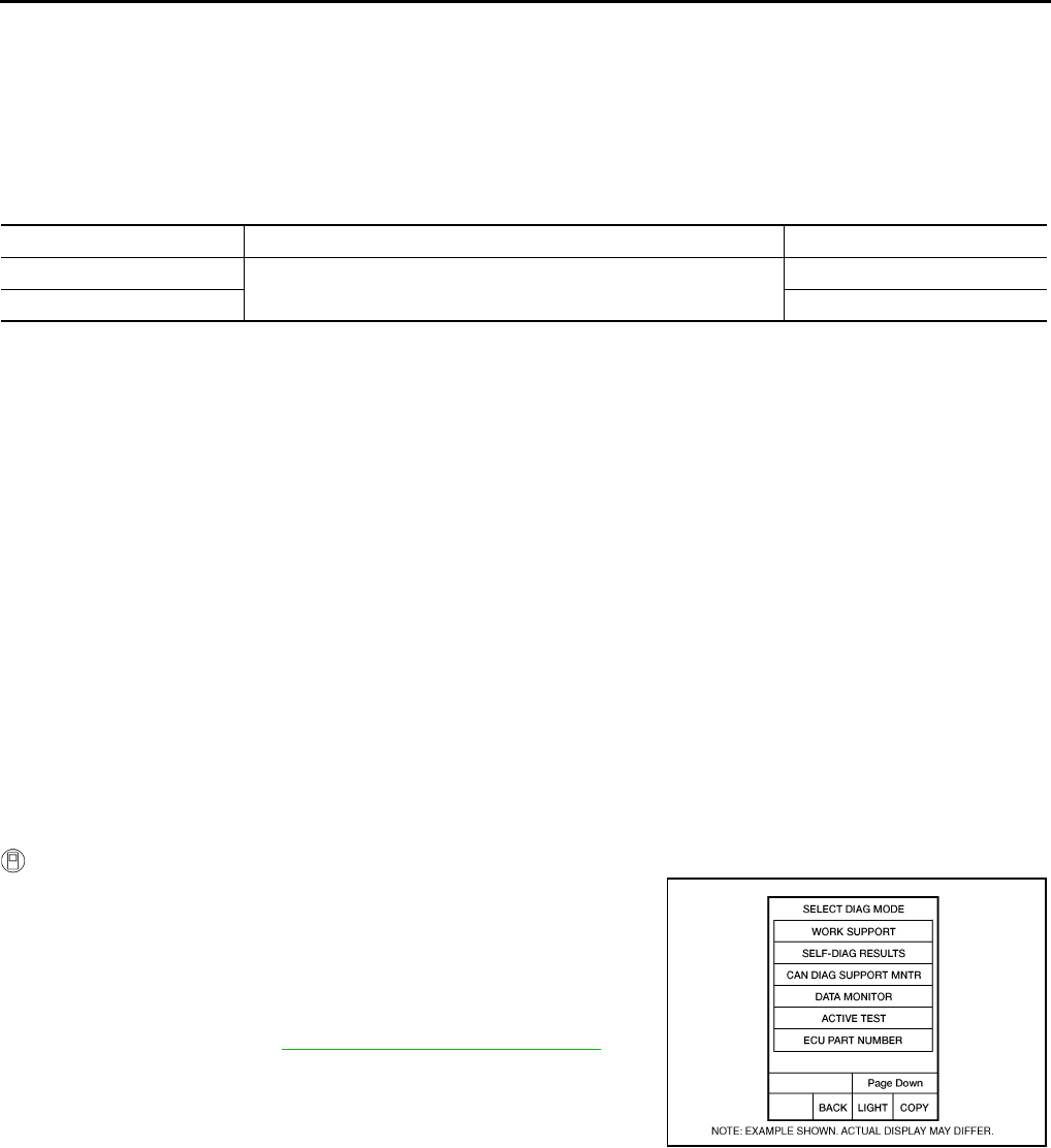
CVT-142
DTC P0841 PRESSURE SENSOR FUNCTION
Revision: 2006 August 2006 Murano
DTC P0841 PRESSURE SENSOR FUNCTION PFP:31936
Description NCS0016K
Using the engine load (throttle position), the primary pulley revolution speed, and the secondary pulley revolu-
tion speed as input signal, TCM changes the operating pressure of the primary pulley and the secondary pul-
ley and changes the groove width of the pulley to control the gear ratio.
CONSULT-II Reference Value NCS0016L
Remarks: Specification data are reference values.
On Board Diagnosis Logic NCS0016M
●This is not an OBD-II self-diagnostic item.
●Diagnostic trouble code “P0841 PRESS SEN/FNCTN” with CONSULT-II is detected when correlation
between the values of the secondary pressure sensor and the primary pressure sensor is out of specifica-
tion.
Possible Cause NCS0016N
●Transmission fluid pressure sensor A (Secondary pressure sensor)
●Transmission fluid pressure sensor B (Primary pressure sensor)
●Harness or connectors
(Sensor circuit is open or shorted.)
DTC Confirmation Procedure NCS0016O
CAUTION:
Always drive vehicle at a safe speed.
NOTE:
If “DTC Confirmation Procedure” has been previously performed, always turn ignition switch OFF and
wait at least 10 seconds before performing the next test.
After the repair, perform the following procedure to confirm the malfunction is eliminated.
WITH CONSULT-II
1. Turn ignition switch ON and select “DATA MONITOR” mode for
“TRANSMISSION” with CONSULT-II.
2. Start engine and maintain the following conditions for at least 12
consecutive seconds.
VEHICLE SPEED: 40 km/h (25 MPH) More than
RANGE: “D” position
3. If DTC is detected, go to CVT-143, "Diagnostic Procedure" .
Item name Condition Display value (Approx.)
PRI HYDR SEN “N” position idle 0.7 - 3.5 V
SEC HYDR SEN 0.8 - 1.0 V
BCIA0031E
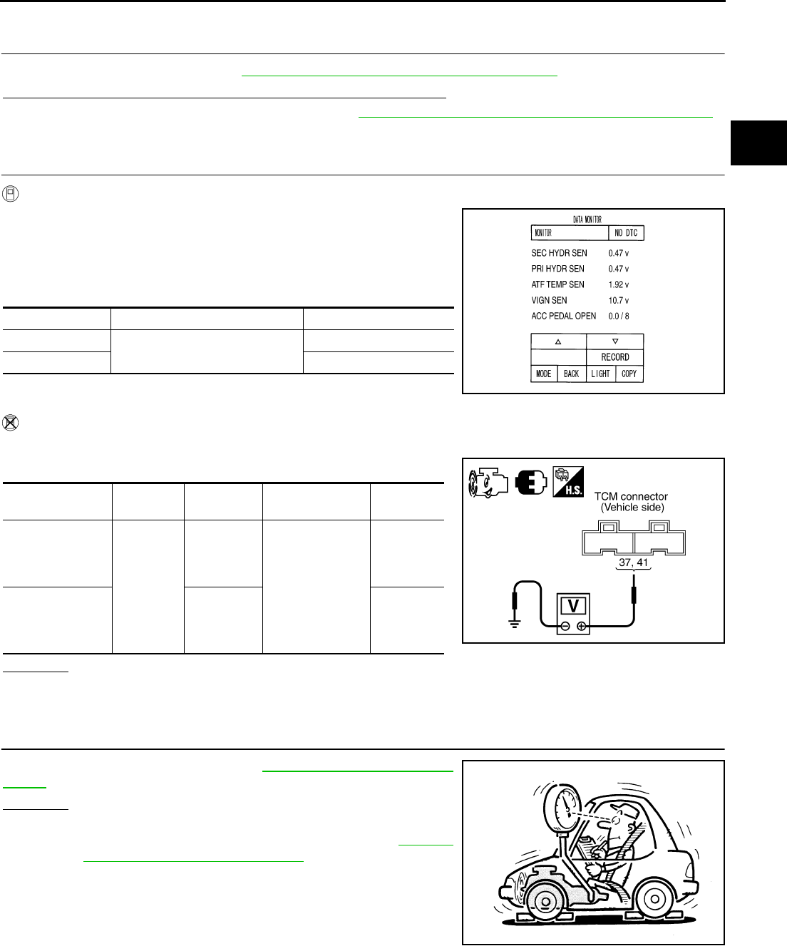
DTC P0841 PRESSURE SENSOR FUNCTION
CVT-143
D
E
F
G
H
I
J
K
L
M
A
B
CVT
Revision: 2006 August 2006 Murano
Diagnostic Procedure NCS0016P
1. CHECK CAN COMMUNICATION LINE
Perform the self-diagnosis. Refer to CVT-65, "SELF-DIAGNOSTIC RESULT MODE" .
Is any malfunction of the “U1000 CAN COMM CIRCUIT” indicated?
YES >> Check CAN communication line. Refer to CVT-72, "DTC U1000 CAN COMMUNICATION LINE" .
NO >> GO TO 2.
2. CHECK INPUT SIGNALS
With CONSULT-II
1. Start engine.
2. Select “ECU INPUT SIGNALS” in “DATA MONITOR” mode for
“TRANSMISSION” with CONSULT-II.
3. Start vehicle and read out the value of “SEC HYDR SEN” and
“PRI HYDR SEN”.
Without CONSULT-II
1. Start engine.
2. Check voltage between TCM connector terminals and ground.
OK or NG
OK >> GO TO 6.
NG >> GO TO 3.
3. CHECK LINE PRESSURE
Perform line pressure test. Refer to CVT-44, "LINE PRESSURE
TEST" .
OK or NG
OK >> GO TO 4.
NG >> Repair or replace damaged parts. Refer to CVT-45,
"Judgment of Line Pressure Test" .
Item name Condition Display value (Approx.)
PRI HYDR SEN “N” position idle 0.7 - 3.5 V
SEC HYDR SEN 0.8 - 1.0 V
SCIA2277E
Name Connector Terminal Condition Voltage
(Approx.)
Transmission fluid
pressure sensor B
(Primary pres-
sure sensor) F104
41 - Ground
“N” position idle
0.7 - 3.5 V
Transmission fluid
pressure sensor A
(Secondary pres-
sure sensor)
37 - Ground 0.8 V
SCIA6879E
SAT494G
CVT-144
DTC P0841 PRESSURE SENSOR FUNCTION
Revision: 2006 August 2006 Murano
4. CHECK TRANSMISSION FLUID PRESSURE SENSOR A (SECONDARY PRESSURE SENSOR) SYS-
TEM AND TRANSMISSION FLUID PRESSURE SENSOR B (PRIMARY PRESSURE SENSOR) SYSTEM
Check transmission fluid pressure sensor A (secondary pressure sensor) system and transmission fluid pres-
sure sensor B (primary pressure sensor) system. Refer to CVT-137, "DTC P0840 TRANSMISSION FLUID
PRESSURE SENSOR A CIRCUIT (SEC PRESSURE SENSOR)" , CVT-145, "DTC P0845 TRANSMISSION
FLUID PRESSURE SENSOR B CIRCUIT (PRI PRESSURE SENSOR)" .
OK or NG
OK >> GO TO 5.
NG >> Repair or replace damaged parts.
5. DETECT MALFUNCTIONING ITEM
Check the following:
●Line pressure solenoid valve. Refer to CVT-120, "Component Inspection" .
●Secondary pressure solenoid valve. Refer to CVT-131, "Component Inspection" .
●Step motor. Refer to CVT-175, "Component Inspection" .
OK or NG
OK >> GO TO 6.
NG >> Repair or replace damaged parts.
6. CHECK DTC
Perform “DTC Confirmation Procedure”. Refer to CVT-142, "DTC Confirmation Procedure" .
OK or NG
OK >> INSPECTION END
NG >> Replace TCM or transaxle assembly. Refer to CVT-229, "Removal and Installation" .
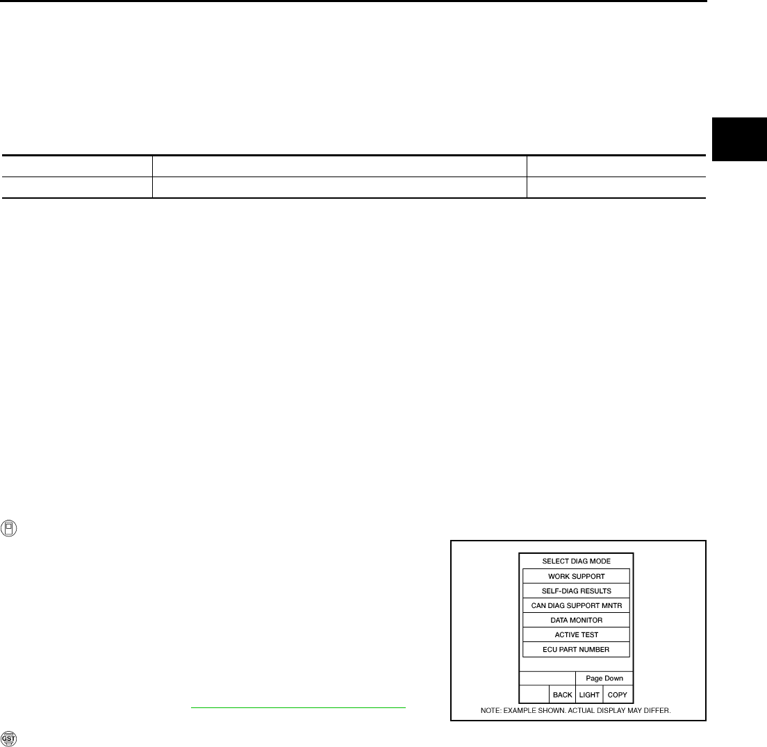
DTC P0845 TRANSMISSION FLUID PRESSURE SENSOR B CIRCUIT (PRI
PRESSURE SENSOR)
CVT-145
D
E
F
G
H
I
J
K
L
M
A
B
CVT
Revision: 2006 August 2006 Murano
DTC P0845 TRANSMISSION FLUID PRESSURE SENSOR B CIRCUIT (PRI PRES-
SURE SENSOR) PFP:31936
Description NCS0016Q
The transmission fluid pressure sensor B (primary pressure sensor) detects primary pressure of CVT and
sends TCM the signal.
CONSULT-II Reference Value NCS0016R
Remarks: Specification data are reference values.
On Board Diagnosis Logic NCS0016S
●This is an OBD-II self-diagnostic item.
●Diagnostic trouble code “P0845 TR PRS SENS/B CIRC” with CONSULT-II is detected under the following
conditions.
–When TCM detects an improper voltage drop when it receives the sensor signal.
–When TCM compares target value with monitor value and detects an irregularity.
Possible Cause NCS0016T
●Transmission fluid pressure sensor B (Primary pressure sensor)
●Harness or connectors
(Sensor circuit is open or shorted.)
DTC Confirmation Procedure NCS0016U
NOTE:
If “DTC Confirmation Procedure” has been previously performed, always turn ignition switch OFF and
wait at least 10 seconds before performing the next test.
After the repair, perform the following procedure to confirm the malfunction is eliminated.
WITH CONSULT-II
1. Turn ignition switch ON and select “DATA MONITOR” mode for
“TRANSMISSION” with CONSULT-II.
2. Make sure that output voltage of line temperature sensor is
within the range below.
ATF TEMP SEN: 1.0 - 2.0 V
If out of range, drive the vehicle to decrease the voltage
(warm up the fluid) or stop engine to increase the voltage
(cool down the fluid)
3. Start engine and wait for at least 5 consecutive seconds.
4. If DTC is detected, go to CVT-147, "Diagnostic Procedure" .
WITH GST
Follow the procedure “WITH CONSULT-II”.
Item name Condition Display value (Approx.)
PRI HYDR SEN “N” position idle 0.7 - 3.5 V
BCIA0031E
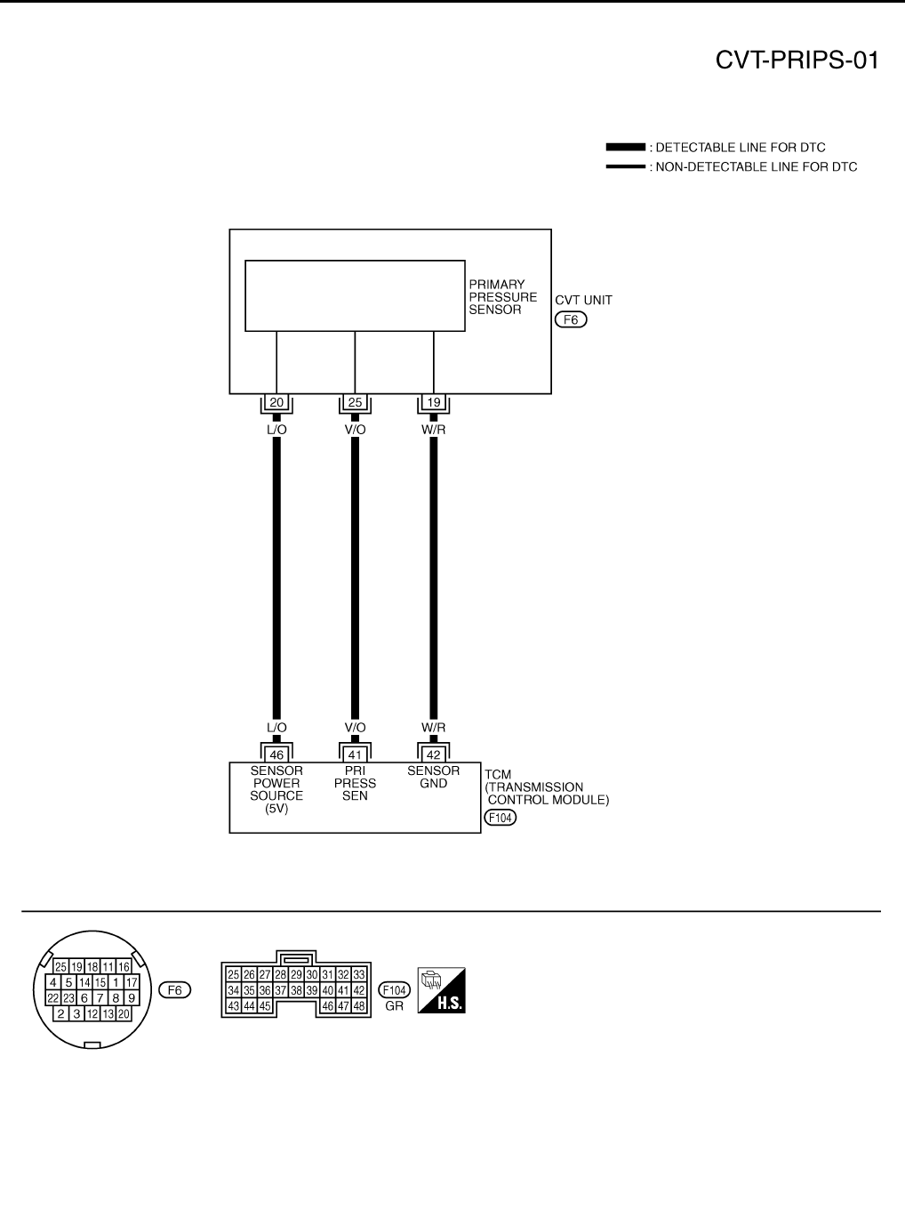
CVT-146
DTC P0845 TRANSMISSION FLUID PRESSURE SENSOR B CIRCUIT (PRI
PRESSURE SENSOR)
Revision: 2006 August 2006 Murano
Wiring Diagram — CVT — PRIPS NCS0016V
TCWA0255E

DTC P0845 TRANSMISSION FLUID PRESSURE SENSOR B CIRCUIT (PRI
PRESSURE SENSOR)
CVT-147
D
E
F
G
H
I
J
K
L
M
A
B
CVT
Revision: 2006 August 2006 Murano
TCM terminal data are reference values, measured between each terminal and ground.
Diagnostic Procedure NCS0016W
1. CHECK INPUT SIGNAL
With CONSULT-II
1. Start engine.
2. Select “ECU INPUT SIGNALS” in “DATA MONITOR” mode for
“TRANSMISSION” with CONSULT-II.
3. Start vehicle and read out the value of “PRI HYDR SEN”.
Without CONSULT-II
1. Start engine.
2. Check voltage between TCM connector terminal and ground.
OK or NG
OK >> GO TO 5.
NG >> GO TO 2.
Terminal Wire color Item Condition Data (Approx.)
41 V/O
Transmission fluid
pressure sensor B
(Primary pressure
sensor)
and “N” position idle 0.7 - 3.5 V
42 W/R Sensor ground Always 0 V
46 L/O Sensor power
— 4.5 - 5.5 V
—0 V
Item name Condition Display value (Approx.)
PRI HYDR SEN “N” position idle 0.7 - 3.5 V
SCIA2277E
Name Connector Terminal Condition Voltage
(Approx.)
Transmis-
sion fluid
pressure
sensor B
(Primary
pressure
sensor)
F104 41 - Ground “N” position idle 0.7 - 3.5 V
SCIA4509E
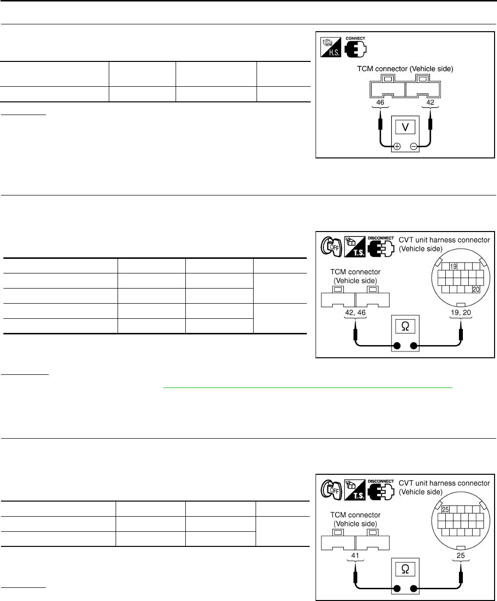
CVT-148
DTC P0845 TRANSMISSION FLUID PRESSURE SENSOR B CIRCUIT (PRI
PRESSURE SENSOR)
Revision: 2006 August 2006 Murano
2. CHECK SENSOR POWER AND SENSOR GROUND
1. Turn ignition switch ON. (Do not start engine)
2. Check voltage between TCM connector terminals.
OK or NG
OK >> GO TO 4.
NG >> GO TO 3.
3. CHECK HARNESS BETWEEN TCM AND CVT UNIT HARNESS CONNECTOR (SENSOR POWER
AND SENSOR GROUND)
1. Turn ignition switch OFF.
2. Disconnect TCM connector and CVT unit harness connector.
3. Check continuity between TCM connector terminals and CVT
unit harness connector terminals.
4. If OK, check harness for short to ground and short to power.
5. Reinstall any part removed.
OK or NG
OK >> Replace TCM. Refer to CVT-9, "Precautions for TCM and CVT Assembly Replacement" .
NG >> Repair open circuit or short to ground or short to power in harness or connectors.
4. CHECK HARNESS BETWEEN TCM AND TRANSMISSION FLUID PRESSURE SENSOR B (PRIMARY
PRESSURE SENSOR)
1. Turn ignition switch OFF.
2. Disconnect TCM connector and CVT unit harness connector.
3. Check continuity between TCM connector terminal and CVT unit
harness connector terminal.
4. If OK, check harness for short to ground and short to power.
5. Reinstall any part removed.
OK or NG
OK >> GO TO 5.
NG >> Repair open circuit or short to ground or short to power
in harness or connectors.
Item Connector Terminal Data
(Approx.)
TCM connector F104 46 - 42 4.5 - 5.5 V
SCIA2367E
Item Connector Terminal Continuity
TCM connector F104 42 Yes
CVT unit harness connector F6 19
TCM connector F104 46 Yes
CVT unit harness connector F6 20
SCIA4681E
Item Connector Terminal Continuity
TCM connector F104 41 Yes
CVT unit harness connector F6 25
SCIA4691E

DTC P0845 TRANSMISSION FLUID PRESSURE SENSOR B CIRCUIT (PRI
PRESSURE SENSOR)
CVT-149
D
E
F
G
H
I
J
K
L
M
A
B
CVT
Revision: 2006 August 2006 Murano
5. CHECK DTC
Perform “DTC Confirmation Procedure”. Refer to CVT-145, "DTC Confirmation Procedure" .
OK or NG
OK >> INSPECTION END
NG >> GO TO 6.
6. CHECK TCM
1. Check TCM input/output signals. Refer to CVT-57, "TCM Input/Output Signal Reference Values" .
2. If NG, re-check TCM pin terminals for damage or loose connection with harness connector.
OK or NG
OK >> Replace the transaxle assembly. Refer to CVT-229, "Removal and Installation" .
NG >> Repair or replace damaged parts.
CVT-150
DTC P0868 SECONDARY PRESSURE DOWN
Revision: 2006 August 2006 Murano
DTC P0868 SECONDARY PRESSURE DOWN PFP:31941
Description NCS0016X
The pressure control solenoid valve B (secondary pressure solenoid valve) regulates the secondary pressure
to suit the driving condition in response to a signal sent from the TCM.
CONSULT-II Reference Value NCS0016Y
Remarks: Specification data are reference values.
On Board Diagnosis Logic NCS0016Z
●This is not an OBD-II self-diagnostic item.
●Diagnostic trouble code “P0868 SEC/PRESS DOWN” with CONSULT-II is detected when secondary fluid
pressure is too low compared with the commanded value while driving.
Possible Cause NCS00170
●Harness or connectors
(Solenoid circuit is open or shorted.)
●Pressure control solenoid valve B (Secondary pressure solenoid valve) system
●Transmission fluid pressure sensor A (Secondary pressure sensor)
●Line pressure control system
DTC Confirmation Procedure NCS00171
CAUTION:
Always drive vehicle at a safe speed.
NOTE:
If “DTC Confirmation Procedure” has been previously performed, always turn ignition switch OFF and
wait at least 10 seconds before performing the next test.
After the repair, perform the following procedure to confirm the malfunction is eliminated.
WITH CONSULT-II
1. Turn ignition switch ON and select “DATA MONITOR” mode for
“TRANSMISSION” with CONSULT-II.
2. Make sure that output voltage of CVT fluid temperature sensor
is within the range below.
ATF TEMP SEN: 1.0 - 2.0 V
If out of range, drive the vehicle to decrease the voltage
(warm up the fluid) or stop engine to increase the voltage
(cool down the fluid)
3. Start engine and maintain the following conditions for at least 10
consecutive seconds.
VEHICLE SPEED (accelerate slowly): 0 → 50 km/h (31 MPH)
ACC PEDAL OPEN: 0.5/8 - 1.0/8
RANGE: “D” position
4. If DTC is detected, go to CVT-151, "Diagnostic Procedure" .
Item name Condition Display value (Approx.)
SEC PRESS “N” position idle 0.5 - 0.9 MPa
BCIA0031E

DTC P0868 SECONDARY PRESSURE DOWN
CVT-151
D
E
F
G
H
I
J
K
L
M
A
B
CVT
Revision: 2006 August 2006 Murano
Diagnostic Procedure NCS00172
1. CHECK INPUT SIGNAL
With CONSULT-II
1. Start engine.
2. Select “MAIN SIGNALS” in “DATA MONITOR” mode for
“TRANSMISSION” with CONSULT-II.
3. Start vehicle and read out the value of “SEC PRESS”.
OK or NG
OK >> GO TO 5.
NG >> GO TO 2.
2. CHECK LINE PRESSURE
Perform line pressure test. Refer to CVT-44, "LINE PRESSURE
TEST" .
OK or NG
OK >> GO TO 3.
NG >> Repair or replace damaged parts. Refer to CVT-45,
"Judgment of Line Pressure Test" .
3. DETECT MALFUNCTIONING ITEM
Check the following:
●Pressure control solenoid valve B (Secondary pressure solenoid valve). Refer to CVT-131, "Component
Inspection" .
●Pressure control solenoid valve A (Line pressure solenoid valve). Refer to CVT-120, "Component Inspec-
tion" .
OK or NG
OK >> GO TO 4.
NG >> Repair or replace damaged parts.
4. CHECK TRANSMISSION FLUID PRESSURE SENSOR A (SECONDARY PRESSURE SENSOR) SYS-
TEM
Check transmission fluid pressure sensor A (secondary pressure sensor) system. Refer to CVT-137, "DTC
P0840 TRANSMISSION FLUID PRESSURE SENSOR A CIRCUIT (SEC PRESSURE SENSOR)" .
OK or NG
OK >> GO TO 5.
NG >> Repair or replace damaged parts.
Item name Condition Display value (Approx.)
SEC PRESS “N” position idle 0.5 - 0.9 MPa
SCIA2366E
SAT494G

CVT-152
DTC P0868 SECONDARY PRESSURE DOWN
Revision: 2006 August 2006 Murano
5. DETECT MALFUNCTIONING ITEM
Check the following:
●Power supply and ground circuit for TCM. Refer to CVT-154, "Wiring Diagram — CVT — POWER" .
●The TCM pin terminals for damage or loose connection with harness connector.
OK or NG
OK >> GO TO 6.
NG >> Repair or replace damaged parts.
6. CHECK DTC
Perform “DTC Confirmation Procedure”. Refer to CVT-150, "DTC Confirmation Procedure" .
OK or NG
OK >> INSPECTION END
NG >> Replace the transaxle assembly. Refer to CVT-229, "Removal and Installation" .
DTC P1701 TRANSMISSION CONTROL MODULE (POWER SUPPLY)
CVT-153
D
E
F
G
H
I
J
K
L
M
A
B
CVT
Revision: 2006 August 2006 Murano
DTC P1701 TRANSMISSION CONTROL MODULE (POWER SUPPLY) PFP:31036
Description NCS00173
When the power supply to the TCM is cut OFF, for example because the battery is removed, and the self-diag-
nosis memory function stops, malfunction is detected.
NOTE:
Since “P1701 TCM-POWER SUPPLY” will be indicated when replacing TCM, perform diagnosis after
erasing “SELF-DIAG RESULTS”
On Board Diagnosis Logic NCS00174
●This is not an OBD-II self-diagnostic item.
●Diagnostic trouble code “P1701 TCM-POWER SUPPLY” with CONSULT-II is detected when TCM does
not receive the voltage signal from the battery power supply.
●This is not a malfunction message. (Whenever shutting OFF a power supply to the TCM, this message
appears on the screen.)
Possible Cause NCS00175
Harness or connectors
(Battery or ignition switch and TCM circuit is open or shorted.)
DTC Confirmation Procedure NCS00176
NOTE:
If “DTC Confirmation Procedure” has been previously conducted, always turn ignition switch OFF and
wait at least 10 seconds before conducting the next test.
After the repair, perform the following procedure to confirm the malfunction is eliminated.
WITH CONSULT-II
1. Turn ignition switch ON. (Do not start engine.)
2. Select “DATA MONITOR” mode for “TRANSMISSION” with
CONSULT-II.
3. Wait for at least 2 consecutive seconds.
4. If DTC is detected, go to CVT-155, "Diagnostic Procedure" .
BCIA0031E
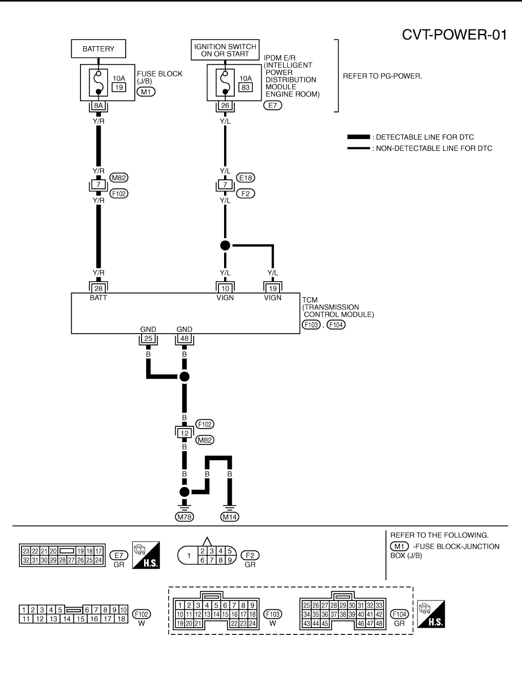
CVT-154
DTC P1701 TRANSMISSION CONTROL MODULE (POWER SUPPLY)
Revision: 2006 August 2006 Murano
Wiring Diagram — CVT — POWER NCS00177
TCWB0393E
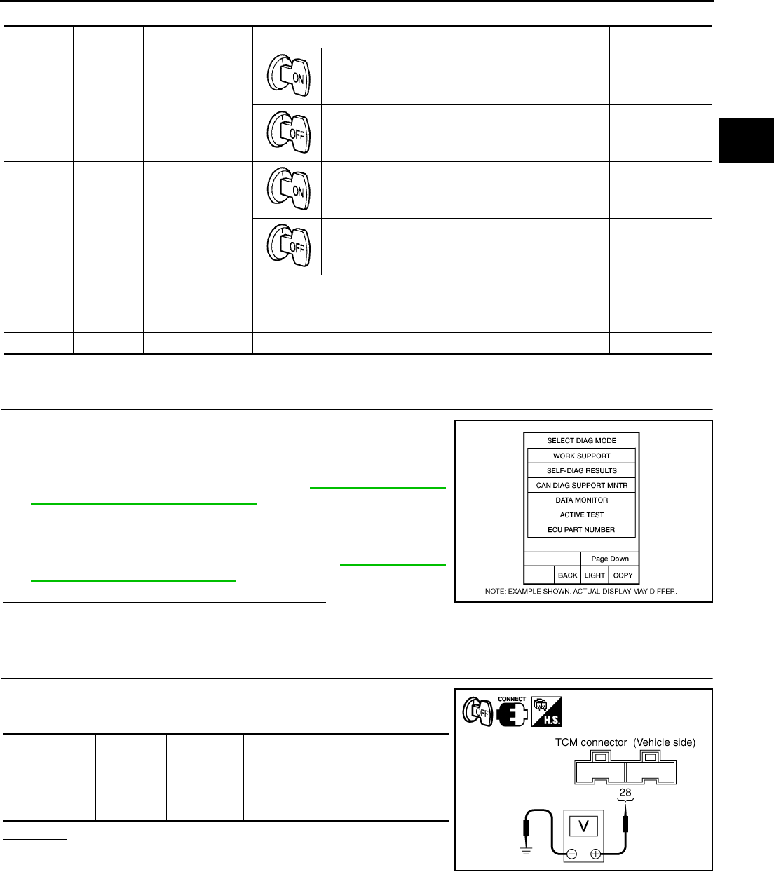
DTC P1701 TRANSMISSION CONTROL MODULE (POWER SUPPLY)
CVT-155
D
E
F
G
H
I
J
K
L
M
A
B
CVT
Revision: 2006 August 2006 Murano
TCM terminals data are reference values, measured between each terminal and ground.
Diagnostic Procedure NCS00178
1. CHECK DTC
1. Turn ignition switch ON. (Do not start engine.)
2. Select “SELF-DIAG RESULTS” mode for “TRANSMISSION”
with CONSULT-II.
3. Erase self-diagnostic results. Refer to CVT-31, "HOW TO
ERASE DTC (WITH CONSULT-II)" .
4. Turn ignition switch OFF, and wait for 5 seconds or more.
5. Start engine.
6. Confirm self-diagnostic results again. Refer to CVT-65, "SELF-
DIAGNOSTIC RESULT MODE" .
Is the “P1701 TCM-POWER SUPPLY” displayed?
YES >> GO TO 2.
NO >> INSPECTION END
2. CHECK TCM POWER SOURCE, STEP 1
1. Turn ignition switch OFF.
2. Check voltage between TCM connector terminal and ground.
OK or NG
OK >> GO TO 3.
NG >> GO TO 4.
Terminal Wire color Item Condition Data (Approx.)
10 Y/L Power supply
— Battery voltage
—0 V
19 Y/L Power supply
— Battery voltage
—0 V
25 B Ground Always 0 V
28 Y/R Power supply
(memory back-up) Always Battery voltage
48 B Ground Always 0 V
BCIA0031E
Name Connector Terminal Condition Voltage
(Approx.)
Power supply
(memory back-
up)
F104 28 - Ground Always Battery
voltage
SCIA4783E
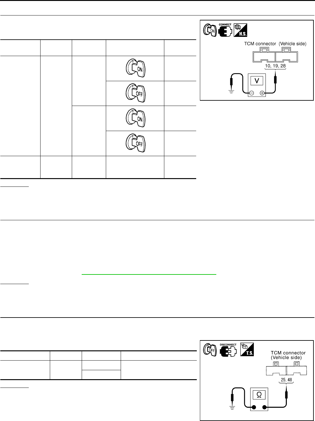
CVT-156
DTC P1701 TRANSMISSION CONTROL MODULE (POWER SUPPLY)
Revision: 2006 August 2006 Murano
3. CHECK TCM POWER SOURCE, STEP 2
1. Turn ignition switch ON. (Do not start engine.)
2. Check voltage between TCM connector terminals and ground.
OK or NG
OK >> GO TO 5.
NG >> GO TO 4.
4. DETECT MALFUNCTIONING ITEM
Check the following.
●Harness for short or open between battery and TCM connector terminal 28
●Harness for short or open between ignition switch and TCM connector terminal 10, 19
●10 A fuse (No.83, located in the IPDM E/R)
●10 A fuse (No.19, located in the fuse block)
●Ignition switch. Refer to PG-3, "POWER SUPPLY ROUTING CIRCUIT" .
OK or NG
OK >> GO TO 5.
NG >> Repair or replace damaged parts.
5. CHECK TCM GROUND CIRCUIT
1. Turn ignition switch OFF.
2. Disconnect TCM connector.
3. Check continuity between TCM connector terminals and ground.
OK or NG
OK >> GO TO 6.
NG >> Repair open circuit or short to ground or short to power
in harness or connectors.
Name Connector Terminal Condition Voltage
(Approx.)
Power supply F103
10 - Ground
Battery
voltage
0 V
19 - Ground
Battery
voltage
0 V
Power supply
(memory
back-up)
F104 28 - Ground Always Battery
voltage
SCIA4784E
Name Connector Terminal Continuity
Ground F104 25 - Ground Yes
48 - Ground
SCIA2671E

DTC P1701 TRANSMISSION CONTROL MODULE (POWER SUPPLY)
CVT-157
D
E
F
G
H
I
J
K
L
M
A
B
CVT
Revision: 2006 August 2006 Murano
6. CHECK DTC
Check again. Refer to CVT-155, "Diagnostic Procedure" .
OK or NG
OK >> INSPECTION END
NG >> GO TO 7.
7. CHECK TCM
1. Check TCM input/output signals. Refer to CVT-57, "TCM Input/Output Signal Reference Values" .
2. If NG, re-check TCM pin terminals for damage or loose connection with harness connector.
OK or NG
OK >> INSPECTION END
NG >> Repair or replace damaged parts.
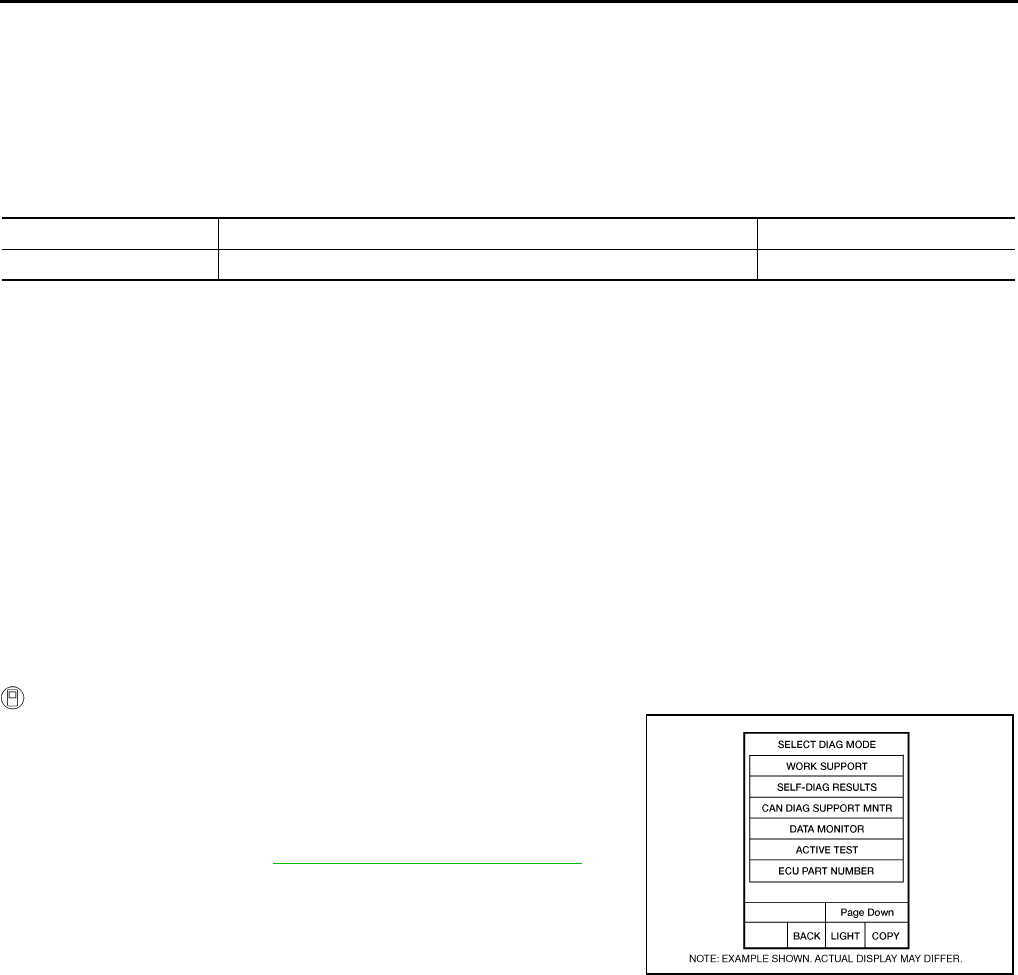
CVT-158
DTC P1705 THROTTLE POSITION SENSOR
Revision: 2006 August 2006 Murano
DTC P1705 THROTTLE POSITION SENSOR PFP:22620
Description NCS00179
Electric throttle control actuator consists of throttle control motor, accelerator pedal position sensor, throttle
position sensor etc. The actuator sends a signal to the ECM, and ECM sends the signal to TCM with CAN
communication.
CONSULT-II Reference Value NCS0017A
Remarks: Specification data are reference values.
On Board Diagnosis Logic NCS0017B
●This is not an OBD-II self-diagnostic item.
●Diagnostic trouble code “P1705 TP SEN/CIRC A/T” with CONSULT-II is detected when TCM does not
receive the proper accelerator pedal position signals (input by CAN communication) from ECM.
Possible Cause NCS0017C
●ECM
●Harness or connectors
(CAN communication line is open or shorted.)
DTC Confirmation Procedure NCS0017D
NOTE:
If “DTC Confirmation Procedure” has been previously performed, always turn ignition switch OFF and
wait at least 10 seconds before performing the next test.
After the repair, perform the following procedure to confirm the malfunction is eliminated.
WITH CONSULT-II
1. Turn ignition switch ON. (Do not start engine.)
2. Select “DATA MONITOR” mode for “TRANSMISSION” with
CONSULT-II.
3. Depress accelerator pedal fully and release it, then wait for 5
seconds.
4. If DTC is detected, go to CVT-159, "Diagnostic Procedure" .
Item name Condition Display value (Approx.)
ACC PEDAL OPEN Released accelerator pedal - Fully depressed accelerator pedal 0.0/8 - 8.0/8
BCIA0031E
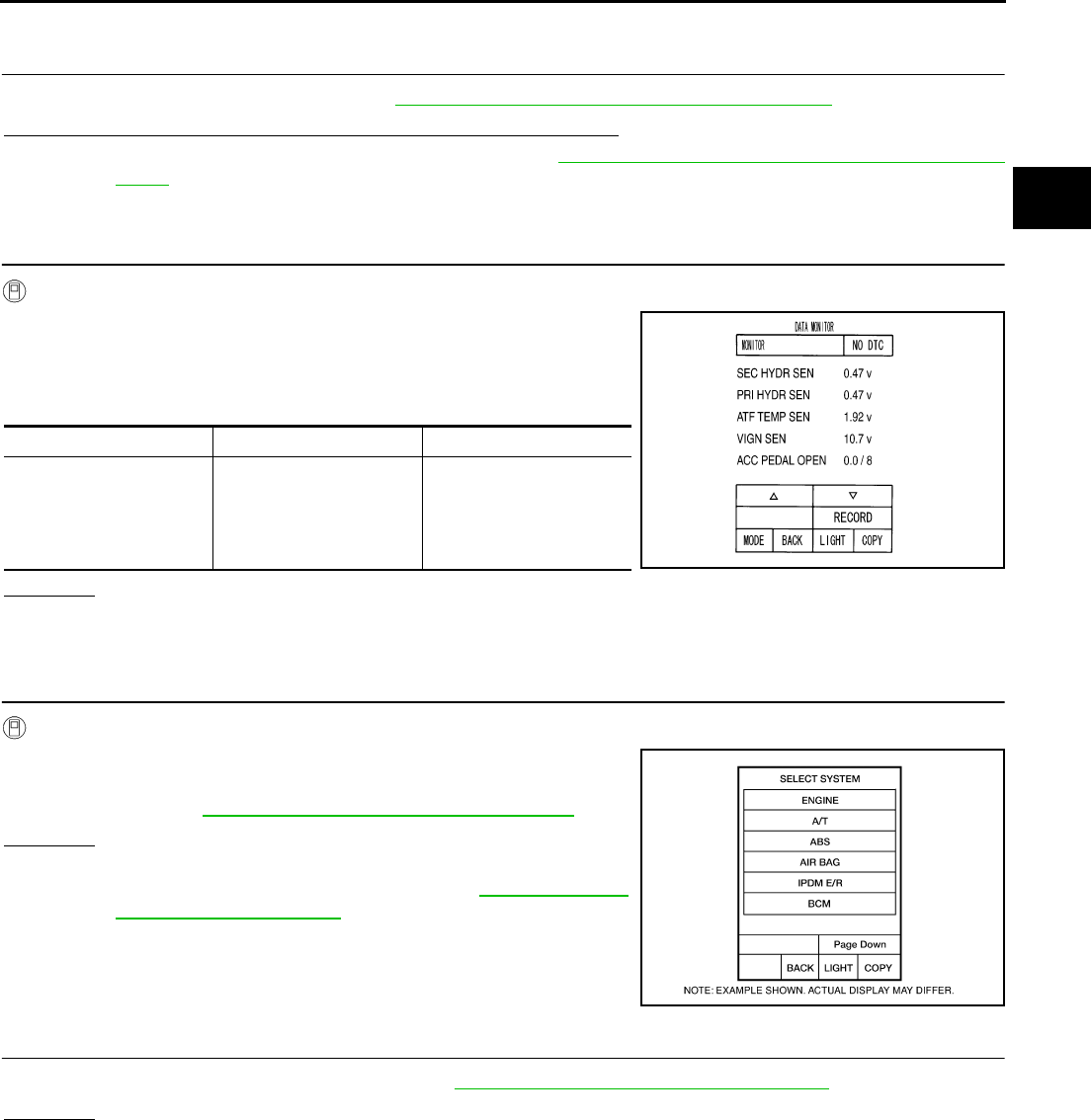
DTC P1705 THROTTLE POSITION SENSOR
CVT-159
D
E
F
G
H
I
J
K
L
M
A
B
CVT
Revision: 2006 August 2006 Murano
Diagnostic Procedure NCS0017E
1. CHECK CAN COMMUNICATION LINE
Perform the self-diagnosis check. Refer to CVT-65, "SELF-DIAGNOSTIC RESULT MODE" .
Is any malfunction of the “U1000 CAN COMM CIRCUIT” indicated?
YES >> Check the CAN communication line. Refer to CVT-72, "DTC U1000 CAN COMMUNICATION
LINE" .
NO >> GO TO 2.
2. CHECK INPUT SIGNAL
With CONSULT-II
1. Turn ignition switch ON. (Do not start engine.)
2. Select “ECU INPUT SIGNALS” in “DATA MONITOR” mode for
“TRANSMISSION” with CONSULT-II.
3. Read out the value of “ACC PEDAL OPEN”.
OK or NG
OK >> GO TO 4.
NG >> GO TO 3.
3. CHECK DTC WITH ECM
With CONSULT-II
1. Turn ignition switch ON. (Do not start engine.)
2. Select “SELF-DIAG RESULTS” mode for “ENGINE” with CON-
SULT-II. Refer to EC-115, "SELF-DIAG RESULTS MODE" .
OK or NG
OK >> GO TO 4.
NG >> Check the DTC Detected Item. Go to EC-115, "SELF-
DIAG RESULTS MODE" .
4. CHECK DTC
Perform “DTC Confirmation Procedure”. Refer to CVT-158, "DTC Confirmation Procedure" .
OK or NG
OK >> INSPECTION END
NG >> Repair or replace damaged parts.
Item name Condition Display value (Approx.)
ACC PEDAL OPEN
Release accelerator
pedal.
↓
Fully depressed acceler-
ator pedal
0.0/8
↓
8.0/8
SCIA2277E
BCIA0030E

CVT-160
DTC P1722 ESTM VEHICLE SPEED SIGNAL
Revision: 2006 August 2006 Murano
DTC P1722 ESTM VEHICLE SPEED SIGNAL PFP:47660
Description NCS0017F
The vehicle speed signal is transmitted from ABS actuator and electric unit (control unit) to TCM by CAN com-
munication line.
CONSULT-II Reference Value NCS0017G
Remarks: Specification data are reference values.
On Board Diagnosis Logic NCS0017H
●This is not an OBD-II self-diagnostic item.
●Diagnostic trouble code “P1722 ESTM VEH SPD SIG” with CONSULT-II is detected when TCM does not
receive the proper vehicle speed signal (input by CAN communication) from ABS actuator and electric
unit (control unit).
Possible Cause NCS0017I
●Harness or connectors
(Sensor circuit is open or shorted.)
●ABS actuator and electric unit (control unit)
DTC Confirmation Procedure NCS0017J
CAUTION:
Always drive vehicle at a safe speed.
NOTE:
If “DTC Confirmation Procedure” has been previously performed, always turn ignition switch OFF and
wait at least 10 seconds before performing the next test.
After the repair, touch “ERASE” on “SELF-DIAG RESULTS” and then perform the following procedure to con-
firm the malfunction is eliminated.
WITH CONSULT-II
1. Turn ignition switch ON. (Do not start engine.)
2. Select “DATA MONITOR” mode for “TRANSMISSION” with
CONSULT-II.
3. Start engine and maintain the following conditions for at least 5
consecutive seconds.
ACC PEDAL OPEN: 1.0/8 or less
VEHICLE SPEED SE: 30 km/h (17 MPH) or more
4. If DTC is detected, go to CVT-161, "Diagnostic Procedure" .
Item name Condition Display value
ESTM VSP SIG During driving Approximately matches the speedometer reading.
VEHICLE SPEED
BCIA0031E
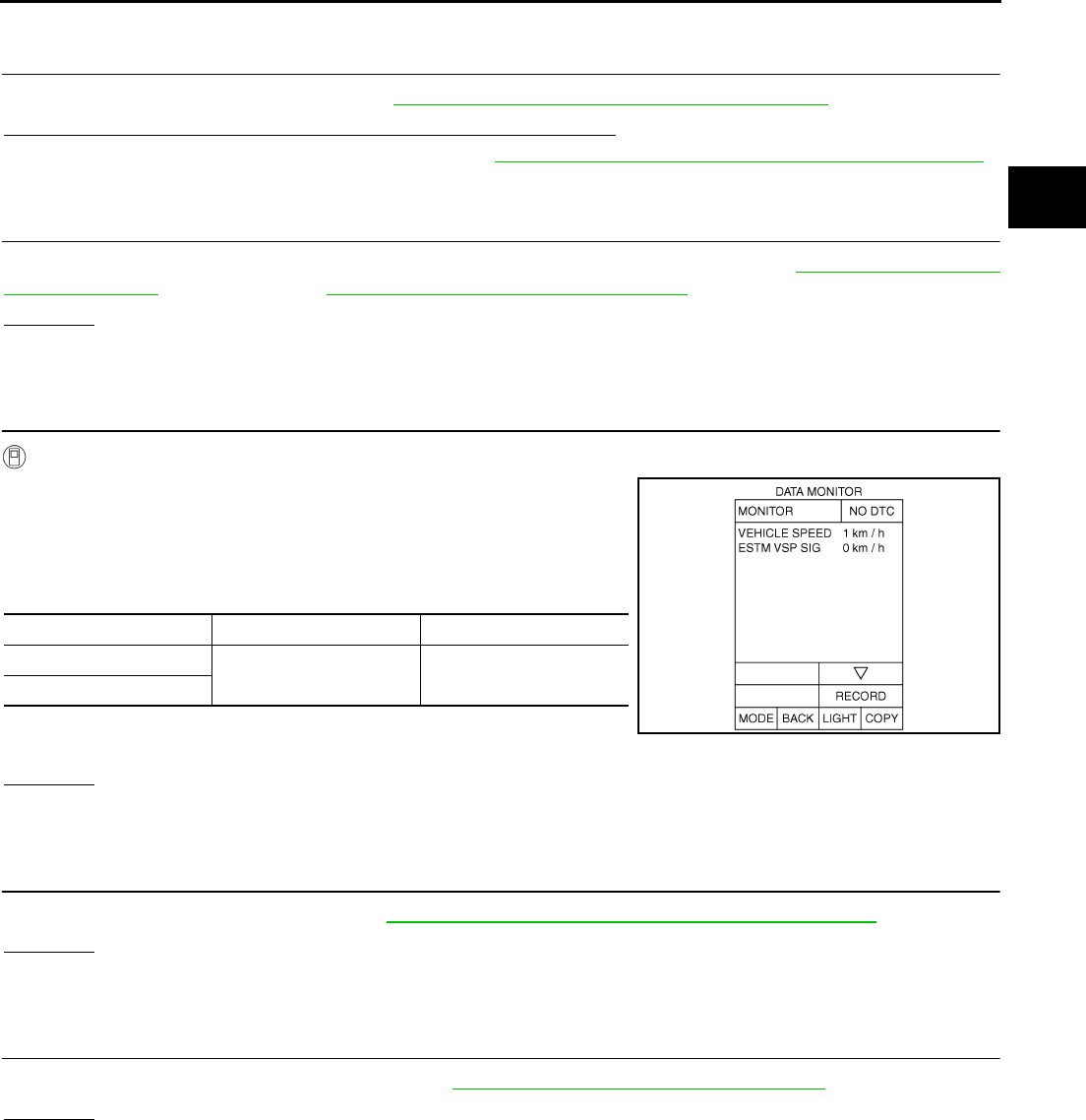
DTC P1722 ESTM VEHICLE SPEED SIGNAL
CVT-161
D
E
F
G
H
I
J
K
L
M
A
B
CVT
Revision: 2006 August 2006 Murano
Diagnostic Procedure NCS0017K
1. CHECK CAN COMMUNICATION LINE
Perform the self-diagnosis check. Refer to CVT-65, "SELF-DIAGNOSTIC RESULT MODE" .
Is any malfunction of the “U1000 CAN COMM CIRCUIT” indicated?
YES >> Check CAN communication line. Refer to CVT-72, "DTC U1000 CAN COMMUNICATION LINE" .
NO >> GO TO 2.
2. CHECK ABS ACTUATOR AND ELECTRIC UNIT (CONTROL UNIT)
Perform ABS actuator and electric unit (control unit) self-diagnosis check. Refer to BRC-22, "SELF-DIAG
RESULT MODE" (ABS models) or BRC-70, "SELF-DIAG RESULT MODE" (VDC/TCS/ABS models).
OK or NG
OK >> GO TO 3.
NG >> Repair or replace damaged parts.
3. CHECK INPUT SIGNALS
With CONSULT-II
1. Start engine.
2. Select “SELECTION FROM MENU” in “DATA MONITOR” mode
for “TRANSMISSION” with CONSULT-II.
3. Drive vehicle and read out the value of “VEHICLE SPEED” and
“ESTM VSP SIG”.
4. Check if there is a great difference between the two values.
OK or NG
OK >> GO TO 5.
NG >> GO TO 4.
4. CHECK TCM
Check TCM input/output signals. Refer to CVT-57, "TCM Input/Output Signal Reference Values" .
OK or NG
OK >> GO TO 5.
NG >> Repair or replace damaged parts.
5. CHECK DTC
Perform “DTC Confirmation Procedure”. Refer to CVT-160, "DTC Confirmation Procedure" .
OK or NG
OK >> INSPECTION END
NG >> GO TO 2.
Item name Condition Display value
ESTM VSP SIG During driving Approximately matches
the speedometer reading.
VEHICLE SPEED
SCIA4510E
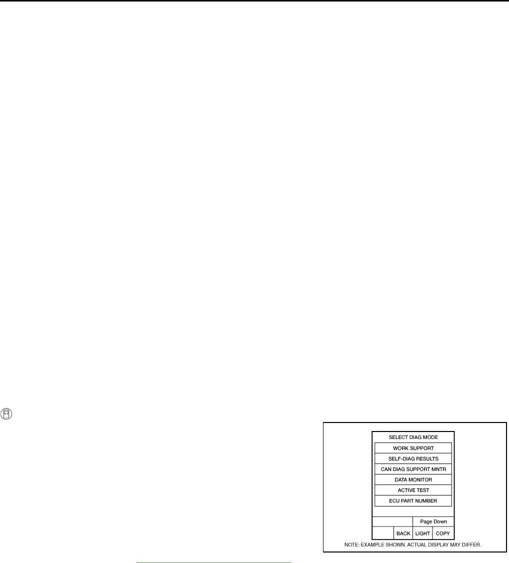
CVT-162
DTC P1723 CVT SPEED SENSOR FUNCTION
Revision: 2006 August 2006 Murano
DTC P1723 CVT SPEED SENSOR FUNCTION PFP:31907
Description NCS0017L
The vehicle speed sensor CVT [output speed sensor (secondary speed sensor)] detects the revolution of the
idler gear parking pawl lock gear and generates a pulse signal. The pulse signal is sent to the TCM, which
converts it into vehicle speed.
The input speed sensor (primary speed sensor) detects the primary pulley revolution speed and sends a sig-
nal to the TCM.
On Board Diagnosis Logic NCS0017M
●This is not an OBD-II self-diagnostic item.
●Diagnostic trouble code “P1723 CVT SPD SEN/FNCTN” with CONSULT-II is detected when there is a
great difference between the vehicle speed signal and the secondary speed sensor signal.
CAUTION:
One of the “P0720 VEH SPD SEN/CIR AT”, the “P0715 INPUT SPD SEN/CIRC” or the “P0725 ENGINE
SPEED SIG“ is displayed with the DTC at the same time.
Possible Cause NCS0017N
●Harness or connectors
(Sensor circuit is open or shorted.)
●Output speed sensor (Secondary speed sensor)
●Input speed sensor (Primary speed sensor)
●Engine speed signal system
DTC Confirmation Procedure NCS0017O
CAUTION:
Always drive vehicle at a safe speed.
NOTE:
If “DTC Confirmation Procedure” has been previously performed, always turn ignition switch OFF and
wait at least 10 seconds before performing the next test.
After the repair, touch “ERASE” on “SELF-DIAG RESULTS” and then perform the following procedure to con-
firm the malfunction is eliminated.
WITH CONSULT-II
1. Turn ignition switch ON and select “DATA MONITOR” mode for
“TRANSMISSION” with CONSULT-II.
2. Start engine and maintain the following conditions for at least 5
consecutive seconds.
VEHICLE SPEED SE: 10 km/h (6 MPH) or more
ACC PEDAL OPEN: More than 1.0/8
RANGE: “D” position
ENG SPEED: 450 rpm or more
Driving location: Driving the vehicle uphill (increased
engine load) will help maintain the driving conditions
required for this test.
3. If DTC is detected, go to CVT-163, "Diagnostic Procedure" .
BCIA0031E
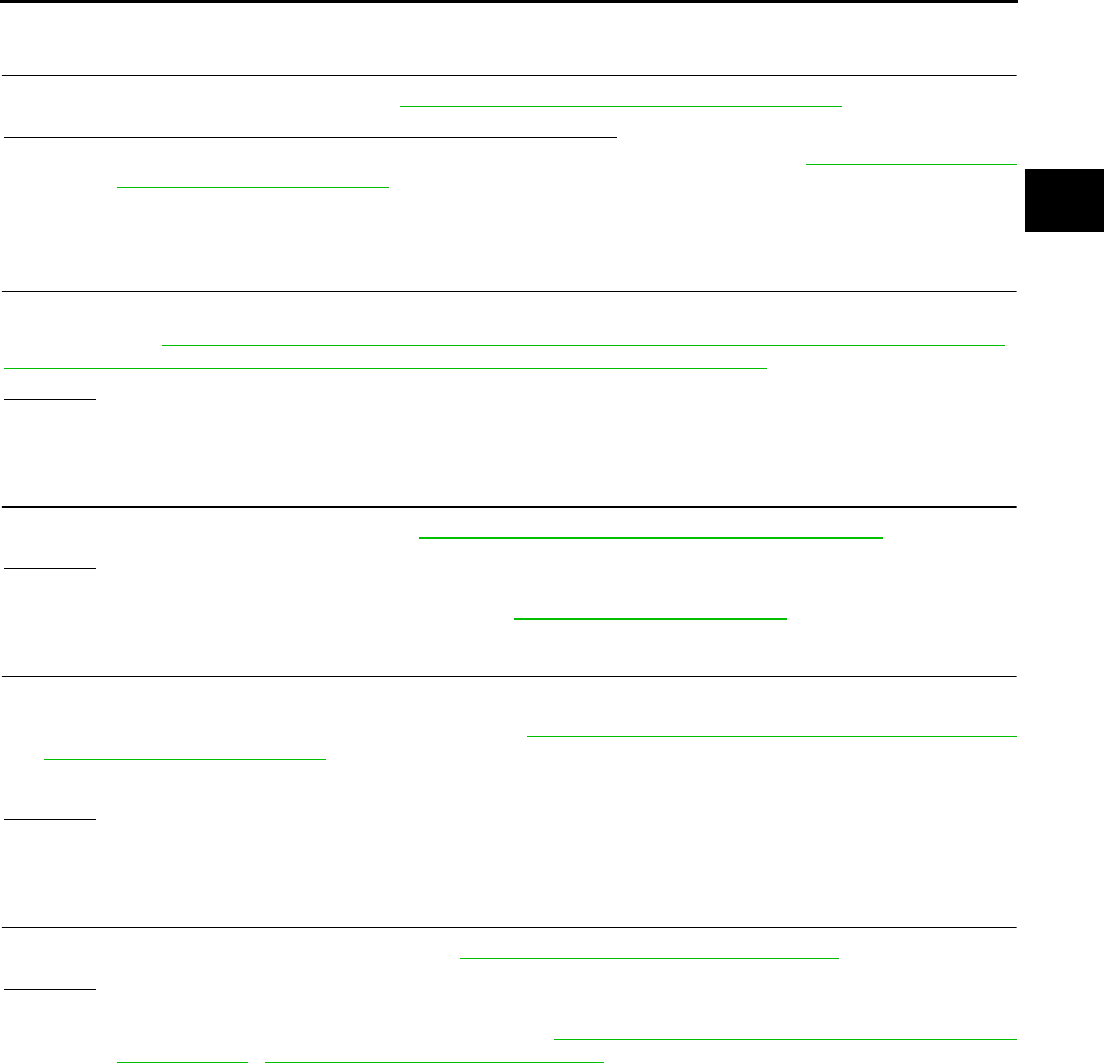
DTC P1723 CVT SPEED SENSOR FUNCTION
CVT-163
D
E
F
G
H
I
J
K
L
M
A
B
CVT
Revision: 2006 August 2006 Murano
Diagnostic Procedure NCS0017P
1. CHECK STEP MOTOR FUNCTION
Perform the self-diagnosis check. Refer to CVT-65, "SELF-DIAGNOSTIC RESULT MODE" .
Is a malfunction in the step motor function indicated in the results?
YES >> Repair or replace damaged parts. (Check the step motor function. Refer to CVT-176, "DTC P1778
STEP MOTOR - FUNCTION" .)
NO >> GO TO 2.
2. CHECK OUTPUT SPEED SENSOR (SECONDARY SPEED SENSOR SYSTEM) AND INPUT SPEED
SENSOR (PRIMARY SPEED SENSOR) SYSTEM
Check output speed sensor (secondary speed sensor) system and input speed sensor (primary speed sensor)
system. Refer to CVT-98, "DTC P0720 VEHICLE SPEED SENSOR CVT (SECONDARY SPEED SENSOR)" ,
CVT-93, "DTC P0715 INPUT SPEED SENSOR CIRCUIT (PRI SPEED SENSOR)" .
OK or NG
OK >> GO TO 3.
NG >> Repair or replace damaged parts.
3. CHECK ENGINE SPEED SIGNAL SYSTEM
Check engine speed signal system. Refer to CVT-104, "DTC P0725 ENGINE SPEED SIGNAL" .
OK or NG
OK >> GO TO 4.
NG >> Repair or replace damaged parts. Refer to EC-640, "IGNITION SIGNAL" .
4. DETECT MALFUNCTIONING ITEM
Check the following:
●Power supply and ground circuit for TCM. Refer to CVT-153, "DTC P1701 TRANSMISSION CONTROL
MODULE (POWER SUPPLY)" .
●The TCM pin terminals for damage or loose connection with harness connector.
OK or NG
OK >> GO TO 5.
NG >> Repair or replace damaged parts.
5. CHECK DTC
Perform “DTC Confirmation Procedure”. Refer to CVT-162, "DTC Confirmation Procedure" .
OK or NG
OK >> INSPECTION END
NG >> Replace TCM or transaxle assembly. Refer to CVT-9, "Precautions for TCM and CVT Assembly
Replacement" , CVT-229, "Removal and Installation" .
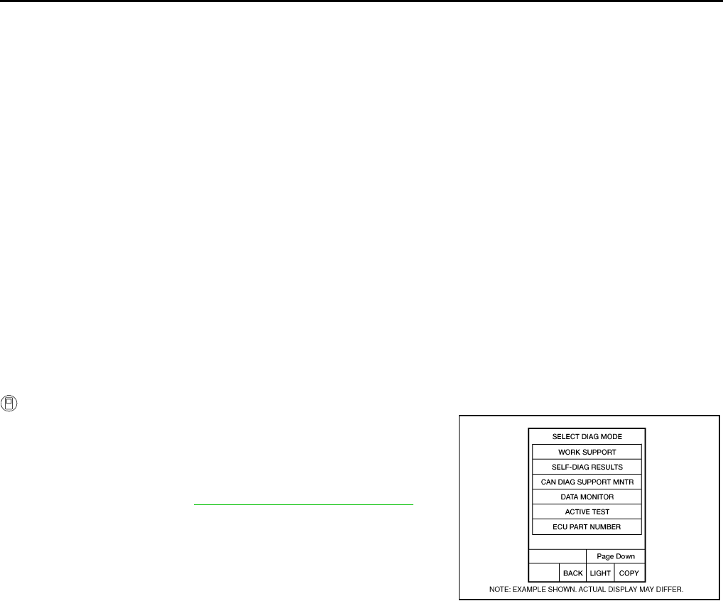
CVT-164
DTC P1726 ELECTRIC THROTTLE CONTROL SYSTEM
Revision: 2006 August 2006 Murano
DTC P1726 ELECTRIC THROTTLE CONTROL SYSTEM PFP:23710
Description NCS0017Q
Electric throttle control actuator consists of throttle control motor, accelerator pedal position sensor, throttle
position sensor etc. The actuator sends a signal to the ECM, and ECM sends the signal to TCM with CAN
communication.
On Board Diagnosis Logic NCS0017R
●This is not an OBD-II self-diagnostic item.
●Diagnostic trouble code “P1726 ELEC TH CONTROL” with CONSULT-II is detected when the electroni-
cally controlled throttle for ECM is malfunctioning.
Possible Cause NCS0017S
Harness or connectors
(Sensor circuit is open or shorted.)
DTC Confirmation Procedure NCS0017T
NOTE:
If “DTC Confirmation Procedure” has been previously performed, always turn ignition switch OFF and
wait at least 10 seconds before performing the next test.
After the repair, touch “ERASE” on “SELF-DIAG RESULTS” and then perform the following procedure to con-
firm the malfunction is eliminated.
WITH CONSULT-II
1. Turn ignition switch ON. (Do not start engine.)
2. Select “DATA MONITOR” mode for “TRANSMISSION” with
CONSULT-II.
3. Start engine and let it idle for 5 seconds.
4. If DTC is detected, go to CVT-165, "Diagnostic Procedure" .
BCIA0031E
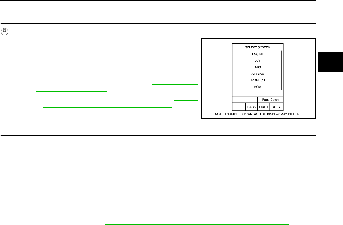
DTC P1726 ELECTRIC THROTTLE CONTROL SYSTEM
CVT-165
D
E
F
G
H
I
J
K
L
M
A
B
CVT
Revision: 2006 August 2006 Murano
Diagnostic Procedure NCS0017U
1. CHECK DTC WITH ECM
With CONSULT-II
1. Turn ignition switch ON. (Do not start engine.)
2. Select “SELF-DIAG RESULTS” mode for “ENGINE” with CON-
SULT-II. Refer to EC-115, "SELF-DIAG RESULTS MODE" .
OK or NG
OK >> GO TO 2.
NG >> Check the DTC Detected Item. Refer to EC-115, "SELF-
DIAG RESULTS MODE" .
●If CAN communication line is detected, go to CVT-72,
"DTC U1000 CAN COMMUNICATION LINE" .
2. CHECK DTC
Perform “DTC Confirmation Procedure”. Refer to CVT-164, "DTC Confirmation Procedure" .
OK or NG
OK >> INSPECTION END
NG >> GO TO 3.
3. DETECT MALFUNCTIONING ITEM
Check the following:
●The TCM pin terminals for damage or loose connection with harness connector.
OK or NG
OK >> Replace TCM. Refer to CVT-9, "Precautions for TCM and CVT Assembly Replacement" .
NG >> Repair or replace damaged parts.
BCIA0030E
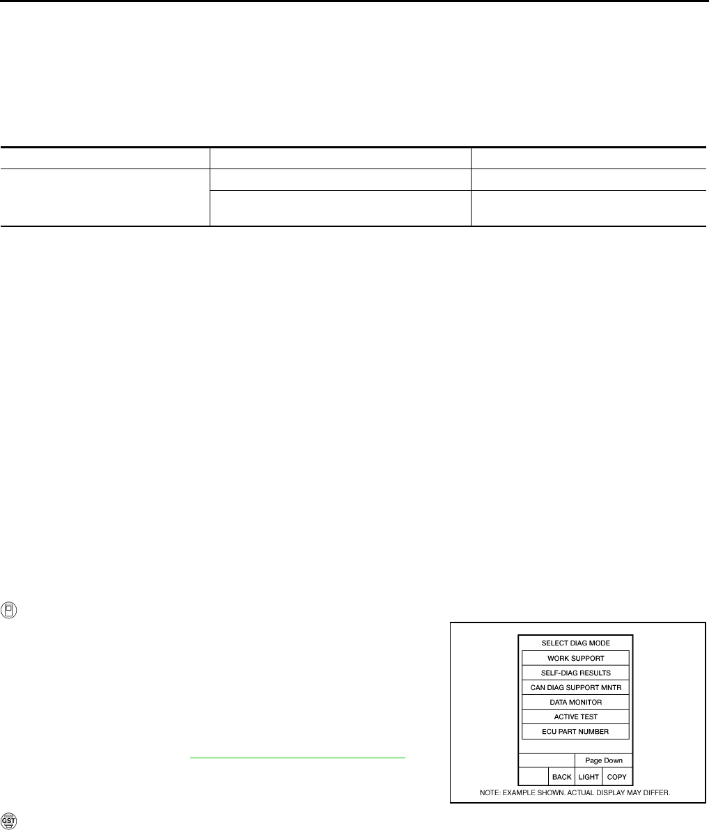
CVT-166
DTC P1740 LOCK-UP SELECT SOLENOID VALVE CIRCUIT
Revision: 2006 August 2006 Murano
DTC P1740 LOCK-UP SELECT SOLENOID VALVE CIRCUIT PFP:31941
Description NCS0017V
●Lock-up select solenoid valve controls lock-up clutch pressure or forward clutch pressure (reverse brake
pressure).
●When controlling lock-up clutch, the valve is turned OFF. When controlling forward clutch, it is turned ON.
CONSULT-II Reference Value NCS0017W
*: Without manual mode.
On Board Diagnosis Logic NCS0017X
●This is an OBD-II self-diagnostic item.
●Diagnostic trouble code “P1740 LU-SLCT SOL/CIRC” with CONSULT-II is detected under the following
conditions.
–When TCM compares target value with monitor value and detects an irregularity.
Possible Cause NCS0017Y
●Lock-up select solenoid valve
●Harness or connectors
(Solenoid circuit is open or shorted.)
DTC Confirmation Procedure NCS0017Z
CAUTION:
Always drive vehicle at a safe speed.
NOTE:
If “DTC Confirmation Procedure” has been previously performed, always turn ignition switch OFF and
wait at least 10 seconds before performing the next test.
After the repair, touch “ERASE” on “SELF-DIAG RESULTS” and then perform the following procedure to con-
firm the malfunction is eliminated.
WITH CONSULT-II
1. Turn ignition switch ON. (Do not start engine.)
2. Select “DATA MONITOR” mode for “TRANSMISSION” with
CONSULT-II.
3. Start engine and maintain the following conditions for at least 5
consecutive seconds.
RANGE: “D” position and “N” position
(At each time, wait for 5 seconds.)
4. If DTC is detected, go to CVT-168, "Diagnostic Procedure" .
WITH GST
Follow the procedure “WITH CONSULT-II”.
Item name Condition Display value
LUSEL SOL OUT
Selector lever in “P” and “N” positions ON
Wait at least for 5 seconds with the selector
lever in “R”, “D” “S”* and “L”* positions OFF
BCIA0031E
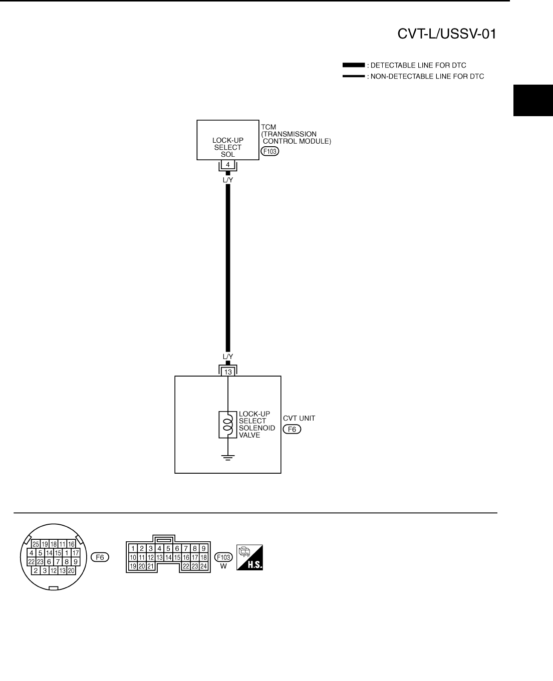
DTC P1740 LOCK-UP SELECT SOLENOID VALVE CIRCUIT
CVT-167
D
E
F
G
H
I
J
K
L
M
A
B
CVT
Revision: 2006 August 2006 Murano
Wiring Diagram — CVT — L/USSV NCS00180
TCWA0252E
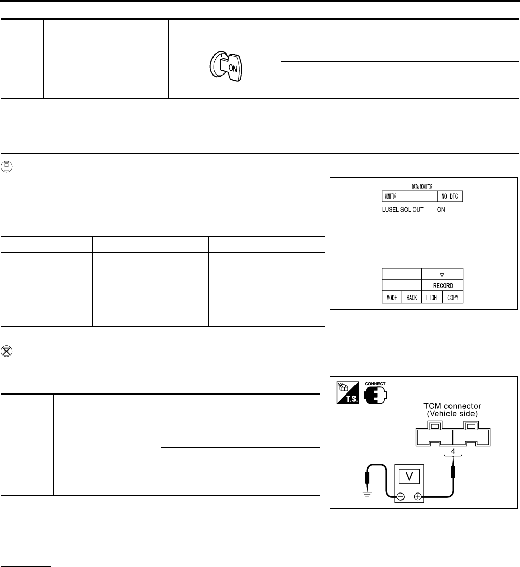
CVT-168
DTC P1740 LOCK-UP SELECT SOLENOID VALVE CIRCUIT
Revision: 2006 August 2006 Murano
TCM terminal data are reference values, measured between each terminal and ground.
*: Without manual mode
Diagnostic Procedure NCS00181
1. CHECK INPUT SIGNAL
With CONSULT-II
1. Turn ignition switch ON.
2. Select “SELECTION FROM MENU” in “DATA MONITOR” mode
for “TRANSMISSION” with CONSULT-II.
3. Read out the value of “LUSEL SOL OUT”.
*: Without manual mode
Without CONSULT-II
1. Turn ignition switch ON.
2. Check voltage between TCM connector terminal and ground.
*: Without manual mode
3. Turn ignition switch OFF.
4. Disconnect the TCM connector.
5. Check if there is continuity between connector terminal and ground.
OK or NG
OK >> GO TO 5.
NG >> GO TO 2.
Terminal Wire color Item Condition Data (Approx.)
4L/Y
Lock-up select
solenoid valve
Selector lever in “P” and “N” posi-
tions Battery voltage
Wait at least for 5 seconds with the
selector lever in “R”, “D”, “S”* and
“L”* positions
0 V
Item name Condition Display value
LUSEL SOL OUT
Selector lever in “P” and “N”
positions ON
Wait at least for 5 seconds
with the selector lever in
“R”, “D”, “S”* and “L”* posi-
tions
OFF
Name Connector Terminal Condition Voltage
(Approx.)
Lock-up
select sole-
noid valve
F103 4 - Ground
Selector lever in “P” and
“N” positions
Battery
voltage
Wait at least for 5 sec-
onds with the selector
lever in “R”, “D”, “S”* and
“L”* positions
0 V
SCIA4512E
SCIA4513E
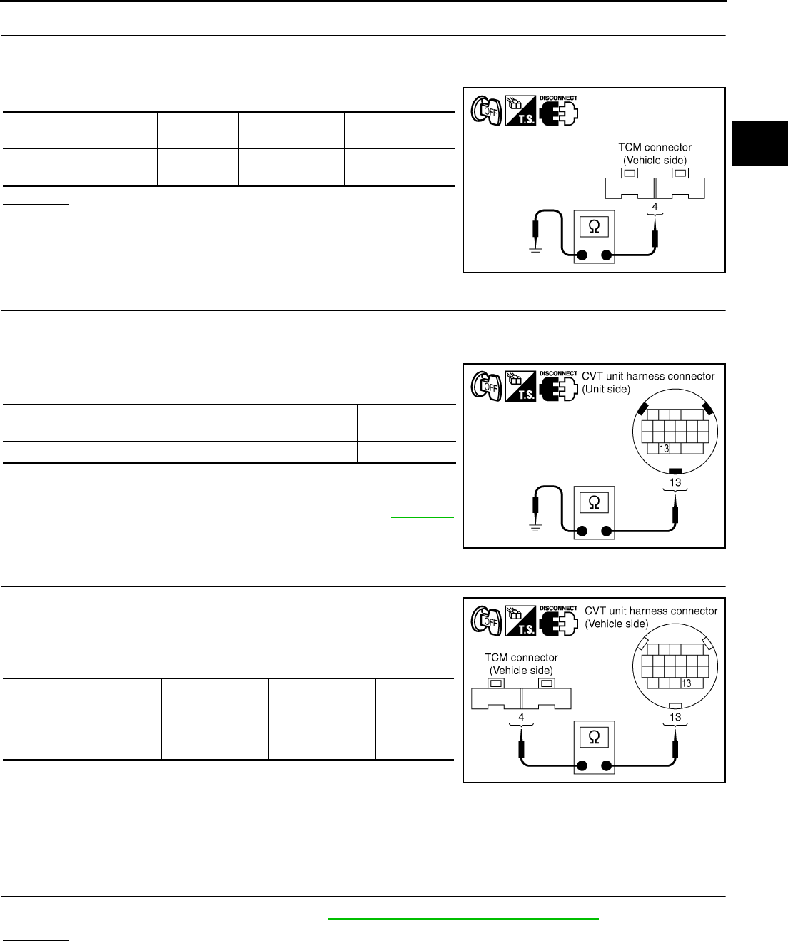
DTC P1740 LOCK-UP SELECT SOLENOID VALVE CIRCUIT
CVT-169
D
E
F
G
H
I
J
K
L
M
A
B
CVT
Revision: 2006 August 2006 Murano
2. CHECK LOCK-UP SELECT SOLENOID VALVE CIRCUIT
1. Turn ignition switch OFF.
2. Disconnect TCM connector.
3. Check resistance between TCM connector terminal and ground.
OK or NG
OK >> GO TO 5.
NG >> GO TO 3.
3. CHECK VALVE RESISTANCE
1. Turn ignition switch OFF.
2. Disconnect CVT unit harness connector.
3. Check resistance between CVT unit harness connector terminal
and ground.
OK or NG
OK >> GO TO 4.
NG >> Replace the transaxle assembly. Refer to CVT-229,
"Removal and Installation" .
4. CHECK HARNESS BETWEEN TCM AND LOCK-UP SELECT SOLENOID VALVE
1. Turn ignition switch OFF.
2. Disconnect TCM connector.
3. Check continuity between TCM connector terminal and CVT unit
harness connector terminal.
4. If OK, check harness for short to ground and short to power.
5. Reinstall any part removed.
OK or NG
OK >> GO TO 5.
NG >> Repair open circuit or short to ground or short to power in harness or connectors.
5. CHECK DTC
Perform “DTC Confirmation Procedure”. Refer to CVT-166, "DTC Confirmation Procedure" .
OK or NG
OK >> INSPECTION END
NG >> GO TO 6.
Solenoid valve Connector Terminal Resistance
(Approx.)
Lock-up select solenoid
valve F103 4 - Ground 6 - 19 Ω
SCIA4692E
Solenoid valve Connector Terminal Resistance
(Approx.)
Lock-up select solenoid valve F6 13 - Ground 6 - 19 Ω
SCIA4693E
Item Connector Terminal Continuity
TCM connector F103 4
Yes
CVT unit harness connec-
tor F6 13
SCIA4694E
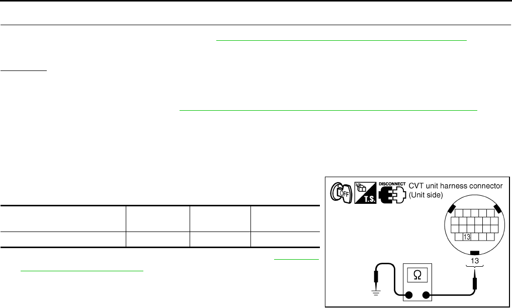
CVT-170
DTC P1740 LOCK-UP SELECT SOLENOID VALVE CIRCUIT
Revision: 2006 August 2006 Murano
6. CHECK TCM
1. Check TCM input/output signals. Refer to CVT-57, "TCM Input/Output Signal Reference Values" .
2. If NG, re-check TCM pin terminals for damage or loose connection with harness connector.
OK or NG
OK >> INSPECTION END
NG >> 1. Repair or replace damaged parts.
2. Replace TCM. Refer to CVT-9, "Precautions for TCM and CVT Assembly Replacement" .
Component Inspection NCS00182
LOCK-UP SELECT SOLENOID VALVE
1. Turn ignition switch OFF.
2. Disconnect CVT unit harness connector.
3. Check resistance between CVT unit harness connector terminal
and ground.
4. If NG, replace the transaxle assembly. Refer to CVT-229,
"Removal and Installation" .
Solenoid valve Connector Terminal Resistance
(Approx.)
Lock-up select solenoid valve F6 13 - Ground 6 - 19 Ω
SCIA4693E
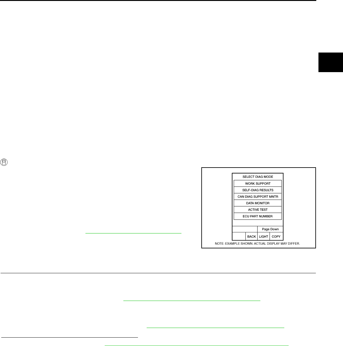
DTC P1745 LINE PRESSURE CONTROL
CVT-171
D
E
F
G
H
I
J
K
L
M
A
B
CVT
Revision: 2006 August 2006 Murano
DTC P1745 LINE PRESSURE CONTROL PFP:31036
Description NCS00183
The pressure control solenoid valve A (line pressure solenoid valve) regulates the oil pump discharge pres-
sure to suit the driving condition in response to a signal sent from the TCM.
On Board Diagnosis Logic NCS00184
●This is not an OBD-II self-diagnostic item.
●Diagnostic trouble code “P1745 L/PRESS CONTROL” with CONSULT-II is detected when TCM detects
the unexpected line pressure.
Possible Cause NCS00185
TCM
DTC Confirmation Procedure NCS00186
NOTE:
If “DTC Confirmation Procedure” has been previously performed, always turn ignition switch OFF and
wait at least 10 seconds before performing the next test.
After the repair, touch “ERASE” on “SELF-DIAG RESULTS” and then perform the following procedure to con-
firm the malfunction is eliminated.
WITH CONSULT-II
1. Turn ignition switch ON and select “DATA MONITOR” mode for
“TRANSMISSION” with CONSULT-II.
2. Make sure that output voltage of CVT fluid temperature sensor
is within the range below.
ATF TEMP SEN: 1.0 - 2.0 V
If out of range, drive the vehicle to decrease the voltage
(warm up the fluid) or stop engine to increase the voltage
(cool down the fluid)
3. If DTC is detected, go to CVT-171, "Diagnostic Procedure" .
Diagnostic Procedure NCS00187
1. CHECK DTC
1. Turn ignition switch ON. (Do not start engine.)
2. Select “SELF-DIAG RESULTS” mode for “TRANSMISSION” with CONSULT-II.
3. Erase self-diagnostic results. Refer to CVT-67, "How to Erase Self-diagnostic Results" .
4. Turn ignition switch OFF, and wait for 5 seconds or more.
5. Start engine.
6. Confirm self-diagnostic results again. Refer to CVT-65, "SELF-DIAGNOSTIC RESULT MODE" .
Is the “P1745 L/PRESS CONTROL” displayed?
YES >> Replace TCM. Refer to CVT-9, "Precautions for TCM and CVT Assembly Replacement" .
NO >> INSPECTION END
BCIA0031E
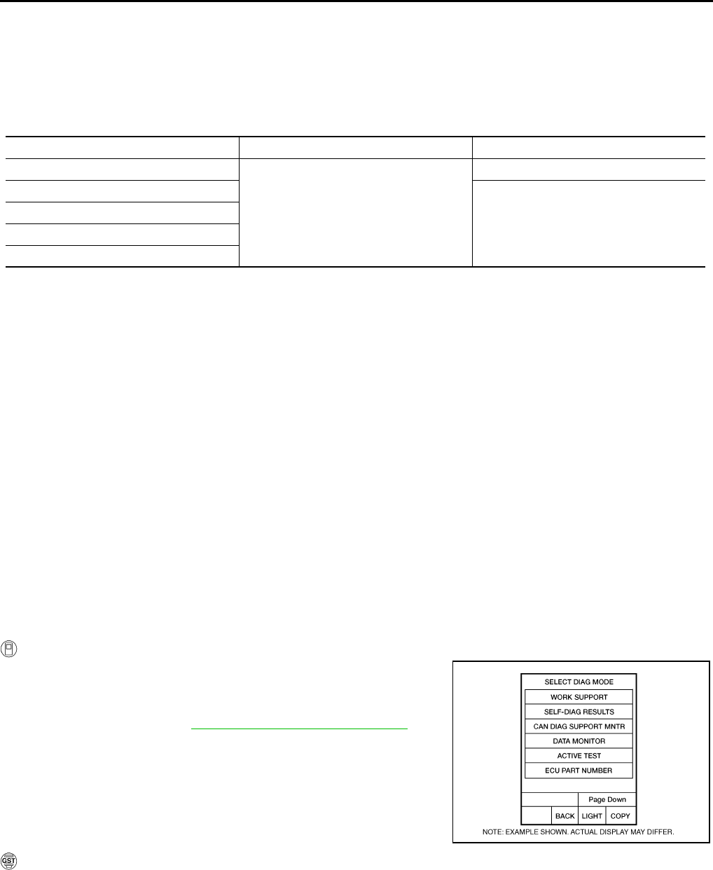
CVT-172
DTC P1777 STEP MOTOR - CIRCUIT
Revision: 2006 August 2006 Murano
DTC P1777 STEP MOTOR - CIRCUIT PFP:31020
Description NCS00188
The step motor changes the step with turning 4 coils ON/OFF according to the signal from TCM. As a result,
the flow of line pressure to primary pulley is changed and pulley ratio is controlled
CONSULT-II Reference Value NCS00189
Remarks: Specification data are reference values.
On Board Diagnosis Logic NCS0018A
●This is an OBD-II self-diagnostic item.
●Diagnostic trouble code “P1777 STEP MOTR CIRC” with CONSULT-II is detected under the following
conditions.
–When operating step motor ON and OFF, there is no proper change in the voltage of TCM terminal which
corresponds to it.
Possible Cause NCS0018B
●Step motor
●Harness or connectors
(Step motor circuit is open or shorted.)
DTC Confirmation Procedure NCS0018C
CAUTION:
Always drive vehicle at a safe speed.
NOTE:
If “DTC Confirmation Procedure” has been previously performed, always turn ignition switch OFF and
wait at least 10 seconds before performing the next test.
After the repair, touch “ERASE” on “SELF-DIAG RESULTS” and then perform the following procedure to con-
firm the malfunction is eliminated.
WITH CONSULT-II
1. Turn ignition switch ON and select “DATA MONITOR” mode for
“TRANSMISSION” with CONSULT-II.
2. Drive vehicle for at least 5 consecutive seconds.
3. If DTC is detected, go to CVT-174, "Diagnostic Procedure" .
WITH GST
Follow the procedure “WITH CONSULT-II”.
Item name Condition Display value (Approx.)
STM STEP
During driving
-20 step - 190 step
SMCOIL A
Changes ON⇔OFF.
SMCOIL B
SMCOIL C
SMCOIL D
BCIA0031E
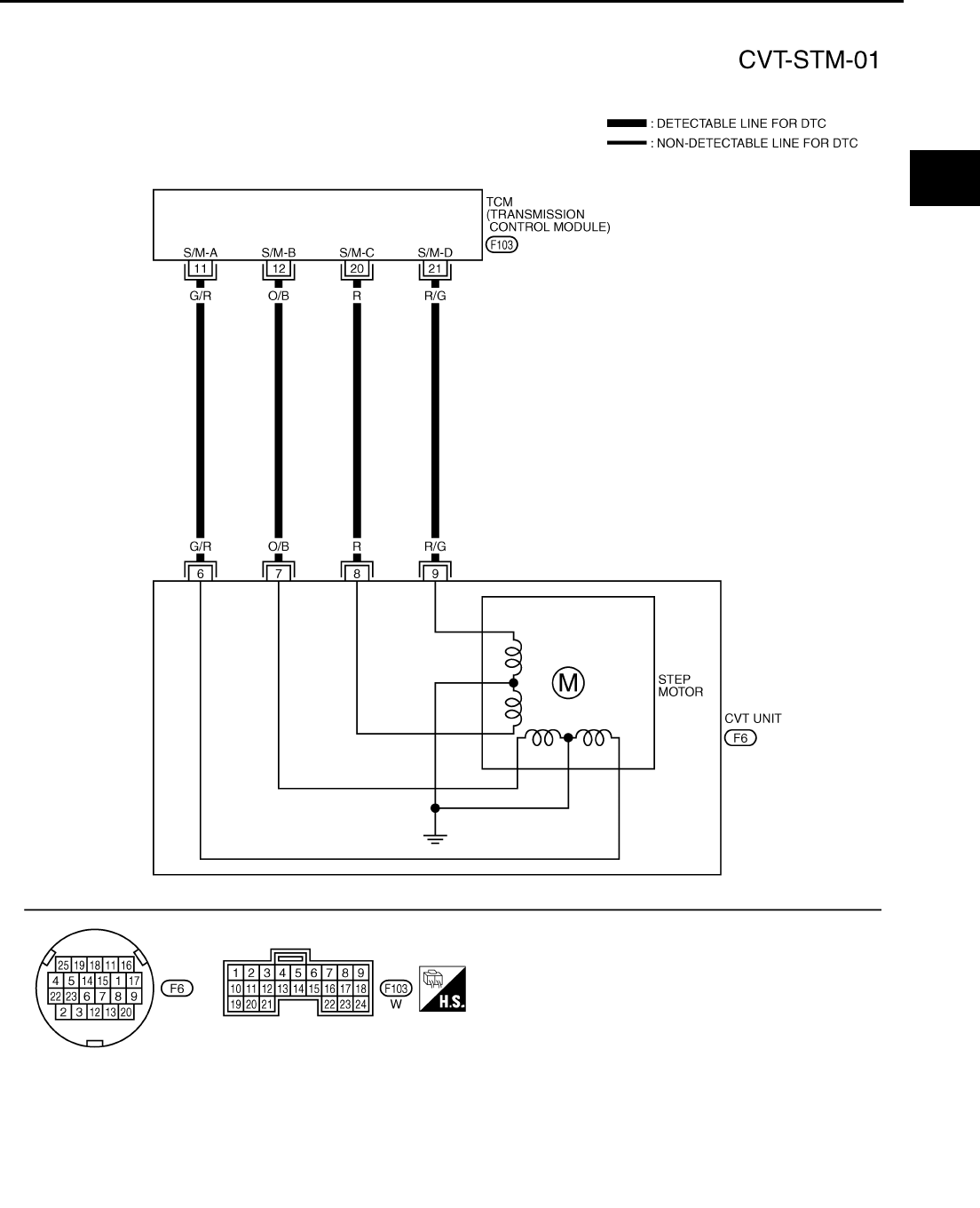
DTC P1777 STEP MOTOR - CIRCUIT
CVT-173
D
E
F
G
H
I
J
K
L
M
A
B
CVT
Revision: 2006 August 2006 Murano
Wiring Diagram — CVT — STM NCS0018D
TCWA0256E
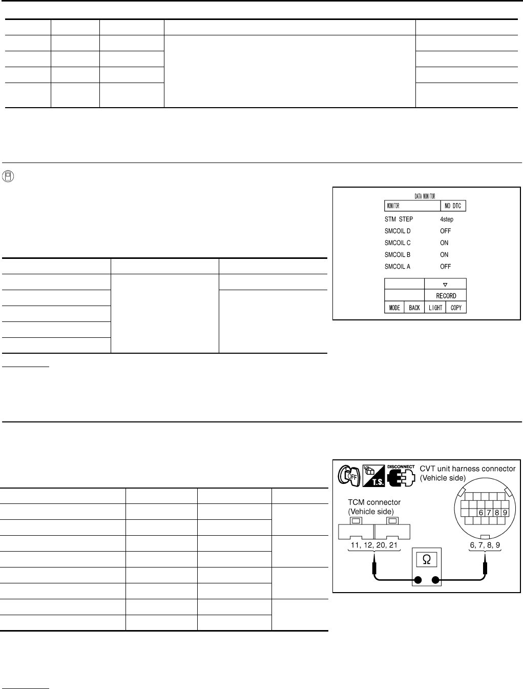
CVT-174
DTC P1777 STEP MOTOR - CIRCUIT
Revision: 2006 August 2006 Murano
TCM terminals data are reference values, measured between each terminal and ground.
*1: A circuit tester cannot be used to test this item.
Diagnostic Procedure NCS0018E
1. CHECK INPUT SIGNALS
With CONSULT-II
1. Start engine.
2. Select “SELECTION FROM MENU” in “DATA MONITOR” mode
for “TRANSMISSION” with CONSULT-II.
3. Start vehicle and read out the value of “STM STEP”, “SMCOIL
A”, “SMCOIL B”, “SMCOIL C”, and “SMCOIL D”.
OK or NG
OK >> GO TO 4.
NG >> GO TO 2.
2. CHECK HARNESS BETWEEN TCM AND STEP MOTOR
1. Turn ignition switch OFF.
2. Disconnect CVT unit connector and TCM connector.
3. Check continuity between TCM connector terminals and CVT
unit harness connector terminals.
4. If OK, check harness for short to ground and short to power.
5. If OK, check continuity between body ground and CVT assembly.
6. Reinstall any part removed.
OK or NG
OK >> GO TO 3.
NG >> Repair open circuit or short to ground or short to power in harness or connectors.
Terminal Wire color Item Condition Data (Approx.)
11 G/R Step motor A Within 2 seconds after ignition switch ON, the time measure-
ment by using the pulse width measurement function (Hi level)
of CONSULT-II.*1
CAUTION:
Connect the diagnosis data link cable to the vehicle diag-
nosis connector.
30.0 msec
12 O/B Step motor B 10.0 msec
20 R Step motor C 30.0 msec
21 R/G Step motor D 10.0 msec
Item name Condition Display value (Approx.)
STM STEP
During driving
-20 step - 190 step
SMCOIL A
Changes ON⇔OFF.
SMCOIL B
SMCOIL C
SMCOIL D
SCIA4516E
Item Connector Terminal Continuity
TCM connector F103 11 Yes
CVT unit harness connector F6 6
TCM connector F103 12 Yes
CVT unit harness connector F6 7
TCM connector F103 20 Yes
CVT unit harness connector F6 8
TCM connector F103 21 Yes
CVT unit harness connector F6 9
SCIA4695E
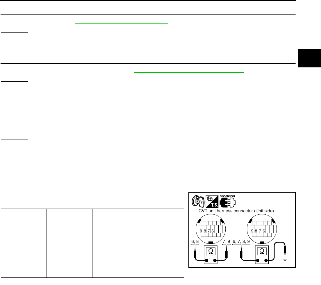
DTC P1777 STEP MOTOR - CIRCUIT
CVT-175
D
E
F
G
H
I
J
K
L
M
A
B
CVT
Revision: 2006 August 2006 Murano
3. CHECK STEP MOTOR
Check step motor. Refer to CVT-175, "Component Inspection" .
OK or NG
OK >> GO TO 4.
NG >> Repair or replace damaged parts.
4. CHECK DTC
Perform “DTC Confirmation Procedure”. Refer to CVT-172, "DTC Confirmation Procedure" .
OK or NG
OK >> INSPECTION END
NG >> GO TO 5.
5. CHECK TCM
1. Check TCM input/output signals. Refer to CVT-57, "TCM Input/Output Signal Reference Values" .
2. If NG, re-check TCM pin terminals for damage or loose connection with harness connector.
OK or NG
OK >> INSPECTION END
NG >> Repair or replace damaged parts.
Component Inspection NCS0018F
STEP MOTOR
1. Turn ignition switch OFF.
2. Disconnect CVT unit harness connector.
3. Check resistance between CVT unit harness connector termi-
nals and ground.
4. If NG, replace the transaxle assembly. Refer to CVT-229, "Removal and Installation" .
Name Connector Terminal Resistance
(Approx.)
Step motor F6
6 - 7 30 Ω
8 - 9
6 - Ground
15 Ω
7 - Ground
8 - Ground
9 - Ground
SCIA4696E
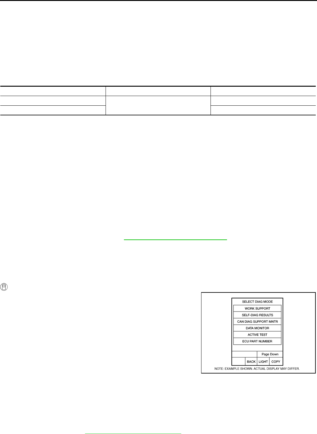
CVT-176
DTC P1778 STEP MOTOR - FUNCTION
Revision: 2006 August 2006 Murano
DTC P1778 STEP MOTOR - FUNCTION PFP:31947
Description NCS0018G
●The step motor's 4 aspects of ON/OFF change according to the signal from TCM. As a result, the flow of
line pressure to primary pulley is changed and pulley ratio is controlled.
●This diagnosis item is detected when electrical system is OK, but mechanical system is NG.
●This diagnosis item is detected when the state of the changing the speed mechanism in unit does not
operate normally.
CONSULT-II Reference Value NCS0018H
Remarks: Specification data are reference values.
On Board Diagnosis Logic NCS0018I
●This is an OBD-II self-diagnostic item.
●Diagnostic trouble code “P1778 STEP MOTR/FNC” with CONSULT-II is detected under the following con-
ditions.
–When not changing the pulley ratio according to the instruction of TCM.
Possible Cause NCS0018J
Step motor
DTC Confirmation Procedure NCS0018K
CAUTION:
●Always drive vehicle at a safe speed.
●Before starting “DTC Confirmation Procedure”, confirm “Hi” or “Mid” or “Low” fixation by “PRI
SPEED” and “VEHICLE SPEED” on “DATA MONITOR MODE”.
●If hi-geared fixation occurred, go to CVT-177, "Diagnostic Procedure" .
NOTE:
If “DTC Confirmation Procedure” has been previously performed, always turn ignition switch OFF and
wait at least 10 seconds before performing the next test.
After the repair, touch “ERASE” on “SELF-DIAG RESULTS” and then perform the following procedure to con-
firm the malfunction is eliminated.
WITH CONSULT-II
1. Turn ignition switch ON and select “DATA MONITOR” mode for
“TRANSMISSION” with CONSULT-II.
2. Make sure that output voltage of CVT fluid temperature sensor
is within the range below.
ATF TEMP SEN: 1.0 - 2.0 V
If out of range, drive the vehicle to decrease the voltage
(warm up the fluid) or stop engine to increase the voltage
(cool down the fluid)
3. Select “DATA MONITOR” mode for “TRANSMISSION” with
CONSULT-II.
4. Start engine and maintain the following conditions for at least 30
consecutive seconds.
TEST START FROM 0 km/h (0 MPH)
CONSTANT ACCELERATION: Keep 30 sec or more
VEHICLE SPEED: 10 km/h (6 MPH) or more
ACC PEDAL OPEN: More than 1.0/8
RANGE: “D” position
ENG SPEED: 450 rpm or more
5. If DTC is detected, go to CVT-177, "Diagnostic Procedure" .
Item name Condition Display value (Approx.)
STM STEP During driving -20 step - 190 step
GEAR RATIO 2.37 - 0.43
BCIA0031E

DTC P1778 STEP MOTOR - FUNCTION
CVT-177
D
E
F
G
H
I
J
K
L
M
A
B
CVT
Revision: 2006 August 2006 Murano
WITH GST
Follow the procedure “WITH CONSULT-II”.
Diagnostic Procedure NCS0018L
1. CHECK STEP MOTOR
With CONSULT-II
It is monitoring whether “GEAR RATIO: 2.37 - 0.43” changes similarly to “STM STEP: -20 - 190” by DATA
MONITOR mode. Refer to CVT-68, "DATA MONITOR MODE" .
Without CONSULT-II
Inspect the engine speed (rise and descend), vehicle speed, throttle position, and check shift change. Refer to
CVT-236, "Vehicle Speed When Shifting Gears" .
OK or NG
OK >> INSPECTION END
NG >> Replace the transaxle assembly. Refer to CVT-229, "Removal and Installation" .
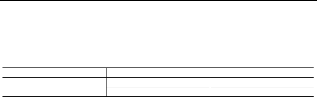
CVT-178
SECOND POSITION SWITCH
Revision: 2006 August 2006 Murano
SECOND POSITION SWITCH PFP:34910
Description NCS0018M
Second position switch is built into CVT control device. When selector lever is in “S” or “L” position, second
position switch turns ON and sends a signal to unified meter and A/C amp. Then signal is transferred to TCM
with CAN communications to improve engine brake performance.
CONSULT-II Reference Value NCS0018N
Remarks: Specification data are reference values.
Item name Condition Display value
SPORT MODE SW Selector lever in “S” and “L” positions ON
Selector lever in other positions OFF
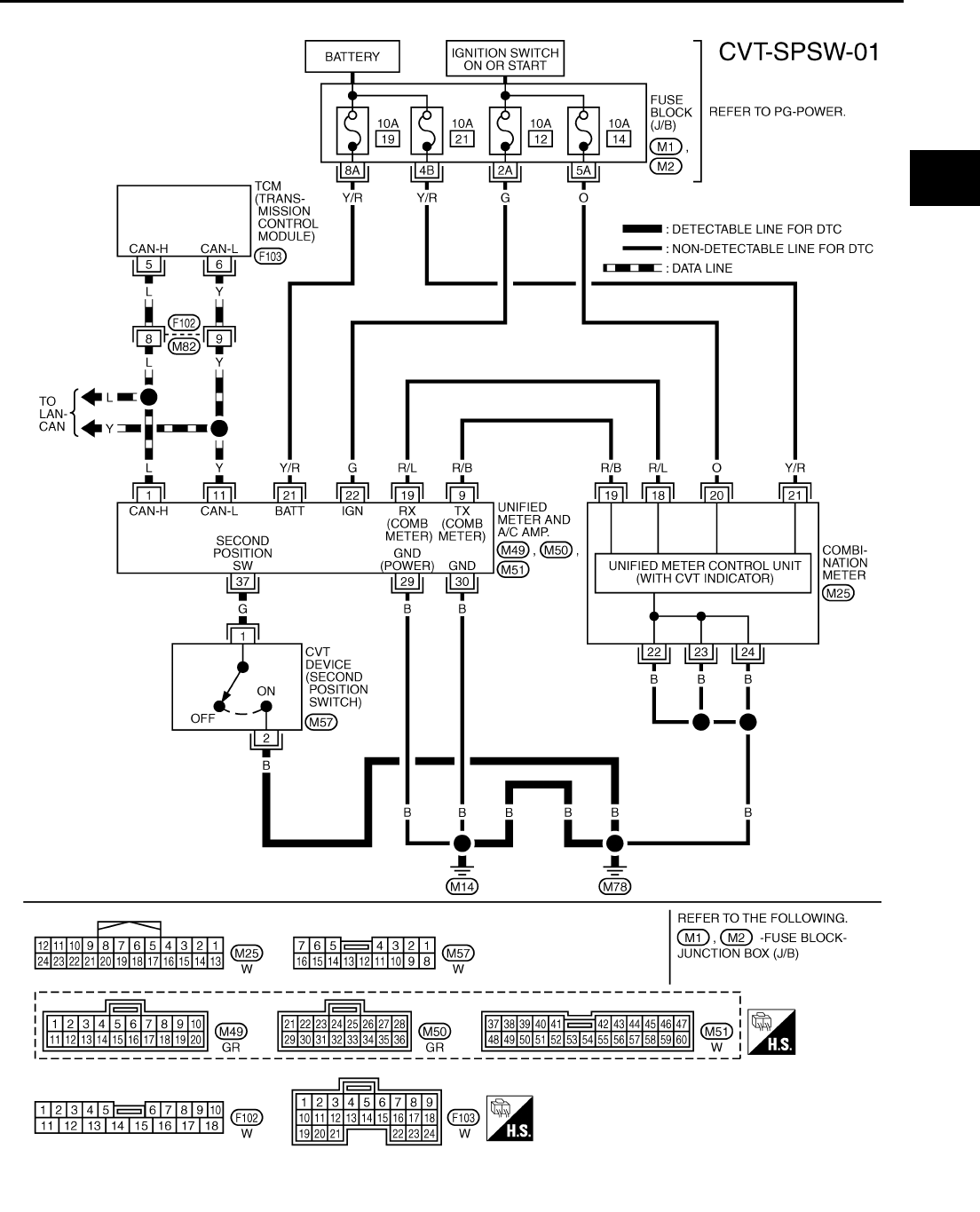
SECOND POSITION SWITCH
CVT-179
D
E
F
G
H
I
J
K
L
M
A
B
CVT
Revision: 2006 August 2006 Murano
Wiring Diagram — CVT — SPSW NCS0018O
TCWA0162E
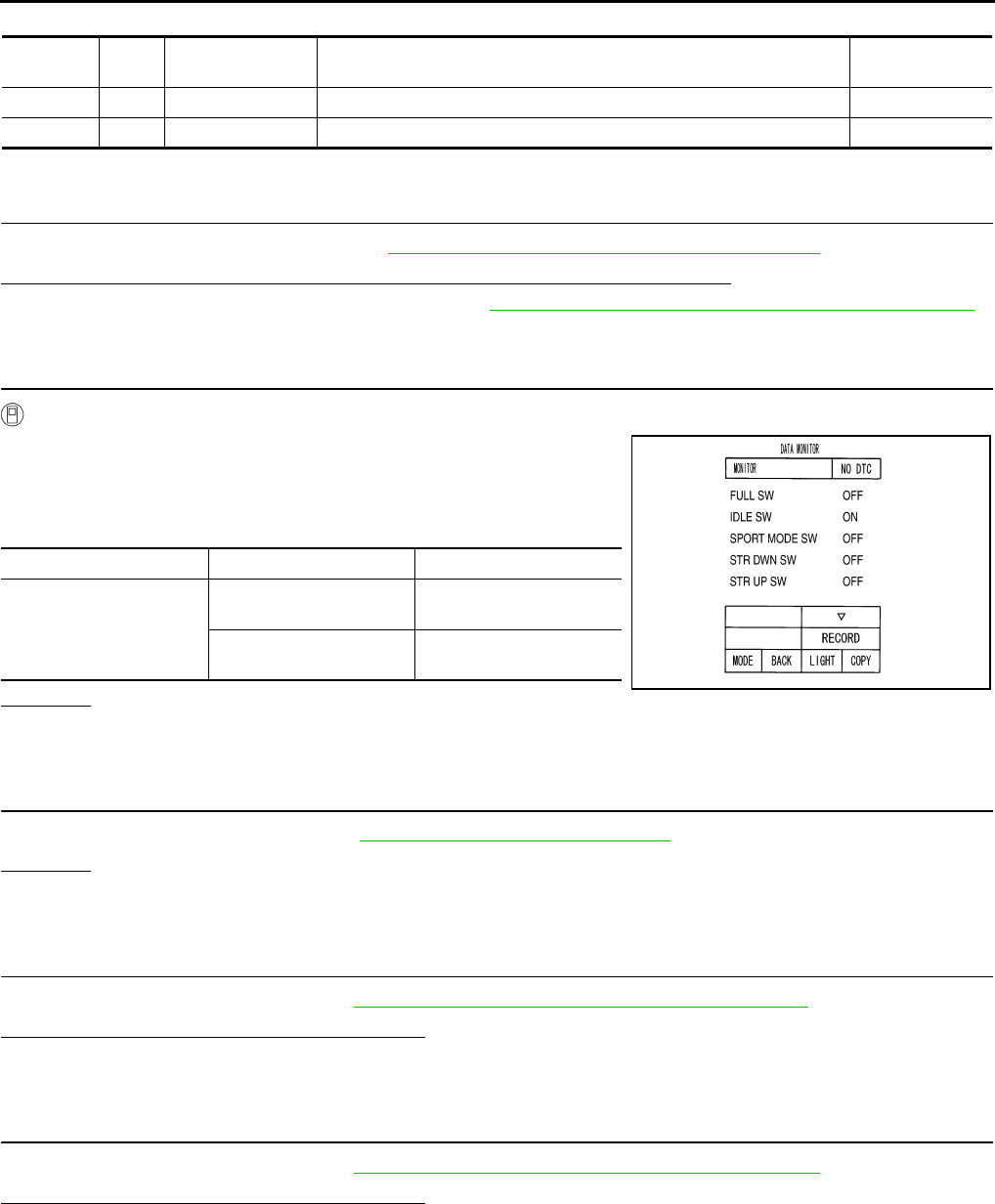
CVT-180
SECOND POSITION SWITCH
Revision: 2006 August 2006 Murano
TCM terminal data are reference values, measured between each terminal and ground.
Diagnostic Procedure NCS0018P
1. CHECK CAN COMMUNICATION LINE
Perform the self-diagnosis check. Refer to CVT-65, "SELF-DIAGNOSTIC RESULT MODE" .
Is any malfunction of the “U1000 CAN COMM CIRCUIT” indicated in the results?
YES >> Check CAN communication line. Refer to CVT-72, "DTC U1000 CAN COMMUNICATION LINE" .
NO >> GO TO 2.
2. CHECK SECOND POSITION SWITCH SIGNAL
With CONSULT-II
1. Turn ignition switch ON.
2. Select “ECU INPUT SIGNALS” in “DATA MONITOR” mode for
“TRANSMISSION” with CONSULT-II.
3. Read out ON/OFF switching action of the “SPORT MODE SW”.
OK or NG
OK >> INSPECTION END
NG >> GO TO 3.
3. CHECK SECOND POSITION SWITCH
Check second position switch. Refer to CVT-181, "Component Inspection"
OK or NG
OK >> GO TO 4.
NG >> Repair or replace damaged parts.
4. CHECK SELF-DIAGNOSTIC RESULTS (UNIFIED METER AND A/C AMP)
Perform self-diagnosis check. Refer to DI-15, "CONSULT-II Function (METER A/C AMP)" .
Is any malfunction detected by self-diagnostic?
YES >> Check the malfunctioning system.
NO >> GO TO 5.
5. CHECK SELF-DIAGNOSTIC RESULTS (COMBINATION METER)
Perform self-diagnosis check. Refer to DI-15, "Self-Diagnosis Mode of Combination Meter" .
Is any malfunction detected by self-diagnostic?
YES >> Check the malfunctioning system.
NO >> GO TO 6.
Terminal Wire
color Item Condition Data (Approx.)
5 L CAN-H — —
6 Y CAN-L — —
Item name Condition Display value
SPORT MODE SW
Selector lever in “S” and
“L” positions ON
Selector lever in other
positions OFF
SCIA4517E
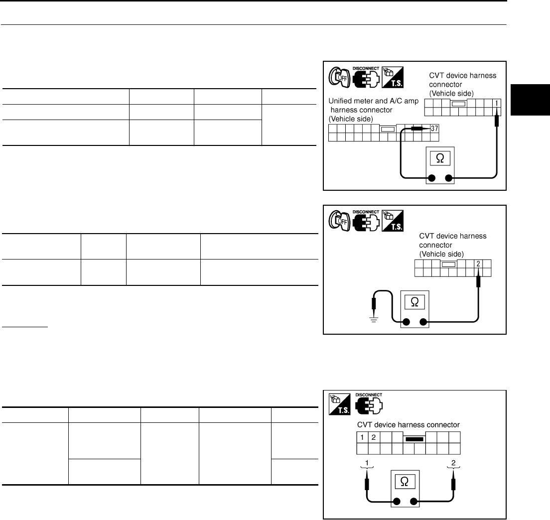
SECOND POSITION SWITCH
CVT-181
D
E
F
G
H
I
J
K
L
M
A
B
CVT
Revision: 2006 August 2006 Murano
6. CHECK SECOND POSITION SWITCH CIRCUIT
1. Turn ignition switch OFF.
2. Disconnect CVT device connector and unified meter and A/C amp connector.
3. Check continuity between CVT device harness connector termi-
nal and unified meter and A/C amp harness connector terminal.
4. Check continuity between CVT device harness connector termi-
nal and ground.
5. If OK, check harness for short to ground and short to power.
6. Reinstall any part removed.
OK or NG
OK >> INSPECTION END
NG >> Repair open circuit or short to ground or short to power in harness or connectors.
Component Inspection NCS0018Q
SECOND POSITION SWITCH
Check continuity between CVT device harness connector terminals.
Item Connector Terminal Continuity
CVT device harness connector M57 1
Yes
Unified meter and A/C amp har-
ness connector M51 37
SCIA4592E
Item Connec-
tor Terminal Continuity
CVT device har-
ness connector M57 2 - Ground Yes
SCIA4593E
Item Condition Connector Terminal Continuity
Second posi-
tion switch
Selector lever in
“S” and “L” posi-
tions M57 1 - 2
Yes
Selector lever in
other positions No
SCIA2041E
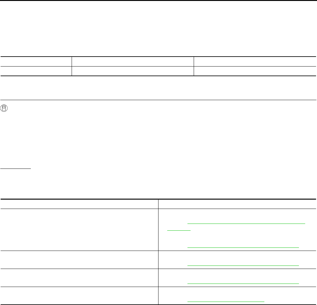
CVT-182
CVT INDICATOR CIRCUIT
Revision: 2006 August 2006 Murano
CVT INDICATOR CIRCUIT PFP:24810
Description NCS0018R
TCM sends the switch signals to unified meter and A/C amp via CAN communication line. Then manual mode
switch position is indicated on the CVT indicator.
CONSULT-II Reference Value NCS0018S
Diagnostic Procedure NCS0018T
1. CHECK INPUT SIGNALS
With CONSULT-II
1. Start engine.
2. Select “MAIN SIGNALS” in “DATA MONITOR” mode for “TRANSMISSION” with CONSULT-II and read
out the value of “M GEAR POS”.
3. Drive vehicle in the manual mode, and confirm that the actual gear position and the meter's indication of
the position mutually coincide when the select lever is shifted to the “+ (up)” or “- (down)” side (1st ⇔ 6th
gear).
OK or NG
OK >> INSPECTION END
NG >> Check the following.
CVT INDICATOR SYMPTOM CHART
Item name Condition Display value
M GEAR POS During driving 1, 2, 3, 4, 5, 6
Items Presumed location of trouble
The actual gear position does not change, or shifting into the
manual mode is not possible (no gear shifting in the manual mode
possible).
The CVT position indicator is not indicated.
Manual mode switch
●Refer to CVT-132, "DTC P0826 MANUAL MODE SWITCH
CIRCUIT" .
CVT main system (Fail-safe function actuated)
●Refer to CVT-65, "SELF-DIAGNOSTIC RESULT MODE" .
The actual gear position changes, but the CVT position indicator
is not indicated.
Perform the self-diagnosis function.
●Refer to CVT-65, "SELF-DIAGNOSTIC RESULT MODE" .
The actual gear position and the indication on the CVT position
indicator do not coincide.
Perform the self-diagnosis function.
●Refer to CVT-65, "SELF-DIAGNOSTIC RESULT MODE" .
Only a specific position or positions is/are not indicated on the
CVT position indicator.
Check the meter control unit.
●Refer to DI-4, "COMBINATION METERS" .
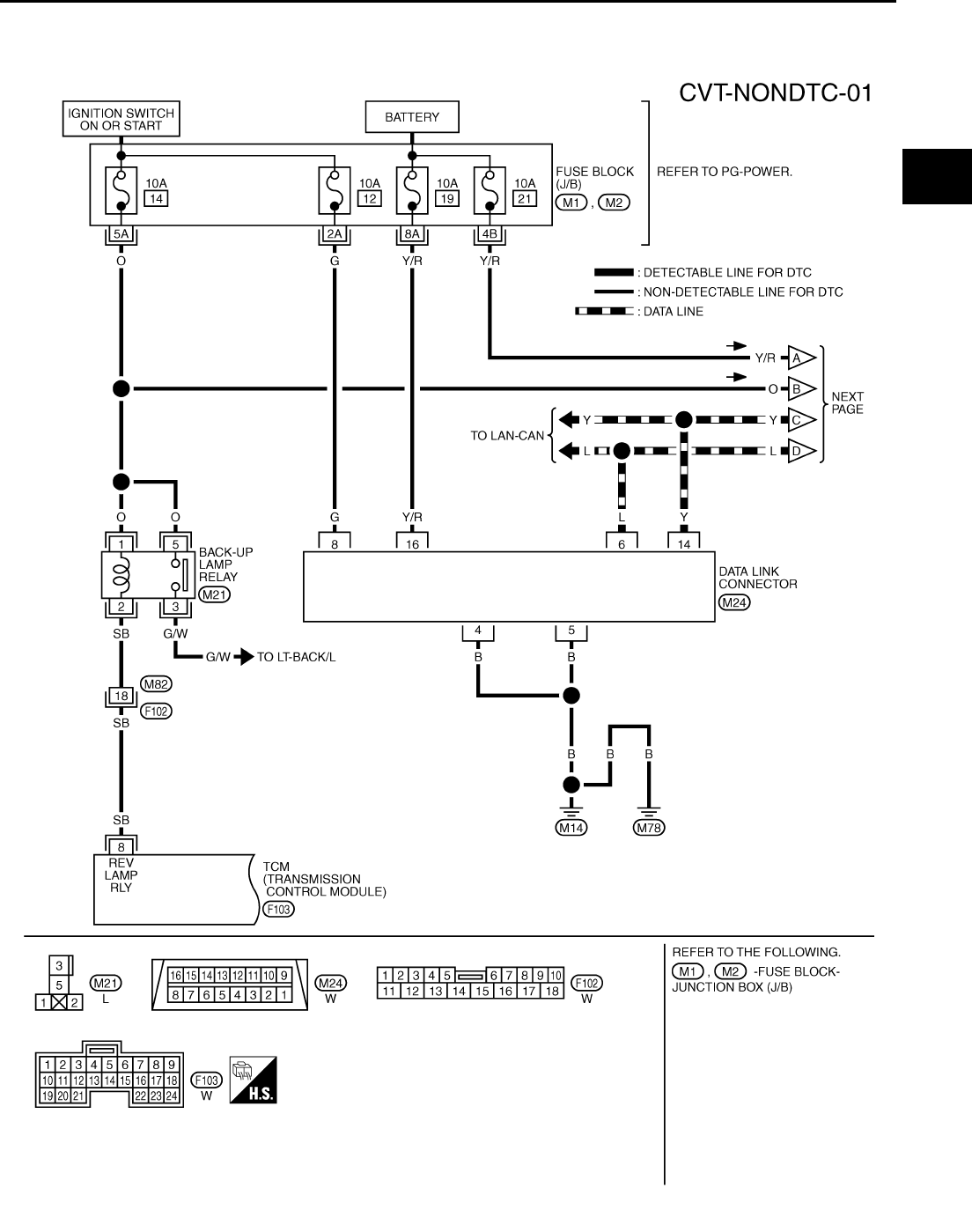
TROUBLE DIAGNOSIS FOR SYMPTOMS
CVT-183
D
E
F
G
H
I
J
K
L
M
A
B
CVT
Revision: 2006 August 2006 Murano
TROUBLE DIAGNOSIS FOR SYMPTOMS PFP:00007
Wiring Diagram — CVT — NONDTC NCS0018U
TCWB0122E
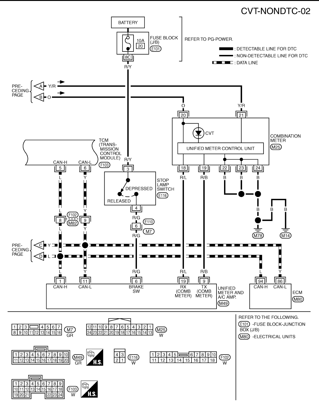
CVT-184
TROUBLE DIAGNOSIS FOR SYMPTOMS
Revision: 2006 August 2006 Murano
TCWB0260E
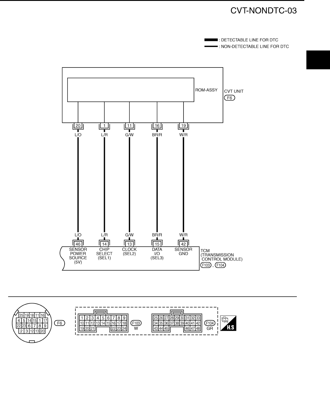
TROUBLE DIAGNOSIS FOR SYMPTOMS
CVT-185
D
E
F
G
H
I
J
K
L
M
A
B
CVT
Revision: 2006 August 2006 Murano
TCWA0258E
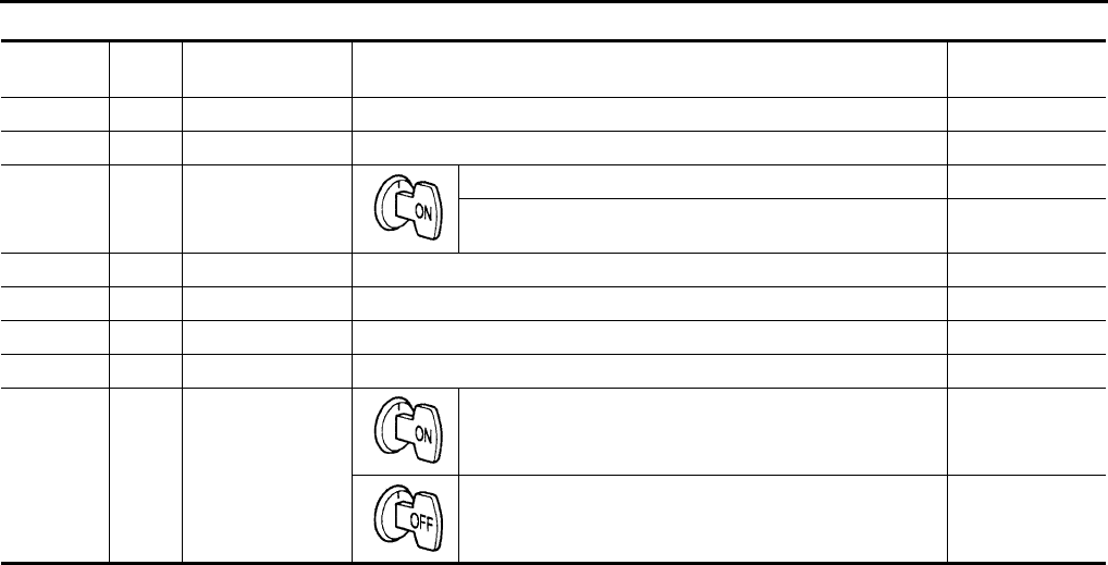
CVT-186
TROUBLE DIAGNOSIS FOR SYMPTOMS
Revision: 2006 August 2006 Murano
TCM terminal data are reference values, measured between each terminal and ground.
Terminal Wire
color Item Condition Data (Approx.)
5 L CAN-H — —
6 Y CAN-L — —
8SB
Back-up lamp
relay
Selector lever in “R” position. 0 V
Selector lever in other positions. Battery voltage
13 G/W ROM assembly — —
14 L/R ROM assembly — —
15 BR/R ROM assembly — —
42 W/R Sensor ground Always 0 V
46 L/O Sensor power
— 4.5 - 5.5 V
— 0 V
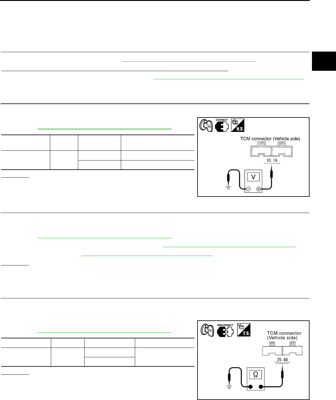
TROUBLE DIAGNOSIS FOR SYMPTOMS
CVT-187
D
E
F
G
H
I
J
K
L
M
A
B
CVT
Revision: 2006 August 2006 Murano
CVT Indicator Lamp Does Not Come On NCS0018V
SYMPTOM:
CVT indicator lamp does not come on for about 2 seconds when turning ignition switch ON.
DIAGNOSTIC PROCEDURE
1. CHECK CAN COMMUNICATION LINE
Perform the self-diagnosis check. Refer to CVT-65, "SELF-DIAGNOSTIC RESULT MODE" .
Is any malfunction of the “U1000 CAN COMM CIRCUIT” indicated in the results?
YES >> Check CAN communication line. Refer to CVT-72, "DTC U1000 CAN COMMUNICATION LINE" .
NO >> GO TO 2.
2. CHECK TCM POWER SOURCE
1. Turn ignition switch ON.
2. Check voltage between TCM connector terminals and ground.
Refer to CVT-154, "Wiring Diagram — CVT — POWER" .
OK or NG
OK >> GO TO 4.
NG >> GO TO 3.
3. DETECT MALFUNCTIONING ITEM
Check the following.
●Harness for short or open between ignition switch and TCM connector terminal 10, 19
Refer to CVT-154, "Wiring Diagram — CVT — POWER" .
●10 A fuse (No.83, located in the IPDM E/R). Refer to CVT-154, "Wiring Diagram — CVT — POWER" .
●Ignition switch. Refer to PG-3, "POWER SUPPLY ROUTING CIRCUIT" .
OK or NG
OK >> GO TO 4.
NG >> Repair or replace damaged parts.
4. CHECK TCM GROUND CIRCUIT
1. Turn ignition switch OFF.
2. Disconnect TCM connector.
3. Check continuity between TCM connector terminals and ground.
Refer to CVT-154, "Wiring Diagram — CVT — POWER" .
OK or NG
OK >> GO TO 5.
NG >> Repair open circuit or short to ground or short to power
in harness or connectors.
Name Connec-
tor Terminal Voltage (Approx.)
Power supply F103 10 - Ground Battery voltage
19 - Ground Battery voltage
SCIA4737E
Name Connector Terminal Continuity
Ground F104 25 - Ground Yes
48 - Ground
SCIA2671E
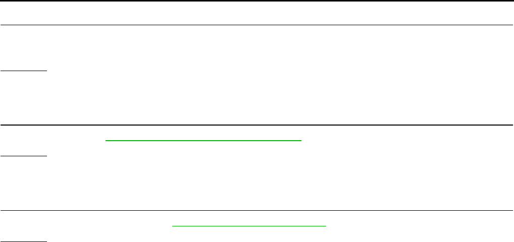
CVT-188
TROUBLE DIAGNOSIS FOR SYMPTOMS
Revision: 2006 August 2006 Murano
5. DETECT MALFUNCTIONING ITEM
Check the following.
●Harness and fuse for short or open between ignition switch and CVT indicator lamp
OK or NG
OK >> GO TO 6.
NG >> Repair or replace damaged parts.
6. CHECK SYMPTOM
Check again. Refer to CVT-48, "Check before Engine Is Started" .
OK or NG
OK >> INSPECTION END
NG >> GO TO 7.
7. CHECK COMBINATION METERS
Check combination meters. Refer to DI-4, "COMBINATION METERS"
OK or NG
OK >> INSPECTION END
NG >> Repair or replace damaged parts.
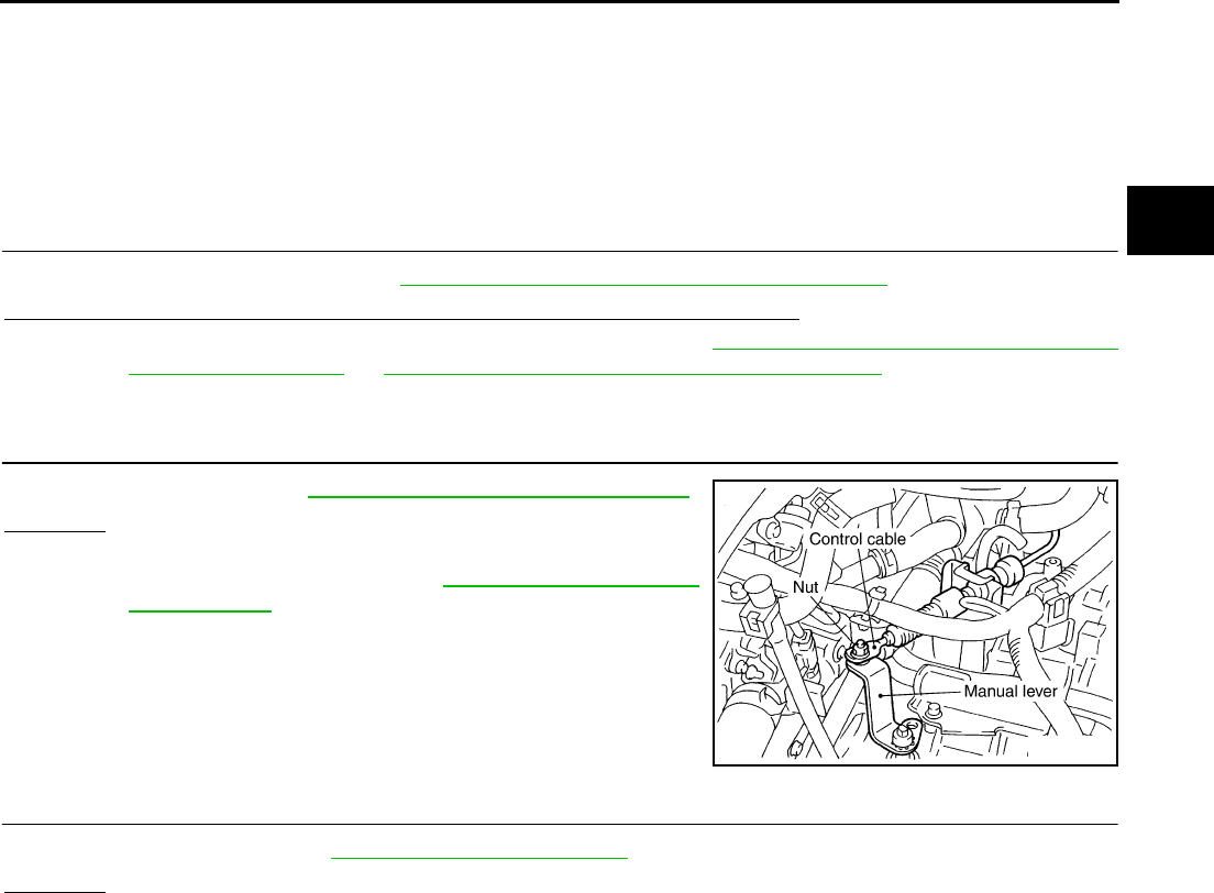
TROUBLE DIAGNOSIS FOR SYMPTOMS
CVT-189
D
E
F
G
H
I
J
K
L
M
A
B
CVT
Revision: 2006 August 2006 Murano
Engine Cannot Be Started in “P” and “N” Position NCS0018W
SYMPTOM:
●Engine cannot be started with selector lever in “P” or “N” position.
●Engine can be started with selector lever in “D”, “M” or “R” position. (With manual mode)
●Engine can be started with selector lever in “D”, “S”, “L” or “R” position. (Without manual mode)
DIAGNOSTIC PROCEDURE
1. CHECK SELF-DIAGNOSTIC RESULTS
Perform self-diagnosis check. Refer to CVT-65, "SELF-DIAGNOSTIC RESULT MODE" .
Do the self-diagnostic results indicate PNP switch circuit or start signal circuit?
YES >> Check PNP switch circuit or start signal circuit. Refer to CVT-81, "DTC P0705 PARK/NEUTRAL
POSITION SWITCH" or CVT-75, "DTC P0615 START SIGNAL CIRCUIT" .
NO >> GO TO 2.
2. CHECK CONTROL CABLE
Check control cable. Refer to CVT-212, "Checking of CVT Position"
OK or NG
OK >> GO TO 3.
NG >> Adjust control cable. Refer to CVT-211, "Adjustment of
CVT Position" .
3. CHECK STARTING SYSTEM
Check starting system. Refer to SC-9, "STARTING SYSTEM" .
OK or NG
OK >> INSPECTION END
NG >> Repair or replace damaged parts.
SCIA2001E
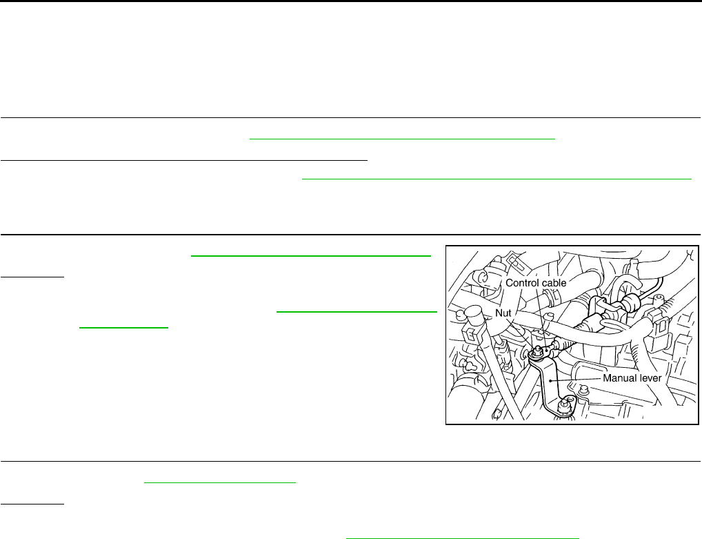
CVT-190
TROUBLE DIAGNOSIS FOR SYMPTOMS
Revision: 2006 August 2006 Murano
In “P” Position, Vehicle Moves Forward or Backward When Pushed NCS0018X
SYMPTOM:
Vehicle moves when it is pushed forward or backward with selector lever in “P” position.
DIAGNOSTIC PROCEDURE
1. CHECK SELF-DIAGNOSTIC RESULTS
Perform self-diagnosis check. Refer to CVT-65, "SELF-DIAGNOSTIC RESULT MODE" .
Do the self-diagnostic results indicate PNP switch circuit?
YES >> Check PNP switch circuit. Refer to CVT-81, "DTC P0705 PARK/NEUTRAL POSITION SWITCH" .
NO >> GO TO 2.
2. CHECK CONTROL CABLE
Check control cable. Refer to CVT-212, "Checking of CVT Position"
OK or NG
OK >> GO TO 3.
NG >> Adjust control cable. Refer to CVT-211, "Adjustment of
CVT Position" .
3. CHECK SYMPTOM
Check again. Refer to CVT-48, "Check at Idle" .
OK or NG
OK >> INSPECTION END
NG >> Replace the transaxle assembly. Refer to CVT-229, "Removal and Installation" .
SCIA2001E
TROUBLE DIAGNOSIS FOR SYMPTOMS
CVT-191
D
E
F
G
H
I
J
K
L
M
A
B
CVT
Revision: 2006 August 2006 Murano
In “N” Position, Vehicle Moves NCS0018Y
SYMPTOM:
Vehicle moves forward or backward when selecting “N” position.
DIAGNOSTIC PROCEDURE
1. CHECK SELF-DIAGNOSTIC RESULTS
Perform self-diagnosis check. Refer to CVT-65, "SELF-DIAGNOSTIC RESULT MODE" .
Do the self-diagnostic results indicate PNP switch circuit?
YES >> Check PNP switch circuit. Refer to CVT-81, "DTC P0705 PARK/NEUTRAL POSITION SWITCH" .
NO >> GO TO 2.
2. CHECK CONTROL CABLE
Check control cable. Refer to CVT-212, "Checking of CVT Position"
OK or NG
OK >> GO TO 3.
NG >> Adjust control cable. Refer to CVT-211, "Adjustment of
CVT Position" .
3. CHECK CVT FLUID LEVEL
Check CVT fluid level. Refer to CVT-15, "Checking CVT Fluid" .
OK or NG
OK >> GO TO 4.
NG >> Refill CVT fluid.
4. CHECK SYMPTOM
Check again. Refer to CVT-48, "Check at Idle" .
OK or NG
OK >> INSPECTION END
NG >> GO TO 5.
5. CHECK TCM
1. Check TCM input/output signals. Refer to CVT-57, "TCM Input/Output Signal Reference Values" .
2. If NG, re-check TCM pin terminals for damage or loose connection with harness connector.
OK or NG
OK >> Replace the transaxle assembly. Refer to CVT-229, "Removal and Installation" .
NG >> Repair or replace damaged parts.
SCIA2001E
SAT638A
CVT-192
TROUBLE DIAGNOSIS FOR SYMPTOMS
Revision: 2006 August 2006 Murano
Large Shock “N” → “R” Position NCS0018Z
SYMPTOM:
There is large shock when shifting from “N” to “R” position.
DIAGNOSTIC PROCEDURE
1. CHECK SELF-DIAGNOSTIC RESULTS
Perform self-diagnosis check. Refer to CVT-65, "SELF-DIAGNOSTIC RESULT MODE" .
Is any malfunction detected by self-diagnosis?
YES >> Check the malfunctioning system. Refer to CVT-65, "Display Items List" .
NO >> GO TO 2.
2. CHECK ENGINE IDLE SPEED
Check the engine idle speed. Refer to EC-73, "Idle Speed and Ignition Timing Check" .
OK or NG
OK >> GO TO 3.
NG >> Repair.
3. CHECK CVT FLUID LEVEL
Check CVT fluid level. Refer to CVT-15, "Checking CVT Fluid" .
OK or NG
OK >> GO TO 4.
NG >> Refill CVT fluid.
4. CHECK LINE PRESSURE
Check line pressure at idle. Refer to CVT-44, "LINE PRESSURE
TEST" .
OK or NG
OK >> GO TO 5.
NG >> Check the malfunctioning item. Refer to CVT-45, "Judg-
ment of Line Pressure Test" .
5. SYMPTOM CHECK
Check again. Refer to CVT-48, "Check at Idle" .
OK or NG
OK >> INSPECTION END
NG >> GO TO 6.
SAT638A
SAT494G

TROUBLE DIAGNOSIS FOR SYMPTOMS
CVT-193
D
E
F
G
H
I
J
K
L
M
A
B
CVT
Revision: 2006 August 2006 Murano
6. CHECK TCM
1. Check TCM input/output signals. Refer to CVT-57, "TCM Input/Output Signal Reference Values" .
2. If NG, re-check TCM pin terminals for damage or loose connection with harness connector.
OK or NG
OK >> Replace the transaxle assembly. Refer to CVT-229, "Removal and Installation" .
NG >> Repair or replace damaged parts.

CVT-194
TROUBLE DIAGNOSIS FOR SYMPTOMS
Revision: 2006 August 2006 Murano
Vehicle Does Not Creep Backward in “R” Position NCS00190
SYMPTOM:
Vehicle does not creep backward when selecting “R” position.
DIAGNOSTIC PROCEDURE
1. CHECK SELF-DIAGNOSTIC RESULTS
Perform self-diagnosis check. Refer to CVT-65, "SELF-DIAGNOSTIC RESULT MODE" .
Is any malfunction detected by self-diagnosis
YES >> Check the malfunctioning system. Refer to CVT-65, "Display Items List" .
NO >> GO TO 2.
2. CHECK CONTROL CABLE
Check control cable. Refer to CVT-212, "Checking of CVT Position"
OK or NG
OK >> GO TO 3.
NG >> Adjust control cable. Refer to CVT-211, "Adjustment of
CVT Position" .
3. CHECK CVT FLUID LEVEL
Check CVT fluid level. Refer to CVT-15, "Checking CVT Fluid" .
OK or NG
OK >> GO TO 4.
NG >> Refill CVT fluid.
4. CHECK LINE PRESSURE
Check line pressure at idle. Refer to CVT-44, "LINE PRESSURE
TEST" .
OK or NG
OK >> GO TO 5.
NG >> Check the malfunctioning item. Refer to CVT-45, "Judg-
ment of Line Pressure Test" .
SCIA2001E
SAT638A
SAT494G

TROUBLE DIAGNOSIS FOR SYMPTOMS
CVT-195
D
E
F
G
H
I
J
K
L
M
A
B
CVT
Revision: 2006 August 2006 Murano
5. CHECK SYMPTOM
Check again. Refer to CVT-48, "Check at Idle" .
OK or NG
OK >> INSPECTION END
NG >> GO TO 6.
6. CHECK TCM
1. Check TCM input/output signals. Refer to CVT-57, "TCM Input/Output Signal Reference Values" .
2. If NG, re-check TCM pin terminals for damage or loose connection with harness connector.
OK or NG
OK >> Replace the transaxle assembly. Refer to CVT-229, "Removal and Installation" .
NG >> Repair or replace damaged parts.
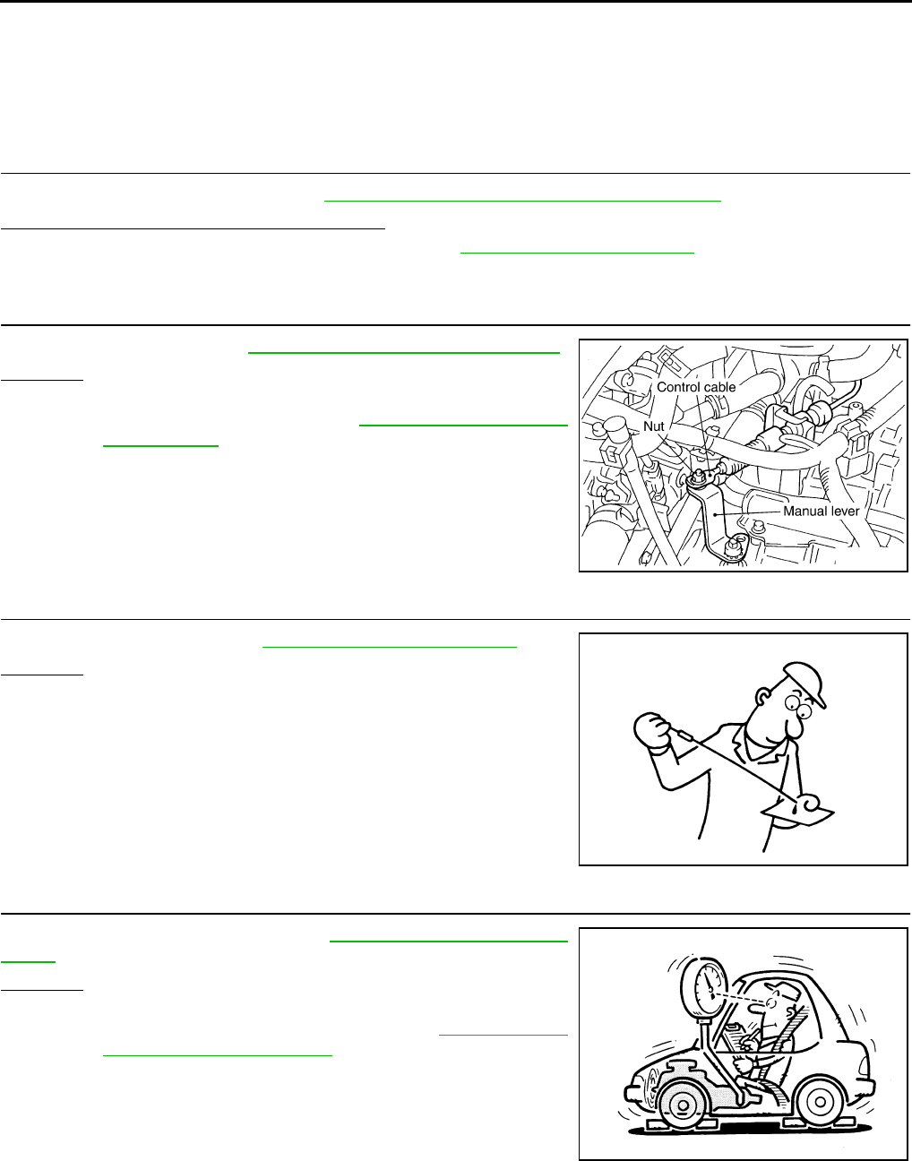
CVT-196
TROUBLE DIAGNOSIS FOR SYMPTOMS
Revision: 2006 August 2006 Murano
Vehicle Does Not Creep Forward in “D”, “S” or “L” Position NCS00191
SYMPTOM:
Vehicle does not creep forward when selecting “D”, “S”*, or “L”* position.
*: Without manual mode
DIAGNOSTIC PROCEDURE
1. CHECK SELF-DIAGNOSTIC RESULTS
Perform self-diagnosis check. Refer to CVT-65, "SELF-DIAGNOSTIC RESULT MODE" .
Is any malfunction detected by self-diagnosis?
YES >> Check the malfunctioning system. Refer to CVT-65, "Display Items List" .
NO >> GO TO 2.
2. CHECK CONTROL CABLE
Check control cable. Refer to CVT-212, "Checking of CVT Position"
OK or NG
OK >> GO TO 3.
NG >> Adjust control cable. Refer to CVT-211, "Adjustment of
CVT Position" .
3. CHECK CVT FLUID LEVEL
Check CVT fluid level. Refer to CVT-15, "Checking CVT Fluid" .
OK or NG
OK >> GO TO 4.
NG >> Refill CVT fluid.
4. CHECK LINE PRESSURE
Check line pressure at idle. Refer to CVT-44, "LINE PRESSURE
TEST" .
OK or NG
OK >> GO TO 5.
NG >> Check the malfunctioning item. Refer to CVT-45, "Judg-
ment of Line Pressure Test" .
SCIA2001E
SAT638A
SAT494G
TROUBLE DIAGNOSIS FOR SYMPTOMS
CVT-197
D
E
F
G
H
I
J
K
L
M
A
B
CVT
Revision: 2006 August 2006 Murano
5. CHECK SYMPTOM
Check again. Refer to CVT-48, "Check at Idle" .
OK or NG
OK >> INSPECTION END
NG >> GO TO 6.
6. CHECK TCM
1. Check TCM input/output signals. Refer to CVT-57, "TCM Input/Output Signal Reference Values" .
2. If NG, re-check TCM pin terminals for damage or loose connection with harness connector.
OK or NG
OK >> Replace the transaxle assembly. Refer to CVT-229, "Removal and Installation" .
NG >> Repair or replace damaged parts.

CVT-198
TROUBLE DIAGNOSIS FOR SYMPTOMS
Revision: 2006 August 2006 Murano
CVT Does Not Shift NCS00192
SYMPTOM:
CVT does not shift at the specified speed on “Cruise Test”.
DIAGNOSTIC PROCEDURE
1. CHECK SELF-DIAGNOSTIC RESULTS
Perform self-diagnosis check. Refer to CVT-65, "SELF-DIAGNOSTIC RESULT MODE" .
Is any malfunction detected by self-diagnosis?
YES >> Check the malfunctioning system. Refer to CVT-65, "Display Items List" .
NO >> GO TO 2.
2. CHECK CONTROL CABLE
Check control cable. Refer to CVT-212, "Checking of CVT Position"
OK or NG
OK >> GO TO 3.
NG >> Adjust control cable. Refer to CVT-211, "Adjustment of
CVT Position" .
3. CHECK CVT FLUID LEVEL
Check CVT fluid level. Refer to CVT-15, "Checking CVT Fluid" .
OK or NG
OK >> GO TO 4.
NG >> Refill CVT fluid.
4. CHECK LINE PRESSURE
Check line pressure at idle. Refer to CVT-44, "LINE PRESSURE
TEST" .
OK or NG
OK >> GO TO 5.
NG >> Check the malfunctioning item. Refer to CVT-45, "Judg-
ment of Line Pressure Test" .
SCIA2001E
SAT638A
SAT494G

TROUBLE DIAGNOSIS FOR SYMPTOMS
CVT-199
D
E
F
G
H
I
J
K
L
M
A
B
CVT
Revision: 2006 August 2006 Murano
5. CHECK SYMPTOM
Check again. Refer to CVT-52, "Cruise Test" .
OK or NG
OK >> INSPECTION END
NG >> GO TO 6.
6. CHECK TCM
1. Check TCM input/output signals. Refer to CVT-57, "TCM Input/Output Signal Reference Values" .
2. If NG, re-check TCM pin terminals for damage or loose connection with harness connector.
OK or NG
OK >> Replace the transaxle assembly. Refer to CVT-229, "Removal and Installation" .
NG >> Repair or replace damaged parts.
CVT-200
TROUBLE DIAGNOSIS FOR SYMPTOMS
Revision: 2006 August 2006 Murano
Cannot Be Changed to Manual Mode NCS00193
SYMPTOM:
Does not change to manual mode when manual shift gate is used.
DIAGNOSTIC PROCEDURE
1. CHECK SELF-DIAGNOSTIC RESULTS
Perform self-diagnosis check. Refer to CVT-65, "SELF-DIAGNOSTIC RESULT MODE" .
Is any malfunction detected by self-diagnosis?
YES >> Check the malfunctioning system. Refer to CVT-65, "Display Items List" .
NO >> GO TO 2.
2. CHECK MANUAL MODE SWITCH
Check the manual mode switch circuit. Refer to CVT-132, "DTC P0826 MANUAL MODE SWITCH CIRCUIT" .
OK or NG
OK >> GO TO 3.
NG >> Repair or replace damaged parts.
3. SYMPTOM CHECK
Check again. Refer to CVT-52, "Cruise Test" .
OK or NG
OK >> INSPECTION END
NG >> GO TO 4.
4. CHECK TCM
1. Check TCM input/output signals. Refer to CVT-57, "TCM Input/Output Signal Reference Values" .
2. If NG, re-check TCM pin terminals for damage or loose connection with harness connector.
OK or NG
OK >> INSPECTION END
NG >> Repair or replace damaged parts.
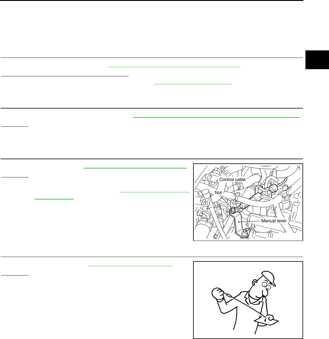
TROUBLE DIAGNOSIS FOR SYMPTOMS
CVT-201
D
E
F
G
H
I
J
K
L
M
A
B
CVT
Revision: 2006 August 2006 Murano
CVT Does Not Shift in Manual Mode NCS00194
SYMPTOM:
Speed does not change even if the selector lever is put in the manual shift gate position and the selec-
tor lever is operated to + side or to - side.
DIAGNOSTIC PROCEDURE
1. CHECK SELF-DIAGNOSTIC RESULTS
Perform self-diagnosis check. Refer to CVT-65, "SELF-DIAGNOSTIC RESULT MODE" .
Is any malfunction detected by self-diagnosis?
YES >> Check the malfunctioning system. Refer to CVT-65, "Display Items List" .
NO >> GO TO 2.
2. CHECK MANUAL MODE SWITCH
Check the manual mode switch circuit. Refer to CVT-132, "DTC P0826 MANUAL MODE SWITCH CIRCUIT" .
OK or NG
OK >> GO TO 3.
NG >> Repair or replace damaged parts.
3. CHECK CONTROL CABLE
Check control cable. Refer to CVT-212, "Checking of CVT Position"
OK or NG
OK >> GO TO 4.
NG >> Adjust control cable. Refer to CVT-211, "Adjustment of
CVT Position" .
4. CHECK CVT FLUID LEVEL
Check CVT fluid level. Refer to CVT-15, "Checking CVT Fluid" .
OK or NG
OK >> GO TO 5.
NG >> Refill CVT fluid.
SCIA2001E
SAT638A
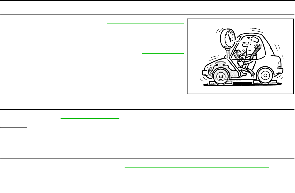
CVT-202
TROUBLE DIAGNOSIS FOR SYMPTOMS
Revision: 2006 August 2006 Murano
5. CHECK LINE PRESSURE
Check line pressure at idle. Refer to CVT-44, "LINE PRESSURE
TEST" .
OK or NG
OK >> GO TO 6.
NG >> Check the malfunctioning item. Refer to CVT-45, "Judg-
ment of Line Pressure Test" .
6. CHECK SYMPTOM
Check again. Refer to CVT-52, "Cruise Test" .
OK or NG
OK >> INSPECTION END
NG >> GO TO 7.
7. CHECK TCM
1. Check TCM input/output signals. Refer to CVT-57, "TCM Input/Output Signal Reference Values" .
2. If NG, re-check TCM pin terminals for damage or loose connection with harness connector.
OK or NG
OK >> Replace the transaxle assembly. Refer to CVT-229, "Removal and Installation" .
NG >> Repair or replace damaged parts.
SAT494G

TROUBLE DIAGNOSIS FOR SYMPTOMS
CVT-203
D
E
F
G
H
I
J
K
L
M
A
B
CVT
Revision: 2006 August 2006 Murano
Cannot Be Changed to Second Position (WITHOUT MANUAL MODE) NCS00195
SYMPTOM:
Does not change to second position when selecting “S” position.
DIAGNOSTIC PROCEDURE
1. CHECK SELF-DIAGNOSTIC RESULTS
Perform self-diagnosis check. Refer to CVT-65, "SELF-DIAGNOSTIC RESULT MODE" .
Is any malfunction detected by self-diagnosis?
YES >> Check the malfunctioning system. Refer to CVT-65, "Display Items List" .
NO >> GO TO 2.
2. CHECK SECOND POSITION SWITCH
Check the second position switch circuit. Refer to CVT-178, "SECOND POSITION SWITCH" .
OK or NG
OK >> GO TO 3.
NG >> Repair or replace damaged parts.
3. CHECK SYMPTOM
Check again. Refer to CVT-52, "Cruise Test" .
OK or NG
OK >> INSPECTION END
NG >> GO TO 4.
4. CHECK TCM
1. Check TCM input/output signals. Refer to CVT-57, "TCM Input/Output Signal Reference Values" .
2. If NG, re-check TCM pin terminals for damage or loose connection with harness connector.
OK or NG
OK >> INSPECTION END
NG >> Repair or replace damaged parts.
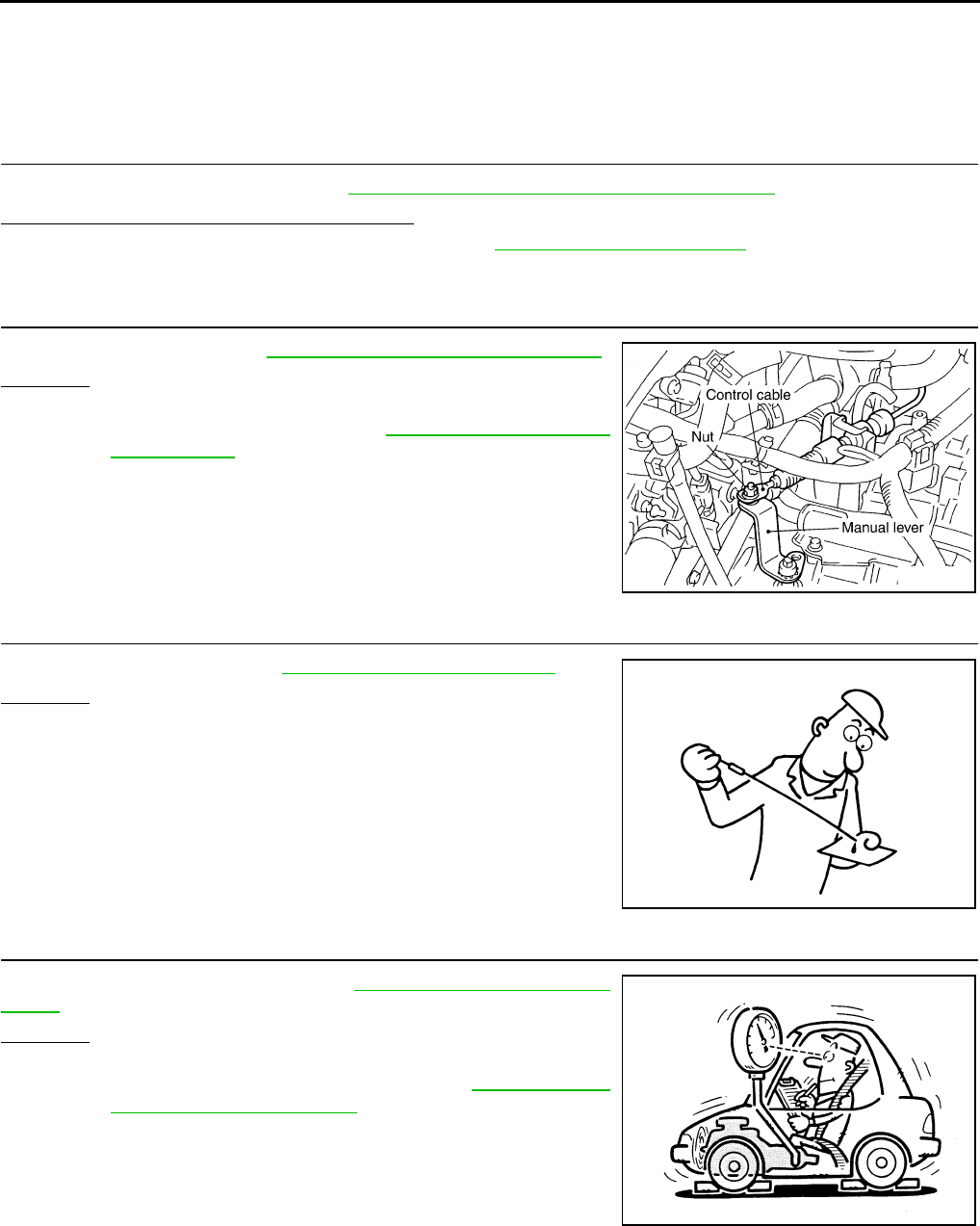
CVT-204
TROUBLE DIAGNOSIS FOR SYMPTOMS
Revision: 2006 August 2006 Murano
Cannot Be Changed to “L” Position (WITHOUT MANUAL MODE) NCS00196
SYMPTOM:
Does not change to “L” position when selecting “L” position.
DIAGNOSTIC PROCEDURE
1. CHECK SELF-DIAGNOSTIC RESULTS
Perform self-diagnosis check. Refer to CVT-65, "SELF-DIAGNOSTIC RESULT MODE" .
Is any malfunction detected by self-diagnosis?
YES >> Check the malfunctioning system. Refer to CVT-65, "Display Items List" .
NO >> GO TO 2.
2. CHECK CONTROL CABLE
Check control cable. Refer to CVT-212, "Checking of CVT Position"
OK or NG
OK >> GO TO 3.
NG >> Adjust control cable. Refer to CVT-211, "Adjustment of
CVT Position" .
3. CHECK CVT FLUID LEVEL
Check CVT fluid level. Refer to CVT-15, "Checking CVT Fluid" .
OK or NG
OK >> GO TO 4.
NG >> Refill CVT fluid.
4. CHECK LINE PRESSURE
Check line pressure at idle. Refer to CVT-44, "LINE PRESSURE
TEST" .
OK or NG
OK >> GO TO 5.
NG >> Check the malfunctioning item. Refer to CVT-45, "Judg-
ment of Line Pressure Test" .
SCIA2001E
SAT638A
SAT494G

TROUBLE DIAGNOSIS FOR SYMPTOMS
CVT-205
D
E
F
G
H
I
J
K
L
M
A
B
CVT
Revision: 2006 August 2006 Murano
5. CHECK SYMPTOM
Check again. Refer to CVT-52, "Cruise Test" .
OK or NG
OK >> INSPECTION END
NG >> GO TO 6.
6. CHECK TCM
1. Check TCM input/output signals. Refer to CVT-57, "TCM Input/Output Signal Reference Values" .
2. If NG, re-check TCM pin terminals for damage or loose connection with harness connector.
OK or NG
OK >> Replace the transaxle assembly. Refer to CVT-229, "Removal and Installation" .
NG >> Repair or replace damaged parts.
CVT-206
TROUBLE DIAGNOSIS FOR SYMPTOMS
Revision: 2006 August 2006 Murano
Vehicle Does Not Decelerate by Engine Brake NCS00197
SYMPTOM:
No engine brake is applied when the gear is shifted from the “M2” to “M1” position.
No engine brake is applied when the gear is shifted from the “S”* to “L” position.
*: Without manual mode
DIAGNOSTIC PROCEDURE
1. CHECK SELF-DIAGNOSTIC RESULTS
Perform self-diagnosis check. Refer to CVT-65, "SELF-DIAGNOSTIC RESULT MODE" .
Is any malfunction detected by self-diagnosis?
YES >> Check the malfunctioning system. Refer to CVT-65, "Display Items List" .
NO >> GO TO 2.
2. CHECK CONTROL CABLE
Check control cable. Refer to CVT-212, "Checking of CVT Position"
OK or NG
OK >> GO TO 3.
NG >> Adjust control cable. Refer to CVT-211, "Adjustment of
CVT Position" .
3. CHECK CVT FLUID LEVEL
Check CVT fluid level. Refer to CVT-15, "Checking CVT Fluid" .
OK or NG
OK >> GO TO 4.
NG >> Refill CVT fluid.
4. CHECK LINE PRESSURE
Check line pressure at idle. Refer to CVT-44, "LINE PRESSURE
TEST" .
OK or NG
OK (With manual mode) >>GO TO 5.
OK (Without manual mode) >>GO TO 6.
NG >> Check the malfunctioning item. Refer to CVT-45, "Judg-
ment of Line Pressure Test" .
SCIA2001E
SAT638A
SAT494G

TROUBLE DIAGNOSIS FOR SYMPTOMS
CVT-207
D
E
F
G
H
I
J
K
L
M
A
B
CVT
Revision: 2006 August 2006 Murano
5. CHECK MANUAL MODE SWITCH
Check the manual mode switch circuit. Refer to CVT-132, "DTC P0826 MANUAL MODE SWITCH CIRCUIT" .
OK or NG
OK >> GO TO 6.
NG >> Repair or replace damaged parts.
6. CHECK SYMPTOM
Check again. Refer to CVT-52, "Cruise Test" .
OK or NG
OK >> INSPECTION END
NG >> GO TO 7.
7. CHECK TCM
1. Check TCM input/output signals. Refer to CVT-57, "TCM Input/Output Signal Reference Values" .
2. If NG, re-check TCM pin terminals for damage or loose connection with harness connector.
OK or NG
OK >> Replace the transaxle assembly. Refer to CVT-229, "Removal and Installation" .
NG >> Repair or replace damaged parts.
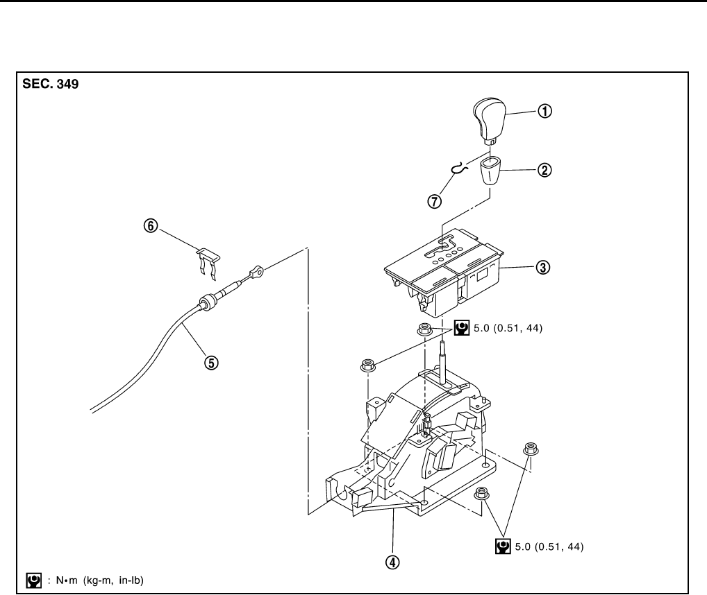
CVT-208
SHIFT CONTROL SYSTEM
Revision: 2006 August 2006 Murano
SHIFT CONTROL SYSTEM PFP:34901
Removal and Installation NCS00198
CONTROL DEVICE COMPONENTS (WITH MANUAL MODE)
1. Selector lever knob 2. Knob cover 3. A/T console finisher
4. Control device assembly 5. Control cable 6. Lock plate
7. Lock pin
SCIA6463E
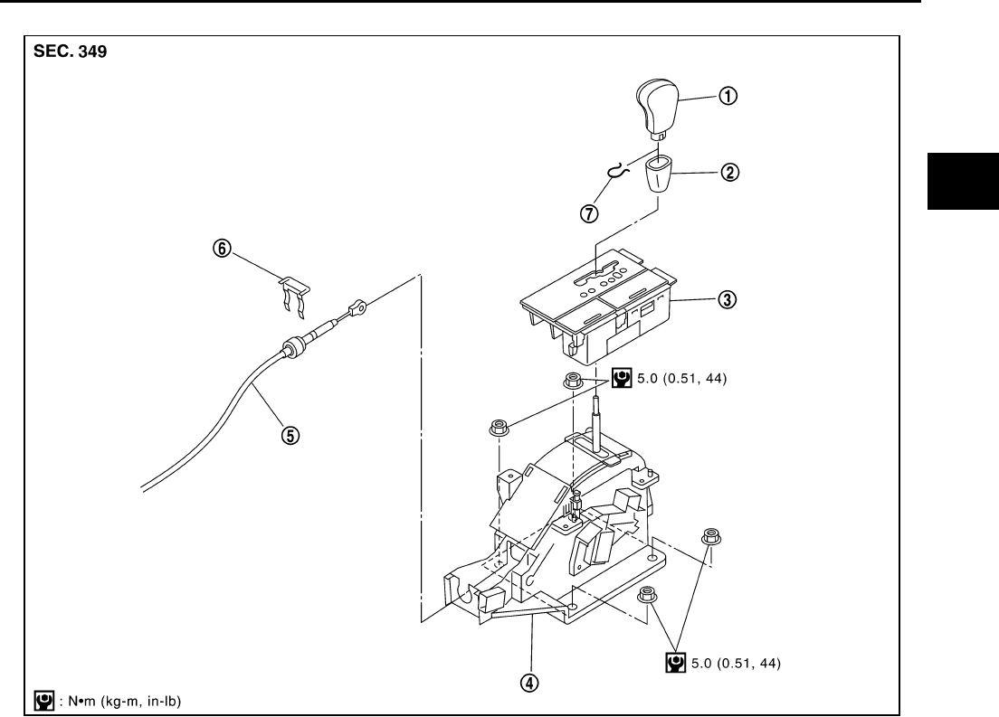
SHIFT CONTROL SYSTEM
CVT-209
D
E
F
G
H
I
J
K
L
M
A
B
CVT
Revision: 2006 August 2006 Murano
CONTROL DEVICE COMPONENTS (WITHOUT MANUAL MODE)
1. Selector lever knob 2. Knob cover 3. A/T console finisher
4. Control device assembly 5. Control cable 6. Lock plate
7. Lock pin
SCIA6464E
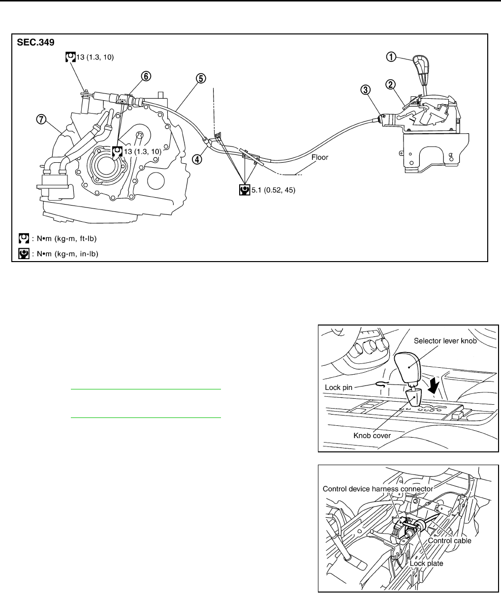
CVT-210
SHIFT CONTROL SYSTEM
Revision: 2006 August 2006 Murano
CONTROL CABLE COMPONENTS
Refer to the figure below for control cable removal and installation procedure.
REMOVAL
1. Remove knob cover below selector lever downward.
2. Pull lock pin out of selector lever knob.
3. Remove selector lever knob.
4. Remove A/T console finisher.
●Refer to IP-18, "Removal and Installation" .
5. Remove console box assembly.
●Refer to IP-18, "Removal and Installation" .
6. Disconnect control cable of control device.
7. Disconnect control device harness connector.
1. Selector lever knob 2. Control device assembly 3. Lock plate
4. Bracket 5. Control cable 6. Lock plate
7. Transaxle assembly
SCIA5988E
SCIA4377E
SCIA5963E
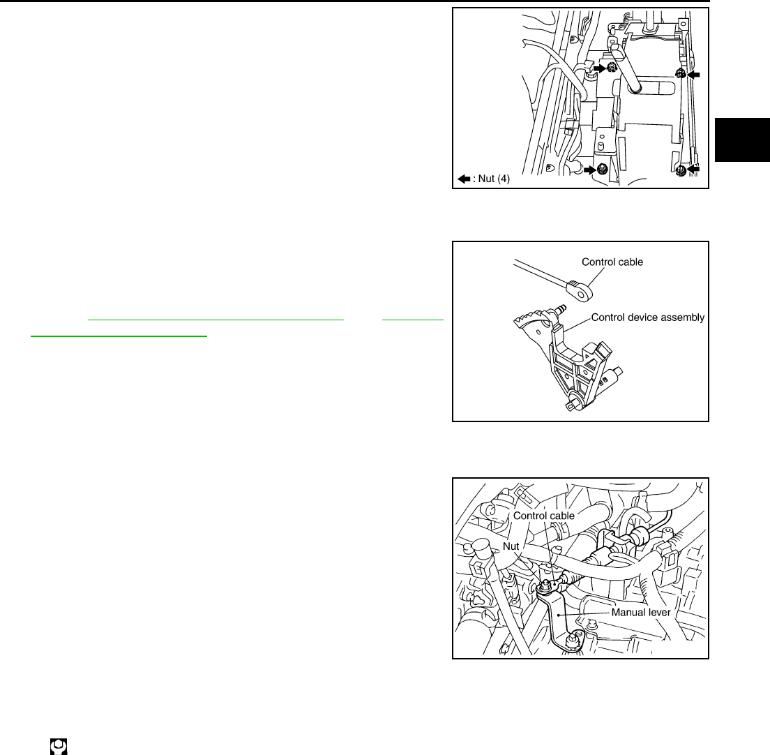
SHIFT CONTROL SYSTEM
CVT-211
D
E
F
G
H
I
J
K
L
M
A
B
CVT
Revision: 2006 August 2006 Murano
8. Remove control device assembly.
INSTALLATION
Note the following, and install in the reverse order of removal.
●The knurled surface of rib should be upward when installing the
control cable to the control device assembly. And insert the con-
trol cable securely.
●After installation is completed, adjust and check CVT position.
Refer to CVT-211, "Adjustment of CVT Position" and CVT-212,
"Checking of CVT Position" .
Adjustment of CVT Position NCS00199
1. Place selector lever in “P” position.
2. Loosen control cable nut and place manual lever in “P” position.
CAUTION:
Turn wheels more than 1/4 rotations and apply the park
lock.
3. Hold the control cable at the end. Push and pull it twice or three
times, and then push it with a load of 9.8 N (approximately 1 kg,
2.2 lb). Temporarily tighten the control cable nut with the control
cable loose.
4. Connect control cable on manual lever.
CAUTION:
No application of a force to the manual lever.
5. Tighten control cable nut.
CAUTION:
Fix the manual lever when tightening.
SCIA5964E
SCIA5990E
: 13 N·m (1.3 kg-m, 10 ft-lb)
SCIA2001E
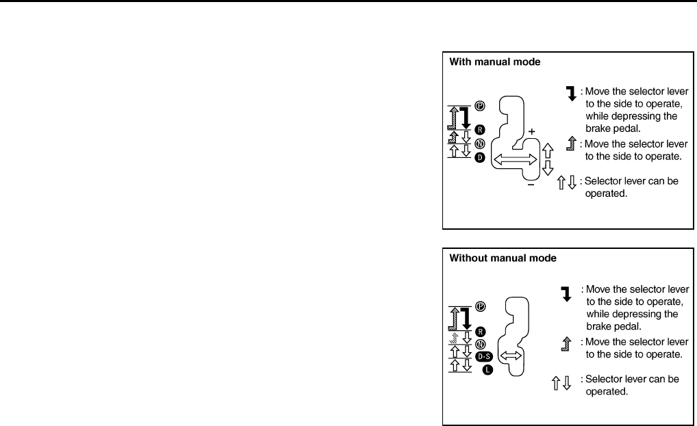
CVT-212
SHIFT CONTROL SYSTEM
Revision: 2006 August 2006 Murano
Checking of CVT Position NCS0019A
1. Place selector lever in “P” position, and turn ignition switch ON. (Do not start engine.)
2. Make sure selector lever can be shifted to other than “P” posi-
tion when brake pedal is depressed. Also make sure selector
lever can be shifted from “P” position only when brake pedal is
depressed.
3. Move the selector lever and check for excessive effort, sticking,
noise or rattle.
4. Confirm the selector lever stops at each position with the feel of
engagement when it is moved through all the positions. Check
whether or not the actual position the selector lever is in
matches the position shown by the shift position indicator and
the transaxle body.
5. The method of operating the selector lever to individual posi-
tions correctly should be as shown in the figure.
6. Confirm the back-up lamps illuminate only when selector lever is
placed in the “R” position. Confirm the back-up lamps do not illu-
minate when the selector lever is pushed toward the “R” position
side with the gear position remained in the “P” or “N” position.
7. Confirm the engine can only be started with the selector lever in
the “P” and “N” positions.
8. Make sure transaxle is locked completely in “P” position.
9. When selector lever is set to manual shift gate, make sure man-
ual mode is displayed on combination meter.
Shift selector lever to “+” and “-” sides, and make sure set shift position changes.
SCIA8112E
SCIA8113E
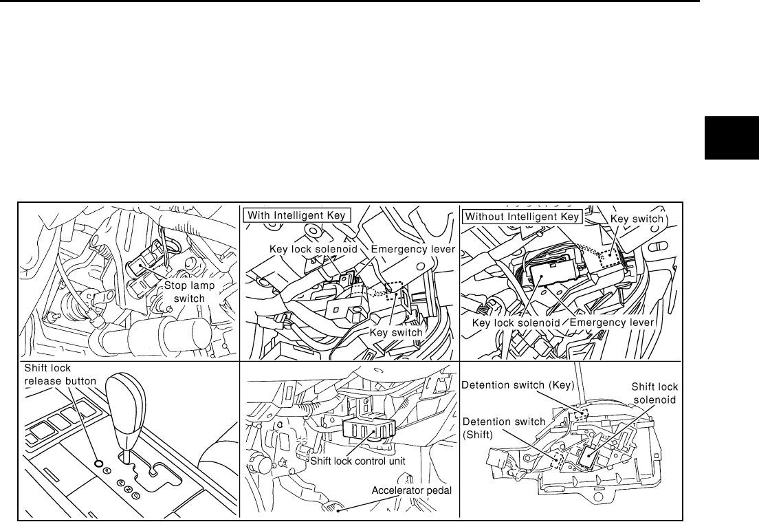
CVT SHIFT LOCK SYSTEM
CVT-213
D
E
F
G
H
I
J
K
L
M
A
B
CVT
Revision: 2006 August 2006 Murano
CVT SHIFT LOCK SYSTEM PFP:00000
Description NCS0019B
●The electrical key interlock mechanism also operates as a shift lock:
With the ignition switch turned to ON, the selector lever cannot be shifted from “P” (parking) to any other
position unless the brake pedal is depressed.
With the key removed, the selector lever cannot be shifted from “P” to any other position.
The key cannot be removed unless the selector lever is placed in “P”.
●The shift lock and key interlock mechanisms are controlled by the ON-OFF operation of the shift lock sole-
noid and by the operation of the rotator and slider located inside the key cylinder, respectively.
Shift Lock System Electrical Parts Location NCS0019C
NOTE:
This emergency lever can be used when battery is off ignition key cannot be removed. In the situation like this,
by operating this lever, ignition key can be removed.
SCIA8159E
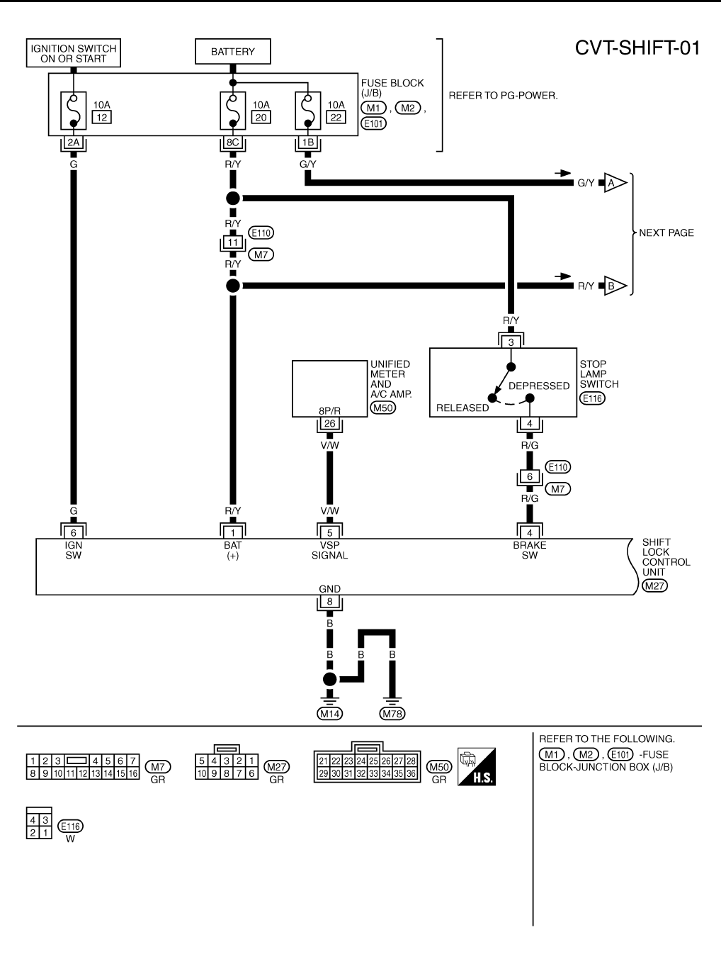
CVT-214
CVT SHIFT LOCK SYSTEM
Revision: 2006 August 2006 Murano
Wiring Diagram — CVT — SHIFT (With Intelligent Key) NCS0019D
TCWB0261E
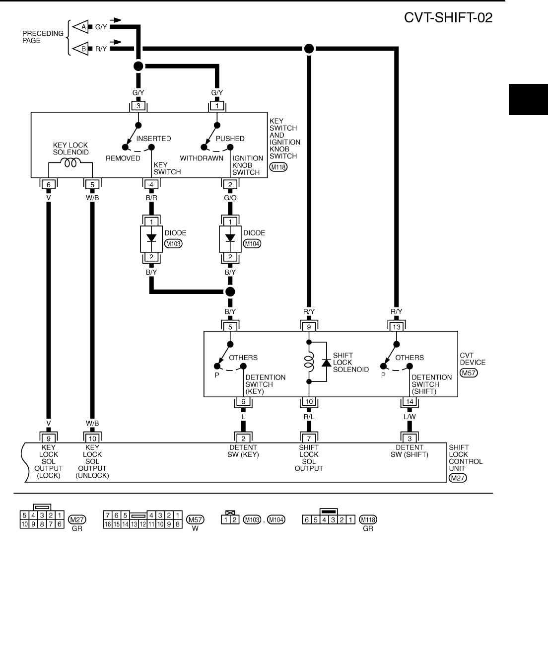
CVT SHIFT LOCK SYSTEM
CVT-215
D
E
F
G
H
I
J
K
L
M
A
B
CVT
Revision: 2006 August 2006 Murano
TCWB0065E
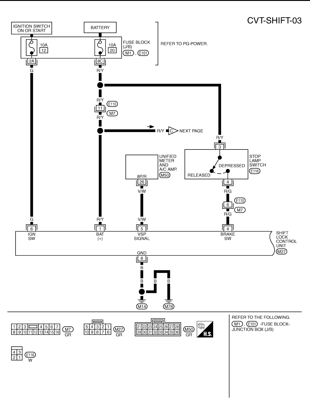
CVT-216
CVT SHIFT LOCK SYSTEM
Revision: 2006 August 2006 Murano
Wiring Diagram — CVT — SHIFT (Without Intelligent Key) NCS0019E
TCWB0262E
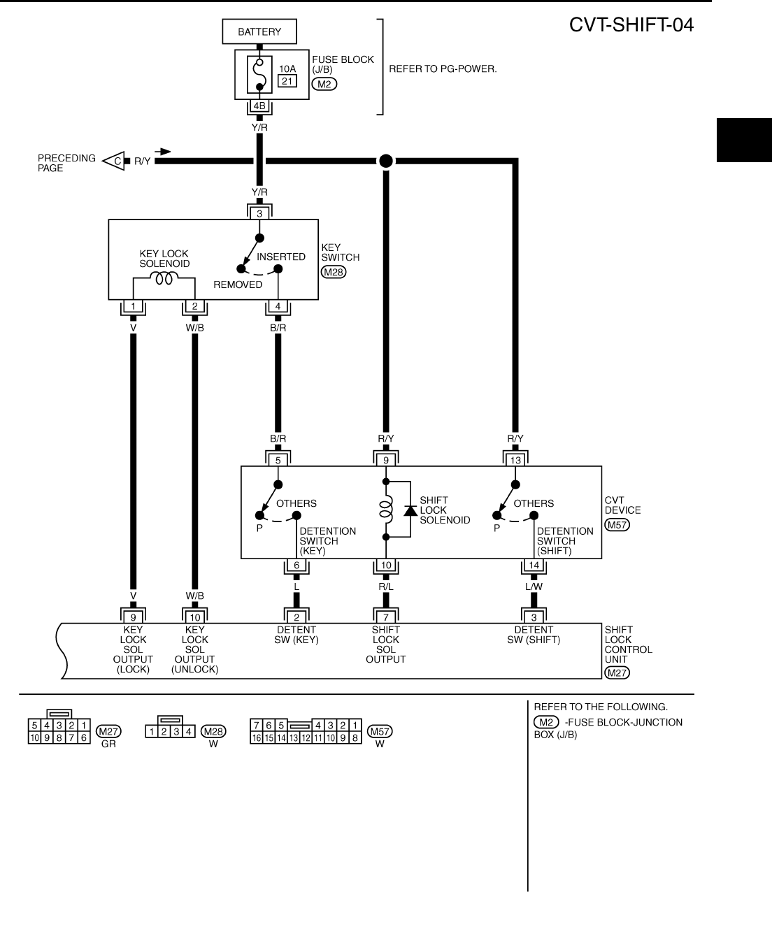
CVT SHIFT LOCK SYSTEM
CVT-217
D
E
F
G
H
I
J
K
L
M
A
B
CVT
Revision: 2006 August 2006 Murano
TCWB0067E
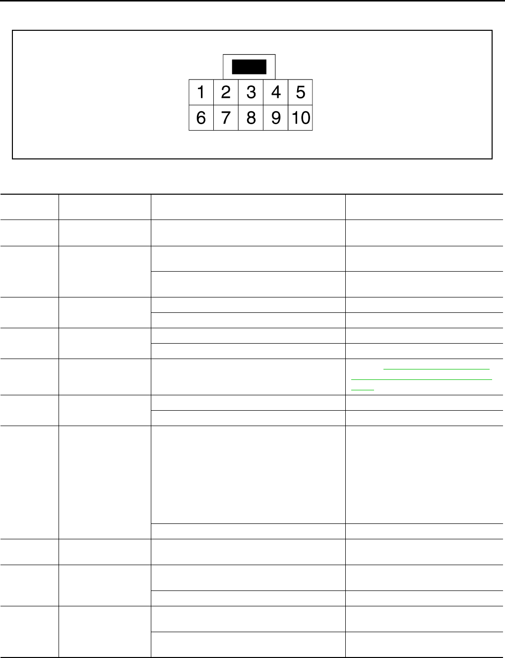
CVT-218
CVT SHIFT LOCK SYSTEM
Revision: 2006 August 2006 Murano
Shift Lock Control Unit Reference Values NCS0019F
SHIFT LOCK HARNESS CONNECTOR TERMINALS LAYOUT
SHIFT LOCK CONTROL UNIT INSPECTION TABLE
Shift lock control unit terminal data are reference values, measured between each terminal and ground.
NOTE:
Take care that the pointer swings only momentarily because the output time is so short. If the inspection is done with an oscilloscope, it
should be observed that the power source voltage lasts for 3.5 to 10 ms.
SCIA2004E
Terminal
(Wire color) Item Condition Judgment standard
1
(R/Y) Power source Always Battery voltage
2
(L)
Detention switch (for
key)
When selector lever is not in “P” position with key
inserted or ignition knob switch pushed. Battery voltage
When selector lever is in “P” position with key
inserted. Approx. 0 V
3
(L/W)
Detention switch (for
shift)
When selector lever is not in “P” position. Battery voltage
When selector lever is in “P” position. Approx. 0 V
4
(R/G) Stop lamp switch When brake pedal is depressed Battery voltage
When brake pedal is released Approx. 0 V
5
(V/W)
Vehicle speed signal
(8pulse signal) Speed meter is operated
Refer to DI-14, "Terminals and Refer-
ence Value for Unified Meter and A/C
Amp." .
6
(G) Ignition signal Ignition switch: OFF Approx. 0 V
Ignition switch: ON Battery voltage
7
(R/L) Shift lock solenoid
●When selector lever is in “P” position, brake
pedal is depressed, and ignition switch is ON.
●When selector lever is not in “P” position, igni-
tion switch is ON, and vehicle speed is 10 km/h
(6 MPH) or less.
●For 3 minutes after selector lever is not in “P”
position, vehicle speed is 10 km/h (6 MPH) or
less, and ignition switch is ON → OFF.
Approx. 0 V
Except the above Battery voltage
8
(B) Ground — Approx. 0 V
9
(V) Key lock solenoid When selector lever is not in “P” position. Battery voltage for approx. 0.1 sec.
(Note)
When selector lever is in “P” position. Approx. 0 V
10
(W/B) Key unlock solenoid
When selector lever is in “P” position with ignition
switch OFF.
Battery voltage for approx. 0.1 sec.
(Note)
When selector lever is not in “P” position with igni-
tion switch OFF. Approx. 0 V
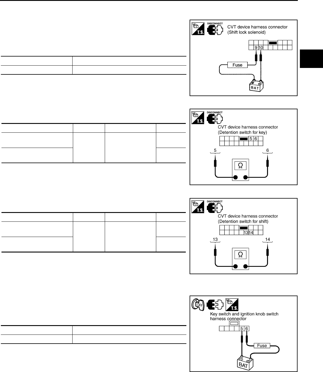
CVT SHIFT LOCK SYSTEM
CVT-219
D
E
F
G
H
I
J
K
L
M
A
B
CVT
Revision: 2006 August 2006 Murano
Component Inspection NCS0019G
SHIFT LOCK SOLENOID
Check operation by applying battery voltage to the CVT device har-
ness connector.
CAUTION:
Be sure to apply the voltage of the correct polarity to the
respective terminals. Otherwise, the part may be damaged.
DETENTION SWITCH (FOR KEY)
Check continuity between terminals of the CVT device harness con-
nector.
DETENTION SWITCH (FOR SHIFT)
Check continuity between terminals of the CVT device harness con-
nector.
KEY LOCK SOLENOID (WITH INTELLIGENT KEY)
Key Lock
Check operation by applying battery voltage to key switch and igni-
tion knob switch harness connector.
CAUTION:
Be careful not to cause burnout of the harness.
Connector Terminal
M57 9 (Battery voltage) - 10 (Ground)
SCIA2005E
Condition Connector Terminal Continuity
When selector lever is in “P”
position. M57 5 - 6
No
When selector lever is not in
“P” position. Yes
SCIA2006E
Condition Connector Terminal Continuity
When selector lever is in “P”
position. M57 13 - 14
No
When selector lever is not in
“P” position. Yes
SCIA2046E
Connector Terminal
M118 6 (Battery voltage) - 5 (Ground)
SCIA6152E
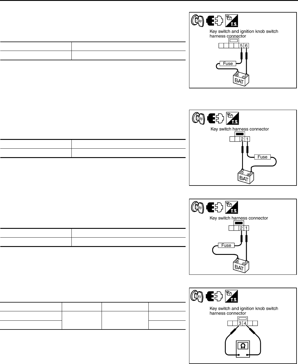
CVT-220
CVT SHIFT LOCK SYSTEM
Revision: 2006 August 2006 Murano
Key Unlock
Check operation by applying battery voltage to key switch and igni-
tion knob switch harness connector.
CAUTION:
Be careful not to cause burnout of the harness.
KEY LOCK SOLENOID (WITHOUT INTELLIGENT KEY)
Key Lock
Check operation by applying battery voltage to key switch harness
connector.
CAUTION:
Be careful not to cause burnout of the harness.
Key Unlock
Check operation by applying battery voltage to key switch harness
connector.
CAUTION:
Be careful not to cause burnout of the harness.
KEY SWITCH (WITH INTELLIGENT KEY)
Check continuity between terminals of the key switch and ignition
knob switch harness connector.
Connector Terminal
M118 5 (Battery voltage) - 6 (Ground)
SCIA6151E
Connector Terminal
M28 1 (Battery voltage) - 2 (Ground)
SCIA6460E
Connector Terminal
M28 2 (Battery voltage) - 1 (Ground)
SCIA6461E
Condition Connector Terminal Continuity
Key inserted M118 3 - 4 Yes
Key withdrawn No
SCIA6153E
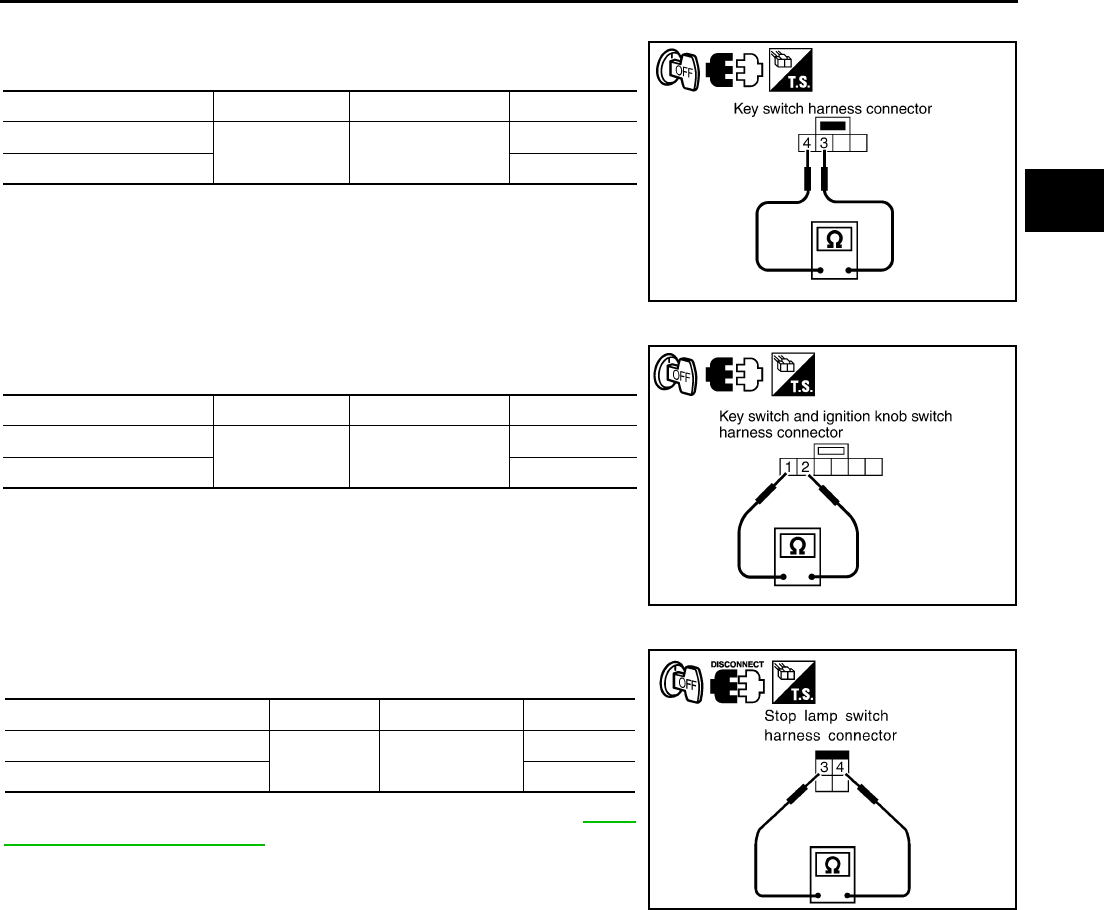
CVT SHIFT LOCK SYSTEM
CVT-221
D
E
F
G
H
I
J
K
L
M
A
B
CVT
Revision: 2006 August 2006 Murano
KEY SWITCH (WITHOUT INTELLIGENT KEY)
Check continuity between terminals of the key switch harness con-
nector.
IGNITION KNOB SWITCH (WITH INTELLIGENT KEY)
Check continuity between terminals of the key switch and ignition
knob switch harness connector.
STOP LAMP SWITCH
Check continuity between terminals of the stop lamp switch harness
connector.
Check stop lamp switch after adjusting brake pedal. Refer to BR-6,
"Inspection and Adjustment" .
Condition Connector Terminal Continuity
Key inserted M28 3 - 4 Yes
Key withdrawn No
SCIA6462E
Condition Connector Terminal Continuity
Pushed M118 1 - 2 Yes
Released No
SCIA6671E
Condition Connector Terminal Continuity
When brake pedal is depressed E116 3 - 4 Yes
When brake pedal is released No
SCIA2126E
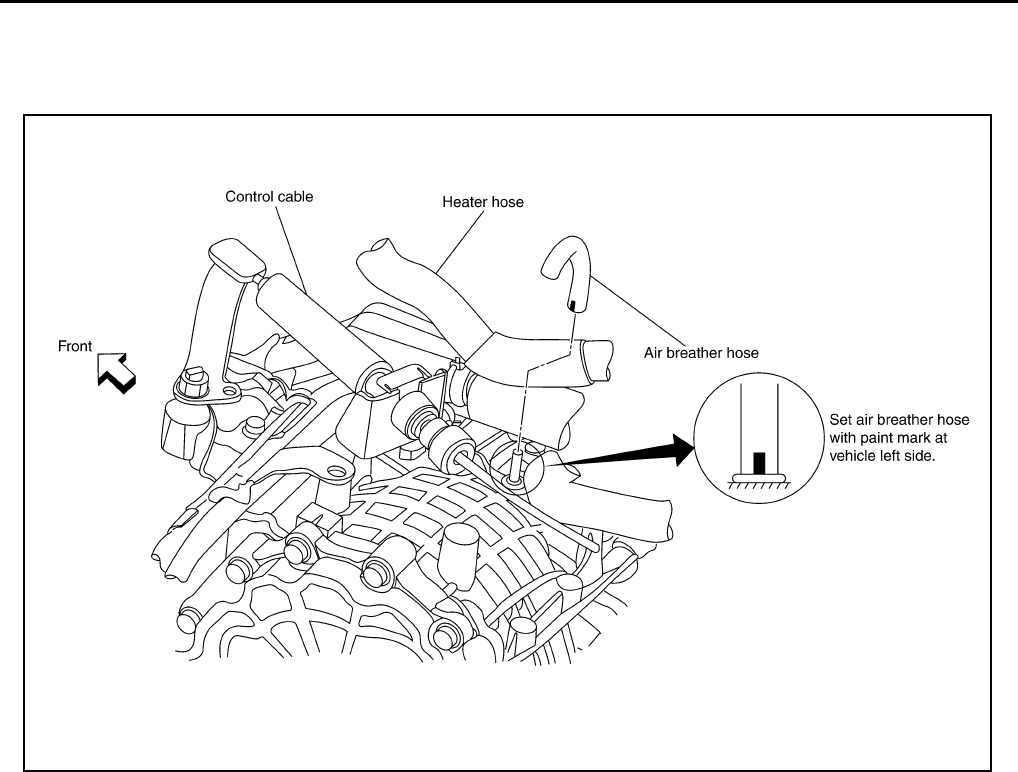
CVT-222
AIR BREATHER HOSE
Revision: 2006 August 2006 Murano
AIR BREATHER HOSE PFP:31098
Removal and Installation NCS0019H
Refer to the figure below for air breather hose removal and installation procedure.
CAUTION:
Securely insert the hose into the air breather until it touches the bottom.
SCIA2284E
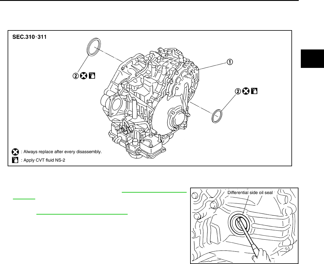
DIFFERENTIAL SIDE OIL SEAL
CVT-223
D
E
F
G
H
I
J
K
L
M
A
B
CVT
Revision: 2006 August 2006 Murano
DIFFERENTIAL SIDE OIL SEAL PFP:33111
Removal and Installation NCS0019I
COMPONENTS
REMOVAL
1. Remove drive shaft assembly. Refer to FAX-7, "FRONT DRIVE
SHAFT" .
2. Remove transfer from transaxle assembly. (AWD models)
Refer to TF-52, "Removal and Installation" .
3. Remove differential side oil seals using a flat-bladed screw-
driver.
CAUTION:
Be careful not to scratch transaxle case or converter hous-
ing.
1. Transaxle assembly 2. Differential side oil seal
SCIA2408E
SCIA2412E
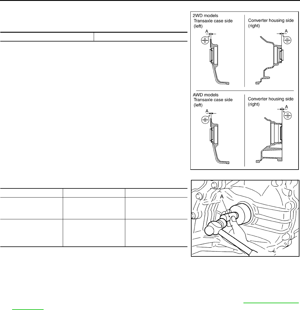
CVT-224
DIFFERENTIAL SIDE OIL SEAL
Revision: 2006 August 2006 Murano
INSTALLATION
1. As shown below, use a drift to drive the differential side oil seals
into the case until it is flush. Refer to dimensions A. Unit: mm (in)
NOTE:
The differential side oil seals pulling direction is used as the ref-
erence.
Drift to be used:
CAUTION:
●Do not reuse differential side oil seals.
●When installing differential side oil seals, apply NISSAN CVT Fluid NS-2.
2. Reinstall any part removed.
CAUTION:
If lubricant leak has occurred, after finishing work, check fluid level. Refer to CVT-15, "Checking
CVT Fluid" .
Dimensions A 0 ± 0.5 (0 ± 0.020)
SCIA2411E
Location 2WD models AWD models
Transaxle case side (left)
Tool number: A
(Kent-Moore No.)
—
(J-47244)
—
(J-47244)
Converter housing side
(right)
Tool number: A
(Kent-Moore No.)
ST33400001
(J-47005)
—
(J-34339-A)
SCIA6583E
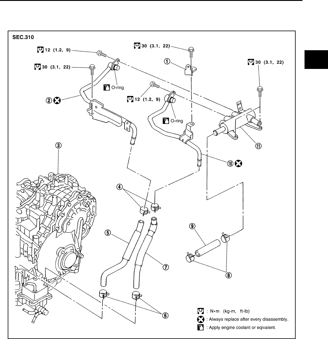
CVT FLUID COOLER VALVE
CVT-225
D
E
F
G
H
I
J
K
L
M
A
B
CVT
Revision: 2006 August 2006 Murano
CVT FLUID COOLER VALVE PFP:21630
Removal and Installation NCS0019J
COMPONENTS
1. Harness bracket 2. CVT fluid cooler inlet tube assembly 3. Transaxle assembly
4. Hose clamp 5. Inlet water hose 6. Hose clamp
7. Outlet water hose 8. Hose clamp 9. Heater hose
10. CVT fluid cooler outlet tube assem-
bly
11. CVT fluid cooler valve assembly
SCIA4344E
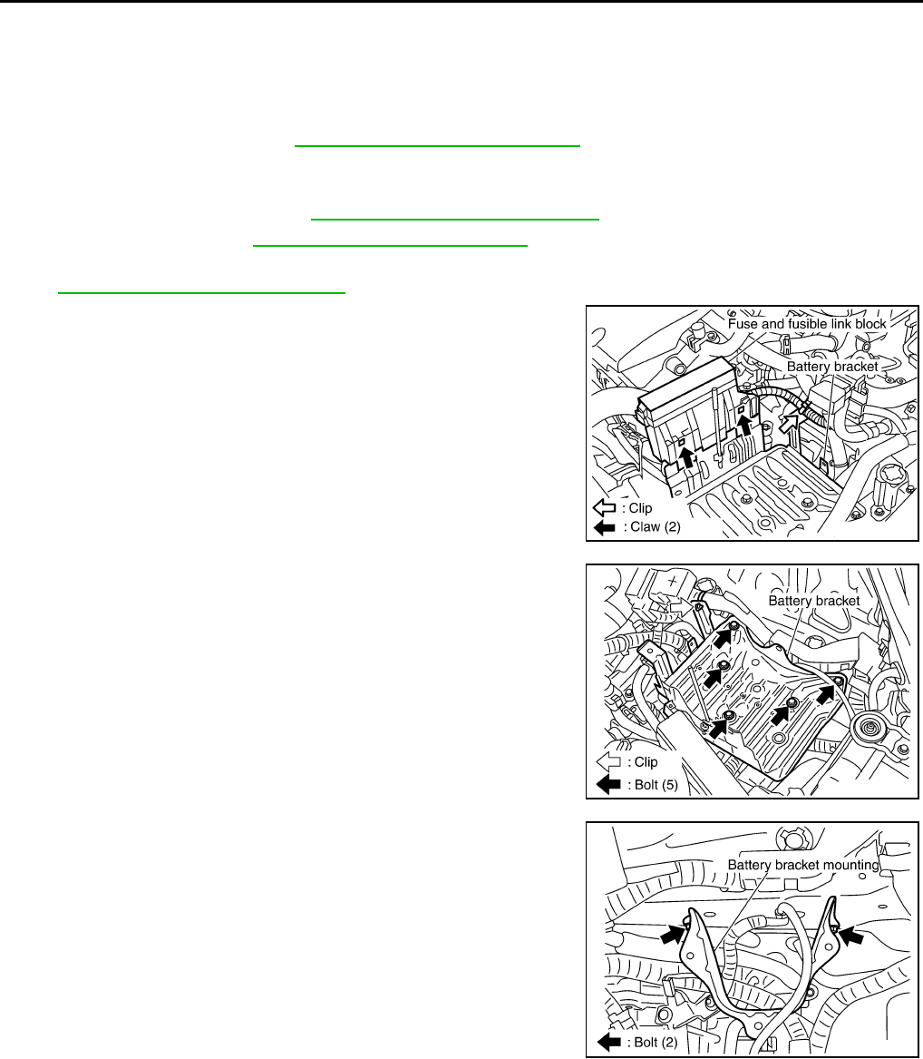
CVT-226
CVT FLUID COOLER VALVE
Revision: 2006 August 2006 Murano
REMOVAL
WARNING:
Never remove the radiator cap when the engine is hot. Serious burns could occur from high pressure
engine coolant escaping from the radiator.
1. Remove engine undercover.
2. Drain engine coolant. Refer to CO-9, "Changing Engine Coolant" .
CAUTION:
Perform when the engine is cold.
3. Remove air duct (inlet). Refer to EM-16, "Removal and Installation" .
4. Remove battery. Refer to SC-8, "Removal and Installation" .
5. Remove air cleaner case (upper and lower), resonator, mass air flow sensor and air duct assembly. Refer
to EM-16, "Removal and Installation" .
6. Remove fuse and fusible link block from battery bracket.
7. Remove battery bracket.
8. Remove battery bracket mounting.
SCIA2749E
SCIA2750E
SCIA2751E
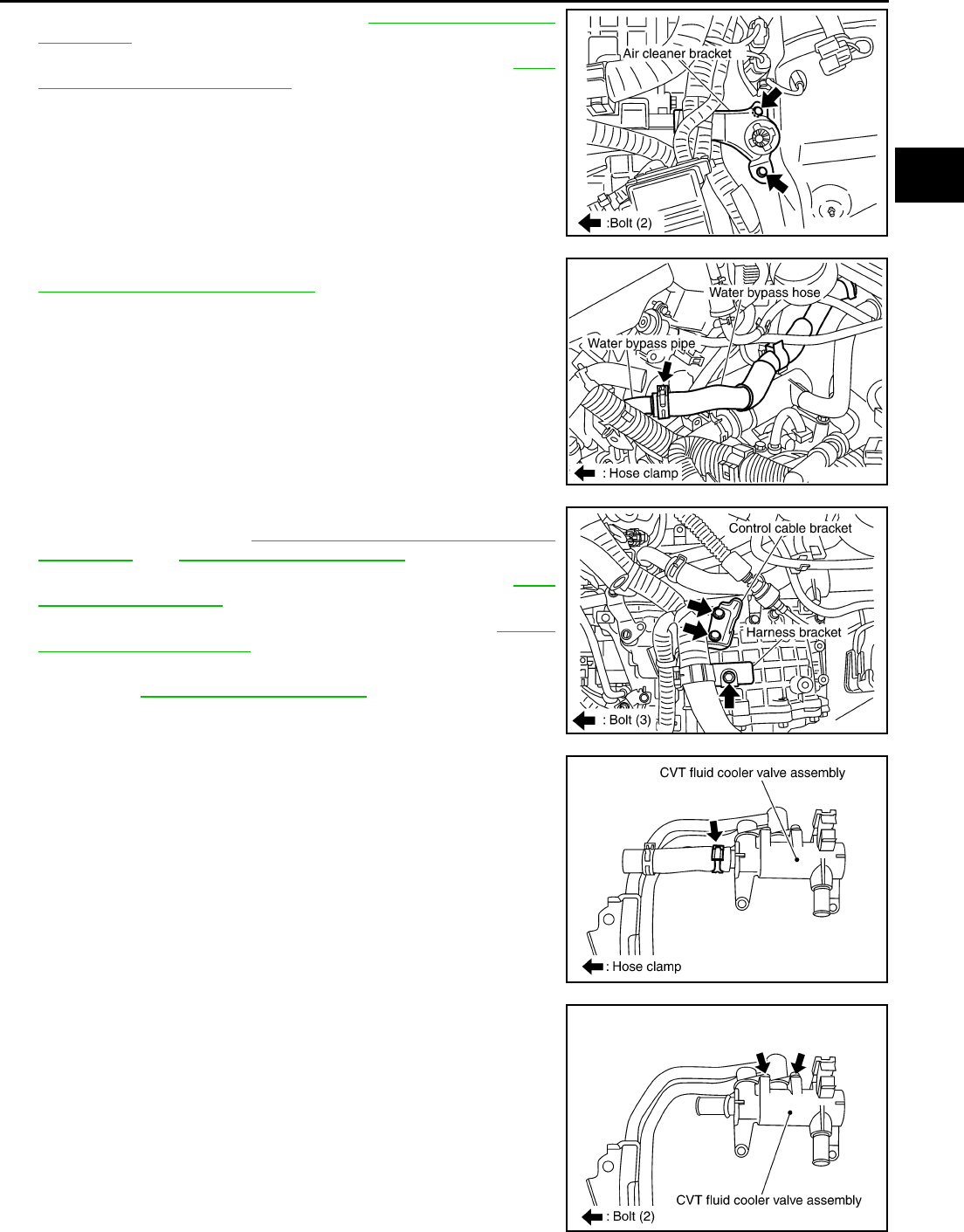
CVT FLUID COOLER VALVE
CVT-227
D
E
F
G
H
I
J
K
L
M
A
B
CVT
Revision: 2006 August 2006 Murano
9. Remove air cleaner bracket. Refer to EM-16, "Removal and
Installation" .
10. Remove control cable from transaxle assembly. Refer to CVT-
208, "Removal and Installation" .
11. Remove water bypass hose from water bypass pipe. Refer to
CO-29, "Removal and Installation" .
12. Remove harness bracket and control cable bracket from tran-
saxle assembly. Refer to CVT-210, "CONTROL CABLE COM-
PONENTS" and CVT-225, "COMPONENTS" .
13. Remove inlet water hose and outlet water hose. Refer to CVT-
225, "COMPONENTS" .
14. Remove heater hose from heater pipe. Refer to CO-29,
"Removal and Installation" .
15. Remove CVT fluid cooler valve assembly from transaxle assem-
bly. Refer to CVT-225, "COMPONENTS" .
16. Remove heater hose from CVT fluid cooler valve assembly.
17. Remove CVT fluid cooler inlet tube assembly and CVT fluid
cooler outlet tube assembly from CVT fluid cooler valve assem-
bly.
SCIA2752E
SCIA4350E
SCIA2753E
SCIA4349E
SCIA4348E
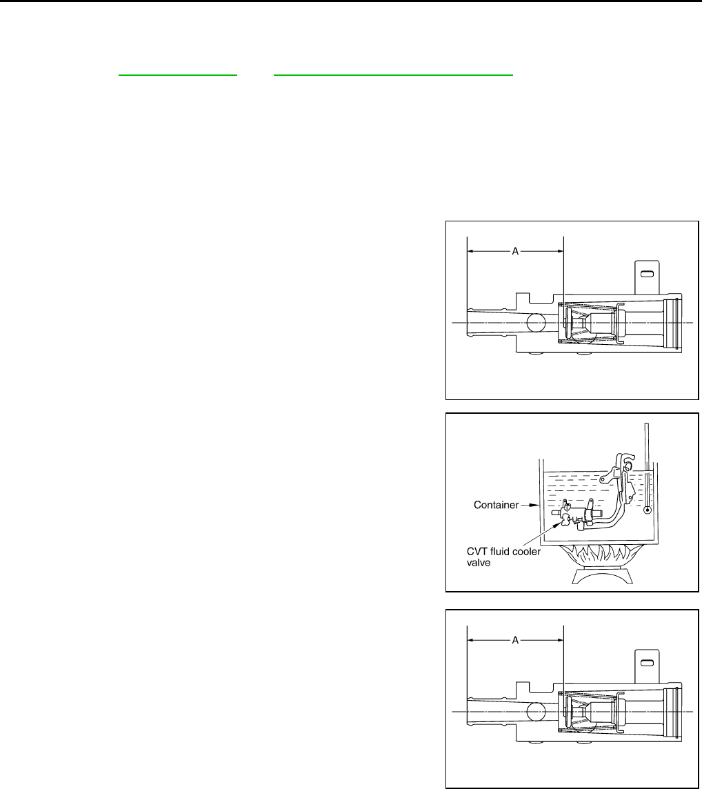
CVT-228
CVT FLUID COOLER VALVE
Revision: 2006 August 2006 Murano
INSTALLATION
Note the following, and install in the reverse order of removal.
●After completing installation, check for engine coolant leakage, engine coolant level, and the positions of
CVT. Refer to CO-9, "Inspection" and CVT-212, "Checking of CVT Position" .
CAUTION:
●Do not reuse CVT fluid cooler inlet tube assembly and CVT fluid cooler outlet tube assembly.
●Install hose clamp with tabs aligned with markings of CVT fluid cooler valve assembly and each
hose.
●Apply LLC around O-ring when installing CVT fluid cooler inlet tube and CVT fluid cooler outlet
tube assembly to CVT fluid cooler valve assembly.
Component Inspection NCS0019K
1. Make sure that CVT fluid cooler valve is fully opened at room
temperature.
2. Put CVT fluid cooler valve into a water-filled container, and then
heat it up to 82°C (180°F) or more for 10 minutes or more.
3. Make sure that CVT fluid cooler valve is fully closed.
Standard
Dimension A from CVT fluid cooler valve port end
to tip of valve shaft
(At room temperature):
Approx. 72.0 mm (2.835 in) or more
SCIA7399E
SCIA2710E
Standard
Dimension A from CVT fluid cooler valve port end
to tip of valve shaft
[When heating to 82°C (180°F) or more for 10 min-
utes or more]:
Approx. 66.5 mm (2.618 in) or less
SCIA7399E
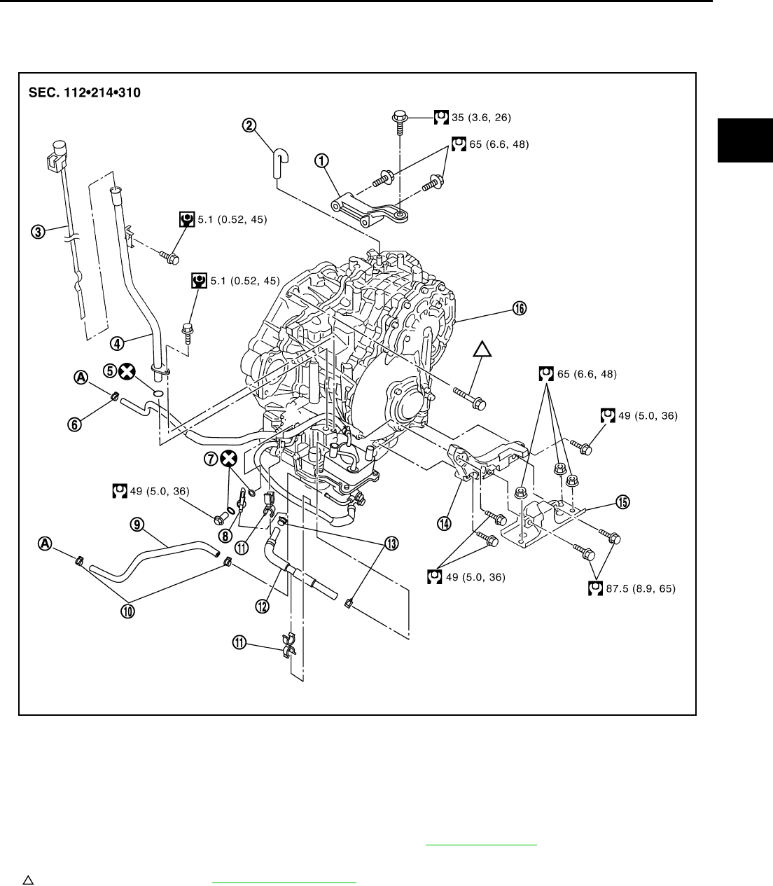
TRANSAXLE ASSEMBLY
CVT-229
D
E
F
G
H
I
J
K
L
M
A
B
CVT
Revision: 2006 August 2006 Murano
TRANSAXLE ASSEMBLY PFP:32020
Removal and Installation NCS0019L
COMPONENTS (2WD MODELS)
1. Rear gusset 2. Air breather hose 3. CVT fluid level gauge
4. CVT fluid charging pipe 5. O-ring 6. Hose clamp
7. Copper washer 8. Fluid cooler tube 9. CVT fluid cooler hose
10. Hose clamp 11. Clip 12. CVT fluid cooler hose
13. Hose clamp 14. LH engine mounting bracket 15. LH engine mounting insulator
16. Transaxle assembly
Refer to GI section to make sure icons (symbol marks) in the figure. Refer to GI-10, "Components" .
However, refer to the following symbols for others.
: For tightening torque, refer to CVT-234, "INSTALLATION" .
A : To radiator
SCIA7516E
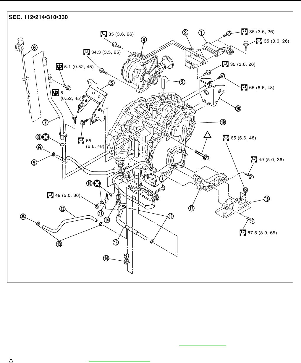
CVT-230
TRANSAXLE ASSEMBLY
Revision: 2006 August 2006 Murano
COMPONENTS (AWD MODELS)
1. Rear gusset 2. Transfer gusset 3. Air breather hose
4. Transfer assembly 5. Front engine mounting bracket 6. CVT fluid level gauge
7. CVT fluid charging pipe 8. O-ring 9. Hose clamp
10. Copper washer 11. Fluid cooler tube 12. CVT fluid cooler hose
13. Hose clamp 14. Clip 15. CVT fluid cooler hose
16. Hose clamp 17. LH engine mounting bracket 18. LH engine mounting insulator
19. Transaxle assembly 20. Rear engine mounting bracket
Refer to GI section to make sure icons (symbol marks) in the figure. Refer to GI-10, "Components" .
However, refer to the following symbols for others.
: For tightening torque, refer to CVT-234, "INSTALLATION" .
A : To radiator
SCIA7517E
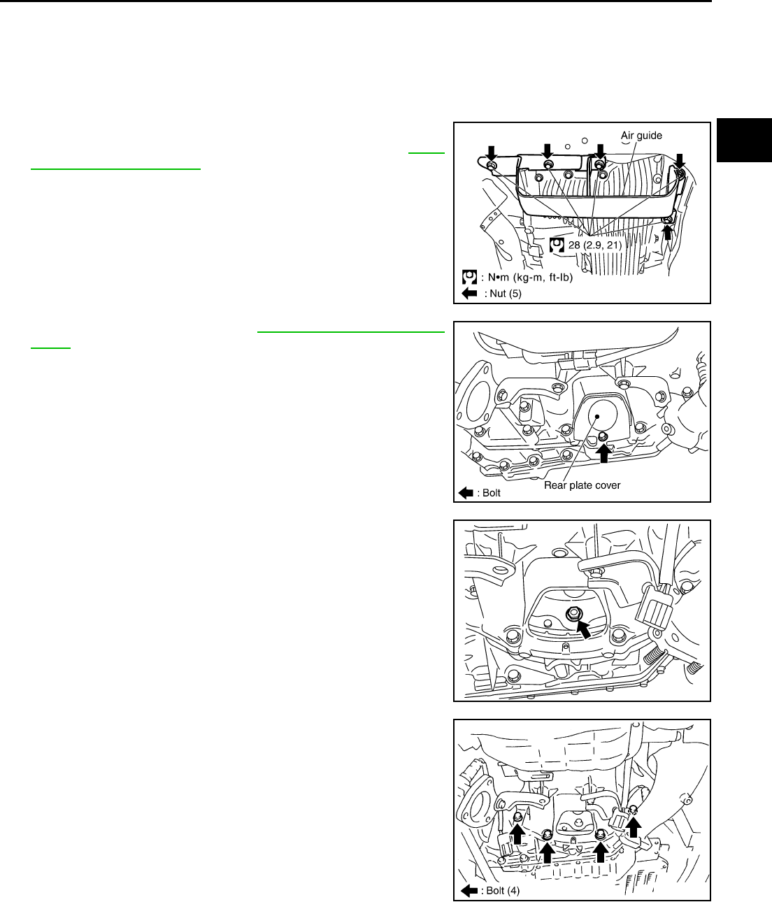
TRANSAXLE ASSEMBLY
CVT-231
D
E
F
G
H
I
J
K
L
M
A
B
CVT
Revision: 2006 August 2006 Murano
REMOVAL
CAUTION:
The transaxle assembly itself cannot be removed from the vehicle. Remove the transaxle assembly
and engine assembly together from the vehicle.
1. Disconnect the battery cable from the negative terminal.
2. Remove engine undercover.
3. Remove air guide.
4. Remove exhaust front tube with power tool. Refer to EX-3,
"Removal and Installation" .
5. Remove rear plate cover. Refer to EM-29, "Removal and Instal-
lation" .
6. Turn crankshaft, and remove the four tightening nuts for drive
plate and torque converter.
CAUTION:
The crankshaft should be rotated clockwise, viewed from
the front of the engine.
7. Remove the four bolts in the figure. (2WD models)
SCIA6476E
SCIA6475E
SCIA1861E
SCIA1893E
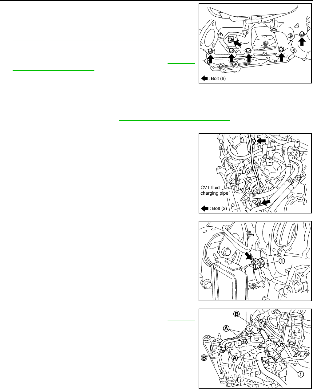
CVT-232
TRANSAXLE ASSEMBLY
Revision: 2006 August 2006 Murano
8. Remove the six bolts in the figure. (AWD models)
9. Remove transaxle assembly and engine assembly together
from the vehicle. Refer to EM-108, "Removal and Installation" .
10. Remove drive shaft. Refer to FAX-7, "Removal and Installation
(Left Side)" , FAX-9, "Removal and Installation (Right Side)" .
CAUTION:
Be sure to replace the differential side oil seal with new one
at the every removal of drive shaft. Refer to CVT-223,
"Removal and Installation" .
11. Remove rear gusset.
12. Remove transfer gusset. (AWD models)
13. Remove transfer assembly. Refer to TF-52, "Removal and Installation" . (AWD models)
CAUTION:
Be sure to replace the differential side oil seal with new one (converter housing side only) at the
every removal of transfer. Refer to CVT-223, "Removal and Installation" .
14. Remove CVT fluid level gauge.
15. Remove CVT fluid charging pipe.
16. Remove O-ring from CVT fluid charging pipe.
17. Disconnect harness connector and wire harness.
18. Remove crankshaft position sensor (POS) (1) from engine
assembly. Refer to EM-29, "Removal and Installation" .
CAUTION:
●Do not subject it to impact by dropping or hitting it.
●Do not disassemble.
●Do not allow metal filings, etc. to get on the sensor's front
edge magnetic area.
●Do not place in an area affected by magnetism.
19. Remove starter motor. Refer to SC-15, "Removal and Installa-
tion" .
20. Remove CVT fluid cooler valve assembly (1). (With CVT fluid
cooler tube assembly and heater hose). Refer to CVT-225,
"Removal and Installation" .
(A): Bolt (4)
(B): Hose clamp (3)
SCIA6016E
SCIA1894E
SCIA6759E
SCIA6880E
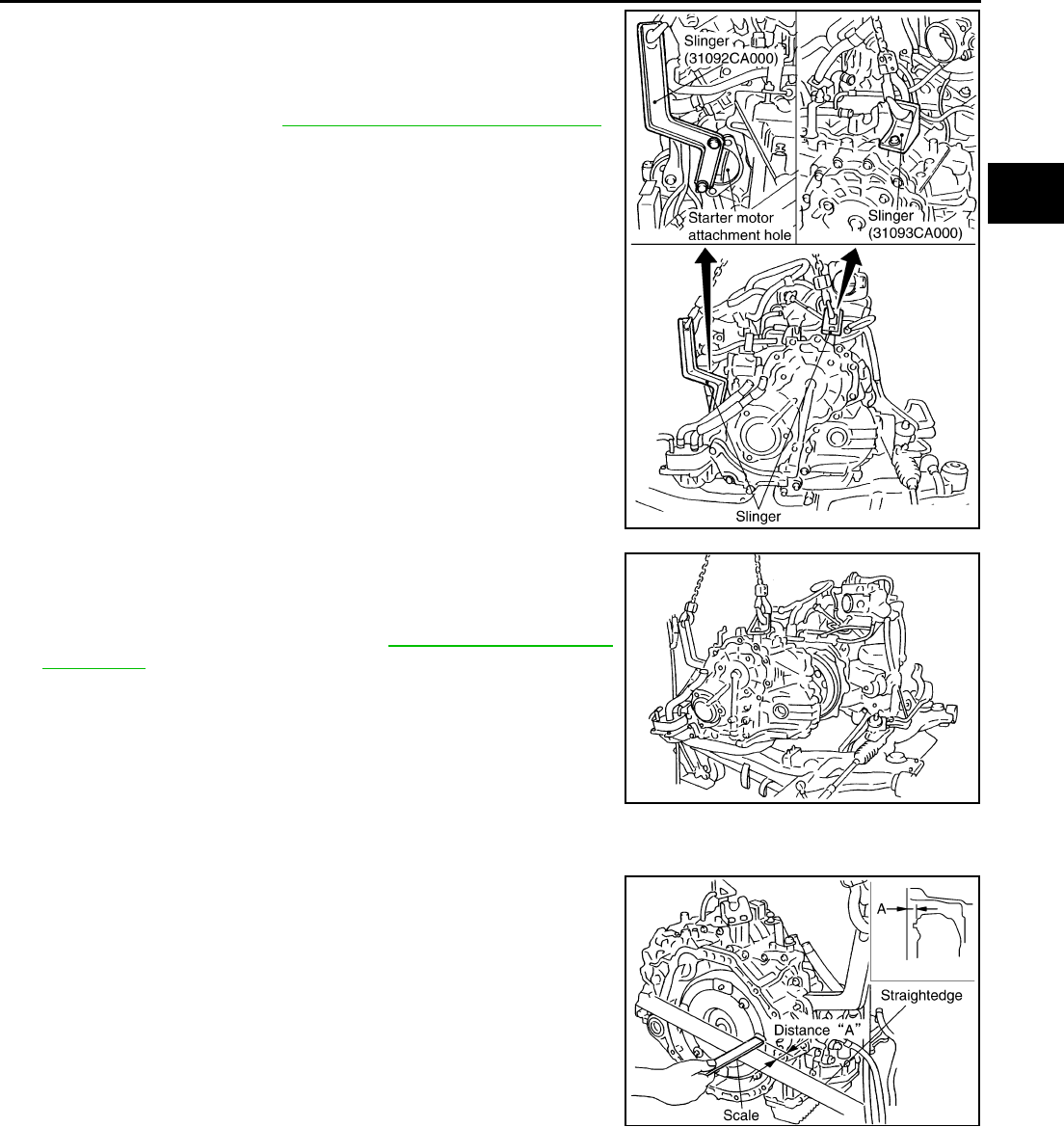
TRANSAXLE ASSEMBLY
CVT-233
D
E
F
G
H
I
J
K
L
M
A
B
CVT
Revision: 2006 August 2006 Murano
21. Install slinger to transaxle assembly.
22. Remove LH engine mounting bracket and LH engine mounting
insulator.
23. Remove front suspension member from transaxle assembly and
engine assembly. Refer to EM-108, "Removal and Installation" .
(AWD models)
24. Remove front engine mounting bracket and rear engine mount-
ing bracket.
25. Remove transaxle assembly fixing bolts with power tool.
26. Remove transaxle assembly from engine assembly with a hoist.
CAUTION:
Secure torque converter to prevent it from dropping.
27. Remove air breather hose. Refer to CVT-222, "Removal and
Installation" .
28. Remove CVT fluid cooler hoses.
29. Remove fluid cooler tube.
INSPECTION
Installation and Inspection of Torque Converter
After inserting a torque converter to a transaxle, be sure to check
distance A to ensure it is within the reference value limit.
SCIA4355E
SCIA1868E
Distance A: 14.0 mm (0.55 in) or more
SCIA2137E
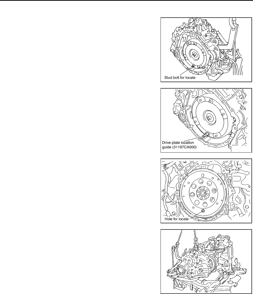
CVT-234
TRANSAXLE ASSEMBLY
Revision: 2006 August 2006 Murano
INSTALLATION
Note the following, and install in the reverse order of removal.
●Set and screw in the drive plate location guide onto the stud
bolts for the torque converter locate.
●Rotate the torque converter for the locate to go down.
●Rotate the drive plate for the hole of the drive plate locate to go
down.
●Install transaxle assembly to engine assembly with a hoist.
SCIA1871E
SCIA6881E
SCIA1872E
SCIA1868E
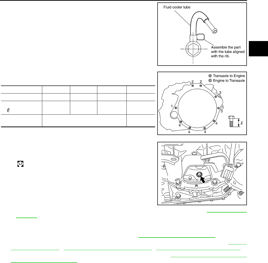
TRANSAXLE ASSEMBLY
CVT-235
D
E
F
G
H
I
J
K
L
M
A
B
CVT
Revision: 2006 August 2006 Murano
●When installing fluid cooler tube to transaxle assembly, assem-
ble the part with the tube aligned with the rib.
●When installing transaxle to the engine, attach the fixing bolts in
accordance with the following standard.
●Align the positions of tightening nuts for drive plate with those of
the torque converter, and temporarily tighten the nuts. Then,
tighten the nuts with the specified torque.
CAUTION:
●Do not reuse O-ring and copper washers.
●When turning crankshaft, turn it clockwise as viewed
from the front of the engine.
●When tightening the tightening nuts for the torque con-
verter after fixing the crankshaft pulley bolts, be sure to
confirm the tightening torque of the crankshaft pulley mounting bolts. Refer to EM-68, "INSTAL-
LATION" .
● After converter is installed to drive plate, rotate crankshaft several turns and check to be sure
that transaxle rotates freely without binding.
●Install crankshaft position sensor (POS) sensor. Refer to EM-29, "Removal and Installation" .
●After completing installation, check for fluid leakage, fluid level, and the positions of CVT. Refer to CVT-15,
"Checking CVT Fluid" , CVT-211, "Adjustment of CVT Position" , CVT-212, "Checking of CVT Position" .
●When replacing the CVT assembly, erase EEP ROM in TCM. Refer to CVT-9, "Precautions for TCM and
CVT Assembly Replacement" .
SCIA2285E
Bolt No. 1 2 3 4
Number of bolts 1 2 2 4
Bolt length
“ ”mm (in) 52 (2.05) 36 (1.42) 105 (4.13) 35 (1.38)
Tightening torque
N·m (kg-m, ft-lb) 75 (7.7, 55) 47 (4.8, 35)
SCIA6882E
: 51 N·m (5.2 kg-m, 38 ft-lb)
SCIA1861E
CVT-236
SERVICE DATA AND SPECIFICATIONS (SDS)
Revision: 2006 August 2006 Murano
SERVICE DATA AND SPECIFICATIONS (SDS) PFP:00030
General Specifications NCS0019M
*1: Refer to MA-10, "Fluids and Lubricants" .
Vehicle Speed When Shifting Gears NCS0019N
Numerical value data are reference values.
*: Without manual mode
CAUTION:
Lock-up clutch is engaged when vehicle speed is approximately 18 km/h (11 MPH) to 90 km/h (56 MPH).
Stall Speed NCS0019O
Line Pressure NCS0019P
*1 : Without manual mode
*2 : Reference values
Applied model VQ35DE engine
2WD AWD
CVT model RE0F09A
CVT assembly Model code number 1XD15 1XD16
Transmission gear ratio
D range Variable
Reverse 1.766
Final drive 5.173
Recommended fluid NISSAN CVT Fluid NS-2*1
Fluid capacity 10.2 liter (10-6/8 US qt, 9 Imp qt)
CAUTION:
●Use only Genuine NISSAN CVT Fluid NS-2. Do not mix with other fluid.
●Using CVT fluid other than Genuine NISSAN CVT Fluid NS-2 will deteriorate in driveability and CVT durability, and may
damage the CVT, which is not covered by the warranty.
Engine type Throttle position Shift pattern Engine speed (rpm)
At 40 km/h (25 MPH) At 60 km/h (37 MPH)
VQ35DE
8/8
“D” position
Second position*
“L” position*
2,800 - 4,300 3,900 - 5,300
2/8
“D” position 1,200 - 2,000 1,300 - 2,100
Second position* 2,200 - 3,000 2,800 - 3,600
“L” position* 2,800 - 3,600 3,800 - 4,600
Stall speed 2,700 - 3,250 rpm
Engine speed Line pressure kPa (kg/cm2 , psi)
“R”, “D” and “L”*1 positions
At idle 750 (7.65, 108.8)
At stall 5,700 (58.14, 826.5)*2
SERVICE DATA AND SPECIFICATIONS (SDS)
CVT-237
D
E
F
G
H
I
J
K
L
M
A
B
CVT
Revision: 2006 August 2006 Murano
Solenoid Valves NCS0019Q
CVT Fluid Temperature Sensor NCS0019R
Primary Speed Sensor NCS0019S
Secondary Speed Sensor NCS0019T
Removal and Installation NCS0019U
Name Resistance (Approx.) (Ω) Terminal
Pressure control solenoid valve B (secondary
pressure solenoid valve)
3.0 - 9.0
3
Pressure control solenoid valve A (line pressure
solenoid valve) 2
Torque converter clutch solenoid valve 12
Lock-up select solenoid valve 6 - 19 13
Name Condition CONSULT-II “DATA MONITOR” (Approx.) (V) Resistance (Approx.)
ATF TEMP SEN 20°C (68°F) 1.8 - 2.0 6.5 kΩ
80°C (176°F) 0.6 - 1.0 0.9 kΩ
Name Condition Data (Approx.)
Primary speed sensor When driving [“D” position, 20 km/h (12 MPH)]. 600 Hz
Name Condition Data (Approx.)
Secondary speed sensor When driving [“D” position, 20 km/h (12 MPH)]. 300 Hz
Distance between end of converter housing and torque converter 14.0 mm (0.55 in) or more

CVT-238
SERVICE DATA AND SPECIFICATIONS (SDS)
Revision: 2006 August 2006 Murano
